MiniCERNBot Educational Platform: Antimatter Factory Mock ... - MDPI
37
sensors Article MiniCERNBot Educational Platform: Antimatter Factory Mock-up Missions for Problem-Solving STEM Learning Josep Marín Garcés 1 , Carlos Veiga Almagro 1,2 , Giacomo Lunghi 2 , Mario Di Castro 1 , Luca Rosario Buonocore 1 , Raúl Marín Prades 2, * and Alessandro Masi 1 Citation: Marín Garcés, J.; Veiga Almagro, C.; Lunghi, G.; Di Castro, M.; Buenocore, L.R.; Marín Prades, R.; Masi, A. MiniCERNBot Educational Platform: Antimatter Factory Mock-up Missions for Problem-Solving STEM Learning. Sensors 2021, 21, 1398. https://doi.org/10.3390/s21041398 Academic Editor: Rasim Guldiken and Miguel Ángel Conde Received: 23 December 2020 Accepted: 2 February 2021 Published: 17 February 2021 Publisher’s Note: MDPI stays neu- tral with regard to jurisdictional clai- ms in published maps and institutio- nal affiliations. Copyright: © 2021 by the authors. Li- censee MDPI, Basel, Switzerland. This article is an open access article distributed under the terms and con- ditions of the Creative Commons At- tribution (CC BY) license (https:// creativecommons.org/licenses/by/ 4.0/). 1 CERN, BE-CEM Controls, Electronics and Mechatronics Group, 1217 Geneva, Switzerland; [email protected] (J.M.G.); [email protected] (C.V.A.); [email protected] (M.D.C.); [email protected] (L.R.B.); [email protected] (A.M.) 2 Interactive Robotic Systems Lab, Jaume I University of Castellón, 12006 Castellón de la Plana, Spain; [email protected] * Correspondence: [email protected] Abstract: Mechatronics and robotics appeared particularly effective in students’ education, allowing them to create non-traditional solutions in STEM disciplines, which have a direct impact and interac- tion with the world surrounding them. This paper presents the current state of the MiniCERNBot Educational Robotic platform for high-school and university students. The robot provides a compre- hensive educative system with tutorials and tasks tuned for different ages on 3D design, mechanical assembly, control, programming, planning, and operation. The system is inspired to existing robotic systems and typical robotic interventions performed at CERN, and includes an education mock-up that follows the example of a previous real operation performed in CERN’s Antimatter Factory. The paper describes the learning paths where the MiniCERNBot platform can be used by students, at different ages and disciplines. In addition, it describes the software and hardware architecture, presenting results on modularity and network performance during education exercises. In summary, the objective of the study is improving the way STEM educational and dissemination activities at CERN Robotics Lab are performed, as well as their possible synergies with other education insti- tutions, such as High-Schools and Universities, improving the learning collaborative process and inspiring students interested in technical studies. To this end, a new educational robotic platform has been designed, inspired on real scientific operations, which allows the students practice multidisci- plinary STEM skills in a collaborative problem-solving way, while increasing their motivation and comprehension of the research activities. Keywords: sensors; robotics; mechatronics; physical devices; education; STEM education; interaction; engineering education 1. Introduction Mechatronics and robotics play an important role in high-school and University education. They provide the students with real world challenges to be solved using novel solutions and pushing into a deeper understanding and direct application of Science, Technology, Engineering, and Mathematics (STEM) language and systems. STEM education aims to provide the knowledge and tools to the widest number of students for pursuing careers in STEM fields [1]. Mechatronics and robotics provide access to all STEM fields by showing how they work in real life and revealing their impact in the world of tomorrow. Education is an important mandate for CERN, whose role is to educate Europe’s future scientists and engineers and provides a series of educational programmes targeting students of different ages [2,3]. Of the 100,000 visitors who visit CERN each year, the majority are high-school students [4,5]. Opportunities for students in applied physics, engineering, computing, and more are available throughout the whole year, thanks to workshops and Sensors 2021, 21, 1398. https://doi.org/10.3390/s21041398 https://www.mdpi.com/journal/sensors
-
Upload
khangminh22 -
Category
Documents
-
view
1 -
download
0
Transcript of MiniCERNBot Educational Platform: Antimatter Factory Mock ... - MDPI
sensors
Article
MiniCERNBot Educational Platform: Antimatter FactoryMock-up Missions for Problem-Solving STEM Learning
Josep Marín Garcés 1 , Carlos Veiga Almagro 1,2 , Giacomo Lunghi 2 , Mario Di Castro 1 ,Luca Rosario Buonocore 1 , Raúl Marín Prades 2,* and Alessandro Masi 1
�����������������
Citation: Marín Garcés, J.;
Veiga Almagro, C.; Lunghi, G.;
Di Castro, M.; Buenocore, L.R.;
Marín Prades, R.; Masi, A.
MiniCERNBot Educational Platform:
Antimatter Factory Mock-up
Missions for Problem-Solving STEM
Learning. Sensors 2021, 21, 1398.
https://doi.org/10.3390/s21041398
Academic Editor: Rasim Guldiken and
Miguel Ángel Conde
Received: 23 December 2020
Accepted: 2 February 2021
Published: 17 February 2021
Publisher’s Note: MDPI stays neu-
tral with regard to jurisdictional clai-
ms in published maps and institutio-
nal affiliations.
Copyright: © 2021 by the authors. Li-
censee MDPI, Basel, Switzerland.
This article is an open access article
distributed under the terms and con-
ditions of the Creative Commons At-
tribution (CC BY) license (https://
creativecommons.org/licenses/by/
4.0/).
1 CERN, BE-CEM Controls, Electronics and Mechatronics Group, 1217 Geneva, Switzerland;[email protected] (J.M.G.); [email protected] (C.V.A.);[email protected] (M.D.C.); [email protected] (L.R.B.); [email protected] (A.M.)
2 Interactive Robotic Systems Lab, Jaume I University of Castellón, 12006 Castellón de la Plana, Spain;[email protected]
* Correspondence: [email protected]
Abstract: Mechatronics and robotics appeared particularly effective in students’ education, allowingthem to create non-traditional solutions in STEM disciplines, which have a direct impact and interac-tion with the world surrounding them. This paper presents the current state of the MiniCERNBotEducational Robotic platform for high-school and university students. The robot provides a compre-hensive educative system with tutorials and tasks tuned for different ages on 3D design, mechanicalassembly, control, programming, planning, and operation. The system is inspired to existing roboticsystems and typical robotic interventions performed at CERN, and includes an education mock-upthat follows the example of a previous real operation performed in CERN’s Antimatter Factory.The paper describes the learning paths where the MiniCERNBot platform can be used by students,at different ages and disciplines. In addition, it describes the software and hardware architecture,presenting results on modularity and network performance during education exercises. In summary,the objective of the study is improving the way STEM educational and dissemination activities atCERN Robotics Lab are performed, as well as their possible synergies with other education insti-tutions, such as High-Schools and Universities, improving the learning collaborative process andinspiring students interested in technical studies. To this end, a new educational robotic platform hasbeen designed, inspired on real scientific operations, which allows the students practice multidisci-plinary STEM skills in a collaborative problem-solving way, while increasing their motivation andcomprehension of the research activities.
Keywords: sensors; robotics; mechatronics; physical devices; education; STEM education; interaction;engineering education
1. Introduction
Mechatronics and robotics play an important role in high-school and Universityeducation. They provide the students with real world challenges to be solved usingnovel solutions and pushing into a deeper understanding and direct application of Science,Technology, Engineering, and Mathematics (STEM) language and systems. STEM educationaims to provide the knowledge and tools to the widest number of students for pursuingcareers in STEM fields [1]. Mechatronics and robotics provide access to all STEM fields byshowing how they work in real life and revealing their impact in the world of tomorrow.
Education is an important mandate for CERN, whose role is to educate Europe’s futurescientists and engineers and provides a series of educational programmes targeting studentsof different ages [2,3]. Of the 100,000 visitors who visit CERN each year, the majority arehigh-school students [4,5]. Opportunities for students in applied physics, engineering,computing, and more are available throughout the whole year, thanks to workshops and
Sensors 2021, 21, 1398. https://doi.org/10.3390/s21041398 https://www.mdpi.com/journal/sensors

Sensors 2021, 21, 1398 2 of 37
internships like high-school internship programme, the Beamline for School challenge,and the S’Cool Lab research facility [6].
The Mechatronics, Robotics and Operations (MRO) section at CERN, part of the Sur-vey, Mechatronics and Measurements (SMM) group of the engineering department is incharge of designing and developing cutting-edge robotics technology to remotely performreal interventions in the accelerator scientific facilities. The CERNBot and Train InspectionMonorail (TIM) platforms are an example of such systems, which are continuously im-proved and adapted to the CERN necessities, while offering new scientific improvementsto the Telerobotics research community [7–11]. The MRO section is part of different CERN’seducational programmes and hosts periodically students between the ages of 16 and 19,from diverse background and education. In addition, Bachelor and Master’s students takepart in longer education activities, related to more specific scientific problems, which needbasic training on STEM related skills. Besides this, in collaboration with Universities, CERNoffers Doctorate Programs, which might need desktop educational kits for prototyping andpreliminary scientific experiments.
STEM is an approach focused on the development of skills in multiple fields during learn-ing. The use of robotics in STEM (Educational Robotics) can increase students’ interest andmotivation [12], both during the learning process as well as future career decisions [13–15].Several studies have been done to present the impact of Educational Robotics (ER) even inyoung students [16–18], thanks to its connection with play and enjoyment is considered tobe an important factor that encourages children and enables intrinsic motivation, especiallyin primary education [19]. Researchers have attempted also to create robotic curricula inhigh-schools and studying their effect [20,21]. In addition, over the last decade, the interestand engagement of teachers and professor around Educational Robotics and STEM haveincreased [22]. Different types of educational robots have been presented, adapting todifferent programs, some more software-centred, others more focused on hardware andmechanical assembly, others on socialisation, interaction and gaming [16]. Overall, Educa-tional Robotics pushes the students at all ages to provide innovative solutions to real-worldproblems, promoting collaborative skills [23], creativity and problem-based learning [24]and allowing them to learn with technology rather than learning about it [25].
In this paper, the MiniCERNBot Educational Robotic kit is presented. The robotickit brings the experience obtained during CERN’s robotic operation to the educationallevel. The robotic kit includes different learning paths adapted to different students’ agesand different training times, spanning from one day to a couple of months. According totheir age and skills, students are required to analyse and understand the requirements of arobotic intervention, inspired by real operations performed in CERN’s accelerator complex.They can define the intervention procedures including checklists, failure analysis andrecovery scenarios as defined by the CERNTAURO framework for remote interventions [8].The students can design and manufacture custom tools to simplify the operations’ tasks,program a control application for the robot and additional behaviours on the robot controlboard thanks to the full support of the CERN Robotic Framework [7] and then apply theirwork to the real robotic intervention. Finally, they can compare their work by controllingthe MiniCERNBot educational robot with the same Human–Robot Interface used to controlthe CERN’s robots.
Research Method and Paper Structure
The paper faces the need of a new educational procedure at CERN Robotics Lab,which is centred on solving real related problems, can be adapted to different educationallevels (i.e., high-school, Bachelor’s and Master’s), is flexible in terms of duration of theactivity (i.e., from one day to three months), allowing collaborative multidisciplinary teams,and greatly helping students to clarify their vocations in STEM carriers.
In order to walk in this direction, the research has focused on three main aspects:(1) The design of a multidisciplinary and adaptable learning path oriented on solvingmissions of increasing difficulty, (2) the design of a mechatronic educational kit (i.e.,MINICERNBot twins and antimatter factory panel) in order to be used as learning scenario
Sensors 2021, 21, 1398 3 of 37
and validation tool, and (3) assessment of the performance, in terms of both mechatronics,and final motivation of the students. The education experiments that provided results onstudents motivation have been performed with high-school, fourth year Computer ScienceEngineering, and first year Robotics&AI Master’s students.
With the aim of helping on the repeatability of the experiments, the paper proposes amultidisciplinary education path, providing a model to combine STEM practices in the samelearning process, identifying free tools that can help enormously in this process. The learningpath can be adapted to other education STEM scenarios as required. Besides this, the robotickit is explained in detail, focusing specially on the used electronics and computer sciencetools, as well as evaluating their performance by using standard benchmarks (i.e., Androidand PC).
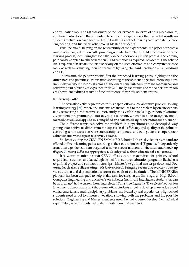
To this aim, the paper presents first the proposed learning paths, highlighting thedifferences and possible customisation according to the student’s age and internship dura-tion. Afterwards, the technical details of the educational kit, both from the mechanical andsoftware point of view, are explained in detail. Finally, the results and video demonstrationare shown, including a resume of the experience of various student groups.
2. Learning Paths
The education activity presented in this paper follows a collaborative problem-solvinglearning strategy [26], where the students are introduced to the problem by on-site experts’(e.g., recovering a radioactive source), study the available tools (e.g., robotic platforms,3D printers, programming), and develop a solution, which has to be designed, imple-mented, tested, and applied in a simplified and safe mock-up of the radioactive scenario.
The different teams can solve the problem in a synchronised or decoupled way,getting quantitative feedback from the experts on the efficiency and quality of the solution,according to the tasks that were successfully completed, and being able to compare theirachievements with respect to previous teams.
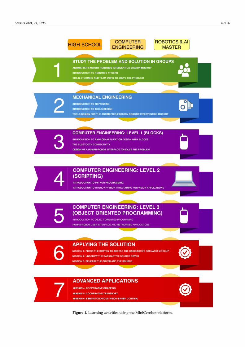
Students visiting the CERN-EN-SMM-MRO Robotics Lab are divided in teams and areoffered different learning paths according to their education level (Figure 1). Independentlyfrom their age, the teams are required to solve a set of missions on the antimatter mock-up(Figure 2), using different appropriate tools adapted to their educational background.
It is worth mentioning that CERN offers education activities for primary school(e.g., demonstrations and labs), high-school (i.e., summer education program), Bachelor’s(e.g., final project and summer internships), Master’s (e.g., final master project), and Doc-torate levels (i.e., collaborating with Universities). Bringing recent discoveries to societyvia education and dissemination is one of the goals of the institution. The MINICERNBotplatform has been designed to help in this task, focusing, at the first stage, on High-School,Computer Engineering and a Master’s on Robotics&Artificial Intelligence students, as canbe appreciated in the current Learning selected Paths (see Figure 1). The selected educationlevels try to demonstrate that the system offers students a tool to develop knowledge basedon incremental and multidisciplinary problems, motivated by real experiences. High schoolstudents need a tool to discern a vocation, showing both the problems and the possiblesolutions. Engineering and Master’s students need the tool to better develop their technicalcapabilities, as well as enhancing their motivation in the subject.
Sensors 2021, 21, 1398 4 of 37
123
6
STUDY THE PROBLEM AND SOLUTION IN GROUPSANTIMATTER-FACTORY ROBOTICS INTERVENTION MISSION MOCKUP
INTRODUCTION TO ROBOTICS AT CERN
BRAIN-STORMING AND TEAM WORK TO SOLVE THE PROBLEM
MECHANICAL ENGINEERINGINTRODUCTION TO 3D PRINTING
INTRODUCTION TO TOOLS DESIGN
TOOLS DESIGN FOR THE ANTIMATTER-FACTORY ROBOTIC INTERVENTION MOCKUP
COMPUTER ENGINEERING: LEVEL 1 (BLOCKS)INTRODUCTION TO ANDROID APPLICATION DESIGN WITH BLOCKS
THE BLUETOOTH CONNECTIVITY
DESIGN OF A HUMAN-ROBOT INTERFACE TO SOLVE THE PROBLEM
A
APPLYING THE SOLUTIONMISSION 1: PRESS THE BUTTON TO ACCESS THE RADIOACTIVE SCENARIO MOCKUP
MISSION 2: UNSCREW THE RADIOACTIVE SOURCE COVER
MISSION 3: RELEASE THE COVER AND THE SOURCE
7 ADVANCED APPLICATIONSMISSION 4: COOPERATIVE GRASPING
MISSION 5: COOPERATIVE TRANSPORT
MISSION 6: SEMIAUTONOMOUS VISION-BASED CONTROL
4 COMPUTER ENGINEERING: LEVEL 2(SCRIPTING)INTRODUCTION TO PYTHON PROGRAMMING
INTRODUCTION TO OPENCV PYTHON PROGRAMING FOR VISION APPLICATIONS
5 COMPUTER ENGINEERING: LEVEL 3(OBJECT ORIENTED PROGRAMMING)INTRODUCTION TO OBJECT ORIENTED PROGRAMING
HUMAN-ROBOT USER INTERFACE AND NETWORKED APPLICATIONS
HIGH-SCHOOL COMPUTERENGINEERING
ROBOTICS & AIMASTER
Figure 1. Learning activities using the MiniCernbot platform.

Sensors 2021, 21, 1398 5 of 37
Figure 2. (First row) Antimatter factory real intervention performed by the CERN-EN-SMM-MRO team to recover aradioactive source; (Second row) Educational Mockup simulating the necessary steps to recover a source.
2.1. Study the Problem and Solution in Groups
The education activity starts with the introduction to the problem, where scientificexperiments must be performed in radioactive scenarios, which do not allow humans todirectly interact with the equipment and tools.
As an example of such activities, the students are introduced to a previous experimentperformed in the Antimatter Factory, where a radioactive target had to be replaced. In fact,the students are provided with the simplified Antimatter Factory Mockup, as shown inFigure 2, where they are invited to reproduce the real intervention in more simple way.
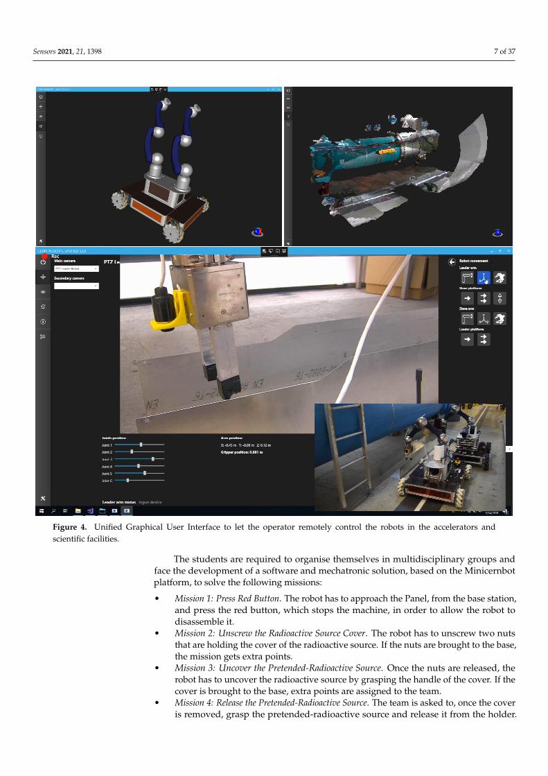
The second step is the introduction to the robotic facilities at CERN, where the stu-dents can face real demonstrations of the modular robots, such as the TIM, CERNBot,CERNBot2, Cranebot, Charmbot, etc., (see Figure 3). In addition, they can better under-stand the way the robots are remotely operated via the Unified Graphical User Interface(GUI [7]), which guarantees human safety by avoiding their exposure to radioactive sce-narios. In addition, the students are able to better understand the meaning of «Science forPeace», focusing exclusively on research and applications that have an outstanding socialbenefit (e.g., medical applications).
The main contribution of this pool of robots is their modularity, which permits adapt-ing the robot configuration to the specific operation to be performed. New tools haveto be designed and assembled for each specific intervention, which needs a continuousdevelopment and improvement of the robot platforms. In addition, the software used bythe operators to control the robots is also explained, so that they can better understand thedifferent ways to interact with the robots, from manual to supervisory control, accordingto the specific necessity and the expertise of the operator (see Figure 4).
Once the students understand the robotic platforms, adapted tools, and user interface,the Minicernbot educational robots are explained in detail (see Figure 5). As will be seenlater in this paper, the new educational robot is inspired by the CERNBot one, and enablesthe student to reconfigure the position and number of robotic arms, as well as the camerahead. In addition, it allows the students to use tracks or omnidirectional wheels, accordingto their specific necessities. The robot can be also enhanced mechanically by the students byattaching tools and components to the gripper and aluminium frame structure, accordingto their specific solutions.

Sensors 2021, 21, 1398 6 of 37
The next step in this first learning group (i.e., «Study the Problem and Solution inGroups») is a comprehension of the problem to be solved. According to a previous realintervention in the radioactive Antimatter Factory, the robot had to disassemble a cover andreplace a radioactive source. This inspired realistic scenario was simplified for education,so the «Antimatter Factory Mockup Panel» was designed (see Figure 2).
Figure 3. Set of modular robots developed at CERN-EN-SMM-MRO section to perform safe operations in radioactive andhazardous scientific facilities (i.e., Cranebot, Charmbot, CERNBot, CERNBot2, TIM, and Unified GUI).
Sensors 2021, 21, 1398 7 of 37
Figure 4. Unified Graphical User Interface to let the operator remotely control the robots in the accelerators andscientific facilities.
The students are required to organise themselves in multidisciplinary groups andface the development of a software and mechatronic solution, based on the Minicernbotplatform, to solve the following missions:
• Mission 1: Press Red Button. The robot has to approach the Panel, from the base station,and press the red button, which stops the machine, in order to allow the robot todisassemble it.
• Mission 2: Unscrew the Radioactive Source Cover. The robot has to unscrew two nutsthat are holding the cover of the radioactive source. If the nuts are brought to the base,the mission gets extra points.
• Mission 3: Uncover the Pretended-Radioactive Source. Once the nuts are released, therobot has to uncover the radioactive source by grasping the handle of the cover. If thecover is brought to the base, extra points are assigned to the team.
• Mission 4: Release the Pretended-Radioactive Source. The team is asked to, once the coveris removed, grasp the pretended-radioactive source and release it from the holder.
Sensors 2021, 21, 1398 8 of 37
If the pretended-radioactive source is brought to the base, extra points are assigned tothe team.
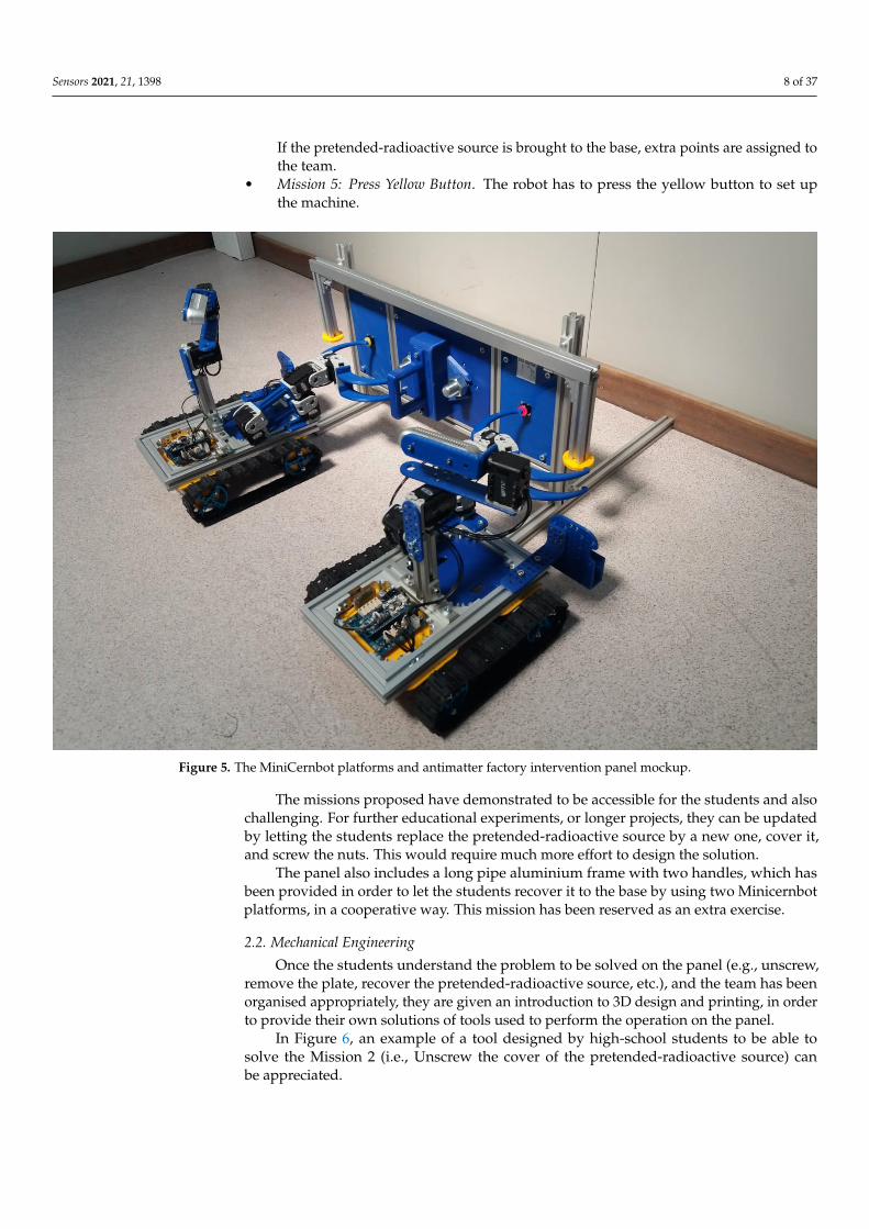
• Mission 5: Press Yellow Button. The robot has to press the yellow button to set upthe machine.
Figure 5. The MiniCernbot platforms and antimatter factory intervention panel mockup.
The missions proposed have demonstrated to be accessible for the students and alsochallenging. For further educational experiments, or longer projects, they can be updatedby letting the students replace the pretended-radioactive source by a new one, cover it,and screw the nuts. This would require much more effort to design the solution.
The panel also includes a long pipe aluminium frame with two handles, which hasbeen provided in order to let the students recover it to the base by using two Minicernbotplatforms, in a cooperative way. This mission has been reserved as an extra exercise.
2.2. Mechanical Engineering
Once the students understand the problem to be solved on the panel (e.g., unscrew,remove the plate, recover the pretended-radioactive source, etc.), and the team has beenorganised appropriately, they are given an introduction to 3D design and printing, in orderto provide their own solutions of tools used to perform the operation on the panel.
In Figure 6, an example of a tool designed by high-school students to be able tosolve the Mission 2 (i.e., Unscrew the cover of the pretended-radioactive source) canbe appreciated.
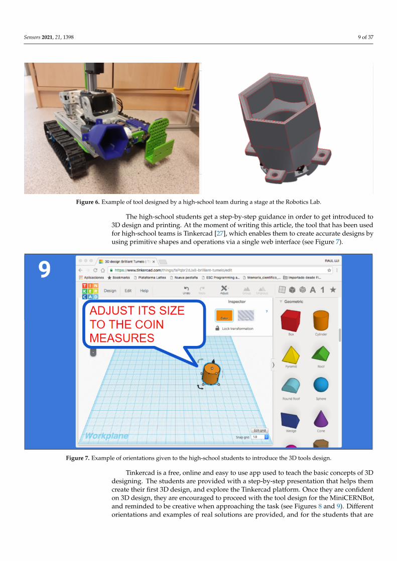
Sensors 2021, 21, 1398 9 of 37
Figure 6. Example of tool designed by a high-school team during a stage at the Robotics Lab.
The high-school students get a step-by-step guidance in order to get introduced to3D design and printing. At the moment of writing this article, the tool that has been usedfor high-school teams is Tinkercad [27], which enables them to create accurate designs byusing primitive shapes and operations via a single web interface (see Figure 7).
Figure 7. Example of orientations given to the high-school students to introduce the 3D tools design.
Tinkercad is a free, online and easy to use app used to teach the basic concepts of 3Ddesigning. The students are provided with a step-by-step presentation that helps themcreate their first 3D design, and explore the Tinkercad platform. Once they are confidenton 3D design, they are encouraged to proceed with the tool design for the MiniCERNBot,and reminded to be creative when approaching the task (see Figures 8 and 9). Differentorientations and examples of real solutions are provided, and for the students that are

Sensors 2021, 21, 1398 10 of 37
struggling to accomplish the task, an already designed base piece is provided with exactmeasurements for the attachment with the robot’s motor, which is normally the area wheremost common errors occur.
Figure 8. Students measuring the panel in order to design the tool to accomplish the Unscrew Mission.
Figure 9. Tool designed by students to unscrew.
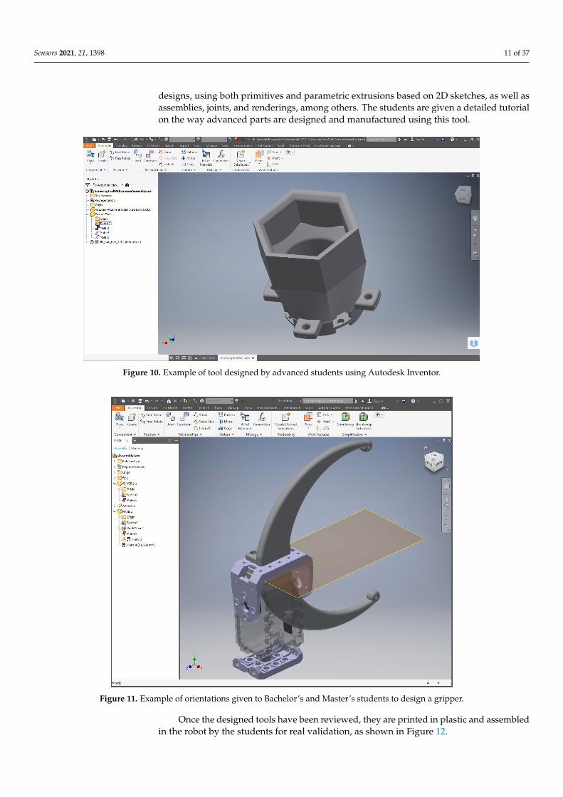
The Bachelor’s and Master’s students and given a tutorial on advanced 3D designwith parametric tools. At the moment of writing, the tool used is Autodesk Inventor [28],as can be appreciated in Figures 10 and 11. This is a tool that permits more advanced
Sensors 2021, 21, 1398 11 of 37
designs, using both primitives and parametric extrusions based on 2D sketches, as well asassemblies, joints, and renderings, among others. The students are given a detailed tutorialon the way advanced parts are designed and manufactured using this tool.
Figure 10. Example of tool designed by advanced students using Autodesk Inventor.
Figure 11. Example of orientations given to Bachelor’s and Master’s students to design a gripper.
Once the designed tools have been reviewed, they are printed in plastic and assembledin the robot by the students for real validation, as shown in Figure 12.

Sensors 2021, 21, 1398 12 of 37
(a) (b)
Figure 12. Students assembling their printed tool: The students also learn about how 3D printers work as they print theirpiece (a) printing tools in 3D; (b) assembling the tool in the robot to solve the missions.
When they have finished the design, they are taught how to export their design in3D format so that they can print it with a 3D printer, and, once printed, they learn how toassemble it into the robot with bolts and nuts previously provided, in order to get the robotready for the intervention (see Figure 12).
2.3. Computer Engineering Level 1 (Blocks)
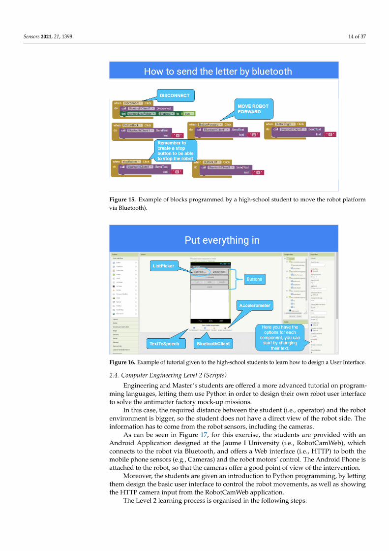
In Figure 13, the software architecture for the Computer Engineering Level 1 exercise isshown. The students are given a tutorial on Android Programming by using the MIT AppInventor Tool, which is based on the use of simple programming blocks. The applicationthey develop (see Figure 14) establishes a Bluetooth connection to the robot sensors/ac-tuators controller, so that the students learn how to solve the robot missions by having adirect field of view to the robot from the Android User Interface, so no camera feedback isrequired in this exercise.
In order to design the first Human–Robot Interface, the MIT App Inventor tool is usedby the students to practice Block-Programming (see Figure 15). This gives them a quick wayto get the robot working and solve the simple operations. With the help of the step-by-steptutorial they are provided with, the students start to add buttons and other components totheir app (see Figure 16). Afterwards, they start programming each component individuallywith different blocks that they can attach together. The MiniCERNBot robotic platformalready has a bluetooth server firmware running on its micro-controller, which startsrunning as soon as the robot is turned on. This program makes the robot move wheneverthe robot is sent a character via Bluetooth. This makes programming much more simpleas the students only need to connect to the robot and send one of the characters thatare provided to them to start the movements. Once they have programmed the basicbuttons (forward, backwards, left, right), they already understand what is going on in theirapp; therefore, they are given different optional tasks to improve their human–robot userinterface such as:
1. Adding images to the buttons.2. Using the Android phone accelerometer sensor to send movements.3. Controlling the speed.4. Improving the control.5. Controlling the robot with the orientation sensor.6. Optionally, for advanced high-school students, they are given a second Android
phone with an HTTP camera application, which provides camera feedback via Wifi,so they can add an HTTP client controller to their blocks program, in order to obtainthe robot images on the user interface.

Sensors 2021, 21, 1398 13 of 37
ANDROID PROGRAMMING BLOCKS
3 COMPUTER ENGINEERING: LEVEL 1 (BLOCKS)INTRODUCTION TO ANDROID APPLICATION DESIGN WITH BLOCKS
THE BLUETOOTH CONNECTIVITY
DESIGN OF A HUMAN-ROBOT INTERFACE TO SOLVE THE PROBLEM
HIGH-SCHOOL
CONNECTION I
ANDROID PROGRAMMING BLOCKS
ANDROID APPLICATION
Figure 13. Software architecture for the Computer Engineering Level 1 exercise.
(a) (b) (c)
Figure 14. Example of Android User interface created by a high-school student (a) base controls; (b) arm controls; (c) AndroidApplication Logo defined by the student.
Sensors 2021, 21, 1398 14 of 37
Figure 15. Example of blocks programmed by a high-school student to move the robot platformvia Bluetooth).
Figure 16. Example of tutorial given to the high-school students to learn how to design a User Interface.
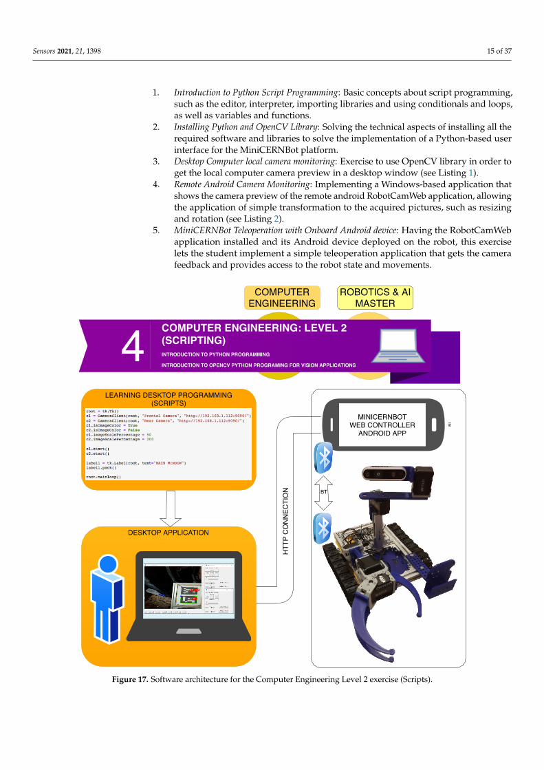
2.4. Computer Engineering Level 2 (Scripts)
Engineering and Master’s students are offered a more advanced tutorial on program-ming languages, letting them use Python in order to design their own robot user interfaceto solve the antimatter factory mock-up missions.
In this case, the required distance between the student (i.e., operator) and the robotenvironment is bigger, so the student does not have a direct view of the robot side. Theinformation has to come from the robot sensors, including the cameras.
As can be seen in Figure 17, for this exercise, the students are provided with anAndroid Application designed at the Jaume I University (i.e., RobotCamWeb), whichconnects to the robot via Bluetooth, and offers a Web interface (i.e., HTTP) to both themobile phone sensors (e.g., Cameras) and the robot motors’ control. The Android Phone isattached to the robot, so that the cameras offer a good point of view of the intervention.
Moreover, the students are given an introduction to Python programming, by lettingthem design the basic user interface to control the robot movements, as well as showingthe HTTP camera input from the RobotCamWeb application.
The Level 2 learning process is organised in the following steps:
Sensors 2021, 21, 1398 15 of 37
1. Introduction to Python Script Programming: Basic concepts about script programming,such as the editor, interpreter, importing libraries and using conditionals and loops,as well as variables and functions.
2. Installing Python and OpenCV Library: Solving the technical aspects of installing all therequired software and libraries to solve the implementation of a Python-based userinterface for the MiniCERNBot platform.
3. Desktop Computer local camera monitoring: Exercise to use OpenCV library in order toget the local computer camera preview in a desktop window (see Listing 1).
4. Remote Android Camera Monitoring: Implementing a Windows-based application thatshows the camera preview of the remote android RobotCamWeb application, allowingthe application of simple transformation to the acquired pictures, such as resizingand rotation (see Listing 2).
5. MiniCERNBot Teleoperation with Onboard Android device: Having the RobotCamWebapplication installed and its Android device deployed on the robot, this exerciselets the student implement a simple teleoperation application that gets the camerafeedback and provides access to the robot state and movements.
MI
LEARNING DESKTOP PROGRAMMING(SCRIPTS)
DESKTOP APPLICATION
4 COMPUTER ENGINEERING: LEVEL 2(SCRIPTING)INTRODUCTION TO PYTHON PROGRAMMING
INTRODUCTION TO OPENCV PYTHON PROGRAMING FOR VISION APPLICATIONS
COMPUTERENGINEERING
ROBOTICS & AIMASTER
BT
MINICERNBOTWEB CONTROLLER
ANDROID APP
HTT
P C
ON
NEC
TIO
N
Figure 17. Software architecture for the Computer Engineering Level 2 exercise (Scripts).

Sensors 2021, 21, 1398 16 of 37
Listing 1. Desktop Computer local camera monitoring template.
1 import cv2 as cv2
3 def getImage(cam, mirror):4 ret_val, img = cam.read()5 if mirror:6 img = cv.flip(img, 1)7
8 return img9
10 cam = cv.VideoCapture(0)11 while True:12 image = getImage(cam, True)13 cv.imshow(’MINICERNBOTCAM’,image)14 k = cv.waitKey(100)
Listing 2. Example of a Python template script to monitor the onboard Android device camera.
15 def url_to_image(url, readFlag=cv.IMREAD_COLOR):16 # download the image, convert it to a NumPy array, and then read17 # it into OpenCV format18 resp = urlopen(url)19 image = np.asarray(bytearray(resp.read()), dtype="uint8")20 image = cv.imdecode(image, readFlag)21 return image22
23 while True:24 #URL of the remote camera webserver25 url = ’http://172.16.20.9:9090/camera.jpg’26 image = url_to_image(url)27 cv.imshow(’MINICERNBOTCAM’,dst)28 k = cv.waitKey(200)
2.5. Computer Engineering Level 3 (Object-Oriented Programming)
Engineering and Master’s students are given the opportunity to learn and practisereal problem-solving using Android Programming with Java Object-oriented language.In fact, two official courses at the Jaume I University are using the MiniCERNBot tool inthe lab, (1) «Networks and Mobile Devices» at fourth course of Computer Engineeringdegree, and (2) «Remote Control» subject at the Intelligent Systems Master.
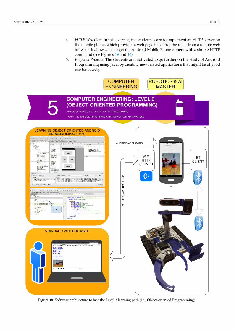
As can be seen in Figure 18, the students use as learning tool, the «Android StudioFramework», which enables them to design low-level applications on Android devices,by using sophisticated API’s such as the Bluetooth and Wifi connections. In fact, theobjective of the course is to design an Android Application that connects to the robot viaBluetooth in order to perform motor movements and sensor readings, as well as lettingremote web browsers to access the mobile phone cameras and robot commands via Web(i.e., HTTP).
The course is organised in the following way:
1. Introduction to Java: First steps on Java object-oriented programming language, study-ing classes declaration, functions, variables, and architectures, such as desktop, web,and Android applications.
2. Introduction to Android Studio: Explaining the structure of the Android Studio Pro-gramming Platform, understanding the basic steps to get an Android Applicationinstalled in the mobile phone.
3. Bluetooth Connection: Study the Bluetooth API that allows the Android implementationof Bluetooth clients and servers. In this step, the students have to implement a clientto control the Minicernbot platform.
Sensors 2021, 21, 1398 17 of 37
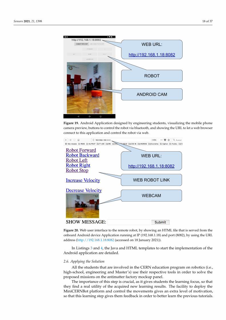
4. HTTP Web Cam: In this exercise, the students learn to implement an HTTP server onthe mobile phone, which provides a web page to control the robot from a remote webbrowser. It allows also to get the Android Mobile Phone camera with a simple HTTPcommand (see Figures 19 and 20).
5. Proposed Projects: The students are motivated to go further on the study of AndroidProgramming using Java, by creating new related applications that might be of gooduse for society.
MI
LEARNING OBJECT ORIENTED ANDROIDPROGRAMMING (JAVA)
STANDARD WEB BROWSER
ANDROID APPLICATION
COMPUTERENGINEERING
ROBOTICS & AIMASTER
HTT
P C
ON
NEC
TIO
N
5 COMPUTER ENGINEERING: LEVEL 3(OBJECT ORIENTED PROGRAMMING)INTRODUCTION TO OBJECT ORIENTED PROGRAMING
HUMAN-ROBOT USER INTERFACE AND NETWORKED APPLICATIONS
WIFIHTTP
SERVER
BTCLIENT
Figure 18. Software architecture to face the Level 3 learning path (i.e., Object-oriented Programming).
Sensors 2021, 21, 1398 18 of 37
WEB URL:
http://192.168.1.18:8082
ROBOT
ANDROID CAM
Figure 19. Android Application designed by engineering students, visualizing the mobile phonecamera preview, buttons to control the robot via bluetooth, and showing the URL to let a web browserconnect to this application and control the robot via web.
WEB URL:
http://192.168.1.18:8082
WEB ROBOT LINK
WEBCAM
Figure 20. Web user interface to the remote robot, by showing an HTML file that is served from theonboard Android device Application running at IP (192.168.1.18) and port (8082), by using the URLaddress (http://192.168.1.18:8082 (accessed on 18 January 2021)).
In Listings 3 and 4, the Java and HTML templates to start the implementation of theAndroid application are detailed.
2.6. Applying the Solution
All the students that are involved in the CERN education program on robotics (i.e.,high-school, engineering and Master’s) use their respective tools in order to solve theproposed missions on the antimatter factory mockup panel.
The importance of this step is crucial, as it gives students the learning focus, so thatthey find a real utility of the acquired new learning results. The facility to deploy theMiniCERNBot platform and control the movements gives an extra level of motivation,so that this learning step gives them feedback in order to better learn the previous tutorials.

Sensors 2021, 21, 1398 19 of 37
Listing 3. Example template to start the implementation of the Java object-oriented HTTP Web Serveron the Android Mobile Phone.
29 public void run() {30 Socket scliente = null;31 ServerSocket unSocket = null;32
33 while (true) {34 try {35 //Creating the HTTP Server port36 unSocket = new ServerSocket(HTTP_SERVER_PORT);37 //Accepting connections from the Web browser38 scliente = unSocket.accept();39
40 System.setProperty("line.separator", "\r\n");41
42 //Creating the objects to read and write date in the HTTP connection43 BufferedReader in = new BufferedReader(44 new InputStreamReader(scliente.getInputStream()));45 PrintStream out=new PrintStream(46 new BufferedOutputStream(scliente.getOutputStream()));47
48 //Reading the HTTP command send by the Web Browser49 //Example of HTTP command: GET /index.html HTTP\1.050 String cadena = in.readLine();
Listing 4. Example template to start the implementation of the HTML file served by the HTTP WebServer on the Android Mobile Phone.
51 <html>52 <head>53 <title>TELEROBOT VERSION 2.0 5/12/2018</title>54 <script type="text/JavaScript">55 function timedRefresh() {56 objectToBeRefreshed = document.camerainput;57 objectToBeRefreshed.src = objectToBeRefreshed.src +58 "?" + Math.random();59 //Call the timedRefresh() function again after 1000 milliseconds60 setTimeout("timedRefresh()",1000);61 }62 </script>63 </head>64 <body>65 <body onload="JavaScript:timedRefresh();">66 <img src=’camera.jpg’ height=’50%’ id=’camerainput’>67 <a href="/forward">Forward</a><br>68 <a href="/backward">Backward</a><br>69 <a href="/left">Left</a><br>70 <a href="/right">Right</a><br>71 <a href="/stop">Stop</a><br>72 <form name="input" action="message" method="get">73 SHOW MESSAGE: <input type="text" name="text">74 <input type="submit" value="Submit">75 </form>76 </body>77 </html>

Sensors 2021, 21, 1398 20 of 37
In Figure 21, an example of solution applied by a student is given, where the studentwas able to solve missions of pressing the buttons and recovering the pipe, with the help ofa manual support on the other side. This experiment gave the students the ideas to solvethe next missions, such as unscrew, uncover, recover the target and pipe transport in acooperative manner.
In Figure 22, the exercise of a student can appreciated while uncovering the mockuppanel, in order to be able to recover the pretended-radioactive source.
(a) (b) (c)
(d) (e) (f)
(g) (h)
Figure 21. Comparison of steady state results (a) student teleoperating the robot to accomplish thefirst mission; (b) robot approaching panel; (c) student preparing arm to get the bar; (d) studentpreparing the approach to the bar; (e) closing the griper; (f) bar taken; (g) taking the bar back to thebase; (h) bar recovered, mission completed.

Sensors 2021, 21, 1398 21 of 37
Figure 22. Students uncovering the antimatter factory panel mockup shield.
2.7. Advanced Applications
The students are also given the possibility to develop more advanced applications,especially for those who spend more than one week in the lab, and have an engineeringlevel equivalent to a Master’s, so that they have the opportunity to further learn theproposed tools.
The proposed missions are the following:
• Mission 4: Cooperative Grasping: This mission consists of helping the student to en-hance the user interface in order to control two MiniCERNBot robots at a time. Therobots should be able to approach the pipe handles and perform the grasping in asynchronised way.
• Mission 5: Cooperative Transport: Once the pipe has been grasped by the two robots,they have to bring it to the base. For this mission, they realize the necessity to useomni-directional wheels instead of tracks, in order to better have a wider range ofmovements the robot can perform.
• Mission 6: Semiautonomous vision-based control At this point, the students realise thatsome of the interventions can be performed automatically by the robots, under the su-pervision of the user, who is able to launch the missions in a more supervised manner.For this, they are offered the possibility to use the already existing vision-trackingalgorithms developed at the CERN Robotic Framework, via a web Jupyter interfaceto design the corresponding python scripts, as explained in the next subsection.
Semi-Autonomous Vision-Based Control
A well studied and structured Python module has been developed and integratedin Jupyter [29], which runs from the client by using the camera installed on the robot(server) platform.
Such a module is fully written in C++ and OpenCV-based [30], which implementsa set of static methods providing different solutions so that students can address everypossible issue they could face by applying a range of strategies for overcoming successfully,fulfilling the necessities on each task, in a friendly manner, without the need for knowingthe inner workings of either the computer vision algorithms or the cameras installed onthe platform. Such a module offers to the students a soft introduction to computer vision,
Sensors 2021, 21, 1398 22 of 37
enhancing their training experience, and showing the power of integrating vision on thealgorithms for robotics.
The module creates a singleton instance which generates a multi-thread system totreat most of the utilities in parallel with the aim to allow for the students to launch asmany strategies as they decide to use. Each utility is well described in the help command(help(MCBV)) of the module, where the users can not only read the behaviour of toolsprovided, but also learn what they are usually used for. These utilities are listed below:
• Launch the camera: running on the back-end, allows the users to visualise the framesfrom the server just by tapping launchTheCamera(MCBV). The frame rate is unaffectedby the image processing (due to the parallelism) with the aim to bring the best imageflow possible.
• Start the tracking: as the camera is launched, it is also working in a parallel thread.It tracks a Region Of Interest (ROI) chosen by the students from the frame. It offerseither the possibility of drawing a square to let the students know the performance ofthe tracking (if the video s being displayed), or send a request to get the error when itneeds. The last one allows for reducing the memory during the process.
• Get the Error: as mentioned above, this method gives the current distance (in pixels)from the centre of the ROI with respect to the centre of the frame either whether ornot the image is displayed.
• Colour filtering: either by parameters (set of colours predefined) as sliding bars, thestudents are able to isolate the targets. With this, we not only get students to learn howuseful the use of colour discrimination is in image processing, but they can also experi-ence this by themselves with the enlargement or reduction of the RGB components.
• Computer Vision: Classic computer vision algorithms such as erosion, dilatation, his-tograms equalisation, and so on, which inserts students into the basic tools of imagepre-processing, fulfilling the main goal of the module.
To run this module, the students have to import the vision module into their Jupyternotebooks (Jupyter client), and interact with the robotic platform by connecting to theJupyter server which is running onto the robot side. The communication with the camerahosted in the robot is established via HTTP.
All of this allows students to work as a team either by sharing a computer, or ondifferent workstations, whereby each can develop their own solutions to later pool them toachieve the best option to overcome the assigned tasks.
2.8. Learning Paths Summary and Tools
In summary, the experimented and described learning paths allow the student to getexpertise on the tools presented in Table 1.
Sensors 2021, 21, 1398 23 of 37
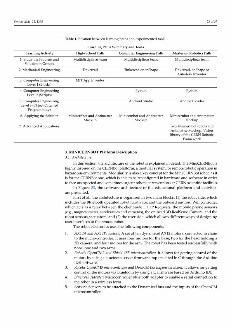
Table 1. Relation between learning paths and experimented tools.
Learning Paths Summary and Tools
Learning Activity High-School Path Computer Engineering Path Master on Robotics Path
1. Study the Problem andSolution in Groups
Multidisciplinar team Multidisciplinar team Multidisciplinar team
2. Mechanical Engineering Tinkercad Tinkercad or onShape Tinkercad, onShape orAutodesk Inventor
3. Computer EngineeringLevel 1 (Blocks)
MIT App Inventor
4. Computer EngineeringLevel 2 (Scripts)
Python Python
5. Computer EngineeringLevel 3 (Object-Oriented
Programming)
Android Studio Android Studio
6. Applying the Solution Minicernbot and AntimatterMockup
Minicernbot and AntimatterMockup
Minicernbot and AntimatterMockup
7. Advanced Applications Two Minicernbot robots andAntimatter Mockup. Visionlibrary of the CERN Robotic
Framework
3. MINICERNBOT Platform Description3.1. Architecture
In this section, the architecture of the robot is explained in detail. The MiniCERNBot ishighly inspired on the CERNBot platform, a modular system for remote robotic operation inhazardous environments. Modularity is also a key concept for the MiniCERNBot robot, as itis for the CERNBot one, which is able to be reconfigured in hardware and software in orderto face unexpected and sometimes urgent robotic interventions at CERN scientific facilities.
In Figure 23, the software architecture of the educational platform and activitiesare presented.
First of all, the architecture is organised in two main blocks: (1) the robot side, whichincludes the Bluetooth operated robot hardware, and the onboard android Wifi controller,which acts as a relay between the client-side HTTP Requests, the mobile phone sensors(e.g., magnetometer, accelerators and cameras), the on-head 3D RealSense Camera, and therobot sensors/actuators; and (2) the user side, which allows different ways of designinguser interfaces to the remote robot.
The robot electronics uses the following components:
1. AX12A and AX12W motors: A set of ten dynamixel AX12 motors, connected in chainto the micro-controller. It uses four motors for the base, two for the head holding a3D camera, and four motors for the arm. The robot has been tested successfully withnone, one and two arms.
2. Robotis OpenCM9 and Shield 485 microcontroller: It allows for getting control of themotors by using a bluetooth server firmware implemented in C through the ArduinoIDE software.
3. Robotis OpenCM9 microcontroller and OpenCM485 Expansion Board: It allows for gettingcontrol of the motors via Bluetooth by using a C firmware based on Arduino IDE.
4. Bluetooth Adapter: Microcontroller bluetooth adapter to enable a serial connection tothe robot in a wireless form.
5. Sensors: Sensors to be attached to the Dynamixel bus and the inputs of the OpenCMmicrocontroller.

Sensors 2021, 21, 1398 24 of 37
Figure 23 represented the blocks that can be developed by the students as a learningpath, including the Blocks GUI, Scripts GUI, Vision Control CERN Robotic Framework, andthe robot-side on-board the Android HTTP controller. These blocks have been explained indetail in the previous section.
BLUETOOTH INTERFACE
BLUETOOTH
WIFI HTTP
MI
RO
BO
T SI
DE
MI
USE
R S
IDE
BLOCKS GUI
BLUETOOTH
SCRIPTS GUI
WIFI HTTP CLIENT
VISION CONTROL CRF
WIFI HTTP CLIENT
CERN ROBOTIC FRAMEWORK SERVER
Figure 23. MiniCERNBot educational robotic platform software architecture.
3.2. Mechanical Design
The aim of the mechanical design of the MiniCERNBot platform is to allow themodular attachment of motors, sensors and components (e.g., arm, head) to aluminiumframes, in order to let the students adapt the robot configuration to the current missionneed. In addition, it is very important to have a robot that is simple to set up, having it inoperation in just a few seconds.
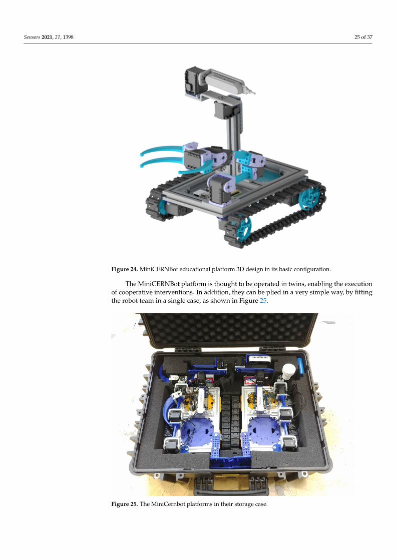
As can be seen in Figure 24, the robot presents a basic configuration of a base withfour motors, which can hold both trucks and omnidirectional wheels. In addition, it canhold robot arms in different configurations, as well as a head that provides the possibilityto move a 3D camera in pan and tilt. The student is able to change the robot configurationin order to enhance the robot efficiency for a particular mission.
Sensors 2021, 21, 1398 25 of 37
Figure 24. MiniCERNBot educational platform 3D design in its basic configuration.
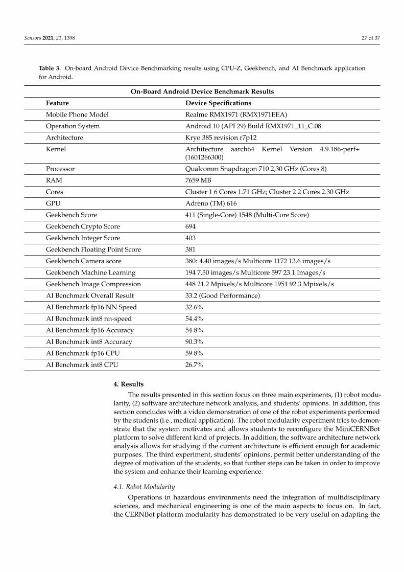
The MiniCERNBot platform is thought to be operated in twins, enabling the executionof cooperative interventions. In addition, they can be plied in a very simple way, by fittingthe robot team in a single case, as shown in Figure 25.
Figure 25. The MiniCernbot platforms in their storage case.

Sensors 2021, 21, 1398 26 of 37
In Table 2, some examples of mechanical parts are described. At the moment ofwriting, the MiniCERNBot platform includes a total of more than 50 mechanical parts,including also the accessories such as the exoskeleton and the master/slave arm.
Table 2. Examples of mechanical parts available at the MiniCERNBot robot.
Mechanical Part Description
Piece for attachment of the dynamixel AX12 motorsto the omnidirectional wheels
Parts that allow the attachment of an arm in one ofthe corners of the MiniCERNBot Base platform
Adapter for attached dynamixel AX12 motors to ageneric aluminium frame. It can be used to attachtools and also wheels to the base
3.3. On-Board Android Device
The MiniCERNbot educational platform uses as a main tool the ability to install thestudent Android device on-board. This possibility offers the students the facility to workat home and also in the lab with their own mobile phones, being able to use the robot forvalidation. The students are also provided with a mobile phone per robot, which can beused in case of necessity.
The provided Android device needs to serve HTTP requests for sensors (e.g., camerapictures) and robot commands, at an efficient manner, so the selected device tries to fitthis requirement.
In fact, the performance experiments presented in the next section are using a RealmeRMX1971EEA Android phone (Realme, Shenzhen, China), with the characteristics ex-plained below.
In order to benchmark the Android device specifications, the CPU-z [31],GeekBench [32], and Android AI Bench applications have been used [33], so that the re-sults can be better compared in further experiments. The specification of the Android deviceaccording to the benchmarks can be seen in Table 3.
Sensors 2021, 21, 1398 27 of 37
Table 3. On-board Android Device Benchmarking results using CPU-Z, Geekbench, and AI Benchmark applicationfor Android.
On-Board Android Device Benchmark Results
Feature Device Specifications
Mobile Phone Model Realme RMX1971 (RMX1971EEA)
Operation System Android 10 (API 29) Build RMX1971_11_C.08
Architecture Kryo 385 revision r7p12
Kernel Architecture aarch64 Kernel Version 4.9.186-perf+(1601266300)
Processor Qualcomm Snapdragon 710 2,30 GHz (Cores 8)
RAM 7659 MB
Cores Cluster 1 6 Cores 1.71 GHz; Cluster 2 2 Cores 2.30 GHz
GPU Adreno (TM) 616
Geekbench Score 411 (Single-Core) 1548 (Multi-Core Score)
Geekbench Crypto Score 694
Geekbench Integer Score 403
Geekbench Floating Point Score 381
Geekbench Camera score 380: 4.40 images/s Multicore 1172 13.6 images/s
Geekbench Machine Learning 194 7.50 images/s Multicore 597 23.1 Images/s
Geekbench Image Compression 448 21.2 Mpixels/s Multicore 1951 92.3 Mpixels/s
AI Benchmark Overall Result 33.2 (Good Performance)
AI Benchmark fp16 NN Speed 32.6%
AI Benchmark int8 nn-speed 54.4%
AI Benchmark fp16 Accuracy 54.8%
AI Benchmark int8 Accuracy 90.3%
AI Benchmark fp16 CPU 59.8%
AI Benchmark int8 CPU 26.7%
4. Results
The results presented in this section focus on three main experiments, (1) robot modu-larity, (2) software architecture network analysis, and students’ opinions. In addition, thissection concludes with a video demonstration of one of the robot experiments performedby the students (i.e., medical application). The robot modularity experiment tries to demon-strate that the system motivates and allows students to reconfigure the MiniCERNBotplatform to solve different kind of projects. In addition, the software architecture networkanalysis allows for studying if the current architecture is efficient enough for academicpurposes. The third experiment, students’ opinions, permit better understanding of thedegree of motivation of the students, so that further steps can be taken in order to improvethe system and enhance their learning experience.
4.1. Robot Modularity
Operations in hazardous environments need the integration of multidisciplinarysciences, and mechanical engineering is one of the main aspects to focus on. In fact,the CERNBot platform modularity has demonstrated to be very useful on adapting the

Sensors 2021, 21, 1398 28 of 37
robot to different configurations, so that it can reach a higher number of places in a safermanner.
In this experiment, a set of projects performed by high-school and Master’s studentsusing the modularity feature are presented.
4.1.1. Dual-Arm/Enhanced Gripper/Omni-Wheels/Omni Camera
Students were able to enhance the robot by providing a dual-arm configuration,including an enhanced gripper in the right arm, which can act in two ways, first as a singleparallel gripper to pick up objects, and second as a screwing tool. In addition, in orderto enhance the robot movements and be able to better intervene in the panel, the trackswere substituted by omnidirectional wheels (see Figure 26). Besides this, the pan-tilt headwas substituted by a 360◦ omnidirectional camera. The new robot configuration has beenvery successful and one of the most interesting aspects is the collaboration between ahigh-school and Master’s student to get it ready for operation.
(a) (b)
Figure 26. MiniCernBot reconfigured to have dual-arms, omnidirectional wheels, multipurposeright-hand, and 360◦ camera. (a) Frontal view, (b) top view
4.1.2. Master–Slave Arm Project
As seen in Figure 27, students developed a master arm prototype in order to be ableto remotely control the robot manipulation in a position master/slave manner. They couldexperience the different kind of teleoperated systems, better understanding the high-fidelitymanipulation movements that a master device provides.
(a) (b)
Figure 27. Student Project to implement a Master–Slave system to control the robot arm at a distance.(a) Frontal view, (b) side view.

Sensors 2021, 21, 1398 29 of 37
4.1.3. Exoskeleton for Improved Manipulation
In Figure 28, we can appreciate the master–slave project extended, so that it is usedas an exoskeleton. The level of motivation of the students with this project was very high,in terms of mechanical engineering. In addition, it is still under improvement, and thecurrent focus is on the electronics integration.
Figure 28. Exoskeleton designed by the student in order to remotely control the robot arm.
4.1.4. Transformer Designs
Thanks to the MiniCernBot’s modularity, once students are finished with the course,they are able to change the designs of the robot, making them improve their designing skills,and making them think creatively to provide interesting configurations for approachingdifferent tasks or environments (see Figures 29 and 30).
Figure 29. An alternative design with four legs like a centaur that a student designed for anenvironment with rocks.

Sensors 2021, 21, 1398 30 of 37
(a) (b)
Figure 30. Transformer design that enables the robot to have two distinct configurations. (a) Trans-former configuration to manipulate a target, (b) configuration to explore the environment
4.1.5. High-School Student Medical Design to Reduce the Spread of Covid-19
During quarantine, a specific educational MiniCernBot configuration was designedby a student for a medical application, with the idea of reducing the spread of Covid-19inside hospitals, making the interactions between the doctors and the patients safer (seeFigure 31).
Figure 31. Helper Bot, MiniCernBot’s configuration for medicine applications.
As it can be appreciated in Figure 31, the robot has an attached tray so that it cantransport water, food or medicines to the patients, without the doctors having to getnear the patient, improving safety, efficiency, and reducing medical equipment such as

Sensors 2021, 21, 1398 31 of 37
masks. The robot contains a cover to make its disinfection quicker, an automatic alcoholdispenser, omni-directional wheels to improve the mobility of the robot, a colour sensorallow following a circuit autonomously, and a phone attached to the robot, in order toestablish communication with patients and give vision to the user.
While doing this project, the student improved drastically his designing skills as hedesigned all the new pieces such as the automatic alcohol dispenser attachment for therobot. He also further developed his problem-solving skills, as he had to confront differentproblems during the project. He learned about programming as he made a program tomake the robot move autonomously through a circuit with the light sensor, and, finally,this project made him interested about the world of medical robotics, giving him a betteridea of what to study at university.
4.2. Software Architecture Network Analysis
In this section, the software architecture is analysed from the network performancepoint of view, considering that using a mobile phone on-board provides a lot of possibilitiesin terms of education, but it is also necessary to study its effects in terms of computerperformance.
First of all, in Figure 32, the network latency between the robot controller and theAndroid device via Bluetooth is shown.
This latency is the result of requesting via bluetooth the state (i.e., position andvelocities) of all the motors in the bus. It means that the microcontroller receives thebluetooth request, then it sends a command to the Dynamixel bus in order to read thememory values at every motor and sensor, and then it returns a JSON string with the statevalues via the Bluetooth adapter, to be received at the Android Blocks application. Thelatency is calculated from the client mobile phone.
We can appreciate that the signal is very stable when teleoperating the robot in thesame laboratory (i.e., less than 5 m), being able to get the real motors and sensors positionin the client side at a rate of five times per second approximately.
Distance (m)
Late
ncy
Ave
rage
(ms)
0
50
100
150
200
250
1 2 3 4 5
Android Bluetooth Robot State
Figure 32. Latency results obtained by sending a «get state» request to the the robot via Bluetoothfrom the Mobile Android Device.
In Figure 33, the latency provided by a Python script user interface interacting withthe robot via the onboard Android HTTP application is presented. As in the previousexample, the latency is calculated in the Python user interface, which requests via HTTP tothe Android Phone the current state of all the motors in the Dynamixel bus. It includes theHTTP management and its interaction with the microcontroller via Bluetooth.

Sensors 2021, 21, 1398 32 of 37
Distance (m)
Late
ncy
Ave
rage
(ms)
0
100
200
300
400
1 2 3 4 5
Python HTTP Robot State
Figure 33. Latency results obtained by teleoperating the robot with a scripting GUI via the on-boardHTTP Android device.
First of all, we can conclude from the previous results that the latency varies slightlyfrom distance due, according to our comprehension, to the lack of automatic gain appliedin the GUI Wifi adapter, when the Radio Signal Straight Indicator is reduced. It means thatthe signal quality is reduced with distance, increasing also the effect of reflections and thenecessity of the higher protocols to resend the packets.
In addition, we can appreciate that the HTTP server implemented on the on-boardAndroid device is adding a significant amount of delay to the communication. Furtherefforts will focus on enhancing the performance of this server. At the moment of writing,its software design uses two multi-thread services, one that takes care of the graphicalinterface plus the Bluetooth connection to the robot, and a second that implements theweb server. It means that threads have to communicate via pipes, which increases thedelay significantly.
Moreover, the current version of the HTTP Server Android Application implements theHTTP 1.0 protocol, which closes the connection after every request. It means that, in orderto send a command to the robot, the connection has to be established (i.e., hand-shakingwith three packets), the information has to be sent and acknowledged (i.e., four packets),and finally the connection has to be closed (i.e., three packets). The next implementationof HTTP 1.1 version will permit the client to ask the server to keep the connection alive,which will enhance the overall system performance during the educational exercises.
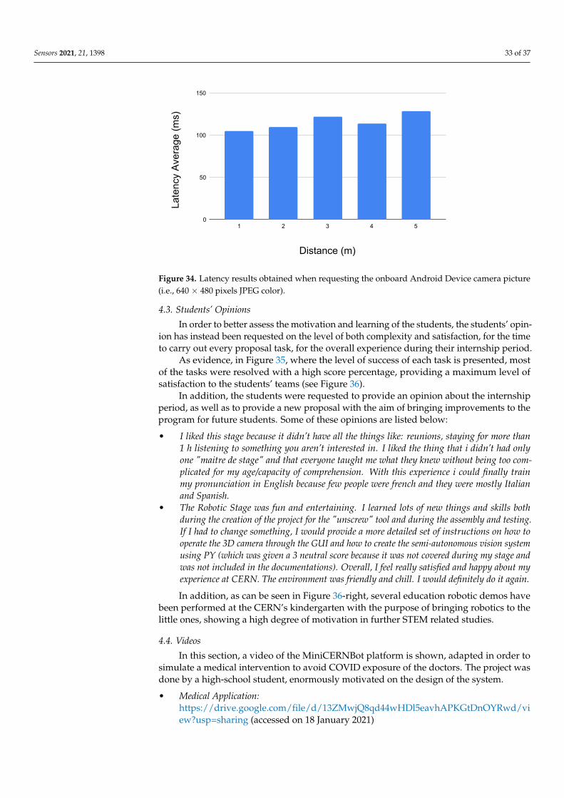
In Figure 34, the latency obtained when getting the current on-board Android phonecamera picture via HTTP to a computer Python script is presented. Results show thatthe image feedback in the user interface can be offered at a rate of 10 frames per second,resolution of 640 × 480 in color, which is enough for educational purposes.
We can conclude that the HTTP connection using Android, as it is implemented, is veryflexible and useful for the academic purposes, and requires a much better enhancement inorder to face bigger challenges. For students, using an Android phone as a robot brain isvery convenient, as can be seen in the next section.
Sensors 2021, 21, 1398 33 of 37
Distance (m)
Late
ncy
Ave
rage
(ms)
0
50
100
150
1 2 3 4 5
Python HTTP Android Camera Color
Figure 34. Latency results obtained when requesting the onboard Android Device camera picture(i.e., 640 × 480 pixels JPEG color).
4.3. Students’ Opinions
In order to better assess the motivation and learning of the students, the students’ opin-ion has instead been requested on the level of both complexity and satisfaction, for the timeto carry out every proposal task, for the overall experience during their internship period.
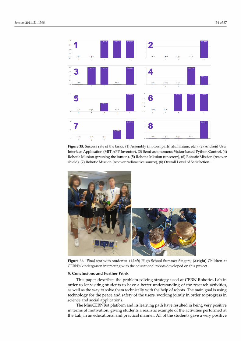
As evidence, in Figure 35, where the level of success of each task is presented, mostof the tasks were resolved with a high score percentage, providing a maximum level ofsatisfaction to the students’ teams (see Figure 36).
In addition, the students were requested to provide an opinion about the internshipperiod, as well as to provide a new proposal with the aim of bringing improvements to theprogram for future students. Some of these opinions are listed below:
• I liked this stage because it didn’t have all the things like: reunions, staying for more than1 h listening to something you aren’t interested in. I liked the thing that i didn’t had onlyone "maitre de stage" and that everyone taught me what they knew without being too com-plicated for my age/capacity of comprehension. With this experience i could finally trainmy pronunciation in English because few people were french and they were mostly Italianand Spanish.
• The Robotic Stage was fun and entertaining. I learned lots of new things and skills bothduring the creation of the project for the "unscrew" tool and during the assembly and testing.If I had to change something, I would provide a more detailed set of instructions on how tooperate the 3D camera through the GUI and how to create the semi-autonomous vision systemusing PY (which was given a 3 neutral score because it was not covered during my stage andwas not included in the documentations). Overall, I feel really satisfied and happy about myexperience at CERN. The environment was friendly and chill. I would definitely do it again.
In addition, as can be seen in Figure 36-right, several education robotic demos havebeen performed at the CERN’s kindergarten with the purpose of bringing robotics to thelittle ones, showing a high degree of motivation in further STEM related studies.
4.4. Videos
In this section, a video of the MiniCERNBot platform is shown, adapted in order tosimulate a medical intervention to avoid COVID exposure of the doctors. The project wasdone by a high-school student, enormously motivated on the design of the system.
• Medical Application:https://drive.google.com/file/d/13ZMwjQ8qd44wHDl5eavhAPKGtDnOYRwd/view?usp=sharing (accessed on 18 January 2021)
Sensors 2021, 21, 1398 34 of 37
Figure 35. Success rate of the tasks: (1) Assembly (motors, parts, aluminium, etc.), (2) Android UserInterface Application (MIT APP Inventor), (3) Semi-autonomous Vision-based Python Control, (4)Robotic Mission (pressing the button), (5) Robotic Mission (unscrew), (6) Robotic Mission (recovershield), (7) Robotic Mission (recover radioactive source), (8) Overall Level of Satisfaction.
Figure 36. Final test with students: (1-left) High-School Summer Stagers; (2-right) Children atCERN’s kindergarten interacting with the educational robots developed on this project.
5. Conclusions and Further Work
This paper describes the problem-solving strategy used at CERN Robotics Lab inorder to let visiting students to have a better understanding of the research activities,as well as the way to solve them technically with the help of robots. The main goal is usingtechnology for the peace and safety of the users, working jointly in order to progress inscience and social applications.
The MiniCERNBot platform and its learning path have resulted in being very positivein terms of motivation, giving students a realistic example of the activities performed atthe Lab, in an educational and practical manner. All of the students gave a very positive
Sensors 2021, 21, 1398 35 of 37
feedback and showed their gratitude to the whole team, encouraging to go further in orderto offer improved learning activities in the future.
Aspects, such as team organisation, brainstorming, multidisciplinary solutions, andbalance between guided tutorials and project-based learning sessions, have demonstratedto be very important in the students’ learning experience. We have also realised theimportance of letting students base their training on real references, such as the roboticintervention in the antimatter factory, which result in higher motivation. It is in fact thismotivation that has resulted, in the authors’ opinion, in being the most interesting aspectof this learning MiniCERNBot educational experience.
In addition, it is worth mentioning that, for the experiment presented in this paper,it was not possible to obtain real data of the degree of influence of the educational experi-ence on later high-school students’ vocations. On the other hand, a pilot experiment wasperformed at the Jaume I University, in collaboration with CERN, where the MINICERNBotrobot was used in two seminars for high-school students, in order to promote ComputerEngineering studies. Ten students out of twenty-five (20%) followed further ComputerEngineering studies. Moreover, from twenty-two Master’s students that followed theeducational experiment, two of them joined the doctorate program for further studies onfield robotics (i.e., radiation and underwater).
Moreover, the system can be improved in several aspects, in order to provide betterlearning experiences. In fact, taking into account the current COVID-19 situation, a realistic3D simulation system, which can be accessed via the web, letting students work in acollaborative way, and compare their results with other teams, can help enormously inorder to increase the value of the system. Besides this, going beyond simulations andletting students solve the problems remotely, with the real robots via web, would beeven more challenging. Further work will focus on this direction, enhancing the waystudents communicate with simulations and real robots, via the web, in a collaborativeonline learning experience. In addition, the learning paths presented in the paper can beenhanced by using the tool in more disciplines and educational levels. Some preliminaryexperiments have been started with this aim, by using the MINICERNbot platform tointroduce advanced research robotics to PhD students, as a desktop reconfigurable roboticplatform, in order to test the experiments before applying them to more realistic scenarios.
Author Contributions: Conceptualization, M.D.C., L.R.B., R.M.P. and A.M.; Data curation, J.M.G.,C.V.A., G.L. and R.M.P.; Formal analysis, M.D.C., L.R.B. and R.M.P.; Funding acquisition, A.M.;Investigation, J.M.G., C.V.A., G.L., L.R.B. and R.M.P.; Methodology, M.D.C., L.R.B., R.M.P. andA.M.; Project administration, C.V.A., M.D.C., R.M.P. and A.M.; Resources, M.D.C., R.M.P. and A.M.;Software, J.M.G., C.V.A., G.L. and R.M.P.; Supervision, M.D.C. and R.M.P.; Validation, J.M.G., C.V.A.,G.L., L.R.B. and R.M.P.; Visualization, J.M.G., C.V.A. and R.M.P.; Writing—original draft, J.M.G.,C.V.A., G.L. and R.M.P.; Writing—review and editing, J.M.G., C.V.A., G.L. and R.M.P. All authorshave read and agreed to the published version of the manuscript.
Funding: It has been fully funded by CERN.
Institutional Review Board Statement: Not applicable.
Informed Consent Statement: Informed consent was obtained from all subjects involved in the study.
Acknowledgments: This work has been performed jointly by the European Center for NuclearResearch (CERN PhD and Summer Student Programs), and the Jaume I University of Castellon (UJI).
Conflicts of Interest: The authors declare no conflict of interest.
Sensors 2021, 21, 1398 36 of 37
AbbreviationsThe following abbreviations are used in this manuscript:
CERN European Organization for Nuclear ResearchSTEM Science, Technology, Engineering and MathematicsMRO Mechatronics, Robotics and OperationsSMM Survey, Mechatronics and MeasurementsTIM Train Inspection MonorailGUI Graphical User InterfaceMIT Massachusetts Institute of TechnologyHRI Human-Robot InterfaceRSSI Radio Signal Strength IndicatorHTTP HyperText Transfer ProtocolURL Uniform Resource LocatorAPI Application Programming InterfacesMCBV MINICERNBot VisionROI Region Of InterestRGB Red Green and BlueIDE Integrated Development EnvironmentJSON JavaScript Object NotationRS Robot StateUJI Universidad Jaume I
References1. Eguchi, A. Robotics as a learning tool for educational transformation. In Proceeding of the 4th International Workshop Teaching
Robotics, Teaching with Robotics & 5th International Conference Robotics in Education, Padova, Italy, 18 July 2014.2. CERN Education Programmes. Available online: https://home.cern/about/what-we-do/our-educational-programmes/
(accessed on 18 January 2021).3. High School Students Internship Programme. Available online: https://hssip.web.cern.ch/ (accessed on 18 January 2021).4. Woithe, J. Designing, Measuring and Modelling the Impact of the Hands-on Particle Physics Learning Laboratory S’Cool LAB at
CERN Effects of Student and Laboratory Characteristics on High-School Students’ Cognitive and Affective Outcomes. TechnicalReport. Available online: https://cds.cern.ch/record/2727453 (accessed on 28 June 2020).
5. Rassat, A.; Tvede, L.; Dixon-Altaber, H.; Ballantine, A. Knowledge Transfer 2018; Technical Report, CERN-Brochure-2019-001-Eng;Education, Communications and Outreach Group: Geneva, Switzerland, 2019.
6. Woithe, J.; Keller, O.; Feistmantl, A.; Jende, K.; Schmeling, S. Learning Particle Physics Using Timepix-Based Pixel Detectorsat CERN S’Cool LAB (2016). In Proceedings of the 20th Int. Conf. on Multimedia in Physics Teaching and Learning, Munich,Germany, 9–11 September 2015.
7. Lunghi, G.; Marin, R.; Di Castro, M.; Masi, A.; Sanz, P.J. Multimodal Human-Robot Interface for Accessible Remote RoboticInterventions in Hazardous Environments. IEEE Access 2019, 7, 127290–127319. [CrossRef]
8. Di Castro, M.; Ferre, M.; Masi, A. CERNTAURO: A Modular Architecture for Robotic Inspection and Telemanipulation in Harshand Semi-Structured Environments. IEEE Access 2018. [CrossRef]
9. Di Castro, M.; Almagro, C.V.; Lunghi, G.; Marin, R.; Ferre, M.; Masi, A. Tracking-Based Depth Estimation of Metallic Pieces forRobotic Guidance. In Proceedings of the 2018 IEEE/RSJ International Conference on Intelligent Robots and Systems (IROS),Madrid, Spain, 1–5 October 2018; pp. 5503–5508.
10. Veiga Almagro, C.; Di Castro, M.; Lunghi, G.; Marín Prades, R.; Sanz Valero, P.J.; Pérez, M.F.; Masi, A. Monocular Robust DepthEstimation Vision System for Robotic Tasks Interventions in Metallic Targets. Sensors 2019, 19, 3220. [CrossRef] [PubMed]
11. Di Castro, M.; Tambutti, M.B.; Ferre, M.; Losito, R.; Lunghi, G.; Masi, A. i-TIM: A Robotic System for Safety, Measurements,Inspection and Maintenance in Harsh Environments. In Proceedings of the 2018 IEEE International Symposium on Safety,Security, and Rescue Robotics (SSRR), Philadelphia, PA, USA, 6–8 August 2018; pp. 1–6.
12. Benitti, F.B.V.; Spolaôr, N. How have robots supported STEM teaching? In Robotics in STEM Education; Springer: Cham,Switzerland, 2017; pp. 103–129.
13. Khanlari, A. Effects of educational robots on learning STEM and on students’ attitude toward STEM. In Proceedings of the 2013IEEE 5th Conference on Engineering Education (ICEED), Kuala Lumpur, Malaysia, 4–5 December 2013; pp. 62–66.
14. Mosley, P.; Ardito, G.; Scollins, L. Robotic cooperative learning promotes student STEM interest. Am. J. Eng. Educ. 2016,7, 117–128.
15. Chen, Y.; Chang, C.C. The Impact of an Integrated Robotics STEM Course with a Sailboat Topic on High School Students’Perceptions of Integrative STEM, Interest, and Career Orientation. EURASIA J. Math. Sci. Technol. Educ. 2018, 14, em1614.
16. Jung, S.E.; Won, E.S. Systematic review of research trends in robotics education for young children. Sustainability 2018, 10, 905.[CrossRef]
Sensors 2021, 21, 1398 37 of 37
17. Mataric, M.J. Robotics education for all ages. In Proceedings of the AAAI Spring Symposium on Accessible, Hands-on AI andRobotics Education, Palo Alto, CA, USA, 22–24 March 2004 .
18. Rusk, N.; Resnick, M.; Berg, R.; Pezalla-Granlund, M. New pathways into robotics: Strategies for broadening participation. J. Sci.Educ. Technol. 2008, 17, 59–69. [CrossRef]
19. Sapounidis, T.; Demetriadis, S. Tangible versus graphical user interfaces for robot programming: exploring cross-age children’spreferences. Pers. Ubiquitous Comput. 2013, 17, 1775–1786. [CrossRef]
20. Bers, M.U. The TangibleK Robotics program: Applied computational thinking for young children. Early Child. Res. Pract. 2010,12, n2.
21. Latip, A.; Hardinata, A. Implementation of STEM-Robotics as High School Intracurricular. Thabiea J. Nat. Sci. Teach. 2020, 3, 11–19.[CrossRef]
22. Sapounidis, T.; Alimisis, D. Educational Robotics for STEM: A Review of Technologies and Some Educational Considerations.In Science and Mathematics Education for 21st Century Citizens: Challenges and Ways Forward; Nova Science Publishers: Hauppauge,NY, USA, 2020; pp. 167–190.
23. Latip, A.; Andriani, Y.; Purnamasari, S.; Abdurrahman, D. Integration of educational robotic in STEM learning to promotestudents’ collaborative skill. In Journal of Physics: Conference Series; IOP Publishing: Bristol, UK, 2020; Volume 1663, p. 012052.
24. Druin, A.; Hendler, J.A.; Hendler, J. Robots for Kids: Exploring New Technologies for Learning; Morgan Kaufmann: San Francisco, CA,USA, 2000.
25. Carbonaro, M.; Rex, M.; Chambers, J. Exploring middle school children’s problem solving during robot construction tasks.In Proceedings of the Society for Information Technology & Teacher Education International Conference, Atlanta, GA,USA, 1–6 March 2004; Association for the Advancement of Computing in Education (AACE): Waynesville, NC, USA, 2004;pp. 4546–4550.
26. Hmelo-Silver, C.; Eberbach, C. Learning Theories and Problem-Based Learning. In Problem-Based Learning in Clinical Education;Springer: Dordrecht, The Netherlands, 2012; pp. 3–17. [CrossRef]
27. Kelly, J. 3D Modeling and Printing with Tinkercad: Create and Print Your Own 3D Models; Pearson Education: Upper Saddle River,NJ, USA, 2014.
28. L. Scott Hansen. Autodesk Inventor 2021 A Tutorial Introduction—L. Scott Hansen. Available online: https://books.google.ch/books?id=xFhfzAEACAAJ&printsec=frontcover&hl=es&source=gbs_ge_summary_r&cad=0#v=onepage&q&f=false (accessedon 30 June 2020).
29. Jupyter. Develop Open-Source Software, Open-standards, and Services for Interactive Computing across Dozens of ProgrammingLanguages. Available online: https://jupyter.org/ (accessed on 8 August 2020).
30. OpenCV. Open Source Computer Vision Library. Available online: https://opencv.org/(accessed on 13 July 2020).31. CPU-Z Benchmark for Android. Available online: https://play.google.com/store/apps/details?id=com.cpuid.cpu_z&hl=en&gl
=US (accessed on 16 December 2020).32. Geekbench 5.2.5 for Android. Available online: https://play.google.com/store/apps/details?id=com.primatelabs.geekbench5
&hl=en&gl=US (accessed on 16 December 2020).33. AI Bench for Android. Available online: https://play.google.com/store/apps/details?id=org.benchmark.demo&hl=en&gl=US
(accessed on 16 December 2020).