Miniature Wave Energy Converter (WEC) - DiVA Portal
31
TVE-MFE; 18005 Examensarbete 15 hp November 2018 Miniature Wave Energy Converter (WEC) Dana Salar Masterprogram i förnybar elgenerering Master Programme in Renewable Electricity Production
-
Upload
khangminh22 -
Category
Documents
-
view
2 -
download
0
Transcript of Miniature Wave Energy Converter (WEC) - DiVA Portal

TVE-MFE; 18005
Examensarbete 15 hpNovember 2018
Miniature Wave Energy Converter (WEC)
Dana Salar
Masterprogram i förnybar elgenereringMaster Programme in Renewable Electricity Production

Teknisk- naturvetenskaplig fakultet UTH-enheten Besöksadress: Ångströmlaboratoriet Lägerhyddsvägen 1 Hus 4, Plan 0 Postadress: Box 536 751 21 Uppsala Telefon: 018 – 471 30 03 Telefax: 018 – 471 30 00 Hemsida: http://www.teknat.uu.se/student
Abstract
Miniature Wave Energy Converter (WEC)
Dana Salar
In this project, I present a design of a scale model of a linear generator (LG) similar toa full size Wave Energy Converter (WEC) being developed at Uppsala Universitysince 2002 and commercialized by Seabased AB. The purpose of a WEC is to convertthe energy from ocean waves into electrical energy. In order to implement the behaviour of the prototype design, a preliminary study hasbeen done to further build it for use in education, laboratory tests and research. Thechallenge with this project is to scale down the WEC but maintain the shape,appearance and characteristics of the generator for educational purposes.A miniature version of a WEC, previously developed by Uppsala University incollaboration with Seabased Industry AB, has been designed with scaling rate 1:14 ofthe linear dimensions. In this case, the value of the output power is not important- ithas simply been calculated. The electrical rated parameters of the three phase generator are power 26 W, peakline-line voltage 13 V and rated armature current 2 A. The mechanical parametersutilized in the design are the total length and the diameter of the miniature WEC, 50cm and 25 cm, respectively. The simulated prototype model (described in Section 5.4) has been validated with anexperimental setup comprising translator and stator (described in Section 5.1), wherethe translator is moved by a programmed industrial robot. The experimental resultshave shown good agreement with the simulations.
TVE-MFE; 18005Examinator: Mikael BergkvistÄmnesgranskare: Marcus BergHandledare: Irina Temiz

2
TABLE OF CONTENTS
Svensk sammanfattning .......................................................................................................................... 3
2 Introduction .......................................................................................................................................... 4
2.1 How the WEC concept works ....................................................................................................... 5
2.2 Objective ....................................................................................................................................... 6
2.3 Problem statement ......................................................................................................................... 7
2.4 Scope ............................................................................................................................................. 7
2.5 Area of use .................................................................................................................................... 7
3 Theory .............................................................................................................................................. 8
3.1 Output power .............................................................................................................................. 10
4 Generator design ................................................................................................................................ 13
4.1 Winding....................................................................................................................................... 15
4.2 Numerical modelling .................................................................................................................. 16
5 Prototype experiment ......................................................................................................................... 18
5.1 Experiment steps ......................................................................................................................... 18
5.1.1 Translator ............................................................................................................................. 18
5.1.2 Stator .................................................................................................................................... 20
5.2 Test experiment ........................................................................................................................... 21
5.3 Prototype experiment parameters ................................................................................................ 21
5.4 Simulation result of the experimental prototype ......................................................................... 23
5.5 Experiment result ........................................................................................................................ 24
6 Discussion and conclusions ............................................................................................................... 26
7 Future research ................................................................................................................................... 27
7.1 Generator usage .......................................................................................................................... 27
Acknowledgments ................................................................................................................................. 28
References ............................................................................................................................................. 29

3
SVENSK SAMMANFATTNING
På avdelningen för elektricitetslära på Uppsala universitet inriktas en hel del forskning mot
förnybar elgenerering. Ett av forskningsområdena är inriktat mot havsvågor, där man
omvandlar havets vågrörelse till elektrisk energi.
Ett så kallat vågkraftverk har utvecklats vid Uppsala universitet och företaget Seabased
Industry AB, för att kunna omvandla vågenergin till elektrisk energi. Generatorn består av två
delar: en fast del, statorn, som är monterad i generatorhöljet och en rörlig del, translatorn.
Statorn är kabellindad och har en kärna uppbyggd av elektroplåt. Translatorn (svarande mot
rotorn i roterande elektriska maskiner) består av polskor och permanentmagneter.
Generatorn placeras på havsbotten. Translatorn kopplas till en boj på havsytan med en vajer.
Bojen rör sig upp och ner med vågorna och drar i sin tur translatorn med sig upp och ner.
Genom dessa upprepade rörelser ändras magnetfälten i statorlindningarna, vilket medför att
spänningar induceras i statorlindningarna.
Generatorn är ca 7 meter hög och väger ca 10, ton vilket gör att det är ganska svårt att kunna
göra vissa tester. Man vill även kunna ha tillgång till en generator för att kunna studera dess
uppbyggnad liksom för visningar och laborationer för utbildningssyften. Det har visats intresse
från olika håll att kunna ha ett nedskalat vågkraftverk för att kunna göra enkla tester och även
kunna laborera i inomhusmiljö och dessutom för forskning och olika studier.
En förstudie har gjorts med hjälp av befintligt forskningsmaterial om vågkraftverk. Ett
lösningsförslag har tagits fram genom beräkningar av generatoregenskaper och modelldesignen
har gjorts i 3D CAD.
Designen har testats i mjukvaran COMSOL multiphysics för simulering av tänkta egenskaper.
Ett enkelt experiment har gjorts för att bekräfta konstruktionen.

4
2 INTRODUCTION
The wave energy converter (WEC), designed and developed at Uppsala University (UU) in
cooperation with the company Seabased Industry AB (SIAB). For about 16 years, various
designs have been researched at UU, where SIAB has worked on the development of several
other possible WEC design configurations and on their commercialization.
Sea waves are enriched with energy. This energy source is very attractive due to the high energy
density. Several different wave energy conversion concepts have been developed and tested,
for example Oscillating Water Column (OWC) [1] and Drakoo [2]. Research on wave energy
harvesting is a multidisplinary area, demanding deep insight into different fields such as
hydrodynamic modelling, environmental aspects, mechanical and electrical development. In
the past years, new wave power concepts at UU have not been invented, but the research is still
ongoing in several directions to attain power quality, low system cost and secure deployment
of underwater bodies [3].
The major problem with wave power is uncontrolled random motion of waves and often harsh
climate, where the WECs have to handle extreme loads electrically and mechanically. The total
electric energy that could be extracted across the world is of the order of PWh (1012 kWh), but
it is greatly reduced in practice since the technology is not fully developed. At the West coast
of Sweden, the average energy in kWh per meter from ocean waves can reach up to 5 kWh /m.
However, in other coastal areas in the world, the average energy can reach up to 100 kWh/m
[4].
A big challenge is to maintain the high efficiency at a low cost. The design with permanent
magnets (PM) made from Nd2Fe14B, considered the world’s strongest magnetic material, is
simple and more efficient but after the price rose, the wave group in the Division of electricity
at Uppsala University and the company SIAB had to find a cheaper concept while maintaining
efficiency. The new design with ferrite PM (FPM) is more advanced to build but more
affordable [3].
There are two different concepts of UU’s WEC: the old one with surface mounted Neodymium
PM and the new one with FPM and pole shoes. This project used the latest concept, i.e. WEC
FPM and pole shoes, in order to be able to compare with the full scale WEC and better
understand the generator structure.
In the beginning of WEC concept development, a linear wave energy generator was in the UU’s
facilities. Therefore testing and studies of generator parts were easier and even students could
participate in full-scale generator development. A few years ago, the entire physical
development was moved to Lysekil to the company SIAB. Since then access (experiments and
study visits) to similar generators is limited due to the distance between Uppsala and Lysekil
(Lysekil is about 5 hours’ drive from Uppsala University). Over the years, several groups at the
department of electricity have been thinking about developing a scaled generator of WEC but
it has not been built so far.

5
2.1 How the WEC concept works
The WEC linear generator average output power is about 50 – 100 kW (depending on which
model size is used). It weighs about 10 tonnes and is about 7 meter tall. The difficulty with the
design is to make it simple, in order to simplify production, service and troubleshooting.The
WEC is placed on the seabed. The moving part of the WEC (translator) is connected to a buoy,
which is floating on the sea surface by means of a wire as shown in Figure 1. The buoy follows
the wave motion up and down, which makes the translator move up and down due to gravity.
During this motion, the magnetic flux through the stator coils is changing, which induces
voltages in the stator coils.
Figure 1 Wave Energy Converter (WEC), developed at Uppsala University

6
The alternating currents from several (6 – 10) WEC are collected in a substation. The voltage
from the random wave motion and other measured properties of a linear generator are varying
in amplitude and frequency which have to be smoothened and sent to the measuring station on
the land (see Figure 2).
This particular design of WEC has been tested in the various locations for several years, one of
the largest parks is the Sotenäs wave power park, where, in total, 40 WECs are installed. The
UU’s WEC concept is still in the process of development. So far it has been quite difficult to
test the generators performance because of large size which entails high costs. Therefore, a
smaller model size that can simulate the performance of the large WEC is needed for easier in-
house tests, for further studies, development and research.
2.2 Objective
The main focus of the work is to develop a possible size of miniature WEC with good
properties/qualities where it provides a possible and manageable way to conduct laboratory
tests and small scale experiments in an indoor environment. The project includes a study of
previous research carried out for the full scale WEC in order to determine a possible miniature
WEC configuration.
The size of the similar miniature generator is based on the calculations that were made earlier
during the design of WEC, based on research done at Uppsala University [3], [5].
Figure 2 Wave power park

7
2.3 Problem statement
The project concerns a study on a miniature linear generator (LG) similar to the WEC from
SIAB and UU. It is impossible to scale down the original WEC to a miniature WEC for practical
reasons. For example, the pole shoe thickness in the full-scale WEC is 15 mm. If you only scale
it down, it will be about 1 mm in thickness, which makes the construction complicated. The
calculation properties have to be scaled correctly to achieve expected output power. The
challenge is to maintain the appearance and design characteristics, but also to get enough power
for education and experiments.
The LG is calculated and simulated in the simulation program COMSOL Multiphysics, a finite
element method based simulation tool used for simulating different kinds of generators. The
program allows to investigate the different physical aspects of the generator such as movement
of the translator, magnetic field, eddy currents and voltages.
2.4 Scope
The purpose of the project is to design and test a small scale model of the existing WEC
concept. The WEC model should provide an easy understanding of how the concept is built
and how it works. It should also enable experiments for upgrading purposes and usage in
education.
The generator structure should be similar to the original WEC generator. The stator package is
to be built from stator sheets with max 10 slots, cable wound. The translator should be made
using the same principles as the WEC original, thus FPM and pole shoes.
2.5 Area of use
The prototype can be used for research and education purposes. It can also be used to
demonstrate and display the concept. However, the output power is not determined but only
aimed towards 26 W. The manageable size of the generator is max 50 cm long and about 25
cm in diameter. The total weight is about 50 kg and the weight of the translator alone is about
15 kg.

8
3 Theory
To design a generator, calculations are needed to ensure sufficient output power is reached. In
this case, the generator designed for laboratory tests and research purposes. The output power
is about 26 W (13 V, 2 A). In order to achieve this power level, a translator movement of 0.5
m/s is required. A manageable size of about 500 mm length and 250 mm diameter is considered.
The generator is designed with a transparent casing.
The pole pitch is described by formula:
τp = sp + wp and wp
τp → 1 (1)
where τp is the pole pitch, sp is the magnet width, wp is the pole width and
δ
sp ≪ 1 (2)
where δ is the air gap between the translator pole shoes and the stator teeth.
Figure 4 Generator part in Comsol software
9
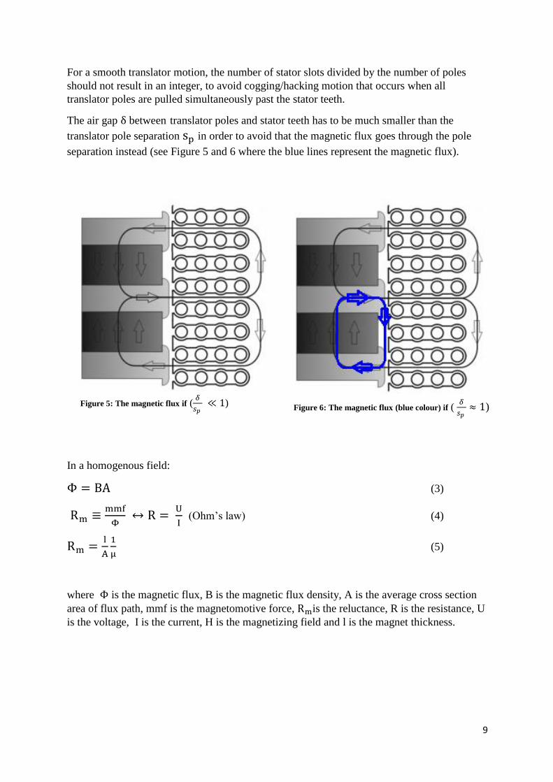
For a smooth translator motion, the number of stator slots divided by the number of poles
should not result in an integer, to avoid cogging/hacking motion that occurs when all
translator poles are pulled simultaneously past the stator teeth.
The air gap δ between translator poles and stator teeth has to be much smaller than the
translator pole separation sp in order to avoid that the magnetic flux goes through the pole
separation instead (see Figure 5 and 6 where the blue lines represent the magnetic flux).
In a homogenous field:
Φ = BA (3)
Rm ≡mmf
Φ ↔ R =
U
I (Ohm’s law) (4)
Rm =l
A
1
μ (5)
where Φ is the magnetic flux, B is the magnetic flux density, A is the average cross section
area of flux path, mmf is the magnetomotive force, Rmis the reluctance, R is the resistance, U
is the voltage, I is the current, H is the magnetizing field and l is the magnet thickness.
Figure 6: The magnetic flux (blue colour) if ( 𝛿
𝑠𝑝 ≈ 1)
Figure 5: The magnetic flux if (𝛿
𝑠𝑝 ≪ 1)

10
3.1 Output power
A certain output power level can be achieved in different ways, for example by increasing the
number of winding turns for a given thickness of the cable or to wind the stator with a thicker
cable while reducing the number of winding turns.
Table 1: Ferrite permanent magnet properties
Quantity Value Units
Br 0.376 T
µrecoil 1.05 -
Maxwell’s equations:
∮
𝑠
∙ 𝑑 = 𝑄
𝜀0
∮
𝑠
∙ 𝑑 = 0
∮ E
c
∙ dl = − dΦ
dt
∮ H
c
∙ dl = I𝑒𝑛𝑐𝑙𝑜𝑠𝑒𝑑
The no-load voltage can be calculated by Faraday’s law Eq. (8):
∮ E
c
∙ dl = −NdΦ1
dt
where N is the number of winding turns, Φ1 is the magnetic flux through one turn of a coil.
Equation (9) assumes that the displacement current can be neglected.
(6)
(9)
(10)
(7)
(8)
If a winding has N turns, and the magnetic flux through each turn is Φ1, then Faraday's law
can be rewritten

11
For sinusoidal flux variation:
Φ1 = Φmax ∗ sin (2π
Tt) →
dΦ
dt=
2π∗Φmax
T∗ cos (
2π
Tt)
Erms,phase =Ê
√2= −N
1
√2∗ max (
dΦ
dt) = −
N
√2∗
2π
T∗ Φmax
= −√2∗N∗π∗Φmax
T (12)
where T is the period time, Erms,phase is set to fixed value of 13 V and the period time T is 2 s
(translator speed 0,5 m/s), the Φmax is calculated by Eq.(15).
Winding number of turns for output voltage 13 V:
N = Erms,phase∗T
−4,44∗Φmax (13)
Calculating the magneto-motive force mmf
mmf = lpm∗Br
μrec∗μ0 (14)
The length of permanent magnet (lpm) is 30 mm (0.03 m) and vacuum permeability μ0
is 4π ∗ 10−7 H/m.
The remanent flux density Br can be read from the diagram (see Figure 7 below).
Figure 7: Magnetization curve
(11)

12
Using Ampère’s law, Φmax can be calculated as shown below
mmf𝑚𝑎𝑥 = Φmax ∗ (Rδ + Rpm + Rsteel) (15)
which gives Φmax = mmf
(Rδ+Rpm+Rsteel)
The reluctance of steel is negligible compared to Rẟ and Rpm. The reluctance of air gap Rδ
and the reluctance of permanent magnet Rpm are calculated by Eqs. (16) and (17):
Rδ = 2δ
μ0∗L∗wp (16)
Rpm = lpm
μ0∗μrecoil∗Apm (17)
where L is the length of stator sheets, lpm is the width of the magnet (here also equal to the
separation width), wp is the magnet width, Apm is the permanent magnet area, µ0 is the
vacuum permeability, µrecoil is the relative recoil permeability, Rδ is the reluctance of an air
gap δ, Rpm is the reluctance of permanent magnets.
The pole shoe number and stator tooth number has to be calculated by Eq. (18). The quotient
should not be an integer to avoid hacking translator motion.
Q = number of stator teeth
number of poles (pole shoes)=
30
20= 1.5
(18)

13
4 GENERATOR DESIGN
In the beginning, a simple 3D CAD model design of a linear generator was implemented in
SolidWorks software tool. Thereafter, simple calculations for translator length and pole number
were made.
The design of the linear generator looks similar to UU’s WEC design but is of a different size.
The FPM and pole-shoes used for constructing the translator and stator coils are fixed.
Table 2: Generator parameters.
Quantity Value Units
Translator length, TL 300 mm
Translator diameter, Td 120 mm
Centre pipe Length, PL 300 mm
No. of pole shoes, Pn 20 -
PM height (pole separation), Sp 6 mm
Pole shoe height (pole width), wp 8 mm
Pole pitch (pole separation + pole shoe height), τp 14 mm
Translator active area, TA 280 mm
Stator height, SL 180 mm
No. of stator teeth, ST 30 -
Coil pitch, τc 6 mm
No. of winding turns, N 10 -

14
The translator consists of a centre pipe, pole shoes and FPM. The translator contains 20 poles
(pole-shoes) and FPM between pole-shoes. The magnets are magnetized in the vertical
direction and mounted between pole-shoes in opposite directions (see Figure 8).
Figure 8: 3D design of the generator in Comsol: (a) a side view, (b) top view, (c) enlargement of (a).
a
c
b
where grey colour is stator package, red/blue
colour is magnet N/S poles, dark green is pole
shoes and purple is centre pipe.

15
4.1 Winding
The stator is cable wound, with a mixed three phase winding to avoid cogging/hacking
translator movement [6].
A simpler winding arrangement is to wind three stator packages, one phase per package, and
mount the packages vertically 120 electrical degrees between packages. This makes the
construction much easier and also easier for debugging, repairing and services. However, it will
have the consequence known as cogging, making it harder for the translator to move. In this
case, the generator is used in labs and similar uses, where hand power is used to simulate the
wave motion or to get some power from the generator. It is therefore important that it is easy
to move the translator up and down.
Figure 9: Winding form

16
4.2 Numerical modelling
The numerical model is a simplified 2D model of the miniature WEC. The generator has 4 sides
but in the numerical simulation only a cross section of one side is calculated for, even though
the real generator is not fully symmetric (see Figure 8).
A numerical model is developed in the simulation tool COMSOL Multiphysics, which is a
finite element method based software.
Figure 11: Numerical 2D model of generator in software tool
COMSOL presenting the magnetization field, three phase Figure 10: Numerical 2D model of generator in software tool
COMSOL presenting the magnetic flux density, three phase

17
Figure 13: Output voltage of generator from COMSOL software tool. Air gap 4 mm, Ferrite pm, translator speed 0.4 m/s
(constant speed)
Figure 12: Mesh generated in COMSOL

18
5 PROTOTYPE EXPERIMENT
To ensure that the generator simulation model the simulation program COMSOL is correct, an
experiment prototype was made using equipment and material available in the workshop. To
do the job easily some changes had to be made in the design, regarding pole width, number of
stator teeth and cable dimension.
5.1 Experiment steps
Existing stator sheets from an old linear generator were used, having tooth width 10 mm, stator
yoke width 20 mm and sheet thickness 1 mm. The coil is made with cable dimension 10 mm2
and 8 turns single phase winding.
5.1.1 Translator
The translator is made of surface mounted Neodymium magnets on a thick steel sheet that are
horizontally magnetized (in Figure 14 (S/N marks pole surfaces) and Figure 15). In order to
achieve a magnetic flux density in the air gap similar to that of the design presented in Section
4, the translator magnet size H x W x L: 6 x 28 x 100 mm was used in the experiment. To keep
the same Q number (Q=1.5 see Eq. (19)), the pole pitch was fixed to 54 mm (see Figure 14).
Figure 14: Translator piece, the magnets are marked S/N. Between magnets are pieces of plastic sheet
to keep a distance between magnets during the experiment.

19
The steel sheet was attached to an industrial ABB robot for accuracy of the movement
(IRB6000).
An ABB robot IRB6000 has six degrees of freedom (DoF) (six joints) with a payload of
150 kg and is used to make a linear movement at different speeds and with different air gaps
between stator and translator.
The translator surface mounted Neodymium magnets are attached to the robot's (6th) joint,
using a plate of POM H plastic (see Figure 15).
Figure 15: Translator piece attached to the ABB robot (IRB6000)
Pom H plastic

20
5.1.2 Stator
The stator coil package consists of 60 electrical steel sheets with 8 winding holes per slot (for
10 mm2 cable).
The stator dimensions are H x W x L: 110 x 60 x 328 mm, see Figure 16.
The stator package is mounted to a table in the laboratory (see Figure 17). With the existing
equipment and experimental setup, the air gap between stator teeth and translator pole could
not be less than 8 mm because of the strong attractive forces between stator and translator.
Winding hole 10 mm2
Figure16: Stator package with one phase wound
Figure 1: Stator packet mounted to an existing table in the lab Figure 17: Experiment prototype

21
5.2 Test experiment
The robot was programed to move vertically up and down with different speeds to imitate
translator motion due to sea waves.
The setup was tested at speeds between 0.1 m/s and 0.3 m/s. In this case, the speed at 0.3 m/s
was the highest achievable velocity of translator movement with the existing robot. Voltage
and current were measured using an oscilloscope and different load resistances (1.0 – 3.2 Ω).
The magnetic flux density in the air gap was measured with a Gauss/Tesla meter. Maximum
power was obtained with resistive load 1 Ω, air gap 8 mm and translator speed 0.3 m/s, as
expected.
5.3 Prototype experiment parameters
The experiment of the generator prototype was made with different air gaps between the stator
teeth and the translator poles and also with different loads (see table 3).
Air gap
(mm)
Speed
(m/s)
No load peak
voltage (V)
Load peak
voltage (V)
Peak
current
(A)
Load
(Ω)
Maximum B field
in air gap (T)
15 0.1 0.2 - - - 0.386
15 0.2 0.3 - - - 0.386
15 0.3 0.4 - - - 0.386
10 0.1 0.3 - - - 0.431
10 0.2 0.5 - - - 0.431
10 0.3 0.6 - - - 0.431
8 0.1 0.4 - - - 0.484
8 0.2 0.8 - - - 0.484
8 0.3 1.2 1.2 0.4 3.2 0.484
8 0.3 - 1.2 0.5 2.1 0.484
8 0.3 - 1.2 0.8 1.4 0.484
8 0.3 - 1.2 1.1 1.0 0.484
Table 3: Experiment parameters

22
Figure 18: Experimental setup
Figure 19: Gauss/Tesla meter used for measuring magnetic flux density in the air
gap between translator poles and stator teeth.

23
5.4 Simulation result of the experimental prototype
A numerical model the experimental prototype was developed in COMSOL Multiphysics to
ensure that the experiment data of materials was reproduced correctly.
For the simulation, the input data match the experiment, except for the translator speed, which
is 0.4 m/s. The translator speed is increased because in the simulation the speed is constant,
whereas in the experiment, the average speed of the translator is 0.3 m/s. I.e. at certain instants
the speed exceeds 0.3 m/s. The robot acceleration is unknown, but the average speed can be
measured.
The simulation results are close to results from the experiment. This ensure that the simulation
properties are correct.
Figure 20: Numerical model of
experiment prototype.
Figure 21: Magnetic flux density

24
The simulation results show that both the magnetic flux density and the voltage are almost
similar to those of the prototype experiment (compare Figure 23 with Figure 24 – 27 output
voltage). The differences between experiment and simulation are +0.3 V and -0.05 T,
respectively.
Figure 22: Simulation magnetic flux in air gap from software tool COMSOL.
Figure 23: No load voltage from simulation software COMSOL.
Time [s]

25
5.5 Experiment result
Figures 24-27 show the measured output voltage and current for different load resistances.
The stator package is short and is phase wound. This causes fewer waves, with accelerating /
decelerating translator movement, so you get the fastest motion in the middle of the stator
package that results in maximum output power.
Figure 24: Voltage and current (Load 3.2 ohm) Figure 25: Voltage and current (Load 2.1 ohm)
Figure 26: Voltage and current (Load 1.4 ohm) Figure 27: Voltage and current (Load 1 ohm)

26
6 DISCUSSION AND CONCLUSIONS
The results from experiments were shown to be close to results from the simulation and
calculations, which ensures that the construction of the generator is made correctly and that the
generator is prepared for the next step. The differences are due to the fact that it was not
practically feasible to make the simulation match the experiment in all details. For example, in
the simulation, the material properties (metal of the stator sheets, magnets, etc.) do not
sufficiently accurately represent the real material. Generic metal properties were adopted. Also
the unknown acceleration of the robot introduces another uncertainty to the experimental
results.
For more accurate results, more work is needed, such as adding all material properties. It is also
necessary to know exactly which materials are used and which properties they have.
Furthermore, an industrial robot with higher accuracy in the movement is required for better
wave motion simulation. The stator needs a stiffer mounting arrangement for a smaller and
more accurate air gap between translator poles and stator teeth.
Multiple winding coils on the stator package will increase the active area for more realistic
results compared with the three phase winding simulation. Translator magnets should be
attached to the translator surface more firmly in order to avoid magnetic losses. Finally the
translator should be made longer for an increased active area.

27
7 FUTURE RESEARCH
A few details are left to determine in this generator before construction of the generator
mentioned as follows. End stop, end spring, winding pattern, cable, linear guide, and magnets.
A simpler investigation is required to determine the above mentioned parts before the generator
construction process begins.
7.1 Generator usage
This generator is designed for examination and is designed to be driven by hand or by a rotating
motor for purposes of education. This generator is not designed to be tested underwater.
Otherwise it will require further investigations for cables, casing, piston and seals.

28
ACKNOWLEDGMENTS
I have really learned a lot of this project and I'm really grateful to the division of electricity that
gave me this opportunity to do this project. I thank everyone at the division that has supported
me during the project - you are amazing.
I would especially like to thank Jonathan Sjölund, who helped me much during the project. I
do not think that I would have done the project so well without him. I would also like to thank
Arvind Parwal and Mohd Nasir Ayob, who spent a lot of time helping me through the project.
Many thanks to my supervisor Irina Temiz and subject reader Marcus Berg, who took me a step
up in both science and technology.

29
REFERENCES
[1] Manabu Takao; Kohei Yamada; M. M. Ashraful Alam; Shinya Okuhara; Yoichi
Kinoue; Shuich Nagata, Counter-rotating impulse turbine for wave energy
conversion — Performance improvement by means of middle vane, conference
article, International Conference on Renewable Energy Research and
Applications (ICRERA). 2017.
[2] Hann-Ocean Energy, Drakoo-Energize the future with ocean waves 2018,
[Online] Available: http://www.hann-
ocean.com/index.php/publications/presentations.html. [Accessed: 30 October
2018].
[3] B. Ekergård, Full Scale Applications of Permanent Magnet Electromagnetic
Energy Converters - From Nd2Fe14B to Ferrite, PhD thesis. Uppsala
University, 2013.
[4] Rafael Waters. “Energy from Ocean Waves: Full Scale Experimental
Verification of a Wave Energy Converter”. PhD thesis. Uppsala University,
2008.
[5] Senad Apelfröjd. “Grid Connection of Permanent Generator Based Renewable Energy System”. PhD thesis. Uppsala University, 2016.
[6] Oskar Danielsson, Wave Energy Conversion, Linear Synchronous Permanent Magnet Generator, PhD thesis. Uppsala University, 2006.
[7] ”Roterande Elektriska Maskiner”, compendium for course 1TE670, Uppsala
University 2016
[8] C. Nordling and J. Österman, Physics Handbook for Science and Engineering, Studentlitteratur, 8th edition, 2006.
[9] "Elektricitetslära" Avdelningen för elektricitetslära, Uppsala universitet, 2018.
[Online]. Available: http://www.teknik.uu.se/electricity/. [Accessed October 2018].
[10] Cecilia Boström. “Electrical Systems for Wave Energy Conversion”. PhD
thesis. Uppsala University, 2011.

30
[11] M. Eriksson, J. Isberg, and M. Leijon. “Hydrodynamic modelling of a direct
drive wave energy converter”, international Journal of Engineering Science 43
(2005).
[12] Seabased, 2018. [Online]. Available: http://www.seabased.com. [Accessed 18
10 2018].
[13] J. Engström, Hydrodynamic Modeling of the Energy Conversion from Ocean Waves to Electricity, Point Absorber - Linear Generator, PhD thesis. Uppsala University, 2009.