Mineralogical and chemical characterization of sepiolite occurrences at Karapinar (Konya Basin,...
10
Mineralogical and chemical characterization of Joule heated soil contaminated by ceramics industry sludge with high Pb contents Francesco Dellisanti, Piermaria L. Rossi, Giovanni Valdrè ⁎ Dipartimento di Scienze della Terra e Geo-Ambientali, Università di Bologna, Piazza di Porta, S. Donato, 1 I-40126, Bologna, Italy Received 2 March 2007; received in revised form 21 May 2007; accepted 22 May 2007 Available online 31 May 2007 Abstract This research deals with the first attempt to vitrify by a Joule heating process soils contaminated by Pb (2.85 wt.%) from ceramic industry sludges. Physical, mineralogical, and chemical characterization of the glasses were obtained by using several imaging and analytical techniques, namely Scanning Electron Microscopy (SEM) with coupled Energy Dispersive Spectroscopy (EDS), X-Ray Diffraction (XRD), X-Ray Fluorescence (XRF) and by a specifically built-in sensor for “in-situ” temperature measurements of the melt. The chemical stability of the glass produced by the process was determined by leaching tests. The progressive heating and successive melting of the soil led to decomposition of organic compounds and removal of volatile metals. The cooling of the melt formed a monolithic glass with the aim of immobilizing the heavy metals and inorganic contaminants. All the glasses were found, on a macroscopic scale, mineralogically, chemically and morphologically homogeneous independent of the starting composition. However, on a microscopic scale an inhomogeneous glass matrix was observed. SEM- EDS and XRD revealed the presence of micro-sized Pb particles and Zr 2 SiO 4 (zircon) crystals. In agreement with the microscopical observations, leaching tests indicated high leaching behaviour for Pb. These results should be considered as a general study of the technological effectiveness of vitrification by Joule heating technology with a view to scaling up the process on a field scale and to the treatment of large amount of inorganic industrial wastes containing high amounts of Pb. © 2007 Elsevier B.V. All rights reserved. Keywords: Joule heating vitrification; Remediation treatment; Glassy materials; Thermal process; Lead 1. Introduction Abundant literature deals with treatments based on physical and thermal properties of soils by vitrification process to remediate inorganic contaminants (Jacob, 1991; Johnson and Cosmos, 1989; Jouan et al., 1986; Komatsu et al., 1990; Orfeuil, 1987). In particular, many efforts have been devoted to develop in-field remediation treatments, in order to prevent or at least reduce the risks related to the removal of contaminated materials. Significant research findings on in-situ vitrification technology (ISV) can be found for instance in reports of the United States-Environmental Protection Agency (Richardson et al., 1995), and of the Pacific Northwest Laboratory (Buelt and Bonner, 1989; Buelt et al., 1987; Farnsworth et al., 1990; Kuhn, 1992; Thompson et al., 1992; Timmerman and Peterson, 1990). Int. J. Miner. Process. 83 (2007) 89 – 98 www.elsevier.com/locate/ijminpro ⁎ Corresponding author. Tel.: +39 51 2094943. E-mail address: [email protected] (G. Valdrè). 0301-7516/$ - see front matter © 2007 Elsevier B.V. All rights reserved. doi:10.1016/j.minpro.2007.05.008
-
Upload
independent -
Category
Documents
-
view
5 -
download
0
Transcript of Mineralogical and chemical characterization of sepiolite occurrences at Karapinar (Konya Basin,...

. 83 (2007) 89–98www.elsevier.com/locate/ijminpro
Int. J. Miner. Process
Mineralogical and chemical characterization of Joule heated soilcontaminated by ceramics industry sludge with high Pb contents
Francesco Dellisanti, Piermaria L. Rossi, Giovanni Valdrè ⁎
Dipartimento di Scienze della Terra e Geo-Ambientali, Università di Bologna, Piazza di Porta, S. Donato, 1 I-40126, Bologna, Italy
Received 2 March 2007; received in revised form 21 May 2007; accepted 22 May 2007Available online 31 May 2007
Abstract
This research deals with the first attempt to vitrify by a Joule heating process soils contaminated by Pb (2.85 wt.%) fromceramic industry sludges.
Physical, mineralogical, and chemical characterization of the glasses were obtained by using several imaging and analyticaltechniques, namely Scanning Electron Microscopy (SEM) with coupled Energy Dispersive Spectroscopy (EDS), X-RayDiffraction (XRD), X-Ray Fluorescence (XRF) and by a specifically built-in sensor for “in-situ” temperature measurements of themelt. The chemical stability of the glass produced by the process was determined by leaching tests.
The progressive heating and successive melting of the soil led to decomposition of organic compounds and removal of volatilemetals. The cooling of the melt formed a monolithic glass with the aim of immobilizing the heavy metals and inorganic contaminants.
All the glasses were found, on a macroscopic scale, mineralogically, chemically and morphologically homogeneousindependent of the starting composition. However, on a microscopic scale an inhomogeneous glass matrix was observed. SEM-EDS and XRD revealed the presence of micro-sized Pb particles and Zr2SiO4 (zircon) crystals. In agreement with the microscopicalobservations, leaching tests indicated high leaching behaviour for Pb.
These results should be considered as a general study of the technological effectiveness of vitrification by Joule heatingtechnology with a view to scaling up the process on a field scale and to the treatment of large amount of inorganic industrial wastescontaining high amounts of Pb.© 2007 Elsevier B.V. All rights reserved.
Keywords: Joule heating vitrification; Remediation treatment; Glassy materials; Thermal process; Lead
1. Introduction
Abundant literature deals with treatments based onphysical and thermal properties of soils by vitrificationprocess to remediate inorganic contaminants (Jacob,1991; Johnson and Cosmos, 1989; Jouan et al., 1986;Komatsu et al., 1990; Orfeuil, 1987). In particular, many
⁎ Corresponding author. Tel.: +39 51 2094943.E-mail address: [email protected] (G. Valdrè).
0301-7516/$ - see front matter © 2007 Elsevier B.V. All rights reserved.doi:10.1016/j.minpro.2007.05.008
efforts have been devoted to develop in-field remediationtreatments, in order to prevent or at least reduce the risksrelated to the removal of contaminated materials.
Significant research findings on in-situ vitrificationtechnology (ISV) can be found for instance in reports ofthe United States-Environmental Protection Agency(Richardson et al., 1995), and of the Pacific NorthwestLaboratory (Buelt and Bonner, 1989; Buelt et al., 1987;Farnsworth et al., 1990; Kuhn, 1992; Thompson et al.,1992; Timmerman and Peterson, 1990).

Table 1Chemical data obtained by X-ray fluorescence (XRF) of the startingmaterials: R-1, uncontaminated soil; SCI, sludge ceramic industry. LOIvalue (Loss On Ignition) takes into account the volatile components(H2O, CO2, organic matter etc.) evaluated by calcination at 950 °C
% Weight R-1 SCI
SiO2 39.35 46.23TiO2 0.56 0.52Al2O3 12.58 9.42Fe2O3 5.19 3.32MnO 0.10 0.15MgO 3.48 1.82CaO 15.28 10.44Na2O 0.49 2.3K2O 2.13 1.61P2O5 0.13 0.15PbO bd.l. 3.07ZrO2 bd.l. 4.03LOI 20.70 16.02
Instrumental detection limit is ∼0.01%.
90 F. Dellisanti et al. / Int. J. Miner. Process. 83 (2007) 89–98
ISV treatment is a thermal process based on the Jouleeffect (Aneko et al., 1992; Buelt and Bonner, 1989;Farnsworth et al., 1990; Spalding et al., 1992; USEPA,1992), which consists in heating the polluted soil by highpower currents up to the melting temperature. Theprogressive heating destroys organic contaminants andremoves volatile and semi-volatile metal compounds(Alexiades et al., 1994; Kuhn, 1992; Spalding et al.,1992). After cooling the melt forms a glassy product thatimmobilizes the inorganic contaminants.
ISV process, initially developed by Pacific NorthwestLaboratory (PNL) for the U.S. Department of Energy(DOE) (Buelt and Bonner, 1989; Spalding et al., 1992;Thompson et al., 1992), should be capable of reclaimingpolluted soils contaminated by a wide variety of inorganicindustrial wastes including heavy metals, mine tailings,radioactive metals, sludge, fly ash, asbestos, etc. (Farns-
Table 2Semi-quantitative mineralogical composition (accuracy of ±1%)obtained by normative recalculation of the chemical and XRD dataof the starting materials: R-1, uncontaminated soil; SCI, sludgeceramic industry
% Weight R-1 SCI
Quartz 30 31Calcite 24 18Dolomite 12 b1Plagioclase 4 20K-feldspar 4 b1Chlorite 10 b1Micas 14 16Kaolinite b1 5Alamosite b1 4Zircon b1 6
worth et al., 1990; Paxton, 1985; Roberts, 1989;Thompson et al., 1992). The main advantages of thisinnovative technique are both the capability to treatsimultaneously different pollutants and to avoid theproblems and risks associated with the recovery andtransportation of contaminated soils.
The present paper originates from the development ofin-situ vitrification technology promoted by a researchproject of the University of Bologna and of a nationalcompany (AREA-HERA S.p.A., Italy) with the aim todevelop large scale remediation processes of contaminat-ed soils.
In order to verify the technological effectiveness ofthe ISV treatment, the research was initially conductedon a pre-pilot scale before the scaling up to the field
Fig. 1. XRD patterns of starting materials treated by the vitrificationprocess, a) uncontaminated soil R-1; b) sludge ceramic industry (SCI);Qtz: quartz; Cal: calcite; Dol: dolomite; Pl: plagioclase; Kfs: k-feldspar; Ms: micas; Chl: chlorite; Kln: kaolinite; Zrn: zircon; Als:alamosite.
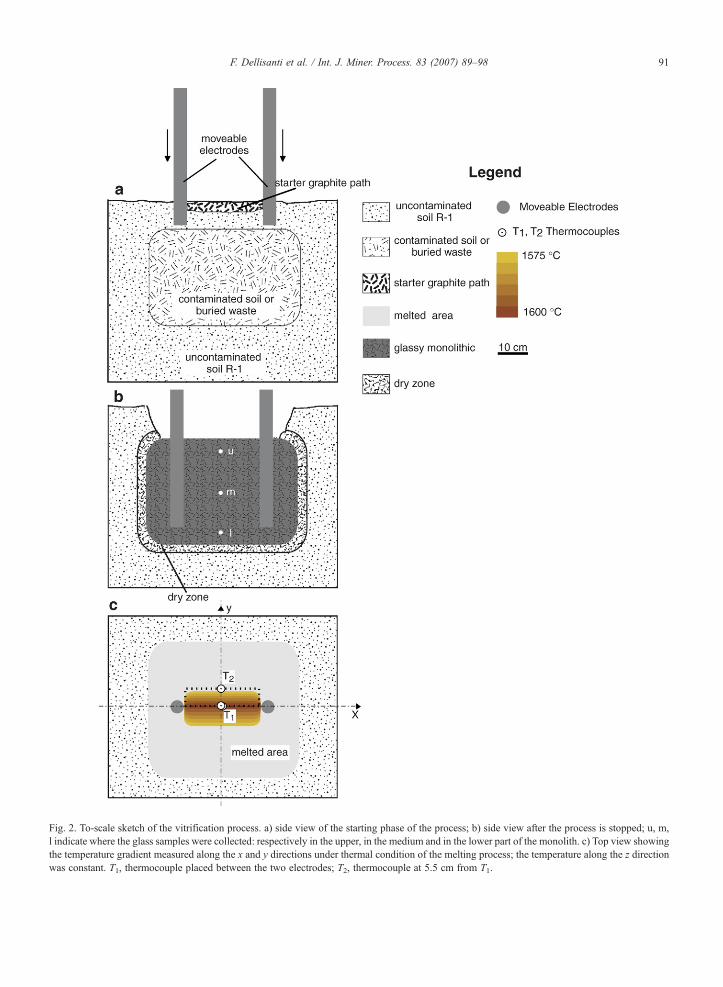
Fig. 2. To-scale sketch of the vitrification process. a) side view of the starting phase of the process; b) side view after the process is stopped; u, m,l indicate where the glass samples were collected: respectively in the upper, in the medium and in the lower part of the monolith. c) Top view showingthe temperature gradient measured along the x and y directions under thermal condition of the melting process; the temperature along the z directionwas constant. T1, thermocouple placed between the two electrodes; T2, thermocouple at 5.5 cm from T1.
91F. Dellisanti et al. / Int. J. Miner. Process. 83 (2007) 89–98

Fig. 3. Photograph of a portion of a glassy product obtained byvitrification as removed from the pre-pilot apparatus. Characteristicconchoidal fractures and sharp edges are visible. Flat fracture surfaceswere also observed in the glass.
Table 3Chemical data obtained by X-ray fluorescence (XRF) of glass samplesfrom the tests on uncontaminated soil R-1
% Weight R-1x1 R-1x2 R-1y1 R-1y2 R-1z1 R-1z2
SiO2 55.9 55.44 55.5 55.45 54.68 55.66TiO2 0.74 0.74 0.74 0.75 0.79 0.74Al2O3 13.25 13.19 13.21 13.19 13.09 13.24Fe2O3 5.86 5.96 5.9 5.95 6.2 5.82MnO 0.15 0.16 0.16 0.16 0.16 0.15MgO 3.31 3.33 3.32 3.32 3.32 3.33CaO 17.09 17.48 17.49 17.45 18.06 17.39Na2O 0.88 0.87 0.85 0.86 0.82 0.85K2O 2.64 2.65 2.67 2.69 2.71 2.64P2O5 0.18 0.18 0.16 0.18 0.17 0.18LOI 0.00 0.00 0.00 0.00 0.00 0.00
Two samplings were made along x, y and z directions within themonolith. Note that the LOI value, which is the amount of the volatilecomponents (H2O, CO2, organic matter etc.) evaluated by calcinationat 950 °C, is zero. Instrumental detection limit is ∼0.01%.
92 F. Dellisanti et al. / Int. J. Miner. Process. 83 (2007) 89–98
application. To this purpose, tests were performed onuncontaminated soil and on residual sludge of ceramicsindustry from the enamelling process of tiles, prevailinglycontaminated by Pb. The main results concerning thecompositional (mineralogical and chemical) and morpho-logical data of the glasses produced by the vitrificationtreatment and a description of the implemented plant on apre-pilot scale are the basis of the present paper.
We believe that this paper is relevant in the field ofremediation of contaminated soils since for the first timeto the authors' knowledge, the vitrification treatment byJoule heating was performed on high Pb containingceramics industry sludge.
2. Materials and methods
2.1. Characterization of the materials to be treated byvitrification process
The vitrification process by Joule heating wasperformed on two materials: an uncontaminated soiland sludge of ceramics industry. The chemical andmineralogical data of the materials to be treated arereported in Tables 1 and 2. The semi-quantitativemineralogical composition of soils and waste to betreated (Table 2) is based on XRD data and chemicalanalyses (reported in Table 1) using a linear program-ming method (LPNORM program) according to DeCaritat et al. (1994).
The uncontaminated soil called R-1 was selected as amineralogically and chemically representative of aregional soil and suitable for the development of thevitrification process and formation of glass (Tables 1and 2). In particular, the high content of silica (SiO2)
assures a high durability of the glass (Lewis, 1989; Parkand Heo, 2002; Plodinec et al., 1982; Tooley, 1974); theCaO acts as stabilizer maintaining the glass durabilityand reducing viscosity, waste solubility and the meltingpoint of materials (Plodinec et al., 1982); the presence ofalkali metals (sodium and potassium) assists andimproves the melting and electrical conductivity withinthe melted ground (Plodinec et al., 1982; Stanek, 1977)preventing an excessive viscosity. Finally, the loworganic content (2.1%) reduces the amounts of volatilecomponents to be treated by gas-effluent system andavoids an excessive volume reduction of the treatedarea. The mineralogical composition is characterized bythe occurrence of quartz, carbonates (calcite anddolomite), feldspars (plagioclase and K-feldspars) andphyllosilicates. A more detailed identification ofphyllosilicates was performed using oriented specimens.It was detected the presence of chlorite and micas(essentially illite), whereas kaolinite and smectite werenot observed within the detection limit (Table 2). Fig. 1areports a typical X-ray diffraction pattern of the soil R-1where the identification of the mineral phases is shown.
The sludge of ceramics industry (SCI) from theenamelling process of tiles are characterized by the highoccurrence of Pb and Zr (Table 1), thus are classified astoxic and injurious to the health by Italian and Europeanlaws, which impose that, in order to be disposed inlandfill, an appropriate remediation treatment isconducted.
Pb and Zr are essentially present respectively as alead silicate phase (alamosite) and as a zirconiumsilicate (zircon) (Table 2 and Fig. 1b). Fig. 1b reports atypical X-ray diffraction pattern of the SCI waste, wherethe above mentioned mineral phases have been indicated

93F. Dellisanti et al. / Int. J. Miner. Process. 83 (2007) 89–98
together with quartz, calcite, plagioclase, micas andkaolinite, which can be ascribed to ceramic raw material.
2.2. X-ray diffraction (XRD)
Mineralogical analyses of uncontaminated soil,waste materials, and glasses obtained by the vitrificationprocess were performed by powder X-Ray Diffraction(XRD). Analyses were made by using a Philips PW1710 diffractometer equipped with a graphite mono-chromator, using CuKα radiation, 40 kV and 30 mApower supply, 1° divergence and detector slits, 0.02°(2θ) step size and a counting time of 1 s/step. A side-loading sample holder was used in order to obtain aquasi-random orientation of particles.
2.3. X-ray fluorescence (XRF)
The chemical composition (major, minor and traceelements) of uncontaminated soil, waste materials, andglasses obtained by the vitrification process was carriedout by X-ray fluorescence (XRF) using a Philips PW1480 spectrometer following the methods introduced byFranzini et al. (1972) and by Leoni and Saitta (1976).Data were recalculated taking into account the volatilecomponents content (H2O, CO2, organic matter etc.)which was evaluated by calcination at 950 °C andindicated as Loss On Ignition (LOI).
2.4. Scanning Electron Microscopy (SEM) and EnergyDispersive Spectroscopy (EDS)
Surface morphological analyses of glasses weremade in a SEM (Philips 515) working at 10 kVelectron
Fig. 4. Cooling curves of the vitrification process. Tl, temperature measured athe “dry zone”; Tm, temperature measured in the middle of the melted mass.
accelerating voltage and with a beam current of about1 nA at the specimen level. Glass samples were carbon-coated with a layer about 10 nm thick by using a metal-coating plant under a vacuum of 0.01 Pa (10−4 Torr).Quantitative chemical analyses of the glasses obtainedby vitrification of SCI waste were also performed usingan X-ray energy dispersive spectrometer (EDS) coupledto the SEM.
2.5. Leaching test
The leaching test was made on glass samplesobtained by the vitrification process following proce-dures reported by the Italian Ministerial Decree 72/1998. The leaching test was performed using deminer-alised water acidified by 1 M of HNO3 (pH 2) asleaching solution; glass blocks with sides of 1, 2, 4 and6 cm and comparable fragments of glass of 1, 2, 4 and6 cm; leaching solution to solid ratio of 5 to 1; contacttime of leaching solution for 2, 8, 24, 48, 72, 102, 168and 384 h (16 days). The sum of concentrations fromeach leaching test was used for comparison to the limitvalue, repetition of 3 cycles for each leaching test wascarried out; filtering under vacuum of eluate on film of0.45 μm of pores size. Determination of Pb in eluatesolution was carried out by Inductively CoupledPlasma-Optical Emission Spectroscopy (ICP-OES)with a Varian Liberty 1000 spectrometer (detectionlimit for Pb of 14 μg/l).
3. Results and discussion
The vitrification plant on pre-pilot scale is made of thefollowing parts: a current generator (consisting of a
t the bottom of melted area close to the interface between the melt and

Fig. 5. XRD patterns of glass matrix after the vitrification treatmentperformed in: a) uncontaminated soil R-1; b) sludge ceramic industry(SCI). Qtz: quartz; Cpx: clinopyroxene; Zrn: zircon; Opx: ortopyroxene.
94 F. Dellisanti et al. / Int. J. Miner. Process. 83 (2007) 89–98
single-phase auto-transformer unit); two identical graph-ite electrodes (45 cm long and 4 cm diameter) to deliverthe current into the soil; a gas effluent capture system; agas effluent treatment system. The electrical details can befound in specific literature (Paolone et al., 2003). The testshave been performed in a steel container (75 cm long,60 cm wide and 60 cm heigh) where, in order to simulatethe field application, the contaminants were placed in thesoil R-1 (Fig. 2a).
The two electrodes were placed apart at the distance of30 cm and the maximum power supplied was 30 kW. Theelectrodes are moveable and can bemechanically loweredby a motor during the development of the process tocontrol the progressive melting of the underneath soil(maximum penetration depth into the soil of 30 cm). Thestarting of the vitrification process is aided by addingbetween the two electrodes a conductive path made of amixture of soil R-1 and flakes of graphite to provide asuitable electrical conductivity to the soil (Fig. 2a).
The vitrification process by Joule heating can bedescribed by the occurrence of four main phases. Thefirst phase of the process is characterized by theelectrical conduction into the soil due to the presenceof the starter graphite path between the electrodes. Thesecond phase is represented by a decrease of electricalresistance and by the formation of the first melted zones(highly conductive). The third phase is characterized byan electrically stable phase where the temperature of themelt increases leading to a progressive heating of theunderneath soil and to the melting of the whole area.The fourth phase follows the end of the process, whenthe cooling of the melted mass takes place leading tothe formation of a monolithic glass (Fig. 2b). The cool-ing and vitrification of the external parts of the meltedarea already start during the downward propagation ofthe melting. The vitrification of the most internal partsof the melt probably occurs in a few hours after thestopping of the test. The monolithic glass reaches roomtemperature (∼25 °C) after ∼24 h.
The volume occupied by the vitrified monolithdepends on the amount and type of the treated materialand on the duration of the test (3–4 h on average). Theestimated vitrified volume has a surface of50 cm×45 cm (length×width) and a depth of about30–35 cm (Fig. 2b). All the waste placed in the steelcontainer (uniformly dispersed) was vitrified andincorporated into the monolithic glass. The total vitrifiedmass is about 50–100 kg. The loss of volatilecomponents (mostly H2O, CO2 and organic matter)and the reduction of pores of soil during the treatment,caused a decrease of volume of about 20–30%, resultingin a glassy product of average density 2.7 g/cm3. The
uncontaminated soil not involved in the melting at theinterface with the vitrified monolith is characterized by a“dry zone”, about 2–3 cm thick (Fig. 2b).
From a macroscopic point of view, the monolith canbe described as a greenish glass, essentially homoge-neous and seldom porous. The vacuoles are practicallyabsent and occur mainly in the uppermost part of themonolith, where the release of gas components duringthe melting takes place. The morphological features ofthe produced glass resemble that of the natural volcanicobsidian, as already observed in previous applications(Buelt and Bonner, 1989; Koegler and Kindle, 1991;Spalding et al., 1992), even though we have not foundsignificant crystallized zones, in contrast to thosedescribed by other authors (Spies and Ellis, 1995).This is probably due to the faster cooling. Macroscopicalobservations of the monolith have shown brittle structureand the presence of characteristic conchoidal fracturesand sharp edges in the glass (Fig. 3). However, someextremely flat fracture surfaces were also observed in the

95F. Dellisanti et al. / Int. J. Miner. Process. 83 (2007) 89–98
glass (Fig. 3); they are probably caused by stress–relaxation effects due to temperature gradients and bydifferences in the cooling behaviour of the melt and/or bylocal minor mineralogical and chemical inhomogeneity.
Mineralogical, chemical and morphological analyseswere carried out on glass samples collected in threeareas (upper, middle and lower parts) of the central
Fig. 6. SEM images of glass samples after the vitrification treatment performc) SEM image and EDS analysis of a micro-sized particles of Pb found in thanalysis. n.d. not detectable.
region of the vitrified monolith as indicated in Fig. 2b.In the case of the test performed on uncontaminated soilR-1, three sets of two sampling were collected along x, yand z directions within the monolith in correspondenceto where the temperatures were measured as reported inTable 3 and Fig. 2c. The respective samples have beennamed accordingly: for example R-1x1means the first
ed in: a) uncontaminated soil R-1; b) sludge ceramic industry (SCI),e glass samples. The insets with arrows indicate the areas of the EDS

Table 4Chemical data obtained by energy dispersive spectrometry (EDS) ofthe glass matrix after the vitrification treatment on sludge ceramicindustry (SCI); u, m, l indicate the glass samples collected respectivelyin the upper, in the medium and in the lower part of the monolith (seeFig. 2b)
% Weight SCIu(n 8) SCIm(n 8) SCIl(n 8)
SiO2 55.56±0.47 55.21±0.41 55.38±0.05TiO2 0.89±0.08 0.95±0.07 0.90±0.07Al2O3 15.01±0.35 14.79±0.57 14.98±0.13Fe2O3 2.98±0.12 3.25±0.35 3.09±0.06MnO 0.17±0.03 0.13±0.09 0.17±0.04MgO 2.41±0.04 2.35±0.36 2.47±0.05CaO 13.42±0.53 14.08±1.36 13.50±0.14Na2O 2.34±0.12 2.18±0.44 2.34±0.08K2O 2.57±0.06 2.60±0.11 2.56±0.04P2O5 n.d. n.d. n.d.PbO n.d. n.d. n.d.ZrO2 4.54±1.22 4.36±0.08 4.50±0.19ZnO n.d. n.d. n.d.LOI 0 0 0
The table provides also the mean values and standard deviationscalculated on eight collected analyses. Note that the LOI value, whichis the amount of the volatile components (H2O, CO2, organic matteretc.) evaluated by calcination at 950 °C, is zero. Instrumental detectionlimit is ∼0.1% n.d. not detectable.
Table 5Concentration of Pb in the eluates of leaching test performed on a glassmonolith according to 72/1998 Italian Ministerial Decree
Glass blocks Pb(1) (mg/l)
1 cm 0.632 cm 0.374 cm 0.516 cm 1.01
Glass fragments Pb(1) (mg/l)
1 cm 0.792 cm 0.444 cm 0.636 cm 1.1
(1) Mean value of 3 cycles for each contact time of leaching test. Limitvalues for Pb is 0.05 mg/l (Italian Ministerial Decree 72/1998).Instrumental detection limit is 14 μg/l.
96 F. Dellisanti et al. / Int. J. Miner. Process. 83 (2007) 89–98
sample of R-1 collected along the x direction, whereasR-1x2 is the second collection along x direction, asshown in Fig. 2c.
The temperature of the melt in the test on uncontam-inated soil R-1 was measured in different points by twoPt–Pt/Rh thermocouples (upper temperature limit ca.1800 °C in oxidizing atmosphere). The two thermo-coupleswere fixed on a specifically built apparatus 5.5 cmapart, and placed in the middle of the melted area betweenthe two electrodes (Fig. 2c). This device allows also thetranslation of the thermocouples (T1, T2) along x, y and zdirections in order to map the spatial temperature gradientduring the melting process. Due to the mechanicalconstraints of the device the thermocouples can bemoved only in a volume as shown in Fig. 2c. The tem-peratures measured by the two thermocouples under loadconditions were on the average of about 1600 °C. Themeasured temperatures along x and z directions wereconstant, whereas at the distance of 5.5 cm along the ydirection a decrease of about 25 °C was measured(Fig. 2c). The mapping of the collected temperature dataindicates very low dispersion of heat within of meltedmass in the sampled volume, and, as expected, that thetransfer current is of ionic type andmaximized in betweenthe electrodes. By contrast, the decrease of temperatureobserved along the y direction indicates a temperaturegradient of about 5 °C/cm (Fig. 2c).
The measurements of the temperature during coolingshowed a behaviour dependent on the position of thethermocouples in the melt. Fig. 4 shows the coolingcurves. Their respective sites of sampling were recordedat the bottom (at the interface with not-melted soil) and inthe middle of the melt, indicatively l and m in Fig. 2b.After 1 h from stopping the vitrification test thetemperature of the melt rapidly decreased to 850 °C (atthe bottom) and to 700 °C (in the middle). After 13 h fromthe stopping of the test, the temperatures in themiddle andat the bottom of the glass were respectively of about150 °C and 200 °C (Fig. 4). The cooling curve (Tl)recorded at the bottom showed a slower decrease than thatrecorded in the middle of the melt (Tm) because of theinsulating properties of the melt, of the not-melted soil atthe interface with the melt related to their respectivedifferent positioning during the experiment. This factindicates that cooling of the melt is not spatiallyhomogeneous leading to a monolith with thermo-inducedmechanical stress and with different kinetics of formationof mineralogical phases.
Chemical analysis of the glass, investigated by XRF,showed as expected, on average a composition strictlydependent on the starting material. No significantdifferences were detected within the glass matrix, whichcan be considered homogeneous (Table 3). XRD analysisshowed mainly the presence of broad patterns in the 2θrange 20–30° typical of amorphous material. However,some amounts of crystalline phases such as quartz andclinopyroxenes were also detected (Fig. 5a).
Clinopyroxenes are high temperature phases due tothe recrystallization of silicate, carbonate and Al andMg-bearing phases (e.g., phyllosilicates) present in thesoil R-1, whereas quartz can be due to a recrystallizationprocess of residual SiO2 present in the melt.
97F. Dellisanti et al. / Int. J. Miner. Process. 83 (2007) 89–98
The presence of amorphous material phases wasdetected also for themonoliths from tests on contaminatedsoil (Fig. 5b), however, a fewmicrocrystalline zones werealso observed. The microcrystals observed by XRD havebeen attributed to high temperature mineral phases asortopyroxenes and zircon (Fig. 5b). Ortopyroxenes aredue to the presence of silica and Al and Mg-bearingphases (e.g., phyllosilicates) mostly occurring in theuncontaminated soil R-1. Zircon is a very high temper-ature phase and highly stable up to about 2000–2200 °C,thus it could represent a residual phase not completelymelted in SCI waste.
Morphological observations on a microscopic scale bySEM (Fig. 6), showed a very low porosity. Only a fewmicro-vacuoles (about 20 μm in diameter) were visible inall glass samples. Unmixing phenomena of crystallinephases was not visible in the glass obtained fromuncontaminated soil, whereas in the test performed onSCI waste (Fig. 6b) the occurrence of zircon microcrystalswas observed; this is also confirmed by XRD results. Thechemical analysis performed in the SEM by energydispersive spectrometry (EDS), revealed a strong compo-sitional homogeneity within the glassy monolith obtainedby vitrification on SCI waste (Table 4), and as expected,that themean chemical results are related to the initial wastecomposition. In the glass samples ZrO2 is recorded eventhough it resulted homogeneously distributed. The pres-ence of ZrO2 in the glassmatrix assures an increase of glassstability (Plodinec et al., 1982). Although PbO was veryabundant in the starting material, it was not observed in theglass matrix (Table 4), likely because Pb is a semi-volatilemetal, with a very low melting temperature. Thecompositional homogeneity of the glass was also con-firmed byXRF analysis. Its presence favours themelting ofthe contaminated mass even if is removed during theprocess as effluent component. However, a more detailedinvestigation highlighted the presence of spherical particlesof Pb (about 10 μm in diameter) (Fig. 6c), as alreadyobserved in high lead glasses (Valdrè, 1992). Theoccurrence of inhomogeneity of the glass at microscopicscale can representweakness zones in presence of chemicalweathering. In fact, leaching tests performed on glasssamples following guidelines of the Italian MinisterialRegulations (see paragraph 2.5) showed a concentration ofPb in eluate solutions higher than the upper limit valueindicated and requested by the Italian laws (Table 5). Thus,even though the vitrification by Joule heating is success-fully performed from a technological point of view asdescribed in reports of the United States-EnvironmentalProtection Agency (USEPA, 1992) and in reports of theItalian National Program n.15 (Andretta et al., 1999; Bertiet al., 1999), leaching tests have to be carefully considered
to validate the effectiveness of this technology for thetreatment of wastes containing high amounts of Pb.
4. Conclusions
In situ vitrification by Joule heating was implementedto test this method of remediation of contaminated soilsby heavy metals and inorganic compounds. In particular,the present research concerns tests on a pre-pilot scale ofsoils contaminated by high-Pb content residual sludge ofceramic industry, compared to uncontaminated soils
The vitrification process led to the progressiveheating and melting of the ground and, as a conse-quence, to the decomposition and/or removal of organiccomponent and semi-volatile metals, which werecaptured and controlled by a suitable effluent treatmentsystem. Non volatile hazardous metals such as Zr wereimmobilized within a glassy monolith.
The monolithic glass was greenish, compact andseldom porous; in addition it showed the characteristicconchoidal fractures and sharp edges, which resemblesthe natural volcanic obsidian.
Mineralogical, morphological and chemical analysesshowed, at macroscopic scale, a very homogenousglassy material, practically independent on the startingcomposition and inhomogeneity of the treated soils andburied wastes. However, detailed analyses carried out ata microscopic scale, showed that the glass presents somemorphological and chemical inhomogeneity highlightedby the occurrence of micro-sized Pb particles andZr2SiO4 (zircon) crystals. In agreement with themicroscopical observations, the produced glass showedhigh leaching behaviour for Pb.
Detailed analysis of the results from leaching testshould be carefully considered concerning the techno-logical effectiveness of the vitrification by Joule heatingfor scaling up the process on a field scale and for thetreatment of large amount of inorganic industrial wastescontaining high concentration of Pb.
References
Alexiades, V., Jacobs, G.K., Dunbar, N.W., 1994. Constraints on massbalance of soil moisture during in situ vitrification. EnvironmentalGeology 23, 83–88.
Andretta, M., Berti, R., Cardi, G., Clini, C., Dellisanti, F., DiClemente, L., Matteucci, C., Mingozzi, L., Paolone, M., Rocco, E.,1999. Tecnologie per il risanamento dei terreni inquinati.Valutazione dei risultati su scala pre-pilota. Technical ReportDSTeGA-3 Linea 1.2, Dipartimento Scienze della Terra e Geo-Ambientali, Università di Bologna.
Aneko, N., Muraoka, M., Tasaka, H., 1992. Future of in-situvitrification technology applicable to environmental preservation.Journal of Atomic Energy Society Japan 34 (9), 838–843.

98 F. Dellisanti et al. / Int. J. Miner. Process. 83 (2007) 89–98
Berti, R., Nucci, C.A., Paolone, M., Rocco, E., 1999. Tecnologie per ilrisanamento dei terreni inquinati. Lay-out dell’impianto prepilota edescrizione dei suoi componenti. Technical Report DSTeGA-1Linea 1.2, Dipartimento Scienze della Terra e Geo-Ambientali,Università di Bologna.
Buelt, J.L., Bonner, W.F., 1989. In situ vitrification: test results for acontaminated soil melting process. Report PNL-SA-16584. PacificNorthwest Laboratory, Richland, Washington.
Buelt, J.L., Timmerman, C.L., Oma, K.H., Fitpatrick, V.F., Carter, J.G.,1987. In situ vitrification of transuranic wastes: system evaluationand application assessment. Report PNL-4800. Pacific NorthwestLaboratory, Richland, Washington.
De Caritat, P., Bloch, J.D., Hutcheon, I.E., Longestaffe, F.J., 1994.Compositional trends of a cretaceous foreland basin shale (BelleFourche formation, Western Canada Sedimentary basin): diage-netic and depositional controls. Clay Minerals 29, 503–526.
Farnsworth, R.K., Oma, K.H., Bigelow, C.E., 1990. Initial tests on insitu vitrification using electrode feeding technique. Report PNL-7355. Pacific Northwest Laboratory, Richland, Washington.
Franzini, M., Leoni, L., Saitta, M., 1972. Simple method to evaluatethe matrix effects in X ray fluorescence analysis. X RaySpectroscopy 1, 151–154.
Jacob, A., 1991. Processing with plasma. Chemical Engineer 33–35.Johnson, N.P., Cosmos, M.G., 1989. Thermal treatment technologies
for hazardous waste remediation. Pollution Engineering 66–85.Jouan, A., ladirat, C., Moncouyoux, J.P., 1986. Present status of the
French continuous fission product vitrification process, NuclearWaste Mangement II. Advances in Ceramics. American CeramicSociety.
Koegler, S.S., Kindle, C.H., 1991. Modelling of the in situ vitrificationprocess. Ceramic Bullettin 70 (5), 832–836.
Komatsu, F.A., Takusagawa, R.W., Asahina, J.K., 1990. Applicationof microwave treatment technology for radioactive wastes. WasteManagement 10, 211–215.
Kuhn, W.L., 1992. Steady-state analysis of the fate of volatilecontaminants during in situ vitrification. Report PNL-8059. PacificNorthwest Laboratory, Richland, Washington.
Leoni, L., Saitta, M., 1976. X-ray fluorescence analysis of 29 traceelements in rock and mineral standards. Rendiconti Società ItalianaMineralogia Petrografia 32 (2), 497–510.
Lewis, M.H., 1989. Glasses and Glass-Ceramic. Chapman & Hall,New York. 38 pp.
Orfeuil, M., 1987. Electric Process Heating. Battelle Press, Columbus.
Paolone, M., Berti, R., Nucci, C.A., Camera Roda, G., Rossi, P.L.,Bruzzi, L., Bazzi, A., 2003. A research on plants for in-situvitrification of contaminated soils. IEEE Bologna Power Tech,Bologna, Italy.
Park, Y.J., Heo, J., 2002. Vitrification of fly ash from municipal solidwaste incinerator. Journal of Hazardous Materials B91, 83–93.
Paxton, J., 1985. Test program on raw; stabilized and vitrified soil,Dep. Army; North Pacific Division; Materials Laboratory; Corpsof Engineers; Troutdale; Environmental Protection Agency OR.
Plodinec, M.J., Wicks, G.G., Bibler, N.E., 1982. An assessment ofSavannah River borosilicate glass in the repository environment.DP-1629, Savannah River Laboratory, Aiken, South Carolina.
Richardson, T., 1995. In situ vitrification. Innovative TechnologyEvaluation Report. Geosafe Corporation: Environmental Protec-tion Agency. 131 pp.
Roberts, D., 1989. The vetrifix process. IEEE Transactions onIndustrial Application. 25 (3), 451–455.
Spalding, B.P., et al., 1992. Tracer-level radioactive pilot-scale test ofin situ vitrification for the stabilization of contaminated soil sites atORNL. Report ORNL/TM-12201. Oak Ridge National Laborato-ry, Tennessee.
Spies, B.R., Ellis, R.G., 1995. Cross-borehole resistivity tomographyof a pilot-scale; in situ vitrification test. Geophysics. 60 (3),886–898.
Stanek, J., 1977. Electric melting of glass. Elsevier Sci. Publ. Co, NewYork.
Thompson, L.E., Bates, S.O., Hansen, J.E., 1992. Technology statusreport: in situ vitrification applied to buried wastes. Report PNL-8219. Pacific Northwest Laboratory, Richland, Washington.
Timmerman, C.L., Peterson, M.E., 1990. Pilot-scale testing of in situvitrification of Arnold Engineering Development Center site 10contaminated soils. Report PNL-7211. Pacific Northwest Labora-tory, Richland, Washington.
Tooley, F.W., 1974. The Handbook of Glass Manufacture. Books forIndustry Inc, New York.
USEPA,1992. Handbook Vitrification Technologies for Treatment ofHazardous and Radioactive Waste EPA/625/R-92/002, http://oaspub.epa.gov/eims/eimsapi.dispdetail?deid=37173.
Valdrè, G., 1992. Defects in glasses examined by backscatteredelectron imaging and by X-ray wavelength and energy dispersivespectroscopy. X-ray Spectrometry 21, 105–109.