Mimicking unfolding motion of a beetle hind wing
9
Chinese Science Bulletin © 2009 SCIENCE IN CHINA PRESS Springer Citation: Muhammad A, Park H C, Hwang D Y, et al. Mimicking unfolding motion of a beetle hind wing. Chinese Sci Bull, 2009, 54: 2416―2424, doi: 10.1007/s11434- 009-0242-z Mimicking unfolding motion of a beetle hind wing MUHAMMAD Azhar 1,3 , PARK Hoon C 1,3,4† , HWANG Do Y 4 , BYUN Doyoung 2,3,4 & GOO Nam S 1,3,4 1 Department of Advanced Technology Fusion, Konkuk University, Seoul 143-701, Korea; 2 Department of Aerospace Engineering, Konkuk University, Seoul 143-701, Korea; 3 National Research Laboratory for Biomimetics and Microsystems, Konkuk University, Seoul 143-701, Korea; 4 Artificial Muscle Research Center, Konkuk University, Seoul 143-701, Korea This paper presents an experimental research aiming to realize an artificial hind wing that can mimic the wing unfolding motion of Allomyrina dichotoma, an insect in coleopteran order. Based on the un- derstanding of working principles of beetle wing folding/unfolding mechanisms, the hind wing unfold- ing motion is mimicked by a combination of creative ideas and state-of-art artificial muscle actuator. In this work, we devise two types of artificial wings and the successfully demonstrate that they can be unfolded by actuation of shape memory alloy wires to provide actuation force at the wing base and along the leading edge vein. The folding/unfolding mechanisms may provide an insight for portable nano/micro air vehicles with morphing wings. Allomyrina dichotoma, wing unfolding, medial bridge, bending zone, marginal joint, point of intersection, folding lines Insect flight has been drawing researchers’ attention be- cause the flight principle may provide a clue to realize innovative micro air vehicles (MAV) [1] that can fly like an insect. Such a bio-inspired design for mimicking in- sect flight requires both understanding working princi- ples of insect flight and creative ideas to realize them. Principles of insect flight, such as a role of wing rota- tion [2] , leading edge vortex [3] , and clap-fling [4] , have been studied by many experimental biologists. However, mimicking these principles is another story. Researchers have been making their efforts to mimic various aspects in insect flight. A research group in University of California at Berkley revealed three im- portant lift generation mechanisms by using a robot fly [3] and another team in the same university fabricated a small flapping system implementing active wing rota- tion [5] . More recently, a flapper with 3 cm wing span was vertically lifted, demonstrating its thrust genera- tion [6] . A research group in Konkuk University devised a flapper with a passive wing rotation mechanism, and examined the effect of wing corrugation [7] and wing shapes on aerodynamic force generation [8] . In spite of these efforts, the realization of a free flying controllable flapping MAV that can fly like an insect seems to take more time. Even though it is realized, their wings might be easily broken by external loading, which can be a huddle for a long time service. In this view point, we became interested in a beetle, Allomyrina di- chotoma (Figure 1). This particular insect has a foldable wing mechanism. The beetle folds and stows hind wings beneath fore wings (Figure 2) for ground locomotion and unfolds them only for flight, which enables a long term operation. In addition, Allomyrina Dichotoma is one of the largest flying insects, and its flight principle is relatively easy to observe with bare eyes. In this paper, we first summarize the working princi- ple of the wing folding and unfolding based on available literature and our observations. Then we propose two types of artificial foldable wing models, proving that they can be unfolded by actuation of shape memory al- loy (SMA) wires installed along the leading edge veins and at the wing base. Received November 6, 2008; accepted February 26, 2009 doi: 10.1007/s11434-009-0242-z † Corresponding author (email: [email protected] ) Supported by the Korea Science and Engineering Foundation Grant (R0A-2007- 000-200012-0) and Korea Research Foundation (KRF-2006-005-J03301)
-
Upload
independent -
Category
Documents
-
view
4 -
download
0
Transcript of Mimicking unfolding motion of a beetle hind wing

Chinese Science Bulletin
© 2009 SCIENCE IN CHINA PRESS
Springer
Citation: Muhammad A, Park H C, Hwang D Y, et al. Mimicking unfolding motion of a beetle hind wing. Chinese Sci Bull, 2009, 54: 2416―2424, doi: 10.1007/s11434-
009-0242-z
Mimicking unfolding motion of a beetle hind wing
MUHAMMAD Azhar1,3, PARK Hoon C1,3,4†, HWANG Do Y4, BYUN Doyoung2,3,4 & GOO Nam S1,3,4 1 Department of Advanced Technology Fusion, Konkuk University, Seoul 143-701, Korea; 2 Department of Aerospace Engineering, Konkuk University, Seoul 143-701, Korea; 3 National Research Laboratory for Biomimetics and Microsystems, Konkuk University, Seoul 143-701, Korea; 4 Artificial Muscle Research Center, Konkuk University, Seoul 143-701, Korea
This paper presents an experimental research aiming to realize an artificial hind wing that can mimic the wing unfolding motion of Allomyrina dichotoma, an insect in coleopteran order. Based on the un-derstanding of working principles of beetle wing folding/unfolding mechanisms, the hind wing unfold-ing motion is mimicked by a combination of creative ideas and state-of-art artificial muscle actuator. In this work, we devise two types of artificial wings and the successfully demonstrate that they can be unfolded by actuation of shape memory alloy wires to provide actuation force at the wing base and along the leading edge vein. The folding/unfolding mechanisms may provide an insight for portable nano/micro air vehicles with morphing wings.
Allomyrina dichotoma, wing unfolding, medial bridge, bending zone, marginal joint, point of intersection, folding lines
Insect flight has been drawing researchers’ attention be-cause the flight principle may provide a clue to realize innovative micro air vehicles (MAV)[1] that can fly like an insect. Such a bio-inspired design for mimicking in-sect flight requires both understanding working princi-ples of insect flight and creative ideas to realize them. Principles of insect flight, such as a role of wing rota-tion[2], leading edge vortex[3], and clap-fling[4], have been studied by many experimental biologists.
However, mimicking these principles is another story. Researchers have been making their efforts to mimic various aspects in insect flight. A research group in University of California at Berkley revealed three im-portant lift generation mechanisms by using a robot fly[3] and another team in the same university fabricated a small flapping system implementing active wing rota-tion[5]. More recently, a flapper with 3 cm wing span was vertically lifted, demonstrating its thrust genera-tion[6]. A research group in Konkuk University devised a flapper with a passive wing rotation mechanism, and examined the effect of wing corrugation[7] and wing shapes on aerodynamic force generation[8].
In spite of these efforts, the realization of a free flying
controllable flapping MAV that can fly like an insect seems to take more time. Even though it is realized, their wings might be easily broken by external loading, which can be a huddle for a long time service. In this view point, we became interested in a beetle, Allomyrina di-chotoma (Figure 1). This particular insect has a foldable wing mechanism. The beetle folds and stows hind wings beneath fore wings (Figure 2) for ground locomotion and unfolds them only for flight, which enables a long term operation. In addition, Allomyrina Dichotoma is one of the largest flying insects, and its flight principle is relatively easy to observe with bare eyes.
In this paper, we first summarize the working princi-ple of the wing folding and unfolding based on available literature and our observations. Then we propose two types of artificial foldable wing models, proving that they can be unfolded by actuation of shape memory al-loy (SMA) wires installed along the leading edge veins and at the wing base. Received November 6, 2008; accepted February 26, 2009 doi: 10.1007/s11434-009-0242-z †Corresponding author (email: [email protected]) Supported by the Korea Science and Engineering Foundation Grant (R0A-2007- 000-200012-0) and Korea Research Foundation (KRF-2006-005-J03301)
Muhammad A et al. Chinese Science Bulletin | July 2009 | vol. 54 | no. 14 2417
PRO
GR
ESS
B
ION
IC E
NG
INE
ER
ING
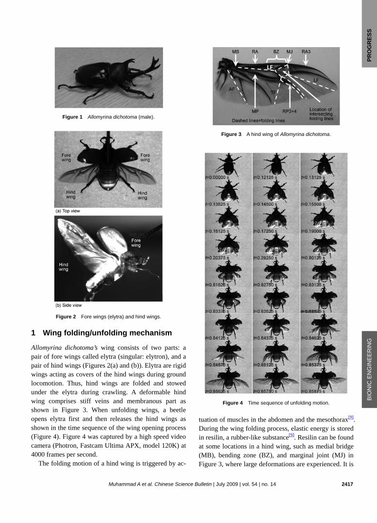
Figure 1 Allomyrina dichotoma (male).
Figure 2 Fore wings (elytra) and hind wings.
1 Wing folding/unfolding mechanism
Allomyrina dichotoma’s wing consists of two parts: a pair of fore wings called elytra (singular: elytron), and a pair of hind wings (Figures 2(a) and (b)). Elytra are rigid wings acting as covers of the hind wings during ground locomotion. Thus, hind wings are folded and stowed under the elytra during crawling. A deformable hind wing comprises stiff veins and membranous part as shown in Figure 3. When unfolding wings, a beetle opens elytra first and then releases the hind wings as shown in the time sequence of the wing opening process (Figure 4). Figure 4 was captured by a high speed video camera (Photron, Fastcam Ultima APX, model 120K) at 4000 frames per second.
The folding motion of a hind wing is triggered by ac-
Figure 3 A hind wing of Allomyrina dichotoma.
Figure 4 Time sequence of unfolding motion.
tuation of muscles in the abdomen and the mesothorax[9]. During the wing folding process, elastic energy is stored in resilin, a rubber-like substance[9]. Resilin can be found at some locations in a hind wing, such as medial bridge (MB), bending zone (BZ), and marginal joint (MJ) in Figure 3, where large deformations are experienced. It is

2418 www.scichina.com | csb.scichina.com | www.springerlink.com
claimed that contraction of a muscle (M. pleura alaris) in the thorax triggers a scissor-like motion and release of the elastic energy stored in resilin during the wing un-folding[9]. The shapes of the hind wing are totally dif-ferent at the folding and unfolding configurations as shown in Figure 5. When the hind wing is fully folded, the angle between the two major vein structures, i.e. ra-dius anterior (RA) and media posterior (MP) is about 10o, as shown in Figure 5(a). After unfolding, the angle is increased to about 20° as shown in Figure 5(b) due to the scissor-like motion of the two veins.
Figure 5 Folding and unfolding of a real hind wing.
In addition to the angle of the two major veins, the
difference between folding and unfolding configurations is also characterized by referring the straight region of RA located nearby the wing base, marginal joint, and tip of radius anterior 3 (RA3). The angle between RA and marginal joint through the tip of RA3 is about 39° for folding condition as shown in Figure 5(a). This angle increases up to 154° during unfolding process as shown in Figure 5(b).
One of the parameters used to specify the order of an organism is the density of wing folding, which can be expressed by the folding ratio[10] as follows:
surface area of unfolded wingFolding ratio= .surface area of folded wing
(1)
In Coleopteran order, the folding ratio ranges from 1.3 to 4.5[10]. A CAD software (AutoCAD) is used to calculate both unfolded and folded wing surface areas of Allomyrina dichotoma, resulting in a folding ratio of 2.3. It means that this beetle is able to reduce the size of its
hind wing more than two times smaller. The folding and unfolding mechanisms involve some
parts called folding structures[10]. Folding structures comprise three members: bending zone, folding patch, and marginal joint. The bending zone is a smooth bend-ing area of the whole costal margin with the wavy sur-face. The folding patch is a morphologically unspecified intersection of folding lines. The marginal joint is an el-bow-like articulation of the leading edge/costal margin.
2 Out-of-plane wing folding/unfolding
Haas et al. explained working principle of hind wing folding and unfolding by using a rectangular membrane wing, which is called the basic mechanism[11]. This mechanism consists of four stiff panels, four folding lines, and a point of intersection (Figure 6), where those folding lines are borders and also hinges of the four stiff panels that meet each other at a point of intersection. A wing is unfolded along the four folding lines by in-creasing the angle ε between its base panels as shown in Figure 7(a). Inversely, as shown in Figure 7(b), the folding configuration can be achieved by reducing the angle ε. The adjustment of the angle ε may be regarded
Figure 6 Folding lines, origin (point of intersection), panels, and angles between folding lines[12].
Figure 7 Basic folding and unfolding mechanisms[12].

Muhammad A et al. Chinese Science Bulletin | July 2009 | vol. 54 | no. 14 2419
PRO
GR
ESS
B
ION
IC E
NG
INE
ER
ING
as a wing base motion in a real beetle. Some wing configurations are not foldable, depend-
ing on the degree of freedom[11]. When the degree of freedom of an artificial hind wing equals to one, then the configuration becomes foldable. Otherwise, the folding motion is undeterminable. The degree of freedom is formulized as eq. 2, 3 2M P C= − , (2) where M is the degree of freedom, P is the number of movable panels, and C is the number of folding lines.
3 In-plane wing folding/unfolding
The basic folding/unfolding mechanism explained by Haas and Wootton[11] involves a large out-of-plane mo-tion during wing opening process. However, when we examine the forced folding/unfolding process based on images captured by a digital camera recorder, it is found that the unfolding process of hind wings of Allomyrina dichotoma occurs nearly in a plane as shown in Figure 8(a). Also, we captured the free unfolding process by using a high speed camera and observed the images. Figure 8(b) shows that the beetle unfolds its hind wing nearly in a plane at the beginning of flapping wing mo-tions. Thus, the hind wing unfolding motion is actually taking place as an in-plane motion.
Around in the middle of leading edge vein, there is a small shrunken part acting like an articulation between the inner leading edge vein (RA) and the outer leading edge vein (RA3), and accordingly forms an in-plane hinge. This part is shown in Figure 3 and Figure 9, and is termed marginal joint (MJ). The marginal joint has the function to perform the folding and unfolding motions, which occur along transverse fold (TF). In this case, the bending stiffness of a hind wing is much degraded and the outer part of the hind wing may be arbitrarily fluctu-ated during flapping motion.
In front of the MJ, there is an interesting member, called bending zone (Figure 9). Its function is to accom-plish the folding and unfolding motions along longitu-dinal fold (LF). The bending zone is bent during folding configuration, and straightened to construct an unfolding shape. It means that the bending zone undergoes a large deformation as shown in Figure 9. However, this mem-ber does not experience any bending back motion even when the hind wing is flapping. In other words, the bending zone is able to sustain the acting forces on the hind wing, so that the outer part of the hind wing does
Figure 8 In-plane unfolding motion.
Figure 9 RA, BZ, MJ and RA3.
not fold back during flight. Therefore, we claim that the bending zone acts like an in-plane hinge with the mar-ginal joint.
4 Design of artificial foldable wings
In this section, we present two artificial models of fold-able hind wings. The two artificial wings are designed

2420 www.scichina.com | csb.scichina.com | www.springerlink.com
based on the out-of-plane and in-plane wing unfolding principles, respectively. Both of them are designed as similar as possible to the real one in terms of dimension, vein thickness, membrane thickness, wing contour, and vein pattern. The folding motion along the anal fold (AF) is ignored in both artificial wings. For the out-of-plane unfolding model, we do not imitate the thickness of vein and membrane of a real beetle wing, thus the four wing panels are flat and have the same thickness.
The first model is an artificial beetle wing that can be unfolded by the out-of-plane motion as described in the previous section based on references [11, 12]. A small panel is added at the inner side of wing articulation for the SMA wire installation as shown in Figure 10. This model has a span length of 7.5 cm excluding the added panel, which is typically 1.5 times longer than that of a real hind wing. A 1 mm thick paper is cut along the outer contour of Figure 3, and then split into four panels fol-lowing their folding lines (dashed lines) as shown in Figure 10. Next, all of the panels are merged and ar-ranged like a real wing by attaching them into two transparent adhesive tapes: one is attached on the upper surface, and the other on the lower surface. These tapes act like hinges during folding and unfolding motions. Each hinge is created by splitting the upper tape along the corresponding folding lines, except for the hinge line mimicking transverse fold (TF), which is split on the lower surface.
Figure 10 The out-of-plane wing model.
The artificial hind wing is first manually folded along
the longitudinal folding (LF) line, which lies across the wing base, and then the unfixed panels are folded con-currently. Based on our experiments, the artificial hind wing is not fully folded if all the panels are separated following the original folding lines shown in Figure 10(a). Therefore, we make a slight modification to the folding lines as shown in Figure 10(b), so that the wing can be perfectly folded. The unfolding of the wing can be achieved simply by increasing the angle ε as shown in Figure 7(b) and Figure 11. We can observe that a large out-of-plane motion is involved in this type of wing folding and unfolding.
Figure 11 Manual unfolding of an artificial wing made of thick paper (out-of-plane model).
Because a real beetle folds and unfolds its hind wing
in a plane as described in Section 4, the above wing model may not correctly mimic the actual mechanism. In order to realize the second model, which creates an in-plane wing folding and unfolding mechanism, we need to mimic some parts in the hind wing, such as veins, membrane, folding lines, point of intersection, medial bridge, bending zone, marginal joint, and a movable veins joint that articulates MP with RP3+4 (ra-dius posterior 3+4). Among them, the most significant contribution to the wing unfolding comes from the me-dial bridge and folding structures. The membrane should be stiff enough but flexible so that it can be repeatedly folded and unfolded.
Figure 12 shows an artificial foldable hind wing with 10.5 cm of span length, which is typically two times longer than that of a real hind wing of Allomyrina Di-chotoma species. Membrane of this model is made of 15 μm thick polypropylene film. A digimatic micrometer (Mitutoyo, MDC-25SB) with 1 μm of resolution is used to measure the thickness. The film is sanded by using soft abrasive paper so that the film becomes more flexi-

Muhammad A et al. Chinese Science Bulletin | July 2009 | vol. 54 | no. 14 2421
PRO
GR
ESS
B
ION
IC E
NG
INE
ER
ING
ble and about 3 μm thinner. Meanwhile, the vein struc-ture is made of 0.4 mm thick glass/epoxy composites. This composition is chosen because it is lightweight and strong enough. In order to acquire accurate dimension, each part of this model is designed by using CAD soft-ware (AutoCAD and CATIA), and the cutting process of composite material is done by a laser cutting machine (LaserPro Mercury, L-440V, GCC American Inc.).
Figure 12 The in-plane wing model.
The bending zone is mimicked by constructing mul-
ti-hinge system as shown in Figure 13, so that this member is able to sustain the acting forces during flight and maintain its shape without folding back. By imple-menting the multiple hinges, the bending zone can be mimicked to create a folding configuration. The medial bridge, marginal joint, and movable veins joint (MVJ) are respectively imitated by single-hinge system as shown in Figure 13. The point of intersection and the folding lines are created by creasing the membrane.
Figure 13 CAD design of vein structure of the in-plane wing model.
Diameters of the holes are all 1.5 mm. The shaft is
made of 1.5 mm diameter carbon rod. Meanwhile, we make the size of each hole slightly smaller to construct interference fit hinge, so that the shape of the wing structure can be kept straight after assembly.
Unlike the first wing model, which is easy to be ma-nually folded and unfolded, the second wing design is more complex. Despite this, the folding and unfolding configurations shown in Figures 14(a) and 14(b) can be achieved in a plane by manually creating a scissor-like motion of the two major artificial veins and a rota-tion-translation motion of the outer wing.
Figure 14 Folding and unfolding of the in-plane wing model.
5 Actuation of artificial wings
By manual actuation of the two artificial wings, we con-firm the possibility of mimicking the beetle wing’s fold-ing and unfolding mechanisms. To electrically activate the two wing models, some artificial muscular system should be added at particular locations in the two artifi-cial wings. In this work, we use Shape Memory Alloy (SMA) wires for the artificial muscle to provide enough actuation force and deformation to create unfolding mo-tion of wing.
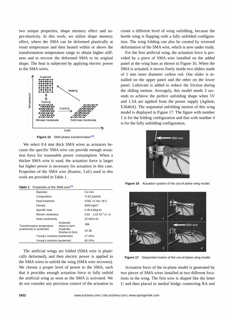
SMA is a metal alloy that can recover its original shape when a sufficient heat is subjected after undergo-ing a deformation. Below its transformation temperature range, a SMA has low Young’s modulus with martensite as the crystal structure. The SMA becomes stiffer and the crystal structure transforms to austenite when heated within the transformation temperature range. Above the transformation temperature range, the crystal structure is purely austenite (Figure 15[13]). Typically, SMAs have
2422 www.scichina.com | csb.scichina.com | www.springerlink.com
two unique properties, shape memory effect and su-per-elasticity. In this work, we utilize shape memory effect, where the SMA can be deformed plastically at room temperature and then heated within or above the transformation temperature range to obtain higher stiff-ness and to recover the deformed SMA to its original shape. The heat is subjected by applying electric power to the SMA wires.
Figure 15 SMA phase transformation[13].
We select 0.4 mm thick SMA wires as actuators be-cause the specific SMA wire can provide enough actua-tion force for reasonable power consumption. When a thicker SMA wire is used, the actuation force is larger but higher power is necessary for actuation in this case. Properties of the SMA wire (Kantoc, Ltd.) used in this work are provided in Table 1.
Table 1 Properties of the SMA wire[14]
Diameter 0.4 mm Composition Ti-50.2at%Ni Heat treatment 470℃×2 min, W.C. Density 6450 kg/m3 Specific heat 0.46 kJ/(kg·K) Electric resistance 0.82―1.03 10−6 Ω·mHeat conductivity 22 W/(m·K)
Austenite starts to form 39℃ Transformation temperature
(martensite to austenite) Austenite finishes to form 54.3℃
Young’s modulus (martensite) 27 GPa Young’s modulus (austenite) 65 GPa
The artificial wings are folded (SMA wire is plasti-
cally deformed), and then electric power is applied to the SMA wires to unfold the wing (SMA wire recovers). We choose a proper level of power to the SMA, such that it provides enough actuation force to fully unfold the artificial wing as soon as the SMA is activated. We do not consider any precision control of the actuation to
create a different level of wing unfolding, because the beetle wing is flapping with a fully unfolded configura-tion. The wing folding can also be created by reversed deformation of the SMA wire, which is now under study.
For the first artificial wing, the actuation force is pro-vided by a piece of SMA wire installed on the added panel at the wing base as shown in Figure 16. When the SMA is actuated, it moves freely inside two sliders made of 1 mm inner diameter carbon rod. One slider is in-stalled on the upper panel and the other on the lower panel. Lubricant is added to reduce the friction during the sliding motion. Averagely, this model needs 3 sec-onds to achieve the perfect unfolding shape when 5V and 1.5A are applied from the power supply (Agilent, E3646A). The sequential unfolding motion of this wing model is displayed in Figure 17. The figure with number 1 is for the folding configuration and that with number 4 is for the fully unfolding configuration.
Figure 16 Actuation system of the out-of-plane wing model.
Figure 17 Sequential motion of the out-of-plane wing model. Actuation force of the in-plane model is generated by
two pieces of SMA wires installed at two different loca-tions in the wing. The first wire is shaped like the letter U and then placed in medial bridge connecting RA and

Muhammad A et al. Chinese Science Bulletin | July 2009 | vol. 54 | no. 14 2423
PRO
GR
ESS
B
ION
IC E
NG
INE
ER
ING
MP as shown in Figure 18(a). When the first wire is ac-tuated, it triggers scissor-like motion of RA and MP, which increases the angle between the two veins around the medial bridge as the rotation axis. Another SMA wire is used to generate force that can straighten the bending zone and concurrently increase the angle be-tween RA and marginal joint through the tip of RA3. Thus, the second wire is installed along the leading edge veins as shown in Figure 18(b). We apply 5V and 1.5A to the SMA wires, and it takes 7 to 8 seconds to unfold the hind wing completely. The sequential unfolding motion of this wing model is available in Figure 19. The figure with number 1 is for the folding configuration and that with number 4 is for the fully unfolding configuration.
Figure 18 Actuation system of the in-plane wing model.
Figure 19 Sequential motion of the in-plane wing model.
In the real wing opening, Allomyrina dichotoma
spends about 0.6 seconds to sequentially open its elytra while it sweeps the folded hind wing forward, flaps, and then spreads the hind wing. The times spent to unfold the artificial wings are longer than that taken in real wing opening. A higher power application to the SMA wires will lead to a faster unfolding motion and more stable unfolding configuration. Since the actuation force is generated by SMA wires, it also depends on how the power is increased. Boosting the electric current is more
effective than a higher voltage. Table 2 summarizes the parameters used to judge si-
milarity between the artificial wings and the real ones. The parameters in the last four rows are used to charac-terize folding and unfolding configurations. The values in the parentheses mean the maximum values that can be achieved when the in-plane wing model is manually un-folded. Therefore, these values are closer to those for a real hind wing. The folding ratios of the artificial wings are always smaller than that of the real ones because the anal fold is neglected in the artificial wings. From the parameters in Table 2, it can be concluded that charac-teristics of the first artificial wing fabricated following the existing explanation on the wing folding/unfolding in references [11, 12] is similar to those of a real wing. Nevertheless, in term of unfolding motion, the second artificial wing is closer to the unfolding mechanism of a real beetle wing since it can be unfolded in a plane.
Table 2 Comparison of data for a real wing and artificial wings
Artificial wing Parameters Real wing
out-of-plane in-plane Wing span (cm) 5.2 7.5 10.5 Weight (g) 0.16 1.50 1.06 Membrane thickness (μm) 3―6 1,000 15 Typical time duration of unfolding motion (s) 0.6 3 7―8
Folding 3.29 9.95 21.88 Projected wing area (cm2) Unfolding 7.62 18.06 32.79 (34.90)
Folding 10 2 12 Angle between RA & MP (°) Unfolding 20 20 16 (19)
Folding 39 42 51 Angle between RA & marginal joint-tip of RA3 (°) Unfolding 154 154 148 (156)
Folding ratio 2.32 1.82 1.50 (1.60)
6 Conclusion and future work
In this paper, we attempt to mimic the wing unfolding motion of Allomyrina dichotoma by using two artificial wing models. The artificial wings are designed based on working principles of the wing folding/unfolding of the beetle. Unlike the explanations in the literatures, the Al-lomyrina dichotoma wings are folded and unfolded within a plane. The in-plane unfolding motion is successfully implemented in an artificial wing based on our observa-tion. We believe that the artificial in-plane wing mimics the real wing unfolding mechanism more closely.
Two types of artificial wings, which are folded and unfolded in the out-of-plane mode and in-plane mode, respectively, are actuated by properly installed SMA wires. The two artificial wings are successfully unfolded

2424 www.scichina.com | csb.scichina.com | www.springerlink.com
from their folding configurations by applying 5V and 1.5A electricity to the SMA wires.
The final purpose of this work is to fully mimic the wing folding/unfolding motions as similar as possible, without ignoring the function as aerodynamic force gen-erator. In an attempt toward that goal, additional activi-ties are being conducted. Recently, we concentrate on scaling down the wing size, which also reduces the weight. For the in-plane model case, a better artificial
membrane made of a thinner film is going to be applied. This will face another challenge since the fabrication process becomes more difficult due to smaller size and weaker material. In near future, tests will be performed to verify whether the artificial hind wing folds back or not during flapping motion.
Eventually, the artificial wing folding/unfolding me- chanisms may provide an insight for portable micro air vehicles with morphing wings.
1 D J Pines, F Bohorquez. Challenges facing future micro-air-vehicle
development. J Aircraft, 2006, 43: 290―305[doi] 2 Dickinson M H, Lehmann F O, Sane S P. Wing rotation and the aerody-
namic basis of insect flight. Science, 1999, 284: 1954―1960[doi] 3 Van Den Berg C, Ellington C P. The three dimensional leading-edge
vortex of a ‘hovering’ model hawkmoth. The Royal Society, Phil Trans R Soc Lond B, 1997, 352: 329―340[doi]
4 Fogh T W. Unusual mechanism for the generation of lift in flying animals. Scientific America, 1975, 233: 80―87
5 Fearing R S, Avadhanula S, et al. A micromechanical flying insect thorax. In: Neuro-Technology for Biomimetic Robots. Cambridge: The MIT Press, 2002. 469―480
6 Wood R. Liftoff of a 60 g flapping-wing MAV. IEEE International Conference on Robotics and Automation Society, 2007. 1889―1894
7 Syaifuddin M, Park H C, Yoon K J, et al. Design and evaluation of a Lipca-actuated flapping device. Smart Materials and Structures, 2006, 15: 1225―1230[doi]
8 Nguyen Q V, Syaifuddin M, Park H C, et al. Characteristics of an in-sect-mimicking flapping system actuated by a unimorph piezoceramic
actuator. J Intel Mate Sys and Struct, 2008, 19: 1185―1193[doi] 9 Haas F, Beutel R G. Wing folding and the functional morphology of
the wing base in coleoptera. Zoology, 2001, 104: 123―141[doi] 10 Haas F. Evidence from folding and functional lines of wings on in-
ter-ordinal relationships in pterygota. Arthropod Systematics Phy-logeny, 2006, 64: 149―158
11 Haas F, Wootton R J. Two basic mechanisms in insect wing folding. In: Proceedings of the Royal Society of London B, 1996, 263: 1651― 1658[doi]
12 Haas F. Wing folding in insects: A natural deployable structure. IUATM & IASS Symposium on Deployable Structures: Theory and Applications, 2000, 137―142
13 Ryhanen J. Biocompatibility evaluation of nickel-titanium shape memory metal alloy. Academic dissertation to be presented with the assent of the Faculty of Medicine. Oulu University Library, 1999
14 Yamashita, Keitaro. Study on mechanical characteristic improvement by shape recovery force of TiNi fiber reinforced intelligent composite materials. Saitama Institute of Technology, 2005
![Folding and Unfolding Movements in a [2]Pseudorotaxane](https://static.fdokumen.com/doc/165x107/634439d403a48733920acacf/folding-and-unfolding-movements-in-a-2pseudorotaxane.jpg)