Military Curriculum Materials for Vocational and ... - ERIC
86
-
Upload
khangminh22 -
Category
Documents
-
view
1 -
download
0
Transcript of Military Curriculum Materials for Vocational and ... - ERIC


ED 216 2Q4
TITLE
INSTITUTION
SPONS AGENCYPUB DATE
'NOTE.AVAILABLE FROM
Reseatch in Vocational Education, 1960 Kenny.Rd.,Columbus, OH 43210. 4
DOCUMENT RESUME
CE 032 551
Military Curriculum Materials for Vocational.andTechnical Education. Builders School, Ceramic TileSetting 3-9.Ohio State Univ., Columbus. National Center fotResearch in Vocational Education.Office of Education (DHEW), Washington, D.C.[78]11$P.Military Curriculum Project, The National Center for
EDHS PRICE' MF01/PC05 Plus Postage.DESCRIPTORS Behavioral Objectives.; *Building Trades;
*Construction (.Profess); Course Content; Curriculum;Group Instruction; Individualized Instruction;Instructional Materials; Learning Activities; LessonPlans; Postsecondary Education; Secondary EdueatioW;Teaching Guides,; Teaching Methods; TechnicalEducation; *Trade and Industrial Education;*Vocational EducationMilitary Curticulum Project; *Tile Occupations
1
IUNTIFIERS
ABSTRACTThis course; for individualized or group instruction
on ceramic tile setting, was developed from military sources foi'usein vocational education k_ Thiourse provides students with skills inmortar preparation, surftie preparation, tile layout planning, tilesetting, tile'cutting,,and the grputing of tile joints. 'Both theoryand shop assignments' are included with the course materials.. Thematerials are organized into two units. Unit 1, the Introduction,covers safety. Unit.2, on ceramic,tile setting, contains thefolloiAng,two sections covering 30 hours'of class 'and shop time:mortar mixing and ceramic tile, and ceraimiC.tile installation.Instrdctors guides are prepared for each section describinginstructional materials, instructional aids, terMinal and enablingobjectives, criterion tests, and homework assignments. Each/Sectionincludes an outline of instruction,,,-isstructor activities, andstudent activities. Four job sheets are prepared to accompany .thelast two sections. These involve 'a list of, the tools, equipment, andmaterials needed for the assignment and a list of procedures.. Textmaterial is also provided. (KC)
° 2)
*****************************************************i*****************. *Reproductions supplied bysEDRS are the best ;lot can be made*
from the original Orocument. ***************************************t********************************
r.
MILITARY CURRICULUM MAWERIALS
The military-developed curriculum materials in this coursepackage were selected by the National. Center for Research in
Vocational Education Military Curriculum Project for dissem-ination to the six regional Curriculum Coordination Centers andother instructional materials agencies. The purpose ofdisseminating these courses was to make curriculum materialsdeveloped by the military more accessible to vocational''educators in the civilian setting:
The course materials were acquired,, evaluated by project,staff and practitioners in the field, and prepared fordissemination. Materials which were specific to the nilitarywere deleted, oopyriqhted materials were either omitted or appro-val for their use was obtined. These course packages containcurriculum `resource Materials which can be adapted to supportvocational.instruction'ana curriculum development.
O
1/4
3
I
The N4tionalCnter ..r1 .-4
N
orwrsMission TStaternent ..=,..i 1,
r*,.......,......... "71" ;;"..r1S73"7. ',"1- '', ,... "t q E. a '-.- 0i t' %'=2:-... = -tsi I c,
. , -<,, -
.c 4z rn
sn
mThe National Center for Research in , "nrVocational Education's mission is to increase , gi =0
213:-the ability of diVerse agericies, institutions,R. E, i Gand organizations to solye_educational prob-
ig =lems relating to individual career planning, ,i 1:1Op L4preparation, and progression. The National \g 2Center fulfills its mission by:
,
Generating knowledge through research
1 . Developing educational programs andproducts' r.
, .Evaluating individual program needsand outcomes .
Installing educational pro rams andproducts
Operating information sy;lems and. services
Conducting leadership dpvelopmen't andtraining program's I
FOR FURTHER INFORMATION ABOUTMilitary Curriculum Materials
WRIT OR CALL- Program Informa;idnOffice%
The National Center for Research in VocationalEducation
The Ohio State University1960 Kenny Road, Colurobus, Ohio 43210
Telephone: 614/486-3655 or Toll Free 800/848-4815 within the contifiental U.S.(except Ohio).
0
Military CurriculumMaterials for
/ Vocational andTechnical Educatioh
Information and FieldSciVic.,es Divioion,
tr
The Iatic.,nal Center foi Resk,archn Vocational Education

JVlilitaiy
.
Curriculum MaterialsDiisernination Is . . .
I
an activity to increase the accessibility ofmilitary-developed curriculum materials tovocational and technical educators.-
This project, fiinded by the U.S. Office ofEducation, includes the identification andacquisition of curriculum materials in printform from the Coast Guard, Air Force,
.Army, Marine Corps and Navy.
Access-Ab military curriculum materials ist,provided through -5 "Joint Memorandum of .
Understanding" between'the U.S. Office ofEducation and the Department of Defense.
The acquired materials ere reviewed by staff..and subjedt matter specialists: and courses
'deemed applicable to vocational and tech.\nical education are seleCted for dissemination.
The National Center for ResearchVocational Education is the U.S. Office ofEducation's designated representative tocquire the materials and conduct the project
activities.
Project Staff:
WesleyE. Budke, Ph.D., DirectorNational Center Clearinghouse
Shirley A. Chase;Ph.D.41)roject Director
C`
ala
What MaterialsAre Available?
One hundred twenty courses on microfiche(thirteen in paper form) ancj descriptions ofeach have been. provided to ihe vocationalCurriculum Coordination Centers and otherinstructional materials agencies for dissemi-/nation.
Course materials include programmedinstructioli,Thurriculukn outlines, instructorguides, student workbooks and technicalmanuals.
The 120 courses represent the followingsixteen vocational subject areas:
AgricuitureAviationBuilding &ConstructionTrades..,*
ClericalOccupations
CommunicationsDraf OngElectronics.'."
'Engine Mechanics
Food Service'HealthHeating & AirCondftioning
Madhine ShopManagement &Supervision.
Meteorology 8LNavigation
PhotographyPublic. Service
The number of courses and the subject areasrepresented will expand as additional mate-rials with application to vocational and ,
technical education are identified and selectedfor dissemination. .
How Can TheseMaterials BeObtained?
Contact the Curriculum Coordination Centein your region for information op detainingmaterials (e.g., availability and cost). Theywill respond to your request directly or referyou to an inst?uctional materials agency
, closer to you.
CURRICULUM COORDINAIION CLN l'EF1S
EAST CENTRAL. ; Rebecca S. Douglass
Director100 No,rth First StreetSpringfield, IL 627,77217/782-0759
MIDWESTRobert PattonDirector1515 West Sixth Ave.Stillwater,-OK 747044051377.2000'
NORTHEASTJoseph F. Kelly, Ph.D.Director225 West State StreetTrenton, NJ 08625609/292.6562
NORTHWESTWilliam DanielsDirectorBuilding 17 6
irdustrial ParkOlympia; WA 98504 .
206/751.009
SOUTHEASTJames F. Shill, Ph.D.
1DirectorMississippi State University
Drawer DX.Mississippi State,MS 397626011325-2510
WESTERNLawrence F. H. Zane, Ph.D.
Director11776 University Ave.Honolulu. Al 96822808/948.7834
7 1 '4
A
k
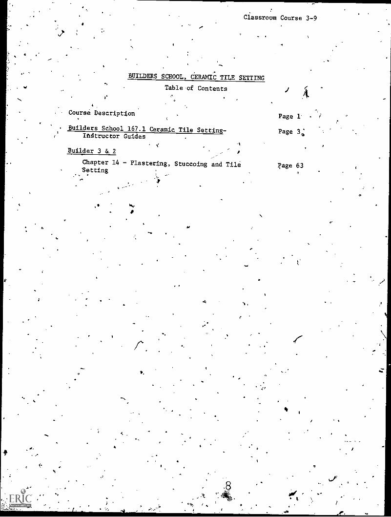
Classroom Course 3-9
BUILDERS SCHOOL, CERAMIC' ILE SETTING
Table of Contents
Course Description
Builders School 167.1 Ceramic Tile SettinK-Ingtructor Guides
Builder 3 &. 2
Chapter 14 - Plastering, Stuccoing and TileSetting
O
f.
/So
,,
v.
o.s
s
Page 1
Page 31:
Page 633

: SPECIAL CONSTRUCTION BATTALION TRAINING
FEB 1916
.......,,4,

BIJILDERS SCHOOL, CERAMIC TILE SETTING
O
Classroom Course 3-9
Developed by.
United States Navy
Oevelopment andReview Oates
February 1976
sl
O.O.T. No.:840.884
Occupational Arse:
Building and Construction
Target Audrancisa:
Grades 10-adult
Print Pages:
85- Cost:
$2.00 44
Military Curriculum Project, The Centerfor Vocational Education, 1960 KennyRd., Columbus, OH 43210
Contents:
Unit 1.1 Introduction
1.1.2 Safety
r .Unit 1.2 :Catamic Tile Setting
1.2.1 Mortar Mixing an d CeramicSetting Surface
1.2.2 &remit Tile Installation
to;
3
.2
4, 4
*
a
V
2x xuHcr
*
*
v.?
9.52
0
4' Materials are recommended but not provi% d.
1nTa nnc411toune .
.. .
1 0 Expires July 1, 1978
f

"O
It.
Course Description
Students ccirhpleting this short course w)( be trained in mortar preparation, surface preparation, tilt layout planning, tile setting, tile cutting, and thegrouting of tile joints.
Both theory and shop assignments,are included with the course materials. The materials are organized into two units. The first section of the first .unit is not suitable for vocational programs. This sectioriVileals with the military chain of command and reporting procedures and was deleted. The'remaining three sections are suitable.
Unit 1.1 Introduction contains a thirty minute section on safety. No shop time is required.
Unit 1.2 Ceramic Tile Setting contains the following two sections covering 30 hours of class and shop tir.
1.2.1 Mortar Mixing and Ceramic Tile (3 hours clasfilistruction, 7 hours shop)1.2.2. Ceramic Tiljnstallation (3 hours chits instruction, 17 hours shOp
Instructors' guidlas are prepared for each section describing instructional materials, instructional aids, terminal and enabling objectives, criterion testsand homework assignments. 'Each section includes an outline of instruction, instructor activities and student activities. Four job sheets are preparedto accompany the last two sections. These involve a list of the tools, equipment, and materials needed for the assignment and a list of procedures.
The text is chapter 14 of a Navy training nianual` Builder 3 & 2, NAVPERS 10648 -F. This text material is provided. Four commercial references aregiven to supplement the course material. A list of course tools,equipment, and materials is provided as well as a list of training aids and devices andteacher prepared materials needed.
The following audio-visual support materials are recommended but not provided:
The Gift of Life (GIF-001218 t
Lathe and Plaster (American Gypsum Com-pany-22 min.)How to GetBetter Clay Tile Installation (Tile Council of America-16 min.)
a.
I
L
111111114
ne Irro KIR KCATIONIL EOLCATION1.4 P.., 5/44 ...^60/fR511

. ,
TITLE PAGE
;.
,
TITLE: ISTECIAL.CONSTRUCTION BATTALION TRAINING COURSE 167.1CERAMIC TILE SETTING.
COURSE NUMBER: SCBT 167.1
COURSE LENGTH: ,32'HOURS.
TAUGHT AT: NaVal Constrcutioq Training Center, Port'ueneme, California93043 ,
/ Naval Construction Training Center, Gulfport,39501
CLASS CAPACITY: No.rmal: 12
Maximum:' 16Minimum: 8
INSTRUCTOR(REQUIREMENTS PER CLASS Clais .16/1Pract: 8/1
Mississippi
COURSE CURRICULUM MODEL MANAGER: Naval Construction TrZinizig'Center.,Port Hueneme, California 93043
CURRICULUM CONTROL:.4Chief of NavalTechnictl Training
(QUOTA MANAGEMENT, AUTHORITY: School at which taught.
- QUOTA CONTROL: School at which taught.
APPROVAL/IMPLEMENTATION DATE:- When approved by Chief of NavalTraining.
4.
a
-e
k
Technidal.
12
iii
J
"
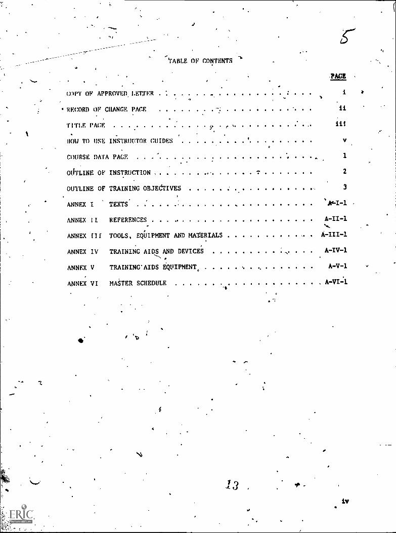
TABLE OF CONTENTS
-PACE
coPY OF APPROVED LEtrER
ii
> iii
HOW TO USE INSTRUCTOR CHIDES v
COURSE DATA PAGE . . 1
RECORD OF CHANGE PACE
TITLE PACF r
OdTLINE OF INSTRUCTION 2
OUTLINE OF TRAINING OBJEdTIVES 3
ANNEX I TEXTS
ANNEX II REFERENCES A-II-1
ANNEX rIf TOOLS, EQUIPMENT AND MATERIALS
ANNEX IV TRAINING AIDS AND DEVICES A-IV-1
ANNEX V TRAINING'AIDS EQUIPMENT, A-V-1
ANNEX VI MASTER SCHEDULE A -VI -1
11
iv

Instructorguides (I.G.'s) are provided for each topic. They
include supporting instructional material and aids identified'by thetopic number and a letter-code designation. The letter codes used in
-I.G.'s are as follows:
AS - Assignment SheetCN - Class NotesDS - Diagram Sheet
EG - Evaluatiod GuideFT - Final TestIS - Information SheetiS -Job SheetOS - Operation Sheet
PE - Performance EvaluationPI -.Programmed InstructionPS - ProblemProblem SheetPT - Practical TestT - TestTR - TransparencyWS - Work Sheet
4
.
4
The instructor guides are intended to be used as master lessonplan'S, but subject however to personalization by the individual instructor.The instructor should study and refer to the lasting of references, materialsand-aids given in the appropriate etvplo*ed annex when annotating theinstructor guides.
,The first page of each instructor guide contains the followingfunctional information:
1. Topic of lesson
2. Average-iime'in periods (class and practical)
3. Instructional ijterials such as texts, refereNes,equipment, tools, training aids, etc.
4. InsjNational materials such as job sheets, handouts, etc.
'5. Terminal and enabling objectives.
6. Crieet.ion Test
/0 Homework assignment
The,second page is the "Outline of Instruction" page whereby achinstructor will develop an appropriate introductiod for each topic that .
(1) create interest; (2) show the value of the topic to the student;(3) relate the. topic to previous and future topics in the course; and(4) communicate the learning objectives to the student. Well prepared
1 lesson introductions can provide direction for student motivation andestablish readiness for learning.
A
s'
9
O
The pages that follow the "Information" and "Outline of Instruction"pages is the body of the instruction guide. The pages are divided intothree columns: the column on the left includes the outlines ofinstruction requirqd.by the objectives of the.lesson; the center columnis for listing instructor activity that corresponds to the particularportion of the.lesson;, and the right hand column contains studentactivity that corresponds to,the particular portion of the lesson.Iestructor creativity' in designing learning-ekercises, techniquesandtraining aids to meet course objectives can enhance the lesson andshould be utilized and noted in the appropriate column. In addition,student comments pertaining to updating, additions, deletions, etc.,to the lesson should be encouraged and noted for continual revision ofthe lesson.
9
I
r
s.)
;
COURSE DATA PAGE
COURSE MISSION: To train selected builders and builder strikers inmortar preparation,' surface preparation, the layout planning, tilesetting, tile cutting and the grouting of tile joints.
PERSONNEL AND RATING ELIGIBLE: E -2 thru E-4.
OBLIGATED SERVICE: Nohe
NEC EARNED: N/A
PHYSICAL REQUIREMENTS: N/A
i SECURITY CLEARANCE REQUIRED: None .
PREREQUISITE TRAINING AND/OR BASIC BATTERY TEST SCORE REQUIRED: None
RELATED TRAINING: None
FOLLOW-UP TRAINING: None
GRADING WEIGHT FACTORS: Performance of tasks throughout the course willbe strictly on a go/no go basis.
1

A
OUTLINE OF INSTRUCTION
Topic Unit 1.1
Introduction
CLASS PRACT TOTAL PAGE
1.1.1 Orientation 1.5 CO 1.5 3
. 1.1.2 Safety .5 0 3
2 0 2
Unit 1.2
Ceramic Tile Setting
1.2,1 Mortar Mixing an(Ceramic Tile 3 7 10 3
Setting Surface
1.2.2 Ceramic Tile Installation 3 17 20
6. 24 30 . 3
* Total Periods Classroom: 8
Total Periods Practical: 24
Total-Hours for Course: 32' .
Total weeki for course:,, 1 Week
Each period of instruction represents 60 minutes of actual instructionr
72
OUTLINE OF TRAINING
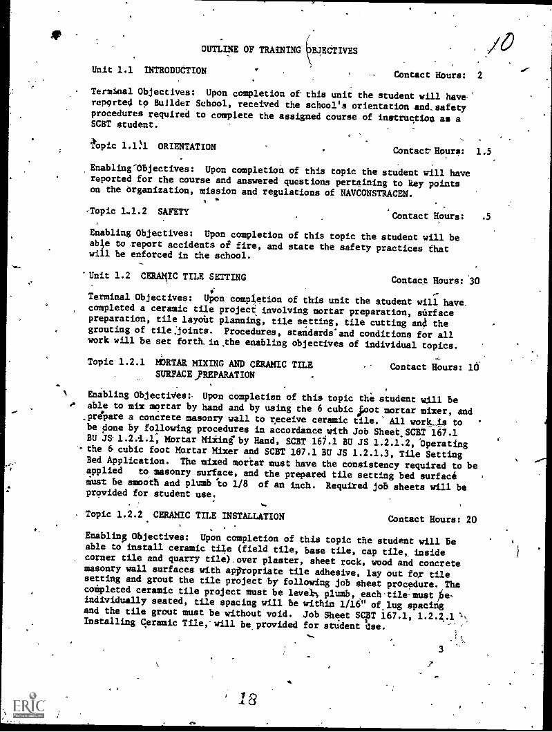
Unit 1.1 INTRODUCTION
BJECTIVES
Contact Hours: 2
Terminal Objectives: Upon completion of this unit the student will havereported to Builder School, received the school's orientation and, safetyprocedures required to complete the assigned course of instruction as aSCBT student.
opic 1.1:1 ORIENTATIONContact, Hours: 1.5
Enabling-Objectives: Upon completion of this topic the student will havereported for the course and answered questions pertaining to key pointson the organization, mission and regulations of NAVCONSTRACEN.
,Topic 1.1.2 SA}..
Contact Hours: .5
Enabling Objectives: Upon completion of this topic the student will beabi,e to report accidents of fire, and state the safety practices thatwill be enforced in the school.
'Unit 1.2 CERAMIC TILE SETTING Contact Hours: 30
Terminal Objectives: Upon completion of this unit the student will have.completed a ceramic tile project involving mortar preparation, surfacepreparation, tile layoUt planning, tile setting, tile cutting ana thegrouting of tile:joints. Procedures, standards'and conditions for allwork will be set forth. in the enabling objectives of individual topics.
Topic 1.2.1 MORTAR MIXING AND CERAMIC TILESURFACE,REPARATION
Contact Hours: 10
Enabling ObjectiVes:. Upon completion of this topic the student will be.4 able to mix mortar by hand and by using the 6 cubic ;not mortar mixer, and
,prepare a concrete masonry wall to receive ceramic tile. All work_is tobe done by following procedures in accordance with Job Sheet SCBT 167.1BU JS 1.2.1.1, Mortar Mixing" by Hand, SCBT 161.1 BU JS 1.2.1.2, 'Operating
'.- the 6 cubic foot Mortar Mixer and SCBT 167.1 BU JS 1.2.1.3, Tile SettingBed Application. The mixed mortar must have the consistency required to beapplied to masonry surface, and the prepared tile setting bed surfacemust be smooth and plumb to 1/8 of an inch. Required job sheets will beprovided for student use.
Topic 1.2.2 CERAMIC TILE INSTALLATION Contact Hours: 20
Enabling Objectives: Upon completion of this topic the student will beable to install ceramic tile (field tile, base tile, cap tile,, insidecorner tile and quarry tile) over plaster, sheet rock, wood and concretemasonry wall surfaces with appropriate the adhesive, lay out for thesetting and grout the tile project by following job sheet procedure. Thecompleted ceramic tile project must be level; plumb, each -tile-must ,6e-individually seated, tile spacing will be within 1/16" of lug spacingand the tile grout must be without void. Job Sheet SOT 167.1, 1.2.2.1Installing Ceramic Tile,-will beprovided for student
- ,
3
,

6 X
ANNEX F
TEXTS
1. Builder 3 & 2, NAVI5ERS 10648-F.
)
o
A-I-1
4

REFERENCES
ANNEX II
4.
,
1.' Plastering Skills and PractieeaBrand andVartse1, American
, 'Technical Society.
"2. Handbook for Ceramic Tile Idstailation, Tile COunAl of America.
3. Glazed Ceiamic Tile, No. 105 15M-7/75, Standard Bran'a Paint Company,
Inc.
4. Complete Do-it-Yourself Manual, Reader's Digesi. .
.t>
20
its
.1%
b

b,
4ANNEX III
,t
TOOLS, EQUIPMENTAND1MATERIAL.
,.TOOLS:
1. Measuring Tape.
2. Trowel Pointing
3. Level, hand
4. Tile -cutter
.5. Tile nipper
6. Squeegee t7. Sponge..
Y.
8. Joint striking toola
9. Beating block
11
trowel
,11. Bucket
12. Shovel, flit nose,
13. Trowel, plastering
14.
IpHawk
15. Darby
16. Straight edge
17. Rake
18. Measuring box,
19. Float, wood
/ EQUIPMENT:
1. Mortar boat.
2. Mortar box
1 cubic foot
4's.
e-
t
O
2i
J
os
ti
TAS, gOIPMENT AND MATERIALS. (CONT"D).
3.' 6 cubic foot mortar mixer
4., Georgia buggy.°
MATERIALS°
1. Sand
2. Lime.
3. Cetamic Tile/
a. Field
b. Outside. corner
c. Caps_
d, Base,.
4. Quarry Tile
I
dr.
vs,
1
Qhi
"1.
. .
A . ') -, .4..,
I
,
S
s
A-III-2
TRAINING AIDSAIDS AND DEVICES:
Pilms:-
1.
ANNEX IVa'
Lath and Plaster (22 min.) "American Gyps Company.-0 ,
Slide Presentation:
How to get Better CCouncil of America.
eInstallation(16 min:) Tile
F Locally Prepared Material:04 4
1. Display Board.
'eramic Tile set on water-resistant drywall with exposed portionon the surface.
2. Job Sheets.
a: SCBT 167.1.BU.JS-2.2.1.1 Mortar Mixing by Hand.
SCBT 167.1 BU JS 1.2.1.2 Operating the 6 cubic foot Mortar Mixer.
c. SOT 167.1 BU JS 1.2.1.3 Tile Setting Bed Application.
d. SCBT 167.1 BU iS,1.3..2.1 -Installing Ceramic Tile
3. Samples.
a. Tiles.
(1) Glazed wall
(2) quarry
(a) Wixed
(b) Non-waxed.
(3) Mosiac
(a) Paper, backing.
(b)' Outside corner.
(c) Rubber-backing.
4
0
A-IV-1I
ti
VO,
r
O
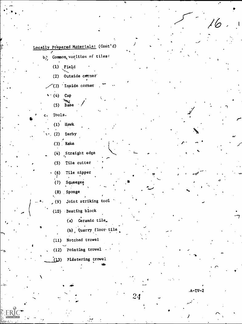
Locally Prepared Raterials: (Cofit'd)44
Commcm,varities of tiles:
(]j Field
(2) Outside canner"
,-/w(3) 'Inside corner
% (4) Cap
.%'4"At
(5) BaSe /
c. Tools.
(1) Hawk
(2) Darby
(3). Rake
(4) Straight edge
(5) Tile cutter
- (b) Tile nipper
(7) Sqgeegel
(8) Sponge
A., (9) Joint striking tool
(10) "Beating block
(a) Ceramic tile.
(b) Quarry floor-tile. .
(11) Notched trowel
(12) Pointing trowel -
(13) Plastering trowel.
41%
1
ti
r.
11 411P;
9ti
.//
.A-IV-2
et.

Training Aids Equipient;,
1. 1* mm projector.
2. Slide projeCtor
3. Tape player.
4. Movie screenI
ANNEX v
0
4 A
4
A-V-1
4
r
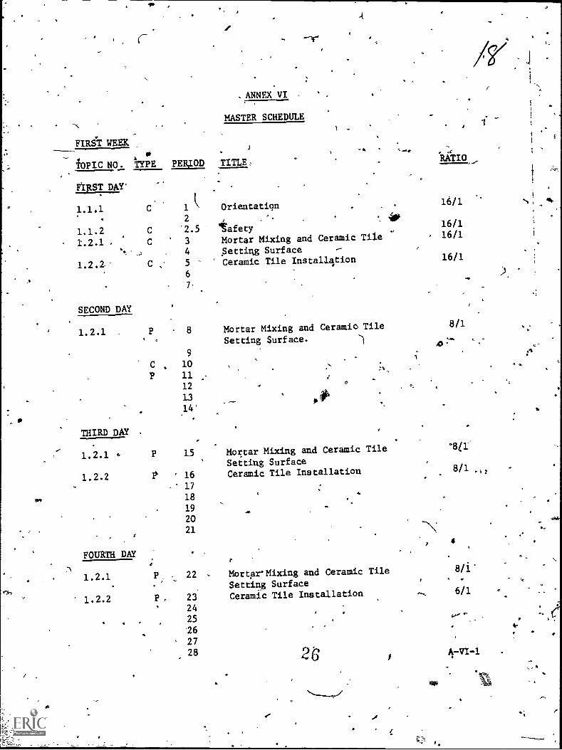
ANNEX VI -
MASTER SCHEDULE-,..
_1 .
FIRST WEEKJ.
TOPIC NO. TYPE PERIOD TITLE, ° RATIO
41ST DAY'
1.1.1 C 1 Orientation .
2 . '. '. 410
1.1.2 C .2.5 tafety
1.2.1. C 3 Mortar Mixing and Ceramic Tile
't _., 4 Setting Surface -
1.2.2.- C 5 Ceramic Tile Installation
6
7-
SECOND DAY
1.2.1 P 8 Mortar Mixing and Ceramic Tile. , Setting surf ace.
94)
C 10..-,
P 11 -
.s.-.,
i
12..
THIRD DAY .
16/1 %.
.16/116/1 i
16/1
8/1
13
14',07#1
15 Mortar Mixing and Ceramic Tile
Setting Surface
P ' 16 Ceramic Tile Installation
' 17
18
19
20
21
..
FOURTH DAY
4
1.2.1 - 22 MortarMixing and Ceramic Tile 8/l.
Setting Surface,
1.2.2 P. 23 Ceramic Tile Installation 6/1
2425
C
'264.
2728 4-VI-1
I
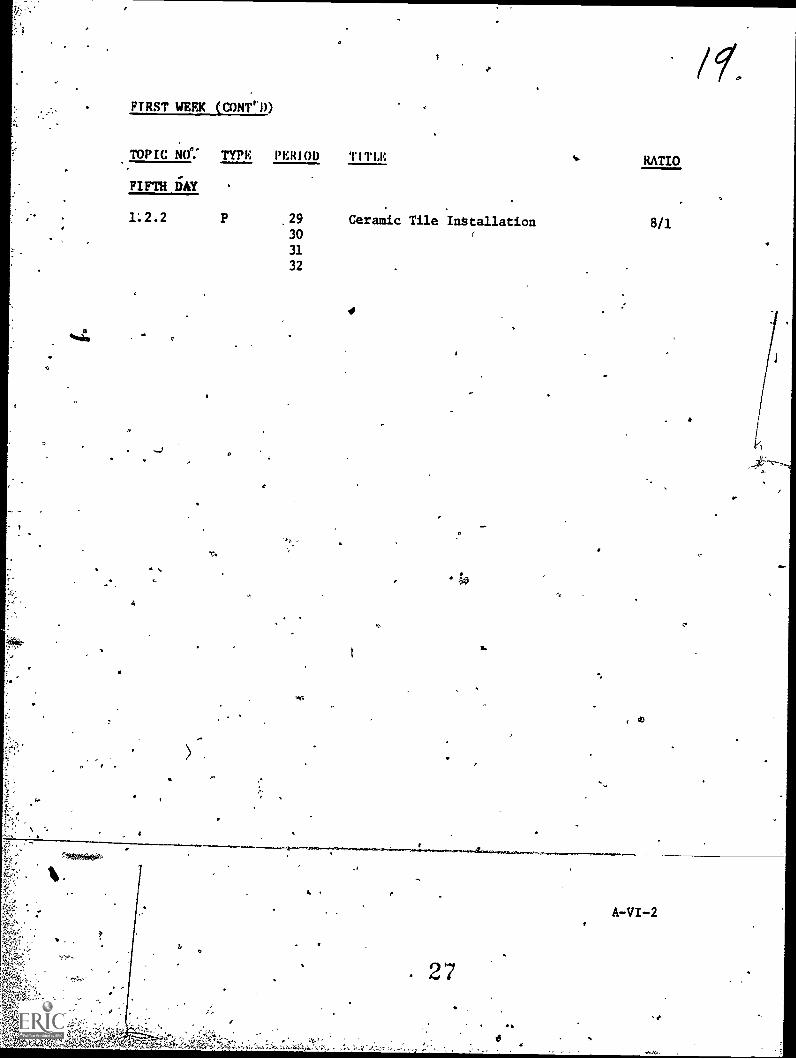
FIRST WEEK (CONTD)
TOPIC NO TYPE PERIOD TITLE RATIO
FIFTH DAY
1.2.2 P 29 Ceramic Tile Installation 8/130 r
31
32
4
r,.
0
4.
. 27
I.
A-VI-2
r
91°
1
..zeick/57 sdo.c&MODIFICATIONS
of this publication has (have) been deleted in
adapting this tateirial for inclusion in the "Trial Implementation of a
Model System to Provide Military Curriculum
and Technical Education." Deleted material
Materials for Use in vocational
involves extensive use of
02)
military iorms, procedures, systems, etc. and was not considered appropriate
for use in vocational and technical education.
4
Cz
A

O.
6
SI SCBT 167.1 BU IG 1.1.2
NAVAL CONSTRUCTION TRAINING CENTERPORT HUENEME, CALIFORNIA 93043
SPECIAL CONSTRUCTION BATTALION TRAINING (SCBT) 167-.1
Classification: Unclassified
Topic: Safety 4
Average Time: 0.5 Periods (Class)
Instructional Materials:
A. Texts: None.
- B. References:
1. NAVCONSTRACENINST 5400.4, (current series)"Organization Manual of NAVCONSTRACEN".
2. "Safety Practices for Shore Activities",NAVMAT P5100, (Jan 1973).
C. Tools, Equipment andMaterials: None.
D. Training Aids and` Devices:
1. Film.
a. GIF-001, "The Gift of Life", (18 min.).
E. Training Aids Equipment:
1 16mmmovie projector.
23
Terminal Objective: Upon completion of this unit thestudent will have reported to Builder School, receivedthe school orientation and safety proCedures required tocomplete the assigned course of instruction as a SCBTstudent.
Enabling pbjectives: Upon' completion of this topic thestudent will be able to report accidents or fire, andstate the safety practices that will be enforced in theschool.
Criterion Test: The student will answer orallyspecific questions pertaining to the method of reportingand fighting fires as established by NAVCOpSTRACENand CBC regulations,.and-will conform to the safetypolicies for 'the duration ofshis assignment to BuilderSchools.' ' At
Homework: None.
(1 of 4)
O
30

OUTLINE Of INSTRUCTION
.eI. Iniroductiom to the Lesson:
A. Establish contact.
1. Name:
2.. Topic: Safety.
B. Establish readiness.
1. Purpose.
2. Assignment.
C. Establish effect.
1. Value.
a. Pass course.
b. Perform better old the job. 04,0
*D. Stift, learning objectives.
1. You will be able to answer orally specific 1. State information and
questions related to the methods of reporting materials necessary to guide
and fighting fires as established'by student.
HAVCONSTRACEN and CBC regulations and conformto the safety practices that will be enforced
in this school.
D. Overview.
INSTRUCTOR ACTIVITTSCBT 16,7,1 BU IC, 1.1:2
STUDENT ACTIVITY
"I.A. Introduce self and topic.
0'
I.E. Motivate student.
I.C. Bring out need and valueof material being presented.
2. Ask questions.,
3. Take notes.
31.
(2 of 4)
32

OUTLINE OF INSTRUCTION
CI. Presentation:
A. Safety,
1 1. Reporting accidents..
33
p
a
,,INSTRUCTOR ACTIVITY
a. Class safety man. 1.a. Pick safety sand andexplain job.
b. Instructor.
cl School director... .
11. First aid when appropriate.
2. Fire safety.
a. Evacuation routes.
. Repdrting fires.
c. Fighting fire.
(1) Location of extinguishers*
3. Field safety. A.3. Introduce film.
a. Show film: GIF-001, "The Gift of* Life." ' a. Discuss key points
to look for.
(1, SCBT 167.1 BU IC 1.1.2
STUDENT ACTIVITY
Discusettilm highlights.
O
b.. Show film.
3.b. Lead disCussion.
1. Ask questions.
2. , Stress safety.
4
3.b. Participate indiscussion - askquestions as decessary!
(3 of 4)
0
tt
n.

OUTLINE OF INSTRUCTION
III. Application:
A. Discussion.
rv. -Summary:
INSTRUCTOR ACTIVITYSCBT 167.1 BU 1.1.2
STUDENT ACTIVITY
MA" 'Questions to be III.A. Answer and askdeveloped by the instructor. questions.
A. 'Safety. 6Mkt
.-..
-4. Reporting accidenf ,
. ,
2. Fire safety. 'Y 0 .
3. Field safety.
V. Test:
-*A. None.
V
35.
a
(4 of 4)
a
o.
1
.4 "0 7
1
02

I .
IN
NAVAL CONSTRUCTION TRAINING CENTERPORT HUENEME, CALIFORNIA 93043
.SPECIAL CONSTRUCTION-BATTALION TRAIN/NG.COURSE (SCBT) 167.1
Classification: Unclassified
Topic: Mortar Mixing and Ceramic Tile .
Setting Surface.
Average Time: 3 Periods (Class) 7 Periods (Pract)
Instructional Materials:
A. Texts:c414.
i. Builder 3 & 2, NAVPERS 10648-F, Chapter 14.
B. References:
1. Plastering Skills and Practices,Branden and Hartsel, American Technical
, Society.
C. Tools, Equiptent andMaterials:6 .1. Too/s.
Hoe, %Awns.
Shovel, flat nose.
Trowel, plastering. ,
d. Hawk.
e. Darby..
. .
SCBT 167... P.': 'I': -
Terminal Objective: Upon completion of thiSunit thestudent will have completed a ceramic tile project in-volving mortar preparation, surface preparation, tilelayOut planning, tile Setting, tile cutting and thegrouting bf tile joints. Procedure, standards andcondition for all work will be set forth in the dis-
abling objectives of indiiridual topics.
Enabling Objectives: Upon completion of this-topic thestudent will be able to mix mortar by hand and by usingthe 6 cubic foot mortar mixer, and prepare a concretemasonry wall to receive ceramic tile. All work is to bedone by following procedures in accordance with JobSheets SCBT 167.1 BU JS 1.2.1.1., Mortar Mixing by Hand.SCBT 167.1 BU JS Operating-the 6 Cubic FootMortar Mixer, and SCBT 167.1 BU JS 1.2.1.3, Tile SdttingBed Application. The mixed mortar must have the, con-sistency required to be applied to masonry surfaces, andthe prepared tile setting bed surface must be smooth andplumb to 1 /$r of an inch. ' Required job sheets will beprdvided for student use.
Criterion Test: The student will mix mortar by hand andby using the 6 cubic foot mortar mixer, and prepare aconcrete masonry wall to receive ceramic tile. Themixed mortar will have the consistency required to beapplied to a mason4ry surface,_andlthe prepared tile set-ting bed surface will be'smooth and plumb to within1/8 of an inch.
7
(1 of 14) .
38

g..
f. Straightvedge.
Jg. Rake
h. Level, hand
4
i. Measuring box, 1 cubic foqt
Pail
Float, wood
,2. Equipment.
a. Mortar box.
44
Homework: None
ite
b. 6 cubic foot mortar mixer
.4:26
SOT 167.1 BU'fd 1.2.1
4
c c. Georgia buggyN . .
'-, .
a. Mortar boat. P
NN\\\3. Materials.
, a. Sand
lit': 'Lime
D. Training Aids and Device&l,
1. Film
a. Lath and Plaster (22 min.)American Gypsum Company.
2. Locally Prepared Materials.
a. "Job Sheets.
(2 of 14)
4
40

r
.t.
(
SCBT 167.1 BUMortar Mixing
SCBT 167.1 BUOperating theMortar Mixer.
iS
by Hand
JS 1.2.1.2,6 cubic foot
SCBT 167.1 BU JS 1.2.1.3,Tile Setting Bed Application
b. Sample.
(1) Hawk
(2) Darby
(3) Rake
(4) Straight edge
(5) tTrowel, plastering
E. Training Aids .Equipment.0
1. 16 mm projector..t.
2. Movie screen.
O (3 of 14)
It
SCBT 167.1,BU IG 1.2.1
A
42_
-
OUTLINE OF INSTRUCTION
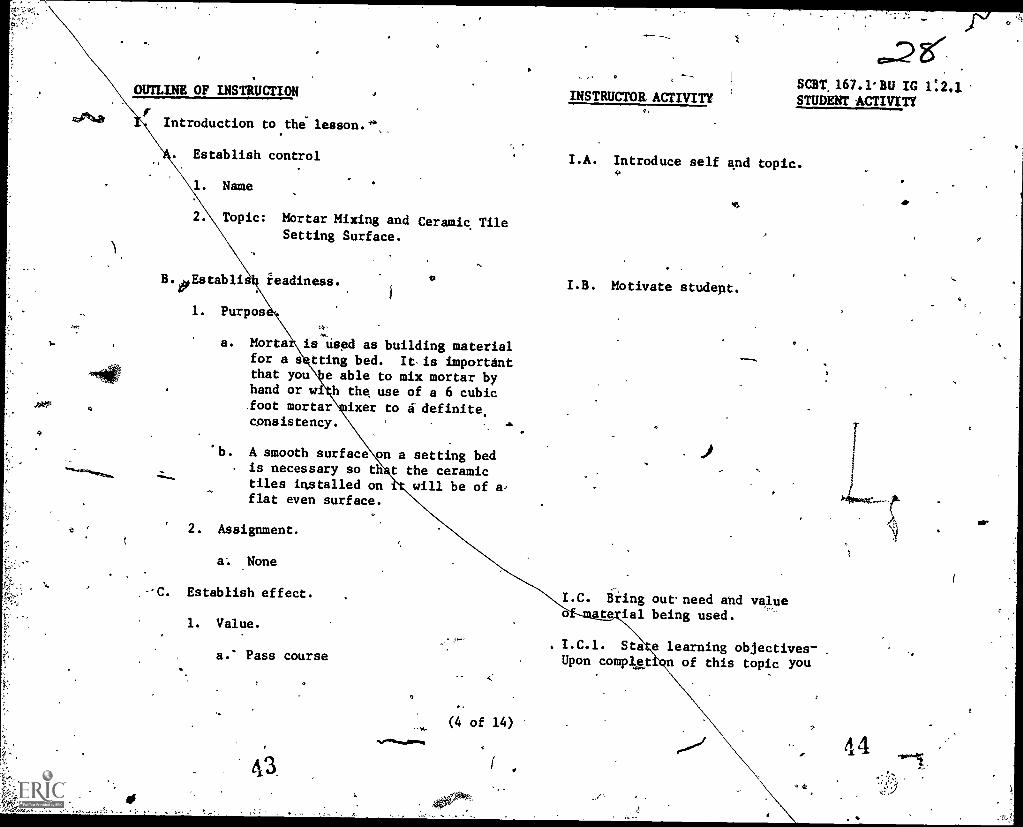
Introduction to the lesson.44
INSTRUCTOR ACTIVITYSOT 167.1 BU IC 1:2.3.STUDENT ACTIVITY
Establish control I.A. Introduce self and topic.9
1. Name
Topic: Mortar Mixing and Ceramic TileSetting Surface.
readiness.
1. Purpos
a. Mortafor a sthat youhand or wifoot mortar
consistency.
is used as building materialtting bed. It-is importante able to mix mortar byh the use of a 6 cubic
ixer to a definite
'b. A smooth surfaceis necessary so thtiles installed onflat even surface.
on a setting bedt the ceramic
will be of a,
I.B. Motivate student.
I.C. Bring outneed and valuet ial being used.
I.C.1. Staa.' Pass course Upon complet
e learning objectives-.
n of this topic you
(4 of 14)
4 4
rA
Or

. r
OUTLINE OF INSTRUCTION
b. Perform better on the job.
c. Get advanced.
d. Be a better builder.'
D. 'Overview:
1. Job Sheet.
a. Followlinstructors presentation onjob sheet for reinforcement.
b. 'Job sheets are to help clarify doubt-ful areas in the field.
2. Safety precautionj.n working with lime.
3. Ask questions anytime - raise yourhand and bd recognized.
II. Presentation.
A. Introduce job sheets.
1. SOET 167.1 BU JS 1.2.1.1, Mortar Mixing by.,Hand.
(5 of 14)Noe.,
SCR 167.1 BU IG 1.2.1
INSTRUCTOR ACTIVITY
will be able to mix mortarby hand and with the useof the,6 cubic fdot mortarmixer, and prepare ceramictile setting surface.
II.A. Hand out jobsheets.
(fi
STUDENT ACTIVITY
46
h.
OUTLINE OF INSTRUCtTON
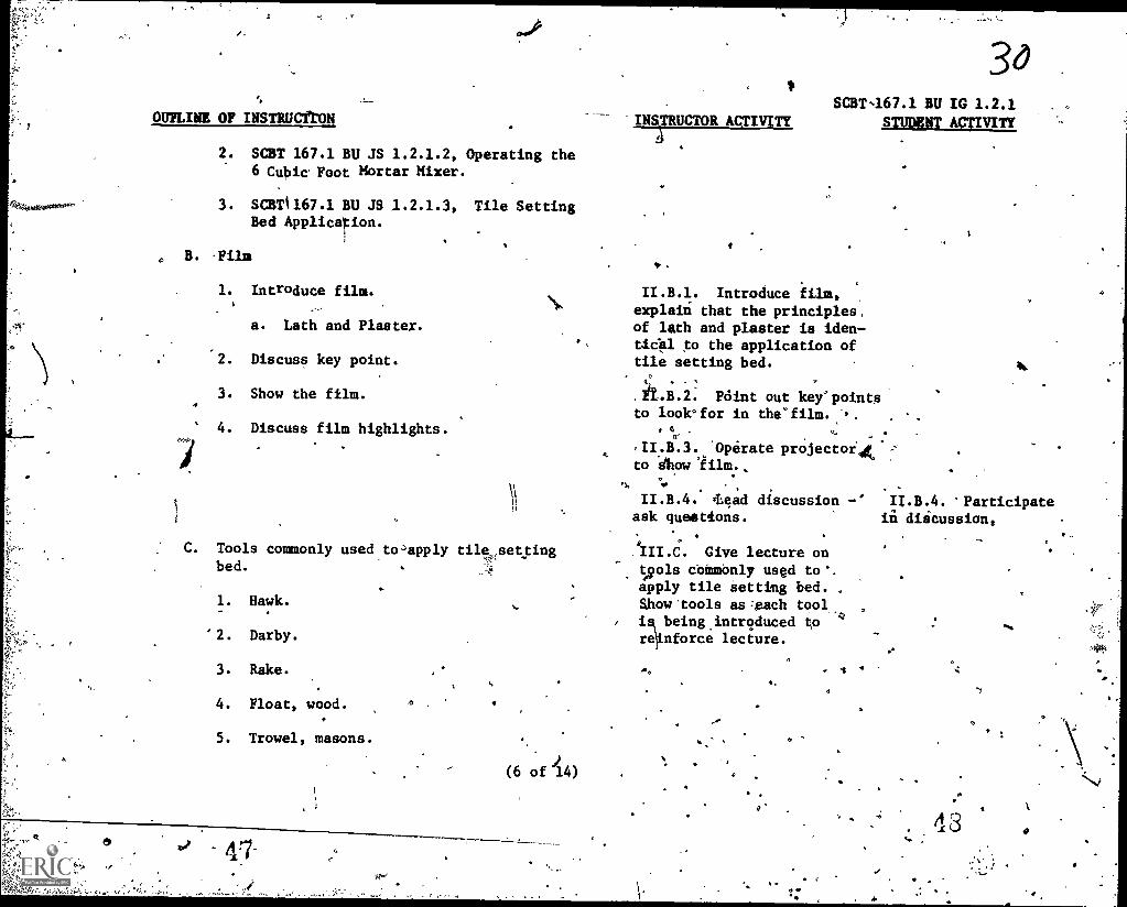
2. SCBT 167.1 BU JS 1.2.1.2,6 Cubic Foot Mortar Mixer.
3. SCBTI167.1 BU JS 1.2.1.3,Bed Application.
B. -Film
Operating the
Tile Setting
1. Introduce film.I
a. Lath and Plaster.
4a.
2. Discuss key point.
3. Show the film.4
4. Discuss film highlights.
C. Tools commonly used toapply tile,,sectingti
bed.
1. Hawk.
'2. Darby.
3. Rake.
4. Float, wood.
5. Trowel, masons.
(6 of 14)
INSTRUCTOR ACTIVITY
30SCBT467.1 BU IG 1.2.1
STUDENT ACTIVITY
II.B.1. Introduce film,explain that the principles,of lath and plaster is iden-tical to the application oftile setting bed.
t, '
Fi.B.2. Point out key' pointsto look°for in thefilm..,.
.
II.B.3. Operate projector4(to show
o.
II.B.4. .Lead discussion -° 11.8.4. 'Participatein discussion,ask queatfons.
AMC. Give lecture ons9ols commonly used to*.apply tile setting bed.Show.tools as =Beach tool.
isbeing.introduced tore nforce lecture.
."7
43r

OUTLINE OF INSTRUCTION
D.4
Steps of Procedure.
1. Mortar preparation by hand.
a. Prepare for mortar' mixing.
(1) Mortar box.
(2), Water
(3) Mortar ingredients.
(a) Lime
(4) Sand
(4) Mixing tools.
(a) Shovel, flat
(b) Hoe, masons.
b. Place dry mix in mortar box.
nose.
(1) Sand
(2) Lite
c. Mix mortar.
(1) Uniform color of mixA.
d. Add water.
e. Check mortar fbr consistency.
'dr
/-INSTRUCTOR ACTIVITY
(7 of 14)
3/SCBT 167:1 BU IG 1.2.1
STUDENT ACTIVITY 7II.D. Take class out tothe field - call studentattention to Job Sheet
SCBT 167.1 BUDS 1.2.1.1
II:D.1.a. Select; and
supervise four students ti
to mix mortar by hand.Simulate actual condi-tion by using lime apdsand vice cemeqt, limeand sand.
'
II.D. Turn to job'sheet and fo3low iI-struction.
If selecteddo a good job in mixingthe mortar. If not,observe mixing proceddresclosely.
4
50.

OUTLINE OF INSTRUCTION
(1) Too dry.
Too wet.
f. Clean up.
(1) Wash down
(24' Oil'.
(3) Store morta(box and tools.is
2. Mortar preparation using the '6 cubic II.D.2. Cali.student II.D.2. Turn to job sheefoot mortar mixer: /
attention to Job Sheet 4- and follow presentation.,
SCBT 167.1 EU JS 1.2.1.2a. Introduce th'e6 cubic foot mortar
SCBT 167.1 BU IC 1.2:1INSTRUCTOR
STUDENT ACTIVITY
a.
mixer.
be Preitart - check mixer.
(1) Check' oil )
CheCkluel
(3) Lubricate moVingiparts.
(4) SpraySpray inside,and outside of'drum with.water. ,
c. Start mixer.%
(P. Set choke to start posion.
(2) .Disengage clutch.
(8 of 14)If
N
5 2

1
OUTLINE OF INSTRUCTION
(3) Insert pull rope in-slot onpulley and wr4, itround clock-wise..
(4) Pull sharply on th rope.
(5) Shut off choke when engine starts.:
4 ,
es
33SCBT 167.1 BU IC 1.2.1
INSTRUCTOR ACTIVITY STUDENT ACTIVITY,
'd. Engage clutch. -.
e. Discharge water fiom drum., 4,- -
(1) With one hand firmly,graspingthe discharge handleand the'other
y hand on the locking leve', pull/ 4
ush discharge lever toward theischarge side of the drum.
(2) After water is discharged, pulldischarge lever back and-lock.
f. Charge the mixer.
(1) Add water.
(2) Add lime.
(3) Add sand.
1'
(4f Mix until lime mortar isuniform in color. ,
(9 of 14)
53 ,
o
f 4.4
II.D.21f. Explain that this mixis for/ training purpose and thatin'an/actual mixing of mortar,cement, lime and.sand areusedvice/lime andsand.
54
'sr
-. ,
* °
a. SCBT 167.1 BU IG 1.2.1, ....,
OUTLINE OF INSTRUCTION INSTRUCTOR ACTIVITY STUDENT ACTIVITY. .
%.
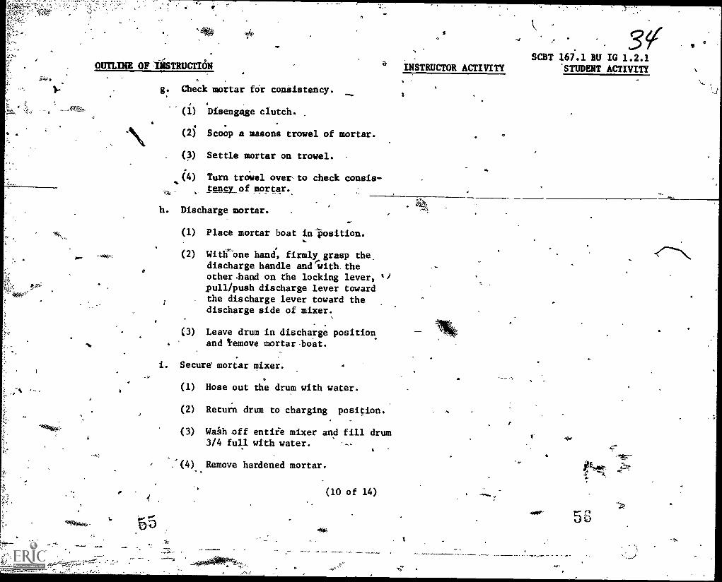
V- g. Check mortar for consistency....... 1
(1) Disengage clutch..
(2) Scoop a masons trowel of mortar. .
(3) Settle mortar on trowel.
(4) Turn trowel over to check consis-tency of mortar. .
Jo.
h. Discharge mortar.
(1) Place mortar boat in position.
(2) With'one hand, firmly grasp the.
discharge handle anewith, theother .hand on the locking lever, 41pull /push discharge lever towardthe discharge lever toward thedischarge side of mixer.
(3) Leave drum in discharge positionand 'remove mortar.boat.
i. Secure' mortar mixer.
(1) Hose out the drum with water.
(2) Return drum to charging position. s
(3) Waih off entire mixer and fill drum3/4 full with water. ti
(4) Remove hardened mortar.
(10 of 14)
1.. Jo
OUTLINE OF INSTRUCTION
o.SCBT 167.1 BU IC 1.2.1
-INSTRUCTOR ACTIVITY STUDENT ACTIVITY
O
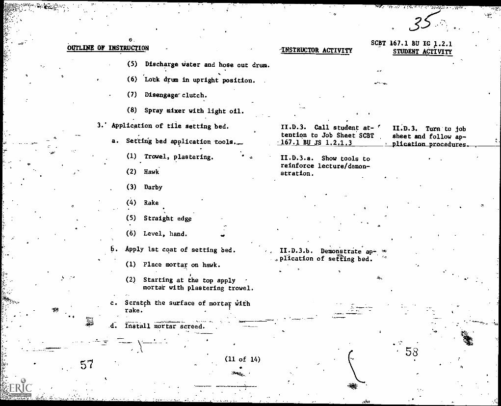
(5) Discharge water and hose out drum.
(6) Lotk drum in upright position.
(7) Disengageclutch.
(8) Spray mixer with light oil.
3.' Application of tile setting bed.
a. Setting bed application tools.
(1) Trowel, plastering.
(2) Hawk
(3) Darby
(4) Rake
(5) Straight edge
(6) Level, hand.
6. Apply 1st coat of setting bed.
(1) Place mortar on hawk.
(2) Starting at the top applymortar with plastering trowel.
c. Scratch the surface of mortar Withrake.
d. Install mortar screed.
57
II.D.3. Call student at- II.D.3. Turn'to jobtention to Job Sheet SCBT sheet and follow ap-167.1 BU JS 1.2.1.3 plication procedures .
II.D.3.a. Show tools toreinforce lecture/demon-stration.
a
II.D.3.b. Demonstrate ap-, "0(.plication of se Ling bed.
58ti

OUTLINE OF INSTRUCTION
(1) Starting at the top run-a line-of mortar screed 3/4" thick and3 ,.. 4 inches wide.
(2) Use hand level and a straightedge, plumb and cut the screedto 3/8" thicknese.'"
13) Run another mortar screed atthe other-end of the wall.
.
(4) At 3 foot intervarun asesmanyecreedsas necessary.
e. 'Apply Mortar between- he screeds.,
.(1) Apply Mortar between thescreeds, start at the top and.40
.working downward. #
(2) Strike off excess portion withthe straight edge on thiscreeds.
(3)* Use darby to finish.
Note: 'One of .the most important steps for- 11.11-.-3.3(3)- Read statementtiling 'successfully is that the wall ifii-jote to emphasize thesurface must be flatzand smooth.:Cer=--importance of this task.
rfsid- and will not bend.with the,contodAp. Tiling uneven, ,
wavy or flexiide --surfaces will cause''tile to crack.
INSTRUCTOR ACTIVITYSCBT 167.1 BU IG
STUDENT ACTIVITY
59
(12 of 14)
p
A
of
GO

O
OUTLINE OF INSTRUCTION
III. Application4
A. Student practice.
1. Mixing mortar by hand.f -
2. Mixing mortar with the 6 cubicfoot.tixer,
3. L21E:telling tile.setting bed.
IV: Summary -,
A. 7"Miortar ingredients.
1. Sand
2. Lime
3. Cement.
B. Mortar mixing.4
I
1. Hand
2. -6 cubic foot mortar mixer.
C. Mortar
1. Consistency.
D. Tools
1. Plastering trowel
2. Hawk
(13 of
. .
INSTRUCTOR ACTIVITY
.
SCBT 167.1 BU IC 1.2.1STUDENT ACTIVITY
III.A. Assign studeni:to mortar mixing tasks,issue tools, assign workarea.
III.A.1. Be..availableto show, as*1st andsupervise\
O
4
Student practice.
4
t
OR,
4
62
lY
OUTLINE OF INSTRUCTION INSTRUCTOR ACTIVITY
4
3. Darby
4. Rake
5, Straight edge.
a, 6. Hand _level.
E. Setting bed application
1. Prepare mortar.
2. Apply' scratch coat.
3. Apply setting bed.
V. Test:,
A. The student will perform CriterJon Test.
63.(14 of 14)
SCBT 167.1 BU IC 1.2.1
STUDENT ACTIVITY /
6 '
,\
SCer 167.1 BU JS 1.2.1.1
NAVAL CONSTRUCTION TRAINING CENTERPORT HUENEME, C4LIFORNIA 93043
SPECIAL CONSTRUCTION BATTALION TRAINING (SCAT) 167.1
JOB SHEET
Title: -Mortar Mixing by lien0
Introduction: This job sheet is to guide you in mixing mortar by hand.
Toolsv'Equipment and Material.:
1. Tools.
a. 1 cubic foot measuring box.
b. Square nose shovel.
c. Mortar hoe.
d. Bucket.
2. Equipment.
a. Mortar box
3. Materials.
a. Lime
b.. Sand
c. Water
procedures:
1. Prepare for mortar mixing.
a. Locate mortar box in the proximity of job site.
b. Have source of water close to the box.
c. Have lime and sand close to the box.
d. Gather tools fothe job.
(1) Square nose shovel.
(2) Mortar hoe.
(3) 1 cubic foot measuring box.
(1" of 2)
G5
V

'
SCBT 167.1 BU JS 1.2.1x1k
(49 Bucket
2. Placdry ingredients into mortar box.
Ia. Three cubic font of sand at one end of the box.
Place a sack of lime on the sand.
c. Place one (1) cubic foot of sand over the °lime.
Note: In normal condition cement, lime and sand are used.
3. Mix dry inredients.
a. Use short choppy strokes with the mortar hoe, tting allthe way to the bottom and moving the ingredie to theother end of the box.
b. Repeat this process until the mixed ingredients are Uni-orm in color..
4. Adi dater to mix.
a. dd water a little 3x a time.
b. -Mix material simultaneously until desired'moitar consis-tency is acquired.
5. Check mix.for consistency;
a. Scoop trowel full of mortar.
b. Tap trowel gently on mortar box to settle the mortar.
c. Turn trowel upside down to check for mortar consistency.
6. Check work with the instructor.
a. Mortar consistency must be within test specified.to Step 5.
7. Clean up tools, equipment and area.
a. Wash tools with water.
b. Apply light coat of oil on tools.
c. Wash out mortar box Of all mortar deposits.
d. Store mortar box o its side; slightly tipped to keep dry.
e. Wash down work are
(2 of 2)
Ge
0

SCBT 167.1 BU JS 1.2.1.2
NAVAL CONSTRUCTION TRAINING SCHOOLPORT HUENEME, CALIFORNIA 93043
SPECIAL CONSTRUCTION BATTALION TRAINING COURSE (SCBT) 167*1
JOB SHEET )
Title: Operating the'6 cubic. foot Mortar Mixer.
Introduction:. This job sheet is to guide you in the operation of the6 cubic foot mortar mixer.
- C
Tools, Equipment and Materials:
./
1. Tools.
a. One cubic foot measuring box.
b. Square nose shovel.
c. Bucket.
2. Equipmen4
a. 6 cubic foot mortar mixer.
b. Mortar boat.
3. Materials
a. Fine sand (masonry)
b. Lime
c. Water
Procedures:
1. Prestart check mixer.
a. Check oiX fuel level.
b.- Lutificate all moving parts whiqhcontain a grease fitting.4
c. Spray inside and outside of drum With water.
(1) To prevent mortar from sticking to drum.
0 s
2. Start' mixer.
a. Set choke .to start pobition by turning it clockwise.
b. Disengage clutch by pushing down clutch lever.
(1 of 3)
k,
4

,/SCBT 167.] BU Mi 4.2.1.2
c. insert.knaton pull rope in slot on the pulley and wrap, ropearound clockwise.
d. Pull sharply on the rope to start engine.
(1) If engine fails to start, repeat steps 2c and 2d.
e. Shut off, choke when engine starts.
it Engage clutch.
a. Raise clu*tch lever upward until it locks in position.
4. Discharge excess water from d rum.
72-,
a. Firmly grasp discharge handle with one hand, using the otherhand to raise locking lever, push or pull discharge lever to-ward discharge side of drum.
b. When discharge is complete, pull discharge lever back in lockposition. If drukfails;to lock automatically, position leveri0into locking grooV?manually.
5. Charge mixer.
a. Load the mixing drum-with 3 cubic foot masonry sand, 1 cubicfoot cement and 13 pounds lime.
Note: Blades should be engaged when Charging mixer.o.
-6b. Mix dry ingredients until mix is uniform in color (a minimum
of one minute.)
c. Add dater slowly until mix is uniformly wet - :do not add toomuch water before checking for consistency.
d. Mix mortar for at least three minutes before checking for con-.
sistency.
6. Check mortar consis,tency (workability).
a. Disengage clutch to stop blades.
b. Scoop some mortar from the drum with a masons trowel.
c. Test the mortar--mortar must be soft and plastic..
Note: Mortar mix consistency will be determined .by the instructor.tie
(2-of .3) 63 .
.
3.
Il I.
(TP
A
d
.

L
7. Discharge mortar.
,SCBT 167.1 BU JS 1.2.1.2
a. Discharge mortar into mortar boat by following procedures in,
step 4. , .
=b. Leave,drum in.discharge position and remove mortar boat..
.
i - 8, Secure mortar mixer.
a. Hose 'down drum with water.
=
b. Return drum to charge position.o
c. With the blades turning, wash off the entire. mixer and filldrum 314 full with water.
d. Remqve hardened mortar with a wire brush.
e.' Discharge water and hose out drum.
f. Disengage clutch and stop engine,,
g. Spray mixer down with a light weight oil 'to prevent rusting.,
k..'Note: The above information is for mixing actual cement Mortar,for training purpose a lime mortar is tb Be mixed. Thefollowing instructions will be used in charging themixer..
Chargemixer with lime mortar batch.
a. With the operating clutch engage and with the'dium filled with
7.'51 I,-
three gallons of water, slowly a one sack of limeand mix4-until lime and Mater make
cs,
b. Slowly charge the mixer with three cubic feet of masonry sand.
c. Mix thelime mortar unoil it becomes uniform in color, checkwith the instructor for desired consistency.'
(3 of 3)
ti
r

SCBT 167.1 BU JS 1.2.1.3
NAVAL CONSTRUCTION TRAINING CENTERPORT HUENEME, CALIFORNIA 93043
SPECIAL CONSTRUCTION BATTALION TRAINING (SCBT) 167.1
JOB SHEET
Title: Tile Setting Bed Application
Introduction: This job sheet is to guide you in the application of tilesetting bed to a concrete masonry wall surface.
`Tools, Equipment and Materials:
1. Tools.
.a.b Wood float.
b. Masons trowel.
c. Hawk.
d. Straight edge:
e: Darby.
f. Rake.
g. Level, hand.
2. Equipment...*
a. Mortar boat.
b. Mortar board.
3. Materials.
a. Sand and lime mortar. )
Procedures:
1. Apply first cbat of setting bed.
. a. Scoop up some previously mixed mortar with masons trowel andplace it on the hawk. ,j
r
b.. Starting at the top of'the wall apply mortar to the mu wallsurface - with the masons trowel, push the aortar off the hawkand onto the-wall, spreading'the mortar with the trowel.
2. Scratch or mar the surface of mortar with a rake.
a. Wait until the mort ar becomes hard and yet not dry.
(1 of 2)
SCBT 167.1IBU JS 1.2.1.3
3: Install mortar vreed.
a. Starting.at the top, run a line of mortar screed 3 or 4 inches'wide down one side of the wall.
B. Use wood float to flatten the surface for mortar screed.
c. Use hand level and straight edge, plumb and cut the screedto 3/8 inch thick.
d. Run another mortar screed atthe,other end of.the wall.
e. At three foot intervals, run as many screed as necessary.
Note: Screeds must be within 1/8 inch of being plumb.
4. Apply mortar between the screeds.
a. Start at the top and work downward.
b. Using the screed as a guide, strike off excess mortar withthe straight edge.
c. Use darby to finish.
5. Check work with the instructor.
a. The;finiihed tile setting bed surface must be plumbtothe 1/8 of an inch.
(2 of 2)

Is
SCBT 167.1 BU IC 1.2.2
NAVAL CONSTRUCTION TRAINING CENTER,
PORT MENEM, CALIFORNIA 93043
SPECIAL CONSTRUCTION BATTALION TRAINING COURSE (SCBT) 167.1
Classification: Unclassified
Title: Ceramic.
Tile Installation Terminal Objectives: Upon completion of this unit thestudent will have completed,a ceramic tile project id-
`Average Time: 3 Periods (Class) 17 Periods (Pract) volving mortar preparation, surface preparation, tile v
..\;. .,.. layout planning, tile setting, tile cutting and theInstructional Materials: - ,grouting of tile joints. Ytobeduies, standards and -4...iof
A. Texts:condttions.for all work will be set forth in the en-abling objectives of individual topics.
. e1. Builder 3 & 2, NAVPERS106487F, Chapter 14
.
1. Plastering Skills and Practices? Brandonand Hartsel, American Technical Society.
2. Handbook.for Ceramic Tile Installation,Tile Council of America.
. References:
3. Glazed Ceramic Tile, No.105 15M-7/75Standard Brands Paint Company, Inc. I
4. Complete.Do-It-Yourself Manual, Reader's-' Digest.
C. Tools, Equipint and Materials:
1. Tools
/2
. Enabling Objectives: bpon.completion.of.thi% topic thestudent will.be able to install ceramic tile (field tile,
JBase.tile, cap' tile, inside Corper tile and quarry tile)over plaster, s 'he'et rock, wood and concrete masonry wall
surface with apprppriate.tile adIesive, lay out.for tile...setting-and grout the tile project by following job sheetprocedures. The comOleted ceramic tile projLt must be .t%
level, plumb, each tile must be individually seated,tile spacing will be within 1/16"of lug spacing.and thetile grout must be wighoutvoid. Job Sheet SCBT 167.1BU JS 1.2.2.1 Installing Ceramic Tile, will be providld
(1 of 13)
for student use. . -
I
Criterion Test: The student willt4nstall ceramic tile(field'tile, base tile, cap tilei'-insele dorner-tile,'and quariy tile)* on a niasontli wall surface. The coil-pleted ceramic tile P.rojetewill be level and plumb, -each tile will be individually seated, tile spacing will
be, within T/164.of lug spacing, and the'tile grout mustbe .without void.
. .

0
-v7SCBT 167.1 BU IG 1.2.2
c. Level hand.
. tile cutter.
e. Tile nipper.
f. Squeegee.
g. Sponge.
h. Joint sikking tool.
i. Beating block.
j. Notched trowel.
k. iBucket.
2. Equipment..
a. Mortar boat.
3. MaterialS.,
a. Ceramic tile.
.
(1) Field tile
,(2) Outside corner tile.
(3) Cap tile:.
(4) Base tile.
b. Ltme.
(2 of 13)
f
0
a b
c. Sand
d. Quarry -tile °
D. Trainiig Aids*and Devices:
1. Slide presentation.
SCBT 167.1 BU IG 1.2.2
a. How to Get Better Clay Tile Installation(16 min.) Tile Council of Amercia, Inc.
2. Locally Pieliared Materials.
a. Jog Sheet.
A
:(1) SCBT-167.1 BUInstalling Ceramic Tile. 0
16
b: Display Board.
° '(1) Ceramic tile set on water-resistantdrywall with exposed portion oforganic tile adhesive on the surface.I
(2) Three types of glazed tile.
(a) Hattie glazed finish.
(b Bisque (plain).
(c) Glazed.
c. Samples.
(1) Tiles.
(3 of 13)A,
O
t-1,7
AA'

./
(a) .,Glazed wall tile.
(b) Quarry tile
1 Waxed
2 Non waxed.
(c) Mosai6.;
1 Paper backing.
2-- Fiber backing
3 Rubber backing.
(2) Common variety of tiles.o
(a) Field tile.
(b) Outside corner tile.
(c) 'Inside corner tile.
( d) Cap tile.
, (e) Base tile.
(3) Tools.'
73
(a) Tile cutter
(b) Tile nipper.
(c) Squeegee.
(d) Spofige.
a.
(4 of 13)*-,6
.
SCBT ST IG 1.2.2
A

so
E.
(e) Joint-striking tool
(f) Beating block."
1° Ceramic tile.
t2 Quarry tile.
Notched trowel
Bucket
Fainting trowel
Hawk..
Training Aids Equipment.
1. Slide projector
/. Jape player.
'3. Movie screen.
(5 of 13)
SCUT 167.1 BU
0
)
.
OUTLINE OF INSTRUCTION'
Introduction to the.lesso'n..
A. Establish contact.
I. Nark.
2. Topic: Ceramic Tile Installation.
B. Establish readiness.
.1. Purpose
.Ceiamic tiles are used extensivelyas wall finishings in bathrooms,-shbwers, and galleys in the.bat-tenons. It would be -o your ad-.,vantage to learn to 4o this well.
2. Assignmer4.
a. Although there-is no assignment,review Job Sheet SCBT 167.1BU JS
C. Establish effect.
Q.
'z' ,,' , ..--- ' .!' ;. i t'- .'.
, 1 . -=. ..:. ',, .. .....:s. . -.',...1.:" - ,'.,;Z: .'
1. Value
1NSTRLCTOR ACTIVITY
. I.A. Introduce ,self andtopic.
SCBT 167.1 AU IG 1.2.2STUDENT ACTIVITY
I.B. Motivate §tudent bystating the purpose.°
I.C.1. Biing out need and. value of material being pre-
a: Pass'. course sentedI
b. Perform better,on the job.
c. Get advanced ,
d. Be a better.builder.
7
4.
.e
(6 -of 13).)
83
C.,
OUTLINE OF INSTRUCTION
D. Overview
01: Job Sheet
I-
.
a. Follow Instructor's demonstrationon the job sheet.
b. Job sheet is to helryou in thefield exercise. When in doubt-,refer tc4$1.1.
2. Safety precautions with tile cutting tools.
3. Ask questionsanytime - raise your handand be recognized.
4. Objectives of this lesson.
II.. Presentation
A. .Introduce Job Sheet
1. SCBT 167.1 BU JS 1.2.2.1,Ceramic Tile.
B. Slide presentation..
Installing
. ,
1. Introduce slide presentation.
a. How to GetBetterClay Ti i In-stallation,
2._ Discuss key'points.
3. Show, slide preseaatiori.$ -
*.
(.
A
lbw
9(7 of 13)
14
SCBT 167.1 IJ IG 1.2.2INSTRUCTOR ACTIVITY STUDENT ACTIVITY
State learning objectives.
I.D.1. Upon completion of this C3
topic you will be able to installceramic tile on concrete masonrywall surface.
II.A.1. 'Hand out job'sheet.
JI.B.1: Introduce slide.presentation.
.
Point out keypoints to look for in slidepresentation.
85
0'
OUTLINE OF INSTRUCTION
Note: Tape does,not have signal, for change.This presentation must be previewed to co-ordinate with narration.
4. Discuss slide presentation highlights.
C.Q Tools commonly used to install ceramic tile.,.
1. Tile cutter.
2: Tile nipper.
3. Pointing trowel.
4. Squeegee.
5. Sponge.
6. Joint striking tool.
7. Beating block.
8. Notchi.4 trowel.
D.- Types of tile
.- 1. Glazed wall tire.
Quarry, tile:
f3. Mosaic tile.
1E. Varities of tile.
1. Field tile.
2. Outside corner tile.
on
(8 of 13)
INSTRUCTOR AcriviTySCBT 167.1 BU IG 1.2.2
STUDENT ACTIVITY
II.B.3. Operate slide pro-jector and tape player.
II.B.4. Lead discussion - II.B.4. Participateask questions. in discsion.
-II.C. Give lecture'on tools.Show tools to reififnt'ce
lecture.'
II.D. Give lecture on typesof tile - shdw samples oftile and display board ontiles to reinforce lecture.
ti
' II.E. Give lediure on thevarities-of tiles - show
variety,samples to reinforceleture.,
a
81

OUTLINE OF INSTRUCTION
3. .Inside corner tile
4. Cap tile.
5. Base tile.
F. Common tile adhesives.
1: Cement
2. Epoxy.
3. Organic.
G. Steps, of procedure.
1. Lay out for tile placement.
. 83
0
a. Determine length of wall to betiled.
a
tib, Calculate width of end tiles.
(1) Divide length of root') by 4 1/4". to determine number of fUll
. tiles needed.
(2) Add 4 1/4" to the remainder instep b (1) and divide this \SLIM by2 for width f end tiles.
Note: End tiles Oust be greaterthan one half the width of a tile.
11.4
c. Lay out vertical guide lines fortile placement.
(9 of 13)
INSTRUCTOR ACTIVITY
II.F. Give lecture onadhesives- use displayhoardln organic tile '
adhesives on dry wall toreinforce lecture.
SCBT 167.1 BU IC 1.2.2STUDENT ACTIVITY
a II.G.1. Give lecture/ ILO Turn to yourdemonstration on layout job sheet.technique - uAe chalk-board to demonstrate cal-culating technique to re-inforce lecture. Callstudent attention to JobSheet SCBT 167.1 BU JS1.2.2.1.
4
od
t89
a
sr)
O

O
OUTLINE OF INSTRUCTION
ai
( ) Divide the number ofin step b (1) by 2.is involved, drop to
number.
full tilesIf half a tilethe next lower
2) Multiply this number by 4 1/4".
(3) Add width of end tile acquired instep b (2) .t.0 this product.-
(4) From one qad of the wall to be til-ed, measure and mark dimension'acquired in step c (3).
(5) Plumb this mark to desired heightof.the top tile.
(6) Locate highest point of elevation.
(7). Measure pp the,wall to the heightof tiles to tit applied:
(8) Draw a level line for the top ofthe tile.
INSTRUCTOR ACTIVITYSCBT 167.1 BU IG 1.2.2
STUDENT ACTIVITY
II.G.l.c.(6) Explain thatcircumstances dictates thehighest or the lowest pointof elevation.
tr.
2. Lay out a row of tile as a dry run similarto chasing out the bond in concrete masonry work.
3. ,Preparation and application of wall tiles.
a. Soak tiles.
(1) In a bucket of water for at least1/2 hour prior.to application.
99I
(10 of 13)
4
Take,student out tofield practice site and givelecture/demonstration onsurface preparation.
91
OUTLINE OF 'INSTRUCTION
b. Apply pure coat (neat cement).
(1) Allow water (cement) lime mix tostand for 20 minutes.
(2) Remix to creamy cobsistericy.
.110 Apply pure coat over area wheretile could be laid immediately.
c. Lay out-vertical guide lines:
, d. lay out horizontal guide lines.
(1) Lay out itor top of second course
°
_ of_rdie.
SCBT 167.1 BLI/IG 1.2.2INSTRUCTOR' ACTIVITY STUDENT ACTIVITY
ti
e: Set first course of field-tile to thehorizontal guide line. . \
(1) Place the first two tiles withthe inside edge against thevertical guide line and press
6
intopure coat.
(2) ,Set the remaining course a/
tiles.
(3) Measure, cut, and set the twoend tiles.
(4) Check entir course for level.
f. Apply remaining courses of tile.,
9392 (11 of 13)
04

OUTLINE OF INSTRUCTION
(1) Use the first course as guideand lay up three courses of tile.
(2) Check tor level and seat tile asneeded with the use of beatingblock.
(3) Before laying up three morecourses, use trowel to cutthrough neat coat to settingbed mortar for control joint.
g. Apply- setting- bed -on floor-
h. Apply neat cement.
i. Install quarry (fiber) tile.
(1) In this manner apply tileAas required..
Grout joints.
ay' Mix white cement and waterto a thick paste.
(2) 'Use 'sponge or your hand towork grout into Joint.
(3) Allowout to set for 20 -30 minutes and clean entiresurface with clean sponge,water, and sqUeegee.
(12 Of 13)
INSTRUCTOR ACTIVITYSCBT 167.1 BU IG 1.2.2
STUDENT ACTIVITY
95
OUTLINE OE INSTRUCTION
It'. Application
A. student.practic6..
IV. Summary.
A. *pea of tile
1. Glazed wall tile.
2. Quarry tile
3. Mosaic tile.
B. Variety 'of tile.
1.. Field tile.
2. Outside corner tile.
Iniide corner tile.
'4. ;dap Nile.
A
V. Test:
.*: Student will,perform Criteriongestt.
as stated. °.
.. (13 of.15)
0
I
INSTRUCTOR ACTIVITYSCBT 167.1 BU IG 1.2.2
STUDENT ACTIVITY
11. ,
III.A. Assign student to III.A. Student practicework site, issue ,tools andmaterials.
III.A.1. Be available toshow, assist and supervise.
N_
0
'.
SCBT 167.1 BU JS 1.2.2.1
NAVAL CONSTRUCTION.TRAIkING CENTER. PORT HUENEME, CALIFORNIA 93043,
SPECIAL CONSTRUCTION aAITATION TRAINING (SCBT) 67.1
JOB SHEET
TItle: Installing Ceramic Tile:
4
Introduction: This job sheet is to guide you in installing ceramic tileto concrete masonry wall and quarry tile to the floor.
Tools, Equipment and Materials:
1. Tools.t
a. Tile cutter.
b., Tile nipper.
s. ,Squeegee.
1d.. Sponge.
e. Joint striking tool.'
f. Beating block
(1) Ceramic tile
(2) Quarry tile.
k
g, Notched trowel
Bucket.:.
i. Pointing trowel
Hawk.
k. Measuring tape.
1. Level, hand.
2. Equipment.
a. Mortar boat.
3. Materials.
a. Lime mortar.
b. Ceramic. tile.
t-
ts
(1 of 4)
93
I'
4

IA
(1)' Field tile:
(2) Outsidecornr tile.
,(3) Cap tile.1
(4) Base tile..
c. Quarry tile. ,
Procedures:
(1. Lay out for tile placement.
a. Determine length'cf wall to be tiled.
b.7,Calculate width of end tiles.
(1) Dpide length of room by 4'I/2""to determine number offull tiles:needed.
,-(2) AlC...4 1/2" to the remainder from 'step b(1) and- divide
this sum by 219r Width.6f.erid tiles.,-4
Note: End tiles must.begreatec than spe hal.f the iiAdth of
,
c. Lay'out-'Vertical guide line for tile placement.
SCBT 167.1 BU JS 1.2.2.1
sn t
L
1 (1)
half a tile is involved,, drop to the next lowerfullnumber.
Divide the number of full tiles is steiiii(1) by 2. . If
(2) Multiply this number; -by 4 1A7.
(3) Add width of end tile acquired in step b(2) to this,product. '
,
(4f From one end'of the wall to be tiled, measure and markdimension acquired in step c3). ,
(5) Plumb this mark to the desired height of the top tile.
Locate highest pointof elevation.4.%
(7) Measure.up the wall to the height...of tiles to bapplied.
(8) Ilrawa level lice for the-top of the tile.
r !
/ of.4
99

SOT 167.1 BU IC 1.24.1. ,
2. Lay out a row of tile as a dry run - similar to chasing out thebond in concrete masonry work. .t
3. Preparation and application of tile.
a. Soak tile.
(1) In a bucket Of water for at least 1/2 hour prior toapplication.
The Apply pure coat.
.(1) Allow water (cement) lime mix to stand for 0 minutes.
(2) Remix to .creamy COnatteacy.
(3) Apply pure coat over aila where tile could be appliedimmediately.
c. Lay out vertical guide line.
d. Lay out horizontal guide line.
(1) One full .1.112-above the base tile from the highest pointof elevation:
- , ,
'(2) Draw level line for top.of second course of tile.
. .
e. Set first course of field tile to borizontaitguide_lines_._
(17 Place the first two tiles with the inside- edge against5' the vertical-guide line, the top ofthe tiles aligned tothe horizontal guideline and press the into pure coat. .
(2) Set;the remaining course ortiles.
(3) Measure,r.cur and set the two end tiles in place.
(4) Check entire-course for level.
I
f. .ApplYnext three courses Of tile.
,(I) .Use first course-as guide.
-,(27 Check for level and seat tile as needed with the use.of IJ
beating block.
, (3) Use trowel to cut through next neat coat to setting bedmortar for.control joint.
4
(3 of 4).
i1)0
I
g. Apply base tile.
' h. Apply course of tile as needed.
SCBT 167.1 BU JS 1.2.2.1
1(1) Cut through neat coot to setting bed mortar every threecourse of tile.
i. Apply setting bed.on floor.
j Apply neat cement.
k. Install quarry (floor) tile.
(1) Use beating block for quarry tile and seat tile.3. Grout tile -joints.
a. Mix white cement and water
(1) To thick paste.
b. Use sponge and./or hand to work groUt into joint.
c. Allow grout to set for - 30 minutes and clean entiresurface with clean sponge,4Water.and squeegee,
5.---1Check-s4ork-with-insructOr.
a. Tile work must be level le +.1/16". .- ....
b. _Tile must be itdividually seated.. ,,
c. :rile joint's spacing must be within 1/16" of required spec-,iiications..
d. Grouting oftile joints must 'be without void.
0
1
of
.14
15'
0 4
Al

CHAPTER 14
PLASTERING, STUCCOING AND TILE SETTING ,
o PLASTER and STUCCO, like concrete, areconstruction materials which are applied in aplastic, condition; and which harden in placeafter being applied. The fundamental differencebetween plaster and stucco is simply oneoflocation; if the material is used internally it iscallei plaster; if it is used externally it iscalled stucco. .
Again like concrete, Ale active ingredientin plaster is, a CEMENTITIOUS material, orBINDER. If plaster is applied in more than onelayer, the top layer is called the FINISH COATand each of the lower layers is a BASE COAT,Plaster for a finish coat may consist of binder,alone; however, most finish coat plaster andmost base coat plaster contains AGGREGATEas well as binder. Plaster aggregate may con-sist of sand or one of several other materials.The aggregate in plaSter, like the aggregate inconcrete, provides additional and stability.
-You can see that plaster tsbItta large extentvery much like Concrete. The principal, differ-
i' ence lieS imthe fact that concrete can, because4 ----cf-its-highCompresswe strengl-ff,Wusea as a
load-bearing structural material. The consid-erably lower strength of ,plaster has, up untilnow, Confined its use principally to finish.HoAtever, experiments are being conducted withan eye to developing plasters with load-bearingstrength.
A plaster mix, like a Concrete mix, is madeplastic for application by the addition of waterto the dry ingredients. Again like concrete, itis a. reaction of the binder to the water calledHYDRATION that causes the mix to harden.
Q PLASTER INGREDIENTS
'The binders most commonly used for plasterare GYPSUM, LIME, and PORTLAND QEMENT.Because gypsum plaster should not be exposedto free water or severe moisture conditions, itis usually confined to interior use. Lime andportland cement plaster mayb be used 'both in-ternal4 and,externally:.
386
GYPSUM PLASTER
Gypsum is a' naturally occurring sediinen-tary gray, white, or pink rock. The naturalrock is crush'ed and then heated, to high tem-perature, a process (known as CALCINING)which drives off about three-quarters of theWATER OF CRYSTALLIZATION which `formsabout 20 percent by weight of the rock in anatural state. The calcined material is thenground 'to a fine powder, to which certain AD'-DITWES are added' to control set, stabilization,aria other physiial or chemical characteristics.
Fora type of gypsum plaster callad KEENEr4.CEMENT the crushed gypsum rock is heateduntil nearly all of the water d crystallizationis dritell,ioff.,, To offset slow- setting caused byabsence of so much WATER OF HYDRATION,an Englishman named Keene patented a processof adding alum as an accelerator. The result-ing plaster, called Keene's cement, produces avery hard, fine-textured finish coat.
The removal of water of crystallization fromnatural ,gypsum-Ts al)E-HYDRATION Vocess.In the course of setting, mixing water (iater ofhydration) added to the mix REHYDRATES withthe gypsum, thus causing RECRYSTALLIZA-
Recrystailization causes the plaster toharden.,
There are four common types, of gypsumbasecoat plasters, as follows:
GYPSUM ftAT plaster is gypsum plasterwithout aggregate, intended for mixing withaggregate on the job.
GYPSUM READY-MIXED plaster consistsof gypsum an6 ordinary mineral aggregate; atthe job it requires addition of only the water.
GYPSUM WOOD- FIBERED plaster 'consistsof calcined gypsum combined with not less than0.75, percent by weight of non-staining woodfibers. It may be used as. is or mixed with1. part sand to produce base coats'of superiorstrength and hardness.
GYPSUM BOND plaster is so-called becauseit is desigAd to bond to properly prepared
a
102 ,
k
61,Chapter 14 PLASTERING, STUCCOING AND TILE SETTING
monolithic concrete. It consists essentially ofcalcined gypsum mixed with from 2 to 5 per-cent of lime by weight.
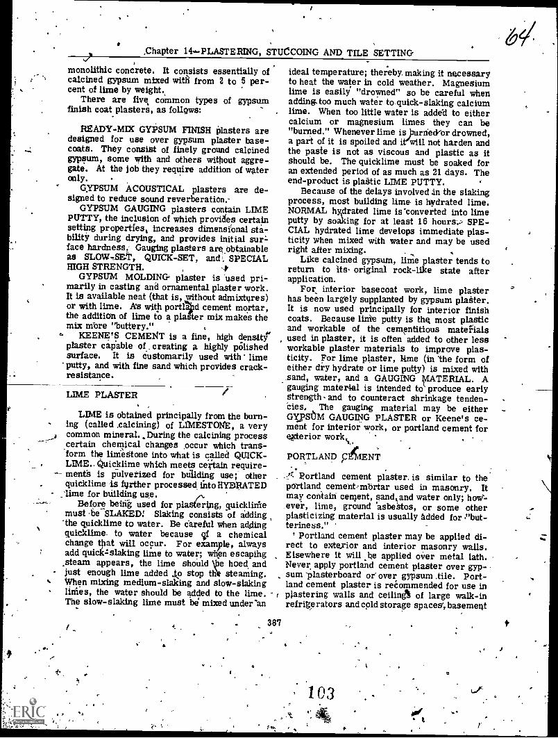
There are fives common types of gypsumfinish coat plasters, as follows:
READY-MIX GYPSUM FINISH plasters aredesigned for use over gypsum plaster base-coats. They consist of finely ground calcinedgypsum, some with and others without aggre-gate. At the job they require addition of wateronly.
GYPSUM ACOUSTICAL plasters are de-signed to reduce sound reverberation.'
GYPSUM GAUGING plasters contain LIMEPUTTY, the inclusion of which provides certainsetting properties, increases dimensional sta-bility during drying, and provides initial sur-face hardness. Gauging plasters are,Obtainableas now,sat, QUICK-SET, andi. SPECIALHIGH STRENGTH.
GYPSUM MOLDING- plaster is used pri-marily in casting and ornamental plaster work.It is available neat (that is, without admixtures)or with lime. A's with portid cement mortar,the addition of lime to a pla er mix makes themix more "buttery."
ICEENE'S CEMENT is a fine, high densityplaster capable of. creating a highly pOlishedsurface. It is customarily used with lime
'putty, and with fine sand which provides crack-resistance.
LIME PLASTER
LIME is obtained principally from the burn-ing (called .calcining) of LIMESTONE, a verycommon mineral. _During the calcining process.certain chemical changes pccur which trans-form the limeStone into what is called QUICK-LIME.. Quicklime which meets certain require-
- meets is pulverized for building use; otherquicklime further processed. into HYDRATED
_lime for building use.Before being used for plastering, quicklithe
must be- SLAKED! Slaking consists of adding'the quicklime to water. Be careful when addingquicklime_ to water because if a chemicalchange that will occur. For example, alwaysadd quick:slaking lime to water; when escaping.steam appears, the lime should \pe hoed, andjust enough lime added ..to stop till* steaming.
% When mixing medium-slaking and slow-slakingfillies, the water should be added to the lime.The slow-slaking lime must be mixed under'an
. 38'7
ideal temperature; thereby. making it necessaryto heat the water in cold weather. Magnesiumlime is easily "drowned" so be careful whenadding.too much water to quick-slaking calciumlime. When too little water is added to eithercalcium or magnesium limes they can be"burned." Whenever lime is Journe&or drowned,a part of it is spoiled and i will not harden andthe paste is not as viscous and plastic as itShould be. The quicklime must be soaked foran extended period of as much as 21 days. Theend-product is plaStic LIME PUTTY.
Because of the delays involved in the slakingprocess, most building lima is hydrated lime.NORMAL hydrated lime is-converted into limeputty by soaking for at least 16 hours.? SPE-CIAL hydrated lime develops immediate plas-ticity when mixed with water and may be usedright after mixing.
Like calcined gypsum, lime plaster tends toreturn to its- original rock-like state afterapplication.
For interior basecoat work, lime plasterhas been largely supplanted by gypsum plaiter.It is now used principally for interior finishcoats. Because lithe putty is the most plasticand workable of the cementitious materialsused in plaster, it is often added to other lessworkable plaster materials to improve plas-ticity. For lime plaster, lime (in 'the form ofeither dry hydrate or lime putty) is mixed withsand, water, and a GAUGING lvIATEFtIAL. Agauging material is intended to produce earlyStrength- and to counteract shrinkage tenden-cies. The gauging material may be eitherGYPSUM GAUGING PLASTER or Keene's ce-ment for interior work, or partland cement foregerior workk.
PORTLAND c6ENT
Portland cement plaster. is similar to thepatland cement-mbrtar used in masonry. Itmay contain cement, sand, and water only; how-ever, lime, ground 'asbestos, or some otherplasticizing material is usually added for Pbut-teriness."
Portland cement plaster may be applied di-rect to exterior and interior masonry walls.Elsewhere it will _he applied over metal lath.Never apply portland cement plaster over gyp-sum 'plasterboard or over gypsum .tile. Port-land cement plaster is recommended for use inplastering walls and ceiling% of large walk-inrefrigerators and cold storage spaces', basement
-t
103

V
BUILDER 3 & 2
spaces, tpilets, showers, and similar areaswhere an extra hard or highly water-resistantsurface is required.
AGGREGATE
The aggregates most commonly used inplaster are SAND, VERMICULITE, and PER-
Generally speaking, any sand retainedon the No. 4 sieve is too coarse to use in plas-ter, and only a small percentage of the mate-rial (about 5 percent) should pass the No. 200sieve.
Sand1
Sand for plaster, like sand for concrete;must be free of more than'a specified minimumof organic impurities and harmful chemicals.Certain tests for these impurities. and chemi-cals are conducted by qualified personnel. ....
Proper aggregate gradation influences plas-ter strength and workability, ,and likewise hasan effect on the tendency of the material toshrink or expand while setting. Fore sand in-tended for use in gypsum plaster, recommendedgradation is as follows: ,
Plaster strength is reduced if excessive fineaggregate material is present in a mix. The
p greater quantity of mixing water requirep rthsesthe water:cement ratio, thereby redu&ug thedry set density. The cementitious 'material be-comes overextended, because it must coat arelatively larger overall aggregate surface.
An excess of coarse adversely affects work-ability;" the mix becomes "harsh working" and,difficult to apply.
Plaster shrinkage during drying- ma becaused by mg, excess of either fine o coarse.Because an excess of fine increases aggre-gate total surface area, a larger quantity ofbinder paste, is needed to coat all particles.The mix becomes too rich in cementitious ma-terial, and it is the cementitious materialwhich is unstable after application. The en
' effect is much the same if there is .too muccoarse; in this case,-there is not enough fine tofill the voids between coarse particles, andmore cementitious material must be used tofill these voids. Again the result is a rich andrelatively unstable material.
Vermiculite
A
.
Sieve Size
Percentage Retainedby Weight
MinMax
No. 4 0No. 8 5 0No.,16 3.0 5No 30 65 30No. 50 95 .65No. 100 100 90
For sand intended for use in exterior plas-ter, recommended gradation is ads follows: ,
Sieve Size
Percentage Retainedby Weight
AMax Min
No. 4 0No. 8 10 .0 0No. 16 40 10
65 30`No. 50 90 70No. 100 100 " 95,
388
'4
VERMICULITE is aMICACEOUS mineral .meaning a mineral in which each particle isLAMINATED, or made up' oil- adjoining layer's.When vermiculite particles are, exposed to in-tense heat, steam forms between the layers soas to force them apart; this causes each par-ticle to increase, from 6 to 20 times in volume.The expanded material is soft and pliable, witha color varying between silver and gold.
For ordinary plaster work, vermiculite isused oniy with gypsum plaster therefore,general, only fort interior plastering. oracoustical plister, vermiculite is combinedwith a special acoustical binder.
Expanded vermiculite is manufactured infive types (I, U, Ili, IV, and V) according toparticle size. Only, type III is used in plaster-'ing. It is the lightest of the \standard plasteraggregates, weighing only front 6 to 10 lbs percu ft. The approximate dry weight of a cu ft of
gyps,um-vermiculite plaster is 50 to 55 lbs; 'the dry weight of a cu ft of comparable saved'plaster is 104 to 120 lbs.
For gypsum-Vermiculite plater ?hefollow.ing gradation for the vermiculite is recom-mended: t
104

66,hapter 14PLASTERING. STUCCOING AND TILE SETTING
Percentage Retainedby Volume
SieVe Size Max
No. 4No. 8
0. 10 0
No. 16 75 40No. 30 95 65NO. 50 98 75No. 100 100 90
'Perlite
Raw perlite is a vOlcanIc glass which, whenflash-roasted, expands to form frcitily particlesof irregular shape that contain countless minuteair Cells. Perlite ore is crushed ' and thenheated to high temperature; as the particlessoften,. combined water turns to steam. Thiscauses the particles to "pop," forminpa frothymass of lass bubbles 4 to 20 times the volumeof the raw particle. Thee process is calledEXPANDING; the color of expanded perliteranges from pearly white to grayish white.
Perlite is used with calcined gypsum orportland cement for interior plasteling; it isalso used withspecial binders for acousticalplaster. The approximate dry weight of a'cu ftof 1:2 gypsiim-perlite plaster is 50 to 55 lbs,or about half the weight of a cu ft of sand..plaster. ,
For gypsum - perlite plaster the recom--mended- gradation -for- the perlite-is-as follows:
Percentage Retainedby Volume
SieveSize Max klAin 4
No. 4 0No: 8 5 0'
No. t6 60 10No. 30 95 45No. 50 98- 75No. 100 100 88
Other'Aggregates
Although sand, vermiculite, and perlite con-stitute the, great preponderance of plastertag-gregate, certain other materials are used.Wood f r may be added to neat gypsum plas-ter`at thAtime of manufacture, to improv theworking qualities of the gypsum. PUMICE is a
naturally foe:Med volcanic glass similar to Per-lite, but heavier (28 to 32 lbs per cu ft, against7.5 to 15 lbs for perlite). The weight differen-tiaA gives perlite an economic advantage, andlimits the use. of pumice to localities nearwhere it is produced.
WATER
The mixing water in plastefperforms. twofunctions. First, it transfor -the dry ingre-.clients into a plastic,. workable m ; second; itcombines mechanically and /or chemically withthe binder to induce hardening. As is. the. casewith concrete, there is a maximum quantity ofwater Or unit of binder required for Completehydration, and an excess over this amount re-duces the plaster tiength below the maximumattainabie.
However, in all plaster mixing more wateris added than is necessary for complete hydra-titm of the bidder; the excess is necessary tobring the mix to workable . consistency. Theamount that must be added for workability de-pends on the character and age of the binder,the method of application, the drying conditions,and the tendency of the base to absorb water.it porous masonry base, for example, will drawa good deal of water out of a, plaster mix. Ifthis reduces the water content of the mix,. be-low the maximum requitred, for hydration, in-complete curing will result..
As a general rule, only the amount of waterrequired to attain workability is added'to a mix,and no More. The water should be clan andfresh, and it must contain no diss21ved chemi-.
cgs which might accelerate or retard the set.Water previously used to wash plastering toolsshould never be used for mixing plaster; such-water may contain particles of set plaster whichmay accelerate setting. Stagnant water shouldbe avoided, because such water may containorganic material which may retard setting andpossibly cause staining.
389
PLASTER BASES
For plastering there must be. a continuoussurface to which the plaster can J.:el applied andto whidh it will cling; such a surface is called aplaster BASE. A continuous concrete or ma-sonry surface may serve as a base without thefiecessity for fuAlier treatment.
For plaster planes such as those defined bythe inner edges,ofistuds or the lower edges of
105.1

I
44.
. BUILDER 3 81 2
.4
67
joists, however, base material must he in-stalled to form a continuous surface which willspan the spaces between the. structural mem'ben. Material.of this kind is called LATH.Lath formerly consisted of thin wooden' stripswhich were nailed at right angles, to the, studsorpists. Narrow openings were left betweendjacent laths, through which-the plaster gene-rated to form a KEY which bonded thepldster
the lath. , /.a,- -In modern plastering, /wooden lath .has beenalmost entirely superseded by GYPSUM lathand METAL lath.
GYPSUM LATH- *
4
Gypsum lath is made by sandwiching a coreof gypsum plaiter between two sheets of afibrous, absorbent paper. For PLAIN {non-perforated) gypsum lath, bond is effected byabsorption or suction of the face of the lath.This absorption draws in some of the cementi-tibus material in the ',raster. As-.the pl ersets, particles of this absorbed material iniodic with nonabsorbed particles in the plaster.For PERFORATED (punched with 3/4-in. holes4 in. apart) gyps= plaster, Suction bond issupplemented by keys formed by plaster Whichpenetrates the holes.
Standard sheet size. for gypsum lath, is16 in. x 48 ih., except in the western U.S.,where it is 16 1/5 in. x 48 in. LONG LENGTHgypsum lath comes 16 or 24 'in; wide and anylength up to 12 ft as ordered. Available thick- ,
nesses are 3/8 in. and 1/2 in. INSULATING- gypsum lath has aluminum foil bonded to the
back "of. the .sheet; this material provides ther-mal insulation and also serves agsa vapor-4.barrier.
Gypsum' lath is hailed to studs, joists, orfurring. strips' with 1.1/8-in. to 1-1/4 in. flat-headed-GYPSUM LATH NAILS, 5 nails to eachstud, joist, or strip crossing. It may-(also beattached with powe-driyen 'Staples. ,
sheet metal perforated with openings of variousshapes. 'EXPANDED metal lath is manufac-tured: by, first cutting staggdred slits in a sheetand then expanding (stretching) the sheet toform the screen openings., RIB EXPANDEDmetal lath contains V-shaped metal ribs for-thepurpose of furring the, lath out from the surfadetowhidh it is attached. Ordinary unribbed ex-
, panded metal lath ilalled FLAT EXPANDED.
METAL LATH - \-
Metal lath consists essentially of a metalscreen. Bpncl is created by -keys formeh byplaster forded through the screen openings; asthe plaster hardens, it and the metal becomerigidly interlocked.
WIRE lath consists simply of wire screen,formed by weaving or welding intersectingwires together. SHEET metal' lath'consists of -t
Sr
Types of Flat Expanded Lath
DIAMOND MESH lath, suitable for alltYPesof ,plastering, comes in 24-in. x 96-in. and2'1-in..x 96- in. sheets.
SELF-FURRING DIAMOND MESH -containsDIMPLES which fur it out 1/4 in. from the sur-face 'to which it is attached. This lath may benailed to smooth concrete or masonry surfaces,or wrapped around structural steel, without thenecessity .fpr previous furring. It it widelyused for replastering old walls and ceilingswhen .the zemoval of the old plaster is not de-,sired. Standard sizes- are the same as fofdiamond mesh.
PAPER- BACKED DIAMOND MESH is de-signed to receive plaster applied 'by machine.
STUCCO MESH has larger openings thandiaxaond meSh; it is intended primarily for ex-terior plastering.
Types of Rib .Expanded Lath ' -
FLAT rib lath has rips 1/8 it deep; THREE-EIGHTHS/INCH rib lath has ribs 3/8 in. deep;and THREE-QUARTER INCH rib 4ath- has ribs3/4 in. deep. ta.ntlarct sheet Sizes'for flat andthree-eighths are the same as for diamondmesh. For three-quarter the widths are the
- same, but lengths of 120 in'. and 144 in. areavailable besides sp in.
Attachment of Metal Lath
Metal lathid nailed to vertical.wooden sup-ports (such as wall studs or wall furring strips)with 4d common nails. it is nailed to horizon-tal wooden supports (such as ceiling joists orceiling furring strips) with 1 ,1/2-in. barbed,roofing nails It..may also be attached to woodensupports with power-driven staples. For at-tachment to metal supports, tie wires are used.
LATHING ACCESSORIES
LATHING ACCESSORIES coisist of STRUC--VRAL COMPONENTS and MISCELLANEOUS
390
10G,
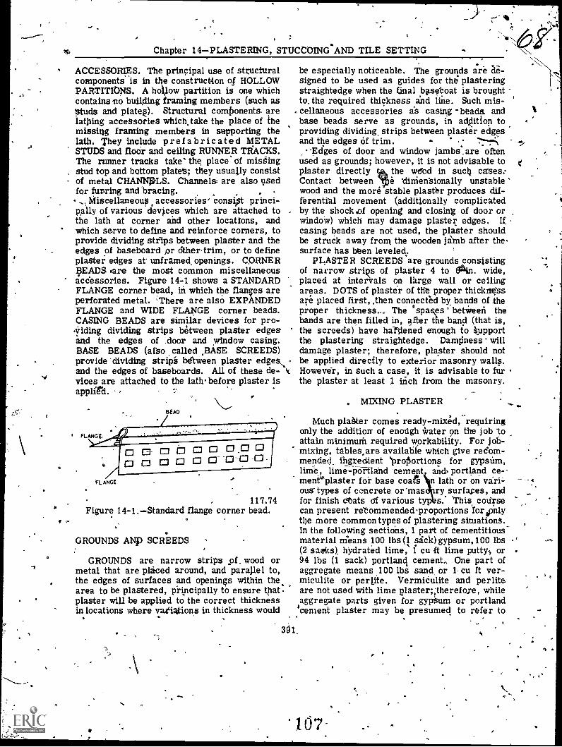
I
Chapter 14PLASTERING, STUCCO1NeAND TILE SETTING
ACCESSORIES. The principal use of structuralcomponents is in the construction of HOLLOWPARTITIONS. A ho low partition is one whichcontainsmo building framing members (such asStuds and plates). Structural comixinents arelathing accessories which, take the place of themissing framing members in supporting thelath. They include prefabricated METALSTUDS and floor and ceiling RUNNER TRACKS.The runner tracks take' the place of misdingstud top and bottom plates; they usually consistof metal CHANNPLS. Channels are also usedfor furring and bracing.,, Miscellaneous accessories' consist princi-
pally of various devices which are attached tothe lath at corner and other locations, andwhich serve to define and reinforce corners, toprovide dividing strips between plaster and theedges of baseboard pr Other-trim, or to defineplaster edges at unframed_ openings. CORNERBEADS rare the most common miscellaneousaccessories. Figure 14-1 shows a STANDARDFLANGE corner bead, in which the flanges areperforated metal. \There are alsO EXPANDEDFLANGE and WIDE FLANGE corner beads.CASING BEADS are similar devices for pro-v iding dividing strips between plaster edgesand the edges of ,door and window casing.BASE BEADS (also called ,BASE SCREEDS)provide dividing strip's bdtween plaster edges, rand the edges of baseboards. All of these de- cvices are attached to the lath' before plaster isapplied.
I ,
FLANGE
117.74Figure 14-1.Standard flange corner bead.
GROUNDS ANp SCREEDS
.be especially noticeable. The grounds are de-signed to be used as guides for the plasteringstraightedge when the final baseboat is broughtto. the required thickness and line. Such mis-cellaneous accessories as casing -beads. andbase beads serve as grounds, in addition toproviding dividing, strips between plaster edgesand the edges of trim.
Edges of door and window jambs _are oftenused as grounds; however, it is not advisable toplaster directly the wdbd in sucl4 cases:Contact between le 'dinientionally unstable 'wood and the more stable plaster produces dif-ferential movement (additionally complicatedby the shock ,of opening and closing of door orwindow) which may damage plaster edges. Ifcasing beads are not used, the plaster shouldbe struck away from the wooden janb after thesurface has been leveled.
PLASTERSCREEDS are grounds consistingof narrow strips of plaster 4 to Olin. wide,placed at intervals on large wall or ceilingareas. DOTS of plaster of the proper thickngssare placed first, then connected by bands of theproper thickness... The °spaces ' between thebands are then filled in, after the band (that is,the screeds) have hardened enough to kupportthe plastering straightedge. Dampness willdamage plaster; therefore, plaster should notbe applied directly to exterior masonry walls.However, in Such a case, it, is advisable to furthe plaster at least 1 inch from the masonry.
. MIXING PLASTER. -
Much plaster comes ready-mixed, requiringonly the addition of enough Water on the job toattain minimum required workability. For job-mixing, tables are available which give red'orn-mended ingredient `ProiSortions for gypsum,
lime-pia-land cement and portland ce--ment'plaster for base coats n lath or on vari-ous-types of concrete or'mas ry surfaces, andfor finish eriats Of various t s. this codrsecan present retommendedproportions forsonlythe more commontypes of plastering situationS.In the following sections, 1 part of cementitious-material means 100 lbs sick) gypsum,100 lbs(2 saeks), hydrated lime, 1 cu ft lime putty-, or94 lbs (1 sack) portland, cement., One part ofaggregate means 100 lbs sand, or 1 cu ft ver-miculite or perlite. Vermiculite and perlite.are not used with lime plaster;;therefore, whileaggregate parts given for gypSum or portlandcement plaster may be presumed to refer to
GROUNDS are narrow strips _of. wood ormetal that are placed around, and parallel to,the edges of surfaces and openings within thearea to be plastered, principally to ensure thatplaster will be applied to the correct thicknessin locations where variations in thickness would
391.
'I.
BUILDER 3 do 2
either sand or vermiculltelperlite, aggregateparts given for lime plaster mean sand only.
BASE COAT PROPORTIONS
TWO -COAT plaster work consists of a singlebase coat and a finish .coat. THFtEEICOAT
I work consists of two base coats (the first calledthe SCRATCH coat, the second Uie BROWN
-coat) and a finish coat:Portland cement plaSter cannot ba applied to
a gypsum base. Lime plaster can in theory,but in practice only gypsum plaster is appliedto gypsiini lath as a base coat. or two-coatwork on gypsum lath, the recommended basecoat proportions for gypsum .,plaster are 1:2.5.
For two-coat work on a maspnry (using, thisterm to mean either monolithic concrete ormasonry) base the recommended base cdatpro-portions are as follows:
Gypsum' plaster: 1:3Lime plaster using hydrated lime: 1:7.5Lime plaster using lime putty: 1:3.5
Portland cement plaster is not used for two -notwork, and two-cdat work is not usually
done an metal lath.For the-coat work on gypsum lath the
recommended base coat proportions for gypsumplaster are: scratch coat 1:2, brown coat 1:3;or both coats 1:2.5.
For three-coat work on metal lath the rec-ommended base coat proportions are as follows:
Gypsum plaster: same as for three-coatwork on gypsuni lath
Lime plaster using hydrated lime: scratch1:6.7511brown 1:9
Lime plaster using lime putty: scratch 1:3,brown 1:4
Portland cement plaster: both coats 1:3 to1:5'
/ For three-coat work on a masonrecommended 'base coat proportions are asfollow 11:
Gypum plaster: both coats 1:3
ry base the
Portland cement plaster: both coats 1:3 to1:5
Lime plaster is not usually used for three-cat work on a masonry base.
FINISH COAT PROPORTIONS1
A lime finish may be applied over a lime,gypsum,.Or portland cement base coat; other
392
finishes; however, should be applied only tobasecbats containing the same cementitiousmaterial. A gypsum-vermiculite finish shouldbe applied only to a gypsumvermiculite base-coat.-
Finish coat proportions vary according towhether the surface is to be finished with aTROWEL or with a FLOAT. These tools aredescribed lat4r. The trowel attains a smoOthfinish; the float attains a finish of a desiredtexture.
For a trowel-finish coat using gypsum plas-ter the recommended proportions are 200 lbs ti
hydrated lime or 5 cu ft ,lime putty to 100 lbsgypsum gauging plaster. \
For a trowel-finish coat using lime-Keene'scement plaster the recommended proportionsare, for a medium-hard finish, 50 lbs hPratedlime or 100 lbs lime putty to 100 lbs Keene'scement. For a hard finish the recommendedproportions are 25 lbs hydrated lime dr. 50 lbslime putty to 100 lbs Keene's cement.
For a trowel-finish coat using lime-portlandcement plaster the recommended proportionsare 200 lbs hydrated lime 'or-5 cu ft lime puttyto 94 lbs portland cement.
For a finish coat using portland cement-sand plaster the recommended ingredient pro-ortions are 300 lbs sand to 94 lbs portland
cement. This plaster may be either trowled orMated. Hydrated lime up.,,to,,.10 percent byweight of the portland cement, or lime putty upto 25 percent of the volume of the portlandcement, may be added as a plasticizer.
For a trowel-finish coat using gypsum gaug-ing or gypsum neat plaster and vermiculiteaggregate the recommended proportions are1 cu ft vermiculite to 100 lbs plaster.
Recommended proportions for various typesof float-fihistrcoats are as follows:
Lime putty 2: Keene's cement 1.5: sand 4.5,by volume
Hydrated lime 1: gypsum gauging plaster 1.5:d 2.3, by weight
Hy ated lime 2: portland cement 1: sand2.5, by weight
Lime putty 1: sand 3, by volumeGypsum neat plaster 1: sand 2, by weight
PLASTER QUANTITY ESTIMATES
The total volume of plaster required for ajob is, of course, the product of the thicknessof the plaster times thee net area to be covered.
103
-
Chapter 14PLASTERING, STUCCOING AND TILE SETTING
Plaster specifications state a minimum thick-ness, which the plasterer must not go under,and Which he should likewise exceed as little aspossible, because a tendency to cracking in-creases with thickness. Specified minimumthickness for gypsum plaster on metal lath,wire lath, masonry/concrete walls and masonryceilings' is usually 5/8 in.; on gypsum lath it is1/2 in.; on monolithiC concrete ceilings it is3/8 in. or interior lime plaster on metal lath(3-coat work) the specified minimum thicknessis usually 7/8 in.; for exterior lime plaster onIdetal lath it is 1 in. For lime plaster on in-terior masonry walls/ceilings the minimumthickness is 5/8 in.; for exterior lime _plasteron masonry it is314-in. For lime plaster oninterior concrete ceilinge, the minimum thick-ness is 1/16 in. to 1/8 in.; on interior walls,5/8 in. For lime plaster on exterior concretethe minimum thicknes's is 3/4 in. For portlandcement plaster, either interior or exterior,recommended thicknesses are 3/8 in. for eachbase coat (3-coat work) and 1/8 in. for thefinish coat.
The YIELD for a given quantity of plastikingredients, like the yield for a given quantityof concrete ingredients, amounts to `the sum oLthe ABSOLUTE VOLUMES of the ingredients.'The absolute volumes of typical plaster ingre-dients are as follows:
100 lbs gypsum 0.) cu ff1 cu ft lime putty 0.26 cu ft100 lbs hydrated lime 0.64 cu ft100 lbs sand 0.61 cu ft 4,94 lbs portland cement . 0.48 cu ft
This list indicates that .(for example) 94 lbsof portland cement, which has a loose volumeof 1 cu ft, has an absolute volume (that is, asolid or exclusive-of-air-voids volume) of only0.48 cu ft. Therefore, 94 lbs Qf portland cementcontributes a volume of only 0.48 cu ft to aplaster (or concrete) mix.
The absolute volume,,Of the last ingredientthe water is -the samOas its "loose" volume:0.13 cu ft per gallon.
r'
Determining Yield.
Suppose now that you want to determine theyield of a plaster mix containing 1 part of gyp-sum plaster to 2.5 parts of sand. One part ofgypsum plaster -is ipo lbs, with an absolutevolume of 0.69 cu ft. Two and five-tenths parts
393
of sand means 250 'lbs of sand. Sand has an,absolute volume of 0.61 Cu ft per 100 lbs;therefore, the absolute volume of the sand is2.5 x 0.61, or 1.52 cu ft.
The water will contribute 0.13 cu ft of vol-ume to the mix for every galion of water added.For approximate yield calculations, you canassume that 8 gals of water will be used forevery 100 lbs of cementitious material. Thereare 100 lbs of gypsum plaster in question here,'which means 8 gals of water. The water vol-ume, then, will be 8 x 0.13,or 1.04 cu ft.
The. yield for a 1-sack batch of till's mix willbe the sum of the absolute volumes, or 0.69 cu ft(for the -gypsum) plus L52 cu it (for the sand)plus 1.04 cu ft (for the water), or 3.25' cu ft.
Estimating Ingredient Quantities4
Suppose that the plastering job is a wall witha net area of 160 sq ft, with a specified totalplaster thickness of 5/8 in. and a 'finish coatthickness of 1/16 in. You are doing two-coat
*mit (o ply a single base coat), and you want toestimate ingredient quantities fail the base coat.The thickness of the base coat'will be 5/8 in.minus 1/16 in., or 9/16 in., which equals about0.046 ft. The voluMe of plaster required forthe base coat, then, will be 160 x 0.046, or about7.36 cu ft.
The yield for a 1-sact batch is .25 cu ft;therefore, the job calls f r a batch th sacksto the number indicated by the value f x in theequation 1:3.25::x:7.36, or about 2.3 acks. Thenumber of parts of sand requ d equals thevalue of x in the equation 1:2.5:`2.3:x, or 5.75parts. There are 100 lbs bf sand in a "part,"and 100 lbs of gypsum in a sack. Therefore,for the base coat you will need 230 lbs of gyp-sum and 575 lbs of sand.
MIXING PLASTER BY HAND
Equipment for plaster mixing by hand con-sists of a flat, shallow-sided MIXING BOX anda hoe; the hoe usually has a perforated blade.Mixed plaster is transferred from the mixingbox to a MORTAR BOARD, similar to ttje oneused in bricklaying. Men applying plaster pickit up from the mortar hoard.
In hand mixing, the dry ingredients are firstplaced in the mixing box and thoroughly mixeduntil a uniform color is obtained. The pile isthen coned up and troughed, and the *crater ismixed in much as it is in hand concrete mixing.
9

0
0
BUILDER 3 & 2
Mixing is continued until the materials havebeen thoroughly blended and proper consistencyhas been attained. With experience a man ac-quires a "feel" for proper consistency. Mixingshould not be continued for more than 10 or 15minutes after the materials have been thor-oughly blended, because excessive agitationmay h;sten the rate of solution' of the cementi-tious material and thereby cause acceleratedset.
Finish-coat lime plaster is usually hand-mixed on a small 5 ft x 5 ft mortar boardcalled a FINISHING BOARD: If the lime usedis hydrated lime, it is first converted to limeputty by soaking in an equal - amount of waterfor 16 hours. In mixing the piaster, the limeputty is first formed into a ring on the finishingboard. Watei is then poured into the z=ing, andthe gypsum or Keene's cemept is then siftedinto the water to avoid lumping. The mix isallowed to stand for one minute, after which thematerials are thoroughly blended. Sand, if it istOe used, is then added and mixed in
MIXING PLASTER BY'MACHINE
A plaster mixing machine (fig. 14-2) con-sists primarily of a metal DRUM containingMIXING BLADES, mounted on a chassis equippedwith wheels for road towing. Mixing is accom-plished either by rotation of the drum or byrotation of the blades inside the drum. Dis-ch into a wheelbarrow or other recejltacleis sually accomplished by tilting the drum asshown in figure 14-2. ,
117.5Figure 14-2.Plaster mixing machine. .
Steps in the machine mmixing of gypsu plan-ter are as follows:
For job-mixed gypsum plaster:1. Put in the approximate amount of water..
Approximate water amounts for various gypsum-aggregate proportions and the common aggre-gates are as follows:
Aggregate
Gypsum-AggregateProportions
1:2 1:2.5 1:3.
SandPerliteVermiculite
6.8 gals7.7 gals.9.0 gars
7.4, gals8.5 gals
10.0 gals
8.2 gals9.1 gals
10.1 gals
2. If sand is used, add approximately one-half of the aggregate. If perlite or vermiculiteis used, add all the aggregate.
3. Add all the cementitious material.4., Add the remainder of the sand aggregate.5. MiX to requirq consistency, adding more
water IF NECESSARY.,
A For ready-mix gypsum piaster: .
1. Put in the . approximate amount of water,as prescribed by manufacturer's instructionsprinted on the sack.
2. Add the plaster.3. Mix to the required consistencyt adding
water IF.NECESSARY.
For machine .mixing of lime and portlandcement plaster, place the dry ingredients in thedrum first and mix dry Amtil a uniform coloris attained.' Then add the .water and mix tothe required consistency. Approximate wateramount is 8 gals per 100 lbs cementitiousmaterial.
It is generally recommended that the mixerbe allowed to run no longer than three minutesafter' all materials have been added.
APPLYING PLASTER
To attain complete structural integrity, aplaster layer must be uniform in thickness;also, a plane plaster surface must be flatenough to appeapflat to the eye and to receive
. surface-applied 'Materials (such as casings andother trim) without the appearance of noticeablespaces. Specified flatness tolerance is usually1/8 in. in 10 ft. °
394
110
O

Chapter 14PLASTERING, STUCCOING AND TILE SETTING
PLASTERING TOOLS
Steel TROWELS are used to apply, spread,and smooth plaster. The shape and size of theblade of a trowel is determined by the pUrposefor which the 001 is used and the manner ofusing it.
"The four common types of plasteringiroivels'are shown in figure 14-3. The RECTANGULAR'*TROWEL, with a blade approximately 4 1/2 in.,wide by 11 in. keg, serves as the principalconveyor and manipulator , of plaster. The
'POINTING trowel, 2 in. wide by about 10 in.long, is designed for use in places where therectangtgar trowel 'won't fit. , The MARGINtrowel is another smaller trowel, similar tothe pointing trowel, but with. a square rather
jettean a pointed end. The ANGLE trowel is usedfor finishing corner angles formed by adjoiningright-angle plaster surfaces.
RECTANGULARTROWEL
POINTINGTROWEL'
MARGIN,TROWEL
ANGLETROWEL
29.164Figure 14-4.72tering trowels.
The HAWK (fig.14-4) is a square lightweightssheet metal platform with 2. vertical centralhandle, .used for carrying mortar from, mortarboard to the place where it is to be applied.The plaster is then removed from the hawkwith the trowel. The size of a ha* variesfrpgi 10 in. square to.14 in. square.
Tl 'FLOAT is glided over the surface of the..Oliatelr,... to fill voids and hollows or to level
by previous operations,, and to MI-, part aextureo the surface. CoMmon types of
117.76Figure 14-4.Hawk.
floats are shown in. figure 14-6. The WOODfloat has 'a wood blade, the ANGLE float a stain-less steel or aluminum blade. The SPONGEfloat is faced with foam rubber qr plastic, in-tended to attain a certain surface texture. ACARPET float is similar to a sponge float, butfaced with a layer of carpet material. 4 CORK
Iltrat is faced with cork.
395
WOOD FLAT
SPONGE GLOAT
29.161Figure 14-5.Plastering floats.
A float bin is 4 or 5 in. wide- and,,about10 in. long.
The ROD any STRAIGHTEDGE consists of awood or lightweight metal' blade 6 in. wide byfpm 4 to 8 ft long.' This is the first tool usedin leveling, and straightening applied plasterbetween the grounds. A wood 'rod has a slot fora handle cut. near the center of the blade. A'metal rod usually has a shaped handle running
.the length of the blade., A wood rod is shown infigure 14-6
The FEATHEREDGE (fig. 14-6) is 'similarto the rod, except that the blade tapers to asharp edge. It is used to cut in corners and to

ti
g.3BUILDER. 3 & 2
. ROD OR STRAIGHTEDGE
c-
Figure
shape sharp,intersection.
The DARBY (fig. 14-7) is, in effect, a float 'with an extra-long (3. 1/2 to 4 ft) blade,equippedwith handles for tVo-handed manipulation. It isused for further straightening of the base coatafter-wrodding is completed; also to level plaster
, screeds and to level finish coats. The blade ofdarby is held nearly flat against the plaster
surface, and in such a way that the line of theedge makes an angle of about 45° with the lineof direction of the stroke.
FEATHEREDGE
117.7714-6.Rod or straightedge
and featheredge.
straight 'lines at corner lines of
o-
Figure 14-7.Darby.
When a plaster Surface is being leveled,the leveling 'top! must move over the plastersmoothly. If the'surface is too dry, lubricationmust be provided 'by moistening. In base coatoperations this is accomplished by dashing orbrushing water on with a water-carryinrbrushcalled a BROWNING brush. This is a fine-bristled brush about 4 or 5 in. wide and 2 in.thick, with bristles about 6 in. long. For finishcoat operations a FINISHING brush*with softer,mdre pliable bristles is used.
A MECHANICAL TROWEL (often called aPOWER TROWEL) is an electrically operated
rotating trowel. which weighs about 6 lbs andresembles a'6-bladed fan. There are usuallytwo sets of blades, one more flexible than theother. The flexible set is used for preliminarytroweling, the stiffer set for final troweling.Mechanical troweling can be done to within1/2 in. of corner ,angles, leaving the angles tobe finished by angle troweling.
There are two types of PLASTERING MA-CHINES. The WET MIX PUMR.carries mixedplaster from the mixing- machine to a hosenozzle. The DRY MIX machine 'carries dry in-gredients to a mixing nozzle when water underpressure combines with the - ix and Rrovidekspraying force. Most plastering machines areof the wet mix pump variety.
A wet mix pump may be of the WORMDRIVE, PISTON PUMP, or HAND HOPPERtype. In a worm drive machine mixed plasteris fed into a hopper and forced through the hoseto -the nozzle by the screw action of a rotor andstator assembly in the neck of the machine. Amachine of this type-has a hopper -capacity offrom 3 to 5 cu ft, and can deliver from 0.5 to2 cu ft of plaster per minute.
-'1 On a piston pump machine a hydraulic, air-operated, br mechanicallY operated piston sup-plies the force for moving the wet plaster. Ona hand hopper machine the dry ingredients areplaced in a hand-held hopper just above. thenozzle. Hopper capacity is usually around1/10 cu ft. These machines are used princi-
ler.---"-pally for applying finish plaster.Machine application cuts down on the re-
quirements for the use of the hawk and trowelin initial plaster application; however, the useof straightening and finishing hand tools re-mains about the same for machine-appliedplaster.
PLASTERING CREWS
A typical plastering crew for hand applica-tion consists of a crew chief,-2 to 4 plasterers,and 2 to 4 TENDERS. The plasterers, underthe crew chief's supervision, set all levels andlines and apply and finish the plaster. Thetenders mix the plaster, deliver it to the plas-terers, construct scaffolds, handle materials,and do cleanup taskS.
For machine application a typical crew con-sists of a NOZZLEMAN who applies the mate-rial, 2 or 3 plasterers leveling and finishing,andi or 3 tenders.
396
. \

Chapter 14PLASTERING, STUCCO G AND TILE SETTING
APPLICATIONS OF PLASTEI4
'Lack of uniformity in the thickness of aplaster coat-detracts from the structural per-formance of the plaster, and the thinner thecoat, the smaller the permissible, variationfrom uniformity. Specifications usually re-qui that plaster be finished "true and even,
with 1/8 in. tolerance in 10 ft, without waves,cra s, or imperfections." The standard of1/8 in. appears to be the closest practical tol-erance to which a plasterer can work by themethods commonly in use.
The importance of adhering to the recom-.mended minimum thickness forthe plastercannot be overstressed. A plaster, wall be-comes, more rigid as thickness over the mini-mum recommended increaseswhich means ineffect that the tendency to cracking increasesas thickness increases. However, tests haveshowri that a reduction of thickness from a rec-ommended minimum of 1/2 in. to 3/8 in., withcertain plasters, decreases cracking resist-ance by as much as 60 percent, while reductionto 1/4 in. decreases is t as much as 82 percent.
Base Coat Application
GYPSUM BASE COATS.The sequence ofoperations in three-coat gypsUm plastering isas follows:
1. Install the plaster base.2. Attach' the grounds.
0. 3. Apply the"; scratch coat approxiinately3/1,6 in. thick.
4. Before the 'scratch coat sets, RAKE andCROSS-RAKE. This procedure., consists of
so,ratching with a tool that leaves furrows ap-proximately 1/8 in. deep, 1/8 in. wide, and1/2 tb 3/4 in. apart. 'The furrows are intendedto improve the bond between the ,scratch coatand the brown coat.
5. Allow the scratch coat to set .firm andhard. 1
6. Apply plaster screeds if required.7. Apply the brown coat to the depth of the.
screeds. ..
8. Using-the screeds as guides, straightenthii surface with a rod.
9. Fill in any hollows and rod again.10. Level and compact the surface with a
darby; then rake and cross-rake to receive thefinish coat.
397
11. Define angles sharply with angle,float andfeatheredge, and trim back plaster aroundgrounds so that finish coat can be applie flush,with grounds. ,
The two-coat method is used with gypsumplaster over a gypsum lath or a masonry base.Steps are as follows:
1. Install the base .if necessary. /2. Attach the grounds and' apply plaster
screeds if necessary.3. Apply the first thickness, and double back
immediately with a second thickness to thedepth of the screeds; because of this procedure,two-coat work is frequently called DOUBLE-BACK.
The remaining steps are similar to the lastfour steps discussed in three-coat work.
LIME BASE COATS.Steps for lime basecoat work are'similar to the steps for gypsumwork,sexcept that for lime an additional floatingis required the clay after the brown coat is ap-plied: This extra floating is required to in-crease the density of the slab and to fill in anycracks which may have developed because ofshrinkage of the plaster. A wood float with oneor two nails protruding 1/8 in. from the sole(called aDEVIL'S.float) is used for the purpose.
The sequence of steps 'for thrde-coat limeplaster work over various bases is_as follows:
o
1. Install the base if necessary, and attachthe grounds. ..
,
, 2. Apply the - scratch coat with sufficientplaster and predgure,to evenly cover the plas-ter base and (for metal lath) provide positivekeying.
, . .
3. Allow the scratch coat to become hard,btft not dry, and scratch with metal scratchingtool. . .
4. Apply plaster screeds if necessary. Forinterior lime plaster on metal lath grounds andcreeds are usually established to provide for
7/8 in. plaster from the face of the plasterbase.
5. Allow the scratch coat to- dry and thenapply the brown coat to the dept1 of the grounds.
6. Rod and darby the surface to a true planeand 'straighten all,,angl s. Cut the brown coatback 1/16'in, at gr s to allow the finish coatto be plastered fills with the grounds.
7. Allow the brOwn coat to'dry for 24 hours;then-float the surface with a devil's float.
- -,
--"'-'
k
11.3
I
\\:

Chapter 14PLA.STERING, STUCCOING AND TILE SETTING
.usually applied in two thin applications. Afterthe first coat has been applied, all depressions,holes, or irregularities are touched up by handto prevent their showing in the final coat.:
Some special interior finish tenuresobtained otherwise than by floating, or by pcedures used in addition to floating. A few
"these are as follows:
STIPPLED FINISH.After the finish coathas been applied, additional plaster is daubedover the surface with a stippling brush.
SPONGE FIVISH.By pressing a spongeagainst the surface of the finish coat, a .verysoft, irregular texture can be obtained.,
DASH COAT FINISH.This texture is ob-tained by throwing plaster onto- the surfacefrom a brush. It produces a fairly coarsefinish, which can be modified by .12rushing theplaster with water before it sets.
TRAVERTINE The plaster is jabbedat random with a *hisk- broom, wire biush, orOther tool thbtt will fdrm a dimpled surface. Asthe plaster gins to set, it is troweled inter-mittently to form a pattern of rough and smoothareas.
PEBBLE DASH.This is a rough finish ob-tained by throwing _small 'pebbles or crushedstone against a newly plastered surface. Ifnecessary, a trowel is used to press the stoneslightly 'into the plaster.
N-.CERAMIC WALL TILE
,
,So walls, especially in bathrooms, showerrooms,galleys, corridors, and the like, aTe en-tirely or partly covei-ed with CERAMIC TILE.The type most conrlonly used is 3/8-in.-thickGLAZED INTERIOr tile, mostly in 4 1/4-in.6-in. squares. Margins, corners, and baselines are finished with TRIMMERS of variousshaped. Available shapes and sized of trim-mers are shown on-a TRIMMER CHART pro-.vided by the manufacturer. )Ceramic tile can be set in a bed of TILE
MORTAR, or it can be set in a TILE ADHE-SIVE furnished by the manufacturer.
MORTAR APPLICATION
nailed on over the paper:. The first coat ofmortar applied do a wall for setting tile' is ascratch coat and the second a float, leveling, orbrown coat. A scratch coat for application as afoundation coat must be not less than 1/4 inahthick and composed of 1 part cement to 3 partssand, with the addition of 10 percent hydratedlime by volume of the cement used. While stillplastic, the -scratch coat is deeply scored orscratched and cross-scratched. The scratchcoat should bee,protected and kept reasonablymoist during the seasoning period. All mortarfor scratch and float boats should be usedwithin 1. hour after mixin'g." The retempering .fpartially hardened mortar will not be pemitted. The scratch coat should be applied notmore than 48 hours, nor less than 24 hours,before starting the setting of tile.
The float coat-should be composed of 1 partcement,' 1 part of hydrated lime, and 3 1/gparts sand. It should be brought flush withscreeds or temporary guide strips,. so plp.ced
"kis to give a true and even surface at the groperdistance frOm the finished face of the tin:
Wall tile should be thoroughly soaked inclean water before it is set. It is set by trowel-ing a slt coat of neat portland cement mortaron the fl at coat, or applying a skim coat tetheback of each tile unit, and immediately floatingthe -tile into. place. Joints must be straight,level, perpendicular, and of even width not ex-ceeding 1/16 inch. Wain cots are built of fullcoukses, which may extend 'to a grater orlesser height, but in no case more than 1 1/2
' inches difference than the specified or figured .
---Veight. Vertical joints must be maintainedplumb for the entire height of the tile work. .
All joints, in wail tile should be grouted fullwith a plastid mix of neat white cement or com-mercial tilegrout immediately after a suitablearea of the tile has been set. The joints shouldbe tooled4slightly concave and the excess knor-tarcut off and wiped from the face of tile. Anyinterstices or depressions in the mortar jointsafter the grout has been,elearfrom the sur-face shquld be roughened at once and filled tothe line of the cushion edge (if applicable)
,the'the* mortar begins to harden. Tile bases02.or-coves should be solidly backed with mortar.All joints between wall tile and plumbing orother built-in fixtures should be made with alight-colored calking compound. Immediately'after the grout has had its initial set, tile wallsurfaces should be given a protective coat ofnoncorrosive soap or other approvedprotegti-on.
For mortar bed setting on a wall with wooden ,studs, a layer of waterproof paper is firsts
' tacked to the studs, and metal lath is then
399
0-

:
P.
1.
BUILDER 3 & 2Cm
AppliCatior?Of tile in existing construction.'Wall tile ingalled over existing and patched or
° new plalter surfaces in an existing .buildilig are' completed as described, 'except that such wall
the ih applied by the adhesive method.Where wall tile is to be installed in areas
subject to intermittent or continual wetting, the4 wall areas should be primed! as recommendedby the manufacturer of the adhesive used.
ADHESIVE APPLICATION
Wall the may be installed either by thefloating method or by the buttering method. Inthe floating method, apply the adhesive uni-formly over the prepared wall surface, usingquantities recommended by the adhesive manu-facturer. Use a notched trowel held at theproper angle to ensure a uniformly spread'coating of .the proper thickness. Touch up thinor bare spots by an additional coating of adhe-sive. one area coated at one time should notbe- any larger than that recommended by tiomanufacturer of the adhesive. In the butteringmethod, daub the adhesive on the back of eachtile in such amount that the adhesive, whenCompressed,',will form a coating not less than1/16 inch thick over 60 percent of the back ofeach tile.
SETTING TILE
Joints must be straight, level, plumb, and safeven width not exceeding 1/16 inch. When thefloating method is used, .one edge orthe tile ispres9ed firmly into the.stwet adhesive, the tilesnaaited into place in a manner to force out allair, then aligned by using a slight twistingmovement. Tile /should not be shoved intoplace. 'Joints must be cleanedof any excessadhesive to ,prOvide for a satisfactory groutingjob. When the buttering method is used, tile ispressed firmly into place, using a "squeegee"motion to spread the daubs of adhesiire. Afterthe adhesive partially sets, but before it iscomplekly dry, all tiles must be realigned sothat fSe.s.are in same plarie and joints are ofproper width, with vertical joints plumb andhorizontal joints level.
Wainscots are built of full courses to a uni-form height. The wainscots- height may be, ad-justed somewhat to accommodate full courses,but the adjustment should not exceed or be lessthan 1 1/2 inches from the top.
400
--The adhesive should be allowed to set for24 hours before grouting is done. Joints mustbe cleaned of dust, dirt, and excessive' adhe-sive, and shouiyt, be thoroughly soaked withclean water before grouting. A grout consist-ing of portland cement, lime, and sand,7or anapproved ready -iii grout may be used, but thegrout shpuld be water resistant and nonstaining.
Nonstaining calking compound should be usedat all joints between built-in fixtures and tile-work, and at the top, of ceramic tile bases, Itoensure complete waterproofing. Internal cob-ners should be calked befbre corner bead isapplied'.
Cracked and broken tile should be' replacedpromptly to protect the edges of adjacent tileand to maintain waterproofing and appearance.Timely pointing of displaced joint material andspalled areas irr joints is necessary, to keeptiles in place.
Newly tiled surfices should be cleaned toremove job marks anddirt. Cleaning should bell6ne according to the tile manufacturer's rec-ommenteions to avoid damage to the tglazedsurfaces.
MODULAR LAYOUT OF TILE
The reqUired number- of acoustical or ce-ramic tiles required to cover a given area isestimated just as it is for floor tiles. Foracoustical tile, a2-man, crew pattern is best,one. man applying cement to the tile and moyingand tending the platform, the other placing thetiles on the ceiling. The norm is ari average Of250 12" x 12" tiles placed per man-day.
For ceramic tile a 2-man crew pattern isusually best; one man °hefting tile and the othermixing mortar, 'making cuts, grouting joints,and cleaning tile. The ideal construction normis 20 4 1/4"x 4 1/4"x 3/8" units per man-hour,or about 200 units or 20 square feet per man- -day and this includes the scratch coat, thebrown coat, and the smooth coat of plaster.
GENERAL HINTS ON STUCCOING
StucCo is the term applied to plaster when-ever it is-applied on the exterior of a b ildingor structure. Stucco can be Applied ove woodframes or masonry structurrs. The m rialis a combination of cement or masonry ent,sand and water, and frequently a p ticizingmaterial. Color pigments are also often usedin the finish coat, which is usually a' factory
115

7
Chapter 14PLASTERING,- STUCCOING AND TILE qTTING
/ prepared mix. :.The end product has all the de-. sirable properties of concrete. It is hard,
strong, fire resistant, weather resistant,. doesnot deteriorate after repeated wetting anddry-ing, resists rot and fungus, and rbttains colors.
The- material used in a stucco mix should befree of contaminants ' and unsound particles.Type I normal portland cement is generallyused for stucco, although type II, type 111, and.air-entraining may be used. The plasticizingmaterial added to the mix is hydrated lime andasbestos fibers. Mixing water should be clean.The aggregate used in cement stucco can greatlyaffect the quality and performance of the fin-ished product. It-should be well graded, clean,and free from loam, clay- or vegetable matter,since these foreign materials prevent the ce-ment paste from properly binding the` aggregateparticles together. The project specificationshould be followed, as to the t5Tpe of cement,lime, and aggregate to-be used.
Metal reinforcement should be used when-ever stucco is applied on the following:, woodframe, steel frame,ifie,'flashing, masonry or anysurfaces not providing a good bond.
Stucco may be applied directly on masonry.4 The rough-floated base coat is approximately
3/8 inch thick. The finish 'coat.' is approxi-mately 1/4 inch thick (see fig. 144). On openframe construction nails are driyen .1/2 thelength 'into the wood. Spacing should be 5 to 6inches bn center from-the bottom Nails shouldbe placed at all corners and openings throtigh-out the entire structure on the exterior, seefigure 14-9. The next step' is to place wire on
133.155Figure 14..80-Masonry (2 coat
work directly applied).
r19.774T, .
- .
LINE WIRE
STUDS
WATERPROOF=BUILDING PAPER
OR FELT
FlyitiliiiAlr.
- .
c
COATS OF STUCCO
133.156Figure 14-:9.-5pen frame construction.
the nails; this is called-installing the line wire.Next; a layer of waferprOof papqr is applied
'over the line wire. Laps should be 3 to 4 inches-and nailed with roofing nails. Next, install wiremesh (stucco netting) used as the reinforce-ment foiwithe stucco. Furring,nails are used tohold the wire away from the paper to a thick-ness of 3J8 of an inch. See figure 14-10. Stuccoor sheathed form _construction is the same asan open frame, except no, line wire is required.The open -and sheathed frame' construction re-quires three ,coats of 3/4-inch scratch coathorizontally scored' or scratched, a 3/8-inchbroivn coat, and a '1/8-inch finish Coat.
PREPARATION OF BASE ANDAPPLICATION.OF STUCCO .
o shOuld be applied, in three coats. The/first co is called the "scratc" coat; the sec-
and the "brown" coat; and th final coat the"finish" coat. However, on masonry where noreinforcement Is used, two coatsythay be suffi-cient. **tart at the top and work/clowq the fall.This will eliiiiinate,the ball of mortargrom fall-ing on the completed work. The first "scratch"coat should be, hushed` through the mesh to en-sure that the metal reinforcement is.ampletelyembedded for mechanical bond. The..,,seo.ond orbzeovm coat shotild be applied as soon as thescratch coaf has set up enough to carry theweight of both coots (usually about 4' or 5 hours).The brown coat should 'be moist -cured forabout 48 hours and then allivied ttL dry for about
, 401
1!6

-7-
it'-',11.7
B'UELDER 2.
ma, i
A'.0 "'
A
y..
Figure 1111r10.,Several types of furring nails.
t _ tl
5 days. Just prior to the application of thefinish coat, the brown cbat should be unifOr-many dampened. The- third or finieb coat isfrequently pigmented to obtain decorative colors.Although the colors may be job mixed, a factory-prepared mix is recommended. The finish coatmay be applied by hand or machine. Stticcofinishes are obtainable in an unlimfted variety°of textures, patterns, and colors.
Before the various coats ofi, stucco can beapplied, the surfaces have to be prepared prop-erly. Roughen the surfaces of masonry unitsenough to provide good mechanical key andclean off paint, oil, dust, soot,' or any othermaterial which may prevent a tight bond. Jointsmay be struck of flush or slightly raked. Oldwalls softened and disintegrated by weatheraction, surfaces that cannot be cleaned thor-°Uglily (painted brick-work, etc.), and fall ma-sonry chimneys should be covered with galva-nize a metal reinforcement before applying thestucco. When masonry surfaies are not roughenough to provide good mechanical key, one or
. more of the following actions ma3Obe taken.Old cast -1n -place concyete or other masonry
may be roughened with-sh hammer's or other'suitable hand tools. Roughen at least '10 per-cent of the surface, with the hammer marksuniformly distributed. Wash the roughenedsurface free of chips mid dust. ;Jet thedry thoroughly. q
Concrete surfaces may be roughened with
1
29.121
' muriatis acid to six parts of water. First wet, ',', the wall so, thatitbe acid will act on ate surface
only. More thin one application may be necesL_sary., After The acid, treatment, wash the wallthoroughlyts remove all, acid. Allow the washedwall to'° dry thoroughly. . . .
RapictrougWAg pf masonry surfaces may beaodomplisliecrby gse of a power driven machineequipped with a:cylindrical cage fitted with a.series of hardened steel cutters (fig. 14-11).
,.;:The butters- are so mount d,as to provide aflailing action which rest.' s in a Scored pat-
'tern: Alter, roughigk,..tvash he wall clean of all.,, chips And dust and let it dry.. '1
Suction is absolutely necessary in order toattain% proper bond of stucco On concrete andniasonry surfaces. It is also necessary in -firstand secdnd ,coats so_ that the -folio-Wing coats'will bond .properly. Uniform suction helps toobtain a uniform color. If onpart of the walldraws more moisture 'froth the stucco than an-other, the finish coat may be spotty. Obtainuniforin suction by dampening the wall evenly,but not soaking,. before applying the stucco.The same- applies to- the scratch and browncoats. If the surface becon2es dry in spots,dampen those areas again to restore suction.Use a, fag Spray for dampening.
When the thasonry -surface is - not rough.enough to ensure adequate bond for, a trowelapplled 'scratch. coat, use the daih method.Acid reatetl surfaces usually require a dashedan acid -wash. Use a .solution of one part of scr oh coat:, Dashing on the scratch loat aids
-A' -
402.,
1
117 L.
0
O
a
"vs
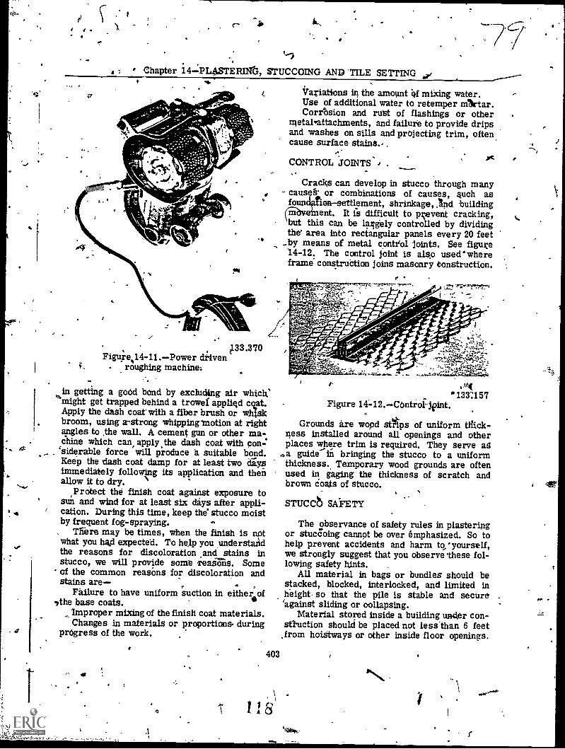
'; Chapter
40 iks
STERThrG, STUCCOING AND 'TILE SETTING kip/
Variations in the amount of mixing water.Use of additional water to retemper !Attar.Corrosion and rust of flashings or other
metal'attachments, and failure to provide dripsand washes on sills and projecting trim, oftencause surface stains...
CONTROL JOINTS-4 .
Cracks can develop in stucco through manycaus g' or combinations of causes, such asfour tion--settlement, shrinkage, :Ind buildingmveinent. It is difficult to prevent cracking,but this can be larlgely controlled by dividingthe° area into rectangular panels every 20 feetby means of metal control joints. See figure14-12. The control joint is also used`whereframe construction joins masonry Construction.
a-1..77s7-7-77z
."
,33.370Figure,14-11.-Power driven
roughing machine:
in getting a good bond by excluding air which''might get trapped behind a trowel appliqd c
Apply the dash coat with a fiber brush or wbroom, using a-strong whipping motion at rightangles to the wall. A cement gun or other ma-chine which can, apply the dash coat with con-.'siderable force will produce a suitable bond.Keep the dash coat damp for at least two daysimmediately following its application and thenallow it to dry.
Protect the finish coat against exposure tosun and wind for at least six days after appli-cation. During this time, keep the' stucco moistby frequent fog-spraying.
'Mere may be times, when the finish is notwhat you had expected. To help you understandthe reasons for discoloration and stains instucco, we will provide some reasOns. Some
* of the common reasons for discoloration andstains are-
Failure to have uniform suction in either of/the base coats.
Improper mixing of the finish coat materials.Changes in materials or proportions, during
progress of the work.
" 41
.?:''1; ;,11, 4;74.
.144*133157
Figure 14-12.-Controlleint.
Grounds are wood stilps of uniform tliick-'less installed around all openings and otherplaces 7here trim is required. They serve ag
.a guide In bringing the stucco to a uniformthickness. Temporary wood grounds are oftenused in gaging the thickness of scratch andbrown Coats of stucco.
STUCCb SAFETY
403
'A 8
The observance of safety rules in plasteringor stuccoing cannot be over emphasized. So tohelp prevent accidents and harm to/yourself,we strongly suggest that you observe *these fol-lowing safety hints.
All material in bags or bundles should bestacked, blocked, interlocked, and limited inheight. so that the pile is stable and secure'against sliding or oollapsing.
Material stored inside a building uwaer con-stluction should be placed not less than 6 feetfrom hoistways or other inside floor openings.
r

,
BUILDER 3 & 2
When material is placed orencroaches uponpassageways,' it should be located so as to,pre-sent the les.Wpossible hazard.
Bags of cement and lime should not bestacked more than 10 bags high without set-back, unless restrained by walls of appropriatestrength.
. The outside row of bags should be placedwith the mouths of the bags facing the center ofthe stack.
During unstaeking, keep The entire top of thestack nearly' level and maintain the necessaryset - backs:
Han e paper Sacks with care to preventbreakin and showering men with cement anddust.
Store lime and ce mentin off-the-floor plat-.forms in dry spaces. Lithe must be kept dry to
prevent possible pe itrziature slaking which couldcause fire.Wear heavy gloved when handlinimetal lath.Wear goggles for eye protection when han-
dling cement and lime.Wear shirts with closgialietgie and
and d I5e sure 'that exp parts of thebody do not come in direct contact with lime.
Avoid wearing clothing which has becomestiff and hard with cement or lime, since suchclothing irritates the skin and may cause in-fection.
Wear, goggles, gloves, .aid other protectiveclothing and equipment when handling muriaticacid.
Practice personal cleanliness and frequentwashing, which are effective preventive of..skinailments.
404
_/
0
4019
O
ti
rl'