MIL-DTL-38999 Series III EN3645 TV-CTV - Amphenol Socapex
64
MIL-DTL-38999 Series III EN3645 TV-CTV www.amphenol-socapex.com
-
Upload
khangminh22 -
Category
Documents
-
view
0 -
download
0
Transcript of MIL-DTL-38999 Series III EN3645 TV-CTV - Amphenol Socapex

www.amphenol-socapex.com
MIL-DTL-38999 Series III EN3645TV-CTV
www.amphenol-socapex.com

Tri-Start™ TV-CTV
Amphenol Tri-Start™ TV-CTV
2
NOTES

Tri-Start™ TV-CTV 3
Amphenol Tri-Start™ TV-CTV
TABLE OF CONTENTSTECHNICAL CHARACTERISTICS . . . . . . . . . . . . . . . . . . . . . . . . . . . . . . . . . . . . . . . . . . . . . . . . . . . . . . . . . . . . . . . . . . . . . . . . 6
• General characteristics . . . . . . . . . . . . . . . . . . . . . . . . . . . . . . . . . . . . . . . . . . . . . . . . . . . . . . . . . . . . . . . . . . . . . . . . . . . . . . . . . . . . . . . . . . . . . . . . . . . . . . . . . . . . .6• Mechanical characteristics . . . . . . . . . . . . . . . . . . . . . . . . . . . . . . . . . . . . . . . . . . . . . . . . . . . . . . . . . . . . . . . . . . . . . . . . . . . . . . . . . . . . . . . . . . . . . . . . . . . . . . . . .7• Environmental characteristics . . . . . . . . . . . . . . . . . . . . . . . . . . . . . . . . . . . . . . . . . . . . . . . . . . . . . . . . . . . . . . . . . . . . . . . . . . . . . . . . . . . . . . . . . . . . . . . . . . . . . .8• Electrical characteristics . . . . . . . . . . . . . . . . . . . . . . . . . . . . . . . . . . . . . . . . . . . . . . . . . . . . . . . . . . . . . . . . . . . . . . . . . . . . . . . . . . . . . . . . . . . . . . . . . . . . . . . . . . . .9• Insert arrangements . . . . . . . . . . . . . . . . . . . . . . . . . . . . . . . . . . . . . . . . . . . . . . . . . . . . . . . . . . . . . . . . . . . . . . . . . . . . . . . . . . . . . . . . . . . . . . . . . . . . . . . . . . . . . 10• Coding – Polarization . . . . . . . . . . . . . . . . . . . . . . . . . . . . . . . . . . . . . . . . . . . . . . . . . . . . . . . . . . . . . . . . . . . . . . . . . . . . . . . . . . . . . . . . . . . . . . . . . . . . . . . . . . . . 15
STANDARD RANGE . . . . . . . . . . . . . . . . . . . . . . . . . . . . . . . . . . . . . . . . . . . . . . . . . . . . . . . . . . . . . . . . . . . . . . . . . . . . . . . . . . . . 16TV METALLIC SHELLS . . . . . . . . . . . . . . . . . . . . . . . . . . . . . . . . . . . . . . . . . . . . . . . . . . . . . . . . . . . . . . . . . . . . . . . . . . . . . . . . . . . . . . . . . . . . . . . . . . . . . . . . . . . . . . . 16
• Aluminium shells presentation . . . . . . . . . . . . . . . . . . . . . . . . . . . . . . . . . . . . . . . . . . . . . . . . . . . . . . . . . . . . . . . . . . . . . . . . . . . . . . . . . . . . . . . . . . . . . . . . . . . 16• Bronze shells presentation . . . . . . . . . . . . . . . . . . . . . . . . . . . . . . . . . . . . . . . . . . . . . . . . . . . . . . . . . . . . . . . . . . . . . . . . . . . . . . . . . . . . . . . . . . . . . . . . . . . . . . . 16• Stainless steel shells presentation . . . . . . . . . . . . . . . . . . . . . . . . . . . . . . . . . . . . . . . . . . . . . . . . . . . . . . . . . . . . . . . . . . . . . . . . . . . . . . . . . . . . . . . . . . . . . . . . 16• Overall dimensions . . . . . . . . . . . . . . . . . . . . . . . . . . . . . . . . . . . . . . . . . . . . . . . . . . . . . . . . . . . . . . . . . . . . . . . . . . . . . . . . . . . . . . . . . . . . . . . . . . . . . . . . . . . . . . 17
CTV COMPOSITE SHELLS . . . . . . . . . . . . . . . . . . . . . . . . . . . . . . . . . . . . . . . . . . . . . . . . . . . . . . . . . . . . . . . . . . . . . . . . . . . . . . . . . . . . . . . . . . . . . . . . . . . . . . . . . . . . 20• Presentation . . . . . . . . . . . . . . . . . . . . . . . . . . . . . . . . . . . . . . . . . . . . . . . . . . . . . . . . . . . . . . . . . . . . . . . . . . . . . . . . . . . . . . . . . . . . . . . . . . . . . . . . . . . . . . . . . . . . . 20• Overall dimensions . . . . . . . . . . . . . . . . . . . . . . . . . . . . . . . . . . . . . . . . . . . . . . . . . . . . . . . . . . . . . . . . . . . . . . . . . . . . . . . . . . . . . . . . . . . . . . . . . . . . . . . . . . . . . . 20
PRINTED CIRCUIT BOARD CONNECTORS . . . . . . . . . . . . . . . . . . . . . . . . . . . . . . . . . . . . . . . . . . . . . . . . . . . . . . . . . . . . . . . . . . . . . . . . . . . . . . . . . . . . . . . . . . . . 22• Panel drilling for composite and metallic receptacles . . . . . . . . . . . . . . . . . . . . . . . . . . . . . . . . . . . . . . . . . . . . . . . . . . . . . . . . . . . . . . . . . . . . . . . . . . . . . . 22• Printed circuit board connectors . . . . . . . . . . . . . . . . . . . . . . . . . . . . . . . . . . . . . . . . . . . . . . . . . . . . . . . . . . . . . . . . . . . . . . . . . . . . . . . . . . . . . . . . . . . . . . . . . 23• Receptacles equipped with size 22D contacts . . . . . . . . . . . . . . . . . . . . . . . . . . . . . . . . . . . . . . . . . . . . . . . . . . . . . . . . . . . . . . . . . . . . . . . . . . . . . . . . . . . . . 24
EXTENDED RANGE . . . . . . . . . . . . . . . . . . . . . . . . . . . . . . . . . . . . . . . . . . . . . . . . . . . . . . . . . . . . . . . . . . . . . . . . . . . . . . . . . . . . 40REDUCED FLANGE . . . . . . . . . . . . . . . . . . . . . . . . . . . . . . . . . . . . . . . . . . . . . . . . . . . . . . . . . . . . . . . . . . . . . . . . . . . . . . . . . . . . . . . . . . . . . . . . . . . . . . . . . . . . . . . . . . 40STAND OFF RECEPTACLE . . . . . . . . . . . . . . . . . . . . . . . . . . . . . . . . . . . . . . . . . . . . . . . . . . . . . . . . . . . . . . . . . . . . . . . . . . . . . . . . . . . . . . . . . . . . . . . . . . . . . . . . . . . . 41TVS-Y/TVS-YN HERMETIC RECEPTACLES . . . . . . . . . . . . . . . . . . . . . . . . . . . . . . . . . . . . . . . . . . . . . . . . . . . . . . . . . . . . . . . . . . . . . . . . . . . . . . . . . . . . . . . . . . . . 42LANYARD RELEASE PLUGS . . . . . . . . . . . . . . . . . . . . . . . . . . . . . . . . . . . . . . . . . . . . . . . . . . . . . . . . . . . . . . . . . . . . . . . . . . . . . . . . . . . . . . . . . . . . . . . . . . . . . . . . . . 44THRU-BULKHEAD RECECTACLES . . . . . . . . . . . . . . . . . . . . . . . . . . . . . . . . . . . . . . . . . . . . . . . . . . . . . . . . . . . . . . . . . . . . . . . . . . . . . . . . . . . . . . . . . . . . . . . . . . . . 46RECEPTACLES WITH ENHANCED SEALING . . . . . . . . . . . . . . . . . . . . . . . . . . . . . . . . . . . . . . . . . . . . . . . . . . . . . . . . . . . . . . . . . . . . . . . . . . . . . . . . . . . . . . . . . . 46INTEGRATED BACKSHELLS . . . . . . . . . . . . . . . . . . . . . . . . . . . . . . . . . . . . . . . . . . . . . . . . . . . . . . . . . . . . . . . . . . . . . . . . . . . . . . . . . . . . . . . . . . . . . . . . . . . . . . . . . . 47MIL-DTL-38999 SERIES III OPTICAL CONNECTORS . . . . . . . . . . . . . . . . . . . . . . . . . . . . . . . . . . . . . . . . . . . . . . . . . . . . . . . . . . . . . . . . . . . . . . . . . . . . . . . . . . 47
ACCESSORIES . . . . . . . . . . . . . . . . . . . . . . . . . . . . . . . . . . . . . . . . . . . . . . . . . . . . . . . . . . . . . . . . . . . . . . . . . . . . . . . . . . . . . . . . . 48PROTECTIVE CAPS . . . . . . . . . . . . . . . . . . . . . . . . . . . . . . . . . . . . . . . . . . . . . . . . . . . . . . . . . . . . . . . . . . . . . . . . . . . . . . . . . . . . . . . . . . . . . . . . . . . . . . . . . . . . . . . . . . 48
• Standard metallic caps . . . . . . . . . . . . . . . . . . . . . . . . . . . . . . . . . . . . . . . . . . . . . . . . . . . . . . . . . . . . . . . . . . . . . . . . . . . . . . . . . . . . . . . . . . . . . . . . . . . . . . . . . . . 48• Rubber caps . . . . . . . . . . . . . . . . . . . . . . . . . . . . . . . . . . . . . . . . . . . . . . . . . . . . . . . . . . . . . . . . . . . . . . . . . . . . . . . . . . . . . . . . . . . . . . . . . . . . . . . . . . . . . . . . . . . . . 49
BACKSHELLS . . . . . . . . . . . . . . . . . . . . . . . . . . . . . . . . . . . . . . . . . . . . . . . . . . . . . . . . . . . . . . . . . . . . . . . . . . . . . . . . . . . . . . . . . . . . . . . . . . . . . . . . . . . . . . . . . . . . . . . . 50OTHER ACCESSORIES . . . . . . . . . . . . . . . . . . . . . . . . . . . . . . . . . . . . . . . . . . . . . . . . . . . . . . . . . . . . . . . . . . . . . . . . . . . . . . . . . . . . . . . . . . . . . . . . . . . . . . . . . . . . . . . 51
• Dummy receptacles . . . . . . . . . . . . . . . . . . . . . . . . . . . . . . . . . . . . . . . . . . . . . . . . . . . . . . . . . . . . . . . . . . . . . . . . . . . . . . . . . . . . . . . . . . . . . . . . . . . . . . . . . . . . . . 51• Holding support . . . . . . . . . . . . . . . . . . . . . . . . . . . . . . . . . . . . . . . . . . . . . . . . . . . . . . . . . . . . . . . . . . . . . . . . . . . . . . . . . . . . . . . . . . . . . . . . . . . . . . . . . . . . . . . . . 51• Plastic dust caps . . . . . . . . . . . . . . . . . . . . . . . . . . . . . . . . . . . . . . . . . . . . . . . . . . . . . . . . . . . . . . . . . . . . . . . . . . . . . . . . . . . . . . . . . . . . . . . . . . . . . . . . . . . . . . . . . 51• Crimp contacts . . . . . . . . . . . . . . . . . . . . . . . . . . . . . . . . . . . . . . . . . . . . . . . . . . . . . . . . . . . . . . . . . . . . . . . . . . . . . . . . . . . . . . . . . . . . . . . . . . . . . . . . . . . . . . . . . . 52• Piggy back grommets . . . . . . . . . . . . . . . . . . . . . . . . . . . . . . . . . . . . . . . . . . . . . . . . . . . . . . . . . . . . . . . . . . . . . . . . . . . . . . . . . . . . . . . . . . . . . . . . . . . . . . . . . . . . 52• Sealing plugs . . . . . . . . . . . . . . . . . . . . . . . . . . . . . . . . . . . . . . . . . . . . . . . . . . . . . . . . . . . . . . . . . . . . . . . . . . . . . . . . . . . . . . . . . . . . . . . . . . . . . . . . . . . . . . . . . . . . 53• Dummy contacts . . . . . . . . . . . . . . . . . . . . . . . . . . . . . . . . . . . . . . . . . . . . . . . . . . . . . . . . . . . . . . . . . . . . . . . . . . . . . . . . . . . . . . . . . . . . . . . . . . . . . . . . . . . . . . . . 53• Standard PC tail contacts . . . . . . . . . . . . . . . . . . . . . . . . . . . . . . . . . . . . . . . . . . . . . . . . . . . . . . . . . . . . . . . . . . . . . . . . . . . . . . . . . . . . . . . . . . . . . . . . . . . . . . . . . 53• Reducing ferrules . . . . . . . . . . . . . . . . . . . . . . . . . . . . . . . . . . . . . . . . . . . . . . . . . . . . . . . . . . . . . . . . . . . . . . . . . . . . . . . . . . . . . . . . . . . . . . . . . . . . . . . . . . . . . . . . 54
APPLICATION TOOLS . . . . . . . . . . . . . . . . . . . . . . . . . . . . . . . . . . . . . . . . . . . . . . . . . . . . . . . . . . . . . . . . . . . . . . . . . . . . . . . . . . . . . . . . . . . . . . . . . . . . . . . . . . . . . . . 55• Crimping tools . . . . . . . . . . . . . . . . . . . . . . . . . . . . . . . . . . . . . . . . . . . . . . . . . . . . . . . . . . . . . . . . . . . . . . . . . . . . . . . . . . . . . . . . . . . . . . . . . . . . . . . . . . . . . . . . . . . 55• Insertion and removal tools . . . . . . . . . . . . . . . . . . . . . . . . . . . . . . . . . . . . . . . . . . . . . . . . . . . . . . . . . . . . . . . . . . . . . . . . . . . . . . . . . . . . . . . . . . . . . . . . . . . . . . 55
HOW TO ORDER . . . . . . . . . . . . . . . . . . . . . . . . . . . . . . . . . . . . . . . . . . . . . . . . . . . . . . . . . . . . . . . . . . . . . . . . . . . . . . . . . . . . . . . 56• Standard versions . . . . . . . . . . . . . . . . . . . . . . . . . . . . . . . . . . . . . . . . . . . . . . . . . . . . . . . . . . . . . . . . . . . . . . . . . . . . . . . . . . . . . . . . . . . . . . . . . . . . . . . . . . . . . . . . 56• Hermetic versions . . . . . . . . . . . . . . . . . . . . . . . . . . . . . . . . . . . . . . . . . . . . . . . . . . . . . . . . . . . . . . . . . . . . . . . . . . . . . . . . . . . . . . . . . . . . . . . . . . . . . . . . . . . . . . . 58• Lanyard released plugs . . . . . . . . . . . . . . . . . . . . . . . . . . . . . . . . . . . . . . . . . . . . . . . . . . . . . . . . . . . . . . . . . . . . . . . . . . . . . . . . . . . . . . . . . . . . . . . . . . . . . . . . . . . 59• Cross references . . . . . . . . . . . . . . . . . . . . . . . . . . . . . . . . . . . . . . . . . . . . . . . . . . . . . . . . . . . . . . . . . . . . . . . . . . . . . . . . . . . . . . . . . . . . . . . . . . . . . . . . . . . . . . . . . 62
NEW
NEW

Tri-Start™ TV-CTV
Amphenol Tri-Start™ TV-CTV
4
ABOUT AMPHENOL SOCAPEX
AMPHENOL SOCAPEX quality & environmental certification
ABOUT AMPHENOL
For over 65 years, Amphenol Socapex has been providing rugged and reliable connectors and interconnect solutions to a large base of customers worldwide in the military, aerospace and industrial markets.
Our products and solutions,designed for rugged and unique situations involving extreme conditions, provide the innovativeness and flexibility essential to meet the needs and requirements of these demanding sectors.
Headquartered in the Technic Valley between Geneva and Mont-Blanc, Amphenol Socapex has 30,000 m2 of manufacturing capacity. Our in-house molding, machining, screw machining & assembly capabilities within our 2 facilities in France & India give us the ability to manage all types of volume with consistent quality.
More info on www.amphenol-socapex.com
Amphenol Socapex is part of Amphenol Group.
Founded in 1932, Amphenol is one of the largest manufacturers of interconnect products in the world. The company designs, manufactures, and markets electrical, electronic, and fiber optic connectors, interconnect systems, and coaxial and specialty cables.
Amphenol products are engineered and manufactured in the Americas, Europe, Asia and Africa and sold by a worldwide sales and marketing organization.
Amphenol has a diversified presence as a leader in high growth areas of the interconnect industry and provides solutions for customers in the automotive, broadband, industrial, information technology and data communications, military and aerospace, mobile devices, and mobile networks markets.
More info on www.amphenol.com
Thyez (74), France Manufacturing site in Pune, India
AmphenolSocapex
Amphenol
Quality certification : ISO 9001 : 2000Thyez (France) and Pune (India)
Aeronautical market qualitycertification :EN9100 : 2003 Thyez (France) and Pune (India)
Military market quality certification (NATO) :AQAP 2110 Thyez (France)
Environnemental certification : ISO 14001 (2004) Thyez (France)
ABOUT US
AMPHENOL SOCAPEX QUALITY & ENVIRONMENTAL CERTIFICATION

Tri-Start™ TV-CTV 5
Amphenol Tri-Start™ TV-CTV
AMPHENOL SOCAPEX quality & environmental certification
CONNECTOR RANGE & ACCESSORIES
STANDARD
TV METALLIC SHELLS CTV COMPOSITE SHELLS
RANGE DERIVATED
REDUCED FLANGE STAND OFF RECEPTACLE
TVS-Y/TVS-YN HERMETICRECEPTACLES BREAKAWAY CONNECTORS
THRU-BULKHEADRECEPTACLES
RECEPTACLES WITHENHANCED SEALING
INTEGRATED BACKSHELLS
MIL-DTL-38999OPTICAL
CONNECTORS
TVOP STARTOP
ACCESSORIES
BACKSHELLS PROTECTIVE CAPS
NEW
NEW

Tri-Start™ TV-CTV
Amphenol Tri-Start™ TV-CTV
6
TV-CTV CONNECTORS (MIL-DTL-38999 SERIES III/EN3645)• MIL-DTL-38999 series III connectors• EN3645 connectors• Dedicated to harsh environment applications• 9 shell sizes (from 09 to 25)• Thread coupling• 100% scoop-proof• More than 80 contact arrangements• Intermountable with MIL-DTL-38999 series I
AMPHENOL ADDED VALUE
MAIN FEATURESSHELL MATERIAL AND PLATING:• Aluminium Standard material
• Composite Lightweight solution up to 70%weight saving Corrosion resistant up to 2000H of salt spray exposure
• Stainless steel Firewall capability
• Marine bronze High corrosion resistance Robustness for marine applications
CONTACTS• Standard contacts plated with a minimum of 1 .27µm gold• Size 00, 4, 8, 10, 12, 16, 20, 22D, 23• Signal, power, twinax, coax, quadrax and optical termini
Contact protection: interfacial seal ensures sealing around each contact and prevents electrolytic erosion
OTHERSQuick coupling• Mate and self-lock in a 360° turn of the coupling nut• Anti-decoupling device for high vibration performance
APPLICATIONSMilitary and aeronautic applications: battlefield, ground vehicles, aircrafts, communication systems…
Advanced industrial applications: high vibration requirements, high density
GENERAL CHARACTERISTICS TECHNICAL CHARACTERISTICS
PLATING:• Olive drab cadmium• Nickel• Passivation• Black zinc nickel
Amphenol goes further the European and American standards by offering an extended range with:
• Inserts compatible with quadrax• Grounded connectors with conductive insert for specific use• Receptacles with reinforced sealing• Hermetic version in Y & N classes• High density inserts (with size 23 contacts)• Filtered versions using tubular or planar technology
EMI/RFI protection:• Shell to shell bottoming• Grounding fingers on the plug shell

Tri-Start™ TV-CTV 7
Amphenol Tri-Start™ TV-CTV
10
11
6
7
9
8
13
1
9
7
12
14
4
2
5
1 Coupling nut 8 Receptacle shell 2 Quick coupling thread 9 Contact retention clips 3 Ratchet 10 Crimping pin contact 4 Anti decoupling device 11 Crimping socket contact 5 Plug shell 12 Interfacial seal6 Spring fingers (EMI) 13 Socket insert7 Grommet 14 Pin insert
• Thermoplastic insert
• Silicone rubber back insert and interfacial seal
• Durability: - 500 cycles - 1500 cycles with composite connector " CTV " fitted with " H " and " J " contact types
• Shocks: half sine wave of 300 G magnitude during 3ms per EIA364 .27
• Sine vibrations: - 60 g from - 55°C to + 175°C (olive drab cadmium finish) - 60 g from - 55°C to +200°C (nickel finish and firewall version)
• Random vibrations per EIA364.28: - 1 G2 / Hz at 175°C olive drab cadmium finish - 1G2 / Hz at 200°C nickel finish and firewall version - 5G2 / Hz at ambient
• Bending moment
• Contact retention force
Shell size Bending momentNmMIL-DTL-38999 Series III Amphenol
A 09 11 .3
B 11 33 .9
C 13 45 .2
D 15 56 .5
E 17 67 .8
F 19 79 .1
G 21 90 .4
H 23 101 .7
J 25 113 .0
Contact Size 23 22D 20 16 12 8 4
Maximum load (N) 44 44 67 111 111 111 150
TECHNICAL CHARACTERISTICS MECHANICAL CHARACTERISTICS
EMI/RFI protection:• Shell to shell bottoming• Grounding fingers on the plug shell

Tri-Start™ TV-CTV
Amphenol Tri-Start™ TV-CTV
8
Shellmaterial
Shellfinish
Salt sprayexposure
per EIA364.26
Classnorm
Amphenol Operating temperature
Shell to shellConductivity
mini maxi
Composite Electroless NickelO .D cadmium
2000 H2000 H
MJ
CTV-RFCTV-RW
-65°C-65°C
+200°C*+175°C
3mΩ3mΩ
Aluminium Electroless NickelO .D cadmium
Durmalon (Ni-PTFE)Green Zinc CobaltBlack Zinc Nickel
48 H500 H500H96H
500H
FWT-Z
TVS-RFTV-RWTV-DTTV-RZ
TV-ZN TV-DZ
-65°C-65°C-65°C-65°C-65°C
+200°C*+175°C+175°C+175°C+175°C
1mΩ2 .5mΩ2 .5mΩ3mΩ
2 .5mΩ
Stainlesssteel
Nickel—
500 H500 H
SK
TVS-RSTVS-RK
-65°C-65°C
+200°C*+200°C*
1mΩ10mΩ
Bronze — 500 H TVS-RB -65°C +200°C* 5mΩ
ENVIRONMENTAL CHARACTERISTICS
• Humidity: per MIL-DTL-38999: § 3 .29
• Altitude immersion: according to MIL-DTL-38999 III standard (except hermetics)
• Air leakage < 1 .10 - 7 cm3/s under 1 bar of differential pressure (hermetics only)
• Fluid immersion per EIA364.10: • Hydraulic fluid, per MIL-H-5606
• Turbine fluid, grade JP-8, per MIL-DTL-83133 (NATO TYPE 34)
• Lubricating oil, per MIL-L-7808
• Lubricating oil, per MIL-PRF-23699
• Defrosting fluid, per MIL-A-8243
• Cleaning compound, diluted for cleaning, per MIL-PRF-87937 type I alkaline base
• Gasoline, per ASTM-D-4814
• Gasohol, per A-A-52530
• One part isopropyl alcohol, per TT-I-735, grade A or B ; and 3 parts mineral spirits, per A-A-2904, type II, grade A or P-D-680, type I, by volume
• Coolant, dielectric fluid, synthetic silicate ester base MIL-PRF-47220 (Coolanol 25) or equivalent
• Hydraulic fluid M2-V Chevron oil ST0145LB0001 or equivalent
• Hermetic shells
• Waterproof shells
Shellmateriel
Shellfinish
Salt sprayexposure
per EIA364.26
Classnorm Amphenol
Operatingtemperature
min max
Stainlesssteel
Nickel-
48 H500 H
NY
TVS-YNTVS-Y
-65°C-65°C
+200°C*+200°C*
* 175°C maxi only for high-density contact arrangements
TECHNICAL CHARACTERISTICS
• Salt spray exposure and working temperature:

Tri-Start™ TV-CTV 9
Amphenol Tri-Start™ TV-CTV
ELECTRICAL CHARACTERISTICS
• Contact resistance
Contact Size 23 *1 22D 20 16 12 8 4
Resistance (mΩ) 15 8 4 .7 2 1 .1 0 .6 0 .26
• Insulation resistance - at ambiant > 5 .103 Mohms - at maximum temperature > 103 Mohms
• Service rating
ServiceDielectric withstanding voltage (Vrms) Working voltage
At sea level 15000 meters 21000 meters 34000 metersmated unmated mated unmated mated unmated mated unmated Vrms Vdc
M 1300 1300 800 550 800 350 800 200 400 550
I 1800 1800 1000 600 1000 400 1000 200 600 850
II 2300 2300 1000 800 1000 500 1000 200 900 1250
• Dimensions of acceptable contacts and cables
ContactSize
ContactDiameter
mm
Crimp barrel Acceptable cables
Diametermm
Depthmm
Gauge AWGSection mm2
Outside diameter (mm)
Min Average Max
23 *1 0,68 0,88 ± 0,03 3,81 22 24 26 28 - - 1 .20 .38 0 .22 0 .15 0 .095
22D 0 .76 0 .88 ± 0 .03 3 .58 22 24 26 28 0 .76 1 .20 1 .370 .38 0 .22 0 .15 0 .095
20 1 1 .19 ± 0 .03 5 .30 20 22 24 - 1 .02 1 .83 2 .110 .60 0 .38 0 .22 -
16 1 .57 1 .70 ± 0 .03 5 .30 16 18 20 - 1 .68 2 .41 2 .771 .34 0 .93 0 .60 -
12 2 .36 2 .54 ± 0 .06 10 12 14 - - 2 .46 3 .20 3 .613 .30 1 .94 - -
8 3 .60 4 .6 ± 0 .05 10 8 4 .50 - 5 .28 .98 Max acceptable: 10mm2
4 5 .70 7 .4 ± 0 .05 12 4 7 .73 - 8 .421 .10
• Contact rating - nominal current per contact
Contact size 23 *1 22 D 20 16 12 8 4 00
Crimp (A) 5 5 7 .5 13 23 60 100 230
Hermetic (A) 3 3 5 10 17 - - -
PC Tail (A) 3 3 4 .5 10 17 40 - -
Resistance 15 8 4 .7 2 1 .1 0 .6 0 .26 -
*1 High-Density arrangements
TECHNICAL CHARACTERISTICS

Tri-Start™ TV-CTV
Amphenol Tri-Start™ TV-CTV
10
Contact Size 23(high density) 22D 20 16 12 8 4
Caption
Available:Coax - - - -
Differential Twinax - - - - - -Quadrax - - - - - -
Power contacts - - -Grounded cavity - - - -
MIL-DTL-38999 Series III / EN3645 insert arrangement reference TV-CTV insert arrangement Service class Number of contacts Contact sizes
11Y
12
3
456
7
8
910
111213
YA
D
B
C
E F
A
D
B
C
EF
G
B 35 / 11N35 B 98 / 11N98 B99 / 11N99
11-19 11-35 11-98 11-99
M I I 19 13 6 7 23 22D 20 20
13
C 4 / 13N04 C 8 / 13N08 - / 13N26 C 35 / 13N35 C 98 / 13N98
13-04 13-08 13-26 13-32 13-35 13-98 I I M M I 4 8 6 2 32 22 10
16 20 22D 12 23 22D 20
15
D 05 / 15N05 D 15 / 15N15 D 18 / 15N18 D 19 / 15N19
15-04 15-05 15-15 15-18 15-19
I M I I I
4 5 14 1 18 19
12 16 20 16 20 20
09
- / 09G01 A 35 / 09N35 A 98 / 09N98 09-05 09-09 09-35 09-94 09-98 N/A M M I 1 9 6 2 3 8 Twinax° 23 22D 20 20
11
- / 11N01 B 2 / 11N02 - / 11N04 B 5 / 11N05 - / 11N12
11-01 11-02 11-04 11-05 11-12
I I I II
1 2 4 5 1
8 Twinax∆ 16 20 20 12
Y
Y
Y
Y Y
Y Y
Y Y Y
Y Y
Y
TECHNICAL CHARACTERISTICS INSERT ARRANGEMENTS
Front face of male insert. (Only the major keyway is illustrated)
Y1
23
4
5
6
YA
CB
ABA
BC
D A
B
C
DE A
Y
AB
CD
A
B
CDE
F
G
H
AB
CD
E2
1F
Y1
22
Y
AB
C
DEF
G
H
JK
Y
A
B
CD
E
P
AB
C
D
EFG
H
J
KL
M
NR
Y
AB
C
DE
FGH
J
K
LM
N P
R
ST
U V
AB
C
D
EF
GH
JK
LM N
P
RS
T U
A 359-35
M6
22D
Y Y
A 989-98
I3
20
11-01**
18
Twinax
11-12
112
B 211-2
I2
16
11-4I4
20
1
23
4
5
6A
CB
9-94I2
20
AB AA B
123
45

Tri-Start™ TV-CTV 11
Amphenol Tri-Start™ TV-CTV
MIL-DTL-38999 Series III / EN3645 insert arrangement reference TV-CTV insert arrangement Service class Number of contacts Contact sizes
15
D 35 / 15N35 D 97 / 15N97
15-25** 15-35 15-55 15-97
M M I
22 3 37 55 8 4
22D 16 22D 23 20 16
17
E 2 / 17N02 E 6 / 17N06 E 8 / 17N08 - / 17N20 - / 17N22 E 26 / 17N26
17-02 17-06 17-08 17-20** 17-22 17-26
M I II M M I
38 1 6 8 16 4 2 2 26 22D 8 Twinax° 12 16 22D 12 12 Coax 8 Twinax∆ 20
17
E 35 / 17N35 - / 17N75 E 99 / 17N99
17-35 17-52 17-73 17-75 17-99
M M I
55 2 73 2 21 2 22D 8 Quadrax
(meets 17-82 Boeing spec)23 8 Twinax° 20 16
19
F 11 / 19N11 - / 19N17 F 18
19-11 19-17 19-18 19-28 19-30
II M M I I
11 10 1 4 2 14 4 26 2 29 1 16 22D 20 16 8 Twinax∆ 22D 8 Twinax° 20 16 20 16
19
- / 19N31 F 32 / 19N32 F 35 / 19N35
19-31 19-32 19-35 19-88
M I M I
2 1 12 32 66 88 8 Coax 12 22D 20 22D 23
Y Y
Y
Y
Y
Y Y
Y Y
TECHNICAL CHARACTERISTICS INSERT ARRANGEMENTS
Front face of male insert. (Only the major keyway is illustrated)
Contact Size 23(high density) 22D 20 16 12 8 4
Caption
Available:Coax - - - -
Differential Twinax - - - - - -Quadrax - - - - - -
Power contacts - - -Grounded cavity - - - -
1 23
4
5
6
78
910
11
12
13 1415
1617
1820 1921
2223 24
25
Y
1
31
Y
AB
C
D
EFG
H
JKL
M
1
6
11
17
30
A
B
C
D
E
F
1
2 3
4
5
67
89
1011
12
13
14 15
16 A
D
C
B
Y
A
B
C
DE
F
G
H
A
BC
D
Y
AB
C
D
E
FGHJ
K
L
M
N
PT
U
VW
XY
Z
aS
b
c
R
E 3517-35
M55
22D
YY
17-52
28
(Meets 17-82Boeing Spec)
E 9917-99
I21 220 16
AB
C
D
E
FGH
1
3
4
9
10
16
17
24 31
2532
40
4753
55
524639
A
B
JK
L
M
N
PR
S T
U
V
W
X
Y Z
A
B
C
DEF
G
H
J
K
L
F 1119-11
II1116
12345
17-75
28
Twinax
A
B
Q ��
E 3517-35
M55
22D
YY
17-52
28
(Meets 17-82Boeing Spec)
E 9917-99
I21 220 16
AB
C
D
E
FGH
1
3
4
9
10
16
17
24 31
2532
40
4753
55
524639
A
B
JK
L
M
N
PR
S T
U
V
W
X
Y Z
A
B
C
DEF
G
H
J
K
L
F 1119-11
II1116
12345
17-75
28
Twinax
A
B
Q ��
E 3517-35
M55
22D
YY
17-52
28
(Meets 17-82Boeing Spec)
E 9917-99
I21 220 16
AB
C
D
E
FGH
1
3
4
9
10
16
17
24 31
2532
40
4753
55
524639
A
B
JK
L
M
N
PR
S T
U
V
W
X
Y Z
A
B
C
DEF
G
H
J
K
L
F 1119-11
II1116
12345
17-75
28
Twinax
A
B
Q ��
E 3517-35
M55
22D
YY
17-52
28
(Meets 17-82Boeing Spec)
E 9917-99
I21 220 16
AB
C
D
E
FGH
1
3
4
9
10
16
17
24 31
2532
40
4753
55
524639
A
B
JK
L
M
N
PR
S T
U
V
W
X
Y Z
A
B
C
DEF
G
H
J
K
L
F 1119-11
II1116
12345
17-75
28
Twinax
A
B
Q ��
E 3517-35
M55
22D
YY
17-52
28
(Meets 17-82Boeing Spec)
E 9917-99
I21 220 16
AB
C
D
E
FGH
1
3
4
9
10
16
17
24 31
2532
40
4753
55
524639
A
B
JK
L
M
N
PR
S T
U
V
W
X
Y Z
A
B
C
DEF
G
H
J
K
L
F 1119-11
II1116
12345
17-75
28
Twinax
A
B
Q ��A
B
C
D
E
FG
HJK
L
M
N
P
RS T
UV
W
X
Y
Z
a
b
cd e
B
A
C
D
EFG
H
J
KL
MN
T
S PR
AB
C
D
FGHJ
K
L
M
N
PR
T
S
U
V
W
XYZa
b
cd
e
g fE
A
B
C
DE
F
G
H
J
K
L
M
N
P
R
S
T
U
1
2
3
9
410
17 25
1624 33
34
42
43
50
51
5763
58
64
66
65
AB
C
D
E
FG
HJK
L
M
N
P
RS T
UV
W
X
YZa
b
c
d
e
j
f
g
h
AVW
UC
B
gh
S
R M
N KE

Tri-Start™ TV-CTV
Amphenol Tri-Start™ TV-CTV
12
INSERT ARRANGEMENTS
23
- / 23N06 H 21 / 23N21 H 35 / 23N35
23-06 23-14 23-21 23-35
M I II M
6 14 21 100 8 twinax° 12 16 22D
23
H 53 / 23N53 - / 23N54 H 55 / 23N55 23-53 23-54 23-55 23-151
I M I
53 40 9 4 55 151 20 22D 16 12 20 23
21
G 11 / 21N11 G 16 / 21N16 - / 21N20 G 35 / 21N35 G 39 / 21N39
21-11 21-16 21-AJ 21-35 21-39
I II M M I
11 16 18 2 79 37 2 12 16 20 8 twinax° 22D 20 16
21
G 41 / 21N41 G 75 / 21N75
21-41 21-48 21-75 21-121
I M M
41 4 4 121 20 8 power 8 coax or 8 twinax*° 23
Y
Y
Y Y
Y
Y
TECHNICAL CHARACTERISTICS
MIL-DTL-38999 Series III / EN3645 insert arrangement reference TV-CTV insert arrangement Service class Number of contacts Contact sizes
Front face of male insert. (Only the major keyway is illustrated)
Contact Size 23(high density) 22D 20 16 12 8 4
Caption
Available:Coax - - - -
Differential Twinax - - - - - -Quadrax - - - - - -
Power contacts - - -Grounded cavity - - - -
Quadrax not available
A
B
C
D
E
F
G
H
J
K
L
A
B
C
D
EFG
H
J
K
L
M
N
PR
S
AB
CK
J
H G FE
D
RPN
ML
V
UT
S
W
21
41
6171
11
3151
79
1 AB
C
D
EF
G
HJ
KLM
NP
R
S
TU
V W
XY
Za
b
cde
f
g
h
ij
kmr
q n
p
AB
C
D
E
F
G
HJ
KLM
N
P
R
S
T
UV
W
XY
Z
a
b
cde
f
g
h
i
j
km
npq
r
s
t
A
B
C
D
Q
A
BC
D
A
BK
CJ LP
MN
DH
EG
F
Q
A
B
C
F
D
E
12
34
5
6
7
816
2535
4656
6777
86
94
95
9697
9899
100
9385
76556645
3424
15
Y
A
B
C
D
E
FGH
J
K
L
MN
P
R
S
TU
V
W
X
Y
AB
C
D
E
F
G
Hc
J
K
L
M
N
PR
S TU
VW
pq
rX
BBCC
sY
HHDD
tZ
EEu
avb
mn
kz
AA
hy
GG
gx
FF
fe
w
d
Y
12
345
6
2627
28
29
78
910
1112
3433
32
31
30
52 45 46
51 53 47
50 49 48
25
35
40
1920
2122
23 24
4443
4241
181716
1514
13
3637
3839
Y Y
AB
C
D
E
F
G
HJK
L
M
N
P
RS
TU V
WX
Y
Z
a
bc
de
fg
h
i
j
km
np
qr
s
tu
vw
x
y
zAA
BBCC
DDEE
FF
GGHH
YY

Tri-Start™ TV-CTV 13
Amphenol Tri-Start™ TV-CTV
INSERT ARRANGEMENTS
25
J 4 / 25N04 J 7 / 25N07 J 8 / 25N08 J 11 / 25N11
25-04 25-07 25-08 25-11 25-1A
I M M N I
48 8 97 2 8 2 9 4 4 20 16 22D 8 Twinax° 8 twinax∆ 20 10 power 16 4 power
25
- / 25L17 J 19 / 25N19 J 20 / 25N20 J 24 / 25N24 - / 25N26
25-17 25-19 25-20 25-24 25-26
M I N I I
36 6 19 10 13 3 4 12 12 16 5 4 22D 8 twinax° 12 20 16 8 twinax° 12 coax 16 12 20 12 8 coax
25
J 46 / 25N46 J 61 / 25N61
25-46 25-61 25-92** 25-187 25-F4
I I M Size 22D=M, Balance =I
40 4 2 61 92 9 187 49 13 4 20 16 8 coax 20 22D 16 23 22D 16 12
25
J 29 / 25N29 J 35 / 25N35 J 37 / 25N37 J 43 / 25N43
25-29 25-35 25-37 25-41 25-43
I M I I I
29 128 37 22 3 11 2 3 23 20 16 22D 16 22D 20 16 12 coax 8 twinax° 20 16
* Military P/N delivered with 8 twinax and proprietary P/N delivered with size 8 coaxial contacts for RG 180 and RG 195 wire .** Not available in composite version .Y Available in hermetic version .
Delivered with twinax contacts for simple braid cable (M17/1760002, AECMA Pr EN 3375 - 003, Raychem 10612, EPD44690, EPD44691) .Δ Delivered with twinax contacts for double braid cable (PAN 6421, AECMA Pr EN 3375 - 004, Raychem 10613, EPD44692, EPD44693) .
Y
Y
Y
Y
TECHNICAL CHARACTERISTICS
MIL-DTL-38999 Series III / EN3645 insert arrangement reference TV-CTV insert arrangement Service class Number of contacts Contact sizes
Front face of male insert. (Only the major keyway is illustrated)
Contact Size 23(high density) 22D 20 16 12 8 4
Caption
Available:Coax - - - -
Differential Twinax - - - - - -Quadrax - - - - - -
Power contacts - - -Grounded cavity - - - -
Quadrax not available
Quadrax not available
A BC
D
G
H
J
KL
MNP
R
S
T
U
V
W
X
YZ
bc
d
e
f
g
hk
mnp
q
r
s
t
uv
w
x
y
z
AA
BBCC
DD
EE
FF
GGHH
JJ
KK
LL
a
E
FR
1
6
1521
28
1926
3342
53
7884
93
99
6068 8276
947
16
1824
22
3241
46
596774
72
81
7985
29 64
7
36
37A
B
C
D
E
F
G
H
AU
Ta
bc
d
e
f
st
rqw
pn
m
v ug
hk
S
R
Z
P
N
MY
LK J
XH
B
CV
D
E
W
F
G
A
B
C
DE
F
G
H
AB
C
D
E
F
G
H
J
K
L
M
N P
R
ST
UV D
A
B
C
E
F
GH
J
K
L
M
N
P
RS
T
U
V
W
X
Y
Z
a
1
2
3
7
8
9
10
11
14
155
12
13
20
21
22
16
2317
18 19
25244
6
A B
C
D
E
F
G
HJ
K
L
M
N
P
RS
T
U
VW
X
Y
Z
1
23
45
67
A
B
C
D
E
F
G
HJ
K
L
M
N
P
R
S
b
a
Z
Y X
W
V
U
T
df
e
c
AB
C
D
E
F
G
H
JKL
M
N
P
R
S
T
U
V
W
X
Y
Z
ab
c
d
e
f
g
h
k
m
n
p
q r
AB
C
D
E
F
G
HJ
K
L
M
N
P
R
S
T
UV
W
X
YZ
a
b
c
d e
fg
h
ijk
mn p
q
r
s t
1
4
7
8
14
15
24
25
35
36
47
48
58
59
70
71
81
82
93
94
104
105
114
115
121
122
125
128
Y
AB
C
D
E
F
G
H
JK
LMN
P
R
S
T
U
V
WX
Y Z
n p a
m w q
k v x r c
b
h u t s d
g f e
AB
C
D
E
F
G
H
JKL
M
N
P
R
S
T
U
V W
XY
Z
a
b
c
d
e
fgh
k
m
n
p
q
r
st u
v
w
xy
z
AA
AB
C
D
E
F
G
HJ
KLMN
PR
S
T
U
V
W
XY
Z a b
c
de
f
g
h
IJm
n
p
q
r
s
t
uv
w
x
y
z
AABB
CC
DD
EE
FF
GG HH
JJ
KKLL
M M
NNPP
k
Y
13
2648283723 III
501526500 Pyle
PrintedCircuit Board
EMI Filter
TransientFiber O
pticsO
ptions O
thersM
atrix Pyle
Crim
p Rear Release M
atrixM
atrix 2 H
igh SpeedContacts
38999
I II
IIISJT
Contact Amphenol Aerospace for more information at 800-678-0141 • www.amphenol-aerospace.com
AmphenolAerospace
Front face of pin inserts illustratedFront face of pin inserts illustrated
CONTACT LEGEND
NOTE: Some specials shown here were formerly known as Pyle arrangements. Consult Amphenol for how to order information for connectors with these inserts. For further information on special arrangements consult Amphenol Aerospace, Sidney NY.
* Pyle 15-4 does not mate with Amphenol Tri-Start 15-4 insert.
AB
A
B C
D3
2113
12
11
456
78
910
1415
1617
181920
2322
21
24
25
A
B
C
D
123
4
5
6 7
8 9
10 11
12
13
1415
16
A
B
C
D
E
K
F
MG
H
J
L
1
2
3
4
56
7
8
9 10
A
B
C
D
E
F
G
H
J
11 12
1314
15
16
1718
1920
21
22
23 24
25 26
27
28
29
30
3132
AB
C
D
E F
G
H
J
KL
M
N
P R
S
1
3
4
5
1324
36
4667
57
79
90
98
101
9789
7866
56 45 3523
12
A M
B LN
C K
D J
E H
F G
W Y
XU aV Zm r
n p skT
SR
P ed
c
btu
fghw
vj
8 10 12 16 20 22D
Shell Size & Insert Arrg. for:
Series II JT 24-61Series I LJT 25-61Series III TV 25-61 25-62 25-90 25-F4Service Rating I I I Size 22D=M, Balance =INumber of Contacts 61 8 4 40 4 2 49 13 4Contact Size 20 16 8 20 16 8 Twinax 22D 16 12
A
B
C
D
E
F
G
H
JKLM
N
a
P
R
S
T
U
V
W
X
Y
Z
b
c
d
efgh
AA
k
q
m
n
p
r
st
u
v
w
xy
z
1
17
18
19
49
35
20
21
22
23
1615
48
59
60 66 64
65
37 50 51 41 42 4331
3038 39 40 29
2726
2524
54636261
36
325352
4455
56
57
46
3414
13
45
12
11
10
9
8
7
6
54
32
33
28
47
58
Shell Size & Insert Arrg. for:
Series III TV 9-2 15-4* 15-25 17-20 21-12 21-21Service Rating I II M M I M/Inst.Number of Contacts 2 4 22 3 16 4 3 9 32 9Contact Size 20 16 22D 16 20 16 20 12 22D 12
Shell Size & Insert Arrg. for:
Series III TV 21-99 25-92 25-97Service Rating M M MNumber of Contacts 5 11 92 9 26 3 13Contact Size 22D 12 22D 16 22D 16 12
MIL-DTL-38999, Series I LJT, II JT, III TVInsert Arrangements
MIL-DTL-38999, Series III TV Special Insert Arrangements
D A
C B
18
45
7 2
6 3
AB
C
D
E
F
G
H
J
KLMN
PR
S
T
U
V
W
XY
Za b
cd
e
fg
hi
jkmn
p
q
r
s
tu
v
w
x
y
z
BBCC
DD
EE
FF
GG HH
JJ
KK
LLMM
NN
AA
PP
98
99
101
90
7967
57
4624
36
13
5
1
4
3
2
1223
3545
56 66 7889
97

Tri-Start™ TV-CTV
Amphenol Tri-Start™ TV-CTV
14
Arrangements ServiceClass
Totalnumber
ofcontacts
Number and size of contacts Grounded insert
availability**Quadraxavailable23 22D 20 16 12 12
coax10
power8
power 8 coax8 triax
ortwinax
4power P S
09-05* N/A 1 1 X X X09-09 9 909-35 M 6 609-94 M 2 209-98 I 3 311-01 1 1 X11-02 I 2 2 X X11-04 I 4 411-05 I 5 511-12 II 1 111-19 19 1911-35 M 13 1311-98 I 6 611-99 I 7 713-04 I 4 4 X13-08 I 8 813-26 M 8 6 213-32 32 3213-35 M 22 2213-98 I 10 1015-04 I 4 415-05 II 5 5 X15-15 I 15 14 115-18 I 18 1815-19 I 19 1915-25 M 25 22 315-35 M 37 3715-55 55 5515-97 I 12 8 417-02 M 39 38 1 X17-06 I 6 6 X17-08 II 8 8 X X17-20 M 20 16 417-22 4 2 2 X X X17-26 I 26 2617-35 M 55 5517-52 1 2 X X X17-73 73 7317-75 M 2 2 X17-99 I 23 21 219-11 II 11 11 X X19-17 M 17 10 1 4 2 X19-18 M 18 14 4 X19-28 I 28 26 219-30 I 30 29 119-31 M 15 12 1 2 X19-32 I 32 3219-35 M 66 6619-88 88 8821-11 I 11 1121-16 II 16 16 X21-AJ M 20 18 2 X21-35 M 79 7921-39 I 39 37 221-41 I 41 4121-48 4 421-75O M 4 4 or 4 X X X21-121 121 121
Legend: * Only grounded insert version available ** Grounded version (metallic insert for use with coaxial, twinax or quadrax contacts, for receptacle only) . O 21-75 delivered with TWINAX contacts when ordered under the Mil P/NFor CTV : 15-25& 17-20 arrangements not available
High-Density arrangements
TECHNICAL CHARACTERISTICS INSERT ARRANGEMENTS

Tri-Start™ TV-CTV 15
Amphenol Tri-Start™ TV-CTV
To avoid cross-plugging problems in applications requiring the use of more than one MIL-DTL-38999 III connector of the same size, alternate key-rotations are available as indicated in the accompa-nying chart . As shown in the diagram below, the secondary keys rotate clockwise from the major one .
In the reference system, the polarizationis shown by the letters N, A, B, C, D or E .
Arrangements ServiceClass
Totalnumber
ofcontacts
Number and size of contacts Grounded insert
availability**Quadraxavailable23 22D 20 16 12 12
coax10
power8
power 8 coax8 triax
ortwinax
4power P S
23-06 M 6 6 X X X23-14 I 14 1423-21 II 21 21 X X23-35 M 100 10023-53 I 53 5323-54 M 53 40 9 423-55 I 55 55
23-151 151 15125-04 I 56 48 825-07 M 99 97 2 X25-08 M 8 8 X X X25-11 N 11 2 925-1A 8 4 425-17 M 42 36 6 X25-19 I 19 19 X25-20 N 30 10 13 4* 3 X25-24 I 24 12 1225-26 I 25 16 5 425-29 I 29 29 X25-35 M 128 12825-37 I 37 3725-41 I 41 22 3 11 2* 325-43 I 43 23 2025-46 I 46 40 4 2 X25-61 I 61 6125-92 M 101 92 9
25-187 187 18725-F4 M 66 49 13 4
Shellsize
Codingidentification
letter
AR°or AP°
BSC
BR°or BP°
BSC
CR°or CP°
BSC
DR°or DP°
BSC
9
N 105 140 215 265A 102 132 248 320B 80 118 230 312C 35 140 205 275D 64 155 234 304E 91 131 197 240
1113
and15
N 95 141 208 236A 113 156 182 292B 90 145 195 252C 53 156 220 255D 119 146 176 298E 51 141 184 242
17and19
N 80 142 196 293A 135 170 200 310B 49 169 200 244C 66 140 200 257D 62 145 180 280E 79 153 197 272
2123
and25
N 80 142 196 293A 135 170 200 310B 49 169 200 244C 66 140 200 257D 62 145 180 280E 79 153 197 272
Legend: ** Grounded version (metallic insert for use with coaxial, twinax or quadraxcontacts, for receptacle only) .
High-Density arrangements
TECHNICAL CHARACTERISTICS
TECHNICAL CHARACTERISTICS
INSERT ARRANGEMENTS
CODING - POLARIZATION

Tri-Start™ TV-CTV
Amphenol Tri-Start™ TV-CTV
16
ALUMINIUM SHELLS
Presentation
Aluminium TV shell connectors are used in professional and international electronic defense programs in standard environmental conditions .
Main characteristics
• Material shell: Aluminium alloy .
• Shell to shell continuity: Max resistance - 1 mΩ for F class - 2 .5 mΩ for W-Z class
• Shell to contact continuity, for grounded inserts versions: Max resistance 10 mΩ
• EMI shielding effectiveness: - 1GHz: -85 dB (Class F, W-Z) - 10 GHz: -65 dB (Class F); -50 dB (Class W-Z)• Standard MIL wiring tools
MARINE BRONZE SHELLS
Presentation
TVS-B bronze connectors are not defined in MIL-DTL-38999-III standard but they are based on its requirements .
TVS-B connectors conform to the European standard CECC 75 .201 .002 . (deviation F485 to be added for plug)
This series was initially selected by the British Navy for a new generation of ships . By extension a lot of the NATO Navy choose this series as a standard of interconnection .
Main characteristics
• Material shell: Nickel aluminum bronze DGS 1043 .
• EMI shielding effectiveness: < -65 dB from 100 MHz to 10 GHz .
STAINLESS STEEL SHELLS
Presentation
Stainless steel shell connectors are used in high temperature environments and in harsh vibration conditions . They provide FIREWALL capabilities .
Main characteristics
• Thermosetting insert
• Shell to shell continuity: Max resistance - 10 mΩ for Class K - 1 mΩ for Class S
• EMI shielding effectiveness: - 1 GHz: -65 dB (Class K); -85 dB (Class S) - 10 GHz: -45 dB (ClassK); -65 dB (Class S)
STANDARD RANGE TV METALLIC SHELLS

Tri-Start™ TV-CTV 17
Amphenol Tri-Start™ TV-CTV
S2 PLACES
0.13 M
T 4 PLACES TT 4 PLACES
R12 PLACES
R22 PLACES
22.99
M L
ZB
+0.15 0
For size 8 coaxialonly
Relativeto A21,87
V THREADMETRIC
CT
SH
A
K REF 2,31 MAXVB
N MAXPANEL THICKNESS1,57 MIN, 3,18 MAX
Size 9/11 = 9,45Size 13/25 = 9,37
Size 9/11 = 22,12Size 13/25 = 22,30
For size 8 coaxialonly
Relativeto A20,17
OVERALL DIMENSIONS / METALLIC VERSIONSSQUARE FLANGE RECEPTACLETVP00RW JD38999/20WTVP00ZN JD38999/20ZTVPS00RF JD38999/20FTVPS00RBTVPS00RK JD38999/20KTVPS00RS JD38999/20S
JAM NUT RECEPTACLETV07RW JD38999/24WTV07ZN JD38999/24ZTVS07RF JD38999/24FTVS07RBTVS07RK JD38999/24KTVS07RS JD38999/24S
For panel drilling, see section "Printed Circuit Board Connectors"For PCB contacts stickout, see section "Printed Circuit Board Connectors"Maximum panel thickness for rear panel mounting: 5mm from size 21 to 25
5,8mm from size 9 to 19
For panel drilling, see section "Printed Circuit Board Connectors"For PCB contacts stickout, see section "Printed Circuit Board Connectors"
S2 PLACES
R12 PLACES
23.11 0.13M L
Z1
B THREADCLASS 2A0.1P-0.3L-TS
V THREADMETRIC
T
0.13 M
R22 PLACES Relative
to A21,87
View Dfor size 8 coaxial
only4 PLACES
TT
Shell size Bthread
Class 2A0.1P-0.3L-TS
(inches)
LMax
(mm)
M+0.00-0.13(mm)
R1(mm)
R2(mm)
S±0.25(mm)
T+0.20-0.13(mm)
Z1Max
(mm)
TT+0.20-0.13(mm)
V threadmetricMIL-DTL-38999
Series IIIAmphenol
A 9 .6250 11 .91 20 .83 18 .26 15 .09 23 .83 3 .25 3 .89 5 .49 M12x1-6gB 11 .7500 11 .91 20 .83 20 .62 18 .26 26 .19 3 .25 3 .89 4 .93 M15x1-6gC 13 .8750 11 .91 20 .83 23 .01 20 .62 28 .58 3 .25 3 .89 4 .93 M18x1-6gD 15 1 .0000 11 .91 20 .83 24 .61 23 .01 30 .96 3 .25 3 .89 4 .39 M22x1-6gE 17 1 .1875 11 .91 20 .83 26 .97 24 .61 33 .32 3 .25 3 .89 4 .93 M25x1-6gF 19 1 .2500 11 .91 20 .83 29 .36 26 .97 36 .53 3 .25 3 .89 4 .93 M28x1-6gG 21 1 .3750 12 .70 20 .07 31 .75 29 .36 39 .67 3 .25 4 .65 4 .93 M31x1-6gH 23 1 .5000 12 .70 20 .07 34 .93 31 .75 42 .88 3 .91 4 .65 6 .15 M34x1-6gJ 25 1 .6250 12 .70 20 .07 38 .10 34 .93 46 .02 3 .91 4 .65 6 .15 M37x1-6g
Shell size Bthread
Class 2A0.1P-0.3L-TS
(inches)
A+0.10-0.15(mm)
CMax
(mm)
H Hex+0.43-0.41(mm)
S+/-0.4(mm)
V threadmetric
Hex nutmax torque
N.mMIL-DTL-38999Series III
Amphenol
A 9 .6250 16 .53 30 .45 22 .23 26 .97 M12x1-6g 4 .1B 11 .7500 19 .07 35 .20 25 .40 31 .75 M15x1-6g 5 .3C 13 .8750 23 .82 38 .38 30 .17 34 .93 M18x1-6g 6 .9D 15 1 .0000 26 .97 41 .55 33 .32 38 .10 M22x1-6g 8 .6E 17 1 .1875 30 .15 44 .73 36 .52 41 .28 M25x1-6g 9 .8F 19 1 .2500 33 .32 49 .50 39 .67 46 .02 M28x1-6g 10 .9G 21 1 .3750 36 .50 52 .65 42 .87 49 .23 M31x1-6g 12 .7H 23 1 .5000 39 .67 55 .85 46 .02 52 .37 M34x1-6g 13 .8J 25 1 .6250 42 .85 59 .00 50 .80 55 .58 M37x1-6g 15
C
SH
A
Shell sizes 9/11 - 22.12Shell sizes 13/25 - 22.30
2.31 MAX
V THREADMETRIC
B THREADCLASS 2A
0.1P-0.3L-TS
SHELLSIZE TO 9/119.11 MAXSHELLSIZE TO 13/259.04 MAX
PANELTHICKNESS
1.57 MIN3.18 MAX
STANDARD RANGE TV METALLIC SHELLS

Tri-Start™ TV-CTV
Amphenol Tri-Start™ TV-CTV
18
Q (F485)Q
31.34 MAX
BV
9.12 MAX
15.01+ 0.1– 0.0
For size 8 coaxialonly
Relativeto A
42,06 MAXSTRAIGHT PLUGTV06RW JD38999/26WTV06ZN JD38999/26ZTVS06RF JD38999/26FTVS06RBTVS06RK JD38999/26KTVS06RS JD38999/26S
* Conforms to CECC 75 .201 .002 (coupling nut for arctic gloves)
Shell size Bthread
Class 2A0.1P-0.3L-TS
QMax
(mm)
V threadmetric(mm)
Q (F485)*(mm)MIL-DTL-38999
Series IIIAmphenol
A 9 .6250 21 .82 M12x1-6g 21 .1B 11 .7500 24 .62 M15x1-6g 23 .8C 13 .8750 28 .98 M18x1-6g 28 .2D 15 1 .0000 32 .16 M22x1-6g 31 .4E 17 1 .1875 35 .33 M25x1-6g 36 .5F 19 1 .2500 38 .10 M28x1-6g 39 .3G 21 1 .3750 41 .28 M31x1-6g 42 .5H 23 1 .5000 44 .45 M34x1-6g 45 .3J 25 1 .6250 47 .63 M37x1-6g 48 .4
STANDARD RANGE TV METALLIC SHELLS

Tri-Start™ TV-CTV 19
Amphenol Tri-Start™ TV-CTV
NOTES

Tri-Start™ TV-CTV
Amphenol Tri-Start™ TV-CTV
20
S2 PLACES
R12 PLACES
23.11 0.13M L
Z1
B THREADCLASS 2A0.1P-0.3L-TS
V THREADMETRIC
T
0.13 M
R22 PLACES Relative
to A21,87
View Dfor size 8 coaxial
only4 PLACES
TT
S2 PLACES
R12 PLACES
23.11 0.13M L
Z1
B THREADCLASS 2A0.1P-0.3L-TS
V THREADMETRIC
T
0.13 M
R22 PLACES Relative
to A21,87
View Dfor size 8 coaxial
only4 PLACES
TT
PRESENTATIONQualified to MIL- DTL- 38999 standard, the Amphenol composite Tri-Start Connectors offers a lightweight corrosion resistant connector with the same high performance features as its metal counterpart . It also includes the following features:
• Lightweight (20 - 40% weight savings vs . aluminium, 60 - 70% weight savings vs stainless steel)
• High Corrosion resistance
• Durability
Note: Coupling nuts and hexagonal nuts are delivered without plating (black)
MAIN CHARACTERISTICS• Shell to shell continuity: Max resistance - Class M: 3 mΩ - Class J: 3 mΩ
• Durability: - 500 cycles with standards contacts - 1500 cycles with "H” type SAE AS39029 pin contacts and “J” type SAE AS39029 socket contacts
• Ozone exposure: MIL-DTL-38999 § 4 .5 .28 / EIA 364 .14 .
• Fungus resistance conforms to: MIL-STD-810, method 508 .
• EMI shielding effectiveness: - 1 GHz: -85 dB ( Class M, J) - 10 GHz: -65 dB (Class M), -50 dB (Class J)
OVERALL DIMENSIONS - COMPOSITE VERSIONS
For panel drilling, see section "Printed Circuit Board Connectors"For PCB contacts stickout, see section "Printed Circuit Board Connectors"Maximum panel thickness for rear panel mounting: 5,8mm from size 9 to 19
5mm from size 21 to 25
SQUARE FLANGE RECEPTACLECTVP00RW JD38999/20JCTVPS00RF JD38999/20M
Shell size BThread(inches)
LMax
(mm)
M+0.00-0.13(mm)
R1(mm)
R2(mm)
S±0.25(mm)
T+0.20-0.13(mm)
Z1Max
(mm)
TT+0.20-0.13(mm)
V threadmetricMIL-DTL-38999
Series IIIAmphenol
A 9 .6250 13 .055 19 .685 18 .26 15 .09 23 .83 3 .25 5 .03 5 .49 M12x1-6gB 11 .7500 13 .055 19 .685 20 .62 18 .26 26 .19 3 .25 5 .03 4 .93 M15x1-6gC 13 .8750 13 .055 19 .685 23 .01 20 .62 28 .58 3 .25 5 .03 4 .93 M18x1-6gD 15 1 .0000 13 .055 19 .685 24 .61 23 .01 30 .96 3 .25 5 .03 4 .39 M22x1-6gE 17 1 .1875 13 .055 19 .685 26 .97 24 .61 33 .32 3 .25 5 .03 4 .93 M25x1-6gF 19 1 .2500 13 .055 19 .685 29 .36 26 .97 36 .53 3 .25 5 .03 4 .93 M28x1-6gG 21 1 .3750 13 .843 18 .923 31 .75 29 .36 39 .67 3 .25 5 .79 4 .93 M31x1-6gH 23 1 .5000 13 .843 18 .923 34 .93 31 .75 42 .88 3 .91 5 .79 6 .15 M34x1-6gJ 25 1 .6250 13 .843 18 .923 38 .10 34 .93 46 .02 3 .91 5 .79 6 .15 M37x1-6g
STANDARD RANGE CTV COMPOSITE SHELLS

Tri-Start™ TV-CTV 21
Amphenol Tri-Start™ TV-CTV
CT
SH
A
Shell sizes 9/11 - 22.12Shell sizes 13/25 - 22.30
2.31 MAX
V THREADMETRIC
B THREADCLASS 2A
0.1P-0.3L-TS
SHELLSIZE TO 9/119.11 MAXSHELLSIZE TO 13/259.04 MAX
PANELTHICKNESS
1.57 MIN3.18 MAX
STRAIGHT PLUGCTV06 RW JD38999/26JCTVS06 RF JD38999/26M
JAM NUT RECEPTACLECTV07 RW JD38999/24JCTVS07 RF JD38999/24M
For panel drilling, see section "Printed Circuit Board Connectors"For PCB contacts stickout, see section "Printed Circuit Board Connectors"
Shell size A+0.00-0.25(mm)
BThread(inches)
CMax
(mm)
H Hex+0.43-0.41(mm)
S+0.28-0.25(mm)
V threadmetric
Hex nutmax torque
N.mMIL-DTL-38999Series III
Amphenol
A 9 16 .99 .6250 30 .45 22 .23 26 .97 M12x1-6g 4 .1B 11 19 .53 .7500 35 .20 25 .40 31 .75 M15x1-6g 5 .3C 13 24 .26 .8750 38 .38 30 .17 34 .92 M18x1-6g 6 .9D 15 27 .53 1 .0000 41 .55 33 .32 38 .10 M22x1-6g 8 .6E 17 30 .68 1 .1875 44 .73 36 .52 41 .28 M25x1-6g 9 .8F 19 33 .86 1 .2500 49 .50 39 .67 46 .02 M28x1-6g 10 .9G 21 37 .06 1 .3750 52 .65 42 .87 49 .22 M31x1-6g 12 .7H 23 40 .00 1 .5000 55 .85 46 .02 52 .37 M34x1-6g 13 .8J 25 43 .41 1 .6250 59 .00 50 .80 55 .57 M37x1-6g 15
Shell size BThread
0.1P-0.3L-TS-2B(inches)
QMax
(mm)
V threadmetric(mm)MIL-DTL-38999
Series IIIAmphenol
A 9 .6250 21 .82 M12x1-6gB 11 .7500 24 .99 M15x1-6gC 13 .8750 29 .39 M18x1-6gD 15 1 .0000 32 .49 M22x1-6gE 17 1 .1875 35 .69 M25x1-6gF 19 1 .2500 38 .48 M28x1-6gG 21 1 .3750 41 .68 M31x1-6gH 23 1 .5000 44 .88 M34x1-6gJ 25 1 .6250 47 .98 M37x1-6g
31.34 MAX
B THREAD
V THREAD
9.12 MAX 15.01 + 0.08- 0
Q
31.34 MAX
B THREAD
V THREAD
9.12 MAX 15.01 + 0.08- 0
Q
C
SH
A
Shell sizes 9/11 - 22.12Shell sizes 13/25 - 22.30
2.31 MAX
V THREADMETRIC
B THREADCLASS 2A
0.1P-0.3L-TS
SHELLSIZE TO 9/119.11 MAXSHELLSIZE TO 13/259.04 MAX
PANELTHICKNESS
1.57 MIN3.18 MAX
STANDARD RANGE CTV COMPOSITE SHELLS

Tri-Start™ TV-CTV
Amphenol Tri-Start™ TV-CTV
22
STANDARD RANGE PANEL DRILLING FOR COMPOSITE AND METALLIC RECEPTACLES
Jam nut receptaclerear panel mounting
Ø C
B
G
V
R1
Ø A
4 Ø W
Square flange receptaclerear panel mounting
V
R1
R2 4 Ø W
Square flange receptaclefront panel mounting
Ø AA
Shell sizeR1
(mm)R2
(mm)
VMini(mm)
ØDMin
(mm)
ØDDMin
(mm)
ØW+0
-0.25(mm)
GMini(mm)
ØC+0.25
0(mm)
B+0
-0.25(mm)
MIL-DTL-38999Series III
Amphenol
A 9 18 .26 15 .09 24 .60 16 .66 13 .11 3 .25 27 .80 17 .60 16 .70B 11 20 .62 18 .26 27 .00 20 .22 15 .88 3 .25 32 .60 20 .96 19 .59C 13 23 .01 20 .62 30 .20 23 .42 19 .05 3 .25 36 .00 25 .65 24 .26D 15 24 .61 23 .01 33 .30 26 .59 23 .01 3 .25 39 .60 28 .83 27 .56E 17 26 .97 24 .61 36 .50 30 .96 25 .81 3 .25 43 .30 32 .01 30 .73F 19 29 .36 26 .97 39 .30 32 .94 28 .98 3 .25 47 .00 35 .18 33 .91G 21 31 .75 29 .36 42 .50 36 .12 32 .16 3 .25 50 .60 38 .35 37 .08H 23 34 .93 31 .75 45 .70 39 .29 34 .93 3 .81 54 .20 41 .53 40 .26J 25 38 .10 34 .93 48 .80 42 .47 37 .69 3 .81 59 .70 44 .70 43 .43
DDD

Tri-Start™ TV-CTV 23
Amphenol Tri-Start™ TV-CTV
STANDARD RANGE PRINTED CIRCUIT BOARD CONNECTORS
STANDARD PCB - TAIL DIMENSIONS AT THE REAR OF RECEPTACLES (IN MM)
Contacts
Ø A (mm) Minimum hole diameter
CI Version LI Version
Gold PCB contacts Tinned PCB contacts Gold PCB contacts Tinned PCB contacts
Size 22D 0 .8 0 .9 1 .0 1 .1
Size 20 1 .0 1 .1 1 .0 1 .1
CI Contacts (5 mm tail length) LI Contacts (8.5 mm tail length)TV 07 - CTV 07 TVP 00 CTVP 00 TV 07 - CTV 07 TVP 00 CTVP 00
09 & 11 13 to 25 09 to 19 21 to 25 09 to 19 21 to 25 09 & 11 13 to 25 09 to 19 21 to 25 09 to 19 21 to 25
PinL1
min 10 .13 9 .95 11 .55 12 .31 12 .71 13 .47 10 .13 9 .95 11 .55 12 .31 12 .71 13 .47Max 11 .07 10 .89 12 .39 13 .15 13 .52 14 .28 11 .07 10 .89 12 .39 13 .15 13 .52 14 .28
L2min 15 .03 14 .85 16 .45 17 .21 17 .61 18 .37 18 .53 18 .35 19 .95 20 .71 21 .11 21 .87Max 16 .17 15 .99 17 .49 18 .25 18 .62 19 .38 19 .67 19 .49 20 .99 21 .75 22 .12 22 .88
SocketL1
min 9 .93 9 .75 11 .35 12 .11 12 .51 13 .27 9 .93 9 .75 11 .35 12 .11 12 .51 13 .27Max 10 .87 10 .69 12 .19 12 .95 13 .32 14 .08 10 .87 10 .69 12 .19 12 .95 13 .32 14 .08
L2min 14 .83 14 .65 16 .25 17 .01 17 .41 18 .17 18 .33 18 .15 19 .75 20 .51 20 .91 21 .67Max 15 .97 15 .79 17 .29 18 .05 18 .42 19 .18 19 .47 19 .29 20 .79 21 .55 21 .92 22 .68
For HD38999 inserts, the CI contacts dimensions are valid for pin contacts only . Consult us for socket contacts and pin contact LI version .

Tri-Start™ TV-CTV
Amphenol Tri-Start™ TV-CTV
24
STANDARD RANGE PRINTED CIRCUIT BOARD CONNECTORS
09
11

Tri-Start™ TV-CTV 25
Amphenol Tri-Start™ TV-CTV
STANDARD RANGE PRINTED CIRCUIT BOARD CONNECTORS
13

Tri-Start™ TV-CTV
Amphenol Tri-Start™ TV-CTV
26
STANDARD RANGE PRINTED CIRCUIT BOARD CONNECTORS
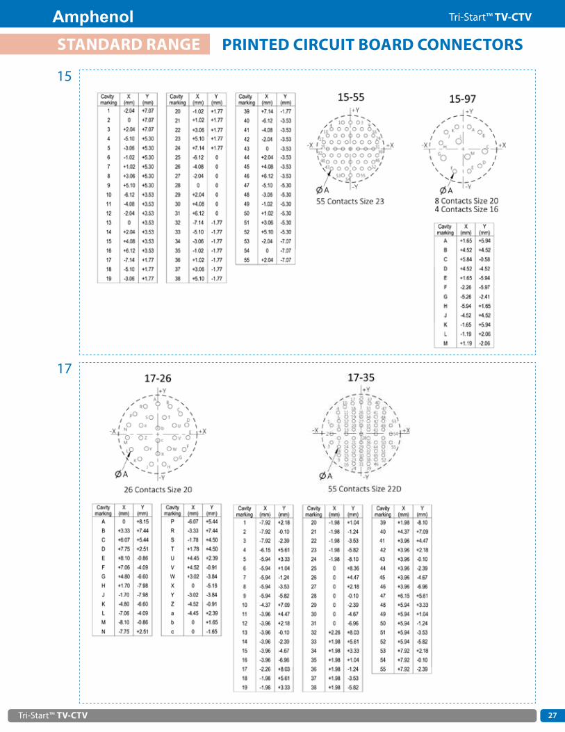
15
Tri-Start™ TV-CTV 27
Amphenol Tri-Start™ TV-CTV
STANDARD RANGE PRINTED CIRCUIT BOARD CONNECTORS
15
17

Tri-Start™ TV-CTV
Amphenol Tri-Start™ TV-CTV
28
STANDARD RANGE PRINTED CIRCUIT BOARD CONNECTORS
17

Tri-Start™ TV-CTV 29
Amphenol Tri-Start™ TV-CTV
STANDARD RANGE PRINTED CIRCUIT BOARD CONNECTORS
19

Tri-Start™ TV-CTV
Amphenol Tri-Start™ TV-CTV
30
STANDARD RANGE PRINTED CIRCUIT BOARD CONNECTORS
21

Tri-Start™ TV-CTV 31
Amphenol Tri-Start™ TV-CTV
STANDARD RANGE PRINTED CIRCUIT BOARD CONNECTORS
21

Tri-Start™ TV-CTV
Amphenol Tri-Start™ TV-CTV
32
STANDARD RANGE PRINTED CIRCUIT BOARD CONNECTORS
23

Tri-Start™ TV-CTV 33
Amphenol Tri-Start™ TV-CTV
STANDARD RANGE PRINTED CIRCUIT BOARD CONNECTORS
23

Tri-Start™ TV-CTV
Amphenol Tri-Start™ TV-CTV
34
STANDARD RANGE PRINTED CIRCUIT BOARD CONNECTORS
25

Tri-Start™ TV-CTV 35
Amphenol Tri-Start™ TV-CTV
STANDARD RANGE PRINTED CIRCUIT BOARD CONNECTORS
25

Tri-Start™ TV-CTV
Amphenol Tri-Start™ TV-CTV
36
25
STANDARD RANGE PRINTED CIRCUIT BOARD CONNECTORS

Tri-Start™ TV-CTV 37
Amphenol Tri-Start™ TV-CTV
25
STANDARD RANGE PRINTED CIRCUIT BOARD CONNECTORS

Tri-Start™ TV-CTV
Amphenol Tri-Start™ TV-CTV
38
STANDARD RANGE PRINTED CIRCUIT BOARD CONNECTORS
25

Tri-Start™ TV-CTV 39
Amphenol Tri-Start™ TV-CTV
NOTES

Tri-Start™ TV-CTV
Amphenol Tri-Start™ TV-CTV
40
MAIN CHARACTERISTICS• More density on panel 37% average footprint surface reduction• More space inside the box: 36% average reduction of panel/PCB distance• Lighter: 30% average lighter than standard 38999 stand off receptacle• Derivated from MIL-DTL-38999 series III version• Mates with standard MIL-DTL-38999 series III plugs and caps• Reduced flange receptacles are available in crimp version, with PC Tail contacts, as well as in stand off version• For jam nut (TV07) configurations
EXTENDED RANGE REDUCED FLANGE NEW
PC Tail Contacts & Stand Off
SMALLER DIMENSIONS
38999 Series III Reduced Flange
Stand Off
38999 Series IIIStand Off
3,6 mm (CI)7,2 mm (LI)
3,7 mm (CI)7,2 mm (LI)
PC Tail Contacts 38999 Series III
Reduced Flange PC Tail
38999 Series III PC Tail
5 + 0,1 (CI)8,5 + 0,1 (LI)
5 + 0,1 (CI)8,5 + 0,1 (LI)
Deviation: F059/F058* with safety castel nut
Crimp Contacts38999 Series III
Standard38999 Series III
Reduced Flange
Deviation: F312/F311* with safety castel nut
X X X
Y
YY
* with safety castel nut
FOOTPRINT AND WEIGHT SAVING
TOOLS
Sizes Footprint Reduction (mm2)9 43%11 46%13 43%15 36%17 26%19 37%21 36%23 34%25 30%
Sizes Tools PN9 80968111 80968213 80968315 80968417 80968519 80968621 80968723 80968825 809689
Example of Weight Reduction : 38999 Series III stand off version: TV07WCI13-35P F459 = 31 .46 g38999 Series III Reduced flange stand off version : TV07WCI13-35P F259 = 19 .49 g> The #13 Reduced flange stand off version is 38 % lighter than 38999 Series III standard stand off version .

Tri-Start™ TV-CTV 41
Amphenol Tri-Start™ TV-CTV
MAIN CHARACTERISTICS
OVERALL DIMENSIONS
Square flange receptacle (size 9 to 25)
Jam nut receptacle (size 13 to 25)
Shell Size S ± 0.25(mm)
R2(mm)
S1 ± 0.4(mm)
øW(mm)
9 23 .83 16 .00 27 .0 20 .50
11 26 .19 18 .26 31 .8 25 .20
13 28 .58 20 .62 34 .9 25 .25
15 30 .96 23 .01 38 .1 28 .42
17 33 .32 26 .10 41 .3 31 .42
19 36 .53 27 .24 46 .0 35 .03
21 39 .67 29 .36 49 .2 37 .82
23 42 .88 31 .75 52 .4 41 .12
25 46 .02 34 .93 55 .6 44 .30
Contact us for more detailed information .
Jam nut receptacle (size 9 and 11)
• Receptacles with stand-off flange shells, for attachment to printed circuit boards .• Tin plated contacts . Lead free versions available .• Available in wall mount (TVP00) and jam nut (TV07) configurations .• Prevent any mechanical stress on the contact tails .• Provide grounding continuity between PCB and box .• Increase reliability and resistance to shocks and vibrations• For composite versions, please consult us .
Deviations :• Lead Tinned Stand Off : F459• Silver Tinned Stand Off : F459LF• Silver Copper Tinned Stand Off : F459LFCFor other versions, please consult us
For ordering informations, see section "Printed Circuit Board Connectors"
EXTENDED RANGE STAND OFF RECEPTACLES

Tri-Start™ TV-CTV
Amphenol Tri-Start™ TV-CTV
42
SR1
R2
T
SR1R2
2.36+0.15 0
B
6.35 MAXV
R3
R4
Ø Y
4 Ø W
Panel drilling
0.13 M
TT0.13 M
23.19+0.28 0
PRESENTATIONTVS-Y and TVS-YN hermetic receptacles are dedicated to applications requiring low air leakage or high protection facing to contamination .
MAIN CHARACTERISTICS• 9 shell sizes (stainless steel)
• Solder pin contacts in nickel alloy
• Contact plating in active zone: Gold
• Glass insert
• Air leakage < 1 .10 -7 cm3/s under 1 bar of differential pressure
• Passivation or nickel plating
OVERALL DIMENSIONS - HERMETIC VERSIONS
Square flange receptacleTVPS02Y JD38999/21Y
TVPS02YN JD38999/21N
Shell size Bthread
Class 2A0.1P-0.3L-TS
(inches)
R1
(mm)R2
(mm)
S±0.25(mm)
T+0.20-0.13(mm)
TT+0.20-0.13(mm)
ØW+0
-0.25(mm)
R3
(mm)R4
(mm)
VMini(mm)
ØYMini(mm)MIL-DTL-38999
Series IIIAmphenol
A 9 .6250 18 .26 15 .09 23 .83 3 .25 5 .49 3 .25 18 .26 15 .09 24 .60 16 .66B 11 .7500 20 .62 18 .26 26 .19 3 .25 4 .93 3 .25 20 .62 18 .26 27 .00 20 .22C 13 .8750 23 .01 20 .62 28 .58 3 .25 4 .93 3 .25 23 .01 20 .62 31 .50 23 .42D 15 1 .0000 24 .61 23 .01 30 .96 3 .25 4 .39 3 .25 24 .61 23 .01 34 .50 26 .59E 17 1 .1875 26 .97 24 .61 33 .32 3 .25 4 .93 3 .25 26 .97 24 .61 28 .00 30 .96F 19 1 .2500 29 .36 26 .97 36 .53 3 .25 4 .93 3 .25 29 .36 26 .97 40 .50 32 .94G 21 1 .3750 31 .75 29 .36 39 .67 3 .25 4 .93 3 .25 31 .75 29 .36 44 .00 36 .12H 23 1 .5000 34 .93 31 .75 42 .88 3 .91 6 .15 3 .81 34 .93 31 .75 47 .00 39 .29J 25 1 .6250 38 .10 34 .93 46 .02 3 .91 6 .15 3 .81 38 .10 34 .93 50 .00 42 .47
EXTENDED RANGE TVS-Y / TVS-YN HERMETIC RECEPTACLES

Tri-Start™ TV-CTV 43
Amphenol Tri-Start™ TV-CTV
Shell sizeB
threadClass 2A
0.1P-0.3L-TS(inches)
ØGG+0.28-0.25(mm)
ØKK+0.03-0.13(mm)
L+0.28
-0(mm)
M+0.15-0.13(mm)
VMini(mm)
ØYMini(mm)MIL-DTL-38999
Series IIIAmphenol
A 9 .6250 19 .05 17 .07 20 .47 3 .18 24 .60 17 .60B 11 .7500 21 .44 19 .84 20 .47 3 .18 27 .00 20 .40C 13 .8750 24 .61 23 .01 20 .47 3 .18 31 .50 23 .50D 15 1 .0000 27 .79 26 .19 20 .47 3 .18 24 .50 26 .70E 17 1 .1875 30 .94 29 .36 20 .47 3 .18 38 .00 29 .90F 19 1 .2500 33 .32 31 .75 20 .47 3 .18 40 .50 32 .30G 21 1 .3750 36 .53 34 .93 20 .47 3 .18 44 .00 35 .50H 23 1 .5000 39 .70 38 .10 21 .29 3 .96 47 .00 38 .60J 25 1 .6250 42 .88 41 .28 21 .29 3 .96 50 .00 41 .80
C
SH
Ø KK
K REF 5.08 MAXB
1.57 MINI3.18 MAX
L Panel drilling
Ø Y
Z
V
L
0.79+0.15–0.13
B9.53 MAX
M
Ø KK
Ø GG
V
Panel drilling
Ø Y
V
Jam nut receptacleTVS07Y JD38999/23YTVS07YN JD38999/23N
Solder mounting receptacleTVSIY JD38999/25YTVSIYN JD38999/25N
Shell size Bthread
Class 2A0.1P-0.3L-TS
(inches)
CMaxi(mm)
H/plats+0.043
-0.41(mm)
LMaxi(mm)
ØKK+0.28
0(mm)
B±0.25(mm)
VMini(mm)
ØYMini(mm)
Z+0
-0.25(mm)
Hex nutmax torquevalue N.mMIL-DTL-38999
Series IIIAmphenol
Socapex
A 9 .6250 30 .45 22 .23 9 .07 16 .31 26 .97 27 .80 17 .78 16 .99 4 .1B 11 .7500 35 .20 25 .40 9 .07 19 .46 31 .75 32 .60 20 .96 19 .53 5 .3C 13 .8750 38 .38 30 .18 9 .07 22 .66 34 .93 36 .00 25 .65 24 .26 6 .9D 15 1 .0000 41 .55 33 .32 9 .07 25 .86 38 .10 39 .60 28 .83 27 .53 8 .6E 17 1 .1875 44 .73 36 .53 9 .07 29 .01 41 .28 43 .30 32 .01 30 .68 9 .8F 19 1 .2500 49 .50 39 .67 9 .68 32 .21 46 .02 47 .00 35 .18 33 .86 10 .9G 21 1 .3750 52 .65 42 .80 9 .68 35 .36 49 .23 50 .60 38 .35 37 .06 12 .7H 23 1 .5000 65 .85 46 .02 9 .68 38 .56 52 .37 54 .20 41 .53 40 .01 13 .8J 25 1 .6250 59 .00 50 .80 9 .68 41 .71 55 .58 59 .70 44 .70 43 .41 15
EXTENDED RANGE TVS-Y / TVS-YN HERMETIC RECEPTACLES
POLARIZATIONMS
CodeSocket contact
Amphenol codeMS
CodePin contact
Amphenol codeSN S (normal) PN P (normal)SA H PA GSB J PB ISC L PC KSD N PD MSE T PE R

Tri-Start™ TV-CTV
Amphenol Tri-Start™ TV-CTV
44
58.5 MAX
51 MAX
3.2 MAX
6.3 RAD
42.4 MAX
LENGTH "X"See chart A
7.11 MAX
Ø42.5 MAXACCESSORY
PRESENTATIONAmphenol Breakaway Connectors provide unequaled performance in environments requiring instant disengagment .
Designed to provide quick disconnect of a connector plug and receptacle with an axial pull on the lanyard, the "Breakaway" Fail Safe connector family offers a wide range of electrical and mechanical features:
• Compatible/intermateable with MIL-DTL-38999 series III receptacles
• Quick disconnect between plug and receptacle and damage free separation
• Up to 15° misalignement for instant desengagement
• Tread coupling (tri start connector)
• Other shell size and arragements available in MIL-DTL-38999 standard lanyard versions
• 2 arrangements available for MIL-STD-1760 applications :
TABLE A
Other lengths are also available under TVFBRW proprietary designation . Consult us .* for TV FBRW only
Length "X" MIL.STD 1760 coding mm
A* 102B* 115C* 127D 140E 153F 166G 178H 191J 407K 229M 254X 432
EXTENDED RANGE LANYARD RELEASE PLUGS (BREAKAWAY CONNECTORS)
J 11 / 25N1125-11
N2 9
20 10 power
J 20 / 25N2025-20
N10 13 3 420 16 8 twinax° 12 coax
Y
OVERALL DIMENSIONSLanyard release plugs - MIL-STD-1760
TVFBRW JD38999/31W
MSCode
Socket contactAmphenol code
MSCode
Pin contactAmphenol code
SN S (normal) PN P (normal)SA H PA GSB J PB ISC L PC KSD N PD MSE T PE R
POLARIZATION

Tri-Start™ TV-CTV 45
Amphenol Tri-Start™ TV-CTV
LANYARD RELEASE PLUGS (BREAKAWAY CONNECTORS)
Blue band
9.12 Max9.50 Max
45.24 Max60.33 Max
Length XSee chart II
Ø 12.70 0.79D
MetricV Thread
B
Lanyard release plugs
Standard version(ordering information, see section "How to Order")
885565 . . .P JD38999/29W915565 . . .P JD38999/29F885565 . . .S JD38999/30W915565 . . .S JD38999/30F
TABLE III
TABLE II
Length "X" (mm) Code MS/Amphenol
102 A115 B127 C140 D153 E166 F178 G191 H203 I216 J229 K242 L254 M267 N280 P293 R305 S318 T331 U356 V381 W407 X432 Y458 Z
TABLE I
Arrangement code Insert arrangement
04 11-0406 11-3507 11-9808 11-0210 13-411 13-0813 13-9814 13-3518 15-519 15-1920 15-3521 15-9722 15-1823 15-1527 17-0628 17-0829 17-2630 17-3531 17-9937 19-1138 19-2839 19-3240 19-3547 21-1148 21-1649 21-3550 21-4151 21-3957 23-2158 23-3559 23-5360 23-5561 23-5466 25-1967 25-2968 25-3569 25-4370 25-6171 25-0472 25-2473 25-46
Shell size
Metric MaxB
Max(mm)
DMax
(mm)MIL-DTL-38999Series III
Amphenol
B 11 M15X1 .0-6G 46 .89 28 .17C 13 M18x1 .0-6g 50 .09 31 .75D 15 M22X1 .0-6G 52 .81 34 .93E 17 M25X1 .0-6G 56 .01 38 .10F 19 M28X1 .0-6G 58 .45 41 .28G 21 M31X1 .0-6G 62 .79 44 .45H 23 M34X1 .0-6G 65 .89 47 .63J 25 M37X1 .0-6G 68 .71 50 .08
EXTENDED RANGE LANYARD RELEASE PLUGS (BREAKAWAY CONNECTORS)

Tri-Start™ TV-CTV
Amphenol Tri-Start™ TV-CTV
46
• Intermateable with MIL-DTL-38999 Series III connectors• 9 shell sizes• Interfacial seal on male side• Olive drab cadmium or nickel plating• Coding possibility
• Intermateable with MIL-DTL-38999 Series III connectors• 9 shell sizes• Solder or PCB pin contacts . Socket contacts available upon request
TVB thru-bulkhead receptacles are used for the feed through of circuits on bulkheads or panels.
TV07 ETC receptacles with enhanced sealing are derived from the standard MIL-DTL-38999 Series III receptacles . The inserts have been modified to ensure an air leakage of < 1 .10-6cm3/s under 1 bar of differential pressure .
For further information, please consult us .
For further information, please consult us .
Thru-bulkhead Receptacles TVB W 15 35 PS N F467
Shell Material and finishW: Olive drab cadmium plated aluminiumF: Electroless nickel plated aluminiumB: Marine bronzeZN: Black Zinc Nickel
Shell size and insert arrangements: see section "Insert Arrangements"
Contact typePS: Pin & Socket
CodingN, A, B, C, D, E
DeviationF467: Drilled and tapped mounting holes (recommended)
Series TV 07 W ET C 15 35 P A
Shell TypeJam nut receptacle: 175°C (O .D . cadmium): 07 200°C (nickel, bronze): S07
Shell material, finish and contact typeW: Olive drab cadmium plated aluminiumF: Electroless nickel plated aluminiumB: Marine bronzeZ: Green zinc cobalt plated aluminiumZN: Black zinc nickel plated aluminium
Enhanced sealing
Contact terminationC: Solder contactsCI: Standard PCB contactsLI: Long tail PCB contacts
Shell size and insert arrangements: see section "Insert Arrangements"
Contact typeP: Pin
CodingBlank for normal, A, B, C, D, E
HOW TO ORDER
HOW TO ORDER
EXTENDED RANGE
RANGE DERIVATED
THRU-BULKHEAD RECEPTACLES
RECEPTACLES WITH ENHANCED SEALING

Tri-Start™ TV-CTV 47
Amphenol Tri-Start™ TV-CTV
TVOP
STARTOP
For further information, please consult us .
For further details, please consult the EWOC catalog (DOC-000503-ANG) .
MAIN CHARACTERISTICS• All in one product• Time saving during order and installation• Space and weight saving• Deviation : F472
Available on plugs and receptacles, these 2 in 1 connectors/band backshells provide a high EMI protection with a quick, easy and cost effective cabling process . They are low profile, with enhance sealing level and allow the use of macro and micro bands, as well as straight or right angle heat shrink moulded pieces . The design of the shells makes them compatible with over moulding process .
The TVOP connector is an optical version of the MIL-DTL-38999 series III connector, which uses standard 2 .5 mm telecom optical termini in dedicated high precision inserts . It is designed to provide high level of performance and reliability, and cost effective solution for outdoor and indoor applications .
The STARTOP connector is made of standard MIL-DTL-38999 electrical connectors, using size 16 MIL-PRF-29504 optical termini .Hybrid versions (electrical and optical) are available, for further details please consult us .
Insert arrangements
Insert arrangements
• 1 to 8 channels• Available in multimode, singlemode PC and singlemode APC• 0 .5 dB typical Insertion Loss in multimode and singlemode
• 1 to 8 channels• Available in multimode• 0 .8 dB typical Insertion Loss
11-2 13-4 17-8
11-02 13-04 15-05 17-08
EXTENDED RANGE
EXTENDED RANGE
INTEGRATED BACKSHELLS
MIL-DTL-38999 SERIES III OPTICAL CONNECTORS

Tri-Start™ TV-CTV
Amphenol Tri-Start™ TV-CTV
48
20.24 MAX
B
A
20.24 MAX
B105 5
A29.62 MAX
N160 5
A
Ø 3.9+0.1+0
Bouchon d'embase à collerette carrée
Bouchon d'embase à collerette ronde
Bouchon de fiche
105 5
Protection cap for receptacles equipped with metallic chain, nylon cord or stainless steel rope
Protection cap for plugs equipped with metallic chain, nylon cord or stainless steel rope
23mm MAX 30mm MAX
ORDERING INFORMATION
STANDARD METALLIC CAPS
For stainless steel caps, please consult us: RoHS compliant
Shell size A thread0.1P-0.3L-TS
Class 2B(inches)
BDiaMax
(mm)
CDiaMin
(mm)
NDiaMax
(mm)MIL-DTL-38999
Series III Amphenol
A 9 .6250 22 .23 17 .86 22 .73B 11 .7500 25 .40 21 .44 25 .40C 13 .8750 28 .58 25 .81 29 .74D 15 1 .0000 31 .75 28 .98 32 .99E 17 1 .1875 36 .53 32 .16 36 .47F 19 1 .2500 38 .10 36 .27 39 .19G 21 1 .3750 41 .28 38 .51 42 .42H 23 1 .5000 44 .45 41 .68 45 .39J 25 1 .6250 47 .63 44 .86 48 .62
Standard Metallic Caps B EC N TV W 15
Protection cap typeEC: For square flange receptacleER: For jam nut receptacleF: For plug
Wire type N: Nylon cordBlank for metallic chainR: Jacketed stainless steel ropeRO: Jacketed stainless steel rope with washer end (only for plug)
Connector type
Finish B: Bronze F: Electroless nickel plated, aluminium version W: Olive drab cadmium plated aluminium version Z: Green zinc cobalt plated aluminium ZN: Black zinc Nickel aluminium from Amphenol Europe
Corresponding connector shell size: 09/11/13/15/17/19/21/23/25
Cap type Metallic chain length (mm) Nylon cord length (mm) Stainless steel rope length (mm)
BEC/BER for receptacle 152 105 127BF for plug 127 160 127
+-
ACCESSORIES PROTECTIVE CAPS
DUST
WATEREMI
MOISTURE• For receptacles & plugs• IP 68 (permanent sealing)

Tri-Start™ TV-CTV 49
Amphenol Tri-Start™ TV-CTV
HOW TO ORDER
RUBBER CAPS
Cap Series RC 00 N TV 9
Protection cap type00: For square flange receptacle07: For jam nut receptacle01: For line receptacle
Wire type N: Nylon cord
Connector type
Shell size: 09/11/13/15/17/19
ACCESSORIES
ACCESSORIES
PROTECTIVE CAPS
PROTECTIVE CAPS - TERMINATION TYPE
NEW
C
4.1 +0.1
4.1 +0.1
4.1 +0.1
4.1 +0.1
4 .1
4 .1
Termination of the chain, rope (RO type) or cord for jam nut receptacle protection caps
Termination of the cord or rope (R type) for square flange receptacle protection caps
Termination of the chain for square flange receptacle and plug protection caps
Termination of the cordfor plugs protection caps
For both standard Metallic Caps & Rubber Caps
DUST
WATER
Sizes ØA Max ØB Max ØC Max +0,25
0 D Max
9 19,25 13,85 17,86 14011 22,55 17,2 22,63 14013 25,95 20,6 25,81 14015 28,75 23,4 30,24 140
• For receptacles• IP67 (1m, 1 hour sealing)

Tri-Start™ TV-CTV
Amphenol Tri-Start™ TV-CTV
50
For more detailed information, consult our Backshell catalog (E118)
SHIELDING
TV-35: BAND BACKSHELL FOR SHIELDING• Full 360° shield termination• Available with different cabling chambers• Easy maintenance or repairability• Sealing ensured by straight or right angled heat-shrink molded piece • Right angle version: TV SBC
TV NSA: HIGH LEVEL OF EMI/RFI PROTECTION• Electrical continuity between cable and connector by clamping
the braid with a screwing system• Free inner ring to avoid twisting of the braid when screwing• Sealing ensured by straight or right angle heat-shrink molded piece
M85049/88: BAND LOCK ADAPTOR• MIL standardized band backshell• Full 360° termination• Sealing ensured by straight or right angle heat-shrink molded piece• Right angle and 45° versions available
SEALING
TV NSD: ADAPTER FOR HEAT-SHRINK MOLDED PIECE
MECHANICAL RETENTION
M85049/38 - M85049/38S: STRAIN RELIEF CLAMP• MIL standardized strain relief clamp• Mechanical retention of the cable• Easy maintenance or repairability• Self locking option available
M85049/19: NON-ENVIRONMENTAL EMI/RFI BACKSHELL• 360° screen termination• Strain relief cable holding mechanism
ACCESSORIES BACKSHELLS

Tri-Start™ TV-CTV 51
Amphenol Tri-Start™ TV-CTV
OTHER ACCESSORIES
DUMMY RECEPTACLES
Dummy receptacle SE 00 TV W 11
Shell type00: derived from the TV square flange receptacle
Series
FinishW: Olive-drab cadmium plated F: Electroless nickel plated B: Marine Bronze ZN: Black Zinc Nickel plated
Shell size09/11/13/15/17/19/21/23/25
: RoHS compliant
HOLDING SUPPORT EQUIPPED WITH OLIVE DRAB CADMIUM DUMMY RECEPTACLES REFERENCE: 809 931
• Dummy receptacles match all plug types with any shell coding (N, A, B, C, D, E)• Dimensions are identical to the front part of TVP00 receptacles• A rubber washer ensures correct sealing of mated connectors• Specific polarized versions are available on request
How to order - Amphenol designation
Size 25 receptacleall codings
Size 23 receptacleall codings
Size 21 receptacleall codings
Size 19 receptacleall codings
Size 17 receptacleall codings
Size 15 receptacleall codings
Size 13 receptacleall codings
Size 11 receptacleall codings
Size 9 receptacleA, B, D codings
Size 9 receptacleN, C, E codings
PLASTIC DUST CAPS
Shellsize
Plastic dust capsfor plug
Plastic dust capsfor receptacles
9 606062 606061
11 805414 606062
13 606073 606063
15 606066 606064
17 606067 606065
19 606068 606066
21 606070 606067
23 606079 606068
25 606079 606069
ACCESSORIES

Tri-Start™ TV-CTV
Amphenol Tri-Start™ TV-CTV
52
CRIMP CONTACTS
Contact sizePin contacts Socket contacts
Proprietary No Military No Proprietary No Military No
Signal and Power
00 Refer to catalog contacts (DOC-000081-ANG) Refer to catalog contacts (DOC-000081-ANG)
4 900007 - 900047 -
8* 900197900198** - 900217 -
12 900005 M39029/58-365 900045 M39029/56-353
16 900000 M39029/58-364 900040 M39029/56-352
20 900001 M39029/58-363 900041 M39029/56-351
22D 900004 M39029/58-360 900044 M39029/56-348
23 900049 M39029/18-177 900048 M39029/17-172
Contact sizePin contacts Socket contacts
Cable TypeProprietary No Military No Proprietary No Military No
Coax
8*
900130 M39029/60-367 900140 M39029/59-366 M17/95-RG180
900135 - 900145 -M17/94-RG179
M17/113-RG316M17/119-RG174
12
900340 M39029/28-211 900350 M39029/75-416M17/94-RG179
M17/113-RG316M17/119-RG174
900341 M39029/28-409 900351 M39029/75-417 M17/95-RG180Raychem 9528 A1318
900384*** - 900394** - M17/113-RG316
16071094 M39029/76-424 070248 M39029/77-428
M17/94-RG179M17/113-RG316M17/119-RG174
KX22A
070575 M39029/76-425 071965 M39029/77-429 M17/93-RG178M17/169-00001
Twinax 8* 074834 M39029/90-529 072453 M39029/91-530 M17/176-00002
Twinax 8* 600611 - 600614 - M17/176-00002
Quadrax 100Ω 8 900330 - 900338 - Tensolite NF24 Q100
Optical contact 16 - M29504/4-4040 - M29504/5-4046 50/125 & 62 .5/125 fiber
* Use with piggy back grommets is mandatory ** For arrangement 21-48 only
* Use with piggy back grommets is mandatory*** High performance size 12 coaxial contacts 50 ohms matchedFor other cable types, please consult us
Type of contact Cable OD (mm) Proprietary No
Size 8 power 4 .4 to 5 .2 900471
Size 8 twinax and coax 3 to 4 .4 900472
Size 8 twinax and coax 3 to 4 .4 900476 ****
PIGGY BACK GROMMETSThe piggy back grommets insure back contact sealing when using size 8 power, coax, twinax or quadrax contacts . Quadrax contact part numbers always include piggy back grommets .
**** to use for arrangements 25-20, 19-17
ACCESSORIES OTHER ACCESSORIES

Tri-Start™ TV-CTV 53
Amphenol Tri-Start™ TV-CTV
SEALING PLUGS
Contact size Proprietary No Military No
8 power 900024 -
12 900023 MS27488-12-2
16 900020 MS27488-16-2
20 900021 MS27488-20-2
22D 900022 MS27488-22-223 900022 MS27488-22-2
To be mounted behind the crimp contacts
DUMMY CONTACTS
Contact size Dummy contact material Proprietary No
4 White plastic 900329
8 Green plastic 900488
8 Brass + gold finish 900183
8 White plastic (recommended) 900029
12 Brass + gold finish 900025
12 White plastic 900486
16 Brass + gold finish 900028
16 Blue plastic 900026
20 Brass + gold finish 900332
To be mounted instead of the contacts
Metal dummy contacts are recommended for applications requesting EMI protection .
Contact size TypePin contacts Socket contacts
Tail dimension (mm) Proprietary No Tail dimension (mm) Proprietary No
Signal
12 CI 5 900238 5 900403
16CI 5 900240 5 900263
LI 8 .5 900246 8 .5 600526
20CI 5 900241 5 900251
LI 8 .5 900243 8 .5 900252
22DCI 5 900245 5 900256
LI 8 .5 922389 8 .5 922390
23 CI 5 900458 5 900459
Coax12
- consult us 900489 - -
- consult us 900409 - -
16 - consult us 900184** consult us 900405
Twinax 8 - consult us 072265 - -
STANDARD PC TAIL CONTACTS
** 900179 = 900184 + tin platingOther PC tail lengths are available, please consult us .
ACCESSORIES OTHER ACCESSORIES

Tri-Start™ TV-CTV
Amphenol Tri-Start™ TV-CTV
54
REDUCING FERRULES
Reducing ferrule No Contact size Wire Gauge Pin contacts Socket contacts
No reducing ferrule8
8900197 / 900198 900217
900154 10
No reducing ferrule
12
121416
900005 900045900092161820
900093202224
No reducing ferrule
16
16182022 900000 900040
900091242628
No reducing ferrule20
202224 900001 900041
900090 2628
900094
22D
34
90004 900044
900099 30
No reducing ferrule
22242628
Reducing ferrules allow using cables with smaller diameters than specified in the table part electrical characteristics
The sealing of mated connectors is only guaranteed for the minimum wire outside diameter given in the table part electrical characteristics .
Contact sizePin contacts Socket contacts
Proprietary No Military No Proprietary No Military No
Signal
20 900318 M39029/107-621 900323 M39029/106-615
22D 900317 M39029/107-620 900322 M39029/106-614
16 900319 M39029/107-622 900324 M39029/106-616
1500 CYCLES CRIMP CONTACTS (FOR CTV ONLY)
ACCESSORIES OTHER ACCESSORIES

Tri-Start™ TV-CTV 55
Amphenol Tri-Start™ TV-CTV
Contact size Contacttype
Contact part number Crimping tool Positioner
Proprietary No Military No Proprietary No Military No Proprietary No Military No
00 Refer to catalog contacts (DOC-000081-ANG)
4P 900007 - 809947 - 809948 -S 900047 - 809947 - 809948
8 CoaxInner pin & socket 809 801 M22520/2-01 - M22520/2-31Outer pin & socket 809 914 M22520/5-01 809 915 M22520/5-41
8 PowerP 900 197 - 809 872 - 809 873 -P 900 198 - 809 872 - 809 873 -S 900 217 - 809 872 - 809 873 -
12 CoaxInner pin & socket 809 801 M22520/2-01 809 932 M22520/2-34Outer pin & socket 809 926 M22520/31-01 809 927 M22520/31-02
12P 900 005 M39029/58-365 809 857 M22520/1-01 809 858 M22520/1-04S 900 045 M39029/56-353 809 857 M22520/1-01 809 858 M22520/1-04
16 CoaxInner pin & socket 809 801 M22520/2-01 809 862 M22520/2-35Outer pin & socket 809 863 M22520/4-01 809 864 M22520/4-02
16P 900 000 M39029/58-364 809 857 M22520/1-01 809 858 M22520/1-04S 900 040 M39029/56-352 809 857 M22520/1-01 809 858 M22520/1-04
20
P 900 001 M39029/58-363 809 857 M22520/1-01 809 858 M22520/1-04809 801 M22520/2-01 809 826 M22520/2-10
S 900 041 M39029/56-351 809 857 M22520/1-01 809 858 M22520/1-04809 801 M22520/2-01 809 826 M22520/2-10
22DP 900 004 M39029/58-360 809 801 M22520/2-01 809 810 M22520/2-09S 900 044 M39029/56-348 809 801 M22520/2-01 809 835 M22520/2-07
23P 900 049 M39029/18-177 809801 M22520/2-01 809 691 M22520/2-13S 900 048 M39029/17-172 809801 M22520/2-01 809 692 M22520/2-16
Contact sizeInsertion tool Removal tool Colour
Proprietary No Military No Proprietary No Military No Insertion Extraction
8 Power/coax * * - M81969/14-12 - green12 809 859 M81969/14-04 809 859 M81969/14-04 yellow white16 809 855 M81969/14-03 809 855 M81969/14-03 blue white20 809 854 M81969/14-10 809 854 M81969/14-10 red orange
22D 809 856 M81969/14-01 809 856 M81969/14-01 green white
Plastic tools
Contact size
Straight type Angle type
Insertion toolsProprietary No
Removal toolsProprietary No
Insertion tools Removal tools
Proprietary No Military No Proprietary No Military No
4 * 809943 - - - -8 Power/coax - 809961 * * 809 845 M81969/8-14
12 - - 809 838 M81969/8-09 809 839 M81969/8-1016 809 816 809 846 809 812 M81969/8-07 809 820 M81969/8-0820 809 817 809 847 809 813 M81969/8-05 809 821 M81969/8-06
22D 809 819 809 849 809 815 M81969/8-01 809 823 M81969/8-0223 810 010 810 010 - - - -
Metallic tools
* Manual insertion
* Manual insertion
CRIMPING TOOLS
INSERTION AND REMOVAL TOOLS
ACCESSORIES APPLICATION TOOLS

Tri-Start™ TV-CTV
Amphenol Tri-Start™ TV-CTV
56
AMPHENOL DESIGNATION Series TV P00 R
Q W 17-75 P A - -
TV: Metallic shell
CTV: Composite shell
Shell type
P00: Square flange receptacle: 175°C (O .D . cadmium, g .zinc cobalt, ni-PTFE, b .zinc nickel)PS00: Square flange receptacle: 200°C *** (nickel, s .steel, bronze)07: Jam nut receptacle: 175°C (O .D . cadmium, g .zinc cobalt, ni-PTFE, b .zinc nickel)S07: Jam nut receptacle: 200°C *** (nickel, s .steel, bronze)06: Straight plug: 175°C (O .D . cadmium, g .zinc cobalt, ni-PTFE, b .zinc nickel)S06: Straight plug: 200°C *** (nickel, s .steel, bronze)01: In line receptacle 175°C (O .D . cadmium, g .zinc cobalt, ni-PTFE, b .zinc nickel)S01: In line receptacles 200°C *** (nickel, s .steel, bronze)P02: P00 without rear thread (no poss . for backshell) 175°C (O .D . cadmium, g .zinc cobalt, ni-PTFE, b .zinc nickel)PS02: PS00 without rear thread (no poss . for backshell) 200°C *** (nickel, s .steel, bronze)
Contact type R: Crimp contacts (or connector delivered without contact)Omit for PC tail contacts, Durmalon plating and black zinc nickel plating
Ground Plane receptacle and Quadrax contact optionsG: conductive insertQ: insert compatible with quadrax or differential twinax contacts **GQ: conductive insert compatible with quadrax or differential twinax contactsOmit for standard receptacle (without conductive insert) and insert without quadrax contact
ClassW: Olive Drab Cadmium plating (on aluminium or composite)F: Nickel Plating (on aluminium or composite) K: Passivated Stainless Steel S: Nickel plated Stainless Steel B: Marine Bronze (copper aluminium alloy) DT: Durmalon plating (Nickel - PTFE) Z: Green zinc Cobalt plated aluminium ZN: Black Zinc Nickel plated aluminium
PC Tail ContactsOmit for crimp contactsCI: standard PCB contactsLI: long tail PCB contacts
Shell size and Contact arrangement *** See section "Insert Arrangements"
Contact type P: Pin (500 cycles) S: Socket (500 cycles) H: Pin (1500 cycles - CTV only) J: Socket (1500 cycles - CTV only)
Polarization Blank for normal or A, B, C, D, E. See coding system, section "Insert Arrangements", sub-section "coding polarization"
Contacts Omit for connectors delivered with contacts LC: Connector delivered without contacts
Deviation F404 / F404LF / F404LFC: Tinned PCB contacts (lead tinned / silver tinned / silver-copper tinned) F485 (for TVS06 RB only): Coupling nut conforms to CECC75 - 201 - 002A (for arctic gloves)F459 / F459LF / F459LFC: stand-off receptacle (lead tinned / silver tinned / silver-copper tinned)F472 Integrated backshellsFor other deviations (FXXX), please consult us .
** For Quadrax or dif . Twinax compatible inserts, please omit the "S" corresponding to 200°C compatibility when applicable, in the P/N . Ex: CTV07RGQF17 52PLCFor other arrangements, shell, coding or deviation, please consult us .***For high-density contact arrangement, please omit the « S » corresponding to 200°C compatibility in the P/N . High-density inserts are +175°C maxi compatible . Ex: TVP 00 RF 09 09 S
: RoHS compliant
HOW TO ORDER STANDARD VERSIONS

Tri-Start™ TV-CTV 57
Amphenol Tri-Start™ TV-CTV
MILITARY DESIGNATION (CRIMP CONTACTS ONLY)
Series JD38999/ 20 F H 53 P A
Shell type20: Square flange receptacle24: Jam nut receptacle26: Straight plug
Shell material and finish CompositeJ: Olive drab cadmium plated 175°C M: Electroless nickel plated 200°C
Aluminium W: Olive drab cadmium plated 175°CF: Electroless nickel plated 200°C T: Nickel PTFE plated 175°C Z: Black Zinc Nickel plated aluminium 175°C
Stainless steelK: Passivated 200°C, firewall capability S: Nickel plated 200°C, firewall capability
Shell size A B C D E F G H J MIL 09 11 13 15 17 19 21 23 25 AmphenolContact arrangement
See section "Insert Arrangements"
Contact and connector type A: Without pin contactB: Without socket contactP: With pin contactsS: With socket contactsH: With 1500 cycles pin contacts (only valid for composite)J: With 1500 cycles socket contacts (only valid for composite)
Polarization N for normal or A, B, C, D, E . See coding system, section "Insert Arrangements"
EN3645 (EUROPEAN NORM ORDERING INFORMATION, ASD-STAN) - (CRIMP CONTACTS ONLY)
Standard number EN3645 F 0 G N 16 A N
Class:W: Crimp version, Aluminum Olive drab cadmium plated, 175°CF: Crimp version, Aluminum Nickel plated, 200°C J: Crimp version, Composite material Olive Drab cadmium plated, 175°CM: Crimp version, Composite material Nickel plated, 200°C K: Crimp version, Passivated Stainless Steel, 200°C Shell style:0: Square flange receptacle7: Jam Nut Receptacle6: PlugShell size code:A for 09, B for 11, C for 13, D for 15, E for 17, F for 19, G for 21, H for 23, J for 25
Insert type:N: StandardG: Grounded cavitiesQ: Quadrax insert, groundedL: Quadrax insert, non groundedR: Power insertContact arrangement according to EN3645-002:See section "Insert Arrangements"
Contact code:
M: with Pin contacts F: with Socket contacts Coax, twinax, quadrax contacts are not supplied with the connector
A: without Pin contacts B: without Socket contactsPolarization (Key Ways rotation):N, A, B, C, D, E. See coding system, section "Inser Arrangements"
: RoHS compliant
HOW TO ORDER STANDARD VERSIONS

Tri-Start™ TV-CTV
Amphenol Tri-Start™ TV-CTV
58
AMPHENOL DESIGNATION
MILITARY DESIGNATION
Series TV SI YN 11 35 P -
Shell typePS02: Square flange receptacleS07: Jam nut receptacleSI: Solder mounting receptacle
Shell material and finish Y: Stainless steel passivated YN: Stainless steel nickel plated
Shell size: 09/11/13/15/17/19/21/23/25
Contact arrangement See section "Insert Arrangements", marked with “Y”
Contact type P: Pin
Polarization Blank for normal or A, B, C, D, E. See coding system, section "Insert Arrangements"
Connector type JD38999/ 25 N B 35 P N
Shell type21: Square flange receptacle23: Jam nut receptacle25: Solder mounting receptacle
Shell material and finish Y: Stainless steel passivated N: Stainless steel nickel plated
Shell size A B C D E F G H J MIL 09 11 13 15 17 19 21 23 25 AmphenolContact arrangement
See section "Insert Arrangements", marked with “Y”
Contact type P: Pin
Polarization N for normal or A, B, C, D, E. See coding system, section "Insert Arrangements"
HOW TO ORDER
: RoHS compliant
HERMETIC VERSIONS

Tri-Start™ TV-CTV 59
Amphenol Tri-Start™ TV-CTV
AMPHENOL DESIGNATION
MILITARY DESIGNATION
Shell finish 8888: Olive-drab cadmium plated 91: Nickel plated
5565 20 K P
Connector type
Shell size and arrangement code See table I, section "Range Derivated", Sub-section "Lanyard Release Plugs"Others, please consult us
Lanyard length A to Z code (see table III, section "Range Derivated", Sub-section "Lanyard Release Plugs"
Contact type and polarizationSee chart below and coding, section "Insert Arrangement"
Connector type JD38999/ 29 W D 35 E N
Shell and contact type29: Plug with pin contacts30: Plug with socket contacts
Shell finish W: Olive drab cadmium platedF: Nickel plated
Shell size A* B C D E F G H J MIL 09* 11 13 15 17 19 21 23 25 Amphenol* Please consult usContact arrangement
See table I, section "Range Derivated", Sub-section "Lanyard Release Plugs"
Lanyard length A to Z code (see table III, section "Range Derivated", Sub-section "Lanyard Release Plugs")
Polarization N for normal or A, B, C, D, E . See coding, section "Insert arrangement"
HOW TO ORDER
: RoHS compliant
LANYARD RELEASE PLUGS - STANDARD VERSIONS

Tri-Start™ TV-CTV
Amphenol Tri-Start™ TV-CTV
60
AMPHENOL DESIGNATION
MILITARY DESIGNATION
Series TV FB RW 25-11 P E
FB: MIL-STD-1760 lanyard release plug
RW: Olive drab cadmium plated
Arrangement 25-11, 25-20: see section "Insert Arrangements"
Contact type and polarization G: 25-11 arrangement, pin contacts onlyP: 25-20 arrangement, pin contacts only
Lanyard length Other lengths are available upon request . See table A, section "Range Derivated", sub-section "Lanyard Release Plugs"
Series JD38999/ 31 W E 11 N 1
Shell and contact type31: Plug with pin contacts, per MIL-STD-1760
Shell finish W: Olive drab cadmium plated 175°C
Lanyard length. See table A, section "Range Derivated", sub-section "Lanyard Release Plugs"
Contact arrangement 11: 25-11 arrangement20: 25-20 arrangement
PolarizationN for 25-20 arrangement . See section "Insert Arrangement"A for 25-11 arrangement .
Plug locking ring type 1: Ø 51mm (low profile)2: Ø 68mm (please consult us)
For MIL-STD-1760 Type II connectors, please consult us .
HOW TO ORDER LANYARD RELEASE PLUGS - COMPATIBLE WITH MIL-STD-1760 APPLICATIONS

Tri-Start™ TV-CTV 61
Amphenol Tri-Start™ TV-CTV
NOTES

Tri-Start™ TV-CTV
Amphenol Tri-Start™ TV-CTV
62
Shell material MIL-DTL-38999 Series III EN 3645 AMPHENOL
Composite shell
JD38999/20J X XX A ° EN3645 J0 X N XX A ° CTVP00RW ## P ^ LCCTVP00WCI ## P ^ LC
EN3645 J0 X L XX A ° CTVP00RQW ## P ^ LCEN3645 J0 X Q XX A ° CTVP00RGQW ## P ^ LC
JD38999/20M X XX A ° EN3645 M0 X N XX A ° CTVPS00RF ## P ^ LCCTVPS00FCI ## P ^ LC
EN3645 M0 X L XX A ° CTVP00RQF ## P ^ LCEN3645 M0 X Q XX A ° CTVP00RGQF ## P ^ LC
JD38999/24J X XX A ° EN3645 J7 X N XX A ° CTV07RW ## P ^ LCCTV07WCI ## P ^ LC
EN3645 J7 X L XX A ° CTV07RQW ## P ^ LCEN3645 J7 X Q XX A ° CTV07RGQW ## P ^ LC
JD38999/24M X XX A ° EN3645 M7 X N XX A ° CTVS07RF ## P ^ LCCTVS07FCI ## P ^ LC
EN3645 M7 X L XX A ° CTV07RQF ## P ^ LCEN3645 M7 X Q XX A ° CTV07RGQF ## P ^ LC
JD38999/26J X XX A ° EN3645 J6 X N XX A ° CTV06RW ## P ^ LCEN3645 J6 X L XX A ° CTV06RQW ## P ^ LC
JD38999/26M X XX A ° EN3645 M6 X N XX A ° CTVS06RF ## P ^ LCEN3645 M6 X L XX A ° CTV06RQF ## P ^ LC
Aluminium shell
JD38999/20W X XX A ° EN3645 W0 X N XX A ° TVP00RW ## P ^ LCTVP00WCI ## P ^ LC
EN3645 W0 X L XX A ° TVP00RQW ## P ^ LCJD38999/20Z X XX A ° TVP00ZN ## P ^ LC
TVP00ZNCI ## P ^ LCTVP00RQZN ## P ^ LC
TVP00RGQZN ## P ^ LCEN3645 W0 X Q XX A ° TVP00RGQW ## P ^ LC
JD38999/20F X XX A ° EN3645 F0 X N XX A ° TVPS00RF ## P ^ LCTVPS00FCI ## P ^ LC
EN3645 F0 X L XX A ° TVP00RQF ## P ^ LCEN3645 F0 X Q XX A ° TVP00RGQF ## P ^ LC
JD38999/24W X XX A ° EN3645 W7 X N XX A ° TV07RW ## P ^ LCTV07WCI ## P ^ LC
EN3645 W7 X L XX A ° TV07RQW ## P ^ LCEN3645 W7 X Q XX A ° TV07RGQW ## P ^ LC
JD38999/24Z X XX A ° TV07ZN ## P ^ LCTV07ZNCI ## P ^ LCTV07RQZN ## P ^ LC
TV07RGQZN ## P ^ LCJD38999/24F X XX A ° EN3645 F7 X N XX A ° TVS07RF ## P ^ LC
TVS07FCI ## P ^ LCEN3645 F7 X L XX A ° TV07RQF ## P ^ LCEN3645 F7 X Q XX A ° TV07RGQF ## P ^ LC
JD38999/26W X XX A ° EN3645 W6 X N XX A ° TV06RW ## P ^ LCEN3645 W6 X L XX A ° TV06RQW ## P ^ LC
JD38999/26Z X XX A ° TV06ZN ## P ^ LCTV06RQZN ## P ^ LC
JD38999/26F X XX A ° EN3645 F6 X N XX A ° TVS06RF ## P ^ LCEN3645 F6 X L XX A ° TV06RQF ## P ^ LC
Stainless Steel shell
JD38999/20K X XX A ° EN3645 K0 X N XX A° TVPS00RK ## P ^ LCTVPS00KCI ## P ^ LC
JD38999/20S X XX A ° TVPS00RS ## P ^ LCTVPS00SCI ## P ^ LC
JD38999/24K X XX A ° EN3645 K7 X N XX A° TVS07RK ## P ^ LCTVS07KCI ## P ^ LC
JD38999/24S X XX A ° TVS07RS ## P ^ LCTVS07SCI ## P ^ LC
JD38999/26K X XX A ° EN3645 K6 X N XX A° TVS06RK ## P ^ LCJD38999/26S X XX A ° TVS06RS ## P ^ LC
Hermeticreceptacle
JD38999/21Y X XX P ° TVPS02Y ## P ^JD38999/21N X XX P ° TVPS02YN ## P ^JD38999/23Y X XX P ° TVS07Y ## P ^JD38999/23N X XX P ° TVS07YN ## P ^JD38999/25Y X XX P ° TVSIY ## P ^JD38999/25N X XX P ° TVSIYN ## P ^
Dust caps
JD38999/32W X R BF R TV W JD38999/32W X N BF RO TV W JD38999/33W X R BEC R TV W JD38999/33W X N BER R TV W
Dummy receptacle SE00 TV W
Caption MIL-DTL-38999 Series III P/N EN3645 AMPHENOL P/NShell size X X
Insert arrangement XX XX ##Polarization, rotation of secondary keyways ° ° ^
As example, male version without contact (except for bronze and hermetic male versions with contacts) .
HOW TO ORDER CROSS REFERENCES

Tri-Start™ TV-CTV 63
Amphenol Tri-Start™ TV-CTV
NOTES

64For more information, please visit our website:
www .amphenol-socapex .com
E113
H /
DO
C-00
0035
-AN
G
Your local Contact:
The information given in this document are as a guideline only.We reserve the right to modify our products in any way we deem necessary .Any duplication is prohibited, unless approved in writing .This catalog uses paper from managed forests, PEFC & FSC labels, and is printed by a printer certified “Imprim’Vert®” .
July 2019Gestion & Edition by AMPHENOL SOCAPEX
Amphenol
948, promenade de l'Arve BP2974311 Thyez Cedex - FrancePhone: +33 (0)4 50 89 28 [email protected]
www.twitter.com/AmphenolSocapexwww.linkedin.com/company/amphenol-socapex
Amphenol Socapex
www.amphenol-socapex.com
The information given in this document is a guideline only. We reserve the right to modify our products in any way we deem necessary. Any duplication is prohibited, unless approved in writing.Designed by Amphenol Socapex
For Technical Support, please contact us:+33 (0)4 50 89 28 49www.amphenol-socapex.com/technical_support
Your local Contact:
Amphenol in the world
Amphenol Sales contacts in Europe
Amphenol Sales contacts in North America
Amphenol PCD72 Cherry Hill Drive - Beverly, MA. 01915 - USAPhone: +1 978-624-3400
Amphenol FibEr SYStEmS iNt.1300 Central Expwy N, Suite 100 Allen, TX 75013 - USAPhone: +1 214-547-2400
Amphenol AEroSPACE oPErAtioNS40-60 Delaware street - Sidney, NY 13838-1395 - USAPhone: +1 800-678-0141
Amphenol PriNtED CirCuit boArD tEChNologY 91 Northeastern Boulevard Nashua, New Hampshire 03062 - USAPhone: +1 603-324-4500
SV miCrowAVE2400 Centrepark West Dr.West Palm Beach, FL 33409 - USAPhone: +1 561-840-1800
Amphenol ADVANCED SENSorS967 Windfall RoadSt. Mary’s, PA 15857-3333 - USAPhone: +1 814-834-9140
Amphenol Sales contacts in Asia
Amphenol DAEShiN558 SongNae-Dong SoSa-Gu, Bucheon-city, Kyunggi-Do Korea 420-130Phone: +81-32 610 3800
Amphenol EASt ASiA ltD.159 Kampong Ampat, #04-01/04KA PlaceSingapore 368328Phone: +656549-6537/ +656294-2128
Amphenol iNtErCoNNECt iNDiA PriVAtE limitED105 Bhosari Industrial Area - Pune 411 026 - IndiaPhone: +91 20 3068 8304
Amphenol PCD Co. ltDBuilding 21, 1st Liao Keng Industrial Zone, Shi Yan StreetBao An District, Shenzhen 518108 - China Phone: +86 755 8173 8000/8286
Amphenol JAPAN471-1, Deba, Ritto-City, Shiga 520 3041 - JapanPhone: +81 77 553 8501
Amphenol Sales contacts in other Areas
Amphenol ArgENtiNAAv. Callao 930 2do piso Oficina B "Plaza" C1023 - AAP Buenos Aires - ARGENTINAPhone: +54 11 4815-6886
Amphenol AuStrAliA PtY limitED2 Fiveways Blvd., Keysborough - MelbourneVictoria 3173- AUSTRALIAPhone: +61 3 8796-8888
Amphenol Do brAzilRua Diogo Moreira, 132, 20 andar, rooms 2001-2-3CEP: 05423-010 Sao Paulo SP - BRAZILPhone: +55 11 3815-1003
bar-tec ltd., iSrAEl3 Hagavish Street, K fir-Barkan Bldg. East Industrial Zone - Kfar-Sava, 44102 - ISRAELPhone: +972 9 764 4100
Amphenol mExiCoProlongacion Reforma 61-6 B2Col Paseo de las Lomas - C.P. 013130 - MEXICOPhone: +52 55 5258-9984
Amphenol AFriCA30 Impala Rd, Sandton 2146 - SOUTH AFRICAPhone: +27 82 410 5179
Amphenol turKEYSun Plaza 15 Kat: 15 Maslak Hah. Bilim Sok. No.5Sisli/Istanbul, 34398 - TURKEYPhone: +90 212 367 9220
timES miCrowAVE SYStEmS358 Hall AvenueWallingford, CT 06492 - USAPhone: +1 800-867-2629
Amphenol griFFith ENtErPriSES6000 E Coury DriveCottonwood, AZ 86326-9202 - USAPhone: +1 928-634-3685
Amphenol NExuS tEChNologiES, iNC50 Sunnyside Ave., Stamford, CT 06902 - USAPhone: +1 203-327-7300
Amphenol boriSCh tEChNologiES4511 East ParisGrand Rapids, MI 49512 - USAPhone: +1 616 554 9820
Amphenol CANADA CorPorAtioN605 Milner avenue - M1B 5X6 - Toronto, Ontario - CANADA Phone: +1 416 291 4401
Amphenol Air lb2 rue Clément Ader, ZAC de WE08110 Carignan - FRANCEPhone: +33 (0)3 24 22 78 49
Amphenol SEFEEZ.I. des Cazes - BP 24312402 Saint-Affrique Cedex - FrancePhone: +33 5 65 98 11 00
Amphenol Air lb gmbhAm Kleinbahnhof 466740 Saarlouis - GERMANYPhone: +49 6831 981 00
Amphenol limitEDThanet Way, WhitstableKent, CT53JF - UNITED KINGDOMPhone: +44 (0) 1227 773200
Amphenol iNVotECInvotec Circuits Tamworth LimitedHedging Lane, Dosthill, Tamworth, B77 5HH - UNITED KINGDOMPhone: +44 (0) 1827 263250
Amphenol ioNixGreenfold Way -LeighLancashire, WN7 3XJ - UNITED KINGDOMPhone: +44 1942 685200
Amphenol mArtEC limitEDSt Augustines Business Park, Swalecliffe, WhitstableKent, CT5 2QJ - UNITED KINGDOMPhone: +44 (0) 1227 793733
Amphenol itAlYVia Barbaiana n.520020 Lainate - Milano - ITALYPhone: +39 293 254 214
Amphenol ibEriCAEdificio Burgosol, Oficina nr 55 - Comunidad de Madrid, 35-bis Las Rozas SPAINPhone: +34 629 054629
Amphenol AuStriA & CEEWiener Gasse 682380 Perchtoldsdorf - AUSTRIAPhone: +43 699 10396071
Amphenol PolANDLwowska 8/16, 53-516 Wrocław - POLANDPhone: +48 513017157
Amphenol SwitzErlAND Phone: +43 699 10396071
Amphenol South CENtErSlovenia, Serbia, Montenegro, Yugoslavia, Greece, BulgariaPhone: +39 02 93254208Phone: +39 02 93254210
Amphenol NorDiCPhone: +46 70 2129200 (Mil/Aero) +46 76 7909560 (Industrial)
Amphenol bENEluxZadkinestraat 26Almere, 1328 NN - THE NETHERLANDSPhone: +31 651 296835
Amphenol SCANDiNAViA AbÄngsullsvägen 7-S187 51 Täby - SWEDENPhone: +46 70 21 29200
Amphenol in the world