mikroC PRO for dsPIC User Manual - Ciiva
783
mikroC PRO for dsPIC ™ Manual mikroC PRO for dsPIC30/33 and PIC24 is a full-featured C compiler for dsPIC30, dsPIC33 and PIC24 MCUs from Microchip. It is designed for developing, building and debugging dsPIC30/33 and PIC24- based embedded applications. This development environment has a wide range of features such as: easy-to-use IDE, very compact and efficient code, many hardware and software libraries, comprehensive documentation, software simulator, COFF file generation, SSA optimization (up to 30% code reduction) and many more. Numerous ready-to-use and well-explained examples will give a good start for your embedded project. Compiler
-
Upload
khangminh22 -
Category
Documents
-
view
2 -
download
0
Transcript of mikroC PRO for dsPIC User Manual - Ciiva

MikroElektronika
mikroC PRO for dsPIC™ Manual
mikroC PRO for dsPIC30/33 and PIC24 is a full-featured C compiler for dsPIC30, dsPIC33 and PIC24 MCUs from Microchip. It is designed for developing, building and debugging dsPIC30/33 and PIC24-based embedded applications. This development environment has a wide range of features such as: easy-to-use IDE, very compact and efficient code, many hardware and software libraries, comprehensive documentation, software simulator, COFF file generation, SSA optimization (up to 30% code reduction) and many more. Numerous ready-to-use and well-explained examples will give a good start for your embedded project.
Com
pile
r

2
mikoC PRO for dsPIC
MikroElektronika
Table of ContentsCHAPTER 1 32INTRODUCTION 32Introduction to mikroC PRO for dsPIC30/33 and PIC24 33
Features 33Where to Start 33
What’s new in mikroC PRO for dsPIC30/33 and PIC24 34Compiler Changes 34IDE Changes 34
Software License Agreement 35mikroElektronika Associates License Statement and Limited Warranty 35IMPORTANT - READ CAREFULLY 35LIMITED WARRANTY 35HIGH RISK ACTIVITIES 36GENERAL PROVISIONS 36
Technical Support 37How to Register 37
Who Gets the License Key 37How to Get License Key 37After Receving the License Key 39
CHAPTER 2 41mikroC PRO for dsPIC30/33 and PIC24 Environment 41Main Menu Options 42File 43
File Menu Options 43Edit 44
Edit Menu Options 44Find Text 45Replace Text 45Find In Files 46Go To Line 46Regular expressions option 46
View 47View Menu Options 47
Project 49Project Menu Options 49
Build 50Build Menu Options 50
Run 51Run Menu Options 51
Tools 52Tools Menu Options 52

mikroC PRO for dsPIC
MikroElektronika3
Help 53Help Menu Options 53
mikroC PRO for dsPIC30/33 and PIC24 IDE 54IDE Overview 54
Code Editor 55Editor Settings 55Auto Save 56Highlighter 56Spelling 56Comment Style 56Code Folding 56Code Assistant 57Parameter Assistant 57Bookmarks 57Go to Line 57Column Select Mode 58Editor Colors 58Auto Correct 59Auto Complete (Code Templates) 60
Code Explorer 62Routine List 63
Project Manager 63Project Settings 65Library Manager 66
Managing libraries using Package Manager 67Statistics 68
Memory Usage Windows 68RAM Memory Usage 69Used RAM Locations 69SFR Locations 70ROM Memory Usage 70ROM Memory Constants 71Functions 71Functions Sorted By Name Chart 72Functions Sorted By Size Chart 72Functions Sorted By Addresses 73Function Tree 73Memory Summary 74
Messages Window 75Quick Converter 76Macro Editor 76Image Preview 77Toolbars 79
File Toolbar 80Edit Toolbar 80

4
mikoC PRO for dsPIC
MikroElektronika
Advanced Edit Toolbar 81Find/Replace Toolbar 81Project Toolbar 82Build Toolbar 82Debug Toolbar 83Styles Toolbar 83Tools Toolbar 84View Toolbar 84Layout Toolbar 85Help Toolbar 85
Customizing IDE Layout 86Docking Windows 86Saving Layout 87Auto Hide 87
Options 88Code editor 88Tools 88Output settings 89
Integrated Tools 91Active Comments Editor 91ASCII Chart 92EEPROM Editor 93Filter Designer 93Graphic Lcd Bitmap Editor 94HID Terminal 95Lcd Custom Character 96Seven Segment Editor 97UDP Terminal 97USART Terminal 98
Active Comments 99New Active Comment 99Renaming Active Comment 106Deleting Active Comment 107
Export Project 108Jump To Interrupt 109Regular Expressions 110
Introduction 110Simple matches 110Escape sequences 110Character classes 110Metacharacters 111Metacharacters - Line separators 111Metacharacters - Predefined classes 112Metacharacters - Word boundaries 112Metacharacters - Iterators 112Metacharacters - Alternatives 113

mikroC PRO for dsPIC
MikroElektronika5
Metacharacters - Subexpressions 113Metacharacters - Backreferences 113
Keyboard Shortcuts 114CHAPTER 3 116mikroC PRO for dsPIC30/33 and PIC24 Command Line Options 116CHAPTER 4 118mikroICD (In-Circuit Debugger) 118Introduction 118mikroICD Debugger Options 120
Debugger Options 120mikroICD Debugger Example 121mikroICD Debugger Windows 125
Debug Windows 125Breakpoints Window 125Watch Values Window 125RAM Window 127Stopwatch Window 127EEPROM Watch Window 128Code Watch Window 129
CHAPTER 5 130Software Simulator Overview 130Software Simulator 131Software Simulator Debug Windows 132
Debug Windows 132Breakpoints Window 132Watch Values Window 132RAM Window 134Stopwatch Window 134EEPROM Watch Window 135Code Watch Window 136
Software Simulator Debugger Options 137Debugger Options 137
CHAPTER 6 138mikroC PRO for dsPIC30/33 and PIC24 Specifics 138
GOTO Table 139ANSI Standard Issues 140
Divergence from the ANSI C Standard 140C Language Extensions 140Implementation-defined Behavior 140
Predefined Globals and Constants 141Predefined project level defines 141
Accessing Individual Bits 142sbit type 143

6
mikoC PRO for dsPIC
MikroElektronika
at keyword 144bit type 144
Interrupts 145Function Calls from Interrupt 145Disable Context Saving 145Interrupt Handling 145Interrupt Example 146
Linker Directives 147Directive absolute 147Directive orgall 147Directive funcorg 148
Indirect Function Calls 148Built-in Routines 149
Lo 150Hi 150Higher 151Highest 151LoWord 152HiWord 152Delay_us 153Delay_ms 153Vdelay_ms 153VDelay_Advanced_ms 154Delay_Cyc 154Delay_Cyc_Long 154Clock_kHz 155Clock_Mhz 155Get_Fosc_kHz 155Get_Fosc_Per_Cyc 156
Code Optimization 157Constant folding 157Constant propagation 157Copy propagation 157Value numbering 157"Dead code" ellimination 157Stack allocation 157Local vars optimization 157Better code generation and local optimization 157
Single Static Assignment Optimization 158Introduction 158Proper Coding Recommendations 159 Asm code and SSA optimization 160Debugging Notes 160Warning Messages Enhancement 160
Common Object File Format (COFF) 161COFF File Format 161

mikroC PRO for dsPIC
MikroElektronika7
COFF File Generation 161CHAPTER 7 163dsPIC30/33 and PIC24 Specifics 163
Types Efficiency 164Nested Calls Limitations 164Limits of Indirect Approach Through PSV 164Limits of Pointer to Function 164Variable, constant and routine alignment 164
dsPIC Memory Organization 165Program Memory (ROM) 165Data Memory (RAM) 166SFR Memory Space 166X and Y Data RAM 166DMA RAM 167Unimplemented Memory Space 167
Memory Type Specifiers 168code 168data 168rx 168sfr 168xdata 169ydata 169dma 169
Memory Type Qualifiers 170Near Memory Qualifier 170Far Memory Qualifier 170
Read Modify Write Problem 171CHAPTER 8 175mikroC PRO for dsPIC30/33 and PIC24 Language Reference 175Lexical Elements Overview 178Whitespace 179
Whitespace in Strings 179Line Splicing with Backslash (\) 179
Comments 180C comments 180C++ comments 180Nested comments 180
Tokens 181Token Extraction Example 181
Constants 182Integer Constants 182
Long and Unsigned Suffixes 182Decimal 182Hexadecimal 183

8
mikoC PRO for dsPIC
MikroElektronika
Binary 183Octal 183
Floating Point Constants 184Character Constants 184
Escape Sequences 184Disambiguation 185
String Constants 186Line Continuation with Backslash 186
Enumeration Constants 187Pointer Constants 187Constant Expressions 188Keywords 189Identifiers 190
Case Sensitivity 190Uniqueness and Scope 191Identifier Examples 191
Punctuators 191Brackets 191Parentheses 192Braces 192Comma 192Semicolon 193Colon 193Asterisk (Pointer Declaration) 193Equal Sign 194Pound Sign (Preprocessor Directive) 194
Concepts 195Objects 195
Objects and Declarations 195Lvalues 196Rvalues 196
Scope and Visibility 196Scope 196Visibility 196
Name Spaces 197Duration 198
Static Duration 198Local Duration 198
Types 199Type Categories 199
Fundamental Types 200Arithmetic Types 200
Integral Types 200Floating-point Types 201

mikroC PRO for dsPIC
MikroElektronika9
Enumerations 201Enumeration Declaration 201Anonymous Enum Type 202Enumeration Scope 202
Void Type 203Void Functions 203Generic Pointers 203
Derived Types 203Arrays 204
Array Declaration 204Array Initialization 204Arrays in Expressions 205Multi-dimensional Arrays 205
Pointers 206Pointer Declarations 206Null Pointers 207Assign an address to a Function Pointer 207Function Pointers 209Assign an address to a Function Pointer 209
Pointer Arithmetic 210Arrays and Pointers 210Assignment and Comparison 211Pointer Addition 212Pointer Subtraction 213
Structures 213Structure Declaration and Initialization 213Incomplete Declarations 214Untagged Structures and Typedefs 215Anonymous Structures 215
Working with Structures 216Assignment 216Size of Structure 216Structures and Functions 216
Structure Member Access 217Accessing Nested Structures 218Structure Uniqueness 218
Unions 219Union Declaration 219Size of Union 219Union Member Access 219Anonymous Unions 220Anonymous Union Member Access 220
Bit Fields 221Bit Fields Declaration 221Bit Fields Access 222

10
mikoC PRO for dsPIC
MikroElektronika
Types Conversions 222Standard Conversions 223
Arithmetic Conversions 223Pointer Conversions 224
Explicit Types Conversions (Typecasting) 224Declarations 225
Declarations and Definitions 225Declarations and Declarators 226
Linkage 226Linkage Rules 227Internal Linkage Rules 227
Storage Classes 227Auto 228Register 228Static 228Extern 228
Type Qualifiers 229Qualifier const 229Qualifier volatile 229
Typedef Specifier 229asm Declaration 230
Accessing variables 230Asm code and SSA optimization 231
Initialization 232Automatic Initialization 232
Functions 233Function Declaration 233Function Prototypes 234Function Definition 234Functions reentrancy 235
Function Calls and Argument Conversions 235Function Calls 235Argument Conversions 236
Ellipsis (‘...’) Operator 237Operators 238
Operators Precedence and Associativity 239Binary Arithmetic Operators 240Unary Arithmetic Operators 240
Relational Operators 241Relational Operators Overview 241Relational Operators in Expressions 241
Bitwise Operators 242Bitwise Operators Overview 242Logical Operations on Bit Level 242

mikroC PRO for dsPIC
MikroElektronika11
Bitwise Shift Operators 243Bitwise vs. Logical 243
Logical Operators 244Logical Operators Overview 244Logical Operations 244Logical Expressions and Side Effects 244Logical vs. Bitwise 245
Conditional Operator ? : 245Conditional Operator Rules 245
Assignment Operators 246Simple Assignment Operator 246Compound Assignment Operators 246Assignment Rules 246
Unary Operators 247Unary Arithmetic Operators 247Unary Logical Operator 248Unary Bitwise Operator 248Address and Indirection Operator 248
Sizeof Operator 249Sizeof Applied to Expression 249Sizeof Applied to Type 249
Expressions 250Comma Expressions 250Statements 251Labeled Statements 251Expression Statements 252Selection Statements 252If Statement 252
Nested If statements 252Switch Statement 253
Nested switch 254Iteration Statements (Loops) 254
While Statement 254Do Statement 254For Statement 255Jump Statements 256Break and Continue Statements 256
Break Statement 256Continue Statement 256
Goto Statement 257Return Statement 257Compound Statements (Blocks) 258Preprocessor 258

12
mikoC PRO for dsPIC
MikroElektronika
Preprocessor Directives 258Line Continuation with Backslash (\) 259
Macros 259Defining Macros and Macro Expansions 259Macros with Parameters 260Undefining Macros 261
File Inclusion 261Explicit Path 262
Preprocessor Operators 263Operator # 263Operator ## 263
Conditional Compilation 264Directives #if, #elif, #else, and #endif 264Directives #ifdef and #ifndef 265
CHAPTER 9 266mikroC PRO for dsPIC30/33 and PIC24 Libraries 266Hardware Libraries 267Digital Signal Processing Libraries 267Standard ANSI C Libraries 268Miscellaneous Libraries 268Hardware Libraries 269ADC Library 269
Library Routines 270ADCx_Init 270ADCx_Init_Advanced 271ADCx_Get_Sample 272ADCx_Read 272ADC_Set_Active 273Library Example 273
CAN Library 275Library Routines 275CANxSetOperationMode 276CANxGetOperationMode 276CANxInitialize 277CANxSetBaudRate 278CANxSetMask 279CANxSetFilter 280CANxRead 281CANxWrite 282CAN Constants 283CAN_OP_MODE Constants 283CAN_CONFIG_FLAGS Constants 283CAN_TX_MSG_FLAGS Constants 284CAN_RX_MSG_FLAGS Constants 285
mikroC PRO for dsPIC
MikroElektronika13
CAN_MASK Constants 285CAN_FILTER Constants 286Library Example 286HW Connection 289
CANSPI Library 290Library Dependency Tree 290External dependencies of CANSPI Library 290Library Routines 291CANSPISetOperationMode 291CANSPIGetOperationMode 292CANSPIInitialize 292CANSPISetBaudRate 294CANSPISetMask 295CANSPISetFilter 296CANSPIRead 297CANSPIWrite 298CANSPI Constants 298CANSPI_OP_MODE Constants 298CANSPI_TX_MSG_FLAGS Constants 300CANSPI_RX_MSG_FLAGS Constants 300CANSPI_MASK Constants 301CANSPI_FILTER Constants 301Library Example 302HW Connection 305
Compact Flash Library 306Library Dependency Tree 306External dependencies of Compact Flash Library 307Library Routines 308Cf_Init 309Cf_Detect 310Cf_Enable 310Cf_Disable 310Cf_Read_Init 311Cf_Read_Byte 311Cf_Write_Init 311Cf_Write_Byte 312Cf_Read_Sector 312Cf_Write_Sector 312Cf_Fat_Init 313Cf_Fat_QuickFormat 313Cf_Fat_Assign 314Cf_Fat_Reset 315Cf_Fat_Read 315Cf_Fat_Rewrite 316Cf_Fat_Append 316Cf_Fat_Delete 316Cf_Fat_Write 317

14
mikoC PRO for dsPIC
MikroElektronika
Cf_Fat_Set_File_Date 317Cf_Fat_Get_File_Date 318Cf_Fat_Get_File_Date_Modified 318Cf_Fat_Get_File_Size 319Cf_Fat_Get_Swap_File 319Library Example 321HW Connection 323
ECAN Library 324Library Routines 324ECANxDmaChannelInit 325ECANxSetOperationMode 325ECANxGetOperationMode 326ECANxInitialize 327ECANxSelectTxBuffers 328ECANxFilterDisable 328ECANxFilterEnable 329ECANxSetBufferSize 329ECANxSetBaudRate 330ECANxSetMask 331ECANxSetFilter 332ECANxRead 333ECANxWrite 334ECAN Constants 335ECAN_OP_MODE Constants 335ECAN_CONFIG_FLAGS Constants 335ECAN_TX_MSG_FLAGS Constants 336ECAN_RX_MSG_FLAGS Constants 336ECAN_MASK Constants 337ECAN_FILTER Constants 337ECAN_RX_BUFFER Constants 338Library Example 339HW Connection 343
EEPROM Library 343Library Routines 343EEPROM_Erase 344EEPROM_Erase_Block 344EEPROM_Read 344EEPROM_Write 345EEPROM_Write_Block 345Library Example 345
Epson S1D13700 Graphic Lcd Library 347External dependencies of the Epson S1D13700 Graphic Lcd Library 347Library Routines 348S1D13700_Init 349S1D13700_Write_Command 350S1D13700_Write_Parameter 351S1D13700_Read_Parameter 351

mikroC PRO for dsPIC
MikroElektronika15
S1D13700_Fill 351S1D13700_GrFill 352S1D13700_TxtFill 352S1D13700_Display_GrLayer 352S1D13700_Display_TxtLayer 353S1D13700_Set_Cursor 353S1D13700_Display_Cursor 354S1D13700_Write_Char 354S1D13700_Write_Text 355S1D13700_Dot 355S1D13700_Line 356S1D13700_H_Line 356S1D13700_V_Line 357S1D13700_Rectangle 357S1D13700_Box 358S1D13700_Rectangle_Round_Edges 358S1D13700_Rectangle_Round_Edges_Fill 359S1D13700_Circle 359S1D13700_Circle_Fill 360S1D13700_Image 360S1D13700_PartialImage 361
Flash Memory Library 362dsPIC30: 362PIC24 and dsPIC33: 36224F04KA201 and 24F16KA102 Family Specifics : 363Library Routines 363dsPIC30 Functions 363PIC24 and dsPIC33 Functions 363dsPIC30 Functions 363FLASH_Erase32 364FLASH_Write_Block 364FLASH_Write_Compact 365FLASH_Write_Init 365FLASH_Write_Loadlatch4 366FLASH_Write_Loadlatch4_Compact 367FLASH_Write_DoWrite 368FLASH_Read4 368FLASH_Read4_Compact 369PIC24 and dsPIC33 Functions 369FLASH_Erase 369FLASH_Write 370FLASH_Write_Compact 370FLASH_Read 371FLASH_Read_Compact 371Library Example 372
Graphic Lcd Library 373Library Dependency Tree 373

16
mikoC PRO for dsPIC
MikroElektronika
External dependencies of Graphic Lcd Library 374Glcd_Init 375Glcd_Set_Side 377Glcd_Set_X 377Glcd_Set_Page 377Glcd_Read_Data 378Glcd_Write_Data 378Glcd_Fill 379Glcd_Dot 379Glcd_Line 379Glcd_V_Line 380Glcd_H_Line 380Glcd_Rectangle 381Glcd_Rectangle_Round_Edges 381Glcd_Rectangle_Round_Edges_Fill 382Glcd_Box 382Glcd_Circle 383Glcd_Circle_Fill 383Glcd_Set_Font 384Glcd_Write_Char 385Glcd_Write_Text 385Glcd_Image 386Glcd_PartialImage 386Library Example 387HW Connection 389
I²C Library 390Library Routines 390I2Cx_Init 390I2Cx_Start 391I2Cx_Restart 391I2Cx_Is_Idle 392I2Cx_Read 392I2Cx_Write 393I2Cx_Stop 393Library Example 394HW Connection 394
Keypad Library 395External dependencies of Keypad Library 395Library Routines 395Keypad_Init 395Keypad_Key_Press 396Keypad_Key_Click 396Library Example 397HW Connection 398
Lcd Library 399Library Dependency Tree 399Keypad_Key_Click 399

mikroC PRO for dsPIC
MikroElektronika17
Library Routines 399Lcd_Init 400Lcd_Out 401Lcd_Out_Cp 401Lcd_Chr 401Lcd_Chr_Cp 402Lcd_Cmd 402Available Lcd Commands 402Library Example 403
Manchester Code Library 405Keypad_Key_Click 405Library Routines 406Man_Receive_Init 406Man_Receive 407Man_Send_Init 407Man_Send 408Man_Synchro 408Man_Break 409Library Example 410Connection Example 412
Multi Media Card Library 413Secure Digital Card 413Secure Digital High Capacity Card 413Library Dependency Tree 414External dependencies of MMC Library 414Library Routines 414Mmc_Init 415Mmc_Read_Sector 416Mmc_Write_Sector 416Mmc_Read_Cid 417Mmc_Read_Csd 417Mmc_Fat_Init 418Mmc_Fat_QuickFormat 419Mmc_Fat_Assign 420Mmc_Fat_Reset 421Mmc_Fat_Read 421Mmc_Fat_Rewrite 422Mmc_Fat_Append 422Mmc_Fat_Delete 422Mmc_Fat_Write 423Mmc_Fat_Set_File_Date 423Mmc_Fat_Get_File_Date 424Mmc_Fat_Get_File_Date_Modified 425Mmc_Fat_Get_File_Size 425Mmc_Fat_Get_Swap_File 426Library Example 427HW Connection 431

18
mikoC PRO for dsPIC
MikroElektronika
OneWire Library 432Library Routines 432Ow_Reset 432Ow_Read 433Ow_Write 433Library Example 434HW Connection 436
Peripheral Pin Select Library 437Library Routines 437Unlock_IOLOCK 437Lock_IOLOCK 437PPS_Mapping 438Direction Parameters 438Input Functions 438Output Functions 439
Port Expander Library 441Library Dependency Tree 441External dependencies of Port Expander Library 441Library Routines 441Expander_Init 442Expander_Init_Advanced 443Expander_Read_Byte 444Expander_Write_Byte 444Expander_Read_PortA 444Expander_Read_PortB 445Expander_Read_PortAB 445Expander_Write_PortA 446Expander_Write_PortB 446Expander_Write_PortAB 447Expander_Set_DirectionPortA 447Expander_Set_DirectionPortB 448Expander_Set_DirectionPortAB 448Expander_Set_PullUpsPortA 448Expander_Set_PullUpsPortB 449Expander_Set_PullUpsPortAB 449HW Connection 451
PS/2 Library 452External dependencies of PS/2 Library 452Library Routines 452Ps2_Config 453Ps2_Key_Read 453Special Function Keys 454Library Example 455HW Connection 456
PWM Library 456Library Routines 456

mikroC PRO for dsPIC
MikroElektronika19
PWM_Init 457PWM_Set_Duty 457PWM_Start 458PWM_Stop 458Library Example 458HW Connection 460
PWM Motor Control Library 460Library Routines 460PWMx_Mc_Init 461PWMx_Mc_Set_Duty 462PWMx_Mc_Start 462PWMx_Mc_Stop 463HW Connection 464
RS-485 Library 464Library Dependency Tree 465External dependencies of RS-485 Library 465Library Routines 465RS485Master_Init 465RS485Master_Receive 466RS485Master_Send 466RS485Slave_Init 467RS485Slave_Receive 468RS485Slave_Send 468Library Example 469HW Connection 472Message format and CRC calculations 473
Software I²C Library 474External dependencies of Software I²C Library 474Library Routines 474Soft_I2C_Init 475Soft_I2C_Start 475Soft_I2C_Read 476Soft_I2C_Write 476Soft_I2C_Stop 477Soft_I2C_Break 478Library Example 479
Software SPI Library 481External dependencies of Software SPI Library 481Library Routines 481Soft_SPI_Init 482Soft_SPI_Read 483Soft_SPI_Write 483Library Example 483
Software UART Library 485Library Routines 485Soft_UART_Init 485

20
mikoC PRO for dsPIC
MikroElektronika
Soft_UART_Read 486Soft_UART_Write 486Soft_UART_Break 487Library Example 488
Sound Library 489Library Routines 489Sound_Init 489Sound_Play 489HW Connection 491
SPI Library 492Library Routines 492SPIx_Init 493SPIx_Init_Advanced 494SPIx_Read 496SPIx_Write 496SPI_Set_Active 497Library Example 497HW Connection 498
SPI Ethernet Library 499Library Dependency Tree 499External dependencies of SPI Ethernet Library 500Library Routines 501SPIx_Write 501SPIx_Write 502SPI_Ethernet_Enable 503SPI_Ethernet_Disable 504SPI_Ethernet_doPacket 505SPI_Ethernet_putByte 505SPI_Ethernet_putBytes 506SPI_Ethernet_putConstBytes 506SPI_Ethernet_putString 506SPI_Ethernet_putConstString 507SPI_Ethernet_getByte 507SPI_Ethernet_getBytes 507SPI_Ethernet_UserTCP 508SPI_Ethernet_UserUDP 509SPI_Ethernet_getIpAddress 510SPI_Ethernet_getDnsIpAddress 510SPI_Ethernet_getIpMask 510SPI_Ethernet_confNetwork 511SPI_Ethernet_arpResolve 511SPI_Ethernet_sendUDP 512SPI_Ethernet_dnsResolve 512SPI_Ethernet_initDHCP 513SPI_Ethernet_doDHCPLeaseTime 514SPI_Ethernet_renewDHCP 514Library Example 515

mikroC PRO for dsPIC
MikroElektronika21
HW Connection 522SPI Ethernet ENC24J600 Library 523
Library Dependency Tree 523External dependencies of SPI Ethernet ENC24J600 Library 524Library Routines 525SPI_Ethernet_24j600_Init 526SPI_Ethernet_24j600_Enable 528SPI_Ethernet_24j600_Disable 529SPI_Ethernet_24j600_doPacket 530SPI_Ethernet_24j600_putByte 530SPI_Ethernet_24j600_putBytes 531SPI_Ethernet_24j600_putConstBytes 531SPI_Ethernet_24j600_putString 532SPI_Ethernet_24j600_putConstString 532SPI_Ethernet_24j600_getByte 532SPI_Ethernet_24j600_getBytes 533SPI_Ethernet_24j600_UserTCP 533SPI_Ethernet_24j600_UserUDP 534SPI_Ethernet_24j600_getIpAddress 534SPI_Ethernet_24j600_getGwIpAddress 535SPI_Ethernet_24j600_getDnsIpAddress 535SPI_Ethernet_24j600_getIpMask 536SPI_Ethernet_24j600_confNetwork 536SPI_Ethernet_24j600_arpResolve 537SPI_Ethernet_24j600_sendUDP 537SPI_Ethernet_24j600_dnsResolve 538SPI_Ethernet_24j600_initDHCP 539SPI_Ethernet_24j600_doDHCPLeaseTime 540SPI_Ethernet_24j600_renewDHCP 540Library Example 540
SPI Graphic Lcd Library 541Library Dependency Tree 541External dependencies of SPI Lcd Library 541Library Routines 541SPI_Glcd_Init 542SPI_Glcd_Set_Side 543SPI_Glcd_Set_Page 543SPI_Glcd_Set_X 543SPI_Glcd_Read_Data 544SPI_Glcd_Write_Data 544SPI_Glcd_Fill 545SPI_Glcd_Dot 545SPI_Glcd_Line 546SPI_Glcd_V_Line 546SPI_Glcd_H_Line 547SPI_Glcd_Rectangle 547SPI_Glcd_Rectangle_Round_Edges 548

22
mikoC PRO for dsPIC
MikroElektronika
SPI_Glcd_Rectangle_Round_Edges_Fill 548SPI_Glcd_Box 549SPI_Glcd_Circle 549SPI_Glcd_Circle_FIll 550SPI_Glcd_Set_Font 551SPI_Glcd_Write_Char 552SPI_Glcd_Write_Text 552SPI_Glcd_Image 553SPI_Glcd_PartialImage 553Library Example 554HW Connection 556
SPI Lcd Library 557Library Dependency Tree 557External dependencies of SPI Lcd Library 557Library Routines 557SPI_Lcd_Config 558SPI_Lcd_Out 558SPI_Lcd_Out_Cp 559SPI_Lcd_Chr 559SPI_Lcd_Chr_Cp 559SPI_Lcd_Cmd 560SPI_Lcd_Cmd 560Library Example 561Default Pin Configuration 561
SPI Lcd8 (8-bit interface) Library 563Library Dependency Tree 563External dependencies of SPI Lcd Library 563Library Routines 563SPI_Lcd8_Config 564SPI_Lcd8_Out 565SPI_Lcd8_Out_Cp 565SPI_Lcd8_Chr 565SPI_Lcd8_Chr_Cp 566SPI_Lcd8_Cmd 566Available SPI Lcd8 Commands 567Library Example 567
SPI T6963C Graphic Lcd Library 570Library Dependency Tree 570External dependencies of SPI T6963C Graphic Lcd Library 570Library Routines 571SPI_Lcd8_Cmd 572SPI_T6963C_writeData 573SPI_T6963C_writeCommand 573SPI_T6963C_setPtr 574SPI_T6963C_waitReady 574SPI_T6963C_fill 574SPI_T6963C_dot 575

mikroC PRO for dsPIC
MikroElektronika23
SPI_T6963C_write_char 575SPI_T6963C_write_text 576SPI_T6963C_line 577SPI_T6963C_rectangle 577SPI_T6963C_rectangle_round_edges 578SPI_T6963C_rectangle_round_edges_fill 578SPI_T6963C_box 579SPI_T6963C_circle 579SPI_T6963C_circle_fill 579SPI_T6963C_image 580SPI_T6963C_PartialImage 580SPI_T6963C_sprite 581SPI_T6963C_set_cursor 581SPI_T6963C_clearBit 581SPI_T6963C_setBit 582SPI_T6963C_negBit 582SPI_T6963C_displayGrPanel 582SPI_T6963C_displayTxtPanel 583SPI_T6963C_setGrPanel 583SPI_T6963C_setTxtPanel 583SPI_T6963C_panelFill 584SPI_T6963C_grFill 584SPI_T6963C_txtFill 584SPI_T6963C_cursor_height 585SPI_T6963C_graphics 585SPI_T6963C_text 585SPI_T6963C_cursor 586SPI_T6963C_cursor_blink 586Library Example 586HW Connection 591
T6963C Graphic Lcd Library 592Library Dependency Tree 592Library Dependency Tree 593Library Routines 594SPI_T6963C_cursor 595T6963C_writeData 596T6963C_writeCommand 597T6963C_setPtr 597T6963C_waitReady 597T6963C_fill 598T6963C_dot 598T6963C_write_char 599T6963C_write_text 600T6963C_line 600T6963C_rectangle 601T6963C_rectangle_round_edges 601T6963C_rectangle_round_edges_fill 602

24
mikoC PRO for dsPIC
MikroElektronika
T6963C_box 602T6963C_circle 602T6963C_circle_fill 603T6963C_image 603T6963C_PartialImage 604T6963C_sprite 604T6963C_set_cursor 605T6963C_clearBit 605T6963C_setBit 605T6963C_negBit 606T6963C_displayGrPanel 606T6963C_displayTxtPanel 606T6963C_setGrPanel 607T6963C_setTxtPanel 607T6963C_panelFill 607T6963C_grFill 608T6963C_txtFill 608T6963C_cursor_height 608T6963C_graphics 609T6963C_text 609T6963C_cursor 609T6963C_cursor_blink 610Library Example 610HW Connection 614
TFT Library 615External dependencies of TFT Library 615Library Routines 616TFT_Init 617TFT_Set_Index 618TFT_Write_Command 618TFT_Write_Data 618TFT_Set_Active 619TFT_Set_Font 620TFT_Write_Char 621TFT_Write_Text 621TFT_Fill_Screen 622TFT_Dot 623TFT_Set_Pen 624TFT_Set_Brush 625TFT_Line 627TFT_H_Line 628TFT_V_Line 628TFT_Rectangle_Round_Edges 629TFT_Circle 629TFT_Image 629TFT_Partial_Image 630TFT_Image_Jpeg 630

mikroC PRO for dsPIC
MikroElektronika25
TFT_RGBToColor16bit 631TFT_Color16bitToRGB 631HW Connection 632
Touch Panel Library 633Library Dependency Tree 633External dependencies of Touch Panel Library 633Library Routines 633TP_Init 634TP_Set_ADC_Threshold 634TP_Press_Detect 635TP_Get_Coordinates 636TP_Calibrate_Bottom_Left 636TP_Calibrate_Upper_Right 637TP_Get_Calibration_Consts 637TP_Set_Calibration_Consts 638Library Example 638
Touch Panel TFT Library 643Library Dependency Tree 643External dependencies of Touch Panel TFT Library 643Library Routines 643TP_TFT_Init 644TP_TFT_Set_ADC_Threshold 644TP_TFT_Press_Detect 645TP_TFT_Get_Coordinates 646TP_TFT_Calibrate_Min 646TP_TFT_Calibrate_Max 647TP_TFT_Get_Calibration_Consts 647TP_TFT_Set_Calibration_Consts 648HW Connection 648
UART Library 649Library Routines 649UARTx_Init 650UARTx_Init_Advanced 651UARTx_Data_Ready 653UARTx_Tx_Idle 654UARTx_Read 655UARTx_Read_Text 656UARTx_Write 657UARTx_Write_Text 658UART_Set_Active 659Library Example 660HW Connection 661
USB Library 662USB HID Class 662Library Routines 662HID_Enable 663

26
mikoC PRO for dsPIC
MikroElektronika
HID_Read 663HID_Write 664HID_Disable 664USB_Interrupt_Proc 665USB_Polling_Proc 665Gen_Enable 666Gen_Read 666Gen_Write 667Library Example 668HW Connection 668
DSP Libraries 669Digital Signal Processing Libraries 669
FIR Filter Library 670Library Routines 670FIR_Radix 670
IIR Filter Library 671Library Routines 671IIR_Radix 671
FFT Library 672Library Dependency Tree 672FFT 672Twiddle Factors: 673TwiddleCoeff_64 673TwiddleCoeff_128 673TwiddleCoeff_256 674TwiddleCoeff_512 674
Bit Reverse Complex Library 676Library Routines 676BitReverseComplex 676
Vectors Library 677Library Routines 677Vector_Set 677Vector_Power 678Vector_Subtract 678Vector_Scale 679Vector_Negate 679Vector_Multiply 680Vector_Min 680Vector_Max 681Vector_Dot 681Vector_Correlate 682Vector_Convolve 683Vector_Add 684
Matrices Library 685Library Routines 685Matrix_Transpose 685

mikroC PRO for dsPIC
MikroElektronika27
Matrix_Subtract 686Matrix_Scale 686Matrix_Multiply 687Matrix_Add 688
Standard ANSI C Libraries 689ANSI C Ctype Library 689
Library Functions 689isalnum 690isalpha 690iscntrl 690isdigit 690isgraph 691islower 691ispunct 691isspace 691isupper 692isxdigit 692toupper 692tolower 692
ANSI C Math Library 693Library Functions 693acos 693asin 694atan 694atan2 694ceil 694cos 695cosh 695exp 695fabs 695floor 695frexp 696ldexp 696log 696log10 696modf 697pow 697sin 697sinh 697sqrt 698tan 698tanh 698
ANSI C Stdlib Library 699Library Dependency Tree 699Library Functions 699abs 699

28
mikoC PRO for dsPIC
MikroElektronika
atof 700atoi 700atol 700div 700ldiv 701uldiv 701labs 701max 701min 702rand 702srand 702xtoi 702Div Structures 703
ANSI C String Library 704Library Functions 704memchr 704memcmp 705memcpy 705memmove 705memset 706strcat 706strchr 706strcmp 707strcpy 707strlen 707strncat 708strncpy 708strspn 708strncmp 709strstr 709strcspn 710strpbrk 710strrchr 710strtok 711
Miscellaneous Libraries 712Button Library 712
Library Routines 712strrchr 712
Conversions Library 714Library Dependency Tree 714Library Routines 714ByteToStr 715ShortToStr 715WordToStr 716IntToStr 716LongToStr 717
mikroC PRO for dsPIC
MikroElektronika29
LongWordToStr 717FloatToStr 718WordToStrWithZeros 719IntToStrWithZeros 719LongWordToStrWithZeros 720LongIntToStrWithZeros 720ByteToHex 721ShortToHex 721WordToHex 722IntToHex 722LongWordToHex 723LongIntToHex 723Dec2Bcd 724Bcd2Dec 724Dec2Bcd16 725Bcd2Dec16 725Rtrim 726Ltrim 726
PrintOut Library 727Library Dependency Tree 727Library Routines 727PrintOut 727
Setjmp Library 731Library Routines 731Setjmp 731Longjmp 732Library Example 732
Sprint Library 734Library Dependency Tree 734Functions 734sprintf 734sprintl 736sprinti 736Library Example 737
Time Library 738Library Routines 738Time_dateToEpoch 738Time_epochToDate 739Time_dateDiff 740Library Example 741
Trigonometry Library 742Library Routines 742sinE3 742cosE3 743
CHAPTER 10 744Tutorials 744

30
mikoC PRO for dsPIC
MikroElektronika
Managing Project 744Projects 744
New Project 745New Project Wizard Steps 745
New Project 748New Project Wizard Steps 748
Customizing Projects 752Managing Project Group 752Add/Remove Files from Project 752Project Level Defines: 753
Add/Remove Files from Project 754Project Level Defines: 755
Source Files 756Managing Source Files 756Creating new source file 756Opening an existing file 756Printing an open file 756Saving file 756Saving file under a different name 757Closing file 757Search Paths 757Paths for Source Files (.c) 758Paths for Header Files (.h) 758
Edit Project 759Source Files 760
Managing Source Files 760Creating new source file 760Opening an existing file 760Printing an open file 760Saving file 760Saving file under a different name 761Closing file 761Search Paths 761Paths for Source Files (.c) 762Paths for Header Files (.h) 762
Clean Project Folder 763Compilation 764
Output Files 764Assembly View 764Multiple Library Versions 765
Using Microchip MPLAB® IDE with mikroElektronika compilers 766Debugging Your Code 766
Using MPLAB® ICD 2 Debugger 766Using MPLAB® Simulator 773

mikroC PRO for dsPIC
MikroElektronika31
Frequently Asked Questions 778Can I use your compilers and programmer on Windows Vista (Windows 7) ? 778I am getting “Access is denied” error in Vista, how to solve this problem ? 778What are differences between mikroC PRO, mikroPascal PRO and mikroBasic PRO compilers ? Why do they have different prices ? 778Why do your PIC compilers don’t support 12F508 and some similar chips ? 778What are limitations of demo versions of mikroElektronika’s compilers ? 778Why do I still get demo limit error when I purchased and installed license key ? 778I have bought license for the older version, do I have to pay license for the new version of the com-piler ? 779Do your compilers work on Windows Vista (Windows 7) ? 779What does this function/procedure/routine do ? 779I try to compile one of the provided examples and nothing happens, what is the problem? 779Can I get your library sources ? I need to provide all sources with my project. 779Can I use code I developed in your compilers in commercial purposes ? Are there some limitations ? 779Why does an example provided with your compilers doesn’t work ? 779Your example works if I use the same MCU you did, but how to make it work for another MCU ? 779I need this project finished, can you help me ? 780Do you have some discount on your compilers/development systems for students/professors ? 780I have a question about your compilers which is not listed here. Where can I find an answer ? 780

32
mikoC PRO for dsPIC
MikroElektronika
CHAPTER 1INTRODUCTIONThe mikroC PRO for dsPIC30/33 and PIC24 is a powerful, feature-rich development tool for dsPIC30/33 and PIC24 microcontrollers. It is designed to provide the programmer with the easiest possible solution to developing applications for embedded systems, without compromising performance or control.
mikroC PRO for dsPIC30/33 and PIC24 IDE

mikroC PRO for dsPIC
MikroElektronika33
Introduction to mikroC PRO for dsPIC30/33 and PIC24dsPIC30/33 and PIC24 and C fit together well: dsPIC is designed as PIC with digital signal processing capabilities. These are Microchip’s first inherent 16-bit (data) microcontrollers. They build on the PIC’s existing strength offering hardware MAC (multiply-accumulate), barrel shifting, bit reversal, (16x16)-bit multiplication and other digital signal processing operations. Having a wide range of application, being prized for its efficiency, dsPIC30/33 and PIC24 MCUs are a natural choice for developing embedded systems. mikroC PRO for dsPIC30/33 and PIC24 provides a successful match featuring highly advanced IDE, ANSI compliant compiler, broad set of hardware libraries, comprehensive documentation, and plenty of ready-to-run examples.
Features
mikroC PRO for dsPIC30/33 and PIC24 allows you to quickly develop and deploy complex applications:
- Write your source code using the built-in Code Editor (Code and Parameter Assistants, Code Folding, Syntax Highlighting, Auto Correct, Code Templates, and more.) - Use included mikroC PRO for dsPIC30/33 and PIC24 libraries to dramatically speed up the development: data acquisition, memory, displays, conversions, communication etc. - Monitor your program structure, variables, and functions in the Code Explorer. - Generate commented, human-readable assembly, and standard HEX compatible with all programmers. - Use the integrated mikroICD (In-Circuit Debugger) Real-Time debugging tool to monitor program execution on the hardware level. - Inspect program flow and debug executable logic with the integrated Software Simulator. - Generate COFF(Common Object File Format) file for software and hardware debugging under Microchip’s MPLAB software. - Use Single Static Assignment optimization to shrink your code to even smaller size. - Get detailed reports and graphs: RAM and ROM map, code statistics, assembly listing, calling tree, and more. - Active Comments enable you to make your comments alive and interactive. - mikroC PRO for dsPIC30/33 and PIC24 provides plenty of examples to expand, develop, and use as building bricks in your projects. Copy them entirely if you deem fit – that’s why we included them with the compiler.
Where to Start
- In case that you’re a beginner in programming dsPIC30/33 and PIC24 microcontrollers, read carefully the dsPIC Specifics chapter. It might give you some useful pointers on dsPIC30/33 and PIC24 constraints, code portability, and good programming practices. - If you are experienced in C programming, you will probably want to consult mikroC PRO for dsPIC30/33 and PIC24 Specifics first. For language issues, you can always refer to the comprehensive Language Reference. A complete list of included libraries is available at mikroC PRO for dsPIC30/33 and PIC24 Libraries. - If you are not very experienced in C programming, don’t panic! mikroC PRO for dsPIC30/33 and PIC24 provides plenty of examples making it easy for you to go quickly. We suggest that you first consult Projects and Source Files, and then start browsing the examples that you’re the most interested in.
Copyright (c) 2002-2010 mikroElektronika. All rights reserved. What do you think about this topic ? Send us feedback!

34
mikoC PRO for dsPIC
MikroElektronika
What’s new in mikroC PRO for dsPIC30/33 and PIC24IDE build 4.60 Command line build 4.60
New features and enhancements in the following areas will boost your productivity by helping you complete many tasks more easily and in less time.
For a complete version history of mikroC PRO for dsPIC30/33 and PIC24, visit the following link : http://www.mikroe.com/download/eng/documents/compilers/mikroc/pro/dspic/version_history.txt
- Compiler Changes - IDE Changes
Compiler Changes
Fixed :
- Optimization issues in specific cases when destination variable is in Rx space. - Alignment not set for the first variable which is the first in block of initializers.
IDE Changes
Fixed :
- Error in Code Explorer in case void interrup is defined (without brackets). - Compiler version is not visible in caption if no projects are open. - Parameter assistant ignores commas when switching to another parameter. - Occasional lost of configuration flags when swithing between projets. - Improper display of RAM memory usage in statistics.
Improved :
- Communication to programmer concerning supported chips. - License Key Request form.

mikroC PRO for dsPIC
MikroElektronika35
Software License Agreement
mikroElektronika Associates License Statement and Limited Warranty
IMPORTANT - READ CAREFULLY
This license statement and limited warranty constitute a legal agreement (“License Agreement”) between you (either as an individual or a single entity) and mikroElektronika (“mikroElektronika Associates”) for software product (“Software”) identified above, including any software, media, and accompanying on-line or printed documentation.
BY INSTALLING, COPYING, OR OTHERWISE USING SOFTWARE, YOU AGREE TO BE BOUND BY ALL TERMS AND CONDITIONS OF THE LICENSE AGREEMENT.
Upon your acceptance of the terms and conditions of the License Agreement, mikroElektronika Associates grants you the right to use Software in a way provided below.
This Software is owned by mikroElektronika Associates and is protected by copyright law and international copyright treaty. Therefore, you must treat this Software like any other copyright material (e.g., a book).
You may transfer Software and documentation on a permanent basis provided. You retain no copies and the recipient agrees to the terms of the License Agreement. Except as provided in the License Agreement, you may not transfer, rent, lease, lend, copy, modify, translate, sublicense, time-share or electronically transmit or receive Software, media or documentation. You acknowledge that Software in the source code form remains a confidential trade secret of mikroElektronika Associates and therefore you agree not to modify Software or attempt to reverse engineer, decompile, or disassemble it, except and only to the extent that such activity is expressly permitted by applicable law notwithstanding this limitation.
If you have purchased an upgrade version of Software, it constitutes a single product with the mikroElektronika Associates software that you upgraded. You may use the upgrade version of Software only in accordance with the License Agreement.
LIMITED WARRANTY
Respectfully excepting the Redistributables, which are provided “as is”, without warranty of any kind, mikroElektronika Associates warrants that Software, once updated and properly used, will perform substantially in accordance with the accompanying documentation, and Software media will be free from defects in materials and workmanship, for a period of ninety (90) days from the date of receipt. Any implied warranties on Software are limited to ninety (90) days.
mikroElektronika Associates’ and its suppliers’ entire liability and your exclusive remedy shall be, at mikroElektronika Associates’ option, either (a) return of the price paid, or (b) repair or replacement of Software that does not meet mikroElektronika Associates’ Limited Warranty and which is returned to mikroElektronika Associates with a copy of your receipt. DO NOT RETURN ANY PRODUCT UNTIL YOU HAVE CALLED MIKROELEKTRONIKA ASSOCIATES FIRST AND OBTAINED A RETURN AUTHORIZATION NUMBER. This Limited Warranty is void if failure of Software has resulted from an accident, abuse, or misapplication. Any replacement of Software will be warranted for the rest of the original warranty period or thirty (30) days, whichever is longer.
TO THE MAXIMUM EXTENT PERMITTED BY APPLICABLE LAW, MIKROELEKTRONIKA ASSOCIATES AND ITS SUPPLIERS DISCLAIM ALL OTHER WARRANTIES AND CONDITIONS, EITHER EXPRESSED OR IMPLIED, INCLUDED, BUT NOT LIMITED TO IMPLIED WARRANTIES OF MERCHANTABILITY, FITNESS FOR A PARTICULAR PURPOSE, TITLE, AND NON-INFRINGEMENT, WITH REGARD TO SOFTWARE, AND THE PROVISION OF OR FAILURE TO PROVIDE SUPPORT SERVICES.

36
mikoC PRO for dsPIC
MikroElektronika
IN NO EVENT SHALL MIKROELEKTRONIKA ASSOCIATES OR ITS SUPPLIERS BE LIABLE FOR ANY SPECIAL, INCIDENTAL, INDIRECT, OR CONSEQUENTIAL DAMAGES WHATSOEVER (INCLUDING, WITHOUT LIMITATION, DAMAGES FOR LOSS OF BUSINESS PROFITS AND BUSINESS INFORMATION, BUSINESS INTERRUPTION, OR ANY OTHER PECUNIARY LOSS) ARISING OUT OF THE USE OF OR INABILITY TO USE SOFTWARE PRODUCT OR THE PROVISION OF OR FAILURE TO PROVIDE SUPPORT SERVICES, EVEN IF MIKROELEKTRONIKA ASSOCIATES HAS BEEN ADVISED OF THE POSSIBILITY OF SUCH DAMAGES. IN ANY CASE, MIKROELEKTRONIKA ASSOCIATES’ ENTIRE LIABILITY UNDER ANY PROVISION OF THIS LICENSE AGREEMENT SHALL BE LIMITED TO THE AMOUNT ACTUALLY PAID BY YOU FOR SOFTWARE PRODUCT PROVIDED, HOWEVER, IF YOU HAVE ENTERED INTO A MIKROELEKTRONIKA ASSOCIATES SUPPORT SERVICES AGREEMENT, MIKROELEKTRONIKA ASSOCIATES’ ENTIRE LIABILITY REGARDING SUPPORT SERVICES SHALL BE GOVERNED BY THE TERMS OF THAT AGREEMENT.
HIGH RISK ACTIVITIES
Software is not fault-tolerant and is not designed, manufactured or intended for use or resale as on-line control equipment in hazardous environments requiring fail-safe performance, such as in the operation of nuclear facilities, aircraft navigation or communication systems, air traffic control, direct life support machines, or weapons systems, in which the failure of Software could lead directly to death, personal injury, or severe physical or environmental damage (“High Risk Activities”). mikroElektronika Associates and its suppliers specifically disclaim any expressed or implied warranty of fitness for High Risk Activities.
GENERAL PROVISIONS
This statement may only be modified in writing signed by you and an authorised officer of mikroElektronika Associates. If any provision of this statement is found void or unenforceable, the remainder will remain valid and enforceable according to its terms. If any remedy provided is determined to have failed for its essential purpose, all limitations of liability and exclusions of damages set forth in the Limited Warranty shall remain in effect.
This statement gives you specific legal rights; you may have others, which vary, from country to country. mikroElektronika Associates reserves all rights not specifically granted in this statement.
mikroElektronikaVisegradska 1A,11000 Belgrade,Europe.
Phone: + 381 11 36 28 830Fax: +381 11 36 28 831Web: www.mikroe.comE-mail: [email protected]

mikroC PRO for dsPIC
MikroElektronika37
Technical SupportThe latest software can be downloaded free of charge via Internet (you might want to bookmark the page so you could check news, patches, and upgrades later on): www.mikroe.com/en/compilers/mikroC PRO/dspic/download.htm .
In case you encounter any problem, you are welcome to our support forums at www.mikroe.com/forum/. Here, you may also find helpful information, hardware tips, and practical code snippets. Your comments and suggestions on future development of the mikroC PRO for dsPIC30/33 and PIC24 are always appreciated — feel free to drop a note or two on our Wishlist.
In our Knowledge Base www.mikroe.com/en/kb/ you can find the answers to Frequently Asked Questions and solutions to known problems. If you can not find the solution to your problem in Knowledge Base then report it to Support Desk www.mikroe.com/en/support/. In this way, we can record and track down bugs more efficiently, which is in our mutual interest. We respond to every bug report and question in a suitable manner, ever improving our technical support.
How to RegisterThe latest version of the mikroC PRO for dsPIC30/33 and PIC24 is always available for downloading from our website. It is a fully functional software with the mikroICD(in-circuit Debugger), all the libraries, examples, and comprehensive help included.
The only limitation of the free version is that it cannot generate hex output over 2K of program words. Although it might sound restrictive, this margin allows you to develop practical, working applications with no thinking of demo limit. If you intend to develop really complex projects in the mikroC PRO for dsPIC30/33 and PIC24, then you should consider the possibility of purchasing the license key.
Who Gets the License Key
Buyers of the mikroC PRO for dsPIC30/33 and PIC24 are entitled to the license key. After you have completed the payment procedure, you have an option of registering your mikroC PRO for dsPIC30/33 and PIC24. In this way you can generate hex output without any limitations.
How to Get License Key
After you have completed the payment procedure, start the program. Select Help › How to Register from the drop-
down menu or click the How To Register Icon .
You can choose between two registering methods, I work online or I work offline, based on your current internet connection and click Request license key now button :

38
mikoC PRO for dsPIC
MikroElektronika
If you choose I work online registering method, following page will be opened in your default browser :

mikroC PRO for dsPIC
MikroElektronika39
Fill out the registration form, select your distributor, and click the Submit button.
If you choose I work offline registering method, following window will be opened :
Fill out the registration form, select your distributor, and click the Submit button.
This will start your e-mail client with message ready for sending. Review the information you have entered, and add the comment if you deem it necessary. Please, do not modify the subject line.
Upon receiving and verifying your request, we will send the license key to the e-mail address you specified in the form.
After Receving the License Key
The license key comes as a small autoextracting file – just start it anywhere on your computer in order to activate your copy of compiler and remove the demo limit. You do not need to restart your computer or install any additional components. Also, there is no need to run the mikroC PRO for dsPIC30/33 and PIC24 at the time of activation.

40
mikoC PRO for dsPIC
MikroElektronika
Important :
- The license key is valid until you format your hard disk. In case you need to format the hard disk, you should request a new activation key. - Please keep the activation program in a safe place. Every time you upgrade the compiler you should start this program again in order to reactivate the license.

mikroC PRO for dsPIC
MikroElektronika41
CHAPTER 2mikroC PRO for dsPIC30/33 and PIC24 Environment

42
mikoC PRO for dsPIC
MikroElektronika
Main Menu OptionsAvailable Main Menu options are:
Related topics: Keyboard shortcuts, Toolbars

mikroC PRO for dsPIC
MikroElektronika43
File
File Menu Options
The File menu is the main entry point for manipulation with the source files.
File Description
Open a new editor window.
Open source file for editing or image file for viewing.
Reopen recently used file.
Save changes for active editor.
Save the active source file with the different name or change the file type.
Close active source file.
Close all opened files.
Print Preview.
Print.
Exit IDE.
Related topics: Keyboard shortcuts, File Toolbar, Managing Source Files

44
mikoC PRO for dsPIC
MikroElektronika
Edit
Edit Menu Options
The Edit Menu contains commands for editing the contents of the current document.
Edit Description
Undo last change.
Redo last change.
Cut selected text to clipboard.
Copy selected text to clipboard.
Paste text from clipboard.
Delete selected text.
Select all text in active editor.
Find text in active editor.
Find next occurence of text in active editor.
Find previous occurence of text in active editor.
Replace text in active editor.
Find text in current file, in all opened files, or in files from desired folder.
Go to line to the desired line in active editor.
Advanced Code Editor options

mikroC PRO for dsPIC
MikroElektronika45
Advanced » Description
Comment selected code or put single line comment if there is no selection.
Uncomment selected code or remove single line comment if there is no selection.
Indent selected code.
Outdent selected code.
Changes selected text case to lowercase.
Changes selected text case to uppercase.
Changes selected text case to titlercase.
Find Text
Dialog box for searching the document for the specified text. The search is performed in the direction specified. If the string is not found a message is displayed.
Replace Text
Dialog box for searching for a text string in file and replacing it with another text string.

46
mikoC PRO for dsPIC
MikroElektronika
Find In Files
Dialog box for searching for a text string in current file, all opened files, or in files on a disk.
The string to search for is specified in the Text to find field. If Search in directories option is selected, The files to search are specified in the Files mask and Path fields.
Go To Line
Dialog box that allows the user to specify the line number at which the cursor should be positioned.
Regular expressions option
By checking this box, you will be able to advance your search, through Regular expressions.
Related topics: Keyboard shortcuts, Edit Toolbar, Advanced Edit Toolbar
mikroC PRO for dsPIC
MikroElektronika47
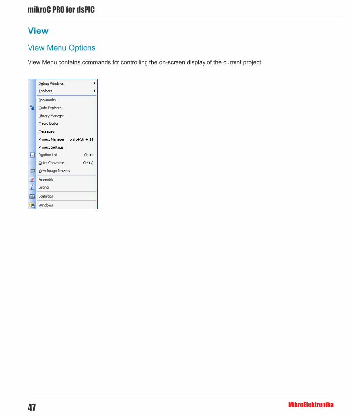
View
View Menu Options
View Menu contains commands for controlling the on-screen display of the current project.

48
mikoC PRO for dsPIC
MikroElektronika
View Description
Show/Hide Software Simulator / mikroICD (In-Circuit Debugger) Debug Windows.
Show/Hide Toolbars.
Show/Hide Bookmarks window.
Show/Hide Code Explorer window.
Show/Hide Library Manager window.
Show/Hide Macro Editor window.
Show/Hide Messages window.
Show/Hide Project Manager window.
Show/Hide Project Settings window.
Show/Hide Routine List in active editor.
Show/Hide Quick Converter window.
Show/Hide View Image Preview window.
View Assembly.
View Listing.
View Statistics.
Show Window List window.
The Tools toolbar can easily be customized by adding new tools in Options(F12) window.
Related topics: Keyboard shortcuts, Integrated Tools

mikroC PRO for dsPIC
MikroElektronika49
Project Description
Open New Project Wizard
Open existing project.
Open project group.
Open recently used project or project group.
Save current project.
Save active project file with the different name.
Close active project.
Close project group.
Add file to project.
Remove file from project.
Edit search paths.
Edit project settings
Clean Project Folder
Export Project.
Project
Project Menu Options
Project Menu allows user to easily manipulate current project.
Related topics: Keyboard shortcuts, Project Toolbar, Creating New Project, Project Manager, Project Settings

50
mikoC PRO for dsPIC
MikroElektronika
Build
Build Menu Options
Build Menu allows user to easily manage building and compiling process.
Build Description
Build active project.
Rebuild all sources in acrive project.
Build all projects.
Stop building of all projects.
Build and program active project.
Related topics: Keyboard shortcuts, Project Toolbar, Creating New Project, Project Manager, Project Settings

mikroC PRO for dsPIC
MikroElektronika51
Run Description
Start Software Simulator or mikroICD (In-Circuit Debugger).
Stop debugger.
Run/Pause Debugger.
Step Into.
Step Over.
Step Out.
Run To Cursor.
Jump to interrupt in current project.
Toggle Breakpoint.
Clear Breakpoints.
Toggle between source and disassembly.
Run
Run Menu Options
Run Menu is used to debug and test compiled code on a software or harware level.
Related topics: Keyboard shortcuts, Debug Toolbar

52
mikoC PRO for dsPIC
MikroElektronika
Tools
Tools Menu Options
Tools Menu contain a number of applications designed to ease the use of compiler and included library routines.
Tools Description
Run mikroElektronika Programmer.
Run Package Manager.
Show/Hide Active Comment Editor window.
Run ASCII Chart
Run EEPROM Editor
Generate HTML code suitable for publishing source code on the web.
Run Filter Designer Tool.
Run Glcd bitmap editor
Run HID Terminal
Run Lcd custom character
Run Seven Segment Editor
Run UDP communication terminal
Run USART Terminal
Open Options window
Related topics: Keyboard shortcuts, Tools Toolbar

mikroC PRO for dsPIC
MikroElektronika53
Help
Help Menu Options
Help Description
Оpen Help File.
Оpen Code Migration Document.
Check if new compiler version is available.
Open mikroElektronika Support Forums in a default browser.
Open mikroElektronika Web Page in a default browser.
Information on how to register
Open About window.
Related topics: Keyboard shortcuts, Help Toolbar

54
mikoC PRO for dsPIC
MikroElektronika
mikroC PRO for dsPIC30/33 and PIC24 IDE
IDE Overview
The mikroC PRO for dsPIC30/33 and PIC24 is an user-friendly and intuitive environment.
For a detailed information on a certain part of IDE, simply click on it (hovering a mouse cursor above a desired IDE part will pop-up its name) :
- The Code Editor features adjustable Syntax Highlighting, Code Folding, Code Assistant, Parameters Assistant, Spell Checker, Auto Correct for common typos and Code Templates (Auto Complete). - The Code Explorer is at your disposal for easier project management. - The Project Manager alows multiple project management - General project settings can be made in the Project Settings window - Library manager enables simple handling libraries being used in a project - The Messages Window displays all messages during compiling and linking. - The source-level Software Simulator lets you debug executable logic step-by-step by watching the program flow. - The New Project Wizard is a fast, reliable, and easy way to create a project. - Help files are syntax and context sensitive. - Like in any modern Windows application, you may customize the layout of mikroC PRO for dsPIC30/33 and PIC24 to suit your needs best. - Spell checker underlines identifiers which are unknown to the project. In this way it helps the programmer to spot potential problems early, much before the project is compiled. Spell checker can be disabled by choosing the option in the Preferences dialog (F12).

mikroC PRO for dsPIC
MikroElektronika55
Code EditorThe Code Editor is advanced text editor fashioned to satisfy needs of professionals. General code editing is the same as working with any standard text-editor, including familiar Copy, Paste and Undo actions, common for Windows environment.
Available Code Editor options are: Editor Settings, Editor Colors, Auto Correct, Auto Complete and Style.
Editor Settings
Main Editor Settings Features are :
- Auto Save - Highlighter - Spelling - Comment Style - Code Folding - Code Assistant - Parameter Assistant - Bookmarks and Go to Line

56
mikoC PRO for dsPIC
MikroElektronika
Auto Save
Auto Save is a function which saves an opened project automatically, helping to reduce the risk of data loss in case of a crash or freeze. Autosaving is done in time intervals defined by the user.
Highlighter
Highlighting is a convenient feature for spotting brackets which notate begin or end of a routine, by making them visually distinct.
Spelling
The Spell Checker underlines unknown objects in the code, so they can be easily noticed and corrected before compiling your project.
Select Tools › Options from the drop-down menu, or click the Show Options Icon and then select the Spell Checker Tab.
Comment Style
Code Editor has a feature to change the comment style to either single-line or multi-line. Commenting or uncommenting
the selected code is done by a simple click of a mouse, using the Comment Icon and Uncomment Icon from
the Advanced Edit Toolbar.
Code Folding
Code folding is IDE feature which allows users to selectively hide and display sections of a source file. In this way it is easier to manage large regions of code within one window, while still viewing only those subsections of the code that are relevant during a particular editing session.
While typing, the code folding symbols ( and ) appear automatically. Use the folding symbols to hide/unhide the code subsections.

mikroC PRO for dsPIC
MikroElektronika57
Another way of folding/unfolding code subsections is by using Alt+← and Alt+→.
If you place a mouse cursor over the tooltip box, the collapsed text will be shown in a tooltip style box.
Code Assistant
If you type the first few letters of a word and then press Ctrl+Space, all valid identifiers matching the letters you have typed will be prompted in a floating panel (see the image below). Now you can keep typing to narrow the choice, or you can select one from the list using the keyboard arrows and Enter.
Parameter Assistant
The Parameter Assistant will be automatically invoked when you open parenthesis “(” or press Shift+Ctrl+Space. If the name of a valid function precedes the parenthesis, then the expected parameters will be displayed in a floating panel. As you type the actual parameter, the next expected parameter will become bold.
Bookmarks
Bookmarks make navigation through a large code easier. To set a bookmark, use Ctrl+Shift+number. The same princliple applies to the removal of the bookmarks. To jump to a bookmark, use Ctrl+number.
Go to Line
The Go to Line option makes navigation through a large code easier. Use the shortcut Ctrl+G to activate this option.

58
mikoC PRO for dsPIC
MikroElektronika
Column Select Mode
This mode changes the operation of the editor for selecting text. When column select mode is used, highlighted text is based on the character column position of the first character selected to the column of the last character of text selected. Text selected in this mode does not automatically include all text between the start and end position, but includes all text in the columns between the first and last character selected.
Column mode editing is sometimes referred to as block mode editing as the act of selecting text forms a rectangle.
To enter this mode, press Alt + Left mouse button, drag the mouse towards the desired direction thus selecting the text.
Editor Colors

mikroC PRO for dsPIC
MikroElektronika59
Editor Colors option allows user to set, change and save text and color settings organized in schemes. Schemes represent custom graphical appearance that can be applied to GUI(Graphical User Interface) to satifsy tastes of different users.
Auto Correct
Auto Correct option facilitate user in such a fashion that it automatically corrects common typing or spelling errors as it types.
This option is already set up to automatically correct some words. For example, if you type whiel, it will be corrected to while when you press the spacebar :

60
mikoC PRO for dsPIC
MikroElektronika
User can easily add its common typos by entering original typo, for example btye, to the Original box, and replacement, byte, to the Replacement box, and just click "Add" button. Next time when the typo occurs, it will be automatically corrected.
Auto Complete (Code Templates)
Auto Complete option saves lots of keystrokes for commonly used phrases by automatically completing user's typing.

mikroC PRO for dsPIC
MikroElektronika61
User can insert the Code Template by typing the name of the template (for instance, dow), then press Ctrl+J and the Code Editor will automatically generate a code :
You can add your own templates to the list by entering the desired keyword, description and code of your template in appropriate boxes. Autocomplete macros can retreive system and project information :
- %DATE% - current system date - %TIME% - current system time - %DEVICE% - device(MCU) name as specified in project settings - %DEVICE_CLOCK% - clock as specified in project settings - %COMPILER% - current compiler version
These macros can be used in template code, see template ptemplate provided with mikroC PRO for dsPIC30/33 and PIC24 installation.
62
mikoC PRO for dsPIC
MikroElektronika
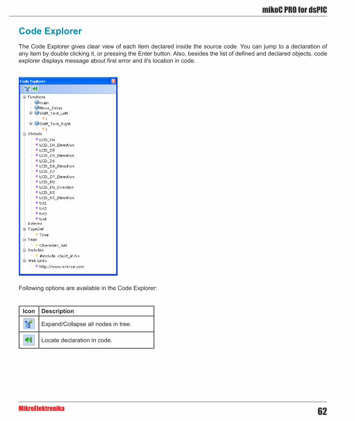
Code ExplorerThe Code Explorer gives clear view of each item declared inside the source code. You can jump to a declaration of any item by double clicking it, or pressing the Enter button. Also, besides the list of defined and declared objects, code explorer displays message about first error and it's location in code.
Following options are available in the Code Explorer:
Icon Description
Expand/Collapse all nodes in tree.
Locate declaration in code.

mikroC PRO for dsPIC
MikroElektronika63
Routine List
Routine list diplays list of routines, and enables filtering routines by name. Routine list window can be accessed by pressing Ctrl+L.
You can jump to a desired routine by double clicking on it, or pressing the Enter button. Also, you can sort routines by size or by address.
Project ManagerProject Manager is IDE feature which allows users to manage multiple projects. Several projects which together make project group may be open at the same time. Only one of them may be active at the moment. Setting project in active mode is performed by double clicking the desired project in the Project Manager, which will result in bolding the project's name. Also, the name of the currently active project will be diplayed in the Program Manager window title, alongside with the number of projects in project group.

64
mikoC PRO for dsPIC
MikroElektronika
Following options are available in the Project Manager:
Icon Description
Save project Group.
Open project group.
Close the active project.
Close project group.
Add project to the project group.
Remove project from the project group.
Add file to the active project.
Remove selected file from the project.
Build the active project.
Run mikroElektronika’s Flash programmer.
For details about adding and removing files from project see Add/Remove Files from Project.
Related topics: Project Settings, Project Menu Options, File Menu Options, Project Toolbar, Build Toolbar, Add/Remove Files from Project

mikroC PRO for dsPIC
MikroElektronika65
Project SettingsFollowing options are available in the Project Settings :
- Device - select the appropriate device from the device drop-down list. - MCU Clock - enter the clock frequency value. - Build/Debugger Type - choose debugger type.
Related topics: Edit Project, Customizing Projects, Project Manager

66
mikoC PRO for dsPIC
MikroElektronika
Library ManagerLibrary Manager enables simple handling libraries being used in a project. Library Manager window lists all libraries (extension .mcl) which are instantly stored in the compiler Uses folder. The desirable library is added to the project by selecting check box next to the library name.
In order to have all library functions accessible, simply press the button Check All and all libraries will be selected.
In case none library is needed in a project, press the button Clear All and all libraries will be cleared from the
project.
Only the selected libraries will be linked.
Icon Description
Refresh Library by scanning files in “Uses” folder.Useful when new libraries are added by copying files to “Uses” folder.
Rebuild all available libraries. Useful when library sources are available and need refreshing.
Include all available libraries in current project.
No libraries from the list will be included in current project.
Restore library to the state just before last project saving.

mikroC PRO for dsPIC
MikroElektronika67
Managing libraries using Package Manager
The Package Manager is a tool which enables users to easily install their own libraries in the mikroIDE. Libraries are distributed in the form of a package, which is an archive composed of one or more files, containing libraries. For more information on Package Manager, visit our website.
Upon package installation, a new node with the package name will be created in the Library Manager. For example :
From the Library Manager, user can also uninstall the desired package by right clicking the the appropriate node, and from the drop-down menu choose Uninstall package :

68
mikoC PRO for dsPIC
MikroElektronika
Related topics: mikroC PRO for PIC Libraries, Creating New Library
StatisticsAfter successful compilation, you can review statistics of your code. Click the Statistics Icon .
Memory Usage Windows
Provides overview of RAM and ROM usage in the various forms.

mikroC PRO for dsPIC
MikroElektronika69
Used RAM Locations
Displays used RAM memory locations and their names.
RAM Memory Usage
Displays RAM memory usage in a pie-like form.

70
mikoC PRO for dsPIC
MikroElektronika
SFR Locations
Displays list of used SFR locations.
ROM Memory Usage
Displays ROM memory space usage in a pie-like form.

mikroC PRO for dsPIC
MikroElektronika71
ROM Memory Constants
Displays ROM memory constants and their addresses.
Functions
Sorts and displays functions in various ways.

72
mikoC PRO for dsPIC
MikroElektronika
Functions Sorted By Name Chart
Sorts and displays functions by their name, in the ascending order.
Functions Sorted By Size Chart
Sorts and displays functions by their sizes in a chart-like form.
mikroC PRO for dsPIC
MikroElektronika73
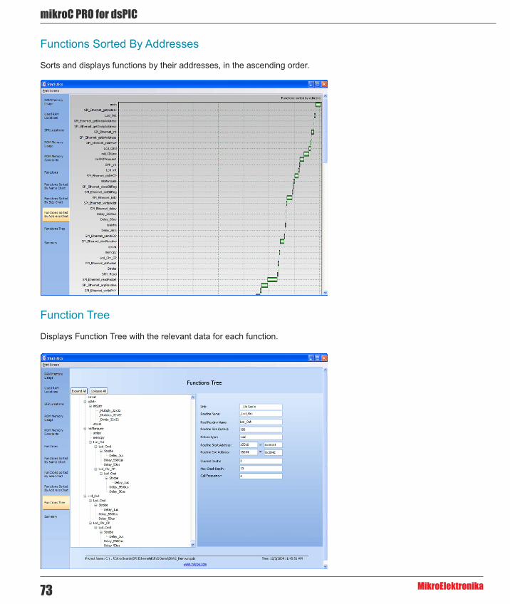
Functions Sorted By Addresses
Sorts and displays functions by their addresses, in the ascending order.
Function Tree
Displays Function Tree with the relevant data for each function.

74
mikoC PRO for dsPIC
MikroElektronika
Memory Summary
Displays summary of RAM and ROM memory in a pie-like form.

mikroC PRO for dsPIC
MikroElektronika75
Messages WindowMessages Window displays various informations and notifications about the compilation process.
It reports for example, time needed for preprocessing, compilation and linking; used RAM and ROM space, generated baud rate with error percentage, etc. User can filter which notifications will Messages Window display by checking Errors, Warning and Hints box.
In case that errors were encountered during compiling, the compiler will report them and won’t generate a hex file. The Messages Window will display errros at the bottom of the window by default. The compiler also reports warnings, but these do not affect the output; only errors can interefere with the generation of hex.
Double click the message line in the Message Window to highlight the line where the error was encountered.

76
mikoC PRO for dsPIC
MikroElektronika
Quick ConverterQuick Converter enables user to easily transform numbers from one base to another.
User can convert integers of various sizes (8, 16 or 32 bits), signed and unsigned, using different representation (decimal, hexadecimal, binary and character). Also, Quick Converter features float point numbers conversion from/to Float Decimal, Float 32bit (IEEE), Float 32bit (Microchip) and Radix 1.15 for dsPIC family of MCUs.
Macro EditorA macro is a series of keystrokes that have been 'recorded' in the order performed. A macro allows you to 'record' a series of keystrokes and then 'playback', or repeat, the recorded keystrokes.

mikroC PRO for dsPIC
MikroElektronika77
The Macro offers the following commands:
Icon Description
Starts ‘recording’ keystrokes for later playback.
Stops capturing keystrokes that was started when the Start Recording command was selected.
Allows a macro that has been recorded to be replayed.
New macro.
Delete macro.
Related topics: Code Editor, Code Templates
Image PreviewThere are a lot of occassions in which the user besides the code, must look at the appropriate schematics in order to succesfully write the desired program. The mikroC PRO for dsPIC30/33 and PIC24 provides this possibility through a Image Preview Window.
To add a image to the Image Preview Window, right click the Image Files node in the Project Manager :

78
mikoC PRO for dsPIC
MikroElektronika
Now, navigate to the desired image file, and simply add it :
Next, right click the added file, and choose Set As Preview Image :

mikroC PRO for dsPIC
MikroElektronika79
Once you have added the image, it will appear in the Image Preview Window :
Also, you can add multiple images to the Image Files node, but only the one that is set will be automatically displayed in the Image Preview Window upon opening the project.
By changing the Image Preview Window size, displayed image will be fit by its height in such a way that its proportions will remain intact.
ToolbarsThis section provides an overview of the toolbars available in mikroC PRO for dsPIC30/33 and PIC24 Help :
- File Toolbar - Edit Toolbar - Advanced Edit Toolbar - Find Toolbar - Project Toolbar - Build Toolbar - Debug Toolbar - Styles Toolbar - Tools Toolbar - View Toolbar - Layout Toolbar - Help Toolbar

80
mikoC PRO for dsPIC
MikroElektronika
File Toolbar
File Toolbar is a standard toolbar with following options:
Icon Description
Opens a new editor window.
Open source file for editing or image file for viewing.
Save changes for active window.
Save changes in all opened windows.
Print Preview.
Print.
Edit Toolbar
Edit Toolbar is a standard toolbar with following options:
Icon Description
Undo last change.
Redo last change.
Cut selected text to clipboard.
Copy selected text to clipboard.
Paste text from clipboard.
mikroC PRO for dsPIC
MikroElektronika81
Icon Description
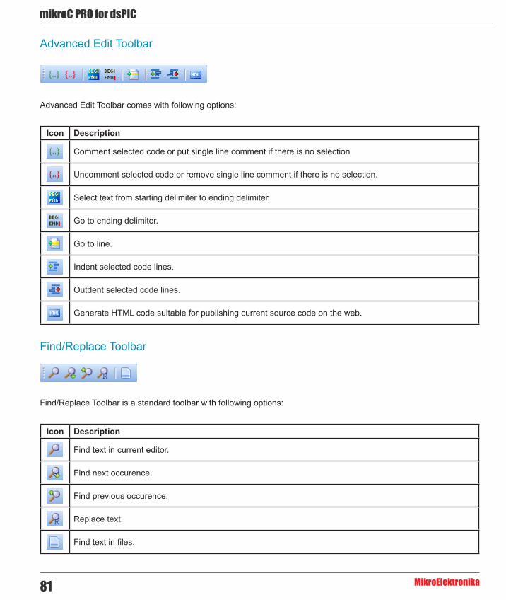
Comment selected code or put single line comment if there is no selection
Uncomment selected code or remove single line comment if there is no selection.
Select text from starting delimiter to ending delimiter.
Go to ending delimiter.
Go to line.
Indent selected code lines.
Outdent selected code lines.
Generate HTML code suitable for publishing current source code on the web.
Advanced Edit Toolbar
Advanced Edit Toolbar comes with following options:
Find/Replace Toolbar
Find/Replace Toolbar is a standard toolbar with following options:
Icon Description
Find text in current editor.
Find next occurence.
Find previous occurence.
Replace text.
Find text in files.

82
mikoC PRO for dsPIC
MikroElektronika
Icon Description
New project.
Open Project
Save Project
Edit project settings.
Close current project.
Clean project folder.
Add File To Project
Remove File From Project
Project Toolbar
Project Toolbar comes with following options:
Build Toolbar
Build Toolbar comes with following options:
Icon Description
Build current project.
Build all opened projects.
Build and program active project.
Start programmer and load current HEX file.

mikroC PRO for dsPIC
MikroElektronika83
Icon Description
Start Software Simulator or mikroICD (In-Circuit Debugger).
Run/Pause Debugger.
Stop Debugger.
Step Into.
Step Over.
Step Out.
Run To Cursor.
Toggle Breakpoint.
View Breakpoints Window
Clear Breakpoints.
View Watch Window
View Stopwatch Window
Debug Toolbar
Debug Toolbar comes with following options:
Styles Toolbar
Styles toolbar allows you to easily change colors of your workspace.

84
mikoC PRO for dsPIC
MikroElektronika
Tools Toolbar
Tools Toolbar comes with following default options:
Icon Description
Run USART Terminal
EEPROM
ASCII Chart
Seven Segment Editor.
Open Active Comment editor.
Options menu
Tip : The Tools toolbar can easily be customized by adding new tools in Options menu window.
View Toolbar
View Toolbar provides access to assembly code, listing file and statistics windows.
Icon Description
Open assembly code in editor.
Open listing file in editor.
View statistics for current project.

mikroC PRO for dsPIC
MikroElektronika85
Icon Description
Open Help file.
How To Register.
Layout Toolbar
Styles toolbar allows you to easily customize workspace through a number of different IDE layouts.
Help Toolbar
Help Toolbar provides access to information on using and registering compilers :
Related topics: Keyboard shortcuts, Integrated Tools
86
mikoC PRO for dsPIC
MikroElektronika
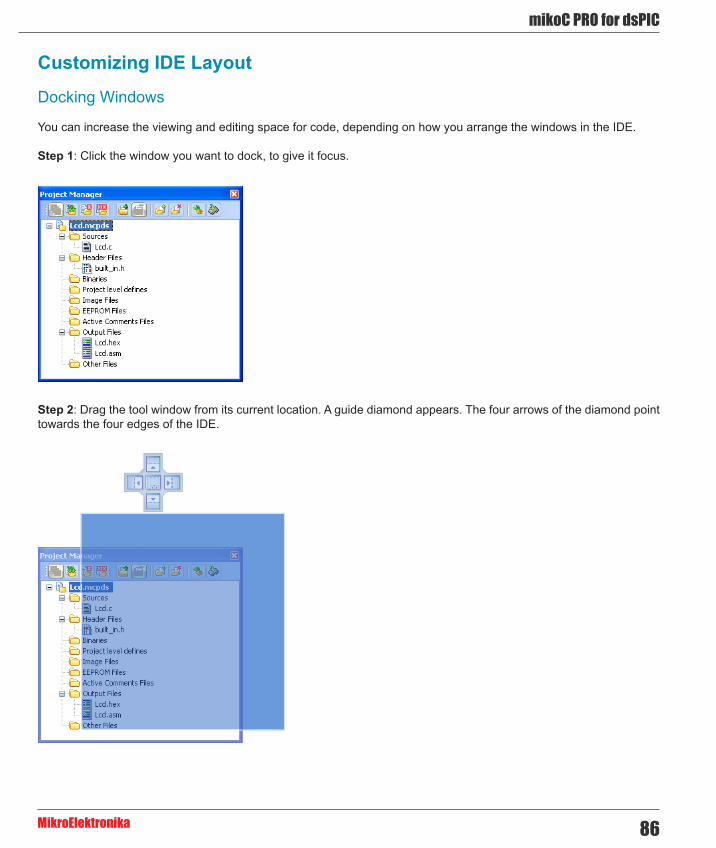
Customizing IDE Layout
Docking Windows
You can increase the viewing and editing space for code, depending on how you arrange the windows in the IDE.
Step 1: Click the window you want to dock, to give it focus.
Step 2: Drag the tool window from its current location. A guide diamond appears. The four arrows of the diamond point towards the four edges of the IDE.

mikroC PRO for dsPIC
MikroElektronika87
Step 3: Move the pointer over the corresponding portion of the guide diamond. An outline of the window appears in the designated area.
Step 4: To dock the window in the position indicated, release the mouse button.
Tip : To move a dockable window without snapping it into place, press CTRL while dragging it.
Saving Layout
Once you have a window layout that you like, you can save the layout by typing the name for the layout and pressing
the Save Layout Icon .
To set the layout select the desired layout from the layout drop-down list and click the Set Layout Icon .
To remove the layout from the drop-down list, select the desired layout from the list and click the Delete Layout
Icon .
Auto Hide
Auto Hide enables you to see more of your code at one time by minimizing tool windows along the edges of the IDE when not in use.
- Click the window you want to keep visible to give it focus.
- Click the Pushpin Icon on the title bar of the window.

88
mikoC PRO for dsPIC
MikroElektronika
When an auto-hidden window loses focus, it automatically slides back to its tab on the edge of the IDE. While a window is auto-hidden, its name and icon are visible on a tab at the edge of the IDE. To display an auto-hidden window, move your pointer over the tab. The window slides back into view and is ready for use.
OptionsOptions menu consists of three tabs: Code Editor, Tools and Output settings
Code editor
The Code Editor is advanced text editor fashioned to satisfy needs of professionals.
Tools
The mikroC PRO for dsPIC30/33 and PIC24 includes the Tools tab, which enables the use of shortcuts to external programs, like Calculator or Notepad. You can set up to 10 different shortcuts, by editing Tool0 - Tool9.

mikroC PRO for dsPIC
MikroElektronika89
Output settings
By modifying Output Settings, user can configure the content of the output files. You can enable or disable, for example, generation of ASM and List file.
Also, user can choose optimization level, and compiler specific settings, which include case sensitivity, dynamic link for string literals setting (described in mikroC PRO for dsPIC30/33 and PIC24 specifics).
Build all files as library enables user to use compiled library (*.mcl) on any MCU (when this box is checked), or for a selected MCU (when this box is left unchecked).
For more information on creating new libraries, see Creating New Library.

90
mikoC PRO for dsPIC
MikroElektronika

mikroC PRO for dsPIC
MikroElektronika91
Integrated Tools
Active Comments Editor
Active Comments Editor is a tool, particularly useful when working with Lcd display. You can launch it from the drop-
down menu Tools › Active Comments Editor or by clicking the Active Comment Editor Icon from Tools toolbar.

92
mikoC PRO for dsPIC
MikroElektronika
ASCII Chart
The ASCII Chart is a handy tool, particularly useful when working with Lcd display. You can launch it from the drop-
down menu Tools › ASCII chart or by clicking the View ASCII Chart Icon from Tools toolbar.

mikroC PRO for dsPIC
MikroElektronika93
EEPROM Editor
The EEPROM Editor is used for manipulating MCU's EEPROM memory. You can launch it from the drop-down menu Tools › EEPROM Editor.
When you run mikroElektronika programmer software from mikroC PRO for dsPIC30/33 and PIC24 IDE - project_name.hex file will be loaded automatically while ihex file must be loaded manually.
Filter Designer
The Filter designer is a tool for designing FIR and IIR filters. It has an user-friendly visual interface for setting the filter parameters. Filter designer output is the mikroC PRO for dsPIC30/33 and PIC24 compatible code. You can launch it from the drop-down menu Tools › Filter Designer.

94
mikoC PRO for dsPIC
MikroElektronika
Graphic Lcd Bitmap Editor
The mikroC PRO for dsPIC30/33 and PIC24 includes the Graphic Lcd Bitmap Editor. Output is the mikroC PRO for dsPIC30/33 and PIC24 compatible code. You can launch it from the drop-down menu Tools › Glcd Bitmap Editor.

mikroC PRO for dsPIC
MikroElektronika95
HID Terminal
The mikroC PRO for dsPIC30/33 and PIC24 includes the HID communication terminal for USB communication. You can launch it from the drop-down menu Tools › HID Terminal.

96
mikoC PRO for dsPIC
MikroElektronika
Lcd Custom Character
mikroC PRO for dsPIC30/33 and PIC24 includes the Lcd Custom Character. Output is mikroC PRO for dsPIC30/33 and PIC24 compatible code. You can launch it from the drop-down menu Tools › Lcd Custom Character.

mikroC PRO for dsPIC
MikroElektronika97
Seven Segment Editor
The Seven Segment Editor is a convenient visual panel which returns decimal/hex value for any viable combination you would like to display on seven segment display. Click on the parts of seven segment image to get the requested value
in the edit boxes. You can launch it from the drop-down menu Tools › Seven Segment Editor or by clicking the Seven
Segment Editor Icon from Tools toolbar.
UDP Terminal
The mikroC PRO for dsPIC30/33 and PIC24 includes the UDP Terminal. You can launch it from the drop-down menu Tools › UDP Terminal.
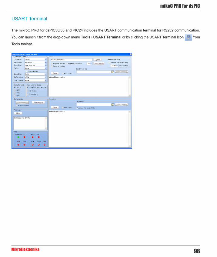
98
mikoC PRO for dsPIC
MikroElektronika
USART Terminal
The mikroC PRO for dsPIC30/33 and PIC24 includes the USART communication terminal for RS232 communication.
You can launch it from the drop-down menu Tools › USART Terminal or by clicking the USART Terminal Icon from
Tools toolbar.
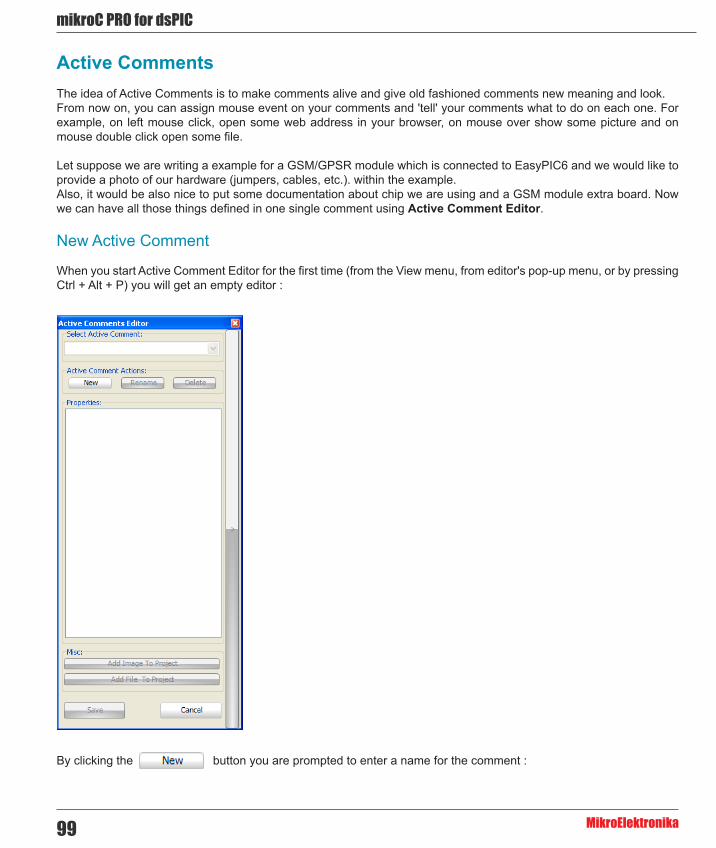
mikroC PRO for dsPIC
MikroElektronika99
Active CommentsThe idea of Active Comments is to make comments alive and give old fashioned comments new meaning and look. From now on, you can assign mouse event on your comments and 'tell' your comments what to do on each one. For example, on left mouse click, open some web address in your browser, on mouse over show some picture and on mouse double click open some file.
Let suppose we are writing a example for a GSM/GPSR module which is connected to EasyPIC6 and we would like to provide a photo of our hardware (jumpers, cables, etc.). within the example. Also, it would be also nice to put some documentation about chip we are using and a GSM module extra board. Now we can have all those things defined in one single comment using Active Comment Editor.
New Active Comment
When you start Active Comment Editor for the first time (from the View menu, from editor's pop-up menu, or by pressing Ctrl + Alt + P) you will get an empty editor :
By clicking the button you are prompted to enter a name for the comment :

100
mikoC PRO for dsPIC
MikroElektronika
You can notice that when you start typing a name, properties pane is automatically displayed so you can edit properties
if you wish. A Comment will be is created when you click button.
Properties are consisted of two major categories - Attributes and Events.
Attributes can be :
- URL - Valid web address. - Image - Image has to be previously added to Project (Project Manager > Images). - File - File has to be previously added to Project (Project Manager > Other Files).
There are four predefined event types you can apply to an Active Comment :
1. OnLeftClick + Alt 2. OnRightClick 3. OnDoubleClick 4. OnMouseOver

mikroC PRO for dsPIC
MikroElektronika101
First three event types can have one of the following three actions :
1. OpenUrl - Opens entered URL in default Web browser. 2. OpenFile - Opens a file within a default program associated with the file extension (defined by Windows). 3. None - Does nothing.
Fourth event, OnMouseOver, has only 2 actions :
1. PreviewImage - Shows image when cursor is moved over a comment. 2. None - Does nothing.
Attributes are tightly bounded with events. For example, you can not have OnLeftClick + Alt -> OpenFile if there is no file attribute set, or if there is no file added to project. Same behavior applies to image attribute.
Let's start editing our Active Comment by entering some valid web address in the URL field :
For every Active Comment a XML file will be created, containing all valid information regarding the Active Comment - attributes, events, etc. and it is automatically added to Project manager after saving it :

102
mikoC PRO for dsPIC
MikroElektronika
You can see the contents of the created XML file by expanding Active Comment Editor :
As we mentioned above you can add image or file which are already included in project. If the the desired image or file
aren't added, you can do it directly from here by clicking the or button.

mikroC PRO for dsPIC
MikroElektronika103
Next file dialog will be opened :
There, you should select the desired image to be added. In our example, Easy_GSM_GPRS.jpg image will be added.
Selected picture is automatically added to the drop down list of the Image field in Active Comment Editor :

104
mikoC PRO for dsPIC
MikroElektronika
Now, when image has been selected, we can assign an event for it. For example, OnMouseOver will be used for PreviewImage action, and OnLeftClick + Alt will be assigned to OpenUrl action :
Now we can save our changes to Active Comment by clicking the Save button.
Note : Setting file attributes is same as for image, so it won't be explained separately.
Once we have finished creating our active comment, we can notice that it has been added to source file on current caret position with ac: prefix 'telling' IDE that it is active comment :
Now let's try it. If you LeftClick+Alt on it, URL in default Web browser will be opened. If you hover the mouse over it, you will see an Image preview:

mikroC PRO for dsPIC
MikroElektronika105
There is another way to add an active comment to an active project. You can do it simply by typing a comment in old fashion way, except with ac: prefix. So it would look like this :
Notice that when you stop typing, Add Comment To Project button will show. By clicking on it, you will open Active Comment Editor and comment name will be already set, so you need only to adjust attributes and settings. After saving you can always edit your active comment by Active Comment Editor, and switch between comments directly from editor.
If you remove a file from the Project Manager or add an Active Comment File which contains information about the file which is no longer in project, and hover the mouse over the comment, you will be prompted to either add file to project or remove event definition from Active Comment for this file :
If you remove active comment file from the Project Manager, you'll receive this message:
Click on Yes button you'll prompted for an active comment file :

106
mikoC PRO for dsPIC
MikroElektronika
If you click No, comment will be removed from the source code.
Renaming Active Comment
When you click on rename button, you will be prompted to enter new name :

mikroC PRO for dsPIC
MikroElektronika107
Now click again Rename button. Now you have renamed your Active Comment in such a way that its filename, source code name are changed :
Deleting Active Comment
Deleting active comment works similar like renaming it. By clicking on delete button, you will remove an active comment from both code and Project Manager.

108
mikoC PRO for dsPIC
MikroElektronika
Export ProjectThis option is very convenient and finds its use in relocating your projects from one place to another (e.g. from your work computer to your home computer).
Often, project contains complicated search paths (files involved within your project could be in a different folders, even on different hard disks), so it is very likely that some files will be forgotten during manual relocation. In order to simplify this, Export Project gives you opportunity to do this task automatically.
To open Export Project, from Project menu select Export Project or hit Ctrl + Alt + E. Following window will appear :
In the empty input boxes, current location and the destination folder of the desired project should be entered.
By default, currently active project will be set for export. You can change it any time by clicking the Open Button .
Once you have entered the appropriate data, click Export Project button. After exporting is done, and if everything was OK, you'll receive a message :
Now, Export Project has copied all project files into desired folder and changed project search paths, so you can easily move the entire folder to another location and run the project.

mikroC PRO for dsPIC
MikroElektronika109
Jump To InterruptLets you choose which interrupt you want to jump to.
Requirement: Interrupt routine is included in project.
You can call Jump To Interrupt by selecting Run › Jump To Interrupt from the drop-down menu, or by clicking the Jump
To Interrupt Icon , from the Watch Values Window.
By checking the Only Used box, you can display only the used breakpoints.

110
mikoC PRO for dsPIC
MikroElektronika
Regular Expressions
Introduction
Regular Expressions are a widely-used method of specifying patterns of text to search for. Special metacharacters allow you to specify, for instance, that a particular string you are looking for, occurs at the beginning, or end of a line, or contains n recurrences of a certain character.
Simple matches
Any single character matches itself, unless it is a metacharacter with a special meaning described below. A series of characters matches that series of characters in the target string, so the pattern "short" would match "short" in the target string. You can cause characters that normally function as metacharacters or escape sequences to be interpreted by preceding them with a backslash "\". For instance, metacharacter "^" matches beginning of string, but "\^" matches character "^", and "\\" matches "\", etc.
Examples :
unsigned matches string 'unsigned' \^unsigned matches string '^unsigned'
Escape sequences
Characters may be specified using a escape sequences: "\n" matches a newline, "\t" a tab, etc. More generally, \xnn, where nn is a string of hexadecimal digits, matches the character whose ASCII value is nn. If you need wide (Unicode) character code, you can use '\x{nnnn}', where 'nnnn' - one or more hexadecimal digits.
\xnn - char with hex code nn \x{nnnn)- char with hex code nnnn (one byte for plain text and two bytes for Unicode) \t - tab (HT/TAB), same as \x09 \n - newline (NL), same as \x0a \r - car.return (CR), same as \x0d \f - form feed (FF), same as \x0c \a - alarm (bell) (BEL), same as \x07 \e - escape (ESC) , same as \x1b
Examples:
unsigned\x20int matches 'unsigned int' (note space in the middle) \tunsigned matches 'unsigned' (predecessed by tab)
Character classes
You can specify a character class, by enclosing a list of characters in [], which will match any of the characters from the list. If the first character after the “[“ is “^”, the class matches any character not in the list.

mikroC PRO for dsPIC
MikroElektronika111
Examples:
count[aeiou]r finds strings 'countar', 'counter', etc. but not 'countbr', 'countcr', etc. count[^aeiou]r finds strings 'countbr', 'countcr', etc. but not 'countar', 'counter', etc.
Within a list, the "-" character is used to specify a range, so that a-z represents all characters between "a" and "z", inclusive.
If you want "-" itself to be a member of a class, put it at the start or end of the list, or precede it with a backslash. If you want ']', you may place it at the start of list or precede it with a backslash.
Examples:
[-az] matches 'a', 'z' and '-' [az-] matches 'a', 'z' and '-' [a\-z] matches 'a', 'z' and '-' [a-z] matches all twenty six small characters from 'a' to 'z' [\n-\x0D] matches any of #10,#11,#12,#13. [\d-t] matches any digit, '-' or 't'. []-a] matches any char from ']'..'a'.
Metacharacters
Metacharacters are special characters which are the essence of regular expressions. There are different types of metacharacters, described below.
Metacharacters - Line separators
^ - start of line $ - end of line \A - start of text \Z - end of text . - any character in line
Examples:
^PORTA - matches string ‘ PORTA ‘ only if it’s at the beginning of line PORTA$ - matches string ‘ PORTA ‘ only if it’s at the end of line ^PORTA$ - matches string ‘ PORTA ‘ only if it’s the only string in line PORT.r - matches strings like ‘PORTA’, ‘PORTB’, ‘PORT1’ and so on
The “^” metacharacter by default is only guaranteed to match beginning of the input string/text, and the “$” metacharacter only at the end. Embedded line separators will not be matched by “^” or “$”. You may, however, wish to treat a string as a multi-line buffer, such that the “^” will match after any line separator within the string, and “$” will match before any line separator. Regular expressions works with line separators as recommended at http://www.unicode.org/unicode/reports/tr18/

112
mikoC PRO for dsPIC
MikroElektronika
Metacharacters - Predefined classes
\w - an alphanumeric character (including "_") \W - a nonalphanumeric character \d - a numeric character \D - a non-numeric character \s - any space (same as [\t\n\r\f]) \S - a non space
You may use \w, \d and \s within custom character classes.
Example:
routi\de - matches strings like 'routi1e', 'routi6e' and so on, but not 'routine', 'routime' and so on.
Metacharacters - Word boundaries
A word boundary ("\b") is a spot between two characters that has an alphanumeric character ("\w") on one side, and a nonalphanumeric character ("\W") on the other side (in either order), counting the imaginary characters off the beginning and end of the string as matching a "\W".
\b - match a word boundary) \B - match a non-(word boundary)
Metacharacters - Iterators
Any item of a regular expression may be followed by another type of metacharacters - iterators. Using this metacharacters,you can specify number of occurences of previous character, metacharacter or subexpression.
* - zero or more (“greedy”), similar to {0,} + - one or more (“greedy”), similar to {1,} ? - zero or one (“greedy”), similar to {0,1} {n} - exactly n times (“greedy”) {n,} - at least n times (“greedy”) {n,m} - at least n but not more than m times (“greedy”) *? - zero or more (“non-greedy”), similar to {0,}? +? - one or more (“non-greedy”), similar to {1,}? ?? - zero or one (“non-greedy”), similar to {0,1}? {n}? - exactly n times (“non-greedy”) {n,}? - at least n times (“non-greedy”) {n,m}? - at least n but not more than m times (“non-greedy”)
So, digits in curly brackets of the form, {n,m}, specify the minimum number of times to match the item n and the maximum m. The form {n} is equivalent to {n,n} and matches exactly n times. The form {n,} matches n or more times. There is no limit to the size of n or m, but large numbers will chew up more memory and slow down execution.
If a curly bracket occurs in any other context, it is treated as a regular character.

mikroC PRO for dsPIC
MikroElektronika113
Examples:
count.*r ß- matches strings like 'counter', 'countelkjdflkj9r' and 'countr' count.+r - matches strings like 'counter', 'countelkjdflkj9r' but not 'countr' count.?r - matches strings like 'counter', 'countar' and 'countr' but not 'countelkj9r' counte{2}r - matches string 'counteer' counte{2,}r - matches strings like 'counteer', 'counteeer', 'counteeer' etc. counte{2,3}r - matches strings like 'counteer', or 'counteeer' but not 'counteeeer'
A little explanation about "greediness". "Greedy" takes as many as possible, "non-greedy" takes as few as possible. For example, 'b+' and 'b*' applied to string 'abbbbc' return 'bbbb', 'b+?' returns 'b', 'b*?' returns empty string, 'b{2,3}?' returns 'bb', 'b{2,3}' returns 'bbb'.
Metacharacters - Alternatives
You can specify a series of alternatives for a pattern using "|" to separate them, so that bit|bat|bot will match any of "bit", "bat", or "bot" in the target string as would "b(i|a|o)t)". The first alternative includes everything from the last pattern delimiter ("(", "[", or the beginning of the pattern) up to the first "|", and the last alternative contains everything from the last "|" to the next pattern delimiter. For this reason, it's common practice to include alternatives in parentheses, to minimize confusion about where they start and end.
Alternatives are tried from left to right, so the first alternative found for which the entire expression matches, is the one that is chosen. This means that alternatives are not necessarily greedy. For example: when matching rou|rout against "routine", only the "rou" part will match, as that is the first alternative tried, and it successfully matches the target string (this might not seem important, but it is important when you are capturing matched text using parentheses.) Also remember that "|" is interpreted as a literal within square brackets, so if you write [bit|bat|bot], you're really only matching [biao|].
Examples:
rou(tine|te) - matches strings 'routine' or 'route'.
Metacharacters - Subexpressions
The bracketing construct ( ... ) may also be used for define regular subexpressions. Subexpressions are numbered based on the left to right order of their opening parenthesis. First subexpression has number ‘1’
Examples:
(int){8,10} matches strings which contain 8, 9 or 10 instances of the ‘int’ routi([0-9]|a+)e matches ‘routi0e’, ‘routi1e’ , ‘routine’, ‘routinne’, ‘routinnne’ etc.
Metacharacters - Backreferences
Metacharacters \1 through \9 are interpreted as backreferences. \ matches previously matched subexpression #.
Examples:
(.)\1+ matches ‘aaaa’ and ‘cc’. (.+)\1+ matches ‘abab’ and ‘123123’ ([‘”]?)(\d+)\1 matches “13” (in double quotes), or ‘4’ (in single quotes) or 77 (without quotes) etc

114
mikoC PRO for dsPIC
MikroElektronika
Keyboard ShortcutsBelow is a complete list of keyboard shortcuts available in mikroC PRO for dsPIC30/33 and PIC24 IDE.
IDE ShortcutsF1 HelpCtrl+N New UnitCtrl+O OpenCtrl+Shift+O Open ProjectCtrl+Shift+N New ProjectCtrl+K Close ProjectCtrl+F4 Close unitCtrl+Shift+E Edit ProjectCtrl+F9 BuildShift+F9 Build AllCtrl+F11 Build And ProgramShift+F4 View BreakpointsCtrl+Shift+F5 Clear BreakpointsF11 Start mE ProgrammerCtrl+Shift+F11 Project ManagerF12 OptionsAlt + X Close mikroC PRO for dsPIC30/33
and PIC24Basic Editor Shortcuts
F3 Find, Find NextShift+F3 Find PreviousAlt+F3 Grep Search, Find In FilesCtrl+A Select AllCtrl+C CopyCtrl+F FindCtrl+R ReplaceCtrl+P PrintCtrl+S Save UnitCtrl+Shift+S Save AllCtrl+V PasteCtrl+X CutCtrl+Y Delete Entire LineCtrl+Z UndoCtrl+Shift+Z Redo
Advanced Editor ShortcutsCtrl+Space Code AssistantCtrl+Shift+Space Parameters AssistantCtrl+D Find DeclarationCtrl+E Incremental SearchCtrl+L Routine ListCtrl+G Goto LineCtrl+J Insert Code TemplateCtrl+Shift+. Comment CodeCtrl+Shift+, Uncomment CodeCtrl+number Goto BookmarkCtrl+Shift+number Set BookmarkCtrl+Shift+I Indent SelectionCtrl+Shift+U Unindent SelectionTAB Indent SelectionShift+TAB Unindent SelectionAlt+Select Select ColumnsCtrl+Alt+Select Select ColumnsAlt + Left Arrow Fold Region (if available)Alt + Right Arrow Unfold Region (if available)Ctrl+Alt+L Convert Selection to LowercaseCtrl+Alt+U Convert Selection to UppercaseCtrl+Alt+T Convert to TitlecaseCtrl+T USART TerminalCtrl+Q Quick Converter
mikroICD Debugger and Software Simulator Shortcuts
F2 Jump To InterruptF4 Run to CursorF5 Toggle BreakpointF6 Run/Pause DebuggerF7 Step IntoF8 Step OverF9 Start DebuggerCtrl+F2 Stop Debugger

mikroC PRO for dsPIC
MikroElektronika115
Ctrl+F5 Add to Watch ListCtrl+F8 Step OutAlt+D Disassembly ViewShift+F5 Open Watch WindowCtrl+Shift+A Show Advanced Breakpoints

116
mikoC PRO for dsPIC
MikroElektronika
CHAPTER 3mikroC PRO for dsPIC30/33 and PIC24 Command Line OptionsUsage: mikroCdsPIC.exe [-<opts> [-<opts>]] [<infile> [-<opts>]] [-<opts>]] Infile can be of *.c, *.mcl and *.pld type.
The following parameters are valid :
-P <devicename> : MCU for which compilation will be done. -FO <oscillator> : Set oscillator [in MHz]. -SP <directory> : Add directory to the search path list. -IP <directory> : Add directory to the #include search path list. -N <filename> : Output files generated to file path specified by filename. -B <directory> : Save compiled binary files (*.mcl) to 'directory'. -O : Miscellaneous output options. -DBG : Generate debug info. -L : Check and rebuild new libraries. -DL : Build all files as libraries. -Y : Dynamic link for string literals. -UICD : ICD build type. -EH <filename> : Full EEPROM HEX file name with path. -LHF : Generate Long hex format. -GC : Generate COFF file.
Example:
mikroCdsPIC.exe -MSF -DBG -p30F4013 -Y -DL -O11111114 -fo80 -N”C:\Lcd\Lcd.mcpds” -SP”C:\Program Files\Mikroelektronika\mikroC PRO for dsPIC\Defs” -SP”C:\Program Files\Mikroelektronika\mikroC PRO for dsPIC\Uses” -SP”C:\Lcd\” “Lcd.c” “__Lib_Math.mcl” “__Lib_MathDouble.mcl” “__Lib_System.mcl” “__Lib_Delays.mcl” “__Lib_LcdConsts.mcl” “__Lib_Lcd.mcl”

mikroC PRO for dsPIC
MikroElektronika117
Parameters used in the example:
-MSF : Short Message Format; used for internal purposes by IDE. -DBG : Generate debug info. -p30F4013 : MCU 30F4013 selected. -Y : Dynamic link for string literals enabled. -DL : All files built as libraries. -O11111114 : Miscellaneous output options. -fo80 : Set oscillator frequency [in MHz]. -N"C:\Lcd\Lcd.mcpds" -SP"C:\Program Files\Mikroelektronika\mikroC PRO for dsPIC\Defs\" : Output files generated to file path specified by filename. -SP"C:\Program Files\Mikroelektronika\mikroC PRO for dsPIC\Defs\" : Add directory to the search path list. -SP"C:\Program Files\Mikroelektronika\mikroC PRO for dsPIC\Uses\" : Add directory to the search path list. -SP"C:\Lcd\" : Add directory to the search path list. "Lcd.c" "__Lib_Math.mcl" "__Lib_MathDouble.mcl" "__Lib_System.mcl" "__Lib_Delays.mcl" "__Lib_LcdConsts.mcl" "__Lib_Lcd.mcl" : Specify input files.

118
mikoC PRO for dsPIC
MikroElektronika
CHAPTER 4mikroICD (In-Circuit Debugger)
IntroductionThe mikroICD is a highly effective tool for a Real-Time debugging on hardware level. The mikroICD debugger enables you to execute the mikroC PRO for dsPIC30/33 and PIC24 program on a host dsPIC30/33 or PIC24 microcontroller and view variable values, Special Function Registers (SFR), RAM, CODE and EEPROM memory along with the mikroICD code execution on hardware.

mikroC PRO for dsPIC
MikroElektronika119
If you have appropriate hardware and software for using the mikroICD select mikroICD Debug Build Type before compiling the project.
Now, compile the project by pressing Ctrl + F9, or by pressing Build Icon on Build Toolbar.
Run the mikroICD by selecting Run › Start Debugger from the drop-down menu or by clicking the Start Debugger
Icon . Starting the Debugger makes more options available: Step Into, Step Over, Run to Cursor, etc. Line that is
to be executed is color highlighted (blue by default). There is also notification about the program execution and it can be found in the Watch Window (yellow status bar). Note that some functions take more time to execute; execution is indicated with "Running..." message in the Watch Window Status Bar.
Related topics: mikroICD Debugger Example, mikroICD Debug Windows, mikroICD Debugger Options

120
mikoC PRO for dsPIC
MikroElektronika
mikroICD Debugger Options
Debugger Options
Name Description Function Key
Toolbar Icon
Start Debugger Starts Debugger. F9
Stop Debugger Stop Debugger. Ctrl + F2
Run/Pause Debugger Run/Pause Debugger. F6
Step IntoExecutes the current program line, then halts. If the executed program line calls another routine, the debugger steps into the routine and halts after executing the first instruction within it.
F7
Step Over
Executes the current program line, then halts. If the executed program line calls another routine, the debugger will not step into it. The whole routine will be executed and the debugger halts at the first instruction following the call.
F8
Step Out Executes all remaining program lines within the subroutine. The debugger halts immediately upon exiting the subroutine. Ctrl + F8
Run To Cursor Executes the program until reaching the cursor position. F4
Toggle Breakpoint Toggle breakpoints option sets new breakpoints or removes those already set at the current cursor position. F5
Related topics: Run Menu, Debug Toolbar

mikroC PRO for dsPIC
MikroElektronika121
mikroICD Debugger ExampleHere is a step-by-step mikroICD Debugger Example.
First you have to write a program. We will show how the mikroICD works using this example :
// Lcd module connectionssbit LCD_RS at LATD0_bit;sbit LCD_EN at LATD1_bit;sbit LCD_D4 at LATB0_bit;sbit LCD_D5 at LATB1_bit;sbit LCD_D6 at LATB2_bit;sbit LCD_D7 at LATB3_bit;
sbit LCD_RS_Direction at TRISD0_bit;sbit LCD_EN_Direction at TRISD1_bit;sbit LCD_D4_Direction at TRISB0_bit;sbit LCD_D5_Direction at TRISB1_bit;sbit LCD_D6_Direction at TRISB2_bit;sbit LCD_D7_Direction at TRISB3_bit;// End Lcd module connections
char text[] = "mikroElektronika";char i;
void Move_Delay() { Delay_ms(500);}
void main() { ADPCFG = 0xFFFF;
Lcd_Init(); Lcd_Cmd(_LCD_CLEAR); Lcd_Cmd(_LCD_CURSOR_OFF);
for(i = 1; i < 17; i++) { Lcd_Chr(1, i, text[i-1]); }}

122
mikoC PRO for dsPIC
MikroElektronika
After successful compilation and MCU programming press F9 to start the mikroICD. After the mikroICD initialization a blue active line should appear.
We will debug the program line by line. To execute code line by line press [F8]. However, it is not recommended to use Step Over [F8] over Delay routines and routines containing delays. In this case use Run to cursor [F4] function or Run [F6] function combined with Breakpoints.

mikroC PRO for dsPIC
MikroElektronika123
Step Into [F7], Step Over [F8] and Step Out [Ctrl+F8] are mikroICD debugger functions that are used in stepping mode. There is also a Real-Time mode supported by the mikroICD. Functions that are used in the Real-Time mode are Run/Pause Debugger [F6] and Run to cursor [F4]. Pressing F4 executes the code until the program reaches the cursor position line.
Run(Pause) Debugger [F6] and Toggle Breakpoints [F5] are mikroICD debugger functions that are used in the Real-Time mode. Pressing F5 marks the line selected by the user for breakpoint. F6 executes code until the breakpoint is reached. After reaching that breakpoint Debugger halts. Here in our example we will use breakpoints for writing a word "mikroElektronika" on LCD char by char. Breakpoint is set on LCD_Chr and the program will stop every time this function is reached. After reaching breakpoint we must press F6 again to continue the program execution.

124
mikoC PRO for dsPIC
MikroElektronika
Breakpoints are divided into two groups: hardware and software breakpoints. The hardware breakpoints are placed in the MCU and provide fastest debugging. Number of hardware breakpoints is limited (4 for PIC24 and dsPIC33 family, for dsPIC30 family this number depends on the MCU used). If all hardware brekpoints are used, then the next breakpoint will be software breakpoint. These breakpoints are placed inside the mikroICD and simulate hardware breakpoints. Software breakpoints are much slower than hardware breakpoints. These differences between hardware and software breakpoints are not visible in the mikroICD software but their different timings are quite notable. That's why it is important to know that there are two types of breakpoints.
The picture below demonstrates step-by-step execution of the code used in above mentioned examples.
Common Errors :
- Trying to program the MCU while the mikroICD is active. - Trying to debug Release build version of the program with the mikroICD debugger. - Trying to debug program code which has been changed, but has not been compiled and programmed into the MCU. - Trying to select line that is empty for Run to cursor [F4] and Toggle Breakpoints [F5] functions. - Trying to debug MCU with mikroICD while Watch Dog Timer is enabled. - Trying to debug MCU with mikroICD while Power Up Timer is enabled. - Trying to Step Into [F7] the mikroC PRO for dsPIC30/33 and PIC24 Library routines. Use Step Over [F8] command for these routines. - It is not possible to force Code Protect while trying to debug MCU with mikroICD. - Trying to debug MCU with mikroICD with pull-up resistors set to ON on RB6 and RB7.
Related topics: mikroICD Debugger, mikroICD Debug Windows, mikroICD Debugger Options

mikroC PRO for dsPIC
MikroElektronika125
mikroICD Debugger Windows
Debug Windows
This section provides an overview of available Debug Windows in mikroC PRO for dsPIC30/33 and PIC24 :
- Breakpoints Window - Watch Values Window - RAM Window - Stopwatch Window - EEPROM Watch Window - Code Watch Window
Breakpoints Window
The Breakpoints window manages the list of currently set breakpoints in the project. Doubleclicking the desired breakpoint will cause cursor to navigate to the corresponding location in source code. In situations when multiple breakpoints are used within the code, it is sometimes handy to enable/disable certain breakpoints. To do this, just check/uncheck the desired breakpoint using the checkbox in front of the breakpoint’s name.
Watch Values Window
Watch Values Window is the main Debugger window which allows you to monitor program execution. To show the Watch Values Window, select Debug Windows › Watch from the View drop-down menu.
The Watch Values Window displays variables and registers of the MCU, with their addresses and values. Values are updated along with the code execution. Recently changed items are coloured red.
There are two ways to add variable/register into the watch list :
- by its real name (variable’s name in program code). Just select wanted variable/register from Select
variable from list drop-down menu and click the button.
- by its name ID (assembly variable name). Simply type name ID of the variable/register you want to
display into Search for variable by assemby name box and click the button.

126
mikoC PRO for dsPIC
MikroElektronika
Also, it is possible to add all variables in the Watch Values Window by clicking button.
To remove a variable from the Watch Values Window, just select the variable that you want to remove and then click
the button, or press the Delete key.
It is possible to remove all variables from the Watch Values Window by clicking button.
You can also expand/collapse complex variables i.e. struct type variables, strings, etc, by clicking the appropriate button ( or ) beside variable name.
Double clicking a variable or clicking the button opens the Edit Value window in which you can assign a
new value to the selected variable/register. Also, you can choose the format of variable/register representation between
decimal, hexadecimal, binary, float or character. All representations except float are unsigned by default. For signed representation click the check box next to the Signed label.
An item's value can also be changed by double clicking item's value field and typing the new value directly.

mikroC PRO for dsPIC
MikroElektronika127
RAM Window
The RAM Window is available from the drop-down menu, View › Debug Windows › RAM.
The RAM Window displays the map of MCU’s RAM, with recently changed items colored red. The user can edit and change the values in the RAM window.
mikroICD Specific : RAM window content will be written to the MCU before the next instruction execution.
Stopwatch Window
The Software Simulator Stopwatch Window is available from the drop-down menu, View › Debug Windows › Stopwatch.
The Stopwatch Window displays a Current Count of cycles/time since the last Software Simulator action. Stopwatch measures the execution time (number of cycles) from the moment Software Simulator has started and can be reset at any time. Delta represents the number of cycles between the lines where Software Simulator action has started and ended.

128
mikoC PRO for dsPIC
MikroElektronika
Notes :
- The user can change the clock in the Stopwatch Window, which will recalculate values for the latest specified frequency. - Changing the clock in the Stopwatch Window does not affect actual project settings – it only provides a simulation. - Stopwatch is available only when Software Simulator is selected as a debugger.
EEPROM Watch Window
Note : EEPROM Watch Window is available only when mikroICD is selected as a debugger.
To show the EEPROM Watch Window, select Debug Windows › EEPROM from the View drop-down menu. The EEPROM Watch Window shows current content of the MCU's internal EEPROM memory.
There are two action buttons concerning the EEPROM Watch Window :
- Reads data from MCU's internal EEPROM memory and loads it up into the EEPROM window.
- Writes data from the EEPROM window into MCU's internal EEPROM memory.

mikroC PRO for dsPIC
MikroElektronika129
Code Watch Window
Note : Code Watch Window is available only when mikroICD is selected as a debugger.
To show the Code Watch Window, select Debug Windows › Code from the View drop-down menu.
The Code Watch Window shows code (hex format) written into the MCU.
There is one action button concerning the Code Watch Window :
- Reads code from the MCU and loads it up into the Code Window. Code reading is resources
consuming operation so the user should wait until the reading is over.
Also, you can set an address scope in which hex code will be read.

130
mikoC PRO for dsPIC
MikroElektronika
CHAPTER 5Software Simulator Overview

mikroC PRO for dsPIC
MikroElektronika131
Software SimulatorThe Source-level Software Simulator is an integral component of the mikroC PRO for dsPIC30/33 and PIC24 environment. It is designed to simulate operations of the Microchip dsPIC30/33 and PIC24 MCUs and assist the users in debugging code written for these devices.
Upon completion of writing your program, choose Release build Type in the Project Settings window:
After you have successfuly compiled your project, you can run the Software Simulator by selecting Run › Start
Debugger from the drop-down menu, or by clicking the Start Debugger Icon from the Debugger Toolbar.
Starting the Software Simulator makes more options available: Step Into, Step Over, Step Out, Run to Cursor, etc. Line that is to be executed is color highlighted (blue by default).
Note : The Software Simulator simulates the program flow and execution of instruction lines, but it cannot fully emulate dsPIC device behavior, i.e. it doesn’t update timers, interrupt flags, etc.
Related topics: Software Simulator Debug Windows, Software Simulator Debugger Options

132
mikoC PRO for dsPIC
MikroElektronika
Software Simulator Debug Windows
Debug Windows
This section provides an overview of available Debug Windows in mikroC PRO for dsPIC30/33 and PIC24 :
- Breakpoints Window - Watch Values Window - RAM Window - Stopwatch Window - EEPROM Watch Window - Code Watch Window
Breakpoints Window
The Breakpoints window manages the list of currently set breakpoints in the project. Doubleclicking the desired breakpoint will cause cursor to navigate to the corresponding location in source code. In situations when multiple breakpoints are used within the code, it is sometimes handy to enable/disable certain breakpoints. To do this, just check/uncheck the desired breakpoint using the checkbox in front of the breakpoint's name.
Watch Values Window
Watch Values Window is the main Debugger window which allows you to monitor program execution. To show the Watch Values Window, select Debug Windows › Watch from the View drop-down menu.
The Watch Values Window displays variables and registers of the MCU, with their addresses and values. Values are updated along with the code execution. Recently changed items are coloured red.
There are two ways to add variable/register into the watch list :
- by its real name (variable's name in program code). Just select wanted variable/register from Select
variable from list drop-down menu and click the button.
- by its name ID (assembly variable name). Simply type name ID of the variable/register you want to
display into Search for variable by assemby name box and click the button.

mikroC PRO for dsPIC
MikroElektronika133
Also, it is possible to add all variables in the Watch Values Window by clicking button.
To remove a variable from the Watch Values Window, just select the variable that you want to remove and then click
the button, or press the Delete key.
It is possible to remove all variables from the Watch Values Window by clicking button.
You can also expand/collapse complex variables i.e. struct type variables, strings, etc, by clicking the appropriate button ( or ) beside variable name.
Double clicking a variable or clicking the button opens the Edit Value window in which you can assign a
new value to the selected variable/register. Also, you can choose the format of variable/register representation between decimal, hexadecimal, binary, float or character. All representations except float are unsigned by default. For signed representation click the check box next to the Signed label.
An item's value can also be changed by double clicking item's value field and typing the new value directly.

134
mikoC PRO for dsPIC
MikroElektronika
RAM Window
The RAM Window is available from the drop-down menu, View › Debug Windows › RAM.
The RAM Window displays the map of MCU’s RAM, with recently changed items colored red. The user can edit and change the values in the RAM window.
mikroICD Specific : RAM window content will be written to the MCU before the next instruction execution.
Stopwatch Window
The Software Simulator Stopwatch Window is available from the drop-down menu, View › Debug Windows › Stopwatch.
The Stopwatch Window displays a Current Count of cycles/time since the last Software Simulator action. Stopwatch measures the execution time (number of cycles) from the moment Software Simulator has started and can be reset at any time. Delta represents the number of cycles between the lines where Software Simulator action has started and ended.
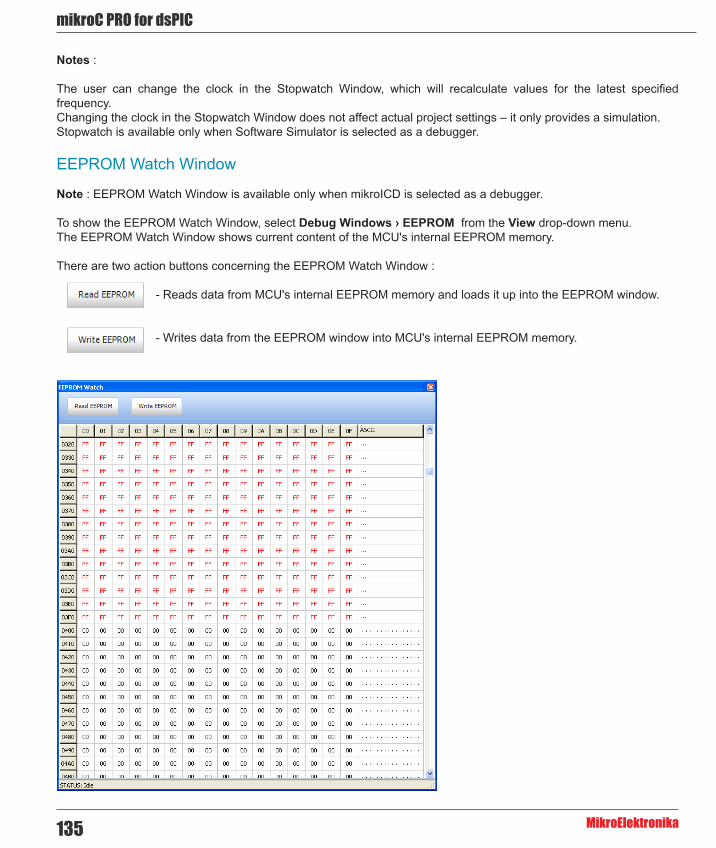
mikroC PRO for dsPIC
MikroElektronika135
Notes :
The user can change the clock in the Stopwatch Window, which will recalculate values for the latest specified frequency. Changing the clock in the Stopwatch Window does not affect actual project settings – it only provides a simulation. Stopwatch is available only when Software Simulator is selected as a debugger.
EEPROM Watch Window
Note : EEPROM Watch Window is available only when mikroICD is selected as a debugger.
To show the EEPROM Watch Window, select Debug Windows › EEPROM from the View drop-down menu. The EEPROM Watch Window shows current content of the MCU's internal EEPROM memory.
There are two action buttons concerning the EEPROM Watch Window :
- Reads data from MCU's internal EEPROM memory and loads it up into the EEPROM window.
- Writes data from the EEPROM window into MCU's internal EEPROM memory.

136
mikoC PRO for dsPIC
MikroElektronika
Code Watch Window
Note : Code Watch Window is available only when mikroICD is selected as a debugger.
To show the Code Watch Window, select Debug Windows › Code from the View drop-down menu.
The Code Watch Window shows code (hex format) written into the MCU.
There is one action button concerning the Code Watch Window :
- Reads code from the MCU and loads it up into the Code Window. Code reading is resources
consuming operation so the user should wait until the reading is over.
Also, you can set an address scope in which hex code will be read.

mikroC PRO for dsPIC
MikroElektronika137
Software Simulator Debugger Options
Debugger Options
Name Description Function Key
Toolbar Icon
Start Debugger Starts Debugger. F9
Stop Debugger Stop Debugger. Ctrl + F2
Run/Pause Debugger Run/Pause Debugger. F6
Step IntoExecutes the current program line, then halts. If the executed program line calls another routine, the debugger steps into the routine and halts after executing the first instruction within it.
F7
Step Over
Executes the current program line, then halts. If the executed program line calls another routine, the debugger will not step into it. The whole routine will be executed and the debugger halts at the first instruction following the call.
F8
Step Out Executes all remaining program lines within the subroutine. The debugger halts immediately upon exiting the subroutine. Ctrl + F8
Run To Cursor Executes the program until reaching the cursor position. F4
Toggle Breakpoint Toggle breakpoints option sets new breakpoints or removes those already set at the current cursor position. F5
Related topics: Run Menu, Debug Toolbar

138
mikoC PRO for dsPIC
MikroElektronika
CHAPTER 6mikroC PRO for dsPIC30/33 and PIC24 Specifics
The following topics cover the specifics of mikroC PRO for dsPIC30/33 and PIC24 compiler:
- ANSI Standard Issues - Predefined Globals and Constants - Accessing Individual Bits - Interrupts - Linker Directives - Built-in Routines - Code Optimization

mikroC PRO for dsPIC
MikroElektronika139
GOTO Table
If a certain routine is allocated on the address higher than 64kB and can not be accessed directly, a GOTO table is created just after the Interrupt Vector Table to enable this routine call. GOTO table comprises of addresses of those routines that are allocated on the addresses higher than 64kB. So, whenever a call is made to a routine which is not directly accessible, it jumps to an assigned GOTO table block which contains address of a desired routine. From there, a GOTO call is generated to that address, and the routine is executed.

140
mikoC PRO for dsPIC
MikroElektronika
ANSI Standard Issues
Divergence from the ANSI C Standard
The mikroC PRO for dsPIC30/33 and PIC24 diverges from the ANSI C standard in a few areas. Some of these modifications are improvements intended to facilitate dsPIC programming, while others are the result of dsPIC30/33 and PIC24 hardware limitations.
- Case Sensitivity. Check identifiers - The mikroC PRO for dsPIC30/33 and PIC24 treats identifiers declared with the const qualifier as “true constants” (C++ style). This allows using const objects in places where ANSI C expects a constant expression. If aiming at portability, use the traditional preprocessor defined constants. See Type Qualifiers and Constants. - The mikroC PRO for dsPIC30/33 and PIC24 allows C++ style single–line comments using two adjacent slashes (//). The comment can start at any position and extends until the next new line. See Comments. - A number of standard C libraries (ctype, math, stdlib, string) have been implemented; check the individual functions for divergence. - The mikroC PRO for dsPIC30/33 and PIC24 does not provide automatic initialization for objects. Uninitialized globals and objects with static duration will take random values from memory. - Anonymous unions and structures are now supported.
C Language Extensions
mikroC PRO for dsPIC30/33 and PIC24 has additional set of keywords that do not belong to the ANSI standard C language keywords:
- code - data - rx - sfr - xdata - ydata - dma - near - far - at - sbit - bit - iv
Implementation-defined Behavior
Certain sections of the ANSI standard have implementation-defined behavior. This means that the exact behavior of some C code can vary from compiler to compiler. This Help contains the sections describing how the mikroC PRO for dsPIC30/33 and PIC24 compiler behaves in such situations.
The most notable specifics include:
- Storage Classes - Bit Fields
Related topics: Keywords, dsPIC30/33 and PIC24 Specifics

mikroC PRO for dsPIC
MikroElektronika141
Predefined Globals and ConstantsTo facilitate dsPIC30/33 and PIC24 programming, the mikroC PRO for dsPIC30/33 and PIC24 implements a number of predefined globals and constants.
All dsPIC30/33 and PIC24 SFR registers are implicitly declared as global variables of volatile unsigned int. These identifiers have an external linkage, and are visible in the entire project. When creating a project, the mikroC PRO for dsPIC30/33 and PIC24 will include an appropriate (*.c) file from defs folder, containing declarations of available SFR registers and constants (such as PORTB, ADPCFG, etc). All identifiers are in upper case, identical to nomenclature in the Microchip datasheets. All dsPIC30/33 and PIC24 SFR registers are also available as structures with bitfields named identically to the Microchip datasheets in order to facilitate bit access e.g
TRISBbits.TRISB3 = 1.
For a complete set of predefined globals and constants, look for “Defs” in the mikroC PRO for dsPIC30/33 and PIC24 installation folder, or probe the Code Assistant for specific letters (Ctrl+Space in the Code Editor).
Predefined project level defines
mikroC PRO for dsPIC30/33 and PIC24 provides several predefined project level defines that you can use in your project :
- First one is equal to the name of selected device for the project i.e. if P30f4013 is selected device, then P30f4013 token will be defined as 1, so it can be used for conditional compilation : #ifdef P30F4013 ... #endif- The second one is value of frequency (in kHz) for which the project is built : #ifdef __FOSC__ == 80000 ... #endif- Third one is for identifying mikroC PRO for dsPIC30/33 and PIC24 compiler : #ifdef __MIKROC_PRO_FOR_DSPIC__ ... #endif- Fourth one is for identifying the build version. For instance, if a desired build version is 142, user should put this in his code : #if __MIKROC_PRO_FOR_DSPIC_BUILD__ == 142 ... #endif
Related topics: Project Level Defines

142
mikoC PRO for dsPIC
MikroElektronika
Accessing Individual BitsThe mikroC PRO for dsPIC30/33 and PIC24 allows you to access individual bits of 16-bit variables. It also supports sbit and bit data types.
Lets use the Zero bit as an example. This bit is defined in the definition file of the particular MCU as :
const register unsigned short int Z = 1;sbit Z_bit at SR.B1;
To access this bit in your code by its name, you can write something like this:
// Clear Zero bit SR.Z = 0;
In this way, if Zero bit changes its position in the register, you are sure that the appropriate bit will be affected. But, if Zero bit is not located in the designated register, you may get errors.
Another way of accesing bits is by using the direct member selector (.) with a variable, followed by one of identifiers B0, B1, … , B15, or F0, F1, … F15, with F15 being the most significant bit, to access the desired bit :
// predefined globals as bit designators// Clear Zero bitSR.B1 = 0;
// Set Zero bitSR.F1 = 1;
In this way, if the target bit changes its position in the register, you cannot be sure that you are invoking the appropriate bit.
This kind of selective access is an intrinsic feature of mikroC PRO for dsPIC30/33 and PIC24 and can be used anywhere in the code. Identifiers B0–B15 are not case sensitive and have a specific namespace.
You may override them with your own members B0–B15 within any given structure.
When using literal constants as bit designators instead of predefined ones, make sure not to exceed the appropriate type size.
Also, you can access the desired bit by using its alias name, in this case Z_bit :
// Set Zero Bit C_bit = 1;
In this way, if the Zero bit changes its register or position in the register, you are sure that the appropriate bit will be affected.
For backward compatibility, you can access bits in this way also :
// Clear TRISB3TRISBbits.TRISB3 = 0;

mikroC PRO for dsPIC
MikroElektronika143
Note : If aiming at portability, avoid this style of accessing individual bits, use the bit fields instead.
See Predefined Globals and Constants for more information on register/bit names.
sbit type
The mikroC PRO for dsPIC30/33 and PIC24 compiler has sbit data type which provides access to registers, SFRs, variables, etc. You can declare a sbit variable in a unit in such way that it points to a specific bit in SFR register:
extern sfr sbit Abit; // Abit is precisely defined in some external file, for example in the main program unit
In the main program you have to specify to which register this sbit points to, for example:
sbit Abit at PORTB.B0; // this is where Abit is fully defined...void main() { ...}
In this way the variable Abit will actually point to PORTB.0. Please note that we used the keyword sfr for declaration of Abit, because we are pointing it to PORTB which is defined as a sfr variable.
Note : Declaring a sbit variable is not possible via F0, F1, … F15 identifiers.
In case we want to declare a bit over a variable which is not defined as sfr, then the keyword sfr is not necessary, for example:
extern sbit AnotherBit; // AnotherBit is precisely defined in some external file, for example in the main program unit
char MyVar;sbit AnotherBit at MyVar.B0; // this is where AnotherBit is fully defined...void main() { ...}

144
mikoC PRO for dsPIC
MikroElektronika
at keyword
You can use the keyword "at" to make an alias to a variable, for example, you can write a library without using register names, and later in the main program to define those registers, for example :
extern char PORTAlias; // here in the library we can use its symbolic name
char PORTAlias at PORTB; // this is where PORTAlias is fully defined...void main() { ...}
Note : Bear in mind that when using at operator in your code over a variable defined through a extern modifier, appropriate memory specifer must be appended also.
bit type
The mikroC PRO for dsPIC30/33 and PIC24 compiler provides a bit data type that may be used for variable declarations. It can not be used for argument lists, and function-return values.
bit bf; // bit variable
There are no pointers to bit variables:
bit *ptr; // invalid
An array of type bit is not valid:
bit arr [5]; // invalid
Note :
- Bit variables can not be initialized. - Bit variables can not be members of structures and unions. - Bit variables do not have addresses, therefore unary operator & (address of) is not applicable to these variables.
Related topics: Bit fields, Predefined globals and constants, Extern modifier

mikroC PRO for dsPIC
MikroElektronika145
InterruptsThe dsPIC30/33 and PIC24 interrupt controller module reduces numerous peripheral interrupt request signals to a single interrupt request signal to the dsPIC30/33 and PIC24 CPU and has the following features:
- Up to 8 processor exceptions and software traps - 7 user-selectable priority levels - Interrupt Vector Table (IVT) with up to 62 vectors (dsPIC30) or up to 118 vectors (dsPIC33 and PIC24) - A unique vector for each interrupt or exception source - Fixed priority within a specified user priority level - Alternate Interrupt Vector Table (AIVT) for debug support
ISRs are organized in IVT. ISR is defined as a standard function but with the iv directive afterwards which connects the function with specific interrupt vector. For example iv IVT_ADDR_T1INTERRUPT is IVT address of Timer1 interrupt source of the dsPIC 30F3014 MCU. For more information on IVT refer to the dsPIC30/33 and PIC24 Family Reference Manual.
Function Calls from Interrupt
Calling functions from within the interrupt routine is possible. The compiler takes care about the registers being used, both in "interrupt" and in "main" thread, and performs "smart" context-switching between two of them, saving only the registers that have been used in both threads. It is not recommended to use a function call from interrupt. In case of doing that take care of stack depth.
Disable Context Saving
Use the #pragma disablecontexsaving to instruct the compiler not to automatically perform context-switching. This means that no register will be saved/restored by the compiler on entrance/exit from interrupt service routine, except STATUS, WREG and BSR registers in high priority interrupt ('Fast Register Stack').
This exception can be overrided by placing an asm RETFIE, 0 instruction at the end of the high priority interrupt routine (with redirecting all routine exits to this instruction). Thus, #pragma disablecontexsaving pragma enables the user to manually write code for saving registers upon entrance and to restore them before exit from interrupt.
Interrupt Handling
For the sake of interrupt handling convenience, new keyword, iv, is introduced. It is used to declare Interrupt Vector Table (IVT) address for a defined interrupt routine :
void int1() iv IVT_ADDR_U1RXINTERRUPT{ asm nop;}
Now it is possible to explicitly declare interrupt routine address :
void int1() org 0x600 iv IVT_ADDR_U1RXINTERRUPT { asm nop;}

146
mikoC PRO for dsPIC
MikroElektronika
For the sake of backward compatibility, user may write also :
void int1() org IVT_ADDR_U1RXINTERRUPT { asm nop;}
which is equivalent to :
void int1() iv IVT_ADDR_U1RXINTERRUPT { asm nop;}
Is is recommended that interrupts are handled in this way for the sake of better readability of the user projects.
Interrupt Example
Here is a simple example of handling the interrupts from Timer1 (if no other interrupts are allowed):
// Interrupt routinevoid Timer1Int() iv IVT_ADDR_T1INTERRUPT { //** it is necessary to clear manually the interrupt flag: IFS0 = IFS0 & 0xFFF7; // Clear TMR1IF
//** user code starts here LATB = ~ PORTB; // Invert PORTB //** user code ends here}
mikroC PRO for dsPIC
MikroElektronika147
Linker DirectivesThe mikroC PRO for dsPIC30/33 and PIC24 uses an internal algorithm to distribute objects within memory. If you need to have a variable or routine at specific predefined address, use the linker directives absolute and org.
Directive absolute
Directive absolute specifies the starting address in RAM for a variable or a starting address in ROM for a constant. If the variable or constant is multi-byte, higher bytes will be stored at the consecutive locations.
Directive absolute is appended to declaration of a variable or constant :
// Variable x will occupy 1 byte at address 0x22 :short x absolute 0x22;
// Variable y will occupy 2 bytes at addresses 0x23 and 0x24 :int y absolute 0x23;
// Array elements will be placed on the consecutive locations starting from 0x1000 :const short ConstantArray[] = {1,2,3} absolute 0x1000;
Note :
If you want to place simple type constant into Flash memory, instead of following declaration:
const short SimpeConstant = 0xAA absolute 0x2000;
use an array consisting of single element :
const short SimpleConstant[] = {0xAA} absolute 0x2000;
In first case, compiler will recognize your attempt, but in order to save Flash space, and boost performance, it will automatically replace all instances of this constant in code with it's literal value. In the second case your constant will be placed in Flash in the exact location specified.
Be careful when using the absolute directive, as you may overlap two variables by accident. For example:
// Variable i will occupy 1 byte at address 0x33char i absolute 0x33;
// Variable will occupy 4 bytes at 0x30, 0x31, 0x32, 0x33; thus,// changing i changes jjjj highest byte at the same time, and vice versalong jjjj absolute 0x30;
Directive orgall
If the user wants to place his routines, constants, etc, above a specified address in ROM, #pragma orgall directive should be used:
#pragma orgall 0x200

148
mikoC PRO for dsPIC
MikroElektronika
Directive funcorg
You can use the #pragma funcorg directive to specify the starting address of a routine in ROM using routine name only:
#pragma funcorg <func_name> <starting_address>
Related topics: Indirect Function Calls
Indirect Function CallsIf the linker encounters an indirect function call (by a pointer to function), it assumes that any of the functions addresses of which were taken anywhere in the program, can be called at that point. Use the #pragma funcall directive to instruct the linker which functions can be called indirectly from the current function:
#pragma funcall <func_name> <called_func>[, <called_func>,...]
A corresponding pragma must be placed in the source module where the function func_name is implemented. This module must also include declarations of all functions listed in the called_func list.
These functions will be linked if the function func_name is called in the code no matter whether any of them was called or not.
Note : The #pragma funcall directive can help the linker to optimize function frame allocation in the compiled stack.
Related topics: Linker Directives

mikroC PRO for dsPIC
MikroElektronika149
Built-in RoutinesThe mikroC PRO for dsPIC30/33 and PIC24 compiler provides a set of useful built-in utility functions.
The Lo, Hi, Higher, Highest, LoWord, HiWord routines are implemented as macros. If you want to use these functions you must include built_in.h header file (located in the inlclude folder of the compiler) into your project.
The Delay_us and Delay_ms routines are implemented as “inline”; i.e. code is generated in the place of a call, so the call doesn’t count against the nested call limit.
The Vdelay_ms, Vdelay_advanced_ms, Delay_Cyc, Delay_Cyc_Long, Get_Fosc_kHz and Get_Fosc_Per_Cyc are actual C routines. Their sources can be found in Delays.c file located in the uses folder of the compiler.
- Lo - Hi - Higher - Highest
- LoWord - HiWord
- Delay_us - Delay_ms - Vdelay_ms - Vdelay_Advanced_ms - Delay_Cyc - Delay_Cyc_Long
- Clock_kHz - Clock_MHz - Get_Fosc_kHz - Get_Fosc_Per_Cyc

150
mikoC PRO for dsPIC
MikroElektronika
Prototype #define Lo(param) ((char *)¶m)[0]
Description The function returns low byte of number. The function does not interpret bit patterns of number – it merely returns 8 bits as found in register.
This is an “inline” routine; code is generated in the place of the call, so the call doesn’t count against the nested call limit.
Parameters number: input number Returns Low byte of number, bits 7..0.Requires Nothing.Example d = 0x12345678;
tmp = Lo(d); // Equals 0x78
Lo(d) = 0xAA; // d equals 0x123456AA
Notes None.
Prototype #define Hi(param) ((char *)¶m)[1]
Description The function returns high byte of number. The function does not interpret bit patterns of number – it merely returns 8 bits as found in register.
This is an “inline” routine; code is generated in the place of the call, so the call doesn’t count against the nested call limit.
Parameters number: input number Returns High byte of number, bits 15..8.Requires Nothing.Example d = 0x12345678;
tmp = Hi(d); // Equals 0x56
Hi(d) = 0xAA; // d equals 0x1234AA78
Notes None.
Lo
Hi

mikroC PRO for dsPIC
MikroElektronika151
Prototype #define Higher(param) ((char *)¶m)[2]
Description The function returns higher byte of number. The function does not interpret bit patterns of number – it merely returns 8 bits as found in register.
This is an “inline” routine; code is generated in the place of the call, so the call doesn’t count against the nested call limit.
Parameters number: input number Returns Higher byte of number, bits 23..16.Requires Nothing.Example d = 0x12345678;
tmp = Higher(d); // Equals 0x34
Higher(d) = 0xAA; // d equals 0x12AA5678
Notes None.
Prototype #define Highest(param) ((char *)¶m)[3]
Description The function returns highest byte of number. The function does not interpret bit patterns of number – it merely returns 8 bits as found in register.
This is an “inline” routine; code is generated in the place of the call, so the call doesn’t count against the nested call limit.
Parameters number: input number Returns Highest byte of number, bits 31..24.Requires Nothing.Example d = 0x12345678;
tmp = Highest(d); // Equals 0x12
Highest(d) = 0xAA; // d equals 0xAA345678
Notes None.
Higher
Highest

152
mikoC PRO for dsPIC
MikroElektronika
Prototype unsigned int LoWord(unsigned long number);
Description The function returns low word of number. The function does not interpret bit patterns of number – it merely returns 16 bits as found in register.
This is an “inline” routine; code is generated in the place of the call, so the call doesn’t count against the nested call limit.
Parameters number: input number Returns Low word of number, bits 15..0.Requires Nothing.Example d = 0x12345678;
tmp = LoWord(d); // Equals 0x5678
LoWord(d) = 0xAAAA; // d equals 0x1234AAAA
Notes None.
Prototype unsigned int HiWord(unsigned long number);
Description The function returns high word of number. The function does not interpret bit patterns of number – it merely returns 16 bits as found in register.
This is an “inline” routine; code is generated in the place of the call, so the call doesn’t count against the nested call limit.
Parameters number: input number Returns High word of number, bits 31..16.Requires Nothing.Example d = 0x12345678;
tmp = HiWord(d); // Equals 0x1234
HiWord(d) = 0xAAAA; // d equals 0xAAAA5678
Notes None.
LoWord
HiWord

mikroC PRO for dsPIC
MikroElektronika153
Prototype void Delay_us(const unsigned long time_in_us);
Description Creates a software delay in duration of time_in_us microseconds.
This is an “inline” routine; code is generated in the place of the call, so the call doesn’t count against the nested call limit.
Parameters time_in_us: delay time in microseconds. Valid values: constant values, range of applicable constants depends on the oscillator frequency
Returns Nothing.Requires Nothing.Example Delay_us(10); /* Ten microseconds pause */
Notes None.
Prototype void Delay_ms(const unsigned int time_in_ms);
Description Creates a software delay in duration of time_in_ms milliseconds.
This is an “inline” routine; code is generated in the place of the call, so the call doesn’t count against the nested call limit.
Parameters time_in_ms: delay time in milliseconds. Valid values: constant values, range of applicable constants depends on the oscillator frequency
Returns Nothing.Requires Nothing.Example Delay_ms(1000); /* One second pause */
Notes For generating delays with variable as input parameter use the Vdelay_ms routine.
Prototype void Vdelay_ms(unsigned Time_ms);
Description Creates a software delay in duration of Time_ms milliseconds. Generated delay is not as precise as the delay created by Delay_ms.
Parameters Time_ms: delay time in milliseconds Returns Nothing.Requires Nothing.Example unsignedpause = 1000;
...Vdelay_ms(pause); // ~ one second pause
Notes Vdelay_ms is a library function rather than a built-in routine; it is presented in this topic for the sake of convenience.
Delay_us
Delay_ms
Vdelay_ms

154
mikoC PRO for dsPIC
MikroElektronika
Prototype void VDelay_Advanced_ms(unsigned time_in_ms, unsigned Current_Fosc_kHz);
Description Creates a software delay in duration of time_in_ms milliseconds (a variable), for a given oscillator frequency. Generated delay is not as precise as the delay created by Delay_ms.
Parameters Time_ms: delay time in milliseconds Current_Fosc_kHz: desiredoscillator frequency
Returns Nothing.Requires Nothing.Example pause = 1000;
fosc = 10000;
VDelay_Advanced_ms(pause, fosc); // Generates approximately one second pause, for a oscillator frequency of 10 MHz
Notes Note that VDelay_Advanced_ms is library function rather than a built-in routine; it is presented in this topic for the sake of convenience.
Prototype void Delay_Cyc(unsigned int x, unsigned int y);
Description Creates a delay based on MCU clock. Delay lasts for x*16384 + y MCU clock cycles.Parameters x: NumberOfCycles divided by 16384
y: remainder of the NumberOfCycles/16384 division Returns Nothing.Requires Nothing.Example Delay_Cyc(1, 10); /* 1x16384 + 10 = 16394 cycles pause */
Notes Delay_Cyc is a library function rather than a built-in routine; it is presented in this topic for the sake of convenience.
Prototype void Delay_Cyc_Long(unsigned long CycNo);
Description Creates a delay based on MCU clock. Delay lasts for CycNo MCU clock cycles.Parameters CycNo: number of cycles Returns Nothing.Requires Nothing.Example Delay_Cyc_Long(16394); // 16394 cycles pause
Notes Delay_Cyc_Long is a library function rather than a built-in routine; it is presented in this topic for the sake of convenience.
VDelay_Advanced_ms
Delay_Cyc
Delay_Cyc_Long

mikroC PRO for dsPIC
MikroElektronika155
Prototype unsigned long Clock_kHz();
Description Function returns device clock in kHz, rounded to the nearest integer.
This is an “inline” routine; code is generated in the place of the call, so the call doesn’t count against the nested call limit.
Parameters None.Returns Device clock in kHz, rounded to the nearest integer.Requires Nothing.Example unsigned long clk;
...clk = Clock_kHz();
Notes None.
Prototype unsigned long Clock_MHz();
Description Function returns device clock in MHz, rounded to the nearest integer.
This is an “inline” routine; code is generated in the place of the call, so the call doesn’t count against the nested call limit.
Parameters None.Returns Device clock in MHz, rounded to the nearest integer.Requires Nothing.Example unsigned long clk;
...clk = Clock_Mhz();
Notes None.
Prototype unsigned long Get_Fosc_kHz();
Description Function returns device clock in kHz, rounded to the nearest integer.
Note that Get_Fosc_kHz is library function rather than a built-in routine; it is presented in this topic for the sake of c?nvenience.
Parameters None.Returns Device clock in kHz, rounded to the nearest integer.Requires Nothing.Example unsigned long clk;
...clk = Get_Fosc_kHz();
Notes None.
Clock_kHz
Clock_Mhz
Get_Fosc_kHz

156
mikoC PRO for dsPIC
MikroElektronika
Prototype unsigned int Get_Fosc_Per_Cyc();
Description Function returns device’s clock per cycle, rounded to the nearest integer.
Note that Get_Fosc_Per_Cyc is library function rather than a built-in routine; it is presented in this topic for the sake of convenience.
Parameters None.Returns Device’s clock per cycle, rounded to the nearest integer.Requires Nothing.Example unsigned int clk_per_cyc;
...clk_per_cyc = Get_Fosc_Per_Cyc();
Notes None.
Get_Fosc_Per_Cyc

mikroC PRO for dsPIC
MikroElektronika157
Code OptimizationOptimizer has been added to extend the compiler usability, cut down the amount of code generated and speed-up its execution. The main features are:
Constant folding
All expressions that can be evaluated in the compile time (i.e. constant) are being replaced by their results. (3 + 5 -> 8);
Constant propagation
When a constant value is being assigned to a certain variable, the compiler recognizes this and replaces the use of the variable by constant in the code that follows, as long as the value of a variable remains unchanged.
Copy propagation
The compiler recognizes that two variables have the same value and eliminates one of them further in the code.
Value numbering
The compiler "recognizes" if two expressions yield the same result and can therefore eliminate the entire computation for one of them.
"Dead code" ellimination
The code snippets that are not being used elsewhere in the programme do not affect the final result of the application. They are automatically removed.
Stack allocation
Temporary registers ("Stacks") are being used more rationally, allowing VERY complex expressions to be evaluated with a minimum stack consumption.
Local vars optimization
No local variables are being used if their result does not affect some of the global or volatile variables.
Better code generation and local optimization
Code generation is more consistent and more attention is payed to implement specific solutions for the code "building bricks" that further reduce output code size.
Related topics: SSA Optimization, dsPIC specifics, mikroC PRO for dsPIC30/33 and PIC24 specifics, Memory type specifiers
158
mikoC PRO for dsPIC
MikroElektronika
Single Static Assignment Optimization
Introduction
In compiler design, static single assignment form (often abbreviated as SSA form or SSA) is an intermediate representation (IR) in which every variable is assigned exactly once.
An SSA-based compiler modifies the program representation so that every time a variable is assigned in the original program, a new version of the variable is created. A new version of the variable is distinguished (renamed) by subscripting the variable name with its version number or an index, so that every definition of each variable in a program becomes unique. At a joining point of the control flow graph where two or more different definitions of a variable meet, a hypothetical function called a phi-function is inserted so that these multiple definitions are merged.
In mikroC PRO for dsPIC, SSA's main goal is in allocating local variables into the RX space (instead onto the frame). To do that, SSA has to make an alias and data flow analysis of the Control Flow Graph.
Besides these savings, there are a number of compiler optimization algorithms enhanced by the use of SSA, like :
- Constant Propagation - Dead Code Elimination - Global Value Numbering - Register Allocation
Changes that SSA brings is also in the way in which routine parameters are passed. When the SSA is enabled, parameters are passed through a part of the RX space which is reserved exclusively for this purpose (W10-W13 for dsPIC). Allocating local variables and parameters in RX space has its true meaning for those architectures with hardware frame.
Enabling SSA optimization in compiler is done by checking box from the Output Settings Menu.
Lets consider a trivial case :
void main() { int y,k; if(y+k) asm nop;}
With SSA enabled, this example is consisted of 3 asm instructions :
;rbuild.c,10 :: if(y+k)0x0212 0x408002 ADD _WREG1, _WREG2, _WREG00x0214 0x320001 BRA Z L_main0L__main2:;rbuild.c,11 :: asm nop;0x0216 0x000000 NOP

mikroC PRO for dsPIC
MikroElektronika159
Without SSA enabled, this example is consisted of 5 asm instructions :
;rbuild.c,10 :: if(y+k)0x0218 0x90008E MOV [_WREG14+0], _WREG10x021A 0x470062 ADD _WREG14, #2, _WREG00x021C 0x408010 ADD _WREG1, [_WREG0], _WREG00x021E 0x320001 BRA Z L_main0L__main2:;rbuild.c,11 :: asm nop;0x0220 0x000000 NOP
Proper Coding Recommendations
To get the maximum out of the SSA, user should regard the following rules during the coding process :
- Routines should not contain too many parameters (not more than 4 words). - Don’t change the value of the parameter in the function body (it is better to use a new local variable). - If the function1 parameters are passed as function2 parameters, then parameter order should remain the same :
f2(int a, int b) { }
f1(int x, int y) { // routine call f2(x,y); // x->a and y->b (1 to 1 and 2 to 2) is far more efficient than : f2(y,x); // y->a and x->b (1 to 2 and 2 to 1) }
- Large amount of nested loops and complex structures as its members should be avoided. - When writing a code in assembly, keep in mind that there are registers reserved exclusively for routine parameters. - Using goto and label statements in nested loops should be avoided. - Obtaining address of the local variable with the global pointer and using it to alter the variable’s address should be avoided.
Notes :
- mcl files compiled with or without SSA enabled are fully compatible and can be used and mixed without any restrictions, except function pointers. - All function prototypes and function pointers have to be built using the same optimizer because of different calling conventions in different optimizers. In SSA, function parameters are passed via working registers, and without SSA they end up on the function frame. - This means that you cannot have a function implementation which is optimized using SSA optimizer, and to call this function via function pointer in another module which is optimized using NON-SSA. When using pointers to functions, compiler must know exactly how to pass function parameters and how to execute function call.

160
mikoC PRO for dsPIC
MikroElektronika
Asm code and SSA optimization
If converting code from an earlier version of the compiler, which consists of mixed asm code with the C code, keep in mind that the generated code can substantially differ when SSA optimization option is enabled or disabled. This is due to the fact that SSA optimization uses certain working registers to store routine parameters (W10-W13), rather than storing them onto the function frame.
Because of this, user must be very careful when writing asm code as existing values in the working registers used by SSA optimization can be overwritten. To avoid this, it is recommended that user includes desired asm code in a separate routine.
Debugging Notes
SSA also influences the code debugging in such a way that the local variables will be available in the Watch Window only in those parts of the procedure where they have useful value (eg. on entering the procedure, variable isn't available until its definition). Variables can be allocated in one part of the procedure in register W4, and in another part of the procedure in register W2, if the optimizer estimates that it is better that way. That means that the local variable has no static address.
Warning Messages Enhancement
Besides the smaller code, SSA also deals with the intensive code analysis, which in turn has the consequence in enhancing the warning messages. For example, compiler will warn the user that the uninitialized variable is used :
void main() { int y;
if (y) // Variable y might not have been initialized PORTD = 0;}
Related topics: Code Optimization, dsPIC Specifics, mikroC PRO for dsPIC30/33 and PIC24 specifics, Memory type specifiers

mikroC PRO for dsPIC
MikroElektronika161
Common Object File Format (COFF)
COFF File Format
The Common Object File Format (COFF) is a specific file format suitable for code debugging. The COFF incorporates symbolic procedure, function, variable and constant names information; line number information, breakpoints settings, code highlighter and all the necessary information for effective and fast debugging.
By using COFF, it is possible to import and debug code generated by mikroElektronika compilers under Microchip's MPLAB®.
COFF File Generation
1. Start mikroC PRO for dsPIC30/33 and PIC24 and open the desired project. For example, UART project for EasydsPIC4A board and dsPIC30F4013 will be opened :

162
mikoC PRO for dsPIC
MikroElektronika
2. When the project is opened, go to Tools › Options › Output settings, and check the "Generate COFF file" option, and click the OK button :
3. Now, compile the project. In the messages window, appropriate message on COFF file generation should appear :
4. Generated COFF file will be created in the project folder, with the .cof extension.
Related topics: Using MPLAB® ICD 2 Debugger, Using MPLAB® Simulator

mikroC PRO for dsPIC
MikroElektronika163
CHAPTER 7dsPIC30/33 and PIC24 SpecificsIn order to get the most from the mikroC PRO for dsPIC30/33 and PIC24 compiler, the user should be familiar with certain aspects of dsPIC30/33 and PIC24 MCU. This knowledge is not essential, but it can provide a better understanding of the dsPIC30/33 and PIC24’s capabilities and limitations, and their impact on the code writing as well.

164
mikoC PRO for dsPIC
MikroElektronika
Types Efficiency
First of all, the user should know that dsPIC30/33 and PIC24’s ALU, which performs arithmetic operations, is optimized for working with 16-bit types. Although mikroC PRO for dsPIC30/33 and PIC24 is capable of handling types like char or short, dsPIC30/33 and PIC24 will generate a better code for 16-bit types, like int. Therefore, use char and short only in places where you can significantlly save RAM (e.g. for arrays char a[30]).
Nested Calls Limitations
There are no Nested Calls Limitations, except by RAM size. A Nested call represents a function call within the function body, either to itself (recursive calls) or to another function.
Recursive calls, as a form of cross-calling, are supported by mikroC PRO for dsPIC30/33 and PIC24, but they should be used very carefully due to dsPIC30/33 and PIC24 stack and memory limitations. Also calling functions from interrupt is allowed. Calling function from both interrupt and main thread is allowed. Be carefull because this programming technique may cause unpredictable results if common resources are used in both main and interrupt.
Limits of Indirect Approach Through PSV
Constant aggregates are stored in Flash and are accessible through PSV. mikroC PRO for dsPIC30/33 and PIC24 can allocate more than 32KByte of constants. See near and far memory specifiers.
Limits of Pointer to Function
Currently pointer to functions are 16-bit variables. For functions which address exceeds 16 bit limit, the compiler uses handle (16-bit pointer on GOTO). A handle usage is automatic compiler process so there is no need for the user to intervene.
Variable, constant and routine alignment
Simple type variables whose size exceeds 1 byte (int, long, float, double, long double) are always set to alignment 2 (i.e. are always allocated on even address). Derived types and constant aggregates whose at least one element exceeds size of 1 byte are set to alignment 2. Routines are always set to aligment 2.

mikroC PRO for dsPIC
MikroElektronika165
dsPIC Memory OrganizationThe dsPIC microcontroller’s memory is divided into Program Memory and Data Memory. Program Memory (ROM) is used for permanent saving program being executed, while Data Memory (RAM) is used for temporarily storing and keeping intermediate results and variables.
Program Memory (ROM)
Program Memory (ROM) is used for permanent saving program code being executed, and it is divided into several sections, as on the picture below. The size of these sections is device dependant. The program memory map is divided into the User Memory Space and Configuration Memory Space. The User Memory Space contains the Reset vector, interrupt vector tables, program memory and data EEPROM memory (dsPIC30 family and some PIC24 family MCU’s). The Configuration Memory Space contains non-volatile configuration bits for setting device options and the device ID locations. Program Memory (ROM) Organization
1. dsPIC33F Program Memory Organization

166
mikoC PRO for dsPIC
MikroElektronika
Data Memory (RAM)
Data memory consists of:
- SFR Memory Space - X and Y Data RAM - DMA RAM (only for dsPIC33F Family) - Unimplemented Memory Space
Data Memory (RAM) Organization
1. PIC24F Data Memory Organization 2. dsPIC33F Data Memory Organization
SFR Memory Space
The first 2kB of data memory is allocated to the Special Function Registers (SFRs). The SFRs are control and status register for core and peripheral functions in the dsPIC.
X and Y Data RAM
Up to 8 kB of data RAM is implemented after the SFRs. This is general purpose RAM that can be used for data storage. This RAM is split into X and Y memory for dsPIC instructions. This allows DSP instructions to support dual operand reads, so that data can be fetched from X and Y memory space at the same time for a single instruction. The X and Y data space boundary is fixed for any given device. When not doing DSP instructions, the memory is all treated as a single block of X memory.

mikroC PRO for dsPIC
MikroElektronika167
DMA RAM
Every dsPIC33F device contains a portion of dual ported DMA RAM located at the end of Y data space. Direct Memory Access (DMA) is a very efficient mechanism of copying data between peripheral SFRs and buffers or variables stored in RAM, with minimal CPU intervention. The DMA controller can automatically copy entire blocks of data without requiring the user software to read or write the peripheral Special Function Registers (SFRs) every time a peripheral interrupt occurs. The DMA controller uses a dedicated bus for data transfers and therefore, does not steal cycles from the code execution flow of the CPU. To exploit the DMA capability, the corresponding user buffers or variables must be located in DMA RAM.
Unimplemented Memory Space
The last segment of data RAM space is not implemented, but can be mapped into program space for Program Space Visibility. This allows program memory to be read as though it were in data RAM.
Notes: - Boundaries between memory spaces are device specific. Please, refer to the appropriate datasheet for details. - Memory spaces are not shown to scale. Please, refer to the appropriate datasheet for details.
There are seven memory type specifiers that can be used to refer to the data memory: rx, data, code, sfr, xdata, ydata, and dma
Related topics: Accessing individual bits, SFRs, Memory type specifiers, dsPIC Memory Type QualifiersC

168
mikoC PRO for dsPIC
MikroElektronika
Memory Type SpecifiersThe mikroC PRO for dsPIC30/33 and PIC24 supports usage of all memory areas. Each variable may be explicitly assigned to a specific memory space by including a memory type specifier in the declaration, or implicitly assigned.
The following memory type specifiers can be used:
- code - data - rx - sfr - xdata - ydata - dma
code
Description The code memory type may be used for allocating constants in program memory.
Example // puts txt in program memory const code char txt[] = “ENTER PARAMETER:”;
data
Description This memory specifier is used when storing variable to the Data RAM.
Example // puts x in data ramdata unsigned char x;
rx
Description This memory specifier allows variable to be stored in the working registers space (WREG0-WREG15).
Example // puts y in working register space rx char y;
sfr
Description This memory specifier allows user to access special function registers. It also instructs compiler to maintain same identifier in source and assembly.
Example sfr char y; // puts y in SFR space

mikroC PRO for dsPIC
MikroElektronika169
xdata
Description This memory specifier allows user to access X Data memory space.
Example xdata char x; // puts x in xdata memory space
ydata
Description This memory specifier allows user to access Y Data memory space.
Example ydata char y; // puts y in ydata memory space
dma
Description This memory specifier allows user to access DMA memory space (dsPIC33F specific).
Example dma char y; // puts y in DMA memory space
Note: If none of the memory specifiers are used when declaring a variable, data specifier will be set as default by the compiler.
Related topics: dsPIC Memory Organization, dsPIC Memory Type Qualifiers, Accessing individual bits, SFRs, Constants, Functions

170
mikoC PRO for dsPIC
MikroElektronika
Memory Type QualifiersIn addition to the standard storage qualifiers(const, volatile) the compiler introduces storage qualifiers of near and far.
Near Memory Qualifier
1. Data Memory Objects
The qualifier near is used to denote that a variable is allocated in near data space (the first 8 kB of Data memory). Such variables can sometimes be accessed more efficiently than variables not allocated (or not known to be allocated) in near data space. If variables are allocated in the near data section, the compiler is often able to generate better (more compact) code than if the variables are not allocated in the near data section.
2. Program Memory Objects
The qualifier near is used to denote that a constant is allocated in the default program memory page (32kB segment of program memory). Default program memory page is the one with most free space and is set by the compiler by analyzing program memory pages. This qualifier is set as default by the compiler, if no other qualifier is used.
Far Memory Qualifier
1 Data Memory Objects
The qualifier far is used to denote that a variable will not be in near data space (i.e. the variable can be located anywhere in data memory). This qualifier is set as default by the compiler, if no other qualifier is used.
2. Program Memory Objects
The qualifier far is used to denote that a constant can be allocated anywhere in the program memory, in the page pointed to by PSVPAG register.
Location of object based on memory qualifiers:
Qualifier/Memory Data Memory Program Memory near First 8 kB of RAM In default pagefar Anywhere in RAM In page pointed to PSVPAG register
Example:
char i; // far memory qualifier is set, variable i can allocated somewhere in data memorychar near j; // near memory qualifier is set, variable j will be allocated in the first 8kB of data memoryconst int k = 10; // near memory qualifier is set, constant k will be allocated in the default memory page
Related topics: dsPIC Memory Organization, dsPIC Memory Type Specifiers
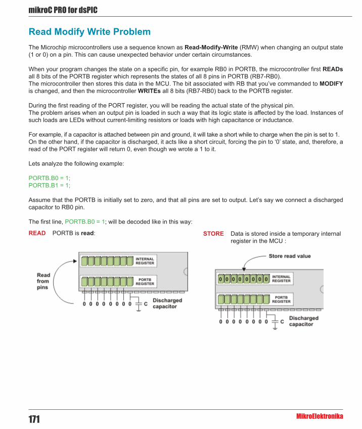
mikroC PRO for dsPIC
MikroElektronika171
Read Modify Write ProblemThe Microchip microcontrollers use a sequence known as Read-Modify-Write (RMW) when changing an output state (1 or 0) on a pin. This can cause unexpected behavior under certain circumstances.
When your program changes the state on a specific pin, for example RB0 in PORTB, the microcontroller first READs all 8 bits of the PORTB register which represents the states of all 8 pins in PORTB (RB7-RB0). The microcontroller then stores this data in the MCU. The bit associated with RB that you’ve commanded to MODIFY is changed, and then the microcontroller WRITEs all 8 bits (RB7-RB0) back to the PORTB register.
During the first reading of the PORT register, you will be reading the actual state of the physical pin. The problem arises when an output pin is loaded in such a way that its logic state is affected by the load. Instances of such loads are LEDs without current-limiting resistors or loads with high capacitance or inductance.
For example, if a capacitor is attached between pin and ground, it will take a short while to charge when the pin is set to 1. On the other hand, if the capacitor is discharged, it acts like a short circuit, forcing the pin to ‘0’ state, and, therefore, a read of the PORT register will return 0, even though we wrote a 1 to it.
Lets analyze the following example:
PORTB.B0 = 1;PORTB.B1 = 1;
Assume that the PORTB is initially set to zero, and that all pins are set to output. Let’s say we connect a discharged capacitor to RB0 pin.
The first line, PORTB.B0 = 1; will be decoded like in this way:
READ PORTB is read: STORE Data is stored inside a temporary internal register in the MCU :

172
mikoC PRO for dsPIC
MikroElektronika
Actual voltage levels on MCU pins are relevant.
MODIFY Data is modified to set the RB0 bit: WRITE PORTB is written with the modified data. The output driver for RB0 turns on, and the capacitor starts to charge:
The second line, PORTB.B1 = 1; will be decoded like in this way:
READ PORTB is read: STORE Because the capacitor is still charging, the voltage at RB0 is still low and reads as a ‘0’ (since we are reading from the pins directly, not from the PORTB register) :
Actual voltage levels on MCU pins are relevant.
MODIFY Data is modified to set the bit: WRITE PORTB is written with the new data. The output driver for RB1 turns on, but the driver for RB0 turns back off:

mikroC PRO for dsPIC
MikroElektronika173
To correct the problem in the code, insert a delay after each PORTB.Bx = 1 line, or modify the entire PORTB register in a single line PORTB = 0b00000011.
This problem can be avoided by using LATx register when writing to ports, rather than using PORTx registers. Writing to a LATx register is equivalent to writing to a PORTx register, but readings from LATx registers return the data value held in the port latch, regardless of the state of the actual pin.
For example, lets analyze the following example:
LATB.B0 = 1;LATB.B1 = 1;
The first line, LATB.B0 = 1; will be decoded like in this way:
READ LATB is read: STORE Data is stored inside a temporary internal register in the MCU :
Actual voltage levels on MCU pins are no longer relevant when using LATx for output
MODIFY Data is modified to set the RB0 bit: WRITE LATB is written with the modified data. The output driver for RB0 turns on, and the capacitor starts to charge:

174
mikoC PRO for dsPIC
MikroElektronika
The second line, LATB.B1 = 1; will be decoded like in this way :
READ LATB is read: STORE Since the voltage levels on MCU pins are no longer relevant, we get the expected value:
Actual voltage levels on MCU pins are no longer relevant when using LATx for output
MODIFY Data is modified to set the bit: WRITE LATB is written with the new data. The output driver for RB1 turns on, and the output driver for RB0 remains turned on:
When to use LATx instead of PORTx
Depending on your hardware, one may experience unpredictable behavior when using PORTx bits for driving output. Displays (GLCD, LCD), chip select pins in SPI interfaces and other cases when you need fast and reliable output, LATx should be used instead of PORTx.
mikroC PRO for dsPIC
MikroElektronika175
CHAPTER 8mikroC PRO for dsPIC30/33 and PIC24 Language Reference

176
mikoC PRO for dsPIC
MikroElektronika
- Lexical Elements
- Whitespace - Comments - Tokens - Constants
- Constants Overview - Integer Constants - Floating Point Constants - Character Constants - String Constants - Enumeration Constants - Pointer Constants - Constant Expressions
- Keywords - Identifiers - Punctuators
- Concepts
- Objects and Lvalues - Scope and Visibility - Name Spaces - Duration
- Types - Fundamental Types
- Arithmetic Types - Enumerations - Void Type
- Derived Types
- Arrays - Pointers
- Introduction to Pointers - Pointer Arithmetic
- Structures
- Introduction to Structures - Working with Structures - Structure Member Access - Unions - Bit Fields

mikroC PRO for dsPIC
MikroElektronika177
- Types Conversions
- Standard Conversions - Explicit Typecasting
- Declarations
- Introduction to Declarations - Linkage - Storage Classes - Type Qualifiers - Typedef Specifier - ASM Declaration - Initialization
- Functions
- Introduction to Functions - Function Calls and Argument Conversion
- Operators
- Introduction to Operators - Operators Precedence and Associativity - Arithmetic Operators - Relational Operators - Bitwise Operators - Logical Operators - Conditional Operator - Assignment Operators - Sizeof Operator
- Expressions
- Introduction to Expressions - Comma Expressions
- Statements
- Introduction - Labeled Statements - Expression Statements - Selection Statements
- If Statement - Switch Statement
- Iteration Statements (Loops)
- While Statement - Do Statement - For Statement

178
mikoC PRO for dsPIC
MikroElektronika
- Jump Statements - Break and Continue Statements - Goto Statement - Return Statement
- Compound Statements (Blocks)
- Preprocessor
- Introduction to Preprocessor - Preprocessor Directives - Macros - File Inclusion - Preprocessor Operators - Conditional Compilation
Lexical Elements OverviewThe following topics provide a formal definition of the mikroC PRO for dsPIC30/33 and PIC24 lexical elements. They describe different categories of word-like units (tokens) recognized by the mikroC PRO for dsPIC30/33 and PIC24.
In the tokenizing phase of compilation, the source code file is parsed (that is, broken down) into tokens and whitespace. The tokens in the mikroC PRO for dsPIC30/33 and PIC24 are derived from a series of operations performed on your programs by the compiler and its built-in preprocessor.

mikroC PRO for dsPIC
MikroElektronika179
WhitespaceWhitespace is a collective name given to spaces (blanks), horizontal and vertical tabs, newline characters and comments. Whitespace can serve to indicate where tokens start and end, but beyond this function, any surplus whitespace is discarded. For example, two sequences
int i; float f;
and
int i;
float f;
are lexically equivalent and parse identically to give six tokens:
inti;floatf;
Whitespace in Strings
The ASCII characters representing whitespace can occur within string literals. In that case they are protected from the normal parsing process (they remain as a part of the string). For example,
char name[] = “mikro foo”;
parses into seven tokens, including a single string literal token:
charname[]=“mikro foo” /* just one token here! */;
Line Splicing with Backslash (\)
A special case occurs if a line ends with a backslash (\). Both backslash and new line character are discarded, allowing two physical lines of a text to be treated as one unit. So, the following code
“mikroC PRO for \
dsPIC30/33 and PIC24 Compiler”
parses into “mikroC PRO for dsPIC30/33 and PIC24 Compiler”. Refer to String Constants for more information.

180
mikoC PRO for dsPIC
MikroElektronika
CommentsComments are pieces of a text used to annotate a program and technically are another form of whitespace. Comments are for the programmer’s use only; they are stripped from the source text before parsing. There are two ways to delineate comments: the C method and the C++ method. Both are supported by mikroC PRO for dsPIC30/33 and PIC24.
You should also follow the guidelines on the use of whitespace and delimiters in comments, discussed later in this topic to avoid other portability problems.
C comments
C comment is any sequence of characters placed after the symbol pair /*. The comment terminates at the first occurance of the pair */ following the initial /*. The entire sequence, including four comment-delimiter symbols, is replaced by one space after macro expansion.
In the mikroC PRO for dsPIC30/33 and PIC24,
int /* type */ i /* identifier */;
parses as:
int i;
Note that the mikroC PRO for dsPIC30/33 and PIC24 does not support a nonportable token pasting strategy using /**/. For more information on token pasting, refer to the Preprocessor Operators.
C++ comments
The mikroC PRO for dsPIC30/33 and PIC24 allows single-line comments using two adjacent slashes (//). The comment can start in any position and extends until the next new line. The following code
int i; // this is a commentint j;
parses as:
int i;int j;
Nested comments
ANSI C doesn’t allow nested comments. The attempt to nest a comment like this
/* int /* declaration */ i; */
fails, because the scope of the first /* ends at the first */. This gives us
i; */
which would generate a syntax error.

mikroC PRO for dsPIC
MikroElektronika181
TokensToken is the smallest element of a C program that compiler can recognize. The parser separates tokens from the input stream by creating the longest token possible using the input characters in a left–to–right scan.
The mikroC PRO for dsPIC30/33 and PIC24 recognizes the following kinds of tokens:
- keywords - identifiers - constants - operators - punctuators (also known as separators)
Tokens can be concatenated (pasted) by means of the preprocessor operator ##. See the Preprocessor Operators for details.
Token Extraction Example
Here is an example of token extraction. Take a look at the following example code sequence:
inter = a+++b;
First, note that inter would be parsed as a single identifier, rather than as the keyword int followed by the identifier er.
The programmer who has written the code might have intended to write inter = a + (++b), but it wouldn’t work that way. The compiler would parse it into the seven following tokens:
inter // variable identifier= // assignment operatora // variable identifier++ // postincrement operator+ // addition operatorb // variable identifier; // statement terminator
Note that +++ parses as ++ (the longest token possible) followed by +.
According to the operator precedence rules, our code sequence is actually:
inter (a++)+b;

182
mikoC PRO for dsPIC
MikroElektronika
ConstantsConstants or literals are tokens representing fixed numeric or character values.
The mikroC PRO for dsPIC30/33 and PIC24 supports:
- integer constants - floating point constants - character constants - string constants (strings literals) - enumeration constants
The data type of a constant is deduced by the compiler using such clues as a numeric value and format used in the source code.
Integer ConstantsInteger constants can be decimal (base 10), hexadecimal (base 16), binary (base 2), or octal (base 8). In the absence of any overriding suffixes, the data type of an integer constant is derived from its value.
Long and Unsigned Suffixes
The suffix L (or l) attached to any constant forces that constant to be represented as a long. Similarly, the suffix U (or u) forces a constant to be unsigned. Both L and U suffixes can be used with the same constant in any order or case: ul, Lu, UL, etc.
In the absence of any suffix (U, u, L, or l), a constant is assigned the “smallest” of the following types that can accommodate its value: short, unsigned short, int, unsigned int, long int, unsigned long int.
Otherwise:
- If a constant has the U suffix, its data type will be the first of the following that can accommodate its value: unsigned short, unsigned int, unsigned long int. - If a constant has the L suffix, its data type will be the first of the following that can accommodate its value: long int, unsigned long int. - If a constant has both L and U suffixes, (LU or UL), its data type will be unsigned long int.
Decimal
Decimal constants from -2147483648 to 4294967295 are allowed. Constants exceeding these bounds will produce an “Out of range” error. Decimal constants must not use an initial zero. An integer constant that has an initial zero is interpreted as an octal constant. Thus,
int i = 10; /* decimal 10 */int i = 010; /* decimal 8 */int i = 0; /* decimal 0 = octal 0 */

mikroC PRO for dsPIC
MikroElektronika183
In the absence of any overriding suffixes, the data type of a decimal constant is derived from its value, as shown below:
Value Assigned to Constant Assumed Type< -2147483648 Error: Out of range!-2147483648 – -32769 long
-32768 – -129 int
-128 – 127 short
128 – 255 unsigned short
256 – 32767 int
32768 – 65535 unsigned int
65536 – 2147483647 long
2147483648 – 4294967295 unsigned long
> 4294967295 Error: Out of range!
Hexadecimal
All constants starting with 0x (or 0X) are taken to be hexadecimal. In the absence of any overriding suffixes, the data type of an hexadecimal constant is derived from its value, according to the rules presented above. For example, 0xC367 will be treated as unsigned int.
Binary
All constants starting with 0b (or 0B) are taken to be binary. In the absence of any overriding suffixes, the data type of an binary constant is derived from its value, according to the rules presented above. For example, 0b11101 will be treated as short.
Octal
All constants with an initial zero are taken to be octal. If an octal constant contains the illegal digits 8 or 9, an error is reported. In the absence of any overriding suffixes, the data type of an octal constant is derived from its value, according to the rules presented above. For example, 0777 will be treated as int.

184
mikoC PRO for dsPIC
MikroElektronika
Floating Point ConstantsA floating-point constant consists of:
- Decimal integer - Decimal point - Decimal fraction - e or E and a signed integer exponent (optional) - Type suffix: f or F or l or L (optional)
Either decimal integer or decimal fraction (but not both) can be omitted. Either decimal point or letter e (or E) with a signed integer exponent (but not both) can be omitted. These rules allow conventional and scientific (exponent) notations.
Negative floating constants are taken as positive constants with an unary operator minus (-) prefixed.
The mikroC PRO for dsPIC30/33 and PIC24 limits floating-point constants to the range ±1.17549435082 * 10-38 .. ±6.80564774407 * 1038.
Here are some examples:
0. // = 0.0-1.23 // = -1.2323.45e6 // = 23.45 * 10^62e-5 // = 2.0 * 10^-53E+10 // = 3.0 * 10^10.09E34 // = 0.09 * 10^34
The mikroC PRO for dsPIC30/33 and PIC24 floating-point constants are of the type double. Note that the mikroC PRO for dsPIC’s implementation of ANSI Standard considers float and double (together with the long double variant) to be the same type.
Character ConstantsA character constant is one or more characters enclosed in single quotes, such as ‘A’, ‘+’, or ‘\n’. In the mikroC PRO for dsPIC30/33 and PIC24, single-character constants are of the unsigned int type. Multi-character constants are referred to as string constants or string literals. For more information refer to String Constants.
Escape Sequences
A backslash character (\) is used to introduce an escape sequence, which allows a visual representation of certain nongraphic characters. One of the most common escape constants is the newline character (\n).
A backslash is used with octal or hexadecimal numbers to represent an ASCII symbol or control code corresponding to that value; for example, ‘\x3F’ for the question mark. Any value within legal range for data type char (0 to 0xFF for the mikroC PRO for dsPIC30/33 and PIC24) can be used. Larger numbers will generate the compiler error “Out of range”.

mikroC PRO for dsPIC
MikroElektronika185
For example, the octal number \777 is larger than the maximum value allowed (\377) and will generate an error. The first nonoctal or nonhexadecimal character encountered in an octal or hexadecimal escape sequence marks the end of the sequence.
Note: You must use the sequence \\ to represent an ASCII backslash, as used in operating system paths.
The following table shows the available escape sequences:
Sequence Value Char What it does?\a 0x07 BEL Audible bell\b 0x08 BS Backspace\f 0x0C FF Formfeed\n 0x0A LF Newline (Linefeed)\r 0x0D CR Carriage Return\t 0x09 HT Tab (horizontal)\v 0x0B VT Vertical Tab\\ 0x5C \ Backslash\’ 0x27 ‘ Single quote (Apostrophe)\” 0x22 “ Double quote\? 0x3F ? Question mark\O any O = string of up to 3 octal digits\xH any H = string of hex digits\XH any H = string of hex digits
Disambiguation
Some ambiguous situations might arise when using escape sequences.
Here is an example:
Lcd_Out_Cp(“\x091.0 Intro”);
This is intended to be interpreted as \x09 and “1.0 Intro”. However, the mikroC PRO for dsPIC30/33 and PIC24 compiles it as the hexadecimal number \x091 and literal string “.0 Intro”. To avoid such problems, we could rewrite the code in the following way:
Lcd_Out_Cp(“\x09” “1.0 Intro”);
For more information on the previous line, refer to String Constants.
Ambiguities might also arise if an octal escape sequence is followed by a nonoctal digit. For example, the following constant:
“\118”
would be interpreted as a two-character constant made up of the characters \11 and 8, because 8 is not a legal octal digit.

186
mikoC PRO for dsPIC
MikroElektronika
String ConstantsString constants, also known as string literals, are a special type of constants which store fixed sequences of characters. A string literal is a sequence of any number of characters surrounded by double quotes:
“This is a string.”
The null string, or empty string, is written like “”. A literal string is stored internally as a given sequence of characters plus a final null character. A null string is stored as a single null character.
The characters inside the double quotes can include escape sequences. This code, for example:
“\t\”Name\”\\\tAddress\n\n”
prints like this:
“Name”\ Address
The “Name” is preceded by two tabs; The Address is preceded by one tab. The line is followed by two new lines. The \” provides interior double quotes. The escape character sequence \\ is translated into \ by the compiler.
Adjacent string literals separated only by whitespace are concatenated during the parsing phase. For example:
“This is “ “just” “ an example.”
is equivalent to
“This is just an example.”
Line Continuation with Backslash
You can also use the backslash (\) as a continuation character to extend a string constant across line boundaries:
“This is really \ a one-line string.”

mikroC PRO for dsPIC
MikroElektronika187
Enumeration ConstantsEnumeration constants are identifiers defined in enum type declarations. The identifiers are usually chosen as mnemonics to contribute to legibility. Enumeration size is calculated according to the enumerators (enumeration elements). They can be used in any expression where integer constants are valid.
For example:
enum weekdays { SUN = 0, MON, TUE, WED, THU, FRI, SAT };
The identifiers (enumerators) used must be unique within the scope of the enum declaration. Negative initializers are allowed. See Enumerations for details about enum declarations.
Pointer ConstantsA pointer or pointed-at object can be declared with the const modifier. Anything declared as const cannot change its value. It is also illegal to create a pointer that might violate a non-assignability of the constant object.
Consider the following examples:
int i; // i is an intint * pi; // pi is a pointer to int (uninitialized)int * const cp = &i; // cp is a constant pointer to intconst int ci = 7; // ci is a constant intconst int * pci; // pci is a pointer to constant intconst int * const cpc = &ci; // cpc is a constant pointer to a constant int The following assignments are legal:
i = ci; // Assign const-int to int*cp = ci; // Assign const-int to // object-pointed-at-by-a-const-pointer++pci; // Increment a pointer-to-constpci = cpc; // Assign a const-pointer-to-a-const to a pointer-to-const The following assignments are illegal:
ci = 0; // NO--cannot assign to a const-intci--; // NO--cannot change a const-int*pci = 3; // NO--cannot assign to an object // pointed at by pointer-to-const.cp = &ci; // NO--cannot assign to a const-pointer, // even if value would be unchanged.cpc++; // NO--cannot change const-pointerpi = pci; // NO--if this assignment were allowed, // you would be able to assign to *pci //(a const value) by assigning to *pi.
Similar rules are applayed to the volatile modifier. Note that both const and volatile can appear as modifiers to the same identifier.

188
mikoC PRO for dsPIC
MikroElektronika
Notes:
- Pointer to constant space (Flash memory) is allocated in RAM. - Due to the previous note, it is not possible to define an extern const. - Constants of a simple type are not allocated in the Flash memory nor in RAM, but changed in the compile time, and therefore, address of a such constant can not be obtained.
Constant ExpressionsA constant expressions can be evaluated during translation rather that runtime and accordingly may be used in any place that a constant may be.
Constant expressions can consist only of the following:
- literals, - enumeration constants, - simple constants (no constant arrays or structures), - sizeof operators.
Constant expressions cannot contain any of the following operators, unless the operators are contained within the operand of a sizeof operator: assignment, comma, decrement, function call, increment.
Each constant expression can evaluate to a constant that is in the range of representable values for its type.
Constant expression can be used anywhere a constant is legal.

mikroC PRO for dsPIC
MikroElektronika189
KeywordsKeywords are words reserved for special purposes and must not be used as normal identifier names.
Beside standard C keywords, all relevant SFR are defined as global variables and represent reserved words that cannot be redefined (for example: TMR0, PCL, etc). Probe the Code Assistant for specific letters (Ctrl+Space in Editor) or refer to Predefined Globals and Constants.
Here is an alphabetical listing of keywords in C:
- absolute - asm - at - auto - bit - bool - break - case - catch - char - class - code - const - continue - data - default - delete - dma - do - double - else - enum - explicit - extern - false - far - float - for - friend - goto - if - inline - int - iv - long - mutable - namespace - near - operator - org - pascal - private

190
mikoC PRO for dsPIC
MikroElektronika
- protected - public - register - return - rx - sfr - short - signed - sizeof - static - struct - switch - template - this - throw - true - try - typedef - typeid - typename - union - unsigned - using - virtual - void - volatile - while - xdata - ydata
Also, the mikroC PRO for dsPIC30/33 and PIC24 includes a number of predefined identifiers used in libraries. You could replace them by your own definitions, if you want to develop your own libraries. For more information, see mikroC PRO for dsPIC30/33 and PIC24 Libraries.
IdentifiersIdentifiers are arbitrary names of any length given to functions, variables, symbolic constants, user-defined data types and labels. All these program elements will be referred to as objects throughout the help (don’t get confused with the meaning of object in object-oriented programming).
Identifiers can contain the letters a to z and A to Z, underscore character “_”, and digits from 0 to 9. The only restriction is that the first character must be a letter or an underscore.
Case Sensitivity
The mikroC PRO for dsPIC30/33 and PIC24 identifiers aren’t case sensitive by default, so that Sum, sum, and suM represent an equivalent identifier. Case sensitivity can be activated or suspended in Output Settings window. Even if case sensitivity is turned off Keywords remain case sensitive and they must be written in lower case.

mikroC PRO for dsPIC
MikroElektronika191
Uniqueness and Scope
Although identifier names are arbitrary (according to the stated rules), if the same name is used for more than one identifier within the same scope and sharing the same name space then error arises. Duplicate names are legal for different name spaces regardless of scope rules. For more information on scope, refer to Scope and Visibility.
Identifier Examples
Here are some valid identifiers:
temperature_V1Pressureno_hitdat2stringSUM3_vtext
… and here are some invalid identifiers:
7temp // NO -- cannot begin with a numeral%higher // NO -- cannot contain special charactersint // NO -- cannot match reserved wordj23.07.04 // NO -- cannot contain special characters (dot)
PunctuatorsThe mikroC PRO for dsPIC30/33 and PIC24 punctuators (also known as separators) are:
- [ ] – Brackets - ( ) – Parentheses - { } – Braces - , – Comma - ; – Semicolon - : – Colon - * – Asterisk - = – Equal sign - # – Pound sign
Most of these punctuators also function as operators.
Brackets
Brackets [ ] indicate single and multidimensional array subscripts:
char ch, str[] = “mikro”;
int mat[3][4]; /* 3 x 4 matrix */ch = str[3]; /* 4th element */

192
mikoC PRO for dsPIC
MikroElektronika
Parentheses
Parentheses ( ) are used to group expressions, isolate conditional expressions, and indicate function calls and function parameters:
d = c * (a + b); /* override normal precedence */
if (d == z) ++x; /* essential with conditional statement */func(); /* function call, no args */void func2(int n); /* function declaration with parameters */
Parentheses are recommended in macro definitions to avoid potential precedence problems during an expansion:
#define CUBE(x) ((x) * (x) * (x))
For more information, refer to Operators Precedence And Associativity and Expressions.
Braces
Braces { } indicate the start and end of a compound statement:
if (d == z) { ++x; func();}
Closing brace serves as a terminator for the compound statement, so a semicolon is not required after }, except in structure declarations. Sometimes, the semicolon can be illegal, as in
if (statement) { ... }; /* illegal semicolon! */else { ... };
For more information, refer to the Compound Statements.
Comma
Comma (,) separates the elements of a function argument list:
void func(int n, float f, char ch);
Comma is also used as an operator in comma expressions. Mixing two uses of comma is legal, but you must use parentheses to distinguish them. Note that (exp1, exp2) evalutates both but is equal to the second:
func(i, j); /* call func with two args */func((exp1, exp2), (exp3, exp4, exp5)); /* also calls func with two args! */

mikroC PRO for dsPIC
MikroElektronika193
Semicolon
Semicolon (;) is a statement terminator. Any legal C expression (including the empty expression) followed by a semicolon is interpreted as a statement, known as an expression statement. The expression is evaluated and its value is discarded. If the expression statement has no side effects, the mikroC PRO for dsPIC30/33 and PIC24 might ignore it.
a + b; /* Evaluate a + b, but discard value */++a; /* Side effect on a, but discard value of ++a */; /* Empty expression, or a null statement */
Semicolons are sometimes used to create an empty statement:
for (i = 0; i < n; i++);
For more information, see the Statements.
Colon
Use colon (:) to indicate the labeled statement:
start: x = 0; ...goto start;
Labels are discussed in the Labeled Statements.
Asterisk (Pointer Declaration)
Asterisk (*) in a variable declaration denotes the creation of a pointer to a type:
char *char_ptr; /* a pointer to char is declared */
Pointers with multiple levels of indirection can be declared by indicating a pertinent number of asterisks:
int **int_ptr; /* a pointer to an array of integers */double ***double_ptr; /* a pointer to a matrix of doubles */
You can also use asterisk as an operator to either dereference a pointer or as multiplication operator:
i = *int_ptr;a = b * 3.14;
For more information, see the Pointers.

194
mikoC PRO for dsPIC
MikroElektronika
Equal Sign
Equal sign (=) separates variable declarations from initialization lists:
int test[5] = { 1, 2, 3, 4, 5 };int x = 5;
Equal sign is also used as an assignment operator in expressions:
int a, b, c;a = b + c;
For more information, see Assignment Operators.
Pound Sign (Preprocessor Directive)
Pound sign (#) indicates a preprocessor directive when it occurs as the first nonwhitespace character on a line. It signifies a compiler action, not necessarily associated with a code generation. See the Preprocessor Directives for more information.
# and ## are also used as operators to perform token replacement and merging during the preprocessor scanning phase. See the Preprocessor Operators.

mikroC PRO for dsPIC
MikroElektronika195
ConceptsThis section covers some basic concepts of language, essential for understanding of how C programs work. First, we need to establish the following terms that will be used throughout the help:
- Objects and lvalues - Scope and Visibility - Name Spaces - Duration
ObjectsAn object is a specific region of memory that can hold a fixed or variable value (or set of values). This use of a term object is different from the same term, used in object-oriented languages, which is more general. Our definiton of the word would encompass functions, variables, symbolic constants, user-defined data types, and labels.
Each value has an associated name and type (also known as a data type). The name is used to access the object and can be a simple identifier or complex expression that uniquely refers the object.
Objects and Declarations
Declarations establish a necessary mapping between identifiers and objects. Each declaration associates an identifier with a data type.
Associating identifiers with objects requires each identifier to have at least two attributes: storage class and type (sometimes referred to as data type). The mikroC PRO for dsPIC30/33 and PIC24 compiler deduces these attributes from implicit or explicit declarations in the source code. Usually, only the type is explicitly specified and the storage class specifier assumes the automatic value auto.
Generally speaking, an identifier cannot be legally used in a program before its declaration point in the source code. Legal exceptions to this rule (known as forward references) are labels, calls to undeclared functions, and struct or union tags.
The range of objects that can be declared includes:
- Variables - Functions - Types - Arrays of other types - Structure, union, and enumeration tags - Structure members - Union members - Enumeration constants - Statement labels - Preprocessor macros
The recursive nature of the declarator syntax allows complex declarators. You’ll probably want to use typedefs to improve legibility if constructing complex objects.

196
mikoC PRO for dsPIC
MikroElektronika
Lvalues
Lvalue is an object locator: an expression that designates an object. An example of lvalue expression is *P, where P is any expression evaluating to a non-null pointer. A modifiable lvalue is an identifier or expression that relates to an object that can be accessed and legally changed in memory. A const pointer to a constant, for example, is not a modifiable lvalue. A pointer to a constant can be changed (but its dereferenced value cannot).
Historically, l stood for “left”, meaning that lvalue could legally stand on the left (the receiving end) of an assignment statement. Now only modifiable lvalues can legally stand to the left of an assignment operator. For example, if a and b are nonconstant integer identifiers with properly allocated memory storage, they are both modifiable lvalues, and assignments such as a = 1 and b = a + b are legal.
Rvalues
The expression a + b is not lvalue: a + b = a is illegal because the expression on the left is not related to an object. Such expressions are sometimes called rvalues (short for right values).
Scope and Visibility
Scope
The scope of an identifier is a part of the program in which the identifier can be used to access its object. There are different categories of scope: block (or local), function, function prototype, and file. These categories depend on how and where identifiers are declared.
- Block: The scope of an identifier with block (or local) scope starts at the declaration point and ends at the end of the block containing the declaration (such block is known as the enclosing block). Parameter declarations with a function definition also have block scope, limited to the scope of the function body. - File: File scope identifiers, also known as globals, are declared outside of all blocks; their scope is from the point of declaration to the end of the source file. - Function: The only identifiers having function scope are statement labels. Label names can be used with goto statements anywhere in the function in which the label is declared. Labels are declared implicitly by writing label_name: followed by a statement. Label names must be unique within a function. - Function prototype: Identifiers declared within the list of parameter declarations in a function prototype (not as a part of a function definition) have a function prototype scope. This scope ends at the end of the function prototype.
Visibility
The visibility of an identifier is a region of the program source code from which an identifier’s associated object can be legally accessed.
Scope and visibility usually coincide, though there are circumstances under which an object becomes temporarily hidden by the appearance of a duplicate identifier: the object still exists but the original identifier cannot be used to access it until the scope of the duplicate identifier ends.

mikroC PRO for dsPIC
MikroElektronika197
Technically, visibility cannot exceed a scope, but a scope can exceed visibility. See the following example:
void f (int i) { int j; // auto by default j = 3; // int i and j are in scope and visible
{ // nested block double j; // j is local name in the nested block j = 0.1; // i and double j are visible; // int j = 3 in scope but hidden } // double j out of scope j += 1; // int j visible and = 4}// i and j are both out of scope
Name SpacesName space is a scope within which an identifier must be unique. The mikroC PRO for dsPIC30/33 and PIC24 uses four distinct categories of identifiers:
1. goto label names - must be unique within the function in which they are declared. 2. Structure, union, and enumeration tags - must be unique within the block in which they are defined. Tags declared outside of any function must be unique. 3. Structure and union member names - must be unique within the structure or union in which they are defined. There is no restriction on the type or offset of members with the same member name in different structures. 4. Variables, typedefs, functions, and enumeration members - must be unique within the scope in which they are defined. Externally declared identifiers must be unique among externally declared variables.
Duplicate names are legal for different name spaces regardless of the scope rules.
For example:
int blue = 73;
{ // open a block enum colors { black, red, green, blue, violet, white } c; /* enumerator blue = 3 now hides outer declaration of int blue */
struct colors { int i, j; }; // ILLEGAL: colors duplicate tag double red = 2; // ILLEGAL: redefinition of red}
blue = 37; // back in int blue scope

198
mikoC PRO for dsPIC
MikroElektronika
DurationDuration, closely related to a storage class, defines a period during which the declared identifiers have real, physical objects allocated in memory. We also distinguish between compile-time and run-time objects. Variables, for instance, unlike typedefs and types, have real memory allocated during run time. There are two kinds of duration: static and local.
Static Duration
Memory is allocated to objects with static duration as soon as execution is underway; this storage allocation lasts until the program terminates. Static duration objects usually reside in fixed data segments allocated according to the memory specifier in force. All globals have static duration. All functions, wherever defined, are objects with static duration. Other variables can be given static duration by using the explicit static or extern storage class specifiers.
In the mikroC PRO for dsPIC30/33 and PIC24, static duration objects are not initialized to zero (or null) in the absence of any explicit initializer.
Don’t mix static duration with file or global scope. An object can have static duration and local scope – see the example below.
Local Duration
Local duration objects are also known as automatic objects. They are created on the stack (or in a register) when an enclosing block or a function is entered. They are deallocated when the program exits that block or function. Local duration objects must be explicitly initialized; otherwise, their contents are unpredictable.
The storage class specifier auto can be used when declaring local duration variables, but it is usually redundant, because auto is default for variables declared within a block.
An object with local duration also has local scope because it does not exist outside of its enclosing block. On the other hand, a local scope object can have static duration. For example:
void f() { /* local duration variable; init a upon every call to f */ int a = 1; /* static duration variable; init b only upon first call to f */ static int b = 1; /* checkpoint! */ a++; b++;}
void main() {/* At checkpoint, we will have: */f(); // a=1, b=1, after first call,f(); // a=1, b=2, after second call,f(); // a=1, b=3, after third call, // etc. }

mikroC PRO for dsPIC
MikroElektronika199
TypesThe mikroC PRO for dsPIC30/33 and PIC24 is a strictly typed language, which means that every object, function, and expression must have a strictly defined type, known in the time of compilation. Note that the mikroC PRO for dsPIC30/33 and PIC24 works exclusively with numeric types.
The type serves:
- to determine the correct memory allocation required, - to interpret the bit patterns found in the object during subsequent accesses, - in many type-checking situations, to ensure that illegal assignments are trapped.
The mikroC PRO for dsPIC30/33 and PIC24 supports many standard (predefined) and user-defined data types, including signed and unsigned integers in various sizes, floating-point numbers with various precisions, arrays, structures, and unions. In addition, pointers to most of these objects can be established and manipulated in memory.
The type determines how much memory is allocated to an object and how the program will interpret the bit patterns found in the object’s storage allocation. A given data type can be viewed as a set of values (often implementation-dependent) that identifiers of that type can assume, together with a set of operations allowed with these values. The compile-time operator sizeof allows you to determine the size in bytes of any standard or user-defined type.
The mikroC PRO for dsPIC30/33 and PIC24 standard libraries and your own program and header files must provide unambiguous identifiers (or expressions derived from them) and types so that the mikroC PRO for dsPIC can consistently access, interpret, and (possibly) change the bit patterns in memory corresponding to each active object in your program.
Type Categories
A common way to categorize types is to divide them into:
- fundamental - derived
The fudamental types represent types that cannot be split up into smaller parts. They are sometimes referred to as unstructured types. The fundamental types are void, char, int, float, and double, together with short, long, signed, and unsigned variants of some of them. For more information on fundamental types, refer to the topic Fundamental Types.
The derived types are also known as structured types and they include pointers to other types, arrays of other types, function types, structures, and unions. For more information on derived types, refer to the topic Derived Types.

200
mikoC PRO for dsPIC
MikroElektronika
Fundamental TypesThe fudamental types represent types that cannot be divided into more basic elements, and are the model for representing elementary data on machine level. The fudamental types are sometimes referred to as unstructured types, and are used as elements in creating more complex derived or user-defined types.
The fundamental types include:
- Arithmetic Types - Enumerations - Void Type
Arithmetic TypesThe arithmetic type specifiers are built up from the following keywords: void, char, int, float and double, together with the prefixes short, long, signed and unsigned. From these keywords you can build both integral and floating-point types.
Integral Types
The types char and int, together with their variants, are considered to be integral data types. Variants are created by using one of the prefix modifiers short, long, signed and unsigned.
In the table below is an overview of the integral types – keywords in parentheses can be (and often are) omitted.
The modifiers signed and unsigned can be applied to both char and int. In the absence of the unsigned prefix, signed is automatically assumed for integral types. The only exception is char, which is unsigned by default. The keywords signed and unsigned, when used on their own, mean signed int and unsigned int, respectively.
The modifiers short and long can only be applied to int. The keywords short and long, used on their own, mean short int and long int, respectively.
Type Size in bytes Rangebit 1-bit 0 or 1sbit 1-bit 0 or 1(unsigned) char 1 0 .. 255signed char 1 - 128 .. 127(signed) short (int) 1 - 128 .. 127unsigned short (int) 1 0 .. 255(signed) int 2 -32768 .. 32767unsigned (int) 2 0 .. 65535(signed) long (int) 4 -2147483648 .. 2147483647unsigned long (int) 4 0 .. 4294967295

mikroC PRO for dsPIC
MikroElektronika201
Floating-point Types
The types float and double, together with the long double variant, are considered to be floating-point types. The mikroC PRO for dsPIC30/33 and PIC24’s implementation of an ANSI Standard considers all three to be the same type.
Floating point in the mikroC PRO for dsPIC30/33 and PIC24 is implemented using the Microchip AN575 32-bit format (IEEE 754 compliant).
An overview of the floating-point types is shown in the table below:
Type Size in bytes Rangefloat 4 -1.5 * 1045 .. +3.4 * 1038
double 4 -1.5 * 1045 .. +3.4 * 1038
long double 4 -1.5 * 1045 .. +3.4 * 1038
EnumerationsAn enumeration data type is used for representing an abstract, discreet set of values with appropriate symbolic names.
Enumeration Declaration
Enumeration is declared like this:
enum tag {enumeration-list};
Here, tag is an optional name of the enumeration; enumeration-list is a comma-delimited list of discreet values, enumerators (or enumeration constants). Each enumerator is assigned a fixed integral value. In the absence of explicit initializers, the first enumerator is set to zero, and the value of each succeeding enumerator is set to a value of its predecessor increased by one.
Variables of the enum type are declared the same as variables of any other type. For example, the following declaration:
enum colors { black, red, green, blue, violet, white } c;
establishes a unique integral type, enum colors, variable c of this type, and set of enumerators with constant integer values (black = 0, red = 1, ...). In the mikroC PRO for dsPIC30/33 and PIC24, a variable of an enumerated type can be assigned any value of the type int – no type checking beyond that is enforced. That is:
c = red; // OKc = 1; // Also OK, means the same
202
mikoC PRO for dsPIC
MikroElektronika
With explicit integral initializers, you can set one or more enumerators to specific values. The initializer can be any expression yielding a positive or negative integer value (after possible integer promotions). Any subsequent names without initializers will be increased by one. These values are usually unique, but duplicates are legal.
The order of constants can be explicitly re-arranged. For example:
enum colors { black, // value 0 red, // value 1 green, // value 2 blue=6, // value 6 violet, // value 7 white=4 }; // value 4
Initializer expression can include previously declared enumerators. For example, in the following declaration:
enum memory_sizes { bit = 1, nibble = 4 * bit, byte = 2 * nibble, kilobyte = 1024 * byte };
nibble would acquire the value 4, byte the value 8, and kilobyte the value 8192.
Anonymous Enum Type
In our previous declaration, the identifier colors is an optional enumeration tag that can be used in subsequent declarations of enumeration variables of the enum colors type:
enum colors bg, border; /* declare variables bg and border */
Like with struct and union declarations, you can omit the tag if no further variables of this enum type are required:
/* Anonymous enum type: */enum { black, red, green, blue, violet, white } color;
Enumeration Scope
Enumeration tags share the same name space as structure and union tags. Enumerators share the same name space as ordinary variable identifiers:
int blue = 73;
{ // open a block enum colors { black, red, green, blue, violet, white } c; /* enumerator blue = 3 now hides outer declaration of int blue */
struct colors { int i, j; }; // ILLEGAL: colors duplicate tag double red = 2; // ILLEGAL: redefinition of red}
blue = 37; // back in int blue scope

mikroC PRO for dsPIC
MikroElektronika203
Void Typevoid is a special type indicating the absence of any value. There are no objects of void; instead, void is used for deriving more complex types.
Void Functions
Use the void keyword as a function return type if the function does not return a value.
void print_temp(char temp) { Lcd_Out_Cp(“Temperature:”); Lcd_Out_Cp(temp); Lcd_Chr_Cp(223); // degree character Lcd_Chr_Cp(‘C’);}
Use void as a function heading if the function does not take any parameters. Alternatively, you can just write empty parentheses:
main(void) { // same as main() ...}
Generic Pointers
Pointers can be declared as void, which means that they can point to any type. These pointers are sometimes called generic.
Derived TypesThe derived types are also known as structured types. They are used as elements in creating more complex user-defined types.
The derived types include:
- arrays - pointers - structures - unions

204
mikoC PRO for dsPIC
MikroElektronika
ArraysArray is the simplest and most commonly used structured type. A variable of array type is actually an array of objects of the same type. These objects represent elements of an array and are identified by their position in array. An array consists of a contiguous region of storage exactly large enough to hold all of its elements.
Array Declaration
Array declaration is similar to variable declaration, with the brackets added after identifer:
type array_name[constant-expression]
This declares an array named as array_name and composed of elements of type. The type can be any scalar type (except void), user-defined type, pointer, enumeration, or another array. Result of constant-expression within the brackets determines a number of elements in array. If an expression is given in an array declarator, it must evaluate to a positive constant integer. The value is a number of elements in an array.
Each of the elements of an array is indexed from 0 to the number of elements minus one. If a number of elements is n, elements of array can be approached as variables array_name[0] .. array_name[n-1] of type.
Here are a few examples of array declaration:
#define MAX = 50int vector_one[10]; /* declares an array of 10 integers */float vector_two[MAX]; /* declares an array of 50 floats */float vector_three[MAX - 20]; /* declares an array of 30 floats */
Array Initialization
An array can be initialized in declaration by assigning it a comma-delimited sequence of values within braces. When initializing an array in declaration, you can omit the number of elements – it will be automatically determined according to the number of elements assigned. For example:
/* Declare an array which holds number of days in each month: */int days[12] = {31,28,31,30,31,30,31,31,30,31,30,31};
/* This declaration is identical to the previous one */int days[] = {31,28,31,30,31,30,31,31,30,31,30,31};
If you specify both the length and starting values, the number of starting values must not exceed the specified length. The opposite is possible, in this case the trailing “excess” elements will be assigned to some encountered runtime values from memory.
In case of array of char, you can use a shorter string literal notation. For example:
/* The two declarations are identical: */const char msg1[] = {‘T’, ‘e’, ‘s’, ‘t’, ‘\0’};const char msg2[] = “Test”;
For more information on string literals, refer to String Constants.

mikroC PRO for dsPIC
MikroElektronika205
Arrays in Expressions
When the name of an array comes up in expression evaluation (except with operators & and sizeof), it is implicitly converted to the pointer pointing to array’s first element. See Arrays and Pointers for more information.
Multi-dimensional Arrays
An array is one-dimensional if it is of scalar type. One-dimensional arrays are sometimes referred to as vectors.
Multidimensional arrays are constructed by declaring arrays of array type. These arrays are stored in memory in such way that the right most subscript changes fastest, i.e. arrays are stored “in rows”. Here is a sample of 2-dimensional array:
float m[50][20]; /* 2-dimensional array of size 50x20 */
A variable m is an array of 50 elements, which in turn are arrays of 20 floats each. Thus, we have a matrix of 50x20 elements: the first element is m[0][0], the last one is m[49][19]. The first element of the 5th row would be m[4][0].
If you don’t initialize the array in the declaration, you can omit the first dimension of multi-dimensional array. In that case, array is located elsewhere, e.g. in another file. This is a commonly used technique when passing arrays as function parameters:
int a[3][2][4]; /* 3-dimensional array of size 3x2x4 */
void func(int n[][2][4]) { /* we can omit first dimension */ ... n[2][1][3]++; /* increment the last element*/}
void main() { ... func(a);}
You can initialize a multi-dimensional array with an appropriate set of values within braces. For example:
int a[3][2] = {{1,2}, {2,6}, {3,7}};

206
mikoC PRO for dsPIC
MikroElektronika
PointersPointers are special objects for holding (or “pointing to”) memory addresses. In the mikroC PRO for dsPIC30/33 and PIC24, address of an object in memory can be obtained by means of an unary operator &. To reach the pointed object, we use an indirection operator (*) on a pointer.
A pointer of type “pointer to object of type” holds the address of (that is, points to) an object of type. Since pointers are objects, you can have a pointer pointing to a pointer (and so on). Other objects commonly pointed to include arrays, structures, and unions.
A pointer to a function is best thought of as an address, usually in a code segment, where that function’s executable code is stored; that is, the address to which control is transferred when that function is called.
Although pointers contain numbers with most of the characteristics of unsigned integers, they have their own rules and restrictions for declarations, assignments, conversions, and arithmetic. The examples in the next few sections illustrate these rules and restrictions.
Pointer Declarations
Pointers are declared the same as any other variable, but with * ahead of identifier. A type at the beginning of declaration specifies the type of a pointed object. A pointer must be declared as pointing to some particular type, even if that type is void, which really means a pointer to anything. Pointers to void are often called generic pointers, and are treated as pointers to char in the mikroC PRO for dsPIC30/33 and PIC24.
If type is any predefined or user-defined type, including void, the declaration
type *p; /* Uninitialized pointer */
declares p to be of type “pointer to type”. All scoping, duration, and visibility rules are applied to the p object just declared. You can view the declaration in this way: if *p is an object of type, then p has to be a pointer to such object (object of type).
Note: You must initialize pointers before using them! Our previously declared pointer *p is not initialized (i.e. assigned a value), so it cannot be used yet. In case of multiple pointer declarations, each identifier requires an indirect operator. For example:
int *pa, *pb, *pc;
// is same as :
int *pa; int *pb; int *pc;
Once declared, though, a pointer can usually be reassigned so that it points to an object of another type. The mikroC PRO for dsPIC30/33 and PIC24 lets you reassign pointers without typecasting, but the compiler will warn you unless the pointer was originally declared to be pointing to void. You can assign the void* pointer to the non-void* pointer – refer to void for details.

mikroC PRO for dsPIC
MikroElektronika207
Null Pointers
A null pointer value is an address that is guaranteed to be different from any valid pointer in use in a program. Assigning the integer constant 0 to a pointer assigns a null pointer value to it.
For example:
int *pn = 0; /* Here’s one null pointer */
/* We can test the pointer like this: */if ( pn == 0 ) { ... }
The pointer type “pointer to void” must not be confused with the null pointer. The declaration
void *vp;
declares that vp is a generic pointer capable of being assigned to by any “pointer to type” value, including null, without complaint.
Assignments without proper casting between a “pointer to type1” and a “pointer to type2”, where type1 and type2 are different types, can invoke a compiler warning or error. If type1 is a function and type2 isn’t (or vice versa), pointer assignments are illegal. If type1 is a pointer to void, no cast is needed. If type2 is a pointer to void, no cast is needed.
Assign an address to a Function Pointer
It’s quite easy to assign the address of a function to a function pointer. Simply take the name of a suitable and known function. Using the address operator & infront of the function’s name is optional.
//Assign an address to the function pointer
int DoIt (float a, char b, char c){ return a+b+c; } pt2Function = &DoIt; // assignment

208
mikoC PRO for dsPIC
MikroElektronika
Example:
int addC(char x,char y){
return x+y;}
int subC(char x,char y){
return x-y;}
int mulC(char x,char y){
return x*y;}
int divC(char x,char y){
return x/y;}
int modC(char x,char y){
return x%y;}
//array of pointer to functions that receive two chars and returns intint (*arrpf[])(char,char) = { addC ,subC,mulC,divC,modC};
int res;char i;void main() {
for (i=0;i<5;i++){ res = arrpf[i](10,20); }
}

mikroC PRO for dsPIC
MikroElektronika209
Function Pointers
Function Pointers are pointers, i.e. variables, which point to the address of a function.
// Define a function pointer int (*pt2Function) (float, char, char);
Note: Thus functions and function pointers with different calling convention (argument order, arguments type or return type is different) are incompatible with each other.
Assign an address to a Function Pointer
It’s quite easy to assign the address of a function to a function pointer. Simply take the name of a suitable and known function. Using the address operator & infront of the function’s name is optional.
//Assign an address to the function pointer
int DoIt (float a, char b, char c){ return a+b+c; } pt2Function = &DoIt; // assignment
Example:
int addC(char x,char y){
return x+y;}
int subC(char x,char y){
return x-y;}
int mulC(char x,char y){
return x*y;}
int divC(char x,char y){
return x/y;}
int modC(char x,char y){
return x%y;}

210
mikoC PRO for dsPIC
MikroElektronika
//array of pointer to functions that receive two chars and returns intint (*arrpf[])(char,char) = { addC ,subC,mulC,divC,modC};
int res;char i;void main() {
for (i=0;i<5;i++){ res = arrpf[i](10,20); }
}
Pointer ArithmeticPointer arithmetic in the mikroC PRO for dsPIC30/33 and PIC24 is limited to:
- assigning one pointer to another, - comparing two pointers, - comparing pointer to zero, - adding/subtracting pointer and an integer value, - subtracting two pointers.
The internal arithmetic performed on pointers depends on the memory specifier in force and the presence of any overriding pointer modifiers. When performing arithmetic with pointers, it is assumed that the pointer points to an array of objects.
Arrays and Pointers
Arrays and pointers are not completely independent types in the mikroC PRO for dsPIC30/33 and PIC24. When the name of an array comes up in expression evaluation (except with operators & and sizeof), it is implicitly converted to the pointer pointing to array’s first element. Due to this fact, arrays are not modifiable lvalues.
Brackets [ ] indicate array subscripts. The expression
id[exp]
is defined as
*((id) + (exp))
where either:
- id is a pointer and exp is an integer, or - id is an integer and exp is a pointer.

mikroC PRO for dsPIC
MikroElektronika211
The following statements are true:
&a[i] = a + i a[i] = *(a + i)
According to these guidelines, it can be written:
pa = &a[4]; // pa points to a[4]x = *(pa + 3); // x = a[7]
/* .. but: */y = *pa + 3; // y = a[4] + 3
Also the care should be taken when using operator precedence:
*pa++; // Equal to *(pa++), increments the pointer(*pa)++; // Increments the pointed object!
The following examples are also valid, but better avoid this syntax as it can make the code really illegible:
(a + 1)[i] = 3;// same as: *((a + 1) + i) = 3, i.e. a[i + 1] = 3
(i + 2)[a] = 0;// same as: *((i + 2) + a) = 0, i.e. a[i + 2] = 0
Assignment and Comparison
The simple assignment operator (=) can be used to assign value of one pointer to another if they are of the same type. If they are of different types, you must use a typecast operator. Explicit type conversion is not necessary if one of the pointers is generic (of the void type).
Assigning the integer constant 0 to a pointer assigns a null pointer value to it.
Two pointers pointing to the same array may be compared by using relational operators ==, !=, <, <=, >, and >=. Results of these operations are the same as if they were used on subscript values of array elements in question:
int *pa = &a[4], *pb = &a[2];
if (pa == pb) {... /* won’t be executed as 4 is not equal to 2 */ }if (pa > pb) {... /* will be executed as 4 is greater than 2 */ }
You can also compare pointers to zero value – testing in that way if the pointer actually points to anything. All pointers can be successfully tested for equality or inequality to null:
if (pa == 0) { ... }if (pb != 0) { ... }
Note: Comparing pointers pointing to different objects/arrays can be performed at programmer’s own responsibility — a precise overview of data’s physical storage is required

212
mikoC PRO for dsPIC
MikroElektronika
Pointer Addition
You can use operators +, ++, and += to add an integral value to a pointer. The result of addition is defined only if the pointer points to an element of an array and if the result is a pointer pointing to the same array (or one element beyond it).
If a pointer is declared to point to type, adding an integral value n to the pointer increments the pointer value by n * sizeof(type) as long as the pointer remains within the legal range (first element to one beyond the last element). If type has a size of 10 bytes, then adding 5 to a pointer to type advances the pointer 50 bytes in memory. In case of the void type, the size of a step is one byte.
For example:
int a[10]; /* array a containing 10 elements of type int */int *pa = &a[0]; /* pa is pointer to int, pointing to a[0] */*(pa + 3) = 6; /* pa+3 is a pointer pointing to a[3], so a[3] now equals 6 */pa++; /* pa now points to the next element of array a: a[1] */
There is no such element as “one past the last element”, of course, but the pointer is allowed to assume such value. C “guarantees” that the result of addition is defined even when pointing to one element past array. If P points to the last array element, P + 1 is legal, but P + 2 is undefined.
This allows you to write loops which access the array elements in a sequence by means of incrementing pointer — in the last iteration you will have the pointer pointing to one element past the array, which is legal. However, applying an indirection operator (*) to a “pointer to one past the last element” leads to undefined behavior.
For example:
void f (some_type a[], int n) { /* function f handles elements of array a; */ /* array a has n elements of type some_type */
int i; some_type *p=&a[0];
for ( i = 0; i < n; i++ ) { /* .. here we do something with *p .. */ p++; /* .. and with the last iteration p exceeds the last element of array a */ } /* at this point, *p is undefined! */}

mikroC PRO for dsPIC
MikroElektronika213
Pointer Subtraction
Similar to addition, you can use operators -, -- , and -= to subtract an integral value from a pointer.
Also, you may subtract two pointers. The difference will be equal to the distance between two pointed addresses, in bytes.
For example:
int a[10];int *pi1 = &a[0];int *pi2 = &a[4];i = pi2 - pi1; /* i equals 8 */pi2 -= (i >> 1); /* pi2 = pi2 - 4: pi2 now points to [0] */
StructuresA structure is a derived type usually representing a user-defined collection of named members (or components). These members can be of any type, either fundamental or derived (with some restrictions to be discussed later), in any sequence. In addition, a structure member can be a bit field.
Unlike arrays, structures are considered to be single objects. The mikroC PRO for dsPIC30/33 and PIC24 structure type lets you handle complex data structures almost as easily as single variables.
The mikroC PRO for dsPIC30/33 and PIC24 supports anonymous structures.
Structure Declaration and Initialization
Structures are declared using the keyword struct:
struct tag {member-declarator-list};
Here, tag is the name of a structure; member-declarator-list is a list of structure members, actually a list of variable declarations. Variables of structured type are declared the same as variables of any other type.
The member type cannot be the same as the struct type being currently declared. However, a member can be a pointer to the structure being declared, as in the following example:
struct mystruct {mystruct s;}; /* illegal! */struct mystruct {mystruct *ps;}; /* OK */

214
mikoC PRO for dsPIC
MikroElektronika
Also, a structure can contain previously defined structure types when declaring an instance of declared structure. Here is an example:
/* Structure defining a dot: */struct Dot {float x, y;};
/* Structure defining a circle: */struct Circle { float r; struct Dot center;} o1, o2;/* declare variables o1 and o2 of Circle */
Note that the structure tag can be omitted, but then additional objects of this type cannot be declared elsewhere. For more information, see the Untagged Structures below.
Structure is initialized by assigning it a comma-delimited sequence of values within braces, similar to array. For example:
/* Referring to declarations from the example above: */
/* Declare and initialize dots p and q: */struct Dot p = {1., 1.}, q = {3.7, -0.5};
/* Declare and initialize circle o1: */struct Circle o1 = {1., {0., 0.}}; // radius is 1, center is at (0, 0)
Incomplete Declarations
Incomplete declarations are also known as forward declarations. A pointer to a structure type A can legally appear in the declaration of another structure B before A has been declared:
struct A; // incompletestruct B {struct A *pa;};struct A {struct B *pb;};
The first appearance of A is called incomplete because there is no definition for it at that point. An incomplete declaration is allowed here, because the definition of B doesn’t need the size of A.

mikroC PRO for dsPIC
MikroElektronika215
Untagged Structures and Typedefs
If the structure tag is omitted, an untagged structure is created. The untagged structures can be used to declare the identifiers in the comma-delimited member-declarator-list to be of the given structure type (or derived from it), but additional objects of this type cannot be declared elsewhere.
It is possible to create a typedef while declaring a structure, with or without tag:
/* With tag: */typedef struct mystruct { ... } Mystruct;Mystruct s, *ps, arrs[10]; /* same as struct mystruct s, etc. */
/* Without tag: */typedef struct { ... } Mystruct;Mystruct s, *ps, arrs[10];
Usually, there is no need to use both tag and typedef: either can be used in structure type declarations.
Untagged structure and union members are ignored during initialization.
Anonymous Structures
mikroC PRO for dsPIC30/33 and PIC24 allows you to declare a structure variable within another structure without giving it a name. These nested structures are called anonymous structures.
You can access the members of an anonymous structure as if they were members in the containing structure:
struct phone{ int areacode; long number;};
struct person { char name[30]; char gender; int age; int weight; struct phone; // Anonymous structure; no name needed} Jim;
Jim.number = 1234567; }
Related topics: Working with structures

216
mikoC PRO for dsPIC
MikroElektronika
Working with StructuresStructures represent user-defined types. A set of rules regarding the application of structures is strictly defined.
Assignment
Variables of the same structured type may be assigned one to another by means of simple assignment operator (=). This will copy the entire contents of the variable to destination, regardless of the inner complexity of a given structure.
Note that two variables are of the same structured type only if they are both defined by the same instruction or using the same type identifier. For example:
/* a and b are of the same type: */struct {int m1, m2;} a, b;
/* But c and d are _not_ of the same type although their structure descriptions are identical: */struct {int m1, m2;} c;struct {int m1, m2;} d;
Size of Structure
The size of the structure in memory can be retrieved by means of the operator sizeof. It is not necessary that the size of the structure is equal to the sum of its members’ sizes. It is often greater due to certain limitations of memory storage.
Structures and Functions
A function can return a structure type or a pointer to a structure type:
mystruct func1(void); /* func1() returns a structure */mystruct *func2(void); /* func2() returns pointer to structure */
A structure can be passed as an argument to a function in the following ways:
void func1(mystruct s;); /* directly */void func2(mystruct *sptr;); /* via a pointer */
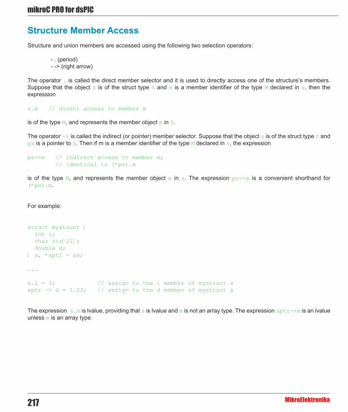
mikroC PRO for dsPIC
MikroElektronika217
Structure Member AccessStructure and union members are accessed using the following two selection operators:
- . (period) - -> (right arrow)
The operator . is called the direct member selector and it is used to directly access one of the structure’s members. Suppose that the object s is of the struct type S and m is a member identifier of the type M declared in s, then the expression
s.m // direct access to member m
is of the type M, and represents the member object m in S.
The operator -> is called the indirect (or pointer) member selector. Suppose that the object s is of the struct type S and ps is a pointer to s. Then if m is a member identifier of the type M declared in s, the expression
ps->m // indirect access to member m; // identical to (*ps).m
is of the type M, and represents the member object m in s. The expression ps->m is a convenient shorthand for (*ps).m.
For example:
struct mystruct { int i; char str[21]; double d;} s, *sptr = &s;
...
s.i = 3; // assign to the i member of mystruct ssptr -> d = 1.23; // assign to the d member of mystruct s
The expression s.m is lvalue, providing that s is lvalue and m is not an array type. The expression sptr->m is an lvalue unless m is an array type.

218
mikoC PRO for dsPIC
MikroElektronika
Accessing Nested Structures
If the structure B contains a field whose type is the structure A, the members of A can be accessed by two applications of the member selectors:
struct A { int j; double x;};struct B { int i; struct A aa; double d;} s, *sptr;
...
s.i = 3; // assign 3 to the i member of Bs.aa.j = 2; // assign 2 to the j member of Asptr->d = 1.23; // assign 1.23 to the d member of Bsptr->aa.x = 3.14; // assign 3.14 to x member of A
Structure Uniqueness
Each structure declaration introduces a unique structure type, so that in
struct A { int i,j; double d;} aa, aaa;
struct B { int i,j; double d;} bb;
the objects aa and aaa are both of the type struct A, but the objects aa and bb are of different structure types. Structures can be assigned only if the source and destination have the same type:
aa = aaa; /* OK: same type, member by member assignment */aa = bb; /* ILLEGAL: different types */
/* but you can assign member by member: */aa.i = bb.i;aa.j = bb.j;aa.d = bb.d;

mikroC PRO for dsPIC
MikroElektronika219
UnionsUnion types are derived types sharing many of syntactic and functional features of structure types. The key difference is that a union members share the same memory space.
Note: The mikroC PRO for PIC supports anonymous unions.
Union Declaration
Unions have the same declaration as structures, with the keyword union used instead of struct:
union tag { member-declarator-list };
Unlike structures’ members, the value of only one of union’s members can be stored at any time. Here is a simple example:
union myunion { // union tag is ‘myunion’ int i; double d; char ch;} mu, *pm;
The identifier mu, of the type myunion, can be used to hold a 2-byte int, 4-byte double or single-byte char, but only one of them at a certain moment. The identifier pm is a pointer to union myunion.
Size of Union
The size of a union is the size of its largest member. In our previous example, both sizeof(union myunion) and sizeof(mu) return 4, but 2 bytes are unused (padded) when mu holds the int object, and 3 bytes are unused when mu holds char.
Union Member Access
Union members can be accessed with the structure member selectors (. and ->), be careful when doing this:
/* Referring to declarations from the example above: */pm = μmu.d = 4.016;tmp = mu.d; // OK: mu.d = 4.016tmp = mu.i; // peculiar result
pm->i = 3;tmp = mu.i; // OK: mu.i = 3
The third line is legal, since mu.i is an integral type. However, the bit pattern in mu.i corresponds to parts of the previously assigned double. As such, it probably won’t provide an useful integer interpretation.
When properly converted, a pointer to a union points to each of its members, and vice versa.

220
mikoC PRO for dsPIC
MikroElektronika
Anonymous Unions
Anonymous unions are unions that are declared without tag or declarator:
union { member-declarator-list };
Such union declarations do not declare types; they declare an unnamed objects. The name of each union member must be unique within the scope where the union is declared.
In C, an anonymous union can have a tag; it cannot have declarators. Names declared in an anonymous union are used directly, like nonmember variables.
In addition to the restrictions listed above in Union, anonymous unions are subject to additional restrictions:
- They must also be declared as static if declared in global scope. If declared in local scope, they must be either static or automatic, not external - They can have only public members; private and protected members in anonymous unions generate errors. - They cannot have function members.
Here is a simple example:
union { // no union tag int i; float f; union { // no union tag unsigned char uc; char c; }; // no declarator}; // no declarator
Anonymous Union Member Access
Anonymous union members are accessed directly because they are in the scope containing the anonymous union :
// Referring to declarations from the example above:i = 1;f = 3.14;uc = ‘c’;c = ‘u’;

mikroC PRO for dsPIC
MikroElektronika221
Bit FieldsBit fields are specified numbers of bits that may or may not have an associated identifier. Bit fields offer a way of subdividing structures into named parts of user-defined sizes.
Structures and unions can contain bit fields that can be up to 16 bits.
You cannot take the address of a bit field.
Note: If you need to handle specific bits of 8-bit variables (char and unsigned short) or registers, you don’t need to declare bit fields. Much more elegant solution is to use the mikroC PRO for dsPIC30/33 and PIC24’s intrinsic ability for individual bit access — see Accessing Individual Bits for more information.
Bit Fields Declaration
Bit fields can be declared only in structures and unions. Declare a structure normally and assign individual fields like this (fields need to be unsigned):
struct tag { unsigned bitfield-declarator-list;}
Here, tag is an optional name of the structure; bitfield-declarator-list is a list of bit fields. Each component identifer requires a colon and its width in bits to be explicitly specified. Total width of all components cannot exceed two bytes (16 bits).
As an object, bit fields structure takes two bytes. Individual fields are packed within two bytes from right to left. In bitfield-declarator-list, you can omit identifier(s) to create an artificial “padding”, thus skipping irrelevant bits.
For example, if there is a need to manipulate only bits 2–4 of a register as one block, create a structure like this:
struct { unsigned : 2, // Skip bits 0 and 1, no identifier here mybits : 3; // Relevant bits 2, 3 and 4 // Bits 5, 6 and 7 are implicitly left out} myreg;
Here is an example:
typedef struct { lo_nibble : 4; hi_nibble : 4; high_byte : 8;} myunsigned;
which declares the structured type myunsigned containing three components: lo_nibble (bits 3..0), hi_nibble (bits 7..4) and high_byte (bits 15..8).

222
mikoC PRO for dsPIC
MikroElektronika
Bit Fields Access
Bit fields can be accessed in the same way as the structure members. Use direct and indirect member selector (. and ->). For example, we could work with our previously declared myunsigned like this:
// Declare a bit field Value_For_PortB:myunsigned Value_For_PortB;
// Declare a pointer to mybitfield type:mybitfield *TimerControl;void main() { TimerControl = (mybitfield *) (void *) &T2CON ; // explicit casting of pointer to T2CON, so it can be assigned
... Value_For_PortB.lo_nibble = 7; Value_For_PortB.hi_nibble = 0x0C; Value_For_PortB.high_byte = 0xAA; PORTB = *(unsigned *) (void *)&Value_For_PortB; // typecasting : // 1. address of structure to pointer to void // 2. pointer to void to pointer to unsigned // 3. dereferencing to obtain the value}
Types ConversionsThe mikroC PRO for dsPIC30/33 and PIC24 is a strictly typed language, with each operator, statement and function demanding appropriately typed operands/arguments. However, we often have to use objects of “mismatching” types in expressions. In that case, type conversion is needed.
Conversion of object of one type means that object’s type is changed into another type. The mikroC PRO for dsPIC30/33 and PIC24 defines a set of standard conversions for built-in types, provided by compiler when necessary. For more information, refer to the Standard Conversions.
Conversion is required in the following situations:
- if a statement requires an expression of particular type (according to language definition), and we use an expression of different type, - if an operator requires an operand of particular type, and we use an operand of different type, - if a function requires a formal parameter of particular type, and we pass it an object of different type, - if an expression following the keyword return does not match the declared function return type, - if intializing an object (in declaration) with an object of different type.
In these situations, compiler will provide an automatic implicit conversion of types, without any programmer’s interference. Also, the programmer can demand conversion explicitly by means of the typecast operator. For more information, refer to the Explicit Typecasting.

mikroC PRO for dsPIC
MikroElektronika223
Standard ConversionsStandard conversions are built in the mikroC PRO for dsPIC30/33 and PIC24. These conversions are performed automatically, whenever required in the program. They can also be explicitly required by means of the typecast operator (refer to the Explicit Typecasting).
The basic rule of automatic (implicit) conversion is that the operand of simpler type is converted (promoted) to the type of more complex operand. Then, the type of the result is that of more complex operand.
Arithmetic Conversions
When using arithmetic expression, such as a + b, where a and b are of different arithmetic types, the mikroC PRO for dsPIC30/33 and PIC24 performs implicit type conversions before the expression is evaluated. These standard conversions include promotions of “lower” types to “higher” types in the interests of accuracy and consistency.
Assigning a signed character object (such as a variable) to an integral object results in automatic sign extension. Objects of type signed char always use sign extension; objects of type unsigned char always has its high byte set to zero when converted to int.
Converting a longer integral type to a shorter type truncates the higher order bits and leaves low-order bits unchanged. Converting a shorter integral type to a longer type either sign-extends or zero-fills the extra bits of the new value, depending on whether the shorter type is signed or unsigned, respectively.
Note: Conversion of floating point data into integral value (in assignments or via explicit typecast) produces correct results only if the float value does not exceed the scope of destination integral type.
In details:
Here are the steps the mikroC PRO for dsPIC30/33 and PIC24 uses to convert the operands in an arithmetic expression:
First, any small integral types are converted according to the following rules:
1. bit converts to char 2. char converts to int 3. signed char converts to int, with the same value 4. short converts to int, with the same value, sign-extended 5. unsigned short converts to unsigned int, with the same value, zero-filled 6. enum converts to int, with the same value
After this, any two values associated with an operator are either int (including the long and unsigned modifiers) or float (equivalent with double and long double in the mikroC PRO for dsPIC30/33 and PIC24).
1. If either operand is float, the other operand is converted to float. 2. Otherwise, if either operand is unsigned long, the other operand is converted to unsigned long. 3. Otherwise, if either operand is long, then the other operand is converted to long. 4. Otherwise, if either operand is unsigned, then the other operand is converted to unsigned. 5. Otherwise, both operands are int.
The result of the expression is the same type as that of the two operands.
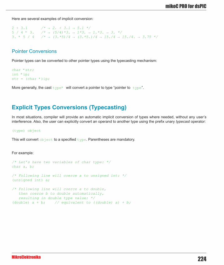
224
mikoC PRO for dsPIC
MikroElektronika
Here are several examples of implicit conversion:
2 + 3.1 /* → 2. + 3.1 → 5.1 */5 / 4 * 3. /* → (5/4)*3. → 1*3. → 1.*3. → 3. */3. * 5 / 4 /* → (3.*5)/4 → (3.*5.)/4 → 15./4 → 15./4. → 3.75 */
Pointer Conversions
Pointer types can be converted to other pointer types using the typecasting mechanism:
char *str;int *ip;str = (char *)ip;
More generally, the cast type* will convert a pointer to type “pointer to type”.
Explicit Types Conversions (Typecasting)In most situations, compiler will provide an automatic implicit conversion of types where needed, without any user’s interference. Also, the user can explicitly convert an operand to another type using the prefix unary typecast operator:
(type) object
This will convert object to a specified type. Parentheses are mandatory.
For example:
/* Let’s have two variables of char type: */char a, b;
/* Following line will coerce a to unsigned int: */(unsigned int) a;
/* Following line will coerce a to double, then coerce b to double automatically, resulting in double type value: */(double) a + b; // equivalent to ((double) a) + b;

mikroC PRO for dsPIC
MikroElektronika225
DeclarationsA declaration introduces one or several names to a program – it informs the compiler what the name represents, what its type is, what operations are allowed with it, etc. This section reviews concepts related to declarations: declarations, definitions, declaration specifiers, and initialization.
The range of objects that can be declared includes:
- Variables - Constants - Functions - Types - Structure, union, and enumeration tags - Structure members - Union members - Arrays of other types - Statement labels - Preprocessor macros
Declarations and Definitions
Defining declarations, also known as definitions, beside introducing the name of an object, also establish the creation (where and when) of an object; that is, the allocation of physical memory and its possible initialization. Referencing declarations, or just declarations, simply make their identifiers and types known to the compiler.
Here is an overview. Declaration is also a definition, except if:
- it declares a function without specifying its body - it has the extern specifier, and has no initializator or body (in case of func.) - it is the typedef declaration There can be many referencing declarations for the same identifier, especially in a multifile program, but only one defining declaration for that identifier is allowed.
For example:
/* Here is a nondefining declaration of function max; *//* it merely informs compiler that max is a function */int max();
/* Here is a definition of function max: */int max(int x, int y) { return (x >= y) ? x : y;}
/* Definition of variable i: */int i;
/* Following line is an error, i is already defined! */int i;

226
mikoC PRO for dsPIC
MikroElektronika
Declarations and Declarators
The declaration contains specifier(s) followed by one or more identifiers (declarators). The declaration begins with optional storage class specifiers, type specifiers, and other modifiers. The identifiers are separated by commas and the list is terminated by a semicolon.
Declarations of variable identifiers have the following pattern:
storage-class [type-qualifier] type var1 [=init1], var2 [=init2], ... ;
where var1, var2,... are any sequence of distinct identifiers with optional initializers. Each of the variables is declared to be of type; if omitted, type defaults to int. The specifier storage-class can take the values extern, static, register, or the default auto. Optional type-qualifier can take values const or volatile. For more details, refer to Storage Classes and Type Qualifiers.
For example:
/* Create 3 integer variables called x, y, and z and initialize x and y to the values 1 and 2, respectively: */int x = 1, y = 2, z; // z remains uninitialized
/* Create a floating-point variable q with static modifier, and initialize it to 0.25: */static float q = .25;
These are all defining declarations; storage is allocated and any optional initializers are applied.
LinkageAn executable program is usually created by compiling several independent translation units, then linking the resulting object files with preexisting libraries. A term translation unit refers to a source code file together with any included files, but without the source lines omitted by conditional preprocessor directives. A problem arises when the same identifier is declared in different scopes (for example, in different files), or declared more than once in the same scope.
The linkage is a process that allows each instance of an identifier to be associated correctly with one particular object or function. All identifiers have one of two linkage attributes, closely related to their scope: external linkage or internal linkage. These attributes are determined by the placement and format of your declarations, together with an explicit (or implicit by default) use of the storage class specifier static or extern.
Each instance of a particular identifier with external linkage represents the same object or function throughout the entire set of files and libraries making up the program. Each instance of a particular identifier with internal linkage represents the same object or function within one file only.

mikroC PRO for dsPIC
MikroElektronika227
Linkage Rules
Local names have internal linkage; the same identifier can be used in different files to signify different objects. Global names have external linkage; identifier signifies the same object throughout all program files.
If the same identifier appears with both internal and external linkage within the same file, the identifier will have internal linkage.
Internal Linkage Rules
1. names having file scope, explicitly declared as static, have internal linkage 2. names having file scope, explicitly declared as const and not explicitly declared as extern, have internal linkage 3. typedef names have internal linkage 4. enumeration constants have internal linkage
External Linkage Rules
1. names having file scope, that do not comply to any of previously stated internal linkage rules, have external linkage
The storage class specifiers auto and register cannot appear in an external declaration. No more than one external definition can be given for each identifier in a translation unit declared with internal linkage. An external definition is an external declaration that defines an object or a function and also allocates a storage. If an identifier declared with external linkage is used in an expression (other than as part of the operand of sizeof), then exactly one external definition of that identifier must be somewhere in the entire program.
Storage ClassesAssociating identifiers with objects requires each identifier to have at least two attributes: storage class and type (sometimes referred to as data type). The mikroC PRO for dsPIC30/33 and PIC24 compiler deduces these attributes from implicit or explicit declarations in the source code.
A storage class dictates the location (data segment, register, heap, or stack) of object and its duration or lifetime (the entire running time of the program, or during execution of some blocks of code). A storage class can be established by the syntax of a declaration, by its placement in the source code, or by both of these factors:
storage-class type identifier
The storage class specifiers in the mikroC PRO for dsPIC30/33 and PIC24 are:
- auto - register - static - extern

228
mikoC PRO for dsPIC
MikroElektronika
Auto
The auto storage-class specifier declares an automatic variable (a variable with a local lifetime). An auto variable is visible only within the block in which it is declared. The auto storage-class specifier can only be applied to names of variables declared in a block or tonames of function parameters. However, these names have automatic storage by default. Therefore the auto storage class specifier is usually redundant in a data declaration.
Register
The register storage-class specifier is used to define local variables that should be stored in a register instead of RAM. At the moment this modifier has no special meaning in mikroC PRO for dsPIC30/33 and PIC24. mikroC PRO for dsPIC30/33 and PIC24 simply ignores requests for register allocation.
Static
The static storage class specifier lets you define variables or functions with internal linkage, which means that each instance of a particular identifier represents the same variable or function within one file only. In addition, variables declared static have static storage duration, which means that memory for these variables is allocated when the program begins running and is freed when the program terminates. Static storage duration for a variable is different from file or global scope. A variable can have static duration, but local scope.
Extern
The extern storage class specifier lets you declare objects that can be used in several source files. An extern declaration makes a described variable usable by the succeeding part of the current source file. This declaration does not replace the definition. It is used to describe a variable that is externally defined. An extern declaration can appear outside a function or at the beginning of a block. If the declaration describes a function or appears outside a function and describes an object with external linkage, the keyword extern is optional. If a declaration for an identifier already exists within the file scope, any extern declaration of the same identifier found within a block refers to the same object. If no other declaration for the identifier exists within the file scope, the identifier has external linkage.
See Linkage for more information.

mikroC PRO for dsPIC
MikroElektronika229
Type QualifiersThe type qualifiers const and volatile are optional in declarations and do not actually affect the type of declared object.
Qualifier const
The const qualifier is used to indicate that variable value cannot be changed. Its value is set at initialization.
The mikroC PRO for dsPIC30/33 and PIC24 treats objects declared with the const qualifier the same as literals or preprocessor constants. If the user tries to change an object declared with the const qualifier compiler will report an error.
For example:
const double PI = 3.14159;
Qualifier volatile
The volatile qualifier indicates that variable values can be changed both with or without user’s interference in the program. The compiler should not optimize such variable.
Typedef SpecifierThe typedef declaration introduces a name that, within its scope, becomes a synonym for the specified type. You can use typedef declarations to construct shorter or more meaningful names for types already defined by the language or declared by the user. Typedef names allow you to encapsulate implementation details that may change. Unlike the struct, union, and enum declarations, the typedef declarations do not introduce new types, but new names for existing types.
The specifier typedef stands first in the declaration:
typedef <type_definition> synonym;
The typedef keyword assigns synonym to <type_definition>. The synonym needs to be a valid identifier.
A declaration starting with the typedef specifier does not introduce an object or a function of a given type, but rather a new name for a given type. In other words, the typedef declaration is identical to a “normal” declaration, but instead of objects, it declares types. It is a common practice to name custom type identifiers with starting capital letter — this is not required by the mikroC PRO for dsPIC30/33 and PIC24.

230
mikoC PRO for dsPIC
MikroElektronika
For example:
/* Let’s declare a synonym for “unsigned long int” */typedef unsigned long int Distance;
/* Now, synonym “Distance” can be used as type identifier: */Distance i; // declare variable i of unsigned long int
In the typedef declaration, as in any other declaration, several types can be declared at once. For example:
typedef int *Pti, Array[10];
Here, Pti is a synonym for type “pointer to int”, and Array is a synonym for type “array of 10 int elements”.
asm DeclarationThe mikroC PRO for dsPIC30/33 and PIC24 allows embedding assembly in the source code by means of the asm declaration. The declarations _asm and __asm are also allowed in the mikroC PRO for dsPIC30/33 and PIC24 and have the same meaning. Note that numerals cannnot be used as absolute addresses for SFR or GPR variables in assembly instructions. Symbolic names may be used instead (listing will display these names as well as addresses).
Assembly instructions can be grouped by the asm keyword (or _asm, or __asm):
asm { block of assembly instructions}
The mikroC PRO for dsPIC30/33 and PIC24 comments (both single-line and multi-line) are allowed in embedded assembly code.
The only types whose name remains the same in asm as it is in the mikroC PRO for dsPIC30/33 and PIC24 are registers, e.g. INTCON, PORTB, WREG, GIE, etc.
Accessing variables
Depending on the place of declaration, accessing a variable can be done in several ways:
- Accessing global variable: 1. If declared as static (visible only in the file where it was declared): <source_file_name>_<variable_name>. 2. If declared as a non-static global (visible throughout the whole project): _<variable_name>. 3. If accessing registers (declared through register, rx or sfr specifiers, visible throughout the whole project) : <variable_name>. - Accessing local variable: <routine_name>_<variable_name>. - Accessing routine parameter: FARG_<routine_name>_<variable_name>.

mikroC PRO for dsPIC
MikroElektronika231
Here is an example of using asm instructions:
unsigned myvar absolute 0x2678;unsigned long myvar1;const char msg[] = “Test” absolute 0x3652;
void main() org 0x11234 { myvar = 5; myvar1 = 0xABCDEFAB; asm { MOV _myvar, w0 ; move myvar to W0 nop MOV #6, W0 ; move literal 6 to W0 MOV W0, _myvar ; move contents of W0 to myvar MOV #lo_addr(_myvar), W1 ; retrieve low address word of _myvar and move it to W1 (0x2678 -> W1) MOV #hi_addr(_myvar), W1 ; retrieve high address word of _myvar and move it to W1 (0x0000 -> W1) MOV #lo_addr(___main_Label1), W0 ; retrieve lo address word of Label1 and move it W0 ( PC(Label1) ) -> W0 MOV #hi_addr(_main), W0 ; retrieve hi address byte of main routine and move it to W0 (0x0001 -> W1) MOV #lo_addr(_msg2), W0 ; retrieve low address word of constant msg and move it to W0 (0x3652 -> W1) MOV _myvar1+2, W1 ; accessing hi word of myvar1 variable and move it to W1 (0xABCD -> W1) } Label1: asm MOV #hi_addr(___main_Label1), W0 // retrieve hi address word of Label1 and move it W0 (PC(Label1)) -> W0 goto Label1; }
When using asm instructions that expect parameters like lit1, lit4, slit6, slit6, bit4, etc. be sure to preceed them with the ‘#’ (hash symbol) to ensure proper functioning. Example:
BSET f, #5 ; set bit #5 in f registerMOV #16000, Wnd ; move number #16000 to destination working registerADD Ws, #-5, Acc ; add number #-5 to accumulator
Asm code and SSA optimization
If asm code is mixed with the C code, keep in mind that the generated code can substantially differ when SSA optimization option is enabled or disabled. This is due to the fact that SSA optimization uses certain working registers to store routine parameters (W10-W13), rather than storing them onto the function frame.
Because of this, user must be very careful when writing asm code as existing values in the working registers used by SSA optimization can be overwritten. To avoid this, it is recommended that user includes desired asm code in a separate routine.

232
mikoC PRO for dsPIC
MikroElektronika
InitializationThe initial value of a declared object can be set at the time of declaration (initialization). A part of the declaration which specifies the initialization is called initializer.
Initializers for globals and static objects must be constants or constant expressions. The initializer for an automatic object can be any legal expression that evaluates to an assignment-compatible value for the type of the variable involved.
Scalar types are initialized with a single expression, which can optionally be enclosed in braces. The initial value of an object is that of the expression; the same constraints for type and conversions as for simple assignments are applied to initializations too.
For example:
int i = 1;char *s = “hello”;struct complex c = {0.1, -0.2};// where ‘complex’ is a structure (float, float)
For structures or unions with automatic storage duration, the initializer must be one of the following:
- An initializer list. - A single expression with compatible union or structure type. In this case, the initial value of the object is that of the expression.
For example:
struct dot {int x; int y; } m = {30, 40};
For more information, refer to Structures and Unions.
Also, you can initialize arrays of character type with a literal string, optionally enclosed in braces. Each character in the string, including the null terminator, initializes successive elements in the array. For more information, refer to Arrays.
Automatic Initialization
The mikroC PRO for dsPIC30/33 and PIC24 does not provide automatic initialization for objects. Uninitialized globals and objects with static duration will take random values from memory.

mikroC PRO for dsPIC
MikroElektronika233
FunctionsFunctions are central to C programming. Functions are usually defined as subprograms which return a value based on a number of input parameters. Return value of the function can be used in expressions – technically, function call is considered to be an expression like any other.
C allows a function to create results other than its return value, referred to as side effects. Often, the function return value is not used at all, depending on the side effects. These functions are equivalent to procedures of other programming languages, such as Pascal. C does not distinguish between procedure and function – functions play both roles.
Each program must have a single external function named main marking the entry point of the program. Functions are usually declared as prototypes in standard or user-supplied header files, or within program files. Functions have external linkage by default and are normally accessible from any file in the program. This can be restricted by using the static storage class specifier in function declaration (see Storage Classes and Linkage).
Note: Check the dsPIC30/33 and PIC24 Specifics for more information on functions’ limitations on the dsPIC30/33 and PIC24 MCUs.
Function Declaration
Functions are declared in user’s source files or made available by linking precompiled libraries. The declaration syntax of the function is:
type function_name(parameter-declarator-list);
The function_name must be a valid identifier. This name is used to call the function; see Function Calls for more information.
type represents the type of function result, and can be of any standard or user-defined type. For functions that do not return value the void type should be used. The type can be omitted in global function declarations, and function will assume the int type by default.
Function type can also be a pointer. For example, float* means that a function result is a pointer to float. The generic pointer void* is also allowed.
The function cannot return an array or another function.
Within parentheses, parameter-declarator-list is a list of formal arguments that function takes. These declarators specify the type of each function parameter. The compiler uses this information to check validity of function calls. If the list is empty, a function does not take any arguments. Also, if the list is void, a function also does not take any arguments; note that this is the only case when void can be used as an argument’s type.
Unlike variable declaration, each argument in the list needs its own type specifier and possible qualifier const or volatile.

234
mikoC PRO for dsPIC
MikroElektronika
Function Prototypes
A function can be defined only once in the program, but can be declared several times, assuming that the declarations are compatible. When declaring a function, the formal argument’s identifier does not have to be specified, but its type does.
This kind of declaration, commonly known as the function prototype, allows better control over argument number, type checking and type conversions. The name of a parameter in function prototype has its scope limited to the prototype. This allows one parameter identifier to have different name in different declarations of the same function:
/* Here are two prototypes of the same function: */
int test(const char*) /* declares function test */int test(const char*p) /* declares the same function test */
Function prototypes are very useful in documenting code. For example, the function Cf_Init takes two parameters: Control Port and Data Port. The question is, which is which? The function prototype:
void Cf_Init(char *ctrlport, char *dataport);
makes it clear. If a header file contains function prototypes, the user can read that file to get the information needed for writing programs that call these functions. If a prototype parameter includes an identifier, then the indentifier is only used for error checking.
Function Definition
Function definition consists of its declaration and function body. The function body is technically a block – a sequence of local definitions and statements enclosed within braces {}. All variables declared within function body are local to the function, i.e. they have function scope.
The function itself can be defined only within the file scope, which means that function declarations cannot be nested.
To return the function result, use the return statement. The statement return in functions of the void type cannot have a parameter – in fact, the return statement can be omitted altogether if it is the last statement in the function body.
Here is a sample function definition:
/* function max returns greater one of its 2 arguments: */
int max(int x, int y) { return (x>=y) ? x : y;}

mikroC PRO for dsPIC
MikroElektronika235
Here is a sample function which depends on side effects rather than return value:
/* function converts Descartes coordinates (x,y) to polar (r,fi): */#include <math.h>
void polar(double x, double y, double *r, double *fi) { *r = sqrt(x * x + y * y); *fi = (x == 0 && y == 0) ? 0 : atan2(y, x); return; /* this line can be omitted */}
Functions reentrancy
Functions reentrancy is allowed. Remember that the dsPIC’s and PIC24 has stack and memory limitations which can varies greatly between MCUs.
Function Calls and Argument Conversions
Function Calls
A function is called with actual arguments placed in the same sequence as their matching formal parameters. Use the function-call operator ():
function_name(expression_1, ... , expression_n)
Each expression in the function call is an actual argument. Number and types of actual arguments should match those of formal function parameters. If types do not match, implicit type conversions rules will be applied. Actual arguments can be of any complexity, but order of their evaluation is not specified.
Upon function call, all formal parameters are created as local objects initialized by the values of actual arguments. Upon return from a function, a temporary object is created in the place of the call, and it is initialized by the expression of the return statement. This means that the function call as an operand in complex expression is treated as a function result.
If the function has no result (type void) or the result is not needed, then the function call can be written as a self-contained expression.
In C, scalar arguments are always passed to the function by value. The function can modify the values of its formal parameters, but this has no effect on the actual arguments in the calling routine. A scalar object can be passed by the address if a formal parameter is declared as a pointer. The pointed object can be accessed by using the indirection operator * .

236
mikoC PRO for dsPIC
MikroElektronika
// For example, Soft_UART_Read takes the pointer to error variable,// so it can change the value of an actual argument:Soft_UART_Read(&error);
// The following code would be wrong; you would pass the value// of error variable to the function:Soft_UART_Read(error);
Argument Conversions
If a function prototype has not been previously declared, the mikroC PRO for dsPIC30/33 and PIC24 converts integral arguments to a function call according to the integral widening (expansion) rules described in Standard Conversions. If a function prototype is in scope, the mikroC PRO for dsPIC30/33 and PIC24 converts the passed argument to the type of the declared parameter according to the same conversion rules as in assignment statements.
If a prototype is present, the number of arguments must match. The types need to be compatible only to the extent that an assignment can legally convert them. The user can always use an explicit cast to convert an argument to a type that is acceptable to a function prototype.
Note: If the function prototype does not match the actual function definition, the mikroC PRO for dsPIC30/33 and PIC24 will detect this if and only if that definition is in the same compilation unit as the prototype. If you create a library of routines with the corresponding header file of prototypes, consider including that header file when you compile the library, so that any discrepancies between the prototypes and actual definitions will be detected.
The compiler is also able to force arguments to change their type to a proper one. Consider the following code:
int limit = 32;char ch = ‘A’;long res;
// prototypeextern long func(long par1, long par2);
main() { ... res = func(limit, ch); // function call}
Since the program has the function prototype for func, it converts limit and ch to long, using the standard rules of assignment, before it places them on the stack for the call to func.
Without the function prototype, limit and ch would be placed on the stack as an integer and a character, respectively; in that case, the stack passed to func will not match size or content that func expects, which can cause problems.
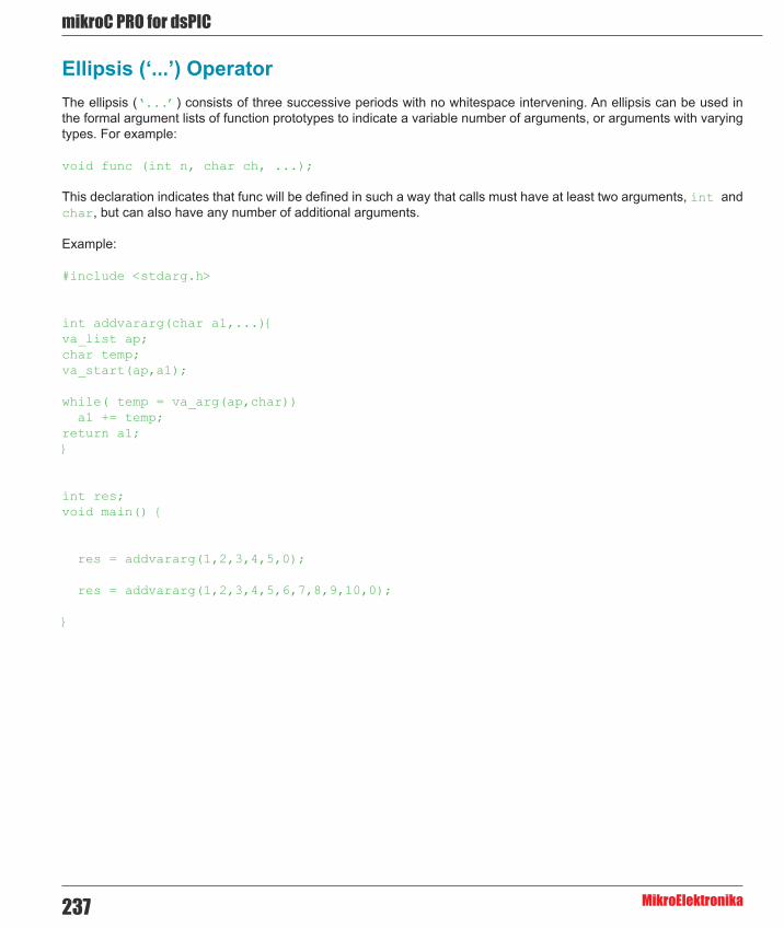
mikroC PRO for dsPIC
MikroElektronika237
Ellipsis (‘...’) OperatorThe ellipsis (‘...’) consists of three successive periods with no whitespace intervening. An ellipsis can be used in the formal argument lists of function prototypes to indicate a variable number of arguments, or arguments with varying types. For example:
void func (int n, char ch, ...);
This declaration indicates that func will be defined in such a way that calls must have at least two arguments, int and char, but can also have any number of additional arguments.
Example:
#include <stdarg.h>
int addvararg(char a1,...){va_list ap;char temp;va_start(ap,a1);
while( temp = va_arg(ap,char)) a1 += temp;return a1;}
int res;void main() {
res = addvararg(1,2,3,4,5,0); res = addvararg(1,2,3,4,5,6,7,8,9,10,0);
}

238
mikoC PRO for dsPIC
MikroElektronika
OperatorsOperators are tokens that trigger some computation when applied to variables and other objects in an expression.
- Arithmetic Operators - Assignment Operators - Bitwise Operators - Logical Operators - Reference/Indirect Operators - Relational Operators - Structure Member Selectors
- Comma Operator , - Conditional Operator ? :
- Array subscript operator [] - Function call operator ()
- sizeof Operator
- Preprocessor Operators # and ##

mikroC PRO for dsPIC
MikroElektronika239
Operators Precedence and Associativity
There are 15 precedence categories, some of them contain only one operator. Operators in the same category have equal precedence.
If duplicates of operators appear in the table, the first occurrence is unary and the second binary. Each category has an associativity rule: left-to-right (→), or right-to-left (←). In the absence of parentheses, these rules resolve a grouping of expressions with operators of equal precedence.
Precedence Operands Operators Asociativity15 2 () [] . -> →14 1 ! ~ ++ -- + - * & (type)
sizeof←
13 2 * / % →12 2 + - →11 2 << >> →10 2 < <= > >= →9 2 == != →8 2 & →7 2 ^ →6 2 | →5 2 && →4 2 || →3 3 ?: ←2 2 = *= /= %= += -= &= ^=
|= <<= >>=←
1 2 , →
Note: Operator * is context sensitive and can also represent the pointer reference operator.

240
mikoC PRO for dsPIC
MikroElektronika
Binary Arithmetic Operators
Division of two integers returns an integer, while remainder is simply truncated:
/* for example: */7 / 4; /* equals 1 */7 * 3 / 4; /* equals 5 */
/* but: */7. * 3. / 4.; /* equals 5.25 because we are working with floats */
Remainder operand % works only with integers; the sign of result is equal to the sign of the first operand:
/* for example: */9 % 3; /* equals 0 */7 % 3; /* equals 1 */-7 % 3; /* equals -1 */
Arithmetic operators can be used for manipulating characters:
‘A’ + 32; /* equals ‘a’ (ASCII only) */‘G’ - ‘A’ + ‘a’; /* equals ‘g’ (both ASCII and EBCDIC) */
Unary Arithmetic Operators
Unary operators ++ and -- are the only operators in C which can be either prefix (e.g. ++k, --k) or postfix (e.g. k++, k--).
When used as prefix, operators ++ and -- (preincrement and predecrement) add or subtract one from the value of the operand before the evaluation. When used as suffix, operators ++ and -- (postincrement and postdecrement) add or subtract one from the value of the operand after the evaluation.
For example:
int j = 5;j = ++k; /* k = k + 1, j = k, which gives us j = 6, k = 6 */
but:
int j = 5;j = k++; /* j = k, k = k + 1, which gives us j = 5, k = 6 */

mikroC PRO for dsPIC
MikroElektronika241
Relational OperatorsUse relational operators to test equality or inequality of expressions. If an expression evaluates to be true, it returns 1; otherwise it returns 0.
All relational operators associate from left to right.
Relational Operators Overview
Operator Operation Precedence== equal 9!= not equal 9> greater than 10< less than 10>= greater than or equal 10<= less than or equal 10
Relational Operators in Expressions
Precedence of arithmetic and relational operators is designated in such a way to allow complex expressions without parentheses to have expected meaning:
a + 5 >= c - 1.0 / e /* → (a + 5) >= (c - (1.0 / e)) */
Do not forget that relational operators return either 0 or 1. Consider the following examples:
/* ok: */5 > 7 /* returns 0 */10 <= 20 /* returns 1 */
/* this can be tricky: */8 == 13 > 5 /* returns 0, as: 8 == (13 > 5) → 8 == 1 → 0 */14 > 5 < 3 /* returns 1, as: (14 > 5) < 3 → 1 < 3 → 1 */a < b < 5 /* returns 1, as: (a < b) < 5 → (0 or 1) < 5 → 1*/
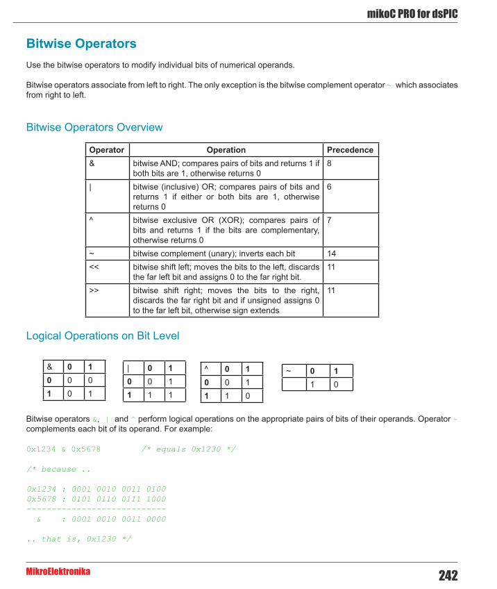
242
mikoC PRO for dsPIC
MikroElektronika
Bitwise OperatorsUse the bitwise operators to modify individual bits of numerical operands.
Bitwise operators associate from left to right. The only exception is the bitwise complement operator ~ which associates from right to left.
Bitwise Operators Overview
Operator Operation Precedence& bitwise AND; compares pairs of bits and returns 1 if
both bits are 1, otherwise returns 08
| bitwise (inclusive) OR; compares pairs of bits and returns 1 if either or both bits are 1, otherwise returns 0
6
^ bitwise exclusive OR (XOR); compares pairs of bits and returns 1 if the bits are complementary, otherwise returns 0
7
~ bitwise complement (unary); inverts each bit 14<< bitwise shift left; moves the bits to the left, discards
the far left bit and assigns 0 to the far right bit.11
>> bitwise shift right; moves the bits to the right, discards the far right bit and if unsigned assigns 0 to the far left bit, otherwise sign extends
11
Logical Operations on Bit Level
& 0 10 0 01 0 1
| 0 10 0 11 1 1
^ 0 10 0 11 1 0
~ 0 11 0
Bitwise operators &, | and ^ perform logical operations on the appropriate pairs of bits of their operands. Operator ~ complements each bit of its operand. For example:
0x1234 & 0x5678 /* equals 0x1230 */
/* because ..
0x1234 : 0001 0010 0011 01000x5678 : 0101 0110 0111 1000---------------------------- & : 0001 0010 0011 0000
.. that is, 0x1230 */

mikroC PRO for dsPIC
MikroElektronika243
/* Similarly: */
0x1234 | 0x5678; /* equals 0x567C */0x1234 ^ 0x5678; /* equals 0x444C */~ 0x1234; /* equals 0xEDCB */
Note: Operator & can also be a pointer reference operator. Refer to Pointers for more information.
Bitwise Shift Operators
Binary operators << and >> move the bits of the left operand by a number of positions specified by the right operand, to the left or right, respectively. Right operand has to be positive.
With shift left (<<), far left bits are discarded and “new” bits on the right are assigned zeroes. Thus, shifting unsigned operand to the left by n positions is equivalent to multiplying it by 2n if all discarded bits are zero. This is also true for signed operands if all discarded bits are equal to a sign bit.
000001 << 5; /* equals 000040 */0x3801 << 4; /* equals 0x8010, overflow! */
With shift right (>>), far right bits are discarded and the “freed” bits on the left are assigned zeroes (in case of unsigned operand) or the value of a sign bit (in case of signed operand). Shifting operand to the right by n positions is equivalent to dividing it by 2n.
0xFF56 >> 4; /* equals 0xFFF5 */0xFF56u >> 4; /* equals 0x0FF5 */
Bitwise vs. Logical
Do not forget of the principle difference between how bitwise and logical operators work. For example:
0222222 & 0555555; /* equals 000000 */0222222 && 0555555; /* equals 1 */
~ 0x1234; /* equals 0xEDCB */! 0x1234; /* equals 0 */
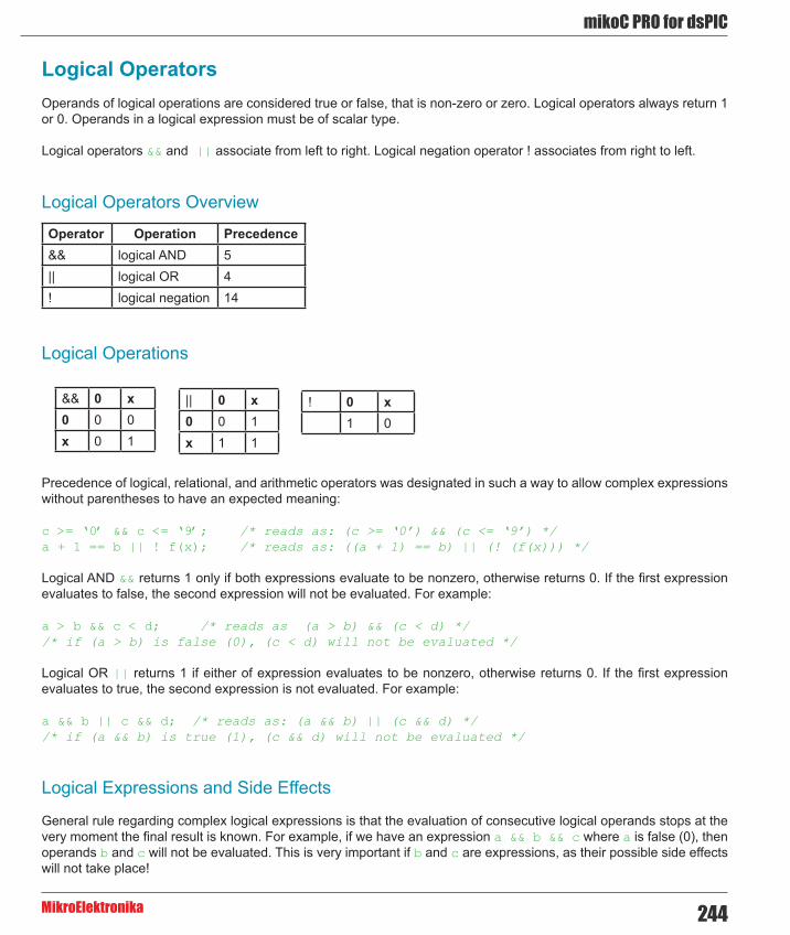
244
mikoC PRO for dsPIC
MikroElektronika
Logical OperatorsOperands of logical operations are considered true or false, that is non-zero or zero. Logical operators always return 1 or 0. Operands in a logical expression must be of scalar type.
Logical operators && and || associate from left to right. Logical negation operator ! associates from right to left.
Logical Operators Overview
|| 0 x0 0 1x 1 1
Operator Operation Precedence&& logical AND 5|| logical OR 4! logical negation 14
&& 0 x0 0 0x 0 1
Logical Operations
! 0 x1 0
Precedence of logical, relational, and arithmetic operators was designated in such a way to allow complex expressions without parentheses to have an expected meaning:
c >= ‘0’ && c <= ‘9’; /* reads as: (c >= ‘0’) && (c <= ‘9’) */a + 1 == b || ! f(x); /* reads as: ((a + 1) == b) || (! (f(x))) */
Logical AND && returns 1 only if both expressions evaluate to be nonzero, otherwise returns 0. If the first expression evaluates to false, the second expression will not be evaluated. For example:
a > b && c < d; /* reads as (a > b) && (c < d) *//* if (a > b) is false (0), (c < d) will not be evaluated */
Logical OR || returns 1 if either of expression evaluates to be nonzero, otherwise returns 0. If the first expression evaluates to true, the second expression is not evaluated. For example:
a && b || c && d; /* reads as: (a && b) || (c && d) *//* if (a && b) is true (1), (c && d) will not be evaluated */
Logical Expressions and Side Effects
General rule regarding complex logical expressions is that the evaluation of consecutive logical operands stops at the very moment the final result is known. For example, if we have an expression a && b && c where a is false (0), then operands b and c will not be evaluated. This is very important if b and c are expressions, as their possible side effects will not take place!

mikroC PRO for dsPIC
MikroElektronika245
Logical vs. Bitwise
Be aware of the principle difference between how bitwise and logical operators work. For example:
0222222 & 0555555 /* equals 000000 */0222222 && 0555555 /* equals 1 */
~ 0x1234 /* equals 0xEDCB */! 0x1234 /* equals 0 */
Conditional Operator ? :The conditional operator ? : is the only ternary operator in C. Syntax of the conditional operator is:
expression1 ? expression2 : expression3
The expression1 is evaluated first. If its value is true, then expression2 evaluates and expression3 is ignored. If expression1 evaluates to false, then expression3 evaluates and expression2 is ignored. The result will be a value of either expression2 or expression3 depending upon which of them evaluates.
Conditional operator associates from right to left.
Note: The fact that only one of these two expressions evaluates is very important if they are expected to produce side effects!
Here are a couple of practical examples:
/* Find max(a, b): */max = ( a > b ) ? a : b;
/* Convert small letter to capital: *//* (no parentheses are actually necessary) */c = ( c >= ‘a’ && c <= ‘z’ ) ? ( c - 32 ) : c;
Conditional Operator Rules
expression1 must be a scalar expression; expression2 and expression3 must obey one of the following rules:
1. Both expressions have to be of arithmetic type. expression2 and expression3 are subject to usual arithmetic conversions, which determines the resulting type. 2. Both expressions have to be of compatible struct or union types. The resulting type is a structure or union type of expression2 and expression3. 3. Both expressions have to be of void type. The resulting type is void. 4. Both expressions have to be of type pointer to qualified or unqualified versions of compatible types. The resulting type is a pointer to a type qualified with all type qualifiers of the types pointed to by both expressions. 5. One expression is a pointer, and the other is a null pointer constant. The resulting type is a pointer to a type qualified with all type qualifiers of the types pointed to by both expressions. 6. One expression is a pointer to an object or incomplete type, and the other is a pointer to a qualified or unqualified version of void. The resulting type is that of the non-pointer-to-void expression.

246
mikoC PRO for dsPIC
MikroElektronika
Assignment OperatorsUnlike many other programming languages, C treats value assignment as operation (represented by an operator) rather than instruction.
Simple Assignment Operator
For a common value assignment, a simple assignment operator (=) is used:
expression1 = expression2
The expression1 is an object (memory location) to which the value of expression2 is assigned. Operand expression1 has to be lvalue and expression2 can be any expression. The assignment expression itself is not lvalue.
If expression1 and expression2 are of different types, the result of the expression2 will be converted to the type of expression1, if necessary. Refer to Type Conversions for more information.
Compound Assignment Operators
C allows more comlex assignments by means of compound assignment operators. The syntax of compound assignment operators is:
expression1 op= expression2
where op can be one of binary operators +, -, *, /, %, &, |, ^, <<, or >>.
Thus, we have 10 different compound assignment operators: +=, -=, *=, /=, %=, &=, |=, ^=, <<= and >>=. All of them associate from right to left. Spaces separating compound operators (e.g. + =) will generate error.
Compound assignment has the same effect as
expression1 = expression1 op expression2
except the lvalue expression1 is evaluated only once. For example, expression1 += expression2 is the same as expression1 = expression1 + expression2.
Assignment Rules
For both simple and compound assignment, the operands expression1 and expression2 must obey one of the following rules:
1. expression1 is of qualified or unqualified arithmetic type and expression2 is of arithmetic type. 2. expression1 has a qualified or unqualified version of structure or union type compatible with the type of expression2. 3. expression1 and expression2 are pointers to qualified or unqualified versions of compatible types and the type pointed to by left has all qualifiers of the type pointed to by right.

mikroC PRO for dsPIC
MikroElektronika247
4. Either expression1 or expression2 is a pointer to an object or incomplete type and the other is a pointer to a qualified or unqualified version of void. The type pointed to by left has all qualifiers of the type pointed to by right. 5. expression1 is a pointer and expression2 is a null pointer constant.
Unary OperatorsUnary operators are operators that take exactly one argument.
Unary Arithmetic Operators
Unary operators ++ and -- are the only operators in C which can be either prefix (e.g. ++k, --k) or postfix (e.g. k++, k--).
When used as prefix, operators ++ and -- (preincrement and predecrement) add or subtract one from the value of the operand before the evaluation. When used as suffix, operators ++ and -- (postincrement and postdecrement) add or subtract one from the value of the operand after the evaluation.
Operator Operation Precedence+ unary plus does not affect the operand 14- unary minus changes the sign of the operand 14++ increment adds one to the value of the operand.
Postincrement adds one to the value of the operand after it evaluates; while preincrement adds one before it evaluates
14
-- decrement subtracts one from the value of the operand. Postdecrement subtracts one from the value of the operand after it evaluates; while predecrement subtracts one before it evaluates
14
For example:
int j = 5; j = ++k; /* k = k + 1, j = k, which gives us j = 6, k = 6 */
but:
int j = 5; j = k++; /* j = k, k = k + 1, which gives us j = 5, k = 6 */

248
mikoC PRO for dsPIC
MikroElektronika
Unary Logical Operator
The ! (logical negation) operator produces the value 0 if its operand is true (nonzero) and the value 1 if its operand is false (0).
Operator Operation Precedence! logical negation 14
The following two expressions are equivalent:
!right;right == 0;
Unary Bitwise Operator
The result of the ~ (bitwise negation) operator is the bitwise complement of the operand. In the binary representation of the result, every bit has the opposite value of the same bit in the binary representation of the operand.
Operator Operation Precedence~ bitwise complement (unary); inverts each bit 14
Address and Indirection Operator
In the mikroC PRO for dsPIC30/33 and PIC24, address of an object in memory can be obtained by means of an unary operator &. To reach the pointed object, we use an indirection operator (*) on a pointer. See Pointers section for more details.
Operator Operation Precedence* accesses a value indirectly, through a pointer; result
is the value at the address to which operand points14
& gives the address of its operand 14
Example:
int *p_to_y; // p_to_y is defined as a pointer to an int int y; // y is defined as an int p_to_y = &y; // assigns the address of the variable y to the pointer p_to_y *p_to_y = 3; // causes the variable y to receive the value 3
Note: Besides these, sizeof and casting unary operators are supported also.
mikroC PRO for dsPIC
MikroElektronika249
Sizeof OperatorThe prefix unary operator sizeof returns an integer constant that represents the size of memory space (in bytes) used by its operand (determined by its type, with some exceptions).
The operator sizeof can take either a type identifier or an unary expression as an operand. You cannot use sizeof with expressions of function type, incomplete types, parenthesized names of such types, or with lvalue that designates a bit field object.
Sizeof Applied to Expression
If applied to expression, the size of an operand is determined without evaluating the expression (and therefore without side effects). The result of the operation will be the size of the type of the expression’s result.
Sizeof Applied to Type
If applied to a type identifier, sizeof returns the size of the specified type. The unit for type size is sizeof(char) which is equivalent to one byte. The operation sizeof(char) gives the result 1, whether char is signed or unsigned.
Thus:
sizeof(char) /* returns 1 */sizeof(int) /* returns 2 */sizeof(unsigned long) /* returns 4 */sizeof(float) /* returns 4 */
When the operand is a non-parameter of array type, the result is the total number of bytes in the array (in other words, an array name is not converted to a pointer type):
int i, j, a[10];...j = sizeof(a[1]); /* j = sizeof(int) = 2 */i = sizeof(a); /* i = 10*sizeof(int) = 20 */
/* To get the number of elements in an array: */int num_elem = i/j;
If the operand is a parameter declared as array type or function type, sizeof gives the size of the pointer. When applied to structures and unions, sizeof gives the total number of bytes, including any padding. The operator sizeof cannot be applied to a function.

250
mikoC PRO for dsPIC
MikroElektronika
ExpressionsExpression is a sequence of operators, operands, and punctuators that specifies a computation. Formally, expressions are defined recursively: subexpressions can be nested without formal limit. However, the compiler will report an out-of-memory error if it can’t compile an expression that is too complex.
In ANSI C, the primary expressions are: constant (also referred to as literal), identifier, and (expression), defined recursively.
Expressions are evaluated according to a certain conversion, grouping, associativity and precedence rules, which depends on the operators used, presence of parentheses and data types of the operands. The precedence and associativity of the operators are summarized in Operator Precedence and Associativity. The way operands and subexpressions are grouped does not necessarily specify the actual order in which they are evaluated by the mikroC PRO for dsPIC30/33 and PIC24.
Expressions can produce lvalue, rvalue, or no value. Expressions might cause side effects whether they produce a value or not.
Comma ExpressionsOne of the specifics of C is that it allows using of comma as a sequence operator to form so-called comma expressions or sequences. Comma expression is a comma-delimited list of expressions – it is formally treated as a single expression so it can be used in places where an expression is expected. The following sequence:
expression_1, expression_2;
results in the left-to-right evaluation of each expression, with the value and type of expression_2 giving the result of the whole expression. Result of expression_1 is discarded.
Binary operator comma (,) has the lowest precedence and associates from left to right, so that a, b, c is the same as (a, b), c. This allows writing sequences with any number of expressions:
expression_1, expression_2, ... expression_n;
which results in the left-to-right evaluation of each expression, with the value and type of expression_n giving the result of the whole expression. Results of other expressions are discarded, but their (possible) side-effect do occur.
For example:
result = ( a = 5, b /= 2, c++ );/* returns preincremented value of variable c, but also intializes a, divides b by 2 and increments c */
result = ( x = 10, y = x + 3, x--, z -= x * 3 - --y );/* returns computed value of variable z, and also computes x and y */

mikroC PRO for dsPIC
MikroElektronika251
Note
Do not confuse comma operator (sequence operator) with comma punctuator which separates elements in a function argument list and initializator lists. To avoid ambiguity with commas in function argument and initializer lists, use parentheses. For example,
func(i, (j = 1, j + 4), k);
calls the function func with three arguments (i, 5, k), not four.
StatementsStatements specify a flow of control as the program executes. In the absence of specific jump and selection statements, statements are executed sequentially in the order of appearance in the source code.
Statements can be roughly divided into:
- Labeled Statements - Expression Statements - Selection Statements - Iteration Statements (Loops) - Jump Statements - Compound Statements (Blocks)
Labeled StatementsEach statement in a program can be labeled. A label is an identifier added before the statement like this:
label_identifier: statement;
There is no special declaration of a label – it just “tags” the statement. Label_identifier has a function scope and the same label cannot be redefined within the same function.
Labels have their own namespace: label identifier can match any other identifier in the program.
A statement can be labeled for two reasons:
1. The label identifier serves as a target for the unconditional goto statement,
2. The label identifier serves as a target for the switch statement. For this purpose, only case and default labeled statements are used:
case constant-expression : statement default : statement
252
mikoC PRO for dsPIC
MikroElektronika
Expression StatementsAny expression followed by a semicolon forms an expression statement:
expression;
The mikroC PRO for dsPIC30/33 and PIC24 executes an expression statement by evaluating the expression. All side effects from this evaluation are completed before the next statement starts executing. Most of expression statements are assignment statements or function calls.
A null statement is a special case, consisting of a single semicolon (;). The null statement does nothing, and therefore is useful in situations where the mikroC PRO for dsPIC30/33 and PIC24 syntax expects a statement but the program does not need one. For example, a null statement is commonly used in “empty” loops:
for (; *q++ = *p++ ;); /* body of this loop is a null statement */
Selection StatementsSelection or flow-control statements select one of alternative courses of action by testing certain values. There are two types of selection statements:
- if - switch
If StatementThe if statement is used to implement a conditional statement. The syntax of the if statement is:
if (expression) statement1 [else statement2]
If expression evaluates to true, statement1 executes. If expression is false, statement2 executes. The expression must evaluate to an integral value; otherwise, the condition is ill-formed. Parentheses around the expression are mandatory.
The else keyword is optional, but no statements can come between if and else.
Nested If statements
Nested if statements require additional attention. A general rule is that the nested conditionals are parsed starting from the innermost conditional, with each else bound to the nearest available if on its left:
if (expression1) statement1else if (expression2) if (expression3) statement2 else statement3 /* this belongs to: if (expression3) */else statement4 /* this belongs to: if (expression2) */

mikroC PRO for dsPIC
MikroElektronika253
Note: #if and #else preprocessor statements (directives) look similar to if and else statements, but have very different effects. They control which source file lines are compiled and which are ignored.
Switch StatementThe switch statement is used to pass control to a specific program branch, based on a certain condition. The syntax of the switch statement is:
switch (expression) { case constant-expression_1 : statement_1; . . . case constant-expression_n : statement_n; [default : statement;]}
First, the expression (condition) is evaluated. The switch statement then compares it to all available constant-expressions following the keyword case. If a match is found, switch passes control to that matching case causing the statement following the match evaluates. Note that constant-expressions must evaluate to integer. It is not possible to have two same constant expressions evaluating to the same value.
Parentheses around expression are mandatory.
Upon finding a match, program flow continues normally: the following instructions will be executed in natural order regardless of the possible case label. If no case satisfies the condition, the default case evaluates (if the label default is specified).
For example, if a variable i has value between 1 and 3, the following switch would always return it as 4:
switch (i) { case 1: i++; case 2: i++; case 3: i++;}
To avoid evaluating any other cases and relinquish control from switch, each case should be terminated with break.
Here is a simple example with switch. Suppose we have a variable phase with only 3 different states (0, 1, or 2) and a corresponding function (event) for each of these states. This is how we could switch the code to the appopriate routine:
switch (phase) { case 0: Lo(); break; case 1: Mid(); break; case 2: Hi(); break; default: Message(“Invalid state!”);}
254
mikoC PRO for dsPIC
MikroElektronika
Nested switch
Conditional switch statements can be nested – labels case and default are then assigned to the innermost enclosing switch statement.
Iteration Statements (Loops)Iteration statements allows to loop a set of statements. There are three forms of iteration statements in the mikroC PRO for dsPIC30/33 and PIC24:
- while - do - for
While Statement
The while keyword is used to conditionally iterate a statement. The syntax of the while statement is:
while (expression) statement
The statement executes repeatedly until the value of expression is false. The test takes place before statement is executed. Thus, if expression evaluates to false on the first pass, the loop does not execute. Note that parentheses around expression are mandatory.
Here is an example of calculating scalar product of two vectors, using the while statement:
int s = 0, i = 0;while (i < n) { s += a[i] * b[i]; i++;}
Note that body of the loop can be a null statement. For example:
while (*q++ = *p++);
Do StatementThe do statement executes until the condition becomes false. The syntax of the do statement is:
do statement while (expression);
The statement is executed repeatedly as long as the value of expression remains non-zero. The expression is evaluated after each iteration, so the loop will execute statement at least once.
Parentheses around expression are mandatory.

mikroC PRO for dsPIC
MikroElektronika255
Note that do is the only control structure in C which explicitly ends with semicolon (;). Other control structures end with statement, which means that they implicitly include a semicolon or closing brace.
Here is an example of calculating scalar product of two vectors, using the do statement:
s = 0; i = 0;do { s += a[i] * b[i]; i++;} while ( i < n );
For StatementThe for statement implements an iterative loop. The syntax of the for statement is:
for ([init-expression]; [condition-expression]; [increment-expression]) statement
Before the first iteration of the loop, init-expression sets the starting variables for the loop. You cannot pass declarations in init-expression.
condition-expression is checked before the first entry into the block; statement is executed repeatedly until the value of condition-expression is false. After each iteration of the loop, increment-expression increments a loop counter. Consequently, i++ is functionally the same as ++i.
All expressions are optional. If condition-expression is left out, it is assumed to be always true. Thus, “empty” for statement is commonly used to create an endless loop in C:
for ( ; ; ) statement
The only way to break out of this loop is by means of the break statement.
Here is an example of calculating scalar product of two vectors, using the for statement:
for ( s = 0, i = 0; i < n; i++ ) s += a[i] * b[i];
There is another way to do this:
for ( s = 0, i = 0; i < n; s += a[i] * b[i], i++ ); /* valid, but ugly */
but it is considered a bad programming style. Although legal, calculating the sum should not be a part of the incrementing expression, because it is not in the service of loop routine. Note that null statement (;) is used for the loop body.

256
mikoC PRO for dsPIC
MikroElektronika
Jump StatementsThe jump statement, when executed, transfers control unconditionally. There are four such statements in the mikroC PRO for dsPIC30/33 and PIC24:
- break - continue - goto - return
Break and Continue Statements
Break Statement
Sometimes it is necessary to stop the loop within its body. Use the break statement within loops to pass control to the first statement following the innermost switch, for, while, or do block.
Break is commonly used in the switch statements to stop its execution upon the first positive match. For example:
switch (state) { case 0: Lo(); break; case 1: Mid(); break; case 2: Hi(); break; default: Message(“Invalid state!”);}
Continue Statement
The continue statement within loops is used to “skip the cycle”. It passes control to the end of the innermost enclosing end brace belonging to a looping construct. At that point the loop continuation condition is re-evaluated. This means that continue demands the next iteration if the loop continuation condition is true.
Specifically, the continue statement within the loop will jump to the marked position as it is shown below:
while (..) {...if (val>0) continue;...// continue jumps here}
do {...if (val>0) continue;...// continue jumps herewhile (..);
for (..;..;..) {...if (val>0) continue;...// continue jumps here}
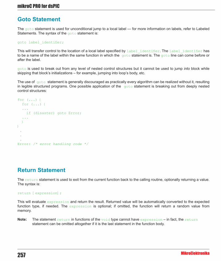
mikroC PRO for dsPIC
MikroElektronika257
Goto StatementThe goto statement is used for unconditional jump to a local label — for more information on labels, refer to Labeled Statements. The syntax of the goto statement is:
goto label_identifier;
This will transfer control to the location of a local label specified by label_identifier. The label_identifier has to be a name of the label within the same function in which the goto statement is. The goto line can come before or after the label.
goto is used to break out from any level of nested control structures but it cannot be used to jump into block while skipping that block’s initializations – for example, jumping into loop’s body, etc.
The use of goto statement is generally discouraged as practically every algorithm can be realized without it, resulting in legible structured programs. One possible application of the goto statement is breaking out from deeply nested control structures:
for (...) { for (...) { ... if (disaster) goto Error; ... }} . . .Error: /* error handling code */
Return StatementThe return statement is used to exit from the current function back to the calling routine, optionally returning a value. The syntax is:
return [expression];
This will evaluate expression and return the result. Returned value will be automatically converted to the expected function type, if needed. The expression is optional; if omitted, the function will return a random value from memory.
Note: The statement return in functions of the void type cannot have expression – in fact, the return statement can be omitted altogether if it is the last statement in the function body.

258
mikoC PRO for dsPIC
MikroElektronika
Compound Statements (Blocks)The compound statement, or block, is a list (possibly empty) of statements enclosed in matching braces { }. Syntactically, the block can be considered to be a single statement, but it also plays a role in the scoping of identifiers. An identifier declared within the block has a scope starting at the point of declaration and ending at the closing brace. Blocks can be nested to any depth up to the limits of memory.
For example, the for loop expects one statement in its body, so we can pass it a compound statement:
for (i = 0; i < n; i++ ) { int temp = a[i]; a[i] = b[i]; b[i] = temp;}
Note that, unlike other statements, compound statements do not end with semicolon (;), i.e. there is never a semicolon following the closing brace.
PreprocessorPreprocessor is an integrated text processor which prepares the source code for compiling. Preprocessor allows:
- inserting text from a specifed file to a certain point in the code (see File Inclusion), - replacing specific lexical symbols with other symbols (see Macros), - conditional compiling which conditionally includes or omits parts of the code (see Conditional Compilation).
Note that preprocessor analyzes text at token level, not at individual character level. Preprocessor is controled by means of preprocessor directives and preprocessor operators.
Preprocessor DirectivesAny line in the source code with a leading # is taken as a preprocessing directive (or control line), unless # is within a string literal, in a character constant, or embedded in a comment. The initial # can be preceded or followed by a whitespace (excluding new lines).
A null directive consists of a line containing the single character #. This line is always ignored.
Preprocessor directives are usually placed at the beginning of the source code, but they can legally appear at any point in a program. The mikroC PRO for dsPIC30/33 and PIC24 preprocessor detects preprocessor directives and parses the tokens embedded in them. A directive is in effect from its declaration to the end of the program file.
Here is one commonly used directive:
#include <math.h>
mikroC PRO for dsPIC
MikroElektronika259
For more information on including files with the #include directive, refer to File Inclusion.
The mikroC PRO for dsPIC30/33 and PIC24 supports standard preprocessor directives:
# (null directive) #if#define #ifdef#elif #ifndef#else #include#endif #line#error #undef
Note: For the time being only funcall pragma is supported.
Line Continuation with Backslash (\)
To break directive into multiple lines end the line with a backslash (\):
#define MACRO This directive continues to \ the following line.
MacrosMacros provide a mechanism for a token replacement, prior to compilation, with or without a set of formal, function-like parameters.
Defining Macros and Macro Expansions
The #define directive defines a macro:
#define macro_identifier <token_sequence>
Each occurrence of macro_identifier in the source code following this control line will be replaced in the original position with the possibly empty token_sequence (there are some exceptions, which are discussed later). Such replacements are known as macro expansions.token_sequence is sometimes called the body of a macro. An empty token sequence results in the removal of each affected macro identifier from the source code.
No semicolon (;) is needed to terminate a preprocessor directive. Any character found in the token sequence, including semicolons, will appear in a macro expansion.token_sequence terminates at the first non-backslashed new line encountered. Any sequence of whitespace, including comments in the token sequence, is replaced with a single-space character.
After each individual macro expansion, a further scan is made of the newly expanded text. This allows the possibility of using nested macros: the expanded text can contain macro identifiers that are subject to replacement. However, if the macro expands into something that looks like a preprocessing directive, such directive will not be recognized by the preprocessor. Any occurrences of the macro identifier found within literal strings, character constants, or comments in the source code will not be expanded.

260
mikoC PRO for dsPIC
MikroElektronika
A macro won’t be expanded during its own expansion (so #define MACRO MACRO won’t expand indefinitely).
Here is an example:
/* Here are some simple macros: */#define ERR_MSG “Out of range!”#define EVERLOOP for( ; ; )
/* which we could use like this: */
main() { EVERLOOP { ... if (error) { Lcd_Out_Cp(ERR_MSG); break; } ... }}
Attempting to redefine an already defined macro identifier will result in a warning unless a new definition is exactly the same token-by-token definition as the existing one. The preferred strategy when definitions might exist in other header files is as follows:
#ifndef BLOCK_SIZE #define BLOCK_SIZE 512#endif
The middle line is bypassed if BLOCK_SIZE is currently defined; if BLOCK_SIZE is not currently defined, the middle line is invoked to define it.
Macros with Parameters
The following syntax is used to define a macro with parameters:
#define macro_identifier(<arg_list>) <token_sequence>
Note that there can be no whitespace between macro_identifier and “(”. The optional arg_list is a sequence of identifiers separated by commas, like the argument list of a C function. Each comma-delimited identifier has the role of a formal argument or placeholder.
Such macros are called by writing
macro_identifier(<actual_arg_list>)
in the subsequent source code. The syntax is identical to that of a function call; indeed, many standard library C “functions” are implemented as macros. However, there are some important semantic differences.
The optional actual_arg_list must contain the same number of comma-delimited token sequences, known as actual arguments, as found in the formal arg_list of the #define line – there must be an actual argument for each formal argument. An error will be reported if the number of arguments in two lists is not the same.

mikroC PRO for dsPIC
MikroElektronika261
A macro call results in two sets of replacements. First, the macro identifier and the parenthesis-enclosed arguments are replaced by the token sequence. Next, any formal arguments occurring in the token sequence are replaced by the corresponding real arguments appearing in actual_arg_list. Like with simple macro definitions, rescanning occurs to detect any embedded macro identifiers eligible for expansion.
Here is a simple example:
/* A simple macro which returns greater of its 2 arguments: */#define _MAX(A, B) ((A) > (B)) ? (A) : (B)
/* Let’s call it: */x = _MAX(a + b, c + d);
/* Preprocessor will transform the previous line into:x = ((a + b) > (c + d)) ? (a + b) : (c + d) */
It is highly recommended to put parentheses around each argument in the macro body in order to avoid possible problems with operator precedence.
Undefining Macros
The #undef directive is used to undefine a macro.
#undef macro_identifier
The directive #undef detaches any previous token sequence from macro_identifier; the macro definition has been forgotten, and macro_identifier is undefined. No macro expansion occurs within the #undef lines.
The state of being defined or undefined is an important property of an identifier, regardless of the actual definition. The #ifdef and #ifndef conditional directives, used to test whether any identifier is currently defined or not, offer a flexible mechanism for controlling many aspects of a compilation.
After a macro identifier has been undefined, it can be redefined with #define, using the same or different token sequence.
File InclusionThe preprocessor directive #include pulls in header files (extension .h) into the source code. Do not rely on preprocessor to include source files (extension .c) — see Add/Remove Files from Project for more information.
The syntax of the #include directive has two formats:
#include <header_name>#include “header_name”

262
mikoC PRO for dsPIC
MikroElektronika
The preprocessor removes the #include line and replaces it with the entire text of a header file at that point in the source code. The placement of #include can therefore influence the scope and duration of any identifiers in the included file.
The difference between these two formats lies in searching algorithm employed in trying to locate the include file.
If the #include directive is used with the <header_name> version, the search is made successively in each of the following locations, in this particular order:
1. the mikroC PRO for dsPIC30/33 and PIC24 installation folder › “include” folder 2. user’s custom search paths
The “header_name” version specifies a user-supplied include file; the mikroC PRO for dsPIC30/33 and PIC24 will look for the header file in the following locations, in this particular order:
1. the project folder (folder which contains the project file .mcpds) 2. the mikroC PRO for dsPIC30/33 and PIC24 installation folder › “include” folder 3. user’s custom search paths
Explicit Path
By placing an explicit path in header_name, only that directory will be searched. For example:
#include “C:\my_files\test.h”
Note
There is also a third version of the #include directive, rarely used, which assumes that neither < nor “ appear as the first non-whitespace character following #include:
#include macro_identifier
It assumes that macro definition that will expand macro identifier into a valid delimited header name with either <header_name> or “header_name” formats exists.

mikroC PRO for dsPIC
MikroElektronika263
Preprocessor OperatorsThe # (pound sign) is a preprocessor directive when it occurs as the first non-whitespace character on a line. Also, # and ## perform operator replacement and merging during the preprocessor scanning phase.
Operator #
In C preprocessor, a character sequence enclosed by quotes is considered a token and its content is not analyzed. This means that macro names within quotes are not expanded.
If you need an actual argument (the exact sequence of characters within quotes) as a result of preprocessing, use the # operator in macro body. It can be placed in front of a formal macro argument in definition in order to convert the actual argument to a string after replacement.
For example, let’s have macro LCD_PRINT for printing variable name and value on Lcd:
#define LCD_PRINT(val) Lcd_Out_Cp(#val “: “); \ Lcd_Out_Cp(IntToStr(val));
Now, the following code,
LCD_PRINT(temp)
will be preprocessed to this:
Lcd_Out_Cp(“temp” “: “); Lcd_Out_Cp(IntToStr(temp));
Operator ##
Operator ## is used for token pasting. Two tokens can be pasted(merged) together by placing ## in between them (plus optional whitespace on either side). The preprocessor removes whitespace and ##, combining the separate tokens into one new token. This is commonly used for constructing identifiers.
For example, see the definition of macro SPLICE for pasting two tokens into one identifier:
#define SPLICE(x,y) x ## _ ## y
Now, the call SPLICE(cnt, 2) will expand to the identifier cnt_2.
Note: The mikroC PRO for dsPIC30/33 and PIC24 does not support the older nonportable method of token pasting using (l/**/r).

264
mikoC PRO for dsPIC
MikroElektronika
Conditional CompilationConditional compilation directives are typically used to make source programs easy to change and easy to compile in different execution environments. The mikroC PRO for dsPIC30/33 and PIC24 supports conditional compilation by replacing the appropriate source-code lines with a blank line.
All conditional compilation directives must be completed in the source or include file in which they have begun.
Directives #if, #elif, #else, and #endif
The conditional directives #if, #elif, #else, and #endif work very similar to the common C conditional statements. If the expression you write after #if has a nonzero value, the line group immediately following the #if directive is retained in the translation unit.
The syntax is:
#if constant_expression_1<section_1>
[#elif constant_expression_2<section_2>] ...[#elif constant_expression_n<section_n>]
[#else<final_section>]
#endif
Each #if directive in a source file must be matched by a closing #endif directive. Any number of #elif directives can appear between #if and #endif directives, but at most one #else directive is allowed. The #else directive, if present, must be the last directive before #endif.
sections can be any program text that has meaning to compiler or preprocessor. The preprocessor selects a single section by evaluating constant_expression following each #if or #elif directive until it finds a true (nonzero) constant expression. The constant expressions are subject to macro expansion.
If all occurrences of constant-expression are false, or if no #elif directives appear, the preprocessor selects the text block after the #else clause. If the #else clause is omitted and all instances of constant_expression in the #if block are false, no section is selected for further processing.
Any processed section can contain further conditional clauses, nested to any depth. Each nested #else, #elif, or #endif directive belongs to the closest preceding the #if directive.
The net result of the preceding scenario is that only one code section (possibly empty) will be compiled.

mikroC PRO for dsPIC
MikroElektronika265
Directives #ifdef and #ifndef
The #ifdef and #ifndef directives can be used anywhere #if can be used and they can test whether an identifier is currently defined or not. The line
#ifdef identifier
has exactly the same effect as #if 1 if identifier is currently defined, and the same effect as #if 0 if identifier is currently undefined. The other directive, #ifndef, tests true for the “not-defined” condition, producing the opposite results.
The syntax thereafter follows that of #if, #elif, #else, and #endif.
An identifier defined as NULL is considered to be defined.

266
mikoC PRO for dsPIC
MikroElektronika
CHAPTER 9mikroC PRO for dsPIC30/33 and PIC24 LibrariesmikroC PRO for dsPIC30/33 and PIC24 provides a set of libraries which simplify the initialization and use of dsPIC30/33 and PIC24 and their modules:
Use Library manager to include mikroC PRO for dsPIC30/33 and PIC24 Libraries in you project.

mikroC PRO for dsPIC
MikroElektronika267
Hardware Libraries - ADC Library - CAN Library - CANSPI Library - Compact Flash Library - Enhanced CAN Library - EEPROM Library - Epson S1D13700 Graphic Lcd Library - Flash Memory Library - Graphic Lcd Library - I²C Library - Keypad Library - Lcd Library - Manchester Code Library - Multi Media Card Library - OneWire Library - Peripheral Pin Select Library - Port Expander Library - PS/2 Library - PWM Library - PWM Motor Library - RS-485 Library - Software I²C Library - Software SPI Library - Software UART Library - Sound Library - SPI Library - SPI Ethernet Library - SPI Ethernet ENC24J600 Library - SPI Graphic Lcd Library - SPI Lcd Library - SPI Lcd8 Library - SPI T6963C Graphic Lcd Library - T6963C Graphic Lcd Library - TFT Display Library - Touch Panel Library - Touch Panel TFT Library - UART Library - USB Library
Digital Signal Processing Libraries - FIR Filter Library - IIR Filter Library - FFT Library - Bit Reverse Complex Library - Vectors Library - Matrices Library

268
mikoC PRO for dsPIC
MikroElektronika
Standard ANSI C Libraries - ANSI C Ctype Library - ANSI C Math Library - ANSI C Stdlib Library - ANSI C String Library
Miscellaneous Libraries - Button Library - Conversions Library - PrintOut Library - Setjmp Library - Sprint Library - Time Library - Trigonometry Library - See also Built-in Routines.

mikroC PRO for dsPIC
MikroElektronika269
Hardware Libraries - ADC Library - CAN Library - CANSPI Library - Compact Flash Library - DSP Libraries - Enhanced CAN Library - EEPROM Library - Epson S1D13700 Graphic Lcd Library - Flash Memory Library - Graphic Lcd Library - I²C Library - Keypad Library - Lcd Library - Manchester Code Library - Multi Media Card Library - OneWire Library - Peripheral Pin Select Library - Port Expander Library - PS/2 Library - PWM Library - PWM Motor Library - RS-485 Library - Software I²C Library - Software SPI Library - Software UART Library - Sound Library - SPI Library - SPI Ethernet Library - SPI Ethernet ENC24J600 Library - SPI Graphic Lcd Library - SPI Lcd Library - SPI Lcd8 Library - SPI T6963C Graphic Lcd Library - T6963C Graphic Lcd Library - TFT Display Library - Touch Panel Library - Touch Panel TFT Library - UART Library - USB Library
ADC LibraryADC (Analog to Digital Converter) module is available with a number of dsPIC30/33 and PIC24 MCU modules. ADC is an electronic circuit that converts continuous signals to discrete digital numbers. ADC Library provides you a comfortable work with the module.

270
mikoC PRO for dsPIC
MikroElektronika
Library Routines
- ADCx_Init - ADCx_Init_Advanced - ADCx_Get_Sample - ADCx_Read - ADC_Set_Active
ADCx_Init
Prototype void ADCx_Init();
Description This routines configures ADC module to work with default settings.
The internal ADC module is set to:
- single channel conversion - 10-bit conversion resolution - unsigned integer data format - auto-convert - VRef+ : AVdd, VRef- : AVss - instruction cycle clock - conversion clock : 32*Tcy - auto-sample time : 31TAD
Parameters None.Returns Nothing.Requires - MCU with built-in ADC module.
- ADC library routines require you to specify the module you want to use. To select the desired ADC module, simply change the letter x in the routine prototype for a number from 1 to 2.
Example ADC1_Init(); // Initialize ADC1 module with default settings
Notes - Number of ADC modules per MCU differs from chip to chip. Please, read the appropriate datasheet before utilizing this library.

mikroC PRO for dsPIC
MikroElektronika271
ADCx_Init_Advanced
Prototype // dsPIC30F and PIC24FJ prototype void ADC1_Init_Advanced(unsigned Reference);
// dsPIC33FJ and PIC24HJ prototype void ADCx_Init_Advanced(unsigned ADCMode, unsigned Reference);
Description This routine configures the internal ADC module to work with user defined settings.Parameters - ADCMode: resolution of the ADC module.
- Reference: voltage reference used in ADC process.
Returns Nothing.Requires - MCU with built-in ADC module.
- ADC library routines require you to specify the module you want to use. To select the desired ADC module, simply change the letter x in the routine prototype for a number from 1 to 2.
Example ADC1_Init_Advanced(_ADC_10bit, _ADC_INTERNAL_REF); // sets ADC module in 12-bit resolution mode with internal reference used
Notes - Number of ADC modules per MCU differs from chip to chip. Please, read the appropriate datasheet before utilizing this library.- Not all MCUs support advanced configuration. Please, read the appropriate datasheet before utilizing this library.
Description Predefined library constADC mode:
10-bit resolution _ADC_10bit
12-bit resolution _ADC_12bit
Voltage referenceInternal voltage reference _ADC_INTERNAL_REF
External voltage reference _ADC_EXTERNAL_REF
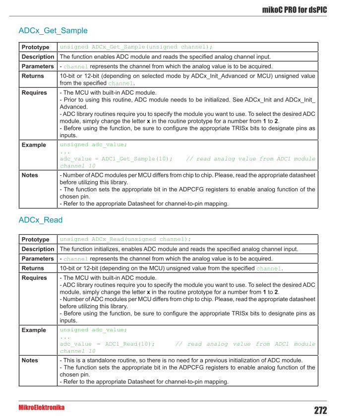
272
mikoC PRO for dsPIC
MikroElektronika
ADCx_Get_Sample
Prototype unsigned ADCx_Get_Sample(unsigned channel);
Description The function enables ADC module and reads the specified analog channel input.Parameters - channel represents the channel from which the analog value is to be acquired.Returns 10-bit or 12-bit (depending on selected mode by ADCx_Init_Advanced or MCU) unsigned value
from the specified channel.Requires - The MCU with built-in ADC module.
- Prior to using this routine, ADC module needs to be initialized. See ADCx_Init and ADCx_Init_Advanced. - ADC library routines require you to specify the module you want to use. To select the desired ADC module, simply change the letter x in the routine prototype for a number from 1 to 2. - Before using the function, be sure to configure the appropriate TRISx bits to designate pins as inputs.
Example unsigned adc_value;...adc_value = ADC1_Get_Sample(10); // read analog value from ADC1 module channel 10
Notes - Number of ADC modules per MCU differs from chip to chip. Please, read the appropriate datasheet before utilizing this library. - The function sets the appropriate bit in the ADPCFG registers to enable analog function of the chosen pin. - Refer to the appropriate Datasheet for channel-to-pin mapping.
ADCx_Read
Prototype unsigned ADCx_Read(unsigned channel);
Description The function initializes, enables ADC module and reads the specified analog channel input.Parameters - channel represents the channel from which the analog value is to be acquired.Returns 10-bit or 12-bit (depending on the MCU) unsigned value from the specified channel.Requires - The MCU with built-in ADC module.
- ADC library routines require you to specify the module you want to use. To select the desired ADC module, simply change the letter x in the routine prototype for a number from 1 to 2. - Number of ADC modules per MCU differs from chip to chip. Please, read the appropriate datasheet before utilizing this library.- Before using the function, be sure to configure the appropriate TRISx bits to designate pins as inputs.
Example unsigned adc_value;...adc_value = ADC1_Read(10); // read analog value from ADC1 module channel 10
Notes - This is a standalone routine, so there is no need for a previous initialization of ADC module. - The function sets the appropriate bit in the ADPCFG registers to enable analog function of the chosen pin. - Refer to the appropriate Datasheet for channel-to-pin mapping.

mikroC PRO for dsPIC
MikroElektronika273
ADC_Set_Active
Prototype void ADC_Set_Active(unsigned (*adc_gs)(unsigned));
Description Sets active ADC module.Parameters Parameters:
- adc_gs: ADCx_Get_Sample handler. Returns Nothing.Requires Routine is available only for MCUs with multiple ADC modules.
Used ADC module must be initialized before using this routine. See ADCx_Init and ADCx_Init_Advanced routines.
Example // Activate ADC2 moduleADC_Set_Active(ADC2_Get_Sample);
Notes None.
Library Example
This code snippet reads analog value from the channel 1 and sends readings as a text over UART1.
Copy Code To Clipboard
unsigned adcRes;char txt[6];
void main() {
PORTB = 0x0000; TRISB.F1 = 1; // set pin as input - needed for ADC to work ADC1_Init(); UART1_Init(9600);
while (1) { adcRes = ADC1_Get_Sample(1); WordToStr(adcRes, txt); UART1_Write_Text(txt); Delay_ms(50); }}

274
mikoC PRO for dsPIC
MikroElektronika
ADC HW connection

mikroC PRO for dsPIC
MikroElektronika275
CAN LibraryThe mikroC PRO for dsPIC30/33 and PIC24 provides a library (driver) for working with the dsPIC30F CAN module.
The CAN is a very robust protocol that has error detection and signalization, self–checking and fault confinement. Faulty CAN data and remote frames are re-transmitted automatically, similar to the Ethernet.
Data transfer rates depend on distance. For example, 1 Mbit/s can be achieved at network lengths below 40m while 250 Kbit/s can be achieved at network lengths below 250m. The greater distance the lower maximum bitrate that can be achieved. The lowest bitrate defined by the standard is 200Kbit/s. Cables used are shielded twisted pairs.
CAN supports two message formats:
- Standard format, with 11 identifier bits and - Extended format, with 29 identifier bits
Important:
- Consult the CAN standard about CAN bus termination resistance. - CAN library routines require you to specify the module you want to use. To use the desired CAN module, simply change the letter x in the routine prototype for a number from 1 to 2. - Number of CAN modules per MCU differs from chip to chip. Please, read the appropriate datasheet before utilizing this library.
Library Routines
- CANxSetOperationMode - CANxGetOperationMode - CANxInitialize - CANxSetBaudRate - CANxSetMask - CANxSetFilter - CANxRead - CANxWrite

276
mikoC PRO for dsPIC
MikroElektronika
CANxSetOperationMode
Prototype void CANxSetOperationMode(unsigned int mode, unsigned int WAIT);
Description Sets the CAN module to requested mode.Parameters - mode: CAN module operation mode. Valid values: CAN_OP_MODE constants. See CAN_OP_
MODE constants. - WAIT: CAN mode switching verification request. If WAIT == 0, the call is non-blocking. The function does not verify if the CAN module is switched to requested mode or not. Caller must use CANxGetOperationMode to verify correct operation mode before performing mode specific operation. If WAIT != 0, the call is blocking – the function won’t “return” until the requested mode is set.
Returns Nothing.Requires MCU with the CAN module.
MCU must be connected to the CAN transceiver (MCP2551 or similar) which is connected to the CAN bus.
Example // set the CAN1 module into configuration mode (wait inside CAN1SetOperationMode until this mode is set)CAN1SetOperationMode(_CAN_MODE_CONFIG, 0xFF);
Notes - CAN library routine require you to specify the module you want to use. To use the desired CAN module, simply change the letter x in the routine prototype for a number from 1 to 2. - Number of CAN modules per MCU differs from chip to chip. Please, read the appropriate datasheet before utilizing this library.
CANxGetOperationMode
Prototype unsigned int CANxGetOperationMode();
Description The function returns current operation mode of the CAN module. See CAN_OP_MODE constants or device datasheet for operation mode codes.
Parameters None.Returns Current operation mode.Requires MCU with the CAN module.
MCU must be connected to the CAN transceiver (MCP2551 or similar) which is connected to the CAN bus.
Example // check whether the CAN1 module is in Normal mode and if it is then do something.if (CAN1GetOperationMode() == _CAN_MODE_NORMAL) { ...}
Notes - CAN library routine require you to specify the module you want to use. To use the desired CAN module, simply change the letter x in the routine prototype for a number from 1 to 2. - Number of CAN modules per MCU differs from chip to chip. Please, read the appropriate datasheet before utilizing this library.

mikroC PRO for dsPIC
MikroElektronika277
CANxInitialize
Prototype void CANxInitialize(unsigned int SJW, unsigned int BRP, unsigned int PHSEG1, unsigned int PHSEG2, unsigned int PROPSEG, unsigned int CAN_CONFIG_FLAGS);
Description Initializes the CAN module.
The internal dsPIC30F CAN module is set to:
- Disable CAN capture - Continue CAN operation in Idle mode - Do not abort pending transmissions - Fcan clock : 4*Tcy (Fosc) - Baud rate is set according to given parameters - CAN mode is set to Normal - Filter and mask registers IDs are set to zero - Filter and mask message frame type is set according to CAN_CONFIG_FLAGS value
SAM, SEG2PHTS, WAKFIL and DBEN bits are set according to CAN_CONFIG_FLAGS value.Parameters - SJW as defined in MCU’s datasheet (CAN Module)
- BRP as defined in MCU’s datasheet (CAN Module) - PHSEG1 as defined in MCU’s datasheet (CAN Module) - PHSEG2 as defined in MCU’s datasheet (CAN Module) - PROPSEG as defined in MCU’s datasheet (CAN Module) - CAN_CONFIG_FLAGS is formed from predefined constants. See CAN_CONFIG_FLAGS constants.
Returns Nothing.Requires MCU with the CAN module.
MCU must be connected to the CAN transceiver (MCP2551 or similar) which is connected to the CAN bus.
Example // initialize the CAN1 module with appropriate baud rate and message acceptance flags along with the sampling rulesunsigned int can_config_flags;... can_config_flags = _CAN_CONFIG_SAMPLE_THRICE & // Form value to be used _CAN_CONFIG_PHSEG2_PRG_ON & // with CAN1Initialize _CAN_CONFIG_STD_MSG & _CAN_CONFIG_DBL_BUFFER_ON & _CAN_CONFIG_MATCH_MSG_TYPE & _CAN_CONFIG_LINE_FILTER_OFF;
CAN1Initialize(1,3,3,3,1,can_config_flags); // initialize the CAN1 module
Notes - CAN mode NORMAL will be set on exit. - CAN library routine require you to specify the module you want to use. To use the desired CAN module, simply change the letter x in the routine prototype for a number from 1 to 2. - Number of CAN modules per MCU differs from chip to chip. Please, read the appropriate datasheet before utilizing this library.

278
mikoC PRO for dsPIC
MikroElektronika
CANxSetBaudRate
Prototype void CANxSetBaudRate(unsigned int SJW, unsigned int BRP, unsigned int PHSEG1, unsigned int PHSEG2, unsigned int PROPSEG, unsigned int CAN_CONFIG_FLAGS);
Description Sets CAN baud rate. Due to complexity of the CAN protocol, you can not simply force a bps value. Instead, use this function when CAN is in Config mode. Refer to datasheet for details.
SAM, SEG2PHTS and WAKFIL bits are set according to CAN_CONFIG_FLAGS value. Refer to datasheet for details.
Parameters - SJW as defined in MCU’s datasheet (CAN Module) - BRP as defined in MCU’s datasheet (CAN Module) - PHSEG1 as defined in MCU’s datasheet (CAN Module) - PHSEG2 as defined in MCU’s datasheet (CAN Module) - PROPSEG as defined in MCU’s datasheet (CAN Module) - CAN_CONFIG_FLAGS is formed from predefined constants. See CAN_CONFIG_FLAGS constants.
Returns Nothing.Requires MCU with the CAN module.
MCU must be connected to the CAN transceiver (MCP2551 or similar) which is connected to the CAN bus.CAN must be in Config mode, otherwise the function will be ignored. See CANxSetOperationMode.
Example // set required baud rate and sampling rulesunsigned int can_config_flags;... CAN1SetOperationMode(_CAN_MODE_CONFIG,0xFF); // set CONFIGURATION mode (CAN1 module must be in config mode for baud rate settings)
can_config_flags = _CAN_CONFIG_SAMPLE_THRICE & // Form value to be used _CAN_CONFIG_PHSEG2_PRG_ON & // with CAN1SetBaudRate _CAN_CONFIG_STD_MSG & _CAN_CONFIG_DBL_BUFFER_ON & _CAN_CONFIG_MATCH_MSG_TYPE & _CAN_CONFIG_LINE_FILTER_OFF;
CAN1SetBaudRate(1,3,3,3,1,can_config_flags);// set the CAN1 module baud rate
Notes - CAN library routine require you to specify the module you want to use. To use the desired CAN module, simply change the letter x in the routine prototype for a number from 1 to 2. - Number of CAN modules per MCU differs from chip to chip. Please, read the appropriate datasheet before utilizing this library.

mikroC PRO for dsPIC
MikroElektronika279
CANxSetMask
Prototype void CANxSetMask(unsigned int CAN_MASK, long val, unsigned int CAN_CONFIG_FLAGS);
Description Function sets mask for advanced filtering of messages. Given value is bit adjusted to appropriate buffer mask registers.
Parameters - CAN_MASK: CAN module mask number. Valid values: CAN_MASK constants. See CAN_MASK constants. - val: mask register value. This value is bit-adjusted to appropriate buffer mask registers - CAN_CONFIG_FLAGS: selects type of message to filter. Valid values: - _CAN_CONFIG_ALL_VALID_MSG, - _CAN_CONFIG_MATCH_MSG_TYPE & _CAN_CONFIG_STD_MSG, - _CAN_CONFIG_MATCH_MSG_TYPE & _CAN_CONFIG_XTD_MSG. See CAN_CONFIG_FLAGS constants.
Returns Nothing.Requires MCU with the CAN module.
MCU must be connected to the CAN transceiver (MCP2551 or similar) which is connected to the CAN bus.CAN must be in Config mode, otherwise the function will be ignored. See CANxSetOperationMode.
Example // set appropriate filter mask and message type valueCAN1SetOperationMode(_CAN_MODE_CONFIG,0xFF); // set CONFIGURATION mode (CAN1 module must be in config mode for mask settings)
// Set all B1 mask bits to 1 (all filtered bits are relevant):// Note that -1 is just a cheaper way to write 0xFFFFFFFF.// Complement will do the trick and fill it up with ones.CAN1SetMask(_CAN_MASK_B1, -1, _CAN_CONFIG_MATCH_MSG_TYPE & _CAN_CONFIG_XTD_MSG);
Notes - CAN library routine require you to specify the module you want to use. To use the desired CAN module, simply change the letter x in the routine prototype for a number from 1 to 2. - Number of CAN modules per MCU differs from chip to chip. Please, read the appropriate datasheet before utilizing this library.

280
mikoC PRO for dsPIC
MikroElektronika
CANxSetFilter
Prototype void CANxSetFilter(unsigned int CAN_FILTER, long val, unsigned int CAN_CONFIG_FLAGS);
Description Function sets message filter. Given value is bit adjusted to appropriate buffer mask registers.Parameters - CAN_FILTER: CAN module filter number. Valid values: CAN_FILTER constants. See CAN_FILTER
constants. - val: filter register value. This value is bit-adjusted to appropriate filter registers - CAN_CONFIG_FLAGS: selects type of message to filter. Valid values: _CAN_CONFIG_STD_MSG and _CAN_CONFIG_XTD_MSG. See CAN_CONFIG_FLAGS constants.
Returns Nothing.Requires MCU with the CAN module.
MCU must be connected to the CAN transceiver (MCP2551 or similar) which is connected to the CAN bus.CAN must be in Config mode, otherwise the function will be ignored. See CANxSetOperationMode.
Example // set appropriate filter value and message typeCAN1SetOperationMode(_CAN_MODE_CONFIG,0xFF); // set CONFIGURATION mode (CAN1 module must be in config mode for filter settings)
// Set id of filter B1_F1 to 3CAN1SetFilter(_CAN_FILTER_B1_F1, 3, _CAN_CONFIG_XTD_MSG);
Notes - CAN library routine require you to specify the module you want to use. To use the desired CAN module, simply change the letter x in the routine prototype for a number from 1 to 2. - Number of CAN modules per MCU differs from chip to chip. Please, read the appropriate datasheet before utilizing this library.

mikroC PRO for dsPIC
MikroElektronika281
CANxRead
Prototype unsigned int CANxRead(unsigned long *id, char *data_, unsigned int *dataLen, unsigned int *CAN_RX_MSG_FLAGS);
Description If at least one full Receive Buffer is found, it will be processed in the following way :
- Message ID is retrieved and stored to location pointed by id pointer - Message data is retrieved and stored to array pointed by data pointer - Message length is retrieved and stored to location pointed by dataLen pointer - Message flags are retrieved and stored to location pointed by CAN_RX_MSG_FLAGS pointer
Parameters - id: message identifier address - data: an array of bytes up to 8 bytes in length - dataLen: data length address - CAN_RX_MSG_FLAGS: message flags address. For message receive flags format refer to CAN_RX_MSG_FLAGS constants. See CAN_RX_MSG_FLAGS constants.
Returns - 0 if nothing is received - 0xFFFF if one of the Receive Buffers is full (message received)
Requires MCU with the CAN module.MCU must be connected to the CAN transceiver (MCP2551 or similar) which is connected to the CAN bus.CAN must be in Config mode, otherwise the function will be ignored. See CANxSetOperationMode.
Example // check the CAN1 module for received messages. If any was received do something. unsigned int msg_rcvd, rx_flags, data_len;char data[8];unsigned long msg_id;...CAN1SetOperationMode(_CAN_MODE_NORMAL,0xFF); // set NORMAL mode (CAN1 module must be in mode in which receive is possible)...rx_flags = 0; // clear message flagsif (msg_rcvd = CAN1Read(&msg_id, data, &data_len, &rx_flags)) { ...}
Notes - CAN library routine require you to specify the module you want to use. To use the desired CAN module, simply change the letter x in the routine prototype for a number from 1 to 2. - Number of CAN modules per MCU differs from chip to chip. Please, read the appropriate datasheet before utilizing this library.

282
mikoC PRO for dsPIC
MikroElektronika
CANxWrite
Prototype unsigned int CANxWrite(long id, char *data_, unsigned int DataLen, unsigned int CAN_TX_MSG_FLAGS);
Description If at least one empty Transmit Buffer is found, the function sends message in the queue for transmission.
Parameters - id: CAN message identifier. Valid values: 11 or 29 bit values, depending on message type (standard or extended) - data: data to be sent - dataLen: data length. Valid values: 0..8 - CAN_RX_MSG_FLAGS: message flags. Valid values: CAN_TX_MSG_FLAGS constants. See CAN_TX_MSG_FLAGS constants.
Returns - 0 if all Transmit Buffers are busy - 0xFFFF if at least one Transmit Buffer is available
Requires MCU with the CAN module.MCU must be connected to the CAN transceiver (MCP2551 or similar) which is connected to the CAN bus.CAN must be in Config mode, otherwise the function will be ignored. See CANxSetOperationMode.
Example // send message extended CAN message with appropriate ID and dataunsigned int tx_flags;char data[8];unsigned long msg_id;...CAN1SetOperationMode(_CAN_MODE_NORMAL,0xFF); // set NORMAL mode (CAN1 must be in mode in which transmission is possible)
tx_flags = _CAN_TX_PRIORITY_0 & _CAN_TX_XTD_FRAME & _CAN_TX_NO_RTR_FRAME; // set message flagsCAN1Write(msg_id, data, 1, tx_flags);
Notes - CAN library routine require you to specify the module you want to use. To use the desired CAN module, simply change the letter x in the routine prototype for a number from 1 to 2. - Number of CAN modules per MCU differs from chip to chip. Please, read the appropriate datasheet before utilizing this library.

mikroC PRO for dsPIC
MikroElektronika283
CAN Constants
There is a number of constants predefined in CAN library. To be able to use the library effectively, you need to be familiar with these. You might want to check the example at the end of the chapter.
CAN_OP_MODE Constants
CAN_OP_MODE constants define CAN operation mode. Function CANxSetOperationMode expects one of these as its argument:
Copy Code To Clipboard
const unsigned int _CAN_MODE_BITS = 0xE0, // Use this to access opmode bits _CAN_MODE_NORMAL = 0x00, _CAN_MODE_SLEEP = 0x20, _CAN_MODE_LOOP = 0x40, _CAN_MODE_LISTEN = 0x60, _CAN_MODE_CONFIG = 0x80;
CAN_CONFIG_FLAGS Constants
CAN_CONFIG_FLAGS constants define flags related to CAN module configuration. Functions CANxInitialize and CANxSetBaudRate expect one of these (or a bitwise combination) as their argument:
Copy Code To Clipboard
const unsigned int _CAN_CONFIG_DEFAULT = 0xFF, // 11111111
_CAN_CONFIG_PHSEG2_PRG_BIT = 0x01, _CAN_CONFIG_PHSEG2_PRG_ON = 0xFF, // XXXXXXX1 _CAN_CONFIG_PHSEG2_PRG_OFF = 0xFE, // XXXXXXX0
_CAN_CONFIG_LINE_FILTER_BIT = 0x02, _CAN_CONFIG_LINE_FILTER_ON = 0xFF, // XXXXXX1X _CAN_CONFIG_LINE_FILTER_OFF = 0xFD, // XXXXXX0X
_CAN_CONFIG_SAMPLE_BIT = 0x04, _CAN_CONFIG_SAMPLE_ONCE = 0xFF, // XXXXX1XX _CAN_CONFIG_SAMPLE_THRICE = 0xFB, // XXXXX0XX
_CAN_CONFIG_MSG_TYPE_BIT = 0x08, _CAN_CONFIG_STD_MSG = 0xFF, // XXXX1XXX _CAN_CONFIG_XTD_MSG = 0xF7, // XXXX0XXX
_CAN_CONFIG_DBL_BUFFER_BIT = 0x10, _CAN_CONFIG_DBL_BUFFER_ON = 0xFF, // XXX1XXXX _CAN_CONFIG_DBL_BUFFER_OFF = 0xEF, // XXX0XXXX

284
mikoC PRO for dsPIC
MikroElektronika
_CAN_CONFIG_MSG_BITS = 0x60, _CAN_CONFIG_ALL_MSG = 0xFF, // X11XXXXX _CAN_CONFIG_VALID_XTD_MSG = 0xDF, // X10XXXXX _CAN_CONFIG_VALID_STD_MSG = 0xBF, // X01XXXXX _CAN_CONFIG_ALL_VALID_MSG = 0x9F; // X00XXXXX
You may use bitwise AND (&) to form config byte out of these values. For example:
Copy Code To Clipboard
init = _CAN_CONFIG_SAMPLE_THRICE & _CAN_CONFIG_PHSEG2_PRG_ON & _CAN_CONFIG_STD_MSG & _CAN_CONFIG_DBL_BUFFER_ON & _CAN_CONFIG_VALID_XTD_MSG & _CAN_CONFIG_LINE_FILTER_OFF;...CANInitialize(1, 1, 3, 3, 1, init); // initialize CAN
CAN_TX_MSG_FLAGS Constants
CAN_TX_MSG_FLAGS are flags related to transmission of a CAN message:
Copy Code To Clipboard
const unsigned int _CAN_TX_PRIORITY_BITS = 0x03, _CAN_TX_PRIORITY_0 = 0xFC, // XXXXXX00 _CAN_TX_PRIORITY_1 = 0xFD, // XXXXXX01 _CAN_TX_PRIORITY_2 = 0xFE, // XXXXXX10 _CAN_TX_PRIORITY_3 = 0xFF, // XXXXXX11
_CAN_TX_FRAME_BIT = 0x08, _CAN_TX_STD_FRAME = 0xFF, // XXXXX1XX _CAN_TX_XTD_FRAME = 0xF7, // XXXXX0XX
_CAN_TX_RTR_BIT = 0x40, _CAN_TX_NO_RTR_FRAME = 0xFF, // X1XXXXXX _CAN_TX_RTR_FRAME = 0xBF; // X0XXXXXX
You may use bitwise AND (&) to adjust the appropriate flags. For example:
Copy Code To Clipboard
// form value to be used with CANSendMessage:send_config = _CAN_TX_PRIORITY_0 & _CAN_TX_XTD_FRAME & _CAN_TX_NO_RTR_FRAME;...CANSendMessage(id, data, 1, send_config);

mikroC PRO for dsPIC
MikroElektronika285
CAN_RX_MSG_FLAGS Constants
CAN_RX_MSG_FLAGS are flags related to reception of CAN message. If a particular bit is set; corresponding meaning is TRUE or else it will be FALSE.
Copy Code To Clipboard
const unsigned int _CAN_RX_FILTER_BITS = 0x07, // Use this to access filter bits _CAN_RX_FILTER_1 = 0x00, _CAN_RX_FILTER_2 = 0x01, _CAN_RX_FILTER_3 = 0x02, _CAN_RX_FILTER_4 = 0x03, _CAN_RX_FILTER_5 = 0x04, _CAN_RX_FILTER_6 = 0x05, _CAN_RX_OVERFLOW = 0x08, // Set if Overflowed else cleared _CAN_RX_INVALID_MSG = 0x10, // Set if invalid else cleared _CAN_RX_XTD_FRAME = 0x20, // Set if XTD message else cleared _CAN_RX_RTR_FRAME = 0x40, // Set if RTR message else cleared _CAN_RX_DBL_BUFFERED = 0x80; // Set if this message was hardware double-buffered
You may use bitwise AND (&) to adjust the appropriate flags. For example:
Copy Code To Clipboard
if (MsgFlag & _CAN_RX_OVERFLOW != 0) { ... // Receiver overflow has occurred. // We have lost our previous message.}
CAN_MASK Constants
CAN_MASK constants define mask codes. Function CANxSetMask expects one of these as its argument:
Copy Code To Clipboard
const unsigned int _CAN_MASK_B1 = 0, _CAN_MASK_B2 = 1;

286
mikoC PRO for dsPIC
MikroElektronika
CAN_FILTER Constants
CAN_FILTER constants define filter codes. Function CANxSetFilter expects one of these as its argument:
Copy Code To Clipboard
const unsigned int _CAN_FILTER_B1_F1 = 0, _CAN_FILTER_B1_F2 = 1, _CAN_FILTER_B2_F1 = 2, _CAN_FILTER_B2_F2 = 3, _CAN_FILTER_B2_F3 = 4, _CAN_FILTER_B2_F4 = 5;
Library Example
The example demonstrates CAN protocol. The 1st node initiates the communication with the 2nd node by sending some data to its address. The 2nd node responds by sending back the data incremented by 1. The 1st node then does the same and sends incremented data back to the 2nd node, etc.
Code for the first CAN node:
Copy Code To Clipboard
unsigned int Can_Init_Flags, Can_Send_Flags, Can_Rcv_Flags; // can flagsunsigned int Rx_Data_Len; // received data length in byteschar RxTx_Data[8]; // can rx/tx data bufferchar Msg_Rcvd; // reception flagunsigned long Tx_ID, Rx_ID; // can rx and tx ID
void main() {
ADPCFG = 0xFFFF; PORTB = 0; TRISB = 0;
Can_Init_Flags = 0; // Can_Send_Flags = 0; // clear flags Can_Rcv_Flags = 0; //
Can_Send_Flags = _CAN_TX_PRIORITY_0 & // Form value to be used _CAN_TX_XTD_FRAME & // with CAN2Write _CAN_TX_NO_RTR_FRAME;
Can_Init_Flags = _CAN_CONFIG_SAMPLE_THRICE & // Form value to be used _CAN_CONFIG_PHSEG2_PRG_ON & // with CAN2Initialize _CAN_CONFIG_XTD_MSG & _CAN_CONFIG_DBL_BUFFER_ON & _CAN_CONFIG_MATCH_MSG_TYPE & _CAN_CONFIG_LINE_FILTER_OFF;

mikroC PRO for dsPIC
MikroElektronika287
RxTx_Data[0] = 9; // set initial data to be sent CAN2Initialize(1,3,3,3,1,Can_Init_Flags); // initialize CAN2 CAN2SetOperationMode(_CAN_MODE_CONFIG,0xFF); // set CONFIGURATION mode
CAN2SetMask(_CAN_MASK_B1,-1,_CAN_CONFIG_MATCH_MSG_TYPE & _CAN_CONFIG_XTD_MSG); // set all mask1 bits to ones CAN2SetMask(_CAN_MASK_B2,-1,_CAN_CONFIG_MATCH_MSG_TYPE & _CAN_CONFIG_XTD_MSG); // set all mask2 bits to ones CAN2SetFilter(_CAN_FILTER_B2_F3,3,_CAN_CONFIG_XTD_MSG); // set id of filter B1_F1 to 3 CAN2SetOperationMode(_CAN_MODE_NORMAL,0xFF); // set NORMAL mode Tx_ID = 12111; // set transmit ID CAN2Write(Tx_ID, RxTx_Data, 1, Can_Send_Flags); // send initial message while(1) { // endless loop Msg_Rcvd = CAN2Read(&Rx_ID , RxTx_Data , &Rx_Data_Len, &Can_Rcv_Flags); // receive message if ((Rx_ID == 3u) && Msg_Rcvd) { // if message received check id PORTB = RxTx_Data[0]; // id correct, output data at PORTB RxTx_Data[0]++; // increment received data Delay_ms(10); CAN2Write(Tx_ID, RxTx_Data, 1, Can_Send_Flags); // send incremented data back } }}

288
mikoC PRO for dsPIC
MikroElektronika
Code for the second CAN node:
Copy Code To Clipboard unsigned int Can_Init_Flags, Can_Send_Flags, Can_Rcv_Flags; // can flagsunsigned int Rx_Data_Len; // received data length in byteschar RxTx_Data[8]; // can rx/tx data bufferchar Msg_Rcvd; // reception flagunsigned long Tx_ID, Rx_ID; // can rx and tx ID
void main() {
ADPCFG = 0xFFFF; PORTB = 0; TRISB = 0;
Can_Init_Flags = 0; // Can_Send_Flags = 0; // clear flags Can_Rcv_Flags = 0; //
Can_Send_Flags = _CAN_TX_PRIORITY_0 & // Form value to be used _CAN_TX_XTD_FRAME & // with CAN2Write _CAN_TX_NO_RTR_FRAME;
Can_Init_Flags = _CAN_CONFIG_SAMPLE_THRICE & // Form value to be used _CAN_CONFIG_PHSEG2_PRG_ON & // with CAN2Initialize _CAN_CONFIG_XTD_MSG & _CAN_CONFIG_DBL_BUFFER_ON & _CAN_CONFIG_MATCH_MSG_TYPE & _CAN_CONFIG_LINE_FILTER_OFF;
CAN2Initialize(1,3,3,3,1,Can_Init_Flags); // initialize CAN2 CAN2SetOperationMode(_CAN_MODE_CONFIG,0xFF); // set CONFIGURATION mode
CAN2SetMask(_CAN_MASK_B1,-1,_CAN_CONFIG_MATCH_MSG_TYPE & _CAN_CONFIG_XTD_MSG); // set all mask1 bits to ones CAN2SetMask(_CAN_MASK_B2,-1,_CAN_CONFIG_MATCH_MSG_TYPE & _CAN_CONFIG_XTD_MSG); // set all mask2 bits to ones CAN2SetFilter(_CAN_FILTER_B1_F1,12111,_CAN_CONFIG_XTD_MSG); // set id of filter B1_F1 to 12111
CAN2SetOperationMode(_CAN_MODE_NORMAL,0xFF); // set NORMAL mode
Tx_ID = 3; // set tx ID
while(1) { // endless loop Msg_Rcvd = CAN2Read(&Rx_ID , RxTx_Data , &Rx_Data_Len, &Can_Rcv_Flags); // receive message if ((Rx_ID == 12111u) && Msg_Rcvd) { // if message received check id PORTB = RxTx_Data[0]; // id correct, output data at PORTB RxTx_Data[0]++; // increment received data CAN2Write(Tx_ID, RxTx_Data, 1, Can_Send_Flags); // send incremented data back } }}

mikroC PRO for dsPIC
MikroElektronika289
HW Connection
Example of interfacing CAN transceiver with MCU and CAN bus

290
mikoC PRO for dsPIC
MikroElektronika
CANSPI LibraryThe SPI module is available with a number of the dsPIC30/33 and PIC24 MCUs. The mikroC PRO for dsPIC30/33 and PIC24 provides a library (driver) for working with mikroElektronika's CANSPI Add-on boards (with MCP2515 or MCP2510) via SPI interface.
In the mikroC PRO for dsPIC30/33 and PIC24, each routine of the CAN library has its own CANSPI counterpart with identical syntax. For more information on Controller Area Network, consult the CAN Library. Note that an effective communication speed depends on SPI and certainly is slower than "real" CAN.
Important :
- Consult the CAN standard about CAN bus termination resistance. - An effective CANSPI communication speed depends on SPI and certainly is slower than “real” CAN. - The library uses the SPI module for communication. User must initialize appropriate SPI module before using the CANSPI Library. - For MCUs with multiple SPI modules it is possible to initialize both of them and then switch by using the SPI_Set_Active routine. - Number of SPI modules per MCU differs from chip to chip. Please, read the appropriate datasheet before utilizing this library.
Library Dependency Tree
External dependencies of CANSPI Library
The following variables must be defined in all projects using CANSPI Library:
Description : Example :
extern sfr sbit CanSpi_CS; Chip Select line. sbit CanSpi_CS at RF0_bit;
extern sfr sbit CanSpi_Rst; Reset line. sbit CanSpi_Rst at
RF1_bit;
extern sfr sbit CanSpi_CS_Direction; Direction of the Chip Select pin.
sbit CanSpi_CS_Direction at TRISF0_bit;
extern sfr sbit CanSpi_Rst_Direction; Direction of the Reset pin.
sbit CanSpi_Rst_Direction at TRISF1_bit;

mikroC PRO for dsPIC
MikroElektronika291
Library Routines
- CANSPISetOperationMode - CANSPIGetOperationMode - CANSPIInitialize - CANSPISetBaudRate - CANSPISetMask - CANSPISetFilter - CANSPIRead - CANSPIWrite
CANSPISetOperationMode
Prototype void CANSPISetOperationMode(char mode, char WAIT);
Description Sets the CANSPI module to requested mode.Parameters mode: CANSPI module operation mode. Valid values: CANSPI_OP_MODE constants. See CANSPI_
OP_MODE constants. WAIT: CANSPI mode switching verification request. If WAIT == 0, the call is non-blocking. The function does not verify if the CANSPI module is switched to requested mode or not. Caller must use CANSPIGetOperationMode to verify correct operation mode before performing mode specific operation. If WAIT != 0, the call is blocking – the function won’t “return” until the requested mode is set.
Returns Nothing.Requires The CANSPI routines are supported only by MCUs with the SPI module.
MCU has to be properly connected to mikroElektronika’s CANSPI Extra Board or similar hardware. See connection example at the bottom of this page.
Example // set the CANSPI module into configuration mode (wait inside CANSPISetOperationMode until this mode is set)CANSPISetOperationMode(_CANSPI_MODE_CONFIG, 0xFF);
Notes None.

292
mikoC PRO for dsPIC
MikroElektronika
CANSPIGetOperationMode
CANSPIInitialize
Prototype char CANSPIGetOperationMode();
Description The function returns current operation mode of the CANSPI module. Check CANSPI_OP_MODE constants or device datasheet for operation mode codes.
Parameters None.Returns Current operation mode.Requires The CANSPI routines are supported only by MCUs with the SPI module.
MCU has to be properly connected to mikroElektronika’s CANSPI Extra Board or similar hardware. See connection example at the bottom of this page.
Example // check whether the CANSPI module is in Normal mode and if it is do something.if (CANSPIGetOperationMode() == _CANSPI_MODE_NORMAL) { ...}
Notes None.
Prototype void CANSPIInitialize(char SJW, char BRP, char PHSEG1, char PHSEG2, char PROPSEG, char CANSPI_CONFIG_FLAGS);
Description Initializes the CANSPI module.
Stand-Alone CAN controller in the CANSPI module is set to:
- Disable CAN capture - Continue CAN operation in Idle mode - Do not abort pending transmissions - Fcan clock : 4*Tcy (Fosc) - Baud rate is set according to given parameters - CAN mode : Normal - Filter and mask registers IDs are set to zero - Filter and mask message frame type is set according to CANSPI_CONFIG_FLAGS value
SAM, SEG2PHTS, WAKFIL and DBEN bits are set according to CANSPI_CONFIG_FLAGS value.Parameters - SJW as defined in MCU’s datasheet (CAN Module)
- BRP as defined in MCU’s datasheet (CAN Module) - PHSEG1 as defined in MCU’s datasheet (CAN Module) - PHSEG2 as defined in MCU’s datasheet (CAN Module) - PROPSEG as defined in MCU’s datasheet (CAN Module) - CANSPI_CONFIG_FLAGS is formed from predefined constants. See CANSPI_CONFIG_FLAGS constants.
Returns Nothing.

mikroC PRO for dsPIC
MikroElektronika293
Requires Global variables :
- CanSpi_CS: Chip Select line - CanSpi_Rst: Reset line - CanSpi_CS_Direction: Direction of the Chip Select pin - CanSpi_Rst_Direction: Direction of the Reset pin
must be defined before using this function.
The CANSPI routines are supported only by MCUs with the SPI module.
The SPI module needs to be initialized. See the SPIx_Init and SPIx_Init_Advanced routines.
MCU has to be properly connected to mikroElektronika’s CANSPI Extra Board or similar hardware. See connection example at the bottom of this page.
Example // CANSPI module connectionssbit CanSpi_CS at RF0_bit;sbit CanSpi_CS_Direction at TRISF0_bit;sbit CanSpi_Rst at RF1_bit;sbit CanSpi_Rst_Direction at TRISF1_bit;// End CANSPI module connections
// initialize the CANSPI module with the appropriate baud rate and message acceptance flags along with the sampling ruleschar CANSPI_Init_Flags; ... CANSPI_Init_Flags = _CANSPI_CONFIG_SAMPLE_THRICE & // form value to be used _CANSPI_CONFIG_PHSEG2_PRG_ON & // with CANSPIInitialize _CANSPI_CONFIG_XTD_MSG & _CANSPI_CONFIG_DBL_BUFFER_ON & _CANSPI_CONFIG_VALID_XTD_MSG; ... SPI1_Init(); // initialize SPI1 module CANSPIInitialize(1,3,3,3,1,CANSPI_Init_Flags); // initialize external CANSPI module
Notes - CANSPI mode NORMAL will be set on exit.

294
mikoC PRO for dsPIC
MikroElektronika
CANSPISetBaudRate
Prototype void CANSPISetBaudRate(char SJW, char BRP, char PHSEG1, char PHSEG2, char PROPSEG, char CANSPI_CONFIG_FLAGS);
Returns Nothing.Description Sets the CANSPI module baud rate. Due to complexity of the CAN protocol, you can not simply force
a bps value. Instead, use this function when the CANSPI module is in Config mode.
SAM, SEG2PHTS and WAKFIL bits are set according to CANSPI_CONFIG_FLAGS value. Refer to datasheet for details.
Parameters - SJW as defined in MCU’s datasheet (CAN Module) - BRP as defined in MCU’s datasheet (CAN Module) - PHSEG1 as defined in MCU’s datasheet (CAN Module) - PHSEG2 as defined in MCU’s datasheet (CAN Module) - PROPSEG as defined in MCU’s datasheet (CAN Module) - CANSPI_CONFIG_FLAGS is formed from predefined constants. See CANSPI_CONFIG_FLAGS constants.
Returns Nothing.Requires The CANSPI module must be in Config mode, otherwise the function will be ignored. See
CANSPISetOperationMode.
The CANSPI routines are supported only by MCUs with the SPI module.
MCU has to be properly connected to mikroElektronika’s CANSPI Extra Board or similar hardware. See connection example at the bottom of this page.
Example // set required baud rate and sampling ruleschar CANSPI_CONFIG_FLAGS;... CANSPISetOperationMode(_CANSPI_MODE_CONFIG,0xFF); // set CONFIGURATION mode (CANSPI module must be in config mode for baud rate settings)CANSPI_CONFIG_FLAGS = _CANSPI_CONFIG_SAMPLE_THRICE & _CANSPI_CONFIG_PHSEG2_PRG_ON & _CANSPI_CONFIG_STD_MSG & _CANSPI_CONFIG_DBL_BUFFER_ON & _CANSPI_CONFIG_VALID_XTD_MSG & _CANSPI_CONFIG_LINE_FILTER_OFF;CANSPISetBaudRate(1, 1, 3, 3, 1, CANSPI_CONFIG_FLAGS);
Notes None.

mikroC PRO for dsPIC
MikroElektronika295
CANSPISetMask
Prototype void CANSPISetMask(unsigned short CANSPI_MASK, long value, unsigned short CANSPI_CONFIG_FLAGS);
Description Configures mask for advanced filtering of messages. The parameter value is bit-adjusted to the appropriate mask registers.
Parameters - CANSPI_MASK: CAN module mask number. Valid values: CANSPI_MASK constants. See CANSPI_MASK constants. - val: mask register value. This value is bit-adjusted to appropriate buffer mask registers - CANSPI_CONFIG_FLAGS: selects type of message to filter. Valid values: - _CANSPI_CONFIG_ALL_VALID_MSG, - _CANSPI_CONFIG_MATCH_MSG_TYPE & _CANSPI_CONFIG_STD_MSG, - _CANSPI_CONFIG_MATCH_MSG_TYPE & _CANSPI_CONFIG_XTD_MSG. See CANSPI_CONFIG_FLAGS constants.
Returns Nothing.Requires The CANSPI module must be in Config mode, otherwise the function will be ignored. See
CANSPISetOperationMode.
The CANSPI routines are supported only by MCUs with the SPI module.
MCU has to be properly connected to mikroElektronika’s CANSPI Extra Board or similar hardware. See connection example at the bottom of this page.
Example // set the appropriate filter mask and message type valueCANSPISetOperationMode(_CANSPI_MODE_CONFIG,0xFF); // set CONFIGURATION mode (CANSPI module must be in config mode for mask settings)
// Set all B1 mask bits to 1 (all filtered bits are relevant):// Note that -1 is just a cheaper way to write 0xFFFFFFFF.// Complement will do the trick and fill it up with ones.CANSPISetMask(_CANSPI_MASK_B1, -1, _CANSPI_CONFIG_MATCH_MSG_TYPE & _CANSPI_CONFIG_XTD_MSG);
Notes None.

296
mikoC PRO for dsPIC
MikroElektronika
CANSPISetFilter
Prototype void CANSPISetFilter(unsigned short CANSPI_FILTER, long value, unsigned short CANSPI_CONFIG_FLAGS);
Description Configures message filter. The parameter value is bit-adjusted to the appropriate filter registers.Parameters - CANSPI_FILTER: CAN module filter number. Valid values: CANSPI_FILTER constants. See
CANSPI_FILTER constants. - val: filter register value. This value is bit-adjusted to appropriate filter registers - CANSPI_CONFIG_FLAGS: selects type of message to filter. Valid values: _CANSPI_CONFIG_STD_MSG and _CANSPI_CONFIG_XTD_MSG. See CANSPI_CONFIG_FLAGS constants.
Returns Nothing.Requires The CANSPI module must be in Config mode, otherwise the function will be ignored. See
CANSPISetOperationMode.
The CANSPI routines are supported only by MCUs with the SPI module.
MCU has to be properly connected to mikroElektronika’s CANSPI Extra Board or similar hardware. See connection example at the bottom of this page.
Example // set the appropriate filter value and message typeCANSPISetOperationMode(_CANSPI_MODE_CONFIG,0xFF); // set CONFIGURATION mode (CANSPI module must be in config mode for filter settings)
// Set id of filter B1_F1 to 3 :CANSPISetFilter(_CANSPI_FILTER_B1_F1, 3, _CANSPI_CONFIG_XTD_MSG);
Notes None.
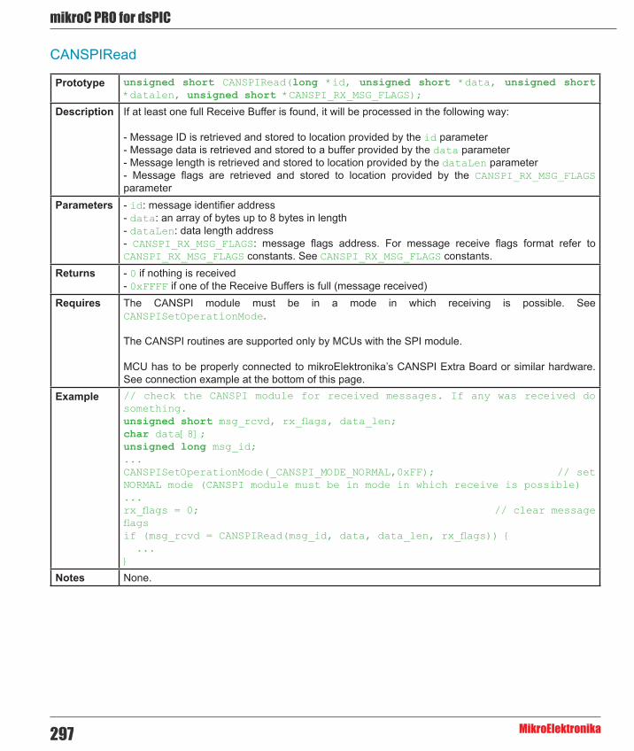
mikroC PRO for dsPIC
MikroElektronika297
CANSPIRead
Prototype unsigned short CANSPIRead(long *id, unsigned short *data, unsigned short *datalen, unsigned short *CANSPI_RX_MSG_FLAGS);
Description If at least one full Receive Buffer is found, it will be processed in the following way:
- Message ID is retrieved and stored to location provided by the id parameter - Message data is retrieved and stored to a buffer provided by the data parameter - Message length is retrieved and stored to location provided by the dataLen parameter - Message flags are retrieved and stored to location provided by the CANSPI_RX_MSG_FLAGS parameter
Parameters - id: message identifier address - data: an array of bytes up to 8 bytes in length - dataLen: data length address - CANSPI_RX_MSG_FLAGS: message flags address. For message receive flags format refer to CANSPI_RX_MSG_FLAGS constants. See CANSPI_RX_MSG_FLAGS constants.
Returns - 0 if nothing is received - 0xFFFF if one of the Receive Buffers is full (message received)
Requires The CANSPI module must be in a mode in which receiving is possible. See CANSPISetOperationMode.
The CANSPI routines are supported only by MCUs with the SPI module.
MCU has to be properly connected to mikroElektronika’s CANSPI Extra Board or similar hardware. See connection example at the bottom of this page.
Example // check the CANSPI module for received messages. If any was received do something. unsigned short msg_rcvd, rx_flags, data_len;char data[8];unsigned long msg_id;...CANSPISetOperationMode(_CANSPI_MODE_NORMAL,0xFF); // set NORMAL mode (CANSPI module must be in mode in which receive is possible)...rx_flags = 0; // clear message flagsif (msg_rcvd = CANSPIRead(msg_id, data, data_len, rx_flags)) { ...}
Notes None.

298
mikoC PRO for dsPIC
MikroElektronika
CANSPIWrite
Prototype unsigned short CANSPIWrite(long id, unsigned short *data, unsigned short datalen, unsigned short CANSPI_TX_MSG_FLAGS);
Description If at least one empty Transmit Buffer is found, the function sends message in the queue for transmission.
Parameters - id: CAN message identifier. Valid values: 11 or 29 bit values, depending on message type (standard or extended) - Data: data to be sent - DataLen: data length. Valid values: 0..8 - CANSPI_TX_MSG_FLAGS: message flags. Valid values: CANSPI_TX_MSG_FLAGS constants. See CANSPI_TX_MSG_FLAGS constants.
Returns - 0 if all Transmit Buffers are busy - 0xFFFF if at least one Transmit Buffer is available
Requires The CANSPI module must be in mode in which transmission is possible. See CANSPISetOperationMode.
The CANSPI routines are supported only by MCUs with the SPI module.
MCU has to be properly connected to mikroElektronika’s CANSPI Extra Board or similar hardware. See connection example at the bottom of this page.
Example // send message extended CAN message with the appropriate ID and dataunsigned short tx_flags;char data[8];long msg_id;...CANSPISetOperationMode(CANSPI_MODE_NORMAL,0xFF); // set NORMAL mode (CANSPI must be in mode in which transmission is possible)
tx_flags = _CANSPI_TX_PRIORITY_0 & _CANSPI_TX_XTD_FRAME; // set message flagsCANSPIWrite(msg_id, data, 2, tx_flags);
Notes None.
CANSPI Constants
There is a number of constants predefined in the CANSPI library. You need to be familiar with them in order to be able to use the library effectively. Check the example at the end of the chapter.
CANSPI_OP_MODE Constants
The CANSPI_OP_MODE constants define CANSPI operation mode. Function CANSPISetOperationMode expects one of these as it's argument:

mikroC PRO for dsPIC
MikroElektronika299
Copy Code To Clipboard
const unsigned int _CANSPI_MODE_BITS = 0xE0, // Use this to access opmode bits _CANSPI_MODE_NORMAL = 0x00, _CANSPI_MODE_SLEEP = 0x20, _CANSPI_MODE_LOOP = 0x40, _CANSPI_MODE_LISTEN = 0x60, _CANSPI_MODE_CONFIG = 0x80;
CANSPI_CONFIG_FLAGS Constants
The CANSPI_CONFIG_FLAGS constants define flags related to the CANSPI module configuration. The functions CANSPIInit, CANSPISetBaudRate, CANSPISetMask and CANSPISetFilter expect one of these (or a bitwise combination) as their argument:
Copy Code To Clipboard
const unsigned int _CANSPI_CONFIG_DEFAULT = 0xFF, // 11111111
_CANSPI_CONFIG_PHSEG2_PRG_BIT = 0x01, _CANSPI_CONFIG_PHSEG2_PRG_ON = 0xFF, // XXXXXXX1 _CANSPI_CONFIG_PHSEG2_PRG_OFF = 0xFE, // XXXXXXX0
_CANSPI_CONFIG_LINE_FILTER_BIT = 0x02, _CANSPI_CONFIG_LINE_FILTER_ON = 0xFF, // XXXXXX1X _CANSPI_CONFIG_LINE_FILTER_OFF = 0xFD, // XXXXXX0X
_CANSPI_CONFIG_SAMPLE_BIT = 0x04, _CANSPI_CONFIG_SAMPLE_ONCE = 0xFF, // XXXXX1XX _CANSPI_CONFIG_SAMPLE_THRICE = 0xFB, // XXXXX0XX
_CANSPI_CONFIG_MSG_TYPE_BIT = 0x08, _CANSPI_CONFIG_STD_MSG = 0xFF, // XXXX1XXX _CANSPI_CONFIG_XTD_MSG = 0xF7, // XXXX0XXX
_CANSPI_CONFIG_DBL_BUFFER_BIT = 0x10, _CANSPI_CONFIG_DBL_BUFFER_ON = 0xFF, // XXX1XXXX _CANSPI_CONFIG_DBL_BUFFER_OFF = 0xEF, // XXX0XXXX
_CANSPI_CONFIG_MSG_BITS = 0x60, _CANSPI_CONFIG_ALL_MSG = 0xFF, // X11XXXXX _CANSPI_CONFIG_VALID_XTD_MSG = 0xDF, // X10XXXXX _CANSPI_CONFIG_VALID_STD_MSG = 0xBF, // X01XXXXX _CANSPI_CONFIG_ALL_VALID_MSG = 0x9F; // X00XXXXX

300
mikoC PRO for dsPIC
MikroElektronika
You may use bitwise AND (&) to form config byte out of these values. For example:
Copy Code To Clipboard
init = _CANSPI_CONFIG_SAMPLE_THRICE & _CANSPI_CONFIG_PHSEG2_PRG_ON & _CANSPI_CONFIG_STD_MSG & _CANSPI_CONFIG_DBL_BUFFER_ON & _CANSPI_CONFIG_VALID_XTD_MSG & _CANSPI_CONFIG_LINE_FILTER_OFF;...CANSPIInit(1, 1, 3, 3, 1, init); // initialize CANSPI
CANSPI_TX_MSG_FLAGS Constants
CANSPI_TX_MSG_FLAGS are flags related to transmission of a CANSPI message:
Copy Code To Clipboard
const unsigned int _CANSPI_TX_PRIORITY_BITS = 0x03, _CANSPI_TX_PRIORITY_0 = 0xFC, // XXXXXX00 _CANSPI_TX_PRIORITY_1 = 0xFD, // XXXXXX01 _CANSPI_TX_PRIORITY_2 = 0xFE, // XXXXXX10 _CANSPI_TX_PRIORITY_3 = 0xFF, // XXXXXX11
_CANSPI_TX_FRAME_BIT = 0x08, _CANSPI_TX_STD_FRAME = 0xFF, // XXXXX1XX _CANSPI_TX_XTD_FRAME = 0xF7, // XXXXX0XX
_CANSPI_TX_RTR_BIT = 0x40, _CANSPI_TX_NO_RTR_FRAME = 0xFF, // X1XXXXXX _CANSPI_TX_RTR_FRAME = 0xBF; // X0XXXXXX
You may use bitwise AND (&) to adjust the appropriate flags. For example:
Copy Code To Clipboard
// form value to be used as sending message flag :send_config = _CANSPI_TX_PRIORITY_0 & _CANSPI_TX_XTD_FRAME & _CANSPI_TX_NO_RTR_FRAME;...CANSPIWrite(id, data, 1, send_config);
CANSPI_RX_MSG_FLAGS Constants
CANSPI_RX_MSG_FLAGS are flags related to reception of CANSPI message. If a particular bit is set then corresponding meaning is TRUE or else it will be FALSE.

mikroC PRO for dsPIC
MikroElektronika301
Copy Code To Clipboard
const unsigned int _CANSPI_RX_FILTER_BITS = 0x07, // Use this to access filter bits _CANSPI_RX_FILTER_1 = 0x00, _CANSPI_RX_FILTER_2 = 0x01, _CANSPI_RX_FILTER_3 = 0x02, _CANSPI_RX_FILTER_4 = 0x03, _CANSPI_RX_FILTER_5 = 0x04, _CANSPI_RX_FILTER_6 = 0x05,
_CANSPI_RX_OVERFLOW = 0x08, // Set if Overflowed else cleared _CANSPI_RX_INVALID_MSG = 0x10, // Set if invalid else cleared _CANSPI_RX_XTD_FRAME = 0x20, // Set if XTD message else cleared _CANSPI_RX_RTR_FRAME = 0x40, // Set if RTR message else cleared _CANSPI_RX_DBL_BUFFERED = 0x80;// Set if this message was hardware double-buffered
You may use bitwise AND (&) to adjust the appropriate flags. For example:
Copy Code To Clipboard
if (MsgFlag & _CANSPI_RX_OVERFLOW != 0) { ... // Receiver overflow has occurred. // We have lost our previous message.}
CANSPI_MASK Constants
The CANSPI_MASK constants define mask codes. Function CANSPISetMask expects one of these as it’s argument:
Copy Code To Clipboard
const unsigned int _CANSPI_MASK_B1 = 0, _CANSPI_MASK_B2 = 1;
CANSPI_FILTER Constants
The CANSPI_FILTER constants define filter codes. Functions CANSPISetFilter expects one of these as it’s argument:
Copy Code To Clipboard
const unsigned int _CANSPI_FILTER_B1_F1 = 0, _CANSPI_FILTER_B1_F2 = 1, _CANSPI_FILTER_B2_F1 = 2, _CANSPI_FILTER_B2_F2 = 3, _CANSPI_FILTER_B2_F3 = 4, _CANSPI_FILTER_B2_F4 = 5;

302
mikoC PRO for dsPIC
MikroElektronika
Library Example
This is a simple demonstration of CANSPI Library routines usage. First node initiates the communication with the second node by sending some data to its address. The second node responds by sending back the data incremented by 1. First node then does the same and sends incremented data back to second node, etc.
Code for the first CANSPI node:
Copy Code To Clipboard
sbit CanSpi_CS at RF0_bit; // Chip select linesbit CanSpi_Rst at RF1_bit; // Reset linesbit CanSpi_CS_Direction at TRISF0_bit; // Direction of the Chip Select pinsbit CanSpi_Rst_Direction at TRISF1_bit; // Direction of the Reset pin
unsigned int Can_Init_Flags, Can_Send_Flags, Can_Rcv_Flags; // Can flagsunsigned int Rx_Data_Len; // Received data length in byteschar RxTx_Data[8]; // Can rx/tx data bufferchar Msg_Rcvd; // Reception flagunsigned long Tx_ID, Rx_ID; // Can rx and tx ID
void main() { ADPCFG = 0xFFFF; PORTB = 0; TRISB = 0;
Can_Init_Flags = 0; // Can_Send_Flags = 0; // Clear flags Can_Rcv_Flags = 0; // Can_Send_Flags = _CANSPI_TX_PRIORITY_0 & // Form value to be used _CANSPI_TX_XTD_FRAME & // with CANSPI1Write _CANSPI_TX_NO_RTR_FRAME; Can_Init_Flags = _CANSPI_CONFIG_SAMPLE_THRICE & // Form value to be used _CANSPI_CONFIG_PHSEG2_PRG_ON & // with CANSPI1Init _CANSPI_CONFIG_XTD_MSG & _CANSPI_CONFIG_DBL_BUFFER_ON & _CANSPI_CONFIG_VALID_XTD_MSG;
SPI1_Init(); // Initialize SPI1 module CANSPIInitialize(1,3,3,3,1,Can_Init_Flags); // Initialize external CANSPI module
CANSPISetOperationMode(_CANSPI_MODE_CONFIG,0xFF); // Set CONFIGURATION mode
CANSPISetMask(_CANSPI_MASK_B1,-1,_CANSPI_CONFIG_XTD_MSG); // Set all mask1 bits to ones CANSPISetMask(_CANSPI_MASK_B2,-1,_CANSPI_CONFIG_XTD_MSG); // Set all mask2 bits to ones CANSPISetFilter(_CANSPI_FILTER_B2_F4,3,_CANSPI_CONFIG_XTD_MSG); // Set id of filter B1_F1 to 3

mikroC PRO for dsPIC
MikroElektronika303
CANSPISetOperationMode(_CANSPI_MODE_NORMAL,0xFF); // Set NORMAL mode
RxTx_Data[0] = 9; // Set initial data to be sent Tx_ID = 12111; // Set transmit ID CANSPIWrite(Tx_ID, RxTx_Data, 1, Can_Send_Flags); // Send initial message while(1) { // Endless loop Msg_Rcvd = CANSPIRead(&Rx_ID , RxTx_Data , &Rx_Data_Len, &Can_Rcv_Flags); // Receive message if ((Rx_ID == 3u) && Msg_Rcvd) { // If message received check id PORTB = RxTx_Data[0]; // Id correct, output data at PORTB RxTx_Data[0]++; // Increment received data Delay_ms(10); CANSPIWrite(Tx_ID, RxTx_Data, 1, Can_Send_Flags); // Send incremented data back } }}
Code for the second CANSPI node:
Copy Code To Clipboard
sbit CanSpi_CS at RF0_bit; // Chip select linesbit CanSpi_Rst at RF1_bit; // Reset linesbit CanSpi_CS_Direction at TRISF0_bit; // Direction of the Chip Select pinsbit CanSpi_Rst_Direction at TRISF1_bit; // Direction of the Reset pin
unsigned int Can_Init_Flags, Can_Send_Flags, Can_Rcv_Flags; // Can flagsunsigned int Rx_Data_Len; // Received data length in byteschar RxTx_Data[8]; // Can rx/tx data bufferchar Msg_Rcvd; // Reception flagunsigned long Tx_ID, Rx_ID; // Can rx and tx ID
void main() { ADPCFG = 0xFFFF; PORTB = 0; TRISB = 0;
Can_Init_Flags = 0; // Can_Send_Flags = 0; // Clear flags Can_Rcv_Flags = 0; // Can_Send_Flags = _CANSPI_TX_PRIORITY_0 & // Form value to be used _CANSPI_TX_XTD_FRAME & // with CANSPI1Write _CANSPI_TX_NO_RTR_FRAME;
Can_Init_Flags = _CANSPI_CONFIG_SAMPLE_THRICE & // Form value to be used _CANSPI_CONFIG_PHSEG2_PRG_ON & // with CANSPI1Init _CANSPI_CONFIG_XTD_MSG &

304
mikoC PRO for dsPIC
MikroElektronika
_CANSPI_CONFIG_DBL_BUFFER_ON & _CANSPI_CONFIG_VALID_XTD_MSG & _CANSPI_CONFIG_LINE_FILTER_OFF;
SPI1_Init(); // Initialize SPI1 module CANSPIInitialize(1,3,3,3,1,Can_Init_Flags); // Initialize CANSPI module
CANSPISetOperationMode(_CANSPI_MODE_CONFIG,0xFF); // Set CONFIGURATION mode
CANSPISetMask(_CANSPI_MASK_B1,-1,_CANSPI_CONFIG_XTD_MSG); // Set all mask1 bits to ones CANSPISetMask(_CANSPI_MASK_B2,-1,_CANSPI_CONFIG_XTD_MSG); // Set all mask2 bits to ones CANSPISetFilter(_CANSPI_FILTER_B2_F3,12111,_CANSPI_CONFIG_XTD_MSG); // Set id of filter B1_F1 to 3 CANSPISetOperationMode(_CANSPI_MODE_NORMAL,0xFF); // Set NORMAL mode Tx_ID = 3; // Set tx ID while (1) { // Endless loop Msg_Rcvd = CANSPIRead(&Rx_ID , RxTx_Data , &Rx_Data_Len, &Can_Rcv_Flags); // Receive message if ((Rx_ID == 12111u) && Msg_Rcvd) { // If message received check id PORTB = RxTx_Data[0]; // Id correct, output data at PORTB RxTx_Data[0]++; // Increment received data CANSPIWrite(Tx_ID, RxTx_Data, 1, Can_Send_Flags); // Send incremented data back } }}

mikroC PRO for dsPIC
MikroElektronika305
HW Connection
Example of interfacing CAN transceiver MCP2510 with MCU via SPI interface

306
mikoC PRO for dsPIC
MikroElektronika
Compact Flash LibraryThe Compact Flash Library provides routines for accessing data on Compact Flash card (abbr. CF further in text). CF cards are widely used memory elements, commonly used with digital cameras. Great capacity and excellent access time of only a few microseconds make them very attractive for microcontroller applications.
In CF card, data is divided into sectors. One sector usually comprises 512 bytes. Routines for file handling, the Cf_Fat routines, are not performed directly but successively through 512B buffer.
Important :
- Routines for file handling can be used only with FAT16 file system. - Library functions create and read files from the root directory only. - Library functions populate both FAT1 and FAT2 tables when writing to files, but the file data is being read from the FAT1 table only; i.e. there is no recovery if the FAT1 table gets corrupted. - If MMC/SD card has Master Boot Record (MBR), the library will work with the first available primary (logical) partition that has non-zero size. If MMC/SD card has Volume Boot Record (i.e. there is only one logical partition and no MBRs), the library works with entire card as a single partition. For more information on MBR, physical and logical drives, primary/secondary partitions and partition tables, please consult other resources, e.g. Wikipedia and similar. - Before writing operation, make sure not to overwrite boot or FAT sector as it could make your card on PC or digital camera unreadable. Drive mapping tools, such as Winhex, can be of great assistance.
Library Dependency Tree

mikroC PRO for dsPIC
MikroElektronika307
External dependencies of Compact Flash Library
The following variables must be defined in all projects using Compact Flash Library:
Description : Example :
extern sfr unsigned int CF_Data_Port; Compact Flash Data Port. char CF_Data_Port at PORTF;
extern sfr sbit CF_RDY; Ready signal line. sbit CF_RDY at RD7_bit;
extern sfr sbit CF_WE; Write Enable signal line. sbit CF_WE at RD6_bit;
extern sfr sbit CF_OE; Output Enable signal line. sbit CF_OE at RD5_bit;
extern sfr sbit CF_CD1; Chip Detect signal line. sbit CF_CD1 at RD4_bit;
extern sfr sbit CF_CE1; Chip Enable signal line. sbit CF_CE1 at RD3_bit;
extern sfr sbit CF_A2; Address pin 2. sbit CF_A2 at RD2_bit;
extern sfr sbit CF_A1; Address pin 1. sbit CF_A1 at RD1_bit;
extern sfr sbit CF_A0; Address pin 0. sbit CF_A0 at RD0_bit;
extern sfr sbit CF_RDY_direction; Direction of the Ready pin. sbit CF_RDY_direction at
TRISD7_bit;
extern sfr sbit CF_WE_direction; Direction of the Write Enable pin. sbit CF_WE_direction at
TRISDB6_bit;
extern sfr sbit CF_OE_direction; Direction of the Output Enable pin. sbit CF_OE_direction at
TRISD5_bit;
extern sfr sbit CF_CD1_direction; Direction of the Chip Detect pin. sbit CF_CD1_direction at
TRISD4_bit;
extern sfr sbit CF_CE1_direction; Direction of the Chip Enable pin. sbit CF_CE1_direction at
TRISD3_bit;
extern sfr sbit CF_A2_direction; Direction of the Address 2 pin. sbit CF_A2_direction at
TRISD2_bit;
extern sfr sbit CF_A1_direction; Direction of the Address 1 pin. sbit CF_A1_direction at
TRISD1_bit;
extern sfr sbit CF_A0_direction; Direction of the Address 0 pin. sbit CF_A0_direction at
TRISD0_bit;

308
mikoC PRO for dsPIC
MikroElektronika
Library Routines
- Cf_Init - Cf_Detect - Cf_Enable - Cf_Disable - Cf_Read_Init - Cf_Read_Byte - Cf_Write_Init - Cf_Write_Byte - Cf_Read_Sector - Cf_Write_Sector
Routines for file handling:
- Cf_Fat_Init - Cf_Fat_QuickFormat - Cf_Fat_Assign - Cf_Fat_Reset - Cf_Fat_Read - Cf_Fat_Rewrite - Cf_Fat_Append - Cf_Fat_Delete - Cf_Fat_Write - Cf_Fat_Set_File_Date - Cf_Fat_Get_File_Date - Cf_Fat_Get_File_Date_Modified - Cf_Fat_Get_File_Size - Cf_Fat_Get_Swap_File
The following routine is for the internal use by compiler only:
- Cf_Issue_ID_Command

mikroC PRO for dsPIC
MikroElektronika309
Cf_Init
Prototype void Cf_Init();
Description Initializes ports appropriately for communication with CF card.Parameters None.Returns Nothing.Requires Global variables :
- CF_Data_Port : Compact Flash data port - CF_RDY : Ready signal line - CF_WE : Write enable signal line - CF_OE : Output enable signal line - CF_CD1 : Chip detect signal line - CF_CE1 : Enable signal line - CF_A2 : Address pin 2 - CF_A1 : Address pin 1 - CF_A0 : Address pin 0 - CF_RDY_direction : Direction of the Ready pin - CF_WE_direction : Direction of the Write enable pin - CF_OE_direction : Direction of the Output enable pin - CF_CD1_direction : Direction of the Chip detect pin - CF_CE1_direction : Direction of the Chip enable pin - CF_A2_direction : Direction of the Address 2 pin - CF_A1_direction : Direction of the Address 1 pin - CF_A0_direction : Direction of the Address 0 pin
must be defined before using this function.Example // set compact flash pinout
char Cf_Data_Port at PORTF;
sbit CF_RDY at RD7_bit;sbit CF_WE at RD6_bit;sbit CF_OE at RD5_bit;sbit CF_CD1 at RD4_bit;sbit CF_CE1 at RD3_bit;sbit CF_A2 at RD2_bit;sbit CF_A1 at RD1_bit;sbit CF_A0 at RD0_bit;
sbit CF_RDY_direction at TRISD7_bit;sbit CF_WE_direction at TRISD6_bit;sbit CF_OE_direction at TRISD5_bit;sbit CF_CD1_direction at TRISD4_bit;sbit CF_CE1_direction at TRISD3_bit;sbit CF_A2_direction at TRISD2_bit;sbit CF_A1_direction at TRISD1_bit;sbit CF_A0_direction at TRISD0_bit;// end of compact flash pinout...Cf_Init(); // initialize CF
Notes None.

310
mikoC PRO for dsPIC
MikroElektronika
Cf_Detect
Cf_Enable
Cf_Disable
Prototype unsigned int Cf_Detect();
Description Checks for presence of CF card by reading the chip detect pin.Parameters None.Returns - 1 - if CF card was detected
- 0 - otherwise Requires The corresponding MCU ports must be appropriately initialized for CF card. See Cf_Init.Example // Wait until CF card is inserted:
do asm nop;while (!Cf_Detect());
Notes dsPIC30 family MCU and CF card voltage levels are different. The user must ensure that MCU’s pin connected to CD line can read CF card Logical One correctly.
Prototype void Cf_Enable();
Description Enables the device. Routine needs to be called only if you have disabled the device by means of the Cf_Disable routine. These two routines in conjunction allow you to free/occupy data line when working with multiple devices.
Parameters None.Returns Nothing.Requires The corresponding MCU ports must be appropriately initialized for CF card. See Cf_Init.Example // enable compact flash
Cf_Enable();
Notes None.
Prototype void Cf_Disable();
Description Routine disables the device and frees the data lines for other devices. To enable the device again, call Cf_Enable. These two routines in conjunction allow you to free/occupy data line when working with multiple devices.
Parameters None.Returns Nothing.Requires The corresponding MCU ports must be appropriately initialized for CF card. See Cf_Init.Example // disable compact flash
Cf_Disable();
Notes None.

mikroC PRO for dsPIC
MikroElektronika311
Cf_Read_Init
Cf_Read_Byte
Cf_Write_Init
Prototype void Cf_Read_Init(unsigned long address, unsigned short sector_count);
Description Initializes CF card for reading.Parameters - address: the first sector to be prepared for reading operation.
- sector_count: number of sectors to be prepared for reading operation. Returns Nothing.Requires The corresponding MCU ports must be appropriately initialized for CF card. See Cf_Init.Example // initialize compact flash for reading from sector 590
Cf_Read_Init(590, 1);
Notes None.
Prototype unsigned char Cf_Read_Byte();
Description Reads one byte from Compact Flash sector buffer location currently pointed to by internal read pointers. These pointers will be autoicremented upon reading.
Parameters None.Returns Returns a byte read from Compact Flash sector buffer.Requires The corresponding MCU ports must be appropriately initialized for CF card. See Cf_Init.
CF card must be initialized for reading operation. See Cf_Read_Init.Example // Read a byte from compact flash:
unsigned char data_;...data_ = Cf_Read_Byte();
Notes Higher byte of the unsigned return value is cleared.
Prototype void Cf_Write_Init(unsigned long address, unsigned short sectcnt);
Description Initializes CF card for writing.Parameters - address: the first sector to be prepared for writing operation.
- sectcnt: number of sectors to be prepared for writing operation. Returns Nothing.Requires The corresponding MCU ports must be appropriately initialized for CF card. See Cf_Init.Example // initialize compact flash for writing to sector 590
Cf_Write_Init(590, 1);
Notes None.

312
mikoC PRO for dsPIC
MikroElektronika
Cf_Write_Byte
Cf_Read_Sector
Cf_Write_Sector
Prototype void Cf_Write_Byte(unsigned short data_);
Description Writes a byte to Compact Flash sector buffer location currently pointed to by writing pointers. These pointers will be autoicremented upon reading. When sector buffer is full, its contents will be transfered to appropriate flash memory sector.
Parameters - data_: byte to be written. Returns Nothing.Requires The corresponding MCU ports must be appropriately initialized for CF card. See Cf_Init.
CF card must be initialized for writing operation. See Cf_Write_Init.Example char data_ = 0xAA;
...Cf_Write_Byte(data_);
Notes None.
Prototype void Cf_Read_Sector(unsigned long sector_number, unsigned short *buffer);
Description Reads one sector (512 bytes). Read data is stored into buffer provided by the buffer parameter.Parameters - sector_number: sector to be read.
- buffer: data buffer of at least 512 bytes in length. Returns Nothing.Requires The corresponding MCU ports must be appropriately initialized for CF card. See Cf_Init.Example // read sector 22
unsigned short data[512];...Cf_Read_Sector(22, data);
Notes None.
Prototype void Cf_Write_Sector(unsigned long sector_number, unsigned short *buffer);
Description Writes 512 bytes of data provided by the buffer parameter to one CF sector.Parameters - sector_number: sector to be written to.
- buffer: data buffer of 512 bytes in length. Returns Nothing.Requires The corresponding MCU ports must be appropriately initialized for CF card. See Cf_Init.Example // write to sector 22
unsigned short data[512];...Cf_Write_Sector(22, data);
Notes None.
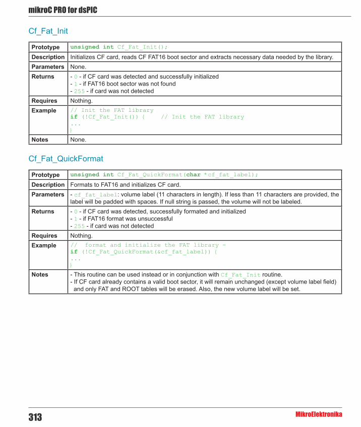
mikroC PRO for dsPIC
MikroElektronika313
Cf_Fat_Init
Cf_Fat_QuickFormat
Prototype unsigned int Cf_Fat_Init();
Description Initializes CF card, reads CF FAT16 boot sector and extracts necessary data needed by the library.Parameters None.Returns - 0 - if CF card was detected and successfully initialized
- 1 - if FAT16 boot sector was not found - 255 - if card was not detected
Requires Nothing.Example // Init the FAT library
if (!Cf_Fat_Init()) { // Init the FAT library...}
Notes None.
Prototype unsigned int Cf_Fat_QuickFormat(char *cf_fat_label);
Description Formats to FAT16 and initializes CF card.Parameters - cf_fat_label: volume label (11 characters in length). If less than 11 characters are provided, the
label will be padded with spaces. If null string is passed, the volume will not be labeled. Returns - 0 - if CF card was detected, successfully formated and initialized
- 1 - if FAT16 format was unsuccessful - 255 - if card was not detected
Requires Nothing.Example // format and initialize the FAT library -
if (!Cf_Fat_QuickFormat(&cf_fat_label)) {...}
Notes - This routine can be used instead or in conjunction with Cf_Fat_Init routine. - If CF card already contains a valid boot sector, it will remain unchanged (except volume label field) and only FAT and ROOT tables will be erased. Also, the new volume label will be set.

314
mikoC PRO for dsPIC
MikroElektronika
Cf_Fat_Assign
Prototype unsigned int Cf_Fat_Assign(char *filename, char file_cre_attr);
Description Assigns file for file operations (read, write, delete...). All subsequent file operations will be applied over the assigned file.
Parameters - filename: name of the file that should be assigned for file operations. The file name should be in DOS 8.3 (file_name.extension) format. The file name and extension will be automatically padded with spaces by the library if they have less than length required (i.e. “mikro.tx” -> “mikro .tx “), so the user does not have to take care of that. The file name and extension are case insensitive. The library will convert them to proper case automatically, so the user does not have to take care of that. Also, in order to keep backward compatibility with the first version of this library, file names can be entered as UPPERCASE string of 11 bytes in length with no dot character between the file name and extension (i.e. “MIKROELETXT” -> MIKROELE.TXT). In this case the last 3 characters of the string are considered to be file extension.
- file_cre_attr: file creation and attributes flags. Each bit corresponds to the appropriate file attribute:
Returns - 0 if file does not exist and no new file is created. - 1 if file already exists or file does not exist but a new file is created.
Requires CF card and CF library must be initialized for file operations. See Cf_Fat_Init. Example // create file with archive attributes if it does not already exist
Cf_Fat_Assign(“MIKRO007.TXT”,0xA0);
Notes Long File Names (LFN) are not supported.
Bit Mask Description0 0x01 Read Only1 0x02 Hidden2 0x04 System3 0x08 Volume Label4 0x10 Subdirectory5 0x20 Archive6 0x40 Device (internal use only, never found on disk)
7 0x80File creation flag. If the file does not exist and this flag is set, a new file with specified name will be
created.

mikroC PRO for dsPIC
MikroElektronika315
Cf_Fat_Reset
Cf_Fat_Read
Prototype void Cf_Fat_Reset(unsigned long *size);
Description Opens currently assigned file for reading.Parameters - size: buffer to store file size to. After file has been open for reading its size is returned through this
parameter. Returns Nothing.Requires CF card and CF library must be initialized for file operations. See Cf_Fat_Init.
File must be previously assigned. See Cf_Fat_Assign.Example unsigned long size;
...Cf_Fat_Reset(size);
Notes None.
Prototype void Cf_Fat_Read(unsigned short *bdata);
Description Reads a byte from currently assigned file opened for reading. Upon function execution file pointers will be set to the next character in the file.
Parameters - bdata: buffer to store read byte to. Upon this function execution read byte is returned through this parameter.
Returns Nothing.Requires CF card and CF library must be initialized for file operations. See Cf_Fat_Init.
File must be previously assigned. See Cf_Fat_Assign.
File must be open for reading. See Cf_Fat_Reset.
Example char character;...Cf_Fat_Read(&character);
Notes None.
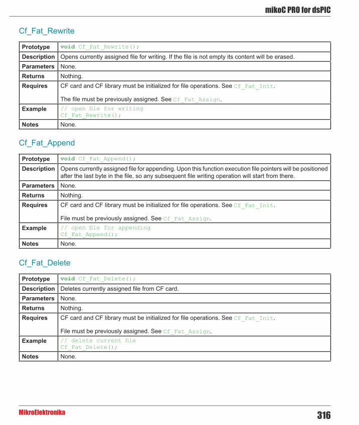
316
mikoC PRO for dsPIC
MikroElektronika
Cf_Fat_Rewrite
Cf_Fat_Append
Cf_Fat_Delete
Prototype void Cf_Fat_Rewrite();
Description Opens currently assigned file for writing. If the file is not empty its content will be erased.Parameters None.Returns Nothing.Requires CF card and CF library must be initialized for file operations. See Cf_Fat_Init.
The file must be previously assigned. See Cf_Fat_Assign.Example // open file for writing
Cf_Fat_Rewrite();
Notes None.
Prototype void Cf_Fat_Append();
Description Opens currently assigned file for appending. Upon this function execution file pointers will be positioned after the last byte in the file, so any subsequent file writing operation will start from there.
Parameters None.Returns Nothing.Requires CF card and CF library must be initialized for file operations. See Cf_Fat_Init.
File must be previously assigned. See Cf_Fat_Assign.Example // open file for appending
Cf_Fat_Append();
Notes None.
Prototype void Cf_Fat_Delete();
Description Deletes currently assigned file from CF card.Parameters None.Returns Nothing.Requires CF card and CF library must be initialized for file operations. See Cf_Fat_Init.
File must be previously assigned. See Cf_Fat_Assign.Example // delete current file
Cf_Fat_Delete();
Notes None.

mikroC PRO for dsPIC
MikroElektronika317
Cf_Fat_Write
Cf_Fat_Set_File_Date
Prototype void Cf_Fat_Write(char *fdata, unsigned data_len);
Description Writes requested number of bytes to currently assigned file opened for writing.Parameters - fdata: data to be written.
- data_len: number of bytes to be written. Returns Nothing.Requires CF card and CF library must be initialized for file operations. See Cf_Fat_Init.
File must be previously assigned. See Cf_Fat_Assign.
File must be open for writing. See Cf_Fat_Rewrite or Cf_Fat_Append.Example char file_contents[42];
...Cf_Fat_Write(file_contents, 42); // write data to the assigned file
Notes None.
Prototype void Cf_Fat_Set_File_Date(unsigned int year, unsigned short month, unsigned short day, unsigned short hours, unsigned short mins, unsigned short seconds);
Description Sets the date/time stamp. Any subsequent file writing operation will write this stamp to currently assigned file’s time/date attributes.
Parameters - year: year attribute. Valid values: 1980-2107 - month: month attribute. Valid values: 1-12 - day: day attribute. Valid values: 1-31 - hours: hours attribute. Valid values: 0-23 - mins: minutes attribute. Valid values: 0-59 - seconds: seconds attribute. Valid values: 0-59
Returns Nothing.Requires CF card and CF library must be initialized for file operations. See Cf_Fat_Init.
File must be previously assigned. See Cf_Fat_Assign.
File must be open for writing. See Cf_Fat_Rewrite or Cf_Fat_Append.Example Cf_Fat_Set_File_Date(2005,9,30,17,41,0);
Notes None.

318
mikoC PRO for dsPIC
MikroElektronika
Cf_Fat_Get_File_Date
Cf_Fat_Get_File_Date_Modified
Prototype void Cf_Fat_Get_File_Date(unsigned int *year, unsigned short *month, unsigned short *day, unsigned short *hours, unsigned short *mins);
Description Reads time/date attributes of currently assigned file.Parameters - year: buffer to store year attribute to. Upon function execution year attribute is returned through this
parameter. - month: buffer to store month attribute to. Upon function execution month attribute is returned through this parameter. - day: buffer to store day attribute to. Upon function execution day attribute is returned through this parameter. - hours: buffer to store hours attribute to. Upon function execution hours attribute is returned through this parameter. - mins: buffer to store minutes attribute to. Upon function execution minutes attribute is returned through this parameter.
Returns Nothing.Requires CF card and CF library must be initialized for file operations. See Cf_Fat_Init.
File must be previously assigned. See Cf_Fat_Assign.Example unsigned year;
char month, day, hours, mins;...Cf_Fat_Get_File_Date(&year, &month, &day, &hours, &mins);
Notes None.
Prototype void Cf_Fat_Get_File_Date_Modified(unsigned int *year, unsigned short *month, unsigned short *day, unsigned short *hours, unsigned short *mins);
Description Retrieves the last modification date/time of the currently assigned file.Parameters - year: buffer to store year of modification attribute to. Upon function execution year of modification
attribute is returned through this parameter. - month: buffer to store month of modification attribute to. Upon function execution month of modification attribute is returned through this parameter. - day: buffer to store day of modification attribute to. Upon function execution day of modification attribute is returned through this parameter. - hours: buffer to store hours of modification attribute to. Upon function execution hours of modification attribute is returned through this parameter. - mins: buffer to store minutes of modification attribute to. Upon function execution minutes of modification attribute is returned through this parameter.
Returns Nothing.Requires CF card and CF library must be initialized for file operations. See Cf_Fat_Init.
File must be previously assigned. See Cf_Fat_Assign.Example unsigned year;
char month, day, hours, mins;...Cf_Fat_Get_File_Date_Modified(&year, &month, &day, &hours, &mins);
Notes None.
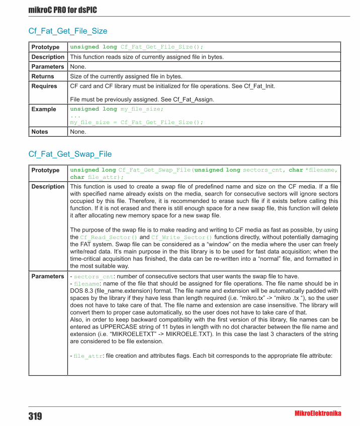
mikroC PRO for dsPIC
MikroElektronika319
Cf_Fat_Get_File_Size
Prototype unsigned long Cf_Fat_Get_File_Size();
Description This function reads size of currently assigned file in bytes. Parameters None.Returns Size of the currently assigned file in bytes.Requires CF card and CF library must be initialized for file operations. See Cf_Fat_Init.
File must be previously assigned. See Cf_Fat_Assign.Example unsigned long my_file_size;
...my_file_size = Cf_Fat_Get_File_Size();
Notes None.
Cf_Fat_Get_Swap_File
Prototype unsigned long Cf_Fat_Get_Swap_File(unsigned long sectors_cnt, char *filename, char file_attr);
Description This function is used to create a swap file of predefined name and size on the CF media. If a file with specified name already exists on the media, search for consecutive sectors will ignore sectors occupied by this file. Therefore, it is recommended to erase such file if it exists before calling this function. If it is not erased and there is still enough space for a new swap file, this function will delete it after allocating new memory space for a new swap file.
The purpose of the swap file is to make reading and writing to CF media as fast as possible, by using the Cf_Read_Sector() and Cf_Write_Sector() functions directly, without potentially damaging the FAT system. Swap file can be considered as a “window” on the media where the user can freely write/read data. It’s main purpose in the this library is to be used for fast data acquisition; when the time-critical acquisition has finished, the data can be re-written into a “normal” file, and formatted in the most suitable way.
Parameters - sectors_cnt: number of consecutive sectors that user wants the swap file to have. - filename: name of the file that should be assigned for file operations. The file name should be in DOS 8.3 (file_name.extension) format. The file name and extension will be automatically padded with spaces by the library if they have less than length required (i.e. “mikro.tx” -> “mikro .tx “), so the user does not have to take care of that. The file name and extension are case insensitive. The library will convert them to proper case automatically, so the user does not have to take care of that. Also, in order to keep backward compatibility with the first version of this library, file names can be entered as UPPERCASE string of 11 bytes in length with no dot character between the file name and extension (i.e. “MIKROELETXT” -> MIKROELE.TXT). In this case the last 3 characters of the string are considered to be file extension.
- file_attr: file creation and attributes flags. Each bit corresponds to the appropriate file attribute:

320
mikoC PRO for dsPIC
MikroElektronika
Parameters
Returns - Number of the start sector for the newly created swap file, if there was enough free space on CF card to create file of required size. - 0 - otherwise.
Requires CF card and CF library must be initialized for file operations. See Cf_Fat_Init.Example //-------------- Try to create a swap file with archive atribute, whose size
will be at least 1000 sectors.// If it succeeds, it sends the No. of start sector over UARTunsigned long size;...size = Cf_Fat_Get_Swap_File(1000, “mikroE.txt”, 0x20);if (size) { UART1_Write(0xAA); UART1_Write(Lo(size)); UART1_Write(Hi(size)); UART1_Write(Higher(size)); UART1_Write(Highest(size)); UART1_Write(0xAA);}
Notes Long File Names (LFN) are not supported.
Bit Mask Description0 0x01 Read Only1 0x02 Hidden2 0x04 System3 0x08 Volume Label4 0x10 Subdirectory5 0x20 Archive6 0x40 Device (internal use only, never found on disk)7 0x80 Not used

mikroC PRO for dsPIC
MikroElektronika321
Library Example
The following example writes 512 bytes at sector no.620, and then reads the data and sends it over UART1 for a visual check. Hardware configurations in this example are made for the dsPICPRO2 board and dsPIC30F6014A.
Copy Code To Clipboard
// set compact flash pinoutchar Cf_Data_Port at PORTF;
sbit CF_RDY at RD7_bit;sbit CF_WE at RD6_bit;sbit CF_OE at RD5_bit;sbit CF_CD1 at RD4_bit;sbit CF_CE1 at RD3_bit;sbit CF_A2 at RD2_bit;sbit CF_A1 at RD1_bit;sbit CF_A0 at RD0_bit;
sbit CF_RDY_direction at TRISD7_bit;sbit CF_WE_direction at TRISD6_bit;sbit CF_OE_direction at TRISD5_bit;sbit CF_CD1_direction at TRISD4_bit;sbit CF_CE1_direction at TRISD3_bit;sbit CF_A2_direction at TRISD2_bit;sbit CF_A1_direction at TRISD1_bit;sbit CF_A0_direction at TRISD0_bit;// end of cf pinout
char SignalPort at PORTB;char SignalPort_direction at TRISB;
void InitCF() { CF_CD1_direction = 1; while (Cf_Detect() == 0) // wait until CF card is inserted ; Cf_Init(); // initialize CF while (!CF_RDY) ; Delay_ms(2000); // wait for a while until the card is stabilized} // period depends on used CF card
void TestBytes() { unsigned int i;
///// Write numbers 0..511 to sector 590 Cf_Write_Init(590,1); // Initialize write at sector address 590 // for 1 sector SignalPort = 0x03; // Notify that write has started Delay_ms(1000); for (i=0; i<=511; i++) // Write 512 bytes to sector 590 Cf_Write_Byte(i);

322
mikoC PRO for dsPIC
MikroElektronika
SignalPort = 0x03; // Notify that write has started Delay_ms(1000); for (i=0; i<=511; i++) // Write 512 bytes to sector 590 Cf_Write_Byte(i);
SignalPort = 0x07; // Notify that write end and read start Delay_ms(1000);
Cf_Read_Init(590,1); // Initialize read from sector address 590 // for 1 sector for (i=0; i<=511; i++) { // Read 512 bytes from sector address 590 SignalPort = Cf_Read_Byte(); // Read one byte at time and display // readings on signal port Delay_ms(5); // Wait for a while to see results } Delay_ms(1000);
///// Write numbers 511..0 to sector 590 Cf_Write_Init(590,1); // Initialize write at sector address 590 // for 1 sector SignalPort = 0x03; // Notify that write has started Delay_ms(1000); for (i=0; i<=511; i++) // Write 512 bytes to sector 590 Cf_Write_Byte(511-i);
SignalPort = 0x07; // Notify that write end and read start Delay_ms(1000);
Cf_Read_Init(590,1); // Initialize read from sector address 590 // for 1 sector for (i=0; i<=511; i++) { // Read 512 bytes from sector address 590 SignalPort = Cf_Read_Byte(); // Read one byte at time and display // readings on signal port Delay_ms(5); // Wait for a while to see results } Delay_ms(1000);}
// Main programvoid main() {
ADPCFG = 0xFFFF; // disable A/D inputs
SignalPort_direction = 0; // designate PORTC as output SignalPort = 0x01; // Notify test start InitCF();
TestBytes(); SignalPort = 0x0F; // Notify test end}

mikroC PRO for dsPIC
MikroElektronika323
HW Connection
Pin diagram of CF memory card

324
mikoC PRO for dsPIC
MikroElektronika
ECAN LibraryThe mikroC PRO for dsPIC30/33 and PIC24 provides a library (driver) for working with the dsPIC33FJ and pic24HJ ECAN module.
ECAN is a very robust protocol that has error detection and signalling, self–checking and fault confinement. Faulty ECAN data and remote frames are re-transmitted automatically, similar to the Ethernet.
Data transfer rates depend on distance. For example, 1 Mbit/s can be achieved at network lengths below 40m while 250 Kbit/s can be achieved at network lengths below 250m. The greater distance the lower maximum bitrate that can be achieved . The lowest bitrate defined by the standard is 200Kbit/s. Cables used are shielded twisted pairs.
ECAN supports two message formats:
- Standard format, with 11 identifier bits, and - Extended format, with 29 identifier bits
ECAN message format and DMA RAM buffer definiton can be found in the ECan_Defs.h header file located in the ECAN project folder. Read this file carefully and make appropriate adjustments for mcu in use. Also, if a new project is to be created this file has to be copied, adjusted and included into the project via include pragma directive with corresponding Search Path updating.
Important :
ECAN buffers are located in DMA RAM, so two DMA channels are used for message transfer, one for each direction (ECAN->DMA RAM, DMA RAM->ECAN). See the ECANxDmaChannelInit routine. Consult CAN standard about CAN bus termination resistance. CAN library routines require you to specify the module you want to use. To select the desired CAN module, simply change the letter x in the routine prototype for a number from 1 to 2. Number of CAN modules per MCU differs from chip to chip. Please, read the appropriate datasheet before utilizing this library.
Library Routines
- ECANxDmaChannelInit - ECANxSetOperationMode - ECANxGetOperationMode - ECANxInitialize - ECANxSelectTxBuffers - ECANxFilterDisable - ECANxFilterEnable - ECANxSetBufferSize - ECANxSetBaudRate - ECANxSetMask - ECANxSetFilter - ECANxRead - ECANxWrite

mikroC PRO for dsPIC
MikroElektronika325
ECANxDmaChannelInit
ECANxSetOperationMode
Prototype unsigned ECANxDmaChannelInit(unsigned DmaChannel, unsigned ChannelDir, void *DmaRamBuffAdd);
Description The function preforms initialization of the DMA module for ECAN.Parameters - DmaChannel: DMA Channel number. Valid values: 0..7.
- ChannelDir: transfer direction. Valid values: 1 (DMA RAM to peripheral) and 0 (peripheral to DMA RAM). - DmaRamBuffAdd: DMA RAM buffer address. DMA RAM location is MCU dependent, refer to datasheet for valid address range.
Returns - 0 - if DMA channel parameter is valid - 0x0001 - if DMA channel is already in use (busy) - 0xFFFF - if DMA channel parameter is invalid
Requires The ECAN routines are supported only by MCUs with the ECAN module.
Microcontroller must be connected to ECAN transceiver which is connected to the ECAN bus.Example // channel 0 will transfer 8 words from DMA RAM at 0x4000 to ECAN1
ECAN1DmaChannelInit(0, 1, 0x4000);
Notes - ECAN library routine require you to specify the module you want to use. To select the desired ECAN module, simply change the letter x in the routine prototype for a number from 1 to 2. - Number of ECAN modules per MCU differs from chip to chip. Please, read the appropriate datasheet before utilizing this library.
Prototype void ECANxSetOperationMode(unsigned int mode, unsigned int WAIT);
Description Sets the ECAN module to requested mode.Parameters - mode: ECAN module operation mode. Valid values: ECAN_OP_MODE constants. See ECAN_OP_MODE
constants. - WAIT: ECAN mode switching verification request. If WAIT == 0, the call is non-blocking. The function does not verify if the ECAN module is switched to requested mode or not. Caller must use ECANxGetOperationMode to verify correct operation mode before performing mode specific operation. If WAIT != 0, the call is blocking – the function won’t “return” until the requested mode is set and no additional verification is necessary.
Returns Nothing.Requires The ECAN routines are supported only by MCUs with the ECAN module.
Microcontroller must be connected to ECAN transceiver which is connected to the ECAN bus.Example // set the ECAN1 module into configuration mode (wait inside ECAN1SetOperationMode
until this mode is set)ECAN1SetOperationMode(_ECAN_MODE_CONFIG, 0xFF);
Notes - ECAN library routine require you to specify the module you want to use. To select the desired ECAN module, simply change the letter x in the routine prototype for a number from 1 to 2. - Number of ECAN modules per MCU differs from chip to chip. Please, read the appropriate datasheet before utilizing this library.

326
mikoC PRO for dsPIC
MikroElektronika
ECANxGetOperationMode
Prototype unsigned int ECANxGetOperationMode();
Description The function returns current operation mode of the ECAN module. See ECAN_OP_MODE constants or device datasheet for operation mode codes.
Parameters None.Returns Current operation mode.Requires The ECAN routines are supported only by MCUs with the ECAN module.
Microcontroller must be connected to ECAN transceiver which is connected to the ECAN bus.Example // check whether the ECAN1 module is in Normal mode and if it is do
something.if (ECAN1GetOperationMode() == _ECAN_MODE_NORMAL){ ...}
Notes - ECAN library routine require you to specify the module you want to use. To select the desired ECAN module, simply change the letter x in the routine prototype for a number from 1 to 2. - Number of ECAN modules per MCU differs from chip to chip. Please, read the appropriate datasheet before utilizing this library.

mikroC PRO for dsPIC
MikroElektronika327
ECANxInitialize
Prototype void ECANxInitialize(unsigned int SJW, unsigned int BRP, unsigned int PHSEG1, unsigned int PHSEG2, unsigned int PROPSEG, unsigned int ECAN_CONFIG_FLAGS);
Description Initializes the ECAN module.
The internal ECAN module is set to:
- Disable ECAN capture - Continue ECAN operation in Idle mode - Abort all pending transmissions - Clear all transmit control registers - Fcan clock : Fcy (Fosc/2) - Baud rate is set according to given parameters - ECAN mode is set to Normal - Filter and mask registers remain unchanged
SAM, SEG2PHTS, WAKFIL and DBEN bits are set according to the ECAN_CONFIG_FLAGS value.Parameters - SJW as defined in MCU’s datasheet (ECAN Module)
- BRP as defined in MCU’s datasheet (ECAN Module) - PHSEG1 as defined in MCU’s datasheet (ECAN Module) - PHSEG2 as defined in MCU’s datasheet (ECAN Module) - PROPSEG as defined in MCU’s datasheet (ECAN Module) - ECAN_CONFIG_FLAGS ECAN module configuration flags. Each bit corresponds to the appropriate ECAN module parameter. Should be formed out of predefined ECAN flag constants. See ECAN_CONFIG_FLAGS constants.
Returns Nothing.Requires The ECAN routines are supported only by MCUs with the ECAN module.
Microcontroller must be connected to ECAN transceiver which is connected to the ECAN bus.Example // initialize the ECAN1 module with appropriate baud rate and message
acceptance flags along with the sampling rulesunsigned int ecan_config_flags;... ecan_config_flags = _ECAN_CONFIG_SAMPLE_THRICE & // Form value to be used _ECAN_CONFIG_PHSEG2_PRG_ON & // with ECANInitialize _ECAN_CONFIG_XTD_MSG & _ECAN_CONFIG_MATCH_MSG_TYPE & _ECAN_CONFIG_LINE_FILTER_OFF;
ECAN1Initialize(1, 3, 3, 3, 1, ecan_config_flags); // initialize the ECAN1 module
Notes - ECAN mode NORMAL will be set on exit. - ECAN library routine require you to specify the module you want to use. To select the desired ECAN module, simply change the letter x in the routine prototype for a number from 1 to 2. - Number of ECAN modules per MCU differs from chip to chip. Please, read the appropriate datasheet before utilizing this library.

328
mikoC PRO for dsPIC
MikroElektronika
ECANxSelectTxBuffers
ECANxFilterDisable
Prototype unsigned ECANxSelectTxBuffers(unsigned txselect);
Description The function designates the ECAN module’s transmit buffers.Parameters - txselect: transmit buffer select. By setting bits in the txselect lower byte corresponding buffers are
enabled for transmition. The ECAN module supports up to 8 transmit buffers. Also, by clearing bits in the txselect lower byte corresponding buffers are enabled for reception.
Returns - 0 - if input parameter is valid - 0xFFFF - if input parameter is invalid
Requires The ECAN routines are supported only by MCUs with the ECAN module.
Microcontroller must be connected to ECAN transceiver which is connected to the ECAN bus.
The ECAN module must be initialized. See the ECANxInitialize routine.Example // Buffers 0 and 2 are enabled for transmition:
ECAN1SelectTxBuffers(0x0005);
Notes - ECAN library routine require you to specify the module you want to use. To select the desired ECAN module, simply change the letter x in the routine prototype for a number from 1 to 2. - Number of ECAN modules per MCU differs from chip to chip. Please, read the appropriate datasheet before utilizing this library.
Prototype void ECANxFilterDisable(unsigned fltdis);
Description The function disables receive filters.Parameters - fltdis: filter disable selection parameter. Each bit corresponds to appropriate filter. By settung bit the
corresponding filter is to be disabled. Returns Nothing.Requires The ECAN routines are supported only by MCUs with the ECAN module.
Microcontroller must be connected to ECAN transceiver which is connected to the ECAN bus.
The ECAN module must be initialized. See the ECANxInitialize routine.Example // Buffers 0 and 2 are enabled for transmition:
ECAN1SelectTxBuffers(0x0005);
Notes - ECAN library routine require you to specify the module you want to use. To select the desired ECAN module, simply change the letter x in the routine prototype for a number from 1 to 2. - Number of ECAN modules per MCU differs from chip to chip. Please, read the appropriate datasheet before utilizing this library.

mikroC PRO for dsPIC
MikroElektronika329
ECANxFilterEnable
ECANxSetBufferSize
Prototype void ECANxFilterEnable(unsigned flten);
Description The function enables receive filters.Parameters - flten: filter enable selection parameter. Each bit corresponds to appropriate filter. By setting bit the
corresponding filter will be enabled. Returns Nothing.Requires The ECAN routines are supported only by MCUs with the ECAN module.
Microcontroller must be connected to ECAN transceiver which is connected to the ECAN bus.
The ECAN module must be initialized. See the ECANxInitialize routine.Example // Filters 0, 4, 8, 12 are to be enabled:
ECAN1FilterEnable(0x1111);
Notes - ECAN library routine require you to specify the module you want to use. To select the desired ECAN module, simply change the letter x in the routine prototype for a number from 1 to 2. - Number of ECAN modules per MCU differs from chip to chip. Please, read the appropriate datasheet before utilizing this library.
Prototype unsigned ECANxSetBufferSize(unsigned Ecan1BuffSize);
Description The function configures the total number of receive and transmit buffers in DMA RAM.Parameters - Ecan1BuffSize: Number of ECAN DMA RAM receive and transmit buffers. Valid values: 4, 6, 8,
12, 16, 24, 32. Each buffer is 16 bytes long. Returns - 0 - if input parameter is valid
- 0xFFFF - if input parameter is invalid Requires The ECAN routines are supported only by MCUs with the ECAN module.
Microcontroller must be connected to ECAN transceiver which is connected to the ECAN bus.
The ECAN module must be initialized. See the ECANxInitialize routine.Example // DMA RAM will have 16 rx+tx buffers
ECAN1SetBufferSize(16);
Notes - The same value should be used for DMA RAM buffer definition in the ECan_Defs.h header file located in the ECAN project folder. - ECAN library routine require you to specify the module you want to use. To select the desired ECAN module, simply change the letter x in the routine prototype for a number from 1 to 2. - Number of ECAN modules per MCU differs from chip to chip. Please, read the appropriate datasheet before utilizing this library.

330
mikoC PRO for dsPIC
MikroElektronika
ECANxSetBaudRate
Prototype void ECANxSetBaudRate(unsigned int SJW, unsigned int BRP, unsigned int PHSEG1, unsigned int PHSEG2, unsigned int PROPSEG, unsigned int ECAN_CONFIG_FLAGS);
Description Sets ECAN module baud rate. Due to complexity of the ECAN protocol, you can not simply force the bps value. Instead, use this function when ECAN is in Config mode. Refer to datasheet for details.
SAM, SEG2PHTS and WAKFIL bits are set according to the ECAN_CONFIG_FLAGS value.Parameters - SJW as defined in MCU’s datasheet (ECAN Module)
- BRP as defined in MCU’s datasheet (ECAN Module) - PHSEG1 as defined in MCU’s datasheet (ECAN Module) - PHSEG2 as defined in MCU’s datasheet (ECAN Module) - PROPSEG as defined in MCU’s datasheet (ECAN Module) - ECAN_CONFIG_FLAGS ECAN module configuration flags. Each bit corresponds to the appropriate ECAN module parameter. Should be formed out of predefined ECAN flag constants. See ECAN_CONFIG_FLAGS constants
Returns Nothing.Requires The ECAN routines are supported only by MCUs with the ECAN module.
Microcontroller must be connected to ECAN transceiver which is connected to the ECAN bus.
The ECAN module must be in Config mode, otherwise the function will be ignored. See ECANxSetOperationMode.
Example // set required baud rate and sampling rulesunsigned int ecan_config_flags;... ECAN1SetOperationMode(_ECAN_MODE_CONFIG,0xFF); // set CONFIGURATION mode (ECAN1 module mast be in config mode for baud rate settings)
ecan_config_flags = _ECAN_CONFIG_SAMPLE_THRICE & // Form value to be used _ECAN_CONFIG_PHSEG2_PRG_ON & // with ECAN1SetBaudRate _ECAN_CONFIG_XTD_MSG & _ECAN_CONFIG_MATCH_MSG_TYPE & _ECAN_CONFIG_LINE_FILTER_OFF; ECAN1SetBaudRate(1, 3, 3, 3, 1, ecan_config_flags); // set ECAN1 module baud rate
Notes - ECAN library routine require you to specify the module you want to use. To select the desired ECAN module, simply change the letter x in the routine prototype for a number from 1 to 2. - Number of ECAN modules per MCU differs from chip to chip. Please, read the appropriate datasheet before utilizing this library.

mikroC PRO for dsPIC
MikroElektronika331
ECANxSetMask
Prototype void ECANxSetMask(unsigned int ECAN_MASK, long val, unsigned int ECAN_CONFIG_FLAGS);
Description The function configures appropriate mask for advanced message filtering.Parameters - ECAN_MASK: ECAN module mask number. Valid values: ECAN_MASK constants. See ECAN_MASK
constants. - val: mask register value. This value is bit-adjusted to appropriate buffer mask registers - ECAN_CONFIG_FLAGS: selects type of messages to filter. Valid values: - _ECAN_CONFIG_ALL_VALID_MSG, - _ECAN_CONFIG_MATCH_MSG_TYPE & _ECAN_CONFIG_STD_MSG, - _ECAN_CONFIG_MATCH_MSG_TYPE & _ECAN_CONFIG_XTD_MSG.
See ECAN_CONFIG_FLAGS constants. Returns Nothing.Requires The ECAN routines are supported only by MCUs with the ECAN module.
Microcontroller must be connected to ECAN transceiver which is connected to the ECAN bus.
The ECAN module must be in Config mode, otherwise the function will be ignored. See ECANxSetOperationMode.
Example // set appropriate filter mask and message type valueECAN1SetOperationMode(_ECAN_MODE_CONFIG,0xFF); // set CONFIGURATION mode (ECAN1 module must be in config mode for mask settings)
// Set all mask0 bits to 1 (all filtered bits are relevant):// Note that -1 is just a cheaper way to write 0xFFFFFFFF.// Complement will do the trick and fill it up with ones.ECAN1SetMask(_ECAN_MASK_0, -1, _ECAN_CONFIG_MATCH_MSG_TYPE & _ECAN_CONFIG_XTD_MSG);
Notes - ECAN library routine require you to specify the module you want to use. To select the desired ECAN module, simply change the letter x in the routine prototype for a number from 1 to 2. - Number of ECAN modules per MCU differs from chip to chip. Please, read the appropriate datasheet before utilizing this library.

332
mikoC PRO for dsPIC
MikroElektronika
ECANxSetFilter
Prototype void ECANxSetFilter(unsigned int ECAN_FILTER, long val, unsigned int ECAN_FILTER_MASK, unsigned int ECAN_FILTER_RXBUFF, unsigned int ECAN_CONFIG_FLAGS);
Description The function configures and enables appropriate message filter.Parameters - ECAN_FILTER: ECAN module filter number. Valid values: ECAN_FILTER constants. See ECAN_
FILTER constants. - val: filter register value. This value is bit-adjusted to appropriate filter registers - ECAN_FILTER_MASK: mask register corresponding to filter. Valid values: ECAN_MASK constants. See ECAN_MASK constants. - ECAN_FILTER_RXBUFF: receive buffer corresponding to filter. Valid values: ECAN_RX_BUFFER constants. See ECAN_RX_BUFFER constants. - ECAN_CONFIG_FLAGS: selects type of messages to filter. Valid values: _ECAN_CONFIG_XTD_MSG and _ECAN_CONFIG_STD_MSG. See ECAN_CONFIG_FLAGS constants.
Returns Nothing.Requires The ECAN routines are supported only by MCUs with the ECAN module.
Microcontroller must be connected to ECAN transceiver which is connected to the ECAN bus.
The ECAN module must be in Config mode, otherwise the function will be ignored. See ECANxSetOperationMode.
Example // set appropriate filter value and message typeECAN1SetOperationMode(_ECAN_MODE_CONFIG,0xFF); // set CONFIGURATION mode (ECAN1 module must be in config mode for filter settings)
// Set id of filter 10 to 3, mask2, receive buffer 7, extended messages:ECAN1SetFilter(_ECAN_FILTER_10, 3, _ECAN_MASK_2, _ECAN_RX_BUFFER_7, _ECAN_CONFIG_XTD_MSG);
Notes ECAN library routine require you to specify the module you want to use. To select the desired ECAN module, simply change the letter x in the routine prototype for a number from 1 to 2. Number of ECAN modules per MCU differs from chip to chip. Please, read the appropriate datasheet before utilizing this library.

mikroC PRO for dsPIC
MikroElektronika333
ECANxRead
Prototype unsigned int ECANxRead(unsigned long *id, char *data, unsigned int *dataLen, unsigned int *ECAN_RX_MSG_FLAGS);
Description If at least one full Receive Buffer is found, it will be processed in the following way:
- Message ID is retrieved and stored to location pointed by the id pointer - Message data is retrieved and stored to array pointed by the data pointer - Message length is retrieved and stored to location pointed by the dataLen pointer - Message flags are retrieved and stored to location pointed by the ECAN_RX_MSG_FLAGS pointer
Parameters - id: message identifier address - data: an array of bytes up to 8 bytes in length - dataLen: data length address - ECAN_RX_MSG_FLAGS: message flags address. For message receive flags format refer to the ECAN_RX_MSG_FLAGS constants. See ECAN_RX_MSG_FLAGS constants.
Returns - 0 if none of Receive Buffers is full - 0xFFFF if at least one of Receive Buffers is full (message received)
Requires The ECAN routines are supported only by MCUs with the ECAN module.
Microcontroller must be connected to ECAN transceiver which is connected to the ECAN bus.
The ECAN module must be in a mode in which receiving is possible. See ECANxSetOperationMode.Example // check the ECAN1 module for received messages. If any was received do
something. unsigned int msg_rcvd, rx_flags, data_len;char data[8];unsigned long msg_id;...ECAN1SetOperationMode(_ECAN_MODE_NORMAL,0xFF); // set NORMAL mode (ECAN1 module must be in a mode in which receiving is possible)...rx_flags = 0; // clear message flagsif (msg_rcvd = ECAN1Read(&msg_id, data, &data_len, &rx_flags)) { ...}
Notes - ECAN library routine require you to specify the module you want to use. To select the desired ECAN module, simply change the letter x in the routine prototype for a number from 1 to 2. - Number of ECAN modules per MCU differs from chip to chip. Please, read the appropriate datasheet before utilizing this library.

334
mikoC PRO for dsPIC
MikroElektronika
ECANxWrite
Prototype unsigned int ECANxWrite(long id, char *Data, unsigned int DataLen, unsigned int ECAN_TX_MSG_FLAGS);
Description If at least one empty Transmit Buffer is found, the function sends message in the queue for transmission.
Parameters - id: ECAN message identifier. Valid values: all 11 or 29 bit values, depending on message type (standard or extended) - Data: data to be sent - DataLen: data length. Valid values: 0..8 - ECAN_TX_MSG_FLAGS: message flags. Valid values: ECAN_TX_MSG_FLAGS constants. See ECAN_TX_MSG_FLAGS constants.
Returns - 0 if all Transmit Buffers are busy - 0xFFFF if at least one Transmit Buffer is empty and available for transmition
Requires The ECAN routines are supported only by MCUs with the ECAN module.
Microcontroller must be connected to ECAN transceiver which is connected to the ECAN bus.
The ECAN module must be in a mode in which transmission is possible. See ECANxSetOperationMode.
Example // send message extended ECAN message with appropriate ID and dataunsigned int tx_flags;char data[8];unsigned long msg_id;...ECAN1SetOperationMode(_ECAN_MODE_NORMAL,0xFF); // set NORMAL mode (ECAN1 must be in a mode in which transmission is possible)
tx_flags = _ECAN_TX_PRIORITY_0 & _ECAN_TX_XTD_FRAME & _ECAN_TX_NO_RTR_FRAME; // set message flagsECAN1Write(msg_id, data, 1, tx_flags);
Notes - ECAN library routine require you to specify the module you want to use. To select the desired ECAN module, simply change the letter x in the routine prototype for a number from 1 to 2. - Number of ECAN modules per MCU differs from chip to chip. Please, read the appropriate datasheet before utilizing this library.

mikroC PRO for dsPIC
MikroElektronika335
ECAN Constants
There is a number of constants predefined in the ECAN library. You need to be familiar with them in order to be able to use the library effectively. Check the example at the end of the chapter.
ECAN_OP_MODE Constants
The ECAN_OP_MODE constants define ECAN operation mode. The routine ECANxSetOperationMode expect one of these as their argument:
Copy Code To Clipboard
const unsigned int _ECAN_MODE_BITS = 0x00E0, // Use this to access opmode bits _ECAN_MODE_NORMAL = 0x00, _ECAN_MODE_DISABLE = 0x01, _ECAN_MODE_LOOP = 0x02, _ECAN_MODE_LISTEN = 0x03, _ECAN_MODE_CONFIG = 0x04, _ECAN_MODE_LISTEN_ALL = 0x07;
ECAN_CONFIG_FLAGS Constants
The ECAN_CONFIG_FLAGS constants define flags related to the ECAN module configuration. The routines ECANxInitialize and ECANxSetBaudRate expect one of these (or a bitwise combination) as their argument:
Copy Code To Clipboard
const unsigned int _ECAN_CONFIG_DEFAULT = 0xFF, // 11111111
_ECAN_CONFIG_PHSEG2_PRG_BIT = 0x01, _ECAN_CONFIG_PHSEG2_PRG_ON = 0xFF, // XXXXXXX1 _ECAN_CONFIG_PHSEG2_PRG_OFF = 0xFE, // XXXXXXX0
_ECAN_CONFIG_LINE_FILTER_BIT = 0x02, _ECAN_CONFIG_LINE_FILTER_ON = 0xFF, // XXXXXX1X _ECAN_CONFIG_LINE_FILTER_OFF = 0xFD, // XXXXXX0X
_ECAN_CONFIG_SAMPLE_BIT = 0x04, _ECAN_CONFIG_SAMPLE_ONCE = 0xFF, // XXXXX1XX _ECAN_CONFIG_SAMPLE_THRICE = 0xFB, // XXXXX0XX
_ECAN_CONFIG_MSG_TYPE_BIT = 0x08, _ECAN_CONFIG_STD_MSG = 0xFF, // XXXX1XXX _ECAN_CONFIG_XTD_MSG = 0xF7, // XXXX0XXX _ECAN_CONFIG_MATCH_TYPE_BIT = 0x20, _ECAN_CONFIG_ALL_VALID_MSG = 0xDF, // XX0XXXXX _ECAN_CONFIG_MATCH_MSG_TYPE = 0xFF; // XX1XXXXX

336
mikoC PRO for dsPIC
MikroElektronika
You may use bitwise AND (&) to form config word out of these values. For example:
Copy Code To Clipboard
init = _ECAN_CONFIG_SAMPLE_THRICE & _ECAN_CONFIG_PHSEG2_PRG_ON & _ECAN_CONFIG_STD_MSG & _ECAN_CONFIG_MATCH_MSG_TYPE & _ECAN_CONFIG_LINE_FILTER_OFF;...ECAN1Initialize(1, 1, 3, 3, 1, init); // initialize ECAN1
ECAN_TX_MSG_FLAGS Constants
ECAN_TX_MSG_FLAGS are flags related to transmission of ECAN message. The routine ECANxWrite expect one of these (or a bitwise combination) as their argument:
Copy Code To Clipboard
const unsigned int _ECAN_TX_PRIORITY_BITS = 0x03, _ECAN_TX_PRIORITY_0 = 0xFC, // XXXXXX00 _ECAN_TX_PRIORITY_1 = 0xFD, // XXXXXX01 _ECAN_TX_PRIORITY_2 = 0xFE, // XXXXXX10 _ECAN_TX_PRIORITY_3 = 0xFF, // XXXXXX11
_ECAN_TX_FRAME_BIT = 0x08, _ECAN_TX_STD_FRAME = 0xFF, // XXXXX1XX _ECAN_TX_XTD_FRAME = 0xF7, // XXXXX0XX
_ECAN_TX_RTR_BIT = 0x40, _ECAN_TX_NO_RTR_FRAME = 0xFF, // X1XXXXXX _ECAN_TX_RTR_FRAME = 0xBF; // X0XXXXXX
You may use bitwise AND (&) to adjust the appropriate flags. For example:
Copy Code To Clipboard
// form value to be used with CANSendMessage: send_config = _ECAN_TX_PRIORITY_0 & _ECAN_TX_XTD_FRAME & _ECAN_TX_NO_RTR_FRAME;...ECAN1SendMessage(id, data, 1, send_config);
ECAN_RX_MSG_FLAGS Constants
ECAN_RX_MSG_FLAGS are flags related to reception of ECAN message. If a particular bit is set then corresponding meaning is TRUE or else it will be FALSE.

mikroC PRO for dsPIC
MikroElektronika337
Copy Code To Clipboard
const unsigned int _ECAN_RX_FILTER_BITS = 0x000F, // Use this to access filter bits _ECAN_RX_FILTER_0 = 0x00, // filter0 match _ECAN_RX_FILTER_1 = 0x01, // filter1 match _ECAN_RX_FILTER_2 = 0x02, // ... _ECAN_RX_FILTER_3 = 0x03, _ECAN_RX_FILTER_4 = 0x04, _ECAN_RX_FILTER_5 = 0x05, _ECAN_RX_FILTER_6 = 0x06, _ECAN_RX_FILTER_7 = 0x07, _ECAN_RX_FILTER_8 = 0x08, _ECAN_RX_FILTER_9 = 0x09, _ECAN_RX_FILTER_10 = 0x0A, _ECAN_RX_FILTER_11 = 0x0B, _ECAN_RX_FILTER_12 = 0x0C, _ECAN_RX_FILTER_13 = 0x0D, _ECAN_RX_FILTER_14 = 0x0E, // ... _ECAN_RX_FILTER_15 = 0x0F, // filter15 match
_ECAN_RX_OVERFLOW = 0x10, // Set if Overflowed else cleared _ECAN_RX_INVALID_MSG = 0x20, // Set if invalid else cleared _ECAN_RX_XTD_FRAME = 0x40, // Set if XTD message else cleared _ECAN_RX_RTR_FRAME = 0x80; // Set if RTR message else cleared
You may use bitwise AND (&) to extract received message status. For example:
Copy Code To Clipboard
if (MsgFlag & _ECAN_RX_OVERFLOW != 0) { ... // Receiver overflow has occurred. // We have lost our previous message.}
ECAN_MASK Constants
The ECAN_MASK constants define mask codes. The routine ECANxSetMask expect one of these as their argument:
Copy Code To Clipboard
const unsigned int _ECAN_MASK_0 = 0, _ECAN_MASK_1 = 1, _ECAN_MASK_2 = 2;
ECAN_FILTER Constants
The ECAN_FILTER constants define filter codes. The routine ECANxSetFilter expect one of these as their argument:

338
mikoC PRO for dsPIC
MikroElektronika
Copy Code To Clipboard
const unsigned int _ECAN_FILTER_0 = 0, _ECAN_FILTER_1 = 1, _ECAN_FILTER_2 = 2, _ECAN_FILTER_3 = 3, _ECAN_FILTER_4 = 4, _ECAN_FILTER_5 = 5, _ECAN_FILTER_6 = 6, _ECAN_FILTER_7 = 7, _ECAN_FILTER_8 = 8, _ECAN_FILTER_9 = 9, _ECAN_FILTER_10 = 10, _ECAN_FILTER_11 = 11, _ECAN_FILTER_12 = 12, _ECAN_FILTER_13 = 13, _ECAN_FILTER_14 = 14, _ECAN_FILTER_15 = 15;
ECAN_RX_BUFFER Constants
The ECAN_RX_BUFFER constants define RX bufer codes codes. The routine ECANxSetFilter expect one of these as their argument:
Copy Code To Clipboard
const unsigned int _ECAN_RX_BUFFER_0 = 0, _ECAN_RX_BUFFER_1 = 1, _ECAN_RX_BUFFER_2 = 2, _ECAN_RX_BUFFER_3 = 3, _ECAN_RX_BUFFER_4 = 4, _ECAN_RX_BUFFER_5 = 5, _ECAN_RX_BUFFER_6 = 6, _ECAN_RX_BUFFER_7 = 7, _ECAN_RX_BUFFER_8 = 8, _ECAN_RX_BUFFER_9 = 9, _ECAN_RX_BUFFER_10 = 10, _ECAN_RX_BUFFER_11 = 11, _ECAN_RX_BUFFER_12 = 12, _ECAN_RX_BUFFER_13 = 13, _ECAN_RX_BUFFER_14 = 14, _ECAN_RX_BUFFER_15 = 15;

mikroC PRO for dsPIC
MikroElektronika339
Library Example
The example demonstrates ECAN protocol. The 1st node initiates the communication with the 2nd node by sending some data to its address. The 2nd node responds by sending back the data incremented by 1. The 1st node then does the same and sends incremented data back to the 2nd node, etc.
Code for the first ECAN node:
Copy Code To Clipboard
#include “ECAN_Defs.h”
unsigned int Can_Init_Flags, Can_Send_Flags, Can_Rcv_Flags; // can flagsunsigned int Rx_Data_Len; // received data length in byteschar RxTx_Data[8]; // can rx/tx data bufferchar Msg_Rcvd; // reception flagunsigned long Tx_ID, Rx_ID; // can rx and tx ID
void C1Interrupt(void) org 0x005A { // ECAN event iterrupt IFS2bits.C1IF = 0; // clear ECAN interrupt flag if(C1INTFbits.TBIF) { // was it tx interrupt? C1INTFbits.TBIF = 0; // if yes clear tx interrupt flag }
if(C1INTFbits.RBIF) { // was it rx interrupt? C1INTFbits.RBIF = 0; // if yes clear rx interrupt flag }}
void main() {
// Set PLL : Fosc = ((Fin/PLLPRE)*PLLDIV)/PLLPOST ; (((10MHz/2)*32)/4) = 20MHz // refer the pic24 family datasheet for more details CLKDIV &= 0xFFE0; //CLKDIVbits.PLLPRE = 0; PLLFBD = 0x1E; //PLLFBDbits.PLLDIV = 0x1E; CLKDIV &= 0xFF3F; //CLKDIVbits.PLLPOST = 1; CLKDIV |= 0x00C0;
AD1PCFGH = 0xFFFF; // AD1PCFGL = 0xFFFF; // all ports digital I/O AD2PCFGL = 0xFFFF; //
/* Clear Interrupt Flags */
IFS0=0; IFS1=0; IFS2=0; IFS3=0; IFS4=0;
/* Enable ECAN1 Interrupt */

340
mikoC PRO for dsPIC
MikroElektronika
IEC2bits.C1IE = 1; // enable ECAN1 interrupts C1INTEbits.TBIE = 1; // enable ECAN1 tx interrupt C1INTEbits.RBIE = 1; // enable ECAN1 rx interrupt
PORTB = 0; // clear PORTB TRISB = 0; // set PORTB as output, // for received message data displaying
Can_Init_Flags = 0; // Can_Send_Flags = 0; // clear flags Can_Rcv_Flags = 0; //
Can_Send_Flags = _ECAN_TX_PRIORITY_0 & // Form value to be used _ECAN_TX_XTD_FRAME & // with CANSendMessage _ECAN_TX_NO_RTR_FRAME;
Can_Init_Flags = _ECAN_CONFIG_SAMPLE_THRICE & // Form value to be used _ECAN_CONFIG_PHSEG2_PRG_ON & // with CANInitialize _ECAN_CONFIG_XTD_MSG & _ECAN_CONFIG_MATCH_MSG_TYPE & _ECAN_CONFIG_LINE_FILTER_OFF;
RxTx_Data[0] = 9; // set initial data to be sent ECAN1DmaChannelInit(0, 1, &ECAN1RxTxRAMBuffer); // init dma channel 0 for // dma to ECAN peripheral transfer ECAN1DmaChannelInit(2, 0, &ECAN1RxTxRAMBuffer); // init dma channel 2 for // ECAN peripheral to dma transfer ECAN1Initialize(1, 3, 3, 3, 1, Can_Init_Flags); // initialize ECAN ECAN1SetBufferSize(ECAN1RAMBUFFERSIZE); // set number of rx+tx buffers in DMA RAM
ECAN1SelectTxBuffers(0x000F); // select transmit buffers // 0x000F = buffers 0:3 are transmit buffers ECAN1SetOperationMode(_ECAN_MODE_CONFIG,0xFF); // set CONFIGURATION mode
ECAN1SetMask(_ECAN_MASK_0, -1, _ECAN_CONFIG_MATCH_MSG_TYPE & _ECAN_CONFIG_XTD_MSG); // set all mask1 bits to ones ECAN1SetMask(_ECAN_MASK_1, -1, _ECAN_CONFIG_MATCH_MSG_TYPE & _ECAN_CONFIG_XTD_MSG); // set all mask2 bits to ones ECAN1SetMask(_ECAN_MASK_2, -1, _ECAN_CONFIG_MATCH_MSG_TYPE & _ECAN_CONFIG_XTD_MSG); // set all mask3 bits to ones ECAN1SetFilter(_ECAN_FILTER_10, 3, _ECAN_MASK_2, _ECAN_RX_BUFFER_7, _ECAN_CONFIG_XTD_MSG); // set id of filter10 to 3, // assign mask2 to filter10 // assign buffer7 to filter10 ECAN1SetOperationMode(_ECAN_MODE_NORMAL, 0xFF); // set NORMAL mode
Tx_ID = 12111; // set transmit ID

mikroC PRO for dsPIC
MikroElektronika341
ECAN1Write(Tx_ID, RxTx_Data, 1, Can_Send_Flags); // send initial message
while (1) { // endless loop Msg_Rcvd = ECAN1Read(&Rx_ID , RxTx_Data , &Rx_Data_Len, &Can_Rcv_Flags); // receive message if ((Rx_ID == 3u) && Msg_Rcvd) { // if message received check id PORTB = RxTx_Data[0]; // id correct, output data at PORTB RxTx_Data[0]++ ; // increment received data Delay_ms(10); ECAN1Write(Tx_ID, RxTx_Data, 1, Can_Send_Flags); // send incremented data back } }}
Code for the second ECAN node:
Copy Code To Clipboard
#include "__Lib_ECAN1_Defs.h"
unsigned int Can_Init_Flags, Can_Send_Flags, Can_Rcv_Flags; // can flagsunsigned int Rx_Data_Len; // received data length in byteschar RxTx_Data[8]; // can rx/tx data bufferchar Msg_Rcvd; // reception flagunsigned long Tx_ID, Rx_ID; // can rx and tx ID
void C1Interrupt(void) org 0x005A { // ECAN event iterrupt IFS2bits.C1IF = 0; // clear ECAN interrupt flag if(C1INTFbits.TBIF) { // was it tx interrupt? C1INTFbits.TBIF = 0; // if yes clear tx interrupt flag }
if(C1INTFbits.RBIF) { // was it rx interrupt? C1INTFbits.RBIF = 0; // if yes clear rx interrupt flag }}
void main() {
// Set PLL : Fosc = ((Fin/PLLPRE)*PLLDIV)/PLLPOST ; (((10MHz/2)*32)/4) = 20MHz // refer the pic24 family datasheet for more details CLKDIV &= 0xFFE0; //CLKDIVbits.PLLPRE = 0; PLLFBD = 0x1E; //PLLFBDbits.PLLDIV = 0x1E; CLKDIV &= 0xFF3F; //CLKDIVbits.PLLPOST = 1; CLKDIV |= 0x00C0;
AD1PCFGH = 0xFFFF; // AD1PCFGL = 0xFFFF; // all ports digital I/O AD2PCFGL = 0xFFFF; //

342
mikoC PRO for dsPIC
MikroElektronika
/* Enable ECAN1 Interrupt */ IEC2bits.C1IE = 1; // enable ECAN1 interrupt C1INTEbits.TBIE = 1; // enable ECAN1 tx interrupt C1INTEbits.RBIE = 1; // enable ECAN1 rx interrupt
PORTB = 0; // clear PORTB TRISB = 0; // set PORTB as output, // for received message data displaying
Can_Init_Flags = 0; // Can_Send_Flags = 0; // clear flags Can_Rcv_Flags = 0; //
Can_Send_Flags = _ECAN_TX_PRIORITY_0 & // Form value to be used _ECAN_TX_XTD_FRAME & // with CANSendMessage _ECAN_TX_NO_RTR_FRAME;
Can_Init_Flags = _ECAN_CONFIG_SAMPLE_THRICE & // Form value to be used _ECAN_CONFIG_PHSEG2_PRG_ON & // with CANInitialize _ECAN_CONFIG_XTD_MSG & _ECAN_CONFIG_MATCH_MSG_TYPE & _ECAN_CONFIG_LINE_FILTER_OFF;
ECAN1DmaChannelInit(0, 1, &ECAN1RxTxRAMBuffer); // init dma channel 0 for // dma to ECAN peripheral transfer ECAN1DmaChannelInit(2, 0, &ECAN1RxTxRAMBuffer); // init dma channel 2 for // ECAN peripheral to dma transfer ECAN1Initialize(1, 3, 3, 3, 1, Can_Init_Flags); // initialize ECAN ECAN1SetBufferSize(ECAN1RAMBUFFERSIZE); // set number of rx+tx buffers in DMA RAM
ECAN1SelectTxBuffers(0x000F); // select transmit buffers // 0x000F = buffers 0:3 are transmit buffers ECAN1SetOperationMode(_ECAN_MODE_CONFIG,0xFF); // set CONFIGURATION mode
ECAN1SetMask(_ECAN_MASK_0, -1, _ECAN_CONFIG_MATCH_MSG_TYPE & _ECAN_CONFIG_XTD_MSG); // set all mask1 bits to ones ECAN1SetMask(_ECAN_MASK_1, -1, _ECAN_CONFIG_MATCH_MSG_TYPE & _ECAN_CONFIG_XTD_MSG); // set all mask2 bits to ones ECAN1SetMask(_ECAN_MASK_2, -1, _ECAN_CONFIG_MATCH_MSG_TYPE & _ECAN_CONFIG_XTD_MSG); // set all mask3 bits to ones ECAN1SetFilter(_ECAN_FILTER_10, 12111, _ECAN_MASK_2, _ECAN_RX_BUFFER_7, _ECAN_CONFIG_XTD_MSG); // set id of filter10 to 12111, // assign mask2 to filter10 // assign buffer7 to filter10 ECAN1SetOperationMode(_ECAN_MODE_NORMAL,0xFF); // set NORMAL mode
Tx_ID = 3; // set tx ID
while (1) { Msg_Rcvd = ECAN1Read(&Rx_ID , RxTx_Data , &Rx_Data_Len, &Can_Rcv_Flags); // receive message if ((Rx_ID == 12111u) && Msg_Rcvd) { // if message received check id PORTB = RxTx_Data[0]; // id correct, output data at PORTB RxTx_Data[0]++ ; // increment received data ECAN1Write(Tx_ID, RxTx_Data, 1, Can_Send_Flags); // send incremented data back } }}

mikroC PRO for dsPIC
MikroElektronika343
HW Connection
Example of interfacing ECAN transceiver with MCU and bus
EEPROM LibraryEEPROM data memory is available with a number of dsPIC30 family and some PIC24 family MCU's. The mikroC PRO for dsPIC30/33 and PIC24 includes a library for comfortable work with MCU's internal EEPROM.
Important : Only PIC24F08KA102 and PIC24F16KA102 of PIC24 family of MCUs have EEPROM memory.
Library Routines
- EEPROM_Erase - EEPROM_Erase_Block - EEPROM_Read - EEPROM_Write - EEPROM_Write_Block
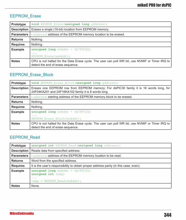
344
mikoC PRO for dsPIC
MikroElektronika
EEPROM_Erase
EEPROM_Erase_Block
EEPROM_Read
Prototype void EEPROM_Erase(unsigned long address);
Description Erases a single (16-bit) location from EEPROM memory.Parameters - address: address of the EEPROM memory location to be erased. Returns Nothing.Requires Nothing.Example unsigned long eeAddr = 0x7FFC80;
...EEPROM_Erase(eeAddr);
Notes CPU is not halted for the Data Erase cycle. The user can poll WR bit, use NVMIF or Timer IRQ to detect the end of erase sequence.
Prototype void EEPROM_Erase_Block(unsigned long address);
Description Erases one EEPROM row from EEPROM memory; For dsPIC30 family it is 16 words long, for 24F04KA201 and 24F16KA102 family it is 8 words long.
Parameters - address: starting address of the EEPROM memory block to be erased. Returns Nothing.Requires Nothing.Example unsigned long eeAddr = 0x7FFC20;
...EEPROM_Erase_Block(eeAddr);
Notes CPU is not halted for the Data Erase cycle. The user can poll WR bit, use NVMIF or Timer IRQ to detect the end of erase sequence.
Prototype unsigned int EEPROM_Read(unsigned long address);
Description Reads data from specified address.Parameters - address: address of the EEPROM memory location to be read. Returns Word from the specified address.Requires It is the user’s responsibility to obtain proper address parity (in this case, even).Example unsigned long eeAddr = 0x7FFC20;
unsigned int temp;...temp = EEPROM_Read(eeAddr);
Notes None.

mikroC PRO for dsPIC
MikroElektronika345
EEPROM_Write
EEPROM_Write_Block
Prototype void EEPROM_Write(unsigned long address, unsigned int data_);
Description Writes data to specified address.Parameters - address: address of the EEPROM memory location to be written.
- data: data to be written. Returns Nothing.Requires Nothing.Example unsigned int eeWrite = 0xAAAA;
unsigned long wrAddr = 0x7FFC30;...EEPROM_Write(wrAddr, eeWrite);
Notes Specified memory location will be erased before writing starts.
Prototype void EEPROM_Write_Block(unsigned long address, unsigned int *data);
Description Writes one EEPROM row (16 words block) of data. Parameters - address: starting address of the EEPROM memory block to be written.
- data: data block to be written. Returns Nothing.Requires It is the user’s responsibility to maintain proper address alignment. In this case, address has to be a
multiply of 32, which is the size (in bytes) of one row of MCU’s EEPROM memory.Example unsigned int eeWrite = 0xAAAA;
unsigned long wrAddr = 0x7FFC30;...EEPROM_Write(wrAddr, eeWrite);
Notes Specified memory block will be erased before writing starts. This routine is not applicable to the 24F04KA201 and 24F16KA102 family of MCUs, due to the architecture specifics.
Library Example
This project demonstrates usage of EEPROM library functions for dsPIC30F4013. Each EEPROM (16-bit) location can be written to individually, or in 16-word blocks, which is somewhat faster than the former. If Writing in blocks, EEPROM data start address must be a multiply of 16. Please read Help for more details on the library functions!
Copy Code To Clipboard
unsigned int eeData;unsigned long eeAddr;unsigned int dArr[16];
void main() {
unsigned i;

346
mikoC PRO for dsPIC
MikroElektronika
ADPCFG = 0xFFFF; // Disable analog inputs TRISB = 0; // PORTB as output LATB = 0xFFFF; eeAddr = 0x7FFC00; // Start address of EEPROM eeData = 0; // Data to be written
while (eeData <= 0x00FF) { EEPROM_Write(eeAddr, eeData++); // Write data into EEPROM while(WR_bit); // Wait for write to finish, LATB = EEPROM_Read(eeAddr); // then, read the just-written // data. eeAddr += 2; // Next address of EEPROM memory location
Delay_ms(30); }
Delay_ms(1000); // Wait 1 second. eeData = 0xAAAA; for (i=0; i<16; i++){ // Initializing array of 16 integers with data dArr[i] = eeData; eeData = ~eeData; }
EEPROM_Write_Block(0x7FFC20, dArr); // Write entire row of EEPROM data while(WR_bit) ; // Wait for write to finish
eeAddr = 0x7FFC20; // Address of EEPROM where reading should start for (i=0; i<16; i++){ // Read the data back LATB = EEPROM_Read(eeAddr); // and show it on PORTB eeAddr += 2; // Next address of EEPROM memory location Delay_ms(500); }}

mikroC PRO for dsPIC
MikroElektronika347
Epson S1D13700 Graphic Lcd LibraryThe mikroC PRO for dsPIC30/33 and PIC24 provides a library for working with Glcds based on Epson S1D13700 controller.
The S1D13700 Glcd is capable of displaying both text and graphics on an LCD panel. The S1D13700 Glcd allows layered text and graphics, scrolling of the display in any direction, and partitioning of the display into multiple screens. It includes 32K bytes of embedded SRAM display memory which is used to store text, character codes, and bit-mapped graphics.
The S1D13700 Glcd handles display controller functions including :
- Transferring data from the controlling microprocessor to the buffer memory - Reading memory data, converting data to display pixels - Generating timing signals for the LCD panel
The S1D13700 Glcd is designed with an internal character generator which supports 160, 5x7 pixel characters in internal mask ROM (CGROM) and 64, 8x8 pixel characters incharacter generator RAM (CGRAM). When the CGROM is not used, up to 256, 8x16 pixel characters are supported in CGRAM.
External dependencies of the Epson S1D13700 Graphic Lcd Library
The following variables must be defined in all projects using S1D13700 Graphic Lcd library:
Description : Example :
extern sfr char S1D13700_DATA; System data bus. char S1D13700_DATA at PORTD;
extern sfr sbit S1D13700_WR; Write signal. sbit S1D13700_WR at LATC2_bit;
extern sfr sbit S1D13700_RD; Read signal. sbit S1D13700_RD at LATC1_bit;
extern sfr sbit S1D13700_A0; System Address pin. sbit S1D13700_A0 at LATC0_bit;
extern sfr sbit S1D13700_RES; Reset signal. sbit S1D13700_RES at LATC4_bit;
extern sfr sbit S1D13700_CS; Chip select. sbit S1D13700_CS at LATC4_bit;
extern sfr sbit S1D13700_DATA_Direction;
Direction of the system data bus pins.
sbit S1D13700_DATA_Direction at TRISD;
extern sfr sbit S1D13700_WR_Direction; Direction of the Write pin. sbit S1D13700_WR_Direction at
TRISC2_bit;
extern sfr sbit S1D13700_RD_Direction; Direction of the Read pin. sbit S1D13700_RD_Direction at
TRISC1_bit;
extern sfr sbit S1D13700_A0_Direction;
Direction of the System Address pin.
sbit S1D13700_A0_Direction at TRISC2_bit;
extern sfr sbit S1D13700_RES_Direction; Direction of the Reset pin. sbit S1D13700_RES_Direction at
TRISC0_bit;
extern sfr sbit S1D13700_CS_Direction;
Direction of the Chip select pin.
sbit S1D13700_CS_Direction at TRISC4_bit;

348
mikoC PRO for dsPIC
MikroElektronika
Library Routines
- S1D13700_Init - S1D13700_Write_Command - S1D13700_Write_Parameter - S1D13700_Read_Parameter - S1D13700_Fill - S1D13700_GrFill - S1D13700_TxtFill - S1D13700_Display_GrLayer - S1D13700_Display_TxtLayer - S1D13700_Set_Cursor - S1D13700_Display_Cursor - S1D13700_Write_Char - S1D13700_Write_Text - S1D13700_Dot - S1D13700_Line - S1D13700_H_Line - S1D13700_V_Line - S1D13700_Rectangle - S1D13700_Box - S1D13700_Rectangle_Round_Edges - S1D13700_Rectangle_Round_Edges_Fill - S1D13700_Circle - S1D13700_Circle_Fill - S1D13700_Image - S1D13700_PartialImage

mikroC PRO for dsPIC
MikroElektronika349
S1D13700_Init
Prototype void S1D13700_Init(unsigned int width, unsigned char height);
Returns Nothing.Description Initializes S1D13700 Graphic Lcd controller.
Parameters :
- width: width of the Glcd panel. - height: height of the Glcd panel.
Requires Global variables :
- S1D13700_Data_Port: Data Bus Port. - S1D13700_WR: Write signal pin. - S1D13700_RD: Read signal pin. - S1D13700_A0: Command/Data signal pin. - S1D13700_RES: Reset signal pin. - S1D13700_CS: Chip Select signal pin.
- S1D13700_Data_Port_Direction: Data Bus Port Direction. - S1D13700_WR_Direction: Direction of Write signal pin. - S1D13700_RD_Direction: Direction of Read signal pin. - S1D13700_A0_Direction: Direction of Command/Data signal pin. - S1D13700_RES_Direction: Direction of Reset signal pin. - S1D13700_CS_Direction: Direction of Chip Select signal pin.
must be defined before using this function.Example // S1D13700 module connections
char S1D13700_Data_Port at PORTD;sbit S1D13700_WR at LATC2_bit;sbit S1D13700_RD at LATC1_bit;sbit S1D13700_A0 at LATC0_bit;sbit S1D13700_RES at LATC4_bit;sbit S1D13700_CS at LATC5_bit;
char S1D13700_Data_Port_Direction at TRISD;sbit S1D13700_WR_Direction at TRISC2_bit;sbit S1D13700_RD_Direction at TRISC1_bit;sbit S1D13700_A0_Direction at TRISC0_bit;sbit S1D13700_RES_Direction at TRISC4_bit;sbit S1D13700_CS_Direction at TRISC5_bit;// End of S1D13700 module connections...// init display for 320 pixel width, 240 pixel heightS1D13700_Init(320, 240);

350
mikoC PRO for dsPIC
MikroElektronika
S1D13700_Write_Command
Prototype void S1D13700_Write_Command(char command);
Returns Nothing.Description Writes a command to S1D13700 controller.
Parameters :
- command: command to be issued :
Requires Glcd module needs to be initialized. See the S1D13700_Init routine.Example // Turn the display on
S1D13700_Write_Command(S1D13700_DISP_ON);
Value DescriptionS1D13700_SYSTEM_SET General system settings.S1D13700_POWER_SAVE Enter into power saving mode.S1D13700_DISP_ON Turn the display on.S1D13700_DISP_OFF Turn the display off.
S1D13700_SCROLL Setup text and graphics address regions.
S1D13700_CS_RIGHT Cursor moves right after write to display memory.
S1D13700_CS_LEFT Cursor moves left after write to display memory.
S1D13700_CS_UP Cursor moves up after write to display memory.
S1D13700_CS_DOWN Cursor moves down after write to display memory.
S1D13700_OVLAY Configure how layers overlay.
S1D13700_CGRAM_ADR Configure character generator RAM address.
S1D13700_HDOT_SCR Set horizontal scroll rate.S1D13700_CSRW Set the cursor address.S1D13700_CSRR Read the cursor address.
S1D13700_GRAYSCALE Selects the gray scale depth, in bits-per-pixel (bpp).
S1D13700_MEMWRITE Write to display memory.S1D13700_MEMREAD Read from display memory.
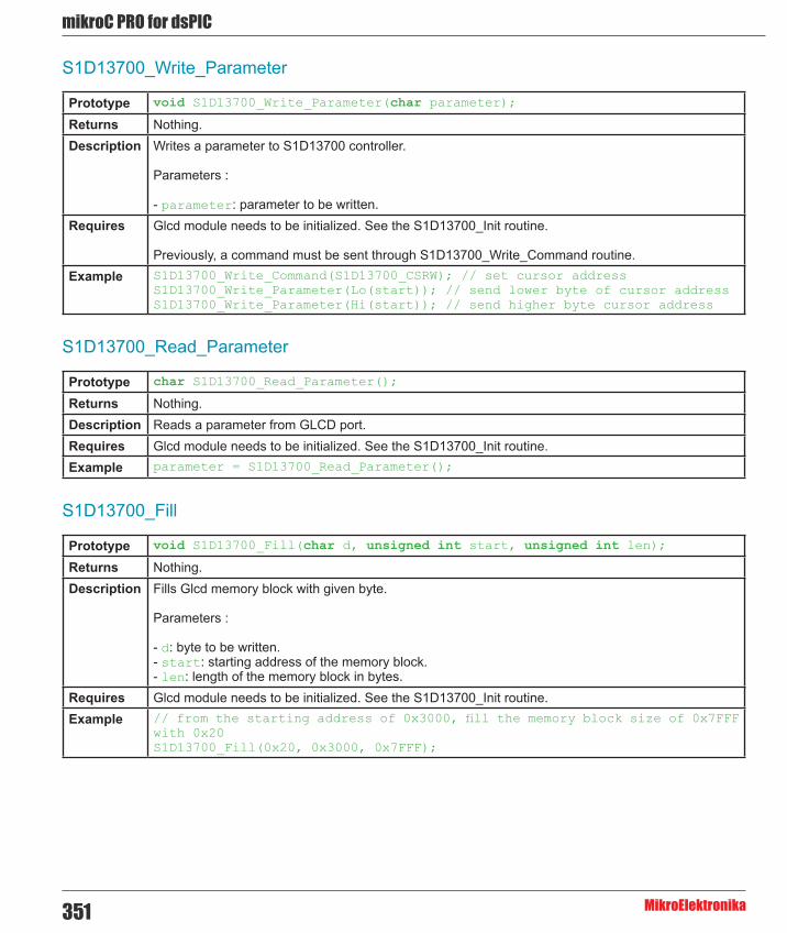
mikroC PRO for dsPIC
MikroElektronika351
S1D13700_Write_Parameter
S1D13700_Read_Parameter
S1D13700_Fill
Prototype void S1D13700_Write_Parameter(char parameter);
Returns Nothing.Description Writes a parameter to S1D13700 controller.
Parameters :
- parameter: parameter to be written. Requires Glcd module needs to be initialized. See the S1D13700_Init routine.
Previously, a command must be sent through S1D13700_Write_Command routine.Example S1D13700_Write_Command(S1D13700_CSRW); // set cursor address
S1D13700_Write_Parameter(Lo(start)); // send lower byte of cursor addressS1D13700_Write_Parameter(Hi(start)); // send higher byte cursor address
Prototype char S1D13700_Read_Parameter();
Returns Nothing.Description Reads a parameter from GLCD port.Requires Glcd module needs to be initialized. See the S1D13700_Init routine.Example parameter = S1D13700_Read_Parameter();
Prototype void S1D13700_Fill(char d, unsigned int start, unsigned int len);
Returns Nothing.Description Fills Glcd memory block with given byte.
Parameters :
- d: byte to be written. - start: starting address of the memory block. - len: length of the memory block in bytes.
Requires Glcd module needs to be initialized. See the S1D13700_Init routine.Example // from the starting address of 0x3000, fill the memory block size of 0x7FFF
with 0x20S1D13700_Fill(0x20, 0x3000, 0x7FFF);

352
mikoC PRO for dsPIC
MikroElektronika
S1D13700_GrFill
S1D13700_TxtFill
S1D13700_Display_GrLayer
Prototype void S1D13700_GrFill(char d);
Returns Nothing.Description Fill graphic layer with appropriate value (0 to clear).
Parameters :
- d: value to fill graphic layer with. Requires Glcd module needs to be initialized. See the S1D13700_Init routine.Example // clear current graphic panel
S1D13700_GrFill(0);
Prototype void S1D13700_TxtFill(char d);
Returns Nothing.Description Fill current text panel with appropriate value (0 to clear).
Parameters :
- d: this value will be used to fill text panel. Requires Glcd module needs to be initialized. See the S1D13700_Init routine.Example // clear current text panel
S1D13700_TxtFill(0);
Prototype void S1D13700_Display_GrLayer(char mode);
Returns Nothing.Description Display selected graphic layer.
Parameters :
- mode: graphic layer mode. Valid values :
Requires Glcd module needs to be initialized. See the S1D13700_Init routine.Example // Turn on graphic layer
S1D13700_Display_GrLayer(S1D13700_LAYER_ON);
Value DescriptionS1D13700_LAYER_OFF Turn off graphic layer.S1D13700_LAYER_ON Turn on graphic layer.
S1D13700_LAYER_FLASH_2Hz Turn on graphic layer and flash it at the rate of 2 Hz.S1D13700_LAYER_FLASH_16Hz Turn on graphic layer and flash it at the rate of 16 Hz.

mikroC PRO for dsPIC
MikroElektronika353
S1D13700_Display_TxtLayer
S1D13700_Set_Cursor
Prototype void S1D13700_Display_TxtLayer(char mode);
Returns Nothing.Description Display selected text layer.
Parameters :
- mode: text layer mode. Valid values :
Requires Glcd module needs to be initialized. See the S1D13700_Init routine.Example // Display on text layer
S1D13700_Display_TxtLayer(S1D13700_LAYER_ON);
Prototype void S1D13700_Set_Cursor(char width, char height, char mode);
Returns Nothing.Description Sets cursor properties.
Parameters :
- width: in pixels-1 (must be less than or equal to the horizontal char size). - height: in lines-1 (must be less than or equal to the vertical char size). - mode: cursor mode. Valid values :
Requires Glcd module needs to be initialized. See the S1D13700_Init routine.Example // set cursor with the following properties : width 5px, height 10px, cursor
shape - blockS1D13700_Set_Cursor(5, 10, S1D13700_CURSOR_BLOCK);
Value DescriptionS1D13700_LAYER_OFF Turn off graphic layer.S1D13700_LAYER_ON Turn on graphic layer.
S1D13700_LAYER_FLASH_2Hz Turn on graphic layer and flash it at the rate of 2 Hz.S1D13700_LAYER_FLASH_16Hz Turn on graphic layer and flash it at the rate of 16 Hz.
Value DescriptionS1D13700_CURSOR_UNDERSCORE Set cursor shape - underscore.
S1D13700_CURSOR_BLOCK Set cursor shape - block.

354
mikoC PRO for dsPIC
MikroElektronika
S1D13700_Display_Cursor
S1D13700_Write_Char
Prototype void S1D13700_Display_Cursor(char mode);
Returns Nothing.Description Displays cursor.
Parameters :
- mode: mode parameter. Valid values:
Requires Glcd module needs to be initialized. See the S1D13700_Init routine.Example // set cursor on
S1D13700_Display_Cursor(S1D13700_CURSOR_ON);
Prototype void S1D13700_Write_Char(unsigned char c, unsigned int x, unsigned int y, unsigned char mode);
Returns Nothing.Description Writes a char in the current text layer of Glcd at coordinates (x, y).
Parameters :
- c: char to be written. - x: char position on x-axis (column). - y: char position on y-axis (row). - mode: mode parameter. Valid values :
Requires Glcd module needs to be initialized. See the S1D13700_Init routine.Example S1D13700_Write_Char(‘A’,22,23,S1D13700_OVERLAY_OR);
Value DescriptionS1D13700_CURSOR_OFF Turn off graphic layer.S1D13700_CURSOR_ON Turn on graphic layer.
S1D13700_CURSOR_FLASH_2Hz Turn on graphic layer and flash it at the rate of 2 Hz.S1D13700_CURSOR_FLASH_16Hz Turn on graphic layer and flash it at the rate of 16 Hz.
Value Description
S1D13700_OVERLAY_OR
In the OR-Mode, text and graphics can be displayed and the data is logically “OR-ed”.
This is the most common way of combining text and graphics, for example labels on buttons.
S1D13700_OVERLAY_XOR In this mode, the text and graphics data are combined via the logical “exclusive OR”.
S1D13700_OVERLAY_AND The text and graphic data shown on display are combined via the logical “AND function”.
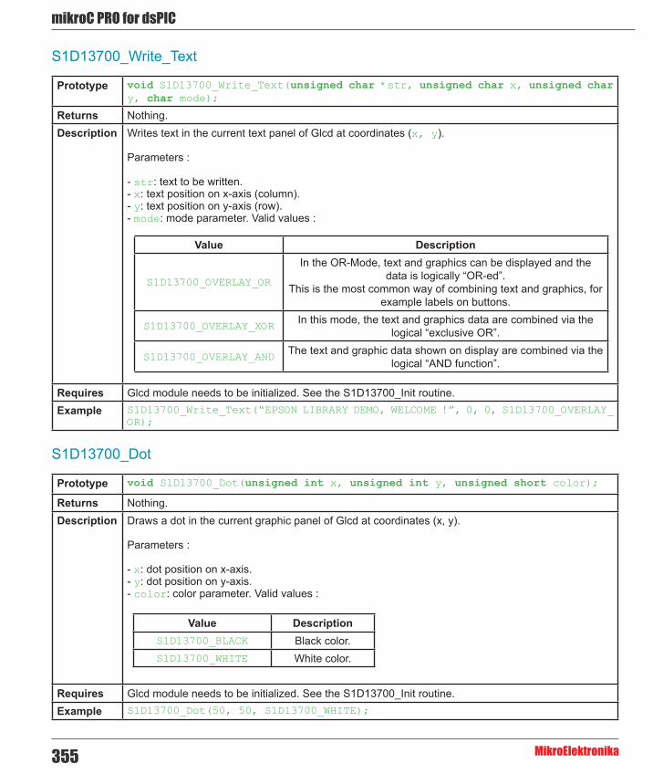
mikroC PRO for dsPIC
MikroElektronika355
S1D13700_Write_Text
S1D13700_Dot
Prototype void S1D13700_Write_Text(unsigned char *str, unsigned char x, unsigned char y, char mode);
Returns Nothing.Description Writes text in the current text panel of Glcd at coordinates (x, y).
Parameters :
- str: text to be written. - x: text position on x-axis (column). - y: text position on y-axis (row). - mode: mode parameter. Valid values :
Requires Glcd module needs to be initialized. See the S1D13700_Init routine.Example S1D13700_Write_Text(“EPSON LIBRARY DEMO, WELCOME !”, 0, 0, S1D13700_OVERLAY_
OR);
Prototype void S1D13700_Dot(unsigned int x, unsigned int y, unsigned short color);
Returns Nothing.Description Draws a dot in the current graphic panel of Glcd at coordinates (x, y).
Parameters :
- x: dot position on x-axis. - y: dot position on y-axis. - color: color parameter. Valid values :
Requires Glcd module needs to be initialized. See the S1D13700_Init routine.Example S1D13700_Dot(50, 50, S1D13700_WHITE);
Value Description
S1D13700_OVERLAY_OR
In the OR-Mode, text and graphics can be displayed and the data is logically “OR-ed”.
This is the most common way of combining text and graphics, for example labels on buttons.
S1D13700_OVERLAY_XOR In this mode, the text and graphics data are combined via the logical “exclusive OR”.
S1D13700_OVERLAY_AND The text and graphic data shown on display are combined via the logical “AND function”.
Value DescriptionS1D13700_BLACK Black color.S1D13700_WHITE White color.

356
mikoC PRO for dsPIC
MikroElektronika
S1D13700_Line
S1D13700_H_Line
Prototype void S1D13700_Line(unsigned int x0, unsigned int y0, unsigned int x1, unsigned int y1, unsigned char pcolor);
Returns Nothing.Description Draws a line from (x0, y0) to (x1, y1).
Parameters :
- x0: x coordinate of the line start. - y0: y coordinate of the line end. - x1: x coordinate of the line start. - y1: y coordinate of the line end. - pcolor: color parameter. Valid values :
Requires Glcd module needs to be initialized. See the S1D13700_Init routine.Example S1D13700_Line(0, 0, 239, 127, S1D13700_WHITE);
Prototype void S1D13700_H_Line(unsigned int x_start, unsigned int x_end, unsigned int y_pos, unsigned short color);
Returns Nothing.Description Draws a horizontal line.
Parameters :
- x_start: x coordinate of the line start. - x_end: x coordinate of the line end. - y_pos: line position on the y axis. - pcolor: color parameter. Valid values :
Requires Glcd module needs to be initialized. See the S1D13700_Init routine.Example S1D13700_Line(0, 0, 239, 127, S1D13700_WHITE);
Value DescriptionS1D13700_BLACK Black color.S1D13700_WHITE White color.
Value DescriptionS1D13700_BLACK Black color.S1D13700_WHITE White color.

mikroC PRO for dsPIC
MikroElektronika357
S1D13700_V_Line
S1D13700_Rectangle
Prototype void S1D13700_V_Line(unsigned int y_start, unsigned int y_end, unsigned int x_pos, unsigned short color);
Returns Nothing.Description Draws a horizontal line.
Parameters :
- y_start: y coordinate of the line start. - y_end: y coordinate of the line end. - x_pos: line position on the x axis. - pcolor: color parameter. Valid values :
Requires Glcd module needs to be initialized. See the S1D13700_Init routine.Example S1D13700_Line(0, 0, 239, 127, S1D13700_WHITE);
Prototype void S1D13700_Rectangle(unsigned int x0, unsigned int y0, unsigned int x1, unsigned int y1, unsigned char pcolor);
Returns Nothing.Description Draws a rectangle on Glcd.
Parameters :
- x0: x coordinate of the upper left rectangle corner. - y0: y coordinate of the upper left rectangle corner. - x1: x coordinate of the lower right rectangle corner. - y1: y coordinate of the lower right rectangle corner. - pcolor: color parameter. Valid values :
Requires Glcd module needs to be initialized. See the S1D13700_Init routine.Example S1D13700_rectangle(20, 20, 219, 107, S1D13700_WHITE);
Value DescriptionS1D13700_BLACK Black color.S1D13700_WHITE White color.
Value DescriptionS1D13700_BLACK Black color.S1D13700_WHITE White color.
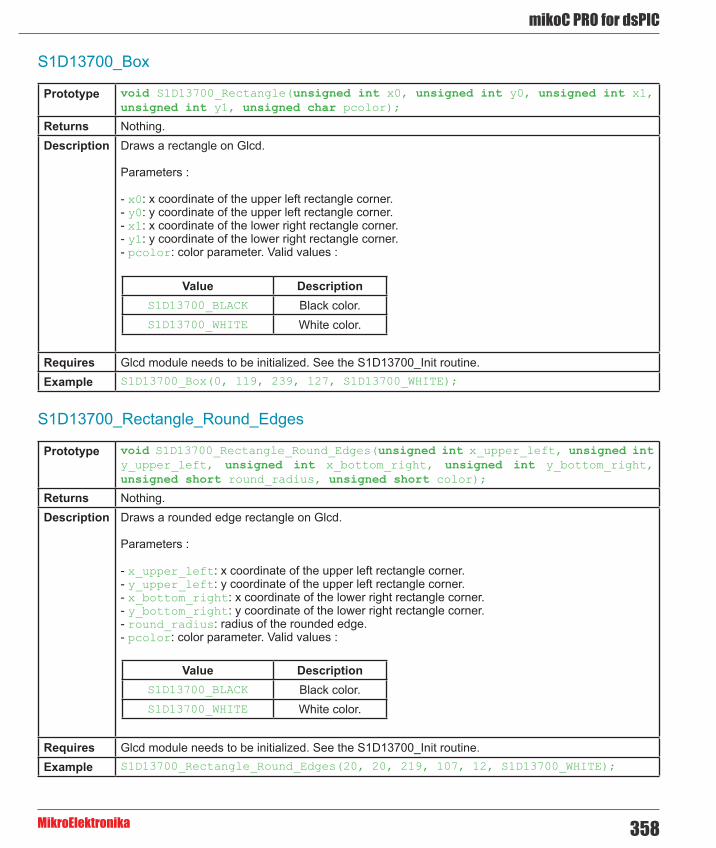
358
mikoC PRO for dsPIC
MikroElektronika
S1D13700_Box
Prototype void S1D13700_Rectangle(unsigned int x0, unsigned int y0, unsigned int x1, unsigned int y1, unsigned char pcolor);
Returns Nothing.Description Draws a rectangle on Glcd.
Parameters :
- x0: x coordinate of the upper left rectangle corner. - y0: y coordinate of the upper left rectangle corner. - x1: x coordinate of the lower right rectangle corner. - y1: y coordinate of the lower right rectangle corner. - pcolor: color parameter. Valid values :
Requires Glcd module needs to be initialized. See the S1D13700_Init routine.Example S1D13700_Box(0, 119, 239, 127, S1D13700_WHITE);
Value DescriptionS1D13700_BLACK Black color.S1D13700_WHITE White color.
S1D13700_Rectangle_Round_Edges
Prototype void S1D13700_Rectangle_Round_Edges(unsigned int x_upper_left, unsigned int y_upper_left, unsigned int x_bottom_right, unsigned int y_bottom_right, unsigned short round_radius, unsigned short color);
Returns Nothing.Description Draws a rounded edge rectangle on Glcd.
Parameters :
- x_upper_left: x coordinate of the upper left rectangle corner. - y_upper_left: y coordinate of the upper left rectangle corner. - x_bottom_right: x coordinate of the lower right rectangle corner. - y_bottom_right: y coordinate of the lower right rectangle corner. - round_radius: radius of the rounded edge. - pcolor: color parameter. Valid values :
Requires Glcd module needs to be initialized. See the S1D13700_Init routine.Example S1D13700_Rectangle_Round_Edges(20, 20, 219, 107, 12, S1D13700_WHITE);
Value DescriptionS1D13700_BLACK Black color.S1D13700_WHITE White color.

mikroC PRO for dsPIC
MikroElektronika359
S1D13700_Rectangle_Round_Edges_Fill
S1D13700_Circle
Prototype void S1D13700_Rectangle_Round_Edges_Fill(unsigned int x0, unsigned int y0, unsigned int x1, unsigned int y1, unsigned short round_radius, unsigned short color);
Returns Nothing.Description Draws a filled rounded edge rectangle on Glcd.
Parameters :
- x_upper_left: x coordinate of the upper left rectangle corner. - y_upper_left: y coordinate of the upper left rectangle corner. - x_bottom_right: x coordinate of the lower right rectangle corner. - y_bottom_right: y coordinate of the lower right rectangle corner. - round_radius: radius of the rounded edge. - pcolor: color parameter. Valid values :
Requires Glcd module needs to be initialized. See the S1D13700_Init routine.Example S1D13700_Rectangle_Round_Edges_Fill(20, 20, 219, 107, 12, S1D13700_WHITE);
Prototype void S1D13700_Circle(unsigned int x_center, unsigned int y_center, unsigned int radius, unsigned short color);
Returns Nothing.Description Draws a circle on Glcd.
Parameters :
- x_center: x coordinate of the circle center. - y_center: y coordinate of the circle center. - radius: radius size. - color: color parameter. Valid values :
Requires Glcd module needs to be initialized. See the S1D13700_Init routine.Example S1D13700_Circle(120, 64, 110, S1D13700_WHITE);
Value DescriptionS1D13700_BLACK Black color.S1D13700_WHITE White color.
Value DescriptionS1D13700_BLACK Black color.S1D13700_WHITE White color.

360
mikoC PRO for dsPIC
MikroElektronika
S1D13700_Circle_Fill
S1D13700_Image
Prototype void S1D13700_Circle_Fill(unsigned int x_center, unsigned int y_center, unsigned int radius, unsigned short color);
Returns Nothing.Description Draws a filled circle on Glcd.
Parameters :
- x_center: x coordinate of the circle center. - y_center: y coordinate of the circle center. - radius: radius size. - color: color parameter. Valid values :
Requires Glcd module needs to be initialized. See the S1D13700_Init routine.Example S1D13700_Circle_Fill(120, 64, 110, S1D13700_WHITE);
Prototype void S1D13700_Image(const code char *pic);
Returns Nothing.Description Displays bitmap on Glcd.
Parameters :
- image: image to be displayed. Bitmap array is located in code memory. Note : Image dimension must match the display dimension.
Requires Glcd module needs to be initialized. See the S1D13700_Init routine.Example S1D13700_Image(image);
Value DescriptionS1D13700_BLACK Black color.S1D13700_WHITE White color.

mikroC PRO for dsPIC
MikroElektronika361
S1D13700_PartialImage
Prototype void S1D13700_PartialImage(unsigned int x_left, unsigned int y_top, unsigned int width, unsigned int height, unsigned int picture_width, unsigned int picture_height, code const unsigned short * image);
Returns Nothing.Description Displays a partial area of the image on a desired location.
Parameters :
- x_left: x coordinate of the desired location (upper left coordinate). - y_top: y coordinate of the desired location (upper left coordinate). - width: desired image width. - height: desired image height. - picture_width: width of the original image. - picture_height: height of the original image. - image: image to be displayed. Bitmap array is located in code memory.
Note : Image dimension must match the display dimension.
Requires Glcd module needs to be initialized. See the S1D13700_Init routine.Example // Draws a 10x15 part of the image starting from the upper left corner on
the coordinate (10,12). Original image size is 16x32. S1D13700_PartialImage(10, 12, 10, 15, 16, 32, image);
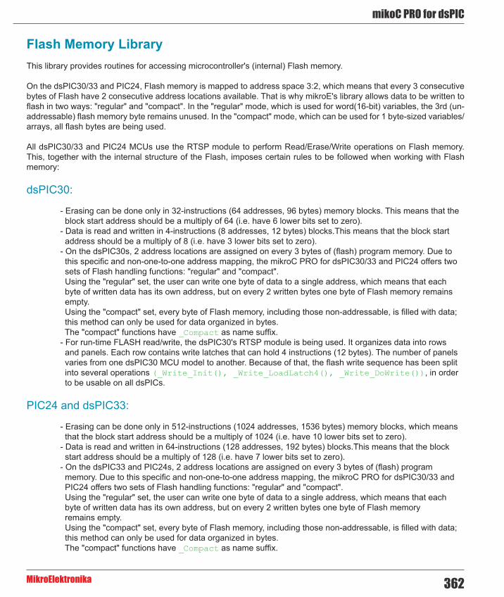
362
mikoC PRO for dsPIC
MikroElektronika
Flash Memory LibraryThis library provides routines for accessing microcontroller's (internal) Flash memory.
On the dsPIC30/33 and PIC24, Flash memory is mapped to address space 3:2, which means that every 3 consecutive bytes of Flash have 2 consecutive address locations available. That is why mikroE's library allows data to be written to flash in two ways: "regular" and "compact". In the "regular" mode, which is used for word(16-bit) variables, the 3rd (un-addressable) flash memory byte remains unused. In the "compact" mode, which can be used for 1 byte-sized variables/arrays, all flash bytes are being used.
All dsPIC30/33 and PIC24 MCUs use the RTSP module to perform Read/Erase/Write operations on Flash memory. This, together with the internal structure of the Flash, imposes certain rules to be followed when working with Flash memory:
dsPIC30:
- Erasing can be done only in 32-instructions (64 addresses, 96 bytes) memory blocks. This means that the block start address should be a multiply of 64 (i.e. have 6 lower bits set to zero). - Data is read and written in 4-instructions (8 addresses, 12 bytes) blocks.This means that the block start address should be a multiply of 8 (i.e. have 3 lower bits set to zero). - On the dsPIC30s, 2 address locations are assigned on every 3 bytes of (flash) program memory. Due to this specific and non-one-to-one address mapping, the mikroC PRO for dsPIC30/33 and PIC24 offers two sets of Flash handling functions: "regular" and "compact". Using the "regular" set, the user can write one byte of data to a single address, which means that each byte of written data has its own address, but on every 2 written bytes one byte of Flash memory remains empty. Using the "compact" set, every byte of Flash memory, including those non-addressable, is filled with data; this method can only be used for data organized in bytes. The "compact" functions have _Compact as name suffix. - For run-time FLASH read/write, the dsPIC30's RTSP module is being used. It organizes data into rows and panels. Each row contains write latches that can hold 4 instructions (12 bytes). The number of panels varies from one dsPIC30 MCU model to another. Because of that, the flash write sequence has been split into several operations (_Write_Init(), _Write_LoadLatch4(), _Write_DoWrite()), in order to be usable on all dsPICs.
PIC24 and dsPIC33:
- Erasing can be done only in 512-instructions (1024 addresses, 1536 bytes) memory blocks, which means that the block start address should be a multiply of 1024 (i.e. have 10 lower bits set to zero). - Data is read and written in 64-instructions (128 addresses, 192 bytes) blocks.This means that the block start address should be a multiply of 128 (i.e. have 7 lower bits set to zero). - On the dsPIC33 and PIC24s, 2 address locations are assigned on every 3 bytes of (flash) program memory. Due to this specific and non-one-to-one address mapping, the mikroC PRO for dsPIC30/33 and PIC24 offers two sets of Flash handling functions: "regular" and "compact". Using the "regular" set, the user can write one byte of data to a single address, which means that each byte of written data has its own address, but on every 2 written bytes one byte of Flash memory remains empty. Using the "compact" set, every byte of Flash memory, including those non-addressable, is filled with data; this method can only be used for data organized in bytes. The "compact" functions have _Compact as name suffix.

mikroC PRO for dsPIC
MikroElektronika363
24F04KA201 and 24F16KA102 Family Specifics :
These MCU's have their Flash memory organized into memory blocks of 32 instructions (96 bytes), unlike other PIC24 devices. Erasing can be done only in 32-instructions (64 addresses, 96 bytes) memory blocks, which means that the block start address should be a multiply of 64 (i.e. have 6 lower bits set to zero). Data is read and written in 32-instructions (64 addresses, 96 bytes) blocks. This means that the block start address should be a multiply of 64 (i.e. have 6 lower bits set to zero). Unlike other PIC24 devices, writing or erasing one block of data (32 instructions), is followed by erasing the memory block of the same size (32 instructions).
Library Routines
dsPIC30 Functions
- FLASH_Erase32
- FLASH_Write_Block - FLASH_Write_Compact - FLASH_Write_Init - FLASH_Write_Loadlatch4 - FLASH_Write_Loadlatch4_Compact - FLASH_Write_DoWrite
- FLASH_Read4 - FLASH_Read4_Compact
PIC24 and dsPIC33 Functions
- FLASH_Erase - FLASH_Write - FLASH_Write_Compact - FLASH_Read - FLASH_Read_Compact
dsPIC30 Functions

364
mikoC PRO for dsPIC
MikroElektronika
FLASH_Erase32
FLASH_Write_Block
Prototype void FLASH_Erase32(unsigned long address);
Description Erases one block (32 instructions, 64 addresses, 96 bytes)from the program FLASH memory.Parameters - address: starting address of the FLASH memory block Returns Nothing.Requires Nothing.Example //--- erase the 32-instruction block, starting from address 0x006000
FLASH_Erase32(0x006000);
Notes The user should take care about the address alignment (see the explanation at the beginning of this page).
Prototype void FLASH_Write_Block(unsigned long address, unsigned int *data_);
Description Fills one writeable block of Flash memory (4 instructions, 8 addresses, 12 bytes) in the “regular” mode. Addresses and data are being mapped 1-on-1. This also means that 3rd byte of each program location remains unused.
Parameters - address: starting address of the FLASH memory block - data_: data to be written
Returns Nothing.Requires The block to be written to must be erased first, either from the user code (through the RTSP), or during
the programming of MCU. Please note that block size that is to be erased is different from the one that can be written with this function!
Example unsigned long flash_address = 0x006000;unsigned int Buffer[4] = {‘A’, ‘B’, ‘C’, ‘D’};...FLASH_Write_Block(flash_address, Buffer);
Notes The user should take care about the address alignment (see the explanation at the beginning of this page).

mikroC PRO for dsPIC
MikroElektronika365
FLASH_Write_Compact
FLASH_Write_Init
Prototype void FLASH_Write_Compact(unsigned long address, void *data_, unsigned bytes);
Description Fills a portion of Flash memory using the dsPIC30 RTSP module, in the “compact” manner. In this way, several blocks of RTSP’s latch can be written in one pass. One latch block contains 4 instructions (8 addresses, 12 bytes). Up to 8 latch blocks can be written in one round, resulting in a total of 8*12 = 96 bytes. This method uses all available bytes of the program FLASH memory, including those that are not mapped to address space (every 3rd byte).
Parameters - address: starting address of the FLASH memory block - data_: data to be written - bytes: number of bytes to be written. The amount of bytes to be written must be a multiply of 12, since this is the size of the RTSP’s write latch(es).
Returns Nothing.Requires The block to be written to must be erased first, either from the user code FLASH_Erase32, or during
the programming of MCU. Please note that block size that is to be erased is different from the one that can be written with this function!
Example unsigned long flash_address = 0x006000;char Buffer[] = “supercalifragillisticexpialidotious”;...FLASH_Write_Compact(flash_address, Buffer, 36);
Notes The user should take care about the address alignment (see the explanation at the beginning of this page).
Prototype void FLASH_Write_Init(unsigned long address, void *data_);
Description Initializes RTSP for write-to-FLASH operation.Parameters - address: starting address of the FLASH memory block
- data_: data to be written Returns Nothing.Requires The block to be written to must be erased first, either from the user code FLASH_Erase32, or during
the programming of MCU. Please note that block size that is to be erased is different from the one that can be written with this function!
Example //--- Initializes the Flash to be written, starting from address 0x006100, the data is located at *pv1void *pv1;...FLASH_Write_Init(0x006100, pv1);
Notes The user should take care about the address alignment (see the explanation at the beginning of this page).

366
mikoC PRO for dsPIC
MikroElektronika
FLASH_Write_Loadlatch4
Prototype void FLASH_Write_Loadlatch4();
Description Loads the current RTSP write latch with data (4 instructions, 8 addresses, 12 bytes). The data is filled in the “regular” mode.
Parameters None.Returns Nothing.Requires The block to be written to must be erased first, either from the user code FLASH_Erase32, or during
the programming of MCU. Please note that block size that is to be erased is different from the one that can be written with this function!
This function is used as a part of the Flash write sequence, therefore the FLASH_Write_Init function must be called before this one.
This function can be called several times before commiting the actual write-to-Flash operation FLASH_Write_DoWrite. This depends on the organization of the RTSP module for the certain dsPIC30. Please consult the Datasheet for particular dsPIC30 on this subject.
Example //--- writes data from an array, in “regular” mannerunsigned int iArr[16] = {‘m’, ‘i’, ‘k’, ‘r’, ‘o’, ‘E’, ‘l’, ‘e’, ‘k’};void * pv1;...pv1 = iArr;FLASH_Write_Init(0x006100, pv1);FLASH_Write_Loadlatch4();FLASH_Write_Loadlatch4();FLASH_Write_DoWrite();
Notes None.

mikroC PRO for dsPIC
MikroElektronika367
FLASH_Write_Loadlatch4_Compact
Prototype void FLASH_Write_Loadlatch4_Compact();
Description Loads the current RTSP write latch with data (4 instructions, 8 addresses, 12 bytes). The data is filled in the “compact” mode.
Parameters None.Returns Nothing.Requires The block to be written to must be erased first, either from the user code FLASH_Erase32, or during
the programming of MCU. Please note that block size that is to be erased is different from the one that can be written with this function!
This function is used as a part of the Flash write sequence, therefore the FLASH_Write_Init function must be called before this one.
This function can be called several times before committing actual write-to-Flash operation FLASH_Write_DoWrite. This depends on the organization of the RTSP module for the certain dsPIC30. Please consult the Datasheet for particular dsPIC30 on this subject.
Example //--- writes data from an array of char, in “compact” mannerchar cArr[] = “supercalifragillisticexpialidotious”; //35+1 bytesvoid * pv1;...pv1 = cArr;FLASH_Write_Init(0x006000, pv1); //initFLASH_Write_Loadlatch4_Compact(); //12 bytesFLASH_Write_Loadlatch4_Compact(); //12 bytesFLASH_Write_Loadlatch4_Compact(); //12 bytesFLASH_Write_DoWrite(); //commit write
Notes None.

368
mikoC PRO for dsPIC
MikroElektronika
FLASH_Write_DoWrite
FLASH_Read4
Prototype void FLASH_Write_DoWrite();
Description Commits the FLASH write operation.Parameters None.Returns Nothing.Requires The block to be written to must be erased first, either from the user code FLASH_Erase32, or during
the programming of MCU. Please note that block size that is to be erased is different from the one that can be written with this function!
This function is used as a part of the Flash write sequence, therefore FLASH_Write_Init and certain number of FLASH_Write_Loadlatch4 or FLASH_Write_Loadlatch4_Compact function calls must be made before this one.
This function is to be called once, at the and of the FLASH write sequence.Example //--- writes data from an array, in “regular” manner
unsigned int iArr[16] = {‘m’, ‘i’, ‘k’, ‘r’, ‘o’, ‘E’, ‘l’, ‘e’, ‘k’};void * pv1;...pv1 = iArr;FLASH_Write_Init(0x006100, pv1);FLASH_Write_Loadlatch4();FLASH_Write_Loadlatch4();FLASH_Write_DoWrite();
Notes None.
Prototype unsigned int* FLASH_Read4(unsigned long address, unsigned int *write_to);
Description Reads one latch row (4 instructions, 8 addresses) in the “regular” mode.Parameters - address: starting address of the FLASH memory block to be read
- write_to: starting address of RAM buffer for storing read data Returns Starting address of RAM buffer for storing read data.Requires Nothing.Example //--- reads 8 bytes (4 words) from location 0x006000 and stores it to
*pv1;unsigned int *pv1;...FLASH_Read4(0x006000, pv1);
Notes The user should take care of the address alignment (see the explanation at the beginning of this page).

mikroC PRO for dsPIC
MikroElektronika369
FLASH_Read4_Compact
FLASH_Erase
PIC24 and dsPIC33 Functions
Prototype void* FLASH_Read4_Compact(unsigned long address, void *write_to);
Description Reads one latch row (4 instructions, 8 addresses) in the “compact” mode.Parameters - address: starting address of the FLASH memory block to be read
- write_to: starting address of RAM buffer for storing read data Returns Starting address of RAM buffer for storing read data.Requires Nothing.Example //--- reads 12 bytes (4 words) from location 0x006000 and stores it to
*pv1;unsigned int *pv1;...FLASH_Read4_Compact(0x006000, pv1);
Notes The user should take care of the address alignment (see the explanation at the beginning of this page).
Prototype void FLASH_Erase(unsigned long address);
Description Erases one block (512 instructions, 1024 addresses, 1536 bytes) from the program FLASH memory.Parameters - address: starting address of the FLASH memory block Returns Nothing.Requires Nothing.Example //--- erase the flash memory block, starting from address 0x006400
unsigned long flash_address = 0x006400;...FLASH_Erase(flash_address);
Notes The user should take care about the address alignment (see the explanation at the beginning of this page).

370
mikoC PRO for dsPIC
MikroElektronika
FLASH_Write
FLASH_Write_Compact
Prototype void FLASH_Write(unsigned long address, unsigned int *data_);
Description Fills one writeable block of Flash memory (64 instructions, 128 addresses, 192 bytes) in the “regular” mode. Addresses and data are being mapped 1-on-1. This also means that 3rd byte of each program location remains unused.
Parameters - address: starting address of the FLASH memory block - data_: data to be written
Returns Nothing.Requires The block to be written to must be erased first, either from the user code (through the RTSP), or during
the programming of MCU. Please note that block size that is to be erased is different from the one that can be written with this function!
Example unsigned int iArr[64] = {‘m’, ‘i’, ‘k’, ‘r’, ‘o’, ‘E’, ‘l’, ‘e’, ‘k’, ‘t’, ‘r’, ‘o’, ‘n’, ‘i’, ‘k’, ‘a’};void * pv1;...pv1 = iArr;FLASH_Write(0x006500, pv1);
Notes The user should take care about the address alignment (see the explanation at the beginning of this page).
Prototype void FLASH_Write_Compact(unsigned long address, char *data_);
Description Fills a portion of Flash memory (64 instructions, 128 addresses, 192 bytes) using the dsPIC33 and PIC24s RTSP (Run Time Self Programming) module, in the “compact” manner. This method uses all available bytes of the program FLASH memory, including those that are not mapped to address space (every 3rd byte).
Parameters - address: starting address of the FLASH memory block - data_: data to be written
Returns Nothing.Requires The block to be written to must be erased first, either from the user code (FLASH_Erase), or during
the programming of MCU. Please note that block size that is to be erased is different from the one that can be written with this function!
Example char cArr[] = “supercalifragillisticexpialidotiousABCDEFGHIJKLMNOPRSTUVWXYZ1234”;void * pv1;...pv1 = cArr;FLASH_Write_Compact(0x006400, pv1);
Notes The user should take care of the address alignment (see the explanation at the beginning of this page).

mikroC PRO for dsPIC
MikroElektronika371
FLASH_Read
FLASH_Read_Compact
Prototype unsigned int* FLASH_Read(unsigned long address, unsigned int *write_to, unsigned NoWords);
Description Reads required number of words from the flash memory in the “regular” mode.Parameters - address: starting address of the FLASH memory block to be read
- write_to: starting address of RAM buffer for storing read data - NoWords: number of words to be read
Returns Address of RAM buffer for storing read data.RequiresExample unsigned Buffer[64];
unsigned long start_address = 0x6500;...FLASH_Read(start_address, Buffer, 10);
Notes The user should take care of the address alignment (see the explanation at the beginning of this page).
Prototype void *FLASH_Read_Compact(unsigned long address, void *write_to, unsigned NoBytes);
Description Reads required number of bytes from the flash memory in the “compact” mode.Parameters - address: starting address of the FLASH memory block to be read
- write_to: starting address of RAM buffer for storing read data - NoBytes: number of bytes to be read
Returns Address of RAM buffer for storing read data.RequiresExample char Buffer[64];
unsigned long start_address = 0x6500;...FLASH_Read_Compact(start_address, Buffer, 10);
Notes The user should take care of the address alignment (see the explanation at the beginning of this page).

372
mikoC PRO for dsPIC
MikroElektronika
Library Example
In this example written for dsPIC30F4013, various read/write tecniques to/from the on-chip FLASH memory are shown. Flash memory is mapped to address space 3:2, meaning every 3 consecutive bytes of Flash have 2 consecutive address locations available. That is why mikroE's library allows data to be written to Flash in two ways: 'regular' and 'compact'. In 'regular' mode, which is used for variables that are size of 2 bytes and more, the 3rd (un-addressable) byte remains unused. In 'compact' mode, which can be used for 1 byte-sized variables/arrays, all bytes of flash are being used.
Copy Code To Clipboard
unsigned int iArr[8] = {‘m’, ‘i’, ‘k’, ‘r’, ‘o’, ‘E’, ‘l’, ‘e’};char cArr[] = “mikroElektronika Flash example”;char cArr2[40];
void * pv1;unsigned bb;
void main() { unsigned i;
pv1 = cArr;
/* This is what FLASH_Write_Compact() does ‘beneath the hood’ * FLASH_Write_Init(0x006000, pv1); FLASH_Write_Loadlatch4_Compact(); FLASH_Write_Loadlatch4_Compact(); FLASH_Write_Loadlatch4_Compact(); FLASH_Write_DoWrite(); */
//--- erase the block first FLASH_Erase32(0x006000);
//--- write compact format to flash FLASH_Write_Compact(0x006000, pv1, 36);
//--- read compact format pv1 = cArr2; FLASH_Read4_Compact(0x006000, pv1); pv1 += 12; FLASH_Read4_Compact(0x006008, pv1); pv1 += 12; FLASH_Read4_Compact(0x006010, pv1); pv1 += 12; *pv1 = 0; //termination
//--- show what has been written i = 0;

mikroC PRO for dsPIC
MikroElektronika373
UART1_Init(9600);// UART1_Write_Text("Start"); UART1_Write(10); UART1_Write(13); while(cArr2[i]) { bb = cArr2[i++]; UART1_Write(bb); }
//--- now for some non-compact flash-write pv1 = iArr; //--- erase the block first FLASH_Erase32(0x006100); FLASH_Write_Init(0x006100, pv1); FLASH_Write_Loadlatch4(); FLASH_Write_Loadlatch4(); FLASH_Write_DoWrite();}
Graphic Lcd LibraryThe mikroC PRO for dsPIC30/33 and PIC24 provides a library for operating Graphic Lcd 128x64 (with commonly used Samsung KS108/KS107 controller).
For creating a custom set of Glcd images use Glcd Bitmap Editor Tool.
Library Dependency Tree

374
mikoC PRO for dsPIC
MikroElektronika
External dependencies of Graphic Lcd LibraryThe following variables must be defined in all projects using Graphic Lcd Library:
Description : Example :
extern sfr sbit GLCD_D0; Data 0 line. sbit GLCD_D0 at LATB0_bit;
extern sfr sbit GLCD_D1; Data 1 line. sbit GLCD_D1 at LATB1_bit;
extern sfr sbit GLCD_D2; Data 2 line. sbit GLCD_D2 at LATF2_bit;
extern sfr sbit GLCD_D3; Data 3 line. sbit GLCD_D3 at LATF3_bit;
extern sfr sbit GLCD_D4; Data 4 line. sbit GLCD_D4 at LATD0_bit;
extern sfr sbit GLCD_D5; Data 5 line. sbit GLCD_D5 at LATD1_bit;
extern sfr sbit GLCD_D6; Data 6 line. sbit GLCD_D6 at LATD2_bit;
extern sfr sbit GLCD_D7; Data 7 line. sbit GLCD_D7 at LATD3_bit;
extern sfr sbit GLCD_CS1; Chip Select 1 line. sbit GLCD_CS1 at LATB4_bit;
extern sfr sbit GLCD_CS2; Chip Select 2 line. sbit GLCD_CS2 at LATB5_bit;
extern sfr sbit GLCD_RS; Register select line. sbit GLCD_RS at LATF0_bit;
extern sfr sbit GLCD_RW; Read/Write line. sbit GLCD_RW at LATF1_bit;
extern sfr sbit GLCD_EN; Enable line. sbit GLCD_RST at LATF5_bit;
extern sfr sbit GLCD_RST; Reset line. sbit GLCD_RST at LATF5_bit;
extern sfr sbit GLCD_D0_Direction; Direction of the Data 0 pin. sbit GLCD_D0_Direction at TRISB0_
bit;
extern sfr sbit GLCD_D1_Direction; Direction of the Data 1 pin. sbit GLCD_D2_Direction at TRISB2_
bit;
extern sfr sbit GLCD_D3_Direction; Direction of the Data 3 pin. sbit GLCD_D3_Direction at TRISB3_
bit;
extern sfr sbit GLCD_D4_Direction; Direction of the Data 4 pin. sbit GLCD_D4_Direction at TRISD0_
bit;
extern sfr sbit GLCD_D5_Direction; Direction of the Data 5 pin. sbit GLCD_D5_Direction at TRISD1_
bit;
extern sfr sbit GLCD_D6_Direction; Direction of the Data 6 pin. sbit GLCD_D6_Direction at TRISD2_
bit;
extern sfr sbit GLCD_D7_Direction; Direction of the Data 7 pin. sbit GLCD_D7_Direction at TRISD3_
bit;
extern sfr sbit GLCD_CS1_Direction;
Direction of the Chip Select 1 pin.
sbit GLCD_CS1_Direction at TRISB4_bit;
extern sfr sbit GLCD_CS2_Direction;
Direction of the Chip Select 2 pin.
sbit GLCD_CS2_Direction at TRISB5_bit;
extern sfr sbit GLCD_RS_Direction;
Direction of the Register select pin.
sbit GLCD_RS_Direction at TRISF0_bit;
extern sfr sbit GLCD_RW_Direction;
Direction of the Read/Write pin.
sbit GLCD_RW_Direction at TRISF1_bit;
extern sfr sbit GLCD_EN_Direction; Direction of the Enable pin. sbit GLCD_EN_Direction at TRISF4_
bit;
extern sfr sbit GLCD_RST_Direction; Direction of the Reset pin. sbit GLCD_RST_Direction at
TRISF5_bit;
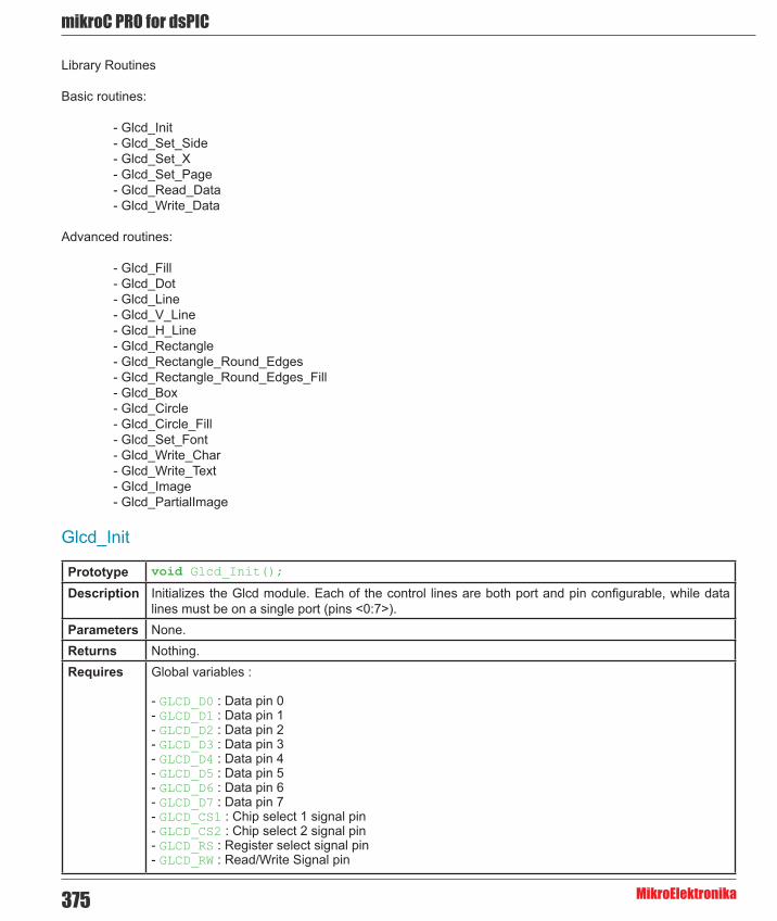
mikroC PRO for dsPIC
MikroElektronika375
Library Routines
Basic routines:
- Glcd_Init - Glcd_Set_Side - Glcd_Set_X - Glcd_Set_Page - Glcd_Read_Data - Glcd_Write_Data
Advanced routines:
- Glcd_Fill - Glcd_Dot - Glcd_Line - Glcd_V_Line - Glcd_H_Line - Glcd_Rectangle - Glcd_Rectangle_Round_Edges - Glcd_Rectangle_Round_Edges_Fill - Glcd_Box - Glcd_Circle - Glcd_Circle_Fill - Glcd_Set_Font - Glcd_Write_Char - Glcd_Write_Text - Glcd_Image - Glcd_PartialImage
Glcd_Init
Prototype void Glcd_Init();
Description Initializes the Glcd module. Each of the control lines are both port and pin configurable, while data lines must be on a single port (pins <0:7>).
Parameters None.Returns Nothing.Requires Global variables :
- GLCD_D0 : Data pin 0 - GLCD_D1 : Data pin 1 - GLCD_D2 : Data pin 2 - GLCD_D3 : Data pin 3 - GLCD_D4 : Data pin 4 - GLCD_D5 : Data pin 5 - GLCD_D6 : Data pin 6 - GLCD_D7 : Data pin 7 - GLCD_CS1 : Chip select 1 signal pin - GLCD_CS2 : Chip select 2 signal pin - GLCD_RS : Register select signal pin - GLCD_RW : Read/Write Signal pin

376
mikoC PRO for dsPIC
MikroElektronika
Requires - GLCD_EN : Enable signal pin - GLCD_RST : Reset signal pin - GLCD_D0_Direction : Direction of the Data pin 0 - GLCD_D1_Direction : Direction of the Data pin 1 - GLCD_D2_Direction : Direction of the Data pin 2 - GLCD_D3_Direction : Direction of the Data pin 3 - GLCD_D4_Direction : Direction of the Data pin 4 - GLCD_D5_Direction : Direction of the Data pin 5 - GLCD_D6_Direction : Direction of the Data pin 6 - GLCD_D7_Direction : Direction of the Data pin 7 - GLCD_CS1_Direction : Direction of the Chip select 1 pin - GLCD_CS2_Direction : Direction of the Chip select 2 pin - GLCD_RS_Direction : Direction of the Register select signal pin - GLCD_RW_Direction : Direction of the Read/Write signal pin - GLCD_EN_Direction : Direction of the Enable signal pin - GLCD_RST_Direction : Direction of the Reset signal pin
must be defined before using this function.Example // Glcd pinout settings
sbit GLCD_D0 at RB0_bit;sbit GLCD_D1 at RB1_bit;sbit GLCD_D2 at RB2_bit;sbit GLCD_D3 at RB3_bit;sbit GLCD_D4 at RD0_bit;sbit GLCD_D5 at RD1_bit;sbit GLCD_D6 at RD2_bit;sbit GLCD_D7 at RD3_bit;sbit GLCD_CS1 at RB0_bit;sbit GLCD_CS2 at RB1_bit;sbit GLCD_RS at RB2_bit;sbit GLCD_RW at RB3_bit;sbit GLCD_EN at RB4_bit;sbit GLCD_RST at RB5_bit;
sbit GLCD_D0_Direction at TRISB0_bit;sbit GLCD_D1_Direction at TRISB1_bit;sbit GLCD_D2_Direction at TRISB2_bit;sbit GLCD_D3_Direction at TRISB3_bit;sbit GLCD_D4_Direction at TRISD0_bit;sbit GLCD_D5_Direction at TRISD1_bit;sbit GLCD_D6_Direction at TRISD2_bit;sbit GLCD_D7_Direction at TRISD3_bit;sbit GLCD_CS1_Direction at TRISB0_bit;sbit GLCD_CS2_Direction at TRISB1_bit;sbit GLCD_RS_Direction at TRISB2_bit;sbit GLCD_RW_Direction at TRISB3_bit;sbit GLCD_EN_Direction at TRISB4_bit;sbit GLCD_RST_Direction at TRISB5_bit;...Glcd_Init();
Notes None.

mikroC PRO for dsPIC
MikroElektronika377
Glcd_Set_Side
Glcd_Set_X
Glcd_Set_Page
Prototype void Glcd_Set_Side(unsigned short x_pos);
Description Selects Glcd side. Refer to the Glcd datasheet for detailed explanation. Parameters - x_pos: Specifies position on x-axis of the Glcd. Valid values: 0..127. Values from 0 to 63 specify the
left side, values from 64 to 127 specify the right side of the Glcd. Returns Nothing.Requires Glcd needs to be initialized, see Glcd_Init routine.Example The following two lines are equivalent, and both of them select the left side of Glcd:
Glcd_Select_Side(0);Glcd_Select_Side(10);
Notes For side, x axis and page layout explanation see schematic at the bottom of this page.
Prototype void Glcd_Set_X(unsigned short x_pos);
Description Sets x-axis position to x_pos dots from the left border of Glcd within the selected side.Parameters - x_pos: position on x-axis. Valid values: 0..63 Returns Nothing.Requires Glcd needs to be initialized, see Glcd_Init routine.Example Glcd_Set_X(25);
Notes For side, x axis and page layout explanation see schematic at the bottom of this page.
Prototype void Glcd_Set_Page(unsigned short page);
Description Selects page of the Glcd.Parameters - page: page number. Valid values: 0..7 Returns Nothing.Requires Glcd needs to be initialized, see Glcd_Init routine.Example Glcd_Set_Page(5);
Notes For side, x axis and page layout explanation see schematic at the bottom of this page.

378
mikoC PRO for dsPIC
MikroElektronika
Glcd_Read_Data
Glcd_Write_Data
Prototype unsigned short Glcd_Read_Data();
Description Reads data from from the current location of Glcd memory and moves to the next location.Parameters None.Returns One byte from Glcd memory, formatted as a word (16-bit).Requires Glcd needs to be initialized, see Glcd_Init routine.
Glcd side, x-axis position and page should be set first. See functions Glcd_Set_Side, Glcd_Set_X, and Glcd_Set_Page.
Example unsigned int data_;...Glcd_Read_Data();data_ = Glcd_Read_Data();
Notes This routine needs to be called twice; After the first call, data is placed in the buffer register. After the second call, data is passed from the buffer register to data lines.
Prototype void Glcd_Write_Data(unsigned short data_);
Returns Nothing.Description Writes one byte to the current location in Glcd memory and moves to the next location.
Parameters :
- data_: data to be written Requires Glcd needs to be initialized, see Glcd_Init routine.
Glcd side, x-axis position and page should be set first. See functions Glcd_Set_Side, Glcd_Set_X, and Glcd_Set_Page.
Example unsigned short data_;...Glcd_Write_Data(data_);

mikroC PRO for dsPIC
MikroElektronika379
Glcd_Fill
Glcd_Dot
Glcd_Line
Prototype void Glcd_Fill(unsigned short pattern);
Description Fills Glcd memory with the byte pattern.
To clear the Glcd screen, use Glcd_Fill(0).
To fill the screen completely, use Glcd_Fill(0xFF).Parameters - pattern: byte to fill Glcd memory with. Returns Nothing.Requires Glcd needs to be initialized, see Glcd_Init routine.Example // Clear screen
Glcd_Fill(0);
Notes None.
Prototype void Glcd_Dot(unsigned short x_pos, unsigned short y_pos, unsigned short color);
Description Draws a dot on Glcd at coordinates (x_pos, y_pos). Parameters - x_pos: x position. Valid values: 0..127
- y_pos: y position. Valid values: 0..63 - color: color parameter. Valid values: 0..2 The parameter color determines a dot state: 0 clears dot, 1 puts a dot, and 2 inverts dot state.
Returns Nothing.Requires Glcd needs to be initialized, see Glcd_Init routine.Example // Invert the dot in the upper left corner
Glcd_Dot(0, 0, 2);
Notes For x and y axis layout explanation see schematic at the bottom of this page.
Prototype void Glcd_Line(int x_start, int y_start, int x_end, int y_end, unsigned short color);
Description Draws a line on Glcd.Parameters - x_start: x coordinate of the line start. Valid values: 0..127
- y_start: y coordinate of the line start. Valid values: 0..63 - x_end: x coordinate of the line end. Valid values: 0..127 - y_end: y coordinate of the line end. Valid values: 0..63 - color: color parameter. Valid values: 0..2 The parameter color determines the line color: 0 white, 1 black, and 2 inverts each dot.
Returns Nothing.Requires Glcd needs to be initialized, see Glcd_Init routine.Example // Draw a line between dots (0,0) and (20,30)
Glcd_Line(0, 0, 20, 30, 1);
Notes None.

380
mikoC PRO for dsPIC
MikroElektronika
Glcd_V_Line
Glcd_H_Line
Prototype void Glcd_V_Line(unsigned short y_start, unsigned short y_end, unsigned short x_pos, unsigned short color);
Description Draws a vertical line on Glcd.Parameters - y_start: y coordinate of the line start. Valid values: 0..63
- y_end: y coordinate of the line end. Valid values: 0..63 - x_pos: x coordinate of vertical line. Valid values: 0..127 - color: color parameter. Valid values: 0..2
The parameter color determines the line color: 0 white, 1 black, and 2 inverts each dot.Returns Nothing.Requires Glcd needs to be initialized, see Glcd_Init routine.Example // Draw a vertical line between dots (10,5) and (10,25)
Glcd_V_Line(5, 25, 10, 1);
Notes None.
Prototype void Glcd_H_Line(unsigned short x_start, unsigned short x_end, unsigned short y_pos, unsigned short color);
Description Draws a horizontal line on Glcd.Parameters - x_start: x coordinate of the line start. Valid values: 0..127
- x_end: x coordinate of the line end. Valid values: 0..127 - y_pos: y coordinate of horizontal line. Valid values: 0..63 - color: color parameter. Valid values: 0..2
The parameter color determines the line color: 0 white, 1 black, and 2 inverts each dot.Returns Nothing.Requires Glcd needs to be initialized, see Glcd_Init routine.Example // Draw a horizontal line between dots (10,20) and (50,20)
Glcd_H_Line(10, 50, 20, 1);
Notes None.

mikroC PRO for dsPIC
MikroElektronika381
Glcd_Rectangle
Glcd_Rectangle_Round_Edges
Prototype void Glcd_Rectangle(unsigned short x_upper_left, unsigned short y_upper_left, unsigned short x_bottom_right, unsigned short y_bottom_right, unsigned short color);
Description Draws a rectangle on Glcd.Parameters - x_upper_left: x coordinate of the upper left rectangle corner. Valid values: 0..127
- y_upper_left: y coordinate of the upper left rectangle corner. Valid values: 0..63 - x_bottom_right: x coordinate of the lower right rectangle corner. Valid values: 0..127 - y_bottom_right: y coordinate of the lower right rectangle corner. Valid values: 0..63 - color: color parameter. Valid values: 0..2
The parameter color determines the color of the rectangle border: 0 white, 1 black, and 2 inverts each dot.
Returns Nothing.Requires Glcd needs to be initialized, see Glcd_Init routine.Example // Draw a rectangle between dots (5,5) and (40,40)
Glcd_Rectangle(5, 5, 40, 40, 1);
Notes None.
Prototype void Glcd_Rectangle_Round_Edges(unsigned short x_upper_left, unsigned short y_upper_left, unsigned short x_bottom_right, unsigned short y_bottom_right, unsigned short round_radius, unsigned short color);
Description Draws a rounded edge rectangle on Glcd.Parameters - x_upper_left: x coordinate of the upper left rectangle corner. Valid values: 0..127
- y_upper_left: y coordinate of the upper left rectangle corner. Valid values: 0..63 - x_bottom_right: x coordinate of the lower right rectangle corner. Valid values: 0..127 - y_bottom_right: y coordinate of the lower right rectangle corner. Valid values: 0..63 - round_radius: radius of the rounded edge. - color: color parameter. Valid values: 0..2
The parameter color determines the color of the rectangle border: 0 white, 1 black, and 2 inverts each dot.
Returns Nothing.Requires Glcd needs to be initialized, see Glcd_Init routine.Example // Draw a rounded edge rectangle between dots (5,5) and (40,40) with the
radius of 12Glcd_Rectangle_Round_Edges(5, 5, 40, 40, 12, 1);
Notes None.

382
mikoC PRO for dsPIC
MikroElektronika
Glcd_Rectangle_Round_Edges_Fill
Glcd_Box
Prototype void Glcd_Rectangle_Round_Edges_Fill(unsigned short x_upper_left, unsigned short y_upper_left, unsigned short x_bottom_right, unsigned short y_bottom_right, unsigned short round_radius, unsigned short color);
Description Draws a filled rounded edge rectangle on Glcd with color.Parameters - x_upper_left: x coordinate of the upper left rectangle corner. Valid values: 0..127
- y_upper_left: y coordinate of the upper left rectangle corner. Valid values: 0..63 - x_bottom_right: x coordinate of the lower right rectangle corner. Valid values: 0..127 - y_bottom_right: y coordinate of the lower right rectangle corner. Valid values: 0..63 - round_radius: radius of the rounded edge - color: color parameter. Valid values: 0..2
The parameter color determines the color of the rectangle border: 0 white, 1 black, and 2 inverts each dot.
Returns Nothing.Requires Glcd needs to be initialized, see Glcd_Init routine.Example // Draws a filled rounded edge rectangle between dots (5,5) and (40,40) with
the radius of 12Glcd_Rectangle_Round_Edges_Fill(5, 5, 40, 40, 12, 1);
Notes None.
Prototype void Glcd_Box(unsigned short x_upper_left, unsigned short y_upper_left, unsigned short x_bottom_right, unsigned short y_bottom_right, unsigned short color);
Description Draws a box on Glcd.
Parameters : Parameters - x_upper_left: x coordinate of the upper left box corner. Valid values: 0..127
- y_upper_left: y coordinate of the upper left box corner. Valid values: 0..63 - x_bottom_right: x coordinate of the lower right box corner. Valid values: 0..127 - y_bottom_right: y coordinate of the lower right box corner. Valid values: 0..63 - color: color parameter. Valid values: 0..2
The parameter color determines the color of the box fill: 0 white, 1 black, and 2 inverts each dot.Returns Nothing.Requires Glcd needs to be initialized, see Glcd_Init routine.Example // Draw a box between dots (5,15) and (20,40)
Glcd_Box(5, 15, 20, 40, 1);
Notes None.

mikroC PRO for dsPIC
MikroElektronika383
Glcd_Circle
Glcd_Circle_Fill
Prototype void Glcd_Circle(int x_center, int y_center, int radius, unsigned short color);
Description Draws a circle on Glcd.1Parameters - x_center: x coordinate of the circle center. Valid values: 0..127
- y_center: y coordinate of the circle center. Valid values: 0..63 - radius: radius size - color: color parameter. Valid values: 0..2
The parameter color determines the color of the circle line: 0 white, 1 black, and 2 inverts each dot.Returns Nothing.Requires Glcd needs to be initialized, see Glcd_Init routine.Example // Draw a circle with center in (50,50) and radius=10
Glcd_Circle(50, 50, 10, 1);
Notes None.
Prototype void Glcd_Circle_Fill(int x_center, int y_center, int radius, unsigned short color);
Description Draws a filled circle on Glcd.Parameters - x_center: x coordinate of the circle center. Valid values: 0..127
- y_center: y coordinate of the circle center. Valid values: 0..63 - radius: radius size - color: color parameter. Valid values: 0..2
Returns Nothing.Requires Glcd needs to be initialized, see Glcd_Init routine.Example // Draws a filled circle with center in (50,50) and radius=10
Glcd_Circle_Fill(50, 50, 10, 1);
Notes None.

384
mikoC PRO for dsPIC
MikroElektronika
Glcd_Set_Font
Prototype void Glcd_Set_Font(const char *activeFont, unsigned short aFontWidth, unsigned short aFontHeight, unsigned int aFontOffs);
Description Sets font that will be used with Glcd_Write_Char and Glcd_Write_Text routines.Parameters - activeFont: font to be set. Needs to be formatted as an array of char
- aFontWidth: width of the font characters in dots. - aFontHeight: height of the font characters in dots. - aFontOffs: number that represents difference between the mikroC PRO for dsPIC30/33 and PIC24 character set and regular ASCII set (eg. if ‘A’ is 65 in ASCII character, and ‘A’ is 45 in the mikroC PRO for dsPIC30/33 and PIC24 character set, aFontOffs is 20). Demo fonts supplied with the library have an offset of 32, which means that they start with space.
The user can use fonts given in the file “__Lib_GLCDFonts” file located in the Uses folder or create his own fonts.
List of supported fonts: - Font_Glcd_System3x5 - Font_Glcd_System5x7 - Font_Glcd_5x7 - Font_Glcd_Character8x7
For the sake of the backward compatibility, these fonts are supported also:
- System3x5 (equivalent to Font_Glcd_System3x5) - FontSystem5x7_v2 (equivalent to Font_Glcd_System5x7) - font5x7 (equivalent to Font_Glcd_5x7) - Character8x7 (equivalent to Font_Glcd_Character8x7)
Returns Nothing.Requires Glcd needs to be initialized, see Glcd_Init routine.Example // Use the custom 5x7 font “myfont” which starts with space (32):
Glcd_Set_Font(&myfont, 5, 7, 32);
Notes None.

mikroC PRO for dsPIC
MikroElektronika385
Glcd_Write_Char
Glcd_Write_Text
Prototype void Glcd_Write_Char(unsigned short character, unsigned short x_pos, unsigned short page_num, unsigned short color);
Description Prints character on the Glcd.Parameters - character: character to be written
- x_pos: character starting position on x-axis. Valid values: 0..(127-FontWidth) - page_num: the number of the page on which character will be written. Valid values: 0..7 - color: color parameter. Valid values: 0..2 The parameter color determines the color of the character: 0 white, 1 black, and 2 inverts each dot.
Returns Nothing.Requires Glcd needs to be initialized, see Glcd_Init routine. Use Glcd_Set_Font to specify the font for display; if
no font is specified, then default Font_Glcd_System5x7 font supplied with the library will be used.Example // Write character ‘C’ on the position 10 inside the page 2:
Glcd_Write_Char(‘C’, 10, 2, 1);
Notes For x axis and page layout explanation see schematic at the bottom of this page.
Prototype void Glcd_Write_Text(char *text, unsigned short x_pos, unsigned short page_num, unsigned short color);
Description Prints text on Glcd.Parameters - text: text to be written
- x_pos: text starting position on x-axis. - page_num: the number of the page on which text will be written. Valid values: 0..7 - color: color parameter. Valid values: 0..2
The parameter color determines the color of the text: 0 white, 1 black, and 2 inverts each dot.Returns Nothing.Requires Glcd needs to be initialized, see Glcd_Init routine. Use Glcd_Set_Font to specify the font for display; if
no font is specified, then default Font_Glcd_System5x7 font supplied with the library will be used.Example // Write text “Hello world!” on the position 10 inside the page 2:
Glcd_Write_Text(“Hello world!”, 10, 2, 1);
Notes For x axis and page layout explanation see schematic at the bottom of this page.

386
mikoC PRO for dsPIC
MikroElektronika
Glcd_Image
Glcd_PartialImage
Prototype void Glcd_Image(code const unsigned short *image);
Description Displays bitmap on Glcd.Parameters - image: image to be displayed. Bitmap array can be located in both code and RAM memory (due to
the mikroC PRO for dsPIC30/33 and PIC24 pointer to const and pointer to RAM equivalency). Returns Nothing.Requires Glcd needs to be initialized, see Glcd_Init routine.Example // Draw image my_image on Glcd
Glcd_Image(my_image);
Notes Use the mikroC PRO for dsPIC30/33 and PIC24 integrated Glcd Bitmap Editor, Tools > Glcd Bitmap Editor, to convert image to a constant array suitable for displaying on Glcd.
Prototype void Glcd_PartialImage(unsigned int x_left, unsigned int y_top, unsigned int width, unsigned int height, unsigned int picture_width, unsigned int picture_height, code const unsigned short * image);
Description Displays a partial area of the image on a desired location.Parameters - x_left: x coordinate of the desired location (upper left coordinate).
- y_top: y coordinate of the desired location (upper left coordinate). - width: desired image width. - height: desired image height. - picture_width: width of the original image. - picture_height: height of the original image. - image: image to be displayed. Bitmap array can be located in both code and RAM memory (due to the mikroC PRO for PIC pointer to const and pointer to RAM equivalency).
Returns Nothing.Requires Glcd needs to be initialized, see Glcd_Init routine.Example // Draws a 10x15 part of the image starting from the upper left corner on
the coordinate (10,12). Original image size is 16x32. Glcd_PartialImage(10, 12, 10, 15, 16, 32, image);
Notes Use the mikroC PRO for dsPIC30/33 and PIC24 integrated Glcd Bitmap Editor, Tools > Glcd Bitmap Editor, to convert image to a constant array suitable for displaying on Glcd.

mikroC PRO for dsPIC
MikroElektronika387
Library Example
The following drawing demo tests advanced routines of the Glcd library.
Copy Code To Clipboard
//Declarations------------------------------------------------------------------const code char truck_bmp[1024];//--------------------------------------------------------------end-declarations
// Glcd module connectionssbit GLCD_D7 at RD3_bit;sbit GLCD_D6 at RD2_bit;sbit GLCD_D5 at RD1_bit;sbit GLCD_D4 at RD0_bit;sbit GLCD_D3 at RB3_bit;sbit GLCD_D2 at RB2_bit;sbit GLCD_D1 at RB1_bit;sbit GLCD_D0 at RB0_bit;sbit GLCD_D7_Direction at TRISD3_bit;sbit GLCD_D6_Direction at TRISD2_bit;sbit GLCD_D5_Direction at TRISD1_bit;sbit GLCD_D4_Direction at TRISD0_bit;sbit GLCD_D3_Direction at TRISB3_bit;sbit GLCD_D2_Direction at TRISB2_bit;sbit GLCD_D1_Direction at TRISB1_bit;sbit GLCD_D0_Direction at TRISB0_bit;
sbit GLCD_CS1 at LATB4_bit;sbit GLCD_CS2 at LATB5_bit;sbit GLCD_RS at LATF0_bit;sbit GLCD_RW at LATF1_bit;sbit GLCD_EN at LATF4_bit;sbit GLCD_RST at LATF5_bit;sbit GLCD_CS1_Direction at TRISB4_bit;sbit GLCD_CS2_Direction at TRISB5_bit;sbit GLCD_RS_Direction at TRISF0_bit;sbit GLCD_RW_Direction at TRISF1_bit;sbit GLCD_EN_Direction at TRISF4_bit;sbit GLCD_RST_Direction at TRISF5_bit;// End Glcd module connections
void delay2S(){ // 2 seconds delay function Delay_ms(2000);}
void main() { unsigned short ii; char *someText;
#define COMPLETE_EXAMPLE // Comment this line to make simpler/smaller example ADPCFG = 0xFFFF; // Configure AN pins as digital

388
mikoC PRO for dsPIC
MikroElektronika
Glcd_Init(); // Initialize GLCD Glcd_Fill(0x00); // Clear GLCD
while(1) { #ifdef COMPLETE_EXAMPLE Glcd_Image(truck_bmp); // Draw image delay2S(); delay2S(); #endif Glcd_Fill(0x00); // Clear GLCD
Glcd_Box(62,40,124,56,1); // Draw box Glcd_Rectangle(5,5,84,35,1); // Draw rectangle Glcd_Line(0, 0, 127, 63, 1); // Draw line delay2S();
for(ii = 5; ii < 60; ii+=5 ){ // Draw horizontal and vertical lines Delay_ms(250); Glcd_V_Line(2, 54, ii, 1); Glcd_H_Line(2, 120, ii, 1); }
delay2S();
Glcd_Fill(0x00); // Clear GLCD #ifdef COMPLETE_EXAMPLE Glcd_Set_Font(Character8x7, 8, 7, 32); // Choose font, see __Lib_GLCDFonts.c in Uses folder #endif Glcd_Write_Text("mikroE", 1, 7, 2); // Write string
for (ii = 1; ii <= 10; ii++) // Draw circles Glcd_Circle(63,32, 3*ii, 1); delay2S();
Glcd_Box(12,20, 70,57, 2); // Draw box delay2S();
#ifdef COMPLETE_EXAMPLE Glcd_Fill(0xFF); // Fill GLCD
Glcd_Set_Font(Character8x7, 8, 7, 32); // Change font someText = “8x7 Font”; Glcd_Write_Text(someText, 5, 0, 2); // Write string delay2S();
Glcd_Set_Font(System3x5, 3, 5, 32); // Change font someText = “3X5 CAPITALS ONLY”; Glcd_Write_Text(someText, 60, 2, 2); // Write string delay2S();

mikroC PRO for dsPIC
MikroElektronika389
Glcd_Set_Font(font5x7, 5, 7, 32); // Change font someText = "5x7 Font"; Glcd_Write_Text(someText, 5, 4, 2); // Write string delay2S();
Glcd_Set_Font(FontSystem5x7_v2, 5, 7, 32); // Change font someText = "5x7 Font (v2)"; Glcd_Write_Text(someText, 5, 6, 2); // Write string delay2S(); #endif }}
HW Connection
Glcd HW connection

390
mikoC PRO for dsPIC
MikroElektronika
I²C LibraryThe I²C full master I²C module is available with a number of the dsPIC30/33 and PIC24 MCU models. The mikroC PRO for dsPIC30/33 and PIC24 provides a library which supports the master I²C mode.
Important :
- I²C library routines require you to specify the module you want to use. To select the desired I²C module, simply change the letter x in the routine prototype for a number from 1 to 3. - Number of I²C modules per MCU differs from chip to chip. Please, read the appropriate datasheet before utilizing this library.
Library Routines
- I2Cx_Init - I2Cx_Start - I2Cx_Restart - I2Cx_Is_Idle - I2Cx_Read - I2Cx_Write - I2Cx_Stop
I2Cx_Init
Prototype void I2Cx_Init(unsigned long scl);
Description Configures and initializes the desired I²C module with default settings.
This function enables the I²C module by setting the I2CEN bit. The rest of the bits in I²C control register remains unchanged. Default initialization (after reset) of I²C module is:
- continue operation in IDLE mode - IPMI mode disabled - 7-bit slave address - slew rate control enabled - general call address disabled - software or receive clock stretching disabled
Parameters - scl: requested serial clock rate. Returns Nothing.Requires MCU with the I²C module.Example // Initialize the I2C1 module with clock_rate of 100000
I2C1_Init(100000);
Notes Refer to the MCU’s datasheet for correct values of the scl in respect with Fosc.
I²C library routines require you to specify the module you want to use. To select the desired I²C module, simply change the letter x in the routine prototype for a number from 1 to 3.
Number of I²C modules per MCU differs from chip to chip. Please, read the appropriate datasheet before utilizing this library.

mikroC PRO for dsPIC
MikroElektronika391
I2Cx_Start
I2Cx_Restart
Prototype void I2Cx_Start();
Description Determines if the I²C bus is free and issues START signal.Parameters None.Returns Nothing.Requires MCU with at least one I²C module.
Used I²C module must be initialized before using this function. See I2Cx_Init routine.Example // Issue START signal
I2C1_Start();
Notes I²C library routines require you to specify the module you want to use. To select the desired I²C module, simply change the letter x in the routine prototype for a number from 1 to 3.
Number of I²C modules per MCU differs from chip to chip. Please, read the appropriate datasheet before utilizing this library.
Prototype void I2Cx_Restart();
Description Issues repeated START signal.Parameters None.Returns Nothing.Requires MCU with at least one I²C module.
Used I²C module must be initialized before using this function. See I2Cx_Init routine.Example // Issue RESTART signal
I2C1_Restart();
Notes I²C library routines require you to specify the module you want to use. To select the desired I²C module, simply change the letter x in the routine prototype for a number from 1 to 3.
Number of I²C modules per MCU differs from chip to chip. Please, read the appropriate datasheet before utilizing this library.

392
mikoC PRO for dsPIC
MikroElektronika
I2Cx_Is_Idle
I2Cx_Read
Prototype unsigned I2Cx_Is_Idle();
Description Waits for the I²C bus to become free. This is a blocking function.Parameters None.Returns - 0 if I²C bus is free.
- 1 if I²C bus is not free. Requires MCU with at least one I²C module.
Used I²C module must be initialized before using this function. See I2Cx_Init routine.Example unsigned char data_;
...if !(I2C1_Is_Idle) I2C1_Write(data_);...
Notes I²C library routines require you to specify the module you want to use. To select the desired I²C module, simply change the letter x in the routine prototype for a number from 1 to 3.
Number of I²C modules per MCU differs from chip to chip. Please, read the appropriate datasheet before utilizing this library.
Prototype unsigned char I2Cx_Read(unsigned ack);
Description Reads a byte from the I²C bus.Parameters - ack: acknowledge signal parameter. If the ack = 0, acknowledge signal will be sent after reading,
otherwise the not acknowledge signal will be sent. Returns Received data.Requires MCU with at least one I²C module.
Used I²C module must be initialized before using this function. See I2Cx_Init routine.
Also, START signal needs to be issued in order to use this function. See I2Cx_Start.Example unsigned char take;
...// Read data and send the not_acknowledge signaltake = I2C1_Read(1);
Notes I²C library routines require you to specify the module you want to use. To select the desired I²C module, simply change the letter x in the routine prototype for a number from 1 to 3.
Number of I²C modules per MCU differs from chip to chip. Please, read the appropriate datasheet before utilizing this library.

mikroC PRO for dsPIC
MikroElektronika393
I2Cx_Write
I2Cx_Stop
Prototype unsigned I2Cx_Write(unsigned char data_);
Description Sends data byte via the I²C bus.Parameters - data_: data to be sent Returns - 0 if there were no errors.
- 1 if write collision was detected on the I²C bus. Requires MCU with at least one I²C module.
Used I²C module must be initialized before using this function. See I2Cx_Init routine.
Also, START signal needs to be issued in order to use this function. See I2Cx_Start.Example unsigned char data_;
unsigned error;...error = I2C1_Write(data_);error = I2C1_Write(0xA3);
Notes I²C library routines require you to specify the module you want to use. To select the desired I²C module, simply change the letter x in the routine prototype for a number from 1 to 3.
Number of I²C modules per MCU differs from chip to chip. Please, read the appropriate datasheet before utilizing this library.
Prototype void I2Cx_Stop();
Description Issues STOP signal.Parameters None.Returns Nothing.Requires MCU with at least one I²C module.
Used I²C module must be initialized before using this function. See I2Cx_Init routine.Example // Issue STOP signal
I2C1_Stop();
Notes I²C library routines require you to specify the module you want to use. To select the desired I²C module, simply change the letter x in the routine prototype for a number from 1 to 3.
Number of I²C modules per MCU differs from chip to chip. Please, read the appropriate datasheet before utilizing this library.

394
mikoC PRO for dsPIC
MikroElektronika
Library Example
This code demonstrates working with the I²C library. Program sends data to EEPROM (data is written at the address 2). After that, program reads data from the same EEPROM address and displays it on PORTB for visual check. See the figure below how to interface the 24C02 to dsPIC30/33 and PIC24.
Copy Code To Clipboard
void main(){ ADPCFG = 0xFFFF; // initialize AN pins as digital
LATB = 0; TRISB = 0; // Configure PORTB as output
I2C1_Init(100000); // initialize I2C communication I2C1_Start(); // issue I2C start signal I2C1_Write(0xA2); // send byte via I2C (device address + W) I2C1_Write(2); // send byte (address of EEPROM location) I2C1_Write(0xF0); // send data (data to be written) I2C1_Stop(); // issue I2C stop signal
Delay_100ms();
I2C1_Start(); // issue I2C start signal I2C1_Write(0xA2); // send byte via I2C (device address + W) I2C1_Write(2); // send byte (data address) I2C1_Restart(); // issue I2C signal repeated start I2C1_Write(0xA3); // send byte (device address + R) LATB = I2C1_Read(0u); // Read the data (NO acknowledge) I2C1_Stop(); // issue I2C stop signal}
HW Connection
Interfacing 24c02 to dsPIC30/33 and PIC24 via I²C

mikroC PRO for dsPIC
MikroElektronika395
Keypad LibraryThe mikroC PRO for dsPIC30/33 and PIC24 provides a library for working with 4x4 keypad. The library routines can also be used with 4x1, 4x2, or 4x3 keypad. For connections explanation see schematic at the bottom of this page.
External dependencies of Keypad Library
The following variable must be defined in all projects using Keypad Library:
Description : Example :
extern sfr unsigned int keypadPort; Keypad Port. unsigned keypadPort at PORTB;
Library Routines
- Keypad_Init - Keypad_Key_Press - Keypad_Key_Click
Keypad_Init
Prototype void Keypad_Init();
Description Initializes given port for working with keypad.Parameters None.Returns Nothing.Requires Global variable :
- keypadPort - Keypad port
must be defined before using this function. Example // Keypad module connections
char unsigned at PORTB;// End of keypad module connections...Keypad_Init();
Notes The Keypad library uses lower byte (bits <7..0>) of keypadPort.

396
mikoC PRO for dsPIC
MikroElektronika
Keypad_Key_Press
Keypad_Key_Click
Prototype unsigned Keypad_Key_Press();
Description Reads the key from keypad when key gets pressed.Parameters None.Returns The code of a pressed key (1..16).
If no key is pressed, returns 0.Requires Port needs to be initialized for working with the Keypad library, see Keypad_Init.Example unsigned kp;
...kp = Keypad_Key_Press();
Notes None
Prototype unsigned Keypad_Key_Click();
Description Call to Keypad_Key_Click is a blocking call: the function waits until some key is pressed and released. When released, the function returns 1 to 16, depending on the key. If more than one key is pressed simultaneously the function will wait until all pressed keys are released. After that the function will return the code of the first pressed key.
Parameters None.Returns The code of a clicked key (1..16).
If no key is clicked, returns 0.Requires Port needs to be initialized for working with the Keypad library, see Keypad_Init.Example kp = Keypad_Key_Click();
Notes None

mikroC PRO for dsPIC
MikroElektronika397
Library Example
The following code can be used for testing the keypad. It is written for keypad_4x3 or _4x4. The code returned by the keypad functions (1..16) is transformed into ASCII codes [0..9,A..F], and then sent via UART1.
Copy Code To Clipboard
unsigned short kp, oldstate = 0;char txt[6];
// Keypad module connectionsunsigned keypadPort at PORTB;unsigned keypadPort_Direction at TRISB;// End Keypad module connections
void main() { ADPCFG = 0xFFFF; UART1_Init(9600); Delay_ms(100); Keypad_Init(); // Initialize Keypad
do { kp = 0; // Reset key code variable
// Wait for key to be pressed and released do // kp = Keypad_Key_Press(); // Store key code in kp variable kp = Keypad_Key_Click(); // Store key code in kp variable while (!kp); // Prepare value for output, transform key to it’s ASCII value switch (kp) { //case 10: kp = 42; break; // ‘*’ // Uncomment this block for keypad4x3 //case 11: kp = 48; break; // ‘0’ //case 12: kp = 35; break; // ‘#’ //default: kp += 48;
case 1: kp = 49; break; // 1 // Uncomment this block for keypad4x4 case 2: kp = 50; break; // 2 case 3: kp = 51; break; // 3 case 4: kp = 65; break; // A case 5: kp = 52; break; // 4 case 6: kp = 53; break; // 5 case 7: kp = 54; break; // 6 case 8: kp = 66; break; // B case 9: kp = 55; break; // 7 case 10: kp = 56; break; // 8 case 11: kp = 57; break; // 9 case 12: kp = 67; break; // C case 13: kp = 42; break; // * case 14: kp = 48; break; // 0 case 15: kp = 35; break; // # case 16: kp = 68; break; // D
} UART1_Write(kp); // Send value of pressed button to UART } while (1);}
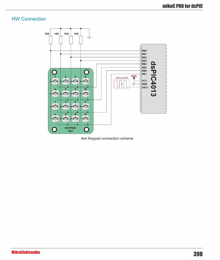
398
mikoC PRO for dsPIC
MikroElektronika
HW Connection
4x4 Keypad connection scheme

mikroC PRO for dsPIC
MikroElektronika399
Lcd LibraryThe mikroC PRO for dsPIC30/33 and PIC24 provides a library for communication with Lcds (with HD44780 compliant controllers) through the 4-bit interface. An example of Lcd connections is given on the schematic at the bottom of this page.
For creating a set of custom Lcd characters use Lcd Custom Character Tool.
Library Dependency Tree
The following variables must be defined in all projects using Lcd Library :
Description : Example :
extern sfr sbit LCD_RS: Register Select line. sbit LCD_RS at LATD0_bit;
extern sfr sbit LCD_EN: Enable line. sbit LCD_EN at LATD1_bit;
extern sfr sbit LCD_D4; Data 4 line. sbit LCD_D4 at LATB0_bit;
extern sfr sbit LCD_D5; Data 5 line. sbit LCD_D5 at LATB1_bit;
extern sfr sbit LCD_D6; Data 6 line. sbit LCD_D6 at LATB2_bit;
extern sfr sbit LCD_D7; Data 7 line. sbit LCD_D7 at LATB3_bit
extern sfr sbit LCD_RS_Direction; Register Select direction pin. sbit LCD_RS_Direction at TRISD0_
bit;
extern sfr sbit LCD_EN_Direction; Enable direction pin. sbit LCD_EN_Direction at TRISD1_
bit;
extern sfr sbit LCD_D4_Direction; Data 4 direction pin. sbit LCD_D4_Direction at TRISB0_
bit;
extern sfr sbit LCD_D5_Direction; Data 5 direction pin. sbit LCD_D5_Direction at TRISB1_
bit;
extern sfr sbit LCD_D6_Direction; Data 6 direction pin. sbit LCD_D6_Direction at TRISB2_
bit;
extern sfr sbit LCD_D7_Direction; Data 7 direction pin. sbit LCD_D7_Direction at TRISB3_
bit;
Keypad_Key_Click
Library Routines
- Lcd_Init - Lcd_Out - Lcd_Out_Cp - Lcd_Chr - Lcd_Chr_Cp - Lcd_Cmd

400
mikoC PRO for dsPIC
MikroElektronika
Lcd_Init
Prototype void Lcd_Init();
Description Initializes Lcd module.Parameters None.Returns Nothing.Requires Global variables:
- LCD_RS: Register Select (data/instruction) signal pin - LCD_EN: Enable signal pin - LCD_D4: Data bit 4 - LCD_D5: Data bit 5 - LCD_D6: Data bit 6 - LCD_D7: Data bit 7
- LCD_RS_Direction: Direction of the Register Select pin - LCD_EN_Direction: Direction of the Enable signal pin - LCD_D4_Direction: Direction of the Data 4 pin - LCD_D5_Direction: Direction of the Data 5 pin - LCD_D6_Direction: Direction of the Data 6 pin - LCD_D7_Direction: Direction of the Data 7 pin
must be defined before using this function.Example // Lcd module connections
sbit LCD_RS at LATD0_bit;sbit LCD_EN at LATD1_bit;sbit LCD_D4 at LATB0_bit;sbit LCD_D5 at LATB1_bit;sbit LCD_D6 at LATB2_bit;sbit LCD_D7 at LATB3_bit;
sbit LCD_RS_Direction at TRISD0_bit;sbit LCD_EN_Direction at TRISD1_bit;sbit LCD_D4_Direction at TRISB0_bit;sbit LCD_D5_Direction at TRISB1_bit;sbit LCD_D6_Direction at TRISB2_bit;sbit LCD_D7_Direction at TRISB3_bit;// End Lcd module connections...
Lcd_Init();
Notes None

mikroC PRO for dsPIC
MikroElektronika401
Lcd_Out
Lcd_Out_Cp
Lcd_Chr
Prototype void Lcd_Out(unsigned int row, unsigned int column, char *text);
Description Prints text on Lcd starting from specified position. Both string variables and literals can be passed as a text.
Parameters - row: starting position row number - column: starting position column number - text: text to be written
Returns Nothing.Requires The Lcd module needs to be initialized. See Lcd_Init routine.Example // Write text “Hello!” on Lcd starting from row 1, column 3:
Lcd_Out(1, 3, “Hello!”);
Notes None
Prototype void Lcd_Chr(unsigned int row, unsigned int column, char out_char);
Description Prints character on Lcd at specified position. Both variables and literals can be passed as a character.
Parameters - row: writing position row number - column: writing position column number - out_char: character to be written
Returns Nothing.Requires The Lcd module needs to be initialized. See Lcd_Init routine.Example // Write character “i” at row 2, column 3:
Lcd_Chr(2, 3, ‘i’);
Notes None
Prototype void Lcd_Out_Cp(char *text);
Returns Nothing.Description Prints text on Lcd at current cursor position. Both string variables and literals can be passed as a
text.Parameters - text: text to be written Requires The Lcd module needs to be initialized. See Lcd_Init routine.Example // Write text “Here!” at current cursor position:
Lcd_Out_Cp(“Here!”);
Notes None

402
mikoC PRO for dsPIC
MikroElektronika
Lcd_Chr_Cp
Lcd_Cmd
Available Lcd Commands
Prototype void Lcd_Chr_Cp(char out_char);
Description Prints character on Lcd at current cursor position. Both variables and literals can be passed as a character.
Parameters - out_char: character to be written Returns Nothing.Requires The Lcd module needs to be initialized. See Lcd_Init routine.Example // Write character “e” at current cursor position:
Lcd_Chr_Cp(‘e’);
Notes None
Prototype void Lcd_Cmd(char out_char);
Description Sends command to Lcd.Parameters - out_char: command to be sent Returns Nothing.Requires The Lcd module needs to be initialized. See Lcd_Init table.Example // Clear Lcd display:
Lcd_Cmd(_LCD_CLEAR);
Notes Predefined constants can be passed to the function, see Available Lcd Commands.
Lcd Command Purpose_LCD_FIRST_ROW Move cursor to the 1st row_LCD_SECOND_ROW Move cursor to the 2nd row_LCD_THIRD_ROW Move cursor to the 3rd row_LCD_FOURTH_ROW Move cursor to the 4th row_LCD_CLEAR Clear display
_LCD_RETURN_HOME Return cursor to home position, returns a shifted display to its original position. Display data RAM is unaffected.
_LCD_CURSOR_OFF Turn off cursor_LCD_UNDERLINE_ON Underline cursor on_LCD_BLINK_CURSOR_ON Blink cursor on_LCD_MOVE_CURSOR_LEFT Move cursor left without changing display data RAM_LCD_MOVE_CURSOR_RIGHT Move cursor right without changing display data RAM_LCD_TURN_ON Turn Lcd display on_LCD_TURN_OFF Turn Lcd display off_LCD_SHIFT_LEFT Shift display left without changing display data RAM_LCD_SHIFT_RIGHT Shift display right without changing display data RAM

mikroC PRO for dsPIC
MikroElektronika403
Library Example
The following code demonstrates usage of the Lcd Library routines:
Copy Code To Clipboard
// LCD module connectionssbit LCD_RS at LATD0_bit;sbit LCD_EN at LATD1_bit;sbit LCD_D4 at LATB0_bit;sbit LCD_D5 at LATB1_bit;sbit LCD_D6 at LATB2_bit;sbit LCD_D7 at LATB3_bit;
sbit LCD_RS_Direction at TRISD0_bit;sbit LCD_EN_Direction at TRISD1_bit;sbit LCD_D4_Direction at TRISB0_bit;sbit LCD_D5_Direction at TRISB1_bit;sbit LCD_D6_Direction at TRISB2_bit;sbit LCD_D7_Direction at TRISB3_bit;// End LCD module connections
char txt1[] = "mikroElektronika"; char txt2[] = "EasydsPIC4A";char txt3[] = "Lcd4bit";char txt4[] = "example";
char i; // Loop variable
void Move_Delay() { // Function used for text moving Delay_ms(500); // You can change the moving speed here}
void main(){ ADPCFG = 0xFFFF; // Configure AN pins as digital I/O
Lcd_Init(); // Initialize LCD
Lcd_Cmd(_LCD_CLEAR); // Clear display Lcd_Cmd(_LCD_CURSOR_OFF); // Cursor off Lcd_Out(1,6,txt3); // Write text in first row
Lcd_Out(2,6,txt4); // Write text in second row Delay_ms(2000); Lcd_Cmd(_LCD_CLEAR); // Clear display
Lcd_Out(1,1,txt1); // Write text in first row Lcd_Out(2,5,txt2); // Write text in second row
Delay_ms(2000);

404
mikoC PRO for dsPIC
MikroElektronika
// Moving text for(i=0; i<4; i++) { // Move text to the right 4 times Lcd_Cmd(_LCD_SHIFT_RIGHT); Move_Delay(); }
while(1) { // Endless loop for(i=0; i<8; i++) { // Move text to the left 7 times Lcd_Cmd(_LCD_SHIFT_LEFT); Move_Delay(); }
for(i=0; i<8; i++) { // Move text to the right 7 times Lcd_Cmd(_LCD_SHIFT_RIGHT); Move_Delay(); } }}
Lcd HW connection

mikroC PRO for dsPIC
MikroElektronika405
Manchester Code LibraryThe mikroC PRO for dsPIC30/33 and PIC24 provides a library for handling Manchester coded signals. The Manchester code is a code in which data and clock signals are combined to form a single self-synchronizing data stream; each encoded bit contains a transition at the midpoint of a bit period, the direction of transition determines whether the bit is 0 or 1; the second half is the true bit value and the first half is the complement of the true bit value (as shown in the figure below).
Important :
- The Manchester receive routines are blocking calls (Man_Receive_Init and Man_Synchro). This means that MCU will wait until the task has been performed (e.g. byte is received, synchronization achieved, etc). - Manchester code library implements time-based activities, so interrupts need to be disabled when using it.
The following variables must be defined in all projects using Manchester Code Library:
Description : Example :
extern sfr sbit MANRXPIN; Receive line. sbit MANRXPIN at RF0_bit;
extern sfr sbit MANTXPIN; Transmit line. sbit MANTXPIN at LATF1_bit;
extern sfr sbit MANRXPIN_Direction; Direction of the Receive pin. sbit MANRXPIN_Direction at
TRISF0_bit;
extern sfr sbit MANTXPIN_Direction; Direction of the Transmit pin. sbit MANTXPIN_Direction at
TRISF1_bit;
Keypad_Key_Click

406
mikoC PRO for dsPIC
MikroElektronika
Library Routines
- Man_Receive_Init - Man_Receive - Man_Send_Init - Man_Send - Man_Synchro - Man_Break
The following routines are for the internal use by compiler only:
- Manchester_0 - Manchester_1 - Manchester_Out
Man_Receive_Init
Prototype unsigned int Man_Receive_Init();
Description The function configures Receiver pin. After that, the function performs synchronization procedure in order to retrieve baud rate out of the incoming signal.
Parameters None.Returns - 0 - if initialization and synchronization were successful.
- 1 - upon unsuccessful synchronization. - 255 - upon user abort.
Requires Global variables :
- MANRXPIN : Receive line - MANRXPIN_Direction : Direction of the receive pin
must be defined before using this function. Example ‘ Initialize Receiver
sbit MANRXPIN at RF0_bit;sbit MANRXPIN_Direction at TRISF0s_bit;...if (Man_Receive_Init() == 0) {...}
Notes In case of multiple persistent errors on reception, the user should call this routine once again or Man_Synchro routine to enable synchronization.
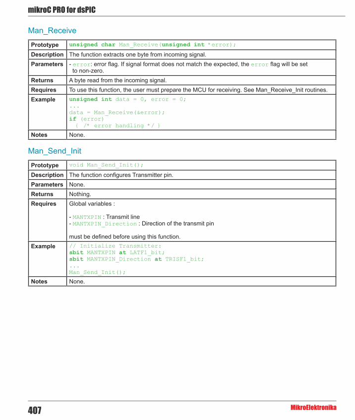
mikroC PRO for dsPIC
MikroElektronika407
Man_Receive
Man_Send_Init
Prototype unsigned char Man_Receive(unsigned int *error);
Description The function extracts one byte from incoming signal.Parameters - error: error flag. If signal format does not match the expected, the error flag will be set
to non-zero. Returns A byte read from the incoming signal.Requires To use this function, the user must prepare the MCU for receiving. See Man_Receive_Init routines.Example unsigned int data = 0, error = 0;
...data = Man_Receive(&error);if (error) { /* error handling */ }
Notes None.
Prototype void Man_Send_Init();
Description The function configures Transmitter pin.Parameters None.Returns Nothing.Requires Global variables :
- MANTXPIN : Transmit line - MANTXPIN_Direction : Direction of the transmit pin
must be defined before using this function. Example // Initialize Transmitter:
sbit MANTXPIN at LATF1_bit;sbit MANTXPIN_Direction at TRISF1_bit;...Man_Send_Init();
Notes None.

408
mikoC PRO for dsPIC
MikroElektronika
Man_Send
Man_Synchro
Prototype void Man_Send(unsigned char tr_data);
Description Sends one byte.Parameters - tr_data: data to be sent Returns Nothing.Requires To use this function, the user must prepare the MCU for sending. See Man_Send_Init routine.Example unsigned int msg;
...Man_Send(msg);
Notes Baud rate used is 500 bps.
Prototype unsigned int Man_Synchro();
Description Measures half of the manchester bit length with 10us resolution.Parameters None.Returns 0 - if synchronization was not successful.
Half of the manchester bit length, given in multiples of 10us - upon successful synchronization. Requires To use this function, you must first prepare the MCU for receiving. See Man_Receive_Init.Example unsigned int man__half_bit_len;
...man__half_bit_len = Man_Synchro();
Notes None.

mikroC PRO for dsPIC
MikroElektronika409
Man_Break
Prototype void Man_Break();
Description Man_Receive is blocking routine and it can block the program flow. Call this routine from interrupt to unblock the program execution. This mechanism is similar to WDT.
Parameters None.Returns Nothing.Requires Nothing.Example char data1, error, counter = 0;
void Timer1Int() org IVT_ADDR_T1INTERRUPT {
if (counter >= 20) { Man_Break(); counter = 0; // reset counter } else counter++; // increment counter
T1IF_bit = 0; // Clear Timer1 overflow interrupt flag}
void main() {
...
if (Man_Receive_Init() == 0) { ... }
...
// try Man_Receive with blocking prevention mechanism IPC0 = IPC0 | 0x1000; // Interrupt priority level = 1 T1IE_bit= 1; // Enable Timer1 interrupts T1CON = 0x8030; // Timer1 ON, internal clock FCY, prescaler 1:256 data1 = Man_Receive(&error); T1IE_bit= 0; // Disable Timer1 interrupts}
Notes Interrupts should be disabled before using Manchester routines again (see note at the top of this page).

410
mikoC PRO for dsPIC
MikroElektronika
Library Example
The following code is code for the Manchester receiver, it shows how to use the Manchester Library for receiving data:
Copy Code To Clipboard
// LCD module connectionssbit LCD_RS at LATD0_bit;sbit LCD_EN at LATD1_bit;sbit LCD_D4 at LATB0_bit;sbit LCD_D5 at LATB1_bit;sbit LCD_D6 at LATB2_bit;sbit LCD_D7 at LATB3_bit;
sbit LCD_RS_Direction at TRISD0_bit;sbit LCD_EN_Direction at TRISD1_bit;sbit LCD_D4_Direction at TRISB0_bit;sbit LCD_D5_Direction at TRISB1_bit;sbit LCD_D6_Direction at TRISB2_bit;sbit LCD_D7_Direction at TRISB3_bit;// End LCD module connections
// Manchester module connectionssbit MANRXPIN at RF0_bit;sbit MANRXPIN_Direction at TRISF0_bit;sbit MANTXPIN at LATF1_bit;sbit MANTXPIN_Direction at TRISF1_bit;// End Manchester module connections
char error, ErrorCount, temp;
void main() { ErrorCount = 0; ADPCFG = 0xFFFF; // Configure AN pins as digital I/O TRISB = 0; LATB = 0;
Lcd_Init(); // Initialize LCD Lcd_Cmd(_LCD_CLEAR); // Clear LCD display
Man_Receive_Init(); // Initialize Receiver while (1) { // Endless loop
Lcd_Cmd(_LCD_FIRST_ROW); // Move cursor to the 1st row while (1) { // Wait for the “start” byte temp = Man_Receive(&error); // Attempt byte receive if (temp == 0x0B) // “Start” byte, see Transmitter example break; // We got the starting sequence if (error) // Exit so we do not loop forever break; }

mikroC PRO for dsPIC
MikroElektronika411
do { temp = Man_Receive(&error); // Attempt byte receive if (error) { // If error occured Lcd_Chr_CP('?'); // Write question mark on LCD ErrorCount++; // Update error counter if (ErrorCount > 20) { // In case of multiple errors temp = Man_Synchro(); // Try to synchronize again //Man_Receive_Init(); // Alternative, try to Initialize Receiver again ErrorCount = 0; // Reset error counter } } else { // No error occured if (temp != 0x0E) // If "End" byte was received(see Transmitter example) Lcd_Chr_CP(temp); // do not write received byte on LCD } Delay_ms(25); } while (temp != 0x0E); // If "End" byte was received exit do loop }}
The following code is code for the Manchester receiver, it shows how to use the Manchester Library for receiving data:
Copy Code To Clipboard
// Manchester module connectionssbit MANRXPIN at RF0_bit;sbit MANRXPIN_Direction at TRISF0_bit;sbit MANTXPIN at LATF1_bit;sbit MANTXPIN_Direction at TRISF1_bit;// End Manchester module connections
char index, character;char s1[] = "mikroElektronika";
void main() {
ADPCFG = 0xFFFF; // Configure AN pins as digital I/O TRISB = 0; LATB = 0;
Man_Send_Init(); // Initialize transmitter
while (1) { // Endless loop Man_Send(0x0B); // Send "start" byte Delay_ms(100); // Wait for a while
character = s1[0]; // Take first char from string index = 0; // Initialize index variable

412
mikoC PRO for dsPIC
MikroElektronika
while (character) { // String ends with zero Man_Send(character); // Send character Delay_ms(90); // Wait for a while index++; // Increment index variable character = s1[index]; // Take next char from string } Man_Send(0x0E); // Send "end" byte Delay_ms(1000); }}
Connection Example
Simple Transmitter connection
Simple Receiver connection

mikroC PRO for dsPIC
MikroElektronika413
Multi Media Card LibraryThe Multi Media Card (MMC) is a Flash memory card standard. MMC cards are currently available in sizes up to and including 32 GB and are used in cellular phones, digital audio players, digital cameras and PDA’s. mikroC PRO for dsPIC30/33 and PIC24 provides a library for accessing data on Multi Media Card via SPI communication. This library also supports SD (Secure Digital) and high capacity SDHC (Secure Digital High Capacity) memory cards .
Secure Digital Card
Secure Digital (SD) is a Flash memory card standard, based on the older Multi Media Card (MMC) format. SD cards are currently available in sizes of up to and including 2 GB, and are used in digital cameras, digital camcorders, handheld computers, media players, mobile phones, GPS receivers, video games and PDAs.
Secure Digital High Capacity Card
SDHC (Secure Digital High Capacity, SD 2.0) is an extension of the SD standard which increases card's storage capacity up to 32 GB by using sector addressing instead of byte addressing in the previous SD standard. SDHC cards share the same physical and electrical form factor as older (SD 1.x) cards, allowing SDHC-devices to support both newer SDHC cards and older SD-cards. The current standard limits the maximum capacity of an SDHC card to 32 GB.
Important :
- Routines for file handling can be used only with FAT16 file system. - Library functions create and read files from the root directory only. - Library functions populate both FAT1 and FAT2 tables when writing to files, but the file data is being read from the FAT1 table only; i.e. there is no recovery if the FAT1 table gets corrupted. - If MMC/SD card has Master Boot Record (MBR), the library will work with the first available primary (logical) partition that has non-zero size. If MMC/SD card has Volume Boot Record (i.e. there is only one logical partition and no MBRs), the library works with entire card as a single partition. For more information on MBR, physical and logical drives, primary/secondary partitions and partition tables, please consult other resources, e.g. Wikipedia and similar. - Before write operation, make sure you don’t overwrite boot or FAT sector as it could make your card on PC or digital camera unreadable. Drive mapping tools, such as Winhex, can be of a great assistance. - Library uses SPI module for communication. The user must initialize the appropriate SPI module before using the MMC Library. - For MCUs with multiple SPI modules it is possible to initialize all of them and then switch by using the SPI_Set_Active() function. See the SPI Library functions.
The SPI module has to be initialized through SPIx_Init_Advanced routine with the following parameters:
- SPI Master - 8bit mode - secondary prescaler 1 - primary prescaler 64 - Slave Select disabled - data sampled in the middle of data output time - clock idle high - Serial output data changes on transition from active clock state to idle clock state
Tip : Once the MMC/SD card is initialized, SPI module can be reinitialized at higher a speed. See the Mmc_Init and Mmc_Fat_Init routines.

414
mikoC PRO for dsPIC
MikroElektronika
Library Dependency Tree
The following variable must be defined in all projects using MMC library:
Description : Example :
extern sfr sbit Mmc_Chip_Select; Chip select pin. sbit Mmc_Chip_Select at LATF0_
bit;
extern sfr sbit Mmc_Chip_Select_Direction;
Direction of the chip select pin.
sbit Mmc_Chip_Select_Direction at TRISF0_bit;
External dependencies of MMC Library
Library Routines
- Mmc_Init - Mmc_Read_Sector - Mmc_Write_Sector - Mmc_Read_Cid - Mmc_Read_Csd
Routines for file handling:
- Mmc_Fat_Init - Mmc_Fat_QuickFormat - Mmc_Fat_Assign - Mmc_Fat_Reset - Mmc_Fat_Read - Mmc_Fat_Rewrite - Mmc_Fat_Append - Mmc_Fat_Delete - Mmc_Fat_Write - Mmc_Fat_Set_File_Date - Mmc_Fat_Get_File_Date - Mmc_Fat_Get_File_Date_Modified - Mmc_Fat_Get_File_Size - Mmc_Fat_Get_Swap_File

mikroC PRO for dsPIC
MikroElektronika415
Mmc_Init
Prototype unsigned int Mmc_Init();
Description Initializes MMC through hardware SPI interface.
Mmc_Init needs to be called before using other functions of this library.Parameters None.Returns - 0 - if MMC/SD card was detected and successfully initialized
- 1 - otherwise Requires The appropriate hardware SPI module must be previously initialized.
Global variables :
- Mmc_Chip_Select: Chip Select line - Mmc_Chip_Select_Direction: Direction of the Chip Select pin
must be defined before using this function. Example // MMC module connections
sbit Mmc_Chip_Select at LATF0_bit;sbit Mmc_Chip_Select_Direction at TRISF0_bit;// MMC module connections...// Initialize the SPI moduleSPI1_Init_Advanced(_SPI_MASTER, _SPI_8_BIT, _SPI_PRESCALE_SEC_1, _SPI_PRESCALE_PRI_64,_SPI_SS_DISABLE, _SPI_DATA_SAMPLE_MIDDLE, _SPI_CLK_IDLE_HIGH, _SPI_ACTIVE_2_IDLE);// Loop until MMC is initializedwhile (Mmc_Init()) ; // Reinitialize the SPI module at higher speed (change primary prescaler).SPI1_Init_Advanced(_SPI_MASTER, _SPI_8_BIT, _SPI_PRESCALE_SEC_1, _SPI_PRESCALE_PRI_4,_SPI_SS_DISABLE, _SPI_DATA_SAMPLE_MIDDLE, _SPI_CLK_IDLE_HIGH, _SPI_ACTIVE_2_IDLE);
Notes None.

416
mikoC PRO for dsPIC
MikroElektronika
Mmc_Read_Sector
Mmc_Write_Sector
Prototype unsigned int Mmc_Read_Sector(unsigned long sector, char *dbuff);
Description The function reads one sector (512 bytes) from MMC card.Parameters - sector: MMC/SD card sector to be read.
- dbuff: buffer of minimum 512 bytes in length for data storage. Returns - 0 - if reading was successful
- 1 - if an error occurred Requires MMC/SD card must be initialized. See Mmc_Init.Example // read sector 510 of the MMC/SD card
unsigned int error;unsigned long sectorNo = 510;char dataBuffer[512];...error = Mmc_Read_Sector(sectorNo, dataBuffer);
Notes None.
Prototype unsigned int Mmc_Write_Sector(unsigned long sector, char *dbuff);
Description The function writes 512 bytes of data to one MMC card sector.Parameters - sector: MMC/SD card sector to be written to.
- dbuff: data to be written (buffer of minimum 512 bytes in length). Returns - 0 - if writing was successful
- 1 - if there was an error in sending write command - 2 - if there was an error in writing (data rejected)
Requires MMC/SD card must be initialized. See Mmc_Init.Example // write to sector 510 of the MMC/SD card
unsigned int error;unsigned long sectorNo = 510;char dataBuffer[512];...error = Mmc_Write_Sector(sectorNo, dataBuffer);
Notes None.

mikroC PRO for dsPIC
MikroElektronika417
Mmc_Read_Cid
Mmc_Read_Csd
Prototype unsigned int Mmc_Read_Cid(char *data_cid);
Description The function reads 16-byte CID register.Parameters - data_cid: buffer of minimum 16 bytes in length for storing CID register content. Returns - 0 - if CID register was read successfully
- 1 - if there was an error while reading Requires MMC/SD card must be initialized. See Mmc_Init.Example unsigned int error;
char dataBuffer[16];...error = Mmc_Read_Cid(dataBuffer);
Notes None.
Prototype unsigned int Mmc_Read_Csd(char *data_csd);
Description The function reads 16-byte CSD register.Parameters - data_csd: buffer of minimum 16 bytes in length for storing CSD register content. Returns - 0 - if CSD register was read successfully
- 1 - if there was an error while reading Requires MMC/SD card must be initialized. See Mmc_Init.Example unsigned int error;
char dataBuffer[16];...error = Mmc_Read_Csd(dataBuffer);
Notes None.

418
mikoC PRO for dsPIC
MikroElektronika
Mmc_Fat_Init
Prototype unsigned int Mmc_Fat_Init();
Description Initializes MMC/SD card, reads MMC/SD FAT16 boot sector and extracts necessary data needed by the library.
Parameters None.Returns - 0 - if MMC/SD card was detected and successfully initialized
- 1 - if FAT16 boot sector was not found - 255 - if MMC/SD card was not detected
Requires Global variables : - Mmc_Chip_Select: Chip Select line - Mmc_Chip_Select_Direction: Direction of the Chip Select pin
must be defined before using this function.
The appropriate hardware SPI module must be previously initialized. See the SPIx_Init, SPIx_Init_Advanced routines.
Example // MMC module connections sbit Mmc_Chip_Select at LATF0_bit;sbit Mmc_Chip_Select_Direction at TRISF0_bit;// MMC module connections
#include <spi_const.h>...// Initialize the SPI moduleSPI1_Init_Advanced(_SPI_MASTER, _SPI_8_BIT, _SPI_PRESCALE_SEC_1, _SPI_PRESCALE_PRI_64,_SPI_SS_DISABLE, _SPI_DATA_SAMPLE_MIDDLE, _SPI_CLK_IDLE_HIGH, _SPI_ACTIVE_2_IDLE);// Initialize MMC/SD card and MMC_FAT16 library globalsMmc_Fat_Init();// Reinitialize the SPI module at higher speed (change primary prescaler).SPI1_Init_Advanced(_SPI_MASTER, _SPI_8_BIT, _SPI_PRESCALE_SEC_1, _SPI_PRESCALE_PRI_4,_SPI_SS_DISABLE, _SPI_DATA_SAMPLE_MIDDLE, _SPI_CLK_IDLE_HIGH, _SPI_ACTIVE_2_IDLE);
Notes MMC/SD card has to be formatted to FAT16 file system.

mikroC PRO for dsPIC
MikroElektronika419
Mmc_Fat_QuickFormat
Prototype unsigned int Mmc_Fat_QuickFormat(char *mmc_fat_label);
Description Formats to FAT16 and initializes MMC/SD card.Parameters - mmc_fat_label: volume label (11 characters in length). If less than 11 characters are provided, the
label will be padded with spaces. If null string is passed volume will not be labeled Returns - 0 - if MMC/SD card was detected, successfully formated and initialized
- 1 - if FAT16 format was unseccessful - 255 - if MMC/SD card was not detected
Requires The appropriate hardware SPI module must be previously initialized.Example // Initialize the SPI module
SPI1_Init_Advanced(_SPI_MASTER, _SPI_8_BIT, _SPI_PRESCALE_SEC_1, _SPI_PRESCALE_PRI_64, _SPI_SS_DISABLE, _SPI_DATA_SAMPLE_MIDDLE, _SPI_CLK_IDLE_HIGH, _SPI_ACTIVE_2_IDLE);// Format and initialize MMC/SD card and MMC_FAT16 library globalsMmc_Fat_QuickFormat(“mikroE”);// Reinitialize the SPI module at higher speed (change primary prescaler).SPI1_Init_Advanced(_SPI_MASTER, _SPI_8_BIT, _SPI_PRESCALE_SEC_1, _SPI_PRESCALE_PRI_4,_SPI_SS_DISABLE, _SPI_DATA_SAMPLE_MIDDLE, _SPI_CLK_IDLE_HIGH, _SPI_ACTIVE_2_IDLE);
Notes This routine can be used instead or in conjunction with Mmc_Fat_Init routine.
If MMC/SD card already contains a valid boot sector, it will remain unchanged (except volume label field) and only FAT and ROOT tables will be erased. Also, the new volume label will be set.

420
mikoC PRO for dsPIC
MikroElektronika
Prototype unsigned int Mmc_Fat_Assign(char *filename, char file_cre_attr);
Description Assigns file for file operations (read, write, delete...). All subsequent file operations will be applied on an assigned file.
Parameters - filename: name of the file that should be assigned for file operations. File name should be in DOS 8.3 (file_name.extension) format. The file name and extension will be automatically padded with spaces by the library if they have less than length required (i.e. “mikro.tx” -> “mikro .tx “), so the user does no have to take care of that. The file name and extension are case insensitive. The library will convert them to proper case automatically, so the user does not have to take care of that. Also, in order to keep backward compatibility with the first version of this library, file names can be entered as UPPERCASE string of 11 bytes in length with no dot character between file name and extension (i.e. “MIKROELETXT” -> MIKROELE.TXT). In this case last 3 characters of the string are considered to be file extension.
- file_cre_attr: file creation and attributes flags. Each bit corresponds to the appropriate file attribute:
Returns - 1 - if file already exists or file does not exist but a new file is created. - 0 - if file does not exist and no new file is created.
Requires MMC/SD card and MMC library must be initialized for file operations. See Mmc_Fat_Init.Example // create file with archive attribute if it does not already exist
Mmc_Fat_Assign(“MIKRO007.TXT”,0xA0);
Notes Long File Names (LFN) are not supported.
Mmc_Fat_Assign
Bit Mask Description0 0x01 Read Only1 0x02 Hidden2 0x04 System3 0x08 Volume Label4 0x10 Subdirectory5 0x20 Archive6 0x40 Device (internal use only, never found on disk)
7 0x80 File creation flag. If file does not exist and this flag is set, a new file with specified name will be created.

mikroC PRO for dsPIC
MikroElektronika421
Mmc_Fat_Reset
Mmc_Fat_Read
Prototype void Mmc_Fat_Reset(unsigned long *size);
Description Procedure resets the file pointer (moves it to the start of the file) of the assigned file, so that the file can be read.
Parameters - size: buffer to store file size to. After file has been opened for reading, its size is returned through this parameter.
Returns Nothing.Requires MMC/SD card and MMC library must be initialized for file operations. See Mmc_Fat_Init.
The file must be previously assigned. See Mmc_Fat_Assign.Example unsigned long size;
...Mmc_Fat_Reset(size);
Notes None.
Prototype void Mmc_Fat_Read(unsigned short *bdata);
Description Reads a byte from the currently assigned file opened for reading. Upon function execution file pointers will be set to the next character in the file.
Parameters - bdata: buffer to store read byte to. Upon this function execution read byte is returned through this parameter.
Returns Nothing.Requires MMC/SD card and MMC library must be initialized for file operations. See Mmc_Fat_Init.
The file must be previously assigned. See Mmc_Fat_Assign.
The file must be opened for reading. See Mmc_Fat_Reset.Example char character;
...Mmc_Fat_Read(&character);
Notes None.
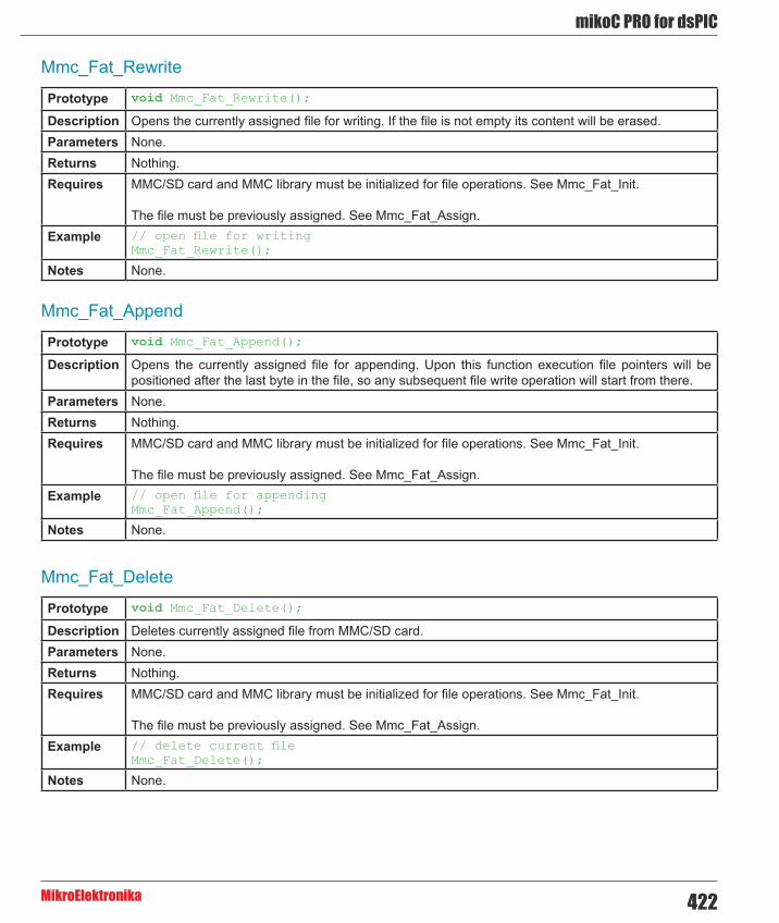
422
mikoC PRO for dsPIC
MikroElektronika
Mmc_Fat_Rewrite
Mmc_Fat_Append
Mmc_Fat_Delete
Prototype void Mmc_Fat_Rewrite();
Description Opens the currently assigned file for writing. If the file is not empty its content will be erased.Parameters None.Returns Nothing.Requires MMC/SD card and MMC library must be initialized for file operations. See Mmc_Fat_Init.
The file must be previously assigned. See Mmc_Fat_Assign.Example // open file for writing
Mmc_Fat_Rewrite();
Notes None.
Prototype void Mmc_Fat_Append();
Description Opens the currently assigned file for appending. Upon this function execution file pointers will be positioned after the last byte in the file, so any subsequent file write operation will start from there.
Parameters None.Returns Nothing.Requires MMC/SD card and MMC library must be initialized for file operations. See Mmc_Fat_Init.
The file must be previously assigned. See Mmc_Fat_Assign.Example // open file for appending
Mmc_Fat_Append();
Notes None.
Prototype void Mmc_Fat_Delete();
Description Deletes currently assigned file from MMC/SD card. Parameters None.Returns Nothing.Requires MMC/SD card and MMC library must be initialized for file operations. See Mmc_Fat_Init.
The file must be previously assigned. See Mmc_Fat_Assign.Example // delete current file
Mmc_Fat_Delete();
Notes None.

mikroC PRO for dsPIC
MikroElektronika423
Mmc_Fat_Write
Mmc_Fat_Set_File_Date
Prototype void Mmc_Fat_Write(char *fdata, unsigned data_len);
Description Writes requested number of bytes to the currently assigned file opened for writing.Parameters - fdata: data to be written.
- data_len: number of bytes to be written. Returns Nothing.Requires MMC/SD card and MMC library must be initialized for file operations. See Mmc_Fat_Init.
The file must be previously assigned. See Mmc_Fat_Assign.
The file must be opened for writing. See Mmc_Fat_Rewrite or Mmc_Fat_Append.Example char file_contents[42];
...Mmc_Fat_Write(file_contents, 42); // write data to the assigned file
Notes None.
Prototype void Mmc_Fat_Set_File_Date(unsigned int year, unsigned short day,unsigned short hours, unsigned short mins, unsigned short seconds);
Description Sets the date/time stamp. Any subsequent file write operation will write this stamp to the currently assigned file’s time/date attributes.
Parameters - year: year attribute. Valid values: 1980-2107 - month: month attribute. Valid values: 1-12 - day: day attribute. Valid values: 1-31 - hours: hours attribute. Valid values: 0-23 - mins: minutes attribute. Valid values: 0-59 - seconds: seconds attribute. Valid values: 0-59
Returns Nothing.Requires MMC/SD card and MMC library must be initialized for file operations. See Mmc_Fat_Init.
The file must be previously assigned. See Mmc_Fat_Assign.
The file must be opened for writing. See Mmc_Fat_Rewrite or Mmc_Fat_Append.Example // April 1st 2005, 18:07:00
Mmc_Fat_Set_File_Date(2005, 4, 1, 18, 7, 0);
Notes None.

424
mikoC PRO for dsPIC
MikroElektronika
Mmc_Fat_Get_File_Date
Prototype void Mmc_Fat_Get_File_Date(unsigned int *year, unsigned short *month, unsigned short *day, unsigned short *hours, unsigned short *mins);
Description Reads time/date attributes of the currently assigned file.Parameters - year: buffer to store year attribute to. Upon function execution year attribute is returned through this
parameter. - month: buffer to store month attribute to. Upon function execution month attribute is returned through this parameter. - day: buffer to store day attribute to. Upon function execution day attribute is returned through this parameter. - hours: buffer to store hours attribute to. Upon function execution hours attribute is returned through this parameter. - mins: buffer to store minutes attribute to. Upon function execution minutes attribute is returned through this parameter.
Returns Nothing.Requires MMC/SD card and MMC library must be initialized for file operations. See Mmc_Fat_Init.
The file must be previously assigned. See Mmc_Fat_Assign.Example // get Date/time of file
unsigned yr;char mnth, dat, hrs, mins;...file_Name = “MYFILEABTXT”;Mmc_Fat_Assign(file_Name);Mmc_Fat_Get_File_Date(&yr, &mnth, &day, &hrs, &mins);
Notes None.

mikroC PRO for dsPIC
MikroElektronika425
Mmc_Fat_Get_File_Date_Modified
Mmc_Fat_Get_File_Size
Prototype void Mmc_Fat_Get_File_Date_Modified(unsigned int *year, unsigned short *month, unsigned short *day, unsigned short *hours, unsigned short *mins);
Description Retrieves the last modification date/time for the currently selected file. Seconds are not being retrieved since they are written in 2-sec increments.
Parameters - year: buffer to store year attribute to. Upon function execution year attribute is returned through this parameter. - month: buffer to store month attribute to. Upon function execution month attribute is returned through this parameter. - day: buffer to store day attribute to. Upon function execution day attribute is returned through this parameter. - hours: buffer to store hours attribute to. Upon function execution hours attribute is returned through this parameter. - mins: buffer to store minutes attribute to. Upon function execution minutes attribute is returned through this parameter.
Returns Nothing.Requires The file must be assigned, see Mmc_Fat_Assign.Example // get modification Date/time of file
unsigned yr;char mnth, dat, hrs, mins;...file_Name = “MYFILEABTXT”;Mmc_Fat_Assign(file_Name);Mmc_Fat_Get_File_Date_Modified(&yr, &mnth, &day, &hrs, &mins);
Prototype unsigned long Mmc_Fat_Get_File_Size();
Description This function reads size of the currently assigned file in bytes. Parameters None.Returns This function returns size of active file (in bytes).Requires MMC/SD card and MMC library must be initialized for file operations. See Mmc_Fat_Init.
The file must be previously assigned. See Mmc_Fat_Assign.Example unsigned long my_file_size;
...my_file_size = Mmc_Fat_Get_File_Size();
Notes None

426
mikoC PRO for dsPIC
MikroElektronika
Prototype unsigned long Mmc_Fat_Get_Swap_File(unsigned long sectors_cnt, char* filename, char file_attr);
Description This function is used to create a swap file of predefined name and size on the MMC/SD media. If a file with specified name already exists on the media, search for consecutive sectors will ignore sectors occupied by this file. Therefore, it is recommended to erase such file if it already exists before calling this function. If it is not erased and there is still enough space for a new swap file, this function will delete it after allocating new memory space for a new swap file.
The purpose of the swap file is to make reading and writing to MMC/SD media as fast as possible, by using the Mmc_Read_Sector() and Mmc_Write_Sector() functions directly, without potentially damaging the FAT system. The swap file can be considered as a “window” on the media where the user can freely write/read data. It’s main purpose in this library is to be used for fast data acquisition; when the time-critical acquisition has finished, the data can be re-written into a “normal” file, and formatted in the most suitable way.
Parameters - sectors_cnt: number of consecutive sectors that user wants the swap file to have. - filename: name of the file that should be assigned for file operations. File name should be in DOS 8.3 (file_name.extension) format. The file name and extension will be automatically padded with spaces by the library if they have less than length required (i.e. “mikro.tx” -> “mikro .tx “), so the user does no have to take care of that. The file name and extension are case insensitive. The library will convert them to proper case automatically, so the user does not have to take care of that. Also, in order to keep backward compatibility with the first version of this library, file names can be entered as UPPERCASE string of 11 bytes in length with no dot character between file name and extension (i.e. “MIKROELETXT” -> MIKROELE.TXT). In this case last 3 characters of the string are considered to be file extension.
- file_attr: file creation and attributes flags. Each bit corresponds to the appropriate file attribute:
Returns Number of the start sector for the newly created swap file, if there was enough free space on the MMC/SD card to create file of required size. 0 - otherwise.
Requires MMC/SD card and MMC library must be initialized for file operations. See Mmc_Fat_Init.
Mmc_Fat_Get_Swap_File
Bit Mask Description0 0x01 Read Only1 0x02 Hidden2 0x04 System3 0x08 Volume Label4 0x10 Subdirectory5 0x20 Archive6 0x40 Device (internal use only, never found on disk)7 0x80 Not used

mikroC PRO for dsPIC
MikroElektronika427
Requires MMC/SD card and MMC library must be initialized for file operations. See Mmc_Fat_Init.Example //-------------- Tries to create a swap file, whose size will be at least
100 sectors.//If it succeeds, it sends the No. of start sector over UARTvoid M_Create_Swap_File(){ size = Mmc_Fat_Get_Swap_File(100); if (size <> 0) { UART1_Write(0xAA); UART1_Write(Lo(size)); UART1_Write(Hi(size)); UART1_Write(Higher(size)); UART1_Write(Highest(size)); UART1_Write(0xAA); } }
Notes Long File Names (LFN) are not supported. Library Example
The following example demonstrates usage of the MMC and MMC_FAT routines.
Copy Code To Clipboard
// MMC module connectionssbit Mmc_Chip_Select at LATF0_bit; // for writing to output pin always use latchsbit Mmc_Chip_Select_Direction at TRISF0_bit;// eof MMC module connections
const LINE_LEN = 43;char err_txt[20] = “FAT16 not found”;char file_contents[LINE_LEN] = “XX MMC/SD FAT16 library by Anton Rieckertn”;char filename[14] = “MIKRO00x.TXT”; // File namesunsigned short loop, loop2;unsigned long i, size;char Buffer[512];
// UART1 write text and new line (carriage return + line feed)void UART1_Write_Line(char *uart_text) { UART1_Write_Text(uart_text); UART1_Write(13); UART1_Write(10); for(loop = 1; loop <= 99; loop++) { UART1_Write(‘.’); file_contents[0] = loop / 10 + 48; file_contents[1] = loop % 10 + 48; Mmc_Fat_Write(file_contents, LINE_LEN-1); // write data to the assigned file }}

428
mikoC PRO for dsPIC
MikroElektronika
// Creates many new files and writes data to themvoid M_Create_Multiple_Files() { for(loop2 = 'B'; loop2 <= 'Z'; loop2++) { UART1_Write(loop2); // signal the progress filename[7] = loop2; // set filename Mmc_Fat_Set_File_Date(2005,6,21,10,35,0); // Set file date & time info Mmc_Fat_Assign(&filename, 0xA0); // find existing file or create a new one Mmc_Fat_Rewrite(); // To clear file and start with new data for(loop = 1; loop <= 44; loop++) { file_contents[0] = loop / 10 + 48; file_contents[1] = loop % 10 + 48; Mmc_Fat_Write(file_contents, LINE_LEN-1); // write data to the assigned file } }}
// Opens an existing file and rewrites itvoid M_Open_File_Rewrite() { filename[7] = 'C'; Mmc_Fat_Assign(&filename, 0); Mmc_Fat_Rewrite(); for(loop = 1; loop <= 55; loop++) { file_contents[0] = loop / 10 + 65; file_contents[1] = loop % 10 + 65; Mmc_Fat_Write(file_contents, LINE_LEN-1); // write data to the assigned file }}
// Opens an existing file and appends data to it// (and alters the date/time stamp)void M_Open_File_Append() { filename[7] = 'B'; Mmc_Fat_Assign(&filename, 0); Mmc_Fat_Set_File_Date(2009, 1, 23, 17, 22, 0); Mmc_Fat_Append(); // Prepare file for append Mmc_Fat_Write(" for mikroElektronika 2005n", 27); // Write data to assigned file}
// Opens an existing file, reads data from it and puts it to UARTvoid M_Open_File_Read() { char character;
filename[7] = ‘B’; Mmc_Fat_Assign(&filename, 0); Mmc_Fat_Reset(&size); // To read file, procedure returns size of file for (i = 1; i <= size; i++) { Mmc_Fat_Read(&character); UART1_Write(character); // Write data to UART }}

mikroC PRO for dsPIC
MikroElektronika429
// Deletes a file. If file doesn't exist, it will first be created// and then deleted.void M_Delete_File() { filename[7] = 'F'; Mmc_Fat_Assign(filename, 0); Mmc_Fat_Delete();}
// Tests whether file exists, and if so sends its creation date// and file size via UARTvoid M_Test_File_Exist() { unsigned long fsize; unsigned int year; unsigned short month, day, hour, minute; unsigned char outstr[12];
filename[7] = 'B'; //uncomment this line to search for file that DOES exists// filename[7] = 'F'; //uncomment this line to search for file that DOES NOT exist if (Mmc_Fat_Assign(filename, 0)) { //--- file has been found - get its create date Mmc_Fat_Get_File_Date(&year, &month, &day, &hour, &minute); UART1_Write_Text(" created: "); WordToStr(year, outstr); UART1_Write_Text(outstr); ByteToStr(month, outstr); UART1_Write_Text(outstr); WordToStr(day, outstr); UART1_Write_Text(outstr); WordToStr(hour, outstr); UART1_Write_Text(outstr); WordToStr(minute, outstr); UART1_Write_Text(outstr);
//--- file has been found - get its modified date Mmc_Fat_Get_File_Date_Modified(&year, &month, &day, &hour, &minute); UART1_Write_Text(“ modified: “); WordToStr(year, outstr); UART1_Write_Text(outstr); ByteToStr(month, outstr); UART1_Write_Text(outstr); WordToStr(day, outstr); UART1_Write_Text(outstr); WordToStr(hour, outstr); UART1_Write_Text(outstr); WordToStr(minute, outstr); UART1_Write_Text(outstr);
//--- get file size fsize = Mmc_Fat_Get_File_Size(); LongToStr((signed long)fsize, outstr); UART1_Write_Line(outstr); }

430
mikoC PRO for dsPIC
MikroElektronika
else { //--- file was not found - signal it UART1_Write(0x55); Delay_ms(1000); UART1_Write(0x55); }}
// Tries to create a swap file, whose size will be at least 100// sectors (see Help for details)void M_Create_Swap_File() { unsigned int i;
for(i=0; i<512; i++) Buffer[i] = i;
size = Mmc_Fat_Get_Swap_File(5000, "mikroE.txt", 0x20); // see help on this function for details
if (size) { LongToStr((signed long)size, err_txt); UART1_Write_Line(err_txt);
for(i=0; i<5000; i++) { Mmc_Write_Sector(size++, Buffer); UART1_Write('.'); } }}
//-------------- Main. Uncomment the function(s) to test the desired operation(s)void main() { #define COMPLETE_EXAMPLE // comment this line to make simpler/smaller example PORTD = 0; TRISD = 0; PORTF = 0; TRISF = 0; ADPCFG = 0xFFFF; // initialize AN pins as digital //--- set up USART for the file read SPI1_Init_Advanced(_SPI_MASTER, _SPI_8_BIT, _SPI_PRESCALE_SEC_1, _SPI_PRESCALE_PRI_64, _SPI_SS_DISABLE, _SPI_DATA_SAMPLE_MIDDLE, _SPI_CLK_IDLE_HIGH, _SPI_ACTIVE_2_IDLE);
UART1_Init(19200); // Initialize UART module at 9600 bps Delay_ms(100); // Wait for UART module to stabilize

mikroC PRO for dsPIC
MikroElektronika431
U1MODEbits.ALTIO = 1; // Switch Rx and Tx pins on their alternate locations. // This is used to free the pins for other module, namely the SPI. //--- init the FAT library if (!Mmc_Fat_Init()) { // reinitialize spi at higher speed SPI1_Init_Advanced(_SPI_MASTER, _SPI_8_BIT, _SPI_PRESCALE_SEC_1, _SPI_PRESCALE_PRI_4, _SPI_SS_DISABLE, _SPI_DATA_SAMPLE_MIDDLE, _SPI_CLK_IDLE_HIGH, _SPI_ACTIVE_2_IDLE); //--- Test start UART1_Write_Line("Test Start."); //--- Test routines. Uncomment them one-by-one to test certain features M_Create_New_File(); #ifdef COMPLETE_EXAMPLE M_Create_Multiple_Files(); M_Open_File_Rewrite(); M_Open_File_Append(); M_Open_File_Read(); M_Delete_File(); M_Test_File_Exist(); M_Create_Swap_File(); #endif UART1_Write_Line("Test End.");
} else { UART1_Write_Line(err_txt); // Note: Mmc_Fat_Init tries to initialize a card more than once. // If card is not present, initialization may last longer (depending on clock speed) }
}
HW Connection
Pin diagram of MMC memory card

432
mikoC PRO for dsPIC
MikroElektronika
OneWire LibraryThe OneWire library provides routines for communication via the Dallas OneWire protocol, e.g. with DS18x20 digital thermometer. OneWire is a Master/Slave protocol, and all communication cabling required is a single wire. OneWire enabled devices should have open collector drivers (with single pull-up resistor) on the shared data line.
Slave devices on the OneWire bus can even get their power supply from data line. For detailed schematic see device datasheet.
Some basic characteristics of this protocol are:
- single master system, - low cost, - low transfer rates (up to 16 kbps), - fairly long distances (up to 300 meters), - small data transfer packages.
Each OneWire device also has a unique 64-bit registration number (8-bit device type, 48-bit serial number and 8-bit CRC), so multiple slaves can co-exist on the same bus.
Important :
- Oscillator frequency Fosc needs to be at least 4MHz in order to use the routines with Dallas digital thermometers. - This library implements time-based activities, so interrupts need to be disabled when using OneWire library.
Library Routines
- Ow_Reset - Ow_Read - Ow_Write
Ow_Reset
Prototype unsigned int Ow_Reset(unsigned int *port, unsigned int pin);
Description Issues OneWire reset signal for DS18x20.Parameters - port: OneWire bus port
- pin: OneWire bus pin Returns - 0 if the device is present
- 1 if the device is not present Requires Devices compliant with the Dallas OneWire protocol.Example // Issue Reset signal on One-Wire Bus connected to pin RF6
Ow_Reset(&PORTF,6);
Notes None.
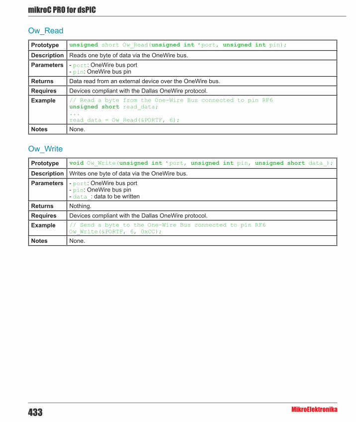
mikroC PRO for dsPIC
MikroElektronika433
Ow_Read
Ow_Write
Prototype unsigned short Ow_Read(unsigned int *port, unsigned int pin);
Description Reads one byte of data via the OneWire bus.Parameters - port: OneWire bus port
- pin: OneWire bus pin Returns Data read from an external device over the OneWire bus.Requires Devices compliant with the Dallas OneWire protocol.Example // Read a byte from the One-Wire Bus connected to pin RF6
unsigned short read_data;...read_data = Ow_Read(&PORTF, 6);
Notes None.
Prototype void Ow_Write(unsigned int *port, unsigned int pin, unsigned short data_);
Description Writes one byte of data via the OneWire bus.Parameters - port: OneWire bus port
- pin: OneWire bus pin - data_: data to be written
Returns Nothing.Requires Devices compliant with the Dallas OneWire protocol.Example // Send a byte to the One-Wire Bus connected to pin RF6
Ow_Write(&PORTF, 6, 0xCC);
Notes None.

434
mikoC PRO for dsPIC
MikroElektronika
Library Example
This example reads the temperature using DS18x20 connected to pin RF6. After reset, MCU obtains temperature from the sensor and prints it on the Lcd. Be sure to set Fosc appropriately in your project, to pull-up RF6 line and to turn off the PORTF leds.
Copy Code To Clipboard
// LCD module connectionssbit LCD_RS at LATB4_bit;sbit LCD_EN at LATB6_bit;sbit LCD_D4 at LATD4_bit;sbit LCD_D5 at LATD5_bit;sbit LCD_D6 at LATD6_bit;sbit LCD_D7 at LATD7_bit;
sbit LCD_RS_Direction at TRISB4_bit;sbit LCD_EN_Direction at TRISB6_bit;sbit LCD_D4_Direction at TRISD4_bit;sbit LCD_D5_Direction at TRISD5_bit;sbit LCD_D6_Direction at TRISD6_bit;sbit LCD_D7_Direction at TRISD7_bit;// End LCD module connections
// Set TEMP_RESOLUTION to the corresponding resolution of used DS18x20 sensor:// 18S20: 9 (default setting; can be 9,10,11,or 12)// 18B20: 12const unsigned short TEMP_RESOLUTION = 9;
char *text = “000.0000”;unsigned temp;
void Display_Temperature(unsigned int temp2write) { const unsigned short RES_SHIFT = TEMP_RESOLUTION - 8; char temp_whole; unsigned int temp_fraction;
// check if temperature is negative if (temp2write & 0x8000) { text[0] = ‘-’; temp2write = ~temp2write + 1; }
// extract temp_whole temp_whole = temp2write >> RES_SHIFT ;
// convert temp_whole to characters if (temp_whole/100) text[0] = temp_whole/100 + 48; else text[0] = ‘0’;

mikroC PRO for dsPIC
MikroElektronika435
text[1] = (temp_whole/10)%10 + 48; // Extract tens digit text[2] = temp_whole%10 + 48; // Extract ones digit
// extract temp_fraction and convert it to unsigned int temp_fraction = temp2write << (4-RES_SHIFT); temp_fraction &= 0x000F; temp_fraction *= 625;
// convert temp_fraction to characters text[4] = temp_fraction/1000 + 48; // Extract thousands digit text[5] = (temp_fraction/100)%10 + 48; // Extract hundreds digit text[6] = (temp_fraction/10)%10 + 48; // Extract tens digit text[7] = temp_fraction%10 + 48; // Extract ones digit
// print temperature on LCD Lcd_Out(2, 5, text);}
void main() {
ADPCFG = 0xFFFF; // Configure AN pins as digital Lcd_Init(); // Initialize LCD Lcd_Cmd(_LCD_CLEAR); // Clear LCD Lcd_Cmd(_LCD_CURSOR_OFF); // Turn cursor off Lcd_Out(1, 1, " Temperature: "); // Print degree character, 'C' for Centigrades Lcd_Chr(2,13,223); // different LCD displays have different char code for degree // if you see greek alpha letter try typing 178 instead of 223
Lcd_Chr(2,14,'C');
//--- main loop do { //--- perform temperature reading Ow_Reset(&PORTF, 6); // Onewire reset signal Ow_Write(&PORTF, 6, 0xCC); // Issue command SKIP_ROM Ow_Write(&PORTF, 6, 0x44); // Issue command CONVERT_T Delay_us(120);
Ow_Reset(&PORTF, 6); Ow_Write(&PORTF, 6, 0xCC); // Issue command SKIP_ROM Ow_Write(&PORTF, 6, 0xBE); // Issue command READ_SCRATCHPAD Delay_ms(400);
temp = Ow_Read(&PORTF, 6); temp = (Ow_Read(&PORTF, 6) << 8) + temp;
//--- Format and display result on Lcd Display_Temperature(temp);
Delay_ms(500); } while (1);}

436
mikoC PRO for dsPIC
MikroElektronika
HW Connection
Example of DS1820 connection

mikroC PRO for dsPIC
MikroElektronika437
Peripheral Pin Select LibraryThe Peripheral Pin Select library enables user to have more than one digital peripheral multiplexed on a single pin. Users may independently map the input and/or output of any one of many digital peripherals to any one of these I/O pins. The peripherals managed by the Peripheral Pin Select library are all digital only peripherals.
A key difference between pin select and non pin select peripherals is that pin select peripherals are not associated with a default I/O pin. The peripheral must always be assigned to a specific I/O pin before it can be used. In contrast, non pin select peripherals are always available on a default pin, assuming that the peripheral is active and not conflicting with another peripheral.
When a pin selectable peripheral is active on a given I/O pin, it takes priority over all other digital I/O and digital communication peripherals associated with the pin.
Important : Before using any of the digital peripherals or its library routines, user must set the desired pins as input/output and assign the desired peripheral to these pins.
Library Routines
- Unlock_IOLOCK - Lock_IOLOCK - PPS_Mapping
Unlock_IOLOCK
Lock_IOLOCK
Prototype void Unlock_IOLOCK();
Description Unlocks I/O pins for Peripheral Pin Mapping.Parameters None.Returns Nothing.Requires Nothing.Example Unlock_IOLOCK();
Notes None.
Prototype void Lock_IOLOCK();
Description Locks I/O pins for Peripheral Pin Mapping.Parameters None.Returns Nothing.Requires Nothing.Example Lock_IOLOCK();

438
mikoC PRO for dsPIC
MikroElektronika
PPS_Mapping
Direction Parameters
Input Functions
Prototype unsigned PPS_Mapping(unsigned short rp_num, unsigned short direction, unsigned short funct_name);
Description Sets desired internal MCU module to be mapped on the requested pins.Parameters - rp_num: Remappable pin number. Consult the appropriate datasheet for adequate values.
- direction: Sets requested pin to be used as an input or output. See Direction Parameters for adequate values. - funct_name: Selects internal MCU module function for usage. See Input Functions or Output Functions for adequate values.
Returns - 0 - if non-existing peripheral pin is selected. - 1 - if desired function is not implemented for the chosen MCU. - 2 - if any of the other RPOUT registers is configured to output the SCK1OUT function while SCK1CM is set (only for P24FJ256GA110 Family). - 255 - if peripheral pin mapping was successful.
Requires Nothing.Example PPS_Mapping(15, _INPUT, _RX2_DT2) // Sets pin 15 to be Input, and maps
RX2/DT2 Input to itPPS_Mapping(5, _OUTPUT, _TX2_CK2); // Sets pin 5 to be Output, and maps EUSART2 Asynchronous Transmit/Synchronous Clock Output to it
Notes None.
Direction Parameter Description_INPUT Sets selected pin as input_OUTPUT Sets selected pin as output
Function Name Description_CIRX ECAN1 Receive_COFSI DCI Frame Sync Input_CSCKI DCI Serial Clock Input_CSDI DCI Serial Data Input_FLTA1 PWM1 Fault_FLTA2 PWM2 Fault_FLTA3 PWM3 Fault_FLTA4 PWM4 Fault_FLTA5 PWM5 Fault_FLTA6 PWM6 Fault_FLTA7 PWM7 Fault_FLTA8 PWM8 Fault_IC1 Input Capture 1
_IC2 Input Capture 2_IC3 Input Capture 3_IC4 Input Capture 4_IC5 Input Capture 5_IC6 Input Capture 6_IC7 Input Capture 7_IC8 Input Capture 8_IC9 Input Capture 9_INDX1 QEI1 Index_INDX2 QEI2 Index_INT1 External Interrupt 1_INT2 External Interrupt 2_INT3 External Interrupt 3_INT4 External Interrupt 4

mikroC PRO for dsPIC
MikroElektronika439
Function Name Description_NULL The NULL function is assigned to all RPn outputs at device Reset and disables the RPn
output function._ACMP1 RPn tied to Analog Comparator Output 1_ACMP2 RPn tied to Analog Comparator Output 2_ACMP3 RPn tied to Analog Comparator Output 3_ACMP4 RPn tied to Analog Comparator Output 4_C1OUT Comparator 1 Output_C2OUT Comparator 2 Output_C3OUT Comparator 3 Output_COFSOS DCI Frame Sync Output_CSCKO DCI Serial Clock Output_CSDO DCI Serial Data Output_CTPLS CTMU Output Pulse_C1TX ECAN1 Transmit_OC1 Output Compare 1_OC2 Output Compare 2_OC3 Output Compare 3_OC4 Output Compare 4_OC5 Output Compare 5_OC6 Output Compare 6_OC7 Output Compare 7_OC8 Output Compare 8
_QEA1 QEI1 Phase A_QEA2 QEI2 Phase A_QEB1 QEI1 Phase B_QEB2 QEI2 Phase B_SCK1IN SPI1 Clock Input_SCK2IN SPI2 Clock Input_SCK3IN SPI3 Clock Input_SDI1 SPI1 Data Input_SDI2 SPI2 Data Input_SDI3 SPI3 Data Input_SS1IN SPI1 Slave Select Input_SS2IN SPI2 Slave Select Input_SS3IN SPI3 Slave Select Input
_T1CK Timer1 External Clock_T2CK Timer2 External Clock_T3CK Timer3 External Clock_T4CK Timer4 External Clock_T5CK Timer5 External Clock_U1CTS UART1 Clear To Send_U2CTS UART2 Clear To Send_U3CTS UART3 Clear To Send_U4CTS UART4 Clear To Send_U1RX UART1 Receive_U2RX UART2 Receive_U3RX UART3 Receive_U4RX UART4 Receive
Output Functions

440
mikoC PRO for dsPIC
MikroElektronika
_OC9 Output Compare 9_OCFA Output Compare Fault A_OCFB Output Compare Fault B_PWM4H RPn tied to PWM output pins associated with PWM Generator 4_PWM4L RPn tied to PWM output pins associated with PWM Generator 4_REFCLKO REFCLK output signal_SCK1OUT SPI1 Clock Output_SCK2OUT SPI2 Clock Output_SCK3OUT SPI3 Clock Output_SDO1 SPI1 Data Output_SDO2 SPI2 Data Output_SDO3 SPI3 Data Output_SS1OUT SPI1 Slave Select Output_SS2OUT SPI2 Slave Select Output_SS3OUT SPI3 Slave Select Output_SYNCI1 External Synchronization signal to PWM Master Time Base_SYNCI2 External Synchronization signal to PWM Master Time Base_SYNCO1 RPn tied to external device synchronization signal via PWM master time base_U1RTS UART1 Request To Send_U2RTS UART2 Request To Send_U3RTS UART3 Request To Send_U4RTS UART4 Request To Send_U1TX UART1 Transmit_U2TX UART2 Transmit_U3TX UART3 Transmit_U4TX UART4 Transmit_UPDN QEI direction (UPDN) status_UPDN1 QEI1 direction (UPDN) status_UPDN2 QEI2 direction (UPDN) status

mikroC PRO for dsPIC
MikroElektronika441
Port Expander LibraryThe mikroC PRO for dsPIC30/33 and PIC24 provides a library for communication with the Microchip’s Port Expander MCP23S17 via SPI interface. Connections of the dsPIC30/33 and PIC24 MCU and MCP23S17 is given on the schematic at the bottom of this page.
Important :
- The library uses the SPI module for communication. User must initialize the appropriate SPI module before using the Port Expander Library. - For MCUs with multiple SPI modules it is possible to initialize all of them and then switch by using the SPI_Set_Active() function. See the SPI Library functions. - Library does not use Port Expander interrupts.
Library Dependency Tree
The following variables must be defined in all projects using Port Expander Library:
Description : Example :
extern sfr sbit SPExpanderRST; Reset line. sbit SPExpanderRST at RF0_bit;
extern sfr sbitSPExpanderCS; Chip Select line. sbit SPExpanderCS at RF1_bit;
extern sfr sbit SPExpanderRST_Direction; Direction of the Reset pin. sbit SPExpanderRST_Direction at
TRISF0_bit;
extern sfr sbit SPExpanderCS_Direction;
Direction of the Chip Select pin.
sbit SPExpanderCS_Direction at TRISF1_bit;
External dependencies of Port Expander Library
Library Routines
- Expander_Init - Expander_Init_Advanced - Expander_Read_Byte - Expander_Write_Byte - Expander_Read_PortA - Expander_Read_PortB - Expander_Read_PortAB - Expander_Write_PortA - Expander_Write_PortB - Expander_Write_PortAB - Expander_Set_DirectionPortA - Expander_Set_DirectionPortB - Expander_Set_DirectionPortAB - Expander_Set_PullUpsPortA - Expander_Set_PullUpsPortB - Expander_Set_PullUpsPortAB

442
mikoC PRO for dsPIC
MikroElektronika
Expander_Init
Prototype void Expander_Init(char ModuleAddress);
Description Initializes Port Expander using SPI communication.
Port Expander module settings :
- hardware addressing enabled - automatic address pointer incrementing disabled (byte mode) - BANK_0 register adressing - slew rate enabled
Parameters - ModuleAddress: Port Expander hardware address, see schematic at the bottom of this page Returns Nothing.Requires Global variables :
- SPExpanderCS: Chip Select line - SPExpanderRST: Reset line - SPExpanderCS_Direction: Direction of the Chip Select pin - SPExpanderRST_Direction: Direction of the Reset pin
must be defined before using this function.
SPI module needs to be initialized. See SPIx_Init and SPIx_Init_Advanced routines. Example // Port Expander module connections
sbit SPExpanderRST at RF0_bit;sbit SPExpanderCS at RF1_bit;sbit SPExpanderRST_Direction at TRISF0_bit;sbit SPExpanderCS_Direction at TRISF1_bit;// End Port Expander module connections
...
// If Port Expander Library uses SPI moduleSPI1_Init(); // Initialize SPI module used with PortExpanderExpander_Init(0); // Initialize Port Expander
Notes None.

mikroC PRO for dsPIC
MikroElektronika443
Expander_Init_Advanced
Prototype void Expander_Init_Advanced(char *rstPort, char rstPin, char haen);
Description Initializes Port Expander using SPI communication.Parameters - rstPort: Port Expander’s reset port
- rstPin: Port Expander’s reset pin - haen: Port Expander’s hardware address
Returns Nothing.Requires - SPExpanderCS: Chip Select line
- SPExpanderRST: Reset line - SPExpanderCS_Direction: Direction of the Chip Select pin - SPExpanderRST_Direction: Direction of the Reset pin
must be defined before using this function.
SPI module needs to be initialized. See SPIx_Init and SPIx_Init_Advanced routines. Example // Port Expander module connections
sbit SPExpanderRST at RF0_bit;sbit SPExpanderCS at RF1_bit;sbit SPExpanderRST_Direction at TRISF0_bit;sbit SPExpanderCS_Direction at TRISF1_bit;// End Port Expander module connections...
// If Port Expander Library uses SPI moduleSPI1_Init(); // Initialize SPI1 module used with PortExpanderExpander_Init_Advanced(&PORTB, 0, 0); // Initialize Port Expander
Notes None.

444
mikoC PRO for dsPIC
MikroElektronika
Expander_Read_Byte
Expander_Write_Byte
Expander_Read_PortA
Prototype char Expander_Read_Byte(char ModuleAddress, char RegAddress);
Description The function reads byte from Port Expander.Parameters - ModuleAddress: Port Expander hardware address, see schematic at the bottom of this page
- RegAddress: Port Expander’s internal register address Returns Byte read.Requires Port Expander must be initialized. See Expander_Init.Example // Read a byte from Port Expander’s register
char read_data;...read_data = Expander_Read_Byte(0,1);
Notes None.
Prototype void Expander_Write_Byte(char ModuleAddress, char RegAddress, char data_);
Description Routine writes a byte to Port Expander.Parameters - ModuleAddress: Port Expander hardware address, see schematic at the bottom of this page
- RegAddress: Port Expander’s internal register address - Data: data to be written
Returns Byte read.Requires Port Expander must be initialized. See Expander_Init.Example // Write a byte to the Port Expander’s register
Expander_Write_Byte(0,1,0xFF);
Notes None.
Prototype char Expander_Read_PortA(char ModuleAddress);
Description The function reads byte from Port Expander’s PortA.Parameters - ModuleAddress: Port Expander hardware address, see schematic at the bottom of this page Returns Byte read.Requires Port Expander must be initialized. See Expander_Init.
Port Expander’s PortA should be configured as input. See Expander_Set_DirectionPortA and Expander_Set_DirectionPortAB routines.
Example // Read a byte from Port Expander’s PORTAchar read_data;...Expander_Set_DirectionPortA(0,0xFF); // set expander’s porta to be input...read_data = Expander_Read_PortA(0);
Notes None.

mikroC PRO for dsPIC
MikroElektronika445
Expander_Read_PortB
Expander_Read_PortAB
Prototype char Expander_Read_PortB(char ModuleAddress);
Description The function reads byte from Port Expander’s PortB.Parameters - ModuleAddress: Port Expander hardware address, see schematic at the bottom of this page Returns Byte read.Requires Port Expander must be initialized. See Expander_Init.
Port Expander’s PortB should be configured as input. See Expander_Set_DirectionPortB and Expander_Set_DirectionPortAB routines.
Example // Read a byte from Port Expander’s PORTBchar read_data;...Expander_Set_DirectionPortB(0,0xFF); // set expander’s portb to be input...read_data = Expander_Read_PortB(0);
Notes None.
Prototype unsigned int Expander_Read_PortAB(char ModuleAddress);
Description The function reads word from Port Expander’s ports. PortA readings are in the higher byte of the result. PortB readings are in the lower byte of the result.
Parameters - ModuleAddress: Port Expander hardware address, see schematic at the bottom of this page Returns Word read.Requires Port Expander must be initialized. See Expander_Init.
Port Expander’s PortA and PortB should be configured as inputs. See Expander_Set_DirectionPortA, Expander_Set_DirectionPortB and Expander_Set_DirectionPortAB routines.
Example // Read a byte from Port Expander’s PORTA and PORTBunsigned int read_data;...Expander_Set_DirectionPortAB(0,0xFFFF); // set expander’s porta and portb to be input...read_data = Expander_Read_PortAB(0);
Notes None.

446
mikoC PRO for dsPIC
MikroElektronika
Expander_Write_PortA
Expander_Write_PortB
Prototype void Expander_Write_PortA(char ModuleAddress, char Data_);
Description The function writes byte to Port Expander’s PortA.Parameters - ModuleAddress: Port Expander hardware address, see schematic at the bottom of this page
- Data: data to be written Returns Nothing.Requires Port Expander must be initialized. See Expander_Init.
Port Expander’s PortA should be configured as output. See Expander_Set_DirectionPortA and Expander_Set_DirectionPortAB routines.
Example // Write a byte to Port Expander’s PORTA
...Expander_Set_DirectionPortA(0,0x00); // set expander’s porta to be output...Expander_Write_PortA(0, 0xAA);
Notes None.
Prototype void Expander_Write_PortB(char ModuleAddress, char Data_);
Description The function writes byte to Port Expander’s PortB.Parameters - ModuleAddress: Port Expander hardware address, see schematic at the bottom of this page
- Data: data to be written Returns Nothing.Requires Port Expander must be initialized. See Expander_Init.
Port Expander’s PortB should be configured as output. See Expander_Set_DirectionPortB and Expander_Set_DirectionPortAB routines.
Example // Write a byte to Port Expander’s PORTB
...Expander_Set_DirectionPortB(0,0x00); // set expander’s portb to be output...Expander_Write_PortB(0, 0x55);
Notes None.
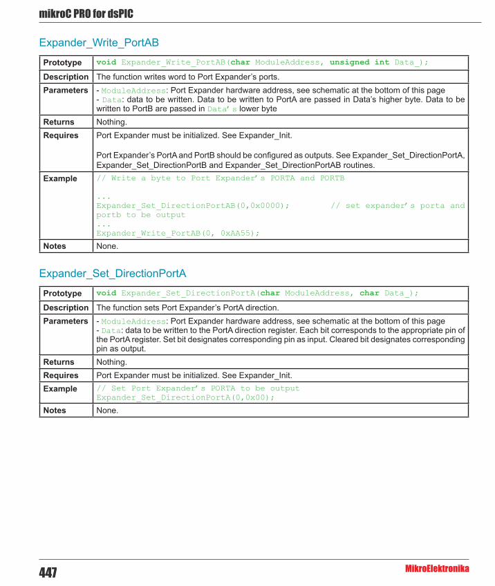
mikroC PRO for dsPIC
MikroElektronika447
Expander_Write_PortAB
Expander_Set_DirectionPortA
Prototype void Expander_Write_PortAB(char ModuleAddress, unsigned int Data_);
Description The function writes word to Port Expander’s ports.Parameters - ModuleAddress: Port Expander hardware address, see schematic at the bottom of this page
- Data: data to be written. Data to be written to PortA are passed in Data’s higher byte. Data to be written to PortB are passed in Data’s lower byte
Returns Nothing.Requires Port Expander must be initialized. See Expander_Init.
Port Expander’s PortA and PortB should be configured as outputs. See Expander_Set_DirectionPortA, Expander_Set_DirectionPortB and Expander_Set_DirectionPortAB routines.
Example // Write a byte to Port Expander’s PORTA and PORTB
...Expander_Set_DirectionPortAB(0,0x0000); // set expander’s porta and portb to be output...Expander_Write_PortAB(0, 0xAA55);
Notes None.
Prototype void Expander_Set_DirectionPortA(char ModuleAddress, char Data_);
Description The function sets Port Expander’s PortA direction.Parameters - ModuleAddress: Port Expander hardware address, see schematic at the bottom of this page
- Data: data to be written to the PortA direction register. Each bit corresponds to the appropriate pin of the PortA register. Set bit designates corresponding pin as input. Cleared bit designates corresponding pin as output.
Returns Nothing.Requires Port Expander must be initialized. See Expander_Init.Example // Set Port Expander’s PORTA to be output
Expander_Set_DirectionPortA(0,0x00);
Notes None.

448
mikoC PRO for dsPIC
MikroElektronika
Expander_Set_DirectionPortB
Expander_Set_DirectionPortAB
Expander_Set_PullUpsPortA
Prototype void Expander_Set_DirectionPortB(char ModuleAddress, char Data_);
Description The function sets Port Expander’s PortB direction.Parameters - ModuleAddress: Port Expander hardware address, see schematic at the bottom of this page
- Data: data to be written to the PortB direction register. Each bit corresponds to the appropriate pin of the PortB register. Set bit designates corresponding pin as input. Cleared bit designates corresponding pin as output.
Returns Nothing.Requires Port Expander must be initialized. See Expander_Init.Example // Set Port Expander’s PORTB to be input
Expander_Set_DirectionPortB(0,0xFF);
Notes None.
Prototype void Expander_Set_DirectionPortAB(char ModuleAddress, unsigned int Direction);
Description The function sets Port Expander’s PortA and PortB direction.Parameters - ModuleAddress: Port Expander hardware address, see schematic at the bottom of this page
- Direction: data to be written to direction registers. Data to be written to the PortA direction register are passed in Direction’s higher byte. Data to be written to the PortB direction register are passed in Direction’s lower byte. Each bit corresponds to the appropriate pin of the PortA/PortB register. Set bit designates corresponding pin as input. Cleared bit designates corresponding pin as output.
Returns Nothing.Requires Port Expander must be initialized. See Expander_Init.Example // Set Port Expander’s PORTA to be output and PORTB to be input
Expander_Set_DirectionPortAB(0,0x00FF);
Notes None.
Prototype void Expander_Set_PullUpsPortA(char ModuleAddress, char Data_);
Description The function sets Port Expander’s PortA pull up/down resistors.Parameters - ModuleAddress: Port Expander hardware address, see schematic at the bottom of this page
- Data: data for choosing pull up/down resistors configuration. Each bit corresponds to the appropriate pin of the PortA register. Set bit enables pull-up for corresponding pin.
Returns Nothing.Requires Port Expander must be initialized. See Expander_Init.Example // Set Port Expander’s PORTA pull-up resistors
Expander_Set_PullUpsPortA(0, 0xFF);
Notes None.

mikroC PRO for dsPIC
MikroElektronika449
Expander_Set_PullUpsPortB
Expander_Set_PullUpsPortAB
Prototype void Expander_Set_PullUpsPortB(char ModuleAddress, char Data_);
Description The function sets Port Expander’s PortB pull up/down resistors.Parameters - ModuleAddress: Port Expander hardware address, see schematic at the bottom of this page
- Data: data for choosing pull up/down resistors configuration. Each bit corresponds to the appropriate pin of the PortB register. Set bit enables pull-up for corresponding pin.
Returns Nothing.Requires Port Expander must be initialized. See Expander_Init.Example // Set Port Expander’s PORTB pull-up resistors
Expander_Set_PullUpsPortB(0, 0xFF);
Notes None.
Prototype void Expander_Set_PullUpsPortAB(char ModuleAddress, unsigned int PullUps);
Description The function sets Port Expander’s PortA and PortB pull up/down resistors.Parameters - ModuleAddress: Port Expander hardware address, see schematic at the bottom of this page
- PullUps: data for choosing pull up/down resistors configuration. PortA pull up/down resistors configuration is passed in PullUps’s higher byte. PortB pull up/down resistors configuration is passed in PullUps’s lower byte. Each bit corresponds to the appropriate pin of the PortA/PortB register. Set bit enables pull-up for corresponding pin.
Returns Nothing.Requires Port Expander must be initialized. See Expander_Init.Example // Set Port Expander’s PORTA and PORTB pull-up resistors
Expander_Set_PullUpsPortAB(0, 0xFFFF);
Notes None.

450
mikoC PRO for dsPIC
MikroElektronika
Library Example
The example demonstrates how to communicate with Port Expander MCP23S17. Note that Port Expander pins A2 A1 A0 are connected to GND so Port Expander Hardware Address is 0.
Copy Code To Clipboard
// Port Expander module connectionssbit SPExpanderRST at RF0_bit;sbit SPExpanderCS at RF1_bit;sbit SPExpanderRST_Direction at TRISF0_bit;sbit SPExpanderCS_Direction at TRISF1_bit;// End Port Expander module connections
unsigned int i = 0;
void main() { ADPCFG = 0xFFFF; // initialize AN pins as digital TRISB = 0x00; LATB = 0xFF;
// If Port Expander Library uses SPI1 module SPI1_Init(); // Initialize SPI module used with PortExpander
Expander_Init(0); // Initialize Port Expander
Expander_Set_DirectionPortA(0, 0x00); // Set Expander's PORTA to be output
Expander_Set_DirectionPortB(0,0xFF); // Set Expander's PORTB to be input Expander_Set_PullUpsPortB(0,0xFF); // Set pull-ups to all of the Expander's PORTB pins
while(1) { // Endless loop Expander_Write_PortA(0, i++); // Write i to expander's PORTA PORTB = Expander_Read_PortB(0); // Read expander's PORTB and write it to LEDs Delay_ms(100); }
}

mikroC PRO for dsPIC
MikroElektronika451
HW Connection
Port Expander HW connection

452
mikoC PRO for dsPIC
MikroElektronika
PS/2 LibraryThe mikroC PRO for dsPIC30/33 and PIC24 provides a library for communication with the common PS/2 keyboard.
Important :
- The library does not utilize interrupts for data retrieval, and requires the oscillator clock to be at least 6MHz. - The pins to which a PS/2 keyboard is attached should be connected to the pull-up resistors. - Although PS/2 is a two-way communication bus, this library does not provide MCU-to-keyboard communication; e.g. pressing the Caps Lock key will not turn on the Caps Lock LED.
The following variables must be defined in all projects using PS/2 Library:
Description : Example :
extern sfr sbit PS2_Data; PS/2 Data line. sbit PS2_Data at RB0_bit;
extern sfr sbit PS2_Clock; PS/2 Clock line. sbit PS2_Clock at RB1_bit;
extern sfr sbit PS2_Data_Direction;
Direction of the PS/2 Data pin.
sbit PS2_Data_Direction at TRISB0_bit;
extern sfr sbit PS2_Clock_Direction;
Direction of the PS/2 Clock pin.
sbit PS2_Clock_Direction at TRISB1_bit;
External dependencies of PS/2 Library
Library Routines
- Ps2_Config - Ps2_Key_Read

mikroC PRO for dsPIC
MikroElektronika453
Ps2_Config
Ps2_Key_Read
Prototype void Ps2_Config();
Description Initializes the MCU for work with the PS/2 keyboard.Parameters None.Returns Nothing.Requires Global variables :
- PS2_Data: Data signal line - PS2_Clock: Clock signal line - PS2_Data_Direction: Direction of the Data pin - PS2_Clock_Direction: Direction of the Clock pin
must be defined before using this function.Example // PS2 pinout definition
sbit PS2_Data at RB0_bit;sbit PS2_Clock at RB1_bit;sbit PS2_Data_Direction at TRISB0_bit;sbit PS2_Clock_Direction at TRISB1_bit;// End of PS2 pinout definition...Ps2_Config(); // Init PS/2 Keyboard
Notes None.
Prototype unsigned int Ps2_Key_Read(unsigned short *value, unsigned short *special, unsigned short *pressed);
Description The function retrieves information on key pressed.Parameters - value: holds the value of the key pressed. For characters, numerals, punctuation marks, and space
value will store the appropriate ASCII code. Routine “recognizes” the function of Shift and Caps Lock, and behaves appropriately. For special function keys see Special Function Keys Table. - special: is a flag for special function keys (F1, Enter, Esc, etc). If key pressed is one of these, special will be set to 1, otherwise 0. - pressed: is set to 1 if the key is pressed, and 0 if it is released.
Returns - 1 if reading of a key from the keyboard was successful - 0 if no key was pressed
Requires PS/2 keyboard needs to be initialized. See Ps2_Config routine.Example unsigned short keydata = 0, special = 0, down = 0;
...// Press Enter to continue:do { if (Ps2_Key_Read(&keydata, &special, &down)) { if (down && (keydata == 16)) break; }} while (1);
Notes None.

454
mikoC PRO for dsPIC
MikroElektronika
Special Function Keys
Key Value returnedF1 1F2 2F3 3F4 4F5 5F6 6F7 7F8 8F9 9F10 10F11 11F12 12Enter 13Page Up 14Page Down 15Backspace 16Insert 17Delete 18Windows 19Ctrl 20Shift 21Alt 22Print Screen 23Pause 24Caps Lock 25End 26Home 27Scroll Lock 28Num Lock 29Left Arrow 30Right Arrow 31Up Arrow 32Down Arrow 33Escape 34Tab 35
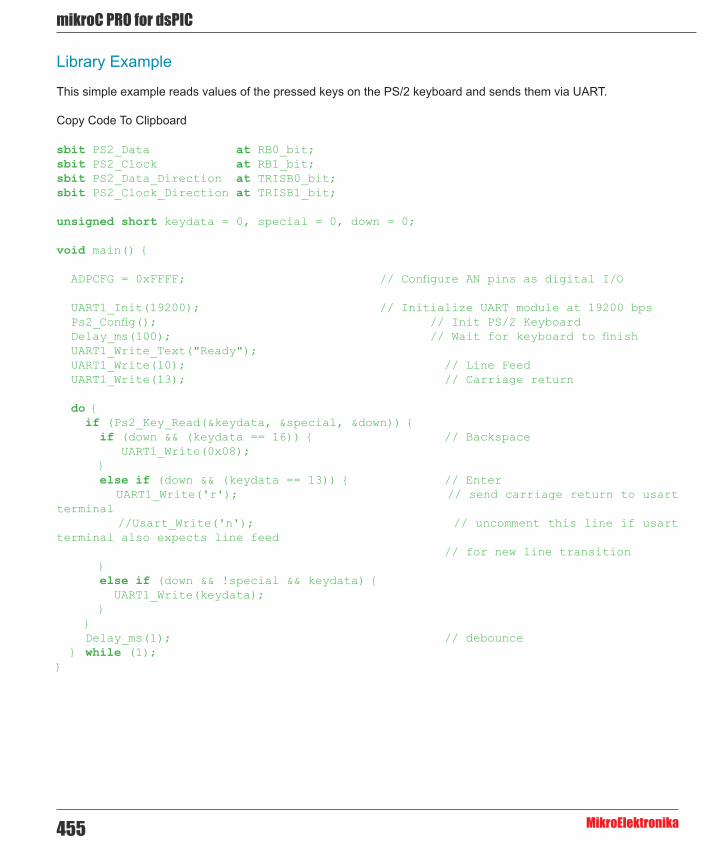
mikroC PRO for dsPIC
MikroElektronika455
Library Example
This simple example reads values of the pressed keys on the PS/2 keyboard and sends them via UART.
Copy Code To Clipboard
sbit PS2_Data at RB0_bit;sbit PS2_Clock at RB1_bit;sbit PS2_Data_Direction at TRISB0_bit;sbit PS2_Clock_Direction at TRISB1_bit;
unsigned short keydata = 0, special = 0, down = 0; void main() {
ADPCFG = 0xFFFF; // Configure AN pins as digital I/O UART1_Init(19200); // Initialize UART module at 19200 bps Ps2_Config(); // Init PS/2 Keyboard Delay_ms(100); // Wait for keyboard to finish UART1_Write_Text("Ready"); UART1_Write(10); // Line Feed UART1_Write(13); // Carriage return
do { if (Ps2_Key_Read(&keydata, &special, &down)) { if (down && (keydata == 16)) { // Backspace UART1_Write(0x08); } else if (down && (keydata == 13)) { // Enter UART1_Write('r'); // send carriage return to usart terminal //Usart_Write('n'); // uncomment this line if usart terminal also expects line feed // for new line transition } else if (down && !special && keydata) { UART1_Write(keydata); } } Delay_ms(1); // debounce } while (1);}

456
mikoC PRO for dsPIC
MikroElektronika
HW Connection
Example of PS2 keyboard connection
PWM LibraryThe CCP module is available with a number of dsPIC30/33 and PIC24 MCUs. mikroC PRO for dsPIC30/33 and PIC24 provides a library which simplifies using of the PWM HW Module.
Important : PWM module uses either Timer2 or Timer3 module.
Library Routines
- PWM_Init - PWM_Set_Duty - PWM_Start - PWM_Stop

mikroC PRO for dsPIC
MikroElektronika457
PWM_Init
PWM_Set_Duty
Prototype unsigned int PWM_Init(unsigned long freq_hz, unsigned int enable_channel_x, unsigned int timer_prescale, unsigned int use_timer_x);
// 30F1010 and dsPIC33FJ06GS101/102/202 prototype unsigned int PWM_Init(unsigned long freq_hz, unsigned int enable_channel_x, unsigned int timer_prescale);
Description Initializes the PWM module with duty ratio 0.Parameters - freq_hz: PWM frequency in Hz (refer to device datasheet for correct values in respect with Fosc)
- enable_channel_x: number of PWM channel to be initialized. Refer to MCU’s datasheet for available PWM channels - timer_prescale: timer prescaler parameter. Valid values: 1, 8, 64, and 256 - use_timer_x: timer to be used with the PWM module. Valid values: 2 (Timer2) and 3 (Timer3)
Returns - 0xFFFF - if timer settings are not valid - otherwise returns calculated timer period
Requires MCU must have the HW PWM Module.Example // Initializes the PWM module at 5KHz, channel 1, no clock prescale, timer2
:unsigned int pwm_period1;...pwm_period1 = PWM_Init(5000, 1, 0, 2);
Notes Number of available PWM channels depends on MCU. Refer to MCU datasheet for details.
Prototype void PWM_Set_Duty(unsigned duty, unsigned channel);
Description The function changes PWM duty ratio.Parameters - duty: PWM duty ratio. Valid values: 0 to timer period returned by the PWM_Init function.
- channel: number of PWM channel to change duty to. Returns Nothing.Requires MCU must have the HW PWM Module.
PWM channel must be properly initialized. See PWM_Init routine.Example // Set channel 1 duty ratio to 50%:
unsigned int pwm_period1;...PWM_Set_Duty(pwm_period1/2, 1);
Notes Number of available PWM channels depends on MCU. Refer to MCU datasheet for details.

458
mikoC PRO for dsPIC
MikroElektronika
PWM_Start
PWM_Stop
Prototype void PWM_Start(char enable_channel_x);
Description Starts PWM at requested channel.Parameters - enable_channel_x: number of PWM channel Returns Nothing.Requires MCU must have the HW PWM Module.
PWM channel must be properly configured. See the PWM_Init and PWM_Set_Duty routines.Example // start PWM at channel 1
PWM_Start(1);
Notes Number of available PWM channels depends on MCU. Refer to MCU datasheet for details.
Prototype void PWM_Stop(char disable_channel_x);
Description Stops PWM at requested channel.Parameters - disable_channel_x: number of PWM channel Returns Nothing.Requires MCU must have the HW PWM Module.Example // stop PWM at channel 1
PWM_Stop(1);
Notes Number of available PWM channels depends on MCU. Refer to MCU datasheet for details.
Library Example
The example changes PWM duty ratio on channels 1 and 2 continuously. If LEDs are connected to channels 1 and 2, a gradual change of emitted light will be noticeable.
Copy Code To Clipboard
unsigned int current_duty, old_duty, current_duty1, old_duty1;unsigned int pwm_period1, pwm_period2;
void InitMain() { ADPCFG = 0xFFFF; // Configure AN pins as digital I/O TRISB = 0xFFFF; // configure PORTB pins as input PORTD = 0; // set PORTD to 0 TRISD = 0; // designate PORTD pins as output}
void main() { InitMain(); current_duty = 16; // initial value for current_duty current_duty1 = 16; // initial value for current_duty1

mikroC PRO for dsPIC
MikroElektronika459
pwm_period1 = PWM_Init(5000 , 1, 1, 2); pwm_period2 = PWM_Init(10000, 2, 1, 3);
PWM_Start(1); PWM_Start(2);
PWM_Set_Duty(current_duty, 1); // Set current duty for PWM1 PWM_Set_Duty(current_duty1, 2); // Set current duty for PWM2
while (1) { // endless loop if (RB0_bit) { // button on RB0 pressed Delay_ms(20); current_duty++; // increment current_duty if (current_duty > pwm_period1) { // if we increase current_duty greater then possible pwm_period1 value current_duty = 0; // reset current_duty value to zero } PWM_Set_Duty(current_duty, 1); // set newly acquired duty ratio }
if (RB1_bit) { // button on RB1 pressed Delay_ms(20); current_duty--; // decrement current_duty if (current_duty > pwm_period1) { // if we decrease current_duty greater then possible pwm_period1 value (overflow) current_duty = pwm_period1; // set current_duty to max possible value } PWM_Set_Duty(current_duty, 1); // set newly acquired duty ratio }
if (RB2_bit) { // button on RB2 pressed Delay_ms(20); current_duty1++; // increment current_duty1 if (current_duty1 > pwm_period2) { // if we increase current_duty1 greater then possible pwm_period2 value current_duty1 = 0; // reset current_duty1 value to zero } PWM_Set_Duty(current_duty1, 2); // set newly acquired duty ratio }
if (RB3_bit) { // button on RB3 pressed Delay_ms(20); current_duty1--; // decrement current_duty1 if (current_duty1 > pwm_period2) { // if we decrease current_duty1 greater then possible pwm_period1 value (overflow) current_duty1 = pwm_period2; // set current_duty to max possible value } PWM_Set_Duty(current_duty1, 2); }
Delay_ms(5); // slow down change pace a little }}

460
mikoC PRO for dsPIC
MikroElektronika
HW Connection
PWM demonstration
PWM Motor Control LibraryThe PWM Motor Control module is available with a number of dsPIC30/33 MCUs. The mikroC PRO for dsPIC30/33 and PIC24 provides a library which simplifies using the PWM Motor Control module.
Important :
- Number of PWM modules per MCU differs from chip to chip. Please, read the appropriate datasheet before utilizing this library. - PWM library routines require you to specify the module you want to use. To use the desired PWM module, simply change the letter x in the routine prototype for a number from 1 to 2.
Library Routines
- PWMx_Mc_Init - PWMx_Mc_Set_Duty - PWMx_Mc_Start - PWMx_Mc_Stop

mikroC PRO for dsPIC
MikroElektronika461
PWMx_Mc_Init
Prototype unsigned int PWMx_Mc_Init(unsigned int freq_hz, unsigned int pair_output_mode, unsigned int enable_output_x, unsigned int clock_prescale_output_postscale);
Description Initializes the Motor Control PWM module with duty ratio 0. The function calculates timer period, writes it to the MCU’s PTPER register and returns it as the function result.
Parameters - freq_hz: PWM frequency in Hz (refer to device datasheet for correct values in respect with Fosc) - pair_output_mode: output mode for output pin pairs: 1 = independent, 0 = complementary.If pair_output_mode.B0 is equal to 1 then PWM channels PWM1L and PWM1H will be independent,If pair_output_mode.B1 is equal to 0 then PWM channels PWM2L and PWM2H will be complementary, ... If pair_output_mode.Bn is equal to 1 then PWM channels PWM(n+1)L and PWM(n+1)H will be independent,If pair_output_mode.Bn is equal to 0 then PWM channels PWM(n+1)L and PWM(n+1)H will be complementary. - enable_output_x: bits <7..0> are enabling corresponding PWM channels <PWM4H, PWM3H, PWM2H, PWM1H, PWM4L, PWM3L, PWM2L, PWM1L>.If bit value is equal to 0 then corresponding PWM channel is disabled (pin is standard I/O).If bit value is equal to 1 then corresponding PWM channel is enabled (pin is PWM output).For detalied explanation consult the “Motor Control PWM Module” section in device datasheet - clock_prescale_output_postscale: PWM clock prescaler/postscaler settings. Values <0..3> and <0..15> correspond to prescaler/postscaler <1:1, 1:4, 1:16, 1:64> and <1:1, 1:2, ..., 1:16>
Returns Calculated timer period.Requires The dsPIC30/33 MCU must have the Motor Control PWM module.Example // Initializes the PWM1 module at 5KHz, complementary pin-pair output,
output enabled on pins 4l..1l, no clock prescale and no clock postscale:unsigned int duty_50;...duty_50 = PWM1_Mc_Init(5000, 1, 0x0F, 0);
Notes - Number of PWM modules per MCU differs from chip to chip. Please, read the appropriate datasheet before utilizing this library. - PWM library routines require you to specify the module you want to use. To use the desired PWM module, simply change the letter x in the routine prototype for a number from 1 to 2.

462
mikoC PRO for dsPIC
MikroElektronika
PWMx_Mc_Set_Duty
PWMx_Mc_Start
Prototype void PWM1_Mc_Set_Duty(unsigned duty, unsigned channel);
// For dsPIC 33FJ MCUs that have PWM2 module :void PWM2_Mc_Set_Duty(unsigned duty);
Description The function changes PWM duty ratio.Parameters - duty: PWM duty ratio. Valid values: 0 to timer period returned by the PWMx_Mc_Init function.
- channel: number of PWM channel to change duty to.Returns Nothing.Requires The dsPIC30/33 MCU must have the Motor Control PWM module.
The PWM module needs to be initalized. See the PWMx_Mc_Init function.Example // Set duty ratio to 50% at channel 1:
PWM1_Mc_Init(5000,1,0xF,0);...PWM1_Mc_Set_Duty(32767, 1);
Notes - Number of PWM modules per MCU differs from chip to chip. Please, read the appropriate datasheet before utilizing this library. - PWM library routines require you to specify the module you want to use. To use the desired PWM module, simply change the letter x in the routine prototype for a number from 1 to 2.
Prototype void PWMx_Mc_Start();
Description Starts the Motor Control PWM module (channels initialized in the PWMx_Mc_Init function).Parameters None.Returns Nothing.Requires The dsPIC30/33 MCU must have the Motor Control PWM module.
The PWM module needs to be initalized. See the PWMx_Mc_Init function.Example // start the Motor Control PWM1 module
PWM1_Mc_Start();
Notes - Number of PWM modules per MCU differs from chip to chip. Please, read the appropriate datasheet before utilizing this library. - PWM library routines require you to specify the module you want to use. To use the desired PWM module, simply change the letter x in the routine prototype for a number from 1 to 2.

mikroC PRO for dsPIC
MikroElektronika463
PWMx_Mc_Stop
Prototype void PWMx_Mc_Stop();
Description Stops the Motor Control PWM module.Parameters None.Returns Nothing.Requires The dsPIC30/33 MCU must have the Motor Control PWM module.Example // stop the Motor Control PWM1 module
PWM1_Mc_Stop();
Notes - Number of PWM modules per MCU differs from chip to chip. Please, read the appropriate datasheet before utilizing this library. - PWM library routines require you to specify the module you want to use. To use the desired PWM module, simply change the letter x in the routine prototype for a number from 1 to 2.
Library Example
The example changes PWM duty ratio on channel 1 continually. If LED is connected to the channel 1, a gradual change of emitted light will be noticeable.
Copy Code To Clipboard
unsigned int i;
unsigned int duty_50;
void main(){
ADPCFG = 0xFFFF; // initialize AN pins as digital PORTB = 0xAAAA; TRISB = 0; // initialize portb as output Delay_ms(1000);
duty_50 = PWM1_MC_Init(5000, 0, 0x01, 0); // Pwm_Mc_Init returns 50% of the duty PWM1_MC_Set_Duty(i = duty_50, 1); PWM1_MC_Start();
do { i--; PWM1_MC_Set_Duty(i, 1); Delay_ms(10); if (i == 0) i = duty_50 * 2 - 1; // Let us not allow the overflow PORTB = i; } while(1);
}

464
mikoC PRO for dsPIC
MikroElektronika
HW Connection
PWM Motor Control demonstration
RS-485 LibraryRS-485 is a multipoint communication which allows multiple devices to be connected to a single bus. The mikroC PRO for dsPIC30/33 and PIC24 provides a set of library routines for comfortable work with RS485 system using Master/Slave architecture. Master and Slave devices interchange packets of information. Each of these packets contains synchronization bytes, CRC byte, address byte and the data. Each Slave has unique address and receives only packets addressed to it. The Slave can never initiate communication.
It is the user’s responsibility to ensure that only one device transmits via 485 bus at a time.
The RS-485 routines require the UART module. Pins of UART need to be attached to RS-485 interface transceiver, such as LTC485 or similar (see schematic at the bottom of this page).
Library constants:
- START byte value = 150 - STOP byte value = 169 - Address 50 is the broadcast address for all Slaves (packets containing address 50 will be received by all Slaves except the Slaves with addresses 150 and 169).
Important :
- The library uses the UART module for communication. The user must initialize the appropriate UART module before using the RS-485 Library. - For MCUs with multiple UART modules it is possible to initialize them and then switch by using the UART_Set_Active routine.

mikroC PRO for dsPIC
MikroElektronika465
Library Dependency Tree
The following variable must be defined in all projects using RS-485 Library:
Description : Example :
extern sfr sbit RS485_rxtx_pin;
Control RS-485 Transmit/Receive operation mode sbit RS485_rxtx_pin at RF2_bit;
extern sfr sbit RS485_rxtx_pin_direction;
Direction of the RS-485 Transmit/Receive pin
sbit RS485_rxtx_pin_direction at TRISF2_bit;
External dependencies of RS-485 Library
Library Routines
- RS485Master_Init - RS485Master_Receive - RS485Master_Send - RS485Slave_Init - RS485Slave_Receive - RS485Slave_Send
RS485Master_Init
Prototype void RS485Master_Init();
Description Initializes MCU as a Master for RS-485 communication.Parameters None.Returns Nothing.Requires Global variables :
- RS485_rxtx_pin - this pin is connected to RE/DE input of RS-485 transceiver(see schematic at the bottom of this page). RE/DE signal controls RS-485 transceiver operation mode. - RS485_rxtx_pin_direction - direction of the RS-485 Transmit/Receive pin. must be defined before using this routine.
UART HW module needs to be initialized. See UARTx_Init.Example // RS485 module pinout
sbit RS485_rxtx_pin_direction at RF2_bit; // transmit/receive control set to PORTC.B2sbit RS485_rxtx_pin_direction at TRISF2_bit; // RxTx pin direction set as output// end RS485 module pinout...UART1_Init(9600); // initialize UART1 moduleRS485Master_Init(); // intialize MCU as a Master for RS-485 communication
Notes None
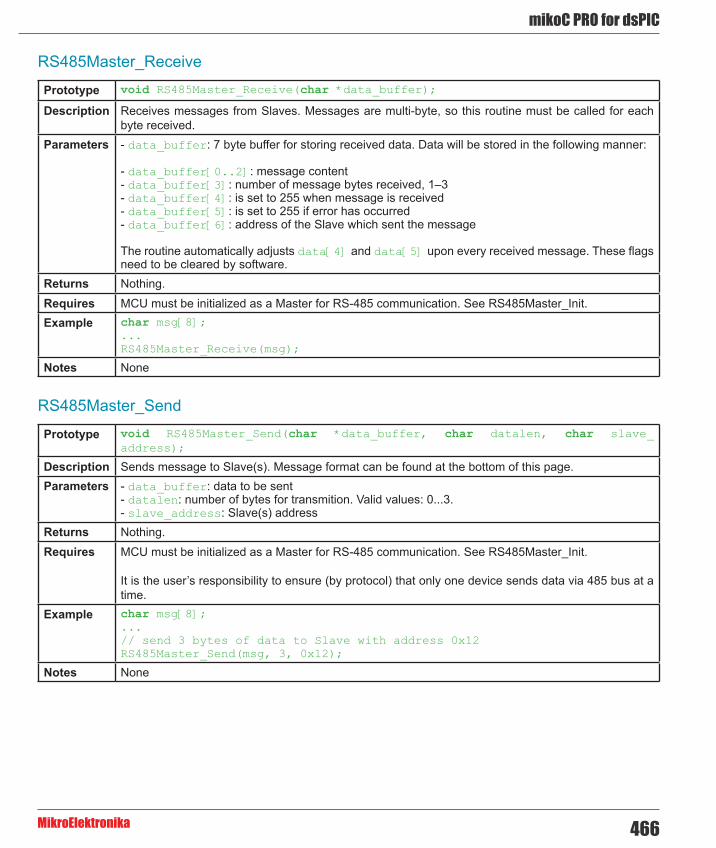
466
mikoC PRO for dsPIC
MikroElektronika
RS485Master_Receive
RS485Master_Send
Prototype void RS485Master_Receive(char *data_buffer);
Description Receives messages from Slaves. Messages are multi-byte, so this routine must be called for each byte received.
Parameters - data_buffer: 7 byte buffer for storing received data. Data will be stored in the following manner:
- data_buffer[0..2]: message content - data_buffer[3]: number of message bytes received, 1–3 - data_buffer[4]: is set to 255 when message is received - data_buffer[5]: is set to 255 if error has occurred - data_buffer[6]: address of the Slave which sent the message
The routine automatically adjusts data[4] and data[5] upon every received message. These flags need to be cleared by software.
Returns Nothing.Requires MCU must be initialized as a Master for RS-485 communication. See RS485Master_Init.Example char msg[8];
...RS485Master_Receive(msg);
Notes None
Prototype void RS485Master_Send(char *data_buffer, char datalen, char slave_address);
Description Sends message to Slave(s). Message format can be found at the bottom of this page.Parameters - data_buffer: data to be sent
- datalen: number of bytes for transmition. Valid values: 0...3. - slave_address: Slave(s) address
Returns Nothing.Requires MCU must be initialized as a Master for RS-485 communication. See RS485Master_Init.
It is the user’s responsibility to ensure (by protocol) that only one device sends data via 485 bus at a time.
Example char msg[8];...// send 3 bytes of data to Slave with address 0x12RS485Master_Send(msg, 3, 0x12);
Notes None

mikroC PRO for dsPIC
MikroElektronika467
RS485Slave_Init
Prototype void RS485Slave_Init(char Slave_address);
Description Initializes MCU as a Slave for RS-485 communication.Parameters - Slave_address: Slave address Returns Nothing.Requires Global variables :
- RS485_rxtx_pin - this pin is connected to RE/DE input of RS-485 transceiver(see schematic at the bottom of this page). RE/DE signal controls RS-485 transceiver operation mode. Valid values: 1 (for transmitting) and 0 (for receiving - RS485_rxtx_pin_direction - direction of the RS-485 Transmit/Receive pin.
must be defined before using this routine.
UART HW module needs to be initialized. See UARTx_Init.Example Initialize MCU as a Slave with address 160:
// RS485 module pinoutsbit RS485_rxtx_pin at RC2_bit; // transmit/receive control set to PORTC.B2sbit RS485_rxtx_pin_direction at TRISC2_bit; // RxTx pin direction set as output// End of RS485 module pinout...UART1_Init(9600); // initialize UART1 moduleRS485Slave_Init(160); // intialize MCU as a Slave for RS-485 communication with address 160
Notes None
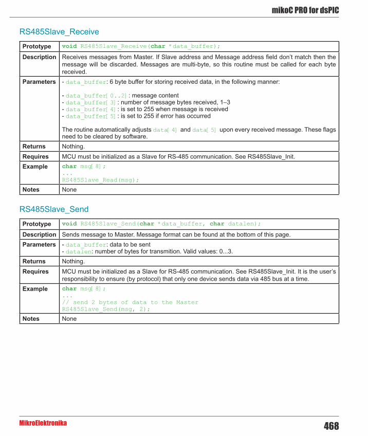
468
mikoC PRO for dsPIC
MikroElektronika
RS485Slave_Receive
RS485Slave_Send
Prototype void RS485Slave_Receive(char *data_buffer);
Description Receives messages from Master. If Slave address and Message address field don’t match then the message will be discarded. Messages are multi-byte, so this routine must be called for each byte received.
Parameters - data_buffer: 6 byte buffer for storing received data, in the following manner:
- data_buffer[0..2]: message content - data_buffer[3]: number of message bytes received, 1–3 - data_buffer[4]: is set to 255 when message is received - data_buffer[5]: is set to 255 if error has occurred
The routine automatically adjusts data[4] and data[5] upon every received message. These flags need to be cleared by software.
Returns Nothing.Requires MCU must be initialized as a Slave for RS-485 communication. See RS485Slave_Init.Example char msg[8];
...RS485Slave_Read(msg);
Notes None
Prototype void RS485Slave_Send(char *data_buffer, char datalen);
Description Sends message to Master. Message format can be found at the bottom of this page.Parameters - data_buffer: data to be sent
- datalen: number of bytes for transmition. Valid values: 0...3. Returns Nothing.Requires MCU must be initialized as a Slave for RS-485 communication. See RS485Slave_Init. It is the user’s
responsibility to ensure (by protocol) that only one device sends data via 485 bus at a time.Example char msg[8];
...// send 2 bytes of data to the MasterRS485Slave_Send(msg, 2);
Notes None

mikroC PRO for dsPIC
MikroElektronika469
Library Example
This is a simple demonstration of RS485 Library routines usage.
Master sends message to Slave with address 160 and waits for a response. The Slave accepts data, increments it and sends it back to the Master. Master then does the same and sends incremented data back to Slave, etc.
Master displays received data on PORTB, while error on receive (0xAA) and number of consecutive unsuccessful retries are displayed on PORTD. Slave displays received data on PORTB, while error on receive (0xAA) is displayed on PORTD. Hardware configurations in this example are made for the EasydsPIC4A board and 30f4013.
RS485 Master code:
Copy Code To Clipboard
sbit rs485_rxtx_pin at RF2_bit; // set transcieve pinsbit rs485_rxtx_pin_direction at TRISF2_bit; // set transcieve pin direction
char dat[10]; // buffer for receving/sending messageschar i,j;
// Interrupt routinevoid interrupt() org IVT_ADDR_U2RXINTERRUPT { RS485Master_Receive(dat); U2RXIF_bit = 0; // ensure interrupt not pending}
void main(){ long cnt = 0;
ADPCFG = 0xFFFF;
PORTB = 0; PORTD = 0; TRISB = 0; TRISD = 0;
UART2_Init(9600); // initialize UART2 module Delay_ms(100);
RS485Master_Init(); // initialize MCU as Master
dat[0] = 0xAA; dat[1] = 0xF0; dat[2] = 0x0F; dat[4] = 0; // ensure that message received flag is 0 dat[5] = 0; // ensure that error flag is 0 dat[6] = 0;
RS485Master_Send(dat,1,160);

470
mikoC PRO for dsPIC
MikroElektronika
URXISEL1_U2STA_bit = 0; URXISEL1_U2STA_bit = 0; NSTDIS_bit = 1; // no nesting of interrupts U2RXIF_bit = 0; // ensure interrupt not pending U2RXIE_bit = 1; // enable intterupt
while (1){ // upon completed valid message receiving // data[4] is set to 255 cnt++; if (dat[5]) { // if an error detected, signal it PORTD = 0xAA; // by setting portd to 0xAA } if (dat[4]) { // if message received successfully cnt = 0; dat[4] = 0; // clear message received flag j = dat[3]; for (i = 1; i <= dat[3]; i++) { // show data on PORTB PORTB = dat[i-1]; } // increment received dat[0] dat[0] = dat[0]+1; // send back to master Delay_ms(1); RS485Master_Send(dat,1,160);
} if (cnt > 100000) { PORTD ++; cnt = 0; RS485Master_Send(dat,1,160); if (PORTD > 10) // if sending failed 10 times RS485Master_Send(dat,1,50); // send message on broadcast address } } // function to be properly linked.}
RS485 Slave code:
Copy Code To Clipboard
sbit rs485_rxtx_pin at RF2_bit; // set transcieve pinsbit rs485_rxtx_pin_direction at TRISF2_bit; // set transcieve pin direction
char dat[9]; // buffer for receving/sending messageschar i,j;
// Interrupt routinevoid interrupt() org IVT_ADDR_U2RXINTERRUPT{ RS485Slave_Receive(dat); U2RXIF_bit = 0; // ensure interrupt not pending}

mikroC PRO for dsPIC
MikroElektronika471
void main() { ADPCFG = 0xFFFF;
PORTB = 0; PORTD = 0; TRISB = 0; TRISD = 0;
UART2_Init(9600); // initialize UART2 module Delay_ms(100);
RS485Slave_Init(160); // Intialize MCU as slave, address 160
dat[0] = 0xAA; dat[1] = 0xF0; dat[2] = 0x0F; dat[4] = 0; // ensure that message received flag is 0 dat[5] = 0; // ensure that error flag is 0 dat[6] = 0;
URXISEL1_U2STA_bit = 0; URXISEL1_U2STA_bit = 0; NSTDIS_bit = 1; // no nesting of interrupts U2RXIF_bit = 0; // ensure interrupt not pending U2RXIE_bit = 1; // enable intterupt
while (1) { if (dat[5]) { // if an error detected, signal it by PORTD = 0xAA; // setting portd to 0xAA dat[5] = 0; } if (dat[4]) { // upon completed valid message receive dat[4] = 0; // data[4] is set to 0xFF j = dat[3]; for (i = 1; i <= dat[3];i++){ PORTB = dat[i-1]; } dat[0] = dat[0]+1; // increment received dat[0] Delay_ms(1); RS485Slave_Send(dat,1); // and send it back to master } }}

472
mikoC PRO for dsPIC
MikroElektronika
HW Connection
Example of interfacing PC to dsPIC MCU via RS485 bus with LTC485 as RS-485 transceiver

mikroC PRO for dsPIC
MikroElektronika473
Message format and CRC calculations
Q: How is CRC checksum calculated on RS485 master side?
Copy Code To Clipboard
START_BYTE = 0x96; // 10010110STOP_BYTE = 0xA9; // 10101001
PACKAGE:-------- START_BYTE 0x96ADDRESSDATALEN[DATA1] // if exists[DATA2] // if exists[DATA3] // if existsCRCSTOP_BYTE 0xA9
DATALEN bits------------bit7 = 1 MASTER SENDS 0 SLAVE SENDSbit6 = 1 ADDRESS WAS XORed with 1, IT WAS EQUAL TO START_BYTE or STOP_BYTE 0 ADDRESS UNCHANGEDbit5 = 0 FIXEDbit4 = 1 DATA3 (if exists) WAS XORed with 1, IT WAS EQUAL TO START_BYTE or STOP_BYTE 0 DATA3 (if exists) UNCHANGEDbit3 = 1 DATA2 (if exists) WAS XORed with 1, IT WAS EQUAL TO START_BYTE or STOP_BYTE 0 DATA2 (if exists) UNCHANGEDbit2 = 1 DATA1 (if exists) WAS XORed with 1, IT WAS EQUAL TO START_BYTE or STOP_BYTE 0 DATA1 (if exists) UNCHANGEDbit1bit0 = 0 to 3 NUMBER OF DATA BYTES SEND
CRC generation :----------------crc_send = datalen ^ address;crc_send ^= data[0]; // if existscrc_send ^= data[1]; // if existscrc_send ^= data[2]; // if existscrc_send = ~crc_send;if ((crc_send == START_BYTE) || (crc_send == STOP_BYTE)) crc_send++;NOTE: DATALEN<4..0> can not take the START_BYTE<4..0> or STOP_BYTE<4..0> values.

474
mikoC PRO for dsPIC
MikroElektronika
Software I²C LibraryThe mikroC PRO for dsPIC30/33 and PIC24 provides routines for implementing Software I²C communication. These routines are hardware independent and can be used with any MCU. The Software I²C library enables you to use MCU as Master in I²C communication. Multi-master mode is not supported.
Important :
- This library implements time-based activities, so interrupts need to be disabled when using Software I²C. - All I²C Library functions are blocking-call functions (they are waiting for I²C clock line to become logical one). - The pins used for the Software I²C communication should be connected to the pull-up resistors. Turning off the LEDs connected to these pins may also be required. - Every Software I²C library routine has its own counterpart in Hardware I²C library, except I2C_Repeated_Start. Soft_I2C_Start is used instead of I2C_Repeated_Start. - Working clock frequency of the Software I²C is 20kHz.
The following variable must be defined in all projects using RS-485 Library:
Description : Example :
extern sbit Soft_I2C_Scl; Soft I²C Clock line. sbit Soft_I2C_Scl at RB11_bit;
extern sbit Soft_I2C_Sda; Soft I²C Data line. sbit Soft_I2C_Sda at RB12_bit;
extern sbit Soft_I2C_Scl_Direction;
Direction of the Soft I²C Clock pin.
sbit Soft_I2C_Scl_Direction at TRISB11_bit;
extern sbit Soft_I2C_Sda_Direction;
Direction of the Soft I²C Data pin.
sbit Soft_I2C_Sda_Direction at TRISB12_bit;
External dependencies of Software I²C Library
Library Routines
- Soft_I2C_Init - Soft_I2C_Start - Soft_I2C_Read - Soft_I2C_Write - Soft_I2C_Stop - Soft_I2C_Break

mikroC PRO for dsPIC
MikroElektronika475
Soft_I2C_Init
Soft_I2C_Start
Prototype void Soft_I2C_Init();
Description Configures the software I²C module.Parameters None.Returns Nothing.Requires Global variables :
- Soft_I2C_Scl: Soft I²C clock line - Soft_I2C_Sda: Soft I²C data line - Soft_I2C_Scl_Pin_Direction: Direction of the Soft I²C clock pin - Soft_I2C_Sda_Pin_Direction: Direction of the Soft I²C data pin
must be defined before using this function. Example // Software I2C connections
sbit Soft_I2C_Scl at RB11_bit;sbit Soft_I2C_Sda at RB12_bit;sbit Soft_I2C_Scl_Direction at TRISB11_bit;sbit Soft_I2C_Sda_Direction at TRISB12_bit;// End Software I2C connections...Soft_I2C_Init();
Notes None
Prototype void Soft_I2C_Start();
Description Determines if the I²C bus is free and issues START signal.Parameters None.Returns Nothing.Requires Software I²C must be configured before using this function. See Soft_I2C_Init routine.Example // Issue START signal
Soft_I2C_Start();
Notes None

476
mikoC PRO for dsPIC
MikroElektronika
Soft_I2C_Read
Soft_I2C_Write
Prototype unsigned short Soft_I2C_Read(unsigned int ack);
Description Reads one byte from the slave.Parameters - ack: acknowledge signal parameter. If the ack==0 not acknowledge signal will be sent after reading,
otherwise the acknowledge signal will be sent. Returns One byte from the Slave.Requires Soft I²C must be configured before using this function. See Soft_I2C_Init routine.
Also, START signal needs to be issued in order to use this function. See Soft_I2C_Start routine.Example unsigned short take;
...// Read data and send the not_acknowledge signaltake = Soft_I2C_Read(0);
Notes None
Prototype unsigned short Soft_I2C_Write(unsigned short data_);
Description Sends data byte via the I²C bus.Parameters - data_: data to be sent Returns - 0 if there were no errors.
- 1 if write collision was detected on the I²C bus. Requires Soft I²C must be configured before using this function. See Soft_I2C_Init routine.
Also, START signal needs to be issued in order to use this function. See Soft_I2C_Start routine.Example unsigned short data_, error;
...error = Soft_I2C_Write(data_);error = Soft_I2C_Write(0xA3);
Notes None

mikroC PRO for dsPIC
MikroElektronika477
Soft_I2C_Stop
Prototype void Soft_I2C_Stop();
Description Issues STOP signal.Parameters None.Returns Nothing.Requires Soft I²C must be configured before using this function. See Soft_I2C_Init routine.Example // Issue STOP signal
Soft_I2C_Stop();
Notes None

478
mikoC PRO for dsPIC
MikroElektronika
Soft_I2C_Break
Prototype void Soft_I2C_Break();
Description All Software I²C Library functions can block the program flow (see note at the top of this page). Calling this routine from interrupt will unblock the program execution. This mechanism is similar to WDT.
Parameters None.Returns Nothing.Requires Nothing. Example // Software I2C connections
sbit Soft_I2C_Scl at RC0_bit;sbit Soft_I2C_Sda at RC1_bit;sbit Soft_I2C_Scl_Direction at TRISC0_bit;sbit Soft_I2C_Sda_Direction at TRISC1_bit;// End Software I2C connections
char counter = 0;
void Timer1Int() org IVT_ADDR_T1INTERRUPT {
if (counter >= 20) { Soft_I2C_Break(); counter = 0; // reset counter } else counter++; // increment counter T1IF_bit = 0; // Clear Timer1 overflow interrupt flag}
void main() {
... // try Soft_I2C_Init with blocking prevention mechanism IPC0 = IPC0 | 0x1000; // Interrupt priority level = 1 T1IE_bit= 1; // Enable Timer1 interrupts T1CON = 0x8030; // Timer1 ON, internal clock FCY, prescaler 1:256
Soft_I2C_Init(); T1IE_bit= 0; // Disable Timer1 interrupts}
Notes Interrupts should be disabled before using Software I²C routines again (see note at the top of this page).

mikroC PRO for dsPIC
MikroElektronika479
Library Example
The example demonstrates use of the Software I²C Library. The dsPIC30/33 or PIC24 MCU is connected (SCL, SDA pins) to PCF8583 RTC (real-time clock). Program sends date/time to RTC.
Copy Code To Clipboard
char seconds, minutes, hours, day, month, year; // Global date/time variables
// Software I2C connectionssbit Soft_I2C_Scl at RB11_bit;sbit Soft_I2C_Sda at RB12_bit;sbit Soft_I2C_Scl_Direction at TRISB11_bit;sbit Soft_I2C_Sda_Direction at TRISB12_bit;// End Software I2C connections
// LCD module connectionssbit LCD_RS at LATD0_bit;sbit LCD_EN at LATD1_bit;sbit LCD_D4 at LATB0_bit;sbit LCD_D5 at LATB1_bit;sbit LCD_D6 at LATB2_bit;sbit LCD_D7 at LATB3_bit;
sbit LCD_RS_Direction at TRISD0_bit;sbit LCD_EN_Direction at TRISD1_bit;sbit LCD_D4_Direction at TRISB0_bit;sbit LCD_D5_Direction at TRISB1_bit;sbit LCD_D6_Direction at TRISB2_bit;sbit LCD_D7_Direction at TRISB3_bit;// End LCD module connections
//--------------------- Reads time and date information from RTC (PCF8583)void Read_Time() {
Soft_I2C_Start(); // Issue start signal Soft_I2C_Write(0xA0); // Address PCF8583, see PCF8583 datasheet Soft_I2C_Write(2); // Start from address 2 Soft_I2C_Start(); // Issue repeated start signal Soft_I2C_Write(0xA1); // Address PCF8583 for reading R/W=1
seconds = Soft_I2C_Read(1); // Read seconds byte minutes = Soft_I2C_Read(1); // Read minutes byte hours = Soft_I2C_Read(1); // Read hours byte day = Soft_I2C_Read(1); // Read year/day byte month = Soft_I2C_Read(0); // Read weekday/month byte Soft_I2C_Stop(); // Issue stop signal
}

480
mikoC PRO for dsPIC
MikroElektronika
//-------------------- Formats date and timevoid Transform_Time() { seconds = ((seconds & 0xF0) >> 4)*10 + (seconds & 0x0F); // Transform seconds minutes = ((minutes & 0xF0) >> 4)*10 + (minutes & 0x0F); // Transform months hours = ((hours & 0xF0) >> 4)*10 + (hours & 0x0F); // Transform hours year = (day & 0xC0) >> 6; // Transform year day = ((day & 0x30) >> 4)*10 + (day & 0x0F); // Transform day month = ((month & 0x10) >> 4)*10 + (month & 0x0F); // Transform month}
//-------------------- Output values to LCDvoid Display_Time() {
Lcd_Chr(1, 6, (day / 10) + 48); // Print tens digit of day variable Lcd_Chr(1, 7, (day % 10) + 48); // Print oness digit of day variable Lcd_Chr(1, 9, (month / 10) + 48); Lcd_Chr(1,10, (month % 10) + 48); Lcd_Chr(1,15, year + 56); // Print year vaiable + 8 (start from year 2008)
Lcd_Chr(2, 6, (hours / 10) + 48); Lcd_Chr(2, 7, (hours % 10) + 48); Lcd_Chr(2, 9, (minutes / 10) + 48); Lcd_Chr(2,10, (minutes % 10) + 48); Lcd_Chr(2,12, (seconds / 10) + 48); Lcd_Chr(2,13, (seconds % 10) + 48);}
//------------------ Performs project-wide initvoid Init_Main() { ADPCFG = 0xFFFF; // initialize AN pins as digital
Soft_I2C_Init(); // Initialize Soft I2C communication Lcd_Init(); // Initialize LCD Lcd_Cmd(_LCD_CLEAR); // Clear LCD display Lcd_Cmd(_LCD_CURSOR_OFF); // Turn cursor off
Lcd_Out(1,1,"Date:"); // Prepare and output static text on LCD Lcd_Chr(1,8,':'); Lcd_Chr(1,11,':'); Lcd_Out(2,1,"Time:"); Lcd_Chr(2,8,':'); Lcd_Chr(2,11,':'); Lcd_Out(1,12,"200");}
//----------------- Main procedurevoid main() {
Delay_ms(2000);
Init_Main(); // Perform initialization
while (1) { // Endless loop Read_Time(); // Read time from RTC(PCF8583) Transform_Time(); // Format date and time Display_Time(); // Prepare and display on LCD
Delay_ms(1000); // Wait 1 second }}

mikroC PRO for dsPIC
MikroElektronika481
Software SPI LibraryThe mikroC PRO for dsPIC30/33 and PIC24 provides routines for implementing Software SPI communication. These routines are hardware independent and can be used with any MCU. The Software SPI Library provides easy communication with other devices via SPI: A/D converters, D/A converters, MAX7219, LTC1290, etc.
Library configuration:
- SPI to Master mode - Clock value = 20 kHz. - Data sampled at the middle of interval. - Clock idle state low. - Data sampled at the middle of interval. - Data transmitted at low to high edge.
The library configures SPI to the master mode, clock = 20kHz, data sampled at the middle of interval, clock idle state low and data transmitted at low to high edge.
Important : The Software SPI library implements time-based activities, so interrupts need to be disabled when using it.
The following variables must be defined in all projects using Software SPI Library:
Description : Example :
extern sfr sbit SoftSpi_SDI; Data In line. sbit SoftSpi_SDI at RF4_bit;
extern sfr sbit SoftSpi_SDO; Data Out line. sbit SoftSpi_SDO at LATF3_bit;
extern sfr sbit SoftSpi_CLK; Clock line. sbit SoftSpi_CLK at LATF6_bit;
extern sfr sbit SoftSpi_SDI_Direction; Direction of the Data In pin. sbit SoftSpi_SDI_Direction at
TRISF4_bit;
extern sfr sbit SoftSpi_SDO_Direction; Direction of the Data Out pin sbit SoftSpi_SDO_Direction at
TRISF3_bit;
extern sfr sbit SoftSpi_CLK_Direction; Direction of the Clock pin. sbit SoftSpi_CLK_Direction at
TRISF6_bit;
External dependencies of Software SPI Library
Library Routines
- Soft_SPI_Init - Soft_SPI_Read - Soft_SPI_Write

482
mikoC PRO for dsPIC
MikroElektronika
Soft_SPI_Init
Prototype void Soft_SPI_Init();
Description Routine initializes the software SPI module.Parameters None.Returns Nothing.Requires Global variables:
- SoftSpi_SDI: Data in line - SoftSpi_SDO: Data out line - SoftSpi_CLK: Data clock line - SoftSpi_SDI_Direction: Direction of the Data in pin - SoftSpi_SDO_Direction: Direction of the Data out pin - SoftSpi_CLK_Direction: Direction of the Data clock pin
must be defined before using this function. Example // Software SPI module connections
sbit SoftSpi_SDI at RF4_bit;sbit SoftSpi_SDO at LATF3_bit;sbit SoftSpi_CLK at LATF6_bit;
sbit SoftSpi_SDI_Direction at TRISF4_bit;sbit SoftSpi_SDO_Direction at TRISF3_bit;sbit SoftSpi_CLK_Direction at TRISF6_bit;// End Software SPI module connections...Soft_SPI_Init(); // Init Soft_SPI
Notes None

mikroC PRO for dsPIC
MikroElektronika483
Soft_SPI_Read
Soft_SPI_Write
Prototype unsigned short Soft_SPI_Read(char sdata);
Description This routine performs 3 operations simultaneously. It provides clock for the Software SPI bus, reads a byte and sends a byte.
Parameters - sdata: data to be sent. Returns Byte received via the SPI bus.Requires Soft SPI must be initialized before using this function. See Soft_SPI_Init routine.Example unsigned short data_read;
char data_send;...// Read a byte and assign it to data_read variable// (data_send byte will be sent via SPI during the Read operation)data_read = Soft_SPI_Read(data_send);
Notes None
Prototype void Soft_SPI_Write(char sdata);
Description This routine sends one byte via the Software SPI bus.Parameters - sdata: data to be sent. Returns Nothing.Requires Soft SPI must be initialized before using this function. See Soft_SPI_Init.Example // Write a byte to the Soft SPI bus
Soft_SPI_Write(0xAA);
Notes None
Library Example
This code demonstrates using library routines for Soft_SPI communication. Also, this example demonstrates working with max7219. Eight 7 segment displays are connected to MAX7219. MAX7219 is connected to SDO, SDI, SCK pins are connected accordingly.
Copy Code To Clipboard
// DAC module connectionssbit Chip_Select at LATF0_bit;sbit SoftSpi_CLK at LATF6_bit;sbit SoftSpi_SDI at RF4_bit;sbit SoftSpi_SDO at LATF3_bit;
sbit Chip_Select_Direction at TRISF0_bit;sbit SoftSpi_CLK_Direction at TRISF6_bit;sbit SoftSpi_SDI_Direction at TRISF4_bit;sbit SoftSpi_SDO_Direction at TRISF3_bit;// End DAC module connections

484
mikoC PRO for dsPIC
MikroElektronika
unsigned int value;
void InitMain() { TRISB0_bit = 1; // Set RB0 pin as input TRISB1_bit = 1; // Set RB1 pin as input Chip_Select = 1; // Deselect DAC Chip_Select_Direction = 0; // Set CS# pin as Output Soft_SPI_Init(); // Initialize Soft_SPI}
// DAC increments (0..4095) --> output voltage (0..Vref)void DAC_Output(unsigned int valueDAC) { char temp;
Chip_Select = 0; // Select DAC chip
// Send High Byte temp = (valueDAC >> 8) & 0x0F; // Store valueDAC[11..8] to temp[3..0] temp |= 0x30; // Define DAC setting, see MCP4921 datasheet Soft_SPI_Write(temp); // Send high byte via Soft SPI
// Send Low Byte temp = valueDAC; // Store valueDAC[7..0] to temp[7..0] Soft_SPI_Write(temp); // Send low byte via Soft SPI
Chip_Select = 1; // Deselect DAC chip}
void main() {
ADPCFG = 0xFFFF; // Configure AN pins as digital
InitMain(); // Perform main initialization
value = 2048; // When program starts, DAC gives // the output in the mid-range
while (1) { // Endless loop
if ((RB0_bit) && (value < 4095)) { // If RB0 button is pressed value++; // increment value } else { if ((RB1_bit) && (value > 0)) { // If RB1 button is pressed value--; // decrement value } }
DAC_Output(value); // Send value to DAC chip Delay_ms(1); // Slow down key repeat pace }}

mikroC PRO for dsPIC
MikroElektronika485
Software UART LibraryThe mikroC PRO for dsPIC30/33 and PIC24 provides routines for implementing Software UART communication. These routines are hardware independent and can be used with any MCU. The Software UART Library provides easy communication with other devices via the RS232 protocol.
Important : The Software UART library implements time-based activities, so interrupts need to be disabled when using it.
Library Routines
- Soft_UART_Init - Soft_UART_Read - Soft_UART_Write - Soft_UART_Break
Soft_UART_Init
Prototype char Soft_UART_Init(unsigned int *port, unsigned int rx, unsigned int tx, unsigned long baud_rate, unsigned int inverted);
Description Configures and initializes the software UART module.
Software UART routines use Delay_Cyc routine. If requested baud rate is too low then calculated parameter for calling Delay_Cyc exceeds Delay_Cyc argument range.
If requested baud rate is too high then rounding error of Delay_Cyc argument corrupts Software UART timings.
Parameters - port: software UART port address - rx: receiver pin - tx: transmiter pin - baud_rate: requested baudrate. Maximum baud rate depends on the MCU’s clock and working conditions - inverted: if set to non-zero value, indicates inverted logic on output
Returns - 2 - error, requested baud rate is too low - 1 - error, requested baud rate is too high - 0 - successful initialization
Requires Nothing.Example This will initialize software UART and establish the communication at 9600 bps:
char error;...error = Soft_UART_Init(&PORTF, 4, 5, 14400, 0); // Initialize Soft UART at 14400 bps
Notes The Software UART library implements time-based activities, so interrupts need to be disabled when using it.

486
mikoC PRO for dsPIC
MikroElektronika
Soft_UART_Read
Soft_UART_Write
Prototype char Soft_UART_Read(char *error);
Description The function receives a byte via software UART.
This is a blocking function call (waits for start bit). Programmer can unblock it by calling Soft_UART_Break routine.
Parameters - error: Error flag. Error code is returned through this variable. Values : - 0 - no error - 1 - stop bit error - 255 - user abort, Soft_UART_Break called
Returns Byte received via UART.Requires Software UART must be initialized before using this function. See the Soft_UART_Init routine.Example char data_;
char error;...// wait until data is receiveddo data = Soft_UART_Read(&error);while (error);
// Now we can work with data:if (data_) {...}
Notes The Software UART library implements time-based activities, so interrupts need to be disabled when using it.
Prototype void Soft_UART_Write(char udata);
Description This routine sends one byte via the Software UART bus.Parameters - udata: data to be sent. Returns Nothing.Requires Software UART must be initialized before using this function. See the Soft_UART_Init routine.
Be aware that during transmission, software UART is incapable of receiving data – data transfer protocol must be set in such a way to prevent loss of information.
Example char some_byte = 0x0A;...// Write a byte via Soft UARTSoft_UART_Write(some_byte);
Notes The Software UART library implements time-based activities, so interrupts need to be disabled when using it.

mikroC PRO for dsPIC
MikroElektronika487
Soft_UART_Break
Prototype void Soft_UART_Break();
Description Soft_UART_Read is blocking routine and it can block the program flow. Calling Soft_UART_Break routine from the interrupt will unblock the program execution. This mechanism is similar to WDT.
Parameters None.Returns Nothing.Requires Nothing. Example char data1, error, counter = 0;
void Timer1Int() org IVT_ADDR_T1INTERRUPT {
if (counter >= 20) { Soft_UART_Break(); counter = 0; // reset counter }
else counter++; // increment counter
T1IF_bit = 0; // Clear Timer1 overflow interrupt flag}
void main() {
...
if (Soft_UART_Init(&PORTF, 4, 5, 14400, 0) = 0) Soft_UART_Write(0x55); ...
// try Soft_UART_Read with blocking prevention mechanism IPC0 = IPC0 | 0x1000; // Interrupt priority level = 1 T1IE_bit= 1; // Enable Timer1 interrupts T1CON = 0x8030; // Timer1 ON, internal clock FCY, prescaler 1:256
data1 = Soft_UART_Read(&error); T1IE_bit= 0; // Disable Timer1 interrupts}
Notes The Software UART library implements time-based activities, so interrupts need to be disabled when using it.

488
mikoC PRO for dsPIC
MikroElektronika
Library Example
This example demonstrates simple data exchange via software UART. If MCU is connected to the PC, you can test the
example from the mikroC PRO for dsPIC30/33 and PIC24 USART communication terminal, launch it from the drop-
down menu Tools › USART Terminal or simply click the USART Terminal Icon .
Copy Code To Clipboard
char i, error, byte_read; // Auxiliary variables
void main(){
ADPCFG = 0xFFFF;
TRISB = 0; // Set PORTB as output (error signalization) LATB = 0;
error = Soft_UART_Init(&PORTF, 4, 5, 14400, 0); // Initialize Soft UART at 14400 bps if (error > 0) { LATB = error; // Signalize Init error while(1); // Stop program } Delay_ms(100);
for (i = 'z'; i >= 'A'; i--) { // Send bytes from 'z' downto 'A' Soft_UART_Write(i); Delay_ms(100); } while(1) { // Endless loop byte_read = Soft_UART_Read(&error); // Read byte, then test error flag if (error) // If error was detected LATB = error; // signal it on PORTB else Soft_UART_Write(byte_read); // If error was not detected, return byte read } }

mikroC PRO for dsPIC
MikroElektronika489
Sound LibraryThe mikroC PRO for dsPIC30/33 and PIC24 provides a Sound Library to supply users with routines necessary for sound signalization in their applications. Sound generation needs additional hardware, such as piezo-speaker (example of piezo-speaker interface is given on the schematic at the bottom of this page).
Library Routines
- Sound_Init - Sound_Play
Sound_Init
Sound_Play
Prototype void Sound_Init(unsigned int *snd_port, unsigned< int/b> snd_pin);
Description Configures the appropriate MCU pin for sound generation.Parameters - snd_port: sound output port address
- snd_pin: sound output pin Returns Nothing.Requires Nothing. Example // Initialize the pin RC3 for playing sound
Sound_Init(&PORTD, 3);
Notes None.
Prototype void Sound_Play(unsigned int freq_in_hz, unsigned< int/b> duration_ms);
Description Generates the square wave signal on the appropriate pin.Parameters - freq_in_hz: signal frequency in Hertz (Hz)
- duration_ms: signal duration in miliseconds (ms) Returns Nothing.Requires In order to hear the sound, you need a piezo speaker (or other hardware) on designated port. Also, you
must call Sound_Init to prepare hardware for output before using this function.Example // Play sound of 1KHz in duration of 100ms
Sound_Play(1000, 100);
Notes None.

490
mikoC PRO for dsPIC
MikroElektronika
Library Example
The example is a simple demonstration of how to use the Sound Library for playing tones on a piezo speaker.
Copy Code To Clipboard
void Tone1() { Sound_Play(659, 250); // Frequency = 659Hz, duration = 250ms}
void Tone2() { Sound_Play(698, 250); // Frequency = 698Hz, duration = 250ms}
void Tone3() { Sound_Play(784, 250); // Frequency = 784Hz, duration = 250ms}
void Melody() { // Plays the melody "Yellow house" Tone1(); Tone2(); Tone3(); Tone3(); Tone1(); Tone2(); Tone3(); Tone3(); Tone1(); Tone2(); Tone3(); Tone1(); Tone2(); Tone3(); Tone3(); Tone1(); Tone2(); Tone3(); Tone3(); Tone3(); Tone2(); Tone2(); Tone1();}
void ToneA() { Sound_Play( 880, 50);}void ToneC() { Sound_Play(1046, 50);}void ToneE() { Sound_Play(1318, 50);}
void Melody2() { unsigned short i; for (i = 9; i > 0; i--) { ToneA(); ToneC(); ToneE(); }}
void main() {
ADPCFG = 0xFFFF; // Configure AN pins as digital TRISB = 0xF8; // Configure RB7..RB3 as input LATB = 0; Sound_Init(&PORTD, 3); Sound_Play(880, 1000); // Play sound at 880Hz for 1 second

mikroC PRO for dsPIC
MikroElektronika491
while (1) { if (Button(&PORTB,7,1,1)) // RB7 plays Tone1 Tone1(); while (RB7_bit); // Wait for button to be released
if (Button(&PORTB,6,1,1)) // RB6 plays Tone2 Tone2(); while (RB6_bit); // Wait for button to be released
if (Button(&PORTB,5,1,1)) // RB5 plays Tone3 Tone3(); while (RB5_bit); // Wait for button to be released
if (Button(&PORTB,4,1,1)) // RB4 plays Melody2 Melody2(); while (RB4_bit); // Wait for button to be released
if (Button(&PORTB,3,1,1)) // RB3 plays Melody Melody(); while (RB3_bit); // Wait for button to be released }}
HW Connection
Example of Sound Library

492
mikoC PRO for dsPIC
MikroElektronika
SPI LibraryThe SPI module is available with all dsPIC30/33 and PIC24 MCUs. mikroC PRO for dsPIC30/33 and PIC24 provides a library for initializing the Slave mode and initializing and comfortable work with the Master mode. The dsPIC30/33 and PIC24 can easily communicate with other devices via SPI: A/D converters, D/A converters, MAX7219, LTC1290, etc.
Important :
SPI library routines require you to specify the module you want to use. To select the desired SPI module, simply change the letter x in the routine prototype for a number from 1 to 3. Number of SPI modules per MCU differs from chip to chip. Please, read the appropriate datasheet before utilizing this library. Switching between the SPI modules in the SPI library is done by the SPI_Set_Active function (both SPI modules have to be previously initialized).
Library Routines
- SPIx_Init - SPIx_Init_Advanced - SPIx_Read - SPIx_Write - SPI_Set_Active

mikroC PRO for dsPIC
MikroElektronika493
SPIx_Init
Prototype void SPIx_Init();
Description Configures and initializes the SPI module with default settings.
Default settings:
- Master mode - 8-bit data mode - secondary prescaler 1:1 - primary prescaler 64:1 - Slave Select disabled - input data sampled in the middle of interval - clock idle state low - Serial output data changes on transition from active clock state to idle clock state
Parameters None.Returns Nothing.Requires MCU must have the SPI1 module.Example // Initialize the SPI1 module with default settings
SPI1_Init();
Notes SPI library routines require you to specify the module you want to use. To select the desired SPI module, simply change the letter x in the routine prototype for a number from 1 to 3.
Number of SPI modules per MCU differs from chip to chip. Please, read the appropriate datasheet before utilizing this library.
Switching between the SPI modules in the SPI library is done by the SPI_Set_Active function (both SPI modules have to be previously initialized).

494
mikoC PRO for dsPIC
MikroElektronika
SPIx_Init_Advanced
Prototype void SPIx_Init_Advanced(unsigned master_mode, unsigned mode16, unsigned sec_prescaler, unsigned pri_prescaler, unsigned slave_select, unsigned data_sample, unsigned clock_idle, unsigned edge);
Description Configures and initializes the SPI module with user defined settings.Parameters Parameters master_mode, mode16, sec_prescaler, pri_prescaler, slave_select, data_
sample, clock_idle and determine the working mode for SPI.
The master_mode parameter determines the working mode for SPI module.
Master/Slave modeDescription Predefined library const
Master mode _SPI_MASTER
Slave mode _SPI_SLAVE
Data Length ModeDescription Predefined library const
16-bit mode _SPI_16_BIT
8-bit mode _SPI_8_BIT
Secondary SPI Clock Prescaler ValueDescription Predefined library const
Secondary Prescaler 1:1 _SPI_PRESCALE_SEC_1
Secondary Prescaler 1:2 _SPI_PRESCALE_SEC_2
Secondary Prescaler 1:3 _SPI_PRESCALE_SEC_3
Secondary Prescaler 1:4 _SPI_PRESCALE_SEC_4
Secondary Prescaler 1:5 _SPI_PRESCALE_SEC_5
Secondary Prescaler 1:6 _SPI_PRESCALE_SEC_6
Secondary Prescaler 1:7 _SPI_PRESCALE_SEC_7
Secondary Prescaler 1:8 _SPI_PRESCALE_SEC_8
The parameter mode16 determines the data length mode, which can be 8-bits (per transmitions cycle) or 16-bits.
The parameter sec_prescaler determines the value of the secondary SPI clock prescaler. Used only in the Master Mode.
The parameter pri_prescaler determines the value of the primary SPI clock prescaler. Used only in the Master Mode.
Primary SPI Clock Prescaler ValueDescription Predefined library const
Primary Prescaler 1:1 _SPI_PRESCALE_PRI_1
Primary Prescaler 4:1 _SPI_PRESCALE_PRI_4
Primary Prescaler 16:1 _SPI_PRESCALE_PRI_16
Primary Prescaler 64:1 _SPI_PRESCALE_PRI_64
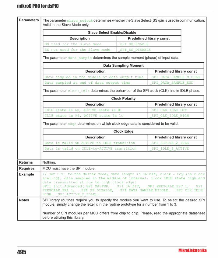
mikroC PRO for dsPIC
MikroElektronika495
Parameters
Returns Nothing.Requires MCU must have the SPI module.Example // Set SPI1 to the Master Mode, data length is 16-bit, clock = Fcy (no clock
scaling), data sampled in the middle of interval, clock IDLE state high and data transmitted at low to high clock edge:SPI1_Init_Advanced(_SPI_MASTER, _SPI_16_BIT, _SPI_PRESCALE_SEC_1, _SPI_PRESCALE_PRI_1, _SPI_SS_DISABLE, _SPI_DATA_SAMPLE_MIDDLE, _SPI_CLK_IDLE_HIGH, _SPI_ACTIVE_2_IDLE);
Notes SPI library routines require you to specify the module you want to use. To select the desired SPI module, simply change the letter x in the routine prototype for a number from 1 to 3.
Number of SPI modules per MCU differs from chip to chip. Please, read the appropriate datasheet before utilizing this library.
Slave Select Enable/DisableDescription Predefined library const
SS used for the Slave mode _SPI_SS_ENABLE
SS not used for the Slave mode _SPI_SS_DISABLE
Data Sampling MomentDescription Predefined library const
Data sampled in the middle of data output time _SPI_DATA_SAMPLE_MIDDLE
Data sampled at end of data output time _SPI_DATA_SAMPLE_END
Clock PolarityDescription Predefined library const
IDLE state is Lo, ACTIVE state is Hi _SPI_CLK_IDLE_LOW
IDLE state is Hi, ACTIVE state is Lo _SPI_CLK_IDLE_HIGH
Clock EdgeDescription Predefined library const
Data is valid on ACTIVE-to-IDLE transition _SPI_ACTIVE_2_IDLE
Data is valid on IDLE-to-ACTIVE transition _SPI_IDLE_2_ACTIVE
The parameter slave_select determines whether the Slave Select (SS) pin is used in communication. Valid in the Slave Mode only.
The parameter data_sample determines the sample moment (phase) of input data.
The parameter clock_idle determines the behaviour of the SPI clock (CLK) line in IDLE phase.
The parameter edge determines on which clock edge data is considered to be valid.

496
mikoC PRO for dsPIC
MikroElektronika
SPIx_Read
SPIx_Write
Prototype unsigned SPIx_Read(unsigned buffer);
Description Reads one word or byte (depending on mode set by init routines) from the SPI bus.Parameters - data_out: dummy data for clock generation (see device Datasheet for SPI modules implementation
details) Returns Received data.Requires Routine requires at least one SPI module.
Used SPI module must be initialized before using this function. See the SPIx_Init and SPIx_Init_Advanced routines.
Example // read a byte from the SPI bus char take, buffer;...take = SPI1_Read(buffer);
Notes SPI library routines require you to specify the module you want to use. To select the desired SPI module, simply change the letter x in the routine prototype for a number from 1 to 3.
Number of SPI modules per MCU differs from chip to chip. Please, read the appropriate datasheet before utilizing this library.
Prototype void SPIx_Write(unsigned data_out);
Description Writes one word or byte (depending on mode set by init routines) via the SPI bus.Parameters - data_out: data to be sent Returns Received data.Requires Routine requires at least one SPI module.
Used SPI module must be initialized before using this function. See the SPIx_Init and SPIx_Init_Advanced routines.
Example // write a byte to the SPI buschar buffer;...SPI1_Write(buffer);
Notes SPI library routines require you to specify the module you want to use. To select the desired SPI module, simply change the letter x in the routine prototype for a number from 1 to 3.
Number of SPI modules per MCU differs from chip to chip. Please, read the appropriate datasheet before utilizing this library.

mikroC PRO for dsPIC
MikroElektronika497
SPI_Set_Active
Prototype void SPI_Set_Active(unsigned (*read_ptr)(unsigned), void(*write_ptr)(unsigned));
Description Sets the active SPI module which will be used by the SPIx_Read and SPIx_Write routines.Parameters Parameters :
- read_ptr: SPI1_Read handler - write_ptr: SPI1_Write handler
Returns Nothing.Requires Routine is available only for MCUs with multiple SPI modules.
Used SPI module must be initialized before using this function. See the SPIx_Init and SPIx_Init_Advanced routines.
Example SPI_Set_Active(SPI1_Read, SPI1_Write); // Sets the SPI1 module active
Notes Number of SPI modules per MCU differs from chip to chip. Please, read the appropriate datasheet before utilizing this library.
Library Example
The code demonstrates how to use SPI library functions for communication between SPI2 module of the MCU and MCP4921 DAC chip.
Copy Code To Clipboard
// DAC module connectionssbit Chip_Select at LATF0_bit;sbit Chip_Select_Direction at TRISF0_bit;// End DAC module connections
unsigned int value;
void InitMain() { TRISB0_bit = 1; // Set RB0 pin as input TRISB1_bit = 1; // Set RB1 pin as input Chip_Select = 1; // Deselect DAC Chip_Select_Direction = 0; // Set CS# pin as Output SPI1_Init(); // Initialize SPI module}
// DAC increments (0..4095) --> output voltage (0..Vref)void DAC_Output(unsigned int valueDAC) { char temp; Chip_Select = 0; // Select DAC chip // Send High Byte temp = (valueDAC >> 8) & 0x0F; // Store valueDAC[11..8] to temp[3..0] temp |= 0x30; // Define DAC setting, see MCP4921 datasheet SPI1_Write(temp); // Send high byte via SPI

498
mikoC PRO for dsPIC
MikroElektronika
// Send Low Byte temp = valueDAC; // Store valueDAC[7..0] to temp[7..0] SPI1_Write(temp); // Send low byte via SPI Chip_Select = 1; // Deselect DAC chip}
void main() {
ADPCFG = 0xFFFF; // Configure AN pins as digital
InitMain(); // Perform main initialization
value = 2048; // When program starts, DAC gives // the output in the mid-range while (1) { // Endless loop
if ((RB0_bit) && (value < 4095)) { // If RB0 button is pressed value++; // increment value } else { if ((RB1_bit) && (value > 0)) { // If RB1 button is pressed value--; // decrement value } } DAC_Output(value); // Send value to DAC chip Delay_ms(1); // Slow down key repeat pace }}
HW Connection
SPI HW connection

mikroC PRO for dsPIC
MikroElektronika499
SPI Ethernet LibraryThe ENC28J60 is a stand-alone Ethernet controller with an industry standard Serial Peripheral Interface (SPI). It is designed to serve as an Ethernet network interface for any controller equipped with SPI.
The ENC28J60 meets all of the IEEE 802.3 specifications. It incorporates a number of packet filtering schemes to limit incoming packets. It also provides an internal DMA module for fast data throughput and hardware assisted IP checksum calculations. Communication with the host controller is implemented via two interrupt pins and the SPI, with data rates of up to 10 Mb/s. Two dedicated pins are used for LED link and network activity indication.
This library is designed to simplify handling of the underlying hardware (ENC28J60). It works with any dsPIC30/33 and PIC24 with integrated SPI and more than 4 Kb ROM memory. 38 to 40 MHz clock is recommended to get from 8 to 10 Mhz SPI clock, otherwise dsPIC30/33 and PIC24 should be clocked by ENC28J60 clock output due to its silicon bug in SPI hardware. If you try lower dsPIC30/33 and PIC24 clock speed, there might be board hang or miss some requests.
SPI Ethernet library supports:
- IPv4 protocol. - ARP requests. - ICMP echo requests. - UDP requests. - TCP requests (no stack, no packet reconstruction). - ARP client with cache. - DNS client. - UDP client. - DHCP client. - packet fragmentation is NOT supported.
Important :
- Global library variable SPI_Ethernet_userTimerSec is used to keep track of time for all client implementations (ARP, DNS, UDP and DHCP). It is user responsibility to increment this variable each second in it's code if any of the clients is used. - For advanced users there are header files ("eth_enc28j60LibDef.h" and "eth_enc28j60LibPrivate.h") in Uses folder of the compiler with description of all routines and global variables, relevant to the user, implemented in the SPI Ethernet Library. - The appropriate hardware SPI module must be initialized before using any of the SPI Ethernet library routines. Refer to SPI Library. - For MCUs with multiple SPI modules it is possible to initialize them and then switch by using the SPI_Set_Active() routine.
Library Dependency Tree

500
mikoC PRO for dsPIC
MikroElektronika
The following variables must be defined in all projects using SPI Ethernet Library:
Description : Example :
extern sfr sbit SPI_Ethernet_CS; ENC28J60 chip select pin. sbit SPI_Ethernet_CS at LATF1_
bit;
extern sfr sbit SPI_Ethernet_RST; ENC28J60 reset pin. sbit SPI_Ethernet_Rst at LATF0_
bit;
extern sfr sbit SPI_Ethernet_CS_Direction;
Direction of the ENC28J60 chip select pin.
sbit SPI_Ethernet_CS_Direction at TRISF1_bit;
extern sfr sbit SPI_Ethernet_RST_Direction;
Direction of the ENC28J60 reset pin.
sbit SPI_Ethernet_Rst_Direction at TRISF0_bit;
The following routines must be defined in all project using SPI Ethernet Library:
Description: Examples :
unsigned int SPI_Ethernet_UserTCP(unsigned char *remoteHost, unsigned int remotePort, unsigned int localPort, unsigned int reqLength, TEthPktFlags *flags);
TCP request handler. Refer to the library example at the bottom of this page for code implementation.
unsigned int SPI_Ethernet_UserUDP(unsigned char *remoteHost, unsigned int remotePort, unsigned int localPort, unsigned int reqLength, TEthPktFlags *flags);
UDP request handler. Refer to the library example at the bottom of this page for code implementation.
External dependencies of SPI Ethernet Library

mikroC PRO for dsPIC
MikroElektronika501
Library Routines
- SPI_Ethernet_Init - SPI_Ethernet_Enable - SPI_Ethernet_Disable - SPI_Ethernet_doPacket - SPI_Ethernet_putByte - SPI_Ethernet_putBytes - SPI_Ethernet_putString - SPI_Ethernet_putConstString - SPI_Ethernet_putConstBytes - SPI_Ethernet_getByte - SPI_Ethernet_getBytes - SPI_Ethernet_UserTCP - SPI_Ethernet_UserUDP - SPI_Ethernet_getIpAddress - SPI_Ethernet_getGwIpAddress - SPI_Ethernet_getDnsIpAddress - SPI_Ethernet_getIpMask - SPI_Ethernet_confNetwork - SPI_Ethernet_arpResolve - SPI_Ethernet_sendUDP - SPI_Ethernet_dnsResolve - SPI_Ethernet_initDHCP - SPI_Ethernet_doDHCPLeaseTime - SPI_Ethernet_renewDHCP
SPIx_Write
Prototype void SPI_Ethernet_Init(unsigned char *mac, unsigned char *ip, unsigned char fullDuplex);
Description This is MAC module routine. It initializes ENC28J60 controller. This function is internaly splited into 2 parts to help linker when coming short of memory.
ENC28J60 controller settings (parameters not mentioned here are set to default):
- receive buffer start address : 0x0000. - receive buffer end address : 0x19AD. - transmit buffer start address: 0x19AE. - transmit buffer end address : 0x1FFF. - RAM buffer read/write pointers in auto-increment mode. - receive filters set to default: CRC + MAC Unicast + MAC Broadcast in OR mode. - flow control with TX and RX pause frames in full duplex mode. - frames are padded to 60 bytes + CRC. - maximum packet size is set to 1518. - Back-to-Back Inter-Packet Gap: 0x15 in full duplex mode; 0x12 in half duplex mode. - Non-Back-to-Back Inter-Packet Gap: 0x0012 in full duplex mode; 0x0C12 in half duplex mode. - Collision window is set to 63 in half duplex mode to accomodate some ENC28J60 revisions silicon bugs. - CLKOUT output is disabled to reduce EMI generation. - half duplex loopback disabled. - LED configuration: default (LEDA-link status, LEDB-link activity).

502
mikoC PRO for dsPIC
MikroElektronika
SPIx_Write
Parameters - mac: RAM buffer containing valid MAC address. - ip: RAM buffer containing valid IP address. - fullDuplex: ethernet duplex mode switch. Valid values: 0 (half duplex mode) and 1 (full duplex mode).
Returns Received data.Requires Global variables :
- SPI_Ethernet_CS: Chip Select line - SPI_Ethernet_CS_Direction: Direction of the Chip Select pin - SPI_Ethernet_RST: Reset line - SPI_Ethernet_RST_Direction: Direction of the Reset pin
must be defined before using this function.
The SPI module needs to be initialized. See the SPIx_Init and SPIx_Init_Advanced routines.Example #define SPI_Ethernet_HALFDUPLEX 0
#define SPI_Ethernet_FULLDUPLEX 1
// mE ethernet NIC pinoutsfr sbit SPI_Ethernet_Rst at RF0_bit;sfr sbit SPI_Ethernet_CS at RF1_bit;sfr sbit SPI_Ethernet_Rst_Direction at TRISF0_bit;sfr sbit SPI_Ethernet_CS_Direction at TRISF1_bit;// end ethernet NIC definitions
unsigned char myMacAddr[6] = {0x00, 0x14, 0xA5, 0x76, 0x19, 0x3f}; // my MAC address unsigned char myIpAddr = {192, 168, 1, 60 }; // my IP addr
SPI1_Init(); SPI_Ethernet_Init(myMacAddr, myIpAddr, SPI_Ethernet_FULLDUPLEX);
Notes None.

mikroC PRO for dsPIC
MikroElektronika503
SPI_Ethernet_Enable
Prototype void SPI_Ethernet_Enable(unsigned char enFlt);
Description This is MAC module routine. This routine enables appropriate network traffic on the ENC28J60 module by the means of it’s receive filters (unicast, multicast, broadcast, crc). Specific type of network traffic will be enabled if a corresponding bit of this routine’s input parameter is set. Therefore, more than one type of network traffic can be enabled at the same time. For this purpose, predefined library constants (see the table below) can be ORed to form appropriate input value.
Advanced filtering available in the ENC28J60 module such as Pattern Match, Magic Packet and Hash Table can not be enabled by this routine. Additionaly, all filters, except CRC, enabled with this routine will work in OR mode, which means that packet will be received if any of the enabled filters accepts it.
This routine will change receive filter configuration on-the-fly. It will not, in any way, mess with enabling/disabling receive/transmit logic or any other part of the ENC28J60 module. The ENC28J60 module should be properly cofigured by the means of SPI_Ethernet_Init routine.
Parameters - enFlt: network traffic/receive filter flags. Each bit corresponds to the appropriate network traffic/receive filter:
Returns Nothing.Requires Ethernet module has to be initialized. See SPI_Ethernet_Init.Example SPI_Ethernet_Enable(_SPI_Ethernet_CRC | _SPI_Ethernet_UNICAST); // enable
CRC checking and Unicast traffic
Notes Advanced filtering available in the ENC28J60 module such as Pattern Match, Magic Packet and Hash Table can not be enabled by this routine. Additionaly, all filters, except CRC, enabled with this routine will work in OR mode, which means that packet will be received if any of the enabled filters accepts it.
This routine will change receive filter configuration on-the-fly. It will not, in any way, mess with enabling/disabling receive/transmit logic or any other part of the ENC28J60 module. The ENC28J60 module should be properly cofigured by the means of SPI_Ethernet_Init routine.
Bit Mask Description Predefined library const
0 0x01 MAC Broadcast traffic/receive filter flag. When set, MAC broadcast traffic will be enabled.
_SPI_Ethernet_BROADCAST
1 0x02 MAC Multicast traffic/receive filter flag. When set, MAC multicast traffic will be enabled.
_SPI_Ethernet_MULTICAST
2 0x04 not used none3 0x08 not used none4 0x10 not used none
5 0x20 CRC check flag. When set, packets with invalid CRC field will be discarded. _SPI_Ethernet_CRC
6 0x40 not used none
7 0x80 MAC Unicast traffic/receive filter flag. When set, MAC unicast traffic will be enabled. _SPI_Ethernet_UNICAST
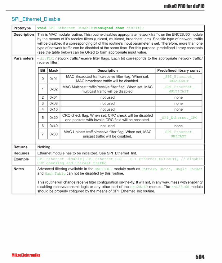
504
mikoC PRO for dsPIC
MikroElektronika
SPI_Ethernet_Disable
Prototype void SPI_Ethernet_Disable(unsigned char disFlt);
Description This is MAC module routine. This routine disables appropriate network traffic on the ENC28J60 module by the means of it’s receive filters (unicast, multicast, broadcast, crc). Specific type of network traffic will be disabled if a corresponding bit of this routine’s input parameter is set. Therefore, more than one type of network traffic can be disabled at the same time. For this purpose, predefined library constants (see the table below) can be ORed to form appropriate input value.
Parameters - disFlt: network traffic/receive filter flags. Each bit corresponds to the appropriate network traffic/receive filter:
Returns Nothing.Requires Ethernet module has to be initialized. See SPI_Ethernet_Init.Example SPI_Ethernet_Disable(_SPI_Ethernet_CRC | _SPI_Ethernet_UNICAST); // disable
CRC checking and Unicast traffic
Notes Advanced filtering available in the ENC28J60 module such as Pattern Match, Magic Packet and Hash Table can not be disabled by this routine.
This routine will change receive filter configuration on-the-fly. It will not, in any way, mess with enabling/disabling receive/transmit logic or any other part of the ENC28J60 module. The ENC28J60 module should be properly cofigured by the means of SPI_Ethernet_Init routine.
Bit Mask Description Predefined library const
0 0x01 MAC Broadcast traffic/receive filter flag. When set, MAC broadcast traffic will be disabled.
_SPI_Ethernet_BROADCAST
1 0x02 MAC Multicast traffic/receive filter flag. When set, MAC multicast traffic will be disabled.
_SPI_Ethernet_MULTICAST
2 0x04 not used none3 0x08 not used none4 0x10 not used none
5 0x20 CRC check flag. When set, CRC check will be disabled and packets with invalid CRC field will be accepted. _SPI_Ethernet_CRC
6 0x40 not used none
7 0x80 MAC Unicast traffic/receive filter flag. When set, MAC unicast traffic will be disabled.
_SPI_Ethernet_UNICAST

mikroC PRO for dsPIC
MikroElektronika505
SPI_Ethernet_doPacket
SPI_Ethernet_putByte
Prototype unsigned int SPI_Ethernet_doPacket();
Description This is MAC module routine. It processes next received packet if such exists. Packets are processed in the following manner:
- ARP & ICMP requests are replied automatically. - upon TCP request the SPI_Ethernet_UserTCP function is called for further processing. - upon UDP request the SPI_Ethernet_UserUDP function is called for further processing.
Parameters None.Returns - 0 - upon successful packet processing (zero packets received or received packet processed
successfully). - 1 - upon reception error or receive buffer corruption. ENC28J60 controller needs to be restarted. - 2 - received packet was not sent to us (not our IP, nor IP broadcast address). - 3 - received IP packet was not IPv4. - 4 - received packet was of type unknown to the library.
Requires Ethernet module has to be initialized. See SPI_Ethernet_Init.Example if (SPI_Ethernet_doPacket() == 0)(1) { // process received packets
...}
Notes SPI_Ethernet_doPacket must be called as often as possible in user’s code.
Prototype void SPI_Ethernet_putByte(unsigned char v);
Description This is MAC module routine. It stores one byte to address pointed by the current ENC28J60 write pointer (EWRPT).
Parameters - v: value to store Returns Nothing.Requires Ethernet module has to be initialized. See SPI_Ethernet_Init.Example char data_;
...SPI_Ethernet_putByte(data); // put an byte into ENC28J60 buffer
Notes None.

506
mikoC PRO for dsPIC
MikroElektronika
SPI_Ethernet_putBytes
SPI_Ethernet_putConstBytes
Prototype void SPI_Ethernet_putBytes(unsigned char *ptr, unsigned int n);
Description This is MAC module routine. It stores requested number of bytes into ENC28J60 RAM starting from current ENC28J60 write pointer (EWRPT) location.
Parameters - ptr: RAM buffer containing bytes to be written into ENC28J60 RAM. - n: number of bytes to be written.
Returns Nothing.Requires Ethernet module has to be initialized. See SPI_Ethernet_Init.Example char *buffer = “mikroElektronika”;
...SPI_Ethernet_putBytes(buffer, 16); // put an RAM array into ENC28J60 buffer
Notes None.
Prototype void SPI_Ethernet_putConstBytes(const unsigned char *ptr, unsigned int n);
Description This is MAC module routine. It stores requested number of const bytes into ENC28J60 RAM starting from current ENC28J60 write pointer (EWRPT) location.
Parameters - ptr: const buffer containing bytes to be written into ENC28J60 RAM. - n: number of bytes to be written.
Returns Nothing.Requires Ethernet module has to be initialized. See SPI_Ethernet_Init.Example const char *buffer = “mikroElektronika”;
...SPI_Ethernet_putConstBytes(buffer, 16); // put a const array into ENC28J60 buffer
Notes None.
SPI_Ethernet_putString
Prototype unsigned int SPI_Ethernet_putString(unsigned char *ptr);
Description This is MAC module routine. It stores whole string (excluding null termination) into ENC28J60 RAM starting from current ENC28J60 write pointer (EWRPT) location.
Parameters - ptr: string to be written into ENC28J60 RAM. Returns Number of bytes written into ENC28J60 RAM.Requires Ethernet module has to be initialized. See SPI_Ethernet_Init.Example char *buffer = “mikroElektronika”;
...SPI_Ethernet_putString(buffer); // put a RAM string into ENC28J60 buffer
Notes None.

mikroC PRO for dsPIC
MikroElektronika507
SPI_Ethernet_putConstString
SPI_Ethernet_getByte
SPI_Ethernet_getBytes
Prototype unsigned int SPI_Ethernet_putConstString(const unsigned char *ptr);
Description This is MAC module routine. It stores whole const string (excluding null termination) into ENC28J60 RAM starting from current ENC28J60 write pointer (EWRPT) location.
Parameters - ptr: const string to be written into ENC28J60 RAM. Returns Number of bytes written into ENC28J60 RAM.Requires Ethernet module has to be initialized. See SPI_Ethernet_Init.Example const char *buffer = “mikroElektronika”;
...SPI_Ethernet_putConstString(buffer); // put a const string into ENC28J60 buffer
Notes None.
Prototype unsigned char SPI_Ethernet_getByte();
Description This is MAC module routine. It fetches a byte from address pointed to by current ENC28J60 read pointer (ERDPT).
Parameters None.Returns Byte read from ENC28J60 RAM.Requires Ethernet module has to be initialized. See SPI_Ethernet_Init.Example char buffer;
...buffer = SPI_Ethernet_getByte(); // read a byte from ENC28J60 buffer
Notes None.
Prototype void SPI_Ethernet_getBytes(unsigned char *ptr, unsigned int addr, unsigned int n);
Description This is MAC module routine. It fetches equested number of bytes from ENC28J60 RAM starting from given address. If value of 0xFFFF is passed as the address parameter, the reading will start from current ENC28J60 read pointer (ERDPT) location.
Parameters - ptr: buffer for storing bytes read from ENC28J60 RAM. - addr: ENC28J60 RAM start address. Valid values: 0..8192. - n: number of bytes to be read.
Returns Nothing.Requires Ethernet module has to be initialized. See SPI_Ethernet_Init.Example char buffer[16];
...SPI_Ethernet_getBytes(buffer, 0x100, 16); // read 16 bytes, starting from address 0x100
Notes None.

508
mikoC PRO for dsPIC
MikroElektronika
SPI_Ethernet_UserTCP
Prototype unsigned int SPI_Ethernet_UserTCP(unsigned char *remoteHost, unsigned int remotePort, unsigned int localPort, unsigned int reqLength, TEthPktFlags *flags);
Description This is TCP module routine. It is internally called by the library. The user accesses to the TCP request by using some of the SPI_Ethernet_get routines. The user puts data in the transmit buffer by using some of the SPI_Ethernet_put routines. The function must return the length in bytes of the TCP reply, or 0 if there is nothing to transmit. If there is no need to reply to the TCP requests, just define this function with return(0) as a single statement.
Parameters - remoteHost: client’s IP address. - remotePort: client’s TCP port. - localPort: port to which the request is sent. - reqLength: TCP request data field length. - flags: structure consisted of two bit fields :
Copy Code To Clipboard
typedef struct { unsigned canCloseTCP: 1; // flag which closes socket unsigned isBroadcast: 1; // flag which denotes that the IP package has been received via subnet broadcast address} TEthPktFlags;
Returns - 0 - there should not be a reply to the request. - Length of TCP reply data field - otherwise.
Requires Ethernet module has to be initialized. See SPI_Ethernet_Init.Example This function is internally called by the library and should not be called by the user’s code.Notes The function source code is provided with appropriate example projects. The code should be adjusted
by the user to achieve desired reply.

mikroC PRO for dsPIC
MikroElektronika509
SPI_Ethernet_UserUDP
Prototype unsigned int SPI_Ethernet_UserUDP(unsigned char *remoteHost, unsigned int remotePort, unsigned int localPort, unsigned int reqLength, TEthPktFlags *flags);
Description This is UDP module routine. It is internally called by the library. The user accesses to the UDP request by using some of the SPI_Ethernet_get routines. The user puts data in the transmit buffer by using some of the SPI_Ethernet_put routines. The function must return the length in bytes of the UDP reply, or 0 if nothing to transmit. If you don’t need to reply to the UDP requests, just define this function with a return(0) as single statement.
Parameters - remoteHost: client’s IP address. - remotePort: client’s port. - localPort: port to which the request is sent. - reqLength: UDP request data field length. - flags: structure consisted of two bit fields :
Copy Code To Clipboard
typedef struct { unsigned canCloseTCP: 1; // flag which closes TCP socket (not relevant to UDP) unsigned isBroadcast: 1; // flag which denotes that the IP package has been received via subnet broadcast address} TEthPktFlags;
Returns - 0 - there should not be a reply to the request. - Length of UDP reply data field - otherwise.
Requires Ethernet module has to be initialized. See SPI_Ethernet_Init.Example This function is internally called by the library and should not be called by the user’s code.Notes The function source code is provided with appropriate example projects. The code should be adjusted
by the user to achieve desired reply.

510
mikoC PRO for dsPIC
MikroElektronika
SPI_Ethernet_getIpAddress
SPI_Ethernet_getDnsIpAddress
SPI_Ethernet_getIpMask
Prototype unsigned char * SPI_Ethernet_getIpAddress();
Description This routine should be used when DHCP server is present on the network to fetch assigned IP address.
Parameters None.Returns Pointer to the global variable holding IP address.Requires Ethernet module has to be initialized. See SPI_Ethernet_Init.Example unsigned char ipAddr[4]; // user IP address buffer
... memcpy(ipAddr, SPI_Ethernet_getIpAddress(), 4); // fetch IP address
Notes User should always copy the IP address from the RAM location returned by this routine into it’s own IP address buffer. These locations should not be altered by the user in any case!
Prototype unsigned char * SPI_Ethernet_getDnsIpAddress();
Description This routine should be used when DHCP server is present on the network to fetch assigned DNS IP address.
Parameters None.Returns Pointer to the global variable holding DNS IP address.Requires Ethernet module has to be initialized. See SPI_Ethernet_Init.Example unsigned char dnsIpAddr[4]; // user DNS IP address buffer
... memcpy(dnsIpAddr, SPI_Ethernet_getDnsIpAddress(), 4); // fetch DNS server address
Notes User should always copy the IP address from the RAM location returned by this routine into it’s own DNS IP address buffer. These locations should not be altered by the user in any case!
Prototype unsigned char * SPI_Ethernet_getIpMask();
Description This routine should be used when DHCP server is present on the network to fetch assigned IP subnet mask.
Parameters None.Returns Pointer to the global variable holding IP subnet mask.Requires Ethernet module has to be initialized. See SPI_Ethernet_Init.Example unsigned char IpMask[4]; // user IP subnet mask buffer
... memcpy(IpMask, SPI_Ethernet_getIpMask(), 4); // fetch IP subnet mask
Notes User should always copy the IP address from the RAM location returned by this routine into it’s own IP subnet mask buffer. These locations should not be altered by the user in any case!

mikroC PRO for dsPIC
MikroElektronika511
SPI_Ethernet_confNetwork
SPI_Ethernet_arpResolve
Prototype void SPI_Ethernet_confNetwork(char *ipMask, char *gwIpAddr, char *dnsIpAddr);
Description Configures network parameters (IP subnet mask, gateway IP address, DNS IP address) when DHCP is not used.
Parameters - ipMask: IP subnet mask. - gwIpAddr gateway IP address. - dnsIpAddr: DNS IP address.
Returns Nothing.Requires Ethernet module has to be initialized. See SPI_Ethernet_Init.Example char ipMask[4] = {255, 255, 255, 0 }; // network mask (for example :
255.255.255.0)char gwIpAddr[4] = {192, 168, 1, 1 }; // gateway (router) IP addresschar dnsIpAddr[4] = {192, 168, 1, 1 }; // DNS server IP address... SPI_Ethernet_confNetwork(ipMask, gwIpAddr, dnsIpAddr); // set network configuration parameters
Notes The above mentioned network parameters should be set by this routine only if DHCP module is not used. Otherwise DHCP will override these settings.
Prototype unsigned char *SPI_Ethernet_arpResolve(unsigned char *ip, unsigned char tmax);
Description This is ARP module routine. It sends an ARP request for given IP address and waits for ARP reply. If the requested IP address was resolved, an ARP cash entry is used for storing the configuration. ARP cash can store up to 3 entries. For ARP cash structure refer to “eth_enc28j60LibDef.h” header file in the compiler’s Uses folder.
Parameters - ip: IP address to be resolved. - tmax: time in seconds to wait for an reply.
Returns - MAC address behind the IP address - the requested IP address was resolved. - 0 - otherwise.
Requires Ethernet module has to be initialized. See SPI_Ethernet_Init.Example unsigned char IpAddr[4] = {192, 168, 1, 1 }; // IP address
... SPI_Ethernet_arpResolve(IpAddr, 5); // get MAC address behind the above IP address, wait 5 secs for the response
Notes The Ethernet services are not stopped while this routine waits for ARP reply. The incoming packets will be processed normaly during this time.

512
mikoC PRO for dsPIC
MikroElektronika
SPI_Ethernet_sendUDP
SPI_Ethernet_dnsResolve
Prototype unsigned int SPI_Ethernet_sendUDP(unsigned char *destIP, unsigned int sourcePort, unsigned int destPort, unsigned char *pkt, unsigned int pktLen);
Description This is UDP module routine. It sends an UDP packet on the network.Parameters - destIP: remote host IP address.
- sourcePort: local UDP source port number. - destPort: destination UDP port number. - pkt: packet to transmit. - pktLen: length in bytes of packet to transmit.
Returns - 1 - UDP packet was sent successfully. - 0 - otherwise.
Requires Ethernet module has to be initialized. See SPI_Ethernet_Init.Example unsigned char IpAddr[4] = {192, 168, 1, 1 }; // remote IP address
... SPI_Ethernet_sendUDP(IpAddr, 10001, 10001, “Hello”, 5); // send Hello message to the above IP address, from UDP port 10001 to UDP port 10001
Notes None.
Prototype unsigned char * SPI_Ethernet_dnsResolve(unsigned char *host, unsigned char tmax);
Description This is DNS module routine. It sends an DNS request for given host name and waits for DNS reply. If the requested host name was resolved, it’s IP address is stored in library global variable and a pointer containing this address is returned by the routine. UDP port 53 is used as DNS port.
Parameters - host: host name to be resolved. - tmax: time in seconds to wait for an reply.
Returns - pointer to the location holding the IP address - the requested host name was resolved. - 0 - otherwise.
Requires Ethernet module has to be initialized. See SPI_Ethernet_Init.Example unsigned char * remoteHostIpAddr[4]; // user host IP address buffer
...// SNTP server:// Zurich, Switzerland: Integrated Systems Lab, Swiss Fed. Inst. of Technology// 129.132.2.21: swisstime.ethz.ch// Service Area: Switzerland and Europe memcpy(remoteHostIpAddr, SPI_Ethernet_dnsResolve(“swisstime.ethz.ch”, 5), 4);
Notes The Ethernet services are not stopped while this routine waits for DNS reply. The incoming packets will be processed normaly during this time.
User should always copy the IP address from the RAM location returned by this routine into it’s own resolved host IP address buffer. These locations should not be altered by the user in any case!

mikroC PRO for dsPIC
MikroElektronika513
SPI_Ethernet_initDHCP
Prototype unsigned int SPI_Ethernet_initDHCP(unsigned char tmax);
Description This is DHCP module routine. It sends an DHCP request for network parameters (IP, gateway, DNS addresses and IP subnet mask) and waits for DHCP reply. If the requested parameters were obtained successfully, their values are stored into the library global variables.
These parameters can be fetched by using appropriate library IP get routines:
- SPI_Ethernet_getIpAddress - fetch IP address. - SPI_Ethernet_getGwIpAddress - fetch gateway IP address. - SPI_Ethernet_getDnsIpAddress - fetch DNS IP address. - SPI_Ethernet_getIpMask - fetch IP subnet mask.
UDP port 68 is used as DHCP client port and UDP port 67 is used as DHCP server port.Parameters - tmax: time in seconds to wait for an reply. Returns - 1 - network parameters were obtained successfully.
- 0 - otherwise. Requires Ethernet module has to be initialized. See SPI_Ethernet_Init.Example ...
SPI_Ethernet_initDHCP(5); // get network configuration from DHCP server, wait 5 sec for the response ...
Notes The Ethernet services are not stopped while this routine waits for DNS reply. The incoming packets will be processed normaly during this time.
When DHCP module is used, global library variable SPI_Ethernet_userTimerSec is used to keep track of time. It is user responsibility to increment this variable each second in it’s code.

514
mikoC PRO for dsPIC
MikroElektronika
SPI_Ethernet_doDHCPLeaseTime
SPI_Ethernet_renewDHCP
Prototype unsigned int SPI_Ethernet_doDHCPLeaseTime();
Description This is DHCP module routine. It takes care of IP address lease time by decrementing the global lease time library counter. When this time expires, it’s time to contact DHCP server and renew the lease.
Parameters None.Returns - 0 - lease time has not expired yet.
- 1 - lease time has expired, it’s time to renew it. Requires Ethernet module has to be initialized. See SPI_Ethernet_Init.Example while(1) {
... if (SPI_Ethernet_doDHCPLeaseTime()) ... // it’s time to renew the IP address lease }
Notes None.
Prototype unsigned int SPI_Ethernet_renewDHCP(unsigned char tmax);
Description This is DHCP module routine. It sends IP address lease time renewal request to DHCP server. Parameters - tmax: time in seconds to wait for an reply. Returns - 1 - upon success (lease time was renewed).
- 0 - otherwise (renewal request timed out). Requires Ethernet module has to be initialized. See SPI_Ethernet_Init.Example while(1) {
... if (SPI_Ethernet_doDHCPLeaseTime()) SPI_Ethernet_renewDHCP(5); // it’s time to renew the IP address lease, with 5 secs for a reply ... }
Notes None.

mikroC PRO for dsPIC
MikroElektronika515
Library Example
This code shows how to use the Ethernet mini library :
- the board will reply to ARP & ICMP echo requests - the board will reply to UDP requests on any port : - returns the request in upper char with a header made of remote host IP & port number - the board will reply to HTTP requests on port 80, GET method with pathnames : - / will return the HTML main page - /s will return board status as text string - /t0 ... /t7 will toggle RD0 to RD7 bit and return HTML main page - all other requests return also HTML main page.
Copy Code To Clipboard
#include “__EthEnc28j60.h”
// duplex config flags#define Spi_Ethernet_HALFDUPLEX 0x00 // half duplex#define Spi_Ethernet_FULLDUPLEX 0x01 // full duplex
// mE ehternet NIC pinoutsfr sbit SPI_Ethernet_Rst at LATF0_bit; // for writing to output pin always use latch sfr sbit SPI_Ethernet_CS at LATF1_bit; // for writing to output pin always use latch sfr sbit SPI_Ethernet_Rst_Direction at TRISF0_bit;sfr sbit SPI_Ethernet_CS_Direction at TRISF1_bit;// end ethernet NIC definitions
/************************************************************ * ROM constant strings */const code unsigned char httpHeader[] = “HTTP/1.1 200 OKnContent-type: “; // HTTP headerconst code unsigned char httpMimeTypeHTML[] = “text/htmlnn”; // HTML MIME typeconst code unsigned char httpMimeTypeScript[] = “text/plainnn”; // TEXT MIME typeunsigned char httpMethod[] = “GET /”;/* * web page, splited into 2 parts : * when coming short of ROM, fragmented data is handled more efficiently by linker * * this HTML page calls the boards to get its status, and builds itself with javascript */const code char *indexPage = // Change the IP address of the page to be refreshed“<meta http-equiv=”refresh” content=”3;url=http://192.168.20.60”><HTML><HEAD></HEAD><BODY><h1>dsPIC + ENC28J60 Mini Web Server</h1>
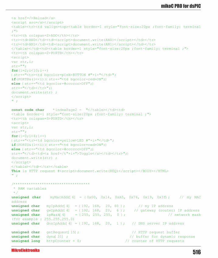
516
mikoC PRO for dsPIC
MikroElektronika
<a href=/>Reload</a><script src=/s></script><table><tr><td valign=top><table border=1 style="font-size:20px ;font-family: terminal ;"><tr><th colspan=2>ADC</th></tr><tr><td>AN0</td><td><script>document.write(AN0)</script></td></tr><tr><td>AN1</td><td><script>document.write(AN1)</script></td></tr></table></td><td><table border=1 style="font-size:20px ;font-family: terminal ;"><tr><th colspan=2>PORTB</th></tr><script>var str,i;str="";for(i=2;i<10;i++){str+="<tr><td bgcolor=pink>BUTTON #"+i+"</td>";if(PORTB&(1<<i)){str+="<td bgcolor=red>ON";}else {str+="<td bgcolor=#cccccc>OFF";}str+="</td></tr>";}document.write(str) ;</script>" ;
const code char *indexPage2 = "</table></td><td><table border=1 style="font-size:20px ;font-family: terminal ;"><tr><th colspan=3>PORTD</th></tr><script>var str,i;str="";for(i=0;i<4;i++){str+="<tr><td bgcolor=yellow>LED #"+i+"</td>";if(PORTD&(1<<i)){str+="<td bgcolor=red>ON";}else {str+="<td bgcolor=#cccccc>OFF";}str+="</td><td><a href=/t"+i+">Toggle</a></td></tr>";}document.write(str) ;</script></table></td></tr></table>This is HTTP request #<script>document.write(REQ)</script></BODY></HTML>" ;
/*********************************** * RAM variables */unsigned char myMacAddr[6] = {0x00, 0x14, 0xA5, 0x76, 0x19, 0x3f}; // my MAC addressunsigned char myIpAddr[4] = {192, 168, 20, 60 }; // my IP addressunsigned char gwIpAddr[4] = {192, 168, 20, 6 }; // gateway (router) IP addressunsigned char ipMask[4] = {255, 255, 255, 0 }; // network mask (for example : 255.255.255.0)unsigned char dnsIpAddr[4] = {192, 168, 20, 1 }; // DNS server IP address
unsigned char getRequest[15]; // HTTP request bufferunsigned char dyna[31] ; // buffer for dynamic responseunsigned long httpCounter = 0; // counter of HTTP requests

mikroC PRO for dsPIC
MikroElektronika517
/******************************************* * functions */
/* * put the constant string pointed to by s to the ENC transmit buffer. *//*unsigned int putConstString(const code char *s) { unsigned int ctr = 0;
while(*s) { Spi_Ethernet_putByte(*s++); ctr++; } return(ctr); }*//* * it will be much faster to use library Spi_Ethernet_putConstString routine * instead of putConstString routine above. However, the code will be a little * bit bigger. User should choose between size and speed and pick the implementation that * suites him best. If you choose to go with the putConstString definition above * the #define line below should be commented out. * */#define putConstString SPI_Ethernet_putConstString
/* * put the string pointed to by s to the ENC transmit buffer *//*unsigned int putString(char *s) { unsigned int ctr = 0;
while(*s) { Spi_Ethernet_putByte(*s++);
ctr++; } return(ctr); }*//* * it will be much faster to use library Spi_Ethernet_putString routine * instead of putString routine above. However, the code will be a little * bit bigger. User should choose between size and speed and pick the implementation that * suites him best. If you choose to go with the putString definition above * the #define line below should be commented out. * */

518
mikoC PRO for dsPIC
MikroElektronika
#define putString SPI_Ethernet_putString
/* * this function is called by the library * the user accesses to the HTTP request by successive calls to Spi_Ethernet_getByte() * the user puts data in the transmit buffer by successive calls to Spi_Ethernet_putByte() * the function must return the length in bytes of the HTTP reply, or 0 if nothing to transmit * * if you don't need to reply to HTTP requests, * just define this function with a return(0) as single statement * */unsigned int SPI_Ethernet_UserTCP(unsigned char *remoteHost, unsigned int remotePort, unsigned int localPort, unsigned int reqLength, TEthPktFlags *flags) { unsigned int len; // my reply length
// should we close tcp socket after response is sent? // library closes tcp socket by default if canCloseTCP flag is not reset here // flags->canCloseTCP = 0; // 0 - do not close socket // otherwise - close socket
if(localPort != 80) // I listen only to web request on port 80 { return(0); }
// get 10 first bytes only of the request, the rest does not matter here for(len = 0; len < 10; len++) { getRequest[len] = SPI_Ethernet_getByte(); } getRequest[len] = 0; len = 0;
if(memcmp(getRequest, httpMethod, 5)) // only GET method is supported here { return(0); }
httpCounter++; // one more request done
if(getRequest[5] == ‘s’) // if request path name starts with s, store dynamic data in transmit buffer { // the text string replied by this request can be interpreted as javascript statements // by browsers
len = putConstString(httpHeader); // HTTP header len += putConstString(httpMimeTypeScript); // with text MIME type

mikroC PRO for dsPIC
MikroElektronika519
// add AN0 value to reply WordToStr(ADC1_Get_Sample(0), dyna) ; len += putConstString("var AN0=") ; len += putString(dyna) ; len += putConstString(";") ;
// add AN1 value to reply WordToStr(ADC1_Get_Sample(1), dyna) ; len += putConstString("var AN1=") ; len += putString(dyna); len += putConstString(";");
// add PORTB value (buttons) to reply len += putConstString("var PORTB="); WordToStr(PORTB, dyna); len += putString(dyna); len += putConstString(";");
// add PORTD value (LEDs) to reply len += putConstString("var PORTD="); WordToStr(PORTD, dyna); len += putString(dyna); len += putConstString(";");
// add HTTP requests counter to reply WordToStr(httpCounter, dyna); len += putConstString("var REQ="); len += putString(dyna); len += putConstString(";"); } else if(getRequest[5] == 't') // if request path name starts with t, toggle PORTD (LED) bit number that comes after { unsigned char bitMask = 0; // for bit mask
if(isdigit(getRequest[6])) // if 0 <= bit number <= 9, bits 8 & 9 does not exist but does not matter { bitMask = getRequest[6] - '0'; // convert ASCII to integer bitMask = 1 << bitMask; // create bit mask PORTD ^= bitMask; // toggle PORTD with xor operator } }
if(len == 0) // what do to by default { len = putConstString(httpHeader); // HTTP header len += putConstString(httpMimeTypeHTML); // with HTML MIME type len += putConstString(indexPage); // HTML page first part len += putConstString(indexPage2); // HTML page second part }
return(len); // return to the library with the number of bytes to transmit }

520
mikoC PRO for dsPIC
MikroElektronika
/* * this function is called by the library * the user accesses to the UDP request by successive calls to Spi_Ethernet_getByte() * the user puts data in the transmit buffer by successive calls to Spi_Ethernet_putByte() * the function must return the length in bytes of the UDP reply, or 0 if nothing to transmit * * if you don't need to reply to UDP requests, * just define this function with a return(0) as single statement * */unsigned int SPI_Ethernet_UserUDP(unsigned char *remoteHost, unsigned int remotePort, unsigned int destPort, unsigned int reqLength, TEthPktFlags *flags) { unsigned int len; // my reply length
// reply is made of the remote host IP address in human readable format ByteToStr(remoteHost[0], dyna); // first IP address byte dyna[3] = '.'; ByteToStr(remoteHost[1], dyna + 4); // second dyna[7] = '.'; ByteToStr(remoteHost[2], dyna + 8); // third dyna[11] = '.'; ByteToStr(remoteHost[3], dyna + 12); // fourth
dyna[15] = ':'; // add separator
// then remote host port number WordToStr(remotePort, dyna + 16); dyna[21] = '['; WordToStr(destPort, dyna + 22); dyna[27] = ']'; dyna[28] = 0;
// the total length of the request is the length of the dynamic string plus the text of the request len = 28 + reqLength;
// puts the dynamic string into the transmit buffer SPI_Ethernet_putBytes(dyna, 28);
// then puts the request string converted into upper char into the transmit buffer while(reqLength--) { SPI_Ethernet_putByte(toupper(SPI_Ethernet_getByte())); }
return(len); // back to the library with the length of the UDP reply }

mikroC PRO for dsPIC
MikroElektronika521
/* * main entry */void main() { ADPCFG |= 0xFFFC; // all digital but rb0(AN0) and rb1(AN1)
PORTB = 0; TRISB = 0xFFFF; // set PORTB as input for buttons and adc
PORTD = 0; TRISD = 0; // set PORTD as output,
ADC1_Init(); // Enable ADC module /* * starts ENC28J60 with : * reset bit on RC0 * CS bit on RC1 * my MAC & IP address * full duplex */// SPI1_Init(); // init SPI communication with ethernet board SPI1_Init_Advanced(_SPI_MASTER, _SPI_8_BIT, _SPI_PRESCALE_SEC_1, _SPI_PRESCALE_PRI_4, _SPI_SS_DISABLE, _SPI_DATA_SAMPLE_MIDDLE, _SPI_CLK_IDLE_LOW, _SPI_IDLE_2_ACTIVE); SPI_Ethernet_Init(myMacAddr, myIpAddr, 1); // init ethernet board
// dhcp will not be used here, so use preconfigured addresses SPI_Ethernet_confNetwork(ipMask, gwIpAddr, dnsIpAddr);
while(1) // do forever { /* * if necessary, test the return value to get error code */ SPI_Ethernet_doPacket(); // process incoming Ethernet packets
/* * add your stuff here if needed * Spi_Ethernet_doPacket() must be called as often as possible * otherwise packets could be lost */ } }

522
mikoC PRO for dsPIC
MikroElektronika
HW Connection

mikroC PRO for dsPIC
MikroElektronika523
SPI Ethernet ENC24J600 LibraryThe ENC24J600 is a stand-alone Ethernet controller with an industry standard Serial Peripheral Interface (SPI). It is designed to serve as an Ethernet network interface for any controller equipped with SPI.
The ENC24J600 meets all of the IEEE 802.3 specifications applicable to 10Base-T and 100Base-TX Ethernet. It incorporates a number of packet filtering schemes to limit incoming packets. It also provides an internal, 16-bit wide DMA module for fast data throughput and hardware assisted IP checksum calculations. Communication with the host controller is implemented via two interrupt pins and the SPI, with data rates of 10/100 Mb/s. Two dedicated pins are used for LED link and network activity indication.
This library is designed to simplify handling of the underlying hardware (ENC24J600). It works with any dsPIC30/33 and PIC24 with integrated SPI and more than 4 Kb ROM memory. 38 to 40 MHz clock is recommended to get from 8 to 10 Mhz SPI clock, otherwise dsPIC30/33 and PIC24 should be clocked by ENC24J600 clock output due to its silicon bug in SPI hardware. If you try lower dsPIC30/33 and PIC24 clock speed, there might be board hang or miss some requests.
SPI Ethernet ENC24J600 library supports:
- IPv4 protocol. - ARP requests. - ICMP echo requests. - UDP requests. - TCP requests (no stack, no packet reconstruction). - ARP client with cache. - DNS client. - UDP client. - DHCP client. - packet fragmentation is NOT supported.
Important :
- Global library variable SPI_Ethernet_24j600_userTimerSec is used to keep track of time for all client implementations (ARP, DNS, UDP and DHCP). It is user responsibility to increment this variable each second in it's code if any of the clients is used. - For advanced users there are header files ("__EthEnc24j600.h" and "__EthEnc24j600Private.h") in Uses folder of the compiler with description of all routines and global variables, relevant to the user, implemented in the SPI Ethernet ENC24J600 Library. - The appropriate hardware SPI module must be initialized before using any of the SPI Ethernet ENC24J600 library routines. Refer to SPI Library. - For MCUs with multiple SPI modules it is possible to initialize them and then switch by using the SPI_Set_Active() routine.
Library Dependency Tree

524
mikoC PRO for dsPIC
MikroElektronika
The following variables must be defined in all projects using SPI Ethernet ENC24J600 Library:
Description : Example :
extern sfr sbit SPI_Ethernet_24j600_CS; ENC24J600 chip select pin. sbit SPI_Ethernet_24j600_CS at
LATF1_bit;
extern sfr sbit SPI_E t h e r n e t _ 2 4 j 6 0 0 _ C S _Direction;
Direction of the ENC24J600 chip select pin.
sbit SPI_Ethernet_24j600_CS_Direction at TRISF1_bit;
The following routines must be defined in all project using SPI Ethernet ENC24J600 Library:
Description : Example :
unsigned int SPI_E t h e r n e t _ 2 4 j 6 0 0 _UserTCP(unsigned char *remoteHost, unsigned int remotePort, unsigned int localPort, unsigned int reqLength, TEthj600PktFlags *flags);
TCP request handler. Refer to the library example at the bottom of this page for code implementation.
unsigned int SPI_E t h e r n e t _ 2 4 j 6 0 0 _UserUDP(unsigned char *remoteHost, unsigned int remotePort, unsigned int localPort, unsigned int reqLength, TEthj600PktFlags *flags);
UDP request handler. Refer to the library example at the bottom of this page for code implementation.
External dependencies of SPI Ethernet ENC24J600 Library

mikroC PRO for dsPIC
MikroElektronika525
Library Routines
- SPI_Ethernet_24j600_Init - SPI_Ethernet_24j600_Enable - SPI_Ethernet_24j600_Disable - SPI_Ethernet_24j600_doPacket - SPI_Ethernet_24j600_putByte - SPI_Ethernet_24j600_putBytes - SPI_Ethernet_24j600_putString - SPI_Ethernet_24j600_putConstString - SPI_Ethernet_24j600_putConstBytes - SPI_Ethernet_24j600_getByte - SPI_Ethernet_24j600_getBytes - SPI_Ethernet_24j600_UserTCP - SPI_Ethernet_24j600_UserUDP - SPI_Ethernet_24j600_getIpAddress - SPI_Ethernet_24j600_getGwIpAddress - SPI_Ethernet_24j600_getDnsIpAddress - SPI_Ethernet_24j600_getIpMask - SPI_Ethernet_24j600_confNetwork - SPI_Ethernet_24j600_arpResolve - SPI_Ethernet_24j600_sendUDP - SPI_Ethernet_24j600_dnsResolve - SPI_Ethernet_24j600_initDHCP - SPI_Ethernet_24j600_doDHCPLeaseTime - SPI_Ethernet_24j600_renewDHCP

526
mikoC PRO for dsPIC
MikroElektronika
SPI_Ethernet_24j600_Init
Prototype void SPI_Ethernet_24j600_Init(unsigned char *mac, unsigned char *ip, unsigned char fullDuplex);
Description This is MAC module routine. It initializes ENC24J600 controller. This function is internaly splited into 2 parts to help linker when coming short of memory.
ENC24J600 controller settings (parameters not mentioned here are set to default):
- receive buffer start address : 0x0000. - receive buffer end address : 0x19AD. - transmit buffer start address: 0x19AE. - transmit buffer end address : 0x1FFF. - RAM buffer read/write pointers in auto-increment mode. - receive filters set to default: CRC + MAC Unicast + MAC Broadcast in OR mode. - flow control with TX and RX pause frames in full duplex mode. - frames are padded to 60 bytes + CRC. - maximum packet size is set to 1518. - Back-to-Back Inter-Packet Gap: 0x15 in full duplex mode; 0x12 in half duplex mode. - Non-Back-to-Back Inter-Packet Gap: 0x0012 in full duplex mode; 0x0C12 in half duplex mode. - Collision window is set to 63 in half duplex mode to accomodate some ENC24J600 revisions silicon bugs. - CLKOUT output is disabled to reduce EMI generation. - half duplex loopback disabled. - LED configuration: default (LEDA-link status, LEDB-link activity).
Parameters - mac: RAM buffer containing valid MAC address. - ip: RAM buffer containing valid IP address. - configuration: ethernet negotiation, duplex and speed mode settings. For this purpose, predefined library constants (see the list below) can be combined using logical AND to form appropriate value :
Description : Predefined library const Set Auto-negotiation SPI_Ethernet_24j600_AUTO_NEGOTIATION
Set manual negotiation. SPI_Ethernet_24j600_MANUAL_NEGOTIATION
Set Half duplex Mode SPI_Ethernet_24j600_HALFDUPLEX
Set Full duplex Mode SPI_Ethernet_24j600_FULLDUPLEX
Set transmission speed of 10Mbps SPI_Ethernet_24j600_SPD10
Set transmission speed of 100Mbps SPI_Ethernet_24j600_SPD100
Note :
- It is advisable to use only the Auto-negotiation setting. If manual negotiation is used, then duplex and speed mode setting must be set also. - Duplex and speed mode may be set only when using manual negotiation.

mikroC PRO for dsPIC
MikroElektronika527
Returns Nothing.Requires Global variables :
- SPI_Ethernet_24j600_CS: Chip Select line - SPI_Ethernet_24j600_CS_Direction: Direction of the Chip Select pin
must be defined before using this function.
The SPI module needs to be initialized. See the SPIx_Init and SPIx_Init_Advanced routines.Example #include “__EthEnc24J600.h”
// mE ethernet NIC pinoutsfr sbit SPI_Ethernet_24j600_CS at RF1_bit;sfr sbit SPI_Ethernet_24j600_CS_Direction at TRISF1_bit;// end ethernet NIC definitions
unsigned char myMacAddr[6] = {0x00, 0x14, 0xA5, 0x76, 0x19, 0x3f}; // my MAC address unsigned char myIpAddr = {192, 168, 1, 60 }; // my IP addr
SPI1_Init(); SPI_Ethernet_24j600_Init(myMacAddr, myIpAddr, SPI_Ethernet_24j600_MANUAL_NEGOTIATION & SPI_Ethernet_24j600_FULLDUPLEX & SPI_Ethernet_24j600_SPD100);
Notes None.

528
mikoC PRO for dsPIC
MikroElektronika
SPI_Ethernet_24j600_Enable
Prototype void SPI_Ethernet_24j600_Enable(unsigned int enFlt);
Description This is MAC module routine. This routine enables appropriate network traffic on the ENC24J600 module by the means of it’s receive filters (unicast, multicast, broadcast, crc). Specific type of network traffic will be enabled if a corresponding bit of this routine’s input parameter is set. Therefore, more than one type of network traffic can be enabled at the same time. For this purpose, predefined library constants (see the table below) can be ORed to form appropriate input value.
Advanced filtering available in the ENC24J600 module such as Pattern Match, Magic Packet and Hash Table can not be enabled by this routine. Additionaly, all filters, except CRC, enabled with this routine will work in OR mode, which means that packet will be received if any of the enabled filters accepts it.
This routine will change receive filter configuration on-the-fly. It will not, in any way, mess with enabling/disabling receive/transmit logic or any other part of the ENC24J600 module. The ENC24J600 module should be properly cofigured by the means of SPI_Ethernet_24j600_Init routine.
Parameters - enFlt: network traffic/receive filter flags. Each bit corresponds to the appropriate network traffic/receive filter:
Returns Nothing.Requires Ethernet module has to be initialized. See SPI_Ethernet_24j600_Init.Example SPI_Ethernet_24j600_Enable(_SPI_Ethernet_24j600_CRC | _SPI_Ethernet_24j600_
UNICAST); // enable CRC checking and Unicast traffic
Notes Advanced filtering available in the ENC24J600 module such as Pattern Match, Magic Packet and Hash Table can not be enabled by this routine. Additionaly, all filters, except CRC, enabled with this routine will work in OR mode, which means that packet will be received if any of the enabled filters accepts it.
This routine will change receive filter configuration on-the-fly. It will not, in any way, mess with enabling/disabling receive/transmit logic or any other part of the ENC24J600 module. The ENC24J600 module should be properly cofigured by the means of SPI_Ethernet_24j600_Init routine.
Bit Mask Description Predefined library const
0 0x01 MAC Broadcast traffic/receive filter flag. When set, MAC broadcast traffic will be enabled.
_SPI_Ethernet_24j600_BROADCAST
1 0x02 MAC Multicast traffic/receive filter flag. When set, MAC multicast traffic will be enabled.
_SPI_Ethernet_24j600_MULTICAST
2 0x04 not used none3 0x08 not used none4 0x10 not used none
5 0x20 CRC check flag. When set, packets with invalid CRC field will be discarded.
_SPI_Ethernet_24j600_CRC
6 0x40 not used none
7 0x80 MAC Unicast traffic/receive filter flag. When set, MAC unicast traffic will be enabled.
_SPI_Ethernet_24j600_UNICAST

mikroC PRO for dsPIC
MikroElektronika529
SPI_Ethernet_24j600_Disable
Prototype void SPI_Ethernet_24j600_Disable(unsigned int disFlt);
Description This is MAC module routine. This routine disables appropriate network traffic on the ENC24J600 module by the means of it’s receive filters (unicast, multicast, broadcast, crc). Specific type of network traffic will be disabled if a corresponding bit of this routine’s input parameter is set. Therefore, more than one type of network traffic can be disabled at the same time. For this purpose, predefined library constants (see the table below) can be ORed to form appropriate input value.
Parameters - disFlt: network traffic/receive filter flags. Each bit corresponds to the appropriate network traffic/receive filter:
Returns Nothing.Requires Ethernet module has to be initialized. See SPI_Ethernet_24j600_Init.Example SPI_Ethernet_24j600_Disable(_SPI_Ethernet_24j600_CRC | _SPI_Ethernet_24j600_
UNICAST); // disable CRC checking and Unicast traffic
Notes - Advanced filtering available in the ENC24J600 module such as Pattern Match, Magic Packet and Hash Table can not be disabled by this routine. - This routine will change receive filter configuration on-the-fly. It will not, in any way, mess with enabling/disabling receive/transmit logic or any other part of the ENC24J600 module. - The ENC24J600 module should be properly cofigured by the means of SPI_Ethernet_24j600_Init routine.
Bit Mask Description Predefined library const
0 0x01 MAC Broadcast traffic/receive filter flag. When set, MAC broadcast traffic will be disabled.
_SPI_Ethernet_24j600_BROADCAST
1 0x02 MAC Multicast traffic/receive filter flag. When set, MAC multicast traffic will be disabled.
_SPI_Ethernet_24j600_MULTICAST
2 0x04 not used none3 0x08 not used none4 0x10 not used none
5 0x20CRC check flag. When set, CRC check will be
disabled and packets with invalid CRC field will be accepted.
_SPI_Ethernet_24j600_CRC
6 0x40 not used none
7 0x80 MAC Unicast traffic/receive filter flag. When set, MAC unicast traffic will be disabled.
_SPI_Ethernet_24j600_UNICAST

530
mikoC PRO for dsPIC
MikroElektronika
SPI_Ethernet_24j600_doPacket
SPI_Ethernet_24j600_putByte
Prototype unsigned int SPI_Ethernet_24j600_doPacket();
Description This is MAC module routine. It processes next received packet if such exists. Packets are processed in the following manner:
- ARP & ICMP requests are replied automatically. - upon TCP request the SPI_Ethernet_24j600_UserTCP function is called for further processing. - upon UDP request the SPI_Ethernet_24j600_UserUDP function is called for further processing.
Parameters None.Returns - 0 - upon successful packet processing (zero packets received or received packet processed
successfully). - 1 - upon reception error or receive buffer corruption. ENC24J600 controller needs to be restarted. - 2 - received packet was not sent to us (not our IP, nor IP broadcast address). - 3 - received IP packet was not IPv4. - 4 - received packet was of type unknown to the library.
Requires Ethernet module has to be initialized. See SPI_Ethernet_24j600_Init.Example if (SPI_Ethernet_24j600_doPacket() == 0)(1) { // process received packets
...}
Notes SPI_Ethernet_24j600_doPacket must be called as often as possible in user’s code.
Prototype void SPI_Ethernet_24j600_putByte(unsigned char v);
Description This is MAC module routine. It stores one byte to address pointed by the current ENC24J600 write pointer (EWRPT).
Parameters - v: value to store Returns Nothing.Requires Ethernet module has to be initialized. See SPI_Ethernet_24j600_Init.Example char data_;
...SPI_Ethernet_24j600_putByte(data); // put an byte into ENC24J600 buffer
Notes None.

mikroC PRO for dsPIC
MikroElektronika531
SPI_Ethernet_24j600_putBytes
SPI_Ethernet_24j600_putConstBytes
Prototype void SPI_Ethernet_24j600_putBytes(unsigned char *ptr, unsigned int n);
Description This is MAC module routine. It stores requested number of bytes into ENC24J600 RAM starting from current ENC24J600 write pointer (EWRPT) location.
Parameters - ptr: RAM buffer containing bytes to be written into ENC24J600 RAM. - n: number of bytes to be written.
Returns Nothing.Requires Ethernet module has to be initialized. See SPI_Ethernet_24j600_Init.Example char *buffer = “mikroElektronika”;
...SPI_Ethernet_24j600_putBytes(buffer, 16); // put an RAM array into ENC24J600 buffer
Notes None.
Prototype void SPI_Ethernet_24j600_putConstBytes(const unsigned char *ptr, unsigned int n);
Description This is MAC module routine. It stores requested number of const bytes into ENC24J600 RAM starting from current ENC24J600 write pointer (EWRPT) location.
Parameters - ptr: const buffer containing bytes to be written into ENC24J600 RAM. - n: number of bytes to be written.
Returns Nothing.Requires Ethernet module has to be initialized. See SPI_Ethernet_24j600_Init.Example const char *buffer = “mikroElektronika”;
...SPI_Ethernet_24j600_putConstBytes(buffer, 16); // put a const array into ENC24J600 buffer
Notes None.
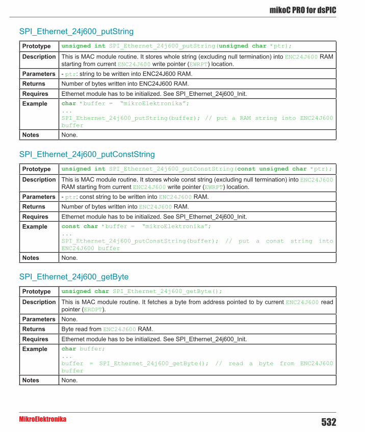
532
mikoC PRO for dsPIC
MikroElektronika
SPI_Ethernet_24j600_putString
SPI_Ethernet_24j600_putConstString
SPI_Ethernet_24j600_getByte
Prototype unsigned int SPI_Ethernet_24j600_putString(unsigned char *ptr);
Description This is MAC module routine. It stores whole string (excluding null termination) into ENC24J600 RAM starting from current ENC24J600 write pointer (EWRPT) location.
Parameters - ptr: string to be written into ENC24J600 RAM. Returns Number of bytes written into ENC24J600 RAM.Requires Ethernet module has to be initialized. See SPI_Ethernet_24j600_Init.Example char *buffer = “mikroElektronika”;
...SPI_Ethernet_24j600_putString(buffer); // put a RAM string into ENC24J600 buffer
Notes None.
Prototype unsigned int SPI_Ethernet_24j600_putConstString(const unsigned char *ptr);
Description This is MAC module routine. It stores whole const string (excluding null termination) into ENC24J600 RAM starting from current ENC24J600 write pointer (EWRPT) location.
Parameters - ptr: const string to be written into ENC24J600 RAM. Returns Number of bytes written into ENC24J600 RAM.Requires Ethernet module has to be initialized. See SPI_Ethernet_24j600_Init.Example const char *buffer = “mikroElektronika”;
...SPI_Ethernet_24j600_putConstString(buffer); // put a const string into ENC24J600 buffer
Notes None.
Prototype unsigned char SPI_Ethernet_24j600_getByte();
Description This is MAC module routine. It fetches a byte from address pointed to by current ENC24J600 read pointer (ERDPT).
Parameters None.Returns Byte read from ENC24J600 RAM.Requires Ethernet module has to be initialized. See SPI_Ethernet_24j600_Init.Example char buffer;
...buffer = SPI_Ethernet_24j600_getByte(); // read a byte from ENC24J600 buffer
Notes None.

mikroC PRO for dsPIC
MikroElektronika533
SPI_Ethernet_24j600_getBytes
SPI_Ethernet_24j600_UserTCP
Prototype void SPI_Ethernet_24j600_getBytes(unsigned char *ptr, unsigned int addr, unsigned int n);
Description This is MAC module routine. It fetches equested number of bytes from ENC24J600 RAM starting from given address. If value of 0xFFFF is passed as the address parameter, the reading will start from current ENC24J600 read pointer (ERDPT) location.
Parameters - ptr: buffer for storing bytes read from ENC24J600 RAM. - addr: ENC24J600 RAM start address. Valid values: 0..8192. - n: number of bytes to be read.
Returns Nothing.Requires Ethernet module has to be initialized. See SPI_Ethernet_24j600_Init.Example char buffer[16];
...SPI_Ethernet_24j600_getBytes(buffer, 0x100, 16); // read 16 bytes, starting from address 0x100
Notes None.
Prototype unsigned int SPI_Ethernet_24j600_UserTCP(unsigned char *remoteHost, unsigned int remotePort, unsigned int localPort, unsigned int reqLength, TEthj600PktFlags *flags);
Description This is TCP module routine. It is internally called by the library. The user accesses to the TCP request by using some of the SPI_Ethernet_24j600_get routines. The user puts data in the transmit buffer by using some of the SPI_Ethernet_24j600_put routines. The function must return the length in bytes of the TCP reply, or 0 if there is nothing to transmit. If there is no need to reply to the TCP requests, just define this function with return(0) as a single statement.
Parameters - remoteHost: client’s IP address. - remotePort: client’s TCP port. - localPort: port to which the request is sent. - reqLength: TCP request data field length. - flags: structure consisted of two bit fields :
Copy Code To Clipboard
typedef struct { unsigned canCloseTCP: 1; // flag which closes socket unsigned isBroadcast: 1; // flag which denotes that the IP package has been received via subnet broadcast address} TEthj600PktFlags;
Returns - 0 - there should not be a reply to the request. - Length of TCP reply data field - otherwise.
Requires Ethernet module has to be initialized. See SPI_Ethernet_24j600_Init.Example This function is internally called by the library and should not be called by the user’s code.Notes The function source code is provided with appropriate example projects. The code should be adjusted
by the user to achieve desired reply.

534
mikoC PRO for dsPIC
MikroElektronika
SPI_Ethernet_24j600_UserUDP
Prototype unsigned int SPI_Ethernet_24j600_UserUDP(unsigned char *remoteHost, unsigned int remotePort, unsigned int destPort, unsigned int reqLength, TEthj600PktFlags *flags);
Description This is UDP module routine. It is internally called by the library. The user accesses to the UDP request by using some of the SPI_Ethernet_24j600_get routines. The user puts data in the transmit buffer by using some of the SPI_Ethernet_24j600_put routines. The function must return the length in bytes of the UDP reply, or 0 if nothing to transmit. If you don’t need to reply to the UDP requests, just define this function with a return(0) as single statement.
Parameters - remoteHost: client’s IP address. - remotePort: client’s port. - localPort: port to which the request is sent. - reqLength: UDP request data field length. - flags: structure consisted of two bit fields :
Copy Code To Clipboard
typedef struct { unsigned canCloseTCP: 1; // flag which closes TCP socket (not relevant to UDP) unsigned isBroadcast: 1; // flag which denotes that the IP package has been received via subnet broadcast address} TEthj600PktFlags;
Returns - 0 - there should not be a reply to the request. - Length of UDP reply data field - otherwise.
Requires Ethernet module has to be initialized. See SPI_Ethernet_24j600_Init.Example This function is internally called by the library and should not be called by the user’s code.Notes The function source code is provided with appropriate example projects. The code should be adjusted
by the user to achieve desired reply.
SPI_Ethernet_24j600_getIpAddress
Prototype unsigned char * SPI_Ethernet_24j600_getIpAddress();
Description This routine should be used when DHCP server is present on the network to fetch assigned IP address.
Parameters None.Returns Pointer to the global variable holding IP address.Requires Ethernet module has to be initialized. See SPI_Ethernet_24j600_Init.Example unsigned char ipAddr[4]; // user IP address buffer
... memcpy(ipAddr, SPI_Ethernet_24j600_getIpAddress(), 4); // fetch IP address
Notes User should always copy the IP address from the RAM location returned by this routine into it’s own IP address buffer. These locations should not be altered by the user in any case!

mikroC PRO for dsPIC
MikroElektronika535
SPI_Ethernet_24j600_getGwIpAddress
SPI_Ethernet_24j600_getDnsIpAddress
Prototype unsigned char * SPI_Ethernet_24j600_getGwIpAddress();
Description This routine should be used when DHCP server is present on the network to fetch assigned gateway IP address.
Parameters None.Returns Pointer to the global variable holding gateway IP address.Requires Ethernet module has to be initialized. See SPI_Ethernet_24j600_Init.Example unsigned char gwIpAddr[4]; // user gateway IP address buffer
... memcpy(gwIpAddr, SPI_Ethernet_24j600_getGwIpAddress(), 4); // fetch gateway IP address
Notes User should always copy the IP address from the RAM location returned by this routine into it’s own gateway IP address buffer. These locations should not be altered by the user in any case!
Prototype unsigned char * SPI_Ethernet_24j600_getDnsIpAddress();
Description This routine should be used when DHCP server is present on the network to fetch assigned DNS IP address.
Parameters None.Returns Pointer to the global variable holding DNS IP address.Requires Ethernet module has to be initialized. See SPI_Ethernet_24j600_Init.Example unsigned char dnsIpAddr[4]; // user DNS IP address buffer
... memcpy(dnsIpAddr, SPI_Ethernet_24j600_getDnsIpAddress(), 4); // fetch DNS server address
Notes User should always copy the IP address from the RAM location returned by this routine into it’s own DNS IP address buffer. These locations should not be altered by the user in any case!

536
mikoC PRO for dsPIC
MikroElektronika
SPI_Ethernet_24j600_getIpMask
SPI_Ethernet_24j600_confNetwork
Prototype unsigned char * SPI_Ethernet_24j600_getDnsIpAddress();
Description This routine should be used when DHCP server is present on the network to fetch assigned DNS IP address.
Parameters None.Returns Pointer to the global variable holding DNS IP address.Requires Ethernet module has to be initialized. See SPI_Ethernet_24j600_Init.Example unsigned char dnsIpAddr[4]; // user DNS IP address buffer
... memcpy(dnsIpAddr, SPI_Ethernet_24j600_getDnsIpAddress(), 4); // fetch DNS server address
Notes User should always copy the IP address from the RAM location returned by this routine into it’s own DNS IP address buffer. These locations should not be altered by the user in any case!
Prototype void SPI_Ethernet_24j600_confNetwork(char *ipMask, char *gwIpAddr, char *dnsIpAddr);
Description Configures network parameters (IP subnet mask, gateway IP address, DNS IP address) when DHCP is not used.
Parameters - ipMask: IP subnet mask. - gwIpAddr gateway IP address. - dnsIpAddr: DNS IP address.
Returns Nothing.Requires Ethernet module has to be initialized. See SPI_Ethernet_24j600_Init.Example char ipMask[4] = {255, 255, 255, 0 }; // network mask (for example :
255.255.255.0)char gwIpAddr[4] = {192, 168, 1, 1 }; // gateway (router) IP addresschar dnsIpAddr[4] = {192, 168, 1, 1 }; // DNS server IP address... SPI_Ethernet_24j600_confNetwork(ipMask, gwIpAddr, dnsIpAddr); // set network configuration parameters
Notes The above mentioned network parameters should be set by this routine only if DHCP module is not used. Otherwise DHCP will override these settings.

mikroC PRO for dsPIC
MikroElektronika537
SPI_Ethernet_24j600_arpResolve
SPI_Ethernet_24j600_sendUDP
Prototype unsigned char *SPI_Ethernet_24j600_arpResolve(unsigned char *ip, unsigned char tmax);
Description This is ARP module routine. It sends an ARP request for given IP address and waits for ARP reply. If the requested IP address was resolved, an ARP cash entry is used for storing the configuration. ARP cash can store up to 3 entries. For ARP cash structure refer to “__EthEnc24j600.h” header file in the compiler’s Uses folder.
Parameters - ip: IP address to be resolved. - tmax: time in seconds to wait for an reply.
Returns - MAC address behind the IP address - the requested IP address was resolved. - 0 - otherwise.
Requires Ethernet module has to be initialized. See SPI_Ethernet_24j600_Init.Example unsigned char IpAddr[4] = {192, 168, 1, 1 }; // IP address
... SPI_Ethernet_24j600_arpResolve(IpAddr, 5); // get MAC address behind the above IP address, wait 5 secs for the response
Notes The Ethernet services are not stopped while this routine waits for ARP reply. The incoming packets will be processed normaly during this time.
Prototype unsigned int SPI_Ethernet_24j600_sendUDP(unsigned char *destIP, unsigned int sourcePort, unsigned int destPort, unsigned char *pkt, unsigned int pktLen);
Description This is UDP module routine. It sends an UDP packet on the network.Parameters - destIP: remote host IP address.
- sourcePort: local UDP source port number. - destPort: destination UDP port number. - pkt: packet to transmit. - pktLen: length in bytes of packet to transmit.
Returns - 1 - UDP packet was sent successfully. - 0 - otherwise.
Requires Ethernet module has to be initialized. See SPI_Ethernet_24j600_Init.Example unsigned char IpAddr[4] = {192, 168, 1, 1 }; // remote IP address
... SPI_Ethernet_24j600_sendUDP(IpAddr, 10001, 10001, “Hello”, 5); // send Hello message to the above IP address, from UDP port 10001 to UDP port 10001
Notes None.

538
mikoC PRO for dsPIC
MikroElektronika
SPI_Ethernet_24j600_dnsResolve
Prototype unsigned char * SPI_Ethernet_24j600_dnsResolve(unsigned char *host, unsigned char tmax);
Description This is DNS module routine. It sends an DNS request for given host name and waits for DNS reply. If the requested host name was resolved, it’s IP address is stored in library global variable and a pointer containing this address is returned by the routine. UDP port 53 is used as DNS port.
Parameters - host: host name to be resolved. - tmax: time in seconds to wait for an reply.
Returns - pointer to the location holding the IP address - the requested host name was resolved. - 0 - otherwise.
Requires Ethernet module has to be initialized. See SPI_Ethernet_24j600_Init.Example unsigned char * remoteHostIpAddr[4]; // user host IP address buffer
...// SNTP server:// Zurich, Switzerland: Integrated Systems Lab, Swiss Fed. Inst. of Technology// 129.132.2.21: swisstime.ethz.ch// Service Area: Switzerland and Europe memcpy(remoteHostIpAddr, SPI_Ethernet_24j600_dnsResolve(“swisstime.ethz.ch”, 5), 4);
Notes The Ethernet services are not stopped while this routine waits for DNS reply. The incoming packets will be processed normaly during this time.
User should always copy the IP address from the RAM location returned by this routine into it’s own resolved host IP address buffer. These locations should not be altered by the user in any case!

mikroC PRO for dsPIC
MikroElektronika539
SPI_Ethernet_24j600_initDHCP
Prototype unsigned int SPI_Ethernet_24j600_initDHCP(unsigned char tmax);
Description This is DHCP module routine. It sends an DHCP request for network parameters (IP, gateway, DNS addresses and IP subnet mask) and waits for DHCP reply. If the requested parameters were obtained successfully, their values are stored into the library global variables.
These parameters can be fetched by using appropriate library IP get routines:
- SPI_Ethernet_24j600_getIpAddress - fetch IP address. - SPI_Ethernet_24j600_getGwIpAddress - fetch gateway IP address. - SPI_Ethernet_24j600_getDnsIpAddress - fetch DNS IP address. - SPI_Ethernet_24j600_getIpMask - fetch IP subnet mask.
UDP port 68 is used as DHCP client port and UDP port 67 is used as DHCP server port.Parameters - tmax: time in seconds to wait for an reply. Returns - 1 - network parameters were obtained successfully.
- 0 - otherwise. Requires Ethernet module has to be initialized. See SPI_Ethernet_24j600_Init.Example ...
SPI_Ethernet_24j600_initDHCP(5); // get network configuration from DHCP server, wait 5 sec for the response ...
Notes The Ethernet services are not stopped while this routine waits for DNS reply. The incoming packets will be processed normaly during this time.
When DHCP module is used, global library variable SPI_Ethernet_24j600_userTimerSec is used to keep track of time. It is user responsibility to increment this variable each second in it’s code.

540
mikoC PRO for dsPIC
MikroElektronika
SPI_Ethernet_24j600_doDHCPLeaseTime
SPI_Ethernet_24j600_renewDHCP
Prototype unsigned int SPI_Ethernet_24j600_doDHCPLeaseTime();
Description This is DHCP module routine. It takes care of IP address lease time by decrementing the global lease time library counter. When this time expires, it’s time to contact DHCP server and renew the lease.
Parameters None.Returns - 0 - lease time has not expired yet.
- 1 - lease time has expired, it’s time to renew it. Requires Ethernet module has to be initialized. See SPI_Ethernet_24j600_Init.Example while(1) {
... if (SPI_Ethernet_24j600_doDHCPLeaseTime()) ... // it’s time to renew the IP address lease }
Notes None.
Prototype unsigned int SPI_Ethernet_24j600_renewDHCP(unsigned char tmax);
Description This is DHCP module routine. It sends IP address lease time renewal request to DHCP server. Parameters - tmax: time in seconds to wait for an reply. Returns - 1 - upon success (lease time was renewed).
- 0 - otherwise (renewal request timed out). Requires Ethernet module has to be initialized. See SPI_Ethernet_24j600_Init.Example while(1) {
... if (SPI_Ethernet_24j600_doDHCPLeaseTime()) SPI_Ethernet_24j600_renewDHCP(5); // it’s time to renew the IP address lease, with 5 secs for a reply ... }
Notes None.
Library Example
This code shows how to use the Ethernet mini library :
-the board will reply to ARP & ICMP echo requests -the board will reply to UDP requests on any port : - returns the request in upper char with a header made of remote host IP & port number -the board will reply to HTTP requests on port 80, GET method with pathnames : - / will return the HTML main page - /s will return board status as text string - /t0 ... /t7 will toggle RD0 to RD7 bit and return HTML main page - all other requests return also HTML main page.
Copy Code To Clipboard

mikroC PRO for dsPIC
MikroElektronika541
SPI Graphic Lcd LibrarymikroC PRO for dsPIC30/33 and PIC24 provides a library for operating Graphic Lcd 128x64 (with commonly used Samsung KS108/KS107 controller) via SPI interface.
For creating a custom set of Glcd images use Glcd Bitmap Editor Tool.
Important : - When using this library with dsPIC33 and PIC24 family MCUs be aware of their voltage incompatibility with certain number of Samsung KS0108 based Glcd modules. So, additional external power supply for these modules may be required. - Library uses the SPI module for communication. The user must initialize the appropriate SPI module before using the SPI Glcd Library. - For MCUs with multiple SPI modules it is possible to initialize all of them and then switch by using the SPI_Set_Active() routine. See the SPI Library functions. - This Library is designed to work with the mikroElektronika's Serial Lcd/Glcd Adapter Board pinout, see schematic at the bottom of this page for details.
Library Dependency Tree
External dependencies of SPI Lcd Library
The implementation of SPI Lcd Library routines is based on Port Expander Library routines.
External dependencies are the same as Port Expander Library external dependencies.
Library Routines
Basic routines:
- SPI_Glcd_Init - SPI_Glcd_Set_Side - SPI_Glcd_Set_Page - SPI_Glcd_Set_X - SPI_Glcd_Read_Data - SPI_Glcd_Write_Data
Advanced routines:
- SPI_Glcd_Fill - SPI_Glcd_Dot - SPI_Glcd_Line - SPI_Glcd_V_Line - SPI_Glcd_H_Line

542
mikoC PRO for dsPIC
MikroElektronika
- SPI_Glcd_Rectangle - SPI_Glcd_Rectangle_Round_Edges - SPI_Glcd_Rectangle_Round_Edges_Fill - SPI_Glcd_Box - SPI_Glcd_Circle - SPI_Glcd_Circle_Fill - SPI_Glcd_Set_Font - SPI_Glcd_Write_Char - SPI_Glcd_Write_Text - SPI_Glcd_Image - SPI_Glcd_PartialImage
SPI_Glcd_Init
Prototype void SPI_Glcd_Init(char DeviceAddress);
Description Initializes the Glcd module via SPI interface.Parameters - DeviceAddress: SPI expander hardware address, see schematic at the bottom of this page Returns Nothing.Requires Global variables :
- SPExpanderCS: Chip Select line - SPExpanderRST: Reset line - SPExpanderCS_Direction: Direction of the Chip Select pin - SPExpanderRST_Direction: Direction of the Reset pin
must be defined before using this function.
The SPI module needs to be initialized. See SPIx_Init and SPIx_Init_Advanced routines. Example // Port Expander module connections
sbit SPExpanderRST at LATF0_bit;sbit SPExpanderCS at LATF1_bit;sbit SPExpanderRST_Direction at TRISF0_bit;sbit SPExpanderCS_Direction at TRISF1_bit;// End Port Expander module connections
...
// If Port Expander Library uses SPI module :SPI1_Init(); // Initialize SPI module used with PortExpanderSPI_Glcd_Init(0);
Notes None.

mikroC PRO for dsPIC
MikroElektronika543
SPI_Glcd_Set_Side
SPI_Glcd_Set_X
SPI_Glcd_Set_Page
Prototype void SPI_Glcd_Set_Side(char x_pos);
Description Selects Glcd side. Refer to the Glcd datasheet for detail explanation. Parameters - x_pos: position on x-axis. Valid values: 0..127
The parameter x_pos specifies the Glcd side: values from 0 to 63 specify the left side, values from 64 to 127 specify the right side.
Returns Nothing.Requires Glcd needs to be initialized for SPI communication, see SPI_Glcd_Init routine.Example The following two lines are equivalent, and both of them select the left side of Glcd:
SPI_Glcd_Set_Side(0);SPI_Glcd_Set_Side(10);
Notes For side, x axis and page layout explanation see schematic at the bottom of this page.
Prototype void SPI_Glcd_Set_X(char x_pos);
Description Sets x-axis position to x_pos dots from the left border of Glcd within the selected side.Parameters - x_pos: position on x-axis. Valid values: 0..63 Returns Nothing.Requires Glcd needs to be initialized for SPI communication, see SPI_Glcd_Init routine.Example SPI_Glcd_Set_X(25);
Notes For side, x axis and page layout explanation see schematic at the bottom of this page.
Prototype void SPI_Glcd_Set_Page(char page);
Description Selects page of Glcd.Returns - page: page number. Valid values: 0..7 Requires Glcd needs to be initialized for SPI communication, see SPI_Glcd_Init routine.Example SPI_Glcd_Set_Page(5);
Notes For side, x axis and page layout explanation see schematic at the bottom of this page.

544
mikoC PRO for dsPIC
MikroElektronika
SPI_Glcd_Read_Data
SPI_Glcd_Write_Data
Prototype char SPI_Glcd_Read_Data();
Description Reads data from the current location of Glcd memory and moves to the next location.Returns One byte from Glcd memory.Requires Glcd needs to be initialized for SPI communication, see SPI_Glcd_Init routine.
Glcd side, x-axis position and page should be set first. See the functions SPI_Glcd_Set_Side, SPI_Glcd_Set_X, and SPI_Glcd_Set_Page.
Parameters None.Example char data_;
...data_ = SPI_Glcd_Read_Data();
Notes None.
Prototype void SPI_Glcd_Write_Data(char data_);
Description Writes one byte to the current location in Glcd memory and moves to the next location.Parameters - data_: data to be written Returns Nothing.Requires Glcd needs to be initialized for SPI communication, see SPI_Glcd_Init routine.
Glcd side, x-axis position and page should be set first. See the functions SPI_Glcd_Set_Side, SPI_Glcd_Set_X, and SPI_Glcd_Set_Page.
Example char data_;...SPI_Glcd_Write_Data(data_);
Notes None.

mikroC PRO for dsPIC
MikroElektronika545
SPI_Glcd_Fill
SPI_Glcd_Dot
Prototype void SPI_Glcd_Write_Data(char data_);
Description Writes one byte to the current location in Glcd memory and moves to the next location.Parameters - data_: data to be written Returns Nothing.Requires Glcd needs to be initialized for SPI communication, see SPI_Glcd_Init routine.
Glcd side, x-axis position and page should be set first. See the functions SPI_Glcd_Set_Side, SPI_Glcd_Set_X, and SPI_Glcd_Set_Page.
Example char data_;...SPI_Glcd_Write_Data(data_);
Notes None.
Prototype void SPI_Glcd_Dot(char x_pos, char y_pos, char color);
Description Draws a dot on Glcd at coordinates (x_pos, y_pos). Parameters - x_pos: x position. Valid values: 0..127
- y_pos: y position. Valid values: 0..63 - color: color parameter. Valid values: 0..2
The parameter color determines the dot state: 0 clears dot, 1 puts a dot, and 2 inverts dot state.Returns Nothing.Requires Glcd needs to be initialized for SPI communication, see SPI_Glcd_Init routine.Example // Invert the dot in the upper left corner
SPI_Glcd_Dot(0, 0, 2);
Notes For x and y axis layout explanation see schematic at the bottom of this page..
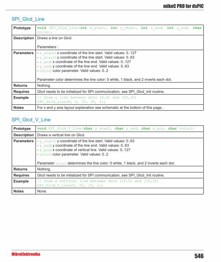
546
mikoC PRO for dsPIC
MikroElektronika
SPI_Glcd_Line
SPI_Glcd_V_Line
Prototype void SPI_Glcd_Line(int x_start, int y_start, int x_end, int y_end, char color);
Description Draws a line on Glcd.
Parameters : Parameters - x_start: x coordinate of the line start. Valid values: 0..127
- y_start: y coordinate of the line start. Valid values: 0..63 - x_end: x coordinate of the line end. Valid values: 0..127 - y_end: y coordinate of the line end. Valid values: 0..63 - color: color parameter. Valid values: 0..2
Parameter color determines the line color: 0 white, 1 black, and 2 inverts each dot.Returns Nothing.Requires Glcd needs to be initialized for SPI communication, see SPI_Glcd_Init routine.Example // Draw a line between dots (0,0) and (20,30)
SPI_Glcd_Line(0, 0, 20, 30, 1);
Notes For x and y axis layout explanation see schematic at the bottom of this page..
Prototype void SPI_Glcd_V_Line(char y_start, char y_end, char x_pos, char color);
Description Draws a vertical line on Glcd.Parameters - y_start: y coordinate of the line start. Valid values: 0..63
- y_end: y coordinate of the line end. Valid values: 0..63 - x_pos: x coordinate of vertical line. Valid values: 0..127 - color: color parameter. Valid values: 0..2
Parameter color determines the line color: 0 white, 1 black, and 2 inverts each dot.Returns Nothing.Requires Glcd needs to be initialized for SPI communication, see SPI_Glcd_Init routine.Example // Draw a vertical line between dots (10,5) and (10,25)
SPI_Glcd_V_Line(5, 25, 10, 1);
Notes None.

mikroC PRO for dsPIC
MikroElektronika547
SPI_Glcd_H_Line
SPI_Glcd_Rectangle
Prototype void SPI_Glcd_H_Line(char x_start, char x_end, char y_pos, char color);
Description Draws a horizontal line on Glcd.Parameters - x_start: x coordinate of the line start. Valid values: 0..127
- x_end: x coordinate of the line end. Valid values: 0..127 - y_pos: y coordinate of horizontal line. Valid values: 0..63 - color: color parameter. Valid values: 0..2
The parameter color determines the line color: 0 white, 1 black, and 2 inverts each dot.Returns Nothing.Requires Glcd needs to be initialized for SPI communication, see SPI_Glcd_Init routine.Example // Draw a horizontal line between dots (10,20) and (50,20)
SPI_Glcd_H_Line(10, 50, 20, 1);
Notes None.
Prototype void SPI_Glcd_Rectangle(char x_upper_left, char y_upper_left, char x_bottom_right, char y_bottom_right, char color);
Description Draws a rectangle on Glcd.Parameters - x_upper_left: x coordinate of the upper left rectangle corner. Valid values: 0..127
- y_upper_left: y coordinate of the upper left rectangle corner. Valid values: 0..63 - x_bottom_right: x coordinate of the lower right rectangle corner. Valid values: 0..127 - y_bottom_right: y coordinate of the lower right rectangle corner. Valid values: 0..63 - color: color parameter. Valid values: 0..2
The parameter color determines the color of the rectangle border: 0 white, 1 black, and 2 inverts each dot.
Returns Nothing.Requires Glcd needs to be initialized for SPI communication, see SPI_Glcd_Init routine.Example // Draw a rectangle between dots (5,5) and (40,40)
SPI_Glcd_Rectangle(5, 5, 40, 40, 1);
Notes None.

548
mikoC PRO for dsPIC
MikroElektronika
SPI_Glcd_Rectangle_Round_Edges
SPI_Glcd_Rectangle_Round_Edges_Fill
Prototype void SPI_Glcd_Rectangle_Round_Edges(unsigned short x_upper_left, unsigned short y_upper_left, unsigned short x_bottom_right, unsigned short y_bottom_right, unsigned short round_radius, unsigned short color);
Description Draws a rounded edge rectangle on Glcd.Parameters - x_upper_left: x coordinate of the upper left rectangle corner. Valid values: 0..127
- y_upper_left: y coordinate of the upper left rectangle corner. Valid values: 0..63 - x_bottom_right: x coordinate of the lower right rectangle corner. Valid values: 0..127 - y_bottom_right: y coordinate of the lower right rectangle corner. Valid values: 0..63 - round_radius: radius of the rounded edge. - color: color parameter. Valid values: 0..2
Returns Nothing.Requires Glcd needs to be initialized, see SPI_Glcd_Init routine.Example // Draw a rounded edge rectangle between dots (5,5) and (40,40) with the
radius of 12SPI_Glcd_Rectangle_Round_Edges(5, 5, 40, 40, 12, 1);
Notes None.
Prototype void SPI_Glcd_Rectangle_Round_Edges_Fill(unsigned short x_upper_left, unsigned short y_upper_left, unsigned short x_bottom_right, unsigned short y_bottom_right, unsigned short round_radius, unsigned short color);
Description Draws a filled rounded edge rectangle on Glcd with color.Parameters - x_upper_left: x coordinate of the upper left rectangle corner. Valid values: 0..127
- y_upper_left: y coordinate of the upper left rectangle corner. Valid values: 0..63 - x_bottom_right: x coordinate of the lower right rectangle corner. Valid values: 0..127 - y_bottom_right: y coordinate of the lower right rectangle corner. Valid values: 0..63 - round_radius: radius of the rounded edge - color: color parameter. Valid values: 0..2
The parameter color determines the color of the rectangle border: 0 white, 1 black, and 2 inverts each dot.
Returns Nothing.Requires Glcd needs to be initialized, see SPI_Glcd_Init routine.Example // Draws a filled rounded edge rectangle between dots (5,5) and (40,40) with
the radius of 12SPI_Glcd_Rectangle_Round_Edges_Fill(5, 5, 40, 40, 12, 1);
Notes None.

mikroC PRO for dsPIC
MikroElektronika549
SPI_Glcd_Box
SPI_Glcd_Circle
Prototype void SPI_Glcd_Box(char x_upper_left, char y_upper_left, char x_bottom_right, char y_bottom_right, char color);
Description Draws a box on Glcd.Parameters - x_upper_left: x coordinate of the upper left box corner. Valid values: 0..127
- y_upper_left: y coordinate of the upper left box corner. Valid values: 0..63 - x_bottom_right: x coordinate of the lower right box corner. Valid values: 0..127 - y_bottom_right: y coordinate of the lower right box corner. Valid values: 0..63 - color: color parameter. Valid values: 0..2
The parameter color determines the color of the box fill: 0 white, 1 black, and 2 inverts each dot.Returns Nothing.Requires Glcd needs to be initialized for SPI communication, see SPI_Glcd_Init routine.Example // Draw a box between dots (5,15) and (20,40)
SPI_Glcd_Box(5, 15, 20, 40, 1);
Notes None.
Prototype void SPI_Glcd_Circle(int x_center, int y_center, int radius, char color);
Description Draws a circle on Glcd.Parameters - x_center: x coordinate of the circle center. Valid values: 0..127
- y_center: y coordinate of the circle center. Valid values: 0..63 - radius: radius size - color: color parameter. Valid values: 0..2
The parameter color determines the color of the circle line: 0 white, 1 black, and 2 inverts each dot.Returns Nothing.Requires Glcd needs to be initialized for SPI communication, see SPI_Glcd_Init routine.Example // Draw a circle with center in (50,50) and radius=10
SPI_Glcd_Circle(50, 50, 10, 1);
Notes None.

550
mikoC PRO for dsPIC
MikroElektronika
SPI_Glcd_Circle_FIll
Prototype void SPI_Glcd_Circle_Fill(int x_center, int y_center, int radius, char color);
Description Draws a filled circle on Glcd.Parameters - x_center: x coordinate of the circle center. Valid values: 0..127
- y_center: y coordinate of the circle center. Valid values: 0..63 - radius: radius size - color: color parameter. Valid values: 0..2
The parameter color determines the color of the circle : 0 white, 1 black, and 2 inverts each dot.Returns Nothing.Requires Glcd needs to be initialized for SPI communication, see SPI_Glcd_Init routine.Example // Draw a circle with center in (50,50) and radius=10
SPI_Glcd_Circle_Fill(50, 50, 10, 1);
Notes None.

mikroC PRO for dsPIC
MikroElektronika551
SPI_Glcd_Set_Font
Prototype void SPI_Glcd_Set_Font(const code char *activeFont, char aFontWidth, char aFontHeight, unsigned int aFontOffs);
Description Sets font that will be used with SPI_Glcd_Write_Char and SPI_Glcd_Write_Text routines.Parameters None.Returns - activeFont: font to be set. Needs to be formatted as an array of char
- aFontWidth: width of the font characters in dots. - aFontHeight: height of the font characters in dots. - aFontOffs: number that represents difference between the mikroC PRO for dsPIC30/33 and PIC24 character set and regular ASCII set (eg. if ‘A’ is 65 in ASCII character, and ‘A’ is 45 in the mikroC PRO for dsPIC30/33 and PIC24 character set, aFontOffs is 20). Demo fonts supplied with the library have an offset of 32, which means that they start with space.
The user can use fonts given in the file __Lib_GLCDFonts file located in the Uses folder or create his own fonts.
List of supported fonts:
- Font_Glcd_System3x5 - Font_Glcd_System5x7 - Font_Glcd_5x7 - Font_Glcd_Character8x7
For the sake of the backward compatibility, these fonts are supported also:
- System3x5 (equivalent to Font_Glcd_System3x5) - FontSystem5x7_v2 (equivalent to Font_Glcd_System5x7) - font5x7 (equivalent to Font_Glcd_5x7) - Character8x7 (equivalent to Font_Glcd_Character8x7)
Requires Glcd needs to be initialized for SPI communication, see SPI_Glcd_Init routine.Example // Use the custom 5x7 font “myfont” which starts with space (32):
SPI_Glcd_Set_Font(myfont, 5, 7, 32);
Notes None.

552
mikoC PRO for dsPIC
MikroElektronika
SPI_Glcd_Write_Char
SPI_Glcd_Write_Text
Prototype void SPI_Glcd_Write_Char(char chr1, char x_pos, char page_num, char color);
Description Prints character on Glcd.Parameters - chr1: character to be written
- x_pos: character starting position on x-axis. Valid values: 0..(127-FontWidth) - page_num: the number of the page on which character will be written. Valid values: 0..7 - color: color parameter. Valid values: 0..2
The parameter color determines the color of the character: 0 white, 1 black, and 2 inverts each dot.Returns Nothing.Requires Glcd needs to be initialized for SPI communication, see SPI_Glcd_Init routine.
Use the SPI_Glcd_Set_Font to specify the font for display; if no font is specified, then the default Font_Glcd_System5x7 font supplied with the library will be used.
Example // Write character ‘C’ on the position 10 inside the page 2:SPI_Glcd_Write_Char(‘C’, 10, 2, 1);
Notes For x axis and page layout explanation see schematic at the bottom of this page.
Prototype void SPI_Glcd_Write_Text(char text[], char x_pos, char page_num, char color);
Description Prints text on Glcd.Parameters - text: text to be written
- x_pos: text starting position on x-axis. - page_num: the number of the page on which text will be written. Valid values: 0..7 - color: color parameter. Valid values: 0..2
The parameter color determines the color of the text: 0 white, 1 black, and 2 inverts each dot.Returns Nothing.Requires Glcd needs to be initialized for SPI communication, see SPI_Glcd_Init routine.
Use the SPI_Glcd_Set_Font to specify the font for display; if no font is specified, then the default Font_Glcd_System5x7 font supplied with the library will be used.
Example // Write text “Hello world!” on the position 10 inside the page 2:SPI_Glcd_Write_Text(“Hello world!”, 10, 2, 1);
Notes For x axis and page layout explanation see schematic at the bottom of this page.

mikroC PRO for dsPIC
MikroElektronika553
SPI_Glcd_Image
SPI_Glcd_PartialImage
Prototype void SPI_Glcd_Image(const code char *image);
Description Displays bitmap on Glcd.Parameters - image: image to be displayed. Bitmap array can be located in both code and RAM memory (due to
the mikroC PRO for dsPIC30/33 and PIC24 pointer to const and pointer to RAM equivalency). Returns Nothing.Requires Glcd needs to be initialized for SPI communication, see SPI_Glcd_Init routine.Example // Draw image my_image on Glcd
SPI_Glcd_Image(my_image);
Notes Use the mikroC PRO for dsPIC30/33 and PIC24 integrated Glcd Bitmap Editor, Tools > Glcd Bitmap Editor, to convert image to a constant array suitable for displaying on Glcd.
Prototype void SPI_Glcd_PartialImage(unsigned int x_left, unsigned int y_top, unsigned int width, unsigned int height, unsigned int picture_width, unsigned int picture_height, code const unsigned short * image);
Description Displays a partial area of the image on a desired location.Parameters - x_left: x coordinate of the desired location (upper left coordinate).
- y_top: y coordinate of the desired location (upper left coordinate). - width: desired image width. - height: desired image height. - picture_width: width of the original image. - picture_height: height of the original image. - image: image to be displayed. Bitmap array can be located in both code and RAM memory (due to the mikroC PRO for PIC pointer to const and pointer to RAM equivalency).
Returns Nothing.Requires Glcd needs to be initialized for SPI communication, see SPI_Glcd_Init routine.Example // Draws a 10x15 part of the image starting from the upper left corner on
the coordinate (10,12). Original image size is 16x32. SPI_Glcd_PartialImage(10, 12, 10, 15, 16, 32, image);
Notes Use the mikroC PRO for dsPIC30/33 and PIC24 integrated Glcd Bitmap Editor, Tools > Glcd Bitmap Editor, to convert image to a constant array suitable for displaying on Glcd.

554
mikoC PRO for dsPIC
MikroElektronika
Library Example
The example demonstrates how to communicate to KS0108 Glcd via the SPI module, using serial to parallel convertor MCP23S17.
Copy Code To Clipboard
const code char truck_bmp[1024];
// Port Expander module connectionssbit SPExpanderRST at LATF0_bit;sbit SPExpanderCS at LATF1_bit;sbit SPExpanderRST_Direction at TRISF0_bit;sbit SPExpanderCS_Direction at TRISF1_bit;// End Port Expander module connections
void Delay2s(){ // 2 seconds delay function Delay_ms(2000);}
void main() { char counter; char *someText;
#define COMPLETE_EXAMPLE ADPCFG = 0xFFFF; // initialize AN pins as digital
// If Port Expander Library uses SPI1 module SPI1_Init(); // Initialize SPI module used with PortExpander
SPI_Glcd_Init(0); // Initialize Glcd via SPI SPI_Glcd_Fill(0x00); // Clear Glcd Delay2s();
while(1) { #ifdef COMPLETE_EXAMPLE SPI_Glcd_Image(truck_bmp); // Draw image Delay2s(); Delay2s(); #endif SPI_Glcd_Fill(0x00); // Clear Glcd Delay2s;
SPI_Glcd_Box(62,40,124,56,1); // Draw box SPI_Glcd_Rectangle(5,5,84,35,1); // Draw rectangle SPI_Glcd_Line(0, 63, 127, 0,1); // Draw line Delay2s();
for(counter = 5; counter < 60; counter+=5 ) { // Draw horizontal and vertical line Delay_ms(250); SPI_Glcd_V_Line(2, 54, counter, 1); SPI_Glcd_H_Line(2, 120, counter, 1); }
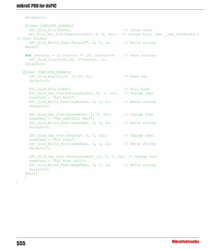
mikroC PRO for dsPIC
MikroElektronika555
Delay2s();
#ifdef COMPLETE_EXAMPLE SPI_Glcd_Fill(0x00); // Clear Glcd SPI_Glcd_Set_Font(Character8x7, 8, 8, 32); // Choose font, see __Lib_GLCDFonts.c in Uses folder SPI_Glcd_Write_Text("mikroE", 5, 7, 2); // Write string #endif
for (counter = 1; counter <= 10; counter++) // Draw circles SPI_Glcd_Circle(63,32, 3*counter, 1); Delay2s();
#ifdef COMPLETE_EXAMPLE SPI_Glcd_Box(12,20, 70,63, 2); // Draw box Delay2s();
SPI_Glcd_Fill(0xFF); // Fill Glcd SPI_Glcd_Set_Font(Character8x7, 8, 7, 32); // Change font someText = "8x7 Font"; SPI_Glcd_Write_Text(someText, 5, 1, 2); // Write string Delay2s();
SPI_Glcd_Set_Font(System3x5, 3, 5, 32); // Change font someText = "3X5 CAPITALS ONLY"; SPI_Glcd_Write_Text(someText, 5, 3, 2); // Write string Delay2s();
SPI_Glcd_Set_Font(font5x7, 5, 7, 32); // Change font someText = "5x7 Font"; SPI_Glcd_Write_Text(someText, 5, 5, 2); // Write string Delay2s();
SPI_Glcd_Set_Font(FontSystem5x7_v2, 5, 7, 32); // Change font someText = "5x7 Font (v2)"; SPI_Glcd_Write_Text(someText, 5, 7, 2); // Write string Delay2s(); #endif }}

556
mikoC PRO for dsPIC
MikroElektronika
HW Connection
SPI Glcd HW connection

mikroC PRO for dsPIC
MikroElektronika557
SPI Lcd LibraryThe mikroC PRO for dsPIC30/33 and PIC24 provides a library for communication with Lcd (with HD44780 compliant controllers) in 4-bit mode via SPI interface.
For creating a custom set of Lcd characters use Lcd Custom Character Tool.
Important :
- When using this library with dsPIC33 and PIC24 family MCUs be aware of their voltage incompatibility with certain number of Lcd modules. So, additional external power supply for these modules may be required. - Library uses the SPI module for communication. The user must initialize the appropriate SPI module before using the SPI Lcd Library. - For MCUs with multiple SPI modules it is possible to initialize all of them and then switch by using the SPI_Set_Active() routine. See the SPI Library functions. - This Library is designed to work with the mikroElektronika's Serial Lcd Adapter Board pinout, see schematic at the bottom of this page for details.
Library Dependency Tree
External dependencies of SPI Lcd Library
The implementation of SPI Lcd Library routines is based on Port Expander Library routines.
External dependencies are the same as Port Expander Library external dependencies.
Library Routines
- SPI_Lcd_Config - SPI_Lcd_Out - SPI_Lcd_Out_Cp - SPI_Lcd_Chr - SPI_Lcd_Chr_Cp - SPI_Lcd_Cmd

558
mikoC PRO for dsPIC
MikroElektronika
SPI_Lcd_Config
SPI_Lcd_Out
Prototype void SPI_Lcd_Config(char DeviceAddress);
Description Initializes the Lcd module via SPI interface.Parameters - DeviceAddress: SPI expander hardware address, see schematic at the bottom of this page Returns Nothing.Requires Global variables :
- SPExpanderCS: Chip Select line - SPExpanderRST: Reset line - SPExpanderCS_Direction: Direction of the Chip Select pin - SPExpanderRST_Direction: Direction of the Reset pin
must be defined before using this function.
The SPI module needs to be initialized. See SPIx_Init and SPIx_Init_Advanced routines. Example // Port Expander module connections
sbit SPExpanderRST at LATF0_bit;sbit SPExpanderCS at LATF1_bit;sbit SPExpanderRST_Direction at TRISF0_bit;sbit SPExpanderCS_Direction at TRISF1_bit;// End Port Expander module connections
// If Port Expander Library uses SPI1 moduleSPI1_Init(); // Initialize SPI module used with PortExpanderSPI_Lcd_Config(0); // initialize Lcd over SPI interface
Notes None.
Prototype void SPI_Lcd_Out(char row, char column, char *text);
Description Prints text on the Lcd starting from specified position. Both string variables and literals can be passed as a text.
Parameters - row: starting position row number - column: starting position column number - text: text to be written
Returns Nothing.Requires Lcd needs to be initialized for SPI communication, see SPI_Lcd_Config routine.Example // Write text “Hello!” on Lcd starting from row 1, column 3:
SPI_Lcd_Out(1, 3, “Hello!”);
Notes None.

mikroC PRO for dsPIC
MikroElektronika559
SPI_Lcd_Out_Cp
SPI_Lcd_Chr
SPI_Lcd_Chr_Cp
Prototype void SPI_Lcd_Out_CP(char *text);
Description Prints text on the Lcd at current cursor position. Both string variables and literals can be passed as a text.
Parameters - text: text to be written Returns Nothing.Requires Lcd needs to be initialized for SPI communication, see SPI_Lcd_Config routine.Example // Write text “Here!” at current cursor position:
SPI_Lcd_Out_CP(“Here!”);
Notes None.
Prototype void SPI_Lcd_Chr(char Row, char Column, char Out_Char);
Description Prints character on Lcd at specified position. Both variables and literals can be passed as character.Parameters - Row: writing position row number
- Column: writing position column number - Out_Char: character to be written
Returns Nothing.Requires Lcd needs to be initialized for SPI communication, see SPI_Lcd_Config routine.Example // Write character “i” at row 2, column 3:
SPI_Lcd_Chr(2, 3, ‘i’);
Notes None.
Prototype void SPI_Lcd_Chr_CP(char Out_Char);
Description Prints character on Lcd at current cursor position. Both variables and literals can be passed as character.
Parameters - Out_Char: character to be written Returns Nothing.Requires Lcd needs to be initialized for SPI communication, see SPI_Lcd_Config routine.Example // Write character “e” at current cursor position:
SPI_Lcd_Chr_Cp(‘e’);
Notes None.

560
mikoC PRO for dsPIC
MikroElektronika
SPI_Lcd_Cmd
SPI_Lcd_Cmd
Prototype void SPI_Lcd_Cmd(char out_char);
Description Sends command to Lcd.Parameters - out_char: command to be sent Returns Nothing.Requires Lcd needs to be initialized for SPI communication, see SPI_Lcd_Config routine.Example // Clear Lcd display:
SPI_Lcd_Cmd(_LCD_CLEAR);
Notes Predefined constants can be passed to the routine, see Available SPI Lcd Commands.
SPI Lcd Command Purpose_LCD_FIRST_ROW Move cursor to the 1st row_LCD_SECOND_ROW Move cursor to the 2nd row_LCD_THIRD_ROW Move cursor to the 3rd row_LCD_FOURTH_ROW Move cursor to the 4th row_LCD_CLEAR Clear display_LCD_RETURN_HOME Return cursor to home position, returns a shifted display
to its original position. Display data RAM is unaffected._LCD_CURSOR_OFF Turn off cursor_LCD_UNDERLINE_ON Underline cursor on_LCD_BLINK_CURSOR_ON Blink cursor on_LCD_MOVE_CURSOR_LEFT Move cursor left without changing display data RAM_LCD_MOVE_CURSOR_RIGHT Move cursor right without changing display data RAM_LCD_TURN_ON Turn Lcd display on_LCD_TURN_OFF Turn Lcd display off_LCD_SHIFT_LEFT Shift display left without changing display data RAM_LCD_SHIFT_RIGHT Shift display right without changing display data RAM
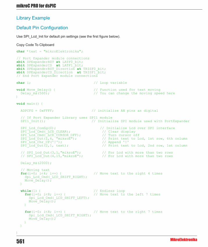
mikroC PRO for dsPIC
MikroElektronika561
Library Example
Default Pin Configuration
Use SPI_Lcd_Init for default pin settings (see the first figure below).
Copy Code To Clipboard
char *text = "mikroElektronika";
// Port Expander module connectionssbit SPExpanderRST at LATF0_bit;sbit SPExpanderCS at LATF1_bit;sbit SPExpanderRST_Direction at TRISF0_bit;sbit SPExpanderCS_Direction at TRISF1_bit;// End Port Expander module connections
char i; // Loop variable
void Move_Delay() { // Function used for text moving Delay_ms(500); // You can change the moving speed here}
void main() {
ADPCFG = 0xFFFF; // initialize AN pins as digital
// If Port Expander Library uses SPI1 module SPI1_Init(); // Initialize SPI module used with PortExpander
SPI_Lcd_Config(0); // Initialize Lcd over SPI interface SPI_Lcd_Cmd(_LCD_CLEAR); // Clear display SPI_Lcd_Cmd(_LCD_CURSOR_OFF); // Turn cursor off SPI_Lcd_Out(1,6, "mikroE"); // Print text to Lcd, 1st row, 6th column SPI_Lcd_Chr_CP('!'); // Append '!' SPI_Lcd_Out(2,1, text); // Print text to Lcd, 2nd row, 1st column
// SPI_Lcd_Out(3,1,"mikroE"); // For Lcd with more than two rows // SPI_Lcd_Out(4,15,"mikroE"); // For Lcd with more than two rows
Delay_ms(2000);
// Moving text for(i=0; i<4; i++) { // Move text to the right 4 times Spi_Lcd_Cmd(_LCD_SHIFT_RIGHT); Move_Delay(); }
while(1) { // Endless loop for(i=0; i<8; i++) { // Move text to the left 7 times Spi_Lcd_Cmd(_LCD_SHIFT_LEFT); Move_Delay(); }
for(i=0; i<8; i++) { // Move text to the right 7 times Spi_Lcd_Cmd(_LCD_SHIFT_RIGHT); Move_Delay(); } }
}

562
mikoC PRO for dsPIC
MikroElektronika
Lcd HW connection by default initialization (using SPI_Lcd_Init)

mikroC PRO for dsPIC
MikroElektronika563
SPI Lcd8 (8-bit interface) LibraryThe mikroC PRO for dsPIC30/33 and PIC24 provides a library for communication with Lcd (with HD44780 compliant controllers) in 8-bit mode via SPI interface.
For creating a custom set of Lcd characters use Lcd Custom Character Tool.
Important :
- When using this library with dsPIC33 and PIC24 family MCUs be aware of their voltage incompatibility with certain number of Lcd modules. So, additional external power supply for these modules may be required. - Library uses the SPI module for communication. The user must initialize the appropriate SPI module before using the SPI Lcd8 Library. - For MCUs with multiple SPI modules it is possible to initialize all of them and then switch by using the SPI_Set_Active() routine. See the SPI Library functions. - This Library is designed to work with the mikroElektronika's Serial Lcd/Glcd Adapter Board pinout, see schematic at the bottom of this page for details.
Library Dependency Tree
External dependencies of SPI Lcd Library
The implementation of SPI Lcd Library routines is based on Port Expander Library routines.
External dependencies are the same as Port Expander Library external dependencies.
Library Routines
- SPI_Lcd8_Config - SPI_Lcd8_Out - SPI_Lcd8_Out_Cp - SPI_Lcd8_Chr - SPI_Lcd8_Chr_Cp - SPI_Lcd8_Cmd

564
mikoC PRO for dsPIC
MikroElektronika
SPI_Lcd8_Config
Prototype void SPI_Lcd8_Config(char DeviceAddress);
Description Initializes the Lcd module via SPI interface.Parameters - DeviceAddress: SPI expander hardware address, see schematic at the bottom of this page Returns Nothing.Requires Global variables :
- SPExpanderCS: Chip Select line - SPExpanderRST: Reset line - SPExpanderCS_Direction: Direction of the Chip Select pin - SPExpanderRST_Direction: Direction of the Reset pin
must be defined before using this function.
The SPI module needs to be initialized. See SPIx_Init and SPIx_Init_Advanced routines. Example // Port Expander module connections
sbit SPExpanderRST at LATF0_bit;sbit SPExpanderCS at LATF1_bit;sbit SPExpanderRST_Direction at TRISF0_bit;sbit SPExpanderCS_Direction at TRISF1_bit;// End Port Expander module connections
...
// If Port Expander Library uses SPI1 moduleSPI1_Init(); // Initialize SPI module used with PortExpanderSPI_Lcd8_Config(0); // intialize Lcd in 8bit mode via SPI
Notes None.

mikroC PRO for dsPIC
MikroElektronika565
SPI_Lcd8_Out
SPI_Lcd8_Out_Cp
SPI_Lcd8_Chr
Prototype void SPI_Lcd8_Out(unsigned short row, unsigned short column, char *text);
Description Prints text on Lcd starting from specified position. Both string variables and literals can be passed as a text.
Parameters - row: starting position row number - column: starting position column number - text: text to be written
Returns Nothing.Requires Lcd needs to be initialized for SPI communication, see SPI_Lcd8_Config routine.Example // Write text “Hello!” on Lcd starting from row 1, column 3:
SPI_Lcd8_Out(1, 3, “Hello!”);
Notes None.
Prototype void SPI_Lcd8_Out_CP(char *text);
Description Prints text on Lcd at current cursor position. Both string variables and literals can be passed as a text.
Parameters - text: text to be written Returns Nothing.Requires Lcd needs to be initialized for SPI communication, see SPI_Lcd8_Config routine.Example // Write text “Here!” at current cursor position:
SPI_Lcd8_Out_Cp(“Here!”);
Notes None.
Prototype void SPI_Lcd8_Chr(unsigned short row, unsigned short column, char out_char);
Description Prints character on Lcd at specified position. Both variables and literals can be passed as character.Parameters - row: writing position row number
- column: writing position column number - out_char: character to be written
Returns Nothing.Requires Lcd needs to be initialized for SPI communication, see SPI_Lcd8_Config routine.Example // Write character “i” at row 2, column 3:
SPI_Lcd8_Chr(2, 3, ‘i’);
Notes None.

566
mikoC PRO for dsPIC
MikroElektronika
SPI_Lcd8_Chr_Cp
SPI_Lcd8_Cmd
Prototype void SPI_Lcd8_Chr_CP(char out_char);
Description Prints character on Lcd at current cursor position. Both variables and literals can be passed as character.
Parameters - out_char: character to be written Returns Nothing.Requires Lcd needs to be initialized for SPI communication, see SPI_Lcd8_Config routine.Example Print “e” at current cursor position:
// Write character “e” at current cursor position:SPI_Lcd8_Chr_Cp(‘e’);
Notes None.
Prototype void SPI_Lcd8_Cmd(char out_char);
Description Sends command to Lcd.Parameters - out_char: command to be sent Returns Nothing.Requires Lcd needs to be initialized for SPI communication, see SPI_Lcd8_Config routine.Example // Clear Lcd display:
SPI_Lcd8_Cmd(_LCD_CLEAR);
Notes Predefined constants can be passed to the routine, see Available SPI Lcd8 Commands.

mikroC PRO for dsPIC
MikroElektronika567
Available SPI Lcd8 Commands
SPI Lcd8 Command Purpose_LCD_FIRST_ROW Move cursor to the 1st row_LCD_SECOND_ROW Move cursor to the 2nd row_LCD_THIRD_ROW Move cursor to the 3rd row_LCD_FOURTH_ROW Move cursor to the 4th row_LCD_CLEAR Clear display_LCD_RETURN_HOME Return cursor to home position, returns a shifted display
to its original position. Display data RAM is unaffected._LCD_CURSOR_OFF Turn off cursor_LCD_UNDERLINE_ON Underline cursor on_LCD_BLINK_CURSOR_ON Blink cursor on_LCD_MOVE_CURSOR_LEFT Move cursor left without changing display data RAM_LCD_MOVE_CURSOR_RIGHT Move cursor right without changing display data RAM_LCD_TURN_ON Turn Lcd display on_LCD_TURN_OFF Turn Lcd display off_LCD_SHIFT_LEFT Shift display left without changing display data RAM_LCD_SHIFT_RIGHT Shift display right without changing display data RAM
Library Example
This example demonstrates how to communicate Lcd in 8-bit mode via the SPI module, using serial to parallel convertor MCP23S17.
Copy Code To Clipboard
char *text = "mikroElektronika";
// Port Expander module connectionssbit SPExpanderRST at LATF0_bit;sbit SPExpanderCS at LATF1_bit;sbit SPExpanderRST_Direction at TRISF0_bit;sbit SPExpanderCS_Direction at TRISF1_bit;// End Port Expander module connections
char i; // Loop variable
void Move_Delay() { // Function used for text moving Delay_ms(500); // You can change the moving speed here}
void main() {
// If Port Expander Library uses SPI1 module SPI1_Init(); // Initialize SPI module used with PortExpander

568
mikoC PRO for dsPIC
MikroElektronika
SPI_Lcd8_Config(0); // Initialize Lcd over SPI interface SPI_Lcd8_Cmd(_LCD_CLEAR); // Clear display SPI_Lcd8_Cmd(_LCD_CURSOR_OFF); // Turn cursor off SPI_Lcd8_Out(1,6, "mikroE"); // Print text to Lcd, 1st row, 6th column SPI_Lcd8_Chr_CP('!'); // Append '!' SPI_Lcd8_Out(2,1, text); // Print text to Lcd, 2nd row, 1st column
// SPI_Lcd8_Out(3,1,"mikroE"); // For Lcd with more than two rows // SPI_Lcd8_Out(4,15,"mikroE"); // For Lcd with more than two rows
Delay_ms(2000);
// Moving text for(i=0; i<4; i++) { // Move text to the right 4 times Spi_Lcd8_Cmd(_LCD_SHIFT_RIGHT); Move_Delay(); }
while(1) { // Endless loop for(i=0; i<8; i++) { // Move text to the left 7 times Spi_Lcd8_Cmd(_LCD_SHIFT_LEFT); Move_Delay(); }
for(i=0; i<8; i++) { // Move text to the right 7 times Spi_Lcd8_Cmd(_LCD_SHIFT_RIGHT); Move_Delay(); } }
}

mikroC PRO for dsPIC
MikroElektronika569
SPI Lcd8 HW connection

570
mikoC PRO for dsPIC
MikroElektronika
SPI T6963C Graphic Lcd LibraryThe mikroC PRO for dsPIC30/33 and PIC24 provides a library for working with Glcds based on TOSHIBA T6963C controller via SPI interface. The Toshiba T6963C is a very popular Lcd controller for the use in small graphics modules. It is capable of controlling displays with a resolution up to 240x128. Because of its low power and small outline it is most suitable for mobile applications such as PDAs, MP3 players or mobile measurement equipment. Although this controller is small, it has a capability of displaying and merging text and graphics and it manages all interfacing signals to the displays Row and Column drivers.
For creating a custom set of Glcd images use Glcd Bitmap Editor Tool.
Important :
- When using this library with dsPIC33 and PIC24 family MCUs be aware of their voltage incompatibility with certain number of T6963C based Glcd modules. So, additional external power supply for these modules may be required. - Glcd size based initialization routines can be found in setup library files located in the Uses folder. - The user must make sure that used MCU has appropriate ports and pins. If this is not the case the user should adjust initialization routines. - The library uses the SPI module for communication. The user must initialize the appropriate SPI module before using the SPI T6963C Glcd Library. - For MCUs with multiple SPI modules it is possible to initialize both of them and then switch by using the SPI_Set_Active() routine. See the SPI Library functions. - This Library is designed to work with mikroElektronika's Serial Glcd 240x128 and 240x64 Adapter Boards pinout, see schematic at the bottom of this page for details. - To use constants located in __Lib_SPIT6963C_Const.h file, user must include it the source file : #include "__SPIT6963C.h".
Some mikroElektronika's adapter boards have pinout different from T6369C datasheets. Appropriate relations between these labels are given in the table below :
Adapter Board T6369C datasheetRS C/DR/W /RD
E /WR
Library Dependency Tree
External dependencies of SPI T6963C Graphic Lcd Library
The implementation of SPI T6963C Graphic Lcd Library routines is based on Port Expander Library routines.
External dependencies are the same as Port Expander Library external dependencies.
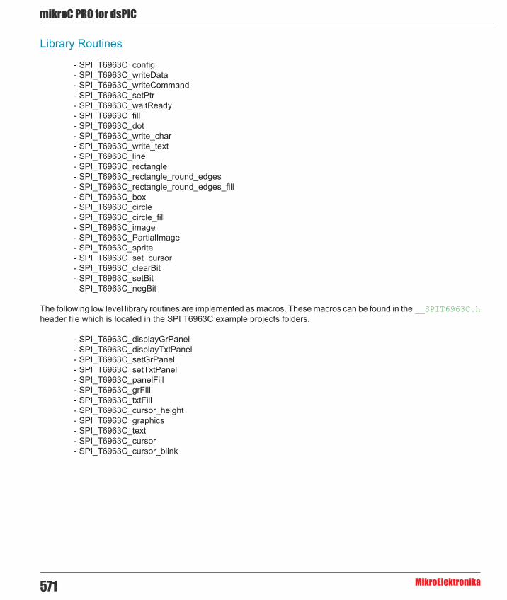
mikroC PRO for dsPIC
MikroElektronika571
Library Routines
- SPI_T6963C_config - SPI_T6963C_writeData - SPI_T6963C_writeCommand - SPI_T6963C_setPtr - SPI_T6963C_waitReady - SPI_T6963C_fill - SPI_T6963C_dot - SPI_T6963C_write_char - SPI_T6963C_write_text - SPI_T6963C_line - SPI_T6963C_rectangle - SPI_T6963C_rectangle_round_edges - SPI_T6963C_rectangle_round_edges_fill - SPI_T6963C_box - SPI_T6963C_circle - SPI_T6963C_circle_fill - SPI_T6963C_image - SPI_T6963C_PartialImage - SPI_T6963C_sprite - SPI_T6963C_set_cursor - SPI_T6963C_clearBit - SPI_T6963C_setBit - SPI_T6963C_negBit
The following low level library routines are implemented as macros. These macros can be found in the __SPIT6963C.h header file which is located in the SPI T6963C example projects folders.
- SPI_T6963C_displayGrPanel - SPI_T6963C_displayTxtPanel - SPI_T6963C_setGrPanel - SPI_T6963C_setTxtPanel - SPI_T6963C_panelFill - SPI_T6963C_grFill - SPI_T6963C_txtFill - SPI_T6963C_cursor_height - SPI_T6963C_graphics - SPI_T6963C_text - SPI_T6963C_cursor - SPI_T6963C_cursor_blink

572
mikoC PRO for dsPIC
MikroElektronika
SPI_Lcd8_Cmd
Prototype void SPI_T6963C_config(unsigned int width, unsigned char height, unsigned char fntW, char DeviceAddress, unsigned char wr, unsigned char rd, unsigned char cd, unsigned char rst);
Description Initializes T6963C Graphic Lcd controller.
Display RAM organization:The library cuts RAM into panels : a complete panel is one graphics panel followed by a text panel (see schematic below).
+---------------------+ /\+ GRAPHICS PANEL #0 + |+ + |+ + |+ + |+---------------------+ | PANEL 0+ TEXT PANEL #0 + |+ + \/+---------------------+ /\+ GRAPHICS PANEL #1 + |+ + |+ + |+ + |+---------------------+ | PANEL 1+ TEXT PANEL #1 + |+ + |+---------------------+ \/
Parameters - width: width of the Glcd panel - height: height of the Glcd panel - fntW: font width - DeviceAddress: SPI expander hardware address, see schematic at the bottom of this page - wr: write signal pin on Glcd control port - rd: read signal pin on Glcd control port - cd: command/data signal pin on Glcd control port - rst: reset signal pin on Glcd control port
Returns Nothing.Requires Global variables :
- SPExpanderCS: Chip Select line - SPExpanderRST: Reset line - SPExpanderCS_Direction: Direction of the Chip Select pin - SPExpanderRST_Direction: Direction of the Reset pin
must be defined before using this function.
The SPI module needs to be initialized. See the SPIx_Init and SPIx_Init_Advanced routines.

mikroC PRO for dsPIC
MikroElektronika573
Example // Port Expander module connectionssbit SPExpanderRST at LATF0_bit;sbit SPExpanderCS at LATF1_bit;sbit SPExpanderRST_Direction at TRISF0_bit;sbit SPExpanderCS_Direction at TRISF1_bit;// End Port Expander module connections
...
// Initialize SPI moduleSPI1_Init();SPI_T6963C_Config(240, 64, 8, 0, 0, 1, 3, 4);
Notes None.
SPI_T6963C_writeData
SPI_T6963C_writeCommand
Prototype void SPI_T6963C_writeData(unsigned char data_);
Description Writes data to T6963C controller via SPI interface.Parameters - data_: data to be written Returns Nothing.Requires Toshiba Glcd module needs to be initialized. See SPI_T6963C_Config routine.Example SPI_T6963C_writeData(data_);
Notes None.
Prototype void SPI_T6963C_writeCommand(unsigned char data_);
Description Writes command to T6963C controller via SPI interface.Parameters - data_: command to be written Returns Nothing.Requires Toshiba Glcd module needs to be initialized. See SPI_T6963C_Config routine.Example SPI_T6963C_writeCommand(SPI_T6963C_CURSOR_POINTER_SET);
Notes None.

574
mikoC PRO for dsPIC
MikroElektronika
SPI_T6963C_setPtr
SPI_T6963C_waitReady
SPI_T6963C_fill
Prototype void SPI_T6963C_setPtr(unsigned int p, unsigned char c);
Description Sets the memory pointer p for command p.Parameters - p: address where command should be written
- c: command to be written Returns Nothing.Requires Toshiba Glcd module needs to be initialized. See SPI_T6963C_Config routine.Example SPI_T6963C_setPtr(SPI_T6963C_grHomeAddr + start, SPI_T6963C_ADDRESS_
POINTER_SET);
Notes None.
Prototype void SPI_T6963C_waitReady();
Description Pools the status byte, and loops until Toshiba Glcd module is ready.Parameters None.Returns Nothing.Requires Toshiba Glcd module needs to be initialized. See SPI_T6963C_Config routine.Example SPI_T6963C_waitReady();
Notes None.
Prototype void SPI_T6963C_fill(unsigned char v, unsigned int start, unsigned int len);
Description Fills controller memory block with given byte.Parameters - v: byte to be written
- start: starting address of the memory block - len: length of the memory block in bytes
Returns Nothing.Requires Toshiba Glcd module needs to be initialized. See SPI_T6963C_Config routine.Example SPI_T6963C_fill(0x33,0x00FF,0x000F);
Notes None.

mikroC PRO for dsPIC
MikroElektronika575
SPI_T6963C_write_char
SPI_T6963C_dot
Prototype void SPI_T6963C_write_char(unsigned char c, unsigned char x, unsigned char y, unsigned char mode);
Description Writes a char in the current text panel of Glcd at coordinates (x, y).Parameters - c: char to be written
- x: char position on x-axis - y: char position on y-axis - mode: mode parameter. Valid values: SPI_T6963C_ROM_MODE_OR, SPI_T6963C_ROM_MODE_XOR, SPI_T6963C_ROM_MODE_AND and SPI_T6963C_ROM_MODE_TEXT
Mode parameter explanation:
- OR Mode: In the OR-Mode, text and graphics can be displayed and the data is logically “OR-ed”. This is the most common way of combining text and graphics for example labels on buttons. - XOR-Mode: In this mode, the text and graphics data are combined via the logical “exclusive OR”. This can be useful to display text in negative mode, i.e. white text on black background. - AND-Mode: The text and graphic data shown on display are combined via the logical “AND function”. - TEXT-Mode: This option is only available when displaying just a text. The Text Attribute values are stored in the graphic area of display memory.
For more details see the T6963C datasheet. Returns Nothing.Requires Toshiba Glcd module needs to be initialized. See SPI_T6963C_Config routine.Example SPI_T6963C_write_char(“A”,22,23,SPI_T6963C_ROM_MODE_AND);
Notes None.
Prototype void SPI_T6963C_dot(int x, int y, unsigned char color);
Description Writes a char in the current text panel of Glcd at coordinates (x, y).
Returns - x: dot position on x-axis - y: dot position on y-axis - color: color parameter. Valid values: SPI_T6963C_BLACK and SPI_T6963C_WHITE
Requires Toshiba Glcd module needs to be initialized. See SPI_T6963C_Config routine.Example SPI_T6963C_dot(x0, y0, SPI_T6963C_BLACK);
Notes None.
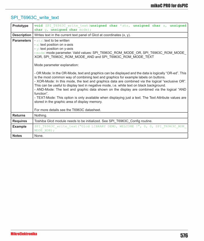
576
mikoC PRO for dsPIC
MikroElektronika
SPI_T6963C_write_text
Prototype void SPI_T6963C_write_text(unsigned char *str, unsigned char x, unsigned char y, unsigned char mode);
Description Writes text in the current text panel of Glcd at coordinates (x, y).Parameters - str: text to be written
- x: text position on x-axis - y: text position on y-axis - mode: mode parameter. Valid values: SPI_T6963C_ROM_MODE_OR, SPI_T6963C_ROM_MODE_XOR, SPI_T6963C_ROM_MODE_AND and SPI_T6963C_ROM_MODE_TEXT
Mode parameter explanation:
- OR Mode: In the OR-Mode, text and graphics can be displayed and the data is logically “OR-ed”. This is the most common way of combining text and graphics for example labels on buttons. - XOR-Mode: In this mode, the text and graphics data are combined via the logical “exclusive OR”. This can be useful to display text in negative mode, i.e. white text on black background. - AND-Mode: The text and graphic data shown on the display are combined via the logical “AND function”. - TEXT-Mode: This option is only available when displaying just a text. The Text Attribute values are stored in the graphic area of display memory.
For more details see the T6963C datasheet. Returns Nothing.Requires Toshiba Glcd module needs to be initialized. See SPI_T6963C_Config routine.Example SPI_T6963C_write_text(“Glcd LIBRARY DEMO, WELCOME !”, 0, 0, SPI_T6963C_ROM_
MODE_XOR);
Notes None.

mikroC PRO for dsPIC
MikroElektronika577
SPI_T6963C_line
SPI_T6963C_rectangle
Prototype void SPI_T6963C_line(int x0, int y0, int x1, int y1, unsigned char pcolor);
Description Draws a line from (x0, y0) to (x1, y1).Parameters - x0: x coordinate of the line start
- y0: y coordinate of the line end - x1: x coordinate of the line start - y1: y coordinate of the line end - pcolor: color parameter. Valid values: SPI_T6963C_BLACK and SPI_T6963C_WHITE
Returns Nothing.Requires Toshiba Glcd module needs to be initialized. See SPI_T6963C_Config routine.Example SPI_T6963C_line(0, 0, 239, 127, SPI_T6963C_WHITE);
Notes None.
Prototype void SPI_T6963C_rectangle(int x0, int y0, int x1, int y1, unsigned char pcolor);
Description Draws a rectangle on Glcd.Parameters - x0: x coordinate of the upper left rectangle corner
- y0: y coordinate of the upper left rectangle corner - x1: x coordinate of the lower right rectangle corner - y1: y coordinate of the lower right rectangle corner - pcolor: color parameter. Valid values: SPI_T6963C_BLACK and SPI_T6963C_WHITE
Returns Nothing.Requires Toshiba Glcd module needs to be initialized. See SPI_T6963C_Config routine.Example SPI_T6963C_rectangle(20, 20, 219, 107, SPI_T6963C_WHITE);
Notes None.

578
mikoC PRO for dsPIC
MikroElektronika
SPI_T6963C_rectangle_round_edges
SPI_T6963C_rectangle_round_edges_fill
Prototype void SPI_T6963C_rectangle_round_edges(int x0, int y0, int x1, int y1, int round_radius, unsigned char pcolor);
Description Draws a rounded edge rectangle on Glcd.Parameters - x0: x coordinate of the upper left rectangle corner
- y0: y coordinate of the upper left rectangle corner - x1: x coordinate of the lower right rectangle corner - y1: y coordinate of the lower right rectangle corner - round_radius: radius of the rounded edge. - pcolor: color parameter. Valid values: SPI_T6963C_BLACK and SPI_T6963C_WHITE
Returns Nothing.Requires Toshiba Glcd module needs to be initialized. See SPI_T6963C_Config routine.Example SPI_T6963C_rectangle_round_edges(20, 20, 219, 107, 12, SPI_T6963C_WHITE);
Notes None.
Prototype void SPI_T6963C_rectangle_round_edges_fill(int x0, int y0, int x1, int y1, int round_radius, unsigned char pcolor);
Description Draws a filled rounded edge rectangle on Glcd.Parameters - x0: x coordinate of the upper left rectangle corner
- y0: y coordinate of the upper left rectangle corner - x1: x coordinate of the lower right rectangle corner - y1: y coordinate of the lower right rectangle corner - round_radius: radius of the rounded edge - pcolor: color parameter. Valid values: SPI_T6963C_BLACK and SPI_T6963C_WHITE
Returns Nothing.Requires Toshiba Glcd module needs to be initialized. See SPI_T6963C_Config routine.Example SPI_T6963C_rectangle_round_edges_fill(20, 20, 219, 107, 12, SPI_T6963C_
WHITE);
Notes None.

mikroC PRO for dsPIC
MikroElektronika579
SPI_T6963C_box
SPI_T6963C_circle
SPI_T6963C_circle_fill
Prototype void SPI_T6963C_box(int x0, int y0, int x1, int y1, unsigned char pcolor);
Description Draws a box on the GlcdParameters - x0: x coordinate of the upper left box corner
- y0: y coordinate of the upper left box corner - x1: x coordinate of the lower right box corner - y1: y coordinate of the lower right box corner - pcolor: color parameter. Valid values: SPI_T6963C_BLACK and SPI_T6963C_WHITE
Returns Nothing.Requires Toshiba Glcd module needs to be initialized. See SPI_T6963C_Config routine.Example SPI_T6963C_box(0, 119, 239, 127, SPI_T6963C_WHITE);
Notes None.
Prototype void SPI_T6963C_circle(int x, int y, long r, unsigned char pcolor);
Description Draws a circle on the Glcd.Parameters - x: x coordinate of the circle center
- y: y coordinate of the circle center - r: radius size - pcolor: color parameter. Valid values: SPI_T6963C_BLACK and SPI_T6963C_WHITE
Returns Nothing.Requires Toshiba Glcd module needs to be initialized. See SPI_T6963C_Config routine.Example SPI_T6963C_circle(120, 64, 110, SPI_T6963C_WHITE);
Notes None.
Prototype void SPI_T6963C_circle_fill(int x, int y, long r, unsigned char pcolor);
Description Draws a filled circle on the Glcd.Parameters - x: x coordinate of the circle center
- y: y coordinate of the circle center - r: radius size - pcolor: color parameter. Valid values: SPI_T6963C_BLACK and SPI_T6963C_WHITE
Returns Nothing.Requires Toshiba Glcd module needs to be initialized. See SPI_T6963C_Config routine.Example SPI_T6963C_circle_fill(120, 64, 110, SPI_T6963C_WHITE);
Notes None.
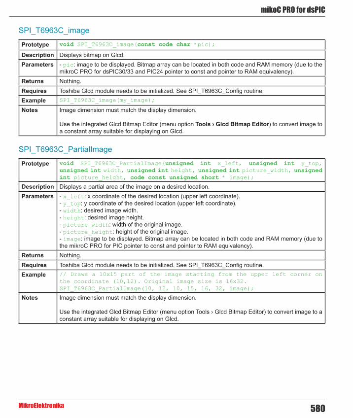
580
mikoC PRO for dsPIC
MikroElektronika
SPI_T6963C_image
SPI_T6963C_PartialImage
Prototype void SPI_T6963C_image(const code char *pic);
Description Displays bitmap on Glcd.Parameters - pic: image to be displayed. Bitmap array can be located in both code and RAM memory (due to the
mikroC PRO for dsPIC30/33 and PIC24 pointer to const and pointer to RAM equivalency). Returns Nothing.Requires Toshiba Glcd module needs to be initialized. See SPI_T6963C_Config routine.Example SPI_T6963C_image(my_image);
Notes Image dimension must match the display dimension.
Use the integrated Glcd Bitmap Editor (menu option Tools › Glcd Bitmap Editor) to convert image to a constant array suitable for displaying on Glcd.
Prototype void SPI_T6963C_PartialImage(unsigned int x_left, unsigned int y_top, unsigned int width, unsigned int height, unsigned int picture_width, unsigned int picture_height, code const unsigned short * image);
Description Displays a partial area of the image on a desired location.Parameters - x_left: x coordinate of the desired location (upper left coordinate).
- y_top: y coordinate of the desired location (upper left coordinate). - width: desired image width. - height: desired image height. - picture_width: width of the original image. - picture_height: height of the original image. - image: image to be displayed. Bitmap array can be located in both code and RAM memory (due to the mikroC PRO for PIC pointer to const and pointer to RAM equivalency).
Returns Nothing.Requires Toshiba Glcd module needs to be initialized. See SPI_T6963C_Config routine.Example // Draws a 10x15 part of the image starting from the upper left corner on
the coordinate (10,12). Original image size is 16x32. SPI_T6963C_PartialImage(10, 12, 10, 15, 16, 32, image);
Notes Image dimension must match the display dimension.
Use the integrated Glcd Bitmap Editor (menu option Tools › Glcd Bitmap Editor) to convert image to a constant array suitable for displaying on Glcd.

mikroC PRO for dsPIC
MikroElektronika581
SPI_T6963C_sprite
SPI_T6963C_set_cursor
SPI_T6963C_clearBit
Prototype void SPI_T6963C_sprite(unsigned char px, unsigned char py, const code char *pic, unsigned char sx, unsigned char sy);
Description Fills graphic rectangle area (px, py) to (px+sx, py+sy) with custom size picture.Parameters - px: x coordinate of the upper left picture corner. Valid values: multiples of the font width
- py: y coordinate of the upper left picture corner - pic: picture to be displayed - sx: picture width. Valid values: multiples of the font width - sy: picture height
Returns Nothing.Requires Toshiba Glcd module needs to be initialized. See SPI_T6963C_Config routine.Example SPI_T6963C_sprite(76, 4, einstein, 88, 119); // draw a sprite
Notes If px and sx parameters are not multiples of the font width they will be scaled to the nearest lower number that is a multiple of the font width.
Prototype void SPI_T6963C_set_cursor(unsigned char x, unsigned char y);
Description Sets cursor to row x and column y.Parameters - x: cursor position row number
- y: cursor position column number Returns Nothing.Requires Toshiba Glcd module needs to be initialized. See SPI_T6963C_Config routine.Example SPI_T6963C_set_cursor(cposx, cposy);
Notes None.
Prototype void SPI_T6963C_clearBit(char b);
Description Clears control port bit(s).Parameters - b: bit mask. The function will clear bit x on control port if bit x in bit mask is set to 1. Returns Nothing.Requires Toshiba Glcd module needs to be initialized. See SPI_T6963C_Config routine.Example // clear bits 0 and 1 on control port
SPI_T6963C_clearBit(0x03);
Notes None.

582
mikoC PRO for dsPIC
MikroElektronika
SPI_T6963C_setBit
SPI_T6963C_negBit
SPI_T6963C_displayGrPanel
Prototype void SPI_T6963C_setBit(char b);
Description Sets control port bit(s).Parameters - b: bit mask. The function will set bit x on control port if bit x in bit mask is set to 1. Returns Nothing.Requires Toshiba Glcd module needs to be initialized. See SPI_T6963C_Config routine.Example // set bits 0 and 1 on control port
SPI_T6963C_setBit(0x03);
Notes None.
Prototype void SPI_T6963C_negBit(char b);
Description Negates control port bit(s).Parameters - b: bit mask. The function will negate bit x on control port if bit x in bit mask is set to 1. Returns Nothing.Requires Toshiba Glcd module needs to be initialized. See SPI_T6963C_Config routine.Example // negate bits 0 and 1 on control port
SPI_T6963C_negBit(0x03);
Notes None.
Prototype void SPI_T6963C_displayGrPanel(unsigned int n);
Description Display selected graphic panel.Parameters - n: graphic panel number. Valid values: 0 and 1. Returns Nothing.Requires Toshiba Glcd module needs to be initialized. See SPI_T6963C_Config routine.Example // display graphic panel 1
SPI_T6963C_displayGrPanel(1);
Notes None.

mikroC PRO for dsPIC
MikroElektronika583
SPI_T6963C_displayTxtPanel
SPI_T6963C_setGrPanel
SPI_T6963C_setTxtPanel
Prototype void SPI_T6963C_displayTxtPanel(unsigned int n);
Description Display selected text panel.Parameters - n: text panel number. Valid values: 0 and 1. Returns Nothing.Requires Toshiba Glcd module needs to be initialized. See SPI_T6963C_Config routine.Example // display text panel 1
SPI_T6963C_displayTxtPanel(1);
Notes None.
Prototype void SPI_T6963C_setGrPanel(unsigned int n);
Description Compute start address for selected graphic panel and set appropriate internal pointers. All subsequent graphic operations will be preformed at this graphic panel.
Parameters - n: graphic panel number. Valid values: 0 and 1. Returns Nothing.Requires Toshiba Glcd module needs to be initialized. See SPI_T6963C_Config routine.Example // set graphic panel 1 as current graphic panel.
SPI_T6963C_setGrPanel(1);
Notes None.
Prototype void SPI_T6963C_setTxtPanel(unsigned int n);
Description Compute start address for selected text panel and set appropriate internal pointers. All subsequent text operations will be preformed at this text panel.
Parameters - n: text panel number. Valid values: 0 and 1. Returns Nothing.Requires Toshiba Glcd module needs to be initialized. See SPI_T6963C_Config routine.Example // set text panel 1 as current text panel.
SPI_T6963C_setTxtPanel(1);
Notes None.

584
mikoC PRO for dsPIC
MikroElektronika
SPI_T6963C_panelFill
SPI_T6963C_grFill
SPI_T6963C_txtFill
Prototype void SPI_T6963C_panelFill(unsigned char v);
Description Fill current panel in full (graphic+text) with appropriate value (0 to clear).Parameters - v: value to fill panel with. Returns Nothing.Requires Toshiba Glcd module needs to be initialized. See SPI_T6963C_Config routine.Example clear current panel
SPI_T6963C_panelFill(0);
Notes None.
Prototype void SPI_T6963C_grFill(unsigned char v);
Description Fill current graphic panel with appropriate value (0 to clear).Parameters - v: value to fill graphic panel with. Returns Nothing.Requires Toshiba Glcd module needs to be initialized. See SPI_T6963C_Config routine.Example // clear current graphic panel
SPI_T6963C_grFill(0);
Notes None.
Prototype void SPI_T6963C_txtFill(unsigned char v);
Description Fill current text panel with appropriate value (0 to clear).Parameters - v: this value increased by 32 will be used to fill text panel. Returns Nothing.Requires Toshiba Glcd module needs to be initialized. See SPI_T6963C_Config routine.Example // clear current text panel
SPI_T6963C_txtFill(0);
Notes None.

mikroC PRO for dsPIC
MikroElektronika585
SPI_T6963C_cursor_height
SPI_T6963C_graphics
SPI_T6963C_text
Prototype void SPI_T6963C_cursor_height(unsigned char n);
Description Set cursor size.Parameters - n: cursor height. Valid values: 0..7. Returns Nothing.Requires Toshiba Glcd module needs to be initialized. See SPI_T6963C_Config routine.Example SPI_T6963C_cursor_height(7);
Notes None.
Prototype void SPI_T6963C_graphics(unsigned int n);
Description Enable/disable graphic displaying.Parameters - n: graphic enable/disable parameter. Valid values: 0 (disable graphic dispaying) and 1 (enable
graphic displaying). Returns Nothing.Requires Toshiba Glcd module needs to be initialized. See SPI_T6963C_Config routine.Example // enable graphic displaying
SPI_T6963C_graphics(1);
Notes None.
Prototype void SPI_T6963C_text(unsigned int n);
Description Enable/disable text displaying.Parameters - n: text enable/disable parameter. Valid values: 0 (disable text dispaying) and 1 (enable text
displaying). Returns Nothing.Requires Toshiba Glcd module needs to be initialized. See SPI_T6963C_Config routine.Example // enable text displaying
SPI_T6963C_text(1);
Notes None.

586
mikoC PRO for dsPIC
MikroElektronika
SPI_T6963C_cursor
SPI_T6963C_cursor_blink
Prototype void SPI_T6963C_cursor(unsigned int n);
Description Set cursor on/off.Parameters - n: on/off parameter. Valid values: 0 (set cursor off) and 1 (set cursor on). Returns Nothing.Requires Toshiba Glcd module needs to be initialized. See SPI_T6963C_Config routine.Example // set cursor on
SPI_T6963C_cursor(1);
Notes None.
Prototype void SPI_T6963C_cursor_blink(unsigned int n);
Description Enable/disable cursor blinking.Parameters - n: cursor blinking enable/disable parameter. Valid values: 0 (disable cursor blinking) and 1 (enable
cursor blinking). Returns Nothing.Requires Toshiba Glcd module needs to be initialized. See SPI_T6963C_Config routine.Example // enable cursor blinking
SPI_T6963C_cursor_blink(1);
Notes None.
Library Example
The following drawing demo tests advanced routines of the SPI T6963C Glcd library. Hardware configurations in this example are made for the EasydsPIC3 board and dsPIC30F4013.
Copy Code To Clipboard
#include "__SPIT6963C.h"
/* * bitmap pictures stored in ROM */const code char mikroE_240x128_bmp[];const code char einstein[];
// Port Expander module connectionssbit SPExpanderRST at LATF0_bit;sbit SPExpanderCS at LATF1_bit;sbit SPExpanderRST_Direction at TRISF0_bit;sbit SPExpanderCS_Direction at TRISF1_bit;// End Port Expander module connections
void main() { char txt1[] = " EINSTEIN WOULD HAVE LIKED mE"; char txt[] = " GLCD LIBRARY DEMO, WELCOME !";

mikroC PRO for dsPIC
MikroElektronika587
unsigned char panel; // Current panel unsigned int i; // General purpose register unsigned char curs; // Cursor visibility unsigned int cposx, cposy; // Cursor x-y position
#define COMPLETE_EXAMPLE // comment this line to make simpler/smaller example
ADPCFG = 0xFFFF;
TRISB0_bit = 1; // Set RB0 as input TRISB1_bit = 1; // Set RB1 as input TRISB2_bit = 1; // Set RB2 as input TRISB3_bit = 1; // Set RB3 as input TRISB4_bit = 1; // Set RB4 as input
// If Port Expander Library uses SPI1 module SPI1_Init(); // Initialize SPI module used with PortExpander
// // If Port Expander Library uses SPI2 module// SPI2_Init(); // Initialize SPI module used with PortExpander
/* * init display for 240 pixel width and 128 pixel height * 8 bits character width * data bus on MCP23S17 portB * control bus on MCP23S17 portA * bit 2 is !WR * bit 1 is !RD * bit 0 is !CD * bit 4 is RST * chip enable, reverse on, 8x8 font internaly set in library */
SPI_T6963C_Config(240, 128, 8, 0, 2, 1, 0, 4); Delay_ms(1000);
/* * Enable both graphics and text display at the same time */ SPI_T6963C_graphics(1); SPI_T6963C_text(1);
panel = 0; i = 0; curs = 0; cposx = cposy = 0; /* * Text messages */ SPI_T6963C_write_text(txt, 0, 0, SPI_T6963C_ROM_MODE_XOR); SPI_T6963C_write_text(txt1, 0, 15, SPI_T6963C_ROM_MODE_XOR);

588
mikoC PRO for dsPIC
MikroElektronika
/* * Cursor */ SPI_T6963C_cursor_height(8); // 8 pixel height SPI_T6963C_set_cursor(0, 0); // move cursor to top left SPI_T6963C_cursor(0); // cursor off
/* * Draw rectangles */ SPI_T6963C_rectangle(0, 0, 239, 127, SPI_T6963C_WHITE); SPI_T6963C_rectangle(20, 20, 219, 107, SPI_T6963C_WHITE); SPI_T6963C_rectangle(40, 40, 199, 87, SPI_T6963C_WHITE); SPI_T6963C_rectangle(60, 60, 179, 67, SPI_T6963C_WHITE);
/* * Draw a cross */ SPI_T6963C_line(0, 0, 239, 127, SPI_T6963C_WHITE); SPI_T6963C_line(0, 127, 239, 0, SPI_T6963C_WHITE);
/* * Draw solid boxes */ SPI_T6963C_box(0, 0, 239, 8, SPI_T6963C_WHITE); SPI_T6963C_box(0, 119, 239, 127, SPI_T6963C_WHITE);
#ifdef COMPLETE_EXAMPLE /* * Draw circles */ SPI_T6963C_circle(120, 64, 10, SPI_T6963C_WHITE); SPI_T6963C_circle(120, 64, 30, SPI_T6963C_WHITE); SPI_T6963C_circle(120, 64, 50, SPI_T6963C_WHITE); SPI_T6963C_circle(120, 64, 70, SPI_T6963C_WHITE); SPI_T6963C_circle(120, 64, 90, SPI_T6963C_WHITE); SPI_T6963C_circle(120, 64, 110, SPI_T6963C_WHITE); SPI_T6963C_circle(120, 64, 130, SPI_T6963C_WHITE);
SPI_T6963C_sprite(76, 4, einstein, 88, 119); // Draw a sprite
SPI_T6963C_setGrPanel(1); // Select other graphic panel
SPI_T6963C_image(mikroE_240x128_bmp); // Draw an image
#endif
for(;;) { // Endless loop /* * If RB0 is pressed, display only graphic panel */

mikroC PRO for dsPIC
MikroElektronika589
if(RB0_bit) { SPI_T6963C_graphics(1); SPI_T6963C_text(0); Delay_ms(300); } #ifdef COMPLETE_EXAMPLE /* * If RB1 is pressed, toggle the display between graphic panel 0 and graphic panel 1 */ else if(RB1_bit) { panel++; panel &= 1; SPI_T6963C_displayGrPanel(panel); Delay_ms(300); } #endif /* * If RB2 is pressed, display only text panel */ else if(RB2_bit) { SPI_T6963C_graphics(0); SPI_T6963C_text(1); Delay_ms(300); }
/* * If RB3 is pressed, display text and graphic panels */ else if(RB3_bit) { SPI_T6963C_graphics(1); SPI_T6963C_text(1); Delay_ms(300); } /* * If RB4 is pressed, change cursor */ else if(RB4_bit) { curs++; if(curs == 3) curs = 0; switch(curs) { case 0: // no cursor SPI_T6963C_cursor(0); break; case 1: // blinking cursor SPI_T6963C_cursor(1); SPI_T6963C_cursor_blink(1); break; case 2: // non blinking cursor SPI_T6963C_cursor(1); SPI_T6963C_cursor_blink(0); break; }
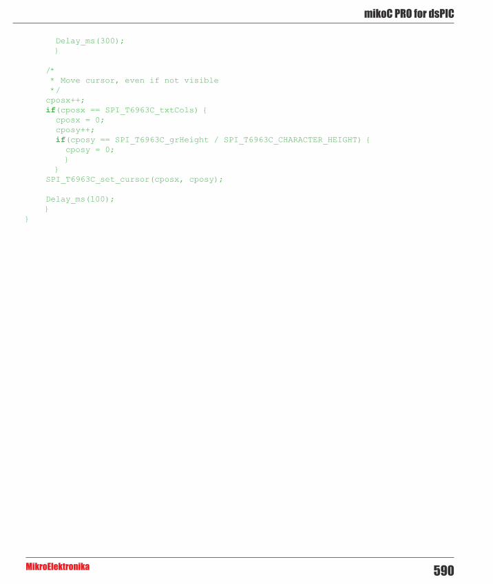
590
mikoC PRO for dsPIC
MikroElektronika
Delay_ms(300); }
/* * Move cursor, even if not visible */ cposx++; if(cposx == SPI_T6963C_txtCols) { cposx = 0; cposy++; if(cposy == SPI_T6963C_grHeight / SPI_T6963C_CHARACTER_HEIGHT) { cposy = 0; } } SPI_T6963C_set_cursor(cposx, cposy);
Delay_ms(100); }}

mikroC PRO for dsPIC
MikroElektronika591
HW Connection
SPI T6963C Glcd HW connection

592
mikoC PRO for dsPIC
MikroElektronika
T6963C Graphic Lcd LibraryThe mikroC PRO for dsPIC30/33 and PIC24 provides a library for working with Glcds based on TOSHIBA T6963C controller. The Toshiba T6963C is a very popular Lcd controller for the use in small graphics modules. It is capable of controlling displays with a resolution up to 240x128. Because of its low power and small outline it is most suitable for mobile applications such as PDAs, MP3 players or mobile measurement equipment. Although small, this contoller has a capability of displaying and merging text and graphics and it manages all the interfacing signals to the displays Row and Column drivers.
For creating a custom set of Glcd images use Glcd Bitmap Editor Tool.
Important :
- When using this library with dsPIC33 and PIC24 family of MCUs be aware of their voltage incompatibility with certain number of T6963C based Glcd modules. So, additional external power supply for these modules may be required. - ChipEnable(CE), FontSelect(FS) and Reverse(MD) have to be set to appropriate levels by the user outside of the T6963C_Init() function. See the Library Example code at the bottom of this page. - Glcd size based initialization routines can be found in setup library files located in the Uses folder. - The user must make sure that used MCU has appropriate ports and pins. If this is not the case the user should adjust initialization routines.
Some mikroElektronika's adapter boards have pinout different from T6369C datasheets. Appropriate relations between these labels are given in the table below :
Adapter Board T6369C datasheetRS C/DR/W /RD
E /WR
Library Dependency Tree

mikroC PRO for dsPIC
MikroElektronika593
The following variables must be defined in all projects using T6963C Graphic Lcd library:
Description : Example :
extern sfr unsigned int T6963C_dataPort; T6963C Data Port. char T6963C_dataPort
at PORTB;
extern sfr sbit T6963C_ctrlwr; Write signal. sbit T6963C_ctrlwr at
LATF2_bit;
extern sfr sbit T6963C_ctrlrd; Read signal. sbit T6963C_ctrlrd at
LATF1_bit;
extern sfr sbit T6963C_ctrlcd; Command/Data signal. sbit T6963C_ctrlcd at
LATF0_bit;
extern sfr sbit T6963C_ctrlrst; Reset signal. sbit T6963C_ctrlrst
at LATF4_bit;
extern sfr sbit T 6 9 6 3 C _ c t r l w r _Direction;
Direction of the Write pin.sbit T6963C_ctrlwr_Direction at TRISF2_bit;
extern sfr sbit T 6 9 6 3 C _ c t r l r d _Direction;
Direction of the Read pin.sbit T6963C_ctrlrd_Direction at TRISF1_bit;
extern sfr sbit T 6 9 6 3 C _ c t r l c d _Direction;
Direction of the Command/Data pin.
sbit T6963C_ctrlcd_Direction at TRISF0_bit;
extern sfr sbit T 6 9 6 3 C _ c t r l r s t _Direction;
Direction of the Reset pin.sbit T6963C_ctrlrst_Direction at TRISF4_bit;
Library Dependency Tree

594
mikoC PRO for dsPIC
MikroElektronika
Library Routines
- T6963C_init - T6963C_writeData - T6963C_writeCommand - T6963C_setPtr - T6963C_waitReady - T6963C_fill - T6963C_dot - T6963C_write_char - T6963C_write_text - T6963C_line - T6963C_rectangle - T6963C_rectangle_round_edges - T6963C_rectangle_round_edges_fill - T6963C_box - T6963C_circle - T6963C_circle_fill - T6963C_image - T6963C_PartialImage - T6963C_sprite - T6963C_set_cursor
The following low level library routines are implemented as macros. These macros can be found in the __T6963C.h header file which is located in the T6963C example projects folders.
- T6963C_clearBit - T6963C_setBit - T6963C_negBit - T6963C_displayGrPanel - T6963C_displayTxtPanel - T6963C_setGrPanel - T6963C_setTxtPanel - T6963C_panelFill - T6963C_grFill - T6963C_txtFill - T6963C_cursor_height - T6963C_graphics - T6963C_text - T6963C_cursor - T6963C_cursor_blink

mikroC PRO for dsPIC
MikroElektronika595
SPI_T6963C_cursor
Prototype void T6963C_init(unsigned int width, unsigned char height, unsigned char fntW);
Description Initalizes the Graphic Lcd controller.
Display RAM organization:The library cuts the RAM into panels : a complete panel is one graphics panel followed by a text panel (see schematic below).
+---------------------+ /\+ GRAPHICS PANEL #0 + |+ + |+ + |+ + |+---------------------+ | PANEL 0+ TEXT PANEL #0 + |+ + \/ +---------------------+ /\ + GRAPHICS PANEL #1 + |+ + |+ + |+ + |+---------------------+ | PANEL 1+ TEXT PANEL #1 + |+ + |+---------------------+ \/
Parameters - width: width of the Glcd panel - height: height of the Glcd panel - fntW: font width
Returns Nothing.Requires Global variables :
- T6963C_dataPort: Data Port - T6963C_ctrlwr: Write signal pin - T6963C_ctrlrd: Read signal pin - T6963C_ctrlcd: Command/Data signal pin - T6963C_ctrlrst: Reset signal pin - T6963C_ctrlwr_Direction: Direction of Write signal pin - T6963C_ctrlrd_Direction: Direction of Read signal pin - T6963C_ctrlcd_Direction: Direction of Command/Data signal pin - T6963C_ctrlrst_Direction: Direction of Reset signal pin
must be defined before using this function.

596
mikoC PRO for dsPIC
MikroElektronika
Example // T6963C module connectionschar T6963C_dataPort at PORTB; // DATA port
sbit T6963C_ctrlwr at LATF2_bit; // WR write signalsbit T6963C_ctrlrd at LATF1_bit; // RD read signalsbit T6963C_ctrlcd at LATF0_bit; // CD command/data signalsbit T6963C_ctrlrst at LATF4_bit; // RST reset signalsbit T6963C_ctrlwr_Direction at TRISF2_bit; // WR write signalsbit T6963C_ctrlrd_Direction at TRISF1_bit; // RD read signalsbit T6963C_ctrlcd_Direction at TRISF0_bit; // CD command/data signalsbit T6963C_ctrlrst_Direction at TRISF4_bit; // RST reset signal
// Signals not used by library, they are set in main functionsbit T6963C_ctrlce at LATF3_bit; // CE signalsbit T6963C_ctrlfs at LATF6_bit; // FS signalsbit T6963C_ctrlmd at LATF5_bit; // MD signalsbit T6963C_ctrlce_Direction at TRISF3_bit; // CE signal directionsbit T6963C_ctrlfs_Direction at TRISF6_bit; // FS signal directionsbit T6963C_ctrlmd_Direction at TRISF5_bit; // MD signal direction// End T6963C module connections ...// init display for 240 pixel width, 128 pixel height and 8 bits character widthT6963C_init(240, 128, 8);
Notes None.
T6963C_writeData
Prototype void T6963C_writeData(unsigned char mydata);
Description Writes data to T6963C controller.Parameters - mydata: data to be written Returns Nothing.Requires Toshiba Glcd module needs to be initialized. See the T6963C_init routine.Example T6963C_writeData(AddrL);
Notes None.

mikroC PRO for dsPIC
MikroElektronika597
T6963C_writeCommand
T6963C_setPtr
T6963C_waitReady
Prototype void T6963C_writeCommand(unsigned char mydata);
Description Writes command to T6963C controller.Parameters - mydata: command to be written Returns Nothing.Requires Toshiba Glcd module needs to be initialized. See the T6963C_init routine.Example T6963C_writeCommand(T6963C_CURSOR_POINTER_SET);
Notes None.
Prototype void T6963C_setPtr(unsigned int p, unsigned char c);
Description Sets the memory pointer p for command p.Parameters - p: address where command should be written
- c: command to be written Returns Nothing.Requires Toshiba Glcd module needs to be initialized. See the T6963C_init routine.Example T6963C_setPtr(T6963C_grHomeAddr + start, T6963C_ADDRESS_POINTER_SET);
Notes None.
Prototype void T6963C_waitReady();
Description Pools the status byte, and loops until Toshiba Glcd module is ready.Parameters None.Returns Nothing.Requires Toshiba Glcd module needs to be initialized. See the T6963C_init routine.Example T6963C_waitReady();
Notes None.

598
mikoC PRO for dsPIC
MikroElektronika
T6963C_fill
T6963C_dot
Prototype void T6963C_fill(unsigned char v, unsigned int start, unsigned int len);
Description Fills controller memory block with given byte.Parameters - v: byte to be written
- start: starting address of the memory block - len: length of the memory block in bytes
Returns Nothing.Requires Toshiba Glcd module needs to be initialized. See the T6963C_init routine.Example T6963C_fill(0x33,0x00FF,0x000F);
Notes None.
Prototype void T6963C_dot(int x, int y, unsigned char color);
Description Draws a dot in the current graphic panel of Glcd at coordinates (x, y). Parameters - x: dot position on x-axis
- y: dot position on y-axis - color: color parameter. Valid values: T6963C_BLACK and T6963C_WHITE
Returns Nothing.Requires Toshiba Glcd module needs to be initialized. See the T6963C_init routine.Example T6963C_dot(x0, y0, pcolor);
Notes None.

mikroC PRO for dsPIC
MikroElektronika599
T6963C_write_char
Prototype void T6963C_write_char(unsigned char c, unsigned char x, unsigned char y, unsigned char mode);
Description Writes a char in the current text panel of Glcd at coordinates (x, y).Parameters - c: char to be written
- x: char position on x-axis - y: char position on y-axis - mode: mode parameter. Valid values: T6963C_ROM_MODE_OR, T6963C_ROM_MODE_XOR, T6963C_ROM_MODE_AND and T6963C_ROM_MODE_TEXT
Mode parameter explanation:
- OR Mode: In the OR-Mode, text and graphics can be displayed and the data is logically “OR-ed”. This is the most common way of combining text and graphics for example labels on buttons. - XOR-Mode: In this mode, the text and graphics data are combined via the logical “exclusive OR”. This can be useful to display text in the negative mode, i.e. white text on black background. - AND-Mode: The text and graphic data shown on display are combined via the logical “AND function”. - TEXT-Mode: This option is only available when displaying just a text. The Text Attribute values are stored in the graphic area of display memory.
For more details see the T6963C datasheet. Returns Nothing.Requires Toshiba Glcd module needs to be initialized. See the T6963C_init routine.Example T6963C_write_char(‘A’,22,23,T6963C_ROM_MODE_AND);
Notes None.

600
mikoC PRO for dsPIC
MikroElektronika
T6963C_write_text
T6963C_line
Prototype void T6963C_write_text(unsigned char *str, unsigned char x, unsigned char y, unsigned char mode);
Description Writes text in the current text panel of Glcd at coordinates (x, y).Parameters - str: text to be written
- x: text position on x-axis - y: text position on y-axis - mode: mode parameter. Valid values: T6963C_ROM_MODE_OR, T6963C_ROM_MODE_XOR, T6963C_ROM_MODE_AND and T6963C_ROM_MODE_TEXT
Mode parameter explanation:
- OR Mode: In the OR-Mode, text and graphics can be displayed and the data is logically “OR-ed”. This is the most common way of combining text and graphics for example labels on buttons. - XOR-Mode: In this mode, the text and graphics data are combined via the logical “exclusive OR”. This can be useful to display text in the negative mode, i.e. white text on black background. - AND-Mode: The text and graphic data shown on display are combined via the logical “AND function”. - TEXT-Mode: This option is only available when displaying just a text. The Text Attribute values are stored in the graphic area of display memory.
For more details see the T6963C datasheet. Returns Nothing.Requires Toshiba Glcd module needs to be initialized. See the T6963C_init routine.Example T6963C_write_text(“Glcd LIBRARY DEMO, WELCOME !”, 0, 0, T6963C_ROM_MODE_
XOR);
Notes None.
Prototype void T6963C_line(int x0, int y0, int x1, int y1, unsigned char pcolor);
Description Draws a line from (x0, y0) to (x1, y1).Parameters - x0: x coordinate of the line start
- y0: y coordinate of the line end - x1: x coordinate of the line start - y1: y coordinate of the line end - pcolor: color parameter. Valid values: T6963C_BLACK and T6963C_WHITE
Returns Nothing.Requires Toshiba Glcd module needs to be initialized. See the T6963C_init routine.Example T6963C_line(0, 0, 239, 127, T6963C_WHITE);
Notes None.

mikroC PRO for dsPIC
MikroElektronika601
T6963C_rectangle
T6963C_rectangle_round_edges
Prototype void T6963C_rectangle(int x0, int y0, int x1, int y1, unsigned char pcolor);
Description Draws a rectangle on Glcd.Parameters - x0: x coordinate of the upper left rectangle corner
- y0: y coordinate of the upper left rectangle corner - x1: x coordinate of the lower right rectangle corner - y1: y coordinate of the lower right rectangle corner - pcolor: color parameter. Valid values: T6963C_BLACK and T6963C_WHITE
Returns Nothing.Requires Toshiba Glcd module needs to be initialized. See the T6963C_init routine.Example T6963C_rectangle(20, 20, 219, 107, T6963C_WHITE);
Notes None.
Prototype void T6963C_rectangle_round_edges(int x0, int y0, int x1, int y1, int round_radius, unsigned char pcolor);
Description Draws a rounded edge rectangle on Glcd.Parameters - x0: x coordinate of the upper left rectangle corner
- y0: y coordinate of the upper left rectangle corner - x1: x coordinate of the lower right rectangle corner - y1: y coordinate of the lower right rectangle corner - round_radius: radius of the rounded edge. - pcolor: color parameter. Valid values: T6963C_BLACK and T6963C_WHITE
Returns Nothing.Requires Toshiba Glcd module needs to be initialized. See the T6963C_init routine.Example T6963C_rectangle_round_edges(20, 20, 219, 107, 12, T6963C_WHITE);
Notes None.

602
mikoC PRO for dsPIC
MikroElektronika
T6963C_rectangle_round_edges_fill
T6963C_box
T6963C_circle
Prototype void T6963C_rectangle_round_edges_fill(int x0, int y0, int x1, int y1, int round_radius, unsigned char pcolor);
Description Draws a filled rounded edge rectangle on Glcd.Parameters - x0: x coordinate of the upper left rectangle corner
- y0: y coordinate of the upper left rectangle corner - x1: x coordinate of the lower right rectangle corner - y1: y coordinate of the lower right rectangle corner - round_radius: radius of the rounded edge - pcolor: color parameter. Valid values: T6963C_BLACK and T6963C_WHITE
Returns Nothing.Requires Toshiba Glcd module needs to be initialized. See the T6963C_init routine.Example T6963C_rectangle_round_edges_fill(20, 20, 219, 107, 12, T6963C_WHITE);
Notes None.
Prototype void T6963C_box(int x0, int y0, int x1, int y1, unsigned char pcolor);
Description Draws a box on GlcdParameters - x0: x coordinate of the upper left box corner
- y0: y coordinate of the upper left box corner - x1: x coordinate of the lower right box corner - y1: y coordinate of the lower right box corner - pcolor: color parameter. Valid values: T6963C_BLACK and T6963C_WHITE
Returns Nothing.Requires Toshiba Glcd module needs to be initialized. See the T6963C_init routine.Example T6963C_box(0, 119, 239, 127, T6963C_WHITE);
Notes None.
Prototype void T6963C_circle(int x, int y, long r, unsigned char pcolor);
Description Draws a circle on Glcd.Parameters - x: x coordinate of the circle center
- y: y coordinate of the circle center - r: radius size - pcolor: color parameter. Valid values: T6963C_BLACK and T6963C_WHITE
Returns Nothing.Requires Toshiba Glcd module needs to be initialized. See the T6963C_init routine.Example T6963C_box(0, 119, 239, 127, T6963C_WHITE);
Notes None.

mikroC PRO for dsPIC
MikroElektronika603
T6963C_circle_fill
T6963C_image
Prototype void T6963C_circle_fill(int x, int y, long r, unsigned char pcolor);
Description Draws a filled circle on Glcd.Parameters - x: x coordinate of the circle center
- y: y coordinate of the circle center - r: radius size - pcolor: color parameter. Valid values: T6963C_BLACK and T6963C_WHITE
Returns Nothing.Requires Toshiba Glcd module needs to be initialized. See the T6963C_init routine.Example T6963C_circle_fill(120, 64, 110, T6963C_WHITE);
Notes None.
Prototype void T6963C_image(const code char *pic);
Description Displays bitmap on Glcd.Parameters - pic: image to be displayed. Bitmap array can be located in both code and RAM memory (due to the
mikroC PRO for dsPIC30/33 and PIC24 pointer to const and pointer to RAM equivalency). Returns Nothing.Requires Toshiba Glcd module needs to be initialized. See the T6963C_init routine.Example T6963C_image(my_image);
Notes Image dimension must match the display dimension.
Use the integrated Glcd Bitmap Editor (menu option Tools › Glcd Bitmap Editor) to convert image to a constant array suitable for displaying on Glcd.
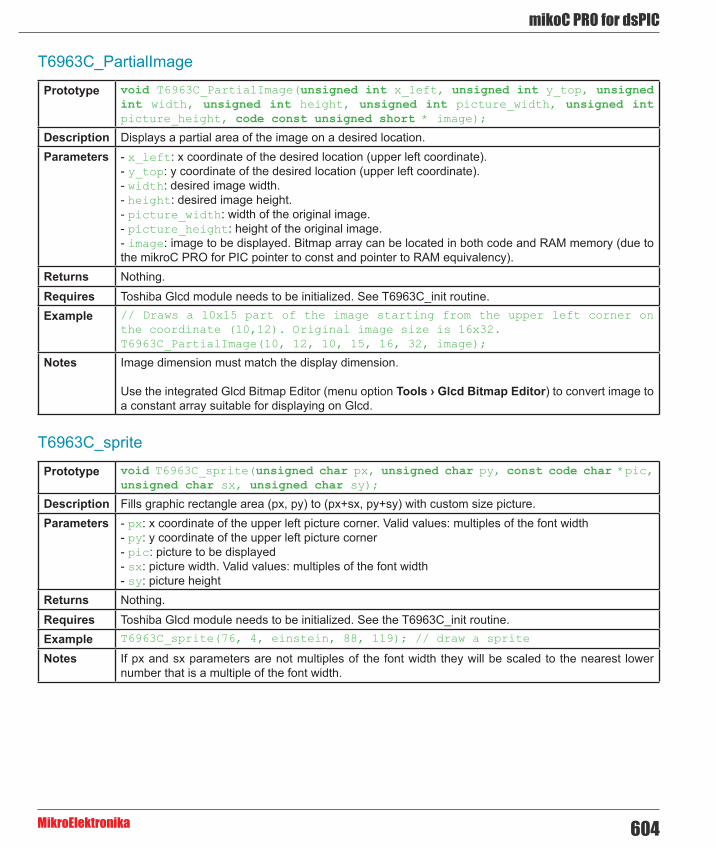
604
mikoC PRO for dsPIC
MikroElektronika
T6963C_PartialImage
T6963C_sprite
Prototype void T6963C_PartialImage(unsigned int x_left, unsigned int y_top, unsigned int width, unsigned int height, unsigned int picture_width, unsigned int picture_height, code const unsigned short * image);
Description Displays a partial area of the image on a desired location.Parameters - x_left: x coordinate of the desired location (upper left coordinate).
- y_top: y coordinate of the desired location (upper left coordinate). - width: desired image width. - height: desired image height. - picture_width: width of the original image. - picture_height: height of the original image. - image: image to be displayed. Bitmap array can be located in both code and RAM memory (due to the mikroC PRO for PIC pointer to const and pointer to RAM equivalency).
Returns Nothing.Requires Toshiba Glcd module needs to be initialized. See T6963C_init routine.Example // Draws a 10x15 part of the image starting from the upper left corner on
the coordinate (10,12). Original image size is 16x32. T6963C_PartialImage(10, 12, 10, 15, 16, 32, image);
Notes Image dimension must match the display dimension.
Use the integrated Glcd Bitmap Editor (menu option Tools › Glcd Bitmap Editor) to convert image to a constant array suitable for displaying on Glcd.
Prototype void T6963C_sprite(unsigned char px, unsigned char py, const code char *pic, unsigned char sx, unsigned char sy);
Description Fills graphic rectangle area (px, py) to (px+sx, py+sy) with custom size picture.Parameters - px: x coordinate of the upper left picture corner. Valid values: multiples of the font width
- py: y coordinate of the upper left picture corner - pic: picture to be displayed - sx: picture width. Valid values: multiples of the font width - sy: picture height
Returns Nothing.Requires Toshiba Glcd module needs to be initialized. See the T6963C_init routine.Example T6963C_sprite(76, 4, einstein, 88, 119); // draw a sprite
Notes If px and sx parameters are not multiples of the font width they will be scaled to the nearest lower number that is a multiple of the font width.

mikroC PRO for dsPIC
MikroElektronika605
T6963C_set_cursor
T6963C_clearBit
T6963C_setBit
Prototype void T6963C_set_cursor(unsigned char x, unsigned char y);
Description Sets cursor to row x and column y.Parameters - x: cursor position row number
- y: cursor position column number Returns Nothing.Requires Toshiba Glcd module needs to be initialized. See the T6963C_init routine.Example T6963C_set_cursor(cposx, cposy);
Notes None.
Prototype void T6963C_clearBit(unsigned int b);
Description Clears control port bit(s).Parameters - b: bit mask. The function will clear bit x on control port if bit x in bit mask is set to 1. Returns Nothing.Requires Toshiba Glcd module needs to be initialized. See the T6963C_init routine.Example // clear bits 0 and 1 on control port
T6963C_clearBit(0x0003);
Notes None.
Prototype void T6963C_setBit(unsigned int b);
Description Sets control port bit(s).Parameters - b: bit mask. The function will set bit x on control port if bit x in bit mask is set to 1. Returns Nothing.Requires Toshiba Glcd module needs to be initialized. See the T6963C_init routine.Example // set bits 0 and 1 on control port
T6963C_setBit(0x0003);
Notes None.

606
mikoC PRO for dsPIC
MikroElektronika
T6963C_negBit
T6963C_displayGrPanel
T6963C_displayTxtPanel
Prototype void T6963C_negBit(unsigned int b);
Description Negates control port bit(s).Parameters - b: bit mask. The function will negate bit x on control port if bit x in bit mask is set to 1. Returns Nothing.Requires Toshiba Glcd module needs to be initialized. See the T6963C_init routine.Example // negate bits 0 and 1 on control port
T6963C_negBit(0x0003);
Notes None.
Prototype void T6963C_displayGrPanel(unsigned int n);
Description Display selected graphic panel.Parameters - n: graphic panel number. Valid values: 0 and 1. Returns Nothing.Requires Toshiba Glcd module needs to be initialized. See the T6963C_init routine.Example // display graphic panel 1
T6963C_displayGrPanel(1);
Notes None.
Prototype void T6963C_displayTxtPanel(unsigned int n);
Description Display selected text panel.Parameters - n: text panel number. Valid values: 0 and 1. Returns Nothing.Requires Toshiba Glcd module needs to be initialized. See the T6963C_init routine.Example // display text panel 1
T6963C_displayTxtPanel(1);
Notes None.

mikroC PRO for dsPIC
MikroElektronika607
T6963C_setGrPanel
T6963C_setTxtPanel
T6963C_panelFill
Prototype void T6963C_setGrPanel(unsigned int n);
Description Compute start address for selected graphic panel and set appropriate internal pointers. All subsequent graphic operations will be preformed at this graphic panel.
Parameters - n: graphic panel number. Valid values: 0 and 1. Returns Nothing.Requires Toshiba Glcd module needs to be initialized. See the T6963C_init routine.Example // set graphic panel 1 as current graphic panel.
T6963C_setGrPanel(1);
Notes None.
Prototype void T6963C_setTxtPanel(unsigned int n);
Description Compute start address for selected text panel and set appropriate internal pointers. All subsequent text operations will be preformed at this text panel.
Parameters - n: text panel number. Valid values: 0 and 1. Returns Nothing.Requires Toshiba Glcd module needs to be initialized. See the T6963C_init routine.Example // set text panel 1 as current text panel.
T6963C_setTxtPanel(1);
Notes None.
Prototype void T6963C_panelFill(unsigned char v);
Description Fill current panel in full (graphic+text) with appropriate value (0 to clear).Parameters - v: value to fill panel with. Returns Nothing.Requires Toshiba Glcd module needs to be initialized. See the T6963C_init routine.Example clear current panel
T6963C_panelFill(0);
Notes None.

608
mikoC PRO for dsPIC
MikroElektronika
T6963C_grFill
T6963C_txtFill
T6963C_cursor_height
Prototype void T6963C_grFill(unsigned char v);
Description Fill current graphic panel with appropriate value (0 to clear).Parameters - v: value to fill graphic panel with. Returns Nothing.Requires Toshiba Glcd module needs to be initialized. See the T6963C_init routine.Example // clear current graphic panel
T6963C_grFill(0);
Notes None.
Prototype void T6963C_txtFill(unsigned char v);
Description Fill current text panel with appropriate value (0 to clear).Parameters - v: this value increased by 32 will be used to fill text panel. Returns Nothing.Requires Toshiba Glcd module needs to be initialized. See the T6963C_init routine.Example // clear current text panel
T6963C_txtFill(0);
Notes None.
Prototype void T6963C_cursor_height(unsigned char n);
Description Set cursor size.Parameters - n: cursor height. Valid values: 0..7. Returns Nothing.Requires Toshiba Glcd module needs to be initialized. See the T6963C_init routine.Example T6963C_cursor_height(7);
Notes None.

mikroC PRO for dsPIC
MikroElektronika609
T6963C_graphics
T6963C_text
T6963C_cursor
Prototype void T6963C_graphics(unsigned int n);
Description Enable/disable graphic displaying.Parameters - n: graphic enable/disable parameter. Valid values: 0 (disable graphic dispaying) and 1 (enable
graphic displaying). Returns Nothing.Requires Toshiba Glcd module needs to be initialized. See the T6963C_init routine.Example // enable graphic displaying
T6963C_graphics(1);
Notes None.
Prototype void T6963C_text(unsigned int n);
Description Enable/disable text displaying.Parameters - n: on/off parameter. Valid values: 0 (disable text displaying) and 1 (enable text displaying). Returns Nothing.Requires Toshiba Glcd module needs to be initialized. See the T6963C_init routine.Example // enable text displaying
T6963C_text(1);
Notes None.
Prototype void T6963C_cursor(unsigned int n);
Description Set cursor on/off.Parameters - n: on/off parameter. Valid values: 0 (set cursor off) and 1 (set cursor on). Returns Nothing.Requires Toshiba Glcd module needs to be initialized. See the T6963C_init routine.Example // set cursor on
T6963C_cursor(1);
Notes None.

610
mikoC PRO for dsPIC
MikroElektronika
T6963C_cursor_blink
Prototype void T6963C_cursor_blink(unsigned int n);
Description Enable/disable cursor blinking.Parameters - n: cursor blinking enable/disable parameter. Valid values: 0 (disable cursor blinking) and 1 (enable
cursor blinking). Returns Nothing.Requires Toshiba Glcd module needs to be initialized. See the T6963C_init routine.Example // enable cursor blinking
T6963C_cursor_blink(1);
Notes None.
Library Example
The following drawing demo tests advanced routines of the T6963C Glcd library. Hardware configurations in this example are made for the dsPICPRO2 board and dsPIC30F6014A.
Copy Code To Clipboard
#include "__T6963C.h"
// T6963C module connectionschar T6963C_dataPort at PORTB; // DATA port
sbit T6963C_ctrlwr at LATF2_bit; // WR write signalsbit T6963C_ctrlrd at LATF1_bit; // RD read signalsbit T6963C_ctrlcd at LATF0_bit; // CD command/data signalsbit T6963C_ctrlrst at LATF4_bit; // RST reset signalsbit T6963C_ctrlwr_Direction at TRISF2_bit; // WR write signalsbit T6963C_ctrlrd_Direction at TRISF1_bit; // RD read signalsbit T6963C_ctrlcd_Direction at TRISF0_bit; // CD command/data signalsbit T6963C_ctrlrst_Direction at TRISF4_bit; // RST reset signal
// Signals not used by library, they are set in main functionsbit T6963C_ctrlce at LATF3_bit; // CE signalsbit T6963C_ctrlfs at LATF6_bit; // FS signalsbit T6963C_ctrlmd at LATF5_bit; // MD signalsbit T6963C_ctrlce_Direction at TRISF3_bit; // CE signal directionsbit T6963C_ctrlfs_Direction at TRISF6_bit; // FS signal directionsbit T6963C_ctrlmd_Direction at TRISF5_bit; // MD signal direction
// End T6963C module connections
/* * bitmap pictures stored in ROM */const code char mikroE_240x128_bmp[];const code char einstein[];

mikroC PRO for dsPIC
MikroElektronika611
void main() { char txt1[] = " EINSTEIN WOULD HAVE LIKED mE"; char txt[] = " GLCD LIBRARY DEMO, WELCOME !";
unsigned char panel; // Current panel unsigned int i; // General purpose register unsigned char curs; // Cursor visibility unsigned int cposx, cposy; // Cursor x-y position
#define COMPLETE_EXAMPLE // comment this line to make simpler/smaller example
ADPCFG = 0xFFFF; // Configure AN pins as digital
TRISB8_bit = 1; // Set RF0 as input TRISB9_bit = 1; // Set RF1 as input TRISB10_bit = 1; // Set RF2 as input TRISB11_bit = 1; // Set RF3 as input TRISB12_bit = 1; // Set RF4 as input
T6963C_ctrlce_Direction = 0; T6963C_ctrlce = 0; // Enable T6963C T6963C_ctrlfs_Direction = 0; T6963C_ctrlfs = 0; // Font Select 8x8 T6963C_ctrlmd_Direction = 0; T6963C_ctrlmd = 0; // Column number select
// Initialize T6963C T6963C_init(240, 128, 8);
/* * Enable both graphics and text display at the same time */ T6963C_graphics(1); T6963C_text(1);
panel = 0; i = 0; curs = 0; cposx = cposy = 0; /* * Text messages */ T6963C_write_text(txt, 0, 0, T6963C_ROM_MODE_XOR); T6963C_write_text(txt1, 0, 15, T6963C_ROM_MODE_XOR);
/* * Cursor */ T6963C_cursor_height(8); // 8 pixel height T6963C_set_cursor(0, 0); // Move cursor to top left T6963C_cursor(0); // Cursor off
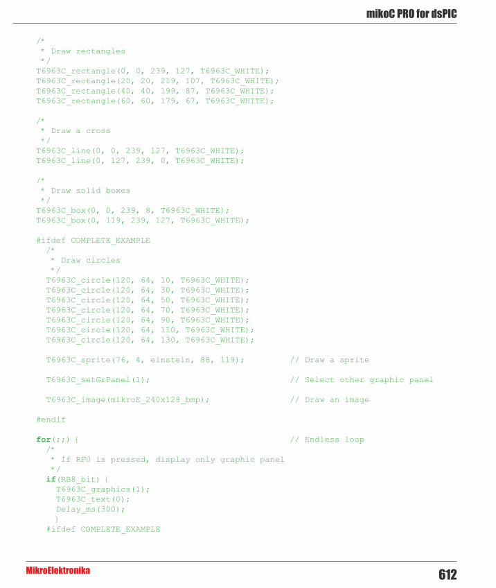
612
mikoC PRO for dsPIC
MikroElektronika
/* * Draw rectangles */ T6963C_rectangle(0, 0, 239, 127, T6963C_WHITE); T6963C_rectangle(20, 20, 219, 107, T6963C_WHITE); T6963C_rectangle(40, 40, 199, 87, T6963C_WHITE); T6963C_rectangle(60, 60, 179, 67, T6963C_WHITE);
/* * Draw a cross */ T6963C_line(0, 0, 239, 127, T6963C_WHITE); T6963C_line(0, 127, 239, 0, T6963C_WHITE);
/* * Draw solid boxes */ T6963C_box(0, 0, 239, 8, T6963C_WHITE); T6963C_box(0, 119, 239, 127, T6963C_WHITE);
#ifdef COMPLETE_EXAMPLE /* * Draw circles */ T6963C_circle(120, 64, 10, T6963C_WHITE); T6963C_circle(120, 64, 30, T6963C_WHITE); T6963C_circle(120, 64, 50, T6963C_WHITE); T6963C_circle(120, 64, 70, T6963C_WHITE); T6963C_circle(120, 64, 90, T6963C_WHITE); T6963C_circle(120, 64, 110, T6963C_WHITE); T6963C_circle(120, 64, 130, T6963C_WHITE);
T6963C_sprite(76, 4, einstein, 88, 119); // Draw a sprite
T6963C_setGrPanel(1); // Select other graphic panel
T6963C_image(mikroE_240x128_bmp); // Draw an image
#endif
for(;;) { // Endless loop /* * If RF0 is pressed, display only graphic panel */ if(RB8_bit) { T6963C_graphics(1); T6963C_text(0); Delay_ms(300); } #ifdef COMPLETE_EXAMPLE
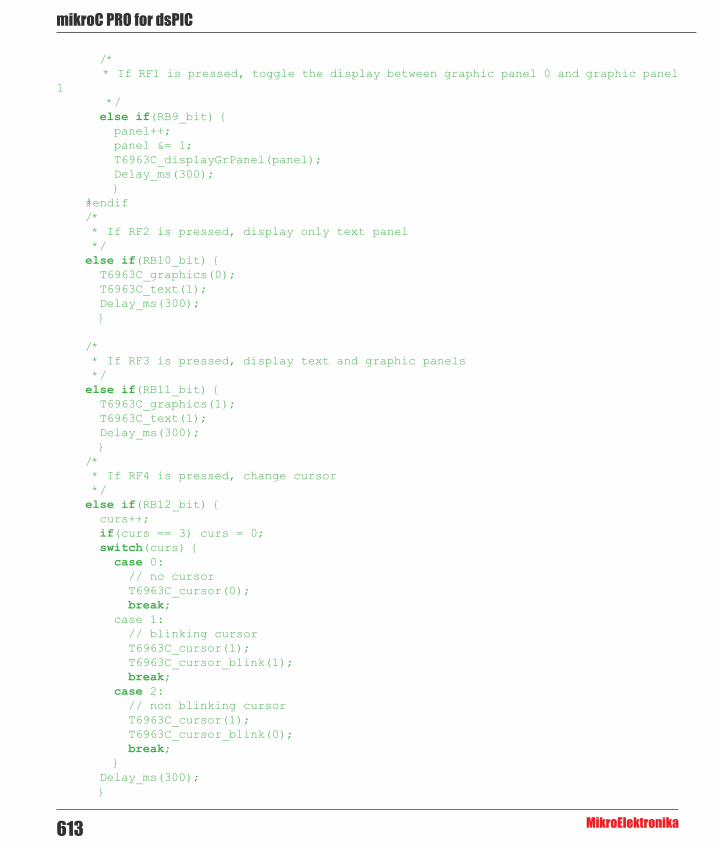
mikroC PRO for dsPIC
MikroElektronika613
/* * If RF1 is pressed, toggle the display between graphic panel 0 and graphic panel 1 */ else if(RB9_bit) { panel++; panel &= 1; T6963C_displayGrPanel(panel); Delay_ms(300); } #endif /* * If RF2 is pressed, display only text panel */ else if(RB10_bit) { T6963C_graphics(0); T6963C_text(1); Delay_ms(300); }
/* * If RF3 is pressed, display text and graphic panels */ else if(RB11_bit) { T6963C_graphics(1); T6963C_text(1); Delay_ms(300); } /* * If RF4 is pressed, change cursor */ else if(RB12_bit) { curs++; if(curs == 3) curs = 0; switch(curs) { case 0: // no cursor T6963C_cursor(0); break; case 1: // blinking cursor T6963C_cursor(1); T6963C_cursor_blink(1); break; case 2: // non blinking cursor T6963C_cursor(1); T6963C_cursor_blink(0); break; } Delay_ms(300); }

614
mikoC PRO for dsPIC
MikroElektronika
/* * Move cursor, even if not visible */ cposx++; if(cposx == T6963C_txtCols) { cposx = 0; cposy++; if(cposy == T6963C_grHeight / T6963C_CHARACTER_HEIGHT) { cposy = 0; } } T6963C_set_cursor(cposx, cposy);
Delay_ms(100); }}
HW Connection
T6963C Glcd HW connection

mikroC PRO for dsPIC
MikroElektronika615
TFT LibraryThin film transistor liquid crystal display (TFT-LCD) is a variant of liquid crystal display (LCD) which uses thin-film transistor (TFT) technology to improve image quality (e.g., addressability, contrast). TFT LCD is one type of active matrix LCD, though all LCD-screens are based on TFT active matrix addressing. TFT LCDs are used in television sets, computer monitors, mobile phones, handheld video game systems, personal digital assistants, navigation systems, projectors, etc.
The mikroC PRO for dsPIC30/33 and PIC24 provides a library for working with HX8347-D 320x240 TFT Lcd controller.The HX8347-D is designed to provide a single-chip solution that combines a gate driver, a source driver, power supply circuit for 262,144 colors to drive a TFT panel with 320x240 dots at maximum.
The HX8347-D is suitable for any small portable battery-driven and long-term driving products, such as small PDAs, digital cellular phones and bi-directional pagers.
The following variables must be defined in all projects using TFT library:
Description : Example :
extern sfr char TFT_DataPort; TFT Data Port. char TFT_DataPort at
LATE;
extern sfr char TFT_DataPort_Direction;
Direction of the TFT Data Port.
char TFT_DataPort_Direction at TRISE;
extern sfr sbit TFT_WR; Write signal. sbit TFT_WR at LATD13_
bit;
extern sfr sbit TFT_RD; Read signal. sbit TFT_RD at LATD12_
bit;
extern sfr sbit TFT_CS; Chip Select signal. sbit TFT_CS at LATC3_
bit;
extern sfr sbit TFT_RS;
Command/Register Select signal.
sbit TFT_RS at LATB15_bit;
extern sfr sbit TFT_RST; Reset signal. sbit TFT_RST at LATC1_
bit;
extern sfr sbit TFT_WR_Direction; Direction of the Write pin. sbit TFT_WR_Direction
at TRISD13_bit;
extern sfr sbit TFT_RD_Direction; Direction of the Read pin. sbit TFT_RD_Direction
at TRISD12_bit;
extern sfr sbit TFT_CS_Direction;
Direction of the Chip Select pin.
sbit TFT_CS_Direction at TRISC3_bit;
extern sfr sbit TFT_RS_Direction;
Direction of the Register Select pin.
sbit TFT_RS_Direction at TRISB13_bit;
extern sfr sbit TFT_RST_Direction; Direction of the Reset pin. sbit TFT_RST_Direction
at TRISC1_bit;
External dependencies of TFT Library

616
mikoC PRO for dsPIC
MikroElektronika
Library Routines
- TFT_Init - TFT_Set_Index - TFT_Write_Command - TFT_Write_Data - TFT_Set_Active - TFT_Set_Font - TFT_Write_Char - TFT_Write_Text - TFT_Fill_Screen - TFT_Set_Pen - TFT_Set_Brush - TFT_Dot - TFT_Line - TFT_H_Line - TFT_V_Line - TFT_Rectangle - TFT_Rectangle_Round_Edges - TFT_Circle - TFT_Image - TFT_PartialImage - TFT_Image_Jpeg - TFT_RGBToColor16bit - TFT_Color16bitToRGB

mikroC PRO for dsPIC
MikroElektronika617
TFT_Init
Prototype void TFT_Init(unsigned int display_width, unsigned char display_height);
Returns NothingDescription Initializes TFT display in the 8-bit working mode.
Parameters :
- width: width of the TFT panel - height: height of the TFT panel
Requires Global variables :
- TFT_DataPort: Data Port - TFT_WR: Write signal pin - TFT_RD: Read signal pin - TFT_CS: Chip Select signal pin - TFT_RS: Register Select signal pin - TFT_RST: Reset signal pin - TFT_DataPort_Direction: Direction of Data Port - TFT_WR_Direction: Direction of Write signal pin - TFT_RD_Direction: Direction of Read signal pin - TFT_CS_Direction: Direction of Chip Select signal pin - TFT_RS_Direction: Direction of Register Select signal pin - TFT_RST_Direction: Direction of Reset signal pin
must be defined before using this function.Example // TFT display connections
char TFT_DataPort at LATE;sbit TFT_WR at LATD13_bit;sbit TFT_RD at LATD12_bit;sbit TFT_CS at LATC3_bit;sbit TFT_RS at LATB15_bit;sbit TFT_RST at LATC1_bit;
char TFT_DataPort_Direction at TRISE;sbit TFT_WR_Direction : at TRISD13_bit;sbit TFT_RD_Direction at TRISD12_bit;sbit TFT_CS_Direction at TRISC3_bit;sbit TFT_RS_Direction at TRISB15_bit;sbit TFT_RST_Direction at TRISC1_bit;// End of TFT display connections
// Initialize 240x320 TFT displayTFT_Init(240, 320);

618
mikoC PRO for dsPIC
MikroElektronika
TFT_Set_Index
TFT_Write_Command
TFT_Write_Data
Prototype void TFT_Set_Index(unsigned short index);
Returns NothingDescription Accesses register space of the controller and sets the desired register.
Parameters :
- index: desired register number. Requires TFT module needs to be initialized. See the TFT_Init routine.Example // Access register at the location 0x02
TFT_Set_Index(0x02);
Prototype void TFT_Write_Command(unsigned short cmd);
Returns NothingDescription Accesses data space and writes a command.
Parameters :
- cmd: command to be written. Requires TFT module needs to be initialized. See the TFT_Init routine.Example // Write a command
TFT_Write_Command(0x02);
Prototype void TFT_Write_Data(unsigned int _data);
Returns NothingDescription Writes date into display memory.
Parameters :
- _data:data to be written. Requires TFT module needs to be initialized. See the TFT_Init routine.Example // Send data
TFT_Write_Data(0x02);

mikroC PRO for dsPIC
MikroElektronika619
TFT_Set_Active
Prototype void TFT_Set_Active(void (*Set_Index_Ptr)(unsigned short), void (*Write_Command_Ptr)(unsigned short), void (*Write_Data_Ptr)(unsigned int));
Returns NothingDescription This function sets appropriate pointers to a user-defined basic routines in order to enable multiple
working modes.
Parameters :
- Set_Index_Ptr: Set_Index handler. - Write_Command_Ptr: _Write_Command handler. - Write_Data_Ptr: Write_Data handler.
Requires None.Example // Example of establishing 16-bit communication between TFT display and
PORTD, PORTE of MCU :
void Set_Index(unsigned short index) { TFT_RS = 0; Lo(LATD) = index; TFT_WR = 0; TFT_WR = 1;}
void Write_Command(unsigned short cmd) { TFT_RS = 1; Lo(LATD) = cmd; TFT_WR = 0; TFT_WR = 1;}
void Write_Data(unsigned int _data) { TFT_RS = 1; Lo(LATE) = Hi(_data); Lo(LATD) = Lo(_data); TFT_WR = 0; TFT_WR = 1;}
void main(){ TRISE = 0; TRISD = 0;
TFT_Set_Active(Set_Index,Write_Command,Write_Data); TFT_Init(320, 240);
.....}

620
mikoC PRO for dsPIC
MikroElektronika
TFT_Set_Font
Prototype void TFT_Set_Font(const char far *activeFont, unsigned int font_color, char font_orientation);
Returns NothingDescription Sets font, its color and font orientation.
Parameters :
- activeFont: desired font. Currently, only TFT_defaultFont (Tahoma14x16) is supported. - font_color: sets font color :
- font_orientation: sets font orientation :
Requires TFT module needs to be initialized. See the TFT_Init routine.Example TFT_Set_Font(TFT_defaultFont, CL_BLACK, FO_HORIZONTAL);
Value DescriptionCL_AQUA Aqua colorCL_BLACK Black colorCL_BLUE Blue colorCL_FUCHSIA Fuchsia colorCL_GRAY Gray colorCL_GREEN Green colorCL_LIME Lime colorCL_MAROON Maroon colorCL_NAVY Navy colorCL_OLIVE Olive colorCL_PURPLE Purple colorCL_RED Red colorCL_SILVER Silver colorCL_TEAL Teal colorCL_WHITE White colorCL_YELLOW Yellow color
Value DescriptionFO_HORIZONTAL Horizontal orientationFO_VERTICAL Vertical orientation

mikroC PRO for dsPIC
MikroElektronika621
TFT_Write_Char
TFT_Write_Text
Prototype void TFT_Write_Char(unsigned int c, unsigned int x, unsigned int y);
Returns Nothing.Description Writes a char on the TFT at coordinates (x, y).
- c: char to be written. - x: char position on x-axis. - y: char position on y-axis.
Requires TFT module needs to be initialized. See the TFT_Init routine.Example TFT_Write_Char(‘A’,22,23,);
Prototype void TFT_Write_Text(unsigned char *text, unsigned int x, unsigned int y);
Returns Nothing.Description Writes text on the TFT at coordinates (x, y).
Parameters :
- text: text to be written. - x: text position on x-axis. - y: text position on y-axis.
Requires TFT module needs to be initialized. See the TFT_Init routine.Example TFT_Write_Text(“TFT LIBRARY DEMO, WELCOME !”, 0, 0,);

622
mikoC PRO for dsPIC
MikroElektronika
TFT_Fill_Screen
Prototype void TFT_Fill_Screen(unsigned int color);
Returns Nothing.Description Fills screen memory block with given color.
Parameters :
- color: color to be filled :
Requires TFT module needs to be initialized. See the TFT_Init routine.Example TFT_Fill_Screen(CL_BLACK);
Value DescriptionCL_AQUA Aqua colorCL_BLACK Black colorCL_BLUE Blue colorCL_FUCHSIA Fuchsia colorCL_GRAY Gray colorCL_GREEN Green colorCL_LIME Lime colorCL_MAROON Maroon colorCL_NAVY Navy colorCL_OLIVE Olive colorCL_PURPLE Purple colorCL_RED Red colorCL_SILVER Silver colorCL_TEAL Teal colorCL_WHITE White colorCL_YELLOW Yellow color

mikroC PRO for dsPIC
MikroElektronika623
TFT_Dot
Prototype void TFT_Dot(int x, int y, unsigned int color);
Returns Nothing.Description Draws a dot on the TFT at coordinates (x, y).
Parameters :
- x: dot position on x-axis. - y: dot position on y-axis. - color: color parameter. Valid values :
Requires TFT module needs to be initialized. See the TFT_Init routine.Example TFT_Dot(50, 50, CL_BLACK);
Value DescriptionCL_AQUA Aqua colorCL_BLACK Black colorCL_BLUE Blue colorCL_FUCHSIA Fuchsia colorCL_GRAY Gray colorCL_GREEN Green colorCL_LIME Lime colorCL_MAROON Maroon colorCL_NAVY Navy colorCL_OLIVE Olive colorCL_PURPLE Purple colorCL_RED Red colorCL_SILVER Silver colorCL_TEAL Teal colorCL_WHITE White colorCL_YELLOW Yellow color

624
mikoC PRO for dsPIC
MikroElektronika
TFT_Set_Pen
Prototype void TFT_Set_Pen(unsigned int pen_color, char pen_width);
Returns Nothing.Description Sets color and thickness parameter for drawing line, circle and rectangle elements.
Parameters :
- pen_color: Sets color.
- pen_width: sets thickness.
Requires TFT module needs to be initialized. See the TFT_Init routine.Example TFT_Set_Pen(CL_BLACK, 10);
Value DescriptionCL_AQUA Aqua colorCL_BLACK Black colorCL_BLUE Blue colorCL_FUCHSIA Fuchsia colorCL_GRAY Gray colorCL_GREEN Green colorCL_LIME Lime colorCL_MAROON Maroon colorCL_NAVY Navy colorCL_OLIVE Olive colorCL_PURPLE Purple colorCL_RED Red colorCL_SILVER Silver colorCL_TEAL Teal colorCL_WHITE White colorCL_YELLOW Yellow color

mikroC PRO for dsPIC
MikroElektronika625
TFT_Set_Brush
Prototype void TFT_Set_Brush(char brush_enabled, unsigned int brush_color, char gradient_enabled, char gradient_orientation, unsigned int gradient_color_from, unsigned int gradient_color_to);
Returns Nothing.Description Sets color and gradient which will be used to fill circles or rectangles.
Parameters :
- brush_enabled: enable brush fill.
- brush_color: set brush fill color.
Value DescriptionCL_AQUA Aqua colorCL_BLACK Black colorCL_BLUE Blue colorCL_FUCHSIA Fuchsia colorCL_GRAY Gray colorCL_GREEN Green colorCL_LIME Lime colorCL_MAROON Maroon colorCL_NAVY Navy colorCL_OLIVE Olive colorCL_PURPLE Purple colorCL_RED Red colorCL_SILVER Silver colorCL_TEAL Teal colorCL_WHITE White colorCL_YELLOW Yellow color
Value Description1 Enable brush fill.0 Disable brush fill.
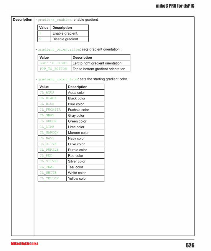
626
mikoC PRO for dsPIC
MikroElektronika
Description - gradient_enabled: enable gradient
- gradient_orientation: sets gradient orientation :
- gradient_color_from: sets the starting gradient color.
Value DescriptionCL_AQUA Aqua colorCL_BLACK Black colorCL_BLUE Blue colorCL_FUCHSIA Fuchsia colorCL_GRAY Gray colorCL_GREEN Green colorCL_LIME Lime colorCL_MAROON Maroon colorCL_NAVY Navy colorCL_OLIVE Olive colorCL_PURPLE Purple colorCL_RED Red colorCL_SILVER Silver colorCL_TEAL Teal colorCL_WHITE White colorCL_YELLOW Yellow color
Value Description1 Enable gradient.0 Disable gradient.
Value DescriptionLEFT_TO_RIGHT Left to right gradient orientationTOP_TO_BOTTOM Top to bottom gradient orientation
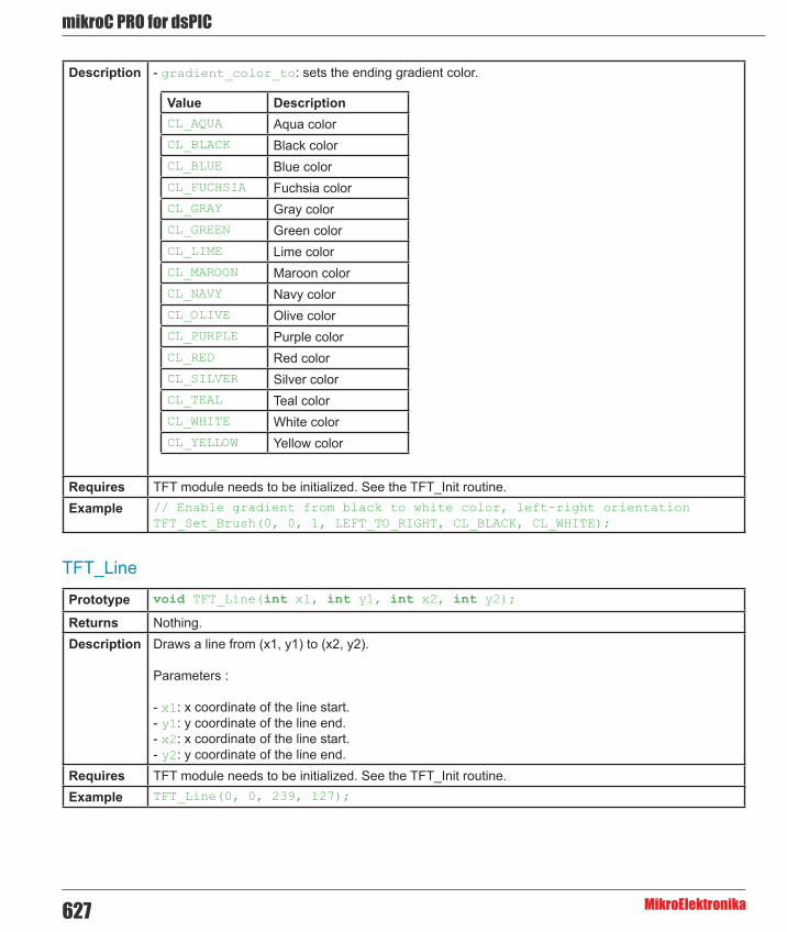
mikroC PRO for dsPIC
MikroElektronika627
Description - gradient_color_to: sets the ending gradient color.
Requires TFT module needs to be initialized. See the TFT_Init routine.Example // Enable gradient from black to white color, left-right orientation
TFT_Set_Brush(0, 0, 1, LEFT_TO_RIGHT, CL_BLACK, CL_WHITE);
Value DescriptionCL_AQUA Aqua colorCL_BLACK Black colorCL_BLUE Blue colorCL_FUCHSIA Fuchsia colorCL_GRAY Gray colorCL_GREEN Green colorCL_LIME Lime colorCL_MAROON Maroon colorCL_NAVY Navy colorCL_OLIVE Olive colorCL_PURPLE Purple colorCL_RED Red colorCL_SILVER Silver colorCL_TEAL Teal colorCL_WHITE White colorCL_YELLOW Yellow color
TFT_Line
Prototype void TFT_Line(int x1, int y1, int x2, int y2);
Returns Nothing.Description Draws a line from (x1, y1) to (x2, y2).
Parameters :
- x1: x coordinate of the line start. - y1: y coordinate of the line end. - x2: x coordinate of the line start. - y2: y coordinate of the line end.
Requires TFT module needs to be initialized. See the TFT_Init routine.Example TFT_Line(0, 0, 239, 127);

628
mikoC PRO for dsPIC
MikroElektronika
TFT_H_Line
TFT_V_Line
Prototype void TFT_H_Line(int x_start, int x_end, int y_pos);
Returns Nothing.Description Draws a horizontal line on TFT.
Parameters :
- x_start: x coordinate of the line start. - x_end: x coordinate of the line end. - y_pos: y coordinate of horizontal line.
Requires TFT module needs to be initialized. See the TFT_Init routine.Example // Draw a horizontal line between dots (10,20) and (50,20)
TFT_H_Line(10, 50, 20);
Prototype void TFT_V_Line(int y_start, int y_end, int x_pos);
Returns Nothing.Description Draws a vertical line on TFT.
Parameters :
- y_start: y coordinate of the line start. - y_end: y coordinate of the line end. - x_pos: x coordinate of vertical line.
Requires TFT module needs to be initialized. See the TFT_Init routine.Example // Draw a vertical line between dots (10,5) and (10,25)
TFT_V_Line(5, 25, 10);

mikroC PRO for dsPIC
MikroElektronika629
TFT_Rectangle_Round_Edges
TFT_Circle
TFT_Image
Prototype void TFT_Rectangle_Round_Edges(unsigned int x_upper_left, unsigned int y_upper_left, unsigned int x_bottom_right, unsigned int y_bottom_right, unsigned int round_radius);
Returns Nothing.Description Draws a rounded edge rectangle on TFT.
Parameters :
- x_upper_left: x coordinate of the upper left rectangle corner. - y_upper_left: y coordinate of the upper left rectangle corner. - x_bottom_right: x coordinate of the lower right rectangle corner. - y_bottom_right: y coordinate of the lower right rectangle corner. - round_radius: radius of the rounded edge.
Requires TFT module needs to be initialized. See the TFT_Init routine.Example TFT_Rectangle_Round_Edges(20, 20, 219, 107, 12);
Prototype void TFT_Circle(int x_center, int y_center, int radius);
Returns Nothing.Description Draws a circle on TFT.
Parameters :
- x: x coordinate of the circle center. - y: y coordinate of the circle center. - r: radius size.
Requires TFT module needs to be initialized. See the TFT_Init routine.Example TFT_Circle(120, 64, 110);
Prototype void TFT_Image(unsigned int left, unsigned int top, code const far unsigned short * image, unsigned short stretch);
Returns Nothing.Description Displays an image on a desired location.
Parameters :
- left: position of the image’s left edge. - top:position of the image’s top edge. - image: image to be displayed. Bitmap array is located in code memory. - stretch: stretches image by a given factor (if 2, it will double the image.).
Requires TFT module needs to be initialized. See the TFT_Init routine.Example TFT_Image(0, 0, image, 1);

630
mikoC PRO for dsPIC
MikroElektronika
TFT_Partial_Image
TFT_Image_Jpeg
Prototype void TFT_Partial_Image(unsigned int left, unsigned int top, unsigned int width, unsigned int height, code const far unsigned short * image, unsigned short stretch);
Returns Nothing.Description Displays a partial area of the image on a desired location.
Parameters :
- left: left coordinate of the image. - top: top coordinate of the image. - width: desired image width. - height: desired image height. - image: image to be displayed. Bitmap array is located in code memory. - stretch: stretches image by a given factor (if 2, it will double the image.).
Requires TFT module needs to be initialized. See the TFT_Init routine.Example // Draws a 10x15 part of the image starting from the upper left corner on
the coordinate (10,12) TFT_PartialImage(10, 12, 10, 15, image, 1);
Prototype char TFT_Image_Jpeg(unsigned int left, unsigned int top, code const far unsigned short *image);
Returns - 0 - if image is loaded and displayed successfully. - 1 - if error occured.
Description Displays a JPEG image on a desired location.
Parameters :
- left: left coordinate of the image. - top: top coordinate of the image. - image: image to be displayed. Bitmap array is located in code memory.
Requires TFT module needs to be initialized. See the TFT_Init routine.Example TFT_Image_Jpeg(0, 0, image);

mikroC PRO for dsPIC
MikroElektronika631
TFT_RGBToColor16bit
TFT_Color16bitToRGB
Prototype unsigned int TFT_RGBToColor16bit(char rgb_red, char rgb_green, char rgb_blue);
Returns Returns a color value in the following bit-order : 5 bits red, 6 bits green and 5 bits blue color.Description Converts 5:6:5 RGB format into true color format.
Parameters :
- rgb_red: red component of the image. - rgb_green: green component of the image. - rgb_blue: blue component of the image.
Requires TFT module needs to be initialized. See the TFT_Init routine.Example color16 = TFT_Image_Jpeg(150, 193, 65);
Prototype void TFT_Color16bitToRGB(unsigned int color, char *rgb_red, char *rgb_green, char *rgb_blue);
Returns Nothing.Description Converts true color into 5:6:5 RGB format.
Parameters :
- color: true color to be converted. - rgb_red: red component of the input color. - rgb_green: green component of the input color. - rgb_blue: blue component of the input color.
Requires TFT module needs to be initialized. See the TFT_Init routine.Example TFT_Color16bitToRGB(start_color, &red_start, &green_start, &blue_start);

632
mikoC PRO for dsPIC
MikroElektronika
HW Connection
TFT HW connection

mikroC PRO for dsPIC
MikroElektronika633
Touch Panel LibraryThe mikroC PRO for dsPIC30/33 and PIC24 provides a library for working with Touch Panel.
Library Dependency Tree
External dependencies of Touch Panel Library
The following variables must be defined in all projects using Touch Panel Library:
Description: Example:
extern sfr sbit DriveA; DriveA line. sbit DriveA at LATC13_bit;
extern sfr sbit DriveB; DriveB line. sbit DriveB at LATC14_bit;
extern sfr sbit DriveA_Direction; Direction of the DriveA pin. sbit DriveA_Direction at TRISC13_bit;
extern sfr sbit DriveB_Direction; Direction of the DriveB pin. sbit DriveB_Direction at TRISC14_bit;
Library Routines
- TP_Init - TP_Set_ADC_Threshold - TP_Press_Detect - TP_Get_Coordinates - TP_Calibrate_Bottom_Left - TP_Calibrate_Upper_Right - TP_Get_Calibration_Consts - TP_Set_Calibration_Consts

634
mikoC PRO for dsPIC
MikroElektronika
TP_Init
Prototype void TP_Init(unsigned int display_width, unsigned int display_height, unsigned int readX_ChNo, unsigned int readY_ChNo);
Description Initialize touch panel display. Default touch panel ADC threshold value is set to 3900.
Parameters- display_width: set display width. - display_height: set display height. - readX_ChNo: read X coordinate from desired ADC channel. - readY_ChNo: read Y coordinate from desired ADC channel.
Returns Nothing.
Requires Before calling this function initialize ADC module.
Example ADC1_Init(); // Initalize ADC moduleTP_Init(128, 64, 6, 7); // Initialize touch panel, dimensions 128x64
Notes None.
TP_Set_ADC_Threshold
Prototype void TP_Set_ADC_Threshold(unsigned int threshold);
Description Set custom ADC threshold value, call this function after TP_Init.
Parameters- threshold: custom ADC threshold value.
Returns Nothing.
Requires TP_Init has to be called before using this routine.
Example TP_Set_ADC_Threshold(3900); // Set touch panel ADC threshold
Notes None.

mikroC PRO for dsPIC
MikroElektronika635
TP_Press_Detect
Prototype char TP_Press_Detect();
Description Detects if the touch panel has been pressed.
Parameters None.
Returns - 1 - if touch panel is pressed. - 0 - otherwise.
Requires Global variables:
- DriveA: DriveA. - DriveB: DriveB. - DriveA_Direction: Direction of DriveA pin. - DriveB_Direction: Direction of DriveB pin.
must be defined before using this function.
Example // Touch Panel module connectionssbit DriveA at LATC13_bit;sbit DriveB at LATC14_bit;sbit DriveA_Direction at TRISC13_bit;sbit DriveB_Direction at TRISC14_bit;// End Touch Panel module connections
if (TP_Press_Detect()) { ...}
Notes None.

636
mikoC PRO for dsPIC
MikroElektronika
TP_Get_Coordinates
Prototype char TP_Get_Coordinates(unsigned int *x_coordinate, unsigned int *y_coordinate);
Description Get touch panel coordinates and store them in x_coordinate and y_coordinate parameters.
Parameters- x_coordinate: x coordinate of the place of touch. - y_coordinate: y coordinate of the place of touch.
Returns - 1 - if reading is within display dimension range. - 0 - if reading is out of display dimension range.
Requires Nothing.
Example if (TP_Get_Coordinates(&x_coord, &y_coord) == 0) { ...}
Notes None.
TP_Calibrate_Bottom_Left
Prototype void TP_Calibrate_Bottom_Left();
Description Calibrate bottom left corner of the touch Panel.
Parameters None.
Returns Nothing.
Requires Nothing.
Example TP_Calibrate_Bottom_Left(); // Calibration of bottom left corner
Notes None.

mikroC PRO for dsPIC
MikroElektronika637
TP_Calibrate_Upper_Right
Prototype void TP_Calibrate_Upper_Right();
Description Calibrate upper right corner of the touch panel.
Parameters None.
Returns Nothing.
Requires Nothing.
Example TP_Calibrate_Upper_Right(); // Calibration of upper right corner
Notes None.
TP_Get_Calibration_Consts
Prototype void TP_Get_Calibration_Consts(unsigned int *x_min, unsigned int *x_max, unsigned int *y_min, unsigned int *y_max);
Description Gets calibration constants after calibration is done and stores them in x_min, x_max, y_min and y_max parameters.
Parameters- x_min: x coordinate of the bottom left corner of the working area. - x_max: x coordinate of the upper right corner of the working area. - y_min: y coordinate of the bottom left corner of the working area. - y_max: y coordinate of the upper right corner of the working area.
Returns Nothing.
Requires Nothing.
Example TP_Get_Calibration_Consts(&x_min, &y_min, &x_max, &y_max); // Get calibration constants
Notes None.

638
mikoC PRO for dsPIC
MikroElektronika
TP_Set_Calibration_Consts
Prototype void TP_Set_Calibration_Consts(unsigned int x_min, unsigned int x_max, unsigned int y_min, unsigned int y_max);
Description Sets calibration constants.
Parameters- x_min: x coordinate of the bottom left corner of the working area. - x_max: x coordinate of the upper right corner of the working area. - y_min: y coordinate of the bottom left corner of the working area. - y_max: y coordinate of the upper right corner of the working area.
Returns Nothing.
Requires Nothing.
Example TP_Set_Calibration_Consts(148, 3590, 519, 3370); // Set calibration constants
Notes None.
Library Example
The following drawing demo tests routines of the Touch Panel library:
Copy Code To Clipboard
// Glcd module connectionssbit GLCD_D7 at RD3_bit;sbit GLCD_D6 at RD2_bit;sbit GLCD_D5 at RD1_bit;sbit GLCD_D4 at RD0_bit;sbit GLCD_D3 at RB3_bit;sbit GLCD_D2 at RB2_bit;sbit GLCD_D1 at RB1_bit;sbit GLCD_D0 at RB0_bit;sbit GLCD_D7_Direction at TRISD3_bit;sbit GLCD_D6_Direction at TRISD2_bit;sbit GLCD_D5_Direction at TRISD1_bit;sbit GLCD_D4_Direction at TRISD0_bit;sbit GLCD_D3_Direction at TRISB3_bit;sbit GLCD_D2_Direction at TRISB2_bit;sbit GLCD_D1_Direction at TRISB1_bit;sbit GLCD_D0_Direction at TRISB0_bit;

mikroC PRO for dsPIC
MikroElektronika639
sbit GLCD_CS1 at LATB4_bit;sbit GLCD_CS2 at LATB5_bit;sbit GLCD_RS at LATF0_bit;sbit GLCD_RW at LATF1_bit;sbit GLCD_EN at LATF4_bit;sbit GLCD_RST at LATF5_bit;sbit GLCD_CS1_Direction at TRISB4_bit;sbit GLCD_CS2_Direction at TRISB5_bit;sbit GLCD_RS_Direction at TRISF0_bit;sbit GLCD_RW_Direction at TRISF1_bit;sbit GLCD_EN_Direction at TRISF4_bit;sbit GLCD_RST_Direction at TRISF5_bit;// End Glcd module connections
// Touch Panel module connectionssbit DriveA at LATC13_bit;sbit DriveB at LATC14_bit;sbit DriveA_Direction at TRISC13_bit;sbit DriveB_Direction at TRISC14_bit;// End Touch Panel module connections
bit write_erase;char pen_size;char write_msg[] = “WRITE”; // GLCD menu messageschar clear_msg[] = “CLEAR”;char erase_msg[] = “ERASE”;unsigned int x_coord, y_coord;
void Initialize() { ADPCFG = 0xFF3F; // set AN6 and AN7 channel pins as analog
DriveA_Direction = 0; // Set DriveA pin as output DriveB_Direction = 0; // Set DriveB pin as output
Glcd_Init(); // Initialize GLCD Glcd_Fill(0); // Clear GLCD
ADC1_Init(); // Initalize ADC module TP_Init(128, 64, 6, 7); // Initialize touch panel TP_Set_ADC_Threshold(3900); // Set touch panel ADC threshold}
void Calibrate() {
Glcd_Dot(0,63,1); // Draw bottom left dot Glcd_Write_Text(“TOUCH BOTTOM LEFT”,12,3,1); TP_Calibrate_Bottom_Left(); // Calibration of bottom left corner Delay_ms(1000);

640
mikoC PRO for dsPIC
MikroElektronika
Glcd_Dot(0,63,0); // Clear bottom left dot Glcd_Dot(127,0,1); // Draw upper right dot Glcd_Write_Text(“ “,12,3,1); Glcd_Write_Text(“TOUCH UPPER RIGHT”,12,4,1); TP_Calibrate_Upper_Right(); // Calibration of upper right corner
Delay_ms(1000);}
void main() {
Initialize();
Glcd_Write_Text(“CALIBRATION”,12,3,1); Delay_ms(1000); Glcd_Fill(0); // Clear GLCD Calibrate();
Glcd_Fill(0); Glcd_Write_Text(“WRITE ON SCREEN”, 20, 5, 1) ; Delay_ms(1000);
Glcd_Fill(0); // Clear GLCD Glcd_V_Line(0,7,0,1); Glcd_Write_Text(clear_msg,1,0,0); Glcd_V_Line(0,7,97,1); Glcd_Write_Text(erase_msg,98,0,0);
// Pen Menu: Glcd_Rectangle(41,0,52,9,1); Glcd_Box(45,3,48,6,1); Glcd_Rectangle(63,0,70,7,1); Glcd_Box(66,3,67,4,1); Glcd_Rectangle(80,0,86,6,1); Glcd_Dot(83,3,1);
write_erase = 1; pen_size = 1; while (1) {
if (TP_Press_Detect()) { // After a PRESS is detected read X-Y and convert it to 128x64 space if (TP_Get_Coordinates(&x_coord, &y_coord) == 0) {
if ((x_coord < 31) && (y_coord < 8)) {
Glcd_Fill(0);

mikroC PRO for dsPIC
MikroElektronika641
// Pen Menu: Glcd_Rectangle(41,0,52,9,1); Glcd_Box(45,3,48,6,1); Glcd_Rectangle(63,0,70,7,1); Glcd_Box(66,3,67,4,1); Glcd_Rectangle(80,0,86,6,1); Glcd_Dot(83,3,1);
Glcd_V_Line(0,7,0,1); Glcd_Write_Text(clear_msg,1,0,0); Glcd_V_Line(0,7,97,1); if (write_erase) Glcd_Write_Text(erase_msg,98,0,0); else Glcd_Write_Text(write_msg,98,0,0); }
// If write/erase is pressed if ((x_coord > 96) && (y_coord < 8)) { if (write_erase) { write_erase = 0; Glcd_Write_Text(write_msg,98,0,0); Delay_ms(500); } else { write_erase = 1; Glcd_Write_Text(erase_msg,98,0,0); Delay_ms(500); } }
// If pen size is selected if ((x_coord >= 41) && (x_coord <= 52) && (y_coord <= 9)) pen_size = 3;
if ((x_coord >= 63) && (x_coord <= 70) && (y_coord <= 7)) pen_size = 2;
if ((x_coord >= 80) && (x_coord <= 86) && (y_coord <= 6)) pen_size = 1;
if (y_coord < 11) continue;
switch (pen_size) { case 1 : { if ( (x_coord >= 0) && (y_coord >= 0) && (x_coord <= 127) && (y_coord <= 63) ) Glcd_Dot(x_coord, y_coord, write_erase); break; }

642
mikoC PRO for dsPIC
MikroElektronika
case 2 : { if ( (x_coord >= 0) && (y_coord >= 0) && (x_coord <= 127-1) && (y_coord <= 63-1) ) Glcd_Box(x_coord, y_coord, x_coord + 1, y_coord + 1, write_erase); break; }case 3 : { if ( (x_coord >= 1) && (y_coord >= 1) && (x_coord <= 127-2) && (y_coord <= 63-2) ) Glcd_Box(x_coord-1, y_coord-1, x_coord + 2, y_coord + 2, write_erase); break; } } } } }}

mikroC PRO for dsPIC
MikroElektronika643
Touch Panel TFT LibraryThe mikroC PRO for dsPIC30/33 and PIC24 provides a library for working with Touch Panel for TFT.
Library Dependency Tree
External dependencies of Touch Panel TFT Library
The following variables must be defined in all projects using Touch Panel TFT Library:
Description: Example:
extern sfr sbit DriveX_Left; DriveX_Left line. sbit DriveX_Left at LATB13_bit;
extern sfr sbit DriveX_Right; DriveX_Right line. sbit DriveX_Right at LATB11_bit;
extern sfr sbit DriveY_Up; DriveY_Up line. sbit DriveY_Up at LATB12_bit;
extern sfr sbit DriveY_Down; DriveY_Down line. sbit DriveY_Down at LATB10_bit;
extern sfr sbit DriveX_Left_Direction;
Direction of the DriveX_Left pin. sbit DriveX_Left_Direction at TRISB13_bit;
extern sfr sbit DriveX_Right_Direction;
Direction of the DriveX_Right pin. sbit DriveX_Right_Direction at TRISB11_bit;
extern sfr sbit DriveY_Up_Direction;
Direction of the DriveY_Up pin. sbit DriveY_Up_Direction at TRISB12_bit;
extern sfr sbit DriveY_Down_Direction;
Direction of the DriveY_Down pin. sbit DriveY_Down_Direction at TRISB10_bit;
Library Routines
- TP_TFT_Init - TP_TFT_Set_ADC_Threshold - TP_TFT_Press_Detect - TP_TFT_Get_Coordinates - TP_TFT_Calibrate_Min - TP_TFT_Calibrate_Max - TP_TFT_Get_Calibration_Consts - TP_TFT_Set_Calibration_Consts

644
mikoC PRO for dsPIC
MikroElektronika
TP_TFT_Init
Prototype void TP_TFT_Init(unsigned int display_width, unsigned int display_height, unsigned int readX_ChNo, unsigned int readY_ChNo);
Description Initialize TFT touch panel display. Default touch panel ADC threshold value is set to 900.
Parameters- display_width: set display width. - display_height: set display height. - readX_ChNo: read X coordinate from desired ADC channel. - readY_ChNo: read Y coordinate from desired ADC channel.
Returns Nothing.
Requires Before calling this function initialize ADC module.
Example ADC1_Init(); // Initalize ADC moduleTP_TFT_Init(320, 240, 13, 12); // Initialize touch panel
Notes None.
TP_TFT_Set_ADC_Threshold
Prototype void TP_TFT_Set_ADC_Threshold(unsigned int threshold);
Description Set custom ADC threshold value, call this function after TP_TFT_Init.
Parameters- threshold: custom ADC threshold value.
Returns Nothing.
Requires TP_TFT_Init has to be called before using this routine.
Example TP_TFT_Set_ADC_Threshold(900); // Set touch panel ADC threshold
Notes None.

mikroC PRO for dsPIC
MikroElektronika645
TP_TFT_Press_Detect
Prototype char TP_TFT_Press_Detect();
Description Detects if the touch panel has been pressed.
Parameters None.
Returns - 1 - if touch panel is pressed. - 0 - otherwise.
Requires Global variables:
- DriveX_Left: DriveX_Left pin. - DriveX_Right: DriveX_Right pin. - DriveY_Up: DriveY_Up pin. - DriveY_Down: DriveY_Down pin. - DriveX_Left_Direction: Direction of DriveX_Left pin. - DriveX_Right_Direction: Direction of DriveX_Right pin. - DriveY_Up_Direction: Direction of DriveY_Up pin. - DriveY_Down_Direction: Direction of DriveY_Down pin.
must be defined before using this function.
Example // Touch Panel module connectionssbit DriveX_Left at LATB13_bit;sbit DriveX_Right at LATB11_bit;sbit DriveY_Up at LATB12_bit;sbit DriveY_Down at LATB10_bit;sbit DriveX_Left_Direction at TRISB13_bit;sbit DriveX_Right_Direction at TRISB11_bit;sbit DriveY_Up_Direction at TRISB12_bit;sbit DriveY_Down_Direction at TRISB10_bit;// End Touch Panel module connections
if (TP_TFT_Press_Detect()) { ...}
Notes None.

646
mikoC PRO for dsPIC
MikroElektronika
TP_TFT_Get_Coordinates
Prototype char TP_TFT_Get_Coordinates(unsigned int *x_coordinate, unsigned int *y_coordinate);
Description Get touch panel coordinates and store them in x_coordinate and y_coordinate parameters.
Parameters- x_coordinate: x coordinate of the place of touch. - y_coordinate: y coordinate of the place of touch.
Returns- 1 - if reading is within display dimension range.- 0 - if reading is out of display dimension range.
Requires Nothing.
Example if (TP_TFT_Get_Coordinates(&x_coord, &y_coord) == 0) { ...}
Notes None.
TP_TFT_Calibrate_Min
Prototype void TP_TFT_Calibrate_Min();
Description Calibrate bottom left corner of the touch Panel.
Parameters None.
Returns Nothing.
Requires Nothing.
Example TP_TFT_Calibrate_Min(); // Calibration of bottom left corner
Notes None.

mikroC PRO for dsPIC
MikroElektronika647
TP_TFT_Calibrate_Max
Prototype void TP_TFT_Calibrate_Max();
Description Calibrate upper right corner of the touch panel.
Parameters None.
Returns Nothing.
Requires Nothing.
Example TP_TFT_Calibrate_Max(); // Calibration of upper right corner
Notes None.
TP_TFT_Get_Calibration_Consts
Prototype void TP_TFT_Get_Calibration_Consts(unsigned int *x_min, unsigned int *x_max, unsigned int *y_min, unsigned int *y_max);
Description Gets calibration constants after calibration is done and stores them in x_min, x_max, y_min and y_max parameters.
Parameters- x_min: x coordinate of the bottom left corner of the working area. - x_max: x coordinate of the upper right corner of the working area. - y_min: y coordinate of the bottom left corner of the working area. - y_max: y coordinate of the upper right corner of the working area.
Returns Nothing.
Requires Nothing.
Example TP_TFT_Get_Calibration_Consts(&x_min, &y_min, &x_max, &y_max);
Notes None.

648
mikoC PRO for dsPIC
MikroElektronika
TP_TFT_Set_Calibration_Consts
Prototype void TP_TFT_Set_Calibration_Consts(unsigned int x_min, unsigned int x_max, unsigned int y_min, unsigned int y_max);
Description Sets calibration constants.
Parameters- x_min: x coordinate of the bottom left corner of the working area. - x_max: x coordinate of the upper right corner of the working area. - y_min: y coordinate of the bottom left corner of the working area. - y_max: y coordinate of the upper right corner of the working area.
Returns Nothing.
Requires Nothing.
Example TP_TFT_Set_Calibration_Consts(173, 776, 75, 760); // Set calibration constants
Notes None.
HW Connection

mikroC PRO for dsPIC
MikroElektronika649
UART LibraryThe UART hardware module is available with a number of dsPIC30/33 and PIC24 MCUs. The mikroC PRO for dsPIC30/33 and PIC24 UART Library provides comfortable work with the Asynchronous (full duplex) mode.
Important:
- UART library routines require you to specify the module you want to use. To select the desired UART module, simply change the letter x in the routine prototype for a number from 1 to 4. - Switching between the UART modules in the UART library is done by the UART_Set_Active function (UART modules have to be previously initialized). - Number of UART modules per MCU differs from chip to chip. Please, read the appropriate datasheet before utilizing this library.
Library Routines
- UARTx_Init - UARTx_Init_Advanced - UARTx_Data_Ready - UARTx_Tx_Idle - UARTx_Read - UARTx_Read_Text - UARTx_Write - UARTx_Write_Text - UART_Set_Active

650
mikoC PRO for dsPIC
MikroElektronika
UARTx_Init
Prototype void UARTx_Init(unsigned long baud_rate);
Description Configures and initializes the UART module.
The internal UART module module is set to:
- continue operation in IDLE mode - default Tx and Rx pins - loopback mode disabled - 8-bit data, no parity - 1 STOP bit - transmitter enabled - generate interrupt on transmission end - interrupt on reception enabled - Address Detect mode disabled
Parameters- baud_rate: requested baud rate
Returns Nothing.
Requires Routine requires the UART module.
Example // Initialize hardware UART1 module and establish communication at 2400 bpsUART1_Init(2400);
Notes Refer to the device data sheet for baud rates allowed for specific Fosc.
For the dsPIC33 and PIC24 MCUs, the compiler will choose for which speed the calculation is to be performed (high or low). This does not mean that it is the best choice for desired baud rate. If the baud rate error generated in this way is too big then UARTx_Init_Advanced routine, which allows speed select be used.
UART library routines require you to specify the module you want to use. To select the desired UART module, simply change the letter x in the routine prototype for a number from 1 to 4.
Switching between the UART modules in the UART library is done by the UART_Set_Active function (UART modules have to be previously initialized).
Number of UART modules per MCU differs from chip to chip. Please, read the appropriate datasheet before utilizing this library.

mikroC PRO for dsPIC
MikroElektronika651
UARTx_Init_Advanced
Prototype // dsPIC30 prototype void UARTx_Init_Advanced(unsigned long baud_rate, unsigned int parity, unsigned int stop_bits);
// dsPIC33 and PIC24 prototype void UARTx_Init_Advanced(unsigned long baud_rate, unsigned int parity, unsigned int stop_bits, unsigned int high_low_speed);
Description Configures and initializes the UART module with user defined settings.
Parameters - baud_rate: requested baud rate - parity: parity and data selection parameter.
Valid values:
- stop_bits: stop bit selection parameter.
Valid values:
- high_low_speed: high/low speed selection parameter. Available only for dsPIC33 and PIC24 MCUs.
Valid values:
Data/Parity ModeDescription Predefined library const
8-bit data, no parity _UART_8BIT_NOPARITY
8-bit data, even parity _UART_8BIT_EVENPARITY
8-bit data, odd parity _UART_8BIT_ODDPARITY
9-bit data, no parity _UART_9BIT_NOPARITY
Stop bitsDescription Predefined library const
One stop bit _UART_ONE_STOPBIT
Two stop bit _UART_TWO_STOPBITS
High/Low SpeedDescription Predefined library const
Low Speed UART _UART_LOW_SPEED
Hi Speed UART _UART_HI_SPEED

652
mikoC PRO for dsPIC
MikroElektronika
Returns Nothing.
Requires Routine requires the UART module.
Example // dsPIC30 family example// Initialize hardware UART1 module and establish communication at 2400 bps, 8-bit data, even parity and 2 STOP bits UART1_Init_Advanced(2400, 2, 1);
// dsPIC33 and PIC24 family example// Initialize hardware UART2 module and establish communication at 2400 bps, 8-bit data, even parity, 2 STOP bits and high speed baud rate calculationsUART2_Init_Advanced(2400, 2, 1, 1);
Notes Refer to the device data sheet for baud rates allowed for specific Fosc.
UART library routines require you to specify the module you want to use. To select the desired UART module, simply change the letter x in the routine prototype for a number from 1 to 4.
Switching between the UART modules in the UART library is done by the UART_Set_Active function (UART modules have to be previously initialized).
Number of UART modules per MCU differs from chip to chip. Please, read the appropriate datasheet before utilizing this library.

mikroC PRO for dsPIC
MikroElektronika653
UARTx_Data_Ready
Prototype unsigned UARTx_Data_Ready();
Description The function tests if data in receive buffer is ready for reading.
Parameters None.
Returns - 1 if data is ready for reading - 0 if there is no data in the receive register
Requires Routine requires at least one UART module.
Used UART module must be initialized before using this routine. See UARTx_Init and UARTx_Init_Advanced routines.
Example unsigned receive;...// read data if readyif (UART1_Data_Ready()) receive = UART1_Read();
Notes UART library routines require you to specify the module you want to use. To select the desired UART module, simply change the letter x in the routine prototype for a number from 1 to 4.
Number of UART modules per MCU differs from chip to chip. Please, read the appropriate datasheet before utilizing this library.

654
mikoC PRO for dsPIC
MikroElektronika
UARTx_Tx_Idle
Prototype char UARTx_Tx_Idle();
Description Use the function to test if the transmit shift register is empty or not.
Parameters None.
Returns - 1 if the data has been transmitted - 0 otherwise
Requires Routine requires at least one UART module.
Used UART module must be initialized before using this routine. See UARTx_Init and UARTx_Init_Advanced routines.
Example // If the previous data has been shifted out, send next data:if (UART1_Tx_Idle() == 1) { UART1_Write(_data); }
Notes UART library routines require you to specify the module you want to use. To select the desired UART module, simply change the letter x in the routine prototype for a number from 1 to 4.
Number of UART modules per MCU differs from chip to chip. Please, read the appropriate datasheet before utilizing this library.

mikroC PRO for dsPIC
MikroElektronika655
UARTx_Read
Prototype unsigned UARTx_Read();
Description The function receives a byte via UART. Use the UARTx_Data_Ready function to test if data is ready first.
Parameters None.
Returns Received byte.
Requires Routine requires at least one UART module.
Used UART module must be initialized before using this routine. See UARTx_Init and UARTx_Init_Advanced routines.
Example unsigned receive;...// read data if readyif (UART1_Data_Ready()) receive = UART1_Read();
Notes UART library routines require you to specify the module you want to use. To select the desired UART module, simply change the letter x in the routine prototype for a number from 1 to 4.
Number of UART modules per MCU differs from chip to chip. Please, read the appropriate datasheet before utilizing this library.

656
mikoC PRO for dsPIC
MikroElektronika
UARTx_Read_Text
Prototype void UARTx_Read_Text(char *Output, char *Delimiter, char Attempts);
Description Reads characters received via UART until the delimiter sequence is detected. The read sequence is stored in the parameter output; delimiter sequence is stored in the parameter delimiter.
This is a blocking call: the delimiter sequence is expected, otherwise the procedure exits (if the delimiter is not found).
Parameters- Output: received text - Delimiter: sequence of characters that identifies the end of a received string - Attempts: defines number of received characters in which Delimiter sequence is expected. If Attempts is set to 255, this routine will continuously try to detect the Delimiter sequence.
Returns Nothing.
Requires Routine requires at least one UART module.
Used UART module must be initialized before using this routine. See UARTx_Init and UARTx_Init_Advanced routines.
Example Read text until the sequence “OK” is received, and send back what’s been received:
UART1_Init(4800); // initialize UART1 moduleDelay_ms(100);
while (1) { if (UART1_Data_Ready() == 1) { // if data is received UART1_Read_Text(output, “OK”, 10); // reads text until ‘OK’ is found UART1_Write_Text(output); // sends back text }}
Notes UART library routines require you to specify the module you want to use. To select the desired UART module, simply change the letter x in the routine prototype for a number from 1 to 4.
Number of UART modules per MCU differs from chip to chip. Please, read the appropriate datasheet before utilizing this library.
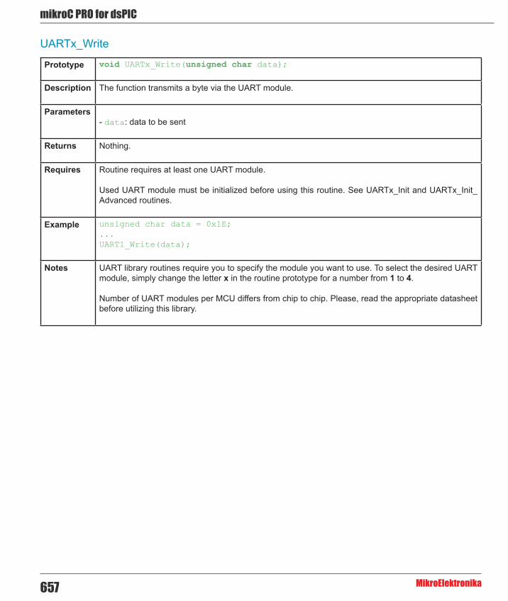
mikroC PRO for dsPIC
MikroElektronika657
UARTx_Write
Prototype void UARTx_Write(unsigned char data);
Description The function transmits a byte via the UART module.
Parameters- data: data to be sent
Returns Nothing.
Requires Routine requires at least one UART module.
Used UART module must be initialized before using this routine. See UARTx_Init and UARTx_Init_Advanced routines.
Example unsigned char data = 0x1E;...UART1_Write(data);
Notes UART library routines require you to specify the module you want to use. To select the desired UART module, simply change the letter x in the routine prototype for a number from 1 to 4.
Number of UART modules per MCU differs from chip to chip. Please, read the appropriate datasheet before utilizing this library.

658
mikoC PRO for dsPIC
MikroElektronika
UARTx_Write_Text
Prototype void UARTx_Write_Text(char * UART_text);
Description Sends text via UART. Text should be zero terminated.
Parameters- UART_text: text to be sent
Returns Nothing.
Requires Routine requires at least one UART module.
Used UART module must be initialized before using this routine. See UARTx_Init and UARTx_Init_Advanced routines.
Example Read text until the sequence “OK” is received, and send back what’s been received:
UART1_Init(4800); // initialize UART1 moduleDelay_ms(100);
while (1) { if (UART1_Data_Ready() == 1) { // if data is received UART1_Read_Text(output, “OK”, 10); // reads text until ‘OK’ is found UART1_Write_Text(output); // sends back text }}
Notes UART library routines require you to specify the module you want to use. To select the desired UART module, simply change the letter x in the routine prototype for a number from 1 to 4.
Number of UART modules per MCU differs from chip to chip. Please, read the appropriate datasheet before utilizing this library.

mikroC PRO for dsPIC
MikroElektronika659
UART_Set_Active
Prototype void UART_Set_Active(unsigned (*read_ptr)(), void (*write_ptr)(unsigned char _data), unsigned (*ready_ptr)(), unsigned (*tx_idle_ptr)());
Description Sets active UART module which will be used by UARTx_Data_Ready, UARTx_Read and UARTx_Write routines.
Parameters Parameters:
- read_ptr: UARTx_Read handler - write_ptr: UARTx_Write handler - ready_ptr: UARTx_Data_Ready handler - tx_idle_ptr: UARTx_Tx_Idle handler
Returns Nothing.
Requires Routine is available only for MCUs with multiple UART modules.
Used UART module must be initialized before using this routine. See UARTx_Init and UARTx_Init_Advanced routines.
Example UART1_Init(9600); // initialize UART1 moduleUART2_Init(9600); // initialize UART2 module
RS485Master_Init(); // initialize MCU as Master
UART_Set_Active(&UART1_Read, &UART1_Write, &UART1_Data_Ready, &UART1_Tx_Idle); // set UART1 activeRS485Master_Send(dat,1,160); // send message through UART1
UART_Set_Active(&UART2_Read, &UART2_Write, &UART2_Data_Ready, &UART2_Tx_Idle); // set UART2 activeRS485Master_Send(dat,1,160); // send through UART2
Notes None.

660
mikoC PRO for dsPIC
MikroElektronika
Library Example
This example demonstrates simple data exchange via UART. If MCU is connected to the PC, you can test the example from the mikroC PRO for dsPIC30/33 and PIC24 USART communication terminal, launch it from the drop-down menu Tools › USART Terminal or simply click the USART Terminal Icon .
Copy Code To Clipboard
char uart_rd;
void main() {
UART1_Init(9600); // Initialize UART module at 9600 bps Delay_ms(100); // Wait for UART module to stabilize // U1MODEbits.ALTIO = 1; // un-comment this line to have Rx and Tx pins on their alternate // locations. This is used to free the pins for other module, namely the SPI. UART1_Write_Text(“Start”); UART1_Write(10); UART1_Write(13); while (1) { // Endless loop if (UART1_Data_Ready()) { // If data is received, uart_rd = UART1_Read(); // read the received data, UART1_Write(uart_rd); // and send data via UART } }}

mikroC PRO for dsPIC
MikroElektronika661
HW Connection
RS232 HW connection

662
mikoC PRO for dsPIC
MikroElektronika
USB LibraryUniversal Serial Bus (USB) provides a serial bus standard for connecting a wide variety of devices, including computers, cell phones, game consoles, PDA’s, etc.
USB Library contains HID routines that support HID class devices, and also the generic routines that can be used with vendor specified drivers.
USB HID Class
The HID class consists primarily of devices that are used by humans to control the operation of computer systems. Typical examples of HID class devices include:
- Keyboards and pointing devices, for example: standard mouse devices, trackballs, and joysticks. - Front-panel controls, for example: knobs, switches, buttons, and sliders. - Controls that might be found on devices such as telephones, VCR remote controls, games or simulation devices, for example: data gloves, throttles, steering wheels, and rudder pedals. - Devices that may not require human interaction but provide data in a similar format to HID class devices, for example, bar-code readers, thermometers, or voltmeters.
Many typical HID class devices include indicators, specialized displays, audio feedback, and force or tactile feedback. Therefore, the HID class definition includes support for various types of output directed to the end user.
Descriptor File
Each project based on the USB library should include a descriptor source file which contains vendor id and name, product id and name, report length, and other relevant information. To create a descriptor file, use the integrated USB HID terminal of mikroC PRO for dsPIC30/33 and PIC24(Tools › USB HID Terminal). The default name for descriptor file is USBdsc.c, but you may rename it.
Library Routines
- HID_Enable - HID_Read - HID_Write - HID_Disable - USB_Interrupt_Proc - USB_Polling_Proc - Gen_Enable - Gen_Read - Gen_Write

mikroC PRO for dsPIC
MikroElektronika663
HID_Enable
Prototype void HID_Enable(char *readbuff, char *writebuff);
Description Enables USB HID communication.
Parameters- readbuff: Read Buffer. - writebuff: Write Buffer.
These parameters are used for HID communication.
Returns Nothing.
Requires Nothing.
Example HID_Enable(&readbuff,&writebuff);
Notes This function needs to be called before using other routines of USB HID Library.
HID_Read
Prototype char HID_Read(void);
Description Receives message from host and stores it in the Read Buffer.
Parameters None.
Returns If the data reading has failed, the function returns 0. Otherwise, it returns number of characters received from the host.
Requires USB HID needs to be enabled before using this function. See HID_Enable.
Example // retry until successwhile(!HID_Read()) ;
Notes None.

664
mikoC PRO for dsPIC
MikroElektronika
HID_Write
Prototype char HID_Write(char *writebuff, char len);
Description Function sends data from Write Buffer writebuff to host.
Parameters- writebuff: Write Buffer, same parameter as used in initialization; see HID_Enable. - len: specifies a length of the data to be transmitted.
Returns If the data transmitting has failed, the function returns 0. Otherwise, it returns number of transmitted bytes.
Requires USB HID needs to be enabled before using this function. See HID_Enable.
Example // retry until successwhile(!HID_Write(&writebuff,64)) ;
Notes Function call needs to be repeated as long as data is not successfuly sent.
HID_Disable
Prototype void HID_Disable(void);
Description Disables USB HID communication.
Parameters None.
Returns Nothing.
Requires USB HID needs to be enabled before using this function. See HID_Enable.
Example HID_Disable();
Notes None.

mikroC PRO for dsPIC
MikroElektronika665
USB_Interrupt_Proc
Prototype void USB_Interrupt_Proc(void);
Description This routine is used for servicing various USB bus events. Should be called inside USB interrupt routine.
Parameters None.
Returns Nothing.
Requires Nothing.
Example void USB1Interrupt() iv IVT_ADDR_USB1INTERRUPT { USB_Interrupt_Proc();}
Notes Do not use this function with USB_Polling_Proc, only one should be used. To enable servicing through interrupt, USB_INTERRUPT constant should be set (it is set by default in descriptor file).
USB_Polling_Proc
Prototype void USB_Polling_Proc(void);
Description This routine is used for servicing various USB bus events. It should be periodically, preferably every 100 microseconds.
Parameters None.
Returns Nothing.
Requires Nothing.
Example while(1) { USB_Polling_Proc(); kk = HID_Read(); if (kk != 0) { for(cnt=0; cnt < 64; cnt++) writebuff[cnt]=readbuff[cnt]; HID_Write(&writebuff,64); }}
Notes Do not use this functions with USB_Interrupt_Proc. To enable servicing by polling, USB_INTERRUPT constant should be set to 0 (it is located in descriptor file).

666
mikoC PRO for dsPIC
MikroElektronika
Gen_Enable
Prototype void Gen_Enable(char* readbuff, char* writebuff);
Description Initialize the USB module of the MCU.
Parameters- readbuff: Read Buffer. - writebuff: Write Buffer.
Returns Nothing.
Requires USB needs to be enabled before using this function. See HID_Enable.
Example Gen_Enable(&readbuff,&writebuff);
Notes None.
Gen_Read
Prototype char Gen_Read(char *readbuff, char length, char ep);
Description Generic routine that receives the specified data from the specified endpoint.
Parameters- readbuff: Received data. - length: The length of the data that you wish to receive. - ep: Endpoint number you want to receive the data into.
Returns Returns the number of received bytes, otherwise 0.
Requires USB needs to be enabled before using this function. See HID_Enable.
Example while(Gen_Read(readbuff,64,1)==0) ;
Notes None.

mikroC PRO for dsPIC
MikroElektronika667
Gen_Write
Prototype char Gen_Write(char* writebuff, char length, char ep);
Description Sends the specified data to the specified endpoint.
Parameters- writebuff: The data that you want to send. - length: the length of the data that you wish to send. - ep: Endpoint number you want to send the data into.
Returns Returns the number of transmitted bytes, otherwise 0.
Requires USB needs to be enabled before using this function. See HID_Enable.
Example while(Gen_Write(writebuff,64,1)==0) ;
Notes None.

668
mikoC PRO for dsPIC
MikroElektronika
Library Example
This example establishes connection with the HID terminal that is active on the PC. Upon connection establishment, the HID Device Name will appear in the respective window. After that software will wait for data and it will return received data back. Examples uses USBdsc.c descriptor file, which is in the same folder, and can be created by the HID Terminal.
Copy Code To Clipboard
char cnt;char readbuff[64];char writebuff[64];
void USB1Interrupt() iv IVT_ADDR_USB1INTERRUPT { USB_Interrupt_Proc();}
void main(void){ AD1PCFGL = 0xFFFF;
HID_Enable(&readbuff,&writebuff);
while(1){ while(!HID_Read()) ;
for(cnt=0;cnt<64;cnt++) writebuff[cnt]=readbuff[cnt];
while(!HID_Write(&writebuff,64)) ; }}
HW Connection

mikroC PRO for dsPIC
MikroElektronika669
DSP LibrariesmikroC PRO for dsPIC30/33 and PIC24 includes various libraries for DSP engine. All DSP routines work with fractional Q15 format.
Digital Signal Processing Libraries
- FIR Filter Library - IIR Filter Library - FFT Library - Bit Reverse Complex Library - Vectors Library - Matrices Library
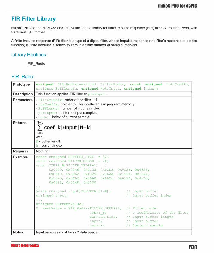
670
mikoC PRO for dsPIC
MikroElektronika
FIR_RadixPrototype unsigned FIR_Radix(unsigned FilterOrder, const unsigned *ptrCoeffs,
unsigned BuffLength, unsigned *ptrInput, unsigned Index);
Description This function applies FIR filter to ptrInput.Parameters - FilterOrder: order of the filter + 1
- ptrCoeffs: pointer to filter coefficients in program memory - BuffLength number of input samples - ptrInput: pointer to input samples - Index: index of current sample
Returns
with : N - buffer length k - current index
Requires Nothing.Example const unsigned BUFFFER_SIZE = 32;
const unsigned FILTER_ORDER = 20; const COEFF_B[FILTER_ORDER+1] = { 0x0000, 0x0048, 0x0133, 0x02D3, 0x052B, 0x0826, 0x0BA0, 0x0F62, 0x1329, 0x16AA, 0x199A, 0x16AA, 0x1329, 0x0F62, 0x0BA0, 0x0826, 0x052B, 0x02D3, 0x0133, 0x0048, 0x0000};ydata unsigned input[BUFFFER_SIZE]; // Input bufferunsigned inext; // Input buffer index...unsigned CurrentValue;CurrentValue = FIR_Radix(FILTER_ORDER+1, // Filter order COEFF_B, // b coefficients of the filter BUFFFER_SIZE, // Input buffer length input, // Input buffer inext); // Current sample
Notes Input samples must be in Y data space.
FIR Filter LibrarymikroC PRO for dsPIC30/33 and PIC24 includes a library for finite impulse response (FIR) filter. All routines work with fractional Q15 format.
A finite impulse response (FIR) filter is a type of a digital filter, whose impulse response (the filter’s response to a delta function) is finite because it settles to zero in a finite number of sample intervals.
Library Routines
- FIR_Radix

mikroC PRO for dsPIC
MikroElektronika671
IIR_RadixPrototype unsigned IIR_Radix (const int BScale, const int AScale, const signed *ptrB,
const signed *ptrA, unsigned FilterOrder, unsigned *ptrInput, unsigned InputLen, unsigned *ptrOutput, unsigned Index);
Description This function applies IIR filter to ptrInput.Parameters - BScale: B scale factor.
- AScale: A scale factor. - ptrB: pointer to B coefficients (in program memory). - ptrA: pointer to A coefficients (in program memory). - FilterOrder: order of the filter + 1. - ptrInput: address of input samples. - InputLen: number of samples. - ptrOutput: pointer to output samples. Output length is equal to Input length. - Index: index of current sample.
Returns
Requires Nothing.Example const unsigned int BUFFER_SIZE = 8;
const unsigned int FILTER_ORDER = 6;const signed int COEFF_B[FILTER_ORDER+1] = {0x0548, 0x1FAE, 0x4F34, 0x699B, 0x4F34, 0x1FAE, 0x0548};const signed int COEFF_A[FILTER_ORDER+1] = {0x4000, 0xB3FE, 0x5389, 0xD4D8, 0x10DD, 0xFCB0, 0x0052};const unsigned int SCALE_B = 2; const unsigned int SCALE_A = -1; unsigned int inext; // Input buffer indexydata unsigned int input[BUFFER_SIZE]; // Input bufferydata unsigned int output[BUFFER_SIZE]; // Output buffer...unsigned int CurrentValue;CurrentValue = IIR_Radix(SCALE_B, SCALE_A, COEFF_B, // b coefficients of the filter COEFF_A, // a coefficients of the filter FILTER_ORDER+1, // Filter order + 1 input, // Input buffer BUFFER_SIZE, // Input buffer length output, // Input buffer inext); // Current sample
Notes Input and output samples must be in Y data space.
IIR Filter LibrarymikroC PRO for dsPIC30/33 and PIC24 includes a library for Infinite Impulse Response (IIR) filter. All routines work with fractional Q15 format.
A infinite impulse response (IIR) filter is a type of a digital filter, whose impulse response (the filter’s response to a delta function) is non-zero over an infinite length of time.
Library Routines
IIR_Radix

672
mikoC PRO for dsPIC
MikroElektronika
FFT
Prototype void FFT(unsigned log2N, const unsigned *TwiddleFactorsAddress, unsigned *Samples);
Description Function applies FFT transformation to input samples, input samples must be in Y data space.
- f(n): array of complex input samples - WN: TwiddleFactors - N = 2m, mϵZ The amplitude of current FFT sample is calculated as:
Parameters - log2N: buffer length (must be the power of 2). - TwiddleFactorsAddress: address of constant array which contains complex twiddle factors. The array is expected to be in program memory. See Twiddle Factors for adequate array values. - Samples: array of input samples. Upon completion, complex array of FFT samples is placed in the Samples: parameter.
Returns Nothing.Requires Nothing.Example ydata unsigned InputSamples[512];
...// Perform FFT (DFT), 7 stages, 128 samples of complex pairsFFT(8, TwiddleCoeff_256, InputSamples);
Notes Complex array of FFT samples is placed in Samples parameter. Input Samples are arranged in manner Re,Im,Re,Im... (where Im is always zero). Output samples are arranged in the same manner but Im parts are different from zero. Output samples are symmetrical (First half of output samples (index from 0 to N/2) is identical as second half of output samples(index from N/2 to N).
Input data is a complex vector such that the magnitude of the real and imaginary parts of each of its elements is less than 0.5. If greater or equal to this value the results could produce saturation. Note that the output values are scaled by a factor of 1/N, with N the length of the FFT. input is expected in natural ordering, while output is produced in bit reverse ordering.
FFT LibrarymikroC PRO for dsPIC30/33 and PIC24 includes a library for FFT calculation. All routines work with fractional Q15 format.
Library Dependency Tree
Library Routines
- FFT

mikroC PRO for dsPIC
MikroElektronika673
Twiddle Factors:
TwiddleCoeff_64
const unsigned TwiddleCoeff_64[64] = { 0x7FFF, 0x0000, 0x7F62, 0xF374, 0x7D8A, 0xE707, 0x7A7D, 0xDAD8, 0x7642, 0xCF04, 0x70E3, 0xC3A9, 0x6A6E, 0xB8E3, 0x62F2, 0xAECC, 0x5A82, 0xA57E, 0x5134, 0x9D0E, 0x471D, 0x9592, 0x3C57, 0x8F1D, 0x30FC, 0x89BE, 0x2528, 0x8583, 0x18F9, 0x8276, 0x0C8C, 0x809E, 0x0000, 0x8000, 0xF374, 0x809E, 0xE707, 0x8276, 0xDAD8, 0x8583, 0xCF04, 0x89BE, 0xC3A9, 0x8F1D, 0xB8E3, 0x9592, 0xAECC, 0x9D0E, 0xA57E, 0xA57E, 0x9D0E, 0xAECC, 0x9592, 0xB8E3, 0x8F1D, 0xC3A9, 0x89BE, 0xCF04, 0x8583, 0xDAD8, 0x8276, 0xE707, 0x809E, 0xF374};
TwiddleCoeff_128
const unsigned TwiddleCoeff_128[128] = { 0x7FFF, 0x0000, 0x7FD9, 0xF9B8, 0x7F62, 0xF374, 0x7E9D, 0xED38, 0x7D8A, 0xE707, 0x7C2A, 0xE0E6, 0x7A7D, 0xDAD8, 0x7885, 0xD4E1, 0x7642, 0xCF04, 0x73B6, 0xC946, 0x70E3, 0xC3A9, 0x6DCA, 0xBE32, 0x6A6E, 0xB8E3, 0x66D0, 0xB3C0, 0x62F2, 0xAECC, 0x5ED7, 0xAA0A, 0x5A82, 0xA57E, 0x55F6, 0xA129, 0x5134, 0x9D0E, 0x4C40, 0x9930, 0x471D, 0x9592, 0x41CE, 0x9236, 0x3C57, 0x8F1D, 0x36BA, 0x8C4A, 0x30FC, 0x89BE, 0x2B1F, 0x877B, 0x2528, 0x8583, 0x1F1A, 0x83D6, 0x18F9, 0x8276, 0x12C8, 0x8163, 0x0C8C, 0x809E, 0x0648, 0x8027, 0x0000, 0x8000, 0xF9B8, 0x8027, 0xF374, 0x809E, 0xED38, 0x8163, 0xE707, 0x8276, 0xE0E6, 0x83D6, 0xDAD8, 0x8583, 0xD4E1, 0x877B, 0xCF04, 0x89BE, 0xC946, 0x8C4A, 0xC3A9, 0x8F1D, 0xBE32, 0x9236, 0xB8E3, 0x9592, 0xB3C0, 0x9930, 0xAECC, 0x9D0E, 0xAA0A, 0xA129, 0xA57E, 0xA57E, 0xA129, 0xAA0A, 0x9D0E, 0xAECC, 0x9930, 0xB3C0, 0x9592, 0xB8E3, 0x9236, 0xBE32, 0x8F1D, 0xC3A9, 0x8C4A, 0xC946, 0x89BE, 0xCF04, 0x877B, 0xD4E1, 0x8583, 0xDAD8, 0x83D6, 0xE0E6, 0x8276, 0xE707, 0x8163, 0xED38, 0x809E, 0xF374, 0x8027, 0xF9B8};

674
mikoC PRO for dsPIC
MikroElektronika
TwiddleCoeff_256
const unsigned TwiddleCoeff_256[256] = { 0x7FFF, 0x0000, 0x7FF6, 0xFCDC, 0x7FD9, 0xF9B8, 0x7FA7, 0xF695, 0x7F62, 0xF374, 0x7F0A, 0xF055, 0x7E9D, 0xED38, 0x7E1E, 0xEA1E, 0x7D8A, 0xE707, 0x7CE4, 0xE3F4, 0x7C2A, 0xE0E6, 0x7B5D, 0xDDDC, 0x7A7D, 0xDAD8, 0x798A, 0xD7D9, 0x7885, 0xD4E1, 0x776C, 0xD1EF, 0x7642, 0xCF04, 0x7505, 0xCC21, 0x73B6, 0xC946, 0x7255, 0xC673, 0x70E3, 0xC3A9, 0x6F5F, 0xC0E9, 0x6DCA, 0xBE32, 0x6C24, 0xBB85, 0x6A6E, 0xB8E3, 0x68A7, 0xB64C, 0x66D0, 0xB3C0, 0x64E9, 0xB140, 0x62F2, 0xAECC, 0x60EC, 0xAC65, 0x5ED7, 0xAA0A, 0x5CB4, 0xA7BD, 0x5A82, 0xA57E, 0x5843, 0xA34C, 0x55F6, 0xA129, 0x539B, 0x9F14, 0x5134, 0x9D0E, 0x4EC0, 0x9B17, 0x4C40, 0x9930, 0x49B4, 0x9759, 0x471D, 0x9592, 0x447B, 0x93DC, 0x41CE, 0x9236, 0x3F17, 0x90A1, 0x3C57, 0x8F1D, 0x398D, 0x8DAB, 0x36BA, 0x8C4A, 0x33DF, 0x8AFB, 0x30FC, 0x89BE, 0x2E11, 0x8894, 0x2B1F, 0x877B, 0x2827, 0x8676, 0x2528, 0x8583, 0x2224, 0x84A3, 0x1F1A, 0x83D6, 0x1C0C, 0x831C, 0x18F9, 0x8276, 0x15E2, 0x81E2, 0x12C8, 0x8163, 0x0FAB, 0x80F6, 0x0C8C, 0x809E, 0x096B, 0x8059, 0x0648, 0x8027, 0x0324, 0x800A, 0x0000, 0x8000, 0xFCDC, 0x800A, 0xF9B8, 0x8027, 0xF695, 0x8059, 0xF374, 0x809E, 0xF055, 0x80F6, 0xED38, 0x8163, 0xEA1E, 0x81E2, 0xE707, 0x8276, 0xE3F4, 0x831C, 0xE0E6, 0x83D6, 0xDDDC, 0x84A3, 0xDAD8, 0x8583, 0xD7D9, 0x8676, 0xD4E1, 0x877B, 0xD1EF, 0x8894, 0xCF04, 0x89BE, 0xCC21, 0x8AFB, 0xC946, 0x8C4A, 0xC673, 0x8DAB, 0xC3A9, 0x8F1D, 0xC0E9, 0x90A1, 0xBE32, 0x9236, 0xBB85, 0x93DC, 0xB8E3, 0x9592, 0xB64C, 0x9759, 0xB3C0, 0x9930, 0xB140, 0x9B17, 0xAECC, 0x9D0E, 0xAC65, 0x9F14, 0xAA0A, 0xA129, 0xA7BD, 0xA34C, 0xA57E, 0xA57E, 0xA34C, 0xA7BD, 0xA129, 0xAA0A, 0x9F14, 0xAC65, 0x9D0E, 0xAECC, 0x9B17, 0xB140, 0x9930, 0xB3C0, 0x9759, 0xB64C, 0x9592, 0xB8E3, 0x93DC, 0xBB85, 0x9236, 0xBE32, 0x90A1, 0xC0E9, 0x8F1D, 0xC3A9, 0x8DAB, 0xC673, 0x8C4A, 0xC946, 0x8AFB, 0xCC21, 0x89BE, 0xCF04, 0x8894, 0xD1EF, 0x877B, 0xD4E1, 0x8676, 0xD7D9, 0x8583, 0xDAD8, 0x84A3, 0xDDDC, 0x83D6, 0xE0E6, 0x831C, 0xE3F4, 0x8276, 0xE707, 0x81E2, 0xEA1E, 0x8163, 0xED38, 0x80F6, 0xF055, 0x809E, 0xF374, 0x8059, 0xF695, 0x8027, 0xF9B8, 0x800A, 0xFCDC};
TwiddleCoeff_512
const unsigned TwiddleCoeff_512[512] = { 0x7FFF, 0x0000, 0x7FFE, 0xFE6E, 0x7FF6, 0xFCDC, 0x7FEA, 0xFB4A, 0x7FD9, 0xF9B8, 0x7FC2, 0xF827, 0x7FA7, 0xF695, 0x7F87, 0xF505, 0x7F62, 0xF374, 0x7F38, 0xF1E4, 0x7F0A, 0xF055, 0x7ED6, 0xEEC6, 0x7E9D, 0xED38, 0x7E60, 0xEBAB, 0x7E1E, 0xEA1E, 0x7DD6, 0xE892, 0x7D8A, 0xE707, 0x7D3A, 0xE57D, 0x7CE4, 0xE3F4, 0x7C89, 0xE26D, 0x7C2A, 0xE0E6, 0x7BC6, 0xDF61, 0x7B5D, 0xDDDC, 0x7AEF, 0xDC59, 0x7A7D, 0xDAD8, 0x7A06, 0xD958, 0x798A, 0xD7D9, 0x790A, 0xD65C, 0x7885, 0xD4E1, 0x77FB, 0xD367, 0x776C, 0xD1EF, 0x76D9, 0xD079, 0x7642, 0xCF04, 0x75A6, 0xCD92, 0x7505, 0xCC21, 0x7460, 0xCAB2, 0x73B6, 0xC946, 0x7308, 0xC7DB, 0x7255, 0xC673, 0x719E, 0xC50D, 0x70E3, 0xC3A9, 0x7023, 0xC248, 0x6F5F, 0xC0E9, 0x6E97, 0xBF8C, 0x6DCA, 0xBE32, 0x6CF9, 0xBCDA, 0x6C24, 0xBB85, 0x6B4B, 0xBA33,

mikroC PRO for dsPIC
MikroElektronika675
0x6A6E, 0xB8E3, 0x698C, 0xB796, 0x68A7, 0xB64C, 0x67BD, 0xB505, 0x66D0, 0xB3C0, 0x65DE, 0xB27F, 0x64E9, 0xB140, 0x63EF, 0xB005, 0x62F2, 0xAECC, 0x61F1, 0xAD97, 0x60EC, 0xAC65, 0x5FE4, 0xAB36, 0x5ED7, 0xAA0A, 0x5DC8, 0xA8E2, 0x5CB4, 0xA7BD, 0x5B9D, 0xA69C, 0x5A82, 0xA57E, 0x5964, 0xA463, 0x5843, 0xA34C, 0x571E, 0xA238, 0x55F6, 0xA129, 0x54CA, 0xA01C, 0x539B, 0x9F14, 0x5269, 0x9E0F, 0x5134, 0x9D0E, 0x4FFB, 0x9C11, 0x4EC0, 0x9B17, 0x4D81, 0x9A22, 0x4C40, 0x9930, 0x4AFB, 0x9843, 0x49B4, 0x9759, 0x486A, 0x9674, 0x471D, 0x9592, 0x45CD, 0x94B5, 0x447B, 0x93DC, 0x4326, 0x9307, 0x41CE, 0x9236, 0x4074, 0x9169, 0x3F17, 0x90A1, 0x3DB8, 0x8FDD, 0x3C57, 0x8F1D, 0x3AF3, 0x8E62, 0x398D, 0x8DAB, 0x3825, 0x8CF8, 0x36BA, 0x8C4A, 0x354E, 0x8BA0, 0x33DF, 0x8AFB, 0x326E, 0x8A5A, 0x30FC, 0x89BE, 0x2F87, 0x8927, 0x2E11, 0x8894, 0x2C99, 0x8805, 0x2B1F, 0x877B, 0x29A4, 0x86F6, 0x2827, 0x8676, 0x26A8, 0x85FA, 0x2528, 0x8583, 0x23A7, 0x8511, 0x2224, 0x84A3, 0x209F, 0x843A, 0x1F1A, 0x83D6, 0x1D93, 0x8377, 0x1C0C, 0x831C, 0x1A83, 0x82C6, 0x18F9, 0x8276, 0x176E, 0x822A, 0x15E2, 0x81E2, 0x1455, 0x81A0, 0x12C8, 0x8163, 0x113A, 0x812A, 0x0FAB, 0x80F6, 0x0E1C, 0x80C8, 0x0C8C, 0x809E, 0x0AFB, 0x8079, 0x096B, 0x8059, 0x07D9, 0x803E, 0x0648, 0x8027, 0x04B6, 0x8016, 0x0324, 0x800A, 0x0192, 0x8002, 0x0000, 0x8000, 0xFE6E, 0x8002, 0xFCDC, 0x800A, 0xFB4A, 0x8016, 0xF9B8, 0x8027, 0xF827, 0x803E, 0xF695, 0x8059, 0xF505, 0x8079, 0xF374, 0x809E, 0xF1E4, 0x80C8, 0xF055, 0x80F6, 0xEEC6, 0x812A, 0xED38, 0x8163, 0xEBAB, 0x81A0, 0xEA1E, 0x81E2, 0xE892, 0x822A, 0xE707, 0x8276, 0xE57D, 0x82C6, 0xE3F4, 0x831C, 0xE26D, 0x8377, 0xE0E6, 0x83D6, 0xDF61, 0x843A, 0xDDDC, 0x84A3, 0xDC59, 0x8511, 0xDAD8, 0x8583, 0xD958, 0x85FA, 0xD7D9, 0x8676, 0xD65C, 0x86F6, 0xD4E1, 0x877B, 0xD367, 0x8805, 0xD1EF, 0x8894, 0xD079, 0x8927, 0xCF04, 0x89BE, 0xCD92, 0x8A5A, 0xCC21, 0x8AFB, 0xCAB2, 0x8BA0, 0xC946, 0x8C4A, 0xC7DB, 0x8CF8, 0xC673, 0x8DAB, 0xC50D, 0x8E62, 0xC3A9, 0x8F1D, 0xC248, 0x8FDD, 0xC0E9, 0x90A1, 0xBF8C, 0x9169, 0xBE32, 0x9236, 0xBCDA, 0x9307, 0xBB85, 0x93DC, 0xBA33, 0x94B5, 0xB8E3, 0x9592, 0xB796, 0x9674, 0xB64C, 0x9759, 0xB505, 0x9843, 0xB3C0, 0x9930, 0xB27F, 0x9A22, 0xB140, 0x9B17, 0xB005, 0x9C11, 0xAECC, 0x9D0E, 0xAD97, 0x9E0F, 0xAC65, 0x9F14, 0xAB36, 0xA01C, 0xAA0A, 0xA129, 0xA8E2, 0xA238, 0xA7BD, 0xA34C, 0xA69C, 0xA463, 0xA57E, 0xA57E, 0xA463, 0xA69C, 0xA34C, 0xA7BD, 0xA238, 0xA8E2, 0xA129, 0xAA0A, 0xA01C, 0xAB36, 0x9F14, 0xAC65, 0x9E0F, 0xAD97, 0x9D0E, 0xAECC, 0x9C11, 0xB005, 0x9B17, 0xB140, 0x9A22, 0xB27F, 0x9930, 0xB3C0, 0x9843, 0xB505, 0x9759, 0xB64C, 0x9674, 0xB796, 0x9592, 0xB8E3, 0x94B5, 0xBA33, 0x93DC, 0xBB85, 0x9307, 0xBCDA, 0x9236, 0xBE32, 0x9169, 0xBF8C, 0x90A1, 0xC0E9, 0x8FDD, 0xC248, 0x8F1D, 0xC3A9, 0x8E62, 0xC50D, 0x8DAB, 0xC673, 0x8CF8, 0xC7DB, 0x8C4A, 0xC946, 0x8BA0, 0xCAB2, 0x8AFB, 0xCC21, 0x8A5A, 0xCD92, 0x89BE, 0xCF04, 0x8927, 0xD079, 0x8894, 0xD1EF, 0x8805, 0xD367, 0x877B, 0xD4E1, 0x86F6, 0xD65C, 0x8676, 0xD7D9, 0x85FA, 0xD958, 0x8583, 0xDAD8, 0x8511, 0xDC59, 0x84A3, 0xDDDC, 0x843A, 0xDF61, 0x83D6, 0xE0E6, 0x8377, 0xE26D, 0x831C, 0xE3F4, 0x82C6, 0xE57D, 0x8276, 0xE707, 0x822A, 0xE892, 0x81E2, 0xEA1E, 0x81A0, 0xEBAB, 0x8163, 0xED38, 0x812A, 0xEEC6, 0x80F6, 0xF055, 0x80C8, 0xF1E4, 0x809E, 0xF374, 0x8079, 0xF505, 0x8059, 0xF695, 0x803E, 0xF827, 0x8027, 0xF9B8, 0x8016, 0xFB4A, 0x800A, 0xFCDC, 0x8002, 0xFE6E};
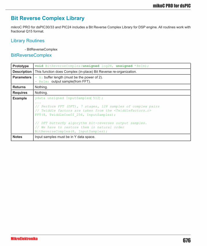
676
mikoC PRO for dsPIC
MikroElektronika
Bit Reverse Complex LibrarymikroC PRO for dsPIC30/33 and PIC24 includes a Bit Reverse Complex Library for DSP engine. All routines work with fractional Q15 format.
Library Routines
- BitReverseComplex
BitReverseComplex
Prototype void BitReverseComplex(unsigned log2N, unsigned *ReIm);
Description This function does Complex (in-place) Bit Reverse re-organization.Parameters - N: buffer length (must be the power of 2).
- ReIm: output sample(from FFT). Returns Nothing.Requires Nothing.Example ydata unsigned InputSamples[512];
...// Perform FFT (DFT), 7 stages, 128 samples of complex pairs// Twiddle factors are taken from the <TwiddleFactors.c>FFT(8, TwiddleCoeff_256, InputSamples);
// DFT butterfly algorythm bit-reverses output samples.// We have to restore them in natural orderBitReverseComplex(8, InputSamples);
Notes Input samples must be in Y data space.

mikroC PRO for dsPIC
MikroElektronika677
Vectors LibrarymikroC PRO for dsPIC30/33 and PIC24 includes a library for working and using vectors. All routines work with fractional Q15 format.
Library Routines
- Vector_Set - Vector_Power - Vector_Subtract - Vector_Scale - Vector_Negate - Vector_Multiply - Vector_Min - Vector_Max - Vector_Dot - Vector_Correlate - Vector_Convolve - Vector_Add
Vector_SetPrototype void Vector_Set(unsigned *input, unsigned size, unsigned value);
Description Sets size elements of input to value, starting from the first element.Parameters - input: pointer to original vector
- size: number of vector elements - value: value written to the elements
Returns Nothing.Requires Nothing.Example unsigned vec2[3] = {1,1,1};
Vector_Set(vec2, 3, 0x4000);
Notes - size must be > 0 - Length of input is limited by available RAM

678
mikoC PRO for dsPIC
MikroElektronika
Vector_PowerPrototype unsigned Vector_Power(unsigned numElems, unsigned *srcV);
Description Function returns result of power value (powVal) in radix point 1.15Parameters - numElems: number elements in vector(s)
- srcV: pointer to source vector Returns
Requires Nothing.Example unsigned vec1[3] = {1,2,3};
Vector_Power(3, vec1);
Notes - [W0..W2] used, not restored - [W4] used, not restored - AccuA used, not restored - CORCON saved, used, restored
Vector_Subtract
Prototype void Vector_Subtract(unsigned *dest, unsigned *v1, unsigned *v2, unsigned numElems);
Description This function does subtraction of two vectors.
dstV[n] = v1[n] - v2[n], n ϵ [0, numElems-1]Parameters - dest: result vector
- v1: first vector - v2: second vector - numElems: must be less or equal to minimum size of two vectors.
Returns Nothing.Requires Nothing.Example unsigned vec1[3] = {1,2,3};
unsigned vec2[3] = {1,1,1};unsigned vecDest[3];
Vector_Subtract(vecDest, vec1, vec2, 3);
Notes - AccuA used, not restored. - CORCON saved, used, restored.

mikroC PRO for dsPIC
MikroElektronika679
Vector_Scale
Prototype void Vector_Scale(unsigned N, int ScaleValue, unsigned *SrcVector, unsigned *DestVector);
Description This function does vector scaling with scale value.
dstV[n] = sclVal * srcV[n], n ϵ [0, numElems-1]Parameters - N: buffer length (number of elements to be scaled)
- ScaleValue: scale value - SrcVector: pointer to original vector - DestVector: pointer to scaled vector
Returns Nothing.Requires Nothing.Example unsigned vec1[3] = {1,2,3};
unsigned vecDest[3];
Vector_Scale(3, 2, vec1, vecDest);
Notes - [W0..W5] used, not restored - AccuA used, not restored - CORCON saved, used, restored
Vector_Negate
Prototype void Vector_Negate(unsigned *srcVector, unsigned *DestVector, unsigned numElems);
Description This function does negation of vector.
dstV[n] = (-1)*srcV1[n] + 0, n ϵ [0, numElems]Parameters - srcVector: pointer to original vector
- destVector: pointer to result vector - numElems: number of elements in vector(s)
Returns Nothing.Requires Nothing.Example unsigned vecDest[3];
unsigned vec1[3] = {1,2,3};
Vector_Negate(vec1, vecDest, 3);
Notes - Negate of 0x8000 is 0x7FFF- [W0]..[W5] used, not restored - AccuA used, not restored - CORCON saved, used, restored

680
mikoC PRO for dsPIC
MikroElektronika
Vector_Multiply
Prototype void Vector_Multiply(unsigned *v1, unsigned *v2, unsigned *dest, unsigned numElems);
Description This function does multiplication of two vectors.
dstV[n] = srcV1[n] * srcV2[n], n ϵ [0, numElems-1]Parameters - v1: pointer to first vector
- v2: pointer to second vector - dest: pointer to result vector - numElems: number elements in vector(s) (must be less or equal to minimum size of two vectors)
Returns Nothing.Requires Nothing.Example unsigned vec1[3] = {1,2,3};
unsigned vec2[3] = {1,1,1};unsigned vConDest[10];
Vector_Multiply(vec1, vConDest, vec2, 3);
Notes - [W0..W5] used, not restored - AccuA used, not restored - CORCON saved, used, restored
Vector_Min
Prototype unsigned Vector_Min(unsigned *Vector, unsigned numElems, unsigned *MinIndex);
Description This function finds minimal value in vector.
minVal = min (srcV[n]), n ϵ [0, numElems-1]
If srcV[i] = srcV[j] = minVal, and i < j, then MinIndex = j.Parameters - Vector: pointer to original vector
- numElems: number of elements in vector - MinIndex: pointer to index of minimum value
Returns Minimum value (minVal).Requires Nothing.Example unsigned vec1[3] = {1,2,3};
unsigned index;unsigned rslt;
rslt = Vector_Min(vec1, 3, &index);
Notes - [W0..W5] used, not restored

mikroC PRO for dsPIC
MikroElektronika681
Vector_Max
Prototype unsigned Vector_Max(unsigned *srcV, unsigned numElems, unsigned *MaxIndex);
Description This function find maximal value in vector.
maxVal = max (srcV[n]), n ϵ [0, numElems-1]
If srcV[i] = srcV[j] = maxVal, and i < j, then maxIndex = j.Parameters - srcV: pointer to original vector
- numElems: number of elements in vector(s) - MaxIndex: pointer to index of maximum value
Returns Minimum value (maxVal).Requires Nothing.Example unsigned vec1[3] = {1,2,3};
unsigned index;unsigned rslt;
rslt = Vector_Max(vec1, 3, &index);
Notes - [W0..W5] used, not restored
Vector_Dot
Prototype unsigned Vector_Dot(unsigned *v1, unsigned *v2, unsigned numElems);
Description Function calculates vector dot product.Parameters - v1: pointer to first vector
- v2: pointer to second vector - numElems: number of elements in vector(s)
Returns Dot product value :
Requires Nothing.Example unsigned vec2[3] = {1,1,1};
unsigned rslt;
rslt = Vector_Dot(vec2,vec2,3);
Notes - [W0..W2] used, not restored - [W4..W5] used, not restored - AccuA used, not restored - CORCON saved, used, restored

682
mikoC PRO for dsPIC
MikroElektronika
Vector_Correlate
Prototype void Vector_Correlate(unsigned *v1, unsigned *v2, unsigned *dest, unsigned numElemsV1, unsigned numElemsV2);
Description Function calculates Vector correlation (using convolution).
where: x[n] defined for n Î [0, N)y[n] defined for n Î [0, M), M £ Nr[n] defined for n Î [0, N+M-1)
Parameters - v1: pointer to first vector - v2: pointer to second vector - dest: pointer to result vector - numElemsV1: number of the first vector elements - numElemsV2: number of the second vector elements
Returns Nothing.Requires Nothing.Example unsigned vConDest[10];
unsigned vec2[3] = {1,1,1};
Vector_Correlate(vec2,vec2,vConDest,3,3);
Notes [W0..W7] used, not restored

mikroC PRO for dsPIC
MikroElektronika683
Vector_Convolve
Prototype void Vector_Convolve(unsigned *v1, unsigned *v2, unsigned *dest, unsigned numElemsV1, unsigned numElemsV2);
Description Function calculates Vector using convolution. , n ϵ [0, M)
, n ϵ [M, N)
, n ϵ [N, N+M-1)
Parameters - v1: pointer to first vector - v2: pointer to second vector - dest: pointer to result vector - numElemsV1: number of the first vector elements - numElemsV2: number of the second vector elements
Returns Nothing.Requires Nothing.Example unsigned vec2[3] = {1,1,1};
unsigned vConDest2[10];
Vector_Convolve(vec2,vec2,vConDest2,3,3);
Notes - [W0..W7] used, not restored - [W8..W10] saved, used, restored - AccuA used, not restored - CORCON saved, used, restored
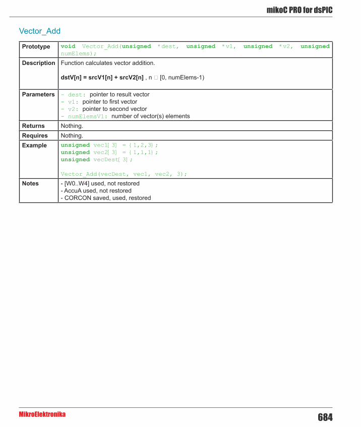
684
mikoC PRO for dsPIC
MikroElektronika
Vector_Add
Prototype void Vector_Add(unsigned *dest, unsigned *v1, unsigned *v2, unsigned numElems);
Description Function calculates vector addition.
dstV[n] = srcV1[n] + srcV2[n] , n ϵ [0, numElems-1)
Parameters - dest: pointer to result vector - v1: pointer to first vector - v2: pointer to second vector - numElemsV1: number of vector(s) elements
Returns Nothing.Requires Nothing.Example unsigned vec1[3] = {1,2,3};
unsigned vec2[3] = {1,1,1};unsigned vecDest[3];
Vector_Add(vecDest, vec1, vec2, 3);
Notes - [W0..W4] used, not restored - AccuA used, not restored - CORCON saved, used, restored

mikroC PRO for dsPIC
MikroElektronika685
Matrices LibrarymikroC PRO for dsPIC30/33 and PIC24 includes a library for operating and working with matrices. All routines work with fractional Q15 format.
Library Routines
Matrix_Transpose Matrix_Subtract Matrix_Scale Matrix_Multiply Matrix_Add
Matrix_Transpose
Prototype void Matrix_Transpose(unsigned *src, unsigned *dest, unsigned numRows, unsigned numCols);
Description Function does matrix transposition.
dstM[i][j] = srcM[j][i]
Parameters - src: pointer to original matrix - dest: pointer to result matrix - numRows: number of rows in the source matrix - numCols: number of cols in the source matrix
Returns Nothing.Requires Nothing.Example int mx1[6] = {1,2,3,4,5,6};
int mxDest[9];
Matrix_Transpose(mx1, mxDest, 2,3);
Notes [W0..W5] used, not restored

686
mikoC PRO for dsPIC
MikroElektronika
Matrix_Subtract
Prototype void Matrix_Subtract(unsigned *src1, unsigned *src2, unsigned *dest, unsigned num_rows, unsigned num_cols);
Description Function does matrix subtraction.
dstM[i][j] = srcM1[i][j] - srcM2[i][j] Parameters - src1: pointer to the first matrix
- src2: pointer to the second matrix - dest: pointer to the result matrix - numRows: number of rows in the source matrix - numCols: number of cols in the source matrix
Returns Nothing.Requires Nothing.Example int mx1[6] = {1,2,3,4,5,6};
int mx2[6] = {2,2,2,2,2,2};int mxDest[9];
Matrix_Subtract(mx1, mx2, mxDest, 2, 3);
Notes - [W0..W4] used, not restored - AccuA used, not restored - AccuB used, not restored - CORCON saved, used, restored
Matrix_Scale
Prototype void Matrix_Scale(unsigned ScaleValue, unsigned *src1, unsigned *dest, unsigned numRows, unsigned numCols);
Description Function does matrix scale.
dstM[i][j] = sclVal * srcM[i][j] Parameters - ScaleValue: scale value
- src1: pointer to the original matrix - dest: pointer to the result matrix - numRows: number of rows in the source matrix - numCols: number of cols in the source matrix
Returns Nothing.Requires Nothing.Example int mx1[6] = {1,2,3,4,5,6};
int mxDest[9];
Matrix_Scale(0x4000, mx1, mxDest, 2,3);
Notes - [W0..W5] used, not restored - AccuA used, not restored - CORCON saved, used, restored - numRows*numCols < 214

mikroC PRO for dsPIC
MikroElektronika687
Matrix_Multiply
Prototype void Matrix_Multiply(unsigned *src1, unsigned *src2, unsigned *dest, unsigned numRows1, unsigned numCols2, unsigned numCols1Rows2);
Description Function does matrix multiplication.
with:i ϵ [0, numRows1-1]j ϵ [0, numCols2-1]k ϵ [0, numCols1Rows2-1]
Parameters- src1: pointer to the first matrix - src2: pointer to the second matrix - dest: pointer to result matrix - numRows1: number of rows in the first matrix - numCols2: number of columns in the second matrix - numCols1Rows2: number of columns in the first matrix and rows in the second matrix
Returns Nothing.Requires Nothing.Example int mx1[6] = {1,2,3,4,5,6} ;
int mx2[6] = {2,2,2,2,2,2} ;int mxDest[9];
Matrix_Multiply(mx1,mx2,mxDest,2,2,3);
Notes - [W0..W7] used, not restored - [W8..W13] used, and restored - AccuA used, not restored - CORCON saved, used, restored

688
mikoC PRO for dsPIC
MikroElektronika
Matrix_Add
Prototype void Matrix_Add(unsigned *src1, unsigned *src2, unsigned *dest, unsigned numRows, unsigned numCols);
Description Function does matrix addition.
dstM[i][j] = srcM1[i][j] + srcM2[i][j]
Parameters- src1: pointer to the first matrix - src2: pointer to the second matrix - dest: pointer to the result matrix - numRows1: number of rows in the first matrix - numCols2: number of columns in the second matrix
Returns Nothing.Requires Nothing.Example int mx1[6] = {1,2,3,4,5,6};
int mx2[6] = {2,2,2,2,2,2};int mxDest[9];
Matrix_Add(mx1,mx2, mxDest,2,3);
Notes- [W0..W4] used, not restored - AccuA used, not restored. - CORCON saved, used, restored. - numRows1*numCols2 < 214

mikroC PRO for dsPIC
MikroElektronika689
Standard ANSI C Libraries - ANSI C Ctype Library - ANSI C Math Library - ANSI C Stdlib Library - ANSI C String Library
ANSI C Ctype LibraryThe mikroC PRO for dsPIC30/33 and PIC24 provides a set of standard ANSI C library functions for testing and mapping characters.
Important:
- Not all of the standard functions have been included. - The functions have been mostly implemented according to the ANSI C standard, but certain functions have been modified in order to facilitate dsPIC30/33 and PIC24 programming. Be sure to skim through the description before using standard C functions.
Library Functions
- isalnum - isalpha - iscntrl - isdigit - isgraph - islower - ispunct - isspace - isupper - isxdigit - toupper - tolower

690
mikoC PRO for dsPIC
MikroElektronika
isalnum
Prototype unsigned int isalnum(char character);
Description Function returns 1 if the character is alphanumeric (A-Z, a-z, 0-9), otherwise returns zero.
Example res = isalnum(‘o’); // returns 1res = isalnum(‘\r’); // returns 0
isalpha
Prototype unsigned int isalpha(char character);
Description Function returns 1 if the character is alphabetic (A-Z, a-z), otherwise returns zero.
Example res = isalpha(‘A’); // returns 1res = isalpha(‘1’); // returns 0
iscntrl
Prototype unsigned int iscntrl(char character);
Description Function returns 1 if the character is a control or delete character(decimal 0-31 and 127), otherwise returns zero.
Example res = iscntrl(‘\r’); // returns 1res = iscntrl(‘o’); // returns 0
isdigit
Prototype unsigned int isdigit(char character);
Description Function returns 1 if the character is a digit (0-9), otherwise returns zero.
Example res = isdigit(‘o’); // returns 1res = isdigit(‘1’); // returns 0

mikroC PRO for dsPIC
MikroElektronika691
isgraph
Prototype unsigned int isgraph(char character);
Description Function returns 1 if the character is a printable, excluding the space (decimal 32), otherwise returns zero.
Example res = isgraph(‘o’); // returns 1res = isgraph(‘ ‘); // returns 0
islower
Prototype unsigned int islower(char character);
Description Function returns 1 if the character is a lowercase letter (a-z), otherwise returns zero.
Example res = islower(‘0’); // returns 1res = islower(‘A’); // returns 0
ispunct
Prototype unsigned int ispunct(char character);
Description Function returns 1 if the character is a punctuation (decimal 32-47, 58-63, 91-96, 123-126), otherwise returns zero.
Example res = ispunct(‘.’); // returns 1res = ispunct(‘1’); // returns 0
isspace
Prototype unsigned int isspace(char character);
Description Function returns 1 if the character is a white space (space, tab, CR, HT, VT, NL, FF), otherwise returns zero.
Example res = isspace(‘ ‘); // returns 1res = isspace(‘1’); // returns 0

692
mikoC PRO for dsPIC
MikroElektronika
isupper
Prototype unsigned int isupper(char character);
Description Function returns 1 if the character is an uppercase letter (A-Z), otherwise returns zero.
Example res = isupper(‘A’); // returns 1res = isupper(‘a’); // returns 0
isxdigit
Prototype unsigned int isxdigit(char character);
Description Function returns 1 if the character is a hex digit (0-9, A-F, a-f), otherwise returns zero.
Example res = isxdigit(‘A’); // returns 1res = isxdigit(‘P’); // returns 0
toupper
Prototype unsigned int toupper(char character);
Description If the character is a lowercase letter (a-z), the function returns an uppercase letter. Otherwise, the function returns an unchanged input parameter.
Example res = toupper(‘a’); // returns Ares = toupper(‘B’); // returns B
tolower
Prototype unsigned int tolower(char character);
Description If the character is an uppercase letter (A-Z), function returns a lowercase letter. Otherwise, function returns an unchanged input parameter.
Example res = tolower(‘A’); // returns ares = tolower(‘b’); // returns b

mikroC PRO for dsPIC
MikroElektronika693
ANSI C Math LibraryThe mikroC PRO for dsPIC30/33 and PIC24 provides a set of standard ANSI C library functions for floating point math handling.
Important: - Not all of the standard functions have been included. - The functions have been mostly implemented according to the ANSI C standard, but certain functions have been modified in order to facilitate dsPIC30/33 and PIC24 programming. Be sure to skim through the description before using standard C functions.
Library Functions
- acos - asin - atan - atan2 - ceil - cos - cosh - exp -fabs - floor - frexp - ldexp - log - log10 - modf - pow - sin - sinh - sqrt - tan
acos
Prototype double acos(double x);
Description Function returns the arc cosine of parameter x; that is, the value whose cosine is x. The input parameter x must be between -1 and 1 (inclusive). The return value is in radians, between 0 and Π (inclusive).
Example doub = acos(0.5); // doub = 1.047198

694
mikoC PRO for dsPIC
MikroElektronika
asin
Prototype double asin(double x);
Description Function returns the arc sine of parameter x; that is, the value whose sine is x. The input parameter x must be between -1 and 1 (inclusive). The return value is in radians, between -Π/2 and Π/2 (inclusive).
Example doub = asin(0.5); // doub = 5.235987e-1
atan
Prototype double atan(double f);
Description Function computes the arc tangent of parameter f; that is, the value whose tangent is f. The return value is in radians, between -Π/2 and Π/2 (inclusive).
Example doub = atan(1.0); // doub = 7.853982e-1
atan2
Prototype double atan2(double y, double x);
Description This is the two-argument arc tangent function. It is similar to computing the arc tangent of y/x, except that the signs of both arguments are used to determine the quadrant of the result and x is permitted to be zero. The return value is in radians, between -Π and Π (inclusive).
Example doub = atan2(2., 1.); // doub = 4.636475e-1
ceil
Prototype double ceil(double x);
Description Function returns value of parameter x rounded up to the next whole number.
Example doub = ceil(0.5); // doub = 1.000000

mikroC PRO for dsPIC
MikroElektronika695
cos
Prototype double cos(double f);
Description Function returns the cosine of f in radians. The return value is from -1 to 1.
Example doub = cos(PI/3.); // doub = 0.500008
cosh
Prototype double cosh(double x);
Description Function returns the hyperbolic cosine of x, defined mathematically as (ex+e-x)/2. If the value of x is too large (if overflow occurs), the function fails.
Example doub = cosh(PI/3.); // doub = 1.600286
exp
Prototype double exp(double x);
Description Function returns the value of e — the base of natural logarithms — raised to the power x (i.e. ex).
Example doub = exp(0.5); // doub = 1.648721
fabs
Prototype double fabs(double d);
Description Function returns the absolute (i.e. positive) value of d.
Example doub = fabs(-1.3); // doub = 1.3
floor
Prototype double floor(double x);
Description Function returns the value of parameter x rounded down to the nearest integer.
Example doub = floor(15.258); // doub = 15.000000

696
mikoC PRO for dsPIC
MikroElektronika
frexp
Prototype double frexp(double value, int *eptr);
Description Function splits a floating-point value into a normalized fraction and an integral power of 2. The return value is the normalized fraction and the integer exponent is stored in the object pointed to by eptr.
ldexp
Prototype double ldexp(double value, int newexp);
Description Function returns the result of multiplying the floating-point number num by 2 raised to the power n (i.e. returns x * 2n).
Example doub = ldexp(2.5, 2); // doub = 10
log
Prototype double log(double x);
Description Function returns the natural logarithm of x (i.e. loge(x)).
Example doub = log(10); // doub = 2.302585E
log10
Prototype double log10(double x);
Description Function returns the base-10 logarithm of x (i.e. log10(x)).
Example doub = log10(100.); // doub = 2.000000

mikroC PRO for dsPIC
MikroElektronika697
modf
Prototype double modf(double val, double *iptr);
Description Function returns the signed fractional component of val, placing its whole number component into the variable pointed to by iptr.
Example doub = modf(6.25, &iptr); // doub = 0.25, iptr = 6.00
pow
Prototype double pow(double x, double y);
Description Function returns the value of x raised to the power y (i.e. xy). If x is negative, the function will automatically cast y into unsigned long.
Example doub = pow(10.,5.); // doub = 9.999984e+4
sin
Prototype double sin(double f);
Description Function returns the sine of f in radians. The return value is from -1 to 1.
Example doub = sin(PI/2.); // doub = 1.000000
sinh
Prototype double sinh(double x);
Description Function returns the hyperbolic sine of x, defined mathematically as (ex-e-x)/2. If the value of x is too large (if overflow occurs), the function fails.
Example doub = sinh(PI/2.); // doub = 2.301296

698
mikoC PRO for dsPIC
MikroElektronika
sqrt
Prototype double sqrt(double x);
Description Function returns the non negative square root of x.
Example doub = sqrt(10000.); // doub = 100.0000
tan
Prototype double tan(double x);
Description Function returns the tangent of x in radians. The return value spans the allowed range of floating point in the mikroC PRO for dsPIC30/33 and PIC24.
Example doub = tan(PI/4.); // doub = 0.999998
tanh
Prototype double tanh(double x);
Description Function returns the hyperbolic tangent of x, defined mathematically as sinh(x)/cosh(x).
Example doub = tanh(-PI/4.); // doub = -0.655793

mikroC PRO for dsPIC
MikroElektronika699
ANSI C Stdlib LibraryThe mikroC PRO for dsPIC30/33 and PIC24 provides a set of standard ANSI C library functions of general utility.
Important: - Not all of the standard functions have been included. - The functions have been mostly implemented according to the ANSI C standard, but certain functions have been modified in order to facilitate dsPIC30/33 and PIC24 programming. Be sure to skim through the description before using standard C functions.
Library Dependency Tree
Library Functions
- abs - atof - atoi - atol - div - ldiv - uldiv - labs - max - min - rand - srand - xtoi
abs
Prototype int abs(int a);
Description Function returns the absolute (i.e. positive) value of a.
Example result = abs(-12); // result = 12

700
mikoC PRO for dsPIC
MikroElektronika
atof
Prototype double atof(char *s);
Description Function converts the input string s into a double precision value and returns the value. Input string s should conform to the floating point literal format, with an optional whitespace at the beginning. The string will be processed one character at a time, until the function reaches a character which it doesn’t recognize (including a null character).
Example doub = atof(“-1.23”); // doub = -1.23
atoi
Prototype int atoi(char *s);
Description Function converts the input string s into an integer value and returns the value. The input string s should consist exclusively of decimal digits, with an optional whitespace and a sign at the beginning. The string will be processed one character at a time, until the function reaches a character which it doesn’t recognize (including a null character).
Example result = atoi(“32000”); // result = 32000
atol
Prototype long atol(char *s);
Description Function converts the input string s into a long integer value and returns the value. The input string s should consist exclusively of decimal digits, with an optional whitespace and a sign at the beginning. The string will be processed one character at a time, until the function reaches a character which it doesn’t recognize (including a null character).
Example result = atol(“-32560”); // result = -32560
div
Prototype div_t div(int number, int denom);
Description Function computes the result of division of the numerator number by the denominator denom; the function returns a structure of type div_t comprising quotient (quot) and remainder (rem), see Div Structures.
Example dt = div(1234,100);

mikroC PRO for dsPIC
MikroElektronika701
ldiv
Prototype ldiv_t ldiv(long number, long denom);
Description Function is similar to the div function, except that the arguments and result structure members all have type long.
Function computes the result of division of the numerator number by the denominator denom; the function returns a structure of type ldiv_t comprising quotient (quot) and remainder (rem), see Div Structures.
Example dl = ldiv(-123456, 1000);
uldiv
Prototype uldiv_t uldiv(unsigned long number, unsigned long denom);
Description Function is similar to the div function, except that the arguments and result structure members all have type unsigned long.
Function computes the result of division of the numerator number by the denominator denom; the function returns a structure of type uldiv_t comprising quotient (quot) and remainder (rem), see Div Structures.
Example dul = uldiv(123456,1000);
labs
Prototype long labs(long x);
Description Function returns the absolute (i.e. positive) value of long integer x.
Example result = labs(-2147483647);
max
Prototype int max(int a, int b);
Description Function returns greater of the two integers, a and b.
Example result = max(123,67); // function returns 123
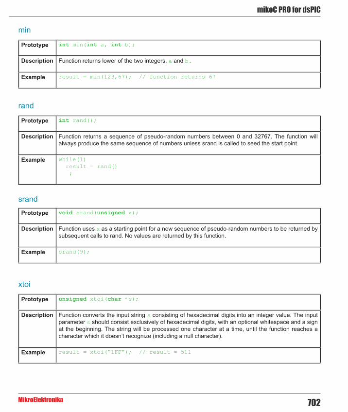
702
mikoC PRO for dsPIC
MikroElektronika
min
Prototype int min(int a, int b);
Description Function returns lower of the two integers, a and b.
Example result = min(123,67); // function returns 67
rand
Prototype int rand();
Description Function returns a sequence of pseudo-random numbers between 0 and 32767. The function will always produce the same sequence of numbers unless srand is called to seed the start point.
Example while(1) result = rand() ;
srand
Prototype void srand(unsigned x);
Description Function uses x as a starting point for a new sequence of pseudo-random numbers to be returned by subsequent calls to rand. No values are returned by this function.
Example srand(9);
xtoi
Prototype unsigned xtoi(char *s);
Description Function converts the input string s consisting of hexadecimal digits into an integer value. The input parameter s should consist exclusively of hexadecimal digits, with an optional whitespace and a sign at the beginning. The string will be processed one character at a time, until the function reaches a character which it doesn’t recognize (including a null character).
Example result = xtoi(“1FF”); // result = 511

mikroC PRO for dsPIC
MikroElektronika703
Div Structures
Copy Code To Clipboard
typedef struct divstruct { int quot; int rem; } div_t;
typedef struct ldivstruct { long quot; long rem; } ldiv_t;
typedef struct uldivstruct { unsigned long quot; unsigned long rem; } uldiv_t;

704
mikoC PRO for dsPIC
MikroElektronika
ANSI C String LibraryThe mikroC PRO for dsPIC30/33 and PIC24 provides a set of standard ANSI C library functions useful for manipulating strings and RAM memory.
Important: - Not all of the standard functions have been included. - The functions have been mostly implemented according to the ANSI C standard, but certain functions have been modified in order to facilitate dsPIC30/33 and PIC24 programming. Be sure to skim through the description before using standard C functions.
Library Functions
- memchr - memcmp - memcpy - memmove - memset - strcat - strchr - strcmp - strcpy - strlen - strncat - strncpy - strspn - strncmp - strstr - strcspn - strpbrk - strrchr - strtok
memchr
Prototype void *memchr(void *p, char n, unsigned int v);
Description Function locates the first occurrence of char n in the initial v bytes of memory area starting at the address p. The function returns the pointer to this location or 0 if the n was not found.
For parameter p you can use either a numerical value (literal/variable/constant) indicating memory address or a dereferenced value of an object, for example &mystring or &PORTB.
Example char txt[] = “mikroElektronika”;res = memchr(txt, ‘e’, 16); // example locates first occurrence of the letter ‘e’ in the string ‘txt’ in the first 16 characters of the string

mikroC PRO for dsPIC
MikroElektronika705
memcmp
Prototype int memcmp(void *s1, void *s2, int n);
Description Function compares the first n characters of objects pointed to by s1 and s2 and returns zero if the objects are equal, or returns a difference between the first differing characters (in a left-to-right evaluation). Accordingly, the result is greater than zero if the object pointed to by s1 is greater than the object pointed to by s2 and vice versa.
Example char txt[] = “mikroElektronika”;char txt_sub[] = “mikro;
res = memcmp(txt, txt_sub, 16); // returns 69, which is ASCII code of the first differing character - letter ‘E’
memcpy
Prototype void *memcpy(void *d1, void *s1, int n);
Description Function copies n characters from the object pointed to by s1 into the object pointed to by d1. If copying takes place between objects that overlap, the behavior is undefined. The function returns address of the object pointed to by d1.
Example char txt[] = “mikroElektronika”;char txt_sub[] = “mikr;
res = memcpy(txt+4, txt_sub, 4); // string ‘txt’ will be populated with the first 4 characters of the ‘txt_sub’ string, beginning from the 4th character // routine returns the address of the first populated character, if memory areas of the strings don’t overlap
memmove
Prototype void *memmove(void *to, void *from, int n);
Description Function copies n characters from the object pointed to by from into the object pointed to by to. Unlike memcpy, the memory areas to and from may overlap. The function returns address of the object pointed to by to.
Example char txt[] = “mikroElektronika”;char txt_sub[] = “mikr;
res = memmove(txt+7, txt_sub, 4); // string ‘txt’ will be populated with first 4 characters of the ‘txt_sub’ string, beginning from the 7th character // routine returns the address of the first populated character (memory areas of the object may overlap)

706
mikoC PRO for dsPIC
MikroElektronika
memset
Prototype void *memset(void *p1, char character, int n);
Description Function copies the value of the character into each of the first n characters of the object pointed by p1. The function returns address of the object pointed to by p1.
Example char txt[] = “mikroElektronika”;
memset(txt, ‘a’, 2); // routine will copy the character ‘a’ into each of the first ‘n’ characters of the string ‘txt’,
strcat
Prototype char *strcat(char *to, char *from);
Description Function appends a copy of the string from to the string to, overwriting the null character at the end of to. Then, a terminating null character is added to the result. If copying takes place between objects that overlap, the behavior is undefined. to string must have enough space to store the result. The function returns address of the object pointed to by to.
Example char txt[] = “mikroElektronika”;char *res;
txt[3] = 0;res = strcat(txt, “_test”); // routine will append the ‘_test’ at the place of the first null character, adding terminating null character to the result // routine returns the address of the ‘txt’ string
strchr
Prototype char *strchr(char *ptr, char chr);
Description Function locates the first occurrence of character chr in the string ptr. The function returns a pointer to the first occurrence of character chr, or a null pointer if chr does not occur in ptr. The terminating null character is considered to be a part of the string.
Example char txt[] = “mikroElektronika”;char *res;
res = strchr(txt, ‘E’); // routine will locate the character ‘E’ in the ‘txt’ string, and return the address of the character

mikroC PRO for dsPIC
MikroElektronika707
strcmp
Prototype int strcmp(char *s1, char *s2);
Description Function compares strings s1 and s2 and returns zero if the strings are equal, or returns a difference between the first differing characters (in a left-to-right evaluation). Accordingly, the result is greater than zero if s1 is greater than s2 and vice versa.
Example char txt = “mikroElektronika”;char txt_sub = “mikro”;int res;
res = strcmp(txt,txt_sub); // compares strings ‘txt’ and ‘txt_sub’ and returns returns a difference between the first differing characters, in this case 69
strcpy
Prototype char *strcpy(char *to, char *from);
Description Function copies the string from into the string to. If copying is successful, the function returns to. If copying takes place between objects that overlap, the behavior is undefined.
Example char txt = “mikroElektronika”;char txt_sub = “mikro_test”;int res;
res = strcpy(txt,txt_sub); // copies string ‘txt_sub’ to ‘txt’
strlen
Prototype int strlen(char *s);
Description Function returns the length of the string s (the terminating null character does not count against string’s length).
Example char txt = “mikroElektronika”;int result;
result = strlen(txt); // calculates the length of the ‘txt’ string, result = 16

708
mikoC PRO for dsPIC
MikroElektronika
strncat
Prototype char *strncat(char *to, char *from, int size);
Description Function appends not more than size characters from the string from to to. The initial character of from overwrites the null character at the end of to. The terminating null character is always appended to the result. The function returns to.
Example char txt = “mikroElektronika”;char txt_sub = “mikro”;char *result;
txt[5] = 0;result = strncat(txt,txt_sub,4); // routine appends first 4 characters from the string ‘txt_sub’ at the place of first null character in the ‘txt’ string
strncpy
Prototype char *strncpy(char *to, char *from, int size);
Description Function copies not more than size characters from string from to to. If copying takes place between objects that overlap, the behavior is undefined. If from is shorter than size characters, then to will be padded out with null characters to make up the difference. The function returns the resulting string to.
Example char txt = “mikroElektronika”;char txt_sub = “mikro_test”;int res;
res = strncpy(txt,txt_sub,4); // copies first 4 characters form the string ‘txt_sub’ to ‘txt’
strspn
Prototype int strspn(char *str1, char *str2);
Description Function returns the length of the maximum initial segment of str1 which consists entirely of characters from str2. The terminating null character at the end of the string is not compared.
Example char txt = “mikroElektronika”;char txt_sub = “mikro_test”;int res;
result = strspn(txt,txt_sub); // routne returns 4

mikroC PRO for dsPIC
MikroElektronika709
strncmp
Prototype int strncmp(char *s1, char *s2, char len);
Description Function lexicographically compares not more than len characters (characters that follow the null character are not compared) from the string pointed by s1 to the string pointed by s2. The function returns a value indicating the s1 and s2 relationship:
Value Meaning< 0 s1 “less than” s2= 0 s1 “equal to” s2> 0 s1 “greater than” s2
Example char txt = “mikroElektronika”;char txt_sub = “mikro”;int res;
res = strncmp(txt_sub,txt,3); // compares the first 3 characters from the string ‘txt’ with the sting ‘txt_sub’ and returns a difference
strstr
Prototype char *strstr(char *s1, char *s2);
Description Function locates the first occurrence of the string s2 in the string s1 (excluding the terminating null character).
The function returns pointer to first occurrence of s2 in s1; if no string was found, function returns 0. If s2 is a null string, the function returns 0.
Example char txt = “mikroElektronika”;char txt_sub = “mikro”;char *res;
res = strstr(txt_sub,txt);

710
mikoC PRO for dsPIC
MikroElektronika
strcspn
Prototype char *strcspn(char * s1, char *s2);
Description Function computes the length of the maximum initial segment of the string pointed to by s1 that consists entirely of characters that are not in the string pointed to by s2.
The function returns the length of the initial segment.
Example char txt = “mikroElektronika”;char txt_sub = “mikro”;char *res;
res = strcspn(txt_sub,txt);
strpbrk
Prototype char *strpbrk(char * s1, char *s2);
Description Function searches s1 for the first occurrence of any character from the string s2. The terminating null character is not included in the search. The function returns pointer to the matching character in s1. If s1 contains no characters from s2, the function returns 0.
Example char txt = “mikroElektronika”;char txt_sub = “mikro”;char *res;
res = strpbrk(txt_sub,txt);
strrchr
Prototype char *strrchr(char * ptr, char chr);
Description Function searches the string ptr for the last occurrence of character chr. The null character terminating ptr is not included in the search. The function returns pointer to the last chr found in ptr; if no matching character was found, function returns 0.
Example char txt = “mikroElektronika”;
res = strrchr(txt_sub,’k’); // returns the pointer to the ‘k’ character of the ‘txt’ string

mikroC PRO for dsPIC
MikroElektronika711
strtok
Prototype char *strtok(char *s1, char *s2);
Returns The strtok function returns a pointer to the first character of a token, or a null pointer if there is no token.
Description A sequence of calls to the strtok function breaks the string pointed to by s1 into a sequence of tokens, each of which is delimited by a character from the string pointed to by s2. The first call in the sequence has s1 as its first argument, and is followed by calls with a null pointer as their first argument. The separator string pointed to by s2 may be different from call to call.
The first call in the sequence searches the string pointed to by s1 for the first character that is not contained in the current separator string pointed to by s2. If no such character is found, then there are no tokens in the string pointed to by s1 and the strtok function returns a null pointer. If such character is found, it is the start of the first token.
The strtok function then searches from there for a character that is contained in the current separator string. If no such character is found, the current token extends to the end of the string pointed to by s1, and subsequent searches for a token will return a null pointer. If such a character is found, it is overwritten by a null character, which terminates the current token. The strtok function saves a pointer to the following character, from which the next search for a token will start.
Each subsequent call, with a null pointer as the value of the first argument, starts searching from the saved pointer and behaves as described above.
Example char x[10] ;
void main(){
strcpy(x, strtok(“mikroEl”, “Ek”)); strcpy(x, strtok(0, “kE”));
}

712
mikoC PRO for dsPIC
MikroElektronika
Miscellaneous Libraries - Button Library - Conversions Library - PrintOut Library - Setjmp Library - Sprint Library - Time Library - Trigonometry Library
Button LibraryThe Button Library provides routines for detecting button presses and debouncing (eliminating the influence of contact flickering upon pressing a button).
Library Routines
- Button
strrchr
Prototype unsigned int Button(unsigned int *port, unsigned int pin, unsigned int time, unsigned int active_state);
Description The function eliminates the influence of contact flickering upon pressing a button (debouncing). The Button pin is tested just after the function call and then again after the debouncing period has expired. If the pin was in the active state in both cases then the function returns 255 (true).
Parameters- port: button port address - pin: button pin - time: debouncing period in milliseconds - active_state: determines what is considered as active state. Valid values: 0 (logical zero) and 1 (logical one)
Returns-255 if the pin was in the active state for given period. - 0 otherwise
Requires Nothing.
Example if (Button(&PORTD, 0, 1, 1)) PORTB = 0xFF; ...
Notes None.
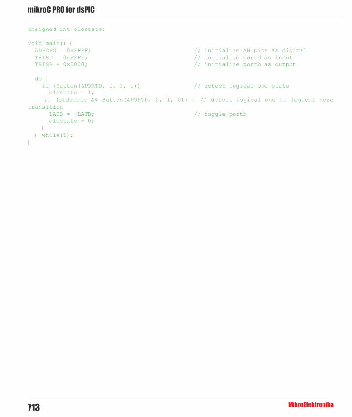
mikroC PRO for dsPIC
MikroElektronika713
unsigned int oldstate;
void main() { ADPCFG = 0xFFFF; // initialize AN pins as digital TRISD = 0xFFFF; // initialize portd as input TRISB = 0x0000; // initialize portb as output
do { if (Button(&PORTD, 0, 1, 1)) // detect logical one state oldstate = 1; if (oldstate && Button(&PORTD, 0, 1, 0)) { // detect logical one to logical zero transition LATB = ~LATB; // toggle portb oldstate = 0; } } while(1);}
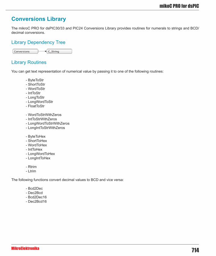
714
mikoC PRO for dsPIC
MikroElektronika
Conversions LibraryThe mikroC PRO for dsPIC30/33 and PIC24 Conversions Library provides routines for numerals to strings and BCD/decimal conversions.
Library Dependency Tree
Library Routines
You can get text representation of numerical value by passing it to one of the following routines:
- ByteToStr - ShortToStr - WordToStr - IntToStr - LongToStr - LongWordToStr - FloatToStr
- WordToStrWithZeros - IntToStrWithZeros - LongWordToStrWithZeros - LongIntToStrWithZeros
- ByteToHex - ShortToHex - WordToHex - IntToHex - LongWordToHex - LongIntToHex
- Rtrim - Ltrim
The following functions convert decimal values to BCD and vice versa:
- Bcd2Dec - Dec2Bcd - Bcd2Dec16 - Dec2Bcd16

mikroC PRO for dsPIC
MikroElektronika715
ByteToStr
Prototype void ByteToStr(unsigned short input, char *output);
Description Converts input byte to a string. The output string has fixed width of 4 characters including null character at the end (string termination). The output string is right justified and remaining positions on the left (if any) are filled with blanks.
Parameters- input: byte to be converted - output: destination string
Returns Nothing.
Requires Destination string should be at least 4 characters in length.
Example unsigned short t = 24;char txt[4];...ByteToStr(t, txt); // txt is “ 24” (one blank here)
Notes None.
ShortToStr
Prototype void ShortToStr(short input, char *output);
Description Converts input signed short number to a string. The output string has fixed width of 5 characters including null character at the end (string termination). The output string is right justified and remaining positions on the left (if any) are filled with blanks.
Parameters- input: signed short number to be converted - output: destination string
Returns Nothing.
Requires Destination string should be at least 5 characters in length.
Example short t = -24;char txt[5];...ShortToStr(t, txt); // txt is “ -24” (one blank here)
Notes None.

716
mikoC PRO for dsPIC
MikroElektronika
WordToStr
Prototype void WordToStr(unsigned input, char *output);
Description Converts input word to a string. The output string has fixed width of 6 characters including null character at the end (string termination). The output string is right justified and the remaining positions on the left (if any) are filled with blanks.
Parameters- input: word to be converted - output: destination string
Returns Nothing.
Requires Destination string should be at least 6 characters in length.
Example unsigned t = 437;char txt[6];...WordToStr(t, txt); // txt is “ 437” (two blanks here)
Notes None.
IntToStr
Prototype void IntToStr(int input, char *output);
Description Converts input signed integer number to a string. The output string has fixed width of 7 characters including null character at the end (string termination). The output string is right justified and the remaining positions on the left (if any) are filled with blanks.
Parameters- input: signed integer number to be converted - output: destination string
Returns Nothing.
Requires Destination string should be at least 7 characters in length.
Example int j = -4220;char txt[7];...IntToStr(j, txt); // txt is “ -4220” (one blank here)
Notes None.
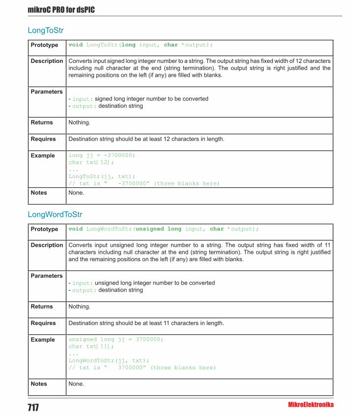
mikroC PRO for dsPIC
MikroElektronika717
LongToStr
Prototype void LongToStr(long input, char *output);
Description Converts input signed long integer number to a string. The output string has fixed width of 12 characters including null character at the end (string termination). The output string is right justified and the remaining positions on the left (if any) are filled with blanks.
Parameters- input: signed long integer number to be converted - output: destination string
Returns Nothing.
Requires Destination string should be at least 12 characters in length.
Example long jj = -3700000;char txt[12];...LongToStr(jj, txt);// txt is “ -3700000” (three blanks here)
Notes None.
LongWordToStr
Prototype void LongWordToStr(unsigned long input, char *output);
Description Converts input unsigned long integer number to a string. The output string has fixed width of 11 characters including null character at the end (string termination). The output string is right justified and the remaining positions on the left (if any) are filled with blanks.
Parameters- input: unsigned long integer number to be converted- output: destination string
Returns Nothing.
Requires Destination string should be at least 11 characters in length.
Example unsigned long jj = 3700000;char txt[11];...LongWordToStr(jj, txt);// txt is “ 3700000” (three blanks here)
Notes None.

718
mikoC PRO for dsPIC
MikroElektronika
FloatToStr
Prototype unsigned char FloatToStr(float fnum, unsigned char *str);
Description Converts a floating point number to a string.
The output string is left justified and null terminated after the last digit.
Parameters- fnum: floating point number to be converted - str: destination string
Returns- 3 if input number is NaN - 2 if input number is -INF - 1 if input number is +INF - 0 if conversion was successful
Requires Destination string should be at least 14 characters in length.
Examplefloat ff1 = -374.2;float ff2 = 123.456789;float ff3 = 0.000001234;char txt[15];...FloatToStr(ff1, txt); // txt is “-374.2”FloatToStr(ff2, txt); // txt is “123.4567”FloatToStr(ff3, txt); // txt is “1.234e-6”
Notes Given floating point number will be truncated to 7 most significant digits before conversion.

mikroC PRO for dsPIC
MikroElektronika719
WordToStrWithZeros
Prototype void WordToStrWithZeros(unsigned int input, char *output);
Description Converts input word to a string. The output string has fixed width of 6 characters including null character at the end (string termination). The output string is right justified and remaining positions on the left (if any) are filled with zeros.
Parameters- input: unsigned integer to be converted - output: destination string
Returns Nothing.
Requires Destination string should be at least 6 characters in length.
Example unsigned short t = 437;char txt[6];...WordToStrWithZeros(t, txt); // txt is “0437” (one zero here)
Notes None.
IntToStrWithZeros
Prototype void IntToStrWithZeros(int input, char *output);
Description Converts input integer to a string. The output string has fixed width of 7 characters including null character at the end (string termination). The output string is right justified and remaining positions on the left (if any) are filled with zeros.
Parameters- input: integer number to be converted - output: destination string
Returns Nothing.
Requires Destination string should be at least 7 characters in length.
Example short t = -3276;char txt[7];...IntToStrWithZeros(t, txt); // txt is “-03276” (one zero here)
Notes None.

720
mikoC PRO for dsPIC
MikroElektronika
LongWordToStrWithZeros
Prototype void LongWordToStrWithZeros(unsigned long input, char *output);
Description Converts input longword to a string. The output string has fixed width of 11 characters including null character at the end (string termination). The output string is right justified and the remaining positions on the left (if any) are filled with zeros.
Parameters- input: unsigned long number to be converted - output: destination string
Returns Nothing.
Requires Destination string should be at least 11 characters in length.
Example unsigned t = 12345678;char txt[11];...LongWordToStrWithZeros(t, txt); // txt is “0012345678” (two zeros)
Notes None.
LongIntToStrWithZeros
Prototype void LongIntToStrWithZeros(long input, char *output);
Description Converts input signed long integer number to a string. The output string has fixed width of 12 characters including null character at the end (string termination). The output string is right justified and the remaining positions on the left (if any) are filled with zeros.
Parameters- input: signed long number to be converted - output: destination string
Returns Nothing.
Requires Destination string should be at least 12 characters in length.
Example int j = -12345678;char txt[12];...LongIntToStrWithZeros(j, txt); // txt is “-0012345678” (one zero here)
Notes None.
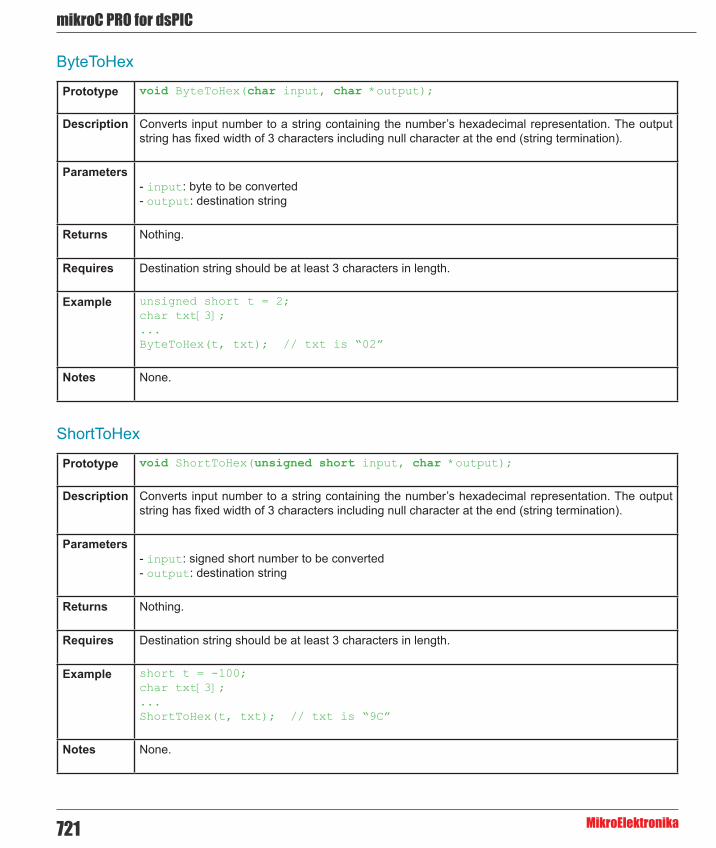
mikroC PRO for dsPIC
MikroElektronika721
ByteToHex
Prototype void ByteToHex(char input, char *output);
Description Converts input number to a string containing the number’s hexadecimal representation. The output string has fixed width of 3 characters including null character at the end (string termination).
Parameters- input: byte to be converted - output: destination string
Returns Nothing.
Requires Destination string should be at least 3 characters in length.
Example unsigned short t = 2;char txt[3];...ByteToHex(t, txt); // txt is “02”
Notes None.
ShortToHex
Prototype void ShortToHex(unsigned short input, char *output);
Description Converts input number to a string containing the number’s hexadecimal representation. The output string has fixed width of 3 characters including null character at the end (string termination).
Parameters- input: signed short number to be converted - output: destination string
Returns Nothing.
Requires Destination string should be at least 3 characters in length.
Example short t = -100;char txt[3];...ShortToHex(t, txt); // txt is “9C”
Notes None.

722
mikoC PRO for dsPIC
MikroElektronika
WordToHex
Prototype void WordToHex(unsigned input, char *output);
Description Converts input number to a string containing the number’s hexadecimal representation. The output string has fixed width of 5 characters including null character at the end (string termination).
Parameters- input: unsigned integer to be converted - output: destination string
Returns Nothing.
Requires Destination string should be at least 5 characters in length.
Example unsigned t = 1111;char txt[5];...WordToHex(t, txt); // txt is “0457”
Notes None.
IntToHex
Prototype void IntToHex(int input, char *output);
Description Converts input number to a string containing the number’s hexadecimal representation. The output string has fixed width of 5 characters including null character at the end (string termination).
Parameters- input: signed integer number to be converted - output: destination string
Returns Nothing.
Requires Destination string should be at least 5 characters in length.
Example int j = -32768;char txt[5];...IntToHex(j, txt); // txt is “8000”
Notes None.
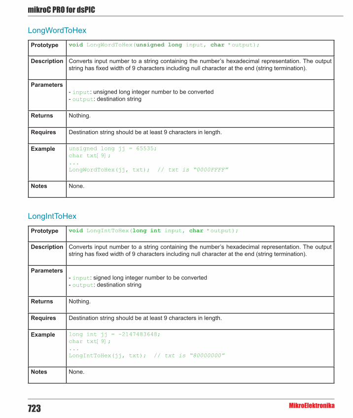
mikroC PRO for dsPIC
MikroElektronika723
LongWordToHex
Prototype void LongWordToHex(unsigned long input, char *output);
Description Converts input number to a string containing the number’s hexadecimal representation. The output string has fixed width of 9 characters including null character at the end (string termination).
Parameters- input: unsigned long integer number to be converted - output: destination string
Returns Nothing.
Requires Destination string should be at least 9 characters in length.
Example unsigned long jj = 65535;char txt[9];...LongWordToHex(jj, txt); // txt is “0000FFFF”
Notes None.
LongIntToHex
Prototype void LongIntToHex(long int input, char *output);
Description Converts input number to a string containing the number’s hexadecimal representation. The output string has fixed width of 9 characters including null character at the end (string termination).
Parameters- input: signed long integer number to be converted - output: destination string
Returns Nothing.
Requires Destination string should be at least 9 characters in length.
Example long int jj = -2147483648;char txt[9];...LongIntToHex(jj, txt); // txt is “80000000”
Notes None.

724
mikoC PRO for dsPIC
MikroElektronika
Dec2Bcd
Prototype unsigned short Dec2Bcd(unsigned short decnum);
Description Converts input unsigned short integer number to its appropriate BCD representation.
Parameters- decnum: unsigned short integer number to be converted
Returns Converted BCD value.
Requires Nothing.
Example unsigned short a, b;...a = 22;b = Dec2Bcd(a); // b equals 34
Notes None.
Bcd2Dec
Prototype unsigned short Bcd2Dec(unsigned short bcdnum);
Description Converts 8-bit BCD numeral to its decimal equivalent.
Parameters- bcdnum: 8-bit BCD numeral to be converted
Returns Converted decimal value.
Requires Nothing.
Example unsigned short a, b;...a = 34;b = Bcd2Dec(22); // b equals 22
Notes None.

mikroC PRO for dsPIC
MikroElektronika725
Dec2Bcd16
Prototype unsigned Dec2Bcd16(unsigned decnum);
Description Converts unsigned 16-bit decimal value to its BCD equivalent.
Parameters- decnum unsigned 16-bit decimal number to be converted
Returns Converted BCD value.
Requires Nothing.
Example unsigned a, b;...a = 2345;b = Dec2Bcd16(a); // b equals 9029
Notes None.
Bcd2Dec16
Prototype unsigned Bcd2Dec16(unsigned bcdnum);
Description Converts 16-bit BCD numeral to its decimal equivalent.
Parameters- bcdnum 16-bit BCD numeral to be converted
Returns Converted decimal value.
Requires Nothing.
Example unsigned a, b;...a = 0x1234; // a equals 4660b = Bcd2Dec16(a); // b equals 1234
Notes None.

726
mikoC PRO for dsPIC
MikroElektronika
Rtrim
Prototype char *Rtrim(char *string);
Description Trims the trailing spaces from array given with *string
Parameters- string: array to be trimmed.
Returns The function returns the address of the first non-space character.
Requires Nothing.
Example char *res;
res = Rtrim(“ mikroe”); // trims the trailing spaces and returns the address of the first non-space character
Notes None.
Ltrim
Prototype char *Ltrim(char *string);
Description 66 Trims the leading spaces from array given with *string
Parameters- string: array to be trimmed.
Returns The function returns the address of the first non-space character.
Requires Nothing.
Example char *res;
res = Ltrim(“ mikroe”); // trims the leading spaces and returns the address of the first non-space character
Notes None.
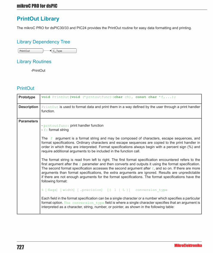
mikroC PRO for dsPIC
MikroElektronika727
PrintOut LibraryThe mikroC PRO for dsPIC30/33 and PIC24 provides the PrintOut routine for easy data formatting and printing.
Library Dependency Tree
Library Routines
-PrintOut
PrintOut
Prototype void PrintOut(void (*prntoutfunc)(char ch), const char *f,...);
Description PrintOut is used to format data and print them in a way defined by the user through a print handler function.
Parameters- prntoutfunc: print handler function - f: format string The f argument is a format string and may be composed of characters, escape sequences, and format specifications. Ordinary characters and escape sequences are copied to the print handler in order in which they are interpreted. Format specifications always begin with a percent sign (%) and require additional arguments to be included in the function call.
The format string is read from left to right. The first format specification encountered refers to the first argument after the f parameter and then converts and outputs it using the format specification. The second format specification accesses the second argument after f, and so on. If there are more arguments than format specifications, the extra arguments are ignored. Results are unpredictable if there are not enough arguments for the format specifications. The format specifications have the following format:
% [flags] [width] [.precision] [{ l | L }] conversion_type
Each field in the format specification can be a single character or a number which specifies a particular format option. The conversion_type field is where a single character specifies that an argument is interpreted as a character, string, number, or pointer, as shown in the following table:
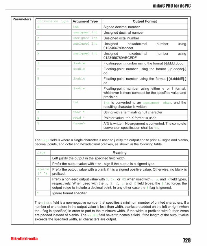
728
mikoC PRO for dsPIC
MikroElektronika
conversion_type Argument Type Output Formatd int Signed decimal numberu unsigned int Unsigned decimal numbero unsigned int Unsigned octal numberx unsigned int Unsigned hexadecimal number using
0123456789abcdefX unsigned int Unsigned hexadecimal number using
0123456789ABCEDFf double Floating-point number using the format [-]dddd.dddde double Floating-point number using the format [-]d.dddde[-]
ddE double Floating-point number using the format [-]d.ddddE[-]
ddg double Floating-point number using either e or f format,
whichever is more compact for the specified value and precision
c int int is converted to an unsigned char, and the resulting character is written
s char * String with a terminating null characterp void * Pointer value, the X format is used% <none> A % is written. No argument is converted. The complete
conversion specification shall be %%.
Parameters
The flags field is where a single character is used to justify the output and to print +/- signs and blanks, decimal points, and octal and hexadecimal prefixes, as shown in the following table.
The width field is a non-negative number that specifies a minimum number of printed characters. If a number of characters in the output value is less than width, blanks are added on the left or right (when the - flag is specified) in order to pad to the minimum width. If the width is prefixed with 0, then zeros are padded instead of blanks. The width field never truncates a field. If the length of the output value exceeds the specified width, all characters are output.
flags Meaning- Left justify the output in the specified field width.+ Prefix the output value with + or - sign if the output is a signed type.space (‘ ‘)
Prefix the output value with a blank if it is a signed positive value. Otherwise, no blank is prefixed.
# Prefix a non-zero output value with 0, 0x, or 0X when used with o, x, and X field types, respectively. When used with the e, E, f, g, and G field types, the # flag forces the output value to include a decimal point. In any other case the # flag is ignored.
* Ignore format specifier.

mikroC PRO for dsPIC
MikroElektronika729
Parameters The precision field is a non-negative number that specifies the number of characters to print, number of significant digits, or number of decimal places. The precision field can cause truncation or rounding of the output value in the case of a floating-point number as specified in the following table.
The optional characters l or L may immediately precede conversion_type to respectively specify long versions of the integer types d, i, u, o, x, and X.
You must ensure that the argument type matches that of the format specification. You can use type casts to ensure that the proper type is passed to printout.
flags Meaning of the precision fieldd, u, o, x, X The precision field is where you specify the minimum number of digits that will
be included in the output value. Digits are not truncated if the number of digits in an argument exceeds that defined in the precision field. If the number of digits in the argument is less than the precision field, the output value is padded on the left with zeros.
f The precision field is where you specify the number of digits to the right of the decimal point. The last digit is rounded.
e, E The precision field is where you specify the number of digits to the right of the decimal point. The last digit is rounded.
g The precision field is where you specify the maximum number of significant digits in the output value.
c, C The precision field has no effect on these field types.s The precision field is where you specify the maximum number of characters in
the output value. Excess characters are not output.
Returns Nothing.
Requires Nothing.
Example Print mikroElektronika example’s header file to UART.
void PrintHandler(char c){
UART1_Write(c);
}
void main(){ UART1_Init(9600); Delay_ms(100);

730
mikoC PRO for dsPIC
MikroElektronika
Example PrintOut(PrintHandler, “/*\r\n” “ * Project name:\r\n” “ PrintOutExample (Sample usage of PrintOut() function)\r\n” “ * Copyright:\r\n” “ (c) MikroElektronika, 2006.\r\n” “ * Revision History:\r\n” “ 20060710:\r\n” “ - Initial release\r\n” “ * Description:\r\n” “ Simple demonstration on usage of the PrintOut() function\r\n” “ * Test configuration:\r\n” “ MCU: PIC30F4013\r\n” “ Dev.Board: EasydsPIC4A\r\n” “ Oscillator: HS, %10.3fMHz\r\n” “ Ext. Modules: None.\r\n” “ SW: mikroC PRO for dsPIC30/33 and PIC24\r\n” “ * NOTES:\r\n” “ None.\r\n” “ */\r\n”, Get_Fosc_kHz()/1000.);
}
Notes None.

mikroC PRO for dsPIC
MikroElektronika731
Setjmp LibraryThe Setjmp library contains functions and types definitions for bypassing the normal function call and return discipline.
jmp_buf is an array of unsigned int type suitable for holding information needed to restore a calling environment. Type declaration is contained in the sejmp.h header file which can be found in the include folder of the compiler.
Library Routines
- Setjmp - Longjmp
Setjmp
Prototype int Setjmp(jmp_buf env);
Description This function saves calling position for a later use by Longjmp.
Parameters- env: buffer suitable for holding information needed for restoring calling environment
Returns- 0 if the return is from direct invocation - nonzero value if the return is from a call to Longjmp (this value will be set by the Longjmp routine)
Requires Nothing.
Example jmp_buf buf;...Setjmp(buf);
Notes None.

732
mikoC PRO for dsPIC
MikroElektronika
Longjmp
Prototype void Longjmp(jmp_buf env, int val);
Description Restores calling environment saved in env buffer by the most recent invocation of Setjmp. If there has been no such invocation, or the function containing the invocation of Setjmp has terminated in the interim, the behavior is undefined.
Parameters- env: buffer holding the information saved by the corresponding Setjmp invocation - val: value to be returned by the corresponding Setjmp function
Returns Nothing.
Requires Invocation of Longjmp must occur before return from the function in which Setjmp was called encounters.
Example jmp_buf buf;...Longjmp(buf, 2);
Notes None.
Library Example
This example demonstrates function cross calling using the Setjmp and Longjmp functions. When called, Setjmp saves its calling environment in its jmp_buf argument for a later use by Longjmp. Longjmp, on the other hand, restores the environment saved by the most recent invocation of Setjmp with the corresponding jmp_buf argument.

mikroC PRO for dsPIC
MikroElektronika733
Copy Code To Clipboard
#include <Setjmp.h>
jmp_buf buf; // Note: Program flow diagrams are indexed according // to the sequence of execution
void func33(){ // 2<------------| // | Delay_ms(1000); // | // | asm nop; // | Longjmp(buf, 2); // 3---------------->| asm nop; // | | // | |} // | | // | |void func(){ // 1<--------| | | // | | | portb = 3; // | | | if (Setjmp(buf) == 2) // 3<----------------| portb = 1; // 4-->| | | else // | | | func33(); // 2------------>| // | | // 4<--| |} // 5----->| | // | |void main() { // | | // | | PORTB = 0; // | | TRISB = 0; // | | // | | asm nop; // | | // | | func(); // 1-------->| // | asm nop; // 5<-----| Delay_ms(1000); PORTB = 0xFFFF;}

734
mikoC PRO for dsPIC
MikroElektronika
Sprint LibraryThe mikroC PRO for dsPIC30/33 and PIC24 provides the standard ANSI C Sprintf function for easy data formatting.
Note: In addition to ANSI C standard, the Sprint Library also includes two limited versions of the sprintf function (sprinti and sprintl) These functions take less ROM and RAM and may be more convenient for use in some cases.
Library Dependency Tree
Functions
- sprintf - sprintl - sprinti
sprintf
Prototype void sprintf(char *wh, const code char *f,...);
Returns The function returns the number of characters actually written to destination string.Description
sprintf is used to format data and print them into destination string.
Parameters:
- wh: destination string - f: format string
The f argument is a format string and may be composed of characters, escape sequences, and format specifications. Ordinary characters and escape sequences are copied to the destination string in the order in which they are interpreted. Format specifications always begin with a percent sign (%) and require additional arguments to be included in the function call.
The format string is read from left to right. The first format specification encountered refers to the first argument after f and then converts and outputs it using the format specification. The second format specification accesses the second argument after f, and so on. If there are more arguments than format specifications, then these extra arguments are ignored. Results are unpredictable if there are not enough arguments for the format specifications. The format specifications have the following format:
% [flags] [width] [.precision] [{ l | L }] conversion_typeEach field in the format specification can be a single character or a number which specifies a particular format option. The conversion_type field is where a single character specifies that the argument is interpreted as a character, string, number, or pointer, as shown in the following table:

mikroC PRO for dsPIC
MikroElektronika735
Description
The flags field is where a single character is used to justify the output and to print +/- signs and blanks, decimal points, and octal and hexadecimal prefixes, as shown in the following table.
The width field is a non-negative number that specifies the minimum number of printed characters. If a number of characters in the output value is less than width, then blanks are added on the left or right (when the - flag is specified) to pad to the minimum width. If width is prefixed with 0, then zeros are padded instead of blanks. The width field never truncates a field. If a length of the output value exceeds the specified width, all characters are output.
conversion_type Argument Type Output Formatd int Signed decimal numberu unsigned int Unsigned decimal numbero unsigned int Unsigned octal numberx unsigned int Unsigned hexadecimal number using
0123456789abcdefX unsigned int Unsigned hexadecimal number using
0123456789ABCEDFf double Floating-point number using the format [-]dddd.dddde double Floating-point number using the format [-]d.dddde[-]
ddE double Floating-point number using the format [-]d.ddddE[-]
ddg double Floating-point number using either e or f format,
whichever is more compact for the specified value and precision
c int int is converted to an unsigned char, and the resulting character is written
s char * String with a terminating null characterp void * Pointer value, the X format is used% <none> A % is written. No argument is converted. The complete
conversion specification shall be %%.
flags Meaning- Left justify the output in the specified field width.+ Prefix the output value with + or - sign if the output is a signed type.space (‘ ‘)
Prefix the output value with a blank if it is a signed positive value. Otherwise, no blank is prefixed.
# Prefix a non-zero output value with 0, 0x, or 0X when used with o, x, and X field types, respectively. When used with the e, E, f, g, and G field types, the # flag forces the output value to include a decimal point. In any other case the # flag is ignored.
* Ignore format specifier.

736
mikoC PRO for dsPIC
MikroElektronika
Parameters The precision field is a non-negative number that specifies a number of characters to print, number of significant digits or number of decimal places. The precision field can cause truncation or rounding of the output value in the case of a floating-point number as specified in the following table.
The optional characters l or L may immediately precede conversion_type to respectively specify long versions of the integer types d, i, u, o, x, and X.
You must ensure that the argument type matches that of the format specification. You can use type casts to ensure that the proper type is passed to sprintf.
flags Meaning of the precision fieldd, u, o, x, X The precision field is where you specify the minimum number of digits that will
be included in the output value. Digits are not truncated if the number of digits in an argument exceeds that defined in the precision field. If the number of digits in the argument is less than the precision field, the output value is padded on the left with zeros.
f The precision field is where you specify the number of digits to the right of the decimal point. The last digit is rounded.
e, E The precision field is where you specify the number of digits to the right of the decimal point. The last digit is rounded.
g The precision field is where you specify the maximum number of significant digits in the output value.
c, C The precision field has no effect on these field types.s The precision field is where you specify the maximum number of characters in
the output value. Excess characters are not output.
sprintl
Prototype void sprintl(char *wh, const code char *f,...);
Returns The function returns the number of characters actually written to destination string.
Description The same as sprintf, except it doesn’t support float-type numbers.
sprinti
Prototype void sprinti(char *wh, const code char *f,...);
Returns The function returns the number of characters actually written to destination string.
Description The same as sprintf, except it doesn’t support long integers and float-type numbers.

mikroC PRO for dsPIC
MikroElektronika737
Library Example
This is a demonstration of the standard C library sprintf routine usage. Three different representations of the same floating poing number obtained by using the sprintf routine are sent via UART.
Copy Code To Clipboard
double ww = -1.2587538e+1;char buffer[15];
void main(){
UART1_Init(4800); // Initialize UART module at 4800 bps Delay_ms(10); UART1_Write_Text(“Floating point number representation”); // Write message on UART
sprintf(buffer, “%12e”, ww); // Format ww and store it to buffer UART1_Write_Text(“rne format:”); // Write message on UART UART1_Write_Text(buffer); // Write buffer on UART
sprintf(buffer, “%12f”, ww); // Format ww and store it to buffer UART1_Write_Text(“rnf format:”); // Write message on UART UART1_Write_Text(buffer); // Write buffer on UART sprintf(buffer, “%12g”, ww); // Format ww and store it to buffer UART1_Write_Text(“rng format:”); // Write message on UART UART1_Write_Text(buffer); // Write buffer on UART}

738
mikoC PRO for dsPIC
MikroElektronika
Time LibraryThe Time Library contains functions and type definitions for time calculations in the UNIX time format which counts the number of seconds since the “epoch”. This is very convenient for programs that work with time intervals: the difference between two UNIX time values is a real-time difference measured in seconds.
What is the epoch?Originally it was defined as the beginning of 1970 GMT. (January 1, 1970 Julian day) GMT, Greenwich Mean Time, is a traditional term for the time zone in England.
The TimeStruct type is a structure type suitable for time and date storage. Type declaration is contained in __Time.h which can be found in the mikroC PRO for dsPIC30/33 and PIC24 Time Library Demo example folder.
Library Routines
- Time_dateToEpoch - Time_epochToDate - Time_dateDiff
Time_dateToEpoch
Prototype long Time_dateToEpoch(TimeStruct *ts);
Description This function returns the UNIX time : number of seconds since January 1, 1970 0h00mn00s.
Parameters- ts: time and date value for calculating UNIX time.
Returns Number of seconds since January 1, 1970 0h00mn00s.
Requires Nothing.
Example #include “__Time.h”...TimeStruct ts1;long epoch ;...//what is the epoch of the date in ts ?epoch = Time_dateToEpoch(&ts1) ;
Notes None.

mikroC PRO for dsPIC
MikroElektronika739
Time_epochToDate
Prototype void Time_epochToDate(long e, TimeStruct *ts);
Description Converts the UNIX time to time and date.
Parameters- e: UNIX time (seconds since UNIX epoch) - ts: time and date structure for storing conversion output
Returns Nothing.
Requires Nothing.
Example #include “__Time.h”...TimeStruct ts2;long epoch ;...//what date is epoch 1234567890 ?epoch = 1234567890 ;Time_epochToDate(epoch, &ts2) ;
Notes None.

740
mikoC PRO for dsPIC
MikroElektronika
Time_dateDiff
Prototype long Time_dateDiff(TimeStruct *t1, TimeStruct *t2);
Description This function compares two dates and returns time difference in seconds as a signed long. Result is positive if t1 is before t2, result is null if t1 is the same as t2 and result is negative if t1 is after t2.
Parameters- t1: time and date structure (the first comparison parameter) - t2: time and date structure (the second comparison parameter)
Parameters None.
Returns Time difference in seconds as a signed long.
Requires Nothing.
Example #include “__Time.h”...TimeStruct ts1, ts2;long diff ;...// how many seconds between these two dates contained in ts1 and ts2 buffers? diff = Time_dateDiff(&ts1, &ts2) ;
Notes None.

mikroC PRO for dsPIC
MikroElektronika741
Library Example
Demonstration of Time library routines usage for time calculations in UNIX time format.
Copy Code To Clipboard
#include “__Time.h”
TimeStruct ts1, ts2;long epoch;long diff;
void main() {
ts1.ss = 0; ts1.mn = 7; ts1.hh = 17; ts1.md = 23; ts1.mo = 5; ts1.yy = 2006;
/* * What is the epoch of the date in ts ? */ epoch = Time_dateToEpoch(&ts1); // 1148404020
/* * What date is epoch 1234567890 ? */ epoch = 1234567890; Time_epochToDate(epoch, &ts2); // {0x1E, 0x1F,0x17, 0x0D, 0x04, 0x02, 0x07D9}
/* * How much seconds between this two dates? */ diff = Time_dateDiff(&ts1, &ts2); // 86163870}

742
mikoC PRO for dsPIC
MikroElektronika
Trigonometry LibraryThe mikroC PRO for dsPIC30/33 and PIC24 implements fundamental trigonometry functions. These functions are implemented as look-up tables. Trigonometry functions are implemented in integer format in order to save memory.
Library Routines
- sinE3 - cosE3
sinE3
Prototype int sinE3(unsigned angle_deg);
Description The function calculates sine multiplied by 1000 and rounded to the nearest integer:
result = round(sin(angle_deg)*1000)
Parameters- angle_deg: input angle in degrees
Returns The function returns the sine of input parameter multiplied by 1000.
Requires Nothing.
Example int res;...res = sinE3(45); // result is 707
Notes Return value range: -1000..1000.
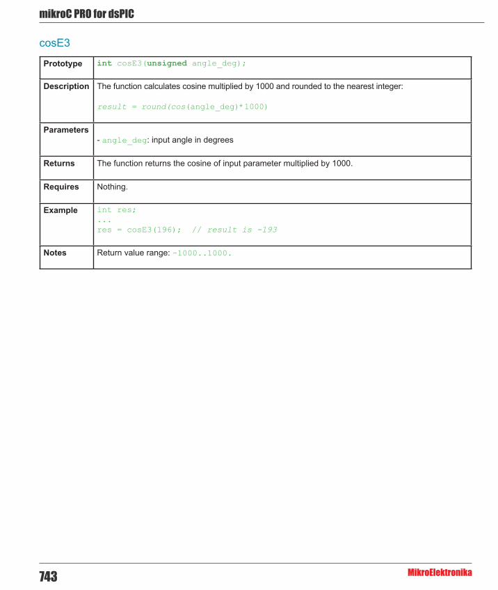
mikroC PRO for dsPIC
MikroElektronika743
cosE3
Prototype int cosE3(unsigned angle_deg);
Description The function calculates cosine multiplied by 1000 and rounded to the nearest integer:
result = round(cos(angle_deg)*1000)
Parameters- angle_deg: input angle in degrees
Returns The function returns the cosine of input parameter multiplied by 1000.
Requires Nothing.
Example int res;...res = cosE3(196); // result is -193
Notes Return value range: -1000..1000.

744
mikoC PRO for dsPIC
MikroElektronika
Managing Project
Projects
The mikroC PRO for dsPIC30/33 and PIC24 organizes applications into projects, consisting of a single project file (extension .mcpds) and one or more source files (extension .c). mikroC PRO for dsPIC30/33 and PIC24 IDE allows you to manage multiple projects (see Project Manager). Source files can be compiled only if they are part of a project.
The project file contains the following information:
- project name and optional description, - target device, - device flags (config word), - device clock, - list of the project source files with paths, - header files (*.h), - binary files (*.mcl), - image files, - other files.
Note that the project does not include files in the same way as preprocessor does, see Add/Remove Files from
Project.
CHAPTER 10Tutorials

mikroC PRO for dsPIC
MikroElektronika745
New ProjectThe easiest way to create a project is by means of the New Project Wizard, drop-down menu Project › New Project or
by clicking the New Project Icon from Project Toolbar.
New Project Wizard Steps
Start creating your New project, by clicking Next button:
Step One - Select the device from the device drop-down list:

746
mikoC PRO for dsPIC
MikroElektronika
Step Two - Enter the oscillator frequency value:
Step Three - Specify the location where your project will be saved:

mikroC PRO for dsPIC
MikroElektronika747
Step Four - Add project file to the project if they are avaiable at this point. You can always add project files later using Project Manager:
Step Five - Select inital Library Manager state:
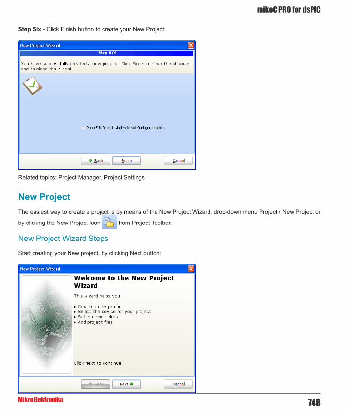
748
mikoC PRO for dsPIC
MikroElektronika
Step Six - Click Finish button to create your New Project:
Related topics: Project Manager, Project Settings
New ProjectThe easiest way to create a project is by means of the New Project Wizard, drop-down menu Project › New Project or
by clicking the New Project Icon from Project Toolbar.
New Project Wizard Steps
Start creating your New project, by clicking Next button:

mikroC PRO for dsPIC
MikroElektronika749
Step One - Select the device from the device drop-down list:
Step Two - Enter the oscillator frequency value:

750
mikoC PRO for dsPIC
MikroElektronika
Step Three - Specify the location where your project will be saved:
Step Four - Add project file to the project if they are avaiable at this point. You can always add project files later using Project Manager:

mikroC PRO for dsPIC
MikroElektronika751
Step Five - Select inital Library Manager state:
Step Six - Click Finish button to create your New Project:
Related topics: Project Manager, Project Settings
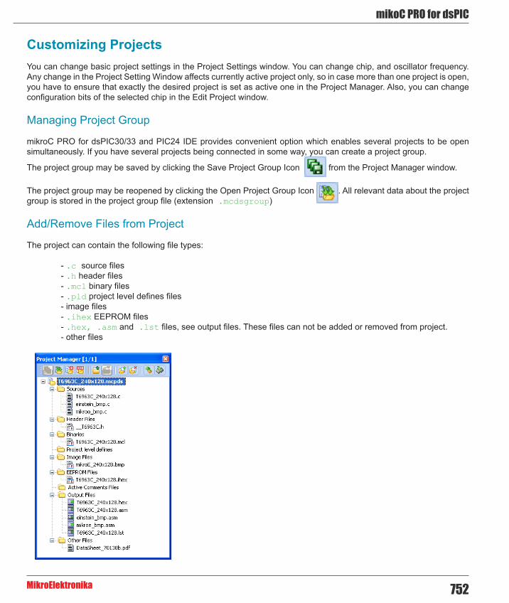
752
mikoC PRO for dsPIC
MikroElektronika
Customizing ProjectsYou can change basic project settings in the Project Settings window. You can change chip, and oscillator frequency. Any change in the Project Setting Window affects currently active project only, so in case more than one project is open, you have to ensure that exactly the desired project is set as active one in the Project Manager. Also, you can change configuration bits of the selected chip in the Edit Project window.
Managing Project Group
mikroC PRO for dsPIC30/33 and PIC24 IDE provides convenient option which enables several projects to be open simultaneously. If you have several projects being connected in some way, you can create a project group.
The project group may be saved by clicking the Save Project Group Icon from the Project Manager window.
The project group may be reopened by clicking the Open Project Group Icon . All relevant data about the project group is stored in the project group file (extension .mcdsgroup)
Add/Remove Files from Project
The project can contain the following file types:
- .c source files - .h header files - .mcl binary files - .pld project level defines files - image files - .ihex EEPROM files - .hex, .asm and .lst files, see output files. These files can not be added or removed from project. - other files
mikroC PRO for dsPIC
MikroElektronika753
The list of relevant files is stored in the project file (extension .mcpds).
To add a file to the project, click the Add File to Project Icon or press Insert button on your keyboard. Each
added source file must be self-contained, i.e. it must have all necessary definitions after preprocessing.
To remove file(s) from the project, click the Remove File from Project Icon or press Delete button on your keyboard.
Project Level Defines:
Project Level Defines (.pld) files can also be added to project. Project level define files enable you to have defines that are visible in all source files in the project. A file must contain one definition per line in the following form:
<symbol>=<value>
Define a macro named symbol. To specify a value, use =<value>. If =<value> is omitted, 1 is assumed. Do not enter white-space characters immediately before the “=”. If a white-space character is entered immediately after the “=”, the macro is defined as zero token. This option can be specified repeatedly. Each appearance of symbol will be replaced by the value before compilation.
For example, lets make a project level define named pld_test. First of all, create a new file with the .pld extension, pld_test_file.pld. Next, open it, and write something like this:
pld_test=3
Once you have done this, save the file. In the Project Manager, add pld_test_file.pld file by right-clicking the Project Level Defines node.
In the source code write the following:
#if pld_test == 3...#endif
There are number of predefined project level defines. See predefined project level defines
Note: For inclusion of the header files (extension .h), use the preprocessor directive #include. See File Inclusion for more information.
Related topics: Project Manager, Project Settings, Edit Project

754
mikoC PRO for dsPIC
MikroElektronika
Add/Remove Files from ProjectThe project can contain the following file types:
- .c source files - .h header files - .mcl binary files - .pld project level defines files - image files - .ihex EEPROM files - .hex, .asm and .lst files, see output files. These files can not be added or removed from project. - other files
The list of relevant files is stored in the project file (extension .mcpds).
To add a file to the project, click the Add File to Project Icon or press Insert button on your keyboard. Each
added source file must be self-contained, i.e. it must have all necessary definitions after preprocessing.
To remove file(s) from the project, click the Remove File from Project Icon or press Delete button on your keyboard.

mikroC PRO for dsPIC
MikroElektronika755
Project Level Defines:
Project Level Defines (.pld) files can also be added to project. Project level define files enable you to have defines that are visible in all source files in the project. A file must contain one definition per line in the following form:
<symbol>=<value>
Define a macro named symbol. To specify a value, use =<value>. If =<value> is omitted, 1 is assumed. Do not enter white-space characters immediately before the “=”. If a white-space character is entered immediately after the “=”, the macro is defined as zero token. This option can be specified repeatedly. Each appearance of symbol will be replaced by the value before compilation.
For example, lets make a project level define named pld_test. First of all, create a new file with the .pld extension, pld_test_file.pld. Next, open it, and write something like this:
pld_test=3
Once you have done this, save the file. In the Project Manager, add pld_test_file.pld file by right-clicking the Project Level Defines node.
In the source code write the following:
#if pld_test == 3...#endif
There are number of predefined project level defines. See predefined project level defines
Note: For inclusion of the header files (extension .h), use the preprocessor directive #include. See File Inclusion for more information.
Related topics: Project Manager, Project Settings, Edit Project

756
mikoC PRO for dsPIC
MikroElektronika
Source FilesSource files containing source code should have the extension .c. The list of source files relevant to the application is stored in project file with extension .mcpds, along with other project information. You can compile source files only if they are part of the project.
Use the preprocessor directive #include to include header files with the extension .h. Do not rely on the preprocessor to include source files other than headers — see Add/Remove Files from Project for more information.
Managing Source Files
Creating new source file
To create a new source file, do the following:
1. Select File › New Unit from the drop-down menu, or press Ctrl+N, or click the New File Icon from the File Toolbar. 2. A new tab will be opened. This is a new source file. Select File › Save from the drop-down menu, or press Ctrl+S, or
click the Save File Icon from the File Toolbar and name it as you want.
If you use the New Project Wizard, an empty source file, named after the project with extension .c, will be created automatically. The mikroC PRO for dsPIC30/33 and PIC24 does not require you to have a source file named the same as the project, it’s just a matter of convenience.
Opening an existing file
1. Select File › Open from the drop-down menu, or press Ctrl+O, or click the Open File Icon from the File
Toolbar. In Open Dialog browse to the location of the file that you want to open, select it and click the Open button. 2. The selected file is displayed in its own tab. If the selected file is already open, its current Editor tab will become active.
Printing an open file
1. Make sure that the window containing the file that you want to print is the active window. 2. Select File › Print from the drop-down menu, or press Ctrl+P. 3. In the Print Preview Window, set a desired layout of the document and click the OK button. The file will be printed on the selected printer.
Saving file
1. Make sure that the window containing the file that you want to save is the active window. 2. Select File › Save from the drop-down menu, or press Ctrl+S, or click the Save File Icon from the File Toolbar.

mikroC PRO for dsPIC
MikroElektronika757
Saving file under a different name
1. Make sure that the window containing the file that you want to save is the active window. 2. Select File › Save As from the drop-down menu. The New File Name dialog will be displayed. 3. In the dialog, browse to the folder where you want to save the file. 4. In the File Name field, modify the name of the file you want to save. 5. Click the Save button.
Closing file
1. Make sure that the tab containing the file that you want to close is the active tab. 2. Select File › Close from the drop-down menu, or right click the tab of the file that you want to close and select Close option from the context menu. 3. If the file has been changed since it was last saved, you will be prompted to save your changes.
Search Paths
You can specify your own custom search paths: select Project › Edit Search Paths... option from the drop-down menu:

758
mikoC PRO for dsPIC
MikroElektronika
Following options are available:
Icon Description
Add Search Path.
Remove Search Path.
Purge Invalid Paths.
Paths for Source Files (.c)
You can specify either absolute or relative path to the source file. If you specify a relative path, mikroC PRO for dsPIC30/33 and PIC24 will look for the file in following locations, in this particular order:
1. the project folder (folder which contains the project file .mcpds), 2. your custom search paths, 3. mikroC PRO for dsPIC30/33 and PIC24 installation folder > Uses folder.
Paths for Header Files (.h)
Header files are included by means of preprocessor directive #include. If you place an explicit path to the header file in preprocessor directive, only that location will be searched.
You can specify either absolute or relative path to the header. If you specify a relative path, mikroC PRO for dsPIC30/33 and PIC24 will look for the file in following locations, in this particular order:
1. the project folder (folder which contains the project file .h), 2. mikroC PRO for dsPIC30/33 and PIC24 installation folder > Include folder. 3. your custom search paths
Related topics:File Menu, File Toolbar, Project Manager, Project Settings

mikroC PRO for dsPIC
MikroElektronika759
Edit ProjectEdit Project gives you option to change MCU you wish to use, change its oscillator frequency and build type. Also, Edit Project enables you to alter specific configuration bits of the selected device.
As you alter these bits, appropriate register values will be updated also. This can be viewed in the Configuration Registers pane. When you have finished configuring your device, you can save bit configuration as a scheme, using button. In case you need this scheme in another project, you can load it using button. There is also a button which lets you select default configuration bit settings for the selected device.
Related topics: Project Settings, Customizing Projects

760
mikoC PRO for dsPIC
MikroElektronika
Source FilesSource files containing source code should have the extension .c. The list of source files relevant to the application is stored in project file with extension .mcpds, along with other project information. You can compile source files only if they are part of the project.
Use the preprocessor directive #include to include header files with the extension .h. Do not rely on the preprocessor to include source files other than headers — see Add/Remove Files from Project for more information.
Managing Source Files
Creating new source file
To create a new source file, do the following:
1. Select File › New Unit from the drop-down menu, or press Ctrl+N, or click the New File Icon from the File Toolbar. 2. A new tab will be opened. This is a new source file. Select File › Save from the drop-down menu, or press Ctrl+S, or click the Save File Icon from the File Toolbar and name it as you want.
If you use the New Project Wizard, an empty source file, named after the project with extension .c, will be created automatically. The mikroC PRO for dsPIC30/33 and PIC24 does not require you to have a source file named the same as the project, it’s just a matter of convenience.
Opening an existing file
1. Select File › Open from the drop-down menu, or press Ctrl+O, or click the Open File Icon from the File Toolbar. In Open Dialog browse to the location of the file that you want to open, select it and click the Open button. 2. The selected file is displayed in its own tab. If the selected file is already open, its current Editor tab will become active.
Printing an open file
1. Make sure that the window containing the file that you want to print is the active window. 2. Select File › Print from the drop-down menu, or press Ctrl+P. 3. In the Print Preview Window, set a desired layout of the document and click the OK button. The file will be printed on the selected printer.
Saving file
1. Make sure that the window containing the file that you want to save is the active window. 2. Select File › Save from the drop-down menu, or press Ctrl+S, or click the Save File Icon from the File Toolbar.

mikroC PRO for dsPIC
MikroElektronika761
Saving file under a different name
1. Make sure that the window containing the file that you want to save is the active window. 2. Select File › Save As from the drop-down menu. The New File Name dialog will be displayed. 3. In the dialog, browse to the folder where you want to save the file. 4. In the File Name field, modify the name of the file you want to save. 5. Click the Save button.
Closing file
1. Make sure that the tab containing the file that you want to close is the active tab. 2. Select File › Close from the drop-down menu, or right click the tab of the file that you want to close and select Close option from the context menu. 3. If the file has been changed since it was last saved, you will be prompted to save your changes.
Search Paths
You can specify your own custom search paths: select Project › Edit Search Paths... option from the drop-down menu:

762
mikoC PRO for dsPIC
MikroElektronika
Following options are available:
Icon Description
Add Search Path.
Remove Search Path.
Purge Invalid Paths.
Paths for Source Files (.c)
You can specify either absolute or relative path to the source file. If you specify a relative path, mikroC PRO for dsPIC30/33 and PIC24 will look for the file in following locations, in this particular order:
1. the project folder (folder which contains the project file .mcpds), 2. your custom search paths, 3. mikroC PRO for dsPIC30/33 and PIC24 installation folder > Uses folder.
Paths for Header Files (.h)
Header files are included by means of preprocessor directive #include. If you place an explicit path to the header file in preprocessor directive, only that location will be searched.
You can specify either absolute or relative path to the header. If you specify a relative path, mikroC PRO for dsPIC30/33 and PIC24 will look for the file in following locations, in this particular order:
1. the project folder (folder which contains the project file .h), 2. mikroC PRO for dsPIC30/33 and PIC24 installation folder > Include folder. 3. your custom search paths
Related topics:File Menu, File Toolbar, Project Manager, Project Settings,

mikroC PRO for dsPIC
MikroElektronika763
Clean Project FolderThis menu gives you option to choose which files from your current project you want to delete.Files marked in bold can be easily recreated by building a project. Other files should be marked for deletion only with a great care, because IDE cannot recover them.
Related topics: Customizing Projects

764
mikoC PRO for dsPIC
MikroElektronika
CompilationWhen you have created the project and written the source code, it’s time to compile it. Select Project › Build from the drop-down menu, or click the Build Icon from the Build Toolbar. If more more than one project is open you
can compile all open projects by selecting Project › Build All Projects from the drop-down menu, or click the Build All Projects Icon from the Build Toolbar.
Progress bar will appear to inform you about the status of compiling. If there are some errors, you will be notified in the Messages Window. If no errors are encountered, the mikroC PRO for dsPIC30/33 and PIC24 will generate output files.
Output Files
Upon successful compilation, the mikroC PRO for dsPIC30/33 and PIC24 will generate output files in the project folder (folder which contains the project file .mcpds). Output files are summarized in the table below:
Format Description File TypeIntel HEX Intel style hex records. Use this file to program
MCU..hex
Binary mikro Compiled Library. Binary distribution of application that can be included in other projects.
.mcl
List File Overview of MCU memory allotment: instruction addresses, registers, routines and labels.
.lst
Assembler File Human readable assembly with symbolic names, extracted from the List File.
.asm
Assembly View
After compiling the program in the mikroC PRO for dsPIC30/33 and PIC24, you can click the View Assembly icon
or select Project › View Assembly from the drop-down menu to review the generated assembly code (.asm file) in a new tab window. Assembly is human-readable with symbolic names.
Related topics: Project Menu, Project Toolbar, Messages Window, Project Manager, Project Settings

mikroC PRO for dsPIC
MikroElektronika765
Creating New Library
mikroC PRO for dsPIC30/33 and PIC24 allows you to create your own libraries. In order to create a library in mikroC PRO for dsPIC30/33 and PIC24 follow the steps bellow:
1. Create a new source file, see Managing Source Files 2. Save the file in one of the subfolders of the compiler’s Uses folder: DriveName:\Program Files\Mikroelektronika\mikroC PRO for dsPIC\Uses\3. Write a code for your library and save it. 4. Add __Lib_Example file in some project, see Project Manager. Recompile the project. If you wish to use this library for all MCUs, then you should go to Tools › Options › Output settings, and check Build all files as library box. This will build libraries in a common form which will work with all MCUs. If this box is not checked, then library will be built for selected MCU. Bear in mind that compiler will report an error if a library built for specific MCU is used for another one. 5. Compiled file __Lib_Example.mcl should appear in ...\mikroC PRO for dsPIC\Uses\ folder. 6. Open the definition file for the MCU that you want to use. This file is placed in the compiler’s Defs folder: DriveName:\Program Files\Mikroelektronika\mikroC PRO for dsPIC\Defs\ and it is named MCU_NAME.mlk, for example 30F4013.mlk 7. Add the the following segment of code to <LIBRARIES> node of the definition file (definition file is in XML format): <LIB> <ALIAS>Example_Library</ALIAS> <FILE>__Lib_Example</FILE> <TYPE>REGULAR</TYPE> </LIB> 8. Add Library to mlk file for each MCU that you want to use with your library. 9. Click Refresh button in Library Manager 10. Example_Library should appear in the Library manager window.
Multiple Library Versions
Library Alias represents unique name that is linked to corresponding Library .mcl file. For example UART library for 30F4013 is different from UART library for 30F6014 MCU. Therefore, two different UART Library versions were made, see mlk files for these two MCUs. Note that these two libraries have the same Library Alias (UART) in both mlk files. This approach enables you to have identical representation of UART library for both MCUs in Library Manager.
Related topics: Library Manager, Project Manager, Managing Source Files
766
mikoC PRO for dsPIC
MikroElektronika
Using Microchip MPLAB® IDE with mikroElektronika compilersThis new feature will boost your productivity by enabling you to import your code in a non-mikroElektronika enironment - Microchip’s MPLAB®. With the introduction of COFF File in mikroElektronika compiler, it is possible to debug and analyze your code through a software or hardware simulator.
Debugging Your Code
If your program has been built correctly, the compiler should generate a .hex file and a .cof file. The cof file contains all the information necessary for high-level debugging in MPLAB®, and it should be loaded by selecting the File › Import... menu in the MPLAB®. Once you have done this, you have two choices: either to use MPLAB® ICD 2 Debugger, if you have the appropriate hardware, or MPLAB® Simulator.
Trademarks: The Microchip name and logo, the Microchip logo, Accuron, dsPIC, KEELOQ, KEELOQ logo, microID, MPLAB, PIC, PICmicro, PICSTART, PRO MATE, rfPIC and SmartShunt are registered trademarks of Microchip Technology Incorporated in the U.S.A. and other countries.
Related topics: COFF File, Using MPLAB® ICD 2 Debugger, Using MPLAB® Simulator
Using MPLAB® ICD 2 DebuggerImportant: - It is assumed that MPLAB® and USB drivers for MPLAB® ICD 2 Debugger are previously installed. - Procedure described below is also relevant for MPLAB® ICD 3 Debugger. - Be sure to import compiled .hex file prior to importing .cof file, because it contains configuration bit settings which are essential for the proper functioning of the user code.
To successfully use MPLAB® ICD 2 Debugger with generated .cof file, follow the steps below:
1. First of all, start mikroC PRO for dsPIC30/33 and PIC24 and open the desired project. In this example, UART project for EasydsPIC4A board and dsPIC30F4013 will be opened. 2. Open Tools › Options › Output settings, and check the “Generate COFF file” option, and click the OK button. 3. After that, compile the project by pressing Ctrl + F9. 4. Connect USB cable and turn on power supply on EasydsPIC4A. 5. Program the MCU by pressing F11. 6. Connect external power supply, USB cable from PC and modular interface cable to the MPLAB® ICD 2 Debugger’s appropiate sockets, like on the picture below :

mikroC PRO for dsPIC
MikroElektronika767
7. Connect second end of the modular interface cable to the ICD (RJ12) socket of EasydsPIC4A :

768
mikoC PRO for dsPIC
MikroElektronika
8. Put the J11 and J10 Jumpers in the correct position, as showed in the picture below:
9. Next, open MPLAB®, and select the appropriate device by choosing Configure › Select Device... :
10. After device selection, click on the File › Import. Open file dialog box should appear. Then, go to the project folder and open the generated HEX file, UART.hex.
Note: This is very important, because hex file contains configuration bit settings which are essential for the proper functioning of the user code.

mikroC PRO for dsPIC
MikroElektronika769
11. Next, click the File › Import. Open file dialog box should appear. Then, go to the project folder and open the generated COFF file, UART.cof:
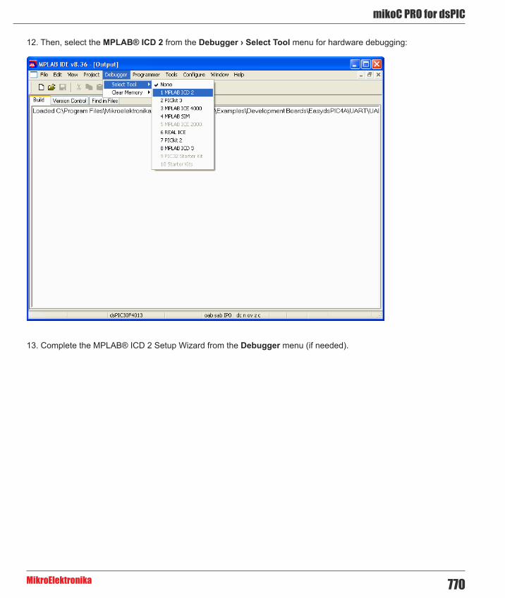
770
mikoC PRO for dsPIC
MikroElektronika
12. Then, select the MPLAB® ICD 2 from the Debugger › Select Tool menu for hardware debugging:
13. Complete the MPLAB® ICD 2 Setup Wizard from the Debugger menu (if needed).

mikroC PRO for dsPIC
MikroElektronika771
14. After completing MPLAB® ICD 2 Setup Wizard, click on the Debugger › Connect:

772
mikoC PRO for dsPIC
MikroElektronika
15. Finally, click on the Debugger › Program:

mikroC PRO for dsPIC
MikroElektronika773
16. Now, you can start debugging the code by clicking Step Over button on the Debug toolbar, or by pressing F8:
Related topics: COFF File, Using MPLAB® Simulator
Using MPLAB® SimulatorNote: It is assumed that MPLAB® is previously installed.
1. First of all, start mikroC PRO for dsPIC30/33 and PIC24 Help and open the desired project. In this example, UART project for EasydsPIC4A board and dsPIC30F4013 will be opened. 2. Open Tools › Options › Output settings, and check the “Generate COFF file” option, and click the OK button. 3. After that, compile the project by pressing Ctrl + F9. 4. Next, open MPLAB®, and select the appropriate device by choosing Configure › Select Device... :

774
mikoC PRO for dsPIC
MikroElektronika

mikroC PRO for dsPIC
MikroElektronika775
5. After device selection, click on the File › Import. Open file dialog box should appear. Then, go to the project folder and open the generated COFF file, UART.cof :
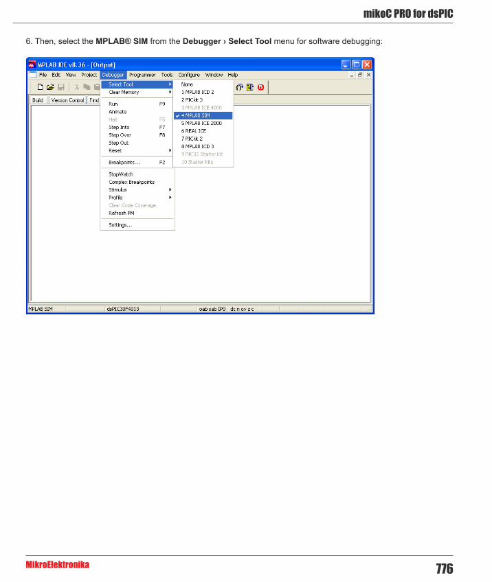
776
mikoC PRO for dsPIC
MikroElektronika
6. Then, select the MPLAB® SIM from the Debugger › Select Tool menu for software debugging:

mikroC PRO for dsPIC
MikroElektronika777
7. Now, you can start debugging the code by clicking Step Over button on the Debug toolbar, or by pressing F8:
Related topics: COFF File, Using MPLAB® ICD 2 Debugger

778
mikoC PRO for dsPIC
MikroElektronika
Frequently Asked QuestionsThis is a list of frequently asked questions about using mikroElektronika compilers. If your question is not answered on this page, please contact mikroElektronika Support Desk.
Can I use your compilers and programmer on Windows Vista (Windows 7) ?
Our compilers and programmer software are developed to work on and tested on Windows 98, Windows 2000, Windows ME, Windows XP (32 and 64 bit), Windows Vista (32 and 64 bit) and Windows 7 (32 and 64 bit) and they work fine on these operating systems. You can find the latest drivers on our website.
I am getting “Access is denied” error in Vista, how to solve this problem ?
Please turn off User Account Control (UAC). This should make your software fully functional. To do this, follow the path in your Windows Vista (logged in as administrator) Control Panel › User Accounts › Turn User Account Control on or off, uncheck Use User Account Control (UAC) and click OK.
What are differences between mikroC PRO, mikroPascal PRO and mikroBasic PRO compilers ? Why do they have different prices ?
Basically, there is little differences between these compilers. mikroC PRO is standardized with ANSI C, and it is much more complex and it is far more difficult to write the compiler for it. We used a lot more resources for making it than what we used for mikroPascal and mikroBasic. We also worked on some very complex topics such as floating point, typedef, union, a completely new debugger and many other. Because of that there is difference in price.
Why do your PIC compilers don’t support 12F508 and some similar chips ?
Unfortunately our PIC compilers don’t support 12F508 and similar chips because these chips are designed to use 12-bit wide instructions. Our compiler support MCUs which use 14-bit or wider instructions.
What are limitations of demo versions of mikroElektronika’s compilers ?
The only limitation of the free demo version is that it cannot generate hex output over 2K of program words. Although it may sound restrictive, this margin allows you to develop practical, working applications without ever thinking of demo limit. If you intend to develop really complex projects in one of our compilers, you should consider purchasing the license key.
Why do I still get demo limit error when I purchased and installed license key ?
If you are first time installing and registering compiler, you need to follow instructions exactly as described in registration procedure. License is valid only for the computer from which request is made, so license requested from one computer won’t work on another computer. You can find on our site manual and video describing in detail how to get your license. If you previously had an older version of our compiler and have working license key for it but it doesn’t work with new compiler, you have to repeat registration procedure from the new compiler and you will get a new license.

mikroC PRO for dsPIC
MikroElektronika779
I have bought license for the older version, do I have to pay license for the new version of the compiler ?
No, once you pay for the license key you get a lifetime license. When we release a new major release of the compiler, you might need to repeat registration procedure from your new compiler and you will get new license free of charge.
Do your compilers work on Windows Vista (Windows 7) ?
Yes!
What does this function/procedure/routine do ?
Please see your compiler’s Help where all of the functions are explained in detail.
I try to compile one of the provided examples and nothing happens, what is the problem?
You need to open project, not file. When you want to open an example, go to Project › Open Project, then browse through projects and choose project file. Now you will be able to compile and program with success.
Can I get your library sources ? I need to provide all sources with my project.
It is our company’s policy not to share our source code.
Can I use code I developed in your compilers in commercial purposes ? Are there some limitations ?
Regarding your code, there are no limitations. Your application is your own property and you can do whatever you like with it. If you want to include some of code we provide with our compilers or on our site, you may include them in your project, however, you are not allowed to charge your users for these.
Why does an example provided with your compilers doesn’t work ?
All of the examples provided with our compilers are tested and work fine. You need to read commented header of the example and be sure that you have used the same MCU example is written for and that you have hardware connections (DIP switches, jumpers etc.) set as described.
Your example works if I use the same MCU you did, but how to make it work for another MCU ?
You should read your MCU’s datasheet. Different MCUs can have different pin assignments and may require different settings. If you need help regarding this, you can find free online books on our website and recommend you starting there. You can also ask for help on our forum.

780
mikoC PRO for dsPIC
MikroElektronika
I need this project finished, can you help me ?
We currently do not do custom projects, however, we can give you some directions when you start working on your project and come to a problem. Also, our forum is very active community and as you can find there experts in different fields, we encourage you to look for help there.
Do you have some discount on your compilers/development systems for students/professors ?
Since large percentage of our customers are schools, laboratories and students, our prices are already scaled for these kinds of users. If you plan ordering more than one of our products, see special offers page on our website. Also, you can contact our Sales Department and see if you are eligible for some additional discount.
I have a question about your compilers which is not listed here. Where can I find an answer ?
Firstly, look for it in your compiler’s Help. If you don’t find an answer there, please create a support ticket on our website.

mikroC PRO for dsPIC
MikroElektronika781

If yo
u w
ant t
o le
arn
mor
e ab
out o
ur p
rodu
cts,
ple
ase
visi
t our
web
site
at w
ww
.mik
roe.
com
If yo
u ar
e ex
perie
ncin
g so
me
prob
lem
s w
ith a
ny o
f our
pro
duct
s or
just
nee
d ad
ditio
nal i
nfor
mat
ion,
ple
ase
plac
e yo
ur ti
cket
at
ww
w.m
ikro
e.co
m/e
n/su
ppor
t
If yo
u ha
ve a
ny q
uest
ions
, com
men
ts o
r bus
ines
s pr
opos
als,
do
not h
esita
te to
con
tact
us
at o
ffice
@m
ikro
e.co
m

Mouser Electronics
Authorized Distributor
Click to View Pricing, Inventory, Delivery & Lifecycle Information: mikroElektronika:
MIKROE-734