Microsoft PowerPoint - Guide RC project ngyt 2013 04 09
69
REINFORCED CONCRETE ‐ DESIGN GUIDE‐ 1 ST PART Prepared by NAGY‐GYÖRGY Tamás Phd, Lecturer [email protected] FLORUȚ Codruț Phd, Assistant Lecturer [email protected] ‐ 2013 ‐ ‐V2‐
-
Upload
independent -
Category
Documents
-
view
0 -
download
0
Transcript of Microsoft PowerPoint - Guide RC project ngyt 2013 04 09

REINFORCED CONCRETE‐ DESIGN GUIDE‐
1ST PART
Prepared by
NAGY‐GYÖRGY TamásPhd, Lecturer
FLORUȚ CodruțPhd, Assistant Lecturer
‐ 2013 ‐
‐V2‐

REFERENCES
SR EN 1992 1 1 2004 P i t t t il d b t P t 1 1 R li l t lădi iSR EN 1992-1-1: 2004, Proiectarea structurilor de beton, Partea 1-1: Reguli generale pentru clădiri(+AC:2008)
SR EN 1992-1-1/NB: 2008, Proiectarea structurilor de beton, Partea 1-1: Reguli generale pentru clădiri.Anexa Naționalăț
EN 1992-1-1: 2004, Design of concrete structures - Part 1-1: General rules and rules for buildings
SR EN 1991-1-1:2004, Acțiuni asupra structurilor. Partea 1-1: Acțiuni generale (+ NA:2006)
P 100-1/2006, Cod de proiectare seismică - Partea I - Prevederi de proiectare pentru clădiri
Cadar I., Clipii T., Tudor A., Beton Armat (ed. II), Ed. Orizonturi Universitare, 2004, ISBN 973-638-176-5
Kiss Z., Oneț T., Proiectarea structurilor de beton armat după SR EN 1992-1, Ed. Abel, 2008, ISBN973114070-0
Mosley W.H., Burgey J.H., Hulse R., Reinforced Concrete Design to Eurocode 2, Sixth Edition, 2007, ISBN:97802305007169780230500716
Nilson A., Darwin D., Dolan Ch., Design of Concrete Structures (13th Ed.), McGraw-Hill Co, 2004, ISBN 0-07-248305-9
Newman J., Choo B. S., Advanced Concrete Technology SET, Ed. Elsevier Science, 2003, ISBN-13:9780750656863

I. DESIGN OF A RC CAST‐IN‐PLACE SLAB
S O OO1. ELEMENTS OF A FLOOR
- STRUCTURAL ELEMENTS WITH STRENGTH ROLE- STRUCTURAL ELEMENTS , WITH STRENGTH ROLE- SLAB AND BEAMS (DISPOSED IN ONE OR TWO DIRECTIONS, WHICH SUPPORTS THESLAB)
NON STRUCTURAL ELEMENTS E G PROTECTIONS- NON-STRUCTURAL ELEMENTS, E.G. PROTECTIONS- FINISHING, FLOORS, ISOLATIONS (ACOUSTIC, HYDRO-), INSULATIONS
GIRDERS (MAIN BEAMS) BEING ALSO IN THE SAME TIME BEAMS OF THE FRAME( )
SECONDARY BEAMS DISPOSED PERPENDICULAR TO THE GIRDERS, BEINGEQUIDISTANT (AS IS MUCH AS IT IS POSSIBLE), THE DISTANCEBETWEEN THEIR AXIS BEINGBETWEEN THEIR AXIS BEING
IN THE CASE OF SLABS REINFORCED IN ONE DIRECTION THE RATIO
IN THE CASE OF SLABS REINFORCED IN ONE DIRECTION, THE RATIOOF A SLAB PANEL RESPECTS THE CONDITION:

I. DESIGN OF A RC CAST‐IN‐PLACE SLAB
1 ELEMENTS OF A FLOOR1. ELEMENTS OF A FLOOR
The cast-in-place floor is a space structure, because, through concrete andt l i f t li k b t th t l t i t dsteel reinforcement a link between the component elements is created.
The computation of a space structure is quite difficult, therefore, in design ist d th l l ti f h t t l l t t l t ki i taccepted the calculation of each structural element separately, taking into
account the load transmission modes, in vertical direction, toward the supports.
I thi it ld b d itt d th t th l b (S) i t d b th dIn this way, it could be admitted that the slab (S) is supported by the secondarybeams (SB), the secondary beams are supported by the girders (G) and columns(C) and the girders together with columns are forming the frame, which transmitsthe loads to the foundations (F) and to the terrainthe loads to the foundations (F) and to the terrain.
S → SB → frame = G + C → F → terrain
The route of the loads specifies the order in which the design of the structural element must be done, i.e.design of the slab, then secondary beams, girders, etc.

I. DESIGN OF A RC CAST‐IN‐PLACE SLAB
S O OO1. ELEMENTS OF A FLOORGirdersSecondary beams
Slab panel
Columns
Detail A
(ope
ning
)
(bay) Transversal sections
girder secondary beam
L
secondary beam
girderDetail A
n x B
L
Girdersecondary beam
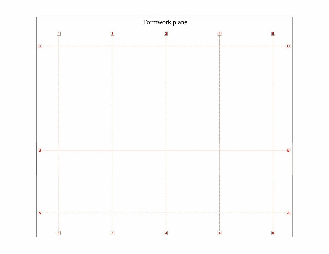
Formwork plane

Formwork plane

Formwork plane

Formwork plane

Formwork plane

Formwork plane

Formwork plane

Formwork plane

I. DESIGN OF A RC CAST‐IN‐PLACE SLAB
S O OO1. ELEMENTS OF A FLOOR
DESIGN PHASESDESIGN PHASES- PRE-DIMENSIONING: choosing the structural elements’ dimensionsaccording to the recommendations, in such a way to correspond also to othercriteria that the strength;g ;
- COMPUTATION OF THE LOADS: determination of the design loads,knowing the structural elements dimensions, the composition of non-structuralelements, destination and location of the construction;
- ESTABLISHING THE STATIC SCHEME FOR DESIGN based on the designf th l tspans of the elements;
- STATIC DESIGN: determining the most unfavourable effects of design loadswhich acting on the admitted static scheme It can be solved by using CADwhich acting on the admitted static scheme. It can be solved by using CADprograms or manually, with approximate methods;

I. DESIGN OF A RC CAST‐IN‐PLACE SLAB
S O OO1. ELEMENTS OF A FLOOR
DESIGN PHASESDESIGN PHASES- THE PROPER DESIGN, through following steps:
- finalization of the elements’ cross section, based on the results,from the static calculations and on the used material characteristics;
- computation of the reinforcement area and setting their layout;
- execution drawing, which includes the framework plane andreinforcement layout, reinforcement details and material consumptions( l f th t d i f t)(volume of the concrete and reinforcement).
I. DESIGN OF A RC CAST‐IN‐PLACE SLAB
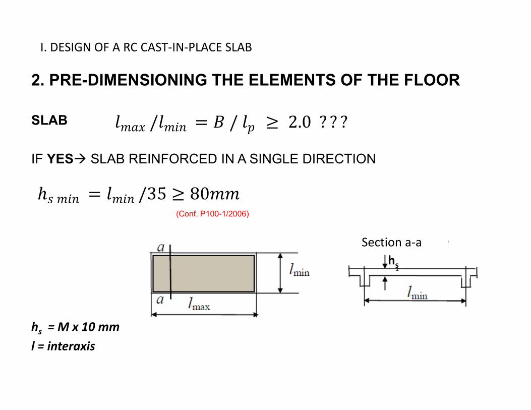
2 PRE DIMENSIONING THE ELEMENTS OF THE FLOOR2. PRE-DIMENSIONING THE ELEMENTS OF THE FLOOR
SLAB
IF YES SLAB REINFORCED IN A SINGLE DIRECTION
(Conf. P100-1/2006)
Section a‐ahs
hs = M x 10 mm
l = interaxis

I. DESIGN OF A RC CAST‐IN‐PLACE SLAB
2 PRE DIMENSIONING THE ELEMENTS OF THE FLOOR2. PRE-DIMENSIONING THE ELEMENTS OF THE FLOOR
BEAMS
DIMENSION RECOMMENDATIONS
L/(12…15) ‐ girders
HEIGHT
Minimum, hmin
/( 5) g de s
L/20 ‐ secondary beams
L/(8…12) ‐ girdersOptimum, hopt
L/(8…12) girders
L/(12…15) ‐ secondary beams
WIDTH h/b = 1.5 … 3 ‐ rectangular section
b i = 200 mm
WIDTH h/b 1.5 … 3 rectangular section
bmin = 200 mm
h, b = M x 50 mm
L = interaxis

I. DESIGN OF A RC CAST‐IN‐PLACE SLAB
2 PRE DIMENSIONING THE ELEMENTS OF THE FLOOR2. PRE-DIMENSIONING THE ELEMENTS OF THE FLOOR
COLUMNS (is chosen)
bCOL = (bG + 5cm) ≥ 350 mm
hCOL ≈ 1,2 bCOL
h, b = M x 50 mm

I. DESIGN OF A RC CAST‐IN‐PLACE SLAB
3 COMPUTATION OF LOADS3. COMPUTATION OF LOADS
ACTION CHARACTERISTICS EXAMPLES
PERMANENTVariation in time is negligible
Self‐weight: structural elements,finishing, etc.
Loads resulted from using of the
VARIABLEVariation in time is important
Loads resulted from using of the buildings (live loads)
Wind
SSnow
ACCIDENTALHigh intensity, reduced time of action
Earthquake
Explosion
Design value of action Partial safety
coefficient
Characteristic value of action

I. DESIGN OF A RC CAST‐IN‐PLACE SLAB
3 COMPUTATION OF LOADS3. COMPUTATION OF LOADS
GENERALLY, THESE LOADS CAN BE CONSIDERED UNIFORMLYDISTRIBUTED ON THE SLAB SURFACE AND THERE ARE EXPRESSED INkN/m2.
FOR THE CHARACTERISTIC VALUES k
DESIGN VALUES d

I. DESIGN OF A RC CAST‐IN‐PLACE SLAB
3 COMPUTATION OF LOADS3. COMPUTATION OF LOADS
PERMANENT (DEAD) CHARACTERISTIC LOADS : gk( ) gk
‐ SELF‐WEIGHTP ,
- RC SLAB ,
- PLASTER
- FLOOR
,
FLOOR- Asphalt
- Mosaic
,2
,2 2
- Pavement
- Cement concrete lining
,2
,2
I. DESIGN OF A RC CAST‐IN‐PLACE SLAB
3 COMPUTATION OF LOADS3. COMPUTATION OF LOADS
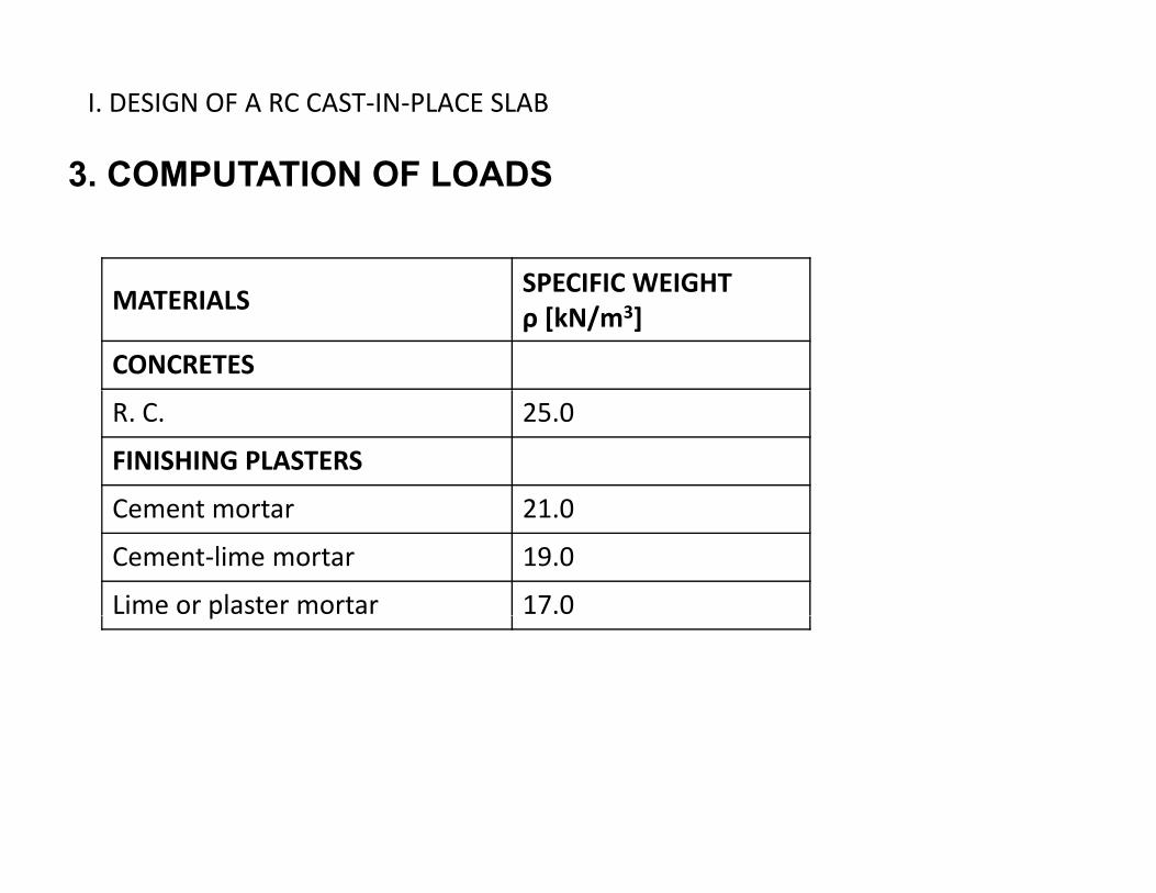
SPECIFIC WEIGHTMATERIALS
SPECIFIC WEIGHT ρ [kN/m3]
CONCRETES
R. C. 25.0
FINISHING PLASTERS
C t t 21 0Cement mortar 21.0
Cement‐lime mortar 19.0
Lime or plaster mortar 17.0p

I. DESIGN OF A RC CAST‐IN‐PLACE SLAB
3 COMPUTATION OF LOADS3. COMPUTATION OF LOADS
VARIABLE (LIVE) CHARACTERISTIC LOADS: qk( ) qk
‐ IMPOSED LOADSQ ,
- CATEGORIES OF USE ,
- PARTITION WALLS ,
(according to SR EN 1991-1-1:2004)

I. DESIGN OF A RC CAST‐IN‐PLACE SLAB
3 COMPUTATION OF LOADS3. COMPUTATION OF LOADS
PERMANENT DESIGN LOADS
VARIABLE DESIGN LOADS
TYPE OF LOADPARTIAL SAFETY FACTOR FOR ACTIONS
TYPE OF LOAD γF
PERMANENT LOADS γg = 1.35
VARIABLE LOADS γq = 1.50

I. DESIGN OF A RC CAST‐IN‐PLACE SLAB
3 COMPUTATION OF LOADS3. COMPUTATION OF LOADS
LOAD COMBINATION
- In the design, actions are combined to produce the most unfavorable effectson the structureon the structure
- The combinations are specific for the limit state which is used in design
- Dimensioning and verification of the concrete sections and the reinforcementswill be done in Ultimate Limit State (ULS)
- General form in conf. of CR 0, ch. 4.3 (!):
,1 0, ,
I. DESIGN OF A RC CAST‐IN‐PLACE SLAB
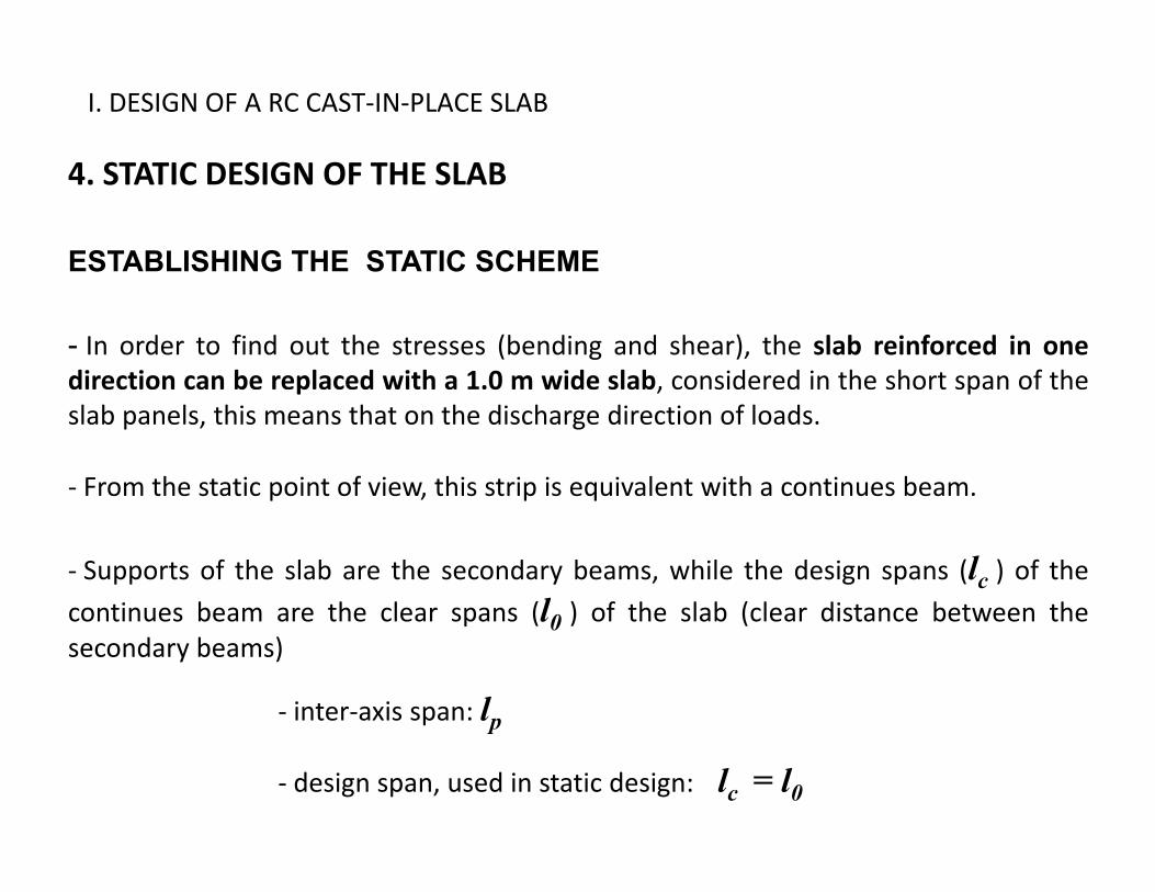
4 STATIC DESIGN OF THE SLAB4. STATIC DESIGN OF THE SLAB
ESTABLISHING THE STATIC SCHEME
- In order to find out the stresses (bending and shear), the slab reinforced in onedirection can be replaced with a 1.0 m wide slab, considered in the short span of thep , pslab panels, this means that on the discharge direction of loads.
‐ From the static point of view, this strip is equivalent with a continues beam.
‐ Supports of the slab are the secondary beams, while the design spans (lc ) of the
continues beam are the clear spans (l0 ) of the slab (clear distance between thecontinues beam are the clear spans (l0 ) of the slab (clear distance between thesecondary beams)
‐ inter‐axis span: lpp
‐ design span, used in static design: lc = l0

I. DESIGN OF A RC CAST‐IN‐PLACE SLAB
4 STATIC DESIGN OF THE SLAB4. STATIC DESIGN OF THE SLAB
ESTABLISHING THE STATIC SCHEME
-The real slab is replaced with a continues beam having spans of lc and linear
distributed loads of pd x 1 m [kN/m]
Envelope curves
gd,gs/qd,gs = 0,5
gd,gs/qd,gs = 5

I. DESIGN OF A RC CAST‐IN‐PLACE SLAB
4 STATIC DESIGN OF THE SLAB4. STATIC DESIGN OF THE SLAB
ESTABLISHING THE STATIC SCHEME
-The real slab is replaced with a continues beam having spans of lc and linear
distributed loads of pd x 1 m [kN/m]
1414
← envelope curves

I. DESIGN OF A RC CAST‐IN‐PLACE SLAB
5 DIMENSIONING OF THE SLAB5. DIMENSIONING OF THE SLAB
CHARACTERISTIC AND DESIGN STRENGTH
CONCRETEQ lit f t i d fi d b th t th l hi h i th h t i tiQuality of concrete is defined by the strength class, which is the characteristic
compressive strength on cylinders
Concrete class is
Design compressive strength of concrete
,
Design compressive strength of concrete
REINFORCEMENT
Design strength of reinforcement

I. DESIGN OF A RC CAST‐IN‐PLACE SLAB
5 DIMENSIONING OF THE SLAB5. DIMENSIONING OF THE SLAB
CHARACTERISTIC AND DESIGN STRENGTH

I. DESIGN OF A RC CAST‐IN‐PLACE SLAB
5 DIMENSIONING OF THE SLAB5. DIMENSIONING OF THE SLAB
FINALIZING THE THICKNESS OF THE SLAB
Design section of the slab
hs
s s
Reinforcement of the slabpopt (%) for reinforcing with
fyk = 400 … 500 N/mm2 fyk = 300 … 400 N/mm2
In 1 direction 0 25 0 50 0 30 0 60‐ In 1 direction 0,25 … 0,50 0,30 … 0,60
‐ In 2 directions 0,20 … 0,50 0,25 … 0,50

I. DESIGN OF A RC CAST‐IN‐PLACE SLAB
5 DIMENSIONING OF THE SLAB5. DIMENSIONING OF THE SLAB
FINALIZING THE THICKNESS OF THE SLAB
Checking of the chosen thickness (necessary)
MEd ‐ themaximum bending moment from the static design
b 000b = 1000 mm
or μ = f(ω) table , where1 0.5
, in function of popt100

I. DESIGN OF A RC CAST‐IN‐PLACE SLAB
5 DIMENSIONING OF THE SLAB5. DIMENSIONING OF THE SLAB
FINALIZING THE THICKNESS OF THE SLAB
Computation of the necessary slab thickness
where,
/2
∆

I. DESIGN OF A RC CAST‐IN‐PLACE SLAB
5 DIMENSIONING OF THE SLAB5. DIMENSIONING OF THE SLAB
FINALIZING THE THICKNESS OF THE SLAB
Computation of the necessary slab thickness
bond
max , ; , ; 10
bond
durability,
0.1 2
durability
!!!!!!!!! in function of the Exposure Class and Structural class (Ch. 4.4 )∆ 5
, 10 25
hs = M x 10 mm

I. DESIGN OF A RC CAST‐IN‐PLACE SLAB
5. DIMENSIONING OF THE SLAB
FINALIZING THE THICKNESS OF THE SLABFINALIZING THE THICKNESS OF THE SLAB
If
OK, ,
If
RE-CALCULATION OF THE LOADS MOMENTS
FINALIZING THE SLAB THICKNESS
, ,

I. DESIGN OF A RC CAST‐IN‐PLACE SLAB
5 DIMENSIONING OF THE SLAB5. DIMENSIONING OF THE SLAB
CALCULATION OF THE REINFORCEMENT AREA
Effective depth:
2

I. DESIGN OF A RC CAST‐IN‐PLACE SLAB
5 DIMENSIONING OF THE SLAB5. DIMENSIONING OF THE SLAB
DETAILING RULES – principal reinforcements(SR EN 1992-1-1/ Ch. 9)
, 0.26 0.0013
, 0.04
1 5 2001.5 200 . .80
straight (bound) bars
0.1 2
6
welded bars (welded fabrics)5
ngyt1

Slide 37
ngyt1 in conformity with the N.A.tamas.nagygyorgy; 02.03.2011

I. DESIGN OF A RC CAST‐IN‐PLACE SLAB
5 DIMENSIONING OF THE SLAB5. DIMENSIONING OF THE SLAB
DETAILING RULES – principal reinforcements(SR EN 1992-1-1/ Ch. 9)
- At the edge of the slab
, 25% ,
- Perpendicular to the girder , 6/ .
logsgs
lo /4
GP gsgs

I. DESIGN OF A RC CAST‐IN‐PLACE SLAB
5 DIMENSIONING OF THE SLAB5. DIMENSIONING OF THE SLAB
DETAILING RULES – secondary reinforcements(SR EN 1992-1-1/ Ch. 9)
= min 20% A= min 20% As
2.5 300 . . ngyt2

Slide 39
ngyt2 in conformity with the N.A.tamas.nagygyorgy; 02.03.2011

I. DESIGN OF A RC CAST‐IN‐PLACE SLAB
5 DIMENSIONING OF THE SLAB5. DIMENSIONING OF THE SLAB
DETAILING RULES – welded wire mesh (fabric) reinforcements(SR EN 1992-1-1/ Ch. 9)
- At the edge of the slab
, 50% ,
- Perpendicular to the girder
, , 5/150logsgs
lo /4
GP gsgs
I. DESIGN OF A RC CAST‐IN‐PLACE SLAB
5 DIMENSIONING OF THE SLAB
4.52cm2 3.50cm2
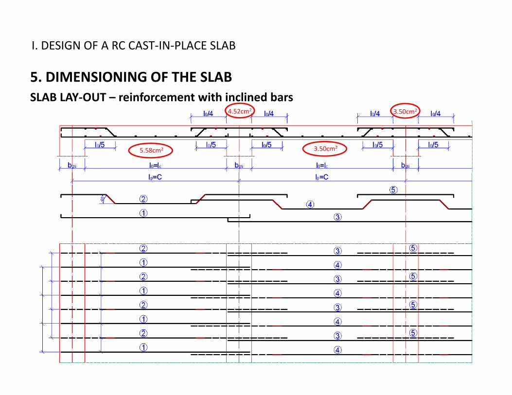
5. DIMENSIONING OF THE SLABSLAB LAY‐OUT – reinforcement with inclined bars
5.58cm2 3.50cm2

I. DESIGN OF A RC CAST‐IN‐PLACE SLAB
5 DIMENSIONING OF THE SLAB
4.52cm2 3.50cm2
5. DIMENSIONING OF THE SLABSLAB LAY‐OUT – reinforcement with inclined bars
5.58cm2 3.50cm2

I. DESIGN OF A RC CAST‐IN‐PLACE SLAB
5 DIMENSIONING OF THE SLAB5. DIMENSIONING OF THE SLABSLAB LAY‐OUT – reinforcement with straight bars
4.52cm2 3.50cm2
5.58cm2 3.50cm2

I. DESIGN OF A RC CAST‐IN‐PLACE SLAB
5 DIMENSIONING OF THE SLAB5. DIMENSIONING OF THE SLABSLAB LAY‐OUT – reinforcement with welded wire mesh (welded fabric)

I. DESIGN OF A RC CAST‐IN‐PLACE SLAB
5 DIMENSIONING OF THE SLAB5. DIMENSIONING OF THE SLAB
CHECKING THE SLAB FOR SHEAR FORCES
Generally, in the case of usual slabs with low thickness, the reinforcement isresulting from the design for bending and reinforcement for shear force is notneeded.needed.
To verify this:
,
, , 100 1/3 0.035 · 3/2 · 1/2 ·
, 0.18/
1200
2.00 0.02

II. DESIGN OF THE SECONDARY BEAM
1. COMPUTATION OF LOADS
s.b.s.b.
s.b
lo sbbG bG
Gs.b
G
B
bsb

II. DESIGN OF THE SECONDARY BEAM
1. COMPUTATION OF LOADS
s.b.
s.b
bsblo sbbG bG
G
s.b
G
P , ,
B IT IS THE TOTALLOAD!!!
Q , ,
, , ,

II. DESIGN OF THE SECONDARY BEAM
2. STATIC DESIGN OF THE SECONDARY BEAM
ESTABLISHING THE STATIC SCHEMEESTABLISHING THE STATIC SCHEME
‐ The secondary beam will be computed as a continues beam, with design
spans , the supports being the girders.0p , pp g g0,
11

II. DESIGN OF THE SECONDARY BEAM
3. DIMENSIONING OF THE SECONDARY BEAM
As1 – Step 2 As1 – Step 2
As2 = the minimum betweens2the reinforcements obtainedfrom the adjacent spans inStep 1 (here from M1 and M2)
As1 ‐ Step 1 As1 ‐ Step 1

II. DESIGN OF THE SECONDARY BEAM
3. DIMENSIONING OF THE SECONDARY BEAM
FINALIZING THE HEIGHT OF THE SECONDARY BEAMFINALIZING THE HEIGHT OF THE SECONDARY BEAM
Checking the chosen height (necessary)
MEd - maximum bending moment from the static designbsb - from pre-dimensioning
or μ = f(ω) table, where1 0.5
, in function of popt ≈ 1.2 … 1.8100
II. DESIGN OF THE SECONDARY BEAM
3. DIMENSIONING OF THE SECONDARY BEAM
FINALIZING THE HEIGHT OF THE SECONDARY BEAMFINALIZING THE HEIGHT OF THE SECONDARY BEAM
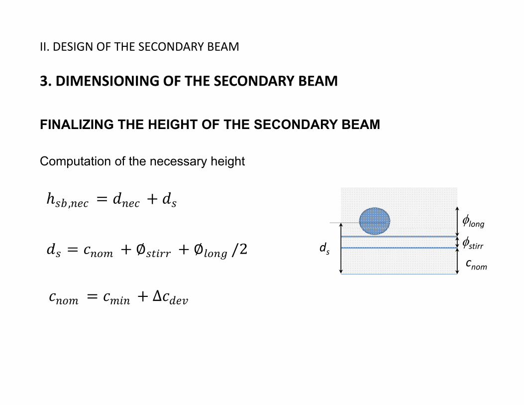
Computation of the necessary height
,long
/2 stirrcnom
ds
∆

II. DESIGN OF THE SECONDARY BEAM
3. DIMENSIONING OF THE SECONDARY BEAM
FINALIZING THE HEIGHT OF THE SECONDARY BEAMFINALIZING THE HEIGHT OF THE SECONDARY BEAM
Computation of the necessary heightbond
max , ; , ; 10
bond
!!!!!!!!!!!!!!!!!! in function of the Exposure Class
,
20 …25
durability
and Structural class (Ch. 4.4 )
∆ 10, 10 25
hsb = M x 50 mm and then verification hsb /bsb =1,5 … 3,0 ???
∆ 10

II. DESIGN OF THE SECONDARY BEAM
3. DIMENSIONING OF THE SECONDARY BEAM
FINALIZING THE HEIGHT OF THE SECONDARY BEAMFINALIZING THE HEIGHT OF THE SECONDARY BEAM
If
OK, ,
If
RE-CALCULATION OF THE LOADS MOMENTS
FINALIZING THE HEIGHT OF THE SECONDARY BEAM
, ,

II. DESIGN OF THE SECONDARY BEAM
3. DIMENSIONING OF THE SECONDARY BEAM
DESIGN OF THE REINFORCEMENTS IN SPANDESIGN OF THE REINFORCEMENTS IN SPAN simple reinforced T section
Th ff ti idth f th fl (b ) d d th b d flThe effective width of the flange (beff ), depends on the web and flangedimensions, the type of loading, the span, the support conditions and thetransverse reinforcement.
lThe effective width of the flange (beff ) should be based on the distance l0between points of zero moment.
(B) (B) (B)

II. DESIGN OF THE SECONDARY BEAM
3. DIMENSIONING OF THE SECONDARY BEAM
DESIGN OF THE REINFORCEMENTS IN SPANDESIGN OF THE REINFORCEMENTS IN SPAN simple reinforced T section
beff
,
0 2 0 1 0 2, 0,2 0,1 0 0,2 0
,

II. DESIGN OF THE SECONDARY BEAM
3. DIMENSIONING OF THE SECONDARY BEAM
DESIGN OF THE REINFORCEMENTS IN SPANDESIGN OF THE REINFORCEMENTS IN SPAN simple reinforced T section
T bl th d Table method
/
ω /
22
If μ > μlim re-dimensioning of the section

II. DESIGN OF THE SECONDARY BEAM
3. DIMENSIONING OF THE SECONDARY BEAM
DETAILING RULESDETAILING RULES(SR EN 1992-1-1/ Ch. 9 and P100/1-2006, Ch.5)
f i i0 26 0 0013 - for non-seismic zones, 0.26 0.0013
- for seismic zones (b = bw)
0 04
, 0.50 0.0013
- according to P100/1-2006
, 0.04
2514
25
II. DESIGN OF THE SECONDARY BEAM
3. DIMENSIONING OF THE SECONDARY BEAM
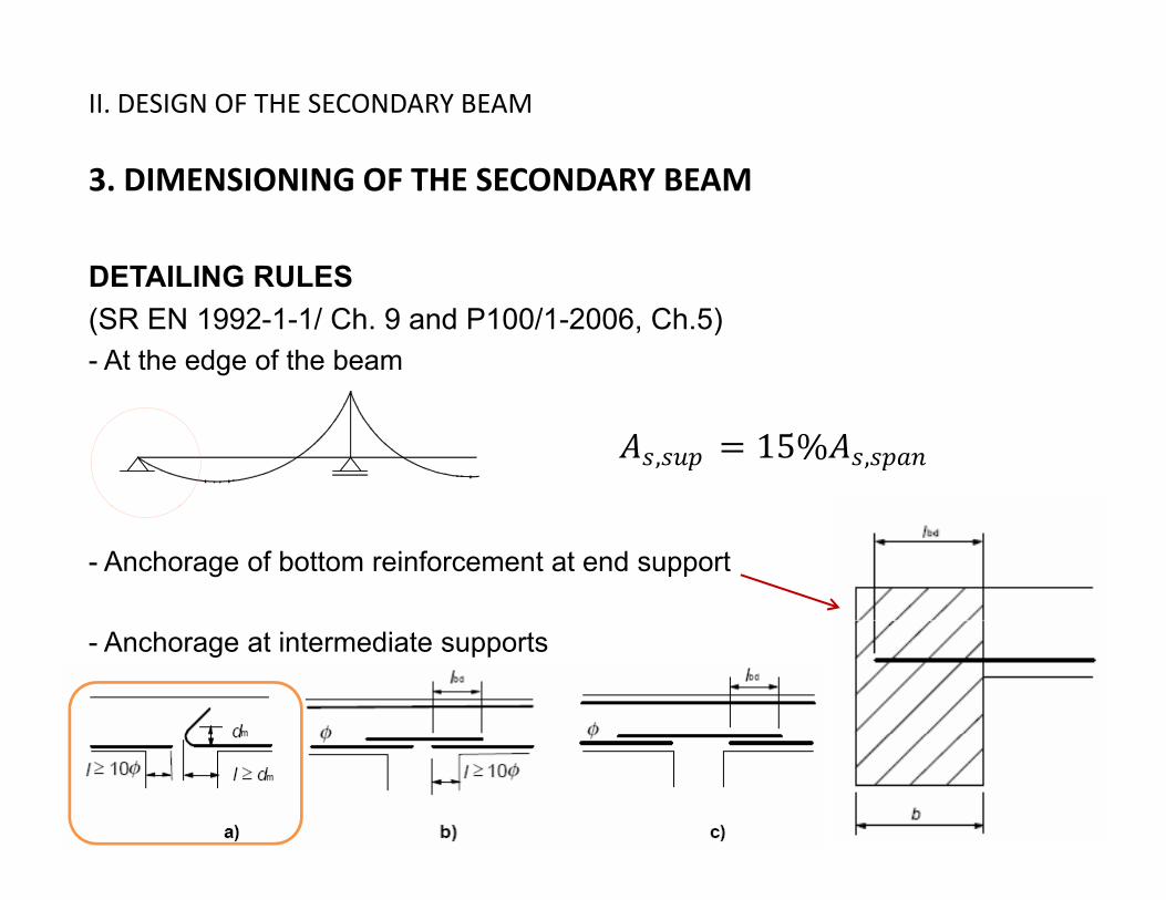
DETAILING RULESDETAILING RULES(SR EN 1992-1-1/ Ch. 9 and P100/1-2006, Ch.5)- At the edge of the beam
, 15% ,
- Anchorage of bottom reinforcement at end support
- Anchorage at intermediate supports

II. DESIGN OF THE SECONDARY BEAM
3. DIMENSIONING OF THE SECONDARY BEAM
DETAILING RULESDETAILING RULES>0.3lo >0.3lo >0.3lo
~10cm ~10cm ~10cm
A B
l≥10d
A B
lbdmin 2ø
2ø8 secondary
min 2ø
lbd min 2ømin 2ø

II. DESIGN OF THE SECONDARY BEAM
3. DIMENSIONING OF THE SECONDARY BEAM
DETAILING RULESDETAILING RULES
(ch. 8.4.4)1 2 3 4 5 , ,
, /4 /4 ·
·
for anchorages in tension0 3 ; 10 ; 100 for anchorages in tension
for anchorages in compression
, 0.3 , ; 10 ; 100
, 0.6 , ; 10 ; 100

II. DESIGN OF THE SECONDARY BEAM
3. DIMENSIONING OF THE SECONDARY BEAM
DESIGN OF THE REINFORCEMENTS ON THE SUPPORTSDESIGN OF THE REINFORCEMENTS ON THE SUPPORTS double reinforced rectangular cross section
AAs1 unknown
As2(reinforcement from the span)

II. DESIGN OF THE SECONDARY BEAM
3. DIMENSIONING OF THE SECONDARY BEAM
DESIGN OF THE REINFORCEMENTS ON THE SUPPORTSDESIGN OF THE REINFORCEMENTS ON THE SUPPORTS double reinforced rectangular cross section
I l l t d 2 2 IT IS THE MINIMUMIs calculated
- If μa > μlim re-dimensioning of the section
2 22 EFFECTIVE AREA !!!
μa μlim g
- If μa < 0 12
- If 0 < μa < μlim , from μa ωa
2
μa μlim μa a
As1 = Aa + As2

II. DESIGN OF THE SECONDARY BEAM
3. DIMENSIONING OF THE SECONDARY BEAM
DESIGN FOR SHEAR FORCEDESIGN FOR SHEAR FORCEComputation the shear resistance of concrete
100 1/3 0 035 · 3/2 · 1/2 ·
0 18/ 200
, , 100 0.035
, 0.18/ 1200
2.00
0.020.02

II. DESIGN OF THE SECONDARY BEAM
3. DIMENSIONING OF THE SECONDARY BEAM
DESIGN FOR SHEAR FORCEDESIGN FOR SHEAR FORCE
If minimum shear reinforcement will be provide,
· · , 0.08
, 0.75 1 300
For providing of double-arm stirrups400

II. DESIGN OF THE SECONDARY BEAM
3. DIMENSIONING OF THE SECONDARY BEAM
DESIGN FOR SHEAR FORCEDESIGN FOR SHEAR FORCE
If is imposed θ = 45o (crack),α = 90o (stirrups)where z ≈ 0,9d
·
choose Asw = n x øsw snec
â and then must be verified if

II. DESIGN OF THE SECONDARY BEAM
3. DIMENSIONING OF THE SECONDARY BEAM
DESIGN FOR SHEAR FORCEDESIGN FOR SHEAR FORCEDETAILING RULES
T h d til f il To have a ductile failure , ,
0 50.5 1
Where 1 0.6 1250

III. DESIGN OF SLAB DEFLECTION
( )1. DESIGN OF SLAB DEFLECTIONS (Axis VM)
‐ Supports blocked in ZSupports blocked in Z
‐ Permanent loads applied simultaneously
‐ Variable loads applied in chess and/or strips
Design combination in SLS in conformity of CR 0, ch. 4.4:
1,1 ,1 2, ,


![(Microsoft PowerPoint - MI2oct 09.ppt [tryb zgodno\234ci])](https://static.fdokumen.com/doc/165x107/6334652f4e43a4bcd80d3474/microsoft-powerpoint-mi2oct-09ppt-tryb-zgodno234ci.jpg)