microcontroller based autometic fire control & monitoring system
60
MICROCONTROLLER BASED AUTOMETIC FIRE CONTROL & MONITORING SYSTEM SUBMITTED BY MD. TAMZID-AL-NOOR ID: 093-33-116 MD. FARHAD HOSSAIN ID: 093-33-112 A Thesis submitted in partial fulfillment of the requirements for the Bachelor of Science degree in Electrical & Electronic Engineering SUPERVISED BY MD. MAHMUDUR RAHMAN Senior Lecturer Department of EEE Daffodil International University DAFFODIL INTERNATIONAL UNIVERSITY DHAKA, BANGLADESH February 2014
-
Upload
khangminh22 -
Category
Documents
-
view
0 -
download
0
Transcript of microcontroller based autometic fire control & monitoring system

i
MICROCONTROLLER BASED AUTOMETIC FIRE
CONTROL & MONITORING SYSTEM
SUBMITTED BY
MD. TAMZID-AL-NOOR
ID: 093-33-116
MD. FARHAD HOSSAIN ID: 093-33-112
A Thesis submitted in partial fulfillment of the requirements for the Bachelor of Science degree
in Electrical & Electronic Engineering
SUPERVISED BY
MD. MAHMUDUR RAHMAN
Senior Lecturer
Department of EEE Daffodil International University
DAFFODIL INTERNATIONAL UNIVERSITY
DHAKA, BANGLADESH
February 2014
ii
Declaration We do hereby declare that the thesis titled “Microcontroller based automatic fire Control & Monitoring” has been done by us under the supervision of Md. Mahmudur Rahman, Senior Lecturer, Department of EEE, Daffodil International University. This is our original work and was not submitted elsewhere for the award of any other degree or any other publication. Date: 10-02-2014
Thesis Supervisor: __________________________________ Md. Mahmudur Rahman Senior Lecturer Department of EEE Daffodil International University
Submitted by:
_________________________ Md. Tamzid - Al - Noor Student ID: 093-33-116 __________________________ Md. Farhad Hossain Student ID: 093-33-112

iii
ACKNOWLEDGEMENT
First we express our heartiest thanks and gratefulness to almighty Allah for His divine
blessing makes us possible to complete this project successfully.
We would like to take this opportunity to express our heartfelt gratitude to our
supervisor Mr. Md. Mahmudur Rahman sir for his guidance, and instruction that he
has given us to complete our thesis project in such a short time. We have been able to
learn the skills from him, which have benefitted us immensely and will continue to
help us throughout our future endeavors, both academically and professionally. We
have been challenged in our education and have grown from it both as a person and as
engineers.
We would like to express our heartiest gratitude to Professor Dr. M. Shamsul Alam,
Dean, Faculty of Engineering (FE) and Professor Dr. Md. Fayzur Rahman, Head,
Department of EEE for their kind help to finish our thesis and also to other faculty
members and the staffs of EEE department of Daffodil International University. We
would like to thank our entire course mate in Daffodil International University, who
took part in this discuss while completing the course work.
Finally, we must acknowledge with due respect the constant supports and patients of
our parents.
iv
ABSTRACT
Fire alarm system plays an important role in maintaining and monitoring the safe of
all kind environments and situations. However the usability of many existing fire
alarm system is well known but could be produce with high cost. Subsequently, it is
not affordable for the low income users. The main objective of this project is to make
a fire control system with low cost. The project has three main systems, 1) the
detection system, 2) the monitoring system and 3) the appliance system. The detection
system operates as the fire detector. This detection system has components like flame
detector, smoke detector, light detector, heat detector etc. This paper discusses the
design and implementation of a fire alarm system using the microcontroller which
operates the entire system. The detectors are placed in parallel in different levels. Any
signal from each detector at any level is monitored using monitoring system. The
appliance system has components like buzzer for alarming and motor pump to stop
the fire. The entire system is controlled by microcontroller. The microcontroller is
programmed in such way by using C-Programming. From the project done, the
system can detects smoke, light, flame, heat etc. sensed by the detector, followed by
the monitoring system which indicates smoke, light, flame, heat etc. at that particular
level. Finally when the sensors form each level triggered individually, the main
buzzer operates and disconnect the AC power supply. Then it shows in the control
panel LCD display which area is affected and which is safe. Then it runs the
emergency exit motor to escape and the water pump motor to the affected zone to stop
the fire.

v
TABLE OF CONTENTS
CONTENTS PAGES
Declaration ……………………………………………………………………. ii
Acknowledgement...…………………………………………………………... Abstract …………....…………….……………………………………………. Table of Contents ……………………………………………………………. List of Figure ……………………………………………………………….. List of Table …………………………………………………………………
iii iv v-vii viii ix
CHAPTERS CHAPTER 1: Introduction
1-3
1.1 General Introduction ……………………………………………………. 1.2 Goal of the research work ……………………………………………….. 1.3 Problem Identification ………..…………………………………………... 1.4 Project Objective …………………………………………………………. 1.5 Project Scope ……………………………………………………………... 1.6 Thesis Structure …………………………...……………………………… CHAPTER 2: Theoretical Background 2.1 System Overview …………………….…………………………………… 2.2 Heat Detector ……..………………………………………………………. 2.2.1 Thermocouple …………………………………………………………... 2.2.2 RTD ………….…….…………………………………………………… 2.2.3 Thermistor ……………………………………………………………….
1 2 2 2 3 3 4-20 4 5 6 6 6
vi
2.2.4 Semiconductor ………………………………………………………….. 2.2.4.1 LM35 Temperature Sensor...………………………………………….. 2.3 N-MOSFET ………………………………………………………………. 2.3.1 BC548 NPN Transistor …….…………………………………………… 2.4 Relay …………...…......………...………………………………………… 2.5 Arduino Platform …......………...………………………………………… 2.5.1 Arduino Uno Board ….…...…………………………………………….. 2.6 ATmega328P Microcontroller …...……………………………………….. 2.7 Output Appliance ………………………………..………………………... 2.7.1 Buzzer ………………………………..…………………………………. 2.7.2 DC Motor ……………………………………..………………………... 2.7.2.1 12 V DC Motor ………………………………………………………. 2.8 Liquid Crystal Display …….……………………………………………… 2.9 12V 7.2 Amp Hour Sealed Lead Acid Battery …………………………. CHAPTER 3: System Design and Development 3.1 System Implementation …..………………………………………………. 3.2 System Architecture ………………………………………………………
3.2.1 Microcontroller Module …….………………………………………….. 3.2.1.1 Programming ATmega328P ………………………………………….. 3.2.1.2 Clock ……………….…………………………………………………
3.2.2 Sensory Module …………………..…………………………………….. 3.2.3 LCD Module ….………………………………………………………… 3.2.3.1 2rows x 16 columns text LCD ……………………………..………….
3.2.4 Appliance Module ……..........................................................................
6 6 7 8 9 10 11 12 15 15 16 17 18 20 21-39 21 22 23 25 28 29 31 31 33 33
vii
3.2.4.1 Buzzer …………………………...…………………………………….
3.3 Voltage Regulator ……………...………………………………………….
3.5 Power Supply ……………………………………………………………...
3.5 Testing the system …………………………………………………….…..
3.6 Circuit diagram of The System ……………………………………………
3.7 System development ………………………………………………………
3.8 Software Configuration …………………………………………………... 3.9 Overall Theory of the Project …………………………………………….. CHAPTER 4: Result & Discussions 4.1 Result …………………………………………………………………….. 4.2 Discussion ………………………………………………………………… 4.2.1 Project Evaluation …………….………………………………………… 4.2.2 System Features …………..…………………………………………….. 4.2.3 Drawbacks / Limitation of the thesis …………………………………… 4.2.4 Costing …………………………………………………………………. CHAPTER 5: Conclusion 5.1 Conclusion ……..………………………………………………………… 5.2 Future Scope ……………………………………………………………… Appendix Appendix 01 C-language code of the system ………..…………………….... References
34 35 35 36 36 37 39 40-44 40 41 42 42 42 43 45-46 45 45 47-50 47 51
viii
LIST OF FIGURE
1.1 System Overview ………………………………………………………….
4
2.1 Types of Heat Sensor ……………………………………………………... 5
2.2 The circuitry of the LM35 for the Basic and Full-Range temp. Sensor…... 7
2.3 N-Chanel MOSFET ………………………………….…………………… 2.4 BC548 Pin Diagram ….…………………………………………………... 2.5 DC Relay …………………………………………………………………. 2.6 Internal Structure of Relay ……………………………………………….. 2.7 Arduino Uno R3 ..................................................................................................
2.8 ATmega328P Microcontroller ……………………………………….……
2.9 ATmega328 Microcontroller Architecture ………………………….…….
2.10 Block diagram of the AVR CPU Core architecture ……………………...
2.11 Buzzer ……………………..……………………………………………..
2.12 DC Motor ………………………………………………………………..
2.13: LCD Model MIS00010 ……………………………………..…………...
3.1 Block Diagram of Simple System Design ………….……………….........
3.2 Block Diagram of Smart Appliance system ………………………………
3.3 Complete flowchart of the Project ………………………………………...
3.4 Pin diagram of Arduino Uno R3 ………………………………………….
3.5 Our Handmade Arduino Uno R3 ………………………………………….
3.6 Pin Diagram of ATmega328P interfacing with Arduino ………………….
3.7 Interfacing ARDUINO Programmer with PC …………………………….
3.8 Upload Bootloader to ARDUINO Programmer …………………………..
8 8 9 10 11 12 13 14 15 16 18 21 22 23 24 24 25 26 26
ix
3.9 Confirmation Message for Upload Bootloader ……………………………
3.10 Burning Bootloader of ATmega328p ……………………………………
3.11 Confirmation message for burn Bootloader ……………………………..
3.12 Uploading PID Formula …………………………………………………
3.13 Message for upload complete ……………………………………………
3.14 Crystal Oscillator ………………………………………………………..
3.15 Two capacitor connected with crystal at the pin 9 & 10 ………………..
3.16 Block diagram of the pin connection of LM35 ………………………...
3.17 LCD Interfacing with Microcontroller …….…………………………...
3.18 Buzzer Interfacing with Microcontroller ………………………………...
3.19 LM35 Voltage Regulator ………………………………………………...
3.20 Heat Sink Mounting with LM7805 ………………………………………
3.21 DC 12 V Lead Acid Battery ………………………………………….….
3.22 Schematic Circuit diagram of the System …….……………...………...
3.23: Programming platform for ARDUINO………………………………….
LIST OF TABLE
Table 1 Table 1: Pin Description of 16X2 LCD Display …………………. Table 2 Result & Instructions and the Response to and from the System …
Table 3 Price list of the Hardware used ……………………………………
27 27 27 28 28 29 29 30 32 33 34 34 35 36 38 19 40 43

`Page | 1
Chapter 1
Introduction
1.1 General Introduction Fire accident is common feature in factories, houses, markets etc. in every country. Due to poor
fire protection, lack of adequate fire alarm and emergency exit, fire increases death. To minimize
fire accident, our project will do protection and location sense at instant which is control from a
central control room as follows-
Suppose there are three zones in a factory and we setup three sensors in three separate zones.
When a sensor sets up for zone 1 by sensing primary fire source (Smoke) it will get activation in
zone 1 and microcontroller will receive this signal as high pulse, so the input pin of
microcontroller will high and the response at the output pin connected LCD display will show
“On Fire: 1” consequently output pin gets activation to power on a water pump and emergency
exit motor. There is common Output pin for every zone as buzzer alarm.
We can control and detect as per above description for other zone or area. To detect multi way
we can also use temperature sensor and light or flame sensing devices.
The well-known companies that deal with security system are such as ADT Security Service
and the Chubb Alarm. The companies have been the innovative leader in the security services.
These companies product offering includes intruder alarms and other highly sophisticated fire
alarm systems. The fire alarm system that has been built up by these companies are high in cost
and need more maintenance to been carried out by the specified companies authority.
From childhood we have examined and noticed fire alarm systems in various locations but never
knew how they work and what engineering approach is involved to meet this criterion. We
started from heat sensor i.e. LM-35 that gives certain output voltage with rising temperature. As
fire involves rising of temperature so this sensor was wisely selected and used in this project. But
heat can be generated from some other source as well e.g. on some hot summer day temperature
can be 50 degree centigrade that is even high enough to generate sufficient voltage to indicate
`Page | 2
fire. The microcontroller based fire alarm system described in this thesis, could be the best thing
to save lives and reduce property losses with low cost.
1.2 Goal of the Research Work The main purpose of this project is to design and implement an automatic fire alarm & fire
control system that can be produced at a low cost with effective and competitive usage. This
system is designed to be more users friendly and easy to operate at any level.
The project is also been designed to be further working vision using minimum hardware at the
lower level of processing. These systems are directed at specific applications.
1.3 Problem Identification The existing fire alarm system in market nowadays, is too complex in term of its design and
structure. Since the system is too complex, it needs regular preventive maintenance to be carried
out to make sure the system operates well. Meanwhile, when the maintenance is been done to the
existing system, it could raise the cost of using the system. Therefore, the project is designed
with a low cost and all level users can have one for a safety purpose.
1.4 Project Objectives Our objective is to design a Fire Alarm & Fire control System that would fulfill the following
objectives:
i) Indicate the room in which fire erupted.
ii) Sound the alarm if fire occurs.
iii) Run the emergency EXIT motor and control the fire by supplying water to the remote
area by motor pump.
iv) False Alarm occurrence should be kept minimum.
v) The system should also provide the flexibility to adjust the temperature.
vi) The system should never be in any ambiguous state. Under normal conditions the
system should indicate the state of the room as ‘Safe’ in order to avoid any confusion.
`Page | 3
1.5 Project Scope In a way to achieved above objectives, this project need to be implemented as below:
i) This fire alarm system can also incorporate the heat and flame detector that are
connected in parallel.
ii) The microcontroller is used as the heart of this fire alarm system that controls the
entire operations involved.
iii) The fire alarm system is capable to locate and identified the place that is in fire where
by it is monitored using the monitoring system.
iv) Capable to display the output from each sensor in the monitoring system.
1.6 Thesis Structure This thesis is constructed into six chapters. The first chapter explains the goal of the research
work, the problem statements, objectives, scopes and limitations of the project.
The second chapter of this thesis is the project’s theoretical background. The theoretical
background is based on the research conducted towards the development of the project. The
theoretical reviews covered are Temperature sensor, N-MOSFET, Relay, Controller,
Microcontroller ATmega328P, LCD Display and Output Appliances.
Meanwhile, chapter three explains the topic of the way we develop and design and also about the
architect of our system.
Chapter four discussed the project development where it describes the working principle of the
system and the development of the hardware and software.
In chapter five, it explains the results of the system development of this project and its analysis
based on the system operation and the system’s function.
Finally chapter six contains the conclusion of the project and the recommendation suggestion for
the continuity of the project and further upgrade. This chapter can be referred to other individuals
who are interested in continuing developing this project.

`Page | 4
Chapter 2
Theoretical Background
2.1 System Overview
Fig: 1.1: System Overview
Figure 1.1 describes that the system consists three main parts of detecting
sensors which is connected in parallel to the microcontroller device.
This alarm system is considered as a true alarm system when all of these three detectors
or sensors are triggered. This is to prevent from false alarm triggering and safety precautions.
The ATmega328p microcontroller acts as a heart of the System. This ATmega controls the entire
operating system. The entire signal received from the sensors is then judged by the ATmega and
`Page | 5
consider either enough information to prove the existing of fire or to reset if any of this sensor do
not respond.
Besides that, the fire alarm system also includes a LCD display, a buzzer which alerts people.
This buzzer is activated once the ATmega gets a signal from the three sensors. The system has a
main water pump to store water, an emergency exit motor and three pump motor for incident
area.
2.2 Heat Detector A number of heat detecting devices are available in the market. These devices include:
Thermistor
Thermocouple
Resistance Temperature Device (RTD)
Diode based Temperature sensor
All of the devices have their own advantages and disadvantages but we will be targeting that
particular device which best suits our requirement.
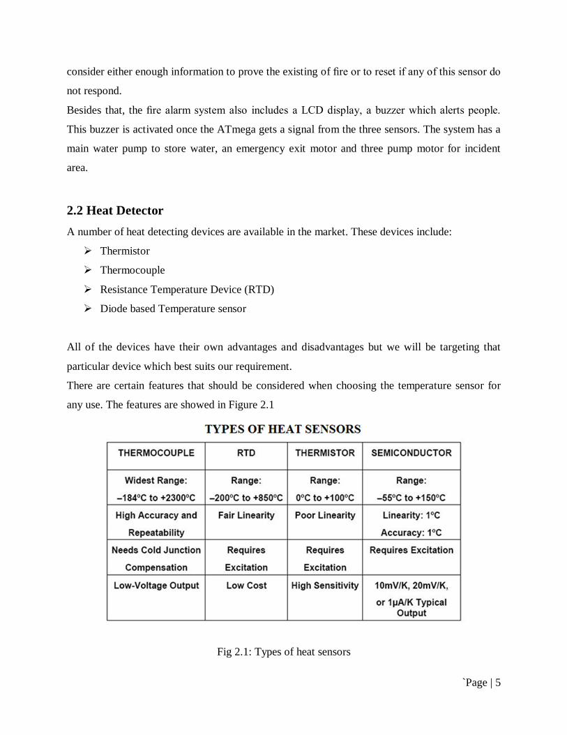
There are certain features that should be considered when choosing the temperature sensor for
any use. The features are showed in Figure 2.1
Fig 2.1: Types of heat sensors
`Page | 6
The pros and cons of each of the following are as follows:
2.2.1 Thermocouple The major advantage that a thermocouple offers to us is the Temperature range. It can be used
for a very wide range of temperatures but at the same time it is highly insensitive.
2.2.2 Resistance Temperature Devices (RTD) Resistor Temperature Device gives linear change in voltage with temperature. It also has a range
that is suitable to our application. The cost of the RTD sensor is also less compared to
thermocouple.
For our application RTD is the best choice mainly because it varies voltage linearly with
temperature and the limited temperature range it has is well enough to fulfill our objective.
2.2.3 Thermistor This device offers the benefit of a very high sensitivity for a range of temperatures but has a non-
linear scale. Extensive mathematical calculations are required to cater for this non-linearity.
2.2.4 Semiconductor Diode The diode is an extremely low cost device but has the disadvantage of a non-linear scale and
rates poorly on the reliability scale.
2.2.4.1 LM35 Temperature Sensor The LM35 series are precision integrated-circuit temperature sensors, with an output voltage
linearly proportional to the centigrade scale. This sensor is fully rated from -55 ºC to +150 ºC
and with the linear scale factor of 10mV/ºC. It operates from 4 to 30 V, has less than 60 µA drain
current and has low self-heating (0.08 ºC in still air). The control circuitry or the interfacing of
LM35 is really easy due to the low output imped-ance, linear output and precise inherent
calibration. The LM35 series is available in hermetic TO transistor packages, while the LM35C,
LM35CA and LM35D are available in TO-92 transistor package. The LM35D is also available
in an 8 lead surface-mount small outline package and a plastic TO-220 package. [14]
Reprinted from datasheet of LM35 [14].
`Page | 7
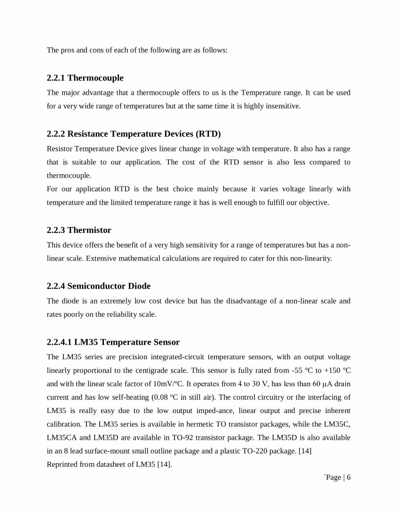
The LM35 can be used as a basic centigrade temperature sensor for sensing the temperature
between +2 ºC and +150 ºC as well as a full-range centigrade temperature sensor for sensing the
temperature between -55 ºC and +150 ºC and the circuitry for using them as basic or full-range is
shown in figure 4. +Vs is the voltage supplied to LM35 and R1 is the resistance connected
between –Vs and Vout (output voltage). The temperature can be obtained in degree Centigrade
by just measuring the output volt-age of the sensor as the output voltage is the function of the
temperature.
Figure 2.2: The circuitry of the LM35 for the Basic and Full-Range temp. Sensor
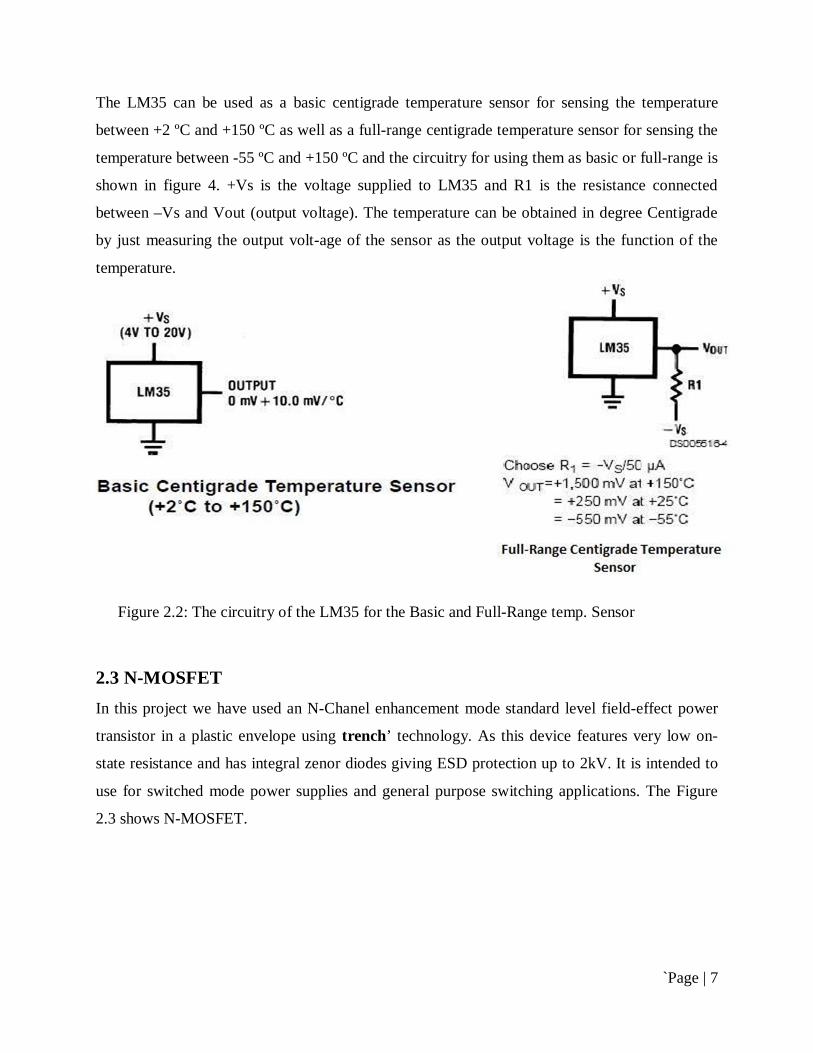
2.3 N-MOSFET In this project we have used an N-Chanel enhancement mode standard level field-effect power
transistor in a plastic envelope using trench’ technology. As this device features very low on-
state resistance and has integral zenor diodes giving ESD protection up to 2kV. It is intended to
use for switched mode power supplies and general purpose switching applications. The Figure
2.3 shows N-MOSFET.

`Page | 8
Fig 2.3: N-Chanel MOSFET
In our project we use BC548 NPN transistor for switching the motor.
2.3.1 BC548 NPN transistor BC548 is general purpose silicon, NPN, bipolar junction transistor. It is used for amplification
and switching purposes. The current gain may vary between 110 and 800. The maximum DC
current gain is 800.
Fig 2.4: BC548 Pin Diagram
`Page | 9
The transistor terminals require a fixed DC voltage to operate in the desired region of its
characteristic curves. This is known as the biasing. For amplification applications, the transistor
is biased such that it is partly on for all input conditions. The input signal at base is amplified and
taken at the emitter. BC548 is used in common emitter configuration for amplifiers. The voltage
divider is the commonly used biasing mode. For switching applications, transistor is biased so
that it remains fully on if there is a signal at its base. In the absence of base signal, it gets
completely off.
2.4 Relay Relay is one of the most important electromechanical devices highly used in industrial
applications specifically in automation. A relay is used for electronic to electrical interfacing i.e.
it is used to switch on or off electrical circuits operating at high AC voltage using a low DC
control voltage. A relay generally has two parts, a coil which operates at the rated DC voltage
and a mechanically movable switch. The electronic and electrical circuits are electrically isolated
but magnetically connected to each other, hence any fault on either side does not affects the other
side.
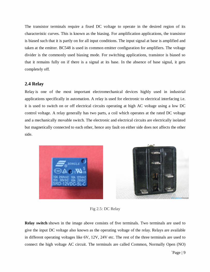
Fig 2.5: DC Relay
Relay switch shown in the image above consists of five terminals. Two terminals are used to
give the input DC voltage also known as the operating voltage of the relay. Relays are available
in different operating voltages like 6V, 12V, 24V etc. The rest of the three terminals are used to
connect the high voltage AC circuit. The terminals are called Common, Normally Open (NO)
`Page | 10
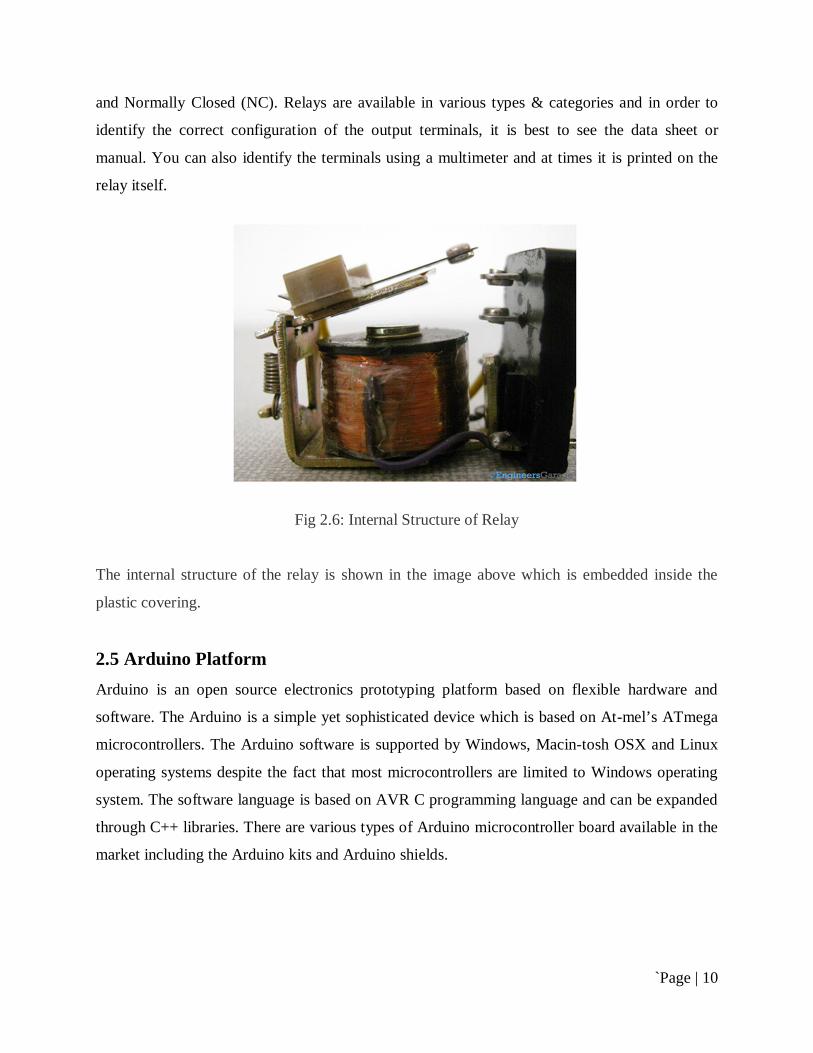
and Normally Closed (NC). Relays are available in various types & categories and in order to
identify the correct configuration of the output terminals, it is best to see the data sheet or
manual. You can also identify the terminals using a multimeter and at times it is printed on the
relay itself.
Fig 2.6: Internal Structure of Relay
The internal structure of the relay is shown in the image above which is embedded inside the
plastic covering.
2.5 Arduino Platform Arduino is an open source electronics prototyping platform based on flexible hardware and
software. The Arduino is a simple yet sophisticated device which is based on At-mel’s ATmega
microcontrollers. The Arduino software is supported by Windows, Macin-tosh OSX and Linux
operating systems despite the fact that most microcontrollers are limited to Windows operating
system. The software language is based on AVR C programming language and can be expanded
through C++ libraries. There are various types of Arduino microcontroller board available in the
market including the Arduino kits and Arduino shields.
`Page | 11
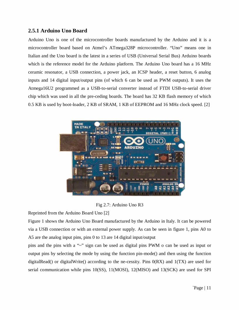
2.5.1 Arduino Uno Board Arduino Uno is one of the microcontroller boards manufactured by the Arduino and it is a
microcontroller board based on Atmel’s ATmega328P microcontroller. “Uno” means one in
Italian and the Uno board is the latest in a series of USB (Universal Serial Bus) Arduino boards
which is the reference model for the Arduino platform. The Arduino Uno board has a 16 MHz
ceramic resonator, a USB connection, a power jack, an ICSP header, a reset button, 6 analog
inputs and 14 digital input/output pins (of which 6 can be used as PWM outputs). It uses the
Atmega16U2 programmed as a USB-to-serial converter instead of FTDI USB-to-serial driver
chip which was used in all the pre-ceding boards. The board has 32 KB flash memory of which
0.5 KB is used by boot-loader, 2 KB of SRAM, 1 KB of EEPROM and 16 MHz clock speed. [2]
Fig 2.7: Arduino Uno R3
Reprinted from the Arduino Board Uno [2]
Figure 1 shows the Arduino Uno Board manufactured by the Arduino in Italy. It can be powered
via a USB connection or with an external power supply. As can be seen in figure 1, pins A0 to
A5 are the analog input pins, pins 0 to 13 are 14 digital input/output
pins and the pins with a “~” sign can be used as digital pins PWM o can be used as input or
output pins by selecting the mode by using the function pin-mode() and then using the function
digitalRead() or digitalWrite() according to the ne-cessity. Pins 0(RX) and 1(TX) are used for
serial communication while pins 10(SS), 11(MOSI), 12(MISO) and 13(SCK) are used for SPI
`Page | 12
(Serial Peripheral Interface) communication. In addition to pin 0 and 1, a Software Serial library
allows serial communication on any of the Uno’s digitals.[2] pin
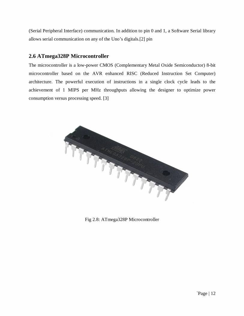
2.6 ATmega328P Microcontroller The microcontroller is a low-power CMOS (Complementary Metal Oxide Semiconductor) 8-bit
microcontroller based on the AVR enhanced RISC (Reduced Instruction Set Computer)
architecture. The powerful execution of instructions in a single clock cycle leads to the
achievement of 1 MIPS per MHz throughputs allowing the designer to optimize power
consumption versus processing speed. [3]
Fig 2.8: ATmega328P Microcontroller

`Page | 13
Fig 2.9: ATmega328 Microcontroller Architecture
Reprinted from Datasheet of ATMega328 [3]
The internal architecture of the microcontroller is shown in figure 2. The central processing unit
(CPU) is the brain of the microcontroller which controls the execution of the program. The MCU
(Microcontroller unit) consists of 4K/8K bytes of in-system programmable flash with read-
while-write capabilities, 256/412/1K bytes EEPROM along with the 512/1K/2K bytes of SRAM.
Along with this, the MCU consists of many other features: [3]
23 general purpose I/O lines and 32 general purpose working registers
flexible timer/counters with compare modes, internal and external interrupts and a serial
programmable USART

`Page | 14
A byte-oriented 2-wire serial interface, an SPI serial port ,a 6-channel 10-bit ADC (8
channels in TQFP and QFN/MLF packages), a programmable watch-dog timer with an
internal oscillator and 5 software-selectable power saving modes.[3]
The five, software selectable, power saving modes are Idle mode, Power-down mode, Power-
save mode, ADC Noise Reduction mode and the Standby mode. As mentioned in section 2.1.2,
the CPU is the brain of the microcontroller which controls the execution of the program.
Therefore the CPU is able to access the memories, perform calculations, control peripherals and
handle interrupts. The AVR uses the Harvard architecture with separate memories and buses for
program and data to maximize the performance as well as the parallelism. The principle of
execution of instructions in the program memory is the single-level pipelining. The concept of
pre-fetching the next instruction while executing one instruction enables the instructions to be
executed in every clock cycle and the program memory is in the System Reprogrammable Flash
memory. [3]
Fig 2.10: Block diagram of the AVR CPU Core architecture

`Page | 15
Reprinted from Datasheet of ATMega328 [3],
The block diagram of AVR CPU Core architecture is shown in figure 3. The fast-access Register
File contains 32 x 8 bit general-purpose working registers with a single cycle access time which
results in a single-cycle ALU operation. The arithmetic and logical operations between the
registers or between the constant and a register are supported by the ALU. The status register is
updated to reflect information about the result of the operation after an arithmetic operation. [3]
The boot program section and the application program section are the two main sections of the
program flash memory. Stack stores the return address of the program counter during the
interrupts and subroutine calls which is allocated in the general data SRAM. The size of the stack
is limited by the total size and usage of the SRAM. The data SRAM is accessible through five
different addressing modes supported in the AVR architecture while the stack pointer is
read/write accessible in the I/O space. The memory spaces in the AVR architecture are all linear
and regular memory maps. [3]
2.7 Output Appliance As Output Appliance we will use LED, Motor and Fire alarm. The entire output appliance will
work according to the command embedded in the controller.
2.7.1 Buzzer For alarm purposes a lot of electric bells, alarms and buzzers are available in the market that has
got different prices and uses. The buzzer being used in this project is a 5-12 V buzzer and has got
enough alarm sound to be used in a fire alarm system. Louder buzzer would have been even
Fig 2.11: Buzzer

`Page | 16
better but then their operating voltages are high as we had a supply of maximum up to 12V
available with us on the board.
2.7.2 DC motor A DC motor is a mechanically commutated electric motor powered from direct current (DC).
The stator is stationary in space by definition and therefore the current in the rotor is switched by
the commutator to also be stationary in space. This is how the relative angle between the stator
and rotor magnetic flux is maintained near 90 degrees, which generates the maximum torque.
DC motors have a rotating armature winding (winding in which a voltage is induced) but non-
rotating armature magnetic field and a static field winding (winding that produce the main
magnetic flux) or permanent magnet. Different connections of the field and armature winding
provide different inherent speed/torque regulation characteristics. The speed of a DC motor can
be controlled by changing the voltage applied to the armature or by changing the field current.
The introduction of variable resistance in the armature circuit or field circuit allowed speed
control. Modern DC motors are often controlled by power electronics systems called DC drives.
The introduction of DC motors to run machinery eliminated the need for local steam or internal
combustion engines, and line shaft drive systems. DC motors can operate directly from
rechargeable batteries, providing the motive power for the first electric vehicles. Today DC
motors are still found in applications as small as toys and disk drives, or in large sizes to operate
steel rolling mills and paper machines.
Fig 2.12: DC motor
`Page | 17
Operation of a DC motor can be shortly explain below,
When the coil is powered, a magnetic field is generated around the armature. First, the left side
of the armature is pushed away from the left magnet and drawn toward the right, causing
rotation. Second, the armature continues to rotate.
2.7.2.1 12 V DC Motor In our project we use 12 V dc motor for emergency exit, for flowing water to the affected area
and for reserve water in the Tank.
12V 6,500 RPM DC Electric Motor
Torque 1300 g.cm
Voltage (V): 12
No Load
Speed (rpm): 13000
Current (A): 0.6
At Stall
Torque (g.cm): 1200
Current (A): 17.2
At Max Frequency
Efficiency (%): 55.1
Power (W): 26.5
Speed (rpm): 10489
Torque (g.cm): 246
Current (A): 4
At Max Power
Output (W): 31.1
Speed (rpm): 9304
Torque (g.cm): 326
Current (A): 5
Dimensions
Diameter: 35.8mm
Total Length: 71mm
`Page | 18
Shaft Length: 9.5mm
Shaft dia: 3.175mm
Mounting thread dia: 3mm
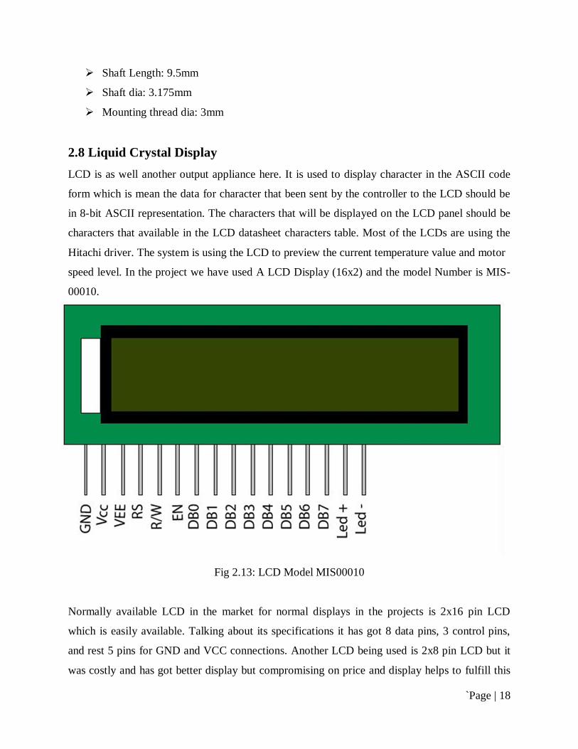
2.8 Liquid Crystal Display LCD is as well another output appliance here. It is used to display character in the ASCII code
form which is mean the data for character that been sent by the controller to the LCD should be
in 8-bit ASCII representation. The characters that will be displayed on the LCD panel should be
characters that available in the LCD datasheet characters table. Most of the LCDs are using the
Hitachi driver. The system is using the LCD to preview the current temperature value and motor
speed level. In the project we have used A LCD Display (16x2) and the model Number is MIS-
00010.
Fig 2.13: LCD Model MIS00010
Normally available LCD in the market for normal displays in the projects is 2x16 pin LCD
which is easily available. Talking about its specifications it has got 8 data pins, 3 control pins,
and rest 5 pins for GND and VCC connections. Another LCD being used is 2x8 pin LCD but it
was costly and has got better display but compromising on price and display helps to fulfill this

`Page | 19
job in a cheaper way. So 2x16 LCD is being used in the project which costs almost Rs. 210/=. Its
display and light intensity is also adjustable which makes it suitable to adjust for the day and
night time use for better display.
Table 1: Pin Description of 16X2 LCD Display:
Pin
No Function Name
1 Ground (0V) Ground
2 Supply voltage; 5V (4.7V – 5.3V) Vcc
3 Contrast adjustment; through a variable resistor
VEE
4 Selects command register when low; and data register when high Register Select
5 Low to write to the register; High to read from the register Read/write
6 Sends data to data pins when a high to low pulse is given Enable
7
8-bit data pins
DB0
8 DB1
9 DB2
10 DB3
11 DB4
12 DB5
13 DB6
14 DB7
15 Backlight VCC (5V) Led+
16 Backlight Ground (0V) Led-
`Page | 20
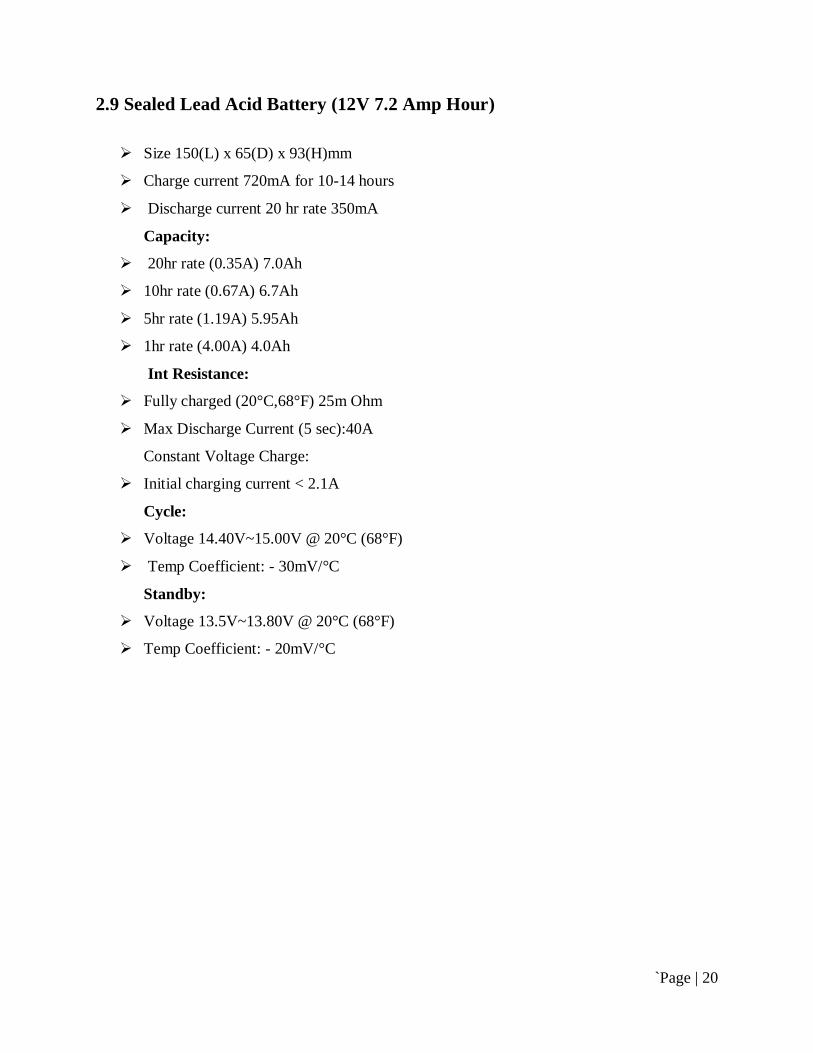
2.9 Sealed Lead Acid Battery (12V 7.2 Amp Hour)
Size 150(L) x 65(D) x 93(H)mm
Charge current 720mA for 10-14 hours
Discharge current 20 hr rate 350mA
Capacity:
20hr rate (0.35A) 7.0Ah
10hr rate (0.67A) 6.7Ah
5hr rate (1.19A) 5.95Ah
1hr rate (4.00A) 4.0Ah
Int Resistance:
Fully charged (20°C,68°F) 25m Ohm
Max Discharge Current (5 sec):40A
Constant Voltage Charge:
Initial charging current < 2.1A
Cycle:
Voltage 14.40V~15.00V @ 20°C (68°F)
Temp Coefficient: - 30mV/°C
Standby:
Voltage 13.5V~13.80V @ 20°C (68°F)
Temp Coefficient: - 20mV/°C
`Page | 21
Chapter 3
System Design and Development
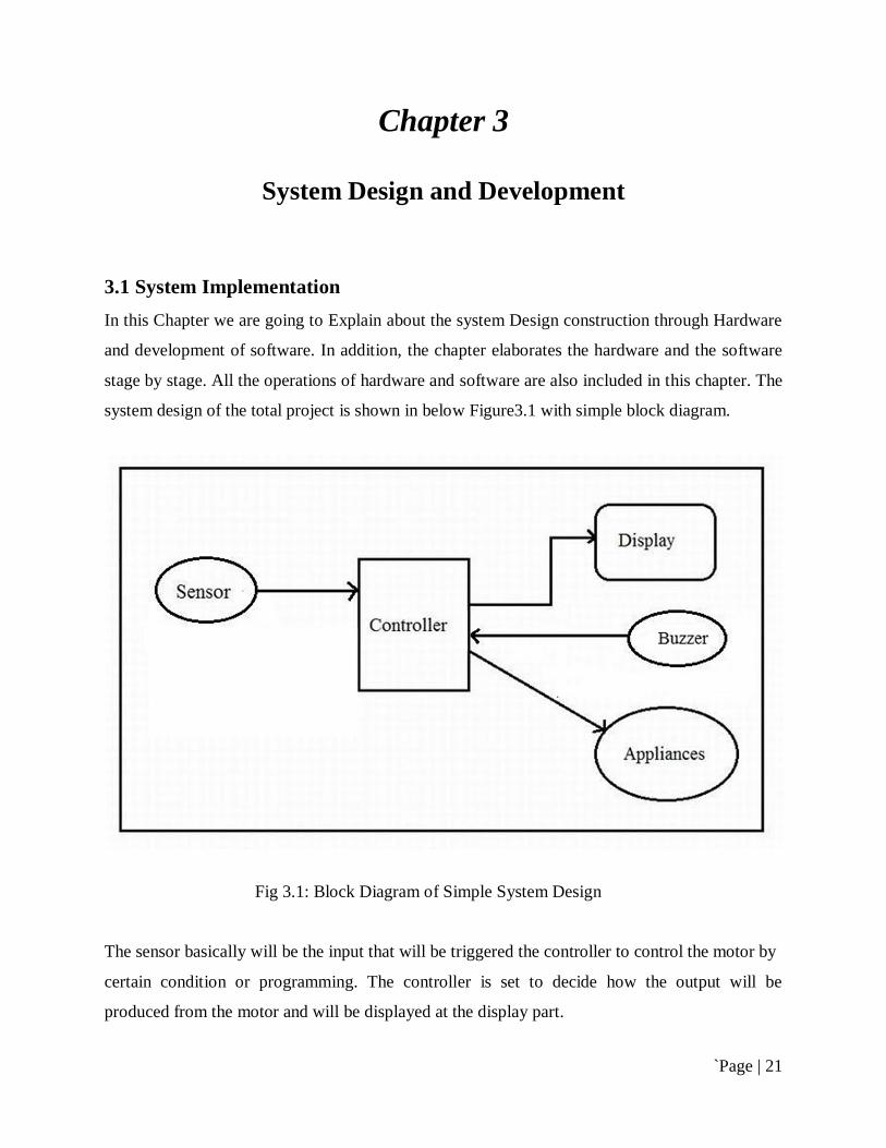
3.1 System Implementation In this Chapter we are going to Explain about the system Design construction through Hardware
and development of software. In addition, the chapter elaborates the hardware and the software
stage by stage. All the operations of hardware and software are also included in this chapter. The
system design of the total project is shown in below Figure3.1 with simple block diagram.
Fig 3.1: Block Diagram of Simple System Design
The sensor basically will be the input that will be triggered the controller to control the motor by
certain condition or programming. The controller is set to decide how the output will be
produced from the motor and will be displayed at the display part.
`Page | 22
As the system requires the use of microcontroller, the design consists of two parts, hardware and
software. Hardware is constructed and integrated module by module, hardware to software for
easy troubleshooting and testing.
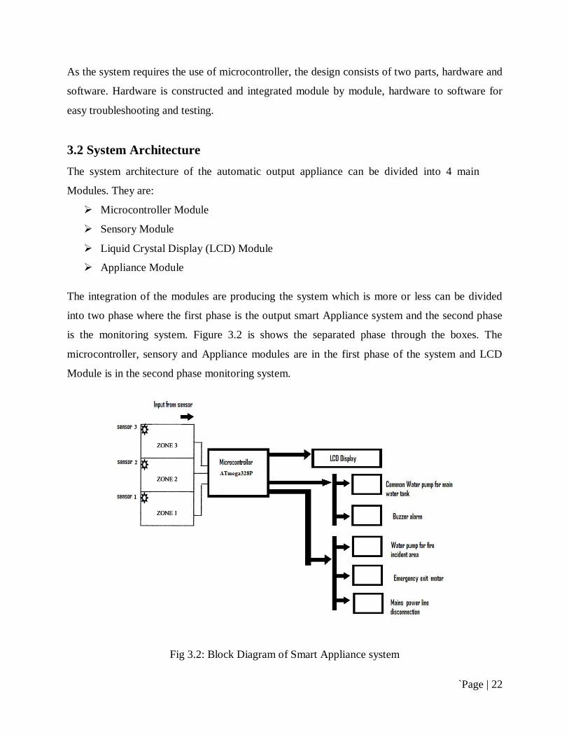
3.2 System Architecture The system architecture of the automatic output appliance can be divided into 4 main
Modules. They are:
Microcontroller Module
Sensory Module
Liquid Crystal Display (LCD) Module
Appliance Module
The integration of the modules are producing the system which is more or less can be divided
into two phase where the first phase is the output smart Appliance system and the second phase
is the monitoring system. Figure 3.2 is shows the separated phase through the boxes. The
microcontroller, sensory and Appliance modules are in the first phase of the system and LCD
Module is in the second phase monitoring system.
Fig 3.2: Block Diagram of Smart Appliance system
`Page | 23
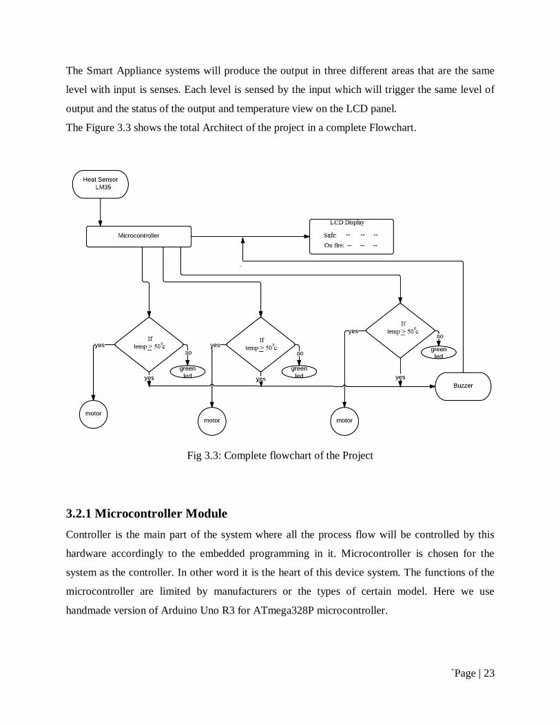
The Smart Appliance systems will produce the output in three different areas that are the same
level with input is senses. Each level is sensed by the input which will trigger the same level of
output and the status of the output and temperature view on the LCD panel.
The Figure 3.3 shows the total Architect of the project in a complete Flowchart.
Fig 3.3: Complete flowchart of the Project
3.2.1 Microcontroller Module Controller is the main part of the system where all the process flow will be controlled by this
hardware accordingly to the embedded programming in it. Microcontroller is chosen for the
system as the controller. In other word it is the heart of this device system. The functions of the
microcontroller are limited by manufacturers or the types of certain model. Here we use
handmade version of Arduino Uno R3 for ATmega328P microcontroller.
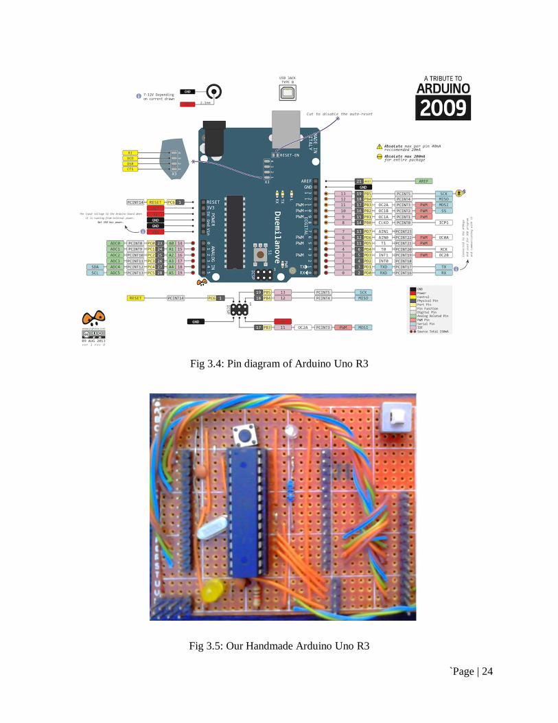
`Page | 24
Fig 3.4: Pin diagram of Arduino Uno R3
Fig 3.5: Our Handmade Arduino Uno R3

`Page | 25
ATmega328P is chosen as the controller for the project since it offers various functions and
applicable for the system also it is mostly available in the market. It’s a 28 pin IC.
Fig 3.6: Pin Diagram of ATmega328P interfacing with Arduino
3.2.1.1 Programming ATmega328P
To program ATMEGA328P at first we have to burn boot loader of new ATMEGA328P using
ARDUINO-UNO R3 Programmer. For burn boot loader connect new ATMEGA328P with
programmer. Connection is shown below.
Caution: make sure Programmer is not connected to external power source because it get
required power from USB cable connected to computer and circuit with ATMEGA328P have
regulated +5v supply.
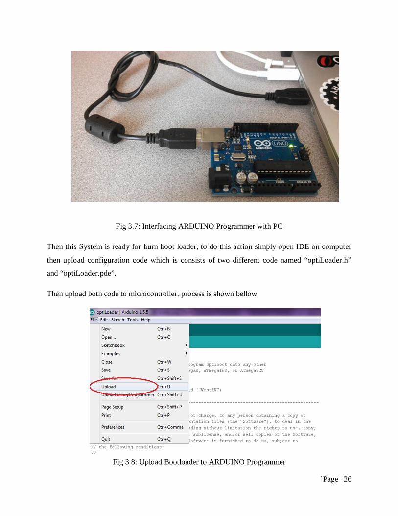
`Page | 26
Fig 3.7: Interfacing ARDUINO Programmer with PC
Then this System is ready for burn boot loader, to do this action simply open IDE on computer
then upload configuration code which is consists of two different code named “optiLoader.h”
and “optiLoader.pde”.
Then upload both code to microcontroller, process is shown bellow
Fig 3.8: Upload Bootloader to ARDUINO Programmer
`Page | 27
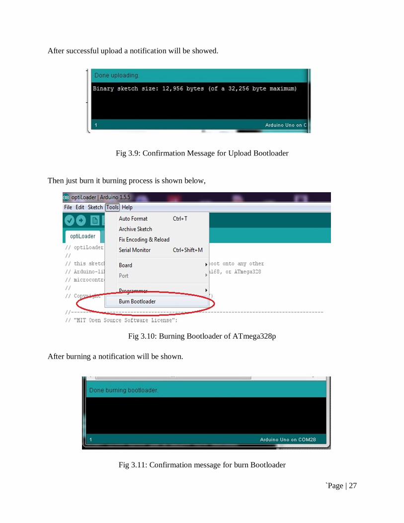
After successful upload a notification will be showed.
Fig 3.9: Confirmation Message for Upload Bootloader
Then just burn it burning process is shown below,
Fig 3.10: Burning Bootloader of ATmega328p
After burning a notification will be shown.
Fig 3.11: Confirmation message for burn Bootloader
`Page | 28
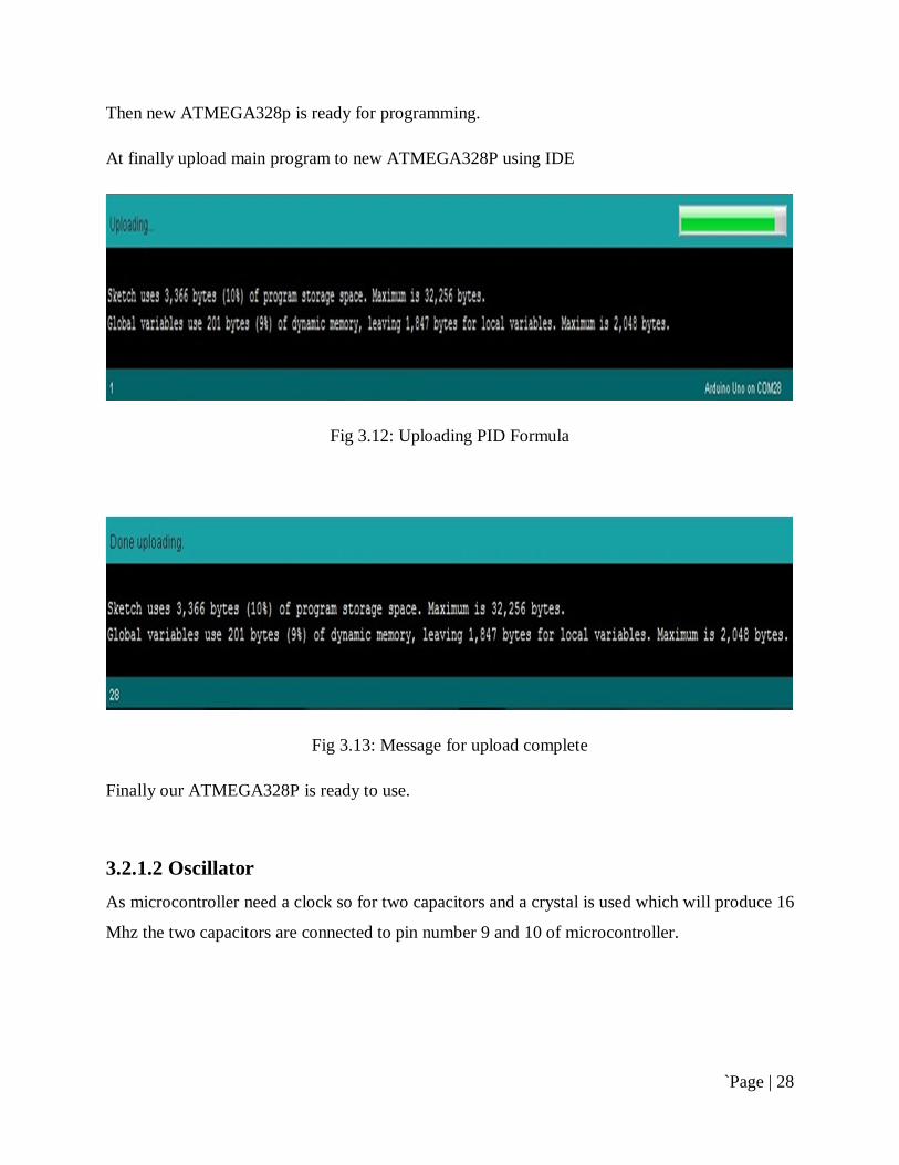
Then new ATMEGA328p is ready for programming.
At finally upload main program to new ATMEGA328P using IDE
Fig 3.12: Uploading PID Formula
Fig 3.13: Message for upload complete
Finally our ATMEGA328P is ready to use.
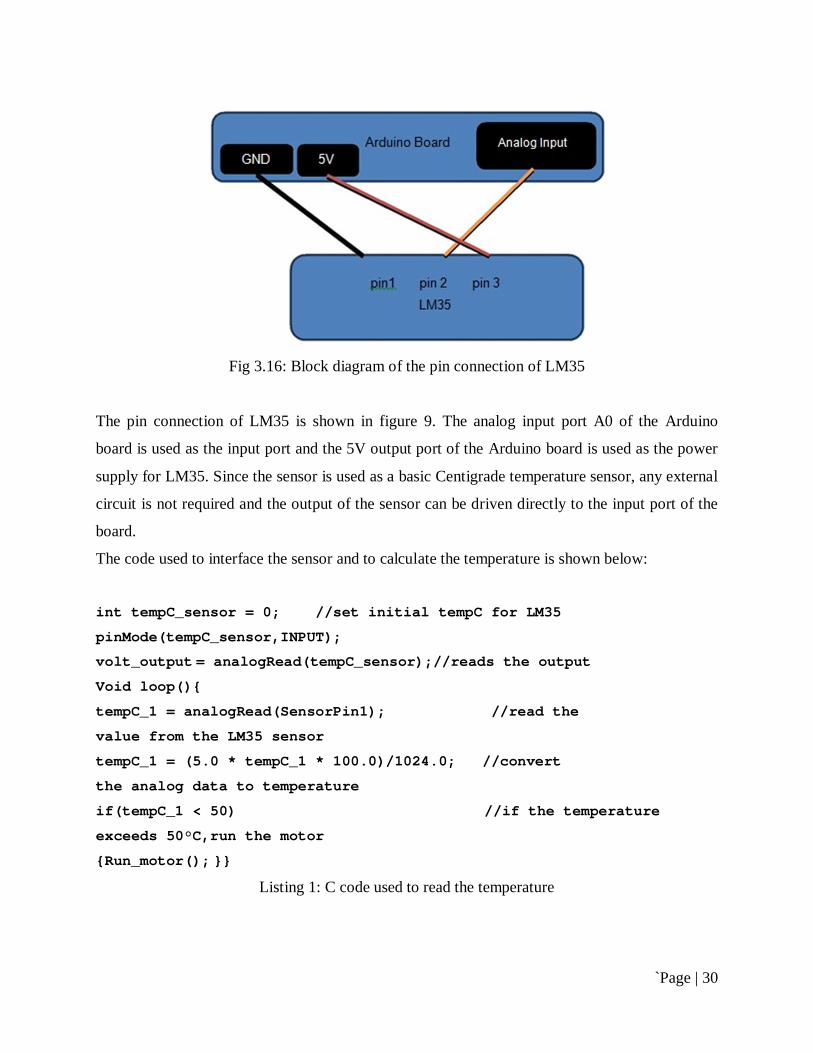
3.2.1.2 Oscillator As microcontroller need a clock so for two capacitors and a crystal is used which will produce 16
Mhz the two capacitors are connected to pin number 9 and 10 of microcontroller.
`Page | 29
Figure 3.5.3: Crystal Oscillator
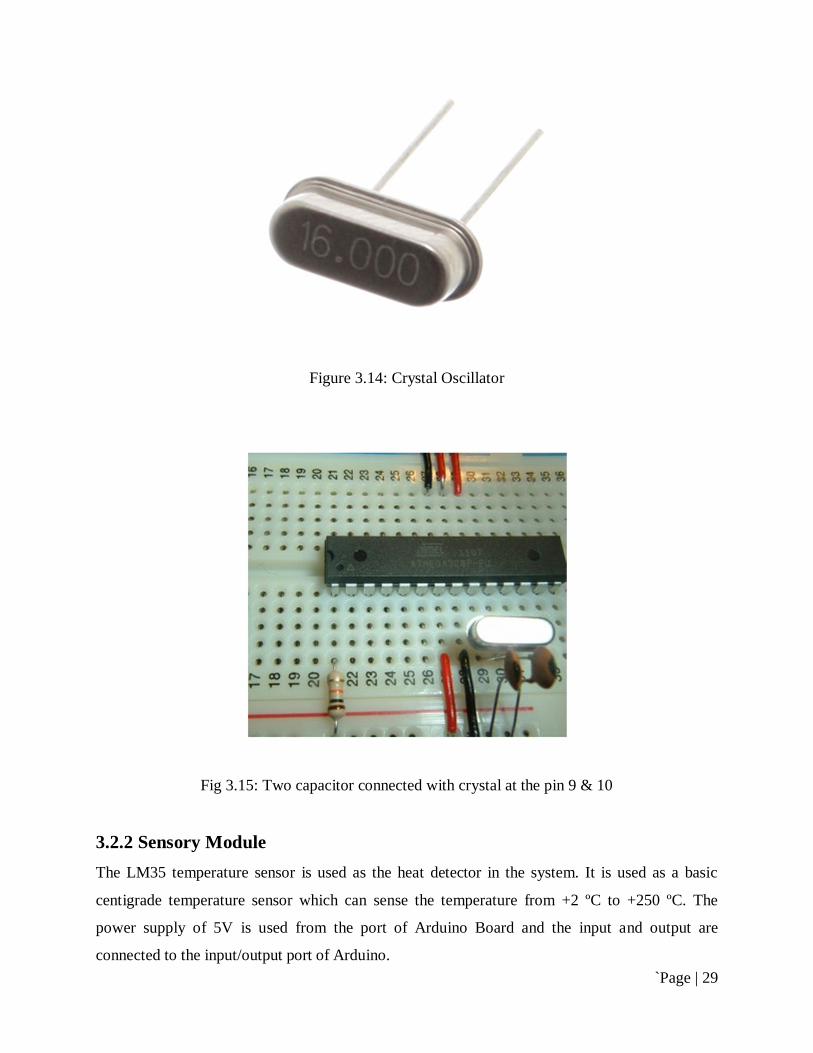
Figure 3.14: Crystal Oscillator
Fig 3.15: Two capacitor connected with crystal at the pin 9 & 10
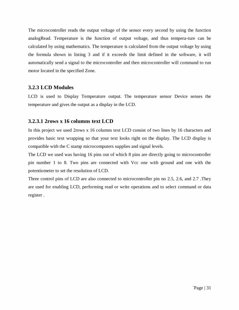
3.2.2 Sensory Module The LM35 temperature sensor is used as the heat detector in the system. It is used as a basic
centigrade temperature sensor which can sense the temperature from +2 ºC to +250 ºC. The
power supply of 5V is used from the port of Arduino Board and the input and output are
connected to the input/output port of Arduino.
`Page | 30
Fig 3.16: Block diagram of the pin connection of LM35
The pin connection of LM35 is shown in figure 9. The analog input port A0 of the Arduino
board is used as the input port and the 5V output port of the Arduino board is used as the power
supply for LM35. Since the sensor is used as a basic Centigrade temperature sensor, any external
circuit is not required and the output of the sensor can be driven directly to the input port of the
board.
The code used to interface the sensor and to calculate the temperature is shown below:
int tempC_sensor = 0; //set initial tempC for LM35
pinMode(tempC_sensor,INPUT);
volt_output = analogRead(tempC_sensor);//reads the output
Void loop()
tempC_1 = analogRead(SensorPin1); //read the
value from the LM35 sensor
tempC_1 = (5.0 * tempC_1 * 100.0)/1024.0; //convert
the analog data to temperature
if(tempC_1 < 50) //if the temperature
exceeds 50°C,run the motor
Run_motor();
Listing 1: C code used to read the temperature
`Page | 31
The microcontroller reads the output voltage of the sensor every second by using the function
analogRead. Temperature is the function of output voltage, and thus tempera-ture can be
calculated by using mathematics. The temperature is calculated from the output voltage by using
the formula shown in listing 3 and if it exceeds the limit defined in the software, it will
automatically send a signal to the microcontroller and then microcontroller will command to run
motor located in the specified Zone.
3.2.3 LCD Modules LCD is used to Display Temperature output. The temperature sensor Device senses the
temperature and gives the output as a display in the LCD.
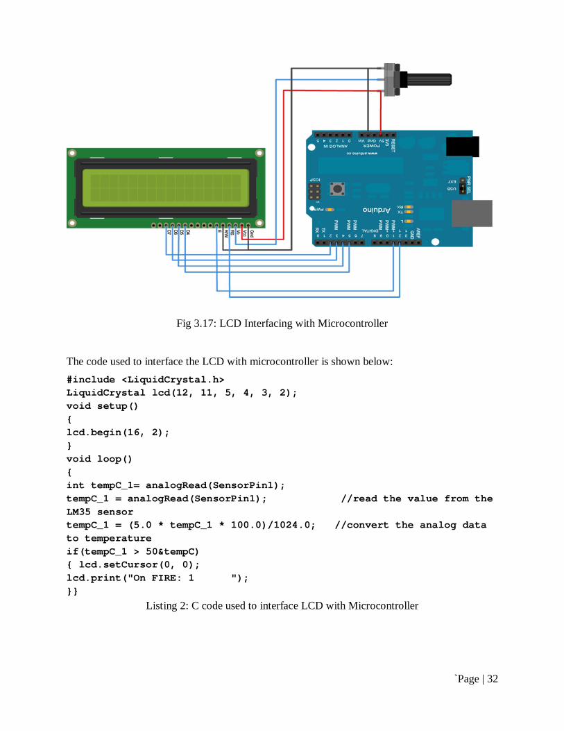
3.2.3.1 2rows x 16 columns text LCD In this project we used 2rows x 16 columns text LCD consist of two lines by 16 characters and
provides basic text wrapping so that your text looks right on the display. The LCD display is
compatible with the C stamp microcomputers supplies and signal levels.
The LCD we used was having 16 pins out of which 8 pins are directly going to microcontroller
pin number 1 to 8. Two pins are connected with Vcc one with ground and one with the
potentiometer to set the resolution of LCD.
Three control pins of LCD are also connected to microcontroller pin no 2.5, 2.6, and 2.7 .They
are used for enabling LCD, performing read or write operations and to select command or data
register .
`Page | 32
Fig 3.17: LCD Interfacing with Microcontroller
The code used to interface the LCD with microcontroller is shown below: #include <LiquidCrystal.h> LiquidCrystal lcd(12, 11, 5, 4, 3, 2); void setup() lcd.begin(16, 2); void loop() int tempC_1= analogRead(SensorPin1); tempC_1 = analogRead(SensorPin1); //read the value from the LM35 sensor tempC_1 = (5.0 * tempC_1 * 100.0)/1024.0; //convert the analog data to temperature if(tempC_1 > 50&tempC) lcd.setCursor(0, 0); lcd.print("On FIRE: 1 ");
Listing 2: C code used to interface LCD with Microcontroller

`Page | 33
3.2.4 Appliance Module In the Appliance Module we have different types of output such as Light, motor, buzzer etc.
3.2.4.1 Buzzer It has two pins; one is connected with the supply and the other one with the microcontroller pin
no 6. When microcontroller will provide low signal, the circuit will be completed and the buzzer
will start alarming.
Fig 3.18: Buzzer Interfacing with Microcontroller
The code used to interface the LCD with microcontroller is shown below:
const int SPKR_PIN = 6; void setup() pinMode(SPKR_PIN, OUTPUT); if(tempC_1 > 50) tone(SPKR_PIN, 1047, 500); delay(200); tone(SPKR_PIN, 1109, 300); delay(200);
`Page | 34
tone(SPKR_PIN, 1175, 100); delay(5);
Listing 3: C code used to interface Buzzer with Microcontroller
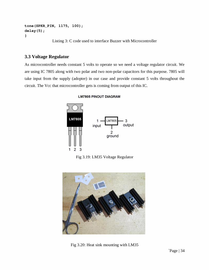
3.3 Voltage Regulator As microcontroller needs constant 5 volts to operate so we need a voltage regulator circuit. We
are using IC 7805 along with two polar and two non-polar capacitors for this purpose. 7805 will
take input from the supply (adopter) in our case and provide constant 5 volts throughout the
circuit. The Vcc that microcontroller gets is coming from output of this IC.
Fig 3.19: LM35 Voltage Regulator
Fig 3.20: Heat sink mounting with LM35
`Page | 35
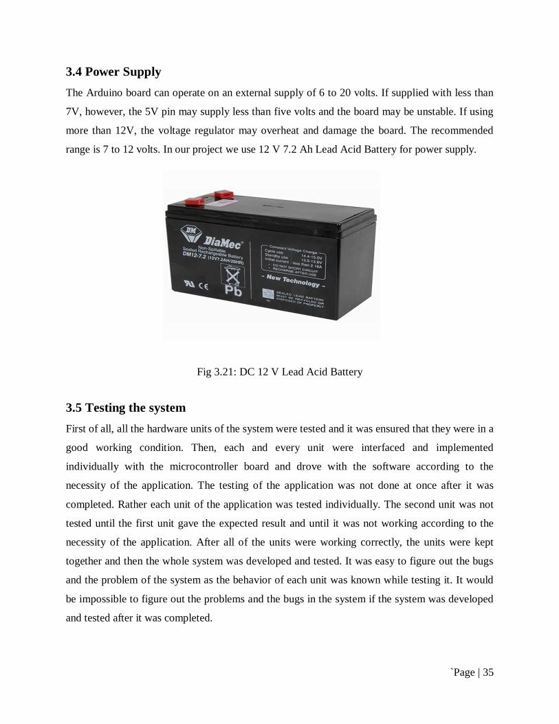
3.4 Power Supply
The Arduino board can operate on an external supply of 6 to 20 volts. If supplied with less than
7V, however, the 5V pin may supply less than five volts and the board may be unstable. If using
more than 12V, the voltage regulator may overheat and damage the board. The recommended
range is 7 to 12 volts. In our project we use 12 V 7.2 Ah Lead Acid Battery for power supply.
Fig 3.21: DC 12 V Lead Acid Battery
3.5 Testing the system First of all, all the hardware units of the system were tested and it was ensured that they were in a
good working condition. Then, each and every unit were interfaced and implemented
individually with the microcontroller board and drove with the software according to the
necessity of the application. The testing of the application was not done at once after it was
completed. Rather each unit of the application was tested individually. The second unit was not
tested until the first unit gave the expected result and until it was not working according to the
necessity of the application. After all of the units were working correctly, the units were kept
together and then the whole system was developed and tested. It was easy to figure out the bugs
and the problem of the system as the behavior of each unit was known while testing it. It would
be impossible to figure out the problems and the bugs in the system if the system was developed
and tested after it was completed.

`Page | 36
3.6 Circuit diagram of The System
Fig 3.22: Schematic Circuit diagram of “Automatic Fire control & specific fire location
monitoring from central control room”
3.7 System development When a sensor 1 gets activation in zone 1, the input pin of microcontroller C.1 will high as per
defined program and the response at the output pin D.0-D.7 connected LCD display will show
“On Fire: 1” consequently output pin B.1 & B.2 will get high pulse which is given to a bipolar
switching transistor’s base, this pulse create base emitter forward bias which is responsible for
transistor activation. Than this transistor activate a relay to power on a water pump for specific
fire location, main power disconnect by magnetic contactor and a motor will get ON for open an
`Page | 37
emergency exit. Here we used a transistor because it can carry up to 500mA current but this
much of current cannot tolerate a microcontroller. Where microcontroller ratings are as follows-
Power Consumption at 12 MHz, 5V, 50°C, Active: 3.6 mA, Idle Mode: 1.0 mA, Power-down
Mode: 0.5 µA.
To protect transistor and microcontroller from burn out, we used a 1kΩ resistor in between base
of the transistor and microcontroller’s output pin. We also used in this circuit to light ON an
indication LED with connected a 2.2kΩ resistor output pin to common GND.
Output pin D.6 is common for every fire zone as we defined program to activate a buzzer alarm
and a main water pump ON to fill water in the main water tank.
For instant smoke sense, we can use a high sensitivity smoke sensing detector to give high pulse
to input pin of microcontroller from which it will get fictional activity as per program installed in
the microcontroller.
For magnetic contactor activate we connected a relay NC (Normally close) point and when relay
will get activation by the transistor the NC point of relay will open hence main power will
disconnect in the specific fire area.
We can use all of assigned sensing input pin of microcontroller as per described working
principal for separate zone to multiple control area.
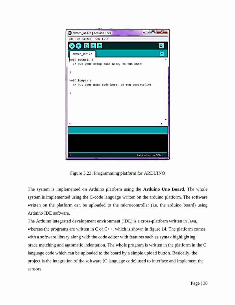
3.8 Software Configuration Programming software of this line follower is known as ARDUINO-IDE .This is open source
programming platform. The open-source ARDUINO environment makes it easy to write code
and upload it to the i/o board. Here we use ARDUINO-1.5.5 BETA platform. To configure
software we have to use ARDUINO IDE named arduino.exe
`Page | 38
Figure 3.23: Programming platform for ARDUINO
The system is implemented on Arduino platform using the Arduino Uno Board. The whole
system is implemented using the C-code language written on the arduino platform. The software
written on the platform can be uploaded to the microcontroller (i.e. the arduino board) using
Arduino IDE software.
The Arduino integrated development environment (IDE) is a cross-platform written in Java,
whereas the programs are written in C or C++, which is shown in figure 14. The platform comes
with a software library along with the code editor with features such as syntax highlighting,
brace matching and automatic indentation. The whole program is written in the platform in the C
language code which can be uploaded to the board by a simple upload button. Basically, the
project is the integration of the software (C language code) used to interface and implement the
sensors.
`Page | 39
3.9 Overall Theory of the Project
The project over all consists of the following components:
Microcontroller ATMEL 89S52.
Temperature sensor LM-35.
16x2 LCD.
12 V DC Motor
5 Volts Buzzer.
6 Volts Relay.
Potentiometers 10K.
5 Volts Voltage regulators 7805.
BJT BC548 NPN-type
Crystal oscillator 11.0592 Mhz.
LED’s.
Push button.
Capacitors.
Arduino Programmer.
12 V 7.2 Ah Battery.
Project board.
Wiring and miscellaneous.

`Page | 40
Chapter 4
Result & Discussions
4.1 Result The aim of the project was to implement a smart home system and the goal was met. The
microcontroller unit responds to the instructions sent by the mobile phone accord-ing to the
necessity of the application as well as triggers the alarm upon a critical situation. The aim of the
application to manage the electronic devices remotely was also achieved.
Table 2: Result & Instructions and the Response to and from the System
Condition
Result Command
On Fire
Safe Temp. ≥ 50° in Zone 1 & Temp. ≤ 50° in Zone 2 & Temp. ≤ 50° in Zone 3
Zone : 1
Zone : 2, 3
Run pump 1 Stop pump 2 Stop pump 3
Temp. ≤ 50° in Zone 1 & Temp. ≥ 50° in Zone 2 & Temp. ≤ 50° in Zone 3
Zone : 2
Zone : 1, 3
Run pump 2 Stop pump 1 Stop pump 3
Temp. ≤ 50° in Zone 1 & Temp. ≤ 50° in Zone 2 & Temp. ≥ 50° in Zone 3
Zone : 3
Zone : 1, 2
Run pump 3 Stop pump 1 Stop pump 2
Temp. ≥ 50° in Zone 1 & Temp. ≥ 50° in Zone 2 & Temp. ≤ 50° in Zone 3
Zone : 1, 2
Zone : 3
Run pump 1 Run pump 2 Stop pump 3
Temp. ≤ 50° in Zone 1 & Temp. ≥ 50° in Zone 2 & Temp. ≥ 50° in Zone 3
Zone : 2, 3
Zone : 1
Run pump 2 Run pump 3 Stop pump 1
Temp. ≥ 50° in Zone 1 & Temp. ≤ 50° in Zone 2 & Temp. ≥ 50° in Zone 3
Zone : 1, 3
Zone : 2
Run pump 1 Run pump 3 Stop pump 2
Temp. ≥ 50° in Zone 1 & Temp. ≥ 50° in Zone 2 & Temp. ≥ 50° in Zone 3
Zone : 1, 2, 3
Zone : No
Run pump 1 Run pump 2 Run pump 3
Temp. ≤ 50° in Zone 1 & Temp. ≤ 50° in Zone 2 & Temp. ≤ 50° in Zone 3
Zone : No
Zone : 1, 2, 3
Stop pump 1 Stop pump 2 Stop pump 3

`Page | 41
4.2 Discussion The development of technology has been affecting the life style of people. They are dependent
on technology even to carry out daily activities and technology has made the lifestyle more
sophisticated and relaxing. It seems as if it was impossible to live without technology in this
century. Advanced technology has replaced the traditional lifestyle of people. For example, a
coffee machine has replaced the traditional way of coffee making, finger-print and voice-
controlled electronic lock have replaced traditional locks, electronic news and media have
replaced the traditional paper news and media, bank cards and online shopping have replaced the
traditional cash and shopping. The examples mentioned above are a few least advanced
technologies replacing the traditional lifestyle. Besides these, there are many advanced
technologies used by people for different purposes, they are playing significant roles in changing
the lifestyle of people. With the development of technology, the concept of simple home has also
been changing into smart home and the concept of home has changed drastically during the last
decade.
The advancement of technology has not only played a significant role in the development of
positive aspects but has also played an important role in the development of negative aspects. It
has increased the risk of burglary and intrusion using the latest modern technologies available.
The busy lifestyle of human beings along with the in-creasing risk has led to the necessity of
remote surveillance of homes. There are different ways to have the surveillance but the easiest
and most advanced technology accessible to everybody is mobile phone surveillance. The mobile
phone can be used for different purposes with the help of the applications developed for the
phones.
This project was a simple application project demonstrating a fire alarm & control system. The
movements and the temperature are detected by installing sensors at different places. The
temperature of the premises where the sensors are installed can be known at any time before
reaching the critical limit set by the user. As this project was a fire alarm & control system
demonstration project, a few sensors and a led light were used. The project can be extended by
increasing the number of sensors used along with an increase in the number of installation
places. The remote management of electronic devices can also be extended with the use of
different real electronic devices.
`Page | 42
The project was completed within the projected time with the expected result. However, there
were many hardware and software errors experienced during the development of the application.
There were many bugs in the software as well as connection errors in the hardware, which came
along with the development of the application and which was solved individually. Despite
reading the datasheet of the sensors before using them, the microcontroller was burnt out by
accidentally connecting the wrong pins. Accidentally, the ground connection and the power
supply were interchanged which burnt down the microcontroller and a new microcontroller had
to be ordered. Similarly, there were some hardware errors while connecting the sensors and the
led with the microcontroller. Many connection errors were faced during the project time which
did not lead to the damage of any hardware unit except the microcontroller was fixed up later.
4.2.1 Project Evaluation
The project has met all the objectives as listed previously. The objective as defined earlier was to
detect fire, confirm its presence by checking through multiple sensors and then indicating its
position on some output device and alarming a buzzer to inform the vicinity the presence of the
fire. Some excellent features are also provided in the project that makes the fire alarm system
more or less sensitive and placement of the fire alarm system in various multiple locations.
4.2.2 System Features i) Pinpoints the exact location of fire.
ii) Displays the presence of fire without any delay.
iii) Sounds alarm loudly enabling the vicinity to take necessary measures to get away from
fire and take steps to put away the fire.
iv) Provides a flexibility to reduce or enhance the sensitivity of the sensors to detect fire.
v) Interfacing various sensors with a single microcontroller chip there by reducing the cost
of the fire alarm systems.
vi) Reluctant to false alarm or any ambiguity.
`Page | 43
4.2.3 Drawbacks / Limitation of the thesis i) Detects the fire from one location at a time, if there is fire in more than 3 locations, the
system will be able to detect and hence locate only in three locations.
ii) No record keeping is being done in the system which deprives us from any type of
analysis which can be beneficial for the betterment of the existing system.
iii) The project has been limited to a desired area of condition which is estimated by 8m
x 4m and the estimated height of desired area is 2.5m.
iv) This is to make the system more sensitive and obtain a quick feedback from the desired
area of condition.
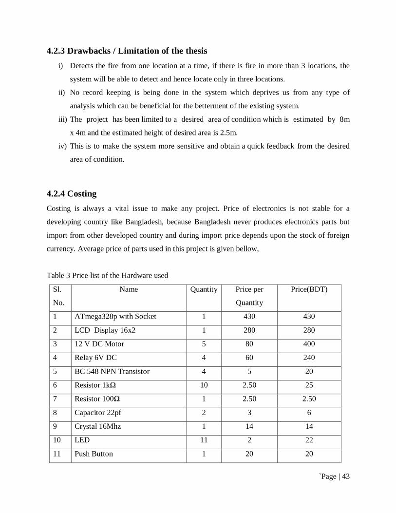
4.2.4 Costing Costing is always a vital issue to make any project. Price of electronics is not stable for a
developing country like Bangladesh, because Bangladesh never produces electronics parts but
import from other developed country and during import price depends upon the stock of foreign
currency. Average price of parts used in this project is given bellow,
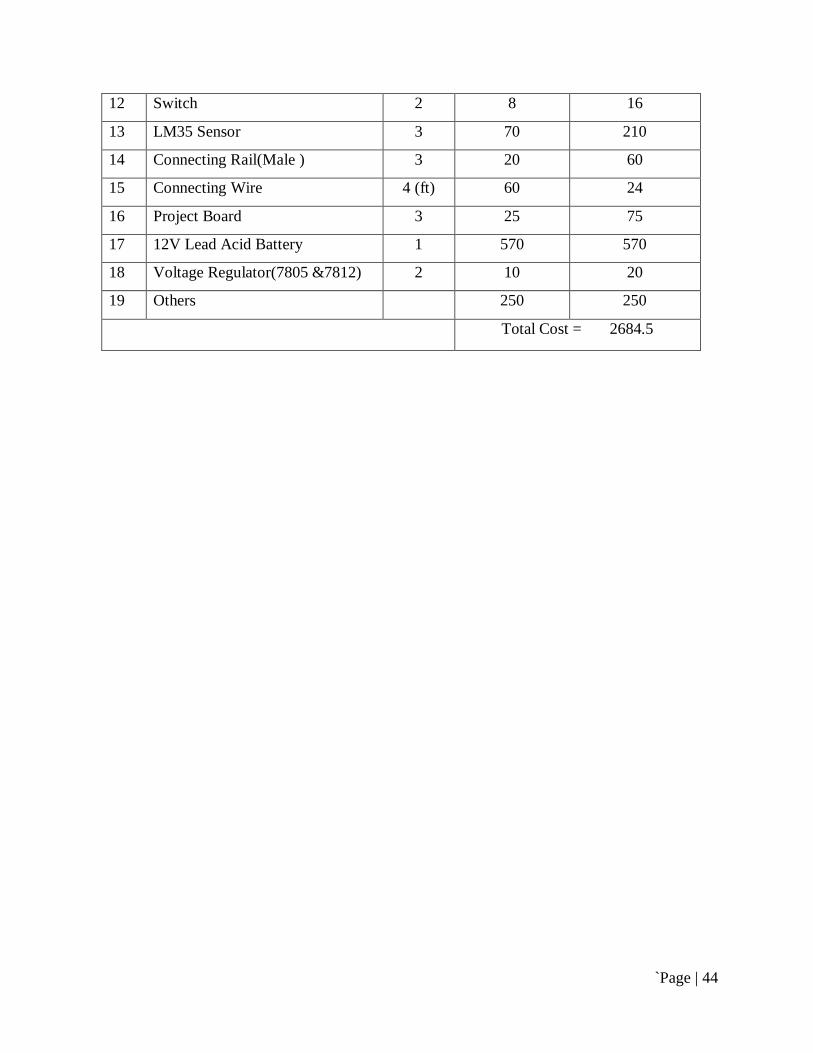
Table 3 Price list of the Hardware used Sl.
No.
Name Quantity Price per
Quantity
Price(BDT)
1 ATmega328p with Socket 1 430 430
2 LCD Display 16x2 1 280 280
3 12 V DC Motor 5 80 400
4 Relay 6V DC 4 60 240
5 BC 548 NPN Transistor 4 5 20
6 Resistor 1kΩ 10 2.50 25
7 Resistor 100Ω 1 2.50 2.50
8 Capacitor 22pf 2 3 6
9 Crystal 16Mhz 1 14 14
10 LED 11 2 22
11 Push Button 1 20 20
`Page | 44
12 Switch 2 8 16
13 LM35 Sensor 3 70 210
14 Connecting Rail(Male ) 3 20 60
15 Connecting Wire 4 (ft) 60 24
16 Project Board 3 25 75
17 12V Lead Acid Battery 1 570 570
18 Voltage Regulator(7805 &7812) 2 10 20
19 Others 250 250
Total Cost = 2684.5
`Page | 45
Chapter 5
Conclusion & Future Scope
5.1 Conclusion
In this work, an attempt has been done to design of a fire alarm & control system using
Temperature sensor and Micro controller for efficient use of electricity. It will help to reduce the
wastage of electricity, save lives, reduce percentage of accident and reduce waste of electric
appliance. The program we embedded in the micro controller works according to our wish.
A step-by-step approach in designing a Microcontroller based system for temperature
measurement has been followed. According to the study and analysis of various parts of the
system, a design has been carried out. The results obtained from the measurement have shown
that the system perform well under all the conditions.
5.2 Future Scope
The Performance of microcontroller and Temperature sensor based efficient use of electricity in
Office appliance system has been found on expected lines. However, there exists a scope for
further improvement in its speed, number of Zone, power consumption, and PC interface
software for post data analysis. Because there is say that “Tomorrow is more advanced than
Today”.
i) The system can be modified with the use of graphical LCD panel so that the
analysis is done by the system itself. The number of analog channels and Zones
can be increased to monitor more sensor outputs.
`Page | 46
ii) The output Appliances can be made more smart by changing the program such as
inside certain temperature not only the Heater will start on, so as there level of
their speed will also change with adjust of the Temperature
iii) We can even also combine the IR sensor, Light sensor, smoke detector, pressure
sensor, gas sensor with this project to make this project more efficient.

`Page | 47
Appendix 01
C-language code of the system
#include <LiquidCrystal.h> LiquidCrystal lcd(12, 11, 5, 4, 3, 2); const int SPKR_PIN = 6; const int LED_RED_1= 7; const int LED_RED_2= 8; const int LED_RED_3= 9; const int LED_YELLOW= 10; int tempC_1= 0; //set initial tempC 0° for all LM35 int tempC_2= 0; int tempC_3= 0; const int SensorPin1=A1; //input sensor pin const int SensorPin2=A2; const int SensorPin3=A3; void setup() pinMode(SPKR_PIN, OUTPUT); lcd.begin(16, 2); pinMode(SensorPin1,INPUT); pinMode(SensorPin2,INPUT); pinMode(SensorPin3,INPUT); pinMode(LED_RED_1, OUTPUT); pinMode(LED_RED_2, OUTPUT); pinMode(LED_RED_3, OUTPUT); pinMode(LED_YELLOW, OUTPUT); //Set control pins to be outputs digitalWrite(LED_RED_1, LOW); digitalWrite(LED_RED_2, LOW); digitalWrite(LED_RED_3, LOW); digitalWrite(LED_YELLOW, LOW);//set both motors off for start-up Serial.begin(9600); //Start the serial connection with the computer //to view the result open the serial monitor void loop() int tempC_1= analogRead(SensorPin1);
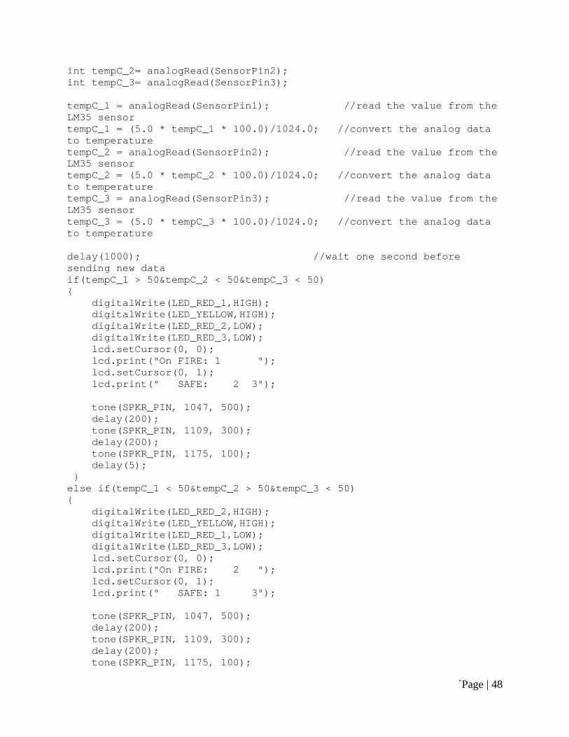
`Page | 48
int tempC_2= analogRead(SensorPin2); int tempC_3= analogRead(SensorPin3); tempC_1 = analogRead(SensorPin1); //read the value from the LM35 sensor tempC_1 = (5.0 * tempC_1 * 100.0)/1024.0; //convert the analog data to temperature tempC_2 = analogRead(SensorPin2); //read the value from the LM35 sensor tempC_2 = (5.0 * tempC_2 * 100.0)/1024.0; //convert the analog data to temperature tempC_3 = analogRead(SensorPin3); //read the value from the LM35 sensor tempC_3 = (5.0 * tempC_3 * 100.0)/1024.0; //convert the analog data to temperature delay(1000); //wait one second before sending new data if(tempC_1 > 50&tempC_2 < 50&tempC_3 < 50) digitalWrite(LED_RED_1,HIGH); digitalWrite(LED_YELLOW,HIGH); digitalWrite(LED_RED_2,LOW); digitalWrite(LED_RED_3,LOW); lcd.setCursor(0, 0); lcd.print("On FIRE: 1 "); lcd.setCursor(0, 1); lcd.print(" SAFE: 2 3"); tone(SPKR_PIN, 1047, 500); delay(200); tone(SPKR_PIN, 1109, 300); delay(200); tone(SPKR_PIN, 1175, 100); delay(5); else if(tempC_1 < 50&tempC_2 > 50&tempC_3 < 50) digitalWrite(LED_RED_2,HIGH); digitalWrite(LED_YELLOW,HIGH); digitalWrite(LED_RED_1,LOW); digitalWrite(LED_RED_3,LOW); lcd.setCursor(0, 0); lcd.print("On FIRE: 2 "); lcd.setCursor(0, 1); lcd.print(" SAFE: 1 3"); tone(SPKR_PIN, 1047, 500); delay(200); tone(SPKR_PIN, 1109, 300); delay(200); tone(SPKR_PIN, 1175, 100);

`Page | 49
delay(5); else if(tempC_1 < 50&tempC_2 < 50&tempC_3 > 50) digitalWrite(LED_RED_3,HIGH); digitalWrite(LED_YELLOW,HIGH); digitalWrite(LED_RED_1,LOW); digitalWrite(LED_RED_2,LOW); lcd.setCursor(0, 0); lcd.print("On FIRE: 3"); lcd.setCursor(0, 1); lcd.print(" SAFE: 1 2 "); tone(SPKR_PIN, 1047, 500); delay(200); tone(SPKR_PIN, 1109, 300); delay(200); tone(SPKR_PIN, 1175, 100); delay(5); else if(tempC_1 > 50&tempC_2 > 50&tempC_3 < 50) digitalWrite(LED_RED_1,HIGH); digitalWrite(LED_RED_2,HIGH); digitalWrite(LED_YELLOW,HIGH); digitalWrite(LED_RED_3,LOW); lcd.setCursor(0, 0); lcd.print("On FIRE: 1 2 "); lcd.setCursor(0, 1); lcd.print(" SAFE: 3"); tone(SPKR_PIN, 1047, 500); delay(200); tone(SPKR_PIN, 1109, 300); delay(200); tone(SPKR_PIN, 1175, 100); delay(5); else if(tempC_1 < 50&tempC_2 > 50&tempC_3 > 50) digitalWrite(LED_RED_2,HIGH); digitalWrite(LED_RED_3,HIGH); digitalWrite(LED_YELLOW,HIGH); digitalWrite(LED_RED_1,LOW); lcd.setCursor(0, 0); lcd.print("On FIRE: 2 3"); lcd.setCursor(0, 1); lcd.print(" SAFE: 1 "); tone(SPKR_PIN, 1047, 500); delay(200); tone(SPKR_PIN, 1109, 300);

`Page | 50
delay(200); tone(SPKR_PIN, 1175, 100); delay(5); else if(tempC_1 > 50&tempC_2 < 50&tempC_3 > 50) digitalWrite(LED_RED_1,HIGH); digitalWrite(LED_RED_3,HIGH); digitalWrite(LED_YELLOW,HIGH); digitalWrite(LED_RED_2,LOW); lcd.setCursor(0, 0); lcd.print("On FIRE: 1 3"); lcd.setCursor(0, 1); lcd.print(" SAFE: 2 "); tone(SPKR_PIN, 1047, 500); delay(200); tone(SPKR_PIN, 1109, 300); delay(200); tone(SPKR_PIN, 1175, 100); delay(5); else if(tempC_1 > 50&tempC_2 > 50&tempC_3 > 50) digitalWrite(LED_RED_1,HIGH); digitalWrite(LED_RED_2,HIGH); digitalWrite(LED_RED_3,HIGH); digitalWrite(LED_YELLOW,HIGH); lcd.setCursor(0, 0); lcd.print("On FIRE: 1 2 3"); lcd.setCursor(0, 1); lcd.print(" SAFE: "); tone(SPKR_PIN, 1047, 500); delay(200); tone(SPKR_PIN, 1109, 300); delay(200); tone(SPKR_PIN, 1175, 100); delay(5); else digitalWrite(LED_RED_1,LOW); digitalWrite(LED_RED_2,LOW); digitalWrite(LED_RED_3,LOW); digitalWrite(LED_YELLOW,LOW); lcd.setCursor(0, 0); lcd.print("On FIRE: "); lcd.setCursor(0, 1); lcd.print(" SAFE: 1 2 3");
`Page | 51
References
1. Arduino. Introduction to Arduino [Online]. Italy: Arduino URL: http://arduino.cc/en/Guide/Introduction Accessed July 15 2013
1 Arduino. Arduino board Uno [Online]. Italy: Arduino URL: http://arduino.cc/en/Main/ArduinoBoardUno Accessed 17 July 2013
2 Arduino 1.0.5 Arduino URL: http://arduino.cc/en/main/software#toc2 Accessed 17 July 2013
3 Atmel Corporation. ATmega328 datasheet [Online]. USA: Atmel Corporation; 10/2009 URL: http://www.atmel.com/Images/doc8161.pdf Accessed 11 July 2013
4 Microcontrollers: Theory and Applications by Ajay V Deshmukh URL: http://books.google.com.bd/books?id=5PDx2Q9Ea_YC&hl=en&authuser Accessed 11 July 2013
5 Tech Shop Bd URL: http://www.techshopbd.com Accessed 11 July 2013
6 BC548 Datasheet URL: www.b-kainka.de/Daten/Transistor/BC548.pdf Accessed 11 July 2013
7 LM7805 Datasheet URL: www.fairchildsemi.com/ds/LM/LM7805.pdf Accessed 11 July 2013
8 6vdc relay datasheet URL: http://www.alldatasheet.com/datasheet-pdf/pdf/98630/NAIS/JS1-6V.html Accessed 11 July 2013