Micro- and Nanofibrillated Cellulose as a Rheology Modifier Additive in CMC-Containing...
18
Micro- and Nanofibrillated Cellulose as a Rheology Modifier Additive in CMC-Containing Pigment-Coating Formulations K. Dimic-Misic,* ,† P. A. C. Gane, †,‡ and J. Paltakari † † School of Chemical Technology, Department of Forest Products Technology, Aalto University, P.O. Box 16300, FI-00076 Aalto, Finland ‡ Omya International AG, Baslerstrasse 42, CH-4665 Oftringen, Switzerland ABSTRACT: Suspension rheology of aqueous coatings influences the coating application performance at high speeds and during high rates of change of the shear rate, as well as the quality of the coated end product determined by the relationship between dewatering, immobilization, and coating coverage. In the case of paper coatings, the end-use printing can be significantly affected by the coating uniformity, pore structure, and surface chemistry. Nanocellulose-containing materials, such as microfibrillated (MFC) and nanofibrillated (NFC) cellulose, are potential additives that could at least partly substitute other natural and synthetic cobinders, including viscoelasticity-inducing starch, carboxymethyl cellulose (CMC), and polyacrylic thickeners, in paper-coating color formulations. Work is reported here in which a systematic comparison of dewatering and rheological characteristics of coating colors, based on three different pigments and mixtures thereof, is illustrated using CMC as the cobinder and incorporated with MFC/NFC as the partial cobinder replacement. All colors are shown to exhibit viscoelasticity, but the MFC/NFC additives are seen to operate as water-binding gel-forming components rather than with the flocculating thickening action of CMC. Immobilization of the color in the presence of nanofibrillar material is identified as the point of gel−water entrapment rather than the traditional stick−slip particle−particle interlocking mechanism predominating in traditional flocculant thickener formulations. ■ INTRODUCTION Cellulose is widely used in the form of microfibers, but recently there has been significant interest in both academia and the industry concerning the production of cellulosic materials having components with characteristic size on the nanometer scale. These are being considered as a major potential contribution to the economic future of the forest products industry. 1 Microfibrillated (MFC) and nanofibrillated (NFC) cellulose are examples of such nanocellulose-containing materials, present in lesser or greater amounts, respectively, and they possess distinctly different properties compared to standard macroscopic fibers. Such properties, including very high mechanical strength and elastic modulus, low thermal expansion, among others, are due primarily to their self- and water-interactive properties, in turn related to the high surface area and unique optical and self-assembly characteristics. 2,3 The geometric properties of the intrinsic nanocellulose structures (shape, length, and diameter) depend mainly on the extraction process and on the origin of the cellulose raw material. 4−6 Cellulose micro/nanofibers can be obtained from mechanical and/or chemical procedures. Among the mechanical proce- dures, the following can be mentioned to exemplify: refining or high-shear homogenizing, 7,8 microfluidizing, 9 and sonication, 3 which result in mechanically ground and/or separated micro- and nanofibrils. Refinement and homogenization are carried out in the presence of water, usually producing micro/ nanofibrils by passing the suspension of pulp fibers through a relatively narrow gap of a disk apparatus between the rotor and stator. In the microfluidising process, the suspension is subject to high pressure to force passage through a Y- or Z-type geometry flow chamber. 9 Sonication is carried out in a fiber suspension in order to separate the micro/nanofibril bundles in the fiber cell wall through cavitation. 10 Among the chemical procedures, the following can be highlighted: enzymatic hydrolysis with cellulases, 11 leading to micro- and nanofibrils, and selective oxidation of primary hydroxyl groups into carboxylate groups, leading to the production of high-aspect- ratio fibrils (TEMPO). 12 This resulting high aspect ratio describes fibrils possessing a diameter varying between 5 and 100 nm, depending on the details of the production process and raw materials. The typical size of NFC is smaller and its surface charge much higher compared to those of MFC. Nanocrystalline cellulose, as opposed to micro/nanofibrillar cellulose, is produced by acid hydrolysis to form an essentially fibril-free material. 13 Nanofibrillar and nanocrystalline cellulose bind water strongly, and retained fiber structures in the fibrillar case swell in the presence of water. The result is a gel-like structure, which acts partially as a voluminous medium in the suspension. 14,15 Nanocellulosic materials, such as those from the production routes described above, are expected to influence traditional coating layer properties, especially those designed for specific purposes, such as absorbency and/or permeability as well as forming selective barriers to liquids. The observation that nanocellulose could be used in paper-coating formulations, as a cobinder for example, based on its biodegradable nature as well Received: September 3, 2013 Revised: October 14, 2013 Accepted: October 15, 2013 Published: October 15, 2013 Article pubs.acs.org/IECR © 2013 American Chemical Society 16066 dx.doi.org/10.1021/ie4028878 | Ind. Eng. Chem. Res. 2013, 52, 16066−16083
Transcript of Micro- and Nanofibrillated Cellulose as a Rheology Modifier Additive in CMC-Containing...

Micro- and Nanofibrillated Cellulose as a Rheology Modifier Additivein CMC-Containing Pigment-Coating FormulationsK. Dimic-Misic,*,† P. A. C. Gane,†,‡ and J. Paltakari†
†School of Chemical Technology, Department of Forest Products Technology, Aalto University, P.O. Box 16300, FI-00076 Aalto,Finland‡Omya International AG, Baslerstrasse 42, CH-4665 Oftringen, Switzerland
ABSTRACT: Suspension rheology of aqueous coatings influences the coating application performance at high speeds andduring high rates of change of the shear rate, as well as the quality of the coated end product determined by the relationshipbetween dewatering, immobilization, and coating coverage. In the case of paper coatings, the end-use printing can be significantlyaffected by the coating uniformity, pore structure, and surface chemistry. Nanocellulose-containing materials, such asmicrofibrillated (MFC) and nanofibrillated (NFC) cellulose, are potential additives that could at least partly substitute othernatural and synthetic cobinders, including viscoelasticity-inducing starch, carboxymethyl cellulose (CMC), and polyacrylicthickeners, in paper-coating color formulations. Work is reported here in which a systematic comparison of dewatering andrheological characteristics of coating colors, based on three different pigments and mixtures thereof, is illustrated using CMC asthe cobinder and incorporated with MFC/NFC as the partial cobinder replacement. All colors are shown to exhibitviscoelasticity, but the MFC/NFC additives are seen to operate as water-binding gel-forming components rather than with theflocculating thickening action of CMC. Immobilization of the color in the presence of nanofibrillar material is identified as thepoint of gel−water entrapment rather than the traditional stick−slip particle−particle interlocking mechanism predominating intraditional flocculant thickener formulations.
■ INTRODUCTION
Cellulose is widely used in the form of microfibers, but recentlythere has been significant interest in both academia and theindustry concerning the production of cellulosic materialshaving components with characteristic size on the nanometerscale. These are being considered as a major potentialcontribution to the economic future of the forest productsindustry.1 Microfibrillated (MFC) and nanofibrillated (NFC)cellulose are examples of such nanocellulose-containingmaterials, present in lesser or greater amounts, respectively,and they possess distinctly different properties compared tostandard macroscopic fibers. Such properties, including veryhigh mechanical strength and elastic modulus, low thermalexpansion, among others, are due primarily to their self- andwater-interactive properties, in turn related to the high surfacearea and unique optical and self-assembly characteristics.2,3 Thegeometric properties of the intrinsic nanocellulose structures(shape, length, and diameter) depend mainly on the extractionprocess and on the origin of the cellulose raw material.4−6
Cellulose micro/nanofibers can be obtained from mechanicaland/or chemical procedures. Among the mechanical proce-dures, the following can be mentioned to exemplify: refining orhigh-shear homogenizing,7,8 microfluidizing,9 and sonication,3
which result in mechanically ground and/or separated micro-and nanofibrils. Refinement and homogenization are carriedout in the presence of water, usually producing micro/nanofibrils by passing the suspension of pulp fibers through arelatively narrow gap of a disk apparatus between the rotor andstator. In the microfluidising process, the suspension is subjectto high pressure to force passage through a Y- or Z-typegeometry flow chamber.9 Sonication is carried out in a fiber
suspension in order to separate the micro/nanofibril bundles inthe fiber cell wall through cavitation.10 Among the chemicalprocedures, the following can be highlighted: enzymatichydrolysis with cellulases,11 leading to micro- and nanofibrils,and selective oxidation of primary hydroxyl groups intocarboxylate groups, leading to the production of high-aspect-ratio fibrils (TEMPO).12 This resulting high aspect ratiodescribes fibrils possessing a diameter varying between 5 and100 nm, depending on the details of the production processand raw materials. The typical size of NFC is smaller and itssurface charge much higher compared to those of MFC.Nanocrystalline cellulose, as opposed to micro/nanofibrillarcellulose, is produced by acid hydrolysis to form an essentiallyfibril-free material.13
Nanofibrillar and nanocrystalline cellulose bind waterstrongly, and retained fiber structures in the fibrillar caseswell in the presence of water. The result is a gel-like structure,which acts partially as a voluminous medium in thesuspension.14,15
Nanocellulosic materials, such as those from the productionroutes described above, are expected to influence traditionalcoating layer properties, especially those designed for specificpurposes, such as absorbency and/or permeability as well asforming selective barriers to liquids. The observation thatnanocellulose could be used in paper-coating formulations, as acobinder for example, based on its biodegradable nature as well
Received: September 3, 2013Revised: October 14, 2013Accepted: October 15, 2013Published: October 15, 2013
Article
pubs.acs.org/IECR
© 2013 American Chemical Society 16066 dx.doi.org/10.1021/ie4028878 | Ind. Eng. Chem. Res. 2013, 52, 16066−16083

as strong shear-thinning properties, raises a question about thepossible processability of MFC/NFC-containing coatings. In ahigh-speed coating process (>1000 m·min−1), dependencyprimarily on high rates of change of the shear rate results inmanifestation of the viscoelasticity and sensitivity to pressure-pulse dewatering when applied to a permeable substrate. Inslower-speed applications, the capillary-driven dewatering onabsorbent substrates dominates, and the nature of the progresstoward coating immobilization on the surface is the criticalfactor.16−18 Controlling precisely the increase in the solidscontent of coating colors, particularly under pressure-pulseconditions, is an important aspect for running high solidscoatings designed at reducing the production cost, as well asimpacting such properties as coating layer coverage and opticalcharacteristics. The mechanism of faster immobilization,resulting in lower demand and reduced reswelling of fibers inthe base paper surface, is a regular target for improved coatingperformance including savings in drying energy.18−20 Coatingcolor formulations have been continuously optimized in orderto maximize the solids content, which, if not accompanied bythe correct control of rheology and dewatering, frequentlyresults in a negative impact on the coating processabilitythrough excessive blade load, blade bleeding, and stalagmiteformation, streaking, and scratches, among other things, leadingto higher numbers of web breaks and unacceptable coatinglayer irregularities.21,22 The high rate of change of the strainrate under shear conditions is affected by the coater speed andwet film thickness, which are, themselves, affected by thecoating color elasticity and water retention properties.At the highest coating speeds or highest coating color solids
content, the short-time-scale response of the viscoelastic colorunder the rapid rates of change of induced stress becomescritical.16,23,24 The viscoelasticity, arising from the colloidal andstructural interactions of the coating color components, resultsin the coating color behaving more as an elastic solid than aviscous liquid, which then imposes a plug-flow regimesupported by boundary slip under the coating blade nip.16
Boundary slip is also supported by the formation of boundarywater layers: a characteristic of gel-like materials when shearedunder fixed geometry and something that is suspected to betypical of nanocellulosic waterborne materials such as thosestudied in this work.25 Loss of water under the pressure pulse ofthe blade exacerbates the viscoelastic property in the regionbefore the high rate of change of induced stress at theblade.16,25 Rapid removal of water, however, can induce somedesirable immobilization of the coating color at the base−paperinterface, but too fast pressure-pulse dewatering can lead toundesirable effects such as binder migration, i.e., nonuniformbinder distribution within and along the coating layer.17,22,26
Besides elasticity, the shear-thinning properties of a coatingcolor describe its behavior under pumping and distribution tothe coating machine head.In this study, MFC and NFC are used to substitute, at least
partially, the standard cobinder material carboxymethylcellulose (CMC). We focus on how MFC/NFC, utilized as acobinder in the coating formulation, influences its rheologicalbehavior, bearing in mind that such nanocellulosic materials actto form gels in water as opposed to inducing the flocculationbehavior of color components known to occur withCMC.16,27−32
■ MATERIALS
To help characterize the constituents of the coatings, the chargeof the pigments was determined by a Zeta-sizer (MalvernInstruments Ltd.). The average particle size of the pigmentsMFC and NFC was measured with dynamic light scattering(DLS), using the photon correlation spectroscopic techniquewith a Zeta-sizer (Malvern Instruments Ltd.). Prior tomeasuring the ζ potential (Ψz) and ensemble average particlesize, the samples were diluted with deionized water to a solidcontent of 0.01%.Pigments used in this work were in predispersed slurry form.
Two ground calcium carbonates (GCCs), produced by wetgrinding in the presence of polyacrylate dispersant, and a high-aspect-ratio sedimentary clay were studied. The two GCCswere respectively a relatively coarse Hydrocarb 60 (cGCC) anda finer Hydrocarb 90 (fGCC) (Omya AG, Switzerland). ThecGCC grade had 60% w/w of particles <2 μm, with a weightmedian diameter of 1.35 μm and ζ potential Ψz of −27.13 mVat pH 9.2. The finer fGCC had 90% w/w of particles <2 μmwith a weight median diameter of 0.7 μm having a Ψz value of−25.4 mV at pH 8.9. The high-aspect-ratio Brazilianrotogravure kaolin clay, Capim RG (supplied by Imerys, St.Austell, Cornwall, U.K.) in slurry form (66% w/w solidscontent), had an ISO brightness of 88.5, with 55% w/w ofparticles <2 μm, a shape factor aspect ratio (platiness) of ∼40,and a Ψz value of −45.33 mV at pH 8.5.Three different thickener/cobinder systems were used in this
work: a carboxymethyl cellulose (CMC; Finnfix 10, Kelco,Finland), which in the further test coating colors is partiallyreplaced by microfibrillated (MFC) and nanofibrillated (NFC)cellulose, respectively. CMC had a molecular weight of 66 kg·mol−1 and a degree of substitution of 0.78. A styrene acryliclatex (SA-Latex), Styron XZ 96 767.00, was used as the binder,having a glass transition temperature Tg of 24 °C, a minimumfilm-forming temperature (MFFT) of 20 °C, a particle size of105 nm, a dry solids content of 50% w/w, pH 8.0, and aviscosity of 320 mPa·s (Styron Suomi Oy, Hamina, Finland), asreported by the supplier.MFC was prepared by grinding Birch Kraft pulp with an
ultrafine friction grinder (Masuko Supermasscolloider, MKZA10-15J) equipped with SiC grinding stones (MKE10-46). Lighttransmittance for 0.1% consistency at a wavelength of 800 nmwas 34.3%. The average particle size of the agglomerates was6692 nm as measured by DLS. The sample NFC was producedin a pilot process by oxidation and then fibrillation. A TEMPOcatalyst was used in oxidation of the Birch Kraft pulp.12 Theaverage size of the agglomerates, measured with DLS, was 977nm. The carboxylic acid content on NFC was 0.1 mmol·g−1 asdetermined by conductometric titration.33 NFC had a degree ofsubstitution of 0.2 and was delivered at 2.3% consistency.Any retained fiber portion in MFC/MFC swells when in
contact with water. The nanofibrillar material combines withwater to form a gel, containing water within its interparticlenanoporous structure. The difference in the water−bindingproperty, relating to the nanoporous structure of MFC andNFC, was evaluated with a water retention value test (WRVISO/DIS 23714), which was modified with respect to samplepreparation to suit the measurement of nanocellulose.34 Thiswas done by mixing quantities of nanocellulose in the range 0−6% with an unrefined Kraft pulp and then centrifuging themixture under normal WRV test conditions. The curve of WRVagainst the nanocellulose content was used to extrapolate to the
Industrial & Engineering Chemistry Research Article
dx.doi.org/10.1021/ie4028878 | Ind. Eng. Chem. Res. 2013, 52, 16066−1608316067
pure nanocellulose swelling. The water retained in NFC andMFC at a 2% content was found to be 24 and 9 g of water/g ofsolids, respectively. The surface charge and fine structure ofNFC largely explain its higher water binding property,effectively exerting a stronger surface wetting and capillaryaction than the centrifugal force used for dewatering in theWRV test.Suspensions of cellulose fibers and nanocellulose were
prepared for individual analysis at four different concentrations(1.0%, 1.5%, 2.0%, and 2.3%, respectively). Differentconsistencies of MFC and NFC suspensions were obtainedby dilution of the initial stock concentrations of 3.0% and 2.3%,respectively. Dilutions were made using deionized water. Thesuspensions were labeled according to their consistency andtype with respect to the material content (MFC/NFC). Thefinal pH of all suspensions was between 8.0 and 8.2.Preparation and Characterization of the Coating
Colors. The relative amount of each ingredient in the coatingcolor formulations is shown in Table 1. The dry solid contentwas 63% w/w for all coating colors. CMC was prepared as anaqueous solution of 10% w/w. The coating colors wereprepared by mixing of the pigment slurries with SA-Latex underagitation in a Diaf mixer (Pilvad Diaf A/S, Humlebæk,Denmark) at 900 min−1 for 15 min, and then the cobinderwas added (CMC and MFC/NFC) using the same rotationspeed for 25 min. The coating color pH values were in therange 8.5−9.0.
■ METHODS
Rheometry. The viscoelastic rheological investigations wereperformed at 23 °C by means of an Anton Paar 300 (AntonPaar Germany GmbH, Ostfildern-Scharnhausen, Germany)oscillatory constant stress/strain and variable shear rheom-eter.35,36 The parallel-plate geometry was selected with anupper plate diameter of 50 mm, with the gap between theupper and bottom plates being 1 mm. Prior to measurement,the sample was presheared at an angular frequency of 10 rad·s−1
and a strain deformation of 0.1% for 10 min, followed by a reststationary state time of 15 min.37,38 Different types ofrheological measurements were performed on the samerheometer, preserving the geometry, viscoelastic measurements,stability and recovery tests,35,36,39 and steady-state flow withincreasing shear rate,38 as well as recording the dynamicalchange in the rheological parameters under dewatering.40,41 Toprevent evaporation of the water medium, a layer of silicone oilwas spread over the surface of the sample in contact with theair, a common procedure.31 By monitoring the viscoelastic
moduli prior and after each experiment, we checked thatevaporation or chemical aging of the sample was negligible.We note that the adopted parallel-plate geometry is very
prone to shear inhomogeneities, such as shear banding due tothe inherent shear gradient in the radial direction.42 This isespecially true for shear-thinning complex fluids, such ascoating colors. Furthermore, because we later discussdewatering, it is well documented in the literature that vacuumfiltration induces a gradient in the solid content in the filternormal direction.43 However, to provide a uniform thickness ofcolor during dewatering, a main target of the study, the parallel-plate geometry is an absolute given. Therefore, all of therheological properties of the samples measured in this waycorrespond to their apparent values specific for this geometryand are suitable only for comparative purposes. Rheograms aremade from representative measurements, and for calculation ofthe rheological parameter, average values of five measurementsare used.
Viscoelastic Behavior. Dynamic moduli, storage modulus(G′) and loss modulus (G″), were measured as a function ofthe angular frequency (ω = 0.1−100 s−1) using oscillatory tests.To perform the frequency sweep test, the LVE range of thesample was obtained from an amplitude sweep using a constantangular frequency (ω = 1 s−1) with varying strain amplitudebetween 0.01 and 500%.
Apparent Extrapolated Yield Stress. For a flow propertycomparison of different MFC/NFC suspensions, we fitted dataof steady-state flow from shear range flow curves for anincreasing upward shear rate range of 0.001−1000 s−1 asapplied in the Herschel−Bulkley equation to obtain theapparent yield stress,44,45 given by
τ τ γ= + K( )n0 (1)
where τ is the shear stress, τ0 is the apparent yield stress, K is aconstant, termed consistency, γ is the shear rate, and n is thefluid index describing the flow behavior in an assumed powerlaw. MFC/NFC suspensions are well-known to exhibit largerheological hysteresis;46−48 therefore, it is advisable to performa complete reverse sweep cycle (up and down in the shear rate)in order to exclude data from any likely shear banding area,which, as mentioned before, may occur under the parallelplate−plate geometry.49 For determination of the local yieldstress, we used the shear stress value generated after shear at 20and 500 s−1, respectively, in which regions are seen to be linearprofiles after the curve bending area as a function of the changeof the shear rate.15
Shear-Thinning Behavior. Shear thinning is clearly observ-able in the rheological response behavior discussed above. In
Table 1. Coating Color Formulationsa
cGCC/ref
cGCC/MFC
cGCC/NFC
fGCC/ref
fGCC/MFC
fGCC/NFC
75cGCC/ref
75cGCC/MFC
75cGCC/ref
50cGCC/CMC
50cGCC/ref
50cGCC/NFC
100clay/ref
100clay/MFC
100clay/NFC
cGCC 100 100 100 0 0 0 75 75 75 50 50 50 100 100 100fGCC 0 0 0 100 100 100 0 0 0 0 0 0 0 0 0clay 0 0 0 0 0 0 25 25 25 50 50 50 100 100 100SA-latex 15 15 15 15 15 15 15 15 15 15 15 15 15 15 15CMC 0.4 0.1 0.1 0.4 0.1 0.1 0.4 0.1 0.1 0.4 0.1 0.1 0.4 0.1 0.1MFC 0 0.3 0 0 0.3 0 0 0.3 0 0 0.3 0 0 0.3 0NFC 0 0 0.3 0 0 0.3 0 0 0.3 0 0 0.3 0 0 0.3aComponent amounts are given in parts per hundred (pph; by weight) based on 100 parts by weight of pigment(s). Complementary to the GCCportion is the kaolin (clay) in all clay-containing formulations in order to form 100 pph pigment.
Industrial & Engineering Chemistry Research Article
dx.doi.org/10.1021/ie4028878 | Ind. Eng. Chem. Res. 2013, 52, 16066−1608316068

this section, we investigate the shear-thinning nature using avariety of shear application devices, interpreting the variousexpressions of viscosity in order to derive likely structuralbehavior during the shear-thinning process. This is importantfor the early stages of dynamic dewatering before the increasingelastic component defines the immobilization state.Apparent Viscosity under Low Shear “Stirring”. The static
apparent viscosities of MFC and NFC suspensions at 1.5%consistency were measured with a Brookfield viscometer(Brookfield DV-II) adopting a vane v-73 for MFC and v-74for NFC viscosity units at a rotation speed of 10 min−1. Theapparent low shear (stirring) viscosity of the coating colors wasdetermined also using the Brookfield viscometer operatedrespectively at two rotation speeds, 50 and 100 min−1, withspindle #4 chosen in this case. For each measurement, a newsample was used, and the mean values of the last five datapoints at a given rotation speed were used for analysis of theexperimental data. All measurements were performed at roomtemperature. Data from apparent low shear viscosities arepresented in Table 2.Dynamic Viscosity from a Steady-State Flow Curve. The
influence of the shear rate on the variation of the dynamicviscosity was observed by measuring the steady-state flow curveusing an increasing shear rate in the range 0.001−1000 s−1, withdata point duration 10 s. The influence of the shear rate on thevariation of the complex viscosity was evaluated by measuringthe complex viscosity response as a function of increasingoscillation frequency (angular frequency ω = 0.1−100 s−1). Apower law according to the Oswald de Waele empirical modelwas fitted to the experimental data for both the dynamic andcomplex viscosities (eq 2), allowing a comparison of the powerlaw coefficients between the different deformation rates andconditions, i.e., within the local linear viscoelastic (LVE) regionfor the complex viscosity and beyond the elastic region for thedynamic viscosity, respectively34,50,51
η γ= −k n.
(2)
where η is the viscosity, γ is the shear rate, and k and n are theflow index and the power law exponent, respectively. Here n =0 indicates a Newtonian fluid and n > 0 pseudoplastic (shear-thinning) behavior.Leveling and Recovery 3ITT Measurements. Leveling and
recovery measurements were performed with the help of thethree-interval test (3ITT test).35,36 Two different 3ITT testswere performed: rotational and elasticity recovery tests.To evaluate the evolution of the dynamic viscosity (η) after
high shear stress, the 3ITT rotational test was performedconsisting of a stepwise shear rate test with three definedintervals of applied shear: low shear interval/high shearinterval/low shear interval.36 During the first and thirdintervals, the sample was sheared at a low shear rate of 0.1s−1, while the second interval was with a high rotation rate of500 s−1. This measurement shows the deformation andrecovery of the structure through regeneration of the dynamicviscosity; i.e., how fast coating colors can regenerate theviscosity after application of a high shear period or impulse.Structure recovery was traced with respect to the time neededfor a given coating color to recover 90% of its dynamic viscosityvalue before deformation (at the end of first interval).In order to evaluate the evolution of the elastic modulus after
the application of high shear, a 3ITT elasticity recovery test wasmade, consisting of three intervals: oscillation/rotation/ Table
2.Resultsof
LowShearApp
arentViscosity
(Brookfield)
andGravimetricDew
atering(Å
A-GWR)forMFC
/NFC
andCoating
Colorsa
MFC
NFC
cGCC/
CMC
cGCC/
MFC
cGCC/
NFC
fGCC/
CMC
fGCC/
MFC
fGCC/
NFC
75cG
CC/
ref
75cG
CC/
MFC
75cG
CC/
NFC
50cG
CC/
ref
50cG
CC/
MFC
50cG
CC/
NFC
100
clay/ref
100clay/
MFC
100clay/
NFC
consistency(%
)1.5
1.5
6363
6363
6363
6363
6363
6363
6363
63AA-GWR(g·m
−2 )
1132
219
198
235
213
189
233
208
153
190
195
99194
206
129
152
194
Brookfield/10
min
−1
(mPa·s)
151768
74334
Brookfield/50
min
−1
(mPa·s)
53268
16345
844
534
793
1809
1459
1548
896
525
652
782
480
581
725
330
423
Brookfield/100min
−1
(mPa·s)
33666
9987
512
328
496
1094
894
981
553
339
422
476
307
374
431
225
275
aCom
plem
entary
totheGCCportionisthekaolin
(clay)
inallclay-containingform
ulations
inorderto
form
100pphpigm
ent.
Industrial & Engineering Chemistry Research Article
dx.doi.org/10.1021/ie4028878 | Ind. Eng. Chem. Res. 2013, 52, 16066−1608316069

oscillation.35 In the first interval of oscillation, the test wasperformed at constant angular frequency [constant direct strainoscillation (DSO)] ω = 10 s−1 and strain γ = 0.01%, which hasa value in the LVE range determined previously by anamplitude sweep test. During the second interval, adeformation was applied to the sample under a rotationalregime with a high shear rate of 500 s−1. The time taken for thestructure to be regained to 90% of the G′ value it had prior tothe high shear interval was evaluated as an indication of thethixotropic behavior of the material. It should be noted herethat complex systems, as described by the materials used in thisstudy, i.e., nanofibrillar and micro- and macrofibrous as well ascolloidal particulates, undergo multiple structural configurationsincluding, and generating, a variety of elastic interactions. Theelastic behavior is, thus, dependent on the material particulateand colloidal configurations, and so for each interaction, orcombinations of interactions, there exists a localized elasticregime dependent on the strain rate condition applied. Thus,the term LVE in this context refers to the particular LVE regionapplicable for the fixed frequency of oscillation used.Gravimetric Dewatering ÅA-GWR. The static gravimetric
dewatering of coating colors was measured using the ÅboAkademi Gravimetric Water Retention device (ÅA-GWR).52 Avolume of 10 cm3 of coating color was inserted into thecylindrical vessel above a polycarbonate membrane (Nucleo-pore Track-Etch membrane 5 μm, Whatman) and an absorbentblotter paper. The cylinder was closed and the sample heldunder an overpressure of 0.5 bar. After 1 min and 45 s, duringwhich dewatering through the membrane occurred, thepressure cylinder was removed. The blotter paper was weighedbefore measurement and 30 s after the pressure was released.The weight difference was multiplied by 15091 m−2, which isthe inverse of the cylinder cross-sectional area. An average offive determinations was computed.Dynamic Dewatering Measurements. Dynamic dewatering
measurements under continuous shear were performed using adewatering unit with a parallel-plate geometry (the immobiliza-tion cell, IMC).41,43 The parallel plate of 50 mm diameter (PP-50) was adopted in all immobilization tests. The initial gap wasset to 1 mm. The filter medium used in these experiments was ahydrophobic Whatman Nucleopore membrane, with a pore sizeof 0.2 μm. In the experiments, the temperature was kept at 23°C and the preset shear rate was 100 s−1 applied for 40 s. We
chose a testing approach in which the sample is subjected toDSO within the LVE range. The method as described isreported also by other authors,41 and the procedure is designedto provide dynamic rheological information for a viscoelasticmaterial during dewatering on the IMC apparatus. Theoscillatory parameters during the measurement were γ = 1%and ω = 10 s−1. The transition from liquidlike to solidlikebehavior for a viscoelastic coating material during immobiliza-tion has been described as the maximum slope of the lossfactor, which is the ratio of the viscous to elastic moduli, G″/G′= tan δ.18,41 In the DSO test, during the progressive transitionbetween liquidlike to solidlike behavior, the loss factordecreases with increasing time, reaching a minimum with G′> G″.During dewatering in the IMC, the structure of the sample
evolves as the solid content increases. The volume of thesample decreases, which is reflected by an artificial reduction inthe normal force as soon as the vacuum |−Δp| = 40 kPa isinitiated (under pressure conditions similar to those ingravimetric dewatering measurements). After the automaticgap setting is applied, the normal force should remain zero, andthe measuring system thus compensates for its negative values,which appear as a result of a tensile stress developing withdewatering.43 The measuring instrument tries, therefore, tocompensate for the negative normal force by moving the upperplate to decrease the gap. Thus, the gap becomes smaller as aresult of the normal force decrease (i.e., the solid contentincrease leads to a reduced sample thickness). In fact, if thesample could be measured at constant volume, as the solidcontent increases, so would the normal force because of theincrease in the elasticity.
Immobilization Solids. In order to investigate theimmobilization layer further, the material that remained onthe upper plate after it had been lifted up at the end of thedewatering tests was scraped off and analyzed gravimetrically, asdescribed in previous research. The height of the apparent filtercake, determined by using the rheometer gap height, as wasfollowed by other authors,43 was not studied because weconsidered that, because of gel-related viscoelastic effects thatmight arise during formation of a concentration gradient uponvacuum dewatering of MFC/NFC-based coatings, thedefinition of a mechanically formed static filter cake per se isquestionable.34
Figure 1. Viscoelastic measurements for MFC and NFC suspensions at 2% and 2.3% consistency: (a) amplitude sweep for a range of strains (γ =0.01−500%) at a constant angular frequency of 1 rad·s−1; (b) frequency sweep (0.1−100 rad·s−1) at a constant strain of 0.1%. Open symbols: elasticmodulus (G′). Closed symbols: loss modulus (G″).
Industrial & Engineering Chemistry Research Article
dx.doi.org/10.1021/ie4028878 | Ind. Eng. Chem. Res. 2013, 52, 16066−1608316070

■ RESULTS AND DISCUSSION
Rheological Characterization. Low Shear ApparentViscosities. As seen in Table 2, a low shear apparent viscosity(Brookfield) at 10 min−1 is higher for MFC than for NFCsuspensions, probably because of greater entanglement of theretained swollen fibrous material in the MFC.14
A comparison of the apparent viscosity values from thecoating colors at rotation rates of 50 and 100 min−1 shows that,across the formulated coating colors, for each given pigmentblend CMC as the cobinder always gives a higher viscosityvalue than MFC/NFC as the cobinder, which can be associatedwith the induced flocculation mechanism between CMC andpigments/latex.27,53 The higher mobility of the particulates inthe MFC and NFC coating color matrix is reflected in a lowerviscosity value. Contrary to the MFC/NFC suspensions,coating colors with NFC as the cobinder have higher apparentviscosity than those with MFC, which is considered to berelated to the independent structural behavior of MFC andpigment, with the pigment effectively acting to dilute thefibrous component and so partially inhibit the fiberentanglement seen with MFC alone.54
Viscoelastic Behavior of MFC/NFC Suspensions. The MFCand NFC suspensions exhibit linear viscoelastic responses atlow strain. Parts a and b of Figure 1 show that within the LVEregime, below critical strain γc, MFC suspensions have higherelastic (G′) and loss (G″) moduli than NFC suspensions at thesame consistencies. This correlates well with the Brookfieldfindings above. Figure 1a shows that the LVE region is furtherextended for NFC suspensions (with the critical strain for MFCsuspensions being γc ∼ 0.015%, and that for NFC suspensionsγc ∼ 0.8%) because of a stronger gel-like structure typical forNFC suspensions at concentration higher than 1%, which isseen in the flow curve as an elastic overshoot, being highest forthe 2.3% NFC suspension.46 For both MFC and NFCsuspensions, the storage modulus (G′) is much greater thanthe loss modulus (G″), which indicates a solidlike elasticbehavior of the material typical for a gel-like structure. Thesame indication of entanglement versus gel-like structure isdepicited in Figure 1b, with viscoelastic moduli (G′ and G″) forthe MFC suspensions being higher than those for the NFCsuspensions. Lower G′ and G″ for NFC suspensions, whichhave higher ζ potential, reflecting greater surface charge, havebeen observed before.55,56 This is due to the higher surfacecharge acting to decrease friction due to both the chargerepulsion and a more spherical presentation to flow, thus
increasing the mobility radius within the suspension matrix. Incontrast, the likelihood of flocculation and entanglement in theMFC suspension is greater. Elastic moduli G′ show anindependence of frequency, but the viscous moduli G″ showa slight increase toward higher frequency, with the loss factor(tan δ) being around 0.2, again giving the indication of gel-likestructures. Similar behavior is observed for MFC/NFCsuspensions at 1% and 1.5% consistencies.The steady shear behavior for MFC/NFC suspensions at
increasing shear rate over the range 0.001−1000 s−1 (Figure 2a)is used for determination of the dynamic apparent yield stressusing the Herschel−Bulkley equation (1), as shown in Figure2b.The Herschel−Bulkley equation does not apply very well
across the whole shear stress profile because of the elasticovershoots typical for MFC/NFC material, which have highelasticity,42 apparent in the steady shear measurements, whichhave short measurement time (Figure 2a), as observed by otherresearchers.42,49 Therefore, we obtained an apparent dynamicyield point by analyzing the data at shear rates higher than thetransition area, i.e., in the shear rate region between 20 and 500s−1, following the procedure described by Karppinen et al.15
(Figure 2b). As expected, for all solids, the yield stress increaseswith an increase in the suspension consistency, as was alsoobserved before by other authors.50,51 At lower consistency, theyield stress is almost the same for MFC and NFC suspensions,increasing for NFC for consistencies higher than 1.5% becauseof the inhibited hydrogen bonding of higher-specific-surface-area NFC (Figure 2c), which gives rise to gel-like structures,seen as elastic overshoots in the flow curve for the 2.3% NFCsuspension.46 Apparent yield point values are for 1% MFC, 43Pa, and for 1% NFC, 50 Pa; for 1.5% MFC, 60 Pa, and for 1.5%NFC, 62 Pa; for 2% NFC, 194 Pa, and for 2% NFC, 230 Pa; for2.3% MFC, 218 Pa, and for 2.3% NFC, 347 Pa.Because of the necessity of extrapolating to the apparent
yield stress point using the Herschel−Bulkley expression over arange where the power law behavior dominates, i.e., beyond thestructure transition in the increasing shear rate regime, clearly itis not possible to define the static rest state yield. However,adopting this technique, we believe, provides a betterdescription of the approach to immobilization under dynamicdewatering, i.e., while being sheared. The apparent yield stressis then greater (Figure 2c) than the stress seen at low shear(Figure 2a). We consider this to be an indication of the greaterdispersed nature of NFC/MFC under shear and so the longer
Figure 2. Steady-state flow curves for MFC/NFC suspensions for shear rate (γ = 0.001−1000 s−1), time between points 10 s: (a) shear stress (τ)against shear strain (γ) over the whole shear rate range; (b) shear rate region for determination of the apparent yield stress (τ0); (c) apparent yieldstress (τ0) for MFC/NFC suspensions as a function of the consistency.
Industrial & Engineering Chemistry Research Article
dx.doi.org/10.1021/ie4028878 | Ind. Eng. Chem. Res. 2013, 52, 16066−1608316071

range likelihood of gel formation when fibrils are effectivelyuncoiled.Nonlinear Viscoelastic Behavior of Coating Colors.
Oscillatory measurements were used to characterize themicrostructure of the coating colors.30,35,39 Parts a−c of Figure3 illustrate the storage (G′) and loss (G″) moduli as a functionof the strain at a constant angular frequency of 1 Hz. The elasticmodulus is constant up to a critical strain γc (∼0.015%), abovewhich the storage modulus decreases with strain and theviscoelastic behavior becomes nonlinear. Therefore, outside theLVE region, the elastic and viscous moduli values can only beconsidered as apparent values. Figure 3 reports the storage andloss moduli as a function of the strain amplitude for fGCC andthe two clay-containing coatings, with the three differentcobinder systems. The first observation is that, for all coatings,the presented G′ is much larger than G″. Second, G′ values arelarger for the CMC-only reference coatings than those havingfibrillar/nanocellulose as the cobinder. The linear domain, inwhich the storage modulus G′ is limited to a value of 95% ofthat of the plateau value30,57 is extended further with respect toshear stress for kaolin coatings than for carbonate coatingsbecause of stronger supramolecular structure buildup by CMCand kaolin.27,32 It is common here, regardless of the pigmenttype, that a transition between the linear and nonlinear regimesoccurs at larger deformations when nanocellulose is included inthe cobinder system, indicating that a potentially differentthickening mechanism is at play.In Figure 4a−e, the G′ and G″ moduli in the linear regime
are presented as functions of the frequency. Again we noticethat G′ is considerably larger than G″, and G′ increases slowlywith the frequency, while its magnitude remains considerablylarger than that of G″, as has been observed by other authors.The G″ increase at higher frequencies and the slight G″decrease at lower frequencies has also been observed by otherauthors.31,39
The variations in the viscoelastic moduli, with respect to theproportion of pigment types in the coating color formulationsand cobinder type, are plotted in Figure 5, with G′ and G″values at γ = 0.2 (%) taken from the angular frequency sweepmeasurement.For coating colors that have kaolin pigments, G′ and G″ in
Figure 5 both increase with an increase in the proportion ofkaolin in the pigment coating formulation blend. For coatingswithout kaolin pigment, G′ and G″ increase with higherpigment packing density, similar to that seen for the apparentviscosity. The flocculation mechanism of CMC on pigments
has been studied before,23,27,29,58 and it is observed thatformation of the floc structures, formed in this way, increasesthe elastic component in the coating rheology. However, allcoatings show a decrease in elastic moduli when CMC ispartially replaced with nanocellulose. The decrease in G′ can beexplained through reduced interaction with the thickenersystem as the amount of CMC is reduced in relation to thepigments/latex. That the replacement of CMC by cellulosedoes not regenerate the floc structure interactions shows thatthe pigments/latex and NFC essentially behave more or lessindependently in the mixed environment. This may be due totheir mutual charge repulsion and/or the higher interparticlemobility of swollen nanocellulose,50,59 which results in lowerelasticity than in the case of the higher CMC level in thepresence of pigments/latex.27,29,32 Solidlike behavior of coat-ings under the blade occurs if the deformation time is veryshort compared to the relaxation time. It is noted that usingvery low rates of change of strain, as applied here duringoscillation measurements, is very different from the high ratesof change of the shear rate conditions under a coating blade,but it is likely that the underlying elasticity is, nonetheless,identifiable because breakdown of most of the color structure isonly likely to occur in practice if the time scale is long enoughat high strain, i.e., under pumping rather than during the shortresidence time under the blade.16,25
Shear-Thinning Behavior. Shear thinning is clearly observ-able in the rheological response behavior discussed above. Inthis section, we investigate the shear-thinning nature using avariety of shear application devices, interpreting the variousexpressions of viscosity in order to derive likely structuralbehavior during the shear-thinning process. This is importantfor the early stages of dynamic dewatering before the increasingelastic component defines the immobilization state.
Complex Viscosity. The complex viscosity is obtained fromfrequency sweep tests, and its shear-thinning response withinthe local LVE region as the frequency of oscillation increaseshelps to characterize the rheological properties of thesuspension. The reduction in the complex viscosity (η*)under increasing shear rate characterizes the transition fromelastic to viscous behavior, and thus at highest shear, theinability to rebuild the structure in the time period of theapplied oscillation, or, as is commonly considered, theresistance to viscosity change during deformation, isobserved.16,23 The absence of a further induced elastic structureat the higher frequency range supports the noninteractivenature of nanocellulose with the particulate materials present.
Figure 3. Storage (G′) and elastic (G″) moduli against strain (γ) for the various coating color thickener systems containing (a) fGCC, (b) 50:50cGCC/clay, and (c) 100 clay. Complementary to the GCC portion is kaolin (clay) in all blend formulations in order to form 100 pph pigment.Closed symbols: elastic modulus (G′). Open symbols: loss modulus (G″).
Industrial & Engineering Chemistry Research Article
dx.doi.org/10.1021/ie4028878 | Ind. Eng. Chem. Res. 2013, 52, 16066−1608316072

Table 3 shows the complex viscosity response (η*) for allcoatings as defining the major difference between CMC- andMFC/NFC-containing cobinder systems. Figure 6a shows thecomplex viscosity (η*) over the whole frequency range (ω =0.1−100 rad·s−1), for 50 cGCC coatings; similar behavior isobserved for all other coatings and presented in Table 3.Dynamic Viscosity, Nonlinear Tests. Steady shear flow
curves of coating colors are presented in Figure 6b. All coatingsshow a similar pattern of a decrease in the viscosity as the shearrate (γ) increases from very low to very high (γ = 0.001−1000s−1), i.e., shear-thinning behavior. Unlike in the case of complexviscosity, where elucidation of the elastic and viscous
components is combined under oscillation, the dynamic flowcurves show three distinct regions.31,57
We defined the three distinct areas in the flow curvescovering three shear zones: (1) γ = 0.001−100 s−1, over whichthe viscosity decreases drastically and data do not follow asingle power law behavior; (2) at shear rates γ = 100−500 s−1,in which all flow curves follow a close fit to a perfect power lawbehavior; (3) at high shear rates γ = 500−1000 s−1. It isimportant to point out that in the shear zone with the highestshear rate NFC coatings have a further strong drop in viscosityat very high shear rates because of either a complete collapse ofthe gel-like structure within the coating color matrix or, much
Figure 4. Responses of G′ and G″ against frequency (ω = 0.1−100 rad·s−1) for all coating colors: (a) 100 cGCC; (b) 100 fGCC; (c) 75 cGCC; (d)50 cGCC; (e) 100 clay. Complementary to the GCC portion is kaolin (clay) in all formulations in order to form 100 pph pigment. Closed symbols:elastic modulus (G′). Open symbols: loss modulus (G″).
Industrial & Engineering Chemistry Research Article
dx.doi.org/10.1021/ie4028878 | Ind. Eng. Chem. Res. 2013, 52, 16066−1608316073

more likely, the establishment of a boundary slip condition dueto the expulsion of water from the gel, as presented in Figure6b. This latter effect, if confirmable, is potentially a vitalobservation with respect to blade coater runnability and theestablishment of plug flow under a high-speed runningblade.16,25,31
Fibrillar Coiling: Cox−Merz Rule? For most systems,particularly polymers, the complex viscosity (η*) provides aconvenient measure of the structural components contributingto low shear viscosity. If the dynamic shear response behavioragainst the shear rate is the same as the complex response as afunction of the frequency, i.e. when expressed in the two forms,then one can derive a polymer-like behavior according to theCox−Merz empirical rule.60 This behavior in pure polymersolutions reflects the structural state of the polymertransitioning from a coiled configuration to that of an extendedlinear array. Figure 6c shows clearly that the Cox−Merz ruledoes not hold for MFC/NFC coating colors, with the complexviscosity being much higher than the dynamic viscosity, and thisfollows observed behavior for MFC/NFC suspensions reportedby other authors.51 We speculate once again that this relates tothe binding of water within a gel structure rather than the moresimple uncoiling and alignment behavior of microfibers that arenot so water binding and so normally express their aspect ratiomore definitely under both oscillatory strain and dynamic shear.Power Law Behavior of Flow Curves. In order to compare
the different responses of complex (η*) and dynamic viscosity(η) of the coating colors, we use iterative least-squares methodsto calculate an average value of the shear-thinning coefficient(n) for each of the flow curves at a given viscosity (η and η*)and observe the behavior of the flow coefficient k for thecomplex and dynamic viscosities, respectively, as in eq 2. Theflow coefficients (k) for complex viscosities (η*) for the givenfitted shear-thinning index (n = 0.82) are presented in Table 3.We see in most cases that k is larger for NFC-containing thanfor MFC-containing coatings, indicating the strong gelationproperties of NFC and/or theoretically the flocculation ofpigment. These findings correlate with the Brookfield results.That this is occurring to a lesser degree in the presence of MFCsupports the option of the dominance of gel formation in theNFC case because NFC would have a far greater numberfrequency of occupation in floc-related structures if the pigmentwere to be strongly flocculated by NFC, and clearly this is not
Figure 5. G′ and G″ for coating colors during the angular frequencysweep, taken at ω = 0.2 rad·s−1. Complementary to the GCC portionis kaolin (clay) in all blend formulations in order to form 100 pphpigment.
Table3.Shear-Thinn
ingBehaviorforAllCoating
Colors:Initialand
FinalV
aluesof
Flow
CurvesforCom
plex
Viscosity
Respo
nse(η*)
andDynam
icViscosity
(η)withTheir
RespectiveFitted
Flow
Indices(k)andShear-Thinn
ingCoefficients
(n)
cGCC/
CMC
cGCC/
MFC
cGCC/
NFC
fGCC/
CMC
fGCC/
MFC
fGCC/
NFC
75cG
CC/
ref
75cG
CC/
MFC
75cG
CC/
NFC
50GCC/ref
50cG
CC/
MFC
50cG
CC/
NFC
100
clay/ref
100clay/
MFC
100clay/
NFC
η*(Pa·s)
atω
=0.1rad·s−
11157
978
1060
2870
1790
2180
1380
949
1270
1181
1040
1048
2490
5000
6810
η*(Pa·s)
atω
=100rad·s−
11.47
1.45
1.49
2.90
1.35
2.70
1.96
0.74
1.09
1.38
0.60
0.82
1.58
0.56
0.71
η(Pa·s)
atγ =0.01
s−1
378
252
206
252
245
214
157
344
254
154
335
252
166
344
274
η(Pa·s)
atγ =100s−
10.280
0.290
0.150
0.287
0.317
0.150
0.198
0.247
0.280
0.190
0.241
0.287
0.210
0.250
0.310
η(Pa·s)
atγ =1000s−
10.050
0.040
0.020
0.040
0.050
0.20
0.040
0.450
0.030
0.030
0.440
0.040
0.040
0.050
0.040
k η*(n
η*=0.83)
181.2
63.4
69.3
262.2
68.9
120.8
103.4
36.1
49.1
63.7
23.8
37.8
69.0
20.6
24.8
n η*(k
η*=79.61)
0.630
0.880
0.863
0.630
0.880
0.860
0.770
1.015
0.940
0.880
1.110
1.000
0.862
1.134
1.090
k η(n
η=0.82)
13.3
17.5
7.0
12.8
13.4
7.2
9.3
11.2
12.9
9.0
12.8
11.8
9.9
11.0
11.2
n η(k
η=11.45)
0.790
0.740
0.930
0.800
0.780
0.913
0.865
0.817
0.802
0.860
0.820
0.800
0.850
0.780
0.820
Industrial & Engineering Chemistry Research Article
dx.doi.org/10.1021/ie4028878 | Ind. Eng. Chem. Res. 2013, 52, 16066−1608316074

the mechanistic case. That the NFC system is not (or less)flocculated is supported in suspension by the higher repulsionbetween the anionic pigments and the high ζ potential of NFC,together with its enhanced gel state compared with MFC. Theopposite is interestingly true for the dynamic viscosity case,where the k values are greater for the MFC-containing colors.This supports well the prediction that the retained fibers inMFC lead to an initial entanglement in the static state andbecome dispersed under dynamic shear.46,47,50
Structure Recovery Tests. So far, we have concentratedon the transition from the elastic static structure to high-strainor high-shear-rate breakdown of that structure. On the onehand, upon determination of the apparent yield stress of anotherwise sheared sample, using the Herschel−Bulkley model,eq 1, a measure of the likely final static structure could bederived from the structural state established under shear.Recovery, on the other hand, describes the reestablishment ofthe true static state after shearing as is set up prior to shear.Rotational 3ITT. After coating color application by metering
onto a substrate, the leveling and sagging are very importantantagonistic properties that should, in turn, be maximized andminimized, respectively, for the final quality of the coating layerto be at an optimum. It is, therefore, desirable that the innersupraparticulate structure be regenerated within a certain timeperiod before drying and before the coating holdout on the
surface above the substrate voids is lost; i.e., leveling requireslower viscosity (slower regeneration), whereas sag preventionrequires high viscosity (rapid regeneration).35,36 Results fromthe viscosity recovery experiment 3ITT, with shearing overthree intervals, go some way to elucidating this propertybalance. Initially, the samples are subjected to low shear rate,then subsequently high shear rate, and finally once again lowshear rate “recovery”. The high shear rate in the test reflects theshear rate during application. By this process, the structuredentities break down, and their recovery to the preshear state inthe postapplication of a high shear state can be measured. Themost important aspect of the structure recovery test isdetermining how the change in the cobinder affects recoveryof any network structure in the system after removal of highshear. The faster the increase (rebuild) of the viscosity, thebetter is the sagging resistance after application on a roughsurface.16,36 We note that sagging in the case of paint is usuallygravity-driven, whereas in the case of paper coating, it is bothdrainage-flow-driven and, additionally, under capillarity. Toofast a recovery of viscosity can, on the contrary, affect levelingof the coating color after the blade because the shear stress forgood leveling must be below the yield point.36 Coating colorsthat have CMC as the cobinder have a typical overshootbehavior after high shear, which is more pronounced for kaolin-based coating colors because of the sudden loss of high-aspect-
Figure 6. Shear-thinning behavior for representative coating 50 cGCC: (a) complex viscosity response (η*) as a function of increasing frequency (ω= 0.1−100 rad·s−1); (b) dynamic viscosity (η) as a function of the shear rate (γ = 0.001−1000 s−1); (c) complex viscosity η* (shown also as a samplelabel postscript) and steady-state viscosity η (shown also as a sample label postscript) as a function of the angular frequency and shear rate within thesame range γ = 1−110 s−1 (Cox−Merz).
Industrial & Engineering Chemistry Research Article
dx.doi.org/10.1021/ie4028878 | Ind. Eng. Chem. Res. 2013, 52, 16066−1608316075

Figure 7. Dynamic viscosity (η) and normalized value (η/ηf) in the third interval of the 3ITT experiment with different shear: (a) cGCC; (b) fGCC;(c) 75 cGCC; (d) 50 cGCC; (e) 100 clay-based colors. Complementary to the GCC portion is kaolin (clay) in all blend formulations in order toform 100 pph pigment.
Industrial & Engineering Chemistry Research Article
dx.doi.org/10.1021/ie4028878 | Ind. Eng. Chem. Res. 2013, 52, 16066−1608316076

ratio particle alignment and the rapid reforming of theinteraction between kaolin and CMC.27,29 The overshooting
behavior at cessation of high shear has been explained by otherauthors as being dependent on the type of CMC27,32,61 and pH
Figure 8. Elastic modulus (G′) during the intervals oscillation/shear/oscillation in the 3ITT experiment and normalized elastic modulus (G′/Gf′)after the third interval: (a) cGCC; (b) fGCC; (c) 75 cGCC; (d) 50 cGCC; (e) 100 clay formulations. Complementary to the GCC portion is kaolin(clay) in all blend formulations in order to form 100 pph pigment.
Industrial & Engineering Chemistry Research Article
dx.doi.org/10.1021/ie4028878 | Ind. Eng. Chem. Res. 2013, 52, 16066−1608316077

in the coating formulation and the pigment type. The viscosityincrease in the third interval of the 3ITT test, normalized by its
final value (η/ηf) at the end of the third interval, ηf, is presentedon the left-hand side of Figure 7a−e.
Figure 9. Elastic modulus (G′) and damping factor (tan δ) immobilization rheograms: (a) cGCC; (b) fGCC; (c) 75 cGCC; (d) 50 cGCC; (e) 100clay colors. Complementary to the GCC portion is kaolin (clay) in all blend formulations in order to form 100 pph pigment.
Industrial & Engineering Chemistry Research Article
dx.doi.org/10.1021/ie4028878 | Ind. Eng. Chem. Res. 2013, 52, 16066−1608316078

While the CMC coatings in the third interval show theexpected overshooting character after high shear, describedabove, the behavior for MFC/NFC-containing coatings is verydifferent because their viscosity after a very pronounced shearthinning at the transition to high shear increases the post highshear uniformly to reach equilibrium, without any overshootingcharacter. Coating colors that have MFC/NFC as the cobindershow, in addition, slower viscosity “recovery” due to the freemobile nature of the movement between the nanocellulosicmaterial and the pigments/latex. The observed results can berationalized on the basis of the faster relaxation times associatedwith stronger polymer-induced interparticle interactions withCMC that cause faster structure recovery after disturbancesduring application. The patterns of the curves in Figure 7a−eshow that after removal of the high shear rate the structureregeneration due to gel-network structure formation is slowerinitially for MFC/NFC-containing coatings because there is lessinteraction between MFC/NFC and pigments but ratherslower diffusion-based capture of water to form a gel-networkstructure.Elasticity Recovery: Oscillation 3ITT. The results from the
3ITT elasticity recovery test, with oscillation within the LVEregion in the first and third intervals and high rotation inbetween, are presented in Figure 8a−e. Rheograms showingelasticity recovery (G′) in the third interval after cessation ofhigh stress illustrate the different structure recovery behaviorsbetween CMC and MFC/NFC coatings, nicely supporting theinterpretation of the data from the previous figures. The initialelasticity of CMC-containing coating colors in the LVE regionis higher than that for MFC/NFC-containing coating colors, asdiscussed before, because of the viscoelastic character of theflocculation mechanism between CMC and pigments/latex,which is absent in the case of little or no direct interactionbetween the fibrillar MFC/NFC and pigments. Time-depend-ent elasticity recovery is also higher for CMC coatings, shownas a repeated pattern in the normalized elasticity (G′normalized by its final value Gf′) diagrams (Figure 8a−e).The presence or absence of this mechanism affects the elasticresponse of viscoelastic coatings at the high rate of change ofthe shear rate under the blade.16,29
The overall conclusion of rotational and oscillatory 3ITTtests is that the traditional nature of interactivity induced byCMC with pigments/latex is very different from that of MFC/NFC and pigments and that CMC coatings will likely showsomewhat worse leveling but better antisagging properties,which is an important parameter balance for coating coverageof rough substrates, whereas the increased mobility within theMFC/NFC gel structures will likely aid leveling on smoothsubstrates, such as when topcoating a precoated fine paper ormultiprecoated boards.Dynamic Dewatering with IMC. The dewatering rate is
one of the most important factors controlling formation of thecoating structure, which is manifest as retention of theimmobilized state on the substrate surface.16,43 The immobi-lization curves for the various coating colors are presented inFigure 9a−e in the form of the increase in G′ during dynamicdewatering, i.e., dewatering under shear oscillation.18,40,41 Thedata display clear differences in the rate and nature ofdewatering, i.e., the increase in elasticity (G′). Carbonate-based coatings have less water retention properties than clay-containing coatings, with the coarse carbonate grade (cGCC)having the least water retention. The higher aspect ratio of clayis accountable, at least in part, for this, although the major effect
with such high-aspect-ratio clay as used here is emphasized inthe CMC−clay interaction13,22 (Figure 9c−e). The finercarbonate grade (fGCC) has medium water retention in theseries, related to the increased particle number (Figures 9a,b).Partial substitution of CMC with MFC/NFC decreases waterretention because immobilization times decrease for all coatingsregardless of the pigment blend, which is seen as a consistentpattern in all immobilization curves (Figure 9a−e). Theimmobilization curves of MFC/NFC-containing coatings havea much steeper increase in G′, indicating much faster initialdewatering and lower retention over time, which could give riseto problems in applications where a too rapid water lossbetween the initial application and metering, connected also topotential binder migration and swelling-induced roughening ofa base paper, can lead to runnability issues.16,22 However,because it was seen in the 3ITT tests that sagging of MFC/NFC-containing coatings might be negatively influenced by themobility of the particle flow, the more rapid immobilizationcould well compensate for or even improve on the coverageand antishrinkage properties. As reported from other research,dewatering in an IMC for traditional flocculation structure-based coating colors is characterized through changes in theloss factor tan δ = G″/G′,41 as an indication of the relationshipof the increase in viscous dissipation versus the increase inelasticity.18 The start of immobilization is defined as theimmobilization initiation point tip, indicating the onset of strongparticle−particle crowding interactions over the maximum tan δrange, while final immobilization, i.e., at immobilization time ti,is the time when tan δ reaches its plateau value.41 Datapresented on the left-hand side of Figure 9a−e) show thechange in tan δ, indicating similar tip values for all coatings butdifferences in ti between CMC-only and MFC/NFC-containingcoating colors. Both cGCC and fGCC coatings having MFC/NFC as the cobinder (Figure 9a,b) have shorter ti than clay-based MFC/NFC-containing coatings (Figure 9c−e). Theseshorter ti observations for carbonate are seen to be similar tothose for CMC alone in the coating mix but with a verydifferent overall time scale; the difference in ti betweencarbonate and clay when using MFC/NFC in the cobinderformulation is up to 500 s, while for CMC coatings, it is up to1500 s. Given the previous rheological analyses, it is clear to seethat this relates to the greater mobility in the MFC/NFC caseversus the stronger differential flocculating effect betweencarbonate and clay in the presence of CMC.To illustrate the link between structure recovery and
dewatering, the structure regeneration of coating colors, aspresented previously in Figure 8, was defined as the timeneeded for recovery to 90% of the viscosity/elasticity in the3ITT tests.36 The 90% recovery time in elasticity (G′), afterremoval of high shear/strain, was measured as an average of fivemeasurements using values of normalized elasticity (G′/Gf)against time from Figure 8. As was also discussed previously,results from both the viscosity/elasticity 3ITT tests showedthat the time-dependent structure regeneration after removal ofthe high shear rate, defined as recovery of viscosity andelasticity, is faster when CMC is used as the sole cobinder inthe reference colors, indicating the stronger three-dimensionalfloc structure in comparison to the relative absence ofinteraction between the gel-like MFC/NFC and pigments,due to the repulsion mechanism between anionic particles andthe water capture, especially of the finer highly swollenNFC.16,29 The immobilization time (ti) is defined as the timeneeded for tan δ to reach its plateau, and the immobilization
Industrial & Engineering Chemistry Research Article
dx.doi.org/10.1021/ie4028878 | Ind. Eng. Chem. Res. 2013, 52, 16066−1608316079

interval (ti − tip) as the time between the onset ofimmobilization, the immobilization initiation point (tip), andthe final plateau of immobilization or end-point immobilizationtime. Here, we make a comparison between the filtrate amountunder gravimetric dewatering and the immobilization intervalwith the elastic recovery property, as found in the 3ITToscillation tests.The correlation, therefore, between the filtrate amount and
elasticity recovery presented in Figure 10a,b shows similarbehavior for all CMC coatings, with higher structure elasticityindicating likely flocculation, which results in higher waterretention under gravimetric dewatering for CMC coatings, as inFigure 10a, and longer immobilization intervals and fasterelasticity recovery time, as seen in Figure 10b, as was alreadydiscussed in relation to Figures 7−9. In fact, the immobilizationtime behavior is seen to be much stronger in inverse correlationto the recovery in G′ (Figure 10b), and this is logical becauseimmobilization by definition means “reaching the point of anelastic solid”.To make the comparison, we use the simplified filtration
model of the earlier stages of filtration based on Darcy’s law,starting from the Hagen−Poiseuille equation, which gives therelation between the filtrate volume and time62 as
η α= Δ
+Vt
Pw V r
dd ( )m (3)
where η is the filtrate viscosity, αm is the specific mass filter cakeresistance, w is the weight of cake solids per unit volume offiltrate, and r is the membrane resistance.On the basis of the modified differential equation, which
models the filtration behavior of compressed networkedsuspensions,62 it has been proposed in other work on coatingcolor dewatering and immobilization40 that the followingrelation holds between gravimetric dewatering and immobiliza-tion interval
∼−
V At t
( / )1
WRi ip (4)
where the (V/A)WR value is assumed to be the volume of thefiltrate, V, per unit area A during the ÅA-GWR measurement
and ti − tip the immobilization interval from the IMC testsdefined above.As we see in Figure 11, when CMC is partially substituted
with NFC/MFC, the correlation in eq 4 does not convincingly
follow a linear trend except for the reference CMC as the solecobinder samples but rather a curvilinear form encompassingthe MFC/NFC-containing samples. We suspect that this is dueto the difference in the mobility and interaction of pigment andCMC (flocculated in the combined structure) versus MFC/NFC (more independent behavior), related to the viscoelasticgel-like nature of MFC/NFC, which affects IMC measure-ments.14
For further investigation of the immobilized layer, thematerial remaining on the upper plate after it had been lifted upwas scraped off and analyzed gravimetrically, according to theprocedure described by previous workers. The resulting dataare presented in Figure 12. Immobilization solids in thescraped-off portions showed slightly higher values for theMFC/NFC coatings. This, however, can only be considered as
Figure 10. Influence of the coating color elasticity recovery on dewatering: (a) correlation among certain formulations between the filtrate amountwith ÅA-GWR and the recovery value defined as the time needed for recovery of 90% of the starting elasticity (G′) in the third interval of 3ITT tests;(b) correlation among certain formulations between the immobilization interval and the recovery value of the time needed for recovery of 90%elasticity (G′) viscosity in the third interval of 3ITT tests.
Figure 11. Correlation diagram showing the filtrate amount in the ÅA-GWR measurement and immobilization interval (ti − tip) for referenceand MFC/NFC coatings.
Industrial & Engineering Chemistry Research Article
dx.doi.org/10.1021/ie4028878 | Ind. Eng. Chem. Res. 2013, 52, 16066−1608316080
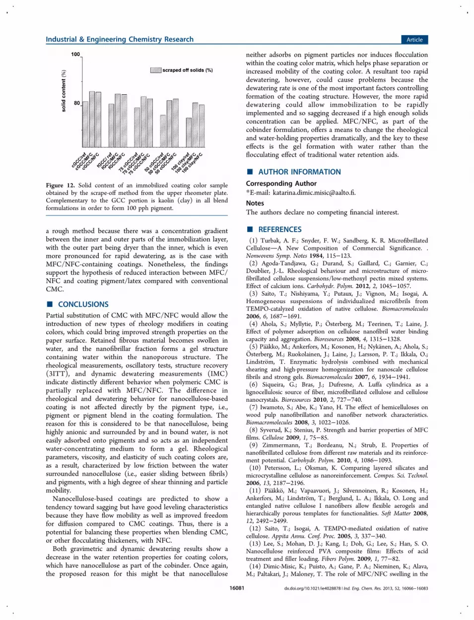
a rough method because there was a concentration gradientbetween the inner and outer parts of the immobilization layer,with the outer part being dryer than the inner, which is evenmore pronounced for rapid dewatering, as is the case withMFC/NFC-containing coatings. Nonetheless, the findingssupport the hypothesis of reduced interaction between MFC/NFC and coating pigment/latex compared with conventionalCMC.
■ CONCLUSIONSPartial substitution of CMC with MFC/NFC would allow theintroduction of new types of rheology modifiers in coatingcolors, which could bring improved strength properties on thepaper surface. Retained fibrous material becomes swollen inwater, and the nanofibrillar fraction forms a gel structurecontaining water within the nanoporous structure. Therheological measurements, oscillatory tests, structure recovery(3ITT), and dynamic dewatering measurements (IMC)indicate distinctly different behavior when polymeric CMC ispartially replaced with MFC/NFC. The difference inrheological and dewatering behavior for nanocellulose-basedcoating is not affected directly by the pigment type, i.e.,pigment or pigment blend in the coating formulation. Thereason for this is considered to be that nanocellulose, beinghighly anionic and surrounded by and in bound water, is noteasily adsorbed onto pigments and so acts as an independentwater-concentrating medium to form a gel. Rheologicalparameters, viscosity, and elasticity of such coating colors are,as a result, characterized by low friction between the watersurrounded nanocellulose (i.e., easier sliding between fibrils)and pigments, with a high degree of shear thinning and particlemobility.Nanocellulose-based coatings are predicted to show a
tendency toward sagging but have good leveling characteristicsbecause they have flow mobility as well as improved freedomfor diffusion compared to CMC coatings. Thus, there is apotential for balancing these properties when blending CMC,or other flocculating thickeners, with NFC.Both gravimetric and dynamic dewatering results show a
decrease in the water retention properties for coating colors,which have nanocellulose as part of the cobinder. Once again,the proposed reason for this might be that nanocellulose
neither adsorbs on pigment particles nor induces flocculationwithin the coating color matrix, which helps phase separation orincreased mobility of the coating color. A resultant too rapiddewatering, however, could cause problems because thedewatering rate is one of the most important factors controllingformation of the coating structure. However, the more rapiddewatering could allow immobilization to be rapidlyimplemented and so sagging decreased if a high enough solidsconcentration can be applied. MFC/NFC, as part of thecobinder formulation, offers a means to change the rheologicaland water-holding properties dramatically, and the key to theseeffects is the gel formation with water rather than theflocculating effect of traditional water retention aids.
■ AUTHOR INFORMATION
Corresponding Author*E-mail: [email protected].
NotesThe authors declare no competing financial interest.
■ REFERENCES(1) Turbak, A. F.; Snyder, F. W.; Sandberg, K. R. MicrofibrillatedCelluloseA New Composition of Commercial Significance. .Nonwovens Symp. Notes 1984, 115−123.(2) Agoda-Tandjawa, G.; Durand, S.; Gaillard, C.; Garnier, C.;Doublier, J.-L. Rheological behaviour and microstructure of micro-fibrillated cellulose suspensions/low-methoxyl pectin mixed systems.Effect of calcium ions. Carbohydr. Polym. 2012, 2, 1045−1057.(3) Saito, T.; Nishiyama, Y.; Putaux, J.; Vignon, M.; Isogai, A.Homogeneous suspensions of individualized microfibrils fromTEMPO-catalyzed oxidation of native cellulose. Biomacromolecules2006, 6, 1687−1691.(4) Ahola, S.; Myllytie, P.; Osterberg, M.; Teerinen, T.; Laine, J.Effect of polymer adsorption on cellulose nanofibril water bindingcapacity and aggregation. Bioresources 2008, 4, 1315−1328.(5) Paakko, M.; Ankerfors, M.; Kosonen, H.; Nykanen, A.; Ahola, S.;Osterberg, M.; Ruokolainen, J.; Laine, J.; Larsson, P. T.; Ikkala, O.;Lindstrom, T. Enzymatic hydrolysis combined with mechanicalshearing and high-pressure homogenization for nanoscale cellulosefibrils and strong gels. Biomacromolecules 2007, 6, 1934−1941.(6) Siqueira, G.; Bras, J.; Dufresne, A. Luffa cylindrica as alignocellulosic source of fiber, microfibrillated cellulose and cellulosenanocrystals. Bioresources 2010, 2, 727−740.(7) Iwamoto, S.; Abe, K.; Yano, H. The effect of hemicelluloses onwood pulp nanofibrillation and nanofiber network characteristics.Biomacromolecules 2008, 3, 1022−1026.(8) Syverud, K.; Stenius, P. Strength and barrier properties of MFCfilms. Cellulose 2009, 1, 75−85.(9) Zimmermann, T.; Bordeanu, N.; Strub, E. Properties ofnanofibrillated cellulose from different raw materials and its reinforce-ment potential. Carbohydr. Polym. 2010, 4, 1086−1093.(10) Petersson, L.; Oksman, K. Comparing layered silicates andmicrocrystalline cellulose as nanoreinforcement. Compos. Sci. Technol.2006, 13, 2187−2196.(11) Paakko, M.; Vapaavuori, J.; Silvennoinen, R.; Kosonen, H.;Ankerfors, M.; Lindstrom, T.; Berglund, L. A.; Ikkala, O. Long andentangled native cellulose I nanofibers allow flexible aerogels andhierarchically porous templates for functionalities. Soft Matter 2008,12, 2492−2499.(12) Saito, T.; Isogai, A. TEMPO-mediated oxidation of nativecellulose. Appita Annu. Conf. Proc. 2005, 3, 337−340.(13) Lee, S.; Mohan, D. J.; Kang, I.; Doh, G.; Lee, S.; Han, S. O.Nanocellulose reinforced PVA composite films: Effects of acidtreatment and filler loading. Fibers Polym. 2009, 1, 77−82.(14) Dimic-Misic, K.; Puisto, A.; Gane, P. A.; Nieminen, K.; Alava,M.; Paltakari, J.; Maloney, T. The role of MFC/NFC swelling in the
Figure 12. Solid content of an immobilized coating color sampleobtained by the scrape-off method from the upper rheometer plate.Complementary to the GCC portion is kaolin (clay) in all blendformulations in order to form 100 pph pigment.
Industrial & Engineering Chemistry Research Article
dx.doi.org/10.1021/ie4028878 | Ind. Eng. Chem. Res. 2013, 52, 16066−1608316081

rheological behaviour and dewatering of high consistency furnishes.Accepted Cellulose 2013.(15) Karppinen, A.; Vesterinen, A. H.; Saarinen, T.; Pietikainen, P.;Seppala, J. Effect of cationic polymethacrylates on the rheology andflocculation of microfibrillated cellulose. Cellulose 2011, 18, 1381−1390.(16) Gane, P. A. C.; McGenity, P. M.; Watters, P. Factors influencingthe runnability of coating colors at high speed. Tappi J. 1992, 5, 61−73.(17) Gane, P. A. C.; Ridgway, C. J.; Scholkopf, J.; Bousfield, D. Heattransfer through calcium carbonate-based coating structures: observa-tion and model for a thermal fusing process. J. Pulp Paper Sci. 2007, 2,60−70.(18) Bluvol, G.; Kassberger, M.; Reichhart, F. Optimizing solids andrheology in blade coating using pigment blends-part. O PAPEL 2011,11, 55−59.(19) Jader, J.; Jarnstrom, L.; Engstrom, G. The immobilization cellrevisited: Prediction of dewatering kinetics and immobilised layerproperties for coating colours. Nord. Pulp Pap. Res. J. 2003, 4, 382−387.(20) Willenbacher, N.; Hanciogullari, H.; Radle, M. New laboratorytest to characterize immobilization and dewatering of paper coatingcolors. Tappi J. 1999, 82, 167−174.(21) Nowicki, S.; Davis, H.; Scriven, L. Drying and binder migrationin coated papers. Drying Technol. 1992, 10, 925−946.(22) Whalen-Shaw, M. Binder Migr. Pap. Paperboard Coat. 1993, 5,87−92.(23) Laudone, G. M.; Matthews, G. P.; Gane, P. A. C. Effect of latexvolumetric concentration on void structure, particle packing, andeffective particle size distribution in a pigmented paper coating layer.Ind. Eng. Chem. Res. 2006, 6, 1918−1923.(24) Iyer, R. R.; Bousfield, D. W. The leveling of coating defects withshear thinning rheology. Chem. Eng. Sci. 1996, 20, 4611−4617.(25) Gane, P.; Coggon, L. Coating blade geometry: its effect oncoating color dynamics and coated sheet properties. Tappi J. 1987, 12,87−96.(26) Eklund, D.; Salminen, P. Water transport in the blade coatingprocess. Tappi J. 1986, 9, 116−119.(27) Husband, J. Adsorption and rheological studies of sodiumcarboxymethyl cellulose onto kaolin: effect of degree of substitution.Colloids Surf., A 1998, 3, 349−358.(28) Kugge, C.; Vanderhoek, N.; Bousfield, D. J. Oscillatory shearresponse of moisture barrier coatings containing clay of different shapefactor. Colloid Interface Sci. 2011, 1, 25−31.(29) McGenity, P.; Gane, P.; Husband, J.; Engley, M. Effects ofInteractions between Coating Color Components and Rheology,Water Retention and Runnability. TAPPI Conf. Proc. 1992, 8, 133−152.(30) Li, J.; Tanguy, P.; Carreau, P.; Moan, M. Effect of thickenerstructure on paper-coating color properties. Colloid Polym. Sci. 2001, 9,865−871.(31) Moan, M.; Aubry, T.; Bossard, F. Nonlinear behavior of veryconcentrated suspensions of plate-like kaolin particles in shear flow. J.Rheol. 2003, 47, 1493−1504.(32) Triantafillopoulos, N. G. Paper coating viscoelasticity and itssignificance in blade coating; Tappi Press: Peachtree Corners, GA, 1996;pp 43−55.(33) Manninen, M.; Nieminen, K.; Maloney, T. The swelling andpore structure of microfibrillated cellulose. 15th Fundam. Res. Symp.2013, 2, 765−784.(34) Dimic-Misic, K.; Puisto, A.; Paltakari, J.; Alava, M.; Maloney, T.The influence of shear on the dewatering of high consistencynanofibrillated cellulose furnishes. Cellulose 2013, 20, 1853−1864.(35) Lauger, J.; Wollny, K.; Huck, S. Direct strain oscillation: a newoscillatory method enabling measurements at very small shear stressesand strains. Rheol. Acta 2002, 4, 356−361.(36) Deka, A.; Dey, N. Rheological studies of two component highbuild epoxy and polyurethane based high performance coatings. J.Coat. Technol. Res. 2012, 3, 305−315.
(37) Moan, M.; Page, A.; Carreau, P. J.; Heuzey, M. Rheologicalbehavior of coating colors: Influence of thickener. Can. J. Chem. Eng.2002, 6, 1181−1188.(38) Yziquel, F.; Moan, M.; Carreau, P.; Tanguy, P. Nonlinearviscoelastic behavior of paper coating colors. Nord. Pulp Pap. Res. J.1999, 14, 37−47.(39) Bossard, F.; Moan, M.; Aubry, T. J. Linear and nonlinearviscoelastic behavior of very concentrated plate-like kaolin suspen-sions. Rheology 2007, 51, 1253−1267.(40) Pajari, H.; Koskela, H. Consolidation of coating colorsExperimental studies. Adv. Coat. Res. Dev. TAAPI 2010, 9, 347−359.(41) Wollny, K. New rheological test method to determine thedewatering kinetics of suspensions. Appl. Rheol. 2001, 4, 197−202.(42) Ovarlez, G.; Rodts, S.; Chateau, X.; Coussot, P. Phenomenologyand physical origin of shear localization and shear banding in complexfluids. Rheol. Acta 2009, 8, 831−844.(43) Jader, J.; Jarnstrom, L. Calculation of filter cake thickness undercondition of dewatering under shear. Appl. Rheol. 2003, 3, 125−131.(44) Herschel, W.; Bulkley, R. Measurement of consistency asapplied to rubber-benzene solutions. Proc. Am. Soc. Testing Mater.1926, 26, 621−633.(45) Burgos, G. R.; Alexandrou, A. N.; Entov, V. On thedetermination of yield surfaces in Herschel−Bulkley fluids. J. Rheol.1999, 43, 463−475.(46) Iotti, M.; Gregersen, Ø. W.; Moe, S.; Lenes, M. RheologicalStudies of Microfibrillar Cellulose Water Dispersions. J. Polym. Environ.2011, 1, 137−145.(47) Puisto, A.; Illa, X.; Mohtaschemi, M.; Alava, M. Modeling theviscosity and aggregation of suspensions of highly anisotropicnanoparticles. Eur. Phys. J. E: Soft Matter Biol. Phys. 2012, 1, 1−7.(48) Illa, X.; Puisto, A.; Lehtinen, A.; Mohtaschemi, M.; Alava, M. J.Transient shear banding in time-dependent fluids. Phys. Rev. E 2013, 2,022307.(49) Divoux, T.; Grenard, V.; Manneville, S. Rheological hysteresis insoft glassy materials. Phys. Rev. Lett. 2013, 1, 8409−8418.(50) Lasseuguette, E.; Roux, D.; Nishiyama, Y. Rheological propertiesof microfibrillar suspension of TEMPO-oxidized pulp. Cellulose 2008,3, 425−433.(51) Richmond, F.; Co, A.; Bousfield, D. The Coating ofNanofibrillated Cellulose onto Paper using Flooded and MeteredSize Press Methods. 2012 Pap. Conf. TAPPI 2012, 12PAP18.(52) Sandas, S.; Salminen, P. J.; Eklund, D. Measuring the waterretention of coating colors. Tappi J. 1989, 12, 207.(53) Yziquel, F.; Moan, M.; Carreau, P.; Tanguy, P. Nonlinearviscoelastic behavior of paper coating colors, Nordic Pulp and PaperResearch Journal. Nord. Pulp Pap. Res. J. 1999, 14, 37−47.(54) Derakhshandeh, B.; Kerekes, R.; Hatzikiriakos, S.; Bennington,C. Rheology of pulp fibre suspensions: A critical review. Chem. Eng.Sci. 2011, 15, 3460−3470.(55) Horvath, A. E.; Lindstrom, T. J. The influence of colloidalinteractions on fiber network strength. Colloid Interface Sci. 2007, 2,511−517.(56) Lindstrom, T. Cellulose suspentions and polyelectrolytessome kinetic aspects. Int. Symp. Wood Pulp. Chem., 8th 1985, 1, 121−122.(57) Fadat, G.; Engstrom, G.; Rigdahl, M. The effect of dissolvedpolymers on the rheological properties of coating colours. Rheol. Acta1988, 3, 289−297.(58) Wallstrom, A.; Jarnstrom, L. The relation between viscoelasticproperties of suspensions based on paper coating minerals andstructures of the corresponding coating layers. Nord. Rheol. Conf. 2004,12, 215−218.(59) Lindstrom, T.; Carlsson, G. The effect of chemical environmenton fiber swelling. Svensk Papperstindning Nordisk Cellulosa 1982, 3,14−20.(60) Marrucci, G. J. Dynamics of entanglements: A nonlinear modelconsistent with the Cox−Merz rule. Non-Newtonian Fluid Mech. 1996,2, 279−289.
Industrial & Engineering Chemistry Research Article
dx.doi.org/10.1021/ie4028878 | Ind. Eng. Chem. Res. 2013, 52, 16066−1608316082

(61) Husband, J. Interactions between ground calcium carbonatepigments and polymer latices. Nord. Pulp Pap. Res. J. 2000, 5, 382−386.(62) Usher, S. P.; De Kretser, R. G.; Scales, P. J. Validation of a newfiltration technique for dewaterability characterization. AIChE J. 2001,7, 1561−1570.
Industrial & Engineering Chemistry Research Article
dx.doi.org/10.1021/ie4028878 | Ind. Eng. Chem. Res. 2013, 52, 16066−1608316083