
mGuard User Manual 7.4
382
Description: Revision: Item no.: 02/24/2012 Innominate 7961_en_01 INNOMINATE mGuard Software Release 7.4 UM EN MGUARD 7.4 01 — This manual applies to mGuard software release 7.4 when used with the following mGuard devices: – mGuard rs4000 – mGuard rs2000 – mGuard centerport – mGuard industrial rs – mGuard smart² – mGuard smart – mGuard pci – mGuard blade – mGuard delta – EAGLE mGuard User Manual
-
Upload
khangminh22 -
Category
Documents
-
view
1 -
download
0
Transcript of mGuard User Manual 7.4
Description:
Revision:
Item no.:
02/24/2012
Innominate
7961_en_01 INNOMINATE
mGuardSoftware Release 7.4
UM EN MGUARD 7.4
01
—
This manual applies to mGuard software release 7.4when used with the following mGuard devices:– mGuard rs4000– mGuard rs2000– mGuard centerport– mGuard industrial rs– mGuard smart²– mGuard smart– mGuard pci– mGuard blade– mGuard delta– EAGLE mGuard
User Manual
mGuard 7.4
Please observe the following notes:
In order to use the product described here safely, you must have read and fully understood the manual. The following notes are intended for initial guidance in using the manual.
Target groups
Operation of the product as described in this manual is intended for the following groups only:– Qualified electricians (or those trained by qualified electricians) who are familiar with
applicable electrotechnical regulations and standards and the relevant safety concepts, in particular.
– Qualified application programmers and software engineers who are familiar with the relevant safety concepts for automation technology and the applicable regulations and standards.
Innominate assumes no liability for human errors and damages to Innominate products and third-party products that result from the improper use of the information in this manual.
Explanation of symbols and signal words
The following symbols indicate dangers that can lead to material damage, or provide useful operation tips.
This symbol indicates dangers that may lead to personal injury. Observe all instructions indicated by this symbol in order to avoid possible injuries.
DANGERIndicates a hazardous situation that will lead to personal injury or death if not avoided.
WARNINGIndicates a hazardous situation that can lead to personal injury or death if not avoided.
CAUTIONIndicates a hazardous situation that can lead to personal injury if not avoided.
ATTENTIONThis symbol and the corresponding text warn the user of actions that can lead to damages or malfunctions on the device, device surroundings, hardware or software.
This symbol and the corresponding text provide additional information (e.g. tips and suggestions for efficient operation or optimizing the software). It is also used to refer the operator to further sources of information (manuals, data sheets etc.).
INNOMINATE 7961_en_01
Legal information
“Innominate” and “mGuard” are registered trade names of Innominate Security Technologies AG. mGuard technology is protected by patent numbers 10138865 and 10305413, which were granted by the German Patent Office. Additional patents are pending.
This document may not be copied or transferred in whole or in part without prior written approval.
Innominate Security Technologies AG reserves the right to modify this document at any time without prior notice.
Furthermore, Innominate Security Technologies AG assumes no liability for errors in this document or for accidental or consequential damages in connection with the delivery, performance or utilization of this document.
This manual may not be photocopied, duplicated or translated into another language, in whole or in part, without the prior written approval of Innominate Security Technologies AG.
Windows XP, Windows Vista and Windows 7 are all registered trademarks of the Microsoft Corporation.
All other product names are trademarks of their respective organizations.
© 2012 Innominate Security Technologies AG
Notes on CE identification
In agreement with the EU directives for the responsible authorities, the conformity declarations are available at the following address:
Innominate Security Technologies AGRudower Chaussee 1312489 Berlin, GermanyTel.: +49 (0)30 92 10 28-0
FCC Note
This note applies to the following devices:mGuard industrial rs, mGuard smart², mGuard smart, mGuard pci, mGuard delta and EAGLE mGuard.
This device complies with Part 15 of the FCC Rules. Operation is subject to the following two conditions: (1) this device may not cause harmful interference, and (2) this device must accept any interference received, including interference that may cause undesired operation.
This equipment has been tested and complies with the limits for a Class A digital device, according to part 15 of the FCC Rules. These limits are designed to provide reasonable protection against harmful interference when the equipment is operated in a commercial environment. This equipment generates, uses, and can radiate radio frequency energy and, if not installed and used in accordance with the instruction manual, may cause harmful interference to radio communications. Operation of this equipment in a residential area is likely to cause harmful interference in which case the user will be required to correct the interference at their own expense.
7961_en_01 INNOMINATE
mGuard 7.4
Issued by:
Innominate Security Technologies AG
Rudower Chaussee 13
12489 Berlin, Germany
Tel.: +49 (0)30 92 10 28-0
www.innominate.com
Copyright © 2012 Innominate Security Technologies AG
Innominate document number: UG207402411-036
INNOMINATE 7961_en_01
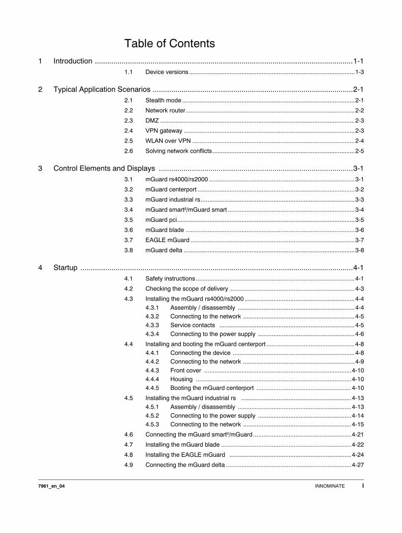
Table of Contents1 Introduction .............................................................................................................................1-1
1.1 Device versions..................................................................................................1-3
2 Typical Application Scenarios .................................................................................................2-12.1 Stealth mode ......................................................................................................2-1
2.2 Network router....................................................................................................2-2
2.3 DMZ ...................................................................................................................2-3
2.4 VPN gateway .....................................................................................................2-3
2.5 WLAN over VPN ................................................................................................2-4
2.6 Solving network conflicts....................................................................................2-5
3 Control Elements and Displays ..............................................................................................3-13.1 mGuard rs4000/rs2000 ......................................................................................3-1
3.2 mGuard centerport .............................................................................................3-2
3.3 mGuard industrial rs...........................................................................................3-3
3.4 mGuard smart²/mGuard smart ...........................................................................3-4
3.5 mGuard pci.........................................................................................................3-5
3.6 mGuard blade ....................................................................................................3-6
3.7 EAGLE mGuard .................................................................................................3-7
3.8 mGuard delta .....................................................................................................3-8
4 Startup ....................................................................................................................................4-14.1 Safety instructions..............................................................................................4-1
4.2 Checking the scope of delivery ..........................................................................4-3
4.3 Installing the mGuard rs4000/rs2000 .................................................................4-4
4.3.1 Assembly / disassembly .....................................................................4-44.3.2 Connecting to the network ..................................................................4-54.3.3 Service contacts ................................................................................4-5
4.3.4 Connecting to the power supply .........................................................4-6
4.4 Installing and booting the mGuard centerport ....................................................4-84.4.1 Connecting the device ........................................................................4-84.4.2 Connecting to the network ..................................................................4-9
4.4.3 Front cover .......................................................................................4-104.4.4 Housing ............................................................................................4-104.4.5 Booting the mGuard centerport ........................................................4-10
4.5 Installing the mGuard industrial rs .................................................................4-13
4.5.1 Assembly / disassembly ...................................................................4-134.5.2 Connecting to the power supply .......................................................4-144.5.3 Connecting to the network ................................................................4-15
4.6 Connecting the mGuard smart²/mGuard..........................................................4-21
4.7 Installing the mGuard blade .............................................................................4-22
4.8 Installing the EAGLE mGuard ........................................................................4-24
4.9 Connecting the mGuard delta ..........................................................................4-27
7961_en_04 INNOMINATE i
mGuard 7.4
4.10 Installing the mGuard pci ................................................................................4-28
4.10.1 Driver mode ......................................................................................4-284.10.2 Power-over-PCI mode ......................................................................4-304.10.3 Hardware installation ........................................................................4-32
4.10.4 Driver installation ..............................................................................4-33
5 Preparing the Configuration ...................................................................................................5-15.1 Connection requirements ...................................................................................5-1
5.2 Easy Initial Setup (EIS) | Local configuration at startup .....................................5-35.2.1 Configuring the mGuard at startup (default: Stealth mode) ................5-45.2.2 Configuring the mGuard at startup (default: Router mode) ...............5-9
5.2.3 Configuring the mGuard pci at startup ..............................................5-10
5.3 Setting up a local configuration connection......................................................5-12
5.4 Remote configuration .......................................................................................5-14
6 Configuration ..........................................................................................................................6-16.1 Operation ...........................................................................................................6-1
6.2 Management menu ............................................................................................6-46.2.1 Management >> System Settings ......................................................6-46.2.2 Management >> Web Settings .........................................................6-21
6.2.3 Management >> Licensing ...............................................................6-326.2.4 Management >> Update ...................................................................6-356.2.5 Management >> Configuration Profiles ............................................6-39
6.2.6 Management >> SNMP ....................................................................6-436.2.7 Management >> Central Management .............................................6-536.2.8 Management >> Restart ...................................................................6-57
6.3 Blade Control menu .........................................................................................6-58
6.3.1 Blade Control >> Overview ...............................................................6-586.3.2 Blade Control >> Blade 01 to 12 ......................................................6-59
6.4 Network menu ..................................................................................................6-616.4.1 Network >> Interfaces ......................................................................6-61
6.4.2 Network >> NAT .............................................................................6-1036.4.3 Network >> DNS .............................................................................6-1086.4.4 Network >> DHCP ..........................................................................6-112
6.4.5 Network >> Proxy Settings .............................................................6-116
6.5 Authentication menu ......................................................................................6-1176.5.1 Authentication >> Administrative Users ..........................................6-1176.5.2 Authentication >> Firewall Users ....................................................6-120
6.5.3 Authentication >> RADIUS Servers ................................................6-1226.5.4 Authentication >> Certificates .........................................................6-124
6.6 Network Security menu ..................................................................................6-1386.6.1 Network Security >> Packet Filter ..................................................6-138
6.6.2 Network Security >> DoS Protection ..............................................6-1526.6.3 Network Security >> User Firewall .................................................6-154
ii INNOMINATE 7961_en_04
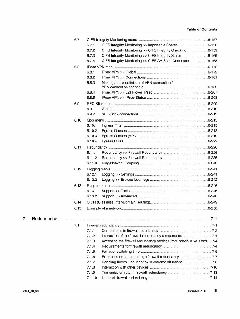
Table of Contents
6.7 CIFS Integrity Monitoring menu ....................................................................6-157
6.7.1 CIFS Integrity Monitoring >> Importable Shares ............................6-1586.7.2 CIFS Integrity Monitoring >> CIFS Integrity Checking ....................6-1596.7.3 CIFS Integrity Monitoring >> CIFS Integrity Status ........................6-165
6.7.4 CIFS Integrity Monitoring >> CIFS AV Scan Connector .................6-168
6.8 IPsec VPN menu............................................................................................6-1726.8.1 IPsec VPN >> Global ......................................................................6-1726.8.2 IPsec VPN >> Connections ............................................................6-181
6.8.3 Making a new definition of VPN connection / VPN connection channels ..............................................................6-182
6.8.4 IPsec VPN >> L2TP over IPsec .....................................................6-2076.8.5 IPsec VPN >> IPsec Status ............................................................6-208
6.9 SEC-Stick menu.............................................................................................6-2096.9.1 Global .............................................................................................6-210
6.9.2 SEC-Stick connections ...................................................................6-213
6.10 QoS menu ......................................................................................................6-2156.10.1 Ingress Filter ...................................................................................6-2156.10.2 Egress Queues ...............................................................................6-218
6.10.3 Egress Queues (VPN) ....................................................................6-2196.10.4 Egress Rules ..................................................................................6-222
6.11 Redundancy ..................................................................................................6-2266.11.1 Redundancy >> Firewall Redundancy ............................................6-226
6.11.2 Redundancy >> Firewall Redundancy ............................................6-2356.11.3 Ring/Network Coupling ..................................................................6-240
6.12 Logging menu ................................................................................................6-2416.12.1 Logging >> Settings ........................................................................6-241
6.12.2 Logging >> Browse local logs .........................................................6-242
6.13 Support menu.................................................................................................6-2466.13.1 Support >> Tools ............................................................................6-2466.13.2 Support >> Advanced .....................................................................6-248
6.14 CIDR (Classless Inter-Domain Routing).........................................................6-249
6.15 Example of a network.....................................................................................6-250
7 Redundancy ...........................................................................................................................7-17.1 Firewall redundancy ...........................................................................................7-1
7.1.1 Components in firewall redundancy ...................................................7-27.1.2 Interaction of the firewall redundancy components ............................7-47.1.3 Accepting the firewall redundancy settings from previous versions ...7-4
7.1.4 Requirements for firewall redundancy ................................................7-47.1.5 Fail-over switching time ......................................................................7-57.1.6 Error compensation through firewall redundancy ...............................7-7
7.1.7 Handling firewall redundancy in extreme situations ...........................7-87.1.8 Interaction with other devices ...........................................................7-107.1.9 Transmission rate in firewall redundancy .........................................7-13
7.1.10 Limits of firewall redundancy ............................................................7-14
7961_en_04 INNOMINATE iii
mGuard 7.4
7.2 VPN redundancy ..............................................................................................7-15
7.2.1 Components in VPN redundancy .....................................................7-157.2.2 Interaction of the VPN redundancy components ..............................7-167.2.3 Error compensation through VPN redundancy .................................7-16
7.2.4 Setting the variables for VPN redundancy ........................................7-177.2.5 Requirements for VPN redundancy ..................................................7-187.2.6 Handling VPN redundancy in extreme situations .............................7-18
7.2.7 Interaction with other devices ...........................................................7-207.2.8 Transmission rate in VPN redundancy .............................................7-227.2.9 Limits of VPN redundancy ................................................................7-23
7.3 Ring/Network Coupling ...................................................................................7-26
8 Restarting, the Recovery Procedure and Flashing Firmware .................................................8-18.1 Performing a restart ...........................................................................................8-1
8.2 Performing a recovery procedure.......................................................................8-2
8.3 Flashing the firmware / rescue procedure..........................................................8-3
8.3.1 Installing the DHCP and TFTP server ................................................8-9
9 Glossary .................................................................................................................................9-1
10 Technical Data ......................................................................................................................10-110.1 mGuard rs4000/rs2000 ...................................................................................10-1
10.2 mGuard centerport ...........................................................................................10-2
10.3 mGuard industrial rs.........................................................................................10-3
10.4 mGuard smart² .................................................................................................10-4
10.5 mGuard smart ..................................................................................................10-5
10.6 mGuard pci.......................................................................................................10-6
10.7 mGuard blade ..................................................................................................10-7
10.8 EAGLE mGuard ...............................................................................................10-8
10.9 mGuard delta ...................................................................................................10-9
iv INNOMINATE 7961_en_04
Introduction
1 Introduction
The mGuard protects IP data connections. In doing this, the device incorporates the following functions:– Network card (mGuard pci) and switch (mGuard delta).
– VPN router (VPN – Virtual Private Network) for the secure transfer of data via public networks (hardware-based DES, 3DES and AES encryption, IPsec protocol).
– Configurable firewall for protection against unauthorized access. The dynamic packet filter inspects data packets using the source and destination addresses and blocks undesired data traffic.
The device can be easily configured using a web browser.
Network features – Stealth (Auto, Static, Multi), Router (Static, DHCP Client), PPPoE (for DSL), PPTP (for DSL) and Modem modes
– VLAN– DHCP Server / Relay on internal and external network interfaces– DNS cache on the internal network interface
– Administration via HTTPS and SSH– Optional rewrite of DSCP / TOS values (Quality of Service values)– Quality of Service (QoS)
– LLDP– MAU management– SNMP
Firewall features – Stateful Packet Inspection– Anti-spoofing– IP filter
– L2 filter (only in Stealth mode)– NAT with FTP, IRC and PPTP support (only in Router modes)– 1:1 NAT (only in Router network mode)
– Port forwarding (not in Stealth network mode)– Individual firewall rules for different users (user firewall)– Individual rule records as action (target) of firewall rules (apart from user firewall or
VPN firewall) – Firewall throughput: max. 99 MBit/s
Anti-virus features – CIFS integrity check of network drives for changes to certain file types (e.g. executable files),
– Antivirus Scan Connector for supporting the central monitoring of network drives with virus scanners
Further information can be found on the Innominate website: www.innominate.com.
7961_en_04 INNOMINATE 1-1
mGuard 7.4
VPN features – Protocol: IPsec (Tunnel and Transport mode)
– IPsec encryption in hardware with DES (56 Bit), 3DES (168 Bit), AES (128, 192, 256 Bit)– Packet authentication: MD5, SHA-1– Internet Key Exchange (IKE) with Main and Quick mode
– Authentication via– Pre-Shared Key (PSK)– X.509v3 certificates with Public Key Infrastructure (PKI) with Certification
Authority (CA), optional Certificate Revocation List (CRL) and filter options according to subject
or– Remote certificate (e.g. self-signed certificates)
– Recognition of changing remote peer IP addresses via DynDNS– NAT Traversal (NAT-T)– Dead Peer Detection (DPD): Recognition of IPsec connection breaks
– IPsec / L2TP server: Connection of IPsec / L2TP clients– IPsec firewall and 1:1 NAT– Default route over VPN
– Forwarding of data between VPNs (hub and spoke)– Depending on the license: up to 250 VPN channels; up to 1000 active VPN channels
on mGuard centerport– Hardware acceleration for encryption in VPN (excluding mGuard centerport)
Additional features – Remote Logging
– Router / Firewall Redundancy (the “Firewall Redundancy” function is not available in firmware version 7.0).
– Administration using SNMP v1-v3 and Innominate Device Manager (IDM)– PKI support for HTTPS / SSH Remote Access– Can function as an NTP and DNS server via the LAN interface
Support Please contact your local dealer if problems occur with the mGuard.
Additional information on the device – plus release notes and software updates – can be found on our website: www.innominate.com.
1-2 INNOMINATE 7961_en_04
Introduction
1.1 Device versions
The mGuard is available in the following device versions, which all have largely identical functions. All devices can be utilized regardless of the processor technology or operating system used by the connected computers.
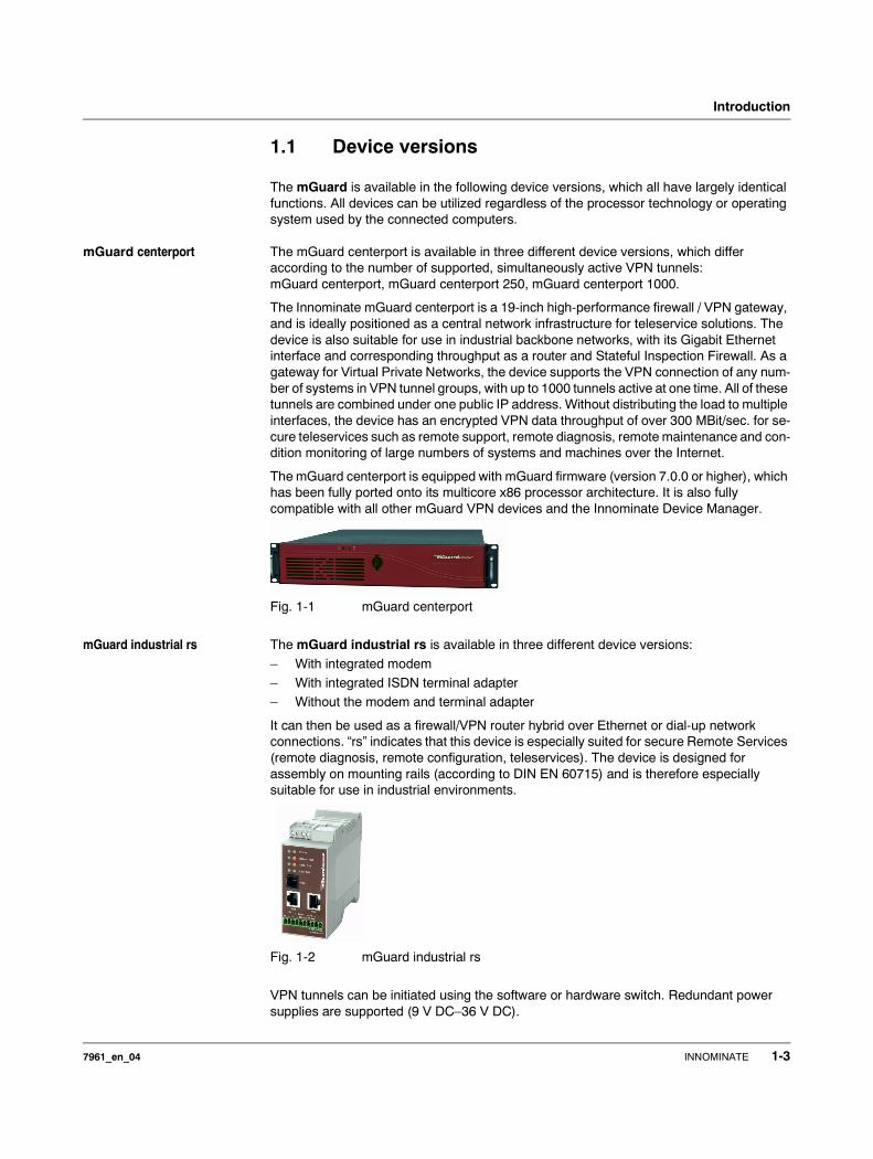
mGuard centerport The mGuard centerport is available in three different device versions, which differ according to the number of supported, simultaneously active VPN tunnels: mGuard centerport, mGuard centerport 250, mGuard centerport 1000.
The Innominate mGuard centerport is a 19-inch high-performance firewall / VPN gateway, and is ideally positioned as a central network infrastructure for teleservice solutions. The device is also suitable for use in industrial backbone networks, with its Gigabit Ethernet interface and corresponding throughput as a router and Stateful Inspection Firewall. As a gateway for Virtual Private Networks, the device supports the VPN connection of any num-ber of systems in VPN tunnel groups, with up to 1000 tunnels active at one time. All of these tunnels are combined under one public IP address. Without distributing the load to multiple interfaces, the device has an encrypted VPN data throughput of over 300 MBit/sec. for se-cure teleservices such as remote support, remote diagnosis, remote maintenance and con-dition monitoring of large numbers of systems and machines over the Internet.
The mGuard centerport is equipped with mGuard firmware (version 7.0.0 or higher), which has been fully ported onto its multicore x86 processor architecture. It is also fully compatible with all other mGuard VPN devices and the Innominate Device Manager.
Fig. 1-1 mGuard centerport
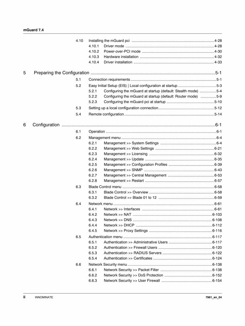
mGuard industrial rs The mGuard industrial rs is available in three different device versions:
– With integrated modem– With integrated ISDN terminal adapter – Without the modem and terminal adapter
It can then be used as a firewall/VPN router hybrid over Ethernet or dial-up network connections. “rs” indicates that this device is especially suited for secure Remote Services (remote diagnosis, remote configuration, teleservices). The device is designed for assembly on mounting rails (according to DIN EN 60715) and is therefore especially suitable for use in industrial environments.
Fig. 1-2 mGuard industrial rs
VPN tunnels can be initiated using the software or hardware switch. Redundant power supplies are supported (9 V DC–36 V DC).
7961_en_04 INNOMINATE 1-3
mGuard 7.4
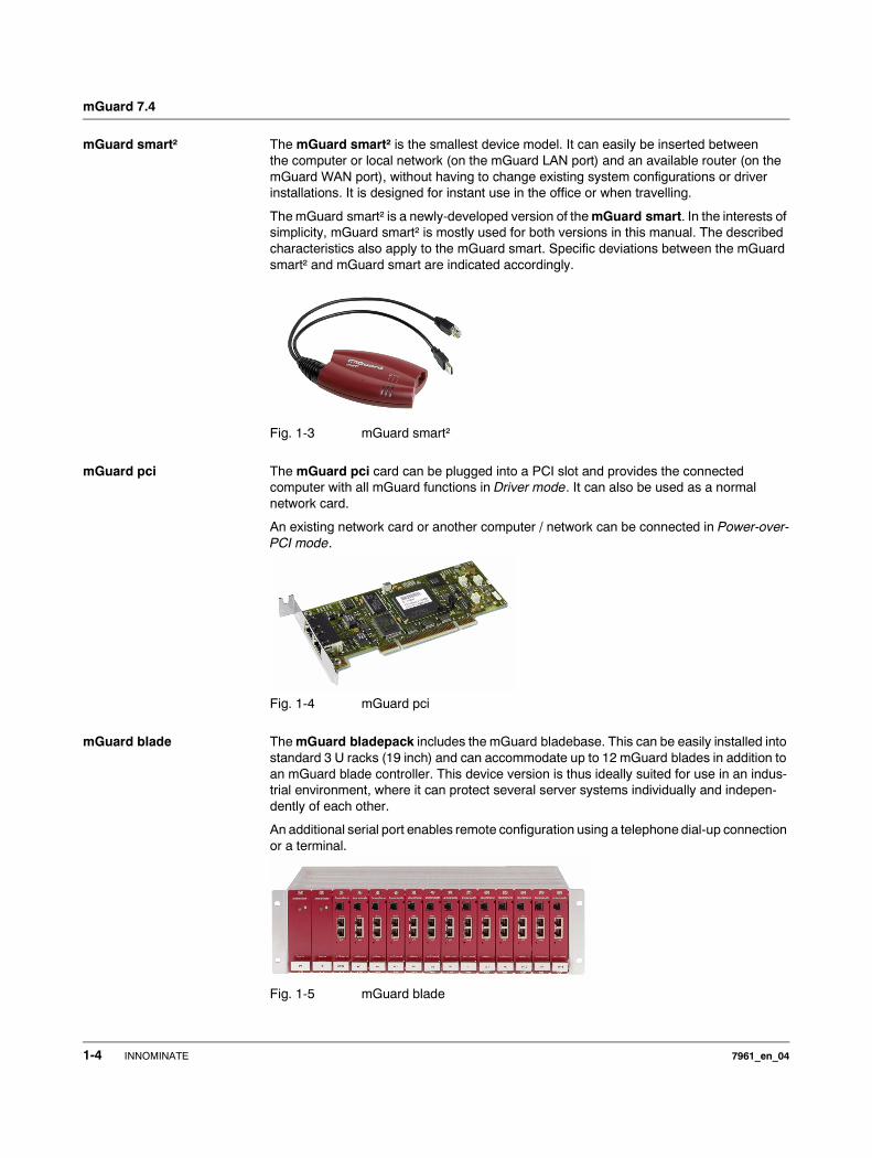
mGuard smart² The mGuard smart² is the smallest device model. It can easily be inserted between the computer or local network (on the mGuard LAN port) and an available router (on the mGuard WAN port), without having to change existing system configurations or driver installations. It is designed for instant use in the office or when travelling.
The mGuard smart² is a newly-developed version of the mGuard smart. In the interests of simplicity, mGuard smart² is mostly used for both versions in this manual. The described characteristics also apply to the mGuard smart. Specific deviations between the mGuard smart² and mGuard smart are indicated accordingly.
Fig. 1-3 mGuard smart²
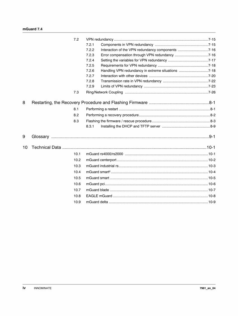
mGuard pci The mGuard pci card can be plugged into a PCI slot and provides the connected computer with all mGuard functions in Driver mode. It can also be used as a normal network card.
An existing network card or another computer / network can be connected in Power-over-PCI mode.
Fig. 1-4 mGuard pci
mGuard blade The mGuard bladepack includes the mGuard bladebase. This can be easily installed into standard 3 U racks (19 inch) and can accommodate up to 12 mGuard blades in addition to an mGuard blade controller. This device version is thus ideally suited for use in an indus-trial environment, where it can protect several server systems individually and indepen-dently of each other.
An additional serial port enables remote configuration using a telephone dial-up connection or a terminal.
Fig. 1-5 mGuard blade
1-4 INNOMINATE 7961_en_04
Introduction
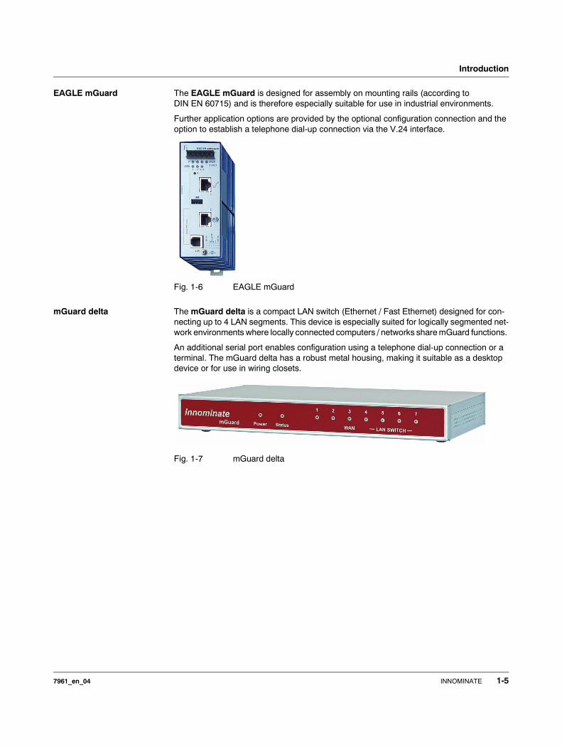
EAGLE mGuard The EAGLE mGuard is designed for assembly on mounting rails (according to DIN EN 60715) and is therefore especially suitable for use in industrial environments.
Further application options are provided by the optional configuration connection and the option to establish a telephone dial-up connection via the V.24 interface.
Fig. 1-6 EAGLE mGuard
mGuard delta The mGuard delta is a compact LAN switch (Ethernet / Fast Ethernet) designed for con-necting up to 4 LAN segments. This device is especially suited for logically segmented net-work environments where locally connected computers / networks share mGuard functions.
An additional serial port enables configuration using a telephone dial-up connection or a terminal. The mGuard delta has a robust metal housing, making it suitable as a desktop device or for use in wiring closets.
Fig. 1-7 mGuard delta
7961_en_04 INNOMINATE 1-5
mGuard 7.4
mGuard rs4000/ mGuard rs2000
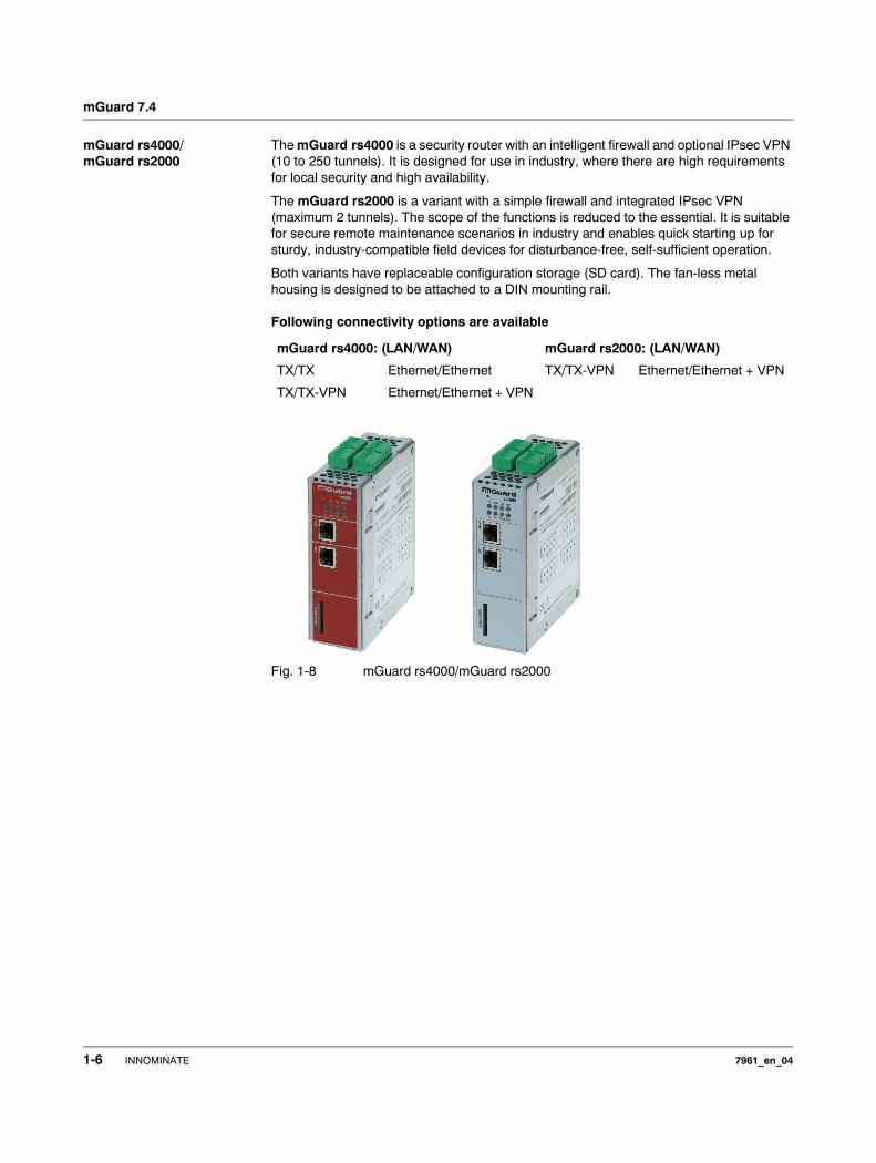
The mGuard rs4000 is a security router with an intelligent firewall and optional IPsec VPN (10 to 250 tunnels). It is designed for use in industry, where there are high requirements for local security and high availability.
The mGuard rs2000 is a variant with a simple firewall and integrated IPsec VPN (maximum 2 tunnels). The scope of the functions is reduced to the essential. It is suitable for secure remote maintenance scenarios in industry and enables quick starting up for sturdy, industry-compatible field devices for disturbance-free, self-sufficient operation.
Both variants have replaceable configuration storage (SD card). The fan-less metal housing is designed to be attached to a DIN mounting rail.
Following connectivity options are available
Fig. 1-8 mGuard rs4000/mGuard rs2000
mGuard rs4000: (LAN/WAN) mGuard rs2000: (LAN/WAN)
TX/TX Ethernet/Ethernet TX/TX-VPN Ethernet/Ethernet + VPN
TX/TX-VPN Ethernet/Ethernet + VPN
1-6 INNOMINATE 7961_en_04
Typical Application Scenarios
2 Typical Application Scenarios
Various possible application scenarios for the mGuard are detailed in this chapter.
– Stealth mode – Network router – DMZ
– VPN gateway – WLAN over VPN – Solving network conflicts
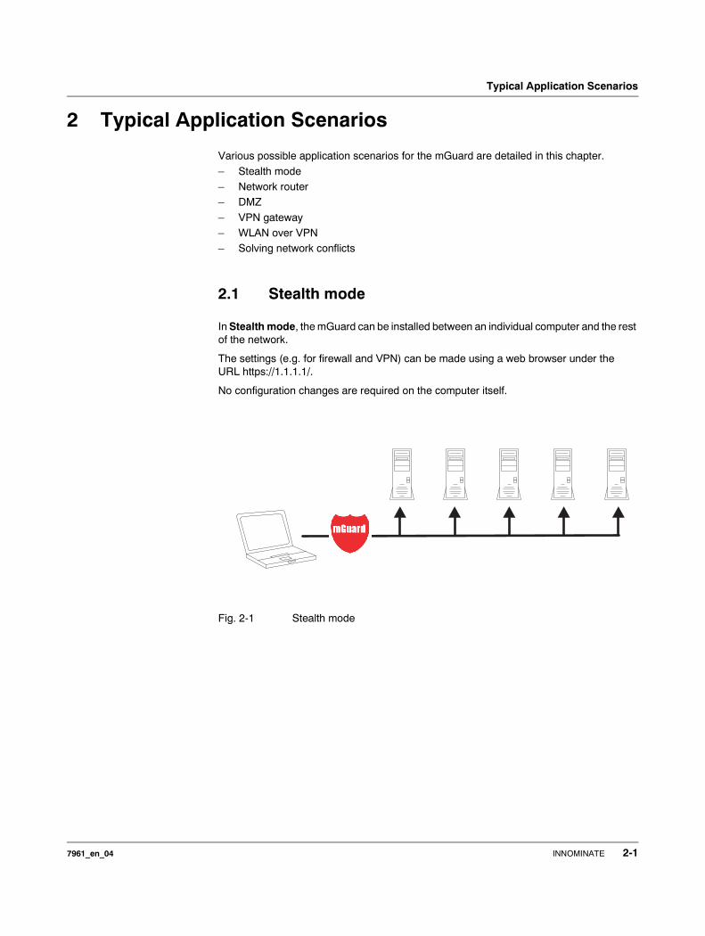
2.1 Stealth mode
In Stealth mode, the mGuard can be installed between an individual computer and the rest of the network.
The settings (e.g. for firewall and VPN) can be made using a web browser under the URL https://1.1.1.1/.
No configuration changes are required on the computer itself.
Fig. 2-1 Stealth mode
7961_en_04 INNOMINATE 2-1
mGuard 7.4
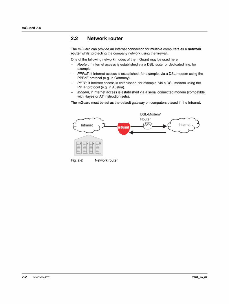
2.2 Network router
The mGuard can provide an Internet connection for multiple computers as a network router whilst protecting the company network using the firewall.
One of the following network modes of the mGuard may be used here:– Router, if Internet access is established via a DSL router or dedicated line, for
example.– PPPoE, if Internet access is established, for example, via a DSL modem using the
PPPoE protocol (e.g. in Germany).– PPTP, if Internet access is established, for example, via a DSL modem using the
PPTP protocol (e.g. in Austria).– Modem, if Internet access is established via a serial connected modem (compatible
with Hayes or AT instruction sets).
The mGuard must be set as the default gateway on computers placed in the Intranet.
Fig. 2-2 Network router
InternetIntranet
DSL-Modem/
Router
2-2 INNOMINATE 7961_en_04
Typical Application Scenarios
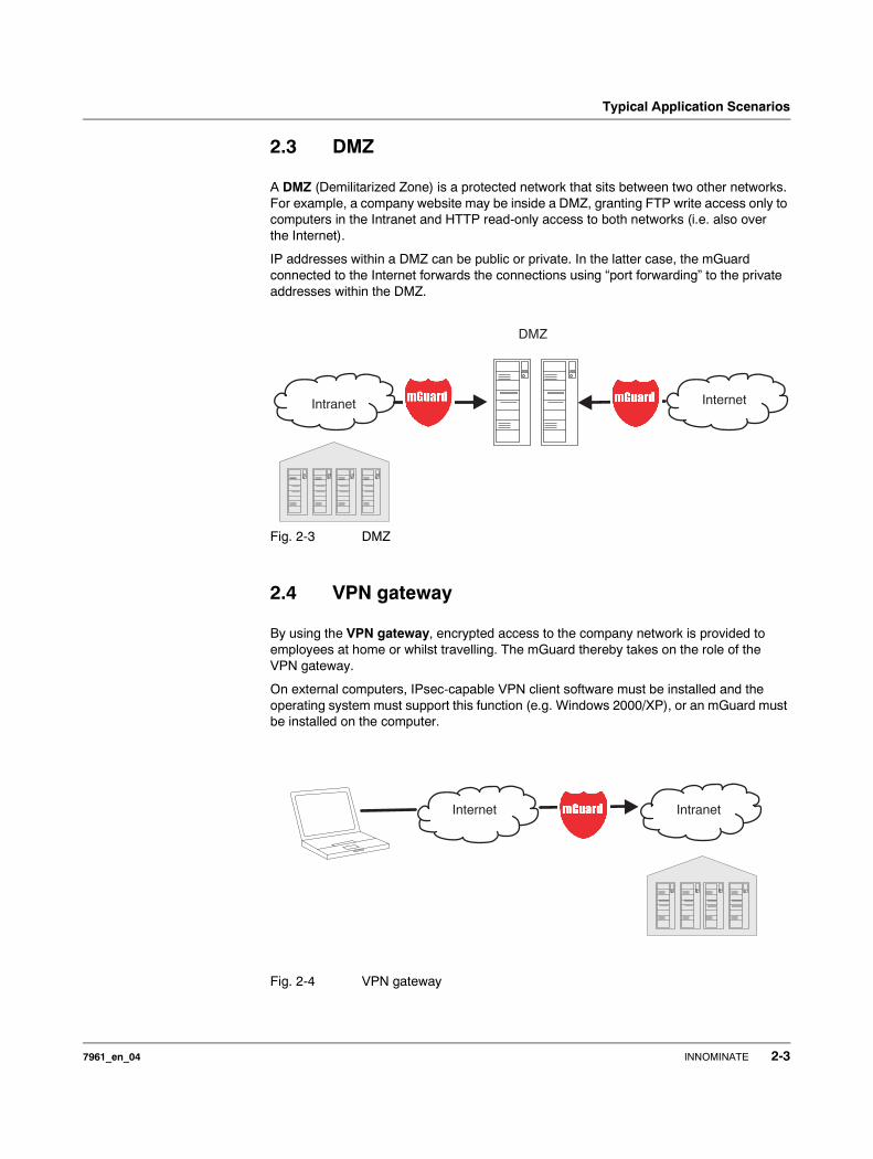
2.3 DMZ
A DMZ (Demilitarized Zone) is a protected network that sits between two other networks. For example, a company website may be inside a DMZ, granting FTP write access only to computers in the Intranet and HTTP read-only access to both networks (i.e. also over the Internet).
IP addresses within a DMZ can be public or private. In the latter case, the mGuard connected to the Internet forwards the connections using “port forwarding” to the private addresses within the DMZ.
Fig. 2-3 DMZ
2.4 VPN gateway
By using the VPN gateway, encrypted access to the company network is provided to employees at home or whilst travelling. The mGuard thereby takes on the role of the VPN gateway.
On external computers, IPsec-capable VPN client software must be installed and the operating system must support this function (e.g. Windows 2000/XP), or an mGuard must be installed on the computer.
Fig. 2-4 VPN gateway
Intranet Internet
DMZ
Internet Intranet
7961_en_04 INNOMINATE 2-3
mGuard 7.4
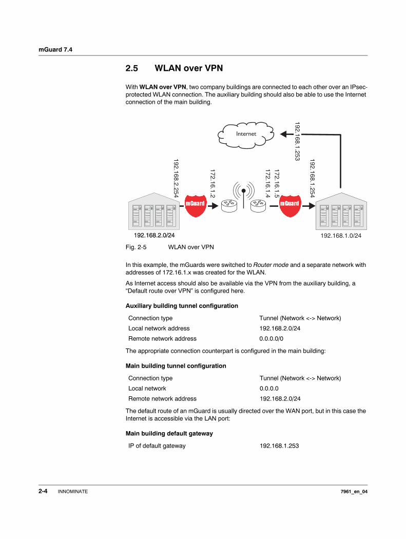
2.5 WLAN over VPN
With WLAN over VPN, two company buildings are connected to each other over an IPsec-protected WLAN connection. The auxiliary building should also be able to use the Internet connection of the main building.
Fig. 2-5 WLAN over VPN
In this example, the mGuards were switched to Router mode and a separate network with addresses of 172.16.1.x was created for the WLAN.
As Internet access should also be available via the VPN from the auxiliary building, a “Default route over VPN” is configured here.
Auxiliary building tunnel configuration
The appropriate connection counterpart is configured in the main building:
Main building tunnel configuration
The default route of an mGuard is usually directed over the WAN port, but in this case the Internet is accessible via the LAN port:
Main building default gateway
Connection type Tunnel (Network <-> Network)
Local network address 192.168.2.0/24
Remote network address 0.0.0.0/0
Connection type Tunnel (Network <-> Network)
Local network 0.0.0.0
Remote network address 192.168.2.0/24
IP of default gateway 192.168.1.253
19
2.1
68
.2.2
54
17
2.1
6.1
.2
17
2.1
6.1
.4
17
2.1
6.1
.5
19
2.1
68
.1.2
54
192.168.2.0/24 192.168.1.0/24
Internet
19
2.1
68
.1.2
53
192.168.2.0/24
2-4 INNOMINATE 7961_en_04
Typical Application Scenarios
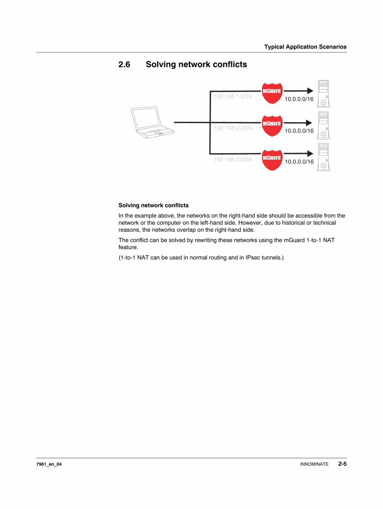
2.6 Solving network conflicts
Solving network conflicts
In the example above, the networks on the right-hand side should be accessible from the network or the computer on the left-hand side. However, due to historical or technical reasons, the networks overlap on the right-hand side.
The conflict can be solved by rewriting these networks using the mGuard 1-to-1 NAT feature.
(1-to-1 NAT can be used in normal routing and in IPsec tunnels.)
192.168.1.0/24
192.168.2.0/24
192.168.3.0/24 10.0.0.0/16
10.0.0.0/16
10.0.0.0/16
7961_en_04 INNOMINATE 2-5

mGuard 7.4
2-6 INNOMINATE 7961_en_04
Control Elements and Displays
3 Control Elements and Displays
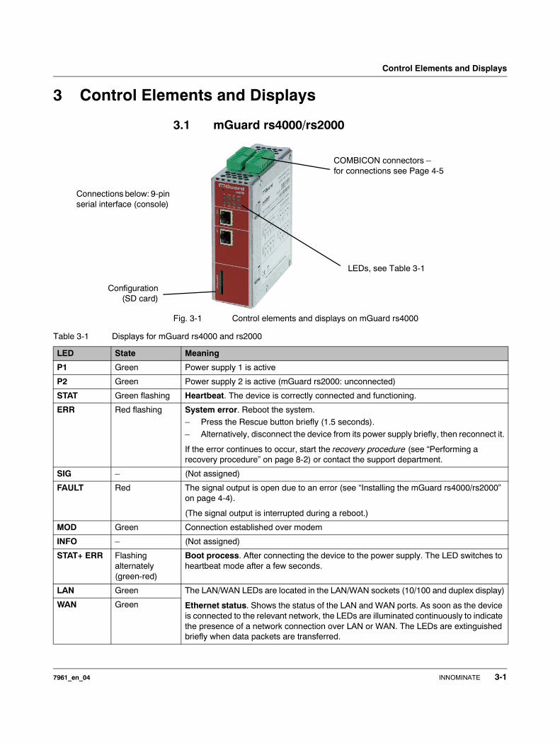
3.1 mGuard rs4000/rs2000
Fig. 3-1 Control elements and displays on mGuard rs4000
LEDs, see Table 3-1
COMBICON connectors – for connections see Page 4-5
Configuration(SD card)
Connections below: 9-pin serial interface (console)
Table 3-1 Displays for mGuard rs4000 and rs2000
LED State Meaning
P1 Green Power supply 1 is active
P2 Green Power supply 2 is active (mGuard rs2000: unconnected)
STAT Green flashing Heartbeat. The device is correctly connected and functioning.
ERR Red flashing System error. Reboot the system.– Press the Rescue button briefly (1.5 seconds). – Alternatively, disconnect the device from its power supply briefly, then reconnect it.
If the error continues to occur, start the recovery procedure (see “Performing a recovery procedure” on page 8-2) or contact the support department.
SIG – (Not assigned)
FAULT Red The signal output is open due to an error (see “Installing the mGuard rs4000/rs2000” on page 4-4).
(The signal output is interrupted during a reboot.)
MOD Green Connection established over modem
INFO – (Not assigned)
STAT+ ERR Flashing alternately (green-red)
Boot process. After connecting the device to the power supply. The LED switches to heartbeat mode after a few seconds.
LAN Green The LAN/WAN LEDs are located in the LAN/WAN sockets (10/100 and duplex display)
Ethernet status. Shows the status of the LAN and WAN ports. As soon as the device is connected to the relevant network, the LEDs are illuminated continuously to indicate the presence of a network connection over LAN or WAN. The LEDs are extinguished briefly when data packets are transferred.
WAN Green
7961_en_04 INNOMINATE 3-1
mGuard 7.4
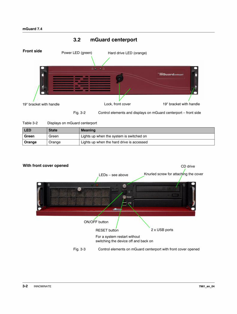
3.2 mGuard centerport
Fig. 3-2 Control elements and displays on mGuard centerport – front side
Fig. 3-3 Control elements on mGuard centerport with front cover opened
Power LED (green)
19" bracket with handle
Hard drive LED (orange)
Lock, front cover
Front side
19" bracket with handle
Table 3-2 Displays on mGuard centerport
LED State Meaning
Green Green Lights up when the system is switched on
Orange Orange Lights up when the hard drive is accessed
ON/OFF button
CD drive
2 x USB ports
With front cover opened
LEDs – see above Knurled screw for attaching the cover
RESET button
For a system restart without switching the device off and back on
3-2 INNOMINATE 7961_en_04
Control Elements and Displays
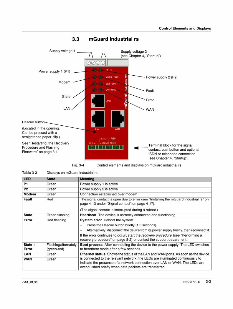
3.3 mGuard industrial rs
Fig. 3-4 Control elements and displays on mGuard industrial rs
mGuard
ind
ust
rial
RS
LAN WAN
State / Error
LAN / WAN
Modem / Fault
P1 / P2
Serial
RINGTIPACKCMD
LineAnalogService
Power supply 1 (P1)
Power supply 2 (P2)
Fault
Modem
Error
WAN
State
LAN
Rescue button
(Located in the opening. Can be pressed with a straightened paper-clip.)
See “Restarting, the Recovery Procedure and Flashing Firmware” on page 8-1.
Supply voltage 1 Supply voltage 2 (see Chapter 4, “Startup”)
Terminal block for the signal contact, pushbutton and optional ISDN or telephone connection (see Chapter 4, “Startup”)
Table 3-3 Displays on mGuard industrial rs
LED State MeaningP1 Green Power supply 1 is activeP2 Green Power supply 2 is active
Modem Green Connection established over modemFault Red The signal contact is open due to error (see “Installing the mGuard industrial rs” on
page 4-13 under “Signal contact” on page 4-17).
(The signal contact is interrupted during a reboot.)State Green flashing Heartbeat. The device is correctly connected and functioning.
Error Red flashing System error. Reboot the system.– Press the Rescue button briefly (1.5 seconds). – Alternatively, disconnect the device from its power supply briefly, then reconnect it.
If the error continues to occur, start the recovery procedure (see “Performing a recovery procedure” on page 8-2) or contact the support department.
State + Error
Flashing alternately (green-red)
Boot process. After connecting the device to the power supply. The LED switches to heartbeat mode after a few seconds.
LAN Green Ethernet status. Shows the status of the LAN and WAN ports. As soon as the device is connected to the relevant network, the LEDs are illuminated continuously to indicate the presence of a network connection over LAN or WAN. The LEDs are extinguished briefly when data packets are transferred.
WAN Green
7961_en_04 INNOMINATE 3-3
mGuard 7.4
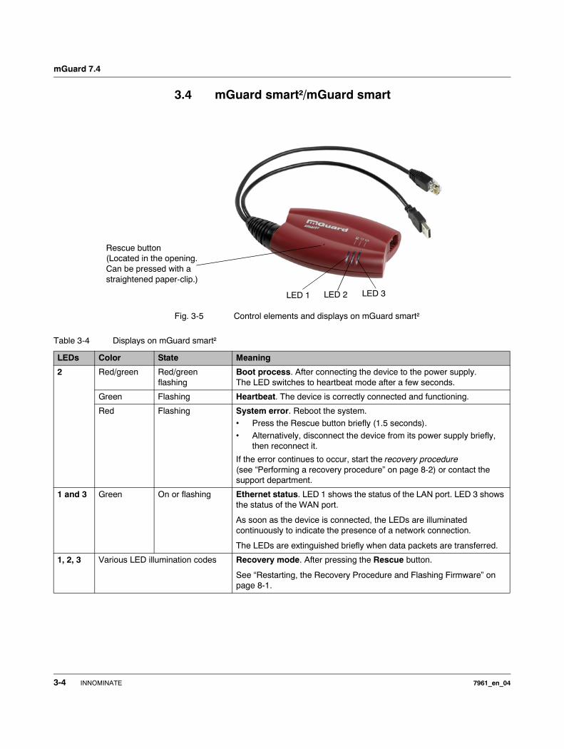
3.4 mGuard smart²/mGuard smart
Fig. 3-5 Control elements and displays on mGuard smart²
LED 1 LED 2 LED 3
Rescue button(Located in the opening. Can be pressed with a straightened paper-clip.)
Table 3-4 Displays on mGuard smart²
LEDs Color State Meaning
2 Red/green Red/green flashing
Boot process. After connecting the device to the power supply. The LED switches to heartbeat mode after a few seconds.
Green Flashing Heartbeat. The device is correctly connected and functioning.
Red Flashing System error. Reboot the system.• Press the Rescue button briefly (1.5 seconds).
• Alternatively, disconnect the device from its power supply briefly, then reconnect it.
If the error continues to occur, start the recovery procedure (see “Performing a recovery procedure” on page 8-2) or contact the support department.
1 and 3 Green On or flashing Ethernet status. LED 1 shows the status of the LAN port. LED 3 shows the status of the WAN port.
As soon as the device is connected, the LEDs are illuminated continuously to indicate the presence of a network connection.
The LEDs are extinguished briefly when data packets are transferred.
1, 2, 3 Various LED illumination codes Recovery mode. After pressing the Rescue button.
See “Restarting, the Recovery Procedure and Flashing Firmware” on page 8-1.
3-4 INNOMINATE 7961_en_04
Control Elements and Displays
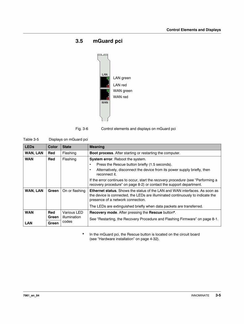
3.5 mGuard pci
Fig. 3-6 Control elements and displays on mGuard pci
* In the mGuard pci, the Rescue button is located on the circuit board (see “Hardware installation” on page 4-32).
LAN red
WAN green
LAN green
WAN red
Table 3-5 Displays on mGuard pci
LEDs Color State Meaning
WAN, LAN Red Flashing Boot process. After starting or restarting the computer.
WAN Red Flashing System error. Reboot the system.• Press the Rescue button briefly (1.5 seconds). • Alternatively, disconnect the device from its power supply briefly, then
reconnect it.
If the error continues to occur, start the recovery procedure (see “Performing a recovery procedure” on page 8-2) or contact the support department.
WAN, LAN Green On or flashing Ethernet status. Shows the status of the LAN and WAN interfaces. As soon as the device is connected, the LEDs are illuminated continuously to indicate the presence of a network connection.
The LEDs are extinguished briefly when data packets are transferred.
WAN RedGreen
Various LED illumination codes
Recovery mode. After pressing the Rescue button*.
See “Restarting, the Recovery Procedure and Flashing Firmware” on page 8-1.LAN Green
7961_en_04 INNOMINATE 3-5
mGuard 7.4
3.6 mGuard blade
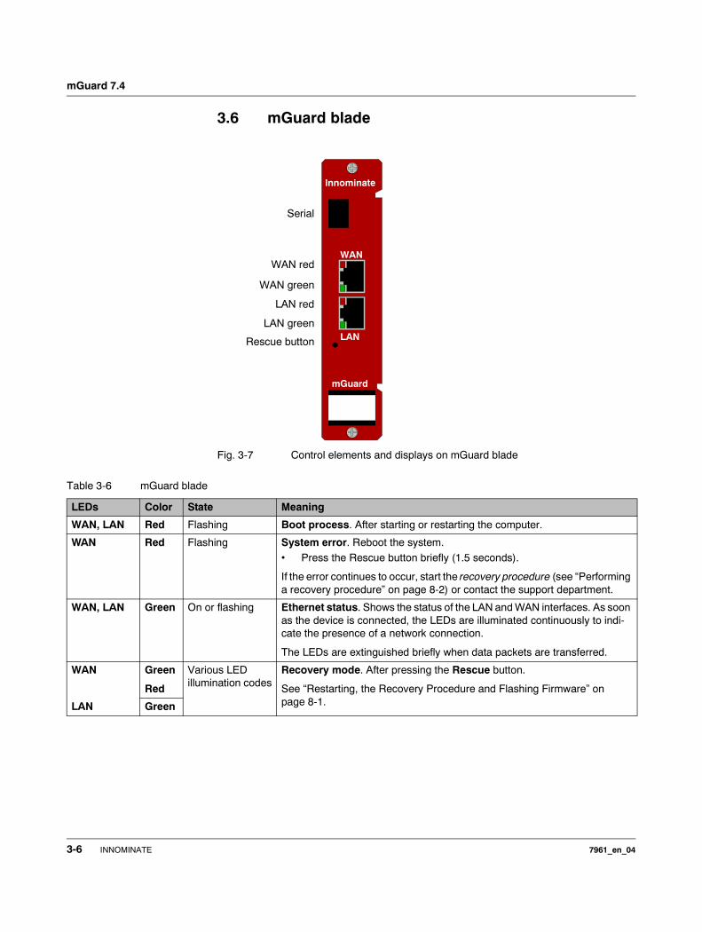
Fig. 3-7 Control elements and displays on mGuard blade
Innominate
mGuard
LAN
WAN
Serial
WAN red
WAN green
LAN red
LAN green
Rescue button
Table 3-6 mGuard blade
LEDs Color State Meaning
WAN, LAN Red Flashing Boot process. After starting or restarting the computer.
WAN Red Flashing System error. Reboot the system. • Press the Rescue button briefly (1.5 seconds).
If the error continues to occur, start the recovery procedure (see “Performing a recovery procedure” on page 8-2) or contact the support department.
WAN, LAN Green On or flashing Ethernet status. Shows the status of the LAN and WAN interfaces. As soon as the device is connected, the LEDs are illuminated continuously to indi-cate the presence of a network connection.
The LEDs are extinguished briefly when data packets are transferred.
WAN Green
Red
Various LED illumination codes
Recovery mode. After pressing the Rescue button.
See “Restarting, the Recovery Procedure and Flashing Firmware” on page 8-1.LAN Green
3-6 INNOMINATE 7961_en_04
Control Elements and Displays
3.7 EAGLE mGuard
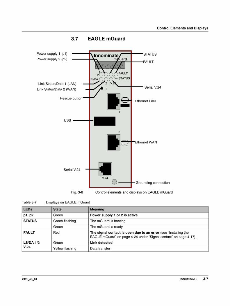
Fig. 3-8 Control elements and displays on EAGLE mGuard
FAULT1 2p
STATUS
InnominatemGuard
LS/DA21 V.24
2
V.24
R
1
Serial V.24
Ethernet WAN
Ethernet LANRescue button
Power supply 1 (p1)
Power supply 2 (p2)FAULT
STATUS
Link Status/Data 2 (WAN) Serial V.24
Grounding connection
Link Status/Data 1 (LAN)
USB
Table 3-7 Displays on EAGLE mGuard
LEDs State Meaning
p1, p2 Green Power supply 1 or 2 is active
STATUS Green flashing The mGuard is booting
Green The mGuard is ready
FAULT Red The signal contact is open due to an error (see “Installing the EAGLE mGuard” on page 4-24 under “Signal contact” on page 4-17).
LS/DA 1/2V.24
Green Link detected
Yellow flashing Data transfer
7961_en_04 INNOMINATE 3-7
mGuard 7.4
3.8 mGuard delta
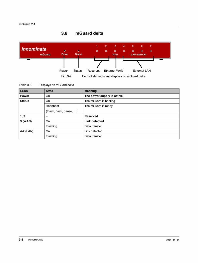
Fig. 3-9 Control elements and displays on mGuard delta
Innominate
mGuard Power Status WAN − LAN SWITCH −
3 765421
Power Status Reserved Ethernet WAN Ethernet LAN
Table 3-8 Displays on mGuard delta
LEDs State Meaning
Power On The power supply is active
Status On The mGuard is booting
Heartbeat
(Flash, flash, pause, …)
The mGuard is ready
1, 2 – Reserved
3 (WAN) On Link detected
Flashing Data transfer
4-7 (LAN) On Link detected
Flashing Data transfer
3-8 INNOMINATE 7961_en_04
Startup
4 Startup
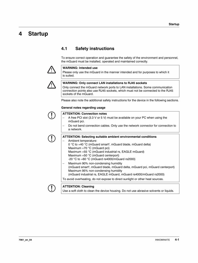
4.1 Safety instructions
To ensure correct operation and guarantee the safety of the environment and personnel, the mGuard must be installed, operated and maintained correctly.
Please also note the additional safety instructions for the device in the following sections.
General notes regarding usage
WARNING: Intended usePlease only use the mGuard in the manner intended and for purposes to which it is suited.
WARNING: Only connect LAN installations to RJ45 socketsOnly connect the mGuard network ports to LAN installations. Some communication connection points also use RJ45 sockets, which must not be connected to the RJ45 sockets of the mGuard.
ATTENTION: Connection notes– A free PCI slot (3.3 V or 5 V) must be available on your PC when using the
mGuard pci.
– Do not bend connection cables. Only use the network connector for connection to a network.
ATTENTION: Selecting suitable ambient environmental conditions– Ambient temperature:
0 °C to +40 °C (mGuard smart², mGuard blade, mGuard delta) Maximum +70 °C (mGuard pci) Maximum +55 °C (mGuard industrial rs, EAGLE mGuard)Maximum +50 °C (mGuard centerport)-20 °C to +60 °C (mGuard rs4000/mGuard rs2000)
– Maximum 90% non-condensing humidity(mGuard smart², mGuard blade, mGuard delta, mGuard pci, mGuard centerport)Maximum 95% non-condensing humidity (mGuard industrial rs, EAGLE mGuard, mGuard rs4000/mGuard rs2000)
To avoid overheating, do not expose to direct sunlight or other heat sources.
ATTENTION: CleaningUse a soft cloth to clean the device housing. Do not use abrasive solvents or liquids.
7961_en_04 INNOMINATE 4-1
mGuard 7.4
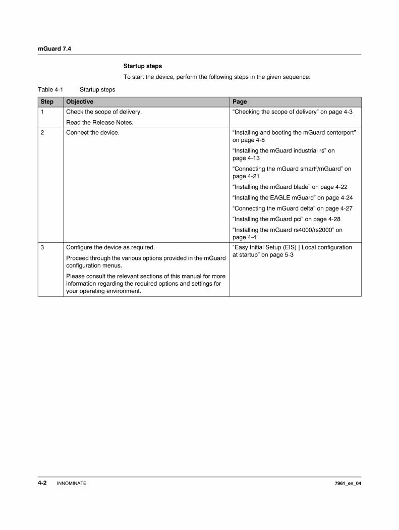
Startup steps
To start the device, perform the following steps in the given sequence:
Table 4-1 Startup steps
Step Objective Page
1 Check the scope of delivery.
Read the Release Notes.
“Checking the scope of delivery” on page 4-3
2 Connect the device. “Installing and booting the mGuard centerport” on page 4-8
“Installing the mGuard industrial rs” on page 4-13
“Connecting the mGuard smart²/mGuard” on page 4-21
“Installing the mGuard blade” on page 4-22
“Installing the EAGLE mGuard” on page 4-24
“Connecting the mGuard delta” on page 4-27
“Installing the mGuard pci” on page 4-28
“Installing the mGuard rs4000/rs2000” on page 4-4
3 Configure the device as required.
Proceed through the various options provided in the mGuard configuration menus.
Please consult the relevant sections of this manual for more information regarding the required options and settings for your operating environment.
“Easy Initial Setup (EIS) | Local configuration at startup” on page 5-3
4-2 INNOMINATE 7961_en_04
Startup
4.2 Checking the scope of delivery
Before starting up the device, check that the package is complete.
Included in the package
– The mGuard device (mGuard centerport, mGuard industrial rs, mGuard blade, mGuard delta, mGuard pci, mGuard smart², EAGLE mGuard, mGuard rs4000 or mGuard rs2000)
– Package leaflet
The mGuard rs4000 and mGuard rs2000 also include:
– COMBICON connectors for the power supply and inputs/outputs (attached)
The mGuard centerport also contains:
– 2 x keys for the front cover lock– 2 x AC mains adapters– Rubber feet (self-adhesive)
The mGuard industrial rs also contains:
– Terminal block for the power supply (attached)– Terminal block for the signal contact, pushbutton and optional ISDN or
telephone connection– 2 covers for RJ45 sockets
The mGuard bladepack also contains:
– 19" mGuard bladebase– 1 x mGuard blade as controller
– 2 x power supply units– 2 x power cables– 12 x place holders
– 12 x handle plates M1 to M12– Screws for installing the mGuard bladebase
The mGuard delta also contains:
– 1 x 5 V DC power supply– 2 x UTP Ethernet cables
7961_en_04 INNOMINATE 4-3
mGuard 7.4
4.3 Installing the mGuard rs4000/rs2000
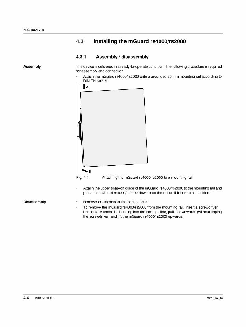
4.3.1 Assembly / disassembly
Assembly The device is delivered in a ready-to-operate condition. The following procedure is required for assembly and connection:• Attach the mGuard rs4000/rs2000 onto a grounded 35 mm mounting rail according to
DIN EN 60715.
Fig. 4-1 Attaching the mGuard rs4000/rs2000 to a mounting rail
• Attach the upper snap-on guide of the mGuard rs4000/rs2000 to the mounting rail and press the mGuard rs4000/rs2000 down onto the rail until it locks into position.
Disassembly • Remove or disconnect the connections.• To remove the mGuard rs4000/rs2000 from the mounting rail, insert a screwdriver
horizontally under the housing into the locking slide, pull it downwards (without tipping the screwdriver) and lift the mGuard rs4000/rs2000 upwards.
4-4 INNOMINATE 7961_en_04
Startup
4.3.2 Connecting to the network
• Connect the mGuard to the network. For this you require a suitable UTP cable (CAT5), which is not included in the delivery.
• Connect the internal network interface LAN 1 of the mGuard to the corresponding Ethernet network card of the configuration computer or to a valid network connection of the internal network (LAN).
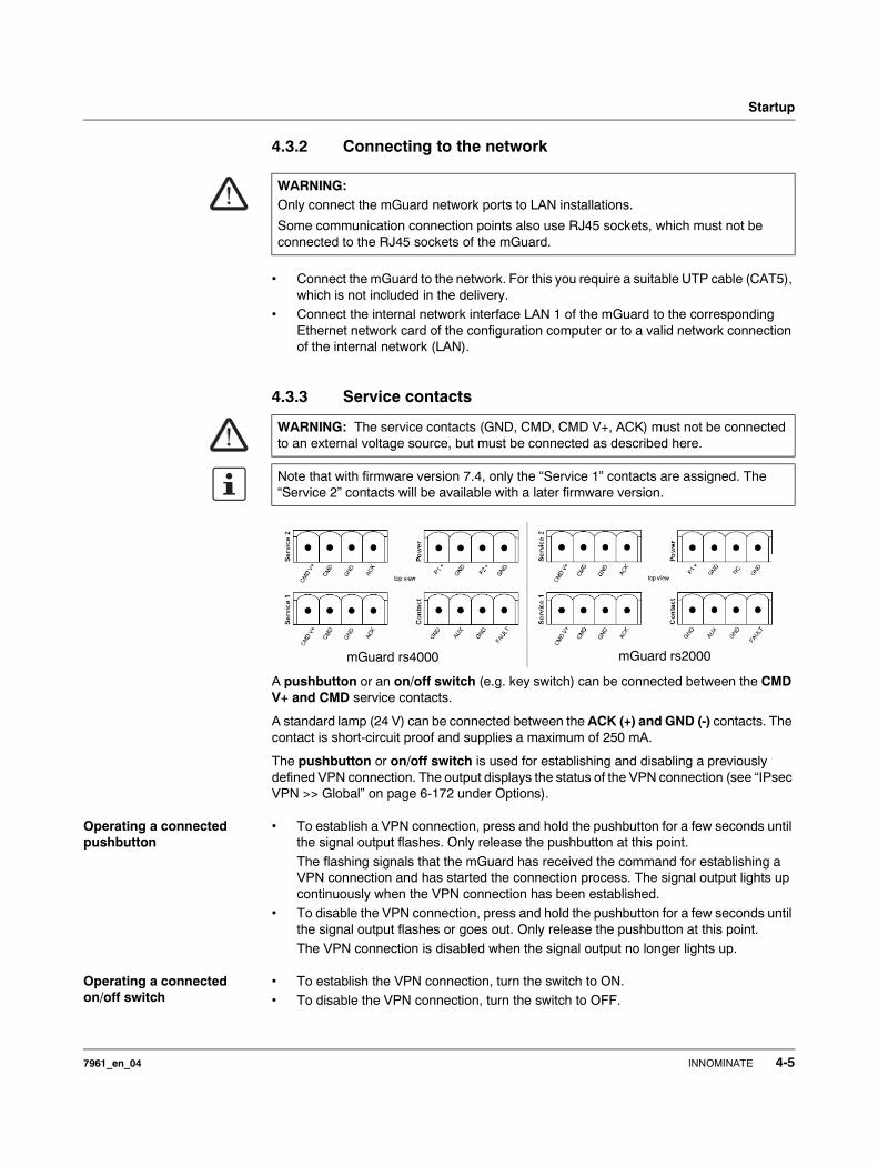
4.3.3 Service contacts
A pushbutton or an on/off switch (e.g. key switch) can be connected between the CMD V+ and CMD service contacts.
A standard lamp (24 V) can be connected between the ACK (+) and GND (-) contacts. The contact is short-circuit proof and supplies a maximum of 250 mA.
The pushbutton or on/off switch is used for establishing and disabling a previously defined VPN connection. The output displays the status of the VPN connection (see “IPsec VPN >> Global” on page 6-172 under Options).
Operating a connected pushbutton
• To establish a VPN connection, press and hold the pushbutton for a few seconds until the signal output flashes. Only release the pushbutton at this point.
The flashing signals that the mGuard has received the command for establishing a VPN connection and has started the connection process. The signal output lights up continuously when the VPN connection has been established.
• To disable the VPN connection, press and hold the pushbutton for a few seconds until the signal output flashes or goes out. Only release the pushbutton at this point.The VPN connection is disabled when the signal output no longer lights up.
Operating a connected on/off switch
• To establish the VPN connection, turn the switch to ON. • To disable the VPN connection, turn the switch to OFF.
WARNING:Only connect the mGuard network ports to LAN installations.
Some communication connection points also use RJ45 sockets, which must not be connected to the RJ45 sockets of the mGuard.
WARNING: The service contacts (GND, CMD, CMD V+, ACK) must not be connected to an external voltage source, but must be connected as described here.
Note that with firmware version 7.4, only the “Service 1” contacts are assigned. The “Service 2” contacts will be available with a later firmware version.
mGuard rs4000 mGuard rs2000
7961_en_04 INNOMINATE 4-5
mGuard 7.4
INFO LED If the signal output is set to OFF, then the defined VPN connection is disabled. The VPN connection was not established or has failed due to an error.
If the INFO LED is set to ON, then the VPN connection is established.
If the INFO LED flashes, then the VPN connection is currently being established or disabled.
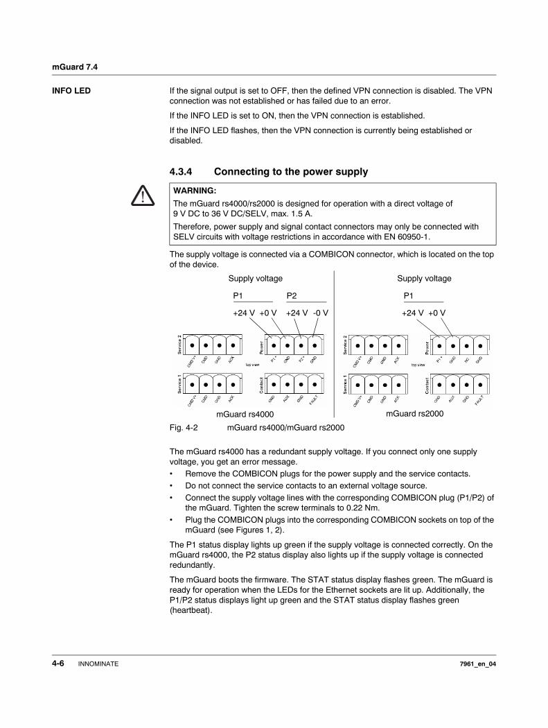
4.3.4 Connecting to the power supply
The supply voltage is connected via a COMBICON connector, which is located on the top of the device.
Fig. 4-2 mGuard rs4000/mGuard rs2000
The mGuard rs4000 has a redundant supply voltage. If you connect only one supply voltage, you get an error message. • Remove the COMBICON plugs for the power supply and the service contacts. • Do not connect the service contacts to an external voltage source.
• Connect the supply voltage lines with the corresponding COMBICON plug (P1/P2) of the mGuard. Tighten the screw terminals to 0.22 Nm.
• Plug the COMBICON plugs into the corresponding COMBICON sockets on top of the mGuard (see Figures 1, 2).
The P1 status display lights up green if the supply voltage is connected correctly. On the mGuard rs4000, the P2 status display also lights up if the supply voltage is connected redundantly.
The mGuard boots the firmware. The STAT status display flashes green. The mGuard is ready for operation when the LEDs for the Ethernet sockets are lit up. Additionally, the P1/P2 status displays light up green and the STAT status display flashes green (heartbeat).
WARNING:
The mGuard rs4000/rs2000 is designed for operation with a direct voltage of 9 V DC to 36 V DC/SELV, max. 1.5 A.
Therefore, power supply and signal contact connectors may only be connected with SELV circuits with voltage restrictions in accordance with EN 60950-1.
Supply voltage
+24 V +0 V +24 V -0 V
P1 P2
Supply voltage
+24 V +0 V
P1
mGuard rs4000 mGuard rs2000
4-6 INNOMINATE 7961_en_04

Startup
Redundant voltage display (mGuard rs4000)
Redundant power supplies are supported. Both inputs are decoupled. There is no load distribution. With a redundant supply, only the power supply unit with the higher output voltage supplies the mGuard rs4000. The supply voltage is electrically isolated from the housing.
In case of a non-redundant voltage supply, the mGuard rs4000 indicates the failure of the supply voltage over the signal contact. You can prevent this signal by connecting the supply voltage to both inputs.
7961_en_04 INNOMINATE 4-7
mGuard 7.4
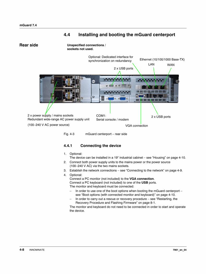
4.4 Installing and booting the mGuard centerport
Fig. 4-3 mGuard centerport – rear side
4.4.1 Connecting the device
1. Optional:The device can be installed in a 19" industrial cabinet – see “Housing” on page 4-10.
2. Connect both power supply units to the mains power or the power source (100–240 V AC) via the two mains sockets.
3. Establish the network connections – see “Connecting to the network” on page 4-9.
4. Optional:Connect a PC monitor (not included) to the VGA connection.Connect a PC keyboard (not included) to one of the USB ports.The monitor and keyboard must be connected:– In order to use one of the boot options when booting the mGuard centerport –
see “Boot options (with connected monitor and keyboard)” on page 4-10.– In order to carry out a rescue or recovery procedure – see “Restarting, the
Recovery Procedure and Flashing Firmware” on page 8-1.The monitor and keyboard do not need to be connected in order to start and operate the device.
2 x power supply / mains socketsRedundant wide-range AC power supply unit
(100–240 V AC power source)
COM1:Serial console / modem
VGA connection
LAN WAN
Rear side Unspecified connections / sockets not used.
2 x USB ports
2 x USB ports
Optional: Dedicated interface for synchronization on redundancy Ethernet (10/100/1000 Base-TX)
4-8 INNOMINATE 7961_en_04
Startup
4.4.2 Connecting to the network
LAN port
• Connect the local computer or network to the LAN port of the mGuard using a UTP (CAT5) Ethernet cable.
WAN port
• Use a UTP cable (CAT5).• Connect to the external network (e.g. WAN, Internet) via the WAN socket.
(Connections to the remote device or network are established over this network.)
COM1: Serial port
The serial port (serial interface) can be used as described under “Serial port” on page 4-19.
WARNING:Only connect the mGuard network ports to LAN installations.
Some communication connection points also use RJ45 sockets, which must not be connected to the RJ45 sockets of the mGuard.
ATTENTION: The serial port (D-sub socket) must not be connected directly to communication connection points. Use a serial cable with a D-sub connector to connect a serial terminal or a modem. The serial cable can have a maximum length of 30 meters.
7961_en_04 INNOMINATE 4-9
mGuard 7.4
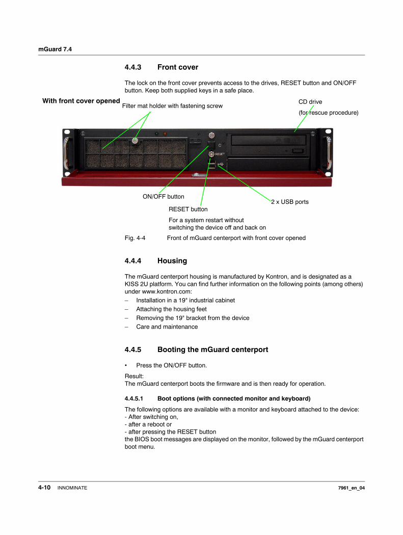
4.4.3 Front cover
The lock on the front cover prevents access to the drives, RESET button and ON/OFF button. Keep both supplied keys in a safe place.
Fig. 4-4 Front of mGuard centerport with front cover opened
4.4.4 Housing
The mGuard centerport housing is manufactured by Kontron, and is designated as a KISS 2U platform. You can find further information on the following points (among others) under www.kontron.com:– Installation in a 19" industrial cabinet– Attaching the housing feet
– Removing the 19" bracket from the device– Care and maintenance
4.4.5 Booting the mGuard centerport
• Press the ON/OFF button.
Result:The mGuard centerport boots the firmware and is then ready for operation.
4.4.5.1 Boot options (with connected monitor and keyboard)
The following options are available with a monitor and keyboard attached to the device: - After switching on, - after a reboot or - after pressing the RESET button the BIOS boot messages are displayed on the monitor, followed by the mGuard centerport boot menu.
ON/OFF button
CD drive
(for rescue procedure)
2 x USB ports
With front cover openedFilter mat holder with fastening screw
RESET button
For a system restart without switching the device off and back on
4-10 INNOMINATE 7961_en_04
Startup
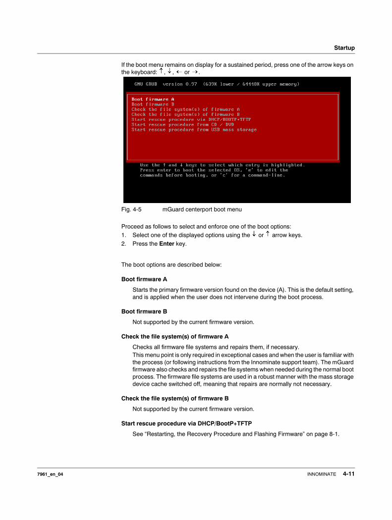
If the boot menu remains on display for a sustained period, press one of the arrow keys on the keyboard: , , or .
Fig. 4-5 mGuard centerport boot menu
Proceed as follows to select and enforce one of the boot options:1. Select one of the displayed options using the or arrow keys.
2. Press the Enter key.
The boot options are described below:
Boot firmware A
Starts the primary firmware version found on the device (A). This is the default setting, and is applied when the user does not intervene during the boot process.
Boot firmware B
Not supported by the current firmware version.
Check the file system(s) of firmware A
Checks all firmware file systems and repairs them, if necessary.This menu point is only required in exceptional cases and when the user is familiar with the process (or following instructions from the Innominate support team). The mGuard firmware also checks and repairs the file systems when needed during the normal boot process. The firmware file systems are used in a robust manner with the mass storage device cache switched off, meaning that repairs are normally not necessary.
Check the file system(s) of firmware B
Not supported by the current firmware version.
Start rescue procedure via DHCP/BootP+TFTP
See “Restarting, the Recovery Procedure and Flashing Firmware” on page 8-1.
7961_en_04 INNOMINATE 4-11

mGuard 7.4
Start rescue procedure from CD / DVD
See “Restarting, the Recovery Procedure and Flashing Firmware” on page 8-1.
Start rescue procedure from USB mass storage
See “Restarting, the Recovery Procedure and Flashing Firmware” on page 8-1.
4-12 INNOMINATE 7961_en_04
Startup
4.5 Installing the mGuard industrial rs
4.5.1 Assembly / disassembly
Assembly The device is delivered in a ready-to-operate condition. The following procedure is required for assembly and connection:• Pull the terminal block from under the mGuard industrial rs and connect the contact
lines and other connections as necessary (see “Connection options on lower terminal block” on page 4-16).
• The screws on the screw terminals must be tightened to at least 0.22 Nm.Wait before inserting the terminal block.
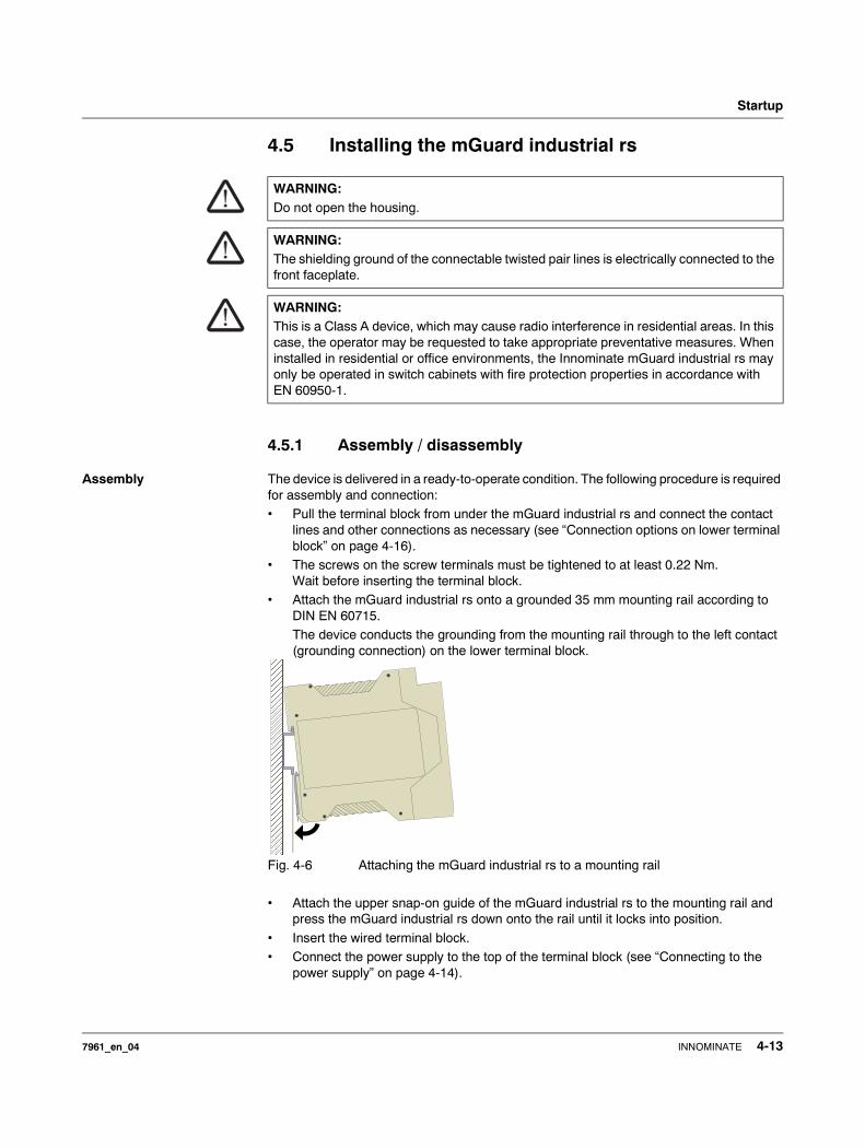
• Attach the mGuard industrial rs onto a grounded 35 mm mounting rail according to DIN EN 60715.The device conducts the grounding from the mounting rail through to the left contact (grounding connection) on the lower terminal block.
Fig. 4-6 Attaching the mGuard industrial rs to a mounting rail
• Attach the upper snap-on guide of the mGuard industrial rs to the mounting rail and press the mGuard industrial rs down onto the rail until it locks into position.
• Insert the wired terminal block. • Connect the power supply to the top of the terminal block (see “Connecting to the
power supply” on page 4-14).
WARNING:Do not open the housing.
WARNING:The shielding ground of the connectable twisted pair lines is electrically connected to the front faceplate.
WARNING:This is a Class A device, which may cause radio interference in residential areas. In this case, the operator may be requested to take appropriate preventative measures. When installed in residential or office environments, the Innominate mGuard industrial rs may only be operated in switch cabinets with fire protection properties in accordance with EN 60950-1.
���������������������������������������������������������������������������������������������������������������
���������������������������������������������������������������������������������������������������������������
7961_en_04 INNOMINATE 4-13
mGuard 7.4
• Make the necessary network connections on the LAN or WAN port (see “Connecting to the network” on page 4-15).
• If necessary, connect the relevant device to the serial port (see “Serial port” on page 4-19).
Disassembly • Remove or disconnect the connections.
• To remove the mGuard industrial rs from the mounting rail, insert a screwdriver horizontally under the housing into the locking slide, pull it downwards (without tipping the screwdriver) and lift the mGuard industrial rs upwards.
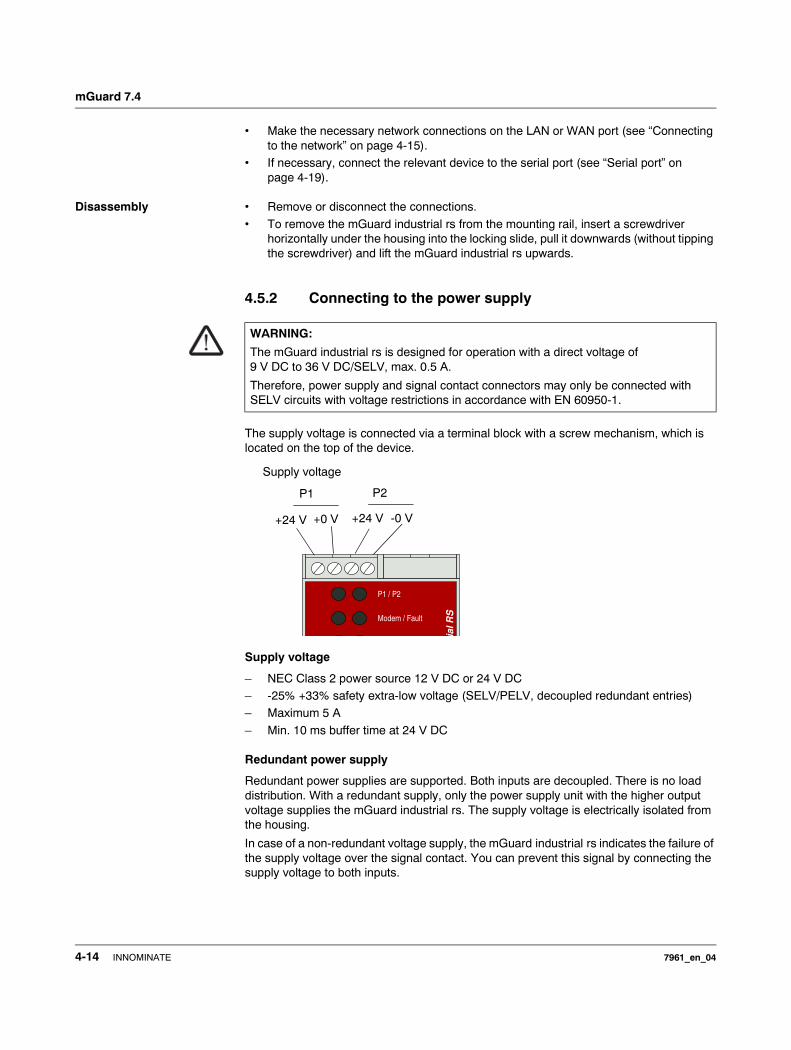
4.5.2 Connecting to the power supply
The supply voltage is connected via a terminal block with a screw mechanism, which is located on the top of the device.
Supply voltage
– NEC Class 2 power source 12 V DC or 24 V DC – -25% +33% safety extra-low voltage (SELV/PELV, decoupled redundant entries)– Maximum 5 A
– Min. 10 ms buffer time at 24 V DC
Redundant power supply
Redundant power supplies are supported. Both inputs are decoupled. There is no load distribution. With a redundant supply, only the power supply unit with the higher output voltage supplies the mGuard industrial rs. The supply voltage is electrically isolated from the housing.
In case of a non-redundant voltage supply, the mGuard industrial rs indicates the failure of the supply voltage over the signal contact. You can prevent this signal by connecting the supply voltage to both inputs.
WARNING:
The mGuard industrial rs is designed for operation with a direct voltage of 9 V DC to 36 V DC/SELV, max. 0.5 A.
Therefore, power supply and signal contact connectors may only be connected with SELV circuits with voltage restrictions in accordance with EN 60950-1.
ial R
SModem / Fault
P1 / P2
Supply voltage
+24 V +0 V +24 V -0 V
P1 P2
4-14 INNOMINATE 7961_en_04

Startup
4.5.3 Connecting to the network
LAN port
• Connect the local computer or network to the LAN port of the mGuard using a UTP (CAT5) Ethernet cable.If your computer is already connected to a network, then patch the mGuard between the existing network connection.
WAN port
• Use a UTP cable (CAT5).• Connect to the external network (e.g. WAN, Internet) via the WAN socket.
(Connections to the remote device or network are established over this network.)
WARNING:Only connect the mGuard network ports to LAN installations.
Use cables with bend relief sleeves for the connectors when setting up the network connections.
Cover unused sockets with the dust caps supplied.
Some communication connection points also use RJ45 sockets, which must not be connected to the RJ45 sockets of the mGuard.
Please note that initial configuration can only be made over the LAN interface. The mGuard industrial rs firewall rejects all IP traffic from the WAN to the LAN interface.
Additional driver installation is not necessary.
For security reasons, we recommend that you change the default Root and Administrator passwords during the first configuration.
7961_en_04 INNOMINATE 4-15
mGuard 7.4
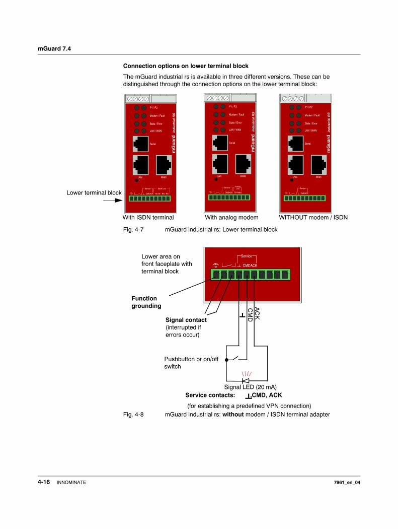
Connection options on lower terminal block
The mGuard industrial rs is available in three different versions. These can be distinguished through the connection options on the lower terminal block:
Fig. 4-7 mGuard industrial rs: Lower terminal block
Fig. 4-8 mGuard industrial rs: without modem / ISDN terminal adapter
mGuard
ind
ust
rial
RS
LAN WAN
State / Error
LAN / WAN
Modem / Fault
P1 / P2
Serial
ACKCMD
ISDN LineService
RX−RX+TX+TX−
mGuard
ind
ust
rial
RS
LAN WAN
State / Error
LAN / WAN
Modem / Fault
P1 / P2
Serial
RINGTIPACKCMD
LineAnalogService
mGuard
ind
ust
rial
RS
LAN WAN
State / Error
LAN / WAN
Modem / Fault
P1 / P2
Serial
ACKCMD
Service
WITHOUT modem / ISDN
Lower terminal block
With analog modemWith ISDN terminal
ACKCMD
ServiceLower area on front faceplate with terminal block
Function grounding
Signal contact(interrupted if errors occur)
Service contacts: ,CMD, ACK
(for establishing a predefined VPN connection)
Pushbutton or on/off switch
Signal LED (20 mA)
AC
KC
MD
4-16 INNOMINATE 7961_en_04
Startup
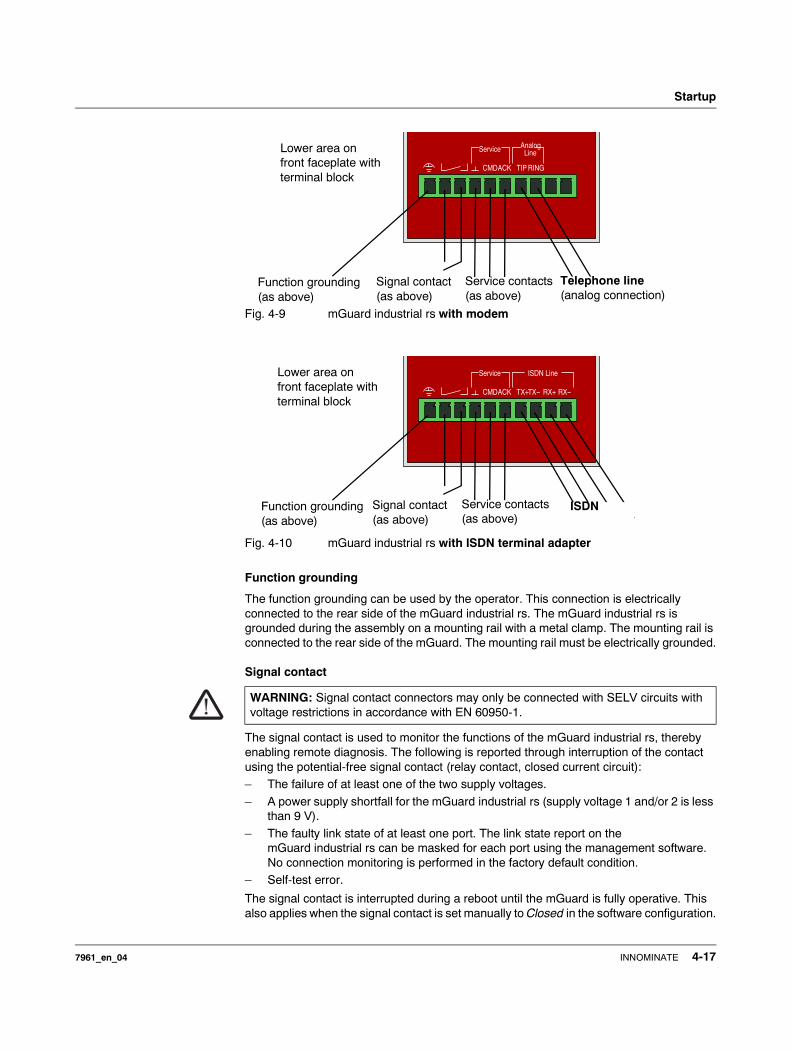
Fig. 4-9 mGuard industrial rs with modem
Fig. 4-10 mGuard industrial rs with ISDN terminal adapter
Function grounding
The function grounding can be used by the operator. This connection is electrically connected to the rear side of the mGuard industrial rs. The mGuard industrial rs is grounded during the assembly on a mounting rail with a metal clamp. The mounting rail is connected to the rear side of the mGuard. The mounting rail must be electrically grounded.
Signal contact
The signal contact is used to monitor the functions of the mGuard industrial rs, thereby enabling remote diagnosis. The following is reported through interruption of the contact using the potential-free signal contact (relay contact, closed current circuit):– The failure of at least one of the two supply voltages.
– A power supply shortfall for the mGuard industrial rs (supply voltage 1 and/or 2 is less than 9 V).
– The faulty link state of at least one port. The link state report on the mGuard industrial rs can be masked for each port using the management software.No connection monitoring is performed in the factory default condition.
– Self-test error.
The signal contact is interrupted during a reboot until the mGuard is fully operative. This also applies when the signal contact is set manually to Closed in the software configuration.
WARNING: Signal contact connectors may only be connected with SELV circuits with voltage restrictions in accordance with EN 60950-1.
RINGTIPACKCMD
LineAnalogServiceLower area on
front faceplate with terminal block
Function grounding (as above)
Signal contact(as above)
Telephone line(analog connection)
Service contacts (as above)
ACKCMD
ISDN LineService
RX−RX+TX+TX−
Lower area on front faceplate with terminal block
Function grounding (as above)
Signal contact(as above)
Service contacts(as above)
ISDN
7961_en_04 INNOMINATE 4-17
mGuard 7.4
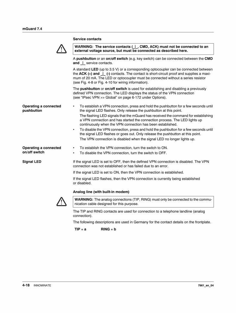
Service contacts
A pushbutton or an on/off switch (e.g. key switch) can be connected between the CMD and _|_ service contacts.
A standard LED (up to 3.5 V) or a corresponding optocoupler can be connected between the ACK (+) and _|_ (-) contacts. The contact is short-circuit proof and supplies a maxi-mum of 20 mA. The LED or optocoupler must be connected without a series resistor (see Fig. 4-8 or Fig. 4-10 for wiring information).
The pushbutton or on/off switch is used for establishing and disabling a previously defined VPN connection. The LED displays the status of the VPN connection (see “IPsec VPN >> Global” on page 6-172 under Options).
Operating a connected pushbutton
• To establish a VPN connection, press and hold the pushbutton for a few seconds until the signal LED flashes. Only release the pushbutton at this point.
The flashing LED signals that the mGuard has received the command for establishing a VPN connection and has started the connection process. The LED lights up continuously when the VPN connection has been established.
• To disable the VPN connection, press and hold the pushbutton for a few seconds until the signal LED flashes or goes out. Only release the pushbutton at this point.The VPN connection is disabled when the signal LED no longer lights up.
Operating a connected on/off switch
• To establish the VPN connection, turn the switch to ON. • To disable the VPN connection, turn the switch to OFF.
Signal LED If the signal LED is set to OFF, then the defined VPN connection is disabled. The VPN connection was not established or has failed due to an error.
If the signal LED is set to ON, then the VPN connection is established.
If the signal LED flashes, then the VPN connection is currently being established or disabled.
Analog line (with built-in modem)
The TIP and RING contacts are used for connection to a telephone landline (analog connection).
The following descriptions are used in Germany for the contact details on the frontplate.
WARNING: The service contacts (_|_, CMD, ACK) must not be connected to an external voltage source, but must be connected as described here.
WARNING: The analog connections (TIP, RING) must only be connected to the commu-nication cable designed for this purpose.
TIP = a RING = b
4-18 INNOMINATE 7961_en_04
Startup
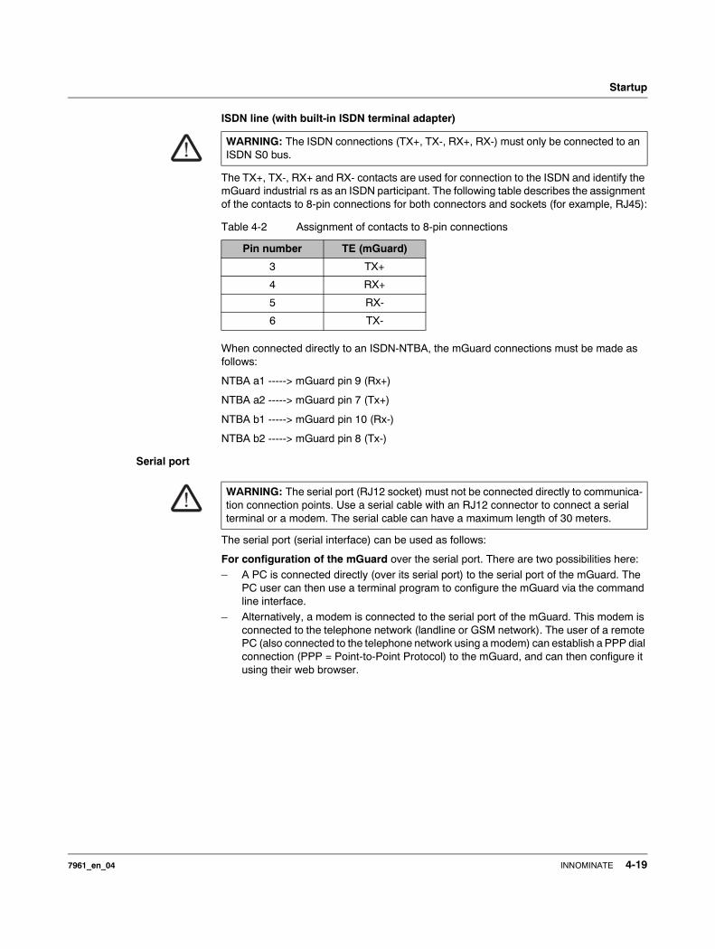
ISDN line (with built-in ISDN terminal adapter)
The TX+, TX-, RX+ and RX- contacts are used for connection to the ISDN and identify the mGuard industrial rs as an ISDN participant. The following table describes the assignment of the contacts to 8-pin connections for both connectors and sockets (for example, RJ45):
When connected directly to an ISDN-NTBA, the mGuard connections must be made as follows:
NTBA a1 -----> mGuard pin 9 (Rx+)
NTBA a2 -----> mGuard pin 7 (Tx+)
NTBA b1 -----> mGuard pin 10 (Rx-)
NTBA b2 -----> mGuard pin 8 (Tx-)
Serial port
The serial port (serial interface) can be used as follows:
For configuration of the mGuard over the serial port. There are two possibilities here:– A PC is connected directly (over its serial port) to the serial port of the mGuard. The
PC user can then use a terminal program to configure the mGuard via the command line interface.
– Alternatively, a modem is connected to the serial port of the mGuard. This modem is connected to the telephone network (landline or GSM network). The user of a remote PC (also connected to the telephone network using a modem) can establish a PPP dial connection (PPP = Point-to-Point Protocol) to the mGuard, and can then configure it using their web browser.
WARNING: The ISDN connections (TX+, TX-, RX+, RX-) must only be connected to an ISDN S0 bus.
Table 4-2 Assignment of contacts to 8-pin connections
Pin number TE (mGuard)
3 TX+
4 RX+
5 RX-
6 TX-
WARNING: The serial port (RJ12 socket) must not be connected directly to communica-tion connection points. Use a serial cable with an RJ12 connector to connect a serial terminal or a modem. The serial cable can have a maximum length of 30 meters.
7961_en_04 INNOMINATE 4-19
mGuard 7.4
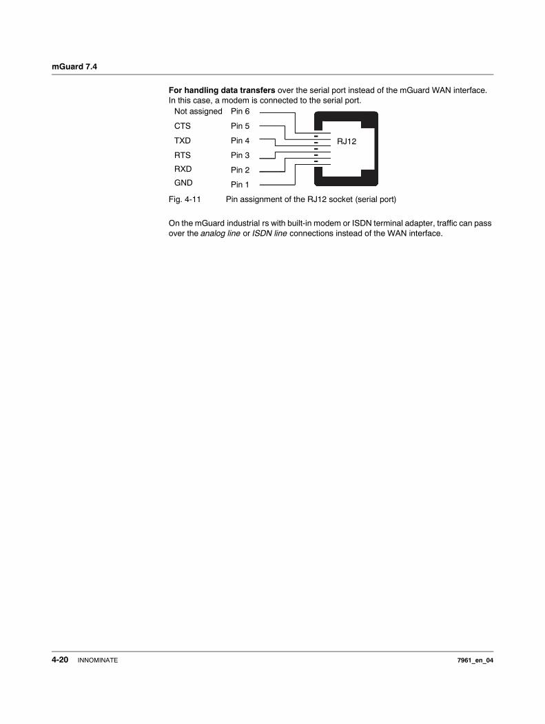
For handling data transfers over the serial port instead of the mGuard WAN interface. In this case, a modem is connected to the serial port.
Fig. 4-11 Pin assignment of the RJ12 socket (serial port)
On the mGuard industrial rs with built-in modem or ISDN terminal adapter, traffic can pass over the analog line or ISDN line connections instead of the WAN interface.
Pin 6
Pin 5
Pin 4
Pin 3
Pin 2
Pin 1
Not assigned
CTS
TXD
RTS
RXD
GND
RJ12
4-20 INNOMINATE 7961_en_04
Startup
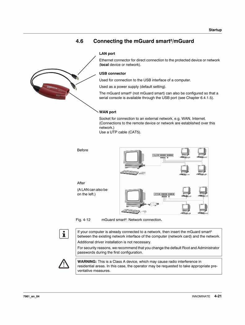
4.6 Connecting the mGuard smart²/mGuard
Fig. 4-12 mGuard smart²: Network connection.
LAN port
Ethernet connector for direct connection to the protected device or network (local device or network).
USB connector
Used for connection to the USB interface of a computer.
Used as a power supply (default setting).
The mGuard smart² (not mGuard smart) can also be configured so that a serial console is available through the USB port (see Chapter 6.4.1.5).
WAN port
Socket for connection to an external network, e.g. WAN, Internet. (Connections to the remote device or network are established over this network.)Use a UTP cable (CAT5).
Before
After
(A LAN can also be on the left.)
If your computer is already connected to a network, then insert the mGuard smart² between the existing network interface of the computer (network card) and the network.
Additional driver installation is not necessary.
For security reasons, we recommend that you change the default Root and Administrator passwords during the first configuration.
WARNING: This is a Class A device, which may cause radio interference in residential areas. In this case, the operator may be requested to take appropriate pre-ventative measures.
7961_en_04 INNOMINATE 4-21

mGuard 7.4
4.7 Installing the mGuard blade
Fig. 4-13 Installing the mGuard blade
Installing the mGuard bladebase
• Install the mGuard bladebase into the rack (e.g. close to the patch panel).
• Provide the two front power supplies and the control unit with the handling plates “P1”, “P2” and “Ctrl” from left to right.
• Connect both power supplies on the back of the mGuard bladebase with 100 V or 220/240 V.
• Switch both power supplies on.• The LEDs on the front of the power supplies should now light up green.
Installing the mGuard blade
The mGuard bladebase does not need to be switched off during installation or deinstallation of an mGuard blade.
• Loosen the upper and lower screw of the faceplate or the mGuard blade to be replaced.• Remove the faceplace or pull out the old mGuard blade.• Insert the new mGuard blade and circuit board into the plastic guides and push until it
is completely installed in the mGuard bladebase.• Secure the mGuard blade by tightening the screws lightly.
• Replace the empty handling plate with the suitable number from the mGuard bladebase accessories, or replace it with the plate from the old mGuard blade. To do this, pull or push the plate in a sideways motion.
Power supply P1/P2
mGuard blade 1 to 12
Control unit (CTRL)Power supply connections P1 & P2
Power supply switches P1 & P2
mGuard bladebase mGuard blade
Screws
Handling plate
ATTENTION: It is very important to ensure sufficient air circulation for the bladepack!
When stacking several bladepacks, fan trays must be installed to discharge the accumulated warm air!
4-22 INNOMINATE 7961_en_04
Startup
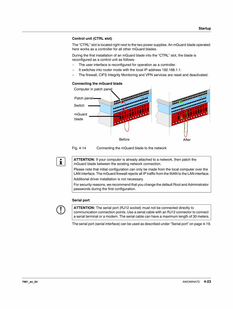
Control unit (CTRL slot)
The “CTRL” slot is located right next to the two power supplies. An mGuard blade operated here works as a controller for all other mGuard blades.
During the first installation of an mGuard blade into the “CTRL” slot, the blade is reconfigured as a control unit as follows:
– The user interface is reconfigured for operation as a controller.– It switches into router mode with the local IP address 192.168.1.1.– The firewall, CIFS Integrity Monitoring and VPN services are reset and deactivated.
Connecting the mGuard blade
Fig. 4-14 Connecting the mGuard blade to the network
Serial port
The serial port (serial interface) can be used as described under “Serial port” on page 4-19.
ATTENTION: If your computer is already attached to a network, then patch the mGuard blade between the existing network connection.
Please note that initial configuration can only be made from the local computer over the LAN interface. The mGuard firewall rejects all IP traffic from the WAN to the LAN interface.
Additional driver installation is not necessary.
For security reasons, we recommend that you change the default Root and Administrator passwords during the first configuration.
ATTENTION: The serial port (RJ12 socket) must not be connected directly to communication connection points. Use a serial cable with an RJ12 connector to connect a serial terminal or a modem. The serial cable can have a maximum length of 30 meters.
IWST C H
IWST C H
Patch panel
Switch
mGuardblade
Before After
Computer in patch panel
7961_en_04 INNOMINATE 4-23
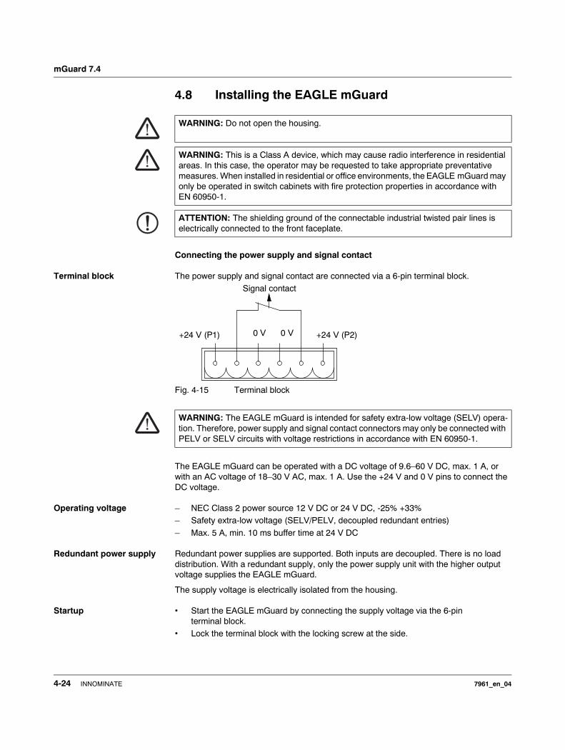
mGuard 7.4
4.8 Installing the EAGLE mGuard
Connecting the power supply and signal contact
Terminal block The power supply and signal contact are connected via a 6-pin terminal block.
Fig. 4-15 Terminal block
The EAGLE mGuard can be operated with a DC voltage of 9.6–60 V DC, max. 1 A, or with an AC voltage of 18–30 V AC, max. 1 A. Use the +24 V and 0 V pins to connect the DC voltage.
Operating voltage – NEC Class 2 power source 12 V DC or 24 V DC, -25% +33% – Safety extra-low voltage (SELV/PELV, decoupled redundant entries)
– Max. 5 A, min. 10 ms buffer time at 24 V DC
Redundant power supply Redundant power supplies are supported. Both inputs are decoupled. There is no load distribution. With a redundant supply, only the power supply unit with the higher output voltage supplies the EAGLE mGuard.
The supply voltage is electrically isolated from the housing.
Startup • Start the EAGLE mGuard by connecting the supply voltage via the 6-pin terminal block.
• Lock the terminal block with the locking screw at the side.
WARNING: Do not open the housing.
WARNING: This is a Class A device, which may cause radio interference in residential areas. In this case, the operator may be requested to take appropriate preventative measures. When installed in residential or office environments, the EAGLE mGuard may only be operated in switch cabinets with fire protection properties in accordance with EN 60950-1.
ATTENTION: The shielding ground of the connectable industrial twisted pair lines is electrically connected to the front faceplate.
WARNING: The EAGLE mGuard is intended for safety extra-low voltage (SELV) opera-tion. Therefore, power supply and signal contact connectors may only be connected with PELV or SELV circuits with voltage restrictions in accordance with EN 60950-1.
Signal contact
0 V 0 V +24 V (P1) +24 V (P2)
4-24 INNOMINATE 7961_en_04
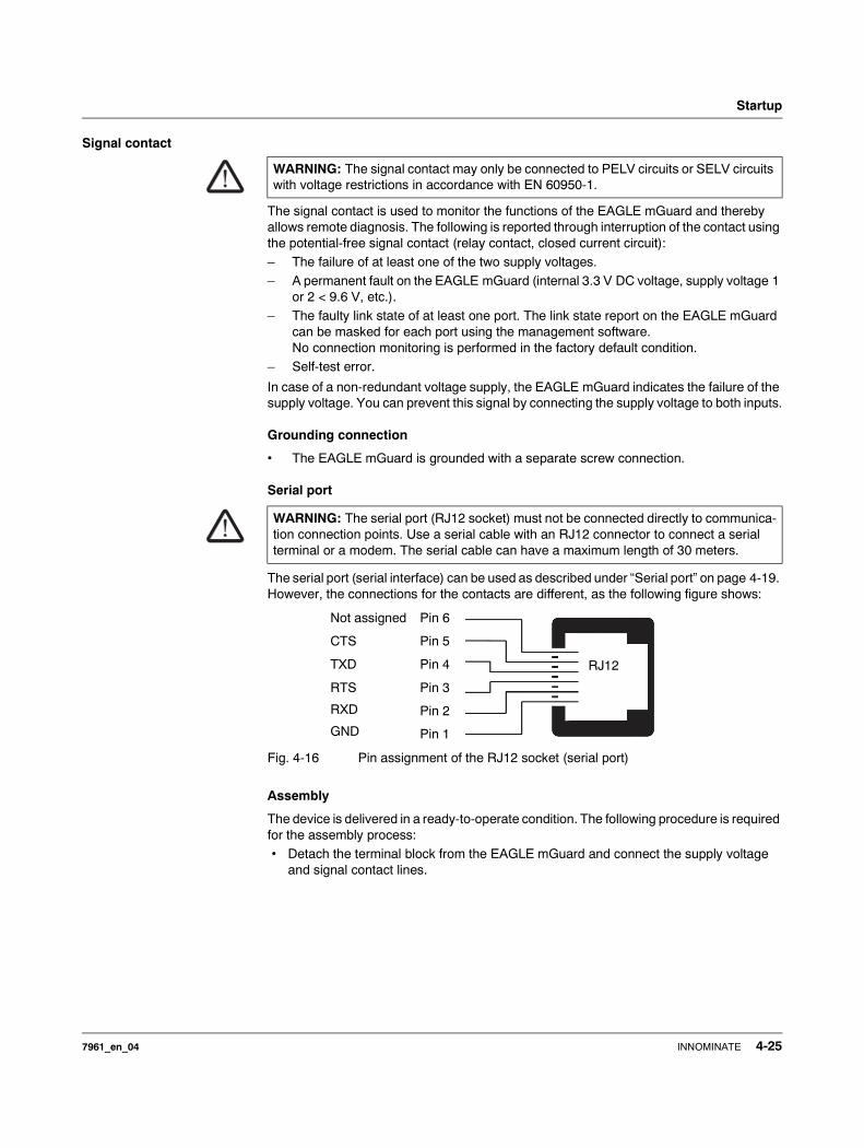
Startup
Signal contact
The signal contact is used to monitor the functions of the EAGLE mGuard and thereby allows remote diagnosis. The following is reported through interruption of the contact using the potential-free signal contact (relay contact, closed current circuit):– The failure of at least one of the two supply voltages.– A permanent fault on the EAGLE mGuard (internal 3.3 V DC voltage, supply voltage 1
or 2 < 9.6 V, etc.).– The faulty link state of at least one port. The link state report on the EAGLE mGuard
can be masked for each port using the management software.No connection monitoring is performed in the factory default condition.
– Self-test error.
In case of a non-redundant voltage supply, the EAGLE mGuard indicates the failure of the supply voltage. You can prevent this signal by connecting the supply voltage to both inputs.
Grounding connection
• The EAGLE mGuard is grounded with a separate screw connection.
Serial port
The serial port (serial interface) can be used as described under “Serial port” on page 4-19. However, the connections for the contacts are different, as the following figure shows:
Fig. 4-16 Pin assignment of the RJ12 socket (serial port)
Assembly
The device is delivered in a ready-to-operate condition. The following procedure is required for the assembly process:• Detach the terminal block from the EAGLE mGuard and connect the supply voltage
and signal contact lines.
WARNING: The signal contact may only be connected to PELV circuits or SELV circuits with voltage restrictions in accordance with EN 60950-1.
WARNING: The serial port (RJ12 socket) must not be connected directly to communica-tion connection points. Use a serial cable with an RJ12 connector to connect a serial terminal or a modem. The serial cable can have a maximum length of 30 meters.
Pin 6
Pin 5
Pin 4
Pin 3
Pin 2
Pin 1
Not assigned
CTS
TXD
RTS
RXD
GND
RJ12
7961_en_04 INNOMINATE 4-25
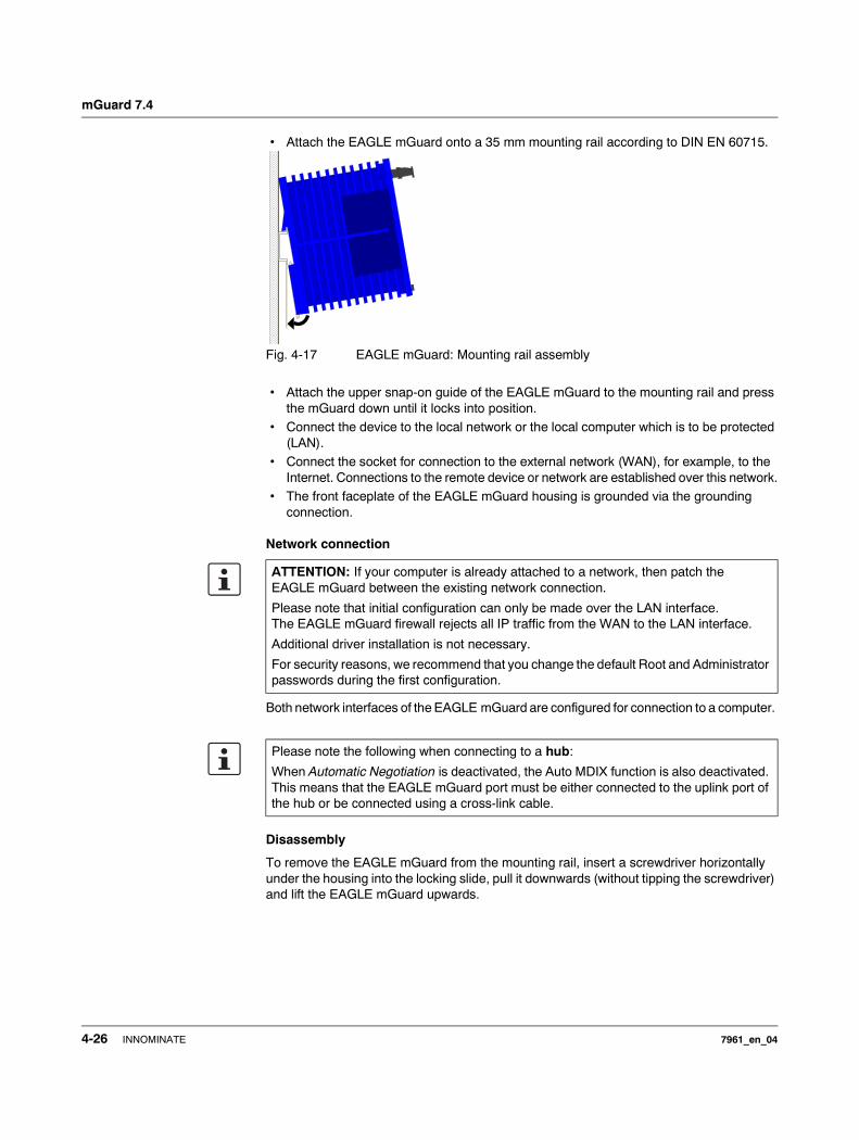
mGuard 7.4
• Attach the EAGLE mGuard onto a 35 mm mounting rail according to DIN EN 60715.
Fig. 4-17 EAGLE mGuard: Mounting rail assembly
• Attach the upper snap-on guide of the EAGLE mGuard to the mounting rail and press the mGuard down until it locks into position.
• Connect the device to the local network or the local computer which is to be protected (LAN).
• Connect the socket for connection to the external network (WAN), for example, to the Internet. Connections to the remote device or network are established over this network.
• The front faceplate of the EAGLE mGuard housing is grounded via the grounding connection.
Network connection
Both network interfaces of the EAGLE mGuard are configured for connection to a computer.
Disassembly
To remove the EAGLE mGuard from the mounting rail, insert a screwdriver horizontally under the housing into the locking slide, pull it downwards (without tipping the screwdriver) and lift the EAGLE mGuard upwards.
ATTENTION: If your computer is already attached to a network, then patch the EAGLE mGuard between the existing network connection.
Please note that initial configuration can only be made over the LAN interface. The EAGLE mGuard firewall rejects all IP traffic from the WAN to the LAN interface.
Additional driver installation is not necessary.
For security reasons, we recommend that you change the default Root and Administrator passwords during the first configuration.
Please note the following when connecting to a hub:
When Automatic Negotiation is deactivated, the Auto MDIX function is also deactivated. This means that the EAGLE mGuard port must be either connected to the uplink port of the hub or be connected using a cross-link cable.
4-26 INNOMINATE 7961_en_04
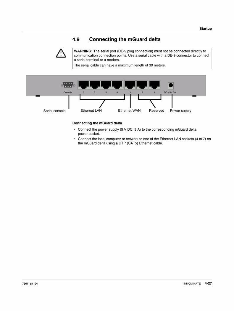
Startup
4.9 Connecting the mGuard delta
Connecting the mGuard delta
• Connect the power supply (5 V DC, 3 A) to the corresponding mGuard delta power socket.
• Connect the local computer or network to one of the Ethernet LAN sockets (4 to 7) on the mGuard delta using a UTP (CAT5) Ethernet cable.
WARNING: The serial port (DE-9 plug connection) must not be connected directly to communication connection points. Use a serial cable with a DE-9 connector to connect a serial terminal or a modem.
The serial cable can have a maximum length of 30 meters.
DC +5V 3A1234567Console
Power supplySerial console ReservedEthernet WANEthernet LAN
7961_en_04 INNOMINATE 4-27
mGuard 7.4
4.10 Installing the mGuard pci
Selection of Driver mode or Power-over-PCI mode
There are two operating modes: Driver mode or Power-over-PCI mode.
• Decide in which mode the mGuard pci should be operated before installation on your computer.
• The mGuard is switched to the desired mode via a jumper.
Driver mode The mGuard pci can be used like a normal network card. The network card then also provides the mGuard functions.
In this case, the driver provided must be installed.
Power-over-PCI mode If the mGuard network card function is not needed or should not be used, then the mGuard pci can be connected behind an existing network card (of the same or another com-puter). It then essentially acts as a stand-alone mGuard device. In reality, the mGuard pci is only plugged into the PCI slot of the computer in this mode in order to receive a power supply and have a housing. This mGuard operating mode is known as Power-over-PCI mode.
No drivers are installed.
4.10.1 Driver mode
In this mode, an mGuard pci interface driver needs to be installed afterwards on the computer (available for Windows XP/2000 and Linux). No additional network cards are required for the computer in Driver mode.
WARNING: This is a Class A device, which may cause radio interference in residential areas. In this case, the operator may be requested to take appropriate preventative measures.
WARNING: Conditions of acceptabilityThe device has been designed for PC installation in a secondary signal circuit. As a result, no tests have been made. Tests must be evaluated by the user.
The circuit board temperature must not exceed 105 °C.
4-28 INNOMINATE 7961_en_04
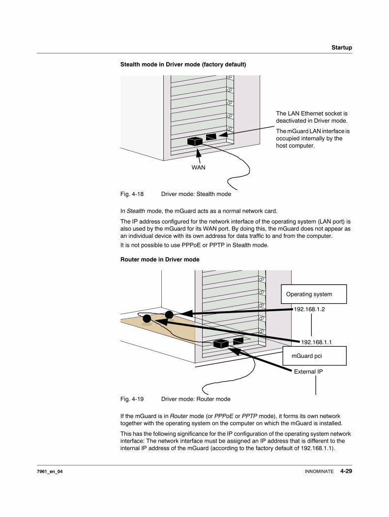
Startup
Stealth mode in Driver mode (factory default)
Fig. 4-18 Driver mode: Stealth mode
In Stealth mode, the mGuard acts as a normal network card.
The IP address configured for the network interface of the operating system (LAN port) is also used by the mGuard for its WAN port. By doing this, the mGuard does not appear as an individual device with its own address for data traffic to and from the computer.
It is not possible to use PPPoE or PPTP in Stealth mode.
Router mode in Driver mode
Fig. 4-19 Driver mode: Router mode
If the mGuard is in Router mode (or PPPoE or PPTP mode), it forms its own network together with the operating system on the computer on which the mGuard is installed.
This has the following significance for the IP configuration of the operating system network interface: The network interface must be assigned an IP address that is different to the internal IP address of the mGuard (according to the factory default of 192.168.1.1).
WANWAN
The LAN Ethernet socket is deactivated in Driver mode.
The mGuard LAN interface is occupied internally by the host computer.
192.168.1.2
192.168.1.1
External IP
Operating system
mGuard pci
7961_en_04 INNOMINATE 4-29
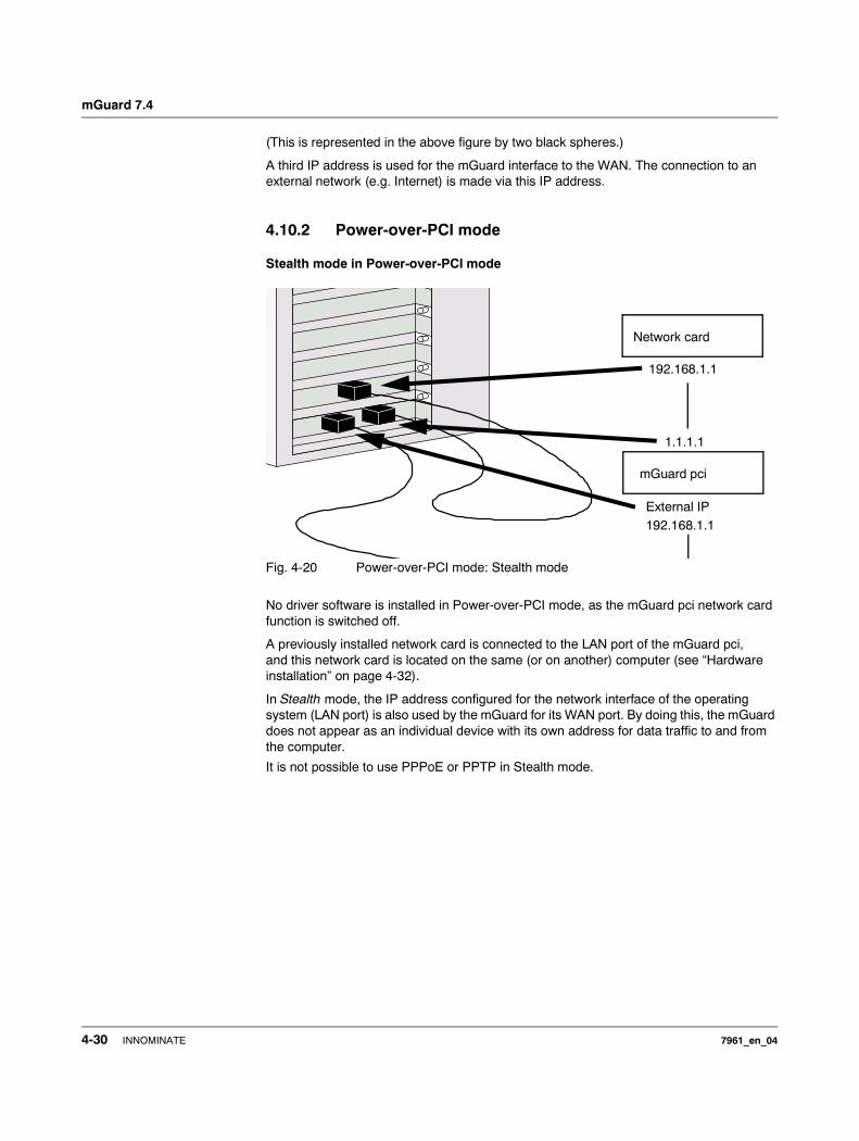
mGuard 7.4
(This is represented in the above figure by two black spheres.)
A third IP address is used for the mGuard interface to the WAN. The connection to an external network (e.g. Internet) is made via this IP address.
4.10.2 Power-over-PCI mode
Stealth mode in Power-over-PCI mode
Fig. 4-20 Power-over-PCI mode: Stealth mode
No driver software is installed in Power-over-PCI mode, as the mGuard pci network card function is switched off.
A previously installed network card is connected to the LAN port of the mGuard pci, and this network card is located on the same (or on another) computer (see “Hardware installation” on page 4-32).
In Stealth mode, the IP address configured for the network interface of the operating system (LAN port) is also used by the mGuard for its WAN port. By doing this, the mGuard does not appear as an individual device with its own address for data traffic to and from the computer.
It is not possible to use PPPoE or PPTP in Stealth mode.
192.168.1.1
1.1.1.1
External IP
mGuard pci
Network card
192.168.1.1
4-30 INNOMINATE 7961_en_04
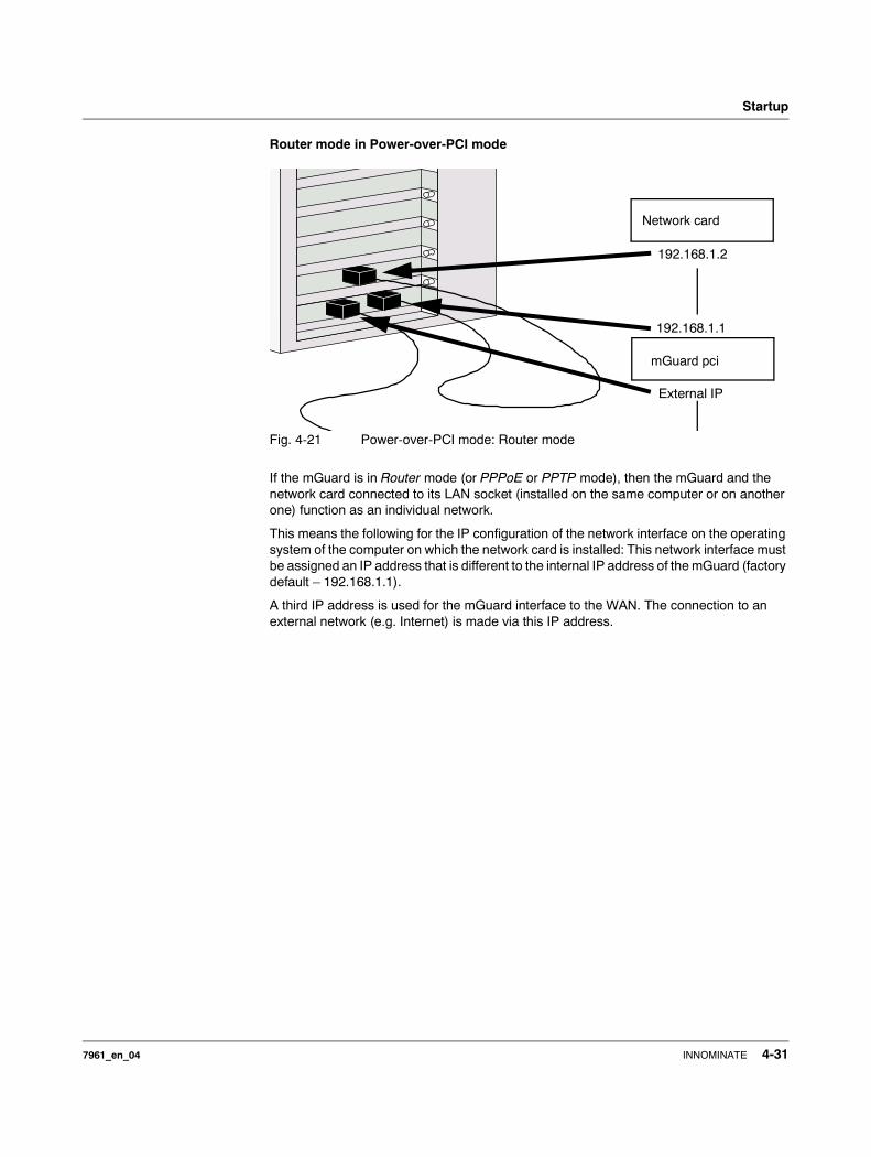
Startup
Router mode in Power-over-PCI mode
Fig. 4-21 Power-over-PCI mode: Router mode
If the mGuard is in Router mode (or PPPoE or PPTP mode), then the mGuard and the network card connected to its LAN socket (installed on the same computer or on another one) function as an individual network.
This means the following for the IP configuration of the network interface on the operating system of the computer on which the network card is installed: This network interface must be assigned an IP address that is different to the internal IP address of the mGuard (factory default – 192.168.1.1).
A third IP address is used for the mGuard interface to the WAN. The connection to an external network (e.g. Internet) is made via this IP address.
192.168.1.2
192.168.1.1
External IP
mGuard pci
Network card
7961_en_04 INNOMINATE 4-31
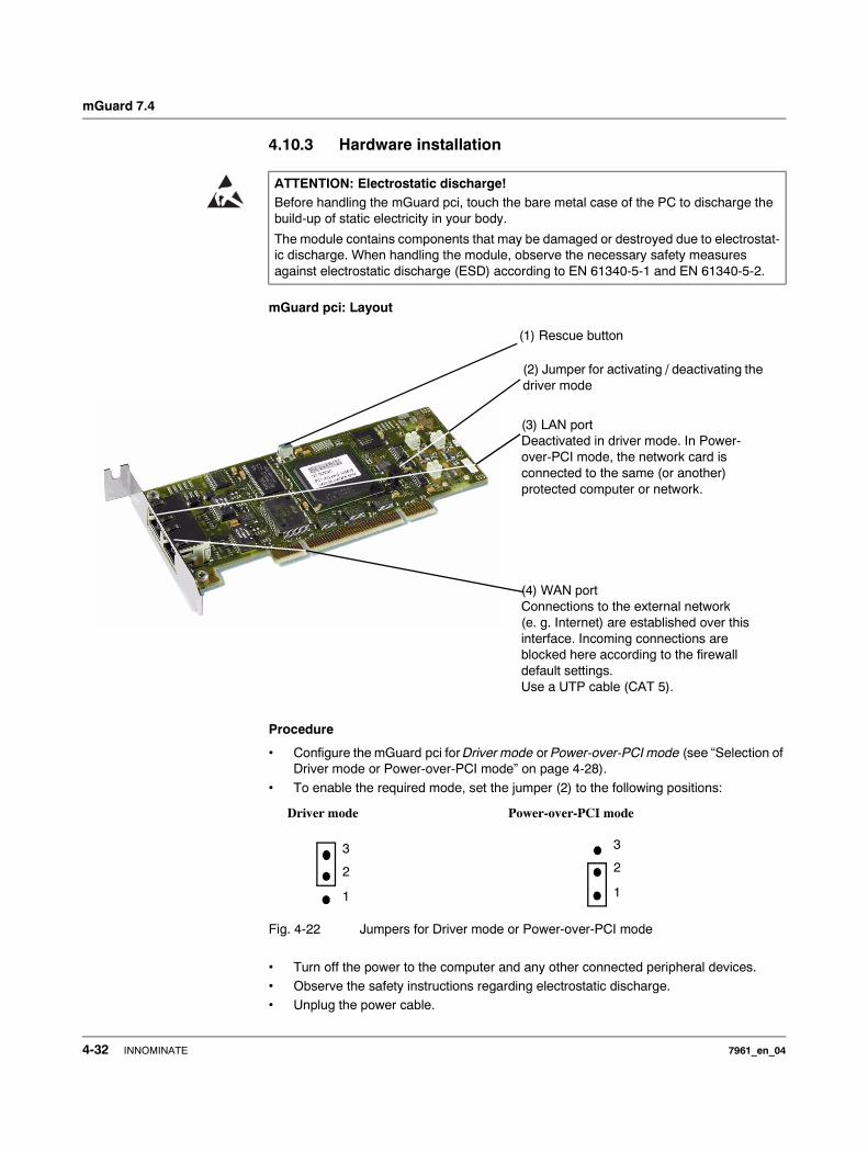
mGuard 7.4
4.10.3 Hardware installation
mGuard pci: Layout
Procedure
• Configure the mGuard pci for Driver mode or Power-over-PCI mode (see “Selection of Driver mode or Power-over-PCI mode” on page 4-28).
• To enable the required mode, set the jumper (2) to the following positions:
Fig. 4-22 Jumpers for Driver mode or Power-over-PCI mode
• Turn off the power to the computer and any other connected peripheral devices. • Observe the safety instructions regarding electrostatic discharge.• Unplug the power cable.
ATTENTION: Electrostatic discharge!Before handling the mGuard pci, touch the bare metal case of the PC to discharge the build-up of static electricity in your body.
The module contains components that may be damaged or destroyed due to electrostat-ic discharge. When handling the module, observe the necessary safety measures against electrostatic discharge (ESD) according to EN 61340-5-1 and EN 61340-5-2.
(1) Rescue button
(4) WAN portConnections to the external network (e. g. Internet) are established over this interface. Incoming connections are blocked here according to the firewall default settings.Use a UTP cable (CAT 5).
(3) LAN portDeactivated in driver mode. In Power-over-PCI mode, the network card is connected to the same (or another) protected computer or network.
(2) Jumper for activating / deactivating the driver mode
1
2
3
1
2
3
Driver mode Power-over-PCI mode
4-32 INNOMINATE 7961_en_04

Startup
• Open the computer cover (please consult your computer manual).
• Select a free PCI slot (3.3 V or 5 V) for the mGuard pci.• Remove the relevant slot plate by loosening the holding screw and pulling it out.
Keep this screw safe for securing the mGuard pci card after installation.
• Carefully align the connection plug board of the mGuard pci card with the selected PCI slot on the motherboard, then push the card down evenly.
• Tighten the card slot plate.• Close the computer cover.• Reconnect the power cable and turn on the computer.
4.10.4 Driver installation
Installation of the driver is only necessary when the mGuard pci is operating in Driver mode (see “Driver mode” on page 4-28).
Requirements • Please first complete the steps described under “Hardware installation” on page 4-32, if not done so already.
• You have the driver files on a data carrier.
If this is not the case: • Download the driver files from the corresponding download area under
www.innominate.com.• Unpack the ZIP archive. • Copy the unpacked files onto a data carrier (e.g. CD, USB memory stick).
7961_en_04 INNOMINATE 4-33
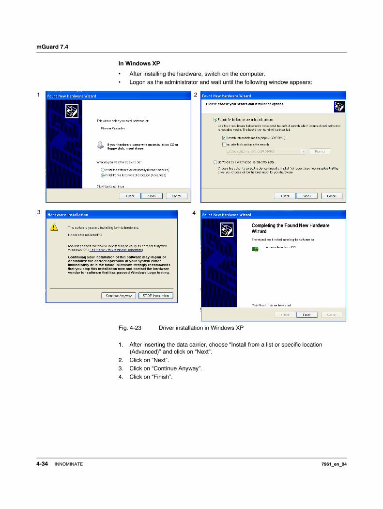
mGuard 7.4
In Windows XP
• After installing the hardware, switch on the computer. • Logon as the administrator and wait until the following window appears:
Fig. 4-23 Driver installation in Windows XP
1. After inserting the data carrier, choose “Install from a list or specific location (Advanced)” and click on “Next”.
2. Click on “Next”.3. Click on “Continue Anyway”.
4. Click on “Finish”.
1
3 4
2
4-34 INNOMINATE 7961_en_04

Startup
In Windows 2000
• After installing the hardware, switch on the computer. • Logon as the administrator and wait until the following window appears:
Fig. 4-24 Driver installation in Windows 2000 (1)
1. Click on “Next”.2. Select “Search for a suitable driver for my device (recommended)” and click on “Next”.3. Select “Specify a location” and click on “Next”.
4. Click on “Next”.
1 2
43
7961_en_04 INNOMINATE 4-35
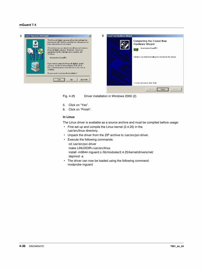
mGuard 7.4
Fig. 4-25 Driver installation in Windows 2000 (2)
5. Click on “Yes”.6. Click on “Finish”.
In Linux
The Linux driver is available as a source archive and must be compiled before usage:• First set up and compile the Linux kernel (2.4.25) in the
/usr/src/linux directory.• Unpack the driver from the ZIP archive to /usr/src/pci-driver.
• Execute the following commands:cd /usr/src/pci-drivermake LINUXDIR=/usr/src/linuxinstall -m0644 mguard.o /lib/modules/2.4.25/kernel/drivers/net/depmod -a
• The driver can now be loaded using the following command:modprobe mguard
65
4-36 INNOMINATE 7961_en_04
Preparing the Configuration
5 Preparing the Configuration
5.1 Connection requirements
mGuard centerport
– When using the mGuard centerport, both power supply units must be connected to the mains power or the power source. If only one power supply unit is connected, then the device can be operated. However, an acoustic signal is also emitted.
– For local configuration: The computer used for configuration must be connected to the LAN socket of the mGuard.
– For remote configuration: The mGuard must be configured to permit remote configuration.
– The mGuard must be connected (i.e. the required connections must be working).
mGuard industrial rs
– The mGuard industrial rs must be connected to at least one active power supply unit.– For local configuration: The computer used for configuration must be connected to
the LAN socket of the mGuard.– For remote configuration: The mGuard must be configured to permit remote
configuration.– The mGuard must be connected (i.e. the required connections must be working).
mGuard smart²
– The mGuard smart² must be switched on (i.e. connected to an active system or power supply unit via the USB cable) in order for it to be supplied with power.
– For local configuration: The computer used for configuration must either be – connected to the LAN port of the mGuard – or connected to the mGuard via the local network.
– For remote configuration: The mGuard must be configured to permit remote configuration.
– The mGuard must be connected (i.e. the required connections must be working).
mGuard pci
– For local configuration: The computer used for configuration must fulfill the following requirements:– mGuard in Driver mode: The mGuard pci driver must be installed on
the computer.– mGuard in Power-over-PCI mode: The computer must be connected to the
mGuard LAN port or connected to the mGuard over the local network.
– For remote configuration: The mGuard must be configured to permit remote configuration.
– The mGuard must be connected (i.e. the required connections must be working).
7961_en_04 INNOMINATE 5-1
mGuard 7.4
mGuard blade
– The mGuard blade must be installed inside the mGuard bladebase, and at least one of the bladebase power supply units must be on.
– For local configuration: The computer used for configuration must either be – connected to the LAN socket of the mGuard– or connected to the mGuard via the local network.
– For remote configuration: The mGuard must be configured to permit remote configuration.
– The mGuard must be connected (i.e. the required connections must be working).
EAGLE mGuard
– The EAGLE mGuard must be connected to at least one active power supply unit.– For local configuration: The computer used for configuration must either be
– connected to the LAN socket of the mGuard– or connected to the mGuard via the local network.
– For remote configuration: The mGuard must be configured to permit remote configuration.
– The mGuard must be connected (i.e. the required connections must be working).
mGuard delta
– The mGuard delta must be connected to its power supply.
– For local configuration: The computer used for configuration must either be – connected to the mGuard LAN switch (Ethernet socket 4 to 7) – or connected to the mGuard via the local network.
– For remote configuration: The mGuard must be configured to permit remote configuration.
– The mGuard must be connected (i.e. the required connections must be working).
mGuard rs4000/rs2000
– The mGuard rs4000/rs2000 must be connected to at least one active power supply unit.
– For local configuration: The computer used for the configuration must be connected to the LAN socket of the mGuard.
– For remote configuration: The mGuard must be configured to permit remote configuration.
– The mGuard must be connected (i.e. the required connections must be working).
5-2 INNOMINATE 7961_en_04
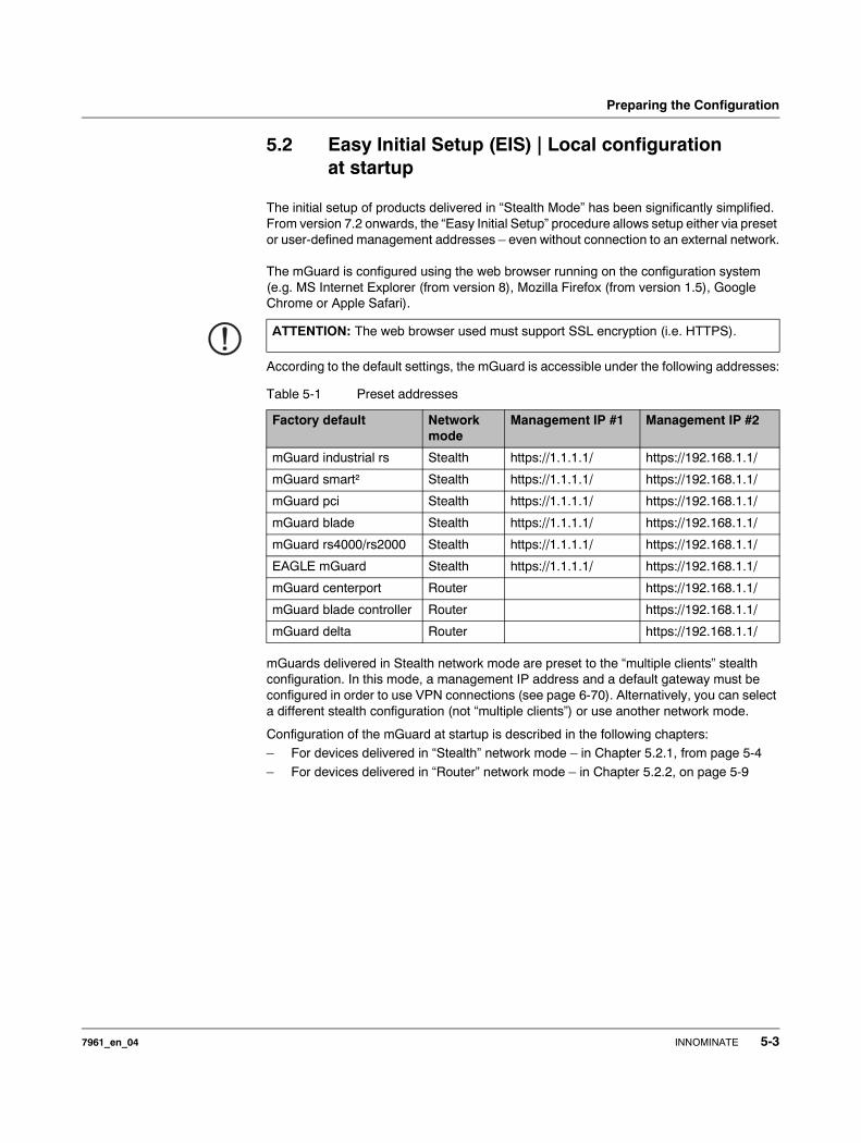
Preparing the Configuration
5.2 Easy Initial Setup (EIS) | Local configuration at startup
The initial setup of products delivered in “Stealth Mode” has been significantly simplified. From version 7.2 onwards, the “Easy Initial Setup” procedure allows setup either via preset or user-defined management addresses – even without connection to an external network.
The mGuard is configured using the web browser running on the configuration system (e.g. MS Internet Explorer (from version 8), Mozilla Firefox (from version 1.5), Google Chrome or Apple Safari).
According to the default settings, the mGuard is accessible under the following addresses:
mGuards delivered in Stealth network mode are preset to the “multiple clients” stealth configuration. In this mode, a management IP address and a default gateway must be configured in order to use VPN connections (see page 6-70). Alternatively, you can select a different stealth configuration (not “multiple clients”) or use another network mode.
Configuration of the mGuard at startup is described in the following chapters:– For devices delivered in “Stealth” network mode – in Chapter 5.2.1, from page 5-4
– For devices delivered in “Router” network mode – in Chapter 5.2.2, on page 5-9
ATTENTION: The web browser used must support SSL encryption (i.e. HTTPS).
Table 5-1 Preset addresses
Factory default Network mode
Management IP #1 Management IP #2
mGuard industrial rs Stealth https://1.1.1.1/ https://192.168.1.1/
mGuard smart² Stealth https://1.1.1.1/ https://192.168.1.1/
mGuard pci Stealth https://1.1.1.1/ https://192.168.1.1/
mGuard blade Stealth https://1.1.1.1/ https://192.168.1.1/
mGuard rs4000/rs2000 Stealth https://1.1.1.1/ https://192.168.1.1/
EAGLE mGuard Stealth https://1.1.1.1/ https://192.168.1.1/
mGuard centerport Router https://192.168.1.1/
mGuard blade controller Router https://192.168.1.1/
mGuard delta Router https://192.168.1.1/
7961_en_04 INNOMINATE 5-3
mGuard 7.4
5.2.1 Configuring the mGuard at startup (default: Stealth mode)
During the initial startup of devices delivered in Stealth mode, the mGuard is accessible under the following two addresses:– https://192.168.1.1/ (see page 5-4)
– https://1.1.1.1/ (see page 5-5)
Alternatively, an IP address can be assigned via BootP (for example, with IPAssign.exe – see “Assigning IP addresses via BootP” on page 5-6).
The mGuard is accessed under https://192.168.1.1/ when the external network interface is not connected on startup.
The mGuard can be accessed by computers under https://1.1.1.1/ when these computers are connected directly or indirectly to the LAN port of the mGuard. To do this, the mGuard with LAN and WAN ports must be integrated into a functional network where the default gateway is accessible via the WAN port.
For initial configuration of the mGuard pci, see “Configuring the mGuard pci at startup” on page 5-10.
5.2.1.1 IP address 192.168.1.1
You may need to adjust the network configuration of your computer to access the configuration interface.
If you are using Windows XP: • Click on “Start, Control Panel, Network Connections”.
• Right-click on the icon of the LAN adapter so that the pop-up menu appears. • Click on “Properties”.• Select the “General” tab page in the “Properties of local network LAN
connections” dialog.• Select “Internet Protocol (TCP/IP)” under “This connection uses the following items”.
– After access has been made under the address 192.168.1.1 and the login was successful, 192.168.1.1 is set permanently as the management IP address.
– 192.168.1.1 is no longer available as an access option after access has been made under the address 1.1.1.1 or following the assignment of an IP address via BootP.
On devices delivered in Stealth mode, the mGuard can be accessed via the LAN interface under the address 192.168.1.1 within network 192.168.1.0/24 if one of the following circumstances applies.– The mGuard is set to the factory defaults (as delivered).– The mGuard has been reset to the default settings through the web interface (see
“Configuration Profiles” on page 6-39) and restarted.– The rescue procedure (flashing the mGuard) or recovery procedure has been
carried out (see Chapter 8).
5-4 INNOMINATE 7961_en_04
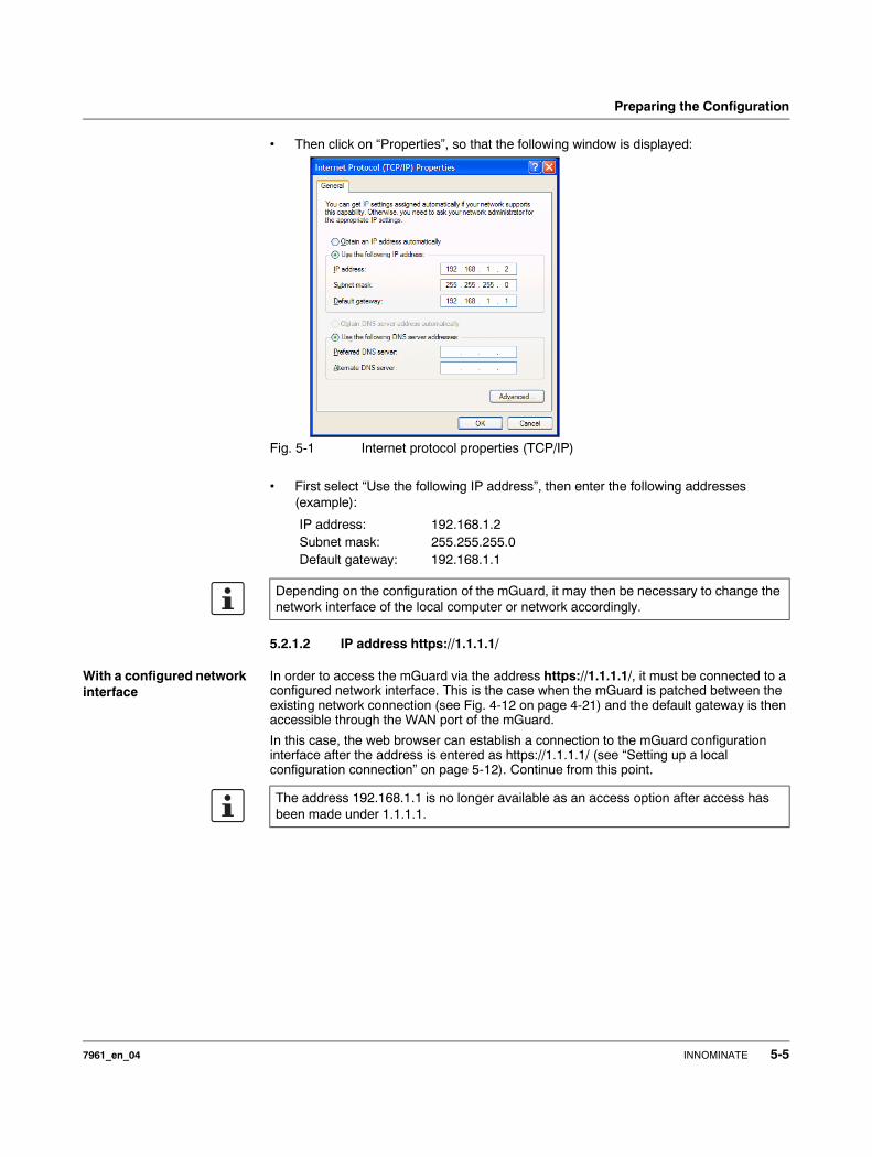
Preparing the Configuration
• Then click on “Properties”, so that the following window is displayed:
Fig. 5-1 Internet protocol properties (TCP/IP)
• First select “Use the following IP address”, then enter the following addresses (example):
5.2.1.2 IP address https://1.1.1.1/
With a configured network interface
In order to access the mGuard via the address https://1.1.1.1/, it must be connected to a configured network interface. This is the case when the mGuard is patched between the existing network connection (see Fig. 4-12 on page 4-21) and the default gateway is then accessible through the WAN port of the mGuard.
In this case, the web browser can establish a connection to the mGuard configuration interface after the address is entered as https://1.1.1.1/ (see “Setting up a local configuration connection” on page 5-12). Continue from this point.
IP address: 192.168.1.2Subnet mask: 255.255.255.0Default gateway: 192.168.1.1
Depending on the configuration of the mGuard, it may then be necessary to change the network interface of the local computer or network accordingly.
The address 192.168.1.1 is no longer available as an access option after access has been made under 1.1.1.1.
7961_en_04 INNOMINATE 5-5

mGuard 7.4
5.2.1.3 Assigning IP addresses via BootP
The mGuard uses the BootP protocol for assigning the IP address. You can also assign the IP address via BootP. A wide range of BootP servers are available on the Internet. Any of these programs can be used to assign the IP address. However, the functional compatibilities are not tested by Innominate.
This chapter describes IP address assignment using the supported Windows software “IP Assignment Tool” (IPAssign.exe). This software is available to download free-of-charge under www.phoenixcontact.net/catalog, or under www.innominate.com (“Downloads > Software”).
Information on BootP
During the initial startup, the mGuard sends uninterrupted BootP requests until a valid IP address is received. No further BootP requests are sent after the mGuard has received a correct IP address. From this point onwards, the address 192.168.1.1 is no longer available as an access option.
The mGuard does not send BootP requests after it has received a BootP answer. This also applies after restarting. In order for the mGuard to send BootP requests again, the default settings must be restored or one of the two procedures (recovery or flash) must be carried out.
Requirements
The mGuard is connected to a computer which uses Microsoft Windows.
Assigning the IP address using IPAssign.exe
Step 1: Downloading and running the program
• Go to www.innominate.com/downloads.
• The Innominate BootP IP assignment tool is found under “Software & Misc”.• Double-click on “IPAssign_mGuard.exe”.• Select “Run” in the window which opens.
The “IPAssign.exe” tool is also available from Phoenix Contact:• Go to www.phoenixcontact.net/catalog.• Enter the item number (e.g. 2832700) in the search bar.
The BootP tool is found under “Configuration file”.• Double-click on “IPAssign.exe”.• Select “Run” in the window which opens.
Step 2: “IP Assignment Wizard”
The program is opened and the start screen of the IP assignment tool appears.
The program mostly uses English as standard. The program buttons are changed according to the local country settings.
The IP address of the PC is shown on the start screen. This helps when assigning the mGuard IP address on subsequent screens. • Click on “Next”.
The address 192.168.1.1 is no longer available as an access option following the assignment of an IP address via BootP.
5-6 INNOMINATE 7961_en_04
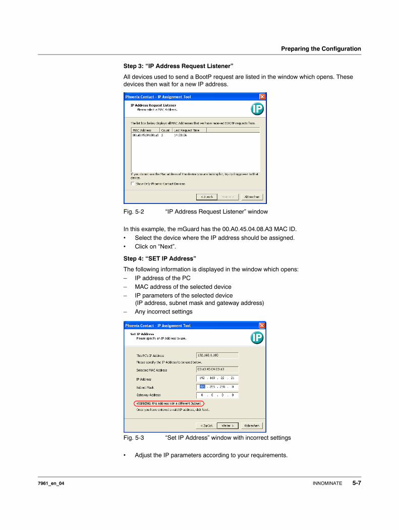
Preparing the Configuration
Step 3: “IP Address Request Listener”
All devices used to send a BootP request are listed in the window which opens. These devices then wait for a new IP address.
Fig. 5-2 “IP Address Request Listener” window
In this example, the mGuard has the 00.A0.45.04.08.A3 MAC ID.
• Select the device where the IP address should be assigned.• Click on “Next”.
Step 4: “SET IP Address”
The following information is displayed in the window which opens:
– IP address of the PC– MAC address of the selected device– IP parameters of the selected device
(IP address, subnet mask and gateway address)– Any incorrect settings
Fig. 5-3 “Set IP Address” window with incorrect settings
• Adjust the IP parameters according to your requirements.
7961_en_04 INNOMINATE 5-7
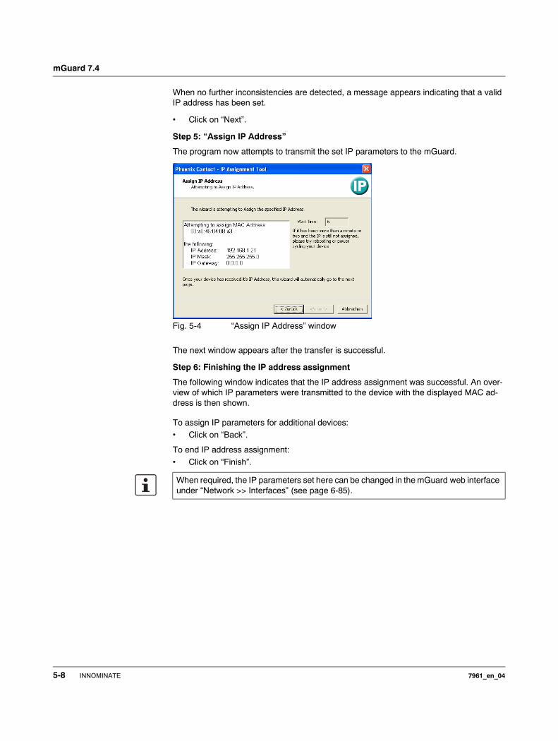
mGuard 7.4
When no further inconsistencies are detected, a message appears indicating that a valid IP address has been set.
• Click on “Next”.
Step 5: “Assign IP Address”
The program now attempts to transmit the set IP parameters to the mGuard.
Fig. 5-4 “Assign IP Address” window
The next window appears after the transfer is successful.
Step 6: Finishing the IP address assignment
The following window indicates that the IP address assignment was successful. An over-view of which IP parameters were transmitted to the device with the displayed MAC ad-dress is then shown.
To assign IP parameters for additional devices:• Click on “Back”.
To end IP address assignment:
• Click on “Finish”.
When required, the IP parameters set here can be changed in the mGuard web interface under “Network >> Interfaces” (see page 6-85).
5-8 INNOMINATE 7961_en_04
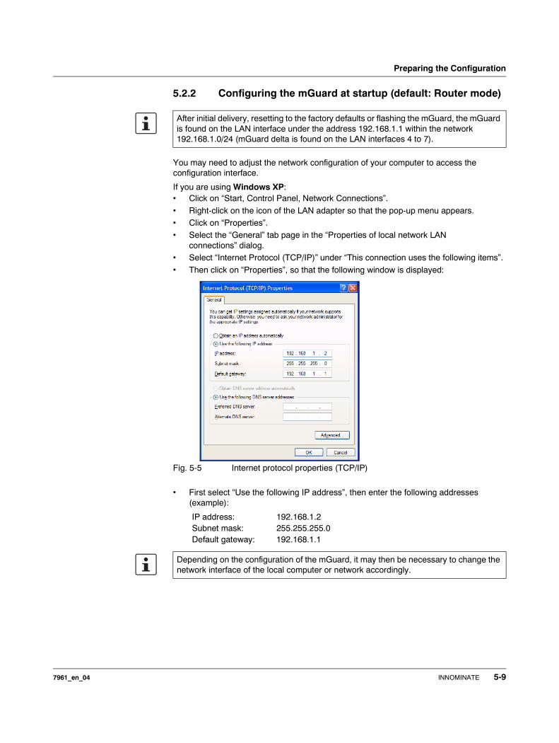
Preparing the Configuration
5.2.2 Configuring the mGuard at startup (default: Router mode)
You may need to adjust the network configuration of your computer to access the configuration interface.
If you are using Windows XP: • Click on “Start, Control Panel, Network Connections”.
• Right-click on the icon of the LAN adapter so that the pop-up menu appears. • Click on “Properties”.• Select the “General” tab page in the “Properties of local network LAN
connections” dialog.• Select “Internet Protocol (TCP/IP)” under “This connection uses the following items”.
• Then click on “Properties”, so that the following window is displayed:
Fig. 5-5 Internet protocol properties (TCP/IP)
• First select “Use the following IP address”, then enter the following addresses (example):
After initial delivery, resetting to the factory defaults or flashing the mGuard, the mGuard is found on the LAN interface under the address 192.168.1.1 within the network 192.168.1.0/24 (mGuard delta is found on the LAN interfaces 4 to 7).
IP address: 192.168.1.2Subnet mask: 255.255.255.0Default gateway: 192.168.1.1
Depending on the configuration of the mGuard, it may then be necessary to change the network interface of the local computer or network accordingly.
7961_en_04 INNOMINATE 5-9
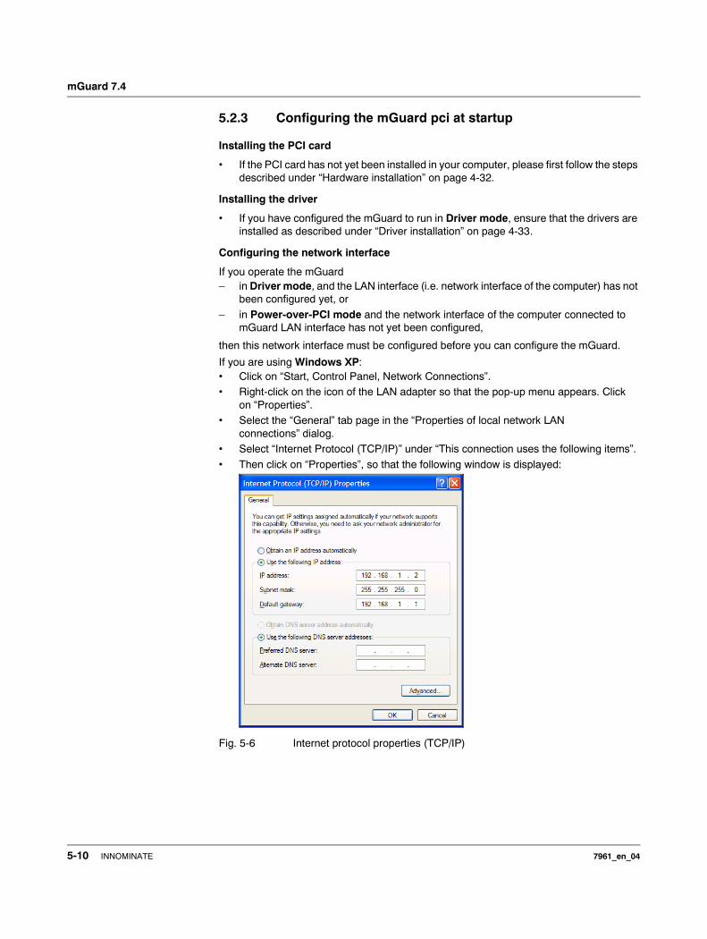
mGuard 7.4
5.2.3 Configuring the mGuard pci at startup
Installing the PCI card
• If the PCI card has not yet been installed in your computer, please first follow the steps described under “Hardware installation” on page 4-32.
Installing the driver
• If you have configured the mGuard to run in Driver mode, ensure that the drivers are installed as described under “Driver installation” on page 4-33.
Configuring the network interface
If you operate the mGuard– in Driver mode, and the LAN interface (i.e. network interface of the computer) has not
been configured yet, or
– in Power-over-PCI mode and the network interface of the computer connected to mGuard LAN interface has not yet been configured,
then this network interface must be configured before you can configure the mGuard.
If you are using Windows XP: • Click on “Start, Control Panel, Network Connections”.• Right-click on the icon of the LAN adapter so that the pop-up menu appears. Click
on “Properties”.• Select the “General” tab page in the “Properties of local network LAN
connections” dialog.• Select “Internet Protocol (TCP/IP)” under “This connection uses the following items”.
• Then click on “Properties”, so that the following window is displayed:
Fig. 5-6 Internet protocol properties (TCP/IP)
5-10 INNOMINATE 7961_en_04
Preparing the Configuration
Default gateway
After you have configured the network interface, you can access the mGuard configuration interface using a web browser under the URL https://1.1.1.1/.
If this is not possible, then the default gateway of the computer may not be available. In this case you must simulate the process as follows:
Initializing the default gateway
Determine the currently valid default gateway address. • If you are using Windows XP, follow the steps described above (under “Configuring
the network interface” on page 5-10) to open the “Internet Protocol (TCP/IP) Properties” dialog.
• If no IP address has been entered as the default gateway in this dialog (e.g. because the “Obtain an IP address automatically” function has been activated), then enter the IP address manually.
To do so, first select “Use the following IP address”, then enter the following addresses (example):
• On the DOS level (Start, Programs, Accessories, Command Prompt), enter the following:arp -s <IP of the default gateway> 00-aa-aa-aa-aa-aaExample:You have determined or set the address of the default gateway as: 192.168.1.1The command should then be: arp -s 192.168.1.1 00-aa-aa-aa-aa-aa
• To proceed with the configuration, establish the necessary configuration connection (see “Setting up a local configuration connection” on page 5-12).
• After setting the configuration, restore the original setting for the default gateway. To do this, either restart the configuration computer or enter the following command on the DOS level:arp -d
Depending on the configuration of the mGuard, it may then be necessary to change the network interface of the local computer or network accordingly.
IP address: 192.168.1.2 Do not under any circumstances assign an address such as 1.1.1.2 to the configuration system!
Subnet mask: 255.255.255.0Default gateway: 192.168.1.1
7961_en_04 INNOMINATE 5-11
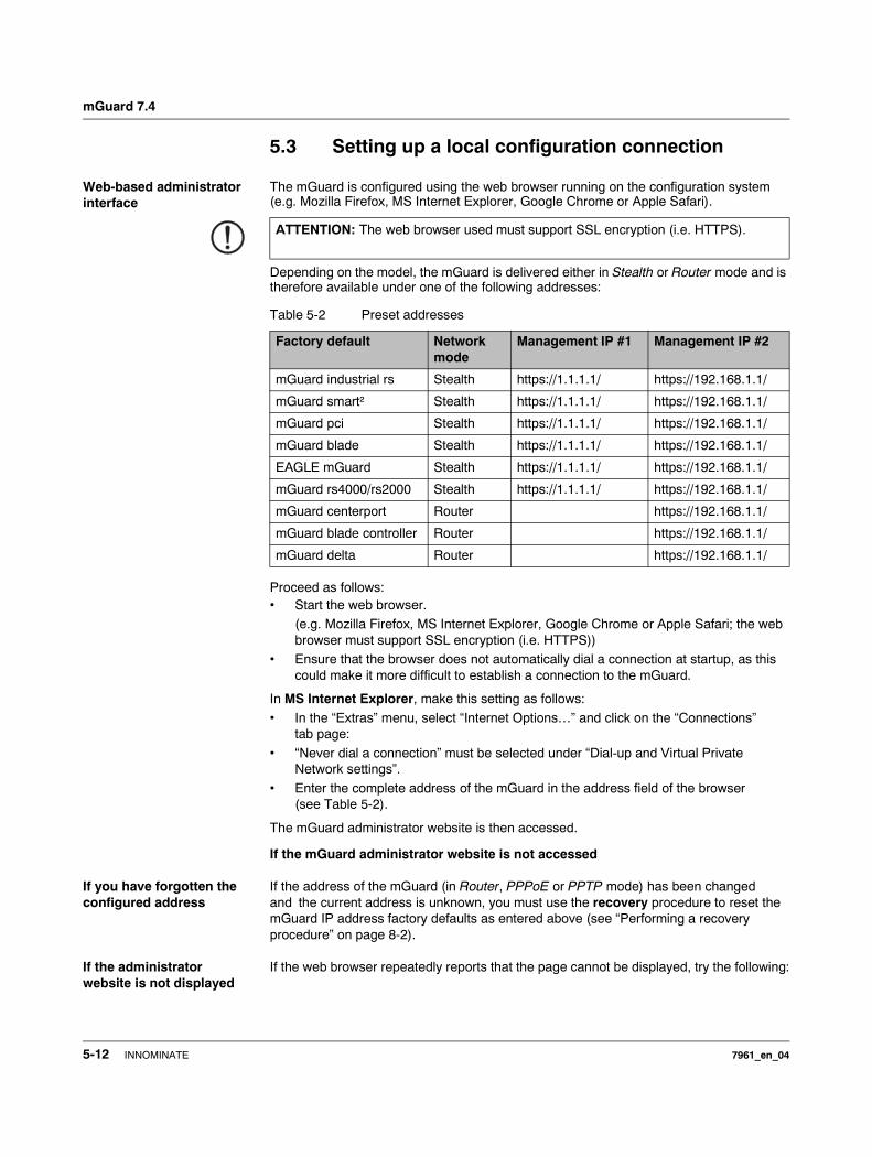
mGuard 7.4
5.3 Setting up a local configuration connection
Web-based administrator interface
The mGuard is configured using the web browser running on the configuration system (e.g. Mozilla Firefox, MS Internet Explorer, Google Chrome or Apple Safari).
Depending on the model, the mGuard is delivered either in Stealth or Router mode and is therefore available under one of the following addresses:
Proceed as follows:• Start the web browser.
(e.g. Mozilla Firefox, MS Internet Explorer, Google Chrome or Apple Safari; the web browser must support SSL encryption (i.e. HTTPS))
• Ensure that the browser does not automatically dial a connection at startup, as this could make it more difficult to establish a connection to the mGuard.
In MS Internet Explorer, make this setting as follows:
• In the “Extras” menu, select “Internet Options…” and click on the “Connections” tab page:
• “Never dial a connection” must be selected under “Dial-up and Virtual Private Network settings”.
• Enter the complete address of the mGuard in the address field of the browser (see Table 5-2).
The mGuard administrator website is then accessed.
If the mGuard administrator website is not accessed
If you have forgotten the configured address
If the address of the mGuard (in Router, PPPoE or PPTP mode) has been changed and the current address is unknown, you must use the recovery procedure to reset the mGuard IP address factory defaults as entered above (see “Performing a recovery procedure” on page 8-2).
If the administrator website is not displayed
If the web browser repeatedly reports that the page cannot be displayed, try the following:
ATTENTION: The web browser used must support SSL encryption (i.e. HTTPS).
Table 5-2 Preset addresses
Factory default Network mode
Management IP #1 Management IP #2
mGuard industrial rs Stealth https://1.1.1.1/ https://192.168.1.1/
mGuard smart² Stealth https://1.1.1.1/ https://192.168.1.1/
mGuard pci Stealth https://1.1.1.1/ https://192.168.1.1/
mGuard blade Stealth https://1.1.1.1/ https://192.168.1.1/
EAGLE mGuard Stealth https://1.1.1.1/ https://192.168.1.1/
mGuard rs4000/rs2000 Stealth https://1.1.1.1/ https://192.168.1.1/
mGuard centerport Router https://192.168.1.1/
mGuard blade controller Router https://192.168.1.1/
mGuard delta Router https://192.168.1.1/
5-12 INNOMINATE 7961_en_04
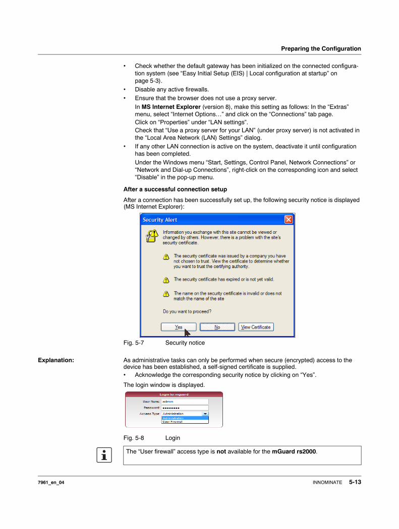
Preparing the Configuration
• Check whether the default gateway has been initialized on the connected configura-tion system (see “Easy Initial Setup (EIS) | Local configuration at startup” on page 5-3).
• Disable any active firewalls.• Ensure that the browser does not use a proxy server.
In MS Internet Explorer (version 8), make this setting as follows: In the “Extras” menu, select “Internet Options…” and click on the “Connections” tab page. Click on “Properties” under “LAN settings”.Check that “Use a proxy server for your LAN” (under proxy server) is not activated in the “Local Area Network (LAN) Settings” dialog.
• If any other LAN connection is active on the system, deactivate it until configuration has been completed. Under the Windows menu “Start, Settings, Control Panel, Network Connections” or “Network and Dial-up Connections”, right-click on the corresponding icon and select “Disable” in the pop-up menu.
After a successful connection setup
After a connection has been successfully set up, the following security notice is displayed (MS Internet Explorer):
Fig. 5-7 Security notice
Explanation: As administrative tasks can only be performed when secure (encrypted) access to the device has been established, a self-signed certificate is supplied.• Acknowledge the corresponding security notice by clicking on “Yes”.
The login window is displayed.
Fig. 5-8 Login
The “User firewall” access type is not available for the mGuard rs2000.
7961_en_04 INNOMINATE 5-13
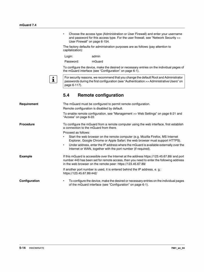
mGuard 7.4
• Choose the access type (Administration or User Firewall) and enter your username and password for this access type. For the user firewall, see “Network Security >> User Firewall” on page 6-154.
The factory defaults for administration purposes are as follows (pay attention to capitalization):
To configure the device, make the desired or necessary entries on the individual pages of the mGuard interface (see “Configuration” on page 6-1).
5.4 Remote configuration
Requirement The mGuard must be configured to permit remote configuration.Remote configuration is disabled by default.
To enable remote configuration, see “Management >> Web Settings” on page 6-21 and “Access” on page 6-22.
Procedure To configure the mGuard from a remote computer using the web interface, first establish a connection to the mGuard from there.
Proceed as follows:• Start the web browser on the remote computer (e.g. Mozilla Firefox, MS Internet
Explorer, Google Chrome or Apple Safari; the web browser must support HTTPS).• Under address, enter the IP address where the mGuard is available externally over the
Internet or WAN, together with the port number (if required).
Example If this mGuard is accessible over the Internet at the address https://123.45.67.89/ and port number 443 has been set for remote access, then you need to enter the following address in the web browser on the remote peer: https://123.45.67.89/
If another port number is used, it is entered behind the IP address, e. g.: https://123.45.67.89:442/
Configuration • To configure the device, make the desired or necessary entries on the individual pages of the mGuard interface (see “Configuration” on page 6-1).
Login: admin
Password: mGuard
For security reasons, we recommend that you change the default Root and Administrator passwords during the first configuration (see “Authentication >> Administrative Users” on page 6-117).
5-14 INNOMINATE 7961_en_04
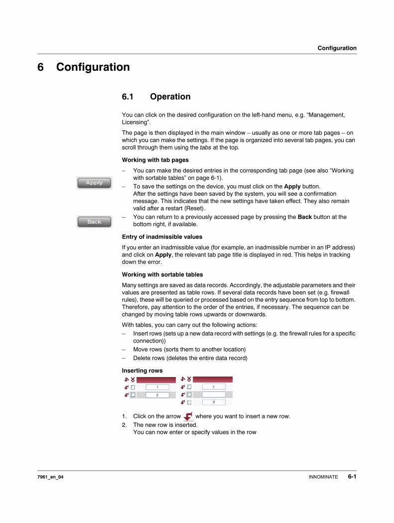
Configuration
6 Configuration
6.1 Operation
You can click on the desired configuration on the left-hand menu, e.g. “Management, Licensing”.
The page is then displayed in the main window – usually as one or more tab pages – on which you can make the settings. If the page is organized into several tab pages, you can scroll through them using the tabs at the top.
Working with tab pages
– You can make the desired entries in the corresponding tab page (see also “Working with sortable tables” on page 6-1).
– To save the settings on the device, you must click on the Apply button.After the settings have been saved by the system, you will see a confirmation message. This indicates that the new settings have taken effect. They also remain valid after a restart (Reset).
– You can return to a previously accessed page by pressing the Back button at the bottom right, if available.
Entry of inadmissible values
If you enter an inadmissible value (for example, an inadmissible number in an IP address) and click on Apply, the relevant tab page title is displayed in red. This helps in tracking down the error.
Working with sortable tables
Many settings are saved as data records. Accordingly, the adjustable parameters and their values are presented as table rows. If several data records have been set (e.g. firewall rules), these will be queried or processed based on the entry sequence from top to bottom. Therefore, pay attention to the order of the entries, if necessary. The sequence can be changed by moving table rows upwards or downwards.
With tables, you can carry out the following actions: – Insert rows (sets up a new data record with settings (e.g. the firewall rules for a specific
connection))– Move rows (sorts them to another location)
– Delete rows (deletes the entire data record)
Inserting rows
1. Click on the arrow where you want to insert a new row.
2. The new row is inserted. You can now enter or specify values in the row
7961_en_04 INNOMINATE 6-1
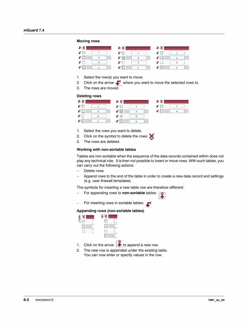
mGuard 7.4
Moving rows
1. Select the row(s) you want to move.2. Click on the arrow where you want to move the selected rows to.
3. The rows are moved.
Deleting rows
1. Select the rows you want to delete.2. Click on the symbol to delete the rows:
3. The rows are deleted.
Working with non-sortable tables
Tables are non-sortable when the sequence of the data records contained within does not play any technical role. It is then not possible to insert or move rows. With such tables, you can carry out the following actions: – Delete rows– Append rows to the end of the table in order to create a new data record and settings
(e.g. user firewall templates)
The symbols for inserting a new table row are therefore different:
– For appending rows to non-sortable tables:
– For inserting rows in sortable tables:
Appending rows (non-sortable tables)
1. Click on the arrow to append a new row.2. The new row is appended under the existing table.
You can now enter or specify values in the row.
6-2 INNOMINATE 7961_en_04
Configuration
Buttons
The following buttons are located at the top of every page:
Logout For logging out after configuration access to the mGuard.
If the user does not conduct a logout procedure, the logout is automatically made when activities have stopped and the defined time limit has expired. Renewed access is only granted after the login process has been repeated.
Reset Optional button.
Resets data to the original values. If you have entered values on a config-uration page and these have not yet been applied (Apply button), you can restore the original values on the page by clicking the Reset button.
This button can only be seen at the top of the page if the validity range of the Apply button is set to “Include all pages” (see “Management >> Web Settings” on page 6-21).
Apply Optional button.
Has the same functions as the Apply button, but is valid for all pages.
This button can only be seen at the top of the page if the validity range of the Apply button is set to “Include all pages” (see “Management >> Web Settings” on page 6-21).
7961_en_04 INNOMINATE 6-3
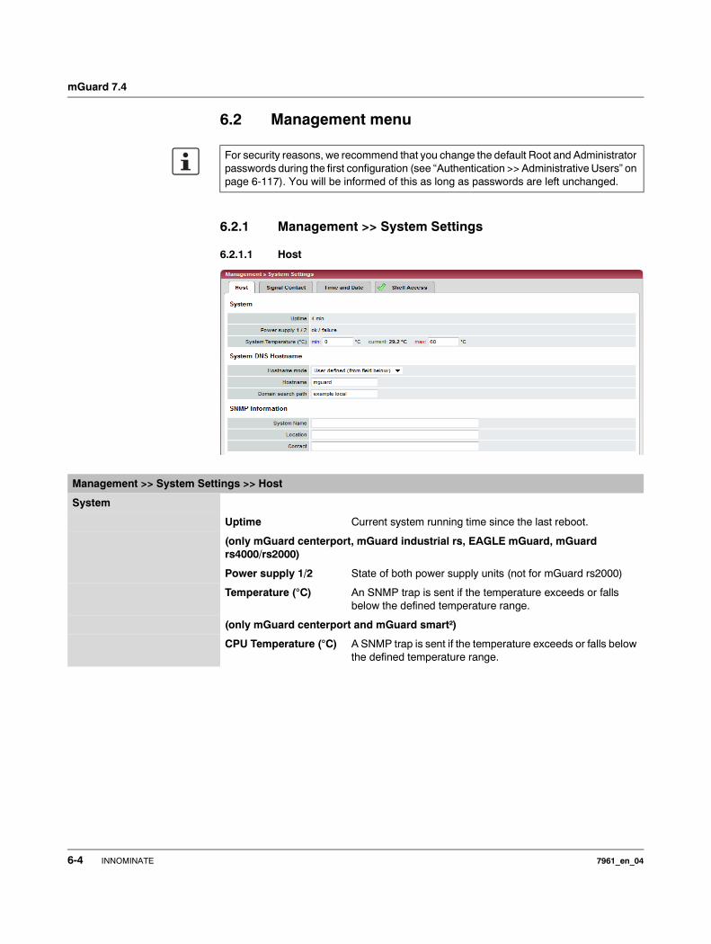
mGuard 7.4
6.2 Management menu
6.2.1 Management >> System Settings
6.2.1.1 Host
For security reasons, we recommend that you change the default Root and Administrator passwords during the first configuration (see “Authentication >> Administrative Users” on page 6-117). You will be informed of this as long as passwords are left unchanged.
Management >> System Settings >> Host
System
Uptime Current system running time since the last reboot.
(only mGuard centerport, mGuard industrial rs, EAGLE mGuard, mGuard rs4000/rs2000)
Power supply 1/2 State of both power supply units (not for mGuard rs2000)
Temperature (°C) An SNMP trap is sent if the temperature exceeds or falls below the defined temperature range.
(only mGuard centerport and mGuard smart²)
CPU Temperature (°C) A SNMP trap is sent if the temperature exceeds or falls below the defined temperature range.
6-4 INNOMINATE 7961_en_04
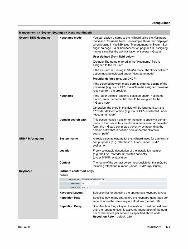
Configuration
System DNS Hostname Hostname mode You can assign a name to the mGuard using the Hostname mode and Hostname fields. For example, this is then displayed when logging in via SSH (see “Management >> System Set-tings” on page 6-4, “Shell Access” on page 6-11). Assigning names simplifies the administration of several mGuards.
User defined (from field below)
(Default) The name entered in the “Hostname” field is assigned to the mGuard.
If the mGuard is running in Stealth mode, the “User defined” option must be selected under “Hostname mode”.
Provider defined (e.g. via DHCP)
If the selected network mode permits external setting of the hostname (e.g. via DHCP), the mGuard is assigned the name received from the provider.
Hostname If the “User defined” option is selected under “Hostname mode”, enter the name that should be assigned to the mGuard here.
Otherwise, the entry in this field will be ignored (i.e. if the “Provider defined” option (e.g. via DHCP) is selected under “Hostname mode”).
Domain search path This option makes it easier for the user to specify a domain name. If the user enters the domain name in an abbreviated form, the mGuard completes the entry by appending the domain suffix that is defined here under the “Domain search path”.
SNMP Information System name A freely selectable name for the mGuard, used for administra-tion purposes (e. g. “Hermes”, “Pluto”) (under SNMP: sysName).
Location Freely selectable description of the installation location (e.g. “hall IV”, “corridor 3”, “switch cabinet”) (under SNMP: sysLocation).
Contact The name of the contact person responsible for this mGuard, including telephone number (under SNMP: sysContact).
Keyboard (mGuard centerport only)
Keyboard Layout Selection list for choosing the appropriate keyboard layout.
Repetition Rate Specifies how many characters the keyboard generates per second when the same key is held down (default: 30).
Repetition Delay Specifies how long a key on the keyboard must be held down until the repeat function is activated (generation of the num-ber of characters per second as specified above under Repetition Rate – default: 250).
Management >> System Settings >> Host (continued)
7961_en_04 INNOMINATE 6-5

mGuard 7.4
6.2.1.2 Signal Contact
The signal contact is a relay which is used by the mGuard to signal error conditions (see also “Signal contact” on page 4-17 and “Signal contact” on page 4-25).
HiDiscovery HiDiscovery is a protocol which supports the initial startup of new network devices and is available in Stealth mode on the local interface (LAN) of the mGuard.
Local HiDiscovery Support
Enabled
HiDiscovery protocol is activated.
Read only
HiDiscovery protocol is activated, but the mGuard cannot be configured using it.
Disabled
HiDiscovery protocol is deactivated.
HiDiscovery Frame Forwarding Yes / No
If this option is set to Yes, then HiDiscovery frames are forwarded from the internal (LAN) port externally over the WAN port.
Management >> System Settings >> Host (continued)
Management >> System Settings >> Signal Contact
Mode (only mGuard industrial rs, EAGLE mGuard)
Signal contact The signal contact can be controlled automatically by the mGuard using Operation supervision (default) or Manual settings.
See also:“Installing the mGuard rs4000/rs2000” on page 4-4“Installing the mGuard industrial rs” on page 4-13 and “Installing the EAGLE mGuard” on page 4-24.
Operation supervision Contact Displays the state of the signal contact. Either Open (Error) or Closed (OK).
Redundant power supply
If set to Ignore, the power supply does not influence the signal contact.If set to Supervise, the signal contact is opened if one of the two power supplies fails.
6-6 INNOMINATE 7961_en_04

Configuration
6.2.1.3 Time and Date
Set the time and date correctly, as certain time-dependent activities otherwise cannot be started by the mGuard (see “Time-dependent activities” on page 6-8).
Link supervision Supervision of the Ethernet interface link state. Possible settings are: – Ignore
– Supervise internal only (trusted)– Supervise external only (untrusted)– Supervise both
Manual settings Contact If the Signal contact is set to Manual setting above, this option sets the contact to Closed or Open (Alarm).
Management >> System Settings >> Signal Contact (continued)
Management >> System Settings >> Time and Date
Time and Date Current system time (UTC)
Displays the current system time in Universal Time Coordi-nates (UTC). If NTP time synchronization is not yet acti-vated (see below) and Time-stamp in filesystem is deacti-vated, the clock will start at January 1st 2000.
Current system time (local)
Display: If the (sometimes different) current local time should be displayed, you must make the corresponding entry under Timezone in POSIX.1 notation… (see below).
System time state Display: Displays whether the system time and run time of the mGuard have ever actually been synchronized with a valid time. If the system time of the mGuard has not been syn-chronized, then the mGuard does not perform any time-con-trolled activities. These are as follows:
7961_en_04 INNOMINATE 6-7
mGuard 7.4
Time-dependent activities
– Time-controlled pick-up of configuration from a configuration server:This is the case when the Time Schedule setting is selected under the Management >> Central Management, Configuration Pull menu for the Pull Schedule setting (see “Management >> Configuration Profiles” on page 6-39, “Configuration Pull” on page 6-53).
– Interruption of the connection at a certain time using the PPPoE network mode:This is the case when the Network Mode is set to PPPoE under the Network >> Interfaces, General menu, and the Automatic Reconnect is set to Yes (see 6.4.1 “Network >> Interfaces”, “Network Mode = Router, Router Mode = PPPoE” on page 6-82).
– Acceptance of certificates when the system time has not yet been synchronized:This is the case when the Wait for synchronization of the system time setting is selected under the Authentication >> RADIUS Servers, Certificate settings menu for the Check the validity period of certificates and CRLs option (see Chapter 6.5.4 and “Certificate settings” on page 6-129).
– CIFS Integrity CheckingThe regular, automatic check of the network drives is only started when the mGuard has a valid date and time (see the following section).
The system time can be set or synchronized by various events:– The mGuard possesses an installed clock which is synchronized with the current
time at least once. The mGuard only has a clock when the Hardware clock state option is visible. The display shows whether the clock is synchronized. A synchro-nized, installed clock ensures that the mGuard has a synchronized system time, even after rebooting.
– The administrator has defined the current time for the mGuard run time by making a relevant entry under Local system time.
– The administrator has set the Time-stamp in filesystem to Yes, and has either transmitted the current system time to the mGuard by NTP (see below under NTP Server) or has entered it under Local system time. The system time of the mGuard is then synchronized using the time stamp after rebooting (even if it has no installed clock and is set exactly again afterwards using NTP).
– The administrator has activated NTP time synchronization under NTP Server, has entered the address of at least one NTP server, and the mGuard has opened connections with at least one of the defined NTP servers. If the network is working correctly then this occurs seconds after rebooting. The display in the NTP State field may only change to “synchronized” much later (see the explanation below under NTP State).
Management >> System Settings >> Time and Date (continued)
6-8 INNOMINATE 7961_en_04
Configuration
Hardware clock state (On mGuard industrial rs, mGuard delta and mGuard smart², but not on mGuard smart)
The state of the installed clock is only visible when the mGuard possesses a clock that also runs when the system is turned off or has no power supply. The display shows if the clock has been synchronized with the current time. The in-stalled clock is only synchronized when the system time of the mGuard is synchronized. Once the clock has been synchro-nized, its state only returns to “not synchronized” if the firm-ware is reinstalled on the device (see Chapter 8.3, “Flashing the firmware / rescue procedure”) or if the condenser (mGuard industrial rs) or the battery (mGuard delta) did not supply the installed clock with sufficient voltage for a period with the device switched off.
Local system time Here you can set the mGuard time if no NTP server has been specified (see below) or the NTP server is not available.
The date and time are specified in the format YYYY.MM.DD-hh:mm:ss:
Timezone in POSIX.1 notation…
If the Current system time above should display a current local time that is different to Greenwich Mean Time, then you must enter the number of hours that your local time is in front of or behind Greenwich Mean Time.
Examples: In Germany, the time is one hour after GMT. Therefore, enter: CET-1.
In New York the time is five hours behind Greenwich Mean Time. Therefore, enter: CET+5.
The only important thing is the -1, -2 or +1 value as only these are evaluated – not the preceding letters. They can be substi-tuted with “CET” or any other designation, such as “UTC”.
If you wish to display Central European Time (e.g. for Germany) and have it automatically switch to/from daylight saving time, enter: CET-1CEST,M3.5.0,M10.5.0/3
Timestamp in filesystem (2h granularity): Yes / No
If this option is set to Yes, the mGuard will save the current system time in its memory every two hours.
If the mGuard is switched off and then back on, a time from this two-hour time period is displayed, not a time on January 1, 2000.
Management >> System Settings >> Time and Date (continued)
YYYY Year
MM Month
DD Day
hh Hour
mm Minute
ss Second
7961_en_04 INNOMINATE 6-9
mGuard 7.4
NTP Server (NTP – Network Time Protocol) The mGuard can function as an NTP server for comput-ers connected at its LAN port. In this case, the computers are configured so that the local address of the mGuard is entered as the address of the NTP server.
If the mGuard is operated in Stealth mode, the management IP address of the mGuard (if this is configured) must be used for the computers, or the IP address 1.1.1.1 must be entered as the local address of the mGuard.
For the mGuard to function as an NTP server, it must get the current date and time from an NTP server (time server). In order to do this, the address of at least one NTP server must be entered. This feature must also be activated.
Enable NTP time synchronization:Yes / No
Once the NTP is enabled, the mGuard obtains the date and time from one or more time server(s) and synchronizes itself with it or them.
The initial time synchronization can take up to 15 minutes. During this period, the mGuard repeatedly compares the time entry in the external time server and its own “clock” in order to match them as closely as possible. Only then can the mGuard function as an NTP server for the computers con-nected at its LAN port and supply them with the system time.
An initial time synchronization with the external time server is performed after every booting process, unless the mGuard has an installed clock (mGuard industrial rs, mGuard delta and mGuard smart², but not mGuard smart). After the initial time synchronization, the mGuard regularly compares the system time with the time servers. Fine-adjustments to the time are usually only made in the range of seconds.
NTP State Displays the current NTP state.Shows whether the NTP server running on the mGuard has synchronized with the configured NTP servers to a sufficient degree of accuracy.
If the system clock of the mGuard has never been synchro-nized before activation of NTP time synchronization, then synchronization can take up to 15 minutes. However, the NTP server still changes the mGuard system clock to the cur-rent time after a few seconds, as soon as it has successfully contacted one of the configured NTP servers. The system time of the mGuard is then synchronized. Fine-adjustment of the time is usually only made in the second range.
NTP Server Enter one or more time servers from which the mGuard should obtain the current time. If you enter several time servers, the mGuard will automatically connect with all of them to determine the current time.
Management >> System Settings >> Time and Date (continued)
6-10 INNOMINATE 7961_en_04
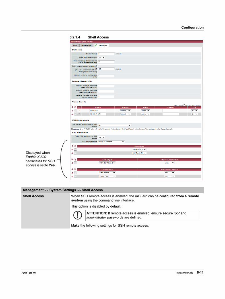
Configuration
6.2.1.4 Shell Access
Displayed when Enable X.509 certificates for SSH access is set to Yes.
Management >> System Settings >> Shell Access
Shell Access When SSH remote access is enabled, the mGuard can be configured from a remote system using the command line interface.
This option is disabled by default.
Make the following settings for SSH remote access:
ATTENTION: If remote access is enabled, ensure secure root and administrator passwords are defined.
7961_en_04 INNOMINATE 6-11
mGuard 7.4
Session Timeout (seconds)
Specifies after how long (in seconds) the session is automatically ended when no action is taken (i.e. automatic logout). The setting “0” (factory default) means that no automatic session end is made.
The value entered also applies when the operator uses shell access over the serial port instead of the SSH protocol.
The effect of the setting in the “Session Timeout” field is temporarily suspended if the processing of a shell command exceeds the set number of seconds.
In contrast, the connection can also be canceled when the connection no longer functions correctly (see “Delay between requests for a sign of life” on page 6-13).
Enable SSH remote access: Yes / No
If you want to enable SSH remote access, then set this option to Yes. You can enable Internal SSH access (i.e. from the directly connected LAN or from the directly connected computer) independently of this switch setting.
You must define the firewall rules for the available interfaces on this page under Allowed Networks in order to specify differentiated access possibilities to the mGuard.
Port for incoming SSH connections (remote administration only)
Default: 22
If this port number is changed, the new port number only applies for access over the External, External 2, VPN and Dial-in interface. Port number 22 still applies for internal access.
The remote peer that makes remote access may have to enter the port number defined here during the login procedure.
Example:
If this mGuard is accessible over the Internet under the ad-dress 123.124.125.21, and the default port number 22 has been set for remote access, you may not need to enter this port number in the address field on the SSH client (e.g. PuTTY or OpenSSH) of the remote peer.
If a different port number has been set (e.g. 2222), this must be specified, e.g.:ssh -p 2222 123.124.125.21
Management >> System Settings >> Shell Access (continued)
6-12 INNOMINATE 7961_en_04
Configuration
Delay between requests for a sign of life
Default: 120 secondsValues between 0 and 3600 seconds can be set. Positive values mean that the mGuard sends a request to the peer within the encrypted SSH connection to see whether it is still accessible. The request is sent when no activity from the remote peer is detected for the specified period (for example, as a result of network traffic within the encrypted connection).
The value entered here relates to the functionality of the encrypted SSH connection. As long as this is in place, the SSH connection is not terminated by the mGuard as a result of this setting, even when the user does not perform any action during this period.
As the number of sessions that can be open at the same time is limited (see Limiting simultaneous sessions), it is important to close sessions that are finished.
Therefore, from version 7.4.0 on, the request for a sign of life has the default value of 120 seconds. With a maximum of three requests for a sign of life, a finished session will be discovered after six minutes and removed.
In previous versions, the default setting was “0”. This means that no requests for a sign of life are sent.
If it is important for no additional traffic to be created, you can modify this value. With a setting of “0” in combination with “Limiting simultaneous sessions”, it is possible for additional access to be blocked if too many sessions have been interrupted by network errors but have not been closed.
Maximum number of missing signs of life
Specifies the maximum number of times a sign of life request to the remote peer can remain unanswered.
For example, if a sign of life request should be made every 15 seconds and this value is set to 3, then the SSH connec-tion is deleted when a sign of life is not detected after approx-imately 45 seconds.
Limiting simultaneous sessions
For administrative access to the mGuard via SSH, there is a limit to the number of simultaneous sessions, depending on the predefined user. Around 0.5 MB of memory is required for each session.
The “root” user has unrestricted access. For administrative access with a different user (admin, netadmin and audit), the number of simultaneous sessions is restricted. You can specify the number here.
The restriction has no effect on existing sessions, but only on newly created access.
Maximum number of simultaneous sessions for the role “admin”
2 to 2147483647
For “admin” at least 2 simultaneously allowed sessions are required so that “admin” does not lock itself out.
Maximum number of simultaneous sessions for the role “netadmin”
0 to 2147483647
With “0” no session is allowed. It is possible that the user “netadmin” is not used.
Management >> System Settings >> Shell Access (continued)
7961_en_04 INNOMINATE 6-13
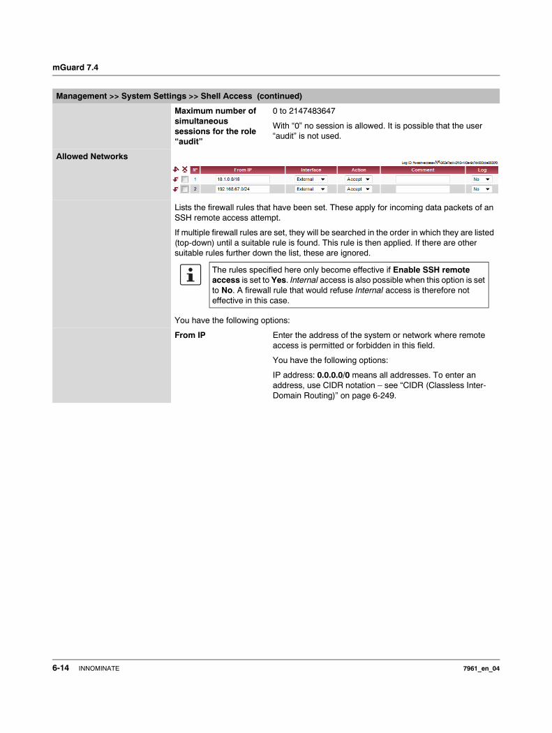
mGuard 7.4
Maximum number of simultaneous sessions for the role “audit”
0 to 2147483647
With “0” no session is allowed. It is possible that the user “audit” is not used.
Allowed Networks
Lists the firewall rules that have been set. These apply for incoming data packets of an SSH remote access attempt.
If multiple firewall rules are set, they will be searched in the order in which they are listed (top-down) until a suitable rule is found. This rule is then applied. If there are other suitable rules further down the list, these are ignored.
You have the following options:
From IP Enter the address of the system or network where remote access is permitted or forbidden in this field.
You have the following options:
IP address: 0.0.0.0/0 means all addresses. To enter an address, use CIDR notation – see “CIDR (Classless Inter-Domain Routing)” on page 6-249.
Management >> System Settings >> Shell Access (continued)
The rules specified here only become effective if Enable SSH remote access is set to Yes. Internal access is also possible when this option is set to No. A firewall rule that would refuse Internal access is therefore not effective in this case.
6-14 INNOMINATE 7961_en_04
Configuration
Interface External / Internal / External 2 / VPN / Dial-in
External 2 and Dial-in are only for devices with serial ports (see “Network >> Interfaces” on page 6-61).
Specifies which interface the rules apply to.
If no rules are set, or if no rule takes effect, the following default settings apply: SSH access is permitted over Internal, VPN and Dial-in. Access over External and External 2 is refused.
Specify the access possibilities according to your requirements.
Action Possible settings:– Accept means that data packets may pass through.– Reject means that the data packets are rejected. The
sender is informed that the data packets have been reject-ed. In Stealth mode, Reject has the same effect as Drop.
– Drop means that data packets may not pass through. Data packets are discarded and the sender is not informed of their whereabouts.
Comment Freely selectable comment for this rule.
Log For each individual firewall rule, you can specify whether the use of the rule– should be logged (set Log to Yes) or – should not be logged (set Log to No – factory default)
Management >> System Settings >> Shell Access (continued)
ATTENTION: If you want to refuse access over Internal, VPN or Dial-in, you must imple-ment this explicitly through corresponding fire-wall rules, by specifying Drop as an action, for example.
To avoid locking yourself out, you may have to simultaneously allow access over another interface explicitly with Accept before you make the new setting effective by clicking the Apply button. Otherwise, if you are locked out, you must perform the recovery procedure.
7961_en_04 INNOMINATE 6-15
mGuard 7.4
RADIUS Authentication
This menu item is notincluded in the scope of
functions for themGuard rs2000.
Use RADIUS authentication for Shell access
When No is selected, the password of the users who logon via shell access are checked according to the local database on the mGuard.
Select Yes to have users authenticated using a RADIUS server. This applies to users who wish to access the mGuard via shell access using SSH or a serial console. The password is only checked locally for the predefined users (root, admin, netadmin and audit).
When Enable X.509 certificates for SSH access is set to Yes under X.509 Authentication, the X.509 authentication procedure can be used alternatively. The procedure actually used by a user depends on how he uses his SSH client.
When setting up RADIUS authentication for the first time, select Yes.
If you intend to use RADIUS authentication As only method for password authentication, then we recommend creating a “Customized Default Profile” which resets the authentica-tion method.
The predefined users (root, admin, netadmin and audit) can then no longer logon to the mGuard via SSH or the serial console. Only exception: Authentication via an externally accessible serial console remains possible when the local password for the root user name is entered correctly.
Management >> System Settings >> Shell Access (continued)
The selection of As only method for password authentication is only suitable for experienced users, as access to the mGuard may be com-pletely blocked.
6-16 INNOMINATE 7961_en_04

Configuration
X.509 Authentication
Management >> System Settings >> Shell Access
X.509 Authentication
This menu item is notincluded in the scope of
functions for themGuard rs2000.
Enable X.509 certificates for SSH access
– If No is selected, then only normal authentication proce-dures (user name and password or private and public keys) are allowed, not the X.509 authentication procedure.
– If Yes is selected, then the X.509 authentication procedure can be used in addition to normal procedures (as seen under No).
– When Yes is selected, the following points must be defined:
– How the mGuard authenticates itself to the SSH client according to X.509 (see SSH server certificate (1))
– How the mGuard authenticates the remote SSH client according to X.509 (see SSH server certificate (2))
SSH server certificate (1)
Specifies how the mGuard identifies itself to the SSH client.
Select one of the machine certificates from the list or the None entry.
None:When None is selected, the SSH server of the mGuard does not authenticate itself to the SSH client via the X.509 certificate. Instead, it uses a server key and thus behaves like older versions of the mGuard.If one of the machine certificates is selected, this is also offered to the SSH client. The client can then decide whether to use the normal authentication procedure or the procedure according to X.509.The selection list gives a selection of machine certificates that are loaded in the mGuard under the Authentication >> Certificates menu (see page 6-124).
7961_en_04 INNOMINATE 6-17

mGuard 7.4
Authentication for SSH
In accordance with this table, the certificates must be provided that the mGuard uses for the authentication of the respective SSH client.
The following instructions assume that the certificates have already been correctly installed in the mGuard (see Chapter 6.5.4, “Authentication >> Certificates”).
SSH server certificate (2)
Specifies how the mGuard authenticates the SSH client
The following definition relates to how the mGuard verifies the authentication of the SSH client.
The table below shows which certificates must be provided for the mGuard to authenticate the SSH client if the SSH client displays one of the following certificate types on connection:– A certificate signed by a CA– A self-signed certificate
For further information on the following table, see Chapter 6.5.4, “Authentication >> Certificates”.
Management >> System Settings >> Shell Access (continued)
The remote peer shows the following:
Certificate (specific to individual) signed by CA
Certificate (specific to individual) self-signed
The mGuard authenticates the remote peer using:
All CA certificates that build the chain to the root CA certificate together with the certificates displayed by the remote peer
or ADDITIONALLY
Remote certificates, if used as a filter
Remote certificate
If the use of block lists (CRL checking) is activated under the Authentication >> Certificates, Certificate settings menu, then each certificate signed by a CA that a HTTPS client presents is checked for blocks.
Management >> System Settings >> Shell Access
CA certificate The configuration is only necessary when the SSH client displays a certificate signed by a CA.
All CA certificates required by the mGuard to form the chain to the respective root CA certificate with the certificates displayed by the SSH client must be configured.
The selection list shows the CA certificates that were loaded in the mGuard under the Authentication >> Certificates menu.
6-18 INNOMINATE 7961_en_04
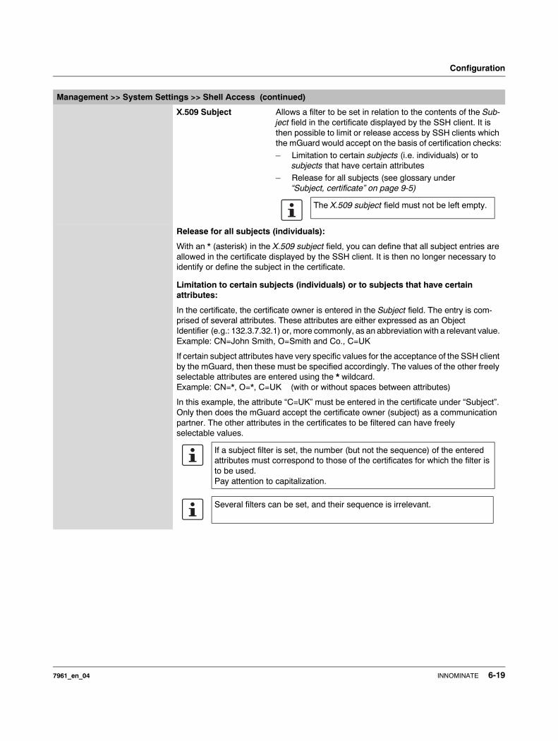
Configuration
X.509 Subject Allows a filter to be set in relation to the contents of the Sub-ject field in the certificate displayed by the SSH client. It is then possible to limit or release access by SSH clients which the mGuard would accept on the basis of certification checks:
– Limitation to certain subjects (i.e. individuals) or to subjects that have certain attributes
– Release for all subjects (see glossary under “Subject, certificate” on page 9-5)
Release for all subjects (individuals):
With an * (asterisk) in the X.509 subject field, you can define that all subject entries are allowed in the certificate displayed by the SSH client. It is then no longer necessary to identify or define the subject in the certificate.
Limitation to certain subjects (individuals) or to subjects that have certain attributes:
In the certificate, the certificate owner is entered in the Subject field. The entry is com-prised of several attributes. These attributes are either expressed as an Object Identifier (e.g.: 132.3.7.32.1) or, more commonly, as an abbreviation with a relevant value. Example: CN=John Smith, O=Smith and Co., C=UK
If certain subject attributes have very specific values for the acceptance of the SSH client by the mGuard, then these must be specified accordingly. The values of the other freely selectable attributes are entered using the * wildcard. Example: CN=*, O=*, C=UK (with or without spaces between attributes)
In this example, the attribute “C=UK” must be entered in the certificate under “Subject”. Only then does the mGuard accept the certificate owner (subject) as a communication partner. The other attributes in the certificates to be filtered can have freely selectable values.
Management >> System Settings >> Shell Access (continued)
The X.509 subject field must not be left empty.
If a subject filter is set, the number (but not the sequence) of the entered attributes must correspond to those of the certificates for which the filter is to be used.Pay attention to capitalization.
Several filters can be set, and their sequence is irrelevant.
7961_en_04 INNOMINATE 6-19
mGuard 7.4
Authorized for access as:
All users / root / admin / netadmin / audit
Additional filter which defines that the SSH client has to have certain administration level authentication in order to gain access.
During connection, the SSH client shows its certificate and also the system user for which the SSH session is to be opened (root, admin, netadmin, audit). Access is only granted when the entries match those defined here.
Access for all listed system users is possible when All users is set.
Client certificate Configuration is required in the following cases:– SSH clients each show a self-signed certificate.
– SSH clients each show a certificate signed by a CA. Filtering should take place: Access is only granted to a user whose certificate copy is installed in the mGuard as the remote certificate and is provided to the mGuard in this table as the Client certificate.This filter is not subordinate to the Subject filter. It resides on the same level and is allocated a logical OR function with the Subject filter.
The entry in this field defines which remote certificate the mGuard should adopt in order to authenticate the remote peer (SSH client).
For this, select one of the remote certificates from the selection list. The selection list shows the remote certificates that were loaded in the mGuard under the Authentication >> Certificates menu.
Authorized for access as:
All users / root / admin / netadmin / audit
Filter which defines that the SSH client has to have certain administration level authentication in order to gain access.
During connection, the SSH client shows its certificate and also the system user for which the SSH session is to be opened (root, admin, netadmin, audit). Access is only granted when the entries match those defined here.
Access for all listed system users is possible when All users is set.
Management >> System Settings >> Shell Access (continued)
The netadmin and audit settings relate to access rights with the Innominate Device Manager.
The netadmin and audit settings relate to access rights with the Innominate Device Manager.
6-20 INNOMINATE 7961_en_04
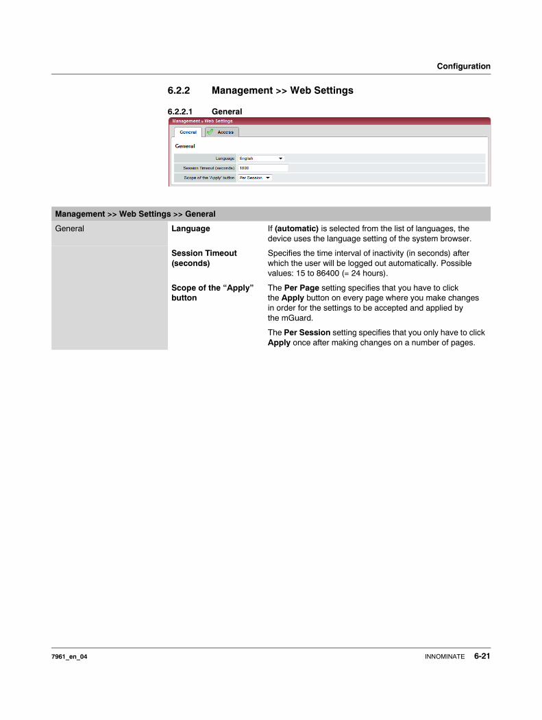
Configuration
6.2.2 Management >> Web Settings
6.2.2.1 General
Management >> Web Settings >> General
General Language If (automatic) is selected from the list of languages, the device uses the language setting of the system browser.
Session Timeout (seconds)
Specifies the time interval of inactivity (in seconds) after which the user will be logged out automatically. Possible values: 15 to 86400 (= 24 hours).
Scope of the “Apply” button
The Per Page setting specifies that you have to click the Apply button on every page where you make changes in order for the settings to be accepted and applied by the mGuard.
The Per Session setting specifies that you only have to click Apply once after making changes on a number of pages.
7961_en_04 INNOMINATE 6-21
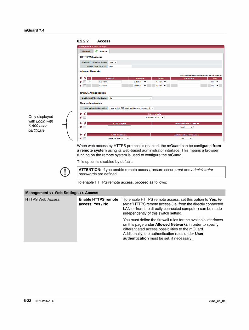
mGuard 7.4
6.2.2.2 Access
When web access by HTTPS protocol is enabled, the mGuard can be configured from a remote system using its web-based administrator interface. This means a browser running on the remote system is used to configure the mGuard.
This option is disabled by default.
To enable HTTPS remote access, proceed as follows:
ATTENTION: If you enable remote access, ensure secure root and administrator passwords are defined.
Only displayed with Login with X.509 user certificate
Management >> Web Settings >> Access
HTTPS Web Access Enable HTTPS remote access: Yes / No
To enable HTTPS remote access, set this option to Yes. In-ternal HTTPS remote access (i.e. from the directly connected LAN or from the directly connected computer) can be made independently of this switch setting.
You must define the firewall rules for the available interfaces on this page under Allowed Networks in order to specify differentiated access possibilities to the mGuard.Additionally, the authentication rules under User authentication must be set, if necessary.
6-22 INNOMINATE 7961_en_04
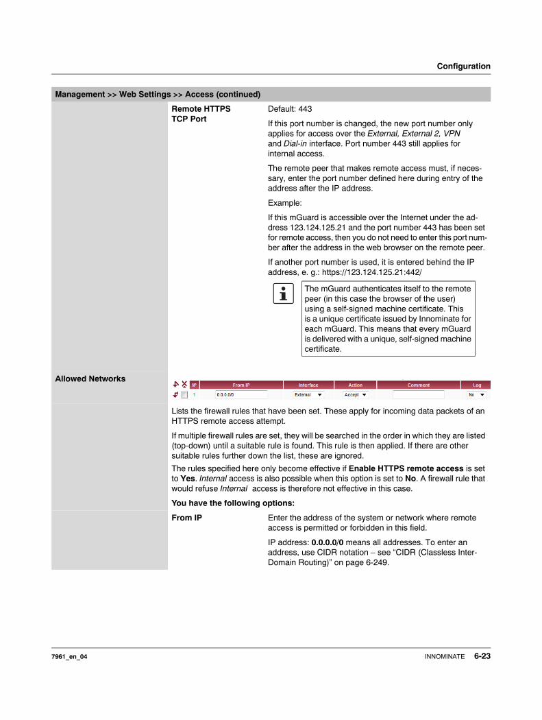
Configuration
Remote HTTPS TCP Port
Default: 443
If this port number is changed, the new port number only applies for access over the External, External 2, VPN and Dial-in interface. Port number 443 still applies for internal access.
The remote peer that makes remote access must, if neces-sary, enter the port number defined here during entry of the address after the IP address.
Example:
If this mGuard is accessible over the Internet under the ad-dress 123.124.125.21 and the port number 443 has been set for remote access, then you do not need to enter this port num-ber after the address in the web browser on the remote peer.
If another port number is used, it is entered behind the IP address, e. g.: https://123.124.125.21:442/
Allowed Networks
Lists the firewall rules that have been set. These apply for incoming data packets of an HTTPS remote access attempt.
If multiple firewall rules are set, they will be searched in the order in which they are listed (top-down) until a suitable rule is found. This rule is then applied. If there are other suitable rules further down the list, these are ignored.
The rules specified here only become effective if Enable HTTPS remote access is set to Yes. Internal access is also possible when this option is set to No. A firewall rule that would refuse Internal access is therefore not effective in this case.
You have the following options:
From IP Enter the address of the system or network where remote access is permitted or forbidden in this field.
IP address: 0.0.0.0/0 means all addresses. To enter an address, use CIDR notation – see “CIDR (Classless Inter-Domain Routing)” on page 6-249.
Management >> Web Settings >> Access (continued)
The mGuard authenticates itself to the remote peer (in this case the browser of the user) using a self-signed machine certificate. This is a unique certificate issued by Innominate for each mGuard. This means that every mGuard is delivered with a unique, self-signed machine certificate.
7961_en_04 INNOMINATE 6-23
mGuard 7.4
Interface External / Internal / External 2 / VPN / Dial-in1
Specifies which interface the rules apply to.
If no rules are set, or if no rule takes effect, the following default settings apply:
HTTPS access is permitted over Internal, VPN and Dial-in. Access over External and External 2 is refused.
Specify the access possibilities according to your requirements.
Action – Accept means that data packets may pass through.– Reject means that the data packets are rejected.
The sender is informed that the data packets have been rejected. In Stealth mode, Reject has the same effect as Drop.
– Drop means that data packets may not pass through. Data packets are discarded and the sender is not informed of their whereabouts.
Comment Freely selectable comment for this rule.
Log For each individual firewall rule, you can specify whether the use of the rule
– should be logged (set Log to Yes) or – should not be logged (set Log to No – factory default).
Management >> Web Settings >> Access (continued)
If you want to refuse access over Internal, VPN or Dial-in, you must implement this explicitly through corresponding firewall rules, by speci-fying Drop as an action, for example. To avoid locking yourself out, you may have to simul-taneously allow access over another interface explicitly with Accept before you make the new setting effective by clicking the Apply button. Otherwise, if you are locked out, you must perform the recovery procedure.
6-24 INNOMINATE 7961_en_04
Configuration
RADIUS Authentication
This menu item is notincluded in the scope of
functions for themGuard rs2000.
Enable RADIUS authentication
When No is selected, the password of users who logon via HTTPS are checked according to the local database.
User authentication method can only be set to Login re-stricted to X.509 client certificate when No is selected.
Select Yes to have users authenticated using the RADIUS server. The password is only checked locally for the pre-defined users (root, admin, netadmin, audit and user).
When setting up RADIUS authentication for the first time, select Yes.
If you intend to use RADIUS authentication As only method for password authentication, then we recommend creating a “Customized Default Profile” which resets the authentica-tion method.
If RADIUS authentication is selected as the only method for checking the password, then access to the mGuard is no longer possible in some circumstances (for example, when an incorrect RADIUS server is set up or the mGuard is moved). The predefined users (root, admin, netadmin, audit and user) are then no longer accepted.
1 External 2 and Dial-in are only for devices with serial ports (see “Network >> Interfaces” on page 6-61).
Management >> Web Settings >> Access (continued)
The selection of As only method for password authentication is only suitable for experienced users, as access to the mGuard may be com-pletely blocked.
7961_en_04 INNOMINATE 6-25
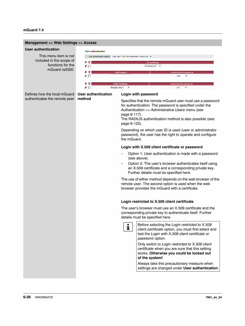
mGuard 7.4
Management >> Web Settings >> Access
User authentication
This menu item is notincluded in the scope of
functions for themGuard rs2000.
Defines how the local mGuardauthenticates the remote peer
User authentication method
Login with password
Specifies that the remote mGuard user must use a password for authentication. The password is specified under the Authentication >> Administrative Users menu (see page 6-117). The RADIUS authentication method is also possible (see page 6-122).
Depending on which user ID is used (user or administrator password), the user has the right to operate and configure the mGuard.
Login with X.509 client certificate or password
– Option 1: User authentication is made with a password (see above).
– Option 2: The user’s browser authenticates itself using an X.509 certificate and a corresponding private key. Further details must be specified here.
The use of either method depends on the web browser of the remote user. The second option is used when the web browser provides the mGuard with a certificate.
Login restricted to X.509 client certificate
The user‘s browser must use an X.509 certificate and the corresponding private key to authenticate itself. Further details must be specified here.
Before selecting the Login restricted to X.509 client certificate option, you must first select and test the Login with X.509 client certificate or password option.
Only switch to Login restricted to X.509 client certificate when you are sure that this setting works. Otherwise you could be locked out of the system!
Always take this precautionary measure when settings are changed under User authentication.
6-26 INNOMINATE 7961_en_04
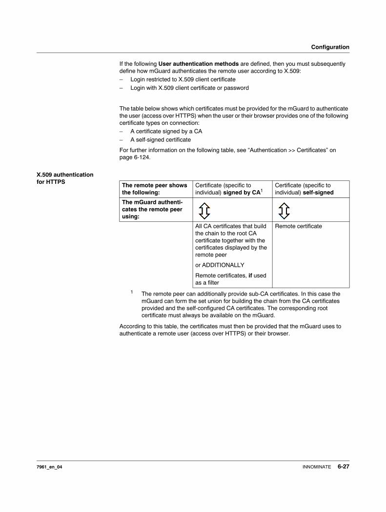
Configuration
If the following User authentication methods are defined, then you must subsequently define how mGuard authenticates the remote user according to X.509:– Login restricted to X.509 client certificate
– Login with X.509 client certificate or password
The table below shows which certificates must be provided for the mGuard to authenticate the user (access over HTTPS) when the user or their browser provides one of the following certificate types on connection:– A certificate signed by a CA– A self-signed certificate
For further information on the following table, see “Authentication >> Certificates” on page 6-124.
X.509 authentication for HTTPS
According to this table, the certificates must then be provided that the mGuard uses to authenticate a remote user (access over HTTPS) or their browser.
The remote peer shows the following:
Certificate (specific to individual) signed by CA1
1 The remote peer can additionally provide sub-CA certificates. In this case the mGuard can form the set union for building the chain from the CA certificates provided and the self-configured CA certificates. The corresponding root certificate must always be available on the mGuard.
Certificate (specific to individual) self-signed
The mGuard authenti-cates the remote peer using:
All CA certificates that build the chain to the root CA certificate together with the certificates displayed by the remote peer
or ADDITIONALLY
Remote certificates, if used as a filter
Remote certificate
7961_en_04 INNOMINATE 6-27
mGuard 7.4
The following instructions assume that the certificates have already been correctly installed in the mGuard (see “Authentication >> Certificates” on page 6-124).
If the use of block lists (CRL checking) is activated under the Authentication >> Certificates, Certificate settings menu, then each certificate signed by a CA that a HTTPS client presents is checked for blocking.
Management >> Web Settings >> Access
CA certificate The configuration is only necessary when a user with HTTPS access displays a certificate signed by a CA.
All CA certificates needed by the mGuard to build the chain to the respective root CA certificate together with the certificates displayed by the users must be configured.
If the browser of the remote user also provides CA certificates that contribute to building of the chain, then it is not necessary for the CA certificate to be installed and referenced at this point.
However, the corresponding root CA certificate must be installed in the mGuard and made available (referenced) at all times.
When selecting the CA certificates to be used, or when changing the selection or the filter settings, you must first select Login with X.509 client certificate or password as the User authentication method and test this before making the (new) setting effective.
Only switch to Login restricted to X.509 client certificate when you are sure that this setting works. Otherwise you could be locked out of the system!
Always take this precautionary measure when settings are changed under User authentication.
6-28 INNOMINATE 7961_en_04
Configuration
X.509 Subject Allows a filter to be set in relation to the contents of the Subject field in the certificate displayed by the browser/HTTPS client.
It is then possible to limit or release access by browser/HTTPS clients which the mGuard would accept on the basis of certification checks:
– Limitation to certain subjects (i.e. individuals) or to subjects that have certain attributes
– Release for all subjects (see glossary under “Subject, certificate” on page 9-5)
Release for all subjects (individuals):
With an * (asterisk) in the X.509 Subject field, you can define that all subject entries are allowed in the certificate provided by the browser/HTTPS client. It is then no longer necessary to identify or define the subject in the certificate.
Management >> Web Settings >> Access (continued)
The X.509 Subject field must not be left empty.
7961_en_04 INNOMINATE 6-29
mGuard 7.4
Limitation to certain subjects (individuals) or to subjects that have certain attributes:
In the certificate, the certificate owner is entered in the Subject field. The entry is comprised of several attributes. These attributes are either expressed as an Object Identifier (e.g.: 132.3.7.32.1) or, more commonly, as an ab-breviation with a relevant value. Example: CN=John Smith, O=Smith and Co., C=UK
If certain subject attributes have very specific values for the acceptance of the browser by the mGuard, then these must be specified accordingly. The values of the other freely selectable attributes are entered using the * wildcard.Example: CN=*, O=*, C=UK (with or without spaces between attributes)
In this example, the attribute “C=UK” must be entered in the certificate under “Subject”. Only then does the mGuard accept the certificate owner (subject) as a communication partner. The other attributes in the certificates to be filtered can have freely selectable values.
With HTTPS, the browser of the accessing user does not specify with which user or administration authorization it logs in. These access rights are allocated by setting filters here (under “Authorized for access”).
This has the following result: If there are several filters that “let through” a certain user, then the first filter comes into effect. The user receives the access rights as defined by this filter. This could deviate from the access rights allocated to the user in the subsequent filters.
Management >> Web Settings >> Access (continued)
If a subject filter is set, the number (but not the se-quence) of the entered attributes must correspond to those of the certificates for which the filter is to be used.Pay attention to capitalization.
Several filters can be set, and their sequence is irrelevant.
If remote certificates are configured as filters in the X.509 Certificate table column, then these filters have priority over filter settings here.
6-30 INNOMINATE 7961_en_04
Configuration
Authorized for access as:
All users / root / admin / netadmin / audit
Defines which user or administrator rights are granted to the remote user.
For a description of the root, admin and user authorization levels, see “Authentication >> Administrative Users” on page 6-117.
The netadmin and audit authorization levels relate to access rights with the Innominate Device Manager.
X.509 Certificate Configuration is required in the following cases:
– Remote users each show a self-signed certificate.– Remote users each show a certificate signed by a CA.
Filtering should take place: Access is only granted to a user whose certificate copy is installed in the mGuard as the remote certificate and is provided to the mGuard in this table as the X.509 Certificate.If used, this filter has priority over the Subject filter in the table above.
The entry in this field defines which remote certificate the mGuard should use in order to authenticate the remote peer (browser of the remote user).
For this, select one of the remote certificates from the selection list.
The selection list shows the remote certificates that were loaded in the mGuard under the Authentication >> Certificates menu.
Authorized for access as:
root / admin / netadmin / audit / user
Defines which user or administrator rights are granted to the remote user.
For a description of the root, admin and user authorization levels, see “Authentication >> Administrative Users” on page 6-117.
The netadmin and audit authorization levels relate to access rights with the Innominate Device Manager.
Management >> Web Settings >> Access (continued)
7961_en_04 INNOMINATE 6-31
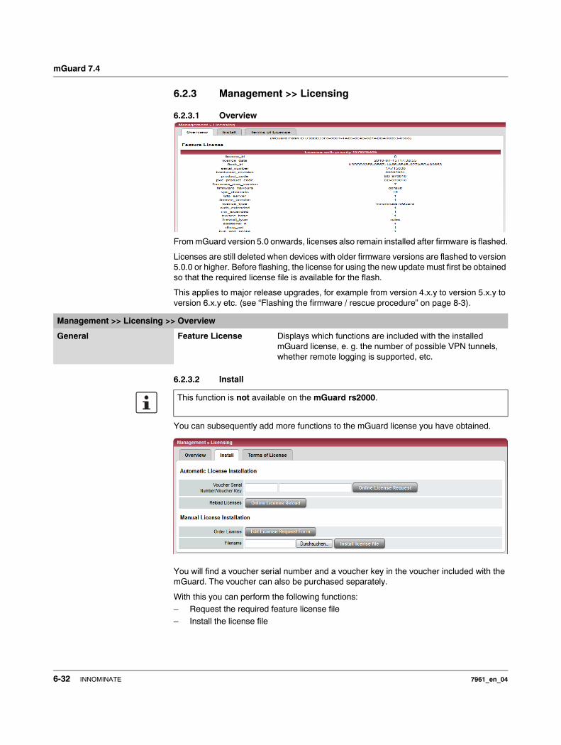
mGuard 7.4
6.2.3 Management >> Licensing
6.2.3.1 Overview
From mGuard version 5.0 onwards, licenses also remain installed after firmware is flashed.
Licenses are still deleted when devices with older firmware versions are flashed to version 5.0.0 or higher. Before flashing, the license for using the new update must first be obtained so that the required license file is available for the flash.
This applies to major release upgrades, for example from version 4.x.y to version 5.x.y to version 6.x.y etc. (see “Flashing the firmware / rescue procedure” on page 8-3).
6.2.3.2 Install
You can subsequently add more functions to the mGuard license you have obtained.
You will find a voucher serial number and a voucher key in the voucher included with the mGuard. The voucher can also be purchased separately.
With this you can perform the following functions: – Request the required feature license file – Install the license file
Management >> Licensing >> Overview
General Feature License Displays which functions are included with the installed mGuard license, e. g. the number of possible VPN tunnels, whether remote logging is supported, etc.
This function is not available on the mGuard rs2000.
6-32 INNOMINATE 7961_en_04

Configuration
Management >> Licensing >> Install
Automatic License Installation
Voucher Serial Number / Voucher Key
Enter the serial number printed on the voucher and the corresponding voucher key, then click on Online License Request.
The mGuard now establishes a connection via the Internet and installs the respective license on the mGuard if the voucher is valid.
Reload Licenses This can be used if the license installed in the mGuard has been deleted. Click on the Online License Reload button.
The licenses that were previously issued for this mGuard are then retrieved from the Internet and installed.
Manual License Installation Order License
Filename
After clicking the Edit License Request Form button, an online form is provided which can be used to order the desired license. In the request form, enter the following information:– Voucher Serial Number: The serial number printed on
the voucher– Voucher Key: The voucher key on the voucher– Flash ID: Filled out automatically
After the form is sent, the license file is made available for downloading and can be installed in the mGuard in a sub-sequent step.
Filename (installing the license)
To install a license, first save the license file as a separate file on your computer, then proceed as follows:
• Click on the Browse… button next to the Filename field. Select the file and open it so that the file name or path is displayed in the Filename field.
• Click on the Install license file button.
7961_en_04 INNOMINATE 6-33
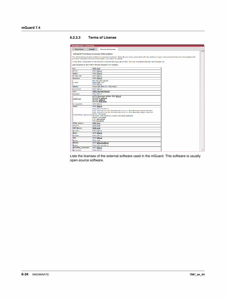
mGuard 7.4
6.2.3.3 Terms of License
Lists the licenses of the external software used in the mGuard. This software is usually open-source software.
6-34 INNOMINATE 7961_en_04
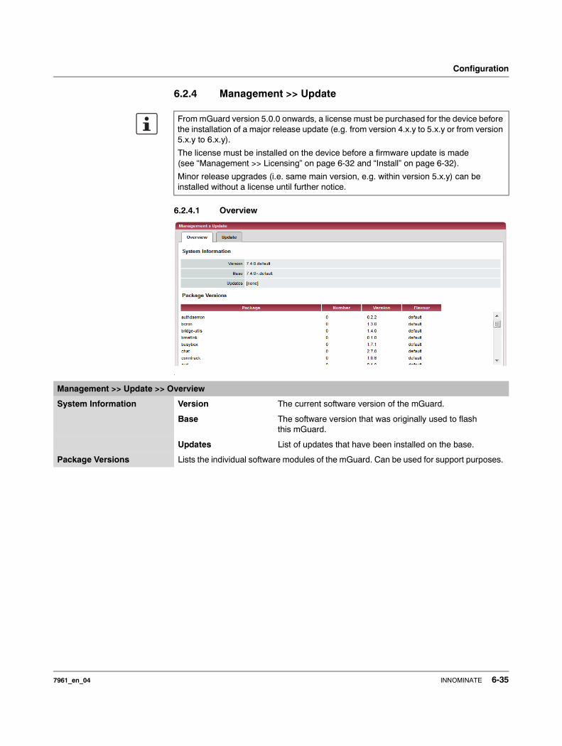
Configuration
6.2.4 Management >> Update
6.2.4.1 Overview
.
From mGuard version 5.0.0 onwards, a license must be purchased for the device before the installation of a major release update (e.g. from version 4.x.y to 5.x.y or from version 5.x.y to 6.x.y).
The license must be installed on the device before a firmware update is made (see “Management >> Licensing” on page 6-32 and “Install” on page 6-32).
Minor release upgrades (i.e. same main version, e.g. within version 5.x.y) can be installed without a license until further notice.
Management >> Update >> Overview
System Information Version The current software version of the mGuard.
Base The software version that was originally used to flash this mGuard.
Updates List of updates that have been installed on the base.
Package Versions Lists the individual software modules of the mGuard. Can be used for support purposes.
7961_en_04 INNOMINATE 6-35
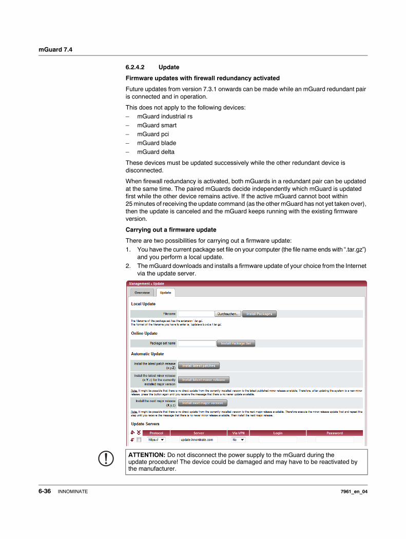
mGuard 7.4
6.2.4.2 Update
Firmware updates with firewall redundancy activated
Future updates from version 7.3.1 onwards can be made while an mGuard redundant pair is connected and in operation.
This does not apply to the following devices:– mGuard industrial rs
– mGuard smart– mGuard pci– mGuard blade
– mGuard delta
These devices must be updated successively while the other redundant device is disconnected.
When firewall redundancy is activated, both mGuards in a redundant pair can be updated at the same time. The paired mGuards decide independently which mGuard is updated first while the other device remains active. If the active mGuard cannot boot within 25 minutes of receiving the update command (as the other mGuard has not yet taken over), then the update is canceled and the mGuard keeps running with the existing firmware version.
Carrying out a firmware update
There are two possibilities for carrying out a firmware update:1. You have the current package set file on your computer (the file name ends with “.tar.gz”)
and you perform a local update.2. The mGuard downloads and installs a firmware update of your choice from the Internet
via the update server.
ATTENTION: Do not disconnect the power supply to the mGuard during the update procedure! The device could be damaged and may have to be reactivated by the manufacturer.
6-36 INNOMINATE 7961_en_04
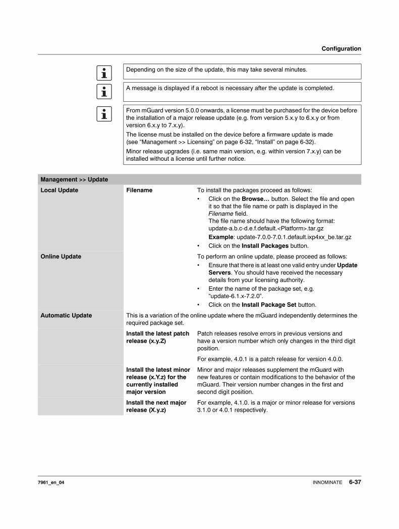
Configuration
Depending on the size of the update, this may take several minutes.
A message is displayed if a reboot is necessary after the update is completed.
From mGuard version 5.0.0 onwards, a license must be purchased for the device before the installation of a major release update (e.g. from version 5.x.y to 6.x.y or from version 6.x.y to 7.x.y).
The license must be installed on the device before a firmware update is made (see “Management >> Licensing” on page 6-32, “Install” on page 6-32).
Minor release upgrades (i.e. same main version, e.g. within version 7.x.y) can be installed without a license until further notice.
Management >> Update
Local Update Filename To install the packages proceed as follows: • Click on the Browse… button. Select the file and open
it so that the file name or path is displayed in the Filename field. The file name should have the following format: update-a.b.c-d.e.f.default.<Platform>.tar.gzExample: update-7.0.0-7.0.1.default.ixp4xx_be.tar.gz
• Click on the Install Packages button.
Online Update To perform an online update, please proceed as follows:• Ensure that there is at least one valid entry under Update
Servers. You should have received the necessary details from your licensing authority.
• Enter the name of the package set, e.g.“update-6.1.x-7.2.0”.
• Click on the Install Package Set button.
Automatic Update This is a variation of the online update where the mGuard independently determines the required package set.
Install the latest patch release (x.y.Z)
Patch releases resolve errors in previous versions and have a version number which only changes in the third digit position.
For example, 4.0.1 is a patch release for version 4.0.0.
Install the latest minor release (x.Y.z) for the currently installed major version
Minor and major releases supplement the mGuard with new features or contain modifications to the behavior of the mGuard. Their version number changes in the first and second digit position.
Install the next major release (X.y.z)
For example, 4.1.0. is a major or minor release for versions 3.1.0 or 4.0.1 respectively.
7961_en_04 INNOMINATE 6-37
mGuard 7.4
Update Servers Define from which servers the mGuard may be updated here.
You have the following options:
Protocol The update can be made using either HTTP or HTTPS.
Server Hostname of the server that provides the update files.
Via VPN The update is performed via the VPN tunnel.
Default: No.
Login Login for the server.
Password Password for the login.
Management >> Update (continued)
The list of servers is processed top-down until an available server is found. The sequence of the entries thus defines their priorities.
All configured update servers must provide the same updates.
Updates via VPN are not supported if the relevant VPN tunnel in the configuration has been switched off (see Chapter 6.8.2, IPsec VPN >> Connections) and was only opened temporarily via the service contact or the CGI interface.
6-38 INNOMINATE 7961_en_04
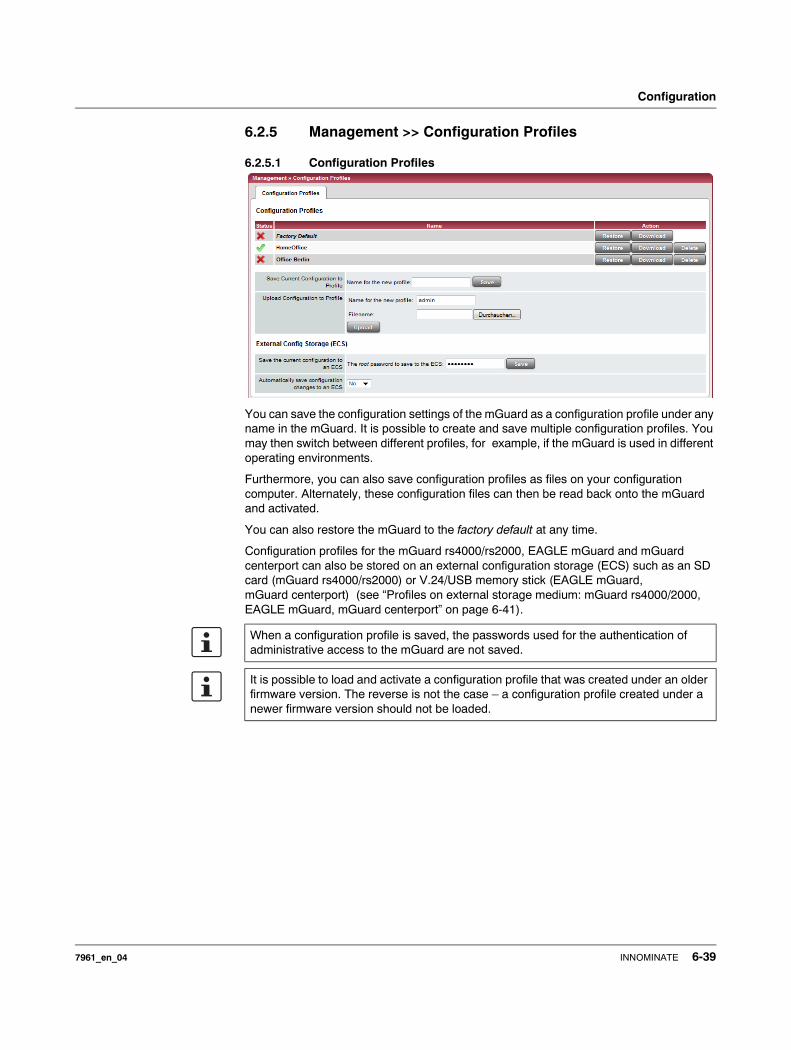
Configuration
6.2.5 Management >> Configuration Profiles
6.2.5.1 Configuration Profiles
You can save the configuration settings of the mGuard as a configuration profile under any name in the mGuard. It is possible to create and save multiple configuration profiles. You may then switch between different profiles, for example, if the mGuard is used in different operating environments.
Furthermore, you can also save configuration profiles as files on your configuration computer. Alternately, these configuration files can then be read back onto the mGuard and activated.
You can also restore the mGuard to the factory default at any time.
Configuration profiles for the mGuard rs4000/rs2000, EAGLE mGuard and mGuard centerport can also be stored on an external configuration storage (ECS) such as an SD card (mGuard rs4000/rs2000) or V.24/USB memory stick (EAGLE mGuard, mGuard centerport) (see “Profiles on external storage medium: mGuard rs4000/2000, EAGLE mGuard, mGuard centerport” on page 6-41).
When a configuration profile is saved, the passwords used for the authentication of administrative access to the mGuard are not saved.
It is possible to load and activate a configuration profile that was created under an older firmware version. The reverse is not the case – a configuration profile created under a newer firmware version should not be loaded.
7961_en_04 INNOMINATE 6-39
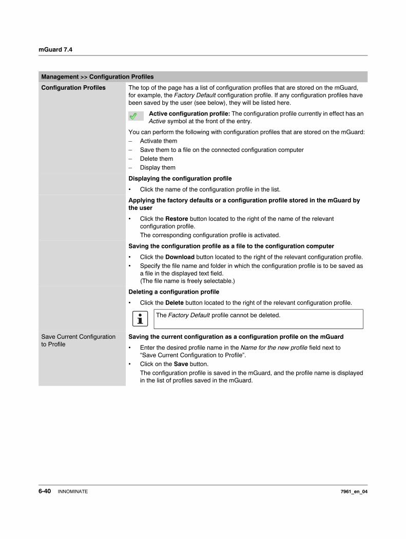
mGuard 7.4
Management >> Configuration Profiles
Configuration Profiles The top of the page has a list of configuration profiles that are stored on the mGuard, for example, the Factory Default configuration profile. If any configuration profiles have been saved by the user (see below), they will be listed here.
Active configuration profile: The configuration profile currently in effect has an Active symbol at the front of the entry.
You can perform the following with configuration profiles that are stored on the mGuard:– Activate them
– Save them to a file on the connected configuration computer– Delete them– Display them
Displaying the configuration profile
• Click the name of the configuration profile in the list.
Applying the factory defaults or a configuration profile stored in the mGuard by the user
• Click the Restore button located to the right of the name of the relevant configuration profile. The corresponding configuration profile is activated.
Saving the configuration profile as a file to the configuration computer
• Click the Download button located to the right of the relevant configuration profile.• Specify the file name and folder in which the configuration profile is to be saved as
a file in the displayed text field.(The file name is freely selectable.)
Deleting a configuration profile
• Click the Delete button located to the right of the relevant configuration profile.
Save Current Configuration to Profile
Saving the current configuration as a configuration profile on the mGuard
• Enter the desired profile name in the Name for the new profile field next to “Save Current Configuration to Profile”.
• Click on the Save button.
The configuration profile is saved in the mGuard, and the profile name is displayed in the list of profiles saved in the mGuard.
The Factory Default profile cannot be deleted.
6-40 INNOMINATE 7961_en_04
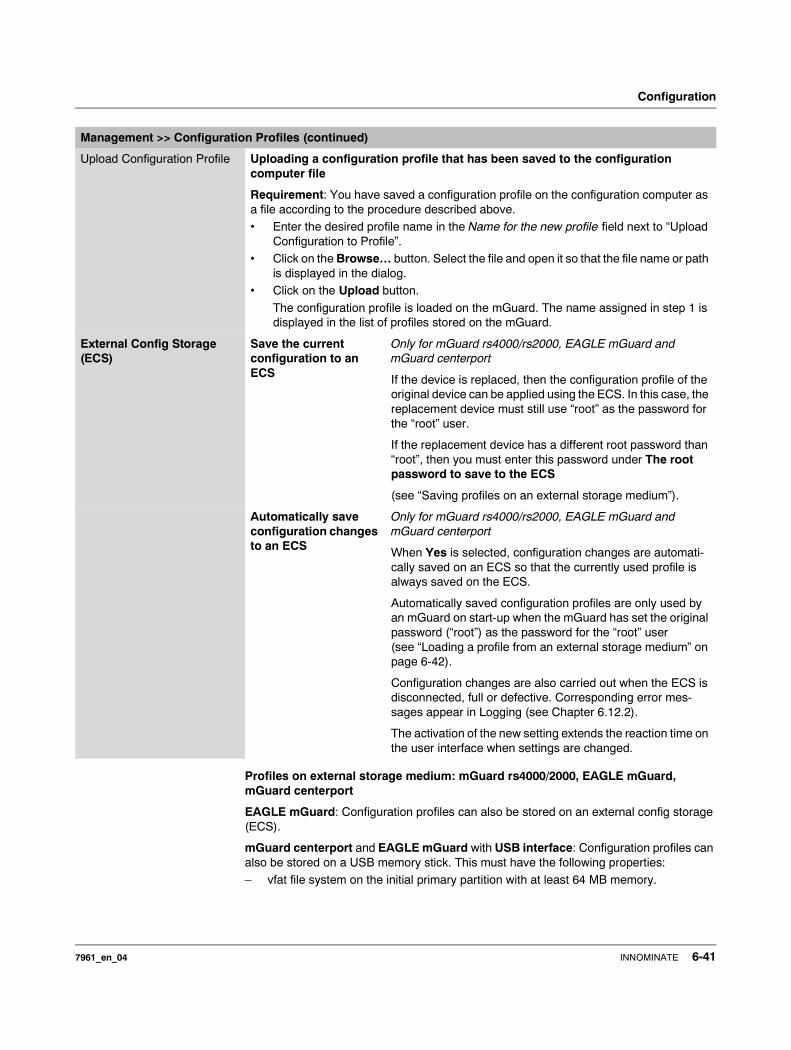
Configuration
Profiles on external storage medium: mGuard rs4000/2000, EAGLE mGuard, mGuard centerport
EAGLE mGuard: Configuration profiles can also be stored on an external config storage (ECS).
mGuard centerport and EAGLE mGuard with USB interface: Configuration profiles can also be stored on a USB memory stick. This must have the following properties:– vfat file system on the initial primary partition with at least 64 MB memory.
Upload Configuration Profile Uploading a configuration profile that has been saved to the configuration computer file
Requirement: You have saved a configuration profile on the configuration computer as a file according to the procedure described above.• Enter the desired profile name in the Name for the new profile field next to “Upload
Configuration to Profile”.• Click on the Browse… button. Select the file and open it so that the file name or path
is displayed in the dialog.• Click on the Upload button.
The configuration profile is loaded on the mGuard. The name assigned in step 1 is displayed in the list of profiles stored on the mGuard.
External Config Storage (ECS)
Save the current configuration to an ECS
Only for mGuard rs4000/rs2000, EAGLE mGuard and mGuard centerport
If the device is replaced, then the configuration profile of the original device can be applied using the ECS. In this case, the replacement device must still use “root” as the password for the “root” user.
If the replacement device has a different root password than “root”, then you must enter this password under The root password to save to the ECS
(see “Saving profiles on an external storage medium”).
Automatically save configuration changes to an ECS
Only for mGuard rs4000/rs2000, EAGLE mGuard and mGuard centerport
When Yes is selected, configuration changes are automati-cally saved on an ECS so that the currently used profile is always saved on the ECS.
Automatically saved configuration profiles are only used by an mGuard on start-up when the mGuard has set the original password (“root”) as the password for the “root” user (see “Loading a profile from an external storage medium” on page 6-42).
Configuration changes are also carried out when the ECS is disconnected, full or defective. Corresponding error mes-sages appear in Logging (see Chapter 6.12.2).
The activation of the new setting extends the reaction time on the user interface when settings are changed.
Management >> Configuration Profiles (continued)
7961_en_04 INNOMINATE 6-41
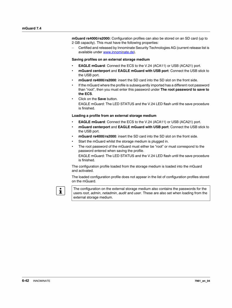
mGuard 7.4
mGuard rs4000/rs2000: Configuration profiles can also be stored on an SD card (up to 2 GB capacity). This must have the following properties: – Certified and released by Innominate Security Technologies AG (current release list is
available under www.innominate.de).
Saving profiles on an external storage medium
• EAGLE mGuard: Connect the ECS to the V.24 (ACA11) or USB (ACA21) port.• mGuard centerport and EAGLE mGuard with USB port: Connect the USB stick to
the USB port.• mGuard rs4000/rs2000: insert the SD card into the SD slot on the front side.• If the mGuard where the profile is subsequently imported has a different root password
than “root”, then you must enter this password under The root password to save to the ECS.
• Click on the Save button.EAGLE mGuard: The LED STATUS and the V.24 LED flash until the save procedure is finished.
Loading a profile from an external storage medium
• EAGLE mGuard: Connect the ECS to the V.24 (ACA11) or USB (ACA21) port.• mGuard centerport and EAGLE mGuard with USB port: Connect the USB stick to
the USB port.• mGuard rs4000/rs2000: insert the SD card into the SD slot on the front side.• Start the mGuard whilst the storage medium is plugged in.
• The root password of the mGuard must either be “root” or must correspond to the password entered when saving the profile.
EAGLE mGuard: The LED STATUS and the V.24 LED flash until the save procedure is finished.
The configuration profile loaded from the storage medium is loaded into the mGuard and activated.
The loaded configuration profile does not appear in the list of configuration profiles stored on the mGuard.
The configuration on the external storage medium also contains the passwords for the users root, admin, netadmin, audit and user. These are also set when loading from the external storage medium.
6-42 INNOMINATE 7961_en_04

Configuration
6.2.6 Management >> SNMP
6.2.6.1 Query
The SNMP (Simple Network Management Protocol) is mainly used in more complex networks to monitor the status and operation of devices.
SNMP is available in several releases: SNMPv1/SNMPv2 and SNMPv3.
The older versions (SNMPv1/SNMPv2) do not use encryption and are not considered to be secure. We therefore do not recommend using SNMPv1/ SNMPv2.
SNMPv3 is considerably better from a security perspective, but not all management consoles support it.
If SNMPv3 or SNMPv1/v2 is enabled, this is indicated by a green signal field on the tab at the top of the page. Otherwise – i.e. if neither v3 nor v1/v2 is enabled – the signal field is red.
Processing an SNMP query can take longer than one second. However, the default timeout value of many SNMP management applications is set to one second.• If you experience timeout problems, set the timeout of your management application
to values between 3 and 5 seconds.
7961_en_04 INNOMINATE 6-43
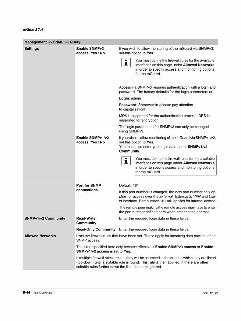
mGuard 7.4
Management >> SNMP >> Query
Settings Enable SNMPv3 access: Yes / No
If you wish to allow monitoring of the mGuard via SNMPv3, set this option to Yes.
Access via SNMPv3 requires authentication with a login and password. The factory defaults for the login parameters are:
Login: admin
Password: SnmpAdmin (please pay attention to capitalization!)
MD5 is supported for the authentication process; DES is supported for encryption.
The login parameters for SNMPv3 can only be changed using SNMPv3.
Enable SNMPv1/v2 access: Yes / No
If you wish to allow monitoring of the mGuard via SNMPv1/v2, set this option to Yes.You must also enter your login data under SNMPv1/v2 Community.
Port for SNMP connections
Default: 161
If this port number is changed, the new port number only ap-plies for access over the External, External 2, VPN and Dial-in interface. Port number 161 still applies for internal access.
The remote peer making the remote access may have to enter the port number defined here when entering the address.
SNMPv1/v2 Community Read-Write Community
Enter the required login data in these fields.
Read-Only Community Enter the required login data in these fields.
Allowed Networks Lists the firewall rules that have been set. These apply for incoming data packets of an SNMP access.
The rules specified here only become effective if Enable SNMPv3 access or Enable SNMPv1/v2 access is set to Yes.
If multiple firewall rules are set, they will be searched in the order in which they are listed (top-down) until a suitable rule is found. This rule is then applied. If there are other suitable rules further down the list, these are ignored.
You must define the firewall rules for the available interfaces on this page under Allowed Networks in order to specify access and monitoring options for the mGuard.
You must define the firewall rules for the available interfaces on this page under Allowed Networks in order to specify access and monitoring options for the mGuard.
6-44 INNOMINATE 7961_en_04

Configuration
From IP Enter the address of the system or network where remote access is permitted or forbidden in this field.
You have the following options:
– An IP address– To enter an address, use CIDR notation (see “CIDR
(Classless Inter-Domain Routing)” on page 6-249).– 0.0.0.0/0 means all addresses.
Interface External / Internal / External 2 / VPN / Dial-in1
Specifies which interface the rules apply to.
If no rules are set, or if no rule takes effect, the following default settings apply:
SNMP monitoring is permitted over Internal, VPN and Dial-in. Access over External and External 2 is refused.
If required, you can specify the monitoring possibilities.
Action Accept means that data packets may pass through.
Reject means that the data packets are rejected. The sender is informed that the data packets have been rejected. In Ste-alth mode, Reject has the same effect as Drop.
Drop means that data packets may not pass through. Data packets are discarded and the sender is not informed of their whereabouts.
Comment Freely selectable comment for this rule.
Log For each individual firewall rule, you can specify whether the use of the rule– should be logged (set Log to Yes) or – should not be logged (set Log to No – factory default).
1 External 2 and Dial-in are only for devices with serial ports (see “Network >> Interfaces” on page 6-61).
Management >> SNMP >> Query (continued)
ATTENTION: If you want to refuse access over Internal, VPN or Dial-in, you must implement this explicitly through corresponding firewall rules, by specifying Drop as an action, for example. To avoid locking yourself out, you may have to si-multaneously allow access over another interface explicitly with Accept before you make the new setting effective by clicking the Apply button. Oth-erwise, if you are locked out, you must perform the recovery procedure.
7961_en_04 INNOMINATE 6-45
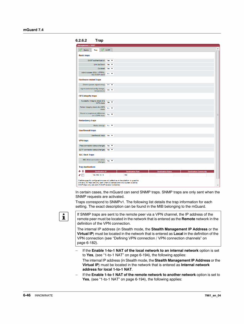
mGuard 7.4
6.2.6.2 Trap
In certain cases, the mGuard can send SNMP traps. SNMP traps are only sent when the SNMP requests are activated.
Traps correspond to SNMPv1. The following list details the trap information for each setting. The exact description can be found in the MIB belonging to the mGuard.
– If the Enable 1-to-1 NAT of the local network to an internal network option is set to Yes, (see “1-to-1 NAT” on page 6-194), the following applies:
The internal IP address (in Stealth mode, the Stealth Management IP Address or the Virtual IP) must be located in the network that is entered as Internal network address for local 1-to-1 NAT.
– If the Enable 1-to-1 NAT of the remote network to another network option is set to Yes, (see “1-to-1 NAT” on page 6-194), the following applies:
If SNMP traps are sent to the remote peer via a VPN channel, the IP address of the remote peer must be located in the network that is entered as the Remote network in the definition of the VPN connection.
The internal IP address (in Stealth mode, the Stealth Management IP Address or the Virtual IP) must be located in the network that is entered as Local in the definition of the VPN connection (see “Defining VPN connection / VPN connection channels” on page 6-182).
6-46 INNOMINATE 7961_en_04
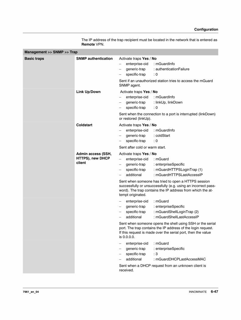
Configuration
The IP address of the trap recipient must be located in the network that is entered as Remote VPN.
Management >> SNMP >> Trap
Basic traps SNMP authentication Activate traps Yes / No– enterprise-oid : mGuardInfo– generic-trap : authenticationFailure
– specific-trap : 0
Sent if an unauthorized station tries to access the mGuard SNMP agent.
Link Up/Down Activate traps Yes / No– enterprise-oid : mGuardInfo
– generic-trap : linkUp, linkDown– specific-trap : 0
Sent when the connection to a port is interrupted (linkDown) or restored (linkUp).
Coldstart Activate traps Yes / No– enterprise-oid : mGuardInfo– generic-trap : coldStart– specific-trap : 0
Sent after cold or warm start.
Admin access (SSH, HTTPS), new DHCP client
Activate traps Yes / No– enterprise-oid : mGuard
– generic-trap : enterpriseSpecific– specific-trap : mGuardHTTPSLoginTrap (1)– additional : mGuardHTTPSLastAccessIP
Sent when someone has tried to open a HTTPS session successfully or unsuccessfully (e.g. using an incorrect pass-word). The trap contains the IP address from which the at-tempt originated.
– enterprise-oid : mGuard– generic-trap : enterpriseSpecific
– specific-trap : mGuardShellLoginTrap (2)– additional : mGuardShellLastAccessIP
Sent when someone opens the shell using SSH or the serial port. The trap contains the IP address of the login request. If this request is made over the serial port, then the value is 0.0.0.0.
– enterprise-oid : mGuard– generic-trap : enterpriseSpecific– specific-trap : 3
– additional : mGuardDHCPLastAccessMAC
Sent when a DHCP request from an unknown client is received.
7961_en_04 INNOMINATE 6-47
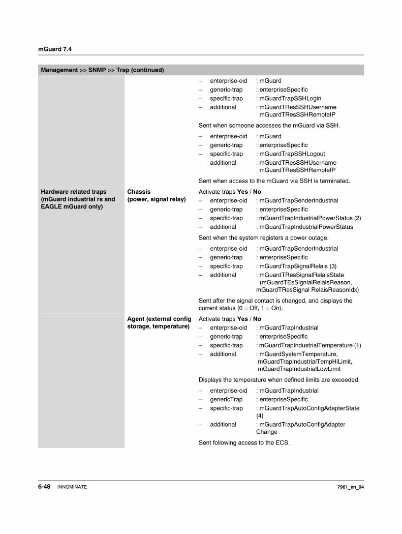
mGuard 7.4
– enterprise-oid : mGuard
– generic-trap : enterpriseSpecific– specific-trap : mGuardTrapSSHLogin– additional : mGuardTResSSHUsername
mGuardTResSSHRemoteIP
Sent when someone accesses the mGuard via SSH.
– enterprise-oid : mGuard– generic-trap : enterpriseSpecific– specific-trap : mGuardTrapSSHLogout
– additional : mGuardTResSSHUsernamemGuardTResSSHRemoteIP
Sent when access to the mGuard via SSH is terminated.
Hardware related traps (mGuard industrial rs and EAGLE mGuard only)
Chassis (power, signal relay)
Activate traps Yes / No– enterprise-oid : mGuardTrapSenderIndustrial
– generic-trap : enterpriseSpecific– specific-trap : mGuardTrapIndustrialPowerStatus (2)– additional : mGuardTrapIndustrialPowerStatus
Sent when the system registers a power outage.
– enterprise-oid : mGuardTrapSenderIndustrial– generic-trap : enterpriseSpecific
– specific-trap : mGuardTrapSignalRelais (3)– additional : mGuardTResSignalRelaisState
(mGuardTEsSignlalRelaisReason, mGuardTResSignal RelaisReasonIdx)
Sent after the signal contact is changed, and displays the current status (0 = Off, 1 = On).
Agent (external config storage, temperature)
Activate traps Yes / No– enterprise-oid : mGuardTrapIndustrial– generic-trap : enterpriseSpecific
– specific-trap : mGuardTrapIndustrialTemperature (1)– additional : mGuardSystemTemperature,
mGuardTrapIndustrialTempHiLimit, mGuardTrapIndustrialLowLimit
Displays the temperature when defined limits are exceeded.
– enterprise-oid : mGuardTrapIndustrial– genericTrap : enterpriseSpecific
– specific-trap : mGuardTrapAutoConfigAdapterState (4)
– additional : mGuardTrapAutoConfigAdapter Change
Sent following access to the ECS.
Management >> SNMP >> Trap (continued)
6-48 INNOMINATE 7961_en_04

Configuration
mGuard blade controller traps (blade only)
Blade status change (blade switch, outage): Activate traps Yes / No– enterprise-oid : mGuardTrapBladeCTRL– generic-trap : enterpriseSpecific– specific-trap : mGuardTrapBladeCtrlPowerStatus (2)
– additional : mGuardTrapBladeRackID, mGuardTrapBladeSlotNr, mGuardTrapBladeCtrlPowerStatus
Sent when the power supply status of the blade pack changes.
– enterprise-oid : mGuardTrapBladeCTRL
– generic-trap : enterpriseSpecific– specific-trap : mGuardTrapBladeCtrlRunStatus (3)– additional : mGuardTrapBladeRackID,
mGuardTrapBladeSlotNr, mGuardTrapBladeCtrlRunStatus
Sent when the blade run status changes.
Blade reconfiguration (backup / restore) : Activate traps Yes / No– enterprise-oid : mGuardTrapBladeCtrlCfg– generic-trap : enterpriseSpecific– specific-trap : mGuardTrapBladeCtrlCfgBackup (1)
– additional : mGuardTrapBladeRackID, mGuardTrapBladeSlotNr, mGuardTrapBladeCtrlCfgBackup
Sent when configuration backup for mGuard blade controller is triggered.
– enterprise-oid : mGuardTrapBladeCtrlCfg
– generic-trap : enterpriseSpecific– specific-trap : mGuardTrapBladeCtrlCfgRestored (2)– additional : mGuardTrapBladeRackID,
mGuardTrapBladeSlotNr, mGuardTrapBladeCtrlCfgRestored
Sent when configuration restoration for mGuard blade controller is triggered.
CIFS integrity traps
This menu item is notincluded in the scope of
functions for themGuard rs2000.
Successful integrity check of a CIFS share
Activate traps Yes / No– enterprise-oid : mGuardTrapCIFSScan
– generic-trap : enterpriseSpecific– specific-trap : mGuardTrapCIFSScanInfo (1)– additional : mGuardTResCIFSShare,
mGuardTResCIFSScanError, mGuardTResCIFSNumDiffs
Sent when the CIFS integrity check has been successfully completed.
Management >> SNMP >> Trap (continued)
7961_en_04 INNOMINATE 6-49
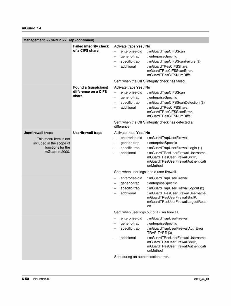
mGuard 7.4
Failed integrity check of a CIFS share
Activate traps Yes / No– enterprise-oid : mGuardTrapCIFSScan– generic-trap : enterpriseSpecific– specific-trap : mGuardTrapCIFSScanFailure (2)
– additional : mGuardTResCIFSShare, mGuardTResCIFSScanError, mGuardTResCIFSNumDiffs
Sent when the CIFS integrity check has failed.
Found a (suspicious) difference on a CIFS share
Activate traps Yes / No– enterprise-oid : mGuardTrapCIFSScan– generic-trap : enterpriseSpecific
– specific-trap : mGuardTrapCIFSScanDetection (3)– additional : mGuardTResCIFSShare,
mGuardTResCIFSScanError, mGuardTResCIFSNumDiffs
Sent when the CIFS integrity check has detected a difference.
Userfirewall traps
This menu item is notincluded in the scope of
functions for themGuard rs2000.
Userfirewall traps Activate traps Yes / No– enterprise-oid : mGuardTrapUserFirewall– generic-trap : enterpriseSpecific
– specific-trap : mGuardTrapUserFirewallLogin (1)– additional : mGuardTResUserFirewallUsername,
mGuardTResUserFirewallSrcIP, mGuardTResUserFirewallAuthenticationMethod
Sent when user logs in to a user firewall.
– enterprise-oid : mGuardTrapUserFirewall– generic-trap : enterpriseSpecific– specific-trap : mGuardTrapUserFirewallLogout (2)
– additional : mGuardTResUserFirewallUsername,mGuardTResUserFirewallSrcIP,mGuardTResUserFirewallLogoutReason
Sent when user logs out of a user firewall.
– enterprise-oid : mGuardTrapUserFirewall
– generic-trap : enterpriseSpecific– specific-trap : mGuardTrapUserFirewallAuthError
TRAP-TYPE (3)– additional : mGuardTResUserFirewallUsername,
mGuardTResUserFirewallSrcIP, mGuardTResUserFirewallAuthenticationMethod
Sent during an authentication error.
Management >> SNMP >> Trap (continued)
6-50 INNOMINATE 7961_en_04
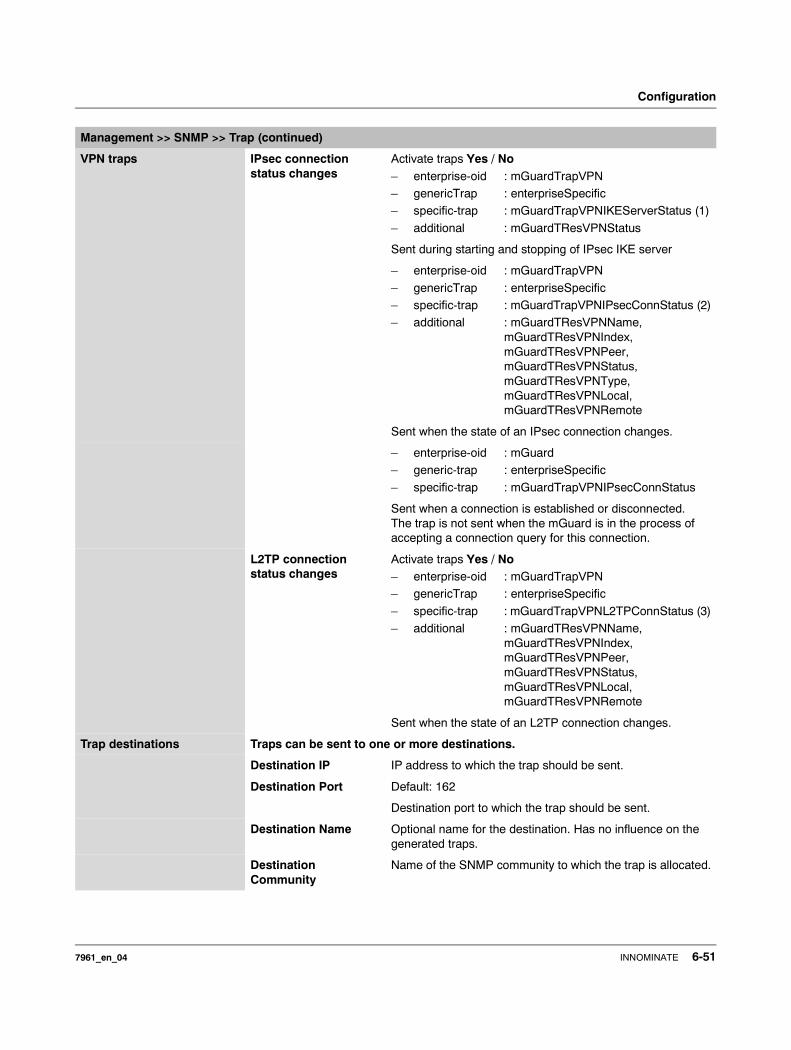
Configuration
VPN traps IPsec connection status changes
Activate traps Yes / No– enterprise-oid : mGuardTrapVPN– genericTrap : enterpriseSpecific– specific-trap : mGuardTrapVPNIKEServerStatus (1)
– additional : mGuardTResVPNStatus
Sent during starting and stopping of IPsec IKE server
– enterprise-oid : mGuardTrapVPN
– genericTrap : enterpriseSpecific– specific-trap : mGuardTrapVPNIPsecConnStatus (2)– additional : mGuardTResVPNName,
mGuardTResVPNIndex,mGuardTResVPNPeer, mGuardTResVPNStatus, mGuardTResVPNType, mGuardTResVPNLocal,mGuardTResVPNRemote
Sent when the state of an IPsec connection changes.
– enterprise-oid : mGuard– generic-trap : enterpriseSpecific
– specific-trap : mGuardTrapVPNIPsecConnStatus
Sent when a connection is established or disconnected. The trap is not sent when the mGuard is in the process of accepting a connection query for this connection.
L2TP connection status changes
Activate traps Yes / No– enterprise-oid : mGuardTrapVPN– genericTrap : enterpriseSpecific
– specific-trap : mGuardTrapVPNL2TPConnStatus (3)– additional : mGuardTResVPNName,
mGuardTResVPNIndex,mGuardTResVPNPeer, mGuardTResVPNStatus,mGuardTResVPNLocal, mGuardTResVPNRemote
Sent when the state of an L2TP connection changes.
Trap destinations Traps can be sent to one or more destinations.
Destination IP IP address to which the trap should be sent.
Destination Port Default: 162
Destination port to which the trap should be sent.
Destination Name Optional name for the destination. Has no influence on the generated traps.
Destination Community
Name of the SNMP community to which the trap is allocated.
Management >> SNMP >> Trap (continued)
7961_en_04 INNOMINATE 6-51
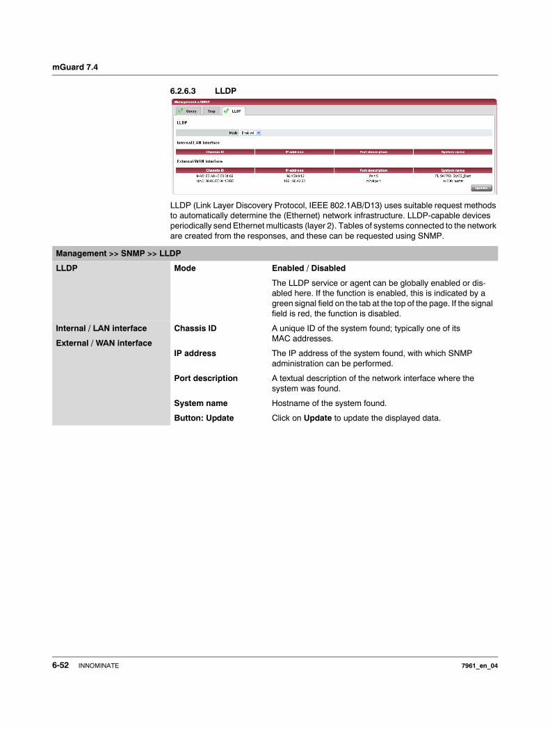
mGuard 7.4
6.2.6.3 LLDP
LLDP (Link Layer Discovery Protocol, IEEE 802.1AB/D13) uses suitable request methods to automatically determine the (Ethernet) network infrastructure. LLDP-capable devices periodically send Ethernet multicasts (layer 2). Tables of systems connected to the network are created from the responses, and these can be requested using SNMP.
Management >> SNMP >> LLDP
LLDP Mode Enabled / Disabled
The LLDP service or agent can be globally enabled or dis-abled here. If the function is enabled, this is indicated by a green signal field on the tab at the top of the page. If the signal field is red, the function is disabled.
Internal / LAN interface
External / WAN interface
Chassis ID A unique ID of the system found; typically one of its MAC addresses.
IP address The IP address of the system found, with which SNMP administration can be performed.
Port description A textual description of the network interface where the system was found.
System name Hostname of the system found.
Button: Update Click on Update to update the displayed data.
6-52 INNOMINATE 7961_en_04
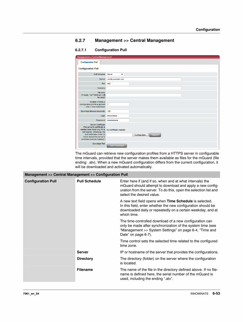
Configuration
6.2.7 Management >> Central Management
6.2.7.1 Configuration Pull
The mGuard can retrieve new configuration profiles from a HTTPS server in configurable time intervals, provided that the server makes them available as files for the mGuard (file ending: .atv). When a new mGuard configuration differs from the current configuration, it will be downloaded and activated automatically.
Management >> Central Management >> Configuration Pull
Configuration Pull Pull Schedule Enter here if (and if so, when and at what intervals) the mGuard should attempt to download and apply a new config-uration from the server. To do this, open the selection list and select the desired value.
A new text field opens when Time Schedule is selected. In this field, enter whether the new configuration should be downloaded daily or repeatedly on a certain weekday, and at which time.
The time-controlled download of a new configuration can only be made after synchronization of the system time (see “Management >> System Settings” on page 6-4, “Time and Date” on page 6-7).
Time control sets the selected time related to the configured time zone.
Server IP or hostname of the server that provides the configurations.
Directory The directory (folder) on the server where the configuration is located.
Filename The name of the file in the directory defined above. If no file-name is defined here, the serial number of the mGuard is used, including the ending “.atv”.
7961_en_04 INNOMINATE 6-53
mGuard 7.4
Number of times a configuration profile is ignored after it was rolled back
Default: 10
After a new configuration is retrieved, it can occur that the mGuard is no longer accessible after the configuration is put into force. A new remote configuration for correction purposes is then no longer possible. In order to rule this out, the mGuard makes the following checks:
After the retrieved configuration is enforced, the mGuard tries to connect again to the configuration server based on the new configuration. The mGuard then attempts to download the newly enforced configuration once again.
If this is successful, the new configuration remains.
If this check is unsuccessful for whatever reason, the mGuard assumes that the newly enforced configuration profile is defective. The mGuard memorizes the MD5 total for identification purposes, then performs a rollback.
Rollback means that the last (working) configuration is restored. This assumes that the new (non-functioning) configuration contains an instruction to perform a rollback if a newly loaded configuration profile is defective according to the check procedure detailed above.
When the mGuard attempts to retrieve a new configuration profile periodically after the time defined in Pull Schedule (and Time Schedule), it will only accept the profile ac-cording to the following selection criterion: The configuration profile provided must differ from the configuration profile identified as defective that led to the rollback.
(The mGuard checks the MD5 total of the old, defective and rejected configuration against the MD5 total of the new configuration profile offered.)
If this selection criterion is fulfilled (i.e. a newer configuration profile is offered), the mGuard gets this configuration profile, enforces it and checks it according to the procedure detailed above. It also disables it if the rollback check is negative.
If the selection criterion is not fulfilled (i.e. the same configuration profile is being offered), the selection criterion remains in force for all additional periodic requests for the period defined in the Number of times… field.
If the defined number of times expires without a change of the configuration profile on the server, the mGuard enforces the unchanged new (“defective”) configuration profile once more, despite it being “defective”. This is to rule out the possibility that external factors (e.g. network outage) caused the check failure.
The mGuard then attempts to connect to the configuration server again based on the new configuration, then downloads the newly enforced configuration profile. If this is unsuccessful, another rollback is performed. The selection criterion is enforced for further load cycles as often as is defined in the Number of times… field.
If the value in the Number of times… field is defined as 0, the selection criterion (the offered configuration profile is ignored if it remains unchanged) will never come into effect. As a result, the second of the following goals can then no longer be reached.
Management >> Central Management >> Configuration Pull (continued)
6-54 INNOMINATE 7961_en_04
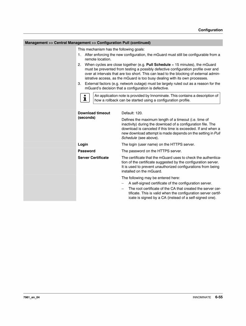
Configuration
This mechanism has the following goals:
1. After enforcing the new configuration, the mGuard must still be configurable from a remote location.
2. When cycles are close together (e.g. Pull Schedule = 15 minutes), the mGuard must be prevented from testing a possibly defective configuration profile over and over at intervals that are too short. This can lead to the blocking of external admin-istrative access, as the mGuard is too busy dealing with its own processes.
3. External factors (e.g. network outage) must be largely ruled out as a reason for the mGuard’s decision that a configuration is defective.
Download timeout (seconds)
Default: 120.
Defines the maximum length of a timeout (i.e. time of inactivity) during the download of a configuration file. The download is canceled if this time is exceeded. If and when a new download attempt is made depends on the setting in Pull Schedule (see above).
Login The login (user name) on the HTTPS server.
Password The password on the HTTPS server.
Server Certificate The certificate that the mGuard uses to check the authentica-tion of the certificate suggested by the configuration server. It is used to prevent unauthorized configurations from being installed on the mGuard.
The following may be entered here:– A self-signed certificate of the configuration server.
– The root certificate of the CA that created the server cer-tificate. This is valid when the configuration server certif-icate is signed by a CA (instead of a self-signed one).
Management >> Central Management >> Configuration Pull (continued)
An application note is provided by Innominate. This contains a description of how a rollback can be started using a configuration profile.
7961_en_04 INNOMINATE 6-55
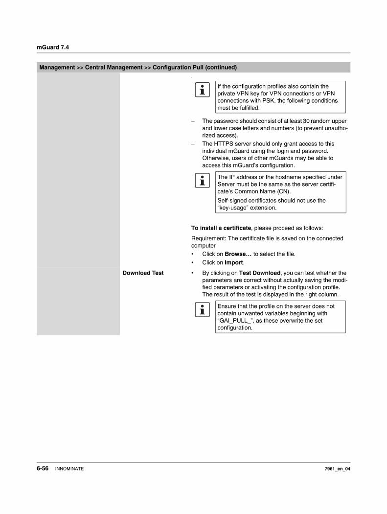
mGuard 7.4
.
– The password should consist of at least 30 random upper and lower case letters and numbers (to prevent unautho-rized access).
– The HTTPS server should only grant access to this individual mGuard using the login and password. Otherwise, users of other mGuards may be able to access this mGuard’s configuration.
To install a certificate, please proceed as follows:
Requirement: The certificate file is saved on the connected computer• Click on Browse… to select the file.
• Click on Import.
Download Test • By clicking on Test Download, you can test whether the parameters are correct without actually saving the modi-fied parameters or activating the configuration profile. The result of the test is displayed in the right column.
Management >> Central Management >> Configuration Pull (continued)
If the configuration profiles also contain the private VPN key for VPN connections or VPN connections with PSK, the following conditions must be fulfilled:
The IP address or the hostname specified under Server must be the same as the server certifi-cate’s Common Name (CN).
Self-signed certificates should not use the “key-usage” extension.
Ensure that the profile on the server does not contain unwanted variables beginning with “GAI_PULL_”, as these overwrite the set configuration.
6-56 INNOMINATE 7961_en_04
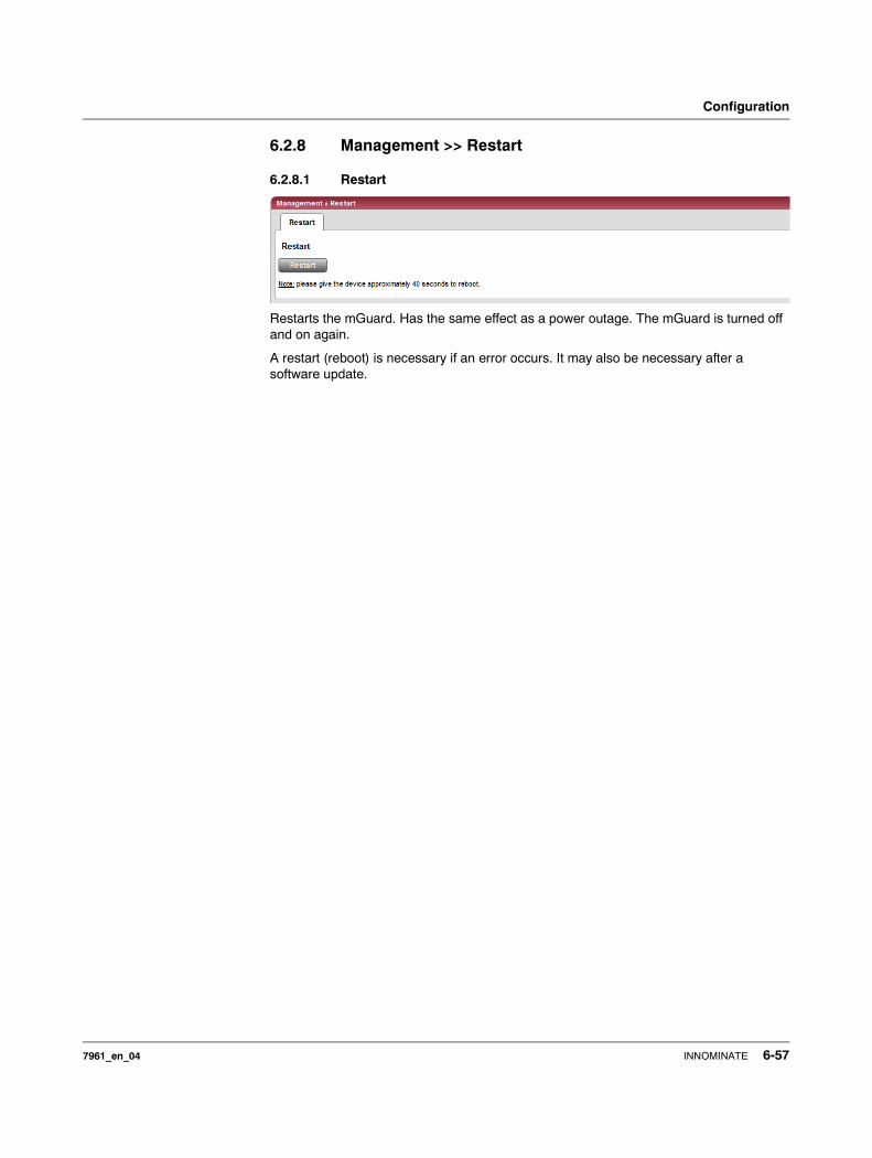
Configuration
6.2.8 Management >> Restart
6.2.8.1 Restart
Restarts the mGuard. Has the same effect as a power outage. The mGuard is turned off and on again.
A restart (reboot) is necessary if an error occurs. It may also be necessary after a software update.
7961_en_04 INNOMINATE 6-57

mGuard 7.4
6.3 Blade Control menu
6.3.1 Blade Control >> Overview
This menu is only available on the mGuard blade controller.
Blade Control >> Overview
Overview Rack ID The ID of the rack where the mGuard is mounted. This value can be configured for all blades on the controller.
Power supply P1/P2 State of power supply units P1 and P2.
– OK– Absent
– Defect– Fatal error
Blade Number of the slot where the mGuard blade is installed.
Device Device name, e.g. “blade” or “blade XL”.
Status – Online – The device in the slot is working correctly.– Present – Device is present but not yet ready
(e.g. in start-up phase).– Absent – No device found in the slot.
WAN Status of the WAN port.
LAN Status of the LAN port.
Serial number The serial number of the mGuard.
Version The software version of the mGuard.
B Backup: Automatic configuration backup on the controller is activated/deactivated for this slot.
R Restore: Automatic configuration restoration after replacing the mGuard is activated/deactivated for this slot.
6-58 INNOMINATE 7961_en_04
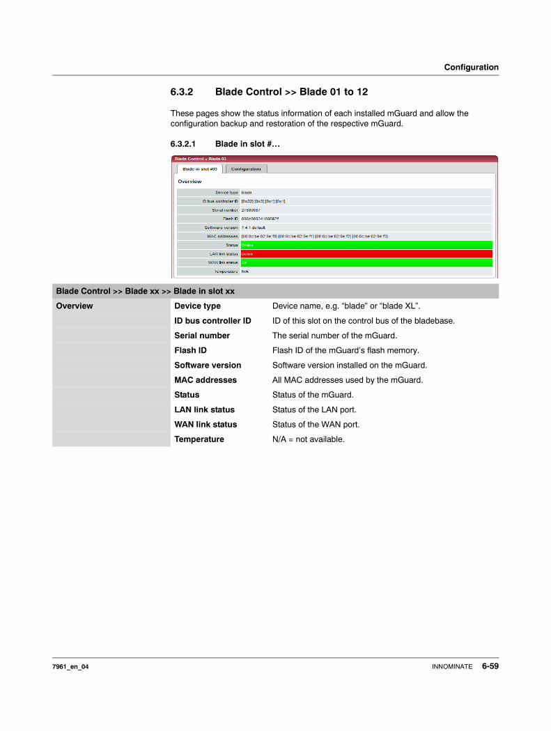
Configuration
6.3.2 Blade Control >> Blade 01 to 12
These pages show the status information of each installed mGuard and allow the configuration backup and restoration of the respective mGuard.
6.3.2.1 Blade in slot #…
Blade Control >> Blade xx >> Blade in slot xx
Overview Device type Device name, e.g. “blade” or “blade XL”.
ID bus controller ID ID of this slot on the control bus of the bladebase.
Serial number The serial number of the mGuard.
Flash ID Flash ID of the mGuard’s flash memory.
Software version Software version installed on the mGuard.
MAC addresses All MAC addresses used by the mGuard.
Status Status of the mGuard.
LAN link status Status of the LAN port.
WAN link status Status of the WAN port.
Temperature N/A = not available.
7961_en_04 INNOMINATE 6-59
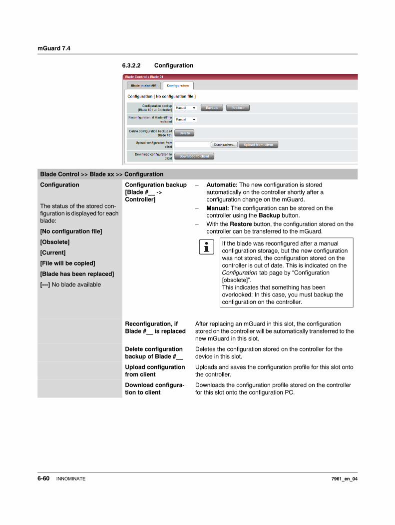
mGuard 7.4
6.3.2.2 Configuration
Blade Control >> Blade xx >> Configuration
Configuration
The status of the stored con-figuration is displayed for each blade:
[No configuration file]
[Obsolete]
[Current]
[File will be copied]
[Blade has been replaced]
[---] No blade available
Configuration backup [Blade #__ -> Controller]
– Automatic: The new configuration is stored automatically on the controller shortly after a configuration change on the mGuard.
– Manual: The configuration can be stored on the controller using the Backup button.
– With the Restore button, the configuration stored on the controller can be transferred to the mGuard.
Reconfiguration, if Blade #__ is replaced
After replacing an mGuard in this slot, the configuration stored on the controller will be automatically transferred to the new mGuard in this slot.
Delete configuration backup of Blade #__
Deletes the configuration stored on the controller for the device in this slot.
Upload configuration from client
Uploads and saves the configuration profile for this slot onto the controller.
Download configura-tion to client
Downloads the configuration profile stored on the controller for this slot onto the configuration PC.
If the blade was reconfigured after a manual configuration storage, but the new configuration was not stored, the configuration stored on the controller is out of date. This is indicated on the Configuration tab page by “Configuration [obsolete]”.This indicates that something has been overlooked: In this case, you must backup the configuration on the controller.
6-60 INNOMINATE 7961_en_04
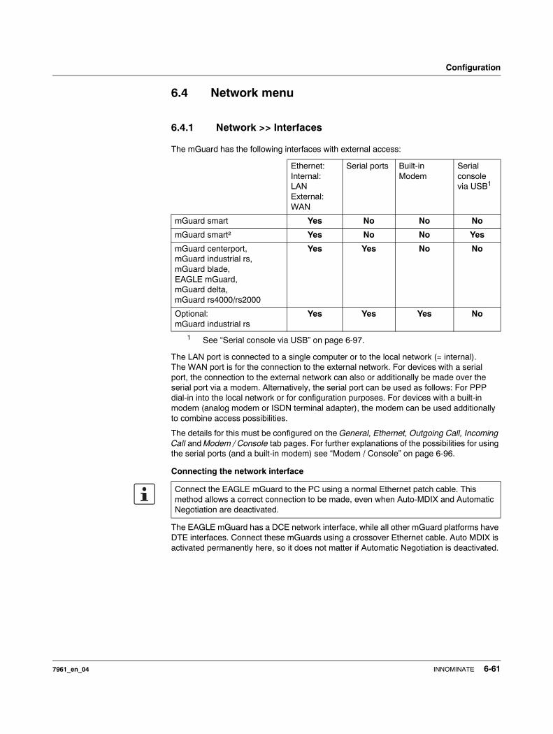
Configuration
6.4 Network menu
6.4.1 Network >> Interfaces
The mGuard has the following interfaces with external access:
The LAN port is connected to a single computer or to the local network (= internal). The WAN port is for the connection to the external network. For devices with a serial port, the connection to the external network can also or additionally be made over the serial port via a modem. Alternatively, the serial port can be used as follows: For PPP dial-in into the local network or for configuration purposes. For devices with a built-in modem (analog modem or ISDN terminal adapter), the modem can be used additionally to combine access possibilities.
The details for this must be configured on the General, Ethernet, Outgoing Call, Incoming Call and Modem / Console tab pages. For further explanations of the possibilities for using the serial ports (and a built-in modem) see “Modem / Console” on page 6-96.
Connecting the network interface
The EAGLE mGuard has a DCE network interface, while all other mGuard platforms have DTE interfaces. Connect these mGuards using a crossover Ethernet cable. Auto MDIX is activated permanently here, so it does not matter if Automatic Negotiation is deactivated.
Ethernet: Internal: LANExternal: WAN
Serial ports Built-in Modem
Serial console via USB1
1 See “Serial console via USB” on page 6-97.
mGuard smart Yes No No No
mGuard smart² Yes No No Yes
mGuard centerport, mGuard industrial rs, mGuard blade, EAGLE mGuard, mGuard delta,mGuard rs4000/rs2000
Yes Yes No No
Optional: mGuard industrial rs
Yes Yes Yes No
Connect the EAGLE mGuard to the PC using a normal Ethernet patch cable. This method allows a correct connection to be made, even when Auto-MDIX and Automatic Negotiation are deactivated.
7961_en_04 INNOMINATE 6-61
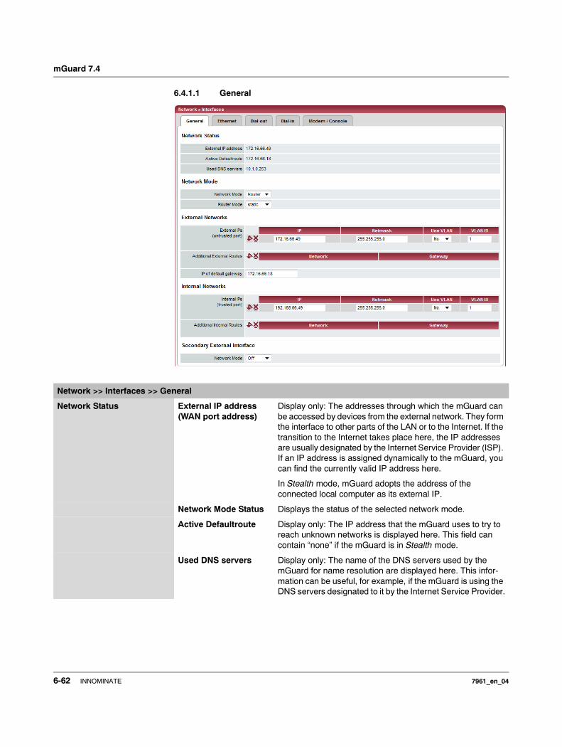
mGuard 7.4
6.4.1.1 General
Network >> Interfaces >> General
Network Status External IP address (WAN port address)
Display only: The addresses through which the mGuard can be accessed by devices from the external network. They form the interface to other parts of the LAN or to the Internet. If the transition to the Internet takes place here, the IP addresses are usually designated by the Internet Service Provider (ISP). If an IP address is assigned dynamically to the mGuard, you can find the currently valid IP address here.
In Stealth mode, mGuard adopts the address of the connected local computer as its external IP.
Network Mode Status Displays the status of the selected network mode.
Active Defaultroute Display only: The IP address that the mGuard uses to try to reach unknown networks is displayed here. This field can contain “none” if the mGuard is in Stealth mode.
Used DNS servers Display only: The name of the DNS servers used by the mGuard for name resolution are displayed here. This infor-mation can be useful, for example, if the mGuard is using the DNS servers designated to it by the Internet Service Provider.
6-62 INNOMINATE 7961_en_04
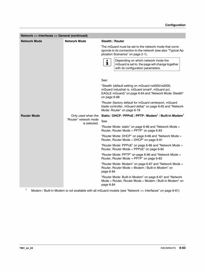
Configuration
Network Mode Network Mode Stealth / Router
The mGuard must be set to the network mode that corre-sponds to its connection to the network (see also “Typical Ap-plication Scenarios” on page 2-1).
See:
“Stealth (default setting on mGuard rs4000/rs2000, mGuard industrial rs, mGuard smart², mGuard pci, EAGLE mGuard)” on page 6-64 and “Network Mode: Stealth” on page 6-68
“Router (factory default for mGuard centerport, mGuard blade controller, mGuard delta)” on page 6-65 and “Network Mode: Router” on page 6-78
Router Mode Only used when the“Router” network mode
is selected.
Static / DHCP / PPPoE / PPTP / Modem1 / Built-in Modem1
See:
“Router Mode: static” on page 6-66 and “Network Mode = Router, Router Mode = PPTP” on page 6-83
“Router Mode: DHCP” on page 6-66 and “Network Mode = Router, Router Mode = DHCP” on page 6-81
“Router Mode: PPPoE” on page 6-66 and “Network Mode = Router, Router Mode = PPPoE” on page 6-82
“Router Mode: PPTP” on page 6-66 and “Network Mode = Router, Router Mode = PPTP” on page 6-83
“Router Mode: Modem” on page 6-67 and “Network Mode = Router, Router Mode = Modem / Built-in Modem” on page 6-84
“Router Mode: Built-in Modem” on page 6-67 and “Network Mode = Router, Router Mode = Modem / Built-in Modem” on page 6-84
1 Modem / Built-in Modem is not available with all mGuard models (see “Network >> Interfaces” on page 6-61)
Network >> Interfaces >> General (continued)
Depending on which network mode the mGuard is set to, the page will change together with its configuration parameters.
7961_en_04 INNOMINATE 6-63
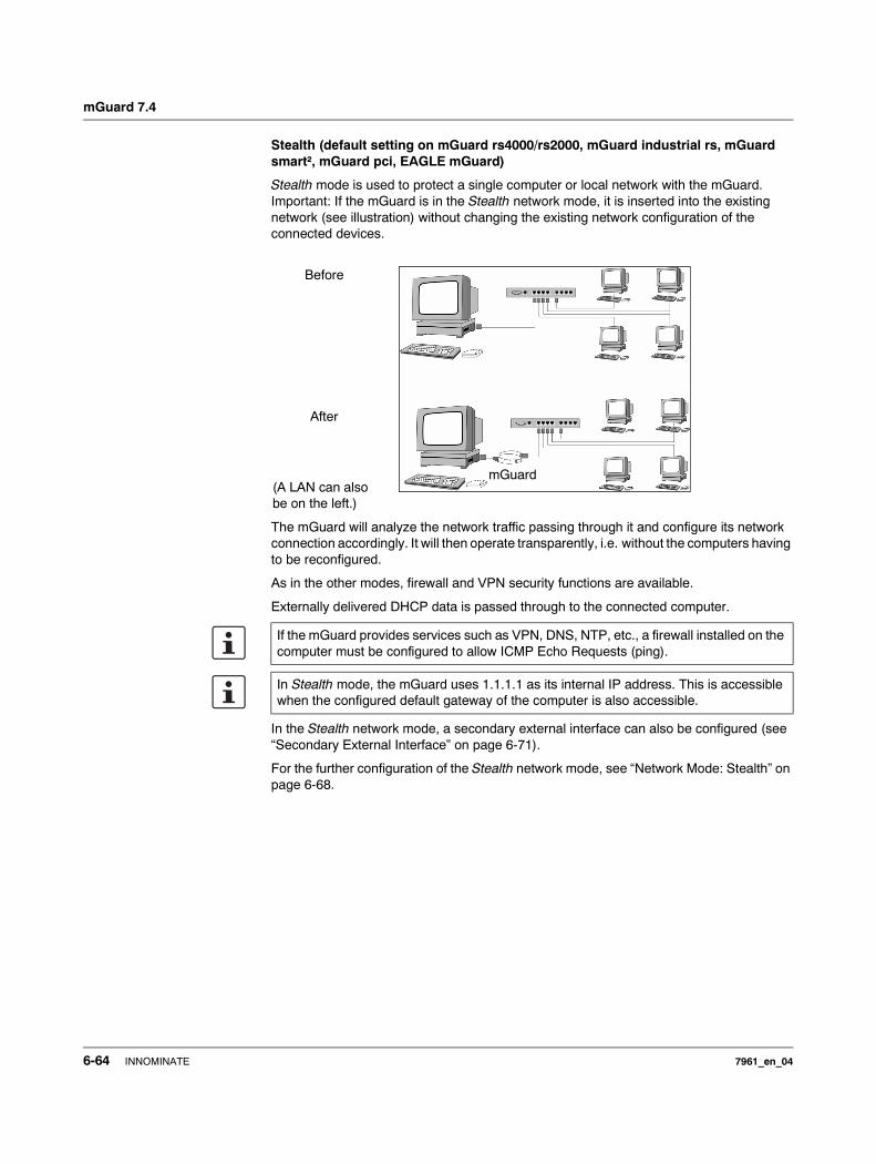
mGuard 7.4
Stealth (default setting on mGuard rs4000/rs2000, mGuard industrial rs, mGuard smart², mGuard pci, EAGLE mGuard)
Stealth mode is used to protect a single computer or local network with the mGuard. Important: If the mGuard is in the Stealth network mode, it is inserted into the existing network (see illustration) without changing the existing network configuration of the connected devices.
The mGuard will analyze the network traffic passing through it and configure its network connection accordingly. It will then operate transparently, i.e. without the computers having to be reconfigured.
As in the other modes, firewall and VPN security functions are available.
Externally delivered DHCP data is passed through to the connected computer.
In the Stealth network mode, a secondary external interface can also be configured (see “Secondary External Interface” on page 6-71).
For the further configuration of the Stealth network mode, see “Network Mode: Stealth” on page 6-68.
Before
After
(A LAN can also be on the left.)
If the mGuard provides services such as VPN, DNS, NTP, etc., a firewall installed on the computer must be configured to allow ICMP Echo Requests (ping).
In Stealth mode, the mGuard uses 1.1.1.1 as its internal IP address. This is accessible when the configured default gateway of the computer is also accessible.
mGuard
6-64 INNOMINATE 7961_en_04

Configuration
Router (factory default for mGuard centerport, mGuard blade controller, mGuard delta)
If the mGuard is in Router mode, it serves as a gateway between different subnetworks and has both an external interface (WAN port) and an internal interface (LAN port) with at least one IP address.
WAN Port The mGuard is connected to the Internet or other external parts of the LAN over the WAN port.– mGuard smart²: The WAN port is the Ethernet socket.
LAN Port The mGuard is connected to a local network or a single computer over the LAN port.
– mGuard smart²: The LAN port is the Ethernet connector.– mGuard pci:
In Driver mode, the LAN port is represented by the operating system’s network interface card (here: mGuard pci) configuration.In Power-over-PCI mode, the LAN port is the LAN socket of the mGuard pci.
As in the other modes, firewall and VPN security functions are available.
In the Router network mode, a secondary external interface can also be configured (see “Secondary External Interface” on page 6-71).
There are several router modes, depending on the Internet connection:– static
– DHCP– PPPoE– PPPT
– Modem– Built-in Modem
If the mGuard is operated in Router mode, it must be set as the default gateway in the connected local computers.
In other words, the IP address of the mGuard LAN port must be entered as the default gateway on these computers.
NAT should be activated if the mGuard is operated in Router mode and establishes the connection to the Internet (see “Network >> NAT” on page 6-103).
Only then can the computers in the connected local network access the Internet over the mGuard. If NAT is not activated, it is possible that only VPN connections can be used.
7961_en_04 INNOMINATE 6-65
mGuard 7.4
Router Mode: static
The IP address is set permanently.
Router Mode: DHCP
The IP address is assigned via DHCP.
Router Mode: PPPoE
PPPoE mode corresponds to the Router mode with DHCP – with one difference: The PPPoE protocol, which is used by many DSL modems for DSL Internet access, is used for connecting to the external network (Internet or WAN). The external IP address that the mGuard uses for access from remote peers is assigned by the Internet Service Provider.
For the further configuration of the PPPoE network mode, see “Network Mode = Router, Router Mode = PPPoE” on page 6-82.
Router Mode: PPTP
Similar to the PPPoE mode. In Austria, for example, PPTP is used instead of the PPPoE protocol for DSL connections.
(PPTP is the protocol that was originally used by Microsoft for VPN connections.)
For the further configuration of the PPTP network mode, see “Network Mode = Router, Router Mode = PPTP” on page 6-83.
If the mGuard is operated in PPPoE mode, it must be set as the default gateway in the connected local computers.
In other words, the IP address of the mGuard LAN port must be entered as the default gateway on these computers.
If the mGuard is operated in PPPoE mode, NAT must be activated in order to gain access to the Internet.
If NAT is not activated, it is possible that only VPN connections can be used.
If the mGuard is operated in PPTP mode, it must be set as the default gateway in the connected local computers.
In other words, the IP address of the mGuard LAN port must be entered as the default gateway on these computers.
If the mGuard is operated in PPTP mode, NAT should be activated in order to gain access to the Internet from the local network (see “Network >> NAT” on page 6-103).
If NAT is not activated, it is possible that only VPN connections can be used.
6-66 INNOMINATE 7961_en_04

Configuration
Router Mode: Modem
If the Modem network mode is selected, the external Ethernet interface of the mGuard is deactivated and data transfer to and from the WAN is made over the serial port that is accessible externally.
An external modem that establishes the connection to the telephone network is connected to the serial port. Connection to the WAN or Internet is then made over the telephone network using the external modem.
Router Mode: Built-in Modem
If the Built-in Modem network mode is selected, the external Ethernet interface of the mGuard is deactivated and data transfer to and from the WAN is made over the modem or ISDN terminal adapter installed in the mGuard. This must be connected to the telephone network. Internet connection is then made over the telephone network.
After Built-in Modem is selected, the text fields used for defining modem connection parameters are displayed.
For the further configuration of the Built-in Modem / Modem network mode, see “Network Mode = Router, Router Mode = Modem / Built-in Modem” on page 6-84.
Only used for mGuard industrial rs without a built-in modem, mGuard centerport, mGuard blade, EAGLE mGuard, mGuard delta
If the address of the mGuard is changed (e.g. by changing the network mode from Ste-alth to Router), the device is only accessible under the new address. When the change is made over the LAN port, a message is displayed with the new address before the change becomes active. When the configuration is changed over the WAN port you will not receive feedback from the mGuard.
If you set the mode to Router, PPPoE or PPTP and then change the IP address of the LAN port and/or the local netmask, make sure you enter the correct values. Otherwise, the mGuard may no longer be accessible.
For the further configuration of the Built-in Modem / Modem network mode, see “Network Mode = Router, Router Mode = Modem / Built-in Modem” on page 6-84.
Only used for mGuard industrial rs with built-in modem or ISDN terminal adapter.
7961_en_04 INNOMINATE 6-67
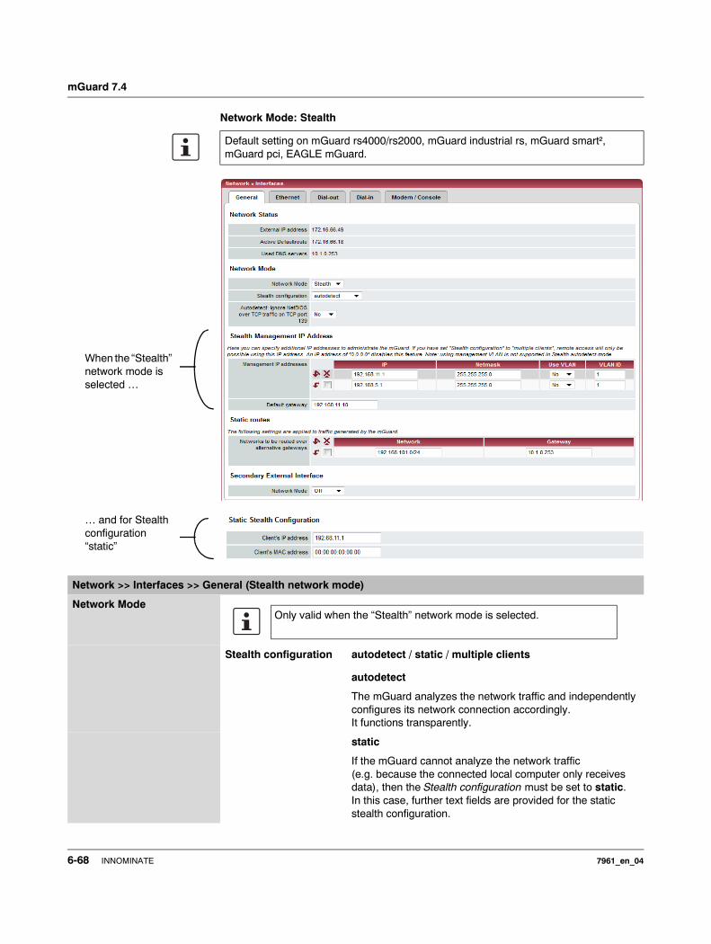
mGuard 7.4
Network Mode: Stealth
Default setting on mGuard rs4000/rs2000, mGuard industrial rs, mGuard smart², mGuard pci, EAGLE mGuard.
When the “Stealth” network mode is selected …
… and for Stealth configuration “static”
Network >> Interfaces >> General (Stealth network mode)
Network Mode
Stealth configuration autodetect / static / multiple clients
autodetect
The mGuard analyzes the network traffic and independently configures its network connection accordingly. It functions transparently.
static
If the mGuard cannot analyze the network traffic (e.g. because the connected local computer only receives data), then the Stealth configuration must be set to static. In this case, further text fields are provided for the static stealth configuration.
Only valid when the “Stealth” network mode is selected.
6-68 INNOMINATE 7961_en_04
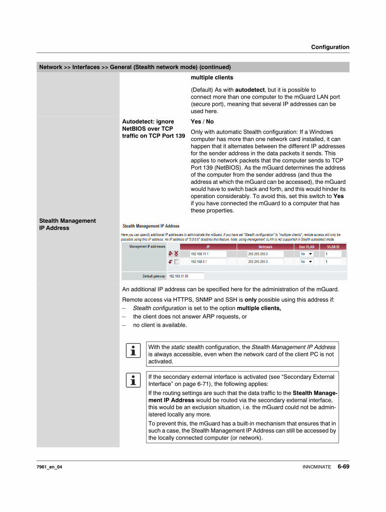
Configuration
multiple clients
(Default) As with autodetect, but it is possible to connect more than one computer to the mGuard LAN port (secure port), meaning that several IP addresses can be used here.
Autodetect: ignore NetBIOS over TCP traffic on TCP Port 139
Yes / No
Only with automatic Stealth configuration: If a Windows computer has more than one network card installed, it can happen that it alternates between the different IP addresses for the sender address in the data packets it sends. This applies to network packets that the computer sends to TCP Port 139 (NetBIOS). As the mGuard determines the address of the computer from the sender address (and thus the address at which the mGuard can be accessed), the mGuard would have to switch back and forth, and this would hinder its operation considerably. To avoid this, set this switch to Yes if you have connected the mGuard to a computer that has these properties.
Stealth Management IP Address
An additional IP address can be specified here for the administration of the mGuard.
Remote access via HTTPS, SNMP and SSH is only possible using this address if:– Stealth configuration is set to the option multiple clients,– the client does not answer ARP requests, or
– no client is available.
Network >> Interfaces >> General (Stealth network mode) (continued)
With the static stealth configuration, the Stealth Management IP Address is always accessible, even when the network card of the client PC is not activated.
If the secondary external interface is activated (see “Secondary External Interface” on page 6-71), the following applies:
If the routing settings are such that the data traffic to the Stealth Manage-ment IP Address would be routed via the secondary external interface, this would be an exclusion situation, i.e. the mGuard could not be admin-istered locally any more.
To prevent this, the mGuard has a built-in mechanism that ensures that in such a case, the Stealth Management IP Address can still be accessed by the locally connected computer (or network).
7961_en_04 INNOMINATE 6-69
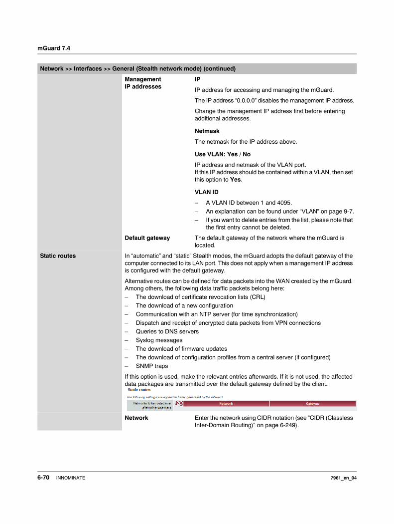
mGuard 7.4
Management IP addresses
IP
IP address for accessing and managing the mGuard.
The IP address “0.0.0.0” disables the management IP address.
Change the management IP address first before entering additional addresses.
Netmask
The netmask for the IP address above.
Use VLAN: Yes / No
IP address and netmask of the VLAN port.If this IP address should be contained within a VLAN, then set this option to Yes.
VLAN ID
– A VLAN ID between 1 and 4095.
– An explanation can be found under “VLAN” on page 9-7.– If you want to delete entries from the list, please note that
the first entry cannot be deleted.
Default gateway The default gateway of the network where the mGuard is located.
Static routes In “automatic” and “static” Stealth modes, the mGuard adopts the default gateway of the computer connected to its LAN port. This does not apply when a management IP address is configured with the default gateway.
Alternative routes can be defined for data packets into the WAN created by the mGuard. Among others, the following data traffic packets belong here:
– The download of certificate revocation lists (CRL)– The download of a new configuration– Communication with an NTP server (for time synchronization)
– Dispatch and receipt of encrypted data packets from VPN connections– Queries to DNS servers– Syslog messages
– The download of firmware updates– The download of configuration profiles from a central server (if configured)– SNMP traps
If this option is used, make the relevant entries afterwards. If it is not used, the affected data packages are transmitted over the default gateway defined by the client.
Network Enter the network using CIDR notation (see “CIDR (Classless Inter-Domain Routing)” on page 6-249).
Network >> Interfaces >> General (Stealth network mode) (continued)
6-70 INNOMINATE 7961_en_04
Configuration
Gateway The gateway where this network can be accessed.
The routes defined here are valid unconditionally for data packets created by the mGuard. This definition takes priority over other settings (see also “Example of a network” on page 6-250).
Static Stealth Configuration Client IP address The IP address of the computer connected to the LAN port.
Client’s MAC address The physical address of the network adapter in the local computer where the mGuard is connected.• The MAC address can be determined as follows:
On the DOS level (Start, Programs, Accessories, Command Prompt), enter the following command:ipconfig /all
The entry of a MAC address is not absolutely necessary. The mGuard can obtain the MAC address automatically from the client. The MAC address 0:0:0:0:0:0 must be entered in order to do this. Please note that the mGuard can only forward the network packets through to the client after the MAC address has been determined.
If no Stealth Management IP Address or Client’s MAC address is configured in static Stealth mode, then DAD ARP requests are sent to the internal interface (see RFC2131, section 4.4.1).
Secondary External Interface
This menu item is notincluded in the scope of
functions for themGuard rs2000.
The secondary external interface can be used to transfer data permanently or temporarily into the external network (WAN).
If the secondary external interface is activated, the following applies:
In Stealth network mode
Only the data traffic created by the mGuard is subject to the routing specified for the secondary external interface, not the data traffic coming from a locally connected computer. Locally connected computers cannot be accessed remotely either, only the mGuard can be accessed remotely – if the configuration permits this.
VPN data traffic can – as in the Router network mode – flow to and from the locally connected computers. Because this traffic is encrypted by the mGuard and is therefore seen as generated by the mGuard.
In Router network mode
All data traffic, i.e. from and to locally connected computers and that which is generated by the mGuard, can be fed into the external network (WAN) via the secondary external interface.
Network >> Interfaces >> General (Stealth network mode) (continued)
Only on Router network mode with static router mode, or Stealth network mode. Only for mGuard rs4000, mGuard centerport, mGuard industrial rs, mGuard blade, EAGLE mGuard, mGuard delta:
In these network modes, the serial port of the mGuard can be configured as an additional secondary external interface.
7961_en_04 INNOMINATE 6-71
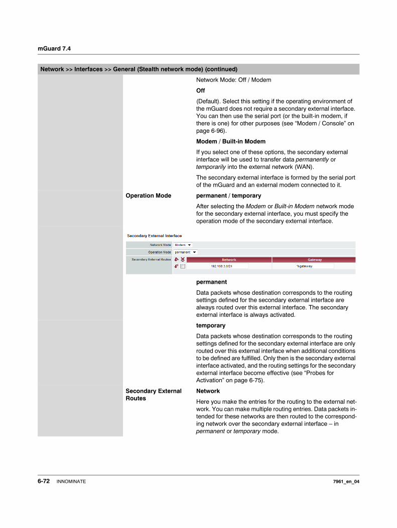
mGuard 7.4
Network Mode: Off / Modem
Off
(Default). Select this setting if the operating environment of the mGuard does not require a secondary external interface. You can then use the serial port (or the built-in modem, if there is one) for other purposes (see “Modem / Console” on page 6-96).
Modem / Built-in Modem
If you select one of these options, the secondary external interface will be used to transfer data permanently or temporarily into the external network (WAN).
The secondary external interface is formed by the serial port of the mGuard and an external modem connected to it.
Operation Mode permanent / temporary
After selecting the Modem or Built-in Modem network mode for the secondary external interface, you must specify the operation mode of the secondary external interface.
permanent
Data packets whose destination corresponds to the routing settings defined for the secondary external interface are always routed over this external interface. The secondary external interface is always activated.
temporary
Data packets whose destination corresponds to the routing settings defined for the secondary external interface are only routed over this external interface when additional conditions to be defined are fulfilled. Only then is the secondary external interface activated, and the routing settings for the secondary external interface become effective (see “Probes for Activation” on page 6-75).
Secondary External Routes
Network
Here you make the entries for the routing to the external net-work. You can make multiple routing entries. Data packets in-tended for these networks are then routed to the correspond-ing network over the secondary external interface – in permanent or temporary mode.
Network >> Interfaces >> General (Stealth network mode) (continued)
6-72 INNOMINATE 7961_en_04
Configuration
Gateway
Enter the IP address of the gateway over which the transfer is made in the above-named external network – if this IP address is known.
When you are dialing in to the Internet using the phone num-ber of the ISP, the address of the gateway is usually only known after the dial-in. In this case, you enter %gateway in the field as a placeholder.
Network >> Interfaces >> General (Stealth network mode) (continued)
7961_en_04 INNOMINATE 6-73

mGuard 7.4
Operation Mode: permanent / temporary
In both the permanent and temporary operation modes, the modem must be available to the mGuard for the secondary external interface so that the mGuard can make a connec-tion to the WAN (Internet) over the telephone network connected to the modem.
Which data packets are transferred over the primary external interface (Ethernet interface) and which are transferred over the secondary external interface is determined by the routing settings in effect for these two external interfaces. Therefore an interface can only take a data packet if the routing setting for that interface matches the destination of the data packet.
The following rules apply to the use of routing entries:
If multiple routing entries for the destination of a data packet match, then the smallest network defined in the routing entries that matches the data packet decides which route this packet takes.
Example:
– The external route of the primary external interface is entered as 10.0.0.0/8, while the external route of the secondary external interface is entered as 10.1.7.0/24. Data packets to network 10.1.7.0/24 are then routed over the secondary external interface, although the routing entry for the primary external interface also matches them. Reason: The routing entry for the secondary external interface indicates a smaller network (10.1.7.0/24 < 10.0.0.0/8).
– (This rule does not apply in Stealth network mode regarding the Stealth Management IP Address – see “Stealth Management IP Address” on page 6-69.)
– If the routing entries for the primary and secondary external interfaces are identical, then the secondary external interface “wins”, i.e. the data packets with a matching destination address are routed over the secondary external interface.
– The routing settings for the secondary external interface only become effective when the secondary external interface is activated. Particular attention must be paid to this if the routing entries for the primary and secondary external interfaces overlap or are identical, whereby the priority of the secondary external interface has a filter effect, with the following result: Data packets whose destination matches both the primary and secondary external interfaces are always transferred over the secondary external interface, but only if this is activated.
– In the temporary operation mode, “activated” signifies the following: Only when certain conditions are fulfilled is the secondary external interface activated, and only then do the routing settings of the secondary external interface become effective.
– Network address 0.0.0.0/0 generally signifies the largest definable network, i.e. the Internet.
In the Router network mode, the local network connected to the mGuard can be accessed via the secondary external interface as long as the firewall settings are defined to allow this.
6-74 INNOMINATE 7961_en_04
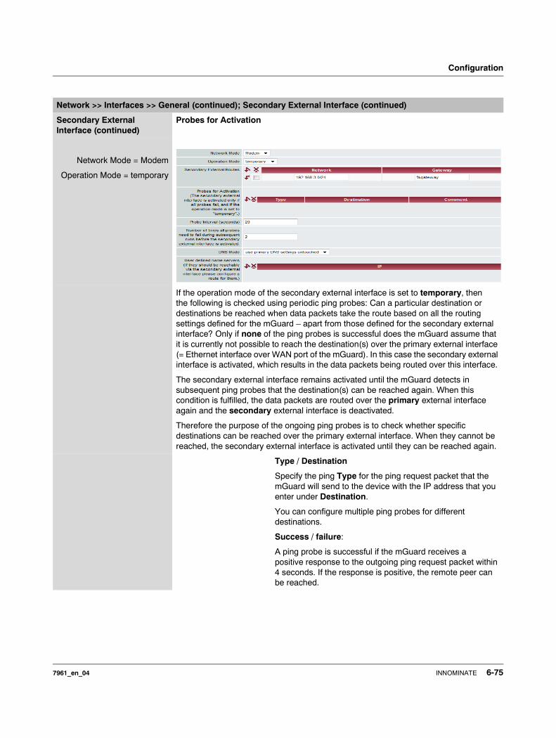
Configuration
Network >> Interfaces >> General (continued); Secondary External Interface (continued)
Secondary External Interface (continued)
Probes for Activation
Network Mode = Modem
Operation Mode = temporary
If the operation mode of the secondary external interface is set to temporary, then the following is checked using periodic ping probes: Can a particular destination or destinations be reached when data packets take the route based on all the routing settings defined for the mGuard – apart from those defined for the secondary external interface? Only if none of the ping probes is successful does the mGuard assume that it is currently not possible to reach the destination(s) over the primary external interface (= Ethernet interface over WAN port of the mGuard). In this case the secondary external interface is activated, which results in the data packets being routed over this interface.
The secondary external interface remains activated until the mGuard detects in subsequent ping probes that the destination(s) can be reached again. When this condition is fulfilled, the data packets are routed over the primary external interface again and the secondary external interface is deactivated.
Therefore the purpose of the ongoing ping probes is to check whether specific destinations can be reached over the primary external interface. When they cannot be reached, the secondary external interface is activated until they can be reached again.
Type / Destination
Specify the ping Type for the ping request packet that the mGuard will send to the device with the IP address that you enter under Destination.
You can configure multiple ping probes for different destinations.
Success / failure:
A ping probe is successful if the mGuard receives a positive response to the outgoing ping request packet within 4 seconds. If the response is positive, the remote peer can be reached.
7961_en_04 INNOMINATE 6-75
mGuard 7.4
Ping types:
– IKE Ping: Determines whether a VPN gateway can be reached at the IP address entered.
– ICMP Ping:Determines whether a device can be reached at the IP address entered.This is the most common ping probe. However, the response to this ping probe is switched off on some devices, so that they do not respond even though they can be reached.
– DNS Ping:
Determines whether a functioning DNS server can be reached at the IP address entered.A generic request is sent to the DNS server with the specified IP address, and every DNS server that can be reached responds to this request.
Please note the following when programming ping probes:
It makes sense to program multiple ping probes. This is because it is possible that an individual probed service is currently undergoing maintenance. In such a case, the result should not be that a secondary external interface is activated and a cost-incurring dial connection over the telephone network is set up.
Because the ping probes generate network traffic, the num-ber of probes and their frequency should be kept within rea-sonable limits. You also want to avoid activating the second-ary external interface too early. The timeout period for the individual ping requests is 4 seconds. This means that after a ping probe is started, the next ping probe starts after 4 seconds if the previous one was negative.
To take this aspect into account, you make the following settings.
Probe Interval (seconds)
The ping probes defined above under Probes for Activation are performed one after the other. When the ping probes defined are performed once in sequence, this is known as a probe run. Probe runs are performed continuously at inter-vals. The interval entered in this field specifies how long the mGuard waits after starting a probe run before it starts the next probe run. The probe runs are not necessarily performed to completion: As soon as one ping probe in a probe run is successful, the subsequent ping probes in this probe run are omitted. If a probe run takes longer than the interval specified, then the subsequent probe run is started directly after it.
Network >> Interfaces >> General (continued); Secondary External Interface (continued)
6-76 INNOMINATE 7961_en_04
Configuration
Number of times all probes need to fail during subsequent runs before the secondary external interface is activated
Specifies how many sequentially performed probe runs must return a negative result before the mGuard activates the secondary external interface. The result of a probe run is negative if none of the ping probes it contains were successful.
The number specified here also indicates how many consecutive probe runs must be successful after the secondary external interface has been activated, before this interface is deactivated again.
DNS Mode Only relevant if the secondary external interface is activated in the temporary operation mode:
The DNS mode selected here specifies which DNS server the mGuard uses for temporary connections set up over the secondary external interface.
– Use primary DNS settings untouched– DNS Root Servers– Provider defined (via PPP dial-up)
– User defined (servers listed below)
Use primary DNS settings untouched
The DNS servers defined under Network --> DNS Server (see “Network >> NAT” on page 6-103) are used.
DNS Root Servers
Queries are sent to the root servers in the Internet whose IP addresses are stored in the mGuard. These addresses rarely change.
Provider defined (via PPP dial-up)
The domain name servers of the Internet Service Provider that provide access to the Internet are used.
User defined (servers listed below)
If this setting is selected, the mGuard will connect to the domain name servers shown in the subsequent list of User defined name servers.
User defined name servers
You can enter the IP addresses of domain name servers in this list. The mGuard uses this list for communication over the secondary external interface – as long as the interface is activated temporarily and the DNS Mode (see above) is specified as User defined for this case.
Network >> Interfaces >> General (continued); Secondary External Interface (continued)
7961_en_04 INNOMINATE 6-77
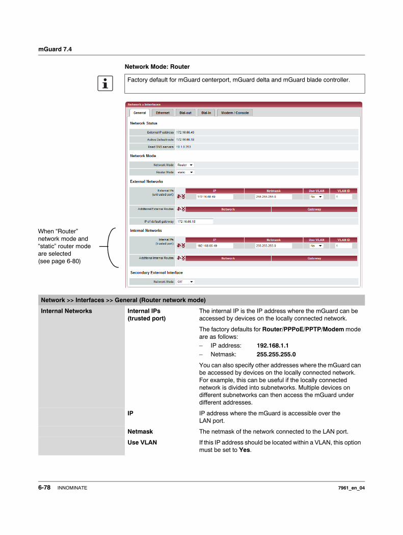
mGuard 7.4
Network Mode: Router
Factory default for mGuard centerport, mGuard delta and mGuard blade controller.
When “Router” network mode and “static” router mode are selected (see page 6-80)
Network >> Interfaces >> General (Router network mode)
Internal Networks Internal IPs (trusted port)
The internal IP is the IP address where the mGuard can be accessed by devices on the locally connected network.
The factory defaults for Router/PPPoE/PPTP/Modem mode are as follows:– IP address: 192.168.1.1– Netmask: 255.255.255.0
You can also specify other addresses where the mGuard can be accessed by devices on the locally connected network. For example, this can be useful if the locally connected network is divided into subnetworks. Multiple devices on different subnetworks can then access the mGuard under different addresses.
IP IP address where the mGuard is accessible over the LAN port.
Netmask The netmask of the network connected to the LAN port.
Use VLAN If this IP address should be located within a VLAN, this option must be set to Yes.
6-78 INNOMINATE 7961_en_04
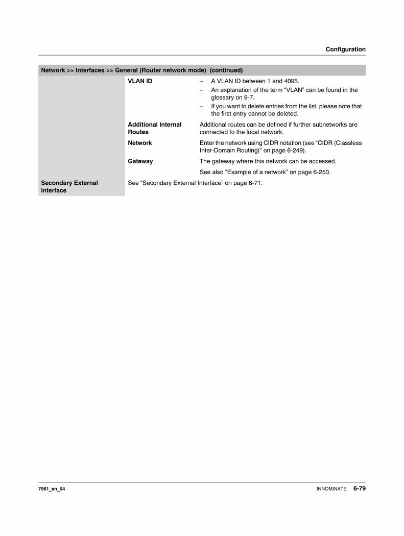
Configuration
VLAN ID – A VLAN ID between 1 and 4095.
– An explanation of the term “VLAN” can be found in the glossary on 9-7.
– If you want to delete entries from the list, please note that the first entry cannot be deleted.
Additional Internal Routes
Additional routes can be defined if further subnetworks are connected to the local network.
Network Enter the network using CIDR notation (see “CIDR (Classless Inter-Domain Routing)” on page 6-249).
Gateway The gateway where this network can be accessed.
See also “Example of a network” on page 6-250.
Secondary External Interface
See “Secondary External Interface” on page 6-71.
Network >> Interfaces >> General (Router network mode) (continued)
7961_en_04 INNOMINATE 6-79
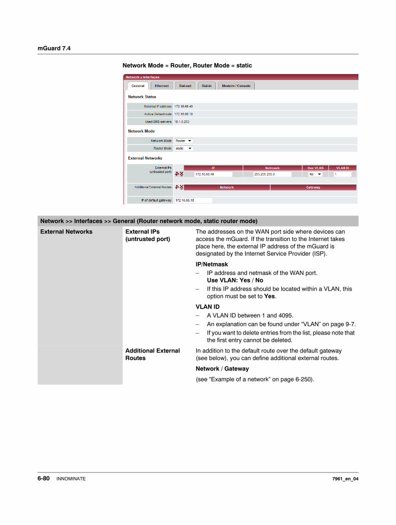
mGuard 7.4
Network Mode = Router, Router Mode = static
Network >> Interfaces >> General (Router network mode, static router mode)
External Networks External IPs (untrusted port)
The addresses on the WAN port side where devices can access the mGuard. If the transition to the Internet takes place here, the external IP address of the mGuard is designated by the Internet Service Provider (ISP).
IP/Netmask– IP address and netmask of the WAN port.
Use VLAN: Yes / No– If this IP address should be located within a VLAN, this
option must be set to Yes.
VLAN ID– A VLAN ID between 1 and 4095.
– An explanation can be found under “VLAN” on page 9-7.– If you want to delete entries from the list, please note that
the first entry cannot be deleted.
Additional External Routes
In addition to the default route over the default gateway (see below), you can define additional external routes.
Network / Gateway
(see “Example of a network” on page 6-250).
6-80 INNOMINATE 7961_en_04
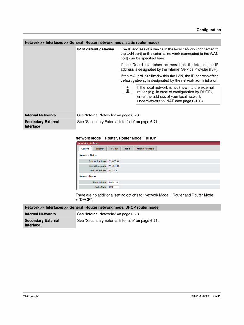
Configuration
Network Mode = Router, Router Mode = DHCP
There are no additional setting options for Network Mode = Router and Router Mode = “DHCP”.
IP of default gateway The IP address of a device in the local network (connected to the LAN port) or the external network (connected to the WAN port) can be specified here.
If the mGuard establishes the transition to the Internet, this IP address is designated by the Internet Service Provider (ISP).
If the mGuard is utilized within the LAN, the IP address of the default gateway is designated by the network administrator.
Internal Networks See “Internal Networks” on page 6-78.
Secondary External Interface
See “Secondary External Interface” on page 6-71.
Network >> Interfaces >> General (Router network mode, static router mode)
If the local network is not known to the external router (e.g. in case of configuration by DHCP), enter the address of your local network underNetwork >> NAT (see page 6-103).
Network >> Interfaces >> General (Router network mode, DHCP router mode)
Internal Networks See “Internal Networks” on page 6-78.
Secondary External Interface
See “Secondary External Interface” on page 6-71.
7961_en_04 INNOMINATE 6-81
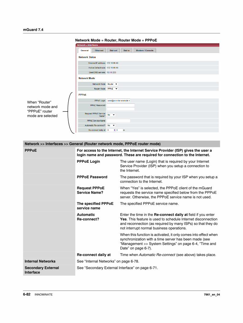
mGuard 7.4
Network Mode = Router, Router Mode = PPPoE
When “Router” network mode and “PPPoE” router mode are selected
Network >> Interfaces >> General (Router network mode, PPPoE router mode)
PPPoE For access to the Internet, the Internet Service Provider (ISP) gives the user a login name and password. These are required for connection to the Internet.
PPPoE Login The user name (Login) that is required by your Internet Service Provider (ISP) when you setup a connection to the Internet.
PPPoE Password The password that is required by your ISP when you setup a connection to the Internet.
Request PPPoE Service Name?
When “Yes” is selected, the PPPoE client of the mGuard requests the service name specified below from the PPPoE server. Otherwise, the PPPoE service name is not used.
The specified PPPoE service name
The specified PPPoE service name.
Automatic Re-connect?
Enter the time in the Re-connect daily at field if you enter Yes. This feature is used to schedule Internet disconnection and reconnection (as required by many ISPs) so that they do not interrupt normal business operations.
When this function is activated, it only comes into effect when synchronization with a time server has been made (see “Management >> System Settings” on page 6-4, “Time and Date” on page 6-7).
Re-connect daily at Time when Automatic Re-connect (see above) takes place.
Internal Networks See “Internal Networks” on page 6-78.
Secondary External Interface
See “Secondary External Interface” on page 6-71.
6-82 INNOMINATE 7961_en_04
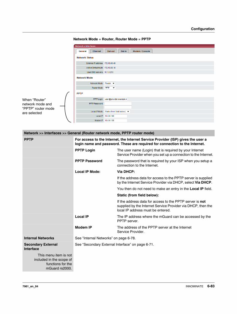
Configuration
Network Mode = Router, Router Mode = PPTP
When “Router” network mode and “PPTP” router mode are selected
Network >> Interfaces >> General (Router network mode, PPTP router mode)
PPTP For access to the Internet, the Internet Service Provider (ISP) gives the user a login name and password. These are required for connection to the Internet.
PPTP Login The user name (Login) that is required by your Internet Service Provider when you set up a connection to the Internet.
PPTP Password The password that is required by your ISP when you setup a connection to the Internet.
Local IP Mode: Via DHCP:
If the address data for access to the PPTP server is supplied by the Internet Service Provider via DHCP, select Via DHCP.
You then do not need to make an entry in the Local IP field.
Static (from field below):
If the address data for access to the PPTP server is not supplied by the Internet Service Provider via DHCP, then the local IP address must be entered.
Local IP The IP address where the mGuard can be accessed by the PPTP server.
Modem IP The address of the PPTP server at the Internet Service Provider.
Internal Networks See “Internal Networks” on page 6-78.
Secondary External Interface
This menu item is notincluded in the scope of
functions for themGuard rs2000.
See “Secondary External Interface” on page 6-71.
7961_en_04 INNOMINATE 6-83
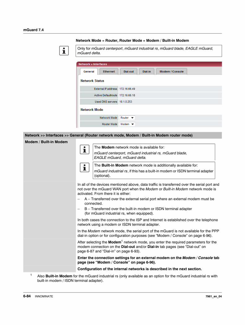
mGuard 7.4
Network Mode = Router, Router Mode = Modem / Built-in Modem
Only for mGuard centerport, mGuard industrial rs, mGuard blade, EAGLE mGuard, mGuard delta.
Network >> Interfaces >> General (Router network mode, Modem / Built-in Modem router mode)
Modem / Built-in Modem
In all of the devices mentioned above, data traffic is transferred over the serial port and not over the mGuard WAN port when the Modem or Built-in Modem network mode is activated. From there it is either: – A – Transferred over the external serial port where an external modem must be
connected.– B – Transferred over the built-in modem or ISDN terminal adapter
(for mGuard industrial rs, when equipped).
In both cases the connection to the ISP and Internet is established over the telephone network using a modem or ISDN terminal adapter.
In the Modem network mode, the serial port of the mGuard is not available for the PPP dial-in option or for configuration purposes (see “Modem / Console” on page 6-96).
After selecting the Modem1 network mode, you enter the required parameters for the modem connection on the Dial-out and/or Dial-in tab pages (see “Dial-out” on page 6-87 and “Dial-in” on page 6-93).
Enter the connection settings for an external modem on the Modem / Console tab page (see “Modem / Console” on page 6-96).
Configuration of the internal networks is described in the next section.
1 Also Built-in Modem for the mGuard industrial rs (only available as an option for the mGuard industrial rs with built-in modem / ISDN terminal adapter).
The Modem network mode is available for:
mGuard centerport, mGuard industrial rs, mGuard blade, EAGLE mGuard, mGuard delta.
The Built-in Modem network mode is additionally available for:
mGuard industrial rs, if this has a built-in modem or ISDN terminal adapter (optional).
6-84 INNOMINATE 7961_en_04
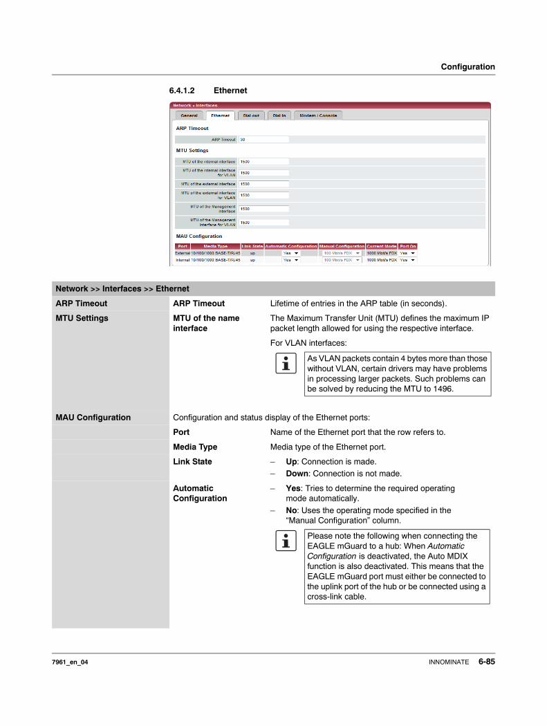
Configuration
6.4.1.2 Ethernet
Network >> Interfaces >> Ethernet
ARP Timeout ARP Timeout Lifetime of entries in the ARP table (in seconds).
MTU Settings MTU of the name interface
The Maximum Transfer Unit (MTU) defines the maximum IP packet length allowed for using the respective interface.
For VLAN interfaces:
MAU Configuration Configuration and status display of the Ethernet ports:
Port Name of the Ethernet port that the row refers to.
Media Type Media type of the Ethernet port.
Link State – Up: Connection is made.– Down: Connection is not made.
Automatic Configuration
– Yes: Tries to determine the required operating mode automatically.
– No: Uses the operating mode specified in the “Manual Configuration” column.
As VLAN packets contain 4 bytes more than those without VLAN, certain drivers may have problems in processing larger packets. Such problems can be solved by reducing the MTU to 1496.
Please note the following when connecting the EAGLE mGuard to a hub: When Automatic Configuration is deactivated, the Auto MDIX function is also deactivated. This means that the EAGLE mGuard port must either be connected to the uplink port of the hub or be connected using a cross-link cable.
7961_en_04 INNOMINATE 6-85
mGuard 7.4
Manual Configuration The desired operating mode when Automatic Configuration is set to No.
Current Mode Current network connection mode.
Port On Yes / No
Enables/disables the Ethernet port.
The Port On function is not supported on:
– mGuard centerport
The Port On function is supported with restrictions on: – mGuard delta: The internal switch ports cannot be
switched off.– mGuard pci: In Driver mode, the internal network
interface cannot be switched off (although this should be possible in Power-over-PCI mode).
Network >> Interfaces >> Ethernet
6-86 INNOMINATE 7961_en_04
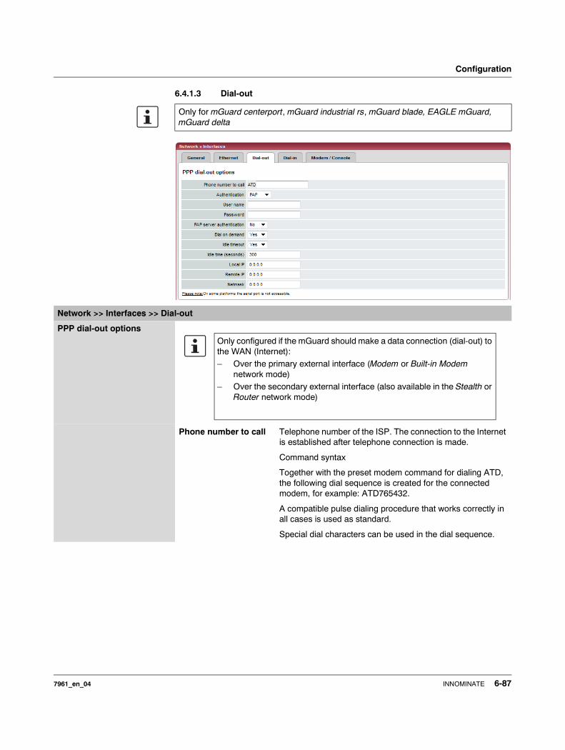
Configuration
6.4.1.3 Dial-out
Only for mGuard centerport, mGuard industrial rs, mGuard blade, EAGLE mGuard, mGuard delta
Network >> Interfaces >> Dial-out
PPP dial-out options
Phone number to call Telephone number of the ISP. The connection to the Internet is established after telephone connection is made.
Command syntax
Together with the preset modem command for dialing ATD, the following dial sequence is created for the connected modem, for example: ATD765432.
A compatible pulse dialing procedure that works correctly in all cases is used as standard.
Special dial characters can be used in the dial sequence.
Only configured if the mGuard should make a data connection (dial-out) to the WAN (Internet):– Over the primary external interface (Modem or Built-in Modem
network mode)– Over the secondary external interface (also available in the Stealth or
Router network mode)
7961_en_04 INNOMINATE 6-87
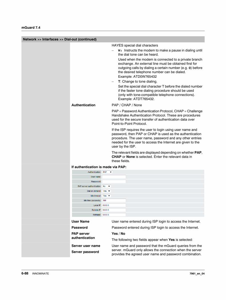
mGuard 7.4
HAYES special dial characters
– W: Instructs the modem to make a pause in dialing until the dial tone can be heard.
Used when the modem is connected to a private branch exchange. An external line must be obtained first for outgoing calls by dialing a certain number (e.g. 0) before the desired telephone number can be dialed. Example: ATD0W765432
– T: Change to tone dialing.Set the special dial character T before the dialed number if the faster tone dialing procedure should be used (only with tone-compatible telephone connections). Example: ATDT765432.
Authentication PAP / CHAP / None
PAP = Password Authentication Protocol, CHAP = Challenge Handshake Authentication Protocol. These are procedures used for the secure transfer of authentication data over Point-to-Point Protocol.
If the ISP requires the user to login using user name and password, then PAP or CHAP is used as the authentication procedure. The user name, password and any other entries needed for the user to access the Internet are given to the user by the ISP.
The relevant fields are displayed depending on whether PAP, CHAP or None is selected. Enter the relevant data in these fields.
If authentication is made via PAP:
User Name User name entered during ISP login to access the Internet.
Password Password entered during ISP login to access the Internet.
PAP server authentication
Yes / No
The following two fields appear when Yes is selected:
Server user name
Server password
User name and password that the mGuard queries from the server. mGuard only allows the connection when the server provides the agreed user name and password combination.
Network >> Interfaces >> Dial-out (continued)
6-88 INNOMINATE 7961_en_04
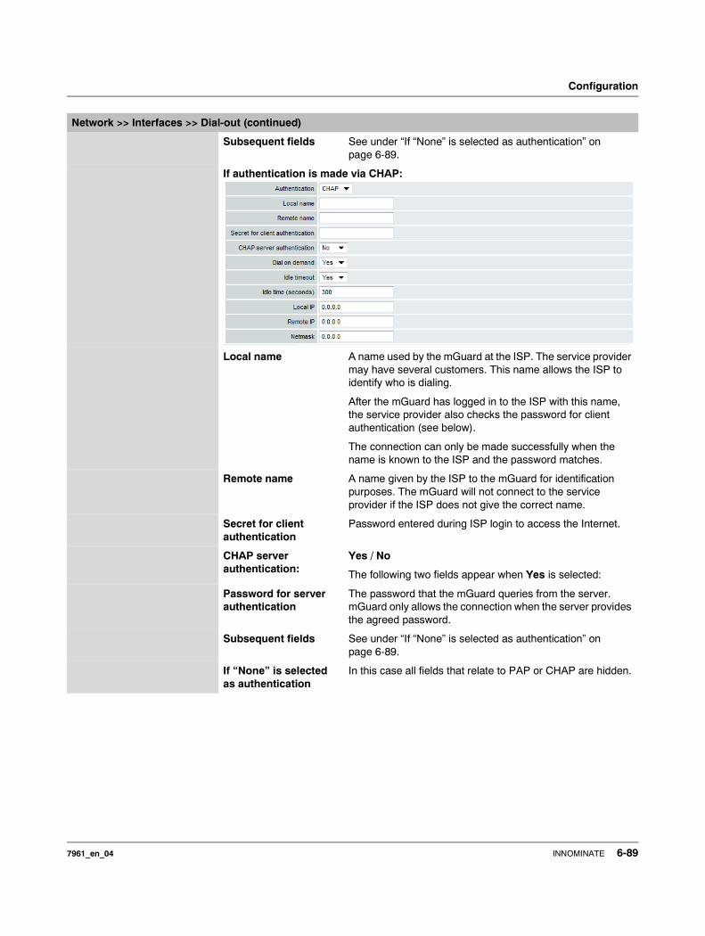
Configuration
Subsequent fields See under “If “None” is selected as authentication” on page 6-89.
If authentication is made via CHAP:
Local name A name used by the mGuard at the ISP. The service provider may have several customers. This name allows the ISP to identify who is dialing.
After the mGuard has logged in to the ISP with this name, the service provider also checks the password for client authentication (see below).
The connection can only be made successfully when the name is known to the ISP and the password matches.
Remote name A name given by the ISP to the mGuard for identification purposes. The mGuard will not connect to the service provider if the ISP does not give the correct name.
Secret for client authentication
Password entered during ISP login to access the Internet.
CHAP server authentication:
Yes / No
The following two fields appear when Yes is selected:
Password for server authentication
The password that the mGuard queries from the server. mGuard only allows the connection when the server provides the agreed password.
Subsequent fields See under “If “None” is selected as authentication” on page 6-89.
If “None” is selected as authentication
In this case all fields that relate to PAP or CHAP are hidden.
Network >> Interfaces >> Dial-out (continued)
7961_en_04 INNOMINATE 6-89
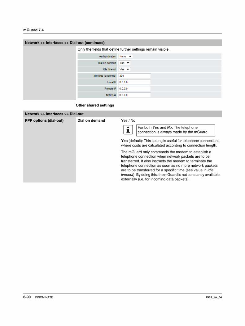
mGuard 7.4
Other shared settings
Only the fields that define further settings remain visible.
Network >> Interfaces >> Dial-out (continued)
Network >> Interfaces >> Dial-out
PPP options (dial-out) Dial on demand Yes / No
Yes (default): This setting is useful for telephone connections where costs are calculated according to connection length.
The mGuard only commands the modem to establish a telephone connection when network packets are to be transferred. It also instructs the modem to terminate the telephone connection as soon as no more network packets are to be transferred for a specific time (see value in Idle timeout). By doing this, the mGuard is not constantly available externally (i.e. for incoming data packets).
For both Yes and No: The telephone connection is always made by the mGuard.
6-90 INNOMINATE 7961_en_04
Configuration
– Often: The mGuard is configured so that it synchronizes its system time (date and time) regularly with an external NTP server.
– Sporadically: The mGuard is acting as a DNS server and has to perform a DNS query for a client.
– After a reboot: An active VPN connection is set to initiate. If this is the case, the mGuard sets up a connection after every reboot.
– After a reboot: For an active VPN connection, the gateway of the remote peer is entered as a hostname. After a restart, the mGuard has to request the IP address belonging to the hostname from a DNS server.
– Often: VPN connections are set up and DPD messages are sent regularly (see “Dead Peer Detection” on page 6-206).
– Often: The mGuard is configured to send its external IP address regularly to a DNS service, e.g. DynDNS, in order to remain accessible over its hostname.
– Often: The IP addresses of remote peer VPN gateways must be requested from the DynDNS service, or they must be kept up to date through new queries.
– Sporadically: The mGuard is configured so that SNMP traps are sent to the remote server.
– Sporadically: The mGuard is configured to permit and accept remote access via HTTPS, SSH or SNMP. (The mGuard then sends reply packets to every IP address from which an access attempt is made (if the firewall rules permit this access).
– Often: The mGuard is configured to make contact with a HTTPS server at regular intervals in order to download any configuration profile available there (see “Management >> Central Management” on page 6-53).
When No is selected, the mGuard establishes a telephone connection using a connected modem as soon as possible after a reboot or activation of the Modem network mode. This remains permanently in place, regardless of whether data is transferred or not. If the telephone connection is then interrupted, the mGuard attempts to restore it immediately. Thus, a permanent connection is made (like a dedicated line). By doing this, the mGuard is constantly available externally (i. e. for incoming data packets).
Idle timeout Yes / No
Only considered when Dial on demand is set to Yes.
When Yes (default) is set, the mGuard terminates the tele-phone connection as soon as no data transfer takes place over the defined Idle time. The mGuard gives the connected modem the relevant command for terminating the telephone connection.
When No is set, the mGuard gives the connected modem no command for terminating the telephone connection.
Network >> Interfaces >> Dial-out (continued)
The mGuard also often or sporadically makes a connection via the modem, or keeps a connection longer, if the following conditions apply:
7961_en_04 INNOMINATE 6-91
mGuard 7.4
Idle time (seconds) Default: 300. If no data traffic is made after the time specified here, the mGuard can terminate the telephone connection (see above under Idle timeout).
Local IP IP address of the mGuard serial port that now acts as a WAN interface. Adopt the preset value if this IP address is assigned dynamically by the ISP: 0.0.0.0.
Otherwise, enter this here (i.e. assignment of a fixed IP address).
Remote IP IP address of the remote peer. This is the IP address of the ISP used for access when connecting to the Internet. As PPP is used for the connection, the IP address is not normally specified. This means you can use the predefined value: 0.0.0.0.
Netmask The netmask here belongs to both Local and Remote IP addresses. Normally, all three values (Local IP, Remote IP and Netmask) are set or remain set to 0.0.0.0.
Enter the connection settings for an external modem on the Modem / Console tab page (see “Modem / Console” on page 6-96).
Network >> Interfaces >> Dial-out (continued)
6-92 INNOMINATE 7961_en_04
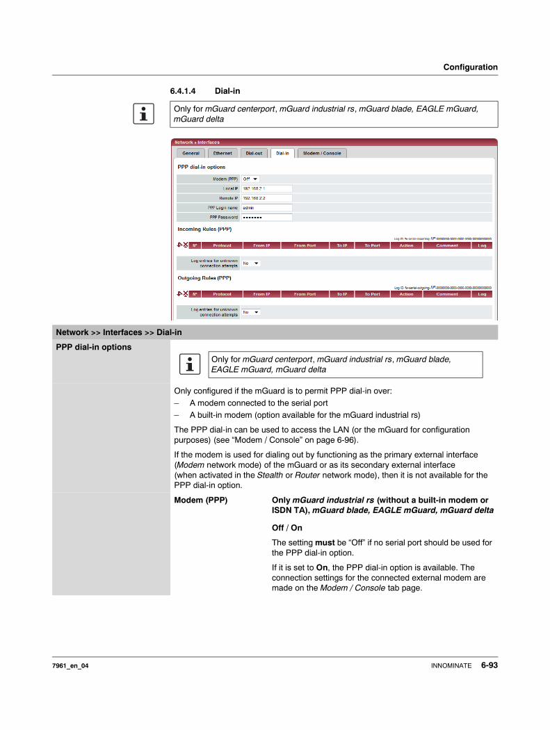
Configuration
6.4.1.4 Dial-in
Only for mGuard centerport, mGuard industrial rs, mGuard blade, EAGLE mGuard, mGuard delta
Network >> Interfaces >> Dial-in
PPP dial-in options
Only configured if the mGuard is to permit PPP dial-in over:
– A modem connected to the serial port– A built-in modem (option available for the mGuard industrial rs)
The PPP dial-in can be used to access the LAN (or the mGuard for configuration purposes) (see “Modem / Console” on page 6-96).
If the modem is used for dialing out by functioning as the primary external interface (Modem network mode) of the mGuard or as its secondary external interface (when activated in the Stealth or Router network mode), then it is not available for the PPP dial-in option.
Modem (PPP) Only mGuard industrial rs (without a built-in modem or ISDN TA), mGuard blade, EAGLE mGuard, mGuard delta
Off / On
The setting must be “Off” if no serial port should be used for the PPP dial-in option.
If it is set to On, the PPP dial-in option is available. The connection settings for the connected external modem are made on the Modem / Console tab page.
Only for mGuard centerport, mGuard industrial rs, mGuard blade, EAGLE mGuard, mGuard delta
7961_en_04 INNOMINATE 6-93
mGuard 7.4
Modem (PPP) Only mGuard industrial rs (with built-in modem or ISDN TA)
Off / Built-in Modem / External Modem
The setting must be Off if the serial port should not be used for the PPP dial-in option.
If it is set to External Modem, the PPP dial-in option is available. Then an external modem must be connected to the serial port. The connection settings for the connected external modem are made on the Modem / Console tab page.
If this is set to Built-in Modem, the PPP dial-in option is available. In this case, the modem connection is not made over the Serial socket on the front side. Instead, it is made over the terminal block on the bottom where the built-in modem or ISDN terminal adapter is connected to the telephone network. The connection settings for the built-in modem are made on the Modem / Console tab page.
If you are using the Built-in Modem option, you can also use the serial port. For the usage options, see “Modem / Console” on page 6-96.
Local IP IP address of the mGuard at which it can be accessed for a PPP connection.
Remote IP IP address of the PPP connection remote peer.
PPP Login name Login name that the PPP remote peer has to enter to gain access to the mGuard using PPP.
PPP Password Password that the PPP remote peer has to enter to gain access to the mGuard using PPP.
Incoming Rules (PPP) Firewall rules for PPP connections to the LAN interface.
If multiple firewall rules are set, they will be searched in the order in which they are listed (top-down) until a suitable rule is found. This rule is then applied. If there are other suitable rules further down the list, these are ignored.
You have the following options:
Protocol All means: TCP, UDP, ICMP, GRE and other IP protocols.
From / To IP 0.0.0.0/0 means all IP addresses. To enter an address, use CIDR notation (see “CIDR (Classless Inter-Domain Routing)” on page 6-249).
From / To Port (Only evaluated for TCP and UDP protocols)
any describes any selected port.
startport:endport (e.g. 110:120) defines a range of ports.
You can specify individual ports by giving either their port number or the corresponding service name: (e.g. 110 for pop3 or pop3 for 110).
Network >> Interfaces >> Dial-in (continued)
6-94 INNOMINATE 7961_en_04

Configuration
Action Accept means that data packets may pass through.
Reject means that the data packets are rejected. The sender is informed that the data packets have been rejected.
Drop means that data packets may not pass through. Data packets are discarded and the sender is not informed of their whereabouts.
Comment Freely selectable comment for this rule.
Log For each individual firewall rule, you can specify whether the use of the rule
– should be logged (set Log to Yes) or – should not be logged (set Log to No – factory default).
Log entries for unknown connection attempts
Yes / No
When set to Yes, all attempts to establish a connection that are not covered by the rules defined above are logged.
Outgoing Rules (PPP) Firewall rules for outgoing PPP connections from the LAN interface.
The parameters correspond to those of the Incoming Rules (PPP).
These outgoing rules apply to data packets that are sent out over a data connection initiated by PPP dial-in.
Network >> Interfaces >> Dial-in (continued)
7961_en_04 INNOMINATE 6-95
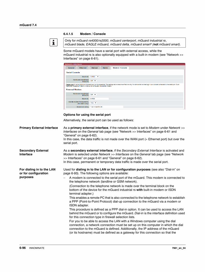
mGuard 7.4
6.4.1.5 Modem / Console
Some mGuard models have a serial port with external access, while the mGuard industrial rs is also optionally equipped with a built-in modem (see “Network >> Interfaces” on page 6-61).
Options for using the serial port
Alternatively, the serial port can be used as follows:
Primary External Interface As a primary external interface, if the network mode is set to Modem under Network >> Interfaces on the General tab page (see “Network >> Interfaces” on page 6-61 and “General” on page 6-62). In this case, the data traffic is not made over the WAN port (= Ethernet port) but over the serial port.
Secondary External Interface
As a secondary external interface, if the Secondary External Interface is activated and Modem is selected under Network >> Interfaces on the General tab page (see “Network >> Interfaces” on page 6-61 and “General” on page 6-62).In this case, permanent or temporary data traffic is made over the serial port.
For dialing in to the LAN or for configuration purposes
Used for dialing in to the LAN or for configuration purposes (see also “Dial-in” on page 6-93). The following options are available:– A modem is connected to the serial port of the mGuard. This modem is connected to
the telephone network (landline or GSM network).(Connection to the telephone network is made over the terminal block on the bottom of the device for the mGuard industrial rs with built-in modem or ISDN terminal adapter.) This enables a remote PC that is also connected to the telephone network to establish a PPP (Point-to-Point Protocol) dial-up connection to the mGuard via a modem or ISDN adapter. This procedure is defined as a PPP dial-in option. It can be used to access the LAN behind the mGuard or to configure the mGuard. Dial-in is the interface definition used for this connection type in firewall selection lists.For you to be able to access the LAN with a Windows computer using the dial connection, a network connection must be set up on this computer in which the dial connection to the mGuard is defined. Additionally, the IP address of the mGuard (or its hostname) must be defined as a gateway for this connection so that the
Only for mGuard rs4000/rs2000, mGuard centerport, mGuard industrial rs, mGuard blade, EAGLE mGuard, mGuard delta, mGuard smart² (not mGuard smart).
6-96 INNOMINATE 7961_en_04
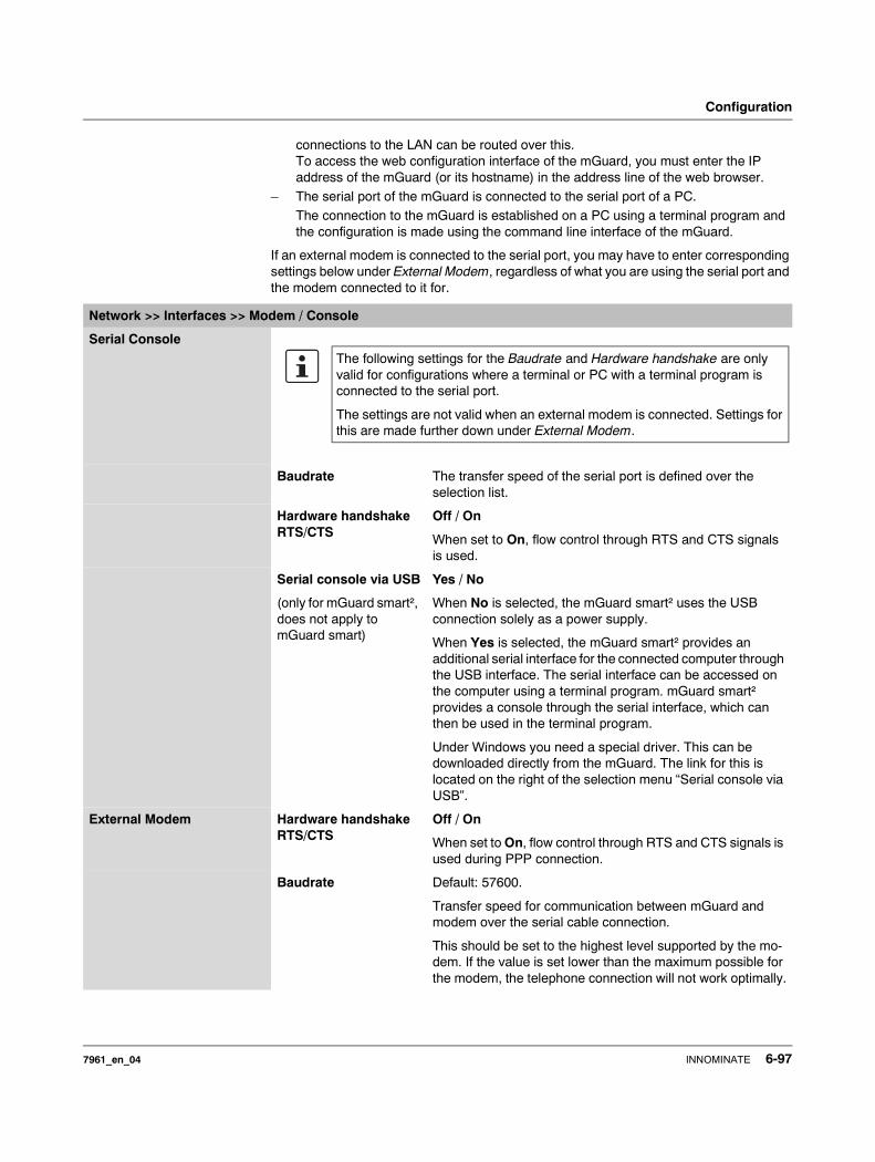
Configuration
connections to the LAN can be routed over this.To access the web configuration interface of the mGuard, you must enter the IP address of the mGuard (or its hostname) in the address line of the web browser.
– The serial port of the mGuard is connected to the serial port of a PC.The connection to the mGuard is established on a PC using a terminal program and the configuration is made using the command line interface of the mGuard.
If an external modem is connected to the serial port, you may have to enter corresponding settings below under External Modem, regardless of what you are using the serial port and the modem connected to it for.
Network >> Interfaces >> Modem / Console
Serial Console
Baudrate The transfer speed of the serial port is defined over the selection list.
Hardware handshake RTS/CTS
Off / On
When set to On, flow control through RTS and CTS signals is used.
Serial console via USB
(only for mGuard smart², does not apply to mGuard smart)
Yes / No
When No is selected, the mGuard smart² uses the USB connection solely as a power supply.
When Yes is selected, the mGuard smart² provides an additional serial interface for the connected computer through the USB interface. The serial interface can be accessed on the computer using a terminal program. mGuard smart² provides a console through the serial interface, which can then be used in the terminal program.
Under Windows you need a special driver. This can be downloaded directly from the mGuard. The link for this is located on the right of the selection menu “Serial console via USB”.
External Modem Hardware handshake RTS/CTS
Off / On
When set to On, flow control through RTS and CTS signals is used during PPP connection.
Baudrate Default: 57600.
Transfer speed for communication between mGuard and modem over the serial cable connection.
This should be set to the highest level supported by the mo-dem. If the value is set lower than the maximum possible for the modem, the telephone connection will not work optimally.
The following settings for the Baudrate and Hardware handshake are only valid for configurations where a terminal or PC with a terminal program is connected to the serial port.
The settings are not valid when an external modem is connected. Settings for this are made further down under External Modem.
7961_en_04 INNOMINATE 6-97
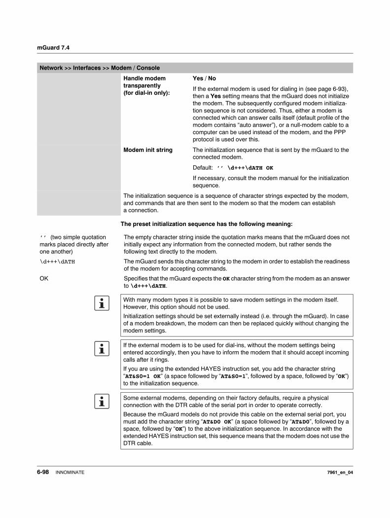
mGuard 7.4
The preset initialization sequence has the following meaning:
Handle modem transparently (for dial-in only):
Yes / No
If the external modem is used for dialing in (see page 6-93), then a Yes setting means that the mGuard does not initialize the modem. The subsequently configured modem initializa-tion sequence is not considered. Thus, either a modem is connected which can answer calls itself (default profile of the modem contains “auto answer”), or a null-modem cable to a computer can be used instead of the modem, and the PPP protocol is used over this.
Modem init string The initialization sequence that is sent by the mGuard to the connected modem.
Default: ’’ \d+++\dATH OK
If necessary, consult the modem manual for the initialization sequence.
The initialization sequence is a sequence of character strings expected by the modem, and commands that are then sent to the modem so that the modem can establish a connection.
Network >> Interfaces >> Modem / Console
’’ (two simple quotation marks placed directly after one another)
The empty character string inside the quotation marks means that the mGuard does not initially expect any information from the connected modem, but rather sends the following text directly to the modem.
\d+++\dATH The mGuard sends this character string to the modem in order to establish the readiness of the modem for accepting commands.
OK Specifies that the mGuard expects the OK character string from the modem as an answer to \d+++\dATH.
With many modem types it is possible to save modem settings in the modem itself. However, this option should not be used.
Initialization settings should be set externally instead (i.e. through the mGuard). In case of a modem breakdown, the modem can then be replaced quickly without changing the modem settings.
If the external modem is to be used for dial-ins, without the modem settings being entered accordingly, then you have to inform the modem that it should accept incoming calls after it rings.
If you are using the extended HAYES instruction set, you add the character string “AT&S0=1 OK” (a space followed by “AT&S0=1”, followed by a space, followed by “OK”) to the initialization sequence.
Some external modems, depending on their factory defaults, require a physical connection with the DTR cable of the serial port in order to operate correctly.
Because the mGuard models do not provide this cable on the external serial port, you must add the character string “AT&D0 OK” (a space followed by “AT&D0”, followed by a space, followed by “OK”) to the above initialization sequence. In accordance with the extended HAYES instruction set, this sequence means that the modem does not use the DTR cable.
6-98 INNOMINATE 7961_en_04
Configuration
If the external modem is to be used for dial-outs, it is connected to a private branch exchange, and if this private branch exchange does not generate a dial tone after the connection is opened, then the modem must be instructed not to wait for a dial tone before dialing.
In this case, please add the character string “ATX3 OK” (a space followed by “ATX3”, followed by a space, followed by “OK”) to the initialization sequence.
In this case, the control character “W” should be added to the Phone number to call after the digit for an outside line in order to wait for a dial tone.
7961_en_04 INNOMINATE 6-99
mGuard 7.4
On mGuard industrial rs with built-in modem / built-in ISDN modem (ISDN terminal adapter)
The mGuard industrial rs can additionally have an optional built-in analog modem or ISDN terminal adapter. The built-in modem or built-in ISDN terminal adapter can be used as follows:
Primary External Interface – As a primary external interface, if the network mode is set to Built-in Modem under Network >> Interfaces on the General tab page (see “Network >> Interfaces” on page 6-61 and “General” on page 6-62). In this case, the data traffic is not made over the WAN port (= Ethernet port) but over this modem.
Secondary External Interface
– As a secondary external interface, if the Secondary External Interface is activated and Built-in Modem is selected under Network >> Interfaces on the General tab page (see “Network >> Interfaces” on page 6-61 and “General” on page 6-62). In this case the data traffic is also made over the serial port.
PPP dial-in options – For the PPP dial-in option (see “Options for using the serial port” on page 6-96)
Note that the serial port of the device also provides similar usage options (see above). Thus, with the mGuard industrial rs with a built-in modem, the normal data traffic can be made over a modem connection (Modem network mode) and simultaneously a second modem connection can be used for the PPP dial-in option, for example.
6-100 INNOMINATE 7961_en_04
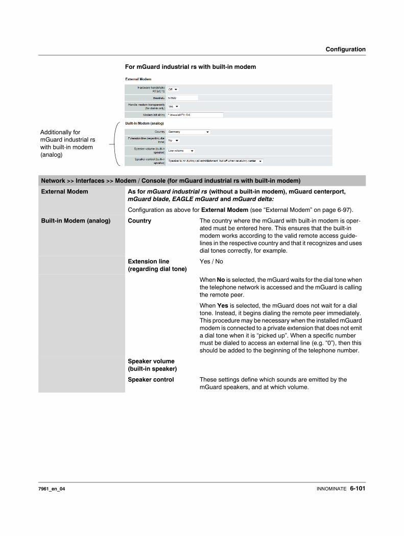
Configuration
For mGuard industrial rs with built-in modem
Additionally for mGuard industrial rs with built-in modem (analog)
Network >> Interfaces >> Modem / Console (for mGuard industrial rs with built-in modem)
External Modem As for mGuard industrial rs (without a built-in modem), mGuard centerport, mGuard blade, EAGLE mGuard and mGuard delta:
Configuration as above for External Modem (see “External Modem” on page 6-97).
Built-in Modem (analog) Country The country where the mGuard with built-in modem is oper-ated must be entered here. This ensures that the built-in modem works according to the valid remote access guide-lines in the respective country and that it recognizes and uses dial tones correctly, for example.
Extension line (regarding dial tone)
Yes / No
When No is selected, the mGuard waits for the dial tone when the telephone network is accessed and the mGuard is calling the remote peer.
When Yes is selected, the mGuard does not wait for a dial tone. Instead, it begins dialing the remote peer immediately. This procedure may be necessary when the installed mGuard modem is connected to a private extension that does not emit a dial tone when it is “picked up”. When a specific number must be dialed to access an external line (e.g. “0”), then this should be added to the beginning of the telephone number.
Speaker volume (built-in speaker)
Speaker control These settings define which sounds are emitted by the mGuard speakers, and at which volume.
7961_en_04 INNOMINATE 6-101
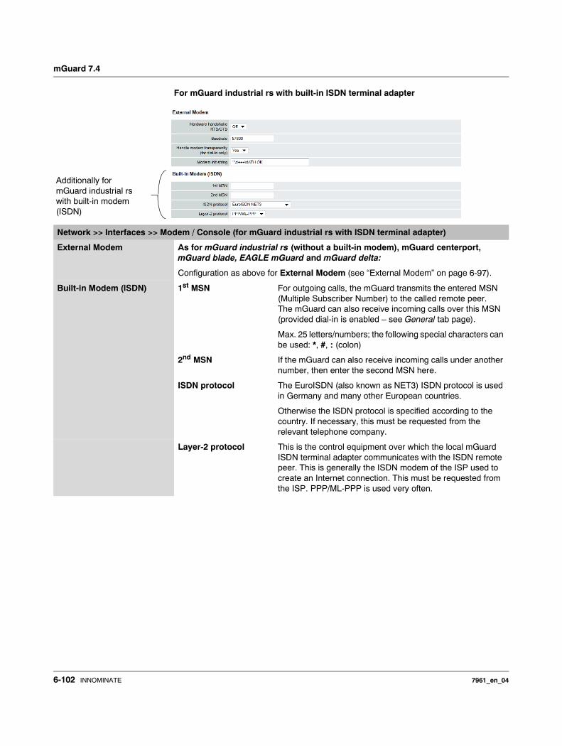
mGuard 7.4
For mGuard industrial rs with built-in ISDN terminal adapter
Network >> Interfaces >> Modem / Console (for mGuard industrial rs with ISDN terminal adapter)
External Modem As for mGuard industrial rs (without a built-in modem), mGuard centerport, mGuard blade, EAGLE mGuard and mGuard delta:
Configuration as above for External Modem (see “External Modem” on page 6-97).
Built-in Modem (ISDN) 1st MSN For outgoing calls, the mGuard transmits the entered MSN (Multiple Subscriber Number) to the called remote peer. The mGuard can also receive incoming calls over this MSN (provided dial-in is enabled – see General tab page).
Max. 25 letters/numbers; the following special characters can be used: *, #, : (colon)
2nd MSN If the mGuard can also receive incoming calls under another number, then enter the second MSN here.
ISDN protocol The EuroISDN (also known as NET3) ISDN protocol is used in Germany and many other European countries.
Otherwise the ISDN protocol is specified according to the country. If necessary, this must be requested from the relevant telephone company.
Layer-2 protocol This is the control equipment over which the local mGuard ISDN terminal adapter communicates with the ISDN remote peer. This is generally the ISDN modem of the ISP used to create an Internet connection. This must be requested from the ISP. PPP/ML-PPP is used very often.
Additionally for mGuard industrial rs with built-in modem (ISDN)
6-102 INNOMINATE 7961_en_04
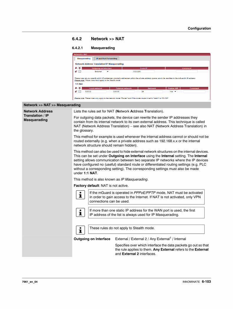
Configuration
6.4.2 Network >> NAT
6.4.2.1 Masquerading
Network >> NAT >> Masquerading
Network Address Translation / IP Masquerading
Lists the rules set for NAT (Network Address Translation).
For outgoing data packets, the device can rewrite the sender IP addresses they contain from its internal network to its own external address. This technique is called NAT (Network Address Translation) – see also NAT (Network Address Translation) in the glossary.
This method for example is used whenever the internal address cannot or should not be routed externally (e.g. when a private address such as 192.168.x.x or the internal network structure should remain hidden).
This method can also be used to hide external network structures on the internal devices. This can be set under Outgoing on Interface using the Internal setting. The Internal setting allows communication between two separate IP networks where the IP devices have configured no (useful) standard route or differentiated routing settings (e.g. PLC without a corresponding setting). The corresponding settings must also be made under 1:1 NAT.
This method is also known as IP Masquerading.
Factory default: NAT is not active.
Outgoing on Interface External / External 2 / Any External1 / Internal
Specifies over which interface the data packets go out so that the rule applies to them. Any External refers to the External and External 2 interfaces.
If the mGuard is operated in PPPoE/PPTP mode, NAT must be activated in order to gain access to the Internet. If NAT is not activated, only VPN connections can be used.
If more than one static IP address for the WAN port is used, the first IP address of the list is always used for IP Masquerading.
These rules do not apply to Stealth mode.
7961_en_04 INNOMINATE 6-103
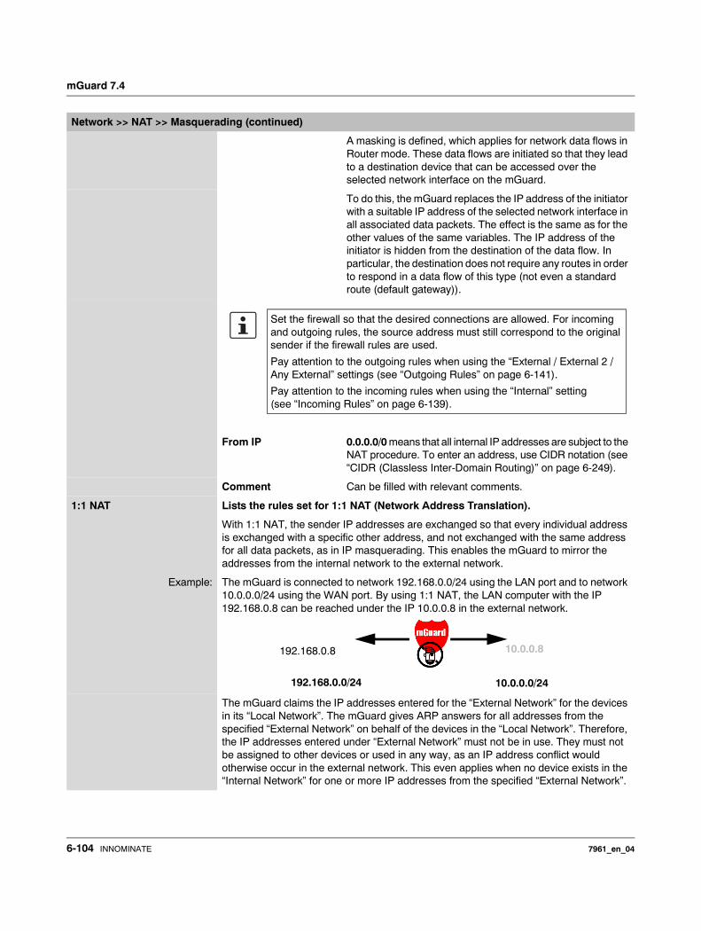
mGuard 7.4
A masking is defined, which applies for network data flows in Router mode. These data flows are initiated so that they lead to a destination device that can be accessed over the selected network interface on the mGuard.
To do this, the mGuard replaces the IP address of the initiator with a suitable IP address of the selected network interface in all associated data packets. The effect is the same as for the other values of the same variables. The IP address of the initiator is hidden from the destination of the data flow. In particular, the destination does not require any routes in order to respond in a data flow of this type (not even a standard route (default gateway)).
From IP 0.0.0.0/0 means that all internal IP addresses are subject to the NAT procedure. To enter an address, use CIDR notation (see “CIDR (Classless Inter-Domain Routing)” on page 6-249).
Comment Can be filled with relevant comments.
1:1 NAT Lists the rules set for 1:1 NAT (Network Address Translation).
With 1:1 NAT, the sender IP addresses are exchanged so that every individual address is exchanged with a specific other address, and not exchanged with the same address for all data packets, as in IP masquerading. This enables the mGuard to mirror the addresses from the internal network to the external network.
Example: The mGuard is connected to network 192.168.0.0/24 using the LAN port and to network 10.0.0.0/24 using the WAN port. By using 1:1 NAT, the LAN computer with the IP 192.168.0.8 can be reached under the IP 10.0.0.8 in the external network.
The mGuard claims the IP addresses entered for the “External Network” for the devices in its “Local Network”. The mGuard gives ARP answers for all addresses from the specified “External Network” on behalf of the devices in the “Local Network”. Therefore, the IP addresses entered under “External Network” must not be in use. They must not be assigned to other devices or used in any way, as an IP address conflict would otherwise occur in the external network. This even applies when no device exists in the “Internal Network” for one or more IP addresses from the specified “External Network”.
Network >> NAT >> Masquerading (continued)
Set the firewall so that the desired connections are allowed. For incoming and outgoing rules, the source address must still correspond to the original sender if the firewall rules are used.
Pay attention to the outgoing rules when using the “External / External 2 / Any External” settings (see “Outgoing Rules” on page 6-141).
Pay attention to the incoming rules when using the “Internal” setting (see “Incoming Rules” on page 6-139).
192.168.0.8 10.0.0.8
192.168.0.0/24 10.0.0.0/24
6-104 INNOMINATE 7961_en_04

Configuration
Factory default: 1:1 NAT is not active.
Local network The network address on the LAN port.
External network The network address on the WAN port.
Netmask The netmask as a value between 1 and 32 for the local and external network addresses (see also “CIDR (Classless Inter-Domain Routing)” on page 6-249).
Comment Can be filled with relevant comments.
1 External 2 and Any External are only for devices with serial ports: mGuard centerport, mGuard industrial rs, mGuard blade, EAGLE mGuard, mGuard delta (see “Secondary External Interface” on page 6-71).
Network >> NAT >> Masquerading (continued)
1:1 NAT cannot be used on the External 2 interface.
1:1 NAT is only used in the Router network mode.
7961_en_04 INNOMINATE 6-105
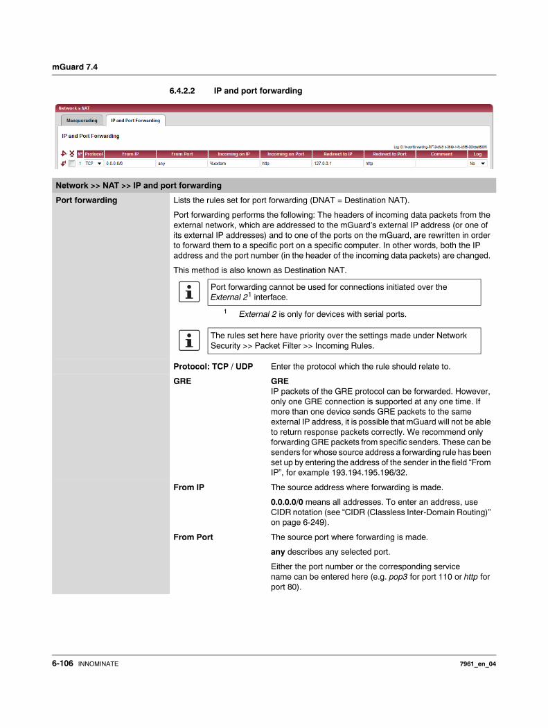
mGuard 7.4
6.4.2.2 IP and port forwarding
Network >> NAT >> IP and port forwarding
Port forwarding Lists the rules set for port forwarding (DNAT = Destination NAT).
Port forwarding performs the following: The headers of incoming data packets from the external network, which are addressed to the mGuard’s external IP address (or one of its external IP addresses) and to one of the ports on the mGuard, are rewritten in order to forward them to a specific port on a specific computer. In other words, both the IP address and the port number (in the header of the incoming data packets) are changed.
This method is also known as Destination NAT.
Protocol: TCP / UDP Enter the protocol which the rule should relate to.
GRE GREIP packets of the GRE protocol can be forwarded. However, only one GRE connection is supported at any one time. If more than one device sends GRE packets to the same external IP address, it is possible that mGuard will not be able to return response packets correctly. We recommend only forwarding GRE packets from specific senders. These can be senders for whose source address a forwarding rule has been set up by entering the address of the sender in the field “From IP”, for example 193.194.195.196/32.
From IP The source address where forwarding is made.
0.0.0.0/0 means all addresses. To enter an address, use CIDR notation (see “CIDR (Classless Inter-Domain Routing)” on page 6-249).
From Port The source port where forwarding is made.
any describes any selected port.
Either the port number or the corresponding service name can be entered here (e.g. pop3 for port 110 or http for port 80).
Port forwarding cannot be used for connections initiated over the External 21 interface.
1 External 2 is only for devices with serial ports.
The rules set here have priority over the settings made under Network Security >> Packet Filter >> Incoming Rules.
6-106 INNOMINATE 7961_en_04
Configuration
Incoming on IP – Enter the external IP address (or one of the external IP addresses) of the mGuard here, or
– use variable: %extern (when a dynamic change of the external IP address of the mGuard is made so that the external IP address cannot be entered).If more than one static IP address is used for the WAN port, the variable %extern always corresponds to the first IP address of the address list.
Incoming on Port The original destination port set in the incoming data packets.
Either the port number or the corresponding service name can be entered here (e.g. pop3 for port 110 or http for port 80).
This entry is irrelevant for the “GRE” protocol. It is ignored by the mGuard.
Redirect to IP The internal IP address to which the data packets should be forwarded. The original destination address is overwritten with this address.
Redirect to Port The port to which the data packets should be forwarded. The original destination port will be overwritten with this port.
Either the port number or the corresponding service name can be entered here (e.g. pop3 for port 110 or http for port 80).
This entry is irrelevant for the “GRE” protocol. It is ignored by the mGuard.
Comment Freely selectable comment for this rule.
Log For each individual port forwarding rule, you can specify whether the use of the rule– should be logged (set Log to Yes) or
– should not be logged (set Log to No – factory default).
Network >> NAT >> IP and port forwarding (continued)
7961_en_04 INNOMINATE 6-107
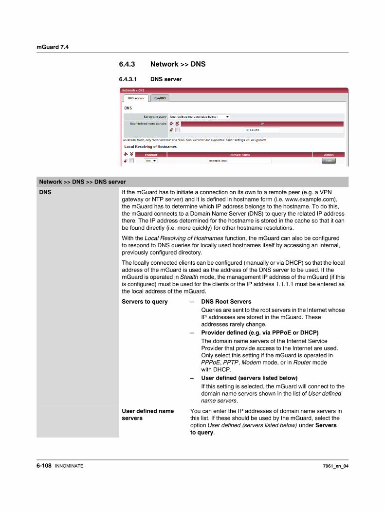
mGuard 7.4
6.4.3 Network >> DNS
6.4.3.1 DNS server
Network >> DNS >> DNS server
DNS If the mGuard has to initiate a connection on its own to a remote peer (e.g. a VPN gateway or NTP server) and it is defined in hostname form (i.e. www.example.com), the mGuard has to determine which IP address belongs to the hostname. To do this, the mGuard connects to a Domain Name Server (DNS) to query the related IP address there. The IP address determined for the hostname is stored in the cache so that it can be found directly (i.e. more quickly) for other hostname resolutions.
With the Local Resolving of Hostnames function, the mGuard can also be configured to respond to DNS queries for locally used hostnames itself by accessing an internal, previously configured directory.
The locally connected clients can be configured (manually or via DHCP) so that the local address of the mGuard is used as the address of the DNS server to be used. If the mGuard is operated in Stealth mode, the management IP address of the mGuard (if this is configured) must be used for the clients or the IP address 1.1.1.1 must be entered as the local address of the mGuard.
Servers to query – DNS Root ServersQueries are sent to the root servers in the Internet whose IP addresses are stored in the mGuard. These addresses rarely change.
– Provider defined (e.g. via PPPoE or DHCP)The domain name servers of the Internet Service Provider that provide access to the Internet are used. Only select this setting if the mGuard is operated in PPPoE, PPTP, Modem mode, or in Router mode with DHCP.
– User defined (servers listed below)If this setting is selected, the mGuard will connect to the domain name servers shown in the list of User defined name servers.
User defined name servers
You can enter the IP addresses of domain name servers in this list. If these should be used by the mGuard, select the option User defined (servers listed below) under Servers to query.
6-108 INNOMINATE 7961_en_04

Configuration
Local Resolving of Hostnames
You can configure multiple entries with assignment pairs of hostnames and IP addresses for various domain names.
You have the option to define, change (edit) and delete assignment pairs of hostnames and IP addresses. You can also activate or deactivate the resolving of hostnames for a domain. You can also delete a domain with all its assignment pairs.
Create a table with assignment pairs for a domain:• Open a new row and click on Edit in this row.
Change or delete assignment pairs belonging to a domain:• Click on Edit in the relevant table row.
After clicking on Edit, the DNS Records tab page is displayed:
Domain for the hosts Any name can be entered, but it must adhere to the rules for assigning domain names. Is assigned to every hostname.
Enabled Yes / No
Switches the function Local Resolving of Hostnames on (Yes) or off (No) for the domain entered in the field above.
Resolve IP Addresses also
No: The mGuard only resolves hostnames, i. e. it supplies the IP address assigned to hostnames.
Yes: Same as for No. It is also possible to get the hostname assigned to an IP address.
Hostnames The table can have any number of entries.
TTL Abbreviation of Time To Live. Entry in seconds. Default: 3600 (= 1 hour)
Defines how long assignment pairs called up may be stored in the cache of the calling computer.
IP The IP address assigned to the hostname in this table row.
Delete domain with all assignment pairs
Delete the corresponding table entry.
Network >> DNS >> DNS server (continued)
A hostname may be assigned to multiple IP addresses. Multiple hostnames may be assigned to one IP address.
7961_en_04 INNOMINATE 6-109
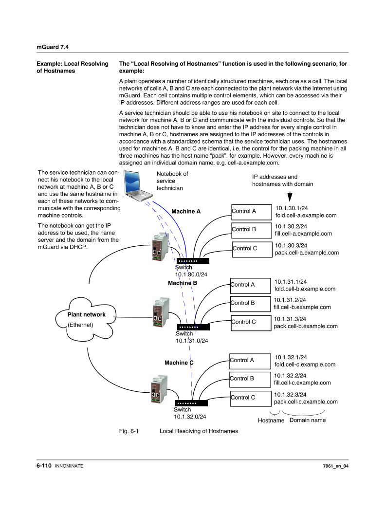
mGuard 7.4
Example: Local Resolving of Hostnames
The “Local Resolving of Hostnames” function is used in the following scenario, for example:
A plant operates a number of identically structured machines, each one as a cell. The local networks of cells A, B and C are each connected to the plant network via the Internet using mGuard. Each cell contains multiple control elements, which can be accessed via their IP addresses. Different address ranges are used for each cell.
A service technician should be able to use his notebook on site to connect to the local network for machine A, B or C and communicate with the individual controls. So that the technician does not have to know and enter the IP address for every single control in machine A, B or C, hostnames are assigned to the IP addresses of the controls in accordance with a standardized schema that the service technician uses. The hostnames used for machines A, B and C are identical, i.e. the control for the packing machine in all three machines has the host name “pack”, for example. However, every machine is assigned an individual domain name, e.g. cell-a.example.com.
Fig. 6-1 Local Resolving of Hostnames
Control A 10.1.30.1/24fold.cell-a.example.com
Control B 10.1.30.2/24fill.cell-a.example.com
Control C 10.1.30.3/24pack.cell-a.example.com
Switch10.1.30.0/24
IP addresses andhostnames with domain
Machine A
Switch10.1.31.0/24
Plant network
(Ethernet)
Notebook ofservice technician
The service technician can con-nect his notebook to the local network at machine A, B or C and use the same hostname in each of these networks to com-municate with the corresponding machine controls.
The notebook can get the IP address to be used, the name server and the domain from the mGuard via DHCP.
Switch10.1.32.0/24
Control A 10.1.31.1/24fold.cell-b.example.com
Control B 10.1.31.2/24fill.cell-b.example.com
Control C 10.1.31.3/24pack.cell-b.example.com
Control A 10.1.32.1/24fold.cell-c.example.com
Control B 10.1.32.2/24fill.cell-c.example.com
Control C 10.1.32.3/24pack.cell-c.example.com
Machine B
Machine C
Hostname Domain name
6-110 INNOMINATE 7961_en_04
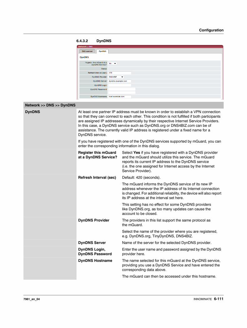
Configuration
6.4.3.2 DynDNS
Network >> DNS >> DynDNS
DynDNS At least one partner IP address must be known in order to establish a VPN connection so that they can connect to each other. This condition is not fulfilled if both participants are assigned IP addresses dynamically by their respective Internet Service Providers. In this case, a DynDNS service such as DynDNS.org or DNS4BIZ.com can be of assistance. The currently valid IP address is registered under a fixed name for a DynDNS service.
If you have registered with one of the DynDNS services supported by mGuard, you can enter the corresponding information in this dialog.
Register this mGuard at a DynDNS Service?
Select Yes if you have registered with a DynDNS provider and the mGuard should utilize this service. The mGuard reports its current IP address to the DynDNS service (i.e. the one assigned for Internet access by the Internet Service Provider).
Refresh Interval (sec) Default: 420 (seconds).
The mGuard informs the DynDNS service of its new IP address whenever the IP address of its Internet connection is changed. For additional reliability, the device will also report its IP address at the interval set here.
This setting has no effect for some DynDNS providers like DynDNS.org, as too many updates can cause the account to be closed.
DynDNS Provider The providers in this list support the same protocol as the mGuard.
Select the name of the provider where you are registered, e.g. DynDNS.org, TinyDynDNS, DNS4BIZ.
DynDNS Server Name of the server for the selected DynDNS provider.
DynDNS Login, DynDNS Password
Enter the user name and password assigned by the DynDNS provider here.
DynDNS Hostname The name selected for this mGuard at the DynDNS service, providing you use a DynDNS Service and have entered the corresponding data above.
The mGuard can then be accessed under this hostname.
7961_en_04 INNOMINATE 6-111

mGuard 7.4
6.4.4 Network >> DHCP
The Dynamic Host Configuration Protocol (DHCP) can be used to automatically assign the appropriate network configuration to the computer connected directly to the mGuard. Under Internal DHCP, you can configure the DHCP settings for the internal interface (LAN port) and under External DHCP the DHCP settings for the external interface (WAN port). The menu item “External DHCP” is not included in the scope of functions for the mGuard rs2000.
In Windows XP: • Select “Control Panel, Network Connections” in the Start menu.• Right-click on the LAN adapter icon, then click on “Properties” in the pop-up menu.
• In the “General” tab page, select “Internet Protocol (TCP/IP)” under “This connection uses the following items”, then click on “Properties”.
• Make the appropriate entries or settings in the “Internet Protocol Properties (TCP/IP)” dialog.
6.4.4.1 Internal / External DHCP
The DHCP server is also operational in Stealth mode.
IP configuration for Windows computers: When you start the mGuard DHCP server, you can configure the locally connected computers so that they obtain IP addresses automatically.
Network >> DHCP >> Internal DHCP
Mode DHCP mode Disabled / Server / Relay
Set this option to Server if the mGuard should function as an independent DHCP server. The selection settings are then displayed at the bottom of the tab page (see “Server”).
Set the option to Relay if the mGuard should forward DHCP queries to another DHCP server. The selection settings are then displayed at the bottom of the tab page (see “Relay”).
If this option is set to Disabled, the mGuard does not answer any DHCP queries.
The Relay DHCP mode is not supported in Stealth mode. If Stealth mode is in operation on the mGuard and Relay DHCP mode is selected, then this setting is ignored.
However, DHCP queries from the computer and the respective answers are forwarded due to the nature of Stealth mode.
6-112 INNOMINATE 7961_en_04
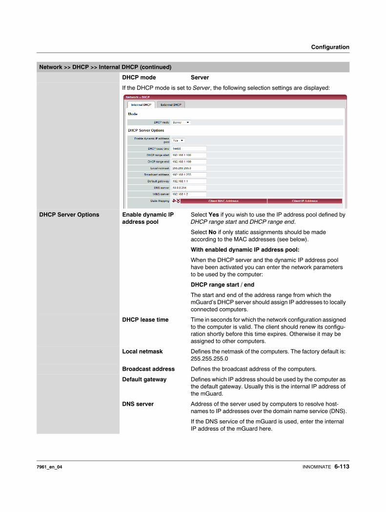
Configuration
DHCP mode Server
If the DHCP mode is set to Server, the following selection settings are displayed:
DHCP Server Options Enable dynamic IP address pool
Select Yes if you wish to use the IP address pool defined by DHCP range start and DHCP range end.
Select No if only static assignments should be made according to the MAC addresses (see below).
With enabled dynamic IP address pool:
When the DHCP server and the dynamic IP address pool have been activated you can enter the network parameters to be used by the computer:
DHCP range start / end
The start and end of the address range from which the mGuard’s DHCP server should assign IP addresses to locally connected computers.
DHCP lease time Time in seconds for which the network configuration assigned to the computer is valid. The client should renew its configu-ration shortly before this time expires. Otherwise it may be assigned to other computers.
Local netmask Defines the netmask of the computers. The factory default is: 255.255.255.0
Broadcast address Defines the broadcast address of the computers.
Default gateway Defines which IP address should be used by the computer as the default gateway. Usually this is the internal IP address of the mGuard.
DNS server Address of the server used by computers to resolve host-names to IP addresses over the domain name service (DNS).
If the DNS service of the mGuard is used, enter the internal IP address of the mGuard here.
Network >> DHCP >> Internal DHCP (continued)
7961_en_04 INNOMINATE 6-113
mGuard 7.4
WINS server Address of the server used by computers to resolve host-names to addresses over the Windows Internet Naming Ser-vice (WINS).
Static Mapping [according to MAC address]
Find out the MAC address of your computer as follows:
Windows 95/98/ME:
• Start winipcfg in a DOS box.
Windows NT/2000/XP: • Start ipconfig /all in a prompt. The MAC address is
shown as “Physical Address”.
Linux:
• Call up /sbin/ifconfig or ip link show in a shell.
You have the following options:– The MAC address of the client/computer (without spaces
or hyphens)– Client IP address
Client IP address
The static IP of the computer to be assigned to the MAC address.
Network >> DHCP >> Internal DHCP (continued)
Static assignments take priority over the dynamic IP address pool.
Static assignments and dynamic IP pool addresses must not overlap.
Do not use one IP address in several static assignments, otherwise several MAC addresses are assigned to this IP address.
Only use one DHCP server per subnetwork.
6-114 INNOMINATE 7961_en_04
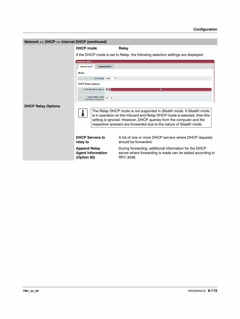
Configuration
DHCP mode Relay
If the DHCP mode is set to Relay, the following selection settings are displayed:
DHCP Relay Options
DHCP Servers to relay to
A list of one or more DHCP servers where DHCP requests should be forwarded.
Append Relay Agent Information (Option 82)
During forwarding, additional information for the DHCP server where forwarding is made can be added according to RFC 3046.
Network >> DHCP >> Internal DHCP (continued)
The Relay DHCP mode is not supported in Stealth mode. If Stealth mode is in operation on the mGuard and Relay DHCP mode is selected, then this setting is ignored. However, DHCP queries from the computer and the respective answers are forwarded due to the nature of Stealth mode.
7961_en_04 INNOMINATE 6-115
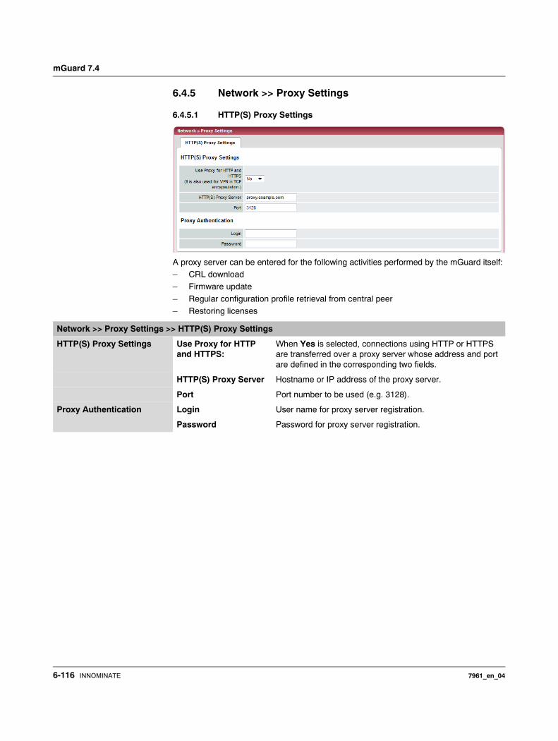
mGuard 7.4
6.4.5 Network >> Proxy Settings
6.4.5.1 HTTP(S) Proxy Settings
A proxy server can be entered for the following activities performed by the mGuard itself: – CRL download– Firmware update
– Regular configuration profile retrieval from central peer– Restoring licenses
Network >> Proxy Settings >> HTTP(S) Proxy Settings
HTTP(S) Proxy Settings Use Proxy for HTTP and HTTPS:
When Yes is selected, connections using HTTP or HTTPS are transferred over a proxy server whose address and port are defined in the corresponding two fields.
HTTP(S) Proxy Server Hostname or IP address of the proxy server.
Port Port number to be used (e.g. 3128).
Proxy Authentication Login User name for proxy server registration.
Password Password for proxy server registration.
6-116 INNOMINATE 7961_en_04
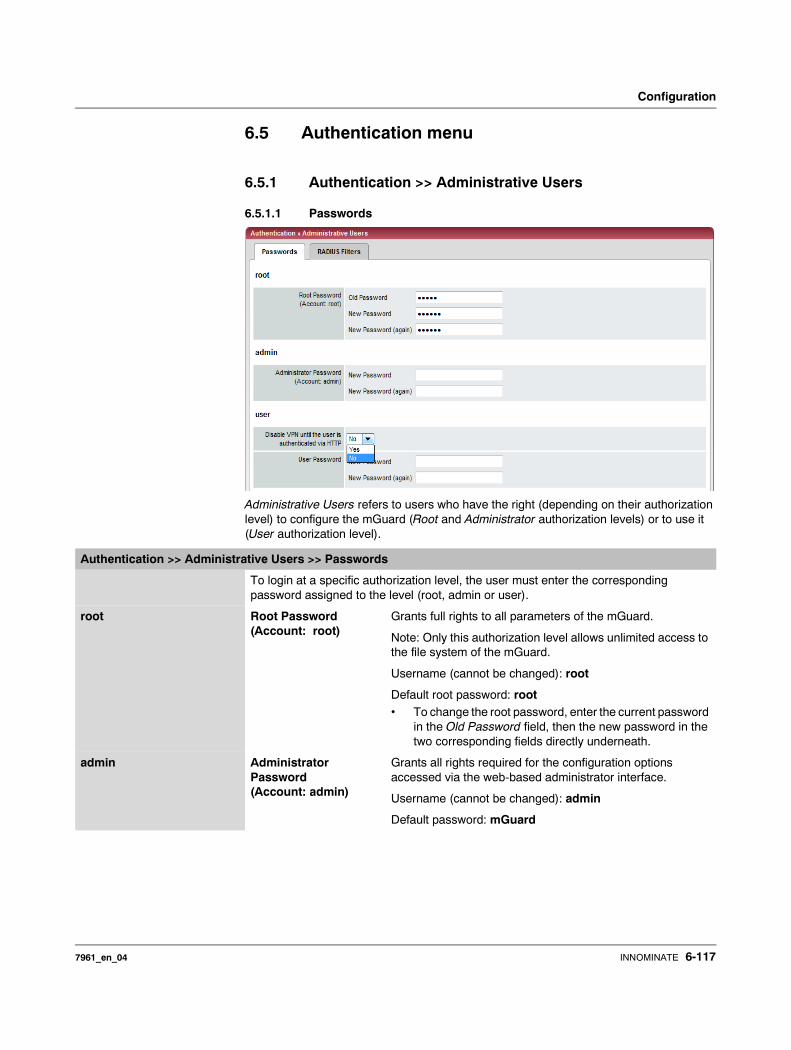
Configuration
6.5 Authentication menu
6.5.1 Authentication >> Administrative Users
6.5.1.1 Passwords
Administrative Users refers to users who have the right (depending on their authorization level) to configure the mGuard (Root and Administrator authorization levels) or to use it (User authorization level).
Authentication >> Administrative Users >> Passwords
To login at a specific authorization level, the user must enter the corresponding password assigned to the level (root, admin or user).
root Root Password (Account: root)
Grants full rights to all parameters of the mGuard.
Note: Only this authorization level allows unlimited access to the file system of the mGuard.
Username (cannot be changed): root
Default root password: root• To change the root password, enter the current password
in the Old Password field, then the new password in the two corresponding fields directly underneath.
admin Administrator Password (Account: admin)
Grants all rights required for the configuration options accessed via the web-based administrator interface.
Username (cannot be changed): admin
Default password: mGuard
7961_en_04 INNOMINATE 6-117
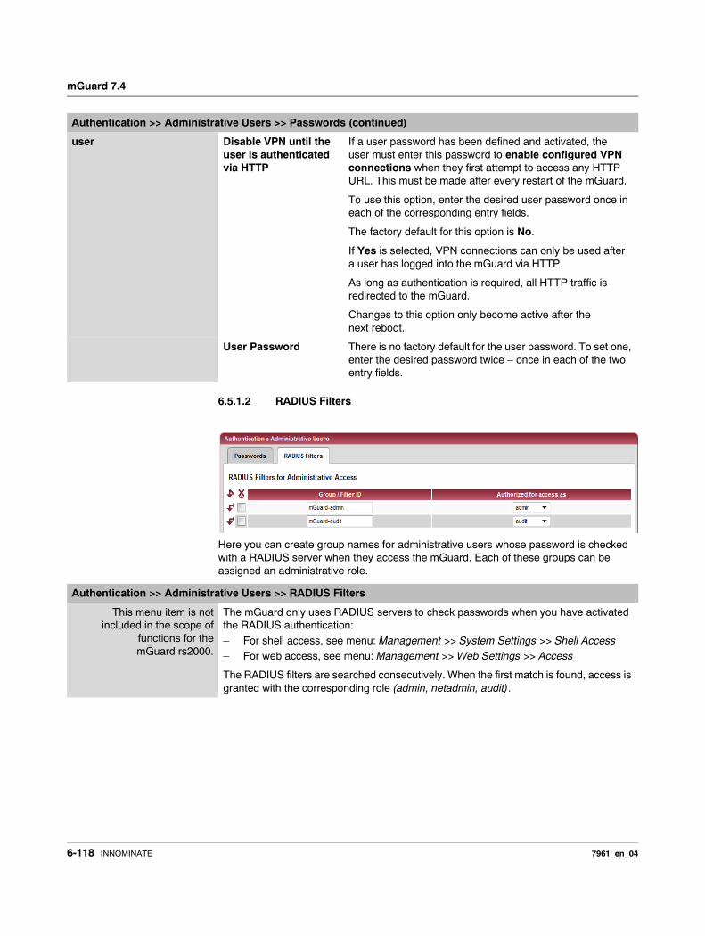
mGuard 7.4
6.5.1.2 RADIUS Filters
Here you can create group names for administrative users whose password is checked with a RADIUS server when they access the mGuard. Each of these groups can be assigned an administrative role.
user Disable VPN until the user is authenticated via HTTP
If a user password has been defined and activated, the user must enter this password to enable configured VPN connections when they first attempt to access any HTTP URL. This must be made after every restart of the mGuard.
To use this option, enter the desired user password once in each of the corresponding entry fields.
The factory default for this option is No.
If Yes is selected, VPN connections can only be used after a user has logged into the mGuard via HTTP.
As long as authentication is required, all HTTP traffic is redirected to the mGuard.
Changes to this option only become active after the next reboot.
User Password There is no factory default for the user password. To set one, enter the desired password twice – once in each of the two entry fields.
Authentication >> Administrative Users >> Passwords (continued)
Authentication >> Administrative Users >> RADIUS Filters
This menu item is notincluded in the scope of
functions for themGuard rs2000.
The mGuard only uses RADIUS servers to check passwords when you have activated the RADIUS authentication:
– For shell access, see menu: Management >> System Settings >> Shell Access– For web access, see menu: Management >> Web Settings >> Access
The RADIUS filters are searched consecutively. When the first match is found, access is granted with the corresponding role (admin, netadmin, audit).
6-118 INNOMINATE 7961_en_04
Configuration
After a RADIUS server has positively checked the password of a user, the RADIUS server sends the mGuard a list of filter IDs in its response.
These filter IDs are assigned to the user in a database of the server. The mGuard uses them to assign the group and thus the authorization as “admin”, “netadmin” or “audit”.
Successful authentication is noted in the logging of the mGuard. Other actions by the user are logged there with the user’s original name. The log messages are forwarded on to a syslog server, provided a syslog server has been approved by the mGuard.
The following actions are saved: – Login
– Logout – Start of a firmware update – Changes to the configuration
– Password changes for one of the predefined users (root, admin, netadmin, audit and user)
RADIUS Filters for Adminis-trative Access
Group / Filter ID The group name may only be used once. Two lines may not have the same value.
Answers from the RADIUS server with a notification of suc-cessful authentication must have this group name in their filter ID attribute.
Up to 50 characters are allowed (printable UTF-8 characters) without spaces.
Authorized for access as
Each group is assigned an administrative role.
admin: Administrator
netadmin: Administrator for the network
audit: Auditor
Authentication >> Administrative Users >> RADIUS Filters (continued)
7961_en_04 INNOMINATE 6-119
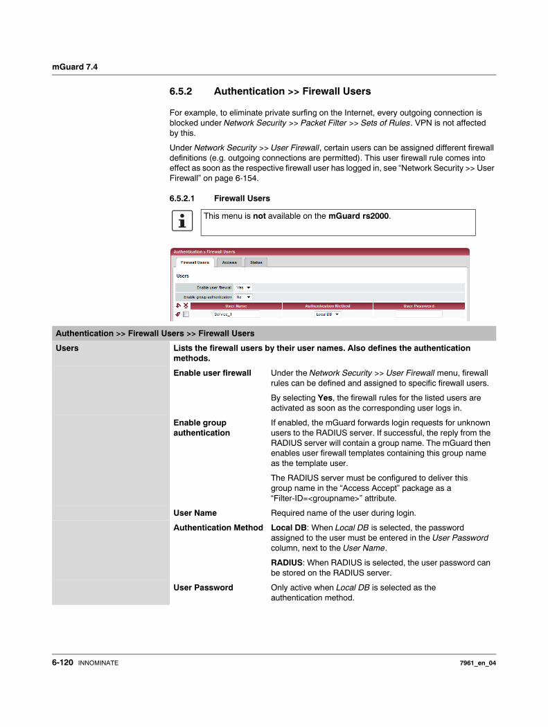
mGuard 7.4
6.5.2 Authentication >> Firewall Users
For example, to eliminate private surfing on the Internet, every outgoing connection is blocked under Network Security >> Packet Filter >> Sets of Rules. VPN is not affected by this.
Under Network Security >> User Firewall, certain users can be assigned different firewall definitions (e.g. outgoing connections are permitted). This user firewall rule comes into effect as soon as the respective firewall user has logged in, see “Network Security >> User Firewall” on page 6-154.
6.5.2.1 Firewall Users
This menu is not available on the mGuard rs2000.
Authentication >> Firewall Users >> Firewall Users
Users Lists the firewall users by their user names. Also defines the authentication methods.
Enable user firewall Under the Network Security >> User Firewall menu, firewall rules can be defined and assigned to specific firewall users.
By selecting Yes, the firewall rules for the listed users are activated as soon as the corresponding user logs in.
Enable group authentication
If enabled, the mGuard forwards login requests for unknown users to the RADIUS server. If successful, the reply from the RADIUS server will contain a group name. The mGuard then enables user firewall templates containing this group name as the template user.
The RADIUS server must be configured to deliver this group name in the “Access Accept” package as a “Filter-ID=<groupname>” attribute.
User Name Required name of the user during login.
Authentication Method Local DB: When Local DB is selected, the password assigned to the user must be entered in the User Password column, next to the User Name.
RADIUS: When RADIUS is selected, the user password can be stored on the RADIUS server.
User Password Only active when Local DB is selected as the authentication method.
6-120 INNOMINATE 7961_en_04
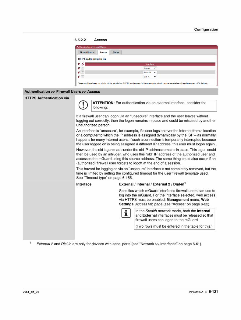
Configuration
6.5.2.2 Access
Authentication >> Firewall Users >> Access
HTTPS Authentication via
If a firewall user can logon via an “unsecure” interface and the user leaves without logging out correctly, then the logon remains in place and could be misused by another unauthorized person.
An interface is “unsecure”, for example, if a user logs on over the Internet from a location or a computer to which the IP address is assigned dynamically by the ISP – as normally happens for many Internet users. If such a connection is temporarily interrupted because the user logged on is being assigned a different IP address, this user must logon again.
However, the old logon made under the old IP address remains in place. This logon could then be used by an intruder, who uses this “old” IP address of the authorized user and accesses the mGuard using this source address. The same thing could also occur if an (authorized) firewall user forgets to logoff at the end of a session.
This hazard for logging on via an “unsecure” interface is not completely removed, but the time is limited by setting the configured timeout for the user firewall template used. See “Timeout type” on page 6-155.
Interface External / Internal / External 2 / Dial-in1
Specifies which mGuard interfaces firewall users can use to log into the mGuard. For the interface selected, web access via HTTPS must be enabled: Management menu, Web Settings, Access tab page (see “Access” on page 6-22).
1 External 2 and Dial-in are only for devices with serial ports (see “Network >> Interfaces” on page 6-61).
ATTENTION: For authentication via an external interface, consider the following:
In the Stealth network mode, both the Internal and External interfaces must be released so that firewall users can logon to the mGuard.
(Two rows must be entered in the table for this.)
7961_en_04 INNOMINATE 6-121
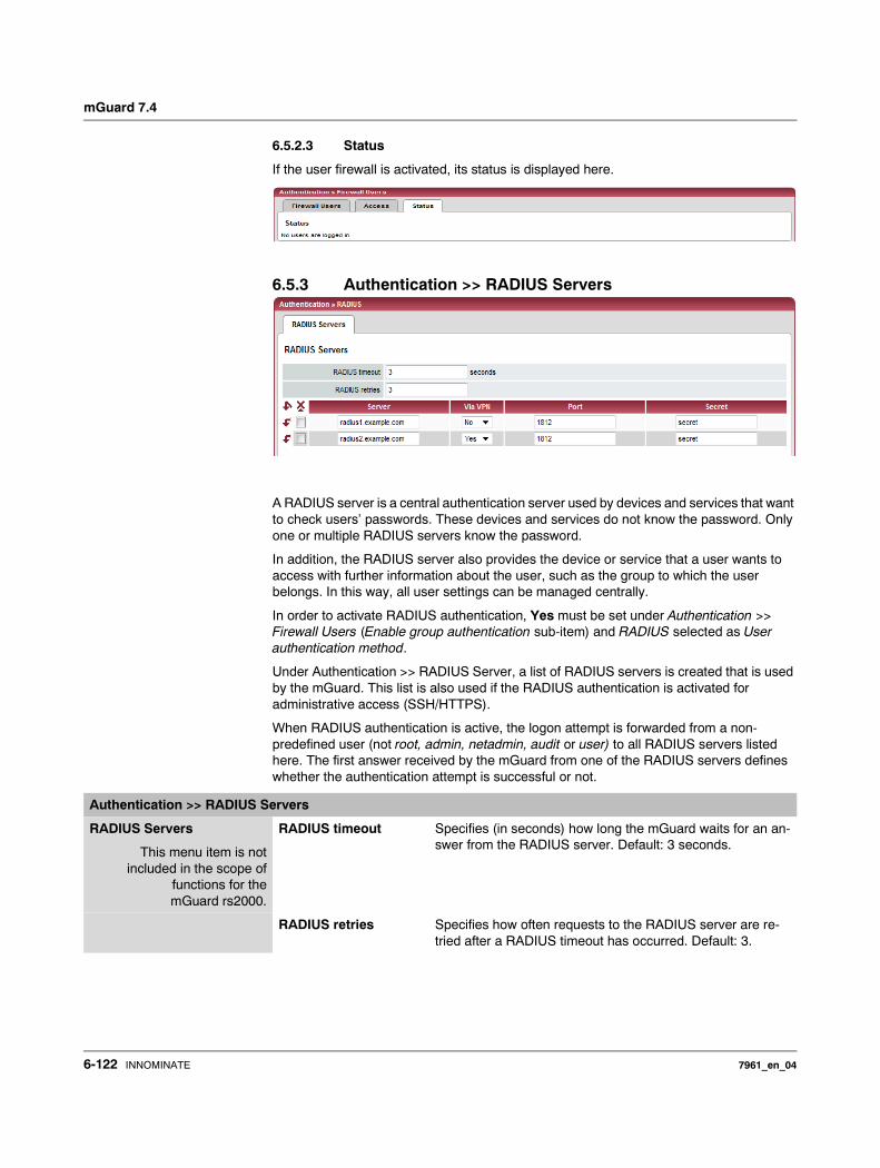
mGuard 7.4
6.5.2.3 Status
If the user firewall is activated, its status is displayed here.
6.5.3 Authentication >> RADIUS Servers
A RADIUS server is a central authentication server used by devices and services that want to check users’ passwords. These devices and services do not know the password. Only one or multiple RADIUS servers know the password.
In addition, the RADIUS server also provides the device or service that a user wants to access with further information about the user, such as the group to which the user belongs. In this way, all user settings can be managed centrally.
In order to activate RADIUS authentication, Yes must be set under Authentication >> Firewall Users (Enable group authentication sub-item) and RADIUS selected as User authentication method.
Under Authentication >> RADIUS Server, a list of RADIUS servers is created that is used by the mGuard. This list is also used if the RADIUS authentication is activated for administrative access (SSH/HTTPS).
When RADIUS authentication is active, the logon attempt is forwarded from a non-predefined user (not root, admin, netadmin, audit or user) to all RADIUS servers listed here. The first answer received by the mGuard from one of the RADIUS servers defines whether the authentication attempt is successful or not.
Authentication >> RADIUS Servers
RADIUS Servers
This menu item is notincluded in the scope of
functions for themGuard rs2000.
RADIUS timeout Specifies (in seconds) how long the mGuard waits for an an-swer from the RADIUS server. Default: 3 seconds.
RADIUS retries Specifies how often requests to the RADIUS server are re-tried after a RADIUS timeout has occurred. Default: 3.
6-122 INNOMINATE 7961_en_04
Configuration
Server Name of the RADIUS server or its IP address.
Via VPN If Yes is selected, the authentication query on the mGuard is always sent via an encrypted VPN tunnel if one is available.
If No is selected, a query of this type is always sent unen-crypted outside the VPN.
If Yes has been selected under Via VPN, then the mGuard supports requests from a RA-DIUS server through its VPN connection. This always occurs automatically when the RADIUS server belongs to the remote network of a configured VPN tunnel and the mGuard has an internal IP address which belongs to the local network of the same VPN tunnel. This makes the authentication query dependent on the availability of a VPN tun-nel.
Port The port number used by the RADIUS server.
Authentication >> RADIUS Servers (continued)
We recommend entering IP addresses as servers instead of names. Otherwise, the mGuard must first resolve the names before it can send authentication queries to the RADIUS server. This takes time when logging on. Additionally, au-thentication cannot be made in some circum-stances when name resolution fails (e.g. because the DNS is not available or the name was deleted in DNS).
During configuration, ensure that the failure of a single VPN tunnel does not prevent administrative access to the mGuard.
7961_en_04 INNOMINATE 6-123

mGuard 7.4
6.5.4 Authentication >> Certificates
Authentication is a fundamental element of secure communication. The X.509 authentication procedure ensures that the “correct” partners communicate with each other. Certificates are used in this process. An “incorrect” communication partner is one who falsely identifies themselves as someone they are not – see glossary under “X.509 Certificate”.
Certificate A certificate is used as proof of authentication for its owner. The relevant authorizing party in this case is the CA (Certificate Authority). The digital signature on the certificate is made by the CA. By providing this signature, the CA confirms that the authorized certificate owner possesses a private key that corresponds to the public key in the certificate.
The name of the certificate provider is shown as Issuer on the certificate, whilst the name of the certificate owner is shown as Subject.
Self-signed certificates A self-signed certificate is one that is signed by the certificate owner, and not by a CA. In self-signed certificates, the name of the certificate owner is shown as both Issuer and Subject.
Secret RADIUS server password.
This password must be the same as on the mGuard. The mGuard uses this password to exchange messages with the RADIUS server and to encrypt the user password. The RA-DIUS server password is not transmitted in the network.
Administrative access to the mGuard should remain possible while the RADIUS server password is being changed. Pro-ceed as follows to ensure this:• Set up the RADIUS server on the mGuard a second time
with a new password. • Also set this new password on the RADIUS server.
• Delete the line with the old password on the mGuard.
Authentication >> RADIUS Servers (continued)
The password is important for security, as the mGuard is vulnerable at this point as a result of weak passwords. We recommend a password with at least 32 characters and a range of special characters. The password must be changed on a regular basis.
If the RADIUS secret is revealed, then an attacker can read the user passwords entered in the RA-DIUS authentication requests. An attacker can also falsify RADIUS answers and gain access to the mGuard if they know the user names. These user names are transmitted as plain text with the RADIUS request. The attacker can thus simulate RADIUS requests and find out the user names and corresponding passwords.
6-124 INNOMINATE 7961_en_04
Configuration
Self-signed certificates are used when communication partners want to use the X.509 authentication procedure without having an official certificate. This type of authentication should only be used between partners that know and trust each other well. Otherwise, from a security point of view such certificates are as worthless as a home-made passport without the official stamp.
Certificates are shown to all communication partners (users or machines) during the connection process, providing the X.509 authentication method is used. In terms of mGuard, this could relate to the following applications:– Authentication of communication partners during establishment of VPN connections
(see “IPsec VPN >> Connections” on page 6-181, “Authentication” on page 6-195).– mGuard management using SSH (shell access) (see “Management >> System
Settings” on page 6-4, “Shell Access” on page 6-11).– mGuard management using HTTPS (see “Management >> Web Settings” on
page 6-21, “Access” on page 6-22).
Certificate, machine certificate
Certificates can be used to identify (authenticate) oneself to others. The certificate used by the mGuard to identify itself to others shall be known as the “machine certificate” here, in line with Microsoft Windows terminology.
A “certificate”, “certificate specific to an individual” or “user certificate displaying a person” is one used by operators to authenticate themselves to remote peers (e.g. for an operator attempting remote access to the mGuard using HTTPS and a web browser). When acquired by a web browser, a certificate specific to an individual can be saved on a chip card and then inserted into the card reader of the owner’s computer.
Remote certificate A certificate is thus used by its owner (person or machine) as a form of ID in order to verify that they really are the individual they identify themselves as. As there are two communica-tion partners, the process takes place alternately: Partner A shows their certificate to their re-mote peer (partner B). Partner B then shows their certificate to their remote peer (partner A).
In order for A to accept the certificate shown by B (thus allowing communication), there is the following option: A has earlier received a copy of the certificate from B (e.g. by data carrier or e-mail), with which B will identify itself. A can then verify the certificate shown later by B by comparing it to this certificate. When related to the mGuard interface, the certificate copy given here by B to A is an example of a Remote certificate.
For bilateral authentication to take place, both partners must thus give each other a copy of their certificate. A installs the copy of the certificate from B as its remote certificate. B then installs the copy of the certificate from A as its remote certificate.
Never give the PKCS#12 file (file name extension: *.p12) as a copy to the remote peer in order to use X.509 authentication at a later time! The PKCS#12 file contains a private key that must be kept secret and must not be given to a third party (see “Creation of certificates” on page 6-126).
To create a copy of a machine certificate imported in the mGuard, proceed as follows:• Click the Current Certificate File button on the machine certificate tab page next to
the row title Download Certificate (see “Machine Certificates” on page 6-131).
CA certificates The certificate shown by a remote peer can also be checked by the mGuard in a different way (i.e. not by consulting the locally installed remote certificate on the mGuard). To check the authentication of remote peers using X.509, the method of consulting CA certificates can be used instead or as a supplement.
CA certificates provide a way of checking whether the certificate shown by the remote peer is really signed by the CA entered within.
7961_en_04 INNOMINATE 6-125
mGuard 7.4
A CA certificate is available from the related CA (file name extension: *.cer, *.pem or *.crt). It is often available to download from the website of the CA itself.
The mGuard can then check if the certificate shown by the remote peer is authentic using the CA certificates loaded in the mGuard. In this case, all CA certificates must be available in mGuard in order to build a chain with the certificate displayed by the remote peer. Aside from the CA certificate, whose signature can be seen in the displayed certificate of the remote peer to be checked, the CA certificate of the superordinate CA up to the root certificate must be used (see glossary under CA certificate).
Authentication using CA certificates allows an expansion in the number of possible remote peers without any increased management output, as the installation of a remote certificate for each possible remote peer is not compulsory.
Creation of certificates For certificate creation, a private key and the corresponding public key are needed. Pro-grams are provided where any user can create these keys. A certificate with the relevant public key can also be created, resulting in a self-signed certificate. (Further documenta-tion on self-creation can be downloaded from www.innominate.com. This can be found in the download area as an application note under the title “How to obtain X.509 certificates”.)
A related certificate signed by a CA must be requested from the CA.
In order for the private key to be imported to the mGuard with the related certificate, these components must be packed into a PKCS#12 file (file name extension: *.p12).
Authentication procedure The mGuard can use two principle procedures for X.509 authentication.– The authentication of a remote peer is carried out based on the certificate and remote
certificate. In this case, the consulted remote certificate must be given for each individual connection (e.g. for VPN connections).
– The mGuard consults the provided CA certificate to check whether the certificate shown by the remote peer is authentic. In this case, all CA certificates must be made available for the mGuard in order to build a chain up to the root certificate using the certificate displayed by the remote peer.
“Available” means that the corresponding CA certificates must be installed in the mGuard (see “CA Certificates” on page 6-133) and must be made available additionally during the configuration of the corresponding applications (SSH, HTTPS, VPN).
Whether both procedures are used alternatively or in combination varies on the application (VPN, SSH and HTTPS).
6-126 INNOMINATE 7961_en_04
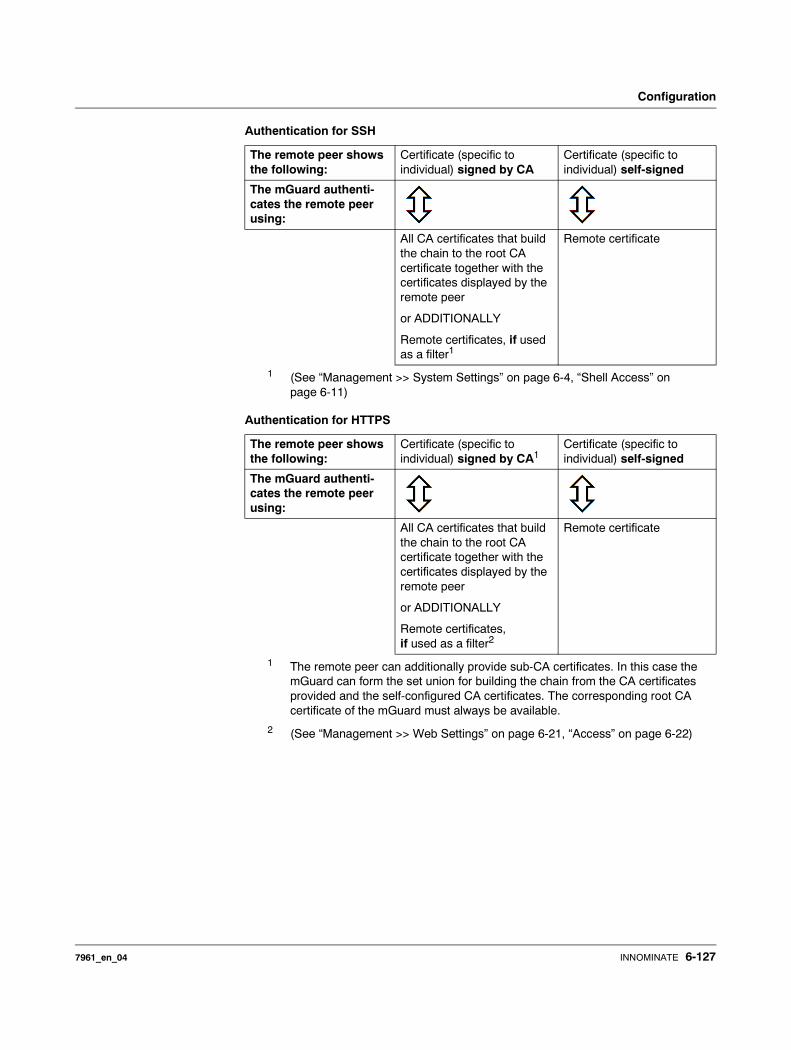
Configuration
Authentication for SSH
Authentication for HTTPS
The remote peer shows the following:
Certificate (specific to individual) signed by CA
Certificate (specific to individual) self-signed
The mGuard authenti-cates the remote peer using:
All CA certificates that build the chain to the root CA certificate together with the certificates displayed by the remote peer
or ADDITIONALLY
Remote certificates, if used as a filter1
1 (See “Management >> System Settings” on page 6-4, “Shell Access” on page 6-11)
Remote certificate
The remote peer shows the following:
Certificate (specific to individual) signed by CA1
1 The remote peer can additionally provide sub-CA certificates. In this case the mGuard can form the set union for building the chain from the CA certificates provided and the self-configured CA certificates. The corresponding root CA certificate of the mGuard must always be available.
Certificate (specific to individual) self-signed
The mGuard authenti-cates the remote peer using:
All CA certificates that build the chain to the root CA certificate together with the certificates displayed by the remote peer
or ADDITIONALLY
Remote certificates, if used as a filter2
2 (See “Management >> Web Settings” on page 6-21, “Access” on page 6-22)
Remote certificate
7961_en_04 INNOMINATE 6-127
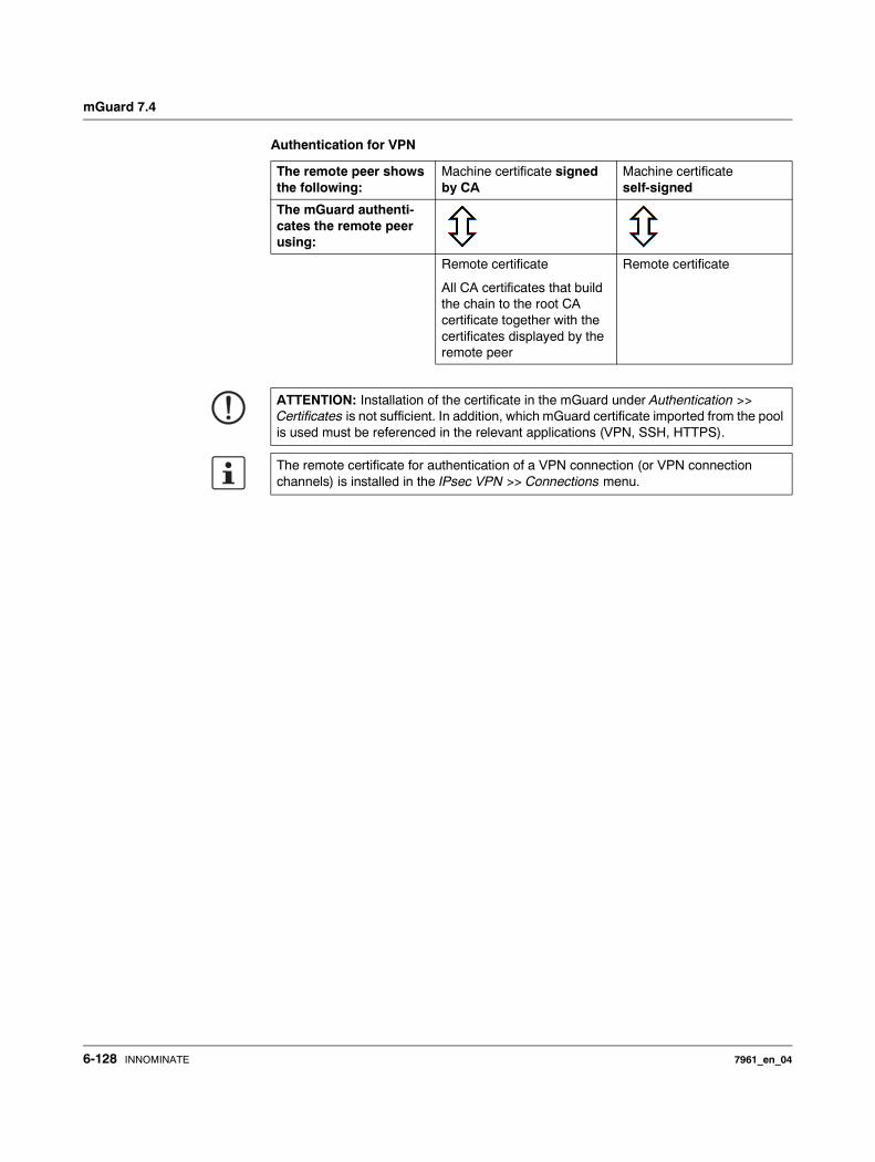
mGuard 7.4
Authentication for VPN
The remote peer shows the following:
Machine certificate signed by CA
Machine certificate self-signed
The mGuard authenti-cates the remote peer using:
Remote certificate
All CA certificates that build the chain to the root CA certificate together with the certificates displayed by the remote peer
Remote certificate
ATTENTION: Installation of the certificate in the mGuard under Authentication >> Certificates is not sufficient. In addition, which mGuard certificate imported from the pool is used must be referenced in the relevant applications (VPN, SSH, HTTPS).
The remote certificate for authentication of a VPN connection (or VPN connection channels) is installed in the IPsec VPN >> Connections menu.
6-128 INNOMINATE 7961_en_04
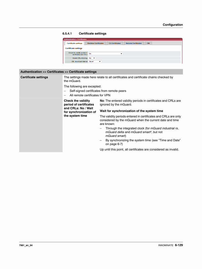
Configuration
6.5.4.1 Certificate settings
Authentication >> Certificates >> Certificate settings
Certificate settings The settings made here relate to all certificates and certificate chains checked by the mGuard.
The following are excepted:
– Self-signed certificates from remote peers– All remote certificates for VPN
Check the validity period of certificates and CRLs: No / Wait for synchronization of the system time
No: The entered validity periods in certificates and CRLs are ignored by the mGuard.
Wait for synchronization of the system time
The validity periods entered in certificates and CRLs are only considered by the mGuard when the current date and time are known:– Through the integrated clock (for mGuard industrial rs,
mGuard delta and mGuard smart², but not mGuard smart)
– By synchronizing the system time (see “Time and Date” on page 6-7)
Up until this point, all certificates are considered as invalid.
7961_en_04 INNOMINATE 6-129
mGuard 7.4
Enable CRL checking Yes: When CRL checking is enabled, the mGuard consults the CRL (Certificate Revocation List) and checks whether the mGuard certificates are blocked or not.
CRLs are issued by the CA and contain the serial numbers of blocked certificates (e.g. certificates which have been registered as stolen).
Enter the origin of the CRL under the CRL tab page (see “CRL” on page 6-137)...
CRL download interval If Enable CRL checking is set to Yes (see above), then select here the time period after which the CRLs should be downloaded and applied.
Enter the origin of the CRL under the CRL tab page (see “CRL” on page 6-137).
If CRL checking is activated but the CRL download is set to Never, then the CRL must be manually loaded on the mGuard so that CRL checking can be performed.
Authentication >> Certificates >> Certificate settings (continued)
When CRL checking is enabled, a CRL must be configured for each Issuer of certificates in the mGuard. Absent CRLs lead to certificates being declared invalid.
CRLs are verified by the mGuard using a relevant CA certificate. Therefore, all CA certificates belonging to a CRL (i.e. all sub-CA certificates and the root certificate) must be installed on the mGuard. If the validity of a CRL cannot be proven, then it is ignored by the mGuard.
If the use of CRLs is activated together with the consideration of validity periods, lists are ignored if their validity period has expired or has not yet started.
6-130 INNOMINATE 7961_en_04

Configuration
6.5.4.2 Machine Certificates
The mGuard authenticates itself to the remote peer using a machine certificate loaded in the mGuard. The machine certificate is the “passport” of an mGuard with which it can authenticate itself to the respective remote peer.
For more details, see “Authentication >> Certificates” on page 6-124.
By importing a PKCS#12 file, the mGuard obtains a private key and the corresponding machine certificate. Several PKCS#12 files can be loaded into the mGuard. The mGuard can then show the remote peer a self-signed certificate or certificate signed by the CA for different connections.
In order to use the installed machine certificate, it must be referenced additionally during the configuration of applications (SSH, VPN) so that it can be used for the respective connection or remote access type.
Example of imported machine certificates:
Authentication >> Certificates >> Machine Certificates
Machine Certificates Shows the currently imported X.509 certificates that the mGuard uses to authenticate itself to remote peers (e.g. other VPN gateways).
7961_en_04 INNOMINATE 6-131
mGuard 7.4
To import a new certificate, please proceed as follows:
Importing a new machine certificate
Requirement:
The PKCS#12 file (format: *.p12 or *.pfx) is saved on the connected computer.
Proceed as follows:
• Click on Browse… to select the file.• Enter the password that is used for protection of the PKCS#12 file private key in the
Password field.• Click on Import.
After the import, the installed certificate can be seen under Certificate.
• Remember to save the imported certificate along with the other entries by clicking on Apply.
Shortname
During the machine certificate import process, the CN attribute from the certificate subject field is suggested as the short name (providing the Shortname field is empty at this point). This name can be adopted or another name can be chosen.
• Name entry (whether the suggested one or another) is mandatory. The names must be unique, meaning they must not be used more than once.
Use of the short name: During the configuration of – SSH (Management >> System Settings menu, Shell access),– HTTPS (Management >> Web Settings menu, Access) and
– VPN connections (IPsec VPN >> Connections menu),
the imported certificates in the mGuard are given as a selection list.
The certificates are displayed under the short name entered for each individual certificate on this page.
For this reason, the entry of a name is necessary.
Creating a certificate copy
You can create a copy of the imported machine certificate (e.g. for the remote peer so that this can authenticate the mGuard). This copy does not contain the private key, and can be made public at any time.
To do this, proceed as follows:• Click on the Current Certificate File button on the machine certificate next to the
Download Certificate row title. • Make the desired entries in the dialog that opens.
6-132 INNOMINATE 7961_en_04
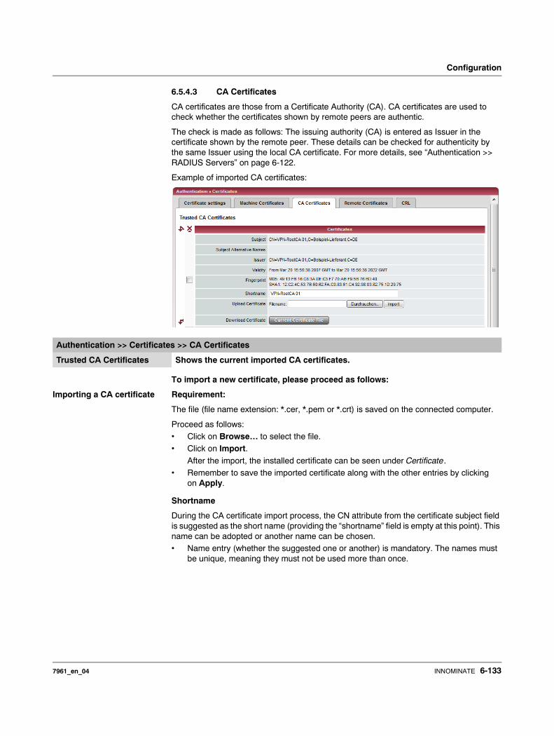
Configuration
6.5.4.3 CA Certificates
CA certificates are those from a Certificate Authority (CA). CA certificates are used to check whether the certificates shown by remote peers are authentic.
The check is made as follows: The issuing authority (CA) is entered as Issuer in the certificate shown by the remote peer. These details can be checked for authenticity by the same Issuer using the local CA certificate. For more details, see “Authentication >> RADIUS Servers” on page 6-122.
Example of imported CA certificates:
To import a new certificate, please proceed as follows:
Importing a CA certificate Requirement:
The file (file name extension: *.cer, *.pem or *.crt) is saved on the connected computer.
Proceed as follows:• Click on Browse… to select the file.• Click on Import.
After the import, the installed certificate can be seen under Certificate. • Remember to save the imported certificate along with the other entries by clicking
on Apply.
Shortname
During the CA certificate import process, the CN attribute from the certificate subject field is suggested as the short name (providing the “shortname” field is empty at this point). This name can be adopted or another name can be chosen. • Name entry (whether the suggested one or another) is mandatory. The names must
be unique, meaning they must not be used more than once.
Authentication >> Certificates >> CA Certificates
Trusted CA Certificates Shows the current imported CA certificates.
7961_en_04 INNOMINATE 6-133

mGuard 7.4
Use of the short name: During the configuration of
– SSH (Management >> System Settings menu, Shell access),– HTTPS (Management >> Web Settings menu, Access) and– VPN connections (IPsec VPN >> Connections menu),
the imported certificates in the mGuard are given as a selection list. The certificates are displayed under the short name entered for each individual certificate on this page. For this reason, the entry of a name is necessary.
Creating a certificate copy
You can make a copy of the imported CA certificate.
To do this, proceed as follows:• Click on the Current Certificate File button on the CA certificate next to the Download
Certificate row title. Make the desired entries in the dialog that opens.
6-134 INNOMINATE 7961_en_04
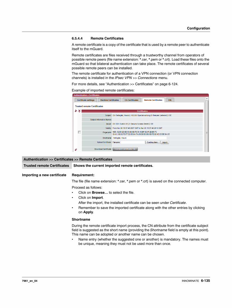
Configuration
6.5.4.4 Remote Certificates
A remote certificate is a copy of the certificate that is used by a remote peer to authenticate itself to the mGuard.
Remote certificates are files received through a trustworthy channel from operators of possible remote peers (file name extension: *.cer, *.pem or *.crt). Load these files onto the mGuard so that bilateral authentication can take place. The remote certificates of several possible remote peers can be installed.
The remote certificate for authentication of a VPN connection (or VPN connection channels) is installed in the IPsec VPN >> Connections menu.
For more details, see “Authentication >> Certificates” on page 6-124.
Example of imported remote certificates:
Importing a new certificate Requirement:
The file (file name extension: *.cer, *.pem or *.crt) is saved on the connected computer.
Proceed as follows:• Click on Browse… to select the file.• Click on Import.
After the import, the installed certificate can be seen under Certificate. • Remember to save the imported certificate along with the other entries by clicking
on Apply.
Shortname
During the remote certificate import process, the CN attribute from the certificate subject field is suggested as the short name (providing the Shortname field is empty at this point). This name can be adopted or another name can be chosen. • Name entry (whether the suggested one or another) is mandatory. The names must
be unique, meaning they must not be used more than once.
Authentication >> Certificates >> Remote Certificates
Trusted remote Certificates Shows the current imported remote certificates.
7961_en_04 INNOMINATE 6-135
mGuard 7.4
Use of the short name: During the configuration of
– SSH (Management >> System Settings menu, Shell access) and– HTTPS (Management >> Web Settings menu, Access)
the imported certificates in the mGuard are given as a selection list. The certificates are displayed under the short name entered for each individual certificate on this page.
For this reason, the entry of a name is necessary.
Creating a certificate copy
You can make a copy of the imported remote certificate.
To do this, proceed as follows:
• Click on the Current Certificate File button on the remote certificate next to the Download Certificate row title. Make the desired entries in the dialog that opens.
6-136 INNOMINATE 7961_en_04
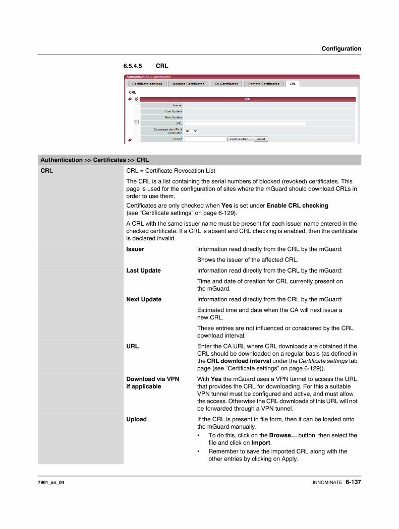
Configuration
6.5.4.5 CRL
Authentication >> Certificates >> CRL
CRL CRL = Certificate Revocation List
The CRL is a list containing the serial numbers of blocked (revoked) certificates. This page is used for the configuration of sites where the mGuard should download CRLs in order to use them.
Certificates are only checked when Yes is set under Enable CRL checking (see “Certificate settings” on page 6-129).
A CRL with the same issuer name must be present for each issuer name entered in the checked certificate. If a CRL is absent and CRL checking is enabled, then the certificate is declared invalid.
Issuer Information read directly from the CRL by the mGuard:
Shows the issuer of the affected CRL.
Last Update Information read directly from the CRL by the mGuard:
Time and date of creation for CRL currently present on the mGuard.
Next Update Information read directly from the CRL by the mGuard:
Estimated time and date when the CA will next issue a new CRL.
These entries are not influenced or considered by the CRL download interval.
URL Enter the CA URL where CRL downloads are obtained if the CRL should be downloaded on a regular basis (as defined in the CRL download interval under the Certificate settings tab page (see “Certificate settings” on page 6-129)).
Download via VPN if applicable
With Yes the mGuard uses a VPN tunnel to access the URL that provides the CRL for downloading. For this a suitable VPN tunnel must be configured and active, and must allow the access. Otherwise the CRL downloads of this URL will not be forwarded through a VPN tunnel.
Upload If the CRL is present in file form, then it can be loaded onto the mGuard manually.• To do this, click on the Browse… button, then select the
file and click on Import. • Remember to save the imported CRL along with the
other entries by clicking on Apply.
7961_en_04 INNOMINATE 6-137
mGuard 7.4
6.6 Network Security menu
6.6.1 Network Security >> Packet Filter
The mGuard comes with an integrated Stateful Packet Inspection Firewall. The connection data for each active connection is collected in a database (connection tracking). Therefore, it is only necessary to define rules for one direction. Only data from the opposite direction of the connection is allowed through, and none other.
A side-effect is that existing connections are not cancelled during reconfiguration, even if a corresponding new connection can no longer be setup.
Factory defaults for the firewall:
– All incoming connections are rejected (except VPN). – Data packets of all outgoing connections are passed through.
Firewall rules here have an effect on the firewall that is constantly active, with the exception of:
– VPN connections. Individual firewall rules are defined for VPN connections (see “IPsec VPN >> Connections” on page 6-181, “Firewall” on page 6-201).
– User firewall. If a user logs in with defined firewall rules, then these take priority (see “Network Security >> User Firewall” on page 6-154). After this, the constantly active firewall rules then come into effect.
This menu is not available on the mGuard blade controller.
This menu is available in a reduced form on the mGuard rs2000.
If multiple firewall rules are set, they will be searched in the order in which they are listed (top-down) until a suitable rule is found. This rule is then applied.
If there are other suitable rules further down the list, these are ignored.
6-138 INNOMINATE 7961_en_04

Configuration
6.6.1.1 Incoming Rules
Network Security >> Packet Filter >> Incoming Rules
Incoming Lists the firewall rules that have been set. These rules apply for incoming data connections that were initiated externally.
If no rule has been set, the data packets for all incoming connections (except VPN) are dropped (factory default).
General firewall setting
Accept all incoming connections: the data packets for all incoming connections are accepted.
Drop all incoming connections: the data packets for all incoming connections are dropped.
Use the firewall ruleset below: displays additional setting options. (This menu item is not included in the scope of functions for the mGuard rs2000.)
The following settings are only visible when “Use the firewall ruleset below” is set.
Interface External / External 2 / Any External1
Specifies over which interface the data packets come in so that the rule applies to them. Any External refers to the External and External 2 interfaces. These interfaces are only available for mGuard models that have a serial port with external access.
Protocol TCP, UDP, ICMP, GRE, All.
From / To IP 0.0.0.0/0 means all IP addresses. To enter an address, use CIDR notation (see “CIDR (Classless Inter-Domain Routing)” on page 6-249).
From Port / To Port (Only evaluated for TCP and UDP protocols)– any describes any selected port.
– startport:endport (e.g. 110:120) defines a range of ports.
You can specify individual ports by giving either their port number or the corresponding service name: (e.g. 110 for pop3 or pop3 for 110).
7961_en_04 INNOMINATE 6-139
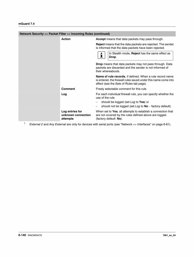
mGuard 7.4
Action Accept means that data packets may pass through.
Reject means that the data packets are rejected. The sender is informed that the data packets have been rejected.
Drop means that data packets may not pass through. Data packets are discarded and the sender is not informed of their whereabouts.
Name of rule records, if defined. When a rule record name is entered, the firewall rules saved under this name come into effect (see the Sets of Rules tab page).
Comment Freely selectable comment for this rule.
Log For each individual firewall rule, you can specify whether the use of the rule
– should be logged (set Log to Yes) or – should not be logged (set Log to No – factory default).
Log entries for unknown connection attempts
When set to Yes, all attempts to establish a connection that are not covered by the rules defined above are logged. (factory default: No).
1 External 2 and Any External are only for devices with serial ports (see “Network >> Interfaces” on page 6-61).
Network Security >> Packet Filter >> Incoming Rules (continued)
In Stealth mode, Reject has the same effect as Drop.
6-140 INNOMINATE 7961_en_04
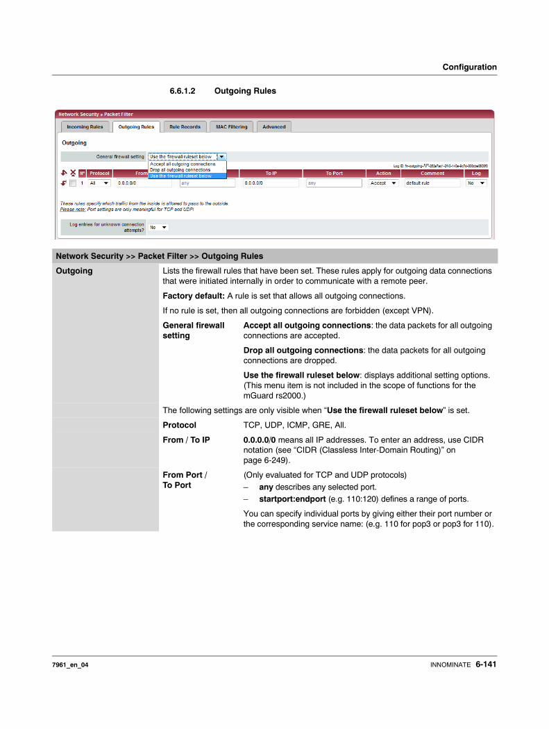
Configuration
6.6.1.2 Outgoing Rules
Network Security >> Packet Filter >> Outgoing Rules
Outgoing Lists the firewall rules that have been set. These rules apply for outgoing data connections that were initiated internally in order to communicate with a remote peer.
Factory default: A rule is set that allows all outgoing connections.
If no rule is set, then all outgoing connections are forbidden (except VPN).
General firewall setting
Accept all outgoing connections: the data packets for all outgoing connections are accepted.
Drop all outgoing connections: the data packets for all outgoing connections are dropped.
Use the firewall ruleset below: displays additional setting options. (This menu item is not included in the scope of functions for the mGuard rs2000.)
The following settings are only visible when “Use the firewall ruleset below” is set.
Protocol TCP, UDP, ICMP, GRE, All.
From / To IP 0.0.0.0/0 means all IP addresses. To enter an address, use CIDR notation (see “CIDR (Classless Inter-Domain Routing)” on page 6-249).
From Port / To Port
(Only evaluated for TCP and UDP protocols)
– any describes any selected port. – startport:endport (e.g. 110:120) defines a range of ports.
You can specify individual ports by giving either their port number or the corresponding service name: (e.g. 110 for pop3 or pop3 for 110).
7961_en_04 INNOMINATE 6-141
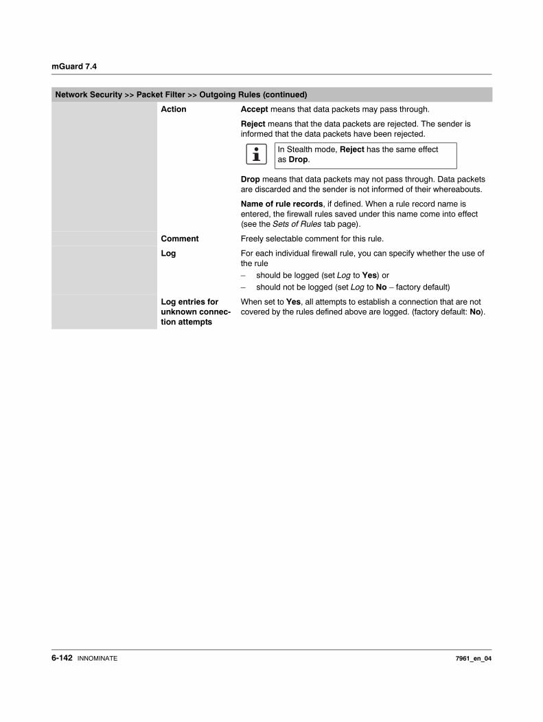
mGuard 7.4
Action Accept means that data packets may pass through.
Reject means that the data packets are rejected. The sender is informed that the data packets have been rejected.
Drop means that data packets may not pass through. Data packets are discarded and the sender is not informed of their whereabouts.
Name of rule records, if defined. When a rule record name is entered, the firewall rules saved under this name come into effect (see the Sets of Rules tab page).
Comment Freely selectable comment for this rule.
Log For each individual firewall rule, you can specify whether the use of the rule– should be logged (set Log to Yes) or – should not be logged (set Log to No – factory default)
Log entries for unknown connec-tion attempts
When set to Yes, all attempts to establish a connection that are not covered by the rules defined above are logged. (factory default: No).
Network Security >> Packet Filter >> Outgoing Rules (continued)
In Stealth mode, Reject has the same effect as Drop.
6-142 INNOMINATE 7961_en_04
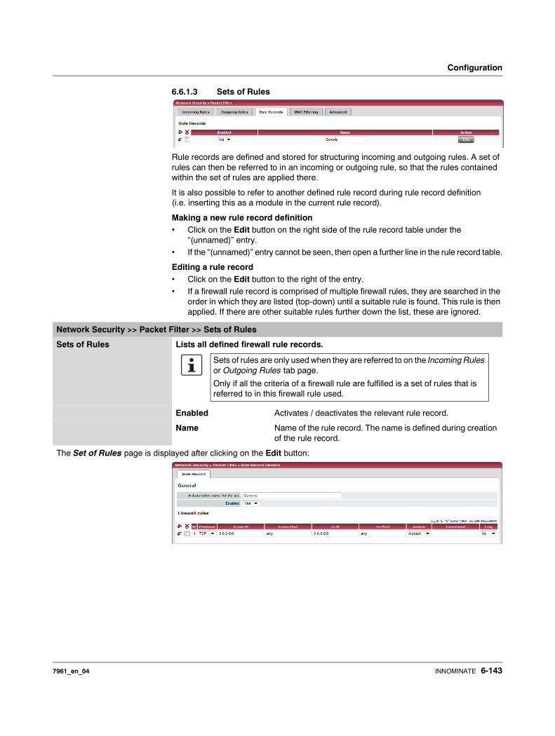
Configuration
6.6.1.3 Sets of Rules
Rule records are defined and stored for structuring incoming and outgoing rules. A set of rules can then be referred to in an incoming or outgoing rule, so that the rules contained within the set of rules are applied there.
It is also possible to refer to another defined rule record during rule record definition (i.e. inserting this as a module in the current rule record).
Making a new rule record definition• Click on the Edit button on the right side of the rule record table under the
“(unnamed)” entry.• If the “(unnamed)” entry cannot be seen, then open a further line in the rule record table.
Editing a rule record• Click on the Edit button to the right of the entry. • If a firewall rule record is comprised of multiple firewall rules, they are searched in the
order in which they are listed (top-down) until a suitable rule is found. This rule is then applied. If there are other suitable rules further down the list, these are ignored.
Network Security >> Packet Filter >> Sets of Rules
Sets of Rules Lists all defined firewall rule records.
Enabled Activates / deactivates the relevant rule record.
Name Name of the rule record. The name is defined during creation of the rule record.
The Set of Rules page is displayed after clicking on the Edit button:
Sets of rules are only used when they are referred to on the Incoming Rules or Outgoing Rules tab page.
Only if all the criteria of a firewall rule are fulfilled is a set of rules that is referred to in this firewall rule used.
7961_en_04 INNOMINATE 6-143
mGuard 7.4
General A descriptive name for the set
Freely selectable name. It must clearly define the rule record in question. A rule record can be referred to in the incoming and outgoing rule lists using this name. To do this, the relevant rule record name is selected in the Action column.
Enabled Activates / deactivates the relevant rule record.
Firewall rules Protocol TCP, UDP, ICMP, GRE, All.
From / To IP 0.0.0.0/0 means all IP addresses. To enter an address, use CIDR notation (see “CIDR (Classless Inter-Domain Routing)” on page 6-249).
From Port / To Port (Only evaluated for TCP and UDP protocols)– any describes any selected port.
– startport:endport (e.g. 110:120) defines a range of ports.
You can specify individual ports by giving either their port number or the corresponding service name: (e.g. 110 for pop3 or pop3 for 110).
Action Accept means that data packets may pass through.
Reject means that the data packets are rejected. The sender is informed that the data packets have been rejected.
Drop means that data packets may not pass through. Data packets are discarded and the sender is not informed of their whereabouts.
Name of rule records, if defined. Aside from “Accept”, “Reject” and “Drop”, the selection list also gives the names of previ-ously defined rule records. If a name is selected (referred to), then the rules in this set of rules are applied here. If the rules from the applied set of rules cannot be used and put into effect with “Accept”, “Reject” or “Drop”, the rule processing continues with the rule following the one from which the set of rules was referred to.
Comment Freely selectable comment for this rule.
Log For each individual firewall rule, you can specify whether the use of the rule– should be logged (set Log to Yes) or
– should not be logged (set Log to No – factory default).
Network Security >> Packet Filter >> Sets of Rules (continued)
In Stealth mode, Reject has the same effect as Drop.
6-144 INNOMINATE 7961_en_04
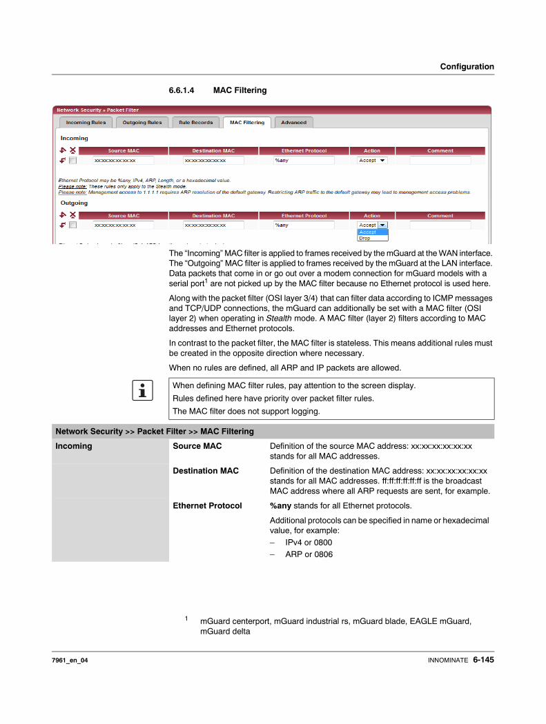
Configuration
6.6.1.4 MAC Filtering
The “Incoming” MAC filter is applied to frames received by the mGuard at the WAN interface. The “Outgoing” MAC filter is applied to frames received by the mGuard at the LAN interface. Data packets that come in or go out over a modem connection for mGuard models with a serial port1 are not picked up by the MAC filter because no Ethernet protocol is used here.
Along with the packet filter (OSI layer 3/4) that can filter data according to ICMP messages and TCP/UDP connections, the mGuard can additionally be set with a MAC filter (OSI layer 2) when operating in Stealth mode. A MAC filter (layer 2) filters according to MAC addresses and Ethernet protocols.
In contrast to the packet filter, the MAC filter is stateless. This means additional rules must be created in the opposite direction where necessary.
When no rules are defined, all ARP and IP packets are allowed.
1 mGuard centerport, mGuard industrial rs, mGuard blade, EAGLE mGuard, mGuard delta
When defining MAC filter rules, pay attention to the screen display.
Rules defined here have priority over packet filter rules.
The MAC filter does not support logging.
Network Security >> Packet Filter >> MAC Filtering
Incoming Source MAC Definition of the source MAC address: xx:xx:xx:xx:xx:xx stands for all MAC addresses.
Destination MAC Definition of the destination MAC address: xx:xx:xx:xx:xx:xx stands for all MAC addresses. ff:ff:ff:ff:ff:ff is the broadcast MAC address where all ARP requests are sent, for example.
Ethernet Protocol %any stands for all Ethernet protocols.
Additional protocols can be specified in name or hexadecimal value, for example:
– IPv4 or 0800– ARP or 0806
7961_en_04 INNOMINATE 6-145

mGuard 7.4
Action Accept means that data packets may pass through.
Drop means that data packets may not pass through (dropped).
Comment Freely selectable comment for this rule.
Outgoing The explanation for “Incoming” also applies to “Outgoing”.
Network Security >> Packet Filter >> MAC Filtering (continued)
6-146 INNOMINATE 7961_en_04
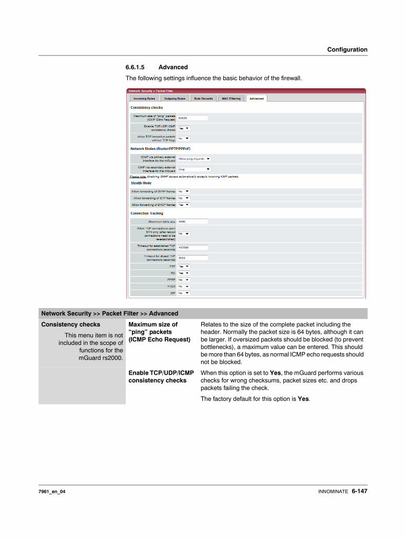
Configuration
6.6.1.5 Advanced
The following settings influence the basic behavior of the firewall.
Network Security >> Packet Filter >> Advanced
Consistency checks
This menu item is notincluded in the scope of
functions for themGuard rs2000.
Maximum size of “ping” packets (ICMP Echo Request)
Relates to the size of the complete packet including the header. Normally the packet size is 64 bytes, although it can be larger. If oversized packets should be blocked (to prevent bottlenecks), a maximum value can be entered. This should be more than 64 bytes, as normal ICMP echo requests should not be blocked.
Enable TCP/UDP/ICMP consistency checks
When this option is set to Yes, the mGuard performs various checks for wrong checksums, packet sizes etc. and drops packets failing the check.
The factory default for this option is Yes.
7961_en_04 INNOMINATE 6-147

mGuard 7.4
Allow TCP keepalive packets without TCP flags
TCP packets without set flags in their TCP header are normally rejected by firewalls. At least one type of Siemens control with older firmware sends TCP keepalive packets without set TCP flags, which are then rejected as invalid by the mGuard.
The Yes setting allows the forwarding of TCP packets where no TCP flags are set in the header. This only applies when TCP packets of this type are sent within an existing TCP connection with a regular structure.
TCP packets without TCP flags do not result in a new entry in the connection table (see “Connection Tracking” on page 6-149). If the connection is established when the mGuard is restarted, then corresponding packets are still rejected and connection problems are observed as long as no packets with flags belonging to the connection are sent.
This setting applies to all TCP packets without flags. The Yes setting thus weakens the security functions provided by the mGuard.
Network Modes (Router/PPTP/PPPoE)
ICMP via primary external interface for the mGuard
ICMP via secondary external interface for the mGuard
With this option you can control which ICMP messages from the external network are accepted by the mGuard via the primary / secondary external interface.
Drop: All ICMP messages directed to the mGuard are dropped.
Allow ping requests: Only ping messages sent to the mGuard (ICMP type 8) are accepted.
Allow all ICMPs: All ICMP messages to the mGuard are accepted.
Stealth Mode Allow forwarding of GVRP frames
Yes / No
The GARP VLAN Registration Protocol (GVRP) is used by GVRP capable switches to exchange configuration information.
When set to Yes, GVRP frames are allowed to pass through the mGuard in Stealth mode.
Allow forwarding of STP frames
Yes / No
The Spanning Tree Protocol (STP) (802.1d) is used by bridges and switches to detect and consider loops in the network topology.
When set to Yes, STP frames are allowed to pass through the mGuard in Stealth mode.
Network Security >> Packet Filter >> Advanced (continued)
Regardless of this setting, incoming ICMP packets are always accepted if SNMP access is enabled.
6-148 INNOMINATE 7961_en_04
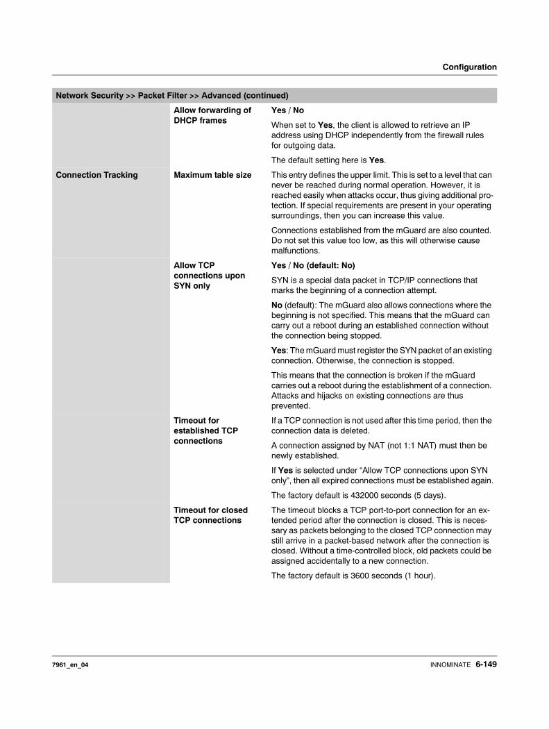
Configuration
Allow forwarding of DHCP frames
Yes / No
When set to Yes, the client is allowed to retrieve an IP address using DHCP independently from the firewall rules for outgoing data.
The default setting here is Yes.
Connection Tracking Maximum table size This entry defines the upper limit. This is set to a level that can never be reached during normal operation. However, it is reached easily when attacks occur, thus giving additional pro-tection. If special requirements are present in your operating surroundings, then you can increase this value.
Connections established from the mGuard are also counted. Do not set this value too low, as this will otherwise cause malfunctions.
Allow TCP connections upon SYN only
Yes / No (default: No)
SYN is a special data packet in TCP/IP connections that marks the beginning of a connection attempt.
No (default): The mGuard also allows connections where the beginning is not specified. This means that the mGuard can carry out a reboot during an established connection without the connection being stopped.
Yes: The mGuard must register the SYN packet of an existing connection. Otherwise, the connection is stopped.
This means that the connection is broken if the mGuard carries out a reboot during the establishment of a connection. Attacks and hijacks on existing connections are thus prevented.
Timeout for established TCP connections
If a TCP connection is not used after this time period, then the connection data is deleted.
A connection assigned by NAT (not 1:1 NAT) must then be newly established.
If Yes is selected under “Allow TCP connections upon SYN only”, then all expired connections must be established again.
The factory default is 432000 seconds (5 days).
Timeout for closed TCP connections
The timeout blocks a TCP port-to-port connection for an ex-tended period after the connection is closed. This is neces-sary as packets belonging to the closed TCP connection may still arrive in a packet-based network after the connection is closed. Without a time-controlled block, old packets could be assigned accidentally to a new connection.
The factory default is 3600 seconds (1 hour).
Network Security >> Packet Filter >> Advanced (continued)
7961_en_04 INNOMINATE 6-149
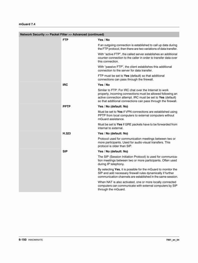
mGuard 7.4
FTP Yes / No
If an outgoing connection is established to call up data during the FTP protocol, then there are two variations of data transfer.
With “active FTP”, the called server establishes an additional counter-connection to the caller in order to transfer data over this connection.
With “passive FTP”, the client establishes this additional connection to the server for data transfer.
FTP must be set to Yes (default) so that additional connections can pass through the firewall.
IRC Yes / No
Similar to FTP: For IRC chat over the Internet to work properly, incoming connections must be allowed following an active connection attempt. IRC must be set to Yes (default) so that additional connections can pass through the firewall.
PPTP Yes / No (default: No)
Must be set to Yes if VPN connections are established using PPTP from local computers to external computers without mGuard assistance.
Must be set to Yes if GRE packets have to be forwarded from internal to external.
H.323 Yes / No (default: No)
Protocol used for communication meetings between two or more participants. Used for audio-visual transfers. This protocol is older than SIP.
SIP Yes / No (default: No)
The SIP (Session Initiation Protocol) is used for communica-tion meetings between two or more participants. Often used during IP telephony.
By selecting Yes, it is possible for the mGuard to monitor the SIP and add necessary firewall rules dynamically if further communication channels are established in the same session.
When NAT is also activated, one or more locally connected computers can communicate with external computers by SIP through the mGuard.
Network Security >> Packet Filter >> Advanced (continued)
6-150 INNOMINATE 7961_en_04
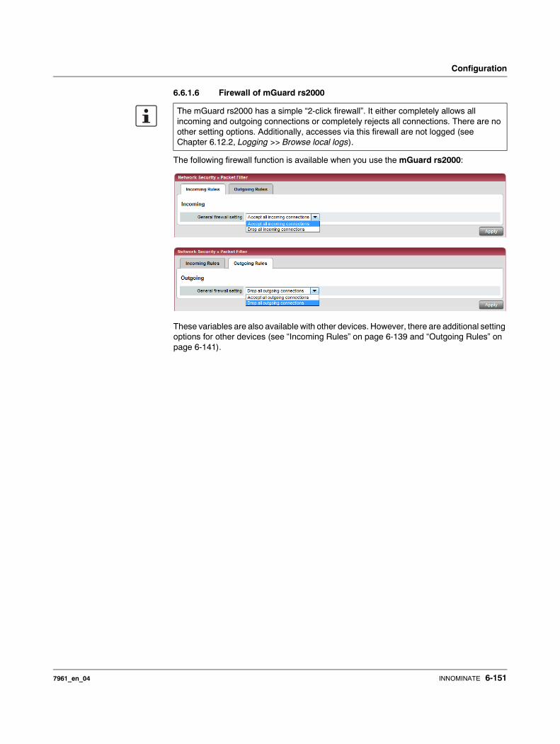
Configuration
6.6.1.6 Firewall of mGuard rs2000
The following firewall function is available when you use the mGuard rs2000:
These variables are also available with other devices. However, there are additional setting options for other devices (see “Incoming Rules” on page 6-139 and “Outgoing Rules” on page 6-141).
The mGuard rs2000 has a simple “2-click firewall”. It either completely allows all incoming and outgoing connections or completely rejects all connections. There are no other setting options. Additionally, accesses via this firewall are not logged (see Chapter 6.12.2, Logging >> Browse local logs).
7961_en_04 INNOMINATE 6-151
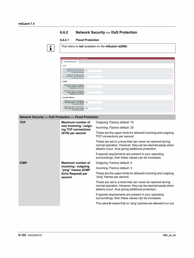
mGuard 7.4
6.6.2 Network Security >> DoS Protection
6.6.2.1 Flood Protection
This menu is not available on the mGuard rs2000.
Network Security >> DoS Protection >> Flood Protection
TCP Maximum number of new incoming / outgo-ing TCP connections (SYN) per second
Outgoing: Factory default: 75
Incoming: Factory default: 25
These are the upper limits for allowed incoming and outgoing TCP connections per second.
These are set to a level that can never be reached during normal operation. However, they can be reached easily when attacks occur, thus giving additional protection.
If special requirements are present in your operating surroundings, then these values can be increased.
ICMP Maximum number of incoming / outgoing “ping” frames (ICMP Echo Request) per second
Outgoing: Factory default: 5
Incoming: Factory default: 3
These are the upper limits for allowed incoming and outgoing “ping” frames per second.
These are set to a level that can never be reached during normal operation. However, they can be reached easily when attacks occur, thus giving additional protection.
If special requirements are present in your operating surroundings, then these values can be increased.
The value 0 means that no “ping” packets are allowed in or out.
6-152 INNOMINATE 7961_en_04
Configuration
Stealth Mode Maximum number of incoming / outgoing ARP requests or ARP replies per second each
Factory default: 500
These are the upper limits for allowed incoming and outgoing ARP requests or replies per second.
These are set to a level that can never be reached during normal operation. However, they can be reached easily when attacks occur, thus giving additional protection.
If special requirements are present in your operating surroundings, then these values can be increased.
Network Security >> DoS Protection >> Flood Protection (continued)
7961_en_04 INNOMINATE 6-153
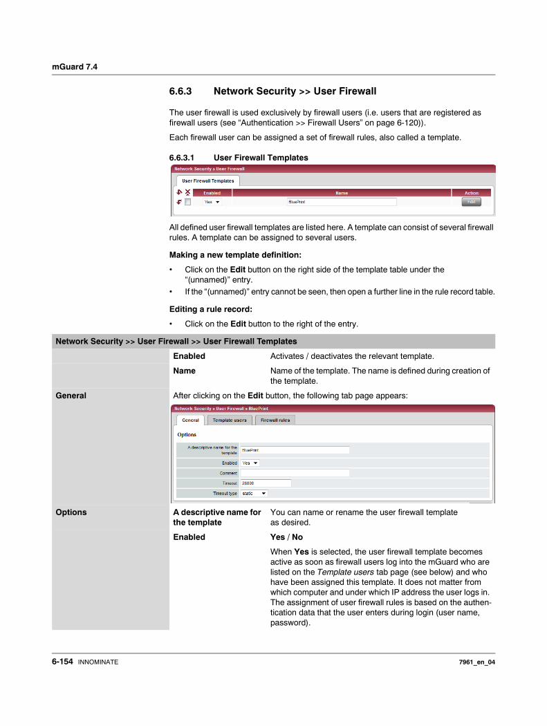
mGuard 7.4
6.6.3 Network Security >> User Firewall
The user firewall is used exclusively by firewall users (i.e. users that are registered as firewall users (see “Authentication >> Firewall Users” on page 6-120)).
Each firewall user can be assigned a set of firewall rules, also called a template.
6.6.3.1 User Firewall Templates
All defined user firewall templates are listed here. A template can consist of several firewall rules. A template can be assigned to several users.
Making a new template definition:
• Click on the Edit button on the right side of the template table under the “(unnamed)” entry.
• If the “(unnamed)” entry cannot be seen, then open a further line in the rule record table.
Editing a rule record:
• Click on the Edit button to the right of the entry.
Network Security >> User Firewall >> User Firewall Templates
Enabled Activates / deactivates the relevant template.
Name Name of the template. The name is defined during creation of the template.
General After clicking on the Edit button, the following tab page appears:
Options A descriptive name for the template
You can name or rename the user firewall template as desired.
Enabled Yes / No
When Yes is selected, the user firewall template becomes active as soon as firewall users log into the mGuard who are listed on the Template users tab page (see below) and who have been assigned this template. It does not matter from which computer and under which IP address the user logs in. The assignment of user firewall rules is based on the authen-tication data that the user enters during login (user name, password).
6-154 INNOMINATE 7961_en_04
Configuration
Comment Optional: Explanatory text
Timeout Default: 28800
Indicates the time in seconds at which point the firewall rules are deactivated. If the user session lasts longer than the timeout time defined here, then the user has to login again.
Timeout type static / dynamic
With a static timeout, users are logged out automatically as soon as the specified timeout expires. With a dynamic time-out, users are logged out automatically after all connections are closed by the user or have expired on the mGuard, and the timeout has elapsed.
An mGuard connection expires when no data is sent for the connection over the following periods.
Connection expiration period after non-usage– TCP 5 days (this value is configurable, see 6-149)
120 additional seconds are added after connection closure. This also applies to connections closed by the user.
– UDP 30 seconds after data traffic in one direction180 seconds after data traffic in both directions
– ICMP 30 seconds– Others 10 minutes
Network Security >> User Firewall >> User Firewall Templates (continued)
7961_en_04 INNOMINATE 6-155
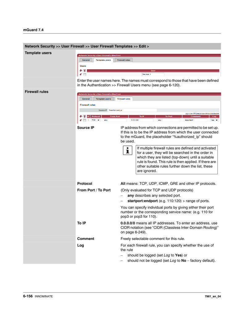
mGuard 7.4
Network Security >> User Firewall >> User Firewall Templates >> Edit >
Template users
Enter the user names here. The names must correspond to those that have been defined in the Authentication >> Firewall Users menu (see page 6-120).
Firewall rules
Source IP IP address from which connections are permitted to be set up. If this is to be the IP address from which the user connected to the mGuard, the placeholder “%authorized_ip” should be used.
Protocol All means: TCP, UDP, ICMP, GRE and other IP protocols.
From Port / To Port (Only evaluated for TCP and UDP protocols)– any describes any selected port.
– startport:endport (e.g. 110:120) > range of ports.
You can specify individual ports by giving either their port number or the corresponding service name: (e.g. 110 for pop3 or pop3 for 110).
To IP 0.0.0.0/0 means all IP addresses. To enter an address, use CIDR notation (see “CIDR (Classless Inter-Domain Routing)” on page 6-249).
Comment Freely selectable comment for this rule.
Log For each firewall rule, you can specify whether the use of the rule
– should be logged (set Log to Yes) or – should not be logged (set Log to No – factory default).
If multiple firewall rules are defined and activated for a user, they will be searched in the order in which they are listed (top-down) until a suitable rule is found. This rule is then applied. If there are other suitable rules further down the list, these are ignored.
6-156 INNOMINATE 7961_en_04

Configuration
6.7 CIFS Integrity Monitoring menu
There are two possible methods for checking network drives for viruses using CIFS Integrity Monitoring:– CIFS Integrity Checking
– CIFS Antivirus Scan Connector
CIFS Integrity Checking In CIFS Integrity Checking, Windows network drives are checked as to whether certain files (e.g. *.exe, *.dll) have been changed. Changes to these files indicate a virus or unauthorized file access.
CIFS Antivirus Scan Connector
In the CIFS Antivirus Scan Connector, the mGuard allows an antivirus scan of drives that are otherwise not externally accessible (e.g. production cells). The mGuard mirrors a drive externally in order to carry out the antivirus scan. Additional antivirus software is necessary in this procedure. Set the necessary read access for your antivirus software.
Setting options for CIFS Integrity Checking
– Which network drives are known by the mGuard (see “CIFS Integrity Monitoring >> Importable Shares” on page 6-158).
– Which access type is allowed (see “CIFS Integrity Monitoring >> CIFS Integrity Checking >> Settings” on page 6-160).
– At which intervals the drives should be checked (see “CIFS Integrity Monitoring >> CIFS Integrity Checking >> Settings >> Edit” on page 6-161).
– Which file types should be checked (see “CIFS Integrity Monitoring >> CIFS Integrity Checking >> Filename Patterns” on page 6-163).
– The type of warning when a change is detected (e.g. by e-mail (see “CIFS Integrity Monitoring >> CIFS Integrity Checking >> Settings” on page 6-160) or by SNMP (see “CIFS integrity traps” on page 6-49)).
Setting options for the CIFS Antivirus Scan Connector
– Which network drives are known by the mGuard (see “CIFS Integrity Monitoring >> Importable Shares” on page 6-158).
– Which access type is allowed (read-only access or read/write access (see “CIFS Integrity Monitoring >> CIFS Antivirus Scan Connector” on page 6-168)).
The CIFS Integrity Monitoring is not available for the mGuard rs2000.
It may not be used on the mGuard blade Controller.
In Stealth network mode, CIFS integrity checking is not possible without a management IP address and the CIFS server for the antivirus scan is not supported.
7961_en_04 INNOMINATE 6-157
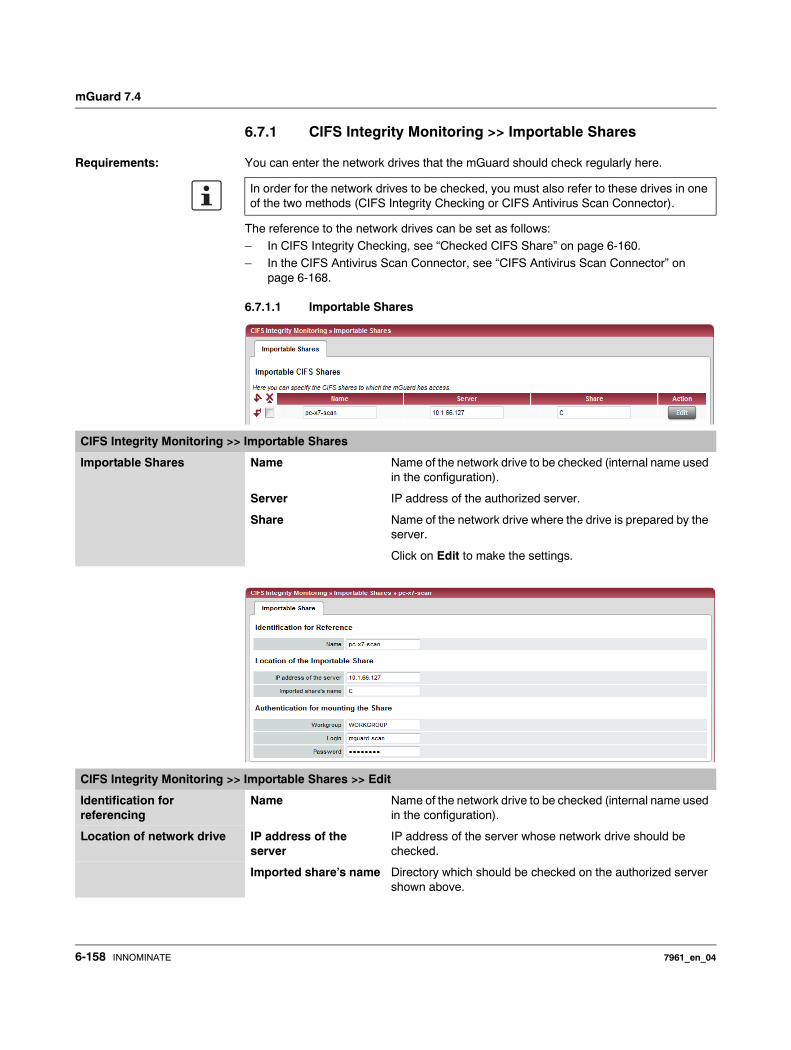
mGuard 7.4
6.7.1 CIFS Integrity Monitoring >> Importable Shares
Requirements: You can enter the network drives that the mGuard should check regularly here.
The reference to the network drives can be set as follows:– In CIFS Integrity Checking, see “Checked CIFS Share” on page 6-160.– In the CIFS Antivirus Scan Connector, see “CIFS Antivirus Scan Connector” on
page 6-168.
6.7.1.1 Importable Shares
In order for the network drives to be checked, you must also refer to these drives in one of the two methods (CIFS Integrity Checking or CIFS Antivirus Scan Connector).
CIFS Integrity Monitoring >> Importable Shares
Importable Shares Name Name of the network drive to be checked (internal name used in the configuration).
Server IP address of the authorized server.
Share Name of the network drive where the drive is prepared by the server.
Click on Edit to make the settings.
CIFS Integrity Monitoring >> Importable Shares >> Edit
Identification for referencing
Name Name of the network drive to be checked (internal name used in the configuration).
Location of network drive IP address of the server
IP address of the server whose network drive should be checked.
Imported share’s name Directory which should be checked on the authorized server shown above.
6-158 INNOMINATE 7961_en_04
Configuration
6.7.2 CIFS Integrity Monitoring >> CIFS Integrity Checking
In CIFS Integrity Checking, Windows network drives are checked as to whether certain files (e.g. *.exe, *.dll) have been changed. Changes to these files indicate a virus or unauthorized file access.
Integrity database If a checked network drive is reconfigured, then an integrity database must be created.
This integrity database forms the basis for comparison when checking the network drive regularly. The checksums of all monitored files are recorded here. The integrity database is protected against manipulation.
The database is either created explicitly due to a specific reason (see “CIFS Integrity Monitoring >> CIFS Integrity Status >> Display >> Actions” on page 6-166) or at the first regular check of the drive.
Authentication for connecting the network drive
Workgroup Name of the workgroup to which the network drive belongs.
Login Login for the server.
Password Password for the login.
CIFS Integrity Monitoring >> Importable Shares >> Edit (continued)
The integrity database must be created again following an intentional manipulation of the files on the network drive. Unauthorized manipulation of the relevant files cannot be detected as long as a valid integrity database is not in place.
7961_en_04 INNOMINATE 6-159
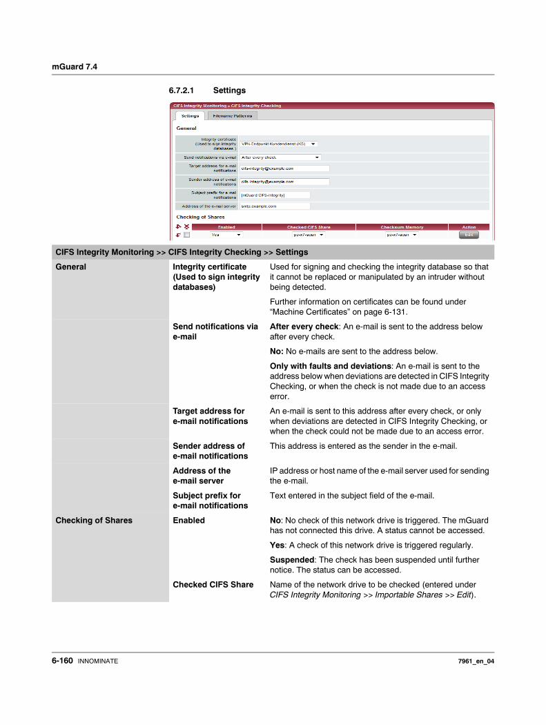
mGuard 7.4
6.7.2.1 Settings
CIFS Integrity Monitoring >> CIFS Integrity Checking >> Settings
General Integrity certificate (Used to sign integrity databases)
Used for signing and checking the integrity database so that it cannot be replaced or manipulated by an intruder without being detected.
Further information on certificates can be found under “Machine Certificates” on page 6-131.
Send notifications via e-mail
After every check: An e-mail is sent to the address below after every check.
No: No e-mails are sent to the address below.
Only with faults and deviations: An e-mail is sent to the address below when deviations are detected in CIFS Integrity Checking, or when the check is not made due to an access error.
Target address for e-mail notifications
An e-mail is sent to this address after every check, or only when deviations are detected in CIFS Integrity Checking, or when the check could not be made due to an access error.
Sender address of e-mail notifications
This address is entered as the sender in the e-mail.
Address of the e-mail server
IP address or host name of the e-mail server used for sending the e-mail.
Subject prefix for e-mail notifications
Text entered in the subject field of the e-mail.
Checking of Shares Enabled No: No check of this network drive is triggered. The mGuard has not connected this drive. A status cannot be accessed.
Yes: A check of this network drive is triggered regularly.
Suspended: The check has been suspended until further notice. The status can be accessed.
Checked CIFS Share Name of the network drive to be checked (entered under CIFS Integrity Monitoring >> Importable Shares >> Edit).
6-160 INNOMINATE 7961_en_04
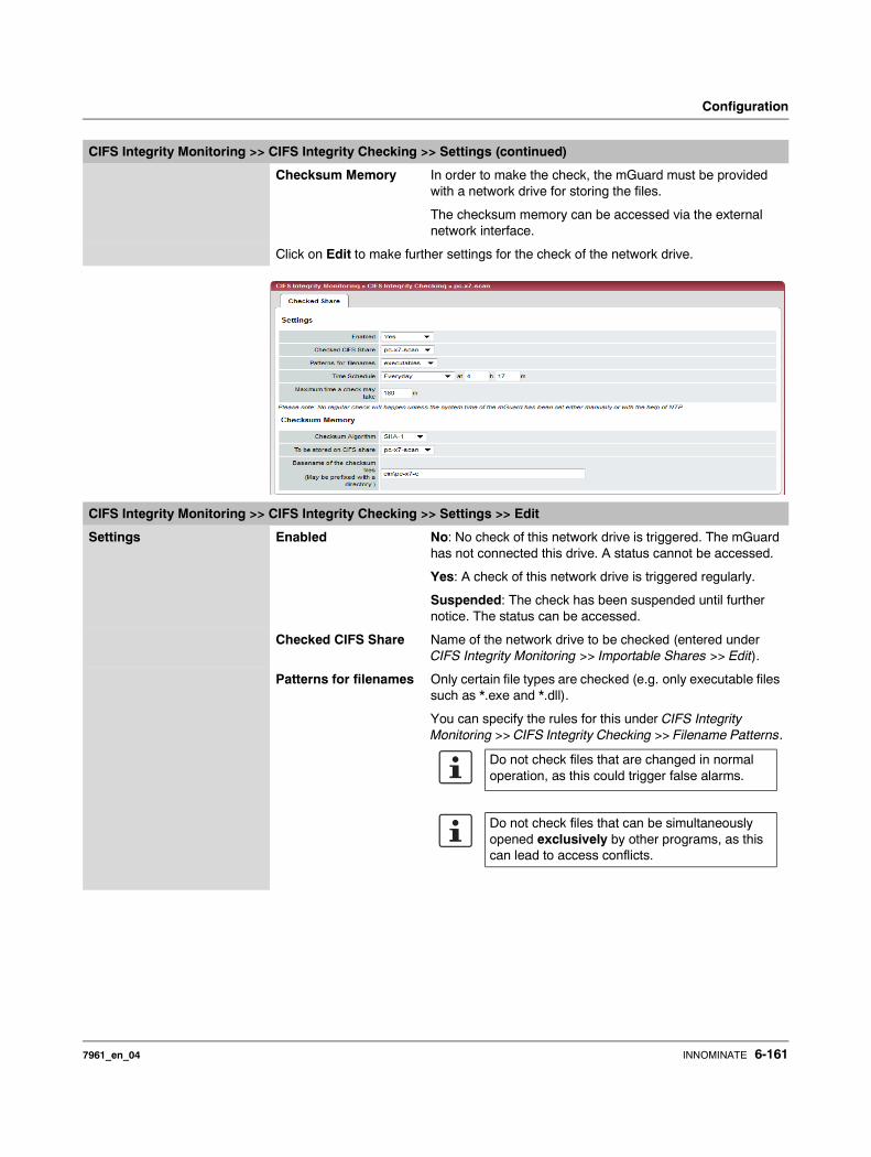
Configuration
Checksum Memory In order to make the check, the mGuard must be provided with a network drive for storing the files.
The checksum memory can be accessed via the external network interface.
Click on Edit to make further settings for the check of the network drive.
CIFS Integrity Monitoring >> CIFS Integrity Checking >> Settings (continued)
CIFS Integrity Monitoring >> CIFS Integrity Checking >> Settings >> Edit
Settings Enabled No: No check of this network drive is triggered. The mGuard has not connected this drive. A status cannot be accessed.
Yes: A check of this network drive is triggered regularly.
Suspended: The check has been suspended until further notice. The status can be accessed.
Checked CIFS Share Name of the network drive to be checked (entered under CIFS Integrity Monitoring >> Importable Shares >> Edit).
Patterns for filenames Only certain file types are checked (e.g. only executable files such as *.exe and *.dll).
You can specify the rules for this under CIFS Integrity Monitoring >> CIFS Integrity Checking >> Filename Patterns.
Do not check files that are changed in normal operation, as this could trigger false alarms.
Do not check files that can be simultaneously opened exclusively by other programs, as this can lead to access conflicts.
7961_en_04 INNOMINATE 6-161
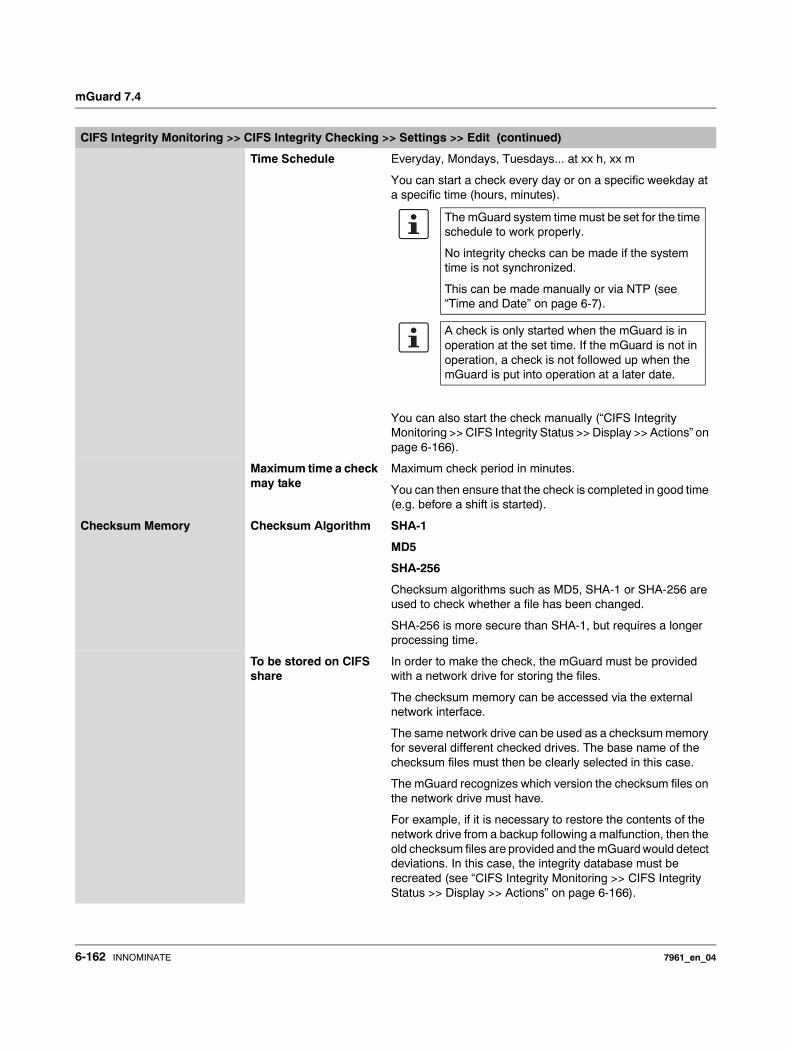
mGuard 7.4
Time Schedule Everyday, Mondays, Tuesdays... at xx h, xx m
You can start a check every day or on a specific weekday at a specific time (hours, minutes).
You can also start the check manually (“CIFS Integrity Monitoring >> CIFS Integrity Status >> Display >> Actions” on page 6-166).
Maximum time a check may take
Maximum check period in minutes.
You can then ensure that the check is completed in good time (e.g. before a shift is started).
Checksum Memory Checksum Algorithm SHA-1
MD5
SHA-256
Checksum algorithms such as MD5, SHA-1 or SHA-256 are used to check whether a file has been changed.
SHA-256 is more secure than SHA-1, but requires a longer processing time.
To be stored on CIFS share
In order to make the check, the mGuard must be provided with a network drive for storing the files.
The checksum memory can be accessed via the external network interface.
The same network drive can be used as a checksum memory for several different checked drives. The base name of the checksum files must then be clearly selected in this case.
The mGuard recognizes which version the checksum files on the network drive must have.
For example, if it is necessary to restore the contents of the network drive from a backup following a malfunction, then the old checksum files are provided and the mGuard would detect deviations. In this case, the integrity database must be recreated (see “CIFS Integrity Monitoring >> CIFS Integrity Status >> Display >> Actions” on page 6-166).
CIFS Integrity Monitoring >> CIFS Integrity Checking >> Settings >> Edit (continued)
The mGuard system time must be set for the time schedule to work properly.
No integrity checks can be made if the system time is not synchronized.
This can be made manually or via NTP (see “Time and Date” on page 6-7).
A check is only started when the mGuard is in operation at the set time. If the mGuard is not in operation, a check is not followed up when the mGuard is put into operation at a later date.
6-162 INNOMINATE 7961_en_04
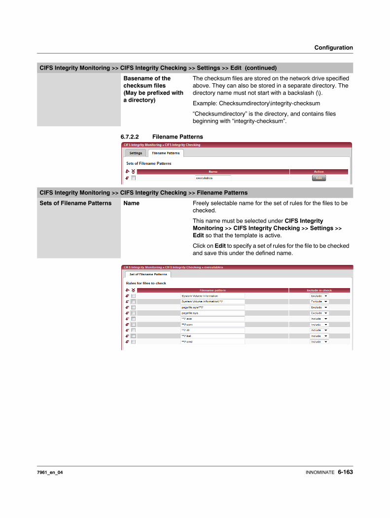
Configuration
6.7.2.2 Filename Patterns
Basename of the checksum files (May be prefixed with a directory)
The checksum files are stored on the network drive specified above. They can also be stored in a separate directory. The directory name must not start with a backslash (\).
Example: Checksumdirectory\integrity-checksum
“Checksumdirectory” is the directory, and contains files beginning with “integrity-checksum”.
CIFS Integrity Monitoring >> CIFS Integrity Checking >> Settings >> Edit (continued)
CIFS Integrity Monitoring >> CIFS Integrity Checking >> Filename Patterns
Sets of Filename Patterns Name Freely selectable name for the set of rules for the files to be checked.
This name must be selected under CIFS Integrity Monitoring >> CIFS Integrity Checking >> Settings >> Edit so that the template is active.
Click on Edit to specify a set of rules for the file to be checked and save this under the defined name.
7961_en_04 INNOMINATE 6-163
mGuard 7.4
CIFS Integrity Monitoring >> CIFS Integrity Checking >> Filename Patterns >> Edit
Rules for files to check Filename pattern The following rules apply here:
**\*.exe means that files are checked (or excluded) that are found in any directory and end with *.exe.
Only one placeholder per directory or file name (*) is allowed.
Placeholders represent wildcards (e.g. win*\*.exe finds files that end with .exe and are found in a directory that begins with win…).
** at the start means that any directory is searched, including the uppermost level (when this is empty). This cannot be combined with other characters (e.g. c** is not allowed).
Example: Name\**\*.exe applies to all files ending with *.exe that are found in the “Name” directory and any subdirectories.
Include in check Include: The files are included in the check.
Each file name is compared to the templates in sequence. The first hit is decisive for the inclusion of the file in the integrity check. The file is not included if no hits are detected.
Exclude: The files are excluded from the check.
Missing files lead to an alarm. Missing files are those files that were present during initialization.
An alarm is also triggered when additional files are detected.
6-164 INNOMINATE 7961_en_04
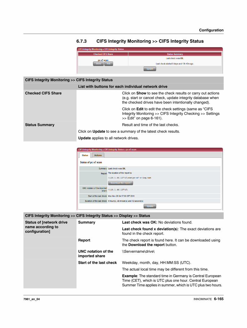
Configuration
6.7.3 CIFS Integrity Monitoring >> CIFS Integrity Status
CIFS Integrity Monitoring >> CIFS Integrity Status
List with buttons for each individual network drive
Checked CIFS Share Click on Show to see the check results or carry out actions (e.g. start or cancel check, update integrity database when the checked drives have been intentionally changed).
Click on Edit to edit the check settings (same as “CIFS Integrity Monitoring >> CIFS Integrity Checking >> Settings >> Edit” on page 6-161).
Status Summary Result and time of the last checks.
Click on Update to see a summary of the latest check results.
Update applies to all network drives.
CIFS Integrity Monitoring >> CIFS Integrity Status >> Display >> Status
Status of [network drive name according to configuration]
Summary Last check was OK: No deviations found.
Last check found x deviation(s): The exact deviations are found in the check report.
Report The check report is found here. It can be downloaded using the Download the report button.
UNC notation of the imported share
\\Servername\drive\
Start of the last check Weekday, month, day, HH:MM:SS (UTC).
The actual local time may be different from this time.
Example: The standard time in Germany is Central European Time (CET), which is UTC plus one hour. Central European Summer Time applies in summer, which is UTC plus two hours.
7961_en_04 INNOMINATE 6-165
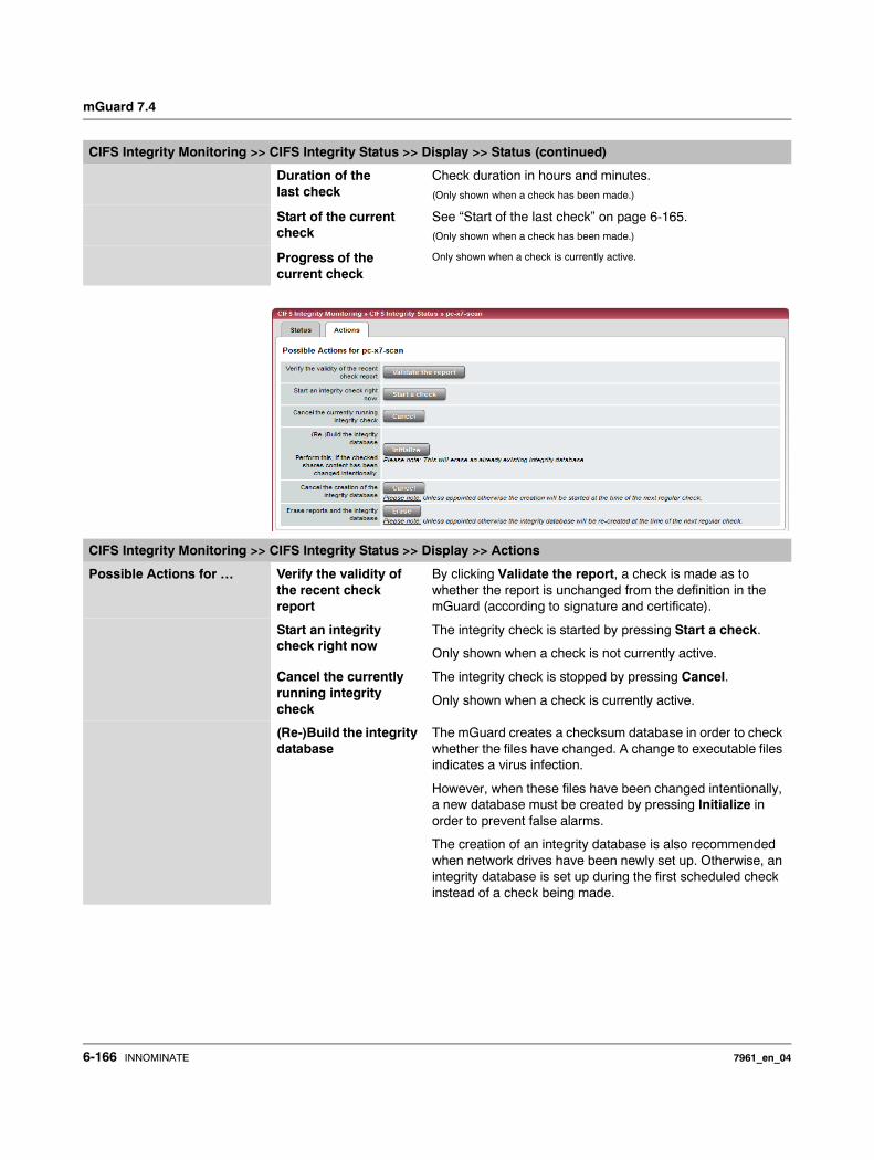
mGuard 7.4
Duration of the last check
Check duration in hours and minutes.(Only shown when a check has been made.)
Start of the current check
See “Start of the last check” on page 6-165.(Only shown when a check has been made.)
Progress of the current check
Only shown when a check is currently active.
CIFS Integrity Monitoring >> CIFS Integrity Status >> Display >> Status (continued)
CIFS Integrity Monitoring >> CIFS Integrity Status >> Display >> Actions
Possible Actions for … Verify the validity of the recent check report
By clicking Validate the report, a check is made as to whether the report is unchanged from the definition in the mGuard (according to signature and certificate).
Start an integrity check right now
The integrity check is started by pressing Start a check.
Only shown when a check is not currently active.
Cancel the currently running integrity check
The integrity check is stopped by pressing Cancel.
Only shown when a check is currently active.
(Re-)Build the integrity database
The mGuard creates a checksum database in order to check whether the files have changed. A change to executable files indicates a virus infection.
However, when these files have been changed intentionally, a new database must be created by pressing Initialize in order to prevent false alarms.
The creation of an integrity database is also recommended when network drives have been newly set up. Otherwise, an integrity database is set up during the first scheduled check instead of a check being made.
6-166 INNOMINATE 7961_en_04
Configuration
Cancel the creation of the integrity database
Only shown when a database
is currently being created.
The creation of the integrity database is stopped by pressing Cancel.
The old database is no longer used. A new database must be created manually, otherwise it is created automatically at the next scheduled check of the drive.
Erase reports and the integrity database
All reports/databases are deleted by pressing Erase.
A new integrity database must be created for any further integrity checks. This can be triggered by pressing Initialize. Otherwise, a new integrity database is created automatically at the next scheduled check. This procedure cannot be seen.
CIFS Integrity Monitoring >> CIFS Integrity Status >> Display >> Actions (continued)
The contents of the network drive may be manipulated (e.g. infected) without being detected when no integrity database is in place.
7961_en_04 INNOMINATE 6-167
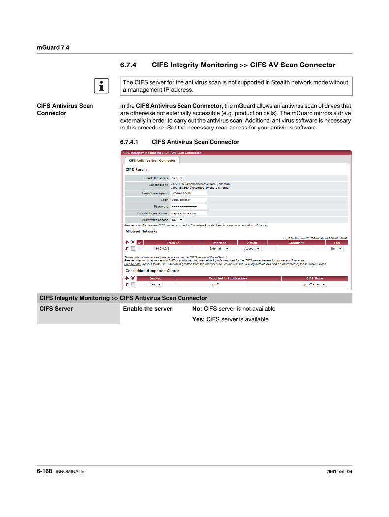
mGuard 7.4
6.7.4 CIFS Integrity Monitoring >> CIFS AV Scan Connector
CIFS Antivirus Scan Connector
In the CIFS Antivirus Scan Connector, the mGuard allows an antivirus scan of drives that are otherwise not externally accessible (e.g. production cells). The mGuard mirrors a drive externally in order to carry out the antivirus scan. Additional antivirus software is necessary in this procedure. Set the necessary read access for your antivirus software.
6.7.4.1 CIFS Antivirus Scan Connector
The CIFS server for the antivirus scan is not supported in Stealth network mode without a management IP address.
CIFS Integrity Monitoring >> CIFS Antivirus Scan Connector
CIFS Server Enable the server No: CIFS server is not available
Yes: CIFS server is available
6-168 INNOMINATE 7961_en_04
Configuration
Accessible as Displays the virtual network drive provided by the mGuard for the “CIFS Antivirus Scan Connector” function.
This path is displayed with UNC notation. You can use this directly on the PC which should use the virtual network drive by copying and pasting (see “Accessing the virtual network drive (CIFS Antivirus Scan Connector)” on page 6-171).
Two UNC addresses (for the internal and external interface) are displayed in the “Router” network mode, while one UNC address is displayed in the “Stealth” network mode.
Access to the virtual network drive can be prevented as a result of the settings in the “Allowed Networks” section. Enter a rule here accordingly, especially when access should be made over the external interface.
Depending on the mGuard configuration, further access options can be established over other IP addresses, such as access via VPN channels or via dial-in (see “Dial-in” on page 6-93).
Server’s workgroup Name of the CIFS server workgroup.
Login Login for the server.
Password Password for the login.
Exported share’s name
Name set for the computers who should use the CIFS server to access the combined drives (the drives are connected under this name).
Allow write access No: Read access only
Yes: Read and write access
Allowed Networks These rules allow external access to the CIFS server of the mGuard.
From IP Enter the address of the system or network where remote access is permitted or forbidden in this field.
IP address: 0.0.0.0/0 means all addresses. To enter an address, use CIDR notation (see 6-249).
CIFS Integrity Monitoring >> CIFS Antivirus Scan Connector (continued)
In Router mode with NAT or port forwarding, the port numbers for the CIFS server have priority over the rules for port forwarding (port forwarding is set under “Network >> NAT”).
Access to the CIFS server is allowed from LAN, via dial-in and VPN by default, and can be restricted or expanded via the firewall rules.
A different default setting can also be defined using these rules.
7961_en_04 INNOMINATE 6-169
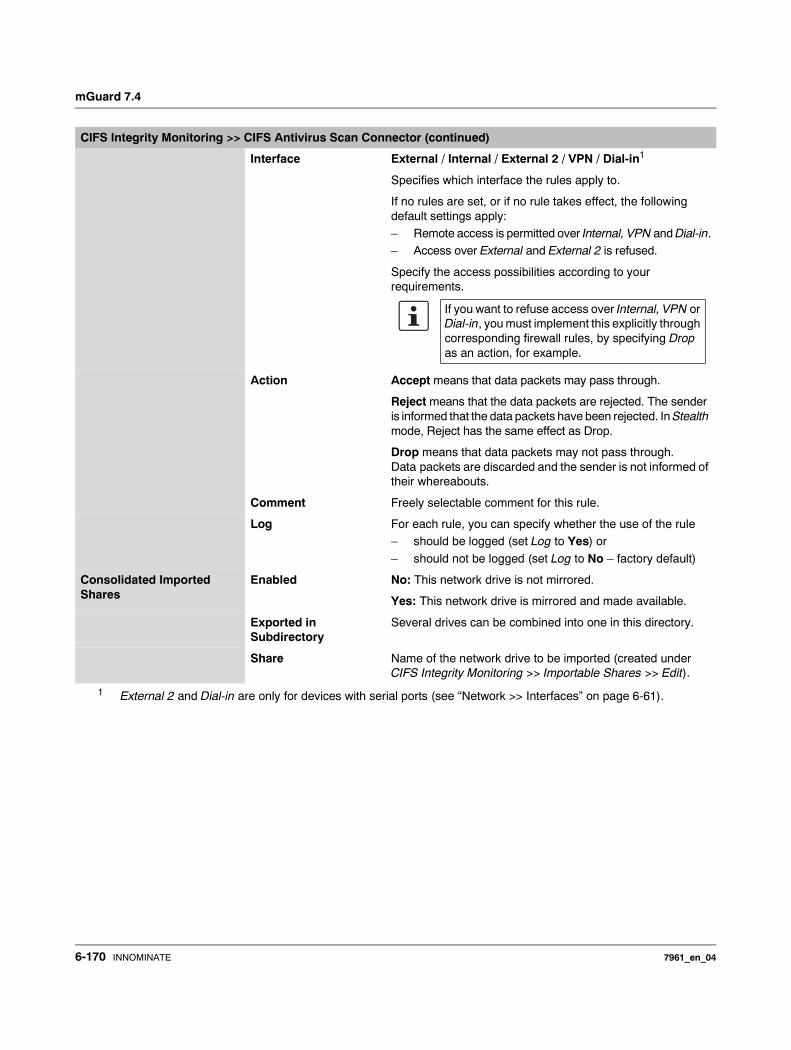
mGuard 7.4
Interface External / Internal / External 2 / VPN / Dial-in1
Specifies which interface the rules apply to.
If no rules are set, or if no rule takes effect, the following default settings apply: – Remote access is permitted over Internal, VPN and Dial-in.– Access over External and External 2 is refused.
Specify the access possibilities according to your requirements.
Action Accept means that data packets may pass through.
Reject means that the data packets are rejected. The sender is informed that the data packets have been rejected. In Stealth mode, Reject has the same effect as Drop.
Drop means that data packets may not pass through. Data packets are discarded and the sender is not informed of their whereabouts.
Comment Freely selectable comment for this rule.
Log For each rule, you can specify whether the use of the rule– should be logged (set Log to Yes) or
– should not be logged (set Log to No – factory default)
Consolidated Imported Shares
Enabled No: This network drive is not mirrored.
Yes: This network drive is mirrored and made available.
Exported in Subdirectory
Several drives can be combined into one in this directory.
Share Name of the network drive to be imported (created under CIFS Integrity Monitoring >> Importable Shares >> Edit).
1 External 2 and Dial-in are only for devices with serial ports (see “Network >> Interfaces” on page 6-61).
CIFS Integrity Monitoring >> CIFS Antivirus Scan Connector (continued)
If you want to refuse access over Internal, VPN or Dial-in, you must implement this explicitly through corresponding firewall rules, by specifying Drop as an action, for example.
6-170 INNOMINATE 7961_en_04
Configuration
Accessing the virtual network drive (CIFS Antivirus Scan Connector)
You can integrate the virtual network drive provided by the mGuard for the “CIFS Antivirus Scan Connector” in Windows Explorer. To do this, open the “Extras, Map network drive…” menu in Windows Explorer and enter the path with UNC notation.
This path is then displayed under “CIFS Integrity Monitoring >> CIFS Antivirus Scan Connector >> Accessible as”.
\\<External IP mGuard>\<Name of the exported share> or\\<Internal IP mGuard>\<Name of the exported share>
Example:
\\10.1.66.49\exported-av-share
\\192.168.66.49\exported-av-share
Alternatively, you can enter the “net use” command in the command line. Further information can be found in the product information from Microsoft.
Notes
– You can also use a DNS name instead of the IP address.
– The authorized network drive cannot be found using the browser or search function.– The “Exported share’s name” must always be entered.– Windows does not display the authorized network drive automatically when the
mGuard is connected.
7961_en_04 INNOMINATE 6-171

mGuard 7.4
6.8 IPsec VPN menu
6.8.1 IPsec VPN >> Global
6.8.1.1 Options
This menu is not available on the mGuard blade controller.
6-172 INNOMINATE 7961_en_04
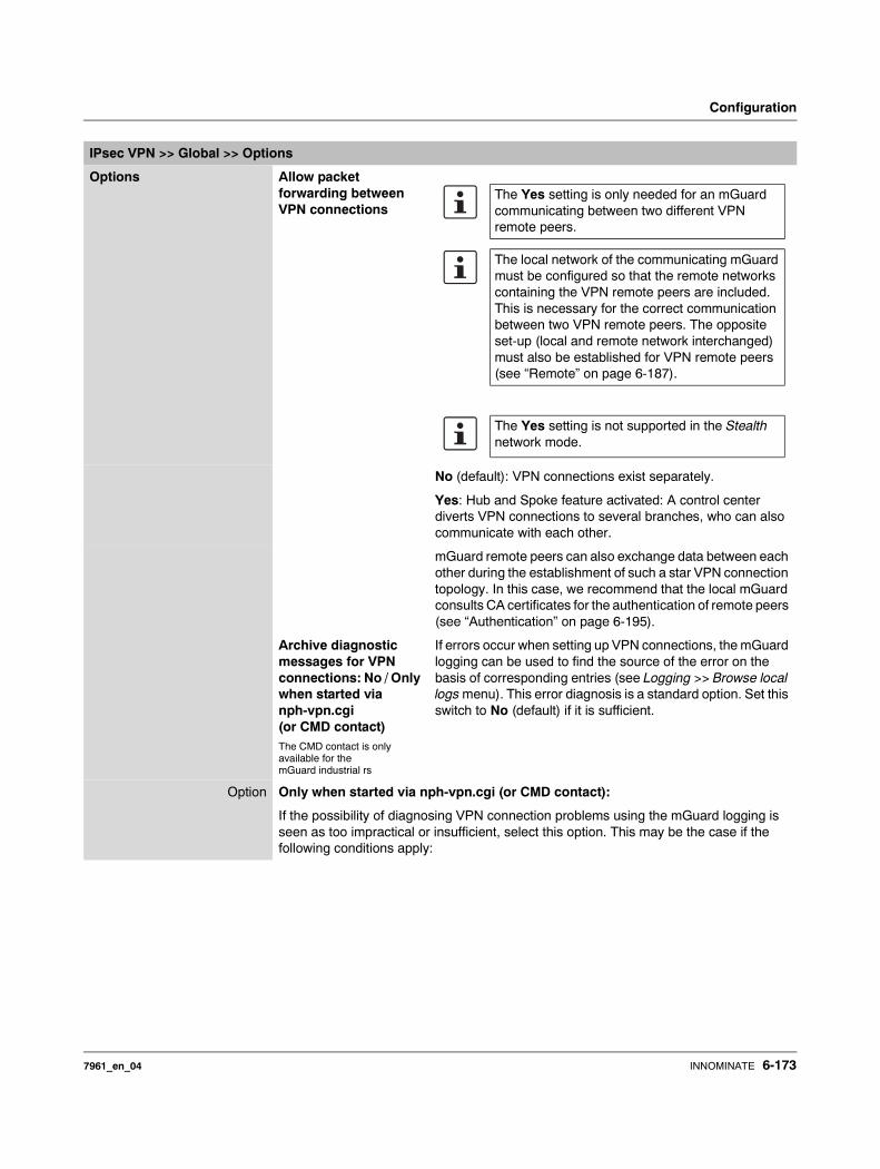
Configuration
IPsec VPN >> Global >> Options
Options Allow packet forwarding between VPN connections
No (default): VPN connections exist separately.
Yes: Hub and Spoke feature activated: A control center diverts VPN connections to several branches, who can also communicate with each other.
mGuard remote peers can also exchange data between each other during the establishment of such a star VPN connection topology. In this case, we recommend that the local mGuard consults CA certificates for the authentication of remote peers (see “Authentication” on page 6-195).
Archive diagnostic messages for VPN connections: No / Only when started via nph-vpn.cgi(or CMD contact)The CMD contact is only available for the mGuard industrial rs
If errors occur when setting up VPN connections, the mGuard logging can be used to find the source of the error on the basis of corresponding entries (see Logging >> Browse local logs menu). This error diagnosis is a standard option. Set this switch to No (default) if it is sufficient.
Option Only when started via nph-vpn.cgi (or CMD contact):
If the possibility of diagnosing VPN connection problems using the mGuard logging is seen as too impractical or insufficient, select this option. This may be the case if the following conditions apply:
The Yes setting is only needed for an mGuard communicating between two different VPN remote peers.
The local network of the communicating mGuard must be configured so that the remote networks containing the VPN remote peers are included. This is necessary for the correct communication between two VPN remote peers. The opposite set-up (local and remote network interchanged) must also be established for VPN remote peers (see “Remote” on page 6-187).
The Yes setting is not supported in the Stealth network mode.
7961_en_04 INNOMINATE 6-173
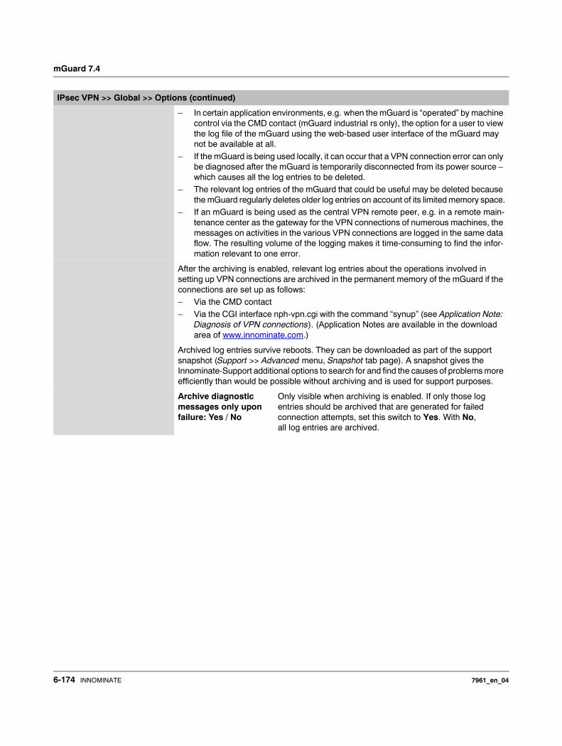
mGuard 7.4
– In certain application environments, e.g. when the mGuard is “operated” by machine control via the CMD contact (mGuard industrial rs only), the option for a user to view the log file of the mGuard using the web-based user interface of the mGuard may not be available at all.
– If the mGuard is being used locally, it can occur that a VPN connection error can only be diagnosed after the mGuard is temporarily disconnected from its power source – which causes all the log entries to be deleted.
– The relevant log entries of the mGuard that could be useful may be deleted because the mGuard regularly deletes older log entries on account of its limited memory space.
– If an mGuard is being used as the central VPN remote peer, e.g. in a remote main-tenance center as the gateway for the VPN connections of numerous machines, the messages on activities in the various VPN connections are logged in the same data flow. The resulting volume of the logging makes it time-consuming to find the infor-mation relevant to one error.
After the archiving is enabled, relevant log entries about the operations involved in setting up VPN connections are archived in the permanent memory of the mGuard if the connections are set up as follows: – Via the CMD contact– Via the CGI interface nph-vpn.cgi with the command “synup” (see Application Note:
Diagnosis of VPN connections). (Application Notes are available in the download area of www.innominate.com.)
Archived log entries survive reboots. They can be downloaded as part of the support snapshot (Support >> Advanced menu, Snapshot tab page). A snapshot gives the Innominate-Support additional options to search for and find the causes of problems more efficiently than would be possible without archiving and is used for support purposes.
Archive diagnostic messages only upon failure: Yes / No
Only visible when archiving is enabled. If only those log entries should be archived that are generated for failed connection attempts, set this switch to Yes. With No, all log entries are archived.
IPsec VPN >> Global >> Options (continued)
6-174 INNOMINATE 7961_en_04
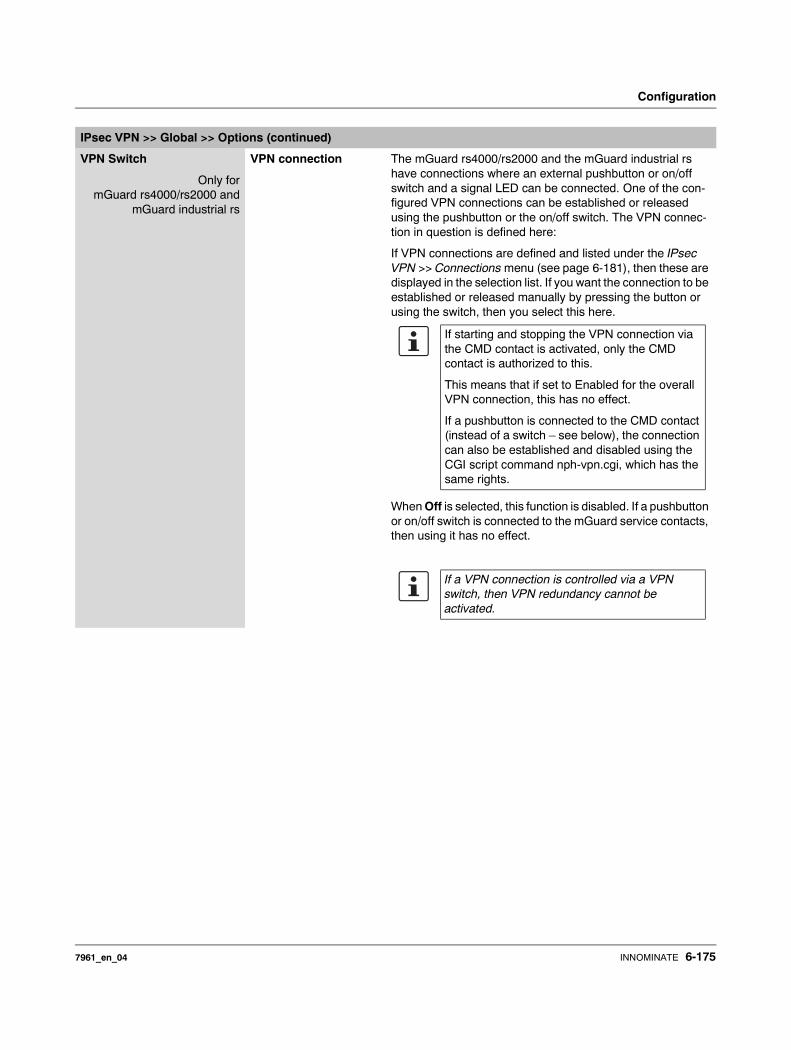
Configuration
VPN Switch
Only formGuard rs4000/rs2000 and
mGuard industrial rs
VPN connection The mGuard rs4000/rs2000 and the mGuard industrial rs have connections where an external pushbutton or on/off switch and a signal LED can be connected. One of the con-figured VPN connections can be established or released using the pushbutton or the on/off switch. The VPN connec-tion in question is defined here:
If VPN connections are defined and listed under the IPsec VPN >> Connections menu (see page 6-181), then these are displayed in the selection list. If you want the connection to be established or released manually by pressing the button or using the switch, then you select this here.
When Off is selected, this function is disabled. If a pushbutton or on/off switch is connected to the mGuard service contacts, then using it has no effect.
IPsec VPN >> Global >> Options (continued)
If starting and stopping the VPN connection via the CMD contact is activated, only the CMD contact is authorized to this.
This means that if set to Enabled for the overall VPN connection, this has no effect.
If a pushbutton is connected to the CMD contact (instead of a switch – see below), the connection can also be established and disabled using the CGI script command nph-vpn.cgi, which has the same rights.
If a VPN connection is controlled via a VPN switch, then VPN redundancy cannot be activated.
7961_en_04 INNOMINATE 6-175
mGuard 7.4
Only formGuard rs4000/rs2000 and
mGuard industrial rs
Switch type connected to the contact:
Push button or on/off switch
The mGuard rs4000/rs2000 and the mGuard industrial rs have connections where an external pushbutton/switch and a signal LED can be connected. Select the switch type that is connected to the corresponding service contacts of the mGuard industrial rs.
See also– “Installing the mGuard rs4000/rs2000” on page 4-4
under Service Contacts.– “Installing the mGuard industrial rs” on page 4-13 under
Service Contacts.
Operation of the different switch types is also described there.
IPsec VPN >> Global >> Options (continued)
If a VPN connection is established by operating the pushbutton or switch, the connection remains in place until it is released by operating the pushbutton/switch again.
If an on/off switch is used (instead of a pushbut-ton) and it is operated to establish a VPN connec-tion, this connection is re-established automati-cally when the mGuard is restarted.
6-176 INNOMINATE 7961_en_04

Configuration
TCP Encapsulation
This function is used to encapsulate data packets to be transmitted via a VPN connection into TCP packets. Without this encapsulation, it is possible that with VPN connections, important data packets belonging to the VPN connection may not be correctly transmitted due to interconnected NAT routers, firewalls or proxy servers, for example.
For example, firewalls may be set up to stop any data packets of the UDP protocol from passing through or (incorrectly implemented) NAT routers may not manage the port numbers correctly for UDP packets.
TCP encapsulation avoids these problems, because the packets belonging to the relevant VPN connection are encapsulated into TCP packets, i.e. they are hidden so that only TCP packets appear for the network infrastructure.
The mGuard can accept encapsulated VPN connections in TCP, even when the mGuard is positioned behind a NAT gateway in the network and thus cannot be reached by the VPN remote port under its primary external IP address. To do this, the NAT gateway must for-ward the corresponding TCP port to the mGuard (see “Listen for incoming VPN connec-tions, which are encapsulated” on page 6-178).
TCP encapsulation can only be used if an mGuard (from version 6.1) is used on both sides of the VPN tunnel.
TCP encapsulation should only be used if it is necessary, because connections are slowed down by the significant increase in the data packet overhead and by the correspondingly longer processing times.
If the mGuard is configured to use a proxy for HTTP and HTTPS in the “Network >> Proxy Settings” menu, then this proxy is also used for VPN connections that use TCP encapsulation.
TCP encapsulation supports the Basic Authentication and NTLM authentication proce-dures to the proxy.
For the TCP encapsulation to work through a HTTP proxy, the proxy must be named explicitly in the proxy settings (“Network >> Proxy Settings” menu) (i.e. not a transparent proxy) and this proxy must also understand and permit the HTTP method CONNECT.
7961_en_04 INNOMINATE 6-177
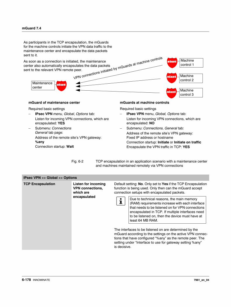
mGuard 7.4
Fig. 6-2 TCP encapsulation in an application scenario with a maintenance center and machines maintained remotely via VPN connections
As participants in the TCP encapsulation, the mGuards for the machine controls initiate the VPN data traffic to the maintenance center and encapsulate the data packets sent to it.
As soon as a connection is initiated, the maintenance center also automatically encapsulates the data packets sent to the relevant VPN remote peer.
mGuard of maintenance center
Required basic settings– IPsec VPN menu, Global, Options tab:
Listen for incoming VPN connections, which are encapsulated: YES
– Submenu: ConnectionsGeneral tab page:Address of the remote site’s VPN gateway: %anyConnection startup: Wait
mGuards at machine controls
Required basic settings – IPsec VPN menu, Global, Options tab:
Listen for incoming VPN connections, which are encapsulated: NO
– Submenu: Connections, General tab:Address of the remote site’s VPN gateway: Fixed IP address or hostnameConnection startup: Initiate or Initiate on trafficEncapsulate the VPN traffic in TCP: YES
VPN connections initiated by mGuards at machine controls
Maintenance center
Machine control 1
Machine control 2
Machine control 3
IPsec VPN >> Global >> Options
TCP Encapsulation Listen for incoming VPN connections, which are encapsulated
Default setting: No. Only set to Yes if the TCP Encapsulation function is being used. Only then can the mGuard accept connection setups with encapsulated packets.
The interfaces to be listened on are determined by the mGuard according to the settings on the active VPN connec-tions that have configured “%any” as the remote peer. The setting under “Interface to use for gateway setting %any” is decisive.
Due to technical reasons, the main memory (RAM) requirements increase with each interface that needs to be listened on for VPN connections encapsulated in TCP. If multiple interfaces need to be listened on, then the device must have at least 64 MB RAM.
6-178 INNOMINATE 7961_en_04
Configuration
TCP port to listen on Number of the TCP port where the encapsulated data packets to be received come in. The port number entered here must be the same as the one entered at the remote peer’s mGuard as TCP Port of the server, which accepts the encapsulated connection (IPsec VPN >> Connections menu, Edit, General tab page).
The following restrictions apply:– The port to listen on must not be identical to a port that
is being used for remote access (SSH, HTTPS or SEC-Stick).
Server ID (0-63) The default value 0 usually does not have to be changed. The numbers are used to differentiate different centers.
A different number only has to be used in the following case: An mGuard installed before a machine must make connec-tions to two or more different maintenance centers and their mGuards with TCP encapsulation activated.
IP Fragmentation IKE Fragmentation UDP packages can be oversized if an IPsec connection is made between the participants, including the exchange of certificates. Some routers are not capable of forwarding large UDP packages if they are fragmented during the transfer pro-cess (e.g. by DSL in 1500 byte segments). Some defective devices forward the first fragment only, leading to a connec-tion failure.
If two mGuards communicate with each other, then the dis-patch of small UDP packages should be agreed upon first. This prevents packages from being fragmented during trans-portation, which may lead to incorrect transfer from certain routers.
If you want to use this option, set it to Yes.
IPsec MTU (default is 16260)
The methods for avoiding oversized IKE data packages (incorrect transfer) can also be applied for IPsec data packages. In order to remain below the upper limit set by DSL (1500 bytes), we recommend setting a value of 1414 (bytes). This also allows enough space for additional headers.
If you want to use this option, enter a value lower than the default setting.
IPsec VPN >> Global >> Options (continued)
If Yes is selected, the setting only comes into ef-fect if the remote peer is an mGuard with installed firmware above version 5.1.0. In all other cases, the setting has no effect (also no negative effects).
7961_en_04 INNOMINATE 6-179
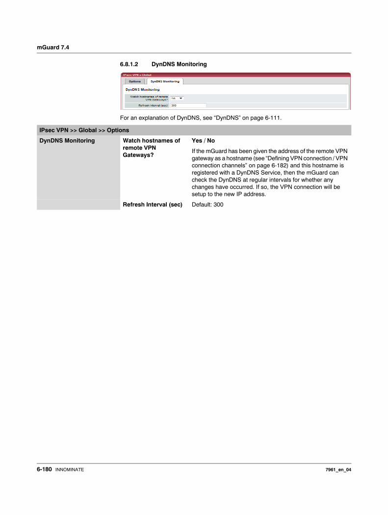
mGuard 7.4
6.8.1.2 DynDNS Monitoring
For an explanation of DynDNS, see “DynDNS” on page 6-111.
IPsec VPN >> Global >> Options
DynDNS Monitoring Watch hostnames of remote VPN Gateways?
Yes / No
If the mGuard has been given the address of the remote VPN gateway as a hostname (see “Defining VPN connection / VPN connection channels” on page 6-182) and this hostname is registered with a DynDNS Service, then the mGuard can check the DynDNS at regular intervals for whether any changes have occurred. If so, the VPN connection will be setup to the new IP address.
Refresh Interval (sec) Default: 300
6-180 INNOMINATE 7961_en_04
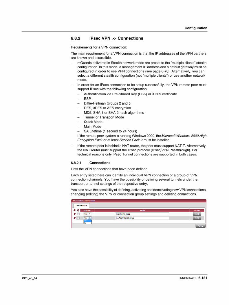
Configuration
6.8.2 IPsec VPN >> Connections
Requirements for a VPN connection:
The main requirement for a VPN connection is that the IP addresses of the VPN partners are known and accessible.
– mGuards delivered in Stealth network mode are preset to the “multiple clients” stealth configuration. In this mode, a management IP address and a default gateway must be configured in order to use VPN connections (see page 6-70). Alternatively, you can select a different stealth configuration (not “multiple clients”) or use another network mode.
– In order for an IPsec connection to be setup successfully, the VPN remote peer must support IPsec with the following configuration:
– Authentication via Pre-Shared Key (PSK) or X.509 certificate – ESP – Diffie-Hellman Groups 2 and 5 – DES, 3DES or AES encryption – MD5, SHA-1 or SHA-2 hash algorithms – Tunnel or Transport Mode– Quick Mode – Main Mode– SA Lifetime (1 second to 24 hours)If the remote peer system is running Windows 2000, the Microsoft Windows 2000 High Encryption Pack or at least Service Pack 2 must be installed.
– If the remote peer is behind a NAT router, the peer must support NAT-T. Alternatively, the NAT router must support the IPsec protocol (IPsec/VPN Passthrough). For technical reasons only IPsec Tunnel connections are supported in both cases.
6.8.2.1 Connections
Lists the VPN connections that have been defined.
Each entry listed here can identify an individual VPN connection or a group of VPN connection channels. You have the possibility of defining several tunnels under the transport or tunnel settings of the respective entry.
You also have the possibility of defining, activating and deactivating new VPN connections, changing (editing) the VPN or connection group settings and deleting connections.
7961_en_04 INNOMINATE 6-181

mGuard 7.4
6.8.3 Making a new definition of VPN connection / VPN connection channels
• Click on the Edit button on the connection table under the “(unnamed)” entry.• If the “(unnamed)” entry cannot be seen, then open a further line in the table.
Editing VPN connection / VPN connection channels:
• Click on the Edit button to the right of the entry.
URL for starting, stopping and status query of a VPN connection
The following URL can be used to start and stop VPN connections and query the connection status, independently from their Enabled setting:
https://server/nph-vpn.cgi?name=connection&cmd=(up|down|status)
Example wget --no-check-certificate "https://admin:mGuard192.168.1.1/nph-vpn.cgi?name=Athen&cmd=up"
The --no-check-certificate option ensures that the HTTPS certificate on the mGuard is not checked further. It may be necessary to code the password for the URL if it contains special characters. A command like this relates to all connection channels that are summarized under the respective name (in this example, Athen). This is the name entered under “A descriptive name for the connection” on the General tab page. If ambiguity occurs, then the URL call only affects the first entry in the connections list.
Access to individual VPN connection channels is not possible. If individual channels are deactivated (Enabled: No), then these are not started. Starting and stopping in this way thus have no effect on the settings of the individual channels (i.e. the list under Transport and Tunnel Settings).
Starting and stopping a connection using a URL only makes sense if the configuration of the connection is deactivated (Enabled: No) or when Connection startup is set to “Wait”. Otherwise, the connection to the mGuard is established independently.
If the status of a VPN connection is queried using the URL detailed above, then the following answers can be expected:
Defining VPN connection / VPN connection channels
Depending on the mGuard network mode, the following page appears after clicking Edit.
Table 6-1 Status of a VPN connection
Answer Meaning
unknown A VPN connection with this name does not exist.
void The connection is inactive due to an error (e.g. the external network is down or the hostname of the remote peer could not be released in an IP address (DNS)).
“void” is also issued as an answer by the CGI interface without an error being present. An example of this is when the VPN connection is deactivated according to the configuration (No in column) and has not been temporarily enabled using the CGI interface or the CMD contact.
ready The connection is ready to establish channels or allow incoming queries regarding channel set-up.
active At least one channel is set-up for the connection.
6-182 INNOMINATE 7961_en_04
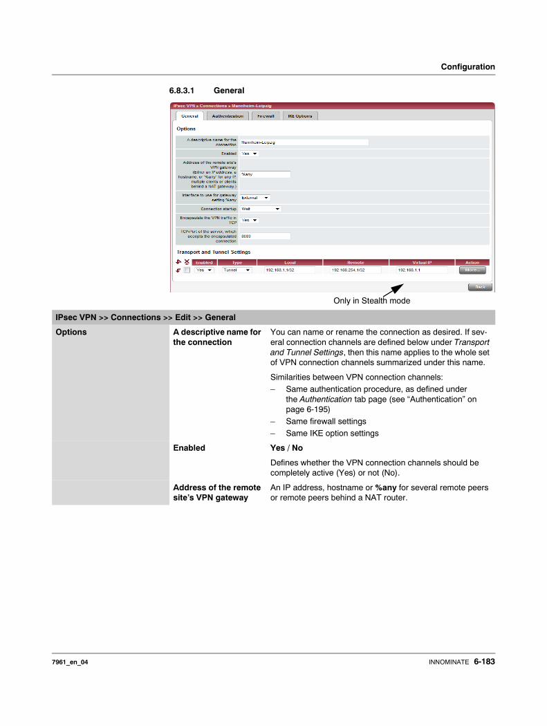
Configuration
6.8.3.1 General
Only in Stealth mode
IPsec VPN >> Connections >> Edit >> General
Options A descriptive name for the connection
You can name or rename the connection as desired. If sev-eral connection channels are defined below under Transport and Tunnel Settings, then this name applies to the whole set of VPN connection channels summarized under this name.
Similarities between VPN connection channels:– Same authentication procedure, as defined under
the Authentication tab page (see “Authentication” on page 6-195)
– Same firewall settings– Same IKE option settings
Enabled Yes / No
Defines whether the VPN connection channels should be completely active (Yes) or not (No).
Address of the remote site’s VPN gateway
An IP address, hostname or %any for several remote peers or remote peers behind a NAT router.
7961_en_04 INNOMINATE 6-183

mGuard 7.4
Address of the remote site’s VPN gateway
Fig. 6-3 The address of the gateway to the private network where the remote communication partner can be found.
– If the mGuard should actively initiate and set up the connection to the remote peer, enter the IP address or the hostname of the remote peer here.
– If the remote peer VPN gateway does not have a fixed and known IP address, you can use the DynDNS Service (see glossary) to simulate a fixed and known address.
– If the mGuard should be ready to accept a connection that was actively initiated and set up by a remote peer with any IP address, enter: %any.This setting should also be selected for VPN star configurations when the mGuard is connected to the control center.The mGuard can then be “called” by a remote peer if this remote peer has been dynamically assigned its IP address by the ISP (i.e. it has a changeable IP address). In this scenario, you may only enter an IP address when the remote peer has a fixed and known IP address.
%any can only be used along with the authentication procedure using X.509 certificates.
If locally stored CA certificates are to be used to authenticate the remote peer, the address of the remote peer’s VPN gateway can be entered explicitly (via IP address or hostname) or via %any. If it is entered using an explicit address (and not with “%any”), then a VPN identifier (see “VPN Identifier” on page 6-198) must be specified.
%any must be selected when the remote peer is located behind a NAT gateway. Other-wise the renegotiation of new connection keys will fail after the connection is established.
If TCP Encapsulation is used (see “TCP Encapsulation” on page 6-177): A fixed IP address or a hostname must be entered if this mGuard is to initiate the VPN connection and encapsulate the VPN data traffic.
If this mGuard is installed before a maintenance center to which multiple remote mGuards set up VPN connections and send encapsulated data packets, the remote site’s VPN gateway must be entered as %any.
InternetVPN gateway of remote peer
mGuard
6-184 INNOMINATE 7961_en_04
Configuration
.
IPsec VPN >> Connections >> Edit >> General
Options Interface to use for gateway setting %any
Internal / External / External 2 / Dial-in
External 2 and Dial-in are only for devices with serial ports (see “Network >> Interfaces” on page 6-61).
The selection of Internal is not allowed in Stealth mode.
This interface setting is only considered when “%any” is en-tered as the address of the VPN gateway on the remote peer. In this case, the interface of the mGuard through which the mGuard answers and permits requests for the establishment of this VPN connection is set here.
The VPN connection can be established through the LAN and WAN port on all Stealth modes when External is selected.
The interface setting allows encrypted communication to be made over a specific interface for VPN remote peers without a known IP address. If an IP address or hostname is entered for the remote peer, then this is used for the implicit assign-ment to an interface.
The mGuard can be used as a single-leg router in Router mode when Internal is selected, as both encrypted and decrypted VPN traffic for this VPN connection are fed over the internal interface.
IKE and IPsec data traffic is only possible through the primary IP address of the individual assigned interface. This also applies to VPN connections with a specific remote peer.
Connection startup: Initiate / Initiate on traffic / Wait
Initiate
The mGuard initiates the connection to the remote peer. In the Address of the remote site’s VPN gateway (see above), the fixed IP address of the remote peer, or its name, must be entered.
Initiate on traffic
The connection is initiated automatically when the mGuard sees that the connection should be used (can be selected in all operating modes of the mGuard (Stealth, Router etc.)).
Wait
The mGuard is ready to accept connections which a remote peer actively initiates and sets up to the mGuard.
When %any is entered under Address of the remote site’s VPN gateway, then Wait must be selected.
7961_en_04 INNOMINATE 6-185
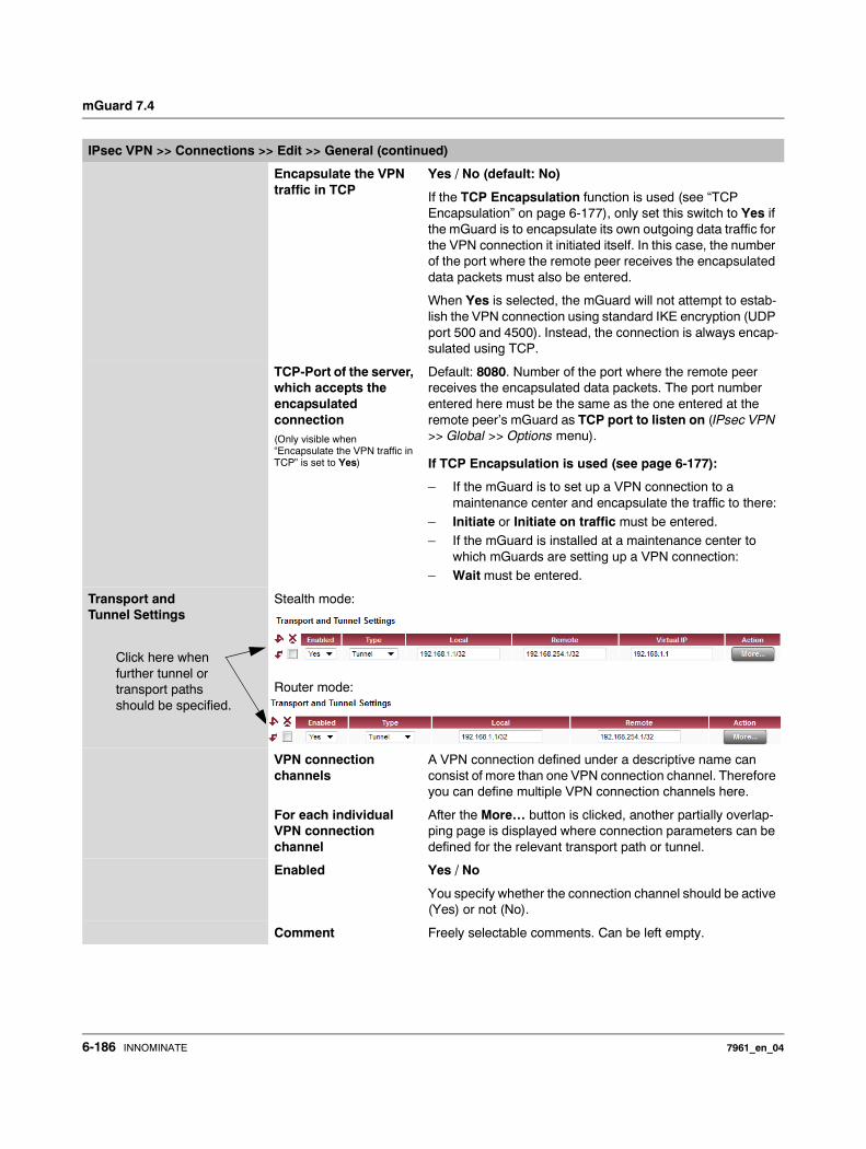
mGuard 7.4
Encapsulate the VPN traffic in TCP
Yes / No (default: No)
If the TCP Encapsulation function is used (see “TCP Encapsulation” on page 6-177), only set this switch to Yes if the mGuard is to encapsulate its own outgoing data traffic for the VPN connection it initiated itself. In this case, the number of the port where the remote peer receives the encapsulated data packets must also be entered.
When Yes is selected, the mGuard will not attempt to estab-lish the VPN connection using standard IKE encryption (UDP port 500 and 4500). Instead, the connection is always encap-sulated using TCP.
TCP-Port of the server, which accepts the encapsulated connection(Only visible when “Encapsulate the VPN traffic in TCP” is set to Yes)
Default: 8080. Number of the port where the remote peer receives the encapsulated data packets. The port number entered here must be the same as the one entered at the remote peer’s mGuard as TCP port to listen on (IPsec VPN >> Global >> Options menu).
If TCP Encapsulation is used (see page 6-177):
– If the mGuard is to set up a VPN connection to a maintenance center and encapsulate the traffic to there:
– Initiate or Initiate on traffic must be entered.– If the mGuard is installed at a maintenance center to
which mGuards are setting up a VPN connection:– Wait must be entered.
Transport and Tunnel Settings
Stealth mode:
Router mode:
VPN connection channels
A VPN connection defined under a descriptive name can consist of more than one VPN connection channel. Therefore you can define multiple VPN connection channels here.
For each individual VPN connection channel
After the More… button is clicked, another partially overlap-ping page is displayed where connection parameters can be defined for the relevant transport path or tunnel.
Enabled Yes / No
You specify whether the connection channel should be active (Yes) or not (No).
Comment Freely selectable comments. Can be left empty.
IPsec VPN >> Connections >> Edit >> General (continued)
Click here when further tunnel or transport paths should be specified.
6-186 INNOMINATE 7961_en_04

Configuration
Tunnel settings IPsec / L2TP
If clients should connect to the mGuard by IPsec/L2TP, then activate the L2TP server and make the following entries in the fields specified below:
– Type: Transport– Protocol: UDP– Local Port: %all
– Remote Port: %all
Type The following can be selected:
– Tunnel (Network ↔ Network)– Transport (Host ↔ Host)
Tunnel (Network ↔ Network)
This connection type is suitable in all cases and is also the most secure. In this mode, the IP datagrams are completely encrypted with a new header and sent to the remote peer VPN gateway – the “tunnel end”. The transferred datagrams are then decrypted and the original datagrams are restored. These are then forwarded to the destination system.
Transport (Host ↔ Host)
In this type of connection, the device only encrypts the data of the IP packets. The IP header information remains unencrypted.
When a change to Transport is made, the following fields (apart from the protocol) are hidden as these parameters are omitted.
Local / remote – for connection type Tunnel (Network ↔ Network)
Define the network areas for both tunnel ends under Local and Remote.
Local Enter the network or computer address where the local mGuard is connected.
Remote Enter the network or computer address found behind the remote VPN gateway here.
If the Address of the remote site’s VPN gateway (see “Address of the remote site’s VPN gateway” on page 6-183) is entered as %any, it is possible that a number of different remote peers will connect to the mGuard.
IPsec VPN >> Connections >> Edit >> General (continued)
InternetLocal Network
IPsec Tunnel
VPN gateway Networkremote remote
mGuard
7961_en_04 INNOMINATE 6-187
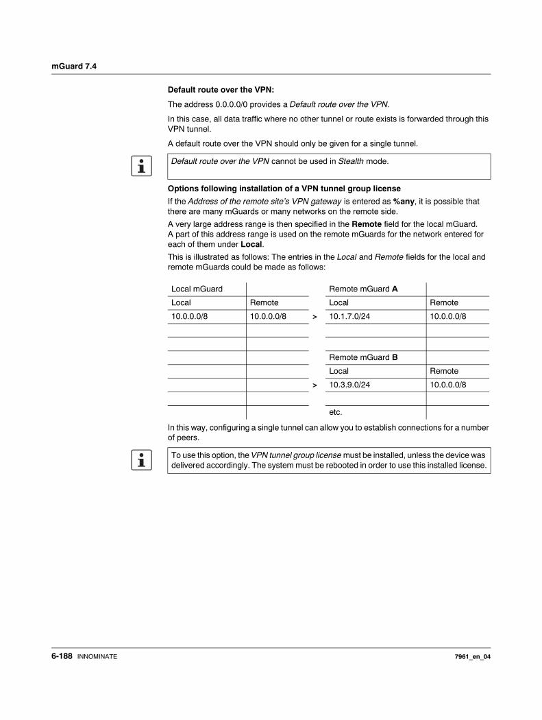
mGuard 7.4
Default route over the VPN:
The address 0.0.0.0/0 provides a Default route over the VPN.
In this case, all data traffic where no other tunnel or route exists is forwarded through this VPN tunnel.
A default route over the VPN should only be given for a single tunnel.
Options following installation of a VPN tunnel group license
If the Address of the remote site’s VPN gateway is entered as %any, it is possible that there are many mGuards or many networks on the remote side.
A very large address range is then specified in the Remote field for the local mGuard. A part of this address range is used on the remote mGuards for the network entered for each of them under Local.
This is illustrated as follows: The entries in the Local and Remote fields for the local and remote mGuards could be made as follows:
In this way, configuring a single tunnel can allow you to establish connections for a number of peers.
Default route over the VPN cannot be used in Stealth mode.
Local mGuard Remote mGuard A
Local Remote Local Remote
10.0.0.0/8 10.0.0.0/8 > 10.1.7.0/24 10.0.0.0/8
Remote mGuard B
Local Remote
> 10.3.9.0/24 10.0.0.0/8
etc.
To use this option, the VPN tunnel group license must be installed, unless the device was delivered accordingly. The system must be rebooted in order to use this installed license.
6-188 INNOMINATE 7961_en_04
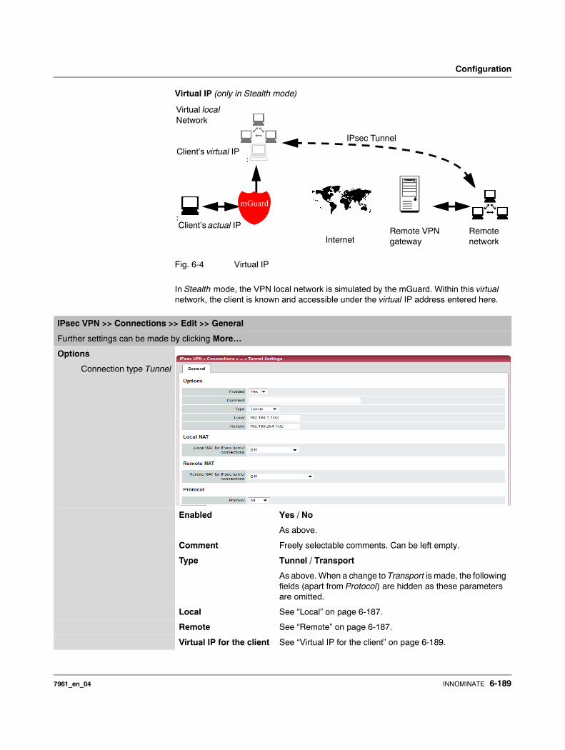
Configuration
Virtual IP (only in Stealth mode)
Fig. 6-4 Virtual IP
In Stealth mode, the VPN local network is simulated by the mGuard. Within this virtual network, the client is known and accessible under the virtual IP address entered here.
Internet
IPsec Tunnel
:
:
Virtual localNetwork
Client’s actual IP
mGuard
Client’s virtual IP
Remote VPN gateway
Remote network
IPsec VPN >> Connections >> Edit >> General
Further settings can be made by clicking More…
Options
Connection type Tunnel
Enabled Yes / No
As above.
Comment Freely selectable comments. Can be left empty.
Type Tunnel / Transport
As above. When a change to Transport is made, the following fields (apart from Protocol) are hidden as these parameters are omitted.
Local See “Local” on page 6-187.
Remote See “Remote” on page 6-187.
Virtual IP for the client See “Virtual IP for the client” on page 6-189.
7961_en_04 INNOMINATE 6-189
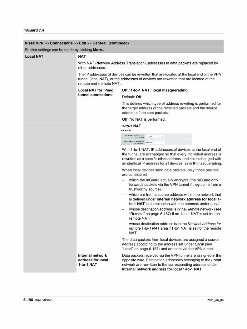
mGuard 7.4
Local NAT NAT
With NAT (Network Address Translation), addresses in data packets are replaced by other addresses.
The IP addresses of devices can be rewritten that are located at the local end of the VPN tunnel (local NAT), or the addresses of devices are rewritten that are located at the remote end (remote NAT).
Local NAT for IPsec tunnel connections
Off / 1-to-1 NAT / local masquerading
Default: Off
This defines which type of address rewriting is performed for the target address of the received packets and the source address of the sent packets.
Off: No NAT is performed.
1-to-1 NAT
With 1-to-1 NAT, IP addresses of devices at the local end of the tunnel are exchanged so that every individual address is rewritten as a specific other address, and not exchanged with an identical IP address for all devices, as in IP masquerading.
When local devices send data packets, only those packets are considered
– which the mGuard actually encrypts (the mGuard only forwards packets via the VPN tunnel if they come from a trustworthy source).
– which are from a source address within the network that is defined under Internal network address for local 1-to-1 NAT in combination with the netmask under Local.
– whose destination address is in the Remote network (see “Remote” on page 6-187) if no 1-to-1 NAT is set for the remote NAT.
– whose destination address is in the Network address for remote 1-to-1 NAT area if 1-to1 NAT is set for the remote NAT.
The data packets from local devices are assigned a source address according to the address set under Local (see “Local” on page 6-187) and are sent via the VPN tunnel.
Internal network address for local 1-to-1 NAT
Data packets received via the VPN tunnel are assigned in the opposite way. Destination addresses belonging to the Local network are rewritten to the corresponding address under Internal network address for local 1-to-1 NAT.
IPsec VPN >> Connections >> Edit >> General (continued)
Further settings can be made by clicking More…
6-190 INNOMINATE 7961_en_04
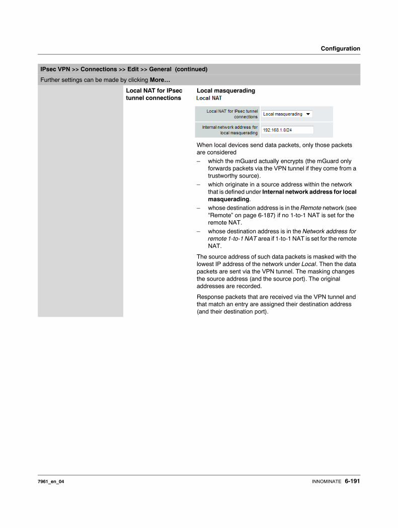
Configuration
Local NAT for IPsec tunnel connections
Local masquerading
When local devices send data packets, only those packets are considered
– which the mGuard actually encrypts (the mGuard only forwards packets via the VPN tunnel if they come from a trustworthy source).
– which originate in a source address within the network that is defined under Internal network address for local masquerading.
– whose destination address is in the Remote network (see “Remote” on page 6-187) if no 1-to-1 NAT is set for the remote NAT.
– whose destination address is in the Network address for remote 1-to-1 NAT area if 1-to-1 NAT is set for the remote NAT.
The source address of such data packets is masked with the lowest IP address of the network under Local. Then the data packets are sent via the VPN tunnel. The masking changes the source address (and the source port). The original addresses are recorded.
Response packets that are received via the VPN tunnel and that match an entry are assigned their destination address (and their destination port).
IPsec VPN >> Connections >> Edit >> General (continued)
Further settings can be made by clicking More…
7961_en_04 INNOMINATE 6-191
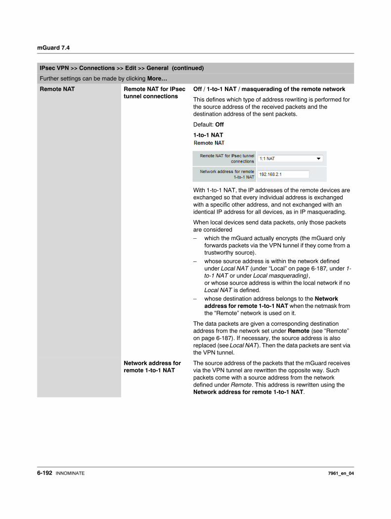
mGuard 7.4
Remote NAT Remote NAT for IPsec tunnel connections
Off / 1-to-1 NAT / masquerading of the remote network
This defines which type of address rewriting is performed for the source address of the received packets and the destination address of the sent packets.
Default: Off
1-to-1 NAT
With 1-to-1 NAT, the IP addresses of the remote devices are exchanged so that every individual address is exchanged with a specific other address, and not exchanged with an identical IP address for all devices, as in IP masquerading.
When local devices send data packets, only those packets are considered– which the mGuard actually encrypts (the mGuard only
forwards packets via the VPN tunnel if they come from a trustworthy source).
– whose source address is within the network defined under Local NAT (under “Local” on page 6-187, under 1-to-1 NAT or under Local masquerading), or whose source address is within the local network if no Local NAT is defined.
– whose destination address belongs to the Network address for remote 1-to-1 NAT when the netmask from the “Remote” network is used on it.
The data packets are given a corresponding destination address from the network set under Remote (see “Remote” on page 6-187). If necessary, the source address is also replaced (see Local NAT). Then the data packets are sent via the VPN tunnel.
Network address for remote 1-to-1 NAT
The source address of the packets that the mGuard receives via the VPN tunnel are rewritten the opposite way. Such packets come with a source address from the network defined under Remote. This address is rewritten using the Network address for remote 1-to-1 NAT.
IPsec VPN >> Connections >> Edit >> General (continued)
Further settings can be made by clicking More…
6-192 INNOMINATE 7961_en_04
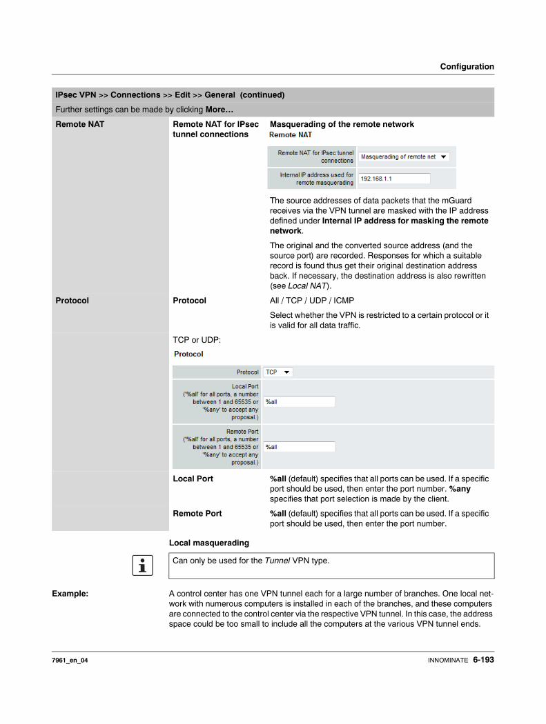
Configuration
Local masquerading
Example: A control center has one VPN tunnel each for a large number of branches. One local net-work with numerous computers is installed in each of the branches, and these computers are connected to the control center via the respective VPN tunnel. In this case, the address space could be too small to include all the computers at the various VPN tunnel ends.
Remote NAT Remote NAT for IPsec tunnel connections
Masquerading of the remote network
The source addresses of data packets that the mGuard receives via the VPN tunnel are masked with the IP address defined under Internal IP address for masking the remote network.
The original and the converted source address (and the source port) are recorded. Responses for which a suitable record is found thus get their original destination address back. If necessary, the destination address is also rewritten (see Local NAT).
Protocol Protocol All / TCP / UDP / ICMP
Select whether the VPN is restricted to a certain protocol or it is valid for all data traffic.
TCP or UDP:
Local Port %all (default) specifies that all ports can be used. If a specific port should be used, then enter the port number. %any specifies that port selection is made by the client.
Remote Port %all (default) specifies that all ports can be used. If a specific port should be used, then enter the port number.
IPsec VPN >> Connections >> Edit >> General (continued)
Further settings can be made by clicking More…
Can only be used for the Tunnel VPN type.
7961_en_04 INNOMINATE 6-193
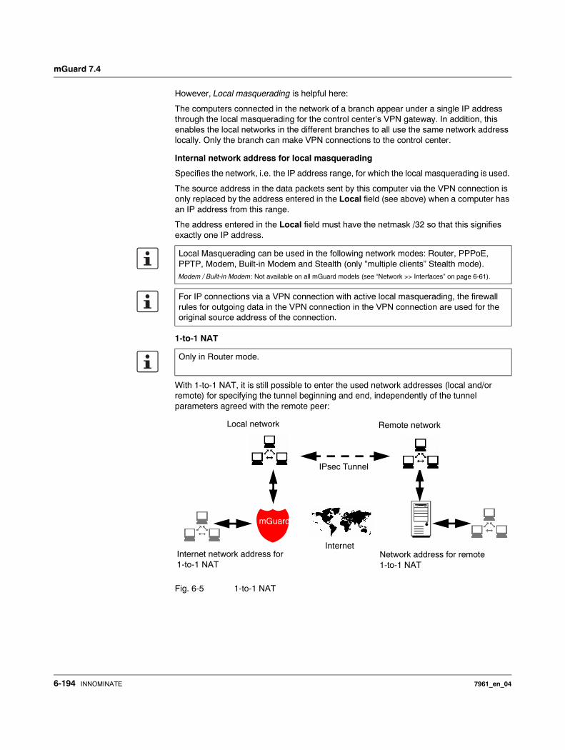
mGuard 7.4
However, Local masquerading is helpful here:
The computers connected in the network of a branch appear under a single IP address through the local masquerading for the control center’s VPN gateway. In addition, this enables the local networks in the different branches to all use the same network address locally. Only the branch can make VPN connections to the control center.
Internal network address for local masquerading
Specifies the network, i.e. the IP address range, for which the local masquerading is used.
The source address in the data packets sent by this computer via the VPN connection is only replaced by the address entered in the Local field (see above) when a computer has an IP address from this range.
The address entered in the Local field must have the netmask /32 so that this signifies exactly one IP address.
1-to-1 NAT
With 1-to-1 NAT, it is still possible to enter the used network addresses (local and/or remote) for specifying the tunnel beginning and end, independently of the tunnel parameters agreed with the remote peer:
Fig. 6-5 1-to-1 NAT
Local Masquerading can be used in the following network modes: Router, PPPoE, PPTP, Modem, Built-in Modem and Stealth (only “multiple clients” Stealth mode).Modem / Built-in Modem: Not available on all mGuard models (see “Network >> Interfaces” on page 6-61).
For IP connections via a VPN connection with active local masquerading, the firewall rules for outgoing data in the VPN connection in the VPN connection are used for the original source address of the connection.
Only in Router mode.
Internet
IPsec Tunnel
Internet network address for 1-to-1 NAT
Network address for remote 1-to-1 NAT
mGuard
Remote networkLocal network
6-194 INNOMINATE 7961_en_04
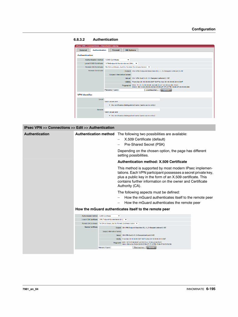
Configuration
6.8.3.2 Authentication
IPsec VPN >> Connections >> Edit >> Authentication
Authentication Authentication method The following two possibilities are available:
– X.509 Certificate (default)– Pre-Shared Secret (PSK)
Depending on the chosen option, the page has different setting possibilities.
Authentication method: X.509 Certificate
This method is supported by most modern IPsec implemen-tations. Each VPN participant possesses a secret private key, plus a public key in the form of an X.509 certificate. This contains further information on the owner and Certificate Authority (CA).
The following aspects must be defined: – How the mGuard authenticates itself to the remote peer– How the mGuard authenticates the remote peer
How the mGuard authenticates itself to the remote peer
7961_en_04 INNOMINATE 6-195
mGuard 7.4
For further information on the following table see chapter “Authentication >> Certificates” on page 6-124.
Authentication for VPN
According to this table, certificates must be provided that the mGuard has to use for authentication of the respective VPN remote peer.
Requirement The following instructions assume that the certificates have already been correctly installed in the mGuard (see “Authentication >> Certificates” on page 6-124; apart from the remote certificate).
Local X.509 Certificate Defines which machine certificate the mGuard uses as authentication to the VPN remote peer.
Select one of the machine certificates from the selection list.
The selection list gives a selection of machine certificates that are loaded in the mGuard under the Authentication >> Certificates menu (see page 6-122).
How the mGuard authenticates the remote peer
The following definition relates to how the mGuard verifies the authentication of the VPN remote peer.
The table below shows which certificates must be provided for the mGuard to authenticate the VPN remote peer if the peer displays one of the following certificate types on connection:– A machine certificate signed by a CA– A self-signed machine certificate
IPsec VPN >> Connections >> Edit >> Authentication
If None is displayed, then a certificate must be installed first. The None entry must not be left in place, as this results in no X.509 authentication.
The remote peer shows the following:
Machine certificate signed by CA
Machine certificate self-signed
The mGuard authenticates the remote peer using:
Remote certificate
All CA certificates that build the chain to the root CA Certificate together with the certificates displayed by the remote peer
Remote certificate
If the use of block lists (CRL checking) is activated under the Authentication >> Certifi-cates, Certificate settings menu, then each certificate signed by a CA that an VPN remote peer presents is checked for blocks. Locally configured remote certificates (imported here) are excepted.
6-196 INNOMINATE 7961_en_04
Configuration
Remote CA Certificate
Self-signed machine certificate
When the VPN remote peer authenticates itself with a self-signed machine certificate:• Select the following entry from the list:
No CA certificate, but the Remote Certificate below
• Install the remote certificate under Remote Certificate (see “Installing the remote certificate” on page 6-197).
Machine certificate signed by the CA
When the VPN remote peer authenticates itself with a machine certificate signed by a CA:
It is possible to authenticate the machine certificate shown by the remote peer as follows:– Using a CA certificate
– Using the corresponding remote certificate
Using a CA certificate:
Only the CA certificate from the CA that signed the certificate shown by the VPN remote peer should be referred to here (selection from list). The additional CA certificates that build the chain to the root CA certificate together with the certificate shown by the remote peer must be installed in the mGuard under Authentication >> Certificates.
The selection list shows all CA certificates that were loaded in the mGuard under the Authentication >> Certificates menu.
The other option is Signed by any trusted CA.
With this setting, all VPN remote peers are accepted, providing that they log on with a certificate signed by a recognized Certificate Authority (CA). The CA is recognized when the relevant CA certificate and all other CA certificates are stored in the mGuard. These then build the chain to the root certificate together with the certificates shown.
Using the corresponding remote certificate:• Select the following entry from the list:
No CA certificate, but the Remote Certificate below• Install the remote certificate under Remote Certificate (see “Installing the remote
certificate” on page 6-197).
Installing the remote certificate
The remote certificate must be configured if the VPN remote peer should be authenticated using a remote certificate.
To import a certificate, please proceed as follows:
It is not possible to refer to a remote certificate loaded in the Authentication >> Certificates menu.
It is not possible to refer to a remote certificate loaded in the Authentication >> Certificates menu.
7961_en_04 INNOMINATE 6-197
mGuard 7.4
Requirement: The certificate file (file format = *.pem, *.cer or *.crt) is saved on the connected computer.
• Click on Browse… to select the file.• Click on Upload.
The certificate contents are then displayed.
IPsec VPN >> Connections >> Edit >> Authentication
VPN Identifier Authentication method: CA certificate
The following explanation applies when authentication of the VPN remote peer is made using CA certificates.
VPN gateways use the VPN Identifier to recognize which configurations belong to the same VPN connection.
If the mGuard consults CA certificates to authenticate a VPN remote peer, then it is possible to use the VPN Identifier as a filter. • Make a corresponding entry in the Remote field.
Local Default: Empty
You can specify the name that the mGuard uses to identify itself to the remote peer using the VPN Identifier. This must match the entries in the mGuard machine certificate.
Valid entries are:– Empty (i.e. no entry) (standard). The subject entry of the
machine certificate (earlier known as Distinguished Name) is then used.
– The subject in the machine certificate.– One of the Subject Alternative Names listed in the
certificate. When the certificate contains Subject Alternative Names, these are entered under “Valid values are”: These can be IP addresses, hostnames with preset @-signs or e-mail addresses.
Remote Defines what must be entered as a subject in the VPN remote peer machine certificate for the mGuard to accept this VPN remote peer as a communication partner.
It is then possible to limit or release access by VPN remote peers that would accept the mGuard in principle based on the certification check:– Limitation to certain subjects (i.e. machines) or to
subjects that have certain attributes– Release for all subjects
(see “Subject, certificate” on page 9-5).
“Subject” was previously known as “Distinguished Name”.
6-198 INNOMINATE 7961_en_04

Configuration
Release for all subjects:
If the Remote field is left empty, then any subject entries are allowed in the machine certificate displayed by the VPN remote peer. It is then no longer necessary to identify or define the subject in the certificate.
Limitation to certain subjects:
In the certificate, the certificate owner is entered in the Subject field. The entry is com-prised of several attributes. These attributes are either expressed as an Object Identifier (e.g.: 132.3.7.32.1) or, more commonly, as an abbreviation with a relevant value. Example: CN=VPN end point 01, O=Smith and Co., C=UK
If certain subject attributes are to have very specific values so that the VPN remote peer is accepted by the mGuard, then these must be specified accordingly. The values of the other freely selectable attributes are entered using the * wildcard.Example: CN=*, O=Smith and Co., C=UK (with or without spaces between attributes)
In this example, the attribute (C=UK and O=Smith and Co.) must be entered in the certificate under “subject”. Only then does the mGuard accept the certificate owner (subject) as a communication partner. The other attributes in the certificates to be filtered can have freely selectable values.
IPsec VPN >> Connections >> Edit >> Authentication (continued)
If a subject filter is set, the number and sequence of the entered attributes must correspond to those of the certificates where the filter is used.
Pay attention to capitalization.
7961_en_04 INNOMINATE 6-199
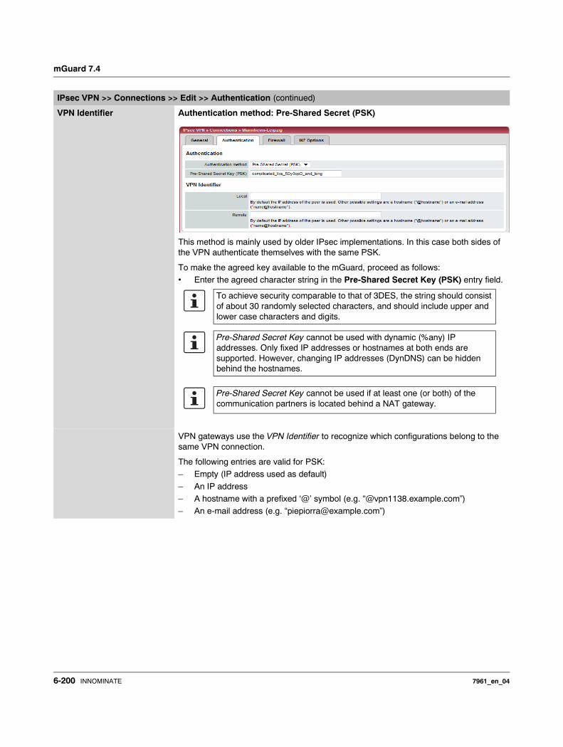
mGuard 7.4
VPN Identifier Authentication method: Pre-Shared Secret (PSK)
This method is mainly used by older IPsec implementations. In this case both sides of the VPN authenticate themselves with the same PSK.
To make the agreed key available to the mGuard, proceed as follows:• Enter the agreed character string in the Pre-Shared Secret Key (PSK) entry field.
VPN gateways use the VPN Identifier to recognize which configurations belong to the same VPN connection.
The following entries are valid for PSK:– Empty (IP address used as default)
– An IP address– A hostname with a prefixed ‘@’ symbol (e.g. “@vpn1138.example.com”)– An e-mail address (e.g. “[email protected]”)
IPsec VPN >> Connections >> Edit >> Authentication (continued)
To achieve security comparable to that of 3DES, the string should consist of about 30 randomly selected characters, and should include upper and lower case characters and digits.
Pre-Shared Secret Key cannot be used with dynamic (%any) IP addresses. Only fixed IP addresses or hostnames at both ends are supported. However, changing IP addresses (DynDNS) can be hidden behind the hostnames.
Pre-Shared Secret Key cannot be used if at least one (or both) of the communication partners is located behind a NAT gateway.
6-200 INNOMINATE 7961_en_04
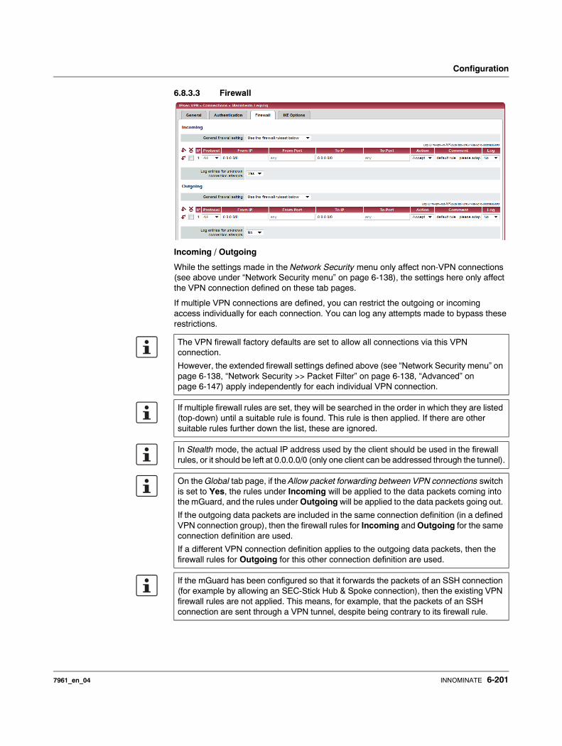
Configuration
6.8.3.3 Firewall
Incoming / Outgoing
While the settings made in the Network Security menu only affect non-VPN connections (see above under “Network Security menu” on page 6-138), the settings here only affect the VPN connection defined on these tab pages.
If multiple VPN connections are defined, you can restrict the outgoing or incoming access individually for each connection. You can log any attempts made to bypass these restrictions.
The VPN firewall factory defaults are set to allow all connections via this VPN connection.
However, the extended firewall settings defined above (see “Network Security menu” on page 6-138, “Network Security >> Packet Filter” on page 6-138, “Advanced” on page 6-147) apply independently for each individual VPN connection.
If multiple firewall rules are set, they will be searched in the order in which they are listed (top-down) until a suitable rule is found. This rule is then applied. If there are other suitable rules further down the list, these are ignored.
In Stealth mode, the actual IP address used by the client should be used in the firewall rules, or it should be left at 0.0.0.0/0 (only one client can be addressed through the tunnel).
On the Global tab page, if the Allow packet forwarding between VPN connections switch is set to Yes, the rules under Incoming will be applied to the data packets coming into the mGuard, and the rules under Outgoing will be applied to the data packets going out.
If the outgoing data packets are included in the same connection definition (in a defined VPN connection group), then the firewall rules for Incoming and Outgoing for the same connection definition are used.
If a different VPN connection definition applies to the outgoing data packets, then the firewall rules for Outgoing for this other connection definition are used.
If the mGuard has been configured so that it forwards the packets of an SSH connection (for example by allowing an SEC-Stick Hub & Spoke connection), then the existing VPN firewall rules are not applied. This means, for example, that the packets of an SSH connection are sent through a VPN tunnel, despite being contrary to its firewall rule.
7961_en_04 INNOMINATE 6-201
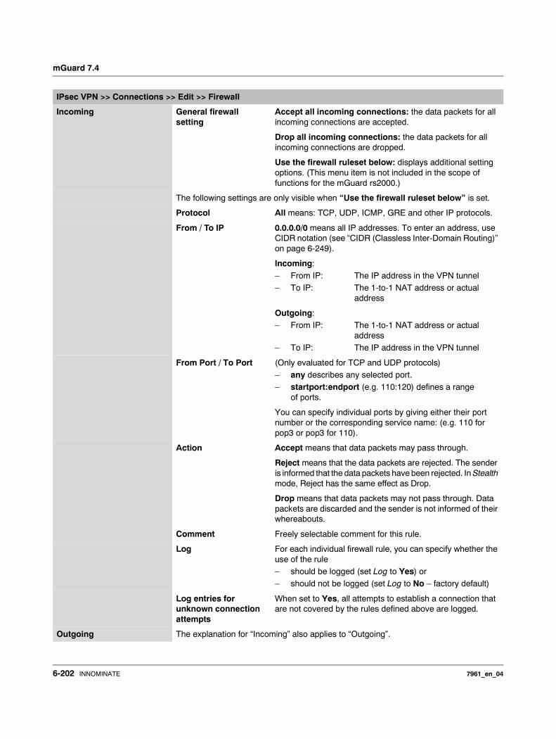
mGuard 7.4
IPsec VPN >> Connections >> Edit >> Firewall
Incoming General firewall setting
Accept all incoming connections: the data packets for all incoming connections are accepted.
Drop all incoming connections: the data packets for all incoming connections are dropped.
Use the firewall ruleset below: displays additional setting options. (This menu item is not included in the scope of functions for the mGuard rs2000.)
The following settings are only visible when “Use the firewall ruleset below” is set.
Protocol All means: TCP, UDP, ICMP, GRE and other IP protocols.
From / To IP 0.0.0.0/0 means all IP addresses. To enter an address, use CIDR notation (see “CIDR (Classless Inter-Domain Routing)” on page 6-249).
Incoming:
– From IP: The IP address in the VPN tunnel– To IP: The 1-to-1 NAT address or actual
address
Outgoing:– From IP: The 1-to-1 NAT address or actual
address– To IP: The IP address in the VPN tunnel
From Port / To Port (Only evaluated for TCP and UDP protocols)– any describes any selected port. – startport:endport (e.g. 110:120) defines a range
of ports.
You can specify individual ports by giving either their port number or the corresponding service name: (e.g. 110 for pop3 or pop3 for 110).
Action Accept means that data packets may pass through.
Reject means that the data packets are rejected. The sender is informed that the data packets have been rejected. In Stealth mode, Reject has the same effect as Drop.
Drop means that data packets may not pass through. Data packets are discarded and the sender is not informed of their whereabouts.
Comment Freely selectable comment for this rule.
Log For each individual firewall rule, you can specify whether the use of the rule– should be logged (set Log to Yes) or – should not be logged (set Log to No – factory default)
Log entries for unknown connection attempts
When set to Yes, all attempts to establish a connection that are not covered by the rules defined above are logged.
Outgoing The explanation for “Incoming” also applies to “Outgoing”.
6-202 INNOMINATE 7961_en_04
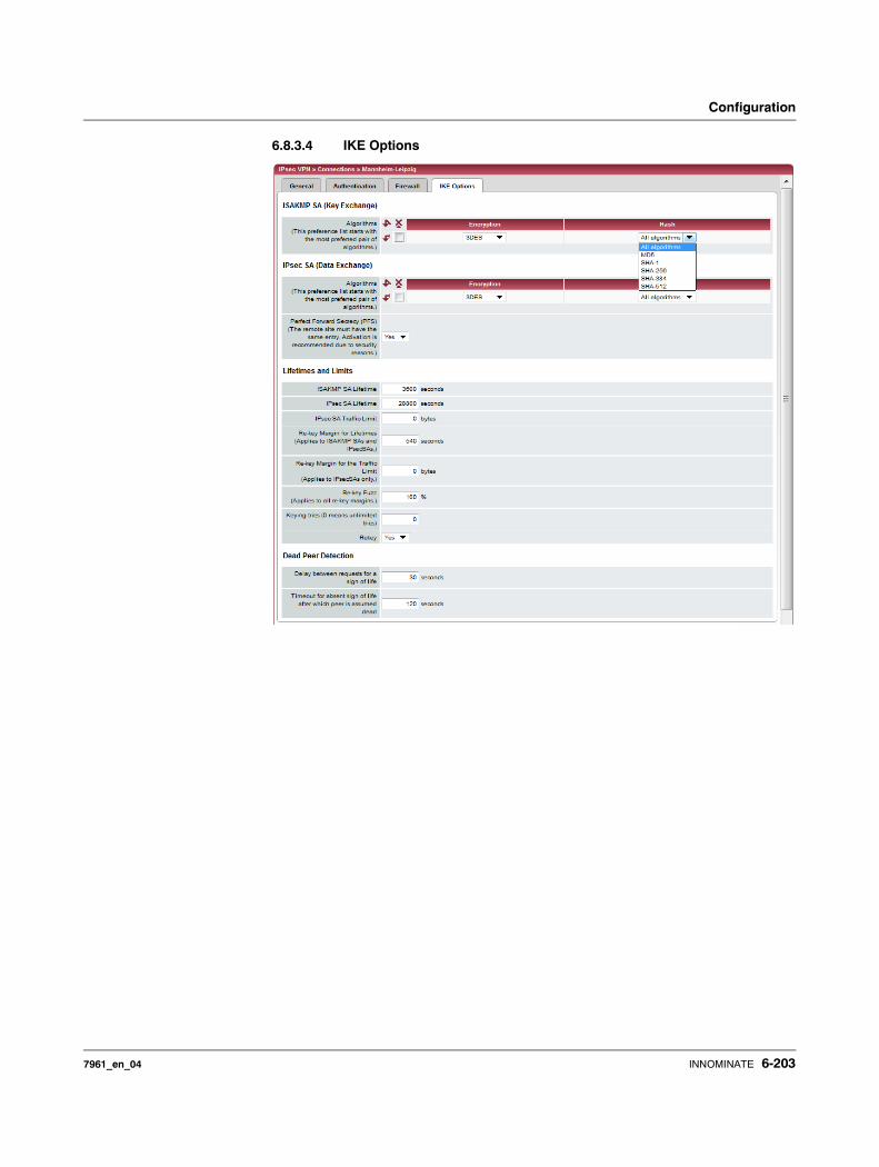
Configuration
6.8.3.4 IKE Options
7961_en_04 INNOMINATE 6-203
mGuard 7.4
IPsec VPN >> Connections >> Edit >> IKE Options
ISAKMP SA (Key Exchange) Algorithms
Encryption
3DES-168 is the most commonly used algorithm and is therefore the default setting.
The following generally applies: The greater the number of bits used by an encryption algorithm (specified by the ap-pended number) the more secure it is. The relatively new AES-256 protocol is therefore considered the most secure, but is not yet widely used.
The longer the key, the longer the time required by the en-cryption process. However, this is of no consequence for the mGuard as it uses a hardware-based encryption technique. This aspect may be of significance for the remote peer.
All algorithms designated as “Null” contains no encryption.
Hash
Keep the setting “All algorithms”. It then does not matter whether the remote peer works with MD5, SHA-1, SHA-256, SHA-384 or SHA-512.
The encryption algorithms SHA-256 and SHA-512 are supported on all mGuards. However, not all mGuards accelerate the algorithms via hardware.
The mGuard centerport neither supports nor requires hardware acceleration. On the other mGuards, MD5 and SHA1 are accelerated with hardware. Only the mGuard smart² additionally accelerates SHA-256 via hardware.
IPsec SA (Data Exchange) In contrast to ISAKMP SA (Key Exchange) (see above), this setting determines the data exchange method. This may or may not be different from the Key Exchange method.
Algorithms See above.
Perfect Forward Secrecy (PFS)
This method is used to increase the security of the data transfer. In IPsec, the key used for the data exchange is changed at certain intervals.
With PFS, a new random number is negotiated with the re-mote peer instead of deriving it from a previously agreed random number.
The remote peer must have the same entry. We recommend activation for security reasons.
Decide on which encryption technique should be used with the remote peer administrator.
Set this to Yes if the remote peer supports PFS.
Set Perfect Forward Secrecy (PFS) to No if the remote peer is an IPsec/L2TP client.
6-204 INNOMINATE 7961_en_04
Configuration
Lifetimes and Limits The keys of an IPsec connection are renewed at certain intervals to increase the costs of an attack to the IPsec connection.
ISAKMP SA Lifetime The lifetime of the ISAKMP SA keys in seconds. Factory default: 3600 seconds (1 hour). The permitted maximum is 86400 seconds (24 hours).
IPsec SA Lifetime The lifetime of the IPsec SA keys in seconds.
Factory default: 28800 seconds (8 hours). The permitted maximum is 86400 seconds (24 hours).
IPsec SA Traffic Limit 0 to 2147483647 bytes.
The value 0 indicates that there is no traffic limit for the IPsec SAs on this VPN connection.
All other values indicate the maximum number of bytes which are encrypted by the IPsec SA for this VPN connection (Hard Limit).
Re-key Margin for Life-times
Applies to ISAKMP SAs and IPsec SAs.
Minimum time interval before the old key expires during which a new key should be created. Factory default: 540 seconds (9 minutes).
Re-key Margin for the Traffic Limit
Only applies to IPsec SAs.
The value 0 indicates that the traffic limit is not used.
0 must be set here when 0 is also set under IPsec SA Traffic Limit.
If a value above 0 is entered, then a new limit is calculated from two values. The number of bytes entered here is sub-tracted from the value specified under IPsec SA Traffic Limit (i.e. Hard Limit).
The calculated value is then known as the Soft Limit. This specifies the number of bytes which must be encrypted so that a new key is negotiated for the IPsec SA.
A further amount is subtracted when a Re-key Fuzz (see be-low) above 0 is entered. This is a percentage of the re-key margin. The percentage is entered under Re-key Fuzz.
The re-key margin value must be lower than the Hard Limit. It must be significantly lower when a Re-key Fuzz is also added.
If the IPsec SA Lifetime is reached earlier, then the Soft Limit is ignored.
Re-key Fuzz Maximum in percent by which Re-key-margin shall be ran-domly increased. This is used to delay key exchange on ma-chines with many VPN connections. Factory default: 100%.
IPsec VPN >> Connections >> Edit >> IKE Options
7961_en_04 INNOMINATE 6-205
mGuard 7.4
Keying tries (0 means unlimited tries)
Number of attempts to negotiate new keys with the remote peer.
The value 0 results in unlimited attempts for connections initiated by the mGuard, otherwise it results in 5.
Rekey Yes / No
When set to Yes, the mGuard will try to negotiate a new key when the old one expires.
Dead Peer Detection When the remote peer supports the Dead Peer Detection (DPD) protocol, both partners can detect whether the IPsec connection is still valid or must be restored.
Delay between requests for a sign of life
The time in seconds after which DPD Keep Alive queries are sent. These queries test whether the remote peer is still available.
Factory default: 30 seconds.
Timeout for absent sign of life after which peer is assumed dead
The time in seconds after which the remote peer is declared dead if Keep Alive queries are not answered.
Factory default: 120 seconds.
IPsec VPN >> Connections >> Edit >> IKE Options
If the mGuard finds that a connection is dead, it acts according to the setting under Connection startup (see definition of this VPN connection under General, Connection startup).
6-206 INNOMINATE 7961_en_04
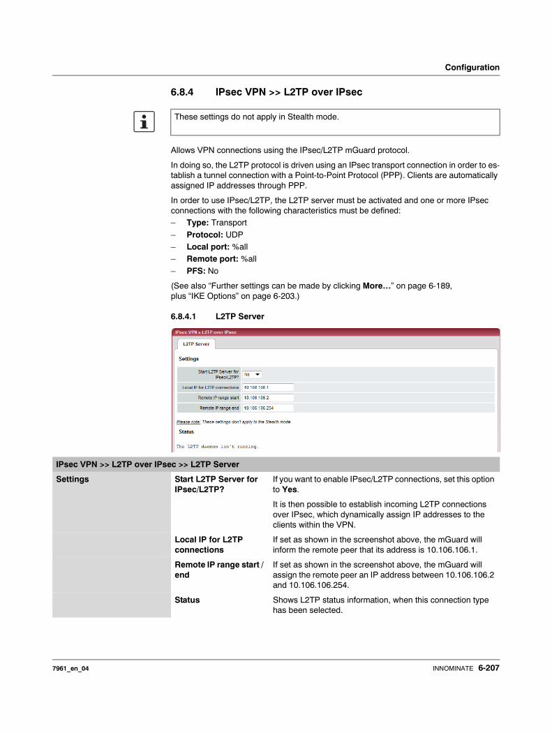
Configuration
6.8.4 IPsec VPN >> L2TP over IPsec
Allows VPN connections using the IPsec/L2TP mGuard protocol.
In doing so, the L2TP protocol is driven using an IPsec transport connection in order to es-tablish a tunnel connection with a Point-to-Point Protocol (PPP). Clients are automatically assigned IP addresses through PPP.
In order to use IPsec/L2TP, the L2TP server must be activated and one or more IPsec connections with the following characteristics must be defined:– Type: Transport
– Protocol: UDP– Local port: %all– Remote port: %all
– PFS: No
(See also “Further settings can be made by clicking More…” on page 6-189, plus “IKE Options” on page 6-203.)
6.8.4.1 L2TP Server
These settings do not apply in Stealth mode.
IPsec VPN >> L2TP over IPsec >> L2TP Server
Settings Start L2TP Server for IPsec/L2TP?
If you want to enable IPsec/L2TP connections, set this option to Yes.
It is then possible to establish incoming L2TP connections over IPsec, which dynamically assign IP addresses to the clients within the VPN.
Local IP for L2TP connections
If set as shown in the screenshot above, the mGuard will inform the remote peer that its address is 10.106.106.1.
Remote IP range start / end
If set as shown in the screenshot above, the mGuard will assign the remote peer an IP address between 10.106.106.2 and 10.106.106.254.
Status Shows L2TP status information, when this connection type has been selected.
7961_en_04 INNOMINATE 6-207
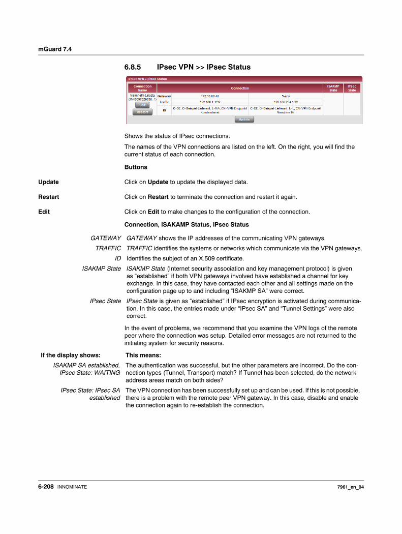
mGuard 7.4
6.8.5 IPsec VPN >> IPsec Status
Shows the status of IPsec connections.
The names of the VPN connections are listed on the left. On the right, you will find the current status of each connection.
Buttons
Update Click on Update to update the displayed data.
Restart Click on Restart to terminate the connection and restart it again.
Edit Click on Edit to make changes to the configuration of the connection.
Connection, ISAKAMP Status, IPsec Status
In the event of problems, we recommend that you examine the VPN logs of the remote peer where the connection was setup. Detailed error messages are not returned to the initiating system for security reasons.
GATEWAY GATEWAY shows the IP addresses of the communicating VPN gateways.
TRAFFIC TRAFFIC identifies the systems or networks which communicate via the VPN gateways.
ID Identifies the subject of an X.509 certificate.
ISAKMP State ISAKMP State (Internet security association and key management protocol) is given as “established” if both VPN gateways involved have established a channel for key exchange. In this case, they have contacted each other and all settings made on the configuration page up to and including “ISAKMP SA” were correct.
IPsec State IPsec State is given as “established” if IPsec encryption is activated during communica-tion. In this case, the entries made under “IPsec SA” and “Tunnel Settings” were also correct.
If the display shows: This means:
ISAKMP SA established,IPsec State: WAITING
The authentication was successful, but the other parameters are incorrect. Do the con-nection types (Tunnel, Transport) match? If Tunnel has been selected, do the network address areas match on both sides?
IPsec State: IPsec SAestablished
The VPN connection has been successfully set up and can be used. If this is not possible, there is a problem with the remote peer VPN gateway. In this case, disable and enable the connection again to re-establish the connection.
6-208 INNOMINATE 7961_en_04
Configuration
6.9 SEC-Stick menu
The mGuard supports the use of a SEC-Stick, an access protector for IT systems. The SEC-Stick is a product of the team2work company: www.team2work.de.
The SEC-Stick is a key. The user inserts it into the USB port of a computer with an Internet connection, and can then set up an encrypted connection to the mGuard in order to se-curely access defined services in the office or home network. For example, the Remote Desktop Protocol can be used within the encrypted and secure SEC-Stick connection to control a PC remotely in the office or at home, as if the user was sitting directly in front of it.
This works because access to the business PC is protected by the mGuard and the mGuard can be configured for the SEC-Stick to permit access. The user of this remote computer, where the SEC-Stick is inserted, authenticates himself to the mGuard with the data and software stored on his SEC-Stick.
The SEC-Stick establishes an SSH connection to the mGuard. Other channels can be embedded in this connection, e.g. TCP/IP connections.
7961_en_04 INNOMINATE 6-209
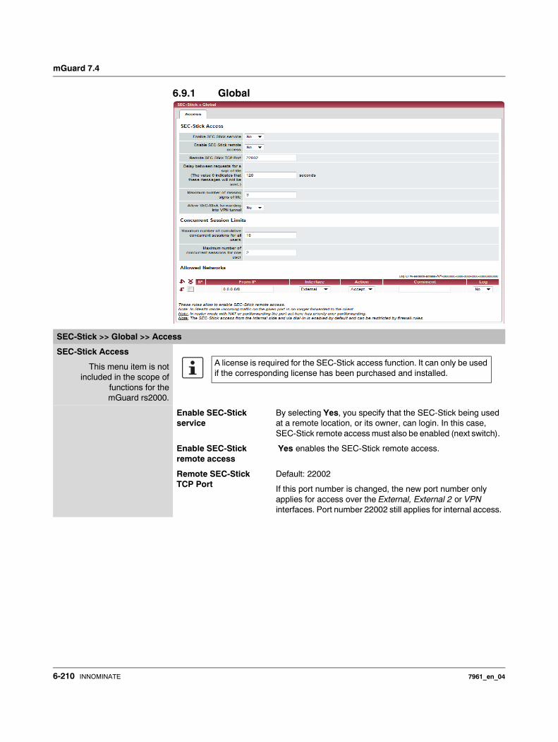
mGuard 7.4
6.9.1 Global
SEC-Stick >> Global >> Access
SEC-Stick Access
This menu item is notincluded in the scope of
functions for themGuard rs2000.
Enable SEC-Stick service
By selecting Yes, you specify that the SEC-Stick being used at a remote location, or its owner, can login. In this case, SEC-Stick remote access must also be enabled (next switch).
Enable SEC-Stick remote access
Yes enables the SEC-Stick remote access.
Remote SEC-Stick TCP Port
Default: 22002
If this port number is changed, the new port number only applies for access over the External, External 2 or VPN interfaces. Port number 22002 still applies for internal access.
A license is required for the SEC-Stick access function. It can only be used if the corresponding license has been purchased and installed.
6-210 INNOMINATE 7961_en_04
Configuration
Delay between requests for a sign of life
Default: 120 seconds
Values between 0 and 3600 seconds can be set. Positive values mean that the mGuard sends a request to the peer within the encrypted SSH connection to see whether it is still accessible. This means that the mGuard sends a request to the peer within the encrypted SSH connection to see whether it is still accessible. The request is sent when no activity from the peer is detected for the specified period (for example, as a result of network traffic within the encrypted connection).
As the number of sessions that can be open at the same time is limited (see Maximum number of simultaneous sessions for all users), it is important to close sessions that are finished.
Therefore, from version 7.4.0 on, the request for a sign of life has the default value of 120 seconds. With a maximum of three requests for a sign of life, a finished session will be discovered after six minutes and removed.
In previous versions, the default setting was “0”. This means that no requests for a sign of life are sent.
Note that the requests for a sign of life create additional traffic.
Maximum number of missing signs of life
Specifies the maximum number of times a sign of life request to the peer can remain unanswered. For example, if a sign of life request should be made every 15 seconds and this value is set to 3, then the SEC stick client connection is deleted when a sign of life is not detected after approximately 45 seconds.
Limiting simultaneous sessions
For administrative access to the mGuard via an SEC stick, there is a limit to the number of simultaneous sessions. Around 0.5 MB of memory is required for each session to ensure the maximum security level.The restriction has no effect on existing sessions, but only on newly created access.
Maximum number of simultaneous sessions for all users
0 to 2147483647
Specifies the number of administrative accesses allowed from all users at the same time. With “0” no session is allowed.
Maximum number of simultaneous sessions for a user
0 to 2147483647
Specifies the number of administrative accesses allowed from one user at the same time. With “0” no session is allowed.
Allowed Networks Lists the firewall rules that have been set. They apply to SEC-Stick remote access.
SEC-Stick >> Global >> Access (continued)
7961_en_04 INNOMINATE 6-211
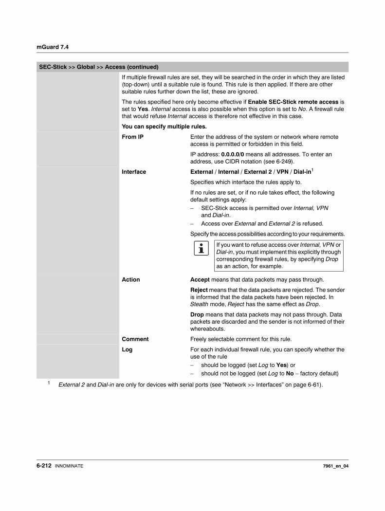
mGuard 7.4
If multiple firewall rules are set, they will be searched in the order in which they are listed (top-down) until a suitable rule is found. This rule is then applied. If there are other suitable rules further down the list, these are ignored.
The rules specified here only become effective if Enable SEC-Stick remote access is set to Yes. Internal access is also possible when this option is set to No. A firewall rule that would refuse Internal access is therefore not effective in this case.
You can specify multiple rules.
From IP Enter the address of the system or network where remote access is permitted or forbidden in this field.
IP address: 0.0.0.0/0 means all addresses. To enter an address, use CIDR notation (see 6-249).
Interface External / Internal / External 2 / VPN / Dial-in1
Specifies which interface the rules apply to.
If no rules are set, or if no rule takes effect, the following default settings apply:
– SEC-Stick access is permitted over Internal, VPN and Dial-in.
– Access over External and External 2 is refused.
Specify the access possibilities according to your requirements.
Action Accept means that data packets may pass through.
Reject means that the data packets are rejected. The sender is informed that the data packets have been rejected. In Stealth mode, Reject has the same effect as Drop.
Drop means that data packets may not pass through. Data packets are discarded and the sender is not informed of their whereabouts.
Comment Freely selectable comment for this rule.
Log For each individual firewall rule, you can specify whether the use of the rule
– should be logged (set Log to Yes) or – should not be logged (set Log to No – factory default)
1 External 2 and Dial-in are only for devices with serial ports (see “Network >> Interfaces” on page 6-61).
SEC-Stick >> Global >> Access (continued)
If you want to refuse access over Internal, VPN or Dial-in, you must implement this explicitly through corresponding firewall rules, by specifying Drop as an action, for example.
6-212 INNOMINATE 7961_en_04
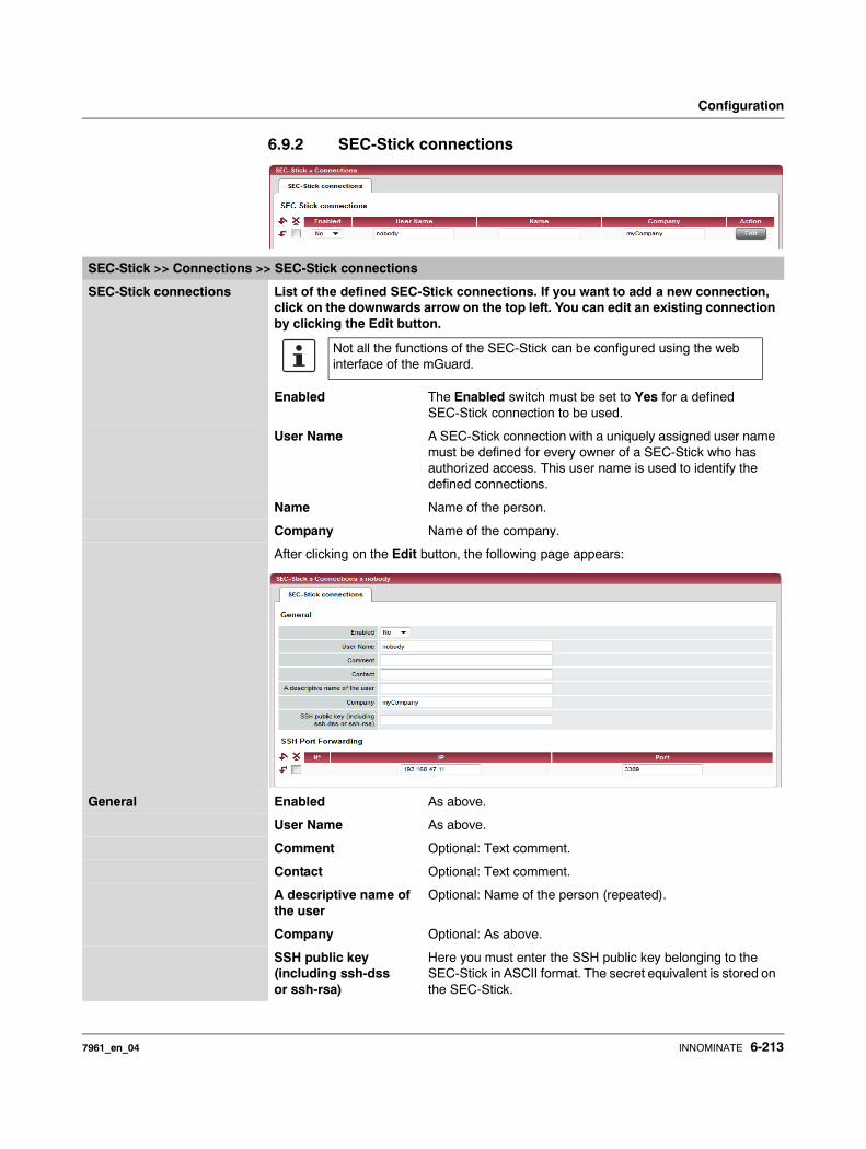
Configuration
6.9.2 SEC-Stick connections
SEC-Stick >> Connections >> SEC-Stick connections
SEC-Stick connections List of the defined SEC-Stick connections. If you want to add a new connection, click on the downwards arrow on the top left. You can edit an existing connection by clicking the Edit button.
Enabled The Enabled switch must be set to Yes for a defined SEC-Stick connection to be used.
User Name A SEC-Stick connection with a uniquely assigned user name must be defined for every owner of a SEC-Stick who has authorized access. This user name is used to identify the defined connections.
Name Name of the person.
Company Name of the company.
After clicking on the Edit button, the following page appears:
General Enabled As above.
User Name As above.
Comment Optional: Text comment.
Contact Optional: Text comment.
A descriptive name of the user
Optional: Name of the person (repeated).
Company Optional: As above.
SSH public key (including ssh-dss or ssh-rsa)
Here you must enter the SSH public key belonging to the SEC-Stick in ASCII format. The secret equivalent is stored on the SEC-Stick.
Not all the functions of the SEC-Stick can be configured using the web interface of the mGuard.
7961_en_04 INNOMINATE 6-213

mGuard 7.4
SSH Port Forwarding List of the allowed access and SSH port forwarding relating to the SEC-Stick of the corresponding user.
IP IP address of the computer to which the access is allowed.
Port Port number to be used when accessing the computer.
SEC-Stick >> Connections >> SEC-Stick connections (continued)
6-214 INNOMINATE 7961_en_04
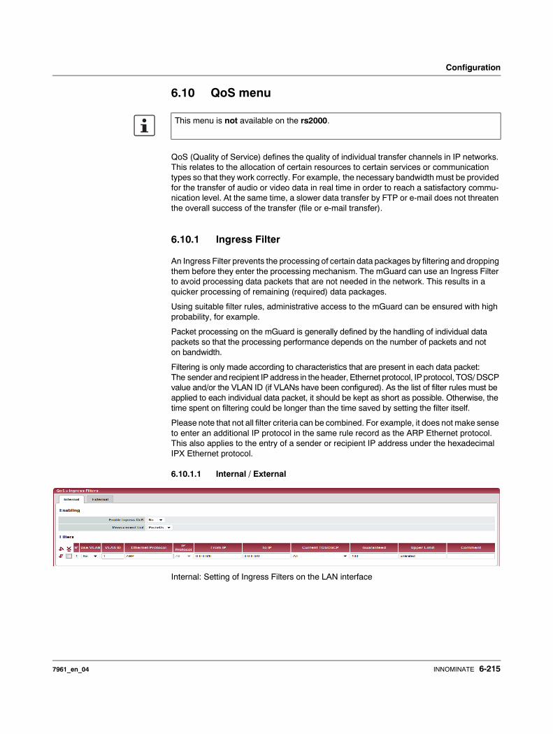
Configuration
6.10 QoS menu
QoS (Quality of Service) defines the quality of individual transfer channels in IP networks. This relates to the allocation of certain resources to certain services or communication types so that they work correctly. For example, the necessary bandwidth must be provided for the transfer of audio or video data in real time in order to reach a satisfactory commu-nication level. At the same time, a slower data transfer by FTP or e-mail does not threaten the overall success of the transfer (file or e-mail transfer).
6.10.1 Ingress Filter
An Ingress Filter prevents the processing of certain data packages by filtering and dropping them before they enter the processing mechanism. The mGuard can use an Ingress Filter to avoid processing data packets that are not needed in the network. This results in a quicker processing of remaining (required) data packages.
Using suitable filter rules, administrative access to the mGuard can be ensured with high probability, for example.
Packet processing on the mGuard is generally defined by the handling of individual data packets so that the processing performance depends on the number of packets and not on bandwidth.
Filtering is only made according to characteristics that are present in each data packet: The sender and recipient IP address in the header, Ethernet protocol, IP protocol, TOS/ DSCP value and/or the VLAN ID (if VLANs have been configured). As the list of filter rules must be applied to each individual data packet, it should be kept as short as possible. Otherwise, the time spent on filtering could be longer than the time saved by setting the filter itself.
Please note that not all filter criteria can be combined. For example, it does not make sense to enter an additional IP protocol in the same rule record as the ARP Ethernet protocol. This also applies to the entry of a sender or recipient IP address under the hexadecimal IPX Ethernet protocol.
6.10.1.1 Internal / External
Internal: Setting of Ingress Filters on the LAN interface
This menu is not available on the rs2000.
7961_en_04 INNOMINATE 6-215
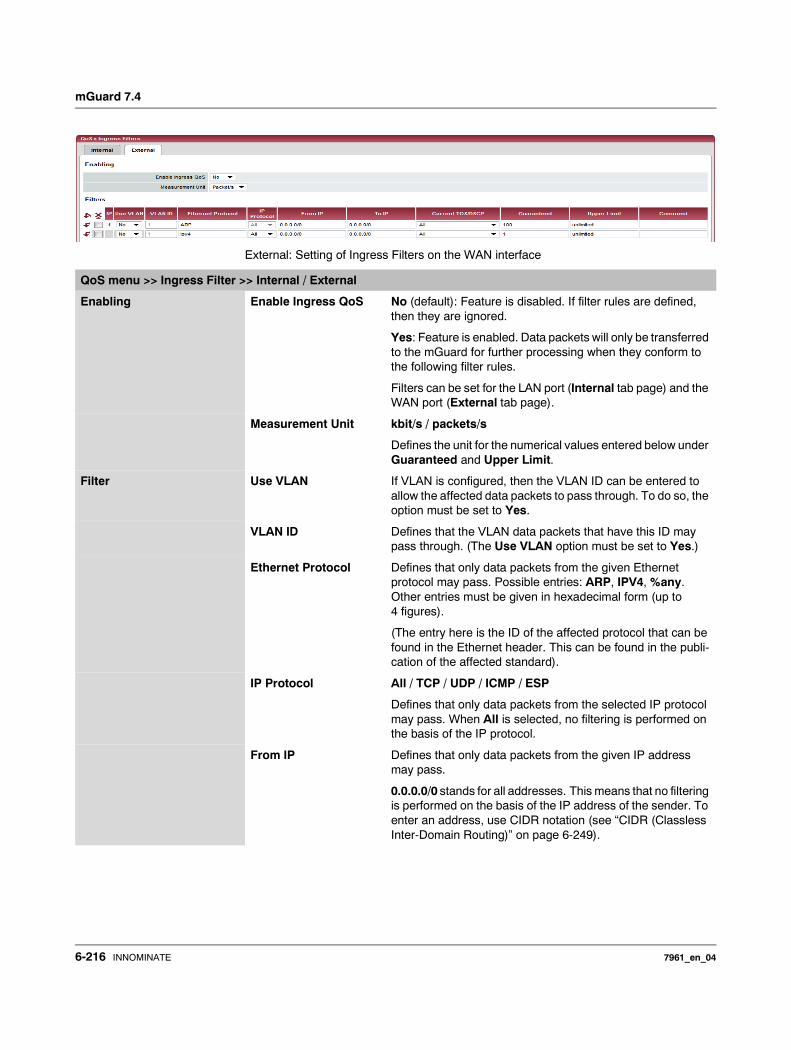
mGuard 7.4
External: Setting of Ingress Filters on the WAN interface
QoS menu >> Ingress Filter >> Internal / External
Enabling Enable Ingress QoS No (default): Feature is disabled. If filter rules are defined, then they are ignored.
Yes: Feature is enabled. Data packets will only be transferred to the mGuard for further processing when they conform to the following filter rules.
Filters can be set for the LAN port (Internal tab page) and the WAN port (External tab page).
Measurement Unit kbit/s / packets/s
Defines the unit for the numerical values entered below under Guaranteed and Upper Limit.
Filter Use VLAN If VLAN is configured, then the VLAN ID can be entered to allow the affected data packets to pass through. To do so, the option must be set to Yes.
VLAN ID Defines that the VLAN data packets that have this ID may pass through. (The Use VLAN option must be set to Yes.)
Ethernet Protocol Defines that only data packets from the given Ethernet protocol may pass. Possible entries: ARP, IPV4, %any. Other entries must be given in hexadecimal form (up to 4 figures).
(The entry here is the ID of the affected protocol that can be found in the Ethernet header. This can be found in the publi-cation of the affected standard).
IP Protocol All / TCP / UDP / ICMP / ESP
Defines that only data packets from the selected IP protocol may pass. When All is selected, no filtering is performed on the basis of the IP protocol.
From IP Defines that only data packets from the given IP address may pass.
0.0.0.0/0 stands for all addresses. This means that no filtering is performed on the basis of the IP address of the sender. To enter an address, use CIDR notation (see “CIDR (Classless Inter-Domain Routing)” on page 6-249).
6-216 INNOMINATE 7961_en_04
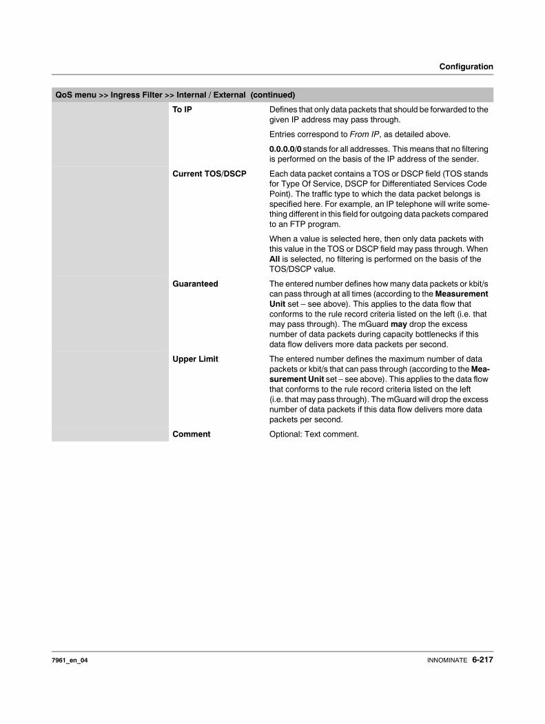
Configuration
To IP Defines that only data packets that should be forwarded to the given IP address may pass through.
Entries correspond to From IP, as detailed above.
0.0.0.0/0 stands for all addresses. This means that no filtering is performed on the basis of the IP address of the sender.
Current TOS/DSCP Each data packet contains a TOS or DSCP field (TOS stands for Type Of Service, DSCP for Differentiated Services Code Point). The traffic type to which the data packet belongs is specified here. For example, an IP telephone will write some-thing different in this field for outgoing data packets compared to an FTP program.
When a value is selected here, then only data packets with this value in the TOS or DSCP field may pass through. When All is selected, no filtering is performed on the basis of the TOS/DSCP value.
Guaranteed The entered number defines how many data packets or kbit/s can pass through at all times (according to the Measurement Unit set – see above). This applies to the data flow that conforms to the rule record criteria listed on the left (i.e. that may pass through). The mGuard may drop the excess number of data packets during capacity bottlenecks if this data flow delivers more data packets per second.
Upper Limit The entered number defines the maximum number of data packets or kbit/s that can pass through (according to the Mea-surement Unit set – see above). This applies to the data flow that conforms to the rule record criteria listed on the left (i.e. that may pass through). The mGuard will drop the excess number of data packets if this data flow delivers more data packets per second.
Comment Optional: Text comment.
QoS menu >> Ingress Filter >> Internal / External (continued)
7961_en_04 INNOMINATE 6-217
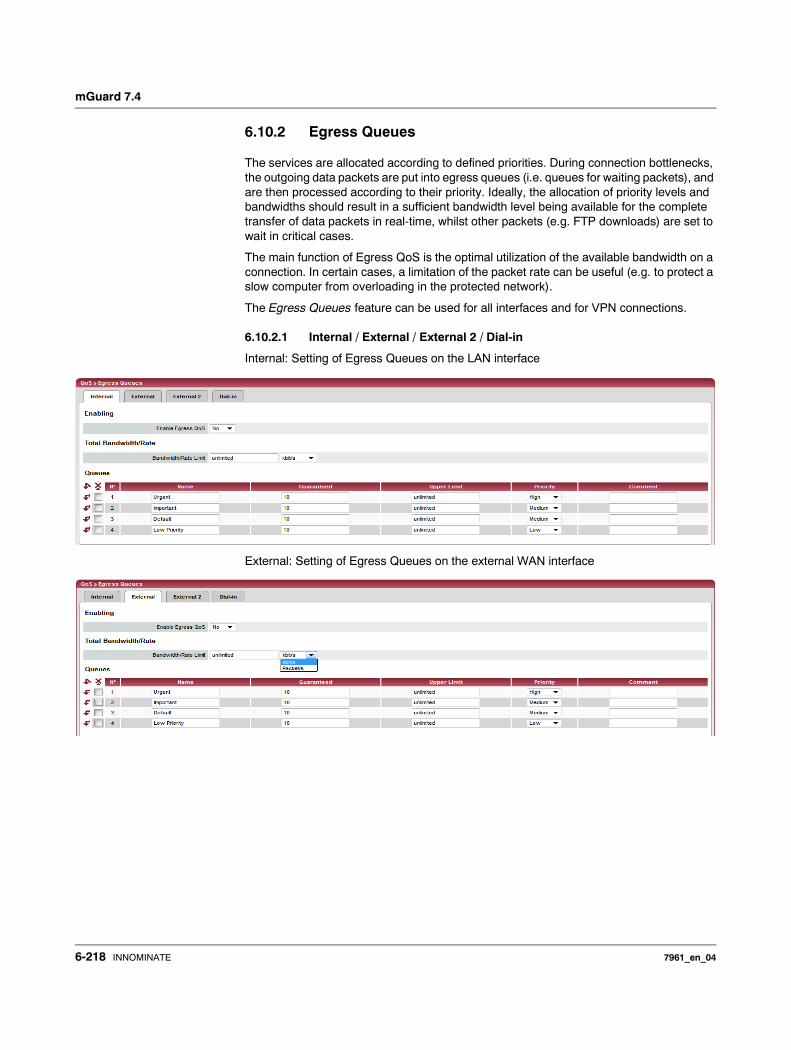
mGuard 7.4
6.10.2 Egress Queues
The services are allocated according to defined priorities. During connection bottlenecks, the outgoing data packets are put into egress queues (i.e. queues for waiting packets), and are then processed according to their priority. Ideally, the allocation of priority levels and bandwidths should result in a sufficient bandwidth level being available for the complete transfer of data packets in real-time, whilst other packets (e.g. FTP downloads) are set to wait in critical cases.
The main function of Egress QoS is the optimal utilization of the available bandwidth on a connection. In certain cases, a limitation of the packet rate can be useful (e.g. to protect a slow computer from overloading in the protected network).
The Egress Queues feature can be used for all interfaces and for VPN connections.
6.10.2.1 Internal / External / External 2 / Dial-in
Internal: Setting of Egress Queues on the LAN interface
External: Setting of Egress Queues on the external WAN interface
6-218 INNOMINATE 7961_en_04
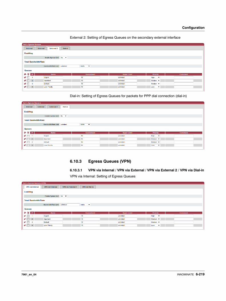
Configuration
External 2: Setting of Egress Queues on the secondary external interface
Dial-in: Setting of Egress Queues for packets for PPP dial connection (dial-in)
6.10.3 Egress Queues (VPN)
6.10.3.1 VPN via Internal / VPN via External / VPN via External 2 / VPN via Dial-in
VPN via Internal: Setting of Egress Queues
7961_en_04 INNOMINATE 6-219
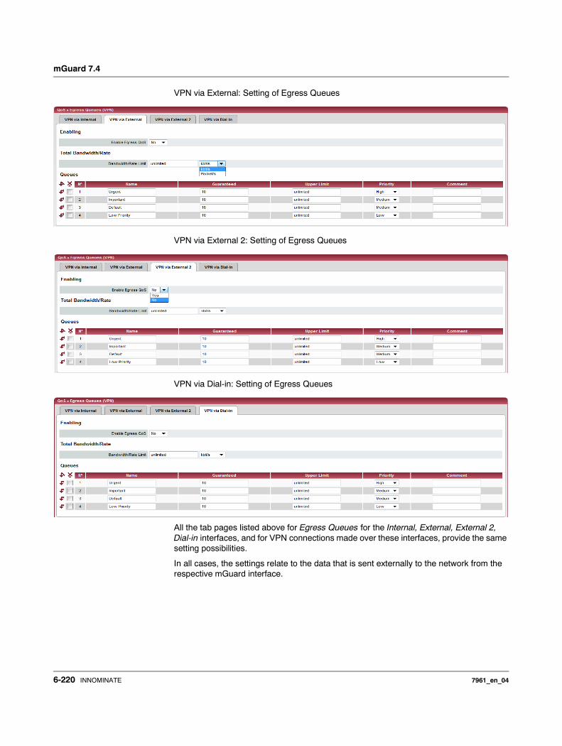
mGuard 7.4
VPN via External: Setting of Egress Queues
VPN via External 2: Setting of Egress Queues
VPN via Dial-in: Setting of Egress Queues
All the tab pages listed above for Egress Queues for the Internal, External, External 2, Dial-in interfaces, and for VPN connections made over these interfaces, provide the same setting possibilities.
In all cases, the settings relate to the data that is sent externally to the network from the respective mGuard interface.
6-220 INNOMINATE 7961_en_04

Configuration
QoS menu >> Egress Queues >> Internal / External / External 2 / Dial-inQoS menu >> Egress Queues (VPN) >> VPN via Internal / VPN via External / VPN via External 2 / VPN via Dial-in
Enabling Enable Egress QoS No (default): Feature is disabled.
Yes: Feature is enabled. This is recommended when the interface is connected to a network with a small bandwidth. This allows the bandwidth allocation to be influenced in favor of especially important data.
Total Bandwidth/Rate Bandwidth/Rate Limit kbit/s / packets/s
Maximum available bandwidth – measured in kbit/s or packets/s.
In order for an optimal prioritization process, the total band-width entered here should be slightly lower than the actual amount. This prevents an overrun in the transferring device buffer, which would create adverse effects.
Queues Name You can apply the preset name for the Egress Queues or select another one. The name does not define data priority.
Guaranteed Bandwidth that should be available for the relevant queue. Use the same units as defined above under Bandwidth/Rate Limit (kbit/s OR packet/s) but do not enter the unit of mea-surement explicitly.
The total of all guaranteed bandwidths must be smaller or equal to the total bandwidth.
Upper Limit Maximum permitted bandwidth available for the relevant queue. Use the same units as defined above under Band-width/Rate Limit (kbit/s OR packet/s) but do not enter the unit of measurement explicitly.This value must be the same as or larger than the guaranteed bandwidth. You can also enter the unlimited setting, which means no further restriction.
Priority Low / Medium / High
Defines with which priority the affected queue should be processed, providing the total available bandwidth is not exhausted.
Comment Optional: Text comment.
7961_en_04 INNOMINATE 6-221
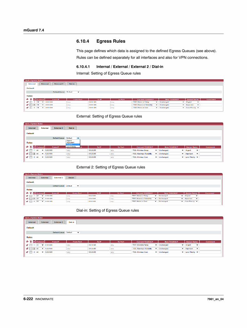
mGuard 7.4
6.10.4 Egress Rules
This page defines which data is assigned to the defined Egress Queues (see above).
Rules can be defined separately for all interfaces and also for VPN connections.
6.10.4.1 Internal / External / External 2 / Dial-in
Internal: Setting of Egress Queue rules
External: Setting of Egress Queue rules
External 2: Setting of Egress Queue rules
Dial-in: Setting of Egress Queue rules
6-222 INNOMINATE 7961_en_04
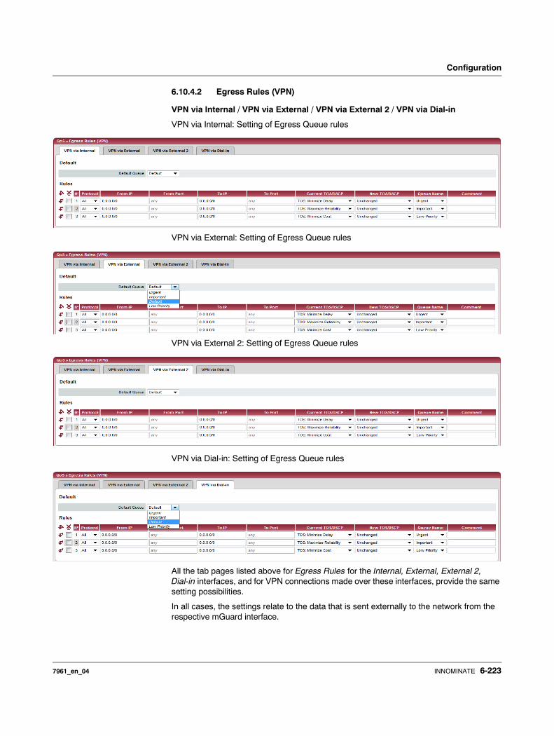
Configuration
6.10.4.2 Egress Rules (VPN)
VPN via Internal / VPN via External / VPN via External 2 / VPN via Dial-in
VPN via Internal: Setting of Egress Queue rules
VPN via External: Setting of Egress Queue rules
VPN via External 2: Setting of Egress Queue rules
VPN via Dial-in: Setting of Egress Queue rules
All the tab pages listed above for Egress Rules for the Internal, External, External 2, Dial-in interfaces, and for VPN connections made over these interfaces, provide the same setting possibilities.
In all cases, the settings relate to the data that is sent externally to the network from the respective mGuard interface.
7961_en_04 INNOMINATE 6-223
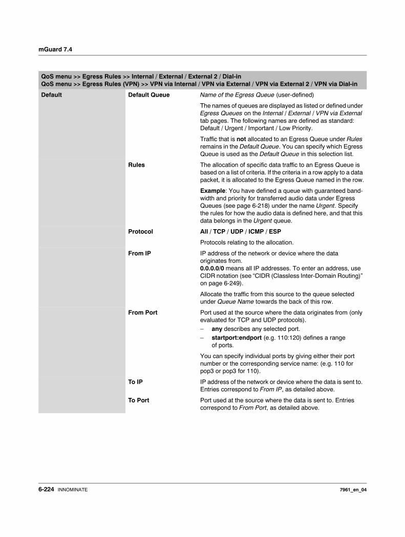
mGuard 7.4
QoS menu >> Egress Rules >> Internal / External / External 2 / Dial-inQoS menu >> Egress Rules (VPN) >> VPN via Internal / VPN via External / VPN via External 2 / VPN via Dial-in
Default Default Queue Name of the Egress Queue (user-defined)
The names of queues are displayed as listed or defined under Egress Queues on the Internal / External / VPN via External tab pages. The following names are defined as standard: Default / Urgent / Important / Low Priority.
Traffic that is not allocated to an Egress Queue under Rules remains in the Default Queue. You can specify which Egress Queue is used as the Default Queue in this selection list.
Rules The allocation of specific data traffic to an Egress Queue is based on a list of criteria. If the criteria in a row apply to a data packet, it is allocated to the Egress Queue named in the row.
Example: You have defined a queue with guaranteed band-width and priority for transferred audio data under Egress Queues (see page 6-218) under the name Urgent. Specify the rules for how the audio data is defined here, and that this data belongs in the Urgent queue.
Protocol All / TCP / UDP / ICMP / ESP
Protocols relating to the allocation.
From IP IP address of the network or device where the data originates from. 0.0.0.0/0 means all IP addresses. To enter an address, use CIDR notation (see “CIDR (Classless Inter-Domain Routing)” on page 6-249).
Allocate the traffic from this source to the queue selected under Queue Name towards the back of this row.
From Port Port used at the source where the data originates from (only evaluated for TCP and UDP protocols).
– any describes any selected port. – startport:endport (e.g. 110:120) defines a range
of ports.
You can specify individual ports by giving either their port number or the corresponding service name: (e.g. 110 for pop3 or pop3 for 110).
To IP IP address of the network or device where the data is sent to. Entries correspond to From IP, as detailed above.
To Port Port used at the source where the data is sent to. Entries correspond to From Port, as detailed above.
6-224 INNOMINATE 7961_en_04
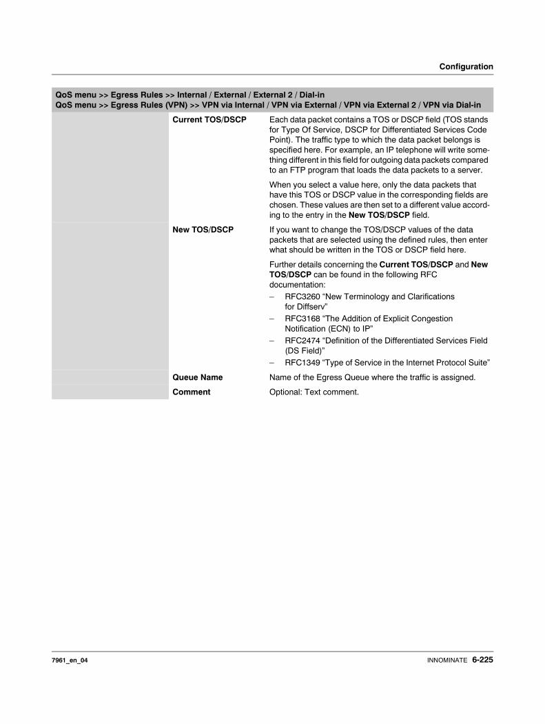
Configuration
Current TOS/DSCP Each data packet contains a TOS or DSCP field (TOS stands for Type Of Service, DSCP for Differentiated Services Code Point). The traffic type to which the data packet belongs is specified here. For example, an IP telephone will write some-thing different in this field for outgoing data packets compared to an FTP program that loads the data packets to a server.
When you select a value here, only the data packets that have this TOS or DSCP value in the corresponding fields are chosen. These values are then set to a different value accord-ing to the entry in the New TOS/DSCP field.
New TOS/DSCP If you want to change the TOS/DSCP values of the data packets that are selected using the defined rules, then enter what should be written in the TOS or DSCP field here.
Further details concerning the Current TOS/DSCP and New TOS/DSCP can be found in the following RFC documentation:– RFC3260 “New Terminology and Clarifications
for Diffserv”– RFC3168 “The Addition of Explicit Congestion
Notification (ECN) to IP”– RFC2474 “Definition of the Differentiated Services Field
(DS Field)”– RFC1349 “Type of Service in the Internet Protocol Suite”
Queue Name Name of the Egress Queue where the traffic is assigned.
Comment Optional: Text comment.
QoS menu >> Egress Rules >> Internal / External / External 2 / Dial-inQoS menu >> Egress Rules (VPN) >> VPN via Internal / VPN via External / VPN via External 2 / VPN via Dial-in
7961_en_04 INNOMINATE 6-225
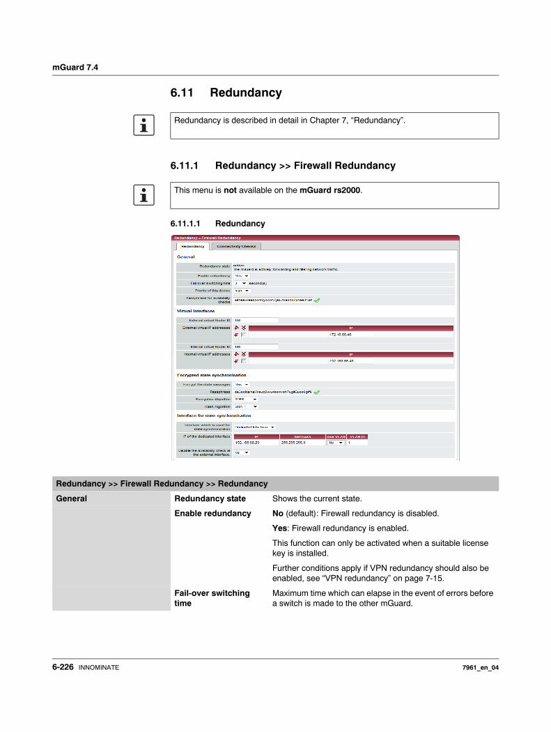
mGuard 7.4
6.11 Redundancy
6.11.1 Redundancy >> Firewall Redundancy
6.11.1.1 Redundancy
Redundancy is described in detail in Chapter 7, “Redundancy”.
This menu is not available on the mGuard rs2000.
Redundancy >> Firewall Redundancy >> Redundancy
General Redundancy state Shows the current state.
Enable redundancy No (default): Firewall redundancy is disabled.
Yes: Firewall redundancy is enabled.
This function can only be activated when a suitable license key is installed.
Further conditions apply if VPN redundancy should also be enabled, see “VPN redundancy” on page 7-15.
Fail-over switching time
Maximum time which can elapse in the event of errors before a switch is made to the other mGuard.
6-226 INNOMINATE 7961_en_04
Configuration
Priority of this device high / low
Specifies the priority connected to presence notifications (CARP).
Set the priority to high on the active mGuard. The mGuard on standby is set to low.
Both mGuards in a redundant pair may either have different priorities or the high priority.
Passphrase for avail-ability checks
On mGuards which are part of a redundant pair, checks are constantly made as to whether an active mGuard is available and whether this should remain active. A variation of the CARP (Common Address Redundancy Protocol) is used here.
CARP uses SHA-1 HMAC encryption together with a pass-word. This password must be the same on both mGuards. It is used for encryption, and is never transmitted in plain text.
Proceed as follows to change the password:
Only if you see a green checkmark to the right of the input field there is a valid password and you are allowed to enter a new password.
Set the new password on both mGuards. The order does not matter, but the password has to be the same for both. If you accidentally enter a different password, follow the instructions under “Procedure for an incorrect password” on page 6-228.
When a redundant pair receives a new password, it decides itself when it can switch to the new password without an interruption.
The status is displayed using symbols. We recommend monitoring this status for security reasons.
A red X indicates that the mGuard has a new password that it wants to use. But the old password is still being used.
A yellow checkmark indicates that the new password is being used, but that the old one will still be accepted, in case the other mGuard is still using it.
If there is no symbol, no password is used. For example, because the redundancy is not activated or the firmware is booting.
Redundancy >> Firewall Redundancy >> Redundancy (continued)
Never set both mGuards in a redundant pair to low priority.
The password is important for security, as the mGuard is vulnerable at this point. We recom-mend a password with at least 20 characters and a range of special characters (printable UTF-8 characters). The password must be changed on a regular basis.
Check which status the set password has before entering a new one.
7961_en_04 INNOMINATE 6-227
mGuard 7.4
If an mGuard fails while the password is being changed, the following cases are possible:
– The password update was started on all mGuards and then interrupted, e.g. due to a network error. This situation is resolved automatically.
– The password update was started on all mGuards. However, one mGuard then fails and has to be replaced. Check the remaining mGuard to see whether the password update has already been completed. If you see a green checkmark, you have to set the new password directly on the mGuard to be replaced.If you do not see a green checkmark, then no password update has taken place on the remaining mGuard. Then you have to change the password again on the mGuard that is still operating. Wait until the green checkmark appears. Only then replace the mGuard that has failed. Configure the replacement mGuard at once when setting up the redundancy with the new password.
– The password update was started, but not on all mGuards, because they have failed. As soon as a failed mGuard is online again, the password update has to be started. A replacement mGuard first has to be configured with the old password before being connected.
Procedure for an incorrect password
If you still know the old password, proceed as follows:
• Reconfigure the mGuard for which the incorrect password was entered with the old password.
• Wait until the mGuard shows that the old password is being used.• Then enter the correct password.
If you do not know the old password any more, proceed as follows:
• Check whether you can read the old password from the other mGuard.• If the other mGuard is switched off or missing, you can simply enter the correct new
password on the active mGuard on which you accidentally set the incorrect password. Make sure that the other mGuard gets the same password before it starts operating again.
• If the other mGuard is already using the new password, you must ensure that the mGuard with the incorrect password is not active or does not become active, e. g. if the cable is disconnected at the LAN or WAN interface. For a remote access, you can enter a destination for the availability check that will not react.
First check that there is no error in the redundancy for either of the mGuards. One mGuard must be active and the other must be on standby. If necessary, you must remove any errors displayed. – Replace the incorrect password with another one.– Also enter this password for the active mGuard.– Start operating the non-active mGuard again. For example, by connecting the
Ethernet cable again or setting up the old settings for the availability check again.
Redundancy >> Firewall Redundancy >> Redundancy (continued)
If you accidentally entered an incorrect password for an mGuard, you cannot simply enter the password again correctly. Otherwise, it can happen that both mGuards are active after this.
6-228 INNOMINATE 7961_en_04
Configuration
Virtual interface External virtual Router ID
1, 2, 3 to 255 (default: 51)
Only in Router network mode.
This ID is sent by the redundant pair with each presence no-tification (CARP) via the external interface, and is used to identify the redundant pair.
This ID must be the same on both mGuards. The ID is used to differentiate the redundant pair from other redundant pairs that are connected to the same Ethernet segment through their external interface.
Please note that CARP uses the same protocol and port as VRRR (Virtual Router Redundancy Protocol). The ID set here must be different to the IDs on other devices which use VRRR or CARP and are located in the same Ethernet segment.
External virtual IP addresses
Default: 10.0.0.100
Only in Router network mode.
These are IP addresses which are used by both mGuards as virtual IP addresses on the external interface. These IP ad-dresses must be the same on both mGuards.
These addresses are used as a gateway for explicit static routes on devices located in the same Ethernet segment as the external network interface of the mGuard.
The active mGuard can receive ICMP requests via this IP ad-dress. It reacts to these ICMP requests depending on the menu settings under Network Security >> Packet Filter >> Advanced.
No netmasks or VLAN IDs are set up for the virtual IP ad-dresses, as these attributes are defined by the actual external IP address. For every virtual IP address, a real IP address must be configured in whose IP network the virtual address fits. The mGuard transmits the netmask and VLAN setting from the actual external IP address to the corresponding vir-tual IP address.
The applied VLAN settings define whether standard MTU set-tings or VLAN MTU settings are used for the virtual IP ad-dress.
Redundancy >> Firewall Redundancy >> Redundancy (continued)
Firewall redundancy cannot work correctly when no actual IP address and netmask are available.
7961_en_04 INNOMINATE 6-229
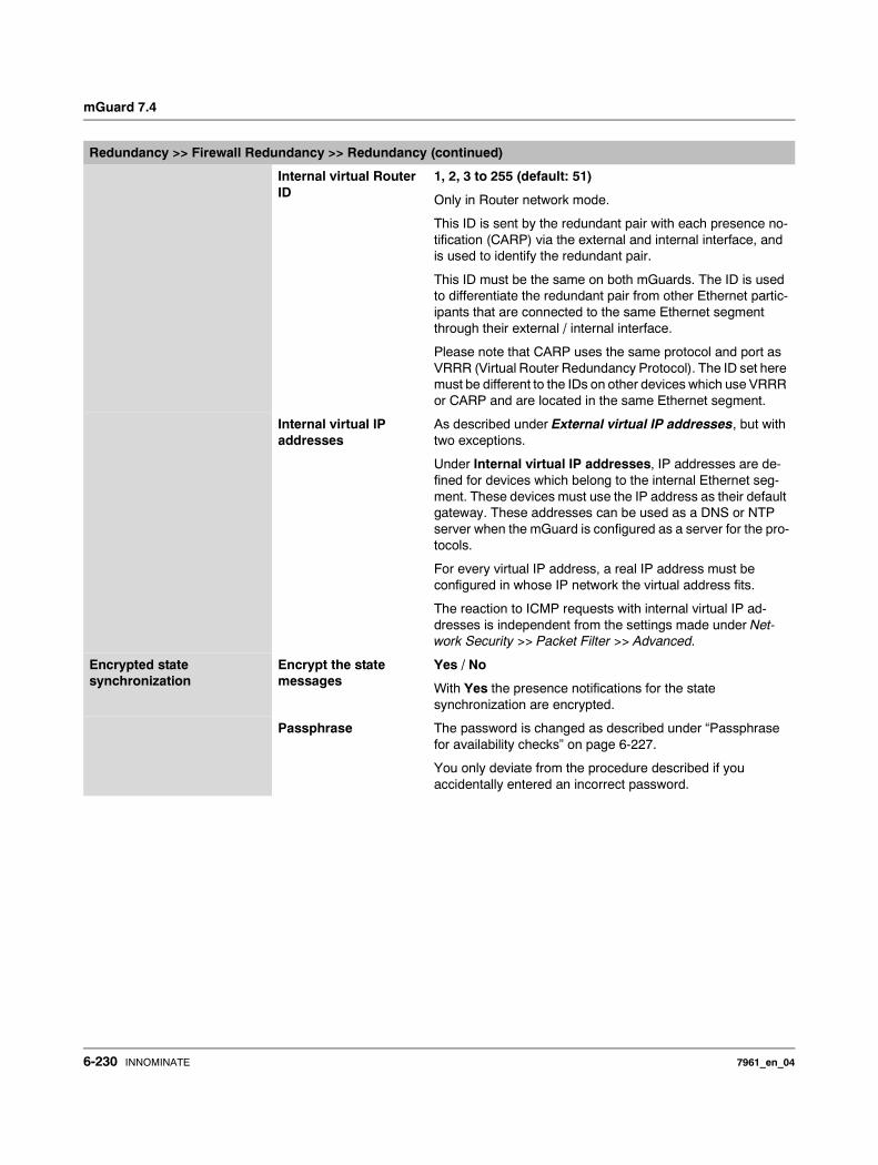
mGuard 7.4
Internal virtual Router ID
1, 2, 3 to 255 (default: 51)
Only in Router network mode.
This ID is sent by the redundant pair with each presence no-tification (CARP) via the external and internal interface, and is used to identify the redundant pair.
This ID must be the same on both mGuards. The ID is used to differentiate the redundant pair from other Ethernet partic-ipants that are connected to the same Ethernet segment through their external / internal interface.
Please note that CARP uses the same protocol and port as VRRR (Virtual Router Redundancy Protocol). The ID set here must be different to the IDs on other devices which use VRRR or CARP and are located in the same Ethernet segment.
Internal virtual IP addresses
As described under External virtual IP addresses, but with two exceptions.
Under Internal virtual IP addresses, IP addresses are de-fined for devices which belong to the internal Ethernet seg-ment. These devices must use the IP address as their default gateway. These addresses can be used as a DNS or NTP server when the mGuard is configured as a server for the pro-tocols.
For every virtual IP address, a real IP address must be configured in whose IP network the virtual address fits.
The reaction to ICMP requests with internal virtual IP ad-dresses is independent from the settings made under Net-work Security >> Packet Filter >> Advanced.
Encrypted state synchronization
Encrypt the state messages
Yes / No
With Yes the presence notifications for the state synchronization are encrypted.
Passphrase The password is changed as described under “Passphrase for availability checks” on page 6-227.
You only deviate from the procedure described if you accidentally entered an incorrect password.
Redundancy >> Firewall Redundancy >> Redundancy (continued)
6-230 INNOMINATE 7961_en_04

Configuration
Procedure for an incorrect password
Case 1: Only one mGuard has an incorrect password. The password changing process has not been started for the other mGuard.
• Reconfigure the mGuard for which the incorrect password was entered with the old password.
• Wait until the mGuard shows that the old password is being used.• Then enter the correct password.
Case 2: The other mGuard is already using the new password.
• Both mGuards must have the status of using an old password but expecting a new one (red X). To get this status, enter random passwords one after the other.
• You then generate a secure password and enter it in both mGuards. This password will then be used immediately without any coordination.
During this procedure, the mGuard which is on standby may enter the “outdated” state briefly, but this automatically resolves itself again.
Encryption Algorithm DES, 3DES, AES-128, AES-192, AES-256
See “Algorithms” on page 6-204.
Checksum algorithm / hash
MD5, SH1, SHA-256, SHA-512
See “Algorithms” on page 6-204.
Interface for state synchro-nisation
Interface used for syn-chronizing the state
Internal Interface / Dedicated Interface
The mGuard centerport supports a Dedicated Interface. This is a reserved, direct Ethernet interface or a dedicated LAN segment through which the state synchronization is sent.
The redundant pair can be connected through an additional dedicated Ethernet interface or an interconnected switch.
On a Dedicated Interface, presence notifications (CARP) are also listened for on the third Ethernet interface. Presence notifications (CARP) are also sent when the mGuard is active.
However, no additional routing is supported for this interface.
Frames received on this interface are not forwarded for secu-rity reasons.
The connection state of the third Ethernet interface can be queried via SNMP.
Redundancy >> Firewall Redundancy >> Redundancy (continued)
If you accidentally entered an incorrect password for an mGuard, you cannot simply enter the password again correctly. Otherwise, it can happen that both mGuards are active after this.
7961_en_04 INNOMINATE 6-231
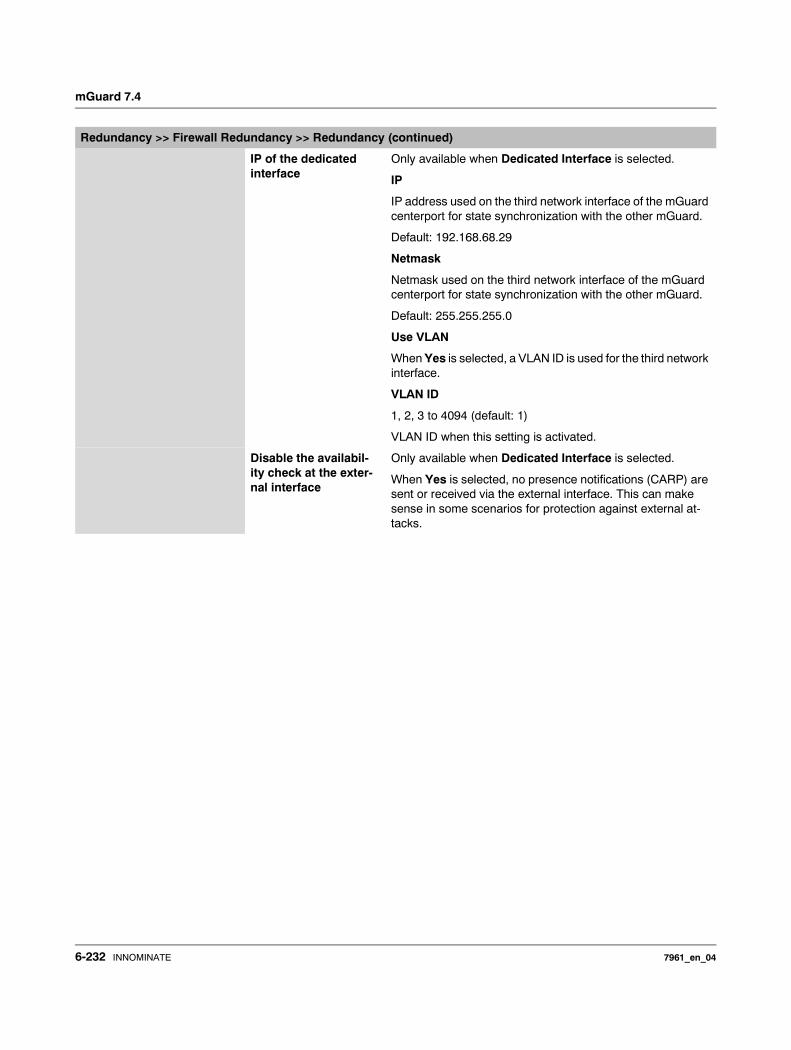
mGuard 7.4
IP of the dedicated interface
Only available when Dedicated Interface is selected.
IP
IP address used on the third network interface of the mGuard centerport for state synchronization with the other mGuard.
Default: 192.168.68.29
Netmask
Netmask used on the third network interface of the mGuard centerport for state synchronization with the other mGuard.
Default: 255.255.255.0
Use VLAN
When Yes is selected, a VLAN ID is used for the third network interface.
VLAN ID
1, 2, 3 to 4094 (default: 1)
VLAN ID when this setting is activated.
Disable the availabil-ity check at the exter-nal interface
Only available when Dedicated Interface is selected.
When Yes is selected, no presence notifications (CARP) are sent or received via the external interface. This can make sense in some scenarios for protection against external at-tacks.
Redundancy >> Firewall Redundancy >> Redundancy (continued)
6-232 INNOMINATE 7961_en_04
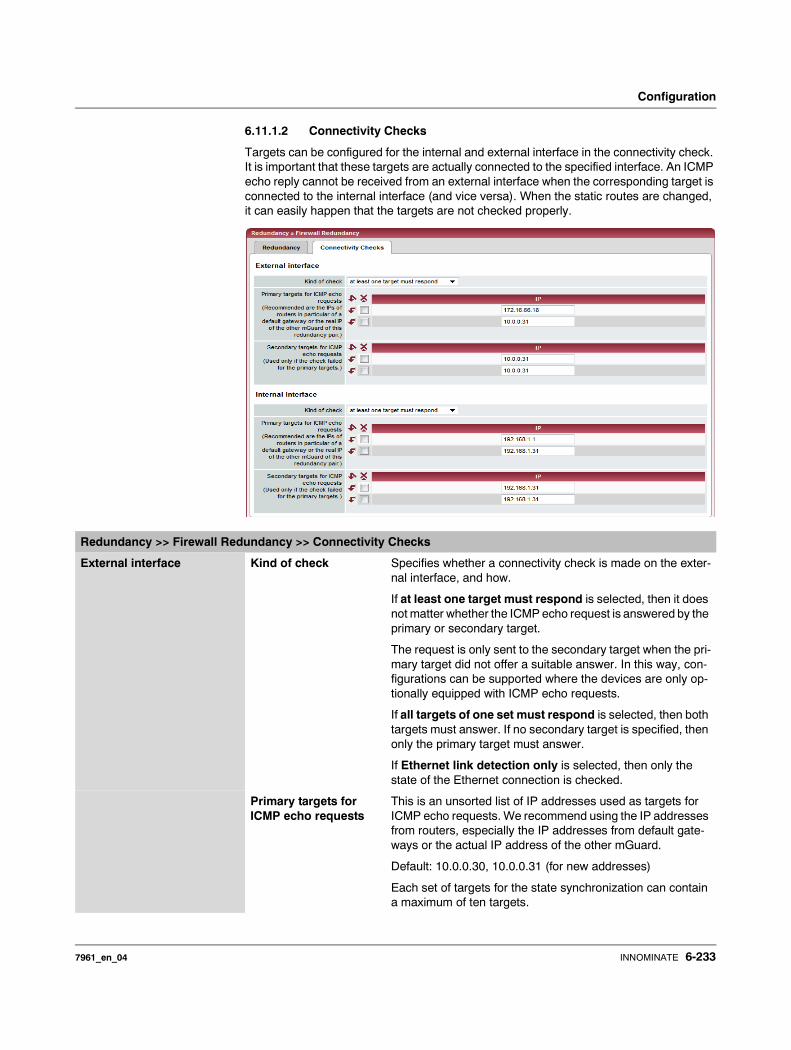
Configuration
6.11.1.2 Connectivity Checks
Targets can be configured for the internal and external interface in the connectivity check. It is important that these targets are actually connected to the specified interface. An ICMP echo reply cannot be received from an external interface when the corresponding target is connected to the internal interface (and vice versa). When the static routes are changed, it can easily happen that the targets are not checked properly.
Redundancy >> Firewall Redundancy >> Connectivity Checks
External interface Kind of check Specifies whether a connectivity check is made on the exter-nal interface, and how.
If at least one target must respond is selected, then it does not matter whether the ICMP echo request is answered by the primary or secondary target.
The request is only sent to the secondary target when the pri-mary target did not offer a suitable answer. In this way, con-figurations can be supported where the devices are only op-tionally equipped with ICMP echo requests.
If all targets of one set must respond is selected, then both targets must answer. If no secondary target is specified, then only the primary target must answer.
If Ethernet link detection only is selected, then only the state of the Ethernet connection is checked.
Primary targets for ICMP echo requests
This is an unsorted list of IP addresses used as targets for ICMP echo requests. We recommend using the IP addresses from routers, especially the IP addresses from default gate-ways or the actual IP address of the other mGuard.
Default: 10.0.0.30, 10.0.0.31 (for new addresses)
Each set of targets for the state synchronization can contain a maximum of ten targets.
7961_en_04 INNOMINATE 6-233
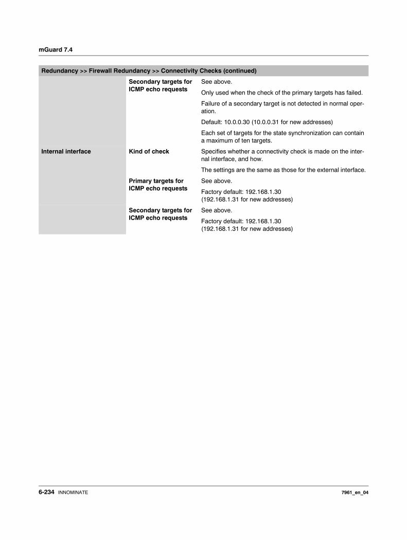
mGuard 7.4
Secondary targets for ICMP echo requests
See above.
Only used when the check of the primary targets has failed.
Failure of a secondary target is not detected in normal oper-ation.
Default: 10.0.0.30 (10.0.0.31 for new addresses)
Each set of targets for the state synchronization can contain a maximum of ten targets.
Internal interface Kind of check Specifies whether a connectivity check is made on the inter-nal interface, and how.
The settings are the same as those for the external interface.
Primary targets for ICMP echo requests
See above.
Factory default: 192.168.1.30 (192.168.1.31 for new addresses)
Secondary targets for ICMP echo requests
See above.
Factory default: 192.168.1.30 (192.168.1.31 for new addresses)
Redundancy >> Firewall Redundancy >> Connectivity Checks (continued)
6-234 INNOMINATE 7961_en_04
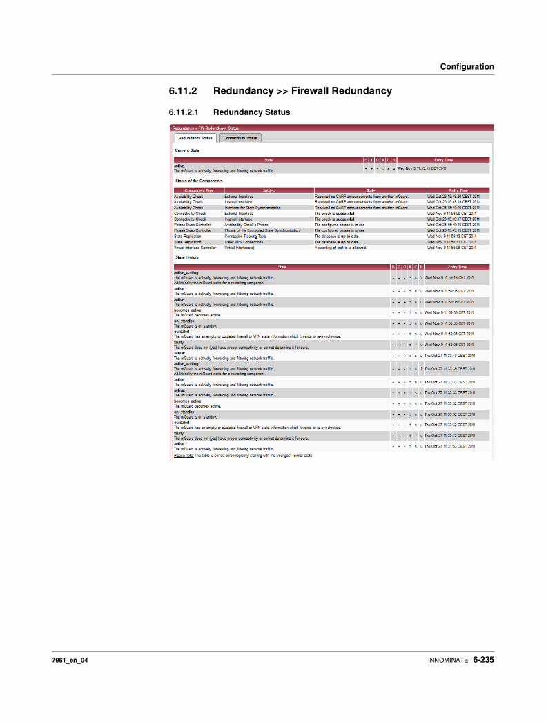
Configuration
6.11.2 Redundancy >> Firewall Redundancy
6.11.2.1 Redundancy Status
7961_en_04 INNOMINATE 6-235
mGuard 7.4
Redundancy >> FW Redundancy Status >> Redundancy Status
Current State The following states are possible:
booting: The mGuard is booting.
faulty: The mGuard is not (yet) connected properly.
outdated: The state synchronization of the databases is not (yet) up-to-date.
on_standby: The mGuard is ready for activation if the other mGuard fails.
becomes_active: The mGuard is preparing for activation as the other mGuard has failed.
active: The mGuard is active.
becomes_standby: The mGuard is switching from the active state into standby mode. The state is changed to outdated, as the status database has to be updated first.
Status of the Components Availability Check Relates to the state of the availability check for the internal or external interface.
The availability check has three possible results.
– Presence notifications (CARP) are not received from any other mGuards.
– Another mGuard is available which will be active or re-main active.
– Another mGuard is available which is active but will re-main “on_standby”.
Connectivity Check Indicates whether the check was successful.
Each interface is checked separately.
State Replication When synchronizing the state, diverse databases are checked as to whether this is up-to-date. With one redundant pair, only one database is active while the other is on standby. A change to this state is also displayed.
– The Connection Tracking Table relates to the firewall state database.
– IPsec VPN connections (with activated VPN redundan-cy).
Virtual Interface Con-troller
All virtual interfaces are checked together to see whether the forwarding of packets is allowed.
6-236 INNOMINATE 7961_en_04
Configuration
State History The table starts with the most recent state.
The abbreviations are as follows:
B Firmware status + Firmware started up completely
- Firmware not yet started up completely
T System time + Valid system time
- Invalid system time
O Timeout of the previous state
+ Timeout
- No timeout
A Availability check ? Unknown state
s Another mGuard is available. This mGuard is active (or is currently being enabled).
f Another mGuard is available. This mGuard is on standby (or is currently switching to standby).
t No other mGuard available
C Connectivity check
? Unknown state
s Check of all components was successful
f Check of at least one component has failed
R State synchroni-sation
? Unknown state
u Database is up-to-date
o Database is obsolete
- Database switching to “on_standby”
+ Database switching to “active”
Redundancy >> FW Redundancy Status >> Redundancy Status (continued)
7961_en_04 INNOMINATE 6-237
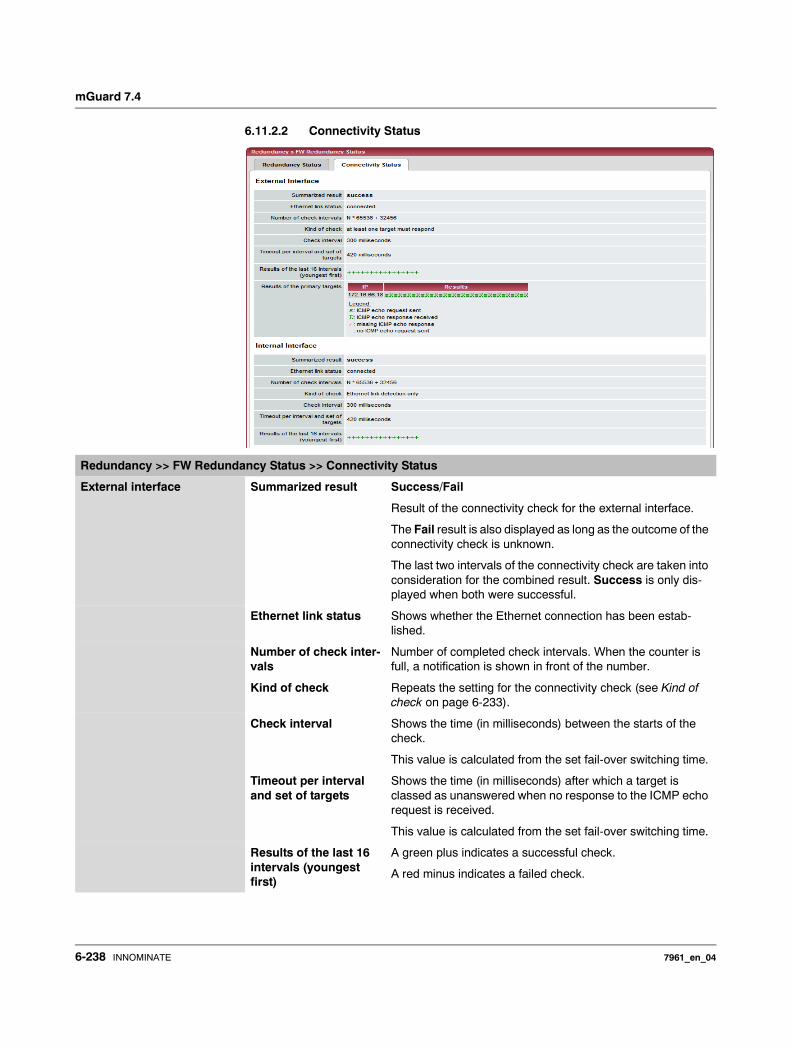
mGuard 7.4
6.11.2.2 Connectivity Status
Redundancy >> FW Redundancy Status >> Connectivity Status
External interface Summarized result Success/Fail
Result of the connectivity check for the external interface.
The Fail result is also displayed as long as the outcome of the connectivity check is unknown.
The last two intervals of the connectivity check are taken into consideration for the combined result. Success is only dis-played when both were successful.
Ethernet link status Shows whether the Ethernet connection has been estab-lished.
Number of check inter-vals
Number of completed check intervals. When the counter is full, a notification is shown in front of the number.
Kind of check Repeats the setting for the connectivity check (see Kind of check on page 6-233).
Check interval Shows the time (in milliseconds) between the starts of the check.
This value is calculated from the set fail-over switching time.
Timeout per interval and set of targets
Shows the time (in milliseconds) after which a target is classed as unanswered when no response to the ICMP echo request is received.
This value is calculated from the set fail-over switching time.
Results of the last 16 intervals (youngest first)
A green plus indicates a successful check.
A red minus indicates a failed check.
6-238 INNOMINATE 7961_en_04
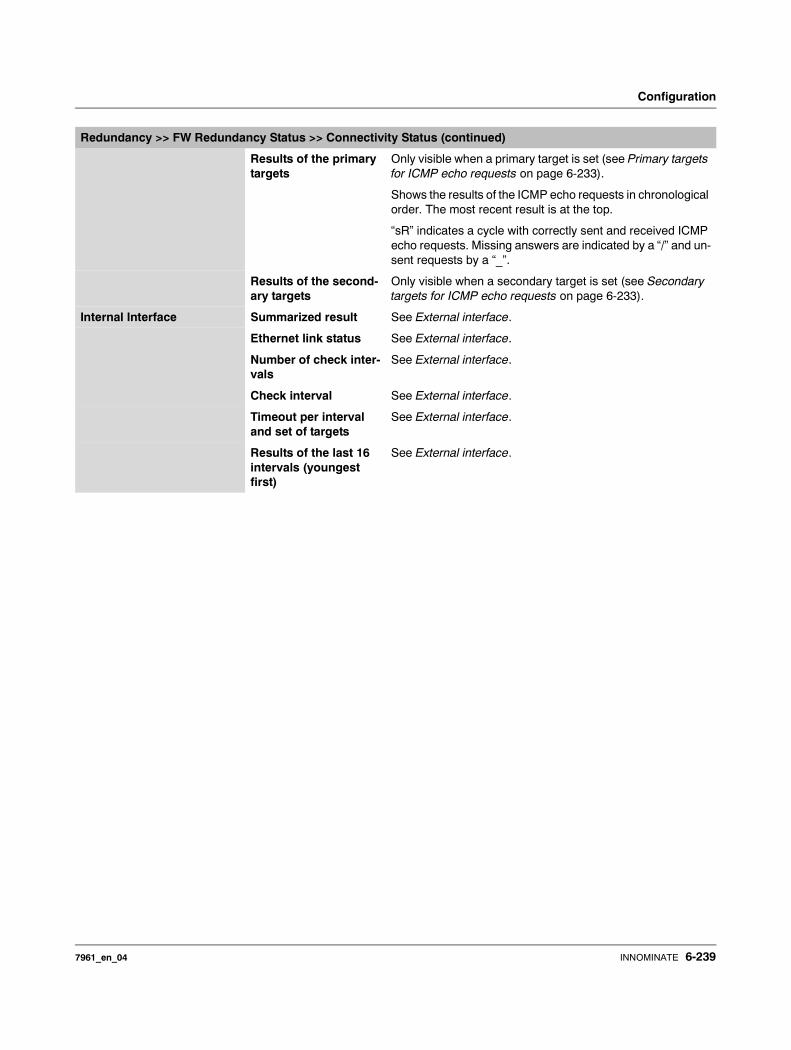
Configuration
Results of the primary targets
Only visible when a primary target is set (see Primary targets for ICMP echo requests on page 6-233).
Shows the results of the ICMP echo requests in chronological order. The most recent result is at the top.
“sR” indicates a cycle with correctly sent and received ICMP echo requests. Missing answers are indicated by a “/” and un-sent requests by a “_”.
Results of the second-ary targets
Only visible when a secondary target is set (see Secondary targets for ICMP echo requests on page 6-233).
Internal Interface Summarized result See External interface.
Ethernet link status See External interface.
Number of check inter-vals
See External interface.
Check interval See External interface.
Timeout per interval and set of targets
See External interface.
Results of the last 16 intervals (youngest first)
See External interface.
Redundancy >> FW Redundancy Status >> Connectivity Status (continued)
7961_en_04 INNOMINATE 6-239
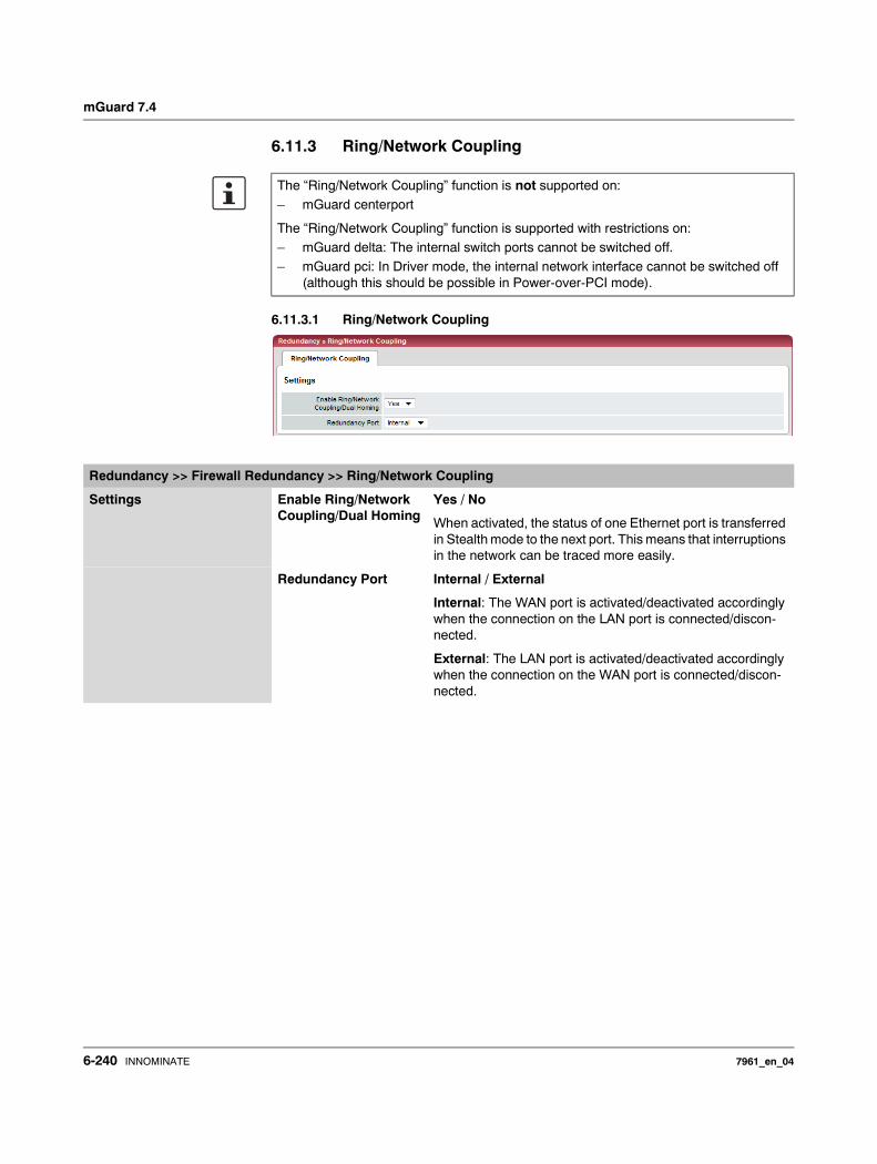
mGuard 7.4
6.11.3 Ring/Network Coupling
6.11.3.1 Ring/Network Coupling
The “Ring/Network Coupling” function is not supported on: – mGuard centerport
The “Ring/Network Coupling” function is supported with restrictions on: – mGuard delta: The internal switch ports cannot be switched off.– mGuard pci: In Driver mode, the internal network interface cannot be switched off
(although this should be possible in Power-over-PCI mode).
Redundancy >> Firewall Redundancy >> Ring/Network Coupling
Settings Enable Ring/Network Coupling/Dual Homing
Yes / No
When activated, the status of one Ethernet port is transferred in Stealth mode to the next port. This means that interruptions in the network can be traced more easily.
Redundancy Port Internal / External
Internal: The WAN port is activated/deactivated accordingly when the connection on the LAN port is connected/discon-nected.
External: The LAN port is activated/deactivated accordingly when the connection on the WAN port is connected/discon-nected.
6-240 INNOMINATE 7961_en_04
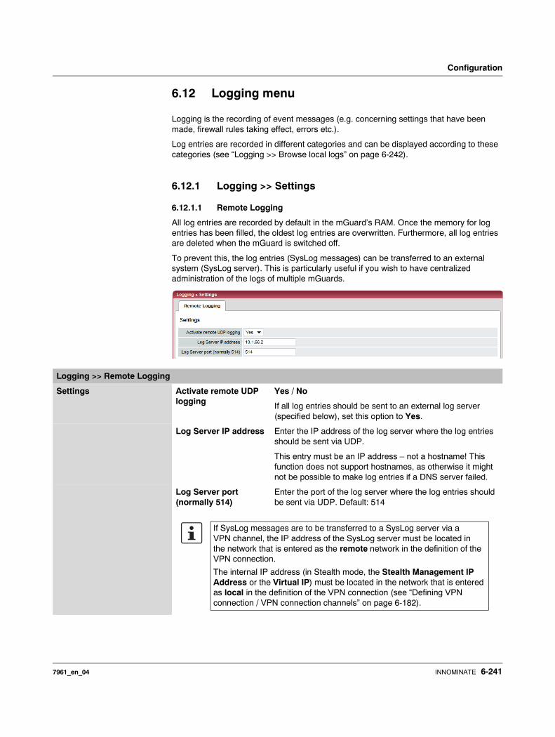
Configuration
6.12 Logging menu
Logging is the recording of event messages (e.g. concerning settings that have been made, firewall rules taking effect, errors etc.).
Log entries are recorded in different categories and can be displayed according to these categories (see “Logging >> Browse local logs” on page 6-242).
6.12.1 Logging >> Settings
6.12.1.1 Remote Logging
All log entries are recorded by default in the mGuard’s RAM. Once the memory for log entries has been filled, the oldest log entries are overwritten. Furthermore, all log entries are deleted when the mGuard is switched off.
To prevent this, the log entries (SysLog messages) can be transferred to an external system (SysLog server). This is particularly useful if you wish to have centralized administration of the logs of multiple mGuards.
Logging >> Remote Logging
Settings Activate remote UDP logging
Yes / No
If all log entries should be sent to an external log server (specified below), set this option to Yes.
Log Server IP address Enter the IP address of the log server where the log entries should be sent via UDP.
This entry must be an IP address – not a hostname! This function does not support hostnames, as otherwise it might not be possible to make log entries if a DNS server failed.
Log Server port (normally 514)
Enter the port of the log server where the log entries should be sent via UDP. Default: 514
If SysLog messages are to be transferred to a SysLog server via a VPN channel, the IP address of the SysLog server must be located in the network that is entered as the remote network in the definition of the VPN connection.
The internal IP address (in Stealth mode, the Stealth Management IP Address or the Virtual IP) must be located in the network that is entered as local in the definition of the VPN connection (see “Defining VPN connection / VPN connection channels” on page 6-182).
7961_en_04 INNOMINATE 6-241
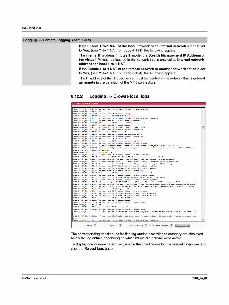
mGuard 7.4
6.12.2 Logging >> Browse local logs
The corresponding checkboxes for filtering entries according to category are displayed below the log entries depending on which mGuard functions were active.
To display one or more categories, enable the checkboxes for the desired categories and click the Reload logs button.
– If the Enable 1-to-1 NAT of the local network to an internal network option is set to Yes, (see “1-to-1 NAT” on page 6-194), the following applies: The internal IP address (in Stealth mode, the Stealth Management IP Address or the Virtual IP) must be located in the network that is entered as Internal network address for local 1-to-1 NAT.
– If the Enable 1-to-1 NAT of the remote network to another network option is set to Yes, (see “1-to-1 NAT” on page 6-194), the following applies: The IP address of the SysLog server must be located in the network that is entered as remote in the definition of the VPN connection.
Logging >> Remote Logging (continued)
6-242 INNOMINATE 7961_en_04
Configuration
6.12.2.1 Log entry categories
General
Log entries which are not assigned to other categories.
Network Security
Logged events are shown here when the logging of firewall events was selected during the definition of firewall rules (Log = Yes).
Log ID and number for tracing errors
Log entries that refer to the firewall rules listed below have a log ID and number. Using this log ID and number, it is possible to trace the firewall rule that the corresponding log entry refers to and that led to the corresponding event.
Firewall rules and their log ID
– Packet filters: Network Security >> Packet Filter >> Incoming Rules menu Network Security >> Packet Filter >> Outgoing Rules menuLog ID: fw-incoming or fw-outgoing
– Firewall rules for VPN connections:IPsec VPN >> Connections >> Edit >> Firewall menu, Incoming / OutgoingLog ID: vpn-fw-in or vpn-fw-out
– Firewall rules for web access through mGuard via HTTPS:
Management >> Web Settings >> Access menuLog ID: fw-https-access
– Firewall rules for web access through mGuard via SNMP: Management >> SNMP >> Query menuLog ID: fw-snmp-access
– Firewall rules for SSH remote access to the mGuard: Management >> System Settings >> Shell Access menuLog ID: fw-ssh-access
– Firewall rules for the user firewall:
Network Security >> User Firewall menu, Firewall rulesLog ID: ufw-
– Rules for NAT, port forwarding:Network >> NAT >> IP and port forwarding menu
Log ID: fw-portforwarding
– Firewall rules for serial port:Network >> Interfaces >> Dial-in menuIncoming RulesLog ID: fw-serial-incomingOutgoing RulesLog ID: fw-serial-outgoing
Accesses through its firewall are not logged in the mGuard rs2000.
7961_en_04 INNOMINATE 6-243
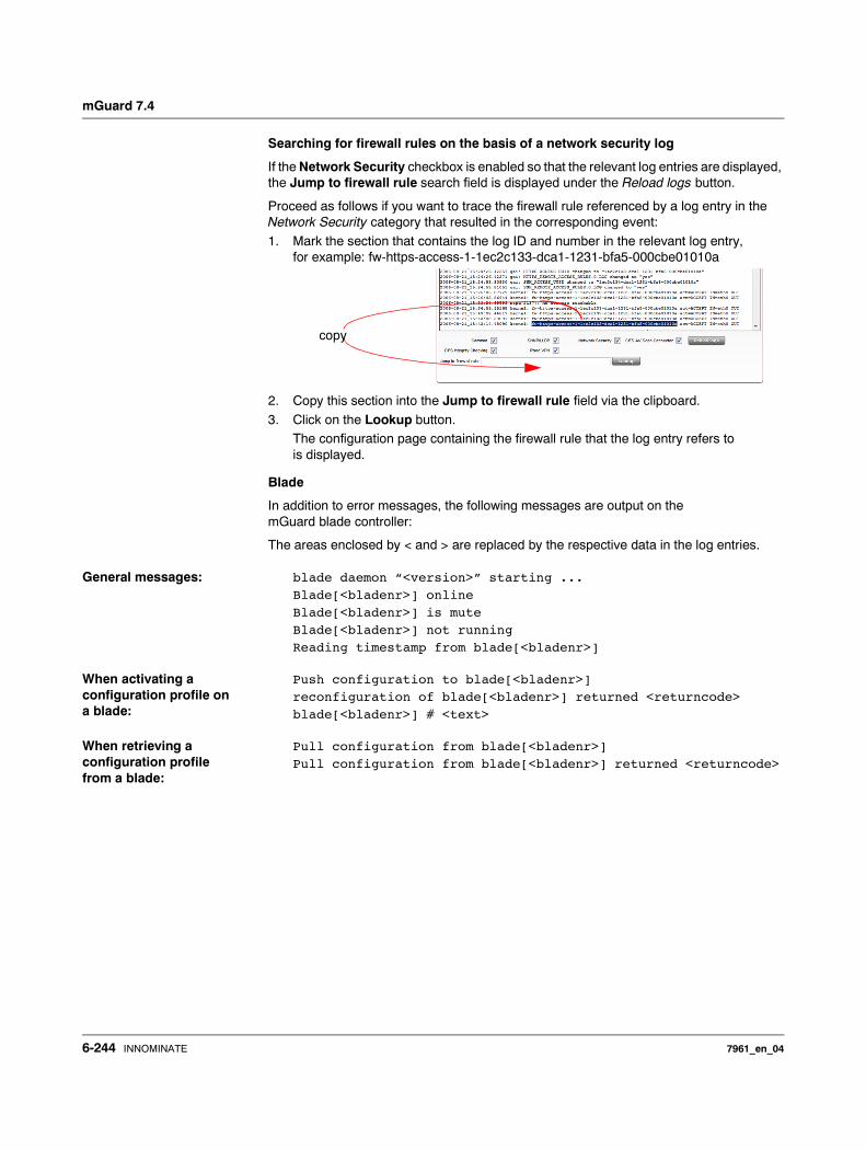
mGuard 7.4
Searching for firewall rules on the basis of a network security log
If the Network Security checkbox is enabled so that the relevant log entries are displayed, the Jump to firewall rule search field is displayed under the Reload logs button.
Proceed as follows if you want to trace the firewall rule referenced by a log entry in the Network Security category that resulted in the corresponding event:
1. Mark the section that contains the log ID and number in the relevant log entry, for example: fw-https-access-1-1ec2c133-dca1-1231-bfa5-000cbe01010a
2. Copy this section into the Jump to firewall rule field via the clipboard.
3. Click on the Lookup button.The configuration page containing the firewall rule that the log entry refers to is displayed.
Blade
In addition to error messages, the following messages are output on the mGuard blade controller:
The areas enclosed by < and > are replaced by the respective data in the log entries.
General messages: blade daemon “<version>” starting ...
Blade[<bladenr>] online
Blade[<bladenr>] is mute
Blade[<bladenr>] not running
Reading timestamp from blade[<bladenr>]
When activating a configuration profile on a blade:
Push configuration to blade[<bladenr>]
reconfiguration of blade[<bladenr>] returned <returncode>
blade[<bladenr>] # <text>
When retrieving a configuration profile from a blade:
Pull configuration from blade[<bladenr>]
Pull configuration from blade[<bladenr>] returned <returncode>
copy
6-244 INNOMINATE 7961_en_04
Configuration
CIFS AV Scan Connector
In this log, messages about the mGuard’s CIFS server, which makes network drives available externally, are displayed.In addition, messages about mounting network drives to be made available externally are also visible.
CIFS Integrity Checking
Messages relating to the integrity check of network drives are displayed in this log.In addition, messages that occur when connecting the network drives and that are required for the integrity check are also visible.
DHCP Server/Relay
Messages from services defined under “Network --> DHCP”.
SNMP/LLDP
Messages from services defined under “Management --> SNMP”.
IPsec VPN
Lists all VPN events.
The format corresponds to the standard Linux format.
Special evaluation programs exist that present information from the logged data in a more readable format.
7961_en_04 INNOMINATE 6-245

mGuard 7.4
6.13 Support menu
6.13.1 Support >> Tools
6.13.1.1 Ping Check
6.13.1.2 DNS Lookup
Support >> Tools >> Ping Check
Ping Check Objective: To check if the remote peer is accessible over a network.
Procedure: • Enter the IP address or remote peer hostname in the Hostname/IP Address field.
Click on the Ping button.You will then receive an appropriate notification.
Support >> Tools >> DNS Lookup
DNS Lookup Objective: To establish which intermediary peers or routers are found on the connection path to a remote peer.
Procedure: • Enter the IP address or hostname of the remote peer to which the route is to be
determined in the Hostname/IP Address field. • If the points on the route are to be given with IP addresses and not hostnames
(if applicable), activate the Do not resolve IP addresses to hostnames checkbox. • Click on the Trace button.
You will then receive an appropriate notification.
6-246 INNOMINATE 7961_en_04

Configuration
6.13.1.3 DNS Lookup
6.13.1.4 IKE Ping
Support >> Tools >> DNS Lookup
DNS Lookup Objective: To establish which hostname belongs to a certain IP addressor which IP address belongs to a certain hostname.
Procedure: • Enter the IP address or hostname in the Hostname field.
• Click on the Lookup button.You will then receive the answer queried by the mGuard according to the DNS configuration.
Support >> Tools >> IKE Ping
IKE Ping Objective: To determine if the VPN gateway software is able to establish a VPN connection, or if a firewall prevents this.
Procedure: • Enter the name or the IP address of the VPN gateway in the Hostname/IP
Address field. • Click on the Ping button.
• You will then receive an appropriate notification.
7961_en_04 INNOMINATE 6-247
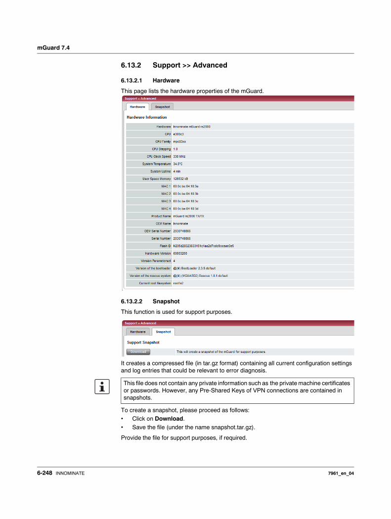
mGuard 7.4
6.13.2 Support >> Advanced
6.13.2.1 Hardware
This page lists the hardware properties of the mGuard.
6.13.2.2 Snapshot
This function is used for support purposes.
It creates a compressed file (in tar.gz format) containing all current configuration settings and log entries that could be relevant to error diagnosis.
To create a snapshot, please proceed as follows:• Click on Download.
• Save the file (under the name snapshot.tar.gz).
Provide the file for support purposes, if required.
This file does not contain any private information such as the private machine certificates or passwords. However, any Pre-Shared Keys of VPN connections are contained in snapshots.
6-248 INNOMINATE 7961_en_04
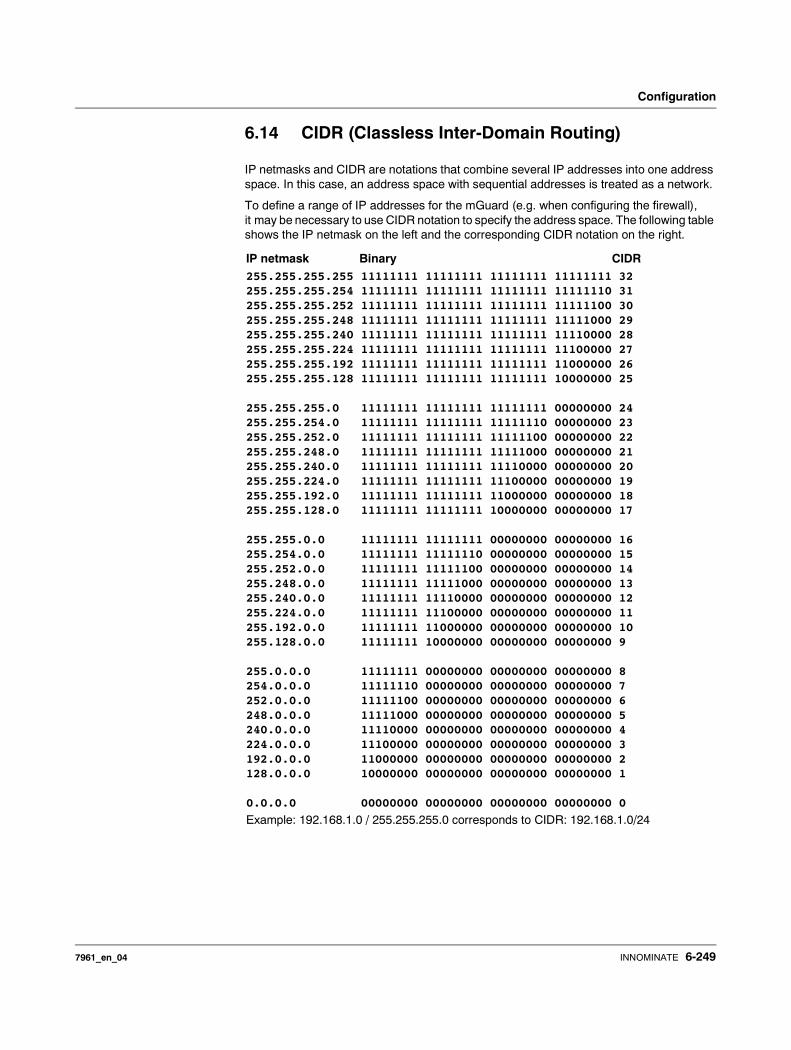
Configuration
6.14 CIDR (Classless Inter-Domain Routing)
IP netmasks and CIDR are notations that combine several IP addresses into one address space. In this case, an address space with sequential addresses is treated as a network.
To define a range of IP addresses for the mGuard (e.g. when configuring the firewall), it may be necessary to use CIDR notation to specify the address space. The following table shows the IP netmask on the left and the corresponding CIDR notation on the right.
IP netmask Binary CIDR255.255.255.255 11111111 11111111 11111111 11111111 32255.255.255.254 11111111 11111111 11111111 11111110 31255.255.255.252 11111111 11111111 11111111 11111100 30255.255.255.248 11111111 11111111 11111111 11111000 29255.255.255.240 11111111 11111111 11111111 11110000 28255.255.255.224 11111111 11111111 11111111 11100000 27255.255.255.192 11111111 11111111 11111111 11000000 26255.255.255.128 11111111 11111111 11111111 10000000 25
255.255.255.0 11111111 11111111 11111111 00000000 24255.255.254.0 11111111 11111111 11111110 00000000 23255.255.252.0 11111111 11111111 11111100 00000000 22255.255.248.0 11111111 11111111 11111000 00000000 21255.255.240.0 11111111 11111111 11110000 00000000 20255.255.224.0 11111111 11111111 11100000 00000000 19255.255.192.0 11111111 11111111 11000000 00000000 18255.255.128.0 11111111 11111111 10000000 00000000 17
255.255.0.0 11111111 11111111 00000000 00000000 16255.254.0.0 11111111 11111110 00000000 00000000 15255.252.0.0 11111111 11111100 00000000 00000000 14255.248.0.0 11111111 11111000 00000000 00000000 13255.240.0.0 11111111 11110000 00000000 00000000 12255.224.0.0 11111111 11100000 00000000 00000000 11255.192.0.0 11111111 11000000 00000000 00000000 10255.128.0.0 11111111 10000000 00000000 00000000 9
255.0.0.0 11111111 00000000 00000000 00000000 8254.0.0.0 11111110 00000000 00000000 00000000 7252.0.0.0 11111100 00000000 00000000 00000000 6248.0.0.0 11111000 00000000 00000000 00000000 5240.0.0.0 11110000 00000000 00000000 00000000 4224.0.0.0 11100000 00000000 00000000 00000000 3192.0.0.0 11000000 00000000 00000000 00000000 2128.0.0.0 10000000 00000000 00000000 00000000 1
0.0.0.0 00000000 00000000 00000000 00000000 0
Example: 192.168.1.0 / 255.255.255.0 corresponds to CIDR: 192.168.1.0/24
7961_en_04 INNOMINATE 6-249
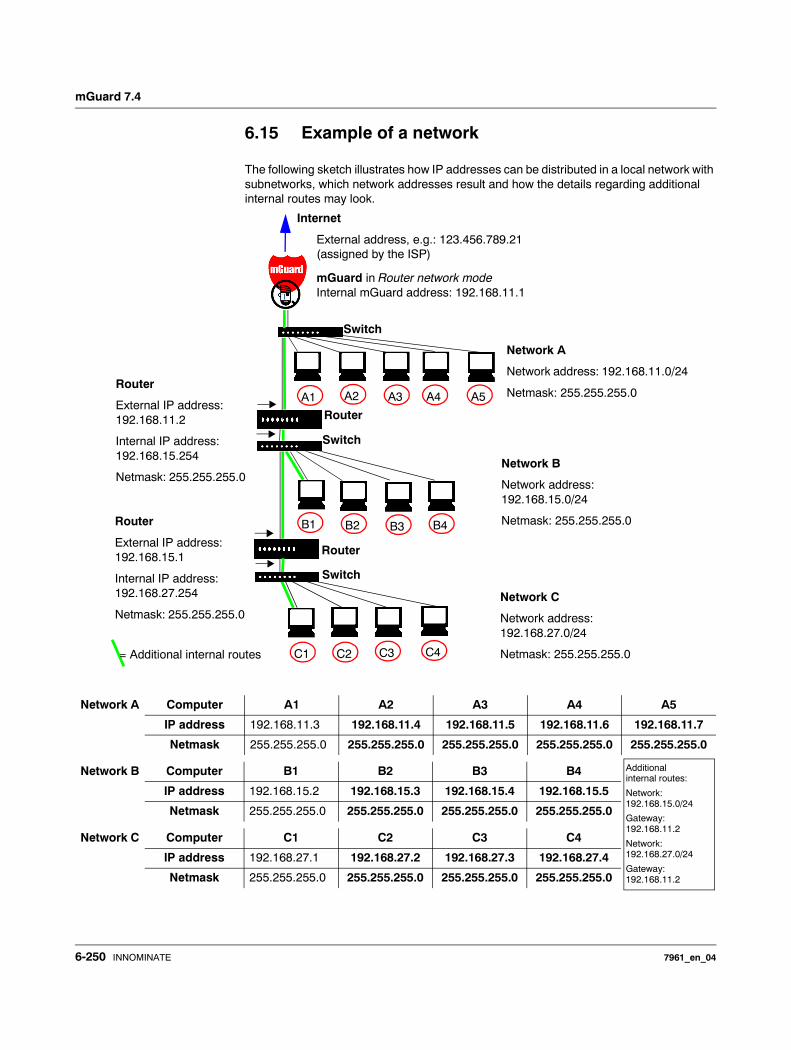
mGuard 7.4
6.15 Example of a network
The following sketch illustrates how IP addresses can be distributed in a local network with subnetworks, which network addresses result and how the details regarding additional internal routes may look.
Internet
External address, e.g.: 123.456.789.21(assigned by the ISP)
mGuard in Router network modeInternal mGuard address: 192.168.11.1
Router
External IP address: 192.168.11.2
Internal IP address: 192.168.15.254
Netmask: 255.255.255.0
Router
External IP address: 192.168.15.1
Internal IP address: 192.168.27.254
Netmask: 255.255.255.0
A1 A2 A3 A4 A5
B1 B2 B3 B4
C1 C2 C3 C4
Network A
Network address: 192.168.11.0/24
Netmask: 255.255.255.0
Network B
Network address: 192.168.15.0/24
Netmask: 255.255.255.0
Network C
Network address: 192.168.27.0/24
Netmask: 255.255.255.0= Additional internal routes
Switch
Switch
Router
Router
Switch
Network A Computer A1 A2 A3 A4 A5
IP address 192.168.11.3 192.168.11.4 192.168.11.5 192.168.11.6 192.168.11.7
Netmask 255.255.255.0 255.255.255.0 255.255.255.0 255.255.255.0 255.255.255.0
Network B Computer B1 B2 B3 B4
IP address 192.168.15.2 192.168.15.3 192.168.15.4 192.168.15.5
Netmask 255.255.255.0 255.255.255.0 255.255.255.0 255.255.255.0
Network C Computer C1 C2 C3 C4
IP address 192.168.27.1 192.168.27.2 192.168.27.3 192.168.27.4
Netmask 255.255.255.0 255.255.255.0 255.255.255.0 255.255.255.0
Additional internal routes:
Network:192.168.15.0/24
Gateway:192.168.11.2
Network:192.168.27.0/24
Gateway:192.168.11.2
6-250 INNOMINATE 7961_en_04
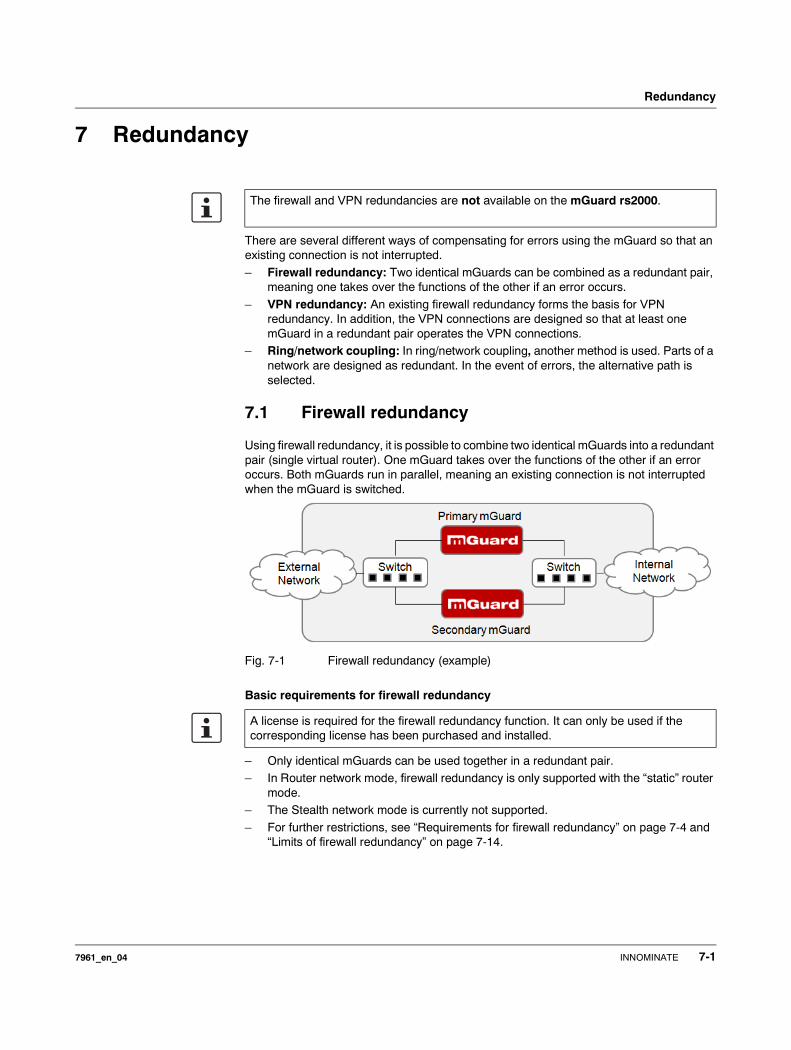
Redundancy
7 Redundancy
There are several different ways of compensating for errors using the mGuard so that an existing connection is not interrupted.
– Firewall redundancy: Two identical mGuards can be combined as a redundant pair, meaning one takes over the functions of the other if an error occurs.
– VPN redundancy: An existing firewall redundancy forms the basis for VPN redundancy. In addition, the VPN connections are designed so that at least one mGuard in a redundant pair operates the VPN connections.
– Ring/network coupling: In ring/network coupling, another method is used. Parts of a network are designed as redundant. In the event of errors, the alternative path is selected.
7.1 Firewall redundancy
Using firewall redundancy, it is possible to combine two identical mGuards into a redundant pair (single virtual router). One mGuard takes over the functions of the other if an error occurs. Both mGuards run in parallel, meaning an existing connection is not interrupted when the mGuard is switched.
Fig. 7-1 Firewall redundancy (example)
Basic requirements for firewall redundancy
– Only identical mGuards can be used together in a redundant pair.– In Router network mode, firewall redundancy is only supported with the “static” router
mode.– The Stealth network mode is currently not supported.
– For further restrictions, see “Requirements for firewall redundancy” on page 7-4 and “Limits of firewall redundancy” on page 7-14.
The firewall and VPN redundancies are not available on the mGuard rs2000.
A license is required for the firewall redundancy function. It can only be used if the corresponding license has been purchased and installed.
7961_en_04 INNOMINATE 7-1
mGuard 7.4
7.1.1 Components in firewall redundancy
Firewall redundancy is comprised of several components:
– Connectivity checkChecks whether the necessary network connections have been established.
– Availability checkChecks whether an active mGuard is available, and whether this should remain active.
– State synchronization of the firewallThe mGuard on standby receives a copy of the current firewall database state.
– Virtual network interfaceProvides virtual IP addresses and MAC addresses that can be used by other devices as routers and default gateways.
– State monitoringCoordinates all components.
– State displayShows the user the state of the mGuard.
Connectivity check
On each mGuard in a redundant pair, checks are constantly made as to whether a connection is established through which the network packets can be forwarded.
Each mGuard checks their own internal and external network interfaces independently from each other. Both interfaces are tested for a continuous connection. This connection must be in place, otherwise the connectivity check will fail.
ICMP echo requests can also be sent (optional). The ICMP echo requests can be set using the Redundancy >> Firewall Redundancy >> Connectivity Checks menu.
Availability check
On each mGuard in a redundant pair, checks are also constantly made as to whether an active mGuard is available and whether this should remain active. A variation of the CARP (Common Address Redundancy Protocol) is used here.
The active mGuard constantly sends presence notifications through its internal and external network interface while both mGuards listen. If a dedicated Ethernet link for the state synchronization of the firewall is available, then the presence notifications are also sent through this link. In this case, the presence display for the external network interface can also be suppressed.
The availability check fails if an mGuard does not receive any presence notifications within a certain time. The check will also fail if an mGuard receives presence notifications with a lower priority than its own.
The data is always transmitted through the physical network interface, and never through the virtual network interface.
7-2 INNOMINATE 7961_en_04
Redundancy
State synchronisation
The mGuard on standby receives a copy of the state on the currently active mGuard.
This includes a database containing the forwarded network connections. This database is filled and updated constantly by the forwarded network packets. It is protected against unauthorized access. The data is transmitted through the physical LAN interface, and never through the virtual network interface.
To keep internal data traffic to a minimum, a VLAN can be configured so that it stores the synchronization data in a separate multicast and broadcast domain.
Virtual IP addresses
Each mGuard is configured with virtual IP addresses. The number of addresses depends on the network mode used. Both mGuards in a redundant pair must be assigned the same virtual IP addresses. The virtual IP addresses are required by the mGuard to establish virtual network interfaces.
Two virtual IP addresses are required in Router network mode, while others can be created. One virtual IP address is required for the external network interface, and the other for the internal network interface.
These IP addresses are used as a gateway for routing devices located in the external or internal LAN. In this way, the devices can benefit from the high availability which occurs through the use of both redundant mGuards.
The redundant pair automatically defines MAC addresses for the virtual network interface. These MAC addresses are identical for the redundant pair. In Router network modes, both mGuards share a MAC address for the virtual network interface connected to the external and internal Ethernet segment.
In Router network mode, the mGuards support forwarding of special UDP/TCP ports from a virtual IP address to other IP addresses, provided the other IP addresses can be reached by the mGuard. In addition, the mGuard also masks data with virtual IP addresses when masquerading rules are set up.
State monitoring
State monitoring is used to decide whether the mGuard is active, on standby or has an error. Each mGuard decides independently on its own state depending on the information provided by other components. State monitoring ensures that two mGuards are not active at the same time.
State display
The state display contains detailed information on the firewall redundancy state. A summary of the state can be called up using the Redundancy >> Firewall Redundancy >> Redundancy or Redundancy >> Firewall Redundancy >> Connectivity Checks menu.
7961_en_04 INNOMINATE 7-3
mGuard 7.4
7.1.2 Interaction of the firewall redundancy components
During operation, the components work together as follows. Both mGuards make ongoing connectivity checks for both network interfaces (internal and external). In addition, an ongoing availability check is made. Each mGuard listens continuously for presence notifications (CARP) and the active mGuard also sends them.
Based on the information from the connectivity and availability checks, the state monitoring is then aware of the mGuard state. State monitoring ensures that the active mGuard mirrors its data onto the other mGuard (state synchronization).
7.1.3 Accepting the firewall redundancy settings from previous versions
Existing configuration profiles on firmware version 6.1.x (and earlier) can be imported with certain restrictions. Please contact Innominate for more information.
7.1.4 Requirements for firewall redundancy
– The firewall redundancy function can only be activated when a suitable license key is installed.(See under: Redundancy >> Firewall Redundancy >> Redundancy >> Enable redundancy)
– Redundancy >> Firewall Redundancy >> Redundancy >> Interface used for synchronizing the stateThe Dedicated Interface value is only accepted on mGuards which have more than two physical, separate Ethernet interfaces. At the moment, this applies to the mGuard centerport.
– Each set of targets for the connectivity check can contain more than ten targets (a fail-over time cannot be guaranteed without an upper limit).
Redundancy >> Firewall Redundancy >> Redundancy– >> External interface >> Primary targets for ICMP echo requests– >> External interface >> Secondary targets for ICMP echo requests– >> Internal interface >> Primary targets for ICMP echo requests– >> Internal interface >> Secondary targets for ICMP echo requestsIf at least one target must respond or all targets of one set must respond is selected under External interface >> Kind of check, then External interface >> Primary targets for ICMP echo requests cannot be empty.This also applies to the internal interface.
– In Router network mode, at least one external and one internal virtual IP address must be set. A virtual IP address cannot be listed twice.
7-4 INNOMINATE 7961_en_04
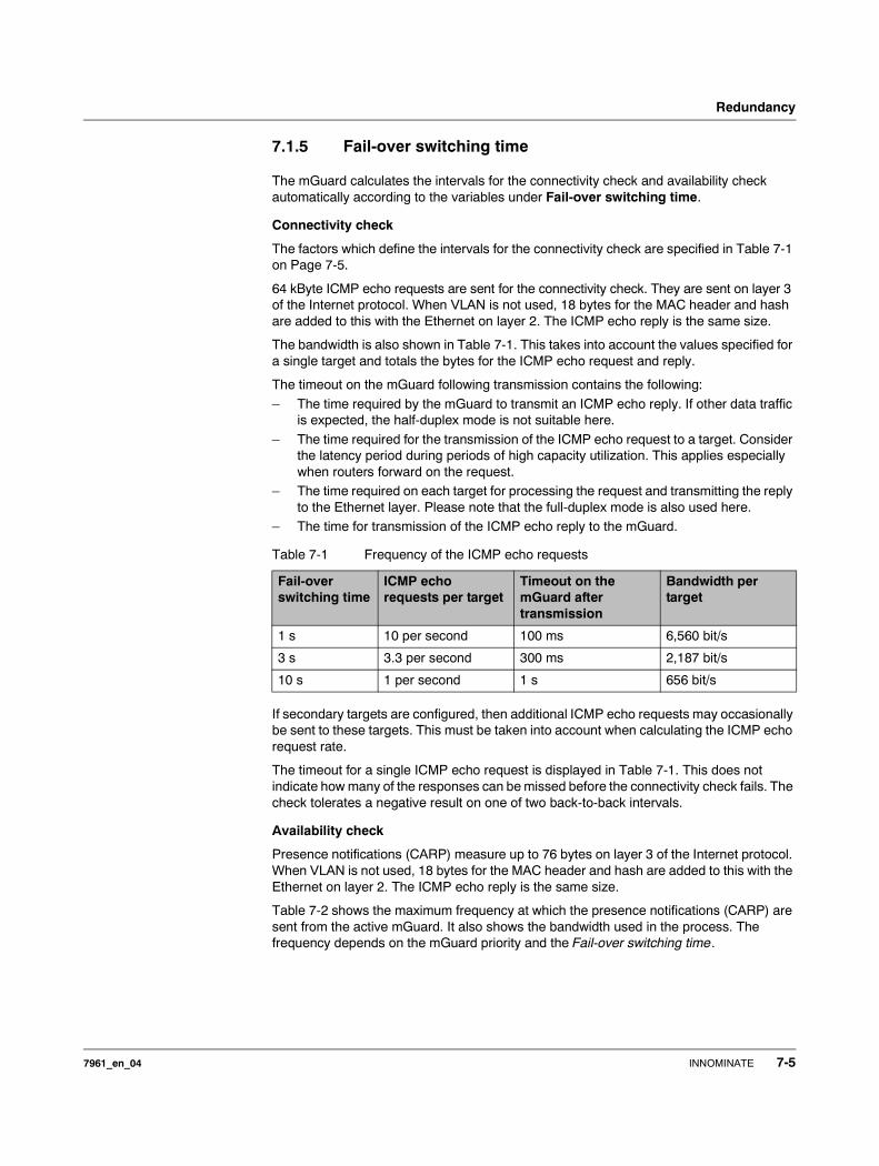
Redundancy
7.1.5 Fail-over switching time
The mGuard calculates the intervals for the connectivity check and availability check automatically according to the variables under Fail-over switching time.
Connectivity check
The factors which define the intervals for the connectivity check are specified in Table 7-1 on Page 7-5.
64 kByte ICMP echo requests are sent for the connectivity check. They are sent on layer 3 of the Internet protocol. When VLAN is not used, 18 bytes for the MAC header and hash are added to this with the Ethernet on layer 2. The ICMP echo reply is the same size.
The bandwidth is also shown in Table 7-1. This takes into account the values specified for a single target and totals the bytes for the ICMP echo request and reply.
The timeout on the mGuard following transmission contains the following:
– The time required by the mGuard to transmit an ICMP echo reply. If other data traffic is expected, the half-duplex mode is not suitable here.
– The time required for the transmission of the ICMP echo request to a target. Consider the latency period during periods of high capacity utilization. This applies especially when routers forward on the request.
– The time required on each target for processing the request and transmitting the reply to the Ethernet layer. Please note that the full-duplex mode is also used here.
– The time for transmission of the ICMP echo reply to the mGuard.
If secondary targets are configured, then additional ICMP echo requests may occasionally be sent to these targets. This must be taken into account when calculating the ICMP echo request rate.
The timeout for a single ICMP echo request is displayed in Table 7-1. This does not indicate how many of the responses can be missed before the connectivity check fails. The check tolerates a negative result on one of two back-to-back intervals.
Availability check
Presence notifications (CARP) measure up to 76 bytes on layer 3 of the Internet protocol. When VLAN is not used, 18 bytes for the MAC header and hash are added to this with the Ethernet on layer 2. The ICMP echo reply is the same size.
Table 7-2 shows the maximum frequency at which the presence notifications (CARP) are sent from the active mGuard. It also shows the bandwidth used in the process. The frequency depends on the mGuard priority and the Fail-over switching time.
Table 7-1 Frequency of the ICMP echo requests
Fail-over switching time
ICMP echo requests per target
Timeout on the mGuard after transmission
Bandwidth per target
1 s 10 per second 100 ms 6,560 bit/s
3 s 3.3 per second 300 ms 2,187 bit/s
10 s 1 per second 1 s 656 bit/s
7961_en_04 INNOMINATE 7-5
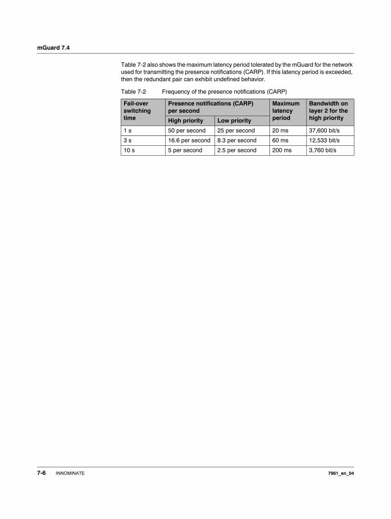
mGuard 7.4
Table 7-2 also shows the maximum latency period tolerated by the mGuard for the network used for transmitting the presence notifications (CARP). If this latency period is exceeded, then the redundant pair can exhibit undefined behavior.
Table 7-2 Frequency of the presence notifications (CARP)
Fail-over switching time
Presence notifications (CARP) per second
Maximum latency period
Bandwidth on layer 2 for the high priorityHigh priority Low priority
1 s 50 per second 25 per second 20 ms 37,600 bit/s
3 s 16.6 per second 8.3 per second 60 ms 12,533 bit/s
10 s 5 per second 2.5 per second 200 ms 3,760 bit/s
7-6 INNOMINATE 7961_en_04
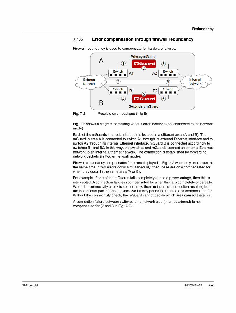
Redundancy
7.1.6 Error compensation through firewall redundancy
Firewall redundancy is used to compensate for hardware failures.
Fig. 7-2 Possible error locations (1 to 8)
Fig. 7-2 shows a diagram containing various error locations (not connected to the network mode).
Each of the mGuards in a redundant pair is located in a different area (A and B). The mGuard in area A is connected to switch A1 through its external Ethernet interface and to switch A2 through its internal Ethernet interface. mGuard B is connected accordingly to switches B1 and B2. In this way, the switches and mGuards connect an external Ethernet network to an internal Ethernet network. The connection is established by forwarding network packets (in Router network mode).
Firewall redundancy compensates for errors displayed in Fig. 7-2 when only one occurs at the same time. If two errors occur simultaneously, then these are only compensated for when they occur in the same area (A or B).
For example, if one of the mGuards fails completely due to a power outage, then this is intercepted. A connection failure is compensated for when this fails completely or partially. When the connectivity check is set correctly, then an incorrect connection resulting from the loss of data packets or an excessive latency period is detected and compensated for. Without the connectivity check, the mGuard cannot decide which area caused the error.
A connection failure between switches on a network side (internal/external) is not compensated for (7 and 8 in Fig. 7-2).
7961_en_04 INNOMINATE 7-7
mGuard 7.4
7.1.7 Handling firewall redundancy in extreme situations
Restoration in the event of a network lobotomy
A network lobotomy occurs when a redundant pair is separated into two mGuards which operate independently from one another. In this case, each mGuard deals with its own tracking information as both mGuards can no longer communicate via layer 2. A network lobotomy can be triggered by a rare and unfortunate combination of network settings, network failures and firewall redundancy settings.
Each mGuard is active during a network lobotomy. The following occurs after the network lobotomy has been rectified: If the mGuards have different priorities, then the mGuard with the higher priority is enabled and the other switches to standby. If both mGuards have the same priority, then an identifier sent with the presence notifications (CARP) decides which mGuard is enabled.
Both mGuards manage their own firewall state during the network lobotomy. The mGuard which is enabled keeps its state. Connections on the other mGuard which were established during the lobotomy are dropped.
Fail-over when establishing complex connections
Complex connections are network protocols which are based on different IP connections. One example of this is the FTP protocol. In an FTP protocol, the client establishes a control channel for a TCP connection. The server is then expected to open another TCP connection over which the client can then transmit data. The data channel on port 20 of the server is set up while the control channel on port 21 of the server is being established.
If the corresponding connection tracking is activated on the mGuard (see “Advanced” on page 6-147), then complex connections of this type are tracked. In this case, the administrator only needs to create a firewall rule on the mGuard which allows the client to establish a control channel to the FTP server. The mGuard permits the establishment of a data channel by the server automatically, regardless of whether this is planned by the firewall rules.
The tracking of complex connections is a part of the firewall state synchronization. However, to establish a short latency period, the mGuard forwards the network packets independently from the update of the firewall state synchronization which they caused themselves.
Therefore, it can occur that a state change for the complex connection is not forwarded on to the mGuard on standby for a very brief period when the active mGuard fails. In this case, tracking of the connection to the mGuard which is active after the fail-over is not continued correctly. This cannot be corrected by the mGuard. The data connection is then reset or interrupted.
Fail-over when establishing semi-unidirectional connections
A semi-unidirectional connection relates to a single IP connection (such as UDP connections) where the data only travels in one direction after the connection is established with a bidirectional handshake.
The data flows from the responder to the initiator. The initiator only sends data packets at the very start.
The following applies only to certain protocols which are based on UDP. Data always flows in both directions on TCP connections.
The situations described here only occur rarely.
7-8 INNOMINATE 7961_en_04
Redundancy
If the firewall of the mGuard is arranged so that it only accepts data packets from the initiator, then the firewall will accept all related answers. This is irrespective of whether a firewall rule is available or not.
It is feasible that the mGuard has allowed the initiating data packet to pass and has then failed before the corresponding connection entry has been made in the other mGuard. The other mGuard may then reject the answers as soon as it becomes the active mGuard.
The mGuard cannot correct this situation due to the unidirectional connection. As a countermeasure, the firewall can be configured so that the connection can be established in both directions. This is normally already managed through the protocol layer, and does not need to be assigned additionally.
Loss of data packets during state synchronization
If data packets are lost during state synchronization, then this is detected automatically by the mGuard, which then requests the active mGuard to send the data again.
This request must be answered within a certain time, otherwise the mGuard on standby is assigned the “outdated” state and asks the active mGuard for a complete copy of all state information.
The response time is calculated automatically from the fail-over switching time. This is longer than the time for presence notifications (CARP), but shorter than the upper limit of the fail-over switching time.
Loss of presence notifications (CARP) during transmission
A single loss of presence notifications (CARP) is tolerated by the mGuard, but not for the next presence notifications (CARP). This applies to the availability check on each individual network interface, even when these are checked simultaneously. It is therefore very unlikely that the availability check will fail as a result of a very brief network interruption.
Loss of ICMP echo requests/replies during transmission
ICMP echo requests or replies are important for the connectivity check. Losses are always observed, but are tolerated under certain circumstances.
The following measures can be used to increase the tolerance level on ICMP echo requests.– Select at least one target must respond under Kind of check in the Redundancy >>
Firewall Redundancy >> Connectivity Checks menu.– Also define a secondary set of targets here. The tolerance for losing ICMP echo
requests can be further increased when the targets of unreliable connections are entered under both sets (primary and secondary) or listed several times within a set.
Restoring the primary mGuard following a failure
If a redundant pair with different priorities is defined, then the secondary mGuard becomes active if the connection fails. The primary mGuard is enabled again after the failure has been rectified. The secondary mGuard receives a presence notification (CARP) and returns to standby mode.
State synchronisation
If the primary mGuard should be enabled again after a failure of the internal network connection, then the mGuard may contain an obsolete copy of the firewall database. This database must be updated before the connection is established again. The primary mGuard ensures that it receives an up-to-date copy before being enabled.
7961_en_04 INNOMINATE 7-9
mGuard 7.4
7.1.8 Interaction with other devices
Virtual and actual IP addresses
In firewall redundancy in Router network mode, the mGuard uses actual IP addresses to communicate with other network devices.
Virtual IP addresses are used in the following two cases:– Virtual IP addresses are used when establishing and operating VPN connections.– If DNS and NTP are used according to the configuration, then these are offered to
internal virtual IP addresses.
The usage of actual (management) IP addresses is especially important for the connectivity check and availability check. Therefore, the actual (management) IP address must be configured so that the mGuard can establish the required connections.
The following are examples of mGuard communication:– With NTP servers to synchronize the time
– With DNS servers to resolve the host name (especially those from VPN partners)– To register its IP address with a DynDNS service– To send SNMP traps
– To forward log messages to a syslog server– To download a CRL from a HTTP(S) server– To authenticate a user through a RADIUS server
– To download a configuration profile through a HTTPS server– To download a firmware update from a HTTPS server
In firewall redundancy in the Router network mode, devices connected to the same LAN segment as the redundant pair must use their respective virtual IP addresses as gateways for their routes. If these devices would use the actual IP address of one of the two mGuards, then this would work until this mGuard fails. However, the other mGuard cannot take over the function in this case.
7-10 INNOMINATE 7961_en_04
Redundancy
Targets for the connectivity check
If a target is set for ICMP echo requests in the connectivity check, then these requests must be answered within a certain time, even if the network is loaded with other data. The network path between the redundant pair and these targets must be set so that it is also able to forward on the ICMP answers when under heavy load. Otherwise, the connectivity check for an mGuard may fail by mistake.
Targets can be configured for the internal and external interface in the connectivity check (see “Connectivity Checks” on page 6-233). It is important that these targets are actually connected to the specified interface. An ICMP echo reply cannot be received from an external interface when the target is connected to the internal interface (and vice versa). When the static routes are changed, it can easily happen that the configuration of the targets is not adjusted properly.
The targets for the connectivity check should be well thought out. Without a connectivity check, just two errors can lead to a network lobotomy.
A network lobotomy is prevented when the targets for both mGuards are identical and all targets have to answer the request. However, a disadvantage of this method is that the connectivity check fails more often when one of the targets is not readily available.
In Router network mode, we recommend defining a readily available device as the target on the external interface. This can be the default gateway for the redundant pair (e.g. a virtual router comprised of two independent devices). In this case, either no targets or a selection of targets should be defined on the internal interface.
Please also note the following information when using a virtual router comprised of two devices as the default gateway for a redundant pair. If these devices use VRRP to synchronize their virtual IP, then a network lobotomy could split the virtual IP of this router into two identical copies. These routers could use a dynamic routing protocol, and only one may be selected for the data flows of the network which is monitored by the mGuard. Only this router should keep the virtual IP. Otherwise, you can define targets which are accessible via this route in the connectivity check. The virtual IP address of the router would then not be a sensible target.
Redundant group
Several redundant pairs can be connected within a LAN segment (redundant group). A value is defined as an identifier (through the router ID) for each virtual presence of the redundant pair. As long as these identifiers are different, the redundant pairs do not come into conflict with each other.
Data traffic
The mGuard on standby is assigned the “outdated” state as a result of a high latency period in a network used for updating the state synchronization or a serious data loss in this network. Provided no more than two back-to-back updates are lost, this does not occur. The mGuard on standby automatically requests a repeat of the update. The latency period requirements are the same as those detailed under “Fail-over switching time” on page 7-5.
7961_en_04 INNOMINATE 7-11
mGuard 7.4
Sufficient bandwidth
The data traffic generated as a result of the connectivity check, availability check and state synchronization uses bandwidth in the network. The connectivity check also generates complicated calculations. There are several ways to limit this or stop it completely.
If the influence on other devices is unacceptable:
– The connectivity check must either be deactivated, or must only relate to the actual IP address of the other mGuard.
– The data traffic generated by the connectivity check and state synchronization must be moved to a separate VLAN.
– Switches must be used which allow separation of the VLANs.
Dedicated interface
The mGuard centerport supports a Dedicated Interface. This is a reserved, direct Ethernet interface or a dedicated LAN segment through which the state synchronization is sent. In this way, the load is physically separated from the internal LAN segment.
X.509 certificates for SSH clients
The mGuard supports the authentication of SSH clients using X.509 certificates. It is sufficient to configure CA certificates that are required for the establishment and validity check of a certificate chain. This certificate chain must exist between the CA certificate on the mGuard and the X.509 certificate shown to the SSH client (see “Shell Access” on page 6-11).
If the validity period of the client certificate is checked by the mGuard (see “Certificate settings” on page 6-129), then new CA certificates must be configured on the mGuard at some point. This must take place before the SSH clients use their new client certificates.
If the CRL check is activated (under Authentication >> Certificates >> Certificate settings), then one URL per CA certificate must be maintained where the corresponding CRL is available. The URL and CRL must be published before the mGuard uses the CA certificates in order to confirm the validity of the certificates displayed by the VPN partners.
7-12 INNOMINATE 7961_en_04
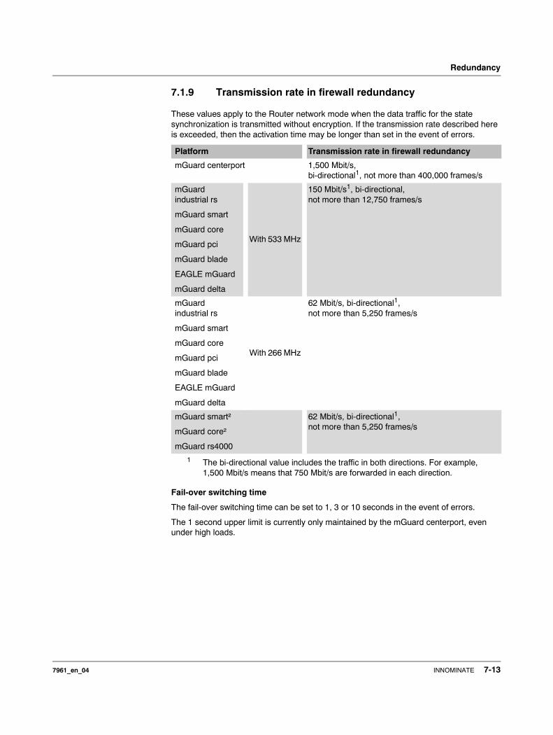
Redundancy
7.1.9 Transmission rate in firewall redundancy
These values apply to the Router network mode when the data traffic for the state synchronization is transmitted without encryption. If the transmission rate described here is exceeded, then the activation time may be longer than set in the event of errors.
Fail-over switching time
The fail-over switching time can be set to 1, 3 or 10 seconds in the event of errors.
The 1 second upper limit is currently only maintained by the mGuard centerport, even under high loads.
Platform Transmission rate in firewall redundancy
mGuard centerport 1,500 Mbit/s, bi-directional1, not more than 400,000 frames/s
1 The bi-directional value includes the traffic in both directions. For example, 1,500 Mbit/s means that 750 Mbit/s are forwarded in each direction.
mGuard industrial rs
mGuard smart
mGuard core
mGuard pci
mGuard blade
EAGLE mGuard
mGuard delta
With 533 MHz
150 Mbit/s1, bi-directional, not more than 12,750 frames/s
mGuard industrial rs
mGuard smart
mGuard core
mGuard pci
mGuard blade
EAGLE mGuard
mGuard delta
With 266 MHz
62 Mbit/s, bi-directional1, not more than 5,250 frames/s
mGuard smart²
mGuard core²
mGuard rs4000
62 Mbit/s, bi-directional1, not more than 5,250 frames/s
7961_en_04 INNOMINATE 7-13
mGuard 7.4
7.1.10 Limits of firewall redundancy
– In Router network mode, firewall redundancy is only supported with the “static” mode.
– Access to the mGuard via the HTTPS, SNMP and SSH management protocols is only possible with an actual IP address from each mGuard. Access attempts to virtual addresses are rejected.
– The following features cannot be used with firewall redundancy.
– A secondary external Ethernet interface– A DHCP server– A DHCP relay– A SEC-Stick server– A user firewall– CIFS Integrity Monitoring
– The redundant pair must have the same configuration. Take this into account when making the following settings:– NAT settings (masquerading, port forwarding and 1-to-1 NAT)– Flood Protection– Packet filter (firewall rules, MAC filter, advanced settings) – Queues and rules for QoS
– Some network connections may be interrupted following a network lobotomy.See “Restoration in the event of a network lobotomy” on page 7-8.
– After a fail-over, semi-unidirectional or complex connections that were established in the second before the fail-over may be interrupted. See “Fail-over when establishing complex connections” on page 7-8 and “Fail-over when establishing semi-unidirectional connections” on page 7-8.
– Firewall redundancy does not support the mGuard pci in Driver mode.– The state synchronization does not replicate the connection tracking entries for ICMP
echo requests forwarded by the mGuard. Therefore, ICMP echo replies can be dropped according to the firewall rules if they only reach the mGuard after the fail-over is completed. Please note that ICMP echo replies are not suitable for measuring the fail-over switching time.
– Masquerading is carried out so that the sender is hidden behind the first virtual IP address or the first internal IP address. This is different to masquerading on the mGuard without firewall redundancy. When firewall redundancy is not activated, the external or internal IP address where the sender is hidden is specified in a routing table.
7-14 INNOMINATE 7961_en_04
Redundancy
7.2 VPN redundancy
VPN redundancy can only be used together with firewall redundancy.
The concept is the same as for firewall redundancy. In order to intercept an error in the system environment, the activity is transmitted from the active mGuard to the mGuard on standby.
At each point in time, at least one mGuard in the redundant pair operates the VPN connection (except in the event of a network lobotomy).
Basic requirements for VPN redundancy
VPN redundancy does not have any of its own variables. It currently does not have its own menu in the user interface – it is activated together with firewall redundancy instead.
VPN redundancy can only be used if the corresponding license has been purchased and installed on the mGuard.
As VPN connections are required for VPN redundancy, an additional VPN license is also necessary.
If you only have the license for firewall redundancy and VPN connections are installed, then VPN redundancy cannot be activated. An error message is displayed as soon as an attempt is made to use firewall redundancy.
Only identical mGuards can be used together in a redundant pair.
7.2.1 Components in VPN redundancy
The components used in VPN redundancy are the same as described under firewall redundancy. One additional component is available here – VPN state synchronization. Some other components are slightly expanded for VPN redundancy. However, the connectivity check, availability check and state synchronization on the firewall are all made in the same way.
VPN state synchronization
The mGuard supports the configuration of firewall rules for the VPN connection.
The VPN state synchronization monitors the state of the different VPN connections on the active mGuard. It ensures that the mGuard on standby receives a valid, up-to-date copy of the VPN state database.
As during state synchronization of the firewall, VPN state synchronization sends updates from the active mGuard to the mGuard on standby. Following a request by the mGuard on standby, the active mGuard sends a complete record of all state information.
Dedicated interface (mGuard centerport)
On the mGuard centerport, the third Ethernet interface can be permanently assigned for VPN state synchronization.
As during state synchronization of the firewall, the data traffic for the VPN state synchronization is transmitted for the dedicated interface when a variable is set. Under Redundancy >> Firewall Redundancy >> Redundancy, set Interface used for synchronizing the state to Dedicated Interface.
7961_en_04 INNOMINATE 7-15
mGuard 7.4
Establishing VPN connections
In VPN redundancy, the virtual network interface is used for an additional purpose – to establish, accept and operate the VPN connections. The mGuard only listens to the first virtual IP address.
In Router network mode, the mGuard listens to the first external and internal virtual IP address.
State monitoring
State monitoring is used to monitor the state synchronization on both the VPN and firewall.
State display
The state display shows additional detailed information on the state of the VPN state synchronization. This is located directly next to the information for the firewall state synchronization.
As a side-effect, the state display of the VPN connection can also be seen on the mGuard on standby. Therefore, the replicated contents of the VPN state database can be found under the normal state display for the VPN connection (under IPsec VPN >> IPsec Status).
Only the state of the synchronization is shown in the state display for firewall redundancy (Redundancy >> FW Redundancy Status >> Redundancy Status).
7.2.2 Interaction of the VPN redundancy components
The individual components for VPN redundancy interact in the same way as described for firewall redundancy. The VPN state synchronization is also controlled by state monitoring. The state is maintained and updates are sent.
Certain conditions must be met for the states to occur. The VPN state synchronization is taken into account here.
7.2.3 Error compensation through VPN redundancy
VPN redundancy compensates for the exact same errors as firewall redundancy (see “Error compensation through firewall redundancy” on page 7-7).
However, the VPN section can hinder the other VPN gateways in the event of a network lobotomy. The independent mGuards then have the same virtual IP address in order to communicate with the VPN partners. This can result in VPN connections being established and disconnected in quick succession.
7-16 INNOMINATE 7961_en_04
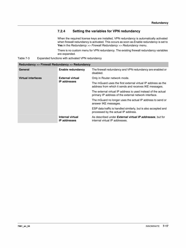
Redundancy
7.2.4 Setting the variables for VPN redundancy
When the required license keys are installed, VPN redundancy is automatically activated when firewall redundancy is activated. This occurs as soon as Enable redundancy is set to Yes in the Redundancy >> Firewall Redundancy >> Redundancy menu.
There is no custom menu for VPN redundancy. The existing firewall redundancy variables are expanded.
Table 7-3 Expanded functions with activated VPN redundancy
Redundancy >> Firewall Redundancy >> Redundancy
General Enable redundancy The firewall redundancy and VPN redundancy are enabled or disabled.
Virtual interfaces External virtual IP addresses
Only in Router network mode.
The mGuard uses the first external virtual IP address as the address from which it sends and receives IKE messages.
The external virtual IP address is used instead of the actual primary IP address of the external network interface.
The mGuard no longer uses the actual IP address to send or answer IKE messages.
ESP data traffic is handled similarly, but is also accepted and processed by the actual IP address.
Internal virtual IP addresses
As described under External virtual IP addresses, but for internal virtual IP addresses.
7961_en_04 INNOMINATE 7-17
mGuard 7.4
7.2.5 Requirements for VPN redundancy
– VPN redundancy can only be activated when the corresponding license key is installed and a VPN connection is activated.
– Only for mGuard industrial rsIf a VPN connection is controlled via a VPN switch, then VPN redundancy cannot be activated.(See under: IPsec VPN >> Global >> Options >> VPN Switch)
During VPN state synchronization, the state of the VPN connection is sent continuously from the active mGuard to the mGuard on standby so that this has an up-to-date copy in the event of errors. The only exception is the state of the IPsec replay window. Changes there are only transmitted sporadically.
The volume of the data traffic for the state synchronization does not depend on the data traffic sent over the VPN channels. The data volumes for state synchronization are defined by a range of parameters that are assigned to the ISAKMP SAs and IPsec SAs.
7.2.6 Handling VPN redundancy in extreme situations
The conditions listed under “Handling firewall redundancy in extreme situations” on page 7-8 also apply to VPN redundancy. They also apply when the mGuard is used exclusively for forwarding on VPN connections. The mGuard forwards the data flows via the VPN channels and rejects incorrect packets, regardless of whether firewall rules have been defined for the VPN connections or not.
An error interrupts the flow of data traffic
An error interrupting the data traffic running over the VPN channels poses an extreme situation. In this case, the IPsec data traffic is briefly vulnerable to replay attacks. A replay attack is the repetition of previously sent encrypted data packets using copies which have been saved by the attacker. The data traffic is protected by sequential numbers. Independent sequential numbers are used for each direction in an IPsec channel. The mGuard drops ESP packets which have the same sequential number as a packet that has already been decrypted for a specific IPsec channel by the mGuard. This mechanism is known as the IPsec replay window.
The IPsec replay window is only replicated sporadically during the state synchronization, as it uses a great deal of resources. It can thus occur that the active mGuard has an obsolete IPsec replay window following a fail-over. An attack is then possible until the real VPN partner has sent the next ESP packet for the corresponding IPsec SA, or until the IPsec SA has been updated.
In order to prevent an insufficient sequential number for the outgoing IPsec SA, VPN redundancy adds a constant value to the sequential number for each outgoing IPsec SA before the mGuard is enabled. This value is calculated so that it corresponds to the maximum number of data packets which can be sent through the VPN channel during the maximum fail-over switching time. In the worst case (1 GB Ethernet and switching time of 10 seconds), this is 0.5% of an IPsec sequence. At best, this is only a per mill value.
Adding a constant value to the sequential number prevents the accidental reuse of a number which was already used by the other mGuard shortly before it failed. Another effect is that ESP packets sent from the previously enabled mGuard are dropped by the VPN partner when new ESP packets are received earlier from the currently enabled mGuard. To do this, the latency period in the network must differ from the fail-over switching time.
7-18 INNOMINATE 7961_en_04
Redundancy
An error interrupts the initial establishment of the ISAKMP SA or IPsec SA
If an error interrupts the initial establishment of the ISAKMP SA or IPsec SA, then the mGuard on standby can continue the process seamlessly as the state of the SA is replicated in parallel. The response to an IKE message is only sent from the active mGuard after the mGuard on standby has confirmed the receipt of the corresponding update to the VPN state synchronization.
When an mGuard is enabled, it immediately repeats the last IKE message which should have been sent from the previously active mGuard. This compensates for cases where the previously active mGuard has sent the state synchronization, but has failed before it could send the corresponding IKE message.
In this way, the establishment of the ISAKMP SA or IPsec SA is only delayed by the switching time during a fail-over.
An error interrupts the replacement of an ISAKMP SA
If an error interrupts the replacement of an ISAKMP SA, then this is compensated in the same way as during the initial establishment of the SA. The old ISAKMP SA is also kept for Dead Peer Detection until the replacement of the ISAKMP SA is completed.
An error interrupts the replacement of an IPsec SA
If an error interrupts the replacement of an IPsec SA, then this is compensated in the same way as during the initial establishment of the SA. As long as the replacement of the ISAKMP SA is not completed, the old outgoing and incoming IPsec SAs are kept until the VPN partner notices the change.
The VPN state synchronization ensures that the old IPsec SAs are kept as long as the mGuard is on standby. When the mGuard is enabled, it can then continue with the decryption and encryption of the data traffic without the need for further action.
Loss of data packets during VPN state synchronization
The state synchronization is resistant against the loss of one of two back-to-back update packets. If more data packets are lost, then this can result in a longer switching time in the event of errors.
The mGuard on standby has an obsolete machine certificate
It can occur that X.509 certificates and private keys used by a redundant pair have to be changed to identify itself as a VPN partner. The combination of a private key and certificate is specified in the following machine certificate.
Each mGuard in a redundant pair must be reconfigured in order to switch the machine certificate. Both mGuards also require the same certificate so that they appear as the same virtual VPN device to their VPN partners.
As each mGuard has to be reconfigured individually, it can occur that the mGuard on standby has an obsolete machine certificate for a brief period.
If the mGuard on standby is enabled at the exact point where the ISAKMP SAs are established, then this procedure cannot be continued with an obsolete machine certificate.
As a countermeasure, the VPN state synchronization replicates the machine certificate from the active mGuard to the mGuard on standby. In the event of a fail-over, the mGuard on standby will only use this to complete a previously started establishment of the ISAKMP SAs.
If the mGuard on standby establishes new ISAKMP SAs after a fail-over, then the existing configured machine certificate will be used.
7961_en_04 INNOMINATE 7-19
mGuard 7.4
Therefore, the VPN state synchronization ensures that the currently used machine certificates are replicated. However, it does not replicate the configuration itself.
The mGuard on standby has an obsolete Pre-Shared Key (PSK)
Pre-Shared Keys (PSK) also need to be updated on occasion in order to authenticate VPN partners. The redundant mGuards may then have a different PSK for a brief period. In this case, only one of the mGuards can establish a VPN connection, as most VPN partners only accept one PSK. No countermeasures exist here on the mGuard.
If the VPN state synchronization replicates the PSKs to the mGuard on standby for a prolonged period, then this also hides an incorrect configuration during this period and is difficult to detect.
7.2.7 Interaction with other devices
Resolving host names
If host names are configured as VPN gateways, then the mGuards in a redundant pair must be able to resolve the host names for the same IP address. This applies especially when DynDNS Monitoring is activated (see Page 6-180).
If the host names are resolved from the mGuard on standby to another IP address, then the VPN connection to this host is interrupted following a fail-over. The VPN connection is established through another IP address. This occurs directly after the fail-over. However, a short delay may occur depending on what is entered under DynDNS Monitoring as a value for the Refresh Interval (sec).
Obsolete IPsec replay window
IPsec data traffic is protected against unauthorized access. To do this, each IPsec channel is provided with an independent sequential number. The mGuard drops ESP packets which have the same sequential number as a packet that has already been decrypted for a specific IPsec channel by the mGuard. This mechanism is known as the IPsec replay window. It prevents replay attacks, where an attacker sends previously recorded data to simulate a different identity.
The IPsec replay window is only replicated sporadically during the state synchronization, as it uses a great deal of resources. It can thus occur that the active mGuard has an obsolete IPsec replay window following a fail-over. An attack is then possible for a brief period until the real VPN partner has sent the next ESP packet for the corresponding IPsec SA, or until the IPsec SA has been updated. However, traffic must be captured completely for this to occur.
Dead Peer Detection
Please note the following point for Dead Peer Detection.
Otherwise, the VPN partner may think that the redundant pair is dead, although it is only dealing with a fail-over.
We therefore recommend using X.509 certificates instead of PSKs.
In Dead Peer Detection, set a higher timeout than the upper limit of the Fail-over switching time on the redundant pair.
(See under: IPsec VPN >> Connections >> Edit >> IKE Options, Delay between requests for a sign of life)
7-20 INNOMINATE 7961_en_04
Redundancy
Data traffic
A high latency period in a network used for updating the state synchronization results in the mGuard on standby being assigned the “outdated” state. This also occurs in the event of serious data loss in this network.
Provided no more than two back-to-back updates are lost, this does not occur. The mGuard on standby automatically requests a repeat of the update. The latency period requirements are the same as those detailed under “Fail-over switching time” on page 7-5.
Actual IP addresses
VPN partners may not send ESP traffic to the actual IP address of the redundant pair. VPN partners must always use the virtual IP address of the redundant pair to send IKE messages or ESP traffic.
7961_en_04 INNOMINATE 7-21
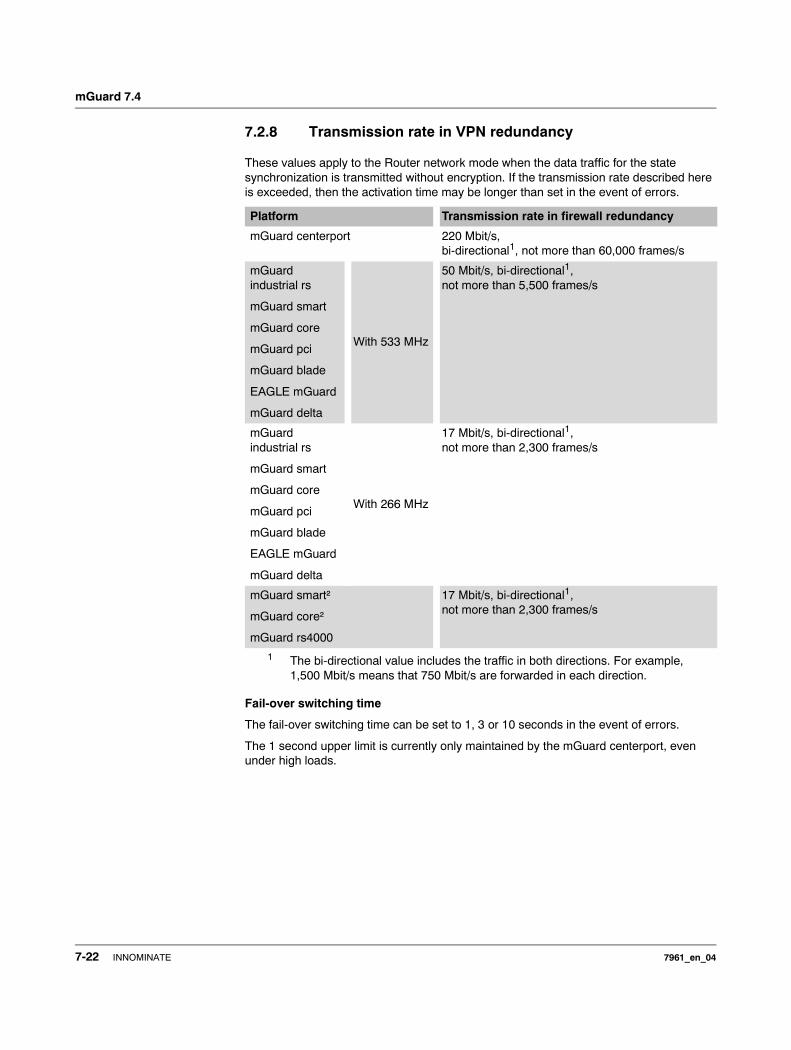
mGuard 7.4
7.2.8 Transmission rate in VPN redundancy
These values apply to the Router network mode when the data traffic for the state synchronization is transmitted without encryption. If the transmission rate described here is exceeded, then the activation time may be longer than set in the event of errors.
Fail-over switching time
The fail-over switching time can be set to 1, 3 or 10 seconds in the event of errors.
The 1 second upper limit is currently only maintained by the mGuard centerport, even under high loads.
Platform Transmission rate in firewall redundancy
mGuard centerport 220 Mbit/s, bi-directional1, not more than 60,000 frames/s
1 The bi-directional value includes the traffic in both directions. For example, 1,500 Mbit/s means that 750 Mbit/s are forwarded in each direction.
mGuard industrial rs
mGuard smart
mGuard core
mGuard pci
mGuard blade
EAGLE mGuard
mGuard delta
With 533 MHz
50 Mbit/s, bi-directional1, not more than 5,500 frames/s
mGuard industrial rs
mGuard smart
mGuard core
mGuard pci
mGuard blade
EAGLE mGuard
mGuard delta
With 266 MHz
17 Mbit/s, bi-directional1, not more than 2,300 frames/s
mGuard smart²
mGuard core²
mGuard rs4000
17 Mbit/s, bi-directional1, not more than 2,300 frames/s
7-22 INNOMINATE 7961_en_04
Redundancy
7.2.9 Limits of VPN redundancy
The limits documented above for firewall redundancy also apply to VPN redundancy (see “Limits of firewall redundancy” on page 7-14). Further restrictions also apply.– The redundant pair must have the same configuration on the following:
– During the general VPN setting. – For each individual VPN connection.
– The mGuard only accepts VPN connections to the first virtual IP address. – In Router network mode, this relates to the first internal IP address and the first
external IP address. – The following features cannot be used with VPN redundancy:
– Dynamic activation of the VPN connections using a VPN switch or the CGI script command nph-vpn.cgi (only on mGuard industrial rs).
– Archiving of diagnosis messages for VPN connections.
– VPN connections are only supported in Tunnel mode. VPN connections in Transport mode are not sufficiently considered.
– The upper limit of the Fail-over switching time does not apply to connections which are encapsulated with TCP. Connections of this type are interrupted for a prolonged period during a fail-over. The encapsulated TCP connections must be established again by the initiating side after each fail-over. If the fail-over occurred on the initiating side, then you can start immediately after the transfer. However, if the fail-over occurred on the answering side, then the initiator must first detect the interruption and then establish the connection again.
– VPN redundancy supports masquerading in the same way as without VPN redundancy. This applies when a redundant pair is masked by a NAT gateway with a dynamic IP address.
For example, a redundant pair can be hidden behind a DSL router, which masks the redundant pair with an official IP address. This DSL router forwards the IPsec data traffic (IKE and ESP, UDP ports 500 and 4500) to the virtual IP addresses. If the dynamic IP address changes, then all active VPN connections which run over the NAT gateway are established again. The connections are established again by Dead Peer Detection (DPD) with the configured time. This effect is outside the influence of the mGuard.
– The redundancy function on the mGuard does not support path redundancy. Path redundancy can be reached using other methods (e.g. through a router pair). This router pair is seen on the virtual side of the mGuards, while each of the routers on the other side have different connections.
Path redundancy may not use NAT mechanisms such as masquerading to hide the virtual IP addresses of the mGuards. Otherwise, a migration from one path to another would change the IP addresses used to mask the redundant pair. This would mean that all VPN connections (all ISAKMP SAs and all IPsec SAs) would have to be established again. The connections are established again by Dead Peer Detection (DPD) with the configured time. This effect is outside the influence of the mGuard.
– In the event of path redundancy caused by a network lobotomy, the VPN connections are no longer supported. A network lobotomy must be prevented whenever possible.
7961_en_04 INNOMINATE 7-23
mGuard 7.4
X.509 certificates for VPN authentication
The mGuard supports the use of X.509 certificates when establishing VPN connections. This is described in detail under “Authentication” on page 6-195.
However, there are some special points to note when X.509 certificates are used for authenticating VPN connections when combined with firewall redundancy and VPN redundancy.
Switching machine certificates
A redundant pair can be configured so that it uses a X.509 certificate and the corresponding private key together to identify itself to a remote VPN partner as an individual virtual IP instance.
These X.509 certificates must be updated regularly. If the VPN partner is set so that it checks the validity period of the certificates, then these must be updated before the validity expires (see “Certificate settings” on page 6-129).
If a machine certificate is replaced, then all VPN connections which use it are restarted by the mGuard. During this time, the mGuard cannot forward data through the affected VPN connections for a certain time. The time period depends on the number of affected VPN connections, the performance of the mGuard/VPN partner and the latency period of the mGuards in the network.
If this is not feasible for redundancy, then the VPN partners of a redundant pair must be configured so that they accept all certificates whose validity is confirmed by a set of specific CA certificates (see “CA Certificates” on page 6-133 and “Authentication” on page 6-195).
If the new machine certificate is issued by a different sub-CA certificate, then the VPN partner must know this before the redundant pair uses the new machine certificate.
The machine certificate must be replaced on both mGuards in a redundant pair. However, this is not always possible when one cannot be reached (e.g. due to a network outage). The mGuard on standby may then have an obsolete machine certificate when it is enabled. This is another reason for setting the VPN partners so that they use both machine certificates.
The machine certificate is normally also replicated with the corresponding key during the VPN state synchronization. In the event of a fail-over, the other mGuard can take over and even continue the creation of incomplete ISAKMP SAs.
Switching the remote certificates for a VPN connection
The mGuard can be set so that it authenticates VPN partners directly through the X.509 certificates which authenticate them. This X.509 certificate must then be set on the mGuard. This is known as the Remote CA Certificate.
If a remote certificate is updated, then only one of the mGuards will have a new certificate for a brief period. We therefore recommend authenticating the VPN partners using CA certificates instead of remote certificates in VPN redundancy.
Adding a new CA certificate to identify VPN partners
The mGuard can be set so that it authenticates VPN partners using CA certificates (see “CA Certificates” on page 6-133 and “Authentication” on page 6-195).
To do this, select Signed by any trusted CA under IPsec VPN >> Connections >> Edit >> Authentication / Remote CA Certificate.
To do this, select Signed by any trusted CA under IPsec VPN >> Connections >> Edit >> Authentication / Remote CA Certificate.
7-24 INNOMINATE 7961_en_04
Redundancy
With this setting, a new CA certificate can be added without affecting the existing VPN connections. However, the new CA certificates are used immediately. The X.509 certificate used by the VPN partner to authenticate itself to the mGuard can then be replaced with a minimal interruption. The only requirement is ensuring that the new CA certificate is available first.
The mGuard can be set so that it checks the validity period of the certificates provided by the VPN partner (see “Certificate settings” on page 6-129). In this case, new trusted CA certificates must be added for configuring the mGuard. These certificates should also have a validity period.
If the CRL check is activated (under Authentication >> Certificates >> Certificate settings), then one URL per CA certificate must be maintained where the corresponding CRL is available. The URL and CRL must be published before the mGuard uses the CA certificates in order to confirm the validity of the certificates displayed by the VPN partners.
Using X.509 certificates with limited validity periods and CRL checks
The use of X.509 certificates is described under “Certificate settings” on page 6-129 (Authentication >> Certificates >> Certificate settings menu).
If X.509 certificates are used here and Check the validity period of certificates and CRLs is set, then the system time must be correct. We recommend synchronizing the system time using a trusted NTP server. Each mGuard in a redundant pair can use the other as an additional NTP server, but not as the only NTP server.
7961_en_04 INNOMINATE 7-25
mGuard 7.4
7.3 Ring/Network Coupling
The “Ring/Network Coupling” function is not supported on:
– mGuard centerport
The “Ring/Network Coupling” function is supported with restrictions on: – mGuard delta: The internal switch ports cannot be switched off.
– mGuard pci: In Driver mode, the internal network interface cannot be switched off (although this should be possible in Power-over-PCI mode).
7-26 INNOMINATE 7961_en_04
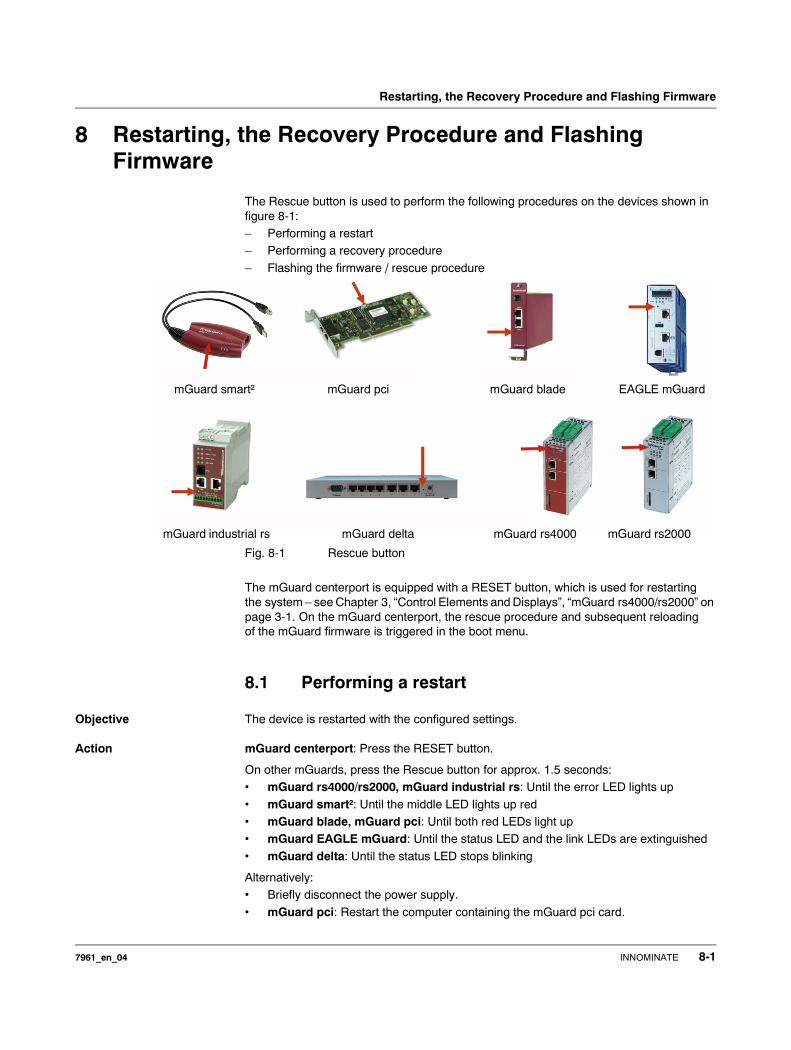
Restarting, the Recovery Procedure and Flashing Firmware
8 Restarting, the Recovery Procedure and Flashing Firmware
The Rescue button is used to perform the following procedures on the devices shown in figure 8-1:– Performing a restart– Performing a recovery procedure
– Flashing the firmware / rescue procedure
Fig. 8-1 Rescue button
The mGuard centerport is equipped with a RESET button, which is used for restarting the system – see Chapter 3, “Control Elements and Displays”, “mGuard rs4000/rs2000” on page 3-1. On the mGuard centerport, the rescue procedure and subsequent reloading of the mGuard firmware is triggered in the boot menu.
8.1 Performing a restart
Objective The device is restarted with the configured settings.
Action mGuard centerport: Press the RESET button.
On other mGuards, press the Rescue button for approx. 1.5 seconds:• mGuard rs4000/rs2000, mGuard industrial rs: Until the error LED lights up
• mGuard smart²: Until the middle LED lights up red• mGuard blade, mGuard pci: Until both red LEDs light up• mGuard EAGLE mGuard: Until the status LED and the link LEDs are extinguished
• mGuard delta: Until the status LED stops blinking
Alternatively:• Briefly disconnect the power supply.
• mGuard pci: Restart the computer containing the mGuard pci card.
mGuard smart² mGuard pci mGuard blade EAGLE mGuard
mGuard deltamGuard industrial rs mGuard rs2000mGuard rs4000
7961_en_04 INNOMINATE 8-1
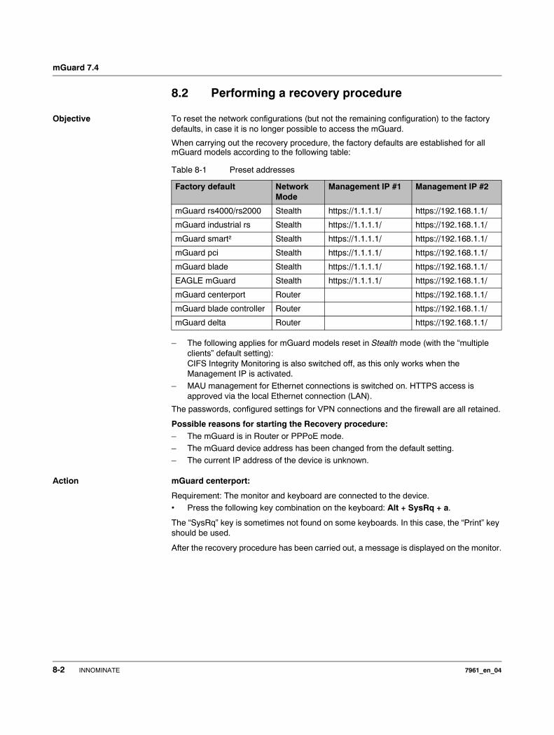
mGuard 7.4
8.2 Performing a recovery procedure
Objective To reset the network configurations (but not the remaining configuration) to the factory defaults, in case it is no longer possible to access the mGuard.
When carrying out the recovery procedure, the factory defaults are established for all mGuard models according to the following table:
– The following applies for mGuard models reset in Stealth mode (with the “multiple clients” default setting): CIFS Integrity Monitoring is also switched off, as this only works when the Management IP is activated.
– MAU management for Ethernet connections is switched on. HTTPS access is approved via the local Ethernet connection (LAN).
The passwords, configured settings for VPN connections and the firewall are all retained.
Possible reasons for starting the Recovery procedure:– The mGuard is in Router or PPPoE mode.– The mGuard device address has been changed from the default setting.– The current IP address of the device is unknown.
Action mGuard centerport:
Requirement: The monitor and keyboard are connected to the device.• Press the following key combination on the keyboard: Alt + SysRq + a.
The “SysRq” key is sometimes not found on some keyboards. In this case, the “Print” key should be used.
After the recovery procedure has been carried out, a message is displayed on the monitor.
Table 8-1 Preset addresses
Factory default Network Mode
Management IP #1 Management IP #2
mGuard rs4000/rs2000 Stealth https://1.1.1.1/ https://192.168.1.1/
mGuard industrial rs Stealth https://1.1.1.1/ https://192.168.1.1/
mGuard smart² Stealth https://1.1.1.1/ https://192.168.1.1/
mGuard pci Stealth https://1.1.1.1/ https://192.168.1.1/
mGuard blade Stealth https://1.1.1.1/ https://192.168.1.1/
EAGLE mGuard Stealth https://1.1.1.1/ https://192.168.1.1/
mGuard centerport Router https://192.168.1.1/
mGuard blade controller Router https://192.168.1.1/
mGuard delta Router https://192.168.1.1/
8-2 INNOMINATE 7961_en_04
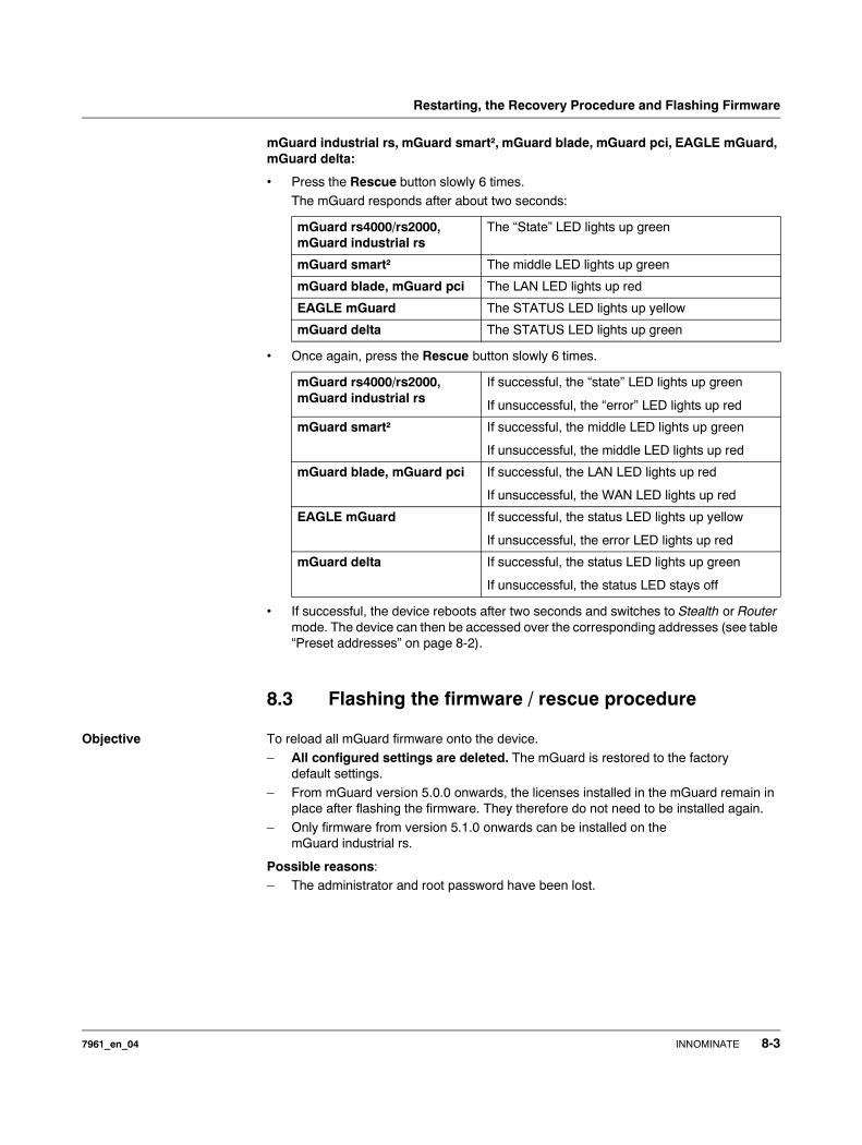
Restarting, the Recovery Procedure and Flashing Firmware
mGuard industrial rs, mGuard smart², mGuard blade, mGuard pci, EAGLE mGuard, mGuard delta:
• Press the Rescue button slowly 6 times.
The mGuard responds after about two seconds:
• Once again, press the Rescue button slowly 6 times.
• If successful, the device reboots after two seconds and switches to Stealth or Router mode. The device can then be accessed over the corresponding addresses (see table “Preset addresses” on page 8-2).
8.3 Flashing the firmware / rescue procedure
Objective To reload all mGuard firmware onto the device.
– All configured settings are deleted. The mGuard is restored to the factory default settings.
– From mGuard version 5.0.0 onwards, the licenses installed in the mGuard remain in place after flashing the firmware. They therefore do not need to be installed again.
– Only firmware from version 5.1.0 onwards can be installed on the mGuard industrial rs.
Possible reasons:– The administrator and root password have been lost.
mGuard rs4000/rs2000, mGuard industrial rs
The “State” LED lights up green
mGuard smart² The middle LED lights up green
mGuard blade, mGuard pci The LAN LED lights up red
EAGLE mGuard The STATUS LED lights up yellow
mGuard delta The STATUS LED lights up green
mGuard rs4000/rs2000, mGuard industrial rs
If successful, the “state” LED lights up green
If unsuccessful, the “error” LED lights up red
mGuard smart² If successful, the middle LED lights up green
If unsuccessful, the middle LED lights up red
mGuard blade, mGuard pci If successful, the LAN LED lights up red
If unsuccessful, the WAN LED lights up red
EAGLE mGuard If successful, the status LED lights up yellow
If unsuccessful, the error LED lights up red
mGuard delta If successful, the status LED lights up green
If unsuccessful, the status LED stays off
7961_en_04 INNOMINATE 8-3

mGuard 7.4
Requirements Requirements – DHCP and TFTP server
Further requirements:
– mGuard centerport:– The monitor and keyboard are connected to the device.– The mGuard firmware has been copied from Innominate Support or from the
website www.innominate.com and saved on the configuration computer.– If your current firmware version is higher than the factory default of the device,
then you must obtain the relevant license for using this update. This applies to major release upgrades, for example from version 4.x.y to version 5.x.y to version 6.x.y, etc.
– DHCP and TFTP servers can be accessed under the same IP address.– mGuard rs4000/rs2000:
– The mGuard firmware has been copied from Innominate Support or from the website www.innominate.com and saved on a compatible SD card.
– This SD card is inserted into the mGuard.The download page of www.innominate.de provides the corresponding firmware files for downloading. On the SD card, the files must be located under these path names or in these folders:Firmware/install-ubi.mpc83xx.p7sFirmware/ubifs.img.mpc83xx.p7s
– mGuard pci: When the mGuard is operated in Power-over-PCI mode, the DHCP / TFTP server must be connected to the mGuards LAN socket.
– mGuard pci: When the mGuard is operated in PCI Driver mode, the DHCP/TFTP server must be operated on the computer or operating system provided by the interface to the mGuard.
Action For the mGuard rs4000/rs2000, mGuard smart², mGuard pci, mGuard blade, EAGLE mGuard, mGuard delta, mGuard industrial rs:
ATTENTION: To flash firmware, a DHCP server and a TFTP or TFTP/BootP server must be installed on the locally connected computer. This does not apply to the mGuard centerport when the firmware is loaded from a USB mass storage device or a CD.
Install the DHCP and TFTP server, if necessary (see “Installing the DHCP and TFTP server” on page 8-9).
No such server is required for the mGuard centerport when the firmware is loaded from a USB mass storage device or a CD ROM.
No such server is required for the mGuard rs4000/rs2000 when the firmware is to be loaded from an SD card. With flashing, the firmware is always first loaded from an SD card. Only if no SD card is found is the firmware loaded from a TFTP server.
Prerequisites for loading the firmware from an SD card: – all the necessary firmware files must exist in a shared directory on the first partition
of the SD card,– this partition uses a vfat file system (standard for SD cards).
ATTENTION: The installation of a second DHCP server in a network can affect the configuration of the entire network.
8-4 INNOMINATE 7961_en_04
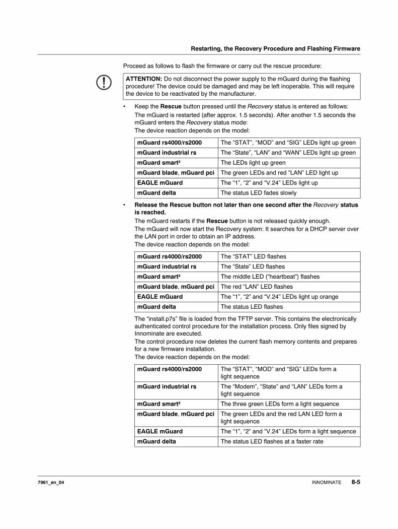
Restarting, the Recovery Procedure and Flashing Firmware
Proceed as follows to flash the firmware or carry out the rescue procedure:
• Keep the Rescue button pressed until the Recovery status is entered as follows: The mGuard is restarted (after approx. 1.5 seconds). After another 1.5 seconds the mGuard enters the Recovery status mode:The device reaction depends on the model:
• Release the Rescue button not later than one second after the Recovery status is reached.The mGuard restarts if the Rescue button is not released quickly enough.The mGuard will now start the Recovery system: It searches for a DHCP server over the LAN port in order to obtain an IP address.The device reaction depends on the model:
The “install.p7s” file is loaded from the TFTP server. This contains the electronically authenticated control procedure for the installation process. Only files signed by Innominate are executed.The control procedure now deletes the current flash memory contents and prepares for a new firmware installation. The device reaction depends on the model:
ATTENTION: Do not disconnect the power supply to the mGuard during the flashing procedure! The device could be damaged and may be left inoperable. This will require the device to be reactivated by the manufacturer.
mGuard rs4000/rs2000 The “STAT”, “MOD” and “SIG” LEDs light up green
mGuard industrial rs The “State”, “LAN” and “WAN” LEDs light up green
mGuard smart² The LEDs light up green
mGuard blade, mGuard pci The green LEDs and red “LAN” LED light up
EAGLE mGuard The “1”, “2” and “V.24” LEDs light up
mGuard delta The status LED fades slowly
mGuard rs4000/rs2000 The “STAT” LED flashes
mGuard industrial rs The “State” LED flashes
mGuard smart² The middle LED (“heartbeat”) flashes
mGuard blade, mGuard pci The red “LAN” LED flashes
EAGLE mGuard The “1”, “2” and “V.24” LEDs light up orange
mGuard delta The status LED flashes
mGuard rs4000/rs2000 The “STAT”, “MOD” and “SIG” LEDs form a light sequence
mGuard industrial rs The “Modem”, “State” and “LAN” LEDs form a light sequence
mGuard smart² The three green LEDs form a light sequence
mGuard blade, mGuard pci The green LEDs and the red LAN LED form a light sequence
EAGLE mGuard The “1”, “2” and “V.24” LEDs form a light sequence
mGuard delta The status LED flashes at a faster rate
7961_en_04 INNOMINATE 8-5
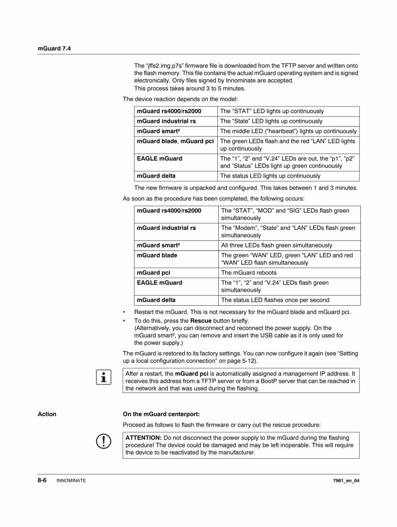
mGuard 7.4
The “jffs2.img.p7s” firmware file is downloaded from the TFTP server and written onto the flash memory. This file contains the actual mGuard operating system and is signed electronically. Only files signed by Innominate are accepted. This process takes around 3 to 5 minutes.
The device reaction depends on the model:
The new firmware is unpacked and configured. This takes between 1 and 3 minutes.
As soon as the procedure has been completed, the following occurs:
• Restart the mGuard. This is not necessary for the mGuard blade and mGuard pci.
• To do this, press the Rescue button briefly. (Alternatively, you can disconnect and reconnect the power supply. On the mGuard smart², you can remove and insert the USB cable as it is only used for the power supply.)
The mGuard is restored to its factory settings. You can now configure it again (see “Setting up a local configuration connection” on page 5-12).
Action On the mGuard centerport:
Proceed as follows to flash the firmware or carry out the rescue procedure:
mGuard rs4000/rs2000 The “STAT” LED lights up continuously
mGuard industrial rs The “State” LED lights up continuously
mGuard smart² The middle LED (“heartbeat”) lights up continuously
mGuard blade, mGuard pci The green LEDs flash and the red “LAN” LED lights up continuously
EAGLE mGuard The “1”, “2” and “V.24” LEDs are out, the “p1”, “p2” and “Status” LEDs light up green continuously
mGuard delta The status LED lights up continuously
mGuard rs4000/rs2000 The “STAT”, “MOD” and “SIG” LEDs flash green simultaneously
mGuard industrial rs The “Modem”, “State” and “LAN” LEDs flash green simultaneously
mGuard smart² All three LEDs flash green simultaneously
mGuard blade The green “WAN” LED, green “LAN” LED and red “WAN” LED flash simultaneously
mGuard pci The mGuard reboots
EAGLE mGuard The “1”, “2” and “V.24” LEDs flash green simultaneously
mGuard delta The status LED flashes once per second
After a restart, the mGuard pci is automatically assigned a management IP address. It receives this address from a TFTP server or from a BootP server that can be reached in the network and that was used during the flashing.
ATTENTION: Do not disconnect the power supply to the mGuard during the flashing procedure! The device could be damaged and may be left inoperable. This will require the device to be reactivated by the manufacturer.
8-6 INNOMINATE 7961_en_04
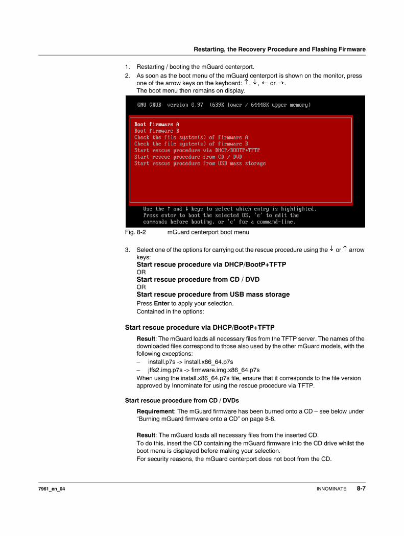
Restarting, the Recovery Procedure and Flashing Firmware
1. Restarting / booting the mGuard centerport.
2. As soon as the boot menu of the mGuard centerport is shown on the monitor, press one of the arrow keys on the keyboard: , , or .The boot menu then remains on display.
Fig. 8-2 mGuard centerport boot menu
3. Select one of the options for carrying out the rescue procedure using the or arrow keys: Start rescue procedure via DHCP/BootP+TFTPORStart rescue procedure from CD / DVDORStart rescue procedure from USB mass storagePress Enter to apply your selection.Contained in the options:
Start rescue procedure via DHCP/BootP+TFTP
Result: The mGuard loads all necessary files from the TFTP server. The names of the downloaded files correspond to those also used by the other mGuard models, with the following exceptions:– install.p7s -> install.x86_64.p7s– jffs2.img.p7s -> firmware.img.x86_64.p7sWhen using the install.x86_64.p7s file, ensure that it corresponds to the file version approved by Innominate for using the rescue procedure via TFTP.
Start rescue procedure from CD / DVDs
Requirement: The mGuard firmware has been burned onto a CD – see below under “Burning mGuard firmware onto a CD” on page 8-8.
Result: The mGuard loads all necessary files from the inserted CD.To do this, insert the CD containing the mGuard firmware into the CD drive whilst the boot menu is displayed before making your selection.For security reasons, the mGuard centerport does not boot from the CD.
7961_en_04 INNOMINATE 8-7
mGuard 7.4
Start rescue procedure from USB mass storage
Requirement: The mGuard firmware has been copied onto a USB storage medium (USB stick). The USB storage medium must have a “vfat” file system on the initial primary partition, and the same files must be found in the same folders as defined for the CD. Additionally, the files can be contained in the Rescue Config folder (as for a CD).Result: The mGuard loads all necessary files from the connected USB storage medium.To do this, connect the USB storage medium containing the firmware into the USB port whilst the boot menu is displayed before making your selection.For security reasons, the mGuard centerport does not boot from the USB storage medium.
4. After the rescue procedure has been carried out, a message is displayed on the monitor. Follow any further instructions which appear on the monitor.
The mGuard is restored to its factory settings. You can now configure it again (see “Setting up a local configuration connection” on page 5-12):
Burning mGuard firmware onto a CD
The mGuard firmware can be burned onto a CD. A ZIP file is available in the download area under www.innominate.com.
Burn the contents of this ZIP archive as a data CD. The following files must be found in the following folders / under the following path names on the CD:
– Firmware/install.x86_64.p7s– Firmware/firmware.img.x86_64.p7s
When using the install.x86_64.p7s file, ensure that it corresponds to the file version approved by Innominate for using the rescue procedure via CD.
If required, the following files can also be contained in the Rescue Config folder on the CD:
Rescue Config/licence.lic License file imported to the device during the rescue procedure.
Rescue Config/<serial>.lic As above, but the <serial> placeholder is replaced by the device serial number. The same CD can then be used simultaneously for various devices.
Rescue Config/preconfig.atv Configuration profile used in the firmware during the rescue procedure. The file must be used by the “Rescue Config/preconfig.sh” script (see below).
Rescue Config/<serial>.atv Same as <serial>.lic
Rescue Config/preconfig.sh Script file executed immediately after installation of the new firmware. More details can be found in “Innominate mGuard – Application Note: Rollout Support”, which is available from the Innominate website (www.innominate.com).
8-8 INNOMINATE 7961_en_04
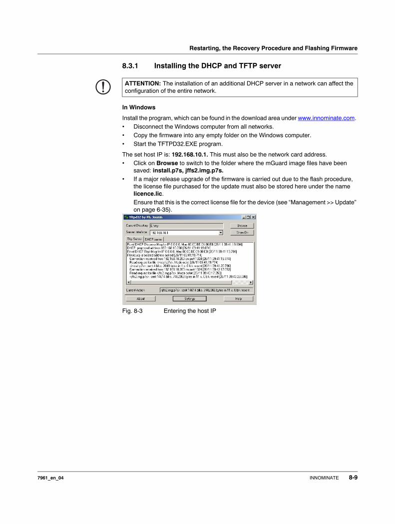
Restarting, the Recovery Procedure and Flashing Firmware
8.3.1 Installing the DHCP and TFTP server
In Windows
Install the program, which can be found in the download area under www.innominate.com. • Disconnect the Windows computer from all networks.• Copy the firmware into any empty folder on the Windows computer.
• Start the TFTPD32.EXE program.
The set host IP is: 192.168.10.1. This must also be the network card address.• Click on Browse to switch to the folder where the mGuard image files have been
saved: install.p7s, jffs2.img.p7s.• If a major release upgrade of the firmware is carried out due to the flash procedure,
the license file purchased for the update must also be stored here under the name licence.lic. Ensure that this is the correct license file for the device (see “Management >> Update” on page 6-35).
Fig. 8-3 Entering the host IP
ATTENTION: The installation of an additional DHCP server in a network can affect the configuration of the entire network.
7961_en_04 INNOMINATE 8-9
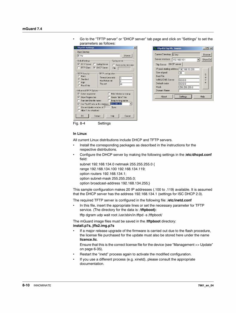
mGuard 7.4
• Go to the “TFTP server” or “DHCP server” tab page and click on “Settings” to set the parameters as follows:
Fig. 8-4 Settings
In Linux
All current Linux distributions include DHCP and TFTP servers.
• Install the corresponding packages as described in the instructions for the respective distributions.
• Configure the DHCP server by making the following settings in the /etc/dhcpd.conf field:
subnet 192.168.134.0 netmask 255.255.255.0 {range 192.168.134.100 192.168.134.119;option routers 192.168.134.1;option subnet-mask 255.255.255.0;option broadcast-address 192.168.134.255;}
This sample configuration makes 20 IP addresses (.100 to .119) available. It is assumed that the DHCP server has the address 192.168.134.1 (settings for ISC DHCP 2.0).
The required TFTP server is configured in the following file: /etc/inetd.conf• In this file, insert the appropriate lines or set the necessary parameter for TFTP
service. (The directory for the data is: /tftpboot):tftp dgram udp wait root /usr/sbin/in.tftpd -s /tftpboot/
The mGuard image files must be saved in the /tftpboot directory:install.p7s, jffs2.img.p7s• If a major release upgrade of the firmware is carried out due to the flash procedure,
the license file purchased for the update must also be stored here under the name licence.lic.
Ensure that this is the correct license file for the device (see “Management >> Update” on page 6-35).
• Restart the “inetd” process again to activate the modified configuration. • If you use a different process (e.g. xinetd), please consult the appropriate
documentation.
8-10 INNOMINATE 7961_en_04
Glossary
9 Glossary
AES The AES (Advanced Encryption Standard) was developed by NIST (National Institute of Standards and Technology) in cooperation with the industry. This symmetrical encryption standard was developed to replace the earlier DES standard. AES specifies three different key lengths (128, 192 and 256 bits).
In 1997, NIST started the AES initiative and announced its conditions for the algorithm. From the many proposed encryption algorithms, NIST selected a total of five algorithms for closer examination – the MARS, RC6, Rijndael, Serpent and Twofish algorithms. In October 2000, the Rijndael algorithm was adopted as the encryption algorithm.
Asymmetrical encryption In asymmetrical encryption, data is encrypted with one key and decrypted with a second key. Both keys are suitable for encryption and decryption. One of the keys is kept secret by its owner (Private Key), whilst the other is made available to the public (Public Key), i.e. to possible communication partners.
A message encrypted with the public key can only be decrypted and read by the owner of the associated private key. A message encrypted with the private key can be decrypted by any recipient who is the owner of the associated public key. Encryption using the private key shows that the message actually originated from the owner of the associated public key. Therefore, the expression “digital signature” is also often used.
However, asymmetrical encryption techniques such as RSA are both slow and susceptible to certain types of attack, meaning they are often combined with some form of symmetrical encryption ( “Subject, certificate” on page 9-5). On the other hand, concepts are available which avoid the additional administration of symmetrical keys.
CA certificate Used to check the reliability of a certificate and the CA (Certificate Authority) that issued it ( “X.509 Certificate” on page 9-8). A CA certificate can be consulted in order to check that a certificate signature has this CA. This check only makes sense if there is little doubt that the CA certificate originates from an authentic source (i.e. is also authentic). If doubt occurs, then the CA certificate itself can be checked. If (as is usually the case) this applies to a sub-CA certificate (i.e. a CA certificate issued by a sub-certificate authority), then the CA certificate of the superordinate CA can be used to check the CA certificate of the sub-ordinate instance. If a superordinate CA certificate also has a superordinate CA certificate, then its CA certificate can be used to check the CA certificate of the subordinate instance. This chain of trust continues down to the root instance (root CA). The CA file of the root CA is necessarily self-signed. This instance is the highest available, and is ultimately the basis of trust. No-one else can certify that this instance is actually the instance in question. A root CA is therefore a state or state-controlled organization.
The mGuard can use its imported CA certificate to check the validity of displayed certifi-cates from remote peers. For example, with VPN connections the authentication of remote peers can only be made using the CA certificate. In this case, all CA certificates must be installed in mGuard in order to build a chain with the certificate displayed by the remote peer: Aside from the CA certificate, whose signature can be seen in the displayed certifi-cate of the VPN partner to be checked, the CA certificate of the superordinate CA up to the root certificate must also be used. If this “trust chain” is checked meticulously in order to accept the authenticity of a remote peer, then the level of security increases.
Client / Server In a client-server environment, a server is a program or computer which accepts and answers queries from client programs or computers.
7961_en_04 INNOMINATE 9-1
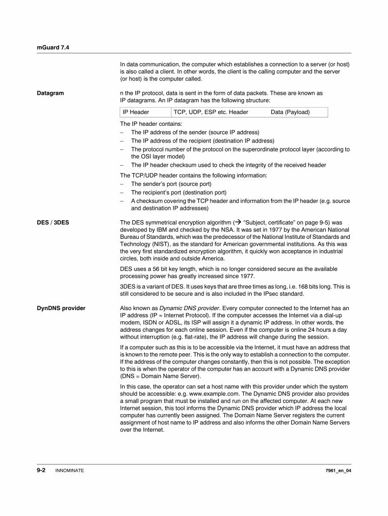
mGuard 7.4
In data communication, the computer which establishes a connection to a server (or host) is also called a client. In other words, the client is the calling computer and the server (or host) is the computer called.
Datagram n the IP protocol, data is sent in the form of data packets. These are known as IP datagrams. An IP datagram has the following structure:
The IP header contains:– The IP address of the sender (source IP address)– The IP address of the recipient (destination IP address)
– The protocol number of the protocol on the superordinate protocol layer (according to the OSI layer model)
– The IP header checksum used to check the integrity of the received header
The TCP/UDP header contains the following information:– The sender’s port (source port)
– The recipient’s port (destination port)– A checksum covering the TCP header and information from the IP header (e.g. source
and destination IP addresses)
DES / 3DES The DES symmetrical encryption algorithm ( “Subject, certificate” on page 9-5) was developed by IBM and checked by the NSA. It was set in 1977 by the American National Bureau of Standards, which was the predecessor of the National Institute of Standards and Technology (NIST), as the standard for American governmental institutions. As this was the very first standardized encryption algorithm, it quickly won acceptance in industrial circles, both inside and outside America.
DES uses a 56 bit key length, which is no longer considered secure as the available processing power has greatly increased since 1977.
3DES is a variant of DES. It uses keys that are three times as long, i.e. 168 bits long. This is still considered to be secure and is also included in the IPsec standard.
DynDNS provider Also known as Dynamic DNS provider. Every computer connected to the Internet has an IP address (IP = Internet Protocol). If the computer accesses the Internet via a dial-up modem, ISDN or ADSL, its ISP will assign it a dynamic IP address. In other words, the address changes for each online session. Even if the computer is online 24 hours a day without interruption (e.g. flat-rate), the IP address will change during the session.
If a computer such as this is to be accessible via the Internet, it must have an address that is known to the remote peer. This is the only way to establish a connection to the computer. If the address of the computer changes constantly, then this is not possible. The exception to this is when the operator of the computer has an account with a Dynamic DNS provider (DNS = Domain Name Server).
In this case, the operator can set a host name with this provider under which the system should be accessible: e.g. www.example.com. The Dynamic DNS provider also provides a small program that must be installed and run on the affected computer. At each new Internet session, this tool informs the Dynamic DNS provider which IP address the local computer has currently been assigned. The Domain Name Server registers the current assignment of host name to IP address and also informs the other Domain Name Servers over the Internet.
IP Header TCP, UDP, ESP etc. Header Data (Payload)
9-2 INNOMINATE 7961_en_04
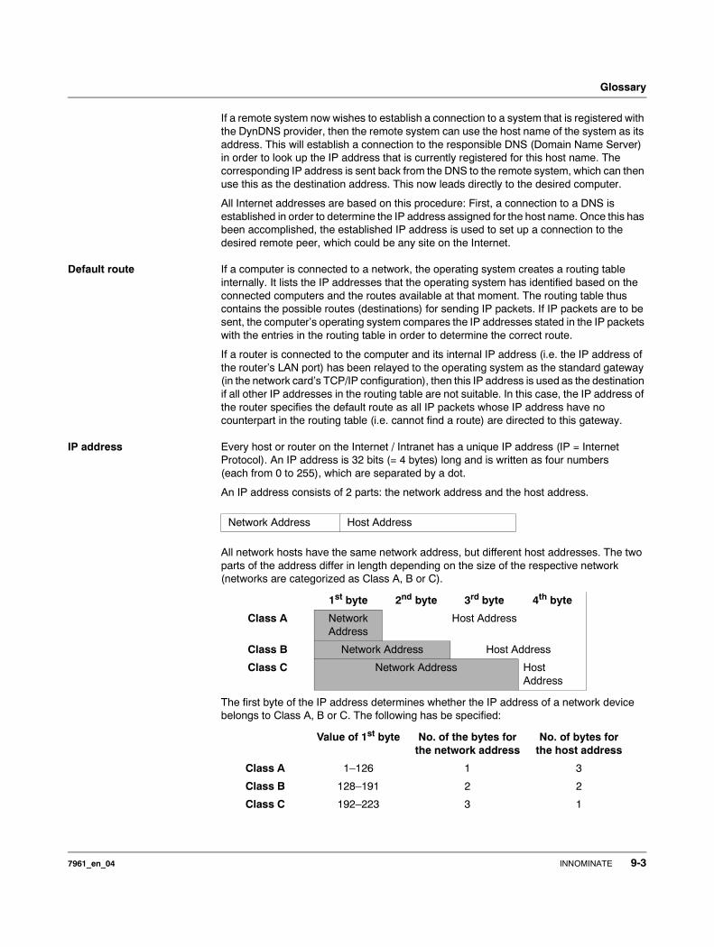
Glossary
If a remote system now wishes to establish a connection to a system that is registered with the DynDNS provider, then the remote system can use the host name of the system as its address. This will establish a connection to the responsible DNS (Domain Name Server) in order to look up the IP address that is currently registered for this host name. The corresponding IP address is sent back from the DNS to the remote system, which can then use this as the destination address. This now leads directly to the desired computer.
All Internet addresses are based on this procedure: First, a connection to a DNS is established in order to determine the IP address assigned for the host name. Once this has been accomplished, the established IP address is used to set up a connection to the desired remote peer, which could be any site on the Internet.
Default route If a computer is connected to a network, the operating system creates a routing table internally. It lists the IP addresses that the operating system has identified based on the connected computers and the routes available at that moment. The routing table thus contains the possible routes (destinations) for sending IP packets. If IP packets are to be sent, the computer’s operating system compares the IP addresses stated in the IP packets with the entries in the routing table in order to determine the correct route.
If a router is connected to the computer and its internal IP address (i.e. the IP address of the router’s LAN port) has been relayed to the operating system as the standard gateway (in the network card’s TCP/IP configuration), then this IP address is used as the destination if all other IP addresses in the routing table are not suitable. In this case, the IP address of the router specifies the default route as all IP packets whose IP address have no counterpart in the routing table (i.e. cannot find a route) are directed to this gateway.
IP address Every host or router on the Internet / Intranet has a unique IP address (IP = Internet Protocol). An IP address is 32 bits (= 4 bytes) long and is written as four numbers (each from 0 to 255), which are separated by a dot.
An IP address consists of 2 parts: the network address and the host address.
All network hosts have the same network address, but different host addresses. The two parts of the address differ in length depending on the size of the respective network (networks are categorized as Class A, B or C).
The first byte of the IP address determines whether the IP address of a network device belongs to Class A, B or C. The following has be specified:
Network Address Host Address
1st byte 2nd byte 3rd byte 4th byte
Class A Network Address
Host Address
Class B Network Address Host Address
Class C Network Address Host Address
Value of 1st byte No. of the bytes for the network address
No. of bytes for the host address
Class A 1–126 1 3
Class B 128–191 2 2
Class C 192–223 3 1
7961_en_04 INNOMINATE 9-3
mGuard 7.4
There is thus a maximum worldwide total of 126 Class A networks. Each of these networks can have a maximum of 256 x 256 x 256 hosts (3 bytes of address space). There can be 64 x 256 Class B networks and each of these networks can have up to 65,536 hosts (2 bytes address space: 256 x 256). There can be 32 x 256 x 256 Class C networks and each of these networks can have up to 256 hosts (1 byte address space).
IPsec P Security (IPsec) is a standard that uses encryption to verify the authenticity of the sender and to ensure the confidentiality and integrity of the data in IP datagrams ( “Datagram” on page 9-2). The components of IPsec are the Authentication Header (AH), the Encapsu-lating Security Payload (ESP), the Security Association (SA) and the Internet Key Exchange (IKE).
At the start of the session, systems that wish to communicate must determine which technique should be used and the implications of this choice for the session e.g. Transport Mode or Tunnel Mode.
In Transport Mode, an IPsec header is inserted between the IP header and the TCP or UDP header respectively in each IP datagram. Since the IP header remains unchanged, this mode is only suitable for host- to-host connections.
In Tunnel Mode, an IPsec header and a new IP header are added in front of the entire IP datagram. This means the original datagram is encrypted in its entirety and stored in the payload of the new datagram.
The Tunnel Mode is used in VPN applications: The devices at the tunnel ends ensure that the datagrams are encrypted before they pass through the tunnel. This means the actual datagrams are completely protected whilst being transferred over a public network.
NAT (Network Address Translation)
During Network Address Translation (NAT) (also known as IP Masquerading), an entire network is “hidden” behind a single device, known as a NAT router. If you communicate externally via a NAT router, the internal computers in the local network and their IP ad-dresses remain hidden. The remote communication partner will only see the NAT router with its own IP address.
In order to allow internal computers to communicate directly with external systems (over the Internet), the NAT router must modify the IP datagrams that are passed to and from the internal computers and the remote peers.
If an IP datagram is sent from the internal network to a remote peer, the NAT router modifies the UDP and TCP headers of the datagram. It replaces the source IP address and port with its own IP address and an unused port. A table is stored in which the original values are listed together with the corresponding new ones.
When a reply datagram is received, the NAT router will recognize that it is intended for an internal computer using the destination port of the datagram. Using the table, the NAT router will replace the destination IP address and port and then forward the datagram on via the internal network.
Port number A port number is assigned to each UDP and TCP protocol participant. It is then possible to differentiate two UDP or TCP connections between two systems and use them at the same time.
Fixed port numbers can be reserved for special purposes. For example, HTTP connections are usually assigned to TCP port 80 and POP3 connections to TCP port 110.
PPPoE PPPoE is an acronym of Point-to-Point Protocol over Ethernet. This protocol is based on PPP and Ethernet standards. PPPoE defines how to connect users via Ethernet with the Internet via a jointly used broadband medium such as DSL, wireless LAN or a cable modem.
9-4 INNOMINATE 7961_en_04
Glossary
PPTP PPTP is an acronym of Point-to-Point Tunneling Protocol. This protocol was developed by companies such as Microsoft and U.S. Robotics in order to securely transfer data between VPN nodes ( VPN) via a public network.
Protocol, communication protocol
Devices that communicate with each other must follow the same rules. To do this, they must “speak” the same language. Rules and standards of this kind are called protocols or communication protocols. Some of the more frequently used protocols are IP, TCP, PPP, HTTP and SMTP.
Proxy A proxy is an intermediary service. A web proxy (e. g. Squid) is often used for a large network. For example, if 100 employees access a certain website at the same time over a web proxy, then the proxy only loads the relevant web pages once from the server and then distributes them as needed amongst the employees. Remote web traffic is reduced, which saves money.
Router A router is a device that is connected to different IP networks and communicates between them. To do this, a router has an interface for each network connected to it. A router must find the correct path to the target for incoming data and must define the appropriate inter-face for forwarding it. It takes data from a local routing table that shows which networks are available over which router connections (or intermediary stations).
Service provider Service providers are companies or institutions that enable users to access the Internet or online services.
Spoofing, anti-spoofing In Internet terminology, spoofing means supplying a false address. Using this false Internet address, a user can create the illusion of being an authorized user.
Anti-spoofing is the term for mechanisms that detect or prevent spoofing.
Subject, certificate In a certificate, the classification of a certificate to its owner is confirmed by a CA (Certifi-cate Authority). This occurs through the confirmation of certain owner characteristics. Furthermore, the certificate owner must possess the private key that matches the public key in the certificate ( “X.509 Certificate” on page 9-8).
Example:Certificate: Data: Version: 3 (0x2) Serial Number: 1 (0x1) Signature Algorithm: md5WithRSAEncryption Issuer: C=XY, ST=Austria, L=Graz, O=TrustMe Ltd, OU=Certificate Authority, CN=CA/[email protected] Validity Not Before: Oct 29 17:39:10 2000 GMT
Subject: CN=anywhere.com,E=doctrans.de,C=DE,ST=Hamburg,L=Hamburg,O=Innominate,OU=Security Subject Public Key Info: Public Key Algorithm: rsaEncryption RSA Public Key: (1024 bit) Modulus (1024 bit): 00:c4:40:4c:6e:14:1b:61:36:84:24:b2:61:c0:b5: d7:e4:7a:a5:4b:94:ef:d9:5e:43:7f:c1:64:80:fd: 9f:50:41:6b:70:73:80:48:90:f3:58:bf:f0:4c:b9: 90:32:81:59:18:16:3f:19:f4:5f:11:68:36:85:f6: 1c:a9:af:fa:a9:a8:7b:44:85:79:b5:f1:20:d3:25: 7d:1c:de:68:15:0c:b6:bc:59:46:0a:d8:99:4e:07: 50:0a:5d:83:61:d4:db:c9:7d:c3:2e:eb:0a:8f:62: 8f:7e:00:e1:37:67:3f:36:d5:04:38:44:44:77:e9: f0:b4:95:f5:f9:34:9f:f8:43 Exponent: 65537 (0x10001) X509v3 extensions: X509v3 Subject Alternative Name: email:[email protected] Netscape Comment: mod_ssl generated test server certificate Netscape Cert Type: SSL Server Signature Algorithm: md5WithRSAEncryption 12:ed:f7:b3:5e:a0:93:3f:a0:1d:60:cb:47:19:7d:15:59:9b:
7961_en_04 INNOMINATE 9-5
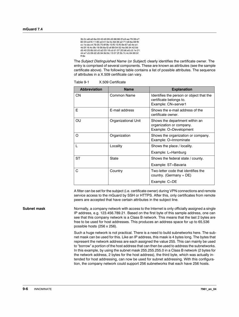
mGuard 7.4
3b:2c:a8:a3:6a:03:43:d0:85:d3:86:86:2f:e3:aa:79:39:e7: 82:20:ed:f4:11:85:a3:41:5e:5c:8d:36:a2:71:b6:6a:08:f9: cc:1e:da:c4:78:05:75:8f:9b:10:f0:15:f0:9e:67:a0:4e:a1: 4d:3f:16:4c:9b:19:56:6a:f2:af:89:54:52:4a:06:34:42:0d: d5:40:25:6b:b0:c0:a2:03:18:cd:d1:07:20:b6:e5:c5:1e:21: 44:e7:c5:09:d2:d5:94:9d:6c:13:07:2f:3b:7c:4c:64:90:bf: ff:8e
The Subject Distinguished Name (or Subject) clearly identifies the certificate owner. The entry is comprised of several components. These are known as attributes (see the sample certificate above). The following table contains a list of possible attributes. The sequence of attributes in a X.509 certificate can vary.
A filter can be set for the subject (i.e. certificate owner) during VPN connections and remote service access to the mGuard by SSH or HTTPS. After this, only certificates from remote peers are accepted that have certain attributes in the subject line.
Subnet mask Normally, a company network with access to the Internet is only officially assigned a single IP address, e.g. 123.456.789.21. Based on the first byte of this sample address, one can see that this company network is a Class B network. This means that the last 2 bytes are free to be used for host addresses. This produces an address space for up to 65,536 possible hosts (256 x 256).
Such a huge network is not practical. There is a need to build subnetworks here. The sub-net mask can be used for this. Like an IP address, this mask is 4 bytes long. The bytes that represent the network address are each assigned the value 255. This can mainly be used to “borrow” a portion of the host address that can then be used to address the subnetworks. In this example, by using the subnet mask 255.255.255.0 in a Class B network (2 bytes for the network address, 2 bytes for the host address), the third byte, which was actually in-tended for host addressing, can now be used for subnet addressing. With this configura-tion, the company network could support 256 subnetworks that each have 256 hosts.
Table 9-1 X.509 Certificate
Abbreviation Name Explanation
CN Common Name Identifies the person or object that the certificate belongs to. Example: CN=server1
E E-mail address Shows the e-mail address of the certificate owner.
OU Organizational Unit Shows the department within an organization or company.Example: O=Development
O Organization Shows the organization or company. Example: O=Innominate
L Locality Shows the place / locality.
Example: L=Hamburg
ST State Shows the federal state / county.
Example: ST=Bavaria
C Country Two-letter code that identifies the country. (Germany = DE)
Example: C=DE
9-6 INNOMINATE 7961_en_04
Glossary
Symmetrical encryption In symmetrical encryption, the same key is used to encrypt and decrypt data. Two examples of symmetrical encryption algorithms are DES and AES. They are fast, but also difficult to administrate as the number of users increases.
TCP/IP (Transmission Control Protocol/Internet Protocol)
These are network protocols used to connect two computers over the Internet.
IP is the base protocol.
UDP is based on IP and sends individual packets. The packets may arrive at the recipient in an different order in which they were sent or they may even be lost.
TCP is used for connection security and ensures, for example, that data packets are passed on to the application in the correct order.
UDP and TCP add port numbers between 1 to 65535 to the IP addresses. These distin-guish the various services offered by the protocols.
A number of additional protocols are based on UDP and TCP, e.g. HTTP (HyperText Transfer Protocol), HTTPS (Secure HyperText Transfer Protocol), SMTP (Simple Mail Transfer Protocol), POP3 (Post Office Protocol, Version 3) and DNS (Domain Name Service).
ICMP is based on IP and contains control messages.
SMTP is an e-mail protocol based on TCP.
IKE is an IPsec protocol based on UDP.
ESP is an IPsec protocol based on IP.
On a Windows PC, the WINSOCK.DLL (or WSOCK32.DLL) handles the development of both protocols.
( “Datagram” on page 9-2)
Trap Aside from other protocols, an SMNP (Simple Network Management Protocol) can also be used, especially in large networks. This UDP-based protocol is used for the central administration of network devices. For example, the configuration of a device can be requested using the “GET” order and changed using the “SET” order. To do this, the requested network device must be SNMP compatible.
An SNMP-compatible device can also send SNMP messages (e. g. when unexpected events occur). Messages of this kind are known as SNMP traps.
VLAN A VLAN (Virtual Local Area Network) divides a physical network into several independent logical networks.
Devices of different VLANs can only access devices within their own VLAN. Assignment to a VLAN is no longer defined by the network topology alone, but also by the configured VLAN ID.
VLAN settings can also be used as optional settings for each IP. A VLAN is identified by its VLAN ID (1-4094). All devices with the same VLAN ID belong to the same VLAN and can therefore communicate with each other.
The Ethernet packet for a VLAN (based on IEEE 802.1Q) is extended by 4 bytes, with 12 bits available for recording the VLAN ID. The VLAN IDs “0” and “4095” are reserved and cannot be used for VLAN identification.
7961_en_04 INNOMINATE 9-7
mGuard 7.4
VPN (Virtual Private Network)
A Virtual Private Network (VPN) connects several separate private networks (subnetworks) together via a public network (e.g. the Internet) to form a single joint network. A cryptographic protocol is used to ensure confidentiality and authenticity. A VPN thus offers an economical alternative to using dedicated lines to build a nationwide corporate network.
X.509 Certificate A type of “seal” that certifies the authenticity of a public key ( Asymmetrical encryption) and the associated data.
It is possible to use certification to enable the user of the public key (used to encrypt the data) to ensure that the received public key is from its actual issuer (and thus from the instance that should later receive the data). A Certification Authority (CA) certifies the au-thenticity of the public key and the associated link between the identity of the issuer and their key. The certification authority will verify authenticity in accordance with its rules. For example, this may require the issuer of the public key to appear before it in person. Once successfully authenticated, the CA adds its digital signature to the issuer’s public key. This results in a certificate.
An X.509(v3) certificate is thus comprised of a public key, information about the key owner (given as Distinguished Name (DN)), authorized usage etc. and the signature of the CA ( Subject, certificate).
The signature is created as follows: The CA creates an individual bit sequence, known as the HASH value, from the bit sequence of the public key, owner information and other data. This sequence may be up to 160 bits long. The CA then encrypts this with its own private key and then adds it to the certificate. The encryption with the CA’s private key proves the authenticity of the certificate (i.e. the encrypted HASH string is the CA’s digital signature). If the certificate data is altered, then this HASH value will no longer be correct and the certificate is then worthless.
The HASH value is also known as the fingerprint. Since it is encrypted with the CA’s private key, anyone who has the corresponding public key can decrypt the bit sequence and thus verify the authenticity of the fingerprint or signature.
The usage of a certification authority means it is not necessary for key owners to know each other. They must only know the certification authority used in the process. The additional key information further simplifies administration of the key.
X.509 certificates can be used for e-mail encryption with S/MIME or IPsec.
9-8 INNOMINATE 7961_en_04
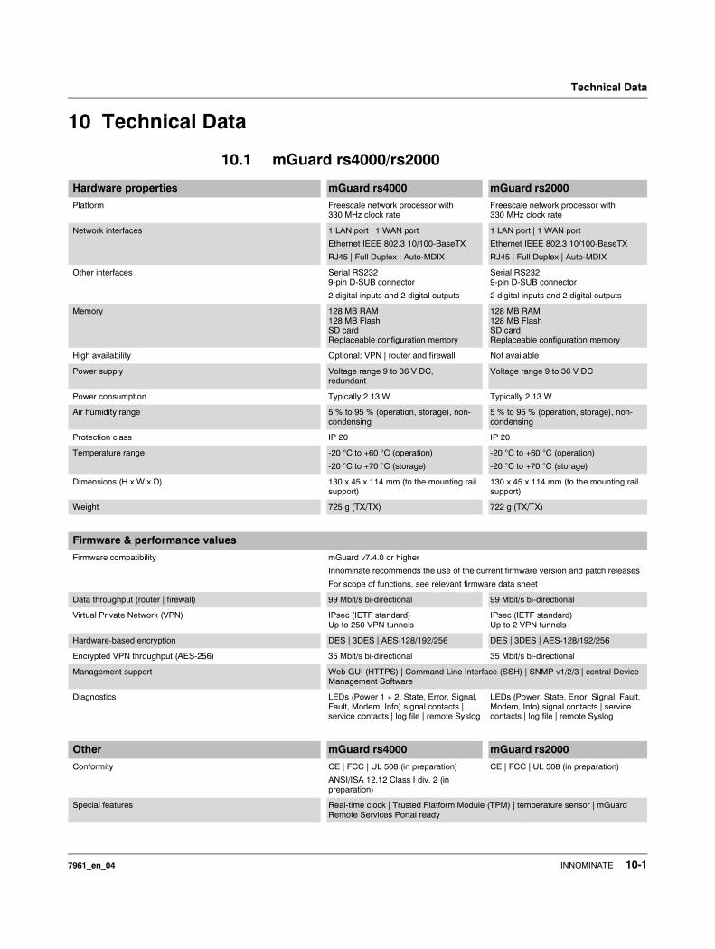
Technical Data
10 Technical Data
10.1 mGuard rs4000/rs2000
Hardware properties mGuard rs4000 mGuard rs2000
Platform Freescale network processor with 330 MHz clock rate
Freescale network processor with 330 MHz clock rate
Network interfaces 1 LAN port | 1 WAN port
Ethernet IEEE 802.3 10/100-BaseTX
RJ45 | Full Duplex | Auto-MDIX
1 LAN port | 1 WAN port
Ethernet IEEE 802.3 10/100-BaseTX
RJ45 | Full Duplex | Auto-MDIX
Other interfaces Serial RS2329-pin D-SUB connector
2 digital inputs and 2 digital outputs
Serial RS2329-pin D-SUB connector
2 digital inputs and 2 digital outputs
Memory 128 MB RAM128 MB FlashSD cardReplaceable configuration memory
128 MB RAM128 MB FlashSD cardReplaceable configuration memory
High availability Optional: VPN | router and firewall Not available
Power supply Voltage range 9 to 36 V DC, redundant
Voltage range 9 to 36 V DC
Power consumption Typically 2.13 W Typically 2.13 W
Air humidity range 5 % to 95 % (operation, storage), non-condensing
5 % to 95 % (operation, storage), non-condensing
Protection class IP 20 IP 20
Temperature range -20 °C to +60 °C (operation)
-20 °C to +70 °C (storage)
-20 °C to +60 °C (operation)
-20 °C to +70 °C (storage)
Dimensions (H x W x D) 130 x 45 x 114 mm (to the mounting rail support)
130 x 45 x 114 mm (to the mounting rail support)
Weight 725 g (TX/TX) 722 g (TX/TX)
Firmware & performance values
Firmware compatibility mGuard v7.4.0 or higher
Innominate recommends the use of the current firmware version and patch releases
For scope of functions, see relevant firmware data sheet
Data throughput (router | firewall) 99 Mbit/s bi-directional 99 Mbit/s bi-directional
Virtual Private Network (VPN) IPsec (IETF standard) Up to 250 VPN tunnels
IPsec (IETF standard) Up to 2 VPN tunnels
Hardware-based encryption DES | 3DES | AES-128/192/256 DES | 3DES | AES-128/192/256
Encrypted VPN throughput (AES-256) 35 Mbit/s bi-directional 35 Mbit/s bi-directional
Management support Web GUI (HTTPS) | Command Line Interface (SSH) | SNMP v1/2/3 | central Device Management Software
Diagnostics LEDs (Power 1 + 2, State, Error, Signal, Fault, Modem, Info) signal contacts | service contacts | log file | remote Syslog
LEDs (Power, State, Error, Signal, Fault, Modem, Info) signal contacts | service contacts | log file | remote Syslog
Other mGuard rs4000 mGuard rs2000
Conformity CE | FCC | UL 508 (in preparation)
ANSI/ISA 12.12 Class I div. 2 (in preparation)
CE | FCC | UL 508 (in preparation)
Special features Real-time clock | Trusted Platform Module (TPM) | temperature sensor | mGuard Remote Services Portal ready
7961_en_04 INNOMINATE 10-1
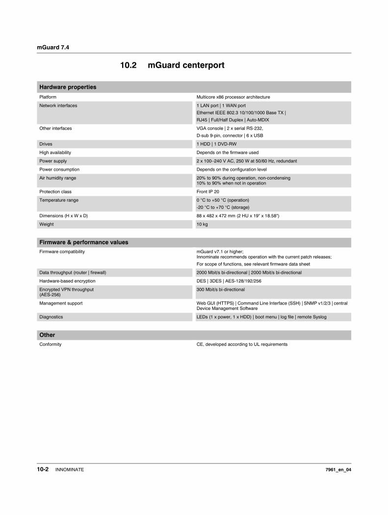
mGuard 7.4
10.2 mGuard centerport
Hardware properties
Platform Multicore x86 processor architecture
Network interfaces 1 LAN port | 1 WAN port
Ethernet IEEE 802.3 10/100/1000 Base TX |
RJ45 | Full/Half Duplex | Auto-MDIX
Other interfaces VGA console | 2 x serial RS-232,
D-sub 9-pin, connector | 6 x USB
Drives 1 HDD | 1 DVD-RW
High availability Depends on the firmware used
Power supply 2 x 100–240 V AC, 250 W at 50/60 Hz, redundant
Power consumption Depends on the configuration level
Air humidity range 20% to 90% during operation, non-condensing10% to 90% when not in operation
Protection class Front IP 20
Temperature range 0 °C to +50 °C (operation)
-20 °C to +70 °C (storage)
Dimensions (H x W x D) 88 x 482 x 472 mm (2 HU x 19" x 18.58")
Weight 10 kg
Firmware & performance values
Firmware compatibility mGuard v7.1 or higher;Innominate recommends operation with the current patch releases;
For scope of functions, see relevant firmware data sheet
Data throughput (router | firewall) 2000 Mbit/s bi-directional | 2000 Mbit/s bi-directional
Hardware-based encryption DES | 3DES | AES-128/192/256
Encrypted VPN throughput(AES-256)
300 Mbit/s bi-directional
Management support Web GUI (HTTPS) | Command Line Interface (SSH) | SNMP v1/2/3 | central Device Management Software
Diagnostics LEDs (1 x power, 1 x HDD) | boot menu | log file | remote Syslog
Other
Conformity CE, developed according to UL requirements
10-2 INNOMINATE 7961_en_04

Technical Data
10.3 mGuard industrial rs
Hardware properties
Platform Intel network processorwith 533 MHz clock rate
Network interfaces 1 LAN port | 1 WAN port
Ethernet IEEE 802.3 10/100 Base TX |
RJ45 | Full Duplex | Auto-MDIX
Other interfaces Serial RS-232, RJ11 socket |Optional analog modem | optional ISDN-TA
Drives –
High availability Depends on the firmware used
Power supply 24 V DC | 170 mA | SELV | redundant | 9–36 V voltage range
Power consumption Typically 4.1 W
Air humidity range 10% to 95% during operation, non-condensing
Protection class IP 20
Temperature range 0 °C to +55 °C (operation)
-20 °C to +70 °C (storage)
Dimensions (H x W x D) 100 x 45 x 112 mm
Weight 250 g
Firmware & performance values
Firmware compatibility mGuard v5.0 or higher;Innominate recommends firmware version 6.x or 7.x with the current patch releases;
For scope of functions, see relevant firmware data sheet
Data throughput (router | firewall) 99 Mbit/s bi-directional | 99 Mbit/s bi-directional
Hardware-based encryption DES | 3DES | AES-128/192/256
Encrypted VPN throughput(AES-256)
70 Mbit/s bi-directional
Management support Web GUI (HTTPS) | Command Line Interface (SSH) | SNMP v1/2/3 | central Device Management Software | optional key switch (VPN)
Diagnostics LEDs (P1, P2, Modem, Fault, State, Error, LAN, WAN) | signal contact (SELV) | service contacts (⊥, CMD, ACK) | log file | remote Syslog
Other
Conformity CE | FCC | UL 508
7961_en_04 INNOMINATE 10-3
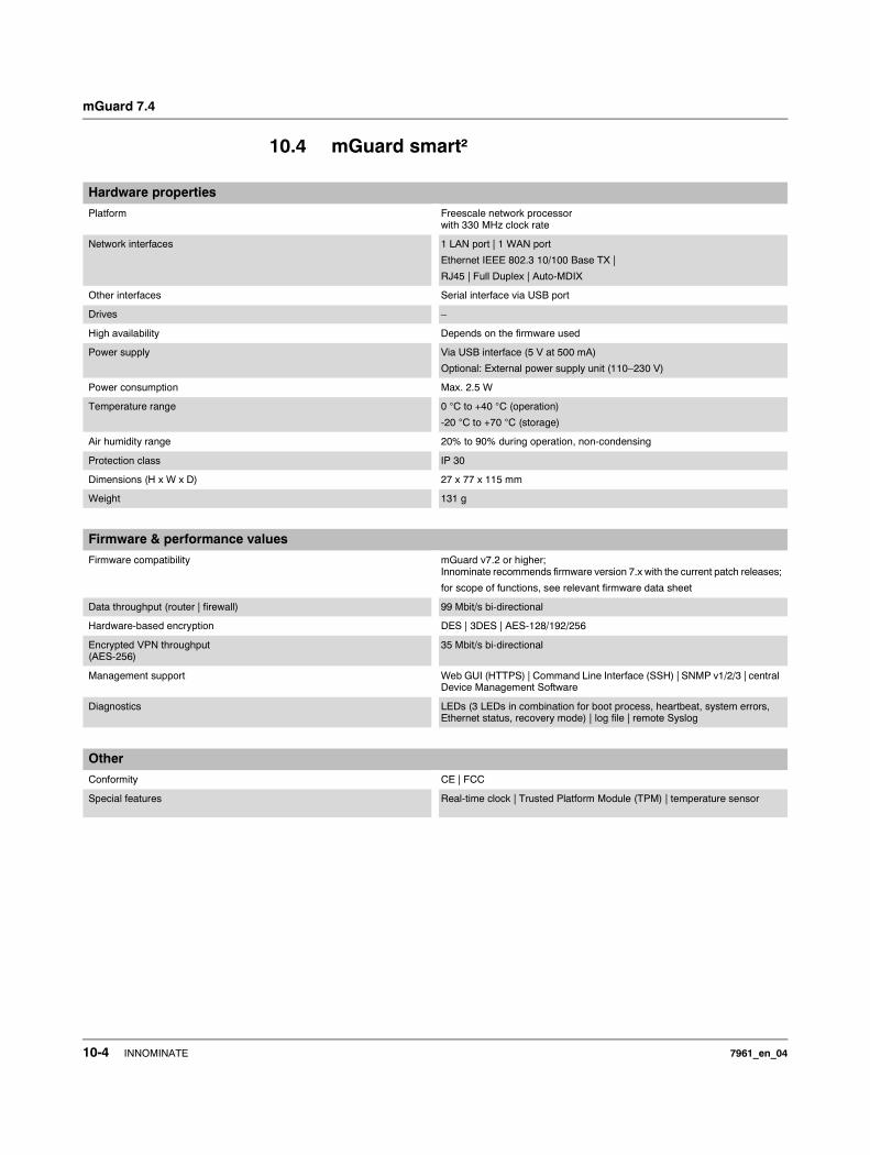
mGuard 7.4
10.4 mGuard smart²
Hardware properties
Platform Freescale network processorwith 330 MHz clock rate
Network interfaces 1 LAN port | 1 WAN port
Ethernet IEEE 802.3 10/100 Base TX |
RJ45 | Full Duplex | Auto-MDIX
Other interfaces Serial interface via USB port
Drives –
High availability Depends on the firmware used
Power supply Via USB interface (5 V at 500 mA)
Optional: External power supply unit (110–230 V)
Power consumption Max. 2.5 W
Temperature range 0 °C to +40 °C (operation)
-20 °C to +70 °C (storage)
Air humidity range 20% to 90% during operation, non-condensing
Protection class IP 30
Dimensions (H x W x D) 27 x 77 x 115 mm
Weight 131 g
Firmware & performance values
Firmware compatibility mGuard v7.2 or higher;Innominate recommends firmware version 7.x with the current patch releases;
for scope of functions, see relevant firmware data sheet
Data throughput (router | firewall) 99 Mbit/s bi-directional
Hardware-based encryption DES | 3DES | AES-128/192/256
Encrypted VPN throughput(AES-256)
35 Mbit/s bi-directional
Management support Web GUI (HTTPS) | Command Line Interface (SSH) | SNMP v1/2/3 | central Device Management Software
Diagnostics LEDs (3 LEDs in combination for boot process, heartbeat, system errors, Ethernet status, recovery mode) | log file | remote Syslog
Other
Conformity CE | FCC
Special features Real-time clock | Trusted Platform Module (TPM) | temperature sensor
10-4 INNOMINATE 7961_en_04
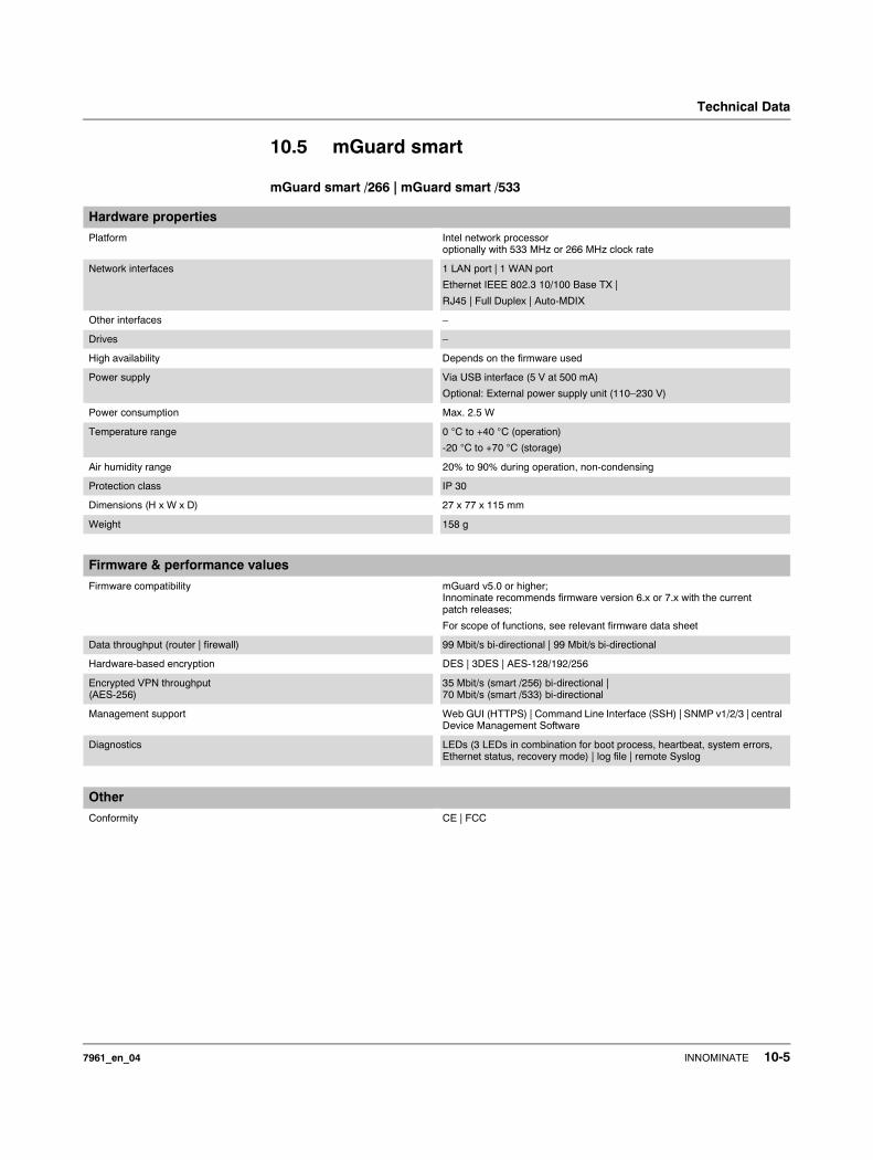
Technical Data
10.5 mGuard smart
mGuard smart /266 | mGuard smart /533
Hardware properties
Platform Intel network processoroptionally with 533 MHz or 266 MHz clock rate
Network interfaces 1 LAN port | 1 WAN port
Ethernet IEEE 802.3 10/100 Base TX |
RJ45 | Full Duplex | Auto-MDIX
Other interfaces –
Drives –
High availability Depends on the firmware used
Power supply Via USB interface (5 V at 500 mA)
Optional: External power supply unit (110–230 V)
Power consumption Max. 2.5 W
Temperature range 0 °C to +40 °C (operation)
-20 °C to +70 °C (storage)
Air humidity range 20% to 90% during operation, non-condensing
Protection class IP 30
Dimensions (H x W x D) 27 x 77 x 115 mm
Weight 158 g
Firmware & performance values
Firmware compatibility mGuard v5.0 or higher;Innominate recommends firmware version 6.x or 7.x with the current patch releases;
For scope of functions, see relevant firmware data sheet
Data throughput (router | firewall) 99 Mbit/s bi-directional | 99 Mbit/s bi-directional
Hardware-based encryption DES | 3DES | AES-128/192/256
Encrypted VPN throughput(AES-256)
35 Mbit/s (smart /256) bi-directional |70 Mbit/s (smart /533) bi-directional
Management support Web GUI (HTTPS) | Command Line Interface (SSH) | SNMP v1/2/3 | central Device Management Software
Diagnostics LEDs (3 LEDs in combination for boot process, heartbeat, system errors, Ethernet status, recovery mode) | log file | remote Syslog
Other
Conformity CE | FCC
7961_en_04 INNOMINATE 10-5
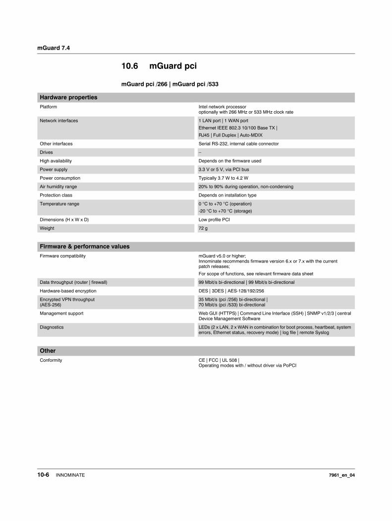
mGuard 7.4
10.6 mGuard pci
mGuard pci /266 | mGuard pci /533
Hardware properties
Platform Intel network processoroptionally with 266 MHz or 533 MHz clock rate
Network interfaces 1 LAN port | 1 WAN port
Ethernet IEEE 802.3 10/100 Base TX |
RJ45 | Full Duplex | Auto-MDIX
Other interfaces Serial RS-232, internal cable connector
Drives –
High availability Depends on the firmware used
Power supply 3.3 V or 5 V, via PCI bus
Power consumption Typically 3.7 W to 4.2 W
Air humidity range 20% to 90% during operation, non-condensing
Protection class Depends on installation type
Temperature range 0 °C to +70 °C (operation)
-20 °C to +70 °C (storage)
Dimensions (H x W x D) Low profile PCI
Weight 72 g
Firmware & performance values
Firmware compatibility mGuard v5.0 or higher;Innominate recommends firmware version 6.x or 7.x with the current patch releases;
For scope of functions, see relevant firmware data sheet
Data throughput (router | firewall) 99 Mbit/s bi-directional | 99 Mbit/s bi-directional
Hardware-based encryption DES | 3DES | AES-128/192/256
Encrypted VPN throughput(AES-256)
35 Mbit/s (pci /256) bi-directional |70 Mbit/s (pci /533) bi-directional
Management support Web GUI (HTTPS) | Command Line Interface (SSH) | SNMP v1/2/3 | central Device Management Software
Diagnostics LEDs (2 x LAN, 2 x WAN in combination for boot process, heartbeat, system errors, Ethernet status, recovery mode) | log file | remote Syslog
Other
Conformity CE | FCC | UL 508 | Operating modes with / without driver via PoPCI
10-6 INNOMINATE 7961_en_04
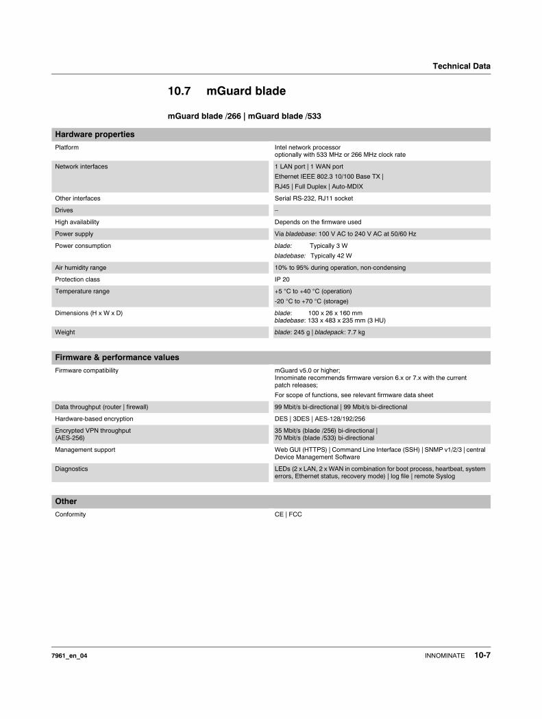
Technical Data
10.7 mGuard blade
mGuard blade /266 | mGuard blade /533
Hardware properties
Platform Intel network processoroptionally with 533 MHz or 266 MHz clock rate
Network interfaces 1 LAN port | 1 WAN port
Ethernet IEEE 802.3 10/100 Base TX |
RJ45 | Full Duplex | Auto-MDIX
Other interfaces Serial RS-232, RJ11 socket
Drives –
High availability Depends on the firmware used
Power supply Via bladebase: 100 V AC to 240 V AC at 50/60 Hz
Power consumption blade: Typically 3 W
bladebase: Typically 42 W
Air humidity range 10% to 95% during operation, non-condensing
Protection class IP 20
Temperature range +5 °C to +40 °C (operation)
-20 °C to +70 °C (storage)
Dimensions (H x W x D) blade: 100 x 26 x 160 mmbladebase: 133 x 483 x 235 mm (3 HU)
Weight blade: 245 g | bladepack: 7.7 kg
Firmware & performance values
Firmware compatibility mGuard v5.0 or higher;Innominate recommends firmware version 6.x or 7.x with the current patch releases;
For scope of functions, see relevant firmware data sheet
Data throughput (router | firewall) 99 Mbit/s bi-directional | 99 Mbit/s bi-directional
Hardware-based encryption DES | 3DES | AES-128/192/256
Encrypted VPN throughput(AES-256)
35 Mbit/s (blade /256) bi-directional |70 Mbit/s (blade /533) bi-directional
Management support Web GUI (HTTPS) | Command Line Interface (SSH) | SNMP v1/2/3 | central Device Management Software
Diagnostics LEDs (2 x LAN, 2 x WAN in combination for boot process, heartbeat, system errors, Ethernet status, recovery mode) | log file | remote Syslog
Other
Conformity CE | FCC
7961_en_04 INNOMINATE 10-7
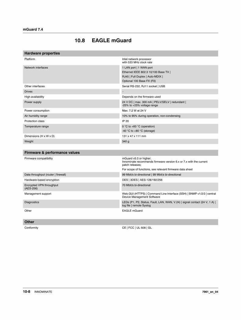
mGuard 7.4
10.8 EAGLE mGuard
Hardware properties
Platform Intel network processorwith 533 MHz clock rate
Network interfaces 1 LAN port | 1 WAN port
Ethernet IEEE 802.3 10/100 Base TX |
RJ45 | Full Duplex | Auto-MDIX |
Optional 100 Base FX (F0)
Other interfaces Serial RS-232, RJ11 socket | USB
Drives –
High availability Depends on the firmware used
Power supply 24 V DC | max. 300 mA | PELV/SELV | redundant |-25% to +25% voltage range
Power consumption Max. 7.2 W at 24 V
Air humidity range 10% to 95% during operation, non-condensing
Protection class IP 20
Temperature range 0 °C to +60 °C (operation)
-40 °C to +80 °C (storage)
Dimensions (H x W x D) 131 x 47 x 111 mm
Weight 340 g
Firmware & performance values
Firmware compatibility mGuard v5.0 or higher;Innominate recommends firmware version 6.x or 7.x with the current patch releases;
For scope of functions, see relevant firmware data sheet
Data throughput (router | firewall) 99 Mbit/s bi-directional | 99 Mbit/s bi-directional
Hardware-based encryption DES | 3DES | AES-128/192/256
Encrypted VPN throughput(AES-256)
70 Mbit/s bi-directional
Management support Web GUI (HTTPS) | Command Line Interface (SSH) | SNMP v1/2/3 | central Device Management Software
Diagnostics LEDs (P1, P2, Status, Fault, LAN, WAN, V.24) | signal contact (24 V, 1 A) | log file | remote Syslog
Other EAGLE mGuard
Other
Conformity CE | FCC | UL 508 | GL
10-8 INNOMINATE 7961_en_04
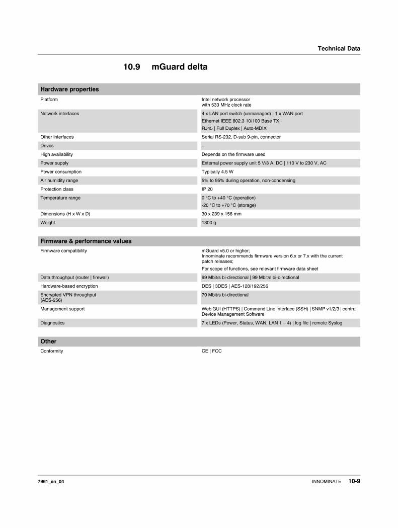
Technical Data
10.9 mGuard delta
Hardware properties
Platform Intel network processorwith 533 MHz clock rate
Network interfaces 4 x LAN port switch (unmanaged) | 1 x WAN port
Ethernet IEEE 802.3 10/100 Base TX |
RJ45 | Full Duplex | Auto-MDIX
Other interfaces Serial RS-232, D-sub 9-pin, connector
Drives –
High availability Depends on the firmware used
Power supply External power supply unit 5 V/3 A, DC | 110 V to 230 V, AC
Power consumption Typically 4.5 W
Air humidity range 5% to 95% during operation, non-condensing
Protection class IP 20
Temperature range 0 °C to +40 °C (operation)
-20 °C to +70 °C (storage)
Dimensions (H x W x D) 30 x 239 x 156 mm
Weight 1300 g
Firmware & performance values
Firmware compatibility mGuard v5.0 or higher;Innominate recommends firmware version 6.x or 7.x with the current patch releases;
For scope of functions, see relevant firmware data sheet
Data throughput (router | firewall) 99 Mbit/s bi-directional | 99 Mbit/s bi-directional
Hardware-based encryption DES | 3DES | AES-128/192/256
Encrypted VPN throughput(AES-256)
70 Mbit/s bi-directional
Management support Web GUI (HTTPS) | Command Line Interface (SSH) | SNMP v1/2/3 | central Device Management Software
Diagnostics 7 x LEDs (Power, Status, WAN, LAN 1 – 4) | log file | remote Syslog
Other
Conformity CE | FCC
7961_en_04 INNOMINATE 10-9

mGuard 7.4
10-10 INNOMINATE 7961_en_04


