La prospection archéologique dans le méthodes et résultats Cherbourg"'
Upload
khangminh22Category
view
0download
0
HAL Id: tel-01280455https://tel.archives-ouvertes.fr/tel-01280455
Submitted on 29 Feb 2016
HAL is a multi-disciplinary open accessarchive for the deposit and dissemination of sci-entific research documents, whether they are pub-lished or not. The documents may come fromteaching and research institutions in France orabroad, or from public or private research centers.
L’archive ouverte pluridisciplinaire HAL, estdestinée au dépôt et à la diffusion de documentsscientifiques de niveau recherche, publiés ou non,émanant des établissements d’enseignement et derecherche français ou étrangers, des laboratoirespublics ou privés.
Méthodes Formelles pour la vérification fonctionnelledes systèmes sur puce cache cohérent
Abderahman Kriouile
To cite this version:Abderahman Kriouile. Méthodes Formelles pour la vérification fonctionnelle des systèmes sur pucecache cohérent. Micro and nanotechnologies/Microelectronics. Université Grenoble Alpes, 2015. En-glish. �NNT : 2015GREAM041�. �tel-01280455�

THÈSEPour obtenir le grade de
DOCTEUR DE L’UNIVERSITÉ DE GRENOBLESpécialité : Informatique
Arrêté ministériel : 7 août 2006
Présentée par
Abderahman KRIOUILE
Thèse dirigée par Radu Mateescuet codirigée par Wendelin Serwe
préparée au sein d’ Inria Grenoble Rhône-Alpes, du laboratoire LIGet de l’Ecole Doctorale Mathématiques, Sciences et Technologies del’Information, Informatique
Formal Methodsfor Functional Verification ofCache-Coherent Systems-on-Chip
Thèse soutenue publiquement le 17 septembre 2015,
devant le jury composé de :
Emmanuelle EncrenazMaître de conférences, LIP6, Université Pierre et Marie Curie, Rapporteur
Franz WotawaProfesseur, IST, Graz University of Technology, Rapporteur
Ghassan ChehaibarDocteur-Ingénieur expert, Bull, Examinateur
Thierry JéronDirecteur de recherche, Inria Rennes, Examinateur
Guilhem BarthesIngénieur expert, STMicroelectronics, Encadrant Industriel
Massimo ZendriDocteur-Ingénieur expert, STMicroelectronics, Encadrant Industriel
Radu MateescuDirecteur de recherche, Inria Grenoble, Directeur de thèse
Wendelin SerweChargé de recherche, Inria Grenoble, Co-directeur de thèse

Abstract
State-of-the-art System-on-Chip (SoC) architectures integrate many different components,such as processors, accelerators, memories, and I/O blocks. Some of those componentsbut not all may have caches. Because the effort of validation with simulation-basedtechniques, as currently used in industry, grows exponentially with the complexity ofthe SoC, this thesis investigates the use of formal verification techniques in this context.More precisely, we use the CADP toolbox to develop and validate a generic formal modelof an SoC compliant with the recent ACE specification proposed by ARM to implementsystem-level cache coherency. We use a constraint-oriented specification style to modelthe general requirements of the specification. We verify system properties on both theconstrained and unconstrained model to detect the cache coherency corner cases. Wetake advantage of the parametrization of the proposed model to produce a comprehensiveset of counterexamples of non-satisfied properties in the unconstrained model.The results of formal verification are then used to improve the industrial simulation-based verification techniques in two aspects. On the one hand, in order to generateclever semi-directed test cases from temporal logic properties, we propose a two-stepapproach. One step consists in generating system-level abstract test cases using model-based testing tools of the CADP toolbox. The other step consists in refining thosetests into interface-level concrete test cases that can be executed at RTL level with acommercial Coverage-Directed Test Generation tool. On the other hand, we suggest touse the formal model to assess the sanity of an interface verification unit.We found that our approach helps in the transition between interface-level and system-level verification, facilitates the validation of system-level properties, and enables earlydetection of bugs in both the SoC and the commercial test-bench.
Key words: System-Level Cache Coherency, Functional Verification, System-on-Chip,System-Level Validation, CADP, Explicit-State Model Checking, Equivalence Checking,Model-Based Testing, Test Coverage, Test Generation
i

Contents
Abstract (English/Français) i
Contents iii
List of figures ix
List of tables xi
1 Introduction 1
1.1 Contributions . . . . . . . . . . . . . . . . . . . . . . . . . . . . . . . . . . 41.2 Outline . . . . . . . . . . . . . . . . . . . . . . . . . . . . . . . . . . . . . 5
I Background and State of the Art 7
2 Background Concepts 9
2.1 Labeled Transition Systems . . . . . . . . . . . . . . . . . . . . . . . . . . 92.2 Process Calculi . . . . . . . . . . . . . . . . . . . . . . . . . . . . . . . . . 102.3 Equivalence Checking . . . . . . . . . . . . . . . . . . . . . . . . . . . . . 112.4 Model checking . . . . . . . . . . . . . . . . . . . . . . . . . . . . . . . . . 12
2.4.1 Temporal Logic Languages . . . . . . . . . . . . . . . . . . . . . . 132.4.2 Propositional Mu-Calculus . . . . . . . . . . . . . . . . . . . . . . 152.4.3 Symbolic Model Checking . . . . . . . . . . . . . . . . . . . . . . . 162.4.4 Explicit-State Model Checking . . . . . . . . . . . . . . . . . . . . 18
2.5 Model-Based Testing . . . . . . . . . . . . . . . . . . . . . . . . . . . . . . 192.5.1 Definition of ioco Relation for IOTS . . . . . . . . . . . . . . . . . 202.5.2 Test Generation and Test Execution for LTSs . . . . . . . . . . . . 202.5.3 Test Selection in Model-Based Testing . . . . . . . . . . . . . . . . 21
2.6 CADP Toolbox . . . . . . . . . . . . . . . . . . . . . . . . . . . . . . . . . 222.6.1 Representing LTSs in CADP . . . . . . . . . . . . . . . . . . . . . 222.6.2 Modeling Language LNT . . . . . . . . . . . . . . . . . . . . . . . 222.6.3 Temporal Logic Language MCL . . . . . . . . . . . . . . . . . . . . 232.6.4 Script Verification Language (SVL) . . . . . . . . . . . . . . . . . . 25
iii
Contents
3 State of the Art: Formal Validation of Hardware 27
3.1 Use of Formal Verification . . . . . . . . . . . . . . . . . . . . . . . . . . . 283.1.1 Formal Verification using Model Checking . . . . . . . . . . . . . . 293.1.2 Formal Verification using Equivalence Checking . . . . . . . . . . . 303.1.3 Formal Verification using Theorem Proving . . . . . . . . . . . . . 30
3.2 Semi-Formal Verification and Assertions . . . . . . . . . . . . . . . . . . . 313.3 System-Level Approaches . . . . . . . . . . . . . . . . . . . . . . . . . . . 32
3.3.1 SystemC Transaction Level Models . . . . . . . . . . . . . . . . . . 323.3.2 High-Level Formal Models and Abstractions . . . . . . . . . . . . . 33
3.4 Test Generation strategies . . . . . . . . . . . . . . . . . . . . . . . . . . . 343.4.1 Coverage-Directed Test Generation . . . . . . . . . . . . . . . . . . 353.4.2 Faults-Based Test Generation . . . . . . . . . . . . . . . . . . . . . 353.4.3 Combining Model-Based and Coverage-Directed Testing . . . . . . 36
3.5 Applications of Formal Verification to Hardware Cache Coherency . . . . 363.6 Applications of CADP to Hardware Validation . . . . . . . . . . . . . . . 37
3.6.1 Formal Modeling . . . . . . . . . . . . . . . . . . . . . . . . . . . . 373.6.2 Functional Verification . . . . . . . . . . . . . . . . . . . . . . . . . 383.6.3 Model-Based Testing . . . . . . . . . . . . . . . . . . . . . . . . . . 393.6.4 Performance Evaluation . . . . . . . . . . . . . . . . . . . . . . . . 40
II Formal Modeling of a System-Level Cache Coherent SoC 43
4 System Level Cache Coherency with AMBA 4 ACE 45
4.1 Introduction . . . . . . . . . . . . . . . . . . . . . . . . . . . . . . . . . . . 454.2 System-Level Cache Coherency . . . . . . . . . . . . . . . . . . . . . . . . 454.3 AMBA 4 ACE protocol . . . . . . . . . . . . . . . . . . . . . . . . . . . . 474.4 ACE States . . . . . . . . . . . . . . . . . . . . . . . . . . . . . . . . . . . 484.5 ACE Ports and Channels . . . . . . . . . . . . . . . . . . . . . . . . . . . 484.6 ACE Transactions . . . . . . . . . . . . . . . . . . . . . . . . . . . . . . . 494.7 Requirements on the Global Ordering of Transactions . . . . . . . . . . . 524.8 Discussion . . . . . . . . . . . . . . . . . . . . . . . . . . . . . . . . . . . . 53
5 Formally Modeling an ACE-based SoC using LNT 55
5.1 Introduction . . . . . . . . . . . . . . . . . . . . . . . . . . . . . . . . . . . 555.2 General Description of the Formal Model . . . . . . . . . . . . . . . . . . 55
5.2.1 Types and Data Structures . . . . . . . . . . . . . . . . . . . . . . 565.2.2 Channels . . . . . . . . . . . . . . . . . . . . . . . . . . . . . . . . 575.2.3 Channel Structures . . . . . . . . . . . . . . . . . . . . . . . . . . . 585.2.4 AXI Slave: Shareable Memory . . . . . . . . . . . . . . . . . . . . 615.2.5 ACE Masters . . . . . . . . . . . . . . . . . . . . . . . . . . . . . . 635.2.6 ACE-Lite Masters . . . . . . . . . . . . . . . . . . . . . . . . . . . 635.2.7 Cache Coherent Interconnect (CCI) . . . . . . . . . . . . . . . . . 64
iv

Contents
5.3 Modeling Global Ordering Requirements . . . . . . . . . . . . . . . . . . . 645.4 State Space Generation . . . . . . . . . . . . . . . . . . . . . . . . . . . . 64
5.4.1 Shareable Focused Model . . . . . . . . . . . . . . . . . . . . . . . 655.4.2 Optimized Model . . . . . . . . . . . . . . . . . . . . . . . . . . . . 66
5.5 Model Validation . . . . . . . . . . . . . . . . . . . . . . . . . . . . . . . . 665.5.1 Absence of Deadlocks . . . . . . . . . . . . . . . . . . . . . . . . . 685.5.2 Absence of Livelocks . . . . . . . . . . . . . . . . . . . . . . . . . . 685.5.3 Complete Execution of Transactions . . . . . . . . . . . . . . . . . 68
5.6 First Industrial Results . . . . . . . . . . . . . . . . . . . . . . . . . . . . 695.7 Discussion . . . . . . . . . . . . . . . . . . . . . . . . . . . . . . . . . . . . 69
III Model Exploitation 71
6 Model Checking System-Level Properties 73
6.1 Introduction . . . . . . . . . . . . . . . . . . . . . . . . . . . . . . . . . . . 736.2 System-Level Cache Coherency Analysis . . . . . . . . . . . . . . . . . . . 73
6.2.1 Cache Line States Coherency Requirements . . . . . . . . . . . . . 746.2.2 Data Integrity Requirements . . . . . . . . . . . . . . . . . . . . . 746.2.3 Messaging Consistency Requirements . . . . . . . . . . . . . . . . . 75
6.3 System-Level Properties . . . . . . . . . . . . . . . . . . . . . . . . . . . . 756.3.1 Cache States Coherency . . . . . . . . . . . . . . . . . . . . . . . . 766.3.2 Data Integrity . . . . . . . . . . . . . . . . . . . . . . . . . . . . . 776.3.3 Consistency of Coherency Parameters . . . . . . . . . . . . . . . . 80
6.4 Model-Checking Results . . . . . . . . . . . . . . . . . . . . . . . . . . . . 836.4.1 Cache State Coherency Results . . . . . . . . . . . . . . . . . . . . 836.4.2 Data Integrity Results . . . . . . . . . . . . . . . . . . . . . . . . . 846.4.3 Consistency of Coherency Parameters Results . . . . . . . . . . . . 856.4.4 Example of a Non Satisfied Property . . . . . . . . . . . . . . . . . 856.4.5 Reproduction of a Previously Fixed Bug . . . . . . . . . . . . . . . 86
6.5 Conclusion . . . . . . . . . . . . . . . . . . . . . . . . . . . . . . . . . . . 87
7 From Temporal Logic Properties to Clever Test Cases 89
7.1 Introduction . . . . . . . . . . . . . . . . . . . . . . . . . . . . . . . . . . . 897.2 Computation of Interesting Configurations Containing Faults . . . . . . . 907.3 Model Checking Based Test Generation . . . . . . . . . . . . . . . . . . . 91
7.3.1 Unique Dirty Cache State Coherency Test Purpose . . . . . . . . . 917.3.2 Unique Clean Cache State Coherency Test Purpose . . . . . . . . . 927.3.3 Shareable Memory Data Integrity Test Purpose . . . . . . . . . . . 947.3.4 Model-Based Test Generation Process . . . . . . . . . . . . . . . . 94
7.4 Industrial Results and Impact . . . . . . . . . . . . . . . . . . . . . . . . . 957.4.1 IVK Dynamic Test Benches . . . . . . . . . . . . . . . . . . . . . . 967.4.2 Making the Test Bench Ready for System-Level Verification . . . . 98
v
Contents
7.4.3 Industrial Results . . . . . . . . . . . . . . . . . . . . . . . . . . . 99
8 Sanity of a Formal Check List 101
8.1 Modeling Formal Checks in LNT . . . . . . . . . . . . . . . . . . . . . . . 1018.1.1 C1: No Overlapping Read Write Transactions . . . . . . . . . . . . 1028.1.2 C2: No Maintenance Transaction while Pending Shareable Trans-
action . . . . . . . . . . . . . . . . . . . . . . . . . . . . . . . . . . 1038.1.3 C3: No Shareable Read Transaction while Pending Maintenance
Transaction . . . . . . . . . . . . . . . . . . . . . . . . . . . . . . . 1048.1.4 C4: No WriteBack or WriteClean while WriteUnique or WriteLine-
Unique . . . . . . . . . . . . . . . . . . . . . . . . . . . . . . . . . 1068.1.5 C5: No Shareable write Transaction while Maintenance Transaction1078.1.6 C6: Snoop Response when Memory Update in Progress . . . . . . 1088.1.7 C7: Order between Channels AC and CD . . . . . . . . . . . . . . 1108.1.8 C8: Order between Channels AC and CR . . . . . . . . . . . . . . 1118.1.9 C9: PassDirty and IsShared Check . . . . . . . . . . . . . . . . . . 112
8.2 Local Sanity of Each Check . . . . . . . . . . . . . . . . . . . . . . . . . . 1138.3 Global Sanity of the List of Checks . . . . . . . . . . . . . . . . . . . . . . 1148.4 Improvement of System Coverage Infrastructure . . . . . . . . . . . . . . . 1158.5 Industrial Results . . . . . . . . . . . . . . . . . . . . . . . . . . . . . . . . 116
9 Conclusion 119
9.1 Summary of Contributions . . . . . . . . . . . . . . . . . . . . . . . . . . . 1199.2 Research Perspectives . . . . . . . . . . . . . . . . . . . . . . . . . . . . . 1219.3 Scientific Publications and Communications . . . . . . . . . . . . . . . . . 122
9.3.1 Scientific Publications . . . . . . . . . . . . . . . . . . . . . . . . . 1229.3.2 Scientific Communications . . . . . . . . . . . . . . . . . . . . . . . 123
IV Appendix 125
A Model Checking Properties 127
A.1 Unique dirty coherency . . . . . . . . . . . . . . . . . . . . . . . . . . . . 127A.2 Unique clean coherency . . . . . . . . . . . . . . . . . . . . . . . . . . . . 128A.3 Shared dirty coherency . . . . . . . . . . . . . . . . . . . . . . . . . . . . . 128A.4 Shared clean coherency . . . . . . . . . . . . . . . . . . . . . . . . . . . . 129A.5 Unique clean data integrity . . . . . . . . . . . . . . . . . . . . . . . . . . 129A.6 Shared dirty data integrity . . . . . . . . . . . . . . . . . . . . . . . . . . 131A.7 Shared clean data integrity . . . . . . . . . . . . . . . . . . . . . . . . . . 132A.8 Shareable memory data integrity . . . . . . . . . . . . . . . . . . . . . . . 134A.9 Read response no PassDirty property . . . . . . . . . . . . . . . . . . . . . 134A.10 Read response no IsShared property . . . . . . . . . . . . . . . . . . . . . 135A.11 Read response no IsSharedDirty property . . . . . . . . . . . . . . . . . . 136
vi
Contents
A.12 Coherency response PassDirty property . . . . . . . . . . . . . . . . . . . 136A.13 Coherency response no PassDirty property . . . . . . . . . . . . . . . . . . 137A.14 Coherency response IsShared property . . . . . . . . . . . . . . . . . . . . 138A.15 Coherency response no IsShared property . . . . . . . . . . . . . . . . . . 138
Bibliography 150
Glossary 151
vii

List of Figures
2.1 LTS example . . . . . . . . . . . . . . . . . . . . . . . . . . . . . . . . . . 102.2 LTL operators . . . . . . . . . . . . . . . . . . . . . . . . . . . . . . . . . 132.3 CTL operators . . . . . . . . . . . . . . . . . . . . . . . . . . . . . . . . . 142.4 Coffee machine example . . . . . . . . . . . . . . . . . . . . . . . . . . . . 152.5 Impact of variable ordering on BDD size . . . . . . . . . . . . . . . . . . . 172.6 LNT module example . . . . . . . . . . . . . . . . . . . . . . . . . . . . . 24
4.1 Example of a heterogeneous SoC using System-Level Cache Coherency . . 464.2 ACE: AXI Coherency Extension . . . . . . . . . . . . . . . . . . . . . . . 474.3 ACE states of a cache line . . . . . . . . . . . . . . . . . . . . . . . . . . . 484.4 Structures of ACE, ACE-Lite, AXI ports . . . . . . . . . . . . . . . . . . 494.5 Execution scenario of a ReadOnce transaction . . . . . . . . . . . . . . . . 50
5.1 Model architecture . . . . . . . . . . . . . . . . . . . . . . . . . . . . . . . 565.2 LNT process representing the shareable memory . . . . . . . . . . . . . . 62
6.1 State-based and action-based view of a cache line . . . . . . . . . . . . . . 766.2 Data integrity counterexample . . . . . . . . . . . . . . . . . . . . . . . . 866.3 Fixed data integrity counterexample . . . . . . . . . . . . . . . . . . . . . 87
7.1 Model-based test generation flow . . . . . . . . . . . . . . . . . . . . . . . 907.2 Function CIC to compute a set of interesting configurations containing faults 907.3 IVK generation flow . . . . . . . . . . . . . . . . . . . . . . . . . . . . . . 977.4 IVK cci400_r1p2 test bench architecture . . . . . . . . . . . . . . . . . . . 98
ix

List of Tables
3.1 CADP: formal modeling effort in past projects . . . . . . . . . . . . . . . 383.2 CADP: functional verification results . . . . . . . . . . . . . . . . . . . . . 393.3 CADP: Model-based testing results . . . . . . . . . . . . . . . . . . . . . . 40
4.1 Snoop transactions and their original transactions . . . . . . . . . . . . . 52
5.1 Experimental results: state space generation of shareable focused modelconfigurations . . . . . . . . . . . . . . . . . . . . . . . . . . . . . . . . . . 65
5.2 Experimental results: state space generation of optimized model configu-rations . . . . . . . . . . . . . . . . . . . . . . . . . . . . . . . . . . . . . . 67
6.1 Cache coherency requirements analysis . . . . . . . . . . . . . . . . . . . . 746.2 Model checking results: cache state coherency . . . . . . . . . . . . . . . . 836.3 Model checking results: : data integrity . . . . . . . . . . . . . . . . . . . 846.4 Model checking results: coherency parameters . . . . . . . . . . . . . . . . 85
7.1 Experimental test case extraction results . . . . . . . . . . . . . . . . . . . 957.2 Industrial results: bugs report . . . . . . . . . . . . . . . . . . . . . . . . . 99
xi

Chapter 1
Introduction
The integration of ever more functionalities in set-top boxes or mobile appliances such assmart-phones increases the complexity of both the embedded software and the hardwarearchitecture. The design and validation of embedded applications address both thesoftware and the hardware aspects of the system. In our study we are interested in thehardware part of embedded applications. The latter is usually a complex System-on-Chip(SoC), featuring a significant number of heterogeneous components. Indeed, a typicalSoC includes nowadays not only processors and memory, but also dedicated hardwareaccelerators and (analog) I/O blocks. Integrating caches into some of these components(in particular, into processors and hardware accelerators) can increase performanceand reduce power consumption, for instance by avoiding accesses to (possibly off-chip)memory.
In the past, prevalence of fast processors encouraged designers to manage cache coherencyin software, taking advantage of the flexibility of software solutions. However, due toincreased software complexity, a recent trend [MHS12, Tho12] is to introduce hardwaresupport for cache coherency, lightening the load on the processors, thus improvingperformance and lowering power consumption. In this vein, ARM proposed AMBA 4ACE (AXI Coherency Extensions) [ARM13], which is becoming a de facto industrialstandard for system-level cache coherence in heterogeneous SoCs (ACE explicitly includesoperations, called ACE-Lite operations, for components without cache). ACE is requiredby the ARM R© big.LITTLETM solution [PG11], which takes advantage of two processors(i.e., a “big” and a “LITTLE” one) for low-power SoCs. Also, STMicroelectronics is aboutto integrate system level cache coherency (based on ACE) in its upcoming heterogeneousSoCs for a family of commercial set-top-boxes supporting multiple Ultra HD flows on asingle chip.
Cache coherence protocols are known to be complex and difficult to validate. Therefore,assuring system-level cache coherency is one of the major challenges faced by architects
1
Chapter 1. Introduction
of current SoC designs. In fact, functional verification continues to be one of themost expensive and time-consuming steps in a typical SoC design flow. Validating aconcurrent system has always been a major issue for systems designers. In practice, mostwidely used techniques are based on extensive simulation due to the related flexibility.Given that the related validation effort grows exponentially with the complexity ofhardware architectures, we study the application of formal verification techniques (rootedin concurrency theory), where the human modeling effort increases linearly with thecomplexity of architectures. Thus, the exponential complexity is handled by automatedverification tools.
In computer science, concurrency is a characteristic of systems in which several com-putations are executed simultaneously, potentially interacting with each other. Thisnotion is intended to cover a wide range of system architectures, from tightly coupled,mostly synchronous parallel systems, to loosely coupled, largely asynchronous distributedsystems. We refer to systems exhibiting concurrency as concurrent systems, and wecall computer programs written for concurrent systems concurrent programs [CS96].Concurrency theory [AFV01] is an active field of research in theoretical computer science,which proposes a variety of formalisms for modeling and reasoning about concurrentsystems.
The validation of concurrent systems is composed of two different branches: functionalverification and performance evaluation. The former consists of verifying the correctnessof the system, i.e., verifying that the system respects the specified functional requirements.The latter focuses on the qualitative aspects. Besides, performance evaluation focuseson quantitative aspects such as measuring the response time of the system and theend-to-end communication delay.
In this thesis, we are interested in functional verification. We aim at validating thecorrectness of the behavior of a hardware concurrent system. In order to functionallyverify a hardware design, the following formal methods are often used: elaborating amathematical correctness proof or checking all possible conditions. The first method isimplemented by theorem provers, which are based on automated deduction, a subfieldof automated reasoning and mathematical logic dealing with proving mathematicaltheorems by computer programs. The second method verifies if a formal model satisfiesthe properties of the system. The properties can be expressed with the same formalism asthe model. In this case we talk about equivalence checking. Otherwise, if the propertiesare expressed in a different formalism than the model, then we talk about model checking.
Model checking has several industrial successes due to its powerful debugging capabilitiesand its easier integration within the industrial development cycle compared to theoremproving. The most critical issues of formal verification are the state explosion problemand the fact that it is hard to deal with parameterized systems. The application of basic
2

formal methods at the RTL1 level are limited to designs of up to 500 flip-flops [Kyu03].To overcome those limitations, several approaches are proposed in the literature usingtechniques based on reachability analysis [VGS12], design state abstraction [CTVW04],design decomposition [JOS+01], or state projection [McM00].
Concretely, we use the CADP toolbox [GLMS13] for the analysis of system-level cachecoherency in a heterogeneous SoC. We are interested in applying and illustrating thefeasibility of the following formal methods on an industrial case study: process calculi (inparticular the modeling language LNT [CCG+14]), explicit-state model checking (with avalue-passing extension of modal µ-calculus), equivalence checking (based on bisimulationand simulation preorder relations), and test case generation based on a sound theory(namely, model-based testing and input-output conformance).
As a first step, we develop a generic formal LNT model of an SoC, including an ACE-based cache coherent interconnect and abstractions of master and slave components(e.g., processors and shared memory). This model is a system-level representation of thespecified behavior, in the sense that the model focuses on the interactions between thecomponents of the system, preserving their order. Our model considers a communicationon a hardware interface channel to be atomic. This model can be considered as ahigh-level formal specification of the ACE protocol. The model is parametric and canbe instantiated with different configurations (number of masters, number of cache lines,and number of memory lines) and different sets of supported ACE transactions. We usea constraint-oriented specification style to model the global requirements of the ACEspecification, which must be guaranteed by any implementation. The LNT model enablesSTMicroelectronics architects to interactively simulate a coherent SoC at system level.We also express several correctness properties in the MCL language [MT08] and checkthem on the LNT model using the EVALUATOR 4.0 model checker.
To benefit from the formal verification of the model of the ACE-based SoC (i.e., modelingthe behavior allowed by the specification) in a concrete industrial case study, we explorethe generation of tests in a semi-formal test bench. A semi-formal test bench is asimulation test bench enhanced by assertions expressed by formal checks. These assertionsmonitor the behavior of the system triggered by tests. However, the success of semi-formalverification, both in terms of total effort spent and final verification coverage achieved,depends heavily on the quality of the tests executed during simulation. Effective testscan achieve higher verification coverage in shorter time, saving engineering resources andimproving confidence in the quality of the Design Under Verification (DUV).
Automatic test generation using model checking is one of the most promising approachesfor high-quality test generation. However, for large designs, model checking rapidlyfaces state explosion when considering hardware protocols in all their details. Wepropose to generate directed “abstract” tests from our formal model, using a test
1Register Transfer Level
3

Chapter 1. Introduction
generator implementing model-based testing techniques issued from the test conformance
theory [Tre92]. We take advantage of the counterexamples extracted by model checking
from the formal model to generate interesting configurations of the model. Thoseconfigurations are used for automatic generation of abstract test cases. Then, theabstract test cases are refined (by introducing randomization) to “concrete” tests, whichcan be run on an RTL level test bench, taking advantage of an industrial coverage-directed
test generation (CDTG) solver.
Furthermore, we apply cross-checking techniques to validate and complete an interface
verification unit (IV unit) consisting in a formal checks list (used for formal coverage).We apply equivalence checking techniques to compare our formal model and a parallelcomposition of the formal checks.
Notice that the hardware design community has its proper terminology. In hardwaredesign, the term verification denotes a large set of techniques (including emulation,simulation, rapid prototyping, and testing) to detect design mistakes; these techniquesare not necessarily formal, and one must use the term formal verification when referringto mathematically based techniques [Gar13]. The verified system is generally calledDesign Under Test (DUT): the system in this case is a design. The expression “test” isused due to the large use of testing techniques in the hardware verification context. Withthe generalization of verification approaches in hardware context, the terminology Design
Under Verification (DUV) is increasingly used. In other contexts, different terminologiesare used to name the verified system. For the Model-Based Testing (MBT) community,it is named the System Under Test (SUT). In fact, the system can be either a softwareprogram or a hardware design, and the activity in MBT is restricted to testing. In formalverification we speak about the system under verification (SUV), which is more generalbecause it includes software and hardware, as well as all verification activities. In orderto avoid confusion, we will use the expression Design Under Verification (DUV) in allparts of the thesis, because, we are interested in different verification activities, including,but not restricted to, testing, applied to a hardware design.
1.1 Contributions
The principal contributions of this thesis are the following.
1. Producing a parametric formal model of an industrial case study [KS13], applyingrelevant abstractions to balance between automatic extraction of relevant verificationreports and state space explosion problems. A large Petri net derived from ourLNT model was provided as Model Checking Contest 2014 benchmark2.
2. Using the parametrization of our formal model in order to produce a comprehensive
2http://mcc.lip6.fr/pdf/ARMCacheCoherence-form.pdf
4
1.2. Outline
set of counterexamples of a property rather than a unique counterexample. As aresult, it becomes possible to provide all the scenarios triggering a violation of theproperty [KS15].
3. Proposing a two-step approach to use model-based testing in order to generateclever semi-directed system level test cases from temporal logic properties. Weuse CADP to generate directed “abstract” system-level test cases, which are thenrefined with a commercial CDTG solver into interface-level “concrete” test casesthat can be executed at RTL level [KS15].
4. We also propose the notion of a system verification unit (SV unit) to measurethe coverage and verdicts of system-level properties. The SV unit is added to thesemi-formal test bench and it is connected to all interfaces of the system. ThisSV unit is implemented by Property Specification Language (PSL) [oEE10] formalchecks [KS15].
5. Proposing a way to assess the sanity of an industrial interface verification unit (IVunit), consisting of a set of behaviors to cover. In our study, we focus on the complexbehaviors expressed by so-called checks of a commercial IV unit. Our solutionenabled us to discover a missing check in a widespread commercial verificationunit [KS15].
An interesting industrial contribution consists in finding a major limitation twenty monthsbefore it is confirmed by other approaches. In addition, our other contributions allow usto produce the list of all scenarios triggering this limitation and to propose a possiblesolution for each scenario.
1.2 Outline
This thesis is organized as follows. The first part presents a general background andthe state of the art. Chapter 2 presents the background concepts used in this thesis.Chapter 3 surveys the state of the art of the formal verification applications in hardwaredesign.
The second part of the thesis presents the formal modeling of a system-level cachecoherent SoC. Chapter 4 introduces the s [AFV01]ystem-level cache coherency as well asits recent standard AMBA 4 ACE specification. Chapter 5 presents our first contributionconsisting in a formal model of an AMBA 4 ACE-based SoC.
The third part of the thesis displays the different exploitations of the formal model.Chapter 6 presents the verification of global properties of the system using explicit-statemodel checking. Chapter 7 exhibits our test generation methodology based on modelchecking counterexamples (i.e., contributions 2, 3, and 4). Chapter 8 describes the
5
Chapter 1. Introduction
validation and completion of an industrial IV unit using equivalence checking. Besides,we present the experimental results and the industrial impact of our work as a section atthe end of each Chapter.
6

Background and State of the Art
7

Chapter 2
Background Concepts
In this chapter we present the background concepts of our thesis. We start by presentingthe underlying LTS (Labeled Transition System) model as well as the process calculusformalism used to describe LTSs. After that, we explore the principal concepts neededto understand the different formal techniques used in the scope of this thesis, namelymodel checking, equivalence checking, and model-based testing. Finally, we introduce theCADP toolbox, which offers an implementation for several formal methods techniques.
2.1 Labeled Transition Systems
Intuitively, a Labeled Transition System (LTS) is a state/transition graph, in whichthe states do not provide information except the indication of the initial state. Theinformation is represented in the labels or actions related to transitions. Figure 2.1 showssome examples of LTSs.
Formally, an LTS is a formalism used as the basis for describing the behavior of processessuch as specifications, implementations, and tests.
Definition 2.1.1. An LTS is a quadruple M = (Q,A,T,q0) where:
• Q is a the set of states;
• A the set of actions (transition labels); the set A contains the invisible action τ ,
which denotes internal (unobservable) activity.
• T ⊆ Q × A × Q is the transition relation;
• q0 ∈ Q is the initial state.
A transition (p, a, q) in T (also noted pa−→ q) means that the system can evolve from
9

Chapter 2. Background Concepts
Figure 2.1 – LTS example
state p to state q by performing action a. If W is a language included in A*, then p W−→qdenotes a transition sequence p a1−→ q2
a2−→... an−→q such that the word a1a2...an belongs toW . All states q of Q are assumed to be reachable from the initial state q0 via sequencesof transitions in T (i.e., q0
A∗−→ q). In the sequel, visible actions of A are denoted by a,and (both visible and invisible) actions of A are denoted by b.
An LTS with the distinction between input and output actions is called an Input-Output
Transition System (IOTS). Input actions are actions from user to machine. Outputactions are actions from machine to user. IOTS have the property that any input actionis always enabled in any state. IOTS(Li, Lu) is the class of input-output transitionsystems with inputs in Li and outputs in Lu. (Li,Lu) is a partition of the set of labels L
of IOTS(Li, Lu), i.e., Li ∩ Lu = ∅ and Li ∪ Lu = L [Tre99].
For large systems, it is impractical to describe explicitly the LTS of the system. Thus,we use higher level formalisms, such as process calculi issued from concurrency theory, inorder to describe LTSs.
2.2 Process Calculi
Process Calculi (also called process algebras [AFV01]) represent a family of formalismsproposed by concurrency theory.
The word process refers to a behavior of a system, for instance the execution of a softwaresystem, the actions of a machine or even the actions of a human being. Behavior isthe set of events or actions that a system can perform, the order in which they can beexecuted and maybe other aspects of this execution such as timing or probabilities. Ingeneral, we describe only certain aspects of the behavior, disregarding other aspects: weare considering an abstraction or idealization of the “real” behavior. We can say that we
10
2.3. Equivalence Checking
have an observation of the behavior. We call action the chosen unit of observation.
Process calculi provide means for a high-level description of interactions, communications,and synchronizations between a set of independent components of a concurrent system.They also provide laws to describe, manipulate, and analyze processes.
Process calculi are characterized by the following main features:
• Representing interactions between independent processes as communication(message-passing on communication gates), and not the modification of sharedvariables. This corresponds to a black box view of the system. In fact, the systemcan be analyzed by observing the communications between the components of thesystem instead of the state of the internal variables of the system (used in a white
box view).
• Describing processes and systems using a small set of primitives and operators inorder to combine those primitives. (Primitives and operators are defined in thegrammar of each process calculus language).
• Using interleaving semantics for compositions of processes. If two processes A
and B execute respectively an action a and b in parallel, then the global behavior(represented by an LTS) will have two possible paths: a then b and b then a. Twoactions never occur at the same time (i.e., asynchronous semantics).
2.3 Equivalence Checking
The equivalence checking compares two graphs (e.g., LTSs) modulo an equivalencerelation. In this thesis, we compare LTSs modulo0 several bisimulation relations. Abisimulation is a binary relation between states, associating states that behave in thesame way.
Two LTSs M1 = (Q1, A, T1, q01) and M2 = (Q2, A, T2, q02) are related modulo anequivalence relation R (noted M1 R M2) if and only if their initial states are relatedmodulo R (noted q01 R q02).
For each equivalence Requ, the corresponding preorder relation Iequ, which indicateswhether a state p is “simulated” by a state q (resp. q is “simulated” by p) is obtained bykeeping only condition 1 (resp. 2) in the definition of Requ.
• strong bisimulation [Par81]: two states p and q are related modulo strong equivalence(p Rstr q) if and only if:
1. for each transition pb−→ p′ in T1
11
Chapter 2. Background Concepts
there is a transition qb−→ q′ in T2
such that p′ Rstr q′
2. for each transition qb−→ q′ in T2
there is a transition pb−→ p′ in T1
such that p′ Rstr q′
• branching bisimulation [vGW89]: two states p and q are are related modulo branch-ing equivalence (p Rbra q) if and only if:
1. for each transition pb−→ p′ in T1
(a) either b = τ and p′ Rbra q, or
(b) there is a sequence qτ∗−→ q′ b−→ q′′ in T2∗
such that p Rbra = q′ and p′ Rbra q′′
2. for each transition qb−→ q′ in T2
(a) either b = τ and p Rbra q′, or
(b) there is a sequence pτ∗−→ p′ b−→ p′′ in T1∗
such that p′ Rbra q and p′′ Rbra q′
• divergence-sensitive branching bisimulation (divbranching) [VGW96] differs frombranching bisimulation only in the way cycles of internal transitions τ (also calleddivergences) are treated. It is known that all states present on a cycle of internaltransitions belong to the same branching equivalence class. While divergences areeliminated in the LTS obtained by reduction modulo ordinary branching bisimu-lation, a self-looping internal transition is kept in each such equivalence class inthe LTS obtained by divergence-sensitive branching bisimulation. Unlike branchingbisimulation, divergence-sensitive branching bisimulation preserves inevitabilityproperties.
Various algorithms are implemented to perform comparison of graphs or to minimizegraphs according to a specific bisimulation.
2.4 Model checking
The model checking [CGP00, BK+08] verifies that a model satisfies a property expressedin a different formalism. In model checking, the system is described by a finite statemodel (e.g., an LTS) and the properties are expressed in temporal logic. Model checkingverifies formally whether the model satisfies a property by automatic exhaustive searchover the state space.
A model checker is a software tool that, given a description of a model M and a propertyϕ, decides whether M satisfies ϕ. The model checker returns True if the property is
12

2.4. Model checking
Figure 2.2 – LTL operators
satisfied, otherwise it returns False, and provides a counterexample. It can also providea witness when the property is satisfied.
2.4.1 Temporal Logic Languages
A Temporal Logic is a system of rules and symbols for representing, and reasoning about,propositions qualified in terms of time. In a temporal logic we can express statementslike “an event A is always possible”, “an event A will eventually happen”, or “an event Ais always possible until an event B happens”. Numerous temporal logics were proposedin the literature. Two principal families of temporal logics are linear time logics [Pnu77]and branching time logics [BAPM83].
• The Linear time temporal logic (LTL1) is a modal temporal logic with modalitiesreferring to discrete time (natural numbers). LTL operators are evaluated over setsof paths, i.e., over infinite, linear sequences of states: “s[0] -> s[1] -> ... -> s[t] ->s[t + 1] -> ...”, where s[t] expresses the tth state of a sequence. LTL provides thefollowing temporal operators (illustrated graphically in Fig. 2.2):
– “Finally” (or “future”): “F p” is true in s[t] if and only if p is true in somes[t’] with t’ ≥ t.
– “Globally” (or “always”): “G p” is true in s[t] if and only if p is true in alls[t’] with t’ ≥ t.
– “Next”: “X p” is true in s[t] if and only if p is true in s[t + 1].
– “Until”: “p U q” is true in s[t] if and only if q is true in some state s[t’] witht’ ≥ t and p is true in all states s[t”] with t ≤ t” < t’.
1Linear Temporal Logic
13

Chapter 2. Background Concepts
Figure 2.3 – CTL operators
• Branching time temporal logic (CTL2 and its variants) considers a tree-like struc-tured model of time, in which the future is not determined; there are differentpaths in the future, any one of which might be an actual path that is realized.CTL operators (illustrated graphically in Fig. 2.3) are evaluated over trees. Everytemporal operator (F; G; X; U) is preceded by a path quantifier (A or E), whereA expresses universal modalities (or necessity) (AF; AG; AX; AU): the temporalformula is true in all paths starting in the current state; and E expresses existentialmodalities (or possibility) (EF; EG; EX; EU): the temporal formula is true in somepaths starting in the current state.
In this thesis, we use a branching time temporal logic. To explain the interest of thistemporal logic in comparison with the widely used linear logic, we present the classicalexample of the coffee machine.
Example 1 Figure 2.4 shows the LTSs of two coffee machines (a) and (b). The machine(a) works properly: once the 30cts is supplied, the machine is in a state in which onecan choose Coffee or Tea. For the machine (b), when the sum of 30cts is supplied,the machine passes non-deterministically to one of the two states: a state in whichthe machine can only provide Coffee and another state in which the machine can onlyprovide Tea. The branching time logic can detect that there is a state in which machine(b) cannot provide Tea and another in which it cannot provide Coffee. In linear time
2Computation Tree Logic
14

2.4. Model checking
Figure 2.4 – Coffee machine example
logic, the two machines (a) and (b) have equivalent traces: {30cts, Coffee} and {30cts,Tea}. In this logic, we can never detect that the machine (b) contains a state in whichwe can never have Coffee and another state in which we can never have Tea.
2.4.2 Propositional Mu-Calculus
The µ-calculus [Koz83] has generated much interest among researchers in computer-aided verification. This interest stems from the fact that many temporal and programlogics can be encoded into the µ-calculus. Another source of interest in the µ-calculuscame from the existence of efficient model checking algorithms for this formalism. Asa consequence, verification procedures for many temporal and modal logics can bedescribed by translation into µ-calculus. A considerable amount of research has focusedon finding techniques for evaluating such formulæ efficiently, and many algorithms havebeen proposed for this purpose.
The propositional µ-calculus is a powerful language for expressing properties of transitionsystems. The letter µ reminds that the µ-calculus is a logic capable of expressing leastand greatest solutions of fixpoint equations X = f(X), where f is a monotone functionmapping some powerset into itself. The µ and ν operators are used to express least andgreatest fixpoints, respectively. Precisely, the notation µX.f(X) is used for the leastfixpoint of the function f, and the notation νX.f(X) is used for the greatest fixpoint off [Len05].
Variables in the µ-calculus can be either free or bound by fixpoint operators. Closedformulæ are the formulæ without free variables. The intuitive meaning of the formula<a> f is “it is possible to make an a-transition to a state where f holds”. Similarly, [a]
f means that “f holds in all states reachable (in one step) by making an a-transition.The empty set of states is denoted by False, and the set of all states S is denoted byTrue [?].
15

Chapter 2. Background Concepts
2.4.3 Symbolic Model Checking
Symbolic model checking is a technique to fight the problem of state explosion. Insteadof enumerating reachable states one at a time, the state space can sometimes be traversedmuch more efficiently by considering large numbers of states at a single step. In symbolicmodel checking the states are manipulated as sets and the transition relations areexpressed as formulæ. The two principal symbolic model checking techniques are Binary
Decision Diagrams (BDD) and Propositional Satisfiability Checkers (SAT solvers).
Binary Decision Diagrams (BDD)
BDDs enabled handling much larger concurrent systems (usually, an order of magnitudeincrease in the hardware case) [BCM+90, McM93]. In popular usage, the term BDDalmost always refers to Reduced Ordered Binary Decision Diagram (ROBDD), which areused when the ordering and reduction aspects need to be emphasized. The advantage ofan ROBDD is that it is canonical (unique) for a particular function and variable order.A variety of properties characterized by least and greatest fixed points can be verifiedpurely by manipulations of these formulæ using ROBDD [McM93].
Example 2 Consider building a BDD for the function f defined by the equation:
f(a1, a2, b1, b2, c1, c2) = (a1 ⊕ a2) and (b1 ⊕ b2) and (c1 ⊕ c2)
first with variable ordering (A) a1 < a2 < b1 < b2 < c1 < c2 and then with (B)a1 < b1 < c1 < a2 < b2 < c2. The BDD with the first ordering is in Fig. 2.5(A)and the one with the second ordering is in Fig. 2.5(B). The size ratio of the second BDDto the first BDD is 23:11, more than a 100% increase.
In the first ordering, (A) a1 < a2 < b1 < b2 < c1 < c2, when a1 = a2, thefunction value is completely determined to be 0 regardless of the values of the othervariables. Therefore, two paths have only two variable nodes, a1 and a2. Similarly,b1 = b2 or c1 = c2 completely determine the value of the function. Thus, we observethat when the variables are ordered together early that completely determine the valueof the function, fewer nodes appear on the paths from BDD root to constant roots, andhence a simpler BDD results. Thus, we observe that when the veriables are ordered ina clever order, the value of the function is completely determined earlier, fewer nodesappear on the paths from BDD root to constant roots, and hence a simpler BDD results.
If a1 and a2 are not equal, then the function is determined solely by the remainingvariables without retaining any knowledge of the specific values that a1 and a2 have taken.In other words, b1 = b2 or c1 = c2 alone determines the value of the function for allunequal values of a1 and a2. Therefore, we see that variables b1 and c1 are being shared
16

2.4. Model checking
0
11 0
a1
a2 a2
b1
b2 b2
c1
c2 c2
a1
b1 b1
c1 c1 c1 c1
a2 a2 a2 a2 a2 a2 a2 a2
b2 b2b2 b2
c2 c2
(B)(A)
Figure 2.5 – Impact of variable ordering on BDD size
by the two paths that represent a1 = 1, a2 = 0 and a1 = 0, a2 = 1. We observethat the less knowledge about previous variable assignment is required to determine thefunction value the more nodes are shared. More sharing gives smaller BDDs.
In the second ordering, (B) a1 < b1 < c1 < a2 < b2 < c2, the earliest time thefunction value is decided is when four variables are assigned values, which is worse thanthe situation from the first ordering. If the values assigned to the first four variables donot determine the function value, some already assigned values need to be rememberedto assign values to the remaining variables. Therefore, this ordering produces a largerBDD size.
SAT solving
SAT-based techniques [SLM+92, GW95] are widely used in the hardware community.These techniques concern the problem of determining if the variables of a given Booleanformula can be consistently replaced by the values True or False in such a way that theformula evaluates to True. If this is the case, the formula is called satisfiable. Otherwise,if no such assignment exists, the function expressed by the formula is equivalent to False
17

Chapter 2. Background Concepts
for all possible variable assignments and the formula is unsatisfiable. For example, theformula "a and not b" is satisfiable because one can find the values a = True and b =
False, which make (a and not b) = True. In contrast, "a and not a" is unsatisfiable.Despite the fact that no algorithms are known that solve SAT efficiently, correctly, and forall possible input instances, many instances of SAT that occur in practice, especially incircuit design, can actually be solved rather efficiently using heuristic SAT-solvers. Suchalgorithms are not believed to be efficient on all SAT instances, but experimentally thesealgorithms tend to work well for many practical applications and specially in hardwareapplications.
Bounded Model Checking
The main idea of Bounded Model Checking [BCC+03] technique is to look for coun-terexample paths of increasing length k, in order to guide the model checking to findbugs. For each k, a boolean formula is built, which is satisfiable if and only if there is acounterexample of length k. The satisfiability of the boolean formulæ is checked using aSAT procedure. This technique can manage complex formulæ on hundreds of thousandsof variables and returns a satisfying assignment (i.e., a counterexample).
Different model checking algorithms are proposed in the literature for symbolic modelchecking: fix-point model checking (historically, for CTL), bounded model checking(historically, for LTL), invariant checking, etc.
2.4.4 Explicit-State Model Checking
After around three decades of symbolic model checking, the explicit-state model checkingstill proposes solutions for complex systems with the ability to use compositional verifi-cation and on-the-fly verification. Our thesis is based on this branch of model checkingtechniques.
Compositional verification
Compositional verification is a way to avoid state explosion for the explicit-state verifica-tion of complex concurrent systems. This approach assumes that the concurrent systemunder study can be expressed as a collection of communicating sequential processes.Process calculi (such as LNT) are suitable for compositional verification, because of theirappropriate parallel composition operators and concurrency semantics. Compositionalverification consists in replacing each sequential process by an equivalent one, smallerthan the original process but still preserving the properties to be verified on the wholesystem. Quite often, this is done by minimizing the process LTS modulo an appropriateequivalence relation (e.g., a bisimulation relation, such as strong or branching equiva-
18
2.5. Model-Based Testing
lence). If the system has a hierarchical structure, minimization can also be applied atevery intermediate level in the hierarchy. Clearly, this approach is only possible if theequivalence relation considered is a congruence with the parallel composition operator.It may be counter-productive in some other cases: generating the LTS of each processseparately may lead to state explosion, whereas the generation of the whole system ofconcurrent processes might succeed if processes constrain each other when composed inparallel [KM97].
On-the-fly verification
On-the-fly verification consists in analyzing the correctness of a concurrent system byconstructing and exploring its state space incrementally. This provides a way to fightagainst state explosion, enabling the detection of errors in systems with large statespaces [Mat03]. In on-the-fly verification, the state space is constructed in a demand-driven way, therefore enabling the detection of errors in large systems. The efficiencyof on-the-fly verification depends on the used property and the model maturity. Infact, on-the-fly verification is more interesting in the debug phase, enabling to detectcounterexamples without generating the global state space. When the property is satisfied,the (compositional) generation of the state space and the verification of the generatedLTS can be more practical than on-the-fly verification.
2.5 Model-Based Testing
When we achieve a good confidence on the formal model of the specification, one canconsider to check the conformance of the DUV (i.e., implementation) against the formalmodel. This can be carried out by generating tests from the model. This activity iscalled Model-Based Testing (MBT). It is important to recall that the purpose of suchtest suites is to check the DUV, not the specification model itself, which is assumed tobe correct.
Some MBT techniques use the theory of conformance testing [Tre92]. According tothis theory, the DUV is conform to the model if and only if the DUV passes all testsgenerated from the model. In our context, we are interested in MBT using LTSs andthe input/output conformance (ioco) relation proposed by the conformance testing theory.If the DUV ioco the LTS model then the DUV passes the generated tests. Thus, theioco relation is sound. If the DUV passes all the generated tests then the DUV ioco theLTS model. Thus, the ioco relation is exhaustive. Although in practice, it is infeasible togenerate all the tests. The DUV behaves as input-enabled LTS (i.e., IOTS).
19
Chapter 2. Background Concepts
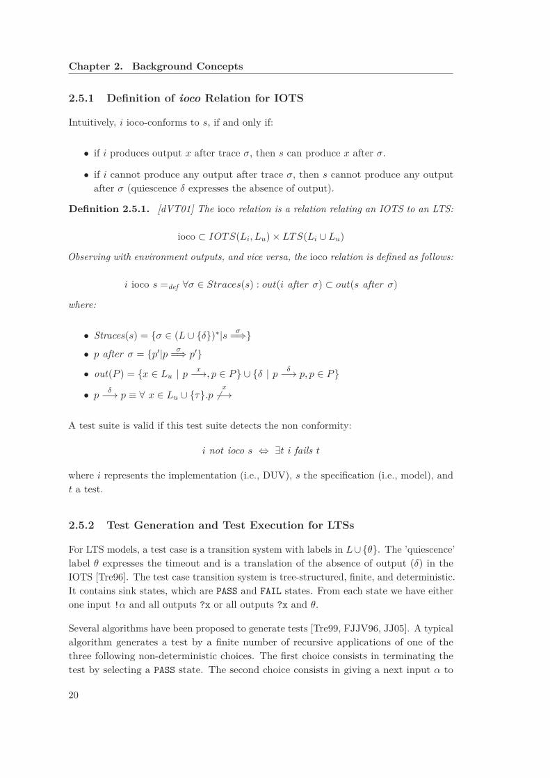
2.5.1 Definition of ioco Relation for IOTS
Intuitively, i ioco-conforms to s, if and only if:
• if i produces output x after trace σ, then s can produce x after σ.
• if i cannot produce any output after trace σ, then s cannot produce any outputafter σ (quiescence δ expresses the absence of output).
Definition 2.5.1. [dVT01] The ioco relation is a relation relating an IOTS to an LTS:
ioco ⊂ IOTS(Li, Lu) × LTS(Li ∪ Lu)
Observing with environment outputs, and vice versa, the ioco relation is defined as follows:
i ioco s =def ∀σ ∈ Straces(s) : out(i after σ) ⊂ out(s after σ)
where:
• Straces(s) = {σ ∈ (L ∪ {δ})∗|s σ=⇒}
• p after σ = {p′|p σ=⇒ p′}
• out(P ) = {x ∈ Lu | px−→, p ∈ P} ∪ {δ | p
δ−→ p, p ∈ P}
• pδ−→ p ≡ ∀ x ∈ Lu ∪ {τ}.p
x
Ó−→
A test suite is valid if this test suite detects the non conformity:
i not ioco s ⇔ ∃t i fails t
where i represents the implementation (i.e., DUV), s the specification (i.e., model), andt a test.
2.5.2 Test Generation and Test Execution for LTSs
For LTS models, a test case is a transition system with labels in L ∪ {θ}. The ’quiescence’label θ expresses the timeout and is a translation of the absence of output (δ) in theIOTS [Tre96]. The test case transition system is tree-structured, finite, and deterministic.It contains sink states, which are PASS and FAIL states. From each state we have eitherone input !α and all outputs ?x or all outputs ?x and θ.
Several algorithms have been proposed to generate tests [Tre99, FJJV96, JJ05]. A typicalalgorithm generates a test by a finite number of recursive applications of one of thethree following non-deterministic choices. The first choice consists in terminating thetest by selecting a PASS state. The second choice consists in giving a next input α to
20

2.5. Model-Based Testing
the implementation and applies recursively the algorithm. The third choice consistsin selecting non-deterministically one among all the outputs and the timeout θ label(absence of output). If the selected output or θ is allowed at the current state, then thetest recalls the algorithm recursively. If the selected output or θ is not allowed at thecurrent state, then the test goes to the FAIL state.
To cope with non deterministic behavior, tests are not linear traces, but trees. Further-more, in order to execute tests, we have to deal with all possible parallel executions (testruns) of test t with implementation i going to state PASS or FAIL.
2.5.3 Test Selection in Model-Based Testing
In practice, exhaustiveness is never achieved. We have to select a subset of “comprehensive”test suites to achieve confidence in the quality of the tested product (DUV in our case).We want to select the best test cases capable of detecting failures and to measure towhat extent testing was exhaustive (i.e., coverage). This leads us to an optimizationproblem: we seek the best possible testing, but within cost/time constraints. In orderto tackle this issue, different test selection approaches were proposed in the literature:random test selection, coverage-oriented selection, or domain specific selection using test
purposes [dVT01].
Conventional testing tools often have problems in handling nondeterminism and onlyexplore a small subset of feasible paths. Model checkers do not have this problem, as theyare designed to systematically explore all reachable states of the system. It is thereforetempting to enhance testing with the capabilities of model checking, an idea expressedin [JW96]. In the literature, dedicated test generation tools have been developed usingexhaustive state-space exploration of the model to produce test cases. The explorationcapabilities are derived from model checking algorithms (e.g., TGV [FJJV96, JJ05]).Some of these test generation techniques use the notion of a test purpose, which isspecified as traces or automata (e.g., LTS) derived from high-level requirements.
A test purpose guides the exploration of the specification model to have more focusedtest cases. Intuitively, it is a means to characterize those states (called ACCEPT states)of the specification that should be reached during test execution. To prune the searchspace for test cases, the test purpose can also contain so-called REFUSE states: if such astate is reached while testing the DUV, the test is stopped and declared inconclusive.Technically, a test purpose is provided as an LTS.
21
Chapter 2. Background Concepts
2.6 CADP Toolbox
CADP (Construction and Analysis of Distributed Processes)3 [GLMS13] is a widespreadtoolbox for the design and verification of asynchronous concurrent systems. CADPsupports, among others, the process calculus LNT for specification, and offers varioustools for simulation and formal verification, including equivalence checkers (bisimulations)and model checkers (temporal logics and modal µ-calculus).
CADP is designed in a modular way and puts the emphasis on intermediate formats andprogramming interfaces (such as the BCG and OPEN/CAESAR software environments),enabling to combine CADP tools with other tools and adapting to various specificationlanguages. CADP implements a large spectrum of research results of concurrency theory,focusing on process calculus languages, namely LOTOS and the recent LNT language.
CADP is developed by the CONVECS team of Inria (until January 2012, by the VASYteam). It is maintained, regularly improved, and used in many industrial projects. Today,CADP contains around fifty tools and more than a dozen libraries.
2.6.1 Representing LTSs in CADP
CADP provides two different representations of an LTS:
• An explicit LTS is an enumerative representation of states, transitions, and labels.CADP provides the BCG (Binary Coded Graphs)4 format and libraries. The BCGformat is an optimized storage format for storing large LTSs (up to 244 states).CADP provides a set of tools and libraries to manipulate BCG files.
• An implicit LTS is defined in comprehension by giving its initial state and a function“post” to calculate its successors. This allows to verify a specification on-the-flywithout generating the LTS explicitly. CADP provides the Open/Caesar API formanipulating implicit LTSs, which is independent of the language in which theimplicit LTS is expressed.
2.6.2 Modeling Language LNT
LNT [CCG+14] (a shorthand for “LOTOS New Technology”) is a modern formal specifi-cation language that has been designed and implemented in the CADP toolbox since2005. LNT is intended to be concise, expressive, easily readable, and user-friendly. LNTcombines the best features of process calculi, functional programming languages, andimperative programming languages. The semantics of an LNT model is defined as an
3http://cadp.inria.fr/4The acronym BCG refers both to a format and a software environment.
22
2.6. CADP Toolbox
LTS, following a black box view of the system. The LNT.OPEN tool translates an LNTmodel into an LTS suitable for (on-the-fly) verification. At present, LNT is implementedby translation to LOTOS [ISO89, BB88].
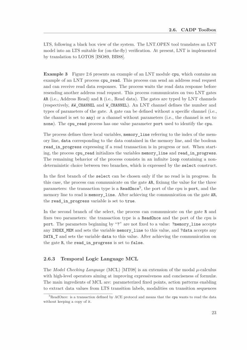
Example 3 Figure 2.6 presents an example of an LNT module cpu, which contains anexample of an LNT process cpu_read. This process can send an address read requestand can receive read data responses. The process waits the read data response beforeresending another address read request. This process communicates on two LNT gatesAR (i.e., Address Read) and R (i.e., Read data). The gates are typed by LNT channels(respectively, AW_CHANNEL and W_CHANNEL). An LNT channel defines the number andtypes of parameters of the gate. A gate can be defined without a specific channel (i.e.,the channel is set to any) or a channel without parameters (i.e., the channel is set tonone). The cpu_read process has one value parameter port used to identify the cpu.
The process defines three local variables, memory_line referring to the index of the mem-ory line, data corresponding to the data contained in the memory line, and the booleanread_in_progress expressing if a read transaction is in progress or not. When start-ing, the process cpu_read initializes the variables memory_line and read_in_progress.The remaining behavior of the process consists in an infinite loop containing a non-deterministic choice between two branches, which is expressed by the select construct.
In the first branch of the select can be chosen only if the no read is in progress. Inthis case, the process can communicate on the gate AR, fixinng the value for the threeparameters: the transaction type is a ReadOnce5, the port of the cpu is port, and thememory line to read is memory_line. After achieving the communication on the gate AR,the read_in_progress variable is set to true.
In the second branch of the select, the process can communicate on the gate R andfixes two parameters: the transaction type is a ReadOnce and the port of the cpu isport. The parameters beginning by “?” are not fixed to a value: ?memory_line acceptsany INDEX_MEM and sets the variable memory_line to this value, and ?data accepts anyDATA_T and sets the variable data to this value. After achieving the communication onthe gate R, the read_in_progress is set to false.
2.6.3 Temporal Logic Language MCL
The Model Checking Language (MCL) [MT08] is an extension of the modal µ-calculuswith high-level operators aiming at improving expressiveness and conciseness of formulæ.The main ingredients of MCL are: parameterized fixed points, action patterns enablingto extract data values from LTS transition labels, modalities on transition sequences
5ReadOnce: is a transaction defined by ACE protocol and means that the cpu wants to read the datawithout keeping a copy of it.
23

Chapter 2. Background Concepts
module cpu ( types ) is
process cpu_read [AR : AR_CHANNEL , R : R_CHANNEL ]
(port : INDEX_CPU )
is
var memory_line : INDEX_MEM ,
data : DATA_T ,
read_in_progress : bool
in
memory_line := INDEX_MEM (1);
read_in_progress := false ;
loop
select
only if not ( read_in_progress ) then
AR(ReadOnce , port , memory_line );
read_in_progress := true
end if
[]
R(ReadOnce , port , memory_line , ?data);
read_in_progress := false
end select
end loop
end var
end process
end module
Figure 2.6 – LNT module example
described using extended regular expressions and programming language constructs, andan infinite looping operator specifying fairness. The EVALUATOR 4.0 model checker ofCADP can verify MCL properties on the fly, based on the local resolution of Booleanequation systems, and has a linear-time complexity for (data-less) alternation-free andfairness formulæ.
We can write (parameterized) macros to simplify the formulæ.
The MCL formulæ used in this thesis specify either liveness or safety properties. Aliveness property expresses that something good eventually happens. A safety propertyexpresses that something bad never happens. We present an example of each.
Example 4 The following MCL formula encodes a liveness property, that expressesinevitability, using the minimal fixed point operator (mu), which acts as binder for thepropositional variable X. This formula states that all transition sequences starting afteran action AR eventually lead to an action R after a finite number of steps.
[ true * . {AR} ]
mu X . ( < true > true and [ not {R} ] X )
24
2.6. CADP Toolbox
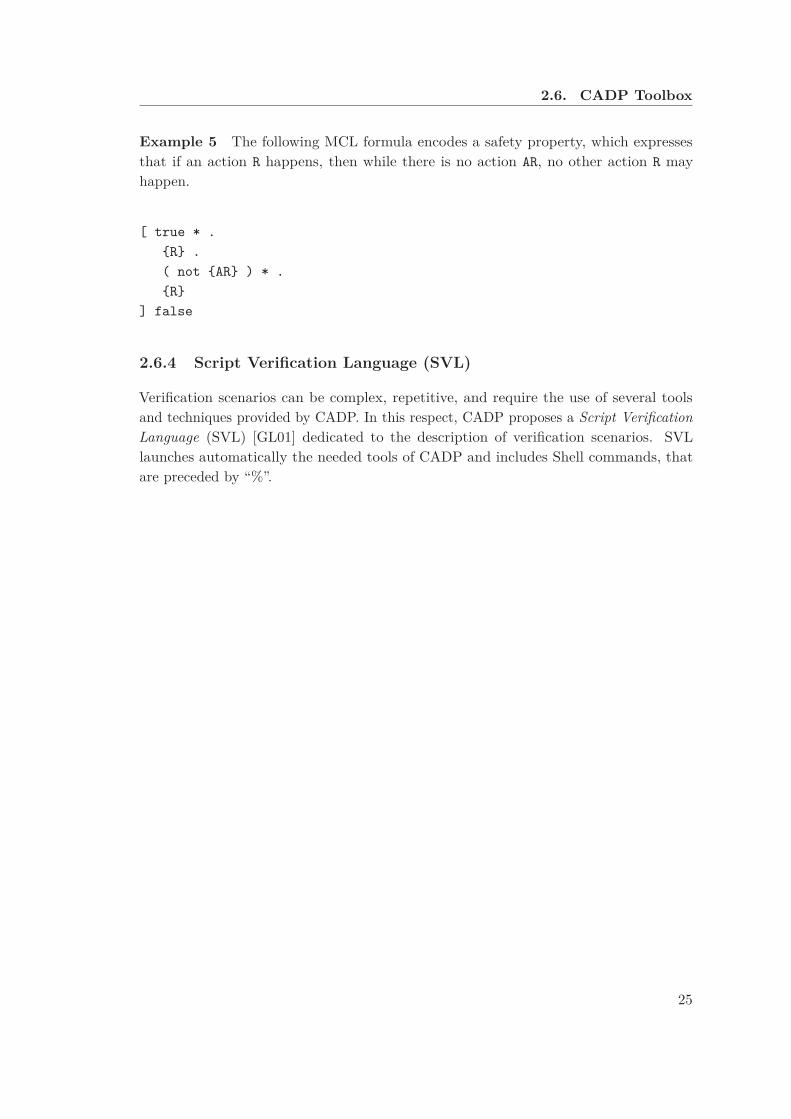
Example 5 The following MCL formula encodes a safety property, which expressesthat if an action R happens, then while there is no action AR, no other action R mayhappen.
[ true * .
{R} .
( not {AR} ) * .
{R}
] false
2.6.4 Script Verification Language (SVL)
Verification scenarios can be complex, repetitive, and require the use of several toolsand techniques provided by CADP. In this respect, CADP proposes a Script Verification
Language (SVL) [GL01] dedicated to the description of verification scenarios. SVLlaunches automatically the needed tools of CADP and includes Shell commands, thatare preceded by “%”.
25


Chapter 3
State of the Art: Formal
Validation of Hardware
The correct design of complex hardware poses serious challenges. Economic pressuresin rapidly evolving markets demand short design cycles while increasing complexity ofdesigns makes simulation coverage less and less complete. Bugs in a design that arenot discovered in early design stages can be costly, and bugs that remain undetecteduntil after a product is shipped can be extremely expensive. The most widely usedtechniques in hardware verification are based on simulation. To improve verification ofcomplex hardware designs, two principal axes are explored: on one side, methodologiesproposed to enable a faster simulation speed, e.g., hardware-accelerated simulation andemulation; on the other side, methodologies proposed to enable a bigger coverage thansimulation. These methodologies introduce formal and semi-formal verification based onformal methods.
(Software) simulation is a dynamic verification method. The bugs are found by runningthe design implementation. Thoroughness of the simulation depends on the tests in use.Some parts are tested repeatedly while other parts are not even tested. There is a speedgap between the speed of software simulation and real silicon vastness:
Simulation speed = C * speed of the simulation engine / size of circuit simulatedwhere C is a constant
A track that has been explored is to improve the speed of the simulation. For thispurpose, hardware-accelerated simulation is often used, by moving the time-consumingpart of the design to hardware. Usually, the software simulation communicates with an
27
Chapter 3. State of the Art: Formal Validation of Hardware
FPGA-based1 hardware accelerator. The limitation of this solution is the dependency onthe speed of the communication between simulator and hardware. To accelerate moreand more (i.e., up to 1000 times faster than simulation), Emulation is used; imitating thefunction of another system to achieve the same results as the imitated system. Usually,the emulation hardware comprises an array of FPGA’s and an interconnection schemeamong them.
Example 6 A formal specification can be useful in emulation. In the context of thePolykid project2 [GVZ01], a missing hardware component (precisely, an ASIC3) wasreplaced by a software program generated from a formal LOTOS model, running on aPowerPC microprocessor.
It was recognized that conventional simulation does not provide sufficient quality assuranceand must be supplemented by formal methods [Fou88]. In fact, approaches combiningformal and simulation techniques are required. Since then, formal verification tools aremore and more introduced in the hardware design flow due to their capability to detecterrors earlier than other techniques. Two formal techniques are often used in hardwarevalidation: theorem provers which use a deductive approach based on rules of inferenceand model checking which uses an algorithmic approach based on exhaustive explorationof the behavior of the system. In addition to that, model-based testing can be used as abridge connecting the formal verification of the specification and the simulation-basedverification of the implementation.
3.1 Use of Formal Verification
Hardware design typically starts with a high-level informal specification (i.e., blockdiagrams, tables, and English text) expressing the desired functionalities. The formalverification of hardware requires the existence of formal descriptions for both designand specification. These methods assure 100% coverage, but in practice, work only forsmall-size finite state systems.
The time required for formal verification must be considered when applying thesetechniques to a real project. There are highly automated formal methods comparable totraditional simulation. Although formal verification methods are employed in the designof several state-of-the-art microprocessors and other complicated chips, we are not awareof a complete top-to-bottom verification for such a design. The cost of such verificationstill appears to be prohibitive. Formal methods can be beneficial even if a completetop-to-bottom verification is not carried out: the exercise of formalizing the requirements
1Field-Programmable Gate Array2Polykid was a Bull project concerning a multiprocessor architecture based on PowerPC, using
CC-NUMA memory model and two cache coherency levels.3Application Specific Integrated Circuit
28

3.1. Use of Formal Verification
or a high-level specification can be useful in itself because it tends to clarify many aspects.It is noticed that hardware engineers acquire a deeper understanding of the design whenformal methods are used. In fact in this case, a greater effort of abstraction is needed, amore precise specification of the environment assumptions is required, and a descriptionof the properties relating inputs and outputs is intended [Gar13]. To achieve successfulintegration, formal methods must be applied in a way that ensures that they can keep upwith the design flow [BCL+94]. If this is the case, formal methods can benefit from thedesign process significantly, as they allow conceptual errors in the design to be discoveredearly in the design process by verifying the high-level design against a set of requirements.
High-level descriptions can often be made concise enough to be tractable by automaticverification methods [BCL+94]. Finally, the cost of verification might be consideredworthwhile for certain subsystems that are particularly difficult to design, while other“straightforward” modules can be treated with traditional methods [KG99].
3.1.1 Formal Verification using Model Checking
In the following, we present some examples of model checking tools used in the hardwarefield.
• SMV [McM99] is a widely used symbolic model checker, in which system de-scriptions are given in terms of a set of equations that determine the next-staterelation; programs may be structured into parameterized modules. SMV modelchecks specifications given in CTL and CTLF. SMV uses hybrid decision diagrams(HDDs) [CFZ95] as the underlying data structure, which permits model checking ofproperties involving words, i.e., bit vectors interpreted as integers. The SMV modelchecker is used by Cadence R© to validate hardware protocols [KNS01, RMK03].
• SPIN [Hol97] is a model checker targeted at the high-level verification of distributedsystems. SPIN accepts model descriptions in the specification language PROMELA,which provides high-level constructs such as communication channels. Specificationsare given in LTL and verified by an on-the-fly model-checking algorithm. Forexample, the SPIN model checker is used in the literature to validate hardwareprotocols [BED03].
• Murφ [Dil96] is both a formal description language and an explicit state model-checking system. Specifications in Murφ are given as simple safety properties,which are verified by explicit state space exploration. Murφ uses a white box viewof the system. In a white box view, the states of all variables are visible during theverification. In contrast, our approach based on LTSs uses a black box view, inwhich only the events are visible. Murφ is based on a set of commands that areexecuted repeatedly in an infinite loop. The Murφ is used in the literature to verifycache coherence protocols in a multiprocessor system design. [Che04].
29
Chapter 3. State of the Art: Formal Validation of Hardware
Model checking the requirements, specified as temporal properties, requires that themodel is small enough in order to be verified in the available CPU and memory resources.To this end, the design must be modeled and verified at a relatively abstract level.Otherwise, the design has to be divided to relatively small subsystems, where each ofwhich is verified separately.
Example 7 At gate level, formal verification techniques are helpful to gain confidencein asynchronous circuits. Those circuits are complex to validate using conventionalsimulation. That is why formal methods are used to address their validation, in order todetect concurrency issues and to establish the correctness, if possible [SSTV07].
3.1.2 Formal Verification using Equivalence Checking
The equivalence checkers are often used in hardware design to compare a (golden)model4 with a refined model. Functional representations are extracted from the designsand compared mathematically. In the hardware community, tools such as Formality
(SynopsysTM) [Sut06] and FormalPro (Mentor GraphicsTM) [Pra08] support equivalencechecking. The equivalence checking can be applied in inter-levels cross verificationperforming a logical comparison of two hardware models.
Example 8 This technique is used to compare an RTL description with the correspond-ing gate-level synthesis in order to prove the absence of synthesis errors. Equivalencechecking has progressively replaced gate-level simulation.
3.1.3 Formal Verification using Theorem Proving
A theorem prover is based on libraries of axioms and hypotheses. It uses a set of inferencerules to prove the formal description of the behavior of the system by simplifying it untilreaching known axioms. Specifications and verification conditions can be expressed ingeneral-purpose logic. Verifying that an implementation meets its specification in such aframework is equivalent to proving a theorem in the underlying logic. In principle, thisproof could be carried out manually. However, proofs of such theorems are often longand rather tedious in practice, making it likely that they contain errors.
Using a mechanized theorem-proving system can ensure soundness and reduce toughnessby automating parts of the proof. Proof discovery in many theorem provers is guided bythe user through the application of proof strategies or tactics. Standard tactics operateat a level of detail such as quantifier instantiation or rewrite with respect to a set ofequalities. Hardware proofs in a particular application domain often follow common
4A model assumed to be correct.
30
3.2. Semi-Formal Verification and Assertions
general patterns, which suggests the development of proof strategies that automaticallydischarge more complex obligations.
In the literature, various logics have been used to implement theorem proving with variouslevels of automation, and many have been used for hardware verification, including thefollowings ones:
• ACL2 tool5 [KM96] uses a first order logic without quantifiers with induction.
• HOL system6 [Gor01] and PVS system7 [ORS92] use higher order logic.
• Coq formal proof management system8 [DFH+91] uses calculus of inductive con-structions.
• Isabelle9 [Pau94] uses a general-purpose logic.
It should be noticed that in the hardware verification framework, higher order logic isless crucial than in other applications [Mel09, Pie14].
3.2 Semi-Formal Verification and Assertions
To take advantage of formal verification in the context of industrial sized case studies,semi-formal approaches were proposed combining simulation and formal assertions. Anassertion (called also check) is a statement on the intended behavior of a design. Thepurpose of assertions is to ensure consistency between the designer intention and theimplementation. This verification approach is called Assertion-based verification (ABV).The key features of ABV are that, if an assertion violation is detected by the simulator,the related signals are identified, and the source of error is reported to the user.
The assertions are expressed as a native assertion construct, e.g., SystemVerilog Assertions
(SVA) [oEE09] or as temporal logic formulæ, e.g., using Property Specification Language
(PSL) [oEE10]. The PSL is defined as a standard for RTL level assertions. This givesthe design architect a standard means of specifying design properties using a concisesyntax with clearly defined formal semantics and enables the RTL implementer to capturedesign intent in a verifiable form, while enabling verification engineer to validate thatthe implementation satisfies its specification.
ABV can be integrated to static and dynamic test benches.
5http://www.cs.utexas.edu/ moore/acl2/6http://www.cl.cam.ac.uk/research/hvg/HOL/7http://pvs.csl.sri.com/8http://coq.inria.fr/9http://www.cl.cam.ac.uk/research/hvg/Isabelle/
31
Chapter 3. State of the Art: Formal Validation of Hardware
• A static test bench is a “pure” formal test bench in which the DUV is connectedto assertion-based formal unit. Those units analyze the hardware description ofthe system (e.g., VHDL or Verilog RTL design) without running any simulation.Although model checking a property (expressed through an assertion) at thehardware description level is intractable, because of the state space explosionproblem, model checking can be carried out by applying several limitations tothe explored state space. The assertions are used to restrain the DUV exploredbehavior and to extract a model checking assignment.
• A dynamic test bench is a simulation test bench, in which (dynamic) verification IPsare connected to the DUV. The verification IPs initiate tests, respond to the DUVrequests, and monitor the DUV activities. The assertion-based unit are connectedto the dynamic test bench, in order to monitor the DUV events triggered by rantests and check that those events respect the properties (expressed by assertions).In this case, we speak about semi-formal verification.
3.3 System-Level Approaches
In the SoC context, different complexity aspects are introduced to the verification activity.A first aspect consists in the combination of software and hardware platforms. Precisely,the hardware DUV cooperate with processor model such as BFM (bus functional model).A second aspect consists in the use of pre-verified and unverified components, e.g., theuse of legacy IPs already verified. A third aspect of complexity resides on the presence ofdifferent languages and different abstraction levels providing common interface structurebetween SoC components. To deal with this specific complexity introduced in SoCverification context, several approaches have been explored.
3.3.1 SystemC Transaction Level Models
A significant amount of system-level approaches in hardware design rely on Sys-
temC [LMSG02], which is a modeling platform consisting of a set of C++ class libraries,including a simulation kernel that supports hardware modeling concepts at the systemlevel, behavioral level, and RTL level. SystemC allows to create an executable specifi-cation of the system and can be used either in cycle level or transaction level. Whilethe cycle-level platform has to synchronize with the DUV at every clock cycle, thetransaction-level platform has just to synchronize at the end of each transaction. TheTransaction-Level Modeling (TLM) [G+05] has no notion of exact time, but preservestransactions order. The TLM model is used as the fastest reference by each block designer.Such a model can be also used to have a rough estimation on performance.
The SystemC/TLM uses software function calls to model the communication betweenblocks in a system. This is in contrast to hardware RTL, and gate level models, which
32
3.3. System-Level Approaches
use signals to model the communication between system blocks. TLM models have beenused in various forms for many years. The emergence of widely used standard modelinglanguages such as SystemC/TLM, enables model interoperability and exchange withincompanies and between companies. This is crucial since modern SoCs rely heavily on IPreuse [Swa06].
It was proposed in the literature to combine system-level modeling with assertion-basedverification [DGG+05], using a platform called FoCs (“Formal Checkers”) [ABG+00]based on both SystemC/TLM and PSL. In fact, formal methods enhance the capabilitiesof SystemC/TLM languages initially intended for simulation and hardware-softwareco-simulation purposes. SystemC models can be verified using model checking, whichimproves simulation speed and coverage [BKS08]. In addition to that, complex designsinvolving asynchronous concurrency may also be specified using dedicated languagesspecifically designed and optimized.
3.3.2 High-Level Formal Models and Abstractions
An alternative style of specification uses a high-level formal model to stipulate theallowed behaviors of a system. In this framework, verification entails reasoning aboutthe relationship between the high-level model, also referred to as the specification, and alower-level model, the implementation [KG99].
Central to this approach is the notion of abstraction, which permits unnecessary detailto be hidden from the high-level model. Furthermore, specifications may be given inan hierarchical fashion; starting from a very abstract model at the highest level, oneproceeds through a series of abstractions to a detailed description of the implementation.The design at some level k assumes the role of the implementation with respect to thespecification at level k-1, and the role of the specification for level k+1.
Different abstraction mechanisms are explored in the literature. We present here fouridentified types of abstraction prevalent in hardware verification [JOS+01].
• Structural abstraction suppresses details about the implementation internal struc-ture in the specification. The specification gives a black-box view of the designthat reflects the externally observable system behavior without constraining itsinternal design.
• Behavioral abstraction suppresses details about what the component does underoperating conditions that should never occur. Behavioral abstraction may alsoindicate “do not care” conditions. This gives the designer greater flexibility tooptimize the implementation. The specification is more abstract, in the sense thatits behaviors are a superset of the implementation behaviors.
33
Chapter 3. State of the Art: Formal Validation of Hardware
• Data abstraction substitutes concrete data by a simpler one. Data abstractionrequires a mapping that determines how the states or signals (representing data)of the implementation are to be interpreted in the specification semantic domain.
• Temporal abstraction relates time steps of the implementation to time steps of thespecification. Frequently, specifications of a microprocessor use the execution of asingle instruction as the basic unit of time. An implementation, however, wouldbase its notion of time on the execution of a microcode instruction, a clock cycle, ora clock phase. Temporal abstraction requires that corresponding execution statesat the two time scales be identified. This is complicated by the possibility that onespecification time-unit does not always necessarily correspond to the same numberof implementation steps.
In practice, the abstractions used in modeling depend on the application domain, thedesign size, and the targeted exploitation of the model (e.g., the kind of properties to beverified on the model).
3.4 Test Generation strategies
Generating tests to achieve high coverage for complex designs has always been a chal-lenging problem. In general, more constrained and less random tests reduce the overallvalidation effort, because the same verification coverage can be achieved with fewer andshorter tests [MC09]. We distinguish three types of test generation techniques withdecreasing degree of randomness: fully random, constrained-random [YPAA03], and fullyspecified tests, hereafter called directed tests, i.e., without randomization.
Fully random tests are the easiest to automate, but require long simulation runs to obtaina reasonable coverage. In many situations, directed tests are the only tests that canthoroughly verify corner cases and important features of a design [BGH+99, KMBA06].However, because directed tests are mostly written manually, it is impractical to generatea comprehensive set of directed tests to achieve a coverage goal [MC09].
Constrained-random testing uses constraint solvers to select tests satisfying a specifiedset of constraints; non-specified details are then filled in by randomization. Manuallywriting directed tests has been a dominant test development methodology even with theemergence of constrained-random test generation, which alleviates part of the problemby producing a large number of guided random tests, so that many verification targetscan be fortuitously covered.
In the following, we explore additional strategies used to generate more directed andmore automated tests.
34
3.4. Test Generation strategies
3.4.1 Coverage-Directed Test Generation
The automation of the feedback from coverage analysis to constrained-random testgeneration led to coverage-directed test generation (CDTG) [SWC+08], which dynamicallyanalyzes coverage results and automatically adapts the randomized test generationprocess to improve the coverage. The Coverage Driven Verification (CDV) and Metric
Driven Verification (MDV) are different instances of the CDTG. The CDV proposes toautomatically generate tests targeting the non covered behaviors, without any organizationof the coverage metric. As designs increase in size, coverage metrics are exploding, makingthe shear magnitude unmanageable without automation. Metric automation has becomean imperative. The MDV improves the CDV by organizing the coverage by types ofcoverage behavior and also by components, which is very useful to define the portion ofthe design that has been verified. Today, the metric methodology is emerging, reducingthe number of manual decisions necessary for claiming verification success. MDV providesthe automation and prescriptive approach to reduce the decision churn.
The challenges of CDTG techniques are that it is sometimes difficult to guide the directionof test generation to increase the coverage of the design, and the need of more efficientcoverage metrics to represent the behavior of the design including corner cases. Forinstance, CDTG succeeds to achieve coverage goals for interface hardware protocols, butreaches its limits for complex system-level protocols, such as system-level cache coherency.Achieving good coverage for these recent protocols is a new challenge in the developmentof industrial test benches and calls for more directed and less random tests.
The semi-formal verification allows the designer to measure the coverage of the testenvironment as the formal assertions are checked during simulation, but the simulationspeed is degraded as the assertions are checked during simulation.
Our thesis is part of the current works trying to resolve the different challenges ofsemi-formal verification.
3.4.2 Faults-Based Test Generation
To avoid writing directed tests manually, several approaches to generate a comprehensiveset of high-quality directed tests are explored. Some techniques of directed test generationpropose to generate tests from potential faults of the system [MSK+07, WAW09]. Forsystem-level protocols, in the SoC context, it is more difficult to examine potential faultsof the DUV. Solutions based on model checking techniques are promising for functionalverification and test generation for reasonably complex systems [GH99]. Hence, wesuggest the use of the model checking of the main system properties, by prohibiting someprotections to generate counterexamples. However, it is unrealistic to assume that acomplete detailed model of a large SoC is tractable by a model checker. We address thisissue by relying on a system-level model, abstracting from all irrelevant details. In this
35

Chapter 3. State of the Art: Formal Validation of Hardware
way, we succeed to model a complex industrial SoC and to extract relevant scenarios bymodel checking.
Some approaches [GH99, QM11] transform counterexamples produced by the modelchecker into test cases. In our approach, we use the counterexamples to produce smallerinteresting configurations of the model that still do not satisfy a given property. Wegenerate test cases from these smaller models, thus avoiding combinatorial explosion inmany cases.
3.4.3 Combining Model-Based and Coverage-Directed Testing
In the literature, it has already been proposed to mix model-based techniques andcoverage-directed techniques. Coverage-directed techniques were used in property learn-ing [CM11] (“reuse learned knowledge from one core to another”), which we do not use,and that relies on SAT-based BMC (whereas CADP implements totally different verifi-cation techniques). Some of those techniques [QM11] focus on homogeneous multicorearchitectures (exploiting symmetry between processors to reduce verification complexity),and only suggest how this could be extended to heterogeneous architectures (by groupingIPs into homogeneous groups to be studied separately). On the contrary, our approachwas designed for heterogeneous SoCs and makes no symmetry assumption. Also, mostof those techniques [CM11, CQKM13, QM11] remain at system level (SystemC/TLM),whereas our approach starts from system level and goes down to RTL level.
3.5 Applications of Formal Verification to Hardware Cache
Coherency
Formal verification techniques such as (symbolic) model checking and theorem proving,have been often applied to the verification of hardware designs of cache coherenceprotocols, using various modeling languages, temporal logics, and verification tools [PD97,KG99]. Most works [Che04, CYGC10, CGH+95, EM95, KKVD13, MS91, PNAD95,SDSH11, SD95] concern elaborated protocols using more complex topologies than thefully connected snoop topology used in our case. The principal differences with ourwork are that we focus on a generic interconnect that includes the behavior of allcorrect implementations and that we study a heterogeneous SoC, rather than verifying aparticular coherency protocol for a homogeneous system.
It was recently reported [DCF+14] that formal verification has to be considered for hotspots at the SoC level and specially for the integration of system-level cache coherency.In fact, efficiency can be improved using formal techniques on the infrastructure that ismanaging various levels of cache and memory subsystem. More and more interconnectfabrics embark cache coherency mechanisms that require dedicated and tricky verification.
36

3.6. Applications of CADP to Hardware Validation
3.6 Applications of CADP to Hardware Validation
Over the last 20 years, the CADP toolbox has been used for verifying numerous complexhardware designs, including Bull supercomputers, STMicroelectronics multiprocessorarchitectures, several Networks on Chip (e.g., CEA/Leti and University of Utah), andvarious asynchronous circuits.
In order to apply formal methods to a hardware design, different aspects can be explored:the formal modeling, the functional verification, the model-based testing, and/or theperformance evaluation. In this thesis, we present an application of the latest languagesand tools of CADP, using the new generation formal language LNT [CCG+14] to describethe system and also the test purposes, which greatly facilitates the testing of complexbehaviors. In parallel with this thesis, the CONVECS team has developed new prototypetools to support these new functionalities.
The remainder of this section gives an overview of previous hardware related case studiesusing CADP.
3.6.1 Formal Modeling
Several guidelines must be followed when developing formal models. For example, wehave to focus on the complex parts of the system (e.g., parallelism, concurrency, etc.).Other parts are less important and can introduce irrelevant complexity in the model.Also, we can use abstractions to hide irrelevant details.
The formal modeling is useful to detect ambiguities of the initial specification. Thisone is usually not formal. That is why many problems are discovered just by formallymodeling, before running any tool. Formal specification triggers discussions with hardwarearchitects, which is interesting in order to have a deep understanding of the complexparts of the system. After that, the model has to be debugged. In fact, several errors arejust introduced during modeling and the debugging aims to remove them. The hardwarearchitects are not interested in those errors, called false negatives.
In the CADP context, the modeling languages used are LOTOS (before 2008-2009)and LNT (since then). LOTOS and LNT are both formal languages to describeasynchronously-concurrent systems. LNT (see Sec. 2.6.2) is more convenient for humanusers, because it is closer to programming languages and hardware languages (such asVHDL). In general, the starting point for producing formal models in hardware contextare natural language descriptions of the specification of the system (English text, tables,diagrams), but in some cases, we extract the formal model from a semi-formal programwritten in other hardware languages (e.g., CHP10, SystemC/TLM, etc.). To remove
10Communicating Hardware Processes
37
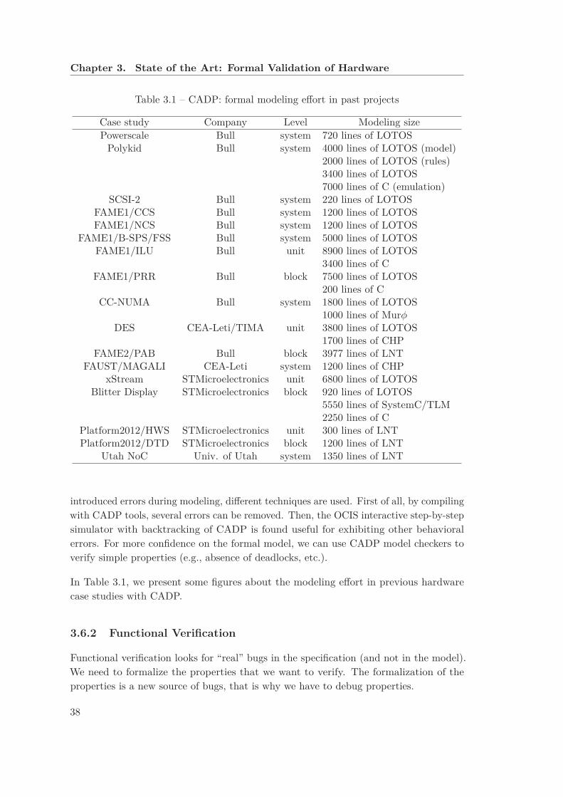
Chapter 3. State of the Art: Formal Validation of Hardware
Table 3.1 – CADP: formal modeling effort in past projects
Case study Company Level Modeling sizePowerscale Bull system 720 lines of LOTOS
Polykid Bull system 4000 lines of LOTOS (model)2000 lines of LOTOS (rules)3400 lines of LOTOS7000 lines of C (emulation)
SCSI-2 Bull system 220 lines of LOTOSFAME1/CCS Bull system 1200 lines of LOTOSFAME1/NCS Bull system 1200 lines of LOTOS
FAME1/B-SPS/FSS Bull system 5000 lines of LOTOSFAME1/ILU Bull unit 8900 lines of LOTOS
3400 lines of CFAME1/PRR Bull block 7500 lines of LOTOS
200 lines of CCC-NUMA Bull system 1800 lines of LOTOS
1000 lines of MurφDES CEA-Leti/TIMA unit 3800 lines of LOTOS
1700 lines of CHPFAME2/PAB Bull block 3977 lines of LNT
FAUST/MAGALI CEA-Leti system 1200 lines of CHPxStream STMicroelectronics unit 6800 lines of LOTOS
Blitter Display STMicroelectronics block 920 lines of LOTOS5550 lines of SystemC/TLM2250 lines of C
Platform2012/HWS STMicroelectronics unit 300 lines of LNTPlatform2012/DTD STMicroelectronics block 1200 lines of LNT
Utah NoC Univ. of Utah system 1350 lines of LNT
introduced errors during modeling, different techniques are used. First of all, by compilingwith CADP tools, several errors can be removed. Then, the OCIS interactive step-by-stepsimulator with backtracking of CADP is found useful for exhibiting other behavioralerrors. For more confidence on the formal model, we can use CADP model checkers toverify simple properties (e.g., absence of deadlocks, etc.).
In Table 3.1, we present some figures about the modeling effort in previous hardwarecase studies with CADP.
3.6.2 Functional Verification
Functional verification looks for “real” bugs in the specification (and not in the model).We need to formalize the properties that we want to verify. The formalization of theproperties is a new source of bugs, that is why we have to debug properties.
38

3.6. Applications of CADP to Hardware Validation
Table 3.2 – CADP: functional verification results
Case study Functional verification resultsPowerscale Hidden bug found in a few minutes [CGM+96]
Polykid Phase 1: 55 questionsPhase 2: 20 questions, 7 serious issuesPhase 3: 13 serious issues [KVZ98]
SCSI-2 SCSI-2 bus arbiter starvation problem confirmed(avoided in SCSI-3 standard)
FAME Critical parts of FAME design verified using CADP10 issues raised, 2 ambiguities pointed out
STBus SoC Error in the design discovered [WCB+03]FAME2/MPI Formally verified
FAUST/MAGALI Routing problem detected in the CHP description [SSTV07]xStream Two design issues detected very early
Blitter Display Avoids complete translation of SystemC/TLM to LOTOS:- reduced translation effort- better integration of formal verification in the design flow
[GHPS09]Platform2012/DTD Problematic configurations with livelocks found
Further investigation by co-simulation [LS11]Utah NoC Found flaws in the original arbiter design [ZSW+14]
At some point, a good confidence is reached in both the formal model and properties.Then, if a verification reports an error, it can be either an error in the verification tool(which is rare, and has to be fixed by tool developers) or a “real” bug in the specificationis detected.
In Table 3.2, we summarize the principal functional verification results of the pasthardware case studies carried out using CADP.
3.6.3 Model-Based Testing
In the CADP context, MBT can be handled by an off-line approach or an on-line one.Off-line approach means that in a first step, test cases are generated, then in a secondstep test cases are run on the implementation. On-line approach consists in doing aco-simulation of the specification and the implementation. Test cases are generated andran in the same time. The result of ran test cases can be used to generate the subsequentones.
The former MBT case studies of CADP are based on TGV [FJJV96, JM99, JJ05], whichuses LOTOS to present the specification and a textual .aut expression of the testpurpose.
39
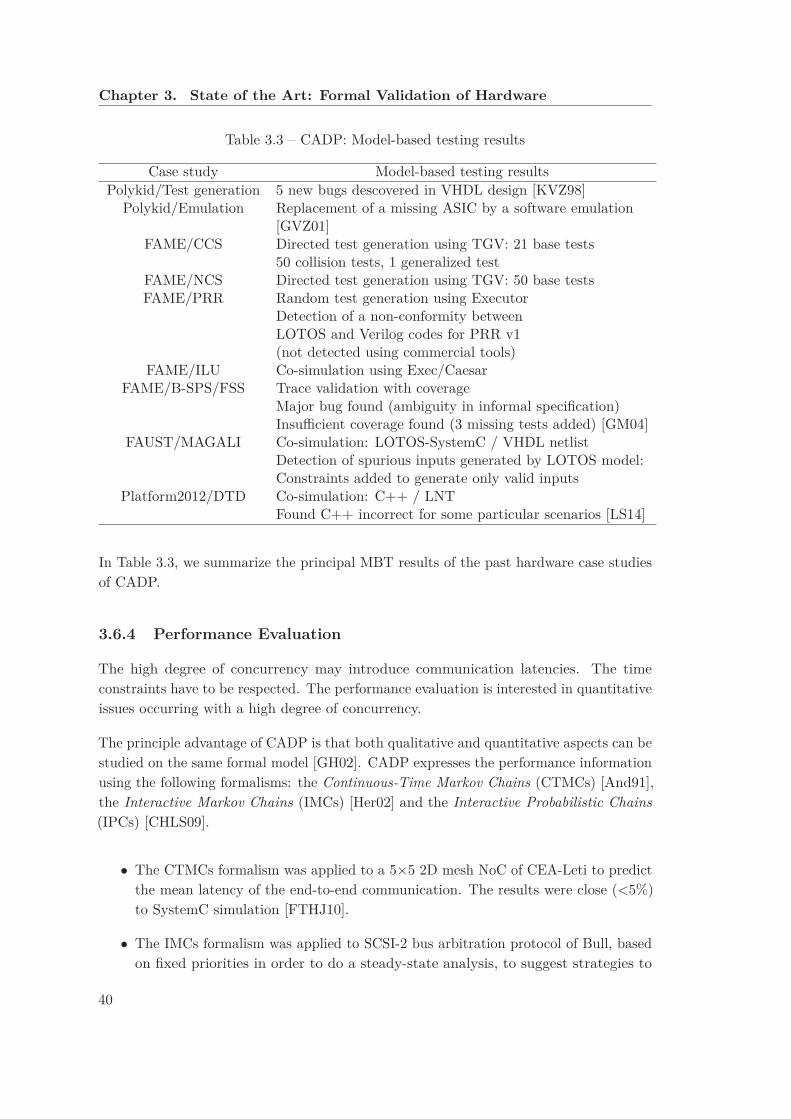
Chapter 3. State of the Art: Formal Validation of Hardware
Table 3.3 – CADP: Model-based testing results
Case study Model-based testing resultsPolykid/Test generation 5 new bugs descovered in VHDL design [KVZ98]
Polykid/Emulation Replacement of a missing ASIC by a software emulation[GVZ01]
FAME/CCS Directed test generation using TGV: 21 base tests50 collision tests, 1 generalized test
FAME/NCS Directed test generation using TGV: 50 base testsFAME/PRR Random test generation using Executor
Detection of a non-conformity betweenLOTOS and Verilog codes for PRR v1(not detected using commercial tools)
FAME/ILU Co-simulation using Exec/CaesarFAME/B-SPS/FSS Trace validation with coverage
Major bug found (ambiguity in informal specification)Insufficient coverage found (3 missing tests added) [GM04]
FAUST/MAGALI Co-simulation: LOTOS-SystemC / VHDL netlistDetection of spurious inputs generated by LOTOS model:Constraints added to generate only valid inputs
Platform2012/DTD Co-simulation: C++ / LNTFound C++ incorrect for some particular scenarios [LS14]
In Table 3.3, we summarize the principal MBT results of the past hardware case studiesof CADP.
3.6.4 Performance Evaluation
The high degree of concurrency may introduce communication latencies. The timeconstraints have to be respected. The performance evaluation is interested in quantitativeissues occurring with a high degree of concurrency.
The principle advantage of CADP is that both qualitative and quantitative aspects can bestudied on the same formal model [GH02]. CADP expresses the performance informationusing the following formalisms: the Continuous-Time Markov Chains (CTMCs) [And91],the Interactive Markov Chains (IMCs) [Her02] and the Interactive Probabilistic Chains
(IPCs) [CHLS09].
• The CTMCs formalism was applied to a 5×5 2D mesh NoC of CEA-Leti to predictthe mean latency of the end-to-end communication. The results were close (<5%)to SystemC simulation [FTHJ10].
• The IMCs formalism was applied to SCSI-2 bus arbitration protocol of Bull, basedon fixed priorities in order to do a steady-state analysis, to suggest strategies to
40

3.6. Applications of CADP to Hardware Validation
avoid starvation and increase throughput [GH02]. This formalism was also appliedto FAME/MPI case study of Bull in order to have an estimation of the number ofcache misses and to select the most efficient configuration of the system [CZM09].
• The IPCs formalism was applied to the xStream architecture of STMicroelectronicsin order to predict latencies, throughputs, and queue occupancy [CHLS09].
41

Formal Modeling of a System-Level
Cache Coherent SoC
43


Chapter 4
System Level Cache Coherency
with AMBA 4 ACE
4.1 Introduction
In this chapter, we define system-level cache coherency in the case of heterogeneousSystem-on-Chip (SoC). Then, we present the AMBA 4 ACE protocol specification anddescribe the main elements introduced by this specification to support cache coherencyin heterogeneous SoCs.
4.2 System-Level Cache Coherency
In general, an SoC is composed of different hardware blocks such as generic or specializedprocessors, memories, interconnects, dedicated Intellectual Properties (IPs), or input/out-put components. These heterogeneous components usually access a shareable memory
consisting of several memory lines. In order to increase data access performance andreduce power consumption, some components may use a cache, containing local copies ofmemory lines. The use of local copies in the caches decreases the number of accesses toglobal memory. The use of multiple caches in the system and the allowance of multipleusers of a cache results in the problem of System-Level Cache Coherency (see Fig. 4.1),which is currently one of the main concerns of the digital hardware industry.
An SoC is cache coherent if write operations to the same memory line by two componentsare observable in the same order by all components of the system. Heterogeneity of anSoC stems from not making any constraint on the nature of the components. The onlysegregation we consider is considering components with caches and without caches. Thecomponents are considered with caches if their neighbors are allowed to use data copiespresent in their caches, unless they are considered without caches. All components can
45

Chapter 4. System Level Cache Coherency with AMBA 4 ACE
Figure 4.1 – Example of a heterogeneous SoC using System-Level Cache Coherency
read their neighbor’s caches instead of reading the global memory, unlike conventionalmultiprocessor systems, on which the cache coherency is only considered between similarprocessors.
One may distinguish shareable and non-shareable memory lines. For example, the graphicsmemory of an SoC might be dedicated to image processing and exclusively used by theGraphical Processing Unit (GPU), whereas the remaining memory might be used eitherby the generic processors (Central Processing Units, CPUs) or by the GPU. In this case,the graphics memory is non-shareable, and the remaining memory is shareable.
The components of an SoC can be grouped into master components (such as CPUs) andslave components (such as memories). Components communicate via an interconnectionmedium, called the interconnect. In the case of a cache coherent system, the interconnectis also called a Cache Coherent Interconnect (CCI). Each component communicates withthe interconnect via a communication port, which consists of several channels. Operationsperformed on ports are called transactions.
Snoop transactions are used for master-to-master accesses. Thank to snoop transactions
46

4.3. AMBA 4 ACE protocol
System level requirements
on transaction ordering
+ Coherency
Channels
AXI Domain
+ Coherency parameters
Figure 4.2 – ACE: AXI Coherency Extension
a master has a consistent view of the transactions of other masters. Previously, inbus-based systems all components are connected to the bus and “snoop” the bus trafficto guarantee the consistency of the system. In the context of CCI, the interconnectinitiates snoop transactions to simulate the bus snoop.
4.3 AMBA 4 ACE protocol
The recent AMBA 4 ACE (AXI Coherency Extension) protocol [ARM13, Ste11], proposedby ARM, extends the AMBA 3 AXI1 protocol in order to support system-level cachecoherency in SoCs. AXI defines communication at interface level between a pair ofmaster/slave ports. AXI specifies several read and write channels (AR, R, AW, W, B) anddetermines the structure of each channel: parameters specifying length and compositionof control, data, and response channels, as well as the different acknowledgments used.As shown in Figure 4.2, the ACE extension introduces system-level requirements ontransaction ordering, adds new channels to send coherency request, enriches existingchannels with new coherency parameters expressing details related to the coherency, anddefines cache line states and a set of transactions.
ACE is designed to maintain coherency when sharing data across caches of an SoC, toenable interactions between heterogeneous components, and to ensure maximal reuse ofcached data. ACE also supports a flexible framework for system level coherency: thesystem designer can determine the ranges of memory lines that are coherent, the systemcomponents that implement the coherency extension, and the communication policies.
The ACE specification defines an interface protocol (between each component and theinterconnect), the expected behavior of the components, and the responsibilities of theinterconnect. ACE admits different policies of cache coherency, known as directory based,snoop filter, or fully connected (no snoop filter) policies.
ACE introduces heterogeneity by defining two types of coherent masters: those witha cache are called ACE masters, and those without caches (but with the ability toaccess caches of other masters) are called ACE-Lite masters. The components not using
1AMBA: Advanced Micro-controller Bus Architecture / AXI: Advanced eXtensible Interface
47
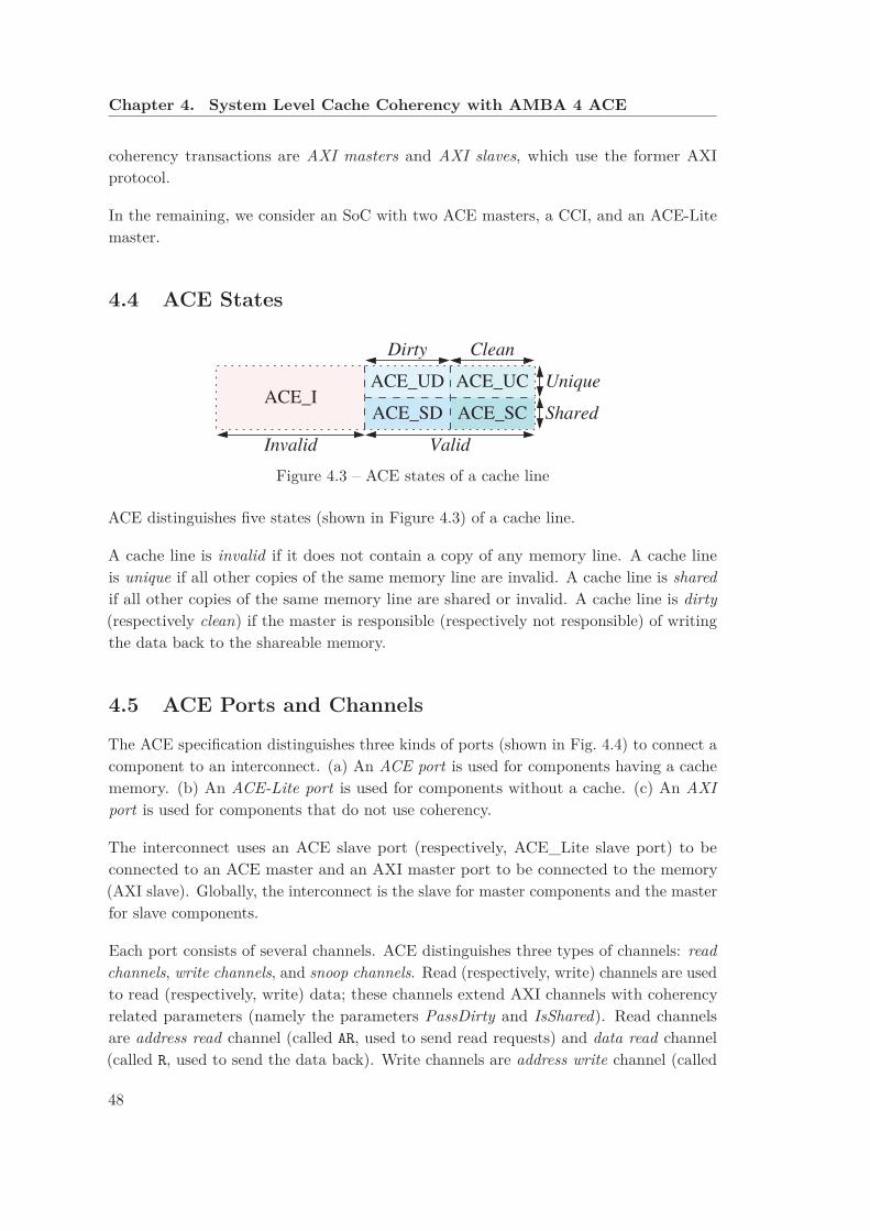
Chapter 4. System Level Cache Coherency with AMBA 4 ACE
coherency transactions are AXI masters and AXI slaves, which use the former AXIprotocol.
In the remaining, we consider an SoC with two ACE masters, a CCI, and an ACE-Litemaster.
4.4 ACE States
ACE_I
Invalid Valid
ACE_SD
ACE_UD
Dirty Clean
ACE_UC
ACE_SC Shared
Unique
Figure 4.3 – ACE states of a cache line
ACE distinguishes five states (shown in Figure 4.3) of a cache line.
A cache line is invalid if it does not contain a copy of any memory line. A cache lineis unique if all other copies of the same memory line are invalid. A cache line is shared
if all other copies of the same memory line are shared or invalid. A cache line is dirty
(respectively clean) if the master is responsible (respectively not responsible) of writingthe data back to the shareable memory.
4.5 ACE Ports and Channels
The ACE specification distinguishes three kinds of ports (shown in Fig. 4.4) to connect acomponent to an interconnect. (a) An ACE port is used for components having a cachememory. (b) An ACE-Lite port is used for components without a cache. (c) An AXI
port is used for components that do not use coherency.
The interconnect uses an ACE slave port (respectively, ACE_Lite slave port) to beconnected to an ACE master and an AXI master port to be connected to the memory(AXI slave). Globally, the interconnect is the slave for master components and the masterfor slave components.
Each port consists of several channels. ACE distinguishes three types of channels: read
channels, write channels, and snoop channels. Read (respectively, write) channels are usedto read (respectively, write) data; these channels extend AXI channels with coherencyrelated parameters (namely the parameters PassDirty and IsShared). Read channelsare address read channel (called AR, used to send read requests) and data read channel(called R, used to send the data back). Write channels are address write channel (called
48
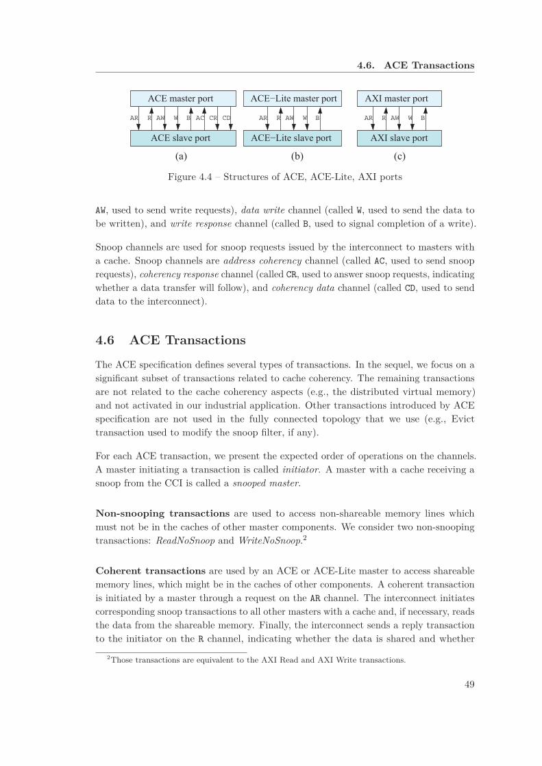
4.6. ACE Transactions
R AW W BAR R AW W BARAR R AW W CR CDACB
ACE master port
ACE slave port
(a) (c)(b)
ACE−Lite slave port
ACE−Lite master port
AXI slave port
AXI master port
Figure 4.4 – Structures of ACE, ACE-Lite, AXI ports
AW, used to send write requests), data write channel (called W, used to send the data tobe written), and write response channel (called B, used to signal completion of a write).
Snoop channels are used for snoop requests issued by the interconnect to masters witha cache. Snoop channels are address coherency channel (called AC, used to send snooprequests), coherency response channel (called CR, used to answer snoop requests, indicatingwhether a data transfer will follow), and coherency data channel (called CD, used to senddata to the interconnect).
4.6 ACE Transactions
The ACE specification defines several types of transactions. In the sequel, we focus on asignificant subset of transactions related to cache coherency. The remaining transactionsare not related to the cache coherency aspects (e.g., the distributed virtual memory)and not activated in our industrial application. Other transactions introduced by ACEspecification are not used in the fully connected topology that we use (e.g., Evicttransaction used to modify the snoop filter, if any).
For each ACE transaction, we present the expected order of operations on the channels.A master initiating a transaction is called initiator. A master with a cache receiving asnoop from the CCI is called a snooped master.
Non-snooping transactions are used to access non-shareable memory lines whichmust not be in the caches of other master components. We consider two non-snoopingtransactions: ReadNoSnoop and WriteNoSnoop.2
Coherent transactions are used by an ACE or ACE-Lite master to access shareablememory lines, which might be in the caches of other components. A coherent transactionis initiated by a master through a request on the AR channel. The interconnect initiatescorresponding snoop transactions to all other masters with a cache and, if necessary, readsthe data from the shareable memory. Finally, the interconnect sends a reply transactionto the initiator on the R channel, indicating whether the data is shared and whether
2Those transactions are equivalent to the AXI Read and AXI Write transactions.
49

Chapter 4. System Level Cache Coherency with AMBA 4 ACE
ACE master 1 CCIACE master 2
AC (ReadOnce, M1)
AC (ReadOnce, M1)
CD (ReadOnce, M1, data)
CR (ReadOnce, M1, false)
CR (ReadOnce, M1, true)
R (ReadOnce, M1, data)
AR (ReadOnce, M1)
ACE−Lite master
Figure 4.5 – Execution scenario of a ReadOnce transaction
the responsibility to write the data to memory is passed to the initiator. The ACEspecification defines the following coherent transactions:
• A ReadClean transaction obtains a copy of the memory line and ensures that thecopy is clean.
• A ReadNotSharedDirty transaction obtains a copy of the memory line and ensuresthat the copy is not SharedDirty.
• A ReadShared transaction obtains a copy of the memory line without any constrainton the resulting state of the cache line.
• A ReadUnique transaction obtains a copy of the memory line and ensures that thecopy is unique (i.e., no other copies exist).
• A CleanUnique transaction obtains a copy of the memory line and ensures that thecopy is unique (i.e., no other copies exist). If another copy of the memory line isdirty, this transaction ensures that the dirty cache line is written to main memory.
• A MakeUnique transaction invalidates all other copies of the memory line.
• A ReadOnce transaction obtains the current contents of a memory line, which maynot be copied into the cache. If a snooped master passes the responsibility to writethe data to the memory, the interconnect must write the data to memory beforeresponding to the initiator.
• A WriteUnique transaction removes all copies of a cache line before issuing a writeof a partial cache line. A CleanInvalid snoop transaction is triggered. If a dirtydata exists in another cache, this data is used to complete the written memory line.
• A WriteLineUnique transaction removes all copies of a cache line before issuing awrite of a complete cache line. A MakeInvalid snoop transaction is triggered.
50

4.6. ACE Transactions
Example 9 Figure 4.5 shows the execution of a ReadOnce transaction (for memoryline M1) initiated by the ACE-Lite master. The CCI snoops both ACE masters, whichanswer with a Boolean indicating whether the data is in their cache. The cache of ACEmaster 2 contains the data, hence this master also sends the data, which the CCI forwardsto the ACE-Lite master to complete the transaction.
Memory update transactions are used to update shareable memory lines. Thesetransactions are initiated by a master on the AW channel; the data to write is sent by themaster on the W channel. The interconnect writes the data to the memory and returnsan acknowledgement on the B channel. The ACE specification defines three differentmemory update transactions:
• A WriteBack transaction is used to write back a dirty line to shareable memory,freeing a cache line that can then be used for a different memory line. No copy ofthe cache line is retained.
• A WriteClean transaction is used to write a dirty line to the shareable memory,while permitting to retain a clean copy of the memory line.
• A WriteEvict transaction is used to evict a clean cache line.
Cache maintenance transactions are used by master components to access andimpact the caches of other components. In particular, cache maintenance transactionsenable a master to observe the effect of load and store operations on caches of othermasters (which cannot otherwise be accessed). The ACE specification distinguishes threecache maintenance transactions: CleanShared, CleanInvalid, and MakeInvalid. Thesetransactions are initiated by sending a request on the AR channel. The interconnectinitiates corresponding snoop transactions to all other masters with a cache. For aCleanShared transaction, a snooped master may retain its local copy of the memory line,but for a CleanInvalid or MakeInvalid transaction, a snooped master must invalidate itslocal copy. For a CleanShared or CleanInvalid transaction, a snooped master must alsoprovide the data if the corresponding cache line is dirty. After all snooped masters haveanswered, the interconnect returns an acknowledgment to the initiator on the R channel.If the responsibility of writing back the data to memory is passed, the interconnect hasto write the data to the memory.
Snoop transactions are initiated by the interconnect to access the cache of an ACEmaster while handling coherent transactions and cache maintenance transactions (seebelow) initiated by another ACE or ACE-Lite master. The interconnect initiates a snooprequest on the AC channel. The snooped master responds on the CR channel indicating ifa data transfer is needed. If so, the data is transferred on the CD channel indicating also
51
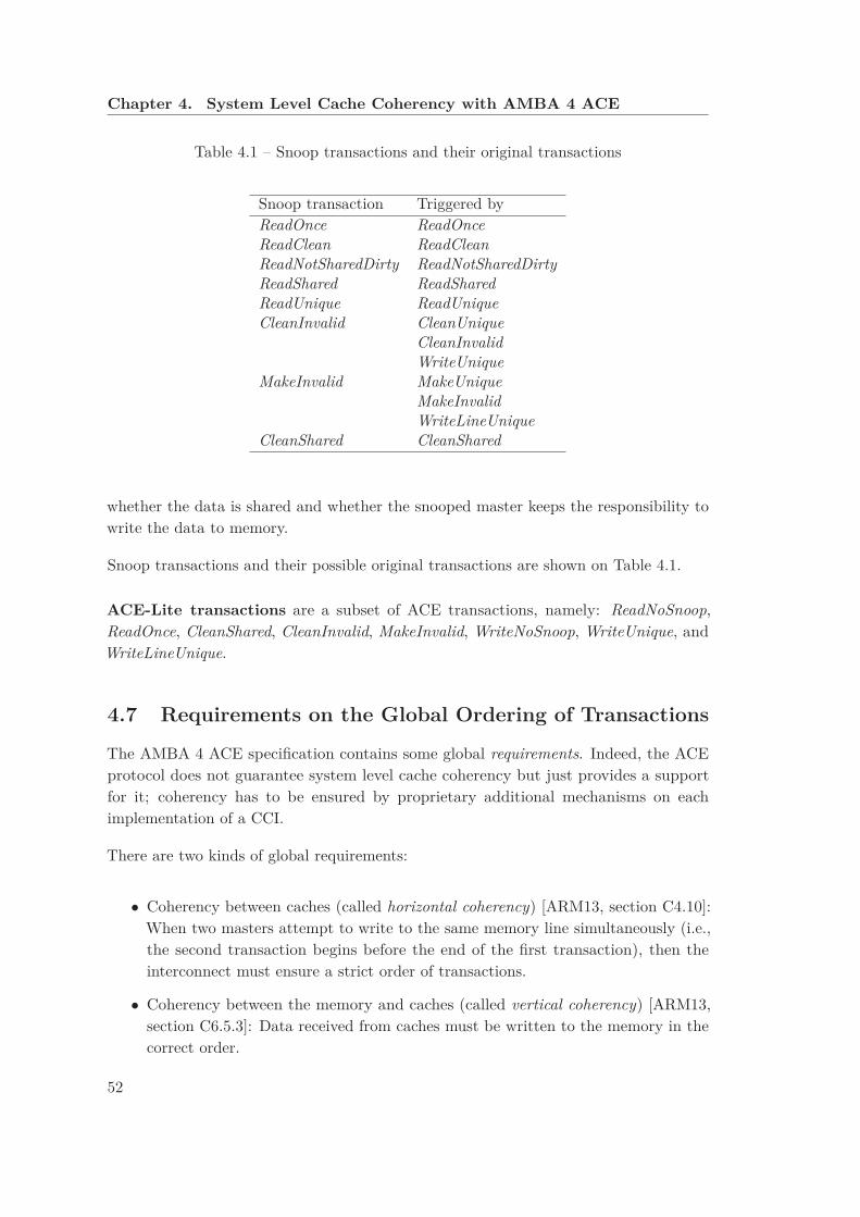
Chapter 4. System Level Cache Coherency with AMBA 4 ACE
Table 4.1 – Snoop transactions and their original transactions
Snoop transaction Triggered byReadOnce ReadOnceReadClean ReadCleanReadNotSharedDirty ReadNotSharedDirtyReadShared ReadSharedReadUnique ReadUniqueCleanInvalid CleanUnique
CleanInvalidWriteUnique
MakeInvalid MakeUniqueMakeInvalidWriteLineUnique
CleanShared CleanShared
whether the data is shared and whether the snooped master keeps the responsibility towrite the data to memory.
Snoop transactions and their possible original transactions are shown on Table 4.1.
ACE-Lite transactions are a subset of ACE transactions, namely: ReadNoSnoop,ReadOnce, CleanShared, CleanInvalid, MakeInvalid, WriteNoSnoop, WriteUnique, andWriteLineUnique.
4.7 Requirements on the Global Ordering of Transactions
The AMBA 4 ACE specification contains some global requirements. Indeed, the ACEprotocol does not guarantee system level cache coherency but just provides a supportfor it; coherency has to be ensured by proprietary additional mechanisms on eachimplementation of a CCI.
There are two kinds of global requirements:
• Coherency between caches (called horizontal coherency) [ARM13, section C4.10]:When two masters attempt to write to the same memory line simultaneously (i.e.,the second transaction begins before the end of the first transaction), then theinterconnect must ensure a strict order of transactions.
• Coherency between the memory and caches (called vertical coherency) [ARM13,section C6.5.3]: Data received from caches must be written to the memory in thecorrect order.
52

4.8. Discussion
4.8 Discussion
The AMBA 4 ACE protocol has become a standard of System-Level Cache Coherency,more than ten big semiconductors companies are using this protocol in their chips.Formally validating such a protocol is very interesting. Before starting any validationwork, we must express formally the protocol and in order to avoid intractable complexitywe have to focus on the new aspects introduced by ACE. In the following chapter wedescribe the formal modeling of a generic SoC based on this hardware protocol.
53


Chapter 5
Formally Modeling an ACE-based
SoC using LNT
5.1 Introduction
In this chapter, we discuss the development and the validation of a formal model of anAMBA 4 ACE-based SoC. We start by giving the main aspects of the formal model. Afterthat, we present the state space generation of several configurations of the model. Then,we discuss the validation of the formal model mainly using model checking techniques.Finally, we show the industrial impact of the formal modeling.
5.2 General Description of the Formal Model
We model the coherent part of an SoC in development at STMicroelectronics. The formalmodel consists of a cache coherent interconnect (CCI) connected to a non-cache-coherentNetwork-on-Chip (NoC), using the LNT language [CCG+14], supported by the CADPtoolbox [GLMS13].
The formal model (about 3,400 lines of LNT code1) focuses on the cache-coherent part ofthe SoC and system-level behavior (i.e., interactions between components), considering atransfer on a channel to be atomic. Hence, parameters about transfer types, identificationof the sender and receiver, and coherency information are modeled, whereas other AXIparameters concerning channel transfer structure are omitted. Our model is useful forstudying the message ordering in the cache-coherent part of the SoC.
A crucial feature of our formal model is that it is parameterized, in particular by the
1A large Petri net derived from our LNT model is available as Model Checking Contest 2014 benchmark(http://mcc.lip6.fr/pdf/ARMCacheCoherence-form.pdf).
55

Chapter 5. Formally Modeling an ACE-based SoC using LNT
AR R AW W CR CDAC AR R AW W CR CDAC
ACE master 1 (big)
Line_1_1 Line_1_2 Line_2_1 Line_2_2
AR R AW WB B B
ACE port 1 ACE−Lite portACE port 2
AXI port
AR R AW W B
(cache−coherent interconnect)
AXI slave(non−cache−coherent NoC/memory)
0
CCI
1 32ACE master 2 (LITTLE)
(GPU)
ACE−Lite master
Figure 5.1 – Model architecture
set of forbidden ACE transactions, the number of ACE masters, ACE-Lite masters,and cache lines per ACE master. The model is generic in the sense that it includes allthe behaviors permitted by the ACE specification for any correct implementation. Themasters are non-deterministic agents, which may initiate all the transactions describedin Chapter 4.
Example 10 In the following, we use the configuration with two ACE masters andone ACE-Lite master corresponding to the industrial use of the protocol (shown inFig. 5.1), which uses the ARM R© big.LITTLETM solution [PG11]: The two ACE masterscorrespond to one big (powerful) and one little (lower-power) processor, enabling todynamically adapt to changing computation load. The ACE-Lite master represents aGraphical Processing Unit (GPU) that can access the caches of both processors. All threemasters access the main memory through a non-cache-coherent NoC. The componentindex is 0 for the AXI slave (shareable memory), 1 and 2 for the ACE masters, and 3 forthe ACE-Lite master. Among the three masters, at most two initiate transactions atthe same time. We vary essentially one parameter, which is the set of forbidden ACEtransactions; we refer to the model as Model(F), where F is the set of forbidden ACEtransactions; Model(∅) corresponds to the complete model.
Due to the industrial choice of STMicroelectronics, we opted for modeling a fully connected
snoop topology, i.e., all coherent transactions lead to snoop transactions for all masterswith caches. Note that the first industrial implementation [ARM12] of the ACE protocolalso has a fully connected snoop topology.
5.2.1 Types and Data Structures
Our model abstracted the ACE specification by applying data independence considera-tions; we replace the 128-bit memory line data by a data type Data_t consisting on alimited range of Nat. At our abstraction level, we only need to know whether two data
56

5.2. General Description of the Formal Model
are equal or different2. This reduces the potential state space produced by the range ofdata (i.e., we use D==7 to differentiate the data in each master cache and the shareablememory and the data after a new master write on the owned or modified cache line).
type Data_t is range 1 .. D of Nat with "==","<>" end type
Each memory line is characterized by two parameters: an index (of range type Index_Mem,where N is the number of memory lines) and a data. The shareable memory can berepresented by an array of values of type Data_t, indexed by the range of Index_Mem.ACE states are represented by an enumerated type called ACE_state.
type Index_Mem is range 1 .. N of Nat end type
type Mem_Lines is array [1 .. N] of Data_t end type
type ACE_state is ACE_I, ACE_UC, ACE_UD, ACE_SC, ACE_SD end type
Similarly, we define an index for system components (Index_Component) and an indexfor cache lines of a master with cache (Index_Cache). ACE transactions are modeled byan enumerated type ACE_Trans.
type Cache_Line is
LINE_C (indC: Index_Cache, S: ACE_state, indM: Index_Mem, data: Data_t)
end type
We introduce an abstract transaction A that simulates an arbitrary ACE transaction byexecuting the classical steps of an ACE transaction without changing the ACE statesof cache lines. The considered steps are: initiating the transaction on an address readchannel (AR), sending the corresponding snoop transaction on the address coherencychannel (AC), receiving a coherency response channel (CR), and issuing the correspondingresponse request in the read response channel (R).
5.2.2 Channels
Each operation on an ACE channel is modeled by an LNT rendezvous3 on a gate of thesame name as the channel. The LNT gates are typed. The types of LNT gates (called
2"==" corresponds to equality function and "<>" corresponds to difference function3The semantics of an LNT rendezvous avoids the need to model the acknowledgment signals at the
level of channel transmission. However, the acknowledgment operation for a non-atomic transaction (e.g.,the operation on the B channel for Write transactions) is represented by an independent LNT rendezvous(on gate B).
57
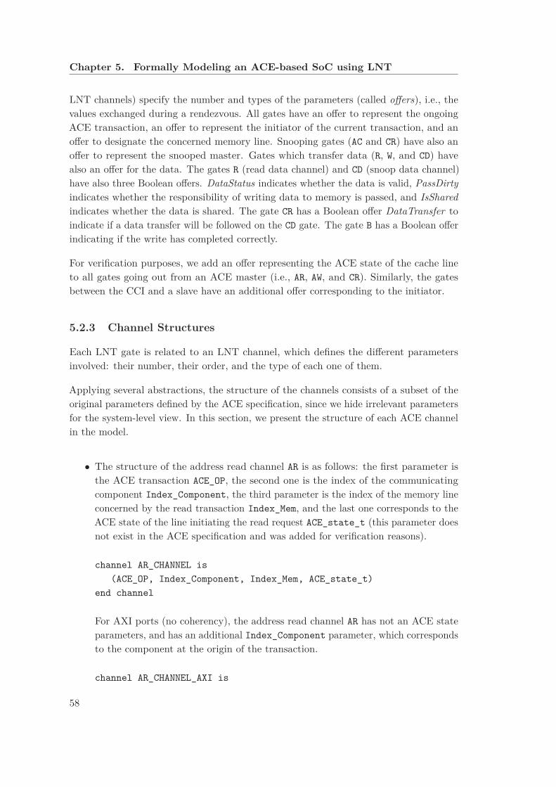
Chapter 5. Formally Modeling an ACE-based SoC using LNT
LNT channels) specify the number and types of the parameters (called offers), i.e., thevalues exchanged during a rendezvous. All gates have an offer to represent the ongoingACE transaction, an offer to represent the initiator of the current transaction, and anoffer to designate the concerned memory line. Snooping gates (AC and CR) have also anoffer to represent the snooped master. Gates which transfer data (R, W, and CD) havealso an offer for the data. The gates R (read data channel) and CD (snoop data channel)have also three Boolean offers. DataStatus indicates whether the data is valid, PassDirty
indicates whether the responsibility of writing data to memory is passed, and IsShared
indicates whether the data is shared. The gate CR has a Boolean offer DataTransfer toindicate if a data transfer will be followed on the CD gate. The gate B has a Boolean offerindicating if the write has completed correctly.
For verification purposes, we add an offer representing the ACE state of the cache lineto all gates going out from an ACE master (i.e., AR, AW, and CR). Similarly, the gatesbetween the CCI and a slave have an additional offer corresponding to the initiator.
5.2.3 Channel Structures
Each LNT gate is related to an LNT channel, which defines the different parametersinvolved: their number, their order, and the type of each one of them.
Applying several abstractions, the structure of the channels consists of a subset of theoriginal parameters defined by the ACE specification, since we hide irrelevant parametersfor the system-level view. In this section, we present the structure of each ACE channelin the model.
• The structure of the address read channel AR is as follows: the first parameter isthe ACE transaction ACE_OP, the second one is the index of the communicatingcomponent Index_Component, the third parameter is the index of the memory lineconcerned by the read transaction Index_Mem, and the last one corresponds to theACE state of the line initiating the read request ACE_state_t (this parameter doesnot exist in the ACE specification and was added for verification reasons).
channel AR_CHANNEL is
(ACE_OP, Index_Component, Index_Mem, ACE_state_t)
end channel
For AXI ports (no coherency), the address read channel AR has not an ACE stateparameters, and has an additional Index_Component parameter, which correspondsto the component at the origin of the transaction.
channel AR_CHANNEL_AXI is
58
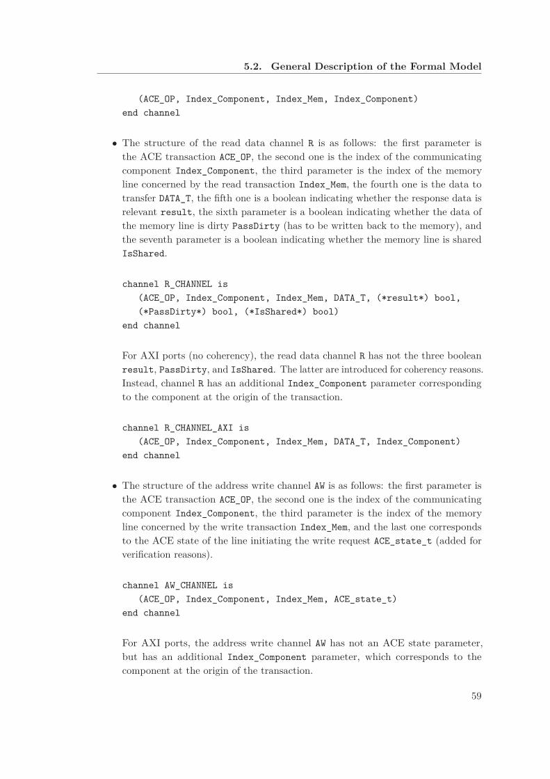
5.2. General Description of the Formal Model
(ACE_OP, Index_Component, Index_Mem, Index_Component)
end channel
• The structure of the read data channel R is as follows: the first parameter isthe ACE transaction ACE_OP, the second one is the index of the communicatingcomponent Index_Component, the third parameter is the index of the memoryline concerned by the read transaction Index_Mem, the fourth one is the data totransfer DATA_T, the fifth one is a boolean indicating whether the response data isrelevant result, the sixth parameter is a boolean indicating whether the data ofthe memory line is dirty PassDirty (has to be written back to the memory), andthe seventh parameter is a boolean indicating whether the memory line is sharedIsShared.
channel R_CHANNEL is
(ACE_OP, Index_Component, Index_Mem, DATA_T, (*result*) bool,
(*PassDirty*) bool, (*IsShared*) bool)
end channel
For AXI ports (no coherency), the read data channel R has not the three booleanresult, PassDirty, and IsShared. The latter are introduced for coherency reasons.Instead, channel R has an additional Index_Component parameter correspondingto the component at the origin of the transaction.
channel R_CHANNEL_AXI is
(ACE_OP, Index_Component, Index_Mem, DATA_T, Index_Component)
end channel
• The structure of the address write channel AW is as follows: the first parameter isthe ACE transaction ACE_OP, the second one is the index of the communicatingcomponent Index_Component, the third parameter is the index of the memoryline concerned by the write transaction Index_Mem, and the last one correspondsto the ACE state of the line initiating the write request ACE_state_t (added forverification reasons).
channel AW_CHANNEL is
(ACE_OP, Index_Component, Index_Mem, ACE_state_t)
end channel
For AXI ports, the address write channel AW has not an ACE state parameter,but has an additional Index_Component parameter, which corresponds to thecomponent at the origin of the transaction.
59
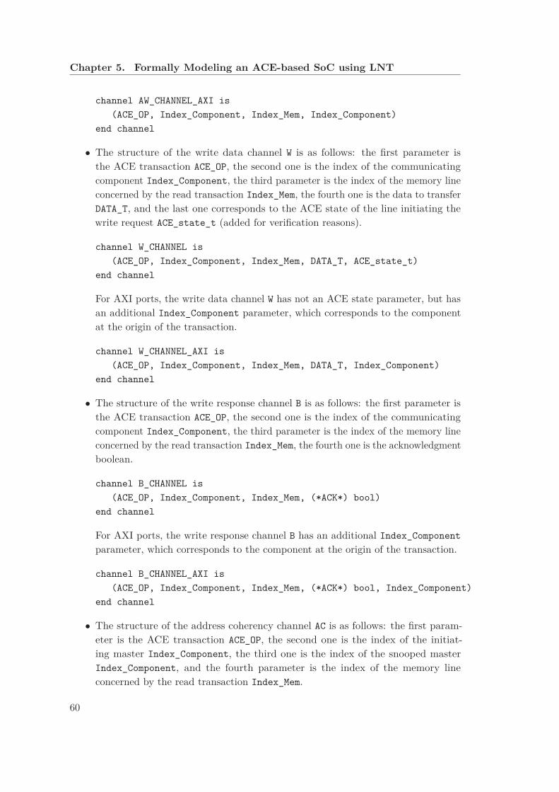
Chapter 5. Formally Modeling an ACE-based SoC using LNT
channel AW_CHANNEL_AXI is
(ACE_OP, Index_Component, Index_Mem, Index_Component)
end channel
• The structure of the write data channel W is as follows: the first parameter isthe ACE transaction ACE_OP, the second one is the index of the communicatingcomponent Index_Component, the third parameter is the index of the memory lineconcerned by the read transaction Index_Mem, the fourth one is the data to transferDATA_T, and the last one corresponds to the ACE state of the line initiating thewrite request ACE_state_t (added for verification reasons).
channel W_CHANNEL is
(ACE_OP, Index_Component, Index_Mem, DATA_T, ACE_state_t)
end channel
For AXI ports, the write data channel W has not an ACE state parameter, but hasan additional Index_Component parameter, which corresponds to the componentat the origin of the transaction.
channel W_CHANNEL_AXI is
(ACE_OP, Index_Component, Index_Mem, DATA_T, Index_Component)
end channel
• The structure of the write response channel B is as follows: the first parameter isthe ACE transaction ACE_OP, the second one is the index of the communicatingcomponent Index_Component, the third parameter is the index of the memory lineconcerned by the read transaction Index_Mem, the fourth one is the acknowledgmentboolean.
channel B_CHANNEL is
(ACE_OP, Index_Component, Index_Mem, (*ACK*) bool)
end channel
For AXI ports, the write response channel B has an additional Index_Component
parameter, which corresponds to the component at the origin of the transaction.
channel B_CHANNEL_AXI is
(ACE_OP, Index_Component, Index_Mem, (*ACK*) bool, Index_Component)
end channel
• The structure of the address coherency channel AC is as follows: the first param-eter is the ACE transaction ACE_OP, the second one is the index of the initiat-ing master Index_Component, the third one is the index of the snooped masterIndex_Component, and the fourth parameter is the index of the memory lineconcerned by the read transaction Index_Mem.
60

5.2. General Description of the Formal Model
channel AC_CHANNEL is
(ACE_OP, (*initiator*) Index_Component,
(*snooped*) Index_Component, Index_Mem)
end channel
• The structure of a coherent response channel CR is as follows: the first param-eter is the ACE transaction ACE_OP, the second one is the index of the initiat-ing master Index_Component, the third one is the index of the snooped masterIndex_Component, the fourth parameter is the index of the memory line concernedby the read transaction Index_Mem, the fifth one is a boolean indicating if theiris a corresponding data transfer DatatTansfer, the sixth parameter is a booleanindicating whether the data of the memory line is dirty PassDirty, the seventhparameter is a boolean indicating whether the memory line is shared IsShared, andthe last one corresponds to the ACE state of the line initiating the write requestACE_state_t (added for verification reasons).
channel CR_CHANNEL is
(ACE_OP, (*initiator*) Index_Component,
(*snooped*) Index_Component, Index_Mem,
(*DatatTansfer*) bool, (*PassDirty*) bool, (*IsShared*) bool,
ACE_state_t)
end channel
• The structure of the coherency data channel CD is as follows: the first param-eter is the ACE transaction ACE_OP, the second one is the index of the initiat-ing master Index_Component, the third one is the index of the snooped masterIndex_Component, the fourth parameter is the index of the memory line concernedby the read transaction Index_Mem, the fifth one is the data to transfer DATA_T,and the sixth one is a boolean indicating whether the response data is relevantresult.
channel CD_CHANNEL is
(ACE_OP, (*initiator*) Index_Component,
(*snooped*) Index_Component,
Index_Mem, DATA_T, (*result*) bool)
end channel
5.2.4 AXI Slave: Shareable Memory
The shareable memory is modeled by the LNT process shown in Figure 5.2. The five gatesAR, R, AW, W, and B correspond to the AXI channels. We use the Boolean pending_read
to indicate if a read operation is in progress. The behavior of the memory process is a
61
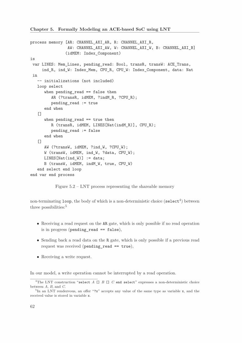
Chapter 5. Formally Modeling an ACE-based SoC using LNT
process memory [AR: CHANNEL_AXI_AR, R: CHANNEL_AXI_R,
AW: CHANNEL_AXI_AW, W: CHANNEL_AXI_W, B: CHANNEL_AXI_B]
(idMEM: Index_Component)
is
var LINES: Mem_Lines, pending_read: Bool, transR, transW: ACE_Trans,
ind_R, ind_W: Index_Mem, CPU_R, CPU_W: Index_Component, data: Nat
in
-- initializations (not included)
loop select
when pending_read == false then
AR (?transR, idMEM, ?indM_R, ?CPU_R);
pending_read := true
end when
[]
when pending_read == true then
R (transR, idMEM, LINES[Nat(indM_R)], CPU_R);
pending_read := false
end when
[]
AW (?transW, idMEM, ?ind_W, ?CPU_W);
W (transW, idMEM, ind_W, ?data, CPU_W);
LINES[Nat(ind_W)] := data;
B (transW, idMEM, indM_W, true, CPU_W)
end select end loop
end var end process
Figure 5.2 – LNT process representing the shareable memory
non-terminating loop, the body of which is a non-deterministic choice (select4) betweenthree possibilities:5
• Receiving a read request on the AR gate, which is only possible if no read operationis in progress (pending_read == false),
• Sending back a read data on the R gate, which is only possible if a previous readrequest was received (pending_read == true),
• Receiving a write request.
In our model, a write operation cannot be interrupted by a read operation.
4The LNT construction “select A [] B [] C end select” expresses a non-deterministic choicebetween A, B, and C.
5In an LNT rendezvous, an offer “?x” accepts any value of the same type as variable x, and thereceived value is stored in variable x.
62
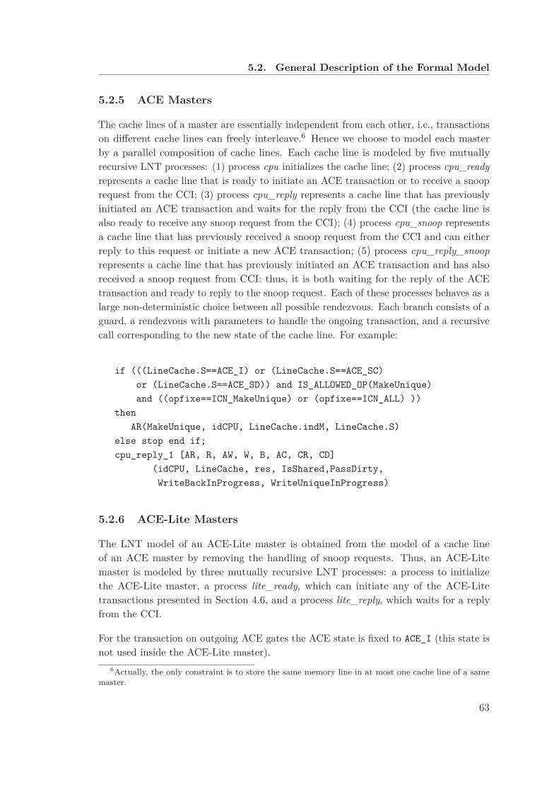
5.2. General Description of the Formal Model
5.2.5 ACE Masters
The cache lines of a master are essentially independent from each other, i.e., transactionson different cache lines can freely interleave.6 Hence we choose to model each masterby a parallel composition of cache lines. Each cache line is modeled by five mutuallyrecursive LNT processes: (1) process cpu initializes the cache line; (2) process cpu_ready
represents a cache line that is ready to initiate an ACE transaction or to receive a snooprequest from the CCI; (3) process cpu_reply represents a cache line that has previouslyinitiated an ACE transaction and waits for the reply from the CCI (the cache line isalso ready to receive any snoop request from the CCI); (4) process cpu_snoop representsa cache line that has previously received a snoop request from the CCI and can eitherreply to this request or initiate a new ACE transaction; (5) process cpu_reply_snoop
represents a cache line that has previously initiated an ACE transaction and has alsoreceived a snoop request from CCI: thus, it is both waiting for the reply of the ACEtransaction and ready to reply to the snoop request. Each of these processes behaves as alarge non-deterministic choice between all possible rendezvous. Each branch consists of aguard, a rendezvous with parameters to handle the ongoing transaction, and a recursivecall corresponding to the new state of the cache line. For example:
if (((LineCache.S==ACE_I) or (LineCache.S==ACE_SC)
or (LineCache.S==ACE_SD)) and IS_ALLOWED_OP(MakeUnique)
and ((opfixe==ICN_MakeUnique) or (opfixe==ICN_ALL) ))
then
AR(MakeUnique, idCPU, LineCache.indM, LineCache.S)
else stop end if;
cpu_reply_1 [AR, R, AW, W, B, AC, CR, CD]
(idCPU, LineCache, res, IsShared,PassDirty,
WriteBackInProgress, WriteUniqueInProgress)
5.2.6 ACE-Lite Masters
The LNT model of an ACE-Lite master is obtained from the model of a cache lineof an ACE master by removing the handling of snoop requests. Thus, an ACE-Litemaster is modeled by three mutually recursive LNT processes: a process to initializethe ACE-Lite master, a process lite_ready, which can initiate any of the ACE-Litetransactions presented in Section 4.6, and a process lite_reply, which waits for a replyfrom the CCI.
For the transaction on outgoing ACE gates the ACE state is fixed to ACE_I (this state isnot used inside the ACE-Lite master).
6Actually, the only constraint is to store the same memory line in at most one cache line of a samemaster.
63

Chapter 5. Formally Modeling an ACE-based SoC using LNT
5.2.7 Cache Coherent Interconnect (CCI)
To ease the modeling of all interleavings between the ports of the CCI, we employ twotechniques. First, we model the CCI by a parallel composition of as many processes asthere are ports; each port is always ready to receive a request from both the correspondingcomponent and other ports. Second, all received requests are stored in a set and arehandled in any order.7
The ports of the CCI communicate internally via dedicated gates, which are not part ofthe ACE specification and can be hidden (in the LTS and in counterexamples), but areuseful in the debug phase of the model.
Example 11 The CCI of Figure 5.1 contains four ports: two ACE ports, each com-municating with an ACE master, one ACE-Lite port communicating with an ACE-Litemaster, and one AXI port communicating with the shareable memory through thenon-cache-coherent NoC.
5.3 Modeling Global Ordering Requirements
Following a constraint-oriented specification style, our LNT model integrates theseglobal requirements as observer processes (one process per requirement and memoryline), composed in parallel with the remainder of the model. Hence, those observersmonitor the system and have a global view of all transactions. For horizontal coherency,while handling a snoop transaction, the observer process ensures that a subset of snooptransactions (relative to the same memory line) is not handled before the end of the firsttransaction. For vertical coherency, the observer process monitors write transactions,prohibiting that an old data overwrites a more recent one.
We call the model containing the observer processes the constrained model. By omittingthose observers, we obtain an unconstrained model, for which the global requirements arenot necessarily satisfied.
5.4 State Space Generation
In this section, we present two different configurations of the model, both correspondingto the architecture proposed on Figure 5.1. For each configuration, we present statisticson generated LTS for different sub-configurations (varying the allowed/forbidden sets oftransactions).
7Because the numbers of masters and cache lines are fixed and each master can issue at most onerequest per cache line at the same time, the number of requests in a set is bounded by construction.
64

5.4. State Space Generation
Table 5.1 – Experimental results: state space generation of shareable focused modelconfigurations
allowed transactions global LTS sizem1 m2 lite constraints states transitions
(1) S0 {A} S0 yes 93,481,270 308,087,560(2) S0 {A} S0 no 105,376,971 351,344,207(3) S0 ∅ S0 yes 7,518,552 21,227,610(4) S1 ∅ S1 yes 3,685,311 10,649,422(5) S1 ∅ S1 no 3,127,707 9,121,134(6) S2 S2 ∅ yes 3,545,801 11,122,536(7) S2 S2 ∅ no 2,819,505 9,095,620(8) S3 ∅ S′
3 yes 1,834,195 5,170,829(9) S3 ∅ S′
3 no 1,437,412 4,547,398(10) S4 S4 ∅ yes 560,299 1,669,886(11) S4 S4 ∅ no 599,971 1,780,634(12) S5 S5 ∅ yes 40,983 63,922(13) S5 S5 ∅ no 55,439 98,688(14) S6 S6 ∅ yes 25,760 71,121(15) S6 S6 ∅ no 25,760 71,121
In this table, we use those sets of allowed transactions:S0 = { CleanInvalid, CleanShared, MakeInvalid, MakeUnique, ReadOnce,
ReadShared, ReadUnique, WriteBack }{A} = the abstract transaction singletonS1 = { MakeUnique, ReadOnce, ReadUnique, WriteBack }S2 = { MakeInvalid, MakeUnique, ReadShared, ReadUnique, WriteBack }S3 = { MakeUnique, WriteBack}, S′
3 = {ReadOnce }S4 = { CleanInvalid, CleanShared, ReadUnique, WriteBack }S5 = { MakeInvalid, MakeUnique, WriteBack }S6 = { CleanInvalid, CleanShared, MakeInvalid }
5.4.1 Shareable Focused Model
For our analysis, we consider several configurations of our formal model, each consistingof a shareable memory (consisting of three memory lines), one ACE-Lite master, andtwo ACE masters, with two cache lines each. To focus on coherency issues, the firstcache lines of each ACE master execute transactions concerning the same shareablememory line (this is suitable according to [DDHY92]). Each master initiates at mostone transaction (chosen from a set of allowed transactions); thus, the second cache lineof each ACE master never initiates a transaction (but answers snoop requests). Wegenerate several partial configurations of the ACE specification (i.e., up to eight ACEtransactions among fifteen ACE transactions allowed in a shareable region of the memory,this limitation being caused by the state space explosion problem). We selected subsetsof transactions that could create problems for properties to verify.
65
Chapter 5. Formally Modeling an ACE-based SoC using LNT
Example 12 For each considered configuration, Table 5.1 gives the size of the corre-sponding LTS. Column one (respectively, two, or three) gives the set of transactions thatmaster 1 (respectively, master 2, or the ACE-Lite master) is allowed to initiate. Columnfour tells whether the model includes the observer processes enforcing the global orderingrequirements; we generate LTSs for unconstrained models to study the impact of theobservers on the properties of the system. The LTS of each constrained model is includedin the corresponding unconstrained model with respect to strong bisimulation (i.e., theconstraints only remove unsuitable behaviors), but the state space may be larger becausea state now also integrates the current state of the observer processes.
5.4.2 Optimized Model
The optimized model introduces the following limitations to the shareable focusedconfiguration: We consider that the shareable memory contains only one line and thateach ACE master contains only one cache line. All transactions issued by the threemasters concern the same memory line. Each master initiates at most one transaction(chosen from a set of allowed transactions), except for memory update transactions, forwhich the master can initiate transactions as long as the ACE state allows.
This optimized model is used to generate complete and partial configurations of the ACEspecification (i.e., all the fifteen ACE transactions can be activated).
Example 13 For each considered configuration of the optimized model, Table 5.2 givesthe size of the corresponding LTS. We have the same configurations as the Table 5.1with the new statistics and additional configurations that were previously difficult togenerate.
5.5 Model Validation
Modeling is a manual activity, and errors might be introduced during this activity. Theformal model must be corrected and validated to have more confidence in it beforeexploiting the formal model in the validation of the modeled system. Compiling the LNTmodel with CADP tools was useful to detect (via the error and warning messages raisedby the LNT compiler) several introduced problems. After that, we used the backtrackingOCIS simulator of CADP to simulate step by step the model to see that the modeledbehavior corresponds to the expected behavior.
In the reminder of this section, we aim to automatically verify the conformity of the LNTmodel with respect to the specification. To this purpose, we write several propertiesexpressed in MCL [MT08]. We start by verifying the absence of deadlocks and livelocks inthe model, then we validate the complete and correct execution of separate transactions.
66

5.5. Model Validation
Table 5.2 – Experimental results: state space generation of optimized model configurations
allowed transactions global LTS sizem1 m2 lite constraints states transitions
(1) ALL ∅ ALL yes 2,895,388 7,951,583(2) ALL ∅ ALL no 1,466,479 3,772,056(3) ALL ALL ∅ yes 1,302,386 2,854,974(4) ALL ALL ∅ no 668,318 1,320,481(5) S1 ∅ S1 yes 221,754 608,247(6) S1 ∅ S1 no 88,760 231,369(7) S1 S1 ∅ yes 28,381 52,430(8) S1 S1 ∅ no 21,231 37,644(9) S2 ∅ S2 yes 26,336 53,410(10) S2 ∅ S2 no 16,260 32,635(11) S2 S2 ∅ yes 40,099 76,324(12) S2 S2 ∅ no 24,594 42,748(13) S3 ∅ S′
3 yes 196,105 542,049(14) S3 ∅ S′
3 no 71,850 189,728(15) S4 ∅ S4 yes 50,882 107,100(16) S4 ∅ S4 no 44,464 94,685(17) S4 S4 ∅ yes 11,125 18,199(18) S4 S4 ∅ no 9,660 16,258(19) S5 ∅ S5 yes 16,421 33,549(20) S5 ∅ S5 no 6,869 13,673(21) S5 S5 ∅ yes 6,004 9,971(22) S5 S5 ∅ no 4,399 7,375(23) S6 ∅ S6 yes 41,585 86,977(24) S6 ∅ S6 no 35,665 76,282(25) S6 S6 ∅ yes 5,102 8,150(26) S6 S6 ∅ no 4,335 7,241
In this table, we use those sets of allowed transactions:ALL = set of all ACE (respectively ACE-Lite) transactions{A} = the abstract transaction singletonS1 = { MakeUnique, ReadOnce, ReadUnique, WriteBack }S2 = { MakeInvalid, MakeUnique, ReadShared, ReadUnique, WriteBack }S3 = { MakeUnique, WriteBack}, S′
3 = {ReadOnce }S4 = { CleanInvalid, CleanShared, ReadUnique, WriteBack }S5 = { MakeInvalid, MakeUnique, WriteBack }S6 = { CleanInvalid, CleanShared, MakeInvalid }
Some of the following MCL formulæ use the macro inevitable (L), which expressesthat a transition labeled with L will eventually occur. This macro can be defined asfollows:
macro inevitable (L) =
67
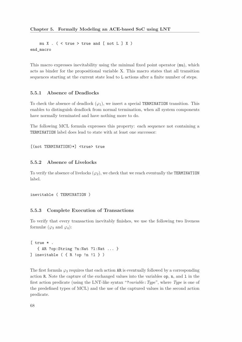
Chapter 5. Formally Modeling an ACE-based SoC using LNT
mu X . ( < true > true and [ not L ] X )
end_macro
This macro expresses inevitability using the minimal fixed point operator (mu), whichacts as binder for the propositional variable X. This macro states that all transitionsequences starting at the current state lead to L actions after a finite number of steps.
5.5.1 Absence of Deadlocks
To check the absence of deadlock (ϕ1), we insert a special TERMINATION transition. Thisenables to distinguish deadlock from normal termination, when all system componentshave normally terminated and have nothing more to do.
The following MCL formula expresses this property: each sequence not containing aTERMINATION label does lead to state with at least one successor:
[(not TERMINATION)*] <true> true
5.5.2 Absence of Livelocks
To verify the absence of livelocks (ϕ2), we check that we reach eventually the TERMINATION
label.
inevitable ( TERMINATION )
5.5.3 Complete Execution of Transactions
To verify that every transaction inevitably finishes, we use the following two livenessformulæ (ϕ3 and ϕ4):
[ true * .
{ AR ?op:String ?n:Nat ?l:Nat ... }
] inevitable ( { R !op !n !l } )
The first formula ϕ3 requires that each action AR is eventually followed by a correspondingaction R. Note the capture of the exchanged values into the variables op, n, and l in thefirst action predicate (using the LNT-like syntax “?variable:Type”, where Type is one ofthe predefined types of MCL) and the use of the captured values in the second actionpredicate.
68
5.6. First Industrial Results
[ true * .
{ AW ?op:String ?n:Nat ?l:Nat ... }
] inevitable ( { B !op !n !l } )
The second formula ϕ4 requires that each action AW is eventually followed by a corre-sponding action B.
5.6 First Industrial Results
The formal model is used inside STMicroelectronics as a reference in discussions withverification engineers and interconnect architects. It helps to understand the new aspectsintroduced by ACE and to define the verification strategy. In this context, the OCISinteractive step-by-step simulator with backtracking of CADP is found useful.
Modeling the ACE-based SoC helps STMicroelectronics engineers to understand thesubtleties of the ACE specification, because the initial specification is not formal. Manyproblems are discovered just by modeling, before running any tool.
5.7 Discussion
We observe that the properties used to validate the model are liveness properties becausethey express that “something good eventually happens”. Classically, the absence ofdeadlocks and livelocks properties are safety properties expressing that never a deadlockhappens or never a livelock happens, but in our case, due to state space generationproblem, the model initiates transactions a limited number of times. The model is notcompletely cyclic.
In the remaining, we present the different exploitations of this formal model. In fact, theformal model is used to validate global properties of the system (Chapter 6), to generate"clever" test cases using model checking results (Chapter 7), and to study the sanityof an interface verification unit (Chapter 8). Those activities are detailed in the threefollowing chapters.
69

Model Exploitation
71

Chapter 6
Model Checking System-Level
Properties
6.1 Introduction
In this chapter we aim at validating the global coherency of the ACE specification byverifying several system-level properties on our formal model of a generic ACE-based SoC(described in Chapter 5). We notice that the ACE masters and ACE-Lite masters includeall the allowed behaviors of the ACE specification. First, we analyze the coherencyaspects of the protocol in order to exhibit the coherency requirements of the system.Then, we present the different properties triggered by those requirements. The propertiesare expressed in MCL (Model Checking Language) [MT08]. Finally, we show the modelchecking results.
6.2 System-Level Cache Coherency Analysis
The modeled system, described in Section 5.2, presents three aspects of coherency: First,the coherency between the ACE states of the different caches containing the same memoryline, which we call cache line states coherency. Second, the coherency of the data indifferent caches or between the caches and the memory, which we call data integrity.Third, the coherency of the coherent parameters of ACE transactions regarding theACE state of the cache line before and after sending the transactions, which we callmessaging consistency. In this section, we explore the requirements regarding each ofthese coherency aspects.
73

Chapter 6. Model Checking System-Level Properties
Table 6.1 – Cache coherency requirements analysis
ACE states Requirement concerningstates of other caches cache line data
(1) ACE_UD ACE_I nothing(2) ACE_UC ACE_I equal to memory data(3) ACE_SD ACE_I/ACE_SC equal to data of ACE_SC, if any(4) ACE_SC ACE_I/ACE_SC/ACE_SD equal to data of ACE_SD/ACE_SC, if any(5) ACE_I nothing nothing
6.2.1 Cache Line States Coherency Requirements
ACE specification defines five cache line states (presented on Section 4.4). For each statewe deduce requirements concerning the ACE state of any cache line of another mastercontaining the same memory line.
Column two of Table 6.1 presents the requirements for ACE state of other caches foreach cache line state (column one).
For a cache line in a unique state (ACE_UD or ACE_UC), the other copies of the samememory line must be invalid (ACE_I). For a cache line in a shared dirty state (ACE_SD),the other copies of the same memory line must be invalid (ACE_I) or in a shared cleanstate (ACE_SC). For a cache line in a shared clean state (ACE_SC), the other copies of thesame memory line must be either invalid or shared. Besides, if the cache line is in aninvalid state (ACE_I), their is no requirement for the other cache lines containing thesame memory line.
6.2.2 Data Integrity Requirements
Data integrity of the system consists in two different aspects:
• First, the cache line data has to respect the cache line states as presented in thethird column of Table 6.1: If the cache line is in a unique clean state (ACE_UC), thedata has to be equal to the data stored in the shareable memory. If the cache lineis shared (ACE_SD or ACE_SC), the data of any other copy of the same memory linehas to be equal to the data in the cache line.
• Second, the data integrity of the shareable memory should be maintained. Wehave to monitor the order of write operations to the shareable memory. We haveto check that an old data never erases a newer one.
74
6.3. System-Level Properties
6.2.3 Messaging Consistency Requirements
Messaging consistency deals with the coherency parameters, namely, the PassDirty andIsShard parameters present both in the read response channel R and the coherencyresponse channel CR.
For the read response channel R, the consistency encompasses three different requirements:
• For a subset of ACE transactions, the initiating master (called also Initiator withinSTMicroelectronics) cannot accept to get the responsibility of writing back the dataon the shareable memory, i.e., the PassDirty parameter must never be asserted(i.e., PassDirty==False).
• For another subset of ACE transactions, the initiator must have the memoryline in a unique state, i.e., the IsShared parameter must never be asserted (i.e.,IsShared==False).
• For the ReadNotSharedDirty transaction, the initiator must never have the memoryline in a shared dirty state, i.e., the PassDirty and the IsShared parameterscannot be asserted at the same time.
For the coherency response channel CR, the parameters depend on the snooped mastercache line state before and after the CR request. In fact, the PassDirty parameter isasserted if and only if the cache line state before the request is dirty and the cache linestate after the request is clean or invalid. The IsShared parameter is asserted if thecache line after the request is in a valid state (ACE_UD, ACE_UC, ACE_SD, or ACE_SC) anddeserted if the cache line after the request is invalid.
6.3 System-Level Properties
Each requirement leads to one or more system-level properties to be checked on the model.Some properties can be expressed by a state-based view, e.g., properties concerning anACE state of a cache line. Those properties are translated to an equivalent action-basedview handling only actions expressed by the transitions of the LTS (see Fig. 6.1).
In practice, when formalizing properties, we can introduce a false positive error: theproperty does not really check the behavior and the result is TRUE (e.g., a syntax error inthe property action with regard to the corresponding model transitions). So we suggestto change slightly the sense of the property to have an evident error and if the check isnot failed the property has to be corrected.
In this section, we present a selection of representative examples of the MCL formulæexpressed in order to check the requirements corresponding to the different coherency
75
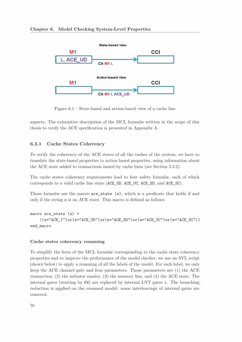
Chapter 6. Model Checking System-Level Properties
Figure 6.1 – State-based and action-based view of a cache line
aspects. The exhaustive description of the MCL formulæ written in the scope of thisthesis to verify the ACE specification is presented in Appendix A.
6.3.1 Cache States Coherency
To verify the coherency of the ACE states of all the caches of the system, we have totranslate the state-based properties to action-based properties, using information aboutthe ACE state added to transactions issued by cache lines (see Section 5.2.2).
The cache states coherency requirements lead to four safety formulæ, each of whichcorresponds to a valid cache line state (ACE_UD, ACE_UC, ACE_SD, and ACE_SC).
Those formulæ use the macro ace_state (s), which is a predicate that holds if andonly if the string s is an ACE state. This macro is defined as follows:
macro ace_state (s) =
((s="ACE_I")or(s="ACE_UD")or(s="ACE_SD")or(s="ACE_UC")or(s="ACE_SC"))
end_macro
Cache states coherency renaming
To simplify the form of the MCL formulæ corresponding to the cache state coherencyproperties and to improve the performance of the model checker, we use an SVL script(shown below) to apply a renaming of all the labels of the model. For each label, we onlykeep the ACE channel gate and four parameters. Those parameters are (1) the ACEtransaction, (2) the initiator master, (3) the memory line, and (4) the ACE state. Theinternal gates (starting by FW) are replaced by internal LNT gates i. The branchingreduction is applied on the renamed model: some interleavings of internal gates areremoved.
76

6.3. System-Level Properties
"renameCacheStateCoherency.bcg" =
branching reduction of
total rename
"\([A-Z]* ![A-Z]* ![0-9] ![0-9]\) ![0-9] \(![A-Z]*_[A-Z]*\)"
-> "\1 \2",
"\([A-Z]* ![A-Z]*\) ![0-9] \(![0-9] ![0-9]\) ![A-Z]* ![A-Z]* ![A-Z]* \(![A-Z]*_[A-Z]*\)"
-> "\1 \2 \3",
"\([A-Z]* ![A-Z]*\) ![0-9] \(![0-9] ![0-9]\) ![0-9] ![A-Z]* \(![A-Z]*_[A-Z]*\)"
-> "\1 \2 \3",
"FW_[A-Z]* [A-Za-z0-9_ !]*" -> "i"
in "model.bcg";
Unique dirty coherency
As a sample, we present the cache state coherency formula concerning the unique dirtystate (ϕ5). The latter requires that if a cache line (master m1, memory line l) is in thestate ACE_UD (the cache line is unique and modified), then as long as the line does notchange its status, all cache lines of other masters (m2 Ó= m1) containing the same memoryline (l) must be in the state ACE_I (the cache line is invalid). This is a state-basedproperty. The corresponding action-based property expresses that if an action {?Ch m1
l ACE_UD} happens then while there is no action {?Ch m1 l s1 where s1 Ó= ACE_UD},we check whether an action {?Ch m2 l s2 where m2 Ó= m1 and s1 Ó= ACE_I} happens.If this is the case, then the property is not satisfied (false).
The MCL formula expressing this action-based property is the following:
[ true * .
{?Ch:String ?op:String ?m1:Nat ?l:Nat !"ACE_UD"} .
( not ({?Ch:String ?op:String !m1 !l ?s1:String
where ace_state (s1) and (s1<>"ACE_UD")}) ) * .
{?Ch:String ?op:String ?m2:Nat !l ?s2:String
where (m2<>m1) and ace_state (s2)
and (s2<>"ACE_I")}
] false
Notice that the unique clean coherency (ϕ6), the shared dirty coherency (ϕ7), and theshared clean coherency (ϕ8) formulæ are described in Appendix A.
6.3.2 Data Integrity
To verify the data integrity, we have to check four different properties, one concerning thewrite ordering on the shareable memory and three others concerning the data integritycorresponding to some cache line states (namely, ACE_UC, ACE_SD, and ACE_SC). The
77
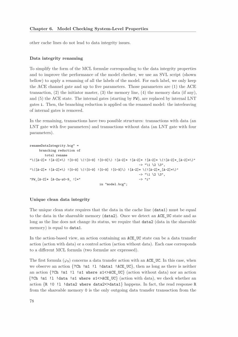
Chapter 6. Model Checking System-Level Properties
other cache lines do not lead to data integrity issues.
Data integrity renaming
To simplify the form of the MCL formulæ corresponding to the data integrity propertiesand to improve the performance of the model checker, we use an SVL script (shownbellow) to apply a renaming of all the labels of the model. For each label, we only keepthe ACE channel gate and up to five parameters. Those parameters are (1) the ACEtransaction, (2) the initiator master, (3) the memory line, (4) the memory data (if any),and (5) the ACE state. The internal gates (starting by FW), are replaced by internal LNTgates i. Then, the branching reduction is applied on the renamed model: the interleavingof internal gates is removed.
In the remaining, transactions have two possible structures: transactions with data (anLNT gate with five parameters) and transactions without data (an LNT gate with fourparameters).
renameDataIntegrity.bcg" =
branching reduction of
total rename
"\([A-Z]* ![A-Z]*\) ![0-9] \(![0-9] ![0-9]\) ![A-Z]* ![A-Z]* ![A-Z]* \(![A-Z]*_[A-Z]*\)"
-> "\1 \2 \3",
"\([A-Z]* ![A-Z]*\) ![0-9] \(![0-9] ![0-9] ![0-9]\) ![A-Z]* \(![A-Z]*_[A-Z]*\)"
-> "\1 \2 \3",
"FW_[A-Z]* [A-Za-z0-9_ !]*" -> "i"
in "model.bcg";
Unique clean data integrity
The unique clean state requires that the data in the cache line (data1) must be equalto the data in the shareable memory (data2). Once we detect an ACE_UC state and aslong as the line does not change its status, we require that data2 (data in the shareablememory) is equal to data1.
In the action-based view, an action containing an ACE_UC state can be a data transferaction (action with data) or a control action (action without data). Each case correspondsto a different MCL formula (two formulæ are expressed).
The first formula (ϕ9) concerns a data transfer action with an ACE_UC. In this case, whenwe observe an action {?Ch !m1 !l !data1 !ACE_UC}, then as long as there is neitheran action {?Ch !m1 !l !s1 where s1<>ACE_UC} (action without data) nor an action{?Ch !m1 !l !data !s1 where s1<>ACE_UC} (action with data), we check whether anaction {R !0 !l !data2 where data2<>data1} happens. In fact, the read response R
from the shareable memory 0 is the only outgoing data transfer transaction from the
78

6.3. System-Level Properties
memory. If such a response occurs, the property is not satisfied (false).
The formula ϕ9 is expressed as follows:
[ true * .
{?Ch:String ?op:String ?m1:Nat ?l:Nat ?data1:Nat !"ACE_UC"} .
(
not ({?Ch:String ?op:String !m1 !l ?any of Nat ?s:String
where ace_state (s) and (s<>"ACE_UC")})
and
not ({?Ch:String ?op:String !m1 !l ?s:String
where ace_state (s) and (s<>"ACE_UC")})
)* .
{R ?op:string !"0" !l ?data2:Nat ?m2:Nat
where (data2<>data1)}
] false
The second formula (ϕ10) concerns a control action with an ACE_UC state. The datatransfer containing the data happens in a different action. In the beginning, we savethe data present in an action with a different cache state than ACE_UC {?Ch !m1 !l
!data !s1 where s1<>ACE_UC}, then we note an action {?Ch !m1 !l !ACE_UC}. Aslong as there is neither an action {?Ch !m1 !l !s1 where s1<>ACE_UC} (action withoutdata) nor an action {?Ch !m1 !l !data !s1 where s1<>ACE_UC} (action with data),we check whether an action {R !0 !l !data2 where data2<>data1} happens. If sucha response occurs, the property is not satisfied (false).
The formula ϕ10 is expressed as follows:
[ true * .
{?Ch:String ?op:String ?m1:Nat ?l:Nat ?data1:Nat ?s:String
where ace_state (s) and (s<>"ACE_UC")} .
(not {?Ch:String ?op:String ?m1:Nat ?l:Nat !"ACE_UC"})* .
{?Ch:String ?op:String ?m1:Nat ?l:Nat !"ACE_UC"} .
(
not ({?Ch:String ?op:String !m1 !l ?h:Nat ?s:String
where ace_state (s) and (s<>"ACE_UC")})
and
not ({?Ch:String ?op:String !m1 !l ?s:String
where ace_state (s) and (s<>"ACE_UC")})
)* .
{R ?op:string !"0" !l ?data2:Nat ?m2:Nat
where (data2<>data1)}
79

Chapter 6. Model Checking System-Level Properties
] false
Notice that the shared dirty data integrity (ϕ11, ϕ12) and the shared clean data integrity
(ϕ13,ϕ14) formulæ are described in Appendix A.
Shareable memory data integrity
The following formula (ϕ15) requires correct order of write operations to the shareablememory:
[ true * .
{W !"WRITEBACK" ?m:Nat ?l:Nat ?d:Nat}.
(not{W !"WRITEBACK" !0 !l !d !m})*.
{W !"WRITEBACK" !0 !l !d !m}.
( (not{AC ... !m ?any of Nat !l}) and
(not{W ?any of String !0 !l ?any of Nat ...}) )*.
{W ?any of String !0 !l ?h:Nat ... where h<>d}
] false
Once a master m initiates a memory update (WriteBack transaction: first action on gateW) of a memory line l and a data d, and this update is actually written to memory(second action on gate W, with port number 0, i.e., the memory) as second offer, theproperty forbids a data h different from d to be written to the same memory line l
without previously receiving a snoop request (gate AC) concerning line l1.
6.3.3 Consistency of Coherency Parameters
First, we start by three consistency properties corresponding to the coherency parametersof the read response channel R, then we present properties relative to the coherencyresponse channel CR.
Read response no PassDirty property
According to the ACE specification [ARM13], for several transactions (i.e., ReadOnce,ReadClean, CleanUnique, MakeUnique, CleanShared), the master initiating the transactioncannot take the responsibility to write the data on the memory, so the PassDirty
parameter of the read response channel R has to be deserted (false).
1The number of parameters differs for the rendezvous on gate W between the CCI and the memoryand those between a master and the CCI: for the former, the fifth parameter corresponds to index of theinitiator.
80

6.3. System-Level Properties
As described in Section 5.2.3, the sixth parameter of a read response channel R is aboolean corresponding the PassDirty parameter and the seventh parameter is a booleancorresponding to the IsShared parameter.
We add the following formula (ϕ16), which checks the correct positioning of the PassDirty
parameter:
[
true * .
{AR ?"READONCE"|"READCLEAN"|"CLEANUNIQUE"|"MAKEUNIQUE"|"CLEANSHARED"
?m:Nat ?l:Nat ?any of String}.
(
not({R !op !m !l ?any of Nat ?any of bool ?any of bool ?any of bool})
)*.
{R !op !m !l ?any of Nat ?any of bool !"TRUE" ?any of bool}
] false
The formula ϕ16 concerns read address AR actions containing one of the followingtransactions: ReadOnce, ReadClean, CleanUnique, MakeUnique, or CleanShared. In fact,the corresponding read response R action (same transaction op) must have the PassDirty
parameter deserted. If this is not the case (i.e., PassDirty==TRUE), the property is notsatisfied (false).
Notice that the read response no IsShared (ϕ17) and the read response no IsSharedDirty
(ϕ18) formulæ are described in Appendix A.
Coherency response renaming
To simplify the form of the MCL formulæ corresponding to the coherency responseparameters properties and to improve the performance of the model checker, we use anSVL script (shown below) to apply a renaming of all the labels of the model except CR
gates: for each label, we only keep the ACE channel gate and four parameters which arethe ACE transaction, the initiator master, the memory line, and the ACE states. Forthe coherency response CR actions, we preserve all the parameters. The internal gates(starting by FW) are replaced by internal LNT gates i. Then the branching reduction isapplied on the renamed model: the interleaving of internal gates is removed.
"renameCoherencyResponse.bcg" =
branching reduction of
total rename
"\([A-Z][^R]* ![A-Z]* ![0-9] ![0-9]\) ![0-9] \(![A-Z]*_[A-Z]*\)"
-> "\1 \2",
81

Chapter 6. Model Checking System-Level Properties
"\([A-Z][^R]* ![A-Z]*\) ![0-9] \(![0-9] ![0-9]\) ![A-Z]* ![A-Z]* ![A-Z]*
\(![A-Z]*_[A-Z]*\)" -> "\1 \2 \3",
"\([A-Z][^R]* ![A-Z]*\) ![0-9] \(![0-9] ![0-9]\) ![0-9] ![A-Z][A-Z]*
\(![A-Z][A-Z]*_[A-Z]*\)" -> "\1 \2 \3",
"CR \(![A-Z]* ![0-9] ![0-9] ![0-9] ![A-Z]* ![A-Z]* ![A-Z]* ![A-Z]*\)
-> "CR \1",
"FW_[A-Z]* [A-Za-z0-9_ !]*" -> "i"
in "model.bcg";
Coherency response PassDirty property
The PassDirty parameter of the coherency response channel CR has to be asserted (true)if and only if the ACE state before the CR request is either ACE_UD or ACE_SD and theACE state after the CR request is either ACE_UC, ACE_SC, or ACE_I.
As described in Section 5.2.3, the sixth parameter of a coherent response channel CR isa boolean corresponding to the PassDirty parameter and the seventh parameter is aboolean corresponding to the IsShared parameter.
The corresponding formula (ϕ19) expresses that if the ACE state switches from a dirtystate to a clean or invalid state during a coherent response CR action, the PassDirty
must be asserted. If it is not the case, the property is not satisfied (false).
The formula ϕ19 is expressed as follows:
[
true * .
{?Ch:String ?op:String ?m:Nat ?l:Nat ?"ACE_UD"|"ACE_SD"} .
(
( not({?Ch:String ?op:String !m !l ?s:String})
and ( not{CR ?op:String !m !l ...) )*.
)*.
{CR ?op:String !m !l ?any of Nat ?any of bool !"FALSE" ?any of bool} .
(
( not({?Ch:String ?op:String !m !l ?s:String})
and ( not{CR ?op:String !m !l ...})
)*.
{?Ch:String ?op:String !m !l ?"ACE_UC"|"ACE_SC"|"ACE_I"}
] false
Notice that the coherency response no PassDirty (ϕ20,ϕ21), the coherency response
IsShared (ϕ22) and the coherency response no IsShared (ϕ18) formulæ are described inAppendix A.
82

6.4. Model-Checking Results
Table 6.2 – Model checking results: cache state coherency
allowed transactions propertiesm1 m2 lite ϕ5 ϕ6 ϕ7 ϕ8
(1) S0 S0 ∅ × × √ ×(2) S0 ∅ S0 × × √ ×(3) S1 S1 ∅ × √ √ √
(4) S1 ∅ S1
√ √ √ √
(5) S2 S2 ∅ × × √ √
(6) S3 ∅ S′
3 × √ √ √
(7) S4 S4 ∅ × √ √ √
(8) S5 S5 ∅ √ × √ √
(9) S6 S6 ∅ √ √ √ √
In Table 6.2, Table 6.3, and Table 6.4, those sets of allowed transactionsare used:S0 = set of all ACE (respectively ACE-Lite) transactions{A} = Onlytheabstracttransaction
S1 = { MakeUnique, ReadOnce, ReadUnique, WriteBack }S2 = { MakeInvalid, MakeUnique, ReadShared, ReadUnique, WriteBack }S3 = { MakeUnique, WriteBack}, S′
3 = {ReadOnce }S4 = { CleanInvalid, CleanShared, ReadUnique, WriteBack }S5 = { MakeInvalid, MakeUnique, WriteBack }S6 = { CleanInvalid, CleanShared, MakeInvalid }
6.4 Model-Checking Results
In this section we report the results of the automatic model checking for each kind ofproperties on the different configurations presented in Section 5.4.2.
We start by checking the properties on the biggest configurations (all the ACE transac-tions allowed in two among three masters), corresponding to the largest LTSs that wecan generate, i.e., (1) (S0,S0,∅) and (2) (S0,∅,S0) either with or without global orderingconstraints. When a property is satisfied for a configuration, then all smaller configura-tions will satisfy this property. We only present results for unconstrained configurationsbecause the constrained configurations satisfy all the properties.
6.4.1 Cache State Coherency Results
The model checking results of the properties (ϕ5), (ϕ6), (ϕ7), and (ϕ8) (see Sec. 6.3.1)are given in columns five to eight of Table 6.2.
For the unconstrained configurations, unique dirty coherency (ϕ5) and unique cleancoherency (ϕ6) formulæ may not be satisfied (×). In this case, EVALUATOR 4.0generates minimal counterexample sequences, which correspond to scenarios to be tested
83
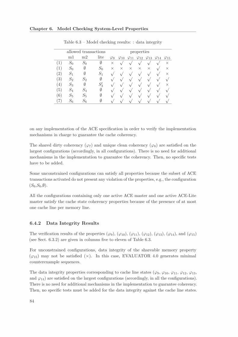
Chapter 6. Model Checking System-Level Properties
Table 6.3 – Model checking results: : data integrity
allowed transactions propertiesm1 m2 lite ϕ9 ϕ10 ϕ11 ϕ12 ϕ13 ϕ14 ϕ15
(1) S0 S0 ∅ × √ √ √ √ √ ×(1) S0 ∅ S0 × × × × × √ ×(2) S1 ∅ S1
√ √ √ √ √ √ ×(3) S2 S2 ∅ √ √ √ √ √ √ √
(4) S3 ∅ S′
3
√ √ √ √ √ √ ×(5) S4 S4 ∅ √ √ √ √ √ √ √
(6) S5 S5 ∅ √ √ √ √ √ √ √
(7) S6 S6 ∅ √ √ √ √ √ √ √
on any implementation of the ACE specification in order to verify the implementationmechanisms in charge to guarantee the cache coherency.
The shared dirty coherency (ϕ7) and unique clean coherency (ϕ8) are satisfied on thelargest configurations (accordingly, in all configurations). There is no need for additionalmechanisms in the implementation to guarantee the coherency. Then, no specific testshave to be added.
Some unconstrained configurations can satisfy all properties because the subset of ACEtransactions activated do not present any violation of the properties, e.g., the configuration(S6,S6,∅).
All the configurations containing only one active ACE master and one active ACE-Litemaster satisfy the cache state coherency properties because of the presence of at mostone cache line per memory line.
6.4.2 Data Integrity Results
The verification results of the properties (ϕ9), (ϕ10), (ϕ11), (ϕ12), (ϕ13), (ϕ14), and (ϕ15)(see Sect. 6.3.2) are given in columns five to eleven of Table 6.3.
For unconstrained configurations, data integrity of the shareable memory property(ϕ15) may not be satisfied (×). In this case, EVALUATOR 4.0 generates minimalcounterexample sequences.
The data integrity properties corresponding to cache line states (ϕ9, ϕ10, ϕ11, ϕ12, ϕ13,and ϕ14) are satisfied on the largest configurations (accordingly, in all the configurations).There is no need for additional mechanisms in the implementation to guarantee coherency.Then, no specific tests must be added for the data integrity against the cache line states.
84

6.4. Model-Checking Results
Table 6.4 – Model checking results: coherency parameters
allowed transactions propertiesm1 m2 lite ϕ16 ϕ17 ϕ18 ϕ19 ϕ20 ϕ21 ϕ22 ϕ23
(1) S0 {A} S0
√ √ √ √ √ √ √ √
(2) S1 ∅ S1
√ √ √ √ √ √ √ √
(3) S2 S2 ∅ √ √ √ √ √ √ √ √
(4) S3 ∅ S′
3
√ √ √ √ √ √ √ √
(5) S4 S4 ∅ √ √ √ √ √ √ √ √
(6) S5 S5 ∅ √ √ √ √ √ √ √ √
(7) S6 S6 ∅ √ √ √ √ √ √ √ √
6.4.3 Consistency of Coherency Parameters Results
The verification results of the properties (ϕ16, ϕ17, ϕ18, ϕ19, ϕ20, ϕ21, ϕ22, and ϕ23)presented in Section 6.3.3 over the LTSs of Section 5.4.2 are given in columns five totwelve of Table 6.4.
All the properties corresponding to the consistency of the coherency parameters aresatisfied on the largest configurations (accordingly, in all the configurations). There is noneed for additional mechanisms in the implementation to guarantee the coherency. Then,no specific tests must be added for this category of properties.
6.4.4 Example of a Non Satisfied Property
The model checking of the property corresponding to the data integrity of shareablememory (ϕ15) over the configuration (S0,∅,S0) produces the counterexample presentedin Figure 6.2.
We generate a minimal configuration of the formal model activating only the ACEtransactions present on the counterexample (S3,∅,S′
3). This configuration, without theglobal ordering constraints, produces the same counterexample. This configurationintroduces only three ACE transactions and it is sufficient to violate the data integrityproperty.
The data integrity property is violated because of the concurrency between two writeoperations on the shareable memory. The first one is initiated by the ACE master(WriteBack transaction), and the second one is initiated by the CCI. In fact, the CCI hasto respond to a ReadOnce transaction and has to take the responsibility to write backthe data in the memory (PassDirty=true), because the master initiating the ReadOnce
cannot take this responsibility: recall that ReadOnce is a “non-cachable” read. It meansthat the memory line is not stored on the master cache if the cache exists. In this case,the master is an ACE-Lite master, their is no cache to store the memory line.
85
Chapter 6. Model Checking System-Level Properties
Figure 6.2 – Data integrity counterexample
To verify the existence of additional scenarios, on the model, leading to this data integrityviolation, we deactivate one of the transactions participating on the first counter-example.EVALUATOR 4.0 model checker will produce another counterexample (if any), otherwisethe property is satisfied in the new configuration. This approach will be explored in theChapter 7 within the model-based test generation activity.
6.4.5 Reproduction of a Previously Fixed Bug
In a previous version of the ACE specification, a data integrity bug was detected (by Jasperin 2011 using white-box verification techniques using the Murφ model checker [Dil96]).To validate our model and our methodology based on black box verification techniques,we try to reproduce this bug.
ARM fixed the bug by changing the ACE specification. The new version forbids thetransition from an ACE_UD cache line state to an ACE_UC cache line state, after thereception of a ReadOnce snoop transaction.
We re-allow this transition and we check the data integrity of the shareable memoryproperty (ϕ15). The EVALUATOR 4.0 model checker produces the counterexamplepresented on the Fig. 6.3.
Indeed, we have reproduced automatically the same counterexample using our methodol-
86
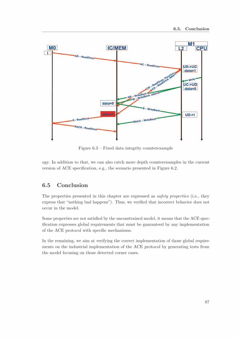
6.5. Conclusion
Figure 6.3 – Fixed data integrity counterexample
ogy. In addition to that, we can also catch more depth counterexamples in the currentversion of ACE specification, e.g., the scenario presented in Figure 6.2.
6.5 Conclusion
The properties presented in this chapter are expressed as safety properties (i.e., theyexpress that “nothing bad happens”). Thus, we verified that incorrect behavior does notoccur in the model.
Some properties are not satisfied by the unconstrained model, it means that the ACE spec-ification expresses global requirements that must be guaranteed by any implementationof the ACE protocol with specific mechanisms.
In the remaining, we aim at verifying the correct implementation of those global require-ments on the industrial implementation of the ACE protocol by generating tests fromthe model focusing on those detected corner cases.
87


Chapter 7
From Temporal Logic Properties
to Clever Test Cases
7.1 Introduction
An interesting idea for the generation of directed tests is to focus on and derive testsfrom potential faults of the DUV [MSK+07, WAW09]. For system-level protocols, inorder to obtain a description of potential faults corresponding to the global requirementsof the SoC, we suggest to use system-level properties together with a model containingfaults. In our case, we use the unconstrained model (see Sec. 5.3). Applying the theoryof conformance testing [Tre92], we generate abstract test cases, which then have to betranslated to the input language of a commercial CDTG solver to randomly completeinterface-level details and finally to run the tests on the RTL test bench.
Because we found the generation of abstract test cases directly from the completemodel to be impractical, we suggest to use information contained in counterexamples toselect interesting configurations of the formal model, which still contain violations of theglobal requirements, and to extract abstract test cases from the selected configurations.
In this chapter, we present our approach to generate abstract test cases from the formalmodel. Figure 7.1 gives an overview of our test generation approach. First, we presentan algorithm to compute a comprehensive set of interesting configurations, which containfaults. Second, we present a counterexample-based test-generation flow and its benefitsfor test generation. Then, we show the impact of our approach on the improvement oftest benches and the corresponding industrial results.
89
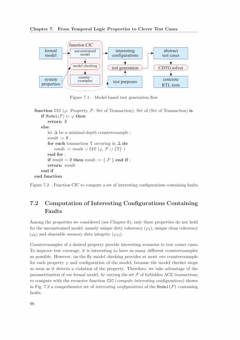
Chapter 7. From Temporal Logic Properties to Clever Test Cases
interesting
test generation
test purposes
CDTG solver
abstract
RTL tests
configurations
concrete
test casesformalmodel
systemproperties
function CIC
unconstrainedmodel
model checking
counter−examples
Figure 7.1 – Model-based test generation flow
function CIC (ϕ: Property, F : Set of Transaction): Set of (Set of Transaction) isif Model(F) |= ϕ then
return ∅else
let ∆ be a minimal-depth counterexample ;result := ∅ ;for each transaction T occuring in ∆ do
result := result ∪ CIC (ϕ, F ∪ {T} )end for ;if result = ∅ then result := { F } end if ;return result
end ifend function
Figure 7.2 – Function CIC to compute a set of interesting configurations containing faults
7.2 Computation of Interesting Configurations Containing
Faults
Among the properties we considered (see Chapter 6), only three properties do not holdfor the unconstrained model, namely unique dirty coherency (ϕ5), unique clean coherency(ϕ6) and shareable memory data integrity (ϕ15).
Counterexamples of a desired property provide interesting scenarios to test corner cases.To improve test coverage, it is interesting to have as many different counterexamplesas possible. However, on-the-fly model checking provides at most one counterexamplefor each property ϕ and configuration of the model, because the model checker stopsas soon as it detects a violation of the property. Therefore, we take advantage of theparametrization of our formal model, by varying the set F of forbidden ACE transactions,to compute with the recursive function CIC (compute interesting configurations) shownin Fig. 7.2 a comprehensive set of interesting configurations of the Model(F) containingfaults.
90
7.3. Model Checking Based Test Generation
Initially, all fifteen ACE transactions are allowed, i.e., we call CIC(ϕ,∅). Function CIC
proceeds as follows. First, we configure the model to exclude the transactions in F , andmodel check property ϕ. If ϕ is not satisfied, the model checker produces a counterex-ample ∆. We use the breadth-first search algorithm of EVALUATOR 4.0 to produce acounterexample of minimal depth, and avoid spurious actions in the counterexample. Foreach transaction T occurring in ∆, we call CIC recursively, deactivating T in addition toF . Function CIC terminates, because the parameter F has an upper bound (the set ofall transactions) and it strictly increases for each recursive call.
The set of interesting configurations {Model(F1),...,Model(Fn)} corresponding to theset {F1, ..., Fn} computed by CIC has the following property: a configuration Model(F ′)
does not satisfy the property ϕ if and only if F ′ is included in or equal to at least onecombination Fi.
We applied CIC to the three properties that were invalid on the unconstrained model(see Sec. 6.4). Altogether, Shareable Memory Data Integrity yields 21 interesting configu-rations (14 from an architecture with two ACE masters initiating transactions, and 7from an architecture with one ACE-Lite master and one ACE master initiating transac-tions), Unique Dirty Coherency yields 18 interesting configurations from an architecturewith two ACE masters initiating transactions (with only one ACE master, i.e., a singlecache, Unique Dirty Coherency holds trivially) and Unique Clean Coherency yields*34 interesting configurations from an architecture with two ACE masters initiatingtransactions.
7.3 Model Checking Based Test Generation
We aim at generating as many tests as possible leading to invalidation of the propertyfor each interesting configuration. We call those tests negative tests, because if a testsucceeds, we detect a failure of the system; but if the system is correct, all tests will fail.
Our test generation approach is based on the theory of conformance testing [Tre92], i.e.,we compute from a specification of a system and a test purpose [JJ05] (see the Sec. 2.5.3)a set of abstract test cases. Thus, we express the negation of each property as a testpurpose in LNT.
7.3.1 Unique Dirty Cache State Coherency Test Purpose
The LNT code for the test purpose corresponding to the Unique Dirty Cache Coherencyis shown below. After an outgoing action (gates AR, AW, W, CR and CD) from an ACEmaster cpu1 with a cache state ACE_UD (Unique Dirty), it monitors all outgoing actionsof all ACE masters. If a different ACE master cpu2 has the corresponding cache line ina valid state (not ACE_I), we ACCEPT the test (a coherency error has been detected). If
91

Chapter 7. From Temporal Logic Properties to Clever Test Cases
cpu1 performs another action with a state other than ACE_UD, we REFUSE the test (thetest is inconclusive).
The unique dirty coherency test purpose is modeled as follows:
module obj_UD ( types ) is
process main [AR: AR_CHANNEL , AW: AW_CHANNEL , CR: CR_CHANNEL ,
ACCEPT , REFUSE : none] is
var cpu1 , cpu2: INDEX_CPU , state : ACE_state_t in
select
AR (?any , ?cpu1 , 1, ACE_UD )
[] AW (? any , ?cpu1 , 1, ACE_UD )
[] W (? any , ?cpu1 , 1, ?any , ACE_UD )
[] CR (? any , ?any , ?cpu1 , 1, ?any , ?any , ?any , ?any , ACE_UD )
[] CD (? any , ?cpu1 , 1, ?any , ACE_UD )
end select ;
select
select
AR (?any , ?cpu2 , 1, ? state )
where (( state <> ACE_I ) and (cpu2 <>cpu1))
[] AW (? any , ?cpu2 , 1, ? state )
where (( state <> ACE_I ) and (cpu2 <>cpu1))
[] W (? any , ?cpu2 , 1, ?any , ? state )
where (( state <> ACE_I ) and (cpu2 <>cpu1))
[] CR (? any , ?any , ?cpu2 , 1, ?any , ?any , ?any , ?any , ? state )
where (( state <> ACE_I ) and (cpu2 <>cpu1))
[] CD (? any , ?cpu2 , 1, ?any , ? state )
where (( state <> ACE_I ) and (cpu2 <>cpu1))
end select ;
ACCEPT
[]
select
AR (?any , cpu1 , 1, ? state )
where (state <> ACE_UD )
[] AW (? any , cpu1 , 1, ? state )
where (state <> ACE_UD )
[] W (? any , cpu1 , 1, ?any , ? state )
where (state <> ACE_UD )
[] CR (? any , ?any , cpu1 , 1, ?any , ?any , ?any , ?any , ? state )
where (state <> ACE_UD )
[] CD (? any , cpu1 , 1, ?any , ? state )
where (state <> ACE_UD )
end select ;
REFUSE
end select ;
stop
end var
end process
end module
7.3.2 Unique Clean Cache State Coherency Test Purpose
The LNT code for the test purpose corresponding to the Unique Clean Cache Coherencyis shown below. After an outgoing action (gates AR, AW, W, CR and CD) from an ACE
92

7.3. Model Checking Based Test Generation
master cpu1 with a cache state ACE_UC (Unique Clean), it monitors all outgoing actionsof all ACE masters. If a different ACE master cpu2 has the corresponding cache line ina valid state (not ACE_I) we ACCEPT the test (a coherency error has been detected). Ifcpu1 performs another action with a state other than ACE_UC, we REFUSE the test (thetest is inconclusive).
The unique clean coherency test purpose is modeled as follows:
module obj_UC ( types ) is
process main [AR: AR_CHANNEL , AW: AW_CHANNEL , CR: CR_CHANNEL ,
ACCEPT , REFUSE : none] is
var cpu1 , cpu2: INDEX_CPU , state : ACE_state_t in
select
AR (?any , ?cpu1 , 1, ACE_UC )
[] AW (? any , ?cpu1 , 1, ACE_UC )
[] W (? any , ?cpu1 , 1, ?any , ACE_UC )
[] CR (? any , ?any , ?cpu1 , 1, ?any , ?any , ?any , ?any , ACE_UC )
[] CD (? any , ?cpu1 , 1, ?any , ACE_UC )
end select ;
select
select
AR (?any , ?cpu2 , 1, ? state )
where (( state <> ACE_I ) and (cpu2 <>cpu1))
[] AW (? any , ?cpu2 , 1, ? state )
where (( state <> ACE_I ) and (cpu2 <>cpu1))
[] W (? any , ?cpu2 , 1, ?any , ? state )
where (( state <> ACE_I ) and (cpu2 <>cpu1))
[] CR (? any , ?any , ?cpu2 , 1, ?any , ?any , ?any , ?any , ? state )
where (( state <> ACE_I ) and (cpu2 <>cpu1))
[] CD (? any , ?cpu2 , 1, ?any , ? state )
where (( state <> ACE_I ) and (cpu2 <>cpu1))
end select ;
ACCEPT
[]
select
AR (?any , cpu1 , 1, ? state )
where (state <> ACE_UC )
[] AW (? any , cpu1 , 1, ? state )
where (state <> ACE_UC )
[] W (? any , cpu1 , 1, ?any , ? state )
where (state <> ACE_UC )
[] CR (? any , ?any , cpu1 , 1, ?any , ?any , ?any , ?any , ? state )
where (state <> ACE_UC )
[] CD (? any , cpu1 , 1, ?any , ? state )
where (state <> ACE_UC )
end select ;
REFUSE
end select ;
stop
end var
end process
end module
93

Chapter 7. From Temporal Logic Properties to Clever Test Cases
7.3.3 Shareable Memory Data Integrity Test Purpose
If a memory update with a data d is achieved, and as long as no snoop request is initiated,the property forbids any data h different from d to be written in the memory line.
The LNT code for the test purpose corresponding to the data integrity test purpose isshown below. First, a memory update action W is proceeded from an ACE master m1, amemory line l, and a data d1. Second, this update is actually written to the shareablememory (port number 0). After that, if a memory update action of the some memoryline (l), with a different data d2, coming from an another master m2, the process reachesthe ACCEPT state. The presence of the AC snoop channel as communication port of thisprocess, expresses that during the previous steps nothing is sent on snoop channel toinform masters of the change in data. The data d2 that has just been written is olderthan the first data d1 written. So we were able to create a data integrity violation.
The shareable memory data integrity test purpose is modeled as follows:
module obj_di ( types ) is
process main [W: W_CHANNEL , AC: AC_CHANNEL , ACCEPT : any]
is
var m1 , m2: INDEX_CPU ,
l: INDEX_MEM ,
d1 , d2: DATA_T ,
any : ACE_OP
in
l := INDEX_MEM (1);
W ( WriteBack , ?m1 , l, ?d1);
W ( WriteBack , INDEX_CPU (0) , l, ?d1 , m1);
W (?any , INDEX_CPU (0) , l, ?d2 , ?m2)
where (( any <> WriteBack ) and
(d2 <> d1) and (m2 <> m1));
ACCEPT ;
stop
end var
end process
end module
7.3.4 Model-Based Test Generation Process
We use two newly developed prototype tools for test generation. A first tool takes asinput a model and a test purpose (both in LNT), and produces a Complete Test Graph
(CTG), i.e., an intermediate LTS containing all information to extract (all) abstract testcases. We use a second tool to extract a set of abstract test cases from the CTG. Thesetest cases are abstract in the sense that they are system-level automata generated fromthe model.
Contrary to the batch approach often used in hardware testing (in which the DUVreceives all its stimuli first, the DUV reaction being analyzed afterwards), the test cases
94

7.4. Industrial Results and Impact
Table 7.1 – Experimental test case extraction results
global CTG extr. nb. of largest CTG smallest CTG extr.prop. masters
states trans. time CTGs states trans. states trans. time
ϕ5 2ACE 6,402 14,323 >1/2 y 18 903 1,957 274 543 ≃7h
ϕ15
2ACE 23,032 48,543 >1/2 y 14 462 888 59 107 <1h1ACE/1Lite 2,815 7,071 >1/2 y 7 193 394 59 107 <1h
generated by our tools are reactive, in the sense that the stimuli sent by the tester maydepend on the reactions of the DUV observed in response to previous stimuli. Reactivetesting increases the quality and coverage of tests, as more behaviors of the DUV can betested [GVZ00].
Thus, those abstract test cases have to be translated to the input language of thecommercial coverage-based solver to randomly complete the interface-level details and torun the tests on the RTL test bench.
By extracting all test cases from each CTG and running each test case on the industrialtest bench, we obtain a locally intensive test around corner cases specified by the globalsystem-level properties.
Table 7.1 summarizes the results of our generation of abstract test cases for a test purposeencoding the negation of a property ϕ. The first two columns describe the propertyand the architecture. Columns 3 to 5 report the size of the global CTG (produced fromthe unconstrained model) and the time to extract test cases. The remaining columnsgive information about our approach based on individual CTGs (produced from theinteresting configurations): column 6 presents the number of CTGs, each of which isextracted from an interesting configuration, columns 7 to 10 report the size of the largestand the smallest CTG, and the last column gives the time to extract test cases from allthe individual CTGs. We see that the approach based on individual CTGs is much moreefficient than the extraction of test cases directly from the global CTG, for which theextraction of test cases does not finish in half a year. Also, our approach reduces thesize of the largest CTG by a factor of 7 for ϕ5 (Unique Dirty Coherency), a factor of 14for ϕ15 (Data Integrity) in the case of the architecture with one ACE master and oneACE-Lite master initiating transactions, and a factor of 49 for ϕ15 in the case of thearchitecture with two ACE masters.
7.4 Industrial Results and Impact
Our formal model is used inside STMicroelectronics as a reference in discussions withverification engineers and interconnect architects. It helps to understand the new
95
Chapter 7. From Temporal Logic Properties to Clever Test Cases
aspects introduced by ACE and to define the verification strategy. In this context, theOCIS interactive step-by-step simulator with backtracking of CADP is found useful forexhibiting execution scenarios of interest.
We also used OCIS to extract the list of possible transaction initiations for each correctinitial state of the system. A correct initial state of the system is a correct combinationof initial ACE states of the caches. For example, if a memory line exists initially in twodifferent caches, the state of these caches cannot be ACE_UD for both caches. So doing,we produce in less than one day 296 simple protocol tests, each of which consists of onesingle ACE transaction, from request to response, including all triggered snoop requests,if any.
Using some of the counterexamples generated during the computation of the interestingconfigurations (cf. Sec. 7.2), we produced also ten complex protocol tests containingconcurrency between different ACE transactions.
7.4.1 IVK Dynamic Test Benches
An interconnect is a hardware component connecting several components (or severalblocks of components) of an SoC. A simple example of an interconnect is a bus. Overtime, more and more features have continuously been added to interconnects, includingrouting features for Networks-on-Chip or hardware support for cache coherency protocols.
STMicroelectronics has capitalized more than 10 years of expertise in interconnects verifi-cation in a tool called Interconnect Verification Kit (IVK). The principle of IVK is shownin Figure 7.3. IVK generates a full verification environment, including sequences andcoverage models, using as input the architectural textual description, called TDL (TargetDescription Language) [Käs03]. The TDL can be either generated from interconnectdesigners GUI1 or through a flow based on spreadsheet describing the elements of thearchitecture. The industrial test benches used in the scope of this thesis are generatedby IVK.
We use IVK to generate a simulation test bench of the ARM PL35 cci400 DUV (calledin the following cci400 ), which is a Verilog RTL IP provided by ARMTM to implement afully connected cache coherent interconnect based on the AMBA 4 ACE specification.The verification infrastructure consists on dynamic verification units (called Verification
Intellectual Properties (VIP)), tests both in functional verification language e [oEE11],IV units in SVA [oEE09], and an SV unit in PSL [oEE10]. This infrastructure is usedto generate several test benches through an IVK flow. IVK uses the FTL technique togenerate tests, this technique consists on writing generic tests that are then instantiateddepending on the types of the components present on the TDL file. For example, an
1graphical user interfaces
96
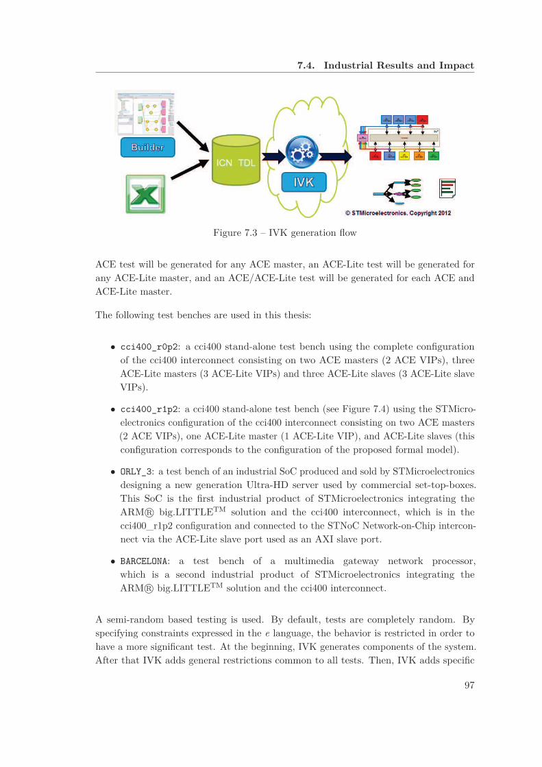
7.4. Industrial Results and Impact
Figure 7.3 – IVK generation flow
ACE test will be generated for any ACE master, an ACE-Lite test will be generated forany ACE-Lite master, and an ACE/ACE-Lite test will be generated for each ACE andACE-Lite master.
The following test benches are used in this thesis:
• cci400_r0p2: a cci400 stand-alone test bench using the complete configurationof the cci400 interconnect consisting on two ACE masters (2 ACE VIPs), threeACE-Lite masters (3 ACE-Lite VIPs) and three ACE-Lite slaves (3 ACE-Lite slaveVIPs).
• cci400_r1p2: a cci400 stand-alone test bench (see Figure 7.4) using the STMicro-electronics configuration of the cci400 interconnect consisting on two ACE masters(2 ACE VIPs), one ACE-Lite master (1 ACE-Lite VIP), and ACE-Lite slaves (thisconfiguration corresponds to the configuration of the proposed formal model).
• ORLY_3: a test bench of an industrial SoC produced and sold by STMicroelectronicsdesigning a new generation Ultra-HD server used by commercial set-top-boxes.This SoC is the first industrial product of STMicroelectronics integrating theARM R© big.LITTLETM solution and the cci400 interconnect, which is in thecci400_r1p2 configuration and connected to the STNoC Network-on-Chip intercon-nect via the ACE-Lite slave port used as an AXI slave port.
• BARCELONA: a test bench of a multimedia gateway network processor,which is a second industrial product of STMicroelectronics integrating theARM R© big.LITTLETM solution and the cci400 interconnect.
A semi-random based testing is used. By default, tests are completely random. Byspecifying constraints expressed in the e language, the behavior is restricted in order tohave a more significant test. At the beginning, IVK generates components of the system.After that IVK adds general restrictions common to all tests. Then, IVK adds specific
97
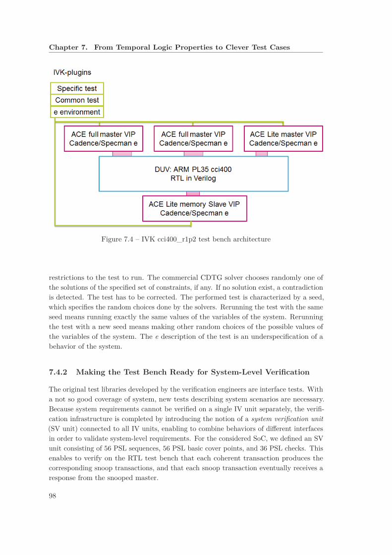
Chapter 7. From Temporal Logic Properties to Clever Test Cases
Figure 7.4 – IVK cci400_r1p2 test bench architecture
restrictions to the test to run. The commercial CDTG solver chooses randomly one ofthe solutions of the specified set of constraints, if any. If no solution exist, a contradictionis detected. The test has to be corrected. The performed test is characterized by a seed,which specifies the random choices done by the solvers. Rerunning the test with the sameseed means running exactly the same values of the variables of the system. Rerunningthe test with a new seed means making other random choices of the possible values ofthe variables of the system. The e description of the test is an underspecification of abehavior of the system.
7.4.2 Making the Test Bench Ready for System-Level Verification
The original test libraries developed by the verification engineers are interface tests. Witha not so good coverage of system, new tests describing system scenarios are necessary.Because system requirements cannot be verified on a single IV unit separately, the verifi-cation infrastructure is completed by introducing the notion of a system verification unit
(SV unit) connected to all IV units, enabling to combine behaviors of different interfacesin order to validate system-level requirements. For the considered SoC, we defined an SVunit consisting of 56 PSL sequences, 56 PSL basic cover points, and 36 PSL checks. Thisenables to verify on the RTL test bench that each coherent transaction produces thecorresponding snoop transactions, and that each snoop transaction eventually receives aresponse from the snooped master.
98

7.4. Industrial Results and Impact
Table 7.2 – Industrial results: bugs report
VIP Bugs detected CAD Fixed OpenACE dynamic VIP 5 3 2
ACE IV unit 5 4 1
Further modifications of the test bench are required to enable the execution of theconcrete test cases derived from our abstract test cases. In particular, it is necessaryto control the order of events. First, we added more synchronizations between differentVerification Intellectual Property (VIP) events to enforce the desired order of the events.Second, we added speed-up randomization: by default the speed of a master for eachof its channels is completely random. To express that a master is faster than anotherone or to enforce an order between two concurrent actions of a same master, we specifyspeed-up ranges (e.g., fast, slow, or very slow). So doing, the speed-up remains random,but in a limited range, ensuring the desired order.
7.4.3 Industrial Results
During the implementation of our abstract test cases on top of commercial VIPs, wedetected ten bugs in those VIPs (the bug report is presented in Table 7.2). This enabledthe CAD supplier to correct the bugs before the use of these VIPs became critical in thedevelopment path of STMicroelectronics.
Because the VIPs and the coverage lists are provided by the same CAD supplier, someverification gaps may not be detected. In fact, the same misinterpretation of the ACEspecification may find its way into both the VIPs and the coverage lists. Working with adifferent approach led us to validate the industrial checks (provided in the IV units), andthanks to our directed tests we detected unverified behaviors.
In October 2014, STMicroelectronics architects detected a limitation in the IP implemen-tation of the CCI. This limitation manifests in a subset of the counterexamples for thedata integrity property we verified 20 months before. Precisely, when the CCI initiates amemory update, some parameters of this update are set to fixed values possibly loosingsome important information, and disturbing the ACE-Lite flow in the non-coherent partof the SoC. This limitation corresponds to a gap that we have detected on the commercialVIPs one year before, when we started experimenting with the translation of abstractto concrete test cases. Our method for computing interesting faulty configurations (seeSec. 7.2) enabled us to provide all the scenarios triggering this limitation. Precisely,those scenarios are a subset of the shareable memory data integrity counterexamples (21distinct cases, 14 for each pair of ACE masters and 7 for each pair of an ACE masterand an ACE-Lite master).
99

Chapter 7. From Temporal Logic Properties to Clever Test Cases
The shareable memory data integrity counterexamples are caused by different aspects: 10among the 21 counterexamples are caused by a memory update transaction initiated bythe cci400. This memory update is related to a coherency response (CR) with an assertedPassDirty==True for an ACE transaction not accepting a read response (R) with anasserted PassDirty==True.
Each of the 10 counterexamples corresponds to one of three cases:
• The first case consists of a cache maintenance transaction (namely CleanInvalid
or CleanShared transaction). In this case, STMicroelectronics architects decideto deactivate those transactions for the ACE-Lite masters: this decision has animpact on the performance of the SoC but it is still feasible.
• The second case consists on the ReadOnce transaction, if a unique dirty cache line(ACE_UD) receives a ReadOnce snoop transaction and the master decides to switchto a shared clean (ACE_SC) or invalid (ACE_I) state. In this case, the PassDirty pa-rameter of the coherent response CR is asserted. For this reason, STMicroelectronicsarchitects decide to deactivate this case on the ACE masters and require that acache line in a unique dirty state receiving a ReadOnce snoop transaction must stayin a dirty state (ACE_UD or ACE_SD). In this case, the PassDirty parameter of thecoherent response CR is deserted and no memory update transaction is producedby the cci400.
• The third case consists on the WriteUnique transaction, this shareable write trans-action is the only way for an ACE-Lite master to write a data in a shareable regionof the memory. Deactivating this transaction is infeasible because it relates afunctional issue and not only a performance issue. We recommend to STMicro-electronics architects to work with this limitation and to address this issue in thenon-coherent part of the SoC.
In addition, we wrote new PSL checks to detect those corner cases. We should noticethat our 306 extracted tests trigger those checks 16 times, whereas the other tests of theSTMicroelectronics test library never trigger these checks.
Our generated tests have direct impact on the development flow of an industrial SoCof STMicroelectronics. We observe that the coverage of the verification plan increasedsignificantly2 and that the coverage of the SV unit part of the verification plan is complete(100%), i.e., all the aspects corresponding to system-level behaviors are tested.
2The coverage of the verification plan increased from 30% to 68%. Notice that 100% coverage is notachievable for the considered SoC, because the verification plan, as defined by the VIPs, includes somefeatures of ACE (e.g., distributed virtual memory), which are handled by the VIPs, but are not used bythe considered SoC.
100

Chapter 8
Sanity of a Formal Check List
Industrial CDTG test benches are based on a so-called verification plan, i.e., a list of allbehaviors to be covered by tests on the Design Under Verification (DUV). The coverageof the verification plan is collected to measure test progression.1 In our work, we focuson the formal checks, which are grouped in so-called interface verification units (IVunit). Each check is an event sequence, e.g., expressed in Property Specification Language
(PSL) [oEE10]. Covering a check consists in activating the check and finishing correctlythe specified sequence. Activating a check means to detect the first event of the sequence.It is a failure if a check is activated and not correctly finished.
In this chapter, we report about the use of our formal model to validate a commercial IVunit. To this end, we encode each check of the IV unit as a Labeled Transition System
(LTS) (by means of an LNT model) and use equivalence checking techniques (hiding,minimization, and comparison operations on LTSs).
At the beginning, we model each check as an LNT process. Then, we verify that eachcheck is an overapproximation of the model behavior. Last, we study if the list of checkscovers all behaviors of the model.
8.1 Modeling Formal Checks in LNT
We start our study by identifying a subset of nine industrial formal checks (called C1... C9), which have a level of abstraction corresponding to our formal model. On onehand, we model each selected check as an LNT model. On the other hand, we derivean interface LTS from our LNT model of the system by hiding all behaviors not relatedto the selected interface. Each check introduces only a subset of ACE channels (AR, R,
1There are two types of behaviors in a verification plan: simple behaviors, called cover points andcomplex behaviors, called (formal) checks.
101
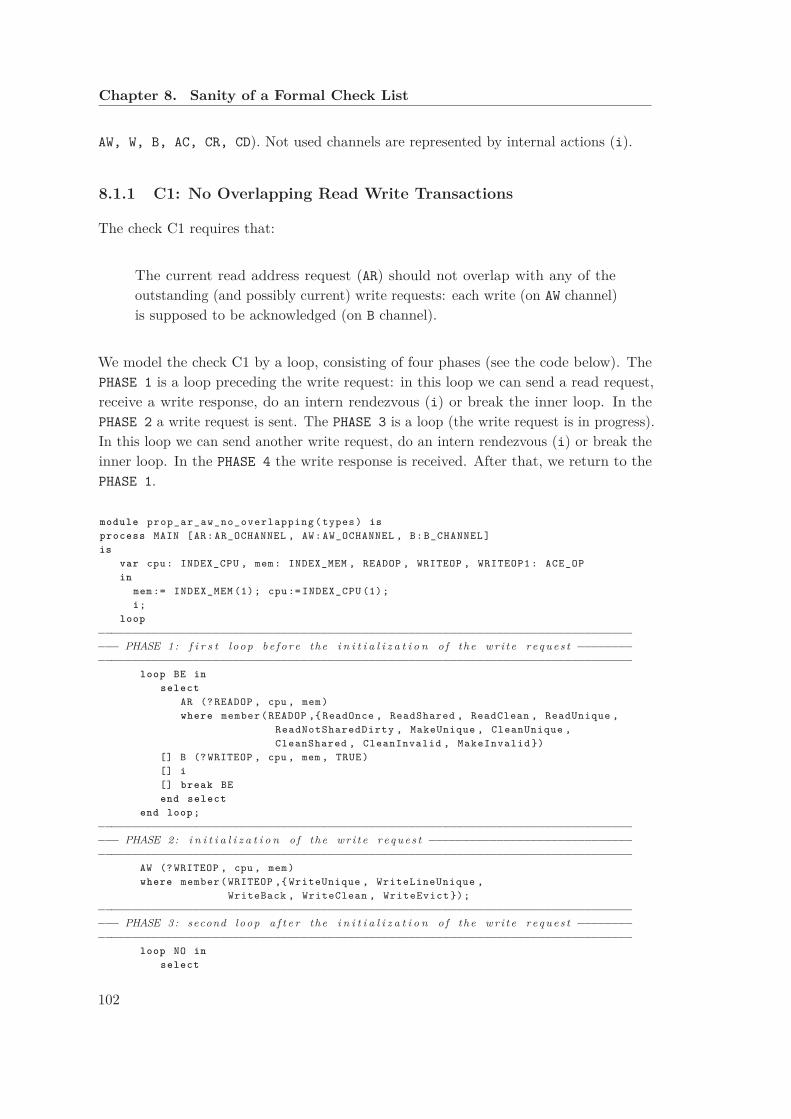
Chapter 8. Sanity of a Formal Check List
AW, W, B, AC, CR, CD). Not used channels are represented by internal actions (i).
8.1.1 C1: No Overlapping Read Write Transactions
The check C1 requires that:
The current read address request (AR) should not overlap with any of theoutstanding (and possibly current) write requests: each write (on AW channel)is supposed to be acknowledged (on B channel).
We model the check C1 by a loop, consisting of four phases (see the code below). ThePHASE 1 is a loop preceding the write request: in this loop we can send a read request,receive a write response, do an intern rendezvous (i) or break the inner loop. In thePHASE 2 a write request is sent. The PHASE 3 is a loop (the write request is in progress).In this loop we can send another write request, do an intern rendezvous (i) or break theinner loop. In the PHASE 4 the write response is received. After that, we return to thePHASE 1.
module prop_ar_aw_no_overlapping ( types ) is
process MAIN [AR: AR_OCHANNEL , AW: AW_OCHANNEL , B: B_CHANNEL ]
is
var cpu: INDEX_CPU , mem: INDEX_MEM , READOP , WRITEOP , WRITEOP1 : ACE_OP
in
mem := INDEX_MEM (1); cpu := INDEX_CPU (1);
i;
loop
−−−−−−−−−−−−−−−−−−−−−−−−−−−−−−−−−−−−−−−−−−−−−−−−−−−−−−−−−−−−−−−−−−−−−−−−−−−−−−−
−−− PHASE 1: f i r s t loop b e f o r e the i n i t i a l i z a t i o n o f the w r i t e r eq u e s t −−−−−−−−
−−−−−−−−−−−−−−−−−−−−−−−−−−−−−−−−−−−−−−−−−−−−−−−−−−−−−−−−−−−−−−−−−−−−−−−−−−−−−−−
loop BE in
select
AR (? READOP , cpu , mem)
where member (READOP ,{ ReadOnce , ReadShared , ReadClean , ReadUnique ,
ReadNotSharedDirty , MakeUnique , CleanUnique ,
CleanShared , CleanInvalid , MakeInvalid })
[] B (? WRITEOP , cpu , mem , TRUE)
[] i
[] break BE
end select
end loop ;
−−−−−−−−−−−−−−−−−−−−−−−−−−−−−−−−−−−−−−−−−−−−−−−−−−−−−−−−−−−−−−−−−−−−−−−−−−−−−−−
−−− PHASE 2: i n i t i a l i z a t i o n o f the w r i t e r e q u e s t −−−−−−−−−−−−−−−−−−−−−−−−−−−−−−
−−−−−−−−−−−−−−−−−−−−−−−−−−−−−−−−−−−−−−−−−−−−−−−−−−−−−−−−−−−−−−−−−−−−−−−−−−−−−−−
AW (? WRITEOP , cpu , mem)
where member (WRITEOP ,{ WriteUnique , WriteLineUnique ,
WriteBack , WriteClean , WriteEvict });
−−−−−−−−−−−−−−−−−−−−−−−−−−−−−−−−−−−−−−−−−−−−−−−−−−−−−−−−−−−−−−−−−−−−−−−−−−−−−−−
−−− PHASE 3: second loop a f t e r the i n i t i a l i z a t i o n o f the wr i t e r eq u e s t −−−−−−−−
−−−−−−−−−−−−−−−−−−−−−−−−−−−−−−−−−−−−−−−−−−−−−−−−−−−−−−−−−−−−−−−−−−−−−−−−−−−−−−−
loop NO in
select
102

8.1. Modeling Formal Checks in LNT
AW (? WRITEOP1 , cpu , mem)
where member (WRITEOP1 ,{ WriteUnique , WriteLineUnique ,
WriteBack , WriteClean , WriteEvict })
[] i
[] break NO
end select
end loop ;
−−−−−−−−−−−−−−−−−−−−−−−−−−−−−−−−−−−−−−−−−−−−−−−−−−−−−−−−−−−−−−−−−−−−−−−−−−−−−−−
−−− PHASE 4: response o f the wr i t e r e q u e s t −−−−−−−−−−−−−−−−−−−−−−−−−−−−−−−−−−−−
−−−−−−−−−−−−−−−−−−−−−−−−−−−−−−−−−−−−−−−−−−−−−−−−−−−−−−−−−−−−−−−−−−−−−−−−−−−−−−−
B (WRITEOP , cpu , mem , TRUE)
end loop
end var
end process
end module
8.1.2 C2: No Maintenance Transaction while Pending Shareable Trans-
action
The check C2 requires that:
The master must complete any outstanding shareable transactions to thecache line before issuing a cache maintenance transaction corresponding tothe same cache line.
We model the check C2 by a loop, consisting of four phases (see the code below). ThePHASE 1 is a loop preceding the shareable write or read request: in this loop we can sendwrite and read requests while those requests are not shareable, receive write and readresponses, do an intern rendezvous (i) or break the inner loop. In PHASE 2 a shareablewrite or read request is sent. The PHASE 3 is a loop (a shareable write or read request isin progress). In this loop we can send a read request while this read is neither shareablenor maintenance, receive a response for a read or write different from the shareable writeor read of the PHASE 2, do an intern rendezvous (i) or break the inner loop. In PHASE 4
the shareable write or read response is received. After that, we return to the PHASE 1.
module prop_ar_aw_no_maintenance ( types ) is
process MAIN [AR: AR_OCHANNEL , AW: AW_OCHANNEL , R: R_CHANNEL , B: B_CHANNEL ]
is
var cpu: INDEX_CPU , mem: INDEX_MEM , ACEOP , SHAREABLE , NOTMAINT :ACE_OP ,
d: DATA_T , b1 , b2 , b3: bool
in
mem := INDEX_MEM (1); cpu := INDEX_CPU (1);
i;
loop
−−−−−−−−−−−−−−−−−−−−−−−−−−−−−−−−−−−−−−−−−−−−−−−−−−−−−−−−−−−−−−−−−−−−−−−−−−−−−−−
−−− PHASE 1: f i r s t loop b e f o r e the s h a r e a b l e r e q u e s t −−−−−−−−−−−−−−−−−−−−−−−−−−
−−−−−−−−−−−−−−−−−−−−−−−−−−−−−−−−−−−−−−−−−−−−−−−−−−−−−−−−−−−−−−−−−−−−−−−−−−−−−−−
loop BE in
select
103

Chapter 8. Sanity of a Formal Check List
AR (? ACEOP , cpu , mem)
where not ( member (ACEOP ,{ ReadShared , ReadClean , ReadNotSharedDirty ,
MakeUnique , ReadUnique , CleanUnique }))
[] AW (? ACEOP , cpu , mem)
where not ( member (ACEOP ,{ WriteUnique , WriteLineUnique }))
[] R (? ACEOP , cpu , mem , ?d, ?b1 , ?b2 , ?b3)
[] B (? ACEOP , cpu , mem , TRUE)
[] i
[] break BE
end select
end loop ;
−−−−−−−−−−−−−−−−−−−−−−−−−−−−−−−−−−−−−−−−−−−−−−−−−−−−−−−−−−−−−−−−−−−−−−−−−−−−−−−
−−− PHASE 2: i n i t i a l i z a t i o n o f the s h a r e a b l e r e q u e s t −−−−−−−−−−−−−−−−−−−−−−−−−−
−−−−−−−−−−−−−−−−−−−−−−−−−−−−−−−−−−−−−−−−−−−−−−−−−−−−−−−−−−−−−−−−−−−−−−−−−−−−−−−
select
AR (? SHAREABLE , cpu , mem)
where member ( SHAREABLE , {ReadOnce , ReadShared , ReadClean ,
ReadNotSharedDirty ,
MakeUnique , ReadUnique , CleanUnique })
[] AW (? SHAREABLE , cpu , mem)
where member ( SHAREABLE , { WriteUnique , WriteLineUnique })
end select ;
−−−−−−−−−−−−−−−−−−−−−−−−−−−−−−−−−−−−−−−−−−−−−−−−−−−−−−−−−−−−−−−−−−−−−−−−−−−−−−−
−−− PHASE 3: second loop a f t e r the i n i t i a l i z a t i o n o f the s h a r e a b l e r e q u e s t −−−−
−−−−−−−−−−−−−−−−−−−−−−−−−−−−−−−−−−−−−−−−−−−−−−−−−−−−−−−−−−−−−−−−−−−−−−−−−−−−−−−
loop NO in
select
AR (? ACEOP , cpu , mem) −− ni maintenance ni s h a r e a b l e
where not ( member (ACEOP , { CleanShared , CleanInvalid , MakeInvalid ,
ReadOnce , ReadShared , ReadClean , ReadNotSharedDirty ,
MakeUnique , ReadUnique , CleanUnique }))
[] R (? ACEOP , cpu , mem , ?d, ?b1 , ?b2 , ?b3)
where (ACEOP <> SHAREABLE )
[] B (? ACEOP , cpu , mem , TRUE)
where (ACEOP <> SHAREABLE )
[] i
[] break NO
end select
end loop ;
−−−−−−−−−−−−−−−−−−−−−−−−−−−−−−−−−−−−−−−−−−−−−−−−−−−−−−−−−−−−−−−−−−−−−−−−−−−−−−−
−−− PHASE 4: response o f the s h a r e a b l e r e q u e s t −−−−−−−−−−−−−−−−−−−−−−−−−−−−−−−−
−−−−−−−−−−−−−−−−−−−−−−−−−−−−−−−−−−−−−−−−−−−−−−−−−−−−−−−−−−−−−−−−−−−−−−−−−−−−−−−
select
R( SHAREABLE , cpu , mem , ?d, ?b1 , ?b2 , ?b3)
[] B ( SHAREABLE , cpu , mem , TRUE)
end select
end loop
end var
end process
end module
8.1.3 C3: No Shareable Read Transaction while Pending Maintenance
Transaction
The check C3 requires that:
104

8.1. Modeling Formal Checks in LNT
The master must not issue any further shareable transactions to the samecache line until the cache maintenance transaction is complete.
We model the check C3 by a loop, consisting of four phases (see the code below). ThePHASE 1 is a loop preceding the maintenance read request: in this loop we can sendnon-maintenance read requests, receive read responses, do an intern rendezvous (i) orbreak the inner loop. In the PHASE 2 a maintenance read request is sent. The PHASE 3
is a loop(a maintenance read request is in progress). In this loop we can send a readrequest while this read is neither shareable nor maintenance, receive a non-maintenanceread response, do an intern rendezvous (i) or break the inner loop. In the PHASE 4 themaintenance read response is received. After that, we return to the PHASE 1.
module prop_no_shareable_read ( types ) is
process MAIN [AR: AR_OCHANNEL , R: R_CHANNEL ]
is
var cpu: INDEX_CPU , mem: INDEX_MEM , ACEOP , MAINTENANCE , NOTMAINT :ACE_OP ,
d: DATA_T , b1 , b2 , b3: bool
in
mem := INDEX_MEM (1); cpu := INDEX_CPU (1);
i;
loop
−−−−−−−−−−−−−−−−−−−−−−−−−−−−−−−−−−−−−−−−−−−−−−−−−−−−−−−−−−−−−−−−−−−−−−−−−−−−−−−
−−− PHASE 1: f i r s t loop b e f o r e the i n i t i a l i z a t i o n o f the maintenance r e q u e s t −−
−−−−−−−−−−−−−−−−−−−−−−−−−−−−−−−−−−−−−−−−−−−−−−−−−−−−−−−−−−−−−−−−−−−−−−−−−−−−−−−
loop BE in
select
AR (? ACEOP , cpu , mem)
where not ( member (ACEOP ,{ CleanShared , CleanInvalid , MakeInvalid }))
[] R (? ACEOP , cpu , mem , ?d, ?b1 , ?b2 , ?b3)
[] i
[] break BE
end select
end loop ;
−−−−−−−−−−−−−−−−−−−−−−−−−−−−−−−−−−−−−−−−−−−−−−−−−−−−−−−−−−−−−−−−−−−−−−−−−−−−−−−
−−− PHASE 2: i n i t i a l i z a t i o n o f the maintenance r e q u e s t −−−−−−−−−−−−−−−−−−−−−−−−
−−−−−−−−−−−−−−−−−−−−−−−−−−−−−−−−−−−−−−−−−−−−−−−−−−−−−−−−−−−−−−−−−−−−−−−−−−−−−−−
AR (? MAINTENANCE , cpu , mem)
where member ( MAINTENANCE , { CleanShared , CleanInvalid , MakeInvalid });
−−−−−−−−−−−−−−−−−−−−−−−−−−−−−−−−−−−−−−−−−−−−−−−−−−−−−−−−−−−−−−−−−−−−−−−−−−−−−−−
−−− PHASE 3: second loop a f t e r the i n i t i a l i z a t i o n o f the maintenance r e q u e s t −−
−−−−−−−−−−−−−−−−−−−−−−−−−−−−−−−−−−−−−−−−−−−−−−−−−−−−−−−−−−−−−−−−−−−−−−−−−−−−−−−
loop NO in
select
AR (? ACEOP , cpu , mem) −− ni maintenance ni s h a r e a b l e
where not ( member (ACEOP , { CleanShared , CleanInvalid , MakeInvalid ,
ReadOnce , ReadShared , ReadClean , ReadNotSharedDirty ,
MakeUnique , ReadUnique , CleanUnique }))
[] R (? ACEOP , cpu , mem , ?d, ?b1 , ?b2 , ?b3)
where (ACEOP <> MAINTENANCE )
[] i
[] break NO
end select
end loop ;
−−−−−−−−−−−−−−−−−−−−−−−−−−−−−−−−−−−−−−−−−−−−−−−−−−−−−−−−−−−−−−−−−−−−−−−−−−−−−−−
−−− PHASE 4: response o f the maintenance r e q u e s t −−−−−−−−−−−−−−−−−−−−−−−−−−−−−−
105
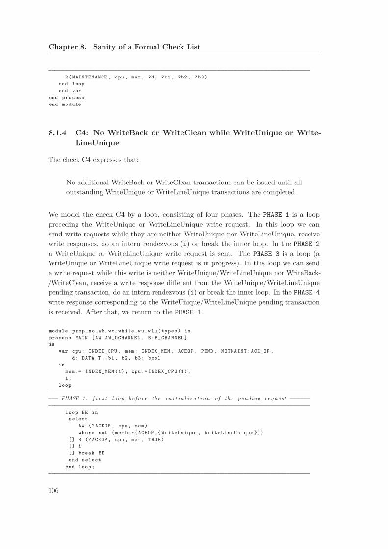
Chapter 8. Sanity of a Formal Check List
−−−−−−−−−−−−−−−−−−−−−−−−−−−−−−−−−−−−−−−−−−−−−−−−−−−−−−−−−−−−−−−−−−−−−−−−−−−−−−−
R( MAINTENANCE , cpu , mem , ?d, ?b1 , ?b2 , ?b3)
end loop
end var
end process
end module
8.1.4 C4: No WriteBack or WriteClean while WriteUnique or Write-
LineUnique
The check C4 expresses that:
No additional WriteBack or WriteClean transactions can be issued until alloutstanding WriteUnique or WriteLineUnique transactions are completed.
We model the check C4 by a loop, consisting of four phases. The PHASE 1 is a looppreceding the WriteUnique or WriteLineUnique write request. In this loop we cansend write requests while they are neither WriteUnique nor WriteLineUnique, receivewrite responses, do an intern rendezvous (i) or break the inner loop. In the PHASE 2
a WriteUnique or WriteLineUnique write request is sent. The PHASE 3 is a loop (aWriteUnique or WriteLineUnique write request is in progress). In this loop we can senda write request while this write is neither WriteUnique/WriteLineUnique nor WriteBack-/WriteClean, receive a write response different from the WriteUnique/WriteLineUniquepending transaction, do an intern rendezvous (i) or break the inner loop. In the PHASE 4
write response corresponding to the WriteUnique/WriteLineUnique pending transactionis received. After that, we return to the PHASE 1.
module prop_no_wb_wc_while_wu_wlu ( types ) is
process MAIN [AW: AW_OCHANNEL , B: B_CHANNEL ]
is
var cpu: INDEX_CPU , mem: INDEX_MEM , ACEOP , PEND , NOTMAINT :ACE_OP ,
d: DATA_T , b1 , b2 , b3: bool
in
mem := INDEX_MEM (1); cpu := INDEX_CPU (1);
i;
loop
−−−−−−−−−−−−−−−−−−−−−−−−−−−−−−−−−−−−−−−−−−−−−−−−−−−−−−−−−−−−−−−−−−−−−−−−−−−−−−−
−−− PHASE 1: f i r s t loop b e f o r e the i n i t i a l i z a t i o n o f the pending r e q u e s t −−−−−−
−−−−−−−−−−−−−−−−−−−−−−−−−−−−−−−−−−−−−−−−−−−−−−−−−−−−−−−−−−−−−−−−−−−−−−−−−−−−−−−
loop BE in
select
AW (? ACEOP , cpu , mem)
where not ( member (ACEOP ,{ WriteUnique , WriteLineUnique }))
[] B (? ACEOP , cpu , mem , TRUE)
[] i
[] break BE
end select
end loop ;
−−−−−−−−−−−−−−−−−−−−−−−−−−−−−−−−−−−−−−−−−−−−−−−−−−−−−−−−−−−−−−−−−−−−−−−−−−−−−−−
106
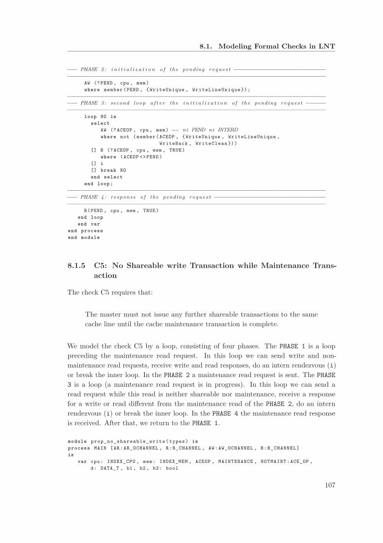
8.1. Modeling Formal Checks in LNT
−−− PHASE 2: i n i t i a l i z a t i o n o f the pending r e q u e s t −−−−−−−−−−−−−−−−−−−−−−−−−−−−
−−−−−−−−−−−−−−−−−−−−−−−−−−−−−−−−−−−−−−−−−−−−−−−−−−−−−−−−−−−−−−−−−−−−−−−−−−−−−−−
AW (? PEND , cpu , mem)
where member (PEND , { WriteUnique , WriteLineUnique });
−−−−−−−−−−−−−−−−−−−−−−−−−−−−−−−−−−−−−−−−−−−−−−−−−−−−−−−−−−−−−−−−−−−−−−−−−−−−−−−
−−− PHASE 3: second loop a f t e r the i n i t i a l i z a t i o n o f the pending r e q u e s t −−−−−−
−−−−−−−−−−−−−−−−−−−−−−−−−−−−−−−−−−−−−−−−−−−−−−−−−−−−−−−−−−−−−−−−−−−−−−−−−−−−−−−
loop NO in
select
AW (? ACEOP , cpu , mem) −− ni PEND ni INTERD
where not ( member (ACEOP , { WriteUnique , WriteLineUnique ,
WriteBack , WriteClean }))
[] B (? ACEOP , cpu , mem , TRUE)
where (ACEOP <>PEND)
[] i
[] break NO
end select
end loop ;
−−−−−−−−−−−−−−−−−−−−−−−−−−−−−−−−−−−−−−−−−−−−−−−−−−−−−−−−−−−−−−−−−−−−−−−−−−−−−−−
−−− PHASE 4: response o f the pending r e q u e s t −−−−−−−−−−−−−−−−−−−−−−−−−−−−−−−−−−
−−−−−−−−−−−−−−−−−−−−−−−−−−−−−−−−−−−−−−−−−−−−−−−−−−−−−−−−−−−−−−−−−−−−−−−−−−−−−−−
B(PEND , cpu , mem , TRUE)
end loop
end var
end process
end module
8.1.5 C5: No Shareable write Transaction while Maintenance Trans-
action
The check C5 requires that:
The master must not issue any further shareable transactions to the samecache line until the cache maintenance transaction is complete.
We model the check C5 by a loop, consisting of four phases. The PHASE 1 is a looppreceding the maintenance read request. In this loop we can send write and non-maintenance read requests, receive write and read responses, do an intern rendezvous (i)or break the inner loop. In the PHASE 2 a maintenance read request is sent. The PHASE
3 is a loop (a maintenance read request is in progress). In this loop we can send aread request while this read is neither shareable nor maintenance, receive a responsefor a write or read different from the maintenance read of the PHASE 2, do an internrendezvous (i) or break the inner loop. In the PHASE 4 the maintenance read responseis received. After that, we return to the PHASE 1.
module prop_no_shareable_write ( types ) is
process MAIN [AR: AR_OCHANNEL , R: R_CHANNEL , AW: AW_OCHANNEL , B: B_CHANNEL ]
is
var cpu: INDEX_CPU , mem: INDEX_MEM , ACEOP , MAINTENANCE , NOTMAINT :ACE_OP ,
d: DATA_T , b1 , b2 , b3: bool
107

Chapter 8. Sanity of a Formal Check List
in
mem := INDEX_MEM (1); cpu := INDEX_CPU (1);
i;
loop
−−−−−−−−−−−−−−−−−−−−−−−−−−−−−−−−−−−−−−−−−−−−−−−−−−−−−−−−−−−−−−−−−−−−−−−−−−−−−−−
−−− PHASE 1: f i r s t loop b e f o r e the i n i t i a l i z a t i o n o f the maintenance r e q u e s t −−
−−−−−−−−−−−−−−−−−−−−−−−−−−−−−−−−−−−−−−−−−−−−−−−−−−−−−−−−−−−−−−−−−−−−−−−−−−−−−−−
loop BE in
select
AR (? ACEOP , cpu , mem)
where not ( member (ACEOP ,{ CleanShared , CleanInvalid , MakeInvalid }))
[] AW (? ACEOP , cpu , mem)
[] R (? ACEOP , cpu , mem , ?d, ?b1 , ?b2 , ?b3)
[] B (? ACEOP , cpu , mem , TRUE)
[] i
[] break BE
end select
end loop ;
−−−−−−−−−−−−−−−−−−−−−−−−−−−−−−−−−−−−−−−−−−−−−−−−−−−−−−−−−−−−−−−−−−−−−−−−−−−−−−−
−−− PHASE 2: i n i t i a l i z a t i o n o f the maintenance r e q u e s t −−−−−−−−−−−−−−−−−−−−−−−−
−−−−−−−−−−−−−−−−−−−−−−−−−−−−−−−−−−−−−−−−−−−−−−−−−−−−−−−−−−−−−−−−−−−−−−−−−−−−−−−
AR (? MAINTENANCE , cpu , mem)
where member ( MAINTENANCE , { CleanShared , CleanInvalid , MakeInvalid });
−−−−−−−−−−−−−−−−−−−−−−−−−−−−−−−−−−−−−−−−−−−−−−−−−−−−−−−−−−−−−−−−−−−−−−−−−−−−−−−
−−− PHASE 3: second loop a f t e r the i n i t i a l i z a t i o n o f the maintenance r e q u e s t −−
−−−−−−−−−−−−−−−−−−−−−−−−−−−−−−−−−−−−−−−−−−−−−−−−−−−−−−−−−−−−−−−−−−−−−−−−−−−−−−−
loop NO in
select
AR (? ACEOP , cpu , mem) −− ni maintenance ni s h a r e a b l e
where not ( member (ACEOP , { CleanShared , CleanInvalid , MakeInvalid ,
ReadOnce , ReadShared , ReadClean , ReadNotSharedDirty ,
MakeUnique , ReadUnique , CleanUnique }))
[] R (? ACEOP , cpu , mem , ?d, ?b1 , ?b2 , ?b3)
where (ACEOP <> MAINTENANCE )
[] B (? ACEOP , cpu , mem , TRUE)
[] i
[] break NO
end select
end loop ;
−−−−−−−−−−−−−−−−−−−−−−−−−−−−−−−−−−−−−−−−−−−−−−−−−−−−−−−−−−−−−−−−−−−−−−−−−−−−−−−
−−− PHASE 4: response o f the maintenance r e q u e s t −−−−−−−−−−−−−−−−−−−−−−−−−−−−−−
−−−−−−−−−−−−−−−−−−−−−−−−−−−−−−−−−−−−−−−−−−−−−−−−−−−−−−−−−−−−−−−−−−−−−−−−−−−−−−−
R( MAINTENANCE , cpu , mem , ?d, ?b1 , ?b2 , ?b3)
end loop
end var
end process
end module
8.1.6 C6: Snoop Response when Memory Update in Progress
The check C6 requires that:
If a snooped master has a memory update in progress, using either a WriteBack
or WriteClean transaction, then once it receives a snoop transaction to thesame line, the snooped master must ensure that no other master can perform a
108
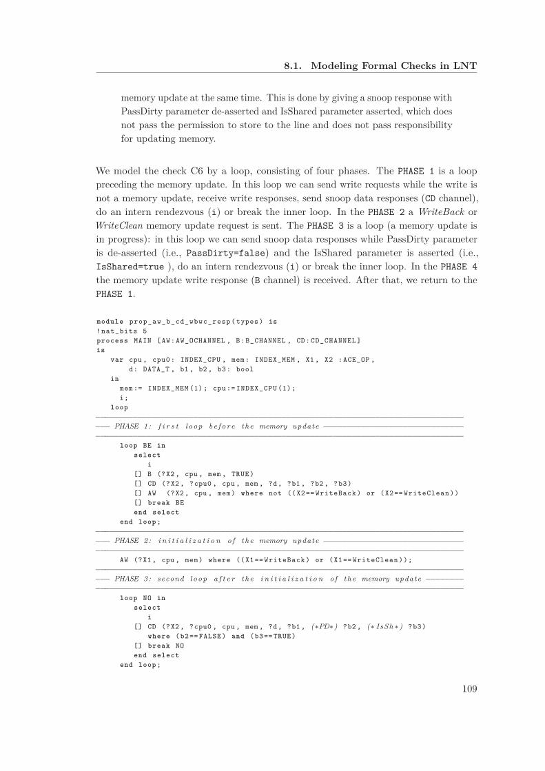
8.1. Modeling Formal Checks in LNT
memory update at the same time. This is done by giving a snoop response withPassDirty parameter de-asserted and IsShared parameter asserted, which doesnot pass the permission to store to the line and does not pass responsibilityfor updating memory.
We model the check C6 by a loop, consisting of four phases. The PHASE 1 is a looppreceding the memory update. In this loop we can send write requests while the write isnot a memory update, receive write responses, send snoop data responses (CD channel),do an intern rendezvous (i) or break the inner loop. In the PHASE 2 a WriteBack orWriteClean memory update request is sent. The PHASE 3 is a loop (a memory update isin progress): in this loop we can send snoop data responses while PassDirty parameteris de-asserted (i.e., PassDirty=false) and the IsShared parameter is asserted (i.e.,IsShared=true ), do an intern rendezvous (i) or break the inner loop. In the PHASE 4
the memory update write response (B channel) is received. After that, we return to thePHASE 1.
module prop_aw_b_cd_wbwc_resp ( types ) is
! nat_bits 5
process MAIN [AW: AW_OCHANNEL , B: B_CHANNEL , CD: CD_CHANNEL ]
is
var cpu , cpu0: INDEX_CPU , mem: INDEX_MEM , X1 , X2 :ACE_OP ,
d: DATA_T , b1 , b2 , b3: bool
in
mem := INDEX_MEM (1); cpu := INDEX_CPU (1);
i;
loop
−−−−−−−−−−−−−−−−−−−−−−−−−−−−−−−−−−−−−−−−−−−−−−−−−−−−−−−−−−−−−−−−−−−−−−−−−−−−−−−
−−− PHASE 1: f i r s t loop b e f o r e the memory update −−−−−−−−−−−−−−−−−−−−−−−−−−−−−−
−−−−−−−−−−−−−−−−−−−−−−−−−−−−−−−−−−−−−−−−−−−−−−−−−−−−−−−−−−−−−−−−−−−−−−−−−−−−−−−
loop BE in
select
i
[] B (?X2 , cpu , mem , TRUE)
[] CD (?X2 , ?cpu0 , cpu , mem , ?d, ?b1 , ?b2 , ?b3)
[] AW (?X2 , cpu , mem) where not (( X2 == WriteBack ) or (X2 == WriteClean ))
[] break BE
end select
end loop ;
−−−−−−−−−−−−−−−−−−−−−−−−−−−−−−−−−−−−−−−−−−−−−−−−−−−−−−−−−−−−−−−−−−−−−−−−−−−−−−−
−−− PHASE 2: i n i t i a l i z a t i o n o f the memory update −−−−−−−−−−−−−−−−−−−−−−−−−−−−−−
−−−−−−−−−−−−−−−−−−−−−−−−−−−−−−−−−−−−−−−−−−−−−−−−−−−−−−−−−−−−−−−−−−−−−−−−−−−−−−−
AW (?X1 , cpu , mem) where (( X1 == WriteBack ) or (X1 == WriteClean ));
−−−−−−−−−−−−−−−−−−−−−−−−−−−−−−−−−−−−−−−−−−−−−−−−−−−−−−−−−−−−−−−−−−−−−−−−−−−−−−−
−−− PHASE 3: second loop a f t e r the i n i t i a l i z a t i o n o f the memory update −−−−−−−−
−−−−−−−−−−−−−−−−−−−−−−−−−−−−−−−−−−−−−−−−−−−−−−−−−−−−−−−−−−−−−−−−−−−−−−−−−−−−−−−
loop NO in
select
i
[] CD (?X2 , ?cpu0 , cpu , mem , ?d, ?b1 , (∗PD∗) ?b2 , (∗ IsSh ∗) ?b3)
where (b2 == FALSE ) and (b3 == TRUE)
[] break NO
end select
end loop ;
109

Chapter 8. Sanity of a Formal Check List
−−−−−−−−−−−−−−−−−−−−−−−−−−−−−−−−−−−−−−−−−−−−−−−−−−−−−−−−−−−−−−−−−−−−−−−−−−−−−−−
−−− PHASE 4: response o f the memory update −−−−−−−−−−−−−−−−−−−−−−−−−−−−−−−−−−−−
−−−−−−−−−−−−−−−−−−−−−−−−−−−−−−−−−−−−−−−−−−−−−−−−−−−−−−−−−−−−−−−−−−−−−−−−−−−−−−−
B (X1 , cpu , mem , TRUE)
end loop
end var
end process
end module
8.1.7 C7: Order between Channels AC and CD
The check C7 requires that:
The master must wait the end of AC transfer before issuing the correspondingCD transfer.
We model the check C7 by a loop, consisting of four phases. The PHASE 1 is a looppreceding the AC transfer. In this loop we do not have to send a CD transfer. We canjust do an intern rendezvous (i) or break the inner loop. In the PHASE 2 an AC transferis sent. The PHASE 3 is a sequence of arbitrary operations (i). In the PHASE 4 thecorresponding CD transfer is sent. After that, we return to the PHASE 1.
module prop_ac_cd_order ( types ) is
! nat_bits 5
process MAIN [AC: AC_CHANNEL , CD: CD_CHANNEL ]
is
var cpu , cpu0: INDEX_CPU , mem: INDEX_MEM , X1 , X2:ACE_OP ,
d: DATA_T , b1 , b2 , b3: bool
in
mem := INDEX_MEM (1); cpu := INDEX_CPU (1);
i;
loop
−−−−−−−−−−−−−−−−−−−−−−−−−−−−−−−−−−−−−−−−−−−−−−−−−−−−−−−−−−−−−−−−−−−−−−−−−−−−−−−
−−− PHASE 1: f i r s t loop b e f o r e AC t r a n s f e r −−−−−−−−−−−−−−−−−−−−−−−−−−−−−−−−−−−
−−−−−−−−−−−−−−−−−−−−−−−−−−−−−−−−−−−−−−−−−−−−−−−−−−−−−−−−−−−−−−−−−−−−−−−−−−−−−−−
loop BE in
select
i
[] break BE
end select
end loop ;
−−−−−−−−−−−−−−−−−−−−−−−−−−−−−−−−−−−−−−−−−−−−−−−−−−−−−−−−−−−−−−−−−−−−−−−−−−−−−−−
−−− PHASE 2: AC t r a n s f e r −−−−−−−−−−−−−−−−−−−−−−−−−−−−−−−−−−−−−−−−−−−−−−−−−−−−−
−−−−−−−−−−−−−−−−−−−−−−−−−−−−−−−−−−−−−−−−−−−−−−−−−−−−−−−−−−−−−−−−−−−−−−−−−−−−−−−
AC (?X1 , ?cpu0 , cpu , mem);
−−−−−−−−−−−−−−−−−−−−−−−−−−−−−−−−−−−−−−−−−−−−−−−−−−−−−−−−−−−−−−−−−−−−−−−−−−−−−−−
−−− PHASE 3: second loop between AC t r a n s f e r and CD t r a n s f e r −−−−−−−−−−−−−−−−
−−−−−−−−−−−−−−−−−−−−−−−−−−−−−−−−−−−−−−−−−−−−−−−−−−−−−−−−−−−−−−−−−−−−−−−−−−−−−−−
loop EB in
select
i
[] break EB
110
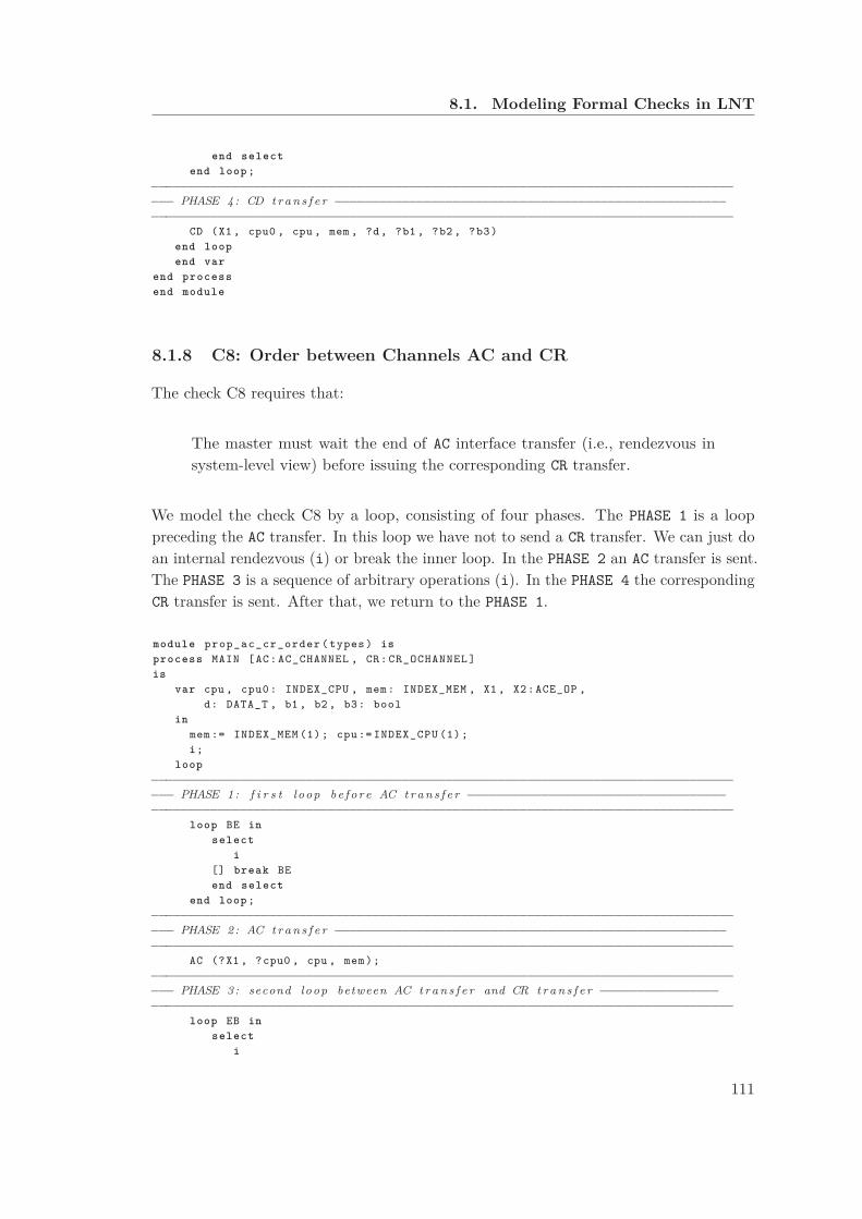
8.1. Modeling Formal Checks in LNT
end select
end loop ;
−−−−−−−−−−−−−−−−−−−−−−−−−−−−−−−−−−−−−−−−−−−−−−−−−−−−−−−−−−−−−−−−−−−−−−−−−−−−−−−
−−− PHASE 4: CD t r a n s f e r −−−−−−−−−−−−−−−−−−−−−−−−−−−−−−−−−−−−−−−−−−−−−−−−−−−−−
−−−−−−−−−−−−−−−−−−−−−−−−−−−−−−−−−−−−−−−−−−−−−−−−−−−−−−−−−−−−−−−−−−−−−−−−−−−−−−−
CD (X1 , cpu0 , cpu , mem , ?d, ?b1 , ?b2 , ?b3)
end loop
end var
end process
end module
8.1.8 C8: Order between Channels AC and CR
The check C8 requires that:
The master must wait the end of AC interface transfer (i.e., rendezvous insystem-level view) before issuing the corresponding CR transfer.
We model the check C8 by a loop, consisting of four phases. The PHASE 1 is a looppreceding the AC transfer. In this loop we have not to send a CR transfer. We can just doan internal rendezvous (i) or break the inner loop. In the PHASE 2 an AC transfer is sent.The PHASE 3 is a sequence of arbitrary operations (i). In the PHASE 4 the correspondingCR transfer is sent. After that, we return to the PHASE 1.
module prop_ac_cr_order ( types ) is
process MAIN [AC: AC_CHANNEL , CR: CR_OCHANNEL ]
is
var cpu , cpu0: INDEX_CPU , mem: INDEX_MEM , X1 , X2:ACE_OP ,
d: DATA_T , b1 , b2 , b3: bool
in
mem := INDEX_MEM (1); cpu := INDEX_CPU (1);
i;
loop
−−−−−−−−−−−−−−−−−−−−−−−−−−−−−−−−−−−−−−−−−−−−−−−−−−−−−−−−−−−−−−−−−−−−−−−−−−−−−−−
−−− PHASE 1: f i r s t loop b e f o r e AC t r a n s f e r −−−−−−−−−−−−−−−−−−−−−−−−−−−−−−−−−−−
−−−−−−−−−−−−−−−−−−−−−−−−−−−−−−−−−−−−−−−−−−−−−−−−−−−−−−−−−−−−−−−−−−−−−−−−−−−−−−−
loop BE in
select
i
[] break BE
end select
end loop ;
−−−−−−−−−−−−−−−−−−−−−−−−−−−−−−−−−−−−−−−−−−−−−−−−−−−−−−−−−−−−−−−−−−−−−−−−−−−−−−−
−−− PHASE 2: AC t r a n s f e r −−−−−−−−−−−−−−−−−−−−−−−−−−−−−−−−−−−−−−−−−−−−−−−−−−−−−
−−−−−−−−−−−−−−−−−−−−−−−−−−−−−−−−−−−−−−−−−−−−−−−−−−−−−−−−−−−−−−−−−−−−−−−−−−−−−−−
AC (?X1 , ?cpu0 , cpu , mem);
−−−−−−−−−−−−−−−−−−−−−−−−−−−−−−−−−−−−−−−−−−−−−−−−−−−−−−−−−−−−−−−−−−−−−−−−−−−−−−−
−−− PHASE 3: second loop between AC t r a n s f e r and CR t r a n s f e r −−−−−−−−−−−−−−−−
−−−−−−−−−−−−−−−−−−−−−−−−−−−−−−−−−−−−−−−−−−−−−−−−−−−−−−−−−−−−−−−−−−−−−−−−−−−−−−−
loop EB in
select
i
111
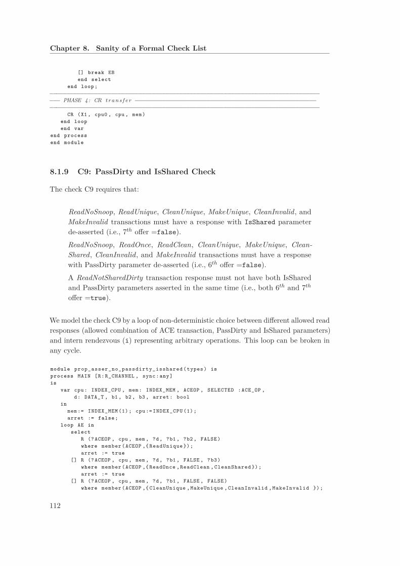
Chapter 8. Sanity of a Formal Check List
[] break EB
end select
end loop ;
−−−−−−−−−−−−−−−−−−−−−−−−−−−−−−−−−−−−−−−−−−−−−−−−−−−−−−−−−−−−−−−−−−−−−−−−−−−−−−−
−−− PHASE 4: CR t r a n s f e r −−−−−−−−−−−−−−−−−−−−−−−−−−−−−−−−−−−−−−−−−−−−−−−−−−−−−
−−−−−−−−−−−−−−−−−−−−−−−−−−−−−−−−−−−−−−−−−−−−−−−−−−−−−−−−−−−−−−−−−−−−−−−−−−−−−−−
CR (X1 , cpu0 , cpu , mem)
end loop
end var
end process
end module
8.1.9 C9: PassDirty and IsShared Check
The check C9 requires that:
ReadNoSnoop, ReadUnique, CleanUnique, MakeUnique, CleanInvalid, andMakeInvalid transactions must have a response with IsShared parameterde-asserted (i.e., 7th offer =false).
ReadNoSnoop, ReadOnce, ReadClean, CleanUnique, MakeUnique, Clean-
Shared, CleanInvalid, and MakeInvalid transactions must have a responsewith PassDirty parameter de-asserted (i.e., 6th offer =false).
A ReadNotSharedDirty transaction response must not have both IsSharedand PassDirty parameters asserted in the same time (i.e., both 6th and 7th
offer =true).
We model the check C9 by a loop of non-deterministic choice between different allowed readresponses (allowed combination of ACE transaction, PassDirty and IsShared parameters)and intern rendezvous (i) representing arbitrary operations. This loop can be broken inany cycle.
module prop_asser_no_passdirty_isshared ( types ) is
process MAIN [R: R_CHANNEL , sync: any]
is
var cpu: INDEX_CPU , mem: INDEX_MEM , ACEOP , SELECTED :ACE_OP ,
d: DATA_T , b1 , b2 , b3 , arret : bool
in
mem := INDEX_MEM (1); cpu := INDEX_CPU (1);
arret := false ;
loop AE in
select
R (? ACEOP , cpu , mem , ?d, ?b1 , ?b2 , FALSE )
where member (ACEOP ,{ ReadUnique });
arret := true
[] R (? ACEOP , cpu , mem , ?d, ?b1 , FALSE , ?b3)
where member (ACEOP ,{ ReadOnce , ReadClean , CleanShared });
arret := true
[] R (? ACEOP , cpu , mem , ?d, ?b1 , FALSE , FALSE )
where member (ACEOP ,{ CleanUnique , MakeUnique , CleanInvalid , MakeInvalid });
112

8.2. Local Sanity of Each Check
arret := true
[] R (? ACEOP , cpu , mem , ?d, ?b1 , ?b2 , ?b3)
where ( ACEOP == ReadNotSharedDirty ) and not (( b2 == TRUE) and (b3 ==
TRUE));
arret := true
[] R (? ACEOP , cpu , mem , ?d, ?b1 , ?b2 , ?b3)
where not ( member (ACEOP , { ReadUnique , CleanUnique , MakeUnique , CleanInvalid
,
MakeInvalid ,ReadOnce , ReadClean , CleanShared }));
arret := true
[] i
end select
end loop
end var
end process
end module
8.2 Local Sanity of Each Check
In fact, the IV unit considers only a single interface (i.e., a single master/slave pair),whereas the formal model describes the complete SoC. To obtain the LTS of the interfacebetween ACE master 1 (big) and the CCI (upper left part of Fig. 5.1), we hide inthe LTS of the whole system all labels except those of the selected interface and thenminimize the resulting LTS according to divergence-sensitive branching bisimulation
(divbranching) [VGW96], which preserves the branching structure and the livelocks(cycles of internal τ -transitions). Applying those steps reduces the LTS as generatedfrom the model (498,197 states, 1,343,799 transitions) by two orders of magnitude (3,653states, 8,924 transitions). We store the reduced LTS in a file named interface.bcg,where the extension .bcg stands for Binary Coded Graph, the compact binary formatused to store LTSs in CADP.
We aim at verifying that each check is well specified. Because each check uses only asubset of interface channels, we generate a corresponding sub-interface by hiding allchannels except those occurring in the check, and apply again divbranching reduction.
Example 14 Check C1 (presented in Section 8.1) uses only three channels: addressread (AR), address write (AW), and write response (B). Thus we obtain the correspondingsub-interface LTS (105 states, 474 transitions). by the following SVL (Script VerificationLanguage) [GL01] script:
"interface_ar_aw_b.bcg" = divbranching reduction of
gate hide all but AR, AW, B in "interface.bcg";
We verify that each sub-interface LTS is included in the corresponding check LTS modulothe preorder of the divbranching bisimulation. We conclude that the check is a correct
113
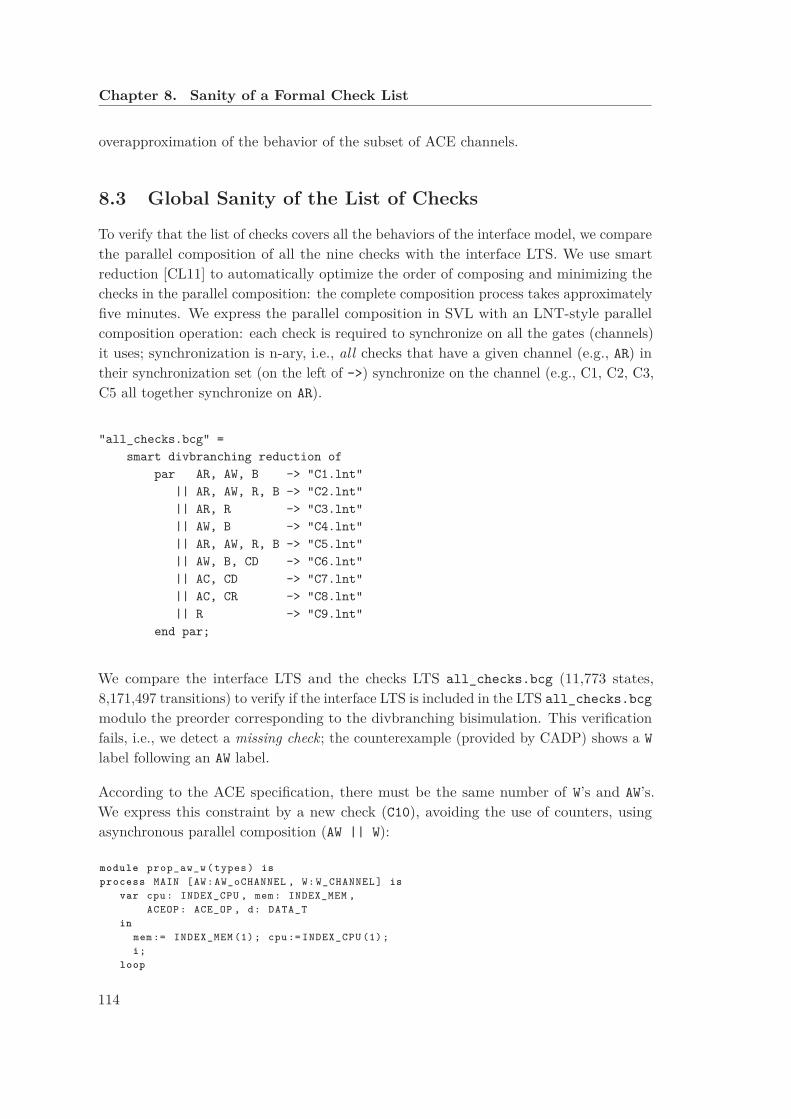
Chapter 8. Sanity of a Formal Check List
overapproximation of the behavior of the subset of ACE channels.
8.3 Global Sanity of the List of Checks
To verify that the list of checks covers all the behaviors of the interface model, we comparethe parallel composition of all the nine checks with the interface LTS. We use smartreduction [CL11] to automatically optimize the order of composing and minimizing thechecks in the parallel composition: the complete composition process takes approximatelyfive minutes. We express the parallel composition in SVL with an LNT-style parallelcomposition operation: each check is required to synchronize on all the gates (channels)it uses; synchronization is n-ary, i.e., all checks that have a given channel (e.g., AR) intheir synchronization set (on the left of ->) synchronize on the channel (e.g., C1, C2, C3,C5 all together synchronize on AR).
"all_checks.bcg" =
smart divbranching reduction of
par AR, AW, B -> "C1.lnt"
|| AR, AW, R, B -> "C2.lnt"
|| AR, R -> "C3.lnt"
|| AW, B -> "C4.lnt"
|| AR, AW, R, B -> "C5.lnt"
|| AW, B, CD -> "C6.lnt"
|| AC, CD -> "C7.lnt"
|| AC, CR -> "C8.lnt"
|| R -> "C9.lnt"
end par;
We compare the interface LTS and the checks LTS all_checks.bcg (11,773 states,8,171,497 transitions) to verify if the interface LTS is included in the LTS all_checks.bcg
modulo the preorder corresponding to the divbranching bisimulation. This verificationfails, i.e., we detect a missing check; the counterexample (provided by CADP) shows a W
label following an AW label.
According to the ACE specification, there must be the same number of W’s and AW’s.We express this constraint by a new check (C10), avoiding the use of counters, usingasynchronous parallel composition (AW || W):
module prop_aw_w ( types ) is
process MAIN [AW: AW_oCHANNEL , W: W_CHANNEL ] is
var cpu: INDEX_CPU , mem: INDEX_MEM ,
ACEOP : ACE_OP , d: DATA_T
in
mem := INDEX_MEM (1); cpu := INDEX_CPU (1);
i;
loop
114

8.4. Improvement of System Coverage Infrastructure
par
AW (? ACEOP , cpu , mem)
|| W (ACEOP , cpu , mem , ?d)
end par
end loop
end var
end process
end module
Adding C10 to the parallel composition of the checks, yields a new LTSall_checks_bis.bcg (38,793 states, 27,200,587 transitions).
We compare all_checks_bis.bcg and interface.bcg and observe now thatinterface.bcg is included in all_checks_bis.bcg for divbranching bisimulation.Hence, the check list is now complete with respect to our formal model. Althoughthe missing check could also be found manually by inspecting the list of channels inthe checks (all channels but W are present), our approach has the additional benefitsof illustrating the missing behavior and enabling to formally, and semi-automatically,establish the completeness of the check list.
8.4 Improvement of System Coverage Infrastructure
However, system requirements cannot be verified on a single IV unit separately. Wecomplete the verification infrastructure by introducing the notion of a system verification
unit (SV unit) connected to all IV units, so as to combine behaviors of different interfacesin order to validate system-level requirements.
For the considered SoC, we define an SV unit consisting of 56 PSL (Property SpecificationLanguage) [oEE10] sequences, 56 PSL basic cover points, and 36 PSL checks. This enablesto verify on the RTL test bench that each coherent transaction produces the correspondingsnoop transaction, and that each snoop transaction eventually receives a response fromthe snooped master.
Example 15 We present below an example of two PSL sequences. The first onepresents a ReadOnce transfer in the address read channel AR for an ACE-Lite master S0
(for the simulation test benches the masters are considered as slaves S? and the slaves areconsidered as masters M?). This transfer is observed if the transfer is valid (i.e., ARVALIDS0
parameter==1), the transaction is not a barrier transaction (i.e., ARBARS0[0]==0), we arein a shareable domain of the memory (i.e., ARDOMAINS0==01 or 10), and the transactionis a ReadOnce (i.e., ARSNOOPS0==0000 in a shareable domain). The second PSL sequencepresents a ReadOnce transfer on the address coherency channel AC for an ACE master S3.This transfer is observed if the transfer is valid (i.e., ACVALIDS3==1) and the transactionis a ReadOnce (i.e., ACSNOOPS0==0000 in a shareable domain).
115
Chapter 8. Sanity of a Formal Check List
//------ AR ReadOnce transaction ACE-Lite S0 ------
sequence AR_ReadOnce_s0 = {{ARVALIDS0==1’b1} & {ARBARS0[0]==1’b0}
& {{ARDOMAINS0==2’b01} | {ARDOMAINS0==2’b10}} & {ARSNOOPS0==4’b0000}};
//------ AC ReadOnce transaction ACE S3 ------
sequence AC_ReadOnce_s3 = {{ACVALIDS3==1’b1} & {ACSNOOPS3==4’b0000}};
Example 16 After that, we present an example of a PSL basic cover point and a PSLcheck. The basic cover point represents an action ReadOnce that occurred on the addressread channel AR. We present that by the defined sequence AR_ReadOnce_s0. The checkrepresents that a ReadOnce transfer in the address read channel AR of the ACE-Litemaster S0 is always followed, after a finite number of clock edges, by a ReadOnce transferin the address coherency channel AC. The defined sequences are useful to abstract theparameters level, when defining cover points and checks.
//------ Cover AR ReadOnce transaction ACE-Lite S0 ------
cover_aread_ReadOnce_s0: cover {AR_ReadOnce_s0}
report "ReadOnce ACE Lite Master 0 transaction occurred";
//------ Assert Transaction AR S0 => AC S3 ------
assert_ReadOnce_S0_AR_S3_AC:
assert (always {AR_ReadOnce_s0} |=> {[*];AC_ReadOnce_s3});
8.5 Industrial Results
Our methodology was used by STMicroelectronics verification solution team to validateIV unit provided by a major CAD supplier. We focused in our study on the system-levelchecks.
The checks of the IV unit are expressed in System Verilog Assertion (SVA). Some checksconcern the behavior of the DUV (i.e., cache coherent interconnect), and are calledassertions. Other checks concern the behavior of the verification IP (i.e., IV unit), andare called constraints.
The IV unit is used both in static and dynamic verification test benches. In the dynamictest benches we connect the IV unit as a monitor to verify if the cover points and checksare activated by the tests runned by a dynamic Verification IP (VIP), provided by thesame CAD supplier, and verify if the activated checks pass or fail. In the static testbenches we connect the IV unit to the RTL of the DUV. We use constraints as inputs of
116

8.5. Industrial Results
the DUV and the assertions as checks to verify the outputs of the DUV.
In our study presented above, we use the LNT model to replace the DUV and we validatethe list of checks. Our LNT model combines both the behavior of the cache coherentinterconnect and the behavior of the connected masters/slaves. As a result, eitherconstraints (C1 to C8) and assertions (C9) of the IV unit are considered as constraintsagainst the LNT model of the ACE-based SoC.
Giving that the VIPs and the coverage lists were provided by the same CAD supplier,some verification gaps may not be detected. In fact, the same misinterpretation of theACE specification can be reproduced. Working with a different approach led us tovalidate the industrial checks, and thanks to our directed tests we could detect gaps inthe industrial VIPs.
The test bench is now ready to check that the coherency mechanisms work well.
117

Chapter 9
Conclusion
There is nothing more practical than a good theory, and there is nothing more interestingthan linking the good theory to a real case study and to prove concretely the relevanceof the theory. Applying formal methods, developed by the concurrency theory researchcommunity, to improve the functional verification of hardware designs is an importantfocus in the current works aiming to introduce formal methods in the hardware designflow. The main purpose of this work is to prove the suitability and the efficiency of thisapproach in an industrial context. To this end, a high-level formal model is used toimprove the functional verification of a cache coherent SoC. This SoC provides hardwaresupport for system-level cache coherency, via the state-of-the-art AMBA 4 ACE protocol,which supports cache coherency in heterogeneous SoCs. A family of those SoCs iscurrently under development at STMicroelectronics.
This thesis starts by formally modeling a generic cache coherent SoC based on theACE specification. Then this model is exploited in different ways: model checking thesystem properties on the formal model, extracting relevant test cases to be run on theimplementation, and validating an industrial verification unit with respect to the formalmodel.
In the sequel, we present a summary of the principal contributions of this thesis. Thenwe propose some research and engineering perspectives to explore in order to capitalizeon the results of this thesis.
9.1 Summary of Contributions
A generic formal LNT model of the recent ACE specification [ARM13] is produced. Theproposed model includes all the behaviors allowed by the specification. Our model isparametric in the sense that a subset of ACE transactions can be activated and the
119
Chapter 9. Conclusion
number of ACE and ACE-Lite masters can be chosen, as well as those that are activatedor not. The constraint-oriented specification style is helpful in the modeling of generalrequirements expressed in natural language. Our model is found to be valuable bySTMicroelectronics architects, because it enables (using the OCIS simulator) interactiveand backtrackable step-by-step system-level simulation of all ACE-compliant behaviors.
Formal modeling of hardware specifications requires expertise and can be time-consuming.Often, the first model is not the best, and several iterations are required in order toobtain a mature model. When formally modeling a hardware system, it is indispensableto focus on the most complex parts, and to use appropriate abstractions. That is why,knowledge and experience must be capitalized. Besides, once the model exists, it can beprofitably exploited in multiple ways. Some of them are presented in the following.
Correctness properties are expressed as temporal logic formulæ (in MCL) and verifiedautomatically (using the EVALUATOR 4.0 tool). Hence, formal verification techniquesare found to be useful for the analysis of heterogeneous coherent SoCs. We take advantageof the parametrization of our model by proposing an approach producing a comprehensiveset of counterexamples for each non-satisfied property. The classical on-the-fly modelchecking approach, on its side, typically produces at most one counterexample.
The formal verification can require the use of clever verification strategies, such ascompositional verification and on-the-fly verification. We notice that the use of explicit-state model checking based on enumerative techniques is not equivalent to a purebrute force technique. In fact, clever techniques are used in the different phases of theverification flow to address the challenges of industrial sized systems. The non-trivialissues detected, e.g., high-quality1 bugs or limitations, prove the effectiveness of formaltechniques introduced in the hardware functional verification flow.
Using only CDTG to generate tests in a one-step approach did not reach a satisfyingcoverage due to the complexity of system-level cache-coherency protocols. That is whythis thesis proposes to enhance the CDTG industrial test bench by introducing model-based test generation of abstract test cases, using the results of the model checking.Those abstract test cases are then refined with the CDTG solver into RTL concrete testcases.
Prior approaches [GH99, QM11] transform counterexamples produced by the modelchecker into test cases. In this thesis, the counterexamples are used to produce smaller(interesting) configurations of the model which still contain violation of a given property,thus abstracting away irrelevant details. The abstract tests are generated from theseinteresting configurations. Those tests concern system-level properties in the sense thatseveral interfaces are activated.
1A high-quality bug is an error that would go undetected by the established validation process ofsome product.
120

9.2. Research Perspectives
The proposed approach capitalizes on existing environments while solving their limitationsfor system-level protocols. This has an impact on a family of industrial SoCs in productionat STMicroelectronics: it helps to improve the test bench and to increase test coverage.In addition, this approach contributes to the maturation of commercial VIPs. Theeffectiveness of the proposed approach is illustrated by finding a major limitation twentymonths before it is found by other classical approaches.
Finally, to check the sanity of an IV unit (i.e., a list of formal checks) used to monitorthe behavior of an interface of the DUV, a cross-checking approach is used, comparingan interface LTS extracted from the proposed formal model with the IV unit. Formalchecks are expressed in LNT. Smart-composition and the divbranching bisimulation areused to compose an LTS representing all the checks. After that, equivalence checking isused to validate the sanity of the formal checks list. This comparison enables to find amissing check.
The formal verification is classically used by hardware engineers on low levels. Thesemi-formal verification, combining simulation and formal checks, releases the formalverification techniques in different ways. It is a solution for the limitations in scalabilityof the formal verification due to the state-explosion problem and a way to confirm issuesdetected by the formal verification of a high-level model in the concrete test bench ofthe design under verification. This thesis improves the state of the art of semi-formalverification test benches by extracting results from high-level formal modeling andverification of the specification in order to extend the capabilities of the semi-formal testbench.
9.2 Research Perspectives
A first perspective concerns the introduction of more automation to strengthen theintegration of the proposed approach in the industrial flow. Some manual parts haveto be automated, in particular the translation of abstract test cases into inputs of aCDTG solver. The automation of this part enables also further development of on-linemodel-based testing approach by co-simulating the formal model and the DUV.
A second perspective concerns extending the proposed formal model to expand the scopeof applications. In particular, the LNT model could be extended to take into account so-called snoop filters, which enable a coherent interconnect to implement a directory-basedmodel, as required for an SoC with a larger number of coherent components. Hence, suchan extension would cover also recently announced interconnects such as ARM’s CCN-504.Furthermore, the LNT model could be annotated with quantitative information (e.g.,operation latencies) using the framework of Interactive Markov Chains [Her02], so as toenable performance evaluation, capitalizing on the modeling effort done in this thesis.
121

Chapter 9. Conclusion
Given the success of our approach, it seems also interesting to apply this approach to thesystem-level protocols in the next generation of SoCs. The proposed approach to assessthe sanity of a check list (i.e., IV unit) against a formal model is akin to crosschecking,a technique widely used in the hardware community in order to improve confidence onthe verification components. To apply our test generation approach, the formal modelmust be configurable, so as to violate a property. These preconditions seem acceptable,as modifying parts of the model (e.g., some data types) is found feasible using simplescripts, and the literature presents several techniques to automate the production offaulty models.
9.3 Scientific Publications and Communications
This thesis led to several publications and communications to the scientific and industrialcommunity.
9.3.1 Scientific Publications
International conference proceedings:
• A. Kriouile and W. Serwe. Using a Formal Model to Improve Verification of aCache-Coherent System-on-Chip. In TACAS, LNCS 9035, pp. 708–722. Springer,April 2015.
• A. Kriouile and W. Serwe. Formal Analysis of the ACE Specification for CacheCoherent Systems-on-Chip. In FMICS, LNCS 8187, pp. 108–122. Springer,September 2013.
Other international publications:
• A. Kriouile and W. Serwe. ARMCacheCoherency Model, benchmark model InModel Checking Contest @ Petri Nets. June 2013.http://mcc.lip6.fr/2014/pdf/ARMCacheCoherenceform.pdf
National proceedings:
• A. Kriouile and W. Serwe. Analyse formelle du protocole ACE : cohérence decaches des systèmes sur puce In ETR, pp. 130- 133. August 2013.
122

9.3. Scientific Publications and Communications
9.3.2 Scientific Communications
Invited talk:
• A. Kriouile and W. Serwe. Using a Formal Model to Improve Verification of aCache-Coherent System-on-Chip. In Cadence Club Formal, France. March 19th
2015.
Presentations in international conferences:
• A. Kriouile and W. Serwe. Using a Formal Model to Improve Verification of aCache-Coherent System-on-Chip. In TACAS, part of ETAPS 2015, Queen MaryUniversity in London, UK. April 17th 2015.
• A. Kriouile and M. Zendri. 20 years of Hardware Verification with CADP. InFormal Methods Forum, LAAS laboratory in Toulouse, France. October 16th 2014.
• A. Kriouile and W. Serwe. Formal Analysis of the ACE Specification for CacheCoherent Systems-on-Chip. In FMICS, University Complutense of Madrid, Spain.September 24th 2013.
Presentations in national seminars:
• A. Kriouile and M. Zendri. Model based test generation for cache coherent Systems-on-Chips. In Formal Methods Forum, LAAS laboratory in Toulouse, France. Juin16th 2015.
• A. Kriouile. Formal Methods for Functional Verification of Cache-Coherent SoCs.In CONVECS’2015, Cheravines, Isére, France. May 2015.
• A. Kriouile. Model-Based Testing of SoCs: from Theory to Practice. In CON-
VECS’2014, Herbelon, Isére, France. June 2014.
• A. Kriouile. Introduction of Formal High Level Modeling into SoC Validation:Illustration on ACE compliant Cache Coherence. In CONVECS’2013, Col de Porte,Isére, France. November 2013.
• A. Kriouile. Formal Modeling and Verification of an ACE Compliant Cache Coher-ent Interconnect. In CONVECS’2012, Pont-en-Royans, Isére, France. November2012.
Posters:
123
Chapter 9. Conclusion
• A. Kriouile (joint work with W. Serwe). Formal Analysis of the ACE specificationfor Cache Coherent Systems-on-Chip (SoC). In ETR’2013.
• A. Kriouile. Validation of Distributed Systems on-Chip. In LIG’2013.
124

Appendix
125


Appendix A
Model Checking Properties
This appendix describes exhaustively the MCL formulæ used to validate the coherencyaspects of the ACE specification.
A.1 Unique dirty coherency
The first cache state coherency formula (ϕ5)1 requires that if a cache line (master m1,memory line l) is in the state ACE_UD (the cache line is unique and modified), then aslong as the line does not change its status, all cache lines of other masters (m2 Ó= m1)containing the same memory line (l) must be in the state ACE_I (the cache line is invalid).This is a state-based property. The corresponding action-based property expresses thatif an action {?Ch m1 l ACE_UD} happens then while there is no action {?Ch m1 l s1
where s1 Ó= ACE_UD}, we check whether an action {?Ch m2 l s2 where m2 Ó= m1 and
s1 Ó= ACE_I} happens. If this is the case, then the property is not satisfied (false).
The MCL formula expressing this action-based property is the following:
[ true * .
{?Ch:String ?op:String ?m1:Nat ?l:Nat !"ACE_UD"} .
( not ({?Ch:String ?op:String !m1 !l ?s1:String
where ace_state (s1) and (s1<>"ACE_UD")}) ) * .
{?Ch:String ?op:String ?m2:Nat !l ?s2:String
where (m2<>m1) and ace_state (s2)
and (s2<>"ACE_I")}
] false
1The ϕ1 to ϕ4 refer to the MCL formulæ written to validate the model (and not the ACE specification)described in the Sec. 5.5
127

Appendix A. Model Checking Properties
A.2 Unique clean coherency
The second cache state coherency formula (ϕ6) is similar to ϕ5 and requires that if acache line (master m1, memory line l) is in the state ACE_UC (the cache line is uniqueand not modified), then as long as the line does not change its status, all cache linesof other masters (m2 Ó= m1) containing the same memory line (l) must be in the stateACE_I (the cache line is invalid).
The corresponding action-based property expresses that if an action {?Ch m1 l ACE_UC}happens, then while there is no action {?Ch m1 l s1 where s1 Ó= ACE_UC}, we checkwhether an action {?Ch m2 l s2 where m2 Ó= m1 and s1 Ó= ACE_I} happens. If this isthe case, the property is not satisfied (false).
This action-based property is expressed by the following MCL formula:
[ true * .
{?Ch:String ?op:String ?m1:Nat ?l:Nat !"ACE_UC"} .
( not ({?Ch:String ?op:String !m1 !l ?s1:String
where ace_state (s1) and (s1<>"ACE_UC")}) ) * .
{?Ch:String ?op:String ?m2:Nat !l ?s2:String
where (m2<>m1) and ace_state (s2)
and (s2<>"ACE_I")}
] false
A.3 Shared dirty coherency
The third cache state coherency formula (ϕ7) requires that if a cache line (master m1,memory line l) is in the state ACE_SD (the cache line is shared and modified), then aslong as the line does not change its status, all cache lines of other masters (m2 Ó= m1)containing the same memory line (l) must be either in the state ACE_SC (the cache lineis shared and not modified) or in the state ACE_I (the cache line is invalid).
The corresponding action-based property expresses that if an action {?Ch m1 l ACE_SD}happens, then while there is no action {?Ch m1 l s1 where s1 Ó= ACE_SD}, we checkwhether an action {?Ch m2 l s2 where m2 Ó= m1 and s1 Ó= ACE_I and s1 Ó= ACE_SC}happens. If this is the case, the property is not satisfied (false).
This action-based property is expressed by the following MCL formula:
[ true * .
{?Ch:String ?op:String ?m1:Nat ?l:Nat !"ACE_SD"} .
( not ({?Ch:String ?op:String !m1 !l ?s1:String
128

A.4. Shared clean coherency
where ace_state (s1) and (s1<>"ACE_SD")}) ) * .
{?Ch:String ?op:String ?m2:Nat !l ?s2:String
where (m2<>m1) and ace_state(s2)
and (s2<>"ACE_I") and (s2<>"ACE_SC")}
] false
A.4 Shared clean coherency
The fourth cache state coherency formula (ϕ8) requires that if a cache line (master m1,memory line l) is in the state ACE_SC (the cache line is shared and not modified), thenas long as the line does not change its status, all cache lines of other masters (m2 Ó=m1) containing the same memory line (l) must be either in a shared state (ACE_SD orACE_SC) or an invalid state (ACE_I).
The corresponding action-based property expresses that if an action {?Ch m1 l ACE_SC}happens then while there is no action {?Ch m1 l s1 where s1 Ó= ACE_SC}, we checkwhether an action {?Ch m2 l s2 where m2 Ó= m1 and s1 Ó= ACE_I and s1 Ó= ACE_SC
and s1 Ó= ACE_SD} happens. If this is the case, the property is not satisfied (false).
This action-based property is expressed by the following MCL formula:
[ true * .
{?Ch:String ?op:String ?m1:Nat ?l:Nat !"ACE_SC"} .
( not ({?Ch:String ?op:String !m1 !l ?s1:String
where ace_state (s1) and (s1<>"ACE_SC")}) ) * .
{?Ch:String ?op:String ?m2:Nat !l ?s2:String
where (m2<>m1) and ace_state(s2) and (s2<>"ACE_I")
and (s2<>"ACE_SC") and (s2<>"ACE_SD")}
] false
A.5 Unique clean data integrity
The unique clean state requires that the data in the cache line (data1) must be equalto the data in the shareable memory (data2). Once we detect an ACE_UC state and aslong as the line does not change its status, we require that data2 (data in the shareablememory) is equal to data1.
In the action-based view, an action containing an ACE_UC state can be a data transferaction (action with data) or a control action (action without data). Each case correspondsto a different MCL formula (two formulæ are expressed).
The first formula (ϕ9) concerns a data transfer action with an ACE_UC. In this case when
129
Appendix A. Model Checking Properties
we observe an action {?Ch !m1 !l !data1 !ACE_UC}, then as long as there is neither anaction {?Ch !m1 !l !s1 where s1<>ACE_UC} (action without data) nor an action {?Ch
m1 l data s1 where s1<>ACE_UC} (action with data). We check whether an action {R
!0 !l !data2 where data2<>data1} happens. In fact, the read response R from theshareable memory 0 is the only outgoing data transfer transaction from the memory. Ifsuch a response occurs, the property is not satisfied (false).
The formula ϕ9 is expressed as follows:
[ true * .
{?Ch:String ?op:String ?m1:Nat ?l:Nat ?data1:Nat !"ACE_UC"} .
(
not ({?Ch:String ?op:String !m1 !l ?h:Nat ?s:String
where ace_state (s) and (s<>"ACE_UC")})
and
not ({?Ch:String ?op:String !m1 !l ?s:String
where ace_state (s) and (s<>"ACE_UC")})
)* .
{R ?op:string !"0" !l ?data2:Nat ?m2:Nat
where (data2<>data1)}
] false
The second formula (ϕ10) concerns a control action with an ACE_UC state. The datatransfer containing the data happens in a different action. In the beginning, we save thedata present in an action with a different cache state than ACE_UC {?Ch !m1 !l !data
!s1 where s1<>ACE_UC}, then we note an action {?Ch !m1 !l !ACE_UC}. As long asthere is neither an action {?Ch !m1 !l !s1 where s1<>ACE_UC} (action without data)nor an action {?Ch !m1 !l !data !s1 where s1<>ACE_UC} (action with data). Wecheck whether an action {R !0 !l !data2 where data2<>data1} happens. If such aresponse occurs, the property is not satisfied (false).
The formula ϕ10 is expressed as follows:
[ true * .
{?Ch:String ?op:String ?m1:Nat ?l:Nat ?data1:Nat ?s:String
where ace_state (s) and (s<>"ACE_UC")} .
(not {?Ch:String ?op:String ?m1:Nat ?l:Nat !"ACE_UC"})* .
{?Ch:String ?op:String ?m1:Nat ?l:Nat !"ACE_UC"} .
(
not ({?Ch:String ?op:String !m1 !l ?h:Nat ?s:String
where ace_state (s) and (s<>"ACE_UC")})
and
130
A.6. Shared dirty data integrity
not ({?Ch:String ?op:String !m1 !l ?s:String
where ace_state (s) and (s<>"ACE_UC")})
)* .
{R ?op:string !"0" !l ?data2:Nat ?m2:Nat
where (data2<>data1)}
] false
A.6 Shared dirty data integrity
The shared dirty state requires that the data1 located in the cache line (master m1,memory line l) must be equal to the data2 in any valid cache line of an other master(m2 Ó= m1) containing the same memory line (l) (Particularly, the cache state of this oneis shared clean).
In the action-based view, an action containing an ACE_SD state can have data or not.Each case corresponds to a different MCL formula (two formulæ are expressed).
The first formula (ϕ11) concerns a data transfer action with an ACE_SD state. In thiscase we note an action {?Ch !m1 !l !data1 !ACE_SD}, then as long as there is neitheran action {?Ch !m1 !l !s1 where s1<>ACE_SD} (action without data) nor an action{?Ch !m1 !l !data !s1 where s1<>ACE_SD} (action with data). We check whetheran action {?Ch !m2 !l !data2 !s where data2<>data1 and s==ACE_SC} happens. Ifsuch a response occurs, the property is not satisfied (false).
The formula ϕ11 is expressed as follows:
[ true * .
{?Ch:String ?op:String ?m1:Nat ?l:Nat ?data1:Nat !"ACE_SD"} .
(
not ({?Ch:String ?op:String !m1 !l ?h:Nat ?s:String
where ace_state (s) and (s<>"ACE_SD")})
and
not ({?Ch:String ?op:String !m1 !l ?s:String
where ace_state (s) and (s<>"ACE_SD")})
)* .
{?Ch:String ?op:String ?m2:Nat !l ?data2:Nat ?"ACE_SC"
where (m2<>m1) and (data2<>data1)}
] false
The second formula (ϕ12) concerns a control action with an ACE_SD state. The datatransfer containing the data happens in a different action. In the beginning, we savethe data present in an action with a different cache state than ACE_SD {?Ch !m1 !l
131

Appendix A. Model Checking Properties
!data !s1 where s1<>ACE_SD}, then we note an action {?Ch !m1 !l !ACE_SD}. Aslong as there is neither an action {?Ch !m1 !l !s1 where s1<>ACE_SD} (action with-out data) nor an action {?Ch !m1 !l !data !s1 where s1<>ACE_SD} (action withdata). We check whether an action {?Ch !m2 !l !data2 !s where data2<>data1 and
s==ACE_SC} happens. If such a response occurs, the property is not satisfied (false).
The formula ϕ12 is expressed as follows:
[ true * .
{?Ch:String ?op:String ?m1:Nat ?l:Nat ?data1:Nat ?s:String
where ace_state (s) and (s<>"ACE_SD")} .
(not {?Ch:String ?op:String ?m1:Nat ?l:Nat !"ACE_SD"})* .
{?Ch:String ?op:String ?m1:Nat ?l:Nat !"ACE_SD"} .
(
not ({?Ch:String ?op:String !m1 !l ?h:Nat ?s:String
where ace_state (s) and (s<>"ACE_SD")})
and
not ({?Ch:String ?op:String !m1 !l ?s:String
where ace_state (s) and (s<>"ACE_SD")})
)* .
{?Ch:String ?op:String ?m2:Nat !l ?data2:Nat ?"ACE_SC"
where (m2<>m1) and (data2<>data1)}
] false
A.7 Shared clean data integrity
The shared clean state requires that the data (data1) in the cache line (master m1,memory line l) must be equal to the data (data2) in any cache line of an other master(m2 Ó= m1) containing the same memory line (l).
In the action-based view, an action containing an ACE_SC state can be with data orwithout data. Each case corresponds to a different MCL formula. Two formulæ areexpressed.
The first formula (ϕ13) concerns a data transfer action with an ACE_SC
state. In this case we note an action {?Ch m1 l data1 ACE_SC}, then aslong as there is neither an action {?Ch m1 l s1 where s1 Ó= ACE_SC} (ac-tion without data) nor an action {?Ch m1 l data s1 where s1 Ó= ACE_SC} (ac-tion with data). We check whether an action {?Ch m2 l data2 s where data2
(m2<>m1) and ((s="ACE_SC" or s="ACE_SD")) and (data2<>data1)} happens. Inthis case, the property is not satisfied (false).
132
A.7. Shared clean data integrity
The formula ϕ13 is expressed as follows:
[ true * .
{?Ch:String ?op:String ?m1:Nat ?l:Nat ?data1:Nat !"ACE_SC"} .
(
not ({?Ch:String ?op:String !m1 !l ?any of Nat ?s:String
where ace_state (s) and (s<>"ACE_SC")})
and
not ({?Ch:String ?op:String !m1 !l ?s:String
where ace_state (s) and (s<>"ACE_SC")})
)* .
{?Ch:String ?op:String ?m2:Nat !l ?data2:Nat ?"ACE_SC"|"ACE_SD"
where (m2<>m1) and (data2<>data1)}
] false
The second formula (ϕ14) concerns a control action with an ACE_SC sstate. The datatransfer containing the data happens in a different action. In the beginning, we save thedata present in an action with a different cache state than ACE_SC {?Ch m1 l data s1
where s1 Ó= ACE_SC}, then we note an action {?Ch m1 l ACE_SC}. As long as there is nei-ther an action {?Ch m1 l s1 where s1 Ó= ACE_SC} (action without data) nor an action{?Ch m1 l data s1 where s1 Ó= ACE_SC} (action with data). We check whether an ac-tion {?Ch m2 l data2 s where data2 (m2<>m1) and ((s="ACE_SC" or s="ACE_SD"))
and (data2<>data1)} happens. In this case, the property is not satisfied (false):
The formula ϕ14 is expressed as follows:
[ true * .
{?Ch:String ?op:String ?m1:Nat ?l:Nat ?data1:Nat ?s:String
where ace_state (s) and (s<>"ACE_SC")} .
(not {?Ch:String ?op:String ?m1:Nat ?l:Nat !"ACE_SC"})* .
{?Ch:String ?op:String ?m1:Nat ?l:Nat !"ACE_SC"} .
(
not ({?Ch:String ?op:String !m1 !l ?h:Nat ?s:String
where ace_state (s) and s<>("ACE_SC")})
and
not ({?Ch:String ?op:String !m1 !l ?s:String
where ace_state (s) and (s<>"ACE_SC")})
)* .
{?Ch:String ?op:String ?m2:Nat !l ?data2:Nat ?"ACE_SC"|"ACE_SD"
133
Appendix A. Model Checking Properties
where (m2<>m1) and (data2<>data1)}
] false
A.8 Shareable memory data integrity
The following formula (ϕ15), requires correct order of write operations to the shareablememory:
[ true * .
{W !"WRITEBACK" ?m:Nat ?l:Nat ?d:Nat}.
(not{W !"WRITEBACK" !0 !l !d !m})*.
{W !"WRITEBACK" !0 !l !d !m}.
( (not{AC ... !m ?any of Nat !l}) and
(not{W ?any of String !0 !l ?any of Nat ...}) )*.
{W ?any of String !0 !l ?h:Nat ... where h<>d}
] false
Once a master m initiates a memory update (WriteBack transaction: first action on gateW) of a memory line l and a data d, and this update is actually written to memory(second action on gate W, with port number 0, i.e., the memory) as second offer, theproperty forbids a data h different from d to be written to the same memory line l
without previously receiving a snoop request (gate AC) concerning line l2.
A.9 Read response no PassDirty property
According to the ACE specification [ARM13], for several transactions (i.e., ReadOnce,ReadClean, CleanUnique, MakeUnique, CleanShared) the master initiating the transactioncannot take the responsibility to write the data on the memory, so the PassDirty
parameter of the read response channel R has to be deserted (false).
As described in Section 5.2.3, the sixth parameter of a read response channel R is aboolean corresponding the PassDirty parameter and the seventh parameter is a booleancorresponding to the IsShared parameter.
We add the following formula (ϕ16), which checks the correct positioning of the PassDirty
parameter:
[
2The number of parameters differs for the rendezvous on gate W between the CCI and the memoryand those between a master and the CCI: for the former, the fifth parameter corresponds to the index ofthe initiator.
134
A.10. Read response no IsShared property
true * .
{AR ?op:String ?m:Nat ?l:Nat ?any of String
where (op="READONCE") or (op="READCLEAN") or (op="CLEANUNIQUE")
or (op="MAKEUNIQUE") or (op="CLEANSHARED")}.
(
not({R !op !m !l ?any of Nat ?any of bool ?any of bool ?any of bool})
)*.
{R !op !m !l ?any of Nat ?any of bool !"TRUE" ?any of bool}
] false
The formula ϕ16 concerns read address AR actions containing one of the followingtransactions: ReadOnce, ReadClean, CleanUnique, MakeUnique, or CleanShared. In fact,the corresponding read response R action (same transaction op) must have the PassDirty
parameter de-asserted. If this is not the case (i.e., PassDirty==TRUE), the property isnot satisfied (false).
A.10 Read response no IsShared property
Several ACE transactions must lead to a unique state (i.e., ReadNoSnoop, ReadUnique,CleanUnique, MakeUnique, CleanInvalid, MakeInvalid). The IsShared parameter of theread response channel R has to be de-asserted (false). i.e., the cache line is unique.
We add the following formula (ϕ17), which checks the correct positioning of the IsShared
parameter.
[
true * .
{AR ?op:String ?m:Nat ?l:Nat ?any of String
where ((op="READNOSNOOP") or (op="READUNIQUE") or (op="CLEANUNIQUE")
or (op="MAKEUNIQUE") or (op="CLEANINVALID"))}.
(
not({R !op !m !l ?any of Nat ?any of bool ?any of bool ?any of bool})
)*.
{R !op !m !l ?any of Nat ?any of bool ?any of bool !"TRUE"}
] false
The formula ϕ17 concerns read address AR actions containing one of the followingtransactions: ReadNoSnoop, ReadUnique, CleanUnique, MakeUnique, or CleanInvalid.In fact, the corresponding read response R action must have the IsShared parameterde-asserted. If it is not the case (i.e., IsShared==TRUE), the property is not satisfied(false).
135

Appendix A. Model Checking Properties
A.11 Read response no IsSharedDirty property
The formula (ϕ18) corresponds to the ReadNotSharedDirty transaction which must notlead to a shared dirty state (ACE_SD). The PassDirty and IsShared parameters of readresponse channel R must never be both asserted (true).
[
true * .
{AR ?op:String ?m:Nat ?l:Nat ?any of String
where (op="READNOTSHAREDDIRTY")}.
(
not({R !op !m !l ?any of Nat ?any of bool ?any of bool ?any of bool})
)*.
{R !op !m !l ?any of Nat ?any of bool !"TRUE" !"TRUE"}
] false
A.12 Coherency response PassDirty property
The PassDirty parameter of the coherency response channel CR has to be asserted (true)if and only if the ACE state before the CR request is either ACE_UD or ACE_SD and theACE state after the CR request is either ACE_UC, ACE_SC, or ACE_I.
As described in Section 5.2.3, the sixth parameter of a coherent response channel CR isa boolean corresponding to the PassDirty parameter and the seventh parameter is aboolean corresponding to the IsShared parameter.
The corresponding formula (ϕ19) expresses that if the ACE state switch from a dirtystate to a clean or invalid state during a coherent response CR action, the PassDirty
must be asserted. If this is not the case, the property is not satisfied (false).
The formula (ϕ19) is expressed as follows:
[
true * .
{?Ch:String ?op:String ?m:Nat ?l:Nat ?"ACE_UD"|"ACE_SD"} .
(
( not({?Ch:String ?op:String !m !l ?s:String})
and ( not{CR ?op:String !m !l ...})
)*.
{CR ?op:String !m !l ?any of Nat ?any of bool !"FALSE" ?any of bool} .
(
( not({?Ch:String ?op:String !m !l ?s:String})
136

A.13. Coherency response no PassDirty property
and ( not{CR ?op:String !m !l ...})
)*.
{?Ch:String ?op:String !m !l ?"ACE_UC"|"ACE_SC"|"ACE_I"}
] false
A.13 Coherency response no PassDirty property
The PassDirty parameter of the coherency response channel CR must be deserted(PassDirty=FALSE) in two cases: firstly, when a dirty state remains dirty, and secondly,when an ACE state was clean or invalid before the CR action.
This property is expressed by two formulæ. The first formula (ϕ20) checks if a PassDirty
is asserted just after an action with a clean or invalid state. In this case, the property isnot satisfied (false).
The formula ϕ20 is expressed as follows:
[
true * .
{?Ch:String ?op:String ?m:Nat ?l:Nat ?s:String
where ace_state (s) and ((s<>"ACE_UD") and (s<>"ACE_SD"))} .
(
( not({?Ch:String ?op:String !m !l ?s:String})
and ( not{CR ?op:String !m !l ...})
)*.
{CR ?op:String !m !l ?any of Nat ?any of bool !"TRUE" ?any of bool}
] false
The second formula (ϕ21) checks if a PassDirty is asserted just before an action with adirty state. In this case the property is not satisfied (false).
The formula ϕ21 is expressed as follows:
[
true * .
{CR ?op:String !m !l ?any of Nat ?any of bool !"TRUE" ?any of bool} .
(
( not({?Ch:String ?op:String !m !l ?s:String})
and ( not{CR ?op:String !m !l ...})
)*.
137

Appendix A. Model Checking Properties
{?Ch:String ?op:String !m !l ?"ACE_UD"|"ACE_SD"}
] false
A.14 Coherency response IsShared property
The IsShared parameter of the coherency response channel CR has to be asserted(IsShared=true) if and only if the ACE state after the CR request is a valid state(ACE_UC, ACE_SC, ACE_UD, or ACE_SD).
The formula ϕ22 expresses this property as follows:
[
true * .
{CR ?op:String !m !l ?any of Nat ?any of bool ?any of bool !"FALSE"} .
(
( not({?Ch:String ?op:String !m !l ?s:String})
and ( not{CR ?op:String !m !l ...})
)*.
{?Ch:String ?op:String !m !l ?"ACE_UD"|"ACE_SD"|"ACE_UC"|"ACE_SC"}
] false
A.15 Coherency response no IsShared property
The IsShared parameter of the coherency response channel CR has to be de-asserted(IsShared=false) if and only if the ACE state after the CR request is the invalid state.
The formula (ϕ23) expresses that the IsShared cannot be asserted just before an actionfrom the same master (m) and memory line (l) with an invalid state (ACE_I):
[
true * .
{CR ?op:String !m !l ?any of Nat ?any of bool ?any of bool !"TRUE"} .
(
( not({?Ch:String ?op:String !m !l ?s:String})
and ( not{CR ?op:String !m !l ...})
)*.
{?Ch:String ?op:String !m !l ?"ACE_I"}
] false
138
Bibliography
[ABG+00] Yael Abarbanel, Ilan Beer, Leonid Gluhovsky, Sharon Keidar, and YaronWolfsthal. Focs–automatic generation of simulation checkers from formalspecifications. In Computer Aided Verification, pages 538–542. Springer,2000.
[AFV01] Luca Aceto, Wan Fokkink, and Chris Verhoef. Structural Operational Se-
mantics, chapter 3, pages 197–292. 2001.
[And91] David F Anderson. Continuous-time markov chains. 1991.
[ARM12] ARM. CoreLink CCI-400 Cache Coherent Interconnect: Tech-
nical Reference Manual, November 2012. revision r1p1,http://infocenter.arm.com/help/topic/com.arm.doc.ddi0470g/DDI0470G_cci400_r1p1_trm.pdf.
[ARM13] ARM. AMBA AXI and ACE Protocol Specifica-
tion, February 2013. version ARM IHI 0022E,http://infocenter.arm.com/help/topic/com.arm.doc.ihi0022e.
[BAPM83] Mordechai Ben-Ari, Amir Pnueli, and Zohar Manna. The temporal logic ofbranching time. Acta informatica, 20(3):207–226, 1983.
[BB88] Tommaso Bolognesi and Ed Brinksma. Introduction to the iso specificationlanguage lotos. Computer Networks and ISDN Systems, 14(1):25–59, January1988.
[BCC+03] Armin Biere, Alessandro Cimatti, Edmund M Clarke, Ofer Strichman, andYunshan Zhu. Bounded model checking. Advances in computers, 58:117–148,2003.
[BCL+94] J. BURCH, E. Clarke, D. Long, K. McMillan, and D. Dill. Symbolic modelchecking for sequential circuit verification. IEEE Trans. Computer-Aided
Design Integration of Circuits, 13:401–424, April 1994.
[BCM+90] Jerry R Burch, Edmund M Clarke, Kenneth L McMillan, David L Dill, andLain-Jinn Hwang. Symbolic model checking: 10 20 states and beyond. In
139
Bibliography
Logic in Computer Science, 1990. LICS’90, Proceedings., Fifth Annual IEEE
Symposium on e, pages 428–439. IEEE, 1990.
[BED03] Vincent Beaudenon, Emmanuelle Encrenaz, and J-L Desbarbieux. Designvalidation of zcsp with spin. In Application of Concurrency to System Design,
2003. Proceedings. Third International Conference on, pages 102–110. IEEE,2003.
[BGH+99] Mike Benjamin, Daniel Geist, Alan Hartman, Gerard Mas, and Ralph Smeets.A Study in Coverage-Driven Test Generation. In Proceedings of the 36th
Design Automation Conference, pages 970–975. IEEE, June 1999.
[BK+08] Christel Baier, Joost-Pieter Katoen, et al. Principles of model checking,volume 26202649. MIT press Cambridge, 2008.
[BKS08] Nicolas Blanc, Daniel Kroening, and Natasha Sharygina. Scoot: A tool forthe analysis of systemc models. In Tools and Algorithms for the Construction
and Analysis of Systems, pages 467–470. Springer, 2008.
[CCG+14] David Champelovier, Xavier Clerc, Hubert Garavel, Yves Guerte, ChristineMcKinty, Vincent Powazny, Frédéric Lang, Wendelin Serwe, and GideonSmeding. Reference manual of the LNT to LOTOS translator (version 6.0).INRIA/VASY - INRIA/CONVECS, 125 pages, 2014.
[CFZ95] E. M. Clarke, M. Fujita, and X. Zhao. Hybrid decision diagrams. In Interna-
tional Conference on Computer-Aided Design, ICCAD-95. 1995 IEEE/ACM
International Conference on, pages 159–163. IEEE, 1995.
[CGH+95] Edmund M. Clarke, Orna Grumberg, Hiromi Hiraishi, Somesh Jha, David E.Long, Kenneth L. McMillan, and Linda A. Ness. Verification of the Fu-turebus+ cache coherence protocol. Formal Methods in System Design,6(2):217–232, March 1995.
[CGM+96] Ghassan Chehaibar, Hubert Garavel, Laurent Mounier, Nadia Tawbi, andFerruccio Zulian. Specification and verification of the powerscale bus arbitra-tion protocol: An industrial experiment with lotos. In Reinhard Gotzhein andJan Bredereke, editors, Proceedings of the Joint International Conference on
Formal Description Techniques for Distributed Systems and Communication
Protocols, and Protocol Specification, Testing, and Verification FORTE/P-
STV’96 (Kaiserslautern, Germany), pages 435–450. IFIP, 1996.
[CGP00] Edmund M Clarke, Orna Grumberg, and Doron Peled. Model checking. MITpress, 2000.
[Che04] Ghassan Chehaibar. Integrating formal verification with Murφ of distributedcache coherence protocols in FAME multiprocessor system design. In David
140
Bibliography
de Frutos-Escrig and Manuel Núñez, editors, Proceedings of the 24th IFIP
WG 6.1 International Conference on Formal Techniques for Networked and
Distributed Systems FORTE 2004 (Madrid, Spain), volume 3235 of Lecture
Notes in Computer Science, pages 243–258. Springer, September 2004.
[CHLS09] Nicolas Coste, Holger Hermanns, Etienne Lantreibecq, and Wendelin Serwe.Towards performance prediction of compositional models in industrial galsdesigns. In Ahmed Bouajjani and Oded Maler, editors, Proceedings of the
21th International Conference on Computer Aided Verification CAV’2009
(Grenoble, France), volume 5643, pages 204–218, July 2009.
[CL11] Pepijn Crouzen and Frédéric Lang. Smart reduction. In Dimitra Gian-nakopoulou and Fernando Orejas, editors, Proceedings of Fundamental Ap-
proaches to Software Engineering FASE’2011 (Saarbrücken, Germany), vol-ume 6603, pages 111–126, March 2011.
[CM11] Mingsong Chen and Prabhat Mishra. Property learning techniques for efficientgeneration of directed tests. IEEE Transactions on Computers, 60(6):852–864,2011.
[CQKM13] Mingsong Chen, Xiaoke Qin, Heon-Mo Koo, and Prabhat Mishra. System-
Level Validation: High-Level Modeling and Directed Test Generation Tech-
niques. Springer, 2013.
[CS96] Rance Cleaveland and Scott A. Smolka. Strategic directions in concurrencyresearch. ACM Comput. Surv., 28(4):607–625, December 1996.
[CTVW04] Edmund Clarke, Muralidhar Talupur, Helmut Veith, and Dong Wang. Satbased predicate abstraction for hardware verification. In Theory and Appli-
cations of Satisfiability Testing, pages 78–92. Springer, 2004.
[CYGC10] Xiaofang Chen, Yu Yang, Ganesh Gopalakrishnan, and Ching-Tsun Chou.Efficient methods for formally verifying safety properties of hierarchicalcache coherence protocols. Formal Methods in System Design, 36(1):37–64,February 2010.
[CZM09] Ghassan Chehaibar, Meriem Zidouni, and Radu Mateescu. Modeling multipro-cessor cache protocol impact on mpi performance. In Advanced Information
Networking and Applications Workshops, 2009. WAINA’09. International
Conference on, pages 1073–1078. IEEE, 2009.
[DCF+14] Rolf Drechsler, Christophe Chevallaz, Franco Fummi, Alan J Hu, RonnyMorad, Frank Schirrmeister, and Alex Goryachev. Future soc verificationmethodology: Uvm evolution or revolution? In Proceedings of the conference
on Design, Automation & Test in Europe, page 372. European Design andAutomation Association, 2014.
141

Bibliography
[DDHY92] David L. Dill, Andreas J. Drexler, Alan J. Hu, and C. Han Yang. Protocolverification as a hardware design aid. In Proceedings of the International Con-
ference on Computer Design: VLSI in Computers and Processors ICCD’92,pages 522–525. IEEE, October 1992.
[DFH+91] Gilles Dowek, Amy Felty, Hugo Herbelin, Gérard Huet, Benjamin Werner,Christine Paulin-Mohring, et al. The coq proof assistant user’s guide: Version5.6, 1991.
[DGG+05] Anat Dahan, Daniel Geist, Leonid Gluhovsky, Dmitry Pidan, Gil Shapir,Yaron Wolfsthal, Lyes Benalycherif, R Kamidem, and Younes Lahbib. Com-bining system level modeling with assertion based verification. In Quality of
Electronic Design, 2005. ISQED 2005. Sixth International Symposium on,pages 310–315. IEEE, 2005.
[Dil96] D. Dill. The murϕ verification system. In R. Alur and T. Henzinger,editors, Proceedings of the 8th International Conference on Computer-Aided
Verification CAV’96, 1996.
[dVT01] René G. de Vries and Jan Tretmans. Towards formal test purposes. In Formal
Approaches to Testing of Software FATES’01, pages 61–76. BRICS NotesSeries, 2001.
[EM95] Ásgeir Th. Eiríksson and Kennth L. McMillan. Using Formal Verification/-Analysis Methods on the Critical Path in System Design: A Case Study. InPierre Wolper, editor, Proceedings of the 7th International Conference on
Computer Aided Verification CAV (Liège, Belgium), volume 939 of Lecture
Notes in Computer Science, pages 367–380. Springer, July 1995.
[FJJV96] Jean-Claude Fernandez, Claude Jard, Thierry Jéron, and César Viho. Usingon-the-fly verification techniques for the generation of test suites. In Computer
Aided Verification, pages 348–359. Springer, 1996.
[Fou88] National Science Foundation, editor. Final Report: NSF Workshop on Billion-
Transistor Systems. NSF, 1988.
[FTHJ10] Sahar Foroutan, Yvain Thonnart, Richard Hersemeule, and Ahmed Jerraya.A markov chain based method for noc end-to-end latency evaluation. In IEEE
International Symposium on Parallel and Distributed Processing, Workshops
and Phd Forum (IPDPSW), (Atlanta, Georgia, USA), pages 1–8. IEEE, April2010.
[G+05] Frank Ghenassia et al. Transaction-level modeling with SystemC. Springer,2005.
142
Bibliography
[Gar13] Hubert Garavel, editor. Formal Methods for Safe and Secure Computers
Systems, volume BSI Study 875 of Federal Office for Information Security.Bundesamt fÃ1
4r Sicherheit in der Informationstechnik (BSI), 2013.
[GH99] A. Gargantini and C. Heitmeyer. Using model checking to generate tests fromrequirements specifications. ACM SIGSOFT Software Engineering Notes,24:146–162, 1999.
[GH02] Hubert Garavel and Holger Hermanns. On combining functional verificationand performance evaluation using cadp. In Lars-Henrik Eriksson and Peter A.Lindsay, editors, Proceedings of the 11th International Symposium of Formal
Methods Europe FME’2002 (Copenhagen, Denmark), volume 2391, pages410–429, 2002.
[GHPS09] Hubert Garavel, Claude Helmstetter, Olivier Ponsini, and Wendelin Serwe.Verification of an industrial systemc/tlm model using lotos and cadp. In Pro-
ceedings of the 7th ACM-IEEE International Conference on Formal Methods
and Models for Codesign MEMOCODE’2009 (Cambridge, MA, USA), 2009.
[GL01] Hubert Garavel and Frédéric Lang. Svl: a scripting language for compositionalverification. In Myungchul Kim, Byoungmoon Chin, Sungwon Kang, andDanhyung Lee, editors, Proceedings of the 21st IFIP WG 6.1 International
Conference on Formal Techniques for Networked and Distributed Systems
FORTE’2001 (Cheju Island, Korea), pages 377–392. IFIP, Kluwer AcademicPublishers, August 2001. Full version available as INRIA Research Report RR-4223.
[GLMS13] Hubert Garavel, Frédéric Lang, Radu Mateescu, and Wendelin Serwe. Cadp2011: A toolbox for the construction and analysis of distributed processes.Software Tools for Technology Transfer, 15(2):89–107, April 2013.
[GM04] Hubert Garavel and Radu Mateescu. Seq.open: A tool for efficient trace-based verification. In Susanne Graf and Laurent Mounier, editors, Proceedings
of the 11th International SPIN Workshop on Model Checking of Software
SPIN’2004 (Barcelona, Spain), volume 2989, pages 150–155, April 2004.
[Gor01] Mike Gordon. HOL-a machine oriented formulation of higher order logic.Citeseer, 2001.
[GVZ00] Hubert Garavel, César Viho, and Massimo Zendri. System design of a cc-numamultiprocessor architecture using formal specification, model-checking, co-simulation, and test generation. Research Report RR-4041, INRIA, November2000.
[GVZ01] Hubert Garavel, César Viho, and Massimo Zendri. System design of a cc-numa multiprocessor architecture using formal specification, model-checking,
143
Bibliography
co-simulation, and test generation. International Journal on Software Tools
for Technology Transfer, 3(3):314–331, 2001.
[GW95] Michel X Goemans and David P Williamson. Improved approximationalgorithms for maximum cut and satisfiability problems using semidefiniteprogramming. Journal of the ACM (JACM), 42(6):1115–1145, 1995.
[Her02] Holger Hermanns. Interactive Markov chains: and the quest for quantified
quality. Springer-Verlag, 2002.
[Hol97] Gerard J. Holzmann. State compression in spin: Recursive indexing andcompression training runs. In Proceedings of SPIN97 the 3rd SPIN Workshop
(Twente University, Enschede, The Netherlands), 1997.
[ISO89] ISOIS ISO. Osi 8807-lotos: a formal description technique based on thetemporal ordering of observational behaviour. International standard, ISO,1989.
[JJ05] Claude Jard and Thierry Jéron. Tgv: theory, principles and algorithms.International Journal on Software Tools for Technology Transfer, 7(4):297–315, 2005.
[JM99] T. Jéron and P. Morel. Test generation derived from model-checking. InN. Halbwachs and D. Peled, editors, Proceedings of the Conference on
Computer-Aided Verification CAV’99 (Trento, Italy), volume 1633, pages108–122, July 1999.
[JOS+01] Robert B Jones, John W O’Leary, Carl-Johan H Seger, Mark D Aagaard, andThomas F Melham. Practical formal verification in microprocessor design.IEEE Design & Test of Computers, 18(4):16–25, 2001.
[JW96] Daniel Jackson and Jeannette Wing. Lightweight formal methods. IEEE
Computer, 29(1):21–22, 1996.
[Käs03] Daniel Kästner. Tdl: a hardware description language for retargetable post-pass optimizations and analyses. In Generative Programming and Component
Engineering, pages 18–36. Springer, 2003.
[KG99] Christoph Kern and Mark R. Greenstreet. Formal Verification in HardwareDesign: A Survey. ACM Transactions on Design Automation of Electronic
Systems, 4(2):123–193, April 1999.
[KKVD13] Hemangee K. Kapoor, Praveen Kanakala, Malti Verma, and Shirshendu Das.Design and formal verification of a hierarchical cache coherence protocol forNoC based multiprocessors. The Journal of Supercomputing, 2013.
144

Bibliography
[KM96] Matt Kaufmann and J Strother Moore. Acl2: An industrial strength versionof nqthm. In Computer Assurance, 1996. COMPASS’96, Systems Integrity.
Software Safety. Process Security. Proceedings of the Eleventh Annual Con-
ference on, pages 23–34. IEEE, 1996.
[KM97] Jean-Pierre Krimm and Laurent Mounier. Compositional state space genera-tion from lotos programs. In Tools and Algorithms for the Construction and
Analysis of Systems TACAS’1997, pages 239–258. Springer, 1997.
[KMBA06] Heon-Mo Koo, Prabhat Mishra, Jayanta Bhadra, and Magdy Abadir. Di-rected micro-architectural test generation for an industrial processor: A casestudy. In Microprocessor Test and Verification, 2006. MTV’06. Seventh
International Workshop on, pages 33–36. IEEE, 2006.
[KNS01] Marta Kwiatkowska, Gethin Norman, and Roberto Segala. Automatedverification of a randomized distributed consensus protocol using cadencesmv and prism? In Computer Aided Verification, pages 194–206. Springer,2001.
[Koz83] Dexter Kozen. Results on the propositional µ-calculus. Theoretical computer
science, 27(3):333–354, 1983.
[KS13] Abderahman Kriouile and Wendelin Serwe. Formal analysis of the acespecification for cache coherent systems-on-chip. In Charles Pecheur andMichael Dierkes, editors, Proceedings of the 18th International Workshop
on Formal Methods for Industrial Critical Systems FMICS’2013 (Madrid,
Spain), volume 8187 of Lecture Notes in Computer Science, pages 108–122.Springer, September 2013.
[KS15] Abderahman Kriouile and Wendelin Serwe. Using a formal model to improveverification of a cache-coherent system-on-chip. In C. Baier and C. Tinelli,editors, 21th International Conference on Tools and Algorithms for the
Construction and Analysis of Systems TACAS 2015 (London, UK), volume9035 of Lecture Notes in Computer Science, pages 708–722. Springer, April2015.
[KVZ98] Hakim Kahlouche, Cesar Viho, and Massimo Zendri. An industrial experimentin automatic generation of executable test suites for a cache coherencyprotocol. In Testing of Communicating Systems, pages 211–226. Springer,1998.
[Kyu03] Chong-Min Kyung. Current status and challenges of soc verification forembedded systems market. In IEEE International SOC Conferenceg. IEEE,2003.
145
Bibliography
[Len05] Giacomo Lenzi. The modal mu-calculus: a survey. Technical Report 9(3),TASK Quarterly, 2005.
[LMSG02] Stan Liao, Grant Martin, Stuart Swan, and Thorsten Grötker. System Design
with SystemC. Springer Science & Business Media, 2002.
[LS11] Etienne Lantreibecq and Wendelin Serwe. Model checking and co-simulationof a dynamic task dispatcher circuit using CADP. In Gwen Salaün andBernhard Schätz, editors, Proceedings of the 16th International Workshop on
Formal Methods for Industrial Critical Systems FMICS 2011 (Trento, Italy),volume 6959, pages 180–195, August 2011.
[LS14] Etienne Lantreibecq and Wendelin Serwe. Formal analysis of a hardwaredynamic task dispatcher with cadp. Science of Computer Programming,80:130–149, 2014.
[Mat03] Radu Mateescu. On-the-fly verification using cadp. In Thomas Arts and WanFokkink, editors, Proceedings of the 8th International Workshop on Formal
Methods for Industrial Critical Systems FMICS’2003 (Trondheim, Norway),volume 80 of Electronic Notes in Theoretical Computer Science. Elsevier,2003.
[MC09] Prabhat Mishra and Mingsong Chen. Efficient techniques for directed test gen-eration using incremental satisfiability. In Proceedings of 22th International
Conference on VLSI Design, pages 65–70. IEEE, 2009.
[McM93] Kenneth L McMillan. Symbolic model checking. Springer, 1993.
[McM99] Kenneth L. McMillan. The SMV language. Technical report, CadenceBerkeley Labs, March 1999.
[McM00] Kenneth L. McMillan. A methodology for hardware verification using compo-sitional model checking. Science of Computer Programming, 37(1):279–309,2000.
[Mel09] Tom F Melham. Higher order logic and hardware verification, volume 31.Cambridge University Press, 2009.
[MHS12] Milo M. K. Martin, Mark D. Hill, and Daniel J. Sorin. Why On-Chip CacheCoherence Is Here to Stay. Communications of the ACM, 55(7):78–89, July2012.
[MS91] Kenneth L. McMillan and Schwalbe. Formal Verification of the EncoreGigamax cache consistency protocol. In Proceedings of the International
Symposium on Shared Memory Multiprocessors, pages 242–251, 1991.
146
Bibliography
[MSK+07] Deepak A Mathaikutty, Sandeep K Shukla, Sreekumar V Kodakara, DavidLilja, and Ajit Dingankar. Design fault directed test generation for micropro-cessor validation. In Design, Automation & Test in Europe Conference &
Exhibition, 2007. DATE’07, pages 1–6. IEEE, 2007.
[MT08] Radu Mateescu and Damien Thivolle. A model checking language for concur-rent value-passing systems. In Jorge Cuellar, Tom Maibaum, and Kaisa Sere,editors, Proceedings of the 15th International Symposium on Formal Methods
FM’08 (Turku, Finland), volume 5014 of Lecture Notes in Computer Science,pages 148–164. Springer, May 2008.
[oEE09] IEEE (Institute of Electrical and Electronics Engineers). Ieeestandard for systemverilog - unified hardware design, specification,and verification language. IEEE Std 1800-2009, December 2009.http://standards.ieee.org/findstds/standard/1850-2010.html.
[oEE10] IEEE (Institute of Electrical and Electronics Engineers). Ieee standard forproperty specification language (psl). IEEE Std 1850-2010, pages i –188,2010. http://standards.ieee.org/findstds/standard/1850-2010.html.
[oEE11] IEEE (Institute of Electrical and Electronics Engineers). Ieee standardfor the functional verification language e. IEEE Std 1647-2011, 2011.http://standards.ieee.org/findstds/standard/1647-2011.html.
[ORS92] Sam Owre, John M Rushby, and Natarajan Shankar. Pvs: A prototype veri-fication system. In Automated Deduction-CADE-11, pages 748–752. Springer,1992.
[Par81] David Park. Concurrency and automata on infinite sequences. In PeterDeussen, editor, Theoretical Computer Science, 1981.
[Pau94] Lawrence C Paulson. Isabelle: A generic theorem prover, volume 828.Springer, 1994.
[PD97] Fong Pong and Michel Dubois. Verification Techniques for Cache CoherenceProtocols. ACM Computing Surveys, 29(1):82–126, March 1997.
[PG11] ARM Peter Greenhalgh. Big. little processing with arm cortexTM-a15 &cortex-a7, 2011.
[Pie14] Laurence Pierre. Outils de démonstration automatique et preuve de circuitsélectroniques. Forum Méthodes Formelles: Preuve de modèle, Preuve de
programme, 2014.
[PNAD95] Fong Pong, Andreas Nowatzyk, Gunes Aybay, and Michel Dubois. VerifyingDistributed Directory-based Cache Coherence Protocols: S3.mp, a Case Study.In Seif Haridi, Khayri A. M. Ali, and Peter Magnusson, editors, Proceedings
147
Bibliography
of the 1st International Conference on Parallel Processing EURO-PAR’95
(Stockholm, Sweden), volume 966 of Lecture Notes in Computer Science,pages 287–300. Springer, August 1995.
[Pnu77] Amir Pnueli. The temporal logic of programs. In Foundations of Computer
Science, 1977., 18th Annual Symposium on, pages 46–57. IEEE, 1977.
[Pra08] Dhiraj K Pradhan. Application of galois fields to logic synthesis. In Industrial
and Information Systems, 2008. ICIIS 2008. IEEE Region 10 and the Third
international Conference on, pages 1–1. IEEE, 2008.
[QM11] Xiaoke Qin and Prabhat Mishra. Efficient directed test generation forvalidation of multicore architectures. In Proceedings of 12th Int’l Symposium
on Quality Electronic Design, pages 276–283. IEEE, 2011.
[RMK03] Abhik Roychoudhury, Tulika Mitra, and SR Karri. Using formal techniquesto debug the amba system-on-chip bus protocol. In Design, Automation and
Test in Europe Conference and Exhibition, 2003, pages 828–833. IEEE, 2003.
[SD95] Ulrich Stern and David L. Dill. Automatic Verification of the SCI CacheCoherence Protocol. In Correct Hardware Design and Verification Methods,volume 987 of Lecture Notes in Computer Science, pages 21–34. Springer,1995.
[SDSH11] Anna Slobodová, Jared Davis, Sol Swords, and Warren Hunt, Jr. A FlexibleFormal Verification Framework for Industrial Scale Verification. In Proceedings
of the 9th IEEE/ACM International Conference on Formal Methods and
Models for Codesign MEMOCODE 2011 (Cambridge, UK), pages 89–97.IEEE Computer Science Press, July 2011.
[SLM+92] Bart Selman, Hector J Levesque, David G Mitchell, et al. A new methodfor solving hard satisfiability problems. In AAAI, volume 92, pages 440–446,1992.
[SSTV07] Gwen Salaun, Wendelin Serwe, Yvain Thonnart, and Pascal Vivet. Formalverification of chp specifications with cadp illustration on an asynchronousnetwork-on-chip. In Asynchronous Circuits and Systems, 2007. ASYNC 2007.
13th IEEE International Symposium on, pages 73–82. IEEE, 2007.
[Ste11] Ashley Stevens. Introduction to AMBA 4 ACE. ARM whitepaper, June2011.
[Sut06] Stuart Sutherland. Modeling with systemverilog in a synopsys synthesisdesign flow using leda, vcs, design compiler and formality. SNUG Europe,2006.
148

Bibliography
[Swa06] Stuart Swan. Systemc transaction level models and rtl verification. InProceedings of the 43rd annual Design Automation Conference, pages 90–92.ACM, 2006.
[SWC+08] Haihua Shen, Wenli Wei, Yunji Chen, Bowen Chen, and Qi Guo. Coveragedirected test generation: Godson experience. In Asian Test Symposium, 2008.
ATS’08. 17th, pages 321–326. IEEE, 2008.
[Tho12] Chris Thompson. Verifying Cache Coherency Protocols with Verification IP.Synopsis, October 2012.
[Tre92] Gerrit Jan Tretmans. A formal approach to conformance testing. TwenteUniversity Press, 1992.
[Tre96] Jan Tretmans. Test generation with inputs, outputs and repetitive quiescence.Software—Concepts and Tools, (TR-CTIT-96-26), 1996.
[Tre99] Jan Tretmans. Testing concurrent systems: A formal approach. In CON-
CUR’99 Concurrency Theory, pages 46–65. Springer, 1999.
[VGS12] Yakir Vizel, Orna Grumberg, and Sharon Shoham. Lazy abstraction andsat-based reachability in hardware model checking. In Formal Methods in
Computer-Aided Design (FMCAD), 2012, pages 173–181. IEEE, 2012.
[vGW89] Robert Jan van Glabbeek and Willem Pieter Weijland. Refinement in
branching time semantics. Centrum voor Wiskunde en Informatica, Computerscience, 1989.
[VGW96] Rob J Van Glabbeek and W Peter Weijland. Branching time and abstractionin bisimulation semantics. Journal of the ACM (JACM), 43(3):555–600, 1996.
[WAW09] Martin Weiglhofer, Bernhard K Aichernig, and Franz Wotawa. Fault-basedconformance testing in practice. Int. J. Software and Informatics, 3(2-3):375–411, 2009.
[WCB+03] Pierre Wodey, Geoffrey Camarroque, Fabrice Baray, Richard Hersemeule,and Jean-Philippe Cousin. Lotos code generation for model checking ofstbus based soc: The stbus interconnect. In Rajesh K. Gupta, SandeepShukla, and Jean-Pierre Talpin, editors, Proceedings of the 1st ACM and
IEEE International Conference on Formal Methods and Models for Codesign
MEMOCODE’03 (Mont Saint-Michel, France), 2003.
[YPAA03] J. Yuan, C. Pixley, A. Aziz, and K. Albin. A framework for constrainedfunctional verification. In International Conference on Computer Aided
Design, pages 142–145. IEEE, November 2003.
149
Bibliography
[ZSW+14] Zhen Zhang, Wendelin Serwe, Jian Wu, Tomohiro Yoneda, Hao Zheng,and Chris Myers. Formal analysis of a fault-tolerant routing algorithmfor a network-on-chip. In Frédéric Lang and Francesco Flammini, editors,Proceedings of the 18th International Workshop on Formal Methods for
Industrial Critical Systems FMICS’2014 (Florence, Italy), volume 8718 ofLecture Notes in Computer Science, pages 48–62. Springer, September 2014.
150
Glossary
ABV Assertion-based verification
ACE AXI Coherency Extensions
ASIC Application Specific Integrated Circuit
AMBA Advanced Microcontroller Bus Architecture
AXI Advanced eXtensible Interface
BCG Binary Coded Graphs
BDD Binary Decision Diagrams
BFM Bus Functional Model
CADP Construction and Analysis of Distributed Processes
CCI Cache Coherent Interconnect
CC-NUMA Cache-Coherent - Non Uniform Memory Access computer memory design
CDTG Coverage-Directed Test Generation
CDV Coverage Driven Verification
CHP Communicating Hardware Processes
CIC Computation of Interesting Configurations
CONVECS Construction of Verified Concurrent Systems (Inria research team)
CPU Central Processing Unit
CTG Complete Test Graph
CTL Computation Tree Logic
CTMC Continuous-Time Markov Chains
151
Appendix A. Glossary
DUT Design Under Test
DUV Design Under Verification
GPU Graphical Processing Unit
FPGA Field-Programmable Gate Array
IMC Interactive Markov Chains
IOTS Input Output Transition System
IPC Interactive Probabilistic Chains
IVK Interconnect Verification Kit
IV unit Interface Verification unit
IP Intellectual Property, refer in SoC context for component designs from a lisensor likeARM
LNT LOTOS New Technology
LOTOS Language Of Temporal Ordering Specification
LTL Linear Temporal Logic
LTS Labeled Transition System
MBT Model-Based Testing
MCL Model Checking Language
MDV Metric Driven Verification
NoC Network on Chip
OCIS Open/Caesar Interactive Simulator
PSL Property Specification Language
ROBDD Reduced Ordered Binary Decision Diagram
RTL Register Transfer Level
SoC System on Chip
SUT System Under Test
SUV System Under Verification
SVA SystemVerilog Assertions
152
SVL Script Verification Language
SV unit System Verification unit
TGV Test Generation from transitions systems using Verification techniques
TLM Transaction-Level Modeling
VASY VAlidation of SYstems (Inria research team)
VHDL VHSIC Hardware Description Language
VIP Verification Intellectual Property
153
Copyright © 2022 FDOKUMEN