
METHOD STATEMENT FOR BEST MANAGEMENT PRACTICES
38
METHOD STATEMENT FOR BEST MANAGEMENT PRACTICES Projek Mengganti Jambatan Sedia Ada di FT006/041/93 Barat Day, Pulau Pinang (Schedule 2). Prepared by: Nilaimas Services EIA & Traffic Consultant
-
Upload
khangminh22 -
Category
Documents
-
view
2 -
download
0
Transcript of METHOD STATEMENT FOR BEST MANAGEMENT PRACTICES

METHOD STATEMENT FOR BEST
MANAGEMENT PRACTICES
Projek Mengganti Jambatan Sedia Ada di FT006/041/93 Barat
Day, Pulau Pinang (Schedule 2).
Prepared by:
Nilaimas Services
EIA & Traffic Consultant

2
Proposed method statement for “Projek Mengganti Jambatan
Sedia Ada di FT006/043/93 Barat Daya, Pulau Pinang
(Schedule 2).”
Work method statement for
Portable Silt Trap
Reference:
JKRBD/RESB/NMS/JTK/2019_1
Portable Silt Trap BMP No.: 1/12
Portable silt trap
Silt trap

3
1.0 INTRODUCTION
Silt trap is a designated area where water that is contaminated with suspended sediment as a
result of construction activity or water runoff is contained. While the water is in the trap, the
sediment can settle to the bottom of the trap until it can be removed. Silt trap can be made
using silt curtains, silt fences or a series of shallow ponds to naturally filter the sediment from
the water before it reaches a stream or clean body of water.
Environmental protection efforts, such as the silt trap, are often seen in conjunction with
mining or construction. Activity from these industries can result in the production of grain-
size particles, stone dust and other components that create suspended sediment when caught
up in water runoff during rainfall. As the rainwater carries these particles and other pollutants
to streams, the suspended sediment can cause a serious issue for the fish and other wildlife
that inhabit these waters.
However, in case of limitation space, portable silt trap is preferable. Also known as settling
tank, this device is used to remove sediment/ silt from water pumped from excavation and
other confined spaces where a traditional sediment basin/ sediment pond would be
impractical. Treatment of the sediment-laden water may involve chemical coagulation to
control turbidity levels.
2.0 METHOD STATEMENT
The best sites to install silt traps are:
Where run-off pathways can be intercepted.
Areas of low productivity.
Areas with easy access for maintenance where compaction can be avoided.
Size and shape: generally, a larger size portable silt trap will be more effective at trapping
sediment.
However a number of factors should be considered:
Soil type.
Run-off volumes.
Amount of sediment removal needed (by calculating the upslope catchment area to decide
on silt trap sizes).
Limitation of portable silt trap:
Only suitable for low to medium flow rates.
Control over silt and turbidity vary from unit to unit, and may require chemical dosing.
Some authorities may place restrictions on the use of certain coagulants.
Petroleum based polymers should not be used.

4
Advantages of using portable silt trap:
Suitable for use in confined spaces.
Tanks are reusable.
Suitable for batch and continuous flow.
One of the few treatment system that can be used for turbidity control.
Disadvantages of using portable silt trap:
Can be more expensive than one – off silt trap/ sediment basin, but can be cost effective
of reused on several sites.
Can be difficult to clean out.
Can be labour intensive operation.
Removal of portable silt trap:
Disassemble and remove all components of the settling tank and remove from the site.
Dispose of the consumables and sediment in a manner that will not create further erosion,
sedimentation or environmental problems.
Rehabilitate all disturbed ground as necessary to minimize the erosion hazard.
3.0 SPECIAL REQUIREMENTS
Portable sediment tanks should be located so that trapped sediments can be readily
removed without interference to construction activities.
Water quality monitoring is usually required.
Use of chemical coagulants requires expert advice and formal operational procedures.
Chemically treated tank effluent must be non-toxic to aquatic organisms. Samples of
treated water should be tested for acute (lethal) toxicity.
A pH adjustment may be required prior to discharge of the treated water.
4.0 OPERATION OF PORTABLE SILT TRAP
1. Refer to approved plans and associated environmental management plans for operational
details. If there are questions or problems with the method of installation or operation,
contact the product supplier and/or responsible on-site officer for assistance.
2. Prior to use, conduct flocculation tests to demonstrate suitability of treatment additive and
approximate dosage rate.
3. Use of chemical additives must be within limits specified by relevant authorities,
including State agencies.
4. Chemical flocculants/coagulants must be allowed to mix rapidly with the waters to insure
proper dispersion.
5. Ensure the tank operates in a manner that prevents the re-suspension and discharge of the
settled sediment.

5
6. Maintain a daily log of batch rates (volume and time), type and amount of chemical usage
(including pH adjustments if any), and water quality monitoring.
5.0 MAINTENANCE OF PORTABLE SILT TRAP
1. Inspect the sedimentation tank regularly and at least daily during de-watering operations.
2. Make repairs/adjustments as needed to maintain the required treatment standard.
3. De-silt the tank and maintain all replaceable components (such as filters) in accordance
with supplied operational instructions. Unique site-modified units should be de-silted
once settled sediment exceeds one third of the storage volume.
4. Dispose of all sediment in a manner that will not create an erosion or pollution hazard.
6
Proposed method statement for “Projek Mengganti Jambatan
Sedia Ada di FT006/043/93 Barat Daya, Pulau Pinang
(Schedule 2).”
Work method statement for
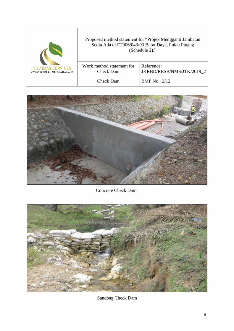
Check Dam
Reference:
JKRBD/RESB/NMS/JTK/2019_2
Check Dam BMP No.: 2/12
Concrete Check Dam
Sandbag Check Dam

7
Gabion check dam
Stones/Rock Check Dam
1.0 INTRODUCTION
A check dam is a small temporary dam constructed across a diversion channel or swale.
Check dam reduce the velocity of concentrated stormwater flows, thereby reducing erosion of
the diversion channel or swale and promoting sedimentation behind the dam.

8
Check dams are primarily used in small channels in steep terrain were velocities exceed 0.6
m/s. This BMP acts to prevent erosion by reducing the velocity of channel flow in small
intermittent channels and temporary swales.
Checks dams should only be placed in small open channels and never on a flowing river or
natural stream. Maintenance is therefore required to remove trapped sediment and to check
for structural stability on regular basis.
2.0 REQUIREMENT
Table 2 shows the design criteria for Check Dams.
Table 2 Design Criteria for Check Dams
PARAMETER REQUIREMENT
Runoff Quantity
Design 2 year ARI unless specified otherwise by Authorities
Overspill All flow greater than 2 year ARI shall safely bypass the crossing
Maximum
Contributing Area 4 ha
Dimension
Height (centre) of dam shall not exceed 1 m
For rock check dam:
- Upstream slope: 2(H) : 1(V) or flatter
- Downstream slope: 4(H) : 1(V) or flatter
Centers of the dam shall be notched to centre to promote
concentrated flow (approx. 0.15 m)
Outer sides of dam shall be at least 0.5 m higher than centre to
avoids undermining
Spill crest shall be at least 100 mm in width parallel to flow
Scour Protection
Structure shall withstand the shear force induced by a 2-year ARI
flow. Materials (rocks, earth and gabion) must be selected to meet
this requirement.
Additional scour protection downstream of check dam shall be
provided if deemed necessary
3.0 METHOD STATEMENT
General layout requirements of check dam structures:
The center of the dam should be at least 150 mm lower than either edge, so as to form
an outfall weir for any active flows. However, the actual freeboard to be incorporated
should be based on the risk and hazard of flooding to the surrounding areas.

9
Stabilization works with channel lining or protection works (such as riprap or gabion
mattresses) should be provided immediately downstream of the check dam to prevent
any possible toe erosion and undercutting.
The embankment/barrier of check dam should be extended adequately into the
existing bank to prevent any excessive seepage and potential breaching of the banks.
If a series of check dams are required, the dams should be spaced so that the
difference in the water levels between any two dams do not fall below 300 mm as
illustrated in Figure 1.
Figure 1 Proposed Location of Series of Check Dam Structures along the Waterway
Check dam should never be placed in live streams unless approved by appropriate local, state
and/or federal authorities. It should be located in straight sections of a watercourse or drain.
4.0 TYPE OF CHECK DAM STRUCTURE
Sand/Local Earth Filled Bags Check Dam
Sand /Local Earth Filled Bags check dam is a series of earth-filled bags placed on a level
contour to intercept flows. It provides a relatively quick and effective way in holding the
water flow to create a pond. Some of the general requirements of earth filled bags are:-
Bags should be made from durable, weather resistance fabric e.g. Geotextile (unless for
short-term). The fabric pores must be tight enough to retain the filler material. The bags
usually measure about the standard size of 1 m x 2 m x 0.15 m or other size as required.
Low quality polypropylene (PP) woven Sugar bags or sacks, commonly used in check
dams construction, are found to be not durable as they are easily damaged by the flows
and have low UV resistance. As such, these materials are not recommended as they
normally do not last longer than a years and required regular maintenance, and as such are
only suitable for short-term check dam structure.

10
On both side of the check dam structure, earth filled bags must be extended and tightly
abutted into the banks to prevent excessive seepage or breaching at the banks of the check
structure.
The center of the check dam must be lower by at least 150mm (min) to allow normal
flows spilling to occur within the mid portion of the structure.
Material specification are as below:
Container bag - They are many types of fabric bags available in the industry, varying both
in term of raw materials and their properties. However, selection of the types of bags
normally takes into consideration factors such as the service life required, accessibility of
site, ease of construction as well as relative cost of the structure.
Filled materials - Fill materials for earth-filled bags should be well graded non-cohesive
material or free from any deleterious materials. For short-term check dam where suitable
filled materials are not available, then local earth materials may be used.
Stones/Rock Check Dam
Stones or rocks placed on top of a blanket of engineering fabric either in loose form or
stacked tightly can also be used to block the water flows in the waterways to create check
dam structure in peat land. Hand or mechanical placement of stones or rocks can be used
depending on the accessibility of the site. Some general requirements of stones/rocks check
dams are discussed below:
Maximum side slopes 1.5H: 1 V
Center portion of the crest of the check dam should at least 150 mm lower that the sides
to prevent normal flows from going around the dam, and eroding the sides of the channel.
Adequate freeboard to be provided for annual flood flows
Adequate scour protection downstream of check dam is to be provided for a length at
least 1.5 times the height of the check dam
Rocks or stones armoring layer of at least 400mm thick should be extended into the banks
of the waterway sides to prevent erosion and breaching of the sides of the check dam
To reduce the loss of water through foundation seepage, the underlying peat soil below
the check structure should be removed and replaced with highly impermeable soils.
Material specification are as below:
Stones/rock size - All stones/rocks shall be dense, hard, durable broken or crushed
granitic rocks. They should be heavy enough to prevent the flows from pushing individual
stones downstream. For height of dam with flow velocity less than 1 m/s maximum, the
nominal stone diameter should be 100 mm to 350 mm. For flow velocity higher than 1
m/s, the stones shall be sized in accordance standard engineering practices.
Gabion Check Dam
Stacked stones in wire cages (gabions or gabion mattresses) are also commonly used to
construct check dams. Gabions check dams are essentially the same as stacked stones/rocks

11
check dam structure, except that the former is wrapped in wire fence meshes for added
stability and strength. Some of the general requirements for gabion check dam structures are:
The gabions formed check dams are highly porous and as such a layer of impermeable
sheet such as HDPE need to be provided within the gabions to reduce the seepage of
water. Alternatively, highly impervious clayey soil can be placed upstream of the gabions
(together with a layer of geotextiles filter layer) to retain the water in the channel.
A layer of gabion flexi-mattress is usually placed on the channel bed and banks before the
required gabions are placed. The mattresses would provide a better sitting on the uneven
ground of the channel bank/bed besides providing a more stable support for the gabions
block.
A layer of geotextile fabric filter is placed on the soil in contact with the gabions
mattresses to prevent ingress of soil into the gabions and washing away by the water
flows.
Proper foundation seepage cut-off needs to be provided to enable effective control of
water level upstream. This could be done by removing the peat soils and replacing with
less permeable soil (clayey) or embedding appropriate cutoff barriers.
Opening in the check dam structure may also be provided for passing flood flows and can
be gated (e.g. using timber drop boards) to raise the water level during the dry weather.
Gabion check dams can provide a very cost-efficient alternative to those constructed using
concrete and are more resilient than concrete. They are also more durable than sand/earth
filled bags, timber logs or loose stacked stones / rocks check dams.
Material specification are as below:
Each stone-filled gabion usually measures about the standard size of 1.0m x 1.0 m x 1.0
m. Other size of up to 4.0 m x 1.0 m x 1.0 m are also available
The wire box cage or mattresses shall be made from galvanized wire or PVC coated
galvanized wire depending on whether they are to be used for temporary or long-term
installation
The stones in-filled shall be dense, sound and durable stones of size between 100 mm to
200 mm nominal diameter.
The gabion check dam should be designed based on the principle of mass earth retaining
walls against both the hydraulic as well as earth pressures.
5.0 MAINTENANCE
1. The check dams should be inspected after each runoff event.
2. Correct all damage immediately.
3. If significant erosion has occurred between structures, a liner of stone or other suitable
material should be installed in that portion of the channel.
4. Remove sediment adjacent to and accumulated behind check dams before it reaches
halfway to the top of the dam.

12
5. Restore dislodged or washed out check dams to their original configuration.
6. Fill in or otherwise repair areas where check dam undercutting or bypasses have occurred.
7. Add stones to dams as needed to maintain design height and cross section. Use larger
stone, if necessary, to counter higher-than-expected flow velocities.
8. Repair ditch/channel areas where excessive down cutting or side scour have occurred.
9. Where fiber logs become dislodged by high ditch/channel velocities, use longer stakes
and reduce the spacing between stakes.
10. If the selected configuration is not preventing channel erosion, consider other materials or
closer spacing in areas experiencing the most problems.
11. If significant erosion occurs between dams, install a protective turf reinforcement mat or
section of riprap liner in that portion of the channel.
12. Rock weirs should be replaced when filtering capacity is reduced by one-half.
6.0 INSPECTION
Check dams should be inspected regularly, especially after rainfall exceeding 0.5 inch.
During each inspection, surface waters, including drainage ditches and conveyance systems
but not curb and gutter systems, must be inspected for evidence of erosion and sediment
deposition. All deltas and sediment deposited in surface waters, including drainage ways,
catch basins, and other drainage systems must be removed and destabilized the areas where
sediment removal results in exposed soil. Removal and stabilization must be completed
within seven (7) calendar days of discovery unless precluded by legal, regulatory, or physical
access constraints. Specific inspection guidelines for check dams include the following:
Inspect check dams and channels for damage after each runoff event and correct all
damage immediately.
Regular inspections should be made to ensure that the center of the dam is lower than the
edges.
Check the structural integrity of the check dams – shape, anchoring, and overall
condition.
Look for scour underneath the check dam and bypasses on the sides.
Note the amount of sediment deposited upslope of the check dams.
Observe erosion of ditch segments between check dams – downcutting and side scour.

13
Proposed method statement for “Projek Mengganti Jambatan
Sedia Ada di FT006/043/93 Barat Daya, Pulau Pinang
(Schedule 2).”
Work method statement for
Silt Fence
Reference:
JKRBD/RESB/NMS/JTK/2019_3
Silt Fence BMP No.: 3/12
Silt fence
1.0 INTRODUCTION
A silt fence is a temporary sediment barriers consisting of filter fabric stretched across and
attached to supporting posts, entrenched and depending upon the strength of the fabric used,
backed by a wire fence for support. Silt fence can be considered an on-site control as it caters
to small overland sheet flow. It is most effective in securing site perimeter, protecting topsoil
stock pile and intercepting sheet flow along slope contours. Silt fence requires regular
inspection and maintenance as it is easily damaged. Sediment built-up behind fence should be
regularly removed.
2.0 REQUIREMENT
Table 3 shows the design criteria for Silt Fence.

14
Table 3 Shows the Design Criteria for Silt Fence
PARAMETER REQUIREMENT
Design Storm First 50mm of rainfall over the contribution (equivalent impervious)
catchment
Slope Slope draining to fence shall be 1(H) : 1(V) or flatter
Length of path draining to fence shall not exceed 60 m
Maximum
Contributing Area 0.4 ha
Hydraulic
For any point along the fence,
- Concentrated flow shall not exceed 50 L/s
- Maximum water depth shall not exceed 600 mm
Sitting of facility
Fences SHALL NOT be installed in areas receiving concentrated
flow, i.e. streams or ditches
Maximum length of each fence segment shall not exceed 30 m
The at least 1 m from ends of each segment shall be turned uphill to
prevent runoff flowing around the fence
Storage Area Storage area to be provided behind fence
Approximately 280 m2 per ha of contributing area is required
3.0 METHOD STATEMENT
Three principal aspects of silt fence design:
Proper placement of fencing
Adequate amount of fencing
Appropriate materials
Installation of a silt fence will typically involve a procedure of digging a trench and securing
the barrier into position. Standard silt fencing will feature an overall height of three feet (3')
to accommodate various sediment build up and water flows. One of most commonly used
approaches for installing silt fence is Static slicing method.
Static sling machine pulls a narrow blade through the ground to create a silt 12” deep, and
simultaneously inserts the silt fence fabric into the slit behind the blade.
The blade is designed to slightly disrupt soil upward nest to the slit minimize horizontal
compaction thereby creating an optimum condition for compacting the soil vertically on
both side of the fabric.
To compact the soil to achieve nearly the same or greater compaction as the original
undisturbed soil is by rolling a tractor wheel 2 to 4 times.
The compaction is to reduce air spaces between soil particle to avoid infiltration saturate
the soil so that water5 will not find a pathway under the fence.

15
When the silt fence is holding back several tons of accumulated water and sediment, it
needs to be supported by posts that are driven 2 ft into well-compacted soil.
The installation of silt fence is complete after the posts are driving in and the fabric is
attaching to the pot.
Figure 2 Static slicing
4.0 MAINTENANCE
1. Use J-hooks (Figure 3) along silt fences, berms, and other structures to break up long
flow paths, reduce flow velocities, and trap sediment before it reaches down gradient
locations.
2. Add more/longer stakes where fiber rolls become dislodged by runoff.
3. Repair or replace silt fence found to be non-functional, due to severe weather conditions,
age, extended use, damage, or other causes.
4. Use rock berms along dips and in low corners of silt fences if blowouts and bypasses
occur frequently in these locations.
5. Where repeated failures occur, install additional upgradient erosion prevention and/or
sediment control practices or redundant BMPs to eliminate the problem.
6. Repair or replace ineffective fabric and fiber rolls due to collapse, tearing, decomposition,
etc. within 24 hours of discovery.

16
Figure 3 J-hooks along silt fences
5.0 INSPECTION
1. During installation, make sure support posts are on the downhill side of the fabric.
2. Inspect silt fences at least once a week and after each rainfall, as required by permits, and
make required repairs immediately.
3. Verify posts are correctly spaced.
4. After installation, tug on the top of the fabric between posts to ensure that it is embedded
tightly.
5. Make sure fabric is securely attached to the posts, without excessive sagging.
6. Ensure geotextile overlap is used on heavy duty type fence.
7. Ensure soil is compacted (not turned over/loosened) for machine-sliced fence.
8. After a rain, check silt fences for bypasses below or around the ends of each silt fence
section.
9. Note and record blowouts, sections where the fence is down, etc.
10. Note the condition of support posts along each section of silt fence.
11. Observe and record the amount of sediment deposited on the upslope side of the silt
fence.

17
Proposed method statement for “Projek Mengganti Jambatan
Sedia Ada di FT006/043/93 Barat Daya, Pulau Pinang
(Schedule 2).”
Work method statement for
Wash Trough
Reference:
JKRBD/RESB/NMS/JTK/2019_4
Wash Trough BMP No.: 4/12
1.0 INTRODUCTION
A wash trough system is a device for cleaning the tires of trucks when they are leaving a site,
to control and eliminate the pollution of public roads. The installation can be made in or
above the ground for either temporary or permanent applications.
The two most important considerations when deciding where to install a wheel wash are:
1. Distance from the exit
2. Proximity to water and drainage

18
The sludge which is washed off may be directed into a recycling tank, with the sedimentation
of the solids accelerated by the use of flocculants. The solids which settle at the bottom of the
tank are removed by an automatic scraper or excavating plant. The aim is for clean water to
be used for every wash.
2.0 METHOD STATEMENT
A wheel cleaning procedure will be used in order to mitigate the amount of mud that could
potentially be deposited on the road by vehicles exiting the construction site. An area close to
the site exit will be utilized for wheel washing prior to vehicles leaving site. A power washer
or water nozzles (manually using manpower) will be used to wash off any mud from the
vehicle’s wheels, with excess mud / slurry being collected and disposed of.
It is anticipated that this will only be required during the initial weeks of the development
when the existing ground is removed and the footings for the new road are constructed.
However, the wheel wash station will remain on site until the development is complete. The
proposed wheel cleaning procedure will consist of:
Before leaving the site, vehicles will be inspected for any heavy deposits left on wheels.
If present, these will be removed manually.
Following inspection, all wheels are to be washed down using a high pressure wash until
clear of all deposits.
Vehicles will be permitted to leave site following approval of the site manager / site
representative that the above steps have been completed to a satisfactory standard.
On site roads will be kept as free of mud as is practicable during ground working operations.
Machine and wagon trafficking around the site will be kept to a minimum in order to reduce
the effects of rain on ‘broken’ ground.
If this is not sufficient, a road sweeper will also be used in the immediate area which will be
ordered directly via the site manager.
In case of confined space, wash water jet pumped is preferable as it is more practical. Pipe
jetting and cleaning is the process of bending a high pressure water nozzle through a pipe,
beating debris and sediment from the pipe. Sediment and debris is collected and removed
through an access point via vactor truck. Water flows from the cleaning vehicles will be drain
into temporary drainage/ existing concrete drainage before flows into silt trap and then
discharge into water body.

19
Proposed method statement for “Projek Mengganti Jambatan
Sedia Ada di FT006/043/93 Barat Daya, Pulau Pinang
(Schedule 2).”
Work method statement for
Sand Bag
Reference:
JKRBD/RESB/NMS/JTK/2019_5
Sand Bag BMP No.: 5/12
1.0 INTRODUCTION
A sandbag barrier consists of a row of sand-filled bags placed on a level contour. When
appropriately placed, a sandbag barrier intercepts and slows sheet flow runoff; causing
temporary ponding. The temporary ponding provides quiescent conditions allowing sediment
to settle. While the sand-filled bags are porous, the fine sand tends to quickly plug with
sediment, limiting the rate of flow through the barrier. The advantages are that the bags and
sand are inexpensive. When empty, the bags are compact and lightweight for easy storage
and transportation. They can be brought to a site empty and filled with local sand or soil.
Disadvantages are that filling bags is labor-intensive. Without proper training, sandbag walls
can be constructed improperly causing them to fail at a lower height than expected, when
Sandbag
20
used in flood-control purposes. They can degrade prematurely in the sun and elements once
deployed.
2.0 REQUIREMENT
Table 4 shows the design criteria for Sand Bag.
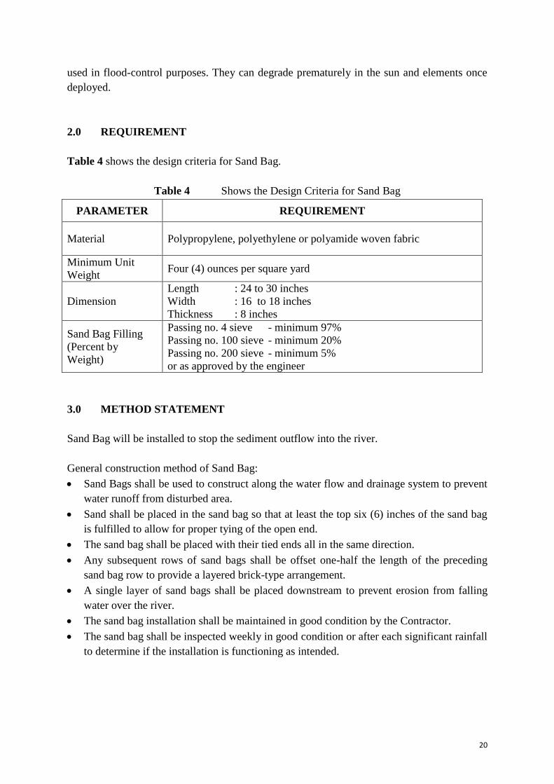
Table 4 Shows the Design Criteria for Sand Bag
PARAMETER REQUIREMENT
Material Polypropylene, polyethylene or polyamide woven fabric
Minimum Unit
Weight Four (4) ounces per square yard
Dimension
Length : 24 to 30 inches
Width : 16 to 18 inches
Thickness : 8 inches
Sand Bag Filling
(Percent by
Weight)
Passing no. 4 sieve - minimum 97%
Passing no. 100 sieve - minimum 20%
Passing no. 200 sieve - minimum 5%
or as approved by the engineer
3.0 METHOD STATEMENT
Sand Bag will be installed to stop the sediment outflow into the river.
General construction method of Sand Bag:
Sand Bags shall be used to construct along the water flow and drainage system to prevent
water runoff from disturbed area.
Sand shall be placed in the sand bag so that at least the top six (6) inches of the sand bag
is fulfilled to allow for proper tying of the open end.
The sand bag shall be placed with their tied ends all in the same direction.
Any subsequent rows of sand bags shall be offset one-half the length of the preceding
sand bag row to provide a layered brick-type arrangement.
A single layer of sand bags shall be placed downstream to prevent erosion from falling
water over the river.
The sand bag installation shall be maintained in good condition by the Contractor.
The sand bag shall be inspected weekly in good condition or after each significant rainfall
to determine if the installation is functioning as intended.

21
Suitable applications
As a linear sediment control measure:
Below the toe of slopes and erodible slopes
As sediment traps at culvert/pipe outlets
Below other small cleared areas
Along the perimeter of a site
Down slope of exposed soil areas
Around temporary stockpiles and spoil areas Parallel to a roadway to keep sediment off
paved areas
Along streams and channels
As linear erosion control measure:
Along the face and at grade breaks of exposed and erodible slopes to shorten slope length
and spread runoff as sheet flow
At the top of slopes to divert runoff away from disturbed slopes
As check dams across mildly sloped construction roads
Figure 4 Detail of sandbag barrier

22
Figure 5 Detail of sandbag barrier
Limitations
It is necessary to limit the drainage area upstream of the barrier to 5 acres.
Degraded sandbags may rupture when removed, spilling sand.
Installation can be labor intensive.
Barriers may have limited durability for long-term projects.
When used to detain concentrated flows, maintenance requirements increase.
Burlap should not be used for sandbags.
4.0 INSPECTIONS AND MAINTENANCE
1. Inspect BMPs prior to forecast min, daily during extended rain events, after rain events,
weekly during the rainy season, and at two-week intervals during the non-rainy season.
2. Sandbags exposed to sunlight will need to be replaced every two to three months due to
degradation of the bags.
3. Reshape or replace sandbags as needed.
4. Repair washouts or other damage as needed.
5. Sediment that accumulates in the BMP must be periodically removed in order to maintain
BMP effectiveness.
6. Sediment should be removed when the sediment accumulation reaches one-third of the
barrier height Sediment removed during maintenance may be incorporated into earthwork
on the site or disposed at an appropriate location.
7. Remove sandbags when no longer needed. Remove sediment accumulation, and clean, re-
grade, and stabilize the area.
23
Proposed method statement for “Projek Mengganti Jambatan
Sedia Ada di FT006/043/93 Barat Daya, Pulau Pinang
(Schedule 2).”
Work method statement for
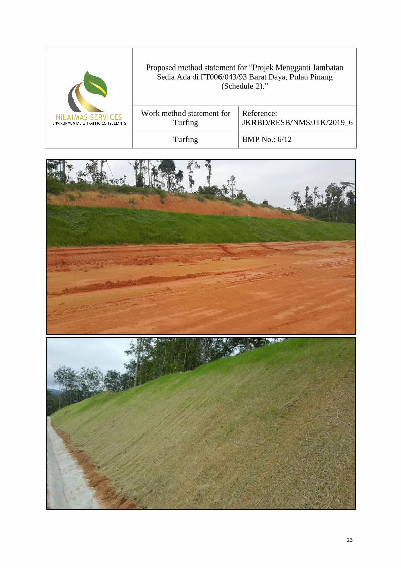
Turfing
Reference:
JKRBD/RESB/NMS/JTK/2019_6
Turfing BMP No.: 6/12

24
1.0 INTRODUCTION
It is important that the bare soil constructed during site clearing phase need to be turfed or
covered as soon as possible to prevent from wind erosion or further erosion into the
waterways which will lead to sedimentation. Replanting through close planting or grass
seeding are the most effective ways to control erosion of soil surface where the dense growth
grass is needed. For close planting, clumps of grass are planted next to the other. For planting
of grass patch, it is suitable when planted on low slope. Bare slopes along the roadside and
construction site slope can be planted with the grass by using hydroseeding method.
Lands recently turfed will be watered regularly until an effective cover has properly
established and plants are growing vigorously. Further application of seed re-turfing might be
necessary later in areas of inadequate vegetation establishment. Prior to the completion of
construction, apply permanent erosion control to remaining disturbed soil areas. Sufficient
erosion control materials shall be maintained onsite to allow implementation in conformance
with this LD-P2M2.
Cover crops is also one (1) of an effective way to control soil erosion. Cover crops can
provide effective protection from the impact of rain, bind the soil structure by holding from
dissociation by water flow on the surface, also improve and maintain the absorption capacity
of the soil. The lack of using cover crop is the cost to develop cover crops is high. However,
cost related to recurrence erosion and work siltation can be reduced
2.0 METHOD STATEMENT
General layout requirements of turfing:
Turfing shall be carried out at the slope and terrace of the designated area.
The grass sod used for turfing will be cut for about 300mm square and minimum
thickness 50mm with original sod adhering to the roots.
Close turfing shall consist of about 300mm square turfing laid side by side with gaps not
exceeding 30mm.
The sods shall be laid onto the surface of prepared ground with leaf turfs upwards, but
jointed as closed as possible to achieve uniform cover.
The turf shall be laid off planks working over turns previously laid.
The whole turf area should present an even smooth surface when finished.
Top dressing of turf area shall be carried out immediately after the turf is laid and
monthly intervals thereafter.

25
3.0 INSPECTION AND MAINTENANCE
1. Inspect the turfing area immediately after seeding (if applicable) to verify seed coverage.
2. The site must be relatively smooth and free of rocks larger than 2 inches, sticks,
protruding roots, clumps of vegetation, trash, and other debris.
3. Pay particular attention to installations on long steep slopes.
4. Flag off the area after installation to keep equipment, vehicles, and foot traffic off turfing
area.
5. After installation, inspect weekly and within 24 hours after each rainfall of ½ inch or
more.
6. Do not mow turfing area until vegetation is at least 8 inches tall and dense. Mower blades
must be kept 6 inches off the mat to prevent snagging and pulling.
7. Use scissors or shears to cut out bulges or large sags, and stake the area securely.
8. Seed missing or damaged sections.

26
Proposed method statement for “Projek Mengganti Jambatan
Sedia Ada di FT006/043/93 Barat Daya, Pulau Pinang
(Schedule 2).”
Work method statement for
Temporary Drainage System
Reference:
JKRBD/RESB/NMS/JTK/2019_7
Temporary Drainage System BMP No.: 7/12
1.0 INTRODUCTION
Before commencement of earthworks, temporary perimeter drains shall be constructed to
channel surface runoff for control of sediment discharge. Perimeter drains are essential to
prevent any sediment-laden runoff from discharging off-site and also to prevent sediment
originated from off-site to enter. All runoff from undisturbed areas should not be allowed to
mix with runoff from the disturbed area.
The design of temporary drainage system should be adequate to ensure that it will not cause
flooding upstream or downstream of the site. All temporary earth drains must be
adequately compacted and the sides cut to slope and maintained t prevent collapse of the

27
sidewalls. If possible, stronger temporary drains in the form of precast concrete drains are
recommended. If the site conditions permits, wider diversion drains and dykes should be
constructed and where the flow velocity is greater than 0.6 m/s, check dams should be
constructed to slow down the flow.
Temporary culvert will be laid to provide access point across the temporary drainage system
for construction purpose. Scour protection shall be provided at the drainage outlet of
culverts to prevent scour caused by high flow velocities and to absorb flow energy to
produce non-erosive velocities.
The temporary drainage system should be regularly inspected and maintained, especially
after each heavy downpour, to prevent clogging, unexpected sediment built-up or erosion,
overtopping and cover failure. The temporary drainage system will be remained at site until
permanent drainage is installed.

28
Proposed method statement for “Projek Mengganti Jambatan
Sedia Ada di FT006/043/93 Barat Daya, Pulau Pinang
(Schedule 2).”
Work method statement for
Silt Curtain
Reference:
JKRBD/RESB/NMS/JTK/2019_8
Silt Curtain BMP No.: 8/12
1.0 INTRODUCTION
Silt curtain is a temporary sediment barrier installed parallel to the bank of a stream or lake. It
is installed in water to contain the sediment produced by construction operations on the bank
of a stream or lake and allow for its removal. for preventing spread of environmental
containments. It is used at riverside construction with its proven effectiveness at minimum of
45% to maximum of 95%. Its superior and durable material also enables the system to
withstand tides, waves and wind action. Accumulated sediment must be removed
periodically. The curtain must be inspected often and after each storm. Any damage must be
immediately repaired. For this proposed project, silt curtain will be installed at the
downstream of project site.

29
2.0 REQUIREMENT
Table 5 shows the design criteria for Silt Curtain.
Table 5 Shows the Design Criteria for Silt Curtain
3.0 METHOD STATEMENT
Type of silt curtain:
Type I – (Light weight) this is designed for use in lower energy environments where there
are no currents and the deployment location is sheltered from any wind and waves.
Type II – (Medium weight) are suited to sites where there is only a small to moderate
current of up to about 1 m/s. Wind and wave action can be present but not considered
major force.
Type III – (Heavy duty) is for sites with higher energy environments, with currents in
excess of 1.5 m/s. Curtains can be deployed in a tidal region and be subject to wind and
wave action.
When developing a turbidity curtain installation plan, consider factors such as:
Current velocity and direction
Wind velocity and direction
Wave height and frequency
Water depth and variances
Tides
Soil type and stability beneath the project area
PARAMETER REQUIREMENT
Screen/Skirt
can be woven, non-woven and knitted in construction with
compositions varying between polyester, polypropylene fabric and
geo-textile
Screen weight 270g/m2 to >700g/m2
Float diameter 0.1 m to 0.3 m depending on the type of screen
Ballast Comprises typically from steel or galvanized chain. Typical chain
thickness approximately 6 mm
Connectors Designed to allow the sections of the curtain to be joining together
while preventing from any leakage between them
Anchor weight Ranging from 4.5 kg to 45 kg

30
General installation for floating silt curtain
Prefabricate a 15m X 12m rectangular shape floating steel frame using 400mm diameter
X 8mm thick steel circular hollow section
Tie the top end of the geotextile to the steel frame by nylon strings/ steel wires
Tie the bottom end of the geotextile with ballast steel chain. This arrangement shall
maintain the geotextile in vertical position during the course of dredging
Place and unfold thee silt curtain parallel to the river by grab dredger/ derrick barge. Fix
the floating steel frame alongside the grab dredger/ derrick barge with a movement joint.
Slowlyput the geotextile together with the ballast steel chain to the sea
Prepare different length off geotextile for replacement in order to suit the various steel
chain to the river.
4.0 INSPECTIONS AND MAINTENANCE
If the silt curtain installation is for an extended period (greater than 3 months), it is
recommended that a visual inspection and maintenance schedule be implemented to check
that the silt curtains are not damaged and performing as required. Visual inspections need to
be carried out on a basis determined by the Contractor and can range from daily to quarterly.
Typical visual inspection and maintenance activities recommended include:
Checking the silt curtain installation maintained the correct position with no obvious
defects or entanglements
Monitoring the curtain skirt against the river bed to ensure it is free moving and not held
down by sand or dispersed mud
Replacing worn or broken anchor lines
Reviewing the integrity of the PVC flotation chamber and connection points
Removing aquatic growth from the curtain
Inspecting the hardware for wear and tear, especially at anchoring points
Inspecting marker buoys and lights (if required) to ensure they present and operational
Removing floating refuse trapped by the silt curtain
As visual inspections are limited to the section above and immediately below the water level,
it may be necessary to use underwater divers to conduct a more thorough inspection of the
skirt and connections. A failure in the curtain resulting in a sediment plume is a typical
trigger for such a thorough inspection. It is common to keep a spare section of silt curtain on
site in case of a rip or tear in an existing section. This minimizes project down time since
replacement of a panel is often quicker than a repair. Where an inspection or maintenance has
been carried out, an inspection report should be completed. The report should record
observations and subsequent actions taken to repair or maintain the silt curtain. The use of
photographic records is recommended where available.

31
Proposed method statement for “Projek Mengganti Jambatan
Sedia Ada di FT006/043/93 Barat Daya, Pulau Pinang
(Schedule 2).”
Work method statement for
Cascade Run
Reference:
JKRBD/RESB/NMS/JTK/2019_9
Cascade Run BMP No.: 9/12
1.0 INTRODUCTION
Cascade run is a step drainage constructed at sloping area. The purpose of cascade run is to
allow water flow from high area to the lower area without causing soil erosion. The step
allow the water to flow down the slope slowly by reducing its velocity

32
Proposed method statement for “Projek Mengganti Jambatan
Sedia Ada di FT006/043/93 Barat Daya, Pulau Pinang
(Schedule 2).”
Work method statement for
Debris Netting
Reference:
JKRBD/RESB/NMS/JTK/2019_10
Debris Netting BMP No.: 10/12
1.0 INTRODUCTION
Debris netting is used on construction sites to contain debris and on scaffolding to prevent
debris from falling. It is generally made from a durable, heavy-duty, plastic netting. Debris
netting are used in construction, building maintenance, entertainment, or other industries.
There are a number of benefits to using debris netting on a construction scaffold:
It provides safe containment of debris, protection of workers, the public and traffic.
Its versatility as an enclosure system means it is easy and economical to handle and can
hang vertically or horizontally to achieve maximum coverage.
The edges are reinforced with eyelets for quick and easy attachment to a scaffold using
wire or plastic ties.
It allows air movement, which can ventilate the scaffold and reduce wind loading.

33
It provides shading against bright sunlight whilst allowing enough light in for tasks to be
carried out.
It gives some protection to work areas and workers from inclement weather conditions.
It is flame retardant.
2.0 METHOD STATEMENT
Wear appropriate safety equipment for working near a leading edge or other fall hazard
String top and bottom of the cables through the eye bolts anchored into the concrete
columns or side wall of the construction
Hang netting panels from top cable with the top edge snap hooks. (The excess fine mesh
debris liner flap should be positioned at the floor end of each netting section)
Fasten the adjoining netting panels to one another with the side edge snap hooks
Fasten the bottom edge snap hooks to the bottom cable
Securer the fine mesh debris flap to the floor with tie-down plates and concrete nails.
Installation
Nets shall be installed in accordance with the net manufacturers' specifications and
instructions. The user responsible for net installation and for the design and installation of the
net supports. Nets shall be installed as close under the working level as practical, but not
lower than 30 feet (9.1m). They shall be hung with sufficient clearance to prevent contact
with the surface of structures below when the user's impact load testing is applied. There
shalt- be no intervening members between the working surface and the net that could be
impacted during a fall. It is intended that only one level of nets be required for bridge
construction provided that
There are no intervening members between the working surface and the net that could
be impacted during a fall.
the net and supports will sustain the impact of a 150 kg bag of sand 30 inches (.76m)
+1¬2 inches (.05m) in diameter and no more than 36 inches (.91 m) high, dropped
from the highest working surface into the lowest point of the net without permanent
distortion of the net pattern or suspension system.
There should be sufficient clearance to ensure against contact of the test weight or the
net with anything below.
3.0 INSPECTION AND MAINTENANCE
Personnel and debris nets shall be inspected by a competent person utilizing any inspection
instructions supplied by the manufacturer. The inspections shall be conducted after each
installation and not less than once each week thereafter. Additional inspections shall be made
after alterations, repair, and impact loadings. If any welding or cutting operations our above

34
the safety nets, debris nets, or both, weld protection shall be provided for that area, and more
frequent inspections shall be conducted in proportion to the danger involved.
The care, maintenance, and storage of nets shall be in accordance with the net manufacturer
recommendations. Due attention shall be given to the factors affecting debris net. Nets
installed for the protection of personnel shall have debris removed at least daily.

35
Proposed method statement for “Projek Mengganti Jambatan
Sedia Ada di FT006/043/93 Barat Daya, Pulau Pinang
(Schedule 2).”
Work method statement for
Hydroseeding
Reference:
JKRBD/RESB/NMS/JTK/2019_11
Hydroseeding BMP No.: 11/12
1.0 INTRODUCTION
Hydroseeding is a planting process that uses slurry of seed and mulch. It is one of the erosion
control technique practices on the construction site. Hydroseeding can be effectively
completed in a very short period of time to cover large area coverage. It can be very effective
for hill slopes area to help erosion control and quick planting of grass. The hydroseeding is
applied with pressure via hose pump onto the soil to create the ideal environment for seed
germination and turf development.

36
2.0 METHOD STATEMENT
Hydroseeding should be done immediately after the completion of a phase of grading
Hydroseeding can be completed using two (2) different steps that is one-step process or
multiple-step process
Multiple-step process ensures maximum direct contact of the seeds planted to the soil
When the one-step hydroseeding process is used to apply the mixture of seed, fiber, etc.,
the seed rate shall be increased to compensate for all seeds not having direct contact with
the soil
Follow-up applications shall be made as needed to cover weak spots
Avoid overspray on existing vegetation, waterways, sidewalks, and roadways
Straw or other mulch should be applied to reduce the erosive capacity of storm water and
to keep the soil and seed in place
Inspect every week within 48 hours after rain event that causes storm water runoff to
occur on-site
Hydroseeded areas should also be inspected for failures and must be re-seeded and
mulched within the planting season, using not less than half of the original application
rates
Supplemental watering may be required
Watering on the hydroseeded area can start immediately the next day and must be
continued daily in the initial stage to ensure speedy seed germination and growth

37
Proposed method statement for “Projek Mengganti Jambatan
Sedia Ada di FT006/043/93 Barat Daya, Pulau Pinang
(Schedule 2).”
Work method statement for
Cover Crops
Reference:
JKRBD/RESB/NMS/JTK/2019_12
Cover Crops BMP No.: 12/12
1.0 INTRODUCTION
Cover crops is also one (1) of an effective way to control soil erosion. Cover crops can
provide effective protection from the impact of rain, bind the soil structure by holding from
dissociation by water flow on the surface, also improve and maintain the absorption capacity
of the soil. The lack of using cover crop is the cost to develop cover crops is high. However,
cost related to recurrence erosion and work siltation can be reduced.

38
2.0 METHOD STATEMENT
General procedure for planting the cover crop:
The soil/ slopes area should be prepared before plantation
Large seeded cover crops (peas, vetch and wheat) will be planted in shallow, closely
spaced furrows
Small seeded cover crops (ryegrarass, buckwheat) placed over the surface and cover with
light raking
If the soil is dry, irrigate often enough to keep the soil damp and germinate the seed