Metal Cutting and Machine Tools Prof. Asimava Roy ...
13
Metal Cutting and Machine Tools Prof. Asimava Roy Choudhury Department of Mechanical Engineering Indian Institute of Technology, Kharagpur Lecture – 06 Different types of tools and mcq Welcome viewers to the sixth lecture of the course metal cutting and machine tools. So, today we are going to discuss different cutting tools, and some leftover numerical problems which you might find uploaded on the website and hopefully you have been able to make use of in the very first week. (Refer Slide Time: 00:44) So, in a single point turning tool, if the principal cutting edge main and auxiliary inclination angles are given, the auxiliary orthogonal clearance can be determined, the auxiliary cutting edge angle can be determined, the principal orthogonal clearance can be determined none of these. So, let us find out what is given. Principal cutting edge angle is given. So, this is the principal sorry this is say the principal cutting edge, the main and auxiliary inclination angles are given. So, I know the main inclination angle lambda I know. So, the way this is inclined from the starting point I am knowing this; and the way the inclination angle of the auxiliary cutting is oriented that also I know.
-
Upload
khangminh22 -
Category
Documents
-
view
0 -
download
0
Transcript of Metal Cutting and Machine Tools Prof. Asimava Roy ...

Metal Cutting and Machine ToolsProf. Asimava Roy Choudhury
Department of Mechanical EngineeringIndian Institute of Technology, Kharagpur
Lecture – 06Different types of tools and mcq
Welcome viewers to the sixth lecture of the course metal cutting and machine tools. So,
today we are going to discuss different cutting tools, and some leftover numerical
problems which you might find uploaded on the website and hopefully you have been
able to make use of in the very first week.
(Refer Slide Time: 00:44)
So, in a single point turning tool, if the principal cutting edge main and auxiliary
inclination angles are given, the auxiliary orthogonal clearance can be determined, the
auxiliary cutting edge angle can be determined, the principal orthogonal clearance can be
determined none of these.
So, let us find out what is given. Principal cutting edge angle is given. So, this is the
principal sorry this is say the principal cutting edge, the main and auxiliary inclination
angles are given. So, I know the main inclination angle lambda I know. So, the way this
is inclined from the starting point I am knowing this; and the way the inclination angle of
the auxiliary cutting is oriented that also I know.

Mind you we are knowing nothing else in that case whether. So, let me write down this is
known. So, we can say that on the rake surface I am knowing the inclination of a straight
line on it that is the main cutting edge. Do I know the inclination of the rake surface as a
whole? I do not at this moment because it is only the main cutting edge together with it is
inclination, in a vertical plane. So, but auxiliary inclination angle is given, but where is it
like whether it is here or whether it is here or whether it is here I do not know.
So, in that case the auxiliary orthogonal clearance angle can be determined; now
auxiliary orthogonal clearance angle will require some knowledge about the clearance
surface that is not given. So, this is not correct. The auxiliary cutting edge angle can be
determined. Auxiliary cutting edge means that we can essentially find out the inclination
the orientation of the auxiliary cutting edge up till now we do not know it the principal
orthogonal clearance angle can be determined.
Now, let us see this one, principal orthogonal clearance angle once again this deals with
information about the clearance surface. So, we cannot define this out; just more what
was the previous one? Auxiliary cutting edge angle we are keeping it in abeyance. So,
principal orthogonal clearance angle now what is that? Principal orthogonal clearance
angle clearance surface. So, this is gone I did not we do not know this one. So, now,
comes this one auxiliary cutting edge angle is this one let me draw it phi 1.
Suppose we know the auxiliary cutting edge angle, in that case we can orient and we can
draw this particular line, and we can pinpoint a particular point in space and we can say
that yes since my since I know the auxiliary inclination angle and I know the orientation
of this phi 1, I can pinpoint the position of this point in space saying that yes this belongs
to the rake surface. And therefore, I can draw this line and I can say that this is the master
line and therefore, I know the rake surface completely.
But the problem is that this information has not been provided principal orthogonal
clearance angle sorry not this one, auxiliary cutting edge angle. If the auxiliary cutting
edge angle is given I can find out a third point in the rake surface and I can join these
three and say that yes this represents the rake surface, but there is not complete
information. Suppose I say that in that case had I known the master line, in that case I
could have shifted along the master line and got different angles, but I am the master line
in the first place is not known.
So, the answer will be none of these. Now let us move on to you know our final
discussion just yeah. So, today we have this lecture different cutting tools and numerical
problems.
(Refer Slide Time: 07:04)
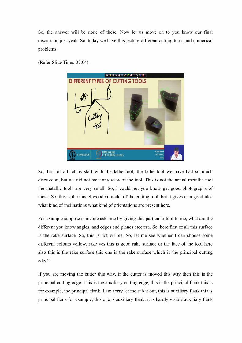
So, first of all let us start with the lathe tool; the lathe tool we have had so much
discussion, but we did not have any view of the tool. This is not the actual metallic tool
the metallic tools are very small. So, I could not you know get good photographs of
those. So, this is the model wooden model of the cutting tool, but it gives us a good idea
what kind of inclinations what kind of orientations are present here.
For example suppose someone asks me by giving this particular tool to me, what are the
different you know angles, and edges and planes etcetera. So, here first of all this surface
is the rake surface. So, this is not visible. So, let me see whether I can choose some
different colours yellow, rake yes this is good rake surface or the face of the tool here
also this is the rake surface this one is the rake surface which is the principal cutting
edge?
If you are moving the cutter this way, if the cutter is moved this way then this is the
principal cutting edge. This is the auxiliary cutting edge, this is the principal flank this is
for example, the principal flank. I am sorry let me rub it out, this is auxiliary flank this is
principal flank for example, this one is auxiliary flank, it is hardly visible auxiliary flank

what is this surface then? This one is principal flank, this one is the main cutting edge
this is the auxiliary cutting edge, this one is the main cutting edge.
So, this way you will also become quite conversant in identifying the different parts of
the tool. So, once we have had a look about the, you know single point turning tool, why
do we refer to it as a single point turning tool? Because just a minute because the tool has
a single point at which it is connected to the work piece. The work piece is rotating and
this is the point at which it is not really a point, but in any way it is a single point at
which the work piece cutter is connected to the work piece. So, this is our cutting tool
this is our work piece.
Next .
(Refer Slide Time: 11:20)

(Refer Slide Time: 11:24)
So, we have already seen this, this is a drill tool what are the characteristic features? A
drill what I call it this the drill which is shown is a specific type of drill what is it called?
It is a double fluted twist drill; there are two cutting lips here. Main two cutting it there is
an auxiliary there is a chisel edge also this is one such you know sorry yes in this one this
is the main body and this is the shank. The shank portion goes inside or tapered hole in
the spindle which is generally rotating ok.
So, this shank looks like this slightly tapered with the bottom is called a tang, this one
gets inside another body with a fitting hole and. So, this is the axis line, this is how a drill
can rotate in an exactly axial manner with the axis of rotation. That means, the body of
the drill can be made etcetera the drill has this conical portion which fix with another
conical you know hole. So, that the axis of this conical portion of the body called
spindle; the axis of the spindle and the axis of the drill they coincide due to one cone
going inside the another inside the other. That is locating the drill is done this way what
about the front of the drill? The front of the drill typically has this sort of a shape as you
can see here. There is one cutting lip here there is another cutting lip on the other side
here it is very clearly shown this is one cutting lip there is one cutting lip here and there
is another cutting lip on the other side. When the drill is rotating these cutting lips rotate
and they remove material from the body.

(Refer Slide Time: 14:44)
Now, if we compare this with a you know a drill a single point turning tool, how would it
look like. So, first of all that if we draw the drill. If the draw the drill this is one cutting
lip, this is another cutting lip and this edge at that at the top is called the chisel edge. So,
when this is rotating it rotates about this axis, and you know this is the axis of the drill
and the drill precedes this way.
So, if the drill is proceeding this way how does it compare with the single point turning
tool. The single point turning tool can be placed this way this is it single point turning
tool, moving this way this is the feed direction. Now you might say that there are two
such a cutting lips how can a single point turning tool, simulate it yes there is a similar
tool which can be supposed to be on the other side doing the very same thing. So, a drill
may be considered to be you know case of conjoint single point turning tools, to single
point turning tools the, you know attached together.

(Refer Slide Time: 16:36)
Now, let us see the other view of the drill, in the other view it looks like this that is it.
This is the main cutting edge, you know we can just have a quick look at the other view
also this is the main cutting edge or principal cutting edge, this one is the main cutting
edge therefore, this is the rake surface rake surface cannot be seen here completely this is
the center of the tool as it is rotating it rotates this way.
If you rotate it in the opposite direction it would not cut therefore, if you say that where
is the cutting velocity direction of cutting velocity, I will say this is the direction of the
cutting velocity hence it is not perpendicular to this cutting lip, but it is making an angle.
But the main cutting edge is here it is therefore, the main cutting edge and this particular
cutting velocity, they are nowhere are they perpendicular to each other this is another one
much less of course,.
So, we understand that the cutting velocity is changing while it is changing because at
different at smaller radius values, at smaller radii it you will develop smaller values of
cutting speed at, larger radii you will have larger values of cutting speed. Now what
about the inclination angle? The inclination angle interestingly in the drill will always be
negative why? Because this is the cutting edge, this is the velocity vector and the cutting
edge instead of being a positive sorry instead of being a positive rake angle or positive
inclination angle say this is a inclination.

We call this positive it is moving of away from the reference velocity, it is moving
towards the reference velocity it is here for the drill here. This angle is less than ninety
degrees therefore, inclination angle always will be negative you might say what about
the as we put the tool here, shall we use a different colour for this yes as we are putting
the tool here does not it mean that this angle is fine yes this is fine. So, if this angle is
twice rho point angle. So, phi is equal to rho in the static system.
So, now we understand in case of the drill, lambda is negative the plan approach angle is
equal to rho plan approach angle or principal cutting edge angle is equal to rho and there
are some other interesting aspects like say let us take that one by one the points, to main
cutting edges chisel edge chisel edge I will show you just now two auxiliary cutting
edges.
(Refer Slide Time: 20:47)
Yeah. So, here we have reference plane is varying, this we have already seen.
Since the velocity direction is going to vary therefore, reference plane will vary in it is
orientation inclination angle is negative this also we have noticed. Principal cutting edge
angle is fixed, in the fixed system the principal cutting edge angle is fixed as we saw that
it is half the point angle. Now I would like to set a question to you, you can think about it
and answer later on what is the value of the end cutting edge angle, what is the value of
the end cutting edge angle and what is the value of the auxiliary inclination angle ok.

If you ask me what is the value of the principal I mean inclination angle? I will say it is
negative it is negative and it is changing from point to point, exact values we will deal
with later on. So, these are the these are the main things that we note about the drill
geometry and I am setting a question before you, what is the value of the end cutting
edge angle in the drill in the twist drill with two flutes, and what is the value of the
auxiliary inclination angle by the way the chisel edge that we were mentioning the chisel
edge is the front most point of the drill, where an additional edge is there. Shall we have
a quick look at a figure to find out what is the chisel edge yes just a moment.
This is the chisel edge let me underscore it in order to emphasize, it is importance this is
the solid edge this is the chisel edge what does it do. So, here there is the chisel edge it
cannot be seen from this side it is a chisel edge, what does it do, what is it is role? As the
as we have to provide a you know body to the drill I really being would have liked this
particular configuration let me show you.
(Refer Slide Time: 23:26)
Yes we would have liked this configuration, is this yes this is visible in this configuration
the drill has no nothing at the center and the reference velocities would have been
developed this way inclination angle would have been negative a zero, and the drill
would have had as a sharp point, but there is a problem here the drill does not have
anybody in the middle to sustain all the you know stresses and torque and torque, I mean
not talk at the stresses that it will be having to endure.

So, that is a problem and these two bodies would have mean physically different, they
only have a point contact line contact. So, that is very very difficult to imagine, and
therefore, we in order to produce give it somebody we are having the you know material
put here and therefore, it is having a sufficient thickness and here and edge forms what is
this surface.
Let me draw fresh figure what is this surface for example? This is this surface; this
surface by you know by simulation this is the principal flank. So, this is one principal
flank, just a minute this is the principal flank this is also principal flank. If these are the
principal flanks they are meeting together to form an edge, this chisel edge hardly does
any cutting.
Why because the velocity at this point is very low because the radius is very small no
matter how much rotations per minute you are applying you would not get much high
velocity. So, at this point velocity is low and the rake angle is highly negative. If the rake
angle is highly negative, in that case instead of cutting with low velocity and a high
negative rake instead of having cutting action you will be having an extruding or
indenting or pressing action on the work piece. The work piece is sort of pushed out of
the way of the drill head that is why when you are using very large drills huge amount of
thrust force will be developed.
If you have this particular chisel edge acting; there has been a lot of work in the you
know in the investigation of the possibility of reducing thrust forces by modifying the
chisel edge. Suppose we reduce the chisel edge by grinding this way we reduce the chisel
edge by grinding off this material that is this is gone. So, that you have a sort of point
here.
So, if you modify the chisel edge the thrust forces will come down, but addition there
will be additional money spent in order to grind the tip and thus modify it. So, after
having learnt about something about the drill, let us quickly go on to the other commonly
used tools in better cutting. This is called a combination center drilling, it makes such a
hole in material.

(Refer Slide Time: 27:08)
If you have a material like this, combination center drill will typically produce a hole of
this type. What is the use of such a hole? Such a hole allows us to put center inside this
which holds, it properly locates the axis of the body of this hole aligned with this
particular center. I mean the sent the axis of this center and the axis of the body which is
being held they will become aligned together.
Moreover since we are offering some latitude here there can be some bending. So, that
when you are doing taper turning and other things this would not be going in you know
indenting it at a particular corner. So, some latitude is there you can pull fill this up with
lubricant some sort of lubricating material. So, that friction is less and this hole can be
done by this one. So, it is having a combination of cutting edges two cutters are on two
sides once this gets blunt you can use the other one. This is called a die and this die is
used to cut external threads, this is a tap which is used for cutting internal threads there
can be different types of tap starting tap finishing tap bottoming tap etcetera etcetera
depending upon the extent to which they have to go inside a hole, whether it is a blind
hole etcetera etcetera.

(Refer Slide Time: 29:36)
So, next since time is short for this one let me finish whatever is to be covered, we have a
milling tool now. So, yeah this is a milling cutter this is called a slab milling cutter and as
you can notice that cut cutting teeth the helical what is the advantage of helical teeth
advantage of helical teeth is that at one point in time more than one teeth will be acting.
So, that the forces are distributed among more teeth, I mean higher number of teeth and
hence the force is not very high on a single tooth where (Refer Time: 30:21) is less.
Moreover the cutting is not jerky if the cutting is jerky if there is no helix angle the one
to suddenly engages with the work piece and there is a jerk jerks are always detrimental.
Also we have to notice this, the problem is this brings in some end thrust which might
create some you know detrimental effects like buckling. So, we have to be sure that this
end thrust can be absorbed without causing much of a problem in the machining process.
Let us have a quick look and at this particular figure what have we tried to show here? If
this is having you know you know if this is mounted on a shaft, this is the shaft and if it
is rotated this way, we have the velocity vector at this point what is this one? This is the
cutting edge. So, we write cutting edge how many cutting edges we have shown? There
we have shown one two and three if we take a section on the cutting edge ok.
Since you know this is the cutting plane this straight plane passing through this point,
this is the cutting plane and if we take a perpendicular I mean a section perpendicular to
it we will get the orthogonal section. So, therefore, if we take this particular section we

get this angle as the orthogonal rake and this one as the orthogonal clearance, but if we
now observe that the cutting edge is inclined.
If we take a section this way we are going to get the normal section and therefore, this
one comes out to be normal rake normal clearance. Now after all this discussion you
might ask me, why are we giving this you know inclination to the cutting edge, why is
inclination angle provided what is it is purpose.
Now, inclination angle if it is zero, then the chips will come out and they will move over
the rake surface and they will basically travel on the orthogonal plane. The chip velocity
will be you know contained in the orthogonal plane, if there is no effect of the side or
auxiliary cutting edge. But if inclination angle is provided the chip is deflected from the
orthogonal plane, and we can have a desirable direction of the chip by suitable selection
of the inclination angle ok.
So, with this we come to the end of the sixth lecture, in the seventh lecture I will be
dealing with you know further discussion on tools chip formation cutting forces etcetera
and you know then proceed on to other subjects like tool where.
Thank you.