Heavy Gas Dispersion Modelling Over a Topographically Complex Mesoscale

ARTICLE
Received 14 Jan 2014 | Accepted 6 Jun 2014 | Published 7 Jul 2014
Mesoscale assembly of chemically modifiedgraphene into complex cellular networksSuelen Barg1, Felipe Macul Perez1, Na Ni1, Paula do Vale Pereira1, Robert C. Maher2, Esther Garcia-Tunon1,
Salvador Eslava1, Stefano Agnoli3, Cecilia Mattevi1 & Eduardo Saiz1
The widespread technological introduction of graphene beyond electronics rests on our ability
to assemble this two-dimensional building block into three-dimensional structures for
practical devices. To achieve this goal we need fabrication approaches that are able to provide
an accurate control of chemistry and architecture from nano to macroscopic levels. Here, we
describe a versatile technique to build ultralight (density Z1 mg cm� 3) cellular networks
based on the use of soft templates and the controlled segregation of chemically modified
graphene to liquid interfaces. These novel structures can be tuned for excellent conductivity;
versatile mechanical response (elastic-brittle to elastomeric, reversible deformation, high
energy absorption) and organic absorption capabilities (above 600 g per gram of material).
The approach can be used to uncover the basic principles that will guide the design
of practical devices that by combining unique mechanical and functional performance will
generate new technological opportunities.
DOI: 10.1038/ncomms5328 OPEN
1 Department of Materials, Centre for Advanced Structural Ceramics, Imperial College London, London SW7 2AZ, UK. 2 Department of Physics, ImperialCollege London, London SW7 2AZ, UK. 3 Department of Chemical Sciences, University of Padua, 35131 Padua, Italy. Correspondence and requests formaterials should be addressed to S.B. (email: [email protected]).
NATURE COMMUNICATIONS | 5:4328 | DOI: 10.1038/ncomms5328 | www.nature.com/naturecommunications 1
& 2014 Macmillan Publishers Limited. All rights reserved.

Awide range of emergent technologies, from tissue
engineering to energy storage or environmental cleaningdemand strong, lightweight porous structures able to
provide a wide range of functionalities such as support for cells ornanoparticles or high thermal or electrical conductivity. Theengineering and scientific challenge is to design and fabricatethese structures in practical dimensions while maintaining anaccurate control of their chemistry and architecture from thenano-level and up. This is particularly difficult when using amaterial like carbon. Although its low density and versatilitymake it extremely appealing in many applications, its reactivityand hydrophobicity creates serious difficulties for most conven-tional processing techniques. In this respect carbon nanomaterialssuch as nanotubes or graphene have not only opened newopportunities but also new challenges. For example, graphene is atruly two-dimensional material with unique functional andmechanical properties from tunable electrical and opticalresponse to high intrinsic stiffness and strength, chemicalversatility, controllable permeability or extremely high specificsurface area (2,630 m2 g� 1) (refs 1–4). If properly integrated intomacroscopic highly porous complex structures, graphene has thepotential to form novel platforms for a wide range of functionalsystems from batteries to supercapacitors, reactive catalyticsupports or filters and membranes to name a few5–7. However,to achieve this goal we need to develop ways for the controlledassembly of three-dimensional (3D) structures using a two-dimensional (2D) building block.
As the first reports on graphene 3D structures based onchemical vapour deposition coatings on metallic foams, differentapproaches based on freeze drying and subcritical drying8,9,
leavening7, nucleation boiling10, hydrothermal processes11,12,hydrothermal carbonization13 or microwave irradiation14 havebeen used to fabricate porous 3D graphene and graphene-basednetworks. However, the challenge still remains on how toeffectively tailor their chemistry and architecture for specificapplications. Furthermore, structural design has to be based on afundamental understanding of how architecture determinesperformance.
These challenges underline the need to develop more flexibleand cost effective processing technologies that allow themanipulation of structure. In this respect, wet-processingapproaches such as emulsion-based techniques are very appeal-ing. They are well developed for a wide range of organic andinorganic materials and they are very attractive due to theirflexibility, scalability and relative low cost15–17. Wet-processingwith graphene still requires much research as it depends on anaccurate control of surface chemistry and particle size to enablethe formulation of suspensions with controlled rheologicalresponse. Here we show that the use of chemically modifiedgraphene (CMG, namely graphene oxide, GO, and its reducedform rGO) opens many possibilities.
In this paper, we propose a self-assembly strategy for thefabrication of complex CMG cellular networks (CMG-CNs) via amulti-step soft/hard template mechanism that combines emul-sion and ice templating. Our approach is based on controlling thesegregation of CMG to liquid interfaces to use it both as anemulsifier and as a building block. Two key challenges aremaintaining the stability of the structures and manipulating theproperties of CMG such that they approach those of pristinegraphene. To this purpose, a range of additives and thermal
Emulsification
Directionalfreezing
Ice
Water
Solventelimination
Thermalreduction
Frozenoil
Oil
CMG
Figure 1 | Microstructural architecture and assembly strategy of CMG-CNs. (a) Overview of the CMG-CN architecture, composed of nearly spherical
pores in the micrometre scale, designed by the emulsion droplet templates. Thin CMG self-assembly: at the pore walls as a result of their entrapment
at the interface between water and oil droplets during emulsification (b) and at the triple junction between adjacent cells, whose arrangement is template
by ice (c). Cell walls surface micro to nanorugosity patterned by the ice crystals during unidirectional freezing (d). SEM images of 5.6 mg cm� 3 GO-CN
(a–d) that after thermal reduction at 1,000 �C results in rGO-CN of 2.2 mg cm� 3. (e) Assembly strategy of CMG-CNs and their structural evolution
from emulsification, unidirectional freezing to freeze drying. Following the arrows: As-prepared aqueous GO suspensions (GO-sus) are emulsified with
75 vol% of the hydrophobic internal phase (toluene) resulting in GO emulsions (GO-em) composed by oil droplets dispersed in the GO aqueous
continuous phase. GO flakes act as a surface-active amphiphile self-assembling at the oil/water interface. GO-em are moulded into cylindrical shaped
moulds and subsequently directionally frozen. As unidirectional freezing of GO-em progresses the ice crystals in the water phase encapsulate liquid oil
droplets (as their solidification temperature is much lower) templating the roughness of CMG at the droplet wall. After eliminating the solvents during
freeze drying GO-CNs are obtained with the ice and emulsion droplet templating the cellular architecture (a–d). rGO-CN are obtained after thermal
annealing. Scale bars, 10 mm (a), 2 mm (b), 1mm (c) and 2 mm (d).
ARTICLE NATURE COMMUNICATIONS | DOI: 10.1038/ncomms5328
2 NATURE COMMUNICATIONS | 5:4328 | DOI: 10.1038/ncomms5328 | www.nature.com/naturecommunications
& 2014 Macmillan Publishers Limited. All rights reserved.

treatments are used. This approach allows the integration of2D CMG into macroscopic 3D cellular networks with tunablehierarchical structures and performance. As a result we canprepare materials with excellent electrical conductivity, highmechanical strength, recoverable structural deformation, highlevels of energy absorption or high organics adsorptioncapabilities.
ResultsAssembling 3D CMG-CNs with controlled architectures. Theassembly strategy (Fig. 1e) is based on the preparation of oil-in-water (o/w) GO emulsions (GO-em), by the emulsification ofwater-based GO suspensions (GO-sus) with a hydrophobic (oil)phase. GO acts as a surface-active amphiphile18 self-assembling atthe interface between the oil droplets and the water phase andstabilizing the GO-em for several months. The oil dropletstemplate the formation of spherical- to polyhedral-shaped cells(Fig. 1a). The cell walls and the volume between cells are formedby an arrangement of CMG flakes (Fig. 1b,c). The challenge is toprepare stable emulsions with high oil content to fabricate highlyporous materials while maintaining the stability of the networkonce the liquid phase is removed.
It has been previously shown that GO can act as a colloidalemulsifier with its interfacial activity being very dependent on pHdue to its structural configuration of more hydrophobic basalplane and more hydrophilic plane edges18. However, the use ofemulsions to prepare porous materials requires enough GOsegregation to the water–oil interface to create stable emulsionswith high oil content and controllable droplet sizes in the lowmicrometre range and, at the same time, to achieve highlyconcentrated GO suspensions in water such that the structurewithstands the capillary forces during solvent elimination. To thisend, we have taken advantage of the pH-dependant interfacialactivity of GO and have designed a two-step process. First, weprepare stable, highly concentrated GO suspensions in waterat neutral pH to assure a high degree of deprotonated –OH and–COOH groups on the surface of GO and to achieve therefore agood dispersion19. Just before emulsification, the suspension pHis adjusted between 2 and 3. At such acidic conditions, the oxygenfunctional groups on GO surface are less deprotonated18. Thisreduces the hydrophilicity of the basal plane and the flakespreferentially segregate to the o/w interfaces (SupplementaryFig. 1). To enable more flexibility in the process, diverse organicadditives can be used to enhance dispersion and emulsificationability.
With our approach we are able to homogeneously dispersehigh concentrations of GO in water (410 mg ml� 1) and
subsequently maximize the surface activity of the GO flakes (bymeans of suspension pH and/or additives) leading to stableemulsions with up to 75 vol% of the oil phase and droplet sizes inthe low micrometre scale, one order of magnitude smaller thanthat previously reported for GO18. The viscoelastic properties ofthe emulsions can be controlled by adjusting the concentration ofGO in the continuous phase or the concentration of oil, allowingthe fabrication of coatings or the extrusion of long wires that canbe down to 200mm in diameter (Fig. 2). This opens newopportunities for the fabrication of graphene-based complexstructures at the macroscale. For example, this technique can beexplored for the design of inks with rheological properties tailoredfor different wet-processing techniques to build structures withporosity determined by droplet size, shape and concentration inthe emulsion.
To maintain the stability of the porous structure after removingthe liquid phase while effectively manipulating the nano to microarchitecture of the network, we use a combination of icetemplating and freeze drying. After emulsification, the GO-emis directionally frozen and subsequently the solvents areeliminated by freeze drying (Fig. 1e). As directional freezingprogresses, the growing ice crystals control the alignment of CMGin the water phase (and consequently the architecture of the triplejunctions between adjacent cells (Fig. 1c)) and encapsulate theliquid oil droplets (as the oil solidification temperature is muchlower than that of water). As the droplets are still ‘soft’ in theliquid phase, the roughness of the ice templates the formation ofmicro to nanorugosity on the CMG-CNs cell walls (Fig. 1d).
In contrast to the lamellar structures resulted from thetraditional freeze casting of aqueous suspensions17 here thestructural evolution is more complex. The emulsion templatesthe formation of spherical to polyhedral cells to create a cellularnetwork (Fig. 1a) with ice forming between the oil droplets. In theemulsions used to fabricate cellular networks the highconcentration of oil droplets may impede the full formation oflamellar ice (as it has been observed with highly concentratedparticle suspensions)20.
This processing approach can be used to form highly porousGO-CNs with densities ranging from 2 to 20 mg cm� 3. The cellsizes are in the range 20–65 mm and the walls are formed by acomplex arrangement of CMG (Fig. 1a–d). The cell size can bemainly controlled varying the amount and size of GO flakes andemulsification energy, whereas the density can be tuned throughthe amount of GO in suspension and oil concentration. Differentorganic additives (such as sucrose or polyvinyl alcohol (PVA))can be added to further control the architecture and propertiesalthough it is possible to fabricate stable structures without theuse of any additive. For example, PVA molecules adsorbed on the
Figure 2 | CMG-CN wires. The viscoelastic properties of the GO emulsion system developed in this work enables its extrusion through micro needles
resulting in GO emulsion wires that maintain their shape (straight, curved or spirals) (a) and can be further processed by the approach described in this
paper. In (b–d) details of rGO-CN wire and internal cellular microstructure after thermal treatment at 1,000 �C in Ar/H2 atmosphere. GO emulsions
prepared by the emulsification of 65 vol% decane in 1 wt% GO suspensions containing 1.2 wt% organic additives (1:1, PVA:sucrose). The wires are several
centimeters long and down to 200mm in diameter. Scale bars, 200mm (a), 300mm (b), 20mm (c) and 10mm (d).
NATURE COMMUNICATIONS | DOI: 10.1038/ncomms5328 ARTICLE
NATURE COMMUNICATIONS | 5:4328 | DOI: 10.1038/ncomms5328 | www.nature.com/naturecommunications 3
& 2014 Macmillan Publishers Limited. All rights reserved.

surface of GO21,22 can change its wettability (SupplementaryFig. 2). This can further boost the surface activity of GO,as evidenced by the improvement in emulsification ability(Supplementary Fig. 3a) and the stabilization of smallerdroplets that will template smaller cells (SupplementaryFig. 3d). On the other hand, sucrose acts as a binder that helpsto hold the structure together after removing the liquids and alsoaffects the shape of the ice crystals formed during templating23.As a result, it determines the topography of the cell walls formingpatterns that can go from straight (Supplementary Fig. 4a–b)to circular (Supplementary Fig. 4c,d). Organic additives canfurther be used to manipulate the formation of cell windows(or openings) of controlled shape at the micro scale (detailedinformation in Supplementary Fig. 4). Before thermal reduction, atypical additive-free GO-CN (Fig. 3 and Supplementary Fig. 4)has a density of the order of 2.5–3.5 mg cm� 3 with an averagecell size of 65 mm. By adding up to 5 wt% organic additives(PVA:sucrose, 1:1 in wt%) denser GO-CNs (up to 20 mg cm� 3)with smaller, spherical shaped cells (up to 40 mm in average size)are formed (Fig. 3a,b and Supplementary Fig. 3c,d).
The final step is a thermal treatment in a reducing atmosphereto promote the reduction of GO into rGO with the decomposi-tion of functional groups24 and organic additives resulting inmass loss and shrinkage (Supplementary Fig. 3c, SupplementaryFigs 6 and 7). Reduction has been performed at temperaturesranging from 300 up to 2,400 �C under 90% Ar/10% H2 or invacuum (25–60 Pa) in a graphite furnace. During this process,the degree of densification and consequently the nano tomacrostructural features of the rGO-CNs including itscrystallinity can be further manipulated as the reductionconditions (time, temperature and atmosphere) and theadditives will determine the evolution of the structure. Whenthe GO-CNs are thermally treated at 1,000 �C, the lineardependency of mass loss versus GO content (SupplementaryFig. 5) suggests that 91% of the organics and 64% of the GO massare eliminated. Thermal annealing at higher temperatures in agraphite furnace is likely to be accompanied by a furtherelimination of residual functional groups on GO andamorphous carbon as indicated by the slight increase in massloss (Supplementary Fig. 6).
rGO-CNs resulted from thermally reducing an additive-freeGO-CN at 1,000 �C in Ar/H2 are ultralight, with densities as lowas 1 mg cm� 3 (99.95% porosity) and average cell size of 63 mm.They are 70% lighter but with a cell size very similar to thestarting non-reduced material as a result of the loss of chemicalgroups attached to GO during firing (Fig. 3a,c and SupplementaryFig. 3b–d). This material is lighter than the lightest silicaaerogels25 and as light as the lightest Ni microlattice26. On theother side, when adding up to 5 wt% additives (PVA:sucrose,1:1 in wt%), and under the same emulsification and thermaltreatment conditions, the network undergoes severe densificationresulting in a density 4100 mg cm� 3 and average cell size of7 mm (Fig. 3b,d and Supplementary Fig. 3b–d). This correspondsto a density increase of over 700% with cells that are 87% smallerafter reduction. In this case, the melting of sucrose to formhigh-molecular-weight compounds, ‘caramel’, during itsdecomposition triggers a process akin to ‘liquid-phasesintering.’ As sucrose melts the liquid flows within the cellularnetwork due to the action of capillary forces bonding theneighbouring rGO flakes (Supplementary Fig. 3b–d). The processenables the formation of CMG-CN structures with a wide rangeof final densities that go over two orders of magnitude from 1 toover 200 mg cm� 3, cell sizes (around one order of magnitudebetween 7 and 65 microns) and shape (spherical to polyhedral)(Figs 3 and 4, Supplementary Fig. 4). It is also possible to
Inte
nsity
(a.
u.)
rGO-CN (no additives)C1srGO-CN (5 wt%)
Inte
nsity
(a.
u.)
Raman shift (cm–1)
2D
D GrGO-CN (no additives)
rGO-CN (5 wt%)
1,000 1,500 2,000 2,500 3,000 288 286 284 282
Binding energy (eV)
Figure 3 | Effect of additives on CMG-CNs microstructure and
crystallinity. SEM images of: GO-CNs produced without (3.3 mg cm� 3
density, 65 mm average cell size) (a) and with the addition of 5 wt% organic
additives (PVA:sucrose, 1:1 wt%) in 0.65 wt% GO-sus (15 mg cm� 3 density,
40mm average cell size) (b); rGO-CNs thermal treated at 1,000 �C in
Ar/H2 atmosphere produced without (1 mg cm� 3 density, 63mm average
cell size) (c) and with the addition of 5 wt% organic additives (112 mg cm� 3
density, 7mm average cell size) (d). Shrinkage during the thermal treatment
results in highly wrinkled rGO at the cell walls (d). The corresponding
Raman spectra (514 nm laser) and C1s XPS of rGO-CNs (prepared without
and with organic additives (SEM in c,d)) are represented in e and f,
respectively. The letter ‘D’ and ‘G’ stand for two characteristic Raman active
modes for graphene and other carbon allotropes and the D/G ratio is a
measure of the density of defects present in the carbon material28. The C1s
XPS spectra (hn¼ 1,253.6 eV) collected on rGO-CN with 5 wt% additives is
indicated in red colour whereas the rGO-CN produced without organic
additives appears in blue colour. The C1s spectrum collected on rGO-CN
with 5 wt% additives was fit by Doniach–Sunjic function after subtracting a
Shirley background as indicated in the lowermost spectrum. The different
components related to various chemical shifts of carbon bonds are
indicated. The component at 284.6 eV is due to the sp2 carbon, the peak at
286.5 eV is related to the remaining C–O bonding and possible carbon sp3
defects, and the component at 287.8 eV is related to residual C¼O
bonding24. The full width at half maximum (FWHM) for the C1s core level
for rGO-CNs, with initially 5 wt% additives is narrower than for rGO-CNs
without additives. This reflects the different sp2 content, which is about
82% in rGO-CNs, with initially 5 wt% additives (before reduction) and
about 80% in rGO-CNs, produced without additives. Scale bars, 100mm
(a,b), 10mm (c,d) and 2mm (insert image in d). a.u., arbitrary unit.
ARTICLE NATURE COMMUNICATIONS | DOI: 10.1038/ncomms5328
4 NATURE COMMUNICATIONS | 5:4328 | DOI: 10.1038/ncomms5328 | www.nature.com/naturecommunications
& 2014 Macmillan Publishers Limited. All rights reserved.

manipulate the cell wall roughness and interconnectivity fromnano to micro levels (Figs 1d, 3 and 4, Supplementary Fig. 5).
Further, the elimination of functional groups uponthermal reduction (B65 to 90% of the mass is lost duringthermal treatment depending on the rGO-CNs composition,Supplementary Fig. 5) generates nanopores and defects on theCMG-CNs walls, revealed in scanning transmission electronmicroscopy (STEM) high-angle annular dark field (Fig. 5a,b).After a thermal treatment at 1,000 �C in Ar/H2, there is a widedistribution of pores on the rGO-CNs walls, (pore size dataobtained by nitrogen adsorption, in the range 2–100 nm ispresented in Supplementary Fig. 7). The nanoporosity decoratesthe restored sp2 network on the rGO-CN cell walls as revealed byelectron energy loss spectroscopy (Fig. 5c). By comparing the Knear-edge structure of rGO-CN with graphite27, we identify thepresence of a sp2 component nearly close to 95%. The nitrogenadsorption curves of rGO-CNs correspond to a type III isothermwith a small high-pressure hysteresis that is typical for macro andmesoporous materials (Fig. 5d). Ultralight additive-free rGO-CNswith a density of 1 mg cm� 3 reach a specific surface area of422±10 m2 g� 1. The addition of additives (1.2 wt%) leads to areduction in the accessible surface of the networks down to
170±10 m2 g� 1. This can be attributed to the densification of theCMG network that accompanies the elimination of organicadditives during thermal treatment (Supplementary Fig. 3b,c).
The Raman spectra of rGO-CNs confirm the formation ofpredominantly crystalline rGO upon thermal reduction (Figs 3eand 4e). Furthermore, the rGO-CNs produced with organicadditives present a more pronounced 2D peak at around2,700 cm� 1, than rGO-CN produced without any additive(Fig. 3e). This indicates that the presence of carbon (due toorganics decomposition) during thermal reduction promotes therecrystallization of graphene.
XPS characterization reveals that the oxygen content is about4% for rGO-CNs prepared initially with 5 wt% additives (inGO-sus) after reduction at 1,000 �C and progressively decreasesfor higher annealing temperatures. Interestingly, the sp2 fractionof rGO-CNs produced with 5 wt% additives is slightly higher(82%) than for additive-free rGO-CNs (80%) as revealed by XPS(Fig. 3f). This further supports the Raman evidence that thepresence of the organic additives as a carbon source favoursrestoration of sp2 bonding.
Furthermore, the crystalline quality of CMG can be greatlyimproved with further treatments at temperatures above 1,000 �C
G
D2,400 °C vacuum 2D
1,500 °C vacuum
1,000 °C vacuum
1,000 °C Ar/H2
GO-CN as prepared
1,40
01,
600
1,80
02,
000
2,20
02,
400
2,60
02,
800
Raman shift (cm–1)
Inte
nsity
(a.
u.)
Figure 4 | Effect of the thermal treatment temperature and atmosphere on rGO-CNs microstructure and crystallinity. SEM images of rGO-CNs
thermally treated in a graphite furnace under high vacuum at: 1,000 �C (a,b) (1.4 mg cm� 3 density) and 2,400 �C (c,d) (7.2 mg cm� 3 density). The density
of as-prepared GO-CNs (0.65 wt% GO and 0.3 wt% additives (PVA:sucrose in 1:1 wt%) in suspension) before thermal treatment is 2.9–3.3 mg cm� 3.
rGO-CNs reduced at 2,400 �C present highly wrinkled cell walls (c,d) as a result of the high degree of shrinkage (87%) during thermal treatment.
(e) Raman spectra of the CMG-CNs as prepared and under different thermal treatments in Ar/H2 atmosphere or in vacuum in a graphite furnace.
The Raman spectrums were obtained using 514 nm laser. The letter ‘D’ and ‘G’ stand for two characteristic Raman active modes for graphene and
other carbon allotropes and the D/G ratio is a measure of the density of defects present in the carbon material28. Scale bars, 100 mm (a–c) and 2 mm (b–d).
a.u., arbitrary unit.
Inte
nsity
(a.
u.)
N2
adso
rbed
vol
ume
(cm
3 g–
1 )
270 290Energy loss (eV)
300 310 320 0.0 0.2 0.4 0.6 0.8 1.0P/P0
0
500
1,000
1,500
2,000
2,500
3,000rGO-CNGraphite
rGO-CN-1.2 wt% additives-adsorption
rGO-CN-no additives-adsorptionDesorption
Desorption
280
Figure 5 | STEM, EELS and N2 adsorption isotherms for ultralight rGO-CNs. (a,b) STEM HAADF images of an rGO-CNs cell wall. The pores appear
in darker contrast on the brighter background of the rGO-CNs. High magnification image (from the region indicated in a reveals mainly mesopores
with sizes ranging between B2 and 10 nm (b). The nanoporosity decorates the rGO-CN restored sp2 network as shown by EELS characterization for
rGO-CNs and graphite (c). By comparing the K near-edge structure of both materials, a fraction of 95% of sp2 bonding is found (d). N2 adsorption curve
for rGO-CN with 431 m2 g� 1 SSA (structure prepared with no additives) and 180 m2 g� 1 SSA (structure prepared with 1.2 wt% additives). Scale bars,
0.2mm (a) and 10 nm (b). a.u., arbitrary unit.
NATURE COMMUNICATIONS | DOI: 10.1038/ncomms5328 ARTICLE
NATURE COMMUNICATIONS | 5:4328 | DOI: 10.1038/ncomms5328 | www.nature.com/naturecommunications 5
& 2014 Macmillan Publishers Limited. All rights reserved.
(Fig. 4e). The D/G intensity ratio for GO is about 0.62, whereasthe ratio is 1.1 after annealing at 1,000 �C in Ar/H2 and 0.96 forthermal treatment in a graphite furnace (under vacuum) at thesame temperature. The increase of the D/G peak intensity ratiofor initial annealing at 1,000 �C in Ar/H2 and the decrease afterannealing in a graphite furnace can be interpreted as a continuousdecrease of the defect density as the evolution of D/G intensityratio with defects can drastically change depending on the level ofdefects density28. Thermal annealing in the graphite furnaceprovides a carbon source that favours restoration of the sp2
bonding similar to the effect of organic additives (Fig. 3e). TheD/G intensity decreases with increasing annealing temperaturereaching a value of 0.16 after annealing at 2,400 �C. This value iscomparable to mildly defected graphene with single and doublevacancies28, suggesting that the sp2 network has been restoredand lattice defects are now sparse with an average distance ofabout 25 nm. At the same time the intensity of the 2D peak isprogressively recovered with the thermal treatment. Although inGO the 2D peak is barely detectable24 (Fig. 4e), the 2D/Gintensity ratio increases with annealing temperature from 0.11 to0.34 after heating up to 1,500 �C. After annealing at 2,400 �C thefull width at half maximum of the 2D peak is about 67 cm� 1 andthe 2D/G intensity ratio about 0.3 suggesting that the material
now consists of few misoriented graphene layers29. The slightdecrease in 2D/G peak between 1,500 �C (0.34) and 2,400 �C(0.30) is likely to be due to the high densification of the materialsleading to a closer proximity between flakes (wrinkled rGO-CNcell walls, Fig. 4d). These results are comparable to those obtainedafter applying high temperature (1,500 �C) and pressure (20 MPa)to CMG films30. They open new possibilities for the fabrication ofhierarchical 3D structures with a restored sp2 network.
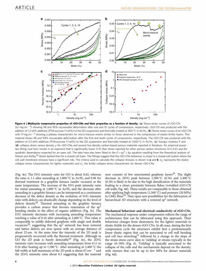
Mechanical behaviour and electrical conductivity of rGO-CNs.The mechanical response under compression reflects the range ofarchitectures that can be fabricated using this approach. Theirbehaviour changes from elastomeric for the lighter materials toelastic-brittle for the denser rGO-CNs. In all cases, during the firstcompression cycle the structures exhibit first a predominantlylinear elastic region that can be associated to cell wall bendingand cell face stretching31 followed by a change in the slope ofthe strain stress curve akin to ‘yielding’ at strains typically in therange 10–30% (Fig. 6). ‘Yielding’ is typically associated to thecollapse of the cells and the mechanisms depend on the density,with stresses that can be up to few MPa for denser materials(Fig. 6d).
Cycles 1, 2, 5, 10
Micro-fractureevents
Cycles 1, 2, 5, 10
CMG-CNsGraphene elastomers, ref. 8Ultra-flyweight aerogels, ref. 32
�e*l
Str
ess
(MP
a)
Str
ess
(MP
a)
0.007
0.006
0.005
0.004
0.003
0.002
0.001
0.000
0.05
0.04
0.03
0.02
0.01
0.000 10 20 30 40 50
10 1001 10 1001
0 10 20 30 40 50Strain (%) Strain (%)
Density (mg cm–3)Density (mg cm–3)
Col
laps
e st
ress
(M
Pa)
Youn
g’s
mod
ulus
(M
Pa)
10
0.1
0.01
1E-3
1E-4
1E-5
1E-6
1
10
0.1
0.01
1E-3
1E-4
1
�c*r
Figure 6 | Multicycle compressive properties of rGO-CNs and their properties as a function of density. (a) Stress-strain curves of rGO-CN
(6.1 mg cm� 3) showing 98 and 95% recoverable deformation after one and 10 cycles of compression, respectively. rGO-CN was produced with the
addition of 1.2 wt% additives (PVA:sucrose 1:1 wt%) to the GO suspension and thermally treated at 300 �C in Ar/H2. (b) Stress-strain curves of an rGO-CN
with 17 mg cm� 3 showing a plateau characteristic for micro-fracture events similar to those observed in the compression of elastic-brittle foams. This
material shows 98 and 94% recoverable deformation after the first and tenth cycles of compression, respectively. The rGO-CN was produced with the
addition of 2.5 wt% additives (PVA:sucrose 1:1 wt%) to the GO suspension and thermally treated at 1,000 �C in Ar/H2. (c) Young’s modulus E and
(d) collapse stress versus density r for rGO-CNs and several low-density carbon-based porous materials reported in literature. An empirical power
law fitting (red line) results in an exponent that is significantly lower (1.3) than those reported for other porous carbon structures (2.3–4.6) and the
quadratic dependence expected for an open cell. The data have also been fitted to the E¼ ar2þ br equation resulting from the theoretical analysis of
Gibson and Ashby35 (black dashed line) for a closed-cell foam. The fittings suggest that the rGO-CNs behaviour is closer to a closed-cell system where the
cell wall membrane stresses have a significant role. The criteria used to calculate the collapse stresses is shown in a and b. s�el represents the elastic
collapse stress (characteristic for lighter materials) and s�cr the brittle collapse stress characteristic for denser rGO-CNs.
ARTICLE NATURE COMMUNICATIONS | DOI: 10.1038/ncomms5328
6 NATURE COMMUNICATIONS | 5:4328 | DOI: 10.1038/ncomms5328 | www.nature.com/naturecommunications
& 2014 Macmillan Publishers Limited. All rights reserved.

As expected, the elastic modulus increases with the density asrepresented in Fig. 6c with other carbon-based materials8,32–34.Interestingly, an empirical power law fitting results in anexponent significantly lower than those reported for othermaterials in the literature and even lower than 2. The deviationfrom the quadratic dependence and the increased weight of thelinear term when using a ar2þ br fitting (Fig. 6c) suggest that thenetworks behaviour is closer to closed-cell cellular structureswhere the membrane stresses have a significant contribution tothe elastic modulus31. However, it has to be also noted that themeasurement of the Young’s modulus in compression,particularly at very low loads, can be fraught with higher errorsas evidenced by the higher deviation in modulus values forlow-density materials.
Denser rGO-CNs (typically with densities above 10 mg cm� 3)or those that have been thermally treated at higher temperaturereach a plateau after brittle collapse with visible micro-fractureevents similar to those observed in the compression of elastic-brittle foams (Fig. 6b)26,35. However, and despite the micro-fractures, elastic-brittle networks can exhibit recoveries of up to98% in the first compressive cycle after strains of 50%. This issimilar to the behaviour of Ni microlattices that also exhibitdamage and recovery during a compressive cycle26. Theexceptions are the structures with densities 4100 mg cm� 3,which do not recover after compression that will be consistentwith the extensive damage of the cell walls and edges. Lightermaterials (densities below B10 mg cm� 3) recover up to 99%during unloading. After ‘yielding’, their stress/strain curvecontinues rising although the slope is significantly lower(Fig. 6a). This behaviour resembles more an elastomeric foamwhere collapse is determined by elastic buckling of the walls31.
Overall, the rGO-CNs are significantly more resistant than Nimicrolattices of similar density and for the lightest networks, thestresses required to reach 50% strains are up to two orders ofmagnitude higher (Supplementary Fig. 8). The behaviour is verysimilar for all structures in subsequent cycles. The curves exhibitwhat can be described as a pseudohardening behaviour, in whichthe slope of the curve increases very fast with strain correspond-ing to significant densification with a large degree of recovery
during unloading (typically between 99 and 97% for rGO-CNswith densities o100 mg cm� 3). In general, a gradual degradationin the properties is always observed in the first four cycles, withthe biggest drop always between cycles 1 and 2 but then thecurves tend to stabilize (Supplementary Fig. 9a) with recoveriesthat can be up to 95% for the lightest foams after 10 cycles of 50%strain.
The capability of a material to absorb energy is key for severalapplications, especially in energy conservation systems for spaceand transportation between others. For these technologies, energyabsorption and low density in high performance materials isextremely important for improved cost effectiveness. The energyloss coefficients (the ratio between the energy dissipated withinthe materials and the work done by compression during the firstcycle) can be as high as 0.86 for the lighter materials. The energyabsorption capability are among the highest found for foamssurpassing the values of foam-like CNT films36 (B0.64),14 mg cm� 3 Ni micro lattices26 (0.77) and just 40.82 obtainedfor 5.1 mg cm� 3 graphene elastomers8.
Furthermore, a good cycling performance is maintained,stabilizing the coefficient values at B0.55 after the first fourcompression cycles (Supplementary Fig. 9a).
We can tune the energy absorption capability of the ultra-lowdensity rGO-CNs exhibiting recoverable deformation by control-ling their reduction degree. For example, the energy losscoefficient of 0.86 for rGO-CNs with a density of 6.1 mg cm� 3
after reduction at 300 �C (Fig. 6a) can go to 0.51 for rGO-CNs ofthe same composition reduced at 1,000 �C (SupplementaryFig. 10). The higher reducing temperature leads to the formationof higher amounts of C sp2 bonding24. The highly crystallizedrGO undergoes less damage through cycling and consequentlydissipates less energy while maintaining an extremely gooddimensional recovery.
The high levels of energy dissipation within the rGO-CNs canbe attributed to a combination of mechanisms taking place atdifferent length scales during compression. At the nanoscale,friction and Van der Waals attraction8 between rGO flakes duringloading and unloading are two mechanisms responsible for thehigh energy loss coefficient during cycling. Specifically, the micro-roughness and organization of rGO flakes in the cell wallsincreases the contact area, leading to a high degree of frictionbetween flakes while buckling and recovering. In addition to theabove-described mechanism, the extra high levels of energydissipation taking place during the first compression cycles is aresult of micro rupturing and wrinkling in the cell walls thatremain after the cycle (Supplementary Fig. 9b). These damagemechanisms contribute to the non-recoverable deformationand the decrease in mechanical properties upon cycling(Supplementary Fig. 9a). At the micro-to-macro scale, thematerials’ cellular structure contributes to the high degree ofrecoverable deformation. Each cell wall can deform and recoverdifferently from the stresses. Depending on the cell size,for example, some of them can present more deformation orfracture during buckling/bending than others. However, thepredominantly undamaged cells can be recovered from thedeformation leading to the macroscopic elastic behaviour ofthe rGO-CNs.
The electrical conductivity of rGO-CNs is shown together withliterature values for other 3D carbon nanomaterials5,8,9,12,33,37
(Fig. 7). We can tune the electrical conductivities of the rGO-CNsto very high levels; surpassing other 3D materials producedfrom GO8 or CNT aerogels37 with similar densities. The highcrystallinity resulting from thermal reduction of CMG attemperatures above 1,000 �C (Fig. 4e) together with their highdegree of interconnection in the cellular network leads to a highlyconductive path. Although the conductivities are still below those
Con
duct
ivity
(S
cm
–1)
10
0.1
0.01
1
Density (mg cm–3)1 10 100
CMG-CNs
2,400 °C
2,400 °C
1,000 °C1,000 °C
1,500 °C
1,000 °C
CNT foams, ref. 33CVD graphene foams, ref. 5Graphene aerogel, ref. 9Graphene elastomers, ref. 8Ultralight CNT aerogel, ref. 37Graphene-based aerogels, ref. 12
Figure 7 | Electrical conductivity of rGO-CNs as a function of density
together with several low-density carbon nanomaterials reported in the
literature. The data correspond to rGO-CNs with different densities
(produced with the addition of 0.3 or 1.2 wt% additives in the GO-sus) after
being thermally treated in vacuum (graphite furnace) between 1,000 and
2,400 �C (annealing temperature identified in the data points).
NATURE COMMUNICATIONS | DOI: 10.1038/ncomms5328 ARTICLE
NATURE COMMUNICATIONS | 5:4328 | DOI: 10.1038/ncomms5328 | www.nature.com/naturecommunications 7
& 2014 Macmillan Publishers Limited. All rights reserved.

of graphene chemical vapour deposition foams5, the electricalconductivity of an ultralight rGO-CN of only 1.5 mg cm� 3
(reduced at 1,500 �C), reaches 0.4 S cm� 1 which is one order ofmagnitude higher than that of a graphene elastomer with similardensity.
Absorption of organics. The rGO-CNs exhibit the perfectcharacteristics of an organics (organic solvents and oils)
absorbent: ultra-low density, extremely high porosity, super-hydrophobicity (Fig. 8a), very good wetting for organics (Fig. 8b),strength and good dimensional recovery. While the rGO cellularnetwork floats when immersed in a vial with water, it efficientlyabsorbs the organic solvents.
We tested the absorbing capability of the rGO-CN with 99.8%porosity (4.3 mg cm� 3 density) with oils and organic solvents(Fig. 8e) and compared with different materials from theliterature, including polymeric foams38, organic fibres39,rGO-foam films7, nanowire membranes40, CNT sponges41,graphene-based aerogels12 and ultra-flyweight aerogels32. TherGO-CNs are among the best absorbers with organics intakereaching 113 to 276 times their own weight. The absorptioncapability will also strongly depend on the absorber density. Inthis way, a lighter rGO-CN of 1.5 mg cm� 3 can increase itsabsorption capability for motor oil from 276 g g� 1 to values ashigh as 605 g g� 1.
Due to its mechanical and chemical stability, the rGO-CNsmaintain the cellular network integrity after exposure to theorganics for several weeks. The oil phase can be ‘squeezed out’ ofthe rGO cellular absorber by compressing it flat above 95% of itsinitial height (Fig. 8c) and the compressed structure can bedirectly re-utilized by immersing it in the oil phase again (evenbefore it recovers the shape). The absorber immediately expandsto its original shape by the absorption of the oil phase withinits structure (Fig. 8d). This process can be repeated overseveral cycles (at least six were tested for each structure)while maintaining the adsorption capability to levels 495%(Supplementary Movie). This recycling approach is very straight-forward, simple and uses the rGO cellular networks as acompressible/expandable absorber making them promisingcandidates as organics absorbers, filters and membranes forenvironmental applications.
DiscussionIn summary, we have developed a mesoscale self-assemblystrategy for the highly efficient fabrication of CMG cellularnetworks. This approach allows the manipulation of the structureat multiple levels from the densities (over two orders ofmagnitude from 1 to 200 mg cm� 3), cell shape (polyhedral tospherical) and sizes (B7 to over 60 mm) at the micro-level to thecell walls topography, porosity and chemistry at the micro-to-nano-level. As a result it is possible to tune properties like, surfacearea, elasticity, specific strength, energy loss coefficient andconductivity. Further, due to the intrinsic flexibility of emulsions,it is possible to extrude CMG wires with cellular architecturesshowing promise for the fabrication of complex structures at the
100
10
Org
anic
s ab
sorp
tion
(g g
–1)
Organics typeDiesel Gasoline Motor oil Petroleum Toluene
Nanowire membrane, ref. 40rGO-CNs
Modified PU foams, ref, 38
PS fibres, ref. 39
rGO-foam films, ref. 7
CNT sponges, ref. 41
Graphene-based aerogels, ref. 12
Ultra-flyweight aerogels. ref. 32
Figure 8 | rGO-CNs capability for organics absorption, wetting behaviour
and recycling approach. (a) The rGO-CN floats when in contact with water
due to its superhydrophobic properties. Water droplet forms a contact
angle of 114� with the rGO-CN surface (insert). (b) rGO-CN rapidly absorbs
gasoline filling the highly porous structure with the solvent resulting on its
immersion in the gasoline vial. In the insert, gasoline trace left after
infiltration in the rGO-CN. (c,d) Recycling approach for rGO-CNs
absorbers. After each absorption cycle, the oil phase can be ‘squeezed out’
of the rGO cellular absorber by compressing it (c) and the compressed
structure can be directly re-utilized by immersing it in the oil phase again.
The absorber immediately expands to its original shape by the absorption
of the oil phase within its structure (d) (details in Supplementary Movie).
(e) Organics absorption (g g� 1) of rGO-CNs in comparison with several
absorbers reported in literature for different organic solvents and oils. The
rGO cellular absorbers tested (4–4.5 mg cm� 3) were produced with
1.2 wt% additives in GO-sus (0.65 wt% GO) and thermally treated at
1,000 �C in Ar/H2 atmosphere.
ARTICLE NATURE COMMUNICATIONS | DOI: 10.1038/ncomms5328
8 NATURE COMMUNICATIONS | 5:4328 | DOI: 10.1038/ncomms5328 | www.nature.com/naturecommunications
& 2014 Macmillan Publishers Limited. All rights reserved.

macroscale. This opens up new opportunities to exploreapplications in numerous fields like in energy damping,compression tolerant supercapacitors or catalyzers or anyapplication where separation, absorption or filtration is required.In special, we have shown that due to the ultra-low density,ultra-high porosity and wettability to organics, the rGO-CNsare promising candidates as absorbers for environmentalapplications, such as in oil spill clean-up.
MethodsFabrication of CMG-CNs. The general processing route for the rGO-CNs isdisplayed in Fig. 1e. GO solutions were prepared using the modified Hummersmethod42 and subsequently freeze-dried (Freezone 4.5, Labconco Corporation) toobtain GO flakes. GO flakes were dispersed in water or aqueous solutionscontaining organic additives (PVA:sucrose in a 1:1 fixed ratio) using an ultrasonictip (UP200S, Hielscher) for 5 min to obtain homogeneous 0.65 wt% (6.5 mg ml� 1)GO-sus. The aqueous GO-sus were then emulsified with a hydrophobic phase(toluene) by hand shaking. The two phases (GO-sus and toluene) formed ahomogeneous GO-em containing up to 75 vol% of the internal phase toluenedroplets. The GO-em was casted into cylindrical Teflon moulds andunidirectionally frozen at 10 K min� 1 in a house-built freeze caster to promote theformation of ice growth within the continuous phase surrounding the droplets.Bulk GO-CNs (with cylindrical shape ofB18 or 20 mm in diameter and 9 or15 mm in height) with densities between 3 and 15 mg cm� 3 were obtained byfreeze drying (Freezone 4.5, Labconco Corporation) the frozen GO-em producedfrom GO-sus containing 0 to 5 wt% organic additives, respectively. The rGO-CNswere thermal treated between 300 and 1,000 �C in 10% H2/90% Ar atmosphereinside a tubular oven (Carbolite Furnaces) and between 1,000 and 2,400 �C in agraphite furnace (FTC model HP W 25) under high vacuum (25–60 Pa).
Characterization of CMG-CNs. The microstructural architecture of CMG-CNswas analyzed via scanning electron microscopy (LEO Gemini 1525, operated at5 kV) and STEM (FEI Titan 80–300 S/TEM, operated at 300 kV). STEM high-angleannular dark field images were acquired with a collection of semi-angles4101 mrad. Cell sizes were measured from scanning electron microscopy imagesusing the linear intercept method (Linear Intercept, TU Darmstadt). The averagecell size (d50) was obtained from cumulative size distribution curves. Electronenergy loss spectroscopy acquisitions were performed in STEM mode with anincident angle a¼ 10 mrad and collection angle b¼ 7 mrad. The spatial and energyresolutions of the microscope under the experimental conditions were B0.5 nmand B0.7 eV (defined as the full width at half maximum of the zero-loss peak),respectively. Raman measurements were carried out with a spectrometer (RenishawRM2000 CCD) using a 514 nm laser excitation, laser power of 0.5 mW and 10 sintegration time. The laser was focused onto the sample using a 50 times shortworking distance objective. Several spectra were collected from random locationson each sample. XPS spectra were collected using Al Ka X-ray source.
The CMG-CNs specific surface area was determined with an Autosorb-6B(Quanta Chrome) using the Brunauer–Emmett–Teller method.
To ensure reproducibility and reliability, the measurements were performed on45 mg of CMG-CNs, which were placed inside plastic capsules closed with filterpaper. Using closed capsules ensured an accurate weighing of the samples andavoided the extremely light foams from getting suctioned during vacuum. Thereliability was confirmed with measurements with different weights. CMG-CNswere degassed in the Autosorb degasser (Quanta Chrome) under 0.03 mbar for atleast 24 h before the nitrogen adsorption. The nitrogen adsorption isothermmeasurements were performed at relative pressures (P/P0) between 0.01 and 1 at abath temperature of 77 K with 40 points for adsorption and 39 points for thedesorption. Cylindrical samples (B20 mm in diameter and 10 mm in height) wereused for measuring density, mechanical testing and electrical conductivitymeasurements. The densities of the CMG-CNs samples r were determined bymeasuring their dimensions with a standard caliper and their mass with a 0.01 mgaccuracy balance. The porosity P was estimated considering the density of therGO-CNs cell walls rc as 2.2 g cm� 3 (ref. 43) with the following equation:P¼ 1� (r/rc)� 100. Repeated compressive load and unload tests were performedin a universal mechanical testing machine (Z2.5, Zwick Roell, Germany). TherGO-CNs cylindrical samples were submitted to 10 compressive cycles of 50%maximum strain, using a 2 kN load cell, in position controlled mode at loading andunloading speed of 0.01 mm s� 1. The electrical conductivity of rGO-CNs wasmeasured using the four-point method.
Organics absorption test on rGO-CNs. The absorption capability of rGO-CNswas evaluated by immersing the absorbent samples on a selection of organicsolvents and oils and measuring the weight uptake with the following equation:Organics absorption (g g� 1)¼ (wtf�wt0)/wt0, where wt0 corresponds to the initialdried weight of the rGO-CN absorbent and wtf to the weight of the sampleinfiltrated with the organics.
References1. Geim, A. K. & Novoselov, K. S. The rise of graphene. Nat. Mater. 6, 183–191
(2007).2. Stoller, M. D., Park, S., Zhu, Y., An, J. & Ruoff, R. S. Graphene-based
ultracapacitors. Nano Lett. 8, 3498–3502 (2008).3. Ghosh, S. et al. Extremely high thermal conductivity of graphene: Prospects for
thermal management applications in nanoelectronic circuits. Appl. Phys. Lett.92, 151911 (2008).
4. Gomez-Navarro, C. et al. Electronic transport properties of individualchemically reduced graphene oxide sheets. Nano Lett. 7, 3499–3503 (2007).
5. Chen, Z. P. et al. Three-dimensional flexible and conductive interconnectedgraphene networks grown by chemical vapour deposition. Nat. Mater. 10,424–428 (2011).
6. Zhu, Y. et al. Carbon-based supercapacitors produced by activation ofgraphene. Science 332, 1537–1541 (2011).
7. Niu, Z., Chen, J., Hng, H. H., Ma, J. & Chen, X. A leavening strategy to preparereduced graphene oxide foams. Adv. Mater. 24, 4144–4150 (2012).
8. Qiu, L., Liu, J. Z., Chang, S. L. Y., Wu, Y. & Li, D. Biomimetic superelasticgraphene-based cellular monoliths. Nat. Commun. 3, 1241 (2012).
9. Zhang, X. et al. Mechanically strong and highly conductive graphene aerogeland its use as electrodes for electrochemical power sources. J. Mater. Chem. 21,6494–6497 (2011).
10. Ahn, H. et al. Self-assembled foam-like graphene networks formed throughnucleate boiling. Sci. Rep. 3, 1396 (2013).
11. Xu, Y., Sheng, K., Li, C. & Shi, G. Self-assembled graphene hydrogel via aone-step hydrothermal process. ACS Nano 4, 4324–4330 (2010).
12. Qian, Y., Ismail, I. M. & Stein, A. Ultralight, high-surface-area, multifunctionalgraphene-based aerogels from self-assembly of graphene oxide and resol.Carbon 68, 221–231 (2014).
13. Zhang, L. et al. Porous 3D graphene-based bulk materials with exceptional highsurface area and excellent conductivity for supercapacitors. Sci. Rep. 3, 1408(2013).
14. Hu, H., Zhao, Z., Wan, W., Gogotsi, Y. & Qiu, J. Ultralight and highlycompressible graphene aerogels. Adv. Mater. 25, 2219–2223 (2013).
15. Barg, S., Soltmann, C., Andrade, M., Koch, D. & Grathwohl, G. Cellularceramics by direct foaming of emulsified ceramic powder suspensions. J. Am.Ceram. Soc. 91, 2823–2829 (2008).
16. Akartuna, I., Studart, A. R., Tervoort, E. & Gauckler, L. J. Macroporousceramics from particle-stabilized emulsions. Adv. Mater. 20, 4714–4718 (2008).
17. Deville, S., Saiz, E., Nalla, R. K. & Tomsia, A. P. Freezing as a path to buildcomplex composites. Science 311, 515–518 (2006).
18. Kim, J. et al. Graphene oxide sheets at interfaces. J. Am. Chem. Soc. 132,8180–8186 (2010).
19. Li, D., Muller, M. B., Gilje, S., Kaner, R. B. & Wallace, G. G. Processableaqueous dispersions of graphene nanosheets. Nat. Nanotechnol. 3, 101–105(2008).
20. Deville, S., Saiz, E. & Tomsia, A. P. Ice-templated porous alumina structures.Acta Materialia 55, 1965–1974 (2007).
21. Liang, J. et al. Molecular-level dispersion of graphene into poly(vinyl alcohol)and effective reinforcement of their nanocomposites. Adv. Funct. Mater. 19,2297–2302 (2009).
22. Li, Y.-Q., Yu, T., Yang, T.-Y., Zheng, L.-X. & Liao, K. Bio-inspired nacre-likecomposite films based on graphene with superior mechanical, electrical, andbiocompatible properties. Adv. Mater. 24, 3426–3431 (2012).
23. Munch, E., Saiz, E., Tomsia, A. P. & Deville, S. Architectural control offreeze-cast ceramics through additives and templating. J. Am. Ceram. Soc. 92,1534–1539 (2009).
24. Mattevi, C. et al. Evolution of electrical, chemical, and structural properties oftransparent and conducting chemically derived graphene thin films. Adv. Funct.Mater. 19, 2577–2583 (2009).
25. Tillotson, T. M. & Hrubesh, L. W. Transparent ultralow-density silica aerogelsprepared by a two-step sol-gel process. J. Non-Cryst. Solids 145, 44–50 (1992).
26. Schaedler, T. A. et al. Ultralight metallic microlattices. Science 334, 962–965(2011).
27. Berger, S. D., McKenzie, D. R. & Martin, P. J. EELS analysis of vaccumarc-deposited diamond-like films. Philos. Mag. Lett. 57, 285–290 (1988).
28. Cancado, L. G. et al. Quantifying defects in graphene via raman spectroscopy atdifferent excitation energies. Nano Lett. 11, 3190–3196 (2011).
29. Poncharal, P., Ayari, A., Michel, T. & Sauvajol, J. L. Raman spectra ofmisoriented bilayer graphene. Phys. Rev. B 78, 113407 (2008).
30. Zhang, Y. et al. High quality graphene sheets from graphene oxide byhot-pressing. Carbon 54, 143–148 (2013).
31. Gibson, L. J. Biomechanics of cellular solids. J. Biomech. 38, 377–399 (2005).32. Sun, H., Xu, Z. & Gao, C. Multifunctional, ultra-flyweight, synergistically
assembled carbon aerogels. Adv. Mater. 25, 2554–2560 (2013).33. Worsley, M. A., Kucheyev, S. O., Satcher, J. H., Hamza, A. V. & Baumann, T. F.
Mechanically robust and electrically conductive carbon nanotube foams. Appl.Phys. Lett. 94, 073115 (2009).
NATURE COMMUNICATIONS | DOI: 10.1038/ncomms5328 ARTICLE
NATURE COMMUNICATIONS | 5:4328 | DOI: 10.1038/ncomms5328 | www.nature.com/naturecommunications 9
& 2014 Macmillan Publishers Limited. All rights reserved.

34. Pekala, R. W., Alviso, C. T. & Lemay, J. D. Organic aerogels-microstructuraldependence of mechanical properties in compression. J. Non-Crystal. Solids125, 67–75 (1990).
35. Gibson, L. J. & Ashby, M. F. Cellular Solids: Structure & Properties (CambridgeUniversity Press, 1997).
36. Cao, A. Y., Dickrell, P. L., Sawyer, W. G., Ghasemi Nejhad, M. N. & Ajayan, P.M. Super-compressible foamlike carbon nanotube films. Science 310,1307–1310 (2005).
37. Zou, J. H. et al. Ultralight multiwalled carbon nanotube aerogel. ACS Nano 4,7293–7302 (2010).
38. Li, H., Liu, L. & Yang, F. Hydrophobic modification of polyurethane foam foroil spill cleanup. Mar. Pollut. Bull. 64, 1648–1653 (2012).
39. Lin, J. et al. Nanoporous polystyrene fibers for oil spill cleanup. Mar. Pollut.Bull. 64, 347–352 (2012).
40. Yuan, J. K. et al. Superwetting nanowire membranes for selective absorption.Nat. Nanotechnol. 3, 332–336 (2008).
41. Gui, X. et al. Carbon nanotube sponges. Adv. Mater. 22, 617–621 (2010).42. Hirata, M., Gotou, T., Horiuchi, S., Fujiwara, M. & Ohba, M. Thin-film particles
of graphite oxide 1:: High-yield synthesis and flexibility of the particles. Carbon42, 2929–2937 (2004).
43. Stankovich, S. et al. Graphene-based composite materials. Nature 442, 282–286(2006).
AcknowledgementsWe acknowledge the EPSRC Grant graphene 3D networks (EP/K01658X/1) and EPSRCfounded Center for Advanced Structural Ceramics (CASC) at Imperial College London.E.S. and S.B. would like to thank the European Commission (FP7—Marie Curie Intra-European Fellowship ACIN and International Reintegration Grant BISM). E.S., S.B. andE.G.-T. thank the Leverhulme Charitable Trust Grant. C.M. acknowledges the award of aRoyal Society University Research Fellowship by the UK Royal Society. N.N. would alsolike to acknowledge the EPSRC postdoctoral prize fellowship.
Author contributionsS.B. designed the processing approach, directed the experiments and wrote themanuscript with input from the other authors. E.S. with the contribution of C.M.mentored the work and revised the manuscript. F.M.P. and P.d.V.P. prepared andcharacterized the samples. F.M.P. and S.B. analysed mechanical and electrical perfor-mance and F.M.P. performed organics absorption tests. S.B., F.M.P. and P.d.V.P.performed SEM. N.N. performed STEM and electron energy loss spectroscopy (EELS)characterizations. S.E. performed nitrogen adsorption tests. C.M. directed the RAMANand the XPS characterizations. C.M. and R.C.M. performed Raman and S.A. XPScharacterization. S.B. and E.G.-T. developed the CMG-CN wires and performed contactangle measurements on GO films.
Additional informationSupplementary Information accompanies this paper at http://www.nature.com/naturecommunications
Competing financial interests: The authors declare no competing financialinterests.
Reprints and permission information is available online at http://npg.nature.com/reprintsandpermissions/
How to cite this article: Barg, S. et al. Mesoscale assembly of chemically modifiedgraphene into complex cellular networks. Nat. Commun. 5:4328 doi: 10.1038/ncomms5328 (2014).
This work is licensed under a Creative Commons Attribution 4.0International License. The images or other third party material in this
article are included in the article’s Creative Commons license, unless indicated otherwisein the credit line; if the material is not included under the Creative Commons license,users will need to obtain permission from the license holder to reproduce the material.To view a copy of this license, visit http://creativecommons.org/licenses/by/4.0/
ARTICLE NATURE COMMUNICATIONS | DOI: 10.1038/ncomms5328
10 NATURE COMMUNICATIONS | 5:4328 | DOI: 10.1038/ncomms5328 | www.nature.com/naturecommunications
& 2014 Macmillan Publishers Limited. All rights reserved.
Copyright © 2022 FDOKUMEN