Meshed high data rate personal area networks
12
IEEE Communications Surveys & Tutorials • 1st Quarter 2008 58 he advent of low-power communication devices start- ed with Bluetooth, which operated via short-range radio frequencies. It covered relatively shorter dis- tances than a traditional wireless local area network (WLAN) with lower throughputs. Due to the popularity of Bluetooth devices and the short operating space, the term personal area network (PAN) came into existence. A wireless PAN (WPAN) is characterized by a small operating space in which informa- tion is conveyed among fewer participants with short dis- tances. It is different than a WLAN (apart from the smaller area covered by a PAN) in a sense that it has little or no infrastructure, which allows inexpensive and power-efficient solutions to be implemented for a range of devices. IEEE released the first standard for PANs based on Bluetooth called 802.15.1, which supported data rates up to 1 Mb/s. Although later industrial implementations supported higher data rates (e.g., Bluetooth 1.2, Bluetooth 2.0), they were still not enough to support multimedia applications that were growing in volume and popularity. To overcome this deficien- cy, IEEE released 802.15.3, which is the standard for high data rate WPANs supporting data rates from at least 20 Mb/s, which is considered to be the lower bound for multimedia applications. The goals for an 802.15.3 WPAN were to pro- vide low complexity, low cost, low power consumption, and high data rate wireless connectivity among devices. Although 802.15.3 can provide high data rates with provi- sion of measures that can lower the power consumption of devices (DEVs), there are some limitations that affect perfor- mance, especially when the number of DEVs is increased. Wireless mesh networks (WMNs) have emerged as a potential technology to improve most of the limitations of ad hoc networks, sensor networks, WPANs, WLANs, and WiMAX. Due to the new and innovative applications WMNs have to offer, most industries, in order to gain market share, introduced solutions for community and municipal areas that were premature and not optimized. Furthermore, the solu- tions were not standardized, and each network offered differ- ent incentives for a particular application. To optimize WMNs for supporting high data rates, voice, and video, further research is still needed to resolve many challenges such as efficient routing metrics, scalable capacity, and optimized medium access control (MAC) to support multiple transmis- sions. The IEEE formed working groups to address the prob- lem of standardization for WMNs. The working groups formed were 802.15.5 (mesh extensions for WPANs), 802.11s (mesh extensions for WLANs), and 802.16 (mesh extensions T SURVEYS IEEE COMMUNICATIONS The Electronic Magazine of Original Peer-Reviewed Survey Articles SAHIBZADA ALI MAHMUD, SHAHBAZ KHAN, AND HAMED AL-RAWESHIDY , BRUNEL UNIVERSITY KUMARENDRA SIVARAJAH, A VANTI COMMUNICATIONS ABSTRACT Wireless mesh networks have proven to be of great potential in providing new and innovative applications in many areas in the last few years. WMNs can address some limitations and optimize the performance of existing standardized networks in terms of cost, reliability, simplified network configuration, extended coverage and so on. This article is a tutorial on the technical aspects of meshed personal area net- works. The proposed solutions for meshing high data rate PANs (802.15.3) are dis- cussed along with related issues where applicable. The article starts by giving an overview of the high data rate PAN standard (802.15.3) and its inherent limitations to operate in a mesh configuration. It discusses the main drivers behind meshing PANs and describes the architecture, operation in a mesh configuration, and the hid- den node/exposed node issue, which is pronounced in mesh networks. The added functionality of routing in meshed PANs, optimizations due to multi-interface/multi- channel communication, improved dynamic channel selection, transmitted power control procedures, and security aspects are also given in this article. The article con- cludes by summarizing the proposed approaches for meshing PANs. MESHED HIGH DATA RATE PERSONAL AREA NETWORKS 1ST QUARTER 2008, VOLUME 10, NO. 1 www.comsoc.org/pubs/surveys 1553-877X Authorized licensed use limited to: Provided by the UBC Science & Engineering Library. Downloaded on November 5, 2008 at 16:13 from IEEE Xplore. Restrictions apply.
Transcript of Meshed high data rate personal area networks
IEEE Communications Surveys & Tutorials • 1st Quarter 200858
he advent of low-power communication devices start-ed with Bluetooth, which operated via short-rangeradio frequencies. It covered relatively shorter dis-
tances than a traditional wireless local area network (WLAN)with lower throughputs. Due to the popularity of Bluetoothdevices and the short operating space, the term personal areanetwork (PAN) came into existence. A wireless PAN (WPAN)is characterized by a small operating space in which informa-tion is conveyed among fewer participants with short dis-tances. It is different than a WLAN (apart from the smallerarea covered by a PAN) in a sense that it has little or noinfrastructure, which allows inexpensive and power-efficientsolutions to be implemented for a range of devices. IEEEreleased the first standard for PANs based on Bluetoothcalled 802.15.1, which supported data rates up to 1 Mb/s.Although later industrial implementations supported higherdata rates (e.g., Bluetooth 1.2, Bluetooth 2.0), they were stillnot enough to support multimedia applications that weregrowing in volume and popularity. To overcome this deficien-cy, IEEE released 802.15.3, which is the standard for highdata rate WPANs supporting data rates from at least 20 Mb/s,which is considered to be the lower bound for multimediaapplications. The goals for an 802.15.3 WPAN were to pro-
vide low complexity, low cost, low power consumption, andhigh data rate wireless connectivity among devices.
Although 802.15.3 can provide high data rates with provi-sion of measures that can lower the power consumption ofdevices (DEVs), there are some limitations that affect perfor-mance, especially when the number of DEVs is increased.
Wireless mesh networks (WMNs) have emerged as apotential technology to improve most of the limitations of adhoc networks, sensor networks, WPANs, WLANs, andWiMAX. Due to the new and innovative applications WMNshave to offer, most industries, in order to gain market share,introduced solutions for community and municipal areas thatwere premature and not optimized. Furthermore, the solu-tions were not standardized, and each network offered differ-ent incentives for a particular application. To optimize WMNsfor supporting high data rates, voice, and video, furtherresearch is still needed to resolve many challenges such asefficient routing metrics, scalable capacity, and optimizedmedium access control (MAC) to support multiple transmis-sions. The IEEE formed working groups to address the prob-lem of standardization for WMNs. The working groupsformed were 802.15.5 (mesh extensions for WPANs), 802.11s(mesh extensions for WLANs), and 802.16 (mesh extensions
T
S U R V E Y SI E E EC O M M U N I C A T I O N S
T h e E l e c t r o n i c M a g a z i n e o fO r i g i n a l P e e r - R e v i e w e d S u r v e y A r t i c l e s
SAHIBZADA ALI MAHMUD, SHAHBAZ KHAN, AND HAMED AL-RAWESHIDY, BRUNEL UNIVERSITY
KUMARENDRA SIVARAJAH, AVANTI COMMUNICATIONS
ABSTRACT
Wireless mesh networks have proven to be of great potential in providing newand innovative applications in many areas in the last few years. WMNs can addresssome limitations and optimize the performance of existing standardized networks interms of cost, reliability, simplified network configuration, extended coverage and soon. This article is a tutorial on the technical aspects of meshed personal area net-works. The proposed solutions for meshing high data rate PANs (802.15.3) are dis-cussed along with related issues where applicable. The article starts by giving anoverview of the high data rate PAN standard (802.15.3) and its inherent limitationsto operate in a mesh configuration. It discusses the main drivers behind meshingPANs and describes the architecture, operation in a mesh configuration, and the hid-den node/exposed node issue, which is pronounced in mesh networks. The addedfunctionality of routing in meshed PANs, optimizations due to multi-interface/multi-channel communication, improved dynamic channel selection, transmitted powercontrol procedures, and security aspects are also given in this article. The article con-cludes by summarizing the proposed approaches for meshing PANs.
MESHED HIGH DATA RATE
PERSONAL AREA NETWORKS
1ST QUARTER 2008, VOLUME 10, NO. 1
www.comsoc.org/pubs/surveys
1553-877X
Authorized licensed use limited to: Provided by the UBC Science & Engineering Library. Downloaded on November 5, 2008 at 16:13 from IEEE Xplore. Restrictions apply.
IEEE Communications Surveys & Tutorials • 1st Quarter 2008 59
for WiMAX). The remaining article continues by giving anoverview of 802.15.3, which is the standard for high data ratePANs. It gives the limitations of PANs to operate in a meshconfiguration followed by the main drivers behind meshingPANs, and gives the architecture of meshed PANs. Next, theoperation in a mesh configuration is described, as well as thehidden node/exposed node problem, routing, multi-inter-face/multichannel communication, improved solutions fordynamic channel selection, transmitted power control, andsecurity.
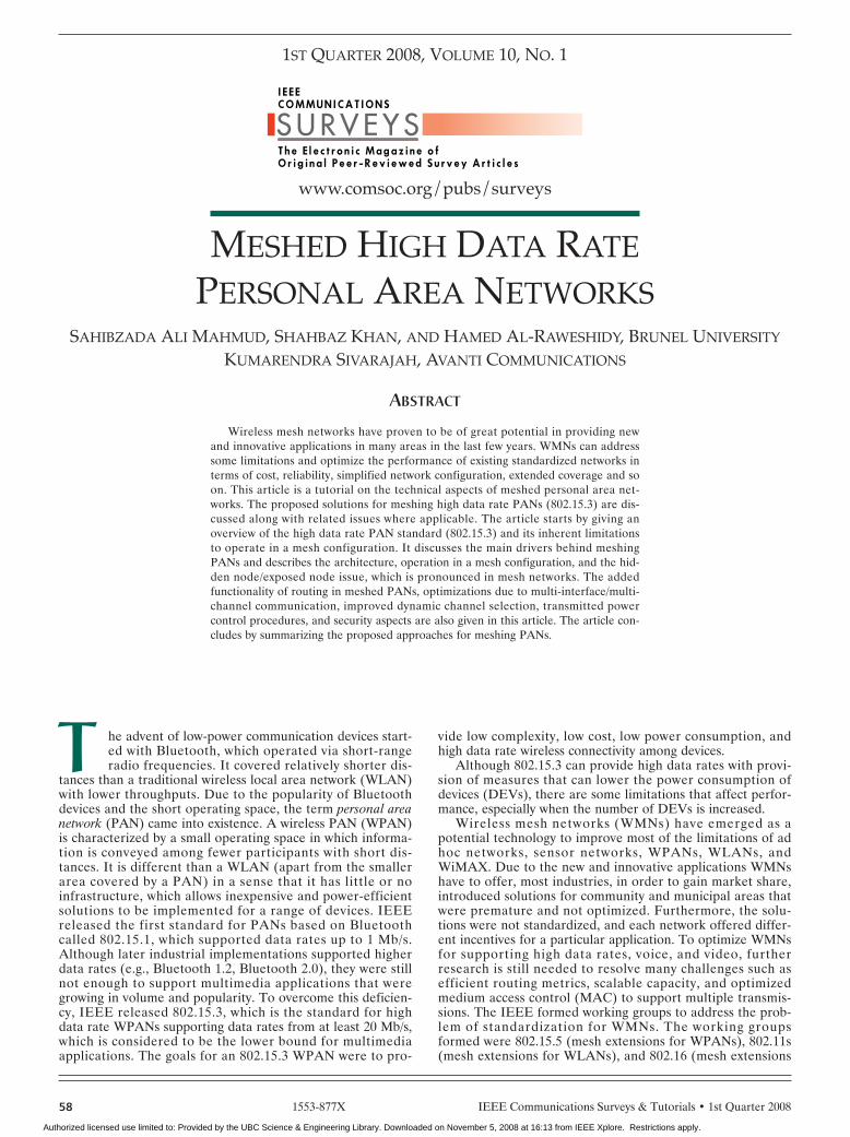
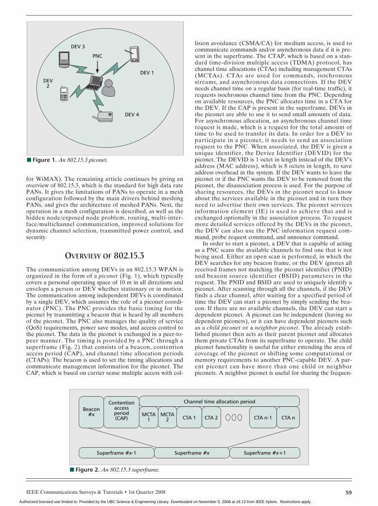
OVERVIEW OF 802.15.3The communication among DEVs in an 802.15.3 WPAN isorganized in the form of a piconet (Fig. 1), which typicallycovers a personal operating space of 10 m in all directions andenvelops a person or DEV whether stationary or in motion.The communication among independent DEVs is coordinatedby a single DEV, which assumes the role of a piconet coordi-nator (PNC). The PNC provides the basic timing for thepiconet by transmitting a beacon that is heard by all membersof the piconet. The PNC also manages the quality of service(QoS) requirements, power save modes, and access control tothe piconet. The data in the piconet is exchanged in a peer-to-peer manner. The timing is provided by a PNC through asuperframe (Fig. 2) that consists of a beacon, contentionaccess period (CAP), and channel time allocation periods(CTAPs). The beacon is used to set the timing allocations andcommunicate management information for the piconet. TheCAP, which is based on carrier sense multiple access with col-
lision avoidance (CSMA/CA) for medium access, is used tocommunicate commands and/or asynchronous data if it is pre-sent in the superframe. The CTAP, which is based on a stan-dard time-division multiple access (TDMA) protocol, haschannel time allocations (CTAs) including management CTAs(MCTAs). CTAs are used for commands, isochronousstreams, and asynchronous data connections. If the DEVneeds channel time on a regular basis (for real-time traffic), itrequests isochronous channel time from the PNC. Dependingon available resources, the PNC allocates time in a CTA forthe DEV. If the CAP is present in the superframe, DEVs inthe piconet are able to use it to send small amounts of data.For asynchronous allocation, an asynchronous channel timerequest is made, which is a request for the total amount oftime to be used to transfer its data. In order for a DEV toparticipate in a piconet, it needs to send an associationrequest to the PNC. When associated, the DEV is given aunique identifier, the Device Identifier (DEVID) for thepiconet. The DEVID is 1 octet in length instead of the DEV’saddress (MAC address), which is 8 octets in length, to saveaddress overhead in the system. If the DEV wants to leave thepiconet or if the PNC wants the DEV to be removed from thepiconet, the disassociation process is used. For the purpose ofsharing resources, the DEVs in the piconet need to knowabout the services available in the piconet and in turn theyneed to advertise their own services. The piconet servicesinformation element (IE) is used to achieve that and isexchanged optionally in the association process. To requestmore detailed services offered by the DEVs in the piconet,the DEV can also use the PNC information request com-mand, probe request command, and announce command.
In order to start a piconet, a DEV that is capable of actingas a PNC scans the available channels to find one that is notbeing used. Either an open scan is performed, in which theDEV searches for any beacon frame, or the DEV ignores allreceived frames not matching the piconet identifier (PNID)and beacon source identifier (BSID) parameters in therequest. The PNID and BSID are used to uniquely identify apiconet. After scanning through all the channels, if the DEVfinds a clear channel, after waiting for a specified period oftime the DEV can start a piconet by simply sending the bea-con. If there are no available channels, the DEV can start adependent piconet. A piconet can be independent (having nodependent piconets), or it can have dependent piconets suchas a child piconet or a neighbor piconet. The already estab-lished piconet then acts as their parent piconet and allocatesthem private CTAs from its superframe to operate. The childpiconet functionality is useful for either extending the area ofcoverage of the piconet or shifting some computational ormemory requirements to another PNC-capable DEV. A par-ent piconet can have more than one child or neighborpiconets. A neighbor piconet is useful for sharing the frequen-
■ Figure 1. An 802.15.3 piconet.
PNC
DEV 3
DEV2
DEV 4
DEV 1
■ Figure 2. An 802.15.3 superframe.
Beacon#x MCTA
1
Channel time allocation period
Superframe #x-1 Superframe #x Superframe #x+1
MCTA2 CTA 1 CTA n-1 CTA nCTA 2
Contentionaccessperiod(CAP)
Authorized licensed use limited to: Provided by the UBC Science & Engineering Library. Downloaded on November 5, 2008 at 16:13 from IEEE Xplore. Restrictions apply.
IEEE Communications Surveys & Tutorials • 1st Quarter 200860
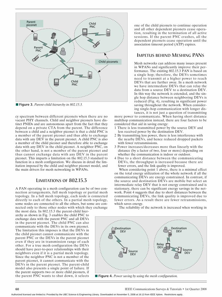
cy spectrum between different piconets when there are novacant PHY channels. Child and neighbor piconets have dis-tinct PNIDs and are autonomous apart from the fact that theydepend on a private CTA from the parent. The differencebetween a child and a neighbor piconet is that a child PNC isa member of the parent piconet and thus able to exchangedata with any DEV in the parent piconet. A child PNC is alsoa member of the child piconet and therefore able to exchangedata with any DEV in the child piconet. A neighbor PNC, onthe other hand, is not a member of the parent piconet andthus cannot exchange data with any DEV in the parentpiconet. This imparts a limitation on the 802.15.3 standard tofunction in a mesh configuration. We discuss in detail the lim-itation imposed by the child and neighbor piconet model, andthe main drivers for mesh networking in WPANs.
LIMITATIONS OF 802.15.3A PAN operating in a mesh configuration can be of two con-nection arrangements, full mesh topology or partial meshtopology. In a full mesh topology, each node is connecteddirectly to each of the others. In a partial mesh topology,some nodes are connected to all the others, but some are con-nected only to those other nodes with which they exchangethe most data. In 802.15.3 the parent-child hier-archy as shown in Fig. 3 enables the child PNC toexchange data with the parent PNC and all DEVsin the parent piconet. The child PNC can alsocommunicate with the DEVs in its own piconet.The limitation this imposes is that the DEVs inthe child piconet cannot communicate with theparent PNC or the DEVs in the parent piconeteven if they are in transmission range of eachother. For a true mesh configuration the DEVsshould have peer-to-peer relationships with theirneighbors even if it is a partial mesh topology.Since the neighbor PNC is not a member of theparent piconet, it cannot communicate with theDEVs in the parent piconet. The parent-childmodel also presents a single point of failure. Ifthe parent supports two or more child piconets, ifthe parent PNC wants to shut down, it selects
one of the child piconets to continue operationand all other dependent piconets cease opera-tion, resulting in the termination of all activesessions. If the parent PNC crashes, all thedependent piconets cease operation until theassociation timeout period (ATP) expires.
IMPETUS BEHIND MESHING PANS
Mesh networks can address many issues presentin WPANs and significantly improve their per-formance. The existing 802.15.3 PAN is based ona single hop; therefore, the DEVs sometimesneed to transmit at a higher power to reachDEVs that are further away. In a mesh networkwe have intermediate DEVs that can relay thedata from a source DEV to a destination DEV.In this way the network is extended, and the sin-gle hop distance between neighboring DEVs isreduced (Fig. 4), resulting in significant powersaving throughout the network. When consider-ing single-hop communication with longer dis-tances, it is not just a question of transmitting
more power to communicate. When having short distancemultihop communication instead, there are four factors to beconsidered that aid in saving energy:1 There is less transmitted power by the source DEV and
less received power by the destination DEV.2 By transmitting less power, there is less interference with
the nearby DEVs, and hence reduced dropped packetswith fewer retransmissions.
3 Power increases/decreases more than linearly with thedistance (by a factor of two, four or more) depending onwhether the communication is indoor or outdoor.
4 Due to a short distance between the communicatingDEVs, the throughput is increased because there arefewer errors, and the link quality is improved.When considering point 1 above, there is a minimal effect
on the total energy utilization of the whole network if all thecommunicating DEVs are energy constrained. In contrast, ifthe source and destination DEVs are mobile but select anintermediate relay DEV that is not energy constrained and isstationary, there can be significant energy savings in the net-work. Point 4 suggests that due to short distances between thecommunicating DEVs, the link quality is improved due tofewer errors. As a result there are fewer retransmissions,which saves energy.
The reliability of the network is increased when working in
■ Figure 3. Parent-child hierarchy in 802.15.3.
Child piconets
Parent piconet Child
PNC
ParentPNC
ChildPNC
■ Figure 4. Power saving by using the mesh configuration.
DestinationDEV
DestinationDEV
SourceDEV
SourceDEV
RelayDEV
Authorized licensed use limited to: Provided by the UBC Science & Engineering Library. Downloaded on November 5, 2008 at 16:13 from IEEE Xplore. Restrictions apply.
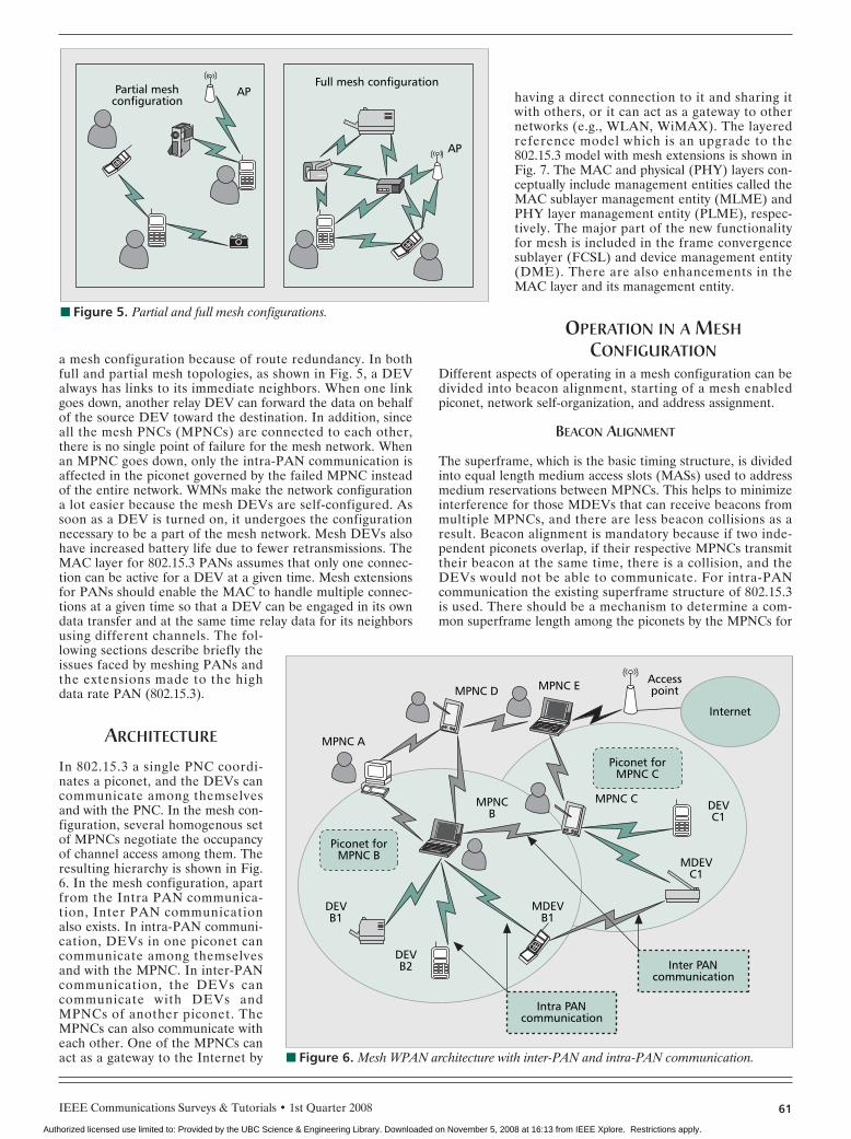
a mesh configuration because of route redundancy. In bothfull and partial mesh topologies, as shown in Fig. 5, a DEValways has links to its immediate neighbors. When one linkgoes down, another relay DEV can forward the data on behalfof the source DEV toward the destination. In addition, sinceall the mesh PNCs (MPNCs) are connected to each other,there is no single point of failure for the mesh network. Whenan MPNC goes down, only the intra-PAN communication isaffected in the piconet governed by the failed MPNC insteadof the entire network. WMNs make the network configurationa lot easier because the mesh DEVs are self-configured. Assoon as a DEV is turned on, it undergoes the configurationnecessary to be a part of the mesh network. Mesh DEVs alsohave increased battery life due to fewer retransmissions. TheMAC layer for 802.15.3 PANs assumes that only one connec-tion can be active for a DEV at a given time. Mesh extensionsfor PANs should enable the MAC to handle multiple connec-tions at a given time so that a DEV can be engaged in its owndata transfer and at the same time relay data for its neighborsusing different channels. The fol-lowing sections describe briefly theissues faced by meshing PANs andthe extensions made to the highdata rate PAN (802.15.3).
ARCHITECTURE
In 802.15.3 a single PNC coordi-nates a piconet, and the DEVs cancommunicate among themselvesand with the PNC. In the mesh con-figuration, several homogenous setof MPNCs negotiate the occupancyof channel access among them. Theresulting hierarchy is shown in Fig.6. In the mesh configuration, apartfrom the Intra PAN communica-tion, Inter PAN communicationalso exists. In intra-PAN communi-cation, DEVs in one piconet cancommunicate among themselvesand with the MPNC. In inter-PANcommunication, the DEVs cancommunicate with DEVs andMPNCs of another piconet. TheMPNCs can also communicate witheach other. One of the MPNCs canact as a gateway to the Internet by
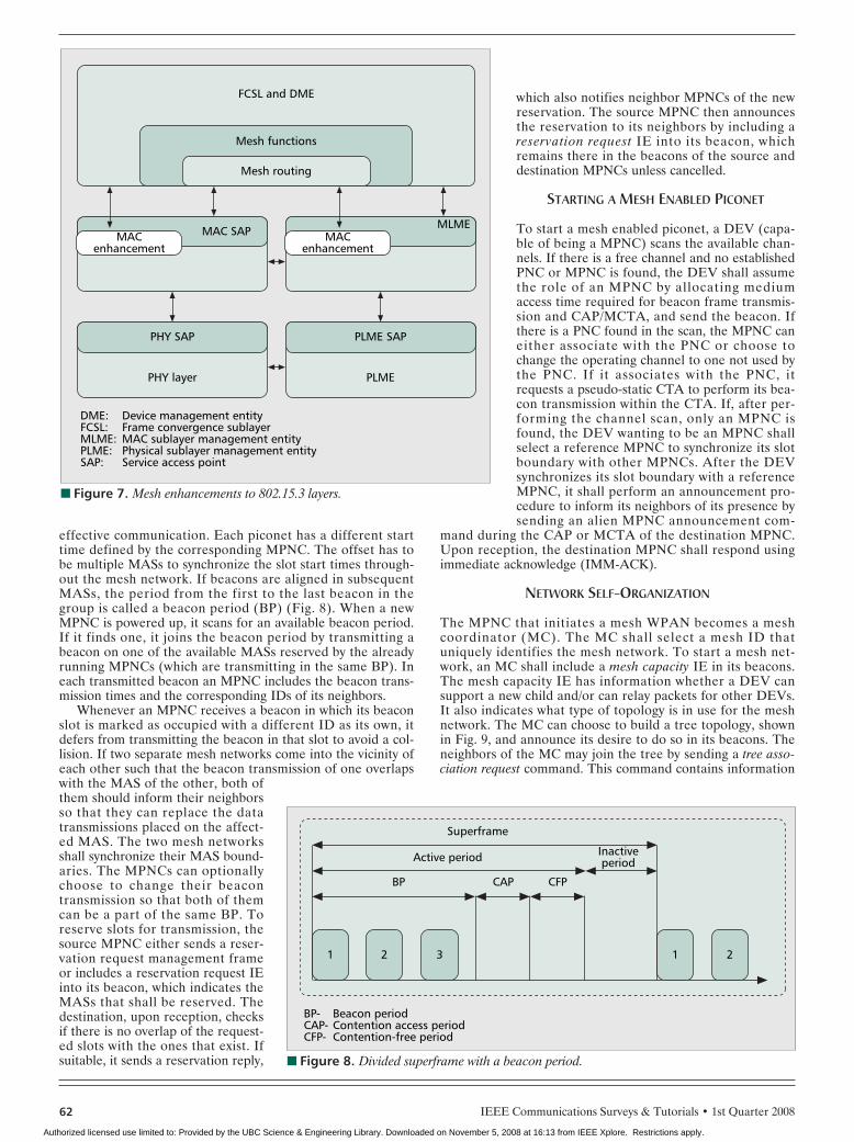
having a direct connection to it and sharing itwith others, or it can act as a gateway to othernetworks (e.g., WLAN, WiMAX). The layeredreference model which is an upgrade to the802.15.3 model with mesh extensions is shown inFig. 7. The MAC and physical (PHY) layers con-ceptually include management entities called theMAC sublayer management entity (MLME) andPHY layer management entity (PLME), respec-tively. The major part of the new functionalityfor mesh is included in the frame convergencesublayer (FCSL) and device management entity(DME). There are also enhancements in theMAC layer and its management entity.
OPERATION IN A MESHCONFIGURATION
Different aspects of operating in a mesh configuration can bedivided into beacon alignment, starting of a mesh enabledpiconet, network self-organization, and address assignment.
BEACON ALIGNMENT
The superframe, which is the basic timing structure, is dividedinto equal length medium access slots (MASs) used to addressmedium reservations between MPNCs. This helps to minimizeinterference for those MDEVs that can receive beacons frommultiple MPNCs, and there are less beacon collisions as aresult. Beacon alignment is mandatory because if two inde-pendent piconets overlap, if their respective MPNCs transmittheir beacon at the same time, there is a collision, and theDEVs would not be able to communicate. For intra-PANcommunication the existing superframe structure of 802.15.3is used. There should be a mechanism to determine a com-mon superframe length among the piconets by the MPNCs for
IEEE Communications Surveys & Tutorials • 1st Quarter 2008 61
■ Figure 5. Partial and full mesh configurations.
Partial meshconfiguration
Full mesh configurationAP
AP
■ Figure 6. Mesh WPAN architecture with inter-PAN and intra-PAN communication.
DEVC1
DEVB2
DEVB1
MDEVC1
MDEVB1
Piconet forMPNC C
Intra PANcommunication
Piconet forMPNC B
AccesspointMPNC E
MPNCB
MPNC C
MPNC D
MPNC A
Internet
Inter PANcommunication
Authorized licensed use limited to: Provided by the UBC Science & Engineering Library. Downloaded on November 5, 2008 at 16:13 from IEEE Xplore. Restrictions apply.
IEEE Communications Surveys & Tutorials • 1st Quarter 200862
effective communication. Each piconet has a different starttime defined by the corresponding MPNC. The offset has tobe multiple MASs to synchronize the slot start times through-out the mesh network. If beacons are aligned in subsequentMASs, the period from the first to the last beacon in thegroup is called a beacon period (BP) (Fig. 8). When a newMPNC is powered up, it scans for an available beacon period.If it finds one, it joins the beacon period by transmitting abeacon on one of the available MASs reserved by the alreadyrunning MPNCs (which are transmitting in the same BP). Ineach transmitted beacon an MPNC includes the beacon trans-mission times and the corresponding IDs of its neighbors.
Whenever an MPNC receives a beacon in which its beaconslot is marked as occupied with a different ID as its own, itdefers from transmitting the beacon in that slot to avoid a col-lision. If two separate mesh networks come into the vicinity ofeach other such that the beacon transmission of one overlapswith the MAS of the other, both ofthem should inform their neighborsso that they can replace the datatransmissions placed on the affect-ed MAS. The two mesh networksshall synchronize their MAS bound-aries. The MPNCs can optionallychoose to change their beacontransmission so that both of themcan be a part of the same BP. Toreserve slots for transmission, thesource MPNC either sends a reser-vation request management frameor includes a reservation request IEinto its beacon, which indicates theMASs that shall be reserved. Thedestination, upon reception, checksif there is no overlap of the request-ed slots with the ones that exist. Ifsuitable, it sends a reservation reply,
which also notifies neighbor MPNCs of the newreservation. The source MPNC then announcesthe reservation to its neighbors by including areservation request IE into its beacon, whichremains there in the beacons of the source anddestination MPNCs unless cancelled.
STARTING A MESH ENABLED PICONET
To start a mesh enabled piconet, a DEV (capa-ble of being a MPNC) scans the available chan-nels. If there is a free channel and no establishedPNC or MPNC is found, the DEV shall assumethe role of an MPNC by allocating mediumaccess time required for beacon frame transmis-sion and CAP/MCTA, and send the beacon. Ifthere is a PNC found in the scan, the MPNC caneither associate with the PNC or choose tochange the operating channel to one not used bythe PNC. If it associates with the PNC, itrequests a pseudo-static CTA to perform its bea-con transmission within the CTA. If, after per-forming the channel scan, only an MPNC isfound, the DEV wanting to be an MPNC shallselect a reference MPNC to synchronize its slotboundary with other MPNCs. After the DEVsynchronizes its slot boundary with a referenceMPNC, it shall perform an announcement pro-cedure to inform its neighbors of its presence bysending an alien MPNC announcement com-
mand during the CAP or MCTA of the destination MPNC.Upon reception, the destination MPNC shall respond usingimmediate acknowledge (IMM-ACK).
NETWORK SELF-ORGANIZATION
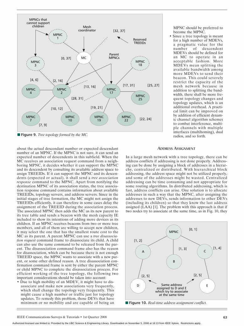
The MPNC that initiates a mesh WPAN becomes a meshcoordinator (MC). The MC shall select a mesh ID thatuniquely identifies the mesh network. To start a mesh net-work, an MC shall include a mesh capacity IE in its beacons.The mesh capacity IE has information whether a DEV cansupport a new child and/or can relay packets for other DEVs.It also indicates what type of topology is in use for the meshnetwork. The MC can choose to build a tree topology, shownin Fig. 9, and announce its desire to do so in its beacons. Theneighbors of the MC may join the tree by sending a tree asso-ciation request command. This command contains information
■ Figure 7. Mesh enhancements to 802.15.3 layers.
MACenhancement
MAC SAP MACenhancement
MLME
Mesh routing
PHY SAP
PHY layer
DME:FCSL:MLME:PLME:SAP:
Device management entityFrame convergence sublayerMAC sublayer management entityPhysical sublayer management entityService access point
PLME SAP
PLME
Mesh functions
FCSL and DME
■ Figure 8. Divided superframe with a beacon period.
1 2
BP- CAP- CFP-
Beacon periodContention access periodContention-free period
3 1 2
BP CAP CFP
Superframe
Active period Inactiveperiod
Authorized licensed use limited to: Provided by the UBC Science & Engineering Library. Downloaded on November 5, 2008 at 16:13 from IEEE Xplore. Restrictions apply.
IEEE Communications Surveys & Tutorials • 1st Quarter 2008 63
about the actual descendant number or expected descendantnumber of an MPNC. If the MPNC is not sure, it can send anexpected number of descendents in this subfield. When theMC receives an association request command from a neigh-boring MPNC, it decides whether it can support the MPNCand its descendent by consulting its available address space toassign TREEIDs. If it can support the MPNC and its descen-dents (expected or actual), it shall send a tree associationresponse command to the MPNC. Apart from notifying thedestination MPNC of its association status, the tree associa-tion response command contains information about availableTREEIDs, topology servers, and address servers. Since in theinitial stages of tree formation, the MC might not assign theTREEIDs efficiently, it can therefore in some cases delay theassignment of the TREEID during the association process.The associated MPNC then adds the MC as its new parent toits tree table and sends a beacon with the mesh capacity IEincluded to show its intentions of adding more devices as itschildren. If an MPNC receives beacons from two or more treemembers, and all of them are willing to accept new children,it may select the one that has the smallest route cost to theMC as its parent. A parent MPNC can use a tree disassocia-tion request command frame to disassociate its child. A childcan also use the same command to be released from the par-ent. The disassociation command frame also has the reasonfor disassociation, which can be because there is not enoughTREEID space, the MPNC wants to associate with a new par-ent, or some other defined reason. A tree disassociation con-firmation command frame is sent by either the parent MPNCor child MPNC to complete the disassociation process. Forefficient working of the tree topology, the following twoimportant considerations should be taken into account:• Due to high mobility of an MDEV, it might have to dis-
associate and make new associations very frequently,which shall change the topology very frequently. Thismight cause a high number or traffic just for topologyupdates. To remedy this problem, those DEVs that haveminimum or no mobility and are capable of being an
MPNC should be preferred tobecome the MPNC.
• Since a tree topology is meantfor a high number of MDEVs,a pragmatic value for thenumber of descendentMDEVs should be defined foran MC to operate in anacceptable fashion. MoreMDEVs mean splitting theavailable bandwidth amongmore MDEVs to send theirbeacon. This could severelyrestrict the capacity of themesh network because inaddition to splitting the band-width, there shall be more fre-quent topology changes andtopology updates, which is anadditional overhead. A practi-cal limit can be improved onby addition of efficient dynam-ic channel algorithm schemesto combat interference, multi-ple channels with multipleinterfaces (multihoming), dualradios, and so forth.
ADDRESS ASSIGNMENT
In a large mesh network with a tree topology, there can beaddress conflicts if addressing is not done properly. Address-ing can be done by assigning a block of addresses in a hierar-chy, centralized or distributed. With hierarchical blockaddressing, the address space might not be utilized properly,and some of the addresses might be wasted. Centralizedaddressing can be time consuming and not appropriate forsome routing algorithms. In distributed addressing, which isfast, address conflicts can arise. One solution is to allocateaddresses in such a way that the MPNC, after assigning theaddresses to new DEVs, sends information to other DEVs(including its children) so that they know the last addressassigned (LAA) [1]. The problem with this approach is that iftwo nodes try to associate at the same time, as in Fig. 10, they
■ Figure 9. Tree topology formed by the MC.
MC
[32, 37]
[0, 37]
[4, 6] [2, 16]
[13, 16]
[28, 31]
[10, 12] [19, 21]
[7, 9]
[22, 24]
[17, 31] [25, 27]
Meshcoordinator
ParentMPNCs
ReservedTREEIDs
MPNCs thatcannot support
children
MPNC3
MPNC4
MPNC7
MPNC10
MPNC19
MPNC22
MPNC2
MPNC17
MPNC25
MPNC1
MPNC18
■ Figure 10. Real-time address assignment conflict.
Same addressassigned to D and E
which try to associateat the same time
[1, 2]
[1, 3] [1, 4]
[2, 5][2, 5]
[0, 1]MPNC
A
D E
B
C
Authorized licensed use limited to: Provided by the UBC Science & Engineering Library. Downloaded on November 5, 2008 at 16:13 from IEEE Xplore. Restrictions apply.
IEEE Communications Surveys & Tutorials • 1st Quarter 200864
might be assigned the same address. This can be resolved ifthe MPNC sends an address reassignment command to thelater arriving device. In a large network resolving the conflictsmight take a long time. Since this approach is not structured,it can be inefficient for tree routing. The approach followed in[2] is suited to a tree topology and is described briefly.
To get information about the tree topology formed andassign TREEIDs accordingly, the MC broadcasts a tree topolo-gy discovery frame. The transmission type of this frame is setto tree broadcast so that only the children of this MC acceptand process this frame. The source MDEVID and DEVIDsubfields of the frame are set as the identity of the MC. AnMPNC, upon receiving a tree topology frame from its parent,sends it to its children if it has some. If it does not have anychildren, it shall create a tree topology update commandframe, set the terminator MDEVID of the frame to the initia-tor MDEVID (MC) of the tree topology discovery frame, andsend the frame to its parent. If the MPNC has children, itshall wait for the topology update command frame from itschildren, and then create its own topology update commandframe and send it to its parent. The MC maintains a TREEIDpool, and first assigns single TREEIDs to those children whocannot support any child. It then reserves some TREEIDs forfuture descendents and lastly divides the remaining TREEIDsamong children that support descendents. Each of the chil-dren (which can support descendents) is assigneda TREEID block, which contains its ownTREEID and TREEIDs of its existing and poten-tial descendents. The MC has a record of theassigned TREEIDs and sends a TREEID assign-ment command frame to each child to notify it ofthe assigned TREEID and TREEID block. Oncean MPNC sets aside a TREEID pool for futuredescendents, it can assign TREEIDs from thispool to newly joined children. If the TREEIDpool of the parent MPNC is not large enough tosupport the new child and its descendents, it shallrequest a TREEID reassignment from its ownparent through a tree topology update commandframe. Figure 9 shows the hierarchy formed bythe MC and the TREE IDs assigned. If an MPNCcannot contact its parent for a long time, it mayselect a new parent from its neighbor MPNCsand try to associate with the new parent. One ormore MPNCs can serve as an address server tohave a mapping of all the addresses. An address
server may periodically broadcast a server notifi-cation command frame to the whole mesh toannounce its existence. The server notificationcommand frame can also be used to announcethe existence of other specialized servers like atopology server, a gateway, and any other server.An MDEV can also get information about theexistence of an available server through the asso-ciation response frame while associating. It cansend a server inquiry frame to its parent, and itsparent can send a server notification commandframe that carries the identity of the server. Theaddress server is updated regularly by everyMPNC by sending an address update commandframe to it.
HIDDEN NODE AND EXPOSED NODEPROBLEM
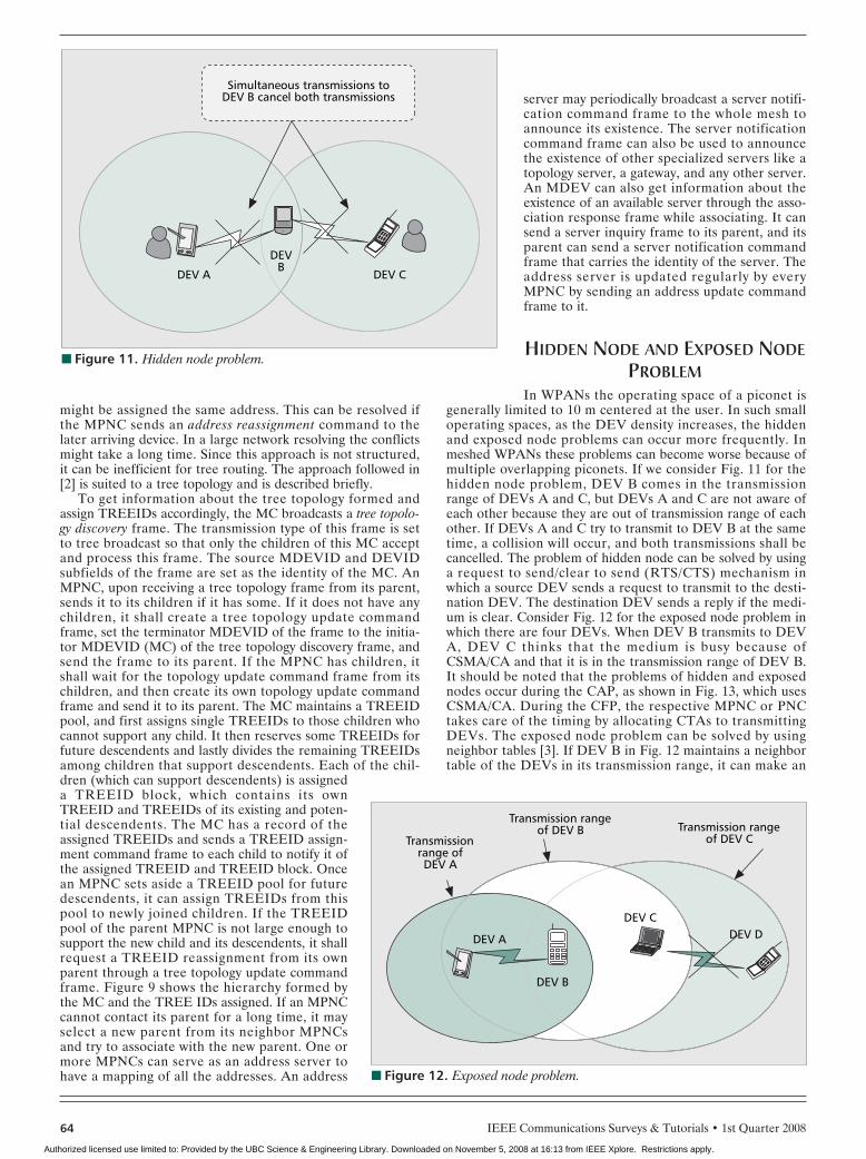
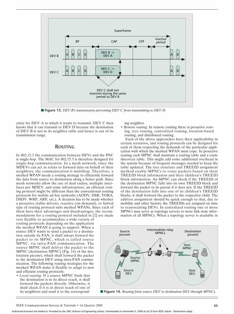
In WPANs the operating space of a piconet isgenerally limited to 10 m centered at the user. In such smalloperating spaces, as the DEV density increases, the hiddenand exposed node problems can occur more frequently. Inmeshed WPANs these problems can become worse because ofmultiple overlapping piconets. If we consider Fig. 11 for thehidden node problem, DEV B comes in the transmissionrange of DEVs A and C, but DEVs A and C are not aware ofeach other because they are out of transmission range of eachother. If DEVs A and C try to transmit to DEV B at the sametime, a collision will occur, and both transmissions shall becancelled. The problem of hidden node can be solved by usinga request to send/clear to send (RTS/CTS) mechanism inwhich a source DEV sends a request to transmit to the desti-nation DEV. The destination DEV sends a reply if the medi-um is clear. Consider Fig. 12 for the exposed node problem inwhich there are four DEVs. When DEV B transmits to DEVA, DEV C thinks that the medium is busy because ofCSMA/CA and that it is in the transmission range of DEV B.It should be noted that the problems of hidden and exposednodes occur during the CAP, as shown in Fig. 13, which usesCSMA/CA. During the CFP, the respective MPNC or PNCtakes care of the timing by allocating CTAs to transmittingDEVs. The exposed node problem can be solved by usingneighbor tables [3]. If DEV B in Fig. 12 maintains a neighbortable of the DEVs in its transmission range, it can make an
■ Figure 11. Hidden node problem.
DEV A DEV C
DEVB
Simultaneous transmissions toDEV B cancel both transmissions
■ Figure 12. Exposed node problem.
Transmissionrange ofDEV A
Transmission rangeof DEV B Transmission range
of DEV C
DEV A
DEV B
DEV CDEV D
Authorized licensed use limited to: Provided by the UBC Science & Engineering Library. Downloaded on November 5, 2008 at 16:13 from IEEE Xplore. Restrictions apply.
IEEE Communications Surveys & Tutorials • 1st Quarter 2008 65
entry for DEV A to which it wants to transmit. DEV C thenknows that it can transmit to DEV D because the destinationof DEV B is not in its neighbor table and hence is out of itstransmission range.
ROUTING
In 802.15.3 the communication between DEVs and the PNCis single-hop. The MAC for 802.15.3 is therefore designed forsingle-hop communication. In a mesh network, since theMDEVs can act as relays to forward data on behalf of theirneighbors, the communication is multihop. Therefore, ameshed WPAN needs a routing strategy to efficiently forwardthe data from source to destination along a better path. Sincemesh networks allow the use of dual radios, multiple inter-faces per MDEV, and some infrastructure, an efficient rout-ing protocol might be different than the conventional routingprotocols for mobile ad hoc networks (AODV, DSR, TORA,DSDV, WRP, ARP, etc.). A decision has to be made whethera proactive (table-driven), reactive (on-demand), or hybridtype of routing protocol suits meshed WPANs. Since each ofthem have their advantages and disadvantages, the recom-mendations for a routing protocol included in [2] are madevery flexible to accommodate a wide variety ofrouting protocols depending on the applicationthe meshed WPAN is going to support. When asource DEV wants to send a packet to a destina-tion outside its PAN, it shall always forward thepacket to its MPNC, which is called sourceMPNC, via intra-PAN communication. Thesource MPNC shall deliver the packet to theMPNC (destination MPNC) (Fig. 14) of the des-tination piconet, which shall forward the packetto the destination DEV using intra-PAN commu-nication. The following routing strategies for themeshed WPAN make it flexible to adapt to newand efficient routing protocols:• Local routing: If a source MPNC finds that
the destination is in its direct reach, it shallforward the packets directly. Otherwise, itshall check if it is in direct reach of one ofits neighbors and send it to the correspond-
ing neighbor.• Remote routing: In remote routing there is proactive rout-
ing, tree routing, centralized routing, location-basedrouting, and distributed routing.Each of the above approaches have their applicability in
certain scenarios, and routing protocols can be designed foreach of them respecting the demands of the particular appli-cation with which the meshed WPAN must cope. In proactiverouting each MPNC shall maintain a routing table and a routediscovery table. This might add some additional overhead inthe system because of frequent messages needed to keep thetable updated. The tree structure and TREEID assignmentmethod enable MPNCs to route packets based on theirTREEID block information and their children’s TREEIDblock information. An MPNC can check if the TREEID ofthe destination MPNC falls into its own TREEID block andforward the packet to its parent if it does not. If the TREEIDof the destination falls into one of its children’s TREEIDblocks, it shall forward the packet to the respective child. Theaddress assignment should be quick enough so that, due tomobility and other factors, the TREEIDs are assigned on timeto reassociating DEVs. In centralized routing one or moreMPNCs may serve as topology servers to store link state infor-mation of all MPNCs. When a topology server is available in
■ Figure 13. DEV B's transmission preventing DEV C from transmitting to DEV D.
A B C D
Superframe
BP CAP CFPInactiveperiod
DEV B ->DEV A A BDEV B
A B C DDEV C ->
DEV D
DEV C shall nottransmit during the same
period as DEV B
A BDEV C
■ Figure 14. Routing from source DEV to destination DEV through MPNCs.
Destinationpiconet
Intermediate relayMPNCs
SourceMPNC
SourceDEV
DestDEV
DestMPNC
Sourcepiconet
Authorized licensed use limited to: Provided by the UBC Science & Engineering Library. Downloaded on November 5, 2008 at 16:13 from IEEE Xplore. Restrictions apply.
IEEE Communications Surveys & Tutorials • 1st Quarter 200866
the mesh network, all MPNCs shall register their link states atthe topology server. To prevent the single point of failure,multiple topology servers can exist in which some serve as abackup server. The main server synchronizes its knowledgewith the backup server by forwarding the link state registra-tion command frames to it. If the main server fails, the neigh-bors of the main server shall forward all link state registrationframes and route discovery frames to the backup server. If thenetwork is too large for one topology server, partial topologyservers can exist that cover a specific area of the tree. Thewhole tree can be divided into subtrees, and each subtree ishanded over to a local partial topology server.
If the PHY layer allows making accurate range measure-ments among DEVs, a coordinate system can be establishedto cover the whole mesh network. A source MPNC shall setthe packet transmission method as location-based routing andput the location of the destination MPNC as well as its ownlocation in the routing assistant field. The source MPNC thencalculates the distance between the destination MPNC andeach of its neighbor MPNCs. The neighbor closest to the des-tination MPNC is chosen as the next forwarding DEV. Ifnone of the mentioned approaches are feasible, a sourceMPNC may opt for distributed routing and shall broadcast aroute discovery frame to the whole mesh network to find anoptimal route to the destination. When an MPNC receives abroadcast route discovery frame, it shall update the route costbetween it and the frame transmitter. If it already has a rout-ing entry for the source MPNC, it shall update the frame ifthe route cost in the route discovery frame is less than that ofits route entry. If the MPNC is the destination MPNC and itsrouting entry is updated by the frame, it shall create a routeformation command frame and send the frame to the sourceMPNC. The source DEVID shall be set as the identity of thedestination MPNC, and the destination DEVID in the frameshall be set as the identity of the source MPNC. The relay listof the frame shall be set as an empty list. If the MPNC receiv-ing the route discovery frame is not the destination of theframe and it receives the frame for the first time, it shallrecord the frame in the route discovery table and rebroadcastthe frame. Otherwise, if it has received the frame before, itshall only rebroadcast it if its routing entry is updated by thisframe. When an MPNC receives the route formation framewith an empty relay list, it shall first check the source DEVIDagainst its routing table. If it does not have a routing entry forthe destination MPNC, it shall create one. Otherwise, it shallupdate its route entry and the cost of the route formationframe to the next-hop relay by consulting the routing entry forthe source MPNC. When the source MPNC receives the routeformation command frame, it shall create a routing entry forthe destination MPNC and start sending data packets.
MULTIRADIO/MULTI-INTERFACECOMMUNICATION
An important aspect in mesh networks to improve capacity isusing multi-interfaces. In conventional communication, eachDEV is equipped with a single network interface with staticchannel assignment. This arrangement can cause capacityissues, especially in multihop mesh networks. Two DEVssending data to different destinations and operating on thesame radio frequency can cause severe interference if theycome in transmission range of each other. Static channelassignment does not utilize the available radio frequency spec-trum efficiently. In a single-interface multichannel design,only one channel can be assigned to the interface at a time,but the interface can switch channels according to changing
network conditions. Algorithms can be designed so that theDEVs are intelligent enough to detect interference and switchchannels accordingly. This approach can enhance the perfor-mance of the network in terms of interference mitigation andcapacity. The drawback of such an approach is that two DEVswho want to communicate do not have a common channelbetween them will not be able to communicate. This cancause network partitioning. The broadcast messages sent froma DEV on one channel are not heard by those DEVs operat-ing on different channels. Appropriate functionality shouldtherefore be put in the MAC layer to coordinate communica-tion between DEVs so that they communicate using a com-mon channel. In a multi-interface multichannel design,different channels can be assigned to the available interfaces.Since in WLANs 802.11b has three nonoverlapping channelsand 802.11a has 12 nonoverlapping channels, many approach-es have been proposed to take advantage of the availablechannels. Some statically assign available channels to availableinterfaces [4], while some dynamically assign channels to avail-able interfaces [5–7]. A preferred approach is that one of thechannels can be permanently assigned to an interface and cantherefore act as a common control channel to coordinatecommunication among DEVs. The common channel can beused to hear broadcasts, and can collect information about thedynamics of the network to switch the channel on the otherinterface/interfaces accordingly. Suitable dynamic channelswitching algorithms can then be implemented to combatinterference, and further enhance network capacity andthroughput [8]. Reference [5] shows that to keep multi-inter-face DEVs cost effective, the number of interfaces is keptlower than the number of available channels. Reference [7]shows that increasing the number of interfaces does not affectthe throughput significantly, but increasing the number ofchannels per DEV does. Multiple interfaces can be homoge-neous (using the same wireless technology) and heteroge-neous (using different wireless technologies). In a meshedPAN those MDEVs that have multiple homogeneous inter-faces can communicate simultaneously with two or moreDEVs (depending on the number of interfaces). They can alsobe involved in intra-PAN communication and inter-PAN com-munication simultaneously because of the same reason.Homogeneous multi-interface MDEVs are indispensable inmeshed PANs because they can dramatically improve the per-formance by enhancing capacity and throughput since thesuperframe is shared by multiple MPNCs in transmissionrange of each other. By sending the beacon on different radiofrequency channels, an MPNC can isolate intra-PAN commu-nication from inter-PAN communication without interference.Furthermore, those MDEVs that have multiple heteroge-neous interfaces (Bluetooth, WLAN, WiMAX, UMTS, etc.)can be made to act as mesh routers and extend the coverageby connecting PANs at different sites (office, home, etc.) usedby the same user.
DYNAMIC CHANNEL SELECTION
When a mesh WPAN operates in a tree topology and thenumber of MDEVs is increased, the superframe is dividedmore and more by the neighboring MPNCs to allocate chan-nel time for their piconets to operate. This can restrict capaci-ty, and the number of simultaneous supported connections isdecreased. Furthermore, since the network operates in adynamic environment and under unlicensed operation rules, itis subject to interference from licensed users and other wire-less entities in its channels. These factors make the need for adynamic channel selection algorithm imperative. The shifting
Authorized licensed use limited to: Provided by the UBC Science & Engineering Library. Downloaded on November 5, 2008 at 16:13 from IEEE Xplore. Restrictions apply.
IEEE Communications Surveys & Tutorials • 1st Quarter 2008 67
from one channel to another should be transparent so that theexisting active sessions are not affected. In 802.15.3 the proce-dure to change the channel is described, but the performanceparameters on which to base decisions are left out. In theexisting mechanism the PNC initiates dynamic channel selec-tion if it determines that the current channel conditions arepoor. The PNC may perform a PNC channel scanning proce-dure or the remote scan procedure, or collect the channel sta-tus from its member DEVs by sending a channel statusrequest command. When the PNC determines that there is achannel with better characteristics than the present one, itundergoes a channel switching procedure. The dependentpiconets shall either change to the new channel with the par-ent PNC or cease operation. The problems with this approachare that the PNC listening range is limited (one hop), and thePNC does not know which nodes it should inquire for thechannel status and when to inquire it of them. The process ofswitching channels in a mesh WPAN is made complex by thefact that since there can be many overlapping piconets in alarge tree with each piconet managed by its own MPNC, ifeach MPNC changes its channel, it might have to undergo thebeacon alignment procedure again. This can cause a delay,and its existing sessions can be disturbed. Also, if the otherMDEVs want to communicate with it, they shall have toswitch channels too. This problem can be solved to an extentby using dual radios with each MDEV operating simultane-ously on two channels. This approach can increase capacityand further minimize interference. One approach proposed by[9] is that the MDEVs decide to do interference detection bythemselves. Another approach in [10] uses a distributeddynamic channel allocation algorithm to allow each piconet todecide the set of channels based on the information availablelocally. A centralized approach for WLAN mesh networks isgiven in [7] that makes use of multiple channels and uses theirapproach to optimize routing. Further research efforts areimperative in acknowledging the specific requirements of aWPAN mesh network and designing an optimal centralized ordistributed dynamic channel algorithm.
The channel scanning in meshed WPANs can be triggeredby instances like too many retransmissions, high packet lossrates, or some other performance parameters. The MDEVscan also do periodic scanning to check properties of the chan-nel used. There should, however, be a criterion to define theminimum and maximum channel switching time to define athreshold for active sessions, especially real-time sessions, notto be disturbed by it. If the MPNC responsible for a piconetsuffers severe interference, it can affect the whole piconetconcerned. MDEVs should also have an alternate way toswitch channels if their MPNC experiences severe interfer-ence.
POWER CONTROL
Controlling transmitted power in a piconet has many advan-tages. The main advantage is reduced interference with otherwireless networks that share the same channel. The powerusage in DEVs is also reduced, increasing their battery life-time. There are two methods provided by 802.15.3 for control-ling transmitted power. Since the length of the link betweenthe PNC and the farthest DEV from it (in its transmissionrange) determines the length of the piconet, the first methodis to set a maximum transmit power for the CAP (since all theDEVs can contend for transmission), beacon, and MCTAs(excluding association MCTAs). The second method allows asource DEV that has a good link to use a CTA to requesteither an increase or decrease in the transmit power of the
remote destination DEV. If the PNC determines that there isinterference in the existing channel, it may also choose tolower its transmit power.
Since the above method for power control for communi-cating DEVs only concerns the link between two DEVs, amore thorough approach is given in [11] that makes use of apower table. A power table records the transmitted power lev-els at which a node transmits signals to neighbor nodes. Thetransmitting node then finds the corresponding transmittedpower (TP) level before it transmits any frames to its neigh-bor node. There is a neighbor-power table that combines apower table of neighbors. A DEV can then change its trans-mitted power to its neighbors according to their distance andlink quality. There are two methods for transmit power con-trol (TPC) in [11], centralized and distributed. In the central-ized TPC method, one of the MDEVs can be assigned therole of a power control server. It might have the whole or par-tial topology information (depending on size and number ofDEVs). When a source DEV wants to change its TP level to adestination, it sends a request to the power control server.The power control server then calculates the appropriatepower level and sends the response back to the source DEV.In the decentralized method for TPC, every DEV has a rout-ing table and a neighbor-power table. Each DEV makes aTPC decision by itself as a result. The centralized TPCmethod can adapt to a small network, and can save powersince a single server is dedicated to make all the calculations.The network structure and performance is improved as aresult. For a larger network, multiple power control serverscan be implemented. The distributed TPC method can beadapted to a large network. It relieves the burden of havingthe overhead to communicate with a single power controlserver. A single DEV therefore does not have to use most ofits resources to calculate power for other DEVs.
SECURITY
Security is one of the most important aspects of any networkdesign and therefore efficient algorithms should be imple-mented to protect sensitive information. According to [12],there are two modes of security, mode 0 and mode 1. In mode0 the DEVs do not require a secure membership to join thepiconet. The only form of security imposed by the PNC is thelist of DEV addresses it maintains. The same list is checked togive access to a particular DEV in that list. In mode 1 theDEVs are required to establish secure membership beforethey can access resources or communicate with memberDEVs in the piconet. The data sent after establishing a securemembership is also protected by cryptographic techniques. Inmode 1, [12] adopts a 128-bit Advanced Encryption Standard(AES) suite to protect the beacon, command, and dataframes. The encryption and authentication operation isdefined to use AES in CCM (CTR+CBC–MAC) mode. How-ever, the process of establishing secure membership and theinitial key establishment schemes are not specified in the stan-dard and are open for implementation. Therefore, a frame-work should be designed to diagnose and cater to therequirements of secure intra-PAN communication and, inaddition, protect inter PAN-communication. There have beencertificate-based and ID-based schemes proposed to establishtrust for WPANs. Both schemes have more or less the samecomputational complexity and overall security level. In a cer-tificate-based security system there must be a DEV to act as acertificate authority (CA) to establish and distribute certifi-cates for other DEVs in the system. In a distributed meshtopology a central CA cannot suffice by presenting a single
Authorized licensed use limited to: Provided by the UBC Science & Engineering Library. Downloaded on November 5, 2008 at 16:13 from IEEE Xplore. Restrictions apply.
IEEE Communications Surveys & Tutorials • 1st Quarter 200868
point of failure. Therefore, there can be multiple topologyand partial topology servers that are assigned this role.
For complete trust establishment in a piconet, a DEV orMDEV should first become a secure member of the piconetby mutual authentication with the PNC or MPNC. Second,the source and destination DEV who want to communicateshould also form a secure peer-to-peer relationship. In ameshed WPAN, there can be different levels of security(intra-PAN) required for different WPANs. Therefore, accessto those piconets that can have sensitive information shouldbe limited. The meshed WPAN imposes more security chal-lenges because of its dynamic topology and mobile nature.Trust relationships can be established among differentpiconets, so the MDEVs that are mobile and require frequentaccess to those piconets do not have to establish a securemembership every time. The security framework should bedesigned so that a common security mode is available for theMDEVs to communicate with DEVs in different piconets.
A complete security solution should encompass securitycomponents of prevention, detection, and reaction. In anunsecured mesh WPAN any DEV can forward data on behalfof its peers and therefore act as a router. Malicious DEVs canalso have access to the networks and start acting as routers.They can start sending bogus update messages that do notcomply with the implemented routing protocol and flood thenetwork. Malicious DEVs can direct traffic toward certaindestinations and cause packets to be forwarded along a routethat is not optimal or even nonexistent. An attacker can cre-ate routing loops in the network, and introduce severe net-work congestion and channel contention in certain areas.WMNs are also prone to denial of service (DoS) attacks. In aDoS attack the attacker injects a large amount of junk packetsinto the network. These junk packets waste a significant por-tion of the network’s resources, and introduce severe wirelesschannel contention and congestion. An attacker along anestablished route may drop the packets or modify them.
In a mesh WPAN beacons periodically broadcast byMPNCs and processed by MDEVs and DEVs ensure theproper operation of a mesh. It is therefore important to guar-antee the authenticity of beacons. An attacker may use bea-con flooding attacks by sending a large number of bogusbeacons to disturb the normal functioning of the network. Asolution to digitally sign the beacons for authenticity canimpose a heavy burden for low-end DEVs due to the frequen-cy of beacon reception. There should be a lightweight yeteffective solution to address this problem.
There are several approaches for message authenticationamong DEVs like keyed hashing for message authenticationcodes (HMAC) [13], digital signatures [14], and one-way key-chain-based authentication [15]. In HMAC two DEVs share asecret key using a cryptographic one-way hash function h. Thecomputation is efficient for low-end DEVs. Since an HMACcan be verified by an intended receiver, it is not efficient forbroadcast message authentication. Digital signature is anotherapproach that is relatively more computation-intensive. It isbased on asymmetric key cryptography. Although scalable, itis prone to DoS attacks. An attacker can feed a victim nodewith a large number of bogus signatures to exhaust its compu-tational resources. The computation for one-way keychain-based authentication is lightweight, and one authenticator canbe verified by a large number of receivers. It requires strictclock synchronization, and the receivers need to buffer a mes-sage to verify it. This can incur significant delay in the verifi-cation of routing updates and other control messages.
Many schemes have been proposed for secure routing likeAriadne [16] for source routing (DSR), Secure Link StateRouting (SLSR) [17] for link state routing protocols, SAODV
[18] for distance vector routing, ARAN [19], and so on. Eachapproach is suitable for a specific scenario. Mesh WPANsoffer further unique requirements and changes in the existingsolutions because of having multiple-interface/multichannelcommunication. The routing protocols for mobile ad hoc net-works have to be modified to become radio-aware. Since amesh WPAN is a multihop network, a centralized securitysolution can delay attack detection and taking appropriatemeasures. Therefore, an optimum solution can possibly be ahybrid one with certain MDEVs assigned the role of handlingsecurity functionality. Proactive security approaches relate toprevention of security hazards, and reactive approaches dealwith detection and taking appropriate action against potentialthreats. There should be a compromise in the complexity ofthe security solution and network performance because highlycomplex solutions require more computational power fromenergy constrained DEVs.
CONCLUSION
Making enhancements to enable WPANs to operate in ameshed configuration can improve their performance andmake way for new applications. In this tutorial the proposalsand solutions described to address different aspects of meshWPANs are still tentative, and there is scope for furtherresearch and improvement. The initial draft [2] addressedsome of the issues for mesh WPANs, and is made flexible andscalable to accommodate future solutions that are better andoptimized for specific applications. The task group to stan-dardize 802.15.5 (TG 5) is active in proposing new solutionsto enable WPANs to utilize the full potential of mesh net-works. It can be expected in the future that some of the exist-ing solutions will revised and new techniques introduced tofurther enhance the functionality of mesh WPANs.
REFERENCES
[1] ftp://ftp.802wirelessworld.com/15/06/15-06-0344-00-0005-routing-algorithm-efficient-real-time-network-address-alloca-tion-mechanismsbased-laa-concept-in-mesh-network
[2] IEEE Draft 15-06-0237-02-0005, “Recommended Practice toStandard for Information Technology — Telecommunicationsand Information Exchange between Systems — Local andMetropolitan Networks — Specific Requirements — Part 15.5:Mesh Enhancements for IEEE 802.15 WPANs,” 2006
[3] ftp://ftp.802wirelessworld.com/15/06/15-06-0267-00-0005-Solution-to-Exposed-Node-Problem-in-Mesh-Networks
[4] R. Draves, J. Padhye, and B. Zill, “Routing in Multi-Radio,Multi-Hop Wireless Mesh Networks,” 2004 Proc. MobiCom,Philadelphia, PA, Sept. 26–Oct. 1, 2004.
[5] P. Kyasanur and N. H. Vaidya, “Routing and Interface Assign-ment in Multi-Channel Multi-Interface Wireless Networks,” IEEEWireless Commun. and Networking Conf., vol. 4, 2005.
[6] K. Ramachandran et al., “Interference-Aware Channel Assign-ment in Multi-Radio Wireless Mesh Networks,” IEEE INFOCOM2006.
[7] A. Raniwal, K. Gopalan, and T. Chiueh, “Centralized ChannelAssignment and Routing Algorithms for Multi-Channel Wire-less Mesh Networks,” ACM SIGMOBILE Mobile Comp. andCommun. Rev., vol. 8, 2004, pp. 50–65.
[8] M. Kodialam and T. Nandagopal, “Characterizing the CapacityRegion in Multi-Radio Multi-Channel Wireless Mesh Networks,”Proc.11th Annual Int’l Conf. Mobile Comp. and Networking,2005, pp. 73–87.
[9] ftp://ftp.802wirelessworld.com/15/06/15-06-0227-00-0005-dynamic-channel-selection-ppt.ppt
[10] A. Rangnekar and K. M. Sivalingam, “QoS Aware Multi-Chan-nel Scheduling for IEEE 802.15.3 Networks,” Springer MobileNetworks and Apps., vol 11, 2006, pp. 47–62.
[11] ftp://ftp.802wirelessworld.com/15/06/15-06-0226-00-0005-
Authorized licensed use limited to: Provided by the UBC Science & Engineering Library. Downloaded on November 5, 2008 at 16:13 from IEEE Xplore. Restrictions apply.
IEEE Communications Surveys & Tutorials • 1st Quarter 2008 69
two-methods-transmitting-power-control-mesh-network[12] IEEE Std. 802.15.3, “Information Technology — Telecommunica-
tions and Information Exchange between Systems — Local andMetropolitan Area Networks —Specific Requirements,” 2003.
[13] H. Krawczyk, M. Bellare, and R. Canetti, “HMAC: Keyed-Hash-ing for Message Authentication,” IETF RFC 2104, 1997.
[14] R. L. Rivest, A. Shamir and L. M. Adleman, “On Digital Signa-tures and Public-Key Cryptosystems,” MIT, Lab. for Comp. Sci.,1977.
[15] A. Perrig et al., “The TESLA Broadcast Authentication Proto-col,” RSA CryptoBytes, vol. 5, 2002, pp. 2–13.
[16] Y. C. Hu, A. Perrig, and D. B. Johnson, “Ariadne: A SecureOn-Demand Routing Protocol for Ad Hoc Networks,” WirelessNetworks, vol. 11, 2005, pp. 21–38.
[17] P. Papadimitratos and Z. Haas, “Secure Link State Routing forMobile Ad Hoc Networks,” Proc. 2003 Symp. Apps. and theInternet Wksp., pp. 379–83.
[18] M. G. Zapata, “Secure Ad Hoc On-Demand Distance VectorRouting,” ACM SIGMOBILE Mobile Comp. and Commun. Rev.,vol. 6, 2002, pp. 106–07.
[19] K. Sanzgiri et al., “A Secure Routing Protocol for Ad Hoc Net-works,” Proc.10th IEEE Int’l Conf. Network Protocols, 2002,pp. 78–87.
BIOGRAPHIES
SAHIZADA A MAHMUD ([email protected]) receivedhis B.Sc. degree in electrical engineering from NWFP University ofEngineering & Technology, Peshawar, Pakistan. Currently, he iswith Wireless Networks & Communications Group, Brunel Univer-sity, West London, United Kingdom. His research mainly focuseson wireless mesh networks, meshing of PANs, and routing andMAC layer issues during PAN formation and meshing. He hasauthored several publications in this area and is currently workingon the IST project MAGNET-beyond.
KUMARENDRA SIVARAJAH ([email protected]) has over six years’ experience in telecommunications fieldcovering significant expertise in 2G (GSM, GPRS, EDGE) and 3G(WCDMA, UTRA-TDD, HSPA, LTE) cellular systems, WiFi, WiMAX,and PAN. He completed his Ph.D. research at Kent University,United Kingdom, on network optimization for UMTS networks in2004. He worked for three years at Brunel University on the EU IPFP6 project called My Personal Adaptive Global Network (MAG-NET), which was trying to find an innovative solution for seamlessalways on networks for the future. He also has vast knowledge ofproject management as a technical and proposal coordinator. Heis now with Avanti Communications, since January 2007, working
for a satellite operator as a wireless consultant.
SHAHBAZ KHAN [M’06] ([email protected]) received hisB.E degree in computer science from the National University ofSciences & Technology, Rawalpindi, Pakistan, in 2004. Currently,he is with Wireless Networks & Communications Group, BrunelUniversity. His research mainly focuses on cross-layer optimizationtechniques for wireless networks; specifically, on multimediaapplication support, mobility management techniques, fast hand-over mechanisms, and optimized routing.
HAMED AL-RAWESHIDY [M’91, SM’96] ([email protected]) joined the Optoelectronics group at Strathclyde Uni-versity in 1987 after completing the postgraduate course in opti-cal information processing at Glasgow University. He subsequentlyobtained his Ph.D. degree for work in the area of spread spec-trum multiplexing for communication networks. Between 1990and 1993 he worked as a research fellow at Oxford Universitywhere his main area of investigation was spread spectrum insatellite applications. During the summer of 1992 he worked withthe fiber access network group at British Telecom Laboratories. InJanuary 1993 he joined the Department of Electrical and Electron-ic Engineering at Manchester Metropolitan University as a seniorlecturer. In November 1998 he joined the Department of Electron-ics at the University of Kent. He is currently a professor and groupleader of the Wireless Communications & Networks ResearchGroup at Brunel University. He is a member of IEE and New YorkAcademy of Sciences. He has been awarded a Nuffield researchgrant as a newly appointed university lecturer in science and engi-neering and UK-Dutch Scientific Research in collaboration withthe International Research Centre for Telecommunications-Trans-mission and Radar, Delft University, Netherlands, for work involv-ing the development of radio over fiber for 3G microcellularmobile communications. He has acted as guest editor for theInternational Journal of Wireless Personal Communications SpecialIssue on Radio over Fibre Systems Technologies and Applications.He is a member of several international conference advisory com-mittees, such as VTC, PIMRC, and GLOBECOM, and has organizedseveral workshops on wireless lightwave interaction and radioover fiber for 3G mobile communications in Europe and Japan. Heis a member of journal editorial boards such as Communicationsand Mobile Computing and Wireless Personal Communications.His main areas of interest are radio over fiber, software radio net-works, and IP mobility. He has published over 100 learned journaland conference papers in these areas. He is editor of a book enti-tled Radio over Fiber Technologies for Mobile CommunicationsNetworks (March 2002).
Authorized licensed use limited to: Provided by the UBC Science & Engineering Library. Downloaded on November 5, 2008 at 16:13 from IEEE Xplore. Restrictions apply.