MEMDOS MR Operating Manual - Lutz-Jesco
36
MEMDOS MR Motor-Driven Diaphragm Dosing Pump Operating Manual Read this operating manual before start-up! To be retained for future reference. EN 02 Dosing Conveying Control Liquids Gases Systems
-
Upload
khangminh22 -
Category
Documents
-
view
2 -
download
0
Transcript of MEMDOS MR Operating Manual - Lutz-Jesco
MEMDOS MRMotor-Driven Diaphragm Dosing Pump
Operating ManualRead this operating manual before start-up!To be retained for future reference.
EN02
DosingConveying
Control
Liquids
Gases
Systems
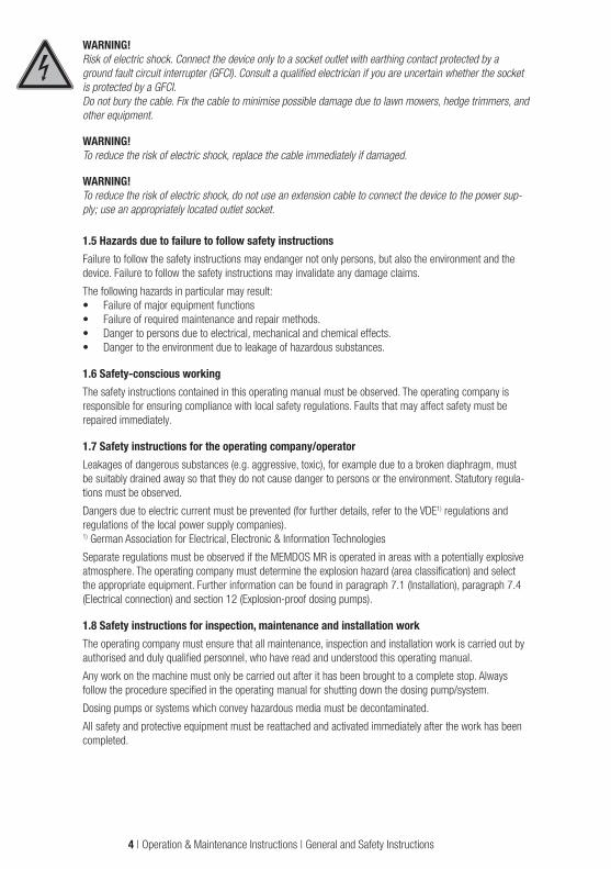
Table of Contents1. General and Safety Instructions ................................................................................................................................3
1.1 General ............................................................................................................................................................. 31.2 Identification of safety instructions in this operating manual ................................................................................. 31.3 Personnel qualifications and training ................................................................................................................... 31.4 Important safety instructions .............................................................................................................................. 31.5 Hazards due to failure to follow safety instructions ............................................................................................... 41.6 Safety-conscious working .................................................................................................................................. 41.7 Safety instructions for the operating company/operator ........................................................................................ 41.8 Safety instructions for inspection, maintenance and installation work .................................................................... 41.9 Unauthorised modification and production of spare parts ..................................................................................... 51.10 Inadmissible operating practices ....................................................................................................................... 51.11 Dosing of chemicals ........................................................................................................................................ 51.12 Transportation ................................................................................................................................................. 61.13 Scope of delivery ............................................................................................................................................. 6
2. General .......................................................................................................................................................................72.1 Use for intended purpose ................................................................................................................................... 72.2 Structure of the dosing pump ............................................................................................................................. 7
3. Function .....................................................................................................................................................................8
4. Dimensioned drawings ..............................................................................................................................................9
5. Technical data ..........................................................................................................................................................115.1 Electric motor data .......................................................................................................................................... 12
6. Delivery characteristic curves ................................................................................................................................14
7. Installation ...............................................................................................................................................................167.1 General information ......................................................................................................................................... 167.2 Installation location .......................................................................................................................................... 177.3 Drain pipe ....................................................................................................................................................... 177.4 Electrical connection of the pump ..................................................................................................................... 177.5 Wiring diagrams for ATE servomotor for stroke length adjustment ....................................................................... 187.6 Pressure control and safety valves .................................................................................................................... 207.7 Injection nozzle installation ............................................................................................................................... 207.8 Installation example ......................................................................................................................................... 21
8. Operation ..................................................................................................................................................................228.1. Stroke length adjustment ................................................................................................................................ 22
9. Start-up ....................................................................................................................................................................239.1 Start-up of MEMDOS MR with ATE servomotor .................................................................................................. 23
10. Shutdown ...............................................................................................................................................................2410.1 Disposal of old equipment .............................................................................................................................. 24
11. Maintenance ..........................................................................................................................................................2511.1 Lubrication .................................................................................................................................................... 2511.2 Maintenance of the bearings .......................................................................................................................... 2511.3 Maintenance of the ATE servomotor (optional) ................................................................................................. 2511.4 Diaphragm replacement ................................................................................................................................. 2511.5 Manual adjustment of the ATE servomotor, Type AR30W .................................................................................. 2711.6 Valves ........................................................................................................................................................... 27
12. Explosion-proof dosing pumps (ATEX) .................................................................................................................2912.1 General ......................................................................................................................................................... 2912.2 Special conditions.......................................................................................................................................... 2912.3 Dosing of flammable media ............................................................................................................................ 29
13. Troubleshooting .....................................................................................................................................................30
14. Spare parts .............................................................................................................................................................3114.1 Spare parts sets ............................................................................................................................................ 31
15. External vent (optional) .........................................................................................................................................32
16. EU Declaration of Confirmity .................................................................................................................................33
2 | Operation & Maintenance Instructions | Table of Contents

1. General and Safety Instructions
1.1 GeneralThis operating manual contains basic instructions to be followed during installation, operation and mainte-nance. It is therefore essential for the assembler and the relevant technical personnel/operating company to read this operating manual prior to installation and start-up. It must remain accessible at the place of installation of the system for reference at all times.
Besides the general safety instructions in this "Safety" section, the special safety instructions in the other sections are also to be followed.
1.2 Identification of safety instructions in this operating manualFailure to follow the safety instructions in this operating manual may result in personal injury or damage to the environment and the system. Safety instructions are identified by the following symbols:
DANGER!Indicates immediate danger. Failure to follow this instruction will lead to death or extremely serious injuries.
WARNING!Refers to a potentially hazardous situation. Failure to follow this instruction may lead to death or extremely serious injuries.
CAUTION!Refers to a potentially hazardous situation. Failure to follow this instruction may lead to minor injuries or damage to property.
ATTENTION! or NOTICE!Failure to follow these safety instructions may endanger the machine and its functions.
IMPORTANT!This indicates additional information that makes work easier and ensures trouble-free operation.
Information attached directly to the dosing pump, such as• cable markings• markings for fluid connections
must be followed without fail and must remain fully legible at all times.
1.3 Personnel qualifications and trainingThe personnel employed for operation, maintenance, inspection, and installation must be suitably qualified for this work. The responsibilities, areas of competence and personnel supervision must be clearly defined by the operating company. Personnel who do not have the required know-how must be duly trained and instructed. If necessary, this can also be done by the manufacturer/supplier on behalf of the operating company. In addition, the operating company must ensure that the personnel are fully familiar with, and have understood the contents of this operating manual.
1.4 Important safety instructionsWhen installing and using this electrical device, basic safety precautions should always be followed, includ-ing the following:
ATTENTION!Read and follow all instructions! Keep this operating manual for future reference!
WARNING!To reduce the risk of injury, do not permit children to use this product unless they are closely supervised at all times.
General and Safety Instructions | Operation & Maintenance Instructions | 3
WARNING!Risk of electric shock. Connect the device only to a socket outlet with earthing contact protected by a ground fault circuit interrupter (GFCI). Consult a qualified electrician if you are uncertain whether the socket is protected by a GFCI. Do not bury the cable. Fix the cable to minimise possible damage due to lawn mowers, hedge trimmers, and other equipment.
WARNING!To reduce the risk of electric shock, replace the cable immediately if damaged.
WARNING!To reduce the risk of electric shock, do not use an extension cable to connect the device to the power sup-ply; use an appropriately located outlet socket.
1.5 Hazards due to failure to follow safety instructionsFailure to follow the safety instructions may endanger not only persons, but also the environment and the device. Failure to follow the safety instructions may invalidate any damage claims.
The following hazards in particular may result:• Failure of major equipment functions• Failure of required maintenance and repair methods.• Danger to persons due to electrical, mechanical and chemical effects.• Danger to the environment due to leakage of hazardous substances.
1.6 Safety-conscious workingThe safety instructions contained in this operating manual must be observed. The operating company is responsible for ensuring compliance with local safety regulations. Faults that may affect safety must be repaired immediately.
1.7 Safety instructions for the operating company/operatorLeakages of dangerous substances (e.g. aggressive, toxic), for example due to a broken diaphragm, must be suitably drained away so that they do not cause danger to persons or the environment. Statutory regula-tions must be observed.
Dangers due to electric current must be prevented (for further details, refer to the VDE1) regulations and regulations of the local power supply companies). 1) German Association for Electrical, Electronic & Information Technologies
Separate regulations must be observed if the MEMDOS MR is operated in areas with a potentially explosive atmosphere. The operating company must determine the explosion hazard (area classification) and select the appropriate equipment. Further information can be found in paragraph 7.1 (Installation), paragraph 7.4 (Electrical connection) and section 12 (Explosion-proof dosing pumps).
1.8 Safety instructions for inspection, maintenance and installation workThe operating company must ensure that all maintenance, inspection and installation work is carried out by authorised and duly qualified personnel, who have read and understood this operating manual.
Any work on the machine must only be carried out after it has been brought to a complete stop. Always follow the procedure specified in the operating manual for shutting down the dosing pump/system.
Dosing pumps or systems which convey hazardous media must be decontaminated.
All safety and protective equipment must be reattached and activated immediately after the work has been completed.
4 | Operation & Maintenance Instructions | General and Safety Instructions

CAUTION!Particular care must be taken when repairing the MEMDOS MR if used in areas with a potentially explosive atmosphere. Due to the risk of sparking, care must be taken to prevent metal parts or tools knocking against one another. When repairing, it is better to move the dosing pump out of the area with a potentially explosive atmosphere.
The instructions given in section 7.2 "Installation location" and section 9. "Start-up" must be observed before start-up.
1.9 Unauthorised modification and production of spare partsThe device may only be modified or converted in consultation with the manufacturer. Use only the manufac-turer's spare parts and accessories. Otherwise the warranty is invalidated.
1.10 Inadmissible operating practicesAny methods of operation other than those described in Section 2 "Proper use" are not permitted and will invalidate any manufacturer liability under the warranty.
1.11 Dosing of chemicals
CAUTION!When working on dosing systems, the local accident prevention regulations must be observed and the specified personal protective equipment must be worn. The following standard protective clothing is recom-mended, depending on the hazardousness of the metered medium:
Protective clothing Protective gloves Protective goggles
It is recommended that all persons responsible for the installation and maintenance of piping systems, hoses and accessories wear this protective clothing.
Before working on the dosing pump and system, disconnect it from the mains power supply and prevent it from being switched on.
CAUTION!Any chemical still present in the dosing head may spray out when the voltage supply is reconnected. This may lead to chemical or other burns to the face and hands. Dosing lines must always be connected before switching on again.
The chemical resistance of the construction materials in the pump must be verified before dosing aggres-sive media!
The pump dosing head and the system connections and lines may be under pressure. Working on the dos-ing system requires special safety precautions and is allowed only for suitably trained personnel:
CAUTION!Chemical may spray out. This may lead to chemical or other burns. Always release the pressure before starting work on the dosing pump.
Before working on the dosing head, valves and connections, flush the dosing pump with a harmless medium (water in most cases), to avoid unintentional contact with the metered medium.
WARNING!Never look into the open end of a clogged line or valve. Chemicals may emerge unexpectedly and cause chemical or other burns to face and hands.
Before start-up, all screw connections must be inspected for correct tightness and leak-tightness, and must be re-tightened using an appropriate tool if necessary.
General and Safety Instructions | Operation & Maintenance Instructions | 5

CAUTION!If connections at the dosing head are loosened during operation, for venting or other reasons, leaking chemicals must be removed properly. This is the only way to avoid health hazards due to chemicals, and chemical corrosion of the dosing pump. Leaking chemicals may also damage the diaphragm at its mounting edge.
ATTENTION!If changing the chemical, check the materials in the pump and other system parts for chemical resistance. If there is a danger of chemical reaction between the different media, clean thoroughly beforehand.
IMPORTANT!To operate the pump, mount the fan cowl in order to ensure sufficient cooling of the motor.
The protection class of the control unit is only ensured if the connection ports are protected by caps or the standard connectors are inserted.
WARNING!Lethal voltage!Take particular care when carrying out adjustment work on the inside of the ATE servomotor (optional for MEMDOS MR). Connections and internal limit switches might be live. Additional limit switches in the ATE servomotor may be under voltage (live) even when the auxiliary voltage is switched off. After installing the ATE servomotor or before start-up, re-attach the cover.
1.12 TransportationNo special devices are required for transportation of the dosing pumps. However, it is advisable to choose a transport method appropriate for the weight of the dosing pumps (e.g. transport trolley). If transporting with the oil drained, the dosing pump should preferably be placed in the horizontal position. Otherwise, stability must be ensured by screwing it onto the transport frame.
1.13 Scope of delivery
IMPORTANT!Carefully unpack the dosing pump and any accompanying accessories ordered, so that small parts are not left inside the packaging. Compare the delivery content with the delivery note immediately. If there are any discrepancies, determine the cause.
The following are part of the scope of delivery:• Dosing pump MEMDOS MR• Suction and discharge side connections• Gear oil• Operating Manual• ATE servomotor (optional)• Separate fan (optional)
6 | Operation & Maintenance Instructions | General and Safety Instructions

2. General
2.1 Use for intended purposeThe device is intended for the following purpose only: the conveying and dosing of chemicals.
Operating safety is guaranteed only if the device is used for its intended purpose. Use for any other purpose is not permitted and will invalidate any liability under the warranty. The operating conditions described in section 5 "Technical Data" must be observed!
2.2 Structure of the dosing pump
c
a
h
b
d i
g
f
e
j
a Dosing headb Suction side valvec Discharge side valved Drain sockete Stroke length adjustmentf Stroke length adjustment lockg Motor terminal box (MEMDOS MR voltage supply)h Oil inleti Oil outletj Oil level glass
General | Operation & Maintenance Instructions | 7

3. FunctionMotor-driven diaphragm dosing pumps of the MEMDOS series are used in industry in the process engineer-ing sector, and in water treatment and wastewater processing.
The MEMDOS is available with one (as MEMDOS MR) or with two dosing heads (as MEMDOS ZMR). If not otherwise pointed out, all specifications of the MEMDOS MR are also applicable for the MEMDOS ZMR.
MEMDOS MRThe MEMDOS MR is used when no control is required for constant dosing. For this the voltage supply is connected directly to the terminal box of the motor. To adapt the dosing capacity, either the stroke length can be adjusted manually from 0 … 100%, or the motor speed is be controlled by means of a separate frequency converter. The MEMDOS MR is optionally available with electrical remote adjustment of the stroke length (ATE).
The MEMDOS MR can be operated in Zone 1 hazardous areas if the corresponding drive is taken into consideration. Further information can be found in section 12.
Principle of operation
a Diaphragmb Diaphragm rodc Return spring for suction stroked Tappet platee Drive eccentricf Stroke limit eccentric
Like the roller bearings, the worm gear set of the single-speed gear runs in an oil bath. Dosing takes place when movement of the drive eccentric e causes movement of the diaphragm rod b. The suction stroke is produced by the return movement due to spring force. Stroke length is adjusted by limiting the tappet return movement using a manually adjustable eccentric disc as the end stop (stroke limiting eccentric f). The adjust-ment range is from 0 to 100%.
a b c d
e
fmin.
max.
max.
8 | Operation & Maintenance Instructions | Function

4. Dimensioned drawings
LA
L
130q
B10
010
1
530
ca.
53
76
D
C
290
ca.
100
101
530
ca.
130q
B
LA
L
53
C
D
O11 O11 130q
B
100
101
530
ca.
LA
L
O11
53
E
D
7676
Dimensioned drawing MEMDOS MR 50 … 980
B130q
100
100
530
~
LA
L
O11
OD
53
~405
C
150
min
. M
onta
gem
aß
Dimensioned drawing MEMDOS MR 50 … 980 ATE
Dimensioned drawings | Operation & Maintenance Instructions | 9

LA
L
130q
B
100
101
530
ca.
53
76
D
C
290
ca.
100
101
530
ca.
130q
B
LA
L
53
C
D
O11 O11 130q
B
100
101
530
ca.
LA
L
O11
53
E
D
7676
Dimensioned drawing MEMDOS ZMR 50 … 980
MEMDOS A B C D E50 272 201
317
ø 152 220
75 272 201 ø 152 220
115 272 201 ø 152 220
140 272 201 ø 152 220
210 272 201 ø 152 220
290 296 201 325 170 225
400 265 225
378
ø 230 288
600 265 225 ø 230 288
980 265 225 ø 230 288
MEMDOS Valves Connection DN Line L
ZMR 50 … 290 G 1 1/4
Pipe bonded connection
8 Pipe ø 12
22
10 Pipe ø 16
15 Pipe ø 20
Pipe thread connection10 Pipe G 3/8
15 Pipe G 1/2
MR 400 … 900 ZMR 400 … 900
68.5
Pipe bonded connection25 Pipe ø 32 40
32 Pipe ø 40 44
Pipe thread connection
20 Pipe G 3/4
4025 Pipe G 1
32 Pipe G 1 1/4
Flange25
60
Pipe bonded connection with thread Pipe ø 32 75 All dimensions in mm
10 | Operation & Maintenance Instructions | Dimensioned drawings
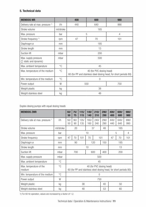
5. Technical data
MEMDOS MR 400 600 980Delivery rate at max. pressure 1) l/h 440 640 990
Stroke volume ml/stroke 165
Max. pressure bar 5 4
Stroke frequency 1) rpm 47 70 101
Diaphragm ø mm 185
Stroke length mm 13
Suction lift mbar 200
Max. supply pressure (∑ static and dynamic)
mbar 500
Max. ambient temperature °C 45
Max. temperature of the medium °C 40 (for PVC dosing head) 60 (for PP and stainless steel dosing head, for short periods 80)
Min. temperature of the medium °C 0
Power output W 550 750
Weight plastic kg 38
Weight stainless steel kg 48
Duplex dosing pumps with equal dosing heads
MEMDOS ZMR 50/50
75/75
115/115
140/140
210/210
290/290
400/400
600/600
980/980
Delivery rate at max. pressure 1 l/h 50/50
90/90
135/135
160/160
240/240
290/290
440/440
640/640
990/990
Stroke volume ml/stroke 20 37 48 165
Max. pressure bar 10 5 4
Stroke frequency rpm 47 70 101 70 101 47 70 101
Diaphragm ø mm 90 120 150 185
Stroke length mm 10 13
Suction lift mbar 700 600 400 200
Max. supply pressure mbar 500
Max. ambient temperature °C 45
Max. temperature of the medium
°C 40 (for PVC dosing head) 60 (for PP and stainless steel dosing head, for short periods 80)
Min. temperature of the medium °C 0
Power output W 750
Weight plastic kg 38 40 50
Weight stainless steel kg 48 53 60
1) For 60 Hz operation, values are increased by a factor of 1.2.
Technical data | Operation & Maintenance Instructions | 11
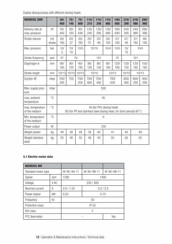
Duplex dosing pumps with different dosing heads
MEMDOS ZMR 50/400
75/140
75/600
115/210
115/290
115/980
140/600
210/290
210/980
290/980
Delivery rate at max. pressure
l/h 55/440
90/160
90/640
135/240
135/290
135/990
160/640
240/290
240/990
290/990
Stroke volume ml/stroke
20/165
20/37
20/165
20/37
20/48
20/165
37/165
37/48
37/165
48/165
Max. pressure bar 10/5
10/10
10/5 10/10 10/4 10/5 10/10
10/4
Stroke frequency rpm 47 70 101 70 101
Diaphragm ø mm 90/185
90/120
90/185
90/120
90/150
90/185
120/185
120/150
120/185
150/185
Stroke length mm 10/13 10/10 10/13 10/10 10/13 10/10 10/13
Suction lift mbar 700/200
700 700/200
700/600
700/400
700/200
600/400
600/200
400/200
Max. supply pres-sure
mbar 500
max. ambient temperature
°C 45
max. temperature of the medium
°C 40 (for PVC dosing head) 60 (for PP and stainless steel dosing head, for short periods 80 °)
Min. temperature of the medium
°C 0
Power output W 750
Weight plastic kg 49 38 49 38 40 41 40 49
Weight stainless steel
kg 55 48 55 48 43 55 50 55
5.1 Electric motor data
MEMDOS MRStandard motor, type AF 80 /4A-11 AF 80 /4B-11 AF 80 /4B-11
Speed rpm 1390 1400
Voltage V AC 230 / 400
Nominal current A 2.6 / 1.55 3.5 / 2.0
Power output kW 0.55 0.75
Frequency Hz 50
Protection class IP 55
ISO class F
PTC thermistor - Yes
12 | Operation & Maintenance Instructions | Technical data
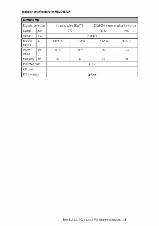
Explosion-proof motors for MEMDOS MR
MEMDOS MRExplosion protection increased safety EExeIIT3 EXdellCT4 pressure-resistant enclosure
Speed] rpm 1370 1380 1400
Voltage V AC 230/400
Nominal current
A 2.6/1.55 3.5/2.0 2.7/1.6 3.5/2.0
Power output
kW 0.55 0.75 0.55 0.75
Frequency Hz 50 50 50 50
Protection class IP 55
ISO class F
PTC thermistor optional
Technical data | Operation & Maintenance Instructions | 13

6. Delivery characteristic curvesThe delivery characteristic curves refer to water at 20 °C (68 °F) and a suction lift of 0.5 m. The medium (density and viscosity) and temperature cause the delivery rate to change. Dosing pumps must therefore be gauged in litres for the application. At 60 Hz operation, values are increased by a factor of 1.2.
0 1 2 3 4 5 6 7 8 9 10
l/h MR 50
0 1 2 3 4 5 6 7 8 9 10
l/h MR 75
10
20
30
40
50
60
70
1020304050607080
10090
1bar
5bar10bar
1bar5bar10bar
0 1 2 3 4 5 6 7 8 9 10 0 1 2 3 4 5 6 7 8 9 10
0 1 2 3 4 5 6 7 8 9 10 0 1 2 3 4 5 6 7 8 9 10
0 1 2 3 4 5 6 7 8 9 10 0 1 2 3 4 5 6 7 8 9 10
0 1 2 3 4 5 6 7 8 9 100 1 2 3 4 5 6 7 8 9 10
l/h MR 980
100
120
140
100
150
200
250
300
350
100
200
300
400
500
600
100200300400500600700800900
10001100
20
40
60
80
50
l/h MR 140
l/h MR 290
l/h MR 600
20406080
100120140160
200180
100
50
150
200
250
300
350
400
200
100
300
400
500
600
700
800
l/h MR 115
l/h MR 210
l/h MR 400
1bar5bar10bar
1bar
5bar
10bar
1bar3bar5bar
2bar3bar4bar
1bar
5bar10bar
1bar
5bar
10bar
1bar3bar5bar
1bar
Stroke length Stroke length
Stroke length Stroke length
Stroke length Stroke length
14 | Operation & Maintenance Instructions | Technical data

0 1 2 3 4 5 6 7 8 9 10
l/h MR 50
0 1 2 3 4 5 6 7 8 9 10
l/h MR 75
10
20
30
40
50
60
70
1020304050607080
10090
1bar
5bar10bar
1bar5bar10bar
0 1 2 3 4 5 6 7 8 9 10 0 1 2 3 4 5 6 7 8 9 10
0 1 2 3 4 5 6 7 8 9 10 0 1 2 3 4 5 6 7 8 9 10
0 1 2 3 4 5 6 7 8 9 10 0 1 2 3 4 5 6 7 8 9 10
0 1 2 3 4 5 6 7 8 9 100 1 2 3 4 5 6 7 8 9 10
l/h MR 980
100
120
140
100
150
200
250
300
350
100
200
300
400
500
600
100200300400500600700800900
10001100
20
40
60
80
50
l/h MR 140
l/h MR 290
l/h MR 600
20406080
100120140160
200180
100
50
150
200
250
300
350
400
200
100
300
400
500
600
700
800
l/h MR 115
l/h MR 210
l/h MR 400
1bar5bar10bar
1bar
5bar
10bar
1bar3bar5bar
2bar3bar4bar
1bar
5bar10bar
1bar
5bar
10bar
1bar3bar5bar
1bar
Stroke length
Stroke length Stroke length
Technical data | Operation & Maintenance Instructions | 15
7. Installation
7.1 General informationLocal rules and regulations must be taken into account when selecting a dosing pump for designing a system, and for installation and operation. This applies to the selection of the appropriate materials for the dosing pump, the handling of chemicals, and electrical installation.
Before installing the pump in areas with a potentially explosive atmosphere, the dosing pump must be checked to ensure that it meets the minimum requirements set by the applicable explosion protection regulations. For this purpose, the data on the dosing pump rating plate must be compared with the local requirements.
The technical specifications of the dosing pump (section 5) must also be taken into consideration, and the system designed accordingly (e.g. pressure loss for pipe dimensions i.e. nominal diameter and length).
The designer and operating company are responsible for ensuring that the entire system, including the dosing pump, is designed in such a way that neither system equipment nor buildings are damaged in the case of chemical leakage due to the failure of wearing parts (e.g. diaphragm rupture) or burst hoses. If the chemical system represents a potential source of danger, the installation must be designed in such a way that no unreasonable consequential damage occurs, even if the dosing pump fails. We therefore recom-mend installing leakage monitors and collecting pans.
The drain socket of the dosing head must be visible so that a diaphragm rupture can be detected. Drainage should be able to flow freely downward through the drain pipe.
To increase dosing accuracy and ensure functional reliability, we recommend installing additional valves and accessories. These include pressure control valves, pressure relief valves, leakage monitors and low level indicators, as shown in the installation examples.
Always use appropriate tools for the installation of plastic connection parts. To avoid damage, never apply excessive force.
IMPORTANT!Plastic parts (especially PVC parts) can be tightened and loosened more easily by applying lubricant (e.g. silicone grease) to the thread beforehand. To prevent seizing, threaded stainless steel parts (e.g. dosing head and valves) must be lubricated before being assembled (e.g. with PTFE spray).
ATTENTION!Check the lubricant for compatibility with the chemical.
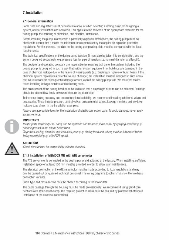
7.1.1 Installation of MEMDOS MR with ATE servomotorThe ATE servomotor is connected to the dosing pump and adjusted at the factory. When installing, sufficient installation space of at least 150 mm must be provided in order to allow later maintenance.
The electrical connection of the ATE servomotor must be made according to local regulations and may only be carried out by qualified technical personnel. The wiring diagrams (Section 7.5) show the two basic connection variants.
Cable type and cross-section must be chosen according to the motor data.
The cable passage through the housing must be made professionally. We recommend using gland con-nections with strain-relief clamp. The required protection class must be ensured by professional-standard installation of the electrical connections.
16 | Operation & Maintenance Instructions | Delivery characteristic curves

ATTENTION!Note that the ATE servomotor can only be actuated when the main drive motor of the dosing pump is run-ning. This means that the ATE servomotor must be locked electrically. Otherwise, the adjusting eccentric will suffer excessive wear, or be destroyed.
7.2 Installation locationThe installation location of the dosing pump must be easily accessible by operating and service personnel.
ATTENTION!Ambient temperatures above 40 °C are not permitted. Radiant heat from apparatus and heat exchangers must be shielded so that heat from the dosing pump can be dissipated sufficiently. Avoid exposure to direct sunlight. If the dosing pump is installed outside, provide a roof to protect it from the effects of weather.
Install the pump so that the suction and discharge valves are in vertical position. To ensure stability, the dosing pump must be screwed onto an appropriate surface. The system piping must not exert any force on the connections and valves of the dosing pump. To avoid dosing errors at the end of the process, the dosing pump must be locked electrically and hydraulically.
7.3 Drain pipe
ATTENTION! Released gases can cause irreparable damage to the gearing in the dosing pump.
Drainage or leakage from the separating chamber must be allowed to flow downward to the collecting pan. The drain pipe must never lead directly back to the medium through the tank cover, otherwise released gases may get into the pump gearbox. The drain pipe should only lead downward to a gas-free collecting tank or downward to a collecting funnel, leaving a sufficient gap from the end of the pipe. Leakage can then be returned through the funnel and through the tank cover. This makes it easier to detect any leakages at the gap to the collecting funnel.
ATTENTION!If a leakage monitor is installed in an area with a potentially explosive atmosphere, the electrical connection must be intrinsically safe. The drive motor must be electrically interlocked to prevent additional medium escaping if a leak occurs.
7.4 Electrical connection of the pumpThe electrical connection of the dosing pump must be made according to local rules and regulations and may only be carried out by qualified technical personnel. Cable type and cross-section of the supply lines must be chosen according to the motor data. The cable passage to the motor terminal box must be made professionally. We recommend using gland connections with strain-relief clamp. The required protection class must be ensured by professional-standard installation of the electrical connections.
ATTENTION! Dosing pumps with explosion-proof motors must be installed and commissioned by specialists qualified to work with equipment intended for use in potentially explosive atmospheres. The user is responsible for ensuring that explosion-proof motors are connected correctly. Both the motor and dosing pump must be grounded to prevent electrostatic discharges.
NOTE!The dosing pump must be plugged into a grounded power outlet.
Delivery characteristic curves | Operation & Maintenance Instructions | 17

NOTE!Signal cables must not be laid parallel to high-voltage current lines or mains cables. Lay supply and signal lines in separate channels. An angle of 90° is required at line crossings. If signal lines are longer than 2 m, shielded cables must be used.
ATTENTION!To avoid premature wear of the gear, always ensure the correct rotation direction of the motor: counter-clockwise (to the left), looking toward the fan wheel.
7.4.1 Drive motor connection
IMPORTANT!Note the data on the motor rating plate
Connection MEMDOS Phases Note
W2 U2 V2
U1 V1 W1
L1 L2 L3 PEMR 50 - 980 3~
Y-connection (Standard)
W2 U2 V2
U1 V1 W1
L1 L2 L3 PE
Delta connection
MEMDOS MR three-phase motors
Electrical connection data
MEMDOS Voltage Frequency Power output CurrentV Hz kW A
MR 50 - 980
400/230 500.55
1,50/2,60400/230
601,25/2,20
400/254 1,25/2,20400/230 50
0.752,00/3,50
400/23060
1,75/3,05400/254 1,70/3,10
7.5 Wiring diagrams for ATE servomotor for stroke length adjustment
123161718
456789
101112131415
③ ④ L L N PE① ② ⑤ ⑥230 V~
18 | Operation & Maintenance Instructions | Installation
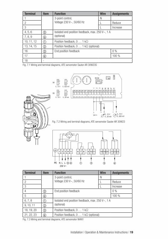
Terminal Item Function Wire Assignments1 3-point control,
Voltage 230 V~, 50/60 HzN
2 L Reduce3 L Increase4, 5, 6 e Isolated end position feedback, max. 250 V~, 1 A
(optional)7, 8, 9 f
10, 11, 12 a Position feedback, 0 … 1 kΩ
13, 14, 15 b Position feedback, 0 … 1 kΩ (optional)
16 c End position feedback 0 %
17 d 100 %
18 -Fig. 7.1 Wiring and terminal diagrams, ATE servomotor Sauter AR 30W23S
S421 1
S5
0...10 V 0...20 mA
0...10 V 0...620 mV
2
21
21
1 2 3 44 46 46 47 21
S5 S4
12
–24 V~
+– +0...10 V0...620 mV
0...10 V0...20 mA
Fig. 7.2 Wiring and terminal diagrams, ATE servomotor Sauter AR 30W23
1 2 3 4 5 6 7 8 9 10 11 18 19 20 21 22 23
N L L ③ ④ ①230 V~
PE ② ③ ④
Terminal Item Function Wire Assignments1 3-point control,
Voltage 230 V~, 50/60 HzN
2 L Reduce3 L Increase4 c End position feedback 0 %
5 d 100 %
6, 7, 8 a Isolated end position feedback, max. 250 V~, 1 A(optional)9, 10, 11 b
18, 19, 20 c Position feedback, 0 … 1 kΩ
21, 22, 23 d Position feedback, 0 … 1 kΩ (optional)Fig. 7.3 Wiring and terminal diagrams, ATE servomotor WAN1
Installation | Operation & Maintenance Instructions | 19

L N N A A B B 2 3 18 19 20 51 52 53 54 55
51 52 53
– +
+–
0/4...20 mA
0...10 V DC
51 52 53
PE L N230 V~
③① ② 0/4...20 mA0...10 V DC0...10 kOhm
④
Terminal Item Function Assignments2 a End position feedback 0 %
3 b 100 %
18, 19, 20 c Position feedback, 0 … 1 kΩ
54 (-) d Position feedback, 0 … 20 mA55 (+)
Fig. 7.4 Wiring and terminal diagrams, ATE servomotor WAN1S
7.6 Pressure control and safety valvesPressure control valves are used to optimise the dosing process. They are used:• to increase the dosing accuracy in the case of fluctuating backpressure.• when the dosing lines are long, in order to prevent excess delivery, since the accelerated medium
continues moving due to its own inertia even after the delivery stroke has ended.• to prevent siphoning, if the supply pressure is higher than system pressure.
Pressure relief and safety valves are used for overload protection of the dosing pump and the associated valves and lines. They prevent inadmissible pressure rises in the delivery side system of the dosing pump; for example, if shutoff valves close while the pump is running, or if the injection nozzle is clogged.
The PENTABLOC is a combination valve and performs the functions of a pressure control valve and a safety valve. It also integrates functions such as anti-siphoning, pressure relief and dosing control.
7.7 Injection nozzle installationInjection nozzles are used to inject the metered medium into the main flow, while at the same time acting as non-return valve. The injection nozzle is usually mounted from the top into the main line. Mounting from below is recommended only for media that have a tendency to crystallise, in order to prevent air bubbles from being trapped in.
For media that tend to contaminate the injection nozzle, we recommend installing an injection nozzle that can be shut off and removed for maintenance purposes.
a
b
a Injection nozzle mounted from above, b Injection nozzle mounted from below (for media that tend to crystallise)
20 | Operation & Maintenance Instructions | Installation
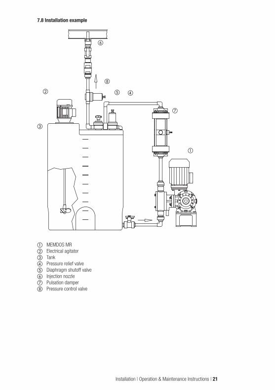
7.8 Installation example
g
h
b d
c
a
f
e
a MEMDOS MRb Electrical agitatorc Tankd Pressure relief valvee Diaphragm shutoff valvef Injection nozzleg Pulsation damperh Pressure control valve
Installation | Operation & Maintenance Instructions | 21

8. Operation
8.1. Stroke length adjustment
ATTENTION!The stroke length should not be adjusted while the dosing pump is stopped!
Proceed as follows to adjust the stroke length:1. Turn the mounting screw on the adjusting knob counterclockwise (to the left) to loosen it.2. Set the stroke length to the required value according to the delivery characteristic curves (section 6).3. Retighten the mounting screw without changing the stroke length setting.
22 | Operation & Maintenance Instructions | Installation
9. Start-up
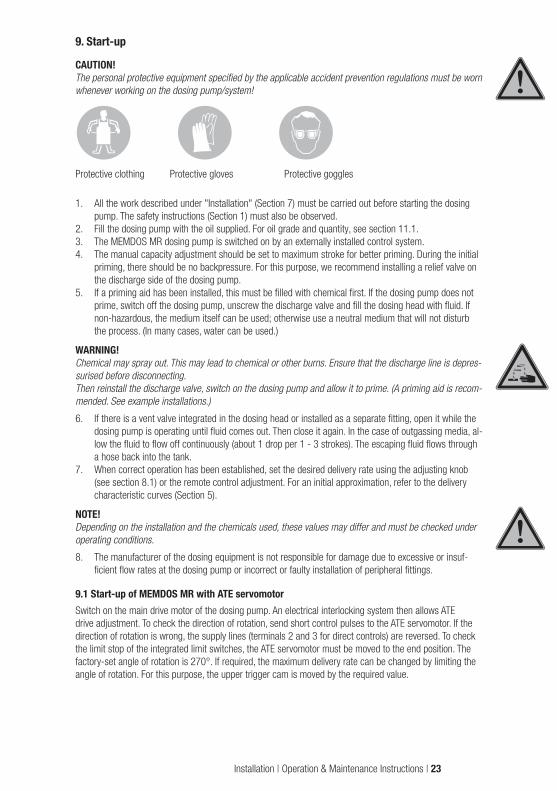
CAUTION!The personal protective equipment specified by the applicable accident prevention regulations must be worn whenever working on the dosing pump/system!
Protective clothing Protective gloves Protective goggles
1. All the work described under "Installation" (Section 7) must be carried out before starting the dosing pump. The safety instructions (Section 1) must also be observed.
2. Fill the dosing pump with the oil supplied. For oil grade and quantity, see section 11.1.3. The MEMDOS MR dosing pump is switched on by an externally installed control system.4. The manual capacity adjustment should be set to maximum stroke for better priming. During the initial
priming, there should be no backpressure. For this purpose, we recommend installing a relief valve on the discharge side of the dosing pump.
5. If a priming aid has been installed, this must be filled with chemical first. If the dosing pump does not prime, switch off the dosing pump, unscrew the discharge valve and fill the dosing head with fluid. If non-hazardous, the medium itself can be used; otherwise use a neutral medium that will not disturb the process. (In many cases, water can be used.)
WARNING!Chemical may spray out. This may lead to chemical or other burns. Ensure that the discharge line is depres-surised before disconnecting. Then reinstall the discharge valve, switch on the dosing pump and allow it to prime. (A priming aid is recom-mended. See example installations.)
6. If there is a vent valve integrated in the dosing head or installed as a separate fitting, open it while the dosing pump is operating until fluid comes out. Then close it again. In the case of outgassing media, al-low the fluid to flow off continuously (about 1 drop per 1 - 3 strokes). The escaping fluid flows through a hose back into the tank.
7. When correct operation has been established, set the desired delivery rate using the adjusting knob (see section 8.1) or the remote control adjustment. For an initial approximation, refer to the delivery characteristic curves (Section 5).
NOTE!Depending on the installation and the chemicals used, these values may differ and must be checked under operating conditions.
8. The manufacturer of the dosing equipment is not responsible for damage due to excessive or insuf-ficient flow rates at the dosing pump or incorrect or faulty installation of peripheral fittings.
9.1 Start-up of MEMDOS MR with ATE servomotorSwitch on the main drive motor of the dosing pump. An electrical interlocking system then allows ATE drive adjustment. To check the direction of rotation, send short control pulses to the ATE servomotor. If the direction of rotation is wrong, the supply lines (terminals 2 and 3 for direct controls) are reversed. To check the limit stop of the integrated limit switches, the ATE servomotor must be moved to the end position. The factory-set angle of rotation is 270°. If required, the maximum delivery rate can be changed by limiting the angle of rotation. For this purpose, the upper trigger cam is moved by the required value.
Installation | Operation & Maintenance Instructions | 23

10. ShutdownBefore starting any maintenance work or before long downtimes, drain the chemicals from the dosing pump and rinse it thoroughly with a neutral medium.
CAUTION!Excess chemicals must be disposed of properly. Observe the applicable accident prevention regulations and wear personal protective equipment.
Protective clothing Protective gloves Protective goggles
CAUTION!The dosing pump must be disconnected from the voltage supply and secured to prevent it being restarted.
CAUTION!Before disconnecting the discharge line from the pump discharge valve, release the pressure so that chemicals do not spray out.
The discharge and suction valves should be unscrewed in order to drain the dosing head.
10.1 Disposal of old equipmentIf the equipment is being disposed of, it should be washed thoroughly. Residual chemicals should be dis-posed of properly. The equipment was manufactured in accordance with the ROHS guideline and the waste electrical equipment legislation. The manufacturer will take care of disposal if the equipment is returned free of charge. It should not be disposed of as domestic waste!
24 | Operation & Maintenance Instructions | Operation

11. MaintenanceThese dosing pumps are produced to the highest quality standards, and have a long service life. Nev-ertheless, some of their parts are subject to wear due to operation (e.g. diaphragms, valve seats, valve balls). Regular visual inspections are therefore necessary in order to ensure a long operating life. Regular maintenance will protect the dosing pump from operation interruptions. The manufacturer recommends maintenance once per year, provided the local regulations do not specify more frequent maintenance.
11.1 LubricationThe MEMDOS MR diaphragm dosing pump requires little maintenance. The dosing pump gear is lubricated with gear oil of viscosity class ISO-VG460 according to DIN 51519 (corresponds to SAE 140 according to DIN 51512). The first filling, which is supplied with the product, is to be replaced after 5,000 operating hours or 1 year, whichever comes first. Further oil changes should be conducted after 10,000 operating hours or 2 years, whichever comes first. The filling capacity is about 0.75 litre for simplex gears and about 0.9 litre for duplex gears. The actually quantity of gear oil required can be determined by reading the oil level glass. The oil should be filled to approx. the middle of the oil level glass.
11.2 Maintenance of the bearingsThe upper bearing of the pinion shaft is a sealed and permanently lubricated ball bearing. The other rolling bearings in the gearing, and the plain bearings of the diaphragm rod, are lubricated by the gear oil. The oil also performs a heat dissipation function.
All bearings must be examined for wear after 10000 hours of operation. The service life of the rolling bear-ings depends on the applied loads.
11.3 Maintenance of the ATE servomotor (optional)The ATE servomotor comes with lifetime lubrication ex factory. Nevertheless, regular inspections are recom-mended if the drive is operated in tough operating conditions, for example in high ambient temperatures or continuous operation. To re-lubricate the ATE gear, use molybdenum disulphite, for example "Molykote BR2plus" or "OKS400".
11.4 Diaphragm replacement
CAUTION!Chemical may spray out. This may lead to chemical or other burns. The dosing pump must always be depressurised and rinsed with water or a suitable medium before starting any work on the dosing pump.
a Dosing head with discharge and suction valveb Diaphragmc Deflector plated Diaphragm rode Diaphragm flangef Gear housing
Fig. 11.1: Dosing head MEMDOS MR
a
d e f
bc
Start-up | Operation & Maintenance Instructions | 25

The diaphragm can be replaced as follows:1. The delivery rate of the dosing pump is set to zero while the motor is running.
This moves the diaphragm to the front end position.2. Switch off the pump.3. The dosing head is removed using an appropriate tool. (see Fig. 1)4. Grasp the edge of the diaphragm and turn it to the left.
IMPORTANT!Before fitting a new diaphragm, the area around the diaphragm flange and support plate must be cleaned to remove any chemicals, otherwise they may corrode the back of the diaphragm. (see Fig. 2)
5. The new diaphragm is turned clockwise until it is screwed securely into the diaphragm rod (grease the thread).
6. The dosing pump stroke is now set to maximum while the motor is running. Switch off the motor. The diaphragm is now seated in the groove of the diaphragm flange.
7. Fit the dosing head at the front. Tighten the screws crosswise, e.g. top left – bottom right – top right – bottom left. (see Fig. 4). For the required tightening torque, see table 11.1.
IMPORTANT!The diaphragm will not be sufficiently sealed if the tightening torque is too low. The dosing head may be damaged if the tightening torque is too high.
9. After connecting the dosing lines, the dosing pump is started as described in "Start-up" (Section 9).10. If the diaphragm becomes worn with unusual frequency, try to determine the cause. For the possible
causes, please refer to "Troubleshooting" (Section 13).
1 2
43
Fig. 11.2: Diaphragm replacement
Diaphragm Ø [mm]
Torque (+/- 10%) [Nm]
90 6120 6150 10185 12
Table 11.1: Required tightening torque for dosing head screws
26 | Operation & Maintenance Instructions | Außerbetriebnahme

11.5 Manual adjustment of the ATE servomotor, Type AR30WThe ATE servomotor, Type AR30W, can be moved manually using a hand crank in the event of an electrical defect. The hand crank is available as an accessory under Part No. 32.587.
Manual adjustment is carried out as described in the following:1. Disconnect the ATE servomotor from the power supply.2. Remove the cover from the drive unit.3. Switch on the main drive motor.4. Insert hand crank in corresponding opening, as shown below, and turn in desired direction.
ATTENTION!Do not turn beyond the end positions.
5. Reattach the cover after manual adjustment.
2
100%
Fig. 11.3: Inserting the hand crank and turning Fig. 11.4: Setting the angle of rotation
11.6 ValvesThe dosing pump valves must be cleaned regularly.
NOTE!When screwing the valves into the dosing head, observe the tightening torque of 2 Nm ±20 %.
CAUTION!Chemical may spray out. This may lead to chemical or other burns. The dosing pump must always be depressurised and rinsed with water or a suitable medium before starting any work on the dosing pump.
NOTE!Dirty valves will affect the dosing accuracy.
Maintenance | Operation & Maintenance Instructions | 27
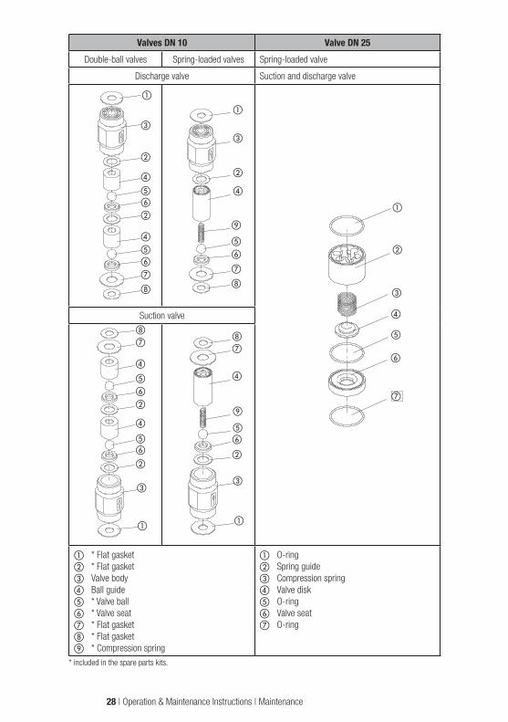
Valves DN 10 Valve DN 25Double-ball valves Spring-loaded valves Spring-loaded valve
Discharge valve Suction and discharge valve
Suction valve
a * Flat gasketb * Flat gasketc Valve bodyd Ball guidee * Valve ballf * Valve seatg * Flat gasketh * Flat gasketi * Compression spring
a O-ringb Spring guidec Compression springd Valve diske O-ringf Valve seatg O-ring
* included in the spare parts kits.
h
g
d
e
f
b
d
ef
b
c
a
a
c
b
d
ef
b
d
ef
g
h
hg
d
i
ef
b
c
a
a
c
b
d
i
e
f
g
h
a
b
c
d
e
f
g
28 | Operation & Maintenance Instructions | Maintenance

12. Explosion-proof dosing pumps (ATEX)
12.1 GeneralThe explosion-proof version of the MEMDOS MR dosing pump is an electric motor-driven, explosion-proof diaphragm dosing pump of equipment category 2, group II.
In combination with an explosion-proof motor (Ex II 2 G E Ex e II T3 or Ex II 2 G E Ex d/de IIB/IIC T4) it is used for dosing fluids Zone 1 hazardous areas. The dosing pump carries the Ex mark "Ex II 2 G c k T4 03 ATEX D086".
ATTENTION!The dosing pump is not intended for dosing gaseous media or solids.
12.2 Special conditionsThe minimum requirements for the zone classification must be ensured if using the dosing pump in areas with a potentially explosive atmosphere. The dosing pump itself and the motor must meet the minimum requirements.
12.3 Dosing of flammable mediaIf dosing flammable fluids, all metal parts in the suction and discharge pipes must be grounded to prevent electrostatic discharge.
Stainless steel is recommended for the dosing head.
Dosing pumps with diaphragms more than 90 mm in diameter are equipped with special conductive dia-phragms to prevent static charging. When obtaining replacement parts, order original diaphragms only.
Maintenance | Operation & Maintenance Instructions | 29
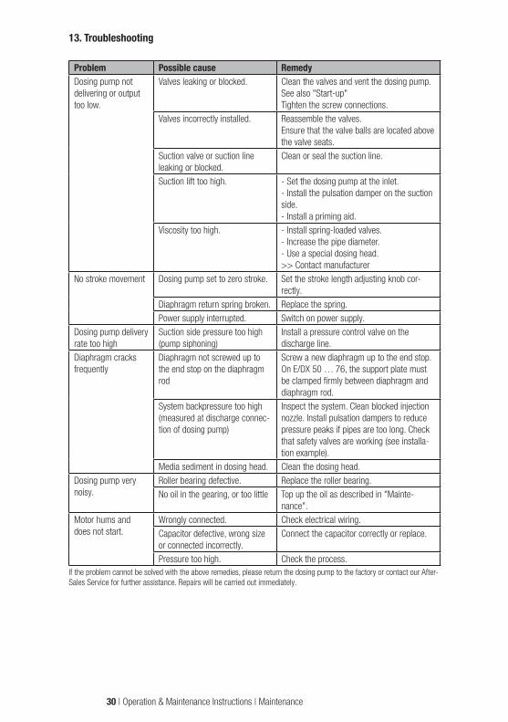
13. Troubleshooting
Problem Possible cause RemedyDosing pump not delivering or output too low.
Valves leaking or blocked. Clean the valves and vent the dosing pump.See also "Start-up"Tighten the screw connections.
Valves incorrectly installed. Reassemble the valves. Ensure that the valve balls are located above the valve seats.
Suction valve or suction line leaking or blocked.
Clean or seal the suction line.
Suction lift too high. - Set the dosing pump at the inlet.- Install the pulsation damper on the suction side.- Install a priming aid.
Viscosity too high. - Install spring-loaded valves.- Increase the pipe diameter.- Use a special dosing head.>> Contact manufacturer
No stroke movement Dosing pump set to zero stroke. Set the stroke length adjusting knob cor-rectly.
Diaphragm return spring broken. Replace the spring.Power supply interrupted. Switch on power supply.
Dosing pump delivery rate too high
Suction side pressure too high (pump siphoning)
Install a pressure control valve on the discharge line.
Diaphragm cracks frequently
Diaphragm not screwed up to the end stop on the diaphragm rod
Screw a new diaphragm up to the end stop. On E/DX 50 … 76, the support plate must be clamped firmly between diaphragm and diaphragm rod.
System backpressure too high (measured at discharge connec-tion of dosing pump)
Inspect the system. Clean blocked injection nozzle. Install pulsation dampers to reduce pressure peaks if pipes are too long. Check that safety valves are working (see installa-tion example).
Media sediment in dosing head. Clean the dosing head.Dosing pump very noisy.
Roller bearing defective. Replace the roller bearing.No oil in the gearing, or too little Top up the oil as described in "Mainte-
nance".Motor hums and does not start.
Wrongly connected. Check electrical wiring.Capacitor defective, wrong size or connected incorrectly.
Connect the capacitor correctly or replace.
Pressure too high. Check the process.If the problem cannot be solved with the above remedies, please return the dosing pump to the factory or contact our After-Sales Service for further assistance. Repairs will be carried out immediately.
30 | Operation & Maintenance Instructions | Maintenance
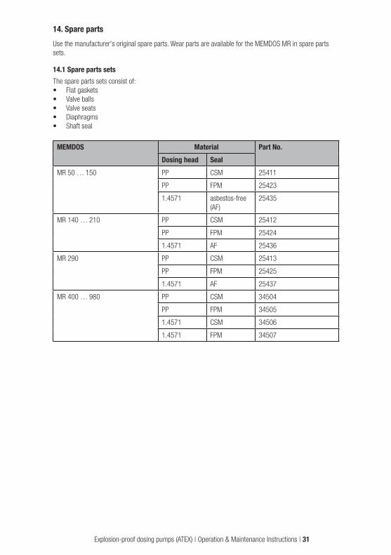
14. Spare partsUse the manufacturer's original spare parts. Wear parts are available for the MEMDOS MR in spare parts sets.
14.1 Spare parts setsThe spare parts sets consist of:• Flat gaskets• Valve balls• Valve seats• Diaphragms• Shaft seal
MEMDOS Material Part No.Dosing head Seal
MR 50 … 150 PP CSM 25411
PP FPM 25423
1.4571 asbestos-free (AF)
25435
MR 140 … 210 PP CSM 25412
PP FPM 25424
1.4571 AF 25436
MR 290 PP CSM 25413
PP FPM 25425
1.4571 AF 25437
MR 400 … 980 PP CSM 34504
PP FPM 34505
1.4571 CSM 34506
1.4571 FPM 34507
Explosion-proof dosing pumps (ATEX) | Operation & Maintenance Instructions | 31

15. External vent (optional)
Functional description of vent motorsThe fan cowl and fan blade of the drive motor are removed and replaced by the extended fan cowl with in-tegrated fan. The fan has a direct mains connection, and therefore delivers the maximum quantity of cool air to protect the motor against overheating at all speeds. Separate fans can be operated over a wide voltage range, according to the technical data. They can be connected to three-phase or alternating current power supply, if connected according to the instructions. For single-phase operation, an operating capacitor is included in the terminal box (see electrical wiring diagram). The fan motors work according to the direction of rotation. The air flow must be directed towards the motor.
Special versions available• Extended fan cowl (for operation with tachogenerator or motor brake)• Alternative mounting bracket• Different fan cowl diameter
Technical dataMotor size 63 71 80 90 100 112
Air flow rate m3/h 47 60 88 169 208 295
Power consumption W 27 30 28.5 86 86 84.5
Speed at 50 Hz (rpm) 2910 2870 2790 2880 2830 2770
Sound pressure level dB(A) 47 51 55 58 59 61
Protection class IP 66
Dimen-sions (mm)
Height 185 190 195 205 210 215
Diameter 126 143 160 176 196 220
Nominal motor current (A)
3~, 200 … 290 V, Delta 0.092 0.095 0.090 0.28 0.27 0.27
3~, 346 … 500 V, Y 0.06 0.06 0.05 0.06 0.06 0.06
1~, 230 V 0.075 0.081 0.090 0.19 0.21 0.23
Electrical wiring diagram
L1 L2 L3 PE L1 L2 L3 PE
L1 N PE
W2 U2 V2
U1 V1 W1
W2 U2 V2
U1 V1 W1
W2 U2 V2
U1 V1 W1
L1 L2 L3 PE L1 L2 L3 PE
L1 N PE
W2 U2 V2
U1 V1 W1
W2 U2 V2
U1 V1 W1
W2 U2 V2
U1 V1 W1
L1 L2 L3 PE L1 L2 L3 PE
L1 N PE
W2 U2 V2
U1 V1 W1
W2 U2 V2
U1 V1 W1
W2 U2 V2
U1 V1 W1
3~ Y-connection 3~ delta connection 1~ Steinmetz connection
32 | Operation & Maintenance Instructions | Troubleshooting

16. EU Declaration of Confirmity
(DE) EU-KonformitätserklärungHiermit erklären wir, dass das nachfolgend bezeichnete Gerät aufgrund seiner Konzipierung und Bauart sowie in der von uns in Verkehr gebrachten Ausführung den einschlägigen grundlegenden Sicherheits- und Gesundheitsanforderungen der aufgeführten EG-Richtlinien entspricht. Bei einer nicht mit uns abgestimmten Änderung am Gerät verliert diese Erklärung ihre Gültigkeit.
(NL) EU-overeenstemmingsverklaringOndergetekende Lutz-Jesco GmbH, bevestigt, dat het volgende genoemde apparaat in de door ons in de handel gebrachte uitvoering voldoet aan de eis van, en in overeenstemming is met de EU-richtlijnen, de EU-veiligheidsstandaard en de voor het product specifieke standaard. Bij een niet met ons afgestemde verandering aan het apparaat verliest deze verklaring haar geldigheid.
(FR) Déclaration de conformité UENous déclarons sous notre propre responsabilité que le produit ci-dessous mentionné répond aux exigences essentielles de sécurité et de santé des directives CE énumérées aussi bien sur le plan de sa conception et de son type de construction que du modèle que nous avons mis en circulation. Cette déclaration perdra sa validité en cas d’une modification effectuée sur le produit sans notre accord explicite.
(PT) Declaração de conformidade UEDeclaramos pelo presente documento que o equipamento a seguir descrito, devido à sua concepção e ao tipo de construção daí resultante, bem como a versão por nós lançada no mercado, cumpre as exigências básicas aplicáveis de segurança e de saúde das directivas CE indicadas. A presente declaração perde a sua validade em caso de alteração ao equipamento não autorizada por nós.
(EN) EU Declaration of ConformityWe hereby certify that the device described in the following complies with the relevant fundamental safety and sanitary requirements and the listed EC regulations due to the concept and design of the version sold by us. If the device is modified without our consent, this declaration loses its validity.
(ES) Declaración de conformidad UEPor la presente declaramos que, dados la concepción y los aspectos constructivos del modelo puesto por nosotros en circulación, el aparato mencionado a conti-nuación cumple con los requisitos sanitarios y de seguridad vigentes de las directivas de la U.E. citadas a continuación. Esta declaración será invalidad por cambios en el aparato realizados sin nuestro consentimiento.
2006/42/EG, 2014/30/EU, 2014/34/EU
Die Schutzziele der Niederspannungsrichtlinie 2014/35/EU wurden gemäß Anhang I, Nr. 1.5.1 der Maschinenrichtlinie 2006/42/EG eingehalten.The protective aims of the Low Voltage Directive 2014/35/EU were adhered to in accordance with Annex I, No. 1.5.1 of the Machinery Directive 2006/42/EC.
EG-Richtlinien:EC directives:
DIN EN ISO 12100:2011-03, DIN EN 809:2012-10,DIN EN 13463-1:2009-07, DIN EN 13463-5:2011-10, DIN EN 13463-8:2004-01
Harmonisierte Normen:Harmonized standards:
Lutz-Jesco GmbHDokumentationsbevollmächtigter:Authorized person for documentation:
Bezeichnung des Gerätes:
Descripción de la mercancía:
Description of the unit:
Omschrijving van het apparaat:
Désignation du matériel:
Designação do aparelho:
Motor-Membrandosierpumpe
Bomba dosificadora de membrana accionada por motor
Motor-driven diaphragm dosing pump
Motor-membraandoseerpomp
Pompe doseuse à membrane entraînée par moteur
Bomba doseadora de membrana a motor
MEMDOS MR-EXMEMDOS ZMR-EX
Typ:Type:
Heinz LutzGeschäftsführer / Chief Executive OfficerLutz-Jesco GmbHWedemark, 01.06.2018
Lutz-Jesco GmbHAm Bostelberge 1930900 WedemarkGermany
PTB 03 ATEX D086Registernummer:Registry number:
Spare parts | Operation & Maintenance Instructions | 33

IndexAAmbient temperature ....................................................11Area with a potentially explosive atmosphere ..................16
BBearings .......................................................................25
CChemical leakage .........................................................16
DDelivery characteristic curves ........................................14Diaphragm replacement ................................................25Diaphragm wear ...........................................................26Dimensioned drawings ....................................................9Disposal .......................................................................24Dosing head ...................................................................7Dosing of chemicals ........................................................5
EElectrical connection .....................................................17Electric motor data ........................................................12Explosion-proof .............................................................29Explosion-proof motors ..................................................13
FFault ............................................................................30Function .........................................................................8
IInjection nozzle .............................................................20Installation ....................................................................16Installation example ......................................................21Installation location .......................................................17
LLubrication ...................................................................25
MMaintenance .................................................................25
OOil inlet...........................................................................7Oil outlet.........................................................................7Operation .....................................................................22
PPressure control and safety valves .................................20Principle of operation ......................................................8Protective clothing...........................................................5
SScope of delivery ............................................................6Separate fan .................................................................32Shutdown .....................................................................24Spare parts ...................................................................31Start-up........................................................................23Stroke frequency ...........................................................11Stroke length ................................................................11Stroke length adjustment ...............................................22Stroke volume ...............................................................11Structure of the dosing pump...........................................7
TTechnical data ..............................................................11Tightening torque ..........................................................26Training ..........................................................................3Troubleshooting ............................................................30
VValves ..........................................................................27
WWiring diagram for the drive motor .................................18
YY-connection .................................................................18
34 | Operation & Maintenance Instructions | External vent

Index | Operation & Maintenance Instructions | 35

BA-10502-02-V06Subject to technical changesand inaccuracies© Lutz-Jesco GmbH 06.2018