MELSEC-Q C Controller Module User's Manual - Mitsubishi ...
516
MELSEC-Q C Controller Module User's Manual -Q24DHCCPU-V -Q24DHCCPU-VG -Q24DHCCPU-LS -Q26DHCCPU-LS -Q12DCCPU-V(Extended mode)
-
Upload
khangminh22 -
Category
Documents
-
view
1 -
download
0
Transcript of MELSEC-Q C Controller Module User's Manual - Mitsubishi ...

MELSEC-Q C Controller Module User's Manual
-Q24DHCCPU-V-Q24DHCCPU-VG-Q24DHCCPU-LS-Q26DHCCPU-LS-Q12DCCPU-V(Extended mode)


1
SAFETY PRECAUTIONS(Read these precautions before using this product.)
Before using this product, please read this manual and the relevant manuals carefully and pay full attention
to safety to handle the product correctly.
In this manual, the safety precautions are classified into two levels: " WARNING" and " CAUTION".
Under some circumstances, failure to observe the precautions given under " CAUTION" may lead to
serious consequences.
Make sure that the end users read this manual and then keep the manual in a safe place for future
reference.
[Design Precautions]
WARNING● Configure safety circuits external to the C Controller module to ensure that the entire system
operates safely even when a fault occurs in the external power supply or the C Controller module.
Failure to do so may result in an accident due to an incorrect output or malfunction.
(1) Configure external safety circuits, such as an emergency stop circuit, protection circuit, and
protective interlock circuit for forward/reverse operation or upper/lower limit positioning.
(2) If the following status (a) or (b) occurs, the system will behave accordingly.
(a)When overcurrent or overvoltage protection of the power supply module is activated, the
outputs (Y) from the user program and writing to the buffer memory are disabled, and all
outputs are turned off.
(b)When the C Controller module detects an error such as a watchdog timer error by the
selfdiagnostic function, the outputs (Y) from the user program and writing to the buffer
memory are disabled. Whether to hold or turn off all outputs can be set by parameters.
All outputs may turn on when an error occurs in the part, such as I/O control part, where the C
Controller module cannot detect any error.To ensure safety operation in such a case, provide a
safety mechanism or a fail-safe circuit external to the C Controller module. For a fail-safe circuit
example, refer to "Page 493, Appendix 11".
(3) Outputs may remain on or off due to a failure of an output module relay or transistor. Configure
an external circuit for monitoring output signals that could cause a serious accident.
WARNING
CAUTION
Indicates that incorrect handling may cause hazardous conditions,
resulting in death or severe injury.
Indicates that incorrect handling may cause hazardous conditions,
resulting in minor or moderate injury or property damage.

2
[Design Precautions]
WARNING● In an output circuit, when a load current exceeding the rated current or an overcurrent caused by a
load short-circuit flows for a long time, it may cause smoke and fire. To prevent this, configure an
external safety circuit, such as a fuse.
● Configure a circuit so that the C Controller system is turned on first and then the external power
supply. If the external power supply is turned on first, an accident may occur due to an incorrect
output or malfunction.
● When there are communication problems with the data link, refer to the corresponding data link
manual for the operating status of each station. Incorrect output or malfunction may result in an
accident.
● When connecting a peripheral device to the CPU module or connecting a personal computer or the
like to the intelligent function module to exercise control (data change) on the running C Controller
module, configure up an interlock circuit in the user program to ensure that the whole system will
always operate safely. Also before exercising other control (program change, operating status
change (status control)) on the running C Controller module, read the manual carefully and fully
confirm safety. Especially for the above control on the remote C Controller module from an external
device, an immediate action may not be taken for C Controller module trouble due to a data
communication fault. In addition to configuring up the interlock circuit in the user program, corrective
and other actions to be taken as a system for the occurrence of a data communication fault should
be predetermined between the external device and CPU module.
● Do not write data into the write-protected area within the intelligent function module buffer memory.
Further, do not output (ON) prohibited signals in the output signals from the CPU module to the
intelligent function module. Writing data to the write-protected area or output of prohibited signals
may cause malfunction of the C Controller system.
● For the write-protected area and prohibited signals, refer to the User's Manual for each intelligent
function module.
● If the communication cable is disconnected, the line becomes unstable and any communication
problem may occur in multiple stations of the network. Even if any network communication problem
occurs in the multiple stations, configure up an interlock circuit in the user program to ensure safe
operation of the system. Failure to do so may result in an accident due to an incorrect output or
malfunction.
● When it is necessary to ensure safety of the C Controller system against unauthorized access from
any external device via the network, include measures by the user. Also, when it is necessary to
ensure safety of the C Controller system against unauthorized access from any external device via
the Internet, include measures such as a firewall.
● In the refresh parameter settings, "Y" cannot be specified for link output (LY) refresh device and
remote output (RY) refresh device. Therefore, the device prior to STOP remains in the event of CPU
STOP.
3
[Design Precautions]
[Installation Precautions]
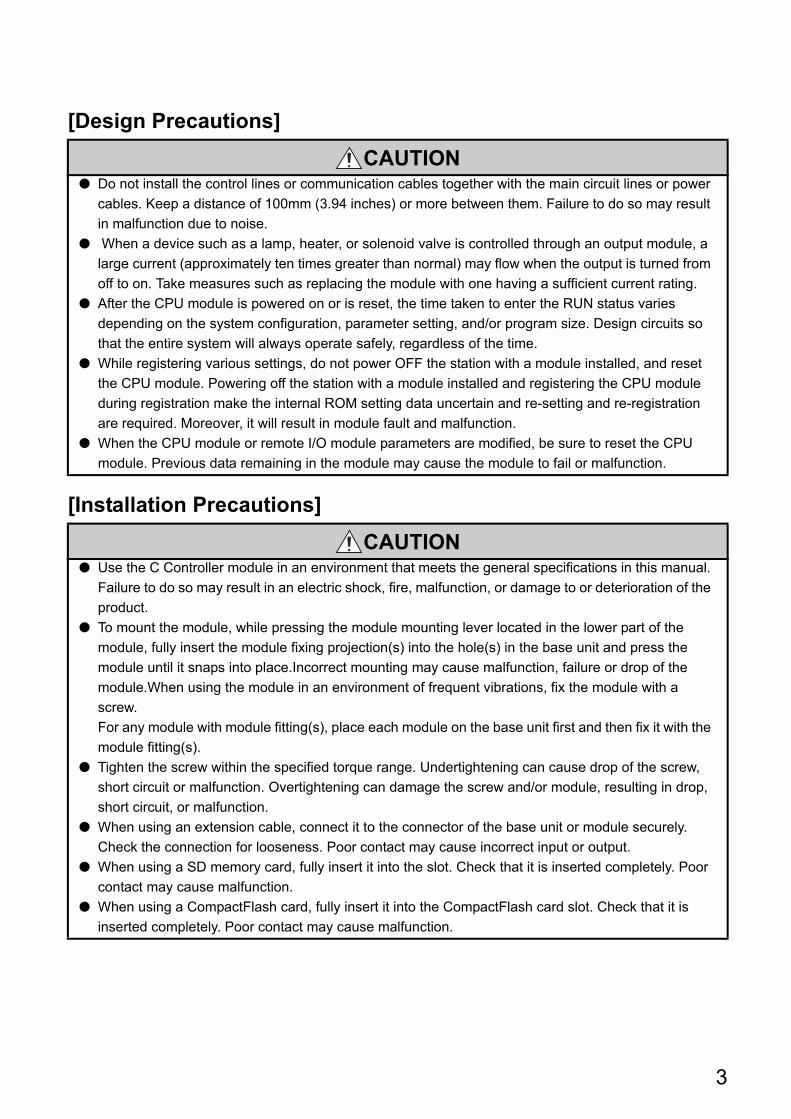
CAUTION● Do not install the control lines or communication cables together with the main circuit lines or power
cables. Keep a distance of 100mm (3.94 inches) or more between them. Failure to do so may result
in malfunction due to noise.
● When a device such as a lamp, heater, or solenoid valve is controlled through an output module, a
large current (approximately ten times greater than normal) may flow when the output is turned from
off to on. Take measures such as replacing the module with one having a sufficient current rating.
● After the CPU module is powered on or is reset, the time taken to enter the RUN status varies
depending on the system configuration, parameter setting, and/or program size. Design circuits so
that the entire system will always operate safely, regardless of the time.
● While registering various settings, do not power OFF the station with a module installed, and reset
the CPU module. Powering off the station with a module installed and registering the CPU module
during registration make the internal ROM setting data uncertain and re-setting and re-registration
are required. Moreover, it will result in module fault and malfunction.
● When the CPU module or remote I/O module parameters are modified, be sure to reset the CPU
module. Previous data remaining in the module may cause the module to fail or malfunction.
CAUTION● Use the C Controller module in an environment that meets the general specifications in this manual.
Failure to do so may result in an electric shock, fire, malfunction, or damage to or deterioration of the
product.
● To mount the module, while pressing the module mounting lever located in the lower part of the
module, fully insert the module fixing projection(s) into the hole(s) in the base unit and press the
module until it snaps into place.Incorrect mounting may cause malfunction, failure or drop of the
module.When using the module in an environment of frequent vibrations, fix the module with a
screw.
For any module with module fitting(s), place each module on the base unit first and then fix it with the
module fitting(s).
● Tighten the screw within the specified torque range. Undertightening can cause drop of the screw,
short circuit or malfunction. Overtightening can damage the screw and/or module, resulting in drop,
short circuit, or malfunction.
● When using an extension cable, connect it to the connector of the base unit or module securely.
Check the connection for looseness. Poor contact may cause incorrect input or output.
● When using a SD memory card, fully insert it into the slot. Check that it is inserted completely. Poor
contact may cause malfunction.
● When using a CompactFlash card, fully insert it into the CompactFlash card slot. Check that it is
inserted completely. Poor contact may cause malfunction.

4
[Installation Precautions]
[Wiring Precautions]
CAUTION● Shut off the external power supply for the system in all phases before mounting or removing the
module. Failure to do so may result in damage to the product. The system using a CPU module
ready for the online module change, and the MELSECNET/H remote I/O station are exchangeable in
the online state (while power is on). However, there are limited number of modules that are
exchangeable in the online state (while power is on) and a replacement procedures is defined for
each module. For details, refer to the QCPU User's Manual (Hardware Design, Maintenance and
Inspection) and the online module change section in the respective manual for each online
exchangeable module.
● Do not directly touch any conductive part of the module. Doing so can cause malfunction or failure of
the module.
● When using the Motion CPU module and the Motion module, be sure to check if the module
combination is correct before powering up. Use of improper combination may result in damage to the
product. For details, refer to the User's Manual for the module used.
WARNING● Shut off the external power supply for the system in all phases before installation and wiring. Failure
to do so may result in electric shock or damage to the product.
● After wiring, attach the included terminal cover to the module before turning it on for operation.
Failure to do so may result in electric shock.
5
CAUTION● Ground the FG and LG terminals to the protective ground conductor dedicated to the C controller
module. Failure to do so may result in electric shock or malfunction.
● Use compatible solderless terminals and tighten them to the specified torque. Use of lead-type
solderless terminals may cause the terminal screws be loosened, leading to a failure.
● Check the rated voltage and terminal layout before wiring to the module, and connect the cables
correctly. Connecting a power supply with a different voltage rating or incorrect wiring may cause a
fire or failure.
● Crimp, weld or properly solder the external connectors and co-axial cable connectors with tools
specified by the manufacturer. Incomplete connections could result in short circuit, fire or
malfunction.
● Do not install the control lines or the communication cables together with the main circuit lines or
power cables.
It should be at least 100 mm apart.Doing so may result in malfunction due to noise.
● Be sure to place in a duct or fix by clamps the power cords and cables connected to the module. If
not, dangling cable may swing or inadvertently be pulled, resulting in damage to the module or
cables or malfunctions due to poor contact.
● Tightening torque for the terminal screws should be in the specified range. Undertightening the
terminal screws can cause short circuit, fire or malfunction. Overtightening can damage the terminal
screw and/or module, resulting in drop, short circuit, or malfunction.

6
[Wiring Precautions]
[Startup and Maintenance Precautions]
CAUTION● Tightening torque for the connector mounting screws should be in the specified range.
Undertightening the screws can cause short circuit, fire or malfunction. Overtightening can damage
the screw and/or module, resulting in drop, short circuit, fire or malfunction.
● Securely install connectors to the module. Improper installation can cause malfunction.
● When disconnecting a cable from the module, do not hold and pull the cable part.For a cable with
connector, hold the connected connector by hand to disconnect the cable. For terminal block cables,
loosen the terminal block terminal screws first. Pulling the cable while being connected to the module
will result in malfunction or damage to the module or the cable.
● Check the type of interface to connect in advance in order to properly connect cables. Connection or
wiring to wrong interface can cause a failure of the module and external device.
● Prevent foreign matter such as dust or wire chips from entering the module. Such foreign matter can
cause a fire, failure, or malfunction.
● To prevent foreign matters such as wire chips from entering into the module during wiring, a sealing
label is attached to the top of the module. During wiring, do not remove this label. During system
operation, be sure to remove this label to release the heat.
● Use the C Controller module as being installed in the control panel. Let the main power wiring
through the relay terminal block to the PLC power supply unit installed in the control panel. Further,
replacement and wiring of the power supply module must be performed by maintenance personnel
fully trained for electric shock protection. For wiring procedures, refer to the QCPU User's Manual
(Hardware Design, Maintenance and Inspection).
WARNING● Do not touch any terminal while power is on. Doing so will cause electric shock.
● Correctly connect the battery connector. Do not charge, disassemble, heat, short-circuit, solder, or
throw the battery into the fire. Doing so will cause the battery to produce heat, explode, or ignite,
resulting in injury and fire.
● Shut off the external power supply for the system in all phases before cleaning the module or
retightening the terminal screws or module fixing screws. Failure to do so may result in electric
shock, module failure or malfunction. Undertightening the terminal screws can cause resulting in
drop, short circuit or malfunction. Overtightening can damage the screw and/or module, resulting in
drop, short circuit, or malfunction.

7
[Startup and Maintenance Precautions]
CAUTION● When connecting a peripheral device to the CPU module or connecting a personal computer or the
like to the intelligent function module to exercise control (data change) on the running C Controller
module, configure up an interlock circuit in the user program to ensure that the whole system will
always operate safely. Also before exercising other control (program change, operating status
change (status control)) on the running C Controller module, read the manual carefully and fully
confirm safety. Especially for the above control on the remote C Controller module from an external
device, an immediate action may not be taken for C Controller module trouble due to a data
communication fault. In addition to configuring up the interlock circuit in the user program, corrective
and other actions to be taken as a system for the occurrence of a data communication fault should
be predetermined between the external device and CPU module.
● Do not disassemble or modify the modules. Doing so may cause failure, malfunction, injury, or a fire.
● Use any radio communication device such as a cellular phone or PHS (Personal Handy-phone
System) more than 25cm (9.85 inches) away in all directions from the C Controller module. Failure to
do so may cause malfunction.
● Shut off the external power supply for the system in all phases before mounting or removing the
module. Failure to do so may cause the module to fail or malfunction. The system using a CPU
module ready for the online module change, and the MELSECNET/H remote I/O station are
exchangeable in the online state (while power is on). However, there are limited number of modules
that are exchangeable in the online state (while power is on) and a replacement procedures is
defined for each module. For details, refer to the QCPU User's Manual (Hardware Design,
Maintenance and Inspection) and the online module change section in the respective manual for
each online exchangeable module.
● After the first use of the product, the number of connections/disconnections is limited to 50 times (in
accordance with IEC 61131-2). Exceeding the limit may cause malfunction.
● After the first use of the SD memory card, the number of insertions/removals is limited to 500 times.
Exceeding the limit may cause malfunction.
● Do not drop or apply shock to the battery to be installed in the module. Doing so may damage the
battery, causing the battery fluid to leak inside the battery. If the battery is dropped or any shock is
applied to it, dispose of it without using.
● Startup and maintenance inside the control panel must be performed by maintenance personnel fully
trained for electric shock protection. Further, take measures to prevent any person other than
maintenance personnel from operating the control panel, e.g. locking the control panel.
● Before handling the module, touch a grounded metal object to discharge the static electricity from
the human body. Failure to do so may cause the module to fail or malfunction.
● After first use of the product, do not install or remove the SD memory card more than 500 times.
Exceeding the limit of 500 times may cause malfunction.

8
[Disposal Precautions]
[Transportation Precautions]
CAUTION● When disposing of this product, treat it as industrial waste.
When disposing of batteries, separate them from other wastes according to the local regulations.
(For details of battery regulations in the EU countries, refer to the QCPU User's Manual (Hardware
Design, Maintenance and Inspection).)
CAUTION● When transporting lithium batteries, follow the transportation regulations. (For details of subject
models, refer to the QCPU User's Manual (Hardware Design, Maintenance and Inspection).)
9
CONDITIONS OF USE FOR THE PRODUCT
(1) Mitsubishi programmable controller ("the PRODUCT") shall be used in conditions;
i) where any problem, fault or failure occurring in the PRODUCT, if any, shall not lead to any major
or serious accident; and
ii) where the backup and fail-safe function are systematically or automatically provided outside of
the PRODUCT for the case of any problem, fault or failure occurring in the PRODUCT.
(2) The PRODUCT has been designed and manufactured for the purpose of being used in general
industries.
MITSUBISHI SHALL HAVE NO RESPONSIBILITY OR LIABILITY (INCLUDING, BUT NOT
LIMITED TO ANY AND ALL RESPONSIBILITY OR LIABILITY BASED ON CONTRACT,
WARRANTY, TORT, PRODUCT LIABILITY) FOR ANY INJURY OR DEATH TO PERSONS OR
LOSS OR DAMAGE TO PROPERTY CAUSED BY the PRODUCT THAT ARE OPERATED OR
USED IN APPLICATION NOT INTENDED OR EXCLUDED BY INSTRUCTIONS, PRECAUTIONS,
OR WARNING CONTAINED IN MITSUBISHI'S USER, INSTRUCTION AND/OR SAFETY
MANUALS, TECHNICAL BULLETINS AND GUIDELINES FOR the PRODUCT.
("Prohibited Application")
Prohibited Applications include, but not limited to, the use of the PRODUCT in;
• Nuclear Power Plants and any other power plants operated by Power companies, and/or any
other cases in which the public could be affected if any problem or fault occurs in the PRODUCT.
• Railway companies or Public service purposes, and/or any other cases in which establishment of
a special quality assurance system is required by the Purchaser or End User.
• Aircraft or Aerospace, Medical applications, Train equipment, transport equipment such as
Elevator and Escalator, Incineration and Fuel devices, Vehicles, Manned transportation,
Equipment for Recreation and Amusement, and Safety devices, handling of Nuclear or
Hazardous Materials or Chemicals, Mining and Drilling, and/or other applications where there is a
significant risk of injury to the public or property.
Notwithstanding the above, restrictions Mitsubishi may in its sole discretion, authorize use of the
PRODUCT in one or more of the Prohibited Applications, provided that the usage of the PRODUCT
is limited only for the specific applications agreed to by Mitsubishi and provided further that no
special quality assurance or fail-safe, redundant or other safety features which exceed the general
specifications of the PRODUCTs are required. For details, please contact the Mitsubishi
representative in your region.

10
OPERATING PRECAUTIONS
(1) Precautions for the Wind River Systems productThe C Controller module has an embedded real-time operating system, VxWorks, made and sold by Wind River
Systems, Inc. in the United States. We, Mitsubishi, make no warranty for the Wind River Systems product and will
not be liable for any problems and damages caused by the Wind River Systems product during use of the C
Controller module.
For the problems or specifications of the Wind River Systems product, refer to the corresponding manual or
consult Wind River Systems, Inc. Contact information is available on the following website.
http://www.windriver.com/
(2) Precautions for the partner operating systemQ24DHCCPU-LS and Q26DHCCPU-LS can be used by installing the operating system (partner operating
system) provided by the partner (operating system vendor). We, Mitsubishi, make no warranty for the partner
(operating system vendor) product and will not be liable for any problems and damages caused by the partner
(operating system vendor) product during use of Q24DHCCPU-LS and Q26DHCCPU-LS.
For the problems or specifications of the partner (operating system vendor) product, refer to the corresponding
manual, or consult the partner (operating system vendor). Contact information is available on the following
website.
• Lineo Solutions, Inc. http://www.lineo.co.jp/modules/english/
(3) Precautions for the partner applicationThe application provided by the partner (application vendor) has been installed in Q24DHCCPU-VG. We,
Mitsubishi, make no warranty for the partner (application vendor) product and will not be liable for any problems
and damages caused by the partner (application vendor) product during use of Q24DHCCPU-VG.
For the problems or specifications of the partner (application vendor) product, refer to the corresponding manual,
or consult the partner (application vendor). Contact information is available on the following website.
• INTERNATIONAL LABORATORY CORPORATION http://www.ilc.co.jp/en/

11
INTRODUCTION
Thank you for purchasing the Mitsubishi C Controller module.
The present document, "MELSEC-Q C Controller Module User's Manual" provides descriptions on functions, programming,
maintenance and inspections, etc. required for use of the C Controller module.
Before using this product, please read this manual and the relevant manuals carefully and develop familiarity with the
functions and performance of the C Controller module to handle the product correctly.
When applying the program examples introduced in this manual to the actual system, ensure the applicability and confirm that
it will not cause system control problems.
Relevant CPU modules: Q24DHCCPU-V, Q24DHCCPU-VG, Q24DHCCPU-LS, Q26DHCCPU-LS, and Q12DCCPU-V
COMPLIANCE WITH EMC AND LOW VOLTAGE DIRECTIVES
(1) C Controller systemFor how to integrate the C Controller module compliant to the EMC and low voltage directives into customer'
product while maintaining the compliance with the EMC and low voltage directives, refer to any of the manuals
below:
• QCPU User's Manual (Hardware Design, Maintenance and Inspection)
• For Your Safety (manual supplied with the CPU module or the base unit)
At that time, replace the terms as follows:
• "programmable controller CPU" "C Controller module"
• "programmable controller system" "C Controller system"
For Ethernet twisted pair cables, replace the following term in descriptions on cables in "QCPU Module with
Integrated Ethernet Port" as follows:
• "10BASE-T/100BASE-TX connector" "user Ethernet port or system Ethernet port"
The following shows measures particular to this product that are not stated in the above manuals.
(a) USB cable
Use a USB cable of 3m (9.84 feet) or less. Also, install the devices to connect within the control panel.
(b) PCI Express® expanded connectors
Position any device to connect to the PCI Express® expanded connectors within the control panel.
For details on PCI Express® expanded connectors, contact our local Mitsubishi representative or distributor.
(2) This productThis product complies with the EMC and low voltage directives. (The CE mark is printed on the rating plate of the
module.)

CONTENTS
12
CONTENTS
SAFETY PRECAUTIONS . . . . . . . . . . . . . . . . . . . . . . . . . . . . . . . . . . . . . . . . . . . . . . . . . . . . . . . . . . . . . 1CONDITIONS OF USE FOR THE PRODUCT . . . . . . . . . . . . . . . . . . . . . . . . . . . . . . . . . . . . . . . . . . . . . 9OPERATING PRECAUTIONS. . . . . . . . . . . . . . . . . . . . . . . . . . . . . . . . . . . . . . . . . . . . . . . . . . . . . . . . . 10INTRODUCTION . . . . . . . . . . . . . . . . . . . . . . . . . . . . . . . . . . . . . . . . . . . . . . . . . . . . . . . . . . . . . . . . . . . 11COMPLIANCE WITH EMC AND LOW VOLTAGE DIRECTIVES . . . . . . . . . . . . . . . . . . . . . . . . . . . . . . 11RELATED MANUALS . . . . . . . . . . . . . . . . . . . . . . . . . . . . . . . . . . . . . . . . . . . . . . . . . . . . . . . . . . . . . . . 20MANUAL PAGE ORGANIZATION. . . . . . . . . . . . . . . . . . . . . . . . . . . . . . . . . . . . . . . . . . . . . . . . . . . . . . 24TERMS . . . . . . . . . . . . . . . . . . . . . . . . . . . . . . . . . . . . . . . . . . . . . . . . . . . . . . . . . . . . . . . . . . . . . . . . . . 26PRODUCT ORGANIZATION. . . . . . . . . . . . . . . . . . . . . . . . . . . . . . . . . . . . . . . . . . . . . . . . . . . . . . . . . . 29PACKING LIST . . . . . . . . . . . . . . . . . . . . . . . . . . . . . . . . . . . . . . . . . . . . . . . . . . . . . . . . . . . . . . . . . . . . 29
PART 1 OVERVIEW AND USAGE OF C CONTROLLER MODULE
CHAPTER 1 WHAT CAN BE DONE WITH C CONTROLLER MODULE 32
1.1 C Controller Module . . . . . . . . . . . . . . . . . . . . . . . . . . . . . . . . . . . . . . . . . . . . . . . . . . . . . . . . .32
1.1.1 Q24DHCCPU-V . . . . . . . . . . . . . . . . . . . . . . . . . . . . . . . . . . . . . . . . . . . . . . . . . . . . . . . . . . . 32
1.1.2 Q24DHCCPU-VG. . . . . . . . . . . . . . . . . . . . . . . . . . . . . . . . . . . . . . . . . . . . . . . . . . . . . . . . . . 32
1.1.3 Q24DHCCPU-LS . . . . . . . . . . . . . . . . . . . . . . . . . . . . . . . . . . . . . . . . . . . . . . . . . . . . . . . . . . 32
1.1.4 Q26DHCCPU-LS . . . . . . . . . . . . . . . . . . . . . . . . . . . . . . . . . . . . . . . . . . . . . . . . . . . . . . . . . . 32
1.1.5 Q12DCCPU-V (Extended mode) . . . . . . . . . . . . . . . . . . . . . . . . . . . . . . . . . . . . . . . . . . . . . . 33
1.2 Features . . . . . . . . . . . . . . . . . . . . . . . . . . . . . . . . . . . . . . . . . . . . . . . . . . . . . . . . . . . . . . . . . . 34
CHAPTER 2 PART NAMES 35
2.1 Q24DHCCPU-V/-VG/-LS and Q26DHCCPU-LS . . . . . . . . . . . . . . . . . . . . . . . . . . . . . . . . . . .35
2.2 Q12DCCPU-V. . . . . . . . . . . . . . . . . . . . . . . . . . . . . . . . . . . . . . . . . . . . . . . . . . . . . . . . . . . . . . 41
CHAPTER 3 SPECIFICATIONS 44
3.1 General Specifications . . . . . . . . . . . . . . . . . . . . . . . . . . . . . . . . . . . . . . . . . . . . . . . . . . . . . . . 44
3.2 Performance Specifications . . . . . . . . . . . . . . . . . . . . . . . . . . . . . . . . . . . . . . . . . . . . . . . . . . . 45
3.2.1 Q24DHCCPU-V/-VG/-LS and Q26DHCCPU-LS . . . . . . . . . . . . . . . . . . . . . . . . . . . . . . . . . . 45
3.2.2 Q12DCCPU-V . . . . . . . . . . . . . . . . . . . . . . . . . . . . . . . . . . . . . . . . . . . . . . . . . . . . . . . . . . . . 48
3.3 Device Specifications . . . . . . . . . . . . . . . . . . . . . . . . . . . . . . . . . . . . . . . . . . . . . . . . . . . . . . . .50
3.3.1 Device list. . . . . . . . . . . . . . . . . . . . . . . . . . . . . . . . . . . . . . . . . . . . . . . . . . . . . . . . . . . . . . . . 50
3.3.2 Device Description . . . . . . . . . . . . . . . . . . . . . . . . . . . . . . . . . . . . . . . . . . . . . . . . . . . . . . . . . 51
CHAPTER 4 SOFTWARE PACKAGES 52
CHAPTER 5 PREPARATORY PROCEDURE 53
5.1 Q24DHCCPU-V . . . . . . . . . . . . . . . . . . . . . . . . . . . . . . . . . . . . . . . . . . . . . . . . . . . . . . . . . . . .53
5.2 Q24DHCCPU-VG . . . . . . . . . . . . . . . . . . . . . . . . . . . . . . . . . . . . . . . . . . . . . . . . . . . . . . . . . . .55
5.3 Q24DHCCPU-LS and Q26DHCCPU-LS . . . . . . . . . . . . . . . . . . . . . . . . . . . . . . . . . . . . . . . . .57
5.3.1 Installation procedure for partner operating system. . . . . . . . . . . . . . . . . . . . . . . . . . . . . . . . 59
5.4 Q12DCCPU-V. . . . . . . . . . . . . . . . . . . . . . . . . . . . . . . . . . . . . . . . . . . . . . . . . . . . . . . . . . . . . . 60

13
CHAPTER 6 HARDWARE OPERATIONS 62
6.1 Initialization . . . . . . . . . . . . . . . . . . . . . . . . . . . . . . . . . . . . . . . . . . . . . . . . . . . . . . . . . . . . . . . .62
6.1.1 Q24DHCCPU-V/-VG/-LS and Q26DHCCPU-LS . . . . . . . . . . . . . . . . . . . . . . . . . . . . . . . . . . 63
6.1.2 Q12DCCPU-V . . . . . . . . . . . . . . . . . . . . . . . . . . . . . . . . . . . . . . . . . . . . . . . . . . . . . . . . . . . . 67
6.2 Change of Operation Status (RUN/STOP) . . . . . . . . . . . . . . . . . . . . . . . . . . . . . . . . . . . . . . . .70
6.3 Reset . . . . . . . . . . . . . . . . . . . . . . . . . . . . . . . . . . . . . . . . . . . . . . . . . . . . . . . . . . . . . . . . . . . . 71
6.4 Restarting User CPU . . . . . . . . . . . . . . . . . . . . . . . . . . . . . . . . . . . . . . . . . . . . . . . . . . . . . . . .73
6.5 Hardware Diagnostics. . . . . . . . . . . . . . . . . . . . . . . . . . . . . . . . . . . . . . . . . . . . . . . . . . . . . . . . 75
6.5.1 Q24DHCCPU-V/-VG/-LS and Q26DHCCPU-LS . . . . . . . . . . . . . . . . . . . . . . . . . . . . . . . . . . 75
6.5.2 Q12DCCPU-V . . . . . . . . . . . . . . . . . . . . . . . . . . . . . . . . . . . . . . . . . . . . . . . . . . . . . . . . . . . . 80
PART 2 HARDWARE DESIGN, MAINTENANCE AND INSPECTION
CHAPTER 7 SYSTEM CONFIGURATION 86
7.1 Overall Configuration . . . . . . . . . . . . . . . . . . . . . . . . . . . . . . . . . . . . . . . . . . . . . . . . . . . . . . . .86
7.2 Precautions for System Configuration . . . . . . . . . . . . . . . . . . . . . . . . . . . . . . . . . . . . . . . . . . .87
7.3 Basic Configuration (Single CPU System Configuration) . . . . . . . . . . . . . . . . . . . . . . . . . . . . .88
7.3.1 Main base unit/power supply module. . . . . . . . . . . . . . . . . . . . . . . . . . . . . . . . . . . . . . . . . . . 88
7.3.2 Extension base unit/extension cable . . . . . . . . . . . . . . . . . . . . . . . . . . . . . . . . . . . . . . . . . . . 88
7.3.3 Battery . . . . . . . . . . . . . . . . . . . . . . . . . . . . . . . . . . . . . . . . . . . . . . . . . . . . . . . . . . . . . . . . . . 90
7.4 Multiple CPU System Configuration . . . . . . . . . . . . . . . . . . . . . . . . . . . . . . . . . . . . . . . . . . . . .91
7.4.1 Supported CPU modules . . . . . . . . . . . . . . . . . . . . . . . . . . . . . . . . . . . . . . . . . . . . . . . . . . . . 91
7.4.2 Combination of CPU modules . . . . . . . . . . . . . . . . . . . . . . . . . . . . . . . . . . . . . . . . . . . . . . . . 92
7.4.3 Mounting position . . . . . . . . . . . . . . . . . . . . . . . . . . . . . . . . . . . . . . . . . . . . . . . . . . . . . . . . . . 93
7.4.4 CPU number . . . . . . . . . . . . . . . . . . . . . . . . . . . . . . . . . . . . . . . . . . . . . . . . . . . . . . . . . . . . . 95
7.5 I/O Module/Intelligent Function Module . . . . . . . . . . . . . . . . . . . . . . . . . . . . . . . . . . . . . . . . . .96
7.5.1 Applicable modules . . . . . . . . . . . . . . . . . . . . . . . . . . . . . . . . . . . . . . . . . . . . . . . . . . . . . . . . 96
7.5.2 Operating precautions . . . . . . . . . . . . . . . . . . . . . . . . . . . . . . . . . . . . . . . . . . . . . . . . . . . . . . 99
7.6 Peripheral Configuration . . . . . . . . . . . . . . . . . . . . . . . . . . . . . . . . . . . . . . . . . . . . . . . . . . . . .102
7.6.1 SD memory card . . . . . . . . . . . . . . . . . . . . . . . . . . . . . . . . . . . . . . . . . . . . . . . . . . . . . . . . . 103
7.6.2 CompactFlash card . . . . . . . . . . . . . . . . . . . . . . . . . . . . . . . . . . . . . . . . . . . . . . . . . . . . . . . 104
7.6.3 Connection with USB device . . . . . . . . . . . . . . . . . . . . . . . . . . . . . . . . . . . . . . . . . . . . . . . . 106
7.6.4 Connection with HMI (GOT). . . . . . . . . . . . . . . . . . . . . . . . . . . . . . . . . . . . . . . . . . . . . . . . . 109
7.6.5 Connection with Personal computer . . . . . . . . . . . . . . . . . . . . . . . . . . . . . . . . . . . . . . . . . . 111
7.6.6 Connection with other peripherals (C Controller module, etc.) . . . . . . . . . . . . . . . . . . . . . . 114
CHAPTER 8 INSTALLATION AND WIRING 116
8.1 Installation Environment and Installation Position . . . . . . . . . . . . . . . . . . . . . . . . . . . . . . . . .116
8.2 Installation and Removal of Module . . . . . . . . . . . . . . . . . . . . . . . . . . . . . . . . . . . . . . . . . . . .116
8.3 Battery Installation . . . . . . . . . . . . . . . . . . . . . . . . . . . . . . . . . . . . . . . . . . . . . . . . . . . . . . . . .119
8.4 Inserting and Removing an SD Memory Card . . . . . . . . . . . . . . . . . . . . . . . . . . . . . . . . . . . .120
8.5 Installing/uninstalling and unmounting a CompactFlash card. . . . . . . . . . . . . . . . . . . . . . . . .122

14
8.6 Inserting/removing and Unmounting a USB Mass Storage Class Standard Compliant
Device . . . . . . . . . . . . . . . . . . . . . . . . . . . . . . . . . . . . . . . . . . . . . . . . . . . . . . . . . . . 124
8.7 Cabling . . . . . . . . . . . . . . . . . . . . . . . . . . . . . . . . . . . . . . . . . . . . . . . . . . . . . . . . . . . . . . . . . .125
8.7.1 USB cabling . . . . . . . . . . . . . . . . . . . . . . . . . . . . . . . . . . . . . . . . . . . . . . . . . . . . . . . . . . . . . 125
8.7.2 Ethernet wiring . . . . . . . . . . . . . . . . . . . . . . . . . . . . . . . . . . . . . . . . . . . . . . . . . . . . . . . . . . . 127
8.7.3 Analog RGB output cabling . . . . . . . . . . . . . . . . . . . . . . . . . . . . . . . . . . . . . . . . . . . . . . . . . 131
8.7.4 RS-232 cabling. . . . . . . . . . . . . . . . . . . . . . . . . . . . . . . . . . . . . . . . . . . . . . . . . . . . . . . . . . . 132
CHAPTER 9 MAINTENANCE AND INSPECTION 134
9.1 Daily Inspection . . . . . . . . . . . . . . . . . . . . . . . . . . . . . . . . . . . . . . . . . . . . . . . . . . . . . . . . . . .134
9.2 Periodical Inspection. . . . . . . . . . . . . . . . . . . . . . . . . . . . . . . . . . . . . . . . . . . . . . . . . . . . . . . .135
9.3 Battery Replacement Procedure. . . . . . . . . . . . . . . . . . . . . . . . . . . . . . . . . . . . . . . . . . . . . . .136
9.4 Standard ROM Life . . . . . . . . . . . . . . . . . . . . . . . . . . . . . . . . . . . . . . . . . . . . . . . . . . . . . . . . .137
9.5 Built-in SSD Life . . . . . . . . . . . . . . . . . . . . . . . . . . . . . . . . . . . . . . . . . . . . . . . . . . . . . . . . . . .137
PART 3 FUNCTION
CHAPTER 10 FUNCTION LIST 140
CHAPTER 11 BASIC FUNCTIONS 146
11.1 I/O Module and Intelligent Function Module Access Function . . . . . . . . . . . . . . . . . . . . . . . .146
11.1.1 I/O module and intelligent function module access function . . . . . . . . . . . . . . . . . . . . . . . . 146
11.1.2 Switch settings for I/O and intelligent function modules. . . . . . . . . . . . . . . . . . . . . . . . . . . . 147
11.1.3 Interrupt from intelligent function module and interrupt module . . . . . . . . . . . . . . . . . . . . . . 148
11.1.4 Input response time selection (I/O response time). . . . . . . . . . . . . . . . . . . . . . . . . . . . . . . . 150
11.1.5 Output (Y) status setting for switching STOP to RUN . . . . . . . . . . . . . . . . . . . . . . . . . . . . . 151
11.1.6 Error time output mode setting. . . . . . . . . . . . . . . . . . . . . . . . . . . . . . . . . . . . . . . . . . . . . . . 152
11.1.7 Hardware error time CPU operation mode setting . . . . . . . . . . . . . . . . . . . . . . . . . . . . . . . . 153
11.2 Self-Diagnostic Function. . . . . . . . . . . . . . . . . . . . . . . . . . . . . . . . . . . . . . . . . . . . . . . . . . . . .154
11.3 Watchdog Timer (WDT) . . . . . . . . . . . . . . . . . . . . . . . . . . . . . . . . . . . . . . . . . . . . . . . . . . . . .158
11.4 Clock Function . . . . . . . . . . . . . . . . . . . . . . . . . . . . . . . . . . . . . . . . . . . . . . . . . . . . . . . . . . . .160
11.5 Remote Operation Function . . . . . . . . . . . . . . . . . . . . . . . . . . . . . . . . . . . . . . . . . . . . . . . . . .163
11.6 Device Function . . . . . . . . . . . . . . . . . . . . . . . . . . . . . . . . . . . . . . . . . . . . . . . . . . . . . . . . . . .169
11.7 Refresh Function . . . . . . . . . . . . . . . . . . . . . . . . . . . . . . . . . . . . . . . . . . . . . . . . . . . . . . . . . .170
11.7.1 Data refresh function . . . . . . . . . . . . . . . . . . . . . . . . . . . . . . . . . . . . . . . . . . . . . . . . . . . . . . 171
11.7.2 Link refresh function. . . . . . . . . . . . . . . . . . . . . . . . . . . . . . . . . . . . . . . . . . . . . . . . . . . . . . . 175
11.7.3 Link refresh cycle setting . . . . . . . . . . . . . . . . . . . . . . . . . . . . . . . . . . . . . . . . . . . . . . . . . . . 175
11.8 Security Function . . . . . . . . . . . . . . . . . . . . . . . . . . . . . . . . . . . . . . . . . . . . . . . . . . . . . . . . . .176
11.8.1 Access authority setting function . . . . . . . . . . . . . . . . . . . . . . . . . . . . . . . . . . . . . . . . . . . . . 177
11.8.2 Individual identification function . . . . . . . . . . . . . . . . . . . . . . . . . . . . . . . . . . . . . . . . . . . . . . 179
11.8.3 File access restriction function . . . . . . . . . . . . . . . . . . . . . . . . . . . . . . . . . . . . . . . . . . . . . . . 183
11.8.4 Service setting function . . . . . . . . . . . . . . . . . . . . . . . . . . . . . . . . . . . . . . . . . . . . . . . . . . . . 185
11.9 Event History Collection Function. . . . . . . . . . . . . . . . . . . . . . . . . . . . . . . . . . . . . . . . . . . . . .187
11.10 Analog RGB Port Display Function. . . . . . . . . . . . . . . . . . . . . . . . . . . . . . . . . . . . . . . . . . . . .188

15
11.11 Battery Less Drive . . . . . . . . . . . . . . . . . . . . . . . . . . . . . . . . . . . . . . . . . . . . . . . . . . . . . . . . .190
CHAPTER 12 FUNCTIONS ACCESSED VIA ETHERNET PORTS 192
12.1 User Ethernet Port (Q24DHCCPU-V/-VG/-LS and Q26DHCCPU-LS) /
Built-in Ethernet Port (Q12DCCPU-V) Function . . . . . . . . . . . . . . . . . . . . . . . . . . . . . . . 192
12.1.1 Telnet function . . . . . . . . . . . . . . . . . . . . . . . . . . . . . . . . . . . . . . . . . . . . . . . . . . . . . . . . . . . 194
12.1.2 FTP function . . . . . . . . . . . . . . . . . . . . . . . . . . . . . . . . . . . . . . . . . . . . . . . . . . . . . . . . . . . . 197
12.1.3 Time setting function (SNTP) . . . . . . . . . . . . . . . . . . . . . . . . . . . . . . . . . . . . . . . . . . . . . . . . 199
12.2 System Ethernet Port (Q24DHCCPU-V/-VG/-LS and Q26DHCCPU-LS) /
Built-in Ethernet Port (Q12DCCPU-V) Function . . . . . . . . . . . . . . . . . . . . . . . . . . . . . . . 200
12.2.1 Time setting function (SNTP) . . . . . . . . . . . . . . . . . . . . . . . . . . . . . . . . . . . . . . . . . . . . . . . . 202
12.2.2 SLMP (MC protocol) communication . . . . . . . . . . . . . . . . . . . . . . . . . . . . . . . . . . . . . . . . . . 204
CHAPTER 13 FUNCTIONS ACCESSED VIA A NETWORK MODULE 208
13.1 Overview of Data Communication via Network . . . . . . . . . . . . . . . . . . . . . . . . . . . . . . . . . . .209
13.2 Cyclic Transmission . . . . . . . . . . . . . . . . . . . . . . . . . . . . . . . . . . . . . . . . . . . . . . . . . . . . . . . .209
13.2.1 Access by link refresh function. . . . . . . . . . . . . . . . . . . . . . . . . . . . . . . . . . . . . . . . . . . . . . . 212
13.2.2 Direct access . . . . . . . . . . . . . . . . . . . . . . . . . . . . . . . . . . . . . . . . . . . . . . . . . . . . . . . . . . . . 217
13.2.3 Buffer memory access . . . . . . . . . . . . . . . . . . . . . . . . . . . . . . . . . . . . . . . . . . . . . . . . . . . . . 219
13.3 Transient Transmission. . . . . . . . . . . . . . . . . . . . . . . . . . . . . . . . . . . . . . . . . . . . . . . . . . . . . .221
13.3.1 Message communication . . . . . . . . . . . . . . . . . . . . . . . . . . . . . . . . . . . . . . . . . . . . . . . . . . . 221
13.3.2 Other station device access . . . . . . . . . . . . . . . . . . . . . . . . . . . . . . . . . . . . . . . . . . . . . . . . . 223
13.4 Each Network Module Access Function . . . . . . . . . . . . . . . . . . . . . . . . . . . . . . . . . . . . . . . . .225
13.4.1 CC-Link IE Controller Network module . . . . . . . . . . . . . . . . . . . . . . . . . . . . . . . . . . . . . . . . 225
13.4.2 MELSECNET/H module. . . . . . . . . . . . . . . . . . . . . . . . . . . . . . . . . . . . . . . . . . . . . . . . . . . . 230
13.4.3 CC-Link IE Field Network master/local module . . . . . . . . . . . . . . . . . . . . . . . . . . . . . . . . . . 232
13.4.4 CC-Link module . . . . . . . . . . . . . . . . . . . . . . . . . . . . . . . . . . . . . . . . . . . . . . . . . . . . . . . . . . 237
13.5 Processing Times . . . . . . . . . . . . . . . . . . . . . . . . . . . . . . . . . . . . . . . . . . . . . . . . . . . . . . . . . .244
13.5.1 Link refresh time. . . . . . . . . . . . . . . . . . . . . . . . . . . . . . . . . . . . . . . . . . . . . . . . . . . . . . . . . . 244
13.5.2 Delay time in cyclic transmission . . . . . . . . . . . . . . . . . . . . . . . . . . . . . . . . . . . . . . . . . . . . . 245
13.5.3 Reducing the link refresh time . . . . . . . . . . . . . . . . . . . . . . . . . . . . . . . . . . . . . . . . . . . . . . . 249
CHAPTER 14 FUNCTIONS USED BY MULTIPLE CPU SYSTEM 251
14.1 Data Communications Using CPU Shared Memory . . . . . . . . . . . . . . . . . . . . . . . . . . . . . . . .251
14.1.1 CPU shared memory structure. . . . . . . . . . . . . . . . . . . . . . . . . . . . . . . . . . . . . . . . . . . . . . . 252
14.1.2 Data communications using auto refresh. . . . . . . . . . . . . . . . . . . . . . . . . . . . . . . . . . . . . . . 256
14.1.3 Communication using the multiple CPU high speed transmission area and auto refresh . . 261
14.1.4 Data communications without using auto refresh . . . . . . . . . . . . . . . . . . . . . . . . . . . . . . . . 266
14.2 Interrupt from Another CPU . . . . . . . . . . . . . . . . . . . . . . . . . . . . . . . . . . . . . . . . . . . . . . . . . .274
14.2.1 Interrupt from C Controller module. . . . . . . . . . . . . . . . . . . . . . . . . . . . . . . . . . . . . . . . . . . . 275
14.2.2 Interrupt from Controller CPU . . . . . . . . . . . . . . . . . . . . . . . . . . . . . . . . . . . . . . . . . . . . . . . 276
14.2.3 Precautions . . . . . . . . . . . . . . . . . . . . . . . . . . . . . . . . . . . . . . . . . . . . . . . . . . . . . . . . . . . . . 279
14.3 Multiple CPU Synchronous Interrupt Function . . . . . . . . . . . . . . . . . . . . . . . . . . . . . . . . . . . .279
14.4 Issuing an Interrupt to Another CPU. . . . . . . . . . . . . . . . . . . . . . . . . . . . . . . . . . . . . . . . . . . .280
14.5 Function to Access to Devices of Other CPU Modules . . . . . . . . . . . . . . . . . . . . . . . . . . . . .281

16
14.5.1 Access to programmable controller CPU and C Controller module . . . . . . . . . . . . . . . . . . . 281
14.5.2 Access to Motion CPU . . . . . . . . . . . . . . . . . . . . . . . . . . . . . . . . . . . . . . . . . . . . . . . . . . . . . 282
14.6 Remote Control Function of Other CPU Modules. . . . . . . . . . . . . . . . . . . . . . . . . . . . . . . . . .283
14.7 Sequence Program Control Function . . . . . . . . . . . . . . . . . . . . . . . . . . . . . . . . . . . . . . . . . . .284
14.8 Motion CPU Control Instruction . . . . . . . . . . . . . . . . . . . . . . . . . . . . . . . . . . . . . . . . . . . . . . .285
14.9 Multiple CPU Synchronized Boot-Up . . . . . . . . . . . . . . . . . . . . . . . . . . . . . . . . . . . . . . . . . . .286
PART 4 SOFTWARE DESIGN AND PROGRAMMING
CHAPTER 15 PARAMETER 288
15.1 Parameter List . . . . . . . . . . . . . . . . . . . . . . . . . . . . . . . . . . . . . . . . . . . . . . . . . . . . . . . . . . . .289
15.1.1 CCPU parameter settings . . . . . . . . . . . . . . . . . . . . . . . . . . . . . . . . . . . . . . . . . . . . . . . . . . 289
15.1.2 Network parameter settings . . . . . . . . . . . . . . . . . . . . . . . . . . . . . . . . . . . . . . . . . . . . . . . . . 291
15.2 Multiple CPU System Parameter Settings . . . . . . . . . . . . . . . . . . . . . . . . . . . . . . . . . . . . . . .294
15.2.1 Parameters required for multiple CPU system. . . . . . . . . . . . . . . . . . . . . . . . . . . . . . . . . . . 294
15.2.2 Multiple CPU parameter importing . . . . . . . . . . . . . . . . . . . . . . . . . . . . . . . . . . . . . . . . . . . . 295
15.3 Parameter Number . . . . . . . . . . . . . . . . . . . . . . . . . . . . . . . . . . . . . . . . . . . . . . . . . . . . . . . . .296
CHAPTER 16 I/O NUMBER ASSIGNMENT 298
16.1 I/O Number Assignment . . . . . . . . . . . . . . . . . . . . . . . . . . . . . . . . . . . . . . . . . . . . . . . . . . . . .298
16.1.1 Assignment order . . . . . . . . . . . . . . . . . . . . . . . . . . . . . . . . . . . . . . . . . . . . . . . . . . . . . . . . . 298
16.1.2 I/O number of each slot . . . . . . . . . . . . . . . . . . . . . . . . . . . . . . . . . . . . . . . . . . . . . . . . . . . . 299
16.1.3 I/O number of each CPU module . . . . . . . . . . . . . . . . . . . . . . . . . . . . . . . . . . . . . . . . . . . . . 299
16.1.4 Start point of the I/O numbers (00H) . . . . . . . . . . . . . . . . . . . . . . . . . . . . . . . . . . . . . . . . . . 300
16.2 Setting I/O Numbers . . . . . . . . . . . . . . . . . . . . . . . . . . . . . . . . . . . . . . . . . . . . . . . . . . . . . . . .301
16.3 Base Unit Assignment Setting . . . . . . . . . . . . . . . . . . . . . . . . . . . . . . . . . . . . . . . . . . . . . . . .303
CHAPTER 17 EXECUTION ORDER AND OPERATION PROCESSING OF C CONTROLLER MODULE 304
17.1 Execution Order . . . . . . . . . . . . . . . . . . . . . . . . . . . . . . . . . . . . . . . . . . . . . . . . . . . . . . . . . . .304
17.2 Operation Processing . . . . . . . . . . . . . . . . . . . . . . . . . . . . . . . . . . . . . . . . . . . . . . . . . . . . . . .305
17.2.1 Initial processing . . . . . . . . . . . . . . . . . . . . . . . . . . . . . . . . . . . . . . . . . . . . . . . . . . . . . . . . . 305
17.2.2 I/O access timing . . . . . . . . . . . . . . . . . . . . . . . . . . . . . . . . . . . . . . . . . . . . . . . . . . . . . . . . . 306
17.2.3 RUN, STOP and PAUSE status operation processing. . . . . . . . . . . . . . . . . . . . . . . . . . . . . 307
17.2.4 Operation processing during momentary power failure . . . . . . . . . . . . . . . . . . . . . . . . . . . . 308
CHAPTER 18 MEMORIES AND FILES 309
18.1 Memories and files of Q24DHCCPU-V. . . . . . . . . . . . . . . . . . . . . . . . . . . . . . . . . . . . . . . . . .309
18.1.1 Memory type . . . . . . . . . . . . . . . . . . . . . . . . . . . . . . . . . . . . . . . . . . . . . . . . . . . . . . . . . . . . 309
18.1.2 Storable data . . . . . . . . . . . . . . . . . . . . . . . . . . . . . . . . . . . . . . . . . . . . . . . . . . . . . . . . . . . . 313
18.1.3 Drive name assignment and format . . . . . . . . . . . . . . . . . . . . . . . . . . . . . . . . . . . . . . . . . . . 314
18.1.4 Files . . . . . . . . . . . . . . . . . . . . . . . . . . . . . . . . . . . . . . . . . . . . . . . . . . . . . . . . . . . . . . . . . . . 316
18.2 Memories and files of Q24DHCCPU-VG . . . . . . . . . . . . . . . . . . . . . . . . . . . . . . . . . . . . . . . .318
18.2.1 Memory type . . . . . . . . . . . . . . . . . . . . . . . . . . . . . . . . . . . . . . . . . . . . . . . . . . . . . . . . . . . . 318

17
18.2.2 Storable data . . . . . . . . . . . . . . . . . . . . . . . . . . . . . . . . . . . . . . . . . . . . . . . . . . . . . . . . . . . . 322
18.2.3 Drive name assignment and format . . . . . . . . . . . . . . . . . . . . . . . . . . . . . . . . . . . . . . . . . . . 323
18.2.4 Files . . . . . . . . . . . . . . . . . . . . . . . . . . . . . . . . . . . . . . . . . . . . . . . . . . . . . . . . . . . . . . . . . . . 325
18.3 Memories of Q24DHCCPU-LS and Q26DHCCPU-LS . . . . . . . . . . . . . . . . . . . . . . . . . . . . . .327
18.3.1 Memory type . . . . . . . . . . . . . . . . . . . . . . . . . . . . . . . . . . . . . . . . . . . . . . . . . . . . . . . . . . . . 327
18.4 Memories and files of Q12DCCPU-V . . . . . . . . . . . . . . . . . . . . . . . . . . . . . . . . . . . . . . . . . . .329
18.4.1 Memory type . . . . . . . . . . . . . . . . . . . . . . . . . . . . . . . . . . . . . . . . . . . . . . . . . . . . . . . . . . . . 329
18.4.2 Storable data . . . . . . . . . . . . . . . . . . . . . . . . . . . . . . . . . . . . . . . . . . . . . . . . . . . . . . . . . . . . 331
18.4.3 Drive name assignment and format . . . . . . . . . . . . . . . . . . . . . . . . . . . . . . . . . . . . . . . . . . . 332
18.4.4 Files . . . . . . . . . . . . . . . . . . . . . . . . . . . . . . . . . . . . . . . . . . . . . . . . . . . . . . . . . . . . . . . . . . . 334
CHAPTER 19 PROGRAMMING 336
19.1 Development Environment . . . . . . . . . . . . . . . . . . . . . . . . . . . . . . . . . . . . . . . . . . . . . . . . . . .336
19.2 Programming Procedure. . . . . . . . . . . . . . . . . . . . . . . . . . . . . . . . . . . . . . . . . . . . . . . . . . . . .337
19.3 Dedicated Function Library. . . . . . . . . . . . . . . . . . . . . . . . . . . . . . . . . . . . . . . . . . . . . . . . . . .337
19.4 Precautions for Programming . . . . . . . . . . . . . . . . . . . . . . . . . . . . . . . . . . . . . . . . . . . . . . . . .339
19.4.1 Precautions for program creation. . . . . . . . . . . . . . . . . . . . . . . . . . . . . . . . . . . . . . . . . . . . . 339
19.4.2 Precautions for interrupt service routine (ISR) . . . . . . . . . . . . . . . . . . . . . . . . . . . . . . . . . . . 341
19.4.3 Precautions for CW Workbench connection . . . . . . . . . . . . . . . . . . . . . . . . . . . . . . . . . . . . 342
19.5 VxWorks Image File Check . . . . . . . . . . . . . . . . . . . . . . . . . . . . . . . . . . . . . . . . . . . . . . . . . .343
19.6 Creating a Script File . . . . . . . . . . . . . . . . . . . . . . . . . . . . . . . . . . . . . . . . . . . . . . . . . . . . . . .344
19.7 User Program Registration . . . . . . . . . . . . . . . . . . . . . . . . . . . . . . . . . . . . . . . . . . . . . . . . . . .348
19.7.1 Q24DHCCPU-V/-VG . . . . . . . . . . . . . . . . . . . . . . . . . . . . . . . . . . . . . . . . . . . . . . . . . . . . . . 348
19.7.2 Q12DCCPU-V . . . . . . . . . . . . . . . . . . . . . . . . . . . . . . . . . . . . . . . . . . . . . . . . . . . . . . . . . . . 350
CHAPTER 20 PROGRAMMING OF C CONTROLLER MODULE DEDICATED FUNCTION 353
20.1 Outline of Functions . . . . . . . . . . . . . . . . . . . . . . . . . . . . . . . . . . . . . . . . . . . . . . . . . . . . . . . .353
20.2 Function list. . . . . . . . . . . . . . . . . . . . . . . . . . . . . . . . . . . . . . . . . . . . . . . . . . . . . . . . . . . . . . .353
20.3 Programming Flow . . . . . . . . . . . . . . . . . . . . . . . . . . . . . . . . . . . . . . . . . . . . . . . . . . . . . . . . .355
20.4 Precautions. . . . . . . . . . . . . . . . . . . . . . . . . . . . . . . . . . . . . . . . . . . . . . . . . . . . . . . . . . . . . . .355
CHAPTER 21 PROGRAMMING USING BUS INTERFACE FUNCTIONS 356
21.1 Outline of Functions . . . . . . . . . . . . . . . . . . . . . . . . . . . . . . . . . . . . . . . . . . . . . . . . . . . . . . . .356
21.2 Function List . . . . . . . . . . . . . . . . . . . . . . . . . . . . . . . . . . . . . . . . . . . . . . . . . . . . . . . . . . . . . .356
21.3 Programming Flow . . . . . . . . . . . . . . . . . . . . . . . . . . . . . . . . . . . . . . . . . . . . . . . . . . . . . . . . .360
21.4 Precautions. . . . . . . . . . . . . . . . . . . . . . . . . . . . . . . . . . . . . . . . . . . . . . . . . . . . . . . . . . . . . . .360
CHAPTER 22 PROGRAMMING USING MELSEC DATA LINK FUNCTIONS 362
22.1 Outline of Functions . . . . . . . . . . . . . . . . . . . . . . . . . . . . . . . . . . . . . . . . . . . . . . . . . . . . . . . .362
22.2 Function List . . . . . . . . . . . . . . . . . . . . . . . . . . . . . . . . . . . . . . . . . . . . . . . . . . . . . . . . . . . . . .362
22.3 Programming Flow . . . . . . . . . . . . . . . . . . . . . . . . . . . . . . . . . . . . . . . . . . . . . . . . . . . . . . . . .363
22.4 Precautions. . . . . . . . . . . . . . . . . . . . . . . . . . . . . . . . . . . . . . . . . . . . . . . . . . . . . . . . . . . . . . .364
22.5 Accessible Networks and Devices . . . . . . . . . . . . . . . . . . . . . . . . . . . . . . . . . . . . . . . . . . . . .366
22.5.1 Access via a bus . . . . . . . . . . . . . . . . . . . . . . . . . . . . . . . . . . . . . . . . . . . . . . . . . . . . . . . . . 367

18
22.5.2 Access via CC-Link IE Controller Network. . . . . . . . . . . . . . . . . . . . . . . . . . . . . . . . . . . . . . 370
22.5.3 Access via MELSECNET/H . . . . . . . . . . . . . . . . . . . . . . . . . . . . . . . . . . . . . . . . . . . . . . . . . 375
22.5.4 Access via CC-Link IE field network . . . . . . . . . . . . . . . . . . . . . . . . . . . . . . . . . . . . . . . . . . 381
22.5.5 Access via CC-Link . . . . . . . . . . . . . . . . . . . . . . . . . . . . . . . . . . . . . . . . . . . . . . . . . . . . . . . 387
PART 5 TROUBLESHOOTING
CHAPTER 23 TROUBLESHOOTING 394
23.1 LED Lighting State . . . . . . . . . . . . . . . . . . . . . . . . . . . . . . . . . . . . . . . . . . . . . . . . . . . . . . . . .395
23.1.1 The POWER LED on the power supply module . . . . . . . . . . . . . . . . . . . . . . . . . . . . . . . . . 395
23.1.2 The LIFE LED on the Life detection power supply module . . . . . . . . . . . . . . . . . . . . . . . . . 396
23.1.3 POWER LED of Redundant Power Supply Module is lit red . . . . . . . . . . . . . . . . . . . . . . . . 397
23.1.4 When MODE LED of the C Controller module is not lit . . . . . . . . . . . . . . . . . . . . . . . . . . . . 397
23.1.5 C Controller module ERR.LED is lit or flashing . . . . . . . . . . . . . . . . . . . . . . . . . . . . . . . . . . 397
23.1.6 C Controller module RUN LED is kept flashing . . . . . . . . . . . . . . . . . . . . . . . . . . . . . . . . . . 398
23.1.7 C Controller module U RDY LED is not lit . . . . . . . . . . . . . . . . . . . . . . . . . . . . . . . . . . . . . . 398
23.1.8 Output module LED is not lit . . . . . . . . . . . . . . . . . . . . . . . . . . . . . . . . . . . . . . . . . . . . . . . . 398
23.2 Display State. . . . . . . . . . . . . . . . . . . . . . . . . . . . . . . . . . . . . . . . . . . . . . . . . . . . . . . . . . . . . .399
23.2.1 Nothing is displayed on the general-purpose analog RGB display . . . . . . . . . . . . . . . . . . . 399
23.3 Checking the Error Details . . . . . . . . . . . . . . . . . . . . . . . . . . . . . . . . . . . . . . . . . . . . . . . . . . .400
23.4 Checking for Functional Errors . . . . . . . . . . . . . . . . . . . . . . . . . . . . . . . . . . . . . . . . . . . . . . . .400
23.4.1 Setting/monitoring tools for the C Controller module cannot be USB-connected . . . . . . . . 401
23.4.2 Ethernet communication with the C Controller module cannot be established . . . . . . . . . . 402
23.4.3 Parameter reading/writing fails. . . . . . . . . . . . . . . . . . . . . . . . . . . . . . . . . . . . . . . . . . . . . . . 404
23.4.4 File access fails . . . . . . . . . . . . . . . . . . . . . . . . . . . . . . . . . . . . . . . . . . . . . . . . . . . . . . . . . . 405
23.4.5 Communication with peripherals fails. . . . . . . . . . . . . . . . . . . . . . . . . . . . . . . . . . . . . . . . . . 405
23.4.6 USB device cannot be recognized . . . . . . . . . . . . . . . . . . . . . . . . . . . . . . . . . . . . . . . . . . . . 406
23.4.7 File read-out (download) from C Controller module fails . . . . . . . . . . . . . . . . . . . . . . . . . . . 406
23.4.8 An error occurs during user program execution. . . . . . . . . . . . . . . . . . . . . . . . . . . . . . . . . . 406
23.4.9 The user program does not start . . . . . . . . . . . . . . . . . . . . . . . . . . . . . . . . . . . . . . . . . . . . . 407
23.4.10 Event history data are incorrect . . . . . . . . . . . . . . . . . . . . . . . . . . . . . . . . . . . . . . . . . . . . . . 408
23.4.11 Refresh function (data refresh, link refresh) and data link of network are stopped . . . . . . . 408
23.4.12 Partner application does not operate . . . . . . . . . . . . . . . . . . . . . . . . . . . . . . . . . . . . . . . . . . 408
APPENDICES 409
Appendix 1 Error Code List . . . . . . . . . . . . . . . . . . . . . . . . . . . . . . . . . . . . . . . . . . . . . . . . . . . . . . .409
Appendix 1.1 CPU error code . . . . . . . . . . . . . . . . . . . . . . . . . . . . . . . . . . . . . . . . . . . . 409
Appendix 1.2 Error code detected during device monitor execution . . . . . . . . . . . . . . . . . . . 420
Appendix 1.3 Error code during function execution . . . . . . . . . . . . . . . . . . . . . . . . . . . . . . 421
Appendix 1.4 Error code returned to peripherals . . . . . . . . . . . . . . . . . . . . . . . . . . . . . . . . 432
Appendix 1.5 Error code for SLMP (MC protocol) communication . . . . . . . . . . . . . . . . . . . . 433
Appendix 2 Event Number List. . . . . . . . . . . . . . . . . . . . . . . . . . . . . . . . . . . . . . . . . . . . . . . . . . . . .434
Appendix 3 VxWorks Component List . . . . . . . . . . . . . . . . . . . . . . . . . . . . . . . . . . . . . . . . . . . . . . .440
Appendix 3.1 Q24DHCCPU-V. . . . . . . . . . . . . . . . . . . . . . . . . . . . . . . . . . . . . . . . . . . . 440
Appendix 3.2 Q24DHCCPU-VG . . . . . . . . . . . . . . . . . . . . . . . . . . . . . . . . . . . . . . . . . . 449

19
Appendix 3.3 Q12DCCPU-V . . . . . . . . . . . . . . . . . . . . . . . . . . . . . . . . . . . . . . . . . . . . . 458
Appendix 4 Replacement of Q12DCCPU-V. . . . . . . . . . . . . . . . . . . . . . . . . . . . . . . . . . . . . . . . . . .465
Appendix 4.1 Replacement Q12DCCPU-V (Basic mode) with Q24DHCCPU-V/-VG. . . . . . . . . 465
Appendix 4.2 Replacement Q12DCCPU-V (Basic mode) with Q12DCCPU-V (Extended mode) . 470
Appendix 5 Function Processing Time. . . . . . . . . . . . . . . . . . . . . . . . . . . . . . . . . . . . . . . . . . . . . . .475
Appendix 6 List of Special Relays . . . . . . . . . . . . . . . . . . . . . . . . . . . . . . . . . . . . . . . . . . . . . . . . . .478
Appendix 7 List of Special Registers . . . . . . . . . . . . . . . . . . . . . . . . . . . . . . . . . . . . . . . . . . . . . . . .480
Appendix 8 Battery Life . . . . . . . . . . . . . . . . . . . . . . . . . . . . . . . . . . . . . . . . . . . . . . . . . . . . . . . . . .487
Appendix 9 Checking Serial Number and Function Version . . . . . . . . . . . . . . . . . . . . . . . . . . . . . .488
Appendix 10Added or Changed Functions . . . . . . . . . . . . . . . . . . . . . . . . . . . . . . . . . . . . . . . . . . . .490
Appendix 10.1 C Controller module upgrade . . . . . . . . . . . . . . . . . . . . . . . . . . . . . . . . . . . 490
Appendix 10.1.1 Q24DHCCPU-V . . . . . . . . . . . . . . . . . . . . . . . . . . . . . . . . . . . . . . . 490
Appendix 10.1.2 Q24DHCCPU-VG. . . . . . . . . . . . . . . . . . . . . . . . . . . . . . . . . . . . . . 491
Appendix 10.1.3 Q12DCCPU-V . . . . . . . . . . . . . . . . . . . . . . . . . . . . . . . . . . . . . . . . 492
Appendix 11 Fail-Safe Circuit. . . . . . . . . . . . . . . . . . . . . . . . . . . . . . . . . . . . . . . . . . . . . . . . . . . . . . .493
Appendix 12Calculating Heat Generation of Programmable Controller . . . . . . . . . . . . . . . . . . . . . .499
Appendix 13External Dimensions . . . . . . . . . . . . . . . . . . . . . . . . . . . . . . . . . . . . . . . . . . . . . . . . . . .499
Appendix 14BIOS Setup . . . . . . . . . . . . . . . . . . . . . . . . . . . . . . . . . . . . . . . . . . . . . . . . . . . . . . . . . .502
INDEX 504
REVISIONS . . . . . . . . . . . . . . . . . . . . . . . . . . . . . . . . . . . . . . . . . . . . . . . . . . . . . . . . . . . . . . . . . . . . . . 507WARRANTY . . . . . . . . . . . . . . . . . . . . . . . . . . . . . . . . . . . . . . . . . . . . . . . . . . . . . . . . . . . . . . . . . . . . . 511

20
RELATED MANUALS
The following are the manuals relevant to this product. Refer to the following tables when ordering required manuals.
● For specifications and functions related to the partner operating system embedded in Q24DHCCPU-LS and Q26DHCCPU-LS, refer to the manuals provided by the partner (operating system vendor), or consult the partner (operating system vendor).
● For specifications and functions related to the partner application installed in Q24DHCCPU-VG, refer to the manuals provided by the partner (application vendor), or consult the partner (application vendor).
Manual name
<manual number (model code)>Description
Setting/Monitoring Tools for the C Controller Module Version 4
Operating Manual
<SH-081131ENG(13JU76)>
The manual describes the system configuration and operation
method of Setting/monitoring tools for the C Controller module.
C Controller Module User's Manual
(Hardware Design, Function Explanation)
<SH-080766ENG(13JZ17)>
The manual describes the system configuration, specifications,
functions, handling methods, wiring, and troubleshooting of
Q12DCCPU-V (Basic mode) and Q06CCPU-V.
C Controller Module User's Manual
(Utility Operation, Programming)
<SH-080767ENG(13JZ18)>
The manual describes the installation/uninstallation, utility
operation, instructions, and programming of SW3PVC-CCPU.
CW Workbench Operating Manual
<SH-080982ENG(13JU71)>
The manual describes the system configuration, specifications,
functions, and troubleshooting of CW Workbench.
CW-Sim Operating Manual
<SH-081159ENG(13JU77)>
The manual describes the system configuration, specifications,
functions, and troubleshooting of CW-Sim.
QCPU User's Manual
(Hardware Design, Maintenance and Inspection)
<SH-080483ENG(13JR73)>
The manual describes the specifications of the CPU module, the
power supply module, the base unit, the extension cable, the
memory card, etc.
QnUCPU User's Manual
(Function Explanation, Program Fundamentals)
<SH-080807ENG(13JZ27)>
The manual describes functions, programming procedures and
devices required for creating programs of the universal model
QCPU are described.
QCPU User's Manual
(Multiple CPU System)
<SH-080485ENG(13JR75)>
The manual describes overview, system configuration, I/O
number,communication between CPU modules, and
ommunication with I/O module/intelligent function module of
multiple CPU system.
MELSEC-Q CC-Link IE Controller Network Reference Manual
<SH-080668ENG(13JV16)>
The manual describes the system configurations, performance
specifications, functions, handling instructions, wiring, and
troubleshooting for the CC-Link IE Controller Network system.
Q Corresponding MELSECNET/H Network System
Reference Manual (PLC to PLC network)
<SH-080049(13JF92)>
The manual describes the PLC-to-PLC network specifications,
preparatory procedures and settings, parameter etting,
programming, and troubleshooting for the MELSECNET/H
network system.
MELSEC-Q CC-Link IE Field Network
Master/Local Module User's Manual
<SH-080917ENG(13JZ47)>
The manual describes the system configurations, performance
specifications, functions, handling instructions, wiring, and
troubleshooting for the CC-Link IE Field Network system.
MELSEC-Q CC-Link System Master/Local Module
User's Manual
<SH-080394E(13JR64)>
The manual describes the system configurations, performance
specifications, functions, handling instructions, wiring, and
troubleshooting for the CC-Link modules.
MELSEC Communication Protocol
Reference Manual
<SH-080008(13JF89)>
The manual describes the specifications of MELSEC
communication protocol (MC protocol), settings and procedures
for the data communication function, and precautions.

21
Reference manuals for respective applications are listed below. Use this manual referring to the following materials.
(1) Overview and basic usage of C Controller systemListed below are reference manuals for basic information of the C Controller system and specifications of
modules to configure.
(2) Hardware design, maintenance and inspectionListed below are reference manuals for system configuration, installation and wiring procedures, and
maintenance and inspections of the C Controller system.
PurposePresent
manual
QCPU User's Manual
QnUCPU
User's
Manual
Setting/Monitoring
Tools for the
C Controller Module
Operating Manual CW Workbench
Operating
Manual
Manual for
each
module
to use
Hardware
Design,
Maintenance
and
Inspection
Multiple
CPU
System
Function
Explanation,
Program
Fundamentals
Function
Help
Operating
Manual
To learn overview and basic usage of
C Controller system. – – – – – – –
To learn specifications of the C
Controller module. – – – – – – –
To learn specifications of the power
supply module, base unit and battery. – – – – – –
To learn specifications of the I/O
module and intelligent function
module, etc.
– – – – – –
To learn types and versions of
compatible software package. – – – – – – –
PurposePresent
manual
QCPU User's Manual
QnUCPU
User's
Manual
Setting/Monitoring
Tools for the
C Controller Module
Operating Manual CW Workbench
Operating
Manual
Manual for
each
module
to use
Hardware
Design,
Maintenance
and
Inspection
Multiple
CPU
System
Function
Explanation,
Program
Fundamentals
Function
Help
Operating
Manual
System
configuration
To learn the basic
configuration (single
CPU system
configuration).
– – – – – – –
To learn about the
power supply module
and base unit.
– – – – – –
To learn about the I/O
module and intelligent
function module, etc.
– – – – – –
Multiple CPU
system
configuration
To learn about basic
concepts. – – – – – –
To learn about the
situation where the C
Controller module is
No.1.
– – – – – – –
To learn about the
situation where the
CPU modules other
than this product are
No.1.
– – – – – –

22
(3) FunctionListed below are reference manuals for functions of the C Controller module.
(4) Software design and programmingListed below are reference manuals for software design and programming procedures of the C Controller module.
Installation
and wiring
procedures
To learn the
installation
environment and
installation position.
– – – – – – –
To learn about the C
Controller module. – – – – – – –
To learn about
modules other than
the C Controller
module.
– – – – – –
To learn the maintenance and
inspection procedures for the C
Controller module.
– – – – – –
PurposePresent
manual
QCPU User's Manual
QnUCPU
User's
Manual
Setting/Monitoring
Tools for the
C Controller Module
Operating Manual CW Workbench
Operating
Manual
Manual for
each
module
to use
Hardware
Design,
Maintenanc
e and
Inspection
Multiple
CPU
System
Function
Explanation,
Program
Fundamentals
Function
Help
Operating
Manual
To learn functions of the C Controller
module. – – – – – – –
To learn about access via the network. – – – – – –
To learn functions and operation
procedures of Setting/monitoring tools
for the C Controller module.
– – – – – – –
To learn functions and operation
procedures of CW Workbench.– – – – – – –
PurposePresent
manual
QCPU User's Manual
QnUCPU
User's
Manual
Setting/Monitoring
Tools for the
C Controller Module
Operating Manual CW Workbench
Operating
Manual
Manual for
each
module
to use
Hardware
Design,
Maintenanc
e and
Inspection
Multiple
CPU
System
Function
Explanation,
Program
Fundamentals
Function
Help
Operating
Manual
To learn items common to the Q series
programmable controller CPU.– – – – – – –
To learn about operation processing
and memory of the C Controller
module.
– – – – – – –
To learn the parameters. – – – – – –
PurposePresent
manual
QCPU User's Manual
QnUCPU
User's
Manual
Setting/Monitoring
Tools for the
C Controller Module
Operating Manual CW Workbench
Operating
Manual
Manual for
each
module
to use
Hardware
Design,
Maintenance
and
Inspection
Multiple
CPU
System
Function
Explanation,
Program
Fundamentals
Function
Help
Operating
Manual

23
(5) TroubleshootingListed below are reference manuals for troubleshooting procedures of the C Controller module.
To learn the user programs. – – – – – –
To learn about the dedicated function
library. – – – – – –
PurposePresent
manual
QCPU User's Manual
QnUCPU
User's
Manual
Setting/Monitoring
Tools for the
C Controller Module
Operating Manual CW Workbench
Operating
Manual
Manual for
each
module
to use
Hardware
Design,
Maintenanc
e and
Inspection
Multiple
CPU
System
Function
Explanation,
Program
Fundamentals
Function
Help
Operating
Manual
To learn about the C Controller
module. – – – – – – –
To learn about modules other than the
C Controller module.– – – – – – –
To learn the user programs. – – – – – –
To learn error codes of the dedicated
function library. – – – – – –
PurposePresent
manual
QCPU User's Manual
QnUCPU
User's
Manual
Setting/Monitoring
Tools for the
C Controller Module
Operating Manual CW Workbench
Operating
Manual
Manual for
each
module
to use
Hardware
Design,
Maintenanc
e and
Inspection
Multiple
CPU
System
Function
Explanation,
Program
Fundamentals
Function
Help
Operating
Manual

24
MANUAL PAGE ORGANIZATION
In this manual, pages are organized and the symbols are used as shown below.
The following page illustration is for explanation purpose only, and the content is different from the actual page.
In this manual, operations of Setting/monitoring tools for the C Controller module are indicated with the following symbols.
Symbol Description Example
[ ] Menu name on a menu bar [Diagnostics]
" "Screen name, item name on a
screen or button name"parameter"
<< >> Tab name on a screen <<Multiple CPU settings>>
Keyboard key
Reference page Page 24
Reference manual
Setting/Monitoring Tools for the C
Controller Module Version 4 Operating
Manual
The section ofthe current page is shown.
The chapter ofthe current page is shown.
shows notes that requires attention.
shows usefulinformation.Remark

25
The following shows an operation sample of Setting/monitoring tools for the C Controller module.
Remark
For details of operations of Setting/monitoring tools for the C Controller module, refer to the following.Setting/Monitoring Tools for the C Controller Module Version 4 Operating Manual
The following table explains the C Controller module icons that indicate the function availability.
Icon Description
This icon indicates that the corresponding module model is available.
This icon indicates that the corresponding module model is available with
restrictions.
This icon indicates that the corresponding module model is not available.
This icon indicates that the availability of the corresponding module model
is different depending on the specifications of the partner operating
system.
For the function, specification, and operation method of the module,
consult the partner (operating system vendor).
Page 10, (2)
Window selected in the view selection area is shown.
View selection area
[Example]
[Example]
From [Diagnostics] in the menu bar select [CCPU diagnostics].
Select the project view in the view selection area. Then open "Parameter" in the project view and select "CCPU parameter" Select the <<Name settings>> tab in the screen that appears.
Menu bar
Tab name
[Diagnostics] [CCPU diagnostics]
Project view "Parameter" "CCPU parameter" <<Name settings>>
Model
Model
Model
For "-LS", consult with thepartner (operating system vendor).

26
TERMS
This manual uses the following terms unless otherwise specified.
represents a variable part for a collective term for more than one model name and version, etc.
[Example]: Q33B, Q35B, Q38B, Q312B Q3B
(1) Terms related to C Controller module.
Term Description
C Controller module
Generic term for Q24DHCCPU-V, Q24DHCCPU-VG, Q24DHCCPU-LS, Q26DHCCPU-LS and
Q12DCCPU-V
In principle, 'C Controller module' indicates Q24DHCCPU-V, Q24DHCCPU-VG,
Q24DHCCPU-LS, Q26DHCCPU-LS and Q12DCCPU-V.
When the classification is needed for such as comparison with other C Controller modules,
'Q24DHCCPU-V', 'Q24DHCCPU-LS', 'Q24DHCCPU-VG', 'Q26DHCCPU-LS', and
'Q12DCCPU-V' is mentioned.
Q24DHCCPU-V Abbreviation for the Q24DHCCPU-V C Controller module
Q24DHCCPU-VG Abbreviation for the Q24DHCCPU-VG C Controller module
Q24DHCCPU-LS Abbreviation for the Q24DHCCPU-LS C Controller module
Q26DHCCPU-LS Abbreviation for the Q26DHCCPU-LS C Controller module
Q12DCCPU-V
Abbreviation for the Q12DCCPU-V C Controller module
In principle, 'Q12DCCPU-V' indicates Q12DCCPU-V (Extended mode).
When the classification is needed for such as comparison with other modes, 'Q12DCCPU-V
(Basic mode)' and 'Q12DCCPU-V (Extended mode)' are mentioned.
Q12DCCPU-V (Basic mode) Status that Q12DCCPU-V is initialized with the basic mode
Q12DCCPU-V (Extended mode) Status that Q12DCCPU-V is initialized with the extended mode
C Controller system Generic term for the system where the C Controller module is mounted
Setting/monitoring tools
for the C Controller moduleCollective term for Setting/monitoring tools for the C Controller module (SW 4 PVC-CCPU)
VxWorksProduct name of the real-time operating system manufactured by Wind River Systems, Inc
which is included in GENWARE3-VG
Partner OSAn operating system embedded in a user CPU of Q24DHCCPU-LS and Q26DHCCPU-LS that
is provided by the partner (operating system vendor)
Partner application A partner (application vendor)-provided-application that is installed in Q24DHCCPU-VG
CW Workbench
Collective term for the engineering tools for C Controller module listed below
• Q24DHCCPU-V and Q24DHCCPU-VG
SW1DND-CWWLQ24-E, SW1DND-CWWLQ24-EZ, SW1DND-CWWLQ24-EVZ
• Q12DCCPU-V
SW1DND-CWWLQ12-E, SW1DND-CWWLQ12-EZ, SW1DND-CWWLQ12-EVZ
Wind River Workbench Abbreviation for Workbench manufactured by Wind River Systems, Inc.
GENWARE3-VG
Abbreviation for the "GENWARE3 for Q24DHCCPU-VG", the integrated development
environment for embedded GUI systems manufactured by International Laboratory
Corporation, which is the partner application
GENIFA3-VGAbbreviation for the "GENIFA3 for Q24DHCCPU-VG", the graphics middleware operated on C
Controller module, which is included in GENWARE3-VG
CI SKETCH-E Abbreviation for the GUI editor included in GENWARE3-VG
Dedicated function libraryCollective term for bus interface functions, MELSEC data link functions and C Controller
module dedicated function
Battery Generic term for the Q6BAT and Q7BAT batteries for CPU modules

27
(2) Terms related to modules other than the C Controller module
User CPU
Name of a CPU that executes user program in the internal configurations of Q24DHCCPU-V
and Q24DHCCPU-VG
Name of a CPU that executes partner operating system and user program in the internal
configurations of Q24DHCCPU-LS and Q26DHCCPU-LS
System CPUName of a CPU that executes MELSEC system program in the internal configurations of
Q24DHCCPU-V, Q24DHCCPU-VG, Q24DHCCPU-LS, and Q26DHCCPU-LS
MELSEC I/F An interface which sends/receives data between a user CPU and a system CPU
Term Description
Single CPU system Control system where a C Controller module is mounted in the CPU slot
Multiple CPU system Control system where multiple CPU modules are mounted on a main base unit
Q series Abbreviation for the Mitsubishi programmable controllers, MELSEC-Q series
AnS seriesAbbreviation for the Mitsubishi programmable controllers, MELSEC-AnS series, which are the
downsized series of the MELSEC-A series
Base unit Generic term for the main base unit and extension base unit.
Power supply moduleCollective term for Q series power supply modules: Q61P-A1, Q61P-A2, Q61P, Q61P-D, Q62P,
Q63P, Q64P, Q64PN, Q63RP, and Q64RP type power supply modules.
CPU module Generic term for the C Controller module, QCPU, and Motion CPU
QCPUGeneric term for the Basic model QCPU, High Performance model QCPU, Process CPU, and
Universal model QCPU
Basic model QCPU Generic term for the Q00CPU and Q01CPU
High Performance model QCPU Generic term for the Q02CPU, Q02HCPU, Q06HCPU, Q12HCPU, and Q25HCPU
Process CPU Generic term for the Q02PHCPU, Q06PHCPU, Q12PHCPU, and Q25PHCPU
Universal model QCPU
Generic term for the Q00UCPU, Q01UCPU, Q02UCPU, Q03UDCPU, Q04UDHCPU,
Q06UDHCPU, Q10UDHCPU, Q13UDHCPU, Q20UDHCPU, Q26UDHCPU, Q03UDECPU,
Q04UDEHCPU, Q06UDEHCPU, Q10UDEHCPU, Q13UDEHCPU, Q20UDEHCPU,
Q26UDEHCPU, Q50UDEHCPU, Q100UDEHCPU, Q03UDVCPU, Q04UDVCPU,
Q06UDVCPU, Q13UDVCPU, and Q26UDVCPU
LCPUGeneric term for the L02SCPU, L02CPU, L02CPU-P, L06CPU, L26CPU, L26CPU-BT, and
L26CPU-PBT
QnACPUGeneric term for the Q2ACPU, Q2ACPU-S1, Q2ASCPU, Q2ASCPU-S1, Q2ASHCPU,
Q2ASHCPU-S1, Q3ACPU, Q4ACPU, and Q4ARCPU
ACPU
Generic term for the A1NCPU, A0J2HCPU, A1SCPU, A1SHCPU, A1SJCPU, A1SJHCPU,
A2CCPU, A2CJCPU, A2NCPU, A2NCPU-S1, A2SCPU, A2SHCPU, A2ACPU, A2ACPU-S1,
A2UCPU, A2UCPU-S1, A2USCPU, A2USCPU-S1, A2USHCPU-S1, A3NCPU, A3ACPU,
A3UCPU, and A4UCPU
Motion CPUCollective term for Mitsubishi Motion Controllers: Q172DCPU, Q173DCPU, Q172DCPU-S1,
Q173DCPU-S1, Q172DSCPU, and Q173DSCPU.
I/O module Collective term for MELSEC-Q series and AnS series I/O modules.
Intelligent function moduleCollective term for MELSEC-Q series and AnS series I/O modules with functions other than I/O
function such as A/D and D/A conversion modules.
GX Works2 Product name for the MELSEC programmable controller software package
Control CPUCPU module that controls I/O modules and intelligent function modules mounted on the main
base unit and extension base units.
Controlled module
I/O module and intelligent function module controlled by a control CPU.
Example: When CPU No. 2 controls a module mounted in Slot 3, the CPU No.2 is the control
CPU of the module in the Slot 3, and the module in Slot 3 is the control module of the CPU
No.2.
Term Description

28
(3) Terms related to peripherals and network access
Non-controlled module
I/O module and intelligent function module other than controlled modules.
Example: When CPU No. 2 controls a module mounted in Slot 3, the module in the Slot 3 is the
non-controlled module of CPU No.1 and 3.
Term Description
SD memory card Memory card compliant with the SD standards formulated by the SD Association.
CompactFlash card (CF card)A storage card regulated by the "CF+ and CompactFlash Specification" issued by the
CompactFlash Association.
GOT Abbreviation for the Mitsubishi Graphic Operation Terminal
Target devicePersonal computer, GOT, and other CPU modules, etc. connected to the CPU module for data
communication.
Network moduleGeneric term for the CC-Link IE Controller Network module, MELSECNET/H module, CC-Link
IE Field Network module and CC-Link module.
CC-Link IE Controller Network moduleCollective term for CC-Link IE Controller Network modules QJ71GP21-SX and QJ71GP21S-
SX.
MELSECNET/H moduleCollective term for MELSECNET/H network modules QJ71LP21-25, QJ71LP21S-25,
QJ71LP21G, QJ71LP21GE, and QJ71BR11.
CC-Link IE Field Network master/local
moduleCollective term for the CC-Link IE Field Network master/local modules QJ71GF11-T2.
CC-Link moduleCollective term for the CC-Link system master/local modules QJ61BT11N and QJ61BT11 and
CC-Link/LT master module QJ61CL12.
MC protocol
Abbreviation for the MELSEC communication protocols. Name for a communication method to
access the CPU module from a target device based on the replacement procedure of the Q
series programmable controller CPU (serial communication and Ethernet modules).
Term Description
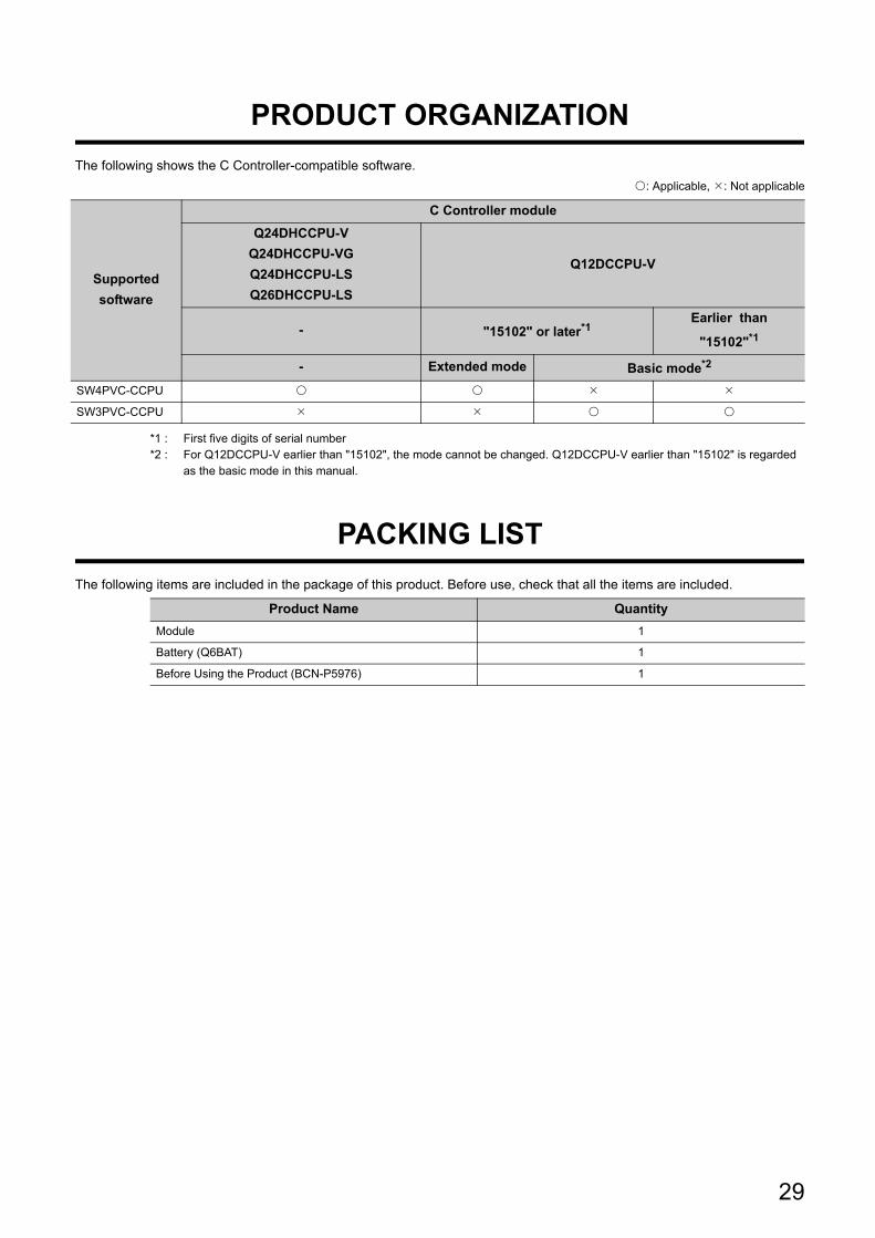
29
PRODUCT ORGANIZATION
The following shows the C Controller-compatible software.
: Applicable, : Not applicable
*1 : First five digits of serial number*2 : For Q12DCCPU-V earlier than "15102", the mode cannot be changed. Q12DCCPU-V earlier than "15102" is regarded
as the basic mode in this manual.
PACKING LIST
The following items are included in the package of this product. Before use, check that all the items are included.
Supported
software
C Controller module
Q24DHCCPU-V
Q24DHCCPU-VG
Q24DHCCPU-LS
Q26DHCCPU-LS
Q12DCCPU-V
- "15102" or later*1Earlier than
"15102"*1
- Extended mode Basic mode*2
SW4PVC-CCPU
SW3PVC-CCPU
Product Name Quantity
Module 1
Battery (Q6BAT) 1
Before Using the Product (BCN-P5976) 1

30
Memo

31
PART 1 OVERVIEW AND USAGE OF C CONTROLLER MODULE
This section describes the specifications and basic usage of the C Controller module.
CHAPTER 1 WHAT CAN BE DONE WITH C CONTROLLER MODULE . . . . . . . . . . . . . 32
CHAPTER 2 PART NAMES . . . . . . . . . . . . . . . . . . . . . . . . . . . . . . . . . . . . . . . . . . . . . . . 35
CHAPTER 3 SPECIFICATIONS . . . . . . . . . . . . . . . . . . . . . . . . . . . . . . . . . . . . . . . . . . . . 44
CHAPTER 4 SOFTWARE PACKAGES . . . . . . . . . . . . . . . . . . . . . . . . . . . . . . . . . . . . . . 52
CHAPTER 5 PREPARATORY PROCEDURE. . . . . . . . . . . . . . . . . . . . . . . . . . . . . . . . . . 53
CHAPTER 6 HARDWARE OPERATIONS . . . . . . . . . . . . . . . . . . . . . . . . . . . . . . . . . . . . 62

32
CHAPTER 1 WHAT CAN BE DONE WITH
C CONTROLLER MODULE
This chapter describes the overview and features of the C Controller module.
1.1 C Controller Module
C Controller module is a CPU module that controls I/O device of the MELSEC-Q series and manages the modules with
programs created in C or C++ language.
1.1.1 Q24DHCCPU-V
Q24DHCCPU-V is the C Controller module in which VxWorks is embedded in the operating system.
The various functions such as Ethernet, USB port driver, and the dedicated function library for communications are
implemented as a standard.
1.1.2 Q24DHCCPU-VG
Q24DHCCPU-VG is the C Controller module which supports the display function with the analog RGB output
connector and graphic driver to connect to a general-purpose display in addition to a great variety of Q24DHCCPU-V
functions.
1.1.3 Q24DHCCPU-LS
Q24DHCCPU-LS is C Controller module which can be embedded the desired operating system. Install the operating
system (partner operating system) provided by the partner (operating system vendor). The drivers and libraries are
provided by the partner (operating system vendor) as well. The required functions can be customized.
1.1.4 Q26DHCCPU-LS
Q26DHCCPU-LS is a C Controller module, which extends memory capacity of Work RAM of Q24DHCCPU-LS and
built-in SSD.
Depending on the extension of memory capacity, developing a vision system or database system, which requires
maximum capacity, becomes easier.

33
CHAPTER 1 WHAT CAN BE DONE WITH C CONTROLLER MODULE
1
1.1 C C
ontroller M
odule
1.1.5 Q12D
CC
PU
-V (E
xtended m
ode)
1.1.5 Q12DCCPU-V (Extended mode)
By using the Q12DCCPU-V (Extended mode), the memory and the network modules which can be used are added,
and the functions are expanded compared with Q12DCCPU-V (Basic mode)
For details of the Q12DCCPU-V (Basic mode), refer to the following manual.
C Controller Module User's Manual (Hardware Design, Function Explanation)
For the procedure to startup Q12DCCPU-V (Extended mode), refer to the following.
Page 60, Section 5.4

34
1.2 Features
(1) High-speed processing of large-volume, complicated operationMELSEC-Q series devices can be controlled by more complex and high-speed processing than the existing
programmable controller CPU.
A large-volume data can be handled, so that the system which has increased the data, can be processed
smoothly.
(2) Reduction of programming cost
(a) Utilization of created C programs
Since the user programs can be created using the existing programs, the costs such as system configuration,
educational expenses for engineers, and engineering costs can be reduced.
• The user programs created with C or C++ language can be used.
• The desired operating system can be selected.
(b) Data can be accessed easily using dedicated interface
Since the data such as memory or devices can be accessed by using dedicated libraries, drivers, or tools, the
programming cost for communication or maintenance can be reduced.
• Devices and memory of the modules can be accessed easily by using the function provided by the library.
• The desired data can be refreshed by setting the condition with the tool, without creating a program.
• Settings, diagnostics, and monitoring can be performed by the tool.
(3) Increasing security, and accelerating a non-PC environmentSince C Controller module supports the wide variety of network device, the appropriate system can be configured
depending on the scale or purpose of the system.
By separating the network between the device and upper server network, the lower devices are incorporated and
the productivity can be improved by protecting the system with the external errors or unauthorized access.
The management cost can be reduced because the devices can be monitored from the remote site via network.
An error can be identified quickly without a personal computer because the status of the device can be diagnosed
primarily with LED in front of the device or the general-purpose analog RGB display.

35
CHAPTER 2 PART NAMES
2
2.1 Q24D
HC
CP
U-V
/-VG
/-LS and Q
26DH
CC
PU
-LS
CHAPTER 2 PART NAMES
This chapter describes the name and application of each part of the C Controller module.
2.1 Q24DHCCPU-V/-VG/-LS and Q26DHCCPU-LS
*1 : The outline drawing for Q24DHCCPU-LS is shown.
No. NameDescription
Q24DHCCPU-V Q24DHCCPU-VG Q24DHCCPU-LS, Q26DHCCPU-LS
1) Indicator LEDs Page 40, (1) in this section
2) Dot matrix LED
Displays settings and results at the time of initialization and hardware diagnostics.
For the display during initialization, refer to the following.
Page 63, Section 6.1.1
For the display during hardware diagnostics, refer to the following.
Page 75, Section 6.5.1
3) USB connector (USB1) USB connector used for connection with a USB device.
4) USB connector (USB2) USB connector used for connection with Setting/monitoring tool for the C Controller module.
5)
User Ethernet portEthernet port for connection with a user program development environment or a personal
computer to use FTP or Telnet function.
CH1
SD/RD
On (green) Physical Ethernet connection detected
Flash (green) Data transmitting/receiving
Off Physical Ethernet connection not detected
1000/
100M
On (orange) Connecting at 100Mbps (automatically determined based on the target device)
On (green) Connecting at 1000Mbps (automatically determined based on the target device)
Off Connecting at 10Mbps (automatically determined based on the target device)
CH2 The same as CH1.
6)
System Ethernet port Ethernet port used for connection with Setting/monitoring tool for the C Controller module.
S
CH1
100MOn (green) Connecting at 100Mbps (automatically determined based on the target device))
Off Connecting at 10Mbps (automatically determined based on the target device)
SD/RD
On (green) Physical Ethernet connection detected
Flash (green) Data transmitting/receiving
Off Physical Ethernet connection not detected
2)
<Q24DHCCPU-V><Q24DHCCPU-VG>*1/<Q24DHCCPU-LS>/<Q26DHCCPU-LS>*1
5)
3)
Front cover Front cover
1)
4)
6)
[ Front ] [ Front ]

36
Pull the section indicated by "PULL" on the front cover by finger and open the cover as shown in the figure below.
*1 : The outline drawing for Q24DHCCPU-LS is shown.
10)8)
9)
7)
11)
[ Front cover opened ] [ Front cover opened ]
Q24DHCCPU-V
<Q24DHCCPU-V><Q24DHCCPU-VG>*1/<Q24DHCCPU-LS>/<Q26DHCCPU-LS>*1
Q24DHCCPU-LS

37
CHAPTER 2 PART NAMES
2
2.1 Q24D
HC
CP
U-V
/-VG
/-LS and Q
26DH
CC
PU
-LS
No. Name
Description
Q24DHCCPU-V Q24DHCCPU-VGQ24DHCCPU-LS
Q26DHCCPU-LS
7) SD memory card slot A slot into which an SD memory card is inserted on the C Controller module.
8) RUN/STOP/MODE switch*1
RUN: Sets the C Controller module operation status to RUN.
STOP: Sets the C Controller module operation status to STOP.
MODE: Used for initialization and hardware diagnostics.
For usage during initialization, refer to the following.
Page 63, Section 6.1.1
For usage during hardware diagnostics, refer to the following.
Page 75, Section 6.5.1
9) RESET/SELECT switch*1
RESET: Resets the C Controller module. (Page 71, Section 6.3)
SELECT: Unmounts a Memory card. (Page 120, Section 8.4)
Pull down each switch for at least 1 second for resetting or unmounting.
For usage during initialization, refer to the following.
Page 63, Section 6.1.1
For usage during hardware diagnostics, refer to the following.
Page 75, Section 6.5.1
10) U RST/P1/P2 switch*1
U RST: Reboots the user CPU. (Page 73, Section 6.4)
P1/P2: Issues an interrupt to the user program.
• If P2 P1, P1 switch interrupt is issued.
• If P1 P2, P2 switch interrupt is issued.
For processing in response to the switch interrupt,
CCPU_WaitSwitchEvent function is used.
For the access method,
consult the partner
(operating system vendor).
11) U EVENT switch*1
Issues an interrupt to the user program. Press the switch for at least 1 second.
For processing in response to the switch interrupt,
CCPU_WaitSwitchEvent function is used.
For the access method,
consult the partner
(operating system vendor).
*1 : Operate the switches by hand. Using a tool such as a screwdriver can cause a failure.
For "-LS", consult with the
partner (operating system vendor).
For "-LS", consult with the
partner (operating system vendor).

38
13)
[ Side ]
12)
14)
15)
[ Bottom ] [ Bottom ]
<Q24DHCCPU-V><Q24DHCCPU-VG>/<Q24DHCCPU-LS>/<Q26DHCCPU-LS>
16)

39
CHAPTER 2 PART NAMES
2
2.1 Q24D
HC
CP
U-V
/-VG
/-LS and Q
26DH
CC
PU
-LS
*2 : Connect the display before powering ON.
No. Name
Description
Q24DHCCPU-V Q24DHCCPU-VGQ24DHCCPU-LS
Q26DHCCPU-LS
12) Battery Battery to retain the battery backup RAM and integral clock (RTC) data during power OFF.
13) Battery connector pin
For connection of the battery lead wires.
(Lead wires are disconnected from the connector when shipping to prevent the battery from
consuming.)
14) RS-232 connector (CH3)
Connector used for connection with an RS-232 compatible device.
–
For the specification when
connecting to the supported
devices, consult the partner
(operating system vendor).
15)PCI Express® expanded
connectors
PCI Express® interface for connection with a device with PCI Express® and PCI bus. For
details, contact our local Mitsubishi representative or distributor.
16) Analog RGB output connector*2 –
Analog RGB output
connector used for
connection with a general-
purpose analog RGB
display.
For the specification when
connecting to the supported
devices, consult the partner
(operating system vendor).
For "-LS", consult with the
partner (operating system vendor).
For "-LS", consult with the
partner (operating system vendor).

40
(1) Indicator LEDs
*1 : The LED indication is not available when any USB device other than the one compliant with the USB Mass Storage Class standard is connected.
Name
Description
Q24DHCCPU-V Q24DHCCPU-VGQ24DHCCPU-LS
Q26DHCCPU-LS
RUN Displays the operation status
On The C Controller module is in the RUN status.
Flash
Any of the following states:• Executing the script file "STARTUP.CMD"• Diagnosing hardware• Initializing modules
Off The C Controller module is in the STOP/PAUSE status.
MODE Display the mode.
On (green) Normal operation mode
Flash (green)
Initialization completion
On (orange) Hardware diagnostics mode
Off A hardware failure occurred or the C Controller module is in reset process.
SD CARD Displays mounting status of the SD memory card.
On Mounting status For the display contents, consult the partner (operating system vendor).Flash During mounting or unmounting
Off SD memory card not installed, or unmounted.
ERR.Displays error status. You may check the error detail by using Setting/monitoring tools for the C Controller module.
On A continuation error occurred.
Flash Stop error or hardware diagnostics error occurred.
Off Normal
CH3 SD/RD Displays data transmission/reception status of the RS-232 connector (CH3).
On Transmitting/receiving
Off Not transmitting/receiving
USER
LED indicator configurable by the user program.
Set the USER LED using the CCPU_SetLEDStatus function.For the display during initialization, refer to the following.Page 63, Section 6.1.1For the display during hardware diagnostics, refer to the following.Page 75, Section 6.5.1
For the setting methods, consult the partner (operating system vendor).
USB1 Displays mounting status of the USB device.*1
On Mounting status For the display contents, consult the partner (operating system vendor).Flash During mounting or unmounting
Off USB device not installed, or unmounted.
U RDY Displays user CPU operation status.
On Run For the display contents, consult the partner (operating system vendor).Flash Preparing (rebooting)
Off Stopped
For "-LS", consult with the
partner (operating system vendor).
For "-LS", consult with the
partner (operating system vendor).
For "-LS", consult with the
partner (operating system vendor).
For "-LS", consult with the
partner (operating system vendor).

41
CHAPTER 2 PART NAMES
2
2.2 Q12D
CC
PU
-V
2.2 Q12DCCPU-V
No. Name Description
1) Indicator LEDs Page 43, (1) in this section.
2) 7-segment LED
Displays settings and results at the time of initialization and hardware diagnostics.
For the display during initialization, refer to the following.
Page 67, Section 6.1.2
For the display during hardware diagnostics, refer to the following.
Page 80, Section 6.5.2
3)
Built-in
Ethernet
port (CH1)
100M
On
(green)Connecting at 100Mbps (automatically determined based on the target device)
Off Connecting at 10Mbps (automatically determined based on the target device)
SD/RD
On
(green)Physical Ethernet connection detected
Flash
(green)Data transmitting/receiving
Off Physical Ethernet connection not detected
4) Built-in Ethernet port (CH2) The same as CH1.
5) EJECT button Used to eject a CompactFlash card from a C Controller module.
6)CompactFlash card installation
slotSlot into which a CompactFlash card is installed.
7) RUN/STOP/MODE switch
RUN: Sets the C Controller module operation status to RUN.
STOP: Sets the C Controller module operation status to STOP.
MODE: Used for initialization and hardware diagnostics.
For usage during initialization, refer to the following.
Page 67, Section 6.1.2
For usage during hardware diagnostics, refer to the following.
Page 80, Section 6.5.2
8) RESET/SELECT switch
RESET: Resets the C Controller module.(Page 71, Section 6.3)
SELECT: Unmount the CompactFlash card. (Page 122, Section 8.5)
Pull down each switch for at least 1 second for resetting or unmounting.
For usage during initialization, refer to the following.
Page 67, Section 6.1.2
For usage during hardware diagnostics, refer to the following.
Page 80, Section 6.5.2
9) USB connector USB connector used for connection with Setting/monitoring tool for the C Controller module.
1)
2)
3)
4)
MODE STOP
RUN
RES.
SEL.
7)
5)
6)
8)
9)
Q12DCCPU-V
[ Front cover opened ][ Front ]

42
No. Name Description
10) Battery Battery to retain the battery backup RAM and integral clock (RTC) data during power OFF.
11) Battery connector pin
For connection of the battery lead wires.
(Lead wires are disconnected from the connector when shipping to prevent the battery from
consuming.)
12) RS-232 connector (CH3) Connector used for connection with an RS-232 compatible device.
10) 11)
12)
[ Side ] [ Bottom ]
Q12DCCPU-V

43
CHAPTER 2 PART NAMES
2
2.2 Q12D
CC
PU
-V
(1) Indicator LEDs
NameDescription
Basic mode Extended mode
RUN Displays the operation status.
On The C Controller module is in the RUN status
Flash Executing the script file "STARTUP.CMD"
Off The C Controller module is in the STOP/PAUSE status
MODE Displays the mode.
On (green) Normal operation mode —
On
(orange)Hardware diagnostics mode Normal operation mode, Hardware diagnostics mode
Flash
(orange)— Standard ROM shutdown status
Off A hardware failure occurred or the C Controller module is in reset process
CF CARD Displays the mount status of the CompactFlash card.
On Mount status
Flash Unmount processing of CompactFlash card operated with the RESET/SELECT switch operation
Off CompactFlash card is not installed, or unmount status
ERR.Displays error status.
You may check the error detail by using Setting/monitoring tools for the C Controller module.
On A continuation error occurred
Flash Stop error or hardware diagnostics error occurred
Off Normal
CH3 SD/RD Displays data transmission/reception status of the RS-232 connector (CH3).
On Transmitting/receiving
Off Not transmitting/receiving
USER
LED indicator configurable by the user program.
Set the USER LED using the CCPU_SetLEDStatus function.For the display during initialization, refer to the following.Page 67, Section 6.1.2For the display during hardware diagnostics, refer to the following.Page 80, Section 6.5.2

44
CHAPTER 3 SPECIFICATIONS
This chapter describes the specifications of the C Controller module.
3.1 General Specifications
The following indicates the general specifications.
Remark
To install/connect peripherals to the C Controller module, the specifications of both the C Controller module and peripherals should be satisfied.
Item Specifications
Operating ambient
temperature0 to 55°C
Storage ambient
temperature-25 to 75°C*1
Operating ambient
humidity5 to 95%RH, non-condensing*2
Storage ambient
humidity
Vibration resistance
Compliant with
JIS B 3502 and
IEC 61131-2
– FrequencyConstant
acceleration
Half
amplitudeSweep count
Under
intermittent
vibration
5 to 8.4Hz – 3.5mm 10 times
each in X, Y
and Z
directions8.4 to 150Hz 9.8m/s2 –
Under continuous
vibration
5 to 8.4Hz – 1.75mm–
8.4 to 150Hz 4.9m/s2 –
Shock resistance Compliant with JIS B 3502 and IEC 61131-2 (147m/s2, 3 times each in 3 directions X, Y, Z)
Operating
atmosphereNo corrosive gases
Operating altitude*3 0 to 2000m
Installation location Inside a control panel
Overvoltage
category*4II or less
Pollution degree*5 2 or less
Device class Class I
*1 : The storage ambient temperature is -20 to 75°C if the system includes an AnS series module.*2 : The operating ambient humidity and storage ambient humidity are 10 to 90%RH if the system includes an AnS series
module.*3 : Do not use or store the C Controller module under pressure higher than the atmospheric pressure at sea level.
Doing so can cause malfunction.For use in a pressurized environment, please consult your local Mitsubishi representative.*4 : This indicates the section of the power supply to which the equipment is assumed to be connected between the public
electrical power distribution network and the machinery within premises. Category II applies to equipment for which electrical power is supplied from fixed facilities.surge voltage withstand level for up to the rated voltage of 300V is 2500V.
*5 : This index indicates the degree to which conductive material is generated in terms of the environment in which the equipment is used.Pollution level 2 is when only non-conductive pollution occurs. A temporary conductivity caused by condensing must be expected occasionally.

45
CHAPTER 3 SPECIFICATIONS
3
3.2 Perform
ance Specificatio
ns3.2.1 Q
24DH
CC
PU
-V/-V
G/-LS
and Q26D
HC
CP
U-LS
3.2 Performance Specifications
3.2.1 Q24DHCCPU-V/-VG/-LS and Q26DHCCPU-LS
The following indicates the performance specifications.
ItemSpecifications
Q24DHCCPU-V Q24DHCCPU-VG Q24DHCCPU-LS Q26DHCCPU-LS
Hardware specifications (System CPU) –
CPU SH4A
Hardware specifications (User CPU) –
Endian format (Memory layout) Little endian
CPU Intel® ATOMTM Processor
Memory
capacities
Work RAM 512 MB 1 GB
Standard RAM 0~4 MB*1 –
Standard ROM 382 MB –
Built-in SSD – 512 MB*2 8 GB*2
Battery backup RAM 1~5 MB*3 5 MB
Software specifications –
Operating system VxWorks Version 6.8.1
Programming language C language (C/C++)
SD memory card specifications –
Interface SD memory card/SDHC memory card(Up to 16 GB)
Power supply DC+3.3V; Up to 200mA
USB connector (USB1) specifications –
Interface USB2.0 ready
Connector Connector type A
Transmission speed 480Mbps(High Speed)
Power supply Bus power DC+5V; Up to 500mA*4
Supported standardUSB Mass Storage Class Standard
(Up to 2TB)
USB connector (USB2) specifications –
Interface USB2.0 ready
Connector Connector type mini-B
Transmission speed 12Mbps(Full Speed)
Power supply Self-Powered
*1 : The area for standard RAM is created by specifying the memory capacity in the battery backup RAM with parameters.*2 : Since the partner operating system is installed, the capacity for a user program will be smaller.*3 : When the area for standard RAM is created, the memory specified for standard RAM is occupied, therefore, the battery backup RAM
area will be decreased.*4 : Select appropriate USB connected devices to observe the current consumption limit.
For "-LS", consult with the
partner (operating system vendor).
For "-LS", consult with the
partner (operating system vendor).

46
Item
Specifications
Q24DHCCPU-V Q24DHCCPU-VGQ24DHCCPU-LS
Q26DHCCPU-LS
User Ethernet port (CH1, CH2)*5 –
Interface 10BASE-T/100BASE-TX/1000BASE-T
Communication method Full- or half-duplex
Data transmission speed10Mbps(10BASE-T)/100Mbps(100BASE-TX)
/1000Mbps(1000BASE-T)
Transmission method Base band
Maximum segment length
(distance between hub and node)100m
Connector applicable to external wiring RJ45
Supported function
Auto negotiation function
(automatic recognition of communication speed/communication method)
Auto-MDIX function
(automatically recognizes straight or crossing cable)
System Ethernet port (S CH1)*5 –
Interface 10BASE-T/100BASE-TX
Communication method Full- or half-duplex
Data transmission speed 10Mbps(10BASE-T)/100Mbps(100BASE-TX)
Transmission method Base band
Maximum segment length 100m
Connector applicable to external wiring RJ45
Supported function
Auto negotiation function
(automatic recognition of communication speed/communication method)
Auto-MDIX function (automatically recognizes straight or crossing cable)
Analog RGB output connector
–
D-sub 15pin
Maximum resolution 1024 768 (XGA)*6
Number of colors 16.7 million colors
Refresh rate 60Hz
*5 : For the possible base number when using a switching hub, follow the specifications of the switching hub used.The possible base number when a repeater hub is used is up to 4 for 10BASE-TX and up to 2 for 100BASE-TX.
*6 : The resolution can be changed to the following settings: • 1024 768 (XGA) • 800 600 (SVGA) • 640 480 (VGA)
For "-LS", consult with the
partner (operating system vendor).

47
CHAPTER 3 SPECIFICATIONS
3
3.2 Perform
ance Specificatio
ns3.2.1 Q
24DH
CC
PU
-V/-V
G/-LS
and Q26D
HC
CP
U-LS
ItemSpecifications
Q24DHCCPU-V Q24DHCCPU-VG, Q24DHCCPU-LS, Q26DHCCPU-LS
RS-232 connector (CH3) specifications –
Interface Compliant with RS-232
Communication method Full- or half-duplex
Synchronization method asynchronous communication
Transmission speed 9600, 14400, 19200, 28800, 38400, 57600, 115200 bps
Transmission distance Up to 15m (49.21 feet)
Data format
Start bit 1
Data bit 7 / 8
Parity bit 1 / None
Stop bit 1 / 2
Parity check Yes (Even/Odd)/No
Sum check code Yes/No
Transmission control Flow control (RS/CS control)
Recommended cable7/0.127 P HRV-SV outside diameter: 8.5mm (0.33 inches) or larger*7
(Limited Specify the number of pairs in .)
Connector applicable to external wiring Round connector (10-pin)
PCI Express® expanded connector
specifications*8–
Interface PCI Express® standards
Link width 1
Transmission speed 2.5Gbps
Number of I/O points 4096 points (X/Y 0 to FFF)
Clock function
Displayed information Year, month, day, hour, minute, second, day of week (automatic leap year detection)
AccuracyDaily error -10.89 to +8.64 seconds (0 to 55 deg.C)
Daily error -4.32 to +5.25 seconds (25 deg.C)
Allowable momentary power failure time Depends on the power supply module
5V DC internal current consumption 2.8 A
External dimensions 98 (3.86 in.) (H) 83 (3.27 in.) (W) 115 (4.53 in.) (D)[mm]
Weight 0.630 kg 0.638 kg
*7 : Oki Electric Cable Company (http://www.okidensen.co.jp)*8 : For usage of this interface, contact our local Mitsubishi representative or distributor.

48
3.2.2 Q12DCCPU-V
The following indicates the performance specifications
*1 : The area for standard RAM is created by specifying the memory capacity in the battery backup RAM with parameters.*2 : When the area for standard RAM is created, the memory specified for standard RAM is occupied, therefore, the battery
backup RAM area will be decreased.*3 : For the possible base number when using a switching hub, follow the specifications of the switching hub used.
The possible base number when a repeater hub is used is up to 4 for 10BASE-TX and up to 2 for 100BASE-TX.
Item Specifications
Hardware specifications –
Endian format (Memory layout) Little endian
CPU SH4A
Memory
capacities
Work RAM 128 MB
Standard RAM 0~3 MB*1
Standard ROM 12 MB
Battery backup RAM 512 KB~3.584 KB*2
Software specifications –
Operating system VxWorks Version 6.4
Programming language C language (C/C++)
CompactFlash card specifications –
Interface
TYPE I card (Up to 8 GB)
TYPE II card is not allowed.
I/O cards, such as a modem card are not allowed.
Power supply DC+3.3V; Up to 150mA
USB connector specifications –
Interface USB2.0 ready
Connector Connector type mini-B
Transmission speed 12Mbps(Full Speed)
Power supply Self-Powered
Built-in Ethernet port (CH1 and CH2)*3 –
Interface 10BASE-T/100BASE-TX
Communication method Full- or half-duplex
Data transmission speed 10Mbps(10BASE-T)/100Mbps(100BASE-TX)
Transmission method Base band
Maximum segment length 100m
Connector applicable to external wiring RJ45
Supported function
Auto negotiation function
(automatic recognition of communication speed/communication method)
Auto-MDIX function (automatically recognizes straight or crossing cable)
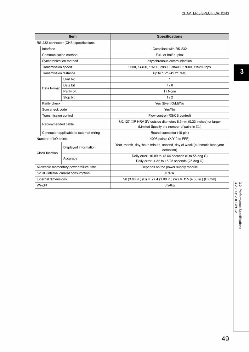
49
CHAPTER 3 SPECIFICATIONS
3
3.2 Perform
ance Specificatio
ns3.2.2 Q
12DC
CP
U-V
Item Specifications
RS-232 connector (CH3) specifications –
Interface Compliant with RS-232
Communication method Full- or half-duplex
Synchronization method asynchronous communication
Transmission speed 9600, 14400, 19200, 28800, 38400, 57600, 115200 bps
Transmission distance Up to 15m (49.21 feet)
Data format
Start bit 1
Data bit 7 / 8
Parity bit 1 / None
Stop bit 1 / 2
Parity check Yes (Even/Odd)/No
Sum check code Yes/No
Transmission control Flow control (RS/CS control)
Recommended cable7/0.127 P HRV-SV outside diameter: 8.5mm (0.33 inches) or larger
(Limited Specify the number of pairs in .)
Connector applicable to external wiring Round connector (10-pin)
Number of I/O points 4096 points (X/Y 0 to FFF)
Clock function
Displayed informationYear, month, day, hour, minute, second, day of week (automatic leap year
detection)
AccuracyDaily error -10.89 to +8.64 seconds (0 to 55 deg.C)
Daily error -4.32 to +5.25 seconds (25 deg.C)
Allowable momentary power failure time Depends on the power supply module
5V DC internal current consumption 0.97A
External dimensions 98 (3.86 in.) (H) 27.4 (1.08 in.) (W) 115 (4.53 in.) (D)[mm]
Weight 0.24kg

50
3.3 Device Specifications
This section describes the available devices.
3.3.1 Device list
Described below are names of the available devices and range of use.
● Do not use any devices that are not described above.
● Do not specify file registers (ZR) when reading/writing data.Doing so may result in a malfunction caused by the data writing to data registers (D) and link registers (W).
Classification Type Device name
Initial valueSetting
range*1Number
of pointsRange of use
I/O device Bit device
Input 4096 point X0 to FFFHexa
decimalN/A
Output 4096 point Y0 to FFFHexa
decimal
Internal user
device
Bit device
Internal relay 8192 point M0 to 8191 Decimal
Available
Link relay 8192 point B0 to 1FFFHexa
decimal
Word device
Data register 12288 point D0 to 12287 Decimal
Link register 8192 point W0 to 1FFFHexa
decimal
Internal system
device
Bit device Special relay 2048 point SM0 to 2047 DecimalN/A
Word device Special register 2048 point SD0 to 2047 Decimal
Link direct
device*2
Bit device
Link input 16384 point Jn\X0 to 3FFFHexa
decimal
N/A
Link output 16384 point Jn\Y0 to 3FFFHexa
decimal
Link relay 32768 point Jn\B0 to 7FFFHexa
decimal
Link special relay 512 point Jn\SB0 to 1FFHexa
decimal
Word device
Link register131072
pointJn\W0 to 1FFFF
Hexa
decimal
Link special register 512 point Jn\SW0 to 1FFHexa
decimal
Module access
deviceWord device
Intelligent function
module device*365536 point Un\G0 to 65535 Decimal N/A
Multiple CPU area
device*4
4096 point U3En\G0 to 4095 DecimalAvailable
14336 point U3En\G10000 to 24335 Decimal
*1 : If the setting range is "Available," the number of points for the respective device can be changed.For parameter settings, refer to the following. Setting/Monitoring Tools for the C Controller Module Version 4 Operating Manual
*2 : The number of points and range of use for the link direct device vary depending on network modules. For the number of points and range of use for the link direct device, refer to the manual for the network module.
*3 : The actual number of available points varies depending on intelligent function modules. For the number of points for the buffer memory, refer to the manual for the respective intelligent function module.
*4 : These devices can be used only for the multiple CPU system configurations.

51
CHAPTER 3 SPECIFICATIONS
3
3.3 Device
Specifications
3.3.2 Device D
escription
3.3.2 Device Description
Described below are the overview of the available devices.
For details, refer to the following manual.
QCPU User's Manual (Function Explanation, Program Fundamentals)
Device Description
I/O Device This is a device that corresponds to various user applications.
Input*1,*2 X
Input is used for giving commands and data to the C Controller module from an
external device such as a push-button switch, a selector switch, a limit switch,
or a digital switch.
Output*3 YOutput is for outputting program control results to an external signal lamp,
digital HMI, electromagnetic switch (contactor), solenoid, etc.
Internal User Device
This is a device created on the work RAM of the C Controller module.
This is a device that corresponds to various user applications. To create an
internal user device, use the device function (Page 169, Section 11.6).
Internal relay M This is an auxiliary relay used inside the C Controller module.
Data register D This memory can store numerical data (-32768 to 32767 or 0000H to FFFFH).
Link relay B This is a relay/memory on the C Controller module side available to refresh the
network module link device (LX/LY/LB/LW/RX/RY/RWw/RWr) to the C
Controller module, or to refresh the data within the C Controller module to the
network modules link device.Link register W
Internal System Device This is a device for system.
Special relay SM
This is an internal relay with specification defined inside the C Controller
module, that stores the C Controller module status.
For details of the special relay, refer to the following.
Page 478, Appendix 6
Special register SD
This is an internal register with specification defined inside the C Controller
module, that stores the C Controller module status (failure diagnostics and
system information).
For details of the special register, refer to the following.
Page 480, Appendix 7
Link Direct Device
This device directly accesses a link device in the network module.
Link devices in network module can be read or written by user programs,
independently of the link device refresh of the C Controller module.
Link input Jn\X
Link output Jn\Y
Link relay Jn\B
Link special relay Jn\SB
Link register Jn\W
Link special register Jn\SW
Module Access Device
Intelligent function
module deviceUn\G
This device is for directly accessing the buffer memory of an intelligent function
module installed in the base unit from the C Controller module.
Multiple CPU area
deviceU3En\G
This device accesses the CPU shared memory in each CPU module of the
multiple CPU system. For the CPU shared memory, refer to the following.
Page 251, Section 14.1
*1 : Writing to the input (X) is ignored.*2 : If the following input (X) is read out, the read data will be 0 (OFF).
• No module is installed. • An output module is installed.
*3 : If the following output (Y) is read out, the read data will be 0 (OFF). • No module is installed. • An output module is installed.

52
CHAPTER 4 SOFTWARE PACKAGES
This chapter describes each software package associated with the C Controller module.
The following software packages can be used for the C Controller module.
*1 : Cannot be connected to Q12DCCPU-V (Basic mode).*2 : For Q24DHCCPU-V with a serial number whose first five digits are "15042" or higher, use Setting/monitoring tools for
the C Controller module Version 4.02C or later.
● For Setting/monitoring tools for the C Controller module, refer to the following. Setting/Monitoring Tools for the C Controller Module Version 4 Operating Manual
● For CW Workbench, refer to the following.CW Workbench Operating Manual
● To create a user program for the C Controller module, CW Workbench or Wind River Workbench 3.2 are necessary. In this manual programming by using CW Workbench is described.
● This is a product of Wind River Workbench is Wind River Systems, Inc. To use the Wind River Workbench, refer to the manual for Wind River Workbench.
Software
Version
Q24DHCCPU Q26DHCCPU
-LS
Q12DCCPU
-V-V -VG -LS
Setting/monitoring tools for the C Controller
module*1
(SW4PVC-CCPU-E)
Version 4.01B
or later*2Version 4.09K
or later
Version 4.03D
or later
Version 4.11M
or later
Version 4.04E
or later
CW Workbench
SW1DND-CWWLQ24-E,
SW1DND-CWWLQ24-EZVersion 1.00A or later
–
Version 1.00A
or later
SW1DND-CWWLQ12-E,
SW1DND-CWWLQ12-EZ–
Version 1.00A
or later
Wind River Workbench Version 3.2 Version 3.2
GX Works2Version 1.91V
or later
Version 1.513K
or later
Version 1.492N
or later
Version 1.540N
or later
Version 1.50C
or later
GT Designer3
(SW1DNC-GTWK3-J)Version 1.60N
or later
Version 1.112S
or later
Version 1.73B
or later–
Version 1.15R
or later
(SW1DNC-GTWK3-E)Version 1.63R
or later
Version 1.112S
or later
Version 1.74C
or later–
Version 1.17T
or later
MX ComponentVersion 4.02C
or later–
Version 3.14Q
or later

53
CHAPTER 5 PREPARATORY PROCEDURE
5
5.1 Q24D
HC
CP
U-V
CHAPTER 5 PREPARATORY PROCEDURE
This chapter describes the procedure to startup the C Controller module.
5.1 Q24DHCCPU-V
The following explains the start-up procedure for Q24DHCCPU-V.
Check fieldQCPU User's Manual
(Hardware Design, Maintenance and Inspection)
Manual for respective module
QCPU User's Manual(Hardware Design, Maintenance and Inspection)
Manual for respective module
Initialization of C Controller module
Initialize the C Controller module.
Hardware Diagnostics
Check the status of the C Controller module hardware.
Module mounting
Module mountingInstall the module to the base unit. • CPU module (for multiple CPU system configuration) • I/O module, intelligent function module and network module
Initial setting of modulesSet each module switch. • Set the RUN/STOP/MODE switch on the C Controller module to STOP. • Set the RUN/STOP/RESET switch on each CPU module to STOP. • Set the intelligent Function module and network module switches.
QCPU User's Manual(Hardware Design, Maintenance and Inspection)
Wiring and connectionArrange wiring: • Extension cable connection to the extension base unit and base number setting • Wiring for external device(s) connected to each module • Wiring between network modules
To the next page
Mount the power supply module and the C Controller module on the base unit.
Start
Power supply module• Mounting on the base unit• Power supply wiringC Controller module• Battery Installation• Mounting on the base unit
Page 62, Section 6.1
Page 75, Section 6.5
Page 116, CHAPTER 8
Page 35, CHAPTER 2

54
Operation
Parameter setting
Error check
C Controller system resetSet the RUN/STOP/MODE switch on the C Controller module to RUN.Reset the C Controller system.
Check for any error indicated by the C Controller module LEDs.Perform troubleshooting if any error is present.If any error is present in other than the C Controller module, refer to and follow the manual for respective module(s) to perform troubleshooting.
Create the user program.• Install CW Workbench to the development environment (Personal
computer).• Create a user program and script file(s).• Connect the C Controller module and the development environment
(Personal computer).(Use CH1 or CH2.After initialization, the IP address is reset to the default. To connect via the Ethernet, use the default IP address.)
• Register the user program to the C Controller module.• Debug the user program.
Check field
From the previous page
User program creation
Power on after check that:• power supply wiring is properly arranged.• power supply voltage is within the operational range.
Create a parameter.• Install Setting/monitoring tools for the C Controller module to the
development environment (Personal computer).• Set the parameters by Setting/monitoring tools for the C Controller
module.• Connect the C Controller module and the development environment
(Personal computer). (Use USB2 or S CH1. After initialization, the IP address is reset to the
default. To connect via the Ethernet, use the default IP address.)• Write the parameters to the C Controller module.
System power-on�QCPU User's Manual
(Hardware Design, Maintenance and Inspection)
�Setting/Monitoring Tools for the C Controller Module Version 4 Operating Manual
�Manual for respective module
�CW Workbench Operating Manual
Page 71, Section 6.3
Page 288, CHAPTER 15 Page 111, Section 7.6.5 Page 129, Section 8.7.2 (3)
Page 394, CHAPTER 23
Page 336, CHAPTER 19 Page 111, Section 7.6.5 Page 127, Section 8.7.2

55
CHAPTER 5 PREPARATORY PROCEDURE
5
5.2 Q24D
HC
CP
U-V
G
5.2 Q24DHCCPU-VG
The following explains the start-up procedure for Q24DHCCPU-VG.
When C Controller module has been initialized, the partner application is deleted.Page 62, Section 6.1
Check field�QCPU User's Manual (Hardware Design, Maintenance and Inspection)
Clearing memory of C Controller module• Install Setting/monitoring tools for the C Controller module to the development environment (Personal computer).• Clearing the battery backup RAM with Setting/monitoring tools for the C Controller module.
Module mountingMount the power supply module and the C Controller module on the base unit.Power supply module• Mounting on the base unit• Power supply wiringC Controller module• Battery Installation• Mounting on the base unit
Start
Module Version 4 Operating Manual�Setting/Monitoring Tools for the C Controller
Page 116, CHAPTER 8
�Manual for respective module
Hardware Diagnostics
Check the status of the C Controller module hardware.
Module mountingInstall the module to the base unit.• CPU module (for multiple CPU system configuration)• I/O module, intelligent function module and network module
�QCPU User's Manual (Hardware Design, Maintenance and Inspection)
Wiring and connectionArrange wiring:• Extension cable connection to the extension base unit and base number setting• Wiring for external device(s) connected to each module• Wiring between network modules
To the next page
Page 75, Section 6.5

56
Parameter setting
Error check
C Controller system resetSet the RUN/STOP/MODE switch on the C Controller module to RUN.Reset the C Controller system.
Check for any error indicated by the C Controller module LEDs.Perform troubleshooting if any error is present.If any error is present in other than the C Controller module, refer to and follow the manual for respective module(s) to perform troubleshooting.
Create the user program.• Install CW Workbench to the development environment (Personal computer).• Create a user program and script file(s).• Connect the C Controller module and the development environment (Personal computer). (Use CH1 or CH2.After initialization, the IP address is reset to the default. To connect via the Ethernet, use the default IP address.)• Register the user program to the C Controller module.• Debug the user program.
From the previous page
User program creation
Power on after check that:• power supply wiring is properly arranged.• power supply voltage is within the operational range.
Create a parameter.• Set the parameters by Setting/monitoring tools for the C Controller module.• Connect the C Controller module and the development environment (Personal computer). (Use USB2 or S CH1. After initialization, the IP address is reset to the default. To connect via the Ethernet, use the default IP address.)• Write the parameters to the C Controller module.
System power-on �QCPU User's Manual (Hardware Design, Maintenance and Inspection)
�Setting/Monitoring Tools for the C Controller Module Version 4 Operating Manual
�Manual for respective module
�CW Workbench Operating Manual
Check field
Set each module switch.• Set the RUN/STOP/MODE switch on the C Controller module to STOP.• Set the RUN/STOP/RESET switch on each CPU module to STOP.• Set the intelligent Function module and network module switches.
Initial setting of modules
Operation
�QCPU User's Manual (Hardware Design, Maintenance and Inspection)�Manual for respective modulePage 35, CHAPTER 2
Page 71, Section 6.3
Page 394, CHAPTER 23
Page 336, CHAPTER 19
Page 188, Section 11.10
Page 111, Section 7.6.5
Page 129, Section 8.7.2 (3)
Page 288, CHAPTER 15
Page 111, Section 7.6.5
Page 129, Section 8.7.2 (3)

57
CHAPTER 5 PREPARATORY PROCEDURE
5
5.3 Q24D
HC
CP
U-LS
and Q26D
HC
CP
U-LS
5.3 Q24DHCCPU-LS and Q26DHCCPU-LS
The following explains the start-up procedure for Q24DHCCPU-LS and Q26DHCCPU-LS.
Check fieldQCPU User's Manual
(Hardware Design, Maintenance and Inspection)
Manual for respective module
QCPU User's Manual(Hardware Design, Maintenance and Inspection)
Manual for respective module
Initialization of C Controller module
Initialize the C Controller module.
Hardware Diagnostics
Check the status of the C Controller module hardware.
Module mounting
Module mountingInstall the module to the base unit. • CPU module (for multiple CPU system configuration) • I/O module, intelligent function module and network module
Initial setting of modulesSet each module switch. • Set the RUN/STOP/MODE switch on the C Controller module to STOP. • Set the RUN/STOP/RESET switch on each CPU module to STOP. • Set the intelligent Function module and network module switches.
QCPU User's Manual(Hardware Design, Maintenance and Inspection)
Wiring and connectionArrange wiring: • Extension cable connection to the extension base unit and base number setting • Wiring for external device(s) connected to each module • Wiring between network modules
To the next page
Mount the power supply module and the C Controller module on the base unit.
Start
Power supply module• Mounting on the base unit• Power supply wiringC Controller module• Battery Installation• Mounting on the base unit
Page 62, Section 6.1
Page 75, Section 6.5
Page 116, CHAPTER 8
Page 35, CHAPTER 2

58
Operation
Parameter setting
Error check
C Controller system resetSet the RUN/STOP/MODE switch on the C Controller module to RUN.Reset the C Controller system.
Check for any error indicated by the C Controller module LEDs.Perform troubleshooting if any error is present.If any error is present in other than the C Controller module, refer to and follow the manual for respective module(s) to perform troubleshooting.
Refer to the manual of the partner operating system, or consult the partner (operating system vendor).
Check field
From the previous page
User program creation
Power on after check that:• power supply wiring is properly arranged.• power supply voltage is within the operational range.
Create a parameter.• Install Setting/monitoring tools for the C Controller module to the
development environment (Personal computer).• Set the parameters by Setting/monitoring tools for the C Controller
module.• Connect the C Controller module and the development environment
(Personal computer). (Use USB2 or S CH1. After initialization, the IP address is reset to the
default. To connect via the Ethernet, use the default IP address.)• Write the parameters to the C Controller module.
System power-on�QCPU User's Manual
(Hardware Design, Maintenance and Inspection)
�Setting/Monitoring Tools for the C Controller Module Version 4 Operating Manual
�Manual for respective module
Installation of partner operating system
Install a partner operating system to this product.
Page 71, Section 6.3
Page 288, CHAPTER 15 Page 111, Section 7.6.5 Page 129, Section 8.7.2 (3)
Page 394, CHAPTER 23
Page 59, Section 5.3.1

59
CHAPTER 5 PREPARATORY PROCEDURE
5
5.3 Q24D
HC
CP
U-LS
and Q26D
HC
CP
U-LS
5.3.1 Installation procedure for partner operating system
5.3.1 Installation procedure for partner operating system
The following explains the installation procedure for partner operating system.
*1 : The self-powered drive is required.When using a keyboard/mouse, connect it via USB hub.
*2 : Press the EVENT switch until POWER LED of the power module turns ON.All the display LEDs of the module are turned OFF (because the status of the system CPU is reset).
Check field
Connect USB external laptop CD/DVD drive
Connect the USB external laptop CD/DVD drive.*1
Refer to the manual of the partner operating system, or consult the
partner (operating system vendor).
Insert installation media
Insert the installation media in the external drive.
Prepare the installation media
Turn on the power of system
After checking the following status, power ON while pressing the "U
EVENT" switch on C Controller module.*2
Power supply wiring
Power supply voltage
Disconnect USB external laptop CD/DVD drive.
Remove the installation media from the external drive, then disconnect
the external drive.
Installation of partner operating system
Install the partner operating system by following the procedure.
Start
Operation

60
5.4 Q12DCCPU-V
The following explains the start-up procedure for Q12DCCPU-V.
Check fieldQCPU User's Manual
(Hardware Design, Maintenance and Inspection)
Manual for respective module
QCPU User's Manual(Hardware Design, Maintenance and Inspection)
Manual for respective module
Initialization of C Controller module
Initialize the C Controller module.Select the following mode and perform the initialization.• Mode "12" module initialization setting (Extended mode)
Hardware Diagnostics
Check the status of the C Controller module hardware.
Module mounting
Module mountingInstall the module to the base unit. • CPU module (for multiple CPU system configuration) • I/O module, intelligent function module and network module
Initial setting of modulesSet each module switch. • Set the RUN/STOP/MODE switch on the C Controller module to STOP. • Set the RUN/STOP/RESET switch on each CPU module to STOP. • Set the intelligent Function module and network module switches.
QCPU User's Manual(Hardware Design, Maintenance and Inspection)
Wiring and connectionArrange wiring: • Extension cable connection to the extension base unit and base number setting • Wiring for external device(s) connected to each module • Wiring between network modules
To the next page
Mount the power supply module and the C Controller module on the base unit.
Start
Power supply module• Mounting on the base unit• Power supply wiringC Controller module• Battery Installation
Page 62, Section 6.1
Page 75, Section 6.5
Page 116, CHAPTER 8
Page 35, CHAPTER 2

61
CHAPTER 5 PREPARATORY PROCEDURE
5
5.4 Q12D
CC
PU
-V
Operation
Parameter setting
Error check
C Controller system resetSet the RUN/STOP/MODE switch on the C Controller module to RUN.Reset the C Controller system.
Check for any error indicated by the C Controller module LEDs.Perform troubleshooting if any error is present.If any error is present in other than the C Controller module, refer to and follow the manual for respective module(s) to perform troubleshooting.
Create the user program.• Install CW Workbench to the development environment (Personal
computer).• Create a user program and script file(s).• Connect the C Controller module and the development environment
(Personal computer).(Use CH1 or CH2.After initialization, the IP address is reset to the default. To connect via the Ethernet, use the default IP address.)
• Register the user program to the C Controller module.• Debug the user program.
Check field
From the previous page
User program creation
Power on after check that:• power supply wiring is properly arranged.• power supply voltage is within the operational range.
Create a parameter.• Install Setting/monitoring tools for the C Controller module to the
development environment (Personal computer).• Set the parameters by Setting/monitoring tools for the C Controller
module.• Connect the C Controller module and the development environment
(Personal computer). (Use USB connector or Built-in Ethernet port (CH1, CH2). After
initialization, the IP address is reset to the default. To connect via the Ethernet, use the default IP address.)
System power-on�QCPU User's Manual
(Hardware Design, Maintenance and Inspection)
�Setting/Monitoring Tools for the C Controller Module Version 4 Operating Manual
�Manual for respective module
�CW Workbench Operating Manual
Page 71, Section 6.3
Page 288, CHAPTER 15 Page 111, Section 7.6.5 Page 129, Section 8.7.2 (3)
Page 394, CHAPTER 23
Page 336, CHAPTER 19 Page 111, Section 7.6.5 Page 127, Section 8.7.2

62
CHAPTER 6 HARDWARE OPERATIONS
This chapter describes the switch operations of the C Controller module.
6.1 Initialization
Described in this section is the initialization of the C Controller module.
Initialization is useful in the following situations:
• Initial operation
• When the C Controller module cannot be started up by executing the script file (user program) registered
with the standard ROM
• When you forgot the account information configured in the C controller module
• When enabling the "Setting/monitoring tools for the C Controller module operation" setting which was
disabled in the service setting function.
Q24DHC-V Q24DHC-VG Q24DHC-LS Q26DHC-LS Q12DC-V

63
CHAPTER 6 HARDWARE OPERATIONS
6
6.1 Initialization6.1.1 Q
24DH
CC
PU
-V/-V
G/-LS
and Q26D
HC
CP
U-LS
6.1.1 Q24DHCCPU-V/-VG/-LS and Q26DHCCPU-LS
(1) Initialization statusInitialization brings the Q24DHCCPU-V/-VG/-LS and Q26DHCCPU-LS into the following status:
(a) Default IP settingNote6.1
• The execution of the script file registered on the "/ROM" drive (standard ROM) is stopped.
• The IP address of the Q24DHCCPU-V/-VG/-LS and Q26DHCCPU-LS is set to the default.
*1 : The items are not initialized by this function. For the method for initialization, consult the partner (operating system vendor).
(b) Module initialization setting
: Supported : Not supported
● For Q24DHCCPU-VG, the partner application will be deleted by performing the module initialization setting.For information on how to reinstall it, refer to the manuals provided by the partner (application vendor), or consult the partner (application vendor).
● Initialization deletes data in the Q24DHCCPU-V/-VG/-LS and Q26DHCCPU-LS.Before you can perform the initialization, back up all necessary data, user programs and parameters.
Note6.1 Not supported by Q24DHCCPU-LS and Q26DHCCPU-LS.
Item
Description
Q24DHCCPUQ26DHCCPU-LS
-V -VG -LS
User Ethernet port CH1 192.168.3.3No change*1
User Ethernet port CH2 No setting
System Ethernet port S CH1 192.168.3.39
Script file No file No change*1
Description
CPU module
Q24DHCCPUQ26DHCCPU-LS
-V -VG -LS
Parameters are reset to the initial values.
Battery backup RAM data is cleared to 0.
"/ROM" drive (standard ROM) is formatted.
(All directories and files in the "/ROM" drive is deleted.)
The resolution is set to 1024 × 768 (XGA).
The keyboard is set to the OADG-compliant Japanese 106-key
keyboard (106JIS).
Q24DHCCPU-LS Q26DHCCPU-LS
Note6.1
Note6.1

64
(2) Operating procedure
(a) Preparation
Before initializing the Q24DHCCPU-V/-VG/-LS and Q26DHCCPU-LS, take the steps listed below:
1. Install the module.
Install the power supply module and Q24DHCCPU-V/-VG/-LS and Q26DHCCPU-LS to the base unit.
Insert the Q24DHCCPU-V/-VG/-LS and Q26DHCCPU-LS into the CPU slot.
Do not install any module other than a power supply module and the Q24DHCCPU-V/-VG/-LS and
Q26DHCCPU-LS.
● For C Controller modules listed below, the initialization can be performed even when the module is mounted on the slot other than the CPU slot. To perform initialization with the module mounted on the slot other than the CPU slot, mount another CPU module on the CPU slot. Although an error may be detected on the CPU module mounted on the CPU slot, the initialization of the C Controller module can be performed.
• Q24DHCCPU-V with a serial number whose first five digits are "15042" • Q24DHCCPU-VG
2. Check the wiring.
Check that the power supply wiring is property arranged.
Do not connect any cable other than power supply cables.
3. Power on.
Check that the power supply voltage is within the specified range.
Check that the RUN/STOP/MODE switch is positioned in STOP.

65
CHAPTER 6 HARDWARE OPERATIONS
6
6.1 Initialization6.1.1 Q
24DH
CC
PU
-V/-V
G/-LS
and Q26D
HC
CP
U-LS
(b) Initialization setting
Perform the following operations to configure settings for initialization.
(c) Countermeasures for abnormal completion
Flashing of the ERR. LED indicates abnormal completion.
• If the dot matrix LED shows "E0F0" and "E0F1" an error occurred during the initialization setting.
• If the dot matrix LED is off and only ERR. LED flashed, a system error is present.
When any error has occurred, take initialization steps again. If failure is detected again, any hardware error
may exist. Please consult your local Mitsubishi service center or representative, explaining the details of the
problem.
1. Move the RESET/SELECT switch to the RESET position.
Do not release the switch while pulling it down.
2. Check that the LED goes off.
3. Move the RUN/STOP/MODE switch to MODE position.
Do not release the switch while pulling it down.
4. Move the RESET/SELECT switch back to the center.
Release the switch then it returns to its center position.
5. Check that the MODE LED turns on in orange.
Dot matrix LED indicates "M-00".
6. Move the RUN/STOP/MODE switch back to the STOP
position.Release the switch then it returns to its center position.
7. Move the RESET/SELECT switch to the SELECT position.
Each time you move the switch to the SELECT position, the mode changes and a value representing the respective mode is displayed by the LEDs.Repeat this step until the dot matrix LED shows target mode in the table below.
8. Move the RUN/STOP/MODE switch back to RUN position.
During execution of the initialization setting, RUN LED is
flashed green.
9. Check that the RUN LED goes off.
Dot matrix LED indicates "0000".
Mode Description
0010 Default IP setting
0011 Module initialization setting

66
(d) Execution of initialization
Perform the following operations to execute initialization.
(e) Countermeasures for abnormal completion
Flashing of the ERR.LED indicates abnormal completion.
When any error has occurred, take initialization steps again. If failure is detected again, any hardware error
may exist. Please consult your local Mitsubishi service center or representative, explaining the details of the
problem.
1. Move the RESET/SELECT switch to the RESET position.
Do not release the switch while pulling it down.
2. Check that the MODE LED goes off.
3. Move the RESET/SELECT switch back to the center.
Release the switch then it returns to its center position.
4. Check that the MODE LED turns on in green.
During initialization, RUN LED and USER LED are flashed.
5. Check that the USER LED goes off.
RUN LED goes off, and MODE LED is flashed green.
6. Move the RESET/SELECT switch to the RESET position.
Do not release the switch while pulling it down.
7. Check that the MODE LED goes off.
8. Move the RESET/SELECT switch back to the center.
Release the switch then it returns to its center position.
9. Check that the MODE LED is lit green.
During user CPU restarting, the U RDY LED flashes and,
when it is completed, the U RDY LED is lit.

67
CHAPTER 6 HARDWARE OPERATIONS
6
6.1 Initialization6.1.2 Q
12DC
CP
U-V
6.1.2 Q12DCCPU-V
(1) Initialization statusInitialization brings the Q12DCCPU-V into the following status:
(a) Default IP setting
• The execution of the script file registered on the "/ROM" drive (standard ROM) is stopped.
• The IP address of the Q12DCCPU-V is set to the default.
(b) Module initialization setting (Extended mode)
• Parameters are reset to the initial values.
• Battery backup RAM data is cleared to 0.
• "/ROM" drive (standard ROM) is formatted.
(All directories and files in the "/ROM" drive is deleted.)
Initialization deletes data in the Q12DCCPU-V.Before you can perform the initialization, back up all necessary data, user programs and parameters.
(2) Operating procedure
(a) Preparation
Before initializing the Q12DCCPU-V, take the steps listed below:
1. Install the module.
Install the power supply module and Q12DCCPU-V to the base unit.
Insert the C Controller module into the CPU slot.
Do not install any module other than a power supply module and the Q12DCCPU-V.
● For Q12DCCPU-V (Extended mode) with a serial number whose first five digits are "15102" or higher, the initialization can be executed even if the module is mounted on the slot other than the CPU slot. When executing the initialization with mounting Q12DCCPU-V (Extended mode) other than CPU slot, mount another CPU module on the CPU slot.
• Although an error may be detected on the CPU mounted on the CPU slot, the initialization can be executed.
2. Check the wiring.
Check that the power supply wiring is property arranged.
Do not connect any cable other than power supply cables.
3. Power on.
Check that the power supply voltage is within the specified range.
Check that the RUN/STOP/MODE switch is positioned in STOP.
Item Description
Built-in Ethernet port CH1 192.168.3.3
Built-in Ethernet port CH2 No setting
Script file No file
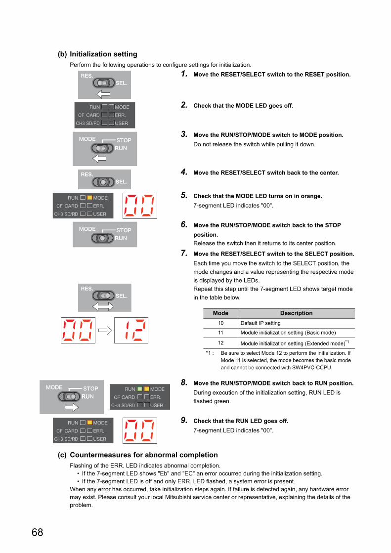
68
(b) Initialization setting
Perform the following operations to configure settings for initialization.
(c) Countermeasures for abnormal completion
Flashing of the ERR. LED indicates abnormal completion. • If the 7-segment LED shows "Eb" and "EC" an error occurred during the initialization setting. • If the 7-segment LED is off and only ERR. LED flashed, a system error is present.
When any error has occurred, take initialization steps again. If failure is detected again, any hardware error may exist. Please consult your local Mitsubishi service center or representative, explaining the details of the problem.
1. Move the RESET/SELECT switch to the RESET position.
2. Check that the MODE LED goes off.
3. Move the RUN/STOP/MODE switch to MODE position.
Do not release the switch while pulling it down.
4. Move the RESET/SELECT switch back to the center.
5. Check that the MODE LED turns on in orange.
7-segment LED indicates "00".
6. Move the RUN/STOP/MODE switch back to the STOP
position.
Release the switch then it returns to its center position.
7. Move the RESET/SELECT switch to the SELECT position.
Each time you move the switch to the SELECT position, the
mode changes and a value representing the respective mode
is displayed by the LEDs.
Repeat this step until the 7-segment LED shows target mode
in the table below.
8. Move the RUN/STOP/MODE switch back to RUN position.
During execution of the initialization setting, RUN LED is
flashed green.
9. Check that the RUN LED goes off.
7-segment LED indicates "00".
Mode Description
10 Default IP setting
11 Module initialization setting (Basic mode)
12 Module initialization setting (Extended mode)*1
*1 : Be sure to select Mode 12 to perform the initialization. If Mode 11 is selected, the mode becomes the basic mode and cannot be connected with SW4PVC-CCPU.

69
CHAPTER 6 HARDWARE OPERATIONS
6
6.1 Initialization6.1.2 Q
12DC
CP
U-V
(d) Execution of initialization
Perform the following operations to execute initialization.
(e) Countermeasures for abnormal completion
Flashing of the ERR.LED indicates abnormal completion.
When any error has occurred, take initialization steps again. If failure is detected again, any hardware error
may exist. Please consult your local Mitsubishi service center or representative, explaining the details of the
problem.
1. Move the RESET/SELECT switch to the RESET position.
2. Check that the MODE LED goes off.
3. Move the RESET/SELECT switch back to the center.
4. Check that the MODE LED turns on in orange.
During initialization, RUN LED and USER LED are flashed.
5. Check that the RUN LED and USER LED go off.
The MODE LED flashes.
6. Move the RESET/SELECT switch to the RESET position.
7. Check that the MODE LED goes off.
8. Move the RESET/SELECT switch back to the center.
9. Check that the MODE LED is lit orange.

70
6.2 Change of Operation Status (RUN/STOP)
You may use RUN/STOP/MODE switch operations to change the C Controller module operation status (RUN/STOP).
For details of the operation status, refer to the following.
Page 307, Section 17.2.3 RUN, STOP and PAUSE status operation processing
● Changing the operation status (RUN/STOP/PAUSE) also changes output from the user program. For details, refer to the following. Page 151, Section 11.1.5 Output (Y) status setting for switching STOP to RUN
● When the operation status is STOP/PAUSE, the user program task does not stop.
● For the remote operation, refer to the following. Page 163, Section 11.5 Remote Operation Function
(1) Operating procedureSwitch operations are described below.
(a) RUN
(b) STOP
1. Move the RUN/STOP/MODE switch to the RUN position.
Q24DHCCPU-V/-VG/-LS and Q26DHCCPU-LS···RUN LED is
lit green.
Q12DCCPU-V···RUN LED is lit orange.
1. Move the RUN/STOP/MODE switch to the STOP position.
RUN LED goes off.
<Q24DHCCPU-V/-VG/-LS><Q26DHCCPU-LS>
<Q12DCCPU-V>
<Q24DHCCPU-V/-VG/-LS><Q26DHCCPU-LS>
<Q12DCCPU-V>

71
CHAPTER 6 HARDWARE OPERATIONS
6
6.3 Reset
6.3 Reset
Reset is an operation to apply any parameter and/or user program change and reboot the entire system.
The procedures to reset the C Controller system are described below.
• Power cycle (power OFF ON)
• Reset the C Controller module (for multiple CPU system, the CPU module No.1)
In any of the following conditions, do not reset the entire system: • Accessing to the SD memory card • Accessing to the CompactFlash card • Accessing to the USB device • Accessing to the standard ROM or user files in the standard RAM
(1) Status after resettingResetting the C Controller module brings the C Controller module into the following status:
• The change(s) in user program(s) is applied.
• The change(s) in parameter setting(s) is applied.
• The data refresh memory*1 and CPU shared memory are cleared to 0.
• Initial processing is executed. ( Page 305, Section 17.2.1)
*1 : The data refresh memory cannot be used in Q12DCCPU-V.
(2) Operating procedureSwitch operations for resetting the C Controller module are described below.
(a) Q24DHCCPU-V/-VG/-LS and Q26DHCCPU-LS1. Move the RESET/SELECT switch to the RESET position.
Do not release the switch while pulling it down.
2. Check that the MODE LED goes off.
U RDY LED also goes off.
3. Move the RESET/SELECT switch back to the center.
Release the switch then it returns to its center position.
4. Check that the MODE LED turns on in green.
During user CPU restarting, the U RDY LED flashes.
When completed, U RDY LED is lit.

72
(b) Q12DCCPU-V
● For the remote reset operation, refer to the following. Page 163, Section 11.5
● Resetting CPUs No.2-4 in multiple CPU systemYou cannot reset CPU modules No.2-4 individually.When you reset any one of No.2 through No.4 during operations of the multiple CPU system, an error occurs in the other modules.In this case, the entire multiple CPU system is down regardless of the operation mode set in Multiple CPU Setting (All station stop by stop error of PLC2-PLC4/Continue).
1. Move the RESET/SELECT switch to the RESET position.
2. Check that the MODE LED goes off.
3. Move the RESET/SELECT switch back to the center.
4. Check that the MODE LED turns on in orange.

73
CHAPTER 6 HARDWARE OPERATIONS
6
6.4 Restartin
g User C
PU
6.4 Restarting User CPU
User CPU restarting is an operation to apply the changes made in the user program while the system is running.
You may restart the user CPU by operating U RST/P1/P2 switches.
In addition, user CPU restarting is also possible from Setting/monitoring tools for the C Controller module or user
program.
● In any of the following conditions, do not restart the user CPU. • Accessing to the SD memory card • Accessing to the USB device • Accessing to the standard ROM or user files in the standard RAM
● Before restarting the user CPUs, check that: • the CPU operation status is STOP; • the user program stop and close operations are performed; • file operations are not in process; • the U RDY LED is not flashing (user CPUs preparing for operations).
(1) Components influenced by user CPU restartingUser CPU restarting will apply any change in the user program.
For components influenced by restarting, refer to the following figure.
*1 : Input (X), output (Y), internal user device and CPU shared memory values will be retained.*2 : Link refreshing with the network module and refreshing with the CPU shared memory will be continued.
● To apply any change in parameter settings, reset the system. User CPU restarting does not apply parameter setting changes.
● To clear input (X), output (Y), internal user device and CPU shared memory values, reset the entire system or clear the respective device(s).
● For initial processing for the entire system by the user program, execute the initial processing again after user CPU restarting, or reset the entire system.
Q24DHC-V Q24DHC-VG Q24DHC-LS Q26DHC-LS Q12DC-V
Network module
Link device
Another CPU
System CPU User CPU
User program
Reboot
Input (X) Output (Y)
CPU shared memory
Internal user device
Unaffected portions*1,*2 Affected portions
C controller module
CPU shared memory
Refresh
Link refresh

74
(2) Setting methodSet the following setting item to "Enable" through Setting/monitoring tools for the C Controller module.
• "CCPU Parameter" <<System settings>> "Restart user CPU"
(3) MethodsThere are 3 ways to execute user CPU restarting, which are described in the following pages.
• By switch operations
Switch operations are described below.
• Using Setting/monitoring tools for the C Controller module
[Online] [Remote Operation]
• Using user program Note6.2
Restart the user CPU by executing the C Controller module dedicated function (CCPU_Restart
function).
The following shows the function(s) used for restarting user CPU.
For the remote reset operation, refer to the following. Page 163, Section 11.5
(4) How to check user CPU restarting from the other CPUsTo check if the C Controller module is restarting the user CPU, refer to the "LED Status" in the "Host CPU
operation information area" in the CPU shared memory. ( Page 252, Section 14.1.1)
If the "U RDY" LED value in "LED Status" is other than "1: On", the user CPU are preparing for operations and the
user program never runs.
1. Set the CPU operation status to STOP.
2. Move the U RST/P1/P2 switch to the U RST position.
Do not release the switch while pulling it down.
3. Check that the U RDY LED goes off.
During user CPU restarting, the U RDY LED flashes.
4. Move the U RST/P1/P2 switch back to the ”P1” position.
Release the switch then it returns to its center position.
5. Check that the U RDY LED is lit.
Note6.2 Not supported by Q24DHCCPU-LS and Q26DHCCPU-LS.
Function name Function
CCPU_Restart Restarts the user CPUs on the C Controller module.
Note6.2
Q24DHCCPU-LS Q26DHCCPU-LS

75
CHAPTER 6 HARDWARE OPERATIONS
6
6.5 Hardw
are Diagnostics
6.5.1 Q24D
HC
CP
U-V
/-VG
/-LS and Q
26DH
CC
PU
-LS
6.5 Hardware Diagnostics
Hardware diagnostics is a test to check the hardware within the C Controller module.
Hardware diagnostics is useful in the following situations:
• Initial operation
• Troubleshooting
During hardware diagnostics, do not power OFF or reset the C Controller system.Otherwise, the C Controller module may no longer be started up normally.If such situation occurs, initialize the C Controller module. Page 62, Section 6.1
6.5.1 Q24DHCCPU-V/-VG/-LS and Q26DHCCPU-LS
(1) Diagnostics typesIn the hardware diagnostics test, diagnostics on the following items are performed.
(a) Q24DHCCPU-V/-VG
ModeDot matrix LED
displayDiagnostic item Description
0 M-00Diagnostic test of Mode 1 to
Mode 6Conducts tests in the order from Mode 1 to Mode 6.
1 M-01
ROM diagnostic test Reads the ROM data and performs error detection.
Work RAM diagnostic test Checks test data by writing/reading/verifying them on the work RAM.
Battery backup RAM
diagnostic test
Checks test data by writing/reading/verifying them on the battery backup
RAM.
2 M-02 Ethernet diagnostic test Diagnoses the status of the Ethernet port (CH1, CH2 and S CH1).
3 M-03SD memory card interface
diagnostic testDiagnoses the SD memory card slot status.
4 M-04 RS-232 diagnostic testConducts a self-loopback test of RS-232 connector (CH3).
The wiring for self-loopback is required.
5 M-05 USB diagnostic test Diagnoses the status of the USB connector (USB1, USB2).
6 M-06 Bus diagnostic test Writes/reads/verifies the memory of the internal bus and register.
7 M-07 Dot matrix LED test Shows the dot matrix LED test display.
Q24DHC-V Q24DHC-VG Q24DHC-LS Q26DHC-LS Q12DC-V

76
(b) Q24DHCCPU-LS and Q26DHCCPU-LS
(2) Operating procedure
(a) Preparation
Before performing the hardware diagnostics test on the Q24DHCCPU-V/-VG/-LS and Q26DHCCPU-LS, take
the steps listed below:
1. Install the module.
Install the power supply module and the Q24DHCCPU-V/-VG/-LS and Q26DHCCPU-LS to the base unit.
Insert the Q24DHCCPU-V/-VG/-LS and Q26DHCCPU-LS into the CPU slot.
Do not install any module other than a power supply module and the Q24DHCCPU-V/-VG/-LS and
Q26DHCCPU-LS.
● For C Controller modules listed below, the hardware diagnostics can be performed even when the module is mounted on the slot other than the CPU slot. To perform the hardware diagnostics with the module mounted on the slot other than the CPU slot, mount another CPU module on the CPU slot. Although an error may be detected on the CPU module mounted on the CPU slot, the hardware diagnostics can be performed.
• Q24DHCCPU-V with a serial number whose first five digits are "15042" • Q24DHCCPU-VG
2. Check the wiring.
Check that the power supply wiring is property arranged.
Do not connect any cable other than power supply cables.
3. Prepare for respective diagnostics as necessary. ( Page 77, (2)(b) in this section)
4. Power on.
Check that the power supply voltage is within the specified range.
Check that the RUN/STOP/MODE switch is positioned in STOP.
ModeDot matrix LED
displayDiagnostic item Description
0 M-00Diagnostic test of Mode 1 to
Mode 6Diagnoses in order of Mode 1 Mode 2 Mode 5 Mode 6.
1 M-01Battery backup RAM
diagnostic test
Checks test data by writing/reading/verifying them on the battery backup
RAM.
2 M-02 Ethernet diagnostic test Diagnoses the status of the Ethernet port (S CH1).
5 M-05 USB diagnostic test Diagnoses the status of the USB connector (USB2).
6 M-06 Bus diagnostic test Writes/reads/verifies the memory of the internal bus and register.
7 M-07 Dot matrix LED test Shows the dot matrix LED test display.

77
CHAPTER 6 HARDWARE OPERATIONS
6
6.5 Hardw
are Diagnostics
6.5.1 Q24D
HC
CP
U-V
/-VG
/-LS and Q
26DH
CC
PU
-LS
(b) Necessary preparations for each diagnostics
Before performing each hardware diagnostics test, take the steps listed below.
• When executing Mode 0
Perform all preparation tasks for executing the following mode from 1 to 6.
• When executing Mode 1
Back up all data in the standard ROM and battery backup RAM data.
Remark
● Backup of data in the standard ROM Use the FTP function to backup the standard ROM data to the PC. (Page 197, Section 12.1.2)
● Backup of battery backup RAM data From [Online] [Battery backup RAM monitor] in Setting/monitoring tools for the C Controller module, or by using the C Controller module dedicated function (CCPU_ReadSRAM function), read out the contents and save data in any location other than in the standard ROM, e.g. your PC.
• When executing Mode 2
Check that no cable is connected to the Ethernet port (CH1, CH2 and S CH1).
• When executing Mode 3
Check that the SD memory card is not installed.
• When executing Mode 4
Connect a cable to RS-232 connector (CH3) as shown below.
The table below shows the connector pin positions and cable connection.
• When executing Mode 5
Check that no cable is connected to the USB connectors (USB1 and USB2).
• When executing Mode 6
No preparation tasks for this mode.
Pin No.Signal
codeSignal name
Cable
connectionC controller module
Q12DCCPU-CBL
RS-232 device
side
1 CD(DCD) Data Carrier Detect
2 RD(RXD) Received Data
3 SD(TXD) Transmitted Data
4 ER(DTR) Data Terminal Ready
5 SG Signal Ground
6 DR(DSR) Data Set Ready
7 RS(RTS) Request To Send
8 CS(CTS) Clear To Send
9 CI(RI) Ring Indicator
10 SG Signal Ground
For "-LS", consult with the
partner (operating system vendor).
For "-LS", consult with the
partner (operating system vendor).
1
2
36
7
5
48
9
10
1
2
3
4
5
6
7
8
9

78
(c) Test mode selection
Perform the following operations to select a test mode to execute.
(d) Execution of the test (mode 0-6)Perform the following operations to execute the test.
1. Move the RESET/SELECT switch to the RESET position.
Do not release the switch while pulling it down.
2. Check that the LED goes off.
3. Move the RUN/STOP/MODE switch to the MODE position.
Do not release the switch while pulling it down.
4. Move the RESET/SELECT switch back to the center.
Release the switch then it returns to its center position.
5. Check that the MODE LED turns on in orange.
Dot matrix LED indicates "M-00".
6. Move the RUN/STOP/MODE switch back to the STOP
position.
Release the switch then it returns to its center position.
7. Move the RESET/SELECT switch to the SELECT position.
Each time you move the switch to the SELECT position, the
mode changes and a value representing the respective mode
is displayed by the LEDs.
Repeat this step until the dot matrix LED shows the desired
mode.
1. Move the RUN/STOP/MODE switch to the RUN position.
While the test is running, RUN LED is flashed green.
The dot matrix LED shows the current mode and progress
alternately.
[Example] "M-01" Alternately displayed "0050"
(progress)
2. Check that the RUN LED goes off.
When the test is completed normally, the dot matrix LED
shows "0000".
If other than "0000" is shown, refer to the following.
Page 79, (2)(e) in this section
3. Power OFF.

79
CHAPTER 6 HARDWARE OPERATIONS
6
6.5 Hardw
are Diagnostics
6.5.1 Q24D
HC
CP
U-V
/-VG
/-LS and Q
26DH
CC
PU
-LS
(e) If the dot matrix LED shows other than "0000"
The "ERR." LED starts flashing once the error is detected during diagnostics or setting.
A value corresponding to the diagnostics for which the error occurred is displayed on the dot matrix LED.
If the dot matrix LED is off and only "ERR." LED flashes, a system error is present.
*1 : An error may occur if a distribution cable is not connected correctly.Correctly connect and distribute the cable again, and then reexecute the self-diagnostic test for Mode 4.
Upon detection of the failure, the diagnostics and setting will be terminated.
Retry the diagnostics and setting if they failed.
If failure is detected again, the hardware of the Q24DHCCPU-V/-VG/-LS and Q26DHCCPU-LS may be faulty.
Please consult your local Mitsubishi service center or representative, explaining the details of the problem.
(f) Execution of the dot matrix LED test (mode 7)
Perform the following operations to execute the test.
Visually check there is no inactive dot in the 4-digit dot matrix LED.If there is any inactive LED, the hardware of the Q24DHCCPU-V/-VG/-LS and Q26DHCCPU-LS may be faulty.Please consult your local Mitsubishi service center or representative, explaining the details of the problem.
ModeDot matrix LED
displayError diagnostics
1
E010, E011 ROM diagnostic test
E020, E021 Work RAM diagnostic test
E031 Battery backup RAM diagnostic test
2
E040 Ethernet diagnostic test (CH1)
E050 Ethernet diagnostic test (CH2)
E061 Ethernet diagnostic test (S CH1)
3 E080 SD memory card interface diagnostic test
4 E090 RS-232 diagnostic test *1
5 E0A0, E0A1 USB diagnostic test
6 E0B1 Bus diagnostic test
- E101(Occurred in system CPU and user CPU
control)
1. Move the RUN/STOP/MODE switch to the RUN position.
2. Move the RESET/SELECT switch to the SELECT position.
Each time you move the switch to the SELECT position, the
dot matrix LED is turned on/off in order from the all-on status.
Visually check the displayed status.
3. Power OFF.
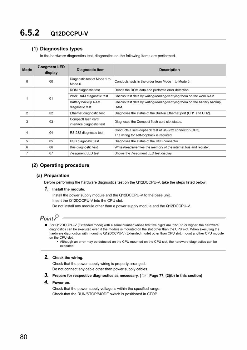
80
6.5.2 Q12DCCPU-V
(1) Diagnostics typesIn the hardware diagnostics test, diagnostics on the following items are performed.
(2) Operating procedure
(a) Preparation
Before performing the hardware diagnostics test on the Q12DCCPU-V, take the steps listed below:
1. Install the module.
Install the power supply module and the Q12DCCPU-V to the base unit.
Insert the Q12DCCPU-V into the CPU slot.
Do not install any module other than a power supply module and the Q12DCCPU-V.
● For Q12DCCPU-V (Extended mode) with a serial number whose first five digits are "15102" or higher, the hardware diagnostics can be executed even if the module is mounted on the slot other than the CPU slot. When executing the hardware diagnostics with mounting Q12DCCPU-V (Extended mode) other than CPU slot, mount another CPU module on the CPU slot.
• Although an error may be detected on the CPU mounted on the CPU slot, the hardware diagnostics can be executed.
2. Check the wiring.
Check that the power supply wiring is property arranged.
Do not connect any cable other than power supply cables.
3. Prepare for respective diagnostics as necessary. ( Page 77, (2)(b) in this section)
4. Power on.
Check that the power supply voltage is within the specified range.
Check that the RUN/STOP/MODE switch is positioned in STOP.
Mode7-segment LED
displayDiagnostic item Description
0 00Diagnostic test of Mode 1 to
Mode 6Conducts tests in the order from Mode 1 to Mode 6.
1 01
ROM diagnostic test Reads the ROM data and performs error detection.
Work RAM diagnostic test Checks test data by writing/reading/verifying them on the work RAM.
Battery backup RAM
diagnostic test
Checks test data by writing/reading/verifying them on the battery backup
RAM.
2 02 Ethernet diagnostic test Diagnoses the status of the Built-in Ethernet port (CH1 and CH2).
3 03CompactFlash card
interface diagnostic testDiagnoses the Compact flash card slot status.
4 04 RS-232 diagnostic testConducts a self-loopback test of RS-232 connector (CH3).
The wiring for self-loopback is required.
5 05 USB diagnostic test Diagnoses the status of the USB connector.
6 06 Bus diagnostic test Writes/reads/verifies the memory of the internal bus and register.
7 07 7-segment LED test Shows the 7-segment LED test display.

81
CHAPTER 6 HARDWARE OPERATIONS
6
6.5 Hardw
are Diagnostics
6.5.2 Q12D
CC
PU
-V
(b) Necessary preparations for each diagnostics
Before performing each hardware diagnostics test, take the steps listed below.
• When executing Mode 0
Perform all preparation tasks for executing the following mode from 1 to 6.
• When executing Mode 1
Back up all data in the standard ROM and battery backup RAM data.
Remark
● Backup of data in the standard ROM Use the FTP function to backup the standard ROM data to the PC. (Page 197, Section 12.1.2)
● Backup of battery backup RAM data From [Online] [Battery backup RAM monitor] in Setting/monitoring tools for the C Controller module, or by using the C Controller module dedicated function (CCPU_ReadSRAM function), read out the contents and save data in any location other than in the standard ROM, e.g. your PC.
• When executing Mode 2
Built-in Ethernet port (CH1 and CH2) by an Ethernet cable (crossing cable).
• When executing Mode 3
Install a CompactFlash card.
• When executing Mode 4
Connect a cable to RS-232 connector (CH3) as shown below.
The table below shows the connector pin positions and cable connection.
• When executing Mode 5
Check that no cable is connected to the USB connectors.
• When executing Mode 6
No preparation tasks for this mode.
Pin No.Signal
codeSignal name
Cable
connectionC controller module
Q12DCCPU-CBL
RS-232 device
side
1 CD(DCD) Data Carrier Detect
2 RD(RXD) Received Data
3 SD(TXD) Transmitted Data
4 ER(DTR) Data Terminal Ready
5 SG Signal Ground
6 DR(DSR) Data Set Ready
7 RS(RTS) Request To Send
8 CS(CTS) Clear To Send
9 CI(RI) Ring Indicator
10 SG Signal Ground
1
2
36
7
5
48
9
10
1
2
3
4
5
6
7
8
9

82
(c) Test mode selection
Perform the following operations to select a test mode to execute.
(d) Execution of the test (mode 0-6)Perform the following operations to execute the test.
1. Move the RESET/SELECT switch to the RESET position.
2. Check that the MODE LED goes off.
3. Move the RUN/STOP/MODE switch to the MODE position.
Do not release the switch while pulling it down.
4. Move the RESET/SELECT switch back to the center.
5. Check that the MODE LED turns on in orange.
7-segment LED indicates "00".
6. Move the RUN/STOP/MODE switch back to the STOP
position.
Release the switch then it returns to its center position.
7. Move the RESET/SELECT switch to the SELECT position.
Each time you move the switch to the SELECT position, the
mode changes and a value representing the respective mode
is displayed by the LEDs.
Repeat this step until the 7-segment LED shows the desired
mode.
1. Move the RUN/STOP/MODE switch to the RUN position.
While the test is running, RUN LED is flashed green.
The 7-segment LED shows the current mode and progress
alternately.
[Example] "01" Alternately displayed "25" (progress)
2. Check that the RUN LED goes off.
When the test is completed normally, the 7-segment LED
shows "00".
If other than "00" is shown, refer to the following.
Page 83, (2)(e) in this section
3. Power OFF.

83
CHAPTER 6 HARDWARE OPERATIONS
6
6.5 Hardw
are Diagnostics
6.5.2 Q12D
CC
PU
-V
(e) If the 7-segment LED shows other than "00"
The "ERR." LED starts flashing once the error is detected during diagnostics or setting.
A value corresponding to the diagnostics for which the error occurred is displayed on the 7-segment LED.
If the 7-segment LED is off and only "ERR." LED flashes, a system error is present.
*1 : An error may occur if a CompactFlash card is not inserted.*2 : An error may occur if a distribution cable is not connected correctly.
Correctly connect and distribute the cable again, and then reexecute the self-diagnostic test for Mode 4.
Upon detection of the failure, the diagnostics and setting will be terminated.
Retry the diagnostics and setting if they failed.
If failure is detected again, the hardware of the Q12DCCPU-V may be faulty.
Please consult your local Mitsubishi service center or representative, explaining the details of the problem.
(f) Execution of the 7-segment LED test (mode 7)
Perform the following operations to execute the test.
Visually check there is no inactive dot in the 7-segment LED.If there is any inactive LED, the hardware of the Q12DCCPU-V may be faulty.Please consult your local Mitsubishi service center or representative, explaining the details of the problem.
Mode7-segment LED
displayError diagnostics
1
E1 ROM diagnostic test
E2 Work RAM diagnostic test
E3 Battery backup RAM diagnostic test
2
E4 Ethernet diagnostic test (CH1)
E5 Ethernet diagnostic test (CH2)
E6 During Ethernet loopback test
3 E7 CompactFlash card interface diagnostic test*1
4 E8 RS-232 diagnostic test *2
5 E9 USB diagnostic test
6 EA Bus diagnostic test
1. Move the RUN/STOP/MODE switch to the RUN position.
2. Move the RESET/SELECT switch to the SELECT position.
The mode shifts as pull the switch to SELECT side, each
segment of 7 segment LED turns ON/OFF in order.
Check the display status by visually.
3. Power OFF.

84
Memo

85
PART 2 HARDWARE DESIGN, MAINTENANCE AND INSPECTION
This section describes items related to hardware design, maintenance and inspection.
CHAPTER 7 SYSTEM CONFIGURATION . . . . . . . . . . . . . . . . . . . . . . . . . . . . . . . . . . . . 86
CHAPTER 8 INSTALLATION AND WIRING . . . . . . . . . . . . . . . . . . . . . . . . . . . . . . . . . . 116
CHAPTER 9 MAINTENANCE AND INSPECTION . . . . . . . . . . . . . . . . . . . . . . . . . . . . . 134

86
CHAPTER 7 SYSTEM CONFIGURATION
This chapter describes the overall configuration, precautions for configuration and peripherals.
7.1 Overall Configuration
The overall configuration of the C Controller system is illustrated below.
For details, refer to the following.
For proper system configuration, observe the precautions described in the following section.Page 87, Section 7.2
Item Reference
Main base unit/Power supply module Page 88, Section 7.3.1
Extension base unit/Extension cable Page 88, Section 7.3.2
Battery Page 90, Section 7.3.3
Multiple CPU system configuration Page 91, Section 7.4
I/O module/Intelligent function module Page 96, Section 7.5
● Battery (Q7BAT) for QCPU
● Q7BAT-SET
● Battery holder
● Battery (Q6BAT) for QCPU (Bundle)
● Power module / I/O module / Intelligent function module● Extension cable
● Q3B type main base unit ● Q3RB type redundant power main base unit ● Q3DB type multiple CPU high speed main base unit
● Extension base unit
● C Controller module● Motion CPU● Basic model QCPU ● High Performance model QCPU ● Process CPU ● Universal model QCPU
For a multiple CPU system
● C Controller module

87
CHAPTER 7 SYSTEM CONFIGURATION
7
7.2 Precau
tions for System
Configuration
7.2 Precautions for System Configuration
This section explains the precautions for configuring the system.
(1) Restrictions on the number of mountable modulesModules with constraints on the number of installations are listed below.
Remark
If the No.1 module is other CPU module than the C Controller module, refer to the manual for the No.1 CPU module used for modules with restriction on the number of installations.
(2) Time adjustment and time notification of GOTFor multiple CPU system configuration, the No.1 CPU module is the target when performing time adjustment and
time notification by GOT connected to the No.2 to No.4 C Controller modules. Synchronize the clocks of No.2-4
modules with that of the No.1.
Restricted modules Restrictions of number of mountable modules
Product Model Per C Controller module Per multiple CPU system
CC-Link IE Controller Network
module
QJ71GP21-SX
QJ71GP21S-SXUp to 4
Up to 4 (Same as the left)MELSECNET/H network
module
QJ71BR11
QJ71LP21G
QJ71LP21GE
QJ71LP21-25
QJ71LP21S-25
Up to 4
(PLC to PLC network/
Remote I/O Network)
CC-Link IE Field Network
master/local moduleQJ71GF11-T2 No restriction*1 (Same as the left)
CC-Link system master/local
module
QJ61BT11
QJ61BT11NUp to 8 No restriction
Interrupt module
QI60
QX40H*2
QX70H*2
QX80H*2
QX90H*2
1*3 Up to 4*3
High-speed data logger module QD81DL96 1
Up to 4
(Note that, only 1 can be
controlled by 1 CPU module)
GOT
GOT1000series
GOT2000series
(only when in bus
connection)*4
Up to 5 (Same as the left)
*1 : Only up to 8 modules can be network parameters set and controlled by Setting/monitoring tools for C Controller module.There is not restrictions on the number of mountable modules on the buffer memory for the network module.For how to set the parameters by buffer memory, refer to the following. MELSEC-Q CC-Link IE Field Network Master/Local Module User's Manual
*2 : The module is available only when the interrupt module is selected by setting the function selector switch (SW2) to OFF.*3 : With interrupt event settings activated, the number of installations is not restricted.*4 : For applicable GOT models, refer to the following.
Connection manuals for GOT2000 series (Mitsubishi Products), (Non-Mitsubishi Products 1), (Non-Mitsubishi Products 2), (Microcomputer, MODBUS Products, Peripherals) Connection manuals for GOT1000 series (Mitsubishi Products), (Non-Mitsubishi Products 1), (Non-Mitsubishi Products 2), (Microcomputer, MODBUS Products, Peripherals)

88
(3) Total current consumptionThe total current consumption for system configuration must not exceed the power supply module's rated output
current of DC5V. For specifications of the power supply module, refer to the manual for respective modules.
QCPU User's Manual (Hardware Design, Maintenance and Inspection)
7.3 Basic Configuration (Single CPU System Configuration)
Described in this section is the basic configuration with a C Controller module.
7.3.1 Main base unit/power supply module
The power supply module and main base units available for the C Controller system are listed below.
For details of each power supply module and main base units, refer to the following.
QCPU User's Manual (Hardware Design, Maintenance and Inspection)
7.3.2 Extension base unit/extension cable
Use an extension base unit that can be combined with a main base unit available for the C Controller system. For
details of each extension base unit and extension cable, refer to the following.
QCPU User's Manual (Hardware Design, Maintenance and Inspection)
(1) Upper limit of extensions and mountable modulesThe upper limit of extensions on the C Controller system is as follows:
Type Model
Power supply module Q series power supply moduleQ61P-A1, Q61P-A2, Q61P, Q61P-D, Q62P, Q63P,
Q64P, Q64PN, Q63RP, Q64RP
Main base unit
Main base unit Q33B, Q35B, Q38B, Q312B
Redundant power main base unit Q38RB
Multiple CPU high speed main base unit Q35DB, Q38DB, Q312DB
Item Description
Maximum number of extension
bases of extension base unit7 extension bases
Maximum number of I/O
modules65 modules - (the number of available CPU slots) (Up to 62 slots)
Maximum total extension cable
length13.2m

89
CHAPTER 7 SYSTEM CONFIGURATION
7
7.3 Basic C
onfiguration (S
ingle C
PU
System
Co
nfiguration)
7.3.2 Extensio
n base unit/extension cable
(2) Extension stage number settingTo use 2 or more extension base units, it is necessary to set the extension base number by the extension base
number setting connector on the extension base unit.
When a C controller module is used, extension base number can be up to 7.
For details of base number setting procedures, refer to the following.
QCPU User's Manual (Hardware Design, Maintenance and Inspection)
● Set extension base numbers in the order of connection, starting from the extension base unit connected to the main base unit.
● Set correct extension base number for the base number setting connector. Do not set the same extension base number for two or more extension base units and do not skip extension base number setting. Doing so may cause incorrect input or incorrect output.
● If an extension stage number is skipped, it will not be reserved as the number for an empty base unit. To reserve an extension stage, perform the base unit setting in the <<I/O assignment settings>> of parameter.Page 303, Section 16.3
Base number setting
connector
Extension stage number setting
Stage 1 Stage 2 Stage 3 Stage 4 Stage 5 Stage 6 Stage 7
Base number setting connector
OUTIN

90
7.3.3 Battery
The batteries available for the C Controller module are listed below.
(1) Specifications
(2) PrecautionsDuring use, observe the following precautions. Improper use of batteries may corrupt the battery backup RAM
data and clock data.
• Use the C Controller module with a battery installed.
• For operations without any battery, use the battery less drive function.
• If any battery error has occurred, replace the battery.
• Follow the procedures in this document for installation and replacement of batteries.
Remark
● For battery installation procedures, refer to Page 119, Section 8.3.
● For battery replacement procedures, refer to Page 136, Section 9.3.
● For details of battery less drive, refer to Page 190, Section 11.11.
● For battery lifetime, refer to Page 487, Appendix 8.
● For battery regulations applicable in EU countries and precautions for battery transportation, refer to the following.QCPU User's Manual (Hardware Design, Maintenance and Inspection)
ItemModel
Q6BAT Q7BAT
Type Manganese dioxide lithium primary battery
Initial voltage 3.0V
Nominal current
capacity1800mAh 5000mAh
Battery life when stored Actual 5 years (room temperature)
Battery life when used Page 487, Appendix 8
Lithium content 0.52g 1.55g
Application Backup of the battery backup RAM data, Backup of clock data
Accessories – Battery holder *1
*1 : Supplied only with Q7BAT-SET.

91
CHAPTER 7 SYSTEM CONFIGURATION
7
7.4 Multiple C
PU
System
Co
nfiguration7.4.1 S
upported C
PU
modules
7.4 Multiple CPU System Configuration
A multiple CPU system consists of two or more CPU modules mounted on a main base unit, and each CPU module
controls I/O module(s) and/or intelligent function module(s) individually.
For concepts of the multiple CPU system, refer to the following.
QCPU User's Manual (Multiple CPU System)
7.4.1 Supported CPU modules
CPU modules available for the C Controller module and multiple CPU system are listed in the table below:
: Compatible, –: Incompatible
*1 : The advanced synchronous control method can be used only for the following C Controller modules. • Q12DCCPU-V (Extended mode) with a serial number whose first five digits are "16012" or higher • Q24DHCCPU-V with a serial number whose first five digits are "16012" or higher • Q24DHCCPU-VG
Remark
For details of each module, refer to the manual for respective modules.
CPU moduleBase unit
Q3B Q3DB Q3RB
QCPU
Basic model QCPU Q00CPU, Q01CPU
–
High Performance
model QCPUQ02CPU, Q02HCPU, Q06HCPU, Q12HCPU, Q25HCPU
Process CPU Q02PHCPU, Q06PHCPU, Q12PHCPU, Q25PHCPU
Universal model
QCPU
Q00UCPU, Q01UCPU, Q02UCPU –
Q03UDCPU, Q04UDHCPU, Q06UDHCPU, Q10UDHCPU,
Q13UDHCPU, Q20UDHCPU, Q26UDHCPU, Q03UDECPU,
Q04UDEHCPU, Q06UDEHCPU, Q10UDEHCPU, Q13UDEHCPU,
Q20UDEHCPU, Q26UDEHCPU, Q50UDEHCPU, Q100UDEHCPU,
Q03UDVCPU, Q04UDVCPU, Q06UDVCPU, Q13UDVCPU,
Q26UDVCPU
Motion CPUQ172DCPU, Q173DCPU, Q172DCPU-S1, Q173DCPU-S1,
Q172DSCPU*1, Q173DSCPU*1– –
C Controller module
Q06CCPU-V, Q12DCCPU-V (Basic mode) –
Q12DCCPU-V (Extended mode), Q24DHCCPU-V,
Q24DHCCPU-VG, Q24DHCCPU-LS, Q26DHCCPU-LS
Motion CPU
C Controller moduleQCPU

92
7.4.2 Combination of CPU modules
Described in this section is possible CPU module combination in the multiple CPU system by using a C Controller
module.
For combination of CPU modules for other than this product, refer to the manual for respective CPU module.
–: Incompatible
CPU No.1
Number of CPUs that can be mounted as CPU No.2 or others Maximum
number of
mountable
modules
(including
CPU No.1)
High Performance model
QCPU
Process CPU
Universal model QCPU
Motion
CPU
C Controller module
Q06CCPU
-V
Q12DCCPU-V Q24DHCCPU Q26DHC
CPU
-LSBasic
mode
Extended
mode-V -VG -LS
Basic model QCPU
QCPU User's Manual (Multiple CPU System)
1 1 3
High Performance model QCPU/
Process CPU1 1 4
Universal
model
QCPU
Q00UCPU,
Q01UCPU,
Q02UCPU
1 1 3
Q03UDCPU,
Q04UDHCPU,
Q06UDHCPU,
Q10UDHCPU,
Q13UDHCPU,
Q20UDHCPU,
Q26UDHCPU,
Q03UDECPU,
Q04UDEHCPU,
Q06UDEHCPU,
Q10UDEHCPU,
Q13UDEHCPU,
Q20UDEHCPU,
Q26UDEHCPU,
Q50UDEHCPU,
Q100UDEHCPU,
Q03UDVCPU,
Q04UDVCPU,
Q06UDVCPU,
Q13UDVCPU,
Q26UDVCPU
1 1 4
C Controller
module
Q06CCPU-VC Controller Module User's Manual
(Hardware Design and Functions)
1 1 4
Q12DCCPU-V
(Basic mode)1 1 4
Q12DCCPU-V
(Extended mode)– 1 – 1 1 1 4
Q24DHCCPU-V,
Q24DHCCPU-VG,
Q24DHCCPU-LS,
Q26DHCCPU-LS
– 1 – 1 1 1 2

93
CHAPTER 7 SYSTEM CONFIGURATION
7
7.4 Multiple C
PU
System
Co
nfiguration7.4.3 M
ounting
position
7.4.3 Mounting position
The C Controller module can be mounted in the base unit CPU slot and slots 0 through 2.
(1) Parameter setting precautions
(a) I/O assignment setting
As the Q24DHCCPU-V/-VG/-LS and Q26DHCCPU-LS is 3-slot, set 2 slots at the right to "Empty" or "CPU
(Empty)" to set parameter I/O assignment.
• Setting example with 2 Q24DHCCPU-V installed
• Setting example with 2 QCPUs and a Q24DHCCPU-V installed
Installation example Slot Type ModelNumber
of points
CPU Slot CPU No.1 Q24DHCCPU-V –
Slot 0 CPU (Empty) (Slot 2) –
Slot 1 CPU (Empty) (Slot 3) –
Slot 2 CPU No.4 Q24DHCCPU-V –
Slot 3 Empty (Slot 2) 0 point
Slot 4 Empty (Slot 3) 0 point
Installation example Slot Type ModelNumber
of points
CPU Slot CPU No.1 Q06UDHCPU –
Slot 0 CPU No.2 Q06UDHCPU –
Slot 1 CPU No.3 Q24DHCCPU-V –
Slot 2 CPU (Empty) (Slot 2) –
Slot 3 Empty (Slot 3) 0 point
CPU 0 1 2 3 4
CPU SlotSlot 0Slot 1Slot 2
Slot No.
No.1 No.4
No.1 No.2 No.3

94
(b) Number of CPUs setting
The number of CPUs set in the Multiple CPU Setting in Parameter for Q24DHCCPU-V/-VG/-LS and
Q26DHCCPU-LS is as follows:
(2) Precautions for combination with CPU module(s) other than this productObserve the following precautions for combination:
• QCPU cannot be installed to the right of any C Controller module.
(If the C Controller module is No.1, QCPU cannot be installed.)
• There is no priorities for mount positions of C Controller module and Motion CPUs.
• For precautions regarding to mount positions of CPU modules other than this product, refer to the manual
for respective module.
• If a QCPU is No.1, refer to the following for precautions regarding to its mount position.
QCPU User's Manual (Multiple CPU System)
CPU module position Number of
CPU modules
Number of
parameter CPUsCPU Slot Slot 0 Slot 1 Slot 2
Q24DHCCPU-V/-VG/-LS
Q26DHCCPU-LS
Q24DHCCPU-V
2 4
Q24DHCCPU-VG
Q24DHCCPU-LS
Q26DHCCPU-LS
Q12DCCPU-V
(Basic mode)
Q12DCCPU-V
(Extended mode)
CPU module

95
CHAPTER 7 SYSTEM CONFIGURATION
7
7.4 Multiple C
PU
System
Co
nfiguration7.4.4 C
PU
number
7.4.4 CPU number
CPU numbers are allocated for identifying the CPU modules mounted on the main base unit in the multiple CPU
system. CPU No.1 is allocated to the CPU slot, and CPU No.2, No.3 and No.4 are allocated to the right of the CPU
No.1 in this order.
CPU No's are used for setting by setting monitoring tools for the C Controller module or GX Works2.
• Specifying the connection target
• Specify a control CPU for I/O assignment setting and the target CPU for the multiple CPU setting in
parameter settings.
Remark
● For Setting/monitoring tools for the C Controller module, refer to the following.Setting/Monitoring Tools for the C Controller Module Version 4 Operating Manual
CPU number
Slot No.
CPU slot: No.1Slot 0: No.2Slot 1: No.3Slot 2: No.4
1 2 3 4
CPU 0 1 2 3 4
CPU number
Communicate with No.4
Specify No.4
Slot No.
1 2 3 4
CPU 0 1 2

96
7.5 I/O Module/Intelligent Function Module
This section describes I/O modules and intelligent function modules that can be used with the C Controller module.
7.5.1 Applicable modules
Available I/O modules and intelligent function modules are listed below.
The MELSEC-AnS/Q2AS series I/O modules and special function modules are not applicable.
(For restrictions on the number of installations, refer to Page 87, Section 7.2)
Module type ModelRestriction on
support version
AC input moduleQ series modules are applicable.
For details, refer to the manual for respective modules.–DC input module
DC/AC input module
High-speed input module QX40H, QX70H, QX80H, QX90H*1 –
Contact output module
Q series modules are applicable.
For details, refer to the manual for respective modules.–
Triac output module
Transistor output module
DC input/transistor output combined module
High-speed output module QY41H –
Interrupt moduleQI60
QX40H, QX70H, QX80H, QX90H*2 –
Analog conversion module
Inter-channel non-
insulated
Q64AD, Q68ADV, Q68ADI,
Q62DA, Q64DA, Q68DAV, Q68DAI
Use the product of
function version B or later.
Q64ADH, Q64DAH, Q62DAN, Q64DAN, Q68DAVN,
Q68DAIN, Q68CT–
Channel-isolatedQ66DA-G, Q64AD-GH, Q62AD-DGH, Q62DA-FG,
Q68AD-G, Q66AD-DG–
Analog Input/Output Module Q64AD2DA –
Load Cell Input Module Q61LD –
Temperature control module
Q64TCTTN, Q64TCTTBWN, Q64TCRTN,
Q64TCRTBWN–
Q64TCTT, Q64TCRT, Q64TCTTBW, Q64TCRTBWUse the product of
function version B or later.
Temperature input module
Inter-channel non-
insulatedQ64RD –
Channel-isolated
Q64TD, Q68TD-G-H01, Q68TD-G-H02, Q68RD3-G –
Q64TDV-GH, Q64RD-GUse the product of
function version B or later.
High-speed counter QD62, QD62D, QD62E, QD64D2, QD65PD2 –
Multi channel high-speed counter QD63P6 –
Loop control module Q62HLC –
Channel-isolated pulse input module QD60P8-G –
MODBUS® interface module QJ71MB91, QJ71MT91 –
*1 : The module is available only when the High-speed input module is selected by setting the function selector switch (SW2) to ON.*2 : The module is available only when the interrupt module is selected by setting the function selector switch (SW2) to OFF.

97
CHAPTER 7 SYSTEM CONFIGURATION
7
7.5 I/O M
odule/Intelligent Functio
n Module
7.5.1 App
licable m
odules
Module type ModelRestriction on
support version
Positioning module
QD75M1, QD75MH1, QD75M2, QD75MH2, QD75M4,
QD75MH4, QD74MH8, QD74MH16, QD70D4,
QD70D8, QD72P3C3, QD75P1N, QD75P2N,
QD75P4N, QD75D1N, QD75D2N, QD75D4N, QD73A1
–
QD75P1, QD75P2, QD75P4, QD75D1, QD75D2,
QD75D4, QD70P4, QD70P8
Use the product of
function version B or later.
Energy measuring moduleQE81WH, QE84WH, QE81WH4W, QE83WH4W,
QE82LG–
High-speed data logger module QD81DL96
Use the product with a
serial number whose first
five digits are "12062" or
higher.
High Speed Data Communication Module QJ71DC96 –
FL-net module
Ver.1.00
specifications
QJ71FL71-T, QJ71FL71-B5 –
QJ71FL71, QJ71FL71-B2Use the product of
function version B or later.
Ver.2.00
specifications
QJ71FL71-T-F01, QJ71FL71-B5-F01 –
QJ71FL71-F01, QJ71FL71-B2-F01Use the product of
function version B or later.
CC-Link IE Controller Network module QJ71GP21-SX, QJ71GP21S-SX
Use the product with a
serial number whose first
five digits are "09042" or
higher.
MELSECNET/H moduleQJ71LP21-25, QJ71LP21S-25, QJ71LP21G,
QJ71LP21GE, QJ71BR11
Use the product of
function version B or later.
CC-Link IE Field Network master/local module QJ71GF11-T2
Use the product with a
serial number whose first
five digits are "14082" or
higher.
CC-Link module
QJ61BT11N –
QJ61BT11Use the product of
function version B or later.
CC-Link/LT module QJ61CL12Use the product of
function version B or later.
Serial communication module*3 QJ71C24N, QJ71C24N-R2, QJ71C24N-R4
Use the product with a
serial number whose first
five digits are "10042" or
higher.
PROFIBUS module
QJ71PB93D, QJ71PB92V –
QJ71PB92DUse the product of
function version B or later.
AS-i master module QJ71AS92Use the product of
function version B or later.
AnyWire DB A20 master module QJ51AW12D2 –
Web server module QJ71WS96
Use the product with a
serial number whose first
five digits are "14022" or
higher.
*3 : Only Non-Procedural protocol is supported.

98
Remark
● Modules available for multiple CPU systemThe C Controller module can control I/O modules and intelligent function modules listed in this section as control modules. For modules controlled by the other CPUs (non-controlled modules), follow the specifications of each CPU module.For details of control modules, refer to the following.QCPU User's Manual (Multiple CPU System)
● Online change by multiple CPU systemAlthough online module change for modules controlled by this product is not supported, modules controlled by the CPU modules with online module change function can be subject to online module change.
MES interface module QJ71MES96
Use the product with a
serial number whose first
five digits are "12092" or
higher.
ID interface module QD35ID1, QD35ID2 –
Simple motion module QD77MS2, QD77MS4, QD77MS16, QD77GF16 –
C Controller interface module Q173SCCF –
GP-IB module EQGPIB –
GOT
For applicable GOT models, refer to the following.
Connection manuals for GOT2000 series (Mitsubishi Products),
(Non-Mitsubishi Products 1), (Non-Mitsubishi Products 2),
(Microcomputer, MODBUS Products, Peripherals)
Connection manuals for GOT1000 series (Mitsubishi Products),
(Non-Mitsubishi Products 1), (Non-Mitsubishi Products 2),
(Microcomputer, MODBUS Products, Peripherals)
Module type ModelRestriction on
support version

99
CHAPTER 7 SYSTEM CONFIGURATION
7
7.5 I/O M
odule/Intelligent Functio
n Module
7.5.2 Operatin
g precautions
7.5.2 Operating precautions
This section explains the precautions for using I/O modules and intelligent function modules.For details of precautions,
refer to the manual for respective modules.
The instructions dedicated to intelligent function modules cannot be used for C Controller modules.
(1) Precautions for using a CC-Link IE Controller Network moduleThe following restrictions are applied to the CC-Link IE controller network module controlled by the C Controller
module.
• The module cannot be used as a relay station for the data link transfer function or the routing function.
When using either of these functions, use a CC-Link IE controller network module controlled by a
programmable controller CPU as a relay station.
• The link dedicated instructions for the CC-Link IE controller network cannot be used. However, message
communication function equivalent to SEND instruction/RECV instruction is available (Page 221,
Section 13.3.1).
• Interrupt sequence program start is not applicable.
• When accessing to a redundant CPU on another station, the system of the redundant CPU cannot be
specified.
Only host system access (station-numberspecified access) is available.
• The pairing setting for the redundant system is not applicable.
(2) Precautions for using a MELSECNET/H moduleThe following restrictions are applied to the MELSECNET/H module controlled by the C Controller module.
• The MELSECNET/H module cannot be used on a remote I/O network.
Use of the module is allowed on a PLC-to-PLC network only.
• The module cannot be used as a relay station for the data link transfer function or the routing function.
When using either of these functions, use a MELSECNET/H module controlled by a programmable
controller CPU as a relay station.
• The link dedicated instructions for MELSECNET/H cannot be used. However, message communication
function equivalent to SEND instruction/RECV instruction is available (Page 221, Section 13.3.1).
• Interrupt sequence program start is not applicable.
• The network diagnostics (test) function is not available.
• The simple dual-structure network function is not applicable.
(The network type cannot be set to "MNET/H standby station")
• When accessing to a redundant CPU on another station, the system of the redundant CPU cannot be
specified.
Only host system access (station-numberspecified access) is available.
• The mode cannot be set to "Debug mode".

100
(3) Precautions for using the CC-Link IE Field Network master/local moduleThe following restrictions are applied to the CC-Link IE field network master/local module controlled by the C
Controller module.
• The module cannot be used as a relay station for the data link transfer function or the routing function.
When using either of these functions, use a CC-Link IE field network master/local module controlled by a
programmable controller CPU as a relay station.
• The link dedicated instructions for the CC-Link IE field network cannot be used. However, message
communication function equivalent to SEND instruction/RECV instruction is available (Page 221,
Section 13.3.1).
• Interrupt sequence program start is not applicable.
• When accessing to a redundant CPU on another station, the system of the redundant CPU cannot be
specified.
Only host system access (station-number specified access) is available.
• The pairing setting for the redundant system is not applicable.
• It cannot be used as a sub-master station.
(4) Precautions for using a CC-Link moduleThe following restrictions are applied to the CC-Link module controlled by the C Controller module.
• The CC-Link dedicated instructions cannot be used.
• Interrupt sequence program start is not applicable.
• Automatic CC-Link start is not applicable.
• The standby master function cannot be used.
• The remote I/O network mode is not available.
(5) Precautions for using a serial communication moduleThe following restrictions are applied to the serial communication module controlled by the C Controller module.
• SLMP (MC protocol) and bidirectional protocol are not applicable.
Only communication by the nonprocedural protocol is supported.
• Dedicated instruction for the serial communication module is not applicable.
• The programmable controller CPU monitoring function is not applicable.
• The modem function is not applicable.
The following settings are required for using an interrupt program.
• Set the interrupt event No. from [System settings] in Setting/monitoring tools for the C Controller module.
• Write "1" to the buffer memory (address 2010H/2110H) of the serial communication module.
• For the user program, use the bus interface function (QBF_WaitUnitEvent function) to receive interrupt
event(s) and perform processing.
(6) Precautions for using an FL-net moduleThe following restrictions are applied to the FL-net module controlled by the C Controller module.
• The word block read/write request messages using the message transmission function cannot be received.
• The auto refresh function is not applicable.

101
CHAPTER 7 SYSTEM CONFIGURATION
7
7.5 I/O M
odule/Intelligent Functio
n Module
7.5.2 Operatin
g precautions
(7) Precautions on interrupt processingInterrupts are used for communications of the C Controller module.
These communications may be disabled if a program that disables interrupts is executed.
Also, communication may become slow if a program with frequent interrupts is executed.
(8) Precautions for using a MES interface module and Web server moduleThe following restrictions are applied to the MES interface module and Web server module controlled by the C
Controller module.
• Only the control CPU is accessible. (Multiple CPU setting and other station setting are not supported.)
• Do not set B device to 60K or higher points in the device function settings for the C Controller module using
a MES interface module with a serial number whose first five digits are "13092" or lower, or a Web server
module with a serial number whose first five digits are "14022" or lower. Otherwise, access to the B device is
denied.
• The dedicated instructions of Web server module are not supported.
(9) Precautions for using a High-speed data logger moduleThe following restrictions are applied to the High-speed data logger module controlled by the C Controller
module.
• Only the control CPU is accessible. (Multiple CPU setting and other station setting are not supported.)
• High-speed sampling is not available.
• Do not set B device to 60K or higher points in the device function settings for the C Controller module using
a High-speed data logger module with a serial number whose first five digits are "14062" or lower. Otherwise,
access to the B device is denied.
(10)Precautions for using a High Speed Data Communication ModuleThe following restrictions are applied to the High Speed Data Communication Module controlled by the C
Controller module.
• Only the control CPU is accessible. (Multiple CPU setting and other station setting are not supported.)
• High-speed sampling is not available.
(11)Precautions for access range of the multiple CPU systemFor multiple CPU system, the access range varies among modules controlled by the host module (control
modules) and those controlled by the other modules (non-controlled modules).
Following accesses to non-controlled modules are defined:
• Output to the output module, I/O combined module and intelligent function module
• Writing to the buffer memory on the intelligent function module
For details, refer to the following manual.
QCPU User's Manual (Multiple CPU System)
(12) Precautions for using MODBUS® interface module
The following restrictions are applied to the MODBUS® interface module controlled by the C Controller module.
• The dedicated instruction cannot be used.
• The MODBUS® device assignment cannot be used.

102
7.6 Peripheral Configuration
For connection with peripherals, refer to the following.
For access to each network configuration devices, refer to the following.
Item Reference
SD memory card Page 103, Section 7.6.1
CompactFlash card Page 104, Section 7.6.2
Connection with USB device Page 106, Section 7.6.3
Connection with HMI (GOT) Page 109, Section 7.6.4
Connection with Personal computer Page 111, Section 7.6.5
Connection with other peripherals (C Controller module, etc.) Page 114, Section 7.6.6
Item Reference
Access via the Ethernet port
• Host communication network, etc.Page 192, CHAPTER 12
Various networks via the network module
• CC-Link IE Controller Network
• MELSECNET/H
• CC-Link IE Field Network
• CC-Link
Page 208, CHAPTER 13
General-purpose
analog display
Setting/monitoring tools
for the C Controller module
HMI (GOT)
USB device
Various networks via the network module
SD memory card/CompactFlash card
Superior communication network
SNTP serverMES server
Personal computer for
maintenance
• Telnet function
• FTP function
User program
development environment
(Personal computer)
• CW Workbench

103
CHAPTER 7 SYSTEM CONFIGURATION
7
7.6 Periphe
ral Configuration
7.6.1 SD
mem
ory card
7.6.1 SD memory card
An SD memory card can be mounted to a Q24DHCCPU-V/-VG/-LS and Q26DHCCPU-LS.
(1) Available SD memory cards Available Mitsubishi Electric Corporation's SD memory cards are as listed below:
• NZ1MEM-2GBSD (memory capacity: 2GB)
• NZ1MEM-4GBSD (memory capacity: 4GB)
• NZ1MEM-8GBSD (memory capacity: 8GB)
• NZ1MEM-16GBSD (memory capacity: 16GB)
• L1MEM-2GBSD (memory capacity: 2GB) (discontinued product)
• L1MEM-4GBSD (memory capacity: 4GB) (discontinued product)
● SD memory cards manufactured by Mitsubishi conform to IEC 61131-2 when being used in the C Controller module. (Page 11, COMPLIANCE WITH EMC AND LOW VOLTAGE DIRECTIVES)
● If power is shut off, the CPU module is reset, or the SD memory card is removed during an access to the SD memory card, data in the SD memory card may corrupt. Stop accessing to an SD memory card, and then power OFF the CPU module, reset the CPU module, or remove an SD memory card.
● Backing up important data at a regular basis by saving data to other media, such as CDs and DVDs is recommended.
(2) Inserting and removing an SD memory card For how to install/remove an SD memory card to/from the Q24DHCCPU-V/-VG, refer to the following.
Page 120, Section 8.4
(3) Data which can be stored For Q24DHCCPU-V, refer to the following.
Page 313, Section 18.1.2
For Q24DHCCPU-VG, refer to the following.
Page 322, Section 18.2.2
(4) Precautions During access to files in an SD memory card, do not perform the following operations. Otherwise, data in the SD
memory card may be corrupted or any file system failure may occur.
• Power OFF
• Reset
• Restarting User CPU
• Unmounting SD memory card
• Removing SD memory card
Q24DHC-V Q24DHC-VG Q24DHC-LS Q26DHC-LS Q12DC-V
For "-LS", consult with the
partner (operating system vendor).
For "-LS", consult with the
partner (operating system vendor).
For "-LS", consult with the
partner (operating system vendor).
For "-LS", consult with the
partner (operating system vendor).

104
7.6.2 CompactFlash card
A CompactFlash card can be mounted to a Q12DCCPU-V.
(1) Available CompactFlash cards
Available Mitsubishi Electric Corporation's CompactFlash cards are as listed below:*1
• QD81MEM-512MBC (memory capacity: 512MB)
• QD81MEM-1GBC (memory capacity: 1GB)
• QD81MEM-2GBC (memory capacity: 2GB)
• QD81MEM-4GBC (memory capacity: 4GB)
• QD81MEM-8GBC (memory capacity: 8GB)
● CompactFlash cards have limited lives (the limited number of writes). • For the QD81MEM
● Saving the important data on the backup media such as CD or DVD is recommended.
(2) Inserting and removing a CompactFlash cardFor how to install/remove a CompactFlash card to/from the Q12DCCPU-V, refer to the following.
Page 122, Section 8.5
(3) Data which can be storedFor Q12DCCPU-V, refer to the following.
Page 331, Section 18.4.2
(4) Precautions During access to files in a CompactFlash card, do not perform the following operations. Otherwise, data in the
CompactFlash card may be corrupted or any file system failure may occur.
• Power OFF
• Reset
• Unmounting CompactFlash card
• Removing CompactFlash card
Model Total writable size *1 (G bytes)
QD81MEM-512MBC 0.5 GB (512 MB) 100,000 = 50,000
QD81MEM-1GBC 1 GB 100,000 = 100,000
QD81MEM-2GBC 2 GB 100,000 = 200,000
QD81MEM-4GBC 4 GB 100,000 = 400,000
QD81MEM-8GBC 8 GB 100,000 = 800.000
*1 : The total writable size means the total size that can be written until a CompactFlash card reaches the end of life (the limitation of writing).
Q24DHC-V Q24DHC-VG Q24DHC-LS Q26DHC-LS Q12DC-V

105
CHAPTER 7 SYSTEM CONFIGURATION
7
7.6 Periphe
ral Configuration
7.6.2 Com
pactFlash card
(5) Measures against static electricity for commercially available CompactFlash
cards in compliance with the EMC directivesThe C Controller system may be affected by static electricity discharged to a commercially
available CompactFlash card.
The following explains an example of static electricity countermeasures for commercially available CompactFlash
card.
Although information in this section is based on the requirements and standards of current regulations, it does not guarantee that the entire machinery constructed according to the information will comply with the EMC Directive.The compliance with the EMC Directive must be finally confirmed by the manufacturer of each machinery.
(a) Preventive measure example
Attach an insulation sheet to the CompactFlash card. All the metal part except the terminal part must be
covered with the insulation sheet as shown below. Be sure not to protrude the insulation sheet on the
CompactFlash card surface or the grooves (connector guide) in the sides of the CompactFlash card. The
CompactFlash card may not be able to be inserted in C Controller module.
(b) Insulation sheet example
Single-sided adhesive sheet for electric insulation
• Base material: 50 m-PET film (UL compliant)
• Adhesive: Acrylic pressure sensitive adhesive
(Product label)
CompactFlash
256MB
CompactFlash card
(commercially available) Terminal part
Groove (connector guide)
Exposed metal
Insulation sheet(Cut it into the proper shape.)
Attaching the
insulation sheet
Attach another sheet on the other side as well.

106
7.6.3 Connection with USB device
(1) Q24DHCCPU-VUSB device(s) compliant with the USB Mass Storage Class standard can be connected to the Q24DHCCPU-V.
(2) Q24DHCCPU-VGIn addition to USB device compliant with the USB Mass Storage Class standard, a mouse and a keyboard can be
connected to Q24DHCCPU-VG. It can also connect multiple devices by using a USB hub*1.
*1 : Use a USB hub with the external power supply. Note that it does not support a cascade connection.
● For a USB device other than the one compliant with the USB Mass Storage Class standard, more than one same-type USB cannot be connected. To connect those devices, connect them before turning ON the power supply for C Controller module.
Q24DHC-V Q24DHC-VG Q24DHC-LS Q26DHC-LS Q12DC-V
●C Controller module
●USB cable●USB device
●C Controller module
●USB cable
●USB device
●USB hub

107
CHAPTER 7 SYSTEM CONFIGURATION
7
7.6 Periphe
ral Configuration
7.6.3 Connection
with
US
B device
(3) Q24DHCCPU-LS and Q26DHCCPU-LSFor details on USB device can be connected to Q24DHCCPU-LS and Q26DHCCPU-LS, consult the partner
(operating system vendor).
(4) Connection via USB connector Use the USB connector USB1 for connection.
For specifications and wiring of the USB cable, refer to the following.
Page 125, Section 8.7.1
(5) Installation/removal of USB device For how to install/remove an USB device to/from the Q24DHCCPU-V/-VG, refer to the following.
Page 124, Section 8.6
When using a USB device other than the one compliant with the USB Mass Storage Class standard, connect a USB cable to the USB connector.
(6) Precautions
(a) Operations prohibited during file access
During access to an USB device, do not perform the following operations Otherwise, data in the USB device
may be corrupted or any file system failure may occur.
• Power OFF
• Reset
• Restarting User CPU
• Unmounting USB device
• Removing USB device
(b) Time until accessible
Depending on format types and capacities of USB Mass Storage Class standard compliant devices to connect,
it may take several minutes until it becomes accessible.
For "-LS", consult with the
partner (operating system vendor).
For "-LS", consult with the
partner (operating system vendor).
For "-LS", consult with the
partner (operating system vendor).
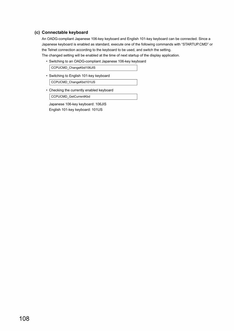
108
(c) Connectable keyboard
An OADG-compliant Japanese 106-key keyboard and English 101-key keyboard can be connected. Since a
Japanese keyboard is enabled as standard, execute one of the following commands with “STARTUP.CMD” or
the Telnet connection according to the keyboard to be used, and switch the setting.
The changed setting will be enabled at the time of next startup of the display application.
• Switching to an OADG-compliant Japanese 106-key keyboard
• Switching to English 101-key keyboard
• Checking the currently enabled keyboard
Japanese 106-key keyboard: 106JIS
English 101-key keyboard: 101US
CCPUCMD_ChangeKbd106JIS
CCPUCMD_ChangeKbd101US
CCPUCMD_GetCurrentKbd
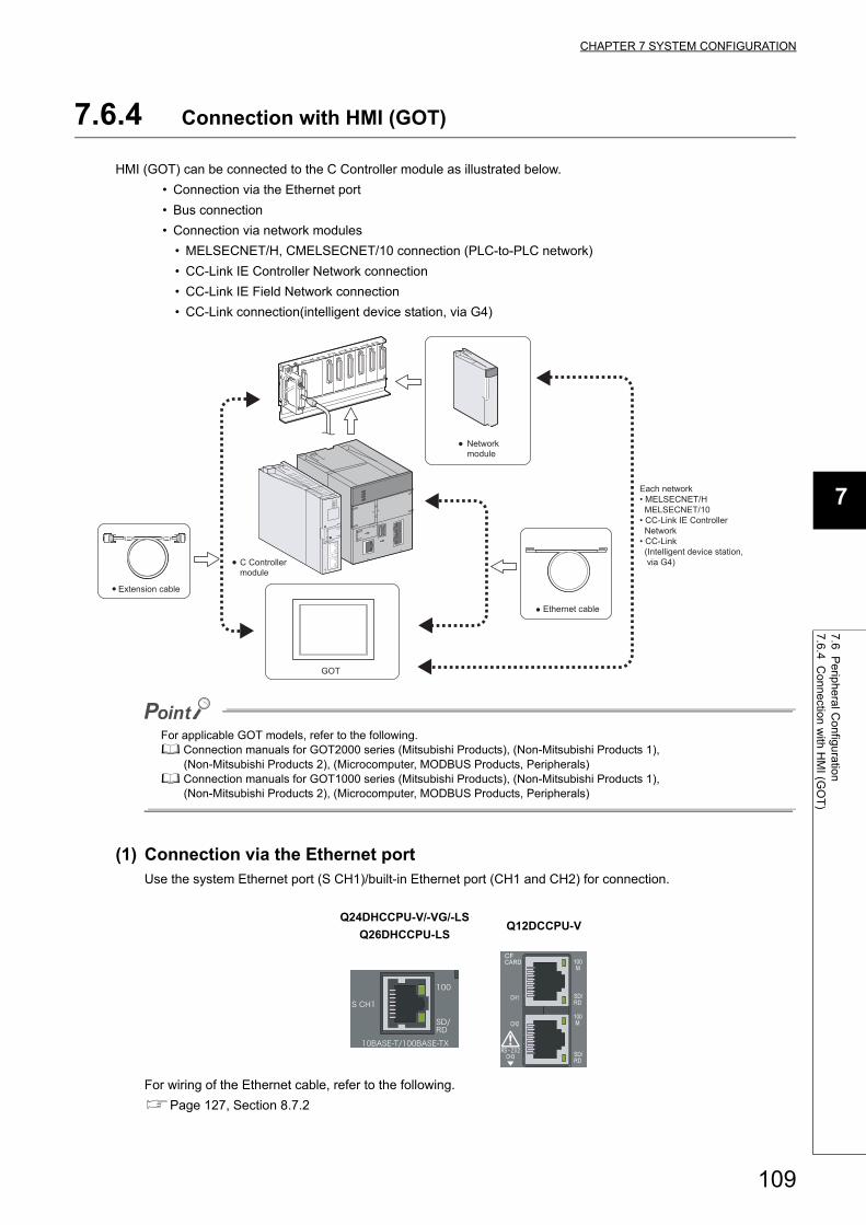
109
CHAPTER 7 SYSTEM CONFIGURATION
7
7.6 Periphe
ral Configuration
7.6.4 Connection
with
HM
I (GO
T)
7.6.4 Connection with HMI (GOT)
HMI (GOT) can be connected to the C Controller module as illustrated below.
• Connection via the Ethernet port
• Bus connection
• Connection via network modules
• MELSECNET/H, CMELSECNET/10 connection (PLC-to-PLC network)
• CC-Link IE Controller Network connection
• CC-Link IE Field Network connection
• CC-Link connection(intelligent device station, via G4)
For applicable GOT models, refer to the following. Connection manuals for GOT2000 series (Mitsubishi Products), (Non-Mitsubishi Products 1), (Non-Mitsubishi Products 2), (Microcomputer, MODBUS Products, Peripherals) Connection manuals for GOT1000 series (Mitsubishi Products), (Non-Mitsubishi Products 1), (Non-Mitsubishi Products 2), (Microcomputer, MODBUS Products, Peripherals)
(1) Connection via the Ethernet portUse the system Ethernet port (S CH1)/built-in Ethernet port (CH1 and CH2) for connection.
For wiring of the Ethernet cable, refer to the following.
Page 127, Section 8.7.2
Q24DHCCPU-V/-VG/-LS
Q26DHCCPU-LSQ12DCCPU-V
Each network • MELSECNET/H MELSECNET/10 • CC-Link IE Controller Network
Network module
Ethernet cable
Extension cable
C Controllermodule
• CC-Link (Intelligent device station, via G4)
GOT

110
(2) Bus connectionUse the main base unit/extension base unit's extension cable connector for connection.
For details, refer to the following.
Connection manuals for GOT2000 series (Mitsubishi Products), (Non-Mitsubishi Products 1),
(Non-Mitsubishi Products 2), (Microcomputer, MODBUS Products, Peripherals)
Connection manuals for GOT1000 series (Mitsubishi Products), (Non-Mitsubishi Products 1),
(Non-Mitsubishi Products 2), (Microcomputer, MODBUS Products, Peripherals)
(a) How the C Controller module recognizes the GOT
If a GOT is connected in a bus topology, the C Controller module recognizes the GOT as an intelligent function
module of 16 I/O points.
Therefore, assign I/O to the C Controller module in GOT setup.
(For GOT bus connection, occupy one the extension base (16 points x 10 slots).)
For details of the GOT setup, refer to the following.
Connection manuals for GOT2000 series (Mitsubishi Products), (Non-Mitsubishi Products 1),
(Non-Mitsubishi Products 2), (Microcomputer, MODBUS Products, Peripherals)
Connection manuals for GOT1000 series (Mitsubishi Products), (Non-Mitsubishi Products 1),
(Non-Mitsubishi Products 2), (Microcomputer, MODBUS Products, Peripherals)
(b) Maximum number of GOTs
Up to five GOTs can connected in a bus topology.
(c) Precautions
• In a bus topology, the GOT must be connected to the last base unit.
A GOT cannot be connected between base units.
• Select an appropriate extension cable for connecting the GOT to the bus so that the total extension cable
length is 13.2 m at maximum.
• A bus extension connector box (A9GT-QCNB) must be used if the first GOT is to be placed at a distance of
more than 13.2 meters away.
• For details of A9GT-QCNB, refer to the following.
A9GT-QCNB type Bus extension connector box User's Manual
• Configure the bus connection settings (extension base number and slot number settings) on the GOT
before activating the C Controller module and GOT.
• Power on the C Controller module and GOT in any of the following sequences.
• Power on the C Controller module and GOT at the same time. • Power on the C Controller module and then GOT.
• The following system alarm may occur in the GOT at start-up, depending on the system configuration and
GOT settings.
"402 A communication timeout occurred. Check the communication path or module."
To avoid the occurrence of the above system alarm, set the GOT title display time to be sufficiently longer
than the C Controller module start-up time.
For how to set the GOT title display time, refer to the following.
GT Designer3 Version1 Screen Design Manual (Fundamentals)
(3) Connection via network modulesFor connection via network modules, refer to the manual for respective network modules.

111
CHAPTER 7 SYSTEM CONFIGURATION
7
7.6 Periphe
ral Configuration
7.6.5 Connection
with
Pe
rsonal compute
r
7.6.5 Connection with Personal computer
A Personal computer can be connected to the C Controller module as illustrated below.
• Connection via USB connector
• Connection via the Ethernet port
• Connection via the CPU module by the multiple CPU system
• Connection via GOT (support of GOT transparent function)
Q24DHC-V Q24DHC-VG Q24DHC-LS Q26DHC-LS Q12DC-V
GOT
User program
development
environment
(Personal computer)
• CW Workbench
Personal computer
for maintenance
• Telnet function
• FTP function
MES server, etc.
Personal computer with
Setting/monitoring tools
for the C Controller
module installed
GOT transparent
function supported
Ethernet cable
USB cable
Ethernet cable
USB cable
Ethernet cable
CPU module
C Controller
module

112
(1) Connection to user program development environment, Personal computer for
maintenance, and superior control servers, etc. The following personal computer can be connected using the user Ethernet port (CH1 and CH2)/built-in Ethernet
port (CH1 and CH2).
• User program development environment (CW Workbench and Wind River Workbench)
• Personal computer for maintenance (Telnet and FTP functions)
• Host communication network's superior control servers (MES server and SNTP server, etc.)
For wiring of the Ethernet cable, refer to the following.
Page 127, Section 8.7.2
Remark
● For the functions of user Ethernet port/built-in Ethernet port, refer to the following.Page 192, Section 12.1
(2) Connection to Personal computer with Setting/monitoring tools for the C
Controller module installedThe following illustrates a sample case of connection with Setting/monitoring tools for the C Controller module.
For versions of Setting/monitoring tools for the C Controller module, refer to the following.
Page 52, CHAPTER 4
(a) Connection via USB connector
Use the USB connector for connection.*1
*1 : Use USB2 for Q24DHCCPU-V/-VG/-LS and Q26DHCCPU-LS.
For specifications and wiring of the USB cable, refer to the following.
Page 125, Section 8.7.1
Connection to USB connector is only possible from 1 Personal computer to 1 C Controller module.
Q24DHCCPU-V/-VG/-LS
Q26DHCCPU-LSQ12DCCPU-V
Q24DHCCPU-V/-VG/-LS
Q26DHCCPU-LSQ12DCCPU-V
For "-LS", consult with the
partner (operating system vendor).

113
CHAPTER 7 SYSTEM CONFIGURATION
7
7.6 Periphe
ral Configuration
7.6.5 Connection
with
Pe
rsonal compute
r
Connection from 1 Personal computer to multiple C Controller modules is not allowed.
(b) Connection via the Ethernet port
Use the system Ethernet port (S CH1)/built-in Ethernet port (CH1 and CH2) for connection.
For wiring of the Ethernet cable, refer to the following.
Page 127, Section 8.7.2
Remark
● For the functions of system Ethernet port/built-in Ethernet port, refer to the following.Page 200, Section 12.2
(c) Connection via the CPU module by the multiple CPU system
Connect the multiple CPU system to the C Controller module(s) of the other CPUs via the CPU module
connected with a Personal computer.
(d) Connection via GOT (support of GOT transparent function)
Use the GOT transparent function to connect via GOT.
For cable to connect with GOT, settings on GOT and precautions, refer to the manual for respective GOT to
connect.
Connection manuals for GOT2000 series (Mitsubishi Products), (Non-Mitsubishi Products 1),
(Non-Mitsubishi Products 2), (Microcomputer, MODBUS Products, Peripherals)
Connection manuals for GOT1000 series (Mitsubishi Products), (Non-Mitsubishi Products 1),
(Non-Mitsubishi Products 2), (Microcomputer, MODBUS Products, Peripherals)
Q24DHCCPU-V/-VG/-LS
Q26DHCCPU-LSQ12DCCPU-V

114
7.6.6 Connection with other peripherals (C Controller module, etc.)
The C Controller module can be connected with other C Controller modules and/or various network peripherals in the
device (internal microcomputers, etc.) by using the following methods:
• Connection via USB connector
• Connection via the Ethernet port
• Connection with a general-purpose analog RGB display
• Connection via the RS-232 connector
• Connection via network modules
• MELSECNET/H, CMELSECNET/10 connection (PLC-to-PLC network)
• CC-Link IE Controller Network connection
• CC-Link IE Field Network connection
• CC-Link connection
(1) Connection via USB connector
Use the USB connector for connection.*1
*1 : Use USB2 for Q24DHCCPU-V/-VG/-LS and Q26DHCCPU-LS.
For specifications and wiring of the USB cable, refer to the following.
Page 125, Section 8.7.1
(2) Connection via the Ethernet port Use the user Ethernet port (CH1 and CH2)/built-in Ethernet port (CH1 and CH2) for connection.
For wiring of the Ethernet cable, refer to the following.
Page 127, Section 8.7.2
Q24DHCCPU-V/-VG/-LS
Q26DHCCPU-LSQ12DCCPU-V
Q24DHCCPU-V/-VG/-LS
Q26DHCCPU-LSQ12DCCPU-V
Q24DHC-V Q24DHC-VG Q24DHC-LS Q26DHC-LS Q12DC-V
Note7.1
For "-LS", consult with the
partner (operating system vendor).
For "-LS", consult with the
partner (operating system vendor).

115
CHAPTER 7 SYSTEM CONFIGURATION
7
7.6 Periphe
ral Configuration
7.6.6 Connection
with
other perip
herals (C C
ontroller m
odule, etc.)
(3) Connection with a general-purpose analog RGB display Note7.1Use the analog RGB output connector for connection.
For specifications and wiring of analog RGB output connector, refer to the following.
Page 131, Section 8.7.3
(a) Precautions for connection with a general-purpose analog RGB display
• Power management function
C Controller module does not support the VESA DPMS-compliant power management function.
(4) Connection via the RS-232 connector Use the RS-232 connector at the bottom of the C Controller module.
For wiring of the RS-232 cable, refer to the following.
Page 132, Section 8.7.4
(5) Connection via network modules For connection via network modules, refer to the manual for respective network modules.
Note7.1 Q24DHCCPU-V and Q12DCCPU-V cannot be connected.
For "-LS", consult with the
partner (operating system vendor).
Q24DHCCPU-V Q12DCCPU-V
For "-LS", consult with the
partner (operating system vendor).
For "-LS", consult with the
partner (operating system vendor).

116
CHAPTER 8 INSTALLATION AND WIRING
This chapter describes the installation and wiring procedures for C Controller module and other optional products.
8.1 Installation Environment and Installation Position
For precautions for installation environment and installation position, refer to the following.
QCPU User's Manual (Hardware Design, Maintenance and Inspection)
8.2 Installation and Removal of Module
The following explains how to install and remove a C Controller module.
For precautions and procedures for handling, installation and removal of CPU module, I/O module, intelligent function
module, power supply module and base unit, etc., refer to the following.
QCPU User's Manual (Hardware Design, Maintenance and Inspection)

117
CHAPTER 8 INSTALLATION AND WIRING
8
8.2 Installation an
d Rem
oval of M
odule
(1) Installation to base unit
*1 : Insert the two module fixing projections on the right and left into the module fixing holes so that they are not misaligned.
*2 : Push the center top of the module so that the two module fixing hooks on the right and left are securely engaged with the base unit hooks.
● When mounting the module, always insert the module fixing projection into the module fixing hole of the base unit.At that time, securely insert the module fixing projection so that it does not come off from the module fixing hole.Failure to do so may damage the module connector and module.
● When using the programmable controller in an environment of frequent vibration or impact, secure the module to the base unit using screws.Module fixing screw : M3 12 (user-prepared)Tightening torque range: 0.36 to 0.48N • m
● After first use of the product, do not mount or remove the module onto or from the base unit more than 50 times (IEC 61131-2 compliant). Exceeding the limit of 50 times may cause malfunction.
Module
Using the module fixing hole as a supporting point, push the module in the direction of arrow until it clicks.
Make sure that the module is inserted in the base unit securely.
Module mounting lever
Module fixing projection*1
Base unit
Module fixing hook*2
Base unit
Module connectorModule fixing hole
Module fixing projection
Base unit
Module mounting lever
Completed
Module fixing hole
Securely insert the module fixing projection*1 into the module fixing hole so that the latch is not misaligned.
Base unit hook
Module fixing hook
Push
Center top

118
(2) Removal from base unit
*1 : Push the two modules fixing hooks on the right and left of the module top simultaneously with your fingers until they stop.
*2 : Remove the two module fixing projections on the right and left of the module bottom from the module fixing holes.
When removing the module which is secured by module fixing screw, remove the module fixing screw first and then module fixing projection off the module fixing hole of the base unit.Failure to do so may damage the module fixing projection.
Module
Support the module with both hands and securely press the module fixing hook*1 with your finger.
Pull the module straight toward you supporting it at its bottom while pressing the module fixing hook*1.
Lifting
Base unit
Module connectorWhile lifting the module, take off the module fixing projection*2 from the module fixing hole.
Completed
Module fixing hole
Module fixing hook*1
Push
Push simultaneously
Module fixing hook

119
CHAPTER 8 INSTALLATION AND WIRING
8
8.3 Battery Installation
8.3 Battery Installation
This section describes the procedures of installing a battery into the C Controller module.
The battery connector is disconnected from the battery before shipping.
Connect the battery connector before use.
For operations without any battery, use the battery less drive function ( Page 190, Section 11.11).
(1) Q6BAT battery installation procedure
● Firmly push the battery connector all the way in to the connector pin.
(2) Q7BAT-SET battery installation procedureWhen changing the battery for the C controller module from the Q6BAT to the Q7BAT, set the battery and connect
its connector in the following procedure.
C Controller module
Battery
Connect the battery connector to the connector pin on the case, checking the orientation
Check the battery is correctly installed.
Open the C controller module bottom cover.
Place the excess lead wire on the top of the battery.
Lead wire of the battery
Completed
Connector
Connector stopper
C controller module
Disconnect the connector connecting the Q6BAT to the C controller module.
Open the C controller module bottom cover.
Remove the Q6BAT and cover from the C controller module.
Set the Q7BAT- SET in the C controller module.
Connect the Q7BAT- SET to the battery connector of the C controller module and set it into the connector holder of the battery holder. Battery holder
Completed
Connector
Connector stopper
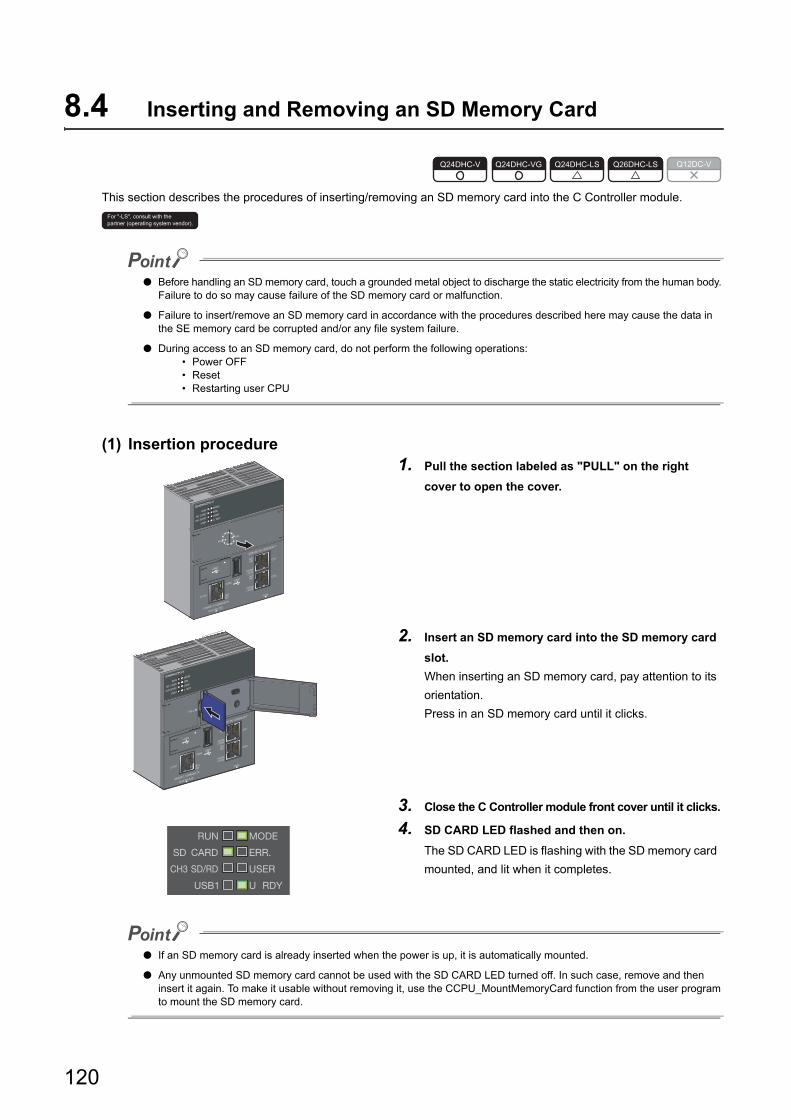
120
8.4 Inserting and Removing an SD Memory Card
This section describes the procedures of inserting/removing an SD memory card into the C Controller module.
● Before handling an SD memory card, touch a grounded metal object to discharge the static electricity from the human body. Failure to do so may cause failure of the SD memory card or malfunction.
● Failure to insert/remove an SD memory card in accordance with the procedures described here may cause the data in the SE memory card be corrupted and/or any file system failure.
● During access to an SD memory card, do not perform the following operations: • Power OFF • Reset • Restarting user CPU
(1) Insertion procedure
● If an SD memory card is already inserted when the power is up, it is automatically mounted.
● Any unmounted SD memory card cannot be used with the SD CARD LED turned off. In such case, remove and then insert it again. To make it usable without removing it, use the CCPU_MountMemoryCard function from the user program to mount the SD memory card.
1. Pull the section labeled as "PULL" on the right
cover to open the cover.
2. Insert an SD memory card into the SD memory card
slot.
When inserting an SD memory card, pay attention to its
orientation.
Press in an SD memory card until it clicks.
3. Close the C Controller module front cover until it clicks.
4. SD CARD LED flashed and then on.
The SD CARD LED is flashing with the SD memory card
mounted, and lit when it completes.
Q24DHC-V Q24DHC-VG Q24DHC-LS Q26DHC-LS Q12DC-V
For "-LS", consult with the
partner (operating system vendor).

121
CHAPTER 8 INSTALLATION AND WIRING
8
8.4 Inserting and R
emovin
g an SD
Mem
ory Card
(2) Removal procedure
● During access to an SD memory card, do not perform the following operations: • Unmounting SD memory card • Removing SD memory card
● You may also unmount the SD memory card from the user program by using the CCPU_UnmountMemoryCard.
1. Pull the section labeled as "PULL" on the cover to
open the cover.
Open both right and left covers.
2. Move the RESET/SELECT switch to the SELECT
position.
Do not release the switch while pulling it down.
3. Check that the SD CARD LED start flashing.
4. Move the RESET/SELECT switch back to the center.
Release the switch then it returns to its center position.
5. Check that the SD CARD LED goes off.
6. Press the SD memory card into the SD memory card
slot until it clicks and then pull it out straight.
7. Close the C Controller module front cover until it
clicks.

122
8.5 Installing/uninstalling and unmounting a CompactFlash card
This section describes the procedures of inserting/removing a CompactFlash card into the C Controller module.
● Before handling a CompactFlash card, touch a grounded metal object to discharge the static electricity from the human body. Failure to do so may cause failure of the module or malfunction.
● If the CompactFlash card is not installed/uninstalled properly as follow the procedure in this section, data corruption or file error in the CompactFlash card may occur.
● Do not operate the following operations during accessing to the CompactFlash card. • Turn the power OFF • Reset
(1) Installation procedure
● If a CompactFlash card is already inserted when the power is up, it is automatically mounted.
● Any unmounted CompactFlash card cannot be used with the CF CARD LED turned off. In such case, remove and then insert it again. To make it usable without removing it, use the CCPU_MountMemoryCard function from the user program to mount the CompactFlash card.
1. Pull the section labeled as "PULL" on the front
cover to open the cover.
2. Press the EJECT button to remove the dummy
CompactFlash card.
Please keep the removed dummy CompactFlash
card in a secure location.
3. Insert a CompactFlash card into the
CompactFlash card installation slot.
When inserting a CompactFlash card, pay
attention to its orientation.
Insert the CompactFlash card into the installation
slot and push it until the card edge is flush with the
EJECT button.
4. Close the C Controller module front cover until
it clicks.
5. Check if the CF CARD LED turns ON.
Q24DHC-V Q24DHC-VG Q24DHC-LS Q26DHC-LS Q12DC-V
Front cover
CompactFlash card slot
1) Open the front cover
Dummy CompactFlash card
EJECT button
2) Press the EJECT button.
EJECT button
Orientation of CompactFlash card
CompactFlash card slot
CompactFlash card
Projected part

123
CHAPTER 8 INSTALLATION AND WIRING
8
8.5 Installing/uninstalling and unmo
unting a C
ompactF
lash card
(2) Uninstallation procedure
● During access to a CompactFlash card, do not perform the following operations: • Unmounting CompactFlash memory card • Removing CompactFlash memory card
● You may also unmount the CompactFlash card from the user program by using the CCPU_UnmountMemoryCard.
1. Pull the section labeled as "PULL" on the front
cover to open the cover.
2. Move the RESET/SELECT switch to the SELECT
position.
Do not release the switch while pulling it down.
3. Check that the CF CARD LED start flashing.
Keep the switch at the SELECT side while flashing the
LED.
4. Check that the CF CARD LED goes off.
5. Move the RESET/SELECT switch back to the center.
6. Press the EJECT button to remove the
CompactFlash card.
While no CompactFlash card is used, a dummy
CompactFlash card must be used.
7. Close the C Controller module front cover until it
clicks.
EJECT button
2) Press theEJECT button.
CompactFlash card

124
8.6 Inserting/removing and Unmounting a USB Mass Storage Class Standard Compliant Device
This section explains how to insert/remove a device compliant with the USB Mass Storage Class standard into/from C
Controller module.
Do not perform the following operations while accessing to a device compliant with the USB Mass Storage Class standard: • Power OFF • Reset • Restarting user CPU • Unmounting a device compliant with the USB Mass Storage Class standard • Removing a device compliant with the USB Mass Storage Class standard
(1) Insertion procedure
For specifications and wiring of USB cables, refer to the following.
Page 125, Section 8.7.1
(2) Removal procedure
1. Firmly insert a USB device or USB cable connector
into the USB connector (USB1).
2. USB1 LED flashed and then on.
The USB1 LED is flashing with the USB device mounted,
and lit when it completes.
1. Use the CCPU_UnmountMemoryCard function to
unmount the USB device from the user program.
2. Check that the USB1 LED is turned off.
3. Disconnect the USB device or USB cable connector
from the USB connector (USB1).
Q24DHC-V Q24DHC-VG Q24DHC-LS Q26DHC-LS Q12DC-V
For "-LS", consult with the
partner (operating system vendor).

125
CHAPTER 8 INSTALLATION AND WIRING
8
8.7 Cabling
8.7.1 US
B cablin
g
8.7 Cabling
8.7.1 USB cabling
Described in this section are the specifications and wiring of compatible USB cables.
(1) USB connector
(a) Q24DHCCPU-V/-VG/-LS and Q26DHCCPU-LS
There are 2 types of USB connectors: USB1 and USB2. Use them accordingly to peripherals to be connected.
(b) Q12DCCPU-V
(2) USB cable
(a) Connection with USB device
Use a USB cable supplied with the USB device.
The type of cable connector compatible with the USB connector (USB1) is the connector type A.
(b) Connection with Personal computer
The types of cable connector compatible with the USB connector (USB2, USB) are as follows.
• C Controller module side: Connector type miniB
• Personal computer side: Connector type A
Use a USB cable of 3m (9.84 feet) or less.
USB connector Connection destination
USB1USB device
USB2Personal computer with Setting/monitoring tools for the C Controller module
installed
USB connector Connection destination
USBPersonal computer with Setting/monitoring tools for the C Controller module
installed
Q24DHC-V Q24DHC-VG Q24DHC-LS Q26DHC-LS Q12DC-V
For "-LS", consult with the
partner (operating system vendor).
For "-LS", consult with the
partner (operating system vendor).

126
(3) USB cable fall-off prevention (Q24DHCCPU-V/-VG/-LS and Q26DHCCPU-LS)USB cable(s) can be fixed to the C Controller module enclosure with a fixing band (recommended specifications:
Width: 6-9 mm and Thickness: 1mm or less).
(4) PrecautionsPrecautions for use of USB cables:
• Do not activate the resume function, suspend setting, energy saving function and standby mode on the
Personal computer communicating with the C Controller module. Otherwise a communication error may
occur.
• Before inserting/removing a USB cable, resetting the C Controller module, or powering up/off, put connected
tool(s) in offline state. Frequent inserting/removing a USB cable, resetting the C Controller module, and
powering up/off during communication may cause an unrecoverable communicating error.
When operation is not recovered from an error, remove a USB cable. Then, connect it again after five or
more seconds. (Even after this operation, an error may occur at initial communication. However,
communication will be successful after that.)
• A communication error may occur depending on the combination of personal computers and USB cables.
Procedure Figure Description
1
A through hole for a fixing band
is prepared next to the PCI
Express® connector at the
bottom of the C Controller
module.
2
• Let a fixing band through as
illustrated.
• When a PCI Express® cable is
connected, disconnect the
PCI Express® cable before
performing this task.
3
• Let a USB cable through the
fixing band to fix it.
• A knot of the fixing band
should face forward.
• Connect the PCI Express®
cable back.

127
CHAPTER 8 INSTALLATION AND WIRING
8
8.7 Cabling
8.7.2 Ethe
rnet wiring
8.7.2 Ethernet wiring
Described in this section are the specifications and wiring of compatible twisted pair cables.
(1) Ethernet port
(a) Q24DHCCPU-V/-VG/-LS and Q26DHCCPU-LS
There are 2 types of Ethernet port: user Ethernet port (CH1 and CH2) and system Ethernet port (S CH1). Use
them accordingly to peripherals to be connected.
(b) Q12DCCPU-V
The reference time from powering up the C Controller module to establishment of communication with Ethernet port is as follows. Required time may vary depending on system configurations.
• User Ethernet port (CH1 and CH2) : 30 seconds • System Ethernet port (S CH1) : 15 seconds • Built-in Ethernet port (CH1 and CH2) : 15 seconds
Ethernet port Connection destination
User Ethernet port
(CH1 and CH2)
User program development environment (Personal computer)
CW Workbench
Personal computer for maintenance
Telnet function
FTP function
Host communication network's peripherals (MES server, etc.)
System
Ethernet port
(S CH1)
Personal computer with Setting/monitoring tools for the C Controller module installed
GOT
Ethernet port Connection destination
Built-in
Ethernet port
(CH1 and CH2)
User program development environment (Personal computer)
CW Workbench
Personal computer for maintenance
Telnet function
FTP function
Host communication network's peripherals (MES server, etc.)
Personal computer with Setting/monitoring tools for the C Controller module installed
GOT
Q24DHC-V Q24DHC-VG Q24DHC-LS Q26DHC-LS Q12DC-V
For "-LS", consult with the
partner (operating system vendor).

128
(2) Twisted pair cableSpecifications of cables that can be used for connection with peripherals by using the user Ethernet ports (CH1
and CH2), system Ethernet port (S CH1), and Built-in Ethernet ports (CH1 and CH2) are described in the table
below.
Cables conforming to the IEEE802.3 10BASE-T/100BASE-TX/1000BASE-T standards can be used.
: Available, -: N/A
In the high-speed communication (100Mbps/1000Mbps) by 100BASE-TX/1000BASE-T connection, a communication error may occur due to high frequency noise generated from a device other than the C Controller module, depending on the installation environment.When configuring a network system, take the following measures on the C Controller module side to eliminate the influence of high frequency noise.
• WiringDo not install the twisted pair cables together with the main circuit lines or power cables.Place the twisted pair cables in a duct.
• CableIn an environment where the system is susceptible to noise, use shielded twisted pair (STP) cables.
• Retry processingIn an environment where the system is susceptible to noise, include the retry processing in the user program.
• Data transmission speedChange the destination device to connect with the C Controller module from 100Mbps and 10Mbps changes the data transmission speed for communication.
Type
Unshielded twisted pair (UTP) cable,
Shielded twisted pair (STP) cable
User
Ethernet port
(CH1 and CH2)
System
Ethernet port
(S CH1)
Built-in
Ethernet port
(CH1 and CH2)Straight cable Crossing cable
10Mbps Category 3 or higher Category 3 to 5e
100Mbps Category 5 or higher Category 5 or 5e
1000Mbps Category 5e or higher Category 5e - -
For "-LS", consult with the
partner (operating system vendor).

129
CHAPTER 8 INSTALLATION AND WIRING
8
8.7 Cabling
8.7.2 Ethe
rnet wiring
(3) Setting an IP addressTo use the Ethernet port(s), it is necessary to set an IP address.
You may set an IP address by using parameters by Setting/monitoring tools for the C Controller module.
● Do not set an IP address for the C Controller module from the user program. Otherwise, network may no longer be function properly.
(a) For the first connection
For factory connection or connection after initialization, use the default IP address.
The C Controller IP addresses set in factory or after initialization are listed below.
<Q24DHCCPU-V/-VG/-LS and Q26DHCCPU-LS>
<Q12DCCPU-V>
An example of setting is illustrated below:
Ethernet port Default IP address
User Ethernet port (CH1)192.168.3.3
User Ethernet port (CH2)(No IP address setting)
System Ethernet port (S CH1) 192.168.3.39
Ethernet port Default IP address
Built-in Ethernet port (CH1) 192.168.3.3
Built-in Ethernet port (CH2) (No IP address setting)
For "-LS", consult with the
partner (operating system vendor).
For "-LS", consult with the
partner (operating system vendor).
C Controller module
IP addressCH1
Subnet mask
Network part Host part Network part Host part
Set the same value.Set different values.
192.168.3. 3
0
10255.255.255.
192.168.3.255.255.255.
Development environment (personal computer)

130
(b) Precautions for IP address setting
The network portion of the IP address must be the same in both the destination device to connect and the user
Ethernet port or Built-in Ethernet port.
CH1 and CH2 of user Ethernet port and built-in Ethernet port must have different network portions in their IP
addresses.
A message to the destination device (including response packet such as ping) is sent (as a response) from the
user Ethernet port or Built-in Ethernet port that has the same network portion in the IP address.
• Example of ping execution from a personal computer
As illustrated below, no message (including response packet such as ping) is not transmitted (as a response) to
the destination device if you connect a user Ethernet port and a destination device with different network
portion in their IP addresses.
• Communication not available
1. Transmit ping request from
Personal computer to the C
Controller module.
2. A ping response is transmitted
(as a response) from the user
Ethernet port CH1 with the
same network portion
(192.168.3) as the destination
device.
3. Transmit ping request from
Personal computer to the C
Controller module.
4. A ping response is transmitted
(as a response) from the user
Ethernet port CH1 with the
same network portion
(192.168.3) as the destination
device. (No transmission from
CH2 that received the ping
request.)
CH1 is not connected to the
destination device, so no ping
response is returned.
For "-LS", consult with the
partner (operating system vendor).
Personal computer C Controller module, CH2
Ethernet
[192.168.3.10] [192.168.4.3]
C Controller module, CH1IP address [192.168.3.3]Subnet mask [255.255.255.0]ping request and
ping response
IP addressSubnet mask [255.255.255.0]
IP addressSubnet mask [255.255.255.0]
Personal computer
Ethernet
[192.168.3.10]
1) ping request
2) A ping response cannot be sent.
IP addressSubnet mask [255.255.255.0]
C Controller module, CH2[192.168.4.3]
C Controller module, CH1IP address [192.168.3.3]Subnet mask [255.255.255.0]
IP addressSubnet mask [255.255.255.0]

131
CHAPTER 8 INSTALLATION AND WIRING
8
8.7 Cabling
8.7.3 Ana
log RG
B outp
ut cabling
8.7.3 Analog RGB output cabling
Described in this section are the specifications and wiring of compatible RGB cables.
(1) Analog RGB output connectorThe analog RGB output connector is located at the bottom face of the module.
*1 : Connect the display before powering ON.
(a) Q24DHCCPU-VG
• Connection with a general-purpose analog RGB display
For the connectable cables and peripheral devices, the ones meet the specifications of analog RGB
connector for C Controller module can be used.
Page 45, Section 3.2
(b) Q24DHCCPU-LS and Q26DHCCPU-LS
For the connectable cables and peripheral devices, refer to the manual of the partner operating system, or
consult the partner (operating system vendor).
Analog RGB output connector Connection destination
General-purpose RGB display *1
Q24DHC-V Q24DHC-VG Q24DHC-LS Q26DHC-LS Q12DC-V

132
8.7.4 RS-232 cabling
Described in this section are the specifications and wiring of compatible RS-232 cables.
(1) RS-232 connectorRS-232 connector is located at the bottom of the module.
(a) When 9-pin D-sub connector is used
To use a 9-pin D-sub connector RS-232 cable, use an optional RS-232 conversion connector cable.
Use the following product as a connection cable connector.
Specifications of fixing screws are as follows:
• Connector fitting screw : M2.6 (user-prepared)
• Tightening torque ranges : 0.206 to 0.39N • m
The table below shows the connector pin positions and signal direction.
RS-232 connector Connection destination
Peripheral device
Cable model Maker name Model name
RS-232 conversion cable
(Round connector 9-pin D-sub connector)Mitsubishi Electric Corporation Q12DCCPU-CBL
Connector type Maker name Model name
D-sub connector
(Solder-connection type)
DDK Ltd.
(http://www.ddknet.co.jp/English/index.html)17JE-23090-02 (D8A)(-CG)
Pin No. Mnemonic Signal name C controller moduleSignal
direction
Q12DCCPU-CBL
RS-232 device
side
1 CD(DCD) Data Carrier Detect
2 RD(RXD) Received Data
3 SD(TXD) Transmitted Data
4 ER(DTR) Data Terminal Ready
5 SG Signal Ground -
6 DR(DSR) Data Set Ready
7 RS(RTS) Request To Send
8 CS(CTS) Clear To Send
9 CI(RI) Ring Indicator
10 SG Signal Ground -
1
2
36
7
5
48
9
10
1
2
3
4
5
6
7
8
9

133
CHAPTER 8 INSTALLATION AND WIRING
8
8.7 Cabling
8.7.4 RS
-232 cabling
(2) PrecautionsPrecautions for use of RS-232 cables:
• Ground the shield of the RS-232 cable to a single point.
• Bend radius of the cable portion near the connector should be "cable's outside diameter 4" or more.
• Confirm the specifications of the peripheral device before connecting it.
• Do not short the FG and SG signals of the RS-232 cable.
• When the FG and SG signals are connected inside of the peripheral device, do not connect the FG signal to
the C Controller module.
• To install a cable, a space for cabling is required as illustrated below.
The bend radius (R) near the connector must be "cable's outside diameter 4" or more when an RS-232
cable is used.
For the Q12DCCPU-CBL, "cable's outside diameter 4" is 22 mm (0.87 inches) or more.
Cable's outside diameter × 4 or more R37 mm (1.47 inches) (For Q12DCCPU-CBL)
22 mm (0.87 inches) (For Q12DCCPU-CBL)

134
CHAPTER 9 MAINTENANCE AND INSPECTION
This chapter explains items you should perform routinely or at regular intervals to ensure normal and the best
conditions of the C Controller module.
9.1 Daily Inspection
The following table lists the items to be inspected daily.
No. Item Inspection Criterion Action
1 Installation of base unitCheck the fixing screws and
cover for looseness.The base unit is securely installed. Retighten the screws.
2 Installation of I/O modules
Check the module and
module fixing hook for
looseness.
The module fixing hooks are securely
engaged and the modules are
securely mounted.
Securely engage the module
fixing hooks.
3 Connection
Check the terminal screws
for looseness.No looseness.
Retighten the terminal
screws.
Check the distance between
solderless terminals.
Proper clearance between solderless
terminals.
Provide proper clearance
between solderless terminals
Check the connector part of
the cable.Connectors are securely connected.
Retighten the connector fixing
screws.
4
Indicator LEDs -
Power supply module
"POWER" LEDCheck that the LED is lit.
Lit green.
(Faulty if the LED is off or on (red))
Page 394, CHAPTER 23
Power supply module *1
"LIFE" LEDCheck that the LED is lit.
Lit green or orange, flashing (orange)
(Faulty if the LED is off, on (red), of
flashing (red))
C Controller module
"MODE" LED
Check that the LED is lit in
the RUN status.
Lit.
(Faulty if the LED is off)
C Controller module
"ERR." LEDCheck that the LED is off.
Off
(Faulty if the LED is off or flashing)
Input module
Input LEDCheck for on/off of the LED.
Lit when the input is on.
Off when the input is off.
(Faulty if the reaction is other than
above.)
QCPU User's Manual
(Hardware Design,
Maintenance and Inspection)
Output module
Output LEDCheck for on/off of the LED.
Lit when the input is on.
Off when the input is off.
(Faulty if the reaction is other than
above.)
Page 394, CHAPTER 23
*1 : When the Life detection power supply module (Q61P-D) is used, check the LIFE LED.

135
CHAPTER 9 MAINTENANCE AND INSPECTION
9
9.2 Periodical In
spection
9.2 Periodical Inspection
This section explains the items to be inspected once or twice every six months or every year.
Note that these inspections are required when the system is moved or modified including re-wiring.
No. Item Inspection Criterion Action
1
Ambient environment *1 -
Ambient temperature Measure with a thermometer
and a hygrometer.
Measure corrosive gas.
0 to 55 deg. C
Criteria must be met.Ambient humidity 5 to 95%RH *2
Ambience No corrosive gas
2 Power voltage
Measure a voltage across
the terminals of 100/200V
AC and 24V DC.
85 to 132V AC
Change the power supply.170 to 264V AC
15.6 to 31.2V DC
3
Installation -
Looseness, rattlingMove the module to check
for looseness and rattling.The module is securely installed.
Retighten the screws.
For the C Controller module,
I/O modules, or power supply
module, secure the module
with screws.
Dirt, foreign matter Visual check. No dirt or foreign matter. Remove and clean it.
4
Connection -
Looseness of terminal
screws
Further tighten with a
screwdriver.No looseness.
Retighten the terminal
screws.
Distance between
solderless terminals.Visual check.
Proper clearance between solderless
terminals.
Provide proper clearance
between solderless terminals.
Looseness of
connectors.Visual check. No looseness.
Retighten the connector fixing
screws.
5 Battery
Check [CCPU diagnostics]
screen of Setting/monitoring
tools for the C Controller
module*3
No "battery error" occurrenceReplace the battery
( Page 136, Section 9.3)
Check the length of term
after purchasing the battery.
Must not be used more than 5
years.
6Standard ROM life
(Page 137, Section 9.4)
Check [Event history] screen
of Setting/monitoring tools
for the C Controller module*3
Event No.80001000
("The count for clearing the standard
ROM drive, "/ROM" exceeds the
100,000.") has not occurred.Replace the C controller
module.
7Built-in SSD life
(Page 137, Section 9.5)
Refer to the manual of the partner operating system, or consult the
partner (operating system vendor)
*1 : When using it inside the panel, inspec the in-panel environment.*2 : 10 to 90%RH when an AnS series module is used in a multiple CPU system.*3 : For Setting/monitoring tools for the C Controller module, refer to the following.
Setting/Monitoring Tools for the C Controller Module Version 4 Operating Manual

136
9.3 Battery Replacement Procedure
Before the C Controller module battery reaches the limit of its life, replace it by the following procedure.
Before removing the battery, turn on the C Controller system power for 10 minutes or more.
Data will be backed up by the capacitor for a while after removing the battery.
However, quickly replace the battery since the data may be cleared if it takes more than the following guaranteed time.
Backup power time
3 minutes
C Controller module
Battery
Power OFF the C Controller system.
Remove the C Controller module from the base unit.
Open the cover of the C Controller module.
Take the old battery out of the holder.
Insert a new battery in the correct orientation, and connect the lead connector to the connector.
Close the cover of the C Controller module.
Power on the C Controller system.
Mount the C Controller module on the base unit.
Check for battery error.
Battery error
No battery error
The C Controller module battery is faulty.
End
Back up data.
Battery side connector
C Controller module side connector
Battery replacement

137
CHAPTER 9 MAINTENANCE AND INSPECTION
9
9.4 Stand
ard RO
M Life
9.4 Standard ROM Life
Described in this section is the standard ROM lifetime.
Do not write files other than parameter and script files to the standard ROM.If you need to do so, write files into an SD memory card or CompactFlash card.
(1) Standard ROM life • The life of the standard ROM is represented as write count index value and writing is allowed until it reaches
to 100,000.
• As the C Controller module make an effect to extend the writing life of the standard ROM, actual write count
index value will not be the same as actual count of writing.
• Replace the C Controller module when the write count index value has reached to 100,000 times.
(If the write count index value exceeds 100,000, writing to the standard ROM may become slower or result in
an error.)
(2) Standard ROM write count index value check • The standard ROM write count index value can be obtained by the C Controller module dedicated function
(CCPU_GetCpuStatus) from the user program.
• If the write count index value exceeds 100,000, it is registered to the event history.
• As the standard ROM operations were checked in our shipping inspection, the initial value of the write count index value is not 0.
• Normally, C Controller module always checks data in the standard ROM area, so the write count index value may be increased.
9.5 Built-in SSD Life
For the life of built-in SSD and the checking method, refer to the manual of the partner operating system, or consult the
partner (operating system vendor)
Q24DHC-V Q24DHC-VG Q24DHC-LS Q26DHC-LS Q12DC-V
Q24DHC-V Q24DHC-VG Q24DHC-LS Q26DHC-LS Q12DC-V

138
Memo

139
PART 3 FUNCTION
This section describes the functions available for the C Controller module.
CHAPTER 10 FUNCTION LIST . . . . . . . . . . . . . . . . . . . . . . . . . . . . . . . . . . . . . . . . . . . 140
CHAPTER 11 BASIC FUNCTIONS. . . . . . . . . . . . . . . . . . . . . . . . . . . . . . . . . . . . . . . . . 146
CHAPTER 12 FUNCTIONS ACCESSED VIA ETHERNET PORTS. . . . . . . . . . . . . . . . 192
CHAPTER 13 FUNCTIONS ACCESSED VIA A NETWORK MODULE . . . . . . . . . . . . . 208
CHAPTER 14 FUNCTIONS USED BY MULTIPLE CPU SYSTEM. . . . . . . . . . . . . . . . . 251

140
CHAPTER 10FUNCTION LIST
This chapter explains the C Controller module functions.
(1) Basic functions: Supported : Not supported : Supported with restrictions
Function Description
CPU module
ReferenceQ24DHC Q26DHC
-LS
Q12DC
-V-V -VG -LS
I/O module, intelligent function module, and interrupt module control function
I/O module and intelligent
function module access
function
Controls I/O modules or intelligent
function modules from the user program
of the C Controller module.
Page 146,
Section 11.1.1
Switch settings for I/O and
intelligent function modules
Configure the settings for intelligent
function modules and interrupt modules.
(For details, refer to the manual for each
module.)
Page 147,
Section 11.1.2
Interrupt from intelligent
function module and
interrupt module
Issues an interrupt event (I50 to I255) in
response to an interrupt request from an
intelligent function module and interrupt
module.
Page 148,
Section 11.1.3
Input response time
selection
(I/O response time)
Allows selection of the response time for
the Q series input modules, I/O
combined modules, high-speed input
modules, and interrupt modules.
Page 150,
Section 11.1.4
Output (Y) setting for
switching from STOP to
RUN
Set the output status (Y) for the case
where the STOP status is switched to
the RUN status.
Page 151,
Section 11.1.5
Error time output mode
setting
Set whether to clear or hold the outputs
to Q series output modules, I/O
combined modules, and intelligent
function modules when a stop error
occurs in the C Controller module.
Page 152,
Section 11.1.6
Hardware error time CPU
operating mode setting
Set whether to stop or run the C
Controller module when a hardware
error occurs in an intelligent function
module.
Page 153,
Section 11.1.7
Self-diagnostic function
Monitors the operating status of each
module, and when an error has
occurred, displays error information.
Page 154,
Section 11.2
Watchdog timer (WDT)
Detects a hardware error or a user
program error of the C Controller
module.
Page 158,
Section 11.3
Clock function
Reads clock data in the C Controller
module by the user program, and uses
them for time control.
Page 160,
Section 11.4

141
CHAPTER 10 FUNCTION LIST
10
Remote operation function
Controls the execution status (RUN/
STOP/PAUSE) of the C Controller
module from its user program or
development environment.
Page 163,
Section 11.5
Device function
Creates a device such as a
programmable controller CPU in work
RAM of the C Controller module.
Page 169,
Section 11.6
Function Description
CPU module
ReferenceQ24DHC Q26DHC
-LS
Q12DC
-V-V -VG -LS

142
: Supported : Not supported : Supported with restrictions
Function Description
CPU module
ReferenceQ24DHC Q26DHC
-LS
Q12DC
-V-V -VG -LS
Refresh function
Refresh cycle settingSets the refresh cycle used by the C
Controller module.
Page 170,
Section 11.7
Data refresh function
Performs refreshing automatically
between the devices of the C Controller
module (X, Y, buffer memory) and the
data refresh memory.
Page 171,
Section 11.7.1
Link refresh function
Performs refreshing automatically
between the devices of the C Controller
module (B and W) and the link device of
the network module.
Page 175,
Section 11.7.2
Security function
Access authority setting
function
Restricts operations from Setting/
monitoring tools for the C Controller
module, Telnet function and FTP
function by setting (adding/deleting)
user(s) to the C Controller module.
Page 177,
Section 11.8.1
Individual identification
function
Creates a user program operable only
with a certain C Controller module with
individual identification information, by
reading out individual identification
information of the C Controller module.
Page 179,
Section 11.8.2
File access restriction
function
Restricts accesses to files and
operations by setting an attribute for
each file.
Page 183,
Section 11.8.3
Service setting function
The status of services (enabling/
disabling services) to be operated on
the C Controller module can be set.
Page 185,
Section 11.8.4
Event history collection
function
Registers the history of up to 500 events
that have occurred on the C Controller
system along with occurrence time.
Page 187,
Section 11.9
Analog RBG port display
function
Displays the GUI screen created with
GENWARE3-VG on the general-
purpose analog RGB display connected
to the analog RGB port.
Page 188,
Section 11.10
Battery less driveOperates the C Controller module
without battery.
Page 190,
Section 11.11

143
CHAPTER 10 FUNCTION LIST
10
(2) Functions accessed via Ethernet ports: Supported : Not supported : Supported with restrictions
Function Description
CPU module
ReferenceQ24DHC Q26DHC
-LS
Q12DC
-V-V -VG -LS
User Ethernet port/Built-in Ethernet port function
Communication function
with peripheral devices
Communicates with Ethernet device
(development personal computer, etc.)
and user Ethernet port, or built-in
Ethernet port of C Controller module.
Page 192,
Section 12.1
Telnet function
Without using CW Workbench, from the
Telnet tool of the development
environment (personal computer),
allows simple remote debugging of the
C Controller module.
Page 194,
Section 12.1.1
FTP function
Operates file(s) in the C Controller
module from a destination device with
the FTP client function.
Page 197,
Section 12.1.2
Time setting function
(SNTP)
Collects time information from the time
information server (SNTP server)
connected to LAN in the user Ethernet
port or built-inEthernet port of C
Controller module.
Page 199,
Section 12.1.3
System Ethernet port/Built-in Ethernet port function
Communication function
with peripheral devices
Communicates with peripheral device
(GOT, or Setting/monitoring tools for C
Controller, etc.) and system Ethernet
port, or built-in Ethernet port of C
Controller module.
Page 200,
Section 12.2
Time setting function
(SNTP)
Collects time information from the time
information server (SNTP server)
connected to LAN in the system
Ethernet port or built-in Ethernet port of
C Controller module and automatically
sets time on CPU module(s).
Page 202,
Section 12.2.1
SLMP (MC protocol)
communication
Performs SLMP (MC protocol)
communication using C Controller
module's system Ethernet port or built-in
Ethernet port.
Page 204,
Section 12.2.2

144
(3) Functions accessed via a network module: Supported : Not supported : Supported with restrictions
Function Description
CPU module
ReferenceQ24DHC Q26DHC
-LS
Q12DC
-V-V -VG -LS
Cyclic transmission function
Access function by link
refresh function
From the user program of the C
Controller module, accesses to
device(s) of the C Controller module.
Device(s) communicate with the link
device of the network module by link
refreshing.
Page 212,
Section 13.2.1
Direct access function
From the user program of the C
Controller module, directly accesses to
a link device of the network module.
Page 217,
Section 13.2.2
Buffer memory access
function
From the user program of the C
Controller module, accesses to a buffer
memory of the network module.
Page 219,
Section 13.2.3
Transient transmission function
Message communication
function
From the user program of the C
Controller module, reads out/writes data
by using the network module channel
from the C Controller module.
Page 221,
Section 13.3.1
Function to access to other
station
From the user program of the C
Controller module, directly accesses to
a link device of the network module of
the other station via the network.
Page 223,
Section 13.3.2
Each network module access function
CC-Link IE Controller
Network master/local
module access function
Transmits data via CC-Link IE controller
network module.
Page 225,
Section 13.4.1
MELSECNET/H module
access function
Transmits data via MELSECNET/H
modules.
Page 230,
Section 13.4.2
CC-Link IE Field Network
master/local module access
function
Transmits data via CC-Link IE field
network master/local module.
Page 232,
Section 13.4.3
CC-Link module access
functionTransmits data via CC-Link module.
Page 237,
Section 13.4.4

145
CHAPTER 10 FUNCTION LIST
10
(4) Functions used by multiple CPU system: Supported : Not supported : Supported with restrictions
Function Description
CPU module
ReferenceQ24DHC Q26DHC
-LS
Q12DC
-V-V -VG -LS
Data communications using CPU shared memory
Data communications using
auto refresh
Transmits/receives data by using
automatic refresh between the C
Controller module and programmable
controller CPU, or Motion CPU, etc.
Page 256,
Section 14.1.2
Communication using the
multiple CPU high speed
transmission area and auto
refresh
Transmits/receives data by using
automatic refresh via multiple CPU high
speed transmission of the CPU shared
memory between the C Controller
module and programmable controller
CPU, or Motion CPU, etc.
Page 261,
Section 14.1.3
Data communications
without using auto refresh
Transmits/receives data without
automatic refresh between the C
Controller module and programmable
controller CPU, or Motion CPU, etc.
Page 266,
Section 14.1.4
Interrupt from another CPU
Resumes the user program set to the
state waiting for an interrupt event by
the bus interface function.
Page 274,
Section 14.2
Multiple CPU synchronous
interrupt function
Creates a user program to be
synchronized with the Motion CPU and
executed by waiting for a multiple CPU
synchronous interrupt event by the bus
interface function.
Page 279,
Section 14.3
Issuing an interrupt to another
CPU
Issues an interrupt to other CPU
modules from the user program of the C
Controller module.
Page 280,
Section 14.4
Function to access to devices
of other CPU modules
From the C Controller module, accesses
to device(s) of other CPU modules
(programmable controller CPU, C
Controller module and Motion CPU).
Page 281,
Section 14.5
Remote control function of
other CPU modules
From the user program of the C
Controller module, controls the
execution status of the programmable
controller CPU.
Page 283,
Section 14.6
Sequence program control
function
From the user program of the C
Controller module, controls the
execution type of the sequence
program.
Page 284,
Section 14.7
Motion CPU control instruction
From the user program of the C
Controller module, start a Motion CPU's
SFC program or servo program or
changes the set or present values of the
servo.
Page 285,
Section 14.8
Multiple CPU synchronized
boot-up function
Synchronizes startup of CPU modules
No.1 through No.4.
Page 286,
Section 14.9

146
CHAPTER 11 BASIC FUNCTIONS
This chapter explains the basic functions of the C Controller module.
Remark
Check details of each function from the following functions of Setting/monitoring tools for the C Controller module. • [Help] [Function help] [C Controller module function help]
11.1 I/O Module and Intelligent Function Module Access Function
11.1.1 I/O module and intelligent function module access function
Reading/writing of devices/buffer memory of the I/O module and intelligent function module controlled by the C
Controller module by creating a user program with the bus interface function. Note11.1
(1) Example
Note11.1 When using Q24DHCCPU-LS and Q26DHCCPU-LS, the intelligent function modules can be accessed by the data
refresh function.
Q24DHC-V Q24DHC-VG Q24DHC-LS Q26DHC-LS Q12DC-V
Q24DHC-V Q24DHC-VG Q24DHC-LS Q26DHC-LS Q12DC-V
Note11.1
Q24DHCCPU-LS Q26DHCCPU-LS
MotorunitDrive
/* Outputs Y in 1-point unit */ ret = QBF_Y_Out_BitEx();
/* Reads X in 1-word unit */ ret = QBF_X_In_WordEx();
/* Writes to the intelligent function buffer memory */ret = QBF_ToBuf();
C Controller module

147
CHAPTER 11 BASIC FUNCTIONS
11
11.1 I/O M
odule and
Intelligent Fu
nction Module A
ccess Function
11.1.2 Sw
itch settings for I/O
and intelligent function modules
(2) FunctionIn the table below, functions used for I/O modules and intelligent function modules are listed.
11.1.2 Switch settings for I/O and intelligent function modules
This function allows to set contents of the intelligent function module and interrupt module switches by Setting/
monitoring tools for the C Controller module.
(1) Setting methodFor this setting, use the following functions in Setting/monitoring tools for the C Controller module.
1. Project view "Parameter" "CCPU Parameter" <<I/O assignment settings>>
2. Set "Intelligent" in "Type" from "I/O Assignment".
3. Configure "Switch Setting".
For setting contents, refer to the manuals for the respective intelligent function module and interrupt module.
(2) PrecautionsThe Switch Setting is active after writing by Setting/monitoring tools for the C Controller module in either of the
following situations.
• The C Controller system is powered on.
• The C Controller module is reset.
Function name Function
QBF_X_In_BitEx Reads out input signals (X) in bit (1 point).
QBF_X_In_WordEx Reads out input signals (X) in word (16 points).
QBF_Y_Out_BitEx Outputs output signals (Y) in bit (1 point).
QBF_Y_Out_WordEx Outputs output signals (Y) in word (16 points).
QBF_Y_In_BitEx Reads out output signals (Y) in bit (1 point).
QBF_Y_In_WordEx Reads out output signals (Y) in word (16 points).
QBF_ToBufWrites data to the CPU shared memory of the specified module and the buffer memory of
the intelligent function module (To instruction).
QBF_FromBufReads data from the CPU shared memory of the specified module and the buffer memory
of the intelligent function module (From instruction).
mdSendEx Batch writes devices.
mdReceiveEx Batch reads devices.
mdRandWEx Writes devices randomly. *1
mdRandREx Reads devices randomly. *1
mdDevSetEx Set the bit device (to ON). *1
mdDevRstEx Reset the bit device (to OFF). *1
*1 : Access is not allowed to the shared CPU memory.
Q24DHC-V Q24DHC-VG Q24DHC-LS Q26DHC-LS Q12DC-V

148
11.1.3 Interrupt from intelligent function module and interrupt module
The C Controller module can resume the user program that has been in the interrupt event waiting status when an
interrupt from the intelligent function module or interrupt module occurs.
Remark
This section describes operations on the C Controller module. For settings on the respective intelligent function module and interrupt module side, refer to the manuals for respective modules.
(1) Setting methodTo receive an interrupt from the intelligent function module or interrupt module (2nd or later), configure settings by
using the following functions of Setting/monitoring tools for the C Controller module.
• Project view "Parameter" "CCPU Parameter" <<System settings>>
"Interrupt event settings"
For setting contents, refer to the manuals for the respective intelligent function module and interrupt module.
• For the first interrupt module, the setting is not necessary. To the first interrupt module, events No.0 through 15 have been assigned.
• For the second and subsequent interrupt modules, this setting is necessary.
(2) Restarting a user program
1. In the user program, call the bus interface function (QBF_WaitUnitEvent).
2. The user program is placed into the interrupt event waiting status by procedure 1.
3. An interrupt from the intelligent function module or interrupt module is issued in the status of
procedure 2.
4. The user program receives an interrupt event by procedure 3 and restarts.
Q24DHC-V Q24DHC-VG Q24DHC-LS Q26DHC-LS Q12DC-V

149
CHAPTER 11 BASIC FUNCTIONS
11
11.1 I/O M
odule and
Intelligent Fu
nction Module A
ccess Function
11.1.3 Interrupt from intelligent fu
nction module and interrupt m
odule
(3) FunctionThe following are functions used in interrupts from the intelligent function module or interrupt module.
(4) Precautions
(a) Interrupt event is already notified when the QBF_WaitUnitEvent function is executed
When an interrupt event from the intelligent function module or interrupt module is already notified when the
QBF_WaitUnitEvent function is executed, the user program restarts from the interrupt event waiting status
simultaneously with the execution of the QBF_WaitUnitEvent function.
If multiple interrupt events with the same interrupt event No. at the time of the QBF_WaitUnitEvent function
execution are already notified, the user program processes them as a single interrupt event notification.
(b) Using the QBF_WaitUnitEvent function by multiple user programs
Do not enter the same CPU number or the same interrupt event number by multiple user programs.
Doing so result in the uncertain situation of which user program to receive the interrupt event.
Function name Function
QBF_WaitUnitEventWaits for an interrupt event notification issued when an interrupt occurs from an intelligent
function module or an interrupt module.
(User program)
1) QBF_WaitUnitEvent function
2) Waiting for an interrupt event
4) User program resumed
3) Interrupt issue
Interrupt event notification
C Controller module

150
11.1.4 Input response time selection (I/O response time)
The input response time can be changed for each Q series module.
(1) Applicable modules and setting contentsThe following table shows the modules whose input response time can be changed and time options for them.
The above Q series modules load external inputs within the specified input response time.
(2) Setting methodFor this setting, use the following functions in Setting/monitoring tools for the C Controller module.
• Project view "Parameter" "CCPU Parameter" <<I/O assignment settings>>
"Detailed Settings" "I/O Response Time"
(3) Precautions
(a) When the input response time is reduced
Reducing the input response time value for high-speed response will make the module noise-sensitive.
Take into account the operating environment when setting the input response time.
(b) Timing when the setting takes effect
The input response time setting takes effect when:
• The C Controller system is powered on.
• The C Controller module is reset.
Module whose input response time can be changed Type Option
Input module Input 1ms, 5ms, 10ms, 20ms, 70ms
(Default: 10ms)I/O combined module I/O Mix
High-speed input module Hi Input 0.1ms, 0.2ms, 0.4ms, 0.6ms, 1ms
(Default: 0.2ms)Interrupt module Interrupt
Q24DHC-V Q24DHC-VG Q24DHC-LS Q26DHC-LS Q12DC-V
OFF
OFF
ON
ON
Input response time
Q series module
External input

151
CHAPTER 11 BASIC FUNCTIONS
11
11.1 I/O M
odule and
Intelligent Fu
nction Module A
ccess Function
11.1.5 Outpu
t (Y) status setting
for switching S
TO
P to R
UN
11.1.5 Output (Y) status setting for switching STOP to RUN
When the C Controller module status is switched from RUN to STOP, the output data (Y) in the RUN status are saved
in the C Controller module and actual outputs are all turned off.
In the STOP status, the output (Y) status cannot be changed from the user program.
Either of the following two options can be selected for the case of switching STOP to RUN.
• Outputting the output status data before STOP. (Previous state)
• Clearing the output (Y) data. (Reset output (Y))
(1) Processing
(a) Previous state (Default)
The output status (Y) immediately before the change to STOP is output.
Then, output from the user program is enabled.
(b) Reset output (Y)
The outputs turn to OFF.
Then, output from the user program is enabled.
(2) Setting methodFor this setting, use the following functions in Setting/monitoring tools for the C Controller module.
• Project view "Parameter" "CCPU Parameter" <<System settings>>
"Output Mode at STOP to RUN"
(3) Precautions
(a) When output (Y) is forced to turn ON in the STOP status and then the status is
changed to RUN
The table below shows the output operation when the output (Y) is forced to turn ON with the C Controller
module set to STOP and then the STOP status is changed to RUN.
Output mode at STOP to RUN Previous StateWhen output (Y) is forced to turn ON in the STOP
status and then the status is changed to RUN
Previous stateOFF OFF (Outputs the status before STOP.)
ON ON (Outputs the status before STOP.)
Reset output (Y)OFF ON (Outputs the Force ON status.)
ON ON (Outputs the Force ON status.)
Q24DHC-V Q24DHC-VG Q24DHC-LS Q26DHC-LS Q12DC-V
Output (Y)
Output (Y)

152
(b) Operations in case where writing operation to output (Y) is set in the data refresh
settings
Regardless of the parameter "Output mode at STOP to RUN" (Previous State/Recalculate), the output (Y) is
refreshed by the data refresh right after the status is changed from STOP to RUN.
• When "Previous State" is selected
• When "Recalculate" is selected
To maintain the state where output (Y) is cleared (OFF), clear the data refresh memory by the user
program when the status changes from RUN to STOP.
11.1.6 Error time output mode setting
This setting determines whether to clear or hold the outputs to the following modules when a stop error occurs in the C
Controller module.
• Output modules
• I/O combined modules
• Intelligent function modules
• Interrupt modules
(1) Setting methodFor this setting, use the following functions in Setting/monitoring tools for the C Controller module.
• Project view "Parameter" "CCPU Parameter" <<I/O assignment settings>>
"Detailed Settings" "Error Time Output Mode"
(2) PrecautionsThe error time output mode setting takes effect when:
• The C Controller system is powered on.
• The C Controller module is reset.
Output (Y)
Refresh Refresh Refresh Refresh
Output by data refresh writing operation right after transition from STOP to RUN status
Output (Y)
Refresh Refresh Refresh Refresh
Output by data refresh writing operation right after transition from STOP to RUN status
Q24DHC-V Q24DHC-VG Q24DHC-LS Q26DHC-LS Q12DC-V

153
CHAPTER 11 BASIC FUNCTIONS
11
11.1 I/O M
odule and
Intelligent Fu
nction Module A
ccess Function
11.1.7 Hardw
are error time C
PU
operation mod
e setting
11.1.7 Hardware error time CPU operation mode setting
This setting determines whether to stop or continue the output (Y) from the C Controller module and writing to the
buffer memory if a hardware error occurs in an intelligent function module or interrupt module.
(1) Setting methodFor this setting, use the following functions in Setting/monitoring tools for the C Controller module.
• Project view "Parameter" "CCPU Parameter" <<I/O assignment settings>>
"Detailed Settings" "CPU Operation Mode at H/W Error"
(2) PrecautionsThe hardware error time CPU operation mode setting takes effect when:
• The C Controller system is powered on.
• The C Controller module is reset.
Q24DHC-V Q24DHC-VG Q24DHC-LS Q26DHC-LS Q12DC-V

154
11.2 Self-Diagnostic Function
The self-diagnostic function allows the C Controller module to detect its own error during operation, preventing a
malfunction and providing preventive maintenance.
(1) Self-diagnostics timingWhen an error occurs at power-on of the C controller module or during RUN/STOP of the C controller module, an
error is detected and displayed, and the operation of the C controller module will be stopped by the self-diagnostic
function.
Note that errors may not be detected by the self-diagnostic function depending on the error occurrence status and the instruction to be executed. Even if the operation will not be stopped by the self-diagnostics, establish a safety circuit outside so that the entire system operates safely.
(2) Error checking
(a) LED ON
When the C controller module detects an error, it turns on ERR. LEDs.
For LED status, refer to the following.
Page 156, (5) in this section
(b) Checking the error details
You may check the error code and error information from the following functions of Setting/monitoring tools for
the C Controller module.
• [Diagnostics] [CCPU diagnostics] <<CCPU diagnostics>>
(c) Checking the event history
Any error that occurred during error detection will be registered to the event history.
You may check the registered event history from the following functions of Setting/monitoring tools for the C
Controller module.
• [Diagnostics] [Event history] <<Event history>>
(3) Processing after error detectionUpon detection of an error, outputs (Y) from the user program and writing to the buffer memory is disabled, and
outputs to output modules, I/O modules, and intelligent function modules are cleared.
For the following items, you may check operations in error detection by using Setting/monitoring tools for the C
Controller module.
(a) Output mode
Whether to clear or retain the output to the module with any error detected can be selected.
For this setting, use the following functions in Setting/monitoring tools for the C Controller module.
• Project view "Parameter" "CCPU Parameter" <<I/O assignment settings>>
"Detailed Settings" "Error Time Output Mode"
Q24DHC-V Q24DHC-VG Q24DHC-LS Q26DHC-LS Q12DC-V

155
CHAPTER 11 BASIC FUNCTIONS
11
11.2 Self-D
iagnostic F
unction
(b) CPU operation mode
Whether to stop or continue the output (Y) from the user program and writing to the buffer memory can be
selected for the module.
For this setting, use the following functions in Setting/monitoring tools for the C Controller module.
• Project view "Parameter" "CCPU Parameter" <<I/O assignment settings>>
"Detailed Settings" " CPU Operation Mode at H/W Error"
(c) Operation mode
Whether to stop or continue the output (Y) from the user program and writing to the buffer memory when fuse
blown error or module verify error occurs can be selected.
For this setting, use the following functions in Setting/monitoring tools for the C Controller module.
• Project view "Parameter" "CCPU Parameter" <<RAS settings>>
"Operating mode at the time of error"
(d) Multiple CPU operation mode
Whether to stop all of the multiple CPU system or not can be selected for the case where a stop error occurs in
any of CPU No.2 to No.4 in the multiple CPU system.
For this setting, use the following functions in Setting/monitoring tools for the C Controller module.
• Project view "Parameter" "CCPU Parameter" <<Multiple CPU setting>>
"Operation Mode"
(4) Selectable error detectionIf any of the following items under "Error check" is not selected in the <<RAS Setting>> of parameter, the
corresponding error detection is not performed.
• Battery check
• Fuse blown check
• Module verification
• Diagnostics of redundant power supply system *1
*1 : When it is deselected, the information of SM, SD1780-1783, and C Controller module dedicated function (CCPU_GetPowerStatus function) will not be updated.
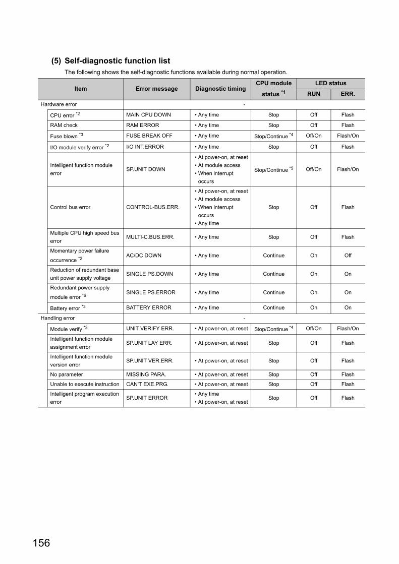
156
(5) Self-diagnostic function listThe following shows the self-diagnostic functions available during normal operation.
Item Error message Diagnostic timingCPU module
status *1
LED status
RUN ERR.
Hardware error -
CPU error *2 MAIN CPU DOWN • Any time Stop Off Flash
RAM check RAM ERROR • Any time Stop Off Flash
Fuse blown *3 FUSE BREAK OFF • Any time Stop/Continue *4 Off/On Flash/On
I/O module verify error *2 I/O INT.ERROR • Any time Stop Off Flash
Intelligent function module
errorSP.UNIT DOWN
• At power-on, at reset
• At module access
• When interrupt
occurs
Stop/Continue *5 Off/On Flash/On
Control bus error CONTROL-BUS.ERR.
• At power-on, at reset
• At module access
• When interrupt
occurs
• Any time
Stop Off Flash
Multiple CPU high speed bus
errorMULTI-C.BUS.ERR. • Any time Stop Off Flash
Momentary power failure
occurrence *2AC/DC DOWN • Any time Continue On Off
Reduction of redundant base
unit power supply voltageSINGLE PS.DOWN • Any time Continue On On
Redundant power supply
module error *6SINGLE PS.ERROR • Any time Continue On On
Battery error *3 BATTERY ERROR • Any time Continue On On
Handling error -
Module verify *3 UNIT VERIFY ERR. • At power-on, at reset Stop/Continue *4 Off/On Flash/On
Intelligent function module
assignment errorSP.UNIT LAY ERR. • At power-on, at reset Stop Off Flash
Intelligent function module
version errorSP.UNIT VER.ERR. • At power-on, at reset Stop Off Flash
No parameter MISSING PARA. • At power-on, at reset Stop Off Flash
Unable to execute instruction CAN'T EXE.PRG. • At power-on, at reset Stop Off Flash
Intelligent program execution
errorSP.UNIT ERROR
• Any time
• At power-on, at resetStop Off Flash

157
CHAPTER 11 BASIC FUNCTIONS
11
11.2 Self-D
iagnostic F
unction
Parameter error -
Parameter setting check PARAMETER ERROR • At power-on, at reset Stop Off Flash
Link parameter error LINK PARA.ERROR • At power-on, at reset Stop Off Flash
Intelli-parameter error SP.PARA.ERROR • At power-on, at reset Stop Off Flash
Refresh time over REF. TIME OVER • At power-on, at reset Continue On On
Network No. duplication error DUPLICAT.NET.NO. • At power-on, at reset Stop Off Flash
CPU error -
System watchdog timer error SYSTEM WDT ERROR • Any time Stop Off Flash
User watchdog timer error USER WDT ERROR • Any time Stop Off Flash
Multiple CPU system error -
Other CPU critical error MULTI CPU DOWN• Any time
• At power-on, at resetStop/Continue *7 Off Flash
Multiple CPU execution error MULTI EXE.ERROR• Any time
• At power-on, at resetStop/Continue *7 Off Flash
Multiple CPU consistency
errorCPU LAY ERROR
• Any time
• At power-on, at resetStop/Continue *7 Off Flash
Other CPU minor error MULTI CPU ERROR • Any time Continue On On
*1 : When "Stop" is detected in CPU operating status, no script file is executed.*2 : How many times a momentary stop was detected can be confirmed by the C Controller module dedicated function
(CCPU_GetPowerStatus).While the C Controller module is detecting "Main CPU error", "Momentary stop detection" (including detection count update) and "Power OFF detection" are not performed.Further, the module may not be started up when this error occurs.
*3 : "Not checked" can be set in "Error check" in Project view "Parameter" "CCPU Parameter" <<RAS settings >>in Setting/monitoring tools for the C Controller module.
*4 : The CPU operation status for error detection can be changed to "Continue" in "Operation mode at the time of error" in Project view "Parameter" "CCPU Parameter" <<RAS settings >> in Setting/monitoring tools for the C Controller module.
*5 : The CPU operation status for error detection can be changed to "Continue" in "H/W error time CPU operation mode" in Project view "Parameter" "CCPU Parameter" <<I/O assignment settings>> in Setting/monitoring tools for the C Controller module.
*6 : For error details, you may check information in special relays ( Page 478, Appendix 6), special registers ( Page 480, Appendix 7).
*7 : Whether to stop the multiple CPU system or not when an error occurs in CPU No.2, No.3, or No.4 can be set in "Operation mode" in Project view "Parameter" "CCPU Parameter" <<Multiple CPU settings>> in Setting/monitoring tools for the C Controller module.
Item Error message Diagnostic timingCPU module
status *1
LED status
RUN ERR.

158
(6) Clearing errorsA C Controller module can clear only continuation errors.
(a) Error clear procedure
To clear errors, complete the following procedure.
1. Eliminate the reason for the error.
2. Perform one of the following operations or processes.Note11.2
• Perform the error clear operations in [Diagnostics] [CCPU diagnostics] <<CCPU
diagnostics>> "Clear error" in Setting/monitoring tools for the C Controller module.
• Execute the C Controller module dedicated function (CCPU_ClearError).
3. The target error will be cleared.
(b) The status after clearing errors
When the C Controller module is restored with error clear, the special relay, special register and LED related to
the error return to the status before the error occurred.
When the same error occurs after error clear is performed, the error is registered to the event history again.
Errors occurring as a result of cause other than the C Controller module cannot be cleared.
[Example]Since "SP. UNIT DOWN" is an error that occurred on the Q bus, the error cause cannot be resolved if error cancellation is performed.Refer to the following, and resolve the error cause. Page 394, CHAPTER 23 TROUBLESHOOTING
11.3 Watchdog Timer (WDT)
Watchdog timers are provided inside the C Controller module to detect failure of the hardware or user program.
The C Controller module has the following two different watchdog timers.
: Supported : Supported with restrictions
*1 : Cannot be set in Setting/monitoring tool for the C Controller module parameter.Set the user watchdog timer by using a user program.
Note11.2 Not supported by Q24DHCCPU-LS and Q26DHCCPU-LS.
Item Description
CPU module
Q24DHC Q26DHC
-LS
Q12DC
-V-V -VG -LS
System watchdog timer
The system watchdog timer monitors the system of the C
Controller module, and is used to detect a fault in the hardware or
system software.
User watchdog timerThe user watchdog timer monitors the user programs, and is used
to detect an error in the hardware of user programs. *1
Q24DHCCPU-LS Q26DHCCPU-LS
Note11.2
Q24DHC-V Q24DHC-VG Q24DHC-LS Q26DHC-LS Q12DC-V

159
CHAPTER 11 BASIC FUNCTIONS
11
11.3 Watchdog T
ime
r (WD
T)
(1) Conditions for watchdog timer time out • System watchdog timer
Times out when the system processing has been suspended for a long time, for reasons such as C
Controller module hardware error and interrupt program execution, etc.
• User watchdog timer
Times out when the system processing has been suspended for a long time, for reasons such as C
Controller module hardware error and interrupt program execution, etc.
Further, it also times out when the user program cannot complete processing within the time specified by the
C Controller module dedicated function (CCPU_StartWDT function) and cannot execute the C Controller
module dedicated function (CCPU_ResetWDT function).
(2) When a watchdog timer times outWhen a watchdog timer times out, a watchdog timer error is detected and the following conditions occur.
• The C Controller module turns off all the outputs.
• The RUN LED turns off, and the ERR.LED flashes.
Only for a system watchdog timer error, the MODE LED also turns off.
• An abnormal completion (WDT error) is detected when the C Controller module dedicated function is used.
(3) Setting a watchdog timer • System watchdog timer
Can be set and changed in the range of 20ms to 2000ms (in increments of 10ms) in Project view "Parameter"
"CCPU Parameter" <<RAS settings>> in Setting/monitoring tools for the C Controller module.
(The default is 1000ms.)
• User watchdog timer
Can be set and changed in the range of 100ms to 10000ms (in increments of 10ms) in Project view
"Parameter" "CCPU Parameter" <<RAS settings>> in Setting/monitoring tools for the C Controller module.
(The default is 1000ms.)
● For setting of the user watchdog timer by the user program Each timer can be set and changed by using the C Controller module dedicated function (CCPU_StartWDT function) after deselecting the Project view "Parameter" "CCPU Parameter" <<RAS settings>> "Use user WDT" checkbox in Setting/monitoring tools for the C Controller module.
(4) Resetting a watchdog timer • System watchdog timer
The system watchdog timer is periodically reset in the C Controller module.
• User watchdog timer
The user watchdog timer is periodically reset in the C Controller module.
● For resetting of the user watchdog timer by the user program Use the C Controller module dedicated function (CCPU_StartWDT function) to start monitoring and the C Controller module dedicated function (CCPU_ResetWDT function) to reset the timer.
For "-LS", consult with the
partner (operating system vendor).
For "-LS", consult with the
partner (operating system vendor).
For "-LS", consult with the
partner (operating system vendor).
For "-LS", consult with the
partner (operating system vendor).
For "-LS", consult with the
partner (operating system vendor).
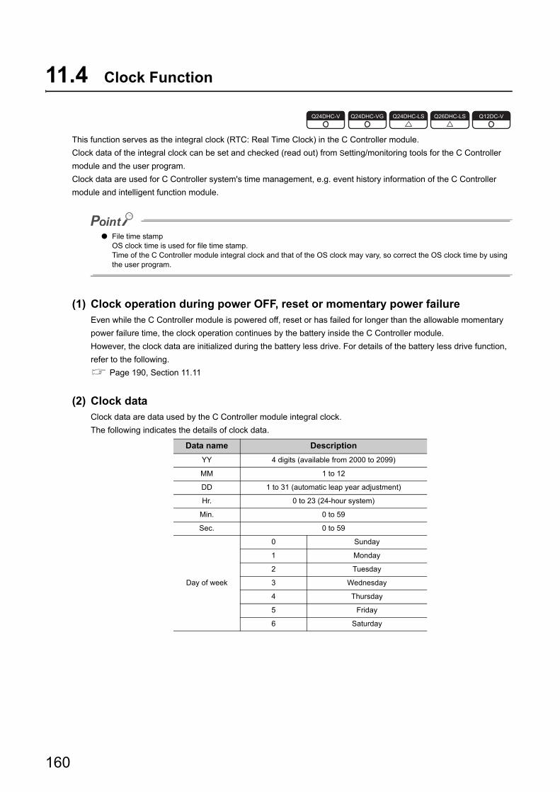
160
11.4 Clock Function
This function serves as the integral clock (RTC: Real Time Clock) in the C Controller module.
Clock data of the integral clock can be set and checked (read out) from Setting/monitoring tools for the C Controller
module and the user program.
Clock data are used for C Controller system's time management, e.g. event history information of the C Controller
module and intelligent function module.
● File time stampOS clock time is used for file time stamp.Time of the C Controller module integral clock and that of the OS clock may vary, so correct the OS clock time by using the user program.
(1) Clock operation during power OFF, reset or momentary power failureEven while the C Controller module is powered off, reset or has failed for longer than the allowable momentary
power failure time, the clock operation continues by the battery inside the C Controller module.
However, the clock data are initialized during the battery less drive. For details of the battery less drive function,
refer to the following.
Page 190, Section 11.11
(2) Clock dataClock data are data used by the C Controller module integral clock.
The following indicates the details of clock data.
Data name Description
YY 4 digits (available from 2000 to 2099)
MM 1 to 12
DD 1 to 31 (automatic leap year adjustment)
Hr. 0 to 23 (24-hour system)
Min. 0 to 59
Sec. 0 to 59
Day of week
0 Sunday
1 Monday
2 Tuesday
3 Wednesday
4 Thursday
5 Friday
6 Saturday
Q24DHC-V Q24DHC-VG Q24DHC-LS Q26DHC-LS Q12DC-V

161
CHAPTER 11 BASIC FUNCTIONS
11
11.4 Clock F
unction
(3) Changing and reading clock data
(a) Changing clock data
There are 2 ways to change clock data as described below.
• Using Setting/monitoring tools for the C Controller module
Select [Online] [Set Clock] to change the clock data.
• Using user program Note11.3
Use the C Controller module dedicated function (CCPU_SetRTC function) to change the clock data.
Obtain clock data from an external computer or programmable controller CPU on the network.
Then, by setting the clock data again for the C Controller module with the CCPU_SetRTC function, adjust
the clock of the C Controller module.
● OS clock settingC Controller module sets its integral clock time to the OS clock time at the power up or startup after resetting.Set the time to the running OS clock by using the user program.
(b) Reading clock data
To read clock data, use the C Controller module dedicated function (CCPU_GetRTC).
(4) Clock data accuracyFor accuracy of the clock data, refer to the following.
Page 45, Section 3.2
To correct the clock data, synchronize the data with the time of the SNTP server on the network.For the time
setting function (SNTP), refer to the following.
Page 202, Section 12.2.1
Note11.3 Q24DHCCPU-LS and Q26DHCCPU-LS cannot be set by user programs.
Function name Function
CCPU_SetRTC Sets time in the C Controller module integral clock.
Function name Function
CCPU_GetRTC Acquires time in the C Controller module integral clock.
Note11.3
Q24DHCCPU-LS Q26DHCCPU-LS
For "-LS", consult with the
partner (operating system vendor).

162
(5) Multiple CPU clock synchronization functionThe multiple CPU clock synchronization function allows clock data synchronization with CPU No.1 when the C
Controller module is set as CPU No.2, No.3, or No.4 in a multiple CPU system.
Clock data will be received from CPU No.1 at the following timing.
• When the multiple CPU system is powered on
• When the multiple CPU system status is changed from RESET or STOP to RUN
• At intervals of one second after startup of the multiple CPU system
• As clock data are set in seconds by the No.1 CPU module, clock data for other CPU modules may be different from the No.1 CPU module's scan time by up to 1 second.
• The C Controller modules (Q12DCCPU-V, Q24DHCCPU-V, and Q24DHCCPU-VG) synchronize the clock data if there is any discrepancy of 3 seconds or more between the clock data received from No.1 module and the clock data in the C Controller module.
• Clock data of CPU No.1 must be set to the year 2000 or later.The C Controller module supports only the year 2000 or later clock data.
(a) When using the time setting function (SNTP)
For No.2 through No.4 modules, the time synchronization with the No.1 CPU module has a priority, so time
synchronization by "Time setting function (SNTP)" will not be conducted.
(b) When using GOT time adjustment and time notification
The No.1 CPU module is the target when performing time adjustment and time notification by GOT connected
to the No.2 to No.4 C Controller modules.
Synchronize the clocks of No.2-4 modules with that of the No.1.
(6) Precautions
(a) Initial clock data setting
No clock data are set for the C Controller module prior to shipping.
Therefore, before using the C Controller module for the first time, be sure to set accurate clock time.
(b) Correcting clock data
Even if a part of clock data is to be corrected, all of clock data must be written to the C Controller module again.
(c) Changing clock data by a user program
When changing clock data by a user program, use the C Controller module dedicated function
(CCPU_SetRTC).
If any other clock data setting function is used, correct clock data will not be set in the C Controller module.
(d) Standard time
The C Controller module integral clock cannot use the local standard time and the global standard time
simultaneously.
Set the local standard time to set time to the integral clock.

163
CHAPTER 11 BASIC FUNCTIONS
11
11.5 Rem
ote Operation F
unction
11.5 Remote Operation Function
The remote operation function controls the operation status of the C Controller module or a programmable controller
CPU from the user program or Setting/monitoring tools for the C Controller module.
Use the dedicated function library for control by the user program. Note11.4
There are the following three different remote operations.
• Remote RUN/STOP (Page 163, (1) in this section)
• Remote PAUSE ( Page 165, (2) in this section
• Remote RESET ( Page 166, (3) in this section)
• Restarting user CPU ( Page 73, Section 6.4)
For the remote operation, refer to the manual for the programmable controller CPU.
(1) Remote RUN/STOPThe remote RUN/STOP is a control from Setting/monitoring tools for the C Controller module, by which the C
Controller module can run or stop with its RUN/STOP/MODE switch set to RUN.
(a) Application
The remote RUN/STOP is useful when:
• The C Controller module is out of reach.
• External signals are used to run or stop the C Controller module inside a control panel.
(b) Operation
The remote RUN/STOP makes the C Controller module behave as described below.
• Remote STOP
As soon as remote STOP is requested, the C Controller module is stopped.
( Page 307, Section 17.2.3 (2))
• Remote RUN
Executing remote RUN in the remote STOP status will change the C Controller module status to RUN
again. ( Page 307, Section 17.2.3 (1))
Note11.4 Q24DHCCPU-LS and Q26DHCCPU-LS cannot be set by user programs.
Q24DHC-V Q24DHC-VG Q24DHC-LS Q26DHC-LS Q12DC-V
Note11.4
Q24DHCCPU-LS Q26DHCCPU-LS

164
(c) Methods for remote RUN/STOP
There are the following 2 different ways to execute remote RUN/STOP.
• Using Setting/monitoring tools for the C Controller module
[Online] [Remote Operation]
• Using user program
Execute a bus interface function (QBF_ControlEx) to perform remote RUN/STOP.
The following shows the function(s) used for remote RUN/STOP.
(d) Precautions
Pay attention to the following since the C Controller module gives priority to STOP.
• STOP timing
The C Controller module is stopped when remote STOP is executed from either of the user program or
Setting/monitoring tools for the C Controller module.
• Changing the remote STOP status to RUN again
Execute remote RUN.
• Output (Y) status during STOP
When "Output mode at STOP to RUN" is set to "Previous state" in Project view "Parameter" "CCPU
Parameter" <<System settings>> in Setting/monitoring tools for the C Controller module, the output (Y)
data at the time when RUN is changed to STOP are output in remote RUN mode.
• User program during STOP
The user program will not stop even if the C Controller module is placed in the remote STOP status.
To change the program processing according to the operation status of the C Controller module, utilize the
C Controller module dedicated function (CCPU_GetCpuStatus) in programming.
Remark
The operation status of the C Controller module can be confirmed by the following. • "CPU operation status" in [Diagnostics] [CCPU diagnostics] <<CCPU diagnostics>> in Setting/monitoring
tools for the C Controller module • C Controller module dedicated function (CCPU_GetCpuStatus)
Function name Function
QBF_ControlExControls remote RUN/STOP/PAUSE operations of the other programmable controller CPU
modules and C Controller module.

165
CHAPTER 11 BASIC FUNCTIONS
11
11.5 Rem
ote Operation F
unction
(2) Remote PAUSEThe remote PAUSE is a control from the user program or Setting/monitoring tools for the C Controller module, by
which the C Controller module can be placed in the PAUSE status with its RUN switch set to RUN.
(a) Application
The remote PAUSE is useful in process control, for example, to keep the ON status of output (Y) set in the
RUN status even if the C Controller module status is changed from RUN to PAUSE.
(b) Operation
As soon as remote PAUSE is requested, the C Controller module enters to PAUSE status.
( Page 307, Section 17.2.3 (3))
(c) Methods for remote PAUSE
There are the following 2 different ways to execute remote PAUSE.
• Using Setting/monitoring tools for the C Controller module
[Online] [Remote Operation]
• Using user program
Execute a bus interface function (QBF_ControlEx) to perform remote PAUSE.
The following shows the function(s) used for remote PAUSE.
(d) Precautions
The user program will not stop even if the C Controller module is placed in the remote PAUSE status.
To change the program processing according to the operation status of the C Controller module, utilize the C
Controller module dedicated function (CCPU_GetCpuStatus) in programming.
Remark
The operation status of the C Controller module can be confirmed by the following. • "CPU operation status" in [Diagnostics] [CCPU diagnostics] <<CCPU diagnostics>> in Setting/monitoring
tools for the C Controller module • C Controller module dedicated function (CCPU_GetCpuStatus)
Function name Function
QBF_ControlExControls remote RUN/STOP/PAUSE operations of the other programmable controller CPU
modules and C Controller module.

166
(3) Remote RESETThe remote RESET is a control from the user program or Setting/monitoring tools for the C Controller module, by
which the C Controller module or programmable controller CPU can be reset when it is in the STOP status.
(a) Application
The C Controller module or programmable controller CPU can be remotely reset when an error occurs in the
place where direct control of the switch on the CPU module is not available.
(b) Remote RESET timing
This is only executable when the C Controller module or the programmable controller CPU is in STOP status.
When the C Controller module or programmable controller CPU is in the RUN status, change the status to
STOP by remote STOP.
Even if the switch of the C Controller module or programmable controller CPU is set to RUN, it can be reset
when it is stopped due to an error that can be detected by the self-diagnostic function.
(c) Setting/operation before performing remote RESET
Perform the setting/operation steps 1 through 4 below before performing remote RESET.
Otherwise, remote RESET cannot be performed.
1. Set "Remote Reset" in Project view "Parameter" "CCPU Parameter" <<System settings>>
in Setting/monitoring tools for the C Controller module to "Enable".
2. Write parameters into the C Controller module.
3. Reset the C Controller module.
4. Set the C Controller module in STOP status.

167
CHAPTER 11 BASIC FUNCTIONS
11
11.5 Rem
ote Operation F
unction
(d) Methods for remote RESET
There are the following 2 different ways to execute remote RESET.
• Using Setting/monitoring tools for the C Controller module
[Online] [Remote Operation]
• Using user program
Execute a bus interface function (QBF_Reset) to perform remote RESET.
The following shows the function(s) used for remote RESET.
(e) Precautions
• Before performing remote RESET
Close the respective user programs in the C Controller module before performing remote RESET.
Execution of remote RESET during user program operation may damage the user program and data files.
• Status after completion of resetting
Execution of remote RESET changes the operation status of the target C Controller module or
programmable controller CPU to the status set with the switch.
• Remote RESET during stop due to an error
If remote RESET is executed when the C Controller module in a single CPU system or CPU No.1 in a
multiple CPU system has stopped due to an error, upon completion of the reset, the module status will be
changed to the one set by the switch. Therefore, special attention must be paid.
• Remote RESET by using Setting/monitoring tools for the C Controller module
Remote RESET will cuts off communication between Setting/monitoring tools for the C Controller module
and C Controller module.
Reconnect Setting/monitoring tools for the C Controller module to the C Controller module after remote
RESET.
• Remote RESET for multiple CPU system with programmable controller CPU as No.1
For remote RESET of programmable controller CPU, refer to the manual for the programmable controller CPU.
Function name Function
QBF_ResetFor single CPU system, resets the C Controller module.
For multiple CPU system, resets the No.1 CPU.

168
(4) Relation between remote operation and RUN/STOP statusThis section explains the relation between the remote operations and the switch setting of the C Controller
module.
(a) Relation between remote operation and RUN/STOP status of C Controller module
(b) Remote operations from the same Setting/monitoring tools for the C Controller
module or user program
When more than one remote operation are attempted from the same Setting/monitoring tools for the C
Controller module or the same user program, the status resulted from the last one is effective.
(c) Remote operations from multiple Setting/monitoring tools for the C Controller
module or user programs
For the C Controller module to which remote operation has already been executed, another remote operation
can be executed from a different Setting/monitoring tools for the C Controller module or user program.
SwitchRemote operation
RUN STOP PAUSE RESET
RUN RUN STOP PAUSE Cannot operate *1
STOP STOP STOP STOP RESET *2
*1 : Reset is available when the C Controller module with the switch set to RUN has been placed in the STOP status by remote STOP.
*2 : Includes the case where the C Controller module is stopped due to an error.

169
CHAPTER 11 BASIC FUNCTIONS
11
11.6 Device F
unction
11.6 Device Function
Creates a device such as a programmable controller CPU in work RAM on the C Controller module.
(1) Device listThe following shows the device that can be created, initial values and setting range.
(2) Setting methodFor this setting, use the following functions in Setting/monitoring tools for the C Controller module.
• Project view "Parameter" "CCPU Parameter" <<Device settings>>
(3) Precautions
(a) Number of device points
Set only the required number of device points.
Because a device is created in work RAM, the available range of work RAM, such as in a user program,
decreases due to an extra setting.
The consumption of work RAM is calculated by the following formulas.
• Bit device
16 points is calculated as one word.
• Word device
1 point is calculated as one word.
Type Device nameDefault value
Setting rangeNumber of points Range
Bit deviceInternal relay 8192 points M0 to 8191 Decimal 0 to 60K
Link relay 8192 points B0 to 1FFF Hexadecimal 0 to 640K
Word deviceData register 12288 points D0 to 12287 Decimal 0 to 4086K
Link register 8192 points W0 to 1FFF Hexadecimal 0 to 1024K
(Consumption of work RAM in the bit device) =
((Number of points assigned to the internal relay (M)) + (Number of points assigned to the link relay (B)) / 16 [word]
(Consumption of work RAM in the word device) =
((Number of points assigned to the data register (D)) + (Number of points assigned to the link register (W)) [word]
Q24DHC-V Q24DHC-VG Q24DHC-LS Q26DHC-LS Q12DC-V

170
11.7 Refresh Function
Refresh function automatically reads/writes device data of the C Controller module to the set area in a cycle.
There are following 2 types of refresh function in the C Controller module.
Execution cycle of data refresh and link refresh is called a refresh cycle.
For refresh cycle, refer to the following.
Page 175, Section 11.7.3
Function Description Reference
Data refresh functionPerform refreshing between the devices of the C Controller module and the data
refresh memory.Page 171, Section 11.7.1
Link refresh functionPerform refreshing between the internal user devices of the C Controller module
and the network module link device.Page 175, Section 11.7.2
Q24DHC-V Q24DHC-VG Q24DHC-LS Q26DHC-LS Q12DC-V
C Controller module
Data refresh memory Data
refreshLink
refresh
Device
Network module
Link device

171
CHAPTER 11 BASIC FUNCTIONS
11
11.7 Refresh F
unction
11.7.1 Data re
fresh function
11.7.1 Data refresh function
This function performs refreshing automatically between the devices of the C Controller module (X, Y, buffer memory)
and the data refresh memory.
Also, it issues an interrupt event when the data refresh memory value meets the specified condition.
C Controller module devices for refreshing are listed below.
To read from/write to the bit device, extract only desired bit information after read-out in words and read/write data.
Device name Setting range Operation
I/O deviceInput *1 X0000 to 0FFF Read
Output*1 Y0000 to 0FFF Read/write *4
Internal user device
Internal relay *1*2 M0 to 61439 Read/write
Link relay *1*2 B0000 to B9FFFF Read/write
Data register *2 D0 to 4184063 Read/write
Link register *2 W0000 to FFFFF Read/write
Internal system deviceSpecial relay SM0 to 2047 Read
Special device SD0 to 2047 Read
Module access device
Intelligent function module device Un\G0 to 65535 Read/write
Multiple CPU shared memory *3G0 to 4095 Read/write
G10000 to 24335 Read/write
*1 : For bit device, specify a multiple of 16 at the beginning of the device.*2 : The number of device points set in the device function ( Page 169, Section 11.6) parameter is the upper limit of the set range.*3 : Some addresses are not readable/writable depending on applications and settings of the shared multiple CPU memory.
For details, refer to the following. Page 251, Section 14.1
*4 : Regardless of the parameter "Output mode at STOP to RUN" (to Previous State/Recalculate) setting, the output (Y) is refreshed by the data refresh right after the status is changed from STOP to RUN.
Q24DHC-V Q24DHC-VG Q24DHC-LS Q26DHC-LS Q12DC-V
Device (setting No.1) Device (setting No.2) Device (setting No.3)
C Controller module
Y D
Un\G
Data refresh memoryUser program
0x0000 to 0x00FF
0x0100 to 0x03FF
0x0400 to 0x05FF
Interrupt event

172
(1) Setting methodFor this setting, use the following functions in Setting/monitoring tools for the C Controller module.
• Project view "Parameter" "CCPU Parameter" <<Data refresh settings>>
The number of points available for data refresh settings is up to 48K words.
(2) Data refresh timeThe following indicates formulas to obtain time required for data refreshing.
*1 : T1 = 2 s*2 : T2 = 0.2 s*3 : T3 = 0.01 s*4 : K = 16 s*5 : Odd numbers should be rounded up.
In any of the following conditions, data refresh delay may occur. • The user program is accessing to the device • An interrupt event from an interrupt module or an intelligent function module occurs • The system is communicating with peripheral(s)
(3) How to access the data refresh memory The data refresh memory can be accessed by using the following C Controller module dedicated function from
the user program.
Function name Function
CCPU_WriteDataRefreshMemory Writes data to the data refresh memory of the C controller module.
CCPU_ReadDataRefreshMemory Reads data from the data refresh memory of the C controller module.
Data refresh time D (ms)
= ((CCPU device access time) ((Total X/Y points / 16 1 word access time (T1 *1))
+
(Total points of M/B/SM / 16 1 word access time (T2 *2))
+
(Total points of D/W/SD 1 word access time (T2 *2) )
+
(CPU shared memory / buffer memory access time) (Total points of G 1 word access time (T3 *3))
+
(Number of settings K *4)
) / 1000 *5
For "-LS", consult with the
partner (operating system vendor).

173
CHAPTER 11 BASIC FUNCTIONS
11
11.7 Refresh F
unction
11.7.1 Data re
fresh function
(4) Interrupt event issuance conditionThe following indicates conditions where an interrupt event can be issued.
(5) Interrupt event issuance settingFor this setting, use the following functions in Setting/monitoring tools for the C Controller module.
• Project view "Parameter" "CCPU Parameter" <<Data refresh settings>>
"Interrupt settings"
(6) Interrupt event reception method Data refresh interrupt event can be received by executing the following C Controller module dedicated function
from the user program.
(7) Precautions
(a) Device duplication setting
For Setting/monitoring tools for the C Controller module version 4.07H or later, the settings of devices can be
duplicated.
For details of the settings, refer to the following.
Setting/Monitoring Tools for the C Controller Module Version 4 Operating Manual
(b) Operations in STOP/PAUSE status
Writing operation data refresh to the output device, intelligent function module device and multiple shared CPU
memory is only executed with the C Controller module in RUN status.
For operations in STOP/PAUSE status, refer to the following.
Page 307, Section 17.2.3
DeviceDetection
MethodInterrupt condition
Word device setting
value
Bit device
Level detectON Interrupts when ON
-
OFF Interrupts when OFF
Edge detectON Interrupts when rising
OFF Interrupts when falling
Value
change
detect
- Interrupts when value changes
Word device
Level detectEqual Interrupts when value matches
0 to 65535
(0H to FFFFH)
Unequal Interrupts when value does not match
Edge detect
EqualInterrupts when value matches (First time
only)
UnequalInterrupts when value does not match (First
time only)
Value
change
detect
- Interrupts when value changes -
Function name Function
CCPU_WaitDataRefreshEvent Waits for an occurrence of a data refresh interrupt event.
For "-LS", consult with the
partner (operating system vendor).

174
(c) Interrupt event issuance timing
The data refresh interrupt event is issued in the timing of data refresh cycle.
For details, refer to the following.
Page 175, Section 11.7.3
(d) When an interrupt event has already been notified at execution of the C Controller
module dedicated function (CCPU_WaitDataRefreshEvent function)
The user program is restarted from the interrupt event waiting status at the same time with the
CCPU_WaitDataRefreshEvent function execution.
If multiple interrupt events with the same interrupt event No. at the time of the CCPU_WaitDataRefreshEvent
function execution are already notified, the user program processes them as a single interrupt event
notification.
(e) When using the C Controller module dedicated function
(CCPU_WaitDataRefreshEvent function) in multiple user programs
Do not enter the same interrupt event number by multiple user programs.
Doing so result in the uncertain situation of which user program to receive the interrupt event.
(f) Operations in reset
When the C Controller system is reset, the data refresh memory is all initialized to 0.
Interrupt condition check is only valid right after resetting.
Therefore, an interrupt event may be issued depending on the interrupt condition.
(g) Assurance of data refresh
Old and new data may be mixed depending on data refresh timing.
However, this does not occur in the following conditions.
• Data refresh data are 16-bit
• Data refresh data are 32-bit and the dare refreshing and data refreshed addresses are of even numbers
(h) I/O to uncontrolled module in multiple CPU system
I/O values to uncontrolled input module/output module/I/O combined module/intelligent function module may
vary from the actual I/O values.
For details of access to uncontrolled modules, refer to the following.
QCPU User's Manual (Multiple CPU System)
(i) When the devices which do not exist are specified
For the data refresh setting, specify the existing devices. If the devices which do not exist, the data refresh and
link refresh will be stop.
For "-LS", consult with the
partner (operating system vendor).
For "-LS", consult with the
partner (operating system vendor).

175
CHAPTER 11 BASIC FUNCTIONS
11
11.7 Refresh F
unction
11.7.2 Link refresh function
11.7.2 Link refresh function
This function performs refreshing automatically between the devices of the C Controller module (B and W) and the link
device of the network module.
For details of link refresh, refer to the following.
Page 212, Section 13.2.1
11.7.3 Link refresh cycle setting
The refresh cycle is the execution cycle for the data refresh function and link refresh function.
(1) Setting methodFor this setting, use the following functions in Setting/monitoring tools for the C Controller module. (Setting range
10 to 2000 ms)
• Project view "Parameter" "CCPU Parameter" <<System settings>>
"Refresh setting"
(2) Calculation methodFor refresh cycle, set valid values in terms of the following formula.
• Refresh cycle (L) > Total refresh time = Link refresh time + Data refresh time
For link refresh time, refer to the following.
Page 244, Section 13.5.1
For data refresh time, refer to the following.
Page 171, Section 11.7.1
Q24DHC-V Q24DHC-VG Q24DHC-LS Q26DHC-LS Q12DC-V
Q24DHC-V Q24DHC-VG Q24DHC-LS Q26DHC-LS Q12DC-V
C Controller module processing
Link scan
Link refresh
Link refresh
Link refresh
Link refresh
Refresh cycle Refresh cycle Refresh cycle
Data refresh time
Link refresh time

176
(3) Refresh time checkThe actual refresh time values (maximum, minimum and current values) while the C Controller system is running
can be checked by using Setting/monitoring tools for the C Controller module.
• [Diagnostics] [CCPU diagnostics] <<CCPU diagnostics>> "Refresh information"
(a) Refresh time
From "Refresh time" in "Refresh information," the actual measurement value for the total refresh time can be checked.
(Total refresh time = Link refresh time + Data refresh time)
Use the confirmed maximum refresh time value as a reference to set the refresh cycle.
(b) Link refresh time
From "Link refresh time" in "Refresh information," the actual measurement value for the total link refresh time
for all network modules controlled by the C Controller module can be checked.
(c) Data refresh time
From "Data refresh time" in "Refresh information," the actual measurement value for the data refresh time can
be checked.
If the user program processing performance is poor, i.e. higher downtime ratio relative to the user program operation time, perform the following processing as necessary.
• Increase the refresh cycle setting value. • Reduce the number of link refresh points to shorten the link refresh time. ( Page 249, Section 13.5.3) • Review the user program task configuration, priority and processing, etc.
11.8 Security Function
This function limits operations to the C Controller module to protect data.
The security function is a function to prevent unauthorized accesses; however, it cannot completely prevent the unauthorized accesses.User security measures are required to secure the system safety against unauthorized accesses from external devices.
[Examples of user security measure] • Enable the firewall. • Set up an external device that control access authority as a relay station.
Please consult a network provider or equipment sales company regarding external devices that can control access authority.
We cannot be held responsibility for any problems caused by unauthorized access.
Q24DHC-V Q24DHC-VG Q24DHC-LS Q26DHC-LS Q12DC-V

177
CHAPTER 11 BASIC FUNCTIONS
11
11.8 Security F
unction11.8.1 A
ccess authority setting function
11.8.1 Access authority setting function
This function restricts operations and access to C Controller module by setting the access authority and lockout
setting*1 for each user account.
*1 : Lockout setting is a function to limit the allowed number of account authentication failures in a row. If the number is exceeded, authentication is locked out for a certain period of time to prevent brute force attacks by unauthorized users.
There are 2 types of access authority to restrict the following operations: Administrator and Maintenance.
Note11.5
: Available, : N/A
Note11.5 The following function and service are not supported by Q24DHCCPU-LS and Q26DHCCPU-LS.
• Telnet, FTP
The following function and service are not supported by Q12DCCPU-V.
• Data refresh memory monitor
Function/service OperationAccess authority No
accountAdministrator Maintenance
Setting/monitoring
tools for the C
Controller module
Online
CCPU read-out
CCPU writing
CCPU verify
Remote operation
CCPU data deletion
Set Clock
Device monitor
Battery backup RAM monitor
Data refresh memory monitor
Watch
Tool
Tolls for intelligent function module
Request of Parameter Initialization/
Flash ROM Write Request
Diagnostics
CCPU diagnostics
Event history
CPU status
Drive information
CC IE Control diagnostics
CC IE Field diagnostics
MELSECNET diagnostics
CC-Link/CC-Link/LT diagnostics
System monitor
Telnet Connected
FTP Connected
Q24DHC-V Q24DHC-VG Q24DHC-LS Q26DHC-LS Q12DC-V
Note11.5
Q24DHCCPU-LS Q26DHCCPU-LS Q12DCCPU-V

178
(1) Setting methodFor this setting, use the following functions in Setting/monitoring tools for the C Controller module.
• Project view "Parameter" "CCPU Parameter" <<Account settings>>
Up to 16 accounts can be created.
(2) Factory account settingsThe following shows factory account settings of Setting/monitoring tools for the C Controller module.
(3) Precautions
(a) Deleting account
It is not allowed to delete all accounts with administrator authority.
At least 1 account have the administrator authority.
(b) Account lockout setting
The number of consecutive failures in account authentication is still retained after power OFF/resetting of the C
Controller module.
Elapsed time after lockout is only valid when the C Controller module power is on.
(c) Account and password
• For characters that can be used in user name and password, refer to the following.
Setting/Monitoring Tools for the C Controller Module Version 4 Operating Manual
• If you forgot your password, initialize the C Controller module.
Initialization restore the factory account settings of the system. For initialization, refer to the following.
Page 62, Section 6.1
(d) Adding/deleting account by VxWorks command Note11.6
Accounts cannot be added/deleted by the VxWorks commands (loginUserAdd and loginUserDelete).
Item Value
User name "target"
Password "password"
Access authority Administrator
Lockout setting No setting
Note11.6 Not supported by Q24DHCCPU-LS and Q26DHCCPU-LS.
Note11.6
Q24DHCCPU-LS Q26DHCCPU-LS

179
CHAPTER 11 BASIC FUNCTIONS
11
11.8 Security F
unction11.8.2 Individual identification function
11.8.2 Individual identification function
This function prevents creation of unauthorized copy system (imitation) of the C Controller module.
The C Controller module can read the individual identification information by accessing to a certain memory.
User program(s) that is not activated by the other C Controller modules can be created by the user program by
implementing the authentication function (activation function) that utilizes the individual identification information.
(1) Q24DHCCPU-V/-VG/-LS and Q26DHCCPU-LS
(a) Read-out method
Described below is the procedure to read the individual identification information.
1. Acquire device setting register address
In the pciFindDevice function*1, specify the vendor ID [8086H], device ID [10D3H], int Index[0 = CH1, 1 =
CH2] and acquire PCI bus No. (int BusNo), PCI device No. (int DeviceNo), and PCI function number (int
FuncNo).
In the pciConfigInLong function*1, specify BusNo, DeviceNo, FuncNo, and base address register 0
[0010H] and acquire the base address (UINT32 BaseAddr).
*1 : When using pciFindDevice function and pciConfigInLong function, include the include file "pciConfigLib.h" (path: \WindRiver\vxworks-6.8\target\h\drv\pci).
2. Calculate the read register (EERD) address
Add an offset value [0014H] to the base address acquired by the pciConfigInLong function.
3. Read the individual identification information.
The individual identification information value is stored in read register (EERD) read addresses (0000H-
0002H) as illustrated below.
[Example] If the individual identification information is "00:26:92:1E:8F:F0"
The read register (EERD) specifications are as follows:[bit 0] START Start reading (START bit)[bit1] DONE End reading (DONE bit)[bit 2 to 15] ADDR Read address (0000H to 0002H)[bit 16 to 31] DATA Read dataSet any of the target addresses 0000H to 0002H in ADDR and write "1" in Start reading (START bit), then data reading starts.When data reading is done, the End read (DONE bit) turns to "1". Then confirm data reading completion and acquire read data (DATA) information.
Q24DHC-V Q24DHC-VG Q24DHC-LS Q26DHC-LS Q12DC-V
For "-LS", consult with the
partner (operating system vendor).
status = pciFindDevice( 0x8086, 0x10D3, Index, &BusNo, &DeviceNo, &FuncNo);
status = pciConfigInLong ( BusNo, DeviceNo, FuncNo, 0x10, &BaseAddr );
EERD = (ULONG*)(BaseAddr + 0x0014);
Read-outaddress
0000H
0001H
0002H
26
1E
F0
00
92
8F
Individual identification information 2, 1 byte
Individual identification information 4, 3 bytes
Individual identification information 6, 5 bytes
b15 b8 b7 b0
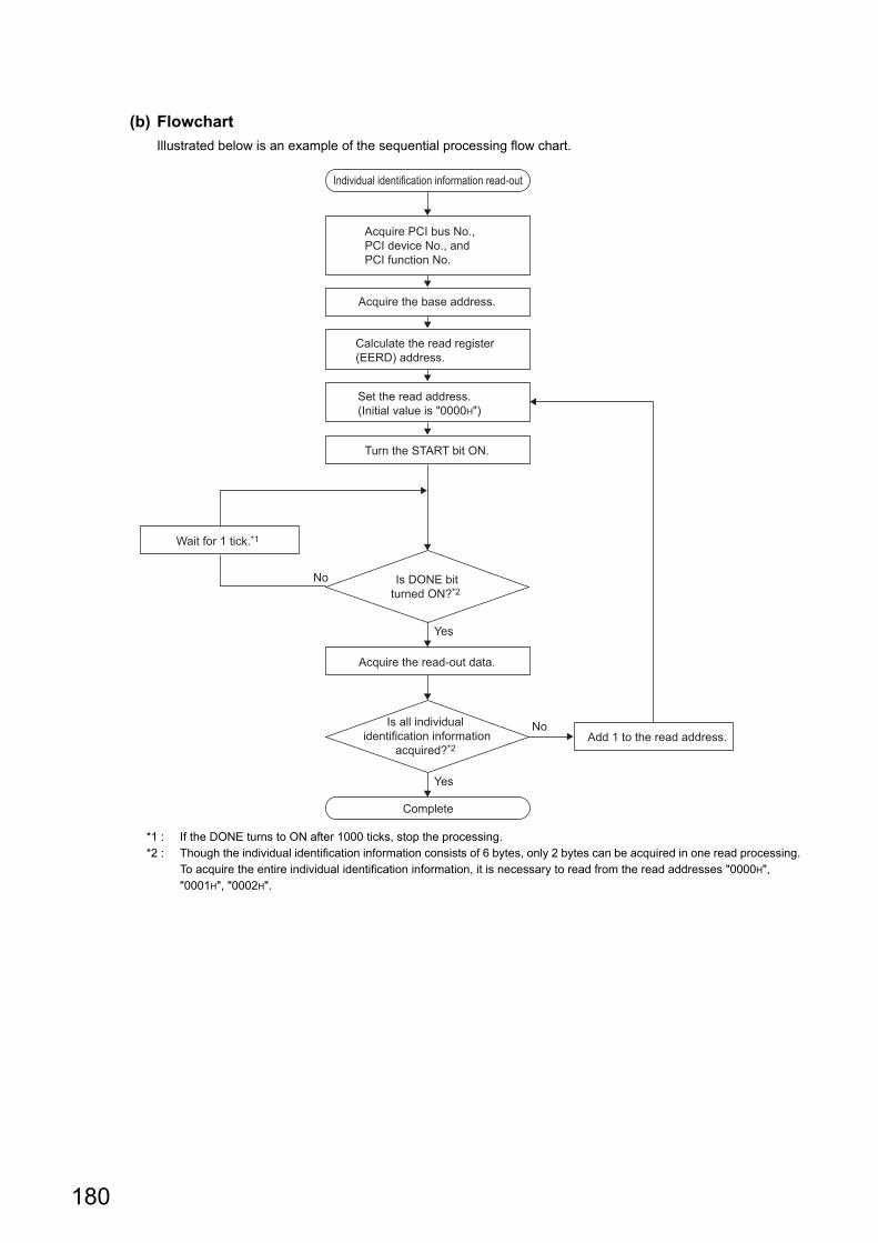
180
(b) Flowchart
Illustrated below is an example of the sequential processing flow chart.
*1 : If the DONE turns to ON after 1000 ticks, stop the processing.*2 : Though the individual identification information consists of 6 bytes, only 2 bytes can be acquired in one read processing.
To acquire the entire individual identification information, it is necessary to read from the read addresses "0000H", "0001H", "0002H".
Individual identification information read-out
Complete
Acquire PCI bus No., PCI device No., and PCI function No.
Calculate the read register (EERD) address.
Set the read address. (Initial value is "0000H")
Acquire the base address.
Turn the START bit ON.
Wait for 1 tick.*1
Add 1 to the read address.
Acquire the read-out data.
Is DONE bit turned ON?*2
Is all individual identification information
acquired?*2
No
No
Yes
Yes

181
CHAPTER 11 BASIC FUNCTIONS
11
11.8 Security F
unction11.8.2 Individual identification function
(c) Sample program
Illustrated below is an example of the sequential processing program.
For "-LS", consult with the
partner (operating system vendor).
/* Individual identification information read-out processing */
#include <vxWorks.h>
#include "pciConfigLib.h"
#include <taskLib.h>
void readIdentify(void){
/* Variable declaration */
unsigned short Identify[3]; /* Individual identification information storage area */
STATUS status = OK; /* Function execution status */
int Index = 0; /* Index */
int BusNo = 0; /* PCI bus No. */
int DeviceNo = 0; /* PCI bus device No. */
int FuncNo = 0; /* PCI function No. */
UINT32 BaseAddr = 0; /* Base address */
ULONG* EERD = NULL; /* Read register (EERD) address */
int i = 0; /* Counter */
int j = 0; /* Counter */
/* 1) Device setting register address acquisition */
status = pciFindDevice( 0x8086, 0x10D3, Index, &BusNo, &DeviceNo, &FuncNo);
if(status == OK){
status = pciConfigInLong ( BusNo, DeviceNo, FuncNo, 0x10, &BaseAddr );
if(status == OK){
/* 2) Read register (EERD) address calculation */
EERD = (ULONG*)(BaseAddr + 0x0014);
/* 3) Individual identification information read-out */
for(i = 0; i <= 2; i++ ){ /* Read individual identification information */
*EERD = (i << 0x02 ) + 1; /* Set read address and START bit */
while(( *EERD & 2 ) == 0 ){ /* Wait until DONE bit rises */
taskDelay( 1 );
j++;
if(j == 1000){
break;
}
}
if(j == 1000){
break;
}
Identify[i] = ( *EERD >> 16 ); /* Acquire read-out data */
}
}
}
return;
}

182
(2) Q12DCCPU-V
(a) Read-out method
Described below is the procedure to read the individual identification information.
1. Read the individual identification information.
The value of the individual identification information is stored in the memory address (0xA00BFFF4 to
0xA00BFFFF) as follows.
Example) The individual identification information is '00:26:92:1E:8F:F0:00:26:92:1E:8F:F1'
(b) Sample program
Illustrated below is an example of the sequential processing program
+0
- - - - 00 26 92 1E 8F F0 00 26 92 1E 8F F1Memory Address 0xA00BFFF0
+4 +8 +C
/* Individual identification information read-out processing */
#include <vxWorks.h>
void readIdentify(void){
/* Variable declaration */
unsigned char Identify[12]; /* Individual identification information storage area */
/* 1) Individual identification information read-out */
memcpy(Identify,0xA00BFFF4,12);
return;
}

183
CHAPTER 11 BASIC FUNCTIONS
11
11.8 Security F
unction11.8.3 F
ile access restrictio
n function
11.8.3 File access restriction function
This function restricts accesses to prevent unauthorized editing on files stored on the standard ROM, standard RAM,
or work RAM (when RAM drive is used).
By setting file attributes (a system file attribute and/or a hidden file attribute) to files under the memories described
below, accesses to the files are restricted, and thus the falsifications by unauthorized users or file leaks can be
prevented.
• Attributes of files on the system ROM (/SYSTEMROM) cannot be changed. • Accessing to the files stored on an SD memory card, CompactFlash card, or USB device can also be restricted.
Since all files can be accessed when an access-authorized SD memory card, CompactFlash card, or USB device is connected with a module other than a C Controller module, conduct a measure to prevent the removal of the SD memory card, CompactFlash card, or USB device.
• The access authority cannot be set to a directory using this function.
(1) File attributesFile attributes can be changed with the password set in "File access restriction setting" on the <<Security
settings>> tab of Setting/monitoring tools for the C Controller module.
For details of the file access restriction setting, refer to the following.
Setting/Monitoring Tools for the C Controller Module Version 4 Operating Manual
(a) File attribute setting
Use the attrib() command to set the file attribute on the file to be protected.
The following shows the file attributes that can be used on C Controller module.
*1 : Operations on the file are allowed when the file name is directly specified.The system file attribute must be specified to prohibit the operations.
For details of the attrib() command, refer to the manual for Vx Works.
: Supported : Not supported
Target memory Remark
CPU module
Q24DHC Q12DC
-V-V -VG
Standard ROM (/ROM) -
Work RAM (/specified by user) -
Standard RAM (/RAM) -
SD memory card (/SD) -
CompactFlash card (/CF) -
USB device (/USB0) Mass storage compatible device
Attribute Description
S: System file attributeThe file operation can be prohibited when the file access restriction is
enabled.
R: Read-only attribute Deleting and writing files can be prohibited.
H: Hidden file attribute*1Files are not displayed on the lists of ls command and FTP file when
the file access restriction is enabled.
Q24DHC-V Q24DHC-VG Q24DHC-LS Q26DHC-LS Q12DC-V

184
(b) Checking file attribute
Use the ll() command to check the file attribute.
The following explains how to identify the file attribute.
For details of the ll() command, refer to the manual for Vx Works.
(2) Operations on files with system file attributeThe access authority needs to be removed with the C Controller module dedicated function.
To change the access authority, the password set in "File access restriction setting" on the <<Security settings>>
tab of Setting/monitoring tools for the C Controller module is required.
For details of C Controller module dedicated function, refer to the following.
Page 353, CHAPTER 20
When accessing the files with the system file attribute in the script file "STARTUP.CMD", remove the access authority inside the script file. After removing the system file attribute of the file, specify the system file attribute to the script file "STARTUP.CMD" in order to prevent the leakage of the password.
(a) Changing access authority
The access authority can be changed with the Shell command, script file, or C Controller module dedicated
function in the user program.
(b) Checking access authority
The access authority can be checked with the Shell command or C Controller module dedicated function in the
user program.
(3) Precautions
(a) Do not use files with the system file attribute in the script file "STARTUP.CMD"
stored on the SD memory card or CompactFlash card to prevent the password leak.
(b) When the parameter is written with Setting/monitoring tools for the C Controller
module version 4.01B or earlier, the password set to "Security password setting" on
the <<Security settings>> tab is initialized. (Q24DHCCPU-V only)
(c) Account and password
• For characters that can be used in user name and password, refer to the following.
Setting/Monitoring Tools for the C Controller Module Version 4 Operating Manual
• If you forgot your password, initialize the C Controller module.
Initialization restore the factory account settings of the system. For initialization, refer to the following.
Page 62, Section 6.1
H: Indicates the hidden file attribute is specified.x: Indicates the hidden file attribute is not specified.
S: Indicates the system file attribute is specified.w, -: Indicates the system file attribute is not specified.
-: Indicates the read-only attribute is specified.w: Indicates the read-only attribute is not specified.
-: Indicates a file.d: Indicates a directory.
drwxrwxrSH

185
CHAPTER 11 BASIC FUNCTIONS
11
11.8 Security F
unction11.8.4 S
ervice setting
function
11.8.4 Service setting function
This function sets the services status (enable/disable) operated on the C Controller module.
By restricting the service which can be performed, accessing from an unexpected user can be prevented.
(1) List of services
: Supported : Not supported
Item Description
CPU module
Q24DHC Q26DHC
-LS
Q12DC
-V-V -VG -LS
Setting/monitoring tools for
the C Controller module
operation
The service in which the account authority is limited to the
administrator or maintenance user
• [Online operation]
Operations on C Controller module (reading/writing/
verifying/deleting data), battery backup RAM, watch
• [Tool operation]
Intelligent function module tool, parameter initialization/
flash ROM data write request
MELSEC data link functionThe service required for using the MELSEC data link
function.
SD memory card access The service to access the SD memory card
SD memory card script
execution
The service required to execute the script file
(STARTUP.CMD) stored on the SD memory card
CF card access*1 The service to access the CompactFlash card
CF card script execution*1The service required to execute the script file
(STARTUP.CMD) stored on the CompactFlash card
CF card parameter boot*1The service required to boot the parameter file stored on
the CompactFlash card
Telnet The service required to control the computer remotely
FTP The service required to use the file transfer function
WDB The service required to connect CW Workbench
Shell The service required to execute shell commands Vx Works
DHCPThe service required to use the function for assigning
network settings automatically
USB storage access The service required to access the USB memory
*1 : Change the service setting by using the parameter setting stored in the "Standard ROM". When changing the service, write to "Standard ROM".
Q24DHC-V Q24DHC-VG Q24DHC-LS Q26DHC-LS Q12DC-V
186
(2) Setting methodSet the settings with the following function in Setting/monitoring tools for the C Controller module.
• Project view "Parameter" "CCPU Parameter" <<Security settings>> "Service settings"
(3) Default service settingsThe settings become the default settings when the module is initialized.
(a) Q24DHCCPU-V/-VG/-LS and Q26DHCCPU-LS
All service settings are enabled.
(b) Q12DCCPU-V
All service settings are enabled except for "CF card parameter boot".
(4) Precautions
(a) Since the parameters cannot be set when the "Setting/monitoring tools for the C
Controller module operation" setting is disabled, the module needs to be initialized
to perform the services again.
(b) When using a CompactFlash card, conduct a measure to prevent the removal of the
CompactFlash card.
(c) When selecting CompactFlash card at the target memory of the parameter, enable
"CF card parameter boot". (The initial setting is set to disabled.)
(d) When the parameter is written to Q24DHCCPU-V with Setting/monitoring tools for
the C Controller module version 4.01B or earlier, the Service settings is initialized.
(e) When the following services are disabled, the specific service cannot be performed
at the same time.
• SD memory card access
"SD memory card script" cannot be used.
• CF card access
"CF card script execution" and "CF card parameter boot" cannot be used.
• Shell
Telnet cannot be used.

187
CHAPTER 11 BASIC FUNCTIONS
11
11.9 Event H
istory Collection F
unction
11.9 Event History Collection Function
Up to 500 events that occurred in the C Controller system will be registered as event history with occurrence time. If
the number of event history items exceeds 500, the oldest event is deleted.
For this setting, use the following functions in Setting/monitoring tools for the C Controller module.
• [Diagnostics] [Event history] <<Event history>>
● As the clock data in the C Controller module is used for event history occurrence time, be sure to set the accurate time first.
● If the battery less drive is enabled, clock data are initialized at power-on. The event history occurrence time registered right after power-on may be the initial value for clock data (00:00:00, Jan 1, 2000).
● If "Do not register system (information) event details." is selected in Project view "Parameter" "CCPU Parameter" <<RAS Setting>> "Event history registration settings", event(s) in the C Controller system will not be registered with the event history.
● If error is occurring, new error(s) may not be registered with the event history.
(1) Event typeThere are following types of events in the C Controller system.
For details of events registered by the C Controller module, refer to the following.
Page 434, Appendix 2
(2) Clearing event historyFor this setting, use the following functions in Setting/monitoring tools for the C Controller module.
• [Diagnostics] [Event history] <<Event history>> "Clear"
The registered event history is all cleared.
(3) Registering events from the user program Note11.7Execute the C Controller module dedicated function (CCPU_RegistEventLog) to register event logs with the
event history.
Type Description
System (Err.) The event is a C Controller system error.
System (Warning) The event is a C Controller system warning.
System (Info.) The event is a C Controller system information.
ApplicationThis event is registered by using the C Controller module dedicated function
(CCPU_RegistEventLog) from the user program.
Note11.7 Not supported by Q24DHCCPU-LS and Q26DHCCPU-LS.
Function name Function
CCPU_RegistEventLog Registers an event log to the event history.
Q24DHC-V Q24DHC-VG Q24DHC-LS Q26DHC-LS Q12DC-V
Note11.7
Q24DHCCPU-LS Q26DHCCPU-LS

188
(4) PrecautionsIf the battery less drive is enabled, event history is cleared at power OFF or reset. Backup any necessary event
history to the personal computer by using Setting/monitoring tools for the C Controller module.
For details of battery less drive, refer to the following.
Page 190, Section 11.11
11.10 Analog RGB Port Display Function
This function displays the GUI screen created with the partner application on the general-purpose analog RGB display
connected to the analog RGB port.
(1) GUI screen development procedureThe following shows the development procedure using CI SKETCH-E and CW Workbench.
Q24DHC-V Q24DHC-VG Q24DHC-LS Q26DHC-LS Q12DC-V
Check field
C Controller code creation
Addition of user program
GUI screen design
Start
Compiling of C code
Debug
Refer to the manual for the partner application, or consult the partner.
Create a project and design the GUI screen with CI SKETCH-E.
Create C code for C Controller.
Write a user program from CW Workbench to the created C code.
Compile the C code with CW Workbench.
Debug the user program.
�CW Workbench Operating Manual
End

189
CHAPTER 11 BASIC FUNCTIONS
11
11.10 Ana
log RG
B P
ort Display F
unction
(2) Resolution settingExecute one of the commands below with “STARTUP.CMD” or the Telnet connection to switch the screen display.
The changed setting will be enabled at the time of next startup of the display application.
For more information on the supported resolution, refer to the following section.
Page 45, Section 3.2
(a) Changing the resolution
• VGA
• SVGA
• XGA
(b) Checking the resolution
Execute the following command with the Telnet connection to check the resolution
currently set.
(3) Precautions
(a) If the analog RGB cable is connected with the power supply for C Controller module
turned ON, the display will not be recognized.
(b) GENWARE3-VG*1 is required in order to use this function. For specifications and
functions of GENWARE3-VG, consult the partner (application vendor).*1 : It is pre-installed in Q24DHCCPU-VG.
(c) When the battery less drive is enabled, the resolution setting is initialized at power-
on. For details on the battery less drive, refer to the following section.
Page 190, Section 11.11
CCPUCMD_ChangeVGA
CCPUCMD_ChangeSVGA
CCPUCMD_ChangeXGA
CCPUCMD_GetResolution

190
11.11 Battery Less Drive
This function operates the C Controller module without battery.
The battery less drive function can improve the maintainability by establishing a system requiring no battery
replacement.
Data listed below are all initialized by powering ON or resetting C Controller system with the battery removed. Configure the settings again.
: Supported : Not supported
Setting data Status after initialization
CPU module
Q24DHC Q26DHC
-LS
Q12DC
-V-V -VG -LS
Event historyThe number of event history data is
initialized to zero.
Battery backup RAM Data is detected to 0.
Standard RAM Formatted.
Clock data Reset to "00:00, Jan 1, 2000".
Resolution 1024 768 (XGA)
Keyboard
106JIS (OADG-compliant Japanese
106-key keyboard)
Q24DHC-V Q24DHC-VG Q24DHC-LS Q26DHC-LS Q12DC-V

191
CHAPTER 11 BASIC FUNCTIONS
11
11.11 Battery Less D
rive
(1) Setting methodFor this setting, use the following functions in Setting/monitoring tools for the C Controller module.
• Project view "Parameter" "CCPU Parameter" <<I/O assignment settings>>
"Switch Settings"
Set the b1 of the "Switch3" in the slot connected with the C Controller module to "ON".
(Doing this to the other CPU slots, the setting is ignored.)
(2) Precautions
(a) Battery error
During battery less drive, battery error cannot be detected.
During battery less drive, the following settings in Setting/monitoring tools for the C Controller module are ignored. • Project view "Parameter" "CCPU Parameter" <<RAS settings>> "Carry Out Battery Check"
( Page 154, Section 11.2)
(b) Battery backup RAM and Standard RAM
For battery less drive, do not use the battery backup RAM and standard RAM.
(c) Clock data
• If the C Controller module in a multiple CPU configuration is No.1,
do not use the battery less drive function.
Otherwise, time in other than No.1 module will be set incorrectly, since the CPU modules other than No.1
are synchronized with time in No.1.
• When the C Controller module in a multiple CPU configuration is No.2 through No.4 modules
The C Controller module clock data are operated with the initialized value (00:00:00, Jan 1, 2000) from the
rising of the C Controller module to the completion of time synchronization with No.1 CPU module.
• When the SNTP function is used
The C Controller module clock data are operated with the initialized value (00:00:00, Jan 1, 2000) from the
rising of the C Controller module to the completion of time synchronization with a SNTP server.
b15 b14 b13 b12 b11 b10 b9 b8 b7 b6 b5 b4 b3 b2 b1 b0
ON

192
CHAPTER 12FUNCTIONS ACCESSED VIA
ETHERNET PORTS
This chapter describes the communication with peripherals, Telnet function and FTP client function.
When using Q12DCCPU-V, consider the terms as shown in the following table.
12.1 User Ethernet Port (Q24DHCCPU-V/-VG/-LS and Q26DHCCPU-LS) / Built-in Ethernet Port (Q12DCCPU-V) Function
User Ethernet port (CH1 and CH2) can establish communication with the following peripherals.
• CW Workbench
• Personal computer for maintenance (such as Telnet and FTP)
● Following peripherals cannot establish communication with the user Ethernet port (CH1 and CH2).Connect to the system Ethernet port (S CH1).
• Setting/monitoring tools for the C Controller module • GOT
● Compatible with jumbo frame for the series Q24DHCCPU-V/-VG that comes first five digits "17092" or higher of serial No.MTU value (Maximum Transmission Unit) used in the IP communication can be changed by using the following operations. (The default value of MTU is 1500 bytes.)
ifconfig("Interface name mtu MTU value") Specify "gei0" and "gei1" for interface name: CH1 and CH2 respectively. Specify MTU value within the range of 1 to 9000 bytes.[Example] When changing MTU of CH1 to 9000 bytes. ifconfig("gei0 mtu 9000")To check the set value, execute ifconfig with no argument.
Ethernet frame exceeding the set MTU will be divided and sent. However, there is an upper limit to the packet size of TCP or UDP using socket communication once. When setting the MTU that exceeds the set upper limit, an error occurs while sending a request.If an error occurs, change the MTU value or the upper limit of the packet size. (The default upper limit of the packet size is IPNET_SOCK_DEFAULT_SEND_BUFSIZE of kernel configuration and is set to 10000 bytes.)The upper limit of the packet size can be changed by specifying the option name "SO_SNDBUF" in the setsockopt() from the Socket API of VxWorks component. For details, refer to VxWorks manual.
Before After
Q24DHCCPU-V/-VG/-LS
Q26DHCCPU-LSQ12DCCPU-V
User Ethernet port (CH1 and CH2)Built-in Ethernet port (CH1 and CH2)
System Ethernet port (S CH1)
Q24DHC-V Q24DHC-VG Q24DHC-LS Q26DHC-LS Q12DC-V
For "-LS", consult with the
partner (operating system vendor).
193
CHAPTER 12 FUNCTIONS ACCESSED VIA ETHERNET PORTS
12
12.1 User E
thernet Po
rt (Q24D
HC
CP
U-V
/-VG
/-LS and Q
26DH
CC
PU
-LS) / B
uilt-in Ethernet P
ort (Q
12DC
CP
U-V
) Functio
n
(1) Setting methodFor this setting, use the following functions in Setting/monitoring tools for the C Controller module.
<Q24DHCCPU-V/-VG>
• Project view ”Parameter" "CCPU Parameter" <<User Ethernet port (CH1 and CH2) settings>>
<Q12DCCPU-V>
• Project view ”Parameter" "CCPU Parameter" <<Built-in Ethernet port (CH1 and CH2) settings>>
(2) Precautions
(a) Checking by KeepAlive
When protocols are set in TCP, KeepAlive checks the status.
An existence check function is sent 22 seconds after the messaging reception of the last existence check
function from the external device to check for a response from the external device.
If there is no response, the existence check function is continuously sent at one second interval.
If a response cannot be confirmed within 8 seconds (30 seconds from the last messaging reception), the
connection is disconnected due to the lack of existence of the external device. (The connection will be
disconnected 30 seconds after the messaging reception of the last existence check function.)
The connection may also be disconnected if the target device is not compatible with the TCP KeepAlive
function (a response corresponding to the ACK function for KeepAlive).
(b) Resend processing for TCP connections
Resend processing for TCP connections when there is no ACK response of the TCP protocols from the
external device for sending in TCP connection, resend processing is performed at the following numbers of
resends and resend intervals.
After the final resend, if there is no ACK response of the TCP protocol within 60 seconds, the connection will be
disconnected as an external device error.
(c) Connection not covered by the operation assurance
Operations of the following commercial connection devices are not assured. Customers need to confirm the
operation before using it.
• Connection using the Internet (a general public line)
• Connection using firewall devices
• Connection using broadband routers
• Connection using wireless LAN
Number of
resends12 times*1
Interval until
resend*2 (Number of resents x Number of resents x RTO*3) / 1024 [Second]
*1 : After 30 seconds from establishment of the connection, destination device error is assumed and the connection is released even if the number of resends does not reach to 12 times.
*2 : The maximum resend interval is 60 seconds.*3 : RTO (retransmission timeout) is a value that is increased exponentially based on RTT (round-trip time).

194
12.1.1 Telnet function
This function executes shell commands from Telnet tool in the development environment (Personal computer) without
using CW Workbench.
This allows simple remote debugging (task information display, memory dumping, etc.) of the C Controller module.
(1) Setting methodA user name and password is required to use the Telnet function.
Before using the Telnet function, set the user name, password and access authority in the C Controller module.
By setting the user information (user name, password and access authority), Telnet users can be restricted. For
details, refer to the following.
Page 177, Section 11.8.1
(2) Available commandsShell commands of CW Workbench can be used.
For shell commands, refer to the following.
Manual for VxWorks
(3) Remote debug by serial communicationRemote debug by serial communication is possible as with Telnet connection.
The standard I/O destination can be switched to the serial communication side by executing the following
commands from Telnet shell or by STARTUP.CMD.
fd = open("/tyCo/0",2,0)
ioctl(fd,4,115200) Transmission speed: 115200[bps]
ioctl(fd,3,0x7F)
ioGlobalStdSet(0,fd)
ioGlobalStdSet(1,fd)
ioGlobalStdSet(2,fd)
For "-LS", consult with the
partner (operating system vendor).
Q24DHC-V Q24DHC-VG Q24DHC-LS Q26DHC-LS Q12DC-V
Development environment (Personal computer)
Remote operation!By Telnet
Telnet
C Controller module

195
CHAPTER 12 FUNCTIONS ACCESSED VIA ETHERNET PORTS
12
12.1 User E
thernet Po
rt (Q24D
HC
CP
U-V
/-VG
/-LS and Q
26DH
CC
PU
-LS) / B
uilt-in Ethernet P
ort (Q
12DC
CP
U-V
) Functio
n12.1.1 T
elnet function
(4) Precautions
(a) Number of connections
Connections from multiple Telnet tools to the same C Controller module is not allowed.
Telnet tool must be connected to the C Controller module on a one-to-one basis.
Further, be sure close the Telnet tool being connected and connect another Telnet tool to the C Controller
module.
(b) Timeout
When the line is disconnected during Telnet connection, it takes 30 seconds before Telnet connection (TCP
connection) times out on the C Controller module. Telnet cannot be reconnected until it times out.
Timeout time may be changed by the (ipcom_sysvar_set) command provided by VxWorks.
• Obtaining timeout time
<Q24DHCCPU-V/-VG>
Timeout time = iptcp.KeepIdle value + (iptcp.KeepIntvl value iptcp.KeepCnt value)
iptcp.KeepIdle: Interval from line disconnection to the first retry
iptcp.KeepIntvl: Interval between retries
iptcp.KeepCnt: Number of retries
• Program example
XX: Specify the time (in seconds). When this is specified to "0", no timeout will occur‘
YY: Specify the time (in seconds). When this is specified to "0", no timeout will occur‘
ZZ: Specify the number of retries
<Q12DCCPU-V>
Timeout time = net.inet.tcp.keepidle + ( net.inet.tcp.keepintvl 8 (number of retries) )
net.inet.tcp.keepidle: Interval from line disconnection to the first retry
net.inet.tcp.keepintvl: Interval between retries
• Program example
XXXXX: Specify the time (in ms).
YYYYY: Specify the time (in ms).
ipcom_sysvar_set("iptcp.KeepIdle", "XX", 1);
ipcom_sysvar_set("iptcp.KeepIntvl", "YY", 1);
ipcom_sysvar_set("iptcp.KeepCnt", "ZZ", 1);
ipcom_ipd_kill ("iptelnets");
ipcom_ipd_start ("iptelnets");
Sysctl("net.inet.tcp.keepidle = XXXXX");
Sysctl("net.inet.tcp.keepintvl = YYYYY");

196
Described below is the procedure to change the Telnet connection (TCP connection) timeout time for the
running C Controller module.
1. Establish Telnet connection by a Telnet tool.
2. Execute the commands above from the Telnet tool shell command to change the timeout time and
reboot the Telnet server
3. Close the Telnet connection.
4. Establish Telnet connection by a Telnet tool again.
Described below is the procedure to change the Telnet connection (TCP connection) timeout time at the startup
of the C Controller module.
1. Describe the commands above in the script file (STARTUP.CMD).
2. Power on the C Controller module.
(c) Shell command
Shell commands entered from the Telnet tool are operated for Priority1 tasks.
In the following cases, system errors/stop (system watchdog timer error, etc.) may occur in the C Controller
module.
• Execution of commands occupying CPU processing
Before executing commands, be sure to check command specifications.
• Reboot by execution of VxWorks (reboot) function and entering +
Reset the C Controller module to reboot VxWorks.
• Execution of command with argument without argument specification (i.e. 0 is specified for argument)
Before executing commands, be sure to check command specifications/argument specification.
[Example] Do not execute the (close) command with no argument specified. Doing so will close the
resources reserved in the VxWorks system.
In any of the following cases, interrupt is prohibited for long period of time and no processing called from the
interrupt routine will be performed. So interrupt that occurs at certain intervals (i.e. synchronization interrupt
between multiple CPUs) may be delayed.
• Execution of command to show the status (Show)
(d) Message display on the shell
Message(s) issued by VxWorks during Telnet connection may be displayed on the shell.
For messages to VxWorks, refer to manuals for VxWorks, and Help of CW Workbench.
(e) Telnet password
If you forgot your Telnet password, initialize the C Controller module.
Initialization restore the factory account settings of the system. For details, refer to the following.
Page 62, Section 6.1

197
CHAPTER 12 FUNCTIONS ACCESSED VIA ETHERNET PORTS
12
12.1 User E
thernet Po
rt (Q24D
HC
CP
U-V
/-VG
/-LS and Q
26DH
CC
PU
-LS) / B
uilt-in Ethernet P
ort (Q
12DC
CP
U-V
) Functio
n12.1.2 F
TP
function
12.1.2 FTP function
The server function of FTP (File Transfer Protocol), a protocol for file transfer to/from destination devices, is supported.
This allows for direct access to file(s) in the C Controller module from a destination device with the FTP client function.
Operations of file(s) in the C Controller module from a destination device with the FTP client function are allowed.
• File read-out (download) from C Controller module
A function to store C Controller module files on the destination device(s).
• File writing (upload) from C Controller module
A function to register files stored in the destination device(s) to the C Controller module.
• Showing directories and files in the C Controller module
A function to view files registered in the C Controller module on the destination device(s).
(1) Setting methodA user name and password is required to use the FTP function.
Before using the FTP function, set the user name, password, and access authority in the C Controller module.
By setting the user information (user name, password and access authority), FTP users can be restricted. For
details, refer to the following.
Page 177, Section 11.8.1
For "-LS", consult with the
partner (operating system vendor).
Q24DHC-V Q24DHC-VG Q24DHC-LS Q26DHC-LS Q12DC-V
Development environment (Personal computer)
File operation!By FTP
FTP
C Controller module

198
(2) Precautions
(a) FTP client specifications
For FTP client specifications implemented in destination device(s), refer to the manuals for the respective
destination device(s).
(b) Operations during file access
During file access, do not power OFF or reset the system, or insert/remove the memory card.
Doing so may corrupt files.
(c) Reconnection in the event of timeout
If any timeout error occurs in file transfer, the TCP connection is closed (disconnected).
To resume file transfer, login the C Controller module by the FTP client again.
(d) File transfer time
File transfer processing time varies depending on the following factors:
• Ethernet line contribution percentage (line busyness)
• Number of simultaneous connections (communication processing for other connections)
• System configuration
(e) Number of simultaneous connections
The number of destination devices (FTP clients) allowed to login to the C Controller module is 10.
In case of connection from the other FTP client(s) in login status, connection fails and an error is generated.
If UDP communication is established during FTP file transfer, errors such as timeout may occur.
Establish communication after file transfer, or by TCP.
(f) File writing
Files with read-only file attribute or locked by other models/function may not be written.
Any write attempt cause a writing error.
If the memory card is write protect, file transfer involving writing is not allowed. Any write attempt cause a
writing error.
To write any large file, change the CPU operation status to STOP in advance.
(g) File deletion
Determine the timing to delete files in view of the entire system including the C Controller module and
peripherals.
(h) If you forgot FTP password
If you forgot your FTP password, initialize the C Controller module.
Initialization restore the factory account settings of the system. For details, refer to the following.
Page 62, Section 6.1

199
CHAPTER 12 FUNCTIONS ACCESSED VIA ETHERNET PORTS
12
12.1 User E
thernet Po
rt (Q24D
HC
CP
U-V
/-VG
/-LS and Q
26DH
CC
PU
-LS) / B
uilt-in Ethernet P
ort (Q
12DC
CP
U-V
) Functio
n12.1.3 T
ime setting fu
nction (SN
TP
)
12.1.3 Time setting function (SNTP)
By using VxWorks standard API function in the user program, the time information can be obtained from the time
information server (SNTP server) connected on the LAN.
(1) Considerations
(a) VN (Version Number) in the SNTP request
For Q24DHCCPU-V/-VG that comes first five digits "17091" or lower of serial No., the VN (Version Number) in
the SNTP request is Version 1.
For Q24DHCCPU-V/-VG that comes first five digits "17092" or higher of serial No., the VN (Version Number) in
the SNTP request can be changed to Version 1 (default setting) or Version 4.
For changing the VN (Version Number), use the following functions in Setting/monitoring tools for the C
Controller module.
• Project view "Parameter" "CCPU Parameter" <<I/O assignment settings>> "Switch
Settings"
If the settings of the user Ethernet port are changed, the settings of the system Ethernet port will also be
changed. (Page 202, Section 12.2.1)
Set the b2 of the "Switch3" in the slot connected with the C Controller module to "ON". (Doing this to the other
CPU slots, the setting is ignored.)
• When the b2 is ON
Set the VN (Version Number) in the request to Version 4 and then send to the SNTP server. If the
destination SNTP server is not compatible with the Version 4, it will fail in time inquiry.
• When the b2 is OFF
Set the VN (Version Number) in the request to Version 1 and then send to the SNTP server.
Start the SNTP daemon by using the following procedure to obtain the time information from the SNTP server that uses the user Ethernet port (CH1, CH2). Change the local time using the user program as per the requirement since OS time is UTC (Coordinated Universal Time).For details, refer to the manual of Wind River.
● SNTP daemon startup procedure • ipcom_sysvar_set("ipsntp.client.primary.addr","primary SNTP server address",1); • ipcom_sysvar_set("ipsntp.client.backup.addr","backup SNTP server address",1); • ipcom_ipd_start("ipsntp");
b15 b14 b13 b12 b11 b10 b9 b8 b7 b6 b5 b4 b3 b2 b1 b0
ON
Q24DHC-V Q24DHC-VG Q24DHC-LS Q26DHC-LS Q12DC-V

200
12.2 System Ethernet Port (Q24DHCCPU-V/-VG/-LS and Q26DHCCPU-LS) / Built-in Ethernet Port (Q12DCCPU-V) Function
System Ethernet port (S CH1) can establish communication with the following peripherals.
• Setting/monitoring tools for the C Controller module
• GOT
Following peripherals cannot establish communication with the system Ethernet port (S CH1).Connect to the user Ethernet port (CH1 and CH2).
• CW Workbench • Personal computer for maintenance (such as Telnet and FTP)
(1) Setting methodFor this setting, use the following functions in Setting/monitoring tools for the C Controller module.
<Q24DHCCPU-V/-VG/-LS><Q26DHCCPU-LS>
• Project view ”Parameter" "CCPU Parameter" <<System Ethernet port (S CH1) settings>>
<Q12DCCPU-V>
• Project view ”Parameter" "CCPU Parameter" <<Built-in Ethernet port (CH1 and CH2) settings>>
Q24DHC-V Q24DHC-VG Q24DHC-LS Q26DHC-LS Q12DC-V

201
CHAPTER 12 FUNCTIONS ACCESSED VIA ETHERNET PORTS
12
12.2 System
Ethernet P
ort (Q
24DH
CC
PU
-V/-V
G/-LS
and Q26D
HC
CP
U-LS
) / Built-in E
thernet Port
(Q12D
CC
PU
-V) F
unction
(2) Precautions
(a) Checking by KeepAlive
The same as user Ethernet port (CH1 and CH2).
(Page 193, Section 12.1 (2)(a))
(b) Resend processing for TCP connections
Resend processing for TCP connections When there is no ACK response of the TCP protocols from the
external device for sending in TCP connection, resend processing is performed at the following numbers of
resends and resend intervals.
After the final resend, if there is no ACK response of the TCP protocol within 64n seconds, the connection will
be disconnected as an external device error.
(c) Connection not covered by the operation assurance
Operations of the following commercial connection devices are not assured. Customers need to confirm the
operation before using it.
• Connection using the Internet (a general public line)
• Connection using firewall devices
• Connection using broadband routers
• Connection using wireless LAN
Number of
resends
Interval until resend
When connection is being
established*1 *2
After connection is
established*1
First n seconds n seconds
Second n seconds 2n seconds
Third n seconds 4n seconds
Fourth n seconds 8n seconds
Fifth n seconds 16n seconds
Sixth 2n seconds 32n seconds
Seventh 4n seconds 64n seconds
Eighth 8n seconds 64n seconds
Ninth 16n seconds 64n seconds
Tenth 32n seconds 64n seconds
Eleventh 64n seconds 64n seconds
Twelfth 64n seconds 64n seconds
*1 : The variable n is a coefficient calculated dynamically based on the external device and network status.
*2 : After 30 seconds, destination device error is assumed and the connection is released even if the number of resends does not reach to 12 times.

202
12.2.1 Time setting function (SNTP)
This function collects time information from the time information server (SNTP server) connected to LAN in the
specified timing and sets time on C Controller module(s).
Select timing of time information acquisition from
• C Controller module power-on or reset
• Execution at certain intervals (execution interval specification)
• Execution in the specified time (specify execution time)
● The time setting function changes the settings for the integral clock (RTC: Real Time Clock).Do not modify OS clock (used for file time stamp).For details of the integral clock and OS clock, refer to the following.Page 160, Section 11.4
● Before setting time at power-on or reset of the C Controller module, check the hub or destination device connection. During execution of the time setting function, ignore the other time setting operations.
(1) Setting methodFor this setting, use the following functions in Setting/monitoring tools for the C Controller module.
<Q24DHCCPU-V/-VG/-LS><Q26DHCCPU-LS>
• Project view "Parameter" "CCPU Parameter" <<System Ethernet port (S CH1) settings>>
"Time Setting"
<Q12DCCPU-V>
• Project view "Parameter" "CCPU Parameter"
<<Built-in Ethernet port (CH1 and CH2) settings>> "Time Setting"
Q24DHC-V Q24DHC-VG Q24DHC-LS Q26DHC-LS Q12DC-V
Time query
Ethernet
LAN
Personal computer
Server time set to C Controller module

203
CHAPTER 12 FUNCTIONS ACCESSED VIA ETHERNET PORTS
12
12.2 System
Ethernet P
ort (Q
24DH
CC
PU
-V/-V
G/-LS
and Q26D
HC
CP
U-LS
) / Built-in E
thernet Port
(Q12D
CC
PU
-V) F
unction
12.2.1 Tim
e setting function (S
NT
P)
(2) Precautions
(a) Timeout
Communication times out in 20 seconds from time query.
(b) Delay due to communication time
The set time delays due to time for communication with the time information server.
For high-accuracy time setting, use a time information server as close as possible on the network.
(c) Time setting function in multiple CPU system configuration
Enable the time setting function only when the C Controller module is No.1.
For details of the clock function, refer to the following.
Page 160, Section 11.4
(d) VN (Version Number) in the SNTP request
For Q24DHCCPU-V/-VG/-LS and Q26DHCCPU-LS that comes first five digits "17091" or lower of serial No.,
the VN (Version Number) in the SNTP request is Version 1.
For Q24DHCCPU-V/-VG/-LS and Q26DHCCPU-LS that comes first five digits "17092" or higher of serial No.,
the VN (Version Number) in the SNTP request can be changed to Version 1 (default setting) or Version 4.
For changing the VN (Version Number), use the following functions in Setting/monitoring tools for the C
Controller module.
• Project view "Parameter" "CCPU Parameter" <<I/O assignment settings>> "Switch
Settings"
If the settings of the system Ethernet port are changed, the settings of the user Ethernet port will also be
changed. (Page 199, Section 12.1.3)
Set the b2 of the "Switch3" in the slot connected with the C Controller module to "ON". (Doing this to the other
CPU slots, the setting is ignored.)
• When the b2 is ON
Set the VN (Version Number) in the request to Version 4 and then send to the SNTP server. If the
destination SNTP server is not compatible with the Version 4, it will fail in time inquiry.
• When the b2 is OFF
Set the VN (Version Number) in the request to Version 1 and then send to the SNTP server.
b15 b14 b13 b12 b11 b10 b9 b8 b7 b6 b5 b4 b3 b2 b1 b0
ON

204
12.2.2 SLMP (MC protocol) communication
Device data can be written to/read from a personal computer or HMI (GOT) using the SLMP (MC protocol)*1.
By writing/reading device data, operation monitoring, data analyses, and production management can be performed
on C Controller module.
*1 : For details of SLMP (MC protocol), refer to the following.MELSEC Communication Protocol Reference Manual
(1) Connection range for SLMP (MC protocol) communication
• Only connected C Controller modules can be accessed.
• The access to other CPUs which are not connected to Ethernet, and the communication with other
stations via C Controller module cannot be performed in a multiple CPU system.
Q24DHC-V Q24DHC-VG Q24DHC-LS Q26DHC-LS Q12DC-V
Ethernet (SLMP (MC protocol))
HMI(GOT)
Personal computer(User program)
Image recognition systemCOGNEX
C Controller module

205
CHAPTER 12 FUNCTIONS ACCESSED VIA ETHERNET PORTS
12
12.2 System
Ethernet P
ort (Q
24DH
CC
PU
-V/-V
G/-LS
and Q26D
HC
CP
U-LS
) / Built-in E
thernet Port
(Q12D
CC
PU
-V) F
unction
12.2.2 SL
MP
(MC
protocol) com
mun
ication
(2) Data communication frames and data codesThe following table shows the data communication frames and data codes which can be used for C Controller
module.
: Available, : Not available
(3) Error codes for SLMP (MC protocol) communicationFor details of the error codes, refer to the following section.
Page 433, Appendix 1.5 Error code for SLMP (MC protocol) communication
(4) Setting methodSet the settings with the following function in Setting/monitoring tools for the C Controller module.
<Q24DHCCPU-V/-VG/-LS><Q26DHCCPU-LS>
• Project view "Parameter" "CCPU Parameter" <<System Ethernet port (S CH1) settings>>
"Open setting"
<Q12DCCPU-V>
• Project view "Parameter" "CCPU Parameter"
<<Built-in Ethernet port (CH1 and CH2) settings>> "Open setting"
● When a new request message is sent to a single UDP port in a period from sending a request message until receiving a response message, the new request message is discarded.
● The setting of two or more same host station port numbers for UDP is equivalent to the setting of only one port number.Select TCP for the protocol when communicating with two or more connected devices using the same host station port number.
Data communication frame and data code Availability
4E frameASCII code
Binary code
QnA compatible 3E frameASCII code
Binary code
A compatible 1E frameASCII code
Binary code

206
(5) Receive processing of response messageA receive processing example on the connected device side is shown below.
For the Ethernet communication, the TCP socket function is used on a personal computer.When this function is sent from the send side by calling once, the receive side needs to call the recv function once, or more than once. (The ratio of the send function and the recv function is not 1 to 1.)Therefore, the receive processing described above is required for the program processing on the connected device.
Communication process on the connected device
Request message/send process
Response message/receive process
The TCP connection is closed.
Timeout of the monitoring timer value
Response message process
Have all the received messages
been processed?
End
Receive the remaining response messages.
The received data size
is insufficient.
If the response message to the next request has been received
Error process
Check the received data size.
Is the TCP connection open?
Were the data
received within the monitoring
timer value?

207
CHAPTER 12 FUNCTIONS ACCESSED VIA ETHERNET PORTS
12
12.2 System
Ethernet P
ort (Q
24DH
CC
PU
-V/-V
G/-LS
and Q26D
HC
CP
U-LS
) / Built-in E
thernet Port
(Q12D
CC
PU
-V) F
unction
12.2.2 SL
MP
(MC
protocol) com
mun
ication
(6) Command listThe commands listed in the following table can be executed in the SLMP (MC protocol) communication function
on C Controller module.
*1 : QnA-compatible 3E frame command*2 : Set the processing points within the range of the following calculation formula.
(Word access points) x 12 + (Double word access points) x 14 <= 1920 • For bit devices, 1 point is 16 bits for word access and 32 bits for double word access. • For word devices, 1 point is 1 word for word access and 2 words for double word access.
(7) Available devices
*1 : ASCII code cannot be used.
FunctionCommand
(Subcommand)*1Description
Processing
points
Device
memory
Batch
read
Bit unit0401
(0001)Reads bit devices in 1-point unit. 7168 points
Word
unit
0401
(0000)
Reads bit devices in 16-point unit.960 words
(15360 points)
Reads word devices in 1-point unit. 960 points
Batch
write
Bit unit1401
(0001)Writes bit devices in 1-point unit. 7168 points
Word
unit
1401
(0000)
Writes bit devices in 16-point unit.960 words
(15360 points)
Writes word devices in 1-point unit. 960 points
Random
read
Word
unit
0403
(0000)
Reads bit devices in 16-point unit and 32-point unit by
specifying devices and device numbers randomly.192 points
Reads word devices in 1-point unit and 2-point unit by
specifying devices and device numbers randomly.
Test
(random
write)
Bit unit1402
(0001)
Sets/resets bit devices in 1-point unit by specifying devices
and device numbers randomly.188 points
Word
unit
1402
(0000)
Sets/resets bit devices in 16-point unit and 32-point unit by
specifying devices and device numbers randomly.*2
Writes word devices in 1-point unit and 2-point unit by
specifying devices and device numbers randomly.
DeviceDevice
code*1Device number range
I/O deviceInput 9CH 0H to FFFH Hexadecimal
Output 9DH 0H to FFFH Hexadecimal
Internal user device
Internal relay 90H
The range can be specified with the device
numbers available on the target C Controller
module.
Decimal
Data register A8H Decimal
Link relay A0H Hexadecimal
Link register B4H Hexadecimal
Internal system deviceSpecial relay 91H 0 to 2047 Decimal
Special register A9H 0 to 2047 Decimal

208
CHAPTER 13FUNCTIONS ACCESSED VIA A
NETWORK MODULE
This chapter describes the functions used for network module(s). The C Controller module can establish data
communicate with network-connected devices by using various network modules.
For multiple CPU system configuration, access via any network module controlled by the other modules is not allowed.
(1) Network moduleNetwork modules available for the C Controller module are listed below:
• CC-Link IE Controller Network module
• MELSECNET/H module
• CC-Link IE Field Network master/local module
• CC-Link module
For the module names, refer to the following.
Page 96, Section 7.5.1
(2) PrecautionsFor the number of mountable network modules and precautions for use, refer to the following.
• Precautions for mountable modules Page 87, Section 7.2
• Precautions for use Page 99, Section 7.5.2
(3) Network parameter settingTo use network module(s), network parameter setting is necessary.
For network parameter setting, refer to the following.
MELSEC-Q CC-Link IE Controller Network Reference Manual
Q Corresponding MELSECNET/H Network System Reference Manual (PLC to PLC network)
MELSEC-Q CC-Link IE Field Network Master/Local Module User's Manual
MELSEC-Q CC-Link System Master/Local Module User's Manual
Remark
Use Setting/monitoring tools for the C Controller module to set parameters.For operation procedures, refer to the following manual.Setting/Monitoring Tools for the C Controller Module Version 4 Operating Manual
Access via the network module
CC-Link IE controller network (MELSECNET/H) CC-Link IE field network (CC-Link)CC-Link IE Controller Network, MELSECNET/H, CC-Link IE Field Network, CC-Link
C Controller module

209
CHAPTER 13 FUNCTIONS ACCESSED VIA A NETWORK MODULE
13
13.1 Overvie
w of D
ata Com
munication via N
etwork
13.1 Overview of Data Communication via Network
There are main types of data communication from the C Controller module via each network.
There are following types of each transmission method.
Section 13.2 and Section 13.3 describe the overall functions.
For each network function, refer to the following.
Page 225, Section 13.4
13.2 Cyclic Transmission
Cyclic transmission is a transmission method specific to the programmable controller network.
A data area dedicated to the network, called a link device, is used for cyclic and automatic transmission/reception of
data.
(1) Data flowData flow in cyclic transmission is illustrated below.
1) The sending C Controller module writes data to the network module link device.
2) The sending link device data are stored in the receiving link device by link scan.
3) The receiving C Controller module reads data from the network module link device.
Transmission
typeDescription Access target Reference
Cyclic
transmission
Communication method to
automatically transmit/receive
data range predefined in the
network parameters in a cycle.
From the user program, uses the host network module link
device controlled by the C Controller module.
Data are transmitted/received between networks by the
cyclic transmission function of the network module.
Page 209, Section
13.2
Transient
transmission
Communication method to
transmit/receive data during cyclic
transmission only upon
communication request.
From the user program, specifies and accesses the
network module device(s) or buffer memory, etc. of the
other destination stations' network module via the network.
Page 221, Section
13.3
Transmission
typeAccess method Reference
Cyclic transmission
Access by link refresh function Page 212, Section 13.2.1
Direct access Page 217, Section 13.2.2
Buffer memory access Page 219, Section 13.2.3
Transient
transmission
Message communication Page 221, Section 13.3.1
Other station device access Page 223, Section 13.3.2
Q24DHC-V Q24DHC-VG Q24DHC-LS Q26DHC-LS Q12DC-V
C Controller module network module
Link device
Link scan
1) 3)
2)
Sending side Receiving side
C Controller modulenetwork module
Link device

210
(2) Link deviceA link device is a data area for network module(s) to share data with the other stations on the network. Data of
each station are updated upon each link scan. Use of the link device allows for the other stations through cyclic
transmission. Link devices available for each network are listed below.
: Available –: N/A
(3) Link scan and link scan timeCyclic transmission allows for each network station to transmit data in the transmission area of the host station in
order at the defined intervals. A go-around of transmission processing by each station is called a link scan.
Transmission authority is passed to each station in each link scan. Time taken for one cycle is called the link scan
time.
For link scan, it is necessary to set network range assignment (network configuration settings) by parameters.
(4) Network range assignment (network configuration settings)For link scan, it is necessary to set the following parameters.
Remark
If the control CPU of the network module (control station/master station) is the C Controller module, use Setting/monitoring tools for the C Controller module to set parameters. If it is the programmable controller CPU, use GX Works2.
Link deviceCC-Link IE Controller
NetworkMELSECNET/H
CC-Link IE Field
NetworkCC-Link
Link input LX
– –Link output LY
Link relay LB
Link register LW
Remote input RX
– – Remote output RY
Remote registerRWw
RWr
Link special relay SB
Link special register SW
Network name Setting item
CC-Link IE Controller NetworkControl station network parameter "Network Range Assignment"
MELSECNET/H
CC-Link IE Field Network Master station network parameter "Network Configuration Settings"
CC-LinkControl station network parameter "Network Range Assignment (Common
Parameters)"

211
CHAPTER 13 FUNCTIONS ACCESSED VIA A NETWORK MODULE
13
13.2 Cyclic T
ransmission
(5) Link device access functionThe dedicated function is used from the user program to access the link device.
There are the following 3 methods to access the link device(s) of the controlled network module from the C
Controller module.
● Proper use of transmission typesFor infrequently used devices, excluding them from the link refresh range without using access by link refresh may reduce the link refresh time. (Page 249, Section 13.5.3)
Link device access methods available from the C Controller module to each controlled network module are listed
below.
: Available –: N/A
Transmission type Description Appropriate data Reference
1)Access by link
refresh function
A method to access internal user device(s) of the C
Controller module from the user program.
Data in the internal user device(s) are communicated to
the link device of the network module by link refreshing.
• Frequently used link device
• Link device that requires block
data assurance per station*1
Page 212,
Section
13.2.1
2) Direct accessA method to directly access network module link
device(s) from the user program.
• Infrequently used link device
Page 217,
Section
13.2.2
3)Buffer memory
access
A method to access network module buffer memory from
the user program.
Page 219,
Section
13.2.3
*1 : For CC-Link module, setting of block data assurance per station is enabled by buffer memory access.
Transmission typeCC-Link IE Controller
NetworkMELSECNET/H
CC-Link IE Field
NetworkCC-Link
1)Access by link
refresh function –
2) Direct access
3)Buffer memory
access– –
1)
2)
3)
C Controller module network module
Link device
Buffer memory
Link scan
network module
Link device
User program
Internal user device
Link refresh
Direct access
Buffer memory access

212
13.2.1 Access by link refresh function
Access by link refresh function is a method to access internal user device(s) of the C Controller module from the user
program. Internal user devices of the C Controller module performs link refresh with the network module link device to
communicate data.
(1) Internal user deviceThe C Controller module uses the following internal user devices to share data with network module(s).
• Link relay (B) : ON/OFF information
• Link register (W): 16-bit number information
(2) Link refresh and refresh cycleLink refresh is a processing to communicate device data between the internal user devices of the C Controller
module and the network module link device. Link refresh is performed in each refresh cycle of the C Controller
module (Page 175, Section 11.7.3).
(3) Parameters to setTo perform link refresh, set the following parameters.
(a) Refresh parameter settings
To perform link refresh, it is necessary to set the refresh parameters.
The refresh parameters are parameters to transfer the network module link device(s) to the internal user
device(s) on the C Controller module to make them available for the user program.
For a setting example of the refresh parameter, refer to the following.
Page 227, Section 13.4.1 (2)(a), Page 234, Section 13.4.3 (2)(a)
(b) Device point setting for internal user devices
Device points can be changed with CCPU parameters in Setting/monitoring tools for the C Controller module.
Initial setting values without change are listed below.
(c) Setting of block data assurance per station
The function of the block data assurance per station is set in the network parameters. Setting location varies
depending on networks. (Page 214, Section 13.2.1 (5))
Internal user deviceNumber of points
(initial value)Range of use (initial value)
Link relay (B) 8192 B0 to B1FFF
Link register (W) 8192 W0 to W1FFF
Q24DHC-V Q24DHC-VG Q24DHC-LS Q26DHC-LS Q12DC-V
C Controller module network module
Link device
Link scan
network module
Link device
User program
Internal user device
Link refresh

213
CHAPTER 13 FUNCTIONS ACCESSED VIA A NETWORK MODULE
13
13.2 Cyclic T
ransmission
13.2.1 Access by link refresh
function
Remark
If the control CPU of the network module is the C Controller module, use Setting/monitoring tools for the C Controller module to set parameters. If it is the programmable controller CPU, use GX Works2.
(4) Refresh rangeRefresh is performed on the range set by refresh parameters and set in the network range assignment (network
configuration settings). For access by link refresh, specify internal user device(s) in the refresh range.
All the range of refresh parameters from the first to the last is set in initial setting. Clicking the "Default" button during refresh parameter setting in Setting/monitoring tools for the C Controller module will restore the initial setting. For operation methods of Setting/monitoring tools for the C Controller module, refer to the following. Setting/Monitoring Tools for the C Controller Module Version 4 Operating Manual
C Controller module
Internal User Device
Actual link refresh range
Network moduleNetwork Range Assignment(Network Configuration Settings)parameter
(Empty)
(Empty)
Refresh parameter setting range
Link refresh
Link refresh
Link refresh
Network Range Assignment(Network Configuration Settings)setting range
Station No.1
Station No.2
Station No.3

214
(5) Assurance of cyclic data integrity (block data assurance per station)The function of block data assurance per station prevents mixing of previous link scan data and new link scan
data in 1 station data set.
Link scan is performed asynchronously with link refresh in the C Controller module.
Therefore, if 32-bit or higher cyclic data is handled, new data and old data may be mixed.
*1 : For data refresh time, refer to the following.Page 171, Section 11.7.1
When the function of block data assurance per station is set, the C Controller module adjusts link refresh timing
with network module(s), so cyclic data are assured per station.
The function of the block data assurance per station is set in the parameters. Setting location varies depending on
networks.
For details of block data assurance per station function, and the other data assurance functions, refer to the
manuals for respective network modules.
To enable block data assurance per station, the following settings are required. • Set the refresh parameters in Network Parameter. • Set a value other than 0 for refresh cycle. Enabling the block data assurance per station with refresh cycle set to
0, normal cyclic transmission may be prevented, resulting in a data link error.
Network name Name of setup field
CC-Link IE Controller Network
Select "Block data assurance per station is available" in "Block data assurance per
station" from the network parameter "Network Range Assignment" -
"Supplementary Setting".
MELSECNET/H
Select "Block send data assurance per station"/"Block receive data assurance per
station" from the network parameter "Network Range Assignment" -
"Supplementary Setting".
CC-Link IE Field Network
Select "Assure Block Data" in "Block Data Assurance per Station" from master
station's network parameter "Network Range Assignment" - "Supplementary
Setting".
CC-LinkSelect "Enable Setting" in "Block Data Assurance per Station" from the network
parameter "Operational Setting".
C Controller module processing
Link scan
Link refresh
Link refresh
Link refresh
Link refresh
Refresh cycle Refresh cycle Refresh cycle
Data refresh time
Link refresh time
C Controller module internal user device
Network module link device
Data assurance
Data assurance
Data assurance
Data assurance
Data assurance
Data assurance
Data assurance
Data assurance
Link refresh
Station No.1Station No.1Station No.1
Station No.2Station No.2Station No.2
Station No.3Station No.3Station No.3
Station No.4Station No.4Station No.4
Station No.1Station No.1Station No.1
Station No.2Station No.2Station No.2
Station No.3Station No.3Station No.3
Station No.4Station No.4Station No.4

215
CHAPTER 13 FUNCTIONS ACCESSED VIA A NETWORK MODULE
13
13.2 Cyclic T
ransmission
13.2.1 Access by link refresh
function
(6) Function to use Note13.1The dedicated function is used from the user program to access internal user device(s).
There are the following 2 ways to access internal user device(s):
• Directly accessing to internal device(s)
(Use the bus interface function and MELSEC data link function.)
• Accessing to data refresh memory and using data refresh
(Use the C Controller module dedicated function.)
Functions used for access by link refresh are indicated below.
(a) Bus interface functions
(b) MELSEC data link functions
(c) C Controller module dedicated function
When the data refresh function (Page 171, Section 11.7.1) is used and internal device(s) is set in the data
refresh memory, reading/writing of internal user device data is allowed by the following functions.
Note13.1 Q24DHCCPU-LS and Q26DHCCPU-LS cannot be accessed to the internal user devices. Access to them using the data
refresh function.
Function name Function
QBF_WriteDevice Writes data to the internal user device of the C Controller module.
QBF_ReadDevice Reads data from the internal user device of the C Controller module.
Function name Function
mdSendEx
Writes data to the internal user device of the C Controller module.mdRandWEx
mdDevSetEx
mdDevRstEx
mdReceiveExReads data from the internal user device of the C Controller module.
mdRandREx
Function name Function
CCPU_WriteDataRefreshMemory Writes data to the data refresh memory of the C controller module.
CCPU_ReadDataRefreshMemory Reads data from the data refresh memory of the C controller module.
Note13.1
Q24DHCCPU-LS Q26DHCCPU-LS
Network module
User program Link deviceInternal user
device
Data refresh memory
C Controller module
C Controller module dedicated function
Bus interface functions MELSEC data link functions
Data refresh
Link refresh

216
● Proper use of dedicated function librariesFor cyclic access to device(s) of the C Controller module (host), use of C Controller module dedicated function and data refresh function may improve the user program processing performance.If the block data assurance per data station is enabled, use QBF_WriteDevice/QBF_ReadDevice to access internal user device(s). Use of the mdSendEx/mdReceiveEx/mdRandWEx/mdRandREx function may cause inconsistency of data.
(7) Devices specified by functions (internal user device)Internal user devices compatible with each link device are listed below.
The corresponding device numbers (range) are to be set in the refresh parameters.
In the dedicated function libraries, specify a device name defined for each function.
When any C Controller module dedicated function is used, specify the data refresh memory offset. Specify an
area on which the internal user device(s) is set in the parameter data refresh settings.
Link device Internal user device
Specified function device name
Bus interface functionsMELSEC data link
functions
Link input LX
B
W
QBFDev_CCPU_B
QBFDev_CCPU_W
DevB
DevW
Link output LY
Link relay LB
Link register LW
Remote input RX
Remote Link output RY
Remote registerRWw
RWr
Link special relay SB Access by link refresh not allowed.
Use direct access.Link special register SW

217
CHAPTER 13 FUNCTIONS ACCESSED VIA A NETWORK MODULE
13
13.2 Cyclic T
ransmission
13.2.2 Direct access
13.2.2 Direct access
Direct access is a method to directly access network module link device(s) from the user program.
(1) Function to useThe dedicated function is used from the user program to access link device(s).
Functions used for direct access are indicated below.
(a) Bus interface functions
(b) MELSEC data link functions
● Proper use of dedicated function librariesTo access to module(s) in the same C Controller module, use of bus interface functions better improves the user program processing performance.In case of CC-Link, use MELSEC data link functions. Access by the bus interface function is not allowed.
Function name Function
QBF_WriteLinkDevice Writes data directly into network module link device(s).
QBF_ReadLinkDevice Reads data directly from network module link device(s).
Function name Function
mdSendEx
Writes data directly into network module link device(s).mdRandWEx
mdDevSetEx
mdDevRstEx
mdReceiveExReads data directly from network module link device(s).
mdRandREx
Q24DHC-V Q24DHC-VG Q24DHC-LS Q26DHC-LS Q12DC-V
C Controller module Network module
Linkdevice
Linkscan
Network module
Linkdevice
User program
Direct access

218
(2) Devices specified by functions (direct link device)In the dedicated function libraries, specify a device name defined for each function.
*1 : Bracketed values () are argument values for device name specifications. For the host station, specify "0".
For access to the other stations, refer to the following.
Page 223, Section 13.3.2
Link device
Specified function device name
Bus interface
functions
MELSEC data link functions
CC-Link IE Controller
Network,
MELSECNET/H
CC-Link IE Field
NetworkCC-Link
Link input LX QBFDev_LX DevLX(0)*1 – –
Link output LY QBFDev_LY DevLY(0)*1 – –
Link relay LB QBFDev_LB DevLB(0)*1 – –
Link register LW QBFDev_LW DevLW(0)*1 – –
Remote input RX QBFDev_LX – DevLX DevX
Remote Link output RY QBFDev_LY – DevLY DevY
Remote registerRWw QBFDev_LW – DevLW DevWw
RWr QBFDev_LW – DevLW DevWr
Link special relay SB QBFDev_LSBDevSM, DevQSB,
DevLSB(0)
DevSM, DevQSB,
DevLSB(0)DevSM,DeVQSB
Link special register SW QBFDev_LSWDevSD, DevQSW,
DevLSW(0)
DevSD, DevQSW,
DevLSW(0)DevSD,DevQSW

219
CHAPTER 13 FUNCTIONS ACCESSED VIA A NETWORK MODULE
13
13.2 Cyclic T
ransmission
13.2.3 Bu
ffer mem
ory access
13.2.3 Buffer memory access
Buffer memory access is a method to access network module buffer memory from the user program.
(1) Function to useThe dedicated function is used from the user program to access buffer memory.
Functions used for access by buffer memory are indicated below.
(a) Bus interface functions
(b) MELSEC data link functions
● Proper use of dedicated function librariesTo access to module(s) in the same C Controller module, use of bus interface functions better improves the user program processing performance.
Function name Function
QBF_ToBuf Writes data directly into network module buffer memory.
QBF_FromBuf Reads data from the network module buffer memory.
QBF_RefreshLinkDeviceRequests refresh to read data from /write data to the CC-Link module buffer memory and
link device(s). (Used when the manual refresh is selected)
Function name Function
mdSendExWrites data directly into network module buffer memory.
mdRandWEx
mdReceiveExReads data from the network module buffer memory.
mdRandREx
Q24DHC-V Q24DHC-VG Q24DHC-LS Q26DHC-LS Q12DC-V
C Controller module Network module
Linkdevice
Buffer memory
Linkscan
Network module
Linkdevice
User program
Buffer memory access

220
(2) Devices specified by functions (buffer memory)Each link device is assigned to a certain address in the buffer memory.
In the dedicated function libraries, specify a device name defined for each function.
When any bus interface function is used, specify the buffer memory offset.
For buffer memory addresses compatible with each link device, refer to the following.
MELSEC-Q CC-Link IE Field Network Master/Local Module User's Manual
MELSEC-Q CC-Link System Master/Local Module User's Manual
For access to the other stations, refer to the following.
Page 223, Section 13.3.2
Link device Specified function device name
Remote input RX
DevSPB
Remote Link output RY
Remote registerRWw
RWr
Link special relay SB
Link special register SW

221
CHAPTER 13 FUNCTIONS ACCESSED VIA A NETWORK MODULE
13
13.3 Transient T
ransmission
13.3.1 Message com
munica
tion
13.3 Transient Transmission
Transient transmission is a communication method to communicate data by using the sequence program link
dedicated instructions in the programmable controller system.
In the C Controller module, use the dedicated function library for the user program.
There are 2 methods for transient transmission: message transmission by controlled network module channel and
direct access to the other station device(s).
13.3.1 Message communication
Message communication is a method to read/write data by using controlled network module channel from the C
Controller module.
Use the dedicated function library for the user program to establish the message communication.
The message communication function allows for data communication equivalent to link dedicated instructions, SEND/
RECV instructions.
(1) Data flowData flow in message communication is illustrated below.
1) The sending C Controller module utilizes the user program's message transmission function to specify the host channel and destination channel(s) and then performs transmission.
2) From the sending channel, data are transmitted to the receiving channel(s).3) The receiving C Controller module(s) (other) automatically confirms the receiving channel(s) and stores the
received data in the internal buffer for message reception.4) The receiving C Controller module(s) (other) reads messages from the internal buffer for message reception
by using message reception functions of the user program.
● When communicating massages with CPU modules other than the C Controller moduleThe message communication function is also available for CPU modules with sending or receiving station(s) that is not the C Controller module.In destination CPU module(s), use the link dedicated instructions, SEND/RECV instructions, or equivalent functions.
● When sending data twice to the same channel of the receiving station with ACK setDo this after the receiving station(s) reads data by using a message reception function (or a RECV instruction).If the sending station transmits data to the same channel as the receiving station(s) before read-out completion by the receiving station(s), an error occurs. If an error is detected, retry the transmission after a little while.
Q24DHC-V Q24DHC-VG Q24DHC-LS Q26DHC-LS Q12DC-V
Q24DHC-V Q24DHC-VG Q24DHC-LS Q26DHC-LS Q12DC-V
Channel 1Channel 2Channel 3Channel 4Channel 5Channel 6Channel 7Channel 8
ret = QBF_RECV();
ret = mdReceiveEx();
ret = QBF_SEND();
ret = mdSendEx();
1)
2)
3)
4)
C Controller module C Controller module (other station)
User program
or
Channel 1Channel 2Channel 3Channel 4Channel 5Channel 6Channel 7Channel 8
Network No.1
User program
or1st2nd
127th128th
Network module
Network module
Internal buffer for message reception
Sending side Receiving side

222
(2) ChannelEach network module has a data area used for message communication, called a "channel".
By using multiple channels, simultaneous access from the host to multiple other stations, and simultaneous
reading and writing to the same module are allowed. The number of channels varies depending on network types.
(3) Internal buffer for message receptionThe C Controller module uses the internal buffer for message reception to store specified data. Internal buffer for
message reception may store up to 128 reception data sets per network module. If data are received when the
buffer area has been full of received data, they will be discarded instead of being stored in the buffer. Therefore,
read received data before the number of the data stored in the internal receive buffer exceeds 128.
In message reception, data of the channel specified in the message receiving function are retrieved from the data
stored in the internal buffer.
ret = QBF_RECV();
ret = mdReceiveEx();
(for 2nd)
(for 3rd)
(for 4th)
1st2nd
127th128th
1st2nd
127th128th
1st2nd
127th128th
1st2nd
127th128th
CC-Link IE Controller Network module (2nd module)
CC-Link IE Controller Network module (3rd module)
CC-Link IE Controller Network module (4th module)
C Controller moduleMessage receptionUser program
or
Channel 1Channel 2Channel 3Channel 4Channel 5Channel 6Channel 7Channel 8
CC-Link IE Controller Network module (1st module)
Internal buffer CC-Link IE Controller
Network module
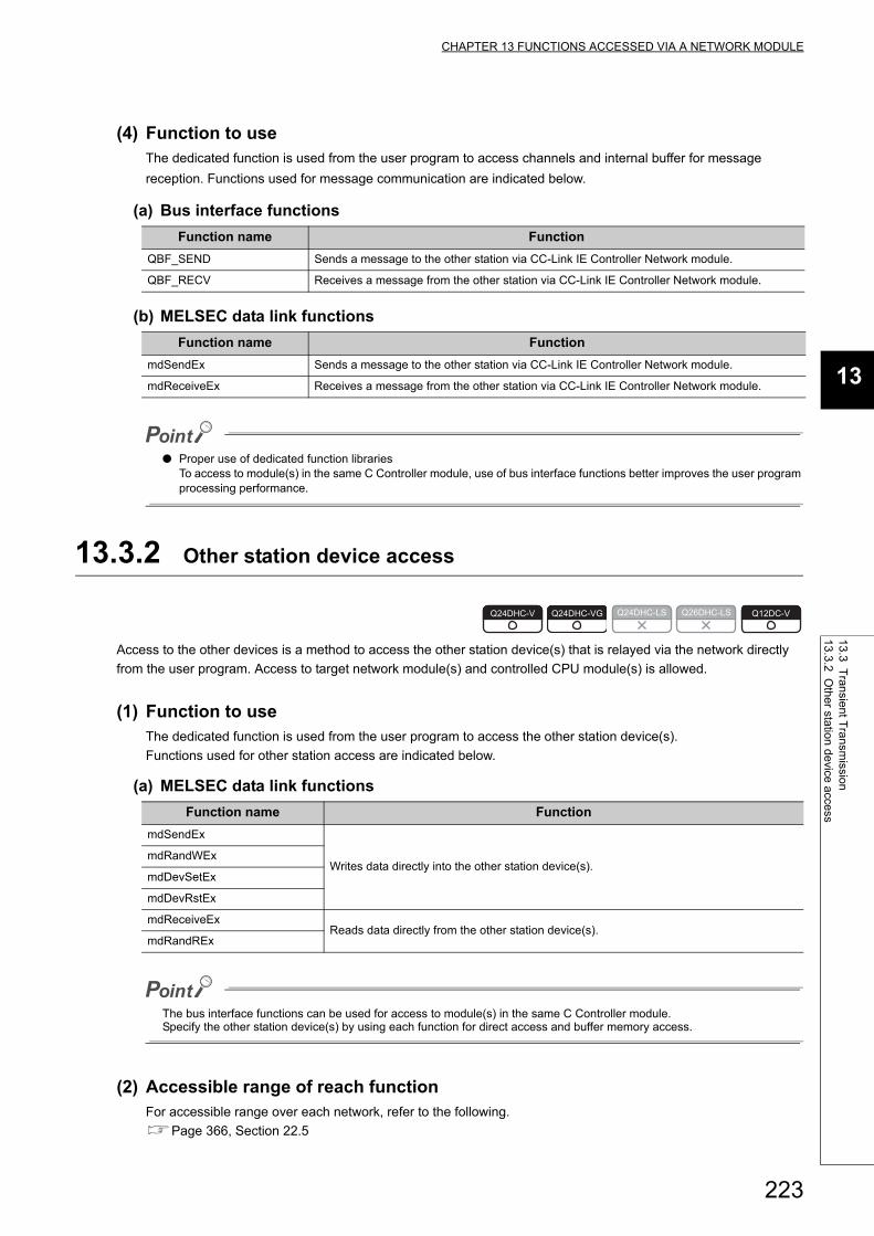
223
CHAPTER 13 FUNCTIONS ACCESSED VIA A NETWORK MODULE
13
13.3 Transient T
ransmission
13.3.2 Other station
device access
(4) Function to useThe dedicated function is used from the user program to access channels and internal buffer for message
reception. Functions used for message communication are indicated below.
(a) Bus interface functions
(b) MELSEC data link functions
● Proper use of dedicated function librariesTo access to module(s) in the same C Controller module, use of bus interface functions better improves the user program processing performance.
13.3.2 Other station device access
Access to the other devices is a method to access the other station device(s) that is relayed via the network directly
from the user program. Access to target network module(s) and controlled CPU module(s) is allowed.
(1) Function to useThe dedicated function is used from the user program to access the other station device(s).
Functions used for other station access are indicated below.
(a) MELSEC data link functions
The bus interface functions can be used for access to module(s) in the same C Controller module.Specify the other station device(s) by using each function for direct access and buffer memory access.
(2) Accessible range of reach functionFor accessible range over each network, refer to the following.
Page 366, Section 22.5
Function name Function
QBF_SEND Sends a message to the other station via CC-Link IE Controller Network module.
QBF_RECV Receives a message from the other station via CC-Link IE Controller Network module.
Function name Function
mdSendEx Sends a message to the other station via CC-Link IE Controller Network module.
mdReceiveEx Receives a message from the other station via CC-Link IE Controller Network module.
Function name Function
mdSendEx
Writes data directly into the other station device(s).mdRandWEx
mdDevSetEx
mdDevRstEx
mdReceiveExReads data directly from the other station device(s).
mdRandREx
Q24DHC-V Q24DHC-VG Q24DHC-LS Q26DHC-LS Q12DC-V
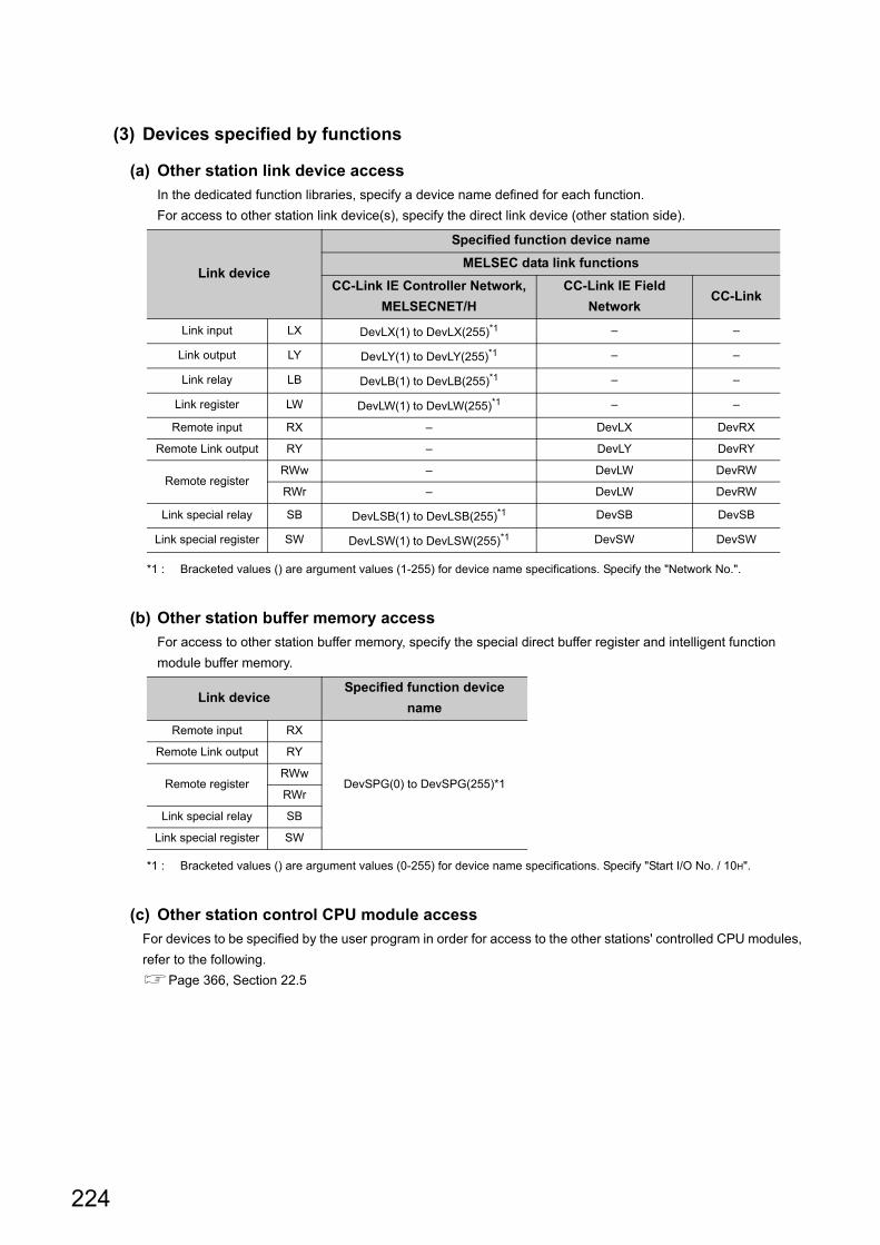
224
(3) Devices specified by functions
(a) Other station link device access
In the dedicated function libraries, specify a device name defined for each function.
For access to other station link device(s), specify the direct link device (other station side).
*1 : Bracketed values () are argument values (1-255) for device name specifications. Specify the "Network No.".
(b) Other station buffer memory access
For access to other station buffer memory, specify the special direct buffer register and intelligent function
module buffer memory.
*1 : Bracketed values () are argument values (0-255) for device name specifications. Specify "Start I/O No. / 10H".
(c) Other station control CPU module access
For devices to be specified by the user program in order for access to the other stations' controlled CPU modules,
refer to the following.
Page 366, Section 22.5
Link device
Specified function device name
MELSEC data link functions
CC-Link IE Controller Network,
MELSECNET/H
CC-Link IE Field
NetworkCC-Link
Link input LX DevLX(1) to DevLX(255)*1 – –
Link output LY DevLY(1) to DevLY(255)*1 – –
Link relay LB DevLB(1) to DevLB(255)*1 – –
Link register LW DevLW(1) to DevLW(255)*1 – –
Remote input RX – DevLX DevRX
Remote Link output RY – DevLY DevRY
Remote registerRWw – DevLW DevRW
RWr – DevLW DevRW
Link special relay SB DevLSB(1) to DevLSB(255)*1 DevSB DevSB
Link special register SW DevLSW(1) to DevLSW(255)*1 DevSW DevSW
Link deviceSpecified function device
name
Remote input RX
DevSPG(0) to DevSPG(255)*1
Remote Link output RY
Remote registerRWw
RWr
Link special relay SB
Link special register SW
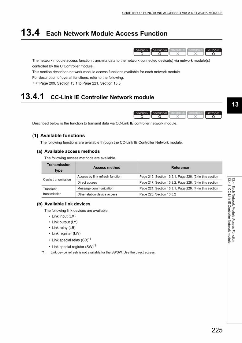
225
CHAPTER 13 FUNCTIONS ACCESSED VIA A NETWORK MODULE
13
13.4 Each N
etwork M
odule Access F
unction13.4.1 C
C-Link IE
Controller N
etwork m
odule
13.4 Each Network Module Access Function
The network module access function transmits data to the network connected device(s) via network module(s)
controlled by the C Controller module.
This section describes network module access functions available for each network module.
For description of overall functions, refer to the following.
Page 209, Section 13.1 to Page 221, Section 13.3
13.4.1 CC-Link IE Controller Network module
Described below is the function to transmit data via CC-Link IE controller network module.
(1) Available functionsThe following functions are available through the CC-Link IE Controller Network module.
(a) Available access methods
The following access methods are available.
(b) Available link devices
The following link devices are available.
• Link input (LX)
• Link output (LY)
• Link relay (LB)
• Link register (LW)
• Link special relay (SB)*1
• Link special register (SW)*1
*1 : Link device refresh is not available for the SB/SW. Use the direct access.
Transmission
typeAccess method Reference
Cyclic transmissionAccess by link refresh function Page 212, Section 13.2.1, Page 226, (2) in this section
Direct access Page 217, Section 13.2.2, Page 228, (3) in this section
Transient
transmission
Message communication Page 221, Section 13.3.1, Page 229, (4) in this section
Other station device access Page 223, Section 13.3.2
Q24DHC-V Q24DHC-VG Q24DHC-LS Q26DHC-LS Q12DC-V
Q24DHC-V Q24DHC-VG Q24DHC-LS Q26DHC-LS Q12DC-V

226
(2) Access by link refresh functionAccess by link refresh function is a method to access internal user device(s) (Link Relay B and Link Register W)
of the C Controller module from the user program.
There are the following 2 ways to access internal user device(s):
• Directly accessing to internal device(s)
(Use the bus interface function and MELSEC data link function.)
• Accessing to data refresh memory and using data refresh
(Use the C Controller module dedicated function.)
Internal user device data are cyclic-transmitted to the other stations by reading from/writing to link device(s) on
network module(s) by link refresh.
*1 : Link device refresh is not available for the SB/SW. Use the direct access.
/* Data writing */ret = QBF_WriteDevice();ret = mdSendEx();ret = mdRandWEx();ret = mdDevSetEx();ret = mdDevRstEx(); orret = CCPU_WriteData RefreshMemory(); /* Data read-out */ret = QBF_ReadDevice();ret = mdReceiveEx();ret = mdRandREx(); orret = CCPU_ReadData RefreshMemory();
Access to the internal user device
BW
LWLB
Link device
LXLY
Link device
SB*1SW*1
C Controller module
User programLink
refresh
Internal user device (link relay,
and link register)
CC-Link IE Controller Network module

227
CHAPTER 13 FUNCTIONS ACCESSED VIA A NETWORK MODULE
13
13.4 Each N
etwork M
odule Access F
unction13.4.1 C
C-Link IE
Controller N
etwork m
odule
(a) Refresh parameter setting example
To perform link refresh, it is necessary to set the refresh parameters.
Illustrated below is an example of refresh parameter settings on a CC-Link IE Controller Network module.
The C Controller module can set up to 64 transfer settings per CC-Link IE Controller Network module.
• System Configuration
• Parameter assignment
Station No.5
Station No.1
Station No.2
to to
C Controller modulePower supply
CC-Link IE Controller Network module
CC-Link IE Controller Network module
Station No.2
Station No.5
Station No.1
Network No.1 Network No.2
Control station
Control station Normal station
0 to 1FF
300 to 4FF
600 to 7FF
900 to AFF
0 to 1FF
300 to 4FF
600 to 7FF
900 to AFF
7FFF
1000
1FFF
B LB
C Controller moduleCC-Link IE Controller Network module (1st)
CC-Link IE Controller Network module (2nd)
0 0
FFF
1FFFF
0
0
FFF
7FFF
1000
1FFFF
1FFF
1000FFF
1FFF
W
LB
LW
LW

228
• CC-Link IE Controller Network module (1st module) setting
• CC-Link IE Controller Network module (2nd module) setting
Remark
If the control CPU of the network module is the C Controller module, use Setting/monitoring tools for the C Controller module to set parameters. If it is the programmable controller CPU, use GX Works2.For Setting/monitoring tools for the C Controller module, refer to the following.Setting/Monitoring Tools for the C Controller Module Version 4 Operating Manual
(3) Direct accessDirect access is a method to directly access network module link device(s) from the user program. Network
module link device data are cyclic-transmitted to the other stations.
Transfer
settings
Link side C Controller module
Device
name
Number
of pointsStart End
Device
name
Number
of pointsStart End
Transfer 1 LB 512 0000 01FF B 512 0000 01FF
Transfer 2 LB 512 0300 04FF B 512 0300 04FF
Transfer 3 LB 512 0600 07FF B 512 0600 07FF
Transfer 4 LB 512 0900 0AFF B 512 0900 0AFF
Transfer 5 LW 4096 00000 00FFF W 4096 00000 00FFF
Transfer
settings
Link side C Controller module
Device
name
Number
of pointsStart End
Device
name
Number
of pointsStart End
Transfer 1 LB 4096 0000 0FFF B 4096 1000 1FFF
Transfer 2 LW 4096 01000 01FFF W 4096 01000 01FFF
User program
/* Data writing */ ret = QBF_WriteLinkDevice(); or ret = mdSendEx(); ret = mdRandWEx(); ret = mdDevSetEx(); ret = mdDevRstEx(); /* Data read-out */ ret = QBF_ReadLinkDevice(); or ret = mdReceiveEx(); ret = mdRandREx();
Direct access
SBSW
LWLB
Link device
LXLY
C Controller moduleCC-Link IE Controller Network
module

229
CHAPTER 13 FUNCTIONS ACCESSED VIA A NETWORK MODULE
13
13.4 Each N
etwork M
odule Access F
unction13.4.1 C
C-Link IE
Controller N
etwork m
odule
(4) Message communicationThe message communication function (Page 221, Section 13.3.1) can be used by the C Controller module
via the controlled CC-Link IE Controller Network module.
Remark
For accessible range, refer to the following.Page 366, Section 22.5
(a) Number of channels and Internal buffer for message reception
Up to 8 channels can be used for message communication by the CC-Link IE Controller Network module, and
the capacity of the internal buffer for message reception is for 4 modules.
Channel 1Channel 2Channel 3Channel 4Channel 5Channel 6Channel 7Channel 8
ret = QBF_RECV();
ret = mdReceiveEx();
ret = QBF_SEND();
ret = mdSendEx();
User program
or
Channel 1Channel 2Channel 3Channel 4Channel 5Channel 6Channel 7Channel 8
Network No.1
User program
or1st2nd
127th128th
C Controller moduleCC-Link IE Controller Network module
CC-Link IE Controller Network module C Controller module (other station)
Sending side Receiving side
Internal buffer for message reception

230
13.4.2 MELSECNET/H module
Described below is the function to transmit data via the MELSECNET/H module.
(1) Available functionsThe following functions are available through the MELSECNET/H module.
(a) Available access methods
The following access methods are available.
*1 : For this function, the same as CC-Link IE Controller Network. Read the stated network name as the relevant name when referring to the CC-Link IE Controller Network module's access function.
(b) Available link devices
The following link devices are available.
• Link input (LX)
• Link output (LY)
• Link relay (LB)
• Link register (LW)
• Link special relay (SB)*1
• Link special register (SW)*1
*1 : Link device refresh is not available for the SB/SW. Use the direct access.
(2) Message communicationThe message communication function (Page 221, Section 13.3.1) can be used by the C Controller module
via the controlled MELSECNET/H module.
Remark
For accessible range, refer to the following.Page 366, Section 22.5
Transmission
typeAccess method Reference
Cyclic transmissionAccess by link refresh function Page 212, Section 13.2.1,Page 226, Section 13.4.1 (2)*1
Direct access Page 217, Section 13.2.2,Page 228, Section 13.4.1 (3)*1
Transient
transmission
Message communication Page 221, Section 13.3.1,Page 230, (2) in this section
Other station device access Page 223, Section 13.3.2
Q24DHC-V Q24DHC-VG Q24DHC-LS Q26DHC-LS Q12DC-V

231
CHAPTER 13 FUNCTIONS ACCESSED VIA A NETWORK MODULE
13
13.4 Each N
etwork M
odule Access F
unction13.4.2 M
EL
SE
CN
ET
/H m
odule
(a) Number of channels and Internal buffer for message reception
Up to 8 channels can be used for message communication by the MELSECNET/H module, and the capacity of
the internal buffer for message reception is for 4 modules.
(b) Logical channel
The MELSECNET/H module can change the channel No. from 1 through 64 for each of the 8 channels. The
channel No. changed by the module is called a "logical channel".
Change the link special register (SW0008-SW000F) value to set the logical channel setting.
*1 : If the value is 0, the logical channel No. is treated as 1-8 as with the actual channel No.
The following shows how to specify channels for each function.
Link special
registerDescription Setting range Initial value
SW0008 Channel 1 logical channel No. setting
1 to 64 0*1SW0009 Channel 2 logical channel No. setting
: :
SW000F Channel 8 logical channel No. setting
Function Function type Function nameChannel specification
method
Message
transmission
Bus interface functions QBF_SENDCan be specified by logical
channel No.
MELSEC data link
functionsmdSendEx
Specified by channel No. 1-8
Message reception
Bus interface functions QBF_RECV
MELSEC data link
functionsmdReceiveEx
Channel 1Channel 2Channel 3Channel 4Channel 5Channel 6Channel 7Channel 8
ret = QBF_RECV();
ret = mdReceiveEx();
ret = QBF_SEND();
ret = mdSendEx();
User program
or
Channel 1Channel 2Channel 3Channel 4Channel 5Channel 6Channel 7Channel 8
Network No.1
User program
or1st2nd
127th128th
C Controller moduleMELSECNET/H
moduleMELSECNET/H
module C Controller module (other station)Sending side Receiving side
Internal buffer for message reception

232
13.4.3 CC-Link IE Field Network master/local module
Described below is the function to transmit data via CC-Link IE Field Network module.
(1) Available functionsThe following functions are available through the CC-Link IE Field Network master/local module.
(a) Available access methods
The following access methods are available.
(b) Available link devices
The following link devices are available.
• Remote input (RX)
• Remote output (RY)
• Remote relay (RWw)
• Remote register (RWr)
• Link special relay (SB)*1
• Link special register (SW)*1
*1 : Link device refresh is not available for the SB/SW. Use the direct access or buffer memory access.
Transmission
typeAccess method Reference
Cyclic transmission
Access by link refresh function Page 212, Section 13.2.1, Page 233, (2) in this section
Direct access Page 217, Section 13.2.2, Page 235, (3) in this section
Buffer memory access Page 219, Section 13.2.3, Page 236, (4) in this section
Transient
transmission
Message communication Page 221, Section 13.3.1, Page 236, (5) in this section
Other station device access Page 223, Section 13.3.2
Q24DHC-V Q24DHC-VG Q24DHC-LS Q26DHC-LS Q12DC-V

233
CHAPTER 13 FUNCTIONS ACCESSED VIA A NETWORK MODULE
13
13.4 Each N
etwork M
odule Access F
unction13.4.3 C
C-Link IE
Field N
etw
ork master/local m
odule
(2) Access by link refresh functionAccess by link refresh function is a method to access internal user device(s) (Link Relay B and Link Register W)
of the C Controller module from the user program.
There are the following 2 ways to access internal user device(s):
• Directly accessing to internal device(s)
(Use the bus interface function and MELSEC data link function.)
• Accessing to data refresh memory and using data refresh
(Use the C Controller module dedicated function.)
Internal user device data are cyclic-transmitted to the other stations by reading from/writing to link device(s) on
network module(s) by link refresh.
*1 : Link device refresh is not available for the SB/SW. Use the direct access or buffer memory access.
/* Data writing */ret = QBF_WriteDevice();ret = mdSendEx();ret = mdRandWEx();ret = mdDevSetEx();ret = mdDevRstEx(); orret = CCPU_WriteData RefreshMemory();
/* Data read-out */ret = QBF_ReadDevice();ret = mdReceiveEx();ret = mdRandREx(); orret = CCPU_ReadData RefreshMemory();
Access to the internal user device
BW
RWrRWw
Link device
RXRY
Link device
SB*1SW*1
C Controller module
User programLink
refresh
CC-Link IE Field Network master/local module
Internal user device (link relay,
and link register)

234
(a) Refresh parameter setting example
To perform link refresh, it is necessary to set the refresh parameters.
Illustrated below is an example of refresh parameter settings on a CC-Link IE Field Network master/local
module.
The C Controller module can set up to 256 transfer settings per CC-Link IE Field Network master/local module.
• System configuration
• Parameter assignment
Station No.5
Station No.1
Station No.2
to to
C Controller modulePower supply
Station No.2
Station No.5
Station No.1
Network No.1 Network No.2
CC-Link IE Field Network master/local module
CC-Link IE Field Network master/local module
Master station
Master station Local station
0 to 1FF
300 to 4FF
600 to 7FF
900 to AFF
0 to 1FF
300 to 4FF
600 to 7FF
900 to AFF
1FFF
2000
2FFF
W RWw
RWr0
1FFF
FFF0
0
FFF
FFF
1FFF
1FFF
5000
3000
5FFF
3FFF
RWr
RWw
C Controller module
CC-Link IE Field Network master/
local module (1st)
CC-Link IE Field Network master/
local module (2nd)

235
CHAPTER 13 FUNCTIONS ACCESSED VIA A NETWORK MODULE
13
13.4 Each N
etwork M
odule Access F
unction13.4.3 C
C-Link IE
Field N
etw
ork master/local m
odule
• CC-Link IE Field Network module (1st module) setting
• CC-Link IE Field Network module (2nd module) setting
Remark
If the control CPU of the network module is the C Controller module, use Setting/monitoring tools for the C Controller module to set parameters. If it is the programmable controller CPU, use GX Works2.For Setting/monitoring tools for the C Controller module, refer to the following.Setting/Monitoring Tools for the C Controller Module Version 4 Operating Manual
(3) Direct accessDirect access is a method to directly access network module link device(s) from the user program. Network
module link device data are cyclic-transmitted to the other stations.
Transfer
settings
Link side C Controller module
Device
name
Number
of pointsStart End
Device
name
Number
of pointsStart End
Transfer 1 RWw 512 0000 01FF W 512 000000 0001FF
Transfer 2 RWw 512 0300 04FF W 512 000300 0004FF
Transfer 3 RWw 512 0600 07FF W 512 000600 0007FF
Transfer 4 RWw 512 0900 0AFF W 512 000900 000AFF
Transfer 5 RWr 4096 0000 0FFF W 4096 002000 002FFF
Transfer
settings
Link side C Controller module
Device
name
Number
of pointsStart End
Device
name
Number
of pointsStart End
Transfer 1 RWw 4096 0000 0FFF W 4096 003000 003FFF
Transfer 2 RWr 4096 0000 0FFF W 4096 005000 005FFF
User program
/* Data writing */ ret = QBF_WriteLinkDevice(); or ret = mdSendEx(); ret = mdRandWEx(); ret = mdDevSetEx(); ret = mdDevRstEx(); /* Data read-out */ ret = QBF_ReadLinkDevice(); or ret = mdReceiveEx(); ret = mdRandREx();
Direct access
SBSW
RWrRWw
Link device
RXRY
C Controller moduleCC-Link IE Field Network
master/local module

236
(4) Buffer memory accessBuffer memory access is a method to access network module buffer memory from the user program. Buffer
memory data are refreshed with link device(s) and cyclic-transmitted to the other stations.
(5) Message communicationThe message communication function (Page 221, Section 13.3.1) can be used by the C Controller module
via the controlled CC-Link IE Field Network master/local module.
Remark
For accessible range, refer to the following.Page 366, Section 22.5
(a) umber of channels and Internal buffer for message reception
Up to 2 channels can be used for message communication by the CC-Link IE Field Network master/local
module, and the capacity of the internal buffer for message reception is for 8 modules.
User program
/* Data writing */ ret = QBF_ToBuf(); /* Data read-out */ ret = QBF_FromBuf();
Buffer memory access
SBSW
RWrRWw
Link device
RXRY
C Controller moduleCC-Link IE Field Network
master/local module
Buffer memory
Channel 1Channel 2 ret = QBF_RECV();
ret = mdReceiveEx();
ret = QBF_SEND();
ret = mdSendEx();
User program
or
Channel 1Channel 2
Network No.1
User program
or1st2nd
127th128th
C Controller module
CC-Link IE Field Network module (Station No.4)
CC-Link IE Field Network module (Station No.5) C Controller module (other station)
Sending side Receiving side
Internal buffer for message reception

237
CHAPTER 13 FUNCTIONS ACCESSED VIA A NETWORK MODULE
13
13.4 Each N
etwork M
odule Access F
unction13.4.4 C
C-Link m
odule
13.4.4 CC-Link module
Described below is the function to transmit data via CC-Link module.
(1) Available functionsThe following functions are available through the CC-Link module.
(a) Available access methods
The following access methods are available.
(b) Available link devices
The following link devices are available.
• Remote input (RX)
• Remote output (RY)
• Remote relay (RWw)
• Remote register (RWr)
• Link special relay (SB)
• Link special register (SW)
(2) Direct accessDirect access is a method to directly access network module link device(s) from the user program. Network
module link device data are cyclic-transmitted to the other stations.
Transmission
typeAccess method Reference
Cyclic transmission
Direct access Page 217, Section 13.2.2, Page 237, (2) in this section
Buffer memory access
Page 219, Section 13.2.3,
Page 238, (3) in this section to Page 241, (5) in this
section
Transient
transmissionOther station device access Page 223, Section 13.3.2
Q24DHC-V Q24DHC-VG Q24DHC-LS Q26DHC-LS Q12DC-V
User program
/* Data writing */ret = mdSendEx();ret = mdRandWEx();ret = mdDevSetEx();ret = mdDevRstEx(); /* Data read-out */ret = mdReceiveEx();ret = mdRandREx();
Direct access
SBSW
RWrRWw
Link device
RXRY
C Controller module CC-Link
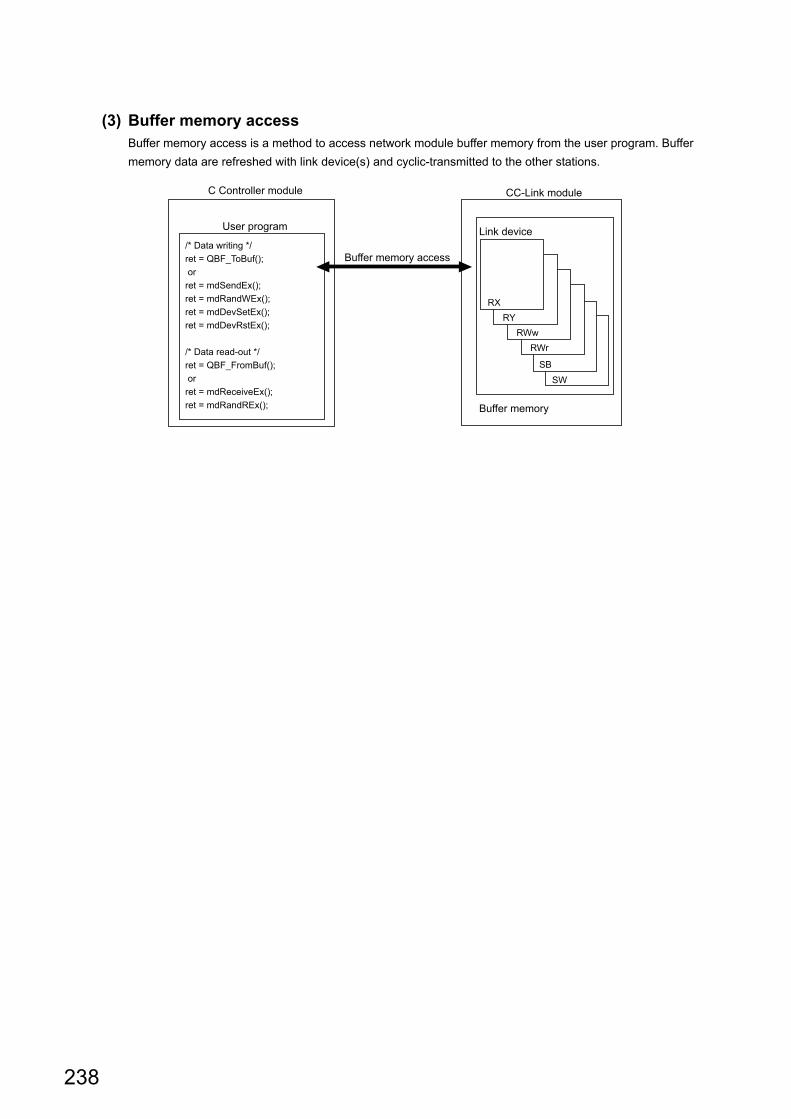
238
(3) Buffer memory accessBuffer memory access is a method to access network module buffer memory from the user program. Buffer
memory data are refreshed with link device(s) and cyclic-transmitted to the other stations.
User program
/* Data writing */ret = QBF_ToBuf(); orret = mdSendEx();ret = mdRandWEx();ret = mdDevSetEx();ret = mdDevRstEx();
/* Data read-out */ret = QBF_FromBuf(); orret = mdReceiveEx();ret = mdRandREx();
Buffer memory access
SBSW
RWrRWw
Link device
RXRY
C Controller module
Buffer memory
CC-Link module

239
CHAPTER 13 FUNCTIONS ACCESSED VIA A NETWORK MODULE
13
13.4 Each N
etwork M
odule Access F
unction13.4.4 C
C-Link m
odule
(4) Reading from buffer memory when using the block data assurance per station
functionTo enable the Block Data Assurance per Station and read data from the buffer memory, follow the following
procedures.
Use the manual cyclic data refresh method if user program processing is to be continued during the waiting time which will occur in the automatic cyclic data refresh.
● The following shows the CC-Link module that supports the block data assurance per station function.
(a) Automatic cyclic data refresh
1) Execute the QBF_FromBuf function with "automatic" specified for "CC-Link refresh method" of the third
argument (ulOffset).
2) In the timing of the next link scan, refreshed cyclic data (in the buffer memory) are read out.
User program processing is suspended until the reading is completed.
3) Upon completion of reading, the user program processing resumes.
During execution of the QBF_FromBuf function, a time of up to one link scan may be spent for standby.
Method Description Reference
Automatic cyclic data
refresh
Data are automatically refreshed during the link scan and read out
just by executing the QBF_FromBuf function.
Page 239, (4)(a) in this
section
Manual cyclic data
refresh
Data are manually refreshed with the QBF_RefreshLinkDevice
function, and then they are read out by executing the QBF_FromBuf
function.
Page 240, (4)(b) in this
section
Model Version
QJ61BT11N Serial number whose first five digits are "08032" or higher.
User program Buffer memory Link scan
C Controller module CC-Link module
Refresh
: User program is waiting
Link scanRefresh request1)
2)
3)Data read-out
QBF_FromBuf (automatic)

240
(b) Manual cyclic data refresh
1) Use the QBF_RefreshLinkDevice function to issue a refresh request.
2) The user program is continued.
3) Data are refreshed by the request in 1).
4) Execute the QBF_FromBuf function with "manual" specified for "CC-Link refresh method" of the third
argument (ulOffset).
Cyclic data (in the buffer memory) are read out.
• If execution of the QBF_FromBuf function is attempted before refreshing data by the
QBF_RefreshLinkDevice function, user program processing is suspended until completion of the refresh.
Upon completion of the refresh, cyclic data (in the buffer memory) are read out, and the user program
processing resumes.
When any of the following operations is performed for the CC-Link module for which the block data assurance per station is enabled, cyclic data are automatically refreshed even if the QBF_RefleshLinkDevice function is not executed.
• Monitoring on Setting/monitoring tools for the C Controller module. • Device reading from another user program (another task) with the QBF_FromBuf function (automatic refresh
method) or a MELSEC data link functionNote that the write (send) area of the link refresh device (in the buffer memory) is not refreshed.Also, cyclic data are not refreshed when monitoring is performed with another station's CC-Link module specified in Setting/monitoring tools for the C Controller module.
Buffer memory Link scan
C Controller module CC-Link module
Refresh
Link scan
Data read-out*1
QBF_RefreshLinkDevice
QBF_FromBuf (manual)
QBF_FromBuf (manual)Data read-out*1
1)
2)
4)
4)
*1: Read out data are the same refresh data.
Refresh request
3)
Link scan
Link scan
User program
Buffer memory Link scan
C Controller module CC-Link module
Refresh
Link scanRefresh requestQBF_RefreshLinkDevice
QBF_FromBuf (manual)
Data read-out
: User program is waiting
1)2)
4)3)
User program

241
CHAPTER 13 FUNCTIONS ACCESSED VIA A NETWORK MODULE
13
13.4 Each N
etwork M
odule Access F
unction13.4.4 C
C-Link m
odule
(5) Writing to buffer memory when using the block data assurance per station
functionTo enable the Block Data Assurance per Station and write data to the buffer memory, follow the following
procedures.
Use the manual cyclic data refresh method if user program processing is to be continued during the waiting time which will occur in the automatic cyclic data refresh.
(a) Automatic cyclic data refresh
1) Execute the QBF_ToBuf function with "automatic" specified for "CC-Link refresh method" of the third
argument (ulOffset).
2) In the timing of the next link scan, data are refreshed.
• If execution of the QBF_ToBuf function is attempted before completion of the previous refresh, data writing
is suspended until completion of the refresh.
Method Description Reference
Automatic cyclic data
refresh
Data are automatically written by just executing the QBF_ToBuf
function in advance, and then they are automatically refreshed at the
time of next link scan.
Page 241, (5)(a) in this
section
Manual cyclic data
refresh
Data are written with the QBF_ToBuf function, and then they are
manually refreshed by executing the QBF_RefreshLinkDevice
function.
Page 242, (5)(b) in this
section
Buffer memory Link scan
C Controller module CC-Link module
Refresh
Link scanRefresh request1)
2)
QBF_ToBuf (automatic)Data writing
User program
Buffer memory Link scan
C Controller module CC-Link module
Link scan
: User program is waiting
QBF_ToBuf (automatic)Data (1) writing
Link scan
Refresh request (1)
Refresh (Data (1))
Refresh request (2)
Refresh (Data (2))
QBF_ToBuf (automatic)Data (2) writing
User program

242
Up to a time of up to one link scan may be required for refreshing the written data after execution of the QBF_ToBuf function.
(b) Manual cyclic data refresh
1) Execute the QBF_ToBuf function with "manual" specified for "CC-Link refresh method" of the third argument
(ulOffset).
2) Use the QBF_RefreshLinkDevice function to issue a refresh request.
3) In the timing of the next link scan, refresh is performed.
• If data are written to the same address area before execution of the QBF_RefreshLinkDevice function, the
area will be overwritten with the data refreshed later.
By writing the data to another address area, both of the data can be written.
Buffer memory Link scan
C Controller module CC-Link module
Refresh
Link scanQBF_ToBuf (manual)
QBF_RefreshLinkDevice
1)
2)
3)
Refresh request Link scan
User program
Buffer memory Link scan
C Controller module CC-Link module
Refresh (Data (1) + (2))*1
Link scan
Refresh requestQBF_RefreshLinkDevice function
QBF_ToBuf (manual) (1)
QBF_ToBuf (manual) (2)
User program
*1: Data written to the same address will be overwritten by the buffer memory, so data written later will be refreshed. If data are written to another address area, both written data sets will be refreshed.

243
CHAPTER 13 FUNCTIONS ACCESSED VIA A NETWORK MODULE
13
13.4 Each N
etwork M
odule Access F
unction13.4.4 C
C-Link m
odule
• If data writing is attempted before completion of the refresh after execution of the QBF_RefreshLinkDevice
function, the data will be not written until completion of the previous refresh.
When any of the following operations is performed for the CC-Link module for which the block data assurance per station is enabled, cyclic data are automatically refreshed even if the QBF_RefleshLinkDevice function is not executed.
• Forced writing to the buffer memory on Setting/monitoring tools for the C Controller module. • Device writing in Setting/monitoring tools for the C Controller module. • Device writing from another user program (another task) with the QBF_ToBuf function (automatic refresh method)
or a MELSEC data link functionNote that the read (receive) area of the link refresh device (in the buffer memory) is not refreshed.Also, cyclic data are not refreshed when device writing is performed with another station's CC-Link module specified in Setting/monitoring tools for the C Controller module.
Buffer memory Link scan
C Controller module CC-Link module
Link scanQBF_ToBuf (manual) (1)
: User program is waiting
Link scan
Refresh request
Refresh(Data (1))
Refresh(Data (2))
QBF_RefreshLinkDevice
QBF_RefreshLinkDevice
QBF_ToBuf (manual) (2)
Refresh request
User program

244
13.5 Processing Times
Described in this section is the cyclic transmission processing time associated with network module access.
For transient transmission processing time, refer to processing time for each function.
(Page 475, Appendix 5)
13.5.1 Link refresh time
(1) For CC-Link IE Controller Network, MELSECNET/HThe following describes processing time in the CC-Link IE Controller Network and MELSECNET/H.
Link refresh time can be calculated by the following formula, with the points assigned to link devices.
KM1, KM2: Constants
LB: Total points of link relay (LB) refreshed by the station*1
LX: Total points of link input (LX) refreshed by the station*1
LY: Total points of link output (LY) refreshed by the station*1
LW: Total points of link register (LW) refreshed by the station*1
*1 : Total of link device points within the range set by refresh parameters and set in the network range assignment. (Excluding the points assigned to reserved stations)
(2) For CC-Link IE Field NetworkThe following describes processing time in the CC-Link IE Field Network.
Link refresh time can be calculated by the following formula, with the points assigned to link devices.
KM1, KM2: Constants
RX: Total points of link input (RX) refreshed by the station*1
RY: Total points of link output (RY) refreshed by the station*1
RWw, RWr: Total points of link register (RWw, RWr) refreshed by the station*1
*1 : Total of link device points within the range set by refresh parameters and set in the network range assignment. (Excluding the points assigned to reserved stations)
Link refresh time [ms]
KM1 + KM2 {(LB + LX + LY) / 16 + LW}
Network module locationCC-Link IE Controller Network MELSECNET/H
KM1 KM2 KM1 KM2
Main base unit 1.0 0.36 10-3 1.0 0.41 10-3
Extension base unit 1.0 0.97 10-3 1.0 0.97 10-3
Link refresh time [ms]
KM1 + KM2 {(RX + RY) / 16 + RWw + RWr}
Network module location KM1 KM2
Main base unit 1.0 0.41 10-3
Extension base unit 1.0 0.99 10-3
Q24DHC-V Q24DHC-VG Q24DHC-LS Q26DHC-LS Q12DC-V
Q24DHC-V Q24DHC-VG Q24DHC-LS Q26DHC-LS Q12DC-V

245
CHAPTER 13 FUNCTIONS ACCESSED VIA A NETWORK MODULE
13
13.5 Proce
ssing T
imes
13.5.2 Dela
y time in cyclic transm
ission
13.5.2 Delay time in cyclic transmission
(1) CC-Link IE Controller NetworkThe following shows the formulas to obtain cyclic transmission delay time in the CC-Link IE Controller Network.
PT: Sending side processing time = RT + T
PR: Receiving side processing time = RR + R
RT, RR: Sending/receiving side refresh cycle (Page 175, Section 11.7.3)
T, R: Sending/receiving side link refresh time*1 (Page 244, Section 13.5.1 (1))
LS: Link scan time*2
*1 : Total time for the number of mounted network modules.*2 : For link scan time, refer to the following.
MELSEC-Q CC-Link IE Controller Network Reference Manual
Remark
For multiple network system, transfer of link device(s) to another network by the relay station's CPU module by using the inter-link transfer function affects the transfer processing time of the relay station's CPU module. For details, refer to the following.MELSEC-Q CC-Link IE Controller Network Reference Manual
If the sending module is a Q series programmable controller CPU, apply the following processing time of the
sending programmable controller CPU to the transmission delay time formulas instead of the stated sending side
processing time (PT).
PT: Sending side processing time = QT: Programmable controller CPU (sending side) processing time = ST + T
ST: Sequence scan time of the programmable controller CPU (sending side) (link refresh time not included)*1
T: Link refresh time of the programmable controller CPU (sending side)*1*2
*1 : For details, refer to the following.MELSEC-Q CC-Link IE Controller Network Reference Manual
*2 : Total time for the number of mounted network modules.
ModeBlock data assurance
per stationRT vs. LS
Calculated
valueTransmission delay time [ms]
Normal
mode
None (None)Normal value PT + LS 0.5 + PR 0.5
Max. value PT + LS + PR
Valid
When RT > LSNormal value PT 1.5 + LS 0.5 + PR 0.5
Max. value PT 2 + LS + PR
When RT < LSNormal value PT + LS + PR 0.5
Max. value PT + LS 2 + PR
Extended
mode
None
When RT > LSNormal value PT + LS 0.5 + PR 0.5
Max. value PT + LS + PR
When RT < LSNormal value PT + LS + PR 0.5
Max. value PT + LS 2 + PR
Valid
When RT > LSNormal value PT 1.5 + LS 0.5 + PR 1.5
Max. value PT 2 + LS + PR 2
When RT < LSNormal value PT + LS + PR 1.5
Max. value PT + LS 2 + PR 2
Q24DHC-V Q24DHC-VG Q24DHC-LS Q26DHC-LS Q12DC-V

246
Formulas to obtain the transmission delay time applicable when the receiving module is a Q series programmable
controller CPU are listed below.
LS: Link scan time*1
PT: Processing time of the C Controller module (sending side) = RT + T
RT: Refresh time of the C Controller module (sending side) (Page 175, Section 11.7.3)
T: Link refresh time of the C Controller module (sending side)*2 (Page 244, Section 13.5.1 (1))
QR: Programmable controller CPU (receiving side) processing time = SR + R
SR: Sequence scan time of the programmable controller CPU (receiving side) (link refresh time not included)*1
R: Link refresh time of the programmable controller CPU (receiving side)*1*2
*1 : For details, refer to the following.MELSEC-Q CC-Link IE Controller Network Reference Manual
*2 : Total time for the number of mounted network modules.
(2) MELSECNET/H The following shows the formulas to obtain cyclic transmission delay time in the MELSECNET/H.
PT: Sending side processing time = RT + T
PR: Receiving side processing time = RR + R
RT, RR: Sending/receiving side refresh cycle (Page 175, Section 11.7.3)
T, R: Sending/receiving side link refresh time*1 (Page 244, Section 13.5.1 (1))
LS: Link scan time*2
*1 : Total time for the number of mounted network modules.*2 : For link scan time, refer to the following.
Q Corresponding MELSECNET/H Network System Reference Manual (PLC to PLC network)
ModeBlock data assurance
per stationRT vs. LS
Calculated
valueTransmission delay time [ms]
Normal
mode
None (None)Normal value PT + LS 0.5 + QR 1.5
Max. value PT + LS + QR 2
Valid
When RT > LSNormal value PT 1.5 + LS 0.5 + QR 1.5
Max. value PT 2 + LS + QR 2
When RT < LSNormal value PT + LS + QR 1.5
Max. value PT + LS 2 + QR 2
Extended
mode
None
When RT > LSNormal value PT + LS 0.5 + QR 1.5
Max. value PT + LS + QR 2
When RT < LSNormal value PT + LS + QR 1.5
Max. value PT + LS 2 + QR 2
Valid
When RT > LSNormal value PT 1.5 + LS 0.5 + QR 2.5
Max. value PT 2 + LS + QR 3
When RT < LSNormal value PT + LS + QR 2.5
Max. value PT + LS 2 + QR 3
ModeBlock data assurance
per stationRT vs. LS
Calculated
valueTransmission delay time [ms]
Normal
mode
None (None)Normal value PT + LS 0.5 + PR 0.5
Max. value PT + LS + PR
Valid
When RT > LSNormal value PT 1.5 + LS 0.5 + PR 0.5
Max. value PT 2 + LS + PR
When RT < LSNormal value PT + LS + PR 0.5
Max. value PT + LS 2 + PR

247
CHAPTER 13 FUNCTIONS ACCESSED VIA A NETWORK MODULE
13
13.5 Proce
ssing T
imes
13.5.2 Dela
y time in cyclic transm
ission
Remark
For multiple network system, transfer of link device(s) to another network by the relay station's CPU module by using the inter-link transfer function affects the transfer processing time of the relay station's CPU module. For details, refer to the following.Q Corresponding MELSECNET/H Network System Reference Manual (PLC to PLC network)
If the sending module is a Q series programmable controller CPU, apply the following processing time of the sending programmable controller CPU to the transmission delay time formulas instead of the stated sending side processing time (PT).
PT: Sending side processing time = QT: Programmable controller CPU (sending side) processing time = ST + T
ST: Sequence scan time of the programmable controller CPU (sending side) (link refresh time not included)*1
T: Link refresh time of the programmable controller CPU (sending side)*1*2
*1 : For details, refer to the manual for respective network modules.Q Corresponding MELSECNET/H Network System Reference Manual (PLC to PLC network)
*2 : Total time for the number of mounted network modules.
Formulas to obtain the transmission delay time applicable when the receiving module is a Q series programmable controller CPU are listed below.
LS: Link scan time*1
PT: Processing time of the C Controller module (sending side) = RT + T
RT: Refresh time of the C Controller module (sending side) (Page 175, Section 11.7.3)
T: Link refresh time of the C Controller module (sending side)*2 (Page 244, Section 13.5.1 (1))
QR: Programmable controller CPU (receiving side) processing time = SR + R
SR: Sequence scan time of the programmable controller CPU (receiving side) (link refresh time not included)*1
R: Link refresh time of the programmable controller CPU (receiving side)*1*2
*1 : For details, refer to the following.Q Corresponding MELSECNET/H Network System Reference Manual (PLC to PLC network)
*2 : Total time for the number of mounted network modules.
(3) Transmission delay time on CC-Link IE Field NetworkFor formulas to obtain cyclic transmission delay time in the CC-Link IE Field Network, refer to the following.MELSEC-Q CC-Link IE Field Network Master/Local Module User's ManualAt that time, use the following processing time instead of "SM: Master station sequence scan time" and "SL: Local station sequence scan time":
SM, SL = P = R + P: Processing time of C controller systemR: Link refresh cycle (Page 175, Section 11.7.3)
: Link refresh time (Page 244, Section 13.5.1 (2))If direct access or buffer memory access are used, it takes no refresh time.For function processing time, refer to the following.Page 475, Appendix 5
(4) Transmission delay time on CC-LinkFor formulas to obtain cyclic transmission delay time in the CC-Link, refer to the following.MELSEC-Q CC-Link System Master/Local Module User's ManualAt that time, use the following processing time for buffer memory access functions instead of "SM: Master station sequence scan time" and "SL: Local station sequence scan time".For function processing time, refer to the following.Page 475, Appendix 5
Mode Block data assurance per station
RT vs. LS Calculated value
Transmission delay time [ms]
Normal mode
None (None)Normal value PT + LS 0.5 + QR 1.5
Max. value PT + LS + QR 2
Valid
When RT > LSNormal value PT 1.5 + LS 0.5 + QR 1.5
Max. value PT 2 + LS + QR 2
When RT < LSNormal value PT + LS + QR 1.5
Max. value PT + LS 2 + QR 2

248
(5) Transmission delay time calculation exampleThe following shows a calculation example for cyclic transmission delay time in a single network system.
The following indicates the system configuration and conditions.
(a) Link refresh time (T, R)
The formula is indicated below.
Variable values are as follows:
KM1: Constants = 1.0
KM2: Constants = 0.36 10-3
LB, LW: Total number of points of link devices (LB and LW) = 1024
LX, LY: Total number of points of link devices (LX and LY) = 0
Assignment of variables in formulas are as follows:
T, R = 1.0 + 0.36 10-3 {(1024 + 0 + 0) / 16 + 1024}
1.39(ms)
(b) Transmission delay time
Formulas in case LT is larger than LS with Block Data Assurance per Station enabled are indicated below.
Variable values are as follows:
PT: Sending side processing time = RT + T
PR: Receiving side processing time = RR + R
RT, RR: Refresh cycle = 100(ms)
T, R: Link refresh time 1.39(ms)
LS: Link scan time 1.25(ms)*1
*1 : For link scan time, refer to the following.MELSEC-Q CC-Link IE Controller Network Reference Manual
Assignment of variables in formulas are as follows:
Normal value = {(100 + 1.39) 1.5} + (1.25 0.5) + {(100 + 1.39) 0.5} = 203.405(ms)
Max. value = {(100 + 1.39) 2} + 1.25 + (100 + 1.39) = 305.420(ms)
Item Description
CPU on sending and receiving station C Controller module
Total number of stations per network 2 (Control station: 1, Normal station: 1)
Total link device points
LB/LW 1024 points
LX/LY 0 points
SB/SW 0 points
Refresh cycle 100ms
Transient transmission None
Block data assurance per station Enabled (Block data assurance per station)
CC-Link IE controller network module Installed to Slot 0 of main base unit
Faulty station None
Link refresh time
T, R = KM1 + KM2 {(LB + LX + LY) / 16 + LW}
Calculated
valueTransmission delay time
Normal value PT 1.5 + LS 0.5 + PR 0.5
Max. value PT 2 + LS + PR

249
CHAPTER 13 FUNCTIONS ACCESSED VIA A NETWORK MODULE
13
13.5 Proce
ssing T
imes
13.5.3 Reducing the link refresh tim
e
13.5.3 Reducing the link refresh time
The link refresh time can be reduced by decreasing the number of refresh points for the C Controller module. To
decrease the refresh points, modify the refresh and network range assignment (network configuration settings)
parameter settings and use the direct access method for accessing link devices.
(1) Reducing the number of refresh points
(a) Refresh parameters
Set the range required to be refreshed in the refresh parameters.
Link refresh time can be reduced by limiting refresh range to necessary parts only.
Q24DHC-V Q24DHC-VG Q24DHC-LS Q26DHC-LS Q12DC-V
C Controller module Internal userdevice
Network moduleNetwork Range Assignment
(Network Configuration Settings)parameter
Network Range Assignment(Network Configuration Settings) setting range
Set refresh parameter only for required part
Link refresh
Link refresh
Link refresh
Station No.1
Station No.2
Station No.3

250
(b) Direct access/buffer memory access
Link refresh time can be reduced by excluding infrequently used link devices in the host station from the link
refresh range by means of direct access or buffer memory access.
(2) Reducing the link scan timeFor MELSECNET/H, link refresh and link scan data (LB/LW) can be reduced by assigning data not required to be
high-speed during normal cyclic transmission (LB/LW) to the extension area (2000H to 3FFFH) and performing
low-speed cyclic transmission.
C Controller module Internal userdevice
Direct access
Direct access
Network moduleNetwork Range Assignment(Network Configuration Settings)parameterAccess to
the internal user device
C Controller module User program
Processing that always requires writing (frequently-used link device)
Processing that performs writing as necessary (less frequently-used link device)
Processing that always requires read-out (frequently-used link device)
Processing that performs read-out as necessary (less frequently-used link device)
Send range to the other station
Receive range from other stations
Access to the internal user device
Link refresh
Link refresh
Station No.1
Station No.3
Station No.2
1FFFH
3FFFH
2000H
C Controller module Internal userdevice
MELSECNET/H module network range assignment parameter
Normal cyclic transmission range
Low speed cyclic transmission range
Low speed link refresh
0H 0HLink refresh Station No.1
Station No.2
Station No.3
Station No.1
Station No.2
Station No.3

251
CHAPTER 14 FUNCTIONS USED BY MULTIPLE CPU SYSTEM
14
14.1 Data C
omm
unications U
sing CP
U S
hared Mem
ory
CHAPTER 14FUNCTIONS USED BY
MULTIPLE CPU SYSTEM
This chapter describes control/access functions of the C Controller module and programmable controller CPU/Motion
CPU in the multiple CPU system.
Remark
For details of each function, install Setting/monitoring tools for the C Controller module and refer to the [C Controller module function help].
14.1 Data Communications Using CPU Shared Memory
Data communication using the CPU shared memory can be used between the C Controller module and the CPU
modules by creating a user program with the bus interface function. Note14.1
Remark
Shared CPU memory can be used only in the multiple CPU configuration.
(1) Data communication methods using the CPU shared memoryThere are the following three kinds of the communication methods.
• Using the auto refresh. (Page 256, Section 14.1.2)
• Using the multiple CPU high speed transmission area. (Page 261, Section 14.1.3)
• Not using the auto refresh. (Page 266, Section 14.1.4)
Note14.1 When using Q24DHCCPU-LS and Q26DHCCPU-LS, the CPU shared memory can be accessed by the data refresh
function.
Q24DHC-V Q24DHC-VG Q24DHC-LS Q26DHC-LS Q12DC-V
Note14.1
Q24DHCCPU-LS Q26DHCCPU-LS

252
(2) Selection of a data communication methodSelect a data communication method of the CPU shared memory from the target CPU module.
The following table lists the availability for each type.
(3) FunctionsThe following shows the functions used for reading from/writing to the CPU shared memory.
14.1.1 CPU shared memory structure
Configuration of CPU shared memory for the C Controller module is described below:
Target CPU module
Data communication methods using the CPU shared memory
Using the auto
refresh
Using the multiple CPU
high speed transmission
area
Not using the auto
refresh
Programmable controller CPU *1
Motion CPU
(Q172DCPU(-S1),
Q173DCPU(-S1),
Q172DSCPU,Q173DSCPU)
C Controller module
(Q24DHCCPU-V,
Q24DHCCPU-VG,
Q12DCCPU-V (Basic mode)
Q12DCCPU-V (Extended mode),
Q06CCPU-V)
*2
*1 : Universal Model QCPU excluding Q00UCPU, Q01UCPU, and Q02UCPU only.*2 : Except the Q06CCPU-V.
Function name Function
QBF_ToBuf*1Writes data to the CPU shared memory of the specified module and the buffer memory of
the intelligent function module (To instruction).
QBF_FromBuf*2Reads data from the CPU shared memory of the specified module and the buffer memory
of the intelligent function module (From instruction).
*1 : MELSEC data link function (mdSendEx function) is also available.*2 : MELSEC data link function (mdReceiveEx function) is also available.
Area name Description
QCPU standard
area
Host CPU operation
information area
Error details or operation status of the host CPU (C Controller module) are stored in
this area. (Page 254, (2) in this section)
System area This area is used by the system.
Auto refresh area
This area data are automatically refreshed into devices of the programmable controller
CPU or Motion CPU, based on the auto refresh settings.
The area size varies depending on the parameter settings.
User setting areaThis area are not refreshed automatically.
The area size varies depending on the parameter settings for the Auto refresh area.
Multiple CPU high speed transmission area
This area is used for the multiple CPU high speed transmission.
(Page 262, Section 14.1.3 (2))
The auto refresh area or user setting area can be set with a parameter.
Q24DHC-V Q24DHC-VG Q24DHC-LS Q26DHC-LS Q12DC-V

253
CHAPTER 14 FUNCTIONS USED BY MULTIPLE CPU SYSTEM
14
14.1 Data C
omm
unications U
sing CP
U S
hared Mem
ory14.1.1 C
PU
shared mem
ory structu
re
(1) AccessibilityAccessibility of the CPU shared memory is illustrated below.
CPU shared
memory
area
address*1
Area name
Access from host CPUAccess from another
CPU*2
1) Access to host
CPU
2) Access to another
CPU3) Access to host CPU
Write Read Write Read Write Read
0H(0H)
to
1FFH(5FH)
QCPU
standard
area
Host CPU
operation
information area
200H(60H)
to
7FFH(BFH)
System area
800H(C0H)
to
FFFH(1FFH)
Auto refresh area
User setting area
1000H
to
270FH
Use prohibited*3
2710H
to
5F0FH
Multiple CPU high speed
transmission area*3
*1 : When CPU No.1 is a Basic model QCPU, addresses of the CPU shared memory are as shown in parentheses.*2 : For information on how to access from another CPU (programmable controller CPU or Motion CPU), refer to the manual for each
CPU module.*3 : Q00UCPU, Q01UCPU, and Q02UCPU have no unavailable area or multiple CPU high speed transmission area.
Power supply
Programmable controller CPUMotion CPUC Controller module (other)
C Controller module (host)
User program
Shared CPU memory for other modules
Shared CPU memory for the host module
2)
Shared CPU memory for other modules
1)
1) Access to host CPU3)
Programmable controller CPU
Sequence program
2)
Program 2) Access to another CPU3) Access to host CPU

254
(2) Host CPU operation information areasContents of the host CPU operation information areas are described in the table below.
Shared
memory
address
Name Description Details
0H Information presence Information flag
The area is provided for checking if information is stored in the host
CPU's operation information area (1H to 1FH) or not.
0: No information, 1: Information exists.
1H Diagnostic error Diagnostic error numberThe error number that occurred in diagnostics is stored as a BIN code
in this area.*1
2H
Date and time of
diagnostic error
Date and time of
diagnostic error
The year and month when the error number is stored in the CPU
shared memory address 1H is stored as a 2-digit BCD code in this
area.*1
3HThe date and time when the error number is stored in the CPU shared
memory address 1H is stored as a 2-digit BCD code in this area.*1
4H
The minute and second when the error number is stored in the CPU
shared memory address 1H is stored as a 2-digit BCD code in this
area.*1
5HError information
identification code
Error information
identification code
The identification codes used to determine what error information
stored in the common error information and individual error information
are stored in this area.*1
6H to 10HCommon error
information
Common error
information
The common information of the error number that occurred in
diagnostics is stored in this area.*1
11H to 1BHIndividual error
information
Individual error
information
The individual information of the error number that occurred in
diagnostics is stored in this area.*1
1CH Empty – Not used
1DH Switch statusC Controller module
switch status
The C Controller module switch status is stored in this area.
0: RUN, 1: STOP
1EH LED statusC Controller module
LED status
The bit pattern of the C Controller module's LEDs is stored in this area.
The same data can be acquired by the C Controller module dedicated
function (CCPU_GetLEDStatus).
For details of the LED status, refer to the following.
Page 255, (2)(a) in this section
1FHC Controller module
operation status
C Controller module
operation status
The operation status of the C Controller module is stored in this area.
The same data can be acquired by the C Controller module dedicated
function (CCPU_GetCpuStatus).
For details of the operation status, refer to the following.
Page 255, (2)(b) in this section
*1 : If no error is detected, 0 is stored.

255
CHAPTER 14 FUNCTIONS USED BY MULTIPLE CPU SYSTEM
14
14.1 Data C
omm
unications U
sing CP
U S
hared Mem
ory14.1.1 C
PU
shared mem
ory structu
re
(a) LED status
(b) Operation status
No.Corresponding
informationStatus
1) "RUN" LED
0 : Off, 1 : On, 2 : Flashing(slow), 3 : Flashing(fast)
2) "ERR." LED
3) "USER" LED
4)"SD CARD" LED
"CF CARD" LED
5) "USB1" LED
6) "U RDY" LED
7) "USER" LED color*1 0 : Red, 1 : Green, 2 : Orange, 3 : Not used
8)*2 "MODE" LED 0 : Off, 1 : Lit green, 2 : Lit orange, 3 : Flashing
*1 : Valid only when USER LED is on/flashing*2 : Flashed orange is not stored.
No.Corresponding
informationStatus
1)C Controller module
operation status0 : RUN, 1: Reserved, 2 : STOP, 3 : PAUSE,
2)STOP/PAUSE factor
(in chronological order)
0 : RUN/STOP/MODE switch
1 : Reserved
2 : Reserved
3 : Execution of bus interface function (QBF_ControlEx) from the user program
4 : Error
5 : Remote operation
3) Mode0 : Basic mode
1 : Extended mode
8) 7) 6) 5) 4) 3) 2) 1)
b15 b12 b11 b8 b7 b4 b0b3
b12 b11 b8 b7 b4 b0b3
2) 1)
b15
3)

256
14.1.2 Data communications using auto refresh
This is a communication method that uses the auto refresh area in the CPU shared memory.
This section described processing in this communication method, and setting methods.
(1) Processing overviewThe following shows the processing of data communication when using auto refresh.
Auto refresh cannot be used for communication between a C Controller module and Motion CPU(Q172DCPU(-S1),Q173DCPU(-S1),Q172DSCPU,Q173DSCPU).Use the auto refresh function in the multiple CPU high speed transmission area.Page 261, Section 14.1.3
ProcessingIn END processing of programmable
controller CPU or Motion CPU
At bus interface function execution of C
Controller module
1)
Data in the device for programmable controller CPU
(or Motion CPU) are transferred to the auto refresh
area in the CPU shared memory.
–
2) –
Execution of the bus interface function (QBF_ToBuf)
transfers user program settings to the auto refresh
area in the C Controller module's CPU shared
memory.
3) –
Execution of the bus interface function
(QBF_FromBuf) transfers the auto refresh area data
of the programmable controller CPU (or Motion
CPU) to the user program.
4)
Auto refresh area data in the C Controller module
are transferred to the device for C Controller module
in the programmable controller CPU (or Motion
CPU).
–
Q24DHC-V Q24DHC-VG Q24DHC-LS Q26DHC-LS Q12DC-V
CPU shared memory
Host CPU operation information area
System area
Auto refresh area for programmable controller CPU (Motion CPU)
User setting area
1)
Device
For programmable controller CPU (Motion CPU)
For C Controller module
Programmable controller CPU, Motion CPU
Host CPU operation information area
System area
Auto refresh area for C Controller module
User setting area
CPU shared memory
User program
Execution of QBF_FromBuf function
Execution of QBF_ToBuf function
2)
C Controller module
3)
4)

257
CHAPTER 14 FUNCTIONS USED BY MULTIPLE CPU SYSTEM
14
14.1 Data C
omm
unications U
sing CP
U S
hared Mem
ory14.1.2 D
ata comm
unications using auto refresh
(2) SettingTo establish data communication by using auto refresh, use the following functions in Setting/monitoring tools for
the C Controller module to configure settings.
• Project view "Parameter" "CCPU Parameter" <<Multiple CPU settings>>
<<Communication Area Setting (Refresh Setting)>>
The following shows various setting items in <<Communication Area Setting (Refresh Setting)>>.
The auto refresh area setting must be identical for all CPUs in the multiple CPU system.If any difference is identified in their settings, a parameter error will occur.
Remark
For the auto refresh area setting for a programmable controller CPU or Motion CPU, refer to the manual for each CPU module.
No. Item Setting
1)Change
screens4 ranges for <<Communication Area Setting (Refresh Setting)>> can be set by "Change screens".
2) Points
Set auto refresh area points for each CPU module in units of two points (two words).
Up to total 2048 points (2K words)*1 can be set for four ranges (Setting 1 to 4) per CPU module, and up
to total 8192 points (8K words)*2 for all CPUs in a multiple CPU system.
For a CPU module that does not use the auto refresh, enter "0" in the "Points" field.*3
3) Start/End
When the "Points" field is set, an offset value (HEX) from the first address of the Auto Refresh Area is
displayed.
For the first address of the Auto Refresh Area, refer to the manual for respective CPUs.
*1 : For a Basic model QCPU, up to total 320 points (320 words) can be set for four ranges (Setting 1 to 4) per CPU module.*2 : When CPU No.1 is a Basic model QCPU, up to 4416 points (4416 words) can be set for all CPUs in a multiple CPU
system.*3 : For CPU modules without that number assignment also, enter "0" in the "Points" field.
1)
2)
3)

258
(3) Setting exampleA setting example where a high performance model QCPU and a C Controller module are used for No.1 and
No.4, respectively, and no auto refresh is used is shown below.
<Setting 1> <Setting 2>
<CPU shared memory of CPU No. 1>
Host CPU operation
information area
System area
Auto refresh area
User setting area
0H
1FFH
200H
7FFH
800H
82FH
Auto refresh area for Setting 1
Auto refresh area for Setting 2
800H
80FH
810H
82FH
830H
FFFH
<CPU shared memory of CPU No. 2>
Host CPU operation
information area
System area
Auto refresh area
User setting area
0H
1FFH
200H
7FFH
800H
83FH
Auto refresh area for Setting 1
800H
83FH
840H
FFFH
<CPU shared memory of CPU No. 3>
Host CPU operation
information area
System area
Auto refresh area
User setting area
0H
1FFH
200H
7FFH
800H
83FH
Auto refresh area for Setting 1
Auto refresh area for Setting 2
800H
81FH
820H
83FH
840H
FFFH
<CPU shared memory of CPU No. 4>
Host CPU operation
information area
System area
User setting area
0H
1FFH
200H
7FFH
800H
FFFH

259
CHAPTER 14 FUNCTIONS USED BY MULTIPLE CPU SYSTEM
14
14.1 Data C
omm
unications U
sing CP
U S
hared Mem
ory14.1.2 D
ata comm
unications using auto refresh
(4) PrecautionsDepending on the timing of writing data to the host CPU's auto refresh area or reading data from another CPU,
old and new data may be mixed in the area for each CPU.
Therefore, configure an interlock program for auto refresh so that data of another CPU will not be used when old
and new data are mixed.
The following parameter settings show an example program to perform interlock in data transmission from
No.1 module (programmable controller CPU) to No.2 module (C Controller module).
Auto refresh setting for CPU No.1
Direction
Auto refresh setting for CPU No.2
CPU
No.
Setting
No.
CPU specific send
range
CPU side
deviceCPU
No.
Setting
No.
CPU specific send
range
Points Start End Start End Points Start End
No.1Setting 1 2 0 1 M0*1 M31
No.1Setting 1 2 0 1
Setting 2 10 2 11 D0 D9 Setting 2 10 2 11
No.2 Setting 1 2 0 1 M32*2 M63 No.2 Setting 1 2 0 1
*1 : M0 as an interlock device (Data set completion bit) of CPU No.1.*2 : M32 as an interlock device (Data processing completion bit) of CPU No.2.
Sending side program(CPU No.1)
Processing flow
(The numbers from 1) through 9)
represent the execution sequence.)
1) Transmission data are stored in D0-D9.
2) The data set complete bit (M0) is turned ON.
END processing by the No.1 module writes the
above data into the auto refresh area in the
No.1 transmission area of the host station.
Data in the auto refresh area in the No.1
transmission area are transmitted to the No.2
module.
7) END processing reads the data from the auto
refresh area in the No.1 module's No.2
transmission area into the specified device.
Data processing complete bit (M32) ON is
detected.
The data set complete bit (M0) is turned OFF.
Write
command
M100 1)
Set send data in
D0 to D9.
2)
7)SET M0
RST M0
RST M100
M32M0
M32M0

260
Receiving side program(CPU No.2)
Processing flow
(The numbers from 1) through 9)
represent the execution sequence.)
3) Data are read out from the No.1 module's auto
refresh area into the internal buffer.
4) The No.2 module detects the data set
complete bit (M0) ON.
5) Received data processing is performed.
6) The received data processing complete bit
(area refreshed to No.1 module's M32) is
turned ON.
8) The No.1 module's data set complete bit (M0)
OFF is confirmed.
9) The received data processing complete bit
(area refreshed to No.1 module's M32) is
turned OFF.

261
CHAPTER 14 FUNCTIONS USED BY MULTIPLE CPU SYSTEM
14
14.1 Data C
omm
unications U
sing CP
U S
hared Mem
ory14.1.3 C
omm
unication using the multip
le CP
U high speed
transmission area and
auto refresh
14.1.3 Communication using the multiple CPU high speed transmission area and auto refresh
This is a communication method that uses the auto refresh area in the multiple CPU high speed transmission area in
the CPU shared memory.
Refresh is performed at certain intervals (multiple CPU high speed transmission cycle = 0.88ms).
Communication by the multiple CPU high speed transmission area is allowed when the following conditions are all satisfied. • A multiple CPU high speed main base unit (Q3DB) is used. • Any of universal model QCPUs (except for Q00UCPU, Q01UCPU, and Q02UCPU) and C Controller modules
(Q24DHCCPU-V, Q24DHCCPU-VG, Q12DCCPU-V (Basic mode), or Q12DCCPU-V (Extended mode)) is No.1. • Any two of universal model QCPUs (except for Q00UCPU, Q01UCPU, and Q02UCPU), C Controller modules
(Q24DHCCPU-V, Q24DHCCPU-VG, Q12DCCPU-V (Basic mode), or Q12DCCPU-V (Extended mode)), or Motion CPUs (Q172DCPU (-S1), Q173DCPU (-S1), Q172DSCPU, or Q173DSCPU) are used.
(1) Processing overviewOperations outline of auto refresh in a configuration in which an universal model QCPU and a C Controller
module are used as No.1 and No.2 modules, respectively is illustrated below.
ProcessingIn END processing of universal
model QCPU (No.1)
At bus interface function execution
of C Controller module (No.2)
1)
In END processing by the No.1 module, device data of
the No.1 module are transferred to the auto refresh area
of the host station.
–
2)The multiple CPU high speed transmission area data in
the No.1 module are transmitted to the No.2 module.–
3) –The No.2 module's user program reads the received data
by executing the bus interface function (QBF_FromBuf).
4) –
The No.2 module's user program write data into the auto
refresh data area by executing the bus interface function
(QBF_ToBuf).
5) –The multiple CPU high speed transmission area data in the
No.2 module are transferred to the No.1 module.
6)In END processing by the No.1 module, the received
data are transferred to the No.2 module's device data.–
Q24DHC-V Q24DHC-VG Q24DHC-LS Q26DHC-LS Q12DC-V
CPU No.1 multiple CPU high speed
transmission area
CPU No.2 multiple CPU high speed
transmission area
Universal model QCPU (CPU No.1)
CPU shared memory CPU shared memory
CPU No.1 multiple CPU high speed
transmission area
CPU No.2 multiple CPU high speed
transmission area
Auto refresh area
Auto refresh area
Auto refresh area
Auto refresh area
Device
For Universal model QCPU (CPU No.1)
For C Controller module (CPU No.2)
User program
QBF_FromBuf function (read) data
C Controller module (CPU No.2)
QBF_ToBuf function (write) data
2)
1) 4)
3)6)
5)

262
(2) Memory structureThe following illustrates memory configuration in the multiple CPU high speed transmission area.
No. Name Description
Size
Setting
range
Setting
unit
1)Multiple CPU high speed
transmission area
• The area for data communications between CPU modules
in a multiple CPU system.
0 to 14K
words1K word
2) CPU No.n send area
• The area where send data of each CPU module are stored.
• Data stored in the host CPU's send area are sent to another
CPU.
• Data received from another CPU are stored in the send
area for another CPU.
0 to 14K
words1K word
3) User setting area
• The area for transmission/reception of data to/from other
CPUs by reading/writing by the user program without using
auto refresh.–*1 –
4) Auto refresh area
• The area for communicating device data with other CPUs
using auto refresh.
• Auto refresh area is assigned from behind the No.n module
transmission area.
0 to 14K
words2 word
*1 : A value obtained by subtracting the number of points set in the auto refresh area from the No.n module's automatic transmission area size.
1) Multiple CPU
high speed
transmission area
2) CPU No.1 send area 3) User setting area
2) CPU No.2 send area
2) CPU No.3 send area
2) CPU No.4 send area
4) Auto refresh area

263
CHAPTER 14 FUNCTIONS USED BY MULTIPLE CPU SYSTEM
14
14.1 Data C
omm
unications U
sing CP
U S
hared Mem
ory14.1.3 C
omm
unication using the multip
le CP
U high speed
transmission area and
auto refresh
(3) Setting methodTo establish data communication by using auto refresh are in the multiple CPU high speed transmission area, use
the following functions in Setting/monitoring tools for the C Controller module to configure settings.
• Project view "Parameter" "CCPU Parameter" <<Multiple CPU settings>>
<<Multiple CPU High Speed Transmission Area Setting>>
The following shows various setting items in <<Multiple CPU High Speed Transmission Area Setting>>.
For a CPU module not supporting the multiple CPU high speed transmission, or a CPU module without number assignment, set the number of transmission area points to 0.
Remark
For Setting/monitoring tools for the C Controller module, refer to the following.Setting/Monitoring Tools for the C Controller Module Version 4 Operating Manual
No. Item Setting
1) PointsSets the number of transmission area points for each CPU (the sum of "User
Setting Area" and "Auto Refresh Area").
2) Total Displays the total number of points in the CPU specific send range*1
3) Refresh setting Sets the number of points in data to be auto-refreshed.
*1 : A value obtained by subtracting the number of points set in the auto refresh area from the No.n module's automatic transmission area size.
Number of
CPUs
Upper limit of the total number of
points in the CPU specific send
range
2 14K points
3 13K points
4 12K points
3)
1)
2)

264
(4) Setting exampleSettings of the reception and transmission areas for auto refresh in 2 ranges (Setting No.1 and Setting No.2) in a
configuration in which an universal model QCPU and a C Controller module are used as No.1 and No.2 modules,
respectively is described below.
Auto refresh setting for Universal model QCPU (CPU No.1) Auto refresh setting for C Controller module (CPU No.2)
Universal model QCPU (CPU No.1)
Multiple CPU high speed transmission area Multiple CPU high speed transmission area
Auto refresh area
User setting area
Auto refresh area
User setting area
CPU No.1 send area
CPU No.1 send area
B0
CPU No.1
B1F
W0
W1F
CPU No.2 receive area
CPU No.2 receive area
CPU No.1 receive area
CPU No.1 receive area
CPU No.2 send area
CPU No.2 send area
B20(13038)
CPU No.2
B3F(13039)
W20(13040)
W3F(13071)
C Controller module (CPU No.2)
Auto refresh area
User setting area
13038(B0)
CPU No.1
13039(B1F)
13040(W0)
13071(W1F)
Auto refresh area
User setting area
13038
CPU No.2
13039
13040
13071

265
CHAPTER 14 FUNCTIONS USED BY MULTIPLE CPU SYSTEM
14
14.1 Data C
omm
unications U
sing CP
U S
hared Mem
ory14.1.3 C
omm
unication using the multip
le CP
U high speed
transmission area and
auto refresh
(5) Precautions
(a) Auto refresh execution
Auto refresh is executed when the CPU module is in the RUN, STOP, or PAUSE status.
(b) Transmission delay time
A transmission delay caused by auto refresh will be within the following range.
0.09 ms to (1.80 + (Sending-side write time*1 + Receiving-side reading cycle*2 2)) ms
*1 : For the write time of the bus interface function (QBF_ToBuf), refer to the following.Page 475, Appendix 5
*2 : When the receiving side is a C Controller module, there is no reading cycle (i.e. 0ms). When the receiving side is other than a C Controller module, it is the scan time on the receiving side.
(c) Assurance of data sent among CPUs
Depending on the timing of sending data from the host CPU and auto-refreshing data in another CPU, new and
old data may be mixed in the area for each CPU.
Therefore, configure an interlock program for auto refresh so that data of another CPU will not be used when
old and new data are mixed.
For the auto refresh method, transfer is performed in descending order of "Setting No." in the auto refresh setting parameters.Therefore, use the "Setting No." smaller than the transfer data for an interlock device so that data of another CPU will not be used when old and new data are mixed.
For an example of program for interlocking, refer to the following.
Page 259, Section 14.1.2 (4)

266
14.1.4 Data communications without using auto refresh
The following areas in the CPU shared memory are used for data communication without use of auto refresh.
1) User setting area
This area is available for CPU modules.
Addresses of the user setting areas vary depending on the CPU module used.
For details, refer to the following.
Page 252, Section 14.1.1
2) User setting area in the multiple CPU high speed transmission area
This area is only available for the following CPU modules.
• Universal model QCPU (except for Q00UCPU, Q01UCPU, and Q02UCPU)
• Motion CPU (Q172DCPU(-S1), Q173DCPU(-S1), Q172DSCPU, and Q173DSCPU)
• C Controller module (Q24DHCCPU-V, Q24DHCCPU-VG, Q12DCCPU-V (Basic mode), and Q12DCCPU-V
(Extended mode))
Transmission area address for each module varies depending on set parameters (multiple CPU high speed
transmission area settings).
For details, refer to the following.
Page 261, Section 14.1.3
The following 3 data communication patterns are described in the following pages.
• Programmable controller CPU C Controller module ( Page 267, (1) in this section)
• C Controller module C Controller module( Page 270, (2) in this section)
• Motion CPU C Controller module( Page 273, (3) in this section)
Q24DHC-V Q24DHC-VG Q24DHC-LS Q26DHC-LS Q12DC-V
Host CPU operation
information area
Auto refresh area
Auto refresh area
Multiple CPU high speed transmission area
User setting area
User setting area
Use prohibited
System area
Can be used by a CPU module.
Can be used by a CPU module
listed in the above 2).

267
CHAPTER 14 FUNCTIONS USED BY MULTIPLE CPU SYSTEM
14
14.1 Data C
omm
unications U
sing CP
U S
hared Mem
ory14.1.4 D
ata comm
unications without using
auto refresh
(1) In case of programmable controller CPU C Controller module
(a) Processing overview
ProcessingWhen executing sequence program of
programmable controller CPU
At bus interface function execution of
C Controller module
1)
By the TO instruction, the data are written to the user
setting area in the CPU shared memory of the
programmable controller CPU.
–
2) –
Execution of the bus interface function (QBF_ToBuf), the
data are written to the user setting area in the CPU shared
memory of the C controller module.
3) –
Execution of the bus interface function (QBF_FromBuf), the
data in the auto refresh area in the programmable controller
CPU are transferred to the user program.
4)By the FROM instruction, the data are read out to the
specified device in the programmable controller CPU.–
CPU shared memory
Host CPU operation information area
System area
Auto refresh area
Data written by TO instruction
(User setting area)
1)
Sequence program
Execution of TO instruction
Execution of FROM instruction
Programmable controller CPU
Host CPU operation information area
System area
Auto refresh area
Data written by QBF_ToBuf function
(User setting area)
CPU shared memory
User program
Execution of QBF_FromBuf function
Execution of QBF_ToBuf function
2)
C Controller module
3)
4)
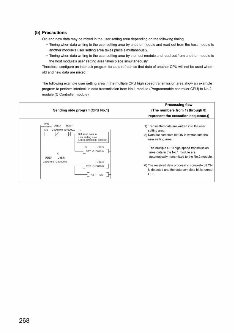
268
(b) Precautions
Old and new data may be mixed in the user setting area depending on the following timing.
• Timing when data writing to the user setting area by another module and read-out from the host module to
another module's user setting area takes place simultaneously.
• Timing when data writing to the user setting area by the host module and read-out from another module to
the host module's user setting area takes place simultaneously.
Therefore, configure an interlock program for auto refresh so that data of another CPU will not be used when
old and new data are mixed.
The following example user setting area in the multiple CPU high speed transmission area show an example
program to perform interlock in data transmission from No.1 module (Programmable controller CPU) to No.2
module (C Controller module).
Sending side program(CPU No.1)
Processing flow
(The numbers from 1) through 8)
represent the execution sequence.))
1) Transmitted data are written into the user setting area.
2) Data set complete bit ON is written into the user setting area.
The multiple CPU high speed transmission area data in the No.1 module are automatically transmitted to the No.2 module.
6) The received data processing complete bit ON is detected and the data complete bit is turned OFF.
1)
2)
6)
M0
Write command U3E0\ U3E1\
G10010.0 G10000.0
U3E0\ U3E1\
U3E0\
SET G10010.0
U3E0\
RST G10010.0
RST M0
G10010.0 G10000.0
Set send data in
user setting area (U3E0\ G10000 to G10009).

269
CHAPTER 14 FUNCTIONS USED BY MULTIPLE CPU SYSTEM
14
14.1 Data C
omm
unications U
sing CP
U S
hared Mem
ory14.1.4 D
ata comm
unications without using
auto refresh
Receiving side program (CPU No.2)
Processing flow
(The numbers from 1) through 8)
represent the execution sequence.))
3) Transmitted data set complete bit ON is
detected.
4) Received data processing is performed.
5) Received data complete bit ON is written into
the user setting area.
The multiple CPU high speed transmission
area data in the No.2 module are automatically
transmitted to the No.1 module.
7) Transmitted data set complete bit OFF is
detected.
8) Data processing complete bit OFF is written
into the user setting area.

270
(2) In case of C Controller module C Controller module
(a) Processing overview
ProcessingAt bus interface function execution of C
Controller module No.1
At bus interface function execution of C
Controller module No.2
1)
Execution of the bus interface function (QBF_ToBuf)
writes the data to the user setting area in the CPU
shared memory of C Controller module No.1.
–
2) –
Execution of the bus interface function (QBF_ToBuf) writes
the data to the user setting area in the CPU shared memory
of C Controller module No.2.
3) –
Execution of the bus interface function (QBF_FromBuf)
reads out the user setting area data of C Controller module
No.1 onto the user program.
4)
Execution of the bus interface function (QBF_ToBuf)
reads out the user setting area data of C Controller
module No.2 onto the user program.
–
CPU shared memory
Host CPU operation information area
System area
Auto refresh area
Data written by QBF_ToBuf function
of C Controller module No.1
(User setting area)
1)
User program
Execution of QBF_ToBuf function
Execution of QBF_FromBuf function
C Controller module No.1
Host CPU operation information area
System area
Auto refresh area
Data written by QBF_ToBuf function
of C Controller module No.2
(User setting area)
CPU shared memory
User program
Execution of QBF_FromBuf function
Execution of QBF_ToBuf function
2)
C Controller module No.2
3)
4)

271
CHAPTER 14 FUNCTIONS USED BY MULTIPLE CPU SYSTEM
14
14.1 Data C
omm
unications U
sing CP
U S
hared Mem
ory14.1.4 D
ata comm
unications without using
auto refresh
(b) Precautions
Old and new data may be mixed in the data for CPU No. depending on the following timing.
• Timing when data writing to the user setting area by another module and read-out from the host module to
another module's user setting area takes place simultaneously.
• Timing when data writing to the user setting area by the host module and read-out from another module to
the host module's user setting area takes place simultaneously.
Therefore, configure an interlock program for auto refresh so that data of another CPU will not be used when
old and new data are mixed.
The following example user setting area in the multiple CPU high speed transmission area show an example
program to perform interlock in data transmission from No.1 module (C Controller module) to No.2 module (C
Controller module).
Sending side program for CPU No.1
Processing flow
(The numbers from 1) through 9) represent
the execution sequence.))
1) Transmitted data are written into the user setting area.
2) Data set complete bit ON is written into the user setting area.
The multiple CPU high speed transmission area data in the No.1 module are automatically transmitted to the No.2 module.
6) Received data processing complete bit ON is detected.
7) The data set complete bit is turned OFF.
The multiple CPU high speed transmission area data in the No.1 module are automatically transmitted to the No.2 module.
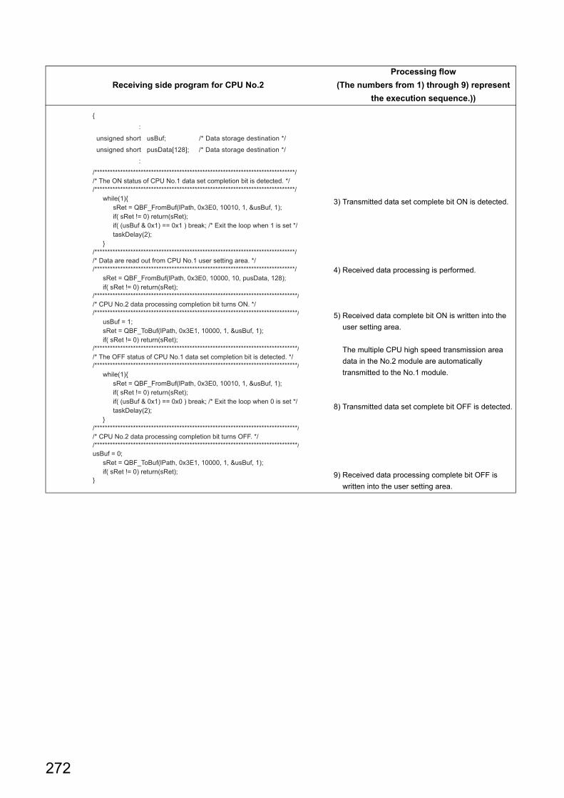
272
Receiving side program for CPU No.2
Processing flow
(The numbers from 1) through 9) represent
the execution sequence.))
3) Transmitted data set complete bit ON is detected.
4) Received data processing is performed.
5) Received data complete bit ON is written into the
user setting area.
The multiple CPU high speed transmission area
data in the No.2 module are automatically
transmitted to the No.1 module.
8) Transmitted data set complete bit OFF is detected.
9) Received data processing complete bit OFF is
written into the user setting area.

273
CHAPTER 14 FUNCTIONS USED BY MULTIPLE CPU SYSTEM
14
14.1 Data C
omm
unications U
sing CP
U S
hared Mem
ory14.1.4 D
ata comm
unications without using
auto refresh
(3) In case of Motion CPU C Controller module
(a) Processing overview
Remark
For instructions of the Motion CPU, refer to the manual for respective Motion CPU.
ProcessingWhen executing Motion SFC program of
Motion CPU
At bus interface function execution of C
Controller module
1)
By the MULTW instruction, the data are written to the
user setting area in the CPU shared memory of the
Motion CPU.
–
2) –
Execution of the bus interface function (QBF_ToBuf) writes
the data to the user setting area in the C Controller
module's CPU shared memory.
3) –
Execution of the bus interface function (QBF_FromBuf
function) reads out the user setting area data of the Motion
CPU onto the user program.
4)
By the MULTR instruction, the user setting area data of
the C Controller module are read out to the specified
device in the Motion CPU.
–
CPU shared memory
Host CPU operation information area
System area
Data written by MULTW instruction (User setting area)
1)
Motion SFC program
Execution of MULTW instruction
Execution of MULTR instruction
Motion CPU
Host CPU operation information area
System area
Auto refresh area
Data written by QBF_ToBuf function (User setting area)
CPU shared memory
User program
Execution of QBF_FromBuf function
Execution of QBF_ToBuf function
2)
C Controller module
3)
4)

274
14.2 Interrupt from Another CPU
An interrupt from another CPU (programmable controller CPU or C Controller module) can restart the user program
that is waiting for an interrupt event by the bus interface function (QBF_WaitEvent).
Described below is the procedure to restart the user program that is waiting for an interrupt event.
1) In the user program, call the bus interface function (QBF_WaitEvent).
2) By 1), the user program is placed into the interrupt event waiting status.
3) In the above 2) status, execute either of the following.
• User program of the other C Controller module (another CPU) (QBF_GINT)
• Sequence program of a programmable controller CPU (another CPU)
(S.GINT or D.GINT instruction)
4) The user program is restarted by 3).
(1) FunctionsThe following shows the functions used for interrupt from another CPU.
Function name Function
QBF_WaitEvent Waits for an interrupt event notified in the event of any interrupt from another CPU.
Q24DHC-V Q24DHC-VG Q24DHC-LS Q26DHC-LS Q12DC-V
Programmable controller CPU (sequence program)
(for S.GINT instruction)
1) QBF_WaitEventfunction executing
3) S.GINT instruction execution
[S.GINT H3E1 KO]
C Controller module
(user program)
User program executing
2) User program interrupt event waiting status
4) User program restarting
1) QBF_WaitEvent function executing
3) QBF_GINTfunction executing
C Controller module
(user program)
User program executing
2) User program interrupt event waiting status
4) User program restarting
C Controller module
(user program)
/*Issue an interrupt*/ret=QBF_GINT( ) ;

275
CHAPTER 14 FUNCTIONS USED BY MULTIPLE CPU SYSTEM
14
14.2 Interru
pt from A
nother C
PU
14.2.1 Interrupt from C
Controller m
odule
14.2.1 Interrupt from C Controller module
The following describes how to interrupt from the C Controller module (another CPU).
(1) Operation timing
(2) FunctionsThe following shows the functions used for interrupt from C Controller module (another CPU)
Remark
The bus interface function (QBF_GINT) may also issue an interrupt to a Motion CPU.
Function name Function
QBF_GINT
Issues an interrupt to another CPU.
When receiving an interrupt from another CPU, a C Controller module resumes the user
program that is waiting for an interrupt event by the QBF_WaitEvent function.
Q24DHC-V Q24DHC-VG Q24DHC-LS Q26DHC-LS Q12DC-V
C Controller module interrupt
routine (interrupt program)
C Controller module user
program
Interrupt issued
User program resumed
Interrupt event in waiting status by user program
QBF_WaitEvent function executed Interrupt event notified *1
Executing an interrupt
routine (interrupt program)
Interrupt routine (interrupt
program) in waiting status
*1: Interrupt event notified after the interrupt routine (interrupt program) ends
Interrupt routine (interrupt program) in waiting status
C Controller module (another
CPU) user program
QBF_GINT function executed

276
14.2.2 Interrupt from Controller CPU
The following describes how to interrupt from the programmable controller CPU.
(1) Operation timing
(2) Dedicated instructionsThe following shows programmable controller CPU dedicated instructions used for interrupt from a programmable
controller CPU (another CPU).
Q24DHC-V Q24DHC-VG Q24DHC-LS Q26DHC-LS Q12DC-V
Sequence program
SM391 (S(P).GINT instruction
execution completed flag)
tEND END END END
S(P).GINT instruction executed
OFF
S(P).GINT instruction executed
S(P).GINT instruction not executed
C Controller module interrupt
routine (interrupt program)
C Controller module user
program
Interrupt issued
ON
ON
User program resumed
OFF
Interrupt event in waiting status by user program
QBF_WaitEvent function executed
Interrupt event notified*1
Interrupt routine (interrupt
program) executed
Interrupt routine (interrupt program) in waiting status
*1: Interrupt event notified after the interrupt routine (interrupt program) ends.
Interrupt routine (interrupt program) in waiting status
S(P). GINT instruction
[Instruction symbol]
SP.GINT
S.GINT
[Execution condition]
SP.GINT (n1) (n2)
S.GINT (n1) (n2)
Command
Command
[Instruction symbol]
DP.GINT
[Execution condition]
DP.GINT (n1) (n2)
DP.GINT (D1) (D2)
Command
Command
D.GINT
(n1) (n2)
D.GINT (n1) (n2)
D.GINT (D1) (D2)(n1) (n2)
Command
Command

277
CHAPTER 14 FUNCTIONS USED BY MULTIPLE CPU SYSTEM
14
14.2 Interru
pt from A
nother C
PU
14.2.2 Interrupt from C
ontroller CP
U
: Applicable : Partly applicable : Not applicable
Remark
For details of D(P).GINT instruction used for interrupt from a Motion CPU, refer to the following.SV13/22 Programming Manual (Motion SFC) [type Q173D(S)/Q172D(S)]
(a) Setting data
(b) Usable devices
Setting
data
Available devices
Internal device
(System, user)
File register
R, ZR
Link direct device
J¥
Intelligent
function module
U¥G
Index
register, Zn
Constant
K, HOthers
Bit Word Bit Word Bit Word
(n1) – *1 – – –
(n2) – *2 – – –
(D1)*3 *4 – *4 – – – –
(D2)*3 – *4 – *4 – – –
*1 : Index modification is allowed for basic model QCPUs, high performance model QCPUs and universal model QCPUs.*2 : Index modification is allowed for basic model QCPUs and universal model QCPUs.*3 : Only when both of (D1) and (D2) are omitted, they can be actually omitted.*4 : Local devices cannot be used.
Setting
dataSetting Data type
(n1)
Start I/O No. of target CPU 10H
Actually specified values are as follows:
CPU No.1: 3E0H, CPU No.2: 3E1H, CPU No.3: 3E2H, CPU No.4: 3E3H
BIN 16 bits
(n2) Interrupt pointer No. (0 to 15) BIN 16 bits
(D1)*1
Completion device
(D1+0): Device that is turned ON for one scan upon completion of the instruction
processing
(D1+1): Device that is turned ON for one scan upon failure of the instruction processing
(When failed, D1+0 is also turned ON.)
Bit
(D2)*1 Device where the completion status data is stored. Word
*1 : Only when both of (D1) and (D2) are omitted, they can be actually omitted.
Internal deviceFile register Constant
Bit Word*1
M, L, B D, W, @ R, ZR K, H
*1 : Number of bit device digits can be specified for word data.
It can be specified with
For example, 16 points from M0 to M15 are specified with
Digits Bit device start No.
K4M0

278
(c) Control details
On the rise (OFF to ON) of the S(P).GINT or D(P).GINT execution command in the sequence program, an
interrupt is issued to the C Controller module.
When receiving an interrupt from a programmable controller CPU, a C Controller module resumes the user
program that is waiting for an interrupt event by the QBF_WaitEvent function.
Whether or not the programmable controller CPU successfully transmitted instruction command to the C Controller module should be determined based on the following.
● If instruction command is successfully transmittedThe SM391 (S(P).GINT or D(P).GINT execution completed) flag of the programmable controller CPU is set to ON.
● If instruction command is not successfully transmittedThe SM391 (S(P).GINT or D(P).GINT execution completed) flag of the programmable controller CPU is set to OFF.
(d) Error details
In any of the following cases, an operation error occurs, the error flag (SM0) of the programmable controller
CPU is set to ON, and an error code is stored in SD0.
(e) Program example
The following is the sequence program that issues an interrupt to C Controller module No.2.
Error code*1 Cause Action
2110CPU No. of a reserved ("Empty" setting) or non-mounted CPU is specified for
the target CPU start I/O No. 10H (n1).
Check and correct
the sequence
program.
2114 The originating CPU is specified for the target CPU start I/O No. 10H (n1).
2117A module that does not support the S(P).GINT and D(P).GINT instructions is
specified for the target CPU start I/O No. 10H (n1).
4100Any of 0 to 3DFH, or 3E4H is specified for the target CPU start I/O No. 10H
(n1).
*1 : 0000H if the processing is normally completed.
S.GINT H3E1 K0
Program for normal completion
Program that will cause interrupt again
SM391
SM391
X0

279
CHAPTER 14 FUNCTIONS USED BY MULTIPLE CPU SYSTEM
14
14.3 Mu
ltiple C
PU
Syn
chronous Interrupt Fu
nction14.2.3 P
recautions
14.2.3 Precautions
(1) When an interrupt event has already been notified at execution of the
QBF_WaitEvent functionWhen an interrupt event has already been notified from a programmable controller CPU or C Controller module
(another CPU) at the time of the QBF_WaitEvent function execution, the user program is restored from the
interrupt event waiting status at the same time with the QBF_WaitEvent function execution.
If multiple interrupt events have been notified with the same interrupt event No. at the time of the QBF_WaitEvent
execution, the user program processes them as a single interrupt event notification.
(2) When using the event notification function in multiple user programsDo not set the same CPU No. and the same interrupt event No. on more than one program.
If such settings are specified, which user program will receive the interrupt event will be uncertain.
14.3 Multiple CPU Synchronous Interrupt Function
The multiple CPU synchronous interrupt is an interrupt issued in the same timing as the Motion CPU*1 control cycle
(multiple CPU high speed transmission cycle = 0.88ms).
Creates a user program to be synchronized with the Motion CPU*1 and executed by waiting for a multiple CPU
synchronous interrupt event by the bus interface function (QBF_WaitMultiCPUSyncEvent function).
*1 : Supported Motion CPUs are shown in the following table. • Q172DCPU(-S1) • Q173DCPU(-S1) • Q172DSCPU • Q173DSCPU
(1) FunctionsThe following shows the function(s) used for multiple CPU synchronous interrupt.
As the multiple CPU synchronous interrupt is a event notification function, it is not guaranteed that the user program with QBF_WaitMultiCPUSyncEvent function operates in 0.88ms cycle.Check the number of receptions from the number of interrupts acquired by the QBF_WaitMultiCPUSyncEvent function.
Function name Function
QBF_WaitMultiCPUSyncEvent Waits for a multiple CPU synchronous interrupt event notification.
Q24DHC-V Q24DHC-VG Q24DHC-LS Q26DHC-LS Q12DC-V
Q24DHC-V Q24DHC-VG Q24DHC-LS Q26DHC-LS Q12DC-V

280
14.4 Issuing an Interrupt to Another CPU
This function allows the C Controller module to issue an interrupt to another CPU (Motion CPU or C Controller module)
from its own user program.
No interrupt can be issued to a programmable controller CPU.
(1) Interrupt to Motion CPUWhen an interrupt is issued to a Motion CPU, the Motion CPU starts an interrupt program.
(2) Interrupt to C Controller module (another CPU)When an interrupt is issued to a C Controller module (another CPU), Resumes the user program that is waiting
for an interrupt event by the Bus interface functions (QBF_WaitEvent function.)
(3) FunctionsThe following shows the function(s) used for multiple CPU synchronous interrupt.
Function name Function
QBF_GINT Issues an interrupt to another CPU.
Q24DHC-V Q24DHC-VG Q24DHC-LS Q26DHC-LS Q12DC-V
C Controller module Motion CPU
Interrupt program/*Issues an interrupt*/
ret=QBF_GINT() ;
C Controller module C Controller module (Another CPU)
/*Issues an interrupt*/
ret=QBF_GINT() ;
User program
(Re-execute)
(Interrupt event in
waiting status)

281
CHAPTER 14 FUNCTIONS USED BY MULTIPLE CPU SYSTEM
14
14.5 Function to A
ccess to Devices o
f Othe
r CP
U M
odules
14.5.1 Access to program
ma
ble controller CP
U and C
Controlle
r module
14.5 Function to Access to Devices of Other CPU Modules
This function allows for access to device(s) of another CPU (programmable controller CPU, C Controller module or
Motion CPU) from the C Controller module.
14.5.1 Access to programmable controller CPU and C Controller module
Use a MELSEC data link function when creating a user program for the C Controller module.
(1) FunctionsThe following shows the functions used for access to programmable controller CPU, and C Controller module
(another CPU).
Function name Function
mdSendEx Batch writes devices.
mdReceiveEx Batch reads devices.
mdRandWEx Writes devices randomly
mdRandREx Reads devices randomly.
mdDevSetEx Sets the bit device.
mdDevRstEx Resets the bit device.
Q24DHC-V Q24DHC-VG Q24DHC-LS Q26DHC-LS Q12DC-V
Q24DHC-V Q24DHC-VG Q24DHC-LS Q26DHC-LS Q12DC-V
Programmable controller CPU
Device date
C controller module
/*Read programmable controller CPU device data*/
ret=mdReceiveEx() ;
/*Write data into programmable controller CPU device(s)*/
ret=mdSendEx() ;
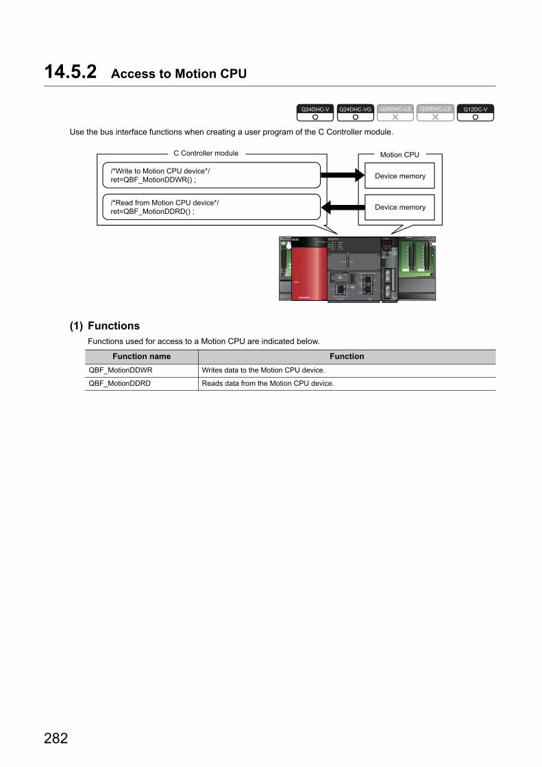
282
14.5.2 Access to Motion CPU
Use the bus interface functions when creating a user program of the C Controller module.
(1) FunctionsFunctions used for access to a Motion CPU are indicated below.
Function name Function
QBF_MotionDDWR Writes data to the Motion CPU device.
QBF_MotionDDRD Reads data from the Motion CPU device.
Q24DHC-V Q24DHC-VG Q24DHC-LS Q26DHC-LS Q12DC-V
Motion CPUC Controller module
/*Write to Motion CPU device*/
ret=QBF_MotionDDWR() ;
/*Read from Motion CPU device*/
ret=QBF_MotionDDRD() ;
Device memory
Device memory

283
CHAPTER 14 FUNCTIONS USED BY MULTIPLE CPU SYSTEM
14
14.6 Rem
ote Control F
unction of O
ther CP
U M
odules
14.6 Remote Control Function of Other CPU Modules
This function allows the C Controller module to control execution status of a programmable controller CPU and a C
Controller module.
Use the bus interface functions when creating a user program of the C Controller module.
(1) FunctionsThe following shows the functions used for the remote control function of the programmable controller CPU, and
C Controller module.
Function name Function
QBF_ControlExPerforms remote RUN/STOP/PAUSE operations of the programmable controller CPU
module and C Controller module.
Q24DHC-V Q24DHC-VG Q24DHC-LS Q26DHC-LS Q12DC-V
C Controller moduleProgrammable controller CPU
RUN
STOP
PAUSE
Execution status
/*Control execution status of the programmable controller CPU*/
ret=QBF_ControlEx() ;

284
14.7 Sequence Program Control Function
This function allows the C Controller module to control (change) the sequence program execution type of a
programmable controller CPU.
Use a bus interface function when creating a user program for the C Controller module.
(1) FunctionsFunctions used for the sequence program control function are indicated below.
When using this function, use a high performance model QCPU as a programmable controller CPU.
Function name Function
QBF_ControlProgram Controls the execute type of the programmable controller CPU module.
Q24DHC-V Q24DHC-VG Q24DHC-LS Q26DHC-LS Q12DC-V
C Controller moduleProgrammable controller CPU
Sequence program
Scan execution type
program
Standby type
program
Low speed execution
type program
Fixed scan execution
type program
/*Controls the execution type of the sequence program*/
ret=QBF_ControlProgram() ;

285
CHAPTER 14 FUNCTIONS USED BY MULTIPLE CPU SYSTEM
14
14.8 Mo
tion CP
U C
ontrol Instruction
14.8 Motion CPU Control Instruction
Control instructions can be given to a Motion CPU from a user program of the C Controller module.
Use bus interface functions when creating a user program of the C Controller module.
(1) FunctionsFunctions used for control instruction to a Motion CPU are indicated below.
*1 : Use the product with a serial number whose first five digits are "16012" or higher.
Function name Function
CPU module
Q24DHCQ12DC-V
-V -VG
QBF_MotionSFCS Requests to start the Motion SFC program.
QBF_MotionSVST Requests to start the specified servo program.
QBF_MotionCHGA Requests to change the current value of the specified axis.
QBF_MotionCHGAS Requests to change the current value of the specified axis. *1 *1
QBF_MotionCHGV Requests to change the speed of the specified axis.
QBF_MotionCHGVS Requests to change the speed of the specified axis. *1 *1
QBF_MotionCHGT Requests to change the torque limit value of the specified axis.
QBF_MotionCHGT2 Requests to change the torque limit value of the specified axis.
Q24DHC-V Q24DHC-VG Q24DHC-LS Q26DHC-LS Q12DC-V
C Controller module Motion CPU
SFC program/*Motion SFC program start request*/
ret=QBF_MotionSFCS() ;
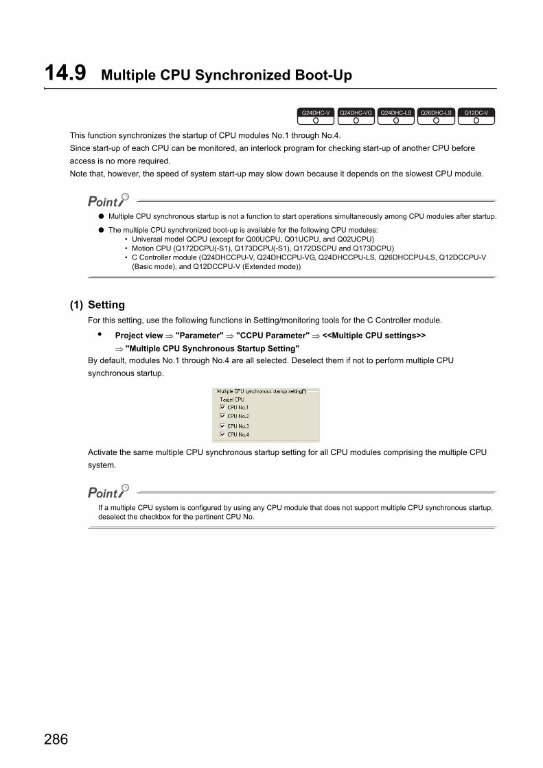
286
14.9 Multiple CPU Synchronized Boot-Up
This function synchronizes the startup of CPU modules No.1 through No.4.
Since start-up of each CPU can be monitored, an interlock program for checking start-up of another CPU before
access is no more required.
Note that, however, the speed of system start-up may slow down because it depends on the slowest CPU module.
● Multiple CPU synchronous startup is not a function to start operations simultaneously among CPU modules after startup.
● The multiple CPU synchronized boot-up is available for the following CPU modules: • Universal model QCPU (except for Q00UCPU, Q01UCPU, and Q02UCPU) • Motion CPU (Q172DCPU(-S1), Q173DCPU(-S1), Q172DSCPU and Q173DCPU) • C Controller module (Q24DHCCPU-V, Q24DHCCPU-VG, Q24DHCCPU-LS, Q26DHCCPU-LS, Q12DCCPU-V
(Basic mode), and Q12DCCPU-V (Extended mode))
(1) SettingFor this setting, use the following functions in Setting/monitoring tools for the C Controller module.
• Project view "Parameter" "CCPU Parameter" <<Multiple CPU settings>>
"Multiple CPU Synchronous Startup Setting"
By default, modules No.1 through No.4 are all selected. Deselect them if not to perform multiple CPU
synchronous startup.
Activate the same multiple CPU synchronous startup setting for all CPU modules comprising the multiple CPU
system.
If a multiple CPU system is configured by using any CPU module that does not support multiple CPU synchronous startup, deselect the checkbox for the pertinent CPU No.
Q24DHC-V Q24DHC-VG Q24DHC-LS Q26DHC-LS Q12DC-V

287
PART 4 SOFTWARE DESIGN AND PROGRAMMING
This section describes items related to software design and creation of user programs.
CHAPTER 15 PARAMETER . . . . . . . . . . . . . . . . . . . . . . . . . . . . . . . . . . . . . . . . . . . . . . 288
CHAPTER 16 I/O NUMBER ASSIGNMENT . . . . . . . . . . . . . . . . . . . . . . . . . . . . . . . . . . 298
CHAPTER 17 EXECUTION ORDER AND OPERATION PROCESSING OF C
CONTROLLER MODULE . . . . . . . . . . . . . . . . . . . . . . . . . . . . . . . . . . . . . . . . . 304
CHAPTER 18 MEMORIES AND FILES . . . . . . . . . . . . . . . . . . . . . . . . . . . . . . . . . . . . . 309
CHAPTER 19 PROGRAMMING . . . . . . . . . . . . . . . . . . . . . . . . . . . . . . . . . . . . . . . . . . . 336
CHAPTER 20 PROGRAMMING OF C CONTROLLER MODULE DEDICATED FUNCTION. . . . 353
CHAPTER 21 PROGRAMMING USING BUS INTERFACE FUNCTIONS . . . . . . . . . . . 356
CHAPTER 22 PROGRAMMING USING MELSEC DATA LINK FUNCTIONS . . . . . . . . 362

288
CHAPTER 15PARAMETER
This chapter describes the parameters required to be set for configuring a C controller module.
(1) Parameter typesThe following parameters are provided
• CCPU parameters (Page 289, Section 15.1.1)
These parameters are set when a C controller module is used.
• Network parameters (Page 291, Section 15.1.2)
These parameters are set when a network module is used.
(2) Parameter setting methodUse Setting/monitoring tools for the C Controller module to set parameters.
For operation methods of the setting/monitoring tools for the C Controller module, refer to the following.
Setting/Monitoring Tools for the C Controller Module Version 4 Operating Manual
Remark
Setting/monitoring tools for the C Controller module can set the common function parameters from the equivalent interface to that of GX Works2. When referring to the manuals for the programmable controller CPU and modules used for related functions and parameter setting methods, replace the following parameters as shown below.
• CCPU parameter PC parameter • Network parameter CC IE/MELSECNET Ethernet/CC IE/MELSECNET
(3) Parameter setting proceduresDescribed below are procedures to create parameters and write into C Controller modules.
1. Start up the Setting/monitoring tools for the C Controller module.
2. Create a project.
3. Set parameters.
4. Connect the a personal computer to the C Controller module. (Page 125, Section 8.7)
5. Write the parameters.
[Online] [Write to CCPU]
6. Reset the C Controller system. (Page 71, Section 6.3)
The written parameters are applied.
(4) Error detectionIf any error occurs in the parameter settings, ERR.LED of the C Controller module is lit.
Use the following functions in Setting/monitoring tools for the C Controller module to check and correct the error
factors.
• [Diagnostics] [CCPU diagnostics]
• [Diagnostics] [Event history]
Double-clicking an event item in the event history display field shows the "Detailed event information" screen. The
"Detailed event information" shows the Parameter No. (Page 296, Section 15.3).

289
CHAPTER 15 PARAMETER
15
15.1 Param
eter List15.1.1 C
CP
U param
eter settings
15.1 Parameter List
This section shows the list of parameter setting items.
For each setting screen and setting item, refer to the following.
Setting/Monitoring Tools for the C Controller Module Version 4 Operating Manual
For Parameter No., refer to the following.
Page 296, Section 15.3
15.1.1 CCPU parameter settings
CCPU parameters are listed below.
Set in: ItemParameter
No.Reference
<<Name settings>>Label 0000H
–Comment 0001H
<<System settings>>
Points Occupied by Empty Slot 1007H Page 299, Section 16.1.2
Remote Reset 1002H Page 163, Section 11.5
Output Mode at STOP to RUN 1003H Page 151, Section 11.1.5
Refresh setting Refresh cycle FD10H Page 170, Section 11.7
Intelligent Function Module Setting
(interrupt event settings)100AH
Manuals for respective intelligent
function modules and interrupt
modulesModule Synchronization 100CH
Restarting user CPU FD05H Page 73, Section 6.4
Standard RAM settings FD03H Page 309, Section 18.1.1
<<RAS settings>>
WDT (Watchdog Timer)
Setting
System WDT Setting 3000HPage 158, Section 11.3
User WDT Setting FD06H
Error Check
Carry Out Battery Check
3001H
Page 154, Section 11.2
Carry Out Fuse Blown
Check
Verify Module
Diagnose Redundant
Power
Supply System
Operating Mode When
There is an Error
Fuse Blown3002H
Module Verify Error
Event history
registration settings
Do not register system
(information) event details.FD00H Page 187, Section 11.9
<<Device settings>> Device Points 2000HPage 169, Section 11.6
Page 212, Section 13.2.1

290
<<I/O assignment settings>>
I/O Assignment 0400H Page 301, Section 16.2
Base Setting 0401H Page 303, Section 16.3
Switch Setting 0409H Page 147, Section 11.1.2
Detailed Setting
Error Time Output Mode 0403HPage 152, Section 11.1.6
Page 154, Section 11.2
H/W error time CPU
operation mode4004H
Page 153, Section 11.1.7
Page 154, Section 11.2
I/O Response Time 0405H Page 150, Section 11.1.4
Control CPU 0406HQCPU User's Manual
(Multiple CPU System)
<<Multiple CPU settings>>
Number of CPUs 0E00H –
Host CPU number E00CHQCPU User's Manual
(Multiple CPU System)
Operation mode 0E01H Page 154, Section 11.2
Multiple CPU synchronous startup setting E00BH Page 286, Section 14.9
Online module change E006H (Page 96, Section 7.5.1)
I/O Sharing When Using Multiple CPUs 0E04HQCPU User's Manual
(Multiple CPU System)
Multiple CPU High Speed Transmission Area Setting E008H Page 261, Section 14.1.3
Communication Area Setting (Refresh Setting) E003H Page 256, Section 14.1.2
<<User Ethernet port (CH1
and CH2) settings>>
IP Address Setting CH1FD02H Page 192, Section 12.1
IP Address Setting CH2
<<System Ethernet port (S
CH1) settings>>
IP Address Setting S CH1
1016H
Page 200, Section 12.2
Time Setting Page 202, Section 12.2.1
<<Built-in Ethernet port (CH1
and CH2) settings>>
IP Address Setting CH1Page 192, Section 12.1
Page 200, Section 12.2
Time Setting Page 202, Section 12.2.1
IP Address Setting CH2 FD09HPage 192, Section 12.1
Page 200, Section 12.2
<<MELSEC data link
function settings>>
Q series bus interface (Channel No.12) FDD0H
Function Help
(Setting/monitoring
tools for the C Controller module)
MELSECNET/H (Channel No. 51 to 54) FDD2H
CC-Link (Channel No.81 to 88) FDD1H
CC-Link IE Controller Network
(Channel No. 151 to 154)FDD3H
CC-Link IE Filed Network (Channel No. 181 to 188) FDD4H
<<Account settings>> Account settings FD01H Page 177, Section 11.8.1
<<Data refresh settings>>Data refresh settings FD11H
Page 171, Section 11.7.1Interrupt Settings FD12H
<<Security settings>>
Service setting FD07H Page 185, Section 11.8.4
Password setting FD08H
Setting/Monitoring Tools for the
C Controller Module
Version 4 Operating Manual
Set in: ItemParameter
No.Reference

291
CHAPTER 15 PARAMETER
15
15.1 Param
eter List15.1.2 N
etwork param
eter settings
15.1.2 Network parameter settings
Network parameters are listed below.
(1) CC-Link IE Controller Network settingNetwork parameters for the CC-Link IE controller are listed below.
(2) MELSECNET/H settingsNetwork parameters for MELSECNET/H and MELSECNET/10 are listed below.
Set in: Item Parameter No. Reference
CC IE/MELSECNET
(When the CC-Link
IE Controller Network
station is
selected by network type)
Network Type A000H
MELSEC-Q CC-Link IE Controller
Network Reference Manual
Start I/O No. ANM0H
Channel No. FDD3H
Network No. ANM0H
Total Stations ANM0H
Group No. 0A**H
Station No. ANM0H
Mode ANM0H
Network Range AssignmentANM2H
ANM3H
Refresh Parameters ANM1HPage 227, Section 13.4.1 (2)(a)
Page 249, Section 13.5.3
Target Settings FDD3H
MELSEC-Q CC-Link IE Controller
Network Reference ManualTransient transmission size FDD3H
Routing Parameters 5003H
Set in: Item Parameter No. Reference
CC IE/MELSECNET
(When the
MELSECNET/H, and
MELSECNET/10
mode station
is selected by network
type)
Network Type 5000H
Q Corresponding MELSECNET/H Network
System Reference Manual
(PLC to PLC network)
Start I/O No. 5NM0H
Channel No. FDD2H
Network No. 5NM0H
Total Stations 5NM0H
Group No. 05**H
Mode 5NM0H
Network Range Assignment 5NM2H
Refresh Parameters 5NM1HPage 227, Section 13.4.1 (2)(a)
Page 249, Section 13.5.3
Return as control station/
Return as normal station5NM2H
Q Corresponding MELSECNET/H Network
System Reference Manual
(PLC to PLC network)
Target Settings FDD2H
Transient transmission size FDD2H
Routing Parameters 5003H

292
(3) CC-Link IE Field Network settingsNetwork parameters for the CC-Link IE Field Network are listed below.
(4) CC-Link settingsCC-Link IE network parameters are listed below.
Set in: Item Parameter No. Reference
CC IE/MELSECNET
(When the CC-Link
IE Field Network station is
selected by network type)
Network Type A080H
MELSEC-Q CC-Link IE Field Network
Master/Local Module User's Manual
Start I/O No. ANM0H
Channel No. FDD4H
Network No. ANM0H
Total Stations ANM0H
Station No. 0A**H
Mode 0A**H
Network
Configuration
Settings
Station No.
ANM2H
Station Type
RX/RY Setting
RWw/RWr
Setting
Reserved/Error
Invalid Station
Supplementary
setting
Alias
ANM3HComment
Network Operation Settings
Refresh Parameters ANM1HPage 234, Section 13.4.3 (2)(a)
Page 249, Section 13.5.3
Target Settings FDD4H
MMELSEC-Q CC-Link IE Field Network
Master/Local Module User's ManualTransient transmission size FDD4H
Routing Parameters 5003H
Set in: Item Parameter No. Reference
CC-Link
Number of Modules C000H
MELSEC-Q CC-Link System Master/
Local Module User's Manual
Start I/O No. CNM2H
Channel No. FDD1H
Operation Setting CNM2H
Type C000H
Mode CNM2H
All connect count CNM2H
Retry Count CNM2H
Auto return station count CNM2H
Standby Master Station No. CNM2H
CPU Down Select CNM2H
Delay information setting CNM2H
Station information settings CNM2H
Target Settings FDD1H

293
CHAPTER 15 PARAMETER
15
15.1 Param
eter List15.1.2 N
etwork param
eter settings
Meaning of "mn", "**", "M", and "N" in parameters is indicated below.
Network types are indicated in the following table.
mn : Start I/O No. divided by 16
** : Any given value
N : The module number
M : Network type
CC-Link IE / MELSECNET setting
M Network type
1
CC-Link IE Control (Control station), CC-Link IE Control Extended mode (Control station),
MNET/10 mode (Control station),
MNET/H mode (Control station), MNET/H Extended mode (Control station)
2
CC-Link IE Control (Normal station), CC-Link IE Control Extended mode (Normal station),
MNET/10 mode (Normal station),
MNET/H mode (Normal station), MNET/H Extended mode (Normal station)
8 CC-Link IE Field (Master station)
9 CC-Link IE Field (Local station)
CC-Link setting
M Network type
0 Master station
1 Local station

294
15.2 Multiple CPU System Parameter Settings
CCPU parameter (PLC Parameter) settings, with some exceptions, must be the same across all CPU modules used in
the multiple CPU system.
For the procedure to import multiple CPU parameters set in another project, refer to the following.
Page 295, Section 15.2.2
When parameters have been changed, make the same settings for all CPUs in the multiple CPU system, then reset
CPU No.1 or reapply power to the multiple CPU system (power OFF to ON).
15.2.1 Parameters required for multiple CPU system
Necessity of parameter item settings required for a multiple CPU system and necessity of the same setting are
described below.
Parameters not indicated below can be set in the multiple CPU module and each CPU module individually as in the
single CPU system.
Set in: ItemNecessity of
setup*1
Necessity of
same setting*2
<<System settings>> Points Occupied By Empty Slot –
<<I/O assignment
settings>>
I/O Assignment
Type –
Points –
Start X/Y –
Base Setting Slots –
Detailed Setting Control CPU
<<Multiple CPU
settings>>
Number of CPUs
Operation Mode
I/O Sharing When Using Multiple
CPUs
All CPUs can read all inputs
All CPUs can read all outputs
Communication Area Setting (Refresh
Setting)Send range for each CPU
Online Module Change
Multiple CPU High Speed
Transmission Area SettingCPU specific send range
Host Station –
*1 : Necessity of setting: Required for multiple CPU systems. (Not operable without the setting): Can be set if necessary for the multiple CPU system.–: Set in the same way as single CPU system setting.
*2 : Same setting: Must be the same for all the CPU modules in the multiple CPU system.: Items to have the same settings among CPU modules that can be set for a multiple CPU system. (These items may not be valid in some CPU modules)–: Can be set individually for each CPU module of the multiple CPU system.

295
CHAPTER 15 PARAMETER
15
15.2 Mu
ltiple C
PU
System
Param
eter Settings
15.2.2 Multiple C
PU
parameter im
porting
15.2.2 Multiple CPU parameter importing
The following describes the procedure to utilize multiple CPU parameters set in another project.
For each setting screen and setting item, refer to the following.
Setting/Monitoring Tools for the C Controller Module Version 4 Operating Manual
(1) Operating procedureThe following is the procedure to import multiple CPU parameters set in another project.
1. Start up the Setting/monitoring tools for the C Controller module.
2. Create a project.
[Project] [New]
3. Select a source project and read out I/O assignment and multiple CPU setting data.
Project view "Parameter" "CCPU Parameter"
<<I/O assignment settings>> / <<Multiple CPU settings>> "Import Multiple CPU Parameter"
4. Use the same setting for Points Occupied by Empty Slot in all CPU modules.
Project view "Parameter" "CCPU Parameter" <<System settings>>
"Points Occupied by Empty Slot"
5. Acknowledge details of <<I/O assignment settings>>.
Project view "Parameter" "CCPU Parameter" <<I/O assignment settings>>
Set the individual items that can be set in each CPU module for the multiple CPU system, as necessary.
Check that items with * in the setting screen are the same across all CPU modules.
6. Acknowledge details of <<Multiple CPU settings>>.
Project view "Parameter" "CCPU Parameter" <<Multiple CPU settings>>
Set the individual items that can be set in each CPU module for the multiple CPU system, as necessary.
Check that items with * in the setting screen are the same across all CPU modules.
7. Set parameters for other than multiple CPU system.
8. Save a project.
[Project] [Save]
9. Connect the PC to the C Controller module. (Page 125, Section 8.7)
10.Write the parameters.
[Online] [Write to CCPU]
11. Reset the C Controller system. (Page 71, Section 6.3)
The written parameters are applied.

296
15.3 Parameter Number
A parameter number is displayed on the “Detailed event information” screen of Setting/monitoring tools for the C
Controller module when an error occurs in parameter setting. Parameters numbers are listed below.
For various settings, refer to the following.
• <<Item>> Page 289, Section 15.1.1
• CC IE Control Page 291, Section 15.1.2 (1)
• MNET/H, MNET/10 Page 291, Section 15.1.2 (2)
• CC IE Field Page 292, Section 15.1.2 (3)
• CC-Link Page 292, Section 15.1.2 (4)
No. Item Set in: No. Item Set in:
0000H Label<<Name settings>>
5NM2H
Network range assignment
MNET/H, MNET/100001H Comment Return as control station/
Return as normal station1002H Remote reset
<<System settings>>
1003H Output mode at STOP to RUN
0A**H
Group No. CC IE Control
1007H Points occupied by empty slot Station numberCC IE Field
100AHIntelligent function module
settings (Interrupt event settings)
Mode
A000H Network Type CC IE Control
100CH Module synchronization A080H Network Type CC IE Field
1016H
IP address setting S CH1 <<System Ethernet
Port (S CH1)
Setting>>
ANM0H
Start I/O No.
CC IE Control
CC IE FieldTime setting Network No.
IP address setting S CH1 <<Built-in Ethernet
Port (CH1 and CH2)
Settings>>
Network range assignment
Time setting Station numberCC IE Control
2000H Number of device points <<Device Setting>> Mode
3000H System WDT setting
<<RAS Setting>>
ANM1H Refresh parametersCC IE Control
CC IE Field
3001H Error check ANM2H
Network range assignment CC IE Control3002H
Operation mode at the time of
errorANM3H
0400H I/O assignment
<<I/O Assignment>>
ANM2HNetwork configuration
settings
CC IE Field0401H Base setting
ANM3H
Network configuration
settings
0403H Error time output mode Network operation settings
4004HH/W error time CPU operation
mode C000HNumber of modules
CC-Link
0405H I/O response time Type
0406H Control CPU
CNM2H
Start I/O No.
0409H Switch settings Operation setting
05**H Group No.
MNET/H, MNET/10
Mode
5000H Network Type All connect count
5003H Routing parameter Retry count
5NM0H
Start I/O No. Auto return station count
Network No. Standby master station No.
Total stations CPU Down Select
Mode Delay information setting
5NM1H Refresh parameters Station information settings

297
CHAPTER 15 PARAMETER
15
15.3 Param
eter Num
ber
Meaning of "mn", "**", "M", and "N" in parameters is indicated below.
Network types are indicated in the following table.
No. Item Set in: No. Item Set in:
0E00H Number of CPU
<<Multiple CPU
Setting>>
FDD0HQ series bus interface
(Channel No.12)
<<MELSEC data link
function settings>>0E01H Operation mode
E003H Normal area setting
FDD1H
CC-Link
(Channel No.81 to 88)
<<MELSEC data link
function settings>>0E04HI/O sharing when using
Multiple CPUs
E006H Online module change Channel No.CC-Link
E008HMultiple CPU high speed
transmission area setting
Target Settings
FDD2H
MELSECNET/H
(Channel No. 51 to 54)
<<MELSEC data link
function settings>>
E00BH
Multiple CPU
synchronous startup
setting
Channel No.
MNET/H, MNET/10Target Settings
E00CH Host CPU number Transient transmission size
FD00HEvent history registration
settings<<RAS Setting>>
FDD3H
CC-Link IE Controller
Network
(Channel No. 151 to 154)
<<MELSEC data link
function settings>>FD01H Account settings <<Account settings>>
FD02H
IP address setting CH1 <<User Ethernet
port (CH1 and CH2)
settings>>IP address setting CH2 Channel No.
CC IE ControlFD03H Standard RAM settings<<System settings>>
Target Settings
FD05H Restart user CPU Transient transmission size
FD06H User WDT setting <<RAS Setting>>
FDD4H
CC-Link IE Filed Network
(Channel No. 181 to 188)
<<MELSEC data link
function settings>>FD07H Service setting
<<Security settings>>FD08H Password setting
FD09H IP address setting CH2
<<Built-in Ethernet
Port (CH1 and CH2)
Settings>>
Channel No.
CC IE Field
FD10H Refresh setting <<System settings>> Target Settings
FD11H Data refresh settings <<Data refresh
settings>>
Transient transmission size
FD12H Interrupt Settings
mn : Start I/O No. divided by 10H
** : Any given value
N : The module number
M : Network type
CC-Link IE / MELSECNET setting
M Network type
1
CC-Link IE Control (Control station), CC-Link IE Control Extended mode (Control station),
MNET/10 mode (Control station),
MNET/H mode (Control station), MNET/H Extended mode (Control station)
2
CC-Link IE Control (Normal station), CC-Link IE Control Extended mode (Normal station),
MNET/10 mode (Normal station),
MNET/H mode (Normal station), MNET/H Extended mode (Normal station)
8 CC-Link IE Field (Master station)
9 CC-Link IE Field (Local station)
CC-Link setting
M Network type
0 Master station
1 Local station

298
CHAPTER 16I/O NUMBER ASSIGNMENT
This chapter describes the assignment of I/O numbers and base units.
(1) Setting methodFor this setting, use the following functions in Setting/monitoring tools for the C Controller module.
• Project view "Parameter" "CCPU Parameter" <<I/O assignment settings>>
For the assignment of I/O numbers, refer to the following.
Page 301, Section 16.2
For the assignment of the base unit, refer to the following.
Page 303, Section 16.3
(2) Checking methodYou may check the I/O numbers of the installed modules from the following functions of Setting/monitoring tools
for the C Controller module.
• [Diagnostics] [System Monitor]
16.1 I/O Number Assignment
The CPU module assigns I/O numbers at power on or reset, according to the I/O assignment setting.
16.1.1 Assignment order
I/O numbers are assigned from the main base units to extension base units, in order.
In each base unit, I/O numbers are assigned in sequence from the left slot to the right.
(1) Main base unit assignment sequenceThe I/O numbers are assigned to the modules from left to right in a sequential order, starting from 00H assigned to
the module on the right of the CPU module.
For the start point of the I/O numbers (00H), refer to the following.
Page 300, Section 16.1.4
(2) Extension base unit assignment sequenceThe leftmost (Slot 0) is assigned a subsequent number of the previous base unit number.
For base number setting of the C Controller module, refer to the following.
Page 88, Section 7.3.2
For details of extension base number setting procedure, refer to the following.
QCPU User's Manual (Hardware Design, Maintenance and Inspection)
When base units are assigned automatically, if an extension stage number is skipped, it will not be reserved as the number for an empty base unit. To reserve an extension stage, perform the base unit setting in the <<I/O Assignment Settings>> of parameter.

299
CHAPTER 16 I/O NUMBER ASSIGNMENT
16
16.1 I/O N
um
ber Assignm
ent16.1.2 I/O
num
ber of each slot
16.1.2 I/O number of each slot
Each slot on the base unit occupies I/O numbers by the number of I/O points of the mounted modules.
The occupied points and start I/O No. of each slot can be set in parameters. For settings, refer to the following.
Page 301, Section 16.2
(1) Number of base unit slotsThe number of assigned I/O numbers is the same as the number of slots set for each base unit. For setting of the
number of base unit slots, refer to the following.
Page 303, Section 16.3
(2) Number of occupied points for empty slotThe number of points specified in parameters are assigned to an empty slot if Auto is set.
(The default is 16 points.)
For this setting, use the following functions in Setting/monitoring tools for the C Controller module.
• Project view "Parameter" "CCPU Parameter" <<System settings>>
"Points Occupied by Empty Slot"
16.1.3 I/O number of each CPU module
In a multiple CPU system configuration, a specific I/O number is assigned to each CPU module for identification.
Each of these I/O number is fixed to the corresponding slot and cannot be changed in the <<I/O assignment setting>>
of parameter.
CPU module position Start I/O number
CPU slot 3E00H
Slot 0 3E10H
Slot 1 3E20H
Slot 2 3E30H

300
16.1.4 Start point of the I/O numbers (00H)
The following describes a start point of the I/O numbers (00H)
(1) Automatic assignmentIn case of automatic assignment, the start point of the I/O number (00H) are determined as described below.
(a) For a single CPU system
Slot 0 of the main base unit is assigned as 00H.
(The immediate right of the C Controller module is Slot 2.)
(b) For a multiple CPU system
The right hand side slot of each CPU module set in parameters in the main base unit is assigned as 00H.
Use the following functions in Setting/monitoring tools for the C Controller module to set the number of CPUs.
• Project view "Parameter" "CCPU Parameter" <<Multiple CPU settings>> "No. of CPU"
(2) To set the immediate right of the Q24DHCCPU-V/-VG/-LS and Q26DHCCPU-LS
as a start pointThe Q24DHCCPU-V/-VG/-LS and Q26DHCCPU-LS takes up 3 slots. 2 of the 3 slots are treated as empty slots.
Therefore, the start point (00H) of the I/O numbers assigned automatically may be the second or third slot of the
Q24DHCCPU-V/-VG/-LS and Q26DHCCPU-LS.
To set the immediate right of the Q24DHCCPU-V/-VG/-LS and Q26DHCCPU-LS (slot to which the I/O modules
and intelligent function modules can be actually inserted) as the I/O number start point (00H), perform either of the
following settings in parameters.
(a) Setting the number of occupied points for empty slot
Use Setting/monitoring tools for the C Controller module to set the number of occupied points for empty slots to
0.
• Project view "Parameter" "CCPU Parameter" <<System settings>>
"Points Occupied by Empty Slot"
(b) To set I/O assignment
Set the type and number of points of 2 right-hand slots of the used slots to "Empty" and "0 Point", respectively.
• Setting example of Q24DHCCPU-V
In case of the multiple CPU system, set the type to "CPU (Empty)".
• Setting example with 2 QCPUs and a Q24DHCCPU-V
Installation example Slot Type Model name Points
CPU slot CPU No.1 Q24DHCCPU-V -
Slot 0 Empty (Slot 2) 0 Point
Slot 1 Empty (Slot 3) 0 Point
Slot 2(Setting not required)
Slot 3
Installation example Slot Type Model name Points
CPU slot CPU No.1 Q06UDHCPU -
Slot 0 CPU No.2 Q06UDHCPU -
Slot 1 CPU No.3 Q24DHCCPU-V -
Slot 2 CPU (Empty) (Slot 2) -
Slot 3 Empty (Slot 3) 0 Point

301
CHAPTER 16 I/O NUMBER ASSIGNMENT
16
16.2 Setting I/O
Num
bers
16.2 Setting I/O Numbers
When changing I/O numbers of each slot, a new start I/O number can be entered for each slot.
For details of setting I/O number, refer to the following.
QnUCPU Users Manual (Function Explanation, Program Fundamentals)
Setting/Monitoring Tools for the C Controller Module Version 4 Operating Manual
For this setting, use the following functions in Setting/monitoring tools for the C Controller module.
• Project view "Parameter" "CCPU Parameter" <<I/O assignment settings>>
"I/O Assignment"
On the I/O Assignment tab, the following items can be set for each slot on the base unit.
• "Points" (I/O points)
• "Start XY" (start I/O number)
• "Type" (module type)
To change the I/O number of the specified slot, setting is allowed only to the number of points.

302
(a) Points
When I/O assignment is set for a slot, the setting has priority over the actual module-mounting status.
The number of points of the mounted module is applied to a slot without any specified number of points.
However, the empty slot is assigned the number of points set in System settings.
● When setting the number of I/O points less than that of mounted I/O modulesThe available number of I/O points for the mounted I/O modules will be reduced. When the number of I/O points is set to 16 points in the I/O Assignment tab of the PLC parameter dialog box for the slot where a 32-point input module is mounted, the second half 16 points of the module becomes unavailable.
● When setting the number of I/O points less than that of mounted intelligent function moduleAn error (error code: 2100, SP.UNIT LAY ERR.) occurs.
● When setting the number of I/O points exceeding that of mounted I/O modulesThe exceeded number of points will not be used in the I/O modules.
● When setting 0 points for empty slotsSetting "Empty" for Type and "0 Point" for Points even occupies one slot. To set slots after the specific slot number unoccupied, set the number of slots in detail mode.
(b) Start XY
When changing I/O numbers of each slot, enter a new start I/O number.
When I/O assignment is set for a slot, the setting has priority over the actual module-mounting status.
To the slot with no start X/Y setting, I/O numbers following those of the configured slot are assigned in order.
For the I/O assignment settings, set the last I/O number to be within the maximum number of I/O points (FFFH).If it exceeds the maximum number of I/O points (FFFH), an error (error code: 2124, SP.UNIT LAY ERR.) occurs.
(c) Type
The type set in the I/O Assignment tab must be the same as that of the mounted module.
Setting a different type may cause incorrect operation. For an intelligent function module, the number of I/O
points must also be the same to the I/O assignment setting.
The following table lists the operations when the mounted module type differs from the one set in the I/O
Assignment tab.
Mounted module I/O assignment setting Result
Input module,
Output module,
I/O combined module
• Intelli.
• Interrupt
Error (error code:2100, SP.UNIT LAY ERR.)
Intelligent function module
• Input
• Hi. Input
• Output
• I/O Mix
Empty slot
• Input
• Hi. Input
• Output
• I/O Mix
• Intelli.
• Interrupt
Empty slot
All modules • Empty
Other combinations -Incorrect operation may be caused, no error occurrence.
Or, error (error code: 3000, PARAMETER ERROR)

303
CHAPTER 16 I/O NUMBER ASSIGNMENT
16
16.3 Base U
nit Assignm
ent Setting
16.3 Base Unit Assignment Setting
The number of slots that can be mounted to the main base units and extension base units can be set for each base
unit regardless of the actual number of slots in the base units used.
For details of base unit assignment, refer to the following.
QnUCPU Users Manual (Function Explanation, Program Fundamentals)
Setting/Monitoring Tools for the C Controller Module Version 4 Operating Manual
For this setting, use the following functions in Setting/monitoring tools for the C Controller module.
• Project view "Parameter" "CCPU Parameter" <<I/O assignment settings>>
"Base Setting"
When "Auto" is selected in the Base Mode, the number of points for the mounted slot becomes valid.
When "Detail" is selected in the Base Mode, the number of slots can be set for each base unit.
● In auto mode, when any extension base unit number is skipped at the setting using the base number setting connector, an empty extension base unit cannot be reserved. To reserve empty extension base units for future extension, select detail mode.
● In detail mode, set the number of slots to all base units used. Failure to do so may result in incorrect I/O assignment setting.

304
CHAPTER 17EXECUTION ORDER AND
OPERATION PROCESSING OF C CONTROLLER MODULE
This chapter describes how the parameters and programs are processed by the C Controller module.
17.1 Execution Order
The C Controller module executes programs in the following order.
Initial processing
Program operation
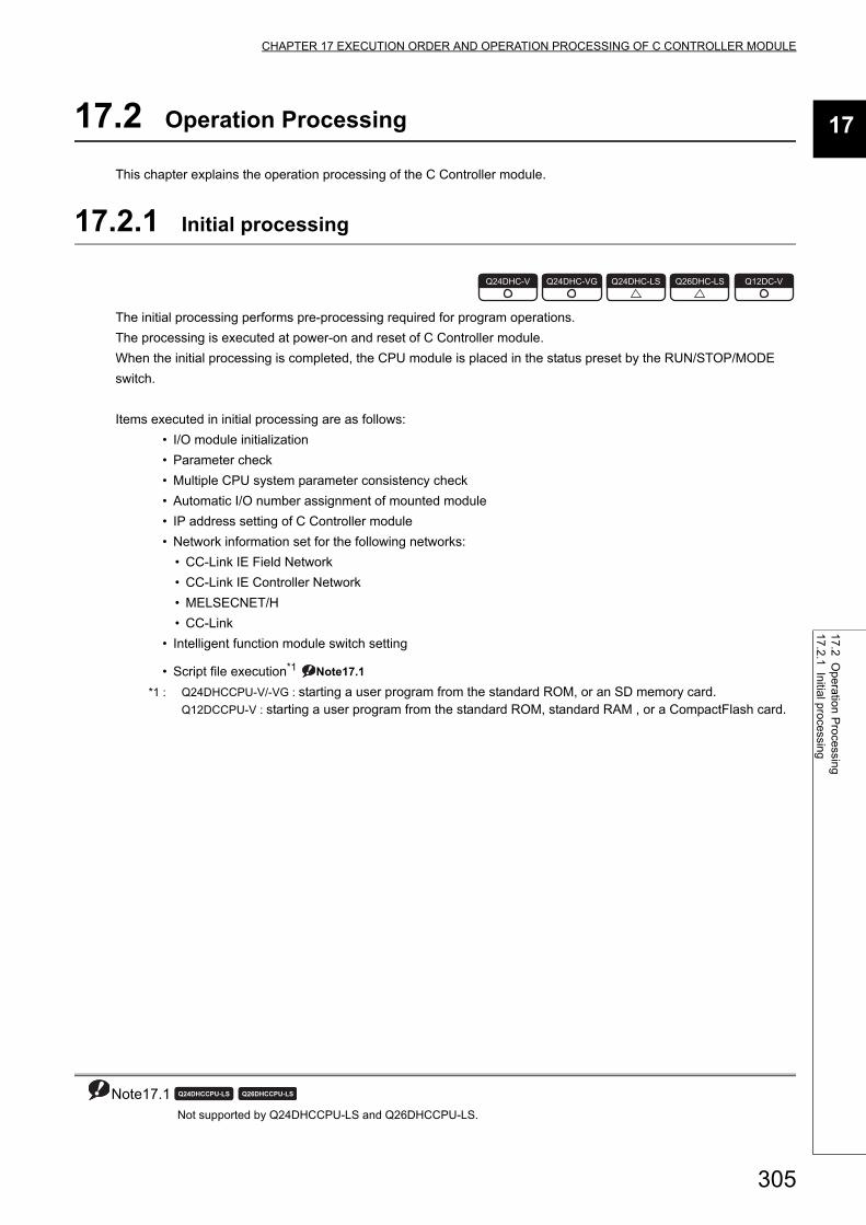
305
CHAPTER 17 EXECUTION ORDER AND OPERATION PROCESSING OF C CONTROLLER MODULE
17
17.2 Operation
Processing
17.2.1 Initial processing
17.2 Operation Processing
This chapter explains the operation processing of the C Controller module.
17.2.1 Initial processing
The initial processing performs pre-processing required for program operations.
The processing is executed at power-on and reset of C Controller module.
When the initial processing is completed, the CPU module is placed in the status preset by the RUN/STOP/MODE
switch.
Items executed in initial processing are as follows:
• I/O module initialization
• Parameter check
• Multiple CPU system parameter consistency check
• Automatic I/O number assignment of mounted module
• IP address setting of C Controller module
• Network information set for the following networks:
• CC-Link IE Field Network
• CC-Link IE Controller Network
• MELSECNET/H
• CC-Link
• Intelligent function module switch setting
• Script file execution*1 Note17.1
*1 : Q24DHCCPU-V/-VG : starting a user program from the standard ROM, or an SD memory card.Q12DCCPU-V : starting a user program from the standard ROM, standard RAM , or a CompactFlash card.
Note17.1 Not supported by Q24DHCCPU-LS and Q26DHCCPU-LS.
Q24DHC-V Q24DHC-VG Q24DHC-LS Q26DHC-LS Q12DC-V
Note17.1
Q24DHCCPU-LS Q26DHCCPU-LS

306
17.2.2 I/O access timing
This section explains the input (X) and output (Y) data transfer timings of the C Controller module.
(1) Input (X) loading timing Note17.2The C Controller module loads input (X) data at one of the following timings.
• When a bus interface function (such as the md_RandREx, QBF_X_In_BitEx) is executed in the user
program
• When data refresh is executed
• When input (X) data are read out from a peripheral device
(When monitoring using the device monitor function of Setting/monitoring tool for the C Controller module.)
(2) Output (Y) writing timing The C Controller module writes output (Y) data at one of the following timings.
• When a bus interface function (such as the md_RandWEx, QBF_Y_Out_BitEx) is executed in the user
program
• When data refresh is executed
• When output (Y) data are written from a peripheral device
(When monitoring using the device monitor function of Setting/monitoring tool for the C Controller module.)
Remark
r
For details of the bus interface functions, refer to the following. Page 356, CHAPTER 21
Note17.2 The bus interface function is not supported by Q24DHCCPU-LS and Q26DHCCPU-LS.
The data refresh function is not supported by Q12DCCPU-V.
Q24DHC-V Q24DHC-VG Q24DHC-LS Q26DHC-LS Q12DC-V
Note17.2
Q24DHCCPU-LS Q26DHCCPU-LS Q12DCCPU-V
Note17.2

307
CHAPTER 17 EXECUTION ORDER AND OPERATION PROCESSING OF C CONTROLLER MODULE
17
17.2 Operation
Processing
17.2.3 RU
N, S
TO
P and
PA
US
E status operation
processing
17.2.3 RUN, STOP and PAUSE status operation processing
The C Controller module has three different operation states: RUN, STOP and PAUSE.
The C Controller module continues the user program operations in either status.
Changing the operation status also changes status of following outputs from the C Controller module:
• Output (Y) to each module
• Buffer memory writing
● Acquisition of module status • To change the program processing according to the operation status of the C Controller module, use a function to
acquire status and perform programming. • Operation status of the C Controller module can be acquired by the C Controller module dedicated function
(CCPU_GetCPUStatus).
(1) Operation processing in the RUN statusIn the RUN status, output (Y) to each module and buffer memory writing are enabled from the user program in the
C Controller module.
(a) Output status when entering the RUN status
Output after transition of the status from STOP to RUN can be selected from the following: (Page 151,
Section 11.1.5)
• Output (Y) status saved in the STOP status (default)
• Result of operations performed after one scan
(2) Operation processing in the STOP statusIn the STOP status, output (Y) to each module and buffer memory writing from the user program of the C
Controller module are disabled.
The C Controller module is also set in the STOP status when a stop error occurs.
(a) Output status when entering the STOP status
When the status changes from STOP to RUN, the C Controller module saves the output status data and clears
all outputs (Y) to OFF.
(3) Operation processing in the PAUSE statusIn the PAUSE status, output (Y) to each module and buffer memory writing from the user program of the C
Controller module are disabled, with the ON/OFF output data (Y) held.
Regardless of which status the C Controller module is in (RUN/STOP/PAUSE), output (Y) operations and writing into the buffer memory are allowed from Setting/monitoring tools for the C Controller module.
Q24DHC-V Q24DHC-VG Q24DHC-LS Q26DHC-LS Q12DC-V
For "-LS", consult with the
partner (operating system vendor).

308
(4) Related functionsThe following indicates the related functions.
(5) Operation procedures Note17.3The operation status can be changed by remote operations from the RUN/STOP/MODE switch or Setting/
monitoring tools for the C Controller module.
17.2.4 Operation processing during momentary power failure
The C Controller module detects a momentary power failure when the input power voltage supplied to the power
supply module falls below the specified range.
When a momentary power failure is detected, either of the following operations is performed.
(1) When momentary power failure time is within the allowable rangeWhen a momentary power failure occurs, the output status is held and the operation stops.
After power is restored, the error information is registered to the event history file. (The initial time only)
(a) After recovering from a momentary power failure
The operation processing is resumed when the module recovers from a momentary power failure.
(b) Confirming the number of detections
The C Controller module counts how many time momentary power failure has been detected and holds the data.
The number of momentary power failure detections can be confirmed by the C Controller module dedicated
function (CCPU_GetPowerStatus) and special register SD53.
(2) When power failure lasts longer than the allowable momentary power failure timeInitial start is required for the C Controller module.
The processing executed at power-on and reset of C Controller module is performed.
Page 305, Section 17.2.1
Function Description Reference
Output (Y) setting for
switching from STOP to
RUN
Selects the status after transition from STOP to RUN from the
following:
• Outputting the output status data before STOP.
• Clearing the output (Y) data.
Page 151, Section 11.1.5
Hardware error time CPU
operating mode setting
Set whether to stop or run the C Controller module when a
hardware error occurs in an intelligent function module.Page 153, Section 11.1.7
Note17.3 The remote operation from a user program is not supported by Q24DHCCPU-LS and Q26DHCCPU-LS.
Operation proceduresOperation status
ReferenceRUN status STOP status PAUSE status
RUN/STOP/MODE switch RUN STOP - Page 70, Section 6.2
User programExecute remote
RUN
Execute remote
STOP
Execute remote
PAUSEPage 163, Section 11.5Setting/monitoring tools for the C
Controller module
Note17.3
Q24DHCCPU-LS Q26DHCCPU-LS
Q24DHC-V Q24DHC-VG Q24DHC-LS Q26DHC-LS Q12DC-V
For "-LS", consult with the
partner (operating system vendor).

309
CHAPTER 18 MEMORIES AND FILES
18
18.1 Me
mories an
d files of Q24D
HC
CP
U-V
18.1.1 Mem
ory type
CHAPTER 18MEMORIES AND FILES
This chapter describes the memories handled by the C Controller module and files that can be stored.
18.1 Memories and files of Q24DHCCPU-V
The following describes the available memories and files that can be stored in Q24DHCCPU-V.
18.1.1 Memory type
The following memories are available.
• System ROM ............................................Page 309, (1) in this section
• Internal ROM ............................................Page 309, (2) in this section
• Standard ROM ..........................................Page 309, (3) in this section
• Work RAM/RAM disk ................................Page 310, (4) in this section
• Battery backup RAM/Standard RAM ........Page 310, (5) in this section
• SD memory card.......................................Page 311, (6) in this section
• USB device ...............................................Page 311, (7) in this section
• CPU shared memory ................................Page 312, (8) in this section
• Data refresh memory ................................Page 312, (9) in this section
(1) System ROMA system ROM is a memory that stores system software and VxWorks image files required for operations of the C
Controller module.
Only read-out from FTP, Telnet and user programs is allowed.
(2) Internal ROMAn internal ROM is a memory that store parameters.
Use the following functions in Setting/monitoring tools for the C Controller module to read/write parameters.
• [Online] [Read from CCPU]/[Write to CCPU]
Access from FTP, Telnet and user programs is not allowed.
Initialization (Page 62, Section 6.1) restores the initial parameter values.
(3) Standard ROMA standard ROM is a memory that store files such as user programs.
Access from FTP, Telnet and user programs is allowed.
Since a standard ROM is a flash ROM, write count (life) is limited.
For the procedures to check the life and writing frequency of a standard ROM, refer to the following.
Page 137, Section 9.4

310
(4) Work RAM / RAM disk
(a) Work RAM
A work RAM is a volatile memory for program execution.
The following programs and software are read and executed in a work RAM.
• User programs stored into a standard ROM, and SD memory card
• C Controller module's OS and system software stored in the system ROM
A work RAM cannot store files. To store files, create a RAM disc within a work RAM.
(b) RAM disk
Create the VxWorks function in a work RAM by the user program.
It can be accessed from FTP, Telnet and user programs and store files.
● Since this is a volatile memory, files are lost upon power OFF. Use it when creating temporary files.
● A sample program to create a RAM disc (MakeRAMDisk) is stored in Setting/monitoring tools for the C Controller module.Setting/Monitoring Tools for the C Controller Module Version 4 Operating Manual
(5) Battery backup RAM / Standard RAM
(a) Battery backup RAM
A battery backup RAM is a memory that stores data that need to be retained through power OFF among data
used by user programs, etc.
Access to a battery backup RAM from the C Controller module dedicated function by using the user program is
allowed. Functions used are indicated below.
Remark
For C Controller module dedicated function, refer to the following.Page 353, CHAPTER 20
A battery backup RAM cannot store files. To store files, create a standard RAM area within a battery backup
RAM.
Function name Function
CCPU_WriteSRAM Writes data to the battery backup RAM.
CCPU_ReadSRAM Reads data from the battery backup RAM.
CCPU_WriteSRAM_ISRWrites data to the battery backup RAM.
Executable from the interrupt service routine.
CCPU_ReadSRAM_ISRReads data from the battery backup RAM.
Executable from the interrupt service routine.

311
CHAPTER 18 MEMORIES AND FILES
18
18.1 Me
mories an
d files of Q24D
HC
CP
U-V
18.1.1 Mem
ory type
(b) Standard RAM
The area for standard RAM is created by specifying the memory capacity in the battery backup RAM with
parameters.
As with a standard ROM, it can be accessed from FTP, Telnet and user programs and store files.
Use the following functions in Setting/monitoring tools for the C Controller module to set a memory capacity of
a standard RAM.
• Project view "Parameter" "CCPU Parameter" <<System settings>> "Standard RAM
settings"
● A standard RAM is created when the set parameters are applied (power OFFON /reset).
● When the area for standard RAM is created, the memory specified for standard RAM is occupied, therefore, the battery backup RAM area will be decreased.[Example] If a 2MB standard RAM is created 5MB (total capacity) - 2MB (standard RAM capacity) = 3MB (available battery backup RAM capacity)
● Before modifying the standard RAM setting, it is recommended to backup the standard RAM data. When the standard RAM setting is modified, the standard RAM area is cleared to 0.
(6) SD memory cardAn SD memory card can store parameters and files such as user programs.
Access from FTP, Telnet and user programs is allowed.
For SD memory cards, refer to the following.
Page 103, Section 7.6.1
(7) USB deviceA USB device can store files other than user programs.
Access from FTP, Telnet and user programs is allowed.
For USB devices, refer to the following.
Page 106, Section 7.6.3
312
(8) CPU shared memoryA CPU shared memory is a memory in a multiple CPU system that stores data to cooperation between CPU
modules. It is cleared to 0 at power OFF or reset.
A CPU shared memory is accessed from the user program by using the bus interface function or MELSEC data
link function.
Functions used are indicated below.
Remark
● For the bus interface function and MELSEC data link function, refer to the following.Page 356, CHAPTER 21. Page 362, CHAPTER 22
● For data communication function by the CPU shared memory, refer to the following.Page 252, Section 14.1.1
(9) Data refresh memoryA data refresh memory is a memory that stores device data to be read/written by the data refresh function. It is
cleared to 0 at power OFF or reset.
Access to a data refresh memory from the C Controller module dedicated function by using the user program is
allowed. Functions used are indicated below.
Remark
● For C Controller module dedicated function, refer to the following.Page 353, CHAPTER 20
● For data refresh between the data refresh memory and user device(s), refer to the following.Page 171, Section 11.7.1
Function name Function
QBF_ToBuf Writes data into the CPU shared memory in the specified module location.
QBF_FromBuf Reads data from the CPU shared memory in the specified module location.
mdSendEx Batch writes devices*1.
mdReceiveEx Batch reads devices*1.
*1 : Specify DevSPB1-DevSPB4 as a device name. (Page 366, Section 22.5)
Function name Function
CCPU_WriteDataRefreshMemory Writes data into the data refresh memory.
CCPU_ReadDataRefreshMemory Reads data from the data refresh memory.

313
CHAPTER 18 MEMORIES AND FILES
18
18.1 Me
mories an
d files of Q24D
HC
CP
U-V
18.1.2 Sto
rable data
18.1.2 Storable data
The following table lists data that can be stored in each memory.
: Storable, : Not storable
Memory Parameter Script fileGeneral files other than
the left
Other than
files
System ROM*1
Internal ROM
Standard ROM *2
Work RAM *3
Battery backed up RAM/
Standard RAM *4
SD memory card
USB device
CPU shared memory
Data refresh memory
*1 : Writing into the system ROM is not allowed.*2 : Do not use the user program to write into the standard ROM. As the write count of the standard ROM is limited, doing
so will reduce the operation life of the C Controller module.*3 : Since this is a volatile memory, files are lost upon power OFF. Use it when creating temporary files. To store files in the
work RAM, create a RAM disc.*4 : To store files in the battery backup RAM, create a standard RAM.
314
18.1.3 Drive name assignment and format
The following memories can be accessed from FTP, Telnet and user programs.
For access from the user program, and file reading/writing by FTP, the target memory is specified by a drive
name.
The procedure for drive name assignment to the memory, supported file systems, and formatting methods are
described below.
(1) Format operation of standard ROM
1. Write the following script file "STARTUP.CMD" to the SD memory card, insert it into the C
Controller module, and then start the C Controller module.
(The RUN LED flashes during processing the script file "STARTUP.CMD".)
*1 : The sample script file for standard ROM formatting is registered to the development environment (personal computer) after installation of SW4PVC-CCPU.
2. The dot matrix LED indicates "END" upon completion of standard ROM format.
The ERR. LED flashes if the standard ROM formatting is terminated in error.
In this case, initialize C Controller module. (Page 62, Section 6.1)
3. Power OFF the C Controller module, and remove the SD memory card.
● Do not format the standard ROM using a command from Workbench Shell.
● Do not perform any of the following operations. Doing so may cause the data corruption or file system abnormal error. • Power OFF • Reset • Restarting user CPU
(a) After formatting standard ROM
After formatting a standard ROM, the data such as user programs are deleted. Write the user programs after
the connection.
Memory Drive name File systems Formatting method
System ROM /SYSTEMROM FAT16 Cannot be formatted.
Standard ROM /ROM FAT16 Page 314, (1) in this section
Work RAM*1 (arbitrary)*2 (FAT16/FAT32) –
Standard RAM /RAM FAT16 Page 315, (2) in this section
SD memory card /SD FAT16/FAT32Page 315, (3) in this section
USB device /USB0*3 FAT16/FAT32
*1 : A RAM disc can be created by using VxWorks function from the user program.*2 : Do not assign the same name as any other drives. Otherwise, the system may fail.*3 : If the drive is partitioned, the second and subsequent partitions are "/USB0:2","USB0:3".
<Sample script file for standard ROM formatting*1>STARTUP.CMD
diskFormat("/ROM")CCPU_SetDotMatrixLED(1,"END")

315
CHAPTER 18 MEMORIES AND FILES
18
18.1 Me
mories an
d files of Q24D
HC
CP
U-V
18.1.3 Drive nam
e assignment and
format
(2) Format operation of standard RAM
1. Write the following script file "STARTUP.CMD" to the SD memory card, insert it into the C
Controller module, and then start the C Controller module.
(The RUN LED flashes during processing the script file "STARTUP.CMD".)
*1 : The sample script file for standard RAM formatting is registered to the development environment (personal computer) after installation of SW4PVC-CCPU.
2. The dot matrix LED indicates "END" upon completion of standard RAM format.
The ERR. LED flashes if the standard RAM formatting is terminated in error.
In this case, initialize C Controller module. (Page 62, Section 6.1)
3. Power OFF the C Controller module, and remove the SD memory card.
● Do not format the standard RAM using a command from Workbench Shell.
● Do not perform any of the following operations. Doing so may cause the data corruption or file system abnormal error. • Power OFF • Reset • Restarting user CPU
(a) After formatting standard RAM
After formatting a standard RAM, the data such as user programs are deleted. Write the user programs after
the connection.
(3) Formatting of SD memory card and USB device in useUse a device formatted by a supported file system.
For formatting methods, refer to the manual for respective devices.
<Sample script file for standard RAM formatting*1>STARTUP.CMD
diskFormat("/RAM")CCPU_SetDotMatrixLED(1,"END")

316
18.1.4 Files
(1) Files configurationFolder and file configuration of the C Controller module is described below:
: Access allowed/Valid, : Access not allowed/Invalid
● Characters that can be used in file and directory names are as follows: • Single-byte alphanumeric characters • Single-byte special characters (excluding \ / * ? < > | : " )
● If wrong characters are used, the following symptoms may occur: • Garbled file and directory names • File name and directory loss
(2) Precautions for file operationsThis section describes the operations and precautions of memories and drives of the C Controller module.
(a) File writing
Before writing files by FTP and Telnet, etc. during user program operations, make sure that the file(s) to write
will not affect the running user program.
(b) File writing destination
Do not use the user program to write into the standard ROM.
As the write count of the standard ROM is limited, doing so will reduce the operation life of the C Controller
module. If files are to be written from the user program frequently, write files into the RAM disc, standard RAM,
SD memory card, USB device and network device*1 (via FTP/NFS/netDrv), etc.
*1 : For details, refer to the manual for VxWorks.
(c) Access to the same file
Files being written are not accessible.
Files being accessed are not writable.
Drive Folder File OverviewFTP
access
Factory
setting
After
initialization
/SYSTEMROM System ROM
prjParams.h VxWorks component list
OS_IMAGEFILE VxWorks image storage folder
Q24DHCCPU-V_XXXXX-Y*1VxWorks image file
(Page 343, Section 19.5)
/ROM Standard ROM
Arbitrary*2 Work RAM
/RAM Standard RAM
/SD SD memory card *3 *3
/USB0*4 USB device *5 *5
*1 : The last part of the file name "XXXXX-Y" indicates the upper five digits of the serial number and function version. *2 : Specify when creating RAM disk in user program.*3 : A "/SD" drive is created when an SD memory card is inserted (mounted) into the SD memory card installation slot.*4 : If the drive is partitioned, the second and subsequent partitions are "/USB0:2", "/USB0:3" and so on.*5 : A "/USB0" drive is created when a USB device is connected (mounted) into the USB connector (USB1).
317
CHAPTER 18 MEMORIES AND FILES
18
18.1 Me
mories an
d files of Q24D
HC
CP
U-V
18.1.4 Files
(d) Operations not allowed during file access
During access to files in a standard ROM, standard RAM, SD memory card, or USB device, do not perform the
following operations. Otherwise, data in the SD memory card and USB device may be corrupted or any file
system failure may occur.
• Power OFF
• Reset
• Restarting user CPU
• Unmounting SD memory card and USB device
• Removing SD memory card and USB device
Configure the program to close the file(s) being accessed and perform the above operations when you access
user file(s) in any of the above memories.
(e) The number of files and directories
The maximum number of files and directories that can be created in the root directory of the following
memories are 512.
• Standard ROM
• Standard RAM
However, the maximum number may be reduced depending on file name length and character types.
The maximum number of files and directories that can be created in the root directory of the following
memories mountable to this product varies depending on memory capacity and file system format.
• SD memory card
• USB device
Moreover, the number directories and the number of files in the root directory are 100 or less. Set this number
to 500 or less.
If you store more files or directories than the above-mentioned, the file access time might significantly increase.
Due to this, it may affect the operation of the C controller module and user program.
(f) Creating a directory
Do not create a directory in the root "/" of the C Controller module. Such directory creation processing fails or
an unintended directory may be created. (These errors occur also when transferring a directory to the root "/"
through FTP.)

318
18.2 Memories and files of Q24DHCCPU-VG
The following describes the available memories and files that can be stored in Q24DHCCPU-VG.
18.2.1 Memory type
The following memories are available.
• System ROM.............................................Page 318, (1) in this section
• Internal ROM.............................................Page 318, (2) in this section
• Standard ROM ..........................................Page 318, (3) in this section
• Work RAM/RAM disk ................................Page 319, (4) in this section
• Battery backup RAM/Standard RAM.........Page 319, (5) in this section
• SD memory card .......................................Page 320, (6) in this section
• USB device ...............................................Page 320, (7) in this section
• CPU shared memory ................................Page 321, (8) in this section
• Data refresh memory ................................Page 321, (9) in this section
(1) System ROMA system ROM is a memory that stores system software and VxWorks image files required for operations of the C
Controller module.
Only read-out from FTP, Telnet and user programs is allowed.
(2) Internal ROMAn internal ROM is a memory that store parameters.
Use the following functions in Setting/monitoring tools for the C Controller module to read/write parameters.
• [Online] [Read from CCPU]/[Write to CCPU]
Access from FTP, Telnet and user programs is not allowed.
Initialization (Page 62, Section 6.1) restores the initial parameter values.
(3) Standard ROMA standard ROM is a memory that store files such as user programs.
Access from FTP, Telnet and user programs is allowed.
Since a standard ROM is a flash ROM, write count (life) is limited.
For the procedures to check the life and writing frequency of a standard ROM, refer to the following.
Page 137, Section 9.4

319
CHAPTER 18 MEMORIES AND FILES
18
18.2 Me
mories an
d files of Q24D
HC
CP
U-V
G18.2.1 M
emory type
(4) Work RAM / RAM disk
(a) Work RAM
A work RAM is a volatile memory for program execution.
The following programs and software are read and executed in a work RAM.
• User programs stored into a standard ROM, and SD memory card
• C Controller module's OS and system software stored in the system ROM
A work RAM cannot store files. To store files, create a RAM disc within a work RAM.
(b) RAM disk
Create the VxWorks function in a work RAM by the user program.
It can be accessed from FTP, Telnet and user programs and store files.
● Since this is a volatile memory, files are lost upon power OFF. Use it when creating temporary files.
● A sample program to create a RAM disc (MakeRAMDisk) is stored in Setting/monitoring tools for the C Controller module.Setting/Monitoring Tools for the C Controller Module Version 4 Operating Manual
(5) Battery backup RAM / Standard RAM
(a) Battery backup RAM
A battery backup RAM is a memory that stores data that need to be retained through power OFF among data
used by user programs, etc.
Access to a battery backup RAM from the C Controller module dedicated function by using the user program is
allowed. Functions used are indicated below.
Remark
For C Controller module dedicated function, refer to the following.Page 353, CHAPTER 20
A battery backup RAM cannot store files. To store files, create a standard RAM area within a battery backup
RAM.
Function name Function
CCPU_WriteSRAM Writes data to the battery backup RAM.
CCPU_ReadSRAM Reads data from the battery backup RAM.
CCPU_WriteSRAM_ISRWrites data to the battery backup RAM.
Executable from the interrupt service routine.
CCPU_ReadSRAM_ISRReads data from the battery backup RAM.
Executable from the interrupt service routine.

320
(b) Standard RAM
The area for standard RAM is created by specifying the memory capacity in the battery backup RAM with
parameters.
As with a standard ROM, it can be accessed from FTP, Telnet and user programs and store files.
Use the following functions in Setting/monitoring tools for the C Controller module to set a memory capacity of
a standard RAM.
• Project view "Parameter" "CCPU Parameter" <<System settings>> "Standard RAM
settings"
● A standard RAM is created when the set parameters are applied (power OFFON /reset).
● When the area for standard RAM is created, the memory specified for standard RAM is occupied, therefore, the battery backup RAM area will be decreased.[Example] If a 2MB standard RAM is created 5MB (total capacity) - 2MB (standard RAM capacity) = 3MB (available battery backup RAM capacity)
● Before modifying the standard RAM setting, it is recommended to backup the standard RAM data. When the standard RAM setting is modified, the standard RAM area is cleared to 0.
(6) SD memory cardAn SD memory card can store parameters and files such as user programs.
Access from FTP, Telnet and user programs is allowed.
For SD memory cards, refer to the following.
Page 103, Section 7.6.1
(7) USB deviceA USB device can store files other than user programs.
Access from FTP, Telnet and user programs is allowed.
For USB devices, refer to the following.
Page 106, Section 7.6.3

321
CHAPTER 18 MEMORIES AND FILES
18
18.2 Me
mories an
d files of Q24D
HC
CP
U-V
G18.2.1 M
emory type
(8) CPU shared memoryA CPU shared memory is a memory in a multiple CPU system that stores data to cooperation between CPU
modules. It is cleared to 0 at power OFF or reset.
A CPU shared memory is accessed from the user program by using the bus interface function or MELSEC data
link function.
Functions used are indicated below.
Remark
● For the bus interface function and MELSEC data link function, refer to the following.Page 356, CHAPTER 21. Page 362, CHAPTER 22
● For data communication function by the CPU shared memory, refer to the following.Page 252, Section 14.1.1
(9) Data refresh memoryA data refresh memory is a memory that stores device data to be read/written by the data refresh function. It is
cleared to 0 at power OFF or reset.
Access to a data refresh memory from the C Controller module dedicated function by using the user program is
allowed. Functions used are indicated below.
Remark
● For C Controller module dedicated function, refer to the following.Page 353, CHAPTER 20
● For data refresh between the data refresh memory and user device(s), refer to the following.Page 171, Section 11.7.1
Function name Function
QBF_ToBuf Writes data into the CPU shared memory in the specified module location.
QBF_FromBuf Reads data from the CPU shared memory in the specified module location.
mdSendEx Batch writes devices*1.
mdReceiveEx Batch reads devices*1.
*1 : Specify DevSPB1-DevSPB4 as a device name. (Page 366, Section 22.5)
Function name Function
CCPU_WriteDataRefreshMemory Writes data into the data refresh memory.
CCPU_ReadDataRefreshMemory Reads data from the data refresh memory.

322
18.2.2 Storable data
The following table lists data that can be stored in each memory.
: Storable, : Not storable
Memory Parameter Script fileGeneral files other than
the left
Other than
files
System ROM*1
Internal ROM
Standard ROM *2
Work RAM *3
Battery backup RAM/
Standard RAM *4
SD memory card
USB device
CPU shared memory
Data refresh memory
*1 : Writing into the system ROM is not allowed.*2 : Do not use the user program to write into the standard ROM. As the write count of the standard ROM is limited, doing
so will reduce the operation life of the C Controller module.*3 : Since this is a volatile memory, files are lost upon power OFF. Use it when creating temporary files. To store files in the
work RAM, create a RAM disc.*4 : To store files in the battery backup RAM, create a standard RAM.

323
CHAPTER 18 MEMORIES AND FILES
18
18.2 Me
mories an
d files of Q24D
HC
CP
U-V
G18.2.3 D
rive name assignm
ent and form
at
18.2.3 Drive name assignment and format
The following memories can be accessed from FTP, Telnet and user programs.
For access from the user program, and file reading/writing by FTP, the target memory is specified by a drive
name.
The procedure for drive name assignment to the memory, supported file systems, and formatting methods are
described below.
(1) Format operation of standard ROM
1. Write the following script file "STARTUP.CMD" to the SD memory card, insert it into the C
Controller module, and then start the C Controller module.
(The RUN LED flashes during processing the script file "STARTUP.CMD".)
*1 : The sample script file for standard ROM formatting is registered to the development environment (personal computer) after installation of SW4PVC-CCPU.
2. The dot matrix LED indicates "END" upon completion of standard ROM format.
The ERR. LED flashes if the standard ROM formatting is terminated in error.
In this case, initialize C Controller module. (Page 62, Section 6.1)
3. Power OFF the C Controller module, and remove the SD memory card.
● Do not format the standard ROM using a command from Workbench Shell.
● Do not perform any of the following operations. Doing so may cause the data corruption or file system abnormal error. • Power OFF • Reset • Restarting user CPU
(a) After formatting standard ROM
After formatting a standard ROM, the data such as user programs are deleted. Write the user programs after
the connection.
Memory Drive name File systems Formatting method
System ROM /SYSTEMROM FAT16 Cannot be formatted.
Standard ROM /ROM FAT16 Page 323, (1) in this section
Work RAM*1 (arbitrary)*2 (FAT16/FAT32) –
Standard RAM /RAM FAT16 Page 324, (2) in this section
SD memory card /SD FAT16/FAT32Page 324, (3) in this section
USB device /USB0*3 FAT16/FAT32
*1 : A RAM disc can be created by using VxWorks function from the user program.*2 : Do not assign the same name as any other drives. Otherwise, the system may fail.*3 : When connecting multiple USB Mass Storage compliant devices, up to 5 devices can be
connected and the second and subsequent devices will be "/USB0:2","USB0:3". If the drive is partitioned, the second and subsequent partitions are "/USB0:2","USB0:3".
<Sample script file for standard ROM formatting*1>STARTUP.CMD
diskFormat("/ROM")CCPU_SetDotMatrixLED(1,"END")

324
(2) Format operation of standard RAM
1. Write the following script file "STARTUP.CMD" to the SD memory card, insert it into the C
Controller module, and then start the C Controller module.
(The RUN LED flashes during processing the script file "STARTUP.CMD".)
*1 : The sample script file for standard RAM formatting is registered to the development environment (personal computer) after installation of SW4PVC-CCPU.
2. The dot matrix LED indicates "END" upon completion of standard RAM format.
The ERR. LED flashes if the standard RAM formatting is terminated in error.
In this case, initialize C Controller module. (Page 62, Section 6.1)
3. Power OFF the C Controller module, and remove the SD memory card.
● Do not format the standard RAM using a command from Workbench Shell.
● Do not perform any of the following operations. Doing so may cause the data corruption or file system abnormal error. • Power OFF • Reset • Restarting user CPU
(a) After formatting standard RAM
After formatting a standard RAM, the data such as user programs are deleted. Write the user programs after
the connection.
(3) Formatting of SD memory card and USB device in useUse a device formatted by a supported file system.
For formatting methods, refer to the manual for respective devices.
<Sample script file for standard RAM formatting*1>STARTUP.CMD
diskFormat("/RAM")CCPU_SetDotMatrixLED(1,"END")

325
CHAPTER 18 MEMORIES AND FILES
18
18.2 Me
mories an
d files of Q24D
HC
CP
U-V
G18.2.4 F
iles
18.2.4 Files
(1) Files configurationFolder and file configuration of the C Controller module is described below:
: Access allowed/Valid, : Access not allowed/Invalid
● Characters that can be used in file and directory names are as follows: • Single-byte alphanumeric characters • Single-byte special characters (excluding \ / * ? < > | : " )
● If wrong characters are used, the following symptoms may occur: • Garbled file and directory names • File name and directory loss
(2) Precautions for file operationsThis section describes the operations and precautions of memories and drives of the C Controller module.
(a) File writing
Before writing files by FTP and Telnet, etc. during user program operations, make sure that the file(s) to write
will not affect the running user program.
(b) File writing destination
Do not use the user program to write into the standard ROM.
As the write count of the standard ROM is limited, doing so will reduce the operation life of the C Controller
module. If files are to be written from the user program frequently, write files into the RAM disc, standard RAM,
SD memory card, USB device and network device*1 (via FTP/NFS/netDrv), etc.
*1 : For details, refer to the manual for VxWorks.
(c) Access to the same file
Files being written are not accessible.
Files being accessed are not writable.
Drive Folder File OverviewFTP
access
Factory
setting
After
initialization
/SYSTEMROM System ROM
prjParams.h VxWorks component list
OS_IMAGEFILE VxWorks image storage folder
Q24DHCCPU-VG_XXXXX-Y*1VxWorks image file
(Page 343, Section 19.5)
/ROM Standard ROM
Arbitrary*2 Work RAM
/RAM Standard RAM
/SD SD memory card *3 *3
/USB0*4 USB device *5 *5
*1 : The last part of the file name "XXXXX-Y" indicates the upper five digits of the serial number and function version. *2 : Specify when creating RAM disk in user program.*3 : A "/SD" drive is created when an SD memory card is inserted (mounted) into the SD memory card installation slot.*4 : When connecting multiple USB Mass Storage compliant devices, up to 5 devices can be connected and the second and subsequent
devices will be "/USB0:2","USB0:3". If the drive is partitioned, the second and subsequent partitions are "/USB0:2", "/USB0:3" and so on.
*5 : A "/USB0" drive is created when a USB device is connected (mounted) into the USB connector (USB1).

326
(d) Operations not allowed during file access
During access to files in a standard ROM, standard RAM, SD memory card, or USB device, do not perform the
following operations. Otherwise, data in the SD memory card and USB device may be corrupted or any file
system failure may occur.
• Power OFF
• Reset
• Restarting user CPU
• Unmounting SD memory card and USB device
• Removing SD memory card and USB device
Configure the program to close the file(s) being accessed and perform the above operations when you access
user file(s) in any of the above memories.
(e) The number of files and directories
The maximum number of files and directories that can be created in the root directory of the following
memories are 512.
• Standard ROM
• Standard RAM
However, the maximum number may be reduced depending on file name length and character types.
The maximum number of files and directories that can be created in the root directory of the following
memories mountable to this product varies depending on memory capacity and file system format.
• SD memory card
• USB device
Moreover, the number directories and the number of files in the root directory are 100 or less. Set this number
to 500 or less.
If you store more files or directories than the above-mentioned, the file access time might significantly increase.
Due to this, it may affect the operation of the C controller module and user program.
(f) Creating a directory
Do not create a directory in the root "/" of the C Controller module. Such directory creation processing fails or
an unintended directory may be created. (These errors occur also when transferring a directory to the root "/"
through FTP.)

327
CHAPTER 18 MEMORIES AND FILES
18
18.3 Me
mories of Q
24DH
CC
PU
-LS and Q
26DH
CC
PU
-LS18.3.1 M
emory type
18.3 Memories of Q24DHCCPU-LS and Q26DHCCPU-LS
The following describes the available memories in Q24DHCCPU-LS and Q26DHCCPU-LS.
18.3.1 Memory type
The following memories are available.
For the usage methods of each memory, refer to the manual of the partner operating system, or consult the partner
(operating system vendor).
• Internal ROM .................... Page 327, (1) in this section
• Built-in SSD ...................... Page 327, (2) in this section
• Work RAM......................... Page 327, (3) in this section
• Battery backup RAM......... Page 327, (4) in this section
• SD memory card............... Page 327, (5) in this section
• USB device ....................... Page 327, (6) in this section
• CPU shared memory ........ Page 328, (7) in this section
• Data refresh memory ........ Page 328, (8) in this section
(1) Internal ROMA memory that stores parameters.
Use the following functions in Setting/monitoring tools for the C Controller module to read/write parameters.
• [Online] [Read from CCPU]/[Write to CCPU]
The initial value is set to parameter by initialization. (Page 62, Section 6.1)
(2) Built-in SSDA sub memory controlled by the partner operating system.
A memory that stores the partner operating system and user program.
For the life of the built-in SSD, refer to the following.
Page 137, Section 9.5
(3) Work RAMA main memory controlled by the partner operating system.
A work RAM is a volatile memory for program execution.
(4) Battery backup RAMA memory that stores data that need to be retained through power OFF among data used by user programs, etc.
(5) SD memory cardA memory card that stores parameters and files such as user programs.
(6) USB deviceA device that stores files other than user programs.

328
(7) CPU shared memoryA memory in a multiple CPU system that stores data to cooperation between CPU modules. It is cleared to 0 at
power OFF or reset.
Remark
For data communication function by the CPU shared memory, refer to the following.Page 252, Section 14.1.1
(8) Data refresh memoryA memory that stores device data to be read/written by the data refresh function. It is cleared to 0 at power OFF
or reset.
Remark
For data refresh between the data refresh memory and user device(s), refer to the following.Page 171, Section 11.7.1

329
CHAPTER 18 MEMORIES AND FILES
18
18.4 Me
mories an
d files of Q12D
CC
PU
-V18.4.1 M
emory type
18.4 Memories and files of Q12DCCPU-V
The following describes the available memories and files that can be stored in Q12DCCPU-V.
18.4.1 Memory type
The following memories are available.
• System ROM ............................................Page 329, (1) in this section
• Standard ROM ..........................................Page 329, (2) in this section
• Work RAM/RAM disk ................................Page 329, (3) in this section
• Battery backup RAM/Standard RAM ........Page 330, (4) in this section
• CompactFlash card...................................Page 331, (5) in this section
• CPU shared memory ................................Page 331, (6) in this section
(1) System ROMA system ROM is a memory that stores system software and VxWorks image files required for operations of the C
Controller module.
(2) Standard ROMA standard ROM is a memory that store files such as user programs.
Since a standard ROM is a flash ROM, write count (life) is limited.
For the procedures to check the life and writing frequency of a standard ROM, refer to the following.
Page 137, Section 9.4
(3) Work RAM / RAM disk
(a) Work RAM
A work RAM is a volatile memory for program execution.
The following programs and software are read and executed in a work RAM.
• User programs stored into a standard ROM, and SD memory card
• C Controller module's OS and system software stored in the system ROM
A work RAM cannot store files. To store files, create a RAM disc within a work RAM.
(b) RAM disk
Create the VxWorks function in a work RAM by the user program.
It can be accessed from FTP, Telnet and user programs and store files.
● Since this is a volatile memory, files are lost upon power OFF. Use it when creating temporary files.
● A sample program to create a RAM disc (MakeRAMDisk) is stored in Setting/monitoring tools for the C Controller module.Setting/Monitoring Tools for the C Controller Module Version 4 Operating Manual

330
(4) Battery backup RAM / Standard RAM
(a) Battery backup RAM
A battery backup RAM is a memory that stores data that need to be retained through power OFF among data
used by user programs, etc.
Access to a battery backup RAM from the C Controller module dedicated function by using the user program is
allowed. Functions used are indicated below.
Remark
For C Controller module dedicated function, refer to the following.Page 353, CHAPTER 20
A battery backup RAM cannot store files. To store files, create a standard RAM area within a battery backup
RAM.
(b) Standard RAM
The area for standard RAM is created by specifying the memory capacity in the battery backup RAM with
parameters.
As with a standard ROM, it can be accessed from FTP, Telnet and user programs and store files.
Use the following functions in Setting/monitoring tools for the C Controller module to set a memory capacity of
a standard RAM.
• Project view "Parameter" "CCPU Parameter" <<System settings>> "Standard RAM
settings"
● A standard RAM is created when the set parameters are applied (power OFFON /reset).
● When the area for standard RAM is created, the memory specified for standard RAM is occupied, therefore, the battery backup RAM area will be decreased.[Example] If a 2MB standard RAM is created 5MB (total capacity) - 2MB (standard RAM capacity) = 3MB (available battery backup RAM capacity)
● Before modifying the standard RAM setting, it is recommended to backup the standard RAM data. When the standard RAM setting is modified, the standard RAM area is cleared to 0.
Function name Function
CCPU_WriteSRAM Writes data to the battery backup RAM.
CCPU_ReadSRAM Reads data from the battery backup RAM.
CCPU_WriteSRAM_ISRWrites data to the battery backup RAM.
Executable from the interrupt service routine.
CCPU_ReadSRAM_ISRReads data from the battery backup RAM.
Executable from the interrupt service routine.

331
CHAPTER 18 MEMORIES AND FILES
18
18.4 Me
mories an
d files of Q12D
CC
PU
-V18.4.2 S
torable data
(5) CompactFlash cardA CompactFlash card can store parameters and files such as user programs.
For CompactFlash card, refer to the following.
Page 104, Section 7.6.2
(6) CPU shared memoryA CPU shared memory is a memory in a multiple CPU system that stores data to cooperation between CPU
modules. It is cleared to 0 at power OFF or reset.
A CPU shared memory is accessed from the user program by using the bus interface function or MELSEC data
link function.
Functions used are indicated below.
Remark
● For the bus interface function and MELSEC data link function, refer to the following.Page 356, CHAPTER 21. Page 362, CHAPTER 22
● For data communication function by the CPU shared memory, refer to the following.Page 252, Section 14.1.1
18.4.2 Storable data
The following table lists data that can be stored in each memory.
: Storable, : Not storable
Function name Function
QBF_ToBuf Writes data into the CPU shared memory in the specified module location.
QBF_FromBuf Reads data from the CPU shared memory in the specified module location.
mdSendEx Batch writes devices*1.
mdReceiveEx Batch reads devices*1.
*1 : Specify DevSPB1-DevSPB4 as a device name. (Page 366, Section 22.5)
Memory Parameter Script fileGeneral files other than
the left
Other than
files
System ROM*1
Standard ROM *2
Work RAM *3
Battery backup RAM /
Standard RAM *2 *4
CompactFlash card *5 *2
*1 : Writing into the system ROM is not allowed.*2 : Store the file either to standard ROM, to standard RAM, or to compactFlash card.*3 : Since this is a volatile memory, files are lost upon power OFF. Use it when creating temporary files. To store files in the
work RAM, create a RAM disc.*4 : To store files in the battery backup RAM, create a standard RAM.*5 : When the parameter data stored in the memory card is Q12DCCPU-V (Basic mode) data, the parameter data stored
in the standard ROM is enabled.

332
18.4.3 Drive name assignment and format
The following memories can be accessed from FTP, Telnet and user programs.
For access from the user program, and file reading/writing by FTP, the target memory is specified by a drive
name.
The procedure for drive name assignment to the memory, supported file systems, and formatting methods are
described below.
(1) Format operation of standard ROM
1. Write the following script file "STARTUP.CMD" to the CompactFlash card, insert it into the C
Controller module, and then start the C Controller module.
(The RUN LED flashes during processing the script file "STARTUP.CMD".)
*1 : The sample script file for standard ROM formatting is registered to the development environment (personal computer) after installation of SW4PVC-CCPU.
2. When the RUN LED stopped flashing and the MODE LED started flashing, the standard ROM
formatting and shutdown processing is completed. Power OFF the C Controller module.
If the formatting of the standard ROM is terminated in error, the ERR. LED flashes.
In this case, initialize C Controller module. (Page 62, Section 6.1)
3. Power OFF the C Controller module, and remove the CompactFlash card.
● Do not format the standard ROM using a command from Workbench Shell.
● Do not perform any of the following operations. Doing so may cause the data corruption or file system abnormal error. • Power OFF • Reset
(a) After formatting standard ROM
After formatting a standard ROM, the files such as parameters and user programs are deleted. Write the
default parameters (or desired parameters) after the connection.
(After formatting the standard ROM, resetting the module causes a parameter error (no parameters) and the
ERR. LED flashes.)
Memory Drive name File systems Formatting method
System ROM /SYSTEMROM FAT16 Cannot be formatted.
Standard ROM /ROM FAT16 Page 332, (1) in this section
Work RAM*1 (arbitrary)*2 (FAT16/FAT32) –
Standard RAM /RAM FAT16 Page 333, (2) in this section
CompactFlash card /CF FAT16/FAT32 Page 333, (3) in this section
*1 : A RAM disc can be created by using VxWorks function from the user program.*2 : Do not assign the same name as any other drives. Otherwise, the system may fail.
<Sample script file for standard ROM formatting*1>
STARTUP.CMD
diskFormatForCCPU("/ROM")CCPU_ShutdownRom()

333
CHAPTER 18 MEMORIES AND FILES
18
18.4 Me
mories an
d files of Q12D
CC
PU
-V18.4.3 D
rive name assignm
ent and form
at
(2) Format operation of standard RAM
1. Write the following script file "STARTUP.CMD" to the CompactFlash card, insert it into the C
Controller module, and then start the C Controller module.
(The RUN LED flashes during processing the script file "STARTUP.CMD".)
*1 : The sample script file for standard RAM formatting is registered to the development environment (personal computer) after installation of SW4PVC-CCPU.
2. The 7-segment LED indicates "FF" upon completion of standard RAM format.
The ERR. LED flashes if the standard RAM formatting is terminated in error.
In this case, initialize C Controller module. (Page 62, Section 6.1)
3. Power OFF the C Controller module, and remove the CompactFlash card.
● Do not format the standard RAM using a command from Workbench Shell.
● Do not perform any of the following operations. Doing so may cause the data corruption or file system abnormal error. • Power OFF • Reset
(a) After formatting standard RAM
After formatting a standard RAM, the data such as user programs are deleted. Write the user programs after
the connection.
(3) Formatting of CompactFlash card and USB device in useUse a device formatted by a supported file system.
For formatting methods, refer to the manual for respective devices.
<Sample script file for standard RAM formatting*1>
STARTUP.CMD
diskFormatForCCPU("/RAM")data=0x7171CCPU_Set7SegLED(0,&data)

334
18.4.4 Files
(1) Files configurationFolder and file configuration of the C Controller module is described below:
: Access allowed/Valid, : Access not allowed/Invalid
● Characters that can be used in file and directory names are as follows: • Single-byte alphanumeric characters • Single-byte special characters (excluding \ / * ? < > | : " )
● If wrong characters are used, the following symptoms may occur: • Garbled file and directory names • File name and directory loss
Drive Folder File OverviewFTP
access
Factory
setting
After
initialization
/SYSTEMROM System ROM
prjParams.h VxWorks component list
OS_IMAGEFILE VxWorks image storage folder
Q12DCCPU-V_XXXXX-
Y_ModeEX*1
VxWorks image file
(Page 343, Section 19.5)
/ROM Standard ROM
MQbf Parameter storage folder
param.qpa CCPU parameter
iparam.qpa Intelligent function parameter
Arbitrary*2 Work RAM
/RAM Standard RAM
/CF CompactFlash card *3 *3
*1 : The last part of the file name "XXXXX-Y" indicates the upper five digits of the serial number and function version. *2 : Specify when creating RAM disk in a user program.*3 : A "/CF" drive is created when a CompactFlash card is inserted (mounted) into the CompactFlash card installation slot.

335
CHAPTER 18 MEMORIES AND FILES
18
18.4 Me
mories an
d files of Q12D
CC
PU
-V18.4.4 F
iles
(2) Precautions for file operationsThis section describes the operations and precautions of memories and drives of the C Controller module.
(a) File writing
Before writing files by FTP and Telnet, etc. during user program operations, make sure that the file(s) to write
will not affect the running user program.
(b) File writing destination
Do not write files to the standard ROM with a user program.
Since a standard ROM has a write cycle limit, the life of C Controller module will be shortened.
When writing files using a user program frequently, write to a standard RAM, CompactFlash card, or network
device*1 (via FTP/NFS/netDrv).
*1 : For details, refer to the manual for VxWorks.
(c) Access to the same file
Files being written are not accessible.
Files being accessed are not writable.
(d) Operations not allowed during file access
Do not operate the following operations during file accessing to the standard ROM, standard RAM, or
CompactFlash card. Doing so may result in data corruption or file system error in the CompactFlash card.
• Power OFF
• Reset
• Unmount of a CompactFlash card
• Removal of a CompactFlash card
Configure the program to close the file(s) being accessed and perform the above operations when you access
user file(s) in any of the above memories.
(e) The number of files and directories
The maximum number of files and directories that can be created in the root directory of the following
memories are 256.
• Standard ROM
• Standard RAM
• CompactFlash card
However, the maximum number may be reduced depending on file name length and character types.
Moreover, the number directories and the number of files in the root directory are 100 or less. Set this number
to 500 or less.
If you store more files or directories than the above-mentioned, the file access time might significantly increase.
Due to this, it may affect the operation of the C controller module and user program.
(f) Creating a directory
Do not create a directory in the root "/" of the C Controller module. Such directory creation processing fails or
an unintended directory may be created. (These errors occur also when transferring a directory to the root "/"
through FTP.)

336
CHAPTER 19PROGRAMMING
This chapter describes the programming of the C Controller module.
The user program perform programming according to the VxWorks specifications.
In the user program, VxWorks standard API functions and functions provided by the C Controller module can be used.
For programming of VxWorks standard API functions, refer to the manual of VxWorks.
• Q24DHCCPU-V/-VG.......VxWorks 6.8
• Q12DCCPU-V.................VxWorks 6.4
For functions provided by the C Controller module, refer to the following.
Page 337, Section 19.3
Remark
● To create a user program for the C Controller module, CW Workbench or Wind River Workbench 3.2 are necessary. In this manual programming by using CW Workbench is described.
● This is a product of Wind River Systems, Inc., Wind River Workbench. To use the Wind River Workbench, refer to the manual for Wind River Workbench.
19.1 Development Environment
Use CW Workbench when creating a user program for the C Controller module.
Prepare a PC with CW Workbench installed, as a development environment.
For PC operational environment and installation procedure, refer to the following.
CW Workbench Operating Manual
To perform debugging and registration of the user program, connect the development environment (personal
computer) with CW Workbench installed to the user Ethernet port (CH1 and CH2) of the C Controller module with a
cable.
For specifications and connection procedure for the cable used, refer to the following.
Page 125, Section 8.7
For CW Workbench settings to establish communication, refer to the following.
CW Workbench Operating Manual
Q24DHC-V Q24DHC-VG Q24DHC-LS Q26DHC-LS Q12DC-V
C Controller module User program development environment (personal computer)
CW Workbench

337
CHAPTER 19 PROGRAMMING
19
19.2 Program
ming P
rocedure
19.2 Programming Procedure
Described below are procedures to create a user program and write into C Controller modules.
1. Install CW Workbench into the development environment (personal computer).
2. Start CW Workbench.
3. Specify a VxWorks image file ( Page 343, Section 19.5) of the same version as the C Controller
module, from CW Workbench.
4. Create a project.
5. Program a user program.
6. Build a user program.
7. Connect the personal computer to the C Controller module.
8. Use CW Workbench to download the user program to the C Controller module.
9. Use CW Workbench to debug the user program.
10.Create a script file and register the created user program. ( Page 344, Section 19.6)
11. Reset the C Controller system, or restart the user CPU*1.
12. The written user program are applied.
*1 : The user CPU restarting function is not supported by Q12DCCPU-V.
19.3 Dedicated Function Library
The C Controller module provides the following dedicated function libraries.
• C Controller module dedicated function
• Bus interface function
• MELSEC data link function
Described in this section is the applications of functions and related functions.
Remark
● For the list of functions and precautions, refer to the following.Page 353, CHAPTER 20, Page 356, CHAPTER 21, Page 362, CHAPTER 22
● For details of each function, refer to the following in Setting/monitoring tools for the C Controller module.[Help] [Function help] [C Controller module function help]
● Device accessAny dedicated function library can access device(s).To improve the processing performance of the user program, observe the following policies in programming.
• To access device(s) of the C Controller module cyclically Use the C Controller module dedicated function and data refresh function.
• To access device(s) of the C Controller module only as necessary Use bus interface functions.
• To access destination device(s) of the other stations via network module(s) cyclically Use the C Controller module dedicated function, refresh function, and the cyclic transmission.
• To access destination device(s) of the other stations via network module(s) only as necessary Use MELSEC data link functions.

338
(1) C Controller module dedicated function
(a) Application
The functions are used to control data of the C Controller module (host), such as those listed below.
• Integral clock (RTC) data
• Data refresh memory
• Battery backup RAM
• event history file (event log registration)
• Operation status, Indicator LED
(b) Related functions
The following indicates the related main functions.
(2) Bus interface function
(a) Application
This function is used for access to module(s) in the same C Controller module via a bus. Some examples of the
application are indicated below.
• Controlling I/O module and intelligent function module
• Using network module's link refresh function
• Cooperation with other CPU modules in a multiple CPU system
(b) Related functions
The following indicates the related main functions.
(3) MELSEC data link function
(a) Application
This function is used for reading/writing of other destination station device(s) and message communication via
network module(s).
(b) Related functions
The following indicates the related main functions.
Related functions Reference
Watchdog timer (WDT) Page 158, Section 11.3
Clock function Page 160, Section 11.4
Data refresh function Page 171, Section 11.7.1
Event history collection function Page 187, Section 11.9
Access by link refresh function Page 212, Section 13.2.1
Related functions Reference
I/O module and intelligent function module access function Page 146, Section 11.1.1
Interrupt from intelligent function module and interrupt module Page 148, Section 11.1.3
Remote operation function Page 163, Section 11.5
Device function Page 169, Section 11.6
Cyclic transmission Page 209, Section 13.2
Communications between CPU modules Page 251, Section 14.1
Related functions Reference
Functions accessed via a network module Page 208, CHAPTER 13

339
CHAPTER 19 PROGRAMMING
19
19.4 Preca
utions for Program
ming
19.4.1 Precaution
s for program creation
19.4 Precautions for Programming
The following describes precautions for programming.
19.4.1 Precautions for program creation
(1) Endian format (memory layout)The endian format (memory layout) of the C Controller module is little endian.
Compile the user program in the little endian format.
(2) VxWorks real-time process (RTP)The C Controller module does not support applications running in VxWorks real-time process.
Create a user program as an application based on the VxWorks kernel.
(3) User program executionExecute a user program by starting a task from the script file. ( Page 344, Section 19.6)
The system may malfunction if the user program is executed without a task being started.
(4) Number of tasksThe number of tasks that can simultaneously execute user programs that use the bus interface function, MELSEC
data link function and C Controller module dedicated function is up to 180.
If over 180 tasks are simultaneously executed, the system may not operate properly.
(5) Startup of a task that performs floating-point operationsAlways specify the VX_FP_TASK option for the third argument of taskSpawn when activating a task that:
• Performs floating-point operations
• Calls a function that returns a floating-point value.
• Calls a function that takes a floating-point value as an argument.
If the above task is activated without the VX_FP_TASK option specified, the operating system may run away.
When specifying the VX_FP_TASK option in a script file, refer to the following.
Page 344, Section 19.6 (2)(b)
For details on the VX_FP_TASK option, refer to the manual for VxWorks.
(6) Execution of the task in STOP or PAUSE statusEven if the C Controller module operation status is STOP or PAUSE, the user program task does not stop.
Use the CCPU_GetCpuStatus function when splitting the user program processing according to the operation
status of the C Controller module.
(7) Access to USB deviceTo create a program that accesses to a USB device, perform processing to check if access to the USB device is
allowed, and retry.
Though a USB device is automatically mounted when connected, it may take several minutes until it becomes
accessible depending on format types and capacities of the USB device.

340
(8) Execution type prioritySet the priority of a task for executing the FTP user program as described below.
(a) When access is not made via FTP during user program execution
Set the priority of the user program task to 100 or more (100 to 255).
If the priority is set within 0 to 99, the system may not operate properly.
(b) When access is made via FTP during user program execution
The actual FTP processing (task) of the C Controller module is performed at the priority of 200.
When accessing via FTP during executing a user program, perform programming as described below.
• Set the priority of the user program task within 201 to 255.
• When setting the priority of the user program task within 100 to 200, insert a wait processing (such as
taskDalay) in the user program to let the actual FTP processing operate.
(9) To communicate with a target device by Ethernet communicationCheck the port number being used in the C Controller module by using the VxWorks standard "netstat" command.
Do not use any port number that has already been used. Normal communication may not be available if used.
Use the Telnet tool to execute the "netstat".
[Example] When the Telnet tool is used
(10)Processing in case there is no response from the functionThere may be no response from the function if an error ("MAIN CPU DOWN") occurs in the C Controller module.
Design a user program taking into account the possibility that there is not response from the function.
The error occurrence status can be confirmed by using the C Controller module dedicated function
(CCPU_GetErrInfo).
(11)Fragmentation of memoryWhen the memory is allocated and free frequently, the system may not operate properly because of the fragment
of the memory.
Port numbers being used in a C Controller module.
Command execution

341
CHAPTER 19 PROGRAMMING
19
19.4 Preca
utions for Program
ming
19.4.2 Precaution
s for interrupt service routine (IS
R)
19.4.2 Precautions for interrupt service routine (ISR)
Be familiar with specifications of VxWorks, the C Controller module OS, before creating routines executed in an
interrupt service routine (ISR).
The following shows the functions executable from an interrupt service routine (ISR) in the C Controller module.
Executing any function other than those listed below from the interrupt service routine (ISR) or setting an inappropriate
value for the function argument, the operating system may run away.
: Available, : Not available
When executing the function other than above provided by C Controller module at the same timing as the
interruption, create a user program which contains a notification processing and execute with task.
When a problem occurs in an interrupt service routine (ISR), the operating system may reboot forcibly. • Perform the troubleshooting according to the error description when a runaway operating system occurs, or a
system error/stop (such as user watchdog timer error) occurs from rebooting the C Controller module.Page 400, Section 23.3 Checking the Error Details
Function libraryFunctions executable from
the interrupt service routine
CPU module
Q24DHCQ12DC-V
-V -VG
C Controller module dedicated
function
CCPU_Get7segLED_ISR
CCPU_GetCounterMillis_ISR
CCPU_GetCounterMicros_ISR
CCPU_GetDotMatrixLED_ISR
CCPU_ReadSRAM_ISR
CCPU_Set7segLED_ISR
CCPU_SetDotMatrixLED_ISR
CCPU_SetLEDStatus_ISR
CCPU_WriteSRAM_ISR
Bus interface functions
QBF_DisableCpuInt_ISR
QBF_DisableMultiCPUSyncInt_ISR
QBF_DisableUnitInt_ISR
QBF_EnableCpuInt_ISR
QBF_EnableMultiCPUSyncInt_ISR
QBF_EnableUnitInt_ISR
QBF_FromBuf_ISR
QBF_ReadDevice_ISR
QBF_ResetDevice_ISR
QBF_SetDevice_ISR
QBF_ToBuf_ISR
QBF_WriteDevice_ISR
QBF_X_In_Word_ISR
QBF_Y_In_Word_ISR
QBF_Y_Out_Word_ISR

342
19.4.3 Precautions for CW Workbench connection
(1) Errors in program downloadWhen a user program is specified and downloaded to the target (C Controller module) from CW Workbench, a
system error or stop (such as a system watchdog timer error) may occur in the
C Controller module during downloading if the program is too large. When a system error or stop (such as a
system watchdog timer error) has occurred, take either of the following measures.
• Increase the value of "WDT (watchdog timer) setting" on the System settings tab of Setting/monitoring tools
for the C Controller module.
• Load the program in the C Controller module before debugging.
(2) Interrupt processing delayDuring remote debugging by CW Workbench, interrupt of the C Controller module may be prohibited. Meantime,
processing called from an interrupt routine (example: C Controller module dedicated function for ISR) is not
executed.
Interrupts that are expected to occur at fixed intervals, such as a cyclic timer interrupt, may delay.
(3) When restarting the C Controller moduleIf the destination C Controller module is restarted with CW Workbench connected ("Connect"), Workbench
automatically connects ("Connect") after startup of the C Controller module. At that time, system task(s) operating
in the C Controller module is temporarily blocked, so an error may occur. To restart the destination C Controller
module, ensure that CW Workbench is disconnected ("Disconnect") in advance.
(4) Message displayed on Host ShellMessage(s) issued by VxWorks during Host Shell connection may be displayed.
For messages of VxWorks, refer to manuals for VxWorks, Workbench, or Help of CW Workbench.

343
CHAPTER 19 PROGRAMMING
19
19.5 VxW
orks Image F
ile Check
19.5 VxWorks Image File Check
Before debugging the user program, ensure that a VxWorks image file of the same version as the C Controller module
is specified in CW Workbench.
Specifying a different file prevents normal debugging.
(1) Checking methodEnsure that the serial number and the function version are the same as described below.
(a) C controller module
Check the 5-digit serial number and function version by using Setting/monitoring tools for the C Controller
module, or on the faceplate on the side of the C Controller module. For details, refer to the following.
Page 488, Appendix 9
(b) Development environment (personal computer)
Check by the VxWorks image file names specified by CW Workbench.
(2) When VxWorks image files are not identicalAcquire and use the VxWorks image files from the C Controller module.
1. Use FTP to copy the VxWorks image files stored in the C Controller module's system ROM (/
SYSTEMROM/OS_IMAGEFILE) to the development environment (personal computer).
2. Configure target server connection settings by CW Workbench.
For details, refer to the following.
CW Workbench Operating Manual
image VxWorks
file
Must match !
Development environment (personal computer)
image VxWorks
file
C Controller module
Q24DHCCPU-V_XXXXX-Y
Function versionSerial number (first five digits)
Q12DCCPU-V_XXXXX-Y_ModeEX
Function versionSerial number (first five digits)
<Q24DHCCPU-V>
Q24DHCCPU-VG_XXXXX-Y
Function versionSerial number (first five digits)
<Q24DHCCPU-VG>
<Q12DCCPU-V>

344
19.6 Creating a Script File
(1) Script file"STARTUP.CMD" is a script file of a user program which starts in booting up of the C Controller module, and it
contains the loading location, startup order, etc. of the user program.
● The script file is executed after the U RDY LED is lit (after startup of user CPUs).
● The RUN LED flashes during executing the script file (command).
(2) Precautions for creating a script file
(a) User program startup
Describe a command that starts the task (priority 100 to 255) when the user program is executed.
(b) To specify VX_FP_TASK option
When specifying a VX_FP_TASK option for the third argument of taskSpawn in a script file, specify 0x1000000.
[Example]When activating the "funcA" function with the VX_FP_TASK option specified:
taskSpawn("taskA",100,0x1000000,20000,funcA,0,0,0,0,0,0,0)
For details on the VX_FP_TASK option, refer to the manual for VxWorks.
(c) Login user setting
Do not describe the login user settings (add/modify).
Set login user(s) by Setting/monitoring tools for the C Controller module.
Describe the loading location, startup order, etc. of the userprogram.Describe the startup sequence, etc.A file specified in STARTUP.CMD
Standard RAM/standard ROM
1) STARTUP.CMD
2) User program (***.out)

345
CHAPTER 19 PROGRAMMING
19
19.6 Creating a S
cript File
(3) Script file storage locationThe script file can be stored into the standard ROM, standard RAM, SD memory card, and CompactFlash card.
(a) Storage drive
The following shows drives to store script files.
Store the script file in the root directory.
(b) When a script file is stored in multiple memory
• <Q24DHCCPU-V/-VG>
When a script file is stored into both a standard ROM and an SD memory card, the one in the SD memory
card will be given priority. The script file in the standard ROM is ignored.
• <Q12DCCPU-V>
When a script file is stored into a standard ROM, standard RAM, and SD memory card, the one in the
CompactFlash card will be given priority. The script file in the standard ROM and standard RAM is ignored.
Note that, when the script file is stored only in a standard ROM and a standard RAM, the script file in a
standard RAM will be given priority.
● Example of SD memory card useBy inserting an SD memory card that stores script files for maintenance into the system operating per a script file stored in the standard ROM, only during maintenance, it can easily be switched to maintenance processing.
● Example of CompactFlash card useBy inserting a CompactFlash card that stores script files for maintenance into the system operating per a script file stored in the standard ROM or standard RAM, only during maintenance, it can easily be switched to maintenance processing.
: Available, : Not available
Memory Drive
CPU module
Q24DHCQ12DC-V
-V -VG
Standard ROM /ROM
Standard RAM /RAM
SD memory card /SD
CompactFlash card /CF

346
(4) Description of script
(a) Description of command
• Only one command can be described in one line.
• Up to 12 arguments can be specified for one command.
(b) Description of comment statement
Describe "//" at the beginning of a line.
No restrictions are applied on the number of characters in a comment statement.
(c) When C++ function is executed
Describe the function declaration part of C++ source code as follows.
extern "C" { Function declaration part }
Remark
● Description in the script file allows for the following operations. • Copy registration of a program to the standard ROM of Q24DHCCPU-V/-VG
Page 349, Section 19.7.1 (2) • Copy registration of a program to the standard ROM and standard RAM of Q12DCCPU-V
Page 351, Section 19.7.2 (2) • Standard ROM and standard RAM formatting
● Commands described in a script file are identical with those described in the startup script file for VxWorks.For details, refer to the manual for VxWorks.
● For the sample file of the script file, refer to the following. Setting/Monitoring Tools for the C Controller Module Version 4 Operating Manual

347
CHAPTER 19 PROGRAMMING
19
19.6 Creating a S
cript File
(5) Example of script file descriptionThe following is an example of loading a user program in the standard ROM and SD memory card from the script
file in the standard ROM.
For Q12DCCPU-V, read the explanation in this section regarding SD memory card (/SD) as CompactFlash card (/CF).
(a) Stored files
(b) Task settings
(c) Example of script file description
STARTUP.CMD
Since the maximum number of arguments to be specified for one command is 12, up to seven arguments can be given to the function entry specified in taskSpawn (funcB in the above example).The task will not start if eight or more arguments are specified for the function entry specified in task Spawn (funcB in the above example).
Memory File storage location File name Description
Standard ROM/ROM STARTUP.CMD Script file to load the user program
/ROM/DirA fileA.out User program ("funcA" function already included)
SD memory card /SD/DirB fileB.out User program ("funcB" function already included)
Startup
orderTask name Priority Stack size
Function
nameArgument specification
1 Default: tN (N=1, 2, ...) Default: 100 Default: 20000 funcA None
2 taskB 120 5000 funcB Specified (First argument: 10)
//The "fileA.out" file is loaded from the standard ROM "DirA" directory.
ld (1, 0, "/ROM/DirA/fileA.out")
//The "fileB.out" file is loaded from the SD memory card "DirB" directory.
ld (1, 0, "/SD/DirB/fileB.out")
//The "funcA" function is generated under the default task name (t1). ("funcA" function already included in fileA.out)
sp (funcA, 0, 0, 0, 0, 0, 0, 0, 0, 0)
//The "funcB" function is generated under the task name "taskB". ("funcB" function already included in fileB.out)
taskSpawn ("taskB", 120, 0, 5000, funcB, 10, 0, 0, 0, 0, 0 )
Q172LX
Files in SD memory card
/ROM"STARTUP.CMD"
/DirA"fileA.out"
/SD
/DirB"fileB.out"
C Controller module
Files in standard ROM

348
19.7 User Program Registration
The following is an overview of the user program registration procedure.
1. Describe the loading location of the user program which starts in booting up of the C Controller
module in the script file "STARTUP.CMD".
2. Write a script file and user program files into the C Controller module.
3. Reset the C Controller module or perform a power cycle OFF ON.
● User program storage memoryUser program files can be stored in any memories that can store files.For memories that can store files, refer to the following. Page 313, Section 18.1.2
● When registering by overwritingClose the file to overwrite before overwriting. Otherwise, overwriting may fail.
There are the following 2 ways to write to files:
• Writing from the development environment (personal computer) by using the FTP function
• Copying from an SD memory card or CompactFlash card by using a script command
Each user program registration procedure is described below in this section.
19.7.1 Q24DHCCPU-V/-VG
(1) Registration from development environment (personal computer)To write files from the development environment (personal computer) to a memory, use the FTP function
(Page 197, Section 12.1.2).
1. Create the following files.
STARTUP.CMD
For details of description of scripts to load user program(s), refer to the following.
Page 347, Section 19.6 (5)
2. Power on the C Controller module.
3. Connect the development environment (personal computer) to the C Controller module.
4. Use the FTP function to write files into a memory.
5. Reset the C Controller module or perform a power cycle OFF ON.
6. Check that the U RDY LED is lit and then the RUN LED start flashing.
The script file "STARTUP.CMD" is started.
7. Check that the RUN LED is lit or goes off.
The user program is executed.
File name Description
STARTUP.CMD Script file to load the user program
file.out User program (Use any file name.)
//The "file.out" file is loaded from the standard ROM root directory.
ld (1, 0, "/ROM/file.out")
//The "func" function is generated under the default task name (t1). ("func" function already included file.out)
sp (func, 0, 0, 0, 0, 0, 0, 0, 0, 0)

349
CHAPTER 19 PROGRAMMING
19
19.7 User P
rogram R
egistration19.7.1 Q
24DH
CC
PU
-V/-V
G
(2) Registration from SD memory cardIn any of the following cases, files can be copied from an SD memory card to a memory by using a script file
command.
• Connection to the development environment (personal computer) fails
• The same user program is to be registered with multiple C Controller modules
1. Create the following files.
STARTUP.CMD
STARTUP.ROM
For details of description of scripts to load user program(s), refer to the following.
Page 347, Section 19.6 (5)
2. Write the created file into an SD memory card.
3. Insert the SD memory card into the C Controller module.
4. Reset or power on the C Controller module.
5. Check that the U RDY LED is lit and then the RUN LED start flashing.
The script file "STARTUP.CMD" in the SD memory card is started.
Command(s) described in the script file "STARTUP.CMD" is executed and files in the SD memory card are
copied into the standard ROM of the C Controller module.
6. Check that the RUN LED is lit or goes off.
The script ends.
7. Power OFF the C Controller module and remove the SD memory card.
8. Power on the C Controller module.
9. Check that the U RDY LED is lit and then the RUN LED start flashing.
The script file "STARTUP.CMD" (a script file to load the user program) copied into the standard ROM is
started.
10.Check that the RUN LED is lit or goes off.
The user program is executed.
File name Description
STARTUP.CMD Script file to copy files to the standard ROM
STARTUP.ROMScript file to load the user program
(File name must be other than "STARTUP.CMD".)
file.out User program (Use any file name.)
//The user program "file.out" in the SD memory card is copied to the standard ROM.
copy "/SD/file.out", "/ROM/file.out"
//Rename the operational script file "STARTUP.ROM" in the SD memory card to "STARTUP.CMD", and
//copy it to the standard ROM.
copy "/SD/STARTUP.ROM", "/ROM/STARTUP.CMD"
//The "file.out" file is loaded from the standard ROM root directory.
ld (1, 0, "/ROM/file.out")
//The "funcA" function is generated under the default task name (t1). ("funcA" function already included file.out)
sp (funcA, 0, 0, 0, 0, 0, 0, 0, 0, 0)

350
19.7.2 Q12DCCPU-V
(1) Registration from development environment (personal computer)To write files from the development environment (personal computer) to a memory, use the FTP function
(Page 197, Section 12.1.2).
1. Create the following files.
STARTUP.CMD
For details of description of scripts to load user program(s), refer to the following.
Page 347, Section 19.6 (5)
2. Power on the C Controller module.
3. Connect the development environment (personal computer) to the C Controller module.
4. Use the FTP function to write files into a memory.
5. Reset the C Controller module or perform a power cycle OFF ON.
6. Check that RUN LED flashes.
The script file "STARTUP.CMD" is started.
7. Check that the RUN LED is lit or goes off.
The user program is executed.
File name Description
STARTUP.CMD Script file to load the user program
file.out User program (Use any file name.)
//The "file.out" file is loaded from the standard ROM root directory.
ld (1, 0, "/ROM/file.out")
//The "func" function is generated under the default task name (t1). ("func" function already included file.out)
sp (func, 0, 0, 0, 0, 0, 0, 0, 0, 0)

351
CHAPTER 19 PROGRAMMING
19
19.7 User P
rogram R
egistration19.7.2 Q
12DC
CP
U-V
(2) Registration from CompactFlash cardIn any of the following cases, files can be copied from an CompactFlash card to a memory by using a script file
command.
• Connection to the development environment (personal computer) fails
• The same user program is to be registered with multiple C Controller modules
1. Create the following files.
• When copying to standard ROM
STARTUP.CMD
STARTUP.ROM
• When copying to standard RAM
STARTUP.CMD
STARTUP.RAM
For details of description of scripts to load user program(s), refer to the following.
Page 347, Section 19.6 (5)
File name Description
STARTUP.CMD Script file to copy files to the standard ROM
STARTUP.ROMScript file to load the user program
(File name must be other than "STARTUP.CMD".)
file.out User program (Use any file name.)
//The user program "file.out" in the CF card is copied to the standard ROM.
copy "/CF/file.out", "/ROM/file.out"
//Rename the operational script file "STARTUP.ROM" in the CF card to "STARTUP.CMD", and
//copy it to the standard ROM.
copy "/CF/STARTUP.ROM", "/ROM/STARTUP.CMD"
//The "file.out" file is loaded from the standard ROM root directory.
ld (1, 0, "/ROM/file.out")
//The "funcA" function is generated under the default task name (t1). ("funcA" function already included file.out)
sp (funcA, 0, 0, 0, 0, 0, 0, 0, 0, 0)
File name Description
STARTUP.CMD Script file to copy files to the standard RAM
STARTUP.RAMScript file to load the user program
(File name must be other than "STARTUP.CMD".)
file.out User program (Use any file name.)
//The user program "file.out" in the CF card is copied to the standard RAM.
copy "/CF/file.out", "/RAM/file.out"
//Rename the operational script file "STARTUP.RAM" in the CF card to "STARTUP.CMD", and
//copy it to the standard RAM.
copy "/CF/STARTUP.RAM", "/RAM/STARTUP.CMD"
//The "file.out" file is loaded from the standard RAM root directory.
ld (1, 0, "/RAM/file.out")
//The "funcA" function is generated under the default task name (t1). ("funcA" function already included file.out)
sp (funcA, 0, 0, 0, 0, 0, 0, 0, 0, 0)

352
2. Write the created file into a CompactFlash card.
3. Insert the CompactFlash card into the C Controller module.
4. Reset or power on the C Controller module.
5. Check that RUN LED flashes.
The script file "STARTUP.CMD" in the CompactFlash card is started.
Command(s) described in the script file "STARTUP.CMD" is executed and files in the CompactFlash card
are copied into the standard ROM or standard RAM of the C Controller module.
6. Check that the RUN LED is lit or goes off.
The script ends.
7. Power OFF the C Controller module and remove the CompactFlash card.
8. Power on the C Controller module.
9. Check that RUN LED flashes.
The script file "STARTUP.CMD" (a script file to load the user program) copied into the standard ROM or
standard RAM is started.
10.Check that the RUN LED is lit or goes off.
The user program is executed
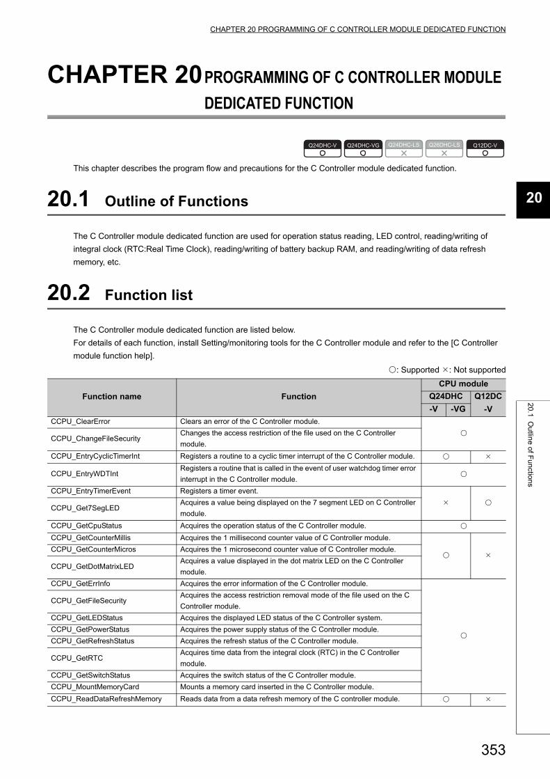
353
CHAPTER 20 PROGRAMMING OF C CONTROLLER MODULE DEDICATED FUNCTION
20
20.1 Outlin
e of Functions
CHAPTER 20PROGRAMMING OF C CONTROLLER MODULE
DEDICATED FUNCTION
This chapter describes the program flow and precautions for the C Controller module dedicated function.
20.1 Outline of Functions
The C Controller module dedicated function are used for operation status reading, LED control, reading/writing of
integral clock (RTC:Real Time Clock), reading/writing of battery backup RAM, and reading/writing of data refresh
memory, etc.
20.2 Function list
The C Controller module dedicated function are listed below.
For details of each function, install Setting/monitoring tools for the C Controller module and refer to the [C Controller
module function help].
: Supported : Not supported
Function name Function
CPU module
Q24DHC Q12DC
-V-V -VG
CCPU_ClearError Clears an error of the C Controller module.
CCPU_ChangeFileSecurity
Changes the access restriction of the file used on the C Controller
module.
CCPU_EntryCyclicTimerInt Registers a routine to a cyclic timer interrupt of the C Controller module.
CCPU_EntryWDTIntRegisters a routine that is called in the event of user watchdog timer error
interrupt in the C Controller module.
CCPU_EntryTimerEvent Registers a timer event.
CCPU_Get7SegLED
Acquires a value being displayed on the 7 segment LED on C Controller
module.
CCPU_GetCpuStatus Acquires the operation status of the C Controller module.
CCPU_GetCounterMillis Acquires the 1 millisecond counter value of C Controller module.
CCPU_GetCounterMicros Acquires the 1 microsecond counter value of C Controller module.
CCPU_GetDotMatrixLEDAcquires a value displayed in the dot matrix LED on the C Controller
module.
CCPU_GetErrInfo Acquires the error information of the C Controller module.
CCPU_GetFileSecurityAcquires the access restriction removal mode of the file used on the C
Controller module.
CCPU_GetLEDStatus Acquires the displayed LED status of the C Controller system.
CCPU_GetPowerStatus Acquires the power supply status of the C Controller module.
CCPU_GetRefreshStatus Acquires the refresh status of the C Controller module.
CCPU_GetRTCAcquires time data from the integral clock (RTC) in the C Controller
module.
CCPU_GetSwitchStatus Acquires the switch status of the C Controller module.
CCPU_MountMemoryCard Mounts a memory card inserted in the C Controller module.
CCPU_ReadDataRefreshMemory Reads data from a data refresh memory of the C controller module.
Q24DHC-V Q24DHC-VG Q24DHC-LS Q26DHC-LS Q12DC-V

354
Execute the following functions from an interrupt service routine (ISR). Otherwise, the operating system may run away.
: Supported : Not supported
CCPU_ReadSRAM Reads data from a battery backup RAM of the C controller module.
CCPU_RegistEventLog Registers an event log with event history of the C Controller module.
CCPU_ResetWDT Resets the user watchdog timer of the C Controller module.
CCPU_Restart Restarts the internal system of the C Controller module.
CCPU_Set7SegLEDSets a value to be displayed on the 7 segment LED on C Controller
module.
CCPU_SetDotMatrixLED Sets a value displayed in the dot matrix LED on the C Controller module.
CCPU_SetLEDStatus Sets the displayed LED status of the C Controller module.
CCPU_SetRTC Sets time data to the integral clock (RTC) in the C Controller module.
CCPU_StartWDTSets the user watchdog timer of the C Controller module and starts up
the user watchdog timer.
CCPU_StopWDT Stops the user watchdog timer of the C Controller module.
CCPU_ShutdownRom Shuts down the standard ROM of C Controller module to power OFF.
CCPU_UnmountMemoryCard Unmounts a memory card inserted in the C Controller module.
CCPU_WaitDataRefreshEventWaits for an occurrence of a data refresh interrupt event of the C
Controller module.
CCPU_WaitSwitchEventWaits for an occurrence of a switch interrupt event of the C Controller
module.
CCPU_WaitTimerEvent Waits for an occurrence of a timer event.
CCPU_WriteDataRefreshMemory Writes data to the data refresh memory of the C controller module.
CCPU_WriteSRAM Writes data to the battery backup RAM of the C controller module.
Function name Function
CPU module
Q24DHC Q12DC
-V-V -VG
CCPU_Get7SegLED_ISRAcquires a value being displayed on the 7 segment LED on C Controller
module.
CCPU_GetCounterMillis_ISR Acquires the 1 millisecond counter value of C Controller module.
CCPU_GetCounterMicros_ISR Acquires the 1 microsecond counter value of C Controller module.
CCPU_GetDotMatrixLED_ISRAcquires a value displayed in the dot matrix LED on the C Controller
module.
CCPU_ReadSRAM_ISR Reads data from a battery backup RAM of the C controller module.
CCPU_Set7SegLED_ISRSets a value to be displayed on the 7 segment LED on C Controller
module.
CCPU_SetDotMatrixLED_ISR Sets a value displayed in the dot matrix LED on the C Controller module.
CCPU_SetLEDStatus_ISR Sets the status of the indicator LED on C Controller module.
CCPU_WriteSRAM_ISR Writes data to the battery backup RAM of the C controller module.
Function name Function
CPU module
Q24DHC Q12DC
-V-V -VG

355
CHAPTER 20 PROGRAMMING OF C CONTROLLER MODULE DEDICATED FUNCTION
20
20.3 Program
ming F
low
20.3 Programming Flow
The following shows the user program flow that involves these functions.
20.4 Precautions
(1) Clock settingDo not perform clock setting in event notification waiting status (where QBF_WaitEvent function and
QBF_WaitUnitEvent function are already executed).
Task startup
Task completion
Perform read-out of the C Controller module status, LED control, and access to resources such as clock and battery backup RAM.

356
CHAPTER 21PROGRAMMING USING BUS
INTERFACE FUNCTIONS
The following describes the bus interface function program flow and precautions.
21.1 Outline of Functions
The bus interface functions are used for access to I/O modules and intelligent function module's buffer memory
controlled by the C Controller module via the base module.
21.2 Function List
The list of bus interface functions is indicated in the table below.
For details of each function, install Setting/monitoring tools for the C Controller module and refer to the [C Controller
module function help].
(1) Available functions
: Supported : Not supported
Function name Function
CPU module
Q24DHC Q12DC
-V-V -VG
QBF_Close Closes a bus.
QBF_ControlExControls remote RUN/STOP/PAUSE operations of the programmable
controller CPU modules and C Controller module.
QBF_ControlProgram Controls the execute type of the programmable controller CPU module.
QBF_DisableCpuIntDisables a routine program which is registered as an interrupt program
from another module.
QBF_DisableMultiCPUSyncIntDisables a routine program executed when processing the multiple CPU
synchronous interrupt program.
QBF_DisableUnitIntDisables a routine program which is registered as an interrupt program
from an intelligent function module/interrupt module.
QBF_EnableCpuIntEnables a routine program which is registered as an interrupt program
from another module.
QBF_EnableMultiCPUSyncIntEnables a routine program executed when processing the multiple CPU
synchronous interrupt program.
QBF_EnableUnitIntEnables a routine program which is registered as an interrupt program
from an intelligent function module/interrupt module.
QBF_EntryCpuIntResisters a routine program to call when an interrupt from another
module has occur.
QBF_EntryMultiCPUSyncIntResisters a routine program to call when an interrupt from multiple CPU
synchronous interrupt program has occur.
QBF_EntryUnitIntResisters a routine program to call when an interrupt from intelligent
function module/interrupt module has occur.
Q24DHC-V Q24DHC-VG Q24DHC-LS Q26DHC-LS Q12DC-V

357
CHAPTER 21 PROGRAMMING USING BUS INTERFACE FUNCTIONS
21
21.2 Function List
QBF_FromBufReads data from the CPU shared memory of the specified module and
the buffer memory of the intelligent function module (From instruction).
QBF_GINT Issues an interrupt to another CPU.
QBF_MotionCHGA Requests to change the current value of the specified axis.
QBF_MotionCHGAS Requests to change the current value of the specified axis. *1 *1
QBF_MotionCHGT Requests to change the torque limit value of the specified axis.
QBF_MotionCHGT2 Requests to change the torque limit value of the specified axis.
QBF_MotionCHGV Requests to change the speed of the specified axis.
QBF_MotionCHGVS Requests to change the speed of the specified axis. *1 *1
QBF_MotionDDRD Reads data from the Motion CPU devices.
QBF_MotionDDWR Writes data to the Motion CPU devices.
QBF_MotionSFCS Requests to start the specified Motion SFC program.
QBF_MotionSVST Requests to start the specified servo program.
QBF_Open Opens a bus.
QBF_ReadDeviceReads data from the internal user or system devices of the C Controller
module.
QBF_ReadLinkDevice
Reads data from link device(s) of the following network modules (host).
• CC-Link IE controller network module
• CC-Link IE Field Network Master/Local Module
• MELSECNET/H module
QBF_RECV
Receives a message from the other station via the following modules.
• CC-Link IE controller network module
• CC-Link IE Field Network Master/Local Module
• MELSECNET/H module
QBF_RefreshLinkDevice Refreshes the CC-Link module link device.
QBF_ResetResets the C Controller module.
Resets No.1 CPU in case of a multiple CPU configuration.
QBF_ResetDeviceResets the internal user or system devices (bit devices) of the C
Controller module.
QBF_REMFR Reads data from the buffer memory of the intelligent device station. *2
QBF_REMTO Writes data to the buffer memory of the intelligent device station. *2
QBF_SEND
Sends a message to another station via the following modules.
• CC-Link IE controller network module
• CC-Link IE Field Network Master/Local Module
• MELSECNET/H module
QBF_SetDeviceSets the internal user or system devices (bit devices) of the C Controller
module.
QBF_ToBufWrites data to the CPU shared memory of the specified module and the
buffer memory of the intelligent function module (To instruction).
QBF_UnitInfo Reads module configuration information.
QBF_WaitEvent Waits for an interrupt event notification from another CPU.
QBF_WaitMultiCPUSyncEvent Waits for a multiple CPU synchronous interrupt event notification.
*1 : Use the product with a serial number whose first five digits are "16012" or higher.*2 : Use the product with a serial number whose first five digits are "15102" or higher.
Function name Function
CPU module
Q24DHC Q12DC
-V-V -VG

358
Execute the following functions from an interrupt service routine (ISR). Otherwise, the operating system may run away.
: Supported : Not supported
QBF_WaitUnitEventWaits for an interrupt event notification from an intelligent function module
or an interrupt module.
QBF_WriteDeviceWrites data to the internal user or system devices of the C Controller
module.
QBF_WriteLinkDevice
Writes data into link device(s) of the following network modules (host).
• CC-Link IE Controller Network module
• CC-Link IE Field Network Master/Local Module
• MELSECNET/H module
QBF_X_In_BitEx Reads out input signals (X) in bit (1 point).
QBF_X_In_WordEx Reads out input signals (X) in word (16 points).
QBF_Y_In_BitEx Reads out output signals (Y) in bit (1 point).
QBF_Y_In_WordEx Reads out output signals (Y) in word (16 points).
QBF_Y_Out_BitEx Outputs output signals (Y) in bit (1 point).
QBF_Y_Out_WordEx Outputs output signals (Y) in word (16 points).
Function name Function
CPU module
Q24DHC Q12DC
-V-V -VG
QBF_DisableCpuInt_ISRDisables a routine program which is registered as an interrupt program
from another module.
QBF_DisableMultiCPUSyncInt_ISRDisables a routine program executed when processing the multiple
CPU synchronous interrupt program.
QBF_DisableUnitInt_ISRDisables a routine program which is registered as an interrupt program
from an intelligent function module/interrupt module.
QBF_EnableCpuInt_ISREnables a routine program which is registered as an interrupt program
from another module.
QBF_EnableMultiCPUSyncInt_ISREnables a routine program executed when processing the multiple
CPU synchronous interrupt program.
QBF_EnableUnitInt_ISREnables a routine program which is registered as an interrupt program
from an intelligent function module/interrupt module.
QBF_FromBuf_ISRReads data from the CPU shared memory of the specified module and
the buffer memory of the intelligent function module.
QBF_ReadDevice_ISRReads data from the internal user device of C Controller module and
the internal system device.
QBF_ResetDevice_ISRResets the internal user device of C Controller module and the internal
system device (bit device).
QBF_SetDevice_ISRSets the internal user device of C Controller module and the internal
system device (bit device).
QBF_ToBuf_ISRWrites data to the CPU shared memory of the specified module and
the buffer memory of the intelligent function module.
QBF_WriteDevice_ISRWrites data to the internal user device of C Controller module and the
internal system device.
QBF_X_In_Word_ISR Reads the input signal (X) in word unit (16 points).
QBF_Y_In_Word_ISR Reads the output signal (Y) in word unit (16 points).
QBF_Y_Out_Word_ISR Outputs the output signal (Y) in word unit (16 points).
Function name Function
CPU module
Q24DHC Q12DC
-V-V -VG

359
CHAPTER 21 PROGRAMMING USING BUS INTERFACE FUNCTIONS
21
21.2 Function List
(2) Functions for compatibilityThe following functions are for Q12DCCPU-V (Basic mode). Use them for utilizing user program(s) for
Q12DCCPU-V (Basic mode). To create a new user program, use the C Controller module dedicated function
(Page 353, CHAPTER 20) or the "Available functions" described in (1) above, instead of these functions.
: Supported : Not supported
Remark
For importing of user program(s) for Q12DCCPU-V (Basic mode), refer to the following.Page 465, Appendix 4
Function name Function
CPU module
Q24DHC Q12DC
-V-V -VG
QBF_ClearError Clears an error.
QBF_ControlControls remote RUN/STOP/PAUSE operations of the C Controller
module.
QBF_Control7SegLED Controls the 7 segment LED of C Controller module.
QBF_Control7SegLED_ISR Controls the 7 segment LED of C Controller module.
QBF_ControlLED Controls USER LED of C Controller module.
QBF_ControlLED_ISR Controls USER LED of C Controller module.
QBF_EntryTimerEvent Registers timer events.
QBF_EntryWDTInt Registers a routine for the user WDT error interrupt.
QBF_GetTime Reads clock data.
QBF_MountCfCard Mounts a Memory card
QBF_ReadSRAM Reads data from the battery backup RAM.
QBF_ReadSRAM_ISR Reads data from battery backup RAM.
QBF_ReadStatusEx Reads the status information (LED, error, etc.) of C Controller module.
QBF_RegistEventLog Registers event logs in the event history file.
QBF_ResetWDT Resets the user WDT.
QBF_SetTime Sets up clock data.
QBF_StartWDT Sets an interval of WDT and starts up the user WDT.
QBF_StopWDT Stops the user WDT.
QBF_UnmountCfCard Unmounts a Memory card.
QBF_WaitTimerEvent Waits for an occurrence of a timer event.
QBF_WriteSRAM Writes data to the battery backup RAM.
QBF_WriteSRAM_ISR Writes data to battery backup RAM.
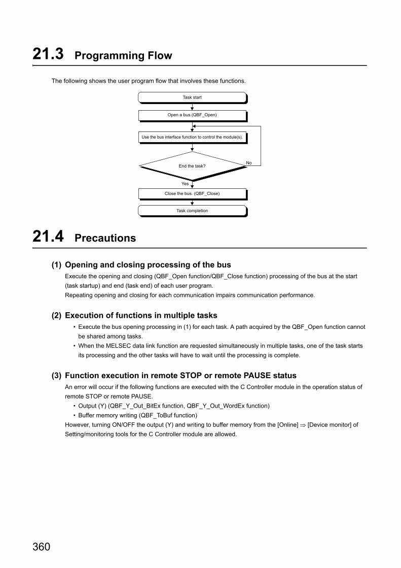
360
21.3 Programming Flow
The following shows the user program flow that involves these functions.
21.4 Precautions
(1) Opening and closing processing of the busExecute the opening and closing (QBF_Open function/QBF_Close function) processing of the bus at the start
(task startup) and end (task end) of each user program.
Repeating opening and closing for each communication impairs communication performance.
(2) Execution of functions in multiple tasks • Execute the bus opening processing in (1) for each task. A path acquired by the QBF_Open function cannot
be shared among tasks.
• When the MELSEC data link function are requested simultaneously in multiple tasks, one of the task starts
its processing and the other tasks will have to wait until the processing is complete.
(3) Function execution in remote STOP or remote PAUSE statusAn error will occur if the following functions are executed with the C Controller module in the operation status of
remote STOP or remote PAUSE.
• Output (Y) (QBF_Y_Out_BitEx function, QBF_Y_Out_WordEx function)
• Buffer memory writing (QBF_ToBuf function)
However, turning ON/OFF the output (Y) and writing to buffer memory from the [Online] [Device monitor] of
Setting/monitoring tools for the C Controller module are allowed.
Task start
Task completion
End the task?
Open a bus.(QBF_Open)
Use the bus interface function to control the module(s).
Close the bus. (QBF_Close)
No
Yes

361
CHAPTER 21 PROGRAMMING USING BUS INTERFACE FUNCTIONS
21
21.4 Preca
utions
(4) Host station device access for network moduleCreate a user program to read/write data after ensuring the following conditions so that data reading/writing is
allowed.
If the following conditions are met, data become valid. However, reading/writing functions may complete normally
even when the conditions are not valid.
(a) CC-Link module
• Module error (Xn0) is off (normal)
• Module ready (XnF) is on (operable)
• Own data link status (Xn1) is on (in data link)
(b) MELSECNET/H module
• Module status (SB20) is off (normal)
• Baton pass status of host station (SB47) is off (normal)
• Data link status of host station (SB49) is off (in data link)
(c) Cc-link IE Controller Network Module/Cc-link IE Field Network Master/local Module • Data link status of own station (SB49) is off (in data link)
• Cyclic transmission status (the bit corresponding to the communication targets in SWB0 to B7 which is
read from the own station) is off (normal)

362
CHAPTER 22PROGRAMMING USING MELSEC
DATA LINK FUNCTIONS
This chapter describes the MELSEC data link function program flow and precautions.
22.1 Outline of Functions
MELSEC data link functions are used for reading/writing via network, or from/to the other programmable controller
CPU device(s) comprising a multiple CPU configuration.
22.2 Function List
The list of MELSEC data link functions is indicated in the table below.
For details of each function, install Setting/monitoring tools for the C Controller module and refer to the [C Controller
module function help].
(1) Available functions
Function name Description
mdClose Closes a communication line.
mdControl Remote operations (RUN/STOP/PAUSE) of the programmable controller CPU.
mdDevRstEx Resets (OFF) the bit device.
mdDevSetEx Sets (ON) the bit device.
mdInit Initializes the programmable controller CPU device information table.
mdOpen Opens a communication line.
mdRandREx Reads devices randomly.
mdRandWEx Writes devices randomly.
mdReceiveEx• Batch reads devices.
• Receives messages.
mdSendEx• Batch writes devices.
• Sends messages
mdTypeRead Reads the model name of the programmable controller CPU.
Q24DHC-V Q24DHC-VG Q24DHC-LS Q26DHC-LS Q12DC-V

363
CHAPTER 22 PROGRAMMING USING MELSEC DATA LINK FUNCTIONS
22
22.3 Program
ming F
low
(2) Functions for compatibilityThe following functions are for Q12DCCPU-V. Use them for importing user program(s) for Q12DCCPU-V. To
create a new user program, use the functions described in (Page 362, (1) in this section), instead of these
functions.
22.3 Programming Flow
The following shows the user program flow that involves these functions.
Function name Description
mdDevRst Resets (OFF) the bit device.
mdDevSet Sets (ON) the bit device.
mdRandR Reads devices randomly.
mdRandW Writes devices randomly.
mdReceive• Batch reads devices.
• Receives messages.
mdSend• Batch writes devices.
• Sends messages
Open a communication circuit.(mdOpen function)
Task completion
End the task?
Perform dummy access (device read-out and model name read-out, etc.) to the targets (programmable controller CPU and C Controller module, etc.)
Close a communication line.(mdClose function)
Task startup
No
Yes
Use the MELSEC data link function to access to target(s).

364
22.4 Precautions
(1) Opening and closing of communication linesExecute the opening and closing (mdOpen function/mdClose function) processing of the communication lines at
the start (task startup) and end (task end) of each user program.
Repeating opening and closing for each communication impairs communication performance.
(2) Dummy accessExecute the dummy access to the communication target CPU module before starting access required for control
(In case of the first access to CPU modules by the task, the function execution time may be prolonged).
In addition, if there are multiple target CPU modules, execute dummy access to all CPU modules.
(3) Execution of functions in multiple tasksExecute opening and closing of the communication lines in (1) in each task. A path acquired by the mdOpen
function cannot be shared among tasks.
(4) Number of communication target CPU modulesThe number of CPU modules to be accessed by each task must be set to 8 or less. Otherwise, the
communication performance may be impaired.
(5) Occurrence of stop errorWhen stop error occurs on the C Controller module, do not access to the station using the block data assurance
per station of the network.
(6) Occurrence of communication timeoutIf a communication timeout occurs, adjust the timeout time in "CCPU Parameter" <<MELSEC data link function
settings>> in Setting/monitoring tools for the C Controller module.
(7) Access to host or another station of the network moduleCreate a user program to read/write data after ensuring the following conditions so that data reading/writing is
allowed.
If the following conditions are met, data become valid. However, reading/writing functions may complete normally
even when the conditions are not valid.
(a) CC-Link module
Host station device access
• Module error (Xn0) is off (normal)
• Module ready (XnF) is on (operable)
• Own station link status (Xn1) is off (in data link)
Access to another station device and remote operations of another station programmable controller CPU
The following condition is added to the conditions.
• Data link status of the access target station (Bits corresponding to a communication target station of SW80
to 83, which are read from the own station) is off (normal communication).

365
CHAPTER 22 PROGRAMMING USING MELSEC DATA LINK FUNCTIONS
22
22.4 Preca
utions
(b) Access via MELSECNET/H module
Host station device access
• Module status (SB20) is off (normal)
• Baton pass status of host station (SB47) is off (normal)
• Data link status of host station (SB49) is off (in data link)
Access to another station device and remote operations of another station programmable controller CPU
The following condition is added to the conditions.
• Baton pass status of the access target station (Bits corresponding to a communication target station of
SW70 to 73, which are read from the host station) is off (normal communication).
• Data link status (Bits corresponding to the communication target station of SW74 to 77, which are read
from the host station) is off (normal communication).
(c) Access via CC-Link IE Controller Network module/CC-Link IE Field Network master/
local module
Host station device access
• Data link status of host station (SB49) is off (in data link)
• Cyclic transmission status (the bit corresponding to the communication targets in SWB0 to B7 which is
read from the own station) is off (normal)
Access to another station device and remote operations of another station programmable controller CPU
The following condition is added to the conditions.
• Baton pass status of host station (SB47) is off (normal)
• Baton pass status of the access target station (Bits corresponding to a communication target station of
SWA0 to A7, which are read from the host station) is off (normal communication).

366
22.5 Accessible Networks and Devices
This section indicates accessibility by access methods, network types, and combinations of destination devices.
(1) Access methodThe table in this section divides the functions used for access into "Batch" and "Random" and indicates
accessibility for each of these 2 categories.
(2) Accessibility by networksThe following indicates accessibility for each network.
Access method Specific functions
Batch• Batch write (mdSendEx function)
• Batch read (mdReceiveEx function)
Random
• Random write (mdRandWEx
functions)
• Random read (mdRandREx function)
• Bit set (mdDevSetEx function)
• Bit reset (mdDevRstEx function)
Network Reference
Bus Page 367, Section 22.5.1
CC-Link IE controller network Page 370, Section 22.5.2
MELSECNET/H Page 375, Section 22.5.3
CC-Link IE field network Page 381, Section 22.5.4
CC-Link Page 387, Section 22.5.5

367
CHAPTER 22 PROGRAMMING USING MELSEC DATA LINK FUNCTIONS
22
22.5 Accessible N
etworks and D
evices22.5.1 A
ccess via a bus
22.5.1 Access via a bus
(1) Accessible rangeVia a bus connection, access to the following is allowed.
• Own station (C Controller module)
• Other station (Programmable controller CPU or C Controller module)
(2) Accessible devices
(a) Host station access
: Accessible : Inaccessible
Device Access methodDevice type
(Device name specification)
Access target
Own station
(C Controller module)
X
Batch/
Random
DevX
Y DevY
M DevM
SM (special relay), SB DevSM
D DevD
SD (special register), SW DevSD
B DevB
W DevW
Special direct buffer register,
Intelligent function module buffer
memory
DevSPG(0) to DevSPG(255)
CPU shared memory
BatchDevSPB1 (for CPU No.1),
DevSPB2 (for CPU No.2),
DevSPB3 (for CPU No.3),
DevSPB4 (for CPU No.4)
Random
Host module (C Controller module)
CPU No.1
CPU No.2
Other CPUs (programmable controller CPU, and C Controller module)

368
(b) Another station access
: Accessible : Inaccessible
DeviceAccess
method
Device type
(Device name specification)
Access target
Programmable
controller CPU
C Controller
module
X
Batch/
Random
DevX
Y DevY
L DevL
M DevM
SM (special relay), SB DevSM
F DevF
T (contact) DevTT
T (coil) DevTC
C (contact) DevCT
C (coil) DevCC
T (current value) DevTN
C (current value) DevCN
D DevD
SD (special register), SW DevSD
T (main setting) DevTM
T (sub setting 1) DevTS
T (sub setting 2) DevTS2
T (sub setting 3) DevTS3
C (main setting) DevCM
C (sub setting 1) DevCS
C (sub setting 2) DevCS2
C (sub setting 3) DevCS3
A DevA
Z DevZ
V (index register) DevV
R (file register) DevR *1
ZR (file register) DevZR
ER (extended file register) DevER(0) to evER(256)
B DevB
W DevW
Q/QnA link special relay
(within Q/QnACPU)DevQSB
Retentive timer (contact) DevSTT
Retentive timer (coil) DevSTC
Q/QnA link special register
(within Q/QnACPU)DevQSW
Q/QnA edge relay
(within Q/QnACPU)DevQV
Own station random access buffer DevMRB
Retentive timer (current value) DevSTN
Own station link register (for sending) DevWw
Own station link register (for receiving) DevWr

369
CHAPTER 22 PROGRAMMING USING MELSEC DATA LINK FUNCTIONS
22
22.5 Accessible N
etworks and D
evices22.5.1 A
ccess via a bus
Own station buffer memory
Batch/
Random
DevSPB
Direct link input (other station side) DevLX(1) to DevLX(255)
Direct link output (other station side) DevLY(1) to DevLY(255)
Direct link relay (other station side) DevLB(1) to DevLB(255)
Direct link register (other station side) DevLW(1) to DevLW(255)
Direct link special relay
(other station side)DevLSB(1) to DevLSB(255)
Direct link special register
(other station side)DevLSW(1) to evLSW(255)
Special direct buffer register,
Intellligent function module buffer
memory
DevSPG(0) to DevSPG(255)
Other station buffer memory
Batch/
Random
DevRBM
Other station random access buffer DevRAB
Other station RX DevRX
Other station RY DevRY
Other station link register DevRW
Other station SB
(link special relay for CC-Link)DevSB
Other station SW
(link special relay for CC-Link)DevSW
CPU shared memory
BatchDevSPB1 (for CPU No.1),
DevSPB2 (for CPU No.2),
DevSPB3 (for CPU No.3),
DevSPB4 (for CPU No.4)
Random
*1 : For the access, use ZR (file register) or ER (extended file register).
: Accessible : Inaccessible
DeviceAccess
method
Device type
(Device name specification)
Access target
Programmable
controller CPU
C Controller
module

370
22.5.2 Access via CC-Link IE Controller Network
(1) Accessible rangeThis section indicates accessible range for each combination of "1. Connection network", "2. Connected station
CPU", "3. Relayed network", and "4. Target CPU" illustrated in the figure below.
• The host station and "2. Connected station CPU" are all accessible.
• "4. Target CPU" devices are represented by the following symbols.
No. CPU type
1)Q06CCPU-V, Q12DCCPU-V (Basic mode), Q12DCCPU-V (Extended mode),
Q24DHCCPU-V, Q24DHCCPU-VG, PC CPU module
2) Personal computer interface board
: Accessible : Inaccessible
1.Connected
network
2.Connected
station CPU3.Relayed network
4.Target CPU
QCPUQnACPU ACPU 1) 2) LCPU
Q mode A mode
CC-Link IE Controller
Network
QCPU
(Q mode)
CC-Link IE Controller
Network*1 *2
*3,*4
CC-Link IE Field
Network*1 *2 *5
MELSECNET/H *2 *4
MELSECNET/10 *2 *4
MELSECNET(II)
Ethernet
Computer link
CC-Link
C Controller
module*3
CC-Link IE Controller
Network
CC-Link IE Field
Network
MELSECNET/H
MELSECNET/10
MELSECNET(II)
Ethernet
Computer link
CC-Link
*1 : Accessible only when all controlled CPUs of the relayed network after the station No.65 are all universal model QCPUs.*2 : Access is not allowed when the connected station CPU is the Q00CPU or Q00JCPU or Q01CPU.*3 : Accessible only for the following C Controller modules:
• Q06CCPU-V with a serial number whose first five digits are "10102" or higher • Q12DCCPU-V (Basic mode) with a serial number whose first five digits are "12042" or later and Q12DCCPU-V
(Extended mode) with a serial number whose first five digits are "15102" or later • Q24DHCCPU-V/-VG
*4 : Access is not allowed to the PC CPU modules.*5 : Accessible only for the following C Controller modules:
• Q12DCCPU-V (Extended mode) • Q24DHCCPU-V/-VG
1C Controller module Connected network
2
3
Relayed module
Target CPU
Target module
Relayed network
4Connected station CPU
Connected module

371
CHAPTER 22 PROGRAMMING USING MELSEC DATA LINK FUNCTIONS
22
22.5 Accessible N
etworks and D
evices22.5.2 A
ccess via CC
-Link IE C
ontroller Netw
ork
(2) Accessible devices
(a) Host station access
Accessible devices are listed below.
(b) Another station access
Destinations are represented by the following symbols.
: Accessible : Inaccessible
DeviceAccess
method
Device type
(Device name
specification)
Accessibility
Own station direct link input (LX)
Batch/
Random
DevLX(0)
Own station direct link output (LY) DevLY(0)
Own station direct link relay (LB) DevLB(0)
Own station direct link register (LW) DevLW(0)
Own station direct link special relay*1 (SB)DevSM, DevQSB,
DevLSB(0)
Own station direct link special register*1 (SW)DevSD, DevQSW,
DevLSW(0)
Q/QnA RECV functionBatch
DevMAIL
Random
*1 : There are multiple device types. Which to specify does not make any difference.
No. Access target
1) A1NCPU
2) A0J2HCPU, A1S(H)CPU, A1SJ(H)CPU, A2NCPU(-S1), A2S(H)CPU
3)A2ACPU(-S1), A2UCPU(-S1), A2USCPU(-S1), A2USHCPU-S1
Q02(H)CPU-A, Q06HCPU-A
4) A3NCPU, A3ACPU, A3UCPU
5) A4UCPU
6)
Q2ACPU(-S1), Q3ACPU, Q4ACPU, Q4ARCPU, Q2ASCPU(-S1), Q2ASHCPU(-S1)
Q00JCPU, Q00CPU, Q01CPU
Q02(H)CPU, Q06HCPU, Q12HCPU, Q25HCPU, Q12PRHCPU, Q25PRHCPU
Q02PHCPU, Q06PHCPU, Q12PHCPU, Q25PHCPU
Q00UJCPU, Q00UCPU, Q01UCPU, Q02UCPU, Q03UDCPU, Q04UDHCPU, Q06UDHCPU,
Q10UDHCPU, Q13UDHCPU, Q20UDHCPU, Q26UDHCPU, Q03UDECPU, Q04UDEHCPU,
Q06UDEHCPU, Q10UDEHCPU, Q13UDEHCPU, Q20UDEHCPU, Q26UDEHCPU, Q50UDEHCPU,
Q100UDEHCPU, Q03UDVCPU, Q04UDVCPU, Q06UDVCPU, Q13UDVCPU, Q26UDVCPU
7)Q24DHCCPU-V, Q24DHCCPU-VG, Q24DHCCPU-LS, Q12DCCPU-V (Basic mode), Q12DCCPU-V
(Extended mode), Q06CCPU-V
8) PC CPU module, personal computer interface board
9) L02CPU, L26CPU-BT, L02CPU-P, L26CPU-PBT, LJ72GF15-T2, NZ2GF-ETB

372
: Accessible : Inaccessible
DeviceAccess
method
Device type
(Device name specification)
Access target
1) 2) 3) 4) 5) 6) 7) 8) 9)
X
Batch/
Random
DevX *1
Y DevY *1
L DevL
M DevM *1
SM (special relay), SB DevSM *1
F DevF
T (contact) DevTT
T (coil) DevTC
C (contact) DevCT
C (coil) DevCC
T (current value) DevTN
C (current value) DevCN
D DevD *1
SD (special register), SW DevSD *1
T (main setting)Batch
DevTM
Random
T (sub setting 1)Batch
DevTS *2
Random
T (sub setting 2)Batch
DevTS2
Random
T (sub setting 3)Batch
DevTS3
Random
C (main setting)Batch
DevCM
Random
C (sub setting 1)Batch
DevCS *2
Random
C (sub setting 2)Batch
DevCS2
Random
C (sub setting 3)Batch
DevCS3
Random
A
Batch/
Random
DevA
Z DevZ
V (index register) DevV
R (file register) DevR *3
ZR (file register) DevZR *4
ER (extended file register) DevER(0) to DevER(256) *4
B DevB *5*6
W DevW *5*6
Q/QnA link special relay
(within Q/QnACPU)DevQSB
Retentive timer (contact) DevSTT
Retentive timer (coil) DevSTC
Q/QnAlink special register
(within Q/QnACPU)DevQSW

373
CHAPTER 22 PROGRAMMING USING MELSEC DATA LINK FUNCTIONS
22
22.5 Accessible N
etworks and D
evices22.5.2 A
ccess via CC
-Link IE C
ontroller Netw
ork
Q/QnA edge relay
(within Q/QnACPU)
Batch/
Random
DevQV
Own station random access
bufferDevMRB
Retentive timer
(current value)DevSTN
Own station link register
(for sending)DevWw
Own station link register
(for receiving)DevWr
Own station buffer memory DevSPB
Q/QnA SEND function
(with arrival confirmation)*7
BatchDevMAIL
Random
Q/QnA SEND function
(no arrival confirmation)*7
BatchDevMAILNC
Random
Direct link input
(other station)
Batch/
Random
DevLX(1) to DevLX(255) *1
Other station RX (remote
input RX for CC-Link IE
Field)
DevLX(1) to DevLX(255) *5 *5
Direct link output
(other station)DevLY(1) to DevLY(255) *1
Other station RY (remote
output RY for CC-Link IE
Field)
DevLY(1) to DevLY(255) *5 *5
Direct link relay
(other station)DevLB(1) to DevLB(255) *1
Direct link register
(other station)DevLW(1) to DevLW(255) *1
Other station RWw (remote
register (sending) RWw for
CC-Link IE Field)
DevLW(1) to DevLW(255) *5 *5
Other station RWr (remote
register (receiving) RWr for
CC-Link IE Field)
DevLW(1) to DevLW(255) *5 *5
Direct link special relay
(other station)DevLSB(1) to DevLSB(255) *1
Direct link special register
(other station)DevLSW(1) to DevLSW(255) *1
Special direct buffer register,
Intelligent function module
buffer memory
DevSPG(0) to DevSPG(255) *1
CPU shared memory
Batch DevSPB1 (for CPU No.1),
DevSPB2 (for CPU No.2),
DevSPB3 (for CPU No.3),
DevSPB4 (for CPU No.4)
Random
: Accessible : Inaccessible
DeviceAccess
method
Device type
(Device name specification)
Access target
1) 2) 3) 4) 5) 6) 7) 8) 9)

374
Other station buffer memory
Batch/
Random
DevRBM
Other station random access
bufferDevRAB
Other station RX (remote
input RX for CC-Link)DevRX
Other station RY (remote
output RY for CC-Link)DevRY
Other station link register DevRW
Other station SB (special
relay SB for CC-Link)DevSB
Other station SW (special
register SW for CC-Link)DevSW
*1 : Accessible only for the following C Controller modules: • Q12DCCPU-V (Basic mode) with a serial number whose first five digits are "12042" or later and Q12DCCPU-V (Extended
mode) with a serial number whose first five digits are "15102" or later. • Q24DHCCPU-V/-VG
*2 : Access is not allowed for the A2ACPU(-S1).*3 : For the access, use ZR (file register) or ER (extended file register).*4 : Access is not allowed for the Q00JCPU.*5 : Accessible only for the following C Controller modules:
• Q12DCCPU-V (Extended mode) • Q24DHCCPU-V/-VG
*6 : For B32768 or higher and W32768 or higher, accessible only for the following C Controller modules: • Q12DCCPU-V (Extended mode) • Q24DHCCPU-V with a serial number whose first five digits are "15102" or later • Q24DHCCPU-VG
*7 : This function is used to send messages to a network module on the other station via a CC-Link IE Controller Network module.
Access is not allowed to a multiple CPU system (when the logical station numbers are specified).
: Accessible : Inaccessible
DeviceAccess
method
Device type
(Device name specification)
Access target
1) 2) 3) 4) 5) 6) 7) 8) 9)

375
CHAPTER 22 PROGRAMMING USING MELSEC DATA LINK FUNCTIONS
22
22.5 Accessible N
etworks and D
evices22.5.3 A
ccess via ME
LSE
CN
ET
/H
22.5.3 Access via MELSECNET/H
(1) Accessible rangeThis section indicates accessible range for each combination of "1. Connection network", "2. Connected station
CPU", "3. Relayed network", and "4. Target CPU" illustrated in the figure below.
• The host station and "2. Connected station CPU" are all accessible.
• "4. Target CPU" devices are represented by the following symbols.
No. CPU type
1)Q06CCPU-V, Q12DCCPU-V (Basic mode), Q12DCCPU-V (Extended
mode), Q24DHCCPU-V, Q24DHCCPU-VG, PC CPU module
2) PC interface board
: Accessible : Inaccessible
1.Connected
network
2.Connected
station CPU3.Relayed network
4.Target CPU
QCPUQnACPU ACPU 1) 2) LCPU
Q mode A mode
MELSECNET/H
QCPU
(Q mode)
CC-Link IE controller
network*1 *4, *5
CC-Link IE field
Network*1 *7
MELSECNET/H*2
MELSECNET/10*3
MELSECNET(II)
Ethernet
Computer link
CC-Link
C Controller
module*6
CC-Link IE controller
network
CC-Link IE field
Network
MELSECNET/H
MELSECNET/10
MELSECNET(II)
Ethernet
Computer link
CC-Link
1C Controller module Connected network
2
3
Relayedmodule
Target CPU
Targetmodule
Relayed network
4Connected station CPU
Connectedmodule

376
MELSECNET/10
QCPU(Q mode)
CC-Link IE controller
network*1 *4, *5
CC-Link IE field
Network*1
MELSECNET/H *5
MELSECNET/10 *5
MELSECNET(II)
Ethernet
Computer link
CC-Link
QnACPU
CC-Link IE controller network
CC-Link IE field Network
MELSECNET/H
MELSECNET/10 *5
MELSECNET(II)
Ethernet
Computer link
CC-Link
QCPU(A mode),ACPU
CC-Link IE controller network
CC-Link IE field Network
MELSECNET/H
MELSECNET/10 *5
MELSECNET(II)
Ethernet
Computer link
CC-Link
C Controller
module*6
CC-Link IE controller network
CC-Link IE field Network
MELSECNET/H
MELSECNET/10
MELSECNET(II)
Ethernet
Computer link
CC-Link
*1 : Accessible only when all controlled station CPUs of the relayed network after the station No.65 are all universal model QCPUs.*2 : Access is allowed when the MELSECNET/H module of the connected station is in the MELSECNET/H mode.*3 : Access is allowed when the MELSECNET/10(H) module of the connected station is in the MELSECNET/10 mode.*4 : The "4. Target CPU" C Controller module is accessible only for the following C Controller modules:
• Q06CCPU-V with a serial number whose first five digits are "10012" or higher • Q12DCCPU-V (Basic mode) with a serial number whose first five digits are "12042" or later and Q12DCCPU-V (Extended
mode) with a serial number whose first five digits are "15102" or later. • Q24DHCCPU-V/-VG
*5 : Access is not allowed to PC CPU modules.*6 : Accessible for the following C Controller modules:
• Q12DCCPU-V (Basic mode) with a serial number whose first five digits are "12042" or later and Q12DCCPU-V (Extended mode) with a serial number whose first five digits are "15102" or later.
• Q24DHCCPU-V/-VG*7 : Accessible only for the following C Controller modules:
• Q12DCCPU-V (Extended mode) • Q24DHCCPU-V/-VG
: Accessible : Inaccessible
1.Connected
network
2.Connected
station CPU3.Relayed network
4.Target CPU
QCPUQnACPU ACPU 1) 2) LCPU
Q mode A mode

377
CHAPTER 22 PROGRAMMING USING MELSEC DATA LINK FUNCTIONS
22
22.5 Accessible N
etworks and D
evices22.5.3 A
ccess via ME
LSE
CN
ET
/H
(2) Accessible devices
(a) Host station access
Accessible devices are listed below.
(b) Another station access
Destinations are represented by the following symbols.
: Accessible : Inaccessible
DeviceAccess
method
Device type
(Device name specification)Accessibility
Q/QnA RECV functionBatch
DevMAIL
Random
Own station direct link input (LX)
Batch/
Random
DevLX(0)
Own station direct link output (LY) DevLY(0)
Own station direct link relay (LB) DevLB(0)
Own station direct link register (LW) DevLW(0)
Own station direct link special relay*1 (SB) DevSM, DevQSB, DevLSB(0)
Own station direct link special register*1 (SW) DevSD, DevQSW, DevLSW(0)
*1 : There are multiple device types. Which to specify does not make any difference.
No. Access target
1) A1NCPU
2) A0J2HCPU, A1S(H)CPU, A1SJ(H)CPU, A2NCPU(-S1), A2S(H)CPU
3)A2ACPU(-S1), A2UCPU(-S1), A2USCPU(-S1), A2USHCPU-S1
Q02(H)CPU-A, Q06HCPU-A
4) A3NCPU, A3ACPU, A3UCPU
5) A4UCPU
6)
Q2ACPU(-S1), Q3ACPU, Q4ACPU, Q4ARCPU, Q2ASCPU(-S1), Q2ASHCPU(-S1)
Q00JCPU, Q00CPU, Q01CPU
Q02(H)CPU, Q06HCPU, Q12HCPU, Q25HCPU
Q02PHCPU, Q06PHCPU, Q12PHCPU, Q25PHCPU, Q12PRHCPU, Q25PRHCPU
Q00UJCPU, Q00UCPU, Q01UCPU, Q02UCPU, Q03UDCPU, Q04UDHCPU, Q06UDHCPU, Q10UDHCPU,
Q13UDHCPU, Q20UDHCPU, Q26UDHCPU, Q03UDECPU, Q04UDEHCPU, Q06UDEHCPU, Q10UDEHCPU,
Q13UDEHCPU, Q20UDEHCPU, Q26UDEHCPU, Q50UDEHCPU, Q100UDEHCPU, Q03UDVCPU,
Q04UDVCPU, Q06UDVCPU, Q13UDVCPU, Q26UDVCPU
7)Q24DHCCPU-V, Q24DHCCPU-VG, Q24DHCCPU-LS, Q12DCCPU-V (Basic mode),
Q12DCCPU-V (Extended mode), Q06CCPU-V
8) PC CPU module, personal computer interface board
9) L02CPU, L26CPU-BT, L02CPU-P, L26CPU-PBT, LJ72GF15-T2, NZ2GF-ETB

378
: Accessible : Inaccessible
DeviceAccess
method
Device type
(Device name specification)
Access target
1) 2) 3) 4) 5) 6) 7) 8) 9)
X
Batch/
Random
DevX *1
Y DevY *1
L DevL
M DevM *1
SM (special relay), SB DevSM *1
F DevF
T (contact) DevTT
T (coil) DevTC
C (contact) DevCT
C (coil) DevCC
T (current value) DevTN
C (current value) DevCN
D DevD *1
SD (special register), SW DevSD *1
T (main setting)Batch
DevTM
Random
T (sub setting 1)Batch
DevTS *2
Random
T (sub setting 2)Batch
DevTS2
Random
T (sub setting 3)Batch
DevTS3
Random
C (main setting)Batch
DevCM
Random
C (sub setting 1)Batch
DevCS *2
Random
C (sub setting 2)Batch
DevCS2
Random
C (sub setting 3)Batch
DevCS3
Random
A
Batch/
Random
DevA
Z DevZ
V (index register) DevV
R (file register) DevR *3
ZR (file register) DevZR *4
ER (extended file register) DevER(0) to DevER(256) *4
B DevB *5*6
W DevW *5*6
Q/QnA link special relay
(within Q/QnACPU)DevQSB
Retentive timer (contact) DevSTT
Retentive timer (coil) DevSTC

379
CHAPTER 22 PROGRAMMING USING MELSEC DATA LINK FUNCTIONS
22
22.5 Accessible N
etworks and D
evices22.5.3 A
ccess via ME
LSE
CN
ET
/H
Q/QnA link special register
(within Q/QnACPU)
Batch/
Random
DevQSW
Q/QnA edge relay
(within Q/QnACPU)DevQV
Own station random access buffer DevMRB
Retentive timer (current value) DevSTN
Own station link register
(for sending)DevWw
Own station link register
(for receiving)DevWr
Own station buffer memory DevSPB
Q/QnA SEND function
(with arrival confirmation)*7
BatchDevMAIL
Random
Q/QnA SEND function
(no arrival confirmation)*7
BatchDevMAILNC
Random
Direct link input (other station)Batch/
RandomDevLX(1) to DevLX(255) *1
Other station RX (remote input RX
for CC-Link IE Field)
BatchDevLX(1) to DevLX(255) *5 *5
Random
Direct link output (other station)Batch/
RandomDevLY(1) to DevLY(255) *1
Other station RY (remote output
RY for CC-Link IE Field)
BatchDevLY(1) to DevLY(255) *5 *5
Random
Direct link relay (other station)
Batch/
Random
DevLB(1) to DevLB(255) *1
Direct link register (other station) DevLW(1) to DevLW(255) *1
Other station RWw (remote
register (sending) RWw for CC-
Link IE field)
DevLW(1) to DevLW(255) *5 *5
Other station RWr (remote register
(receiving) RWr for CC-Link IE
Field)
DevLW(1) to DevLW(255) *5 *5
Direct link special relay
(other station)DevLSB(1) to DevLSB(255) *1
Direct link special register
(other station)DevLSW(1) to DevLSW(255) *1
Special direct buffer register,
Intelligent function module
buffer memory
DevSPG(0) to DevSPG(255) *1
CPU shared memory
Batch DevSPB1 (for CPU No.1),
DevSPB2 (for CPU No.2),
DevSPB3 (for CPU No.3),
DevSPB4 (for CPU No.4)
Random
: Accessible : Inaccessible
DeviceAccess
method
Device type
(Device name specification)
Access target
1) 2) 3) 4) 5) 6) 7) 8) 9)
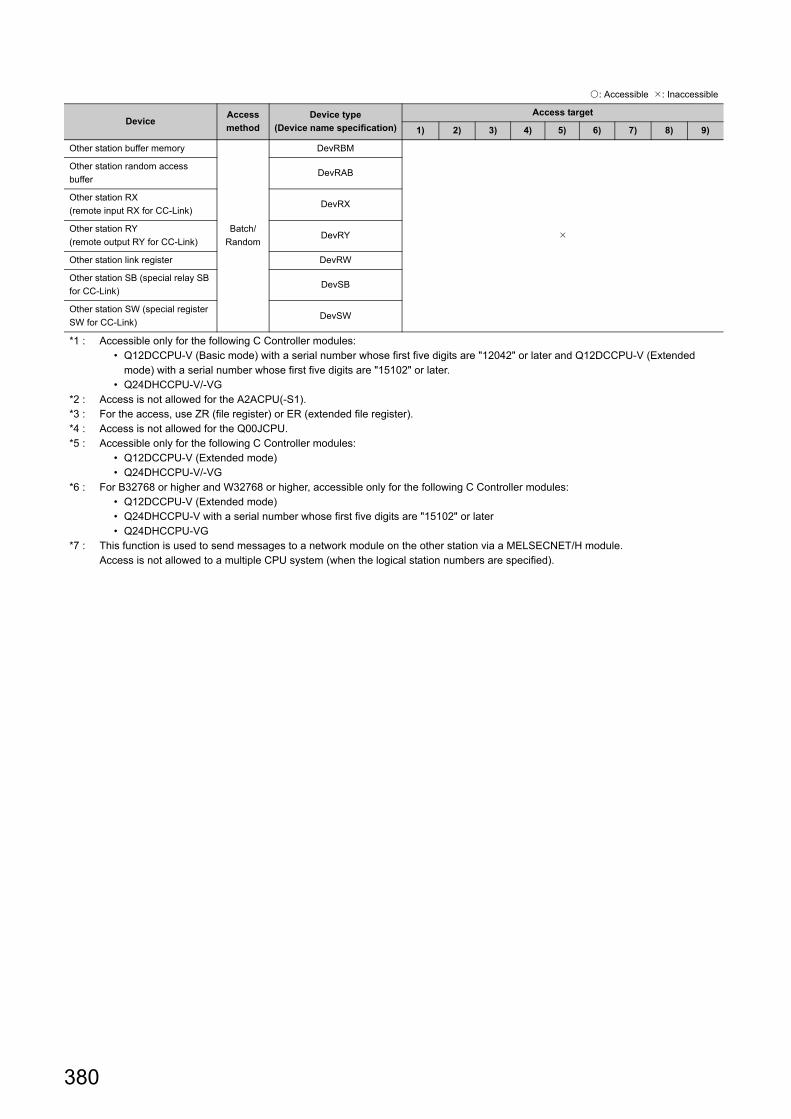
380
Other station buffer memory
Batch/
Random
DevRBM
Other station random access
bufferDevRAB
Other station RX
(remote input RX for CC-Link)DevRX
Other station RY
(remote output RY for CC-Link)DevRY
Other station link register DevRW
Other station SB (special relay SB
for CC-Link)DevSB
Other station SW (special register
SW for CC-Link)DevSW
*1 : Accessible only for the following C Controller modules: • Q12DCCPU-V (Basic mode) with a serial number whose first five digits are "12042" or later and Q12DCCPU-V (Extended
mode) with a serial number whose first five digits are "15102" or later. • Q24DHCCPU-V/-VG
*2 : Access is not allowed for the A2ACPU(-S1).*3 : For the access, use ZR (file register) or ER (extended file register).*4 : Access is not allowed for the Q00JCPU.*5 : Accessible only for the following C Controller modules:
• Q12DCCPU-V (Extended mode) • Q24DHCCPU-V/-VG
*6 : For B32768 or higher and W32768 or higher, accessible only for the following C Controller modules: • Q12DCCPU-V (Extended mode) • Q24DHCCPU-V with a serial number whose first five digits are "15102" or later • Q24DHCCPU-VG
*7 : This function is used to send messages to a network module on the other station via a MELSECNET/H module.Access is not allowed to a multiple CPU system (when the logical station numbers are specified).
: Accessible : Inaccessible
DeviceAccess
method
Device type
(Device name specification)
Access target
1) 2) 3) 4) 5) 6) 7) 8) 9)

381
CHAPTER 22 PROGRAMMING USING MELSEC DATA LINK FUNCTIONS
22
22.5 Accessible N
etworks and D
evices22.5.4 A
ccess via CC
-Link IE field netw
ork
22.5.4 Access via CC-Link IE field network
(1) Accessible rangeThis section indicates accessible range for each combination of "1. Connection network", "2. Connected station
CPU", "3. Relayed network", and "4. Target CPU" illustrated in the figure below.
• The host station and "2. Connected station CPU" are all accessible.
• Target devices are represented by the following symbols.
No. CPU type
1)Q06CCPU-V, Q12DCCPU-V (Basic mode), Q12DCCPU-V (Extended mode),
Q24DHCCPU-V, Q24DHCCPU-VG, PC CPU module
2) Personal computer interface board
: Accessible : Inaccessible
1.Connected
network
2.Connected
station CPU3.Relayed network
4.Target CPU
QCPUQnACPU ACPU 1) 2) LCPU
Q mode A mode
CC-Link IE Field
Network
QCPU
(Q mode)
CC-Link IE Controller
Network*1 *2 *3
CC-Link IE Field
Network*1 *2 *4
MELSECNET/H *2
MELSECNET/10 *2
MELSECNET(II)
Ethernet
Computer link
CC-Link
C Controller
module*4
CC-Link IE Controller
Network
CC-Link IE Field
Network
MELSECNET/H
MELSECNET/10
MELSECNET(II)
Ethernet
Computer link
CC-Link
1
2
3
4
C Controller module Connected network
Relayedmodule
Target CPU
Targetmodule
Relayed network
Connected station CPU
Connectedmodule

382
CC-Link IE Field
NetworkLCPU
CC-Link IE controller
network
CC-Link IE field
Network
MELSECNET/H
MELSECNET/10
MELSECNET(II)
Ethernet
Computer link
CC-Link
*1 : Accessible only when all controlled CPUs of the relayed network after the station No.65 are all universal model QCPUs.*2 : Access is not allowed when the connected station CPU is the Q00JCPU or Q00CPU or Q01CPU.*3 : Accessible only for the following C Controller modules:
• Q06CCPU-V with a serial number whose first five digits are "10102" or higher • Q12DCCPU-V (Basic mode) with a serial number whose first five digits are "12042" or later and Q12DCCPU-V (Extended
mode) with a serial number whose first five digits are "15102" or later. • Q24DHCCPU-V/-VG
*4 : Accessible only for the following C Controller modules: • Q12DCCPU-V (Extended mode) • Q24DHCCPU-V/-VG
: Accessible : Inaccessible
1.Connected
network
2.Connected
station CPU3.Relayed network
4.Target CPU
QCPUQnACPU ACPU 1) 2) LCPU
Q mode A mode

383
CHAPTER 22 PROGRAMMING USING MELSEC DATA LINK FUNCTIONS
22
22.5 Accessible N
etworks and D
evices22.5.4 A
ccess via CC
-Link IE field netw
ork
(2) Accessible devices
(a) Host station access
Accessible devices are listed below.
(b) Another station access
Destinations are represented by the following symbols.
: Accessible : Inaccessible
DeviceAccess
method
Device type
(Device name specification)Accessibility
Host station remote input (RX)
Batch/
Random
DevLX(0)
Host station remote output (RY) DevLY(0)
Own station direct link special relay*1 (SB) DevSM, DevQSB, DevLSB(0)
Own station direct link special register*1 (SW) DevSD, DevQSW, DevLSW(0)
Host station remote register (sending) (RWw) DevLW(0)
Host station remote register (receiving) (RWr) DevLW(0)
Buffer memory DevSPB
Q/QnA RECV functionBatch
DevMAIL
Random
*1 : There are multiple device types. Which to specify does not make any difference.
No. Access target
1) A1NCPU
2) A0J2HCPU, A1S(H)CPU, A1SJ(H)CPU, A2NCPU(-S1), A2S(H)CPU
3)A2ACPU(-S1), A2UCPU(-S1), A2USCPU(-S1), A2USHCPU-S1
Q02(H)CPU-A, Q06HCPU-A
4) A3NCPU, A3ACPU, A3UCPU
5) A4UCPU
6)
Q2ACPU(-S1), Q3ACPU, Q4ACPU, Q4ARCPU, Q2ASCPU(-S1), Q2ASHCPU(-S1)
Q00JCPU, Q00CPU, Q01CPU
Q02(H)CPU, Q06HCPU, Q12HCPU, Q25HCPU
Q02PHCPU, Q06PHCPU, Q12PHCPU, Q25PHCPU, Q12PRHCPU, Q25PRHCPU
Q00UJCPU, Q00UCPU, Q01UCPU, Q02UCPU, Q03UDCPU, Q04UDHCPU, Q06UDHCPU, Q10UDHCPU,
Q13UDHCPU, Q20UDHCPU, Q26UDHCPU, Q03UDECPU, Q04UDEHCPU, Q06UDEHCPU, Q10UDEHCPU,
Q13UDEHCPU, Q20UDEHCPU, Q26UDEHCPU, Q50UDEHCPU, Q100UDEHCPU, Q03UDVCPU,
Q04UDVCPU, Q06UDVCPU, Q13UDVCPU, Q26UDVCPU
7)Q24DHCCPU-V, Q24DHCCPU-VG, Q24DHCCPU-LS, Q12DCCPU-V (Basic mode),
Q12DCCPU-V (Extended mode), Q06CCPU-V
8) PC CPU module, personal computer interface board
9) L02CPU, L02CPU-P, L26CPU-BT, L26CPU-PBT, LJ72GF15-T2, NZ2GF-ETB

384
Accessible devices are listed below.
: Accessible : Inaccessible
DeviceAccess
method
Device type
(Device name specification)
Access target
1) 2) 3) 4) 5) 6) 7) 8) 9)
X
Batch/
Random
DevX *1
Y DevY *1
L DevL
M DevM *1
SM (special relay), SB DevSM *1
F DevF
T (contact) DevTT
T (coil) DevTC
C (contact) DevCT
C (coil) DevCC
T (current value) DevTN
C (current value) DevCN
D DevD *1
SD (special register), SW DevSD *1
T (main setting)Batch
DevTM
Random
T (sub setting 1)Batch
DevTS *2
Random
T (sub setting 2)Batch
DevTS2
Random
T (sub setting 3)Batch
DevTS3
Random
C (main setting)Batch
DevCM
Random
C (sub setting 1)Batch
DevCS *2
Random
C (sub setting 2)Batch
DevCS2
Random
C (sub setting 3)Batch
DevCS3
Random
A
Batch/
Random
DevA
Z DevZ
V (index register) DevV
R (file register) DevR *3
ZR (file register)*5 DevZR *4
ER (extended file register) DevER(0) to DevER(256) *4
B DevB
*5*6
W DevW
*5*6
Q/QnA link special relay
(within Q/QnACPU)DevQSB
Retentive timer (contact) DevSTT
Retentive timer (coil) DevSTC
Q/QnA link special register
(within Q/QnACPU)DevQSW

385
CHAPTER 22 PROGRAMMING USING MELSEC DATA LINK FUNCTIONS
22
22.5 Accessible N
etworks and D
evices22.5.4 A
ccess via CC
-Link IE field netw
ork
Q/QnA edge relay
(within Q/QnACPU)
Batch/
Random
DevQV
Own station random access buffer DevMRB
Retentive timer (current value) DevSTN
Own station link register
(for sending)DevWw
Own station link register
(for receiving)DevWr
Own station buffer memory DevSPB
Q/QnA SEND function
(with arrival confirmation)
BatchDevMAIL
*7
Random
Q/QnA SEND function
(no arrival confirmation)
BatchDevMAILNC
*7
Random
Direct link input (other station)
Batch/
Random
DevLX(1) to DevLX(255)
Other statio RX (remote input RX for
CC-Link IE Field)
DevLX(1) to DevLX(255) *5
DevLY(1) to DevLY(255)
Direct link output (other station) DevLY(1) to DevLY(255) *5
Other station RY (remote output RY
for CC-Link IE Field)
DevLB(1) to DevLB(255)
DevLW(1) to DevLW(255)
Direct link relay (other station) DevLW(1) to DevLW(255) *5
Direct link register (other station) DevLW(1) to DevLW(255) *5
Other station RWw (remote register
(sending) RWw for CC-Link IE Field)DevLSB(1) to DevLSB(255) *1
Other station RWr (remote register
(receiving) RWr for CC-Link IE Field)DevLSW(1) to DevLSW(255) *1
Direct link special relay
(other station)DevSPG(0) to DevSPG(255) *1
CPU shared memory
Batch DevSPB1 (for CPU No.1),
DevSPB2 (for CPU No.2),
DevSPB3 (for CPU No.3),
DevSPB4 (for CPU No.4)
Random
: Accessible : Inaccessible
DeviceAccess
method
Device type
(Device name specification)
Access target
1) 2) 3) 4) 5) 6) 7) 8) 9)

386
Other station buffer memory
Batch/
Random
DevRBM
Other station random access buffer DevRAB
Other station RX
(remote input RX for CC-Link)DevRX
Other station RY
(remote output RY for CC-Link)DevRY
Other station link register DevRW
Other station SB (special relay SB for
CC-Link)DevSB
Other station SW (special register SW
for CC-Link)DevSW
*1 : Accessible only for the following C Controller modules: • Q12DCCPU-V (Basic mode) with a serial number whose first five digits are "12042" or later and Q12DCCPU-V (Extended
mode) with a serial number whose first five digits are "15102" or later. • Q24DHCCPU-V/-VG
*2 : Access is not allowed for the A2ACPU(-S1).*3 : For the access, use ZR (file register) or ER (extended file register).*4 : Access is not allowed for the Q00JCPU.*5 : Accessible only for the following C Controller modules:
• Q12DCCPU-V (Extended mode) • Q24DHCCPU-V/-VG
*6 : For B32768 or higher and W32768 or higher, accessible only for the following C Controller modules: • Q12DCCPU-V (Extended mode) • Q24DHCCPU-V with a serial number whose first five digits are "15102" or later • Q24DHCCPU-VG
*7 : Access is not allowed for the PC CPU module.
: Accessible : Inaccessible
DeviceAccess
method
Device type
(Device name specification)
Access target
1) 2) 3) 4) 5) 6) 7) 8) 9)

387
CHAPTER 22 PROGRAMMING USING MELSEC DATA LINK FUNCTIONS
22
22.5 Accessible N
etworks and D
evices22.5.5 A
ccess via CC
-Link
22.5.5 Access via CC-Link
(1) Accessible rangeThe following accesses are allowed via CC-Link.
• Programmable controller CPU that controls CC-Link module
• C Controller module that controls CC-Link module
• Intelligent device station of CC-Link
• Personal computer with the CC-Link board is installed
Access to the other stations is not allowed if the station No. of master or local stations controlled by the C Controller module is 64. Access is allowed only to the own station.
Host station (master or local station controlled by the C Controller module) Other programmable controller CPU,
C Controller module, and PC CPU module
(master or local station)
CC-Link board (Personal computer) Intelligent device
station

388
(a) Host station access
Accessible devices are listed below.
(b) Another station access
Destinations are represented by the following symbols.
: Accessible : Inaccessible
DeviceAccess
method
Device type
(Device name specification)Accessibility
Own station RX
Batch/
Random
DevX
Own station RY DevY
Host station SB
(special relay SB for CC-Link)DevSM
Host station SW
(special register SW for CC-Link)DevSD
Own station link register (for sending) DevWw
Own station link register (for receiving) DevWr
Own station buffer memory DevSPB
Own station random access buffer DevMRB
No. Access target
1) A1NCPU
2) A0J2HCPU, A1S(H)CPU, A1SJ(H)CPU, A2NCPU(-S1), A2S(H)CPU
3)A2ACPU(-S1), A2UCPU(-S1), A2USCPU(-S1), A2USHCPU-S1
Q02(H)CPU-A, Q06HCPU-A
4) A3NCPU, A3ACPU, A3UCPU
5) A4UCPU
6)
Q2ACPU(-S1), Q3ACPU, Q4ACPU, Q4ARCPU, Q2ASCPU(-S1), Q2ASHCPU(-S1)
Q00JCPU, Q00CPU, Q01CPU
Q02(H)CPU, Q06HCPU, Q12HCPU, Q25HCPU
Q02PHCPU, Q06PHCPU, Q12PHCPU, Q25PHCPU, Q12PRHCPU, Q25PRHCPU
Q00UJCPU, Q00UCPU, Q01UCPU, Q02UCPU, Q03UDCPU, Q04UDHCPU, Q06UDHCPU, Q10UDHCPU,
Q13UDHCPU, Q20UDHCPU, Q26UDHCPU, Q03UDECPU, Q04UDEHCPU, Q06UDEHCPU, Q10UDEHCPU,
Q13UDEHCPU, Q20UDEHCPU, Q26UDEHCPU, Q50UDEHCPU, Q100UDEHCPU, Q03UDVCPU,
Q04UDVCPU, Q06UDVCPU, Q13UDVCPU, Q26UDVCPU
7)Q24DHCCPU-V, Q24DHCCPU-VG, Q24DHCCPU-LS, Q12DCPU-V (Basic mode),
Q12DCCPU-V (Extended mode), Q06CCPU-V
8) PC CPU module, personal computer interface board, Intelligent device station on CC-Link
9) L02CPU, L02CPU-P, L26CPU-BT, L26CPU-PBT

389
CHAPTER 22 PROGRAMMING USING MELSEC DATA LINK FUNCTIONS
22
22.5 Accessible N
etworks and D
evices22.5.5 A
ccess via CC
-Link
: Accessible : Inaccessible
DeviceAccess
method
Device type
(Device name
specification)
Access target
1) 2) 3) 4) 5) 6) 7) 8) 9)*1
X
Batch/
Random
DevX *2
Y DevY *2
L DevL
M DevM *2
SM (special relay), SB DevSM *2
F DevF
T (contact) DevTT
T (coil) DevTC
C (contact) DevCT
C (coil) DevCC
T (current value) DevTN
C (current value) DevCN
D DevD *2
SD (special register), SW DevSD *2
T (main setting)Batch
DevTM
Random
T (sub setting 1)Batch
DevTS *3
Random
T (sub setting 2)Batch
DevTS2
Random
T (sub setting 3)Batch
DevTS3
Random
C (main setting)Batch
DevCM
Random
C (sub setting 1)Batch
DevCS *3
Random
C (sub setting 2)Batch
DevCS2
Random
C (sub setting 3)Batch
DevCS3
Random
A
Batch/
Random
DevA
Z DevZ
V (index register) DevV
R (file register) DevR *4
ZR (file register) DevZR *5

390
ER (extended file register)
Batch/
Random
DevER(0) to
DevER(256) *5
B DevB *6*7
W DevW *6*7
Q/QnA link special relay
(within Q/QnACPU)DevQSB
Retentive timer (contact) DevSTT
Retentive timer (coil) DevSTC
Q/QnA link special register
(within Q/QnACPU)DevQSW
Q/QnA edge relay
(within Q/QnACPU)DevQV
Own station random access
bufferDevMRB
Retentive timer (current
value)DevSTN
Own station link register
(for sending)DevWw
Own station link register
(for receiving)DevWr
Own station buffer memory DevSPB
Q/QnA SEND function
(with arrival confirmation)DevMAIL
Q/QnA SEND function
(no arrival confirmation)DevMAILNC
Direct link input
(Other station side)
DevLX(1) to
DevLX(255) *2
Direct link output
(Other station side)DevLY(1) to DevLY(255) *2
Direct link relay
(Other station side)
DevLB(1) to
DevLB(255) *2
Direct link register
(Other station side)
DevLW(1) to
DevLW(255) *2
Direct link special relay
(Other station side)
DevLSB(1) to
DevLSB(255) *2
Direct link special register
(Other station side)
DevLSW(1) to
DevLSW(255) *2
Special direct buffer
register,
Intelligent function module
buffer memory
DevSPG(0) to
DevSPG(255) *2
CPU shared memory
Batch DevSPB1 (for CPU No.1),
DevSPB2 (for CPU No.2),
DevSPB3 (for CPU No.3),
DevSPB4 (for CPU No.4)
Random
Other station buffer
memory*8
BatchDevRBM
Random
: Accessible : Inaccessible
DeviceAccess
method
Device type
(Device name
specification)
Access target
1) 2) 3) 4) 5) 6) 7) 8) 9)*1

391
CHAPTER 22 PROGRAMMING USING MELSEC DATA LINK FUNCTIONS
22
22.5 Accessible N
etworks and D
evices22.5.5 A
ccess via CC
-Link
Other station random
access buffer*8
BatchDevRAB
Random
Other station RX*8Batch
DevRX
Random
Other station RY*8Batch
DevRY
Random
Other station link register*8Batch
DevRW
Random
Other station SB (special
relay SB for CC-Link)*8Batch
DevSB
Random
Other station SW (special
register SW for CC-Link)*8Batch
DevSW
Random
*1 : Accessible only for the following C Controller modules: • Q06CCPU-V with a serial number whose first five digits are "10102" or higher • Q12DCCPU-V (Basic mode) with a serial number whose first five digits are "12042" or later and Q12DCCPU-V (Extended
mode) with a serial number whose first five digits are "15102" or later. • Q24DHCCPU-V/-VG
*2 : Accessible only for the following C Controller modules: • Q12DCCPU-V (Basic mode) with a serial number whose first five digits are "12042" or later and Q12DCCPU-V (Extended
mode) with a serial number whose first five digits are "15102" or later. • Q24DHCCPU-V/-VG
*3 : Access is not allowed for the A2ACPU(-S1).*4 : For the access, use ZR (file register) or ER (extended file register).*5 : Access is not allowed for the Q00JCPU.*6 : Accessible only for the following C Controller modules:
• Q12DCCPU-V (Extended mode) • Q24DHCCPU-V/-VG • Q24DHCCPU-V/-VG
*7 : For B32768 or higher and W32768 or higher, accessible only for the following C Controller modules: • Q12DCCPU-V (Extended mode) • Q24DHCCPU-V with a serial number whose first five digits are "15102" or later • Q24DHCCPU-VG
*8 : Indicates the access to the buffer memory of a CC-Link module (intelligent device station) installed with each CPU module.Access is not allowed to multiple CPU systems (when the logical station number is specified).
: Accessible : Inaccessible
DeviceAccess
method
Device type
(Device name
specification)
Access target
1) 2) 3) 4) 5) 6) 7) 8) 9)*1

392
Memo

393
PART 5 TROUBLESHOOTING
This section describes actions against troubles.
CHAPTER 23 TROUBLESHOOTING . . . . . . . . . . . . . . . . . . . . . . . . . . . . . . . . . . . . . . . 394

394
CHAPTER 23TROUBLESHOOTING
This chapter describes how to investigate the root cause of troubles in the C Controller system and corresponding
corrective actions.
When any trouble has occurred, check the following items.
(1) LED lighting stateAfter checking the LED lighting state indicated on the front face of the C Controller module, refer to the following
to take actions.
Page 395, Section 23.1
(2) Display stateAfter checking the state of the general-purpose analog RGB display, refer to the following to take actions.
Page 399, Section 23.2
(3) ErrorRefer to the following to check for any error.
Page 400, Section 23.3
(4) I/O signalUse the following methods to check if the I/O module(s), external device(s) and user program(s) are connected
with correct I/O numbers as per the design.
• Change the input (X) ON/OFF to check if read-out by the user program is allowed.
• Use the user program to change the output (Y) ON/OFF to check if the external device status changes in
conjunction with output (Y).
(5) CablingCheck communication cables, connectors and module terminal blocks used for any looseness or disconnection,
and check the wiring is correctly arranged.
For wiring of the C Controller module main, refer to the following.
Page 125, Section 8.7
(6) Module installation statusCheck that each module is securely installed to the base unit.
For the C Controller module, refer to the following.
Page 116, Section 8.2
Then, divide the trouble sources into the following categories to resolve problems in each section:
• C Controller module
• Connection cable
• Module other C Controller module
• external devices
If performing the check items and corresponding actions described in this chapter does not resolve the problem,
the hardware may be faulty. Please consult your local Mitsubishi service center or representative, explaining the
details of the problem.

395
CHAPTER 23 TROUBLESHOOTING
23
23.1 LE
D Ligh
ting State
23.1.1 The P
OW
ER
LED
on the power supply m
odule
23.1 LED Lighting State
The LED lighting states are as shown below.
23.1.1 The POWER LED on the power supply module
(1) When POWER LED is not litCheck the following items.
(2) When POWER LED is lit redCheck the following items.
LED lighting state to be checked Reference
The POWER LED on the power supply module -
Off Page 395, Section 23.1.1 (1)
On(red) Page 395, Section 23.1.1 (2)
On (orange) Page 396, Section 23.1.1 (3)
The LIFE LED on the Life detection power supply module -
Off Page 396, Section 23.1.2 (1)
On(red) Page 396, Section 23.1.2 (2)
Flash(red) Page 396, Section 23.1.2 (3)
POWER LED of the redundant power supply module is lit red Page 397, Section 23.1.3
The MODE LED on the C Controller module -
When MODE LED is not lit Page 397, Section 23.1.4
When ERR.LED is lit or flashing Page 397, Section 23.1.5
When RUN LED is kept flashing Page 398, Section 23.1.6
When U RDY LED is not lit Page 398, Section 23.1.7
When the output module LED is not lit Page 398, Section 23.1.8
Check item Corrective action
MODE LED of the C Controller module is lit.The power supply module has failed.
Replace the power supply module.
Power supply voltage is not appropriate. Supply power voltage within the specified range.
The internal current consumption for the entire system
exceeds the rated output current of the power supply
module.
Reexamine the system configuration so that the internal
current consumption does not exceed the rated output
current.
POWER LED is lit when the power supply is turned on
again with all modules other than the power supply
module disconnected.
Repeatedly supply power to the system, returning the
modules back to the system one by one.
The last installed module at the time POWER LED
becomes no longer active has failed. Replace the
defective module.
Check item Corrective action
POWER LED is lit red even when the pertinent power
supply module is removed and installed to another normal
base unit and then the power is turned on again.
The power supply module has failed.
Replace the power supply module.

396
(3) When POWER LED is lit orangeCheck the following items.
23.1.2 The LIFE LED on the Life detection power supply module
(1) When LIFE LED is not litCheck the following items.
(2) When LIFE LED is lit redCheck the following items.
(3) When LIFE LED is flashing redCheck the following items.
Remark
For lighting status other than the above, refer to the following.QCPU User's Manual (Hardware Design, Maintenance and Inspection)
Check item Corrective action
POWER LED is lit orange even when the power is turned
on again.
The power supply module has failed.
Replace the power supply module.
Check item Corrective action
LIFE LED is lit red for 1 second when the power is turned
on again.
The life detection power supply module has reached the
end of life.
Replace the power supply module.
LIFE LED is kept off when the power is turned on again.The power supply module should be replaced as the life
diagnostics is impossible.
Check item Corrective action
The ambient temperature of the life detection power
supply module exceeds the range of 0-55°C.
Keep the operating ambient temperature within the range
of 0 to 55°C.
LIFE LED is lit red even when the power is turned on
again.
Stop the operation of the power supply module for a while,
and resupply power to the system after the internal
temperature of the module is lowered.
Replace the pertinent power supply module if power-on
again does not light the LED green or orange.
Check item Corrective action
LG-FG wiring status (grounding and routing) is correct.
QCPU User's Manual (Hardware Design,
Maintenance and Inspection)
Arrange correct wiring.

397
CHAPTER 23 TROUBLESHOOTING
23
23.1 LE
D Ligh
ting State
23.1.3 PO
WE
R LE
D of R
edundant Pow
er Supply M
odule is lit red
23.1.3 POWER LED of Redundant Power Supply Module is lit red
Check the following items.
Remark
For the procedure to replace the redundant power supply module during operations of the C Controller system, refer to the following.QCPU User's Manual (Hardware Design, Maintenance and Inspection)
23.1.4 When MODE LED of the C Controller module is not lit
Check the following items.
If the MODE LED does not light after checking the items and performing the corresponding actions described above, the hardware may be faulty. Please consult your local Mitsubishi service center or representative, explaining the details of the problem.
23.1.5 C Controller module ERR.LED is lit or flashing
An error has occurred.
For error details, check the event history and error code in [Diagnostics] [CCPU diagnostics] in Setting/monitoring
tools for the C Controller module.
Check item Corrective action
POWER LED is lit green when the pertinent power supply
module is replaced and the power is turned on again.
The power supply module has failed.
Replace the power supply module.
POWER LED is not lit when the power supply is turned on
again with all modules other than the power supply
module disconnected.
The Redundant power supply base unithas failed.
Replace the edundant power supply base unit
The internal current consumption for the entire system
exceeds the rated output current of the power supply
module.
Reexamine the system configuration so that the internal
current consumption does not exceed the rated output
current.
Check item Corrective action
ERR.LED is flashing.
System watchdog timer error has occurred.
Take actions against occurrence of any system watchdog
timer error (CPU Error code : 5000).
(Page 409, Appendix 1)
The module is started up in the hardware diagnostics
mode.
Power OFF the module to terminate the hardware
diagnostics mode and power-on the module again.
Check item Corrective action
Event history Check if multiple errors have occurred at the same time.
Error code
Take actions according to the error code.
If multiple error have occurred at the same time, take actions against the first error.
For error codes, refer to the following.
Page 409, Appendix 1

398
23.1.6 C Controller module RUN LED is kept flashing
RUN LED flashing status indicates that the script file (STARTUP.CMD) is running.
After applicable "Corrective action" described in the "Check item" below is taken, correct the script file and the user
program that is started up from the script file.
23.1.7 C Controller module U RDY LED is not lit
Check the following items.
23.1.8 Output module LED is not lit
Check the following items.
Check item Corrective action
The script file is stored in the standard ROM.
• Store the unprocessed script file in an SD memory card
or CompactFlash card, and turn the power on again.
• Initialize the C Controller module.
(Page 62, Section 6.1)
The standard ROM script file cannot be overwritten.
• Store the unprocessed script file in an SD memory card
or CompactFlash card, and turn the power on again.
• Cordon a free space in the standard ROM.
• Initialize the C Controller module.
(Page 62, Section 6.1)
Check item Corrective action
U RDY LED is kept lit.
• Network load is increased and startup may be
prevented. Disconnect the Ethernet cable and start the
C Controller module again.
• Initialize the C Controller module.
(Page 62, Section 6.1)
Check item Corrective action
C Controller module RUN LED is off. Put the C Controller module into RUN status.
The target device (Y) is not ON in [Online] [Device monitor]
in Setting/monitoring tools for the C Controller module.Reexamine the user program.
The target output module's LED is not turned ON when the
target device (Y) is turned ON from [Online] [Device
monitor] in Setting/monitoring tools for the C Controller
module, with the C Controller module in the STOP status.
Check the "Start I/O" of the target module in [Diagnostics]
[System monitor] in Setting/monitoring tools for the C
Controller module and correct the output No. of the user
program.
The target output module's LED is turned ON when the target
device (Y) is turned ON from [Online] [Device monitor] in
Setting/monitoring tools for the C Controller module, with the
C Controller module in the STOP status.
Reexamine the user program.
For "-LS", consult with the
partner (operating system vendor).

399
CHAPTER 23 TROUBLESHOOTING
23
23.2 Display S
tate23.2.1 N
othing is displayed on the
general-purpose analog R
GB
display
23.2 Display State
The states of general-purpose analog RBG display are as shown below.
23.2.1 Nothing is displayed on the general-purpose analog RGB display
Check the following items.
Check item Corrective action
C Controller module has not been connected with the display
correctly.
Check if C Controller module is connected with the display
correctly.
An error occurred on C Controller module.Remove the error factors according to the corrective
actions.
The general-purpose analog RGB display was connected
after the power for C Controller module had been turned ON.
Connect the general-purpose analog RGB display before
powering ON.

400
23.3 Checking the Error Details
(1) Error details of the C Controller moduleCheck the currently active error code(s) in [Diagnostics] [CCPU diagnostics] in Setting/monitoring tools for the
C Controller module. Refer to the following to take action(s) according to the respective error code.
Page 409, Appendix 1
(2) Error details of modules controlled by the C Controller moduleCheck the currently active error code(s) in each module in [Diagnostics] [System monitor] in Setting/monitoring
tools for the C Controller module. Refer to the manuals for respective modules to take action(s) according to the
respective error code.
23.4 Checking for Functional Errors
If the C Controller module has a functional problem, check the following items and perform troubleshooting.
In addition, if ERR.LED is lit or flashing, eliminate its cause(s).
Functional error Reference
Setting/monitoring tools for the C Controller module cannot be USB-connected Page 401, Section 23.4.1
Ethernet communication between the development environment (PC) and the C
Controller module cannot be establishedPage 402, Section 23.4.2
PING command response is incorrect Page 402, Section 23.4.2 (1)
PING command response is correct Page 402, Section 23.4.2 (2)
Setting/monitoring tools for the C Controller module cannot be connectedPage 403, Section 23.4.2
(2)(a)
CW Workbench connection failsPage 403, Section 23.4.2
(2)(b)
Telnet connection failsPage 404, Section 23.4.2
(2)(c)
FTP connection failsPage 404, Section 23.4.2
(2)(d)
Parameter reading/writing fails Page 404, Section 23.4.3
File access fails Page 405, Section 23.4.4
Communication with peripherals fails Page 405, Section 23.4.5
USB device cannot be recognized Page 406, Section 23.4.6
File read-out (download) from C Controller module fails Page 406, Section 23.4.7
An error occurs during user program execution Page 406, Section 23.4.8
Event history data are incorrect Page 408, Section 23.4.10
Refresh function (data refresh, link refresh) and data link of network are stopped Page 408, Section 23.4.11
Partner application does not operate Page 408, Section 23.4.12

401
CHAPTER 23 TROUBLESHOOTING
23
23.4 Checking for F
unctional E
rrors23.4.1 S
etting/m
onitoring
tools for the C C
ontroller m
odule cannot be U
SB
-connected
23.4.1 Setting/monitoring tools for the C Controller module cannot be USB-connected
Check the following items.
Check item Corrective action
The destination of Setting/monitoring tools for the C
Controller module is set to the route other than USB.
Set a correct destination of Setting/monitoring tools for the
C Controller module.
The communication test in "Transfer Setup" screen of
Setting/monitoring tools for the C Controller module is
normally completed with the user program not operating.
Review the task priorities of the user program.
• Set priorities in the range of 100-255.
• Use a wait processing (taskDelay, etc.).
After initialization of the C Controller module, the
communication test in the "Transfer Setup" of Setting/
monitoring tools for the C Controller module is not
completed normally.
The hardware of the C Controller module may be faulty.
User name and password is not sure.Initializes a C Controller module.
(Page 62, Section 6.1 Initialization)
A USB driver is not installed.
Install a USB driver.
(Setting/Monitoring Tools for the C Controller Module
Version 4 Operating Manual)
The C Controller module is inserted in a slot other than
that for No.1 in a multiple CPU system configuration.
• Connect it to the No.1 CPU module and take actions
according to the error code.
• Reset CPU No.1 or reactivate the multiple CPU system
power supply.
In the multiple CPU system configuration, a CPU module
incompatible with the multiple CPU system is mounted.
• Remove the incompatible CPU module from the main
base unit.
• Replace the incompatible CPU module with a
compatible one.
The configuration is a multiple CPU system configuration
incompatible with the C Controller module.
Review and make the configuration to be a multiple CPU
system configuration compatible with the C Controller
module.
The system in a multiple CPU system is faulty. Reset the multiple CPU system and restart it.
The "Setting/monitoring tools for the C Controller module
operation" setting in the service setting function is
disabled.
Initialize the C Controller module.
(Page 62, Section 6.1 Initialization)
The C Controller module has been communicated using
Setting/monitoring tool for the C Controller module whose
version is not supported.
• Initialize the C Controller module.
(Page 62, Section 6.1 Initialization)
• Perform communication with the C Controller module
using the supported version of the Setting/monitoring
tool for the C Controller module.
(Page 52, CHAPTER 4 SOFTWARE PACKAGES)

402
23.4.2 Ethernet communication with the C Controller module cannot be established
Issue PING from the personal computer to the C Controller module and check the response.
(1) PING response is incorrectCheck the following items and take appropriate actions so that the PING response becomes normal.
To set parameters of the C Controller module, connect Setting/monitoring tools for the C Controller module to the USB connector.
(2) PING response is correctCheck the reference of any relevant trouble and take appropriate actions.
Check item Corrective action
The IP address segments of the personal computer and C
Controller module are different.
Set both the personal computer and C Controller module
to the same segment.
(Page 129, Section 8.7 (3))
If it is relayed through another segment LAN via the
gateway, contact the network administrator of the
connected LAN.
The duplicated IP addresses of personal computer and C
Controller module exist in the connected LAN.
Contact the LAN network administrator to eliminate the IP
address duplication.
Replacement of the C Controller module makes PING not
responding normally.
Resets all terminals of the network to which the C
Controller module is connected.
IP address not in the correct range is specified.
Check the following items and specify a right IP address.
• The IP address shall start with a number from 1 to 233,
excluding 127.
• There shall be no space in the IP address.
The system in a multiple CPU system is faulty. Reset the multiple CPU system and restart it.
A large number of files and directories stored in the root
directory of the drive.
The number of files and directories stored in the root
directory are reduced to 100 or less. Or, move to the
subdirectory. (Page 309, CHAPTER 18)
No. Problem Reference
1 Setting/monitoring tools for the C Controller module cannot be connectedPage 403, (2)(a) in this
section
2 CW Workbench connection failsPage 403, (2)(b) in this
section
3 Telnet connection failsPage 404, (2)(c) in this
section
4 FTP connection failsPage 404, (2)(d) in this
section

403
CHAPTER 23 TROUBLESHOOTING
23
23.4 Checking for F
unctional E
rrors23.4.2 E
thernet com
munication w
ith the C C
ontroller module cann
ot be established
(a) Setting/monitoring tools for the C Controller module cannot be connected
Check the following items.
(b) CW Workbench connection fails
Check the following items.
Check item Corrective action
The Ethernet cable is not connected to the system
Ethernet port (S CH1).Connect the Ethernet cable.
The Ethernet cable is not connected to the built-in
Ethernet port (CH1 and CH2).
The destination of Setting/monitoring tools for the C
Controller module is set to a different route.
Set a correct destination of Setting/monitoring tools for the
C Controller module, via Ethernet.
The C Controller module is inserted in a slot other than
that for No.1 in a multiple CPU system configuration.
• Connect it to the No.1 CPU module and take actions
according to the error code.
• Reset CPU No.1 or reactivate the multiple CPU system
power supply.
In the multiple CPU system configuration, a CPU module
incompatible with the multiple CPU system is mounted.
Remove the incompatible CPU module from the main
base unit, or replace it with a compatible one.
The configuration is a multiple CPU system configuration
incompatible with the C Controller module.
Review and make the configuration to be a multiple CPU
system configuration compatible with the C Controller
module.
The "Setting/monitoring tools for the C Controller module
operation" setting in the service setting function is
disabled.
Initialize the C Controller module.
(Page 62, Section 6.1 Initialization)
The C Controller module has been communicated using
Setting/monitoring tool for the C Controller module whose
version is not supported.
• Initialize the C Controller module.
(Page 62, Section 6.1 Initialization)
• Perform communication with the C Controller module
using the supported version of the Setting/monitoring
tool for the C Controller module.
(Page 52, CHAPTER 4 SOFTWARE PACKAGES)
Check item Corrective action
The Ethernet cable is not connected to the user Ethernet
port (CH1 and CH2).Connect the Ethernet cable.
The Ethernet cable is not connected to the built-in
Ethernet port (CH1 and CH2).
"Target Server Options" of CW Workbench are not
properly set.
Set "Target Server Options" of CW Workbench properly.
(CW Workbench Operating Manual)

404
(c) Telnet connection fails
Check the following items.
(d) FTP connection fails
Check the following items.
23.4.3 Parameter reading/writing fails
Check the following items.
Check item Corrective action
The Ethernet cable is not connected to the user Ethernet
port (CH1 and CH2).Connect the Ethernet cable.
The Ethernet cable is not connected to the built-in
Ethernet port (CH1 and CH2).
User name and password is not sure.Initializes a C Controller module.
(Page 62, Section 6.1)
A message "Sorry, session limit reached." appears.
Terminate the Telnet connection from another personal
computer and take any of the following actions:
• Reconnect after the Telnet connection timeout time has
elapsed
(Page 195, Section 12.1.1 (4))
• Reset the C Controller system
Check item Corrective action
The Ethernet cable is not connected to the user Ethernet
port (CH1 and CH2).Connect the Ethernet cable.
The Ethernet cable is not connected to the built-in
Ethernet port (CH1 and CH2).
User name and password is not sure.Initializes a C Controller module.
(Page 62, Section 6.1)
There are 11 or more FTP connections to one C Controller
module.
Make an adjustment so that the number of FTP
connections becomes 10 or less.
A FTP connection can be established normally from the
Windows® command prompt.
Change to a FTP client tool that can establish a
connection normally.
Check item Corrective action
Setting/monitoring tools for the C Controller module is
connected by a user name without "Administrator" access
authority.
Connect to Setting/monitoring tools for the C Controller module
by a user name with "Administrator" access authority.
Administrator's user name and password is not sure.Initializes a C Controller module.
(Page 62, Section 6.1)

405
CHAPTER 23 TROUBLESHOOTING
23
23.4 Checking for F
unctional E
rrors23.4.4 F
ile access fails
23.4.4 File access fails
Check the following items.
(1) Diagnostics and restoration of the file system in the driveUse the FAT format for the file system in following drives:
• SD memory card ("/SD")
• CF card ("/CF")
• USB device ("/USB0")
For diagnostics of the FAT format structure, use the "chkdsk" command.
Be sure to execute the "chkdsk" in a format that starts tasks by the "sp" command from the following tools:
• CW Workbench shell
• Telnet
For specifications of the "chkdsk" command, refer to the manual for VxWorks.
Backup the program files and data before restoring a file system, and write the backup files and data after restoration.After file restoration, a partial error, i.e. loss of stored files, may occur.
23.4.5 Communication with peripherals fails
Check the following items.
Check item Corrective action
SD CARD LED is off with the reading/writing target set to
an SD memory card.
Insert an SD memory card.
(Re-insert an SD memory card.)
CF CARD LED is off with the reading/writing target set to
an CF card.
Insert an CF card.
(Re-insert an CF card.)
The SD memory card is write-protected with the writing
target set to an SD memory card.
Cancel the write protection of the SD memory card.
(Refer to the manual for the SD memory card used.)
USB LED is off with the reading/writing target set to a USB
device.
Install a USB device.
(Re-install a USB device.)
There is no free space in the write target drive.• Allocate a free space in the write target drive.
• Change the write target to another drive.
The user program that uses the write target files is running. Stop the user program that uses the write target files.
A file system error has occurred in an SD memory card, CF
card or a USB Mass Storage Class compatible device.
Restore the file system in the SD memory card, CF card or a
USB Mass Storage Class compatible device.
(Page 405, (1) in this section)
Check item Corrective action
The system in a multiple CPU system is faulty. Reset the multiple CPU system and restart it.

406
23.4.6 USB device cannot be recognized
Check the following items.
23.4.7 File read-out (download) from C Controller module fails
Check the following items.
23.4.8 An error occurs during user program execution
Check the following items.
Check item Corrective action
C Controller module has not been connected with the USB
device correctly.
Check if C Controller module is connected with the USB
device correctly.
Page 106, Section 7.6.3
An error occurred on C Controller module.Remove the error factors according to the corrective actions
for each error.
USB device (other than the one compliant with the USB
Mass Storage Class standard) was connected with the
power supply for C Controller module turned ON.
Connect a USB device (other than the one compliant with the
USB Mass Storage Class standard) before turning ON the
power supply for C Controller module.
Check item Corrective action
Check the transfer mode of FTP. Change the transfer mode of FTP to a proper mode.
Check item Corrective action
An error occurs in executable file (*.out) loading.
(Page 407, (1) in this section)
• Set the "Build Spec" in compiling to "PENTIUM4gnu".
(CW Workbench Operating Manual)
• Cordon a free space in the work RAM.
• Download the files with all symbols required for files to load
first.
Event(s) is registered with the event history.
Take appropriate actions according to details of the
registered event(s).
(Page 434, Appendix 2)
An error occurs in C Controller module dedicated
function, bus interface functions or MELSEC data link
functions.
• Take appropriate actions according to the error code
shown at the time of function execution.
(Page 409, Appendix 1)
• Check the mode which has been executed the initialization
setting.
(Page 62, Section 6.1)
An error occurs in VxWorks standard API functions.Refer to the manual for VxWorks.
If the error persists, consult Wind River Systems, Inc.
Stack size of the task that runs the user program is
insufficient.Increase the task stack size.
The pointer used by the user program refers to an
invalid address.Make correction to make the pointer refer to a valid address.
The memory area specified in Size is not allocated. Allocate the memory area.
The VX_FP_TASK option is not specified for the task
that performs floating-point operations.
Specify the VX_FP_TASK option for the task that performs
floating-point operations.
A VxWorks message appears when an error occurs. Consult the Wind River Systems, Inc.

407
CHAPTER 23 TROUBLESHOOTING
23
23.4 Checking for F
unctional E
rrors23.4.9 T
he user program
does not start
(1) Error display in case of Build Spec unmatchIf the executable file's Build Spec is other than "PENTIUM4gnu", the following error message appears during
loading (Download, ld command of CW Workbench).
(a) When CW Workbench downloads an executable file
The following screen appears.
(b) When the ld command loads an executable file (from Telnet)
The following response is returned.
Remark
The details of ermo can be checked by the printErrno command.
23.4.9 The user program does not start
Check the following items
->ld(1,0,"/SD/Demo1.out")
ld(): error loading file (errno = 0x610001).
value = 0 = 0x0
->printErrno 0x610001
errno = 0x610001 : S_loadElfLib_HDR_READ.
value = 0 = 0x0
Check item Corrective action
A large number of files and directories stored in the root
directory of the drive.
The number of files and directories stored in the root
directory are reduced to 100 or less. Or, move to the
subdirectory. (Page 309, CHAPTER 18)
The user program task has not been started by the
script file.Start the user program task by using taskSpawn or sp.
The script file name is incorrect. Set the script file name to STARTUP.CMD.

408
23.4.10 Event history data are incorrect
Check the following items.
23.4.11 Refresh function (data refresh, link refresh) and data link of network are stopped
Check the following items.
23.4.12 Partner application does not operate
Check the following items.
● Reinstalling the partner applicationFor specifications and functions related to the partner application, refer to the manuals provided by the partner (application vendor), or consult the partner (application vendor).
Check item Corrective action
Error information, BATTERY ERROR, is lit red in the
"CCPU diagnostics" of Setting/monitoring tools for the
C Controller module.
Battery replacement
Check item Corrective action
The multiple CPU high-speed transmission area is specified
to the data refresh setting without selecting "Use multiple
CPU high speed communication" in the multiple CPU
setting.
Clear the multiple CPU high-speed transmission area in the
data refresh setting.
Or, select "Use multiple CPU high speed communication" and
configure the settings to be accessed.
An intelligent function module that cannot be accessed is
specified to the data refresh setting.
Check the I/O assignment setting and the mounting status of
the intelligent function module and configure the settings to be
accessed.
Check item Corrective action
C Controller module has been initialized.
The partner application will be deleted by performing the
hardware initialization setting (Page 62, Section 6.1).
Reinstall the partner application when deleted.
Data necessary for the partner application has been deleted
from FTP or user program.
Check data in the standard ROM to find if any data necessary
for the partner application has been deleted.
If deleted, reinstall the partner application.

409
APPENDICES
A
Appendix 1 E
rror C
ode ListA
ppendix 1.1 CP
U error cod
e
APPENDICES
Appendix 1 Error Code List
This section explains error codes that are returned upon error occurrence.
In any of the following cases, please consult your local Mitsubishi service center or representative, explaining the details of the problem.
• Any error code not listed in the following table is detected • The actions indicated in the following table does not resolve the program
Appendix 1.1 CPU error code
The error codes and respective detailed information and corrective actions are shown below.
Type Description Reference
CPU error code Error code that occurs in C controller module. Page 409, Appendix 1.1
Error code detected during device
monitor execution
Error code detected during device monitor function
execution in Setting/monitoring tools for the C
Controller module.
Page 420, Appendix 1.2
Error code during function execution
Error code returned by bus interface functions,
C Controller module dedicated function and
MELSEC data link functions.
Page 421, Appendix 1.3
Error code returned to peripherals
Error code returned to communication request
device from the intelligent function module and
network system such as peripherals (GOT, etc.).
Page 432, Appendix 1.4
Error
codeError message
Error
information
LED status CPU
operation
status
Error details and cause Corrective actionRUN ERR.
1000 MAIN CPU DOWN - Off Flashing Stop
CPU module drives recklessly or it breaks down.• Malfunction by noise etc.• Hardware error.• Data error of battery backup RAM was
detected.
• Take a preventive measure against noise.
• Initializes the C Controller module.• Check for any battery error, and replace
the battery.• Reset the CPU module and restart it.
1009 MAIN CPU DOWN - Off Flashing Stop
• A failure was detected in the power supply module, C Controller module, main base unit, extension base unit, or extension cable.
• When using the redundant base unit, the redundant power supply module failure in both systems and/or the redundant base unit failure are detected.
• Reset the C Controller module and set it to RUN again.
• If the same error is displayed again, check the modules and replace a faulty module.

410
1106 RAM ERROR - Off Flashing StopData error of battery backup RAM was detected.
• In the hardware diagnostic test, execute the battery backup RAM diagnostic test (mode 1).<When completed normally>For Q24DHCCPU-VG, clear the Battery backup RAM monitor screen with Setting/monitoring tools for the C Controller module, and then restart the C Controller module.For Q24DHCCPU-V/Q24DHCCPU-LS/Q26DHCCPU-LS/Q12DCCPU-V, perform the module initialization setting procedure, and restart the C Controller module.<When failed>Replace the C Controller module.
• Check for any battery error, and replace the battery, if any.
• Take a preventive measure against noise• Initialize the module to restore the
default status of the module.
1300 FUSE BREAK OFF Module No.*1 Off/OnFlashing/
On
Stop/
Continue *2The fuse of an output module has been blown.
Check the ERR. LED of each output module, and replace the module whose ERR. LED is on.• Read the error information in Setting/
monitoring tools for the C Controller module, and replace the fuse of the output module that corresponds to the value (module No.)
• If a GOT is connected to the main or extension base unit in a bus topology, check the extension cable connection and the GOT grounding status.
1310 I/O INT.ERROR -
Off Flashing StopAn A series interrupt module is mounted in the position which set to Empty in the I/O assignment.
Check the I/O assignment and the actually mounted module.
Off Flashing StopAn interrupt occurred even though no interrupt module is mounted.
Check the modules and replace a faulty module.
1401 SP.UNIT DOWN Module No.*1 Off/OnFlashing/
On
Stop/
Continue *3
• In the initial processing, no response returns from an intelligent function module.
• The buffer memory size of an intelligent function module is incorrect.
• An unsupported module is mounted.
• When unsupported module is mounted, remove the module.
• If the module is supported, check the modules and replace a faulty module.
1403 SP.UNIT DOWN Module No.*1 Off/OnFlashing/
On
Stop/
Continue *3
• An unsupported module is mounted.• An intelligent function module error was
detected. (Handshake error)• An I/O module (including intelligent
function modules and special function modules) is being removed, was removed. or mounted during operation.
• When unsupported module is mounted, remove the module.
• If the module is supported, check the modules and replace a faulty module.
1412 CONTROL-BUS.ERR. Module No.*1 Off Flashing StopThe FROM/TO instruction cannot be executed due to a control bus error with an intelligent function module.
• Reset the C Controller module and set it to RUN again.
• If the same error is displayed again, check the modules and replace a faulty module.
1413 CONTROL-BUS.ERR. -
Off Flashing StopIn the multiple CPU system, a CPU module incompatible with the multiple CPU system is mounted.
• Remove the incompatible CPU module from the main base unit.
• Replace the incompatible CPU module with a compatible one.
• Mount the CPU modules in the CPU slot and slot 0 to 2.
• Check the modules and replace a faulty module.
Off Flashing StopAn error was detected on the system bus.• Self-diagnostic error of the system bus• Self-diagnostic error of the CPU module
• Reset the C Controller module and set it to RUN again.
• If the same error is displayed again, check the modules and replace a faulty module.
1414 CONTROL-BUS.ERR. Module No.*1 Off Flashing Stop
• Failure of a mounted module was detected.
• In the multiple CPU system, a CPU module incompatible with the multiple CPU system is mounted.
• Remove the incompatible CPU module from the main base unit.
• Replace the incompatible CPU module with a compatible one.
• Reset the C Controller module and set it to RUN again.
• If the same error is displayed again, check the modules and replace a faulty module.
Error
codeError message
Error
information
LED status CPU
operation
status
Error details and cause Corrective actionRUN ERR.

411
APPENDICES
A
Appendix 1 E
rror C
ode ListA
ppendix 1.1 CP
U error cod
e
1415 CONTROL-BUS.ERR. Base No. Off Flashing StopFailure of the main or extension base unit was detected.
• Reset the CPU module and set it to RUN again.
• If the same error is displayed again, check the modules and replace a faulty module.
1416 CONTROL-BUS.ERR. Module No.*1 Off Flashing StopA bus error was detected when power is turned on or the CPU module is reset.
1430 MULTI-C.BUS.ERR. - Off Flashing StopThe error of connected CPU was detected at the multiple CPU high speed transmission.
1431 MULTI-C.BUS.ERR. Module No.*1 Off Flashing StopError (Disconnected) with other CPU was detected at the multiple CPU high speed transmission.
• Take a preventive measure against noise.
• Check if the CPU module is mounted on the main base unit correctly.
• Reset the CPU module and set it to RUN again.
• If the same error is displayed again, check the modules and replace a faulty module.
1432 MULTI-C.BUS.ERR. Module No.*1 Off Flashing StopCommunication timeout with other CPU was detected at the multiple CPU high speed transmission.
• Reset the CPU module and set it to RUN again.
• If the same error is displayed again, check the modules and replace a faulty module.
143314341435
MULTI-C.BUS.ERR.
Module No.*1 Off Flashing Stop
Error (Disconnected) with other CPU was detected at the multiple CPU high speed transmission.
• Take a preventive measure against noise.
• Check if the CPU module is mounted on the main base unit correctly.
• Reset the CPU module and set it to RUN again.
• If the same error is displayed again, check the modules and replace a faulty module.
Module No.*1 Off Flashing Stop
Module No.*1 Off Flashing Stop
1436 MULTI-C.BUS.ERR. - Off Flashing Stop
The error of the multiple CPU high speed transmission main base unit was detected at the multiple CPU high speed transmission.(The error of the multiple CPU high speed transmission was detected.)
• Reset the CPU module and set it to RUN again.
• If the same error is displayed again, check the modules and replace a faulty module.
1437 MULTI-C.BUS.ERR. - Off Flashing Stop
The error of the multiple CPU high speed transmission main base unit was detected at the multiple CPU high speed transmission.(The error of the multiple CPU high speed transmission was detected.)
• Take a preventive measure against noise.
• Check if the CPU module is mounted on the main base unit correctly.
• Reset the CPU module and set it to RUN again.
• If the same error is displayed again, check the modules and replace a faulty module.
1439 MULTI-C.BUS.ERR. - Off Flashing Stop
The error of the multiple CPU high speed transmission main base unit was detected at the multiple CPU high speed transmission.(The error of the multiple CPU high speed transmission was detected.)
• Reset the CPU module and set it to RUN again.
• If the same error is displayed again, check the modules and replace a faulty module.
1500 AC/DC DOWN - Off Flashing Stop
• A momentary power failure occurred in the power supply.(The number of detected momentary power failures can be confirmed by the CCPU_GetPowerStatus function.)
• The power supply was turned off.
Check the power supply.
1510 SINGLE PS.DOWNBase No./
Power supply No.
On On ContinueOn the redundant power supply base unit, the voltage of one of the power supplies dropped.
Check the supply power to the redundant power supply module on the redundant power supply base unit.
1520 SINGLE PS.ERRORBase No./
Power supply No.
On On ContinueIn the redundant power supply system, a failure was detected in one of the redundant power supply modules.
Check the modules and replace a faulty module.
1600 BATTERY ERROR - On On Continue
• The battery voltage of the CPU module has dropped to the specified value or less.
• The lead connector of the battery in the CPU module is not connected.
• The lead connector of the CPU module battery is not securely engaged.
• Replace the battery.• Connect the lead connector.• Check the lead connector of the CPU
module for looseness. Firmly engage the connector if it is loose.
Error
codeError message
Error
information
LED status CPU
operation
status
Error details and cause Corrective actionRUN ERR.

412
2000 UNIT VERIFY ERR. Module No.*1 Off/OnFlashing/
On
Stop/
Continue *2
In the multiple CPU system, a CPU module incompatible with the multiple CPU system is mounted.
Replace the incompatible CPU module with a compatible one.
The setting is different from the I/O module information input at power on.(The I/O module mounting status was changed during operation. Or, the module is almost disconnected.)
• Read the error information in Setting/monitoring tools for the C Controller module, check the module corresponding to the value (module No.), and replace the module.
• If a GOT is connected to the main or extension base unit in a bus topology, check the extension cable connection and the GOT grounding status.
2100 SP.UNIT LAY ERR. Module No.*1 Off Flashing Stop
In the I/O assignment parameter setting, the slot of the QI60 is set to other than Intelli. (intelligent function module) and Interrupt (interrupt module).
Correct the I/O assignment parameter setting.
• In the I/O assignment parameter setting, an I/O module is set as an intelligent function module, or vice versa.
• In the I/O assignment parameter setting, a CPU module is set as another module type or empty, or vice versa.
• In the I/O assignment parameter setting, the number of points set for an intelligent function module is less than the actual number of points.
• In the I/O assignment parameter setting, the switches were set for the module than has no switch setting.
• Correct the I/O assignment parameters to match them to the actual mounting status of intelligent function modules and CPU modules.
• In the I/O assignment parameter setting, remove the switch settings.
2103 SP.UNIT LAY ERR. Module No.*1 Off Flashing Stop
• Two or more QI60 modules are mounted in the single CPU system.
• Two or more QI60/A1SI61 modules are mounted for the same control CPU (programmable controller CPU only) in the multiple CPU system.
• Two or more A1SI61 modules are mounted in the multiple CPU system.
• Use one QI60 in the single CPU system.• Change the number of QI60 modules set
for the same control CPU to only one in the multiple CPU system.
• Use only one A1SI61 in the multiple CPU system.
• If an interrupt module is used for each QCPU in the multiple CPU system, replace it with the QI60. (Use one A1SI61 and up to three QI60 modules, or the QI60 modules only.)
Two or more QI60 modules with no interrupt pointer setting are mounted.
• Use only one QI60.• Configure the interrupt event settings for
the QI60 modules other than the first one.
2106 SP.UNIT LAY ERR. Module No.*1 Off Flashing Stop
A total of five or more MELSECNET/H modules and/or CC-Link IE Controller Network modules are mounted on the entire system.
Reduce the total number of MELSECNET/H modules and CC-Link IE Controller Network modules on the entire system to four or less.
• Five or more MELSECNET/H modules are mounted.
• Five or more CC-Link IE Controller Network modules are mounted.
• Five or more Q series Ethernet modules are mounted.
• Reduce the number of MELSECNET/H modules to four or less.
• Reduce the number of CC-Link IE Controller Network modules to four or less.
• Reduce the number of Q series Ethernet modules to four or less.
The same network No. or station No. is set for different networks or stations on the MELSECNET/H or CC-Link IE Controller Network system.
Check the network numbers or station numbers.
2107 SP.UNIT LAY ERR. Module No.*1 Off Flashing StopThe start X/Y set in the I/O assignment parameter setting is overlapped with the one set for another module.
Correct the I/O assignment parameters to match them to the actual mounting status of intelligent function modules.
2108 SP.UNIT LAY ERR. Module No.*1 Off Flashing Stop
• A network module for the A2UCPU (A1SJ71LP21, A1SJ71BR11, A1SJ71LR21, A1SJ71AP21, A1SJ71AR21, or A1SJ71AT21B) is mounted.
• A network module for the Q2AS (A1SJ71QLP21(S), A1SJ71QBR11, or A1SJ71QLR21) is mounted.
Replace the network module with a MELSECNET/H module.
Error
codeError message
Error
information
LED status CPU
operation
status
Error details and cause Corrective actionRUN ERR.

413
APPENDICES
A
Appendix 1 E
rror C
ode ListA
ppendix 1.1 CP
U error cod
e
2110 SP.UNIT ERROR Module No.*1 Off Flashing Stop
The following problem exist in a module specified in Data refresh settings:• The module other than intelligent function
module/special function module• The module that does not include buffer
memory• The module being accessed is faulty.• No module is installed.• Writing into a CPU shared memory of
other than the host station is set.
• Read the error information in Setting/monitoring tools for the C Controller module to identify the numeric value (module No.). Correct the data refresh setting corresponding to the value as necessary.
• Check the destination intelligent function module/special function module and replace a faulty module.
2116 SP.UNIT ERROR Module No.*1 Off Flashing Stop
• Any module controlled by another module is specified in Data refresh settings.
• Any module for A and QnA series controlled by another module is specified in Data refresh settings.
Read the error information in Setting/monitoring tools for the C Controller module to identify the numeric value (module No.). Correct the data refresh setting corresponding to the value as necessary.
2118 SP.UNIT ERROR Module No.*1 Off Flashing Stop
When the online module change setting is set to be "enabled" in the PLC parameter in a multiple CPU system, an intelligent function module controlled by another module is specified in Data refresh settings.
• When performing the online module change in a multiple CPU system, correct the data refresh setting so that access will not be made to the intelligent function module controlled by the other CPU.
• When accessing the intelligent function module controlled by the other CPU in a multiple CPU system, set the online module change setting to be "disabled" by parameter.
2120 SP.UNIT LAY ERR. - Off Flashing Stop
• In the single CPU system, the QAB or QA1SB base unit is used.
• In a multiple CPU system configuration, a C Controller module is set as a CPU that controls modules on the QAB or QA1SB.
• Replace the base unit with the QB.• Set a High Performance model QCPU as
a CPU that controls the modules on the QAB or QA1SB.
2121 SP.UNIT LAY ERR. - Off Flashing StopA CPU module is installed to other than the CPU slot and slot 0 to 2.
Check the slot position of the C Controller module and install the CPU module in the correct slot.
2122 SP.UNIT LAY ERR. - Off Flashing StopThe QA1SB is used as the main base unit.
Change the main base unit to the QB.
2124 SP.UNIT LAY ERR. - Off Flashing Stop
• A module is installed in the position of slot 65 or higher.
• A module is installed in the position of the slot number that exceeds the number of slots set for the base unit.
• A module is installed in the slot where I/O points of 4096 or higher are assigned.
• A module is installed in the slot whose assigned I/O points cross over the boundary of 4096.
• Remove the module in slot 65 or higher.• Remove the module installed in the
position of the slot number that exceeds the number of slots set for the base unit.
• Remove the module installed in the slot where 4096 points or higher are assigned.
• Replace the last module with a module whose I/O points do not exceed 4096.
2125 SP.UNIT LAY ERR. Module No.*1 Off Flashing Stop
• A module that cannot be recognized is mounted.
• No response returns from an intelligent function module.
• Mount applicable modules.• Check the modules and replace a faulty
module.
2126 SP.UNIT LAY ERR. Module No.*1 Off Flashing Stop
In the multiple CPU system, CPU modules are configured as follows:• The slot on the left of a CPU module is
empty.• A CPU module other than High
Performance model QCPUs is mounted on the left of a High Performance model QCPU.
• When CPU No.1 is a High Performance model QCPU, a CPU module other than C Controller modules is mounted on the right of a C Controller module.
• When CPU No.1 is a C Controller module, a programmable controller CPU is mounted on the right of the C Controller module.
• When CPU No.1 is a Basic model QCPU, a CPU module is mounted on the right of the C Controller module.
• Eliminate any empty slot space between CPU modules. (An empty slot must be set on the right side of CPU modules.)
• Replace the module other than High Performance model QCPUs on the left of the High Performance model QCPU with a High Performance model QCPU.
• Remove the CPU module other than C Controller modules on the right of the C Controller module.
• Remove the programmable controller CPU mounted on the right of the C Controller module.
• Remove the CPU module mounted on the right of the C Controller module.
2150 SP.UNIT VER.ERR. Module No.*1 Off Flashing Stop
In the multiple CPU system, an intelligent function module incompatible with the multiple CPU system is set to be controlled by a CPU other than CPU No.1.
• Change the module to an intelligent function module that supports the multiple CPU system (function version B or later).
• Change the control CPU setting for the intelligent function module to CPU No.1.
Error
codeError message
Error
information
LED status CPU
operation
status
Error details and cause Corrective actionRUN ERR.

414
2200 MISSING PARA. - Off Flashing Stop
• No parameter file is set.• The parameters were written to a drive
different from a valid one.• The system WDT times out and
parameters are not correctly written.
• Set the parameter file.• Write the parameters to a valid drive.• Initialize the module and correct the
system WDT setting values so that the parameter file writing is completed.
2502 CAN'T EXE.PRG. - Off Flashing Stop
• One command (one line) in the script file has 129 or more characters.
• The command in the script file cannot be executed. (An error in the syntax, or no command exists.)
Correct the description of the error script file as shown below, and restart the C Controller module.• Reduce the number of characters for
one command (one line) in the script file to 128 or less.
• Confirm no error in the syntax and the presence of a command.
3000 PARAMETER ERROR Parameter No.*4 Off Flashing Stop
In the multiple CPU system, an intelligent function module controlled by another CPU is specified in the interrupt event setting of Parameter.
• In the interrupt event setting of Parameter, specify the start I/O No. of the intelligent function module controlled by the host CPU.
• Delete the interrupt event setting of Parameter.
In the parameter setting, the points for an empty slot are not set within the range applicable to the C Controller module.
• Read the error information in Setting/monitoring tools for the C Controller module, check the parameter item corresponding to the value (parameter No.), and correct it.
• Write the corrected parameters again to the C Controller module, and restart the C Controller system or reset the C Controller module.
• If the same error is displayed again, check the modules and replace a faulty module.
• If the corrected parameters cannot be written to the C Controller module, initialize the C Controller module and use Setting/monitoring tools for the C Controller module supported by the module to be used.
3001 PARAMETER ERROR Parameter No.*4 Off Flashing Stop
The parameter data are corrupted.
A large number of files and directories stored in the root directory of the drive.
The number of files and directories stored in the root directory are reduced to 100 or less. Or, move to the subdirectory.(Page 309, CHAPTER 18)
3010 PARAMETER ERROR Parameter No.*4 Off Flashing Stop
In the multiple CPU system, the number of CPU modules set in the Parameter setting differs from the number of actually mounted CPU modules.
Correct the number of CPU modules set in the Multiple CPU settings (the number of CPUs - CPU (Empty) setting in I/O assignment) to match it to the actual mounting status.
3012 PARAMETER ERROR Parameter No.*4 Off Flashing Stop
In the multiple CPU system, the multiple CPU settings and control CPU settings written to a CPU are different from those of CPU No.1.
Correct the multiple CPU settings and control CPU settings to match them to those of CPU No.1.
3013 PARAMETER ERROR Parameter No.*4 Off Flashing Stop
Multiple CPU auto refresh setting was following on the multiple CPU system.• The number of the sending points is odd
number.• The total of the sending points exceeds
the maximum refresh point.
In the refresh setting of the multiple CPU setting, check the following and correct as follows:• Set the number of send points to an
even number.• Change the setting so that the total
number of send points does not exceed the maximum refresh points.
3014 PARAMETER ERROR Parameter No.*4 Off Flashing Stop
In s multiple CPU system configuration, the online module change parameter (multiple CPU system parameter) setting written to a CPU is different from that of CPU No.1.
Correct the online module change parameter (multiple CPU system parameter) setting written to the CPU to match it to that of CPU No.1.
In s multiple CPU system configuration, the online module change is enabled even though the mounted CPU module does not support the online module change parameter.
Disable the online module change when the mounted CPU module does not support the online module change parameter.
3015 PARAMETER ERROR Parameter No.*4/CPU No.
Off Flashing StopWhen the multiple CPU system, it is different from CPU that the parameter setting verified.
Read the error information in Setting/monitoring tools for the C Controller module, check the parameter item corresponding to the value (parameter No./CPU No.) and the target CPU parameters, and correct them.
Error
codeError message
Error
information
LED status CPU
operation
status
Error details and cause Corrective actionRUN ERR.
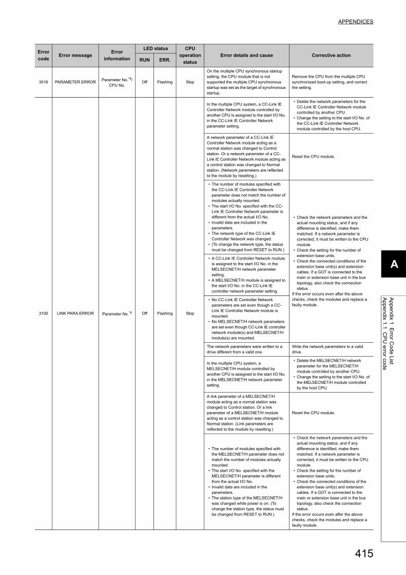
415
APPENDICES
A
Appendix 1 E
rror C
ode ListA
ppendix 1.1 CP
U error cod
e
3016 PARAMETER ERROR Parameter No.*4/CPU No.
Off Flashing Stop
On the multiple CPU synchronous startup setting, the CPU module that is not supported the multiple CPU synchronous startup was set as the target of synchronous startup.
Remove the CPU from the multiple CPU synchronized boot-up setting, and correct the setting.
3100 LINK PARA.ERROR Parameter No.*4 Off Flashing Stop
In the multiple CPU system, a CC-Link IE Controller Network module controlled by another CPU is assigned to the start I/O No. in the CC-Link IE Controller Network parameter setting.
• Delete the network parameters for the CC-Link IE Controller Network module controlled by another CPU.
• Change the setting to the start I/O No. of the CC-Link IE Controller Network module controlled by the host CPU.
A network parameter of a CC-Link IE Controller Network module acting as a normal station was changed to Control station. Or a network parameter of a CC-Link IE Controller Network module acting as a control station was changed to Normal station. (Network parameters are reflected to the module by resetting.)
Reset the CPU module.
• The number of modules specified with the CC-Link IE Controller Network parameter does not match the number of modules actually mounted.
• The start I/O No. specified with the CC-Link IE Controller Network parameter is different from the actual I/O No.
• Invalid data are included in the parameters.
• The network type of the CC-Link IE Controller Network was changed.
• (To change the network type, the status must be changed from RESET to RUN.)
• Check the network parameters and the actual mounting status, and if any difference is identified, make them matched. If a network parameter is corrected, it must be written to the CPU module.
• Check the setting for the number of extension base units.
• Check the connected conditions of the extension base unit(s) and extension cables. If a GOT is connected to the main or extension base unit in the bus topology, also check the connection status.
If the error occurs even after the above checks, check the modules and replace a faulty module.
• A CC-Link IE Controller Network module is assigned to the start I/O No. in the MELSECNET/H network parameter setting.
• A MELSECNET/H module is assigned to the start I/O No. in the CC-Link IE controller network parameter setting.
• No CC-Link IE Controller Network parameters are set even though a CC-Link IE Controller Network module is mounted.
• No MELSECNET/H network parameters are set even though CC-Link IE controller network module(s) and MELSECNET/H module(s) are mounted.
The network parameters were written to a drive different from a valid one.
Write the network parameters to a valid drive.
In the multiple CPU system, a MELSECNET/H module controlled by another CPU is assigned to the start I/O No. in the MELSECNET/H network parameter setting.
• Delete the MELSECNET/H network parameter for the MELSECNET/H module controlled by another CPU.
• Change the setting to the start I/O No. of the MELSECNET/H module controlled by the host CPU.
A link parameter of a MELSECNET/H module acting as a normal station was changed to Control station. Or a link parameter of a MELSECNET/H module acting as a control station was changed to Normal station. (Link parameters are reflected to the module by resetting.)
Reset the CPU module.
• The number of modules specified with the MELSECNET/H parameter does not match the number of modules actually mounted.
• The start I/O No. specified with the MELSECNET/H parameter is different from the actual I/O No.
• Invalid data are included in the parameters.
• The station type of the MELSECNET/H was changed while power is on. (To change the station type, the status must be changed from RESET to RUN.)
• Check the network parameters and the actual mounting status, and if any difference is identified, make them matched. If a network parameter is corrected, it must be written to the CPU module.
• Check the setting for the number of extension base units.
• Check the connected conditions of the extension base unit(s) and extension cables. If a GOT is connected to the main or extension base unit in the bus topology, also check the connection status.
If the error occurs even after the above checks, check the modules and replace a faulty module.
Error
codeError message
Error
information
LED status CPU
operation
status
Error details and cause Corrective actionRUN ERR.

416
3101 LINK PARA.ERROR Parameter No.*4 Off Flashing Stop
• When the station No. of a MELSECNET/H module is 0, parameters for the PLC-to-PLC network are set.
• When the station No. of a MELSECNET/H module is other than 0, parameters for a remote master are set.
Correct the type or station No. of the MELSECNET/H module.
The refresh parameters for the CC-Link IE Controller Network are out of range.
• Check the network parameters and the actual mounting status, and if any difference is identified, make them matched. If a network parameter is corrected, it must be written to the CPU module.
• Check the setting for the number of extension base units.
• Check the connected conditions of the extension base unit(s) and extension cables. If a GOT is connected to the main or extension base unit in the bus topology, also check the connection status.
If the error occurs even after the above checks, check the modules and replace a faulty module.
• The network No. specified with the parameter is different from the actual network No.
• The start I/O No. specified with the parameter is different from the actual I/O No.
• The network type specified with the parameter is different from the actual network type.
• Network refresh parameters for MELSECNET/H or MELSECNET/10 are out of range.
3102 LINK PARA.ERROR Parameter No.*4 Off Flashing Stop
A network parameter error on the CC-Link IE Controller Network was detected. • Correct the network parameters and
write them.• If the error occurs after the correction,
check the modules and replace a faulty module.
• A network module detected a network parameter error.
• A MELSECNET/H network parameter error was detected.
3103 LINK PARA.ERROR Parameter No.*4 Off Flashing Stop
In the multiple CPU system, a Q series Ethernet module controlled by another CPU is specified for the start I/O No. in the Network parameter setting for Ethernet.
• Delete the network parameter of the Q series Ethernet module controlled by another CPU.
• Change it to the start I/O No. of the Q series Ethernet module that the host CPU controls.
• Although the number of modules is set to one or greater in the Ethernet module count parameter setting, the number of actually mounted modules is zero.
• The start I/O No. in the Network parameter setting for Ethernet differs from that of the actually mounted module.
• Correct the network parameters and write them.
• If the error occurs after the correction, check the modules and replace a faulty module.
3104 LINK PARA.ERROR Parameter No.*4 Off Flashing Stop
• The Ethernet, CC-Link IE Controller Network, MELSECNET/H and MELSECNET/10 use the same network number.
• The network number, station number or group number set in the Parameter is out of range.
• The specified I/O No. is outside the range of the CPU module.
• The Ethernet-specific parameter setting is not normal.
3105 LINK PARA.ERROR Parameter No.*4 Off Flashing Stop
In the multiple CPU system, a Q series CC-Link module controlled by another CPU is specified for the start I/O No. in the CC-Link parameter setting.
• Delete the network parameter of the Q series CC-Link module controlled by another CPU.
• Change it to the start I/O No. of the Q series CC-Link module that the host CPU controls.
• Although the number of modules is set to one or greater in the CC-Link module count parameter setting, the number of actually mounted modules is zero.
• The start I/O No. in the common parameters is different from that of the actually mounted module.
• The station type in the CC-Link module count parameter setting is different from that of the actual station.
• Correct the network parameters and write them.
• If the error occurs after the correction, check the modules and replace a faulty module.
3107 LINK PARA.ERROR Parameter No.*4 Off Flashing Stop
• The CC-Link parameter setting is incorrect.
• The current mode is not allowed for the version of the mounted CC-Link module.
Check the parameter setting.
Error
codeError message
Error
information
LED status CPU
operation
status
Error details and cause Corrective actionRUN ERR.

417
APPENDICES
A
Appendix 1 E
rror C
ode ListA
ppendix 1.1 CP
U error cod
e
3150 DUPLICAT.NET.NO. Parameter No.*4 Off Flashing Stop
• When the CC-Link IE Field Network is used, the network number set in the network parameter and the switch setting is duplicated.
• No network parameter and switch setting are configured, or the CC-Link IE Field Network
• module with an incorrect switch setting is mounted.
• Check the parameter setting.• Configure the network parameters and
the switch settings, and then write network parameters and the switch settings to the module.
3300 SP.PARA.ERROR Parameter No.*4 Off Flashing Stop
The start I/O No. of an intelligent function module set in Setting/monitoring tools for the C Controller module differs from the actual I/O No.
Check the parameter setting.3301 SP.PARA.ERROR Parameter No.*4 Off Flashing Stop
The refresh parameter of an intelligent function module is outside the range, or the refresh range exceeded the file register capacity.
3302 SP.PARA.ERROR Parameter No.*4 Off Flashing StopAn intelligent function parameter is not normal. Check the parameter setting.
3303 SP.PARA.ERROR Parameter No.*4 Off Flashing StopIn the multiple CPU system, the parameter setting was performed for an intelligent function module controlled by another CPU.
• Delete the parameter setting of the intelligent function module controlled by another CPU.
• Change it to the parameter setting of the intelligent function module that the host CPU controls.
5000SYSTEM WDT
ERRORTime
(set value: ms)Off Flashing Stop
The system watchdog timer controlled by the system detected an error, or an error occurred in the system software.• The time set for the system watchdog
timer is too short.• A task of high CPU utilization is running.• A program that will cause an error in the
memory, stack, etc. was executed.*5
• An operation that increase the CPU utilization by the system task (restarting user CPU, and writing parameter from the setting/monitoring tools for the C Controller module) was executed.
• At a stop error occurrence, the station using block data assurance per station of the network was accessed.
• CPU module drives recklessly or it breaks down. (Malfunction by noise etc. and Hardware error)
• Restart the C Controller module• Increase the system WDT time value in
System settings of Setting/monitoring tools for the C Controller module.
• Decrease the CPU utilization of the task, or disable the task operation.
• Check the user program.*5
• Taking into account the system task CPU utilization, sufficiently prolong the system WDT setting time.
• Take a preventive measure against noise.
• Check that the C Controller module is securely installed in the base unit and the ambient environment is within the general specification range.
• Review the user program not to access to the station that is used block data assurance per station of the network at a stop error occurrence.
If the error occurs even after the above checks, check the modules and replace a faulty module.
5001 USER WDT ERRORTime
(set value: ms)Off Flashing Stop
Since the WDT reset was not executed within the user WDT setting time, the USER WDT (watchdog timer) controlled by the system detected an error. Or, an error occurred in the user program.• The user WDT setting time is too short.• A task of high CPU utilization is running.• A program that will cause an error in the
memory, stack, etc. was executed.• It debugged while online connection with
CW Workbench.*5
• The command was executed from Shell
for debugging.*5
• Functions that increase the CPU*5 utilization by system tasks are used:•Mount/unmount of SD memory card•Mount/unmount of CompactFlash card•Ethernet communication•NFS server communication
• Restart the C Controller module• Increase the user WDT time.• Decrease the CPU utilization of the task,
or disable the task operation.• Check the user program.• Check the command executed from
Shell.*5
• Taking into account the system task CPU utilization, sufficiently prolong the system
WDT setting time.*5
If the error occurs even after the above checks, check the modules and replace a faulty module.
Error
codeError message
Error
information
LED status CPU
operation
status
Error details and cause Corrective actionRUN ERR.

418
5012 REF. TIME OVER
Refresh cycle(set value: ms)/
Refresh time(measured value: ms)
On On Continue
The sum of the data refresh time and link refresh time exceeds the set refresh cycle.• The refresh cycle value is too short.• The number of set refresh points is
excessive.• A task of high CPU utilization is running.
(Ethernet communication load is high, etc.)
• Increase the refresh cycle value in Setting/monitoring tools for the C Controller module.
• Decrease the number of set refresh points in Setting/monitoring tools for the C Controller module.
• Decrease the CPU utilization of the task, or disable the task operation.
The C Controller module was restarted while online connection with CW
Workbench.*5
For precautions for program debugging, refer to the following. Setting/Monitoring Tools for the C Controller Module Version 4 Operating Manual
Restart the C Controller module with CW
Workbench connection disconnected.*5
7000 MULTI CPU DOWN Module No.*1 Off Flashing Stop
• In the operating mode of the multiple CPU system, a CPU error occurred in the CPU for which "All station stop by stop error of CPU" is selected.
• In the multiple CPU system, a CPU module incompatible with the multiple CPU system is mounted.
• When CPU No.1 is a Basic model QCPU, a "CPU (Empty)" slot is set on the right side of the C Controller module.
• Any CPU module other than CPU No.1 was disconnected from the base unit during operation. Or any CPU module other than CPU No.1 was reset.
• Identify the error of the CPU module and eliminate the error cause.
• Remove the incompatible CPU module from the main base unit.
• Change the setting.• Check the mounting status of CPU
modules other than CPU No.1 and whether the CPU modules were reset.
In the multiple CPU system, a stop error occurred in CPU No.1 during power-on, and thereby the other CPUs (No.2 to No.4) cannot start.
Identify the error of the CPU module and eliminate the error cause.
7002 MULTI CPU DOWN Module No.*1 Off Flashing Stop
• During the initial communication in the multiple CPU system, no response returns from the target CPU.
• In the multiple CPU system, a CPU module incompatible with the multiple CPU system is mounted.
• Remove the incompatible CPU module from the main base unit.
• Replace the incompatible CPU module with a compatible one.
• Reset the CPU module and restart it.• If the same error is displayed again,
check the modules and replace a faulty module.
7010 MULTI EXE.ERROR Module No.*1 Off Flashing Stop
• In the multiple CPU system, a faulty CPU module is mounted.
• In the multiple CPU system, a CPU module incompatible with the multiple CPU system is mounted. (A CPU module compatible with the multiple CPU system detects this error.)
• In the multiple CPU system, any of the CPU No.2 to No.4 was reset with power ON. (A CPU that released from the reset status detects this error.)
• Replace the faulty CPU.• Replace it with a CPU module that is
compatible with the multiple CPU system.
• Do not reset any of CPU No.2 to No.4.• Reset CPU No.1 and restart the multiple
CPU system.
7011 MULTI EXE.ERROR
Module No.*1 Off Flashing Stop
In a multiple CPU system, the either of following setting was set.• Set the multiple CPU auto refresh setting
to the CPU module that cannot execute the multiple CPU auto refresh setting.
• Set the I/O sharing when using Multiple CPUs to the CPU module that cannot read the I/O of outside of the group.
• Correct the multiple CPU automatic refresh setting.
• Correct the "I/O sharing when using multiple CPUs" setting.
Module No.*1 Off Flashing Stop
It does not meet the system requirement to use the multiple CPU high speed transmission.• It is not used QnUD(H)CPU or
QnDCCPU in CPU No.1.• It is not used the multiple CPU high
speed main base unit (Q3DB).• The send range is set excluding 0 point
to the CPU module that is not supported the multiple CPU high speed transmission.
• The send range is set excluding 0 point to the CPU module that is not supported the multiple CPU interchangeability area.
• Change the system configuration so that the conditions for using the multiple CPU high speed transmission function are met.
• When performing automatic refresh in the multiple CPU compatible area, set the send range of a CPU that does not support the function to zero points.
7013 MULTI EXE.ERROR Module No.*1 Off Flashing StopQ172(H)CPU(N) or Q173(H)CPU(N) is installed in CPU slot and slot 0 to 2 (There is a possibility that the module breaks down.).
Check QCPUs and Motion CPUs that can be used in multiple CPU systems, and change the system configuration.
Error
codeError message
Error
information
LED status CPU
operation
status
Error details and cause Corrective actionRUN ERR.

419
APPENDICES
A
Appendix 1 E
rror C
ode ListA
ppendix 1.1 CP
U error cod
e
7020 MULTI CPU ERROR Module No.*1 On On Stop
In the operating mode of the multiple CPU system, an error occurred in the CPU for which "All station stop by stop error of CPU" is not selected. (A normal CPU module detects this error.)
Identify the error of the CPU module, and eliminate the error.
7036 CPU LAY ERROR Module No.*1 Off Flashing Stop
The number of connected CPU set in the multiple CPU setting does not match the number of connected CPU that is decided according to fixing point of CPU module.
• Mount the CPU module in the correct slot.
• Change the host CPU No. set in the multiple CPU setting to the one determined by the mounting position of the CPU module.
*1 : The error information (module No.) in "Event information" in the <<Event history>> tab of Setting/monitoring tools for the C Controller module is displayed as follows:"Error information: XX - YYY"XX (DEC.): Slot No. (0 to 63), CPU No. (1 to 4)YYY (HEX.): Start I/O No. 16 (000 to 0FF, 3E0 to 3E3)
*2 : The CPU operation status for error detection can be changed to "Continue" in "Operation mode at the time of error" in Project view "Parameter" "CCPU Parameter" <<RAS settings>> in Setting/monitoring tools for the C Controller module.
*3 : Either of "Stop" or "Continue" can be set for each module >> in "Detailed Setting" "CPU Operation Mode at H/W Error" through Project view" "Parameter" "CCPU Parameter" <<I/O assignment settings>>
*4 : For the parameter setting location for each parameter number, refer to the following. Page 296, Section 15.3
*5 : Not supported by Q24DHCCPU-LS and Q26DHCCPU-LS.
Error
codeError message
Error
information
LED status CPU
operation
status
Error details and cause Corrective actionRUN ERR.

420
Appendix 1.2 Error code detected during device monitor execution
This section describes error codes detected during device monitor function execution in Setting/monitoring tools for the
C Controller module.
Error code may not be returned as described in "(1) How to read error code".Check details of "(2) Precautions for error code checking" first, and then refer to "(1) How to read error code".
(1) How to read error codeThe error code is composed of 4 bytes.
The higher 2 bytes represents the error detection module and the lower 2 bytes represents the error details.
(2) Precautions for error code checkingPrecautions for error code checking are described below.
(a) Setting of "Transfer Setup" in Setting/monitoring tools for the C Controller module
Check that the actual system configuration and "Transfer Setup" are matched and monitored.
If the used system configuration and "Transfer Setup" setting are not matched, error code (higher 2 bytes) does
not indicate the correct error detection module.
For example, if the destination CPU module is actually QCPU (Q mode) and ACPU is set in "Transfer Setup",
error code (higher 2 bytes) may indicate the ACPU.
(b) To monitor another station
Check the manuals for used CPUs and the relayed network module also.
When it monitors another station, error details of the relayed network module (CC-Link IE Controller Network,
MELSECNET/H, MELSECNET/10, CC-Link, or CC-Link IE Field Network) may be stored in error code (lower 2
bytes).
In such case, error code (higher 2 bytes) may not match with the module in which any error occurs.
Error code
(Higher 2 bytes)Error detection module
0101H QCPU (A mode), ACPU
0102H QnACPU
010AH QCPU (Q mode), LCPU, C Controller module
010FH GOT
Error code
(Lower 2 bytes)Error description
0000H to FFFFH Refer to the manual for the error detection module.
Error detection module
Error description
Higher Lower

421
APPENDICES
A
Appendix 1 E
rror C
ode ListA
ppendix 1.3 Error code during function execution
Appendix 1.3 Error code during function execution
The error codes returned in bus interface, C Controller module dedicated function or MELSEC data link function
execution are returned as a return value.
(1) Common error codes returned by each functionThe following table provides the error descriptions and corrective actions to individual error code commonly
returned in execution of bus interface functions, C Controller module dedicated function, and MELSEC data link
functions.
Return value
(HEX)*1Error description Corrective action
0
(0000H)Completed normally -
1
(0001H)
Driver not started
• The driver has not been started.
• Check the channel No.
• Correct the error that occurred when starting the driver.
• Check the status of the system drive.
• Check if the operating system is running normally.
2
(0002H)
Timeout error
• A timeout occurred while waiting for response.
• Check the operation status and mounting condition of the accessed
station(s).
• Retry from the user program.
• Increase MD function timeout value in Setting/monitoring tools for the C
Controller module.
66
(0042H)
Already opened
• The specified channel has already been opened.
Open once.
(A correct path is returned to the argument even when this error occurs.)
67
(0043H)
Already closed
• The specified channel has already been closed.Close once.
69
(0045H)
Unsupported function execution error
• A function which is not supported by the target station was executed.
• Check the path of channel, network number, and station number.
• Check if the function is supported by the target station.
70
(0046H)
Station No. error
• The specified station No. is incorrect.
• This station received a request destined for another station. Or, the station No.
corresponds to the own station (0xFF) but the network No. is not 0.
Correct the network No. and station No. in the user program.
71
(0047H)
Data reception error (When a RECV request is issued.)
• Data have not been received.
• Retry.
• Check the channel number.
• Check whether the data is sent on the sending station with the SEND
function.
77
(004DH)
Memory error/resource memory shortage error/excessive task number error
• Sufficient memory could not be allocated.
• Bus interface functions/C Controller module dedicated function/MELSEC data link
functions are used in a excessive number of tasks.
• Terminate other task(s) currently running, or decrease the size of data to
be accessed.
• Check if the C Controller module is running normally.
• Reset the C controller system.
• Reduce the number of tasks that use bus interface functions/C Controller
module dedicated function
• /MELSEC data link functions and then retry.
• Review the size and quantity specified in the function argument.
85
(0055H)
Network channel No. error (When a SEND/RECV request is issued.)
Channel No. errorCheck the specified channel No. when a SEND/RECV request is issued.
102
(0066H)
Transmission error
• Transmitting data has failed.
• Retry.
• Check if the C Controller module is running normally.
• Reset the C controller system.
• Retry after restarting.
103
(0067H)
Reception error
• Receiving data has failed.
• Retry.
• Check if the C Controller module is running normally.
• Reset the C controller system.
130
(0082H)
Device No. error
• The specified device No. is out of range.
• Device No. in the bit device settings is not a multiple of 8.
• Check the device No..
• When specifying device No.32768(8000H) or higher, replace the
"functions for compatibility" with "available functions".
Page 356, Section 21.2, Page 362, Section 22.2
131
(0083H)
Device points error
• The specified number of points is out of range.
• The number of points in the bit device settings is not a multiple of 8.
• Check the number of device points.
• When specifying a size of 32768(8000H) bytes or more, replace the
"functions for compatibility" with "available functions".
Page 356, Section 21.2, Page 362, Section 22.2
8193
(2001H)
• The specified device is a device that cannot be used with the Motion CPU.
• The specified device is out of the device range.
• Check the specified device name.
• Check the specified device No. and size.

422
8194
(2002H)
The dedicated instruction which is not supported by the operating system of motion
CPU is executed.
Check if the executed motion dedicated instruction is supported by the
operating system of motion CPU used.
8320
(2080H)The number of write data points set by the D(P).DDWR instruction is invalid.
Check the specified size.8321
(2081H)The number of read data points set by the D(P).DDRD instruction is invalid.
8322
(2082H)The interrupt pointer No. set by the D(P).GINT instruction is out of the range of 0 to 15. Check the specified interrupt pointer No..
8448
(2100H)
• There were 33 or more instructions simultaneously requested from the
Programmable controller CPU/C Controller module to the Motion CPU in
D(P).GINT. The Motion CPU cannot process the instructions.
• There were 65 or more instructions simultaneously requested to the Motion CPU in
D(P).SFCS. The Motion CPU cannot process the instructions.
• There were 65 or more instructions (for Q172DS/Q173DS using SV13/SV22
version B or later, 129 or more instructions) simultaneously requested from the
Programmable controller CPU/C Controller module to the Motion CPU in
D(P).SVST, D(P).CHGA, and D(P).CHGAS combined. The Motion CPU cannot
process the instructions.
• There were 65 or more instructions simultaneously requested from the
programmable controller CPU/C language controller module to the Motion CPU in
D(P).DDRD and D(P).DDWR combined. The Motion CPU cannot process the
instructions.
• Wait for the Motion CPU to process instruction requests, and try again.
• Reduce the number of instructions requested to the Motion CPU.
8704
(22004)The Motion SFC program number to be started is out of the range of 0 to 255. Check the specified SFC program No..
8705
(2201H)The servo program number to be executed is out of the range of 0 to 4095. Check the specified servo program No..
8706
(2202H)The axis number set in the D(P).SVST instruction is invalid.
Check the specified axis No..
8707
(2203H)The axis number set in the D(P).CHGA instruction is invalid.
8708
(2204H)The axis number set in the D(P).CHGV instruction is invalid.
8709
(2205H)The axis number set in the D(P).CHGT instruction is invalid.
8710
(2206H)The axis number set in the D(P).CHGT2 instruction is invalid.
8711
(2207H)The axis number set in the D(P).CHGAS instruction is invalid.
8712
(2208H)The axis number set in the D(P).CHGVS instruction is invalid.
16384
(4000H)
to
20479
(4FFFH)
Error detected in destination CPUs Refer to the user's manual for the respective destination CPU module.
16385
(4001H)An unprocessable request was received. Change the request destination.
16386
(4002H)
16400
(4010H)Not executable during running Reset the C Controller module when it is in the STOP status.
16432
(4030H)The specified device type does not exist.
• Check the device type.
• Check if the device number is validated on the target station.
16433
(4031H)
• The specified device No. is out of range.
• The block No., network No., start I/O No. / 10H, or CPU No. of the specified device
is invalid.
• The specified device name is not supported by the CPU modules.
• Check the device No.
• When specifying device No.32768(8000H) or higher, replace the
"functions for compatibility" with "available functions".
Page 356, Section 21.2, Page 362, Section 22.2
• Check the block No., network No., start I/O No. / 10H, and CPU No.
(device type) of the specified device.
• On the target, check if the specified device, block No., network No., start
I/O No. / 10H, and CPU No. are valid.
• Check the device settings of the CPU modules.
• Check the device name.
16448
(4040H)The module does not exist.
Do not issue a request that generated an error to the specified special
function.
Return value
(HEX)*1Error description Corrective action

423
APPENDICES
A
Appendix 1 E
rror C
ode ListA
ppendix 1.3 Error code during function execution
16449
(4041H)
The number of device points is out of range.
• Check the start address and number of access points.
• When specifying a size of 32768(8000H) bytes or more, replace the
"functions for compatibility" with "available functions".
Page 356, Section 21.2, Page 362, Section 22.2
The specified device is not accessible.Check the start address and the number of access points, and access an
accessible device.
16450
(4042H)Corresponding module error. Check if the specified module is operating normally.
16451
(4043H)
The specified intelligent function module does not exist.Check the I/O number and network No. of the specified intelligent function
module.
In a single CPU system configuration, an access to the CPU shared memory of the C
Controller module was attempted.
To access the CPU shared memory of the C Controller module, configure a
multiple CPU system.
Access to an inaccessible CPU shared memory area was attempted. Check the specified CPU shared memory area.
16480
(4060H)
Online registration error
• The online debug function is currently running on another peripheral device.
• After the operation has ended on the other peripheral device, execute the
function once again.
• In a case where the operation is in progress or the operation has been
suspended on the other peripheral device, execute the operation once
again on the other peripheral device, wait for the operation to end
normally, and then execute the operation once again.
16523
(408BH)Remote request not executable
Allow "Remote reset" in Setting/monitoring tools for the C Controller module,
and then execute remote reset.
16641
(4101H)The number of write data is out of the storage device range for data to be written. Check and revise the program to a proper user program.
16716
(414CH)
An inaccessible buffer memory address was specified. Check and correct the buffer memory address.
The inaccessible CPU shared memory address was specified. Check and correct the CPU shared memory address.
17232
(4350H)
The specified destination CPU module is wrong.
A CPU No. set as reserved was specified.
A CPU No. not mounted was specified.
The start I/O No. of the destination CPU module divided by 10H is out of the range of
3E0H to 3E3H.
Check and revise the program to a proper user program.
17233
(4351H)
The instruction cannot be executed on the specified target CPU module.
• The instruction name is wrong.
• A non-supported instruction was executed on the target CPU module.
17234
(4352H)The number of devices of the specified instructions is wrong.
17235
(4353H)An inapplicable device was specified in the specified instruction.
17236
(4354H)A non-supported string was specified in the specified instruction.
17237
(4355H)The number of write data is out of the range of 1 to 20.
18944
(4A00H)
• Network No. or station No. is incorrect.
• Routing parameter does not exist in other network settings
• The module with relay network No. and station No. specified in the routing
parameter settings is not mounted.
• Check the specified network No. and station No..
• Check the routing parameter settings.
19200
(4B00H)An error was detected in the target.
• Check the target.
• Confirm the error occurred in the target or relay station, and then take a
corrective action.
19201
(4B01H)The target is not the bus master CPU (CPU 1).
If the target is not the bus master CPU (CPU 1), it cannot execute remote
reset.
19203
(4B03H)
Unsupported communication path error
• The request cannot be executed via the specified communication path/target.
• Check the communication path/target that supports the request.
• Do not issue a request that has generated an error to a C Controller
module.
• When sending a request to the own station, select station No. 255 (FFH).
19457
(4C01H)
The instruction for the multiple CPU system is not supported by operating system of
the Motion CPU. (The error code returned by the Motion CPU)
Refer to the manual of the Motion CPU currently used. Check the user program on C Controller module.
19458
(4C02H)
Motion SFC program No. error (the error code returned by the Motion CPU)
Refer to the manual of the Motion CPU currently used.
Return value
(HEX)*1Error description Corrective action
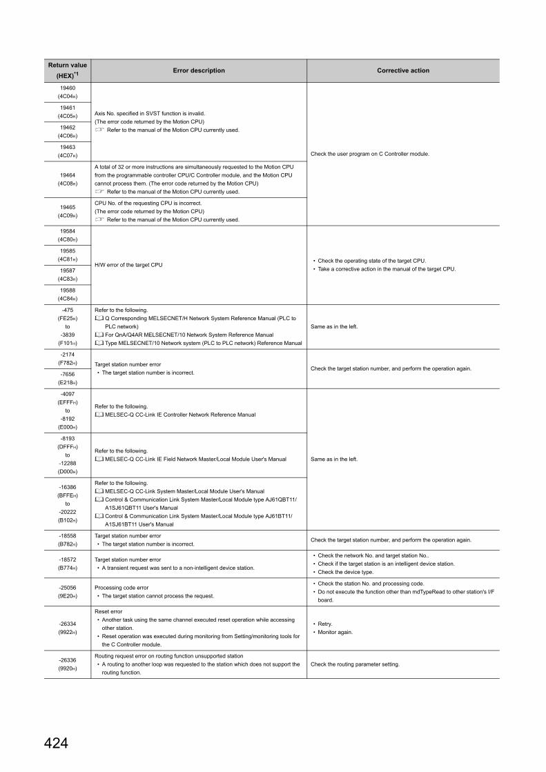
424
19460
(4C04H)
Axis No. specified in SVST function is invalid.
(The error code returned by the Motion CPU)
Refer to the manual of the Motion CPU currently used.
Check the user program on C Controller module.
19461
(4C05H)
19462
(4C06H)
19463
(4C07H)
19464
(4C08H)
A total of 32 or more instructions are simultaneously requested to the Motion CPU
from the programmable controller CPU/C Controller module, and the Motion CPU
cannot process them. (The error code returned by the Motion CPU)
Refer to the manual of the Motion CPU currently used.
19465
(4C09H)
CPU No. of the requesting CPU is incorrect.
(The error code returned by the Motion CPU)
Refer to the manual of the Motion CPU currently used.
19584
(4C80H)
H/W error of the target CPU• Check the operating state of the target CPU.
• Take a corrective action in the manual of the target CPU.
19585
(4C81H)
19587
(4C83H)
19588
(4C84H)
-475
(FE25H)
to
-3839
(F101H)
Refer to the following.
Q Corresponding MELSECNET/H Network System Reference Manual (PLC to
PLC network)
For QnA/Q4AR MELSECNET/10 Network System Reference Manual
Type MELSECNET/10 Network system (PLC to PLC network) Reference Manual
Same as in the left.
-2174
(F782H) Target station number error
• The target station number is incorrect.Check the target station number, and perform the operation again.
-7656
(E218H)
-4097
(EFFFH)
to
-8192
(E000H)
Refer to the following.
MELSEC-Q CC-Link IE Controller Network Reference Manual
Same as in the left.
-8193
(DFFFH)
to
-12288
(D000H)
Refer to the following.
MELSEC-Q CC-Link IE Field Network Master/Local Module User's Manual
-16386
(BFFEH)
to
-20222
(B102H)
Refer to the following.
MELSEC-Q CC-Link System Master/Local Module User's Manual
Control & Communication Link System Master/Local Module type AJ61QBT11/
A1SJ61QBT11 User's Manual
Control & Communication Link System Master/Local Module type AJ61BT11/
A1SJ61BT11 User's Manual
-18558
(B782H)
Target station number error
• The target station number is incorrect.Check the target station number, and perform the operation again.
-18572
(B774H)
Target station number error
• A transient request was sent to a non-intelligent device station.
• Check the network No. and target station No..
• Check if the target station is an intelligent device station.
• Check the device type.
-25056
(9E20H)
Processing code error
• The target station cannot process the request.
• Check the station No. and processing code.
• Do not execute the function other than mdTypeRead to other station's I/F
board.
-26334
(9922H)
Reset error
• Another task using the same channel executed reset operation while accessing
other station.
• Reset operation was executed during monitoring from Setting/monitoring tools for
the C Controller module.
• Retry.
• Monitor again.
-26336
(9920H)
Routing request error on routing function unsupported station
• A routing to another loop was requested to the station which does not support the
routing function.
Check the routing parameter setting.
Return value
(HEX)*1Error description Corrective action

425
APPENDICES
A
Appendix 1 E
rror C
ode ListA
ppendix 1.3 Error code during function execution
-28150
(920AH)
Device access error during data link stop
• .RX/RY/RWw/RWr was accessed when the own station was not transmitting data.
• Check the specified device start number and size, or the device range of
the parameter on the master station.
• Restart the data link.
(Writing/reading data will be performed even when this error occurs.
However, the data are not guaranteed.)
-28151
(9209H)
Abnormal data reception error
• An incorrect response data was received.
Check if there is an error in the target CPU, CC-Link module, or
MELSECNET/H module. If the status is normal, try again.
-28155
(9205H)
SRAM write error
• Battery backup RAM writing failed.Change the C Controller module if the error persists.
-28158
(9202H)
WDT error
• Watchdog timer (WDT) error occurred.Reset the C Controller system.
-28410
(9106H)
Target CPU busy error
• Target CPU is busy.
• Add a program to wait until the processing is completed or to retry.
• Increase the timeout value in the user program.
-28412
(9104H)
Target CPU unsupported error
• An unsupported request was sent to the target CPU.Change the target CPU No. in the user program.
-28413
(9103H)
Target CPU down error
• Check the operating status of the target CPU and trouble shoot the error.
Check the operating status of the target CPU and trouble shoot the error.-28414
(9102H)
Target CPU abnormal start error
• A request was sent to the CPU which was not operating normally.
-28415
(9101H)
Target CPU critical error
• A request was sent to the CPU where a critical error occurred.
-28416
(9100H)
Target CPU not mounted error
• A request was processed for the CPU No. to which no CPU module is installed.
• Check if the target CPU is mounted properly.
• Change the target CPU No. specified in the user program.
-28622
(9032H)
Target module busy error
• Target module is busy.
• The channel specified for "Channel used by the own station" or "Target station
channel" is being used by another instruction.
Add a program to wait until the processing is completed or to retry.
-28624
(9030H)
Function unsupported error
• Processing was executed for the module that does not support the block data
assurance per station function.
• Processing was executed for the module where the block data assurance per
station function was not activated.
• Own CPU does not control the specified module.
• Check the version to see if the target module supports the block data
assurance per station function.
• Check if the block data assurance per station setting is enabled for the
target module in Setting/monitoring tools for the C Controller module.
• Check if the control CPU of the specified module is own CPU.
-28625
(902FH)
Intelligent function module offline error
• Intelligent function module was accessed while offline.
Check the mode state of the intelligent function module and access the
module while online.
-28626
(902EH)
Control data error
• The specified control data is out of range.Check the user program, and correct the control data setting.
-28627
(902DH)
Transient unsupported error
• A transient request cannot be executed via the specified communication path and
target. (With CC-Link communication, when the station No. of the own station was
"64", other station was specified.)
• Check a communication path and target which supports the transient
request.
• Change the station No. of the own station.
-28628
(902CH)
Pointer address error (pointer address is invalid.)
• The address of a short type pointer is not a multiple of 2.
• The address of a long type pointer is not a multiple of 4.
Check the pointer type and address (cast, structure alignment, etc.).
-28629
(902BH)
WDT not running error
• WDT was reset when WDT was started up.Start the WDT and then reset WDT.
-28630
(902AH)
WDT startup error
• WDT was started up while WDT was running.Stop WDT and then restart WDT.
-28631
(9029H)
Buffer access range error
• The specified offset is out of range.
• The specified offset plus size is out of range.
• Check the offset.
• Check the buffer size.
• Check the offset plus size.
-28632
(9028H)
I/O No. error
• The specified I/O No. is out of range.
• The module is not mounted on the specified I/O No., or the specified module
cannot be accessed.
Check the I/O No.
-28633
(9027H)
Non-controlled module read error
• Reading from a non-controlled module is not allowed.
• Clear "Enable online module change with another CPU" selection in the
multiple CPU setting.
• Check if the control CPU of the specified module is own CPU (C
Controller module).
-28634
(9026H)
Intelligent function module down error
• There is a problem in the intelligent function module.
• Check if the intelligent function module is mounted properly.
• Replace the intelligent function module or base unit.
-28635
(9025H)
Intelligent function module error
• The intelligent function module is not mounted on the accessed slot.
• Check the I/O No.
• Check if the intelligent function module is mounted properly.
-28636
(9024H)
Control bus error
• Control bus error occurred.
• Check if there is an error in CPU 1 in the multiple CPU system.
• Check if the intelligent function module is mounted properly.
• Replace the intelligent function module or base unit.
Return value
(HEX)*1Error description Corrective action

426
-28638
(9022H)Multiple CPU unsupported operation error Reset CPU 1.
-28640
(9020H)
STOP/PAUSE error
• Output data was written to output module when the CPU operating status is STOP/
PAUSE. Buffer memory data was written to intelligent function module when the
CPU operating status is STOP/PAUSE.
Change the CPU operating status to RUN.
-28653
(9013H)
I/O assignment error
• Input data was read from output module.
• Output data was written to input module.
• Output data was read from input module.
• Check the I/O No.
-28654
(9012H)
Non-controlled module write error
• Own CPU does not control the specified module.Check if the control CPU of the specified module is own CPU.
-28660
(900CH)
Access size error
• The specified size is out of range.Check the offset and size.
-28661
(900BH)
Access area error
• The specified area cannot be accessed.
-28662
(900AH)
CPU No. error
• The specified CPU No. is out of range or invalid.
• Check the CPU No.
• Check the operating status of the specified CPU.
-28663
(9009H)
Base unit No. error
• The specified base unit No. is out of range.Check the base unit No.
-28664
(9008H)Data transmission area occupied. Retry.
-28665
(9007H)No registration data error
Reset the C Controller system.-28666
(9006H)Data length error
-28668
(9004H)Reply data stored error Resend the request.
-28669
(9003H)
Area No. error
• The specified area No., offset address, or mode is out of range.Check the area No., offset address, or mode.
-28671
(9001H)Module identification error
• Check the parameter.
• Check the specified module.
• Reset the C controller system.
-28672
(9000H)Processing code error Reset the C Controller system.
*1 : If the result value is a long type function, the value is 8-digit in hexadecimal form.
Return value
(HEX)*1Error description Corrective action

427
APPENDICES
A
Appendix 1 E
rror C
ode ListA
ppendix 1.3 Error code during function execution
(2) Error codes returned by bus interface functions or C Controller module
dedicated functionThe following provides the error descriptions and corrective actions corresponding to individual error code
returned in execution of bus interface functions or C Controller module dedicated function.
Return value
(HEX)Error description Corrective action
0
(0000H)Completed normally -
-201
(FF37H)
Module identification error
• The specified module identification is invalid.Check the specified module.
-202
(FF36H)
Path error
• The specified path is invalid.Use the path pointer returned by "QBF_Open" function.
-203
(FF35H)
I/O No. error
• The specified I/O No. is out of range.Check the I/O No.
-204
(FF34H)
I/O access size error
• The specified I/O access size is out of range.Check the I/O access size (I/O No. and read/write size.)
-205
(FF33H)
I/O No. error
• The specified I/O No. is out of range.Check the I/O No.
-206
(FF32H)
Program execution type error
• The specified program execution type is out of range.Check the program execution type.
-208
(FF30H)
Offset error
• The specified offset is out of range.
• AnS series module (buffer memory) was accessed.
• Check the offset.
• Check the I/O No.
-209
(FF2FH)
Buffer memory size error
• The specified offset plus size is out of range.
• The address of data storage buffer pointer is 0.
• Check the specified buffer memory size.
• Check the offset plus size.
• Check the data storage buffer pointer.
-210
(FF2EH)
Read area size error
• The read area size is smaller than the read size.• Check the read size and read area size.
-211
(FF2DH)
Time setting error
• Time setting is out of range.Check the specified time.
-214
(FF2AH)
Intelligent function module error
• The intelligent function module is not mounted on the accessed slot.
• Check the I/O No.
• Check if the intelligent function module is mounted properly.
-217
(FF27H)
Driver not started
• Driver has not been started.Check if the driver has been started.
-218
(FF26H)
Bus already opened
• "QBF_Open" is executed twice.Only one instance of "QBF_Open" can be executed.
-219
(FF25H)
Program name error
• The specified program name is invalid.
(The program name does not exist in the programmable controller CPU or is not
registered with a parameter.)
Check the program name.
-220
(FF24H)
WDT type error
• The specified WDT type is out of range.Check the WDT type.
-222
(FF22H)
Bus master CPU reset error
• Remote reset for the bus master CPU (CPU 1) has failed.
• Allow "Remote reset" in the system settings for the bus master CPU
(CPU 1).
• Change the status of the bus master CPU (CPU 1) to STOP.
• Check if the bus master CPU (CPU 1) is programmable controller CPU or
C Controller module.
-223
(FF21H)
Memory allocation error
• Sufficient memory could not be allocated.Check available memory.
-224
(FF20H)
LED set value error
• The specified LED control value is out of range.Check the LED set value.
-225
(FF1FH)
Event No. error
• The specified event No. is out of range or duplicated.Check the event No.
-227
(FF1DH)
Control code send error
• Sending the control code has failed.
• Retry.
• Check if the C Controller module is running normally.
• Reset the C Controller system.
-231
(FF19H)
Event timeout error
• A timeout occurred while waiting for the event.
• Increase the timeout value.
• Check that the interrupt event No. is set properly.
-232
(FF18H)
CPU No. error
• The specified CPU No. is incorrect.
• The specified CPU cannot execute the request.
• Specify a different CPU No.
• Do not issue a request that generated an error to the CPU.

428
-234
(FF16H)
Event wait error
• An error other than timeout occurred while waiting for the event.
• Ensure the operating system is not forcibly terminating the program.
• Check if the C Controller module is running normally.
• Reset the C Controller system.
-235
(FF15H)
Number of event settings error
• The specified number of event settings is out of range.Check the number of event settings.
-236
(FF14H)
Remote operation code error
• The specified remote operation code is out of range.Check the remote operation code.
-237
(FF13H)
Event source/event information character string error
• Any character other than one-byte alphanumeric ('a'-'z', 'A'-'Z', '0'-'9') is in event
source "pcSrcStr[]".
• Any character string 11 bytes or more is in event source "pcSrcStr[]".
• Any character string 201 bytes or more is in event information "pcAddMsg[]".
Change the event source/event information character string.
-238
(FF12H)
Event log registration error
• Event log registration has failed.Reset the C Controller system.
-239
(FF11H)
Memory card error
• SD Memory card is not inserted.
• CompactFlash card is not inserted.
• Check if the SD memory card is inserted.
• Check if the CompactFlash card is inserted.
-240
(FF10H)
Clock data error
• The clock data setting/clock data setting to be read is invalid.
• Check the clock data setting.
• If this error occurred when reading the clock data, set the clock data.
-241
(FF0FH)
Cycle error
• The specified event cycle is out of range.
• The event cycle is being registered.
• Check the specified event cycle.
• Check if the event cycle is being registered.
-242
(FF0EH)
Synchronization type error
• The specified synchronization type is out of range.Check the specified synchronization type.
-243
(FF0DH)
SRAM size error
• The specified offset plus size is out of range.
• Check the specified size.
• Check the offset plus size.
-245
(FF0BH)
Not executable during interrupt service routine
• A value other than 1 (ISR) was specified in "sFlg", and the function was executed
as interrupt service routine.
Specify 1 (ISR) in "sFlg" to correct the routine registered.
-246
(FF0AH)
Timer event registration error
• Timer event registration has failed.
• Retry.
• Check if the C Controller module is running normally.
• Reset the C Controller system.
-247
(FF09H)
Program No. error
• The specified program No. is out of range or invalid.
SFC program No. (0 to 255)
Servo program No. (0 to 4095)
Correct the program No. in the user program.
-248
(FF08H)
Number of axes error
• 9 or more axes was specified.Correct the number of axes in the user program.
-249
(FF07H)
Axis type error
• The specified axis type is not axis (stopped axis), synchronous encoder axis, or
cam axis.
Correct the axis type in the user program.
-250
(FF06H)
Axis No. error
• The specified axis No. is out of range.Correct the axis No. in the user program.
-252
(FF04H)
Torque limit value error
• The specified torque limit value is out of range.Correct the torque limit value in the user program.
-253
(FF03H)
Device No. error
• The specified device No. is out of range.
• Device No. in the bit device settings is not a multiple of 16.
Correct the start device No.
-254
(FF02H)
Device type error
• The specified device type is invalid.Correct the device type in the user program.
-255
(FF01H)
Size error
• The specified start device No. plus size is out of range.Correct the start device No. and size.
-256
(FF00H)
Timeout error
• A timeout occurred while waiting for response from other CPU.
• Increase the timeout value in the user program.
• Correct the user program (including other tasks which execute Motion
CPU control/access functions)
• Check the program (user program, SFC program, or ladder program) of
the target CPU. (e.g., Add WAIT instruction to enable execution from
other CPU.)
-257
(FEFFH)The value specified as the interrupt type is out of range.
Review the specified value, and specify a value that is within range.-258
(FEFEH)The value specified as the interrupt type is out of range.
-259
(FEFDH)
No interrupt routine service registration
• When an attempt was made to enable processing for an event (interrupt), the
processing was not registered.
Register the processing for the event (interrupt) and then execute the
operation once again.
Return value
(HEX)Error description Corrective action

429
APPENDICES
A
Appendix 1 E
rror C
ode ListA
ppendix 1.3 Error code during function execution
-260
(FEFCH)
Memory card mount/unmount error
• The SD memory card mounting process or un-mounting process has failed.
• The CompactFlash card mounting process or un-mounting process has failed.
• Retry.
• Verify that the SD memory card or CompactFlash card is not damaged.
• Replace the SD memory card or CompactFlash card.
-262
(FEFAH)
User CPU restarting error
• The user CPU is not ready for restarting.
• Configure settings to permit user CPU restarting in Setting/monitoring
tools for the C Controller module.
• Check if the C Controller module is in STOP status.
-263
(FEF9H)
Call source flag error
• The value specified in the call source flag is out of range.Review the specified value, and specify a value that is within range.
-264
(FEF8H)
Pointer error
• The specified pointer address is invalid.Check the specified pointer.
-265
(FEF7H)
The target system specification error
• A value specified for the target system is out of range.Review the specified value, and specify a value that is within range.
-266
(FEF6H)
Watchdog timer startup error
• User watchdog timer is started up by Setting/monitoring tools for the C Controller
module.
Check the user watchdog timer setting.
(If user watchdog timer is started up by Setting/monitoring tools for the C
Controller module, the user watchdog timer cannot be started up or stopped
by the user program.)
Return value
(HEX)Error description Corrective action

430
(3) Error codes returned by MELSEC data link functionsThe following provides the error descriptions and corrective actions corresponding to individual error code
returned in execution of MELSEC data link functions.
Return value
(HEX)*1Error description Corrective action
0
(0000H)Completed normally -
-1
(FFFFH)
Path error
• The specified path is invalid.User a path pointer returned by the mdOpen function.
-2
(FFFEH)
Device No. error
• The specified device No. is out of range.
• Device No. in the bit device settings is not a multiple of 8.
• Device No. plus the number of points specified in mdRandR/mdRandREx/
mdRandW/mdRandWEx function exceeds the range for the same block.
• Check the start device No. of the specified device.
• Check the device No. plus the number of points of the same block.
• Check if the specified device is validated in a programmable controller
CPU on the target station.
• When specifying device No.32768(8000H) or higher, replace the
"functions for compatibility" with "available functions".
( Page 356, Section 21.2)
• When specifying within the expanded B or W device number range,
check if using Q12DCCPU-V with a serial number whose first five digits
are "15102" or later and the mode has been switched to the extended
mode.
-3
(FFFDH)
Device type error
• The specified device type is invalid.
• Check if the specified device type is in the device list.
• Check if the device number is validated on the target station.
• When specifying within the expanded B or W device number range,
check if using Q12DCCPU-V with a serial number whose first five digits
are "15102" or later and the mode has been switched to the extended
mode.
-5
(FFFBH)
Size error
• The device No. plus size exceeds the device range.
• Access was attempted in odd byte(s).
• The device No. plus size exceeds the range for the same block.
• The total of the specified point of each block No. of mdRandREx, mdRandWEx
exceeds 10240 points.
• Check the device size.
• Check the device No. plus size.
• When specifying device No.32768(8000H) or higher, replace the
"functions for compatibility" with "available functions".
( Page 356, Section 21.2)
• When specifying a size of 32768(8000H) bytes or more, replace the
"functions for compatibility" with "available functions".
( Page 356, Section 21.2)
• The total of the specified point of each block No. of mdRandREx,
mdRandWEx is adjusted to 10240 points or less.
-6
(FFFAH)
No. of blocks error
• The number of blocks specified for mdRandR/mdRandREx/mdRandW/
mdRandWEx is out of range.
Check the number of blocks specified.
-8
(FFF8H)
Channel No. error
• The channel No. specified in the mdOpen function is invalid.Check the channel No.
-11
(FFF5H)
Insufficient buffer area
• Read data storage size is smaller than the read data size.Check the read data size and the read data storage size.
-12
(FFF4H)
Block No. error
• The specified block No. is invalid.
• Check the block No. (device type).
• Check if the specified device and block No. are valid in the target.
-13
(FFF3H)
Write protect error
• The specified block No. of the extension file register is overlapping with the write
protect area of the memory cassette.
• Check the block No. (device type) of the extension file register.
• Check the write protect DIP switch of the accessed memory cassette.
-16
(FFF0H)
Station No. error, Network No. error
• The specified station No. or network No. is out of range.Check the station No. and network No.
-17
(FFEFH)
All stations/group No. specification error
• All stations/group No. specification is not supported by the specified function.
• Check if the function allows for specifying all stations/group No..
• Specify the device type as "no arrival confirmation", when specified
station No. is "All stations" or "Group No.".
-18
(FFEEH)
Remote operation error
• An inappropriate was specified.Check the code.
-19
(FFEDH)
SEND/RECV channel No. error
• The channel No. specified in the SEND/RECV function is out of range.
Specify the channel No. within the range.
• MELSECNET/H, CC-Link IE Controller Network (1 to 8)
• CC-Link IE Field Network (1 to 2)
-31
(FFE1H)
Module load error
• Loading a module required for executing the functions has failed.
• Memory may be insufficient. Terminate other task(s) currently running, or
decrease the access size.
• Check the system drive of C Controller module.
-32
(FFE0H)
Resource time-out error
• The resource is being used by other task(s) or thread(s).
The resource is timed out after 30 seconds.
• Retry.
• Memory may be insufficient. Terminate other task(s) currently running.
• Check if the C Controller module is running normally.
• Reset the C Controller system.

431
APPENDICES
A
Appendix 1 E
rror C
ode ListA
ppendix 1.3 Error code during function execution
-33
(FFDFH)
Incorrect access target error
• The communication target specified by the network number and the station number
is a model which is not supported.
• Check whether an unsupported communication target is specified by the
network number and the station number.
• Check the target setting of Setting/monitoring tools for the C Controller
module.
-34
(FFDEH)
Registry open error
• Opening parameter files in the registry has failed.
Check if the connection settings are correct in Setting/monitoring tools for
the C Controller module.
-35
(FFDDH)
Registry read error
• Reading parameter files in the registry has failed.
• Check if the connection settings are correct in Setting/monitoring tools for
the C Controller module.
• Check if the specified channel No. is valid.
• Recheck the parameters in Setting/monitoring tools for the C Controller
module, write the parameters, and then reset the C Controller system.
-36
(FFDCH)
Registry write error
• Writing parameter files to the registry has failed.
• Check if the standard ROM has been shutdown.
• Reset the C Controller system.
-37
(FFDBH)
Communication initialization error
• Initializing communications has failed.
• Retry.
• Memory may be insufficient. Terminate other task(s) currently running.
• Check if the C Controller module is running normally.
• Reset the C Controller system.
-42
(FFD6H)
Close error
• Communication cannot be closed.
• Retry.
• Check if the C Controller module is running normally.
• Reset the C Controller system.
-43
(FFD5H)
ROM operation error
• A TC setting value was written to the CPU during ROM operation.Change the TC setting value during RAM operation.
-52
(FFCCH)
MELSEC data link function service error.
• MELSEC data link function service are disabled.
Allow MELSEC data link function service in Setting/monitoring tools for the C
Controller module.
*1 : If the result value is a long type function, the value is 8-digit in hexadecimal form.
Return value
(HEX)*1Error description Corrective action

432
Appendix 1.4 Error code returned to peripherals
The C Controller module returns an error code to the request source when any error occurs during communication
request from any of the following:
• Peripheral device (such as GOT)
• Intelligent function module
• Network system
● Error codes shown in this section are not for the errors that can be detected by the self-diagnostic function of the C Controller module. Therefore, none of these are stored in the special register, Diagnostic error (SD0).
● When the request source is a peripheral device, a message or an error code will be shown on the peripheral device.When the request source is an intelligent function module or a network system, an error code for the requested processing will be returned to the request source.
The following table lists the error codes detectable by the C Controller module (4001H to 4FFFH) and troubleshooting
actions.
Error code Error description Corrective action
4001H
Execution of an unsupported request was attempted. Check the CPU module model selected for the peripheral device.4002H
4010HThe requested task cannot be executed because the C Controller module is in the
RUN status.Set the C Controller module to STOP.
4030H The specified device name is not valid. Confirm the specified device name.
4031H The specified device No. is out of range.• Check the specified device No.
• Check the device settings of the C Controller module.
4040H The specified intelligent function module cannot handle the request. Check if the specified intelligent function module has a buffer memory.
4041H
The access range exceeded the buffer memory range of the specified intelligent
function module.
Check the start address and the number of access points, and make an
access within the range allowed for the intelligent function module.
The buffer memory address, to which no access is allowed, was specified. Check the buffer memory address, and correct it to retry.
4042H Unable to access the specified intelligent function module.• Check if the specified intelligent function module is operating normally.
• Check the specified module for hardware failure.
4043H The specified intelligent function module does not exist. Check the I/O number of the specified intelligent function module.
408BH The remote request cannot be executed.
• Set the C Controller module into the remote request-executable state and
then make the request again.
• For a remote reset operation, enable the remote reset with the parameter.
414AHIn a multiple CPU system, the operation was performed for an intelligent function
module that is not in the controlled group.Retry the operation from the control CPU of the target module.
414CH
The buffer memory address, to which no access is allowed, was specified. Check the buffer memory address, and correct it to retry.
The CPU shared memory address, to which no access is allowed, was specified. Check the CPU shared memory address, and correct it to retry.
4201HThe requested task cannot be executed because the online module change function is
enabled in the multiple CPU parameter settings.
Do not make the request, or disable the online module change function and
then execute the request again.
4A00H
• Unable to access the specified station because no routing parameters are set for
the source and relay CPU modules.
• In the case of a relay through a multiple CPU system, the control CPU of the
relaying network module has not been activated.
• In a redundant system configuration, an access to another station through a
network module was performed while system A or B is not defined.
• To access the specified station, set the routing parameters for the
relevant stations.
• Wait a little while, and retry. Or, after confirming activation of the relay
system, start the communication.
• In the case of a redundant system configuration, activate systems A and
B normally with a tracking cable, and then start communication again.
4A01H The network of the network No. set for the routing parameter does not exist. Check the routing parameter set for the relevant stations, and correct it.
4A02H Unable to access the specified station.• Check the network module or link module for failure or offline mode.
• Check the specified network No. and station No. for an error.
4B00HFailure has occurred at the access target or a relay station. Or, the specified
connection destination (I/O number of the requested module) is incorrect.
• Identify the error occurred at the specified access target or a relay station
on the route to the access destination, and take action.
• Check the access target specification (I/O number or station number of
the request target module).
4B01H The target is not CPU No.1 of the multiple CPU system. Execute the request to CPU No.1 of the multiple CPU system.
4B02H The request is not addressed to a CPU module. Perform the operation to a module that can execute the specified function.
4B03H• The specified module version does not support the route.
• The communication target CPU module is not mounted.Check if the specified route is supported.

433
APPENDICES
A
Appendix 1 E
rror C
ode ListA
ppendix 1.5 Error code for S
LMP
(MC
protocol) comm
unication
Appendix 1.5 Error code for SLMP (MC protocol) communication
The following table provides the descriptions and corrective actions for error codes sent from a C Controller module to
external devices at the error occurrence related to the SLMP (MC protocol) communication.
Error code Error description Corrective action
4000H to 4FFFH
An error detected by the C Controller module for the
function other than the SLMP (MC protocol)
communication function
Refer to the C Controller Module User's Manual and check the corrective action.
C051H to C054HThe number of write/read points is outside the allowable
range.
Correct the number of read/write points and send the data to the C Controller module
again.
C056H The read/write request exceeds the maximum address.
Correct the start address or the number of read/write points by making sure that the
request does not exceed the largest address, and send the data to the C Controller
module again.
C059H
Incorrect specification of the command (subcommand)
Inapplicable command (subcommand) for C Controller
module
Correct the request details.
Send a command (subcommand) that can be used on the C Controller module.
C05BHThe C Controller module cannot read/write data from/to
the specified device.Check the write/read command.
C05CHIncorrect request (For example, a request for data read/
write in bit units has been issued to a word device.)
Correct the request and send it to the C Controller module again.
(A correction such as changing the subcommand)
C05FHThis request cannot be executed to the target CPU
module.
Correct the network number, personal computer number, request target module I/O
number, or request target module station number.
C060HIncorrect request (For example, an incorrect
specification on data for a bit device.)
Correct the request and send it to the C Controller module again.
(A correction such as correcting data)
C061HThe request data length does not match with the
number of data in the character.
Check and correct the text or requested data length of the header. Then send the data
to the C Controller module again.
C06FHASCII request message was received when the
communication data code setting was binary.
Send a request message corresponds to the communication data code setting.
Change the communication data code setting corresponds to the request message.
C070H The device memory is extended for the target station. Read/write data without extending the device memory.
C0B5HData that cannot be processed on the CPU module was
specified.
Correct the request.
Cancel the current request.
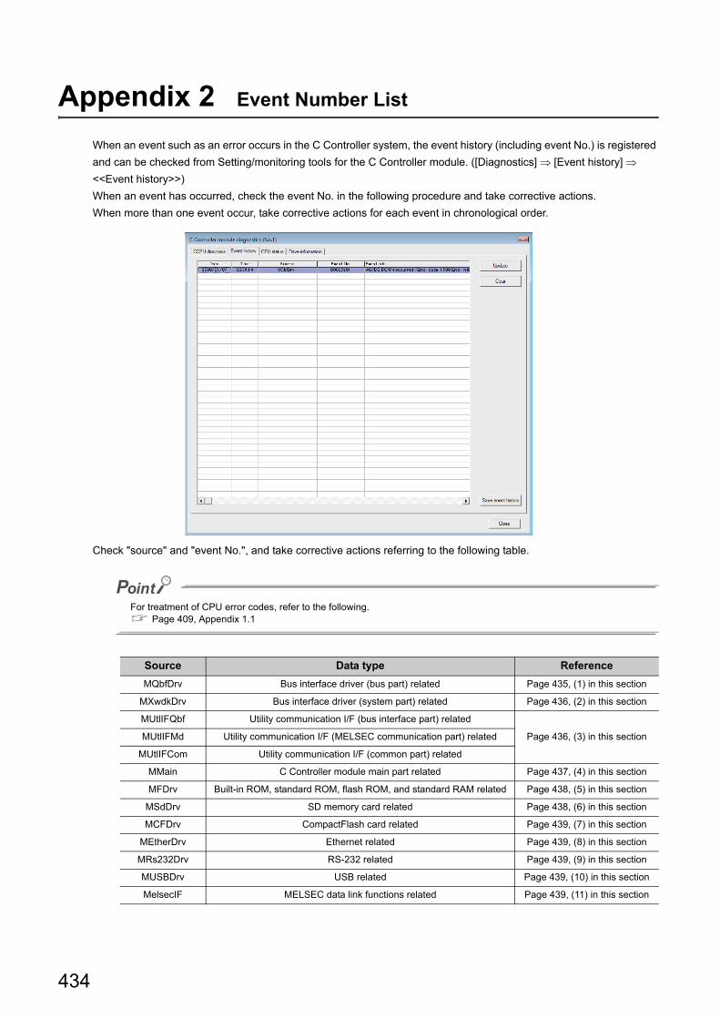
434
Appendix 2 Event Number List
When an event such as an error occurs in the C Controller system, the event history (including event No.) is registered
and can be checked from Setting/monitoring tools for the C Controller module. ([Diagnostics] [Event history]
<<Event history>>)
When an event has occurred, check the event No. in the following procedure and take corrective actions.
When more than one event occur, take corrective actions for each event in chronological order.
Check "source" and "event No.", and take corrective actions referring to the following table.
For treatment of CPU error codes, refer to the following. Page 409, Appendix 1.1
Source Data type Reference
MQbfDrv Bus interface driver (bus part) related Page 435, (1) in this section
MXwdkDrv Bus interface driver (system part) related Page 436, (2) in this section
MUtlIFQbf Utility communication I/F (bus interface part) related
Page 436, (3) in this sectionMUtlIFMd Utility communication I/F (MELSEC communication part) related
MUtlIFCom Utility communication I/F (common part) related
MMain C Controller module main part related Page 437, (4) in this section
MFDrv Built-in ROM, standard ROM, flash ROM, and standard RAM related Page 438, (5) in this section
MSdDrv SD memory card related Page 438, (6) in this section
MCFDrv CompactFlash card related Page 439, (7) in this section
MEtherDrv Ethernet related Page 439, (8) in this section
MRs232Drv RS-232 related Page 439, (9) in this section
MUSBDrv USB related Page 439, (10) in this section
MelsecIF MELSEC data link functions related Page 439, (11) in this section

435
APPENDICES
A
Appendix 2 E
vent N
umber List
● The following values are stored with an event No.
● In any of the following cases, please consult your local Mitsubishi service center or representative, explaining the details of the problem.
• Any event No. not listed in the following table is detected • The actions indicated in the following table does not resolve the program
(1) Actions against each event No. that occurs in "MQbfDrv"Actions against each event No. that occurs in "MQbfDrv" are described below.
Event
levelDescription Corrective action
InformationThe C Controller module is running normally, but the
customer system may be affected.
Refer to the event detail field of each event and take
appropriate actions if the customer system may be
affected.
Warning The C Controller module is not running normally. Refer to the processing field of each event and take
appropriate actions.Error The C Controller module is not running.
Event No. Event type Event Corrective action
C000011EH System (Err.) Failed to allocate memory required for the driver start-up.• Increase the system memory.
• Reduce the memory usage of other programs.
C0000127H System (Err.) SYSTEM WDT ERROR occurred. Take corrective actions for error code 5000.
C0000131H System (Err.) USER WDT ERROR occurred. Take corrective actions for error code 5001.
C0000201H System (Err.) AC/DC DOWN occurred. Take corrective actions for error code 1500.
C0000202H System (Err.) CONTROL-BUS.ERR. occurred. Take corrective actions for error code 1413, 1414, 1415, and 1416.
C0000204H System (Err.) UNIT VERIFY ERR. occurred. Take corrective actions for error code 2000.
C0000206H System (Err.) FUSE BREAK OFF occurred. Take corrective actions for error code 1300.
C0000207H System (Err.) SP.UNIT DOWN occurred. Take corrective actions for error code 1401 and 1403.
C0000208H System (Err.) CONTROL-BUS.ERR. occurred. Take corrective actions for error code 1412.
C0000209H System (Err.) SP.UNIT LAY ERR. occurred.Take corrective actions for error code 2100, 2103, 2106, 2107, 2108,
2120, 2121, 2122, 2124, 2125, 2126, and 2150.
C000020AH System (Err.) PARAMETER ERROR occurred.Take corrective actions for error code 3000, 3001, 3010, 3012, 3014,
3015, and 3016.
C000020BH System (Err.)An error occurred during module initialization.
(Only the first error is displayed.)
Take corrective actions corresponding to the error code displayed in
the event information.
C000020EH System (Err.) A CPU module built-in battery error occurred. Take corrective actions for error code 1600.
C0000210H System (Err.) MULTI CPU DOWN occurred. Take corrective actions for error code 7000 and 7002.
C0000211H System (Err.) MULTI EXE.ERROR occurred. Take corrective actions for error code 7010, 7011, and 7013.
C0000212H System (Err.) MULTI CPU ERROR occurred. Take corrective actions for error code 7020.
C0000213H System (Err.) SP.PARAMETER ERROR occurred. Take corrective actions for error code 3300, 3301, 3302, and 3303.
C0000214H System (Err.) LINK PARAMETER ERROR occurred.Take corrective actions for error code 3100, 3101, 3102, 3103, 3104,
3105, and 3107.
C0000215H System (Err.) I/O INT.ERROR occurred. Take corrective actions for error code 1310.
C0000216H System (Err.) MAIN CPU DOWN occurred. Take corrective actions for error code 1000 and 1009.
C0000218H System (Err.) LINK REFRESH TIME OVER occurred. Take corrective actions for error code 5012.
C0000219H System (Err.) SINGLE PS.DOWN occurred. Take corrective actions for error code 1510.
C000021AH System (Err.) SINGLE PS.ERROR occurred. Take corrective actions for error code 1520.
C000021BH System (Err.) MULTI-C.BUS.ERR. occurred.Take corrective actions for error code 1430, 1431, 1432, 1433, 1434,
1435, 1436, 1437, and 1439.
bit 31 bit 016 15
Event level 0 x 4000: Information 0 x 8000: Warning 0 x C000: Error
"Source" specific event No
Higher word value Lower word value
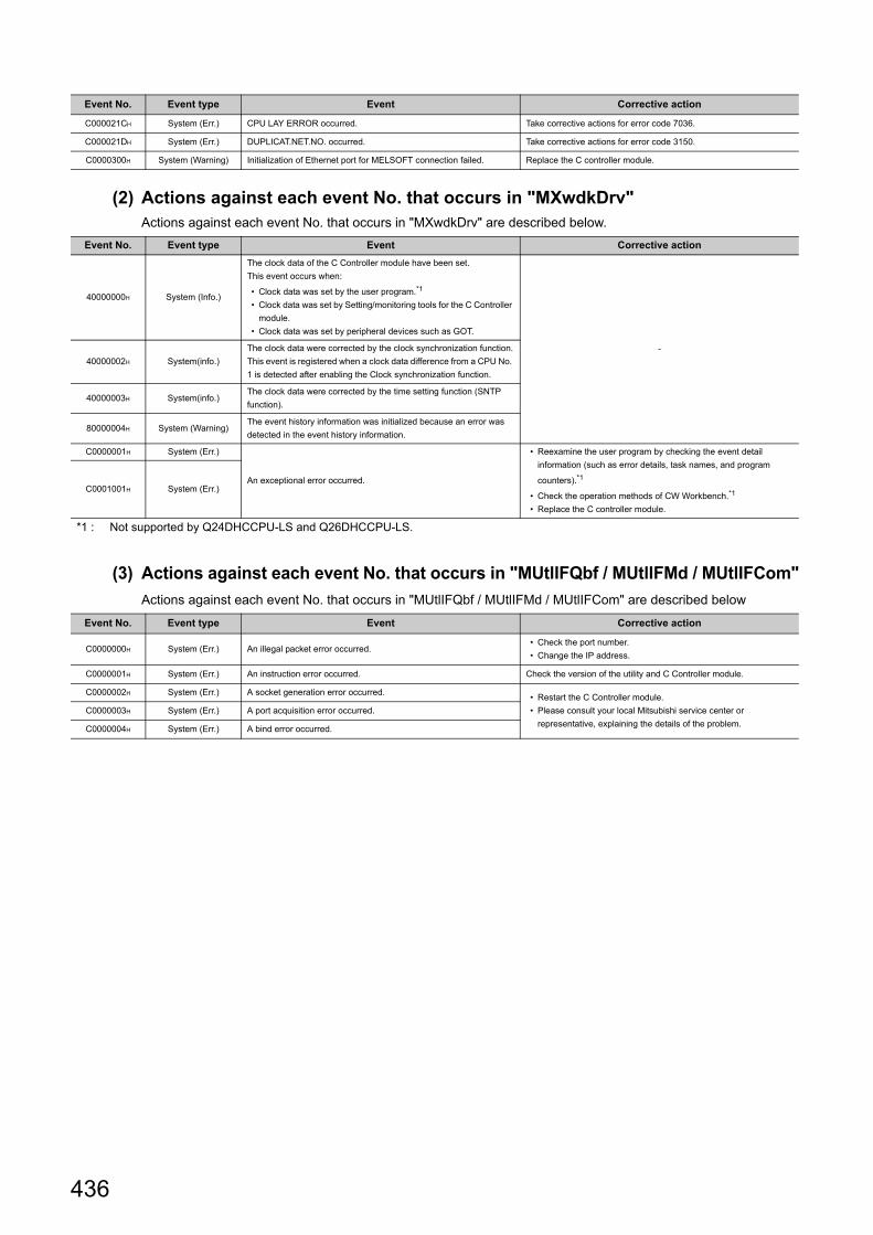
436
(2) Actions against each event No. that occurs in "MXwdkDrv"Actions against each event No. that occurs in "MXwdkDrv" are described below.
(3) Actions against each event No. that occurs in "MUtlIFQbf / MUtlIFMd / MUtlIFCom"
Actions against each event No. that occurs in "MUtlIFQbf / MUtlIFMd / MUtlIFCom" are described below
C000021CH System (Err.) CPU LAY ERROR occurred. Take corrective actions for error code 7036.
C000021DH System (Err.) DUPLICAT.NET.NO. occurred. Take corrective actions for error code 3150.
C0000300H System (Warning) Initialization of Ethernet port for MELSOFT connection failed. Replace the C controller module.
Event No. Event type Event Corrective action
40000000H System (Info.)
The clock data of the C Controller module have been set.
This event occurs when:
• Clock data was set by the user program.*1
• Clock data was set by Setting/monitoring tools for the C Controller
module.
• Clock data was set by peripheral devices such as GOT.
-
40000002H System(info.)
The clock data were corrected by the clock synchronization function.
This event is registered when a clock data difference from a CPU No.
1 is detected after enabling the Clock synchronization function.
40000003H System(info.)The clock data were corrected by the time setting function (SNTP
function).
80000004H System (Warning)The event history information was initialized because an error was
detected in the event history information.
C0000001H System (Err.)
An exceptional error occurred.
• Reexamine the user program by checking the event detail
information (such as error details, task names, and program
counters).*1
• Check the operation methods of CW Workbench.*1
• Replace the C controller module.
C0001001H System (Err.)
*1 : Not supported by Q24DHCCPU-LS and Q26DHCCPU-LS.
Event No. Event type Event Corrective action
C0000000H System (Err.) An illegal packet error occurred.• Check the port number.
• Change the IP address.
C0000001H System (Err.) An instruction error occurred. Check the version of the utility and C Controller module.
C0000002H System (Err.) A socket generation error occurred.• Restart the C Controller module.
• Please consult your local Mitsubishi service center or
representative, explaining the details of the problem.
C0000003H System (Err.) A port acquisition error occurred.
C0000004H System (Err.) A bind error occurred.
Event No. Event type Event Corrective action

437
APPENDICES
A
Appendix 2 E
vent N
umber List
(4) Actions against each event No. that occurs in "MMain"Actions against each event No. that occurs in "MMain" are described below.
● Q24DHCCPU-V/-VGIf the "U RDY" LED does not light after performing the corresponding actions described above, the hardware may be faulty. Please consult your local Mitsubishi service center or representative, explaining the details of the problem.
● Q12DCCPU-VIf performing the corresponding actions described above does not resolve the problem, the hardware may be faulty. Please consult your local Mitsubishi service center or representative, explaining the details of the problem.
Event No. Event type Event Corrective action
80000331H System (Warning) Time synchronization to the SNTP server failed.
• Check the SNTP server's IP address.
• Check the Ethernet cable.
• Check that it is connected to the system Ethernet port (S CH1).
• Check if the SNTP server is running normally.
C0000111H System (Err.)One command (one line) in the script file has 129 or more
characters.
Reduce the number of characters for one command (one line) in the
script file to 128 or less.
C0000330H System (Err.) Failed to access LAN.
• The parameter file (IP address setting area) does not exist. Using
Setting/monitoring tools for the C Controller module, set the IP
address or write the parameters.
• Replace the C Controller module.
C0000400H System (Err.) MAIN CPU DOWN occurred.Initializes the C Controller module.
C0000401H System (Err.) PARAMETER ERROR occurred.
C0001111H System (Err.)
The command in the script file cannot be executed.
• An error in the syntax
• No command exists
• One command (one line) in the script file has 129 or more
characters.
Take corrective actions for CPU error code 2502.
C0001400H System (Err.) MAIN CPU DOWN occurred. Initializes the C Controller module.

438
(5) Actions against each event No. that occurs in "MFDrv"Actions against each event No. that occurs in "MFDrv" are described below.
● Q24DHCCPU-V/-VGIf the "U RDY" LED does not light after performing the corresponding actions described above, the hardware may be faulty. Please consult your local Mitsubishi service center or representative, explaining the details of the problem.
● Q12DCCPU-VIf performing the corresponding actions described above does not resolve the problem, the hardware may be faulty. Please consult your local Mitsubishi service center or representative, explaining the details of the problem.
(6) Actions against each event No. that occurs in "MSdDrv"Actions against each event No. that occurs in "MSdDrv" are described below.
Event No. Event type Event Corrective action
80000000H System (Warning)The index value of writing count of the internal ROM has exceeded
100 thousand.Replace the C Controller module.
80000406H System (Warning)A timeout occurred during writing to file in the standard ROM drive "/
ROM".
• Write the file again if the file was not written correctly.
• If this event occurs frequently, reexamine the user program
(processing, task priority, etc.) that runs on the C Controller
module.
80001000H System (Warning)The index value of writing count of the standard ROM drive "/ROM"
has exceeded 100 thousand.Replace the C Controller module.
C0000400H System (Err.) A built-in ROM drive "/ROM" format error occurred. Reformat the built-in ROM drive "/ROM".
C0000402H System (Err.) An access beyond the flash ROM size occurred.
Replace the C Controller module.C0000403H System (Err.)
An internal ROM ("/ROM", "/SYSTEMROM") initialization error
occurred.
C0000404H System (Err.) An internal ROM drive "/ROM" start address error occurred.
C0000405H System (Err.) An internal ROM drive "/ROM" block count error occurred.
C000040AH System (Err.) MAIN CPU DOWN occurred. Take corrective actions for CPU error code 1000.
C0000409H System (Err.) An internal ROM ("/ROM","/SYSTEMROM") error was detected.
Initializes the C Controller module.
C000040AH System (Err.) MAIN CPU DOWN occurred.
C0000410H System (Err.) A standard RAM drive "/RAM" format error occurred.
C0000411H System (Err.)An access operation exceeding the standard RAM drive size
occurred.
C0000412H System (Err.) A standard RAM drive "/RAM" initialization error occurred.
C0000417H System (Err.) RAM ERROR occurred.
Event No. Event type Event Corrective action
C0000480H System (Err.) The SD memory card is not responding.• The SD memory card is pulled out once, and it inserts it again.
• Replace the SD memory card.C0000481H System (Err.)
An error occurred while obtaining the SD memory card drive
information.
C0000482H System (Err.) An error occurred while reading master boot record (MBR).
• The SD memory card is pulled out once, and it inserts it again.
• Reformat the SD memory card on a personal computer, etc.
• Replace the SD memory card.
C0000483H System (Err.) The master boot record (MBR) cannot be recognized in this format.• Reformat the SD memory card on a personal computer, etc.
• Replace the SD memory card.
C0000490H System (Err.) A resource shortage error occurred.Check the utilization of the memory, provide a free space, and
execute again.
C0000491H System (Err.) A SD driver initialization error occurred.Please consult your local Mitsubishi service center or representative,
explaining the details of the problem.C0000492H System (Err.) A device name registration error occurred
C0000493H System (Err.) A block No. error occurred.

439
APPENDICES
A
Appendix 2 E
vent N
umber List
(7) Actions against each event No. that occurs in "MCFDrv"Actions against each event No. that occurs in "MCFDrv" are described below.
(8) Actions against each event No. that occurs in "MEtherDrv"There is no event that may occur in "MEtherDrv".
(9) Actions against each event No. that occurs in "MRs232Drv"There is no event that may occur in "MRs232Drv".
(10)Actions against each event No. that occurs in "MUSBDrv"Actions against each event No. that occurs in "MUSBDrv" are described below.
(11)Actions against each event No. that occurs in "MelsecIF"Actions against each event No. that occurs in "MelsecIF" are described below.
Event No. Event type Event Corrective action
C0000480H System (Err.) CF card is not responding.• Pull the CompactFlash card once, and insert it again.
• Replace the CompactFlash card.C0000481H System (Err.) An error occurred during acquiring the CF card information.
C0000482H System (Err.) An error occurred during reading master boot record (MBR).
• Pull the CompactFlash card once, and insert it again.
• Reformat the CompactFlash card on a personal computer, etc.
• Replace the CompactFlash card.
C0000483H System (Err.) The master boot record (MBR) cannot be recognizes in this format.• Reformat the CompactFlash card on a personal computer, etc.
• Replace the CompactFlash card.
C0000490H System (Err.) A resource shortage error occurred.Check the memory usage condition, and execute again after creating
a free capacity of the memory.
C0000491H System (Err.) A CF card driver initialization error occurred. Please consult your local Mitsubishi service center or representative,
explaining the details of the problem.C0000493H System (Err.) A block number error occurred.
Event No. Event type Event Corrective action
80000000H System (Warning)An external device where current exceeding allowable supply current
flows was connected.
Check the current consumption of the external device and review the
configuration so that it is below the allowable supply current of the C
Controller module.
Event No. Event type Event Corrective action
40000004H System (Info.) User CPU restart was executed. -
C0000000H System (Err.) MAIN CPU DOWN occurred. Refer to the CPU error code 1000.
C0000001H System (Err.) PARAMETER ERROR occurred. Refer to the CPU error code 3001.
C0000002H System (Err.) SP.UNIT ERROR occurred. Refer to the CPU error code 2110.
C0000003H System (Err.) REF.TIME OVER occurred. Refer to the CPU error code 5012.
C0001000H System (Err.) MAIN CPU DOWN occurred. Refer to the CPU error code 1000.
C0001001H System (Err.) A battery backup RAM error was detected. Refer to the CPU error code 1106.

440
Appendix 3 VxWorks Component List
This section describes the list of VxWorks components implemented in the C Controller module.
Remark
Description of each component can be displayed on the PC with CW Workbench installed.Use the following procedure to display each description.
1. Start CW Workbench.
2. Select [Help] [Help Contents] from the menu bar.
The Web browser shows the CW Workbench Help.
3. Enter a component name to show in the "Search" field and click the "Go" button.
Appendix 3.1 Q24DHCCPU-V
Description Name
32-bit physical address space INCLUDE_MMU_P6_32BIT
Address Space Allocator Show Routines INCLUDE_ADR_SPACE_SHOW
address space shell commands INCLUDE_ADR_SPACE_SHELL_CMD
ANSI assert INCLUDE_ANSI_ASSERT
ANSI ctype INCLUDE_ANSI_CTYPE
ANSI errno to error string conversion function INCLUDE_ANSI_STRERROR
ANSI locale INCLUDE_ANSI_LOCALE
ANSI math INCLUDE_ANSI_MATH
ANSI stdio INCLUDE_ANSI_STDIO
ANSI stdio extentions INCLUDE_ANSI_STDIO_EXTRA
ANSI stdlib INCLUDE_ANSI_STDLIB
ANSI string INCLUDE_ANSI_STRING
ANSI string duplication function INCLUDE_ANSI_STRDUP
ANSI time INCLUDE_ANSI_TIME
application inialization INCLUDE_USER_APPL
arp utility wrapper INCLUDE_IPWRAP_ARP
arpLib INCLUDE_ARP_API
asynchronous IO show routine INCLUDE_POSIX_AIO_SHOW
atomic operators support INCLUDE_ATOMIC_OPERATORS
Attach END to IPv4 INCLUDE_IPATTACH
AUX clock INCLUDE_AUX_CLK
Basic IO System INCLUDE_IO_BASIC
basic memory allocator INCLUDE_MEM_MGR_BASIC
basic MMU INCLUDE_MMU_BASIC
basic network support INCLUDE_NETWORK
binary semaphore creation routine INCLUDE_SEM_BINARY_CREATE
binary semaphores NCLUDE_SEM_BINARY
Boot parameter process INCLUDE_NET_BOOT
BSP memory Configuration INCLUDE_MEMORY_CONFIG
built-in symbol table INCLUDE_STANDALONE_SYM_TBL
c line interpreter INCLUDE_SHELL_INTERP_C

441
APPENDICES
A
Appendix 3 V
xWorks C
ompon
ent ListA
ppendix 3.1 Q24D
HC
CP
U-V
C++ compiler support routines INCLUDE_CPLUS_LANG
C++ core runtime INCLUDE_CPLUS
C++ iostreams and other standard library facilities INCLUDE_CPLUS_IOSTREAMS
C++ symbol demangler INCLUDE_CPLUS_DEMANGLER
cache support INCLUDE_CACHE_SUPPORT
class show routine INCLUDE_CLASS_SHOW
Classifier INCLUDE_IPNET_CLASSIFIER
command line interpreter INCLUDE_SHELL_INTERP_CMD
Common network infrastructure INCLUDE_COMMON_NET
Commonly used legacy mbuf routines INCLUDE_MBUF_UTIL1
coprocessor INCLUDE_COPROCESSOR
coprocessor show routine INCLUDE_COPROCESSOR_SHOW
Core NFS client INCLUDE_CORE_NFS_CLIENT
counting semaphore creation routine INCLUDE_SEM_COUNTING_CREATE
counting semaphores INCLUDE_SEM_COUNTING
CPU Power Light utilization manager INCLUDE_CPU_LIGHT_PWR_MGR
CPU Power management framework INCLUDE_CPU_PWR_MGMT
debug shell commands INCLUDE_DEBUG_SHELL_CMD
debugging facilities INCLUDE_DEBUG
Device Manager INCLUDE_DEVICE_MANAGER
DHCP Client INCLUDE_IPDHCPC
Differentiated Services INCLUDE_IPNET_DIFFSERV
DNS Client INCLUDE_IPDNSC
DOS File System Consistency Checker INCLUDE_DOSFS_CHKDSK
DOS File System FAT12/16/32 Handler INCLUDE_DOSFS_FAT
DOS File System Old Directory Format Handler INCLUDE_DOSFS_DIR_FIXED
DOS File System VFAT Directory Handler INCLUDE_DOSFS_DIR_VFAT
DOS File System Volume Formatter Module INCLUDE_DOSFS_FMT
DOS filesystem backward-compatibility INCLUDE_DOSFS
Dos FS BIO buffer size INCLUDE_DOSFS_VOL_BIO_BUFFER_SIZE
Dos FS Show Routines INCLUDE_DOSFS_SHOW
dosfs File System Main Module (dosFs2) INCLUDE_DOSFS_MAIN
doubly linked lists INCLUDE_DLL
ED&R shell commands INCLUDE_EDR_SHELL_CMD
ED&R show routines INCLUDE_EDR_SHOW
EHCI INCLUDE_EHCI
EHCI Init INCLUDE_EHCI_INIT
EHCI Start INCLUDE_EHCI_BUS
enable caches INCLUDE_CACHE_ENABLE
enable guard pages for kernel task stacks INCLUDE_PROTECT_TASK_STACK
enable non-executable kernel task stacks INCLUDE_TASK_STACK_NO_EXEC
END driver polled statistics support INCLUDE_END_POLLED_STATS
END: common Enhanced Network Device support INCLUDE_END_COMMON
END: END-style interface support INCLUDE_END
error status table INCLUDE_STAT_SYM_TBL
Ethernet Interface support INCLUDE_IPCOM_USE_ETHERNET
Event Reporting Framework INCLUDE_ERF
exception handling INCLUDE_EXC_HANDLING
exception show routines INCLUDE_EXC_SHOW
exception task INCLUDE_EXC_TASK
Extended Block Device INCLUDE_XBD
Description Name

442
extended object library INCLUDE_OBJ_OPEN
File System and Disk Utilities INCLUDE_DISK_UTIL
File System Event Utilities INCLUDE_FS_EVENT_UTIL
File System IO INCLUDE_IO_FILE_SYSTEM
File System Monitor INCLUDE_FS_MONITOR
file system shell commands INCLUDE_DISK_UTIL_SHELL_CMD
file upload path initialization INCLUDE_WVUPLOAD_FILE
floating point show routine INCLUDE_HW_FP_SHOW
formatted IO INCLUDE_FORMATTED_IO
formatted IO output routines INCLUDE_FORMATTED_OUT_BASIC
fpp formatting for printf INCLUDE_FLOATING_POINT
FTP Client Backend INCLUDE_FTP
full featured memory allocator INCLUDE_MEM_MGR_FULL
Generic PHY driver INCLUDE_GENERICPHY
get name info INCLUDE_GETNAMEINFO
get servce by name INCLUDE_GETSERVBYNAME
get servce by port INCLUDE_GETSERVBYPORT
gethostbyaddr wrapper INCLUDE_IPWRAP_GETHOSTBYADDR
getnameinfo wrapper INCLUDE_IPWRAP_GETNAMEINFO
getopt function INCLUDE_GETOPT
getservbyname wrapper INCLUDE_IPWRAP_GETSERVBYNAME
getservbyport wrapper INCLUDE_IPWRAP_GETSERVBYPORT
Global configurations INCLUDE_IPAIP_GLOBAL_CONFIGS
GNU compiler support routines INCLUDE_GNU_INTRINSICS
GTF support INCLUDE_GTF
gtf_timer_start INCLUDE_GTF_TIMER_START
handle show routines INCLUDE_HANDLE_SHOW
hardware fpp support INCLUDE_HW_FP
hash library INCLUDE_HASH
high resolution timestamping INCLUDE_TIMESTAMP
Highly Reliable File System INCLUDE_HRFS
host table INCLUDE_HOST_TBL
host table sysctl support INCLUDE_HOST_TBL_SYSCTL
Host/target breakpoint synchronization INCLUDE_WDB_BP_SYNC
host/target modules and symbols synchronization INCLUDE_WDB_MDL_SYM_SYNC
HRFS Default Write Mode INCLUDE_HRFS_DEFAULT_WRITE_MODE
HRFS File System Consistency Checker INCLUDE_HRFS_CHKDSK
HRFS Format INCLUDE_HRFS_FORMAT
i8253 timer Driver DRV_TIMER_I8253
ifconfig INCLUDE_IFCONFIG
ifconfig wrapper INCLUDE_IPWRAP_IFCONFIG
ifLib wrapper INCLUDE_IPWRAP_IFLIB
ifShow wrapper INCLUDE_IPWRAP_IFSHOW
inetLib INCLUDE_INETLIB
inetLib wrapper INCLUDE_IPWRAP_INETLIB
Init pre-kernel memory allocation globally INIT_HWMEMPOOL_GLOBAL
initialize system symbol table INCLUDE_SYM_TBL_INIT
Intel ICH SATA Controller INCLUDE_DRV_STORAGE_INTEL_ICH
Intel ICH SATA Controller Show Routines INCLUDE_DRV_STORAGE_INTEL_ICH_SHOW
Intel PRO/1000 VxBus Enhanced Network Driver INCLUDE_GEI825XX_VXB_END
Intel timestamp Driver DRV_TIMER_IA_TIMESTAMP
Description Name
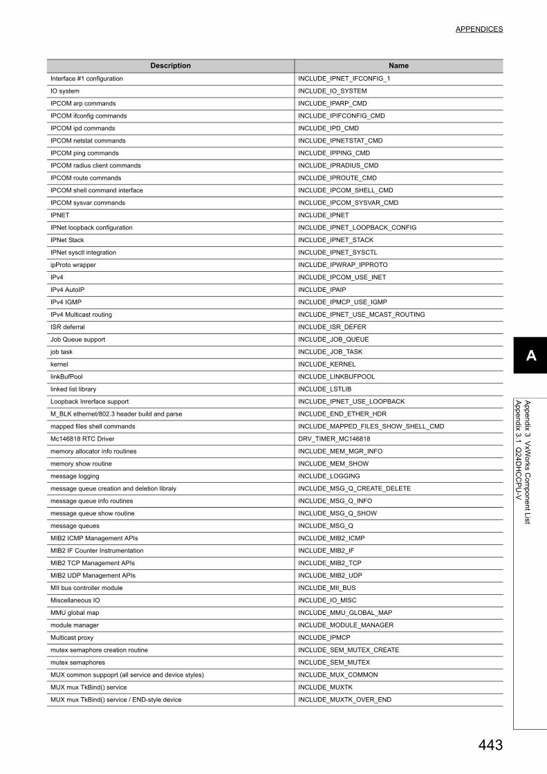
443
APPENDICES
A
Appendix 3 V
xWorks C
ompon
ent ListA
ppendix 3.1 Q24D
HC
CP
U-V
Interface #1 configuration INCLUDE_IPNET_IFCONFIG_1
IO system INCLUDE_IO_SYSTEM
IPCOM arp commands INCLUDE_IPARP_CMD
IPCOM ifconfig commands INCLUDE_IPIFCONFIG_CMD
IPCOM ipd commands INCLUDE_IPD_CMD
IPCOM netstat commands INCLUDE_IPNETSTAT_CMD
IPCOM ping commands INCLUDE_IPPING_CMD
IPCOM radius client commands INCLUDE_IPRADIUS_CMD
IPCOM route commands INCLUDE_IPROUTE_CMD
IPCOM shell command interface INCLUDE_IPCOM_SHELL_CMD
IPCOM sysvar commands INCLUDE_IPCOM_SYSVAR_CMD
IPNET INCLUDE_IPNET
IPNet loopback configuration INCLUDE_IPNET_LOOPBACK_CONFIG
IPNet Stack INCLUDE_IPNET_STACK
IPNet sysctl integration INCLUDE_IPNET_SYSCTL
ipProto wrapper INCLUDE_IPWRAP_IPPROTO
IPv4 INCLUDE_IPCOM_USE_INET
IPv4 AutoIP INCLUDE_IPAIP
IPv4 IGMP INCLUDE_IPMCP_USE_IGMP
IPv4 Multicast routing INCLUDE_IPNET_USE_MCAST_ROUTING
ISR deferral INCLUDE_ISR_DEFER
Job Queue support INCLUDE_JOB_QUEUE
job task INCLUDE_JOB_TASK
kernel INCLUDE_KERNEL
linkBufPool INCLUDE_LINKBUFPOOL
linked list library INCLUDE_LSTLIB
Loopback Inrerface support INCLUDE_IPNET_USE_LOOPBACK
M_BLK ethernet/802.3 header build and parse INCLUDE_END_ETHER_HDR
mapped files shell commands INCLUDE_MAPPED_FILES_SHOW_SHELL_CMD
Mc146818 RTC Driver DRV_TIMER_MC146818
memory allocator info routines INCLUDE_MEM_MGR_INFO
memory show routine INCLUDE_MEM_SHOW
message logging INCLUDE_LOGGING
message queue creation and deletion libraly INCLUDE_MSG_Q_CREATE_DELETE
message queue info routines INCLUDE_MSG_Q_INFO
message queue show routine INCLUDE_MSG_Q_SHOW
message queues INCLUDE_MSG_Q
MIB2 ICMP Management APIs INCLUDE_MIB2_ICMP
MIB2 IF Counter Instrumentation INCLUDE_MIB2_IF
MIB2 TCP Management APIs INCLUDE_MIB2_TCP
MIB2 UDP Management APIs INCLUDE_MIB2_UDP
MII bus controller module INCLUDE_MII_BUS
Miscellaneous IO INCLUDE_IO_MISC
MMU global map INCLUDE_MMU_GLOBAL_MAP
module manager INCLUDE_MODULE_MANAGER
Multicast proxy INCLUDE_IPMCP
mutex semaphore creation routine INCLUDE_SEM_MUTEX_CREATE
mutex semaphores INCLUDE_SEM_MUTEX
MUX common suppoprt (all service and device styles) INCLUDE_MUX_COMMON
MUX mux TkBind() service INCLUDE_MUXTK
MUX mux TkBind() service / END-style device INCLUDE_MUXTK_OVER_END
Description Name

444
MUX mux2Bind() service INCLUDE_MUX2
MUX mux2Bind() service / END-style device INCLUDE_MUX2_OVER_END
MUX muxBind() service INCLUDE_MUX
MUX private support for M_BLK/Ipcom_pkt conversion INCLUDE_VXMUX_MBLK
netBufLib INCLUDE_NETBUFLIB
netBufLib show routines INCLUDE_NETPOOLSHOW
netBufPool INCLUDE_NETBUFPOOL
NetDrv for remote IO INCLUDE_NET_DRV
netstat INCLUDE_NETSTAT
netstat wrapper INCLUDE_IPWRAP_NETSTAT
network boot device configuration INCLUDE_NET_BOOT_CONFIG
Network Daemon Support INCLUDE_NET_DAEMON
network device netmask setup INCLUDE_NETMASK_GET
network init INCLUDE_NET_INIT
network remote I/O access INCLUDE_NET_REM_IO
Network Stack Memory Pool Configuration INCLUDE_NET_POOL
NETWORK SYSCTL INCLUDE_NET_SYSCTL
NFS client All INCLUDE_NFS_CLIENT_ALL
NFS server INCLUDE_CORE_NFS_SERVER
NFS server All INCLUDE_NFS_SERVER_ALL
NFS server V2 INCLUDE_NFS2_SERVER
NFS server V3 INCLUDE_NFS3_SERVER
NFS v2 client INCLUDE_NFS2_CLIENT
NFS v3 client INCLUDE_NFS3_CLIENT
non-blocking message logging INCLUDE_NBIO_LOG
nullBufPool INCLUDE_VXMUX_NULLBUFPOOL
object information INCLUDE_OBJ_INFO
object management INCLUDE_OBJ_LIB
object management ownership INCLUDE_OBJ_OWNERSHIP
object show routines INCLUDE_OBJECT_SHOW
oldRouteLib wrapper INCLUDE_IPWRAP_OLDROUTELIB
PCI Bus legacy Auto Configuration Routines INCLUDE_PCI_OLD_CONFIG_ROUTINES
PCI Bus Show Routines INCLUDE_PCI_BUS_SHOW
Pentium PCI host controller INCLUDE_PENTIUM_PCI
Peripheral Component Interconnect Bus INCLUDE_PCI_BUS
persistent error log INCLUDE_EDR_ERRLOG
persistent memory INCLUDE_EDR_PM
PING client INCLUDE_PING
ping wrapper INCLUDE_IPWRAP_PING
pipes INCLUDE_PIPES
pool allocation library INCLUDE_POOL
POSIX advisory file locking INCLUDE_POSIX_ADVISORY_FILE_LOCKING
POSIX AIO driver INCLUDE_POSIX_AIO_SYSDRV
POSIX asynchornous IO INCLUDE_POSIX_AIO
POSIX clocks INCLUDE_POSIX_CLOCKS
POSIX directory utilities INCLUDE_POSIX_DIRLIB
POSIX ftruncate INCLUDE_POSIX_FTRUNC
POSIX IO INCLUDE_IO_POSIX
POSIX Memory Mapped Files INCLUDE_POSIX_MAPPED_FILES
POSIX message queue show routine INCLUDE_POSIX_MQ_SHOW
POSIX message queues INCLUDE_POSIX_MQ
Description Name

445
APPENDICES
A
Appendix 3 V
xWorks C
ompon
ent ListA
ppendix 3.1 Q24D
HC
CP
U-V
POSIX mman INCLUDE_POSIX_MEM
POSIX process scheduling INCLUDE_POSIX_SCHED
POSIX scheduling support including SCHED_SPORADIC policy in RTPs INCLUDE_PX_SCHED_SPORADIC_POLICY
POSIX semaphore show routine INCLUDE_POSIX_SEM_SHOW
POSIX semaphores INCLUDE_POSIX_SEM
POSIX signals INCLUDE_POSIX_SIGNALS
POSIX thread CPU-time clock INCLUDE_POSIX_THREAD_CPUTIME
POSIX thread scheduler in RTPs INCLUDE_POSIX_PTHREAD_SCHEDULER
POSIX threads INCLUDE_POSIX_PTHREADS
Posix timer show component INCLUDE_POSIX_TIMER_SHOW
POSIX timers INCLUDE_POSIX_TIMERS
POSIX TRACE INCLUDE_POSIX_TRACE
POSIX_Shared Memory Objects INCLUDE_POSIX_SHM
Pre-Kernel Memory Allocation INCLUDE_HWMEM_ALLOC
process shell commands INCLUDE_RTP_SHELL_CMD
process show shell commands INCLUDE_RTP_SHOW_SHELL_CMD
Processor Local Bus INCLUDE_PLB_BUS
ProxyARP INCLUDE_IPPROXYARP
Pseudo terminal driver INCLUDE_PTYDRV
public hostname setup INCLUDE_NET_HOST_SETUP
Radius Authentication Support INCLUDE_IPCOM_USE_AUTH_RADIUS
Radius client INCLUDE_IPRADIUS
RAM Disk INCLUDE_RAM_DISK
RAM disk driver INCLUDE_RAMDRV
raw filesystem INCLUDE_RAWFS
rBuff library INCLUDE_RBUFF
rBuff show routine INCLUDE_RBUFF_SHOW
read the bootline INCLUDE_BOOT_LINE_INIT
reader/writer semaphore creation routine INCLUDE_SEM_READ_WRITE_CREATE
reader/writer semaphores INCLUDE_SEM_READ_WRITE
Remote Command INCLUDE_REMLIB
Remote Command sysctl support INCLUDE_REMLIB_SYSCTL
Removable IO INCLUDE_IO_REMOVABLE
ring buffers INCLUDE_RNG_BUF
RLOGIN/TELNET password protection INCLUDE_SECURITY
routec INCLUDE_ROUTECMD
routec wrapper INCLUDE_IPWRAP_ROUTECMD
Routing socket support INCLUDE_IPNET_USE_ROUTESOCK
RPC INCLUDE_RPC
RTP INCLUDE_RTP
RTP getnameinfo() sysctl support INCLUDE_GETNAMEINFO_SYSCTL
RTP Hook Support INCLUDE_RTP_HOOKS
RTP IO INCLUDE_IO_RTP
RTP Show INCLUDE_RTP_SHOW
RTP Startup Facility: User-defined code INCLUDE_RTP_APPL_USER
run static initializers INCLUDE_CTORS_DTORS
SD Host Controller driver DRV_STORAGE_SD
select INCLUDE_SELECT
semaphore deletion routines INCLUDE_SEM_DELETE
semaphore exchange routine INCLUDE_SEM_EXCHANGE
semaphore info routines INCLUDE_SEM_INFO
Description Name

446
semaphore show routine INCLUDE_SEM_SHOW
shared data region support in RTPs or kernel INCLUDE_SHARED_DATA
Shared Data Show INCLUDE_SHARED_DATA_SHOW
shared data show shell commands INCLUDE_SHARED_DATA_SHOW_SHELL_CMD
shared library commands INCLUDE_SHL_SHELL_CMD
Shared Library Show INCLUDE_SHL_SHOW
shared library support in RTPs INCLUDE_SHL
shell banner INCLUDE_SHELL_BANNER
show routine component INCLUDE_SHOW_ROUTINES
Show routines for memory mapped objects INCLUDE_MAPPED_FILES_SHOW
sigevent notification library INCLUDE_SIGEVENT
signals INCLUDE_SIGNALS
Simple Marker INCLUDE_IPNET_DS_SM
Single Rate Three Color Marker INCLUDE_IPNET_DS_SRTCM
SIO INCLUDE_SIO
Sio Channel Utilities INCLUDE_SIO_UTILS
SNTP Client (API) INCLUDE_IPSNTPC_API
SNTP Client (daemon) INCLUDE_IPSNTPC
SNTP common configurations INCLUDE_IPSNTP_COMMON
sntpcTimeGet wrapper INCLUDE_IPWRAP_SNTPCTIMEGET
Socket API INCLUDE_SOCKLIB
Socket API System Call support INCLUDE_SC_SOCKLIB
Socket backend INCLUDE_IPNET_USE_SOCK_COMPAT
Socket support INCLUDE_IPNET_SOCKET
spinLock INCLUDE_SPINLOCK
spy INCLUDE_SPY
Stack/Application Logging Utility INCLUDE_APPL_LOG_UTIL
stdio INCLUDE_STDIO
stdio show routine INCLUDE_STDIO_SHOW
Support for reboot hooks INCLUDE_REBOOT_HOOKS
symbol shell commands INCLUDE_SYM_SHELL_CMD
symbol table show routine INCLUDE_SYM_TBL_SHOW
SYSCTL INCLUDE_SYSCTL
SYSCTL CLI INCLUDE_SYSCTL_CLI
sysctl System Call INCLUDE_SC_SYSCTL
System Call Hook Support INCLUDE_SYSCALL_HOOKS
System clock INCLUDE_SYSCLK_INIT
system debug flag INCLUDE_EDR_SYSDBG_FLAG
System Viewer class instrumentation INCLUDE_WINDVIEW_CLASS
System Viewer library INCLUDE_WINDVIEW
system-defined timestamping INCLUDE_SYS_TIMESTAMP
target loader INCLUDE_LOADER
target loader shell command INCLUDE_MODULE_SHELL_CMD
target symbol table INCLUDE_SYM_TBL
target unloader INCLUDE_UNLOADER
target-resident kernel shell INCLUDE_SHELL
task create hooks INCLUDE_TASK_CREATE_HOOKS
task hook show routine INCLUDE_TASK_HOOKS_SHOW
task hooks INCLUDE_TASK_HOOKS
task info routines INCLUDE_TASK_INFO
task list management INCLUDE_TASK_LIST
Description Name

447
APPENDICES
A
Appendix 3 V
xWorks C
ompon
ent ListA
ppendix 3.1 Q24D
HC
CP
U-V
task shell commands INCLUDE_TASK_SHELL_CMD
task show routine INCLUDE_TASK_SHOW
task switch hooks INCLUDE_TASK_SWITCH_HOOKS
task variables INCLUDE_TASK_VARS
TCP INCLUDE_IPTCP
TELNET Server INCLUDE_IPTELNETS
terminal driver INCLUDE_TTY_DEV
terminal driver support INCLUDE_TYLIB
TFTP Client INCLUDE_IPTFTPC
TFTP Client APIs INCLUDE_TFTP_CLIENT
TFTP common configurations INCLUDE_IPTFTP_COMMON
Thermal Monitor and Geyserville III suppport INCLUDE_THERM_MONITOR
timex INCLUDE_TIMEX
tip serial line connection utility INCLUDE_TIP
TSFS upload path initialization INCLUDE_WVUPLOAD_TSFSSOCK
Tunnel Interface suport INCLUDE_IPNET_USE_TUNNEL
UART support for ns16550-compatible devices DRV_SIO_NS16550
unix compatible environment variables INCLUDE_ENV_VARS
unloader shell command INCLUDE_UNLOADER_SHELL_CMD
USB GEN2 Helper Init INCLUDE_USB_GEN2_HELPER
USB GEN2 Mass Storage INCLUDE_USB_GEN2_STORAGE
USB GEN2 Mass Storage Init INCLUDE_USB_GEN2_STORAGE_INIT
USB Host Stack INCLUDE_USB
USB Host Stack Init INCLUDE_USB_INIT
Use Authentication INCLUDE_IPCOM_USE_AUTH
vi-like editing mode INCLUDE_SHELL_VI_MODE
VIO driver INCLUDE_WDB_VIO
virtual memory show shell commands INCLUDE_VM_SHOW_SHELL_CMD
Virtual Root File System INCLUDE_VRFS
VLAN Pseudo Interface support INCLUDE_IPNET_USE_VLAN
VM library show routine INCLUDE_VM_SHOW
vxBus Aux Clk Support INCLUDE_VXB_AUX_CLK
VxBus Device Table VXBUS_TABLE_CONFIG
vxBus Driver DMA System INCLUDE_DMA_SYS
vxBus Driver Parameter System INCLUDE_PARAM_SYS
vxBus subsystem INCLUDE_VXBUS
vxBus subsystem show routines INCLUDE_VXBUS_SHOW
vxBus Sys Clk Support INCLUDE_VXB_SYS_CLK
vxBus Timer Support INCLUDE_TIMER_SYS
vxBus Timestamp Support INCLUDE_VXB_TIMESTAMP
vxMemProbe initializer for exception handler suport INCLUDE_VXMEMPROBE_INIT
VxWorks events INCLUDE_VXEVENTS
VxWorks IPCOM INCLUDE_IPCOM
watchdog timer show routine INCLUDE_WATCHDOGS_SHOW
watchdog timers INCLUDE_WATCHDOGS
watchdog timers creation and deletion library INCLUDE_WATCHDOGS_CREATE_DELETE
WDB agent INCLUDE_WDB
WDB banner INCLUDE_WDB_BANNER
WDB breakpoints INCLUDE_WDB_BP
WDB call functions INCLUDE_WDB_FUNC_CALL
WDB callouts INCLUDE_WDB_DIRECT_CALL
Description Name

448
WDB dynamic printf INCLUDE_WDB_DPRINTF
WDB eventpoints INCLUDE_WDB_EVENTPOINTS
WDB events INCLUDE_WDB_EVENTS
WDB exception notification INCLUDE_WDB_EXC_NOTIFY
WDB gopher INCLUDE_WDB_GOPHER
WDB memory access INCLUDE_WDB_MEM
WDB network connection INCLUDE_WDB_COMM_NETWORK
WDB post kernel initialization INCLUDE_WDB_POST_KERNEL_INIT
WDB register access INCLUDE_WDB_REG
WDB RTP breakpoints INCLUDE_WDB_RTP_BP
WDB RTP control support INCLUDE_WDB_RTP_CONTROL
WDB RTP support INCLUDE_WDB_RTP
WDB target server file system INCLUDE_WDB_TSFS
WDB task breakpoints INCLUDE_WDB_TASK_BP
WDB task creation INCLUDE_WDB_START_NOTIFY
WDB task debugging INCLUDE_WDB_TASK
WDB task exit notification INCLUDE_WDB_EXIT_NOTIFY
WDB task hooks INCLUDE_WDB_TASK_HOOKS
WDB task registers INCLUDE_WDB_TASK_REG
WDB tasks INCLUDE_WDB_CTXT
WDB user event INCLUDE_WDB_USER_EVENT
WDB virtual I/O library INCLUDE_WDB_VIO_LIB
write-protect program text INCLUDE_PROTECT_TEXT
XBD Block Device INCLUDE_XBD_BLK_DEV
XBD Disk Patition Handler INCLUDE_XBD_PART_LIB
XBD Ram Drive INCLUDE_XBD_RAMDRV
XDR INCLUDE_XDR
Description Name

449
APPENDICES
A
Appendix 3 V
xWorks C
ompon
ent ListA
ppendix 3.2 Q24D
HC
CP
U-V
G
Appendix 3.2 Q24DHCCPU-VG
Description Name
32-bit physical address space INCLUDE_MMU_P6_32BIT
Address Space Allocator Show Routines INCLUDE_ADR_SPACE_SHOW
address space shell commands INCLUDE_ADR_SPACE_SHELL_CMD
ANSI assert INCLUDE_ANSI_ASSERT
ANSI ctype INCLUDE_ANSI_CTYPE
ANSI errno to error string conversion function INCLUDE_ANSI_STRERROR
ANSI locale INCLUDE_ANSI_LOCALE
ANSI math INCLUDE_ANSI_MATH
ANSI stdio INCLUDE_ANSI_STDIO
ANSI stdio extentions INCLUDE_ANSI_STDIO_EXTRA
ANSI stdlib INCLUDE_ANSI_STDLIB
ANSI string INCLUDE_ANSI_STRING
ANSI string duplication function INCLUDE_ANSI_STRDUP
ANSI time INCLUDE_ANSI_TIME
application inialization INCLUDE_USER_APPL
arp utility wrapper INCLUDE_IPWRAP_ARP
arpLib INCLUDE_ARP_API
asynchronous IO show routine INCLUDE_POSIX_AIO_SHOW
atomic operators support INCLUDE_ATOMIC_OPERATORS
Attach END to IPv4 INCLUDE_IPATTACH
AUX clock INCLUDE_AUX_CLK
Basic IO System INCLUDE_IO_BASIC
basic memory allocator INCLUDE_MEM_MGR_BASIC
basic MMU INCLUDE_MMU_BASIC
basic network support INCLUDE_NETWORK
binary semaphore creation routine INCLUDE_SEM_BINARY_CREATE
binary semaphores INCLUDE_SEM_BINARY
Boot parameter process INCLUDE_NET_BOOT
BSP memory Configuration INCLUDE_MEMORY_CONFIG
built-in symbol table INCLUDE_STANDALONE_SYM_TBL
c line interpreter INCLUDE_SHELL_INTERP_C
C++ compiler support routines INCLUDE_CPLUS_LANG
C++ core runtime INCLUDE_CPLUS
C++ iostreams and other standard library facilities INCLUDE_CPLUS_IOSTREAMS
C++ symbol demangler INCLUDE_CPLUS_DEMANGLER
cache support INCLUDE_CACHE_SUPPORT
class show routine INCLUDE_CLASS_SHOW
Classifier INCLUDE_IPNET_CLASSIFIER
command line interpreter INCLUDE_SHELL_INTERP_CMD
Common network infrastructure INCLUDE_COMMON_NET
Commonly used legacy mbuf routines INCLUDE_MBUF_UTIL1
coprocessor INCLUDE_COPROCESSOR
coprocessor show routine INCLUDE_COPROCESSOR_SHOW
Core NFS client INCLUDE_CORE_NFS_CLIENT
counting semaphore creation routine INCLUDE_SEM_COUNTING_CREATE
counting semaphores INCLUDE_SEM_COUNTING
CPU Power Light utilization manager INCLUDE_CPU_LIGHT_PWR_MGR

450
CPU Power management framework INCLUDE_CPU_PWR_MGMT
debug shell commands INCLUDE_DEBUG_SHELL_CMD
debugging facilities INCLUDE_DEBUG
Device Manager INCLUDE_DEVICE_MANAGER
DHCP Client INCLUDE_IPDHCPC
Differentiated Services INCLUDE_IPNET_DIFFSERV
DNS Client INCLUDE_IPDNSC
DOS File System Consistency Checker INCLUDE_DOSFS_CHKDSK
DOS File System FAT12/16/32 Handler INCLUDE_DOSFS_FAT
DOS File System Old Directory Format Handler INCLUDE_DOSFS_DIR_FIXED
DOS File System VFAT Directory Handler INCLUDE_DOSFS_DIR_VFAT
DOS File System Volume Formatter Module INCLUDE_DOSFS_FMT
DOS filesystem backward-compatibility INCLUDE_DOSFS
Dos FS BIO buffer size INCLUDE_DOSFS_VOL_BIO_BUFFER_SIZE
Dos FS Show Routines INCLUDE_DOSFS_SHOW
dosfs File System Main Module (dosFs2) INCLUDE_DOSFS_MAIN
doubly linked lists INCLUDE_DLL
ED&R shell commands INCLUDE_EDR_SHELL_CMD
ED&R show routines INCLUDE_EDR_SHOW
EHCI INCLUDE_EHCI
EHCI Init INCLUDE_EHCI_INIT
EHCI Start INCLUDE_EHCI_BUS
enable caches INCLUDE_CACHE_ENABLE
enable guard pages for kernel task stacks INCLUDE_PROTECT_TASK_STACK
enable non-executable kernel task stacks INCLUDE_TASK_STACK_NO_EXEC
END driver polled statistics support INCLUDE_END_POLLED_STATS
END: common Enhanced Network Device support INCLUDE_END_COMMON
END: END-style interface support INCLUDE_END
error status table INCLUDE_STAT_SYM_TBL
Ethernet Interface support INCLUDE_IPCOM_USE_ETHERNET
Event Reporting Framework INCLUDE_ERF
exception handling INCLUDE_EXC_HANDLING
exception show routines INCLUDE_EXC_SHOW
exception task INCLUDE_EXC_TASK
Extended Block Device INCLUDE_XBD
extended object library INCLUDE_OBJ_OPEN
File System and Disk Utilities INCLUDE_DISK_UTIL
File System Event Utilities INCLUDE_FS_EVENT_UTIL
File System IO INCLUDE_IO_FILE_SYSTEM
File System Monitor INCLUDE_FS_MONITOR
file system shell commands INCLUDE_DISK_UTIL_SHELL_CMD
file upload path initialization INCLUDE_WVUPLOAD_FILE
floating point show routine INCLUDE_HW_FP_SHOW
formatted IO INCLUDE_FORMATTED_IO
formatted IO output routines INCLUDE_FORMATTED_OUT_BASIC
fpp formatting for printf INCLUDE_FLOATING_POINT
FTP Client Backend INCLUDE_FTP
full featured memory allocator INCLUDE_MEM_MGR_FULL
Generic PHY driver INCLUDE_GENERICPHY
get name info INCLUDE_GETNAMEINFO
get servce by name INCLUDE_GETSERVBYNAME
Description Name

451
APPENDICES
A
Appendix 3 V
xWorks C
ompon
ent ListA
ppendix 3.2 Q24D
HC
CP
U-V
G
get servce by port INCLUDE_GETSERVBYPORT
gethostbyaddr wrapper INCLUDE_IPWRAP_GETHOSTBYADDR
getnameinfo wrapper INCLUDE_IPWRAP_GETNAMEINFO
getopt function INCLUDE_GETOPT
getservbyname wrapper INCLUDE_IPWRAP_GETSERVBYNAME
getservbyport wrapper INCLUDE_IPWRAP_GETSERVBYPORT
Global configurations INCLUDE_IPAIP_GLOBAL_CONFIGS
GNU compiler support routines INCLUDE_GNU_INTRINSICS
GTF support INCLUDE_GTF
gtf_timer_start INCLUDE_GTF_TIMER_START
handle show routines INCLUDE_HANDLE_SHOW
hardware fpp support INCLUDE_HW_FP
hash library INCLUDE_HASH
high resolution timestamping INCLUDE_TIMESTAMP
Highly Reliable File System INCLUDE_HRFS
host table INCLUDE_HOST_TBL
host table sysctl support INCLUDE_HOST_TBL_SYSCTL
Host/target breakpoint synchronization INCLUDE_WDB_BP_SYNC
host/target modules and symbols synchronization INCLUDE_WDB_MDL_SYM_SYNC
HRFS Default Write Mode INCLUDE_HRFS_DEFAULT_WRITE_MODE
HRFS File System Consistency Checker INCLUDE_HRFS_CHKDSK
HRFS Format INCLUDE_HRFS_FORMAT
i8253 timer Driver DRV_TIMER_I8253
ifconfig INCLUDE_IFCONFIG
ifconfig wrapper INCLUDE_IPWRAP_IFCONFIG
ifLib wrapper INCLUDE_IPWRAP_IFLIB
ifShow wrapper INCLUDE_IPWRAP_IFSHOW
Include Kernel Drivers(required for both kernel and RTP applications) INCLUDE_WINDML
inetLib INCLUDE_INETLIB
inetLib wrapper INCLUDE_IPWRAP_INETLIB
Init pre-kernel memory allocation globally INIT_HWMEMPOOL_GLOBAL
initialize system symbol table INCLUDE_SYM_TBL_INIT
Intel ICH SATA Controller INCLUDE_DRV_STORAGE_INTEL_ICH
Intel ICH SATA Controller Show Routines INCLUDE_DRV_STORAGE_INTEL_ICH_SHOW
Intel PRO/1000 VxBus Enhanced Network Driver INCLUDE_GEI825XX_VXB_END
Intel timestamp Driver DRV_TIMER_IA_TIMESTAMP
Interface #1 configuration INCLUDE_IPNET_IFCONFIG_1
IO system INCLUDE_IO_SYSTEM
IPCOM arp commands INCLUDE_IPARP_CMD
IPCOM ifconfig commands INCLUDE_IPIFCONFIG_CMD
IPCOM ipd commands INCLUDE_IPD_CMD
IPCOM netstat commands INCLUDE_IPNETSTAT_CMD
IPCOM ping commands INCLUDE_IPPING_CMD
IPCOM radius client commands INCLUDE_IPRADIUS_CMD
IPCOM route commands INCLUDE_IPROUTE_CMD
IPCOM shell command interface INCLUDE_IPCOM_SHELL_CMD
IPCOM sysvar commands INCLUDE_IPCOM_SYSVAR_CMD
IPNET INCLUDE_IPNET
IPNet loopback configuration INCLUDE_IPNET_LOOPBACK_CONFIG
IPNet Stack INCLUDE_IPNET_STACK
IPNet sysctl integration INCLUDE_IPNET_SYSCTL
Description Name

452
ipProto wrapper INCLUDE_IPWRAP_IPPROTO
IPv4 INCLUDE_IPCOM_USE_INET
IPv4 AutoIP INCLUDE_IPAIP
IPv4 IGMP INCLUDE_IPMCP_USE_IGMP
IPv4 Multicast routing INCLUDE_IPNET_USE_MCAST_ROUTING
ISR deferral INCLUDE_ISR_DEFER
Job Queue support INCLUDE_JOB_QUEUE
job task INCLUDE_JOB_TASK
kernel INCLUDE_KERNEL
linkBufPool INCLUDE_LINKBUFPOOL
linked list library INCLUDE_LSTLIB
Loopback Inrerface support INCLUDE_IPNET_USE_LOOPBACK
M_BLK ethernet/802.3 header build and parse INCLUDE_END_ETHER_HDR
mapped files shell commands INCLUDE_MAPPED_FILES_SHOW_SHELL_CMD
Mapping of device using shared data INCLUDE_WINDML_GRAPHICS_SHARED_DATA
Mc146818 RTC Driver DRV_TIMER_MC146818
memory allocator info routines INCLUDE_MEM_MGR_INFO
memory show routine INCLUDE_MEM_SHOW
message logging INCLUDE_LOGGING
message queue creation and deletion libraly INCLUDE_MSG_Q_CREATE_DELETE
message queue info routines INCLUDE_MSG_Q_INFO
message queue show routine INCLUDE_MSG_Q_SHOW
message queues INCLUDE_MSG_Q
MIB2 ICMP Management APIs INCLUDE_MIB2_ICMP
MIB2 IF Counter Instrumentation INCLUDE_MIB2_IF
MIB2 TCP Management APIs INCLUDE_MIB2_TCP
MIB2 UDP Management APIs INCLUDE_MIB2_UDP
MII bus controller module INCLUDE_MII_BUS
Miscellaneous IO INCLUDE_IO_MISC
MMU global map INCLUDE_MMU_GLOBAL_MAP
module manager INCLUDE_MODULE_MANAGER
Multicast proxy INCLUDE_IPMCP
mutex semaphore creation routine INCLUDE_SEM_MUTEX_CREATE
mutex semaphores INCLUDE_SEM_MUTEX
MUX common suppoprt (all service and device styles) INCLUDE_MUX_COMMON
MUX mux TkBind() service INCLUDE_MUXTK
MUX mux TkBind() service / END-style device INCLUDE_MUXTK_OVER_END
MUX mux2Bind() service INCLUDE_MUX2
MUX mux2Bind() service / END-style device INCLUDE_MUX2_OVER_END
MUX muxBind() service INCLUDE_MUX
MUX private support for M_BLK/Ipcom_pkt conversion INCLUDE_VXMUX_MBLK
netBufLib INCLUDE_NETBUFLIB
netBufLib show routines INCLUDE_NETPOOLSHOW
netBufPool INCLUDE_NETBUFPOOL
NetDrv for remote IO INCLUDE_NET_DRV
netstat INCLUDE_NETSTAT
netstat wrapper INCLUDE_IPWRAP_NETSTAT
network boot device configuration INCLUDE_NET_BOOT_CONFIG
Network Daemon Support INCLUDE_NET_DAEMON
network device netmask setup INCLUDE_NETMASK_GET
network init INCLUDE_NET_INIT
Description Name

453
APPENDICES
A
Appendix 3 V
xWorks C
ompon
ent ListA
ppendix 3.2 Q24D
HC
CP
U-V
G
network remote I/O access INCLUDE_NET_REM_IO
Network Stack Memory Pool Configuration INCLUDE_NET_POOL
NETWORK SYSCTL INCLUDE_NET_SYSCTL
NFS client All INCLUDE_NFS_CLIENT_ALL
NFS server INCLUDE_CORE_NFS_SERVER
NFS server All INCLUDE_NFS_SERVER_ALL
NFS server V2 INCLUDE_NFS2_SERVER
NFS server V3 INCLUDE_NFS3_SERVER
NFS v2 client INCLUDE_NFS2_CLIENT
NFS v3 client INCLUDE_NFS3_CLIENT
non-blocking message logging INCLUDE_NBIO_LOG
nullBufPool INCLUDE_VXMUX_NULLBUFPOOL
object information INCLUDE_OBJ_INFO
object management INCLUDE_OBJ_LIB
object management ownership INCLUDE_OBJ_OWNERSHIP
object show routines INCLUDE_OBJECT_SHOW
oldRouteLib wrapper INCLUDE_IPWRAP_OLDROUTELIB
PCI Bus legacy Auto Configuration Routines INCLUDE_PCI_OLD_CONFIG_ROUTINES
PCI Bus Show Routines INCLUDE_PCI_BUS_SHOW
Pentium PCI host controller INCLUDE_PENTIUM_PCI
Peripheral Component Interconnect Bus INCLUDE_PCI_BUS
persistent error log INCLUDE_EDR_ERRLOG
persistent memory INCLUDE_EDR_PM
PING client INCLUDE_PING
ping wrapper INCLUDE_IPWRAP_PING
pipes INCLUDE_PIPES
pool allocation library INCLUDE_POOL
POSIX advisory file locking INCLUDE_POSIX_ADVISORY_FILE_LOCKING
POSIX AIO driver INCLUDE_POSIX_AIO_SYSDRV
POSIX asynchornous IO INCLUDE_POSIX_AIO
POSIX clocks INCLUDE_POSIX_CLOCKS
POSIX directory utilities INCLUDE_POSIX_DIRLIB
POSIX ftruncate INCLUDE_POSIX_FTRUNC
POSIX IO INCLUDE_IO_POSIX
POSIX Memory Mapped Files INCLUDE_POSIX_MAPPED_FILES
POSIX message queue show routine INCLUDE_POSIX_MQ_SHOW
POSIX message queues INCLUDE_POSIX_MQ
POSIX mman INCLUDE_POSIX_MEM
POSIX process scheduling INCLUDE_POSIX_SCHED
POSIX scheduling support including SCHED_SPORADIC policy in RTPs INCLUDE_PX_SCHED_SPORADIC_POLICY
POSIX semaphore show routine INCLUDE_POSIX_SEM_SHOW
POSIX semaphores INCLUDE_POSIX_SEM
POSIX Shared Memory Objects INCLUDE_POSIX_SHM
POSIX signals INCLUDE_POSIX_SIGNALS
POSIX thread CPU-time clock INCLUDE_POSIX_THREAD_CPUTIME
POSIX thread scheduler in RTPs INCLUDE_POSIX_PTHREAD_SCHEDULER
POSIX threads INCLUDE_POSIX_PTHREADS
Posix timer show component INCLUDE_POSIX_TIMER_SHOW
POSIX timers INCLUDE_POSIX_TIMERS
POSIX TRACE INCLUDE_POSIX_TRACE
Pre-Kernel Memory Allocation INCLUDE_HWMEM_ALLOC
Description Name

454
process shell commands INCLUDE_RTP_SHELL_CMD
process show shell commands INCLUDE_RTP_SHOW_SHELL_CMD
Processor Local Bus INCLUDE_PLB_BUS
ProxyARP INCLUDE_IPPROXYARP
Pseudo terminal driver INCLUDE_PTYDRV
public hostname setup INCLUDE_NET_HOST_SETUP
Radius Authentication Support INCLUDE_IPCOM_USE_AUTH_RADIUS
Radius client INCLUDE_IPRADIUS
RAM Disk INCLUDE_RAM_DISK
RAM disk driver INCLUDE_RAMDRV
raw filesystem INCLUDE_RAWFS
rBuff library INCLUDE_RBUFF
rBuff show routine INCLUDE_RBUFF_SHOW
read the bootline INCLUDE_BOOT_LINE_INIT
reader/writer semaphore creation routine INCLUDE_SEM_READ_WRITE_CREATE
reader/writer semaphores INCLUDE_SEM_READ_WRITE
Remote Command INCLUDE_REMLIB
Remote Command sysctl support INCLUDE_REMLIB_SYSCTL
Removable IO INCLUDE_IO_REMOVABLE
ring buffers INCLUDE_RNG_BUF
RLOGIN/TELNET password protection INCLUDE_SECURITY
routec INCLUDE_ROUTECMD
routec wrapper INCLUDE_IPWRAP_ROUTECMD
Routing socket support INCLUDE_IPNET_USE_ROUTESOCK
RPC INCLUDE_RPC
RTP INCLUDE_RTP
RTP getnameinfo() sysctl support INCLUDE_GETNAMEINFO_SYSCTL
RTP Hook Support INCLUDE_RTP_HOOKS
RTP IO INCLUDE_IO_RTP
RTP Show INCLUDE_RTP_SHOW
RTP Startup Facility: User-defined code INCLUDE_RTP_APPL_USER
run static initializers INCLUDE_CTORS_DTORS
Run-time INCLUDE_WINDML_ALL
SD Host Controller driver DRV_STORAGE_SD
select INCLUDE_SELECT
semaphore deletion routines INCLUDE_SEM_DELETE
semaphore exchange routine INCLUDE_SEM_EXCHANGE
semaphore info routines INCLUDE_SEM_INFO
semaphore show routine INCLUDE_SEM_SHOW
shared data region support in RTPs or kernel INCLUDE_SHARED_DATA
Shared Data Show INCLUDE_SHARED_DATA_SHOW
shared data show shell commands INCLUDE_SHARED_DATA_SHOW_SHELL_CMD
shared library commands INCLUDE_SHL_SHELL_CMD
Shared Library Show INCLUDE_SHL_SHOW
shared library support in RTPs INCLUDE_SHL
shell banner INCLUDE_SHELL_BANNER
show routine component INCLUDE_SHOW_ROUTINES
Show routines for memory mapped objects INCLUDE_MAPPED_FILES_SHOW
sigevent notification library INCLUDE_SIGEVENT
signals INCLUDE_SIGNALS
Simple Marker INCLUDE_IPNET_DS_SM
Description Name

455
APPENDICES
A
Appendix 3 V
xWorks C
ompon
ent ListA
ppendix 3.2 Q24D
HC
CP
U-V
G
Single Rate Three Color Marker INCLUDE_IPNET_DS_SRTCM
SIO INCLUDE_SIO
Sio Channel Utilities INCLUDE_SIO_UTILS
SNTP Client (API) INCLUDE_IPSNTPC_API
SNTP Client (daemon) INCLUDE_IPSNTPC
SNTP common configurations INCLUDE_IPSNTP_COMMON
sntpcTimeGet wrapper INCLUDE_IPWRAP_SNTPCTIMEGET
Socket API INCLUDE_SOCKLIB
Socket API System Call support INCLUDE_SC_SOCKLIB
Socket backend INCLUDE_IPNET_USE_SOCK_COMPAT
Socket support INCLUDE_IPNET_SOCKET
spinLock INCLUDE_SPINLOCK
spy INCLUDE_SPY
Stack/Application Logging Utility INCLUDE_APPL_LOG_UTIL
stdio INCLUDE_STDIO
stdio show routine INCLUDE_STDIO_SHOW
Support for reboot hooks INCLUDE_REBOOT_HOOKS
symbol shell commands INCLUDE_SYM_SHELL_CMD
symbol table show routine INCLUDE_SYM_TBL_SHOW
SYSCTL INCLUDE_SYSCTL
SYSCTL CLI INCLUDE_SYSCTL_CLI
sysctl System Call INCLUDE_SC_SYSCTL
System Call Hook Support INCLUDE_SYSCALL_HOOKS
System clock INCLUDE_SYSCLK_INIT
system debug flag INCLUDE_EDR_SYSDBG_FLAG
System Viewer class instrumentation INCLUDE_WINDVIEW_CLASS
System Viewer library INCLUDE_WINDVIEW
system-defined timestamping INCLUDE_SYS_TIMESTAMP
target loader INCLUDE_LOADER
target loader shell command INCLUDE_MODULE_SHELL_CMD
target symbol table INCLUDE_SYM_TBL
target unloader INCLUDE_UNLOADER
target-resident kernel shell INCLUDE_SHELL
task create hooks INCLUDE_TASK_CREATE_HOOKS
task hook show routine INCLUDE_TASK_HOOKS_SHOW
task hooks INCLUDE_TASK_HOOKS
task info routines INCLUDE_TASK_INFO
task list management INCLUDE_TASK_LIST
task shell commands INCLUDE_TASK_SHELL_CMD
task show routine INCLUDE_TASK_SHOW
task switch hooks INCLUDE_TASK_SWITCH_HOOKS
task variables INCLUDE_TASK_VARS
TCP INCLUDE_IPTCP
TELNET Server INCLUDE_IPTELNETS
terminal driver INCLUDE_TTY_DEV
terminal driver support INCLUDE_TYLIB
TFTP Client INCLUDE_IPTFTPC
TFTP Client APIs INCLUDE_TFTP_CLIENT
TFTP common configurations INCLUDE_IPTFTP_COMMON
Thermal Monitor and Geyserville III suppport INCLUDE_THERM_MONITOR
timex INCLUDE_TIMEX
Description Name

456
tip serial line connection utility INCLUDE_TIP
TSFS upload path initialization INCLUDE_WVUPLOAD_TSFSSOCK
Tunnel Interface suport INCLUDE_IPNET_USE_TUNNEL
UART support for ns16550-compatible devices DRV_SIO_NS16550
unix compatible environment variables INCLUDE_ENV_VARS
unloader shell command INCLUDE_UNLOADER_SHELL_CMD
USB GEN2 Helper Init INCLUDE_USB_GEN2_HELPER
USB GEN2 Keyboard INCLUDE_USB_GEN2_KEYBOARD
USB GEN2 Keyboard Init INCLUDE_USB_GEN2_KEYBOARD_INIT
USB GEN2 Mass Storage INCLUDE_USB_GEN2_STORAGE
USB GEN2 Mass Storage Init INCLUDE_USB_GEN2_STORAGE_INIT
USB GEN2 Mouse INCLUDE_USB_GEN2_MOUSE
USB GEN2 Mouse Init INCLUDE_USB_GEN2_MOUSE_INIT
USB GEN2 TouchPanel INCLUDE_USB_GEN2_TOUCHPANEL
USB GEN2 TouchPanel Init INCLUDE_USB_GEN2_TOUCHPANEL_INIT
USB Host Stack INCLUDE_USB
USB Host Stack Init INCLUDE_USB_INIT
Use Authentication INCLUDE_IPCOM_USE_AUTH
vi-like editing mode INCLUDE_SHELL_VI_MODE
VIO driver INCLUDE_WDB_VIO
virtual memory show shell commands INCLUDE_VM_SHOW_SHELL_CMD
Virtual Root File System INCLUDE_VRFS
VLAN Pseudo Interface support INCLUDE_IPNET_USE_VLAN
VM library show routine INCLUDE_VM_SHOW
vxBus Aux Clk Support INCLUDE_VXB_AUX_CLK
VxBus Device Table VXBUS_TABLE_CONFIG
vxBus Driver DMA System INCLUDE_DMA_SYS
vxBus Driver Parameter System INCLUDE_PARAM_SYS
vxBus subsystem INCLUDE_VXBUS
vxBus subsystem show routines INCLUDE_VXBUS_SHOW
vxBus Sys Clk Support INCLUDE_VXB_SYS_CLK
vxBus Timer Support INCLUDE_TIMER_SYS
vxBus Timestamp Support INCLUDE_VXB_TIMESTAMP
vxMemProbe initializer for exception handler suport INCLUDE_VXMEMPROBE_INIT
VxWorks events INCLUDE_VXEVENTS
VxWorks IPCOM INCLUDE_IPCOM
watchdog timer show routine INCLUDE_WATCHDOGS_SHOW
watchdog timers INCLUDE_WATCHDOGS
watchdog timers creation and deletion library INCLUDE_WATCHDOGS_CREATE_DELETE
WDB agent INCLUDE_WDB
WDB banner INCLUDE_WDB_BANNER
WDB breakpoints INCLUDE_WDB_BP
WDB call functions INCLUDE_WDB_FUNC_CALL
WDB callouts INCLUDE_WDB_DIRECT_CALL
WDB dynamic printf INCLUDE_WDB_DPRINTF
WDB eventpoints INCLUDE_WDB_EVENTPOINTS
WDB events INCLUDE_WDB_EVENTS
WDB exception notification INCLUDE_WDB_EXC_NOTIFY
WDB gopher INCLUDE_WDB_GOPHER
WDB memory access INCLUDE_WDB_MEM
WDB network connection INCLUDE_WDB_COMM_NETWORK
Description Name

457
APPENDICES
A
Appendix 3 V
xWorks C
ompon
ent ListA
ppendix 3.2 Q24D
HC
CP
U-V
G
WDB post kernel initialization INCLUDE_WDB_POST_KERNEL_INIT
WDB register access INCLUDE_WDB_REG
WDB RTP breakpoints INCLUDE_WDB_RTP_BP
WDB RTP control support INCLUDE_WDB_RTP_CONTROL
WDB RTP support INCLUDE_WDB_RTP
WDB target server file system INCLUDE_WDB_TSFS
WDB task breakpoints INCLUDE_WDB_TASK_BP
WDB task creation INCLUDE_WDB_START_NOTIFY
WDB task debugging INCLUDE_WDB_TASK
WDB task exit notification INCLUDE_WDB_EXIT_NOTIFY
WDB task hooks INCLUDE_WDB_TASK_HOOKS
WDB task registers INCLUDE_WDB_TASK_REG
WDB tasks INCLUDE_WDB_CTXT
WDB user event INCLUDE_WDB_USER_EVENT
WDB virtual I/O library INCLUDE_WDB_VIO_LIB
WDT task exit notification INCLUDE_WDB_EXIT_NOTIFY
write-protect program text INCLUDE_PROTECT_TEXT
XBD Block Device INCLUDE_XBD_BLK_DEV
XBD Disk Patition Handler INCLUDE_XBD_PART_LIB
XBD Ram Drive INCLUDE_XBD_RAMDRV
XDR INCLUDE_XDR
Description Name

458
Appendix 3.3 Q12DCCPU-V
Description Name
Address Space Allocator Show Routines INCLUDE_ADR_SPACE_SHOW
address space shell commands INCLUDE_ADR_SPACE_SHELL_CMD
ANSI assert INCLUDE_ANSI_ASSERT
ANSI ctype INCLUDE_ANSI_CTYPE
ANSI errno to erro string conversion function INCLUDE_ANSI_STRERROR
ANSI locale INCLUDE_ANSI_LOCALE
ANSI math INCLUDE_ANSI_MATH
ANSI stdio INCLUDE_ANSI_STDIO
ANSI stdio extensions INCLUDE_ANSI_STDIO_EXTRA
ANSI stdlib INCLUDE_ANSI_STDLIB
ANSI string INCLUDE_ANSI_STRING
ANSI string duplication function INCLUDE_ANSI_STRDUP
ANSI time INCLUDE_ANSI_TIME
application initialization INCLUDE_USER_APPL
Application Interface INCLUDE_CCI_COREAPI
arpLib INCLUDE_ARP_API
Attach END to IPv4 INCLUDE_IPATTACH
AUX clock INCLUDE_AUX_CLK
basic memory allocator INCLUDE_MEM_MGR_BASIC
basic MMU INCLUDE_MMU_BASIC
basic network support INCLUDE_NETWORK
Basic PPP Components INCLUDE_BASIC_PPP
binary semaphore creation routine INCLUDE_SEM_BINARY_CREATE
binary semaphores INCLUDE_SEM_BINARY
Boot parameter process INCLUDE_NET_BOOT
BPF Support INCLUDE_BPF
BSD socket support INCLUDE_BSD_SOCKET
BSP Memory Configuration INCLUDE_MEMORY_CONFIG
buffer manager INCLUDE_BUF_MGR
builti-in symbol table INCLUDE_STANDALONE_SYM_TBL
c line interpreter INCLUDE_SHELL_INTERP_C
C++ symbol demangler INCLUDE_CPLUS_DEMANGLER
C++ compiler support routines INCLUDE_CPLUS_LANG
C++ core runtime INCLUDE_CPLUS
C++ iostream and other standard library facilities INCLUDE_CPLUS_IOSTREAM
cache support INCLUDE_CACHE_SUPPORT
CIPHER-AES - Advanced Encryption Standard INCLUDE_CCI_IMPORT_AES
CIPHER-DES/3DES/DESX - Data Encryption Encryption INCLUDE_CCI_IMPORT_DES
CIPHER-NULL - Encryption INCLUDE_CCI_IMPORT_NULL
CIPHER-RC4 - RC4 Encryption INCLUDE_CCI_IMPORT_RC4
CIPHER-RC4TKIP - Wireless Temporal Key Integrity Protocol INCLUDE_CCI_IMPORT_RC4TKIP
command line interpreter INCLUDE_SHELL_INTERP_CMD
coprocessor INCLUDE_COPROCESSOR
coprocessor show routine INCLUDE_COPROCESSOR_SHOW
Core NFS client INCLUDE_CORE_NFS_CLIENT
counting semaphore creation routine INCLUDE_SEM_COUNTING_CREATE
counting semaphores INCLUDE_SEM_COUNTING

459
APPENDICES
A
Appendix 3 V
xWorks C
ompon
ent ListA
ppendix 3.3 Q12D
CC
PU
-V
Create Basic PPP Framework INCLUDE_PPP_FRAMEWORK
debug shell commands INCLUDE_DEBUG_SHELL_CMD
debugging facilities INCLUDE_DEBUG
Default (Software) INCLUDE_CCI_DEFAULT_PROVIDER
Device Manager INCLUDE_DEVICE_MANAGER
DHCP client show routines INCLUDE_DHCPC_SHOW
DHCP client taimestamp setup INCLUDE_DHCPC_LEASE_GET
DHCP Core files INCLUDE_DHCP_CORE
DHCPv4 boot-time client INCLUDE_DHCPC_BOOT
DHCPv4 client common library INCLUDE_DHCPC_SHARE
DHCPv4 Client Lease Verification/Assignment INCLUDE_DHCPC_LEASE_TEST
DHCPv4 client timestamp storage INCLUDE_DHCPC_LEASE_SAVE
DHCPv4 runtime client INCLUDE_DHCPC
DNS resolver INCLUDE_DNS_RESOLVER
DNS resolver debug output INCLUDE_DNS_RESOLVER_DEBUG
DOS File System Consistency Checker INCLUDE_DOSFS_CHKDSK
DOS File System FAT12/16/32 Handler INCLUDE_DOSFS_FAT
DOS File System Old Directory Format Handler INCLUDE_DOSFS_DIR_FIXED
DOS File System VFAT Directory Handler INCLUDE_DOSFS_DIR_VFAT
DOS File System Volume Fomatter Module INCLUDE_DOSFS_FMT
DOS filesystem backward-compatibility INCLUDE_DOSFS
dosfs File System Main Module (dosFs2) INCLUDE_DOSFS_MAIN
doubly linked lists INCLUDE_DLL
ED&R shell commands INCLUDE_EDR_SHELL_CMD
ED&R show routines INCLUDE_EDR_SHOW
enable caches INCLUDE_CACHE_ENABLE
enable guard pages for kernel task stacks INCLUDE_PROTECT_TASK_STACK
enable non-executable kernel task stacks INCLUDE_TASK_STACK_NO_EXEC
END driver polled statistics support INCLUDE_END_POLLED_STATS
END interface support INCLUDE_END
error status table INCLUDE_STAT_SYM_TBL
Ethernet interface support INCLUDE_ETHERNET
Event Reporting Framework INCLUDE_ERF
exception handling INCLUDE_EXC_HANDLING
exception show routines INCLUDE_EXC_SHOW
exception task INCLUDE_EXC_TASK
Extended Block Device INCLUDE_XBD
extended object library INCLUDE_OBJ_OPEN
File System and Disk Utilities INCLUDE_DISK_UTIL
File System Event Utilities INCLUDE_FS_EVNET_UTIL
File System Monitor INCLUDE_FS_MONITOR
file system shell commands INCLUDE_DISK_UTIL_SHELL_CMD
file upload path initialization INCLUDE_WVUPLOAD_FILE
floating point show routine INCLUDE_WH_FP_SHOW
formatted IO INCLUDE_FORMATTED_IO
formatted output routines INCLUDE_FORMATTED_OUT_BASIC
fpp formatting for printf INCLUDE_FLOATING_POINT
FTP client INCLUDE_FTP
full featured memory allocator INCLUDE_MEM_MGR_FULL
General BSP macros INCLUDE_BSP_MACROS
get name info INCLUDE_GETNAMEINFO
Description Name

460
get serv by name INCLUDE_GETSERVBYNAME
GNU compiler support routines INCLUDE_GNU_INTRINSICS
GTF support INCLUDE_GTF
gtf_timer_start INCLUDE_GTF_TIMER_START
handle show routines INCLUDE_HANDLE_SHOW
hardware fpp support INCLUDE_HW_FP
hash library INCLUDE_HASH
HASH-CRC32 - Authentication INCLUDE_CCI_IMPORT_HASH_CRC32
HASH-MD2 - Authentication INCLUDE_CCI_IMPORT_HASH_MD2
HASH-MD4 - Authentication INCLUDE_CCI_IMPORT_HASH_MD4
HASH-MD5 - Authentication INCLUDE_CCI_IMPORT_HASH_MD5
HASH-RIP128 - Authentication INCLUDE_CCI_IMPORT_HASH_RIP128
HASH-RIP160 - Authentication INCLUDE_CCI_IMPORT_HASH_RIP160
HASH-SHA1 - Authentication INCLUDE_CCI_IMPORT_HASH_SHA1
HASH-SHA224 - Authentication INCLUDE_CCI_IMPORT_HASH_SHA224
HASH-SHA256 - Authentication INCLUDE_CCI_IMPORT_HASH_SHA256
HASH-SHA384 - Authentication INCLUDE_CCI_IMPORT_HASH_SHA384
HASH-SHA512 - Authentication INCLUDE_CCI_IMPORT_HASH_SHA512
high resolution timestamping INCLUDE_TIMESTAMP
Highly Reliable File System INCLUDE_HRFS
HMAC-AESXCBC - Authentication using key INCLUDE_CCI_IMPORT_HMAC_AESXCBC
HMAC-MD4 - Authentication using key INCLUDE_CCI_IMPORT_HMAC_MD4
HMAC-MD5 - Authentication using key INCLUDE_CCI_IMPORT_HMAC_MD5
HMAC-RIP128 - Authentication using key INCLUDE_CCI_IMPORT_HMAC_RIP128
HMAC-RIP160 - Authentication using key INCLUDE_CCI_IMPORT_HMAC_RIP160
HMAC-SHA1 - Authentication using key INCLUDE_CCI_IMPORT_HMAC_SHA1
HMAC-SHA224 - Authentication using key INCLUDE_CCI_IMPORT_HMAC_SHA224
HMAC-SHA256 - Authentication using key INCLUDE_CCI_IMPORT_HMAC_SHA256
HMAC-SHA384 - Authentication using key INCLUDE_CCI_IMPORT_HMAC_SHA384
HMAC-SHA512 - Authentication using key INCLUDE_CCI_IMPORT_HMAC_SHA512
host table INCLUDE_HOST_TBL
Host/target breakpoint synchronization INCLUDE_WDB_BP_SYNC
host/target modules and symbols synchronization INCLUDE_WDB_MDL_SYM_SYNC
HRFS File System Consistency Checker INCLUDE_HRFS_CHKDSK
HRFS Format INCLUDE_HRFS_FORMAT
ICMP show routines INCLUDE_ICMP_SHOW
ICMP v4 INCLUDE_ICMPV4
IF INCLUDE_IF
ifIndex Initialization INCLUDE_IFINDEX
IGMP v2/v3 INCLUDE_IGMP
Include Protocol Framework INCLUDE_PROTOCOL_FRAMEWORK
inetLib INCLUDE_INETLIB
initialize system symbol table INCLUDE_SYM_TBL_INIT
INTEGER - Precision Math Operations INCLUDE_CCI_IMPORT_INTEGER
IO system INCLUDE_IO_SYSTEM
IP v4 INCLUDE_IPV4
IPSEC - Single Pass Encryption/Authentication INCLUDE_CCI_IMPORT_IPSEC_SINGLEPASS
IPv4 interface address library INCLUDE_IFLIB
Job Queue support INCLUDE_JOB_QUEUE
job task INCLUDE_JOB_TASK
kernel INCLUDE_KERNEL
Description Name

461
APPENDICES
A
Appendix 3 V
xWorks C
ompon
ent ListA
ppendix 3.3 Q12D
CC
PU
-V
KEYWRAP - AES - Keywrap Algorithm INCLUDE_CCI_IMPORT_AESKW
link BufPool INCLUDE_LINKBUFPOOL
linked list library INCLUDE_LSTLIB
logical set library INCLUDE_SET
loopback interface support INCLUDE_LOOPBACK
mapped files shell commands INCLUDE_MAPPED_FILES_SHOW_SHELL_CMD
md5 INCLUDE_NET_MD5
memory allocator info routines INCLUDE_MEM_MGR_INFO
memory show routine INCLUDE_MEM_SHOW
message logging INCLUDE_LOGGING
message queue creation and deletion library INCLUDE_MESSAGE_Q_CREATE_DELETE
message queue info routines INCLUDE_MESSAGE_Q_INFO
message queue show routine INCLUDE_MSG_Q_SHOW
message queues INCLUDE_MESSAGE_Q
MIB2 ICMP Management APIs INCLUDE_MIB2_ICMP
MIB2 IF Counter Instrumentation INCLUDE_MIB2_IF
MIB2 TCP Management APIs INCLUDE_MIB2_TCP
MIB2 UDP Management APIs INCLUDE_MIB2_UDP
MMU global map INCLUDE_MMU_GLOBAL_MAP
module manager INCLUDE_MODULE_MANAGER
mutex semaphore creation routine INCLUDE_SEM_MUTEX_CREATE
mutex semaphores INCLUDE_SEM_MUTEX
MUX support INCLUDE_MUX
netBufLib INCLUDE_NETBUFLIB
netBufPool INCLUDE_NETBUFPOOL
NetDrv for remote IO INCLUDE_NET_DRV
netstat INCLUDE_NETSTAT
netstat for IPv4 INCLUDE_NETSTAT_IPV4
network boot device configuration INCLUDE_NET_BOOT_CONFIG
Network Daemon Support INCLUDE_NET_DAEMON
network device netmask setup INCLUDE_NETMASK_GET
Network function binding INCLUDE_NET_FUNCBIND
network init INCLUDE_NET_INIT
Network interface show routines INCLUDE_NET_IF_SHOW
network remote I/O access INCLUDE_NET_REM_IO
Network route show routines INCLUDE_NET_ROUTE_SHOW
Network route show snprintf buffering INCLUDE_NET_ROUTE_SHOW_SNPRINTF
Network Stack Memory Pool Configuration INCLUDE_NET_POOL
NETWORK SYSCTL INCLUDE_NET_SYSCTL
NFS client All INCLUDE_NFS_CLIENT_ALL
NFS server INCLUDE_CORE_NFS_SERVER
NFS server All INCLUDE_NFS_SERVER_ALL
NFS server V2 INCLUDE_NFS2_SERVER
NFS server V3 INCLUDE_NFS3_SERVER
NFS v2 client INCLUDE_NFS2_CLIENT
NFS v3 client INCLUDE_NFS3_CLIENT
non-blocking message logging INCLUDE_NBIO_LOG
object management INCLUDE_OBJ_LIB
object management ownership INCLUDE_OBJ_OWNERSHIP
old route INCLUDE_OLDROUTE
persistent error log INCLUDE_EDR_ERRLOG
Description Name

462
persistent memory INCLUDE_EDR_PM
PING client INCLUDE_PING
pipes INCLUDE_PIPES
PKI - RSA - Public Key Encryption INCLUDE_CCI_IMPORT_PUBLICKEY_RSA
pool allocation library INCLUDE_POOL
POSIX advisory file locking INCLUDE_POSIX_ADVISORY_FILE_LOCKING
POSIX AIO driver INCLUDE_POSIX_AIO_SYSDRV
POSIX asynchoronous IO INCLUDE_POSIX_AIO
POSIX clocks INCLUDE_POSIX_CLOCKS
POSIX directory utilities INCLUDE_POSIX_DIRLIB
POSIX ftruncate INCLUDE_POSIX_FTRUNC
POSIX Memory Mapped Files for RTPs INCLUDE_POSIX_MAPPED_FILES
POSIX message queue show routine INCLUDE_POSIX_MQ_SHOW
POSIX message queues INCLUDE_POSIX_MQ
POSIX mman INCLUDE_POSIX_MEM
POSIX process scheduling INCLUDE_POSIX_SCHED
POSIX PSE52 support for RTPs INCLUDE_RTP_POSIX_PSE52
POSIX scheduling policies SCHED_FIFO/SCHED_RR/SCHED_OTHER support in
RTPsINCLUDE_PX_SCHED_DEF_PLICIES
POSIX semaphore INCLUDE_POSIX_SEM
POSIX semaphore show routine INCLUDE_POSIX_SEM_SHOW
POSIX Shared Memory Objects INCLUDE_POSIX_SHM
POSIX signal INCLUDE_POSIX_SIGNALS
POSIX thread CPU-time clock INCLUDE_POSIX_THREAD_CPUTIME
POSIX thread scheduler in RTPs INCLUDE_POSIX_PTHREAD_SCHEDULER
POSIX threads INCLUDE_POSIX_PTHREADS
POSIX timers INCLUDE_POSIX_TIMERS
PRNG - Pseudo Random Number Generation INCLUDE_CCI_IMPORT_PRNG
process shell commands INCLUDE_RTP_SHELL_CMD
process show shell commands INCLUDE_RTP_SHOW_SHELL_CMD
Pseudo terminal driver INCLUDE_PTYDRV
public hostname setup INCLUDE_NET_HOST_SETUP
RAM Disk INCLUDE_RAM_DISK
RAM disk driver INCLUDE_RAMDRV
random INCLUDE_KERN_RANDOM
raw filesystem INCLUDE_RAWFS
RAW v4 INCLUDE_RAWV4
rBuff library INCLUDE_RBUFF
read the bootline INCLUDE_BOOT_LINE_INIT
Remote Command INCLUDE_REMLIB
Reverse ARP client INCLUDE_RARP
ring buffers INCLUDE_RING_BUF
route INCLUDE_ROUTE
route_storage INCLUDE_ROUTE_STORAGE
Routing Socket INCLUDE_ROUTING_SOCKET
RPC INCLUDE_RPC
RTP INCLUDE_RTP
RTP Hook Support INCLUDE_RTP_HOOKS
RTP Show INCLUDE_RTP_SHOW
RTP Startup Facility: User-defined code INCLUDE_RTP_APPL_USER
run static initializers INCLUDE_CTORS_DTORS
Description Name

463
APPENDICES
A
Appendix 3 V
xWorks C
ompon
ent ListA
ppendix 3.3 Q12D
CC
PU
-V
select INCLUDE_SELECT
semaphore deletion routines INCLUDE_SEM_DELETE
semaphore info routines INCLUDE_SEM_INFO
semaphore show routine INCLUDE_SEM_SHOW
SH-4A 32-Bit Address Extended Mode INCLUDE_SH4A_EXTENDED_32BIT_SUPPORT
shared data region support in RTPs or kernel INCLUDE_SHARED_DATA
Shared Data Show INCLUDE_SHARE_DATA_SHOW
shared data show shell commands INCLUDE_SHARED_DATA_SHOW_SHELL_CMD
shared library commands INCLUDE_SHL_SHELL_CMD
Shared Library Show INCLUDE_SHL_SHOW
shared library support in RTPs INCLUDE_SHL
shell banner INCLUDE_SHELL_BANNER
Show routines for memory mapped objects INCLUDE_MAPPED_FILES_SHOW
sigevent notification library INCLUDE_SIGEVENT
signals INCLUDE_SIGNALS
SIO INCLUDE_SIO
SNTP client INCLUDE_SNTPC
Socket API INCLUDE_SOCKLIB
Socket API System Call support INCLUDE_SC_SOCKLIB
spy INCLUDE_SPY
Stack/Application Logging Utility INCLUDE_APPL_LOG_UTIL
stdio INCLUDE_STDIO
stricmp INCLUDE_STRICMP
strnicmp INCLUDE_STRNICMP
Support for reboot hooks INCLUDE_REBOOT_HOOKS
symbol shell commands INCLUDE_SYM_SHELL_CMD
symbol table show routine INCLUDE_SYM_TBL_SHOW
SYSCTL INCLUDE_SYSCTL
SYSCTL CLI INCLUDE_SYSCTL_CLI
sysctl System Call INCLUDE_SC_SYSCTL
System Call Hook Support INCLUDE_SYSCALL_HOOKS
System clock INCLUDE_SYSCLK_INIT
system debug flag INCLUDE_EDR_SYSDBG_FLAG
System Viewer class instrumentation INCLUDE_WINDVIEW_CLASS
System Viewer library INCLUDE_WINDVIEW
system-defined timestamping INCLUDE_SYS_TIMESTAMP
target loader INCLUDE_LOADER
target loader shell command INCLUDE_MODULE_SHELL_CMD
target symbol table INCLUDE_SYM_TBL
target unloader INCLUDE_UNLOADER
target-resident kernel shell INCLUDE_SHELL
task hook show routine INCLUDE_TASK_HOOKS_SHOW
task hooks INCLUDE_TASK_HOOKS
task shell commands INCLUDE_TASK_SHELL_CMD
task show routine INCLUDE_TASK_SHOW
task variables INCLUDE_TASK_VARS
TCP v4 INCLUDE_TCPV4
Telnet server INCLUDE_TELNET
TELNET/FTP password protection INCLUDE_SECURITY
terminal driver INCLUDE_TTY_DEV
terminal driver support INCLUDE_TYLIB
Description Name

464
TFTP client INCLUDE_TFTP_CLIENT
timex INCLUDE_TIMEX
TSFS upload path initialization INCLUDE_WVUPLOAD_TSFSSOCK
UDP v4 INCLUDE_UDPV4
uipc_domain INCLUDE_DOMAIN_INIT
unix compatible environment variables INCLUDE_ENV_VARS
unloader shell command INCLUDE_UNLOADER_SHELL_CMD
vi-like editing mode INCLUDE_SHELL_VI_MODE
VIO driver INCLUDE_WDB_VIO
virtual memory show shell commands INCLUDE_VM_SHOW_SHELL_CMD
Virtual Root File Sytem INCLUDE_VRFS
VM library show routine INCLUDE_VM_SHOW
VxWorks events INCLUDE_VXEVENTS
watchdog timers INCLUDE_WATCHDOGS
watchdog timers creation and deletion library INCLUDE_WATCHDOGS_CREATE_DELETE
WDB agent INCLUDE_WDB
WDB banner INCLUDE_WDB_BANNER
WDB breakpoints INCLUDE_WDB_BP
WDB call functions INCLUDE_WDB_FUNC_CALL
WDB callouts INCLUDE_WDB_DIRECT_CALL
WDB eventpoints INCLUDE_WDB_EVENTPOINTS
WDB events INCLUDE_WDB_EVENTS
WDB exception notification INCLUDE_WDB_EXC_NOTIFY
WDB gopher INCLUDE_WDB_GOPHER
WDB memory access INCLUDE_WDB_MEM
WDB network connection INCLUDE_WDB_COMM_NETWORK
WDB post kernel initialization INCLUDE_WDB_POST_KERNEL_INIT
WDB register access INCLUDE_WDB_REG
WDB RTP breakpoints INCLUDE_WDB_RTP_BP
WDB RTP control support INCLUDE_WDB_RTP_CONTROL
WDB RTP support INCLUDE_WDB_RTP
WDB target server file system INCLUDE_WDB_TSFS
WDB task breakpoints INCLUDE_WDB_TASK_BP
WDB task creation INCLUDE_WDB_START_NOTIFY
WDB task debugging INCLUDE_WDB_TASK
WDB task exit notification INCLUDE_WDB_EXIT_NOTIFY
WDB task hooks INCLUDE_WDB_TASK_HOOKS
WDB task registers INCLUDE_WDB_TASK_REG
WDB tasks INCLUDE_WDB_CTXT
WDB user event INCLUDE_WDB_USER_EVENT
WDB virtual I/O library INCLUDE_WDB_VIO_LIB
XBD Block Device INCLUDE_XBD_BLK_DEV
XBD Disk Partition Handler INCLUDE_XBD_PART_LIB
XBD Ram Drive INCLUDE_XBD_RAMDRV
XDR INCLUDE_XDR
Description Name

465
APPENDICES
A
Appendix 4 R
eplacement of Q
12DC
CP
U-V
Appendix 4.1 R
eplacement Q
12DC
CP
U-V
(Basic m
ode) w
ith Q24D
HC
CP
U-V
/-VG
Appendix 4 Replacement of Q12DCCPU-V
Appendix 4.1 Replacement Q12DCCPU-V (Basic mode) with Q24DHCCPU-V/-VG
This section describes replacement of Q12DCCPU-V (Basic mode) with Q24DHCCPU-V/-VG.
To replace Q12DCCPU-V (Basic mode) with Q24DHCCPU-V/-VG, the following tasks are necessary.
To replace Q12DCCPU-V (Basic mode) with Q24DHCCPU-V/-VG, verify the C Controller system thoroughly.
See the following for details of tasks after replacement.
(1) Parameter replacementThe following indicates the procedure to replace Q12DCCPU-V (Basic mode) parameter with Q24DHCCPU-V/-VG
parameter.
1. Use Setting/monitoring tools for the C Controller module (SW4PVC-CCPU) to read the parameter
created by Setting/monitoring tools for the C Controller module (SW3PVC-CCPU).
2. Use Setting/monitoring tools for the C Controller module (SW4PVC-CCPU) to write the parameter
into Q24DHCCPU-V/-VG.
Use the following function of Setting/monitoring tools for the C Controller module (SW4PVC-CCPU) to read the parameter of Setting/monitoring tools for the C Controller module (SW3PVC-CCPU).
• [Project] [Open another format data] [Open parameter setting file...]For details, refer to the following manual.Setting/Monitoring Tools for the C Controller Module Version 4 Operating Manual
Description Reference
Parameter replacement Page 465, Appendix 4.1(1)
User program replacement Page 466, Appendix 4.1(2)
Script File replacement Page 469, Appendix 4.1(3)
Verification of C Controller system after replacement Page 469, Appendix 4.1(4)

466
(2) User program replacementThe following indicates the procedure to replace Q12DCCPU-V (Basic mode) user program with Q24DHCCPU-V/-VG
parameter.
1. Project replacement
Import the Q12DCCPU-V (Basic mode) project by using CW Workbench (SW1DND-CWWLQ24-E)
("import") and modify "Active build spec" in the project "Build Specs" to "PENTIUM4gnu".
For procedures to import the project and modify "Active build spec", refer to the following. CW Workbench Operating Manual
2. VxWorks standard API function replacement
Q24DHCCPU-V/-VG VxWorks is a higher version of Q12DCCPU-V (Basic mode).
(VxWorks 6.4 VxWorks 6.8.1)
For replacement of VxWorks standard API functions, refer to VxWorks "MIGRATION GUIDE".
VxWorks "MIGRATION GUIDE" PDF file is supplied with CW Workbench.

467
APPENDICES
A
Appendix 4 R
eplacement of Q
12DC
CP
U-V
Appendix 4.1 R
eplacement Q
12DC
CP
U-V
(Basic m
ode) w
ith Q24D
HC
CP
U-V
/-VG
3. Bus interface function replacement
The following bus interface functions are obsolete in Q24DHCCPU-V/-VG.
If any of them is used in the user program to be replaced, change it to the processing indicated in
Substitute action.
Functions obsolete in
Q24DHCCPU-V/-VGSubstitute action
QBF_ShutdownRom Not required in Q24DHCCPU-V/-VG.
QBF_EntryMultiCPUSyncInt Q24DHCCPU-V/-VG does not support registration of a routine called from
ISR upon occurrence of multiple CPU synchronous interrupt.
Use the QBF_WaitMultiCPUSyncEvent function to change the task to wait
for an interrupt event notification.
QBF_EnableMultiCPUSyncInt
QBF_DisableMultiCPUSyncInt
QBF_EntryCpuInt Q24DHCCPU-V/-VG does not support registration of a routine called from
ISR upon occurrence of an interrupt from another CPU.
Use the QBF_WaitEvent function to change the task to wait for an interrupt
event notification.
QBF_EnableCpuInt
QBF_DisableCpuInt
QBF_EntryUnitInt Q24DHCCPU-V/-VG does not support registration of a routine called from
ISR upon occurrence of an interrupt from another CPU.
Use the QBF_WaitUnitEvent function to change the task to wait for an
interrupt event notification.
QBF_EnableUnitInt
QBF_DisableUnitInt
QBF_ControlLED_ISRThis product does not support module control from ISR. Change the task to
control the module.
QBF_Control7SegLED_ISR Use CCPU_SetDotMatrixLED_ISR function
QBF_WriteSRAM_ISR Use CCPU_WriteSRAM_ISR function
QBF_ReadSRAM_ISR Use CCPU_ReadSRAM_ISR function
QBF_X_In_Word_ISR
Q24DHCCPU-V/-VG does not support module control from ISR.
Change the task to control the module.
QBF_Y_In_Word_ISR
QBF_Y_Out_Word_ISR
QBF_ToBuf_ISR
QBF_FromBuf_ISR
QBF_EnableMultiCPUSyncInt_ISR
QBF_DisableMultiCPUSyncInt_ISR
QBF_WriteDevice_ISR
QBF_ReadDevice_ISR
QBF_SetDevice_ISR
QBF_ResetDevice_ISR
QBF_EnableCpuInt_ISR
QBF_DisableCpuInt_ISR
QBF_EnableUnitInt_ISR
QBF_DisableUnitInt_ISR

468
The following bus interface functions are functions to run the user program created for Q12DCCPU-V
(Basic mode).
To create a new user program for Q24DHCCPU-V/-VG, use the applicable C Controller module dedicated function.
Function name of Q12DCCPU-V
(Basic mode)
Function name of Q24DHCCPU-V/-VG
(C Controller module dedicated function)
QBF_StartWDT CCPU_StartWDT
QBF_ResetWDT CCPU_ResetWDT
QBF_StopWDT CCPU_StopWDT
QBF_EntryWDTInt CCPU_EntryWDTInt
QBF_EntryTimerEventCCPU_EntryCyclicTimerInt*1
QBF_WaitTimerEvent
QBF_ReadStatusEx*2
CCPU_GetErrInfo
CCPU_GetSwitchStatus
CCPU_GetRefreshStatus
CCPU_GetLEDStatus
CCPU_GetCpuStatus
CCPU_GetPowerStatus
QBF_ControlLED CCPU_SetLEDStatus
QBF_RegistEventLogCCPU_RegistEventLog
CCPU_RegistEventLog_ISR
QBF_MountCfCard CCPU_MountMemoryCard
QBF_UnmountCfCard CCPU_UnmountMemoryCard
QBF_SetTime CCPU_SetRTC
QBF_GetTime CCPU_GetRTC
QBF_WriteSRAM CCPU_WriteSRAM
QBF_ReadSRAM CCPU_ReadSRAM
QBF_Control7SegLED_ISR CCPU_SetDotMatrixLED_ISR
QBF_WriteSRAM_ISR CCPU_WriteSRAM_ISR
QBF_ReadSRAM_ISR CCPU_ReadSRAM_ISR
*1 : By using a routine called upon occurrence of a timer interrupt in the set cycle to implement processing to issue a timer event by the user program, a more flexible timer function can be used.
*2 : Acquire the IP address of the user Ethernet port (CH1 and CH2) by using VxWorks standard API functions from the user program.

469
APPENDICES
A
Appendix 4 R
eplacement of Q
12DC
CP
U-V
Appendix 4.1 R
eplacement Q
12DC
CP
U-V
(Basic m
ode) w
ith Q24D
HC
CP
U-V
/-VG
4. Device type replacement
The following device types are obsolete in Q24DHCCPU-V/-VG.
If any of them is used in the user program to be replaced, change it to the processing indicated in
Substitute action.
5. Compilation of replaced project
For the compilation method, refer to the following manual.
CW Workbench Operating Manual
(3) Script File replacementQ24DHCCPU-V/-VG cannot register/add login user(s) by using script file.
Register login user(s) in Setting/monitoring tools for the C Controller module.
(4) Verification of C Controller system after replacementReplacement of Q12DCCPU-V (Basic mode) with Q24DHCCPU-V/-VG affects the operations of the C Controller
system as follows. Thorough review and verification is needed after replacement.
• The number of occupied slots are changed from 1 to 3, so the installation positions of I/O module and
intelligent function module, and start XY numbers are changed.
• Due to the change of C Controller module processing performance, the Q12DCCPU-V device and operation
timing are changed.
Device types obsolete in Q24DHCCPU-V/-VG
(Bus interface function)Substitute action
Device name
specificationDevice
QBFDev_LXBufLink input internal buffer
(LX buffer) Use the devices B and W (new devices available in
Q24DHCCPU-V/-VG) to perform link refresh with the
MELSECNET/H module and CC-Link IE Controller Network
module.
For link refresh, refer to the following.
Page 212, Section 13.2.1
QBFDev_LYBufLink output internal buffer
(LY buffer)
QBFDev_LBBufLink relay internal buffer
(LB buffer)
QBFDev_LWBufLink register internal buffer
(LW buffer)
Device types obsolete in Q24DHCCPU-V/-VG
(Melsec date link function)Substitute action
Device name
specificationDevice
DevXOwn station link input internal
buffer (LX buffer) Use the devices B and W (new devices available in
Q24DHCCPU-V/-VG) to perform link refresh with the
MELSECNET/H module and CC-Link IE Controller Network
module.
For link refresh, refer to the following.
Page 212, Section 13.2.1
DevYOwn station link output
internal buffer (LY buffer)
DevBOwn station link relay internal
buffer (LB buffer)
DevWOwn station link register
internal buffer (LW buffer)

470
Appendix 4.2 Replacement Q12DCCPU-V (Basic mode) with Q12DCCPU-V (Extended mode)
To replace Q12DCCPU-V (Basic mode) with Q12DCCPU-V (Extended mode), the following tasks are necessary
To replace Q12DCCPU-V (Basic mode) with Q12DCCPU-V (Extended mode), verify the C Controller system thoroughly.
Description Reference
Mode switching of Q12DCCPU-V Page 471, Appendix 4.2(1)
Parameter replacement Page 472, Appendix 4.2(2)
User program replacement Page 473, Appendix 4.2(3)
Script File replacement Page 474, Appendix 4.2(4)

471
APPENDICES
A
Appendix 4 R
eplacement of Q
12DC
CP
U-V
Appendix 4.2 R
eplacement Q
12DC
CP
U-V
(Basic m
ode) w
ith Q12D
CC
PU
-V (E
xtended mo
de)
(1) Mode switchingThe following explains the procedure to switch the basic mode with the extended mode.
Check
Backup user program
Select operation type
Backup parameter setting file
Acquire image file of operating system
Convert parameter setting file
start
Use FTP or CF card.
Backup the user program using the following method.
Mode 12: Module initialization setting (Extended mode)
Select the following mode with the module initialization setting and perform initialization.
Acquire the operating system image file from Q12DCCPU-V (Extended
mode) using the FTP function.
Write parameter setting file
Check the operation
Complete
Backup the parameter setting files.
Select [Online] - [Read parameter] - [Save files] to backup the parameter
setting files of the system which is currently operating.
Convert the backup parameter file to the parameter file which can be handled by extended
mode using Setting/monitoring tools for the C Controller module (SW4PVC-CCPU).
Select [Project]-[Open another format data]- [Open parameter setting file]
to convert the backup parameter file.
Write the converted parameter file to Q12DCCPU-V (Extended mode)
whose operation mode has been changed.
Select [Online]-[Write to CCPU] to write the parameter.
Check the operation after changing the operation mode.Check if the module can be connected with Setting/monitoring tools for
the C Controller module, and set the parameter.
Page 62, Section 6.1
Page 343, Section 19.5

472
(2) Parameter replacementThe following indicates the procedure to replace Q12DCCPU-V (Basic mode) parameter with Q12DCCPU-V
(Extended mode) parameter.
1. Use Setting/monitoring tools for the C Controller module (SW4PVC-CCPU) to read the parameter
created by Setting/monitoring tools for the C Controller module (SW3PVC-CCPU).
2. Use Setting/monitoring tools for the C Controller module (SW4PVC-CCPU) to write the parameter
into Q12DCCPU-V (Extended mode).
Use the following function of Setting/monitoring tools for the C Controller module (SW4PVC-CCPU) to read the parameter of Setting/monitoring tools for the C Controller module (SW3PVC-CCPU)
• [Project] [Open another format data] [Open parameter setting file...]For details, refer to the following manual. Setting/Monitoring Tools for the C Controller Module Version 4 Operating Manual

473
APPENDICES
A
Appendix 4 R
eplacement of Q
12DC
CP
U-V
Appendix 4.2 R
eplacement Q
12DC
CP
U-V
(Basic m
ode) w
ith Q12D
CC
PU
-V (E
xtended mo
de)
(3) User program replacementThe following indicates the procedure to replace Q12DCCPU-V (Basic mode) user program with Q12DCCPU-V
(Extended mode) user program.
1. Bus interface function replacement
The following bus interface functions are the function that operates the user programs created for
Q12DCCPU-V (Basic mode).
When creating new user programs for Q12DCCPU-V (Extended mode), use the C Controller module dedicated function to be used.
Function name of Q12DCCPU-V
(Basic mode)
Function name of Q12DCCPU-V (Extended mode)
(C Controller module dedicated function)
QBF_StartWDT CCPU_StartWDT
QBF_ResetWDT CCPU_ResetWDT
QBF_StopWDT CCPU_StopWDT
QBF_EntryWDTInt CCPU_EntryWDTInt
QBF_EntryTimerEvent CCPU_EntryTimerEvent
QBF_WaitTimerEvent CCPU_WaitTimerEvent
QBF_ReadStatusEx
CCPU_GetErrInfo
CCPU_GetSwitchStatus
CCPU_GetRefreshStatus
CCPU_GetLEDStatus
CCPU_GetCpuStatus
CCPU_GetPowerStatus
QBF_ControlLED CCPU_SetLEDStatus
QBF_RegistEventLog CCPU_RegistEventLog
QBF_MountCfCard CCPU_MountMemoryCard
QBF_UnmountCfCard CCPU_UnmountMemoryCard
QBF_SetTime CCPU_SetRTC
QBF_GetTime CCPU_GetRTC
QBF_Control7SegLED CCPU_Set7SegLED
QBF_WriteSRAM CCPU_WriteSRAM
QBF_ReadSRAM CCPU_ReadSRAM
QBF_Control7SegLED_ISR CCPU_Set7SegLED_ISR
QBF_ControlLED_ISR CCPU_SetLEDStatus_ISR
QBF_WriteSRAM_ISR CCPU_WriteSRAM_ISR
QBF_ReadSRAM_ISR CCPU_ReadSRAM_ISR

474
2. Device type replacement
The following device types are obsolete in Q12DCCPU-V (Extended mode).
If any of them is used in the user program to be replaced, change it to the processing indicated in
Substitute action.
3. Compilation of replaced project
For the compilation method, refer to the following manual.
CW Workbench Operating Manual
(4) Script File replacementQ12DCCPU-V (Extended mode) cannot register/add login user(s) by using script file.
Register login user(s) in Setting/monitoring tools for the C Controller module.
Device types obsolete in Q12DCCPU-V
(Extended mode)
(Bus interface function) Substitute action
Device name
specificationDevice
QBFDev_LXBufLink input internal buffer
(LX buffer) Use the devices B and W (new devices available in
Q12DCCPU-V (Extended mode)) to perform link refresh with
the MELSECNET/H module and CC-Link IE Controller
Network module.
For link refresh, refer to the following.
Page 212, Section 13.2.1
QBFDev_LYBufLink output internal buffer
(LY buffer)
QBFDev_LBBufLink relay internal buffer
(LB buffer)
QBFDev_LWBufLink register internal buffer
(LW buffer)
Device types obsolete in Q12DCCPU-V
(Extended mode)
(Melsec date link function) Substitute action
Device name
specificationDevice
DevXOwn station link input internal
buffer (LX buffer) Use the devices B and W (new devices available in
Q12DCCPU-V (Extended mode)) to perform link refresh with
the MELSECNET/H module and CC-Link IE Controller
Network module.
For link refresh, refer to the following.
Page 212, Section 13.2.1
DevYOwn station link output
internal buffer (LY buffer)
DevBOwn station link relay internal
buffer (LB buffer)
DevWOwn station link register
internal buffer (LW buffer)

475
APPENDICES
A
Appendix 5 F
unction Processing T
ime
Appendix 5 Function Processing Time
This section explains the time required for processing respective functions when a user program using bus interface
function, MELSEC data link function, and/or C Controller module dedicated function is executed with the task priority
set to 100.
Function specifications can be checked by using the following functions in Setting/monitoring tools for the C Controller
module.
• [Help] [Function help] [C Controller module function help]
For the processing time of Q12DCCPU-V (Extended mode), refer to the following manual.
C Controller Module User's Manual (Hardware Design, Function Explanation)
Processing time for the bus interface functions, MELSEC data link functions, C Controller module vary somewhat depending on the operation conditions of the OS, execution condition of the user programThe access time data shown in below are typical processing time values for respective functions
(1) Bus interface function processing time
(a) I/O access time
When accessing an input module QX42 (Start input number: X0) in a single CPU system
When accessing an output module QY42P (Start output number: Y0) in a single CPU system
Function Access size Access time
QBF_X_In_BitEx 1bit 384µs
QBF_X_In_WordEx
1word 428µs
16words 446µs
64words 533µs
Function Access size Access time
QBF_Y_Out_BitEx 1bit 380µs
QBF_Y_Out_WordEx
1word 413µs
16words 434µs
64words 519µs
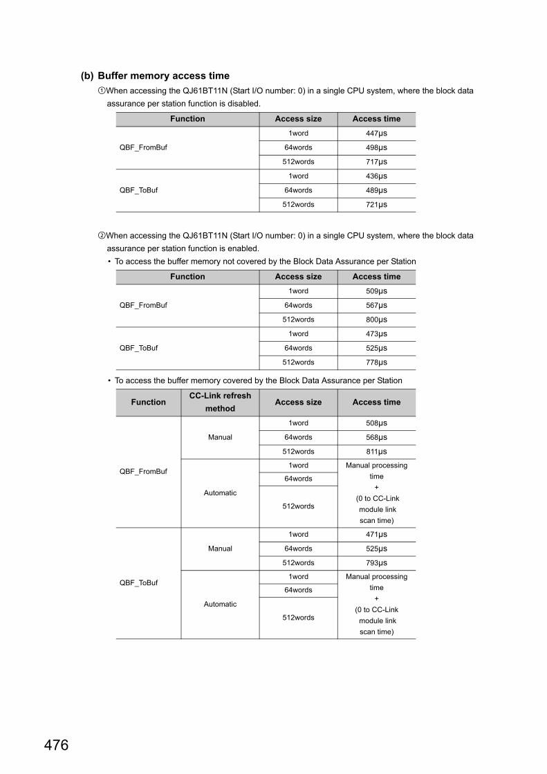
476
(b) Buffer memory access time
When accessing the QJ61BT11N (Start I/O number: 0) in a single CPU system, where the block data
assurance per station function is disabled.
When accessing the QJ61BT11N (Start I/O number: 0) in a single CPU system, where the block data
assurance per station function is enabled.
• To access the buffer memory not covered by the Block Data Assurance per Station
• To access the buffer memory covered by the Block Data Assurance per Station
Function Access size Access time
QBF_FromBuf
1word 447µs
64words 498µs
512words 717µs
QBF_ToBuf
1word 436µs
64words 489µs
512words 721µs
Function Access size Access time
QBF_FromBuf
1word 509µs
64words 567µs
512words 800µs
QBF_ToBuf
1word 473µs
64words 525µs
512words 778µs
FunctionCC-Link refresh
methodAccess size Access time
QBF_FromBuf
Manual
1word 508µs
64words 568µs
512words 811µs
Automatic
1word Manual processing
time
+
(0 to CC-Link
module link
scan time)
64words
512words
QBF_ToBuf
Manual
1word 471µs
64words 525µs
512words 793µs
Automatic
1word Manual processing
time
+
(0 to CC-Link
module link
scan time)
64words
512words

477
APPENDICES
A
Appendix 5 F
unction Processing T
ime
When accessing the positioning module other than QD72P3C3 in a single CPU system
(c) Multiple CPU shared memory (auto refresh area or user setting area) access time
When accessing the CPU shared memory (auto refresh area or user setting area) in a multiple CPU system
(CPU No.1:Q26UDHCPU, CPU No.2: C Controller module)
(d) Multiple CPU shared memory (multiple CPU high speed transmission area) access time
When accessing the CPU shared memory (multiple CPU high speed transmission area) in a multiple CPU
system (CPU No.1:Q26UDHCPU, CPU No.2: C Controller module)
(2) MELSEC data link function processing timeThe MELSEC data link function processing time varies depending on the target module, and the route and
devices used for communication.
When the communication target is a programmable controller CPU, the operating status, sequence scan time,
and link scan time of the programmable controller CPU may also affect the processing time.
(3) C Controller module dedicated function processing time
Function Access size Access time
QBF_FromBuf
1word 451µs
64words 511µs
512words 741µs
QBF_ToBuf
1word 431µs
64words 491µs
512words 761µs
Function Access sizeAccess time
Host No.1
QBF_FromBuf
1word 424µs 420µs
64words 450µs 484µs
512words 545µs 711µs
QBF_ToBuf
1word 414µs –
64words 441µs –
512words 555µs –
Function Access sizeAccess time
Host No.1
QBF_FromBuf
1word 433µs 437µs
64words 481µs 508µs
512words 585µs 736µs
QBF_ToBuf
1word 423µs –
64words 454µs –
512words 577µs –
Function Access size Access time
CCPU_ReadDataRefreshMemory
1word 5µs
64words 114µs
512words 896µs
CCPU_WriteDataRefreshMemory
1word 3µs
64words 15µs
512words 114µs

478
Appendix 6 List of Special Relays
The special relay (SM) is an internal relay whose application is fixed in a C Controller module.
The special relay cannot be used in the same way as other internal relays are used in user programs.
(1) Diagnostic information
Item Description
Number Indicates the number of the special relay.
Name Indicates the name of the special relay.
Description Indicates descriptions about the special relay.
Detailed
descriptionIndicates detailed descriptions about the special relay.
Setting side
(setting time)
Explains setting side and setting time at the system side.
Number Name Description Detailed descriptionSetting side
(setting time)
SM0 Diagnostic errorOFF: No error
ON: Error
• Turns on when a diagnostic result error occurs.
Later, on status is held even after returning to normal.
S
(Error)
SM1Self-diagnostic
error
OFF: No self-diagnostic error
ON: Self-diagnostic error
• Turns on when a diagnostic result error occurs.
Later, on status is held even after returning to normal.
S
(Error)
SM5Common error
information
OFF: No common error
information
ON: Common error
information
• When SM0 turns on, the relay turns on if there is
common error information.
S
(Error)
SM16Error individual
information
OFF: No error individual
information
ON: Error individual
information
• When SM0 turns on, the relay turns on if there is error
individual information.
S
(Error)
SM53AC/DC DOWN
detection
OFF: Without AC/DC
DOWN
ON: With AC/DC DOWN
• Turned on when a momentary power failure for 20ms or
less occurs if the AC power supply module is used.
Reset when a power cycle is performed.
S
(Error)
SM60Fuse blown
detection
OFF: Normal
ON: Fuse blown module
• Turns on when more than one output module in fuse
blown status exist.
Later, on status is held even after returning to normal.
S
(Error)
SM61I/O module
verification error
OFF: Normal
ON: Error
• Turns on when the I/O module is different from the
status that was registered upon power on.
Later, on status is held even after returning to normal.
S
(Error)
• Setting side
S : Set at the system side.
• Setting timeError
occurrence: Set when an error occurs.
System : Set when a fixed scan or the status is changed at the system side.

479
APPENDICES
A
Appendix 6 List of S
pecial Relays
(2) Redundant power supply module information
Number Name Description Detailed descriptionSetting side
(setting time)
SM1780Power supply off
detection flag
OFF: No redundant
power supply
module with
input power OFF
detected
ON: Redundant
power supply
module with
input power OFF
detected
• Turns ON when one or more redundant power supply
modules with input power OFF are detected.
• Turns on if any of SD1780 bits is on.
• Turns off if all bits of SD1780 are off.
• This relay turns off when the main base unit is not the
redundant main base unit (Q38RB).
• When the multiple CPU system is configured, the flags
are stored only to the CPU No.1.
S
(System)
SM1781
Power supply
failure detection
flag
OFF: No faulty
redundant power
supply module
detected
ON: Faulty redundant
power supply
module detected
• Turns ON when one or more faulty redundant power
supply modules are detected.
• Turns on if any of SD1781 bits is on.
• Turns off if all bits of SD1781 are off.
• This relay turns off when the main base unit is not the
redundant main base unit (Q38RB).
• When the multiple CPU system is configured, the flags
are stored only to the CPU No.1.
S
(System)
SM1782
Momentary
power failure
detection flag for
power supply 1 *1
OFF: No momentary
power failure
detected
ON: Momentary
power failure
detected
• Turns ON when a momentary power failure of the input
power supply to the power supply 1 or 2 is detected one
or more times. After turning on, this relay remains on
even if the power supply recovers from the momentary
power failure.
• Turns off the flags (SM1782 and SM1783) of the power
supply 1 and 2 when the CPU module starts.
• When the input power to one of the redundant power
supply modules turns OFF the corresponding flag turns
OFF.
• This relay turns off when the main base unit is not the
redundant main base unit (Q38RB).
• When the multiple CPU system is configured, the flags
are stored only to the CPU No.1.
S
(System)
SM1783
Momentary
power failure
detection flag for
power supply 2 *2
*1 : Indicates the redundant power supply module mounted on the POWER 1 slot of the redundant base unit (Q38RB/Q68RB/Q65WRB).*2 : Indicates the redundant power supply module mounted on the POWER 2 slot of the redundant base unit (Q38RB/Q68RB/Q65WRB).

480
Appendix 7 List of Special Registers
The special register (SD) is an internal register whose application is fixed in a C Controller module.
The special relay cannot be used in the same way as other internal relays are used in user programs.
Data is stored in binary format unless otherwise specified.
(1) Diagnostic information
Item Description
Number Indicates the number of the special register
Name Indicates the name of the special register.
Description Indicates descriptions about the special register.
Detailed
descriptionIndicates detailed descriptions about the special register.
Setting side
(setting time)
Explains setting side and setting time at the system side.
Number Name Description Detailed descriptionSetting side
(setting time)
SD0 Diagnostic errorDiagnostic error
code
• The error code occurred in diagnostics in diagnostics is stored as a
binary code.
• The information is the same as the latest error code.
S
(Error)
SD1
Date and time of
diagnostic error
Date and time of
diagnostic error
• The year (the last two digits of the year) and month when SD0 data
was updated are stored as a 2-digit BCD code. S
(Error)
SD2
• The date and time when SD0 data was updated are stored as a 2-
digit BCD code. S
(Error)
SD3
• The minute and second when SD0 data was updated are stored as
a 2-digit BCD code. S
(Error)
SD4Error information
identification
Error information
identification
code
• Identification codes used to determine what error information stored
in the common information (SD5 to SD15) and individual
information (SD16 to SD26) are stored.
• In the common information category codes, the following codes are stored.
0: None
1: Module No. (Slot No./CPU No./Base No.)
3: Time (setting value)
7: Base No./power supply
• In the individual information category codes, the following codes are stored.
00: None
3: Time (actual measurement value)
5: Parameter No.
S
(Error)
• Setting side
S : Set at the system side.
• Setting time
System : Set when a fixed scan or the status is changed at the system side.
Initial : Set only at initialization (power on, STOP RUN, etc.)
Error : Set when an error occurs.
b15 b7 b0b8to to
YY (0 to 99) MM (1 to 12)
(Example) October, 1995
H9510
b15 b7 b0b8to to
DD (1 to 31) Hr. (0 to 23)
(Example) Day of 25th, 10:00
H2510
b15 b7 b0b8to to
Min. (0 to 59) Sec. (0 to 59)
(Example) 35 minutes, 48 seconds
H3548
b15 b7 b0b8to toIndividual information
category codeCommon information
category code

481
APPENDICES
A
Appendix 7 List of S
pecial Registers
SD5
to
SD15
Common error
information
Common error
information
• Common information corresponding to the error code (SD0) is
stored.
• The following three types of information are stored.
• Common error information type can be determined by "Common
information category code" in SD4.
(The value of the Common information category code stored in SD4
corresponds to 1),3), and 7) below.)
Module No..
*1 : For multiple CPU systems, the slot No. or CPU No. is stored, depending on the error.(Regarding which number is stored, refer to each error code.)No. 1 CPU: 1, No. 2 CPU: 2, No. 3 CPU: 3, No. 4 CPU: 4
*2 : Definition of the base No. and slot No.<Base No.>The value to identify the base unit mounted on the C Controller module.The definition of the base No. is shown in the following table.
<Slot No.>
This value to identify the slot of each base unit and the module inserted
in the slot.
*3 : When FFFFH is stored in SD6 (I/O No.), the I/O No. is not identifiable, so specify the faulty sections in SD5.
*4 : If the slot No. does not exist in the module No., FFH is stored.Time (setting value)
S
(Error)
Number Name Description Detailed descriptionSetting side
(setting time)
*1, *2, *4SD5
SD6
SD7
SD8
SD9
SD10
SD11
SD12
SD13
SD14
SD15
No.
Slot No./CPU No./BaseNo.
I/O No. *3
Item
(Empty)
0
1 to 7
BaseNo.
Indicates the main base unit which a CPU module is mounted.
Indicates an extension base unit.
The stage number setting by a base number setting connector
of extension base unit turn to be Base No.
When a stage number setting is the first stage of extension
module: Base No. = 1
When a stage number setting is the seventh stage of
extension module: Base No. = 7
Definition
• I/O slot 0 (the right side of slot for the CPU slot) of the main
base unit is the slot of "Slot No. = 0".
• The slot No. order is the main base unit, the extension base
unit numbers 1 to 7 in that order, and a serial number is
assigned to each slot of each base unit.
• If I/O assignment of Setting/monitoring tools for the C
Controller module is used to set the number of slots in the
base unit, slot numbers are assigned for the set number of
slots.
SD5
SD6
SD7
SD8
SD9
SD10
SD11
SD12
SD13
SD14
SD15
No. Item
Hr.: in units of 1ms (0 to 65535ms)
(Empty)
(Empty)

482
SD5
to
SD15
Common error
information
Common error
information
Base No./power supply No..
S
(Error)
SD16
to
SD26
Error individual
information
Error individual
information
• Individual information corresponding to the error code (SD0) is
stored.
• The following information are stored.
• Error individual information type can be determined by "individual
information category code" in SD4.
(The value of the "individual information category code" stored in
SD4 corresponds to below.)
Time (actual measurement value)
Parameter No.
S
(Error)
SD53AC/DC DOWN
detection
AC/DC DOWN
detection count
• The count increments by 1 each time the input voltage goes below
the rated 85% (AC power supply)/65% (DC power supply) during
CPU module operations.
S
(Error)
SD60Fuse blown
module No.
Fuse blown
module No.
• The latest I/O number of the module that generated the blown fuse
is stored.
S
(Error)
SD61
I/O module
verification error
No.
I/O module
verification error
No.
• The latest I/O number of the module that generated the I/O module
verification error is stored.
S
(Error)
Number Name Description Detailed descriptionSetting side
(setting time)
1: Error occurring in power supply 1
2: Error occurring in power supply 2
Redundant power supply module mounting
on POWER 1 slot of the redundant base
unit (Q38RB, Q68RB, and Q65WRB)
"Power supply 1" :
SD5
SD6
SD7
SD8
SD9
SD10
SD11
SD12
SD13
SD14
SD15
No. Item
Base No.
Power supply No.
(Empty)
Redundant power supply module mounting
on POWER 2 slot of the redundant base
unit (Q38RB, Q68RB, and Q65WRB)
"Power supply 2" :
SD16
SD17
SD18
SD19
SD20
SD21
SD22
SD23
SD24
SD25
SD26
No. Item
Hr.: in units of 1ms (0 to 65535ms)
(Empty)
(Empty)
SD17
SD18
SD19
SD20SD21
SD22
SD23
SD24
SD16
SD25
SD26
Parameter No.
(Empty)
No. Item

483
APPENDICES
A
Appendix 7 List of S
pecial Registers
(2) System information
(3) Drive information
Number Name Description Detailed descriptionSetting side
(setting time)
SD200 Switch status
C Controller
module switch
status
• The switch status of the C Controller module is stored.
0: RUN, 1: STOP
S
(System)
SD203
C Controller
module
operation status
C Controller
module
operation status
• The operation status of the C Controller module is stored as
described below.
S
(System)
SD286
Device
assignment
M assignment
points
(for extension)
• The M assignment points are stored in 32-bit.S
(Initial)SD287• Even when M assignment points are 32K or less, the assignment
points are stored.
SD288 B assignment
points
(for extension)
• The B assignment points are stored in 32-bit.
• Even when B assignment points are 32K or less, the assignment
points are stored.
S
(Initial)SD289
SD308Device
assignment 2
(including
extension device
settings)
D assignment
points (internal +
extension)
• The M assignment points are stored in 32-bit.
(the total points of the D device and extension D device in the
internal device memory area)
S
(Initial)SD309
SD310 W assignment points (internal + extension)
• The W assignment points are stored in 32-bit.
(the total points of the W device and extension W device in the
internal device memory area)
S(Initial)SD311
Number Name Description Detailed descriptionSetting side
(setting time)
SD670Parameter-valid
drive information
Parameter-valid
drive No.
• Information for the valid parameter storage drive is stored.
Q24DHCCPU-V/-VG
0 : Drive 0 (internal ROM)
Q12DCCPU-V (Extended mode)
2 : Drive 2 (CF card)
4 : Drive 4 (Standard ROM)
S(Initial)
b0b3b4b7b8b11b12b15
2) 1)
1): C Controller module operation status
2): STOP/PAUSE factor (in chronological order)
0: RUN1: Reserved2: STOP3: PAUSE
0: RUN/STOP/MODE Switch1: Reserved2: Reserved
5: Remote operation from another CPU
3: QBF_Control function executed from a user program4: Error
3)
3): Mode 0: Basic mode1: Extended mode

484
(4) Fuse blown module
(5) I/O module verification
Number Name Description Detailed descriptionSetting side
(setting time)
SD1300
to
SD1331
Fuse blown
module
The bit pattern
of the fuse
blown module
in units of 16
points
0: No fuse blown
1: Fuse blown
• The output module number (by 16 points) in the fuse blown status is
stored in bit pattern.
(If it is set in parameters, the set number is applied.)
• This is not cleared even when normal status is restored.
Perform error clear to clear them.
S
(Error)
Number Name Description Detailed descriptionSetting side
(setting time)
SD1400
to
SD1431
I/O module
verification error
Bit pattern of
verification error
module in units
of 16 points
0: No I/O
verification
error
1: I/O verification
error
• If an I/O module different from that in the I/O module information
registered at power-on is detected, the I/O module number is stored
in bit pattern.
(If it is set in parameters, the set I/O module number is applied.)
• This is not cleared even when normal status is restored.
Perform error clear to clear them.
S
(Error)
b15 b14b13b12 b11b10 b9 b8 b7 b6 b5 b4 b3 b2 b1 b0
0 0 01
(YC0) 0 0 0 0 0 0 0 0 0 0 01
(Y80)SD1300
0 01
(Y1F0) 0 0 0 0 0 0 0 0 0 01
(Y1A0)SD1301 0 0
0 01
Y1FB0
0 0 0 0 0 0 0 0SD1331 0 001
Y1F30
0
Indicates the fuse blown status.
b15 b14 b13 b12 b11 b10 b9 b8 b7 b6 b5 b4 b3 b2 b1 b0
0 0 0 0 0 0 0 0 0 0 0 0 0SD1400
0 0 0 0 0 0 0 0 0 0 0SD1401 0 0
0 0 0 0 0 0 0 0 0SD1431 0 000
Indicates I/O module verify err.
0 0
00
00
1X Y0
1X Y190
1X Y1FE0
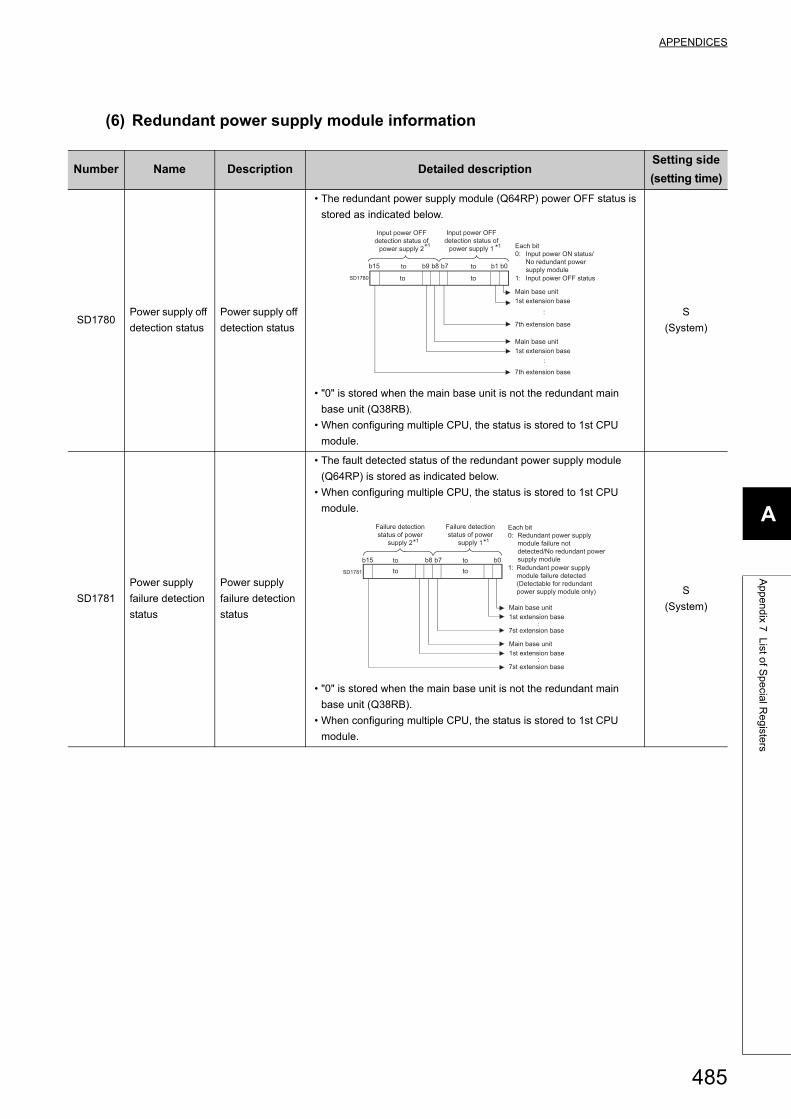
485
APPENDICES
A
Appendix 7 List of S
pecial Registers
(6) Redundant power supply module information
Number Name Description Detailed descriptionSetting side
(setting time)
SD1780Power supply off
detection status
Power supply off
detection status
• The redundant power supply module (Q64RP) power OFF status is
stored as indicated below.
• "0" is stored when the main base unit is not the redundant main
base unit (Q38RB).
• When configuring multiple CPU, the status is stored to 1st CPU
module.
S
(System)
SD1781
Power supply
failure detection
status
Power supply
failure detection
status
• The fault detected status of the redundant power supply module
(Q64RP) is stored as indicated below.
• When configuring multiple CPU, the status is stored to 1st CPU
module.
• "0" is stored when the main base unit is not the redundant main
base unit (Q38RB).
• When configuring multiple CPU, the status is stored to 1st CPU
module.
S
(System)
b0b7b8b15
SD1780
b9 b1
:
:
toto
toto
Input power OFF
detection status of
power supply 2 Each bit
0: Input power ON status/
No redundant power
supply module
1: Input power OFF status
Input power OFF
detection status of
power supply 11 1
Main base unit
1st extension base
7th extension base
Main base unit
1st extension base
7th extension base
b0b7b8b15
SD1781
:
:
toto
toto
Failure detection
status of power
supply 1
Failure detection
status of power
supply 2 1 1
Each bit
0: Redundant power supply
module failure not
detected/No redundant power
supply module
1: Redundant power supply
module failure detected
(Detectable for redundant
power supply module only)
Main base unit
1st extension base
7st extension base
Main base unit
1st extension base
7st extension base

486
SD1782
Momentary
power failure
detection
counter for
power supply 1*1
Momentary
power failure
detection count
for power supply
1
• Counts the number of times of momentary power failure of the
power supply 1/2.
• Monitors the status of the power supply 1/ 2 mounted on the
redundant power main base unit (Q38RB) and counts the number of
times of momentary power failure.
Status of power supply 1/power supply 2 mounted on the redundant
extension base unit is not monitored.
• When the CPU module starts, the counter of the power supply 1/ 2
is cleared to 0.
• If the input power to one of the redundant power supply modules is
turned OFF, the corresponding counter is cleared to 0.
• The counter is incremented by one upon momentary power failure
on the power supply 1 or 2. (The counter repeats increment and
decrement of the value; 0 32767 32768 0 .
(The value is displayed within the range of 0 to 65535 in the system
monitor screen of programming tool.))
• "0" is stored when the main base unit is not the redundant main
base unit (Q38RB).
• When configuring multiple CPU, the status is stored to 1st CPU
module.
S
(System)
SD1783
Momentary
power failure
detection
counter for
power supply 2*2
Momentary
power failure
detection count
for power supply
2
*1 : Indicates the redundant power supply module mounted on the POWER 1 slot of the redundant base unit (Q38RB/68RB/).*2 : Indicates the redundant power supply module mounted on the POWER 2 slot of the redundant base unit (Q38RB/68RB/).
Number Name Description Detailed descriptionSetting side
(setting time)
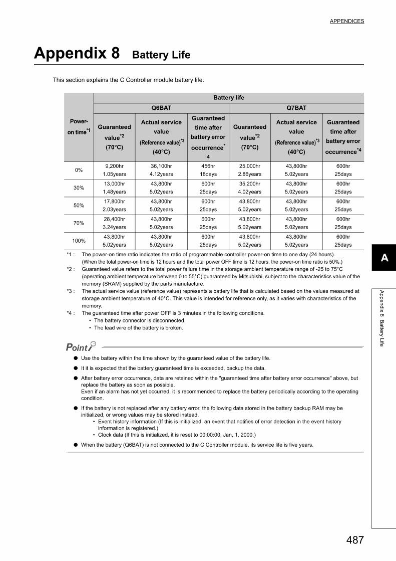
487
APPENDICES
A
Appendix 8 B
attery Life
Appendix 8 Battery Life
This section explains the C Controller module battery life.
● Use the battery within the time shown by the guaranteed value of the battery life.
● It it is expected that the battery guaranteed time is exceeded, backup the data.
● After battery error occurrence, data are retained within the "guaranteed time after battery error occurrence" above, but replace the battery as soon as possible. Even if an alarm has not yet occurred, it is recommended to replace the battery periodically according to the operating condition.
● If the battery is not replaced after any battery error, the following data stored in the battery backup RAM may be initialized, or wrong values may be stored instead.
• Event history information (If this is initialized, an event that notifies of error detection in the event history information is registered.)
• Clock data (If this is initialized, it is reset to 00:00:00, Jan, 1, 2000.)
● When the battery (Q6BAT) is not connected to the C Controller module, its service life is five years.
Power-
on time*1
Battery life
Q6BAT Q7BAT
Guaranteed
value*2
(70°C)
Actual service
value
(Reference value)*3
(40°C)
Guaranteed
time after
battery error
occurrence*
4
Guaranteed
value*2
(70°C)
Actual service
value
(Reference value)*3
(40°C)
Guaranteed
time after
battery error
occurrence*4
0%9,200hr
1.05years
36,100hr
4.12years
456hr
18days
25,000hr
2.86years
43,800hr
5.02years
600hr
25days
30%13,000hr
1.48years
43,800hr
5.02years
600hr
25days
35,200hr
4.02years
43,800hr
5.02years
600hr
25days
50%17,800hr
2.03years
43,800hr
5.02years
600hr
25days
43,800hr
5.02years
43,800hr
5.02years
600hr
25days
70%28,400hr
3.24years
43,800hr
5.02years
600hr
25days
43,800hr
5.02years
43,800hr
5.02years
600hr
25days
100%43,800hr
5.02years
43,800hr
5.02years
600hr
25days
43,800hr
5.02years
43,800hr
5.02years
600hr
25days
*1 : The power-on time ratio indicates the ratio of programmable controller power-on time to one day (24 hours).(When the total power-on time is 12 hours and the total power OFF time is 12 hours, the power-on time ratio is 50%.)
*2 : Guaranteed value refers to the total power failure time in the storage ambient temperature range of -25 to 75°C (operating ambient temperature between 0 to 55°C) guaranteed by Mitsubishi, subject to the characteristics value of the memory (SRAM) supplied by the parts manufacture.
*3 : The actual service value (reference value) represents a battery life that is calculated based on the values measured at storage ambient temperature of 40°C. This value is intended for reference only, as it varies with characteristics of the memory.
*4 : The guaranteed time after power OFF is 3 minutes in the following conditions. • The battery connector is disconnected. • The lead wire of the battery is broken.
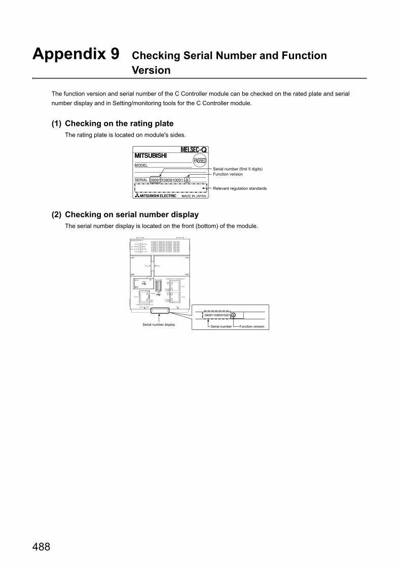
488
Appendix 9 Checking Serial Number and Function Version
The function version and serial number of the C Controller module can be checked on the rated plate and serial
number display and in Setting/monitoring tools for the C Controller module.
(1) Checking on the rating plateThe rating plate is located on module's sides.
(2) Checking on serial number displayThe serial number display is located on the front (bottom) of the module.
Serial number (first 5 digits)Function version
Relevant regulation standards
Serial number Function versionSerial number display

489
APPENDICES
A
Appendix 9 C
hecking Serial N
umber and F
unction Version
(3) Setting/monitoring tools for the C Controller moduleThey can be checked by the following function of Setting/monitoring tools for the C Controller module.
• [Diagnostics] [System Monitor] "Product Information List"
The serial number (product number) printed on the rating plate of the module is displayed in the "Product No." column.*1
Note that "-" is displayed for the module that does not support the product number display.
The serial number on the rating plate and the serial number displayed in Setting/monitoring tools for the C Controller module may be different.
• The serial numbers on the rating plate and the front of the module indicate the management information. • The serial number displayed in the "Product Information List" screen of Setting/monitoring tools for the C
Controller module represents the product function information.(The functional information of the product will be updated when a function is added.)
Serial number
Function version
Productionnumber

490
Appendix 10 Added or Changed Functions
Functions and specifications of the CPU module are added and/or changed at each version upgrade.
Available functions and specifications differ according to the function version and serial number of the CPU module.
Appendix 10.1 C Controller module upgrade
The following table shows the functions and specifications which are supported according to the upgrades.
Appendix 10.1.1 Q24DHCCPU-V
Serial No. Software version Added function Reference
14122 Ver.4.01B
The following CPU modules are supported.
• Universal model QCPU
Q03UDVCPU, Q04UDVCPU, Q06UDVCPU, Q13UDVCPU,
Q26UDVCPU
Page 27
15042 Ver.4.02C
The security function is supported.
• File access restriction function*1
• Service setting function*1
Page 176, Section
11.8
The SLMP (MC protocol) is supported.Page 200, Section
12.2
The following CPU modules are supported.
• High Speed Data Communication Module
QJ71DC96
• Analog conversion module
Q64ADH, Q68CT, Q64DAH
• QD70 type positioning module
QD73A1
• MODBUS® interface module
QJ71MB91,QJ71MT91
• Energy measuring module
QE81WH, QE84WH, QE81WH4W, QE83WH4W, QE82LG
Page 96, Section 7.5
15102 Ver.4.04E
The following CPU modules are supported.
• Simple motion module
QD77MS2, QD77MS4, QD77MS16, QD77GF16
Page 96, Section 7.5
The following function are supported.
• CCPU_GetCounterMillis
• CCPU_GetCounterMicros
• CCPU_GetCounterMillis_ISR
• CCPU_GetCounterMicros_ISR
• QBF_REMTO
• QBF_REMFR
Page 353, Section
20.2
16012 Ver.4.06G
The advanced synchronous control method for Q172DSCPU and
Q173DSCPU is supported.–
The following function are supported.
• QBF_MotionCHGAS
• QBF_MotionCHGVS
Page 356, Section
21.2
*1 : When the parameter is written with Setting/monitoring tools for the C Controller module version 4.01B or earlier, the password set to "Security password setting" on the <<Security settings>> tab is initialized.

491
APPENDICES
A
Appendix 10 A
dded or Changed
Functio
nsA
ppendix 10.1 C C
ontroller m
odule upgrade
Appendix 10.1.2 Q24DHCCPU-VG
16012 Ver.4.07HDevice overlapping settings are enabled when the operations differ by
the data refresh settings.
Page 173, Section
11.7 (7)(a)
17092 Ver.4.10L
Maximum value of frame size of Ethernet communication which uses
User Ethernet port (CH1, CH2) is changed. (Jumbo frame supporting)
Page 192, Section
12.1
SNTP version to be used can be selected in SNTP client function,
which uses User Ethernet port (CH1, CH2) and system Ethernet port
(S.CH1).
Page 199, Section
12.1.3
Serial No. Software version Added function Reference
17102 Ver.4.10L
Maximum value of frame size of Ethernet communication which uses
User Ethernet port (CH1, CH2) is changed. (Jumbo frame supporting)
Page 192, Section
12.1
SNTP version to be used can be selected in SNTP client function,
which uses User Ethernet port (CH1, CH2) and system Ethernet port
(S.CH1).
Page 199, Section
12.1.3
Serial No. Software version Added function Reference

492
Appendix 10.1.3 Q12DCCPU-V
Serial No. Software version Added function Reference
15102 Ver.4.04E
Q12DCCPU-V (Extended mode) is supported. Page 33, Section 1.1.5
The setting/monitoring tool for the C Controller module connection
function is supported.Page 52, CHAPTER 4
The following CPU modules are supported.
• Universal model QCPU
Q03UDVCPU, Q04UDVCPU, Q06UDVCPU, Q13UDVCPU,
Q26UDVCPU
Page 27
The Standard ROM is supported. –
The Time setting function (SNTP) is supported.Page 202, Section
12.2.1
The System Monitor is supported. –
The Battery less drive is supported.Page 190, Section
11.11
The security function is supported.Page 176, Section
11.8
The SLMP (MC protocol) communication is supported.Page 204, Section
12.2.2
The following CPU modules are supported.
• Simple motion module
QD77MS2, QD77MS4, QD77MS16, QD77GF16
• Analog conversion module
Q64ADH, Q68CT, Q64DAH
• Positioning module
QD73A1
• MODBUS® interface module
QJ71MB91
• High Speed Data Communication Module
QJ71DC96
• Energy measuring module
QE84WH, QE81WH4W, QE83WH4W
• CC-Link IE Field Network master/local module
QJ71GF11-T2
Page 96, Section 7.5
The following function are supported.
• QBF_REMTO
• QBF_REMFR
Page 356, Section
21.2
16012 Ver.4.06G
The advanced synchronous control method for Q172DSCPU and
Q173DSCPU is supported.–
The following function are supported.
• QBF_MotionCHGAS
• QBF_MotionCHGVS
Page 356, Section
21.2

493
APPENDICES
A
Appendix 11 F
ail-Safe C
ircuit
Appendix 11 Fail-Safe Circuit
At power-on/off of the C Controller module, the control output may become inoperable temporarily due to the
difference between the delay time and rising time of the C Controller module power supply and the controlled external
power supply (especially for DC).
For example, if the controlled external power supply is energized in the DC output module and then the C Controller
system power supply is energized, a momentary incorrect output may occur at power-on of the C Controller system by
the DC output module. Therefore, It is necessary to configure a circuit that can be energized by the C Controller
system power supply first.
In addition, a faulty operation may occur in the event of external power supply failure or failure of the C Controller
module main.
Configure circuits outside the C Controller module for components for which machine damage and/or accidents may
occur due to these faulty operations not leading to faulty operations of the entire system, or in view failsafe (emergency
stop circuit, protection circuit, and interlock circuit, etc.).
A circuit example for system design prepared in the above point of view is illustrated in the next page.

494
(1) Circuit example for system design (when not using the ERR. contact of the
power supply module)
C Controller module
User
program
*1
MC
RA1
RA2 XM
Ym
Yn
MC2
MC1
MC MC
MC
MC2
MC1
Ym
Yn
MC
RA1
MC
MC
RA2
L
MC1
RA1
MC2
MC1
MC2
L
RA1
MC
(-) (+)
FOR AC FOR AC/DCPower supply
Power supply
Transformer
Fuse
START SW
STOP SW
Input module
Output module
Output moduleLow battery alarm(Lamp or buzzer)
Turns ON at start of C Controller module user program.
Power to output equipment is turned off when the STOP signal is given.
Started when RA1
(control start output of
C Controller module)
turns ON.
RUN/STOP circuit
In the case of anemergency stop or a stop caused by a limit switch.
Interlock circuits
Trans-former
Trans-former
Fuse Fuse
Fuse
DC power
Voltage relay is recommended
Low battery alarm(Lamp or buzzer)
Turns ON at start of C Controller module user program.
Power to output equipment is turned off when the STOP signal is given.
In the case of anemergency stop or a stop caused by a limit switch.
START SW
STOP SW
Output module
Output module
Provide external interlock circuits for conflicting operations, such as forward rotation and reverse rotation, and for parts that could damage the machine or cause accidents .
User
program
*2
C Controller module

495
APPENDICES
A
Appendix 11 F
ail-Safe C
ircuit
*1 : Program the system so that the following operation will be performed at start-up of the C Controller module. • When a battery voltage drop is detected, Ym is turned on.
<Q24DHCCPU-V/-VG and Q12DCCPU-V(Extended mode)>Use CCPU_GetErrInfo function or QBF_Y_Out_BitEx function.<Q24DHCCPU-LS and Q26DHCCPU-LS>Refer to the manual of the partner (operating system vendor), or consult the partner (operating system vendor).
• Yn is turned on at start of the user program.<Q24DHCCPU-V/-VG and Q12DCCPU-V(Extended mode)>Use CCPU_GetErrInfo function or QBF_Y_Out_BitEx function.<Q24DHCCPU-LS and Q26DHCCPU-LS>Refer to the manual of the partner (operating system vendor), or consult the partner (operating system vendor).
*2 : Program the system so that the following operation will be performed at start-up of the C Controller module. • After XM turns on and the DC input signal is established, system processing is started.
Create a program so that system processing will start when the DC input signal establishment time has elapsed after turn-on of XM (the status can be confirmed by the QBF_X_In_BitEx function).(The DC input signal establishment time is the time taken from "on" of RA2 to 100% establishment of the DC input signal. Set this time to 0.5 seconds.)However, when a voltage relay is used for RA2, the DC input signal establishment time need not be set in the user program.
<Q24DHCCPU-V/-VG and Q12DCCPU-V(Extended mode)>Use QBF_X_In_BitEx function.<Q24DHCCPU-LS and Q26DHCCPU-LS>Refer to the manual of the partner (operating system vendor), or consult the partner (operating system vendor).
The power-up procedure is as follows.
For AC
1. Turn on the power.
2. Set the C Controller module to "RUN".
3. Turn on the start switch.
4. When the magnetic contactor (MC) turns on, the output equipment is driven by the user program.*1
For AC/DC
1. Turn on the power.
2. Set the C Controller module to "RUN".
3. When DC power is applied, RA2 is turned on.
4. When RA2 turns on, XM is turned on.
Upon 100% establishment of the DC input signal, processing is started by the user program.*2
5. Turn on the start switch.
6. When the magnetic contact (MC) turns on, the output equipment is driven by the user program.

496
(2) Circuit example for system design (When using the ERR. contact of the power
supply module)
This relay turns off if the
ERR. contact turns off
(a stop error occurs).
MC
RA1 RA3
RA2XM
Ym
Yn
MC2
MC1
MC MC
MC
RA2
L
MC1
RA1
MC2
(-) (+)
FOR AC/DCPower supply
Started when RA1
(control start output of
C Controller module)
turns ON.
RUN/STOP circuit
Interlock circuits
Transformer Transformer
Fuse Fuse
Fuse
DC power
Voltage relay is recommended
Low battery alarm(Lamp or buzzer)
Turns ON at start of C Controller module user program.
The stop switch turns off by an emergency stop, a stop caused by exceeding a limit value, or turning off the ERR. contact.
START SW
STOP SW
Output module
ERR.RA3
Power supply module
Output module
Provide external interlock circuits for conflicting operations, such as forward rotation and reverse rotation, and for parts that could damage the machine or cause accidents .
Power to output equipment is turned off when the STOP signal is given.
User
program*1
C Controller module

497
APPENDICES
A
Appendix 11 F
ail-Safe C
ircuit
*1 : Program the system so that the following operation will be performed at start-up of the C Controller module. • When a battery voltage drop is detected, Ym is turned on.
<Q24DHCCPU-V/-VG and Q12DCCPU-V(Extended mode)>Use CCPU_GetErrInfo function or QBF_Y_Out_BitEx function.<Q24DHCCPU-LS and Q26DHCCPU-LS>Refer to the manual of the partner (operating system vendor), or consult the partner (operating system vendor).
• Yn is turned on at start of the user program.<Q24DHCCPU-V/-VG and Q12DCCPU-V(Extended mode)>Use CCPU_GetErrInfo function or QBF_Y_Out_BitEx function.<Q24DHCCPU-LS and Q26DHCCPU-LS>Refer to the manual of the partner (operating system vendor), or consult the partner (operating system vendor).
• After XM turns on and the DC input signal is established, system processing is started.Create a program so that system processing will start when the DC input signal establishment time has elapsed after turn-on of XM (the status can be confirmed by the QBF_X_In_BitEx function).(The DC input signal establishment time is the time taken from "on" of RA2 to 100% establishment of the DC input signal. Set this time to 0.5 seconds.)However, when a voltage relay is used for RA2, the DC input signal establishment time need not be set in the user program.
<Q24DHCCPU-V/-VG and Q12DCCPU-V(Extended mode)>Use QBF_X_In_BitEx function.<Q24DHCCPU-LS and Q26DHCCPU-LS>Refer to the manual of the partner (operating system vendor), or consult the partner (operating system vendor).
The power-up procedure is as follows.
For AC/DC
1. Turn on the power.
2. Set the C Controller module to "RUN".
3. When DC power is applied, RA2 is turned on.
4. When RA2 turns on, XM is turned on.
Upon 100% establishment of the DC input signal, processing is started by the user program.*1
5. Turn on the start switch.
6. When the magnetic contactor (MC) turns on, the output equipment is driven by the user
program.
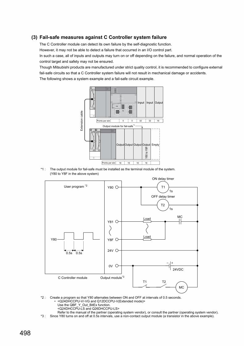
498
(3) Fail-safe measures against C Controller system failureThe C Controller module can detect its own failure by the self-diagnostic function.
However, it may not be able to detect a failure that occurred in an I/O control part.
In such a case, all of inputs and outputs may turn on or off depending on the failure, and normal operation of the
control target and safety may not be ensured.
Though Mitsubishi products are manufactured under strict quality control, it is recommended to configure external
fail-safe circuits so that a C Controller system failure will not result in mechanical damage or accidents.
The following shows a system example and a fail-safe circuit example.
*1 : The output module for fail-safe must be installed as the terminal module of the system. (Y80 to Y8F in the above system)
*2 : Create a program so that Y80 alternates between ON and OFF at intervals of 0.5 seconds. • <Q24DHCCPU-V/-VG and Q12DCCPU-V(Extended mode)>
Use the QBF_Y_Out_BitEx function.<Q24DHCCPU-LS and Q26DHCCPU-LS>Refer to the manual of the partner (operating system vendor), or consult the partner (operating system vendor).
*3 : Since Y80 turns on and off at 0.5s intervals, use a non-contact output module (a transistor in the above example).
Exte
nsio
n c
ab
le
Y80
to Y
8F
OutputInput Input
Points per slot 0 0 32
16 16 16 16
32 16
Output module for fail-safe*1
Points per slot
EmptyOutputOutputOutputOutput
Load
Load
User program *2
ON delay timer
1s
OFF delay timer
1s
T2T1
24VDC
Y80
Y81
Y8F
24V
0V
Y80
0.5s0.5s
C Controller module Output module*3
MC
T1
T2
MC

499
APPENDICES
A
Appendix 12 C
alculating H
eat Gene
ration of Prog
ramm
able Controller
Appendix 12 Calculating Heat Generation of Programmable Controller
The ambient temperature inside the panel storing the programmable controller must be suppressed to an ambient
temperature of 55×C or less, which is specified for the programmable controller.
For the design of a heat releasing panel, it is necessary to know the average power consumption (heating value) of the
devices and instruments stored inside.
Obtain the average power consumption of the C Controller module and calculate the increase of in-panel temperature
increase based on the power consumption.
For details, refer to the following.
QCPU User's Manual (Hardware Design, Maintenance and Inspection)
Appendix 13 External Dimensions
115
984
83
<Q24DHCCPU-V>
<Q24DHCCPU-VG>
115
98483

500
115
98
4
83
<Q24DHCCPU-LS>
83 115
984
<Q26DHCCPU-LS>

501
APPENDICES
A
Appendix 13 E
xternal D
imensions
115
498
23
27.4
<Q12DCCPU-V>

502
Appendix 14 BIOS Setup
(1) Starting the setupWhen Q24DHCCPU-VG/-LS and Q26DHCCPU-LS is started up, AMIBIOS is started as well.
The setup program can be started by the following operation while the BIOS setup screen is displayed.
• When executing POST, press the key while the following message is displayed in the middle of the
screen.*1
'Press DEL to run Setup'
*1 : When executing POST, do not press the key while the following message is displayed on the screen.'Press F11 for BBS POPUP'
When the message is disappeared before pressing the key, reset the C Controller module or restart the user CPU.
(2) BIOS setup screen
(a) Main tab screen
*1 : The setting contents are applied immediately.
(b) Exit screen
: Applicable : Not applicable
Item DescriptionSetting
applicability
AMIBIOS Display the information about BIOS.
Version Display the core version.
BuildData Display the date to be built.
ID Display the ID for administration.
Processor Display the information about the processor.
(CPU) Display the CPU name and operation frequency.
Speed Display the operation frequency.
Count Display the number of embedded CPUs.
System Memory Display the information of system memory.
Size Display the capacity of work memory.
System Time*1 Display the time.
System Data*1 Display the date.
CMC Display CMC code.
Item Description
Save Changes and Exit Exit the BIOS setup.

503
APPENDICES
A
Appendix 14 B
IOS
Setu
p
(3) Help window (General Help)The Help window is displayed when pressing the key on the BIOS setup screen.
*1 : Invalid key operation.
Operation key Description
/ Switch the tab between Main tab and Exit tab.
/ Switch the System Time and SystemDate.
/Increase/decrease a number of input values of System Time and
SystemDate.
• Display a pop-up window.
• Move to the time setting item.
Scroll the page downward.
Scroll the page upward.
Move the cursor to the top of the setting item on the screen.
Move the cursor to the bottom of the setting item on the screen.
/ Change the color of the screen.
Discard the change.*1
Read the failsafe value.*1
Read the initial settings.*1
End the BIOS setup with saving the change of all the setting information.
• Close the pop-up window.
• End the BIOS setup without saving the change of all the setting information.

504
INDEX
A
Access authority setting function . . . . . . . . . . . . . 177Access by link refresh function . . . . . . . . . . . . . . 212Access to Motion CPU . . . . . . . . . . . . . . . . . . . . 282Access to programmable controller CPU and C Controller module. . . . . . . . . . . . . . . . . . . . . . . . 281Access via a bus . . . . . . . . . . . . . . . . . . . . . . . . 367account. . . . . . . . . . . . . . . . . . . . . . . . . . . . . . . 177Administrator . . . . . . . . . . . . . . . . . . . . . . . . . . . 177Analog RGB output cabling . . . . . . . . . . . . . . . . . 131Applicable modules . . . . . . . . . . . . . . . . . . . . . . . 96Auto refresh area . . . . . . . . . . . . . . . . . . . . . . . . 252
B
Backup power time. . . . . . . . . . . . . . . . . . . . . . . 136Base Unit Assignment Setting . . . . . . . . . . . . . . . 303Basic mode . . . . . . . . . . . . . . . . . . . . . . . . . . . 26,29Batch . . . . . . . . . . . . . . . . . . . . . . . . . . . . . . . . 366Battery . . . . . . . . . . . . . . . . . . . . . . . . . . . . . . . . 39Battery backup RAM . . . . . . . . . . . . . . 310,319,330Battery Installation . . . . . . . . . . . . . . . . . . . . . . . 119Battery Less Drive . . . . . . . . . . . . . . . . . . . . . . . 190Battery Life . . . . . . . . . . . . . . . . . . . . . . . . . . . . 487Battery Replacement Procedure . . . . . . . . . . . . . 136Battery Specifications . . . . . . . . . . . . . . . . . . . . . . 90BIOS Setup . . . . . . . . . . . . . . . . . . . . . . . . . . . . 502block data assurance per station . . . . . . . . . . . . . 212Buffer memory access . . . . . . . . . . . . . . . . . . . . 219Bus connection . . . . . . . . . . . . . . . . . . . . . . . . . 110Bus interface function . . . . . . . . . . . . . . . . . . 338,356
C
Cabling . . . . . . . . . . . . . . . . . . . . . . . . . . . . . . . 125CC-Link . . . . . . . . . . . . . . . . . . . . . . . 100,237,387CC-Link IE Controller Network. . . . . . . . . 99,225,370CC-Link IE Field Network . . . . . . . . . . . 100,232,381CCPU parameter settings . . . . . . . . . . . . . . . . . . 289CH1 . . . . . . . . . . . . . . . . . . . . . . . . . . . . . . . . . . 35CH2 . . . . . . . . . . . . . . . . . . . . . . . . . . . . . . . . . . 35Change of Operation Status (RUN/STOP) . . . . . . . 70Channel . . . . . . . . . . . . . . . . . . . . . . . . . . . . . . 222Checking the Error Details . . . . . . . . . . . . . . . . . 400chkdsk . . . . . . . . . . . . . . . . . . . . . . . . . . . . . . . 405Clock data. . . . . . . . . . . . . . . . . . . . . . . . . . . . . 160Clock Function. . . . . . . . . . . . . . . . . . . . . . . . . . 160Communication using the multiple CPU high speed transmission area and auto refresh . . . . . . . . . . . 261Connection with HMI (GOT) . . . . . . . . . . . . . . . . 109connector . . . . . . . . . . . . . . . . . . . . . . . . . . . . . . 35CPU error code . . . . . . . . . . . . . . . . . . . . . . . . . 409CPU number . . . . . . . . . . . . . . . . . . . . . . . . . . . . 95CPU shared memory . . . . . . . . . . . . . . 312,321,331CPU shared memory structure . . . . . . . . . . . . . . 252Creating a directory . . . . . . . . . . . . . . . 317,326,335CW Workbench . . . . . . . . . . . . . . . . . . . . . . . . . 342CW Workbench connection fails . . . . . . . . . . . . . 403Cyclic Transmission . . . . . . . . . . . . . . . . . . . . . . 209
D
Daily Inspection . . . . . . . . . . . . . . . . . . . . . . . . . 134Data communications using auto refresh . . . . . . . 256Data Communications Using CPU Shared Memory . . . . . . . . . . . . . . . . . . . . . . . . . . . . . . 251Data communications without using auto refresh. . 266Data refresh function . . . . . . . . . . . . . . . . . . . . . 171Data refresh memory . . . . . . . . . . . . . . 312,321,328Dedicated functions for C Controller module . . . . . . . . . . . . . . . . . . . . . . . . . . . . . . . . . 338,353Delay time in cyclic transmission . . . . . . . . . . . . . 245Development Environment . . . . . . . . . . . . . . . . . 336Device Description. . . . . . . . . . . . . . . . . . . . . . . . 51Device Function. . . . . . . . . . . . . . . . . . . . . . . . . 169Device list . . . . . . . . . . . . . . . . . . . . . . . . . . . . . 169Direct access . . . . . . . . . . . . . . . . . . . . . . . . . . 217Disposal Precautions . . . . . . . . . . . . . . . . . . . . . . . 8Drive name . . . . . . . . . . . . . . . . . . . . . 314,323,332
E
Empty slot. . . . . . . . . . . . . . . . . . . . . . . . . . . . . 302Endian format (memory layout) . . . . . . . . . . . . . . 339ERR.LED . . . . . . . . . . . . . . . . . . . . . . . . . . . . . 397Error Code . . . . . . . . . . . . . . . . . . . . . . . . . . . . 409Error code during function execution . . . . . . . . . . 421Error code returned to peripherals . . . . . . . . . . . . 432Error time output mode setting . . . . . . . . . . . . . . 152Event History Collection Function . . . . . . . . . . . . 187Event Number . . . . . . . . . . . . . . . . . . . . . . . . . . 434Extended mode . . . . . . . . . . . . . . . . . . . . . 26,29,33extension cable . . . . . . . . . . . . . . . . . . . . . . . . . . 88Extension stage number . . . . . . . . . . . . . . . . . . . . 89External Dimensions . . . . . . . . . . . . . . . . . . . . . 499
F
Fail-Safe Circuit. . . . . . . . . . . . . . . . . . . . . . . . . 493File access . . . . . . . . . . . . . . . . . . . . . . . . . . . . 405File access restriction function . . . . . . . . . . . . . . 183File diagnostics . . . . . . . . . . . . . . . . . . . . . . . . . 405file operations . . . . . . . . . . . . . . . . . . . 316,325,335File read-out (download) from C Controller module fails . . . . . . . . . . . . . . . . . . . . . . . . . . . . . . . . . 406File restoration . . . . . . . . . . . . . . . . . . . . . . . . . 405Files configuration . . . . . . . . . . . . . . . . 316,325,334floating-point operations . . . . . . . . . . . . . . . . . . . 339For characters that can be used in user name and password . . . . . . . . . . . . . . . . . . . . . . . . . . . . . 178format. . . . . . . . . . . . . . . . . . . . . . . . . 314,323,332FTP . . . . . . . . . . . . . . . . . . . . . . . . . . . . . . . . . 404FTP function . . . . . . . . . . . . . . . . . . . . . . . . . . . 197Function Processing Time . . . . . . . . . . . . . . . . . 475FUNCTIONS ACCESSED VIA A NETWORK MODULE . . . . . . . . . . . . . . . . . . . . . . . . . . . . . 208Functions for compatibility . . . . . . . . . . . . . . 359,363

I
4
3
4
7
8
505
G
General Specifications. . . . . . . . . . . . . . . . . . . . . . 44
H
Hardware Diagnostics . . . . . . . . . . . . . . . . . . . . . . 75Hardware error time CPU operation mode setting. . . . . . . . . . . . . . . . . . . . . . . . . . . . . . . . . . . . . 153HARDWARE OPERATIONS . . . . . . . . . . . . . . . . . 62Heat Generation . . . . . . . . . . . . . . . . . . . . . . . . . 499HMI (GOT) . . . . . . . . . . . . . . . . . . . . . . . . . . . . . 109hub . . . . . . . . . . . . . . . . . . . . . . . . . . . . . . . . . . . 46
I
I/O access timing . . . . . . . . . . . . . . . . . . . . . . . . 306I/O assignment setting. . . . . . . . . . . . . . . . . . . . . . 93I/O module and intelligent function module access function . . . . . . . . . . . . . . . . . . . . . . . . . . . . . . . 146I/O NUMBER . . . . . . . . . . . . . . . . . . . . . . . . . . . 298I/O number of each CPU module . . . . . . . . . . . . . 299I/O to uncontrolled module . . . . . . . . . . . . . . . . . . 174Image File . . . . . . . . . . . . . . . . . . . . . . . . . . . . . 343Individual identification function . . . . . . . . . . . . . . 179Initial processing . . . . . . . . . . . . . . . . . . . . . . . . . 305Initialization . . . . . . . . . . . . . . . . . . . . . . . . . . . . . 62Input response time selection (I/O response time) . 150Inserting and Removing an SD Memory Card. . . . . 120Installation and Removal of Module. . . . . . . . . . . . 116Internal ROM . . . . . . . . . . . . . . . . . . . . 309,318,329Interrupt event of the data refresh function. . . . . . . 173Interrupt from Another CPU . . . . . . . . . . . . . . . . . 274Interrupt from C Controller module . . . . . . . . . . . . 275Interrupt from Controller CPU . . . . . . . . . . . . . . . . 276Interrupt from intelligent function module and interrupt module . . . . . . . . . . . . . . . . . . . . . . . . . . . . . . . 148interrupt service routine (ISR). . . . . . . . . . . . . . . . 341Issuing an Interrupt to Another CPU . . . . . . . . . . . 280
L
LED. . . . . . . . . . . . . . . . . . . . . . . . . . . . . . . . . . . 35LIFE LED . . . . . . . . . . . . . . . . . . . . . . . . . . . . . . 396Link device . . . . . . . . . . . . . . . . . . . . . . . . . . . . . 210Link device access function . . . . . . . . . . . . . . . . . 211Link refresh cycle setting . . . . . . . . . . . . . . . . . . . 175Link refresh function . . . . . . . . . . . . . . . . . . . . . . 175Link refresh time . . . . . . . . . . . . . . . . . . . . . . . . . 244Link scan . . . . . . . . . . . . . . . . . . . . . . . . . . . . . . 210List of Special Registers . . . . . . . . . . . . . . . . . . . 480List of Special Relays . . . . . . . . . . . . . . . . . . . . . 478Lockout . . . . . . . . . . . . . . . . . . . . . . . . . . . . . . . 177LOW VOLTAGE DIRECTIVES . . . . . . . . . . . . . . . . 11
M
Main base unit/power supply module. . . . . . . . . . . . 88Maintenance. . . . . . . . . . . . . . . . . . . . . . . . . . . . 177Maximum number . . . . . . . . . . . . . . . . . . . . . . . . 110MC protocol communication . . . . . . . . . . . . . . . . . 204MELSEC data link function. . . . . . . . . . . . . . 338,362MELSECNET/H . . . . . . . . . . . . . . . . . . . 99,230,375
Message communication . . . . . . . . . . . . . . . . . . . 221MODE. . . . . . . . . . . . . . . . . . . . . . . . . . . . . . . . . 37MODE LED . . . . . . . . . . . . . . . . . . . . . . . . . . . . 397Modules available. . . . . . . . . . . . . . . . . . . . . . . . . 98Modules with constraints on the number of installations are listed below . . . . . . . . . . . . . . . . . 87Motion CPU Control Instruction . . . . . . . . . . . . . . 285Mounting position . . . . . . . . . . . . . . . . . . . . . . . . . 93Multiple CPU high speed transmission area. . . . . . 252Multiple CPU Synchronized Boot-Up. . . . . . . . . . . 286Multiple CPU Synchronous Interrupt Function . . . . 279
N
Network parameter settings . . . . . . . . . . . . . . . . . 291Number of CPUs setting . . . . . . . . . . . . . . . . . . . . 94number of files . . . . . . . . . . . . . . . . . . . 317,326,335Number of tasks . . . . . . . . . . . . . . . . . . . . . . . . . 339
O
Online change . . . . . . . . . . . . . . . . . . . . . . . . . . . 98Opening and closing . . . . . . . . . . . . . . . . . . 360,364Operation processing during momentary power failure . . . . . . . . . . . . . . . . . . . . . . . . . . . . . . . . 308Operation processing in the PAUSE status . . . . . . 307Operation processing in the RUN status . . . . . . . . 307Operation processing in the STOP status . . . . . . . 307other peripherals (C Controller module, etc.) . . . . . 114Other station device access . . . . . . . . . . . . . . . . . 223Output (Y) status setting for switching STOP to RUN . . . . . . . . . . . . . . . . . . . . . . . . . . . . . . . . . 151
P
P1. . . . . . . . . . . . . . . . . . . . . . . . . . . . . . . . . . . . 37P2. . . . . . . . . . . . . . . . . . . . . . . . . . . . . . . . . . . . 37PARAMETER. . . . . . . . . . . . . . . . . . . . . . . . . . . 288parameter importing . . . . . . . . . . . . . . . . . . . . . . 295Parameter Number . . . . . . . . . . . . . . . . . . . . . . . 296Parameter Settings . . . . . . . . . . . . . . . . . . . . . . . 294PART NAMES . . . . . . . . . . . . . . . . . . . . . . . . . . . 35password. . . . . . . . . . . . . . . . . . . . . . . . . . . . . . 178PCI Express®. . . . . . . . . . . . . . . . . . . . . . . . . . . . 39Performance Specifications . . . . . . . . . . . . . . . . . . 45Periodical Inspection. . . . . . . . . . . . . . . . . . . . . . 135Peripheral Configuration . . . . . . . . . . . . . . . . . . . 102Personal computer . . . . . . . . . . . . . . . . . . . . . . . 111POWER LED . . . . . . . . . . . . . . . . . . . . . . . 395,397Precautions for access range. . . . . . . . . . . . . . . . 101Precautions for using a serial communication module . . . . . . . . . . . . . . . . . . . . . . . . . . . . . . . 100Precautions for using an FL-net module . . . . . . . . 100Precautions on interrupt processing . . . . . . . . . . . 101PREPARATORY PROCEDURE. . . . . . . . . . . . . . . 53priority . . . . . . . . . . . . . . . . . . . . . . . . . . . . . . . . 340PROGRAMMING . . . . . . . . . . . . . . . . . . . . . . . . 336
Q
Q24DHCCPU-LS . . . . . . . . . . . . . . . . . . . . . . 32,57Q26DHCCPU-LS . . . . . . . . . . . . . . . . . . . . . . 32,57

506
R
RAM disk . . . . . . . . . . . . . . . . . . . . . . 310,319,329Random . . . . . . . . . . . . . . . . . . . . . . . . . . . . . . 366Reducing the link refresh time . . . . . . . . . . . . . . . 249Refresh Function . . . . . . . . . . . . . . . . . . . . . . . . 170Refresh time check . . . . . . . . . . . . . . . . . . . . . . 176Remote Control Function of Other CPU Modules . . . . . . . . . . . . . . . . . . . . . . . . . . . . . . . . . . . . 283Remote Operation Function . . . . . . . . . . . . . . . . 163Replacement of Q12DCCPU-V . . . . . . . . . . . . . . 465Reset . . . . . . . . . . . . . . . . . . . . . . . . . . . . . . . . . 71Restarting . . . . . . . . . . . . . . . . . . . . . . . . . . . 73,342Restarting User CPU . . . . . . . . . . . . . . . . . . . . . . 73Restrictions on the number of mountable modules . . . . . . . . . . . . . . . . . . . . . . . . . . . . . . . . . . . . . 87RS-232 connector . . . . . . . . . . . . . . . . . . . . . 39,132RUN LED . . . . . . . . . . . . . . . . . . . . . . . . . . . . . 398
S
S CH1. . . . . . . . . . . . . . . . . . . . . . . . . . . . . . . . . 35Script File . . . . . . . . . . . . . . . . . . . . . . . . . . . . . 344SD memory card . . . . . . . . . . . . . . . . . . . . . . . . 103Security Function . . . . . . . . . . . . . . . . . . . . . . . . 176SELECT . . . . . . . . . . . . . . . . . . . . . . . . . . . . . . . 37Sequence Program Control Function . . . . . . . . . . 284Serial Number . . . . . . . . . . . . . . . . . . . . . . . . . . 488Service setting function. . . . . . . . . . . . . . . . . . . . 185Setting an IP address . . . . . . . . . . . . . . . . . . . . . 129Setting I/O Numbers. . . . . . . . . . . . . . . . . . . . . . 301Setting/monitoring tools for the C Controller module cannot be connected . . . . . . . . . . . . . . . . . . . . . 403Setting/monitoring tools for the C Controller module cannot be USB-connected . . . . . . . . . . . . . . . . . 401Shell command . . . . . . . . . . . . . . . . . . . . . . . . . 196SNTP . . . . . . . . . . . . . . . . . . . . . . . . . . . . . . . . 202SOFTWARE PACKAGES . . . . . . . . . . . . . . . . . . . 52Standard RAM. . . . . . . . . . . . . . . . . . . 311,320,330Standard ROM. . . . . . . . . . . . . . . . . . . 309,318,329Standard ROM Life . . . . . . . . . . . . . . . . . . . . . . 137Standard time . . . . . . . . . . . . . . . . . . . . . . . . . . 162Start point of the I/O numbers (00H) . . . . . . . . . . . 300Start XY . . . . . . . . . . . . . . . . . . . . . . . . . . . . . . 302Switch settings for I/O and intelligent function modules . . . . . . . . . . . . . . . . . . . . . . . . . . . . . . 147System Configuration . . . . . . . . . . . . . . . . . . . . 86,91System Ethernet port . . . . . . . . . . . . . . . 35,127,200System ROM. . . . . . . . . . . . . . . . . . . . 309,318,329
T
Telnet . . . . . . . . . . . . . . . . . . . . . . . . . . . . . 194,404Time adjustment and time notification. . . . . . . . . . . 87Time setting function . . . . . . . . . . . . . . . . . . . . . 202Transient Transmission . . . . . . . . . . . . . . . . . . . 221transparent function . . . . . . . . . . . . . . . . . . . . . . 113Transportation Precautions . . . . . . . . . . . . . . . . . . . 8TROUBLESHOOTING . . . . . . . . . . . . . . . . . . . . 394Twisted pair cable . . . . . . . . . . . . . . . . . . . . . . . 128Type . . . . . . . . . . . . . . . . . . . . . . . . . . . . . . . . . 302
U
U EVENT . . . . . . . . . . . . . . . . . . . . . . . . . . . . . . 37U RDY LED . . . . . . . . . . . . . . . . . . . . . . . . . . . 398U RST . . . . . . . . . . . . . . . . . . . . . . . . . . . . . . . . 37unmount . . . . . . . . . . . . . . . . . . . . . . . . . . . . . . 124USB device. . . . . . . . . . . . . . . . . . . . . . . . . . . . 106User Ethernet port . . . . . . . . . . . . . . . . . . . . . 35,127User Ethernet Port Function . . . . . . . . . . . . . . . . 192User Program Registration . . . . . . . . . . . . . . . . . 348
V
VxWorks Component List . . . . . . . . . . . . . . . . . . 440VxWorks real-time process (RTP) . . . . . . . . . . . . 339VxWorks standard API functions . . . . . . . . . . . . . 336
W
Watchdog Timer (WDT) . . . . . . . . . . . . . . . . . . . 158Work RAM . . . . . . . . . . . . . . . . . . . . . 310,319,329

507
REVISIONS
*The manual number is given on the bottom left of the back cover.
Print date *Manual number Revision
Dec., 2012 SH(NA)-081130ENG-A First edition
Apr., 2013 SH(NA)-081130ENG-B
RELATED MANUALS, TERMS, CHAPTER4, CHAPTER5, Section 6.1,
Section 7.1, Section 7.4.1, Section 7.4.2, Section 7.5.1, Section 8.6.2,
Section 8.6.2, CHAPTER10, Section 11.8, Section 11.8.2, Section 11.8.3,
Section 11.8.4, Section 12.2, Section 12.2.2, CHAPTER19, Section 19.4.2,
Section 20.2, Section 22.5, Section 22.5.1, Section 22.5.2, Section 22.5.3,
Section 22.5.4, Section 22.5.5, Section 23.1.1, Section 23.3.1, Section 23.3.2,
Section 23.6, Appendix 1.1, Appendix 10.1
Section 11.8.3, Section 11.8.4, Section 12.2.2, Appendix 1.5
Jul., 2013 SH(NA)-081130ENG-C
OPERATING PRECAUTIONS, INTRODUCTION, MANUAL PAGE
ORGANIZATION, TERMS, CHAPTER 1, CHAPTER 2, CHAPTER 3,
Section 3.2, CHAPTER 4, CHAPTER 5, CHAPTER 6, Section 6.1, Section 6.4,
Section 6.5, CHAPTER 7, Section 7.2, Section 7.4.1, Section 7.4.2,
Section 7.4.3, Section 7.5.1, Section 7.6, Section 7.6.1, Section 7.6.2,
Section 7.6.4, Section 7.6.5, CHAPTER 8, Section 8.4, Section 8.5,
Section 8.6, Section 8.6.1, Section 8.6.2, CHAPTER 9, Section 9.2,
CHAPTER 10, CHAPTER 11, Section 11.1, Section 11.1.1, Section 11.1.3,
Section 11.3, Section 11.4, Section 11.5, Section 11.7, Section 11.7.1,
Section 11.8, Section 11.8.1, Section 11.8.2, Section 11.8.3, Section 11.8.4,
Section 11.9, CHAPTER 12, Section 12.1, Section 12.1.1, Section 12.1.2,
CHAPTER 13, Section 13.2, Section 13.2.1, Section 13.2.2, Section 13.2.3,
Section 13.3, Section 13.4, CHAPTER 14, Section 14.1, Section 14.2,
Section 14.3, Section 14.4, Section 14.5, Section 14.6, Section 14.7,
Section 14.8, CHAPTER 17, Section 17.2, Section 17.2.1, Section 17.2.2,
Section 17.2.3, Section 17.2.4, Section 18.2, Section 18.2.1, CHAPTER 19,
CHAPTER 20, CHAPTER 21, CHAPTER 22, Section 23.1.7, Appendix 1.1,
Appendix 2, Appendix 1.1, Appendix 10, Appendix 11, Appendix 13
Section 8.6.3 changed to 8.6.4, Section 18.2 changed to 18.1.4
Section 5.2, Section 5.2.1, Section 8.6.3, Section 9.5, Section 18.1,
Appendix 14
Section 18.2.2
Correction
Addition
Correction
Addition
Deletion

508
Nov., 2013 SH(NA)-081130ENG-D
SAFETY PRECAUTIONS, INTRODUCTION, RELATED MANUALS, TERMS,
CHAPTER 4, Section 5.1, Section 5.2, Section 6.2, Section 6.3, Section 6.4,
Section 6.5, Section 7.1, Section 7.4.1, Section 7.4.2, Section 7.4.3,
Section 7.5.1, Section 7.5.2, Section 7.6, Section 7.6.1, Section 7.6.3,
Section 7.6.4, Section 7.6.5, Section 7.6.6, CHAPTER 8, Section 8.4,
Section 8.6, Section 8.7, Section 8.7.1, Section 8.7.2, Section 8.7.3,
CHAPTER 9, Section 9.4, Section 9.5, CHAPTER 10, CHAPTER 11,
Section 11.1, Section 11.1.1, Section 11.1.3, Section 11.2, Section 11.3,
Section 11.4, Section 11.5, Section 11.6, Section 11.7, Section 11.7.1,
Section 11.8, Section 11.8.1, Section 11.8.2, Section 11.8.3, Section 11.8.4,
Section 11.9, Section 11.10, CHAPTER 12, Section 12.1, Section 12.2,
CHAPTER 13, Section 13.1, Section 13.2, Section 13.2.1, Section 13.2.2
Section 13.2.3, Section 13.3, Section 13.4, Section 13.4.2, Section 13.4.3,
CHAPTER 14, Section 14.1, Section 14.1.3, Section 14.1.4, Section 14.2,
Section 14.3, Section 14.4, Section 14.5, Section 14.6, Section 14.7,
Section 14.8, Section 14.9, Section 15.1.1, Section 15.3, CHAPTER 16,
Section 16.1.4, CHAPTER 17, Section 17.2, Section 17.2.2, Section 17.2.3,
Section 17.2.4, CHAPTER 18, Section 18.1.1, Section 18.1.4, Section 18.2.1,
CHAPTER 19, Section 19.4.2, Section 19.5, Section 19.6, Section 19.7,
CHAPTER 20, CHAPTER 21, Section 21.2, CHAPTER 22, Section 22.5.2,
Section 22.5.3, Section 22.5.4, Section 22.5.5, Section 23.3.1, Section 23.3.2,
Section 23.3.7, Appendix 2, Appendix 4.1, Appendix 10
PRODUCT ORGANIZATION, Section 1.1.3, Section 2.1, Section 2.2,
Section 3.2.1, Section 3.2.2, Section 5.3, Section 6.1.1, Section 6.1.2,
Section 6.5.1, Section 6.5.2, Section 7.6.2, Section 8.5, Section 18.3,
Section 18.3.1, Section 18.3.2, Section 18.3.3, Section 18.3.4, Appendix 4.2
Jan., 2014 SH(NA)-081130ENG-E Section 7.4, Section 7.5.1, Section 14.8, Section 21.2, Appendix 1.3,
Appendix 7
Mar., 2014 SH(NA)-081130ENG-F
TERMS, Section 3.2.1, Section 3.2.2, Section 5.1, Section 5.2, Section 6.4,
Section 6.5.1, Section 6.5.2, Section 9.4, Section 7.4, Section 11.2,
Section 11.3, Section 11.5, Section 11.7.1, Section 11.8.3, Section 11.9,
Section 13.2.1, Section 13.4.1, Section 13.4.3, Section 14.1.1, Section 14.1.2,
Section 14.1.4, Section 17.2.3, Section 17.2.4, Section 18.1.1, Section 18.3.1,
Section 19.3, Section 19.4.1, Section 19.4.2, Section 19.4.3, CAPTER 20,
Section 20.1, Section 20.2, Section 21.2, Section 23.3.7, Appendix 1,
Appendix 1.3, Appendix 3, Appendix 4.1, Appendix 4.2, Appendix 5,
Appendix 8, Appendix 11
Print date *Manual number Revision
Correction
Addition
Correction
Correction

509
Jul., 2014 SH(NA)-081130ENG-G
OPERATING PRECAUTIONS, INTRODUCTION, RELATED MANUALS,
TERMS, PRODUCT ORGANIZATION,
Section 1.2, Section 2.1, Section 3.2.1, CHAPTER 4, Section 5.1, Section 5.3,
Section 6.1, Section 6.1.1, Section 6.2, Section 6.3, Section 6.4, Section 6.5,
Section 6.5.1, Section 7.2, Section 7.4.1, Section 7.4.2, Section 7.4.3,
Section 7.5.1, Section 7.6.1, Section 7.6.2, Section 7.6.3, Section 7.6.4,
Section 7.6.5, Section 7.6.6, Section 8.4, Section 8.5, Section 8.7.1,
Section 8.7.2, Section 8.7.3, Section 9.4, Section 9.5, CHAPTER 10,
Section 11.1, Section 11.1.1, Section 11.1.2, Section 11.1.3, Section 11.1.4,
Section 11.1.5, Section 11.1.6, Section 11.1.7, Section 11.2, Section 11.3,
Section 11.4, Section 11.5, Section 11.6, Section 11.7, Section 11.7.1,
Section 11.7.2, Section 11.7.3, Section 11.8, Section 11.8.1, Section 11.8.2,
Section 11.8.3, Section 11.8.4, Section 11.9, Section 11.11, CHAPTER 12,
Section 12.1, Section 12.1.1, Section 12.1.2, Section 12.2, Section 12.2.1,
Section 12.2.2, Section 13.2, Section 13.2.1, Section 13.2.2, Section 13.2.3,
Section 13.3, Section 13.3.1, Section 13.3.2, Section 13.4, Section 13.4.1,
Section 13.4.2, Section 13.4.3, Section 13.4.4, Section 13.5, Section 13.5.1,
Section 13.5.2, Section 13.5.3, Section 14.1, Section 14.1.1, Section 14.1.2,
Section 14.1.3, Section 14.1.4, Section 14.2, Section 14.2.1, Section 14.2.2,
Section 14.2.3, Section 14.3, Section 14.4, Section 14.5, Section 14.5.1,
Section 14.5.2, Section 14.6, Section 14.7, Section 14.8, Section 14.9,
Section 16.1.4, Section 17.2.1, Section 17.2.2, Section 17.2.3, Section 17.2.4,
Section 18.1.3, CHAPTER 19, Section 19.4.2, Section 19.5, Section 19.6,
Section 19.7.1, CHAPTER 20, Section 20.2, CHAPTER 21, Section 21.2,
CHAPTER 22, Section 22.5.2, Section 22.5.3, Section 22.5.4, Section 22.5.5,
CHAPTER 23, Section 23.1, Section 23.4, Appendix 2, Appendix 4.1,
Appendix 7, Appendix 11, Appendix 13, Appendix 14
Section 1.1.2, Section 5.2, Section 8.6, Section 11.10, Section 18.2,
Section 18.2.1, Section 18.2.2, Section 18.2.3, Section 18.2.4, Section 23.2,
Section 23.2.1, Section 23.4.6, Section 23.4.11, Appendix 3.2
Feb., 2015 SH(NA)-081130ENG-HSection 7.3.3, Section 7.5.2
June, 2015 SH(NA)-081130ENG-I Section 7.6.1, Section 22.5.1, Section 22.5.2, Section 22.5.3, Section 22.5.4,
Section 22.5.5
Print date *Manual number Revision
Correction
Addition
Correction
Correction

510
Japanese manual version SH-081077-L
© 2012 MITSUBISHI ELECTRIC CORPORATION
Sept, 2015 SH(NA)-081130ENG-J
CHAPTER 10, Section 12.1, Section 12.2.1, Section 18.1.4, Section 18.2.4,
Section 18.4.4, Section 23.4.2, Appendix 1, Appendix 2
Section 12.1.3, Section 23.4.9
Dec., 2015 SH(NA)-081130ENG-K
OPERATING PRECAUTIONS, INTRODUCTION, RELATED MANUALS,
TERMS, PRODUCT ORGANIZATION,
Section 2.1, Section 2.2, Section 3.2.1, CHAPTER 4, Section 5.3, Section 6.1,
Section 6.1.1, Section 6.2, Section 6.3, Section 6.4, Section 6.5, Section 6.5.1,
Section 7.4.1, Section 7.4.2, Section 7.4.3, Section 7.6.1, Section 7.6.2,
Section 7.6.3, Section 7.6.4, Section 7.6.5, Section 7.6.6, Section 8.4,
Section 8.5, Section 8.6, Section 8.7.1, Section 8.7.2, Section 8.7.3,
Section 9.4, Section 9.5, CHAPTER 10, Section 11.1, Section 11.1.1,
Section 11.1.2, Section 11.1.3, Section 11.1.4, Section 11.1.5, Section 11.1.6,
Section 11.1.7, Section 11.2, Section 11.3, Section 11.4, Section 11.5,
Section 11.6, Section 11.7, Section 11.7.1, Section 11.7.2, Section 11.7.3,
Section 11.8, Section 11.8.1, Section 11.8.2, Section 11.8.3, Section 11.8.4,
Section 11.9, Section 11.10, Section 11.11, CHAPTER 12, Section 12.1,
Section 12.1.1, Section 12.1.2, Section 12.1.3, Section 12.2, Section 12.2.1,
Section 12.2.2, Section 13.2, Section 13.2.1, Section 13.2.2, Section 13.2.3,
Section 13.3, Section 13.3.1, Section 13.3.2, Section 13.4, Section 13.4.1,
Section 13.4.2, Section 13.4.3, Section 13.4.4, Section 13.5, Section 13.5.1,
Section 13.5.2, Section 13.5.3, Section 14.1, Section 14.1.1, Section 14.1.2,
Section 14.1.3, Section 14.1.4, Section 14.2, Section 14.2.1, Section 14.2.2,
Section 14.2.3, Section 14.3, Section 14.4, Section 14.5, Section 14.5.1,
Section 14.5.2, Section 14.6, Section 14.7, Section 14.8, Section 14.9,
Section 16.1.4, Section 17.2.1, Section 17.2.2, Section 17.2.3, Section 17.2.4,
Section 18.3, CHAPTER 19, CHAPTER 20, CHAPTER 21, CHAPTER 22,
Appendix 1.1, Appendix 2, Appendix 10.1.1, Appendix 11, Appendix 13,
Appendix 14
Section 1.1.4, Appendix 10.1.2
This manual confers no industrial property rights or any rights of any other kind, nor does it confer any patent licenses.
Mitsubishi Electric Corporation cannot be held responsible for any problems involving industrial property rights which may
occur as a result of using the contents noted in this manual.
Print date *Manual number Revision
Correction
Addition
Correction
Addition

511
WARRANTY
Please confirm the following product warranty details before using this product.
1. Gratis Warranty Term and Gratis Warranty RangeIf any faults or defects (hereinafter "Failure") found to be the responsibility of Mitsubishi occurs during use of the product within the gratis warranty term, the product shall be repaired at no cost via the sales representative or Mitsubishi Service Company.However, if repairs are required onsite at domestic or overseas location, expenses to send an engineer will be solely at the customer's discretion. Mitsubishi shall not be held responsible for any re-commissioning, maintenance, or testing on-site that involves replacement of the failed module.[Gratis Warranty Term]The gratis warranty term of the product shall be for one year after the date of purchase or delivery to a designated place.Note that after manufacture and shipment from Mitsubishi, the maximum distribution period shall be six (6) months, and the longest gratis warranty term after manufacturing shall be eighteen (18) months. The gratis warranty term of repair parts shall not exceed the gratis warranty term before repairs.[Gratis Warranty Range](1) The range shall be limited to normal use within the usage state, usage methods and usage environment, etc., which
follow the conditions and precautions, etc., given in the instruction manual, user's manual and caution labels on the product.
(2) Even within the gratis warranty term, repairs shall be charged for in the following cases.1. Failure occurring from inappropriate storage or handling, carelessness or negligence by the user. Failure caused
by the user's hardware or software design.2. Failure caused by unapproved modifications, etc., to the product by the user.3. When the Mitsubishi product is assembled into a user's device, Failure that could have been avoided if functions
or structures, judged as necessary in the legal safety measures the user's device is subject to or as necessary by industry standards, had been provided.
4. Failure that could have been avoided if consumable parts (battery, backlight, fuse, etc.) designated in the instruction manual had been correctly serviced or replaced.
5. Failure caused by external irresistible forces such as fires or abnormal voltages, and Failure caused by force majeure such as earthquakes, lightning, wind and water damage.
6. Failure caused by reasons unpredictable by scientific technology standards at time of shipment from Mitsubishi.7. Any other failure found not to be the responsibility of Mitsubishi or that admitted not to be so by the user.
2. Onerous repair term after discontinuation of production(1) Mitsubishi shall accept onerous product repairs for seven (7) years after production of the product is discontinued.
Discontinuation of production shall be notified with Mitsubishi Technical Bulletins, etc.(2) Product supply (including repair parts) is not available after production is discontinued.
3. Overseas serviceOverseas, repairs shall be accepted by Mitsubishi's local overseas FA Center. Note that the repair conditions at each FA Center may differ.
4. Exclusion of loss in opportunity and secondary loss from warranty liabilityRegardless of the gratis warranty term, Mitsubishi shall not be liable for compensation to:(1) Damages caused by any cause found not to be the responsibility of Mitsubishi.(2) Loss in opportunity, lost profits incurred to the user by Failures of Mitsubishi products.(3) Special damages and secondary damages whether foreseeable or not, compensation for accidents, and
compensation for damages to products other than Mitsubishi products.(4) Replacement by the user, maintenance of on-site equipment, start-up test run and other tasks.
5. Changes in product specificationsThe specifications given in the catalogs, manuals or technical documents are subject to change without prior notice.

512
Microsoft and Windows are trademarks or registered trademarks of Microsoft Corporation in the United States and other
countries.
Pentium is a trademark or registered trademark of Intel Corporation in the United States and other countries.
Ethernet is a trademark or registered trademark of Xerox Corporation.
The SD logo and SDHC logo are trademarks or registered trademarks .
CompactFlash is trademark or registered trademark of SanDisk Corporation,
registered in the United States and other countries
All other company names and product names used in this manual are trademarks or
registered trademarks of their respective companies.


SH(NA)-081130ENG-K(1512)KWIX
MODEL: Q24DHCCPU-V-U-E
MODEL CODE: 13JZ75
Specifications subject to change without notice.
When exported from Japan, this manual does not require application to theMinistry of Economy, Trade and Industry for service transaction permission.
HEAD OFFICE : TOKYO BUILDING, 2-7-3 MARUNOUCHI, CHIYODA-KU, TOKYO 100-8310, JAPANNAGOYA WORKS : 1-14 , YADA-MINAMI 5-CHOME , HIGASHI-KU, NAGOYA , JAPAN