MEDIUM VOLTAGE LEAD SHEATHED POWER CABLES
124
MEDIUM VOLTAGE LEAD SHEATHED POWER CABLES CONTENTS GENERAL TECHNICAL SINGLE CORE XLPE INSULATED, LEAD SHEATHED/SCREENED UNARMOURED CABLES SINGLE CORE XLPE INSULATED, LEAD SHEATHED/SCREENED ALUMINUM WIRE ARMOURED CABLES MULTI CORE XLPE INSULATED, OVERALL LEAD SHEATHED /SCREENED UNARMOURED CABLES MULTI CORE XLPE INSULATED, INDIVIDUAL CU TAPE SCREENED, OVERALL LEAD SHEATHED UNARMOURED CABLES MULTI CORE XLPE INSULATED, OVERALL LEAD SHEATHED/SCREENED STEEL WIRE ARMOURED CABLES MULTI CORE XLPE INSULATED, INDIVIDUAL CU TAPE SCREENED, OVERALL LEAD SHEATHED, STEEL WIRE ARMOURED CABLES XLPE INSULATED, INDIVIDUAL LEAD SHEATHED/SCREENED STEEL WIRE ARMOURED CABLES MULTI CORE XLPE INSULATED, INDIVIDUAL LEAD SHEATHED/SCREENED UNARMOURED CABLES INTRODUCTION 1 INFORMATION 4 ALUMINUM ALUMINUM 27 79 COPPER COPPER 17 69 COPPER 37 ALUMINUM 47 COPPER COPPER COPPER COPPER 41 89 93 109 ALUMINUM ALUMINUM ALUMINUM ALUMINUM 51 99 103 115 COPPER 57 ALUMINUM 63
-
Upload
khangminh22 -
Category
Documents
-
view
2 -
download
0
Transcript of MEDIUM VOLTAGE LEAD SHEATHED POWER CABLES

MEDIUM VOLTAGE LEAD SHEATHEDPOWER CABLES
CONTENTSGENERAL
TECHNICAL
SINGLE CORE XLPE INSULATED, LEAD SHEATHED/SCREENED UNARMOURED CABLES
SINGLE CORE XLPE INSULATED, LEAD SHEATHED/SCREENED ALUMINUM WIRE ARMOURED CABLES
MULTI CORE XLPE INSULATED, OVERALL LEAD SHEATHED /SCREENED UNARMOURED CABLES
MULTI CORE XLPE INSULATED, INDIVIDUAL CU TAPE SCREENED, OVERALL LEAD SHEATHED UNARMOURED CABLES
MULTI CORE XLPE INSULATED, OVERALL LEAD SHEATHED/SCREENED STEEL WIRE ARMOURED CABLES
MULTI CORE XLPE INSULATED, INDIVIDUAL CU TAPE SCREENED, OVERALL LEAD SHEATHED,STEEL WIRE ARMOURED CABLES
XLPE INSULATED, INDIVIDUAL LEAD SHEATHED/SCREENED STEEL WIRE ARMOURED CABLES
MULTI CORE XLPE INSULATED, INDIVIDUAL LEAD SHEATHED/SCREENED UNARMOURED CABLES
INTRODUCTION1
INFORMATION4
ALUMINUM
ALUMINUM
27
79
COPPER
COPPER
17
69
COPPER37ALUMINUM47
COPPER
COPPER
COPPER
COPPER
41
89
93
109
ALUMINUM
ALUMINUM
ALUMINUM
ALUMINUM
51
99
103
115
COPPER57ALUMINUM63

Bahra Cables Company was established in 2008 to serve Saudi & GCC Markets. It is based in
Bahra industrial city located 25km from Jeddah. Bahra Cables Factory occupies over 300,000
square meters of prime manufacturing space together with associated design offices, laboratories
and storage area. It specializes in Manufacturing and Distributing Electric Cables.
Bahra Cables Company is committed to the production of the best product quality and service,
utilizing cutting edge European Technology in manufacturing. The core technologies in
production processes, material applications and logistic procedures were provided German
experts and the key functions are being managed by German engineers.
The organization has a lean vertical management structure which is designed to integrate with
a highly developed IT-based structure. This partnership allows the rapid flow of information
through the management chain and facilities timely response in the best traditions of ‘hands
on’ management. Bahra Cables Company has the flexibility to provide a versatile product range
to serve its customers. As example, construction sectors, electric utilities, distribution, industrial,
oil & gas and petrochemical sectors. The cables produced comply with both American standards
(CSA, ANSI and ICEA) and European standards ( IEC, BS, NF and VDE Specifications.)
The scope of this catalogue is to provide an in depth view of the technical
information of the medium voltage Lead Sheathed/Screened cables upto
36kV, with XLPE insulation to IEC 60502-2 /BS 6622, HD620, BS 7870-4.11
AREABahra Cables Company has a total land area of about 300,000sqm at disposal.
The built-up area, including offices and plant, of start up phase is more than 62,000sqm.
The factory extension under construction is more than 8,000sqm already.
The total available stock yard for(drum) storage is more than 80,000sqm
GENERALINTRODUCTION
1

PRODUCT SCOPE
BAHRA CABLES COMPANY is committed to deliver the highest standard wires and power cables to the
local market, GCC and for export.
To do so, Bahra Cables Company produces a versatile product range cover most of our customer
needs: MV Cables to IEC 60502-2 up to 18/30 (36) kV and to BS 6622 up to 19/33 (36) kV, which is
covered in the catalogue, in adition to other products described in seperate catalogues:
• MV cables to IEC 60502-2 up to 18/30 (36) KV and to BS 6622 up to 19/33 (36) KV., which is
covered in the catalogue , in addition to other products described in separate catalogues:
• MV cables with LSFZH to BS 7835.
• Flexible wires and cables up to 300 mm2 to IEC 60227 , BS 6004 & BS 6500 .
• Building wires, THHN/THWN & THW to UL 8.3, with conductor sizes starting from 16 AWG.
• Thermosetting insulated wires types XHHW-2 , XHHW, XHH, RHW-2, RHW &RHH to UL44
• Building wires ( NYA) to IEC 60227 and BS 6004, from 1.5 mm2 and above.
• LV power Cables with PVC and XLPE insulation to IEC 60502-1, BS 5476, BS 7889 and UL 1277.
• Low smoke and fume , zero halogen building wire ( LSFZH) to BS 7611 , with thermosetting
insulation which is alternative to wire type (NYA) , where the application requires higher standards
of safety against the emission of smoke, fumes and toxic gases.
• LV cables with LSFZH, thermosetting insulation which under exposure of to fire generate low
emission of smoke, fumes and toxic gases and zero halogens. The cables are produced according
to BS 6724, IEC 60502-1 and tested to IEC 61034, IEC 60754 & IEC 60332.
• MV cables (Lead Sheathed / Armoured / Un armoured) PVC or MDPE Sheath.
• HV cables up to 132 kv to IEC 60840, and to ANSI / ICEA S-108-720, with conductor sizes up to
1000 mm2.
The future product scope will be extended to Extra High Voltage cables up to 480 kv and conductor
cross sections bigger than 2000 mm2.
FACTORY MACHINERY
All production machines are top of the line of the cables machinery suppliers. From start up
with wire drawing lines to extrusion lines, to assembly machines up to the laboratories and
the final test fields , all technical equipment is provided with the highest European standards
of electronic control equipment and measuring devices which insures that the requirements of
different quality standards are met.
All machines/production lines are prepared for data communication and data exchange bottom
up and top down using the most modern decentralized control software at the lines (PLC)
combined with an efficient central steering and a planning system focused on the demand of
cable manufacturers. This way, full traceability will be guaranteed from production start to end,
by being able to follow up the machines involved and the material used.
2

LOGISTICS
All material flow in BCC from incoming raw material up to outgoing cables will be planned
and controlled by a complete software system. Herein a classical ERP system will be enhanced
and completed by the most modern MES (Manufacturing Executive System) which has a unique
focus on the specific problematic issues of cables manufacturing with longitudinal products being
winded up and winded off.
The Manufacturing Executive System - MES - covers:
PLANNING
The planning system is active on several levels. For the proper function, all master data (material
properties, dimensions, etc.) are saved and permanently maintained in the central database
based on
- Cable design
- Planning of Sales Orders
- Planning of Production Orders
DATA COMMUNICATION
The exchange of data is important in several areas.
- Incoming inspection
- Raw Materials - Status quo of production orders
- Finished goods
- Shipping status
3

Bahra Cables Company is willing to provide advice and assistance on all matters concerning XLPE insulated power cables. Please contact the Technology Department for any query.
QUALITY IS OUR MAIN TARGET
Bahra Cables Company is born to be one of the leading Power Cables Manufacturers in Saudi Arabia and the GCC area. We are working in different axes to completely fulfill customers satisfaction which is the milestone of our business, such axes are:
1. Product quality complying with the local and international standards
2. Product Reliability is starting from the time of product design to fit for the intended application and environmental conditions, to the selection of the raw material from only the highest class suppliers with internationally trusted reputation. Our state of art testing equipments and the strict quality procedures ensure the product quality and integrity so we can guarantee that our cables are defect free and suitable for the intended application through the cable service lifetime.
3. High performance of the product and service through cooperation between experienced staff from Germany and local experts who are aware of the local market requirements and the highest international standards of cables manufacturing. Such cooperation in know-how is invested to provide our customer with the best service and support.
4. Bahra Cables Company’s Quality Management System conforms to the ISO 9001: 2008 International Management Quality System Standard with scope of Design and Manufacturing of Electrical Power Cables and Wires. BCC is certified by American Systems Registrar (ASR), ANAB Accredited.
5. Bahra Cables Company is frequently testing its products at internationally reputable labs, diversity of products have been tested and confirmed compliance to the international standard at KEMA, IPH, SAG(Berlin), BSI and BASEC Labs covers all the company product range.
6. Bahra Cables Company has UL Registration for wire types such as THHN., THWN, THW, XHHW-2, XHW, XHH, RHW-2, RHW & RHH, cables Type TC (Low voltage control cables and Low Voltage Power Cables for tray and direct buried applications) which only implies that Bahra Cables Company is committed to provide customer satisfaction through quality product and services.
TECHNICAL INFORMATIONGENERAL
4
PRODUCT RANGE
This Catalogue is intended for Medium Voltage Lead Sheathed Power Cables, Aluminum and
Copper conductors of voltage range up to and includes 36 kV
CABLE TYPES
1) Copper Conductor Lead Sheathed Cables
2) Aluminum Conductor Lead Sheathed Cables
3) Voltage range U0/ U / (Umax) as :
As per IEC 60502/2 also equivalent BS 6622
a. 3.6/6 (7.2) KV 3.8/6.6(7.2) KV
b. 6.0/10(12) KV 6.35/11(12) KV
c. 8.7/15(17.5) KV 8.7/15(17.5) KV
d. 12/20(24) KV 12.7/22(24) KV
e. 18/30(36) KV 19/33(36) KV
Single core cables up to and including 630 mm2
3 core cables up to and including 400 mm2
APPLICABLE STANDARDS
IEC 60502 (Part 2) “XLPE insulated cables” Single Core / 3 core Lead Sheathed Cables
Any other customer of International standards e.g. BS 7870-4-11 & HD 620 S2:2010 etc.
TECHNICAL INFORMATIONGENERAL
5

1. NOMINAL VOLTAGEThe Nominal voltage is to be expressed with two values of alternative current Uo/U in V (volt)Uo/U : Phase to earth voltage Uo : Voltage between conductor and earth U : Voltage between phases (conductors)
2. RESISTANCEThe Values of conductor DC resistance are dependent on temperature as given by :Rt = R20 x [l + α 20(t - 20)] Ω/kmRt : conductor DC resistance at t ° C Ω/kmR20 : conductor DC resistance at 20 ° C Ω/kmt : operating temperature ° Cα : resistance temperature coefficient = 0.00393 for copper = 0.00403 for aluminum Generally DC resistance is based on IEC 60228 To calculate AC resistance of the conductor at the operating temperature as the following:RAC = Rt x[ 1+ ys + yp ]ys : skin effect factoryp : proximity effect Generally AC resistance is based on IEC 60287
3. CAPACITANCE μF/km C : Operating capacitance μF/km D : Diameter over insulation mmd : Conductor diameter mmЄr : Relative permittivity of insulation material Єr = 4.8 for PVC Єr = 2.3 for XLPE
4. INDUCTANCEL = K + 0.2 ln ( 2s/d) mH/kmL : Inductance mH/kmK :Constant depends on number of wires of conductord: Conductor diameter S : Axial spacing between cables ( Trefoil formation ) S : 1.26 x axial spacing between cables( Flat formation)
5. REACTANCE The inductive reactance per phase of a cable may be obtained by the formula: X = 2 π f L x 10-3 Ω/km X: Reactance Ω/km f : Frequency Hz L : Inductance mH/km
6. IMPEDANCE
Z = Ω/kmZ : Phase impedance of cable Ω/kmRac : AC resistance at operating temperature Ω/kmX : Reactance Ω/km
22 XR ac +
ELECTRICAL TECHNICAL INFORMATIONCABLE PARAMETERS CALCULATION GUIDE
6

7. INSULATION RESISTANCE 1000 * LN (D/d) R =
2 * π
R : Insulation resistance at 20° C MΩ.kmD : Insulated conductor diameter mmd : Conductor diameter mm
8.CHARGING CURRENT I = Uo x 2Π f x C x 10-6
I : Charging current A/kmUo : voltage between phase and earth VC : Capacitance to neutral μF/km
9. DIELECTRIC LOSSESD = 2 π f C Uo2 tan δ 10-6 watt/km/phase D : Dielectric losses watt/km/phase Uo : Voltage between phase and earth VC : Capacitance to neutral μF/km tan δ : Dielectric power factor
10. CABLE SHORT CIRCUIT CAPACITYIsc(t) = Isc(1) / √t kA Isc(t): Short circuit for t second kAIsc(1): Short circuit for 1 second kA
Data about short circuit are tabulated in construction tables 11. VOLTAGE DROPWhen the current flows in conductor, there is a voltage drop between the ends of the conductor. For low voltage cable network of normal operation, it is advisable of a voltage drop of 3-5 %.To calculate voltage drop as the following: 1- for single phase circuit: Vd = 2I ι ( R cosφ + X sinφ ) 2- for three phase circuit : Vd = √3 I ι ( R cosφ + X sinφ ) Vd : Voltage drop V I : Load current A R : AC resistance Ω/km X : Reactance Ω/km ι : Length kmcosφ : Power factor - Relation between cosφ and sinφ as following:
cosφ 1.0 0.9 0.8 0.71 0.6 0.5sinφ 0.0 0.44 0.6 0.71 0.8 0.87
ELECTRICAL TECHNICAL INFORMATIONCABLE PARAMETERS CALCULATION GUIDE
7

1.0 CONDUCTORS
A conductor is the metallic part of cables that is carrying the electric current
Conductor materials are :
1.1 Plain annealed or tin coated copper conductor (to BS EN 1977, ASTM B3,
ASTM B49 & ASTM B 33)
1.2 Aluminum (to ASTM B233)
The conductor structure is complying to the requirements of BS EN 60228
(IEC 60228) class 2 stranded, non Compacted or compacted conductor.
Conductor may have Water Blocking layer for cables require to be water light.
2.0 CONDUCTOR SEMI-CONDUCTIVE - INSULATION – INSULATION SEMI-CONDUCTIVE
The three layers are extruded in one step using the state-of-art Catenary Continuous
Vulcanization ( CCV ) technology with advanced automatic concentricity control system which
can guarantee the highest quality of the insulated conductor.
2.1 Conductor Semi-conductive (Stress control layer)
Over the metallic conductor, an extruded layer of cross linked semi-conducting
compound is applied. This layer acts to smooth out any irregularities and thus
reduces the probability of protrusions into the insulating layer. Such protrusions
into the insulation or into the semi-conducting layer increase the localized
stress that may exceed the long-term breakdown strength of the insulation, so
the semi-conductive layer is acting as a stress control layer.
2.2 Insulation:
Each core conductor is insulated by extruded cross-linked low density
polyethylene (GP 8) conforming to BS 7655: Section 1.3 and IEC 60502-2 , the
insulating compound is a developed material suitable for application through
CCV technology. Upon customer request, a tree resistant’ XLPE (TR-XLPE)
insulation is used.
The insulation thickness is selected based on the designated voltage rate
complying with IEC 60502-2 & BS 6622, which as the following table:
2.3 Insulation Semi-conductive -Stress Relief Layer Over the insulation, an extruded layer of cross linked semi-conducting compound is applied. This layer, which has a very smooth surface, is a transition form the insulating material where the electric field exists to a conductive metallic screen, where the electric field is zero, so it will reduce the stress enhancement at the insulation layer. The insulation’s shield layer could be bonded to the insulation or strippable type for easily removable to facilitate splicing and terminating. The volume resistivity of this ex-ternal layer is limited to 500 meter-ohms.
MEDIUM VOLTAGE CABLES TECHNICAL INFORMATIONCABLE STRUCTURE
8

MEDIUM VOLTAGE CABLES TECHNICAL INFORMATIONCABLE STRUCTURE
3.0 METALLIC SCREENING / SHIELDING
The metallic screening over insulation semi-conductive layer is necessary to cancel out the electric field outside the cable and to provide a low resistance path for charging current to flow to ground. When the screening bonded to earth it will also carry out the short circuit fault current.
Metallic screening could have one of the following structure.1) Copper wire-Concentric2) Copper Tape-Lapped3) Lead Screening - Extruded
Water blocking material may be applied under and over lead screening if the cables is specified as water light.
4.0 CABLE ASSEMBLY
For 3 core cable, the screened cores will have identification tape ( Red , Yellow & Blue) under the metallic screen, then the cores are laid up together to form the laid up cable cores. A non-hygroscopic polypropylene filler is applied between laid up cores to provide a circular shape to the cable.
Polypropylene tape(s) or PETP (Polyester) tape(s) is used as a barrier tape over the laid up cores. Such tape(s) will bind the cores together and prevent them from opening out. 5.0 LEAD SHEATH
It consists of Lead or Lead Alloy ‘E’ Compound as per BS EN 12659 & protects the cable against moisture, hydrocarbons & corrosive contaminants. This also serve as a collective metallic screen.
6.0 BEDDING
It could be also called seperation sheath, which serves as a bedding under cable armouring to protect the Lead Sheath as a seperation sheth. The bedding is an extruded PVC type 9 Compound as per BS 7655-4.2.
7.0 ARMOURING
The cable intended for tray application is protected enough and does not require armour in general, while it is recomended to have armour for the cable intended for Direct Burial applicable. The armour provides mechanical protection against crushing forces. Armour also can serve as an Earth Contunuity Conductor (ECC). The Armouring type could be:
7.1 One layer of galvanized Round Steel Wire to BS EN 10257 is applied helically over the bedding. 7.2 Aluminum wire armouring for a single core cable acts as non magnetic armour.
9

MEDIUM VOLTAGE CABLES TECHNICAL INFORMATIONCABLE STRUCTURE
6.0 OUTERSHEATH (OUTERJACKET)
6.1 It is the outer protection part of the cable against the surrounding environment. 6.2 Several materials can be used as over sheath based on the intended application. General purpose 90 °C PVC Type ST2 compound as specified in IEC 60502-2, or its equivalent PVC Type 9 to BS 7655-4.2. Medium or High density Polyethylene MDPE / HDPE compound fulfill and exceed the requirements of Type ST7 IEC 60502-2 for cables that require to be abrasion resistant, protected against water ingress and strong Environmental Stress Crack Resistant (ESCR). The standard sheath color is Black or Red which has a suitable UV proved additive is added to ensure resistance to sunlight. When the cable is required to ant-termite / anti-vermin, a special additive is added to the sheathing compound. A layer of graphite coated is applied upon customer request. All cables produced at Bahra Cables Company with PVC jackets are complying with the flame retardant test to IEC 60332-1. When ever a requirement for more severe tests as IEC 60332-3 is needed, a jacketing compound with Oxygen index value more than 30% will be used.
A recommended minimum bending radius is included in Table 2; the cable jacket may 1.
be damaged if the cable is bended in diameters less than these values.
Table 2: Recommended minimum bending radius
Type of cableRecommended Minimum Bending Radius (mm)
During Installation Adjacent to joints or terminals
Single Core Cables 20D 20D
Three Core Cables 15D 15D
10

TECHNICAL INFORMATIONELECTRICAL CHARACTERISTICS CURRENT RATING
CURRENT RATING ASSUMPTIONS 1.
The calculation of the current ratings, Current rating equations (100% load factor)
and calculation of losses are based on IEC 60287 series , and the values of current
ratings are verified with the tabulated value in IEC 60502-2.
The calculation is based on the standard dimensions of cables based on IEC
60502-2, which may have a slight difference from the applied cable dimension
which are following the best common manufacturing practices.
The values given in the tables are for one circuit installed thermally isolated from
other circuits or any other heat source.
The basis of the standard conditions is the climate conditions of the Kingdom of
Saudi Arabia, which are :
Ambient Air Temperature : 40 °C
Ambient Ground Temperature : 35°C
Depth of laying in ground : 0.80 m
Soil Thermal Resistivity : 1.2 °K.m/W
For other installation conditions or any value of different air/ ground temperature,
depth of laying, different soil thermal resistivity the customer is divided to multiply
the tabulated current rating by the de-rating factor values as in tables 3 to 5 for
direct buried cables in ground and tables 6 to 12 for cables installed in duct.
11

Table 3 : Rating factors for ground temperature variation
2 INSTALLATION CONDITIONS FOR DIRECT BURIAL CABLES For a cable installed direct buried, the following tables will be used to calculate the current rates based on the actual soil thermal resistivity, Ground ambient temperature and the Depth of Laying.
Ground
Temparature15°C 20°C 25°C 30°C 35°C 40°C 45°C 50°C 55°C
Rating Factors 1.17 1.12 1.08 1.04 1.00 0.96 0.90 0.85 0.80
TECHNICAL INFORMATIONELECTRICAL CHARACTERISTICS CURRENT RATING
Table 4 : Rating factors for depth of laying
Table 5 : Rating factors for variation in thermal resistivity of soil (average values)
Depth of Laying
Single Core Cables
Three Core Cables Nominal conductor size
mm2≤ 185 mm2 > 185 mm2
0.50 1.04 1.06 1.040.60 1.02 1.04 1.030.80 1.00 1.00 1.001.00 0.98 0.97 0.981.25 0.96 0.95 0.961.50 0.95 0.93 0.952.0 0.93 0.90 0.932.5 0.91 0.88 0.913.0 0.90 0.86 0.90
Rating FactorsSoil Thermal Resistivity ( °C m / W )
0.8 0.9 1.0 1.2 1.5 2.0 2.5 3.0
Single Core Cables
≤ 50 mm2 1.19 1.16 1.11 1 0.91 0.83 0.77 0.69
> 50 mm2 & ≤ 185 mm2 1.21 1.16 1.13 1 0.92 0.82 0.76 0.69
240 mm2 and above 1.23 1.17 1.17 1 0.92 0.82 0.76 0.68
Three Core Cables
≤ 50 mm2 1.15 1.12 1.09 1 0.89 0.85 0.80 0.72
> 50 mm2 & ≤ 185 mm2 1.16 1.13 1.09 1 0.89 0.85 0.80 0.72
240 mm2 and above 1.17 1.14 1.10 1 0.90 0.85 0.79 0.72
12

TECHNICAL INFORMATIONELECTRICAL CHARACTERISTICS CURRENT RATING
Ground
Temparature15°C 20°C 25°C 30°C 35°C 40°C 45°C 50°C 55°C
All Cable Types 1.16 1.13 1.09 1.03 1 0.95 0.89 0.84 0.79
3 INSTALLATION CONDITIONS FOR CABLES IN DUCTS
A duct is an enclosure of metal or insulating material other than conduits or cable trunking,
intended for the protection of cables which are drawn in after errection of the ducting.
Table 6 : Rating factors for ground temperature variation
Table 7 : Rating factors for depth of laying (to center of cable or trefoil group of cables)
Depth of Laying
Single Core Cables
Three Core CablesNominal conductor size mm2
≤ 185 mm2 >185 mm2
0.50 1.04 1.06 1.03
0.60 1.02 1.03 1.02
0.80 1.00 1.00 1.00
1.00 0.98 0.97 0.99
1.25 0.96 0.95 0.97
1.50 0.95 0.93 0.96
2.0 0.93 0.91 0.94
2.5 0.91 0.89 0.93
3.0 0.90 0.88 0.92
Table 8: Rating factors for variation in thermal resistivity of soil (average values)
Rating FactorsSoil Thermal Resistivity ( °C m / W )
0.8 0.9 1.0 1.2 1.5 2.0 2.5 3.0
Single Core Cables
≤ 50 mm2 1.13 1.10 1.07 1 0.96 0.87 0.8 0.76
> 50 mm2 & ≤ 185 mm2 1.14 1.10 1.07 1 0.95 0.87 0.79 0.74
240 mm2 and above 1.15 1.11 1.08 1 0.95 0.85 0.79 0.73
Three Core Cables
≤ 50 mm2 1.16 1.12 1.08 1 0.97 0.87 0.80 0.76
> 50 mm2 & ≤ 185 mm2 1.17 1.13 1.08 1 0.96 0.87 0.79 0.73
240 mm2 and above 1.18 1.13 1.09 1 0.96 0.85 0.79 0.72
13

TECHNICAL INFORMATIONELECTRICAL CHARACTERISTICS CURRENT RATING
14
Table 9 : Group rating factors for circuits of three single core cables in trefoil or laid flat touching, in horizontal formation
Number of Circuits
Nil (Cables Touching) Cable to Cable Clearance A
Trefoil Flat Laying 0.15m 0.30m 0.45m 0.60m
2 0.78 0.81 0.81 0.85 0.88 0.90
3 0.66 0.70 0.71 0.76 0.80 0.83
4 0.61 0.64 0.64 0.72 0.76 0.80
5 0.56 0.60 0.60 0.68 0.73 0.77
6 0.53 0.57 0.57 0.66 0.72 0.76
A Spacing
A Spacing
Table 10: Group rating factors for multi-core cables in horizontal formation
Table 11: Rating factors for other ambient air temperatures
Number of Cables in Group
Cable to Cable Clearance A
Touching 0.15m 0.30m 0.45m 0.60m
2 0.81 0.84 0.87 0.89 0.91
3 0.70 0.73 0.78 0.82 0.85
4 0.63 0.68 0.74 0.78 0.82
5 0.59 0.63 0.70 0.75 0.79
6 0.55 0.60 0.68 0.74 0.77
A Spacing
Air
Temparature25°C 30°C 35°C 40°C 45°C 50°C 55°C 60°C
Cable Type
PVC Insulated 1.18 1.15 1.08 1.00 0.90 0.82 0.70 0.59
XLPE Insulated 1.12 1.10 1.055 1.00 0.96 0.90 0.835 0.78

TECHNICAL INFORMATIONELECTRICAL CHARACTERISTICS CURRENT RATING
15
Table 12 : Flat formation derating factors for three single core cables laid in free air
Table 13 : Trefoil touching formation derating factors for three single core cables laid in free air
Clearance = Cable diameter(d) Clearance from the wall 2 cm
Number of circuits1 2 3
Laid on the floor 0.92 0.89 0.88
Number of troughs
Laid Cables 1 0.92 0.89 0.88
troughs 2 0.87 0.84 0.83
(Circulation of air 3 0.84 0.84 0.83
is restricted) 6 0.82 0.80 0.79
Number of racks
1 1.00 0.97 0.96Laid on cable racks 2 0.97 0.94 0.93
3 0.96 0.93 0.926 0.94 0.91 0.90
Arranged near the wall 0.90 0.87 0.86
Arranged on the wall 0.89 0.86 0.84
Clearance = 2 (d) Clearance from the wall 2 cm
Number of circuits1 2 3
Laid on the floor 0.95 0.90 0.88
Number of troughs
Laid Cables 1 0.95 0.90 0.88
troughs 2 0.90 0.85 0.83
(Circulation of air 3 0.88 0.83 0.81
is restricted) 6 0.86 0.81 0.79
Number of racks
1 1.00 0.98 0.96
Laid on cable racks 2 1.00 0.95 0.93
3 1.00 0.94 0.92
6 1.00 0.93 0.90
Arrangements for which reduction of the current is not necessary

TECHNICAL INFORMATIONELECTRICAL CHARACTERISTICS CURRENT RATING
16
Table 14 :Horizontal or vertical formation derating factors for multi-core cables laid in free air
Table 15 :Derating factors for multi-core cables touching and in contact with the wall in free air
Clearance = Cable diameter(d) Clearance from the wall 2 cm
Number of circuits1 2 3 4 5 6 9
Laid on the floor 0.95 0.90 0.88 0.85 0.84
Number of troughs
Laid Cables 1 0.95 0.90 0.88 0.85 0.84
troughs 2 0.90 0.85 0.83 0.81 0.80
(Circulation of air 3 0.88 0.83 0.81 0.79 0.78
is restricted) 6 0.86 0.81 0.79 0.77 0.76
Number of racks1 1.00 0.98 0.96 0.93 0.92
Laid on cable racks 2 1.00 0.95 0.93 0.90 0.893 1.00 0.94 0.92 0.89 0.886 1.00 0.93 0.90 0.87 0.86
Arranged near the wall 1.00 0.93 0.90 0.87 0.86
Arrangements for which reduction of the current is not necessary
Clearance from the wall> 2cm
Clearance betweencables> 2d
Clearance touching troughs and contact with wall
Number of circuits1 2 3 4 5 6 9
Laid on the floor 0.90 0.84 0.80 0.75 0.73
Number of troughs
Laid Cables 1 0.95 0.84 0.80 0.75 0.73
troughs 2 0.95 0.80 0.76 0.71 0.69(Circulation of air 3 0.95 0.78 0.74 0.70 0.68
is restricted) 6 0.95 0.76 0.72 0.68 0.66
Number of racks
1 0.95 0.84 0.80 0.75 0.73Laid on cable
racks2 0.95 0.80 0.76 0.71 0.69
3 0.95 0.78 0.74 0.70 0.68
6 0.95 0.76 0.72 0.68 0.66
Arranged near the wall 0.95 0.78 0.73 0.68 0.66
Cable Code
Conductor Insulation Lead Sheath Outer Sheath Packaging
Cross Sectional
Area Nominal
mm2
DiameterNominal
mm
Thickness Nominal
mm
Thickness Nominal
mm
Thickness Nominal
mm
Overall Diameter
Approx.mm
Net Weight
Approx.Kg/Km
Standard Drum
m+/-5%
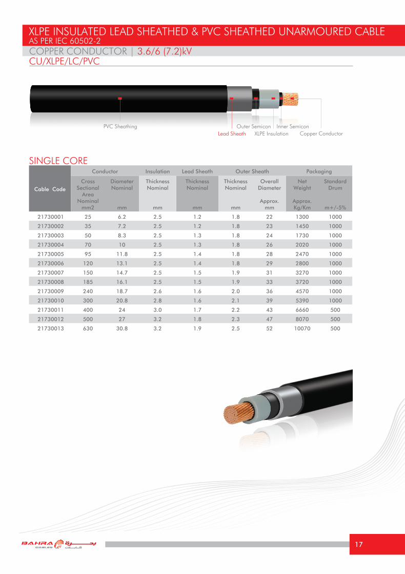
21730001 25 6.2 2.5 1.2 1.8 22 1300 1000
21730002 35 7.2 2.5 1.2 1.8 23 1450 1000
21730003 50 8.3 2.5 1.3 1.8 24 1730 1000
21730004 70 10 2.5 1.3 1.8 26 2020 1000
21730005 95 11.8 2.5 1.4 1.8 28 2470 1000
21730006 120 13.1 2.5 1.4 1.8 29 2800 1000
21730007 150 14.7 2.5 1.5 1.9 31 3270 1000
21730008 185 16.1 2.5 1.5 1.9 33 3720 1000
21730009 240 18.7 2.6 1.6 2.0 36 4570 1000
21730010 300 20.8 2.8 1.6 2.1 39 5390 1000
21730011 400 24 3.0 1.7 2.2 43 6660 500
21730012 500 27 3.2 1.8 2.3 47 8070 500
21730013 630 30.8 3.2 1.9 2.5 52 10070 500
COPPER CONDUCTOR | 3.6/6 (7.2)kV
SINGLE CORE
XLPE INSULATED LEAD SHEATHED & PVC SHEATHED UNARMOURED CABLEAS PER IEC 60502-2
CU/XLPE/LC/PVC
PVC Sheathing Outer SemiconCopper Conductor
Inner SemiconLead Sheath XLPE Insulation
17

TECHNICAL INFORMATIONCOPPER CONDUCTOR | 3.6/6 (7.2)kV
Size mm2 25 35 50 70 95 120 150 185 240 300 400 500 630
Maximum DC resistance of Conductor @ 20°C
Ω/km 0.727 0.524 0.387 0.268 0.193 0.153 0.124 0.0991 0.0754 0.0601 0.0470 0.0366 0.0283
Approximate AC resistance of Conductor @ 90°C
Ω/km 0.927 0.668 0.494 0.342 0.247 0.196 0.160 0.129 0.099 0.0804 0.0647 0.0527 0.0434
Inductance at 60 HzmH/
Km0.442 0.424 0.408 0.385 0.377 0.362 0.355 0.342 0.330 0.323 0.311 0.308 0.297
Reactance at 60 Hz Ω/km 0.17 0.16 0.15 0.15 0.14 0.14 0.13 0.13 0.12 0.12 0.12 0.12 0.11
Capacitance at 60 Hz μF/Km 0.25 0.28 0.31 0.35 0.39 0.43 0.47 0.52 0.56 0.58 0.60 0.63 0.75
Short Circuit Current For 1 second
1- Conductor KA 3.58 5.01 7.15 10.01 13.59 17.16 21.45 26.46 34.32 42.90 57.20 71.50 90.09
2- Metallic Sheath/Screen
KA 1.3 1.5 1.6 1.8 2.1 2.3 2.5 2.7 3.1 3.6 4.3 4.9 5.6
Current Rating Capacity
1- Laid direct in ground
Trefoil Formation (Approx.)
A 153 175 211 250 274 315 370 415 470 530 595 680 740
Flat Formation(Approx.)
A 157 181 218 258 282 323 378 420 473 525 550 640 685
2- Laid in free air
Trefoil Formation (Approx.)
A 163 205 245 269 329 379 430 494 583 669 769 860 1000
Flat Formation(Approx.)
A 178 217 260 324 395 455 509 580 678 770 854 895 1035
Voltage Drop per phase
V/A/
km0.842 0.632 0.488 0.362 0.283 0.239 0.208 0.180 0.154 0.137 0.122 0.111 0.102
Minimum Bending radius
mm 440 460 480 520 560 580 620 660 720 780 860 990 1040
The above values are based on the following conditions: Ambient Air Temperature: 40 °CAmbient Ground Temperature: 35 °CDepth of laying in ground: 0.80 mSoil Thermal Resistivity: 1.2 °K.m/W
(Current Rating Capacities for all cables mentioned in this catalogue are focused according to the special climatic conditions in the Middle East)
CU/XLPE/LC/PVC
18
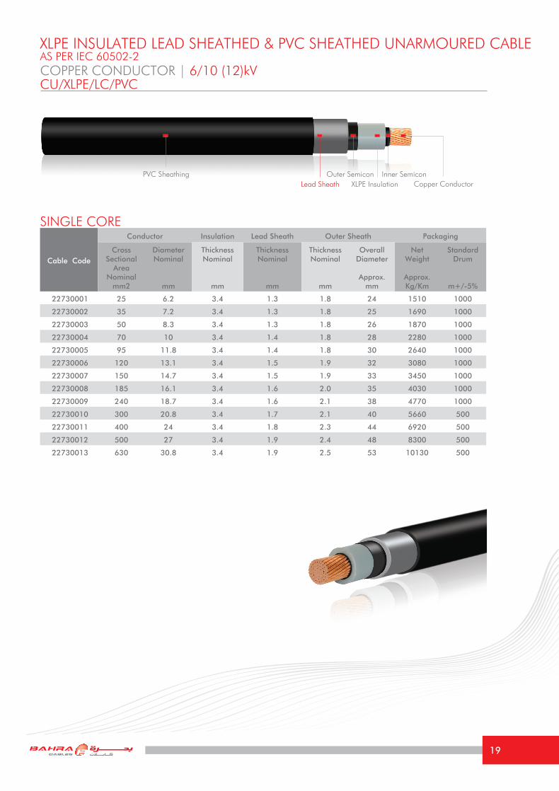
COPPER CONDUCTOR | 6/10 (12)kV
XLPE INSULATED LEAD SHEATHED & PVC SHEATHED UNARMOURED CABLEAS PER IEC 60502-2
CU/XLPE/LC/PVC
Cable Code
Conductor Insulation Lead Sheath Outer Sheath Packaging
Cross Sectional
Area Nominal
mm2
DiameterNominal
mm
Thickness Nominal
mm
Thickness Nominal
mm
Thickness Nominal
mm
Overall Diameter
Approx.mm
Net Weight
Approx.Kg/Km
Standard Drum
m+/-5%
22730001 25 6.2 3.4 1.3 1.8 24 1510 1000
22730002 35 7.2 3.4 1.3 1.8 25 1690 1000
22730003 50 8.3 3.4 1.3 1.8 26 1870 1000
22730004 70 10 3.4 1.4 1.8 28 2280 1000
22730005 95 11.8 3.4 1.4 1.8 30 2640 1000
22730006 120 13.1 3.4 1.5 1.9 32 3080 1000
22730007 150 14.7 3.4 1.5 1.9 33 3450 1000
22730008 185 16.1 3.4 1.6 2.0 35 4030 1000
22730009 240 18.7 3.4 1.6 2.1 38 4770 1000
22730010 300 20.8 3.4 1.7 2.1 40 5660 500
22730011 400 24 3.4 1.8 2.3 44 6920 500
22730012 500 27 3.4 1.9 2.4 48 8300 500
22730013 630 30.8 3.4 1.9 2.5 53 10130 500
SINGLE CORE
PVC SheathingCopper ConductorLead Sheath XLPE Insulation
Outer Semicon Inner Semicon
19

TECHNICAL INFORMATIONCOPPER CONDUCTOR | 6/10 (12)kV
The above values are based on the following conditions: Ambient Air Temperature: 40 °CAmbient Ground Temperature: 35 °CDepth of laying in ground: 0.80 mSoil Thermal Resistivity: 1.2 °K.m/W
(Current Rating Capacities for all cables mentioned in this catalogue are focused according to the special climatic conditions in the Middle East)
CU/XLPE/LC/PVC
Size mm2 25 35 50 70 95 120 150 185 240 300 400 500 630
Maximum DC resistance of Conductor @ 20°C
Ω/km 0.727 0.524 0.387 0.268 0.193 0.153 0.124 0.0991 0.0754 0.0601 0.0470 0.0366 0.0283
Approximate AC resistance of Conductor @ 90°C
Ω/km 0.927 0.668 0.494 0.342 0.247 0.196 0.160 0.129 0.099 0.0804 0.0647 0.0527 0.0434
Inductance at 60 HzmH/
Km0.460 0.440 0.420 0.408 0.382 0.375 0.363 0.354 0.340 0.330 0.319 0.309 0.295
Reactance at 60 Hz Ω/km 0.17 0.17 0.16 0.15 0.14 0.14 0.14 0.13 0.13 0.12 0.12 0.12 0.11
Capacitance at 60 Hz μF/Km 0.20 0.23 0.25 0.29 0.30 0.33 0.37 0.40 0.45 0.49 0.54 0.60 0.70
Short Circuit Current For 1 second
1- Conductor KA 3.58 5.01 7.15 10.01 13.59 17.16 21.45 26.46 34.32 42.90 57.20 71.50 90.09
2- Metallic Sheath/Screen
KA 1.5 1.7 1.9 2.1 2.3 2.6 2.8 3.0 3.4 3.8 4.5 5.0 5.7
Current Rating Capacity
1- Laid direct in ground
Trefoil Formation (Approx.)
A 153 175 211 250 274 315 370 415 470 530 595 680 740
Flat Formation(Approx.)
A 157 181 218 258 282 323 378 420 473 525 550 640 685
2- Laid in free air
Trefoil Formation (Approx.)
A 163 205 245 269 329 379 430 494 583 669 769 860 1000
Flat Formation(Approx.)
A 178 217 260 324 395 455 509 580 678 770 854 895 1035
Voltage Drop per phase
V/A/
km0.846 0.635 0.490 0.364 0.284 0.242 0.210 0.183 0.156 0.138 0.123 0.111 0.103
Minimum Bending radius
mm 480 500 520 560 600 640 660 700 760 800 880 960 1060
20

COPPER CONDUCTOR | 8.7/15 (17.5)kVCU/XLPE/LC/PVC
Cable Code
Conductor Insulation Lead Sheath Outer Sheath Packaging
Cross Sectional
Area Nominal
mm2
DiameterNominal
mm
Thickness Nominal
mm
Thickness Nominal
mm
Thickness Nominal
mm
Overall Diameter
Approx.mm
Net Weight
Approx.Kg/Km
Standard Drum
m+/-5%
23730001 25 6.2 4.5 1.3 1.8 26 1700 1000
23730002 35 7.2 4.5 1.4 1.8 28 1970 1000
23730003 50 8.3 4.5 1.4 1.8 29 2170 1000
23730004 70 10 4.5 1.4 1.8 30 2480 1000
23730005 95 11.8 4.5 1.5 1.9 32 2970 1000
23730006 120 13.1 4.5 1.5 2.0 34 3320 1000
23730007 150 14.7 4.5 1.6 2.0 36 3810 1000
23730008 185 16.1 4.5 1.6 2.1 38 4310 1000
23730009 240 18.7 4.5 1.7 2.2 40 5190 1000
23730010 300 20.8 4.5 1.7 2.2 43 5950 500
23730011 400 24 4.5 1.8 2.3 46 7210 500
23730012 500 27 4.5 1.9 2.4 50 8610 500
23730013 630 30.8 4.5 2.0 2.6 55 10670 500
SINGLE CORE
XLPE INSULATED LEAD SHEATHED & PVC SHEATHED UNARMOURED CABLEAS PER IEC 60502-2
PVC SheathingCopper ConductorXLPE InsulationLead Sheath
Outer Semicon Inner Semicon
21

TECHNICAL INFORMATIONCOPPER CONDUCTOR | 8.7/15 (17.5)kV
The above values are based on the following conditions: Ambient Air Temperature: 40 °CAmbient Ground Temperature: 35 °CDepth of laying in ground: 0.80 mSoil Thermal Resistivity: 1.2 °K.m/W
(Current Rating Capacities for all cables mentioned in this catalogue are focused according to the special climatic conditions in the Middle East)
CU/XLPE/LC/PVC
Size mm2 25 35 50 70 95 120 150 185 240 300 400 500 630
Maximum DC resistance of Conductor @ 20°C
Ω/km 0.727 0.524 0.387 0.268 0.193 0.153 0.124 0.0991 0.0754 0.0601 0.0470 0.0366 0.0283
Approximate AC resistance of Conductor @ 90°C
Ω/km 0.927 0.668 0.494 0.342 0.247 0.196 0.160 0.129 0.099 0.0804 0.0647 0.0527 0.0434
Inductance at 60 HzmH/
Km0.470 0.455 0.435 0.415 0.402 0.389 0.377 0.366 0.350 0.340 0.327 0.319 0.306
Reactance at 60 Hz Ω/km 0.18 0.17 0.16 0.16 0.15 0.15 0.14 0.14 0.13 0.13 0.12 0.12 0.12
Capacitance at 60 Hz μF/Km 0.17 0.18 0.20 0.23 0.25 0.27 0.29 0.32 0.35 0.39 0.43 0.48 0.53
Short Circuit Current For 1 second
1- Conductor KA 3.58 5.01 7.15 10.01 13.59 17.16 21.45 26.46 34.32 42.90 57.20 71.50 90.09
2- Metallic Sheath/Screen
KA 1.8 2.0 2.2 2.4 2.7 2.9 3.2 3.4 3.9 4.3 4.9 5.5 6.2
Current Rating Capacity
1- Laid direct in ground
Trefoil Formation (Approx.)
A 153 175 211 250 274 315 370 415 470 530 595 680 740
Flat Formation(Approx.)
A 157 181 218 258 282 323 378 420 473 525 550 640 685
2- Laid in free air
Trefoil Formation (Approx.)
A 163 205 245 269 329 379 430 494 583 669 769 860 1000
Flat Formation(Approx.)
A 178 217 260 324 395 455 509 580 678 770 854 895 1035
Voltage Drop per phase
V/A/
km0.850 0.636 0.492 0.366 0.286 0.245 0.215 0.185 0.158 0.140 0.126 0.113 0.106
Minimum Bending radius
mm 520 560 580 600 640 680 720 760 800 860 920 1000 1110
22

COPPER CONDUCTOR | 12/20 (24)kVCU/XLPE/LC/PVC
Cable Code
Conductor Insulation Lead Sheath Outer Sheath Packaging
Cross Sectional
Area Nominal
mm2
DiameterNominal
mm
Thickness Nominal
mm
Thickness Nominal
mm
Thickness Nominal
mm
Overall Diameter
Approx.mm
Net Weight
Approx.Kg/Km
Standard Drum
m+/-5%
24730001 35 7.2 5.5 1.4 1.8 30 2160 1000
24730002 50 8.3 5.5 1.5 1.9 31 2470 1000
24730003 70 10 5.5 1.5 1.9 33 2790 1000
24730004 95 11.8 5.5 1.6 2.0 35 3310 1000
24730005 120 13.1 5.5 1.6 2.0 36 3640 1000
24730006 150 14.7 5.5 1.6 2.1 38 4060 1000
24730007 185 16.1 5.5 1.7 2.1 40 4660 1000
24730008 240 18.7 5.5 1.7 2.2 42 5440 500
24730009 300 20.8 5.5 1.8 2.3 45 6370 500
24730010 400 24 5.5 1.9 2.4 49 7670 500
24730011 500 27 5.5 2.0 2.5 53 9230 500
24730012 630 30.8 5.5 2.1 2.6 56 11170 500
SINGLE CORE
XLPE INSULATED LEAD SHEATHED & PVC SHEATHED UNARMOURED CABLEAS PER IEC 60502-2
PVC SheathingCopper ConductorXLPE Insulation
Outer Semicon Inner SemiconLead Sheath
23

The above values are based on the following conditions: Ambient Air Temperature: 40 °CAmbient Ground Temperature: 35 °CDepth of laying in ground: 0.80 mSoil Thermal Resistivity: 1.2 °K.m/W
(Current Rating Capacities for all cables mentioned in this catalogue are focused according to the special climatic conditions in the Middle East)
TECHNICAL INFORMATIONCOPPER CONDUCTOR | 12/20 (24)kVCU/XLPE/LC/PVC
Size mm2 35 50 70 95 120 150 185 240 300 400 500 630
Maximum DC resistance of Conductor @ 20°C
Ω/km 0.524 0.387 0.268 0.193 0.153 0.124 0.0991 0.0754 0.0601 0.0470 0.0366 0.0283
Approximate AC resistance of Conductor @ 90°C
Ω/km 0.668 0.494 0.342 0.247 0.196 0.160 0.129 0.099 0.0804 0.0647 0.0527 0.0434
Inductance at 60 HzmH/
Km0.468 0.449 0.425 0.414 0.400 0.388 0.375 0.361 0.350 0.335 0.327 0.315
Reactance at 60 Hz Ω/km 0.18 0.17 0.16 0.16 0.15 0.15 0.14 0.14 0.13 0.13 0.12 0.12
Capacitance at 60 Hz μF/Km 0.15 0.17 0.20 0.22 0.24 0.26 0.27 0.30 0.33 0.37 0.41 0.46
Short Circuit Current For 1 second
1- Conductor KA 5.01 7.15 10.01 13.59 17.16 21.45 26.46 34.32 42.90 57.20 71.50 90.09
2- Metallic Sheath/Screen
KA 2.3 2.5 2.7 3.0 3.3 3.5 3.8 4.3 4.7 5.4 6.0 6.7
Current Rating Capacity
1- Laid direct in ground
Trefoil Formation (Approx.)
A 175 211 250 274 315 370 415 470 530 595 680 740
Flat Formation(Approx.)
A 181 218 258 282 323 378 420 473 525 550 640 685
2- Laid in free air
Trefoil Formation (Approx.)
A 205 245 269 329 379 430 494 583 669 769 860 1000
Flat Formation(Approx.)
A 217 260 324 395 455 509 580 678 770 854 895 1035
Voltage Drop per phase
V/A/
km0.640 0.495 0.369 0.290 0.248 0.217 0.187 0.160 0.142 0.127 0.115 0.107
Minimum Bending radius
mm 600 620 660 700 720 760 800 840 900 980 1000 1120
24

COPPER CONDUCTOR | 18/30 (36)kV 19/33 (36)kVCU/XLPE/LC/PVC
Cable Code
Conductor Insulation Lead Sheath Outer Sheath Packaging
Cross Sectional
Area Nominal
mm2
DiameterNominal
mm
Thickness Nominal
mm
*Thickness Nominal
mm
Thickness Nominal
mm
Overall Diameter
Approx.mm
Net Weight
Approx.Kg/Km
Standard Drum
m+/-5%
25730001 50 8.3 8.0 1.6 2.1 37 3150 1000
25730002 70 10 8.0 1.7 2.1 39 3620 1000
25730003 95 11.8 8.0 1.7 2.2 40 4050 1000
25730004 120 13.1 8.0 1.7 2.2 42 4410 1000
25730005 150 14.7 8.0 1.8 2.3 44 4970 1000
25730006 185 16.1 8.0 1.8 2.3 45 5470 500
25730007 240 18.7 8.0 1.9 2.4 48 6440 500
25730008 300 20.8 8.0 2.0 2.5 51 7430 500
25730009 400 24 8.0 2.0 2.6 55 8750 500
25730010 500 27 8.0 2.1 2.7 59 10250 500
25730011 630 30.8 8.0 2.2 2.8 63 12260 500
SINGLE CORE
XLPE INSULATED LEAD SHEATHED & PVC SHEATHED UNARMOURED CABLEAS PER IEC 60502-2 / BS 7870-4.11
PVC SheathingCopper ConductorXLPE Insulation
Outer Semicon Inner Semicon
* Tabulated values of lead screams are based on IEC 60502-2, thickness may be varied if BS 7870-4.11 is required.
Lead Sheath
25

The above values are based on the following conditions: Ambient Air Temperature: 40 °CAmbient Ground Temperature: 35 °CDepth of laying in ground: 0.80 mSoil Thermal Resistivity: 1.2 °K.m/W
(Current Rating Capacities for all cables mentioned in this catalogue are focused according to the special climatic conditions in the Middle East)
TECHNICAL INFORMATIONCOPPER CONDUCTOR | 18/30 (36)kV 19/33 (36)kVCU/XLPE/LC/PVC
Size mm2 50 70 95 120 150 185 240 300 400 500 630
Maximum DC resistance of Conductor @ 20°C
Ω/km 0.387 0.268 0.193 0.153 0.124 0.0991 0.0754 0.0601 0.0470 0.0366 0.0283
Approximate AC resistance of Conductor @ 90°C
Ω/km 0.494 0.342 0.247 0.196 0.160 0.129 0.099 0.0804 0.0647 0.0527 0.0434
Inductance at 60 HzmH/
Km0.480 0.460 0.445 0.430 0.415 0.405 0.4390 0.375 0.360 0.350 0.340
Reactance at 60 Hz Ω/km 0.18 0.17 0.17 0.16 0.16 0.15 0.17 0.14 0.14 0.13 0.13
Capacitance at 60 Hz μF/Km 0.14 0.15 0.17 0.18 0.20 0.21 0.23 0.25 0.27 0.30 0.34
Short Circuit Current For 1 second
1- Conductor KA 7.15 10.01 13.59 17.16 21.45 26.46 34.32 42.90 57.20 71.50 90.09
2- Metallic Sheath/Screen
KA 3.4 3.6 4.0 4.2 4.5 4.9 5.3 5.8 6.6 7.2 8.1
Current Rating Capacity
1- Laid direct in ground
Trefoil Formation (Approx.)
A 211 250 274 315 370 415 470 530 595 680 740
Flat Formation(Approx.)
A 218 258 282 323 378 420 473 525 550 640 685
2- Laid in free air
Trefoil Formation (Approx.)
A 245 269 329 379 430 494 583 669 769 860 1000
Flat Formation(Approx.)
A 260 324 395 455 509 580 678 770 854 895 1035
Voltage Drop per phase
V/A/
km0.502 0.375 0.300 0.254 0.220 0.194 0.166 0.149 0.133 0.121 0.113
Minimum Bending radius
mm 740 780 800 840 880 900 960 1020 1110 1180 1206
26

Cable Code
Conductor Insulation Lead Sheath Outer Sheath Packaging
Cross Sectional
Area Nominal
mm2
DiameterNominal
mm
Thickness Nominal
mm
Thickness Nominal
mm
Thickness Nominal
mm
Overall Diameter
Approx.mm
Net Weight
Approx.Kg/Km
Standard Drum
m+/-5%
21830001 25 5.7 2.5 1.2 1.8 22 1160 1000
21830002 35 7.1 2.5 1.2 1.8 23 1250 1000
21830003 50 7.9 2.5 1.3 1.8 24 1450 1000
21830004 70 9.7 2.5 1.3 1.8 26 1650 1000
21830005 95 11.3 2.5 1.4 1.8 27 1870 1000
21830006 120 12.6 2.5 1.4 1.8 28 2050 1000
21830007 150 14.1 2.5 1.5 1.9 30 2320 1000
21830008 185 16.0 2.5 1.5 1.9 33 2610 1000
21830009 240 18.1 2.6 1.6 2.0 35 3020 1000
21830010 300 20.4 2.8 1.6 2.1 38 3530 1000
21830011 400 23.1 3.0 1.7 2.2 42 4150 1000
21830012 500 25.9 3.2 1.8 2.3 46 5100 1000
21830013 630 29.5 3.2 1.9 2.5 50 6600 500
ALUMINUM CONDUCTOR | 3.6/6 (7.2)kV
SINGLE CORE
XLPE INSULATED LEAD SHEATHED & PVC SHEATHED UNARMOURED CABLEAS PER IEC 60502-2
AL/XLPE/LC/PVC
PVC SheathingAluminum ConductorXLPE Insulation
Outer Semicon Inner SemiconLead Sheath
27

The above values are based on the following conditions: Ambient Air Temperature: 40 °CAmbient Ground Temperature: 35 °CDepth of laying in ground: 0.80 mSoil Thermal Resistivity: 1.2 °K.m/W
(Current Rating Capacities for all cables mentioned in this catalogue are focused according to the special climatic conditions in the Middle East)
TECHNICAL INFORMATION
Size mm2 25 35 50 70 95 120 150 185 240 300 400 500 630
Maximum DC resistance of Conductor @ 20°C
Ω/km 1.20 0.868 0.641 0.443 0.320 0.253 0.206 0.164 0.125 0.100 0.0778 0.0605 0.0469
Approximate AC resistance of Conductor @ 90°C
Ω/km 1.54 1.113 0.822 0.568 0.411 0.326 0.265 0.211 0.161 0.130 0.1016 0.0799 0.0632
Inductance at 60 HzmH/
Km0.444 0.425 0.408 0.385 0.377 0.362 0.355 0.342 0.330 0.323 0.311 0.308 0.297
Reactance at 60 Hz Ω/km 0.17 0.16 0.15 0.15 0.14 0.14 0.13 0.13 0.12 0.12 0.12 0.12 0.11
Capacitance at 60 Hz μF/Km 0.26 0.29 0.31 0.35 0.39 0.43 0.47 0.52 0.56 0.58 0.60 0.63 0.75
Short Circuit Current For 1 second
1- Conductor KA 2.34 3.28 4.69 6.56 8.90 11.24 14.06 17.33 22.49 28.11 37.48 46.85 59.03
2- Metallic Sheath/Screen
KA 1.3 1.5 1.6 1.8 2.1 2.3 2.5 2.7 3.1 3.6 4.3 4.9 5.6
Current Rating Capacity
1- Laid direct in ground
Trefoil Formation (Approx.)
A 100 100 120 135 165 200 230 260 293 330 370 415 520
Flat Formation(Approx.)
A 105 105 125 140 170 210 240 270 303 341 379 400 500
2- Laid in free air
Trefoil Formation (Approx.)
A 116 116 140 167 209 255 295 335 386 457 525 612 705
Flat Formation(Approx.)
A 139 139 168 202 253 308 356 400 459 540 616 700 790
Voltage Drop per phase
V/A/
km1.332 0.987 0.751 0.542 0.414 0.342 0.293 0.246 0.206 0.178 0.153 0.134 0.119
Minimum Bending radius
mm 440 460 480 520 540 560 600 660 700 760 840 920 1000
ALUMINUM CONDUCTOR | 3.6/6 (7.2)kVAL/XLPE/LC/PVC
28

ALUMINUM CONDUCTOR | 6/10 (12)kVAL/XLPE/LC/PVC
Cable Code
Conductor Insulation Lead Sheath Outer Sheath Packaging
Cross Sectional
Area Nominal
mm2
DiameterNominal
mm
Thickness Nominal
mm
Thickness Nominal
mm
Thickness Nominal
mm
Overall Diameter
Approx.mm
Net Weight
Approx.Kg/Km
Standard Drum
m+/-5%
22830001 25 5.7 3.4 1.3 1.8 23 1350 1000
22830002 35 7.1 3.4 1.3 1.8 25 1490 1000
22830003 50 7.9 3.4 1.3 1.8 27 1570 1000
22830004 70 9.7 3.4 1.4 1.8 28 1930 1000
22830005 95 11.3 3.4 1.4 1.8 29 2090 1000
22830006 120 12.6 3.4 1.5 1.9 31 2380 1000
22830007 150 14.1 3.4 1.5 1.9 32 2500 1000
22830008 185 16.0 3.4 1.6 2.0 35 2870 1000
22830009 240 18.1 3.4 1.6 2.1 37 3380 1000
22830010 300 20.4 3.4 1.7 2.1 39 3950 1000
22830011 400 23.1 3.4 1.8 2.3 43 4500 1000
22830012 500 25.9 3.4 1.9 2.4 47 5400 1000
22830013 630 29.5 3.4 1.9 2.5 51 6700 500
SINGLE CORE
XLPE INSULATED LEAD SHEATHED & PVC SHEATHED UNARMOURED CABLEAS PER IEC 60502-2
PVC SheathingAluminum ConductorXLPE Insulation
Outer Semicon Inner SemiconLead Sheath
29

The above values are based on the following conditions: Ambient Air Temperature: 40 °CAmbient Ground Temperature: 35 °CDepth of laying in ground: 0.80 mSoil Thermal Resistivity: 1.2 °K.m/W
(Current Rating Capacities for all cables mentioned in this catalogue are focused according to the special climatic conditions in the Middle East)
TECHNICAL INFORMATIONALUMINUM CONDUCTOR | 6/10 (12)kVAL/XLPE/LC/PVC
Size mm2 25 35 50 70 95 120 150 185 240 300 400 500 630
Maximum DC resistance of Conductor @ 20°C
Ω/km 1.20 0.868 0.641 0.443 0.320 0.253 0.206 0.164 0.125 0.100 0.0778 0.0605 0.0469
Approximate AC resistance of Conductor @ 90°C
Ω/km 1.54 1.113 0.822 0.568 0.411 0.326 0.265 0.211 0.161 0.130 0.1016 0.0799 0.0632
Inductance at 60 HzmH/
Km0.460 0.440 0.420 0.408 0.382 0.375 0.363 0.354 0.340 0.330 0.319 0.309 0.295
Reactance at 60 Hz Ω/km 0.17 0.17 0.16 0.15 0.14 0.14 0.14 0.13 0.13 0.12 0.12 0.12 0.11
Capacitance at 60 Hz μF/Km 0.20 0.23 0.25 0.29 0.30 0.33 0.37 0.40 0.45 0.49 0.54 0.60 0.70
Short Circuit Current For 1 second
1- Conductor KA 2.34 3.28 4.69 6.56 8.90 11.24 14.06 17.33 22.49 28.11 37.48 46.85 59.03
2- Metallic Sheath/Screen
KA 1.5 1.7 1.9 2.1 2.3 2.6 2.8 3.0 3.4 3.8 4.5 5.0 5.7
Current Rating Capacity
1- Laid direct in ground
Trefoil Formation (Approx.)
A 100 120 135 165 200 230 260 293 330 370 415 520 750
Flat Formation(Approx.)
A 105 125 140 170 210 240 270 303 341 379 400 500 690
2- Laid in free air
Trefoil Formation (Approx.)
A 116 140 167 209 255 295 335 386 457 525 612 705 800
Flat Formation(Approx.)
A 139 168 202 253 308 356 400 459 540 616 700 790 885
Voltage Drop per phase
V/A/
km1.33 0.990 0.754 0.545 0.416 0.345 0.294 0.250 0.207 0.179 0.154 0.134 0.119
Minimum Bending radius
mm 460 500 540 560 580 620 640 700 740 780 860 940 1020
30

ALUMINUM CONDUCTOR | 8.7/15 (17.5)kVAL/XLPE/LC/PVC
Cable Code
Conductor Insulation Lead Sheath Outer Sheath Packaging
Cross Sectional
Area Nominal
mm2
DiameterNominal
mm
Thickness Nominal
mm
Thickness Nominal
mm
Thickness Nominal
mm
Overall Diameter
Approx.mm
Net Weight
Approx.Kg/Km
Standard Drum
m+/-5%
23830001 25 5.7 4.5 1.3 1.8 25 1520 1000
23830002 35 7.1 4.5 1.4 1.8 27 1770 1000
23830003 50 7.9 4.5 1.4 1.8 28 1870 1000
23830004 70 9.7 4.5 1.4 1.8 30 2080 1000
23830005 95 11.3 4.5 1.5 1.9 31 2370 1000
23830006 120 12.6 4.5 1.5 2.0 33 2620 1000
23830007 150 14.1 4.5 1.6 2.0 35 2900 1000
23830008 185 16.0 4.5 1.6 2.1 38 3100 1000
23830009 240 18.1 4.5 1.7 2.2 39 3700 1000
23830010 300 20.4 4.5 1.7 2.2 42 4150 1000
23830011 400 23.1 4.5 1.8 2.3 45 4800 1000
23830012 500 25.9 4.5 1.9 2.4 49 5800 500
23830013 630 29.5 4.5 2.0 2.6 53 7300 500
SINGLE CORE
XLPE INSULATED LEAD SHEATHED & PVC SHEATHED UNARMOURED CABLEAS PER IEC 60502-2
PVC SheathingAluminum ConductorXLPE Insulation
Outer Semicon Inner SemiconLead Sheath
31
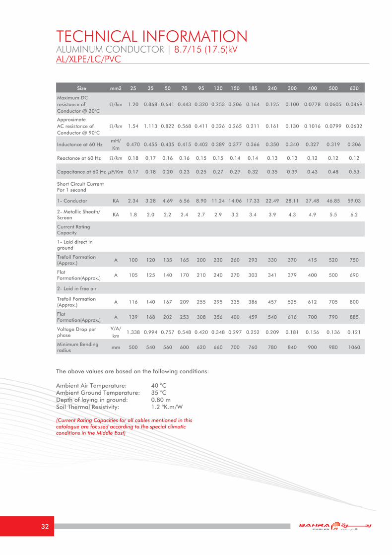
The above values are based on the following conditions: Ambient Air Temperature: 40 °CAmbient Ground Temperature: 35 °CDepth of laying in ground: 0.80 mSoil Thermal Resistivity: 1.2 °K.m/W
(Current Rating Capacities for all cables mentioned in this catalogue are focused according to the special climatic conditions in the Middle East)
TECHNICAL INFORMATIONALUMINUM CONDUCTOR | 8.7/15 (17.5)kVAL/XLPE/LC/PVC
Size mm2 25 35 50 70 95 120 150 185 240 300 400 500 630
Maximum DC resistance of Conductor @ 20°C
Ω/km 1.20 0.868 0.641 0.443 0.320 0.253 0.206 0.164 0.125 0.100 0.0778 0.0605 0.0469
Approximate AC resistance of Conductor @ 90°C
Ω/km 1.54 1.113 0.822 0.568 0.411 0.326 0.265 0.211 0.161 0.130 0.1016 0.0799 0.0632
Inductance at 60 HzmH/
Km0.470 0.455 0.435 0.415 0.402 0.389 0.377 0.366 0.350 0.340 0.327 0.319 0.306
Reactance at 60 Hz Ω/km 0.18 0.17 0.16 0.16 0.15 0.15 0.14 0.14 0.13 0.13 0.12 0.12 0.12
Capacitance at 60 Hz μF/Km 0.17 0.18 0.20 0.23 0.25 0.27 0.29 0.32 0.35 0.39 0.43 0.48 0.53
Short Circuit Current For 1 second
1- Conductor KA 2.34 3.28 4.69 6.56 8.90 11.24 14.06 17.33 22.49 28.11 37.48 46.85 59.03
2- Metallic Sheath/Screen
KA 1.8 2.0 2.2 2.4 2.7 2.9 3.2 3.4 3.9 4.3 4.9 5.5 6.2
Current Rating Capacity
1- Laid direct in ground
Trefoil Formation (Approx.)
A 100 120 135 165 200 230 260 293 330 370 415 520 750
Flat Formation(Approx.)
A 105 125 140 170 210 240 270 303 341 379 400 500 690
2- Laid in free air
Trefoil Formation (Approx.)
A 116 140 167 209 255 295 335 386 457 525 612 705 800
Flat Formation(Approx.)
A 139 168 202 253 308 356 400 459 540 616 700 790 885
Voltage Drop per phase
V/A/
km1.338 0.994 0.757 0.548 0.420 0.348 0.297 0.252 0.209 0.181 0.156 0.136 0.121
Minimum Bending radius
mm 500 540 560 600 620 660 700 760 780 840 900 980 1060
32
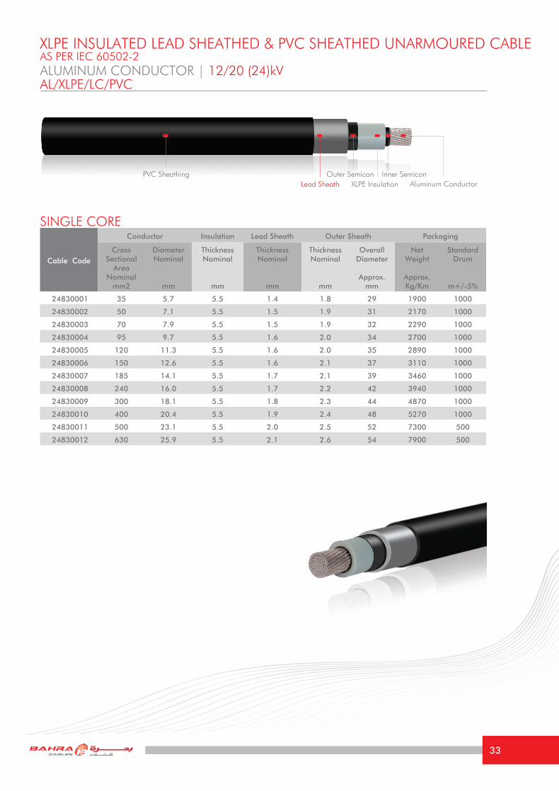
ALUMINUM CONDUCTOR | 12/20 (24)kVAL/XLPE/LC/PVC
Cable Code
Conductor Insulation Lead Sheath Outer Sheath Packaging
Cross Sectional
Area Nominal
mm2
DiameterNominal
mm
Thickness Nominal
mm
Thickness Nominal
mm
Thickness Nominal
mm
Overall Diameter
Approx.mm
Net Weight
Approx.Kg/Km
Standard Drum
m+/-5%
24830001 35 5.7 5.5 1.4 1.8 29 1900 1000
24830002 50 7.1 5.5 1.5 1.9 31 2170 1000
24830003 70 7.9 5.5 1.5 1.9 32 2290 1000
24830004 95 9.7 5.5 1.6 2.0 34 2700 1000
24830005 120 11.3 5.5 1.6 2.0 35 2890 1000
24830006 150 12.6 5.5 1.6 2.1 37 3110 1000
24830007 185 14.1 5.5 1.7 2.1 39 3460 1000
24830008 240 16.0 5.5 1.7 2.2 42 3940 1000
24830009 300 18.1 5.5 1.8 2.3 44 4870 1000
24830010 400 20.4 5.5 1.9 2.4 48 5270 1000
24830011 500 23.1 5.5 2.0 2.5 52 7300 500
24830012 630 25.9 5.5 2.1 2.6 54 7900 500
SINGLE CORE
XLPE INSULATED LEAD SHEATHED & PVC SHEATHED UNARMOURED CABLEAS PER IEC 60502-2
PVC SheathingAluminum ConductorXLPE Insulation
Outer Semicon Inner SemiconLead Sheath
33

The above values are based on the following conditions: Ambient Air Temperature: 40 °CAmbient Ground Temperature: 35 °CDepth of laying in ground: 0.80 mSoil Thermal Resistivity: 1.2 °K.m/W
(Current Rating Capacities for all cables mentioned in this catalogue are focused according to the special climatic conditions in the Middle East)
TECHNICAL INFORMATIONALUMINUM CONDUCTOR | 12/20 (24)kVAL/XLPE/LC/PVC
Size mm2 35 50 70 95 120 150 185 240 300 400 500 630
Maximum DC resistance of Conductor @ 20°C
Ω/km 0.868 0.641 0.443 0.320 0.253 0.206 0.164 0.125 0.100 0.0778 0.0605 0.0469
Approximate AC resistance of Conductor @ 90°C
Ω/km 1.113 0.822 0.568 0.411 0.326 0.265 0.211 0.161 0.130 0.1016 0.0799 0.0632
Inductance at 60 Hz mH/Km 0.468 0.449 0.425 0.414 0.400 0.388 0.375 0.361 0.350 0.335 0.327 0.315
Reactance at 60 Hz Ω/km 0.18 0.17 0.16 0.16 0.15 0.15 0.14 0.14 0.13 0.13 0.12 0.12
Capacitance at 60 Hz μF/Km 0.15 0.17 0.20 0.22 0.24 0.26 0.27 0.30 0.33 0.37 0.41 0.46
Short Circuit Current For 1 second
1- Conductor KA 3.28 4.69 6.56 8.90 11.24 14.06 17.33 22.49 28.11 37.48 46.85 59.03
2- Metallic Sheath/Screen
KA 2.3 2.5 2.7 3.0 3.3 3.5 3.8 4.3 4.7 5.4 6.0 6.7
Current Rating Capacity
1- Laid direct in ground
Trefoil Formation (Approx.)
A 100 120 135 165 200 230 260 293 330 370 415 520
Flat Formation(Approx.) A 105 125 140 170 210 240 270 303 341 379 400 500
2- Laid in free air
Trefoil Formation (Approx.)
A 116 140 167 209 255 295 335 386 457 525 612 705
Flat Formation(Approx.) A 139 168 202 253 308 356 400 459 540 616 700 790
Voltage Drop per phase V/A/km 0.966 0.760 0.551 0.422 0.350 0.300 0.254 0.212 0.183 0.158 0.138 0.123
Minimum Bending radius mm 580 620 640 680 700 740 780 840 880 960 1040 1080
34
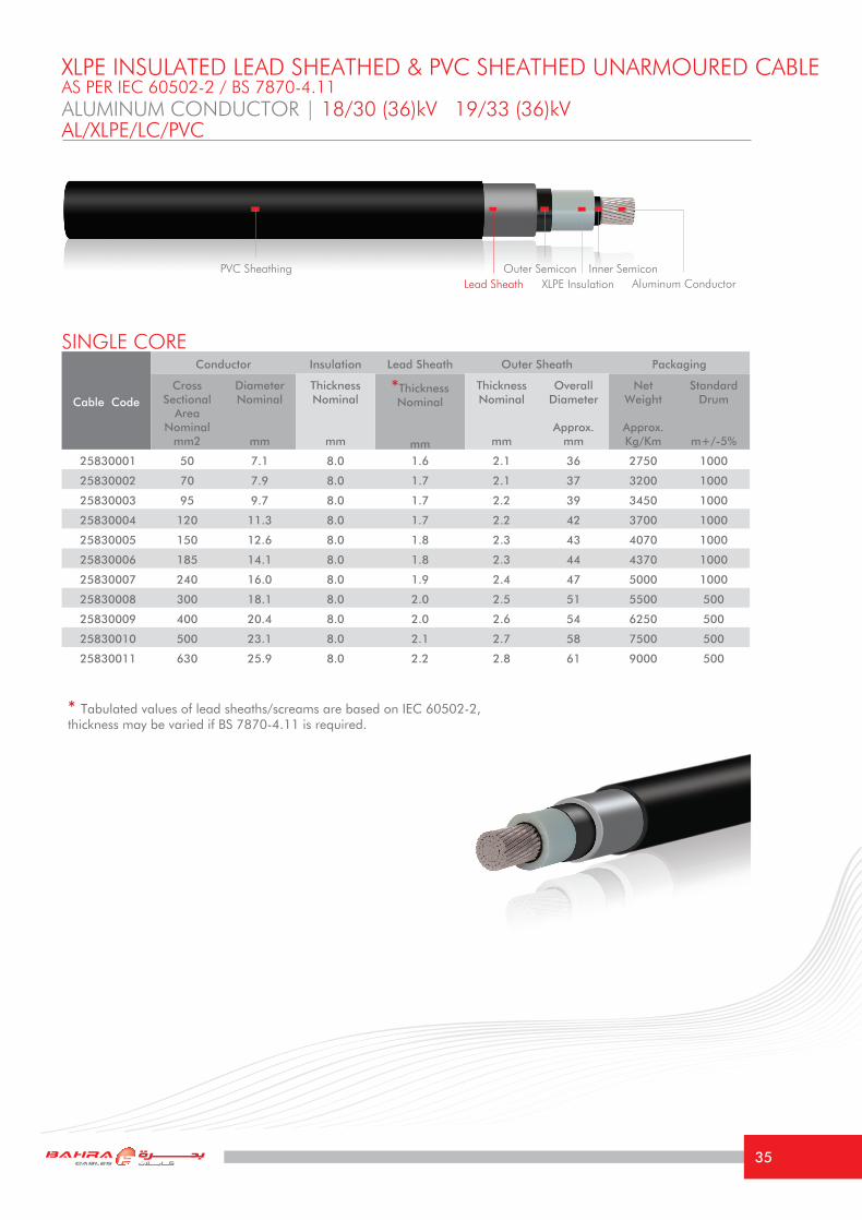
ALUMINUM CONDUCTOR | 18/30 (36)kV 19/33 (36)kVAL/XLPE/LC/PVC
Cable Code
Conductor Insulation Lead Sheath Outer Sheath Packaging
Cross Sectional
Area Nominal
mm2
DiameterNominal
mm
Thickness Nominal
mm
*Thickness Nominal
mm
Thickness Nominal
mm
Overall Diameter
Approx.mm
Net Weight
Approx.Kg/Km
Standard Drum
m+/-5%
25830001 50 7.1 8.0 1.6 2.1 36 2750 1000
25830002 70 7.9 8.0 1.7 2.1 37 3200 1000
25830003 95 9.7 8.0 1.7 2.2 39 3450 1000
25830004 120 11.3 8.0 1.7 2.2 42 3700 1000
25830005 150 12.6 8.0 1.8 2.3 43 4070 1000
25830006 185 14.1 8.0 1.8 2.3 44 4370 1000
25830007 240 16.0 8.0 1.9 2.4 47 5000 1000
25830008 300 18.1 8.0 2.0 2.5 51 5500 500
25830009 400 20.4 8.0 2.0 2.6 54 6250 500
25830010 500 23.1 8.0 2.1 2.7 58 7500 500
25830011 630 25.9 8.0 2.2 2.8 61 9000 500
SINGLE CORE
XLPE INSULATED LEAD SHEATHED & PVC SHEATHED UNARMOURED CABLEAS PER IEC 60502-2 / BS 7870-4.11
PVC SheathingAluminum ConductorXLPE Insulation
Outer Semicon Inner Semicon
* Tabulated values of lead sheaths/screams are based on IEC 60502-2, thickness may be varied if BS 7870-4.11 is required.
Lead Sheath
35
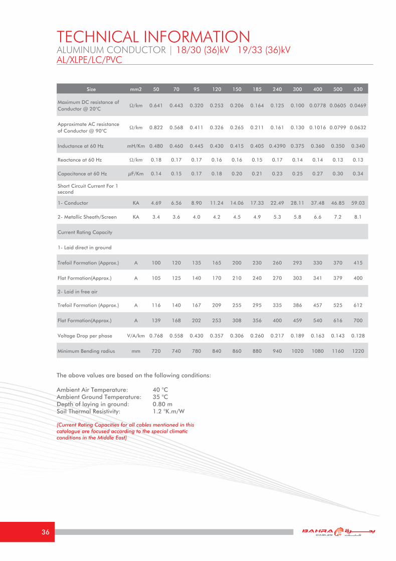
The above values are based on the following conditions: Ambient Air Temperature: 40 °CAmbient Ground Temperature: 35 °CDepth of laying in ground: 0.80 mSoil Thermal Resistivity: 1.2 °K.m/W
(Current Rating Capacities for all cables mentioned in this catalogue are focused according to the special climatic conditions in the Middle East)
TECHNICAL INFORMATIONALUMINUM CONDUCTOR | 18/30 (36)kV 19/33 (36)kVAL/XLPE/LC/PVC
Size mm2 50 70 95 120 150 185 240 300 400 500 630
Maximum DC resistance of Conductor @ 20°C
Ω/km 0.641 0.443 0.320 0.253 0.206 0.164 0.125 0.100 0.0778 0.0605 0.0469
Approximate AC resistance of Conductor @ 90°C
Ω/km 0.822 0.568 0.411 0.326 0.265 0.211 0.161 0.130 0.1016 0.0799 0.0632
Inductance at 60 Hz mH/Km 0.480 0.460 0.445 0.430 0.415 0.405 0.4390 0.375 0.360 0.350 0.340
Reactance at 60 Hz Ω/km 0.18 0.17 0.17 0.16 0.16 0.15 0.17 0.14 0.14 0.13 0.13
Capacitance at 60 Hz μF/Km 0.14 0.15 0.17 0.18 0.20 0.21 0.23 0.25 0.27 0.30 0.34
Short Circuit Current For 1 second
1- Conductor KA 4.69 6.56 8.90 11.24 14.06 17.33 22.49 28.11 37.48 46.85 59.03
2- Metallic Sheath/Screen KA 3.4 3.6 4.0 4.2 4.5 4.9 5.3 5.8 6.6 7.2 8.1
Current Rating Capacity
1- Laid direct in ground
Trefoil Formation (Approx.) A 100 120 135 165 200 230 260 293 330 370 415
Flat Formation(Approx.) A 105 125 140 170 210 240 270 303 341 379 400
2- Laid in free air
Trefoil Formation (Approx.) A 116 140 167 209 255 295 335 386 457 525 612
Flat Formation(Approx.) A 139 168 202 253 308 356 400 459 540 616 700
Voltage Drop per phase V/A/km 0.768 0.558 0.430 0.357 0.306 0.260 0.217 0.189 0.163 0.143 0.128
Minimum Bending radius mm 720 740 780 840 860 880 940 1020 1080 1160 1220
36
Cable Code
Conductor Insulation Lead Sheath Outer Sheath Packaging
Cross Sectional
Area Nominal
mm2
DiameterNominal
mm
Thickness Nominal
mm
Thickness Nominal
mm
Thickness Nominal
mm
Overall Diameter
Approx.mm
Net Weight
Approx.Kg/Km
Standard Drum
m+/-5%
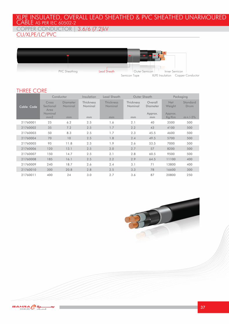
21760001 25 6.2 2.5 1.6 2.1 40 3500 500
21760002 35 7.2 2.5 1.7 2.2 43 4100 500
21760003 50 8.3 2.5 1.7 2.3 45.5 4600 500
21760004 70 10 2.5 1.8 2.4 49.5 5700 500
21760005 95 11.8 2.5 1.9 2.6 53.5 7000 500
21760006 120 13.1 2.5 2.0 2.7 57 8200 500
21760007 150 14.7 2.5 2.1 2.8 60.5 9500 500
21760008 185 16.1 2.5 2.2 2.9 64.5 11100 400
21760009 240 18.7 2.6 2.4 3.1 71 13800 400
21760010 300 20.8 2.8 2.5 3.3 78 16600 300
21760011 400 24 3.0 2.7 3.6 87 20800 250
COPPER CONDUCTOR | 3.6/6 (7.2)kV
THREE CORE
XLPE INSULATED, OVERALL LEAD SHEATHED & PVC SHEATHED UNARMOURED CABLE AS PER IEC 60502-2
CU/XLPE/LC/PVC
PVC SheathingCopper ConductorXLPE InsulationSemicon Tape
Lead Sheath Outer Semicon Inner Semicon
37

The above values are based on the following conditions: Ambient Air Temperature: 40 °CAmbient Ground Temperature: 35 °CDepth of laying in ground: 0.80 mSoil Thermal Resistivity: 1.2 °K.m/W
(Current Rating Capacities for all cables mentioned in this catalogue are focused according to the special climatic conditions in the Middle East)
TECHNICAL INFORMATIONCOPPER CONDUCTOR | 3.6/6 (7.2)kVCU/XLPE/LC/PVC
Size mm2 25 35 50 70 95 120 150 185 240 300 400
Maximum DC resistance of Conductor @ 20°C
Ω/km 0.727 0.524 0.387 0.268 0.193 0.153 0.124 0.0991 0.0754 0.0601 0.0470
Approximate AC resistance of Conductor @ 90°C
Ω/km 0.927 0.669 0.494 0.344 0.247 0.196 0.161 0.129 0.099 0.0815 0.0660
Inductance at 60 Hz mH/Km 0.305 0.294 0.283 0.273 0.267 0.260 0.253 0.250 0.244 0.236 0.226
Reactance at 60 Hz Ω/km 0.115 0.111 0.107 0.103 0.101 0.098 0.095 0.094 0.092 0.089 0.085
Capacitance at 60 Hz μF/Km 0.26 0.30 0.32 0.36 0.39 0.44 0.46 0.53 0.56 0.58 0.60
Short Circuit Current For 1 second
1- Conductor KA 3.58 5.01 7.15 10.01 13.59 17.16 21.45 26.46 34.32 42.90 57.20
2- Metallic Sheath/Screen KA 4.03 5.53 5.16 5.88 6.75 7.56 8.42 9.39 11.03 12.81 15.63
Current Rating Capacity
1- Laid direct in ground (Approx.)
A 140 168 195 248 275 310 346 395 445 505 565
2- Laid in free air (Approx.) A 130 155 186 231 277 320 363 415 486 552 635
Voltage Drop per phase V/A/km 0.812 0.603 0.460 0.335 0.259 0.215 0.185 0.160 0.134 0.117 0.102
Minimum Bending radius mm 600 645 683 743 803 855 908 968 1065 1170 1305
38

Cable Code
Conductor Insulation Lead Sheath Outer Sheath Packaging
Cross Sectional
Area Nominal
mm2
DiameterNominal
mm
Thickness Nominal
mm
Thickness Nominal
mm
Thickness Nominal
mm
Overall Diameter
Approx.mm
Net Weight
Approx.Kg/Km
Standard Drum
m+/-5%
22760001 25 6.2 3.4 1.7 2.3 45 4000 500
22760002 35 7.2 3.4 1.8 2.4 47.5 4700 500
22760003 50 8.3 3.4 1.9 2.5 50 5500 500
22760004 70 10 3.4 1.9 2.6 54 6400 500
22760005 95 11.8 3.4 2.0 2.7 58 7700 500
22760006 120 13.1 3.4 2.1 2.8 62 8900 500
22760007 150 14.7 3.4 2.2 2.9 65 10300 400
22760008 185 16.1 3.4 2.3 3.1 69 11900 400
22760009 240 18.7 3.4 2.5 3.2 75 14800 300
22760010 300 20.8 3.4 2.6 3.4 81 17400 300
22760011 400 24 3.4 2.8 3.7 89 21400 250
THREE CORE
XLPE INSULATED, OVERALL LEAD SHEATHED & PVC SHEATHED UNARMOURED CABLE AS PER IEC 60502-2
CU/XLPE/LC/PVCCOPPER CONDUCTOR | 6/10 (12)kV
PVC SheathingCopper ConductorXLPE InsulationSemicon Tape
Outer Semicon Inner SemiconLead Sheath
39

The above values are based on the following conditions: Ambient Air Temperature: 40 °CAmbient Ground Temperature: 35 °CDepth of laying in ground: 0.80 mSoil Thermal Resistivity: 1.2 °K.m/W
(Current Rating Capacities for all cables mentioned in this catalogue are focused according to the special climatic conditions in the Middle East)
TECHNICAL INFORMATIONCOPPER CONDUCTOR | 6/10 (12)kVCU/XLPE/LC/PVC
Size mm2 25 35 50 70 95 120 150 185 240 300 400
Maximum DC resistance of Conductor @ 20°C
Ω/km 0.727 0.524 0.387 0.268 0.193 0.153 0.124 0.0991 0.0754 0.0601 0.0470
Approximate AC resistance of Conductor @ 90°C
Ω/km 0.927 0.669 0.494 0.344 0.247 0.196 0.161 0.129 0.099 0.0815 0.0660
Inductance at 60 Hz mH/Km 0.332 0.318 0.306 0.292 0.284 0.276 0.270 0.263 0.256 0.248 0.239
Reactance at 60 Hz Ω/km 0.125 0.120 0.115 0.110 0.107 0.104 0.102 0.099 0.097 0.093 0.090
Capacitance at 60 Hz μF/Km 0.20 0.23 0.25 0.29 0.30 0.33 0.37 0.40 0.45 0.49 0.54
Short Circuit Current For 1 second
1- Conductor KA 3.58 5.01 7.15 10.01 13.59 17.16 21.45 26.46 34.32 42.90 57.20
2- Metallic Sheath/Screen KA 4.87 5.41 6.09 6.87 7.8 8.67 9.58 10.6 12.2 13.75 16.3
Current Rating Capacity
1- Laid direct in ground (Approx.)
A 140 168 195 248 275 310 346 395 445 505 565
2- Laid in free air (Approx.) A 130 155 186 231 277 320 363 415 486 552 635
Voltage Drop per phase V/A/km 0.815 0.606 0.465 0.340 0.263 0.220 0.190 0.162 0.132 0.120 0.106
Minimum Bending radius mm 675 713 750 810 870 930 975 1035 1125 1215 1336
40
Cable Code
Conductor Insulation Lead Sheath Outer Sheath Packaging
Cross Sectional
Area Nominal
mm2
DiameterNominal
mm
Thickness Nominal
mm
Thickness Nominal
mm
Thickness Nominal
mm
Overall Diameter
Approx.mm
Net Weight
Approx.Kg/Km
Standard Drum
m+/-5%
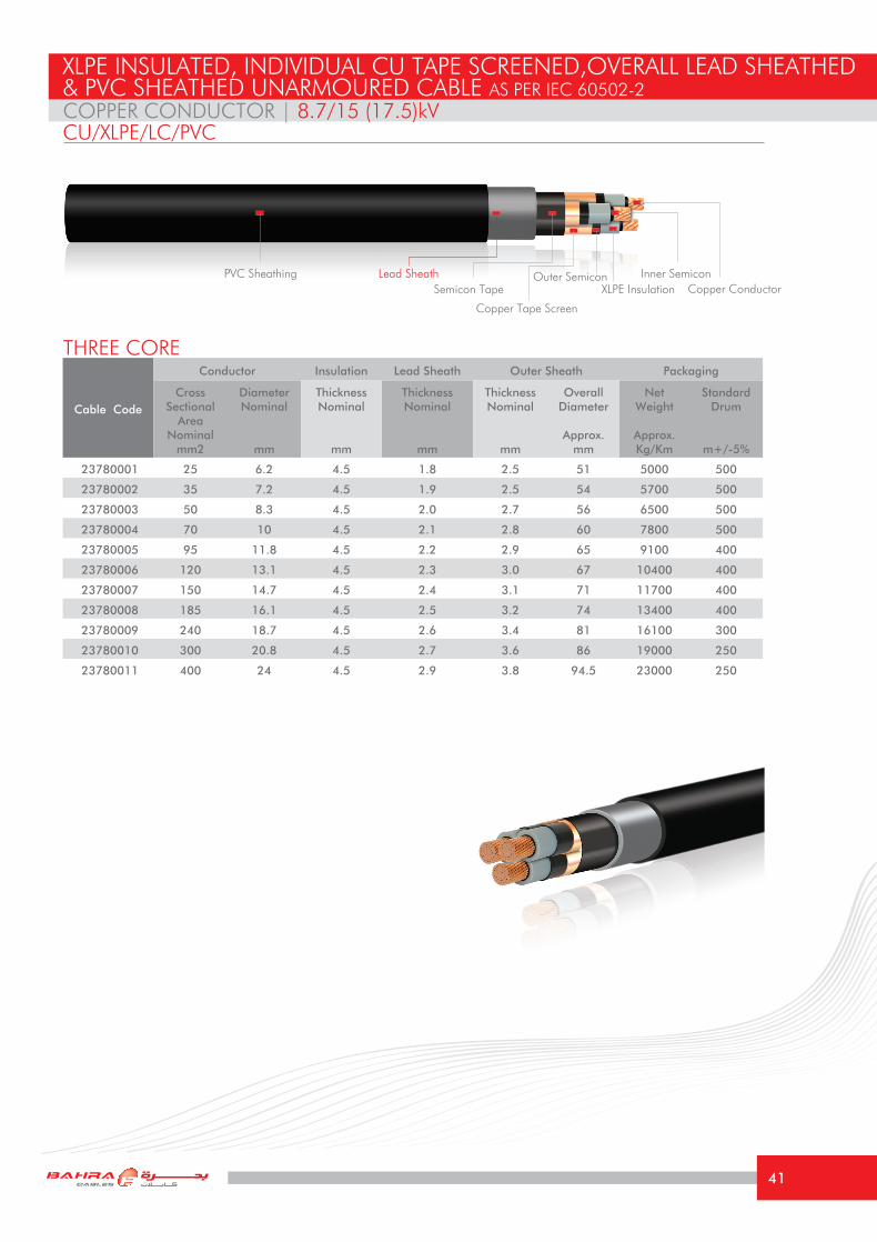
23780001 25 6.2 4.5 1.8 2.5 51 5000 500
23780002 35 7.2 4.5 1.9 2.5 54 5700 500
23780003 50 8.3 4.5 2.0 2.7 56 6500 500
23780004 70 10 4.5 2.1 2.8 60 7800 500
23780005 95 11.8 4.5 2.2 2.9 65 9100 400
23780006 120 13.1 4.5 2.3 3.0 67 10400 400
23780007 150 14.7 4.5 2.4 3.1 71 11700 400
23780008 185 16.1 4.5 2.5 3.2 74 13400 400
23780009 240 18.7 4.5 2.6 3.4 81 16100 300
23780010 300 20.8 4.5 2.7 3.6 86 19000 250
23780011 400 24 4.5 2.9 3.8 94.5 23000 250
THREE CORE
COPPER CONDUCTOR | 8.7/15 (17.5)kV
XLPE INSULATED, INDIVIDUAL CU TAPE SCREENED,OVERALL LEAD SHEATHED & PVC SHEATHED UNARMOURED CABLE AS PER IEC 60502-2
CU/XLPE/LC/PVC
PVC SheathingCopper ConductorXLPE Insulation
Copper Tape Screen
Outer Semicon Inner SemiconSemicon Tape
Lead Sheath
41

The above values are based on the following conditions: Ambient Air Temperature: 40 °CAmbient Ground Temperature: 35 °CDepth of laying in ground: 0.80 mSoil Thermal Resistivity: 1.2 °K.m/W
(Current Rating Capacities for all cables mentioned in this catalogue are focused according to the special climatic conditions in the Middle East)
TECHNICAL INFORMATIONCOPPER CONDUCTOR | 8.7/15 (17.5)kVCU/XLPE/LC/PVC
Size mm2 25 35 50 70 95 120 150 185 240 300 400
Maximum DC resistance of Conductor @ 20°C
Ω/km 0.727 0.524 0.387 0.268 0.193 0.153 0.124 0.0991 0.0754 0.0601 0.0470
Approximate AC resistance of Conductor @ 90°C
Ω/km 0.927 0.669 0.494 0.344 0.247 0.196 0.161 0.129 0.099 0.0815 0.0655
Inductance at 60 Hz mH/Km 0.360 0.345 0.330 0.315 0.306 0.295 0.288 0.280 0.270 0.260 0.251
Reactance at 60 Hz Ω/km 0.14 0.13 0.12 0.12 0.12 0.11 0.11 0.11 0.10 0.10 0.09
Capacitance at 60 Hz μF/Km 0.17 0.18 0.2 0.23 0.25 0.27 0.29 0.32 0.35 0.39 0.43
Short Circuit Current For 1 second
1- Conductor KA 3.58 5.01 7.15 10.01 13.59 17.16 21.45 26.46 34.32 42.90 57.20
2- Metallic Sheath/Screen KA 1.32 1.38 1.47 1.59 1.68 1.8 1.89 2.01 2.16 2.31 2.52
Current Rating Capacity
1- Laid direct in ground (Approx.)
A 140 168 195 248 275 310 346 395 445 505 565
2- Laid in free air (Approx.) A 130 155 186 231 277 320 363 415 486 552 635
Voltage Drop per phase V/A/km 0.823 0.613 0.472 0.345 0.266 0.225 0.194 0.166 0.141 0.123 0.107
Minimum Bending radius mm 765 810 840 900 975 1005 1065 1110 1215 1290 1380
42

Cable Code
Conductor Insulation Lead Sheath Outer Sheath Packaging
Cross Sectional
Area Nominal
mm2
DiameterNominal
mm
Thickness Nominal
mm
Thickness Nominal
mm
Thickness Nominal
mm
Overall Diameter
Approx.mm
Net Weight
Approx.Kg/Km
Standard Drum
m+/-5%
24780001 35 7.2 5.5 2.0 2.7 59 7000 500
24780002 50 8.3 5.5 2.1 2.8 62 7800 500
24780003 70 10 5.5 2.2 2.9 64 9100 500
24780004 95 11.8 5.5 2.3 3.1 69 10500 400
24780005 120 13.1 5.5 2.4 3.2 72 11900 400
24780006 150 14.7 5.5 2.5 3.3 76 13400 400
24780007 185 16.1 5.5 2.6 3.4 80 15100 300
24780008 240 18.7 5.5 2.7 3.6 86 18000 300
24780009 300 20.8 5.5 2.9 3.7 91 21300 250
24780010 400 24 5.5 3.1 4.0 100 25500 250
THREE CORE
COPPER CONDUCTOR | 12/20 (24)kV
XLPE INSULATED, INDIVIDUAL CU TAPE SCREENED,OVERALL LEAD SHEATHED & PVC SHEATHED UNARMOURED CABLE AS PER IEC 60502-2
CU/XLPE/LC/PVC
PVC SheathingCopper ConductorXLPE Insulation
Outer Semicon Inner Semicon
Copper Tape Screen
Semicon TapeLead Sheath
43

The above values are based on the following conditions: Ambient Air Temperature: 40 °CAmbient Ground Temperature: 35 °CDepth of laying in ground: 0.80 mSoil Thermal Resistivity: 1.2 °K.m/W
(Current Rating Capacities for all cables mentioned in this catalogue are focused according to the special climatic conditions in the Middle East)
TECHNICAL INFORMATIONCOPPER CONDUCTOR | 12/20 (24)kVCU/XLPE/LC/PVC
Size mm2 35 50 70 95 120 150 185 240 300 400
Maximum DC resistance of Conductor @ 20°C
Ω/km 0.524 0.387 0.268 0.193 0.153 0.124 0.0991 0.0754 0.0601 0.0470
Approximate AC resistance of Conductor @ 90°C
Ω/km 0.668 0.494 0.344 0.247 0.196 0.161 0.129 0.099 0.0810 0.0650
Inductance at 60 Hz mH/Km 0.365 0.350 0.333 0.322 0.312 0.303 0.295 0.285 0.270 0.262
Reactance at 60 Hz Ω/km 0.14 0.13 0.13 0.12 0.12 0.11 0.11 0.11 0.10 0.10
Capacitance at 60 Hz μF/Km 0.15 0.17 0.2 0.22 0.24 0.26 0.27 0.3 0.33 0.37
Short Circuit Current For 1 second
1- Conductor KA 5.01 7.15 10.01 13.59 17.16 21.45 26.46 34.32 42.90 57.20
2- Metallic Sheath/Screen KA 1.5 1.59 1.71 1.83 1.92 2.04 2.16 2.31 2.46 2.64
Current Rating Capacity
1- Laid direct in ground (Approx.)
A 168 195 248 275 310 346 395 445 505 565
2- Laid in free air (Approx.) A 155 186 231 277 320 363 415 486 552 635
Voltage Drop per phase V/A/km 0.620 0.475 0.350 0.271 0.228 0.198 0.170 0.143 0.125 0.111
Minimum Bending radius mm 885 930 960 1035 1080 1140 1200 1290 1365 1470
44

Cable Code
Conductor Insulation Lead Sheath Outer Sheath Packaging
Cross Sectional
Area Nominal
mm2
DiameterNominal
mm
Thickness Nominal
mm
Thickness Nominal
mm
Thickness Nominal
mm
Overall Diameter
Approx.mm
Net Weight
Approx.Kg/Km
Standard Drum
m+/-5%
25780001 50 8.3 8.0 2.4 3.2 74 10400 400
25780002 70 10 8.0 2.5 3.3 78 11800 400
25780003 95 11.8 8.0 2.6 3.5 82 13500 400
25780004 120 13.1 8.0 2.7 3.6 84 15000 300
25780005 150 14.7 8.0 2.8 3.7 88 16600 300
25780006 185 16.1 8.0 2.9 3.8 92 18800 250
25780007 240 18.7 8.0 3.1 4.0 98 21900 250
25780008 300 20.8 8.0 3.2 4.1 104 25000 250
THREE CORE
COPPER CONDUCTOR | 18/30 (36)kV
XLPE INSULATED, INDIVIDUAL CU TAPE SCREENED,OVERALL LEAD SHEATHED & PVC SHEATHED UNARMOURED CABLE AS PER IEC 60502-2
CU/XLPE/LC/PVC
PVC SheathingCopper ConductorXLPE Insulation
Outer Semicon Inner Semicon
Copper Tape Screen
Semicon TapeLead Sheath
45

The above values are based on the following conditions: Ambient Air Temperature: 40 °CAmbient Ground Temperature: 35 °CDepth of laying in ground: 0.80 mSoil Thermal Resistivity: 1.2 °K.m/W
(Current Rating Capacities for all cables mentioned in this catalogue are focused according to the special climatic conditions in the Middle East)
TECHNICAL INFORMATIONCOPPER CONDUCTOR | 18/30 (36)kVCU/XLPE/LC/PVC
Size mm2 50 70 95 120 150 185 240 300
Maximum DC resistance of Conductor @ 20°C
Ω/km 0.387 0.268 0.193 0.153 0.124 0.0991 0.0754 0.0601
Approximate AC resistance of Conductor @ 90°C
Ω/km 0.494 0.341 0.247 0.196 0.161 0.128 0.098 0.0801
Inductance at 60 Hz mH/Km 0.398 0.380 0.369 0.355 0.345 0.335 0.320 0.308
Reactance at 60 Hz Ω/km 0.15 0.14 0.14 0.13 0.13 0.13 0.12 0.12
Capacitance at 60 Hz μF/Km 0.14 0.15 0.17 0.18 0.2 0.21 0.23 0.25
Short Circuit Current For 1 second
1- Conductor KA 7.15 10.01 13.59 17.16 21.45 26.46 34.32 42.90
2- Metallic Sheath/Screen KA 1.95 2.07 2.19 2.28 2.37 2.49 2.67 2.82
Current Rating Capacity
1- Laid direct in ground (Approx.) A 195 248 275 310 346 395 445 505
2- Laid in free air (Approx.) A 186 231 277 320 363 415 486 552
Voltage Drop per phase V/A/km 0.485 0.361 0.280 0.237 0.206 0.178 0.153 0.134
Minimum Bending radius mm 1110 1170 1230 1260 1320 1380 1470 1560
46
Cable Code
Conductor Insulation Lead Sheath Outer Sheath Packaging
Cross Sectional
Area Nominal
mm2
DiameterNominal
mm
Thickness Nominal
mm
Thickness Nominal
mm
Thickness Nominal
mm
Overall Diameter
Approx.mm
Net Weight
Approx.Kg/Km
Standard Drum
m+/-5%
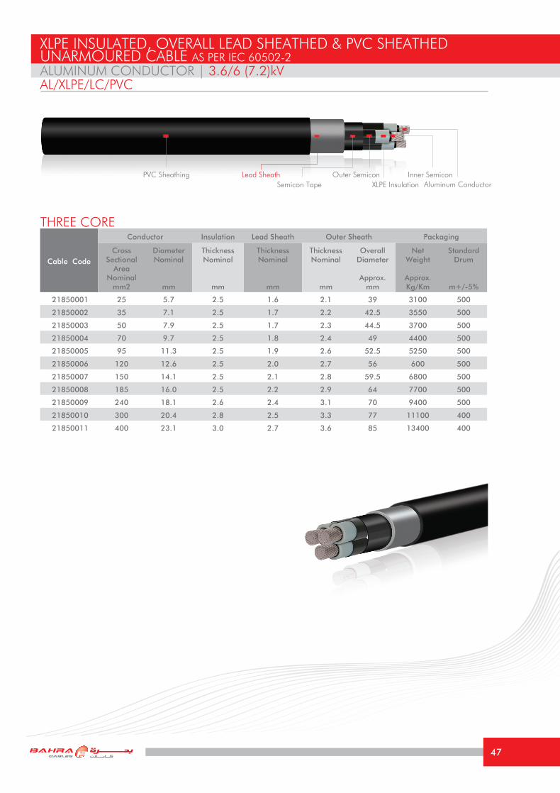
21850001 25 5.7 2.5 1.6 2.1 39 3100 500
21850002 35 7.1 2.5 1.7 2.2 42.5 3550 500
21850003 50 7.9 2.5 1.7 2.3 44.5 3700 500
21850004 70 9.7 2.5 1.8 2.4 49 4400 500
21850005 95 11.3 2.5 1.9 2.6 52.5 5250 500
21850006 120 12.6 2.5 2.0 2.7 56 600 500
21850007 150 14.1 2.5 2.1 2.8 59.5 6800 500
21850008 185 16.0 2.5 2.2 2.9 64 7700 500
21850009 240 18.1 2.6 2.4 3.1 70 9400 500
21850010 300 20.4 2.8 2.5 3.3 77 11100 400
21850011 400 23.1 3.0 2.7 3.6 85 13400 400
ALUMINUM CONDUCTOR | 3.6/6 (7.2)kV
THREE CORE
XLPE INSULATED, OVERALL LEAD SHEATHED & PVC SHEATHEDUNARMOURED CABLE AS PER IEC 60502-2
AL/XLPE/LC/PVC
PVC SheathingAluminum ConductorXLPE Insulation
Outer Semicon Inner SemiconSemicon Tape
Lead Sheath
47

The above values are based on the following conditions: Ambient Air Temperature: 40 °CAmbient Ground Temperature: 35 °CDepth of laying in ground: 0.80 mSoil Thermal Resistivity: 1.2 °K.m/W
(Current Rating Capacities for all cables mentioned in this catalogue are focused according to the special climatic conditions in the Middle East)
TECHNICAL INFORMATIONALUMINUM CONDUCTOR | 3.6/6 (7.2)kVAL/XLPE/LC/PVC
Size mm2 25 35 50 70 95 120 150 185 240 300 400
Maximum DC resistance of Conductor @ 20°C
Ω/km 1.20 0.868 0.641 0.443 0.320 0.253 0.206 0.164 0.125 0.100 0.0778
Approximate AC resistance of Conductor @ 90°C
Ω/km 1.54 1.113 0.822 0.569 0.411 0.325 0.265 0.212 0.163 0.131 0.1034
Inductance at 60 Hz mH/Km 0.305 0.294 0.283 0.273 0.267 0.260 0.253 0.250 0.244 0.236 0.226
Reactance at 60 Hz Ω/km 0.115 0.111 0.107 0.103 0.101 0.098 0.095 0.094 0.092 0.089 0.085
Capacitance at 60 Hz μF/Km 0.26 0.30 0.32 0.36 0.39 0.44 0.46 0.53 0.56 0.58 0.60
Short Circuit Current For 1 second
1- Conductor KA 2.34 3.28 4.69 6.56 8.90 11.24 14.06 17.33 22.49 28.11 37.48
2- Metallic Sheath/Screen KA 4.03 5.53 5.16 5.88 6.75 7.56 8.42 9.39 11.03 12.81 15.63
Current Rating Capacity
1- Laid direct in ground (Approx.)
A 108 127 148 178 210 238 265 298 341 383 435
2- Laid in free air (Approx.) A 100 120 144 178 215 248 281 323 378 432 502
Voltage Drop per phase V/A/km 1.300 0.957 0.722 0.516 0.389 0.319 0.269 0.225 0.185 0.157 0.133
Minimum Bending radius mm 585 638 667 735 788 840 893 960 1050 1155 1275
48
Cable Code
Conductor Insulation Lead Sheath Outer Sheath Packaging
Cross Sectional
Area Nominal
mm2
DiameterNominal
mm
Thickness Nominal
mm
Thickness Nominal
mm
Thickness Nominal
mm
Overall Diameter
Approx.mm
Net Weight
Approx.Kg/Km
Standard Drum
m+/-5%
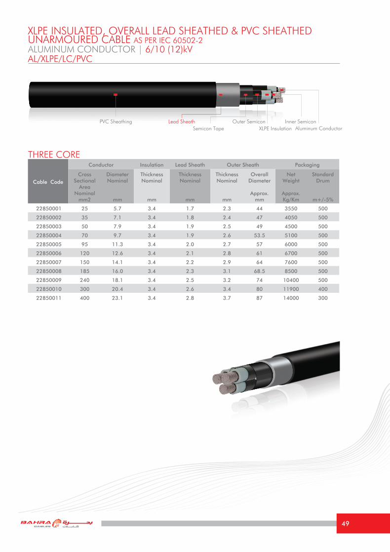
22850001 25 5.7 3.4 1.7 2.3 44 3550 500
22850002 35 7.1 3.4 1.8 2.4 47 4050 500
22850003 50 7.9 3.4 1.9 2.5 49 4500 500
22850004 70 9.7 3.4 1.9 2.6 53.5 5100 500
22850005 95 11.3 3.4 2.0 2.7 57 6000 500
22850006 120 12.6 3.4 2.1 2.8 61 6700 500
22850007 150 14.1 3.4 2.2 2.9 64 7600 500
22850008 185 16.0 3.4 2.3 3.1 68.5 8500 500
22850009 240 18.1 3.4 2.5 3.2 74 10400 500
22850010 300 20.4 3.4 2.6 3.4 80 11900 400
22850011 400 23.1 3.4 2.8 3.7 87 14000 300
THREE CORE
XLPE INSULATED, OVERALL LEAD SHEATHED & PVC SHEATHEDUNARMOURED CABLE AS PER IEC 60502-2
AL/XLPE/LC/PVCALUMINUM CONDUCTOR | 6/10 (12)kV
PVC SheathingAluminum ConductorXLPE Insulation
Outer Semicon Inner SemiconSemicon Tape
Lead Sheath
49

The above values are based on the following conditions: Ambient Air Temperature: 40 °CAmbient Ground Temperature: 35 °CDepth of laying in ground: 0.80 mSoil Thermal Resistivity: 1.2 °K.m/W
(Current Rating Capacities for all cables mentioned in this catalogue are focused according to the special climatic conditions in the Middle East)
TECHNICAL INFORMATIONALUMINUM CONDUCTOR | 6/10 (12)kVAL/XLPE/LC/PVC
Size mm2 25 35 50 70 95 120 150 185 240 300 400
Maximum DC resistance of Conductor @ 20°C
Ω/km 1.20 0.868 0.641 0.443 0.320 0.253 0.206 0.164 0.125 0.100 0.0778
Approximate AC resistance of Conductor @ 90°C
Ω/km 1.54 1.113 0.822 0.569 0.411 0.325 0.265 0.212 0.163 0.131 0.1034
Inductance at 60 Hz mH/Km 0.332 0.318 0.306 0.292 0.284 0.276 0.270 0.263 0.256 0.248 0.239
Reactance at 60 Hz Ω/km 0.125 0.120 0.115 0.110 0.107 0.104 0.102 0.099 0.097 0.093 0.090
Capacitance at 60 Hz μF/Km 0.20 0.23 0.25 0.29 0.30 0.33 0.37 0.40 0.45 0.49 0.54
Short Circuit Current For 1 second
1- Conductor KA 2.34 3.28 4.69 6.56 8.90 11.24 14.06 17.33 22.49 28.11 37.48
2- Metallic Sheath/Screen KA 4.87 5.41 6.09 6.87 7.8 8.67 9.58 10.6 12.2 13.75 16.3
Current Rating Capacity
1- Laid direct in ground (Approx.)
A 108 127 148 178 210 238 265 298 341 383 435
2- Laid in free air (Approx.) A 100 120 144 178 215 248 281 323 378 432 502
Voltage Drop per phase V/A/km 1.306 0.962 0.727 0.520 0.393 0.322 0.273 0.228 0.187 0.160 0.134
Minimum Bending radius mm 660 705 735 803 865 915 960 1030 1110 1200 1305
50

Cable Code
Conductor Insulation Lead Sheath Outer Sheath Packaging
Cross Sectional
Area Nominal
mm2
DiameterNominal
mm
Thickness Nominal
mm
Thickness Nominal
mm
Thickness Nominal
mm
Overall Diameter
Approx.mm
Net Weight
Approx.Kg/Km
Standard Drum
m+/-5%
23860001 25 5.7 4.5 1.8 2.5 50 4700 500
23860002 35 7.1 4.5 1.9 2.5 53.5 5300 500
23860003 50 7.9 4.5 2.0 2.7 55 5900 500
23860004 70 9.7 4.5 2.1 2.8 59.5 6700 500
23860005 95 11.3 4.5 2.2 2.9 64 7700 500
23860006 120 12.6 4.5 2.3 3.0 66 8500 500
23860007 150 14.1 4.5 2.4 3.1 70 9400 500
23860008 185 16.0 4.5 2.5 3.2 73.5 10400 500
23860009 240 18.1 4.5 2.6 3.4 80 12100 400
23860010 300 20.4 4.5 2.7 3.6 85 13900 300
23860011 400 23.1 4.5 2.9 3.8 92 16100 250
THREE CORE
ALUMINUM CONDUCTOR | 8.7/15 (17.5)kV
XLPE INSULATED, INDIVIDUAL CU TAPE SCREENED,OVERALL LEAD SHEATHED & PVC SHEATHED UNARMOURED CABLE AS PER IEC 60502-2
AL/XLPE/LC/PVC
PVC SheathingAluminum ConductorXLPE Insulation
Outer Semicon Inner Semicon
Copper Tape Screen
Semicon TapeLead Sheath
51
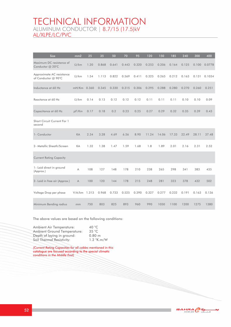
The above values are based on the following conditions: Ambient Air Temperature: 40 °CAmbient Ground Temperature: 35 °CDepth of laying in ground: 0.80 mSoil Thermal Resistivity: 1.2 °K.m/W
(Current Rating Capacities for all cables mentioned in this catalogue are focused according to the special climatic conditions in the Middle East)
TECHNICAL INFORMATIONALUMINUM CONDUCTOR | 8.7/15 (17.5)kVAL/XLPE/LC/PVC
Size mm2 25 35 50 70 95 120 150 185 240 300 400
Maximum DC resistance of Conductor @ 20°C
Ω/km 1.20 0.868 0.641 0.443 0.320 0.253 0.206 0.164 0.125 0.100 0.0778
Approximate AC resistance of Conductor @ 90°C
Ω/km 1.54 1.113 0.822 0.569 0.411 0.325 0.265 0.212 0.163 0.131 0.1034
Inductance at 60 Hz mH/Km 0.360 0.345 0.330 0.315 0.306 0.295 0.288 0.280 0.270 0.260 0.251
Reactance at 60 Hz Ω/km 0.14 0.13 0.12 0.12 0.12 0.11 0.11 0.11 0.10 0.10 0.09
Capacitance at 60 Hz μF/Km 0.17 0.18 0.2 0.23 0.25 0.27 0.29 0.32 0.35 0.39 0.43
Short Circuit Current For 1 second
1- Conductor KA 2.34 3.28 4.69 6.56 8.90 11.24 14.06 17.33 22.49 28.11 37.48
2- Metallic Sheath/Screen KA 1.32 1.38 1.47 1.59 1.68 1.8 1.89 2.01 2.16 2.31 2.52
Current Rating Capacity
1- Laid direct in ground (Approx.)
A 108 127 148 178 210 238 265 298 341 383 435
2- Laid in free air (Approx.) A 100 120 144 178 215 248 281 323 378 432 502
Voltage Drop per phase V/A/km 1.313 0.968 0.733 0.525 0.390 0.327 0.277 0.232 0.191 0.163 0.136
Minimum Bending radius mm 750 803 825 893 960 990 1050 1100 1200 1275 1380
52

Cable Code
Conductor Insulation Lead Sheath Outer Sheath Packaging
Cross Sectional
Area Nominal
mm2
DiameterNominal
mm
Thickness Nominal
mm
Thickness Nominal
mm
Thickness Nominal
mm
Overall Diameter
Approx.mm
Net Weight
Approx.Kg/Km
Standard Drum
m+/-5%
24860001 35 7.1 5.5 2.0 2.7 58.5 6200 500
24860002 50 7.9 5.5 2.1 2.8 61 6900 500
24860003 70 9.7 5.5 2.2 2.9 63.5 7900 500
24860004 95 11.3 5.5 2.3 3.1 68 8800 500
24860005 120 12.6 5.5 2.4 3.2 71 9500 500
24860006 150 14.1 5.5 2.5 3.3 75 10600 500
24860007 185 16.0 5.5 2.6 3.4 79.5 11600 400
24860008 240 18.1 5.5 2.7 3.6 85 13400 300
24860009 300 20.4 5.5 2.9 3.7 90 15600 300
24860010 400 23.1 5.5 3.1 4.0 98 18100 250
THREE CORE
ALUMINUM CONDUCTOR | 12/20 (24)kV
XLPE INSULATED, INDIVIDUAL CU TAPE SCREENED,OVERALL LEAD SHEATHED & PVC SHEATHED UNARMOURED CABLE AS PER IEC 60502-2
AL/XLPE/LC/PVC
PVC SheathingAluminum ConductorXLPE Insulation
Outer Semicon Inner Semicon
Copper Tape Screen
Semicon TapeLead Sheath
53
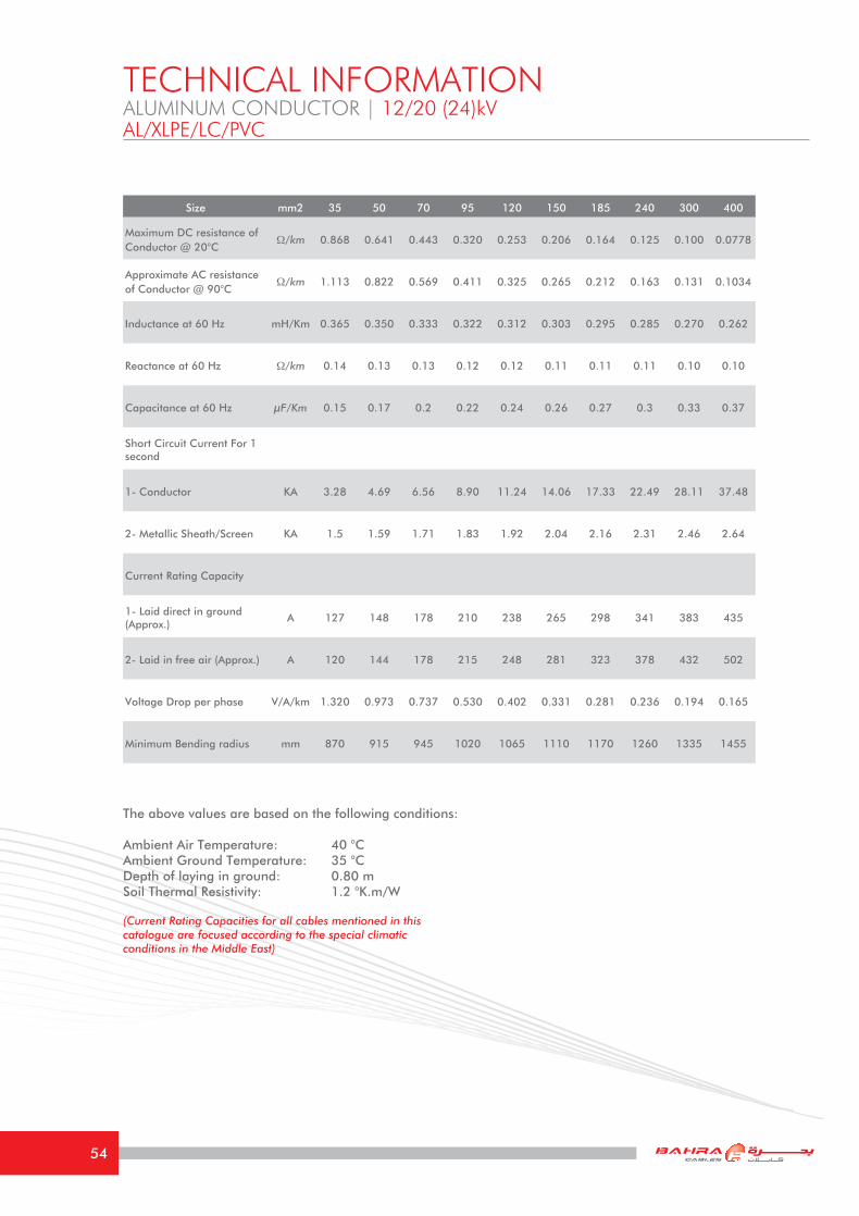
The above values are based on the following conditions: Ambient Air Temperature: 40 °CAmbient Ground Temperature: 35 °CDepth of laying in ground: 0.80 mSoil Thermal Resistivity: 1.2 °K.m/W
(Current Rating Capacities for all cables mentioned in this catalogue are focused according to the special climatic conditions in the Middle East)
TECHNICAL INFORMATIONALUMINUM CONDUCTOR | 12/20 (24)kVAL/XLPE/LC/PVC
Size mm2 35 50 70 95 120 150 185 240 300 400
Maximum DC resistance of Conductor @ 20°C
Ω/km 0.868 0.641 0.443 0.320 0.253 0.206 0.164 0.125 0.100 0.0778
Approximate AC resistance of Conductor @ 90°C
Ω/km 1.113 0.822 0.569 0.411 0.325 0.265 0.212 0.163 0.131 0.1034
Inductance at 60 Hz mH/Km 0.365 0.350 0.333 0.322 0.312 0.303 0.295 0.285 0.270 0.262
Reactance at 60 Hz Ω/km 0.14 0.13 0.13 0.12 0.12 0.11 0.11 0.11 0.10 0.10
Capacitance at 60 Hz μF/Km 0.15 0.17 0.2 0.22 0.24 0.26 0.27 0.3 0.33 0.37
Short Circuit Current For 1 second
1- Conductor KA 3.28 4.69 6.56 8.90 11.24 14.06 17.33 22.49 28.11 37.48
2- Metallic Sheath/Screen KA 1.5 1.59 1.71 1.83 1.92 2.04 2.16 2.31 2.46 2.64
Current Rating Capacity
1- Laid direct in ground (Approx.)
A 127 148 178 210 238 265 298 341 383 435
2- Laid in free air (Approx.) A 120 144 178 215 248 281 323 378 432 502
Voltage Drop per phase V/A/km 1.320 0.973 0.737 0.530 0.402 0.331 0.281 0.236 0.194 0.165
Minimum Bending radius mm 870 915 945 1020 1065 1110 1170 1260 1335 1455
54

Cable Code
Conductor Insulation Lead Sheath Outer Sheath Packaging
Cross Sectional
Area Nominal
mm2
DiameterNominal
mm
Thickness Nominal
mm
Thickness Nominal
mm
Thickness Nominal
mm
Overall Diameter
Approx.mm
Net Weight
Approx.Kg/Km
Standard Drum
m+/-5%
25860001 50 7.9 8.0 2.4 3.2 73 9200 500
25860002 70 9.7 8.0 2.5 3.3 77.5 10200 400
25860003 95 11.3 8.0 2.6 3.5 81 11300 400
25860004 120 12.6 8.0 2.7 3.6 83 12300 300
25860005 150 14.1 8.0 2.8 3.7 87 13500 300
25860006 185 16.0 8.0 2.9 3.8 91.5 15000 300
25860007 240 18.1 8.0 3.1 4.0 97 17000 250
25860008 300 20.4 8.0 3.2 4.1 103 19000 250
THREE CORE
ALUMINUM CONDUCTOR | 18/30 (36)kV
XLPE INSULATED, INDIVIDUAL CU TAPE SCREENED,OVERALL LEAD SHEATHED & PVC SHEATHED UNARMOURED CABLE AS PER IEC 60502-2
AL/XLPE/LC/PVC
PVC SheathingAluminum ConductorXLPE Insulation
Outer Semicon Inner Semicon
Copper Tape Screen
Semicon TapeLead Sheath
55

The above values are based on the following conditions: Ambient Air Temperature: 40 °CAmbient Ground Temperature: 35 °CDepth of laying in ground: 0.80 mSoil Thermal Resistivity: 1.2 °K.m/W
(Current Rating Capacities for all cables mentioned in this catalogue are focused according to the special climatic conditions in the Middle East)
TECHNICAL INFORMATIONALUMINUM CONDUCTOR | 18/30 (36)kVAL/XLPE/LC/PVC
Size mm2 50 70 95 120 150 185 240 300
Maximum DC resistance of Conductor @ 20°C
Ω/km 0.641 0.443 0.320 0.253 0.206 0.164 0.125 0.100
Approximate AC resistance of Conductor @ 90°C
Ω/km 0.822 0.569 0.411 0.325 0.265 0.212 0.163 0.131
Inductance at 60 Hz mH/Km 0.398 0.380 0.369 0.355 0.345 0.335 0.320 0.308
Reactance at 60 Hz Ω/km 0.15 0.14 0.14 0.13 0.13 0.13 0.12 0.12
Capacitance at 60 Hz μF/Km 0.14 0.15 0.17 0.18 0.2 0.21 0.23 0.25
Short Circuit Current For 1 second
1- Conductor KA 4.69 6.56 8.90 11.24 14.06 17.33 22.49 28.11
2- Metallic Sheath/Screen KA 1.95 2.07 2.19 2.28 2.37 2.49 2.67 2.82
Current Rating Capacity
1- Laid direct in ground (Approx.) A 148 178 210 238 265 298 341 383
2- Laid in free air (Approx.) A 144 178 215 248 281 323 378 432
Voltage Drop per phase V/A/km 0.749 0.540 0.412 0.340 0.290 0.244 0.202 0.174
Minimum Bending radius mm 1095 1155 1215 1245 1290 1350 1440 1545
56
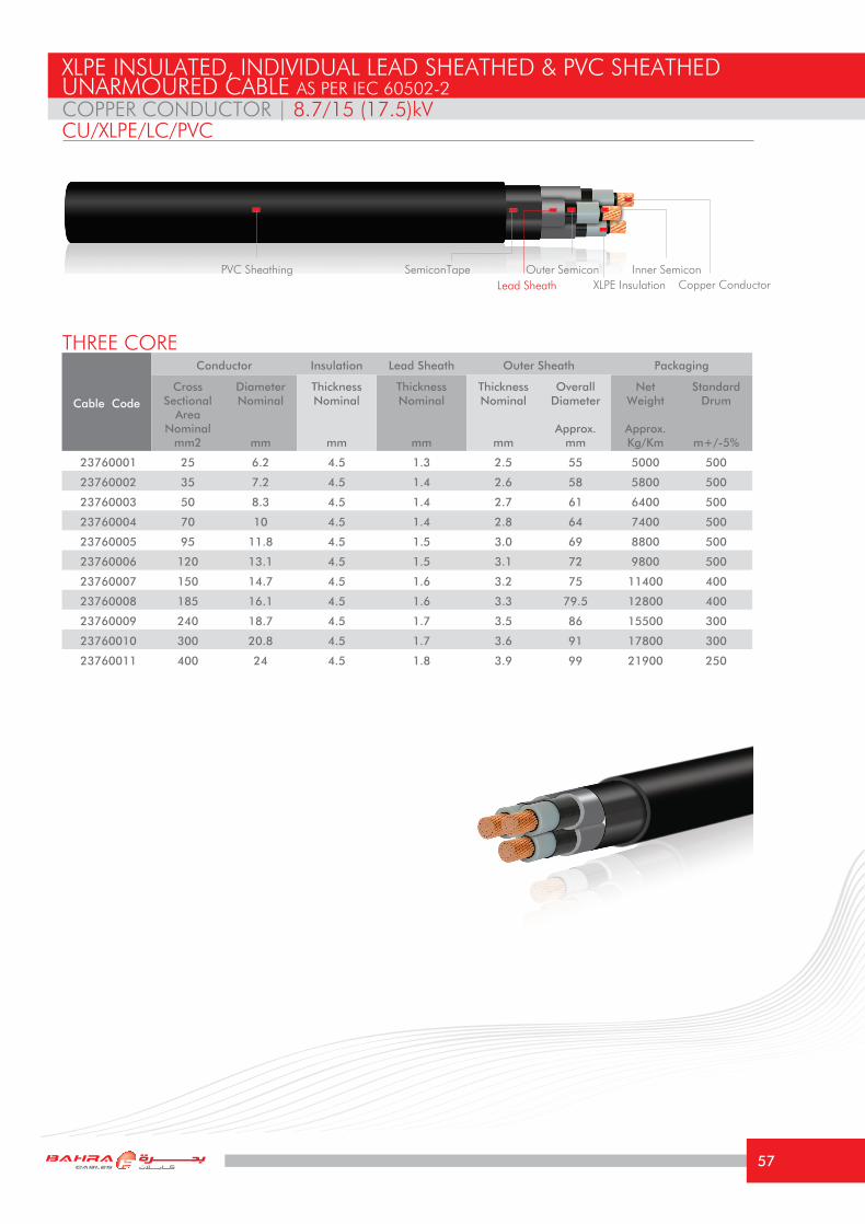
COPPER CONDUCTOR | 8.7/15 (17.5)kV
XLPE INSULATED, INDIVIDUAL LEAD SHEATHED & PVC SHEATHEDUNARMOURED CABLE AS PER IEC 60502-2
CU/XLPE/LC/PVC
Cable Code
Conductor Insulation Lead Sheath Outer Sheath Packaging
Cross Sectional
Area Nominal
mm2
DiameterNominal
mm
Thickness Nominal
mm
Thickness Nominal
mm
Thickness Nominal
mm
Overall Diameter
Approx.mm
Net Weight
Approx.Kg/Km
Standard Drum
m+/-5%
23760001 25 6.2 4.5 1.3 2.5 55 5000 500
23760002 35 7.2 4.5 1.4 2.6 58 5800 500
23760003 50 8.3 4.5 1.4 2.7 61 6400 500
23760004 70 10 4.5 1.4 2.8 64 7400 500
23760005 95 11.8 4.5 1.5 3.0 69 8800 500
23760006 120 13.1 4.5 1.5 3.1 72 9800 500
23760007 150 14.7 4.5 1.6 3.2 75 11400 400
23760008 185 16.1 4.5 1.6 3.3 79.5 12800 400
23760009 240 18.7 4.5 1.7 3.5 86 15500 300
23760010 300 20.8 4.5 1.7 3.6 91 17800 300
23760011 400 24 4.5 1.8 3.9 99 21900 250
THREE CORE
PVC SheathingCopper ConductorXLPE InsulationLead Sheath
Outer Semicon Inner SemiconSemiconTape
57

The above values are based on the following conditions: Ambient Air Temperature: 40 °CAmbient Ground Temperature: 35 °CDepth of laying in ground: 0.80 mSoil Thermal Resistivity: 1.2 °K.m/W
(Current Rating Capacities for all cables mentioned in this catalogue are focused according to the special climatic conditions in the Middle East)
TECHNICAL INFORMATIONCOPPER CONDUCTOR | 8.7/15 (17.5)kVCU/XLPE/LC/PVC
Size mm2 25 35 50 70 95 120 150 185 240 300 400
Maximum DC resistance of Conductor @ 20°C
Ω/km 0.727 0.524 0.387 0.268 0.193 0.153 0.124 0.0991 0.0754 0.0601 0.0470
Approximate AC resistance of Conductor @ 90°C
Ω/km 0.927 0.669 0.494 0.344 0.247 0.196 0.161 0.129 0.099 0.0815 0.0655
Inductance at 60 Hz mH/Km 0.360 0.345 0.330 0.315 0.306 0.295 0.288 0.280 0.270 0.260 0.251
Reactance at 60 Hz Ω/km 0.14 0.13 0.12 0.12 0.12 0.11 0.11 0.11 0.10 0.10 0.09
Capacitance at 60 Hz μF/Km 0.17 0.18 0.2 0.23 0.25 0.27 0.29 0.32 0.35 0.39 0.43
Short Circuit Current For 1 second
1- Conductor KA 3.58 5.01 7.15 10.01 13.59 17.16 21.45 26.46 34.32 42.90 57.20
2- Metallic Sheath/Screen KA 5.5 6.6 6.8 7.3 8.0 8.8 9.5 10.3 11.6 12.8 14.8
Current Rating Capacity
1- Laid direct in ground (Approx.)
A 140 168 195 248 275 310 346 395 445 505 565
2- Laid in free air (Approx.) A 130 155 186 231 277 320 363 415 486 552 635
Voltage Drop per phase V/A/km 0.823 0.613 0.472 0.345 0.266 0.225 0.194 0.166 0.141 0.123 0.107
Minimum Bending radius mm 825 870 900 975 1035 1065 1125 1170 1275 1350 1470
58
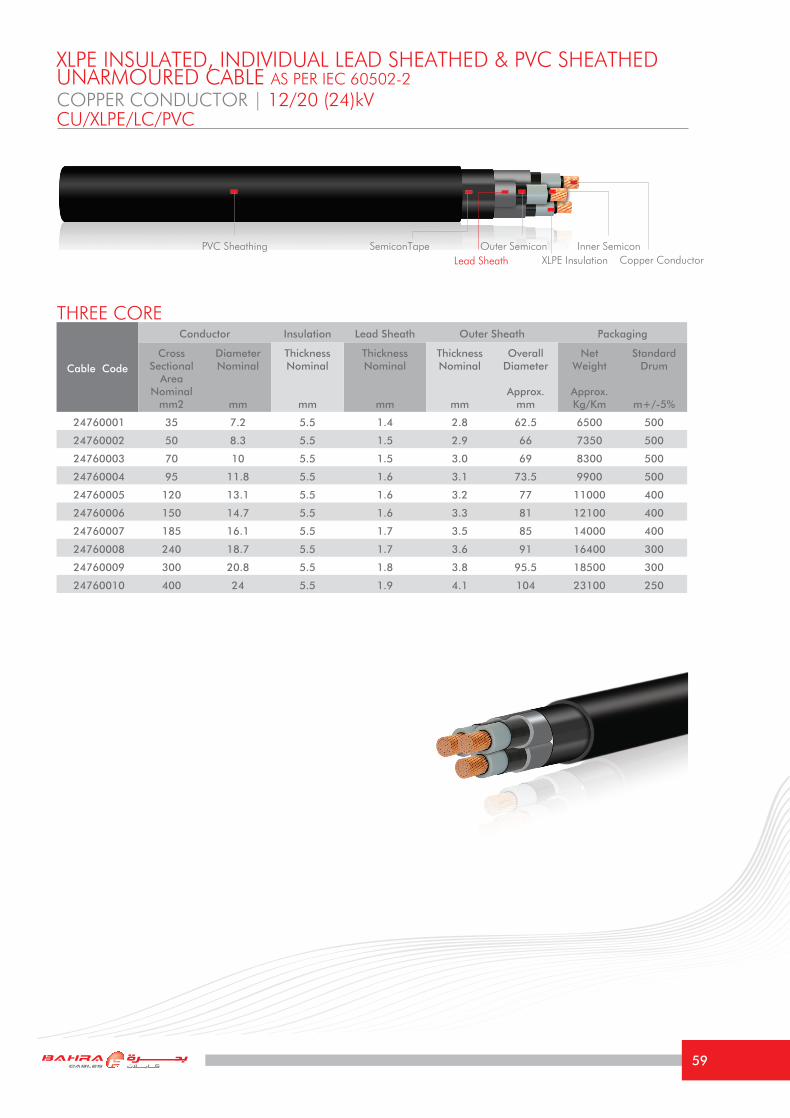
Cable Code
Conductor Insulation Lead Sheath Outer Sheath Packaging
Cross Sectional
Area Nominal
mm2
DiameterNominal
mm
Thickness Nominal
mm
Thickness Nominal
mm
Thickness Nominal
mm
Overall Diameter
Approx.mm
Net Weight
Approx.Kg/Km
Standard Drum
m+/-5%
24760001 35 7.2 5.5 1.4 2.8 62.5 6500 500
24760002 50 8.3 5.5 1.5 2.9 66 7350 500
24760003 70 10 5.5 1.5 3.0 69 8300 500
24760004 95 11.8 5.5 1.6 3.1 73.5 9900 500
24760005 120 13.1 5.5 1.6 3.2 77 11000 400
24760006 150 14.7 5.5 1.6 3.3 81 12100 400
24760007 185 16.1 5.5 1.7 3.5 85 14000 400
24760008 240 18.7 5.5 1.7 3.6 91 16400 300
24760009 300 20.8 5.5 1.8 3.8 95.5 18500 300
24760010 400 24 5.5 1.9 4.1 104 23100 250
THREE CORE
COPPER CONDUCTOR | 12/20 (24)kV
XLPE INSULATED, INDIVIDUAL LEAD SHEATHED & PVC SHEATHEDUNARMOURED CABLE AS PER IEC 60502-2
CU/XLPE/LC/PVC
PVC SheathingCopper ConductorXLPE Insulation
Outer Semicon Inner SemiconLead Sheath
SemiconTape
59

The above values are based on the following conditions: Ambient Air Temperature: 40 °CAmbient Ground Temperature: 35 °CDepth of laying in ground: 0.80 mSoil Thermal Resistivity: 1.2 °K.m/W
(Current Rating Capacities for all cables mentioned in this catalogue are focused according to the special climatic conditions in the Middle East)
TECHNICAL INFORMATIONCOPPER CONDUCTOR | 12/20 (24)kVCU/XLPE/LC/PVC
Size mm2 35 50 70 95 120 150 185 240 300 400
Maximum DC resistance of Conductor @ 20°C
Ω/km 0.524 0.387 0.268 0.193 0.153 0.124 0.0991 0.0754 0.0601 0.0470
Approximate AC resistance of Conductor @ 90°C
Ω/km 0.668 0.494 0.344 0.247 0.196 0.161 0.129 0.099 0.0810 0.0650
Inductance at 60 Hz mH/Km 0.365 0.350 0.333 0.322 0.312 0.303 0.295 0.285 0.270 0.262
Reactance at 60 Hz Ω/km 0.14 0.13 0.13 0.12 0.12 0.11 0.11 0.11 0.10 0.10
Capacitance at 60 Hz μF/Km 0.15 0.17 0.2 0.22 0.24 0.26 0.27 0.3 0.33 0.37
Short Circuit Current For 1 second
1- Conductor KA 5.01 7.15 10.01 13.59 17.16 21.45 26.46 34.32 42.90 57.20
2- Metallic Sheath/Screen KA 6.9 7.6 8.2 9.1 9.8 10.6 11.5 12.8 14.1 16.1
Current Rating Capacity
1- Laid direct in ground (Approx.)
A 168 195 248 275 310 346 395 445 505 565
2- Laid in free air (Approx.) A 155 186 231 277 320 363 415 486 552 635
Voltage Drop per phase V/A/km 0.620 0.475 0.350 0.271 0.228 0.198 0.170 0.143 0.125 0.111
Minimum Bending radius mm 938 990 1035 1100 1155 1215 1275 1365 1433 1560
60

Cable Code
Conductor Insulation Lead Sheath Outer Sheath Packaging
Cross Sectional
Area Nominal
mm2
DiameterNominal
mm
Thickness Nominal
mm
Thickness Nominal
mm
Thickness Nominal
mm
Overall Diameter
Approx.mm
Net Weight
Approx.Kg/Km
Standard Drum
m+/-5%
25760001 50 8.3 8.0 1.6 3.3 77.5 9600 400
25760002 70 10 8.0 1.7 3.4 82 11000 400
25760003 95 11.8 8.0 1.7 3.5 86 12300 400
25760004 120 13.1 8.0 1.7 3.6 89 13400 400
25760005 150 14.7 8.0 1.8 3.7 92 15000 300
25760006 185 16.1 8.0 1.8 3.9 96 16500 300
25760007 240 18.7 8.0 1.9 4.0 103 29500 250
25760008 300 20.8 8.0 2.0 4.2 108 22400 250
THREE CORE
COPPER CONDUCTOR | 18/30 (36)kV
XLPE INSULATED, INDIVIDUAL LEAD SHEATHED & PVC SHEATHEDUNARMOURED CABLE AS PER IEC 60502-2
CU/XLPE/LC/PVC
PVC SheathingCopper ConductorXLPE Insulation
Outer Semicon Inner SemiconLead Sheath
SemiconTape
61

The above values are based on the following conditions: Ambient Air Temperature: 40 °CAmbient Ground Temperature: 35 °CDepth of laying in ground: 0.80 mSoil Thermal Resistivity: 1.2 °K.m/W
(Current Rating Capacities for all cables mentioned in this catalogue are focused according to the special climatic conditions in the Middle East)
TECHNICAL INFORMATIONCOPPER CONDUCTOR | 18/30 (36)kVCU/XLPE/LC/PVC
Size mm2 50 70 95 120 150 185 240 300
Maximum DC resistance of Conductor @ 20°C
Ω/km 0.387 0.268 0.193 0.153 0.124 0.0991 0.0754 0.0601
Approximate AC resistance of Conductor @ 90°C
Ω/km 0.494 0.341 0.247 0.196 0.161 0.128 0.098 0.0801
Inductance at 60 Hz mH/Km 0.398 0.380 0.369 0.355 0.345 0.335 0.320 0.308
Reactance at 60 Hz Ω/km 0.15 0.14 0.14 0.13 0.13 0.13 0.12 0.12
Capacitance at 60 Hz μF/Km 0.14 0.15 0.17 0.18 0.2 0.21 0.23 0.25
Short Circuit Current For 1 second
1- Conductor KA 7.15 10.01 13.59 17.16 21.45 26.46 34.32 42.90
2- Metallic Sheath/Screen KA 10.2 10.4 11.9 12.7 13.6 14.6 16.0 17.4
Current Rating Capacity
1- Laid direct in ground (Approx.) A 195 248 275 310 346 395 445 505
2- Laid in free air (Approx.) A 186 231 277 320 363 415 486 552
Voltage Drop per phase V/A/km 0.485 0.361 0.280 0.237 0.206 0.178 0.153 0.134
Minimum Bending radius mm 1163 1230 1290 1335 1380 1440 1545 1620
62

ALUMINUM CONDUCTOR | 8.7/15 (17.5)kV
XLPE INSULATED, INDIVIDUAL LEAD SHEATHED & PVC SHEATHEDUNARMOURED CABLE AS PER IEC 60502-2
AL/XLPE/LC/PVC
Cable Code
Conductor Insulation Lead Sheath Outer Sheath Packaging
Cross Sectional
Area Nominal
mm2
DiameterNominal
mm
Thickness Nominal
mm
Thickness Nominal
mm
Thickness Nominal
mm
Overall Diameter
Approx.mm
Net Weight
Approx.Kg/Km
Standard Drum
m+/-5%
23850001 25 5.7 4.5 1.3 2.5 54 4550 500
23850002 35 7.1 4.5 1.4 2.6 57.5 5200 500
23850003 50 7.9 4.5 1.4 2.7 60 5450 500
23850004 70 9.7 4.5 1.4 2.8 63.5 6100 500
23850005 95 11.3 4.5 1.5 3.0 68 7000 500
23850006 120 12.6 4.5 1.5 3.1 71 7600 500
23850007 150 14.1 4.5 1.6 3.2 74 8700 500
23850008 185 16.0 4.5 1.6 3.3 79 9400 500
23850009 240 18.1 4.5 1.7 3.5 85 11100 400
23850010 300 20.4 4.5 1.7 3.6 90 12300 400
23850011 400 23.1 4.5 1.8 3.9 97 14500 300
THREE CORE
PVC SheathingAluminum ConductorXLPE Insulation
SemiconTape Outer Semicon Inner SemiconLead Sheath
63
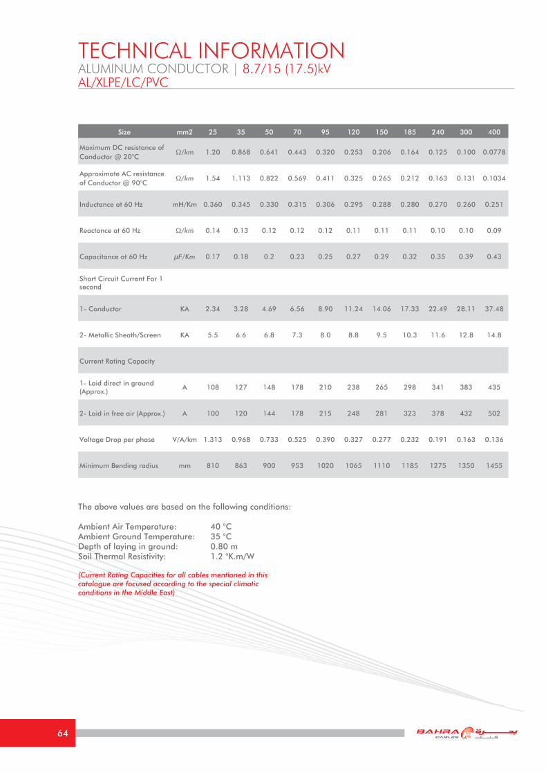
The above values are based on the following conditions: Ambient Air Temperature: 40 °CAmbient Ground Temperature: 35 °CDepth of laying in ground: 0.80 mSoil Thermal Resistivity: 1.2 °K.m/W
(Current Rating Capacities for all cables mentioned in this catalogue are focused according to the special climatic conditions in the Middle East)
TECHNICAL INFORMATIONALUMINUM CONDUCTOR | 8.7/15 (17.5)kVAL/XLPE/LC/PVC
Size mm2 25 35 50 70 95 120 150 185 240 300 400
Maximum DC resistance of Conductor @ 20°C
Ω/km 1.20 0.868 0.641 0.443 0.320 0.253 0.206 0.164 0.125 0.100 0.0778
Approximate AC resistance of Conductor @ 90°C
Ω/km 1.54 1.113 0.822 0.569 0.411 0.325 0.265 0.212 0.163 0.131 0.1034
Inductance at 60 Hz mH/Km 0.360 0.345 0.330 0.315 0.306 0.295 0.288 0.280 0.270 0.260 0.251
Reactance at 60 Hz Ω/km 0.14 0.13 0.12 0.12 0.12 0.11 0.11 0.11 0.10 0.10 0.09
Capacitance at 60 Hz μF/Km 0.17 0.18 0.2 0.23 0.25 0.27 0.29 0.32 0.35 0.39 0.43
Short Circuit Current For 1 second
1- Conductor KA 2.34 3.28 4.69 6.56 8.90 11.24 14.06 17.33 22.49 28.11 37.48
2- Metallic Sheath/Screen KA 5.5 6.6 6.8 7.3 8.0 8.8 9.5 10.3 11.6 12.8 14.8
Current Rating Capacity
1- Laid direct in ground (Approx.)
A 108 127 148 178 210 238 265 298 341 383 435
2- Laid in free air (Approx.) A 100 120 144 178 215 248 281 323 378 432 502
Voltage Drop per phase V/A/km 1.313 0.968 0.733 0.525 0.390 0.327 0.277 0.232 0.191 0.163 0.136
Minimum Bending radius mm 810 863 900 953 1020 1065 1110 1185 1275 1350 1455
64

Cable Code
Conductor Insulation Lead Sheath Outer Sheath Packaging
Cross Sectional
Area Nominal
mm2
DiameterNominal
mm
Thickness Nominal
mm
Thickness Nominal
mm
Thickness Nominal
mm
Overall Diameter
Approx.mm
Net Weight
Approx.Kg/Km
Standard Drum
m+/-5%
24760001 35 7.1 5.5 1.4 2.8 62 5900 500
24760002 50 7.9 5.5 1.5 2.9 65 6450 500
24760003 70 9.7 5.5 1.5 3.0 68.5 7000 500
24760004 95 11.3 5.5 1.6 3.1 72.5 8200 500
24760005 120 12.6 5.5 1.6 3.2 76 8800 500
24760006 150 14.1 5.5 1.6 3.3 80 9400 500
24760007 185 16.0 5.5 1.7 3.5 84.5 10600 400
24760008 240 18.1 5.5 1.7 3.6 90 12400 400
24760009 300 20.4 5.5 1.8 3.8 94.5 13500 400
24760010 400 23.1 5.5 1.9 4.1 102 15700 300
THREE CORE
ALUMINUM CONDUCTOR | 12/20 (24)kV
XLPE INSULATED, INDIVIDUAL LEAD SHEATHED & PVC SHEATHEDUNARMOURED CABLE AS PER IEC 60502-2
AL/XLPE/LC/PVC
PVC SheathingAluminum ConductorXLPE Insulation
Outer Semicon Inner SemiconLead Sheath
SemiconTape
65

The above values are based on the following conditions: Ambient Air Temperature: 40 °CAmbient Ground Temperature: 35 °CDepth of laying in ground: 0.80 mSoil Thermal Resistivity: 1.2 °K.m/W
(Current Rating Capacities for all cables mentioned in this catalogue are focused according to the special climatic conditions in the Middle East)
TECHNICAL INFORMATIONALUMINUM CONDUCTOR | 12/20 (24)kVAL/XLPE/LC/PVC
Size mm2 35 50 70 95 120 150 185 240 300 400
Maximum DC resistance of Conductor @ 20°C
Ω/km 0.868 0.641 0.443 0.320 0.253 0.206 0.164 0.125 0.100 0.0778
Approximate AC resistance of Conductor @ 90°C
Ω/km 1.113 0.822 0.569 0.411 0.325 0.265 0.212 0.163 0.131 0.1034
Inductance at 60 Hz mH/Km 0.365 0.350 0.333 0.322 0.312 0.303 0.295 0.285 0.270 0.262
Reactance at 60 Hz Ω/km 0.14 0.13 0.13 0.12 0.12 0.11 0.11 0.11 0.10 0.10
Capacitance at 60 Hz μF/Km 0.15 0.17 0.2 0.22 0.24 0.26 0.27 0.3 0.33 0.37
Short Circuit Current For 1 second
1- Conductor KA 3.28 4.69 6.56 8.90 11.24 14.06 17.33 22.49 28.11 37.48
2- Metallic Sheath/Screen KA 6.9 7.6 8.2 9.1 9.8 10.6 11.5 12.8 14.1 16.1
Current Rating Capacity
1- Laid direct in ground (Approx.)
A 127 148 178 210 238 265 298 341 383 435
2- Laid in free air (Approx.) A 120 144 178 215 248 281 323 378 432 502
Voltage Drop per phase V/A/km 1.320 0.973 0.737 0.530 0.402 0.331 0.281 0.236 0.194 0.165
Minimum Bending radius mm 930 975 1028 1088 1140 1200 1268 1350 1426 1530
66

Cable Code
Conductor Insulation Lead Sheath Outer Sheath Packaging
Cross Sectional
Area Nominal
mm2
DiameterNominal
mm
Thickness Nominal
mm
Thickness Nominal
mm
Thickness Nominal
mm
Overall Diameter
Approx.mm
Net Weight
Approx.Kg/Km
Standard Drum
m+/-5%
25850001 50 7.9 8.0 1.6 3.3 76.5 8700 500
25850002 70 9.7 8.0 1.7 3.4 81.5 9700 500
25850003 95 11.3 8.0 1.7 3.5 85 10550 400
25850004 120 12.6 8.0 1.7 3.6 88 11200 400
25850005 150 14.1 8.0 1.8 3.7 91 12300 400
25850006 185 16.0 8.0 1.8 3.9 95.5 13100 300
25850007 240 18.1 8.0 1.9 4.0 102 25100 300
25850008 300 20.4 8.0 2.0 4.2 107 15000 300
THREE CORE
ALUMINUM CONDUCTOR | 18/30 (36)kV
XLPE INSULATED, INDIVIDUAL LEAD SHEATHED & PVC SHEATHEDUNARMOURED CABLE AS PER IEC 60502-2
AL/XLPE/LC/PVC
PVC SheathingAluminum ConductorXLPE Insulation
Outer Semicon Inner SemiconLead Sheath
SemiconTape
67

The above values are based on the following conditions: Ambient Air Temperature: 40 °CAmbient Ground Temperature: 35 °CDepth of laying in ground: 0.80 mSoil Thermal Resistivity: 1.2 °K.m/W
(Current Rating Capacities for all cables mentioned in this catalogue are focused according to the special climatic conditions in the Middle East)
TECHNICAL INFORMATIONALUMINUM CONDUCTOR | 18/30 (36)kVAL/XLPE/LC/PVC
Size mm2 50 70 95 120 150 185 240 300
Maximum DC resistance of Conductor @ 20°C
Ω/km 0.641 0.443 0.320 0.253 0.206 0.164 0.125 0.100
Approximate AC resistance of Conductor @ 90°C
Ω/km 0.822 0.569 0.411 0.325 0.265 0.212 0.163 0.131
Inductance at 60 Hz mH/Km 0.398 0.380 0.369 0.355 0.345 0.335 0.320 0.308
Reactance at 60 Hz Ω/km 0.15 0.14 0.14 0.13 0.13 0.13 0.12 0.12
Capacitance at 60 Hz μF/Km 0.14 0.15 0.17 0.18 0.2 0.21 0.23 0.25
Short Circuit Current For 1 second
1- Conductor KA 4.69 6.56 8.90 11.24 14.06 17.33 22.49 28.11
2- Metallic Sheath/Screen KA 10.2 10.4 11.9 12.7 13.6 14.6 16.0 17.4
Current Rating Capacity
1- Laid direct in ground (Approx.) A 148 178 210 238 265 298 341 383
2- Laid in free air (Approx.) A 144 178 215 248 281 323 378 432
Voltage Drop per phase V/A/km 0.749 0.540 0.412 0.340 0.290 0.244 0.202 0.174
Minimum Bending radius mm 1140 1215 1275 1320 1380 1440 1515 1590
68

COPPER CONDUCTOR | 3.6/6 (7.2)kV
XLPE INSULATED, LEAD SHEATHED, ALUMINUM WIRE ARMOURED &PVC SHEATHED CABLE AS PER IEC 60502-2
CU/XLPE/LC/PVC/AWA/PVC
Cable Code
Conductor Insulation Lead Sheath Bedding Armouring Outer Sheath Packaging
Cross Sectional
Area Nominal
mm2
DiameterNominal
mm
Thickness Nominal
mm
Thickness Nominal
mm
Thickness Nominal
mm
Dia. Of Aluminum
wireNominal
mm
Thickness Nominal
mm
Overall Diameter
Approx.mm
Net Weight
Approx.Kg/Km
Standard Drum
m+/-5%
21700001 25 6.2 2.5 1.2 1.0 1.80 1.8 26.5 1600 1000
21700002 35 7.2 2.5 1.2 1.0 1.80 1.8 27.5 1750 1000
21700003 50 8.3 2.5 1.3 1.0 1.80 1.8 28.5 2030 1000
21700004 70 10 2.5 1.3 1.0 1.80 1.9 30.5 2380 1000
21700005 95 11.8 2.5 1.4 1.0 1.80 1.9 32.5 2850 1000
21700006 120 13.1 2.5 1.4 1.1 2.00 2.0 34.5 3270 1000
21700007 150 14.7 2.5 1.5 1.1 2.00 2.1 37.0 3770 1000
21700008 185 16.1 2.5 1.5 1.1 2.00 2.1 38.5 4240 1000
21700009 240 18.7 2.6 1.6 1.2 2.00 2.2 42.0 5150 1000
21700010 300 20.8 2.8 1.6 1.2 2.00 2.3 45.0 5950 500
21700011 400 24 3.0 1.7 1.3 2.50 2.5 49.5 7480 500
21700012 500 27 3.2 1.8 1.4 2.50 2.6 54.5 8700 500
21700013 630 30.8 3.2 1.9 1.4 2.50 2.7 59.0 11170 500
SINGLE CORE
PVC SheathingCopper ConductorXLPE Insulation
Outer Semicon Inner SemiconLead SheathAluminum Wire Armoured Bedding
69

TECHNICAL INFORMATIONCOPPER CONDUCTOR | 3.6/6 (7.2)kVCU/XLPE/LC/PVC/AWA/PVC
The above values are based on the following conditions: Ambient Air Temperature: 40 °CAmbient Ground Temperature: 35 °CDepth of laying in ground: 0.80 mSoil Thermal Resistivity: 1.2 °K.m/W
(Current Rating Capacities for all cables mentioned in this catalogue are focused according to the special climatic conditions in the Middle East)
Size mm2 25 35 50 70 95 120 150 185 240 300 400 500 630
Maximum DC resistance of Conductor @ 20°C
Ω/km 0.727 0.524 0.387 0.268 0.193 0.153 0.124 0.0991 0.0754 0.0601 0.0470 0.0366 0.0283
Approximate AC resistance of Conductor @ 90°C
Ω/km 0.927 0.668 0.494 0.342 0.247 0.196 0.160 0.129 0.099 0.0804 0.0647 0.0527 0.0434
Inductance at 60 HzmH/
Km0.472 0.461 0.440 0.417 0.405 0.392 0.379 0.370 0.355 0.346 0.3335 0.328 0.315
Reactance at 60 Hz Ω/km 0.18 0.17 0.17 0.16 0.15 0.15 0.14 0.14 0.13 0.13 0.13 0.12 0.12
Capacitance at 60 Hz μF/Km 0.25 0.28 0.31 0.35 0.39 0.43 0.47 0.52 0.56 0.58 0.60 0.63 0.75
Short Circuit Current For 1 second
1- Conductor KA 3.58 5.01 7.15 10.01 13.59 17.16 21.45 26.46 34.32 42.90 57.20 71.50 90.09
2- Metallic Sheath/Screen
KA 1.3 1.5 1.6 1.8 2.1 2.3 2.5 2.7 3.1 3.6 4.3 4.9 5.6
Current Rating Capacity
1- Laid direct in ground
Trefoil Formation (Approx.)
A 153 175 211 250 274 315 370 415 470 530 595 680 740
Flat Formation(Approx.)
A 157 181 218 258 282 323 378 420 473 525 550 640 685
2- Laid in free air
Trefoil Formation (Approx.)
A 163 205 245 269 329 379 430 494 583 669 769 860 1000
Flat Formation(Approx.)
A 178 217 260 324 395 455 509 580 678 770 854 895 1035
Voltage Drop per phase
V/A/
km0.850 0.641 0.492 0.365 0.289 0.246 0.215 0.185 0.159 0.140 0.127 0.115 0.107
Minimum Bending radius
mm 530 550 570 610 650 690 740 770 840 900 990 1090 1180
70

COPPER CONDUCTOR | 6/10 (12)kV
XLPE INSULATED, LEAD SHEATHED, ALUMINUM WIRE ARMOURED &PVC SHEATHED CABLE AS PER IEC 60502-2
CU/XLPE/LC/PVC/AWA/PVC
Cable Code
Conductor Insulation Lead Sheath Bedding Armouring Outer Sheath Packaging
Cross Sectional
Area Nominal
mm2
DiameterNominal
mm
Thickness Nominal
mm
Thickness Nominal
mm
Thickness Nominal
mm
Dia. Of Aluminum
wireNominal
mm
Thickness Nominal
mm
Overall Diameter
Approx.mm
Net Weight
Approx.Kg/Km
Standard Drum
m+/-5%
22700001 25 6.2 3.4 1.3 1.0 1.80 1.8 28.5 1800 1000
22700002 35 7.2 3.4 1.3 1.0 1.80 1.8 29.5 1990 1000
22700003 50 8.3 3.4 1.3 1.0 1.80 1.9 30.5 2200 1000
22700004 70 10 3.4 1.4 1.0 1.80 2.0 32.5 2630 1000
22700005 95 11.8 3.4 1.4 1.1 2.00 2.0 35.0 3080 1000
22700006 120 13.1 3.4 1.5 1.1 2.00 2.1 36.5 3550 1000
22700007 150 14.7 3.4 1.5 1.1 2.00 2.2 38.0 3940 1000
22700008 185 16.1 3.4 1.6 1.2 2.00 2.2 40.5 4580 1000
22700009 240 18.7 3.4 1.6 1.2 2.00 2.3 43.5 5400 1000
22700010 300 20.8 3.4 1.7 1.3 2.50 2.4 47.0 6500 500
22700011 400 24 3.4 1.8 1.3 2.50 2.5 51.0 7830 500
22700012 500 27 3.4 1.9 1.4 2.50 2.6 55.5 9300 500
22700013 630 30.8 3.4 1.9 1.4 2.50 2.7 60.0 11670 400
SINGLE CORE
PVC SheathingCopper ConductorXLPE Insulation
Outer Semicon Inner SemiconLead SheathAluminum Wire Armoured Bedding
71

TECHNICAL INFORMATIONCOPPER CONDUCTOR | 6/10 (12)kVCU/XLPE/LC/PVC/AWA/PVC
The above values are based on the following conditions: Ambient Air Temperature: 40 °CAmbient Ground Temperature: 35 °CDepth of laying in ground: 0.80 mSoil Thermal Resistivity: 1.2 °K.m/W
(Current Rating Capacities for all cables mentioned in this catalogue are focused according to the special climatic conditions in the Middle East)
Size mm2 25 35 50 70 95 120 150 185 240 300 400 500 630
Maximum DC resistance of Conductor @ 20°C
Ω/km 0.727 0.524 0.387 0.268 0.193 0.153 0.124 0.0991 0.0754 0.0601 0.0470 0.0366 0.0283
Approximate AC resistance of Conductor @ 90°C
Ω/km 0.927 0.668 0.494 0.342 0.247 0.196 0.160 0.129 0.099 0.0804 0.0647 0.0527 0.0434
Inductance at 60 HzmH/
Km0.489 0.472 0.450 0.429 0.415 0.401 0.390 0.378 0.364 0.352 0.338 0.328 0.317
Reactance at 60 Hz Ω/km 0.18 0.18 0.17 0.16 0.16 0.15 0.15 0.14 0.14 0.13 0.13 0.12 0.12
Capacitance at 60 Hz μF/Km 0.20 0.23 0.25 0.29 0.30 0.33 0.37 0.40 0.45 0.49 0.54 0.60 0.70
Short Circuit Current For 1 second
1- Conductor KA 3.58 5.01 7.15 10.01 13.59 17.16 21.45 26.46 34.32 42.90 57.20 71.50 90.09
2- Metallic Sheath/Screen
KA 1.5 1.7 1.9 2.1 2.3 2.6 2.8 3.0 3.4 3.8 4.5 5.0 5.7
Current Rating Capacity
1- Laid direct in ground
Trefoil Formation (Approx.)
A 153 175 211 250 274 315 370 415 470 530 595 680 740
Flat Formation(Approx.)
A 157 181 218 258 282 323 378 420 473 525 550 640 685
2- Laid in free air
Trefoil Formation (Approx.)
A 163 205 245 269 329 379 430 494 583 669 769 860 1000
Flat Formation(Approx.)
A 178 217 260 324 395 455 509 580 678 770 854 895 1035
Voltage Drop per phase
V/A/
km0.851 0.641 0.495 0.370 0.292 0.248 0.215 0.187 0.160 0.142 0.125 0.117 0.106
Minimum Bending radius
mm 570 590 610 650 700 730 760 810 870 940 1020 1110 1200
72

COPPER CONDUCTOR | 8.7/15 (17.5)kV
XLPE INSULATED, LEAD SHEATHED, ALUMINUM WIRE ARMOURED &PVC SHEATHED CABLE AS PER IEC 60502-2
CU/XLPE/LC/PVC/AWA/PVC
Cable Code
Conductor Insulation Lead Sheath Bedding Armouring Outer Sheath Packaging
Cross Sectional
Area Nominal
mm2
DiameterNominal
mm
Thickness Nominal
mm
Thickness Nominal
mm
Thickness Nominal
mm
Dia. Of Aluminum
wireNominal
mm
Thickness Nominal
mm
Overall Diameter
Approx.mm
Net Weight
Approx.Kg/Km
Standard Drum
m+/-5%
23700001 25 6.2 4.5 1.3 1.0 1.80 1.9 30.5 2060 1000
23700002 35 7.2 4.5 1.4 1.0 1.80 1.9 32.5 2330 1000
23700003 50 8.3 4.5 1.4 1.1 1.80 2.0 33.5 2580 1000
23700004 70 10 4.5 1.4 1.1 2.00 2.1 35.5 2990 1000
23700005 95 11.8 4.5 1.5 1.1 2.00 2.1 37.5 3500 1000
23700006 120 13.1 4.5 1.5 1.1 2.00 2.2 39.0 3870 1000
23700007 150 14.7 4.5 1.6 1.2 2.00 2.2 41.5 4400 1000
23700008 185 16.1 4.5 1.6 1.2 2.00 2.3 44.5 4900 1000
23700009 240 18.7 4.5 1.7 1.3 2.50 2.4 47.0 6000 500
23700010 300 20.8 4.5 1.7 1.3 2.50 2.5 50.0 6800 500
23700011 400 24 4.5 1.8 1.4 2.50 2.6 53.0 8170 500
23700012 500 27 4.5 1.9 1.4 2.50 2.7 57.0 9340 500
23700013 630 30.8 4.5 2.0 1.5 2.50 2.8 62.0 11880 500
SINGLE CORE
PVC SheathingCopper ConductorXLPE Insulation
Outer Semicon Inner SemiconLead SheathAluminum Wire Armoured Bedding
73

TECHNICAL INFORMATIONCOPPER CONDUCTOR | 8.7/15 (17.5)kVCU/XLPE/LC/PVC/AWA/PVC
The above values are based on the following conditions: Ambient Air Temperature: 40 °CAmbient Ground Temperature: 35 °CDepth of laying in ground: 0.80 mSoil Thermal Resistivity: 1.2 °K.m/W
(Current Rating Capacities for all cables mentioned in this catalogue are focused according to the special climatic conditions in the Middle East)
Size mm2 25 35 50 70 95 120 150 185 240 300 400 500 630
Maximum DC resistance of Conductor @ 20°C
Ω/km 0.727 0.524 0.387 0.268 0.193 0.153 0.124 0.0991 0.0754 0.0601 0.0470 0.0366 0.0283
Approximate AC resistance of Conductor @ 90°C
Ω/km 0.927 0.668 0.494 0.342 0.247 0.196 0.160 0.129 0.099 0.0804 0.0647 0.0527 0.0434
Inductance at 60 HzmH/
Km0.504 0.485 0.463 0.440 0.428 0.414 0.400 0.389 0.374 0.361 0.345 0.338 0.325
Reactance at 60 Hz Ω/km 0.19 0.18 0.17 0.17 0.16 0.16 0.15 0.15 0.14 0.14 0.13 0.13 0.12
Capacitance at 60 Hz μF/Km 0.17 0.18 0.20 0.23 0.25 0.27 0.29 0.32 0.35 0.39 0.43 0.48 0.53
Short Circuit Current For 1 second
1- Conductor KA 3.58 5.01 7.15 10.01 13.59 17.16 21.45 26.46 34.32 42.90 57.20 71.50 90.09
2- Metallic Sheath/Screen
KA 1.8 2.0 2.2 2.4 2.7 2.9 3.2 3.4 3.9 4.3 4.9 5.5 6.2
Current Rating Capacity
1- Laid direct in ground
Trefoil Formation (Approx.)
A 153 175 211 250 274 315 370 415 470 530 595 680 740
Flat Formation(Approx.)
A 157 181 218 258 282 323 378 420 473 525 550 640 685
2- Laid in free air
Trefoil Formation (Approx.)
A 163 205 245 269 329 379 430 494 583 669 769 860 1000
Flat Formation(Approx.)
A 178 217 260 324 395 455 509 580 678 770 854 895 1035
Voltage Drop per phase
V/A/
km0.855 0.645 0.500 0.374 0.295 0.250 0.220 0.190 0.163 0.145 0.130 0.119 0.108
Minimum Bending radius
mm 610 650 670 710 750 780 830 890 940 1000 1060 1140 1240
74

COPPER CONDUCTOR | 12/20 (24)kV
XLPE INSULATED, LEAD SHEATHED, ALUMINUM WIRE ARMOURED &PVC SHEATHED CABLE AS PER IEC 60502-2
CU/XLPE/LC/PVC/AWA/PVC
Cable Code
Conductor Insulation Lead Sheath Bedding Armouring Outer Sheath Packaging
Cross Sectional
Area Nominal
mm2
DiameterNominal
mm
Thickness Nominal
mm
Thickness Nominal
mm
Thickness Nominal
mm
Dia. Of Aluminum
wireNominal
mm
Thickness Nominal
mm
Overall Diameter
Approx.mm
Net Weight
Approx.Kg/Km
Standard Drum
m+/-5%
24700001 35 7.2 5.5 1.4 1.1 2.00 2.0 35.0 2600 1000
24700002 50 8.3 5.5 1.5 1.1 2.00 2.1 36.0 2940 1000
24700003 70 10 5.5 1.5 1.1 2.00 2.1 38.0 3280 1000
24700004 95 11.8 5.5 1.6 1.2 2.00 2.2 40.0 3850 1000
24700005 120 13.1 5.5 1.6 1.2 2.00 2.3 42.0 4240 1000
24700006 150 14.7 5.5 1.6 1.2 2.00 2.3 43.5 4380 1000
24700007 185 16.1 5.5 1.7 1.3 2.50 2.4 46.5 5490 1000
24700008 240 18.7 5.5 1.7 1.3 2.50 2.5 49.5 6320 500
24700009 300 20.8 5.5 1.8 1.3 2.50 2.6 52.0 7320 500
24700010 400 24 5.5 1.9 1.4 2.50 2.7 57.0 8720 500
24700011 500 27 5.5 2.0 1.5 2.50 2.8 60.5 10400 500
24700012 630 30.8 5.5 2.1 1.5 2.50 2.9 65.0 12450 400
SINGLE CORE
PVC SheathingCopper ConductorXLPE Insulation
Outer Semicon Inner SemiconLead SheathAluminum Wire Armoured Bedding
75

TECHNICAL INFORMATIONCOPPER CONDUCTOR | 12/20 (24)kVCU/XLPE/LC/PVC/AWA/PVC
The above values are based on the following conditions: Ambient Air Temperature: 40 °CAmbient Ground Temperature: 35 °CDepth of laying in ground: 0.80 mSoil Thermal Resistivity: 1.2 °K.m/W
(Current Rating Capacities for all cables mentioned in this catalogue are focused according to the special climatic conditions in the Middle East)
Size mm2 35 50 70 95 120 150 185 240 300 400 500 630
Maximum DC resistance of Conductor @ 20°C
Ω/km 0.524 0.387 0.268 0.193 0.153 0.124 0.0991 0.0754 0.0601 0.0470 0.0366 0.0283
Approximate AC resistance of Conductor @ 90°C
Ω/km 0.668 0.494 0.342 0.247 0.196 0.160 0.129 0.099 0.0804 0.0647 0.0527 0.0434
Inductance at 60 HzmH/
Km0.495 0.474 0.452 0.438 0.423 0.412 0.398 0.393 0.371 0.356 0.346 0.334
Reactance at 60 Hz Ω/km 0.19 0.18 0.17 0.17 0.16 0.16 0.15 0.15 0.14 0.13 0.13 0.13
Capacitance at 60 Hz μF/Km 0.15 0.17 0.20 0.22 0.24 0.26 0.27 0.30 0.33 0.37 0.41 0.46
Short Circuit Current For 1 second
1- Conductor KA 5.01 7.15 10.01 13.59 17.16 21.45 26.46 34.32 42.90 57.20 71.50 90.09
2- Metallic Sheath/Screen
KA 2.3 2.5 2.7 3.0 3.3 3.5 3.8 4.3 4.7 5.4 6.0 6.7
Current Rating Capacity
1- Laid direct in ground
Trefoil Formation (Approx.)
A 175 211 250 274 315 370 415 470 530 595 680 740
Flat Formation(Approx.)
A 181 218 258 282 323 378 420 473 525 550 640 685
2- Laid in free air
Trefoil Formation (Approx.)
A 205 245 269 329 379 430 494 583 669 769 860 1000
Flat Formation(Approx.)
A 217 260 324 395 455 509 580 678 770 854 895 1035
Voltage Drop per phase
V/A/
km0.645 0.500 0.377 0.300 0.254 0.221 0.192 0.165 0.148 0.133 0.120 0.112
Minimum Bending radius
mm 700 720 760 800 840 870 930 990 1040 11400 1210 1300
76

COPPER CONDUCTOR | 18/30 (36)kV
XLPE INSULATED, LEAD SHEATHED, ALUMINUM WIRE ARMOURED &PVC SHEATHED CABLE AS PER IEC 60502-2
CU/XLPE/LC/PVC/AWA/PVC
Cable Code
Conductor Insulation Lead Sheath Bedding Armouring Outer Sheath Packaging
Cross Sectional
Area Nominal
mm2
DiameterNominal
mm
Thickness Nominal
mm
Thickness Nominal
mm
Thickness Nominal
mm
Dia. Of Aluminum
wireNominal
mm
Thickness Nominal
mm
Overall Diameter
Approx.mm
Net Weight
Approx.Kg/Km
Standard Drum
m+/-5%
25700001 50 8.3 8.0 1.6 1.2 2.00 2.3 42.5 3750 1000
25700002 70 10 8.0 1.7 1.2 2.00 2.3 44.0 4250 1000
25700003 95 11.8 8.0 1.7 1.3 2.50 2.4 47.0 4870 1000
25700004 120 13.1 8.0 1.7 1.3 2.50 2.5 49.0 5280 1000
25700005 150 14.7 8.0 1.8 1.3 2.50 2.5 50.5 5860 500
25700006 185 16.1 8.0 1.8 1.4 2.50 2.6 52.5 6440 500
25700007 240 18.7 8.0 1.9 1.4 2.50 2.7 55.5 7480 500
25700008 300 20.8 8.0 2.0 1.4 2.50 2.8 58.0 8560 500
25700009 400 24 8.0 2.0 1.5 2.50 2.9 62.5 9990 500
25700010 500 27 8.0 2.1 1.6 2.50 3.0 66.5 11600 500
25700011 630 30.8 8.0 2.2 1.6 2.50 3.1 70.5 13700 500
SINGLE CORE
PVC SheathingCopper ConductorXLPE Insulation
Outer Semicon Inner SemiconLead SheathAluminum Wire Armoured Bedding
77

TECHNICAL INFORMATIONCOPPER CONDUCTOR | 18/30 (36)kVCU/XLPE/LC/PVC/AWA/PVC
The above values are based on the following conditions: Ambient Air Temperature: 40 °CAmbient Ground Temperature: 35 °CDepth of laying in ground: 0.80 mSoil Thermal Resistivity: 1.2 °K.m/W
(Current Rating Capacities for all cables mentioned in this catalogue are focused according to the special climatic conditions in the Middle East)
Size mm2 50 70 95 120 150 185 240 300 400 500 630
Maximum DC resistance of Conductor @ 20°C
Ω/km 0.387 0.268 0.193 0.153 0.124 0.0991 0.0754 0.0601 0.0470 0.0366 0.0283
Approximate AC resistance of Conductor @ 90°C
Ω/km 0.494 0.342 0.247 0.196 0.160 0.129 0.099 0.0804 0.0647 0.0527 0.0434
Inductance at 60 HzmH/
Km0.505 0.481 0.467 0.450 0.438 0.425 0.408 0.395 0.378 0.368 0.358
Reactance at 60 Hz Ω/km 0.19 0.18 0.18 0.17 0.17 0.16 0.15 0.15 0.14 0.14 0.13
Capacitance at 60 Hz μF/Km 0.14 0.15 0.17 0.18 0.20 0.21 0.23 0.25 0.27 0.30 0.34
Short Circuit Current For 1 second
1- Conductor KA 7.15 10.01 13.59 17.16 21.45 26.46 34.32 42.90 57.20 71.50 90.09
2- Metallic Sheath/Screen
KA 3.4 3.6 4.0 4.2 4.5 4.9 5.3 5.8 6.6 7.2 8.1
Current Rating Capacity
1- Laid direct in ground
Trefoil Formation (Approx.)
A 211 250 274 315 370 415 470 530 595 680 740
Flat Formation(Approx.)
A 218 258 282 323 378 420 473 525 550 640 685
2- Laid in free air
Trefoil Formation (Approx.)
A 245 269 329 379 430 494 583 669 769 860 1000
Flat Formation(Approx.)
A 260 324 395 455 509 580 678 770 854 895 1035
Voltage Drop per phase
V/A/
km0.509 0.383 0.305 0.260 0.228 0.198 0.171 0.153 0.137 0.125 0.116
Minimum Bending radius
mm 850 880 940 980 1010 1050 1110 1160 1250 1330 1410
78

ALUMINUM CONDUCTOR | 3.6/6 (7.2)kV
XLPE INSULATED, LEAD SHEATHED, ALUMINUM WIRE ARMOURED &PVC SHEATHED CABLE AS PER IEC 60502-2
Cable Code
Conductor Insulation Lead Sheath Bedding Armouring Outer Sheath Packaging
Cross Sectional
Area Nominal
mm2
DiameterNominal
mm
Thickness Nominal
mm
Thickness Nominal
mm
Thickness Nominal
mm
Dia. Of Aluminum
wireNominal
mm
Thickness Nominal
mm
Overall Diameter
Approx.mm
Net Weight
Approx.Kg/Km
Standard Drum
m+/-5%
21840001 25 5.7 2.5 1.2 1.0 1.80 1.8 26.0 1430 1000
21840002 35 7.1 2.5 1.2 1.0 1.80 1.8 27.0 1540 1000
21840003 50 7.9 2.5 1.3 1.0 1.80 1.8 28.0 1740 1000
21840004 70 9.7 2.5 1.3 1.0 1.80 1.9 30.0 1960 1000
21840005 95 11.3 2.5 1.4 1.0 1.80 1.9 32.0 2270 1000
21840006 120 12.6 2.5 1.4 1.1 2.00 2.0 34.0 2520 1000
21840007 150 14.1 2.5 1.5 1.1 2.00 2.1 36.5 2870 1000
21840008 185 16.0 2.5 1.5 1.1 2.00 2.1 38.0 3100 1000
21840009 240 18.1 2.6 1.6 1.2 2.00 2.2 41.5 3680 1000
21840010 300 20.4 2.8 1.6 1.2 2.00 2.3 44.5 4100 1000
21840011 400 23.1 3.0 1.7 1.3 2.50 2.5 48.5 5070 1000
21840012 500 25.9 3.2 1.8 1.4 2.50 2.6 53.5 5900 500
21840013 630 29.5 3.2 1.9 1.4 2.50 2.7 58.0 7600 500
SINGLE CORE
AL/XLPE/LC/PVC/AWA/PVC
PVC SheathingAluminum ConductorXLPE Insulation
Outer Semicon Inner SemiconLead SheathAluminum Wire Armoured Bedding
79

TECHNICAL INFORMATIONALUMINUM CONDUCTOR | 3.6/6 (7.2)kV
The above values are based on the following conditions: Ambient Air Temperature: 40 °CAmbient Ground Temperature: 35 °CDepth of laying in ground: 0.80 mSoil Thermal Resistivity: 1.2 °K.m/W
(Current Rating Capacities for all cables mentioned in this catalogue are focused according to the special climatic conditions in the Middle East)
Size mm2 25 35 50 70 95 120 150 185 240 300 400 500 630
Maximum DC resistance of Conductor @ 20°C
Ω/km 1.20 0.868 0.641 0.443 0.320 0.253 0.206 0.164 0.125 0.100 0.0778 0.0605 0.0469
Approximate AC resistance of Conductor @ 90°C
Ω/km 1.54 1.113 0.822 0.568 0.411 0.326 0.265 0.211 0.161 0.130 0.1016 0.0799 0.0632
Inductance at 60 HzmH/
Km0.472 0.461 0.440 0.417 0.405 0.392 0.379 0.370 0.355 0.346 0.3335 0.328 0.315
Reactance at 60 Hz Ω/km 0.18 0.17 0.17 0.16 0.15 0.15 0.14 0.14 0.13 0.13 0.13 0.12 0.12
Capacitance at 60 Hz μF/Km 0.25 0.28 0.31 0.35 0.39 0.43 0.47 0.52 0.56 0.58 0.60 0.63 0.75
Short Circuit Current For 1 second
1- Conductor KA 2.34 3.28 4.69 6.56 8.90 11.24 14.06 17.33 22.49 28.11 37.48 46.85 59.03
2- Metallic Sheath/Screen
KA 1.3 1.5 1.6 1.8 2.1 2.3 2.5 2.7 3.1 3.6 4.3 4.9 5.6
Current Rating Capacity
1- Laid direct in ground
Trefoil Formation (Approx.)
A 100 120 135 165 200 230 260 293 330 370 415 520 750
Flat Formation(Approx.)
A 105 125 140 170 210 240 270 303 341 379 400 500 690
2- Laid in free air
Trefoil Formation (Approx.)
A 116 140 167 209 255 295 335 386 457 525 612 705 800
Flat Formation(Approx.)
A 139 168 202 253 308 356 400 459 540 616 700 790 885
Voltage Drop per phase
V/A/
km1.338 0.995 0.758 0.549 0.421 0.349 0.298 0.252 0.210 0.182 0.157 0.138 0.122
Minimum Bending radius
mm 520 540 560 600 640 680 730 760 830 890 970 1070 1160
AL/XLPE/LC/PVC/AWA/PVC
80
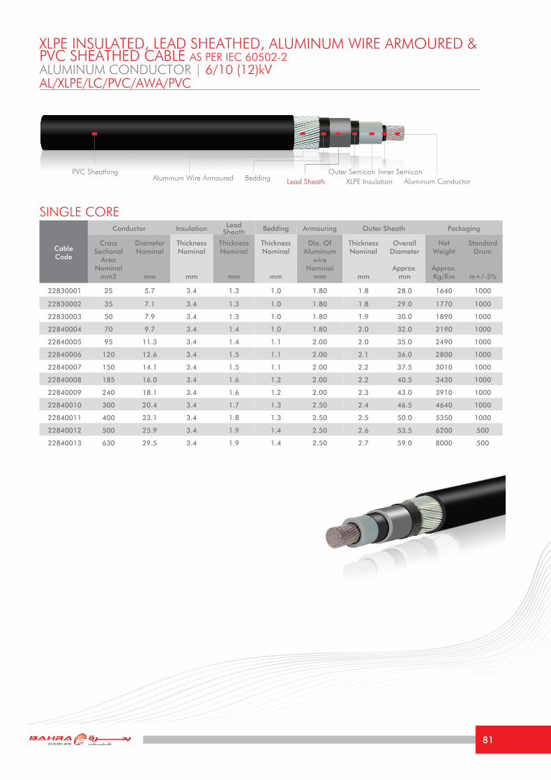
ALUMINUM CONDUCTOR | 6/10 (12)kV
XLPE INSULATED, LEAD SHEATHED, ALUMINUM WIRE ARMOURED &PVC SHEATHED CABLE AS PER IEC 60502-2
Cable Code
Conductor Insulation Lead Sheath Bedding Armouring Outer Sheath Packaging
Cross Sectional
Area Nominal
mm2
DiameterNominal
mm
Thickness Nominal
mm
Thickness Nominal
mm
Thickness Nominal
mm
Dia. Of Aluminum
wireNominal
mm
Thickness Nominal
mm
Overall Diameter
Approx.mm
Net Weight
Approx.Kg/Km
Standard Drum
m+/-5%
22830001 25 5.7 3.4 1.3 1.0 1.80 1.8 28.0 1640 1000
22830002 35 7.1 3.4 1.3 1.0 1.80 1.8 29.0 1770 1000
22830003 50 7.9 3.4 1.3 1.0 1.80 1.9 30.0 1890 1000
22840004 70 9.7 3.4 1.4 1.0 1.80 2.0 32.0 2190 1000
22840005 95 11.3 3.4 1.4 1.1 2.00 2.0 35.0 2490 1000
22840006 120 12.6 3.4 1.5 1.1 2.00 2.1 36.0 2800 1000
22840007 150 14.1 3.4 1.5 1.1 2.00 2.2 37.5 3010 1000
22840008 185 16.0 3.4 1.6 1.2 2.00 2.2 40.5 3430 1000
22840009 240 18.1 3.4 1.6 1.2 2.00 2.3 43.0 3910 1000
22840010 300 20.4 3.4 1.7 1.3 2.50 2.4 46.5 4640 1000
22840011 400 23.1 3.4 1.8 1.3 2.50 2.5 50.0 5350 1000
22840012 500 25.9 3.4 1.9 1.4 2.50 2.6 53.5 6200 500
22840013 630 29.5 3.4 1.9 1.4 2.50 2.7 59.0 8000 500
SINGLE CORE
AL/XLPE/LC/PVC/AWA/PVC
PVC SheathingAluminum ConductorXLPE Insulation
Outer Semicon Inner SemiconLead SheathAluminum Wire Armoured Bedding
81

TECHNICAL INFORMATIONALUMINUM CONDUCTOR | 6/10 (12)kV
The above values are based on the following conditions: Ambient Air Temperature: 40 °CAmbient Ground Temperature: 35 °CDepth of laying in ground: 0.80 mSoil Thermal Resistivity: 1.2 °K.m/W
(Current Rating Capacities for all cables mentioned in this catalogue are focused according to the special climatic conditions in the Middle East)
Size mm2 25 35 50 70 95 120 150 185 240 300 400 500 630
Maximum DC resistance of Conductor @ 20°C
Ω/km 1.20 0.868 0.641 0.443 0.320 0.253 0.206 0.164 0.125 0.100 0.0778 0.0605 0.0469
Approximate AC resistance of Conductor @ 90°C
Ω/km 1.54 1.113 0.822 0.568 0.411 0.326 0.265 0.211 0.161 0.130 0.1016 0.0799 0.0632
Inductance at 60 HzmH/
Km0.489 0.472 0.450 0.429 0.415 0.401 0.390 0.378 0.364 0.352 0.338 0.328 0.317
Reactance at 60 Hz Ω/km 0.18 0.18 0.17 0.16 0.16 0.15 0.15 0.14 0.14 0.13 0.13 0.12 0.12
Capacitance at 60 Hz μF/Km 0.20 0.23 0.25 0.29 0.30 0.33 0.37 0.40 0.45 0.49 0.54 0.60 0.70
Short Circuit Current For 1 second
1- Conductor KA 2.34 3.28 4.69 6.56 8.90 11.24 14.06 17.33 22.49 28.11 37.48 46.85 59.03
2- Metallic Sheath/Screen
KA 1.5 1.7 1.9 2.1 2.3 2.6 2.8 3.0 3.4 3.8 4.5 5.0 5.7
Current Rating Capacity
1- Laid direct in ground
Trefoil Formation (Approx.)
A 100 120 135 165 200 230 260 293 330 370 415 520 750
Flat Formation(Approx.)
A 105 125 140 170 210 240 270 303 341 379 400 500 690
2- Laid in free air
Trefoil Formation (Approx.)
A 116 140 167 209 255 295 335 386 457 525 612 705 800
Flat Formation(Approx.)
A 139 168 202 253 308 356 400 459 540 616 700 790 885
Voltage Drop per phase
V/A/
km1.343 0.997 0.761 0.551 0.423 0.351 0.300 0.254 0.212 0.183 0.158 0.139 0.123
Minimum Bending radius
mm 560 580 600 640 700 720 750 810 860 930 1000 1070 1180
AL/XLPE/LC/PVC/AWA/PVC
82

ALUMINUM CONDUCTOR | 8.7/15 (17.5)kV
XLPE INSULATED, LEAD SHEATHED, ALUMINUM WIRE ARMOURED &PVC SHEATHED CABLE AS PER IEC 60502-2
Cable Code
Conductor Insulation Lead Sheath Bedding Armouring Outer Sheath Packaging
Cross Sectional
Area Nominal
mm2
DiameterNominal
mm
Thickness Nominal
mm
Thickness Nominal
mm
Thickness Nominal
mm
Dia. Of Aluminum
wireNominal
mm
Thickness Nominal
mm
Overall Diameter
Approx.mm
Net Weight
Approx.Kg/Km
Standard Drum
m+/-5%
23840001 25 5.7 4.5 1.3 1.0 1.80 1.9 30.0 1900 1000
23840002 35 7.1 4.5 1.4 1.0 1.80 1.9 32.0 2100 1000
23840003 50 7.9 4.5 1.4 1.1 1.80 2.0 33.0 2280 1000
23840004 70 9.7 4.5 1.4 1.1 2.00 2.1 35.0 2560 1000
23840005 95 11.3 4.5 1.5 1.1 2.00 2.1 37.0 2910 1000
23840006 120 12.6 4.5 1.5 1.1 2.00 2.2 38.5 3140 1000
23840007 150 14.1 4.5 1.6 1.2 2.00 2.2 41.0 3520 1000
23840008 185 16.0 4.5 1.6 1.2 2.00 2.3 44.0 3780 1000
23840009 240 18.1 4.5 1.7 1.3 2.50 2.4 46.5 4500 1000
23840010 300 20.4 4.5 1.7 1.3 2.50 2.5 49.5 4960 1000
23840011 400 23.1 4.5 1.8 1.4 2.50 2.6 52.0 5770 500
23840012 500 25.9 4.5 1.9 1.4 2.50 2.7 56.0 6500 500
23840013 630 29.5 4.5 2.0 1.5 2.50 2.8 61.0 8300 500
SINGLE CORE
AL/XLPE/LC/PVC/AWA/PVC
PVC SheathingAluminum ConductorXLPE Insulation
Outer Semicon Inner SemiconLead SheathAluminum Wire Armoured Bedding
83

TECHNICAL INFORMATIONALUMINUM CONDUCTOR | 8.7/15 (17.5)kV
The above values are based on the following conditions: Ambient Air Temperature: 40 °CAmbient Ground Temperature: 35 °CDepth of laying in ground: 0.80 mSoil Thermal Resistivity: 1.2 °K.m/W
(Current Rating Capacities for all cables mentioned in this catalogue are focused according to the special climatic conditions in the Middle East)
Size mm2 25 35 50 70 95 120 150 185 240 300 400 500 630
Maximum DC resistance of Conductor @ 20°C
Ω/km 1.20 0.868 0.641 0.443 0.320 0.253 0.206 0.164 0.125 0.100 0.0778 0.0605 0.0469
Approximate AC resistance of Conductor @ 90°C
Ω/km 1.54 1.113 0.822 0.568 0.411 0.326 0.265 0.211 0.161 0.130 0.1016 0.0799 0.0632
Inductance at 60 HzmH/
Km0.504 0.485 0.463 0.440 0.428 0.414 0.400 0.389 0.374 0.361 0.345 0.338 0.325
Reactance at 60 Hz Ω/km 0.19 0.18 0.17 0.17 0.16 0.16 0.15 0.15 0.14 0.14 0.13 0.13 0.12
Capacitance at 60 Hz μF/Km 0.17 0.18 0.20 0.23 0.25 0.27 0.29 0.32 0.35 0.39 0.43 0.48 0.53
Short Circuit Current For 1 second
1- Conductor KA 2.34 3.28 4.69 6.56 8.90 11.24 14.06 17.33 22.49 28.11 37.48 46.85 59.03
2- Metallic Sheath/Screen
KA 1.8 2.0 2.2 2.4 2.7 2.9 3.2 3.4 3.9 4.3 4.9 5.5 6.2
Current Rating Capacity
1- Laid direct in ground
Trefoil Formation (Approx.)
A 100 120 135 165 200 230 260 293 330 370 415 520 750
Flat Formation(Approx.)
A 105 125 140 170 210 240 270 303 341 379 400 500 690
2- Laid in free air
Trefoil Formation (Approx.)
A 116 140 167 209 255 295 335 386 457 525 612 705 800
Flat Formation(Approx.)
A 139 168 202 253 308 356 400 459 540 616 700 790 885
Voltage Drop per phase
V/A/
km1.345 1.001 0.765 0.554 0.426 0.353 0.303 0.257 0.214 0.186 0.160 0.141 0.125
Minimum Bending radius
mm 600 640 660 700 740 770 820 880 930 990 1040 1120 1220
AL/XLPE/LC/PVC/AWA/PVC
84

ALUMINUM CONDUCTOR | 12/20 (24)kV
XLPE INSULATED, LEAD SHEATHED, ALUMINUM WIRE ARMOURED &PVC SHEATHED CABLE AS PER IEC 60502-2
Cable Code
Conductor Insulation Lead Sheath Bedding Armouring Outer Sheath Packaging
Cross Sectional
Area Nominal
mm2
DiameterNominal
mm
Thickness Nominal
mm
Thickness Nominal
mm
Thickness Nominal
mm
Dia. Of Aluminum
wireNominal
mm
Thickness Nominal
mm
Overall Diameter
Approx.mm
Net Weight
Approx.Kg/Km
Standard Drum
m+/-5%
24840001 35 5.7 5.5 1.4 1.1 2.00 2.0 35.0 2380 1000
24840002 50 7.1 5.5 1.5 1.1 2.00 2.1 35.5 2630 1000
24840003 70 7.9 5.5 1.5 1.1 2.00 2.1 37.5 2840 1000
24840004 95 9.7 5.5 1.6 1.2 2.00 2.2 39.5 3260 1000
24840005 120 11.3 5.5 1.6 1.2 2.00 2.3 41.5 3490 1000
24840006 150 12.6 5.5 1.6 1.2 2.00 2.3 43.0 3450 1000
24840007 185 14.1 5.5 1.7 1.3 2.50 2.4 46.0 4340 1000
24840008 240 16.0 5.5 1.7 1.3 2.50 2.5 49.0 4830 1000
24840009 300 18.1 5.5 1.8 1.3 2.50 2.6 51.5 5460 1000
24840010 400 20.4 5.5 1.9 1.4 2.50 2.7 56.0 6240 500
24840011 500 23.1 5.5 2.0 1.5 2.50 2.8 59.5 7300 500
24840012 630 25.9 5.5 2.1 1.5 2.50 2.9 63.5 8550 500
SINGLE CORE
AL/XLPE/LC/PVC/AWA/PVC
PVC SheathingAluminum ConductorXLPE Insulation
Outer Semicon Inner SemiconLead SheathAluminum Wire Armoured Bedding
85

TECHNICAL INFORMATIONALUMINUM CONDUCTOR | 12/20 (24)kV
The above values are based on the following conditions: Ambient Air Temperature: 40 °CAmbient Ground Temperature: 35 °CDepth of laying in ground: 0.80 mSoil Thermal Resistivity: 1.2 °K.m/W
(Current Rating Capacities for all cables mentioned in this catalogue are focused according to the special climatic conditions in the Middle East)
Size mm2 35 50 70 95 120 150 185 240 300 400 500 630
Maximum DC resistance of Conductor @ 20°C
Ω/km 0.868 0.641 0.443 0.320 0.253 0.206 0.164 0.125 0.100 0.0778 0.0605 0.0469
Approximate AC resistance of Conductor @ 90°C
Ω/km 1.113 0.822 0.568 0.411 0.326 0.265 0.211 0.161 0.130 0.1016 0.0799 0.0632
Inductance at 60 HzmH/
Km0.495 0.474 0.452 0.438 0.423 0.412 0.398 0.393 0.371 0.356 0.346 0.334
Reactance at 60 Hz Ω/km 0.19 0.18 0.17 0.17 0.16 0.16 0.15 0.15 0.14 0.13 0.13 0.13
Capacitance at 60 Hz μF/Km 0.15 0.17 0.20 0.22 0.24 0.26 0.27 0.30 0.33 0.37 0.41 0.46
Short Circuit Current For 1 second
1- Conductor KA 3.28 4.69 6.56 8.90 11.24 14.06 17.33 22.49 28.11 37.48 46.85 59.03
2- Metallic Sheath/Screen
KA 2.3 2.5 2.7 3.0 3.3 3.5 3.8 4.3 4.7 5.4 6.0 6.7
Current Rating Capacity
1- Laid direct in ground
Trefoil Formation (Approx.)
A 100 120 135 165 200 230 260 293 330 370 415 520
Flat Formation(Approx.)
A 105 125 140 170 210 240 270 303 341 379 400 500
2- Laid in free air
Trefoil Formation (Approx.)
A 116 140 167 209 255 295 335 386 457 525 612 705
Flat Formation(Approx.)
A 139 168 202 253 308 356 400 459 540 616 700 790
Voltage Drop per phase
V/A/
km1.003 0.766 0.557 0.428 0.356 0.305 0.259 0.216 0.188 0.162 0.142 0.126
Minimum Bending radius
mm 700 710 750 790 830 860 920 920 980 1030 1120 1190
AL/XLPE/LC/PVC/AWA/PVC
86

ALUMINUM CONDUCTOR | 18/30 (36)kV
XLPE INSULATED, LEAD SHEATHED, ALUMINUM WIRE ARMOURED &PVC SHEATHED CABLE AS PER IEC 60502-2
Cable Code
Conductor Insulation Lead Sheath Bedding Armouring Outer Sheath Packaging
Cross Sectional
Area Nominal
mm2
DiameterNominal
mm
Thickness Nominal
mm
Thickness Nominal
mm
Thickness Nominal
mm
Dia. Of Aluminum
wireNominal
mm
Thickness Nominal
mm
Overall Diameter
Approx.mm
Net Weight
Approx.Kg/Km
Standard Drum
m+/-5%
25840001 50 7.1 8.0 1.6 1.2 2.00 2.3 42.0 3440 1000
25840002 70 7.9 8.0 1.7 1.2 2.00 2.3 43.5 3810 1000
25840003 95 9.7 8.0 1.7 1.3 2.50 2.4 46.5 4280 1000
25840004 120 11.3 8.0 1.7 1.3 2.50 2.5 48.5 4530 1000
25840005 150 12.6 8.0 1.8 1.3 2.50 2.5 50.0 4930 1000
25840006 185 14.1 8.0 1.8 1.4 2.50 2.6 52.0 5290 1000
25840007 240 16.0 8.0 1.9 1.4 2.50 2.7 55.0 5990 500
25840008 300 18.1 8.0 2.0 1.4 2.50 2.8 57.5 6700 500
25840009 400 20.4 8.0 2.0 1.5 2.50 2.9 61.5 7510 500
25840010 500 23.1 8.0 2.1 1.6 2.50 3.0 65.5 8500 500
25840011 630 25.9 8.0 2.2 1.6 2.50 3.1 69.5 9800 500
SINGLE CORE
AL/XLPE/LC/PVC/AWA/PVC
PVC SheathingAluminum ConductorXLPE Insulation
Outer Semicon Inner SemiconLead SheathAluminum Wire Armoured Bedding
87

TECHNICAL INFORMATIONALUMINUM CONDUCTOR | 18/30 (36)kVAL/XLPE/LC/PVC/AWA/PVC
The above values are based on the following conditions: Ambient Air Temperature: 40 °CAmbient Ground Temperature: 35 °CDepth of laying in ground: 0.80 mSoil Thermal Resistivity: 1.2 °K.m/W
(Current Rating Capacities for all cables mentioned in this catalogue are focused according to the special climatic conditions in the Middle East)
Size mm2 50 70 95 120 150 185 240 300 400 500 630
Maximum DC resistance of Conductor @ 20°C
Ω/km 0.641 0.443 0.320 0.253 0.206 0.164 0.125 0.100 0.0778 0.0605 0.0469
Approximate AC resistance of Conductor @ 90°C
Ω/km 0.822 0.568 0.411 0.326 0.265 0.211 0.161 0.130 0.1016 0.0799 0.0632
Inductance at 60 HzmH/
Km0.505 0.481 0.467 0.450 0.438 0.425 0.408 0.395 0.378 0.368 0.358
Reactance at 60 Hz Ω/km 0.19 0.18 0.18 0.17 0.17 0.16 0.15 0.15 0.14 0.14 0.13
Capacitance at 60 Hz μF/Km 0.14 0.15 0.17 0.18 0.20 0.21 0.23 0.25 0.27 0.30 0.34
Short Circuit Current For 1 second
1- Conductor KA 4.69 6.56 8.90 11.24 14.06 17.33 22.49 28.11 37.48 46.85 59.03
2- Metallic Sheath/Screen
KA 3.4 3.6 4.0 4.2 4.5 4.9 5.3 5.8 6.6 7.2 8.1
Current Rating Capacity
1- Laid direct in ground
Trefoil Formation (Approx.)
A 100 120 135 165 200 230 260 293 330 370 415
Flat Formation(Approx.)
A 105 125 140 170 210 240 270 303 341 379 400
2- Laid in free air
Trefoil Formation (Approx.)
A 116 140 167 209 255 295 335 386 457 525 612
Flat Formation(Approx.)
A 139 168 202 253 308 356 400 459 540 616 700
Voltage Drop per phase
V/A/
km0.773 0.563 0.434 0.362 0.311 0.265 0.222 0.193 0.167 0.147 0.131
Minimum Bending radius
mm 840 870 930 970 1000 1040 1100 1150 1230 1310 1390
88

Cable Code
Conductor Insulation Lead Sheath Bedding Armouring Outer Sheath Packaging
Cross Sectional
Area Nominal
mm2
DiameterNominal
mm
Thickness Nominal
mm
Thickness Nominal
mm
Thickness Nominal
mm
Dia. Of Steel wireNominal
mm
Thickness Nominal
mm
Overall Diameter
Approx.mm
Net Weight
Approx.Kg/Km
Standard Drum
m+/-5%
21790001 25 6.2 2.5 1.6 1.3 2.50 2.4 48 5790 500
21790002 35 7.2 2.5 1.7 1.3 2.50 2.5 51 6560 500
21790003 50 8.3 2.5 1.7 1.4 2.50 2.6 53.5 7290 500
21790004 70 10 2.5 1.8 1.4 2.50 2.7 57.5 8550 500
21790005 95 11.8 2.5 1.9 1.5 2.50 2.9 62 10080 500
21790006 120 13.1 2.5 2.0 1.6 2.50 3.0 65.5 11520 400
21790007 150 14.7 2.5 2.1 1.6 2.50 3.1 69 13030 400
21790008 185 16.1 2.5 2.2 1.7 2.50 3.2 73.5 14910 300
21790009 240 18.7 2.6 2.4 1.8 3.15 3.5 83.5 19050 300
21790010 300 20.8 2.8 2.5 1.9 3.15 3.7 89 22360 250
21790011 400 24 3.0 2.7 2.1 3.15 3.9 99 27200 200
COPPER CONDUCTOR | 3.6/6 (7.2)kV
THREE CORE
XLPE INSULATED, OVERALL LEAD SHEATHED, STEEL WIRE ARMOURED &PVC SHEATHED CABLE AS PER IEC 60502-2
CU/XLPE/LC/PVC/SWA/PVC
PVC Sheathing Semicon Tape Copper ConductorXLPE InsulationOuter Semicon Inner SemiconLead SheathSteel Wire Armoured Bedding
89

The above values are based on the following conditions: Ambient Air Temperature: 40 °CAmbient Ground Temperature: 35 °CDepth of laying in ground: 0.80 mSoil Thermal Resistivity: 1.2 °K.m/W
(Current Rating Capacities for all cables mentioned in this catalogue are focused according to the special climatic conditions in the Middle East)
TECHNICAL INFORMATIONCOPPER CONDUCTOR | 3.6/6 (7.2)kVCU/XLPE/LC/PVC/SWA/PVC
Size mm2 25 35 50 70 95 120 150 185 240 300 400
Maximum DC resistance of Conductor @ 20°C
Ω/km 0.727 0.524 0.387 0.268 0.193 0.153 0.124 0.0991 0.0754 0.0601 0.0470
Approximate AC resistance of Conductor @ 90°C
Ω/km 0.927 0.669 0.494 0.344 0.247 0.196 0.161 0.129 0.099 0.0815 0.0660
Inductance at 60 Hz mH/Km 0.365 0.345 0.334 0.322 0.316 0.10 0.303 0.300 0.294 0.286 0.279
Reactance at 60 Hz Ω/km 0.14 0.13 0.13 0.12 0.12 0.04 0.11 0.11 0.11 0.11 0.11
Capacitance at 60 Hz μF/Km 0.26 0.30 0.32 0.36 0.39 0.44 0.46 0.53 0.56 0.58 0.60
Short Circuit Current For 1 second
1- Conductor KA 3.58 5.01 7.15 10.01 13.59 17.16 21.45 26.46 34.32 42.90 57.20
2- Metallic Sheath/Screen KA 4.03 5.53 5.16 5.88 6.75 7.56 8.42 9.39 11.03 12.81 15.63
Current Rating Capacity
1- Laid direct in ground (Approx.)
A 140 170 196 245 278 310 344 390 440 490 530
2- Laid in free air (Approx.) A 132 158 189 240 285 320 365 415 484 545 615
Voltage Drop per phase V/A/km 0.820 0.613 0.471 0.345 0.269 0.228 0.197 0.170 0.145 0.130 0.121
Minimum Bending radius mm 720 760 803 863 920 983 1035 1102 1253 1335 1485
90

Cable Code
Conductor Insulation Lead Sheath Bedding Armouring Outer Sheath Packaging
Cross Sectional
Area Nominal
mm2
DiameterNominal
mm
Thickness Nominal
mm
Thickness Nominal
mm
Thickness Nominal
mm
Dia. Of Steel wireNominal
mm
Thickness Nominal
mm
Overall Diameter
Approx.mm
Net Weight
Approx.Kg/Km
Standard Drum
m+/-5%
22790001 25 6.2 3.4 1.7 1.3 2.50 2.6 53 6580 500
22790002 35 7.2 3.4 1.8 1.4 2.50 2.6 55.5 7420 500
22790003 50 8.3 3.4 1.9 1.4 2.50 2.8 58 8350 500
22790004 70 10 3.4 1.9 1.5 2.50 2.9 62.5 9500 500
22790005 95 11.8 3.4 2.0 1.6 2.50 3.0 66.5 11000 500
22790006 120 13.1 3.4 2.1 1.6 2.50 3.1 70.5 12500 400
22790007 150 14.7 3.4 2.2 1.7 2.50 3.2 74 14000 300
22790008 185 16.1 3.4 2.3 1.8 3.15 3.4 79.5 16900 300
22790009 240 18.7 3.4 2.5 1.9 3.15 3.6 86 20300 250
22790010 300 20.8 3.4 2.6 2.0 3.15 3.8 92 23300 250
22790011 400 24 3.4 2.8 2.1 3.15 4.0 100 27800 200
COPPER CONDUCTOR | 6/10 (12)kV
THREE CORE
XLPE INSULATED, OVERALL LEAD SHEATHED, STEEL WIRE ARMOURED &PVC SHEATHED CABLE AS PER IEC 60502-2
CU/XLPE/LC/PVC/SWA/PVC
PVC Sheathing Semicon Tape Copper ConductorXLPE InsulationOuter Semicon Inner SemiconLead SheathSteel Wire Armoured Bedding
91

The above values are based on the following conditions: Ambient Air Temperature: 40 °CAmbient Ground Temperature: 35 °CDepth of laying in ground: 0.80 mSoil Thermal Resistivity: 1.2 °K.m/W
(Current Rating Capacities for all cables mentioned in this catalogue are focused according to the special climatic conditions in the Middle East)
TECHNICAL INFORMATIONCOPPER CONDUCTOR | 6/10 (12)kVCU/XLPE/LC/PVC/SWA/PVC
Size mm2 25 35 50 70 95 120 150 185 240 300 400
Maximum DC resistance of Conductor @ 20°C
Ω/km 0.727 0.524 0.387 0.268 0.193 0.153 0.124 0.0991 0.0754 0.0601 0.0470
Approximate AC resistance of Conductor @ 90°C
Ω/km 0.927 0.669 0.494 0.344 0.247 0.196 0.161 0.129 0.099 0.0815 0.0660
Inductance at 60 Hz mH/Km 0.387 0.369 0.355 0.342 0.335 0.326 0.320 0.313 0.305 0.298 0.290
Reactance at 60 Hz Ω/km 0.15 0.14 0.13 0.13 0.13 0.12 0.12 0.12 0.11 0.11 0.11
Capacitance at 60 Hz μF/Km 0.20 0.23 0.25 0.29 0.30 0.33 0.37 0.40 0.45 0.49 0.54
Short Circuit Current For 1 second
1- Conductor KA 3.58 5.01 7.15 10.01 13.59 17.16 21.45 26.46 34.32 42.90 57.20
2- Metallic Sheath/Screen KA 4.87 5.41 6.09 6.87 7.8 8.67 9.58 10.6 12.2 13.75 16.3
Current Rating Capacity
1- Laid direct in ground (Approx.)
A 140 168 195 248 275 310 346 395 445 505 565
2- Laid in free air (Approx.) A 130 155 186 231 277 320 363 415 486 552 635
Voltage Drop per phase V/A/km 0.829 0.618 0.475 0.352 0.274 0.231 0.200 0.173 0.149 0.132 0.117
Minimum Bending radius mm 795 833 870 938 998 1058 1110 1192 1290 1380 1500
92

Cable Code
Conductor Insulation Lead Sheath Bedding Armouring Outer Sheath Packaging
Cross Sectional
Area Nominal
mm2
DiameterNominal
mm
Thickness Nominal
mm
Thickness Nominal
mm
Thickness Nominal
mm
Dia. Of Steel wireNominal
mm
Thickness Nominal
mm
Overall Diameter
Approx.mm
Net Weight
Approx.Kg/Km
Standard Drum
m+/-5%
23810001 25 6.2 4.5 1.8 1.4 2.50 2.7 59 7900 500
23810002 35 7.2 4.5 1.9 1.5 2.50 2.8 62.5 8750 500
23810003 50 8.3 4.5 2.0 1.5 2.50 2.9 64.5 9700 500
23810004 70 10 4.5 2.1 1.6 2.50 3.1 68.5 11200 500
23810005 95 11.8 4.5 2.2 1.7 2.50 3.2 74 12870 400
23810006 120 13.1 4.5 2.3 1.7 3.15 3.3 77 15200 300
23810007 150 14.7 4.5 2.4 1.8 3.15 3.5 82.5 17000 300
23810008 185 16.1 4.5 2.5 1.9 3.15 3.6 84.5 19100 250
23810009 240 18.7 4.5 2.6 2.0 3.15 3.8 92 22200 250
23810010 300 20.8 4.5 2.7 2.1 3.15 3.9 97 25500 200
23810011 400 24 4.5 2.9 2.2 3.15 4.2 106 30200 200
COPPER CONDUCTOR | 8.7/15 (17.5)kV
THREE CORE
XLPE INSULATED, INDIVIDUAL CU TAPE SCREENED, OVERALL LEAD SHEATHED,STEEL WIRE ARMOURED & PVC SHEATHED CABLE AS PER IEC 60502-2
CU/XLPE/LC/PVC/SWA/PVC
PVC Sheathing
Copper Tape Screen
Semicon Tape Copper ConductorXLPE InsulationOuter Semicon Inner SemiconLead SheathSteel Wire Armoured Bedding
93

TECHNICAL INFORMATIONCOPPER CONDUCTOR | 8.7/15 (17.5)kVCU/XLPE/LC/PVC/SWA/PVC
Size mm2 25 35 50 70 95 120 150 185 240 300 400
Maximum DC resistance of Conductor @ 20°C
Ω/km 0.727 0.524 0.387 0.268 0.193 0.153 0.124 0.0991 0.0754 0.0601 0.0470
Approximate AC resistance of Conductor @ 90°C
Ω/km 0.927 0.669 0.494 0.344 0.247 0.196 0.161 0.129 0.099 0.0815 0.0655
Inductance at 60 Hz mH/Km 0.415 0.395 0.380 0.365 0.356 0.345 0.339 0.330 0.321 0.312 0.302
Reactance at 60 Hz Ω/km 0.16 0.15 0.14 0.14 0.13 0.13 0.13 0.12 0.12 0.12 0.11
Capacitance at 60 Hz μF/Km 0.17 0.18 0.2 0.23 0.25 0.27 0.29 0.32 0.35 0.39 0.43
Short Circuit Current For 1 second
1- Conductor KA 3.58 5.01 7.15 10.01 13.59 17.16 21.45 26.46 34.32 42.90 57.20
2- Metallic Sheath/Screen KA 1.32 1.38 1.47 1.59 1.68 1.8 1.89 2.01 2.16 2.31 2.52
Current Rating Capacity
1- Laid direct in ground (Approx.)
A 140 168 195 248 275 310 346 395 445 505 565
2- Laid in free air (Approx.) A 130 155 186 231 277 320 363 415 486 552 635
Voltage Drop per phase V/A/km 0.835 0.625 0.480 0.358 0.277 0.235 0.204 0.178 0.152 0.135 0.118
Minimum Bending radius mm 895 938 968 1025 1110 1153 1238 1268 1380 1455 1590
The above values are based on the following conditions: Ambient Air Temperature: 40 °CAmbient Ground Temperature: 35 °CDepth of laying in ground: 0.80 mSoil Thermal Resistivity: 1.2 °K.m/W
(Current Rating Capacities for all cables mentioned in this catalogue are focused according to the special climatic conditions in the Middle East)
94
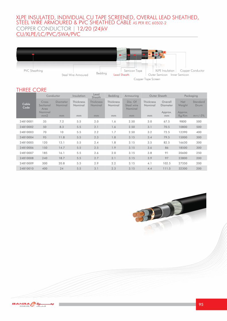
Cable Code
Conductor Insulation Lead Sheath Bedding Armouring Outer Sheath Packaging
Cross Sectional
Area Nominal
mm2
DiameterNominal
mm
Thickness Nominal
mm
Thickness Nominal
mm
Thickness Nominal
mm
Dia. Of Steel wireNominal
mm
Thickness Nominal
mm
Overall Diameter
Approx.mm
Net Weight
Approx.Kg/Km
Standard Drum
m+/-5%
24810001 35 7.2 5.5 2.0 1.6 2.50 3.0 67.5 9800 500
24810002 50 8.3 5.5 2.1 1.6 2.50 3.1 70.5 10800 500
24810003 70 10 5.5 2.2 1.7 2.50 3.2 72.5 12390 400
24810004 95 11.8 5.5 2.3 1.8 3.15 3.4 79.5 15000 300
24810005 120 13.1 5.5 2.4 1.8 3.15 3.5 82.5 16630 300
24810006 150 14.7 5.5 2.5 1.9 3.15 3.6 86 18500 300
24810007 185 16.1 5.5 2.6 2.0 3.15 3.8 91 20600 250
24810008 240 18.7 5.5 2.7 2.1 3.15 3.9 97 23800 200
24810009 300 20.8 5.5 2.9 2.2 3.15 4.1 102.5 27350 200
24810010 400 24 5.5 3.1 2.3 3.15 4.4 111.5 32300 200
COPPER CONDUCTOR | 12/20 (24)kV
THREE CORE
XLPE INSULATED, INDIVIDUAL CU TAPE SCREENED, OVERALL LEAD SHEATHED,STEEL WIRE ARMOURED & PVC SHEATHED CABLE AS PER IEC 60502-2
CU/XLPE/LC/PVC/SWA/PVC
PVC Sheathing
Copper Tape Screen
Semicon Tape Copper ConductorXLPE InsulationOuter Semicon Inner SemiconLead SheathSteel Wire Armoured Bedding
95

TECHNICAL INFORMATIONCOPPER CONDUCTOR | 12/20 (24)kVCU/XLPE/LC/PVC/SWA/PVC
Size mm2 35 50 70 95 120 150 185 240 300 400
Maximum DC resistance of Conductor @ 20°C
Ω/km 0.524 0.387 0.268 0.193 0.153 0.124 0.0991 0.0754 0.0601 0.0470
Approximate AC resistance of Conductor @ 90°C
Ω/km 0.668 0.494 0.344 0.247 0.196 0.161 0.129 0.099 0.0810 0.0650
Inductance at 60 Hz mH/Km 0.415 0.400 0.381 0.374 0.362 0.354 0.345 0.335 0.320 0.305
Reactance at 60 Hz Ω/km 0.16 0.15 0.14 0.14 0.14 0.13 0.13 0.13 0.12 0.11
Capacitance at 60 Hz μF/Km 0.15 0.17 0.2 0.22 0.24 0.26 0.27 0.3 0.33 0.37
Short Circuit Current For 1 second
1- Conductor KA 5.01 7.15 10.01 13.59 17.16 21.45 26.46 34.32 42.90 57.20
2- Metallic Sheath/Screen KA 1.5 1.59 1.71 1.83 1.92 2.04 2.16 2.31 2.46 2.64
Current Rating Capacity
1- Laid direct in ground (Approx.)
A 168 195 248 275 310 346 395 445 505 565
2- Laid in free air (Approx.) A 155 186 231 277 320 363 415 486 552 635
Voltage Drop per phase V/A/km 0.630 0.486 0.361 0.283 0.240 0.210 0.180 0.156 0.137 0.120
Minimum Bending radius mm 1013 1058 1088 1193 1238 1290 1365 1455 1538 1673
The above values are based on the following conditions: Ambient Air Temperature: 40 °CAmbient Ground Temperature: 35 °CDepth of laying in ground: 0.80 mSoil Thermal Resistivity: 1.2 °K.m/W
(Current Rating Capacities for all cables mentioned in this catalogue are focused according to the special climatic conditions in the Middle East)
96

Cable Code
Conductor Insulation Lead Sheath Bedding Armouring Outer Sheath Packaging
Cross Sectional
Area Nominal
mm2
DiameterNominal
mm
Thickness Nominal
mm
Thickness Nominal
mm
Thickness Nominal
mm
Dia. Of Steel wireNominal
mm
Thickness Nominal
mm
Overall Diameter
Approx.mm
Net Weight
Approx.Kg/Km
Standard Drum
m+/-5%
25810001 50 8.3 8.0 2.4 1.9 3.15 3.6 84.5 15270 300
25810002 70 10 8.0 2.5 1.9 3.15 3.7 89 16870 300
25810003 95 11.8 8.0 2.6 2.0 3.15 3.8 93 18800 250
25810004 120 13.1 8.0 2.7 2.1 3.15 3.9 95 20600 250
25810005 150 14.7 8.0 2.8 2.1 3.15 4.0 99 22450 250
25810006 185 16.1 8.0 2.9 2.2 3.15 4.2 103.5 24700 200
25810007 240 18.7 8.0 3.1 2.3 3.15 4.4 109.5 28400 200
25810008 300 20.8 8.0 3.2 2.4 3.15 4.5 115.5 31800 200
COPPER CONDUCTOR | 18/30 (36)kV
THREE CORE
XLPE INSULATED, INDIVIDUAL CU TAPE SCREENED, OVERALL LEAD SHEATHED,STEEL WIRE ARMOURED & PVC SHEATHED CABLE AS PER IEC 60502-2
CU/XLPE/LC/PVC/SWA/PVC
PVC Sheathing
Copper Tape Screen
Semicon Tape Copper ConductorXLPE InsulationOuter Semicon Inner SemiconLead SheathSteel Wire Armoured Bedding
97
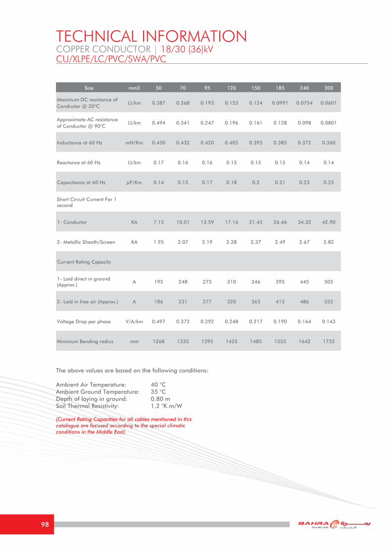
TECHNICAL INFORMATIONCOPPER CONDUCTOR | 18/30 (36)kVCU/XLPE/LC/PVC/SWA/PVC
Size mm2 50 70 95 120 150 185 240 300
Maximum DC resistance of Conductor @ 20°C
Ω/km 0.387 0.268 0.193 0.153 0.124 0.0991 0.0754 0.0601
Approximate AC resistance of Conductor @ 90°C
Ω/km 0.494 0.341 0.247 0.196 0.161 0.128 0.098 0.0801
Inductance at 60 Hz mH/Km 0.450 0.432 0.420 0.405 0.395 0.385 0.372 0.360
Reactance at 60 Hz Ω/km 0.17 0.16 0.16 0.15 0.15 0.15 0.14 0.14
Capacitance at 60 Hz μF/Km 0.14 0.15 0.17 0.18 0.2 0.21 0.23 0.25
Short Circuit Current For 1 second
1- Conductor KA 7.15 10.01 13.59 17.16 21.45 26.46 34.32 42.90
2- Metallic Sheath/Screen KA 1.95 2.07 2.19 2.28 2.37 2.49 2.67 2.82
Current Rating Capacity
1- Laid direct in ground (Approx.)
A 195 248 275 310 346 395 445 505
2- Laid in free air (Approx.) A 186 231 277 320 363 415 486 552
Voltage Drop per phase V/A/km 0.497 0.372 0.292 0.248 0.217 0.190 0.164 0.143
Minimum Bending radius mm 1268 1335 1395 1425 1485 1553 1642 1733
The above values are based on the following conditions: Ambient Air Temperature: 40 °CAmbient Ground Temperature: 35 °CDepth of laying in ground: 0.80 mSoil Thermal Resistivity: 1.2 °K.m/W
(Current Rating Capacities for all cables mentioned in this catalogue are focused according to the special climatic conditions in the Middle East)
98

Cable Code
Conductor Insulation Lead Sheath Bedding Armouring Outer Sheath Packaging
Cross Sectional
Area Nominal
mm2
DiameterNominal
mm
Thickness Nominal
mm
Thickness Nominal
mm
Thickness Nominal
mm
Dia. Of Steel wireNominal
mm
Thickness Nominal
mm
Overall Diameter
Approx.mm
Net Weight
Approx.Kg/Km
Standard Drum
m+/-5%
21820001 25 5.7 2.5 1.6 1.3 2.50 2.4 47 5320 500
21820002 35 7.1 2.5 1.7 1.3 2.50 2.5 50 5910 500
21820003 50 7.9 2.5 1.7 1.4 2.50 2.6 52.5 6360 500
21820004 70 9.7 2.5 1.8 1.4 2.50 2.7 56.5 7250 500
21820005 95 11.3 2.5 1.9 1.5 2.50 2.9 61 8310 500
21820006 120 12.6 2.5 2.0 1.6 2.50 3.0 64.5 9290 500
21820007 150 14.1 2.5 2.1 1.6 2.50 3.1 68 10240 500
21820008 185 16.0 2.5 2.2 1.7 2.50 3.2 73 11470 400
21820009 240 18.1 2.6 2.4 1.8 3.15 3.5 82.5 14590 300
21820010 300 20.4 2.8 2.5 1.9 3.15 3.7 88 16780 300
21820011 400 23.1 3.0 2.7 2.1 3.15 3.9 97 19770 250
ALUMINUM CONDUCTOR | 3.6/6 (7.2)kV
THREE CORE
XLPE INSULATED, OVERALL LEAD SHEATHED, STEEL WIRE ARMOURED &PVC SHEATHED CABLE AS PER IEC 60502-2
AL/XLPE/LC/PVC/SWA/PVC
PVC Sheathing Semicon Tape Aluminum ConductorXLPE InsulationOuter Semicon Inner SemiconLead SheathSteel Wire Armoured Bedding
99

TECHNICAL INFORMATIONALUMINUM CONDUCTOR | 3.6/6 (7.2)kVAL/XLPE/LC/PVC/SWA/PVC
Size mm2 25 35 50 70 95 120 150 185 240 300 400
Maximum DC resistance of Conductor @ 20°C
Ω/km 1.20 0.868 0.641 0.443 0.320 0.253 0.206 0.164 0.125 0.100 0.0778
Approximate AC resistance of Conductor @ 90°C
Ω/km 1.54 1.113 0.822 0.569 0.411 0.325 0.265 0.212 0.163 0.131 0.1034
Inductance at 60 Hz mH/Km 0.365 0.345 0.334 0.322 0.316 0.10 0.303 0.300 0.294 0.286 0.279
Reactance at 60 Hz Ω/km 0.14 0.13 0.13 0.12 0.12 0.04 0.11 0.11 0.11 0.11 0.11
Capacitance at 60 Hz μF/Km 0.26 0.30 0.32 0.36 0.39 0.44 0.46 0.53 0.56 0.58 0.60
Short Circuit Current For 1 second
1- Conductor KA 2.34 3.28 4.69 6.56 8.90 11.24 14.06 17.33 22.49 28.11 37.48
2- Metallic Sheath/Screen KA 4.03 5.53 5.16 5.88 6.75 7.56 8.42 9.39 11.03 12.81 15.63
Current Rating Capacity
1- Laid direct in ground (Approx.)
A 108 127 148 178 211 238 264 297 339 379 426
2- Laid in free air (Approx.) A 101 121 145 178 217 249 281 322 378 430 496
Voltage Drop per phase V/A/km 1.313 0.968 0.733 0.527 0.400 0.330 0.281 0.237 0.196 0.169 0.140
Minimum Bending radius mm 705 750 788 848 915 968 1020 1095 1238 1320 1455
The above values are based on the following conditions: Ambient Air Temperature: 40 °CAmbient Ground Temperature: 35 °CDepth of laying in ground: 0.80 mSoil Thermal Resistivity: 1.2 °K.m/W
(Current Rating Capacities for all cables mentioned in this catalogue are focused according to the special climatic conditions in the Middle East)
100

Cable Code
Conductor Insulation Lead Sheath Bedding Armouring Outer Sheath Packaging
Cross Sectional
Area Nominal
mm2
DiameterNominal
mm
Thickness Nominal
mm
Thickness Nominal
mm
Thickness Nominal
mm
Dia. Of Steel wireNominal
mm
Thickness Nominal
mm
Overall Diameter
Approx.mm
Net Weight
Approx.Kg/Km
Standard Drum
m+/-5%
22820001 25 5.7 3.4 1.7 1.3 2.50 2.6 52 6110 500
22820002 35 7.1 3.4 1.8 1.4 2.50 2.6 55 6770 500
22820003 50 7.9 3.4 1.9 1.4 2.50 2.8 57 7420 500
22820004 70 9.7 3.4 1.9 1.5 2.50 2.9 61.5 8200 500
22820005 95 11.3 3.4 2.0 1.6 2.50 3.0 65.5 9230 500
22820006 120 12.6 3.4 2.1 1.6 2.50 3.1 69.5 10270 500
22820007 150 14.1 3.4 2.2 1.7 2.50 3.2 73 11210 500
22820008 185 16.0 3.4 2.3 1.8 3.15 3.4 79 13460 400
22820009 240 18.1 3.4 2.5 1.9 3.15 3.6 85 15840 300
22820010 300 20.4 3.4 2.6 2.0 3.15 3.8 91 17720 300
22820011 400 23.1 3.4 2.8 2.1 3.15 4.0 98 20370 250
ALUMINUM CONDUCTOR | 6/10 (12)kV
THREE CORE
XLPE INSULATED, OVERALL LEAD SHEATHED, STEEL WIRE ARMOURED &PVC SHEATHED CABLE AS PER IEC 60502-2
AL/XLPE/LC/PVC/SWA/PVC
PVC Sheathing Semicon Tape Aluminum ConductorXLPE InsulationOuter Semicon Inner SemiconLead SheathSteel Wire Armoured Bedding
101

The above values are based on the following conditions: Ambient Air Temperature: 40 °CAmbient Ground Temperature: 35 °CDepth of laying in ground: 0.80 mSoil Thermal Resistivity: 1.2 °K.m/W
(Current Rating Capacities for all cables mentioned in this catalogue are focused according to the special climatic conditions in the Middle East)
TECHNICAL INFORMATIONALUMINUM CONDUCTOR | 6/10 (12)kVAL/XLPE/LC/PVC/SWA/PVC
Size mm2 25 35 50 70 95 120 150 185 240 300 400
Maximum DC resistance of Conductor @ 20°C
Ω/km 1.20 0.868 0.641 0.443 0.320 0.253 0.206 0.164 0.125 0.100 0.0778
Approximate AC resistance of Conductor @ 90°C
Ω/km 1.54 1.113 0.822 0.569 0.411 0.325 0.265 0.212 0.163 0.131 0.1034
Inductance at 60 Hz mH/Km 0.387 0.369 0.355 0.342 0.335 0.326 0.320 0.313 0.305 0.298 0.290
Reactance at 60 Hz Ω/km 0.15 0.14 0.13 0.13 0.13 0.12 0.12 0.12 0.11 0.11 0.11
Capacitance at 60 Hz μF/Km 0.20 0.23 0.25 0.29 0.30 0.33 0.37 0.40 0.45 0.49 0.54
Short Circuit Current For 1 second
1- Conductor KA 2.34 3.28 4.69 6.56 8.90 11.24 14.06 17.33 22.49 28.11 37.48
2- Metallic Sheath/Screen KA 4.87 5.41 6.09 6.87 7.8 8.67 9.58 10.6 12.2 13.75 16.3
Current Rating Capacity
1- Laid direct in ground (Approx.)
A 108 127 148 178 210 238 265 298 341 383 435
2- Laid in free air (Approx.) A 100 120 144 178 215 248 281 323 378 432 502
Voltage Drop per phase V/A/km 1.319 0.974 0.739 0.532 0.405 0.334 0.284 0.240 0.199 0.172 0.142
Minimum Bending radius mm 780 825 855 923 983 1043 1095 1185 1275 1365 1470
102

Cable Code
Conductor Insulation Lead Sheath Bedding Armouring Outer Sheath Packaging
Cross Sectional
Area Nominal
mm2
DiameterNominal
mm
Thickness Nominal
mm
Thickness Nominal
mm
Thickness Nominal
mm
Dia. Of Steel wireNominal
mm
Thickness Nominal
mm
Overall Diameter
Approx.mm
Net Weight
Approx.Kg/Km
Standard Drum
m+/-5%
23870001 25 5.7 4.5 1.8 1.4 2.50 2.7 58 7420 500
23870002 35 7.1 4.5 1.9 1.5 2.50 2.8 62 8090 500
23870003 50 7.9 4.5 2.0 1.5 2.50 2.9 63.5 8810 500
23870004 70 9.7 4.5 2.1 1.6 2.50 3.1 67.5 9920 500
23870005 95 11.3 4.5 2.2 1.7 2.50 3.2 73 11100 400
23870006 120 12.6 4.5 2.3 1.7 3.15 3.3 76 12970 400
23870007 150 14.1 4.5 2.4 1.8 3.15 3.5 81.5 14260 300
23870008 185 16.0 4.5 2.5 1.9 3.15 3.6 84 15660 300
23870009 240 18.1 4.5 2.6 2.0 3.15 3.8 91 17700 300
23870010 300 20.4 4.5 2.7 2.1 3.15 3.9 96 19870 250
23870011 400 23.1 4.5 2.9 2.2 3.15 4.2 104 22960 200
ALUMINUM CONDUCTOR | 8.7/15 (17.5)kV
THREE CORE
XLPE INSULATED, INDIVIDUAL CU TAPE SCREENED, OVERALL LEAD SHEATHED,STEEL WIRE ARMOURED & PVC SHEATHED CABLE AS PER IEC 60502-2
AL/XLPE/LC/PVC/SWA/PVC
PVC Sheathing
Copper Tape Screen
Semicon Tape Aluminum ConductorXLPE InsulationOuter Semicon Inner SemiconLead SheathSteel Wire Armoured Bedding
103

TECHNICAL INFORMATIONALUMINUM CONDUCTOR | 8.7/15 (17.5)kVAL/XLPE/LC/PVC/SWA/PVC
Size mm2 25 35 50 70 95 120 150 185 240 300 400
Maximum DC resistance of Conductor @ 20°C
Ω/km 1.20 0.868 0.641 0.443 0.320 0.253 0.206 0.164 0.125 0.100 0.0778
Approximate AC resistance of Conductor @ 90°C
Ω/km 1.54 1.113 0.822 0.569 0.411 0.325 0.265 0.212 0.163 0.131 0.1034
Inductance at 60 Hz mH/Km 0.415 0.395 0.380 0.365 0.356 0.345 0.339 0.330 0.321 0.312 0.302
Reactance at 60 Hz Ω/km 0.16 0.15 0.14 0.14 0.13 0.13 0.13 0.12 0.12 0.12 0.11
Capacitance at 60 Hz μF/Km 0.17 0.18 0.2 0.23 0.25 0.27 0.29 0.32 0.35 0.39 0.43
Short Circuit Current For 1 second
1- Conductor KA 2.34 3.28 4.69 6.56 8.90 11.24 14.06 17.33 22.49 28.11 37.48
2- Metallic Sheath/Screen KA 1.32 1.38 1.47 1.59 1.68 1.8 1.89 2.01 2.16 2.31 2.52
Current Rating Capacity
1- Laid direct in ground (Approx.)
A 108 127 148 178 210 238 265 298 341 383 435
2- Laid in free air (Approx.) A 100 120 144 178 215 248 281 323 378 432 502
Voltage Drop per phase V/A/km 1.325 0.980 0.744 0.537 0.410 0.338 0.289 0.243 0.202 0.175 0.145
Minimum Bending radius mm 870 930 953 1013 1095 1140 1223 1260 1365 1440 1560
The above values are based on the following conditions: Ambient Air Temperature: 40 °CAmbient Ground Temperature: 35 °CDepth of laying in ground: 0.80 mSoil Thermal Resistivity: 1.2 °K.m/W
(Current Rating Capacities for all cables mentioned in this catalogue are focused according to the special climatic conditions in the Middle East)
104

Cable Code
Conductor Insulation Lead Sheath Bedding Armouring Outer Sheath Packaging
Cross Sectional
Area Nominal
mm2
DiameterNominal
mm
Thickness Nominal
mm
Thickness Nominal
mm
Thickness Nominal
mm
Dia. Of Steel wireNominal
mm
Thickness Nominal
mm
Overall Diameter
Approx.mm
Net Weight
Approx.Kg/Km
Standard Drum
m+/-5%
24870001 35 7.1 5.5 2.0 1.6 2.50 3.0 67 9140 500
24870002 50 7.9 5.5 2.1 1.6 2.50 3.1 69.5 9910 500
24870003 70 9.7 5.5 2.2 1.7 2.50 3.2 71.5 11110 500
24870004 95 11.3 5.5 2.3 1.8 3.15 3.4 78.5 13230 400
24870005 120 12.6 5.5 2.4 1.8 3.15 3.5 81.5 14400 300
24870006 150 14.1 5.5 2.5 1.9 3.15 3.6 85 15760 300
24870007 185 16.0 5.5 2.6 2.0 3.15 3.8 90.5 17160 300
24870008 240 18.1 5.5 2.7 2.1 3.15 3.9 96 19300 250
24870009 300 20.4 5.5 2.9 2.2 3.15 4.1 101.5 21720 200
24870010 400 23.1 5.5 3.1 2.3 3.15 4.4 109.5 25060 200
ALUMINUM CONDUCTOR | 12/20 (24)kV
THREE CORE
XLPE INSULATED, INDIVIDUAL CU TAPE SCREENED, OVERALL LEAD SHEATHED,STEEL WIRE ARMOURED & PVC SHEATHED CABLE AS PER IEC 60502-2
AL/XLPE/LC/PVC/SWA/PVC
PVC Sheathing
Copper Tape Screen
Semicon Tape Aluminum ConductorXLPE InsulationOuter Semicon Inner SemiconLead SheathSteel Wire Armoured Bedding
105

TECHNICAL INFORMATIONALUMINUM CONDUCTOR | 12/20 (24)kVAL/XLPE/LC/PVC/SWA/PVC
Size mm2 35 50 70 95 120 150 185 240 300 400
Maximum DC resistance of Conductor @ 20°C
Ω/km 0.868 0.641 0.443 0.320 0.253 0.206 0.164 0.125 0.100 0.0778
Approximate AC resistance of Conductor @ 90°C
Ω/km 1.113 0.822 0.569 0.411 0.325 0.265 0.212 0.163 0.131 0.1034
Inductance at 60 Hz mH/Km 0.415 0.400 0.381 0.374 0.362 0.354 0.345 0.335 0.320 0.305
Reactance at 60 Hz Ω/km 0.16 0.15 0.14 0.14 0.14 0.13 0.13 0.13 0.12 0.11
Capacitance at 60 Hz μF/Km 0.15 0.17 0.2 0.22 0.24 0.26 0.27 0.3 0.33 0.37
Short Circuit Current For 1 second
1- Conductor KA 3.28 4.69 6.56 8.90 11.24 14.06 17.33 22.49 28.11 37.48
2- Metallic Sheath/Screen KA 1.5 1.59 1.71 1.83 1.92 2.04 2.16 2.31 2.46 2.64
Current Rating Capacity
1- Laid direct in ground (Approx.)
A 127 148 178 210 238 265 298 341 383 435
2- Laid in free air (Approx.) A 120 144 178 215 248 281 323 378 432 502
Voltage Drop per phase V/A/km 0.984 0.749 0.541 0.413 0.342 0.292 0.247 0.205 0.176 0.147
Minimum Bending radius mm 1005 1043 1073 1178 1223 1275 1358 1440 1523 1643
The above values are based on the following conditions: Ambient Air Temperature: 40 °CAmbient Ground Temperature: 35 °CDepth of laying in ground: 0.80 mSoil Thermal Resistivity: 1.2 °K.m/W
(Current Rating Capacities for all cables mentioned in this catalogue are focused according to the special climatic conditions in the Middle East)
106

Cable Code
Conductor Insulation Lead Sheath Bedding Armouring Outer Sheath Packaging
Cross Sectional
Area Nominal
mm2
DiameterNominal
mm
Thickness Nominal
mm
Thickness Nominal
mm
Thickness Nominal
mm
Dia. Of Steel wireNominal
mm
Thickness Nominal
mm
Overall Diameter
Approx.mm
Net Weight
Approx.Kg/Km
Standard Drum
m+/-5%
25870001 50 7.9 8.0 2.4 1.9 3.15 3.6 83.5 14380 300
25870002 70 9.7 8.0 2.5 1.9 3.15 3.7 88 15590 300
25870003 95 11.3 8.0 2.6 2.0 3.15 3.8 92 17030 300
25870004 120 12.6 8.0 2.7 2.1 3.15 3.9 94 18370 250
25870005 150 14.1 8.0 2.8 2.1 3.15 4.0 98 19710 250
25870006 185 16.0 8.0 2.9 2.2 3.15 4.2 103 21260 200
25870007 240 18.1 8.0 3.1 2.3 3.15 4.4 108.5 23900 200
25870008 300 20.4 8.0 3.2 2.4 3.15 4.5 113.5 26170 200
ALUMINUM CONDUCTOR | 18/30 (36)kV
THREE CORE
XLPE INSULATED, INDIVIDUAL CU TAPE SCREENED, OVERALL LEAD SHEATHED,STEEL WIRE ARMOURED & PVC SHEATHED CABLE AS PER IEC 60502-2
AL/XLPE/LC/PVC/SWA/PVC
PVC Sheathing
Copper Tape Screen
Semicon Tape Aluminum ConductorXLPE InsulationOuter Semicon Inner SemiconLead SheathSteel Wire Armoured Bedding
107

TECHNICAL INFORMATIONALUMINUM CONDUCTOR | 18/30 (36)kVAL/XLPE/LC/PVC/SWA/PVC
Size mm2 50 70 95 120 150 185 240 300
Maximum DC resistance of Conductor @ 20°C
Ω/km 0.641 0.443 0.320 0.253 0.206 0.164 0.125 0.100
Approximate AC resistance of Conductor @ 90°C
Ω/km 0.822 0.569 0.411 0.325 0.265 0.212 0.163 0.131
Inductance at 60 Hz mH/Km 0.450 0.432 0.420 0.405 0.395 0.385 0.372 0.360
Reactance at 60 Hz Ω/km 0.17 0.16 0.16 0.15 0.15 0.15 0.14 0.14
Capacitance at 60 Hz μF/Km 0.14 0.15 0.17 0.18 0.2 0.21 0.23 0.25
Short Circuit Current For 1 second
1- Conductor KA 4.69 6.56 8.90 11.24 14.06 17.33 22.49 28.11
2- Metallic Sheath/Screen KA 1.95 2.07 2.19 2.28 2.37 2.49 2.67 2.82
Current Rating Capacity
1- Laid direct in ground (Approx.)
A 148 178 210 238 265 298 341 383
2- Laid in free air (Approx.) A 144 178 215 248 281 323 378 432
Voltage Drop per phase V/A/km 0.760 0.552 0.424 0.352 0.301 0.256 0.214 0.185
Minimum Bending radius mm 1253 1320 1380 1410 1470 1545 1628 1703
The above values are based on the following conditions: Ambient Air Temperature: 40 °CAmbient Ground Temperature: 35 °CDepth of laying in ground: 0.80 mSoil Thermal Resistivity: 1.2 °K.m/W
(Current Rating Capacities for all cables mentioned in this catalogue are focused according to the special climatic conditions in the Middle East)
108

Cable Code
Conductor Insulation Lead Sheath Bedding Armouring Outer Sheath Packaging
Cross Sectional
Area Nominal
mm2
DiameterNominal
mm
Thickness Nominal
mm
Thickness Nominal
mm
Thickness Nominal
mm
Dia. Of Steel wireNominal
mm
Thickness Nominal
mm
Overall Diameter
Approx.mm
Net Weight
Approx.Kg/Km
Standard Drum
m+/-5%
23790001 25 6.2 4.5 1.3 1.5 2.50 2.8 63.5 8350 500
23790002 35 7.2 4.5 1.4 1.5 2.50 2.9 66.5 9300 500
23790003 50 8.3 4.5 1.4 1.6 2.50 3.0 69.5 10150 500
23790004 70 10 4.5 1.4 1.6 2.50 3.1 73.5 11300 400
23790005 95 11.8 4.5 1.5 1.7 2.50 3.3 77.5 13100 400
23790006 120 13.1 4.5 1.5 1.8 3.15 3.4 82.5 15300 300
23790007 150 14.7 4.5 1.6 1.9 3.15 3.5 87 17100 300
23790008 185 16.1 4.5 1.6 1.9 3.15 3.7 91 18950 250
23790009 240 18.7 4.5 1.7 2.0 3.15 3.8 97 22100 250
23790010 300 20.8 4.5 1.7 2.1 3.15 4.0 102.5 24800 200
23790011 400 24 4.5 1.8 2.3 3.15 4.3 110.5 29500 200
COPPER CONDUCTOR | 8.7/15 (17.5)kV
THREE CORE
XLPE INSULATED, INDIVIDUAL LEAD SHEATHED, STEEL WIRE ARMOURED & PVC SHEATHED CABLE AS PER IEC 60502-2
CU/XLPE/LC/PVC/SWA/PVC
PVC SheathingCopper ConductorXLPE Insulation
SemiconTape Outer Semicon Inner SemiconLead SheathSteel Wire Armoured Bedding
109

TECHNICAL INFORMATIONCOPPER CONDUCTOR | 8.7/15 (17.5)kVCU/XLPE/LC/PVC/SWA/PVC
Size mm2 25 35 50 70 95 120 150 185 240 300 400
Maximum DC resistance of Conductor @ 20°C
Ω/km 0.727 0.524 0.387 0.268 0.193 0.153 0.124 0.0991 0.0754 0.0601 0.0470
Approximate AC resistance of Conductor @ 90°C
Ω/km 0.927 0.669 0.494 0.344 0.247 0.196 0.161 0.129 0.099 0.0815 0.0655
Inductance at 60 Hz mH/Km 0.415 0.395 0.380 0.365 0.356 0.345 0.339 0.330 0.321 0.312 0.302
Reactance at 60 Hz Ω/km 0.16 0.15 0.14 0.14 0.13 0.13 0.13 0.12 0.12 0.12 0.11
Capacitance at 60 Hz μF/Km 0.17 0.18 0.2 0.23 0.25 0.27 0.29 0.32 0.35 0.39 0.43
Short Circuit Current For 1 second
1- Conductor KA 3.58 5.01 7.15 10.01 13.59 17.16 21.45 26.46 34.32 42.90 57.20
2- Metallic Sheath/Screen KA 5.5 6.6 6.8 7.3 8.0 8.8 9.5 10.3 11.6 12.8 14.8
Current Rating Capacity
1- Laid direct in ground (Approx.)
A 140 168 195 248 275 310 346 395 445 505 565
2- Laid in free air (Approx.) A 130 155 186 231 277 320 363 415 486 552 635
Voltage Drop per phase V/A/km 0.835 0.625 0.480 0.358 0.277 0.235 0.204 0.178 0.152 0.135 0.118
Minimum Bending radius mm 953 998 1043 1103 1163 1237 1305 1365 1455 1538 1658
The above values are based on the following conditions: Ambient Air Temperature: 40 °CAmbient Ground Temperature: 35 °CDepth of laying in ground: 0.80 mSoil Thermal Resistivity: 1.2 °K.m/W
(Current Rating Capacities for all cables mentioned in this catalogue are focused according to the special climatic conditions in the Middle East)
110

Cable Code
Conductor Insulation Lead Sheath Bedding Armouring Outer Sheath Packaging
Cross Sectional
Area Nominal
mm2
DiameterNominal
mm
Thickness Nominal
mm
Thickness Nominal
mm
Thickness Nominal
mm
Dia. Of Steel wireNominal
mm
Thickness Nominal
mm
Overall Diameter
Approx.mm
Net Weight
Approx.Kg/Km
Standard Drum
m+/-5%
24790001 35 7.2 5.5 1.4 1.6 2.50 3.1 71.5 10250 500
24790002 50 8.3 5.5 1.5 1.7 2.50 3.2 75 11400 500
24790003 70 10 5.5 1.5 1.7 3.15 3.3 79 13400 400
24790004 95 11.8 5.5 1.6 1.8 3.15 3.5 84.5 15400 300
24790005 120 13.1 5.5 1.6 1.9 3.15 3.6 88 16700 300
24790006 150 14.7 5.5 1.6 1.9 3.15 3.7 92 18200 300
24790007 185 16.1 5.5 1.7 2.0 3.15 3.8 96 20500 250
24790008 240 18.7 5.5 1.7 2.1 3.15 4.0 102.5 23300 250
24790009 300 20.8 5.5 1.8 2.2 3.15 4.2 107 26600 200
24790010 400 24 5.5 1.9 2.3 3.15 4.4 115.5 31200 200
COPPER CONDUCTOR | 12/20 (24)kV
THREE CORE
XLPE INSULATED, INDIVIDUAL LEAD SHEATHED, STEEL WIRE ARMOURED & PVC SHEATHED CABLE AS PER IEC 60502-2
CU/XLPE/LC/PVC/SWA/PVC
PVC SheathingCopper ConductorXLPE Insulation
SemiconTape Outer Semicon Inner SemiconLead SheathSteel Wire Armoured Bedding
111

TECHNICAL INFORMATIONCOPPER CONDUCTOR | 12/20 (24)kVCU/XLPE/LC/PVC/SWA/PVC
Size mm2 35 50 70 95 120 150 185 240 300 400
Maximum DC resistance of Conductor @ 20°C
Ω/km 0.524 0.387 0.268 0.193 0.153 0.124 0.0991 0.0754 0.0601 0.0470
Approximate AC resistance of Conductor @ 90°C
Ω/km 0.668 0.494 0.344 0.247 0.196 0.161 0.129 0.099 0.0810 0.0650
Inductance at 60 Hz mH/Km 0.415 0.400 0.381 0.374 0.362 0.354 0.345 0.335 0.320 0.305
Reactance at 60 Hz Ω/km 0.16 0.15 0.14 0.14 0.14 0.13 0.13 0.13 0.12 0.11
Capacitance at 60 Hz μF/Km 0.15 0.17 0.2 0.22 0.24 0.26 0.27 0.3 0.33 0.37
Short Circuit Current For 1 second
1- Conductor KA 5.01 7.15 10.01 13.59 17.16 21.45 26.46 34.32 42.90 57.20
2- Metallic Sheath/Screen KA 6.9 7.6 8.2 9.1 9.8 10.6 11.5 12.8 14.1 16.1
Current Rating Capacity
1- Laid direct in ground (Approx.)
A 168 195 248 275 310 346 395 445 505 565
2- Laid in free air (Approx.) A 155 186 231 277 320 363 415 486 552 635
Voltage Drop per phase V/A/km 0.630 0.486 0.361 0.283 0.240 0.210 0.180 0.156 0.137 0.120
Minimum Bending radius mm 1073 1125 1185 1268 1320 1380 1440 1538 1605 1733
The above values are based on the following conditions: Ambient Air Temperature: 40 °CAmbient Ground Temperature: 35 °CDepth of laying in ground: 0.80 mSoil Thermal Resistivity: 1.2 °K.m/W
(Current Rating Capacities for all cables mentioned in this catalogue are focused according to the special climatic conditions in the Middle East)
112

Cable Code
Conductor Insulation Lead Sheath Bedding Armouring Outer Sheath Packaging
Cross Sectional
Area Nominal
mm2
DiameterNominal
mm
Thickness Nominal
mm
Thickness Nominal
mm
Thickness Nominal
mm
Dia. Of Steel wireNominal
mm
Thickness Nominal
mm
Overall Diameter
Approx.mm
Net Weight
Approx.Kg/Km
Standard Drum
m+/-5%
25790001 50 8.3 8.0 1.6 1.9 3.15 3.6 89 15280 300
25790002 70 10 8.0 1.7 2.0 3.15 3.8 93 17130 300
25790003 95 11.8 8.0 1.7 2.0 3.15 3.9 97 18730 300
25790004 120 13.1 8.0 1.7 2.1 3.15 4.0 101 20160 250
25790005 150 14.7 8.0 1.8 2.2 3.15 4.1 104 22100 250
25790006 185 16.1 8.0 1.8 2.2 3.15 4.2 108 24000 250
25790007 240 18.7 8.0 1.9 2.3 3.15 4.4 115 27400 200
25790008 300 20.8 8.0 2.0 2.4 3.15 4.6 120 31000 200
COPPER CONDUCTOR | 18/30 (36)kV
THREE CORE
XLPE INSULATED, INDIVIDUAL LEAD SHEATHED, STEEL WIRE ARMOURED & PVC SHEATHED CABLE AS PER IEC 60502-2
CU/XLPE/LC/PVC/SWA/PVC
PVC SheathingCopper ConductorXLPE Insulation
SemiconTape Outer Semicon Inner SemiconLead SheathSteel Wire Armoured Bedding
113

TECHNICAL INFORMATIONCOPPER CONDUCTOR | 18/30 (36)kVCU/XLPE/LC/PVC/SWA/PVC
Size mm2 50 70 95 120 150 185 240 300
Maximum DC resistance of Conductor @ 20°C
Ω/km 0.387 0.268 0.193 0.153 0.124 0.0991 0.0754 0.0601
Approximate AC resistance of Conductor @ 90°C
Ω/km 0.494 0.341 0.247 0.196 0.161 0.128 0.098 0.0801
Inductance at 60 Hz mH/Km 0.450 0.432 0.420 0.405 0.395 0.385 0.372 0.360
Reactance at 60 Hz Ω/km 0.17 0.16 0.16 0.15 0.15 0.15 0.14 0.14
Capacitance at 60 Hz μF/Km 0.14 0.15 0.17 0.18 0.2 0.21 0.23 0.25
Short Circuit Current For 1 second
1- Conductor KA 7.15 10.01 13.59 17.16 21.45 26.46 34.32 42.90
2- Metallic Sheath/Screen KA 10.2 10.4 11.9 12.7 13.6 14.6 16.0 17.4
Current Rating Capacity
1- Laid direct in ground (Approx.)
A 195 248 275 310 346 395 445 505
2- Laid in free air (Approx.) A 186 231 277 320 363 415 486 552
Voltage Drop per phase V/A/km 0.497 0.372 0.292 0.248 0.217 0.190 0.164 0.143
Minimum Bending radius mm 1335 1395 1455 1515 1560 1620 1725 1800
The above values are based on the following conditions: Ambient Air Temperature: 40 °CAmbient Ground Temperature: 35 °CDepth of laying in ground: 0.80 mSoil Thermal Resistivity: 1.2 °K.m/W
(Current Rating Capacities for all cables mentioned in this catalogue are focused according to the special climatic conditions in the Middle East)
114

Cable Code
Conductor Insulation Lead Sheath Bedding Armouring Outer Sheath Packaging
Cross Sectional
Area Nominal
mm2
DiameterNominal
mm
Thickness Nominal
mm
Thickness Nominal
mm
Thickness Nominal
mm
Dia. Of Steel wireNominal
mm
Thickness Nominal
mm
Overall Diameter
Approx.mm
Net Weight
Approx.Kg/Km
Standard Drum
m+/-5%
23820001 25 5.7 4.5 1.3 1.5 2.50 2.8 62.5 7880 500
23820002 35 7.1 4.5 1.4 1.5 2.50 2.9 65.5 8650 500
23820003 50 7.9 4.5 1.4 1.6 2.50 3.0 68.5 9220 500
23820004 70 9.7 4.5 1.4 1.6 2.50 3.1 72.5 10000 500
23820005 95 11.3 4.5 1.5 1.7 2.50 3.3 76.5 11330 400
23820006 120 12.6 4.5 1.5 1.8 3.15 3.4 81.5 13070 400
23820007 150 14.1 4.5 1.6 1.9 3.15 3.5 86 14310 300
23820008 185 16.0 4.5 1.6 1.9 3.15 3.7 90 15510 300
23820009 240 18.1 4.5 1.7 2.0 3.15 3.8 95 17640 300
23820010 300 20.4 4.5 1.7 2.1 3.15 4.0 100.5 19130 250
23820011 400 23.1 4.5 1.8 2.3 3.15 4.3 108.5 22000 250
ALUMINUM CONDUCTOR | 8.7/15 (17.5)kV
THREE CORE
XLPE INSULATED, INDIVIDUAL LEAD SHEATHED, STEEL WIRE ARMOURED & PVC SHEATHED CABLE AS PER IEC 60502-2
AL/XLPE/LC/PVC/SWA/PVC
PVC SheathingAluminum ConductorXLPE Insulation
SemiconTape Outer Semicon Inner SemiconLead SheathSteel Wire Armoured Bedding
115

TECHNICAL INFORMATIONALUMINUM CONDUCTOR | 8.7/15 (17.5)kVAL/XLPE/LC/PVC/SWA/PVC
Size mm2 25 35 50 70 95 120 150 185 240 300 400
Maximum DC resistance of Conductor @ 20°C
Ω/km 1.20 0.868 0.641 0.443 0.320 0.253 0.206 0.164 0.125 0.100 0.0778
Approximate AC resistance of Conductor @ 90°C
Ω/km 1.54 1.113 0.822 0.569 0.411 0.325 0.265 0.212 0.163 0.131 0.1034
Inductance at 60 Hz mH/Km 0.415 0.395 0.380 0.365 0.356 0.345 0.339 0.330 0.321 0.312 0.302
Reactance at 60 Hz Ω/km 0.16 0.15 0.14 0.14 0.13 0.13 0.13 0.12 0.12 0.12 0.11
Capacitance at 60 Hz μF/Km 0.17 0.18 0.2 0.23 0.25 0.27 0.29 0.32 0.35 0.39 0.43
Short Circuit Current For 1 second
1- Conductor KA 2.34 3.28 4.69 6.56 8.90 11.24 14.06 17.33 22.49 28.11 37.48
2- Metallic Sheath/Screen KA 5.5 6.6 6.8 7.3 8.0 8.8 9.5 10.3 11.6 12.8 14.8
Current Rating Capacity
1- Laid direct in ground (Approx.)
A 108 127 148 178 210 238 265 298 341 383 435
2- Laid in free air (Approx.) A 100 120 144 178 215 248 281 323 378 432 502
Voltage Drop per phase V/A/km 1.325 0.980 0.744 0.537 0.410 0.338 0.289 0.243 0.202 0.175 0.145
Minimum Bending radius mm 938 983 1028 1088 1148 1223 1290 1350 1425 1507 1628
The above values are based on the following conditions: Ambient Air Temperature: 40 °CAmbient Ground Temperature: 35 °CDepth of laying in ground: 0.80 mSoil Thermal Resistivity: 1.2 °K.m/W
(Current Rating Capacities for all cables mentioned in this catalogue are focused according to the special climatic conditions in the Middle East)
116

Cable Code
Conductor Insulation Lead Sheath Bedding Armouring Outer Sheath Packaging
Cross Sectional
Area Nominal
mm2
DiameterNominal
mm
Thickness Nominal
mm
Thickness Nominal
mm
Thickness Nominal
mm
Dia. Of Steel wireNominal
mm
Thickness Nominal
mm
Overall Diameter
Approx.mm
Net Weight
Approx.Kg/Km
Standard Drum
m+/-5%
24820001 35 7.1 5.5 1.4 1.6 2.50 3.1 71 9600 500
24820002 50 7.9 5.5 1.5 1.7 2.50 3.2 74 10470 500
24820003 70 9.7 5.5 1.5 1.7 3.15 3.3 78 12100 400
24820004 95 11.3 5.5 1.6 1.8 3.15 3.5 83.5 13630 400
24820005 120 12.6 5.5 1.6 1.9 3.15 3.6 87 14470 300
24820006 150 14.1 5.5 1.6 1.9 3.15 3.7 91 15410 300
24820007 185 16.0 5.5 1.7 2.0 3.15 3.8 95.5 17060 300
24820008 240 18.1 5.5 1.7 2.1 3.15 4.0 101.5 18840 250
24820009 300 20.4 5.5 1.8 2.2 3.15 4.2 106 21020 250
24820010 400 23.1 5.5 1.9 2.3 3.15 4.4 113.5 23770 200
ALUMINUM CONDUCTOR | 12/20 (24)kV
THREE CORE
XLPE INSULATED, INDIVIDUAL LEAD SHEATHED, STEEL WIRE ARMOURED & PVC SHEATHED CABLE AS PER IEC 60502-2
AL/XLPE/LC/PVC/SWA/PVC
PVC SheathingAluminum ConductorXLPE Insulation
SemiconTape Outer Semicon Inner SemiconLead SheathSteel Wire Armoured Bedding
117

TECHNICAL INFORMATIONALUMINUM CONDUCTOR | 12/20 (24)kVAL/XLPE/LC/PVC/SWA/PVC
Size mm2 35 50 70 95 120 150 185 240 300 400
Maximum DC resistance of Conductor @ 20°C
Ω/km 0.868 0.641 0.443 0.320 0.253 0.206 0.164 0.125 0.100 0.0778
Approximate AC resistance of Conductor @ 90°C
Ω/km 1.113 0.822 0.569 0.411 0.325 0.265 0.212 0.163 0.131 0.1034
Inductance at 60 Hz mH/Km 0.415 0.400 0.381 0.374 0.362 0.354 0.345 0.335 0.320 0.305
Reactance at 60 Hz Ω/km 0.16 0.15 0.14 0.14 0.14 0.13 0.13 0.13 0.12 0.11
Capacitance at 60 Hz μF/Km 0.15 0.17 0.2 0.22 0.24 0.26 0.27 0.3 0.33 0.37
Short Circuit Current For 1 second
1- Conductor KA 3.28 4.69 6.56 8.90 11.24 14.06 17.33 22.49 28.11 37.48
2- Metallic Sheath/Screen KA 6.9 7.6 8.2 9.1 9.8 10.6 11.5 12.8 14.1 16.1
Current Rating Capacity
1- Laid direct in ground (Approx.)
A 127 148 178 210 238 265 298 341 383 435
2- Laid in free air (Approx.) A 120 144 178 215 248 281 323 378 432 502
Voltage Drop per phase V/A/km 0.984 0.749 0.541 0.413 0.342 0.292 0.247 0.205 0.176 0.147
Minimum Bending radius mm 1065 1110 1170 1253 1305 1365 1433 1523 1590 1703
The above values are based on the following conditions: Ambient Air Temperature: 40 °CAmbient Ground Temperature: 35 °CDepth of laying in ground: 0.80 mSoil Thermal Resistivity: 1.2 °K.m/W
(Current Rating Capacities for all cables mentioned in this catalogue are focused according to the special climatic conditions in the Middle East)
118
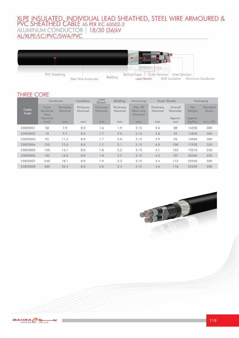
Cable Code
Conductor Insulation Lead Sheath Bedding Armouring Outer Sheath Packaging
Cross Sectional
Area Nominal
mm2
DiameterNominal
mm
Thickness Nominal
mm
Thickness Nominal
mm
Thickness Nominal
mm
Dia. Of Steel wireNominal
mm
Thickness Nominal
mm
Overall Diameter
Approx.mm
Net Weight
Approx.Kg/Km
Standard Drum
m+/-5%
25820001 50 7.9 8.0 1.6 1.9 3.15 3.6 88 14350 300
25820002 70 9.7 8.0 1.7 2.0 3.15 3.8 92 15830 300
25820003 95 11.3 8.0 1.7 2.0 3.15 3.9 96 16960 300
25820004 120 12.6 8.0 1.7 2.1 3.15 4.0 100 17930 350
25820005 150 14.1 8.0 1.8 2.2 3.15 4.1 103 19310 250
25820006 185 16.0 8.0 1.8 2.2 3.15 4.2 107 20560 250
25820007 240 18.1 8.0 1.9 2.3 3.15 4.4 113 22940 200
25820008 300 20.4 8.0 2.0 2.4 3.15 4.6 118 25420 200
ALUMINUM CONDUCTOR | 18/30 (36)kV
THREE CORE
XLPE INSULATED, INDIVIDUAL LEAD SHEATHED, STEEL WIRE ARMOURED & PVC SHEATHED CABLE AS PER IEC 60502-2
AL/XLPE/LC/PVC/SWA/PVC
PVC SheathingAluminum ConductorXLPE Insulation
SemiconTape Outer Semicon Inner SemiconLead SheathSteel Wire Armoured Bedding
119

TECHNICAL INFORMATIONALUMINUM CONDUCTOR | 18/30 (36)kVAL/XLPE/LC/PVC/SWA/PVC
Size mm2 50 70 95 120 150 185 240 300
Maximum DC resistance of Conductor @ 20°C
Ω/km 0.641 0.443 0.320 0.253 0.206 0.164 0.125 0.100
Approximate AC resistance of Conductor @ 90°C
Ω/km 0.822 0.569 0.411 0.325 0.265 0.212 0.163 0.131
Inductance at 60 Hz mH/Km 0.450 0.432 0.420 0.405 0.395 0.385 0.372 0.360
Reactance at 60 Hz Ω/km 0.17 0.16 0.16 0.15 0.15 0.15 0.14 0.14
Capacitance at 60 Hz μF/Km 0.14 0.15 0.17 0.18 0.2 0.21 0.23 0.25
Short Circuit Current For 1 second
1- Conductor KA 4.69 6.56 8.90 11.24 14.06 17.33 22.49 28.11
2- Metallic Sheath/Screen KA 10.2 10.4 11.9 12.7 13.6 14.6 16.0 17.4
Current Rating Capacity
1- Laid direct in ground (Approx.)
A 148 178 210 238 265 298 341 383
2- Laid in free air (Approx.) A 144 178 215 248 281 323 378 432
Voltage Drop per phase V/A/km 0.760 0.552 0.424 0.352 0.301 0.256 0.214 0.185
Minimum Bending radius mm 1320 1380 1440 1500 1545 1605 1695 1770
The above values are based on the following conditions: Ambient Air Temperature: 40 °CAmbient Ground Temperature: 35 °CDepth of laying in ground: 0.80 mSoil Thermal Resistivity: 1.2 °K.m/W
(Current Rating Capacities for all cables mentioned in this catalogue are focused according to the special climatic conditions in the Middle East)
120

Cables and Conductors should be installed by trained personnel in accordance with good
engineering practices, recognized codes of practise, statutory local requirements, IEE wiring
regulations and where relevant, in accordance with any specific instructions issued by the
company. Cables are often supplied in heavy cable reels and handling these reels can constitute
a safety hazard. In particular, dangers may arise during the removal of steel binding straps and
during the removal of retaining battens and timbers which may expose projecting nails.
Lifting cable drums using crane.
Lift drums on fork trucks correctly.
Secure drums adequately before transportation. Roll in the direction shown by the arrow.
Do not lay drums flat on their sides, use properstops to prevent drums roling.
DRUM HANDLING INSTRUCTIONS
121

INSTALLATION
- Precautions should be taken to avoid mechanical damage to thecables before and during installation.
- Exceeding the manufacturer’s recommended maximum pullingtensions should be avoided as this can result in damage to the cable.
- If cables are to be installed in ducts, the correct size of ductshould be used.
- The type of jointing and filling compounds employed should bechemically compatible with the cable materials.
- The cable support system should be such as to avoid damage tothe cables.
- Cables specified in this catalouge British Standard are designed for fixedinstallations only; they are not intended for use as, for example, trailingor reeling cables.
- Repeated over-voltage testing can lead to premature failure ofthe cable.
- The selection of cable glands, accessories and any associatedtools should take account of all aspects of intended use. Anysemi-conducting coating present on the oversheath should be removedfor a suitable distance from joints and terminations.
- Care should be exercised with single-core cables to ensure thatthe bonding and earthing arrangements are adequate to cater forcirculating currents in the armour and screen(s).
RECOMMENDATIONS FOR CABLES INSTALLATION
122

To serve our customer in minimum time and high efficiency, our valuable customers are requested
to provide the following details along with their enquiries and orders:
1. Number of phases/cores (3 or 1).
2. Conductor required cross sectional area.
3. Metallic screen type (copper tape or copper wire) and area (copper wire screen)
4. System Voltage Rate.
5. System Short Circuit required.
6. Applicable customer specification or International Standard / Norm.
7. Conductor material (Copper/Aluminum).
8. Insulation Material (XLPE).
9. Bedding / Inner Sheathing (Inner Jacketing ( PVC/PE, .. ).
10. Lead Alloy
11. Armouring Type (SWA, AWA).
12. Cable jacketing material (PVC/MDPE).
13. Cable special features required, e.g. Flame Retardant Type to IEC 60332-3, Anti-termite
14. Required length of cables (drum schedules)
ORDERING INFORMATION
101