Medical application of the Internet of things (IoT) - University of ...
136
University of Cape Town i Medical Application of the Internet of Things (IoT): Prototyping a Telemonitoring System Fredrick Chisanga Supervisors: Neco Ventura and Joyce Mwangama Dissertation submitted to the Department of Electrical Engineering in fulfillment of the requirements for the Master of Science in Electrical Engineering degree at the University of Cape Town August 2017
-
Upload
khangminh22 -
Category
Documents
-
view
1 -
download
0
Transcript of Medical application of the Internet of things (IoT) - University of ...
Univers
ity of
Cap
e Tow
n
i
Medical Application of the Internet of Things (IoT): Prototyping a Telemonitoring System
Fredrick Chisanga
Supervisors:
Neco Ventura and Joyce Mwangama
Dissertation submitted to the Department of Electrical Engineering in fulfillment of the requirements for the Master of Science in Electrical
Engineering degree at the University of Cape Town
August 2017

The copyright of this thesis vests in the author. No quotation from it or information derived from it is to be published without full acknowledgement of the source. The thesis is to be used for private study or non-commercial research purposes only.
Published by the University of Cape Town (UCT) in terms of the non-exclusive license granted to UCT by the author.
Univers
ity of
Cap
e Tow
n
ii
Declaration
I know the meaning of plagiarism and declare that all the work in the document, save for that which is properly acknowledged, is my own. This thesis/dissertation has been submitted to the Turnitin module (or equivalent similarity and originality checking software) and I confirm that my supervisor has seen my report and any concerns revealed by such have been resolved with my supervisor.
…………………………
Fredrick Chisanga
August 2017
iii
Supervisors’ Declaration
As the candidate’s supervisor, I have approved this dissertation for submission
………………………………….
Neco Ventura
August 2016
As the candidate’s co-supervisor, I have approved this dissertation for submission
………………………………….
Joyce Mwangama
August 2016
iv
Application for Approval of Ethics in Research (EiR) Projects Facu lty of Engineer ing and the Bui lt Environment, University of Cape Town
APPLICATION FORM Please Note: Any person planning to undertake research in the Faculty of Engineering and the Built Environment (EBE) at the University of Cape Town is required to complete this form before collecting or analysing data.The objective of submitting this application prior to embarking on research is to ensure that the highest ethical standards in research, conducted under the auspices of the EBE Faculty, are met. Please ensure that you have read, and understood the EBE Ethics in Research Handbook(available from the UCT EBE, Research Ethics website) prior to completing this appl ication form: http://www.ebe.uct.ac.zalusr/ebe/research/ethics.pdf
APPLICANT'S DETAILS
Name of principal researcher, student or CHISANGA FREDRICK external applicant
Department ELECTRICAL ENGINEERING
Preferred email address of applicant: CHSFRE001@MYUCT .AC .ZA
Your Degree: MSc If a Student e.g., MSc, PhD, etc.,
Name of Supervisor (if NECO VENTURA AND JOYCE MWANAGAMA supervised):
If this is a researchcontract. indicate the N/A source of funding/sponsorship
Proiect Title MEDICAL APPLICATION OF THE INTERNET OF THINGS (JOT) : PROTOTYPING A TELE-MONITORING SYSTEM.
I hereby undertake to carry out my research in such a way that: there is no apparent legal objection to the nature or the method of research; and the research will not compromise staff or students or the other responsibilities of the University; the stated objective will be achieved, and the findings will have a high degree of validity; limitations and alternative interpretations will be considered; the findings could be subject to peer review and publicly available; and I will comply with the conventions of copyright and avoid any practice that would constitute plagiarism .
SIGNED BY
Principal Researcher/ Student/External applicant
APPLICATION APPROVED BY
Supervisor (where applicable)
HOD (or delegated nominee)
Final authori ty for all applicants who have answered NO to all questions in Section1 ; and for all Undergraduateresearch (Including Honours).
Chair : Faculty EIR Committee
For applicants other than
Full name
CHISANGA FREDRICK
Full name
NECO VENTURA
C H-a l;, ... f ]) \-W fl_ 'I Cl ick here to enter text/
undergraduate students who have Click here to enter text answered YES to any of the above questions.
Page 1 of 1
r I I
I I
Date
12 May 2017
Date
12 May 2017
I !Jr{17 Click here to enter a date.
Chck here to enter a date.

v
Acknowledgements
Foremost, I would like to thank God for His continued help and provisions in my life.
I would also like to thank my family: W. M. Chisanga - my forbearing, lovely and loving wife, and my two amigos: J. and J. Chisanga for letting daddy abandon them for months on end at a critical time in their development. Hope you eventually get to see the fruits of the sacrifice.
My heartfelt gratitude goes to the following people who have helped me make significant strides in this research project:
Mr. N. Ventura for his massive input and guidance at every stage of the project. Ms. J. Mwangama for her ear and assistance in the shaping up of the research topic. Mr. S. Banda for the willingness to bail me out whenever I got entangled in the code. Mr. N. Sikasote and Ms. A. Hunma for the diligent support in reviewing and helping me edit the work. Dr. S. C. Lubobya for convincing me to pursue this project and being in it throughout the journey.
Lastly, I wish to thank all my colleagues in the Communications Research Group (CRG) and everyone that I interacted with during this research project for their invaluable support at various levels and capacities. Without which, the time at University of Cape Town (UCT) would not have been worthwhile.
God bless you all.
vi
Abstract
The Internet of Things (IoT) is a technological paradigm that can be perceived as an evolution of the internet. It is a shift from the traditional way of connecting devices to the internet, both in number and diversity of connected devices. This significant and marked growth in the number and diversity of devices connected to the internet has prompted a rethink of approaches to interconnect devices. The growth in the number of connected devices is driven by emerging applications and business models and supported by falling device costs while the growth in the diversity is driven by the reduction in the cost of manufacturing these devices. This has led to an increase in the number of users (not limited to people) of the internet. According to statistics by the ITU, by the end of 2015, about 3.2 billion people were using the Internet. Significantly, 34% of households in developing countries had Internet access, with more than 80% of households in developed countries. This indicates that it is realistic to leverage the IoT in living spaces.
Appreciating this potential, many sectors of society are already positioning themselves to reap the benefits of this great promise. Hence the health sector would do well to adopt this technological paradigm to enhance service delivery. One specific area where the health sector can benefit from the adoption of the IoT is in telemonitoring and the associated early response to medical emergencies.
Statistics and research show that there are areas in the medical field, that still need improvement to enhance service delivery. The Nursing Times has summed up these areas into four categories. The first one is a need to have a regular observation of patients and their vital signs. Here, health service providers (SPs) need to adopt creative and non-obtrusive methods that will encourage patients’ participation in the monitoring of these vital signs. As much as possible, vital signs readings should be taken at convenient locations and times. Therefore, devices that have consistent internet access and are usually a part of daily life for most patients, such as the mobile phones would prove to be a key enabler of regular observation of vital signs. Furthermore, miniaturization of the vital signs monitoring or sensing devices would be a key step towards realizing this scenario. A lot of work is already being done to miniaturize these devices and make them as much a part of daily life as possible, as evidenced by advancements in the field of fitness and wearables. To map this use to the medical field, a system needs to be created that would allow for the aggregation of these disparate measuring and monitoring devices with medical information management systems. The second potential area of improvement is in the early recognition of deterioration of the patients. With regular observation of patients, it is possible to recognize deterioration at its early stage. Taking cognizance of the different needs of the various stakeholders is important to achieve the intended results. The third potential area of improvement is in the communication among stakeholders. This has to do with identifying the relevant data that must be delivered to the stakeholders during the monitoring and management process. Lastly, effective response to medical concerns is the other potential area of improvement. It is noted that patients do not generally get the right response at the right time because the information does not reach the rightly qualified personnel in good time. The regular and real-time capture of vital signs data coupled with added analytics can
vii
enable IoT SPs to design solutions that automate the management and transmission of medical data in a timely manner.
This work addresses how the medical sector can adopt IoT-based solutions to improve service delivery, while utilizing existing resources such as smartphones, for the transmission and management of vital signs data, availing it to stakeholders and improve communication among them. It develops a telemonitoring system based on IoT design approaches. The developed system captures readings of vital signs from monitoring devices, processes and manages this data to serve the needs of the various stakeholders. Additionally, intelligence was added to enable the system to interpret the data and make decisions that will help medical practitioners and other stakeholders (patients, caregivers, etc.) to more timely, consistently and reliably provide and receive medical services/assistance. Two end user applications were developed. A cloud-based web application developed using PHP, HTML, and JavaScript and an Android mobile application developed using Java programming language in Android studio. An ETSI standards-compliant M2M middleware is used to aggregate the system using M2M applications developed in Python. This is to leverage the benefits of the standards-compliant middleware while offering flexibility in the design of applications. The developed system was evaluated to assess whether it meets the requirements and expectations of the various stakeholders. Finally, the performance of the proposed telemonitoring system was studied by analyzing the delay on the delivery of messages (local notifications, SMS, and email) to various stakeholders to assess the contribution towards reducing the overall time of the cardiac arrest chain of survival. The results obtained showed a marked improvement (over 28 seconds) on previous work.
In addition to improved performance in monitoring and management of vital signs, telemonitoring systems have a potential of decongesting health institutions and saving time for all the stakeholders while bridging most of the gaps discussed above. The captured data can also provide the health researchers and physicians with most of the prerequisite data to effectively execute predictive health thereby improving service delivery in the health sector.
viii
Table of Contents
Declaration .......................................................................................................................................................... ii
Acknowledgements .......................................................................................................................................... v
Abstract ............................................................................................................................................................... vi
Table of Contents .......................................................................................................................................... viii
List of Figures ................................................................................................................................................... xii
List of Tables .................................................................................................................................................... xiv
List of Acronyms ............................................................................................................................................. xv
Chapter 1 .............................................................................................................................................................. 1
1.1 Research Motivation ...................................................................................................................... 2
1.1.1 Problem Definition ................................................................................................................. 3
1.1.2 Research Questions ............................................................................................................... 7
1.2 Objectives ........................................................................................................................................... 8
1.3 Scope and Limitation ..................................................................................................................... 8
1.4 Dissertation Outline ....................................................................................................................... 9
Chapter 2 ........................................................................................................................................................... 11
2.1 Information and Communication Technology (ICT) in the healthcare industry....... 11
2.1.1 Telemedicine ......................................................................................................................... 11
2.1.2 Telemonitoring ..................................................................................................................... 12
2.1.3 EHealth and Telehealth ..................................................................................................... 13
2.2 The Internet of Things (IoT) .................................................................................................... 15
2.2.1 Defining the IoT .................................................................................................................... 15
2.2.2 Background of the IoT ....................................................................................................... 16
2.2.3 M2M - An IoT Enabler ........................................................................................................ 17
2.2.4 The IoT Vision ....................................................................................................................... 18
2.2.5 The IoT Standardization Efforts .................................................................................... 19
2.3 Review of eHealth Solutions .................................................................................................... 22
2.3.1 Middleware ............................................................................................................................ 29
2.3.2 Monitoring Devices ............................................................................................................. 37
2.3.3 End-User Applications ....................................................................................................... 38
2.3.4 Web Applications and Cloud Computing .................................................................... 40
2.3.5 Stakeholders’ Notification Design Approaches ........................................................ 40
2.4 Chapter Summary ........................................................................................................................ 41
ix
Chapter 3 ........................................................................................................................................................... 43
3.1 General Description ..................................................................................................................... 43
3.2 Initialization ................................................................................................................................... 44
3.3 Stakeholders ................................................................................................................................... 45
3.3.1 Patient ...................................................................................................................................... 45
3.3.2 Physician ................................................................................................................................. 45
3.3.3 Caregiver ................................................................................................................................. 45
3.4 Regular Monitoring Use Case .................................................................................................. 45
3.4.1 General Description ............................................................................................................ 45
3.4.2 Scenario ................................................................................................................................... 45
3.4.3 Information Exchanges ..................................................................................................... 46
3.4.4 Stakeholders Requirements ............................................................................................ 46
3.5 Chronic Patient Use Case ........................................................................................................... 47
3.5.1 General Description ............................................................................................................ 47
3.5.2 Scenario ................................................................................................................................... 48
3.5.3 Information Exchanges ..................................................................................................... 48
3.5.4 Stakeholders Requirements ............................................................................................ 49
3.5.5 Messaging Platforms .......................................................................................................... 50
3.6 System Requirements of the proposed telemonitoring system ................................. 50
3.6.1 End-to-End Communication ............................................................................................ 50
3.6.2 Communication Failure Notification ............................................................................ 50
3.6.3 Abstraction of Network Technologies ......................................................................... 51
3.6.4 Message Confirmation ....................................................................................................... 51
3.6.5 Data Analytics and Processing ....................................................................................... 51
3.6.6 Continuous Connectivity .................................................................................................. 51
3.6.7 Time Stamping ...................................................................................................................... 51
3.6.8 Reuse of Services Offered by Underlying Networks .............................................. 51
3.6.9 Support for Multiple Applications and Devices ....................................................... 51
3.6.10 Data Collection and Reporting........................................................................................ 52
3.6.11 Information Reception ...................................................................................................... 52
3.6.12 Reachability ........................................................................................................................... 52
3.6.13 Monitoring and Sensing .................................................................................................... 52
3.6.14 Reliability ................................................................................................................................ 52
3.6.15 Integrity ................................................................................................................................... 52
x
3.7 Proposed Telemonitoring System ......................................................................................... 52
3.7.1 Remote Monitoring Devices (RMDs) ........................................................................... 54
3.7.2 Mobile Application (MA) .................................................................................................. 54
3.7.3 Distributed M2M Middleware ........................................................................................ 55
3.7.4 Electronic Health Records (EHR) System .................................................................. 56
3.8 Chapter Summary ........................................................................................................................ 57
Chapter 4 ........................................................................................................................................................... 58
4.1 Prototype Design Objectives .................................................................................................... 58
4.2 Requirements of the Prototype .............................................................................................. 58
4.3 Software Used ................................................................................................................................ 59
4.3.1 Remote Monitoring Devices (RMDs) ........................................................................... 59
4.3.2 Mobile Application (MA) .................................................................................................. 59
4.3.3 Distributed M2M Middleware ........................................................................................ 62
4.3.4 Electronic Health Record (EHR) System .................................................................... 65
4.4 Operation and functions of the Prototype .......................................................................... 66
4.4.1 Patient Creation ................................................................................................................... 67
4.4.2 Registration and Authentication ................................................................................... 71
4.4.3 RMD and Mobile Application .......................................................................................... 72
4.4.4 Mobile Application and M2M Gateway ....................................................................... 74
4.4.5 M2M Gateway and M2M Server ..................................................................................... 74
4.4.6 M2M Server and EHR ......................................................................................................... 75
4.4.7 Database Synchronization ............................................................................................... 75
4.4.8 Messaging Mechanism ....................................................................................................... 77
4.4.9 EHR Data Processing .......................................................................................................... 78
4.5 Hardware Used ............................................................................................................................. 79
4.6 Limitations of the Prototype .................................................................................................... 80
4.7 Chapter Summary ........................................................................................................................ 81
Chapter 5 ........................................................................................................................................................... 82
5.1 Functional Evaluation of the Prototype ............................................................................... 82
5.1.1 Regular Monitoring Use Case .......................................................................................... 82
5.1.2 Chronic Patient Use Case .................................................................................................. 95
5.2 Delay Analysis................................................................................................................................ 97
5.2.1 Local Notifications .............................................................................................................. 98
5.2.2 Inter-SP SMS Messages ...................................................................................................... 99
xi
5.2.3 Intra SP SMS Messages .................................................................................................... 100
5.2.4 Email ....................................................................................................................................... 101
5.3 Chapter Summary ...................................................................................................................... 102
Chapter 6 ......................................................................................................................................................... 104
6.1 Dissertation Summary .............................................................................................................. 104
6.2 Conclusions ................................................................................................................................... 105
6.3 Recommendations ..................................................................................................................... 105
References ...................................................................................................................................................... 107
Appendices ..................................................................................................................................................... 115
Appendix A: The Plan of Action ......................................................................................................... 115
Appendix B: The Zephyr HxM BT Smart Device .......................................................................... 115
Appendix C: Mobile Application (MA) Class Diagram ............................................................... 116
Appendix D: Author’s List of Peer Reviewed Work ................................................................... 117
xii
List of Figures
Figure 1-1: Projection of Connected devices . ............................................................................................ 1 Figure 1-2: The AHA Cardiac Arrest Chain of Survival ......................................................................... 5 Figure 2-1: The ITU's IoT reference model . ............................................................................................ 19 Figure 2-2: The three-layered model ........................................................................................................ 21 Figure 2-3: The ETSI high-level reference architecture . .................................................................... 22 Figure 2-4: The CPS system architecture for remote monitoring .................................................. 23 Figure 2-5: A telemonitoring scenario ...................................................................................................... 25 Figure 2-6: Illustration of the eHealth Monitoring Architecture .................................................... 26 Figure 2-7: Three components architecture ........................................................................................... 27 Figure 2-8: Implementation of aggregation of multiple sensors .................................................... 28 Figure 2-9: The ECG Monitoring System Architecture ....................................................................... 29 Figure 2-10: The oneM2M interface mappings ..................................................................................... 30 Figure 2-11: The Alljoyn proximal network ........................................................................................... 32 Figure 2-12: The possible router implementations ............................................................................. 32 Figure 2-13: The Consumer device accessing a service object ....................................................... 33 Figure 2-14: The AJCL - An application's gateway ............................................................................... 33 Figure 2-15: The OpenMTC logical diagram ........................................................................................... 34 Figure 2-16: The OpenMTC Platform Architecture ............................................................................. 35 Figure 2-17: Mapping of RPs with the SCLs ............................................................................................ 35 Figure 2-18: Supported ETSI implementation scenarios .................................................................. 36 Figure 2-19: The Android Architecture ..................................................................................................... 39 Figure 3-1: Overview of an IoT telemonitoring solution .................................................................... 44 Figure 3-2: Message flow diagram illustrating the communication between components .. 46 Figure 3-3: Logic diagram for the handling of heart rates by the MA ........................................... 49 Figure 3-4: Proposed high-level telemonitoring system’s architecture ....................................... 53 Figure 3-5: The ETSI M2M use case #2 s .................................................................................................. 53 Figure 3-6: The proposed telemonitoring Functional Architecture ............................................... 54 Figure 3-7: M2M middleware interface resource tree example ...................................................... 56 Figure 4-1: The MA's Activities and Fragments interaction .............................................................. 60 Figure 4-2: The History Activity with its attendant Fragments ....................................................... 61 Figure 4-3: The main pages of the MA ....................................................................................................... 61 Figure 4-4: The SQLite (hc_companion) DB schema ............................................................................ 62 Figure 4-5: The distributed M2M middleware ....................................................................................... 63 Figure 4-6: A sample of the tree structure of the M2M API ............................................................... 63 Figure 4-7: The EHR system architecture. ............................................................................................... 65 Figure 4-8: The EHR's MySQL (h_companion) DB schema ................................................................ 66 Figure 4-9: The prototype's end-to-end communication sequence diagram ............................. 67 Figure 4-10: The accessRule() PHP function - in charge of RBAC ................................................... 68 Figure 4-11: The administrator's (Fredrick) view ................................................................................ 69 Figure 4-12: The Patient's (patientview) view, with limited options and operations ............ 69 Figure 4-13: A sample of the initial data in JSON format .................................................................... 70 Figure 4-14: The Patient create page of the web application, showing that Physician is a
required field to create a Patient ...................................................................................... 70
xiii
Figure 4-15: The registration page of the MA ......................................................................................... 71 Figure 4-16: Interaction of the python scripts and the M2M interfaces in the M2M
middleware ................................................................................................................................ 72 Figure 4-17: A summary of the logic that handles a heart rate reading in the MA .................. 73 Figure 4-18: The readings page of the MA, before any heart rate readings ................................ 73 Figure 4-19: The two phases of the synchronization process of the two DBs ........................... 76 Figure 4-20: The tags in the hc_companion DB during the DB synchronization phases ....... 77 Figure 4-21: The EHR's implementation of the diagnosis function ............................................... 78 Figure 4-22: The network diagram of the prototype ........................................................................... 79 Figure 5-1: Exchange of messages among the various components ..……………………………….83 Figure 5-2: MA's heart rate handling logic ............................................................................................... 84 Figure 5-3: MA's History page heart rate data........................................................................................ 86 Figure 5-4: The heart rate data as stored in the SQLite (hc_companion) DB ............................. 86 Figure 5-5: Heart rate data as stored in the MySQL (h_companion) DB at the EHR ................ 87 Figure 5-6: Heart rate data as viewed from the web application (EHR) GUI ............................. 88 Figure 5-7: Steps (clicks) required to access last four heart rate data ......................................... 90 Figure 5-8: Steps (clicks) required to initiate heart rate monitoring ............................................ 90 Figure 5-9: Graphical data representation options (i.e. table view and graphical view) ....... 91 Figure 5-10: The web application data representation modes ....................................................... 92 Figure 5-11: Resource utilization during heart rate monitoring .................................................... 93 Figure 5-12: Resource utilization at MA startup ................................................................................... 94 Figure 5-13: Resource utilization during user interaction with MA's GUI .................................. 94 Figure 5-14: Resource utilization when MA is idle ............................................................................... 95 Figure 5-15: Sample event-based messages ........................................................................................... 97 Figure 5-16: Results for local notification delays .................................................................................. 99 Figure 5-17: Results for inter-SP SMS messages delay ....................................................................... 99 Figure 5-18: Results for intra-SP SMS messages delay ..................................................................... 100 Figure 5-19: Results for email delays ....................................................................................................... 101
xiv
List of Tables
Table 1-1: Categories of Blood Pressure (Adults aged 18 and older) .............................................. 6
Table 1-2: Categories of Heart Rate conditions. ........................................................................................ 6
Table 1-3: Categories of Body Temperature conditions ........................................................................ 7
Table 1-4: Guideline on the action to take at various BP levels ......................................................... 7
Table 3-1: Delay analysis of a custom communication application (over Wi-Fi) .................... 49
Table 3-2: CRUD to HTTP mapping ............................................................................................................. 56
Table 4-1: The Python scripts implemented and their roles in the prototype .......................... 64
Table 4-2: A summary of the hosts used to implement the prototype .......................................... 79
Table 5-1: Summary of delays .................................................................................................................... 102
xv
List of Acronyms
AJCL AllJoyn Core Library
ABPM Ambulatory Blood Pressure Monitor
AHA American Heart Association
AE Application Entity
API Application Programmable Interface
AAA Authentication, Authorization and Accounting
BS Base Station
BPM Beats per Minute
BP Blood Pressure
BT Bluetooth
BLE Bluetooth Low Energy
CL Capability layer
CPR Cardiopulmonary resuscitation
CPU Central Processing Unit
CSE Common Services Entity
CSF Common Services Function
CAGR Compounded Annual Growth Rate
CoAP Constrained Application Protocol
CAN Controller Area Network
CRUD Create, Retrieve, Update and Delete
CPS Cyber-Physical Systems
DB Database
DA Device Application
DIP Device Interworking Proxy
DSCL Device SCL
ECG Electrocardiography
eHealth Electronic Health
EHR Electronic Health Records
xvi
email Electronic Mail
ERS Emergency Response Services
E2E End-to-End
ESO European Standards Organization
ETSI European Telecommunications Standards Institute
EU European Union
XML eXtensible Markup Language
FCAPS Fault, Configuration, Accounting, Performance, and Security
FDA Food and Drug Administration
GA Gateway Application
GIP Gateway Interworking Proxy
GSCL Gateway SCL
GPS Global Positioning System
GUID Globally Unique Identifier
GUI Graphical User Interface
HRM Heart Rate Monitor
H2M Human-to-Machines
HTML HyperText Markup Language
HTTP Hypertext Transfer Protocol
IIC Industrial Internet Consortium
ICT Information and Communication Technologies
IEEE Institute of Electrical and Electronics Engineers
ISO International Standards Organization
ITU International Telecommunication Union
IAB Internet Architecture Board
IEFT Internet Engineering Task Force
IoE Internet of Everything
IoT Internet of Things
IoT-A Internet of Things - Architecture
xvii
IP Internet Protocol
IPSO Internet Protocol for Smart Objects
JSP Java Server Pages
M2M Machine-to-Machine
M2MC Machine-to-Machine Communication
MTC Machine-Type-Communication
MQTT Message Queue Telemetry Transport
MA Mobile Application
MCS Mobile Crowd Sensing
mHealth Mobile Health
MVC Model-View-Controller
NIST National Institute of Standards and Technology
NFC Near-field Communication
NetApp Network Appliance
NA Network Application
NIP Network Interworking Proxy
NSCL Network SCL
NSE Network Services Entity
OCF Open Connectivity Foundation
OASIS Organization for the Advancement of Structured Information Standards
PCMHM Patient-Centered Mobile Health Monitoring
PPHS Patients’ Personal Home Server
PC Personal Computer
PS Personal Server
P2P Point-to-Point
QoS Quality of Service
RFID Radio-Frequency Identification
RP Reference Points
RMD Remote Monitoring Devices
xviii
REST Representational State Transfer
R&D Research and Development
RBAC Role-Based Access Control
SOS Sensor Observation Service
SWE Sensor Web Enablement
SC Service Capabilities
SCL Service Capabilities Layer
SP Service Provider
SMS Short Message Service
SDK Software Development Kit
TC M2M Technical Committee for Machine-to-Machine
TUB Technical University Berlin
TCP Transmission Control Protocol
URI Uniform Resource Identifier
URL Uniform Resource Locator
UN United Nations
WAN Wide Area Network
WBAN Wireless Body Sensor Networks
W-iPCN Wireless Intelligent Personal Communication Node
WHO World Health Organization
W3C World Wide Web Consortium
1
Chapter 1
Introduction
The Internet of Things (IoT) is a technological paradigm that can be simplified as an evolution of the traditional Internet [1]–[5]. It is a shift from the traditional way of connecting devices to the internet, both in terms of the number and diversity of connected devices. This significant and marked growth in the number and diversity of devices connected to the internet has prompted a rethink of approaches to interconnect devices [6], [7]. The growth in the number of connected devices is driven by emerging applications and business models and supported by falling device costs. While the growth in the diversity is driven by the reduction in the cost of manufacturing these devices [8]. Therefore, this has led to an increase in the number of users (not limited to people) on the internet. According to statistics by the International Telecommunication Union (ITU) [9], by the end of 2015, about 3.2 billion people were using the Internet. Significantly, 34% of households in developing countries had Internet access, with more than 80% of households in developed countries. This indicates that it is realistic to leverage the IoT in living spaces.
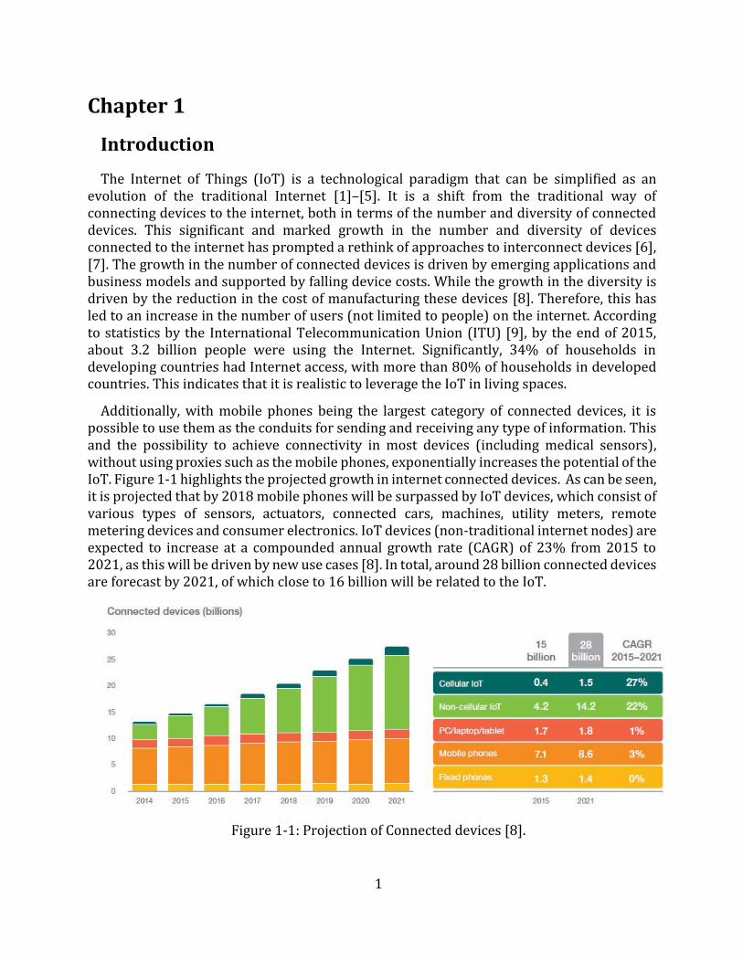
Additionally, with mobile phones being the largest category of connected devices, it is possible to use them as the conduits for sending and receiving any type of information. This and the possibility to achieve connectivity in most devices (including medical sensors), without using proxies such as the mobile phones, exponentially increases the potential of the IoT. Figure 1-1 highlights the projected growth in internet connected devices. As can be seen, it is projected that by 2018 mobile phones will be surpassed by IoT devices, which consist of various types of sensors, actuators, connected cars, machines, utility meters, remote metering devices and consumer electronics. IoT devices (non-traditional internet nodes) are expected to increase at a compounded annual growth rate (CAGR) of 23% from 2015 to 2021, as this will be driven by new use cases [8]. In total, around 28 billion connected devices are forecast by 2021, of which close to 16 billion will be related to the IoT.
Figure 1-1: Projection of Connected devices [8].
2
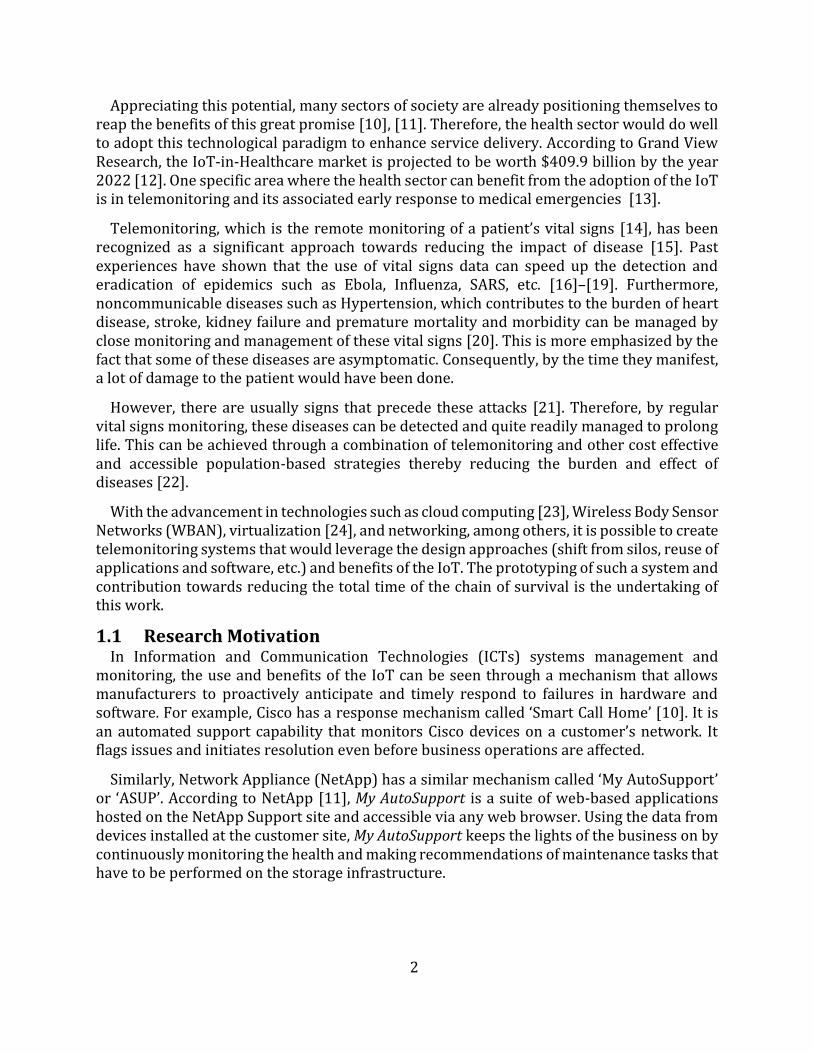
Appreciating this potential, many sectors of society are already positioning themselves to reap the benefits of this great promise [10], [11]. Therefore, the health sector would do well to adopt this technological paradigm to enhance service delivery. According to Grand View Research, the IoT-in-Healthcare market is projected to be worth $409.9 billion by the year 2022 [12]. One specific area where the health sector can benefit from the adoption of the IoT is in telemonitoring and its associated early response to medical emergencies [13].
Telemonitoring, which is the remote monitoring of a patient’s vital signs [14], has been recognized as a significant approach towards reducing the impact of disease [15]. Past experiences have shown that the use of vital signs data can speed up the detection and eradication of epidemics such as Ebola, Influenza, SARS, etc. [16]–[19]. Furthermore, noncommunicable diseases such as Hypertension, which contributes to the burden of heart disease, stroke, kidney failure and premature mortality and morbidity can be managed by close monitoring and management of these vital signs [20]. This is more emphasized by the fact that some of these diseases are asymptomatic. Consequently, by the time they manifest, a lot of damage to the patient would have been done.
However, there are usually signs that precede these attacks [21]. Therefore, by regular vital signs monitoring, these diseases can be detected and quite readily managed to prolong life. This can be achieved through a combination of telemonitoring and other cost effective and accessible population-based strategies thereby reducing the burden and effect of diseases [22].
With the advancement in technologies such as cloud computing [23], Wireless Body Sensor Networks (WBAN), virtualization [24], and networking, among others, it is possible to create telemonitoring systems that would leverage the design approaches (shift from silos, reuse of applications and software, etc.) and benefits of the IoT. The prototyping of such a system and contribution towards reducing the total time of the chain of survival is the undertaking of this work.
1.1 Research Motivation In Information and Communication Technologies (ICTs) systems management and
monitoring, the use and benefits of the IoT can be seen through a mechanism that allows manufacturers to proactively anticipate and timely respond to failures in hardware and software. For example, Cisco has a response mechanism called ‘Smart Call Home’ [10]. It is an automated support capability that monitors Cisco devices on a customer’s network. It flags issues and initiates resolution even before business operations are affected.
Similarly, Network Appliance (NetApp) has a similar mechanism called ‘My AutoSupport’ or ‘ASUP’. According to NetApp [11], My AutoSupport is a suite of web-based applications hosted on the NetApp Support site and accessible via any web browser. Using the data from devices installed at the customer site, My AutoSupport keeps the lights of the business on by continuously monitoring the health and making recommendations of maintenance tasks that have to be performed on the storage infrastructure.
3
The key feature that the aforementioned solutions offer is regular updates for the respective systems manufacturers on the health of installed systems, thereby enabling a proactive handling of failures. The overall effect is reduced downtime on the network or storage infrastructure. This is telemonitoring at its basic, which is the exact requirement the medical field has in dealing with many diseases. However, instead of referring to downtime, reduced mortality and morbidity are the benefits when adopted in the medical field. The parallel, however, is that diagnosis of diseases, just like ICT systems failures, stems from an analysis of a large collection of data about a patient. While physicians are generally apt to carry out the proper diagnosis, there is limited data for them to work with [25]. In most cases this data is only accessed/availed when a patient is taken ill, leading to a reactive course of actions. Sometimes, this delay represents the gap between saving and losing a life. However, if this data could be regularly captured and availed to medical personnel, as is done with the aforementioned ICT systems, timely actions that could prove invaluable in dealing with the burden of diseases can be taken [26]. By regularly and consistently monitoring these vital signs and taking timely corrective measures a lot of lives could be saved [21].
Additionally, there is an increased demand for vital signs data as evidenced by a surge in wearables and fitness devices [27]–[30]. Therefore, with the maturity of the IoT and other related paradigms, such as machine-to-machine (M2M) communication, data can be made available to users at any time and anywhere, not only for medical purposes and applications, through the implementation of telemonitoring and other related solutions. This will aid in lifestyle changes that would ultimately lead to improved quality of life and reduce the stakeholders’ response time to health emergencies.
Another key value that the IoT brings is improved collaboration among various SPs [7]. For example, in a case of a medical emergency, there is a need for an ambulance to be timely dispatched and for it to arrive at an optimal time. For this to be assured, traffic information (such as congestion on roads, breakdowns, etc.) among other factors would be valuable data in selecting the optimal path. With the IoT, it is possible to aggregate all this data in a common platform or simply enable data sharing among disparate but somewhat dependent sectors. This would aid in the choice of the best resources to dispatch in response to a medical need.
Hence by leveraging the IoT in the design of telemonitoring solutions, significant improvements in the delivery of health services can be realized. Sensing or monitoring devices can be incorporated into the communication infrastructure by using Application Programmable Interfaces (APIs) and the captured data made available to applications and persisted in databases through the use of middleware which provides abstraction and interoperability [7]. Intelligence can, optionally, be added to interpret that data and make decisions that will help medical practitioners and stakeholders (patients, caregivers, and relations) to consistently and reliably provide and receive medical services in a timely manner.
1.1.1 Problem Definition It is generally accepted that there are gaps that need to be bridged in the medical field to
ensure better provision of services to the patients [13], [31]. According to the Nursing Times [31], these gaps can generally be categorized into four “potential areas of improvement”.
4
The first is a need to have a regular observation of patients and their vital signs. This means that alternatives have to be provided to circumvent the prevailing apathy [22], [25] to visit health institutions for measurements to be done. Most patients have tended to assume that the hospital is only meant to be visited when there is a serious medical issue that needs to be addressed [22]. Regular and scheduled check-ups are not usually given the due emphasis and attention. This is usually because of the busy nature of hospitals hence they pose as a major time consumer. Sometimes the distance to health institutions can also prove a deterrent to regular hospital visits [32]. This is because other costs such as transport become significant. However, patients are interested to know the state of their health and would be very responsive and cooperative with any assistance that might be offered to them should emergencies arise [15]. Therefore, solutions that would allow vital signs to be monitored at the convenience of the patient would improve patient participation.
Therefore, Health SPs need to adopt creative and non-obtrusive methods that will encourage patients’ participation in the monitoring of these vital signs. As much as possible, vital signs readings should be taken at convenient locations and times. Therefore, devices that have consistent internet access and are usually part of the daily life of most patients, such as the mobile phones, would prove to be key enablers of regular observation of vital signs. Furthermore, miniaturization of the vital signs monitoring or sensing devices would be a key step towards making the monitoring process non-obtrusive. A lot of work is already being done to miniaturize these devices and make them as much part of daily life as possible, as evidenced by advancements in the field of fitness and wearables [27]–[30]. To map this use to the medical field, a system needs to be created that would allow for the aggregation of these disparate measuring and monitoring devices with electronic health records (EHR) systems. Such systems should be designed with the end-users’ needs in mind.
The second potential area of improvement is in the communication among stakeholders. Communication is not just about delivering information, it also has to do with delivery/prescription of the right information to the right people at the right time – information therapy [33]. With an increased number of vital signs readings being captured, it is possible to overwhelm the stakeholders with non-critical data. This would reduce the seriousness attached to such notifications. Therefore, to maintain the relevance of the notifications, it is necessary to filter the communicated data so that just the right data is delivered to the stakeholders.
Thirdly, effective response to medical concerns is another potential area of improvement. It is noted that patients do not generally get the right response at the right time because the information does not reach the rightly qualified personnel in good time [25], [13].
The final potential area of improvement, according to the Nursing Times, is in the early recognition of deterioration of the patients. This area of improvement is closely tied to the first one. With regular observation of the patient, it is possible to recognize deterioration at its early stage. However, with the other stakeholders (physicians and caregivers) in the management of disease either being overwhelmed or just busy with other tasks, recognition time tends to be affected. Therefore, it is imperative to consider specific needs of various stakeholders.
5
Physicians have specific needs that need to be addressed for them to efficiently deliver services to patients. For example, they have to deal with an overwhelming number of patients [34]. This means that they could do without perceived mundane tasks such as taking vital signs readings and concentrate on diagnosis and administration of treatments. The process of taking the vital signs is generally a time-consuming process. However, if this process can be automated by the adoption of IoT solutions, the data can be made readily available to the physician to work with. Additionally, a continuance vital signs data gathering process will avail medical researchers and physicians with the prerequisite data for them to carry out an early recognition of deterioration [21].
The other key stakeholder in patient management is a caregiver. Caregivers vary from next of kin to concerned neighbors and even strangers. While they are concerned about the health of a patient, they are usually only interested in critical readings that would signal a need for urgent attention. This is because, on average, caregivers are also occupied with the rigors of their own life. However, they, on average, tend to spend more time with the patient and are generally the first respondents to emergencies (particularly out-of-hospital) compared with the physician. Hence an automated system that only alerts them at exact moments when their help is needed and would prove none disruptive to their lives would enhance their availability to render help.
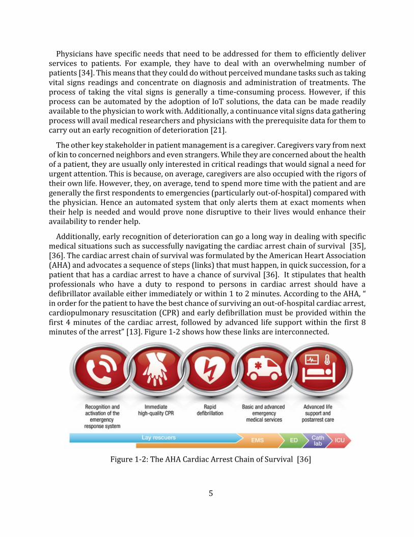
Additionally, early recognition of deterioration can go a long way in dealing with specific medical situations such as successfully navigating the cardiac arrest chain of survival [35], [36]. The cardiac arrest chain of survival was formulated by the American Heart Association (AHA) and advocates a sequence of steps (links) that must happen, in quick succession, for a patient that has a cardiac arrest to have a chance of survival [36]. It stipulates that health professionals who have a duty to respond to persons in cardiac arrest should have a defibrillator available either immediately or within 1 to 2 minutes. According to the AHA, “ in order for the patient to have the best chance of surviving an out-of-hospital cardiac arrest, cardiopulmonary resuscitation (CPR) and early defibrillation must be provided within the first 4 minutes of the cardiac arrest, followed by advanced life support within the first 8 minutes of the arrest” [13]. Figure 1-2 shows how these links are interconnected.
Figure 1-2: The AHA Cardiac Arrest Chain of Survival [36]
6
While all the steps are essential to achieving a successful patient resuscitation, it is recognizable that telemonitoring solutions can only contribute towards accomplishing the first link (recognition and activation of the emergency response system) and possibly activate the second thereby setting a target of 1 to 2 minutes. However, in order for the patient to have a chance of surviving an out-of-hospital cardiac arrest, advanced life support within the first 8 minutes of the arrest must be availed [13]. Therefore, the ultimate objective is to make the time interval between collapse and the call for advanced life support as short as possible, chiefly by expediting the execution of the first two links. This is because the chain of survival begins with the early recognition of deterioration, leading to the patient receiving any form of help as quickly as possible. The CPR chain is initiated when a medical emergency is recognized and the emergency medical system accessed or activated. According to Wellens [13], “an important breakthrough to improve the results of cardiac resuscitation could come from developing a device (or a system) specifically geared towards diminishing the time interval between collapse and the start of the resuscitation effort and notification of advanced life support of the location of the victim. This device should continuously register vital signs (like cardiac rhythm, arterial pulsations or heart sounds) allowing prompt recognition of circulatory arrest”.
Hence by developing a telemonitoring solution that can capture readings of vital signs, the chain of survival can be activated, in a timely manner, with the patient receiving timely help. Additionally, intelligence can be added to interpret that data and make decisions that will help medical practitioners and other stakeholders (patients, caregivers, etc.) to more timely, consistently and reliably provide and receive medical services/assistance.
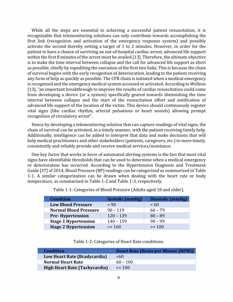
One key factor that works in favor of automated alerting systems is the fact that most vital signs have identifiable thresholds that can be used to determine when a medical emergency or deterioration has occurred. According to the Hypertension Diagnosis and Treatment Guide [37] of 2014, Blood Pressure (BP) readings can be categorized as summarized in Table 1-1. A similar categorization can be drawn when dealing with the heart rate or bodytemperature, as summarized in Table 1-2 and Table 1-3, respectively.
Table 1-1: Categories of Blood Pressure (Adults aged 18 and older).
Condition Systolic (mmHg) Diastolic (mmHg) Low Blood Pressure < 90 < 60 Normal Blood Pressure 90 – 119 60 – 79 Pre- Hypertension 120 – 139 80 – 89 Stage 1 Hypertension 140 – 159 90 – 99 Stage 2 Hypertension >= 160 >= 100
Table 1-2: Categories of Heart Rate conditions.
Condition Heart Rate (Beats per Minute (BPM)) Low Heart Rate (Bradycardia) <60 Normal Heart Rate 60 – 100 High Heart Rate (Tachycardia) >= 100
7
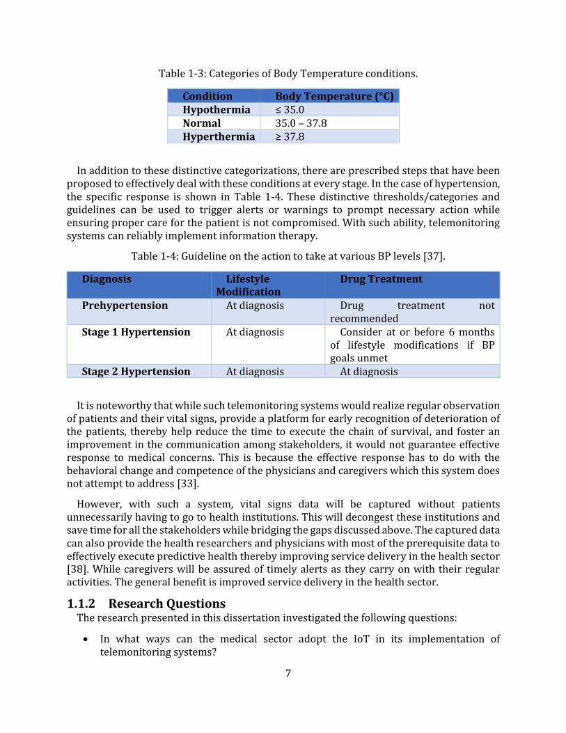
Table 1-3: Categories of Body Temperature conditions.
Condition Body Temperature (°C) Hypothermia ≤ 35.0 Normal 35.0 – 37.8 Hyperthermia ≥ 37.8
In addition to these distinctive categorizations, there are prescribed steps that have been proposed to effectively deal with these conditions at every stage. In the case of hypertension, the specific response is shown in Table 1-4. These distinctive thresholds/categories and guidelines can be used to trigger alerts or warnings to prompt necessary action while ensuring proper care for the patient is not compromised. With such ability, telemonitoring systems can reliably implement information therapy.
Table 1-4: Guideline on the action to take at various BP levels [37].
Diagnosis Lifestyle Modification
Drug Treatment
Prehypertension At diagnosis Drug treatment not recommended
Stage 1 Hypertension At diagnosis Consider at or before 6 months of lifestyle modifications if BP goals unmet
Stage 2 Hypertension At diagnosis At diagnosis
It is noteworthy that while such telemonitoring systems would realize regular observation of patients and their vital signs, provide a platform for early recognition of deterioration of the patients, thereby help reduce the time to execute the chain of survival, and foster an improvement in the communication among stakeholders, it would not guarantee effective response to medical concerns. This is because the effective response has to do with the behavioral change and competence of the physicians and caregivers which this system does not attempt to address [33].
However, with such a system, vital signs data will be captured without patients unnecessarily having to go to health institutions. This will decongest these institutions and save time for all the stakeholders while bridging the gaps discussed above. The captured data can also provide the health researchers and physicians with most of the prerequisite data to effectively execute predictive health thereby improving service delivery in the health sector [38]. While caregivers will be assured of timely alerts as they carry on with their regular activities. The general benefit is improved service delivery in the health sector.
1.1.2 Research Questions The research presented in this dissertation investigated the following questions:
In what ways can the medical sector adopt the IoT in its implementation oftelemonitoring systems?
8
Stakeholders in the medical sector have smart devices (smartphones). In what wayscan these be utilized to improve health service provision?
What are the possibilities of automating the transmission and management of vitalsigns: to improve the response time to deterioration, to increase the availability ofdata, and to improve communication among stakeholders as needed?
To what extent can an IoT-based telemonitoring system contribute towards reducingthe time to execute the chain of survival?
1.2 Objectives The aim of this work is to prototype a telemonitoring system that adopts the IoT design
approaches. Therefore, this dissertation investigates the adoption of IoT in healthcare, specifically in the monitoring and management of vital signs. It discusses literature on the IoT and its related paradigms and assesses how these can be adopted in telemonitoring. In addition to the discussion of literature, a prototype of a vital signs monitoring, transmission, and management system is proposed and implemented. A detailed discussion is given of the development and testing of this prototype.
In summary, the objectives of this dissertation are to:
Investigate the approaches of current implementations of vital signs monitoring andmanagement systems.
Investigate IoT frameworks or middleware that can be adopted to implement IoToriented telemonitoring systems.
Propose a prototype for a telemonitoring system to address gaps in the medicalsector.
Design and implement the proposed prototype and add value to it by implementinganalytics on the vital signs data. The analytics implemented will check vital signsreadings against preset thresholds to determine the action to be taken.
Evaluate and test the prototype to assess whether it delivers on the expectations ofthe identified stakeholders.
1.3 Scope and Limitation This dissertation considers the requirements of an IoT system that can be used in
telemonitoring. It addresses the gaps that have been identified in the delivery of medical services, as earlier discussed. While four gaps or areas of improvement have been identified, this work centers on the following: regular observation of patients and their vital signs, early recognition of deterioration of the patient, and improvement in the communication among stakeholders. It does not attempt to address effective response to medical concerns/emergencies.
As the main aspect of this study is management and analysis of vital signs, it addresses how the various components of such a system would interwork. However, this work does not address/discuss the medical accuracy or feasibility of the vital signs data. These are used purely to facilitate the study of the operations of the proposed prototype. Therefore, the stakeholders’ requirements are studied and based on these, functional requirements for the system are drawn. The study also follows the design approaches espoused by the IoT i.e. shift from silos to the implementation of a common horizontal platform that can accommodate
9
various vertical use cases. The study also recognizes that additional stakeholders, other than the identified (patient, physician, and caregiver), could be considered. These could include, SPs (network, M2M middleware, monitoring device SPs, etc.), applications and remote monitoring devices (RMDs) – which become active participants in an IoT implementation, etc.
While the network infrastructure is key to the successful implementation of any IoT solution, this work does not attempt to propose or implement any network infrastructure and the implementation thereof. It assumes the existence of and uses an existing network infrastructure. The only network requirement is that there must be Internet Protocol (IP) communication among the various system components. Therefore, the study of network parameters such as available bandwidth, latency, and cost of implementation of the network is outside the scope of this work.
Furthermore, while this work recognizes that there is no universally accepted standard IoT framework that has been defined, based on the time and literature reviewed, it is generally accepted that every IoT solution consists of sensing devices, the network infrastructure - to enable access to the internet and end user applications, and IoT applications [39]. This work concentrates on the development of two end user applications - a web application and a mobile application, their associated data management systems, andthe aggregation of the two using standard-compliant M2M middleware. This is to leveragethe benefits of the standards-compliant middleware while offering flexibility in the design ofapplications. The mobile application will reside on an Android device (smartphone) whilethe web application will be hosted on a virtual server and can be accessed over an IP networkby any capable devices.
While the work recognizes the importance of security and privacy with regard to the handling of patients’ data, it only discusses security in terms of role-based access control (RBAC) in accessing data using the web application. It does not give a detailed discussion on the implementation of the authentication process during the registration of the mobile application to the middleware, and the possibility of adding encryption to secure the transfer of data and mitigate man-in-the-middle attacks. Furthermore, it assumes that the network infrastructure SP addresses some/most of the security concerns.
Lastly, this work does not design or develop any sensing or monitoring devices but uses an off the shelf device (Zephyr HxM Heart Rate Monitor Bluetooth (BT) [30]). However, to interface this monitoring device with the Android mobile application, a broadcast receiver is designed and implemented as discussed in Chapter 4. To demonstrate the management of multiple vital signs, BP readings are simulated.
1.4 Dissertation Outline The rest of this dissertation is structured as follows:
Chapter 2 looks at the related work and current research on the IoT paradigm. It discusses some applications of communication technologies in the medical sector, some IoT implementation approaches and how they can build on the traditional approaches, and vital
10
signs monitoring and management systems that are currently being utilized in the health and fitness sectors. The Chapter investigates the key components that can be used to develop a functional vital signs monitoring, transmission, and management system for use in telemonitoring.
Chapter 3 discusses the key requirements for the implementation of the telemonitoring system. The Chapter details the stakeholders and their expectations of the system. It also details the use cases that will then define the functional requirements, which ultimately defines the parameters for the implementation of the proposed system.
Chapter 4 details the design and architectural considerations of the proposed telemonitoring system. The functional system diagram is presented and the various components of the system are described in detail. The Chapter also details the hardware and software implementation of the system.
Chapter 5 discusses the verification, evaluation, and analysis carried out of the system. Proof of concept and performance tests were performed on the framework. The proof of concept tests are required to show that the architectural requirements of the prototype are met and hence show that the solution is a suitable implementation to cater for the stakeholders' needs. The performance tests are designed to verify that prototype met the stakeholders’ expectations. A detailed discussion of the tests’ findings is presented in this Chapter.
Chapter 6 presents the conclusions drawn from the research work done and highlights the key contribution of the work. The Chapter ends with recommendations for further work that can be done on the same or similar topic.
11
Chapter 2
Literature Review
The previous Chapter discussed the challenges faced by the healthcare industry in remote monitoring and management of vital signs. It highlighted the gaps that telemonitoring systems can bridge to contribute to the improvement of healthcare service delivery. This Chapter presents an overview of the variants of the application of ICTs in delivering healthcare services. The Chapter discusses the IoT and M2M communication paradigms while highlighting the value that these would add to healthcare service provision, particularly in telemonitoring. Various implementation approaches of eHealth solutions are then presented to highlight their key contributions and possible areas of improvement. These contributions and possible areas of improvement will serve as the building blocks and gaps which this dissertation builds on and attempts to bridge, respectively.
2.1 Information and Communication Technology (ICT) in the healthcare industry
This section discusses the historical and current adoptions of ICT in the healthcare industry. It presents the common terms used to refer to the use of ICT and how these terms fit into the broader discussion of healthcare service delivery.
2.1.1 Telemedicine The health sector has a long-standing history of the use of ICT as a service delivery tool.
While some researchers trace the use of these technologies, in the shape of telemedicine, as far back as the second half of 19th century, with one of the first published accounts occurring in the early 20th century when electrocardiograph data were transmitted over telephone wires [40] , some researchers cite later dates [41].
However, despite this long-standing history, there is no single definition of the term telemedicine that has been globally adopted [42], [43]. Therefore, a discussion of some of the definitions is presented here. According to Okrent [41], of the Alliance for Health Reform, telemedicine is the use of electronic communication to exchange medical information from one site to another. Okrent submits that its adoption has increased with the improvements in technology and expansion of broadband connectivity to include remote readings of radiological images, round-the-clock intensive care unit consultations, and telephone outreach services to manage people with chronic conditions. The underlying objective is the extension of care to patients in remote areas. A similar view is put forward by the World Health Organization (WHO) who give a rather concise definition in [40]. They submit that telemedicine literally means “healing at a distance”. This, they posit, signifies the use of ICT to improve patient outcomes by increasing access to care and medical information. It is the delivery of health services or clinical care, where distance is a critical factor, by all health care professionals, using ICT for the exchange of valid information for diagnosis, treatment, prevention of disease and injuries, research and evaluation, and the continuing education of health care providers, all in the interests of advancing the health of individuals and their communities [32].
12
Pare et al. [14] posit that telemedicine is the direct provision of clinical care, including diagnosing, treating, or consultation, via telecommunications platforms for a patient at a distance. With this definition, there is an imperative requirement for active involvement of the medical practitioner. The authors note that telemedicine may cover diverse patient care services such as telepsychiatry, teleradiology, teledermatology, and teleophthalmology, among others. They also posit that its primary function is to provide specialist consultation to distant communities, rather than to provide a tool for self-management of chronic disease. Therefore, their definition, unlike Okrent’s, emphasizes the provision of specialist consultation to distant communities. However, central to both definitions is the distance factor.
The European Commission [44] defines telemedicine as “the provision of healthcare services, through the use of ICT, in situations where the health professional and the patient (or two health professionals) are not in the same location. It involves the secure transmission of medical data and information, through text, sound, images or other forms needed for the prevention, diagnosis, treatment, and follow-up of patients.” It is generally used for the purpose of consulting, and remote medical procedures or examinations [14], [32]. This definition covers both the active involvement of health professionals, as submitted by Pare et al., and the provision of healthcare services over a distance, as posited by the WHO and Okrent.
In addition to the definitions given, WHO posits that telemedicine applications can be classified into two basic types, according to the timing of the information transmitted and the interaction between the individuals involved. These basic types are store-and-forward, or asynchronous communication and real-time, or synchronous communication [40]. A similar classification is made by authors in [45]. Store-and-forward involves the exchange of pre-recorded data between two or more individuals at different times. In this scenario, information is acquired in one location and reviewed in another at a later stage (or time). An example given is a scenario where a patient or referring health professional sends an e-mail description of a medical case to an expert who later sends back an opinion regarding diagnosis and optimal management. In contrast, real-time communication requires the individuals involved to be simultaneously present for immediate exchange of information, as in the case of video conferencing. It is contended that the primary objective in either type of telemedicine is to link healthcare SPs with specialists, referral hospitals, and tertiary care centers.
2.1.2 Telemonitoring Another term used to refer to the adoption of ICTs in the medical field is telemonitoring.
According to Brown [32], telemonitoring is a form of telemedicine which involves the monitoring of a patient, usually in a home setup, using vital signs monitoring devices and transferring the information to a caregiver/physician. This is the same position held by the European Commission [44]. Some researchers, however, opt to treat telemedicine and telemonitoring as two disparate practices due to a number of subtleties [14], [46]. According to Pare et al. [14], who use the phrase “home telemonitoring”, telemonitoring is an automated process for the transmission of data on a patient’s health status from a home setting to the respective healthcare setting. It is the use of ICT to monitor a patient’s status at a distance. They further submit that telemonitoring does not involve the electronic
13
transmission of data by a health care professional at the patient’s location. Only patients or their family members, when necessary, are responsible for keying in and transmitting their data without the help of a healthcare provider such as a nurse or a physician. This, they argue, differentiates it from telemedicine where a health practitioner can be an active participant at either end of the communication link. Additionally, they posit that the patient is the center of telemonitoring while the central objective of telemedicine is extending healthcare (particularly specialist services) over a distance. According to Lu et al. [46], telemonitoring is a result of the fundamental changes the healthcare industry is currently undergoing that include a shift from hospital-centric services to a more ambulatory system (with home care, day care clinics, and so on) and the treatment of chronic diseases that actively involves the patient’s active participation. In contrast, telemedicine is mainly seen as a means to avail or ‘extend’ the health practitioner, with the primary aim of enabling doctors to stay in contact with their patients regardless of their location [39]. This addresses the challenge of distance between the patients and the health practitioner while telemonitoring does not address distance as its primary objective, but emphasizes the active participation of patients and their family in healthcare service delivery. However, after close study of the varying positions on the subject, this work treats telemonitoring as a part of telemedicine, as posited in [32] and [44].
After studying the effect of telemonitoring on the provision of health care, Mckinstry et al. [15], showed that the use of supported-telemonitoring of home measured BP in primary care produces clinically important reductions in both daytime systolic and diastolic ambulatory BP in a group of patients with uncontrolled BP. They deduce that telemonitoring is associated with an increase in the use of health service resources resulting in the reductions observed. They posit that the key factor to this observed reduction is the combined effort of patients and the attending nurse or doctor. Therefore, to achieve the best outcome for telemonitoring, there must be a concerted effort by health professionals, the patient, and the patient’s family.
2.1.3 EHealth and Telehealth The other terms used to refer to the use of ICT for healthcare service delivery are eHealth
and Telehealth. Oh et al. [43] after reviewing an array of efforts to define eHealth recognize the lack of a universally accepted definition of eHealth and refuse to yield to the temptation of attempting to give a “better” definition of the same. However, they acknowledge that the introduction of eHealth represented the promise of ICTs to improve health and the healthcare service delivery system. They submit that in the definitions they reviewed, the use of ICT was viewed both as a tool to enable a process/function/service and as the embodiment of eHealth itself (e.g., a health website on the Internet). They posit that the majority of the definitions they reviewed could be condensed into the following definition - "the use of information technology in the delivery of health care”. They observe that eHealth is aimed at enhancing human (medical practitioners’) activities, rather than as a substitute for them.
Similarly, Pagliari et al. [42] submit that eHealth involves the use of ICT, especially the Internet, to improve or enable health and health care service delivery. They submit that it is a field of medical informatics, referring to the organization and delivery of health services and information using the Internet and its related technologies. They posit that the term
14
characterizes not only a technical development, but also a new way of working, an attitude and a commitment towards a networked global thinking to improve health care locally, regionally, and worldwide by using ICT. In terms of its functional scope, they observe, just like Lu et al. [46], that most definitions conceptualize eHealth as a broad range of medical informatics applications for facilitating the management and delivery of health care. According to Lu et al., eHealth is a field that stems from the intersection of medical informatics, public health, and business, and refers to health services and information delivered or enhanced through the Internet and related technologies.
On the other hand, Telehealth, according to the American Hospitals Association, has many guises ranging from “remote monitoring programs used by hospitals for post-discharge monitoring, to reduce readmissions,” to “hospital emergency departments using remote video consultations to enable patients to receive telepsychiatric screening” [47]. It is an umbrella term that covers telemonitoring, telemedicine and other related medical practices. They posit that the term Telehealth is to be used broadly to describe the delivery of health care services, education, and information using ICT.
In the broader context, the term eHealth is an umbrella term that covers Health Informatics, Telehealth and other ICT solutions in healthcare and medicine [48]. Usually, telemedicine and telemonitoring have been used to describe narrower ranges of healthcare services, while the terms Telehealth and eHealth have been used to refer to a broader scope of healthcare services, including non-clinical services such as training and education that are provided at a distance [32]. Though Brown, in [32], contends that the term eHealth is only often used in the United Kingdom (UK) and Europe, as can be noted in [49].
In terms of modalities or implementation approaches, the American Hospitals Association recognizes three traditional approaches or modalities, and one emerging approach or modality, each with distinct applications within the broader Telehealth industry. The first traditional Telehealth modality is a real-time approach which enables communication between a patient and a healthcare provider. This utilizes various ICTs that enable live and two way audiovisual interaction. Real-time Telehealth services can be used for consultancy, diagnosis, and treatment. The second traditional Telehealth modality is store-and-forward. In this modality a patient’s recorded health history is securely transmitted to a health care provider using ICT platforms. This does not need to be in done in real-time. While the third traditional Telehealth modality is remote patient monitoring. This is enabled and relies on a collection of a patient’s personal health data using ICTs. This data is then is transmitted to a healthcare provider at a different location. The data transmitted enables out-of-hospital care and support. The outcome is continued provision of support by the provider even when not in contact. While the newer Telehealth modality is categorized as mobile health (mHealth). This is seen as a combination of technologies, applications and online services that are availed directly to patients and are intended not to stifle mobility. Examples include wearable devices which are intended to be non-obtrusive [47].
Nevertheless, despite the variances in the adoption of ICT in the medical field, it is contended that there are benefits that come with the use of these technologies. Among these benefits are: reduced time-off-work and savings in travel costs [45], offer of cost-effective alternatives to the more traditional face-to-face way of providing medical care [47],
15
increased access to health services by patients in remote areas [40], provision to patients and healthcare professionals of easy access to medical information irrespective of the physical location [46], improved efficiency, effectiveness, and quality of clinical and business processes utilized by healthcare organizations and stakeholders [49], and increased patients’ participation in healthcare service delivery [46]. Therefore for continued and enhanced benefits, this adoption of the ICT should continue to move with the advancements in ICT such as the emergence of the IoT and its design approaches.
2.2 The Internet of Things (IoT) This section discusses the IoT by reviewing the attempts to define it followed by a
discussion of its background. It also presents the IoT vision and the role of M2M communication in delivering this vision. Lastly, the section gives a brief highlight of some of the work that is being done to standardize the IoT landscape.
2.2.1 Defining the IoT The IoT is a technological paradigm that is currently undergoing a phase of massive
research and development (R&D) [50]. While there is currently no globally recognized definition of the phrase “Internet of Things”, a number of research and standards bodies have put forward definitions that guide them to scope their respective work. Some of these definitions are reviewed in this subsection to adopt a working definition for this work.
The Internet Engineering Task Force (IEFT) defines the IoT as a network of smart objects [51]. These smart objects are both human and non-human controlled devices. The Institute of Electrical and Electronics Engineers (IEEE) describes the IoT as a network of items each embedded with sensors and connected to the internet [52]. The Organization for the Advancement of Structured Information Standards (OASIS) defines the IoT as a system where the Internet is connected to the physical world via ubiquitous sensors [52]. The European Union (EU) Commission defines IoT as a transition from a network of interconnected computers to a network of interconnected objects [53]. The National Institute of Standards and Technology (NIST) considers the IoT under the umbrella term cyber-physical systems (CPS). They define CPS as the connection of smart devices and systems in various sectors [52]. The World Wide Web Consortium (W3C) uses the term Web of Things which is epitomized by the role of web technologies to facilitate the development of applications and services for the IoT. Sensors, as well as physical objects tagged with a bar code or Near-field Communication (NFC), are central to this vision [52]. The Internet Architecture Board (IAB) describes the IoT as a trend where a huge number of embedded devices employ communication services offered by the internet protocols [51].
Cisco, however, posits that the IoT is simply a point in time when more objects/things are connected to the internet [1]. In essence, it is simply a point in the growth of the current internet when the majority of the end-users will be these objects/things. While no apparent technicality is given in this definition, the key takeaway is that the development of the IoT does not usher in a technology or infrastructure overhaul but simply utilizes the same network-of-networks (internet) as is currently available. This is the same position held by authors in [54]. Therefore, the IoT is an era where a very large number (billions) of sensors are connected to the internet [2].
16
Furthermore, the IoT is defined as a framework in which all things have representation and a virtual presence on the internet hence bridging the gap between the virtual and physical world [51]. The realization of this bridge between the physical and virtual world is being accomplished due to advancement in the identification, embedded processing and sensing technologies [54]. Hence the IoT can also be viewed as a term used to describe technologies, systems and design principles associated with the emerging wave of internet connected things that are based on the physical environment [55].
From the definitions given above, the IoT is a: network, system, transition, connection, framework and/or trend. Despite this diversity in the reviewed definitions, there are common ideas that cut across them. After an effort to combine these ideas and have a working definition for this work, the IoT can be seen as an infrastructure for the information society, that makes available or enables advanced services by interconnecting a vast number of physical and virtual everyday objects/things based on existing and evolving interoperable ICTs [51]. It is a communication infrastructure that provides unified, simple and economical access to a plethora of public services [56], [57]. Its two key features are being immersive and pervasive [56].
An acceptance of the idea that the same infrastructure or networks that are being used by the end users of the current/traditional internet will continue in the IoT leads to an important observation in understanding the IoT as an evolution of the current Internet [1]–[5]. Additionally, the objects/things of this internet will have interactions and will communicate with other machines, objects, environment, and infrastructure as do the users of the internet [54], [58].
2.2.2 Background of the IoT Kevin Ashton [51], co-founder and executive director of the Auto-ID Center, is credited
with the coinage of the phrase “Internet of Things”. He used it to describe a system in which objects in the physical world could be connected to the internet by sensors. This was in an effort to demonstrate the power of connecting radio-frequency identification (RFID) tags to the internet.
However, even Ashton would not have imagined how much progress would be made in this field. His idea was to empower computers with sensory abilities using RFID and sensor technologies to free them of human limitations [59] and connecting them to the internet. However, it is now generally accepted that the IoT is leading to an evolution of the internet [1]–[5]. This is evident by the work being done by the Internet Protocol for Smart Objects (IPSO) Alliance [60] in ensuring the continued use of the IP protocol, a bedrock of the traditional internet, in the IoT. Hence the history of the IoT is closely tied to that of the internet. Without giving a detailed discussion of that history, it is important to note that from the inception of the ‘www’ (world-wide-web) (also referred to as the web 1.0) in 1991, leading to the popularity of the internet, the internet has been in a constant state of evolution. Early days of static HyperText Markup Language (HTML) documents [3] seem to be in a distant past as the web 2.0 presently dominates the current internet. This era (web 2.0) of the internet is where the web became a point-to-point (P2P) network where all users have an equal participation status. This, according to Nokia’s Jadoul [4], ushered in the Internet of services.
17
During the web 1.0 era, internet nodes were only passive consumers [55]. However, with the ushering in of the web 2.0, the internet nodes became both active consumers and producers of data [3]. Hence as this evolution continues, a new era is emerging. The era of the semantic web (web 3.0). The goal of the semantic web is to furnish enough data for machines to understand and make data more searchable [3]. Currently, machines/things are mainly content producers, with servers along with databases performing the role of data consumers [55]. This in many ways parallels the web 1.0 era, hence the phrase “machines’ web 1.0 era” [55] - the infancy of the IoT vision. Notably, in its infancy, the IoT is still made up of a loose collection of disparate, purpose-built networks or silos [1], [2].
The fuel that has propelled the evolution of the internet is the development and progress of technologies in sensor networks and NFC using RFID tags [3]. Continued development of RFID and sensor networks technologies is leading to ICT systems being embedded in the environment around us [61]. This will ultimately usher in the machines’ web 2.0 era [55].
A concise summary of the history of the IoT is given in [62].
2.2.3 M2M - An IoT Enabler M2M is a paradigm that is closely linked with the IoT paradigm. The European
Telecommunications Standards Institute (ETSI) posits that M2M is communication among machines without human intervention [63]. Its role is to establish the conditions that allow an M2M device to exchange information with a business application via a communication network while that M2M device and/or application acts as the owner of the information exchanged [64]. In this communication, the realization of automated communication is key [52]. Hence, M2M would be best called M2MC or machine-type-communication (MTC) - which is essentially communication between machines [65], [66].
In attempts to contextualize the term, the M2M Alliance [67] describes M2MC as communicative networking of mobile or stationary intelligent objects, where data transfer is automated and independent of underlying network infrastructure [55]. Therefore, M2M refers to systems that enable machines to communicate with backend information systems and/or directly with other machines in order to provide real-time data [68], [52]. These systems consist of technologies that enable communication and networking of devices, usually within a closed network [57], [69], [70]. The objective, generally, is to attain remote connectivity to the devices, the service enablement interfaces and application logic, and integration of the M2M application into the business processes. Core to achieving this objective is the connection of sensors, actuators and other devices to the communication infrastructure [5].
Originally, these systems were purpose driven and very much local to the designers’ locale. They were (and some continue to be) special purpose devices/systems that are application specific - meant to resolve a specific enterprise problem [5]. This led to the introduction of protocols such as ZigBee [71], Constrained Application Protocol (CoAP) [72], Message Queue Telemetry Transport (MQTT) [73], and others that were generally not intended to connect to the internet. This is because M2M networks needed not connect to the internet or interact over the internet as M2M solutions were generally not intended for the broad sharing of data. Furthermore, M2M networks would only allow communication between devices of the same type to serve a specific purpose. However, this is being changed, making M2M appear as
18
though it is evolving into the IoT [5]. Because of this evolution and development of M2M communication, it currently provides the ‘plumbing’ of most IoT implementations, thereby rightfully acting the role of an enabler of the IoT [57], [68], [74], [75].
2.2.4 The IoT Vision The IoT is driven by users’ desire to have knowledge and control over the environment
and the resources they own. Therefore, central to the desire to connect things to the internet is a need to have readily available data. The more data can be amassed and interpreted, the more meaningful the IoT could become. This implies a need to add context to this data. Furthermore, this information must be available anytime and all the time [2], [52], [76].
Therefore, the IoT offers a stage in the evolution of the internet when a large scale of diverse objects of everyday life [1], [3], equipped with microcontrollers, and transceivers are able to communicate with users and other objects that are part of the internet [51], [56]. “Things” will be equal users of the internet compared to the traditional nodes. They will be identified by IP or equivalent and will communicate with other smart objects and network nodes [58].
According to Perera et al. [2], once these new users of the internet have started producing data, the natural step in the evolution will be for them to start consuming. This will lead to greater autonomy and complexity. Hence this will naturally call for added security, analytics, and management capabilities as a lot more responsibilities will be thrust on these nodes [1].
Texas Instrumentation [5] refers to the IoT as the “internet of tomorrow” which they posit will be the largest horizontal system architecture ever created. Vertical applications will continue to exist; however, the fundamental lowest levels of connectivity and information passing will need to be ubiquitous and invisible in all applications. They posit that the IoT requires manufacturers to deliver on the most fundamental challenges, including connectivity, power management, security, complexity, and rapid evolution. This calls for the optimized performance of systems and processes. This, in time, will save time for people and businesses, resulting in improved quality of life by enabling monitoring and management of machines, the physical world, people, animals, etc. [54], [77].
In an effort to realize this vision, a number of standards bodies and projects have been instituted. These include (by no means exhaustive): The ITU [78] - that has taken a global lead in developing standards for the IoT, the IEEE’s IoT-A [79] – that defines an architectural framework for the IoT, the Industrial Internet Consortium (IIC) [80] – that promotes the accelerated growth of the Industrial IoT, the OASIS [81] – that promotes industry consensus and produces worldwide standards for security, Internet of Things, cloud computing, energy, content technologies, emergency management, and other areas, the Open Connectivity Foundation (OCF) [82] – that promises to unlock the massive opportunity in the IoT market, accelerate industry innovation and help developers and companies create solutions that map to a single open specification by creating a specification and sponsoring an open source project, the IPSO Alliance [83] - focused on enabling IoT devices to communicate, understand and trust each other with global interoperability based on open standards, the AllSeen Alliance [84] – that is looking at interoperability of billions of devices, services and apps, the Thread Group [85] – that seeks to connect and control products in the home, and the Internet Engineering Task Force (IETF) [86].
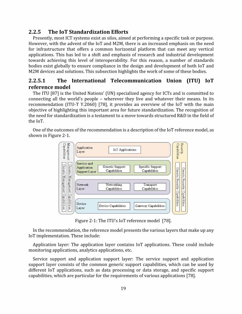
19
2.2.5 The IoT Standardization Efforts Presently, most ICT systems exist as silos, aimed at performing a specific task or purpose.
However, with the advent of the IoT and M2M, there is an increased emphasis on the need for infrastructure that offers a common horizontal platform that can meet any vertical applications. This has led to a shift and emphasis of research and industrial development towards achieving this level of interoperability. For this reason, a number of standards bodies exist globally to ensure compliance in the design and development of both IoT and M2M devices and solutions. This subsection highlights the work of some of these bodies.
2.2.5.1 The International Telecommunication Union (ITU) IoT reference model
The ITU [87] is the United Nations’ (UN) specialized agency for ICTs and is committed to connecting all the world's people – wherever they live and whatever their means. In its recommendation (ITU-T Y.2060) [78], it provides an overview of the IoT with the main objective of highlighting this important area for future standardization. The recognition of the need for standardization is a testament to a move towards structured R&D in the field of the IoT.
One of the outcomes of the recommendation is a description of the IoT reference model, as shown in Figure 2-1.
Figure 2-1: The ITU's IoT reference model [78].
In the recommendation, the reference model presents the various layers that make up any IoT implementation. These include:
Application layer: The application layer contains IoT applications. These could include monitoring applications, analytics applications, etc.
Service support and application support layer: The service support and application support layer consists of the common generic support capabilities, which can be used by different IoT applications, such as data processing or data storage, and specific support capabilities, which are particular for the requirements of various applications [78].
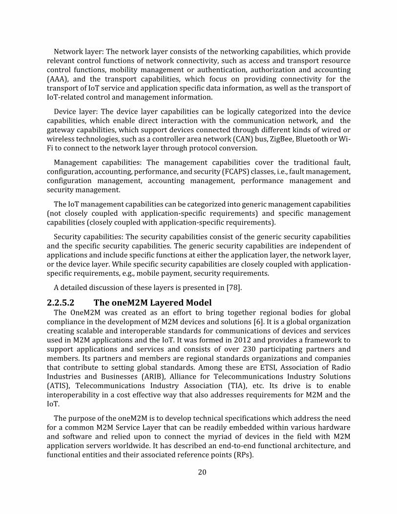
20
Network layer: The network layer consists of the networking capabilities, which provide relevant control functions of network connectivity, such as access and transport resource control functions, mobility management or authentication, authorization and accounting (AAA), and the transport capabilities, which focus on providing connectivity for the transport of IoT service and application specific data information, as well as the transport of IoT-related control and management information.
Device layer: The device layer capabilities can be logically categorized into the device capabilities, which enable direct interaction with the communication network, and the gateway capabilities, which support devices connected through different kinds of wired or wireless technologies, such as a controller area network (CAN) bus, ZigBee, Bluetooth or Wi-Fi to connect to the network layer through protocol conversion.
Management capabilities: The management capabilities cover the traditional fault, configuration, accounting, performance, and security (FCAPS) classes, i.e., fault management, configuration management, accounting management, performance management and security management.
The IoT management capabilities can be categorized into generic management capabilities (not closely coupled with application-specific requirements) and specific management capabilities (closely coupled with application-specific requirements).
Security capabilities: The security capabilities consist of the generic security capabilities and the specific security capabilities. The generic security capabilities are independent of applications and include specific functions at either the application layer, the network layer, or the device layer. While specific security capabilities are closely coupled with application-specific requirements, e.g., mobile payment, security requirements.
A detailed discussion of these layers is presented in [78].
2.2.5.2 The oneM2M Layered Model The OneM2M was created as an effort to bring together regional bodies for global
compliance in the development of M2M devices and solutions [6]. It is a global organization creating scalable and interoperable standards for communications of devices and services used in M2M applications and the IoT. It was formed in 2012 and provides a framework to support applications and services and consists of over 230 participating partners and members. Its partners and members are regional standards organizations and companies that contribute to setting global standards. Among these are ETSI, Association of Radio Industries and Businesses (ARIB), Alliance for Telecommunications Industry Solutions (ATIS), Telecommunications Industry Association (TIA), etc. Its drive is to enable interoperability in a cost effective way that also addresses requirements for M2M and the IoT.
The purpose of the oneM2M is to develop technical specifications which address the need for a common M2M Service Layer that can be readily embedded within various hardware and software and relied upon to connect the myriad of devices in the field with M2M application servers worldwide. It has described an end-to-end functional architecture, and functional entities and their associated reference points (RPs).
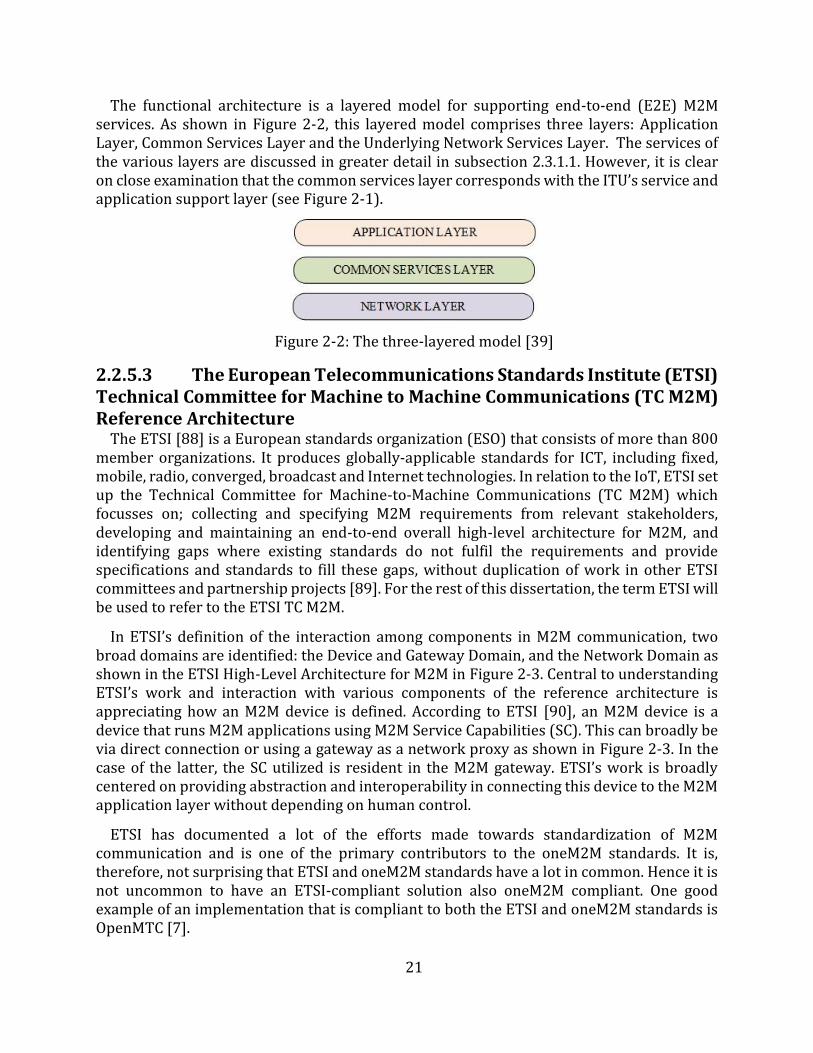
21
The functional architecture is a layered model for supporting end-to-end (E2E) M2M services. As shown in Figure 2-2, this layered model comprises three layers: Application Layer, Common Services Layer and the Underlying Network Services Layer. The services of the various layers are discussed in greater detail in subsection 2.3.1.1. However, it is clear on close examination that the common services layer corresponds with the ITU’s service and application support layer (see Figure 2-1).
Figure 2-2: The three-layered model [39]
2.2.5.3 The European Telecommunications Standards Institute (ETSI) Technical Committee for Machine to Machine Communications (TC M2M) Reference Architecture
The ETSI [88] is a European standards organization (ESO) that consists of more than 800 member organizations. It produces globally-applicable standards for ICT, including fixed, mobile, radio, converged, broadcast and Internet technologies. In relation to the IoT, ETSI set up the Technical Committee for Machine-to-Machine Communications (TC M2M) which focusses on; collecting and specifying M2M requirements from relevant stakeholders, developing and maintaining an end-to-end overall high-level architecture for M2M, and identifying gaps where existing standards do not fulfil the requirements and provide specifications and standards to fill these gaps, without duplication of work in other ETSI committees and partnership projects [89]. For the rest of this dissertation, the term ETSI will be used to refer to the ETSI TC M2M.
In ETSI’s definition of the interaction among components in M2M communication, two broad domains are identified: the Device and Gateway Domain, and the Network Domain as shown in the ETSI High-Level Architecture for M2M in Figure 2-3. Central to understanding ETSI’s work and interaction with various components of the reference architecture is appreciating how an M2M device is defined. According to ETSI [90], an M2M device is a device that runs M2M applications using M2M Service Capabilities (SC). This can broadly be via direct connection or using a gateway as a network proxy as shown in Figure 2-3. In the case of the latter, the SC utilized is resident in the M2M gateway. ETSI’s work is broadly centered on providing abstraction and interoperability in connecting this device to the M2M application layer without depending on human control.
ETSI has documented a lot of the efforts made towards standardization of M2M communication and is one of the primary contributors to the oneM2M standards. It is, therefore, not surprising that ETSI and oneM2M standards have a lot in common. Hence it is not uncommon to have an ETSI-compliant solution also oneM2M compliant. One good example of an implementation that is compliant to both the ETSI and oneM2M standards is OpenMTC [7].
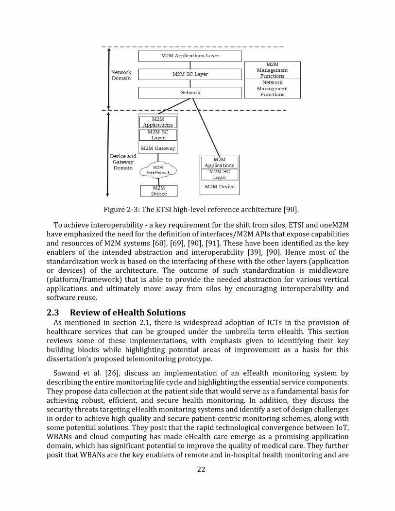
22
Figure 2-3: The ETSI high-level reference architecture [90].
To achieve interoperability - a key requirement for the shift from silos, ETSI and oneM2M have emphasized the need for the definition of interfaces/M2M APIs that expose capabilities and resources of M2M systems [68], [69], [90], [91]. These have been identified as the key enablers of the intended abstraction and interoperability [39], [90]. Hence most of the standardization work is based on the interfacing of these with the other layers (application or devices) of the architecture. The outcome of such standardization is middleware (platform/framework) that is able to provide the needed abstraction for various vertical applications and ultimately move away from silos by encouraging interoperability and software reuse.
2.3 Review of eHealth Solutions As mentioned in section 2.1, there is widespread adoption of ICTs in the provision of
healthcare services that can be grouped under the umbrella term eHealth. This section reviews some of these implementations, with emphasis given to identifying their key building blocks while highlighting potential areas of improvement as a basis for this dissertation’s proposed telemonitoring prototype.
Sawand et al. [26], discuss an implementation of an eHealth monitoring system by describing the entire monitoring life cycle and highlighting the essential service components. They propose data collection at the patient side that would serve as a fundamental basis for achieving robust, efficient, and secure health monitoring. In addition, they discuss the security threats targeting eHealth monitoring systems and identify a set of design challenges in order to achieve high quality and secure patient-centric monitoring schemes, along with some potential solutions. They posit that the rapid technological convergence between IoT, WBANs and cloud computing has made eHealth care emerge as a promising application domain, which has significant potential to improve the quality of medical care. They further posit that WBANs are the key enablers of remote and in-hospital health monitoring and are
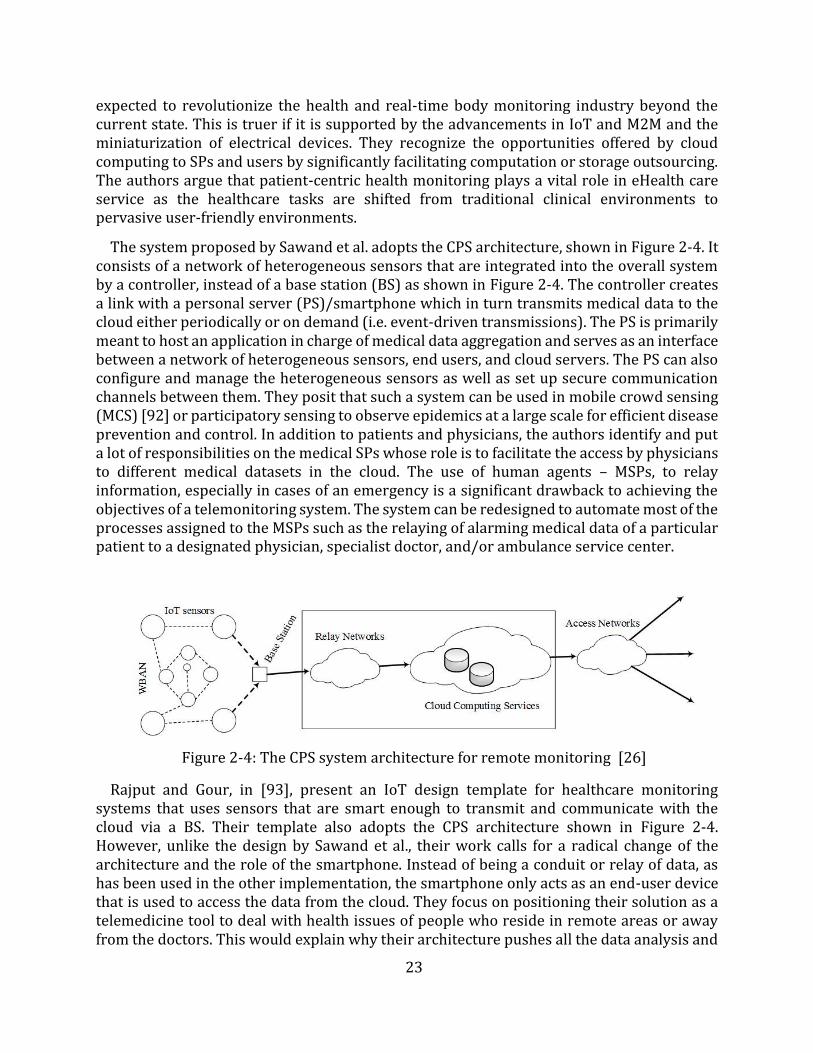
23
expected to revolutionize the health and real-time body monitoring industry beyond the current state. This is truer if it is supported by the advancements in IoT and M2M and the miniaturization of electrical devices. They recognize the opportunities offered by cloud computing to SPs and users by significantly facilitating computation or storage outsourcing. The authors argue that patient-centric health monitoring plays a vital role in eHealth care service as the healthcare tasks are shifted from traditional clinical environments to pervasive user-friendly environments.
The system proposed by Sawand et al. adopts the CPS architecture, shown in Figure 2-4. It consists of a network of heterogeneous sensors that are integrated into the overall system by a controller, instead of a base station (BS) as shown in Figure 2-4. The controller creates a link with a personal server (PS)/smartphone which in turn transmits medical data to the cloud either periodically or on demand (i.e. event-driven transmissions). The PS is primarily meant to host an application in charge of medical data aggregation and serves as an interface between a network of heterogeneous sensors, end users, and cloud servers. The PS can also configure and manage the heterogeneous sensors as well as set up secure communication channels between them. They posit that such a system can be used in mobile crowd sensing (MCS) [92] or participatory sensing to observe epidemics at a large scale for efficient disease prevention and control. In addition to patients and physicians, the authors identify and put a lot of responsibilities on the medical SPs whose role is to facilitate the access by physicians to different medical datasets in the cloud. The use of human agents – MSPs, to relay information, especially in cases of an emergency is a significant drawback to achieving the objectives of a telemonitoring system. The system can be redesigned to automate most of the processes assigned to the MSPs such as the relaying of alarming medical data of a particular patient to a designated physician, specialist doctor, and/or ambulance service center.
Figure 2-4: The CPS system architecture for remote monitoring [26]
Rajput and Gour, in [93], present an IoT design template for healthcare monitoring systems that uses sensors that are smart enough to transmit and communicate with the cloud via a BS. Their template also adopts the CPS architecture shown in Figure 2-4. However, unlike the design by Sawand et al., their work calls for a radical change of the architecture and the role of the smartphone. Instead of being a conduit or relay of data, as has been used in the other implementation, the smartphone only acts as an end-user device that is used to access the data from the cloud. They focus on positioning their solution as a telemedicine tool to deal with health issues of people who reside in remote areas or away from the doctors. This would explain why their architecture pushes all the data analysis and
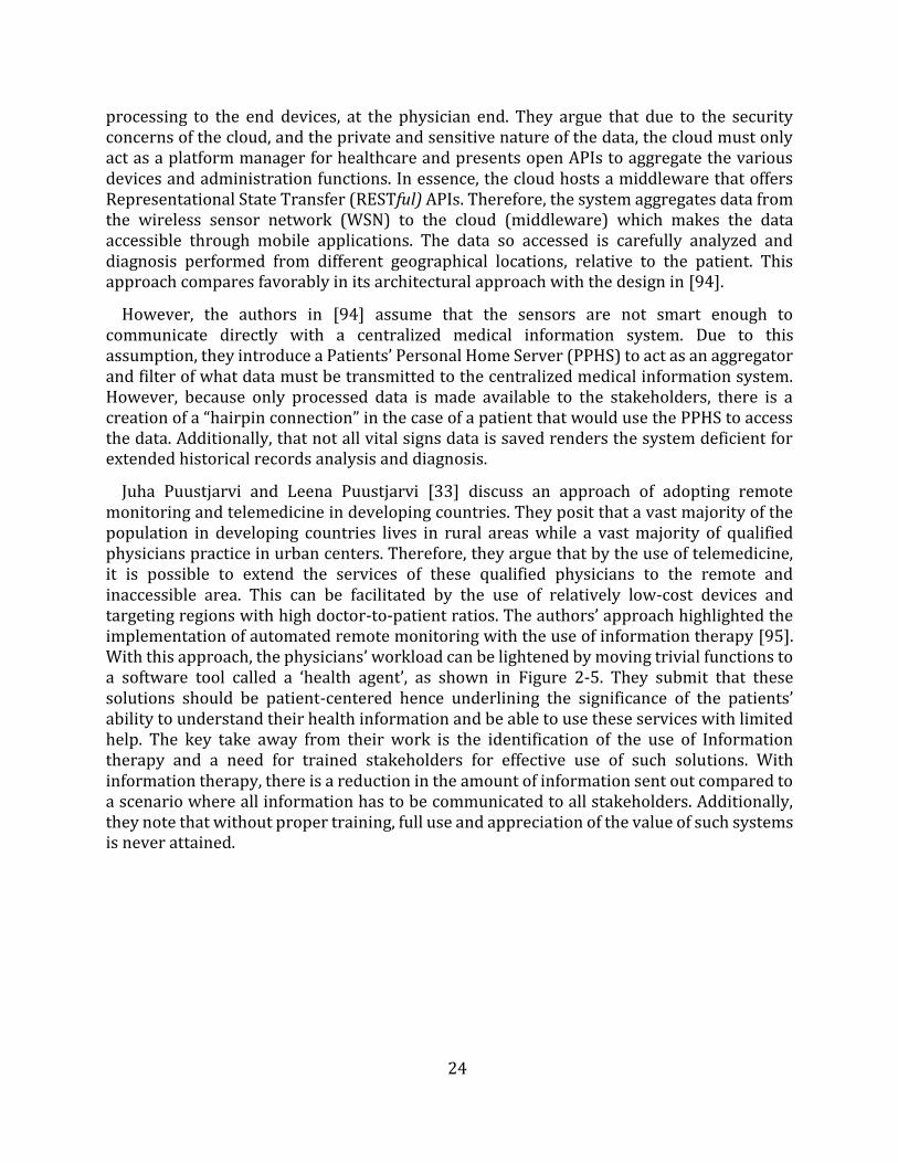
24
processing to the end devices, at the physician end. They argue that due to the security concerns of the cloud, and the private and sensitive nature of the data, the cloud must only act as a platform manager for healthcare and presents open APIs to aggregate the various devices and administration functions. In essence, the cloud hosts a middleware that offers Representational State Transfer (RESTful) APIs. Therefore, the system aggregates data from the wireless sensor network (WSN) to the cloud (middleware) which makes the data accessible through mobile applications. The data so accessed is carefully analyzed and diagnosis performed from different geographical locations, relative to the patient. This approach compares favorably in its architectural approach with the design in [94].
However, the authors in [94] assume that the sensors are not smart enough to communicate directly with a centralized medical information system. Due to this assumption, they introduce a Patients’ Personal Home Server (PPHS) to act as an aggregator and filter of what data must be transmitted to the centralized medical information system. However, because only processed data is made available to the stakeholders, there is a creation of a “hairpin connection” in the case of a patient that would use the PPHS to access the data. Additionally, that not all vital signs data is saved renders the system deficient for extended historical records analysis and diagnosis.
Juha Puustjarvi and Leena Puustjarvi [33] discuss an approach of adopting remote monitoring and telemedicine in developing countries. They posit that a vast majority of the population in developing countries lives in rural areas while a vast majority of qualified physicians practice in urban centers. Therefore, they argue that by the use of telemedicine, it is possible to extend the services of these qualified physicians to the remote and inaccessible area. This can be facilitated by the use of relatively low-cost devices and targeting regions with high doctor-to-patient ratios. The authors’ approach highlighted the implementation of automated remote monitoring with the use of information therapy [95]. With this approach, the physicians’ workload can be lightened by moving trivial functions to a software tool called a ‘health agent’, as shown in Figure 2-5. They submit that these solutions should be patient-centered hence underlining the significance of the patients’ ability to understand their health information and be able to use these services with limited help. The key take away from their work is the identification of the use of Information therapy and a need for trained stakeholders for effective use of such solutions. With information therapy, there is a reduction in the amount of information sent out compared to a scenario where all information has to be communicated to all stakeholders. Additionally, they note that without proper training, full use and appreciation of the value of such systems is never attained.
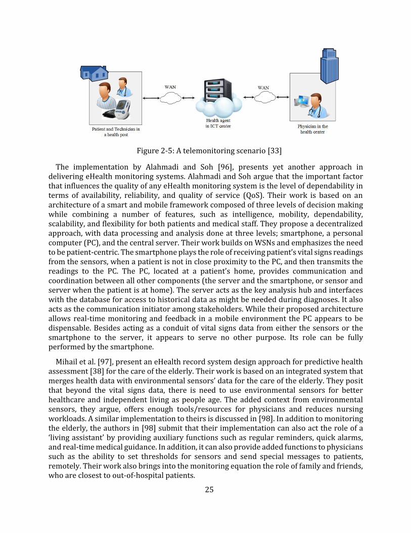
25
Figure 2-5: A telemonitoring scenario [33]
The implementation by Alahmadi and Soh [96], presents yet another approach in delivering eHealth monitoring systems. Alahmadi and Soh argue that the important factor that influences the quality of any eHealth monitoring system is the level of dependability in terms of availability, reliability, and quality of service (QoS). Their work is based on an architecture of a smart and mobile framework composed of three levels of decision making while combining a number of features, such as intelligence, mobility, dependability, scalability, and flexibility for both patients and medical staff. They propose a decentralized approach, with data processing and analysis done at three levels; smartphone, a personal computer (PC), and the central server. Their work builds on WSNs and emphasizes the need to be patient-centric. The smartphone plays the role of receiving patient’s vital signs readings from the sensors, when a patient is not in close proximity to the PC, and then transmits the readings to the PC. The PC, located at a patient’s home, provides communication and coordination between all other components (the server and the smartphone, or sensor and server when the patient is at home). The server acts as the key analysis hub and interfaces with the database for access to historical data as might be needed during diagnoses. It also acts as the communication initiator among stakeholders. While their proposed architecture allows real-time monitoring and feedback in a mobile environment the PC appears to be dispensable. Besides acting as a conduit of vital signs data from either the sensors or the smartphone to the server, it appears to serve no other purpose. Its role can be fully performed by the smartphone.
Mihail et al. [97], present an eHealth record system design approach for predictive health assessment [38] for the care of the elderly. Their work is based on an integrated system that merges health data with environmental sensors’ data for the care of the elderly. They posit that beyond the vital signs data, there is need to use environmental sensors for better healthcare and independent living as people age. The added context from environmental sensors, they argue, offers enough tools/resources for physicians and reduces nursing workloads. A similar implementation to theirs is discussed in [98]. In addition to monitoring the elderly, the authors in [98] submit that their implementation can also act the role of a ‘living assistant’ by providing auxiliary functions such as regular reminders, quick alarms, and real-time medical guidance. In addition, it can also provide added functions to physicians such as the ability to set thresholds for sensors and send special messages to patients, remotely. Their work also brings into the monitoring equation the role of family and friends, who are closest to out-of-hospital patients.
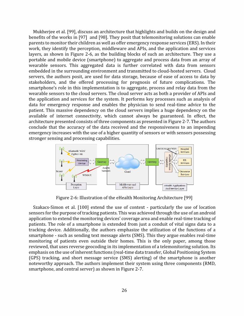
26
Mukherjee et al. [99], discuss an architecture that highlights and builds on the design and benefits of the works in [97] and [98]. They posit that telemonitoring solutions can enable parents to monitor their children as well as offer emergency response services (ERS). In their work, they identify the perception, middleware and APIs, and the application and services layers, as shown in Figure 2-6, as the building blocks of such an architecture. They use a portable and mobile device (smartphone) to aggregate and process data from an array of wearable sensors. This aggregated data is further correlated with data from sensors embedded in the surrounding environment and transmitted to cloud-hosted servers. Cloud servers, the authors posit, are used for data storage, because of ease of access to data by stakeholders, and the offered processing for prognosis of future complications. The smartphone’s role in this implementation is to aggregate, process and relay data from the wearable sensors to the cloud servers. The cloud server acts as both a provider of APIs and the application and services for the system. It performs key processes such as analysis of data for emergency response and enables the physician to send real-time advice to the patient. This massive dependency on the cloud servers implies a huge dependency on the available of internet connectivity, which cannot always be guaranteed. In effect, the architecture presented consists of three components as presented in Figure 2-7. The authors conclude that the accuracy of the data received and the responsiveness to an impending emergency increases with the use of a higher quantity of sensors or with sensors possessing stronger sensing and processing capabilities.
Figure 2-6: Illustration of the eHealth Monitoring Architecture [99]
Szakacs-Simon et al. [100] extend the use of context - particularly the use of location sensors for the purpose of tracking patients. This was achieved through the use of an android application to extend the monitoring devices’ coverage area and enable real-time tracking of patients. The role of a smartphone is extended from just a conduit of vital signs data to a tracking device. Additionally, the authors emphasize the utilization of the functions of a smartphone - such as sending text message alerts (SMS). This they argue enables real-time monitoring of patients even outside their homes. This is the only paper, among those reviewed, that uses reverse geocoding in its implementation of a telemonitoring solution. Its emphasis on the use of inherent functions (real-time data transfer, Global Positioning System (GPS) tracking, and short message service (SMS) alerting) of the smartphone is another noteworthy approach. The authors implement their system using three components (RMD, smartphone, and central server) as shown in Figure 2-7.
27
Figure 2-7: Three components architecture
Bhaumik et al. [101], present an implementation approach that aggregates the sensors in a WSN using middleware. Their approach treats healthcare as a vertical service on a horizontal IoT platform. They contend that the sensor observation service (SOS - their middleware), which is a part of a component they refer to as the sensor web enablement (SWE), provides a generic model that interacts with sensors and collates data collected by them. It acts as a horizontal service, which can accommodate & store the observations from all types of sensors. The SOS provides access to the sensor data in a standard way irrespective of the sensor type. Their work is able to integrate medical instruments with heterogeneous interfaces as web-enabled sensors. However, a number of challenges of the SOS are highlighted. Among them are; the existence of proprietary devices which they are unable to interact with and only upload data directly to vendors’ websites, RESTful APIs are not available in the SOS implementations, available open source SOS implementations do not allow removal/editing of erroneous/corrupt data from SOS repositories, it is only extensible markup language (XML) compliant hence a proxy to handle REST requests from clients and convert them to XML has to be developed, and it does not offer RBAC. In addition to these highlighted deficiencies, their work only concentrates on the development of the middleware and hence only offers data management and archiving functions. Yi and Saniie [102], address an identical scenario with the patient-centered mobile health monitoring (PCMHM). In their work, the term “patient-centered” is used to imply that the outcome of the diagnosis is dependent on the patient’s physiological characteristics and the surrounding environment that affects the patients’ health condition. However, their work, like [99], [97] and [98] emphasizes the need to add context to the vital signs readings unlike the work in [101], that assumes all sensors are vital signs monitoring devices. This can enable determination of patients’ activities (e.g., sleep patterns) and their health condition. From the determination of the patients’ activities, it is feasible to determine the cause of the health condition/medical emergency through the use of multiple sensors. Due to the emphasis applied on adding context to the vital signs data, it is assumed that there is a variety of sensors (medical and environmental sensors) hence the use of the Wireless Intelligent Personal Communication Node (W-iPCN). Figure 2-8 shows how the various components are connected. The W-iPCN analyzes both the medical and environmental sensor data and relays the data to the remote database server. The W-iPCN is designed to be reconfigurable and able to adapt to various types of wireless communication protocols. In essence, it serves the
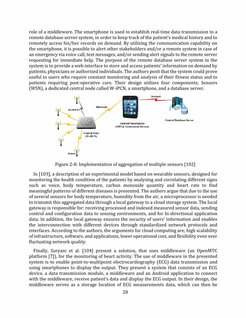
28
role of a middleware. The smartphone is used to establish real-time data transmission to a remote database server system, in order to keep track of the patient’s medical history and to remotely access his/her records on demand. By utilizing the communication capability on the smartphone, it is possible to alert other stakeholders and/or a remote system in case of an emergency via voice call, text messages, and/or sending alert signals to the remote server requesting for immediate help. The purpose of the remote database server system in the system is to provide a web interface to store and access patients’ information on demand by patients, physicians or authorized individuals. The authors posit that the system could prove useful to users who require constant monitoring and analysis of their fitness status and to patients requiring post-operative care. Their design utilizes four components; Sensors (WSN), a dedicated central node called W-iPCN, a smartphone, and a database server.
Figure 2-8: Implementation of aggregation of multiple sensors [102]
In [103], a description of an experimental model based on wearable sensors, designed for monitoring the health condition of the patients by analyzing and correlating different signs such as voice, body temperature, carbon monoxide quantity and heart rate to find meaningful patterns of different diseases is presented. The authors argue that due to the use of several sensors for body temperature, humidity from the air, a microprocessor is needed to transmit this aggregated data through a local gateway to a cloud storage system. The local gateway is responsible for: receiving processed and indexed measured sensor data, sending control and configuration data to sensing environments, and for bi-directional application data. In addition, the local gateway ensures the security of users’ information and enables the interconnection with different devices through standardized network protocols and interfaces. According to the authors, the arguments for cloud computing are; high scalability of infrastructure, software, and applications, lower operational cost, and flexibility even over fluctuating network quality.
Finally, Suryani et al. [104] present a solution, that uses middleware (an OpenMTC platform [7]), for the monitoring of heart activity. The use of middleware in the presented system is to enable point-to-multipoint electrocardiography (ECG) data transmission and using smartphones to display the output. They present a system that consists of an ECG device, a data transmission module, a middleware and an Android application to connect with the middleware, receive patient’s data and display the ECG output. In their design, the middleware serves as a storage location of ECG measurements data, which can then be
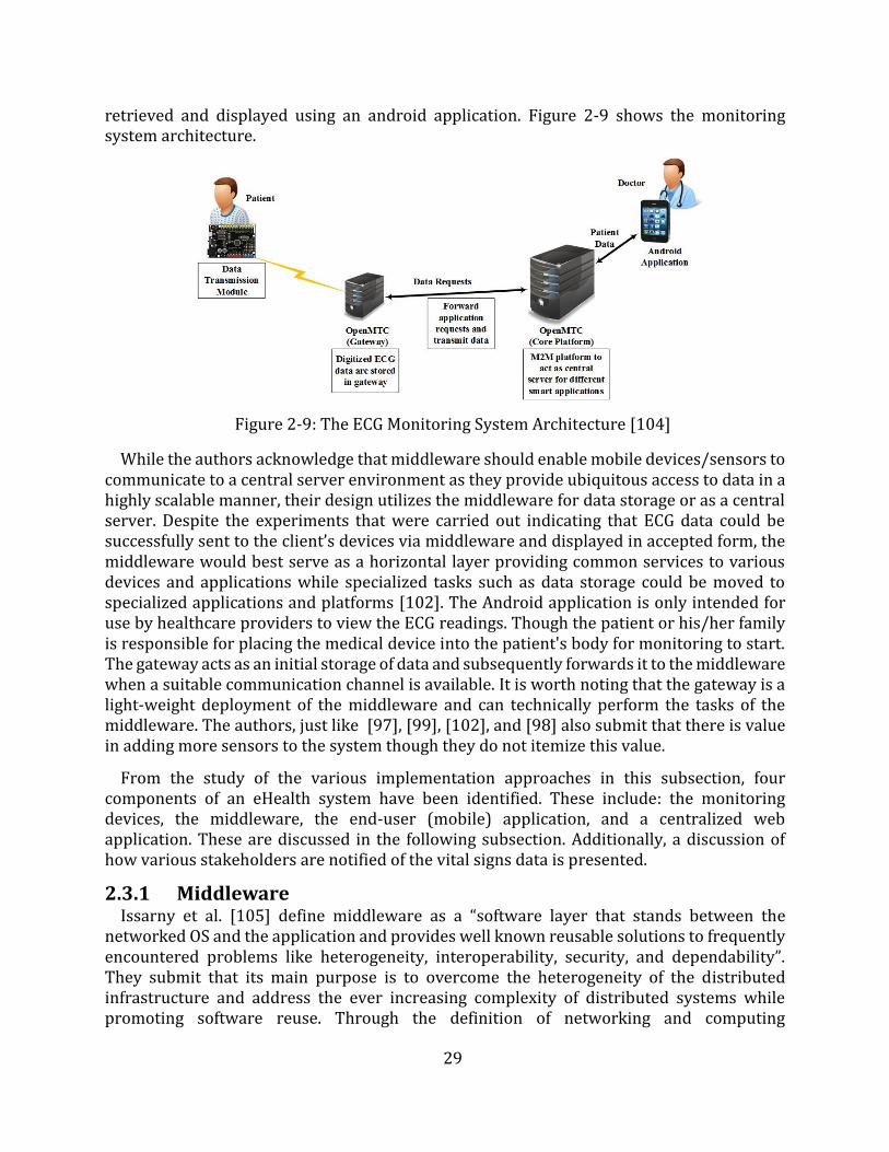
29
retrieved and displayed using an android application. Figure 2-9 shows the monitoring system architecture.
Figure 2-9: The ECG Monitoring System Architecture [104]
While the authors acknowledge that middleware should enable mobile devices/sensors to communicate to a central server environment as they provide ubiquitous access to data in a highly scalable manner, their design utilizes the middleware for data storage or as a central server. Despite the experiments that were carried out indicating that ECG data could be successfully sent to the client’s devices via middleware and displayed in accepted form, the middleware would best serve as a horizontal layer providing common services to various devices and applications while specialized tasks such as data storage could be moved to specialized applications and platforms [102]. The Android application is only intended for use by healthcare providers to view the ECG readings. Though the patient or his/her family is responsible for placing the medical device into the patient's body for monitoring to start. The gateway acts as an initial storage of data and subsequently forwards it to the middleware when a suitable communication channel is available. It is worth noting that the gateway is a light-weight deployment of the middleware and can technically perform the tasks of the middleware. The authors, just like [97], [99], [102], and [98] also submit that there is value in adding more sensors to the system though they do not itemize this value.
From the study of the various implementation approaches in this subsection, four components of an eHealth system have been identified. These include: the monitoring devices, the middleware, the end-user (mobile) application, and a centralized web application. These are discussed in the following subsection. Additionally, a discussion of how various stakeholders are notified of the vital signs data is presented.
2.3.1 Middleware Issarny et al. [105] define middleware as a “software layer that stands between the
networked OS and the application and provides well known reusable solutions to frequently encountered problems like heterogeneity, interoperability, security, and dependability”. They submit that its main purpose is to overcome the heterogeneity of the distributed infrastructure and address the ever increasing complexity of distributed systems while promoting software reuse. Through the definition of networking and computing
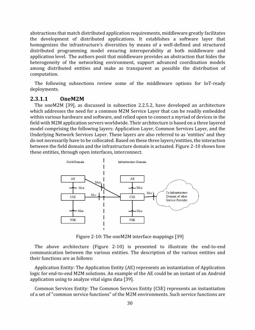
30
abstractions that match distributed application requirements, middleware greatly facilitates the development of distributed applications. It establishes a software layer that homogenizes the infrastructure’s diversities by means of a well-defined and structured distributed programming model ensuring interoperability at both middleware and application level. The authors posit that middleware provides an abstraction that hides the heterogeneity of the networking environment, support advanced coordination models among distributed entities and make as transparent as possible the distribution of computation.
The following subsections review some of the middleware options for IoT-ready deployments.
2.3.1.1 OneM2M The oneM2M [39], as discussed in subsection 2.2.5.2, have developed an architecture
which addresses the need for a common M2M Service Layer that can be readily embedded within various hardware and software, and relied upon to connect a myriad of devices in the field with M2M application servers worldwide. Their architecture is based on a three layered model comprising the following layers: Application Layer, Common Services Layer, and the Underlying Network Services Layer. These layers are also referred to as ‘entities’ and they do not necessarily have to be collocated. Based on these three layers/entities, the interaction between the field domain and the infrastructure domain is actuated. Figure 2-10 shows how these entities, through open interfaces, interconnect.
Figure 2-10: The oneM2M interface mappings [39]
The above architecture (Figure 2-10) is presented to illustrate the end-to-end communication between the various entities. The description of the various entities and their functions are as follows:
Application Entity: The Application Entity (AE) represents an instantiation of Application logic for end-to-end M2M solutions. An example of the AE could be an instant of an Android application using to analyze vital signs data [39].
Common Services Entity: The Common Services Entity (CSE) represents an instantiation of a set of "common service functions" of the M2M environments. Such service functions are
31
exposed to other entities through RPs Mca and Mcc. RP Mcn is used for accessing Underlying Network Services Entity (NSE). In essence, the CSE represents the middleware of a oneM2M M2M solution. Examples of service functions offered by CSE include Data Management, Device Management, M2M Subscription Management, and Location Services. Such "sub-functions" offered by a CSE may be logically and informatively conceptualized as Common Services Functions (CSFs). The normative Resources which implement the service functions in a CSE can be mandatory or optional. It is important to note that the AE and the CSE could or could not be co-located within the same physical node [39].
Underlying Network Services Entity: The NSE provides services from the underlying network to the CSEs. Examples of such services include device management, location services, and device triggering. No particular organization of the NSEs is assumed. Underlying networks provide data transport services between entities in the oneM2M System. Such data transport services are not included in the NSE [39].
The middleware (CSE) exposes its functionalities through interfaces or RPs. In addition to showing the various entities of the three-layered model, Figure 2-10 also shows how the RPs are mapped onto the functional architecture. The Mca RP enables communication between an AE and a CSE. This enables the AE to use the services supported by the CSE, and for the CSE to communicate with the AE. The Mcc RP enables communication between two CSEs. This enables a CSE to use the services supported by another CSE. The Mcn RP enables communication between a CSE and the NSE. This enables a CSE to use the supported services (other than transport and connectivity services) provided by the NSE. Finally, the Mcc' RP enables communication between two CSEs in infrastructure nodes that are oneM2M compliant and that resides in different M2M SP domains. This enables the CSE of an infrastructure node residing in the Infrastructure Domain of an M2M SP to communicate with a CSE of another infrastructure node residing in the Infrastructure Domain of another M2M SP to use its supported services and vice versa. Mcc' extends the reachability of services offered over the Mcc RP, or a subset thereof. Information exchange between two M2M nodes assumes the usage of the transport and connectivity services of the underlying NSEs, which are considered to be the basic services.
2.3.1.2 Alljoyn The Allseen Alliance [106], has developed a framework that targets proximal (a network
of devices close to each other) Internet of Everything (IoE) [107] networks (shown in Figure 2-11) [91]. They propose that smart devices within each IoE proximal network shoulddynamically discover and communicate with each over direct peer-to-peer, bearer agnosticconnections. As can be seen from Figure 2-11, for a smart device to join this network, it musthave the Alljoyn framework installed.
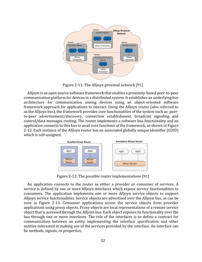
32
Figure 2-11: The Alljoyn proximal network [91]
Alljoyn is an open source software framework that enables a proximity-based peer-to-peer communication platform for devices in a distributed system. It establishes an underlying bus architecture for communication among devices using an object-oriented software framework approach for applications to interact. Using the Alljoyn router (also referred to as the Alljoyn bus), the framework provides core functionalities of the system such as: peer-to-peer advertisement/discovery, connection establishment, broadcast signaling and control/data messages routing. The router implements a software bus functionality and an application connects to this bus to avail core functions of the framework, as shown in Figure 2-12. Each instance of the AllJoyn router has an associated globally unique identifier (GUID)which is self-assigned.
Figure 2-12: The possible router implementations [91]
An application connects to the router as either a provider or consumer of services. A service is defined by one or more Alljoyn interfaces which expose service functionalities to consumers. The application implements one or more Alljoyn service objects to support Alljoyn service functionalities. Service objects are advertised over the Alljoyn bus, as can be seen in Figure 2-13. Consumer applications access the service objects from provider applications using proxy objects. Proxy objects are local representations of a remote service object that is accessed through the Alljoyn bus. Each object exposes its functionality over the bus through one or more interfaces. The role of the interfaces is to define a contract for communication between an entity implementing the interface specification and other entities interested in making use of the services provided by the interface. An interface can be methods, signals, or properties.
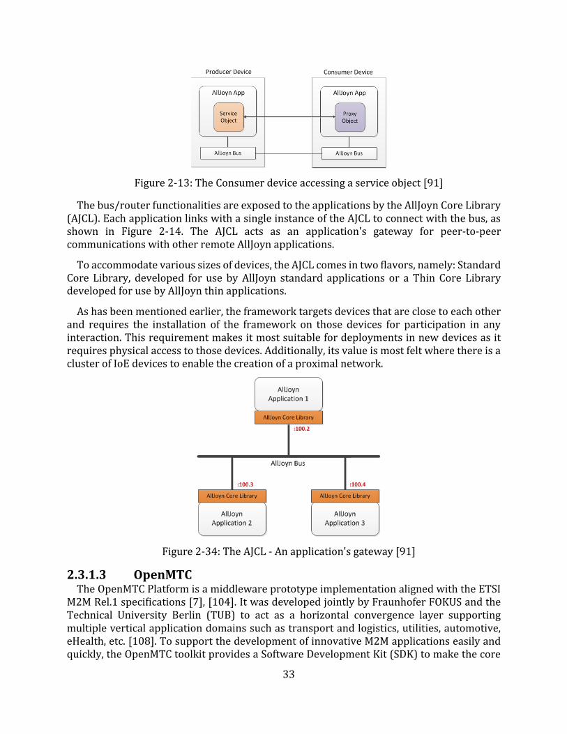
33
Figure 2-13: The Consumer device accessing a service object [91]
The bus/router functionalities are exposed to the applications by the AllJoyn Core Library (AJCL). Each application links with a single instance of the AJCL to connect with the bus, as shown in Figure 2-14. The AJCL acts as an application's gateway for peer-to-peer communications with other remote AllJoyn applications.
To accommodate various sizes of devices, the AJCL comes in two flavors, namely: Standard Core Library, developed for use by AllJoyn standard applications or a Thin Core Library developed for use by AllJoyn thin applications.
As has been mentioned earlier, the framework targets devices that are close to each other and requires the installation of the framework on those devices for participation in any interaction. This requirement makes it most suitable for deployments in new devices as it requires physical access to those devices. Additionally, its value is most felt where there is a cluster of IoE devices to enable the creation of a proximal network.
Figure 2-34: The AJCL - An application's gateway [91]
2.3.1.3 OpenMTC The OpenMTC Platform is a middleware prototype implementation aligned with the ETSI
M2M Rel.1 specifications [7], [104]. It was developed jointly by Fraunhofer FOKUS and the Technical University Berlin (TUB) to act as a horizontal convergence layer supporting multiple vertical application domains such as transport and logistics, utilities, automotive, eHealth, etc. [108]. To support the development of innovative M2M applications easily and quickly, the OpenMTC toolkit provides a Software Development Kit (SDK) to make the core
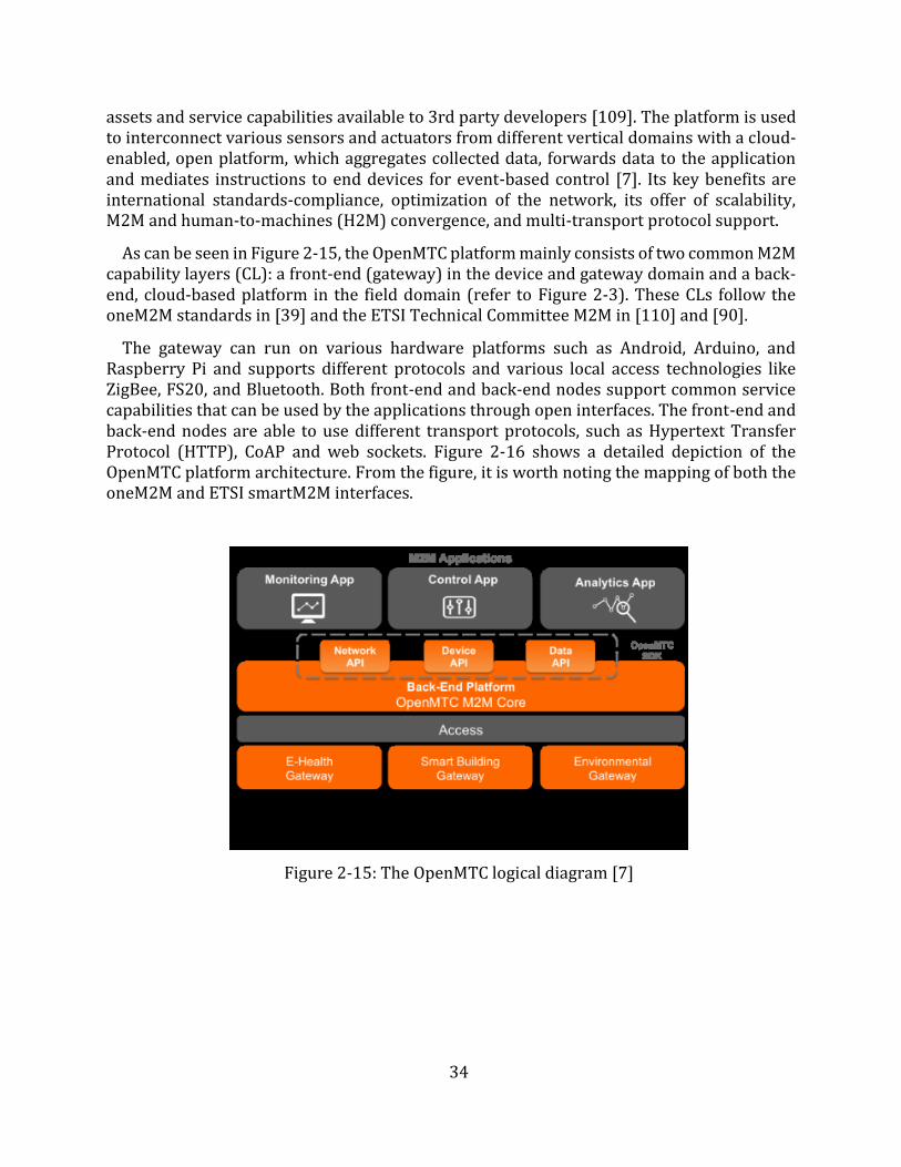
34
assets and service capabilities available to 3rd party developers [109]. The platform is used to interconnect various sensors and actuators from different vertical domains with a cloud-enabled, open platform, which aggregates collected data, forwards data to the application and mediates instructions to end devices for event-based control [7]. Its key benefits are international standards-compliance, optimization of the network, its offer of scalability, M2M and human-to-machines (H2M) convergence, and multi-transport protocol support.
As can be seen in Figure 2-15, the OpenMTC platform mainly consists of two common M2M capability layers (CL): a front-end (gateway) in the device and gateway domain and a back-end, cloud-based platform in the field domain (refer to Figure 2-3). These CLs follow the oneM2M standards in [39] and the ETSI Technical Committee M2M in [110] and [90].
The gateway can run on various hardware platforms such as Android, Arduino, and Raspberry Pi and supports different protocols and various local access technologies like ZigBee, FS20, and Bluetooth. Both front-end and back-end nodes support common service capabilities that can be used by the applications through open interfaces. The front-end and back-end nodes are able to use different transport protocols, such as Hypertext Transfer Protocol (HTTP), CoAP and web sockets. Figure 2-16 shows a detailed depiction of the OpenMTC platform architecture. From the figure, it is worth noting the mapping of both the oneM2M and ETSI smartM2M interfaces.
Figure 2-15: The OpenMTC logical diagram [7]
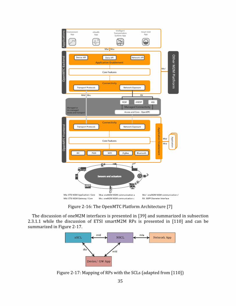
35
Figure 2-16: The OpenMTC Platform Architecture [7]
The discussion of oneM2M interfaces is presented in [39] and summarized in subsection 2.3.1.1 while the discussion of ETSI smartM2M RPs is presented in [110] and can be summarized in Figure 2-17.
Figure 2-17: Mapping of RPs with the SCLs (adapted from [110])
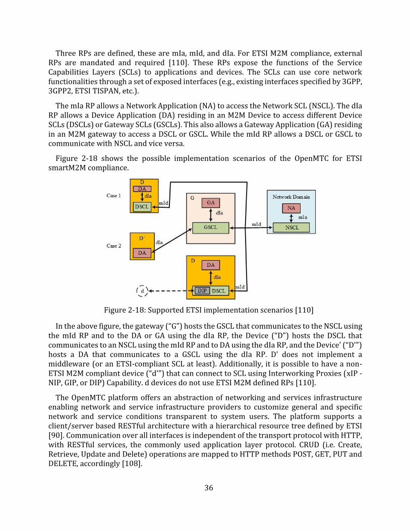
36
Three RPs are defined, these are mIa, mId, and dIa. For ETSI M2M compliance, external RPs are mandated and required [110]. These RPs expose the functions of the Service Capabilities Layers (SCLs) to applications and devices. The SCLs can use core network functionalities through a set of exposed interfaces (e.g., existing interfaces specified by 3GPP, 3GPP2, ETSI TISPAN, etc.).
The mIa RP allows a Network Application (NA) to access the Network SCL (NSCL). The dIa RP allows a Device Application (DA) residing in an M2M Device to access different Device SCLs (DSCLs) or Gateway SCLs (GSCLs). This also allows a Gateway Application (GA) residing in an M2M gateway to access a DSCL or GSCL. While the mId RP allows a DSCL or GSCL to communicate with NSCL and vice versa.
Figure 2-18 shows the possible implementation scenarios of the OpenMTC for ETSI smartM2M compliance.
Figure 2-18: Supported ETSI implementation scenarios [110]
In the above figure, the gateway (“G”) hosts the GSCL that communicates to the NSCL using the mId RP and to the DA or GA using the dIa RP, the Device (“D”) hosts the DSCL that communicates to an NSCL using the mId RP and to DA using the dIa RP, and the Device' (“D'”) hosts a DA that communicates to a GSCL using the dIa RP. D' does not implement a middleware (or an ETSI-compliant SCL at least). Additionally, it is possible to have a non-ETSI M2M compliant device (“d'”) that can connect to SCL using Interworking Proxies (xIP - NIP, GIP, or DIP) Capability. d devices do not use ETSI M2M defined RPs [110].
The OpenMTC platform offers an abstraction of networking and services infrastructure enabling network and service infrastructure providers to customize general and specific network and service conditions transparent to system users. The platform supports a client/server based RESTful architecture with a hierarchical resource tree defined by ETSI [90]. Communication over all interfaces is independent of the transport protocol with HTTP, with RESTful services, the commonly used application layer protocol. CRUD (i.e. Create, Retrieve, Update and Delete) operations are mapped to HTTP methods POST, GET, PUT and DELETE, accordingly [108].

37
2.3.2 Monitoring Devices In [111], Fletcher et al. discuss the development of a sensing device based on 802.15.4
wireless standard [112] while delivering affective computing [113], [114]. They posit that advances in low-power radio electronics and wireless protocols have enabled the development of new technologies for long-term, comfortable sensing of autonomic information in new areas of health and medical research. They show that new sensors, while non-traditional in their placement and design, are capable of gathering data comparable to data gathered by traditional sensors of electrodermal activity and heart rate. They opt to use ZigBee as it is an ideal candidate for the design due to the use of low powered radio hardware. They conclude that it is possible to design a low cost, comfortable, and robust sensor module that can provide the necessary set of measurements needed for affective sensing.
On the other hand, Luxner [115] developed a mobile device-controlled BP monitor to provide an alternative to the expensive Ambulatory Blood Pressure Monitors (ABPMs). To accomplish this he got an off the shelf BP monitor (manufactured by Amron) and integrated an Arduino board to it so as to extract the readings and be able to send them via Bluetooth to the mobile phone. The author concentrated on interfacing the monitor with the mobile phone and subsequently transmitting the readings to a server. The author argues that by moving some of the functions, such as storage of readings and display from the ABPM to the mobile application, it is possible to make the monitor smaller, simpler and possibly cheaper. Despite managing to accomplish the objective, the work was merely demonstrative of the ability to extract data from the monitor at the expense of what the author called ‘hacking’ into proprietary devices. However, the author acknowledges that the device developed would be difficult to deploy in real life. He submits that for the proposed device to have any chance of real life deployment, the design and its associated services need to be compacted into a dedicated or specialized printed circuit board thereby eliminating the hanging cables and unused pins, connectors, and other hardware.
It is no wonder that Kakria et al. [116], submit that the integration of wearable technologies with mobile networks can offer greater possibilities for rapid, reliable, and secure information transfer from patients to the doctors. With these devices, they submit that it is possible to continuously monitor vital signs and transmit the readings to a smartphone, wirelessly, using BLE technology [117]. Furthermore, the collected information on the smartphone can be transmitted to a web interface via Wi-Fi/3G. In their work, they use the Zephyr HxM Bluetooth (BT) [30] as a wearable sensor for the capturing of heart rate information of the patients requiring continuous monitoring. They argue that the selection of the Zephyr HxM BT sensor is made on the basis of accuracy, reliability, cost, availability, comfort, compatibility with Android applications, and its support for Bluetooth low energy (BLE).
While the above demonstrate scholarly work in the design, development, and use of monitoring devices, the industry has also taken an active role in the design and development of these devices. For example, Withings, which is a part of Nokia, has developed a range of wearables (e.g., smart watches, Withings Pulse, Withings BP Monitor, etc.) and monitoring devices (e.g., smart thermos, smart body analyzers, smart hair combs, smart scales, etc.) [118]. A lot of work has been done in the fitness sector to develop wearables, particularly
38
heart rate monitors. Examples range from chest strapping heart rate monitors (HRMs) such as; Zephyr HxM BT [72], Myzone-MZ-3 [29], TICKR X HRM [119], Garmin's HRM-Tri [27], etc. to wrist strapping HRMs: Mio Alpha 2 [28], Garmin Forerunner 235 [120], Fitbit Charge 2 [121], etc. These are generally used during workouts to track activities and pursue fitness goals. Activities range from running, swimming, hiking, sleeping, etc. However, they can be used in telemonitoring use cases as is demonstrated in [116]. These are designed to be as non-obtrusive as possible.
Because of the interest in monitoring devices, there is need to control the standardization of the manufacture of these devices. Bodies such as Continua Health Alliance [122] and government institutions such as the U. S. Food and Drug Administration (FDA) [123], among others, have been set up. Continua Health Alliance is an international non-profit, open industry group of nearly 240 companies. It aims to develop a system to deliver personal and individual healthcare by enabling end-to-end plug and play connectivity of devices and services for personal health management and healthcare delivery. Through collaboration with governments and regulatory bodies (e.g., IEEE), Continua works to provide guidelines for the effective management of diverse products and services from a global network of vendors. In 2012, it made public a design guideline to assist developers to be compliant with its standards. The mission is to empower an information-driven health management and facilitate the incorporation of communication devices [124]. This has enabled researchers to concentrate on the development of applications with the assurance that monitoring and sensing will be achieved.
2.3.3 End-User Applications From the implementation approaches discussed in section 2.3, it was noted that users can
have access to the vital signs data using either custom applications hosted on smartphones or web browsers using any capable device. Custom applications can be developed using various SDKs such as; Android SDK [125], iOS SDK [126], Windows Phone SDK [125], etc. While there are a number of factors that influence the choice of an SDK the target market is the chief factor.
Wang et al. [127], discuss the use of Android mobile platforms in systems that monitor medical data remotely. They posit that compared to the traditional healthcare system, the use of Android mobile platforms in systems significantly reduces investment on healthcare resources while making healthcare more efficient and more practical. They recognize the value of inherent functions and resources that come with Android mobile platforms such as the SQLite (lightweight) Databases (DBs) and the high quality visual (graphical user interface (GUI)) functionalities. The authors note that due to the networking abilities of Android mobile platforms the interworking with other platforms such as cloud services, the middleware, and servers is simplified. Figure 2-19 highlights the Android Architecture and the features and functionalities available to developers.
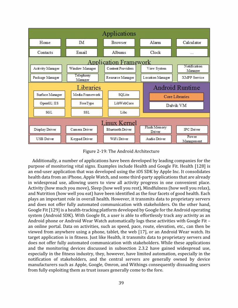
39
Figure 2-19: The Android Architecture
Additionally, a number of applications have been developed by leading companies for the purpose of monitoring vital signs. Examples include Health and Google Fit. Health [128] is an end-user application that was developed using the iOS SDK by Apple Inc. It consolidates health data from an iPhone, Apple Watch, and some third-party applications that are already in widespread use, allowing users to view all activity progress in one convenient place. Activity (how much you move), Sleep (how well you rest), Mindfulness (how well you relax), and Nutrition (how well you eat) have been identified as the four facets of good health. Each plays an important role in overall health. However, it transmits data to proprietary servers and does not offer fully automated communication with stakeholders. On the other hand, Google Fit [129] is a health-tracking platform developed by Google for the Android operating system (Android SDK). With Google fit, a user is able to effortlessly track any activity as an Android phone or Android Wear Watch automatically logs these activities with Google Fit – an online portal. Data on activities, such as speed, pace, route, elevation, etc., can then be viewed from anywhere using a phone, tablet, the web [17], or an Android Wear watch. Its target application is in fitness. Just like Health, it transmits data to proprietary servers and does not offer fully automated communication with stakeholders. While these applications and the monitoring devices discussed in subsection 2.3.2 have gained widespread use, especially in the fitness industry, they, however, have limited automation, especially in the notification of stakeholders, and the central servers are generally owned by device manufacturers such as Apple, Google, Omron, and Withings consequently dissuading users from fully exploiting them as trust issues generally come to the fore.
40
2.3.4 Web Applications and Cloud Computing The importance of web applications in telemonitoring systems cannot be overemphasized.
Shahriyar et al. [94] position the Intelligent Medical Server as the backbone of their architecture. Beyond just acting as an interface for users to access data, they posit that it can learn patient specific thresholds based on historical data. The application persists the data to a central database. While Kakria et al. [116] implement their web application to enable simultaneous access by various stakeholders. This is realized by implementing web interfaces using Laravel PHP framework [130]. The exposure of web application interfaces is the same design approach employed in the design of web services. Yii and Saniie [102] implement their web application using Apache Tomcat [131], Java web server [132] and MySQL database [133]. The web server handles HTTP requests and responds to the client using a web page. HTTP requests are forwarded to the web container, which manages the Java runtime environment for Java servlets and Java Server Pages (JSP). Results from the Java program execution are returned to the client as HTTP responses.
The web applications discussed above are relatively lightweight and usually single page applications that just show vital signs data and interact with the central database while exposing their services/functions to the rest of the system through interfaces. However, to leverage the benefits of these tools, a robust application should be developed. Yii framework [134] is an example of a framework that can be used to implement a robust web application.
With the advent of cloud computing, these web applications can also be setup and made ubiquitous. The NIST [135] defines cloud computing as “a model for enabling ubiquitous, convenient, on-demand network access to a shared pool of configurable computing resources (e.g., networks, servers, storage, applications, and services) that can be rapidly provisioned and released with minimal management effort or SP interaction.” While Grobauer et al. [136] posit that cloud computing has its foundation on web applications and services, virtualized infrastructure as a service (IaaS) offerings, and cryptography for security. Therefore, cloud computing provides a platform for the efficient deployment of web applications and other services (e.g., the M2M middleware).
2.3.5 Stakeholders’ Notification Design Approaches The key to realizing the benefits of any telemonitoring solution is ensuring that the
stakeholders receive or have access to the data from the monitoring devices in a timely manner. The traditional devices require that the operator (patient or physician) has access to the LED display and is able to read the data from it. However, as noted by Luxner [115], this to a large extent would defeat the purpose of telemonitoring. The vital signs data and the added context must be transmitted to the stakeholders. Additionally, as highlighted in [33] only the right data must be transmitted to the various stakeholders.
The design approaches to the transmission and presentation of the vital signs data vary considerably. For example, authors in [97]–[99] present static data on cloud servers. This data can be viewed by stakeholders using any device that has internet and web browsing capabilities. In addition to such access to the data, authors in [100] implement notification and alert mechanisms on these servers. Using these mechanisms, stakeholders can be notified or alerted of any emergencies or critical data. Either of these approaches is too dependent on the availability of internet connectivity.
41
Authors in [100] and [127] identify and prefer to use the inherent functions of the smartphone for the information, notification, and alerting of the stakeholders. In these designs, applications on smartphones can act as alarms, reminder senders, and even offer real-time guidance to patients. The use of applications on the smartphone fits the telemonitoring ideal best because the communication is close to the patient, who is at the center of the solution. Even when there is no Internet access to the middleware or central servers, stakeholders can be notified of vital signs readings and any emergencies (via SMS, or application notifications). Authors in [98] and [100] go a step further and adopt the use of both the smartphones and servers for notification purposes.
Furthermore, there is also the possibility of using the middleware to initiate the notification of the stakeholders. As can be noted in [104] the middleware performs all the stakeholders’ notification functions. However, it is easy to notice that this is mainly because the design approach delegates the functions that would otherwise be performed by specialized servers to the middleware.
Lastly, authors in [26] still maintain human agents in the monitoring process. They use MSPs to facilitate the access to data by physicians. Despite these being dedicated agents in the communication process, there are notable deficiencies in this approach as already highlighted earlier. In an era where automation is at the center of most innovations, the use of human agents is a significant drawback.
Kakria et al. [116] studied the contribution of a telemonitoring system towards early response by assessing the performance (delay) of their prototype to quantify the time taken to send messages from a patient’s interface (mobile application) to a physician’s interface. Their prototype used the communication capabilities of the smartphone. However, they designed an end-to-end (patient to the physician) communication application. Their prototype achieved a 29 seconds delay for a message to be delivered to a physician. While their findings represent a commendable contribution towards reducing the overall time of the chain of survival, it is noteworthy that the set target of 4 to 6 minutes represented the overall required time, and not the time required to alert the physician or activate an emergency response system. However, their work sets a benchmark for this research.
The value of early recognition of deterioration and the timely notification of stakeholders can go a long way in successfully navigating the chain of survival, in dealing with cardiac arrests, as was discussed in Chapter 1.
2.4 Chapter Summary This Chapter has presented an overview of the healthcare industry and its use of ICT for
service delivery. The Chapter has shown that the healthcare industry has a long-standing history of the use of ICT, dating back to the second half of the 19th century. This use of ICT has been mainly riding on the development in the ICT industry itself. It was highlighted that the adoption of ICT can be perceived under the umbrella terms eHealth and Telehealth. These constitute nonclinical and clinical (telemedicine) services, where clinical services constitute: telemonitoring, telepsychiatry, teleradiology, teledermatology, teleophthalmology, etc.
42
The Chapter then introduced the IoT as a technological paradigm that is currently undergoing substantial R&D and promises to affect the connection of things to the internet, both in scale and manner of connectivity. This paradigm has been enabled by the advancements made in the development of the M2M communication paradigm. Because of its promise and potential, efforts are being made to standardize the adoption of the IoT. This is to emphasize the need for infrastructure that offers a common horizontal platform that can meet any vertical application. This was done by highlighting the work done by the ITU, the oneM2M, and ETSI and their proposed architectures which emphasize the need for a middleware that would not stifle the development of applications and devices, yet deliver abstraction and interoperability.
The Chapter then presented some implementations of Telehealth solutions to highlight the key implementation strategies and building blocks of these solutions. Of the solutions reviewed, they could broadly be grouped into two categories; those utilizing three components (RMD, gateway (usually a smartphone), and web servers) and those utilizing four components (RMD, gateway (usually a smartphone), middleware, and web servers). It was quickly observed that most of these solutions exist as silos hence highlighting the profound need for the healthcare industry to adopt the design approaches of the IoT. This dissertation builds on the contributions of these implementations and adopts the design approaches of the IoT to develop a telemonitoring system.
The following Chapter introduces the prototype proposed by this dissertation. It discusses the key requirements for the implementation of an IoT telemonitoring system. The Chapter also details the use cases, the stakeholders and the system requirements of the prototype. Based on these requirements, a functional architecture is developed whose building blocks are discussed in the Chapter.
43
Chapter 3
Requirements and Architecture of the Proposed Telemonitoring System
The first Chapter of this dissertation presented a discussion of the challenges that the healthcare industry faces particularly in remote monitoring and management of vital signs. It highlighted the gaps that telemonitoring systems can bridge to contribute towards the improvement of healthcare service delivery particularly in the reduction of the overall time of the cardiac arrest chain of survival. The previous Chapter presented an overview of the variants of the applications of ICTs in healthcare service delivery in an attempt to meet the challenges identified in Chapter 1. Then through the discussion of the implementations of eHealth systems, the Chapter highlighted the need to shift from silos to an implementation of a common horizontal platform for various vertical applications through the adoption of the IoT, which is enabled by the M2M communication paradigm. The Chapter also identified the key building blocks and gaps of such systems that this work seeks to build on and bridge, respectively.
This Chapter discusses the use cases that have been identified to help interrogate the research questions formulated in Chapter 1. Two use cases have been identified, i.e. a regular monitoring use case and a chronic patient use case. The regular monitoring use case interrogates how the medical sector can adopt the IoT in its implementation of telemonitoring systems, and how the use of smart devices, particularly the smartphone, can be utilized to improve healthcare service delivery by automating the telemonitoring process. While the chronic patient use case interrogates whether the automation of the transmission and management of vital signs data can improve the response time to deterioration while increasing the availability of data and improving communication among stakeholders. It further seeks to give a quantitative analysis of the performance of the proposed telemonitoring system by studying the delay in the delivery of messages to stakeholders and assess how this compares with previous work by Kakria et al. [116], particularly in the contribution towards reducing the overall time of the cardiac arrest chain of survival.
The interrogation of the research questions, through the two use cases, led to the proposal, design, and implementation of an IoT-based telemonitoring system. The detailed discussion of the design and implementation and the evaluation and testing of the prototype is presented in Chapters 4 and 5, respectively.
The plan of action that was followed during this research is shown in Appendix A.
3.1 General Description According to ETSI [137], M2M applications for eHealth enable:
the remote monitoring of patient health and fitness information; the triggering of alarms when critical conditions are detected; the remote control of certain medical treatments or parameters.
For these to be enabled, it is imperative that a WBAN that consists of appropriate sensors that are able to capture vital signs data be setup. These sensors, usually attached to a patient
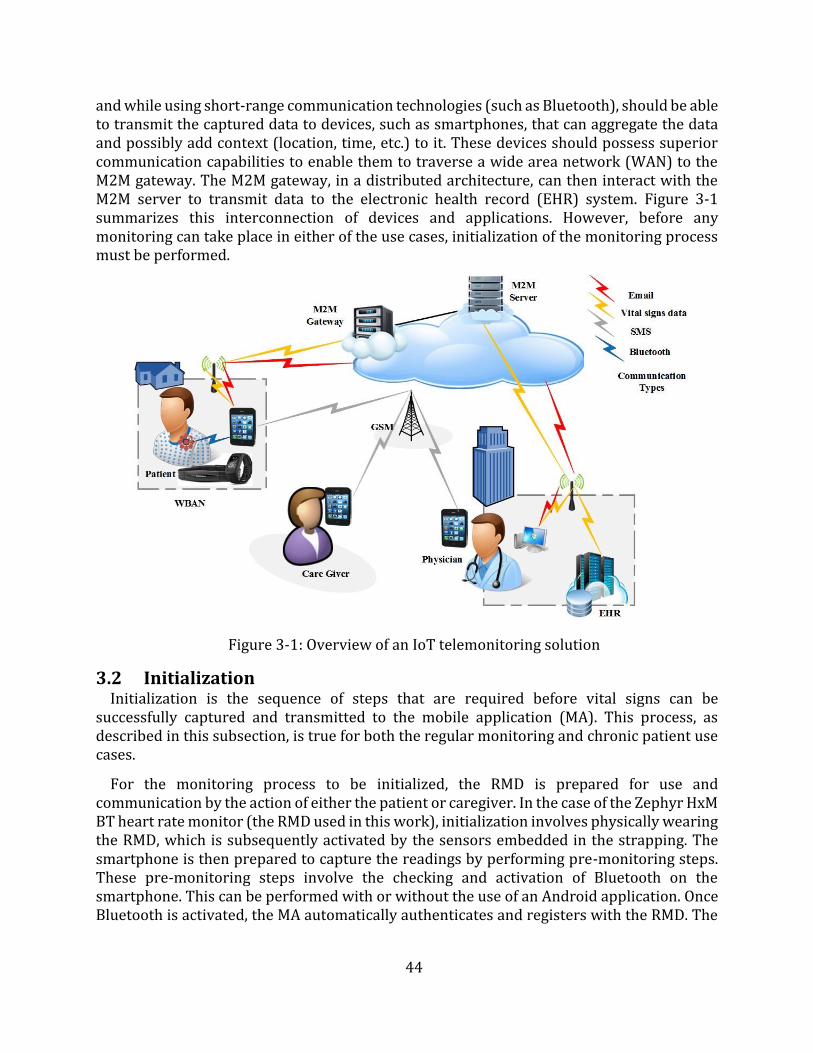
44
and while using short-range communication technologies (such as Bluetooth), should be able to transmit the captured data to devices, such as smartphones, that can aggregate the data and possibly add context (location, time, etc.) to it. These devices should possess superior communication capabilities to enable them to traverse a wide area network (WAN) to the M2M gateway. The M2M gateway, in a distributed architecture, can then interact with the M2M server to transmit data to the electronic health record (EHR) system. Figure 3-1 summarizes this interconnection of devices and applications. However, before any monitoring can take place in either of the use cases, initialization of the monitoring process must be performed.
Figure 3-1: Overview of an IoT telemonitoring solution
3.2 Initialization Initialization is the sequence of steps that are required before vital signs can be
successfully captured and transmitted to the mobile application (MA). This process, as described in this subsection, is true for both the regular monitoring and chronic patient use cases.
For the monitoring process to be initialized, the RMD is prepared for use and communication by the action of either the patient or caregiver. In the case of the Zephyr HxM BT heart rate monitor (the RMD used in this work), initialization involves physically wearing the RMD, which is subsequently activated by the sensors embedded in the strapping. The smartphone is then prepared to capture the readings by performing pre-monitoring steps. These pre-monitoring steps involve the checking and activation of Bluetooth on the smartphone. This can be performed with or without the use of an Android application. Once Bluetooth is activated, the MA automatically authenticates and registers with the RMD. The
45
RMD, after registering starts transmitting readings, every second, to the MA. The transmission continues until the pairing of the RMD and smartphone is interrupted.
3.3 Stakeholders In an IoT system, stakeholders range from end-users to devices and applications. However,
only end-users (particularly the patient, physician, and caregiver) are considered in this dissertation. This section defines the stakeholders that are considered in the two use cases.
3.3.1 Patient The "patient" may be any individual or surrogate, who could use an RMD to take
measurements, gather data or monitor events. The measurements may be taken in various settings such as hospitals or nonclinical settings such as homes, at work, at school, while traveling, or in assisted living facilities [137].
3.3.2 Physician The “physician” includes medical practitioners, medical doctors, nurses, nurse
practitioners, health assistants, psychologists, and other clinical personnel who clinically evaluate the remote measurements to determine appropriate clinical interventions, if needed, to deliver healthcare [137].
3.3.3 Caregiver The “caregiver” includes personal care aides, home health aides, patient advocates,
surrogates, family members, and other parties who may be acting for, or in support of a patient receiving healthcare services [137].
3.4 Regular Monitoring Use Case
3.4.1 General Description At the highest level, the regular monitoring use case focuses on the communication of the
patient's RMD readings to the EHR system and the notification of the patient of their vital signs readings. In this use case, the patient is not in a critical health condition hence the involvement of the physician and the caregiver is not urgent. The use case is focused on the transmission of messages from the RMD to the MA, the transmission of messages between the MA and the distributed M2M middleware, and the transmission of data between the distributed M2M middleware and the EHR system, as discussed in subsection 3.4.3. The preconditions are that:
the initialization process has been successfully executed, the MA is able to communicate with and is already authenticated and registered to
the M2M gateway, the MA has already retrieved the initial patient data (physician's details and
caregiver's details) from the EHR system via the distributed M2M middleware, and, the M2M middleware is able to communicate with the EHR system.
3.4.2 Scenario This subsection discusses the events that occur in the execution of the regular monitoring
use case.
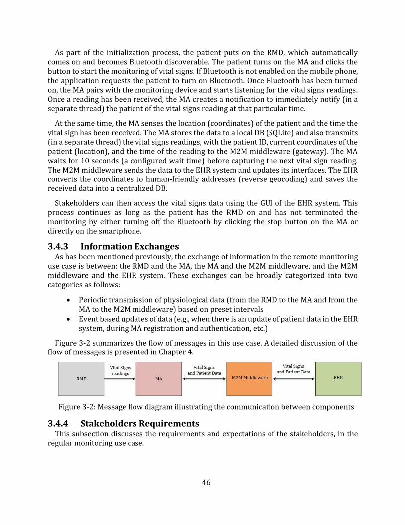
46
As part of the initialization process, the patient puts on the RMD, which automatically comes on and becomes Bluetooth discoverable. The patient turns on the MA and clicks the button to start the monitoring of vital signs. If Bluetooth is not enabled on the mobile phone, the application requests the patient to turn on Bluetooth. Once Bluetooth has been turned on, the MA pairs with the monitoring device and starts listening for the vital signs readings. Once a reading has been received, the MA creates a notification to immediately notify (in a separate thread) the patient of the vital signs reading at that particular time.
At the same time, the MA senses the location (coordinates) of the patient and the time the vital sign has been received. The MA stores the data to a local DB (SQLite) and also transmits (in a separate thread) the vital signs readings, with the patient ID, current coordinates of the patient (location), and the time of the reading to the M2M middleware (gateway). The MA waits for 10 seconds (a configured wait time) before capturing the next vital sign reading. The M2M middleware sends the data to the EHR system and updates its interfaces. The EHR converts the coordinates to human-friendly addresses (reverse geocoding) and saves the received data into a centralized DB.
Stakeholders can then access the vital signs data using the GUI of the EHR system. This process continues as long as the patient has the RMD on and has not terminated the monitoring by either turning off the Bluetooth by clicking the stop button on the MA or directly on the smartphone.
3.4.3 Information Exchanges As has been mentioned previously, the exchange of information in the remote monitoring
use case is between: the RMD and the MA, the MA and the M2M middleware, and the M2M middleware and the EHR system. These exchanges can be broadly categorized into two categories as follows:
Periodic transmission of physiological data (from the RMD to the MA and from theMA to the M2M middleware) based on preset intervals
Event based updates of data (e.g., when there is an update of patient data in the EHRsystem, during MA registration and authentication, etc.)
Figure 3-2 summarizes the flow of messages in this use case. A detailed discussion of the flow of messages is presented in Chapter 4.
Figure 3-2: Message flow diagram illustrating the communication between components
3.4.4 Stakeholders Requirements This subsection discusses the requirements and expectations of the stakeholders, in the
regular monitoring use case.
47
3.4.4.1 Patient Patients are mainly concerned with the obtrusive nature of the RMDs, the ease of use and
setup of the telemonitoring system/process, the security of the data transmitted, and the demand on the resources of the smartphone. Therefore, the RMDs must be lightweight and non-obtrusive. While the MA must be easy to use by presenting most of the data on the home page or with a few clicks. The MA should only use the smartphone’s resources when performing intended functions and should free up the resources when idle. In addition, the system should ensure that data is reliably delivered to the EHR and is not accessible by unauthorized personnel. Lastly, the system should reliably notify the patient of all vital signs readings.
3.4.4.2 Physician As has already been stated, the physician is not very active in this use case. This is because
the patient under monitoring does not need urgent healthcare. However, there is value in the harvesting of all vital signs data to enable the physician to perform predictive health and diagnosis. Therefore, the physician is interested in the system reliably delivering the vital signs to the EHR. For this to happen, the monitoring process must be easy to initiate, it must capture vital signs data accordingly, there must be reliable communication between components, and the system must implement recovery mechanisms in case of failure to deliver the data. Additionally, for security reasons, the physician is interested in assuring controlled access to patients’ data.
3.4.4.3 Caregiver The caregiver, just like the physician, is not very active in this use case unless in
exceptional circumstances where the patient is a minor or requires special assistance. In such cases, the caregiver performs some tasks such as initialization of the monitoring process on behalf of the patient. Such a requirement makes the caregiver to assume the requirements of a patient, as discussed in subsection 3.4.4.1. Otherwise, the caregiver is only interested in the reliability of the telemonitoring system.
3.5 Chronic Patient Use Case
3.5.1 General Description At the highest level, the chronic patient use case focuses on the communication of the
patient's RMD readings to the EHR system and the urgent communication/delivery of notification messages to the relevant stakeholders. In this use case, the patient is in a critical health condition (high risk of medical emergency) hence the involvement of the physician and the caregiver is urgent. The use case is focused on the transmission of information from the RMD to the MA, the exchange of information between the MA and the M2M middleware, and the exchange of information between the M2M middleware and the EHR system. Critical to this use case is the need for urgent delivery of warning and alert messages from the MA to the stakeholders.
The preconditions of this use case are that:
the initialization process has been successfully executed, the MA is able to communicate with and is already authenticated and registered to
the middleware,
48
the MA has already retrieved the initial data (physician's details and caregiver'sdetails) from the EHR via the distributed M2M middleware,
The MA is able to send SMS messages, and has access to the internet for purposesof sending out emails, and
the middleware is also able to communicate with the EHR.
3.5.2 Scenario This subsection discusses the events that occur in the execution of the chronic patient use
case.
As part of the initialization process, the patient puts on the RMD or when necessary is assisted by a caregiver to set up the RMD. Once the RMD has been setup and the smartphone prepared for the reception of data from the device, the MA pairs with the RMD and starts listening for the vital signs readings. When the MA receives a vital sign reading from the RMD, it creates a notification (in a separate thread) to immediately notify the patient of the vital signs reading at that particular time. The MA senses the location (coordinates) of the patient and the time the vital sign has been taken. It stores the data in a local DB (SQLite) and also sends out (in a separate thread) the vital signs, with the patient identification (ID) number, current coordinates of the patient (location) and time of the reading to the M2M middleware (gateway). At the same time, the MA analyses the vital signs data and based on preset thresholds, determines the appropriate message and message type to send to each stakeholder. Based on the outcome of the analysis, the stakeholders are communicated to, accordingly (via local application notification, SMS messages and/or email).
Once the M2M gateway receives the data from the MA, it transmits it via the M2M server, to the EHR. The EHR upon receipt of the data saves it into a centralized DB. Furthermore, it performs data processing such as conversion of the coordinates to human-friendly addresses (reverse geocoding) and some basic diagnosis tasks.
Stakeholders can then access this data using the GUI of the EHR. This process continues as long as there is no disruption in connectivity or any disruptive configuration.
3.5.3 Information Exchanges The core exchange of information during the chronic patient use case is as highlighted in
subsection 3.4.3. However, an additional and critical category is introduced in this use case, namely; threshold/condition-based alerts or warnings. These involve the local notification to the patient, the sending of emails and SMS messages to notify the other stakeholders (physician and caregiver). These exchanges are initiated as a result of the analysis that is done by the MA (discussed in Chapter 4). While the proposed prototype implements the monitoring of BP and heart rate, Figure 3-3 only shows the logic for handling of heart rates.
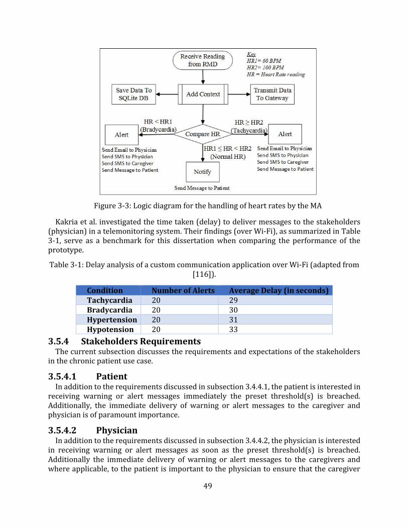
49
Figure 3-3: Logic diagram for the handling of heart rates by the MA
Kakria et al. investigated the time taken (delay) to deliver messages to the stakeholders (physician) in a telemonitoring system. Their findings (over Wi-Fi), as summarized in Table 3-1, serve as a benchmark for this dissertation when comparing the performance of theprototype.
Table 3-1: Delay analysis of a custom communication application over Wi-Fi (adapted from [116]).
Condition Number of Alerts Average Delay (in seconds) Tachycardia 20 29 Bradycardia 20 30 Hypertension 20 31 Hypotension 20 33
3.5.4 Stakeholders Requirements The current subsection discusses the requirements and expectations of the stakeholders
in the chronic patient use case.
3.5.4.1 Patient In addition to the requirements discussed in subsection 3.4.4.1, the patient is interested in
receiving warning or alert messages immediately the preset threshold(s) is breached. Additionally, the immediate delivery of warning or alert messages to the caregiver and physician is of paramount importance.
3.5.4.2 Physician In addition to the requirements discussed in subsection 3.4.4.2, the physician is interested
in receiving warning or alert messages as soon as the preset threshold(s) is breached. Additionally the immediate delivery of warning or alert messages to the caregivers and where applicable, to the patient is important to the physician to ensure that the caregiver
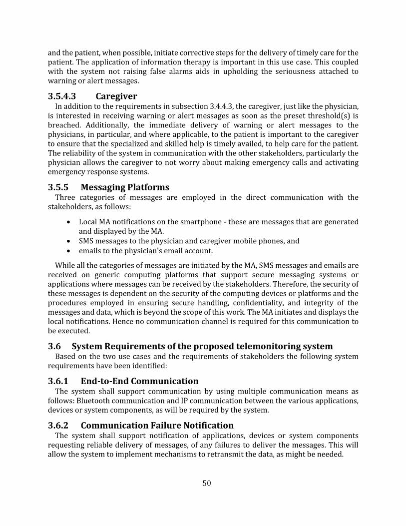
50
and the patient, when possible, initiate corrective steps for the delivery of timely care for the patient. The application of information therapy is important in this use case. This coupled with the system not raising false alarms aids in upholding the seriousness attached to warning or alert messages.
3.5.4.3 Caregiver In addition to the requirements in subsection 3.4.4.3, the caregiver, just like the physician,
is interested in receiving warning or alert messages as soon as the preset threshold(s) is breached. Additionally, the immediate delivery of warning or alert messages to the physicians, in particular, and where applicable, to the patient is important to the caregiver to ensure that the specialized and skilled help is timely availed, to help care for the patient. The reliability of the system in communication with the other stakeholders, particularly the physician allows the caregiver to not worry about making emergency calls and activating emergency response systems.
3.5.5 Messaging Platforms Three categories of messages are employed in the direct communication with the
stakeholders, as follows:
Local MA notifications on the smartphone - these are messages that are generatedand displayed by the MA.
SMS messages to the physician and caregiver mobile phones, and emails to the physician's email account.
While all the categories of messages are initiated by the MA, SMS messages and emails are received on generic computing platforms that support secure messaging systems or applications where messages can be received by the stakeholders. Therefore, the security of these messages is dependent on the security of the computing devices or platforms and the procedures employed in ensuring secure handling, confidentiality, and integrity of the messages and data, which is beyond the scope of this work. The MA initiates and displays the local notifications. Hence no communication channel is required for this communication to be executed.
3.6 System Requirements of the proposed telemonitoring system Based on the two use cases and the requirements of stakeholders the following system
requirements have been identified:
3.6.1 End-to-End Communication The system shall support communication by using multiple communication means as
follows: Bluetooth communication and IP communication between the various applications, devices or system components, as will be required by the system.
3.6.2 Communication Failure Notification The system shall support notification of applications, devices or system components
requesting reliable delivery of messages, of any failures to deliver the messages. This will allow the system to implement mechanisms to retransmit the data, as might be needed.
51
3.6.3 Abstraction of Network Technologies The system through the use of M2M middleware must be capable of interfacing over
various network technologies. This shall provide the capability for applications, devices or components to communicate with other applications, devices or components without the need for them to be aware of the network technology and the specific communication protocol of the other applications, devices or components.
3.6.4 Message Confirmation The system shall support mechanisms to confirm or acknowledge receipt of messages.
However, unconfirmed messages will also be supported by the system. Therefore, a message may be unconfirmed or confirmed.
3.6.5 Data Analytics and Processing The system shall be able to support capabilities (e.g., processing functions) for performing
data analytics based on preset thresholds from applications or the system. This shall provide the capability of interpreting and applying logic or an algorithm that may trigger operations upon other resources, applications or attributes according to the change of the monitored resource (e.g., vital sign condition).
3.6.6 Continuous Connectivity The system shall support continuous connectivity, for applications requesting the same
service on a regular and continuous basis. This continuous connectivity may be de-activated upon request of the application or by an internal mechanism within the system. An example of this requirement is continuous connectivity between the RMD and the MA during the monitoring process.
3.6.7 Time Stamping The system shall be able to support accurate, secure and trusted time-stamping.
Applications and the M2M middleware may support this requirement.
3.6.8 Reuse of Services Offered by Underlying Networks The system shall be able to reuse the services offered by underlying networks to
applications, devices and/or services. Examples of available services are:
Emailing. Location (GPS). Messaging (SMS). Data transmission.
These services may be used to add context to the RMD readings or to enable delivery of messages to the stakeholders, as might be deemed necessary by the system.
3.6.9 Support for Multiple Applications and Devices The system shall support a mechanism to manage multiple applications and shall provide
a mechanism to enable interaction between multiple applications. This mechanism support shall be as follows:
Maintenance of the list of registered M2M applications in the M2M middleware.
52
Maintenance of registration information of applications and devices.
3.6.10 Data Collection and Reporting The system shall support the collection and reporting of data from specific applications
and devices in a way requested by the system's applications as listed below:
A periodic reporting with the time period determined by the RMD or the MA; An event-based reporting.
3.6.11 Information Reception The system shall support the following mechanisms for receiving information from the
RMD, MA, M2M middleware, and EHR:
Receiving unsolicited information (passive retrieval). Receiving scheduled information. Receiving solicited information.
3.6.12 Reachability The system may be aware of the reachability state of the devices and applications to ensure
controlled and predictable behavior of devices and applications in instances where other devices and applications are not reachable. For example, the system should sense the reachability of the M2M gateway to control how data is stored into the SQLite DB, or the reachability of the RMD during monitoring to control how data is saved, processed and transmitted.
3.6.13 Monitoring and Sensing The system shall be able to sense the vital signs (e.g., heart rate) of a patient and transmit
the data to the MA for processing and further propagation.
3.6.14 Reliability It is essential that the system should not alter the vital signs reading. Therefore, the system
shall deliver data reliably to the stakeholders and applications or devices.
3.6.15 Integrity The system shall be able to manage sensitive and personal health data in such a way that
only authorized and authenticated users will have access to the data.
3.7 Proposed Telemonitoring System Based on the system requirements and the use cases discussed in the previous sections,
the proposed high-level telemonitoring system’s architecture is shown in Figure 3-4. While this work recognizes that some RMDs have communication capabilities that would enable them to connect to the middleware directly, the proposed architecture uses an RMD that does not possess such capabilities hence having to connect to the MA. This and the value of using inherent functions of the smartphone influenced this design choice. The work, however, simulates the RMDs with direct communication to the M2M middleware for demonstrative purposes, particularly, the proposed system’s ability to manage multiple vital signs.
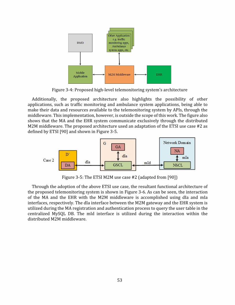
53
Figure 3-4: Proposed high-level telemonitoring system’s architecture
Additionally, the proposed architecture also highlights the possibility of other applications, such as traffic monitoring and ambulance system applications, being able to make their data and resources available to the telemonitoring system by APIs, through the middleware. This implementation, however, is outside the scope of this work. The figure also shows that the MA and the EHR system communicate exclusively through the distributed M2M middleware. The proposed architecture used an adaptation of the ETSI use case #2 as defined by ETSI [90] and shown in Figure 3-5.
Figure 3-5: The ETSI M2M use case #2 (adapted from [90])
Through the adoption of the above ETSI use case, the resultant functional architecture of the proposed telemonitoring system is shown in Figure 3-6. As can be seen, the interaction of the MA and the EHR with the M2M middleware is accomplished using dIa and mIa interfaces, respectively. The dIa interface between the M2M gateway and the EHR system is utilized during the MA registration and authentication process to query the user table in the centralized MySQL DB. The mId interface is utilized during the interaction within the distributed M2M middleware.
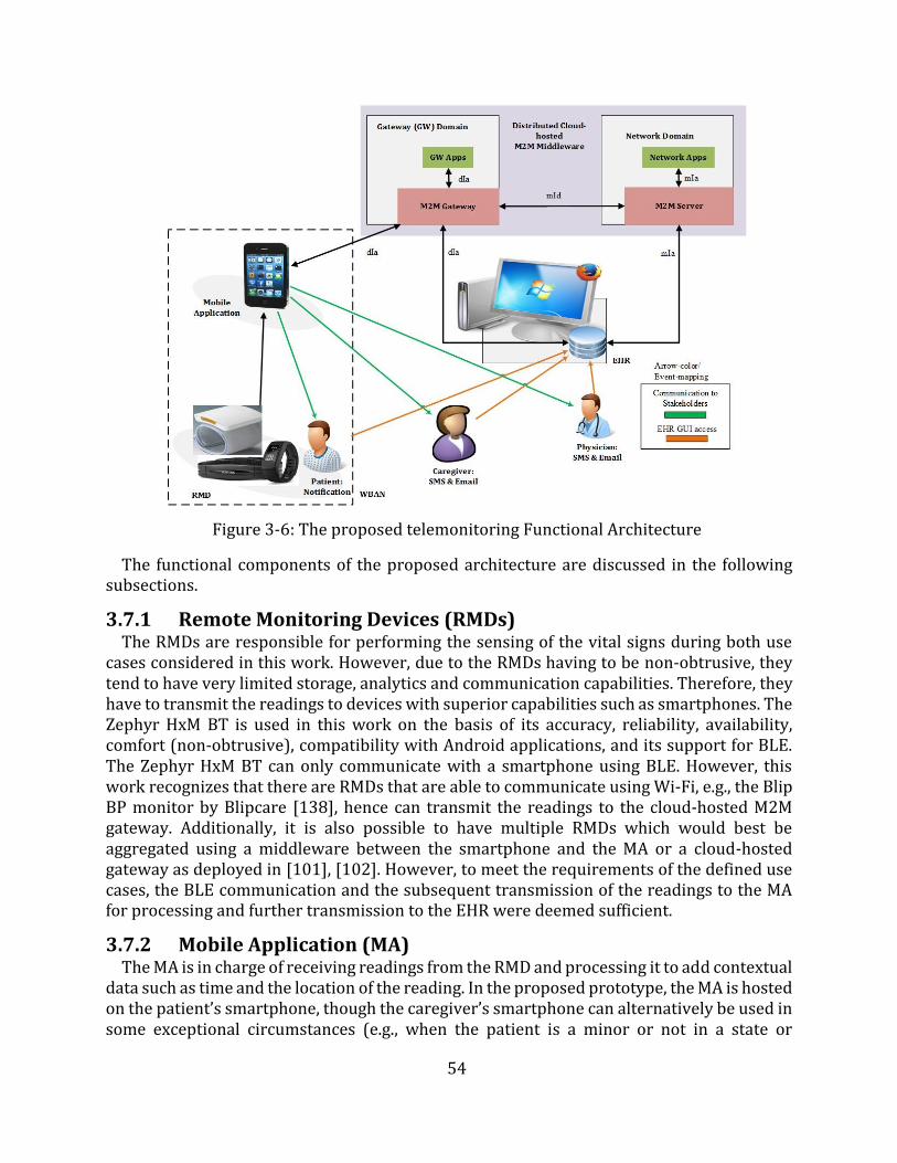
54
Figure 3-6: The proposed telemonitoring Functional Architecture
The functional components of the proposed architecture are discussed in the following subsections.
3.7.1 Remote Monitoring Devices (RMDs) The RMDs are responsible for performing the sensing of the vital signs during both use
cases considered in this work. However, due to the RMDs having to be non-obtrusive, they tend to have very limited storage, analytics and communication capabilities. Therefore, they have to transmit the readings to devices with superior capabilities such as smartphones. The Zephyr HxM BT is used in this work on the basis of its accuracy, reliability, availability, comfort (non-obtrusive), compatibility with Android applications, and its support for BLE. The Zephyr HxM BT can only communicate with a smartphone using BLE. However, this work recognizes that there are RMDs that are able to communicate using Wi-Fi, e.g., the Blip BP monitor by Blipcare [138], hence can transmit the readings to the cloud-hosted M2M gateway. Additionally, it is also possible to have multiple RMDs which would best be aggregated using a middleware between the smartphone and the MA or a cloud-hosted gateway as deployed in [101], [102]. However, to meet the requirements of the defined use cases, the BLE communication and the subsequent transmission of the readings to the MA for processing and further transmission to the EHR were deemed sufficient.
3.7.2 Mobile Application (MA) The MA is in charge of receiving readings from the RMD and processing it to add contextual
data such as time and the location of the reading. In the proposed prototype, the MA is hosted on the patient’s smartphone, though the caregiver’s smartphone can alternatively be used in some exceptional circumstances (e.g., when the patient is a minor or not in a state or
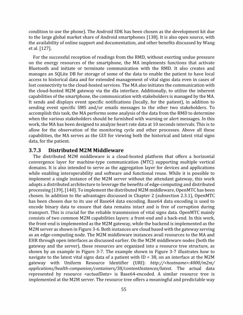
55
condition to use the phone). The Android SDK has been chosen as the development kit due to the large global market share of Android smartphones [138]. It is also open source, with the availability of online support and documentation, and other benefits discussed by Wang et al. [127].
For the successful reception of readings from the RMD, without exerting undue pressure on the energy resources of the smartphone, the MA implements functions that activate Bluetooth and initiate or terminate communication with the RMD. It also creates and manages an SQLite DB for storage of some of the data to enable the patient to have local access to historical data and for extended management of vital signs data even in cases of lost connectivity to the cloud-hosted services. The MA also initiates the communication with the cloud-hosted M2M gateway via the dIa interface. Additionally, to utilize the inherent capabilities of the smartphone, the communication with stakeholders is managed by the MA. It sends and displays event specific notifications (locally, for the patient), in addition to sending event specific SMS and/or emails messages to the other two stakeholders. To accomplish this task, the MA performs some analysis of the data from the RMD to determine when the various stakeholders should be furnished with warning or alert messages. In this work, the MA has been designed to analyze heart rate data at 10 seconds intervals. This is to allow for the observation of the monitoring cycle and other processes. Above all these capabilities, the MA serves as the GUI for viewing both the historical and latest vital signs data, for the patient.
3.7.3 Distributed M2M Middleware The distributed M2M middleware is a cloud-hosted platform that offers a horizontal
convergence layer for machine-type communication (MTC) supporting multiple vertical domains. It is also intended to serve as the aggregation layer for devices and applications while enabling interoperability and software and functional reuse. While it is possible to implement a single instance of the M2M server without the attendant gateway, this work adopts a distributed architecture to leverage the benefits of edge-computing and distributed processing [139], [140]. To implement the distributed M2M middleware, OpenMTC has been chosen. In addition to the advantages discussed in Chapter 2 (subsection 2.3.1), OpenMTC has been chosen due to its use of Base64 data encoding. Base64 data encoding is used to encode binary data to ensure that data remains intact and is free of corruption during transport. This is crucial for the reliable transmission of vital signs data. OpenMTC mainly consists of two common M2M capabilities layers: a front-end and a back-end. In this work, the front-end is implemented as the M2M gateway, while the backend is implemented as the M2M server as shown in Figure 3-6. Both instances are cloud based with the gateway serving as an edge-computing node. The M2M middleware instances avail resources to the MA and EHR through open interfaces as discussed earlier. On the M2M middleware nodes (both the gateway and the server), these resources are organized into a resource tree structure, as shown by an example in Figure 3-7. The example shown in Figure 3-7 illustrates how to navigate to the latest vital signs data of a patient with ID = 38, on an interface at the M2M gateway with Uniform Resource Identifier (URI): http://<hostname>:4000/m2m/ applications/health-companion/containers/38/contentInstances/latest. The actual data represented by resource <actualData> is Base64-encoded. A similar resource tree is implemented at the M2M server. The resource tree offers a meaningful and predictable way
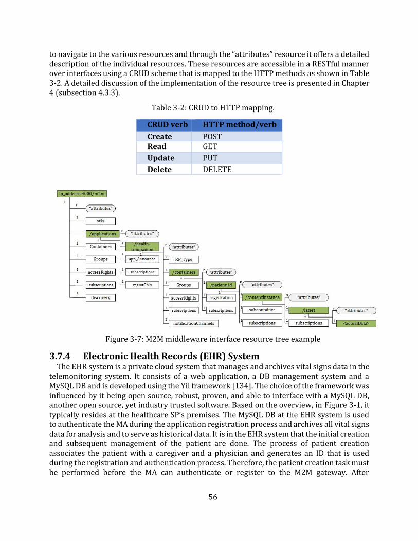
56
to navigate to the various resources and through the “attributes” resource it offers a detailed description of the individual resources. These resources are accessible in a RESTful manner over interfaces using a CRUD scheme that is mapped to the HTTP methods as shown in Table 3-2. A detailed discussion of the implementation of the resource tree is presented in Chapter4 (subsection 4.3.3).
Table 3-2: CRUD to HTTP mapping.
CRUD verb HTTP method/verb
Create POST Read GET
Update PUT
Delete DELETE
Figure 3-7: M2M middleware interface resource tree example
3.7.4 Electronic Health Records (EHR) System The EHR system is a private cloud system that manages and archives vital signs data in the
telemonitoring system. It consists of a web application, a DB management system and a MySQL DB and is developed using the Yii framework [134]. The choice of the framework was influenced by it being open source, robust, proven, and able to interface with a MySQL DB, another open source, yet industry trusted software. Based on the overview, in Figure 3-1, it typically resides at the healthcare SP’s premises. The MySQL DB at the EHR system is used to authenticate the MA during the application registration process and archives all vital signs data for analysis and to serve as historical data. It is in the EHR system that the initial creation and subsequent management of the patient are done. The process of patient creation associates the patient with a caregiver and a physician and generates an ID that is used during the registration and authentication process. Therefore, the patient creation task must be performed before the MA can authenticate or register to the M2M gateway. After
57
successful registration and authentication, it is this patient data and the associated attributes that constitute the data that is retrieved by the MA.
The EHR communicates with the M2M server to both receive new vital signs data and update (POST) the M2M server whenever there is a change in the patient data via the mIa interface. It is also responsible for performing analytics and further processing of the vital signs data. The processing involves reverse geocoding and performance of simple diagnoses to add some context to the individual vital signs readings. Furthermore, it serves as the GUI for all the stakeholders. To ensure controlled access to data, the EHR implements RBAC.
3.8 Chapter Summary In this Chapter, a use case based approach was used to identify the stakeholders and their
requirements of the telemonitoring system. Based on the stakeholders' expectations and the general use cases, system requirements for the proposed telemonitoring system were drawn. The two use cases identified were aimed at interrogating the research questions formulated in Chapter 1. The regular monitoring use case interrogates how the medical sector can adopt the IoT in its implementation of telemonitoring systems, and how the use of smart devices, particularly the smartphone, can be utilized to improve healthcare service delivery by automating the telemonitoring process. While the chronic patient use case interrogates whether the automation of the transmission and management of vital signs data can improve the response time to deterioration thereby increasing the availability of data, and improving communication among stakeholders. Based on these use cases, the proposed architecture, adapting the ETSI M2M use case in the implementation of the distributed M2M middleware was identified. The architecture consists of the following components: the RMD, the MA, the distributed M2M middleware, and the EHR system. The MA is hosted on a smartphone, while the M2M gateway and the M2M server constitute the distributed M2M middleware that is hosted on cloud infrastructure. Finally, the EHR system, consisting of the web application, a DB management system and a MySQL DB, is hosted on private cloud infrastructure.
The following Chapter gives a detailed discussion of the implementation of the IoT telemonitoring system prototype. It details the implementation of the key functionalities of all the components that make up the proposed prototype. This is achieved by detailing the software and hardware that was used. The current and the next Chapters lay the foundation for the prototype evaluation and testing that is presented in Chapter 5.
58
Chapter 4
Design and Implementation of the Proposed Prototype
The previous Chapter identified the stakeholders of the telemonitoring system and their requirements through the use of the use case approach. Based on the stakeholders’ requirements, the system requirements for the proposed telemonitoring system were drawn. The Chapter then proposed an architecture that adapts the ETSI M2M use case in the implementation of the distributed M2M middleware. The proposed architecture consists of the following components: an RMD, a smartphone-hosted MA, the distributed M2M middleware, and an EHR system.
This Chapter discusses the design and implementation of a prototype of the proposed telemonitoring system. The discussion starts with a presentation of the objectives and requirements of the framework and then proceeds to detail the software used to implement all the components of the prototype. To give a coherent discussion of the implemented functions of the various components, a detailed discussion of the operation of the prototype, based on the sequence diagram, is presented. Then the Chapter presents a summary of the hardware used to implement the prototype. Thereafter, the Chapter ends by discussing the limitations of the implemented prototype.
4.1 Prototype Design Objectives The prototype is used to test whether the proposed architecture is feasible in typical
deployment scenarios. Therefore, its objectives are closely tied to the objectives of the dissertation.
The objectives are:
To implement an end-to-end IoT telemonitoring system. To test the suitability of the proposed telemonitoring system in meeting the
expectations and requirements of the stakeholders as discussed in Chapter 3. To integrate analytics that compares vital signs readings against preset thresholds
and assesses the suitability of such implementations as means of triggering messagesto notify stakeholders.
To validate the proposed telemonitoring system's ability to meet the systemrequirements identified in Chapter 3.
4.2 Requirements of the Prototype In order to satisfy the objectives of the this work, a prototype must be designed and
implemented. The implemented prototype should satisfy the following requirements:
It must be able to aggregate the various applications and devices and allow successfulmonitoring of vital signs, and support of the requirements of the stakeholders.
It must implement an MA that can enable delivery of event-triggered messages to thestakeholders identified in Chapter 3. These event-triggered messages should begenerated after analysis of vital signs data using the MA implemented logic.
59
It must implement a standards-compliant distributed M2M middleware in avirtualized environment. The middleware should act as the aggregation andabstraction layer to enable interoperability and functional reuse.
It must support end-to-end communication over Bluetooth and IP when needed.
4.3 Software Used This section presents a discussion of the implementation of the components of the
prototype of the proposed telemonitoring system. The section starts with a discussion of the generation of vital signs data and then discusses the implementation of the MA. This is followed by a discussion of the implementation of the distributed M2M middleware. Lastly, a discussion of the EHR system is presented.
4.3.1 Remote Monitoring Devices (RMDs) As has been discussed in subsection 3.5.1, two types of vital signs were managed by the
proposed telemonitoring system. These are BP and heart rate. The BP data were simulated and mainly served as a demonstration of the management of multiple vital signs. The simulated data were generated using Python scripts (that will henceforth in the document be simply referred to as scripts) at the M2M gateway. The choice of the M2M gateway, as opposed to the smartphone for generation of BP data, was to act as simulated RMDs that have WAN communication capabilities hence do not need to use the smartphone for transmission.
The heart rate data was captured using the Zephyr HxM BT heart rate monitor – an off the shelf RMD. The heart rate monitor has a fixed data capture and transmission rate of one reading per second. Therefore the control of the readings’ interval was implemented at the MA as discussed in subsection 4.4.3.
The manufacturer instructions and specifications of the Zephyr HxM BT are given in Appendix B.
4.3.2 Mobile Application (MA) The MA is developed using Java programming language and the Android SDK, in Android
Studio. As already mentioned in Chapter 3, Android has been chosen for the implementation of the MA because of its large share in the smartphone market, its maturity and the rich features of its SDK. The Java programming language was an automatic choice because it is the only programming language used for application development in Android studio. For the implementation of the MA, Android API level 15 (Ice Cream Sandwich/version 4.0.3) or newer was targeted as it is estimated that this would cover about 97% of Android devices [141].
The MA was implemented using the Model-View-Controller (MVC) design approach that promotes reuse of classes and modular development of applications. The model holds the application’s data and “business logic”, while the view consists of user interface objects such as buttons, text boxes, etc. that are grouped as layout resources, and the controller contains the “application logic”. A layout resource is basically a set of user interface objects and their position on the screen and its definitions are written in XML. Each definition is used to create an object that appears on screen, like a button or some text [142]. This enables the MA to deliver a GUI for the patient or caregiver.
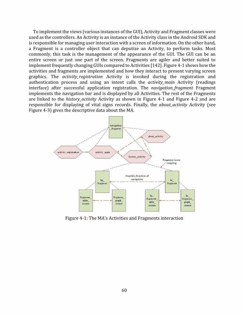
60
To implement the views (various instances of the GUI), Activity and Fragment classes were used as the controllers. An Activity is an instance of the Activity class in the Android SDK and is responsible for managing user interaction with a screen of information. On the other hand, a Fragment is a controller object that can deputize an Activity, to perform tasks. Most commonly, this task is the management of the appearance of the GUI. The GUI can be an entire screen or just one part of the screen. Fragments are agiler and better suited to implement frequently changing GUIs compared to Activities [142]. Figure 4-1 shows how the activities and fragments are implemented and how they interact to present varying screen graphics. The activity_registration Activity is invoked during the registration and authentication process and using an intent calls the activity_main Activity (readings interface) after successful application registration. The navigation_fragment Fragment implements the navigation bar and is displayed by all Activities. The rest of the Fragments are linked to the history_activity Activity as shown in Figure 4-1 and Figure 4-2 and are responsible for displaying of vital signs records. Finally, the about_activity Activity (see Figure 4-3) gives the descriptive data about the MA.
Figure 4-1: The MA's Activities and Fragments interaction
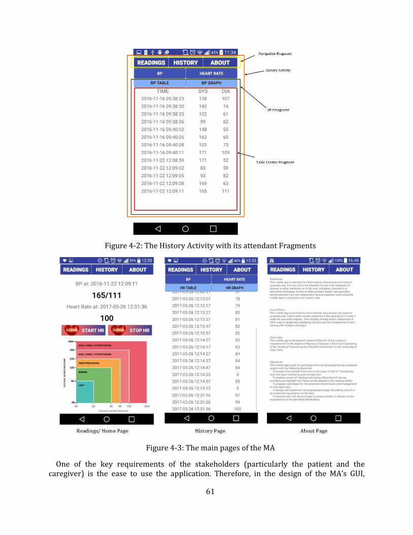
61
Figure 4-2: The History Activity with its attendant Fragments
Figure 4-3: The main pages of the MA
One of the key requirements of the stakeholders (particularly the patient and the caregiver) is the ease to use the application. Therefore, in the design of the MA’s GUI,
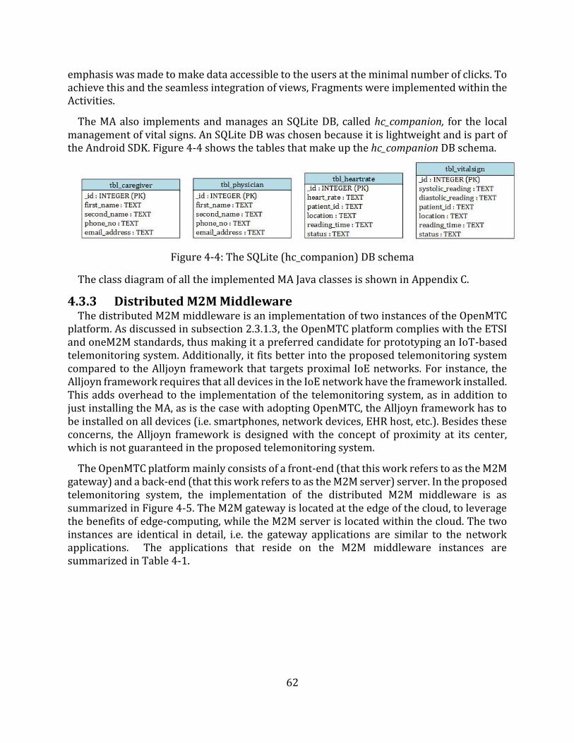
62
emphasis was made to make data accessible to the users at the minimal number of clicks. To achieve this and the seamless integration of views, Fragments were implemented within the Activities.
The MA also implements and manages an SQLite DB, called hc_companion, for the local management of vital signs. An SQLite DB was chosen because it is lightweight and is part of the Android SDK. Figure 4-4 shows the tables that make up the hc_companion DB schema.
Figure 4-4: The SQLite (hc_companion) DB schema
The class diagram of all the implemented MA Java classes is shown in Appendix C.
4.3.3 Distributed M2M Middleware The distributed M2M middleware is an implementation of two instances of the OpenMTC
platform. As discussed in subsection 2.3.1.3, the OpenMTC platform complies with the ETSI and oneM2M standards, thus making it a preferred candidate for prototyping an IoT-based telemonitoring system. Additionally, it fits better into the proposed telemonitoring system compared to the Alljoyn framework that targets proximal IoE networks. For instance, the Alljoyn framework requires that all devices in the IoE network have the framework installed. This adds overhead to the implementation of the telemonitoring system, as in addition to just installing the MA, as is the case with adopting OpenMTC, the Alljoyn framework has to be installed on all devices (i.e. smartphones, network devices, EHR host, etc.). Besides these concerns, the Alljoyn framework is designed with the concept of proximity at its center, which is not guaranteed in the proposed telemonitoring system.
The OpenMTC platform mainly consists of a front-end (that this work refers to as the M2M gateway) and a back-end (that this work refers to as the M2M server) server. In the proposed telemonitoring system, the implementation of the distributed M2M middleware is as summarized in Figure 4-5. The M2M gateway is located at the edge of the cloud, to leverage the benefits of edge-computing, while the M2M server is located within the cloud. The two instances are identical in detail, i.e. the gateway applications are similar to the network applications. The applications that reside on the M2M middleware instances are summarized in Table 4-1.
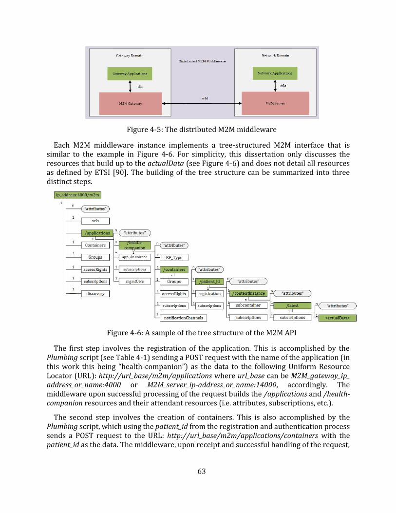
63
Figure 4-5: The distributed M2M middleware
Each M2M middleware instance implements a tree-structured M2M interface that is similar to the example in Figure 4-6. For simplicity, this dissertation only discusses the resources that build up to the actualData (see Figure 4-6) and does not detail all resources as defined by ETSI [90]. The building of the tree structure can be summarized into three distinct steps.
Figure 4-6: A sample of the tree structure of the M2M API
The first step involves the registration of the application. This is accomplished by the Plumbing script (see Table 4-1) sending a POST request with the name of the application (in this work this being “health-companion”) as the data to the following Uniform Resource Locator (URL): http://url_base/m2m/applications where url_base can be M2M_gateway_ip_ address_or_name:4000 or M2M_server_ip-address_or_name:14000, accordingly. The middleware upon successful processing of the request builds the /applications and /health-companion resources and their attendant resources (i.e. attributes, subscriptions, etc.).
The second step involves the creation of containers. This is also accomplished by the Plumbing script, which using the patient_id from the registration and authentication process sends a POST request to the URL: http://url_base/m2m/applications/containers with the patient_id as the data. The middleware, upon receipt and successful handling of the request,
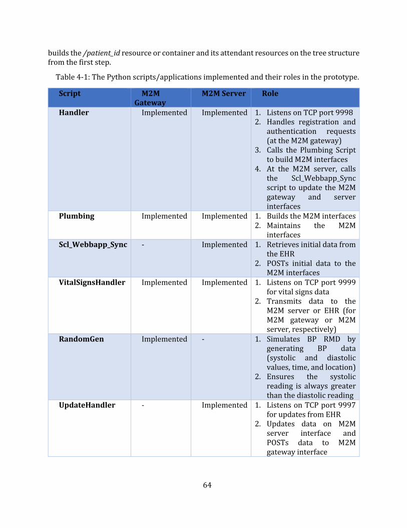
64
builds the /patient_id resource or container and its attendant resources on the tree structure from the first step.
Table 4-1: The Python scripts/applications implemented and their roles in the prototype.
Script M2M Gateway
M2M Server Role
Handler Implemented Implemented 1. Listens on TCP port 99982. Handles registration and
authentication requests(at the M2M gateway)
3. Calls the Plumbing Scriptto build M2M interfaces
4. At the M2M server, callsthe Scl_Webbapp_Syncscript to update the M2Mgateway and serverinterfaces
Plumbing Implemented Implemented 1. Builds the M2M interfaces2. Maintains the M2M
interfacesScl_Webbapp_Sync - Implemented 1. Retrieves initial data from
the EHR2. POSTs initial data to the
M2M interfacesVitalSignsHandler Implemented Implemented 1. Listens on TCP port 9999
for vital signs data2. Transmits data to the
M2M server or EHR (forM2M gateway or M2Mserver, respectively)
RandomGen Implemented - 1. Simulates BP RMD bygenerating BP data(systolic and diastolicvalues, time, and location)
2. Ensures the systolicreading is always greaterthan the diastolic reading
UpdateHandler - Implemented 1. Listens on TCP port 9997for updates from EHR
2. Updates data on M2Mserver interface andPOSTs data to M2Mgateway interface
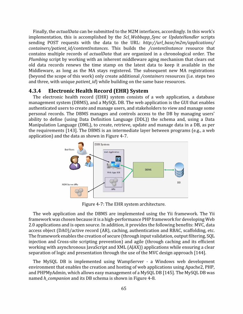
65
Finally, the actualData can be submitted to the M2M interfaces, accordingly. In this work’s implementation, this is accomplished by the Scl_Webbapp_Sync or UpdateHandler scripts sending POST requests with the data to the URL: http://url_base/m2m/applications/ containers/patient_id/contentInstances. This builds the /contentInstance resource that contains multiple records of actualData that are organized in a chronological order. The Plumbing script by working with an inherent middleware aging mechanism that clears out old data records renews the time stamp on the latest data to keep it available in the Middleware, as long as the MA stays registered. The subsequent new MA registrations (beyond the scope of this work) only create additional /containers resources (i.e. steps two and three, with unique patient_id) while building on the same base resources.
4.3.4 Electronic Health Record (EHR) System The electronic health record (EHR) system consists of a web application, a database
management system (DBMS), and a MySQL DB. The web application is the GUI that enables authenticated users to create and manage users, and stakeholders to view and manage some personal records. The DBMS manages and controls access to the DB by managing users' ability to define (using Data Definition Language (DDL)) the schema and, using a Data Manipulation Language (DML), to create, retrieve, update and manage data in a DB, as per the requirements [143]. The DBMS is an intermediate layer between programs (e.g., a web application) and the data as shown in Figure 4-7.
Figure 4-7: The EHR system architecture.
The web application and the DBMS are implemented using the Yii framework. The Yii framework was chosen because it is a high-performance PHP framework for developing Web 2.0 applications and is open source. In addition, it provides the following benefits: MVC, data access object (DAO)/active record (AR), caching, authentication and RBAC, scaffolding, etc. The framework enables the creation of secure (through input validation, output filtering, SQL injection and Cross-site scripting prevention) and agile (through caching and its efficient working with asynchronous JavaScript and XML (AJAX)) applications while ensuring a clear separation of logic and presentation through the use of the MVC design approach [144].
The MySQL DB is implemented using WampServer - a Windows web development environment that enables the creation and hosting of web applications using Apache2, PHP, and PHPMyAdmin, which allows easy management of a MySQL DB [145]. The MySQL DB was named h_companion and its DB schema is shown in Figure 4-8.
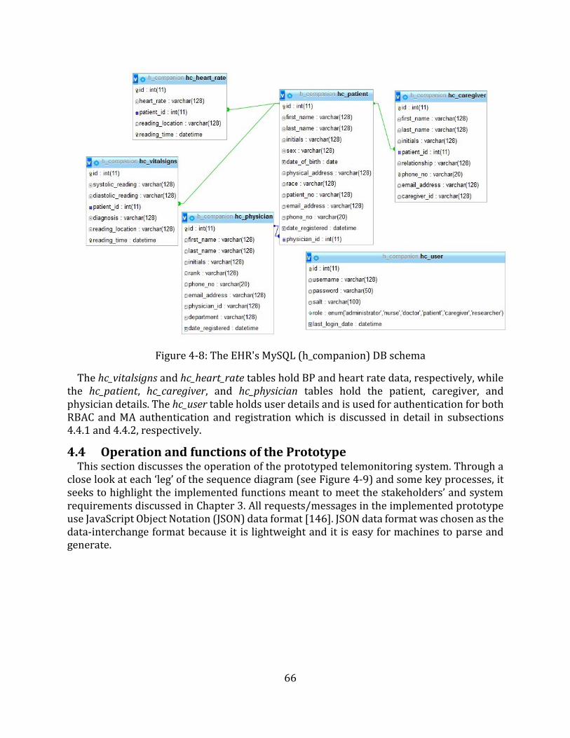
66
Figure 4-8: The EHR's MySQL (h_companion) DB schema
The hc_vitalsigns and hc_heart_rate tables hold BP and heart rate data, respectively, while the hc_patient, hc_caregiver, and hc_physician tables hold the patient, caregiver, and physician details. The hc_user table holds user details and is used for authentication for both RBAC and MA authentication and registration which is discussed in detail in subsections 4.4.1 and 4.4.2, respectively.
4.4 Operation and functions of the Prototype This section discusses the operation of the prototyped telemonitoring system. Through a
close look at each ‘leg’ of the sequence diagram (see Figure 4-9) and some key processes, it seeks to highlight the implemented functions meant to meet the stakeholders’ and system requirements discussed in Chapter 3. All requests/messages in the implemented prototype use JavaScript Object Notation (JSON) data format [146]. JSON data format was chosen as the data-interchange format because it is lightweight and it is easy for machines to parse and generate.

67
Figure 4-9: The prototype's end-to-end communication sequence diagram
4.4.1 Patient Creation The foremost step in the operation of the proposed prototype is the creation of users
(stakeholders) of the system. These include the patients, caregivers, and physicians. The order of creation of these users is particularly important as there are foreign key (FK) constraints that must be satisfied. For example, because of the relation between the hc_patient table and the hc_physician table by the id (in hc_physician) and the physician_id (in hc_patient), the patient can only be created if a physician exists. Therefore, to successfully create the users, the order is as follows: the physician is created first, followed by the patient, and lastly the caregiver. The creation of the patient and the physician auto-populates the hc_user table and associates the users with the roles to enable them to access and manage
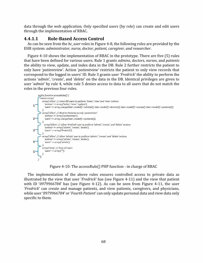
68
data through the web application. Only specified users (by role) can create and edit users through the implementation of RBAC.
4.4.1.1 Role-Based Access Control As can be seen from the hc_user roles in Figure 4-8, the following roles are provided by the
EHR system: administrator, nurse, doctor, patient, caregiver, and researcher.
Figure 4-10 shows the implementation of RBAC in the prototype. There are five (5) rules that have been defined for various users. Rule 1 grants admins, doctors, nurses, and patients the ability to view, update, and index data in the DB. Rule 2 further restricts the patient to only have ‘patientview’. Action ‘patientview’ restricts the patient to only view records that correspond to the logged in users’ ID. Rule 3 grants user ‘Fredrick’ the ability to perform the actions ‘admin’, ‘create’, and ‘delete’ on the data in the DB. Identical privileges are given to user ‘admin’ by rule 4, while rule 5 denies access to data to all users that do not match the roles in the previous four rules.
Figure 4-10: The accessRule() PHP function - in charge of RBAC
The implementation of the above rules ensures controlled access to private data as illustrated by the view that user ‘Fredrick’ has (see Figure 4-11) and the view that patient with ID ‘0979966784’ has (see Figure 4-12). As can be seen from Figure 4-11, the user ‘Fredrick’ can create and manage patients, and view patients, caregivers, and physicians, while user ‘0979966784’ or ‘Fourth Patient’ can only update personal data and view data only specific to them.
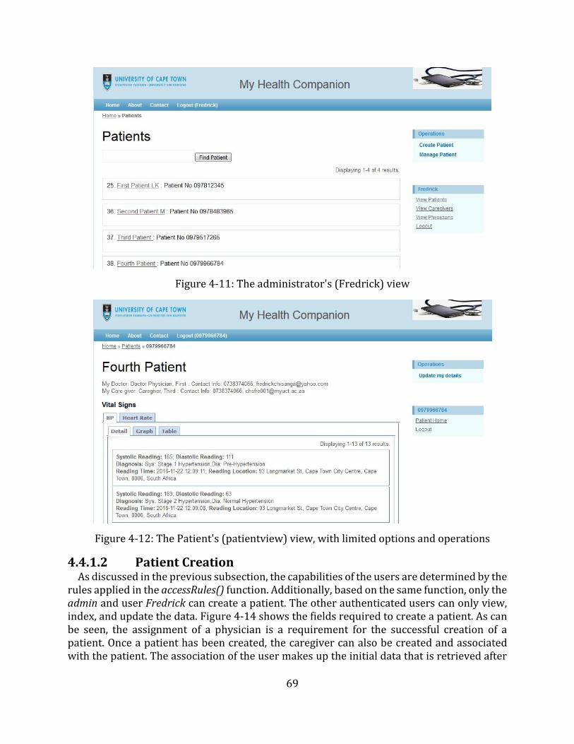
69
Figure 4-11: The administrator's (Fredrick) view
Figure 4-12: The Patient's (patientview) view, with limited options and operations
4.4.1.2 Patient Creation As discussed in the previous subsection, the capabilities of the users are determined by the
rules applied in the accessRules() function. Additionally, based on the same function, only the admin and user Fredrick can create a patient. The other authenticated users can only view, index, and update the data. Figure 4-14 shows the fields required to create a patient. As can be seen, the assignment of a physician is a requirement for the successful creation of a patient. Once a patient has been created, the caregiver can also be created and associated with the patient. The association of the user makes up the initial data that is retrieved after
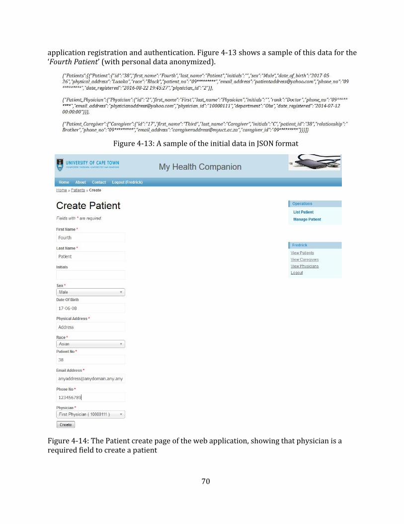
70
application registration and authentication. Figure 4-13 shows a sample of this data for the ‘Fourth Patient’ (with personal data anonymized).
Figure 4-13: A sample of the initial data in JSON format
Figure 4-14: The Patient create page of the web application, showing that physician is a required field to create a patient
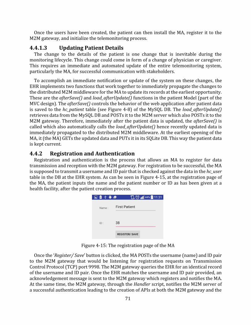
71
Once the users have been created, the patient can then install the MA, register it to the M2M gateway, and initialize the telemonitoring process.
4.4.1.3 Updating Patient Details The change to the details of the patient is one change that is inevitable during the
monitoring lifecycle. This change could come in form of a change of physician or caregiver. This requires an immediate and automated update of the entire telemonitoring system, particularly the MA, for successful communication with stakeholders.
To accomplish an immediate notification or update of the system on these changes, the EHR implements two functions that work together to immediately propagate the changes to the distributed M2M middleware for the MA to update its records at the earliest opportunity. These are the afterSave() and load_afterUpdate() functions in the patient Model (part of the MVC design). The afterSave() controls the behavior of the web application after patient data is saved to the hc_patient table (see Figure 4-8) of the MySQL DB. The load_afterUpdate() retrieves data from the MySQL DB and POSTs it to the M2M server which also POSTs it to the M2M gateway. Therefore, immediately after the patient data is updated, the afterSave() is called which also automatically calls the load_afterUpdate() hence recently updated data is immediately propagated to the distributed M2M middleware. At the earliest opening of the MA, it (the MA) GETs the updated data and PUTs it in its SQLite DB. This way the patient data is kept current.
4.4.2 Registration and Authentication Registration and authentication is the process that allows an MA to register for data
transmission and reception with the M2M gateway. For registration to be successful, the MA is supposed to transmit a username and ID pair that is checked against the data in the hc_user table in the DB at the EHR system. As can be seen in Figure 4-15, at the registration page of the MA, the patient inputs the name and the patient number or ID as has been given at a health facility, after the patient creation process.
Figure 4-15: The registration page of the MA
Once the ‘Register/ Save’ button is clicked, the MA POSTs the username (name) and ID pair to the M2M gateway that would be listening for registration requests on Transmission Control Protocol (TCP) port 9998. The M2M gateway queries the EHR for an identical record of the username and ID pair. Once the EHR matches the username and ID pair provided, an acknowledgement message is sent to the M2M gateway which registers and notifies the MA. At the same time, the M2M gateway, through the Handler script, notifies the M2M server of a successful authentication leading to the creation of APIs at both the M2M gateway and the
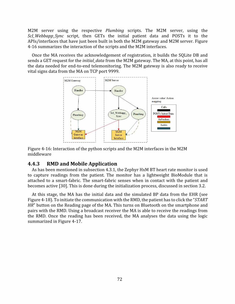
72
M2M server using the respective Plumbing scripts. The M2M server, using the Scl_Webbapp_Sync script, then GETs the initial patient data and POSTs it to the APIs/interfaces that have just been built in both the M2M gateway and M2M server. Figure 4-16 summarizes the interaction of the scripts and the M2M interfaces.
Once the MA receives the acknowledgement of registration, it builds the SQLite DB andsends a GET request for the initial_data from the M2M gateway. The MA, at this point, has all the data needed for end-to-end telemonitoring. The M2M gateway is also ready to receive vital signs data from the MA on TCP port 9999.
Figure 4-16: Interaction of the python scripts and the M2M interfaces in the M2M middleware
4.4.3 RMD and Mobile Application As has been mentioned in subsection 4.3.1, the Zephyr HxM BT heart rate monitor is used
to capture readings from the patient. The monitor has a lightweight BioModule that is attached to a smart-fabric. The smart-fabric senses when in contact with the patient and becomes active [30]. This is done during the initialization process, discussed in section 3.2.
At this stage, the MA has the initial data and the simulated BP data from the EHR (see Figure 4-18). To initiate the communication with the RMD, the patient has to click the “START HR” button on the Reading page of the MA. This turns on Bluetooth on the smartphone and pairs with the RMD. Using a broadcast receiver the MA is able to receive the readings from the RMD. Once the reading has been received, the MA analyses the data using the logic summarized in Figure 4-17.
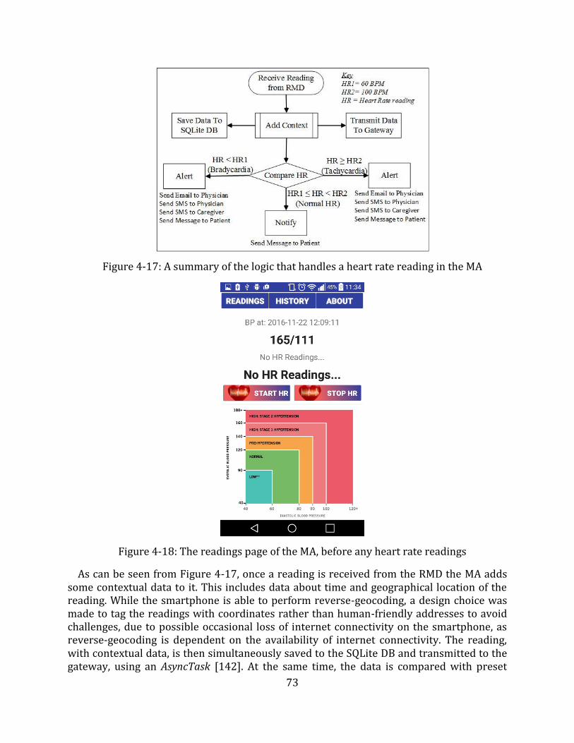
73
Figure 4-17: A summary of the logic that handles a heart rate reading in the MA
Figure 4-18: The readings page of the MA, before any heart rate readings
As can be seen from Figure 4-17, once a reading is received from the RMD the MA adds some contextual data to it. This includes data about time and geographical location of the reading. While the smartphone is able to perform reverse-geocoding, a design choice was made to tag the readings with coordinates rather than human-friendly addresses to avoid challenges, due to possible occasional loss of internet connectivity on the smartphone, as reverse-geocoding is dependent on the availability of internet connectivity. The reading, with contextual data, is then simultaneously saved to the SQLite DB and transmitted to the gateway, using an AsyncTask [142]. At the same time, the data is compared with preset
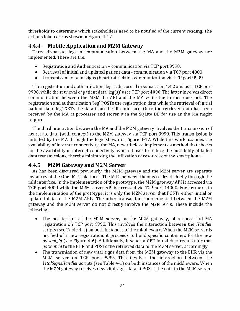
74
thresholds to determine which stakeholders need to be notified of the current reading. The actions taken are as shown in Figure 4-17.
4.4.4 Mobile Application and M2M Gateway Three disparate ‘legs’ of communication between the MA and the M2M gateway are
implemented. These are the:
Registration and Authentication – communication via TCP port 9998. Retrieval of initial and updated patient data - communication via TCP port 4000. Transmission of vital signs (heart rate) data - communication via TCP port 9999.
The registration and authentication ‘leg’ is discussed in subsection 4.4.2 and uses TCP port 9998, while the retrieval of patient data ‘leg(s)’ uses TCP port 4000. The latter involves direct communication between the M2M dIa API and the MA while the former does not. The registration and authentication ‘leg’ POSTs the registration data while the retrieval of initial patient data ‘leg’ GETs the data from the dIa interface. Once the retrieved data has been received by the MA, it processes and stores it in the SQLite DB for use as the MA might require.
The third interaction between the MA and the M2M gateway involves the transmission of heart rate data (with context) to the M2M gateway via TCP port 9999. This transmission is initiated by the MA through the logic shown in Figure 4-17. While this work assumes the availability of internet connectivity, the MA, nevertheless, implements a method that checks for the availability of internet connectivity, which it uses to reduce the possibility of failed data transmissions, thereby minimizing the utilization of resources of the smartphone.
4.4.5 M2M Gateway and M2M Server As has been discussed previously, the M2M gateway and the M2M server are separate
instances of the OpenMTC platform. The MTC between them is realized chiefly through the mId interface. In the implementation of the prototype, the M2M gateway API is accessed via TCP port 4000 while the M2M server API is accessed via TCP port 14000. Furthermore, in the implementation of the prototype, it is only the M2M server that POSTs either initial or updated data to the M2M APIs. The other transactions implemented between the M2M gateway and the M2M server do not directly involve the M2M APIs. These include the following:
The notification of the M2M server, by the M2M gateway, of a successful MAregistration on TCP port 9998. This involves the interaction between the Handlerscripts (see Table 4-1) on both instances of the middleware. When the M2M server isnotified of a new registration, it proceeds to build specific containers for the newpatient_id (see Figure 4-6). Additionally, it sends a GET initial data request for thatpatient_id to the EHR and POSTs the retrieved data to the M2M server, accordingly.
The transmission of new vital signs data from the M2M gateway to the EHR via theM2M server on TCP port 9999. This involves the interaction between theVitalSignsHandler scripts (see Table 4-1) on both instances of the middleware. Whenthe M2M gateway receives new vital signs data, it POSTs the data to the M2M server.
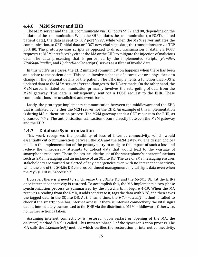
75
4.4.6 M2M Server and EHR The M2M server and the EHR communicate via TCP ports 9997 and 80, depending on the
initiator of the communication. When the EHR initiates the communication (to POST updated patient data), the data is sent to TCP port 9997, while when the M2M server initiates the communication, to GET initial data or POST new vital signs data, the transactions are via TCP port 80. The prototype uses scripts as opposed to direct transmission of data, via POST requests, to M2M interfaces by either the MA or the EHR to mitigate the injection of malicious data. The data processing that is performed by the implemented scripts (Handler, VitalSignHandler, and UpdateHandler scripts) serves as a filter of invalid data.
In this work’s use cases, the EHR initiated communication happens when there has been an update to the patient data. This could involve a change of a caregiver or a physician or a change in the personal details of the patient. The EHR implements a function that POSTs updated data to the M2M server after the changes to the DB are made. On the other hand, the M2M server initiated communication primarily involves the retargeting of data from the M2M gateway. This data is subsequently sent via a POST request to the EHR. These communications are unsolicited and event-based.
Lastly, the prototype implements communication between the middleware and the EHR that is initiated by neither the M2M server nor the EHR. An example of this implementation is during MA authentication process. The M2M gateway sends a GET request to the EHR, as discussed 4.4.2. The authentication transaction occurs directly between the M2M gateway and the EHR.
4.4.7 Database Synchronization This work recognizes the possibility of loss of internet connectivity, which would
essentially cut communication between the MA and the M2M gateway. The design choices made in the implementation of the prototype try to mitigate the impact of such a loss and reduce the unnecessary attempts to upload data that would lead to the wastage of smartphone resources. These choices include the use of the smartphone’s inherent functions such as SMS messaging and an instance of an SQLite DB. The use of SMS messaging ensures stakeholders are warned or alerted of any emergencies even with no internet connectivity, while the use of the SQLite DB ensures continued management of vital signs data even when the MySQL DB is inaccessible.
However, there is a need to synchronize the SQLite DB and the MySQL DB (at the EHR) once internet connectivity is restored. To accomplish this, the MA implements a two-phase synchronization process as summarized by the flowcharts in Figure 4-19. When the MA receives a reading from the RMD, it adds context to it, tags the data with ‘UD’, and then saves the tagged data in the SQLite DB. At the same time, the isConnected() method is called to check if the smartphone has internet access. If there is internet connectivity the vital signs data is immediately transmitted to the EHR via the distributed M2M middleware. Otherwise, no further action is taken.
Assuming internet connectivity is restored, upon restart or opening of the MA, the onStart() method [147] is called. This initiates phase 2 of the synchronization process. The MA calls the isConnected() method which verifies the restoration of internet connectivity.
76
The MA then queries the SQLite for all vital signs data records that have the ‘UD’ tag. All the records that were saved during Phase 1 will then be uploaded to the EHR via the distributed M2M middleware as they are interpreted by the MA as being out of sync. Upon the successful upload of this out of sync data, the MA then queries the MySQL DB for a record of the data it has. If the MySQL confirms receipt of the data that was just uploaded, the MA updates the data in the SQLite DB by changing the tag to ‘D’. This two-phased process thereby keeps the two DBs in sync, at the earliest opportunity. Figure 4-20 highlights how the tags of the entries in the SQLite change during the course of the two phases.
Figure 4-19: The two phases of the synchronization process of the two DBs
77
Figure 4-20: The tags in the hc_companion DB during the DB synchronization phases
4.4.8 Messaging Mechanism The proposed telemonitoring system seeks to be patient-centric as much as possible.
Because of this, as much processing of data as possible is done at the patient end of the system. In line with this design choice, the inherent features of the smartphone have been used to generate warning and alert messages to the stakeholders. These features include the phone’s ability to send local notifications, emails and SMS messages. The local notifications are generated and displayed by the MA.
Depending on the outcome of the implemented logic (see Figure 4-17), an alert or a notify decision can follow. When an alert decision is made, an email is sent to the physician, SMS messages are sent to the physician and the caregiver, and a local notification message is displayed to the patient. On the other hand, when a notify decision is made, only the local notification message is displayed to the patient. This demonstrates the implementation of information therapy, as discussed in Chapter 2.
In composing the messages, the MA uses the initial data that is saved in the SQLite DB as a source of details such as the phone numbers of the physician and the caregiver, or the email address of the physician. To ensure that this data is kept as current as possible, the EHR POSTs any changes to the distributed M2M middleware that caches the data. Whenever the MA is opened, it queries the M2M gateway for any changes to the data in its SQLite DB and makes the changes to the data, accordingly. This design choice was made as opposed to implementing the sending of changes by the M2M gateway, via POST requests, to the MA. Such an approach would require the MA to be always awake, thus always using up the
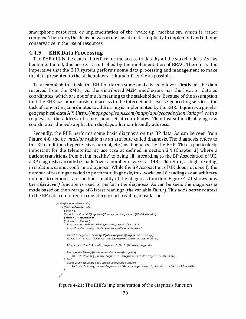
78
smartphone resources, or implementation of the “wake-up” mechanism, which is rather complex. Therefore, the decision was made based on its simplicity to implement and it being conservative in the use of resources.
4.4.9 EHR Data Processing The EHR GUI is the central interface for the access to data by all the stakeholders. As has
been mentioned, this access is controlled by the implementation of RBAC. Therefore, it is imperative that the EHR system performs some data processing and management to make the data presented to the stakeholders as human-friendly as possible.
To accomplish this task, the EHR performs some analysis as follows: Firstly, all the data received from the RMDs, via the distributed M2M middleware has the location data as coordinates, which are not of much meaning to the stakeholders. Because of the assumption that the EHR has more consistent access to the internet and reverse-geocoding services, the task of converting coordinates to addressing is implemented by the EHR. It queries a google-geographical-data API (http://maps.googleapis.com/maps/api/geocode/json?latlng=) with a request for the address of a particular set of coordinates. Then instead of displaying raw coordinates, the web application displays a human-friendly address.
Secondly, the EHR performs some basic diagnosis on the BP data. As can be seen from Figure 4-8, the hc_vitalsigns table has an attribute called diagnosis. The diagnosis refers to the BP condition (hypertensive, normal, etc.) as diagnosed by the EHR. This is particularly important for the telemonitoring use case as defined in section 3.4 (Chapter 3) where a patient transitions from being ‘healthy’ to being ‘ill’. According to the BP Association of UK, a BP diagnosis can only be made “over a number of weeks” [148]. Therefore, a single reading, in isolation, cannot confirm a diagnosis. While the BP Association of UK does not specify the number of readings needed to perform a diagnosis, this work used 6 readings as an arbitrary number to demonstrate the functionality of the diagnosis function. Figure 4-21 shows how the afterSave() function is used to perform the diagnosis. As can be seen, the diagnosis is made based on the average of 6 latest readings (the variable $limit). This adds better context to the BP data compared to considering each reading in isolation.
Figure 4-21: The EHR's implementation of the diagnosis function
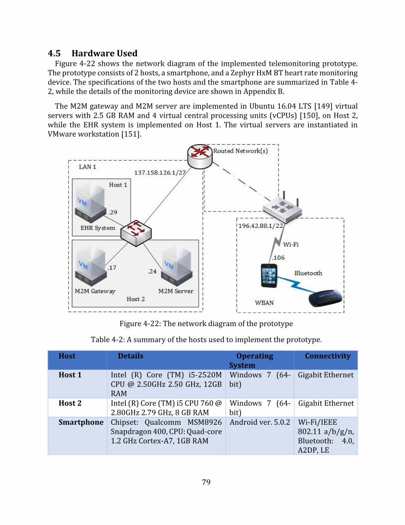
79
4.5 Hardware Used Figure 4-22 shows the network diagram of the implemented telemonitoring prototype.
The prototype consists of 2 hosts, a smartphone, and a Zephyr HxM BT heart rate monitoring device. The specifications of the two hosts and the smartphone are summarized in Table 4-2, while the details of the monitoring device are shown in Appendix B.
The M2M gateway and M2M server are implemented in Ubuntu 16.04 LTS [149] virtual servers with 2.5 GB RAM and 4 virtual central processing units (vCPUs) [150], on Host 2, while the EHR system is implemented on Host 1. The virtual servers are instantiated in VMware workstation [151].
Figure 4-22: The network diagram of the prototype
Table 4-2: A summary of the hosts used to implement the prototype.
Host Details Operating System
Connectivity
Host 1 Intel (R) Core (TM) i5-2520M CPU @ 2.50GHz 2.50 GHz, 12GB RAM
Windows 7 (64-bit)
Gigabit Ethernet
Host 2 Intel (R) Core (TM) i5 CPU 760 @ 2.80GHz 2.79 GHz, 8 GB RAM
Windows 7 (64-bit)
Gigabit Ethernet
Smartphone Chipset: Qualcomm MSM8926 Snapdragon 400, CPU: Quad-core 1.2 GHz Cortex-A7, 1GB RAM
Android ver. 5.0.2 Wi-Fi/IEEE 802.11 a/b/g/n, Bluetooth: 4.0, A2DP, LE
80
4.6 Limitations of the Prototype The implemented prototype demonstrated the feasibility of deploying an end-to-end
telemonitoring system. However, there are some limitations that were noted that would create possible resistance to its ready adoption. Firstly, the use of inherent smartphone messaging platforms, particularly SMS messaging, implies that there is a cost implication on the patient for every SMS message sent out. While the prototype only sends out SMS messages in cases of an emergency, these could be many over an extended period of time, for patients that are in a lengthy critical state. The cost of about 0.34 Rands (US$0.027) per SMS message [152] may appear small in isolation, but when the number of messages increases, this amount can increase significantly. The possible workaround is to pause the telemonitoring process when a patient is under in-hospital care. This would be done at the assumption that telemonitoring has been replaced by more “in-contact” monitoring. Additionally, government or private entities (such as SMS message SPs, and eHealth SPs, etc.) could draw up agreements to subsidize eHealth SMS messages to reduce the cost, on the patient, of implementation of the proposed telemonitoring system.
Secondly, the preferred use of real life devices, as opposed to simulation, makes the prototype less suitable for scalability testing and modeling of scalability scenarios. While this work has simulated BP readings, for the purpose of demonstrating the management of multiple vital signs, it does not discuss end-to-end transmission, processing, and management of multiple vital signs. The use of real life devices, without simulations, would render the prototype too costly for experimentation on scalability problems.
Thirdly, the implemented prototype, in the current form, does not present an ideal scalability (in terms of the number of patients monitored) testing platform. The proposed architecture intends to have multiple regional M2M gateways that connect to a central M2M server. Such a deployment should allow for the MA to connect to the different (one at a time) M2M gateways and still maintain end-to-end communication. For such a scenario to be achieved, two possible implementation approaches could be considered. The first is to make the MA intelligent enough to search for M2M gateways and register with the one that offers better service (i.e. delay, latency, uptime, etc.). Then the M2M server must be equally intelligent enough to learn the addresses of the M2M gateway that transmits registration data of a particular MA, or that transmits vital signs data from a particular MA, and use the learned information to communicate back to the M2M gateway. The second approach is to implement the M2M server to multicast the vital signs data to all the M2M gateways, and only add intelligence to the MA to identify and connect to the best M2M gateway. However, the scalability requirement is outside the scope of this work.
Lastly, as can be seen from the network diagram in Figure 4-22, The M2M gateway and M2M server were deployed within the same network. This deployment renders the prototype ill-suited for assessing the effect of network parameters (such as delay, latency, etc.) in the delivery of data to the EHR as it does not reflect a realistic real life deployment scenario, which has multiple hops between the components.
While the above limitations of the implemented prototype highlight a number of potential areas of improvement, for the objectives of this work and the system requirements identified in Chapter 3, the prototype presents a sufficient evaluation and testing environment.
81
4.7 Chapter Summary This Chapter discussed the design and implementation of the proposed prototype. It
presented the objectives and requirements of the framework and highlighted that they are closely knit into the objectives of the dissertation. The Chapter also highlighted the need to implement a prototype of the proposed telemonitoring system that must satisfy the stated requirements and provide a valid testing tool. A detailed discussion of the software and hardware used to implement the prototype were subsequently detailed.
The Chapter, through a discussion of the operation of the implemented prototype, gave a detailed discussion of the implemented functions aimed at meeting the stakeholders’ and system requirements as drawn up in Chapter 3. The discussion was segmented into the communication legs of the proposed system’s sequence diagram, for coherence. However, the order of operation, as was noted, is not always sequential.
The following Chapter presents a discussion of the evaluation, analysis, and operational verification that was performed on the prototype to show how it fits into the stakeholders and system requirements. Furthermore, the Chapter discusses the results of the tests in the delay to deliver messages to the stakeholders, as a way to highlight the contribution this work makes in reducing the overall time of the cardiac arrest chain of survival. Lastly, the Chapter discusses the results of the assessment of the impact of the MA on the smartphone’s resources (space and processing resources).
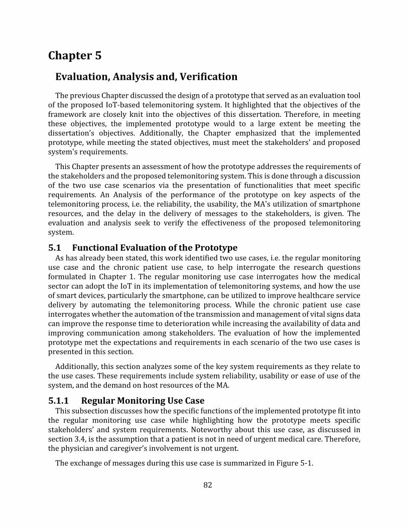
82
Chapter 5
Evaluation, Analysis and, Verification
The previous Chapter discussed the design of a prototype that served as an evaluation tool of the proposed IoT-based telemonitoring system. It highlighted that the objectives of the framework are closely knit into the objectives of this dissertation. Therefore, in meeting these objectives, the implemented prototype would to a large extent be meeting the dissertation’s objectives. Additionally, the Chapter emphasized that the implemented prototype, while meeting the stated objectives, must meet the stakeholders' and proposed system's requirements.
This Chapter presents an assessment of how the prototype addresses the requirements of the stakeholders and the proposed telemonitoring system. This is done through a discussion of the two use case scenarios via the presentation of functionalities that meet specific requirements. An Analysis of the performance of the prototype on key aspects of the telemonitoring process, i.e. the reliability, the usability, the MA's utilization of smartphone resources, and the delay in the delivery of messages to the stakeholders, is given. The evaluation and analysis seek to verify the effectiveness of the proposed telemonitoring system.
5.1 Functional Evaluation of the Prototype As has already been stated, this work identified two use cases, i.e. the regular monitoring
use case and the chronic patient use case, to help interrogate the research questions formulated in Chapter 1. The regular monitoring use case interrogates how the medical sector can adopt the IoT in its implementation of telemonitoring systems, and how the use of smart devices, particularly the smartphone, can be utilized to improve healthcare service delivery by automating the telemonitoring process. While the chronic patient use case interrogates whether the automation of the transmission and management of vital signs data can improve the response time to deterioration while increasing the availability of data and improving communication among stakeholders. The evaluation of how the implemented prototype met the expectations and requirements in each scenario of the two use cases is presented in this section.
Additionally, this section analyzes some of the key system requirements as they relate to the use cases. These requirements include system reliability, usability or ease of use of the system, and the demand on host resources of the MA.
5.1.1 Regular Monitoring Use Case This subsection discusses how the specific functions of the implemented prototype fit into
the regular monitoring use case while highlighting how the prototype meets specific stakeholders’ and system requirements. Noteworthy about this use case, as discussed in section 3.4, is the assumption that a patient is not in need of urgent medical care. Therefore, the physician and caregiver’s involvement is not urgent.
The exchange of messages during this use case is summarized in Figure 5-1.
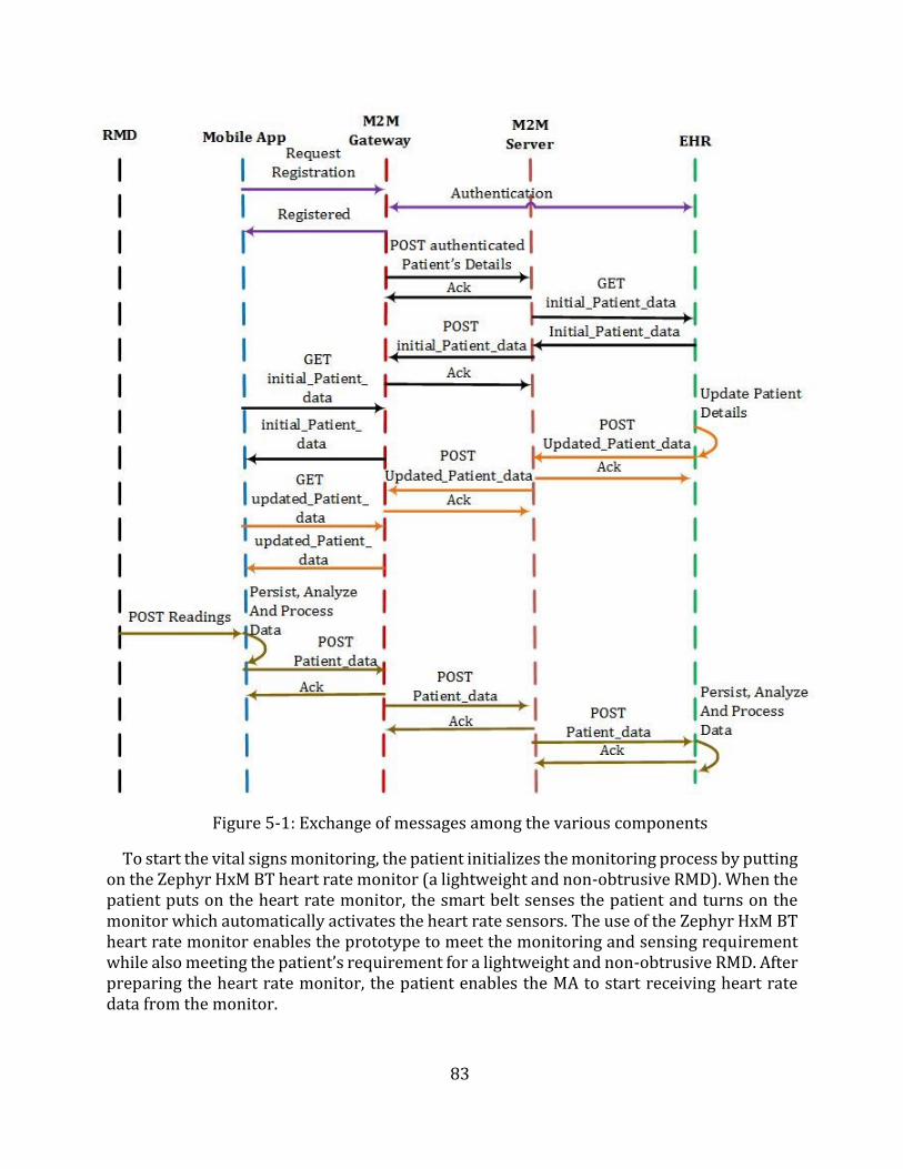
83
Figure 5-1: Exchange of messages among the various components
To start the vital signs monitoring, the patient initializes the monitoring process by putting on the Zephyr HxM BT heart rate monitor (a lightweight and non-obtrusive RMD). When the patient puts on the heart rate monitor, the smart belt senses the patient and turns on the monitor which automatically activates the heart rate sensors. The use of the Zephyr HxM BT heart rate monitor enables the prototype to meet the monitoring and sensing requirement while also meeting the patient’s requirement for a lightweight and non-obtrusive RMD. After preparing the heart rate monitor, the patient enables the MA to start receiving heart rate data from the monitor.
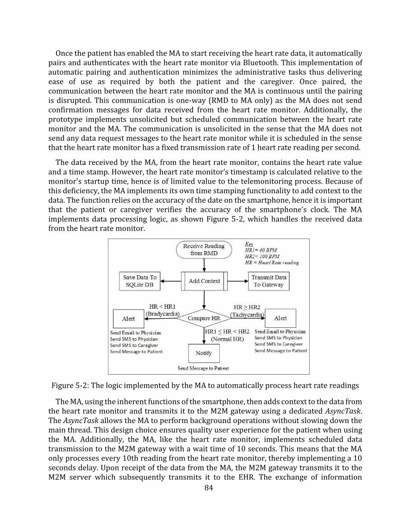
84
Once the patient has enabled the MA to start receiving the heart rate data, it automatically pairs and authenticates with the heart rate monitor via Bluetooth. This implementation of automatic pairing and authentication minimizes the administrative tasks thus delivering ease of use as required by both the patient and the caregiver. Once paired, the communication between the heart rate monitor and the MA is continuous until the pairing is disrupted. This communication is one-way (RMD to MA only) as the MA does not send confirmation messages for data received from the heart rate monitor. Additionally, the prototype implements unsolicited but scheduled communication between the heart rate monitor and the MA. The communication is unsolicited in the sense that the MA does not send any data request messages to the heart rate monitor while it is scheduled in the sense that the heart rate monitor has a fixed transmission rate of 1 heart rate reading per second.
The data received by the MA, from the heart rate monitor, contains the heart rate value and a time stamp. However, the heart rate monitor’s timestamp is calculated relative to the monitor's startup time, hence is of limited value to the telemonitoring process. Because of this deficiency, the MA implements its own time stamping functionality to add context to the data. The function relies on the accuracy of the date on the smartphone, hence it is important that the patient or caregiver verifies the accuracy of the smartphone’s clock. The MA implements data processing logic, as shown Figure 5-2, which handles the received data from the heart rate monitor.
Figure 5-2: The logic implemented by the MA to automatically process heart rate readings
The MA, using the inherent functions of the smartphone, then adds context to the data from the heart rate monitor and transmits it to the M2M gateway using a dedicated AsyncTask. The AsyncTask allows the MA to perform background operations without slowing down the main thread. This design choice ensures quality user experience for the patient when using the MA. Additionally, the MA, like the heart rate monitor, implements scheduled data transmission to the M2M gateway with a wait time of 10 seconds. This means that the MA only processes every 10th reading from the heart rate monitor, thereby implementing a 10 seconds delay. Upon receipt of the data from the MA, the M2M gateway transmits it to the M2M server which subsequently transmits it to the EHR. The exchange of information
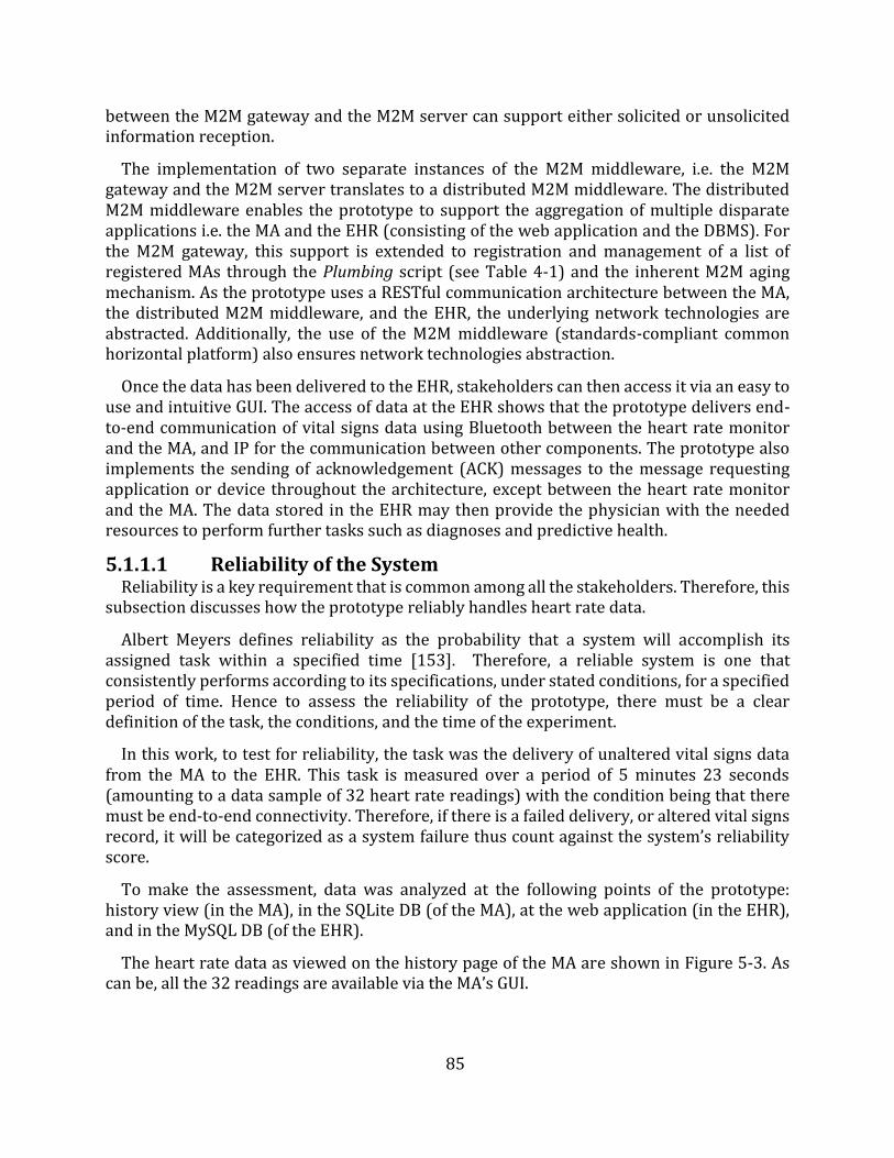
85
between the M2M gateway and the M2M server can support either solicited or unsolicited information reception.
The implementation of two separate instances of the M2M middleware, i.e. the M2M gateway and the M2M server translates to a distributed M2M middleware. The distributed M2M middleware enables the prototype to support the aggregation of multiple disparate applications i.e. the MA and the EHR (consisting of the web application and the DBMS). For the M2M gateway, this support is extended to registration and management of a list of registered MAs through the Plumbing script (see Table 4-1) and the inherent M2M aging mechanism. As the prototype uses a RESTful communication architecture between the MA, the distributed M2M middleware, and the EHR, the underlying network technologies are abstracted. Additionally, the use of the M2M middleware (standards-compliant common horizontal platform) also ensures network technologies abstraction.
Once the data has been delivered to the EHR, stakeholders can then access it via an easy to use and intuitive GUI. The access of data at the EHR shows that the prototype delivers end-to-end communication of vital signs data using Bluetooth between the heart rate monitor and the MA, and IP for the communication between other components. The prototype also implements the sending of acknowledgement (ACK) messages to the message requesting application or device throughout the architecture, except between the heart rate monitor and the MA. The data stored in the EHR may then provide the physician with the needed resources to perform further tasks such as diagnoses and predictive health.
5.1.1.1 Reliability of the System Reliability is a key requirement that is common among all the stakeholders. Therefore, this
subsection discusses how the prototype reliably handles heart rate data.
Albert Meyers defines reliability as the probability that a system will accomplish its assigned task within a specified time [153]. Therefore, a reliable system is one that consistently performs according to its specifications, under stated conditions, for a specified period of time. Hence to assess the reliability of the prototype, there must be a clear definition of the task, the conditions, and the time of the experiment.
In this work, to test for reliability, the task was the delivery of unaltered vital signs data from the MA to the EHR. This task is measured over a period of 5 minutes 23 seconds (amounting to a data sample of 32 heart rate readings) with the condition being that there must be end-to-end connectivity. Therefore, if there is a failed delivery, or altered vital signs record, it will be categorized as a system failure thus count against the system’s reliability score.
To make the assessment, data was analyzed at the following points of the prototype: history view (in the MA), in the SQLite DB (of the MA), at the web application (in the EHR), and in the MySQL DB (of the EHR).
The heart rate data as viewed on the history page of the MA are shown in Figure 5-3. As can be, all the 32 readings are available via the MA’s GUI.
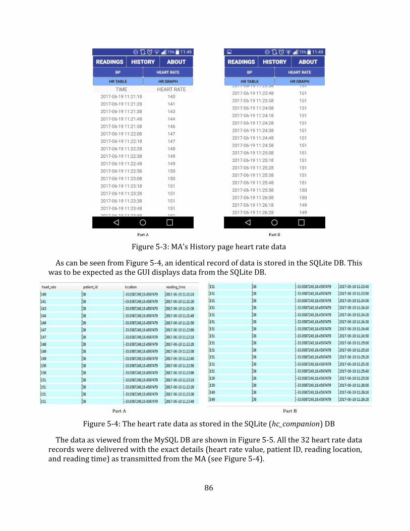
86
Figure 5-3: MA's History page heart rate data
As can be seen from Figure 5-4, an identical record of data is stored in the SQLite DB. This was to be expected as the GUI displays data from the SQLite DB.
Figure 5-4: The heart rate data as stored in the SQLite (hc_companion) DB
The data as viewed from the MySQL DB are shown in Figure 5-5. All the 32 heart rate data records were delivered with the exact details (heart rate value, patient ID, reading location, and reading time) as transmitted from the MA (see Figure 5-4).
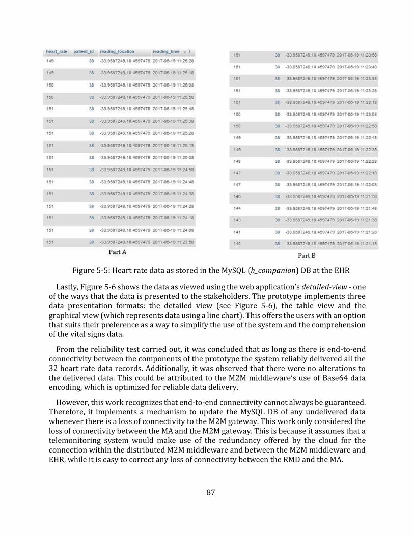
87
Figure 5-5: Heart rate data as stored in the MySQL (h_companion) DB at the EHR
Lastly, Figure 5-6 shows the data as viewed using the web application’s detailed-view - one of the ways that the data is presented to the stakeholders. The prototype implements three data presentation formats: the detailed view (see Figure 5-6), the table view and the graphical view (which represents data using a line chart). This offers the users with an option that suits their preference as a way to simplify the use of the system and the comprehension of the vital signs data.
From the reliability test carried out, it was concluded that as long as there is end-to-end connectivity between the components of the prototype the system reliably delivered all the 32 heart rate data records. Additionally, it was observed that there were no alterations to the delivered data. This could be attributed to the M2M middleware’s use of Base64 data encoding, which is optimized for reliable data delivery.
However, this work recognizes that end-to-end connectivity cannot always be guaranteed. Therefore, it implements a mechanism to update the MySQL DB of any undelivered data whenever there is a loss of connectivity to the M2M gateway. This work only considered the loss of connectivity between the MA and the M2M gateway. This is because it assumes that a telemonitoring system would make use of the redundancy offered by the cloud for the connection within the distributed M2M middleware and between the M2M middleware and EHR, while it is easy to correct any loss of connectivity between the RMD and the MA.
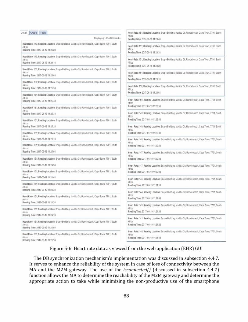
88
Figure 5-6: Heart rate data as viewed from the web application (EHR) GUI
The DB synchronization mechanism’s implementation was discussed in subsection 4.4.7. It serves to enhance the reliability of the system in case of loss of connectivity between the MA and the M2M gateway. The use of the isconnected() (discussed in subsection 4.4.7) function allows the MA to determine the reachability of the M2M gateway and determine the appropriate action to take while minimizing the non-productive use of the smartphone
89
resources. The tagging of the data (discussed in subsection 4.4.7) in the SQLite DB serves as a means of notifying the MA of failed data delivery.
5.1.1.2 System Usability The usability of a system is an attribute that is not easy to quantify because it is generally
a subjective experience, different for each individual user. According to the International Standards Organization (ISO), usability is the extent to which a product can be used by specified users to achieve specified goals with effectiveness, efficiency, and satisfaction in a specified context of use [154]. It usually has to do with the users’ experience as they interact with the GUIs.
Whitney Quesenbery [155] gives definitions of the three aspects (effectiveness, efficiency, and satisfaction) of usability as follows:
Effectiveness is the completeness and accuracy with which users achieve specifiedgoals.
Efficiency is the speed (with accuracy) in which users can complete the tasks forwhich they use the product. This can be quantified by a count of clicks required orpages viewed to accomplish a task.
Satisfaction is a measure of how engaging an interface is. This is a measure of howpleasant and satisfying to use the interface is. The visual design of an application orsystem is the most obvious element of this characteristic.
Therefore, this work evaluated the usability of the system, for the patient, by considering these three aspects. Effectiveness, as defined above, was assessed by considering the accuracy of the data presented to users by the GUIs (MA GUI and web application GUI). As discussed in subsection 5.1.1.1, the prototype was 100% accurate in its transmission of data captured by the RMD. This data as saved in the respective DBs (SQLite and MySQL) was accurately displayed by the GUIs. Therefore, the system effectively performed its tasks.
Efficiency, as has been mentioned, can be quantified by the number of clicks or pages viewed to accomplish a task. To assess this aspect, two tasks were identified i.e. viewing of the last 4 heart rates and initiating the monitoring of heart rates.
To view the last 4 heart rates, it takes a minimum of three clicks as shown in Figure 5-7. The user starts the MA (circled in Figure 5-7), then clicks the History tab, and then selects the “Heart Rate” tab. From the HR Table view, the user can view the last 4 heart rates as per requirement. It is noteworthy, however, that it only takes a single click to view the latest vital signs data (see “After 1st Click” in Figure 5-7) and a minimum of two clicks to view the last 4 BP readings (see “After 2nd Click” in Figure 5-7).
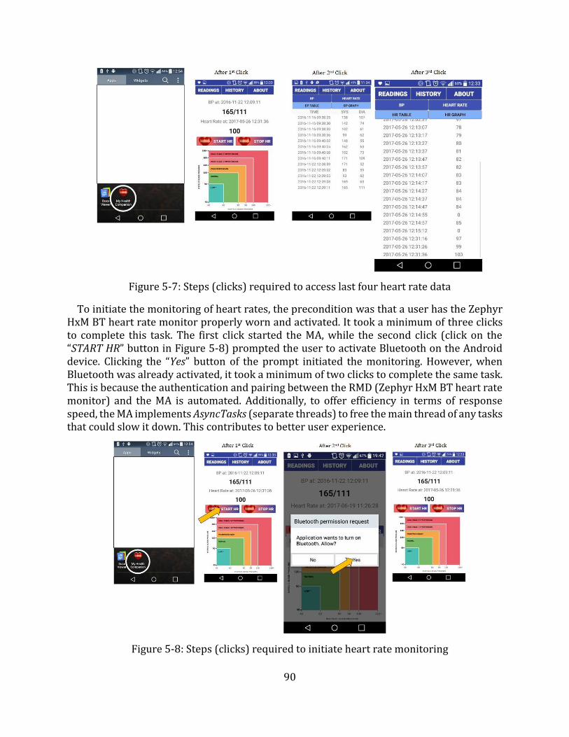
90
Figure 5-7: Steps (clicks) required to access last four heart rate data
To initiate the monitoring of heart rates, the precondition was that a user has the Zephyr HxM BT heart rate monitor properly worn and activated. It took a minimum of three clicks to complete this task. The first click started the MA, while the second click (click on the “START HR” button in Figure 5-8) prompted the user to activate Bluetooth on the Android device. Clicking the “Yes” button of the prompt initiated the monitoring. However, when Bluetooth was already activated, it took a minimum of two clicks to complete the same task. This is because the authentication and pairing between the RMD (Zephyr HxM BT heart rate monitor) and the MA is automated. Additionally, to offer efficiency in terms of response speed, the MA implements AsyncTasks (separate threads) to free the main thread of any tasks that could slow it down. This contributes to better user experience.
Figure 5-8: Steps (clicks) required to initiate heart rate monitoring
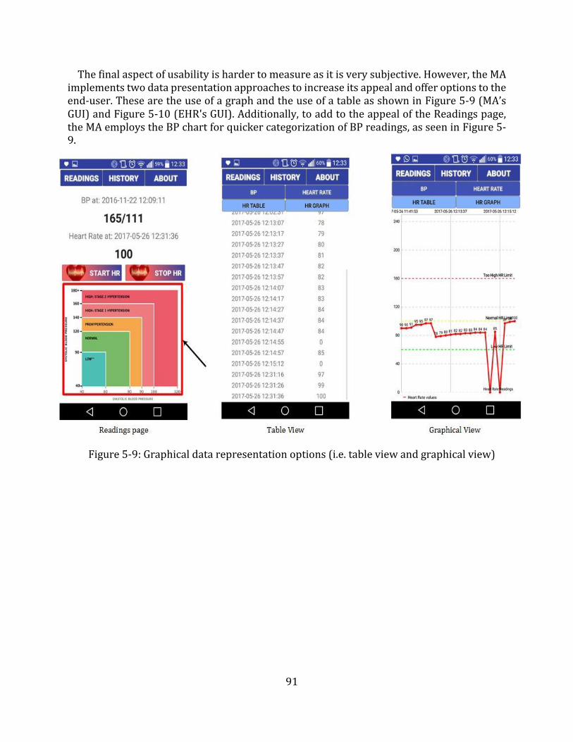
91
The final aspect of usability is harder to measure as it is very subjective. However, the MA implements two data presentation approaches to increase its appeal and offer options to the end-user. These are the use of a graph and the use of a table as shown in Figure 5-9 (MA’s GUI) and Figure 5-10 (EHR's GUI). Additionally, to add to the appeal of the Readings page, the MA employs the BP chart for quicker categorization of BP readings, as seen in Figure 5-9.
Figure 5-9: Graphical data representation options (i.e. table view and graphical view)
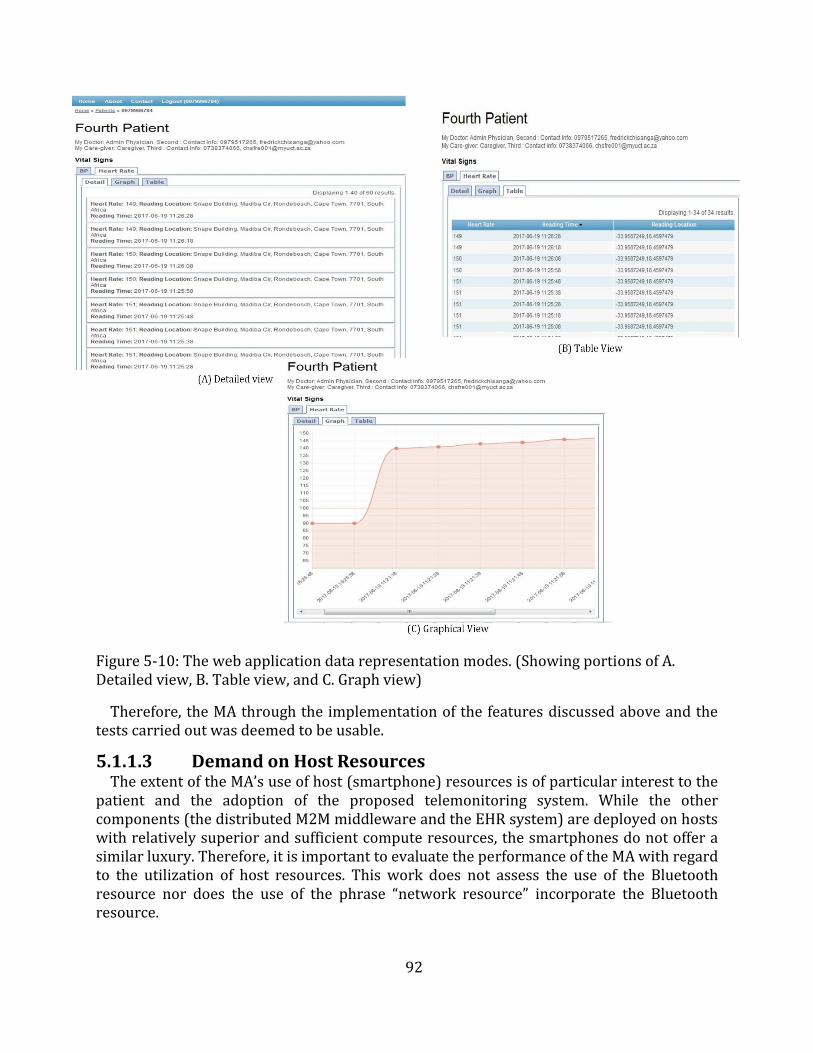
92
Figure 5-10: The web application data representation modes. (Showing portions of A. Detailed view, B. Table view, and C. Graph view)
Therefore, the MA through the implementation of the features discussed above and the tests carried out was deemed to be usable.
5.1.1.3 Demand on Host Resources The extent of the MA’s use of host (smartphone) resources is of particular interest to the
patient and the adoption of the proposed telemonitoring system. While the other components (the distributed M2M middleware and the EHR system) are deployed on hosts with relatively superior and sufficient compute resources, the smartphones do not offer a similar luxury. Therefore, it is important to evaluate the performance of the MA with regard to the utilization of host resources. This work does not assess the use of the Bluetooth resource nor does the use of the phrase “network resource” incorporate the Bluetooth resource.
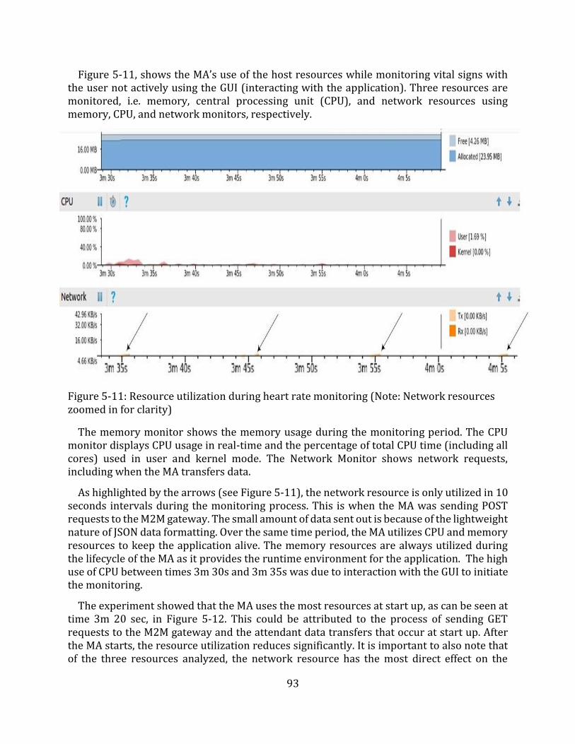
93
Figure 5-11, shows the MA’s use of the host resources while monitoring vital signs with the user not actively using the GUI (interacting with the application). Three resources are monitored, i.e. memory, central processing unit (CPU), and network resources using memory, CPU, and network monitors, respectively.
Figure 5-11: Resource utilization during heart rate monitoring (Note: Network resources zoomed in for clarity)
The memory monitor shows the memory usage during the monitoring period. The CPU monitor displays CPU usage in real-time and the percentage of total CPU time (including all cores) used in user and kernel mode. The Network Monitor shows network requests, including when the MA transfers data.
As highlighted by the arrows (see Figure 5-11), the network resource is only utilized in 10 seconds intervals during the monitoring process. This is when the MA was sending POST requests to the M2M gateway. The small amount of data sent out is because of the lightweight nature of JSON data formatting. Over the same time period, the MA utilizes CPU and memory resources to keep the application alive. The memory resources are always utilized during the lifecycle of the MA as it provides the runtime environment for the application. The high use of CPU between times 3m 30s and 3m 35s was due to interaction with the GUI to initiate the monitoring.
The experiment showed that the MA uses the most resources at start up, as can be seen at time 3m 20 sec, in Figure 5-12. This could be attributed to the process of sending GET requests to the M2M gateway and the attendant data transfers that occur at start up. After the MA starts, the resource utilization reduces significantly. It is important to also note that of the three resources analyzed, the network resource has the most direct effect on the
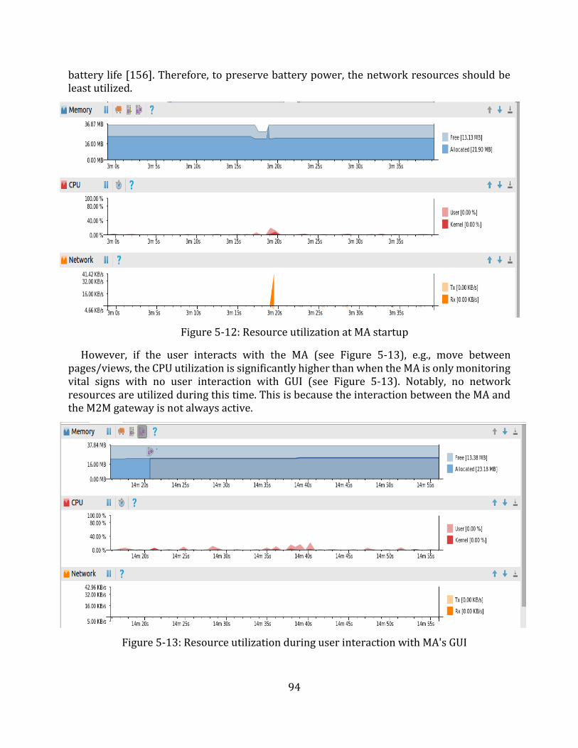
94
battery life [156]. Therefore, to preserve battery power, the network resources should be least utilized.
Figure 5-12: Resource utilization at MA startup
However, if the user interacts with the MA (see Figure 5-13), e.g., move between pages/views, the CPU utilization is significantly higher than when the MA is only monitoring vital signs with no user interaction with GUI (see Figure 5-13). Notably, no network resources are utilized during this time. This is because the interaction between the MA and the M2M gateway is not always active.
Figure 5-13: Resource utilization during user interaction with MA's GUI
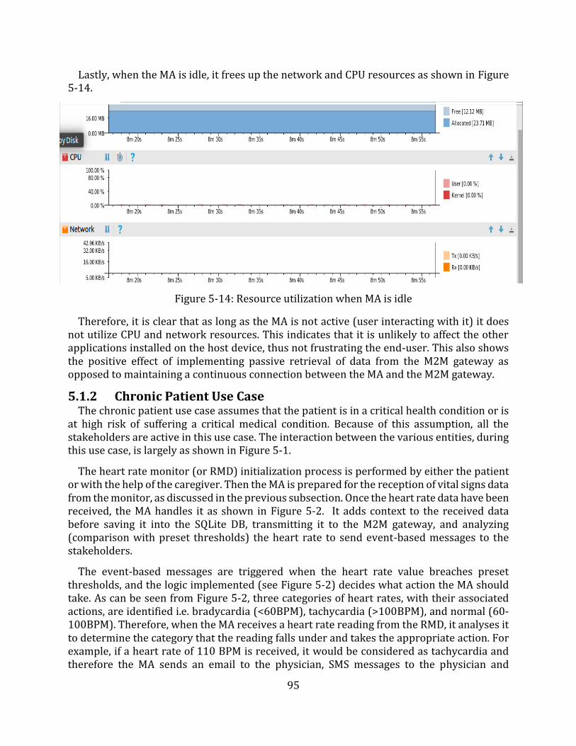
95
Lastly, when the MA is idle, it frees up the network and CPU resources as shown in Figure 5-14.
Figure 5-14: Resource utilization when MA is idle
Therefore, it is clear that as long as the MA is not active (user interacting with it) it does not utilize CPU and network resources. This indicates that it is unlikely to affect the other applications installed on the host device, thus not frustrating the end-user. This also shows the positive effect of implementing passive retrieval of data from the M2M gateway as opposed to maintaining a continuous connection between the MA and the M2M gateway.
5.1.2 Chronic Patient Use Case The chronic patient use case assumes that the patient is in a critical health condition or is
at high risk of suffering a critical medical condition. Because of this assumption, all the stakeholders are active in this use case. The interaction between the various entities, during this use case, is largely as shown in Figure 5-1.
The heart rate monitor (or RMD) initialization process is performed by either the patient or with the help of the caregiver. Then the MA is prepared for the reception of vital signs data from the monitor, as discussed in the previous subsection. Once the heart rate data have been received, the MA handles it as shown in Figure 5-2. It adds context to the received data before saving it into the SQLite DB, transmitting it to the M2M gateway, and analyzing (comparison with preset thresholds) the heart rate to send event-based messages to the stakeholders.
The event-based messages are triggered when the heart rate value breaches preset thresholds, and the logic implemented (see Figure 5-2) decides what action the MA should take. As can be seen from Figure 5-2, three categories of heart rates, with their associated actions, are identified i.e. bradycardia (<60BPM), tachycardia (>100BPM), and normal (60-100BPM). Therefore, when the MA receives a heart rate reading from the RMD, it analyses it to determine the category that the reading falls under and takes the appropriate action. For example, if a heart rate of 110 BPM is received, it would be considered as tachycardia and therefore the MA sends an email to the physician, SMS messages to the physician and
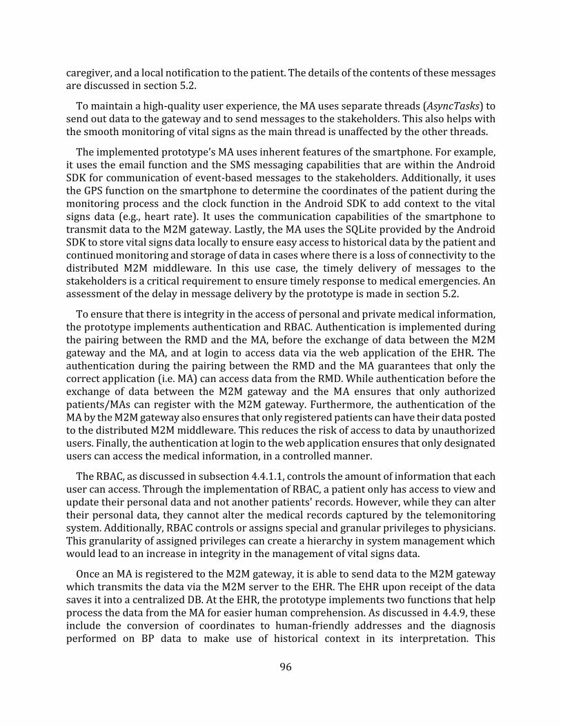
96
caregiver, and a local notification to the patient. The details of the contents of these messages are discussed in section 5.2.
To maintain a high-quality user experience, the MA uses separate threads (AsyncTasks) to send out data to the gateway and to send messages to the stakeholders. This also helps with the smooth monitoring of vital signs as the main thread is unaffected by the other threads.
The implemented prototype’s MA uses inherent features of the smartphone. For example, it uses the email function and the SMS messaging capabilities that are within the Android SDK for communication of event-based messages to the stakeholders. Additionally, it uses the GPS function on the smartphone to determine the coordinates of the patient during the monitoring process and the clock function in the Android SDK to add context to the vital signs data (e.g., heart rate). It uses the communication capabilities of the smartphone to transmit data to the M2M gateway. Lastly, the MA uses the SQLite provided by the Android SDK to store vital signs data locally to ensure easy access to historical data by the patient and continued monitoring and storage of data in cases where there is a loss of connectivity to the distributed M2M middleware. In this use case, the timely delivery of messages to the stakeholders is a critical requirement to ensure timely response to medical emergencies. An assessment of the delay in message delivery by the prototype is made in section 5.2.
To ensure that there is integrity in the access of personal and private medical information, the prototype implements authentication and RBAC. Authentication is implemented during the pairing between the RMD and the MA, before the exchange of data between the M2M gateway and the MA, and at login to access data via the web application of the EHR. The authentication during the pairing between the RMD and the MA guarantees that only the correct application (i.e. MA) can access data from the RMD. While authentication before the exchange of data between the M2M gateway and the MA ensures that only authorized patients/MAs can register with the M2M gateway. Furthermore, the authentication of the MA by the M2M gateway also ensures that only registered patients can have their data posted to the distributed M2M middleware. This reduces the risk of access to data by unauthorized users. Finally, the authentication at login to the web application ensures that only designated users can access the medical information, in a controlled manner.
The RBAC, as discussed in subsection 4.4.1.1, controls the amount of information that each user can access. Through the implementation of RBAC, a patient only has access to view and update their personal data and not another patients' records. However, while they can alter their personal data, they cannot alter the medical records captured by the telemonitoring system. Additionally, RBAC controls or assigns special and granular privileges to physicians. This granularity of assigned privileges can create a hierarchy in system management which would lead to an increase in integrity in the management of vital signs data.
Once an MA is registered to the M2M gateway, it is able to send data to the M2M gateway which transmits the data via the M2M server to the EHR. The EHR upon receipt of the data saves it into a centralized DB. At the EHR, the prototype implements two functions that help process the data from the MA for easier human comprehension. As discussed in 4.4.9, these include the conversion of coordinates to human-friendly addresses and the diagnosis performed on BP data to make use of historical context in its interpretation. This
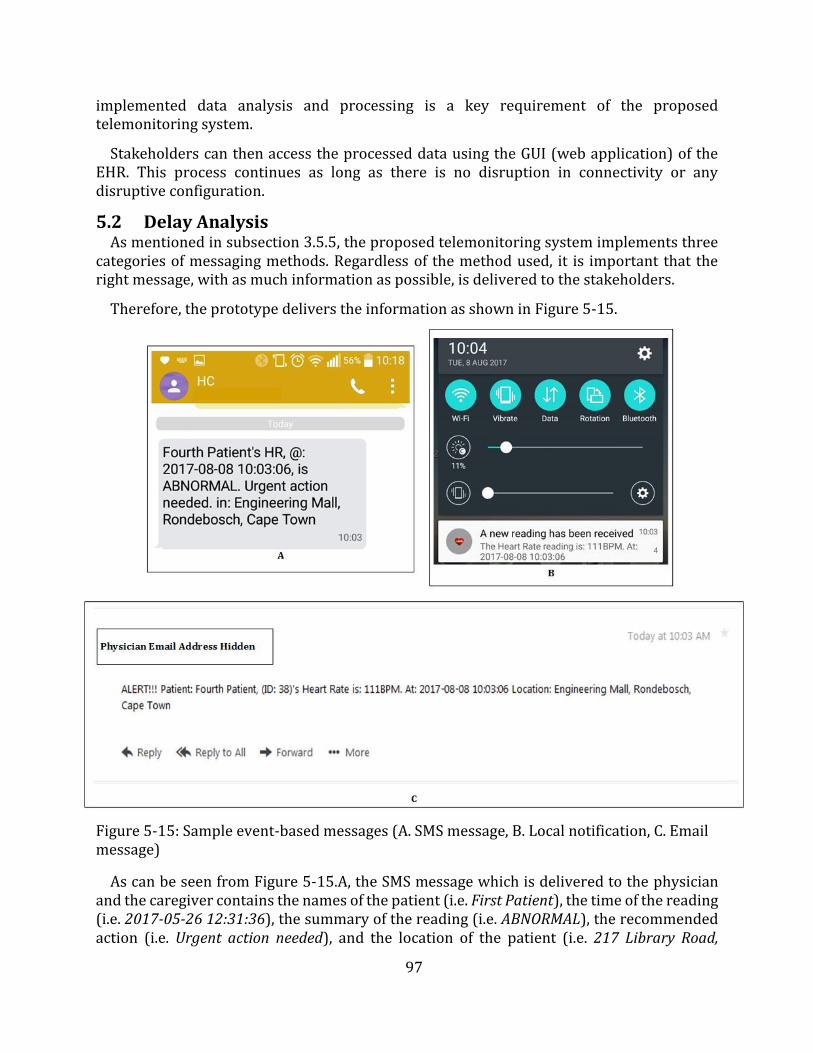
97
implemented data analysis and processing is a key requirement of the proposed telemonitoring system.
Stakeholders can then access the processed data using the GUI (web application) of the EHR. This process continues as long as there is no disruption in connectivity or any disruptive configuration.
5.2 Delay Analysis As mentioned in subsection 3.5.5, the proposed telemonitoring system implements three
categories of messaging methods. Regardless of the method used, it is important that the right message, with as much information as possible, is delivered to the stakeholders.
Therefore, the prototype delivers the information as shown in Figure 5-15.
Figure 5-15: Sample event-based messages (A. SMS message, B. Local notification, C. Email message)
As can be seen from Figure 5-15.A, the SMS message which is delivered to the physician and the caregiver contains the names of the patient (i.e. First Patient), the time of the reading (i.e. 2017-05-26 12:31:36), the summary of the reading (i.e. ABNORMAL), the recommended action (i.e. Urgent action needed), and the location of the patient (i.e. 217 Library Road,
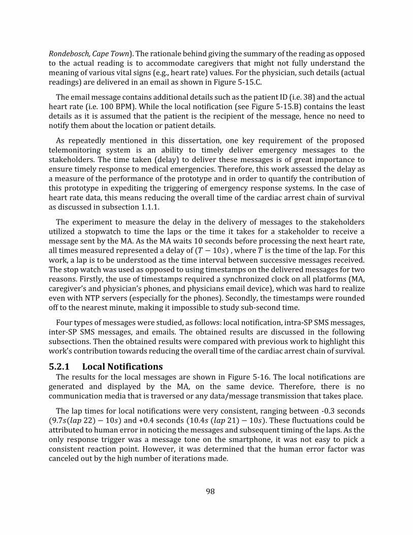
98
Rondebosch, Cape Town). The rationale behind giving the summary of the reading as opposed to the actual reading is to accommodate caregivers that might not fully understand the meaning of various vital signs (e.g., heart rate) values. For the physician, such details (actual readings) are delivered in an email as shown in Figure 5-15.C.
The email message contains additional details such as the patient ID (i.e. 38) and the actual heart rate (i.e. 100 BPM). While the local notification (see Figure 5-15.B) contains the least details as it is assumed that the patient is the recipient of the message, hence no need to notify them about the location or patient details.
As repeatedly mentioned in this dissertation, one key requirement of the proposed telemonitoring system is an ability to timely deliver emergency messages to the stakeholders. The time taken (delay) to deliver these messages is of great importance to ensure timely response to medical emergencies. Therefore, this work assessed the delay as a measure of the performance of the prototype and in order to quantify the contribution of this prototype in expediting the triggering of emergency response systems. In the case of heart rate data, this means reducing the overall time of the cardiac arrest chain of survival as discussed in subsection 1.1.1.
The experiment to measure the delay in the delivery of messages to the stakeholders utilized a stopwatch to time the laps or the time it takes for a stakeholder to receive a message sent by the MA. As the MA waits 10 seconds before processing the next heart rate, all times measured represented a delay of (𝑇 − 10𝑠) , where 𝑇 is the time of the lap. For this work, a lap is to be understood as the time interval between successive messages received. The stop watch was used as opposed to using timestamps on the delivered messages for two reasons. Firstly, the use of timestamps required a synchronized clock on all platforms (MA, caregiver’s and physician’s phones, and physicians email device), which was hard to realize even with NTP servers (especially for the phones). Secondly, the timestamps were rounded off to the nearest minute, making it impossible to study sub-second time.
Four types of messages were studied, as follows: local notification, intra-SP SMS messages, inter-SP SMS messages, and emails. The obtained results are discussed in the following subsections. Then the obtained results were compared with previous work to highlight this work’s contribution towards reducing the overall time of the cardiac arrest chain of survival.
5.2.1 Local Notifications The results for the local messages are shown in Figure 5-16. The local notifications are
generated and displayed by the MA, on the same device. Therefore, there is no communication media that is traversed or any data/message transmission that takes place.
The lap times for local notifications were very consistent, ranging between -0.3 seconds (9.7𝑠(𝑙𝑎𝑝 22) − 10𝑠) and +0.4 seconds (10.4𝑠 (𝑙𝑎𝑝 21) − 10𝑠). These fluctuations could be attributed to human error in noticing the messages and subsequent timing of the laps. As the only response trigger was a message tone on the smartphone, it was not easy to pick a consistent reaction point. However, it was determined that the human error factor was canceled out by the high number of iterations made.
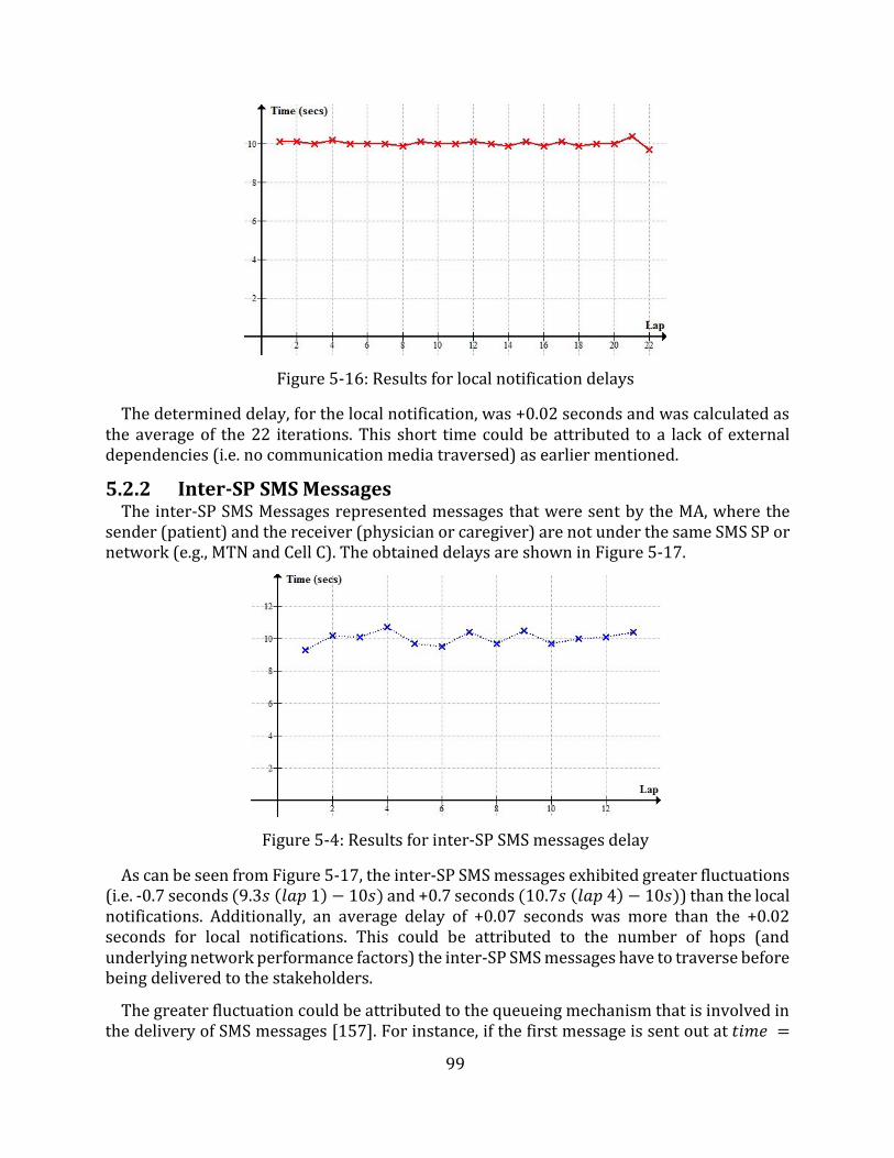
99
Figure 5-16: Results for local notification delays
The determined delay, for the local notification, was +0.02 seconds and was calculated as the average of the 22 iterations. This short time could be attributed to a lack of external dependencies (i.e. no communication media traversed) as earlier mentioned.
5.2.2 Inter-SP SMS Messages The inter-SP SMS Messages represented messages that were sent by the MA, where the
sender (patient) and the receiver (physician or caregiver) are not under the same SMS SP or network (e.g., MTN and Cell C). The obtained delays are shown in Figure 5-17.
Figure 5-4: Results for inter-SP SMS messages delay
As can be seen from Figure 5-17, the inter-SP SMS messages exhibited greater fluctuations (i.e. -0.7 seconds (9.3𝑠 (𝑙𝑎𝑝 1) − 10𝑠) and +0.7 seconds (10.7𝑠 (𝑙𝑎𝑝 4) − 10𝑠)) than the local notifications. Additionally, an average delay of +0.07 seconds was more than the +0.02 seconds for local notifications. This could be attributed to the number of hops (and underlying network performance factors) the inter-SP SMS messages have to traverse before being delivered to the stakeholders.
The greater fluctuation could be attributed to the queueing mechanism that is involved in the delivery of SMS messages [157]. For instance, if the first message is sent out at 𝑡𝑖𝑚𝑒 =
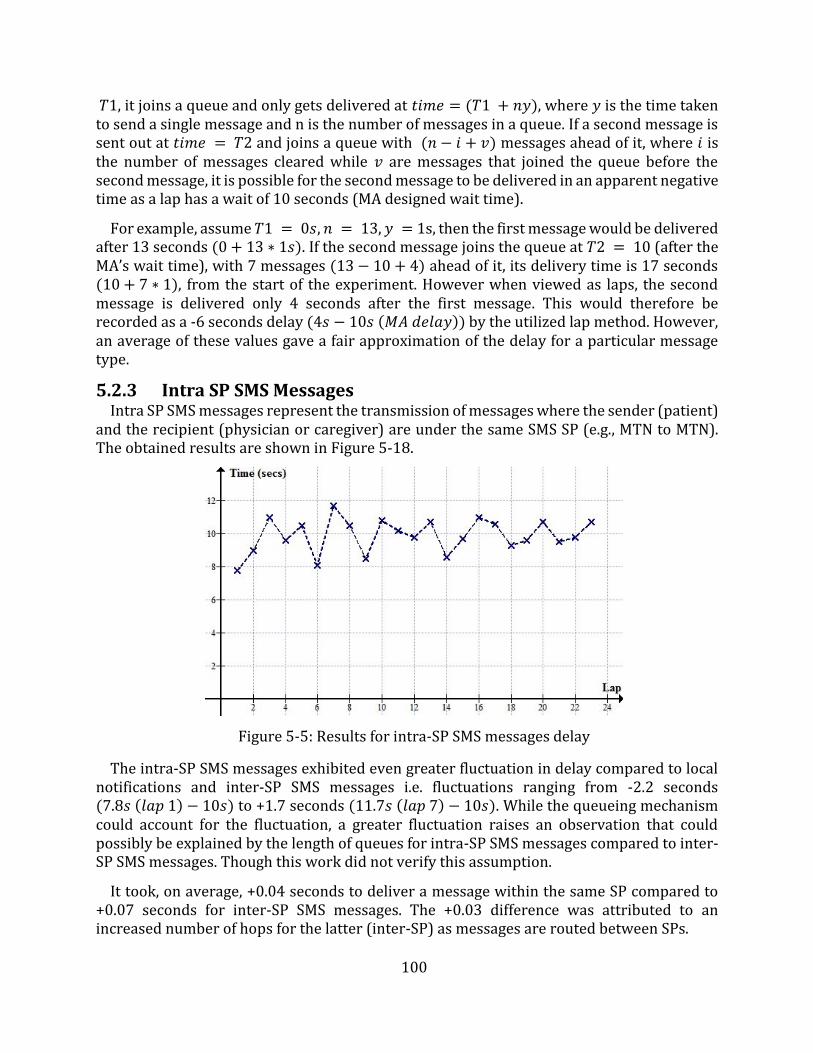
100
𝑇1, it joins a queue and only gets delivered at 𝑡𝑖𝑚𝑒 = (𝑇1 + 𝑛𝑦), where 𝑦 is the time taken to send a single message and n is the number of messages in a queue. If a second message is sent out at 𝑡𝑖𝑚𝑒 = 𝑇2 and joins a queue with (𝑛 − 𝑖 + 𝑣) messages ahead of it, where 𝑖 is the number of messages cleared while 𝑣 are messages that joined the queue before the second message, it is possible for the second message to be delivered in an apparent negative time as a lap has a wait of 10 seconds (MA designed wait time).
For example, assume 𝑇1 = 0𝑠, 𝑛 = 13, 𝑦 = 1s, then the first message would be delivered after 13 seconds (0 + 13 ∗ 1𝑠). If the second message joins the queue at 𝑇2 = 10 (after the MA’s wait time), with 7 messages (13 − 10 + 4) ahead of it, its delivery time is 17 seconds (10 + 7 ∗ 1), from the start of the experiment. However when viewed as laps, the second message is delivered only 4 seconds after the first message. This would therefore be recorded as a -6 seconds delay (4𝑠 − 10𝑠 (𝑀𝐴 𝑑𝑒𝑙𝑎𝑦)) by the utilized lap method. However, an average of these values gave a fair approximation of the delay for a particular message type.
5.2.3 Intra SP SMS Messages Intra SP SMS messages represent the transmission of messages where the sender (patient)
and the recipient (physician or caregiver) are under the same SMS SP (e.g., MTN to MTN). The obtained results are shown in Figure 5-18.
Figure 5-5: Results for intra-SP SMS messages delay
The intra-SP SMS messages exhibited even greater fluctuation in delay compared to local notifications and inter-SP SMS messages i.e. fluctuations ranging from -2.2 seconds (7.8𝑠 (𝑙𝑎𝑝 1) − 10𝑠) to +1.7 seconds (11.7𝑠 (𝑙𝑎𝑝 7) − 10𝑠). While the queueing mechanism could account for the fluctuation, a greater fluctuation raises an observation that could possibly be explained by the length of queues for intra-SP SMS messages compared to inter-SP SMS messages. Though this work did not verify this assumption.
It took, on average, +0.04 seconds to deliver a message within the same SP compared to +0.07 seconds for inter-SP SMS messages. The +0.03 difference was attributed to anincreased number of hops for the latter (inter-SP) as messages are routed between SPs.
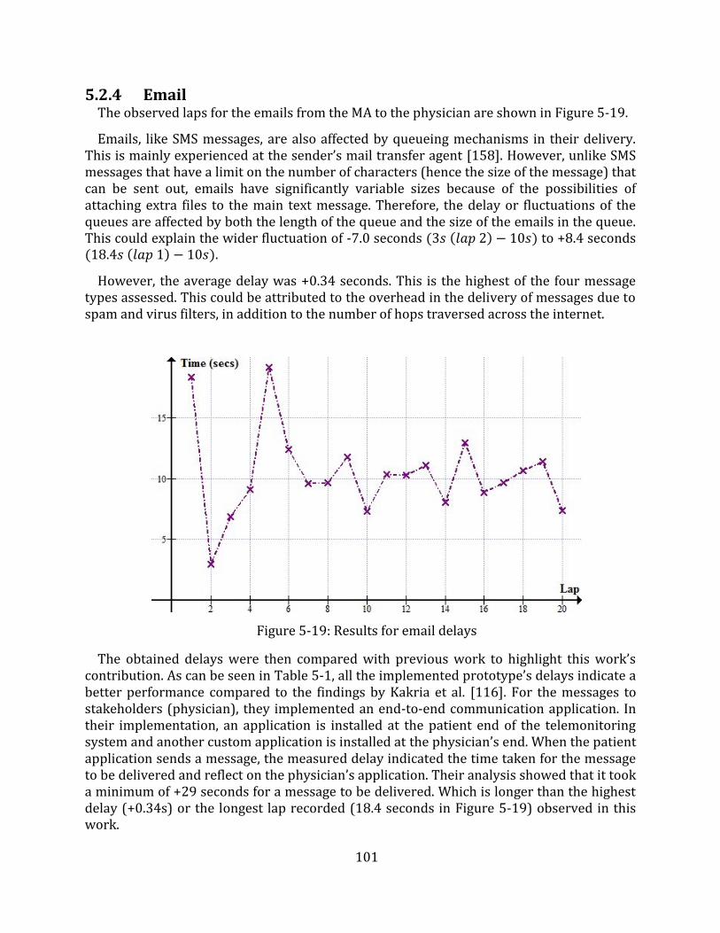
101
5.2.4 Email The observed laps for the emails from the MA to the physician are shown in Figure 5-19.
Emails, like SMS messages, are also affected by queueing mechanisms in their delivery. This is mainly experienced at the sender’s mail transfer agent [158]. However, unlike SMS messages that have a limit on the number of characters (hence the size of the message) that can be sent out, emails have significantly variable sizes because of the possibilities of attaching extra files to the main text message. Therefore, the delay or fluctuations of the queues are affected by both the length of the queue and the size of the emails in the queue. This could explain the wider fluctuation of -7.0 seconds (3𝑠 (𝑙𝑎𝑝 2) − 10𝑠) to +8.4 seconds (18.4𝑠 (𝑙𝑎𝑝 1) − 10𝑠).
However, the average delay was +0.34 seconds. This is the highest of the four message types assessed. This could be attributed to the overhead in the delivery of messages due to spam and virus filters, in addition to the number of hops traversed across the internet.
Figure 5-19: Results for email delays
The obtained delays were then compared with previous work to highlight this work’s contribution. As can be seen in Table 5-1, all the implemented prototype’s delays indicate a better performance compared to the findings by Kakria et al. [116]. For the messages to stakeholders (physician), they implemented an end-to-end communication application. In their implementation, an application is installed at the patient end of the telemonitoring system and another custom application is installed at the physician’s end. When the patient application sends a message, the measured delay indicated the time taken for the message to be delivered and reflect on the physician’s application. Their analysis showed that it took a minimum of +29 seconds for a message to be delivered. Which is longer than the highest delay (+0.34s) or the longest lap recorded (18.4 seconds in Figure 5-19) observed in this work.
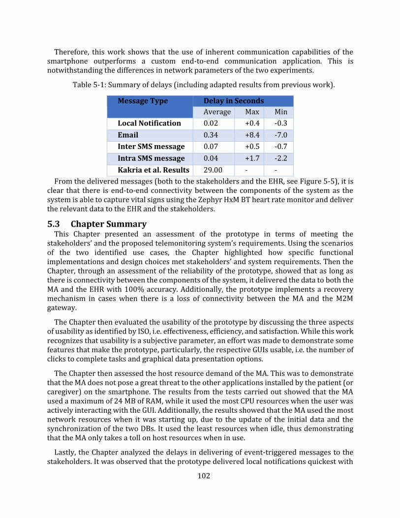
102
Therefore, this work shows that the use of inherent communication capabilities of the smartphone outperforms a custom end-to-end communication application. This is notwithstanding the differences in network parameters of the two experiments.
Table 5-1: Summary of delays (including adapted results from previous work).
Message Type Delay in Seconds
Average Max Min
Local Notification 0.02 +0.4 -0.3
Email 0.34 +8.4 -7.0
Inter SMS message 0.07 +0.5 -0.7
Intra SMS message 0.04 +1.7 -2.2
Kakria et al. Results 29.00 - -
From the delivered messages (both to the stakeholders and the EHR, see Figure 5-5), it is clear that there is end-to-end connectivity between the components of the system as the system is able to capture vital signs using the Zephyr HxM BT heart rate monitor and deliver the relevant data to the EHR and the stakeholders.
5.3 Chapter Summary This Chapter presented an assessment of the prototype in terms of meeting the
stakeholders’ and the proposed telemonitoring system’s requirements. Using the scenarios of the two identified use cases, the Chapter highlighted how specific functional implementations and design choices met stakeholders’ and system requirements. Then the Chapter, through an assessment of the reliability of the prototype, showed that as long as there is connectivity between the components of the system, it delivered the data to both the MA and the EHR with 100% accuracy. Additionally, the prototype implements a recovery mechanism in cases when there is a loss of connectivity between the MA and the M2M gateway.
The Chapter then evaluated the usability of the prototype by discussing the three aspects of usability as identified by ISO, i.e. effectiveness, efficiency, and satisfaction. While this work recognizes that usability is a subjective parameter, an effort was made to demonstrate some features that make the prototype, particularly, the respective GUIs usable, i.e. the number of clicks to complete tasks and graphical data presentation options.
The Chapter then assessed the host resource demand of the MA. This was to demonstrate that the MA does not pose a great threat to the other applications installed by the patient (or caregiver) on the smartphone. The results from the tests carried out showed that the MA used a maximum of 24 MB of RAM, while it used the most CPU resources when the user was actively interacting with the GUI. Additionally, the results showed that the MA used the most network resources when it was starting up, due to the update of the initial data and the synchronization of the two DBs. It used the least resources when idle, thus demonstrating that the MA only takes a toll on host resources when in use.
Lastly, the Chapter analyzed the delays in delivering of event-triggered messages to the stakeholders. It was observed that the prototype delivered local notifications quickest with
103
emails taking the longest time to be delivered to the stakeholders. However, the results obtained showed that this work’s prototype performed better than previous work, thus would potentially reduce the response time to medical emergencies.
The following Chapter presents the conclusion of this dissertation. It begins with a summary of this work and then presents a concise discussion of the conclusions drawn from this research project. Lastly, the Chapter highlights some of the recommendations for future work.
104
Chapter 6
Conclusion and Recommendations
This dissertation presented the design and implementation of a telemonitoring system that adopts the design approaches espoused by the IoT paradigm. The dissertation discussed the implementation of a prototype of the proposed telemonitoring system which through the use of ETSI and oneM2M standards-compliant M2M middleware leverages the design approaches of the IoT. This Chapter summarizes the contributions made and conclusions drawn in this work. In addition, it presents recommendations for areas that can act as foundations for further study.
6.1 Dissertation Summary This dissertation noted that the health sector has areas of potential improvement that can
be improved by the use of ICTs. However, it was noted that there is a longstanding history of the use of ICT in the health sector that can be traced as far back as the second half of 19th century. Therefore, through a discussion of the emergence of the IoT paradigm and its design approaches, this dissertation presented an option of delivering efficiency and automation that the health sector could do well to adopt in its long-standing use of ICTs.
An extensive study of the current implementations of eHealth systems was conducted to identify the building blocks of eHealth solutions, particularly, telemonitoring systems and identify potential areas of improvement. This study showed that, at most, four broad components are used to build an end-to-end eHealth system, i.e. a monitoring device (sensor), a proxy (usually a smartphone), middleware, and central server. However, the majority of the implementations studied only used three components, i.e. sensors, a proxy, and a central server. As the middleware enables interoperability, its absence in such implementations limits the support for integration with other vertical domains, as they are closed systems - silos. Furthermore, the implementations that deploy middleware only use it to aggregate multiple sensors or for data storage purposes.
However, the advent of the IoT and M2M paradigms is emphasizing the need to move away from such closed systems to more interoperable systems. Additionally, it was noted that most efforts in the IoT domain are focusing on standardizing the middleware as it has been acknowledged as the greatest promise towards interoperability and abstraction. Based on this note, this work proposed a telemonitoring system that adopts the design approaches of the IoT and subsequently designed and implemented a prototype as a proof of concept. This work purposely opted to use ETSI and oneM2M standards-compliant M2M middleware (OpenMTC) for the aggregation of the various components and applications. For the use cases identified in this work, the standards-compliant M2M middleware was implemented between the proxy (smartphone) and the central server (EHR).
The prototype was then used to study whether the proposed system could meet the stakeholders' requirements thus enabling reliable telemonitoring. Additionally, the prototype demonstrated the use of standards-compliant M2M middleware to deliver an IoT telemonitoring system. Through the discussion of the implemented functions of the
105
prototype, it was shown that it is possible to use application logic to automate the analysis, transmission, and management of vital signs data.
Lastly, an evaluation and analysis of the prototype were done to verify its suitability as a telemonitoring system. The results showed that the prototype, while highly usable, reliably transmitted and managed vital signs data. Additionally, it was shown that the MA did not needlessly use the smartphone's resources. Furthermore, a study of the delay in the delivery of messages to the stakeholders showed that the prototype performed better than previous work such as [116].
6.2 Conclusions This dissertation showed that while the health sector has a long standing history in the use
of ICT, the current implementations of eHealth solutions have not widely adopted the present evolution of the internet - the IoT. It identified that the current eHealth solutions can be broadly categorised into two groups i.e. three components design and four components designs. These components/layers are generally: device/sensor layer, middleware layer (only applicable in the four layered model), central server layer, and end-user application layer (typically hosted on smartphones). It was further noted that the middleware layer is a key component towards achieving the objectives of the IoT. Therefore, the prototype implemented in this work adopted the four components model and showed that the use of IoT design approaches can deliver largely reliable and automated telemonitoring systems.
The conclusions drawn from the design, implementation, and evaluation of the prototype showed that the proposed telemonitoring systems can reliably manage and transmit vital signs data as required by stakeholders. Additionally, it was shown that the use of a smartphone leverages the benefits of its inherent functions to the telemonitoring process. These inherent functions, particularly for the delivery of messages to stakeholders, rendered the prototype more efficient than previous work. The shorter delay achieved by the prototype, compared to previous work, showed the potential of the proposed system to reduce response time to medical emergencies, and reduce the overall time of recommendations such as the cardiac arrest time of survival.
Furthermore, this dissertation showed that it is possible to implement the MA in such a way that it does not needlessly utilize the smartphone’s resources - one of the key expectations of the patients and caregivers. This was achieved by minimizing the needless use of network resources and automating some processes thus reducing the time required for the user to interact with the MA when performing tasks such as initialization of the monitoring process.
Lastly, the dissertation showed that the transmission and management of vital signs can be automated thereby increasing the availability of vital signs data for the physicians. This can be realized while using a highly usable telemonitoring system.
6.3 Recommendations While some limitations of the prototype were discussed in Chapter 4, there are other areas
of study that can be pursued besides those limitations. For example, the security implications of dealing with personal health data have to be explored and incorporated into the implementation of the telemonitoring system.
106
Additionally, the prototype was not assessed on its ability to support multiple users (patients). Therefore, a study of the scalability of the proposed system is another area of future consideration. This would demand a consideration of the network parameters, a study of the ability of the middleware to support multiple MA registrations, a study of the effect on the EHR of multiple and possibly simultaneous data access requests, etc.
Furthermore, as an IoT system, it is imperative that the proposed system must be able to interoperate with other vertical applications using the same horizontal platform. Therefore, it is necessary to study the integration or interworking of the proposed system with other systems. Such studies should incorporate other systems or applications into the same M2M middleware and assess the feasibility of data sharing and functional reuse.
Finally, the implementation of the prototype was achieved in a highly experimental setup. Therefore, future work could assess how the system performs in a real world scenario, where the middleware is hosted on cloud infrastructure and then study the effect of network parameters on the delivery of data to the EHR and general performance of the system.
107
References
[1] D. Evans, “The Internet of Things - How the Next Evolution of the Internet is ChangingEverything,” CISCO white Pap., no. April, pp. 1–11, 2011.
[2] C. Perera, A. Zaslavsky, P. Christen, and D. Georgakopoulos, “Context aware computing for theinternet of things: A survey,” IEEE Commun. Surv. Tutorials, vol. 16, no. 1, pp. 414–454, 2014.
[3] A. Whitmore, A. Agarwal, and L. Da Xu, “The Internet of Things???A survey of topics andtrends,” Inf. Syst. Front., vol. 17, no. 2, pp. 261–274, 2015.
[4] M. Jadoul, “The IoT: The next step in internet evolution | Insight | Nokia,” Insight- Nokia, 2015.[Online]. Available: https://insight.nokia.com/iot-next-step-internet-evolution. [Accessed:06-Nov-2016].
[5] J. Holler, V. Tsiatsis, C. Mulligan, S. Avesand, S. Karnouskos, and D. Boyle, From Machine-to-Machine to the Internet of Things: Introduction to a New Age of Intelligence. 2014.
[6] OneM2M, “oneM2M-whitepaper-January-2015.pdf.” 2015.[7] OpenMTC, “Boosting the development of innovative M2M and IoT applications,” 2016.
[Online]. Available: http://www.openmtc.org/#MainFeatures. [Accessed: 03-May-2016].[8] Ericsson, “MOBILITY REPORT: ON THE PULSE OF THE NETWORKED SOCIETY,” 2016.[9] International Telecommunication Union (ITU) Planning Team, “Facts and Figures,” Geneva,
2015.[10] Cisco, “Catalyst 6500 Release 12.2SX Software Configuration Guide - Call Home [Cisco Catalyst
6500 Series Switches].” [Online]. Available:http://www.cisco.com/c/en/us/td/docs/switches/lan/catalyst6500/ios/12-2SX/configuration/guide/book/callhome.html. [Accessed: 24-Apr-2016].
[11] NetApp, “AutoSupport – Remote Support Diagnostics – Support Automation | NetApp,” 2016.[Online]. Available: http://www.netapp.com/us/services-support/autosupport.aspx.[Accessed: 24-Apr-2016].
[12] Grand View Research, “IoT in Healthcare Market To Be Worth $409.9 Billion By 2022,” 2017.[Online]. Available: http://www.grandviewresearch.com/press-release/global-iot-in-healthcare-market. [Accessed: 10-May-2017].
[13] H. J. Wellens, “Sudden cardiac arrest - How can we improve results of resuscitation?,” Appl.Cardiopulm. Pathophysiol., vol. 16, no. 2, pp. 127–132, 2012.
[14] G. Paré, M. Jaana, C. Sicotte, and R. Paper, “Systematic review of home telemonitoring forchronic diseases: the evidence base.,” J. Am. Med. Inform. Assoc., vol. 14, no. 3, pp. 269–277,2007.
[15] B. McKinstry, J. Hanley, S. Wild, C. Pagliari, M. Paterson, S. Lewis, A. Sheikh, A. Krishan, A.Stoddart, and P. Padfield, “Telemonitoring based service redesign for the management ofuncontrolled hypertension: multicentre randomised controlled trial.,” BMJ, vol. 346, no. May,pp. f3030–f3030, 2013.
[16] T. R. Frieden and I. K. Damon, “Ebola in West Africa: CDC’s role in epidemic detection, control,and prevention,” Emerg. Infect. Dis., vol. 21, no. 11, pp. 1897–1905, 2015.
[17] L. A. Selvey, C. Antão, and R. Hall, “Entry screening for infectious diseases in humans,” Emerg.Infect. Dis., vol. 21, no. 2, pp. 197–201, 2015.
[18] A. Kaushik, S. Tiwari, R. Dev Jayant, A. Marty, and M. Nair, “Towards detection and diagnosisof Ebola virus disease at point-of-care,” Biosens. Bioelectron., vol. 75, pp. 254–272, 2016.
[19] J. D. Malone, R. Brigantic, G. A. Muller, A. Gadgil, W. Delp, B. H. McMahon, R. Lee, J. Kulesz, andF. M. Mihelic, “U.S. airport entry screening in response to pandemic influenza: Modeling andanalysis,” Travel Med. Infect. Dis., vol. 7, no. 4, pp. 181–191, 2009.
[20] World Health Organisation, “World Health Day 2013,” A Glob. Br. Hypertens., p. 9, 2013.[21] K. M. Hillman, P. J. Bristow, T. Chey, K. Daffurn, T. Jacques, S. L. Norman, G. F. Bishop, and G.

108
Simmons, “Antecedents to hospital deaths,” Intern. Med. J., vol. 31, no. 6, pp. 343–348, 2001. [22] World Health Organisation, “Prevention of cardiovascular disease and stroke: Guidelines for
assessment and management of cardiovascular risk,” 2007.[23] A. Apostu, F. Puican, G. Ularu, G. Suciu, and G. Todoran, “Study on Advantages and
Disadvantages of Cloud Computing - the Advantages of Telemetry Applications in the Cloud,”Recent Adv. Appl. Comput. Sci. Digit. Serv., pp. 118–123, 2013.
[24] Y. Hao and R. Foster, “Wireless body sensor networks for health-monitoring applications.,”Physiol. Meas., vol. 29, no. 11, pp. R27–R56, 2008.
[25] S. Sarwar, “NCEPOD - National Confidential Enquiry into Patient Outcome and Death,” pp. 278–279, 2007.
[26] A. Sawand, S. Djahel, Z. Zhang, and F. Naït-abdesselam, “Toward Energy-Efficient andTrustworthy eHealth Monitoring System,” pp. 46–65.
[27] Garmin, “HRM-Tri | Garmin,” 2016. [Online]. Available: https://buy.garmin.com/en-US/US/p/136403. [Accessed: 18-Dec-2016].
[28] MioGlobal, “Mio ALPHA 2 Heart Rate Activity Tracker Watch,” 2016. [Online]. Available:http://www.mioglobal.com/en-us/Mio-ALPHA-2-Heart-Rate-Sport-Watch/Product.aspx.[Accessed: 18-Dec-2016].
[29] MyZone, “MyZone MZ-3 review,” 2015. [Online]. Available: http://www.wareable.com/sport/myzone-mz-3-review-3333. [Accessed: 18-Dec-2016].
[30] Medtronic, “HxM | Zephyr Performance Systems,” 2017. [Online]. Available:https://www.zephyranywhere.com/resources/hxm. [Accessed: 09-May-2017].
[31] C. Boulanger and M. Toghill, “How to measure and record vital signs to ensure detection ofdeteriorating patients.,” Nurs. Times, vol. 105, no. 47, pp. 10–12, 2009.
[32] N. Brown, “What is Telemedicine,” Telemed. Inf. Exch. (TIE). http//tie. …, pp. 1–11, 1996.[33] J. Puustjarvi and L. Puustjarvi, “Automating remote monitoring and information therapy: An
opportunity to practice telemedicine in developing countries,” {IST-Africa} Conf. Proceedings,2011, pp. 1–9, 2011.
[34] M. Breier, “The Shortage of Medical Doctors in South Africa,” South Africa Dep. Labour, no.March, pp. 1–97, 2008.
[35] R. Cummins, J. P. Ornato, W. H. Thies, P. E. Pepe, J. E. Billi, J. Seidel, A. S. Jaffe, L. S. Flint, S.Goldstein, N. S. Abramson, C. Brown, N. C. Chandra, E. R. Gonzalez, L. Newell, K. R. Stults, andG. E. Membrino, “Improving Survival From Sudden Cardiac Arrest : The ‘ Chain of Survival ’Concept,” Circulation, vol. Vol 83, No, pp. 1832–1847, 1991.
[36] American Heart Association, “Chain of Survival,” 2014. [Online]. Available:http://www.heart.org/HEARTORG/CPRAndECC/WhatisCPR/ECCIntro/Chaine-of-Survival_UCM_307516_Article.jsp#.WQMMRm4lG00. [Accessed: 28-Apr-2017].
[37] S. H. Thayer Chris, Cohen Avra, Paul Brock, Diane Dozois, “Hypertension Diagnosis andTreatment Guideline Major Changes as of August 2014,” Hypertens. Diagnosis Treat. Guidel.,vol. 3, no. 2, pp. 1–19, 2014.
[38] K. L. Brigham, “Predictive health: The imminent revolution in health care,” J. Am. Geriatr. Soc.,vol. 58, no. SUPPL. 2, pp. 298–302, 2010.
[39] oneM2M, “Technical Specification oneM2M-TS-0001 - V-2014-08: oneM2M FunctionalArchitecture Baseline Draft,” vol. 1, pp. 1–297, 2014.
[40] World Health Organisation, “Opportunities and developments in Member States,” 2010.[41] D. Okrent, “Telemedicine : The Promise and Challenges,” Alliance Heal. reform, 2014.[42] C. Pagliari, D. Sloan, P. Gregor, F. Sullivan, D. Detmer, J. P. Kahan, W. Oortwijn, and S.
MacGillivray, “What is eHealth (4): A scoping exercise to map the field,” J. Med. Internet Res.,vol. 7, no. 1, pp. 1–20, 2005.
[43] H. Oh, C. Rizo, M. Enkin, and A. Jadad, “What is eHealth (3): A systematic review of publisheddefinitions,” J. Med. Internet Res., vol. 7, no. 1, pp. 1–12, 2005.
109
[44] European Union, “Communication from the Commission to the European Parliament, theCouncil, the European Economic and Social Committee and the Committee of the Regions ontelemedicine for the benefit of patients, healthcare systems and society,” Brussels, 2008.
[45] N. Strehle, E. M. Shabde, “One hundred years of telemedicine: Does this new technology havea place in paediatrics?,” Arch. Dis. Child., vol. 91, no. 12, pp. 955–956, 2006.
[46] S. Lu, Y. Hong, L. Qian, L. Wang, and R. Dssouli, “Implementing Web-based e-Health PortalSystems.,” pp. 1–25.
[47] American Hospitals Association, “The Promise of Telehealth for Hospitals, Health Systems andTheir Communities,” 2015.
[48] M. Miyazaki, E. Igras, L. Liu, and T. Ohyanagi, “Global Health Through EHealth / Telehealth,” ineHealth and Remote Monitoring, 1st ed., Intech Open Science, 2012.
[49] M. Mobach, “e-Health in Europe,” Pharm. World Sci., vol. 26, no. 1, pp. 1–2, 2004.[50] Gartner, “Gartner’s 2015 Hype Cycle for Emerging Technologies Identifies the Computing
Innovations That Organizations Should Monitor.” [Online]. Available:http://www.gartner.com/newsroom/id/3114217. [Accessed: 19-Sep-2016].
[51] K. Rose, S. Eldridge, and C. Lyman, “The internet of things: an overview,” no. October, p. 53,2015.
[52] R. Minerva, A. Biru, and D. Rotondi, “Towards a definition of the Internet of Things (IoT),” IEEEinternet Things, no. 1, 2015.
[53] European Union, “Internet of Things : an action plan for Europe,” Communication from theCommission to the European Parliament, the Council, the European Economic and SocialCommittee and the Committee of the Regions, 2009. [Online]. Available: http://eur-lex.europa.eu/legal-content/EN/TXT/?uri=celex:52009DC0278. [Accessed: 29-Jun-2017].
[54] D. A. K. Karimi, “What the Internet of Things (IoT) Needs to Become a Reality,” Free. WhitePap., p. 16, 2013.
[55] M. Pticek, V. Podobnik, and G. Jezic, “Beyond the Internet of Things : The Social Networking ofMachines,” vol. 2016, 2016.
[56] A. Zanella, S. Member, N. Bui, A. Castellani, L. Vangelista, and M. Zorzi, “Internet of Things forSmart Cities,” IEEE Internet things, vol. 1, no. 1, pp. 22–32, 2014.
[57] M. Ptiček, V. Čačković, M. Pavelić, M. Kušek, and G. Ježić, “Architecture and functionality in M2Mstandards,” 2015 38th Int. Conv. Inf. Commun. Technol. Electron. Microelectron. MIPRO 2015 -Proc., no. May, pp. 413–418, 2015.
[58] M. Friedemann and C. Floerkemeir, “From the Internet to the Internet of Things,” From Act.Data Manag. to Event-Based Syst. More, pp. 242–259, 2011.
[59] K. Ashton, “That ‘internet of things’ thing,” RFiD J., vol. 22, no. 7, pp. 97–114, 2009.[60] Internet Protocol for Smart Objects (IPSO), “Internet Protocol | About IPSO Alliance,” 2016.
[Online]. Available: http://www.ipso-alliance.org/about-us/. [Accessed: 06-Nov-2016].[61] J. Gubbi, R. Buyya, and S. Marusic, “Internet of Things ( IoT ): A Vision , Architectural Elements
, and Future Directions,” vol. 29, no. 1, pp. 1–19, 2013.[62] Postscapes, “Internet of Things History | Background and Timeline of the Topic,” Postscapes,
2016. [Online]. Available: http://www.postscapes.com/internet-of-things-history/.[Accessed: 06-Nov-2016].
[63] ETSI Technical Committee M2M, “Machine to Machine Communications - ETSI TC M2MOverview,” no. June, p. 20, 2011.
[64] D. Boswarthick, O. Elloumi, and O. Hersent, M2M Communication: A systems approach. JohnWiley & Sons Ltd, 2012.
[65] M. Jislav and M. Jelena, Machine-to-Machine Communication: Architectures, Technology,Standards, and Applications. Taylor & Francis Group, LLC, 2015.
[66] S. Abdul Salam, S. A. Mahmud, G. M. Khan, and H. S. Al-Raweshidy, “M2M communication inSmart Grids: Implementation scenarios and performance analysis,” 2012 IEEE Wirel. Commun.
110
Netw. Conf. Work. WCNCW 2012, vol. 1, pp. 142–147, 2012. [67] M2M Alliance, “M2M Alliance - Home.” [Online]. Available: http://www.m2m-alliance.de/.
[Accessed: 20-Sep-2016].[68] D. Tsaimos, N. Vicari, W. Liekens, A. Olivereau, A. Nettsträter, M. Rossi, and P. Giacomin,
“Internet-of-Things Architecture Project Deliverable D3. 1 - Initial M2M API Analysis,” 2012.[69] European Telecommunications Standards Institute (ETSI) Technical Committee (TC) M2M,
“ETSI Technical Reports (TR) 102 725 - Machine-to-Machine communications (M2M);Definitions,” 2013.
[70] M. Alam, R. H. Nielsen, and N. R. Prasad, “The evolution of M2M into IoT,” 2013 1st Int. BlackSea Conf. Commun. Networking, BlackSeaCom 2013, pp. 112–115, 2013.
[71] J. Holler, From machine-to-machine to the internet of things introduction to a new age ofintelligence. .
[72] A. Zanella, N. Bui, A. Castellani, L. Vangelista, and M. Zorzi, “Internet of things for smart cities.,”Internet Things J., vol. 1, no. 1, pp. 22–32, 2014.
[73] Internet Society, “The Internet of Things : An Overview,” Geneva, 2015.[74] J. M. Costa and G. Miao, “Context-aware Machine-to-Machine communications,” pp. 730–735,
2014.[75] C. Polsonetti, “Know the Difference Between IoT and M2M | Automation World,”
Automationworld.com, 2014. [Online]. Available: http://www.automationworld.com/cloud-computing/know-difference-between-iot-and-m2m. [Accessed: 08-Nov-2016].
[76] A. Botthoff, M. Bovenschulte, S. Evdokimov, B. Fabian, P. Gabriel, O. Günther, and E. Hartmann,Internet of Things. 2009.
[77] J. Manyika, M. Chui, P. Bisson, J. Woetzel, R. Dobbs, J. Bughin, and D. Aharon, “The Internet ofThings: Mapping the value beyond the hype,” McKinsey Glob. Inst., no. June, p. 144, 2015.
[78] International Telecommunication Union, “Overview of the Internet of things,” Ser. Y Glob. Inf.infrastructure, internet Protoc. Asp. next-generation networks - Fram. Funct. Archit. Model., p.22, 2012.
[79] Institute of Electrical and Electronics Engineers (IEEE), “IEEE SA - IoT Architecture - Internetof Things (IoT) Architecture,” 2016. [Online]. Available:https://standards.ieee.org/develop/wg/IoT_Architecture.html. [Accessed: 08-Nov-2016].
[80] Industrial Internet Consortium (IIC), “Industrial Internet Consortium,” 2016. [Online].Available: http://www.iiconsortium.org/index.htm. [Accessed: 08-Nov-2016].
[81] Organization for the Advancement of Structured Information Standards (OASIS), “About Us |OASIS,” 2016. [Online]. Available: https://www.oasis-open.org/org. [Accessed: 08-Nov-2016].
[82] OPEN CONNECTIVITY FOUNDATION (OCF), “OPEN CONNECTIVITY FOUNDATION (OCF),”2016. [Online]. Available: https://openconnectivity.org/. [Accessed: 08-Nov-2016].
[83] Internet Protocol for Smart Objects (IPSO), “Internet Protocol | About IPSO Alliance,” 2016.[Online]. Available: http://www.ipso-alliance.org/about-us/. [Accessed: 10-Nov-2016].
[84] Allseen Alliance, “AllSeen Alliance,” 2016. [Online]. Available: https://allseenalliance.org/.[Accessed: 10-Nov-2016].
[85] Thread, “About,” 2016. [Online]. Available: http://threadgroup.org/About. [Accessed: 10-Nov-2016].
[86] Internet Engineering Task Force (IETF), “About the IETF,” 2016. [Online]. Available:https://www.ietf.org/about/. [Accessed: 10-Nov-2016].
[87] International Telecomunications Union, “ITU (International Telecommunication Union) -About,” The World in 2010, 2012. [Online]. Available: http://www.itu.int/ITU-D/ict/statistics/. [Accessed: 08-May-2017].
[88] European Telecommunications Standards Institute (ETSI), “ETSI - About us,” 2016. [Online].Available: http://www.etsi.org/about. [Accessed: 03-May-2016].
111
[89] European Telecommunications Standards Institute (ETSI), “Terms of Reference (ToR) forTechnical Committee Machine-to-Machine communications (M2M),” 2011. [Online].Available: https://portal.etsi.org/m2m/m2m_tor.asp. [Accessed: 01-Jun-2017].
[90] European Telecommunications Standards Institute (ETSI), “ETSI TS 102 690 - V1.1.1 -Machine-to-Machine communications (M2M); Functional architecture,” Sophia AntipolisCedex, 2011.
[91] Allseen Alliance - Linux Foundation: Collaborative Projects, “AllJoynTM System Description |AllSeen Alliance,” 2017. [Online]. Available:http://allseenalliance.org/framework/documentation/learn/core/system-description.[Accessed: 04-May-2017].
[92] B. Guo, Z. Yu, X. Zhou, and D. Zhang, “From participatory sensing to Mobile Crowd Sensing,”2014 IEEE Int. Conf. Pervasive Comput. Commun. Work. PERCOM Work. 2014, pp. 593–598,2014.
[93] D. Singh Rajput and R. Gour, “An IoT Framework for Healthcare Monitoring Systems,” Int. J.Comput. Sci. Inf. Secur., vol. 14, no. 5, pp. 451–456, 2016.
[94] R. Shahriyar, M. F. Bari, G. Kundu, S. I. Ahamed, and M. M. Akbar, “Intelligent mobile healthmonitoring system (IMHMS),” Int. J. Control Autom., vol. 2, no. 3, pp. 13–28, 2009.
[95] N. Keene, A. Chesser, T. A. Hart, P. Twumasi-Ankrah, and D. D. Bradham, “Preliminary Benefitsof Information Therapy,” J. Prim. Care Community Health, vol. 2, no. 1, pp. 45–48, 2011.
[96] A. Alahmadi and B. Soh, “A smart approach towards a mobile e-health monitoring systemarchitecture,” 2011 Int. Conf. Res. Innov. Inf. Syst. ICRIIS’11, 2011.
[97] M. Popescu, G. Chronis, R. Ohol, M. Skubic, and M. Rantz, “An eldercare electronic health recordsystem for predictive health assessment BT - 2011 IEEE 13th International Conference on e-Health Networking, Applications and Services, HEALTHCOM 2011, June 13, 2011 - June 15,2011,” pp. 193–196, 2011.
[98] Z. Lv, F. Xia, G. Wu, L. Yao, and Z. Chen, “iCare: A mobile health monitoring system for theelderly,” Proc. - 2010 IEEE/ACM Int. Conf. Green Comput. Commun. GreenCom 2010, 2010IEEE/ACM Int. Conf. Cyber, Phys. Soc. Comput. CPSCom 2010, pp. 699–705, 2010.
[99] S. Mukherjee, K. Dolui, and S. K. Datta, “Patient Health Management System using e-HealthMonitoring Architecture,” pp. 400–405, 2014.
[100] P. Szakacs-Simon, S. A. Moraru, and L. Perniu, “Android application developed to extend healthmonitoring device range and real-time patient tracking,” ICCC 2013 - IEEE 9th Int. Conf.Comput. Cybern. Proc., pp. 171–175, 2013.
[101] C. Bhaumik, A. K. Agrawal, S. Adak, A. Ghose, and D. Das, “Sensor Observation Service basedMedical Instrument Integration Data Capture , Analysis and Rendering,” SMART 2012 First Int.Conf. Smart Syst. Devices Technol., no. c, pp. 48–54, 2012.
[102] W.-J. Yi and J. Saniie, “Patient Centered Real-Time Mobile Health Monitoring System,” E-HealthTelecommun. Syst. Networks, vol. 5, no. 4, pp. 75–94, 2016.
[103] C. G. Butca, G. Suciu, A. Ochian, O. Fratu, and S. Halunga, “Wearable sensors and cloud platformfor monitoring environmental parameters in e-health applications,” 2014 11th Int. Symp.Electron. Telecommun. ISETC 2014 - Conf. Proc., 2015.
[104] V. Suryani, A. Rizal, A. Herutomo, M. Abdurohman, T. Magedanz, and A. Elmangoush,“Electrocardiagram monitoring on OpenMTC platform,” Proc. - Conf. Local Comput. Networks,LCN, no. 2, pp. 843–847, 2013.
[105] V. Issarny, M. Caporuscio, and N. Georgantas, “A Perspective on the Future of Middleware-based Software Engineering A Perspective on the Future of Middleware-based SoftwareEngineering,” 2002.
[106] Allseen Alliance - Linux Foundation: Collaborative Projects, “Alliance | AllSeen Alliance,” 2017.[Online]. Available: http://allseenalliance.org/alliance. [Accessed: 04-May-2017].
[107] Cisco, “Internet of Everything FAQ | Internet of Everything,” Internet of Everything (IoE)
112
Assessment, 2017. [Online]. Available: http://ioeassessment.cisco.com/learn/ioe-faq. [Accessed: 28-May-2017].
[108] A. Elmangoush, “OpenMTC Platform A Generic M2M Communication Platform OpenMTCPlatform A Generic M2M Communication Platform,” no. July, 2015.
[109] J. Mwangama, A. Willner, N. Ventura, A. Elmangoush, T. Pfeifer, and T. Magedanz, “Testbeds forReliable Smart City Machine-to-Machine Communication,” South. African Telecommun.Networks Appl. Conf., pp. 339–344, 2013.
[110] European Telecommunications Standards Institute (ETSI), “Etsi Techincal Specification (TS)102 921 (2013-06) Machine-to-Machine communications (M2M); mIa, dIa and mIdinterfaces,” 2013.
[111] R. Fletcher, K. Dobson, M. Goodwin, H. Eydgahi, O. Wilder-Smith, D. Fernholz, Y. Kuboyama, E.Hedman, M.-Z. Poh, and R. Picard, “iCalm: Wearable Sensor and Network Architecture forWirelessy Communicating and Logging Autonomic Activity,” IEEE Trans. Inf. Technol. Biomed.,vol. 14, no. 2, pp. 215–223, 2010.
[112] P. Baronti, P. Pillai, V. W. C. Chook, S. Chessa, A. Gotta, and Y. F. Hu, “Wireless sensor networks:A survey on the state of the art and the 802.15.4 and ZigBee standards,” Comput. Commun., vol.30, no. 7, pp. 1655–1695, 2007.
[113] E. L. Van Den Broek, “Affective computing: A reverence for a century of research,” Lect. NotesComput. Sci. (including Subser. Lect. Notes Artif. Intell. Lect. Notes Bioinformatics), vol. 7403LNCS, pp. 434–448, 2012.
[114] R. W. Picard, “Affective Computing,” MIT Press, no. 321, pp. 1–16, 1995.[115] A. Luxner, “A Moblie Device-Controlled Blood Pressure Monitor,” 2013.[116] P. Kakria, N. K. Tripath, and P. Kitipawang, “A real-time health monitoring system for remote
cardiac patients using smartphone and wearable sensors,” Int. J. Telemed. Appl., vol. 2015, p.no pagination, 2015.
[117] C. Gomez, J. Oller, and J. Paradells, “Overview and evaluation of bluetooth low energy: Anemerging low-power wireless technology,” Sensors (Switzerland), vol. 12, no. 9, pp. 11734–11753, 2012.
[118] Withings, “Withings,” 2017. [Online]. Available: https://help.withings.com/hc/en-us.[Accessed: 09-May-2017].
[119] Wahoo, “TICKR X Heart Rate Monitor with Motion Analytics | Wahoo,” 2016. [Online].Available: http://uk.wahoofitness.com/devices/wahoo-tickr-x-heart-rate-strap. [Accessed:18-Dec-2016].
[120] Garmin, “Forerunner® 235 | Garmin,” 2016. [Online]. Available: https://buy.garmin.com/en-US/US/p/529988. [Accessed: 18-Dec-2016].
[121] Fitbit, “Fitbit Charge 2 Heart Rate + Fitness Wristband,” 2016. [Online]. Available:https://www.fitbit.com/charge2. [Accessed: 18-Dec-2016].
[122] Continua, “Continua Health Alliance,” About the Alliance, 2014.[123] United States (US) Department of Health and Human Services, “Medical Devices.” [Online].
Available: https://www.fda.gov/MedicalDevices/default.htm. [Accessed: 09-May-2017].[124] Continua Health Alliance, “Continua Health Alliance : The Next Generation of Personal
Telehealth,” San Diego, 2010.[125] Microsoft, “Windows 10 SDK - Windows app development,” 2017. [Online]. Available:
https://developer.microsoft.com/en-us/windows/downloads/windows-10-sdk. [Accessed:09-May-2017].
[126] Apple Inc., “iOS 10 for Developers - Apple Developer,” 2017. [Online]. Available:https://developer.apple.com/ios/. [Accessed: 09-May-2017].
[127] Y. Wang, M. Liu, and J. Li, “Application of android mobile platform in remote medicalmonitoring system,” Int. J. Smart Home, vol. 9, no. 4, pp. 163–174, 2015.
[128] Apple, “iOS - Health - Apple,” 2016. [Online]. Available: http://www.apple.com/ios/health/.
113
[Accessed: 18-Dec-2016]. [129] Google, “Google Fit - Fitness Tracking - Android Apps on Google Play,” 2016. [Online].
Available:https://play.google.com/store/apps/details?id=com.google.android.apps.fitness&hl=en.[Accessed: 18-Dec-2016].
[130] Laravel, “Laravel - The PHP Framework For Web Artisans,” 2017. [Online]. Available:https://laravel.com/. [Accessed: 11-May-2017].
[131] The Apache Software Foundation, “Apache Tomcat® - Welcome!,” 2017. [Online]. Available:http://tomcat.apache.org/. [Accessed: 11-May-2017].
[132] Oracle, “Java Servlet Technology,” 2017. [Online]. Available:http://www.oracle.com/technetwork/java/index-jsp-135475.html. [Accessed: 11-May-2017].
[133] Oracle, “MySQL,” 2017. [Online]. Available: https://www.mysql.com/. [Accessed: 11-May-2017].
[134] Yii Software, “About Yii | Yii PHP Framework,” 2017. [Online]. Available:http://www.yiiframework.com/about/. [Accessed: 11-May-2017].
[135] P. Mell and T. Grance, “The NIST Definition of Cloud Computing: Recommendations of theNational Institute of Standards and Technology,” Gaithersburg, 2011.
[136] B. Grobauer, T. Walloschek, and E. Stöcker, “Understanding Cloud Computing Vulnerabilities,”Softw. Reuse Emerg. Cloud Comput. Era, no. April, pp. 204–227, 2011.
[137] European Telecommunications Standards Institute (ETSI), “ETSI Technical Report (TR) 102732 (2013-09) Machine-to-Machine Communications (M2M): Use Cases of M2M applicationsfor eHealth,” Sophia Antipolis Cedex, 2013.
[138] Gartner, “Gartner Says Five of Top 10 Worldwide Mobile Phone Vendors Increased Sales inSecond Quarter of 2016,” 2016. [Online]. Available:http://www.gartner.com/newsroom/id/3415117. [Accessed: 02-Jun-2017].
[139] M. S. Satya, “Edge Computing : Vision and Challenges,” vol. 3, no. 5, pp. 637–646, 2016.[140] S. Carlini, “The Drivers and Benefits of Edge Computing,” Schneider Electr., p. 8, 2016.[141] Android Developers, “Dashboards | Android Developers,” 2017. [Online]. Available:
https://developer.android.com/about/dashboards/index.html. [Accessed: 13-Jun-2017].[142] B. Phillips and B. Hardy, Android Programming: The Big Nerd Ranch Guide. 2013.[143] H. Garcia-Molina, J. D. Ullman, J. Widom, M. Özsu, P. Valduriez, T. Connolly, C. Begg, R. Elmasri,
S. B. Navathe, M. Lin, M. Tsuchiya, S. Member, M. P. Mariani, M. Sharma, G. Singh, and R. Virk,Database Systems: A Practical Approach to Design, Implementation, and Management, vol. 49,no. 4. 2010.
[144] Yii Software, “Features | Yii PHP Framework,” 2017. [Online]. Available:http://www.yiiframework.com/features/. [Accessed: 07-Jun-2017].
[145] Quentin Nichini, “WampServer, The web development platform under Windows - Apache,MySQL, PHP,” 2017. [Online]. Available: http://www.wampserver.com/en/. [Accessed: 07-Jun-2017].
[146] ECMA International, “The JSON Data Interchange Format,” Geneva, 2013.[147] Android Developers, “The Activity Lifecycle | Android Developers,” 2017. [Online]. Available:
https://developer.android.com/guide/components/activities/activity-lifecycle.html.[Accessed: 13-Jun-2017].
[148] National Institute of Hypertension (NIH), “What is High Blood Pressure?,” What is bloodpressure, 2012. [Online]. Available: http://www.nhlbi.nih.gov/health/health-topics/topics/hbp. [Accessed: 15-Jun-2017].
[149] Canonical Group Ltd (GB), “Download Ubuntu Desktop | Download | Ubuntu,” 2017. [Online].Available: https://www.ubuntu.com/download/desktop. [Accessed: 13-Jun-2017].
[150] Hyve, “What is a VMware vCPU? - Hyve,” 2011. [Online]. Available:
114
https://www.hyve.com/cloudhosting/what-is-a-vmware-vcpu. [Accessed: 13-Jun-2017]. [151] VMware, “Workstation for Windows - VMware Products,” 2017. [Online]. Available:
https://www.vmware.com/products/workstation.html. [Accessed: 13-Jun-2017].[152] Twilio, “SMS Pricing for Text Messaging - Twilio,” 2017. [Online]. Available:
https://www.twilio.com/sms/pricing/za. [Accessed: 14-Jun-2017].[153] A. Myers, “Basic Elements of System Reliability,” in Complex System Reliability: Multichannel
Systems with Imperfect Fault Coverage, vol. 1, Springer, 2010.[154] International Standards Organization (ISO), “ISO 9241-11:1998(en), Ergonomic requirements
for office work with visual display terminals (VDTs) — Part 11: Guidance on usability,” 1998.[Online]. Available: https://www.iso.org/obp/ui/#iso:std:iso:9241:-11:ed-1:v1:en.[Accessed: 19-Jun-2017].
[155] W. Quesenbery, “What Does Usability Mean: Looking Beyond ‘Ease of Use’ - WhitneyInteractive Design,” in 48th Annual International Conference of the Society for TechnicalCommunication (STC), 2001.
[156] Android Developers, “Network Monitor | Android Studio,” 2017. [Online]. Available:https://developer.android.com/studio/profile/am-network.html. [Accessed: 21-Jun-2017].
[157] ActiveXperts, “SMS (Short Message Service),” 2017. [Online]. Available:https://www.activexperts.com/sms-messaging-server/sms/smstech/. [Accessed: 20-Jun-2017].
[158] Oasis Open, “How Email Really Works,” 2017. [Online]. Available: https://www.oasis-open.org/khelp/kmlm/user_help/html/how_email_works.html. [Accessed: 20-Jun-2017].
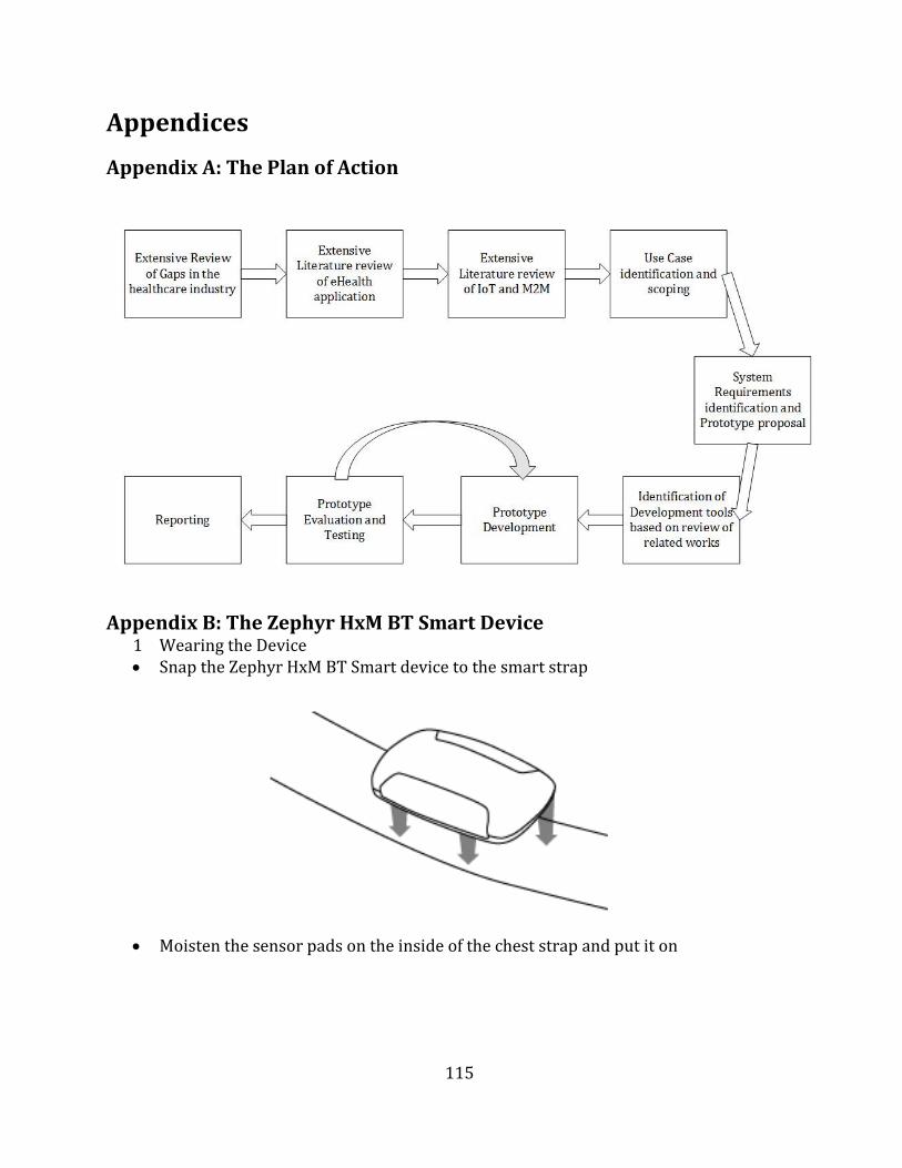
115
Appendices
Appendix A: The Plan of Action
Appendix B: The Zephyr HxM BT Smart Device 1 Wearing the Device Snap the Zephyr HxM BT Smart device to the smart strap
Moisten the sensor pads on the inside of the chest strap and put it on
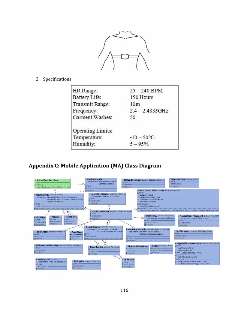
116
2 Specifications
Appendix C: Mobile Application (MA) Class Diagram
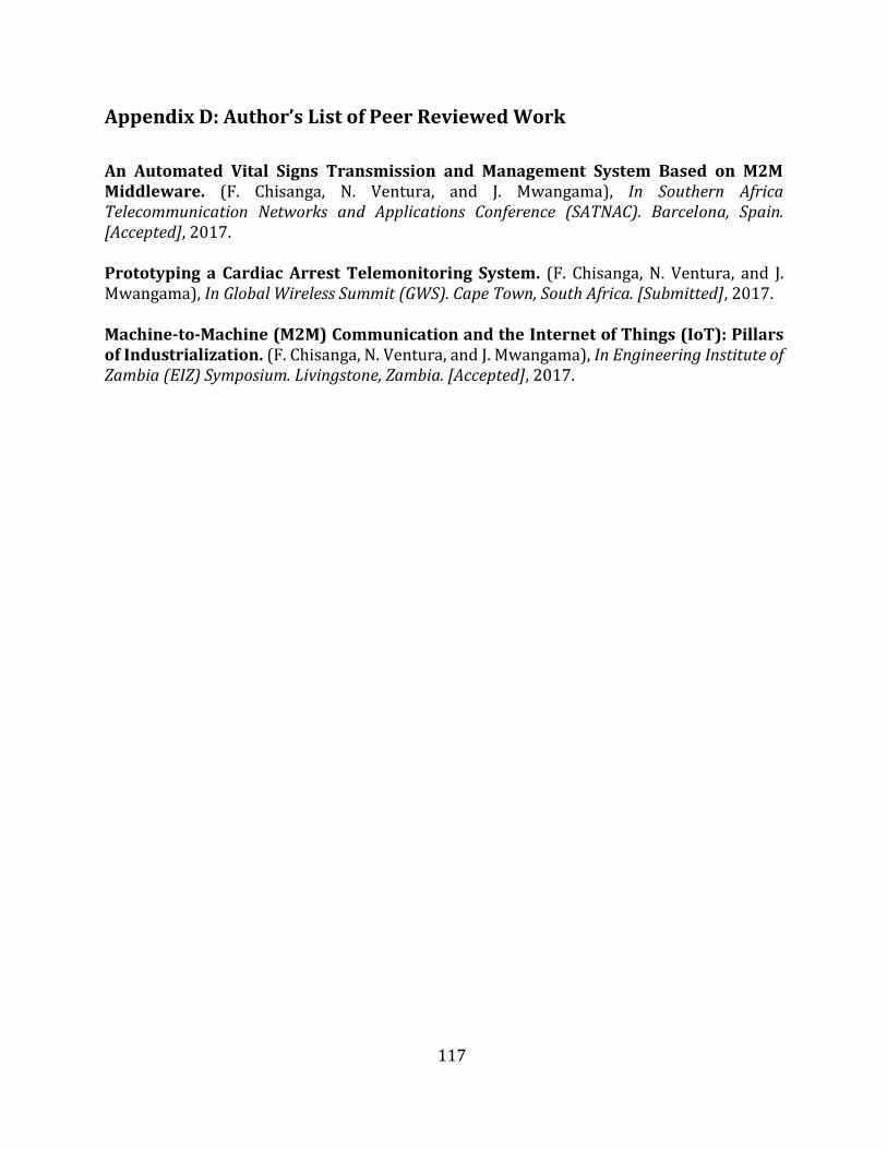
117
Appendix D: Author’s List of Peer Reviewed Work
An Automated Vital Signs Transmission and Management System Based on M2M Middleware. (F. Chisanga, N. Ventura, and J. Mwangama), In Southern Africa Telecommunication Networks and Applications Conference (SATNAC). Barcelona, Spain. [Accepted], 2017.
Prototyping a Cardiac Arrest Telemonitoring System. (F. Chisanga, N. Ventura, and J. Mwangama), In Global Wireless Summit (GWS). Cape Town, South Africa. [Submitted], 2017.
Machine-to-Machine (M2M) Communication and the Internet of Things (IoT): Pillars of Industrialization. (F. Chisanga, N. Ventura, and J. Mwangama), In Engineering Institute of Zambia (EIZ) Symposium. Livingstone, Zambia. [Accepted], 2017.