Meddybemps ES 2017 Final QAPP Nobis - Maine.gov
304
Client-Focused, Employee-Owned www.nobiseng.com Nobis Engineering, Inc. 585 Middlesex Street Lowell, MA 01851 T (978) 683-0891 EPA Region 1 RAC 2 Contract No. EP-S1-06-03 September 15, 2017 Nobis Project No. 80115 U.S. Environmental Protection Agency, Region 1 Attention: Mr. Terrence Connelly, Task Order Project Officer 5 Post Office Square, Suite 100 Boston, Massachusetts 02109-3912 Subject: Transmittal of Final Quality Assurance Project Plan Eastern Surplus Company Superfund Site, Meddybemps, Maine Remedial Design Task Order No. 0115-RD-RD-0189 Dear Mr. Connelly: Attached with this correspondence is the Final Quality Assurance Project Plan (QAPP) for the Remedial Design at the Eastern Surplus Superfund Site located in Meddybemps, Maine. The QAPP has been revised to address the State of Maine Department of Environmental Protection (MEDEP) comments received September 12, 2017. The responses to their comments are included with this cover letter. Should you have any questions or comments, please contact me at (603) 724-6235 or at [email protected]. Sincerely, NOBIS ENGINEERING, INC. Scott W. Harding, P.E. Program Manager Enclosure c: File 80115/NH (w/enc.) Rebecca Hewett, MEDEP Project Manager Via Electronic Submittal
-
Upload
khangminh22 -
Category
Documents
-
view
1 -
download
0
Transcript of Meddybemps ES 2017 Final QAPP Nobis - Maine.gov
Client-Focused, Employee-Owned
www.nobiseng.com
Nobis Engineering, Inc.
585 Middlesex Street
Lowell, MA 01851
T (978) 683-0891
EPA Region 1 RAC 2 Contract No. EP-S1-06-03 September 15, 2017 Nobis Project No. 80115 U.S. Environmental Protection Agency, Region 1 Attention: Mr. Terrence Connelly, Task Order Project Officer 5 Post Office Square, Suite 100 Boston, Massachusetts 02109-3912 Subject: Transmittal of Final Quality Assurance Project Plan Eastern Surplus Company Superfund Site, Meddybemps, Maine Remedial Design Task Order No. 0115-RD-RD-0189 Dear Mr. Connelly: Attached with this correspondence is the Final Quality Assurance Project Plan (QAPP) for the Remedial Design at the Eastern Surplus Superfund Site located in Meddybemps, Maine. The QAPP has been revised to address the State of Maine Department of Environmental Protection (MEDEP) comments received September 12, 2017. The responses to their comments are included with this cover letter. Should you have any questions or comments, please contact me at (603) 724-6235 or at [email protected]. Sincerely, NOBIS ENGINEERING, INC. Scott W. Harding, P.E. Program Manager Enclosure c: File 80115/NH (w/enc.) Rebecca Hewett, MEDEP Project Manager
Via Electronic Submittal

1
RESPONSE TO MEDEP COMMENTS, DATED SEPTEMBER 12, 2017 QUALITY ASSURANCE PROJECT PLAN – REMEDIAL DESIGN
EASTERN SURPLUS COMPANY SUPERFUND SITE MEDDYBEMPS, MAINE
Nobis Engineering, Inc. (Nobis) has prepared responses to the State of Maine Department of
Environmental Protection (MEDEP) review comments on the Draft Quality Assurance Project Plan
(QAPP) for the Remedial Design, dated August 29, 2017 for the Eastern Surplus Company
Superfund Site (the Site) located in Meddybemps, Maine. MEDEP were received on September
12, 2017 via email.
The MEDEP comments are provided in italic type, followed by Nobis responses.
1. Page 5, Section 5.0 – MEDEP requests a copy of the July 2017 Draft Work Plan prepared by
Nobis.
Nobis Response: The Draft Work Plan is attached as requested.
2. Page 13, Section 8.1.2, 3rd paragraph and Page 14, Section 8.1.3, 3rd paragraph – Table 8-2 only
lists location basis information for monitoring wells. Please add a table that lists surface water and
pore water sampling locations and the basis for selection or add this information to Table 8.2 but
amend the title to represent sampling locations other than wells.
Nobis Response:
3. Page 26, Section 15.1 – Please add that copies of all laboratory reports will be provided to Maine
DEP.
Nobis Response: This has been addressed in the text.
4. Page 27, Section 15.2 – Please add that EDDs will be provided to MEDEP in EGAD v. 6.0 format
as has been done in the past.
Nobis Response: This has been addressed in the text.

2
5. Table 3-1 – Please add “Rebecca Hewett, State Project Manager, MEDEP, (207) 287-8554” to
the QAPP distribution list.
Nobis Response: The addition has been made.
6. Table 6-1 – Please amend the entries in the “Dates” columns for the “QAPP Review by EPA”,
“QAPP – Final Revision” and “Sampling” rows to reflect QAPP completion earlier in September
2017 and sampling being done the week of September 18, 2017.
Nobis Response: Updates to the table have been made.
7. Table 6-2 – Andrea Colby is no longer with Katahdin Analytical Services. Please update the table
for current KAS contact.
Nobis Response: The new contact is Allison Harbottle. The change has been made.
8. Table 6-3 and 6-4 – Please add units of measure to the column headers.
Nobis Response: Units have been added to all criteria columns.
9. Table 6-3 – Please change the MCL for Toluene to 1000 ug/L instead of 100 ug/L.
Nobis Response: The MCL has been corrected. Additionally, the PAL has been changed from
100 to 600 ug/L based on the MEG value, which is now the lower of the two values.
10. Table 6-4 – Please reference the lower project limits for barium, silver and lead that are included
in Section 12.2.
Nobis Response: The lower quantitation limits (QLs) are now displayed in Table 6-4 for barium,
silver, and lead for ICP-MS.

FD Final Quality Assurance Project Plan Eastern Surplus Company Superfund Site Meddybemps, Maine Remedial Design EPA Task Order Number 0115-RD-RD-0189 REMEDIAL ACTION CONTRACT No. EP-S1-06-03 FOR
US Environmental Protection Agency Region 1 BY
Nobis Engineering, Inc. Nobis Project Number 80115
September 2017
Nobis Engineering, Inc.
Lowell, Massachusetts
Concord, New Hampshire
Phone (800) 394-4182
www.nobisengineering.com
U.S. Environmental Protection Agency
Region 1
5 Post Office Square, Suite 100
Boston, Massachusetts 02109-3919

TABLE OF CONTENTS FINAL QUALITY ASSURANCE PROJECT PLAN
EASTERN SURPLUS COMPANY SUPERFUND SITE MEDDYBEMPS, MAINE
SECTION PAGE
NH-4357-2017-F i Nobis Engineering, Inc.
ACRONYMS ................................................................................................................. AC-1
1.0 TITLE AND APPROVAL PAGE ............................................................................. 1
2.0 DOCUMENT OVERVIEW ....................................................................................... 2
3.0 PROJECT PERSONNEL DISTRIBUTION LIST AND DOCUMENT CONTROL ..... 3 3.1 Distribution List .......................................................................................... 3
4.0 PROJECT ORGANIZATION .................................................................................. 3 4.1 Project Organizational Chart ...................................................................... 3 4.2 Communication Pathways .......................................................................... 4 4.3 Personnel Responsibilities and Qualifications ............................................ 5
5.0 PROJECT PLANNING/PROJECT DEFINITION ..................................................... 5 5.1 Project Scoping Meetings ........................................................................... 5 5.2 Problem Definition ...................................................................................... 6
6.0 PROJECT DESCRIPTION AND SCHEDULE ......................................................... 7 6.1 Project Overview ........................................................................................ 7 6.2 Project Schedule ........................................................................................ 7 6.3 Analytical Services ..................................................................................... 8
7.0 PROJECT QUALITY OBJECTIVES AND MEASUREMENT PERFORMANCE CRITERIA ............................................................................................................... 8 7.1 Introduction ................................................................................................ 9 7.2 Project Data Quality Objectives .................................................................. 9 7.3 Measurement Performance Criteria............................................................ 9
7.3.1 Precision ..................................................................................... 9 7.3.2 Accuracy ................................................................................... 10 7.3.3 Representativeness .................................................................. 10 7.3.4 Completeness ........................................................................... 11 7.3.5 Comparability ............................................................................ 11 7.3.6 Sensitivity .................................................................................. 11 7.3.7 Quantitation Limits .................................................................... 11
8.0 SAMPLING PROCESS DESIGN .......................................................................... 12 8.1 Sampling Design Rationale ...................................................................... 12
8.1.1 Groundwater Sampling.............................................................. 13 8.1.2 Surface Water Sampling ........................................................... 13 8.1.3 Pore Water Sampling ................................................................ 14
9.0 FIELD SAMPLING PROCEDURES AND REQUIREMENTS ................................ 14 9.1 Containers, Preservation, and Handling ................................................... 14

TABLE OF CONTENTS (cont.)
FINAL QUALITY ASSURANCE PROJECT PLAN EASTERN SURPLUS COMPANY SUPERFUND SITE
MEDDYBEMPS, MAINE
SECTION PAGE
NH-4357-2017-F ii Nobis Engineering, Inc.
9.2 Water Sampling Procedures..................................................................... 15 9.3 Sampling SOP Modifications .................................................................... 16 9.4 Decontamination of Equipment and Investigation-Derived Waste ............ 16 9.5 Field Equipment Calibration ..................................................................... 17 9.6 Field Equipment Maintenance, Testing, and Inspection Requirements ..... 17 9.7 Inspection and Acceptance Requirements for Supplies and Sample
Containers ................................................................................................ 17
10.0 SAMPLE HANDLING, TRACKING AND CUSTODY REQUIREMENTS .............. 17 10.1 Sample Collection Documentation ........................................................... 18 10.2 Sample Handling, Tracking, and Custody Procedures ............................. 18
10.2.1 Field Custody and Sampling Shipping Procedures .................... 19 10.2.2 Laboratory Custody Procedures ................................................ 20
11.0 FIELD ANALYTICAL METHOD REQUIREMENTS .............................................. 21 11.1 Field Analytical Methods and Standard Operating Procedures ................. 21 11.2 Field Analytical Method/Standard Operating Procedures Modifications .... 21 11.3 Field Calibration Procedures and Frequency ............................................ 21 11.4 Field Analytical Instrument/Equipment Maintenance, Testing, and
Inspection Requirements .......................................................................... 22 11.5 Field Analytical Inspection and Acceptance Requirement for Supplies ..... 22
12.0 FIXED LABORATORY ANALYTICAL METHOD REQUIREMENTS .................... 22 12.1 Fixed Laboratory Analytical Methods and Standard Operating
Procedures ............................................................................................... 23 12.2 Fixed Laboratory Analytical Method/Standard Operating Procedures
Modifications ............................................................................................ 23 12.3 Fixed Laboratory Analytical Calibration Procedures ................................. 23 12.4 Fixed Laboratory Instrument Equipment Maintenance, Testing and
Inspection................................................................................................. 24 12.5 Fixed Laboratory Inspection and Acceptance Requirements for
Supplies ................................................................................................... 24
13.0 QUALITY CONTROL REQUIREMENTS .............................................................. 24
14.0 DATA ACQUISITION REQUIREMENTS (NON-DIRECT MEASUREMENTS) ...... 25
15.0 DOCUMENTATION, RECORDS, AND DATA MANAGEMENT ........................... 26 15.1 Fixed Laboratory Data Package Deliverables ........................................... 26 15.2 Electronic Data ......................................................................................... 27
16.0 ASSESSMENTS AND RESPONSE ACTIONS ..................................................... 27 16.1 Planned Assessments .............................................................................. 28

TABLE OF CONTENTS (cont.)
FINAL QUALITY ASSURANCE PROJECT PLAN EASTERN SURPLUS COMPANY SUPERFUND SITE
MEDDYBEMPS, MAINE
SECTION PAGE
NH-4357-2017-F iii Nobis Engineering, Inc.
16.2 Assessment Findings and Corrective Action Responses .......................... 29
17.0 QUALITY ASSURANCE MANAGEMENT REPORTS .......................................... 30
18.0 VERIFICATION AND VALIDATION REQUIREMENTS ........................................ 30
19.0 VERIFICATION AND VALIDATION PROCEDURES ........................................... 31
20.0 DATA USABILITY/RECONCILIATION WITH PROJECT QUALITY OBJECTIVES ....................................................................................................... 32
21.0 REFERENCES ..................................................................................................... 33
TABLES
NUMBER
3-1 Distribution List 4-1 Personnel Responsibilities and Qualifications 6-1 Project Schedule Timeline 6-2 Chemical Analysis Information 6-3 Target Analyte List – Volatile Organic Compounds (VOCs) – Water 6-4 Target Analyte List – Metals – Water 6-5 Target Analyte List – Anions – Water 6-6 Target Analyte List – Dissolved Gases – Water 6-7 Target Analyte List – Volatile Fatty Acids (VFAs) – Water 6-8 Field and Quality Control Sample Summary 7-1 Measurement Performance Criteria 8-1 Sampling Investigations, Rationale, Locations, and SOPs 8-2 Well Information and Required Analyses 9-1 Project Sampling SOP Reference 9-2 Sample Containers, Preservation, and Holding Time by Analysis 10-1 Sample Identification System 11-1 Field Analytical Instrument Calibration 11-2 Field Analytical Instrument/Equipment Maintenance, Testing, and Inspection 12-1 Fixed Laboratory Analytical Method/SOP References 12-2 Fixed Laboratory Instrument Maintenance and Calibration 13-1 Fixed Laboratory Analytical QC Samples 15-1 Project Documentation and Records 17-1 QA Management Reports 18-1 Data Verification Process

TABLE OF CONTENTS (cont.)
FINAL QUALITY ASSURANCE PROJECT PLAN EASTERN SURPLUS COMPANY SUPERFUND SITE
MEDDYBEMPS, MAINE
NH-4357-2017-F iv Nobis Engineering, Inc.
18-2 Data Validation Summary
FIGURES
NUMBER
4-1 Project Organization 5-1 Site Plan 6-1 Sampling Locations
APPENDICES
A Laboratory SOPs B Field Sampling SOPs C CLP Metals Modification

NH-4357-2017-F AC-1 Nobis Engineering, Inc.
ACRONYMS
°C degrees Centigrade
CD Compact disc
CERCLA Comprehensive Environmental Response, Compensation, and Liability Act
CLP Contract Laboratory Program
COC Constituent of Concern
CVAA cold vapor atomic absorption
DAS Delivery of Analytical Services
Dhc Dehalicoccoides
DO dissolved oxygen
DQO Data Quality Objective
EDD electronic data deliverable
EDM EXES Data Manager
EPA Environmental Protection Agency
EXES Electronic Data Exchange and Evaluation System
FOL Field Operations Leader
FS Feasibility Study
GC gas chromatography
GC/MS gas chromatograph/mass spectrometer
IC ion chromatography
ICP-AES inductively coupled plasma-atomic emission spectroscopy
ICP inductively coupled plasma-mass spectrometry
IGCL Interim Groundwater Cleanup Level
ISB in-situ bioremediation
LCS laboratory control sample
µg/L microgram per liter
MDL method detection limit
MEDEP Maine Department of Environmental Protection
MEG maximum exposure guideline
MS matrix spike
MSD matrix spike duplicate
NE New England
Nobis Nobis Engineering, Inc.

NH-4357-2017-F AC-2 Nobis Engineering, Inc.
ACRONYMS (cont.)
NTCRA non-time critical removal action
ORP oxidation-reduction potential
PAL project action limit
PCE tetrachloroethene
PE performance evaluation
PL Protection Level
PM Project Manager
PO Project Officer
QA quality assurance
QAPP Quality Assurance Project Plan
QC quality control
QL quantitation limit
%R percent recovery
RAC Remedial Action Contract
RAS Routine Analytical Services
RCRA Resource Conservation and Recovery Act
RI Remedial Investigation
ROD Record of Decision
RPD relative percent difference
RSCC regional sample control coordinator
RSD relative standard deviation
SDG sample delivery group
SMO sample management office
SOP standard operating procedure
SOW statement of work
SW surface water
TAL target analyte list
TCD thermal conductivity detector
TCE trichloroethene
TO Task Order
TOPO Task Order Project Officer
VFA volatile fatty acid

NH-4357-2017-F AC-3 Nobis Engineering, Inc.
ACRONYMS (cont.)
VOC volatile organic compound

NH-4357-2017-F 1 Nobis Engineering, Inc.
1.0 TITLE AND APPROVAL PAGE
Site Name/Project Name: Eastern Surplus Company Title: QAPP
Superfund Site Revision Number: 1
Remedial Design Revision Date: September 2017
Site Location: Meddybemps, Maine Page: 1 of 1
Document Title: Quality Assurance Project Plan (QAPP)
Lead Organization: U.S. Environmental Protection Agency (EPA), Region 1
Preparer’s Name and Organizational Affiliation:
Ms. Gail DeRuzzo, Nobis Engineering Inc.
Preparer’s Address and Telephone Number: 585 Middlesex Street
Lowell, Massachusetts 01851, 978-683-0891
Preparation Date: August 2017
Lead Organization’s Project Manager:
September 15, 2017
Signature/Date
Scott W. Harding, P.E. / Nobis Engineering, Inc.
Printed Name/Organization
Lead Organization’s Project QA Officer:
September 15, 2017
Signature/Date
Gail DeRuzzo / Nobis Engineering Inc..
Printed Name/Organization
Approval Signature:
Signature/Date
Terrence Connelly / EPA Task Order Project Officer
Printed Name/Organization
Approval Authority
Other Approval Signatures:
Signature/Date
Nora Conlon Ph.D. / EPA QAPP Coordinator/ Reviewer
Printed Name/Organization

NH-4357-2017-F 2 Nobis Engineering, Inc.
2.0 DOCUMENT OVERVIEW
Site Name/Project Name: Eastern Surplus Company Superfund Site
Site Location: Meddybemps, Maine
Site Number/Code: EPA ID#: MED981073711 / Site ID# 0189
Operable Unit: OU1
Contractor Name: Nobis Engineering, Inc. (Nobis)
Contract Number: EP-S1-06-03
Contract Title: Remedial Action Contract (RAC 2)
Task Order Number: 0115-RD-RD-0189
Anticipated date of QAPP Implementation: September 2017
1. Guidance Used to Prepare QAPP: EPA Requirements for QA Project Plans (QA/R-5), March 2001; EPA-New England Quality Assurance Project Plan Program Guidance, Revision 2, January 2010 (EPA-NE, 2010).
2. EPA Program: Comprehensive Environmental Response, Compensation, and Liability
Act (CERCLA)/Superfund
3. Approval Entity: EPA
4. QAPP Generic Program/Project Specific: This document is a project specific QAPP, addressing sampling and analytical activities planned for Remedial Design.
5. Dates of Scoping Meetings That Were Held: NA
6. Title of QAPP Documents and Approval Dates Written for Previous Site Work, If Applicable: First QAPP for Remedial Design.
7. Organizational Partners (Stakeholders) and Connection with EPA and/or State: Not Applicable.
8. Data Users: EPA Task Order Project Officer (TOPO); Maine Department of Environmental Protection (MEDEP); Nobis Project Staff
9. Document Control System: Once approvals are provided by EPA, copies of the signed
Title and Approval page will be distributed to Stakeholders listed in Table 3-1.

NH-4357-2017-F 3 Nobis Engineering, Inc.
3.0 PROJECT PERSONNEL DISTRIBUTION LIST AND DOCUMENT CONTROL
In accordance with the EPA QAPP Guidance (EPA, 2001), this section documents the QAPP
Distribution List and document control of the project-specific QAPP for the Eastern Surplus
Company Superfund Site (the Site), located in Meddybemps, Maine.
3.1 Distribution List
The Distribution List (Table 3-1) documents who will receive copies of the approved QAPP.
Typically, the final approved copies of the QAPP will be made available electronically via email or
on compact disc (CD) in pdf format to those on the distribution list.
The document control number NH-4357-2017-F has been assigned to this document for tracking
purposes. Individuals listed in Table 3-1 receiving a copy of the QAPP will be provided with all
applicable revisions, addenda, and amendments. Those individuals in receipt of a controlled copy
are responsible for removing all outdated material from circulation, and for distributing revised or
additional material to update any copies within their organization.
A complete copy of the QAPP and any subsequent revisions will be maintained on file at Nobis
Engineering, Inc. in Concord, New Hampshire (Nobis) and will be available to EPA upon request.
4.0 PROJECT ORGANIZATION
This section identifies the project case team members and other key personnel participating in the
project and describes their specific roles, responsibilities, and qualifications. This section also
provides an explanation of the lines of authority, reporting relationships, and communication paths.
4.1 Project Organizational Chart
The key project personnel and responsibilities are listed in Table 4-1. The organizational chart
presented as Figure 4-1, includes the names of the project contacts for each organization. Nobis
is the prime contractor for all aspects of the Remedial Design and all subcontractors will report
directly to Nobis.

NH-4357-2017-F 4 Nobis Engineering, Inc.
At a minimum, the anticipated subcontracted services include bioremediation services and
Routine Analytical Services (RAS), Contract Laboratory Program (CLP), and Delivery of Analytical
Services (DAS) laboratory analytical services. Potential subcontractors are also identified in
Figure 4-1.
4.2 Communication Pathways
The communication pathways are discussed in this section. Program level directions will be
provided by the Nobis Program Manager and/or Nobis Deputy Program Manager to the Nobis
Project Manager (PM), who will provide these directions to the technical team and Field Operations
Leader (FOL). Additional program and technical direction may be provided by the Nobis Quality
Assurance (QA) Officer/ Lead Chemist, and Corporate Health and Safety Officer. Technical
direction is communicated by the EPA TOPO to the Nobis PM. Communications between Nobis
and EPA will be coordinated primarily between the PM and the TOPO. The EPA TOPO coordinates
and receives input from the EPA Project Officer (PO), EPA QA Reviewer, and the MEDEP Site
Manager with respect to the evaluation of the final Data Quality Objective (DQO) actions.
The FOL is the principal contact that provides communication and direction to the field technical
staff and non-laboratory pool subcontractors. The FOL also provides information regularly
concerning all field activities and status to the PM and communicates the sample shipping
information to the Lead Chemist.
Nobis will not release Site-related information to entities outside of the project unless specifically
directed to do so by EPA.
Mr. Scott Harding, the Nobis PM, will serve as the primary point of contact for all project and field
related issues. Ms. Gail DeRuzzo, the Nobis Lead Chemist, will be the primary contact for all
laboratory or data assessment and validation related issues. The FOL will be in charge of the field
data collection activities and coordination with the on-site subcontractors.
Records of communication (i.e., letters, faxes, emails, telephone conversation logs, meeting
minutes, etc.) to or from Nobis will be maintained within the Nobis central project file.

NH-4357-2017-F 5 Nobis Engineering, Inc.
4.3 Personnel Responsibilities and Qualifications
Roles and responsibilities for key Nobis Team individuals and subcontractors for this project are
described in Table 4-1. The hierarchy of project personnel is shown in Figure 4-1. Nobis is the
primary consultant to the Lead Organization (EPA) for this project, under the current RAC 2.
Subcontractors to Nobis will be used for activities including RAS, CLP, and DAS laboratory
analytical services.
5.0 PROJECT PLANNING/PROJECT DEFINITION
The primary activities covered by this QAPP are field investigation and data acquisition activities
to be conducted at the Site for Remedial Design. These activities are fully described in the
following document:
• Draft Work Plan, Eastern Surplus Superfund Site, Meddybemps, Maine. Prepared by
Nobis Engineering Inc., July 2017. (Nobis, 2017).
Field investigation and data collection activities supporting the Remedial Design of the selected
remedy as defined in the pending Explanation of Significant Differences (ESD) (EPA, 2017a) include:
a) Full-scale implementation of enhanced bioremediation.
b) Monitoring the implementation, measuring volatile organic compounds (VOCs), dissolved
gases, volatile fatty acids (VFAs), anions, and the target analyte list metals, along with
geochemical parameters.
5.1 Project Scoping Meetings
• June 14, 2017 - Prepared Scoping Questions and submitted to EPA; received responses
on June 15, 2017.
• June 29, 2017 – Nobis and EPA conducted a site walk to determine the current conditions
of the Site and discuss SOW.
NH-4357-2017-F 6 Nobis Engineering, Inc.
5.2 Problem Definition
The Site consists of approximately 4 to 5 acres of land north of Route 191 and another 2 to 3
acres of land south of Route 191 in Meddybemps, Maine, a rural community with a year-round
population under 200. The 2000 Record of Decision (ROD) (EPA, 2000) designated the area
north of Route 191 as the “surficial site”. The Site is bounded by residential property and
Meddybemps Lake to the north, by the Denny’s River to the east, and undeveloped land to the
south and west. A dam controls the outlet of the lake to the river, and a small wetland exists
adjacent to the river just downstream of the dam. Most of the Site is above the floodplain as a
steep bank runs along the Denny’s River. A site plan is included as Figure 5-1.
Starting in 1946, two owners used the property north of Route 191 as a storage and salvage yard.
The area north of Route 191 at one time had debris/junk covering over half of the area, with thick
vegetation covering the rest of the property. Some of the junk/surplus materials contained
hazardous substances that were released into the soils and further released into the groundwater.
In 1985, the MEDEP performed an inspection and identified the Site as an uncontrolled hazardous
substance site. MEDEP initiated a removal action to stabilize the Site. At the request of MEDEP,
EPA then took over the removal activities. Most of the hazardous waste stored in above-ground
containers was removed during the first EPA removal action in the 1980s. EPA placed the Site
on the National Priorities List on June 17, 1996 and began a remedial investigation and feasibility
study (RI/FS) the same year. In 1998-1999, EPA performed a non-time-critical removal action
(NTCRA) that, among other things, excavated and disposed of contaminated soils and sediment
to an approved off-site facility. Site investigations identified two distinct contaminated groundwater
plumes. The northern plume is situated in the northern half of the Site north of Route 191. In
September 2000, EPA issued a ROD for the Site. The ROD set forth the selected remedy for the
Site that included groundwater extraction and treatment of both plumes, land use restrictions,
long-term monitoring, archaeological mitigation activities, and review of the Site every 5 years.
The groundwater extraction system for the southern plume was shut down in 2010 and then
decommissioned in 2013-2014. The groundwater extraction system for the northern plume was
suspended in 2011 to allow for an enhanced bioremediation pilot study. This occurred after a 49-
day bench-scale test, injections of site groundwater, an electron donor (e.g., lactate, vegetable
oil, etc.), and a proprietary culture of Dehalicoccoides (Dhc) were made in October 2012 and April

NH-4357-2017-F 7 Nobis Engineering, Inc.
2013. Follow-up sampling indicated significant de-chlorination of the primary site contaminants,
tetrachloroethene (PCE) and trichloroethene (TCE).
The major components of the selected remedy include the following:
• Full-scale implementation of enhanced bioremediation.
• Monitoring the implementation by measuring VOCs, dissolved gases, VFAs, anions, and
the target analyte list metals, along with geochemical parameters.
6.0 PROJECT DESCRIPTION AND SCHEDULE
This section of the QAPP provides an overview of the general activities that will be performed and
how and when they will be performed to meet the DQOs specified in Section 7.0.
6.1 Project Overview
The primary tasks covered by this QAPP include field investigation activities performed to support
the Remedial Design for the Site. Activities include collecting groundwater, pore water, and
surface water samples for fixed laboratory analysis. The anticipated field activities will include the
following in the general order of occurrence described below.
Ten groundwater wells will be sampled for VOCs, anions (chloride, sulfate, nitrate, and nitrite),
dissolved gases (methane, ethane, and ethene), and VFAs analyses. An additional 10
groundwater wells will be sampled for VOCs and metals analyses. All 20 wells will be monitored
for geochemical parameters during sampling. Prior to sampling, all northern plume monitoring
and extraction wells (53) will be measured for water levels. Three surface water samples and
three pore water samples will be sampled for VOCs and metals analyses. Sampling locations are
designated in Figure 6-1. Samples will be placed in appropriate containers (refer to Section 9.0)
labeled, and shipped or delivered to the designated laboratories for analyses.
6.2 Project Schedule
The project schedule for these activities is presented on Table 6-1. The majority of field activities will
take place in the fall of 2017. Data validation and evaluation will follow 1 to 2 months after sampling.
If an event causes an impact to the schedule, the Nobis PM will notify the EPA TOPO immediately.

NH-4357-2017-F 8 Nobis Engineering, Inc.
6.3 Analytical Services
Analytical data required for this project will be obtained using off-site analysis at the CLP analytical
laboratories for VOCs and metals; and the DAS analytical laboratory (Katahdin) for anions,
dissolved gases, and VFAs. Table 6-2 shows the laboratory services by parameter. Table 6-3
through Table 6-7 identify the target analytes and associated project action limits (PALs) for the
water samples to be collected and the quantitation limits (QLs) that can be achieved by the
proposed analytical methods.
VOCs will be analyzed by gas chromatography/mass spectrometry (GC/MS). Metals will be
analyzed by inductively coupled plasma-atomic absorption spectroscopy (ICP-AES), inductively
coupled plasma-mass spectroscopy (ICP-MS), and cold vapor atomic absorption spectroscopy
(CVAA). Anions will be analyzed by ion chromatography (IC). Dissolved gases are analyzed by
gas chromatography (GC) equipped with a thermal conductivity detector (TCD). VFAs are
analyzed by IC equipped with a TCD.
Refer to Section 12.0 for specific information pertaining to the analytical services required for
this investigation.
Analytical methods were selected for use with the objective of achieving as many of the identified
PALs as practical, considering the suspected contaminants of concern and the use of the data.
Any analytes for which the proposed analytical methods do not achieve identified PALs, are
highlighted in the Tables 6-3 and 6-4.
Table 6-8 defines the number of field sample and quality control (QC) samples to be collected
and analyzed for each sampling event.
7.0 PROJECT QUALITY OBJECTIVES AND MEASUREMENT PERFORMANCE
CRITERIA
This section describes project quality objectives and measurement performance criteria for
measurement data in terms of precision, accuracy, representativeness, completeness, and
comparability.
NH-4357-2017-F 9 Nobis Engineering, Inc.
7.1 Introduction
QA objectives are qualitative and quantitative statements that specify the quality of data
necessary for regulatory and/or project-specific requirements. The process of developing QA
objectives for a given study helps to ensure that data generated are of adequate quality for the
intended use. QA objectives may be expressed in terms of the precision, accuracy,
representativeness, completeness, and comparability of the collected data.
Groundwater, surface water, and pore water samples will be collected prior to the preparation of
the enhanced bioremediation design as a means to further develop the current site conceptual
model. Groundwater samples will be sampled for VOCs, dissolved gases, VFAs, anions, and the
target analyte list metals, along with geochemical parameters. Surface water and pore water
samples will be sampled for VOCs and metals. The results for contaminants of concern (COCs)
will be compared to ROD action limits.
7.2 Project Data Quality Objectives
DQOs for the data collected under the investigations covered by this QAPP have been defined to
ensure that the collected data will comply with EPA requirements.
Table 7-1 presents the DQOs for critical measurements in terms of precision and accuracy for all
parameters analyzed for this investigation. Estimated accuracy is expressed as percent recovery
(%R), and estimated precision is expressed as a relative percent difference (RPD) (for two values)
or a standard deviation (RSD) (for three or more values).
7.3 Measurement Performance Criteria
The measurement performance criteria are described in this section. The methods used to assess
these criteria are presented in Table 7-1 and in this section.
7.3.1 Precision
In general, field duplicate samples will be collected at a rate of one per 20 samples depending on
method (see Table 7-1 for criteria and Table 6-8 for frequency for this project). Field duplicates
will provide a measure of field variability and sample homogeneity. Additionally, matrix spike (MS)

NH-4357-2017-F 10 Nobis Engineering, Inc.
and matrix spike duplicates (MSD) may be performed by the laboratory at a rate of one per 20
samples or once per sample delivery group (SDG) for organic parameters (see Table 13-1 for
criteria and Table 6-8 for frequency for this project) per matrix (soils). A laboratory duplicate will
be performed once per 20 samples or once per SDG for all analyses (see Table 7-1 and Table
13-1 for criteria). Laboratory duplicates and matrix spike duplicates indicate laboratory variability
and consistency. All precision data will be calculated using RPD determinations.
7.3.2 Accuracy
Method blanks, equipment blanks, and instrument blanks will be used to assess accuracy and
bias (see Table 13-1 for criteria). For this project, it is anticipated that dedicated equipment will
be used for surface water and groundwater sampling, therefore, equipment blanks will not be
required for this activity. One equipment blank will be collected for pore water samples where
non-dedicated equipment is used. Calibration standards evaluate the continuing accuracy of the
operating system (see Table 12-2 for criteria). Matrix spikes evaluate the accuracy of the
preparation steps (see Table 13-1 for criteria). Laboratory control samples (LCS) and
performance evaluation (PE) samples evaluate the accuracy of the complete analytical process
(see Table 7-1 and Table 13-1 for criteria). Percent recovery of known concentrations is used to
monitor accuracy.
7.3.3 Representativeness
Representativeness is reflective of the design of the sampling program; representativeness is
maximized by proper selection of sampling locations and collection of a sufficient number of
samples. A representative sample should possess the same qualities or properties relevant to the
investigation as the material under investigation. Section 8.0 addresses selection of
representative sampling locations.
As a quantitative measure of representativeness, field duplicates will be collected and analyzed
for all parameters in each matrix as specified in Tables 6-8 and 7-1. Field duplicate criteria are
based on analytical method criteria and the EPA-New England (NE) data validation guidelines.
NH-4357-2017-F 11 Nobis Engineering, Inc.
7.3.4 Completeness
Completeness is defined as a measure of the amount (percentage) of valid data obtained from a
measurement system, field or laboratory, compared to the amount expected from the system. A
target of 95 percent completeness for all field and laboratory data is planned for this project. Less
than 100 percent may be a result of sample matrix issues, loss of sample, or inability to collect all
planned sample points.
7.3.5 Comparability
Comparability addresses the confidence with which one data set can be compared to another.
Use of appropriate sampling and analytical methods, chain-of-custody procedures, as well as
adherence to strict QA/QC procedures, provide the basis for uniformity in sample collection and
analysis activities. A quantitative measure of comparability in the laboratory can be measured
with acceptable PE sample results. The PE samples will provide comparison of the laboratory
performance to reference results.
7.3.6 Sensitivity
The CLP and DAS laboratories perform method detection limit (MDL) studies at least annually to
determine their ability to detect the target analytes at the required quantitation limits. Quantitation limits
are set at the lowest calibration point and are based on method and sample matrix. See Section 7.3.7.
7.3.7 Quantitation Limits
QLs are chosen to achieve PALs or ROD Interim Groundwater Cleanup Levels (IGCLs) and ROD
Surface Water Protective Levels (SW PLs) for the project. ROD IGCLs and SW PLs are only given
for site COCs. These are shown in Tables 6-3 and 6-4.
PALs for the project are based on the following:
1) Site ROD, September 2000, Table 30, IGCLs.
2) Site ROD, September 2000, Table 27, SW PLs.
3) Federal Maximum Contaminant Levels (MCLs).
4) Maine Maximum Exposure Guidelines (MEGs) for Drinking Water, December 31, 2016.

NH-4357-2017-F 12 Nobis Engineering, Inc.
The PALs for VOCs and metals for the site COCs are based on IGCLs and SW PLs. PALs for
non-COCs are selected based on the lower of MCLs or MEGs for each analyte.
The target analytes, PALs, and laboratory QLs are included in Tables 6-3 through 6-7. PALs that are
not achievable with the listed QLs are highlighted in these tables. As laboratory QLs are based on
published methods, the methods have been selected based on laboratory programs and available
technology. The laboratory’s MDLs are typically three to five times lower than the project QLs, and
therefore, may provide valid but qualified results for reported data to achieve more of the PALs.
Vinyl chloride is identified as a non-COC but related to site contamination. The PAL of 0.2
microgram per liter (µg/L) is not achieved with trace-level VOCs analysis. A CLP modification will
be requested to lower the laboratory quantitation limit for vinyl chloride to 0.1 µg/L to achieve the
PAL. Some samples are expected to have high concentrations of target VOC analytes, therefore,
will be requested by the low-level VOC method and will not achieve three other analytes (1,1,2-
trichloroethane, chloromethane, and tetrachloroethene).
Groundwater samples will be analyzed by ICP-MS for antimony, arsenic, and cadmium in order
to meet PALs. Surface water/pore water samples will be analyzed by ICP-MS for aluminum,
barium, lead, and silver. Additionally, CLP modifications for surface water and pore water samples
will be requested to lower laboratory quantitation limits to 0.25 µg/L for lead and silver and to 2
µg/L for barium to meet the PALs. The CLP metals modification is provided in Appendix C.
8.0 SAMPLING PROCESS DESIGN
This section describes the sampling methodology of the field program and includes the specific
information necessary to conduct the sampling components of field investigations. The sampling
process design and rationale, including the sample locations, number of samples to be collected,
and the sampling frequency are presented below.
8.1 Sampling Design Rationale
The objective of the field investigation and sampling program is to define current contaminant
levels, other physical/chemical properties, and volume to support the remedial activities.
Environmental sampling will include groundwater, surface water, and pore water samples

NH-4357-2017-F 13 Nobis Engineering, Inc.
collected from existing monitoring wells and pre-determined locations along the Denny’s River.
The data will be used to update the conceptual site model in preparation for the Remedial Design
of the in-situ bioremediation (ISB). The subsections below describe the design of the various
elements of the planned field investigation. Table 8-1 lists the sampling frequency by media
planned for this effort, the rationale for the proposed sampling, and the parameters which will be
included for analysis.
8.1.1 Groundwater Sampling
One round of current plume characterization groundwater samples will be collected during
September or October 2017 to establish the status of VOCs and metals in the northern plume
area. During the event, all 53 wells in the northern plume will be measured for static water level;
10 wells in the northern plume will be sampled for VOCs, VFAs, anions, and dissolved gases; and
another 10 wells will be sampled for VOCs and target analyte list (TAL) metals. All Site wells are
depicted on Figure 6-1 and well information and required analyses are listed on Table 8-2. The
required sample containers, preservatives, and holding times, are listed in Table 9-2.
Wells to be sampled were selected by EPA and are based on the results from Long-Term
Monitoring and the spatial distribution of wells to evaluate both overburden and bedrock
components of the plume. These locations will be sampled to provide data that can be used to
evaluate the contaminant trends in both the overburden and bedrock plumes.
8.1.2 Surface Water Sampling
Sampling of three surface water stations will be conducted during September 2017 or October
2017 to determine if the plume is impacting the water in the Denny’s River. Sampling will be
conducted at selected locations where surface water samples were collected during the previous
sampling events so that data can be compared and used for trend analysis. Sampling locations
are depicted in Figure 6-1. Surface water stations will be co-located with pore water locations and
will replicate previous sampling locations.
The surface water samples will be analyzed for VOCs and TAL metals. The required sample
containers, preservatives, and holding times, are listed in Table 9-2.
The proposed sampling stations and basis for selection are presented in Table 8-2.

NH-4357-2017-F 14 Nobis Engineering, Inc.
8.1.3 Pore Water Sampling
Sampling of three pore water stations will be conducted during September or October 2017 to
determine if the plume is impacting the water in the Denny’s River. Sampling will be conducted at
selected locations where pore water samples were collected during the previous sampling events
so that data can be compared and used for trend analysis. Sampling locations are depicted in
Figure 6-1. Surface water locations will be co-located with pore water locations and will replicate
previous sampling locations.
The pore water samples will be analyzed for VOCs and TAL metals. The required sample
containers, preservatives, and holding times, are listed in Table 9-2.
The proposed sampling stations and basis for selection are presented in Table 8-2.
9.0 FIELD SAMPLING PROCEDURES AND REQUIREMENTS
Sampling procedures that will be used for the project are summarized in this section and in Table
9-1. Detailed standard operating procedures (SOPs) for field activities are included in Appendix
B. These standardized protocols provide consistency between samplers; facilitate collection of
accurate, precise, and representative data; and improve data comparability and usability.
9.1 Containers, Preservation, and Handling
The following sections on containers, preservation, and handling apply to the groundwater,
surface water, and pore water sampling activities described in this QAPP.
Sample Containers
To ensure the integrity of the field samples, specific steps must be taken to minimize the potential
for cross-contamination from the containers in which the samples are stored. Sample containers
must be compatible with the analytes of interest. The sample containers required for the collection
of the various analytical samples for the investigation are summarized in Table 9-2.
NH-4357-2017-F 15 Nobis Engineering, Inc.
Nobis will procure adequate sample containers as described in subsequent sections for all
analytical testing. All sample containers supplied will be Level 3, pre-cleaned in accordance with
EPA guidance. Certificates of Analysis documenting lot approval will be provided with each
shipment and retained in the project files. Any reuse of sample containers is expressly prohibited.
Sample Preservation and Holding Times
The purpose of sample preservation is to prevent or retard the degradation or transformation of
target analytes in the field samples during transport and storage. Preservation efforts to ensure
sample integrity will be initiated at the time of sampling and will continue until the analyses are
performed. The required preservatives and holding times for specific analytical samples to be
collected are indicated in Table 9-2. For those samples requiring chemical preservation, the
sample containers will be acquired pre-preserved.
After collection, all samples will be stored and shipped on ice in order to maintain sample
temperature at 4 degrees Centigrade (°C) ± 2°C. It is anticipated that samples to be submitted to
the DAS laboratory will either be shipped via FedEx service or picked up by laboratory courier.
Samples to be submitted to the RAS CLP laboratories will be shipped via FedEx service. Sample
management will be performed in the field in accordance with the Scribe Sample Documentation
SOP DOC-002 (Appendix B). Sample shipment will be performed in accordance with the Sample
Shipment SOP SH-001 (Appendix B). The recommended maximum holding times for analytical
samples are indicated in Table 9-2; maximum holding times are calculated from the date and time
of sample collection.
9.2 Water Sampling Procedures
Water samples shall be collected as grab samples following the sampling SOPs SA-003 Low-
Flow Groundwater Sampling, and SA-011 Surface Water Sampling, and ENV-023 Pore Water
Sampling (Appendix B). The samples will be collected utilizing dedicated, disposable polyethylene
tubing and peristaltic pumps. Instrumentation utilized during sample collection will include an In-
Situ® SmarTroll water quality meter (or equivalent) and a LaMotte 2100q turbidimeter (or
equivalent) to collect field parameters (e.g., temperature, specific conductivity, pH, dissolved
oxygen, and turbidity) in accordance with the Field Measurement of Water Quality Parameters
SOP SA-008 (Appendix B). Each of these instruments will be calibrated and checked for drift after
each day’s activities. All non-dedicated equipment will be thoroughly decontaminated in

NH-4357-2017-F 16 Nobis Engineering, Inc.
accordance with the Field Sampling Equipment Decontamination SOP FS-004 (Appendix B).
Sample preservation requirements are specified in Table 9-2.
9.3 Sampling SOP Modifications
Specific wells are known to drawdown during sampling and have diameters that prohibit the use
of submersible pumps; therefore, the MEDEP’s “no purge” sampling method will be employed at
these locations. The no purge methodology requires evacuation of the dedicated tubing prior to
sample collection. The wells currently have dedicated tubing with foot valves installed in them that
will be raised and lowered in order to evacuate the standing water in the tubing. The volume of
water required for evacuation is calculated by using a multiplication factor of 80 milliliters per foot
of water-filled tubing. The depth of the wells and the sampling method for each well is listed in
Table 8-2.
No other method modifications are anticipated for this investigation. If additional major
modifications to Nobis field sampling procedures become necessary, the EPA TOPO will be
contacted for approval prior to implementation of the modifications. Any minor changes to the
sampling SOPs will be documented in field logs as they become necessary. The documentation
will include the reason for modification as well as the modifications themselves.
9.4 Decontamination of Equipment and Investigation-Derived Waste
Decontamination of equipment and sample collection tools will be completed in accordance with
the Field Sampling Equipment Decontamination SOP FS-004 (Appendix B). All non-dedicated
equipment utilized during this investigation will be thoroughly and completely decontaminated in
between each use. In addition, the necessary field equipment blanks will be collected from each
piece of equipment in accordance with the QA/QC requirements of the project. Field equipment
blanks will evaluate the effectiveness of the cleaning and decontamination procedure utilized
during the investigations. It is anticipated that sampling will be conducted with dedicated
equipment and decontamination will not be necessary for surface water and groundwater
sampling. One equipment blank will be collected during pore water sampling.

NH-4357-2017-F 17 Nobis Engineering, Inc.
9.5 Field Equipment Calibration
Field instruments will be maintained in accordance with manufacturer’s specifications and
calibration information will be recorded in the field logbook and on field calibration sheets daily. A
SmarTroll multi-meter or equivalent will be used during groundwater monitoring well sampling and
surface water and pore water sampling to document monitoring water quality parameters. The
SmarTroll will be calibrated in accordance with the Calibration of In-Situ SmarTroll SOP FS-008
and manufacturer’s instructions. A LaMotte 2020 turbidimeter or equivalent will be utilized to
monitor water sample turbidity and calibrated in accordance with manufacturer’s
recommendations and the Calibration of Turbidity Meters SOP FS-006. Both calibration SOPs
are included in Appendix B.
9.6 Field Equipment Maintenance, Testing, and Inspection Requirements
Field instruments and equipment used for sample analysis will be serviced and maintained only
by qualified personnel. Repairs, adjustments, routine maintenance, and calibrations made on-site
will be documented in an appropriate logbook or data sheet that will be kept on file. The instrument
maintenance and calibration records will clearly document the date, the description of the
problems, the corrective action taken, the result, and who performed the work.
9.7 Inspection and Acceptance Requirements for Supplies and Sample
Containers
Supplies (including sample containers) will be obtained from appropriate vendors and will be
maintained in a clean condition, away from contaminant sources. Nobis will obtain certified-clean
bottles for sampling from an approved vendor for organics and inorganics analyses. Certificates
of analyses will be maintained in the project files for each lot of bottles utilized. The DAS
subcontract laboratory will be providing certified-clean containers to Nobis for the anions,
dissolved gases, and VFAs analyses.
10.0 SAMPLE HANDLING, TRACKING AND CUSTODY REQUIREMENTS
The following sections describe the methods to document, handle, and track samples.

NH-4357-2017-F 18 Nobis Engineering, Inc.
10.1 Sample Collection Documentation
A single bound field book will be maintained by the FOL to record Site activities. Field data sheets
shall be completed by the field personnel and turned into the FOL at the conclusion of each day.
All field documentation will be completed in indelible ink or on handheld electronic devices with
secure file storage. Field data captured on electronic devices will be handled in accordance with
SOP DOC-003 Electronic Data Management using Handheld Connected Devices including being
backed up frequently, daily at a minimum, to ensure no loss of data. Field sheets to be utilized
are included in the SOPs in Appendix B.
The following items should be recorded on sample data sheets:
• Sampler name
• Sample collection method
• Information concerning sampling changes, scheduling modifications and change orders
• Details of sampling location
• Date and time of collection
• Field observations
• Any field measurements made
• Sample identification number(s)
• Sample preservation
• Documentation of any scope of work changes required by field conditions
• Signature and date (entered by personnel responsible for observations)
10.2 Sample Handling, Tracking, and Custody Procedures
This section describes procedures for sample handling, tracking, and custody procedures to be
followed by Nobis’ sampling personnel and the subcontracted laboratories. The primary objective
of sample handling, tracking, and custody is to provide an accurate written record that can be
used to trace the possession and handling of a sample from the moment of its collection through
its analysis. A sample is considered to be in custody if it is: in someone's physical possession; in
someone's view; or kept in a secured area that can only be accessed by authorized personnel.
Sample identification documents must be carefully prepared so that sample identification and
chain-of-custody procedures can be maintained and sample disposition controlled. Sample

NH-4357-2017-F 19 Nobis Engineering, Inc.
identification documents shall include field notebooks, sample labels, custody seals, and chain-
of-custody records.
10.2.1 Field Custody and Sampling Shipping Procedures
Each sample collected will be given a unique sample number. For samples bound for RAS CLP
and DAS laboratories, the Nobis Lead Chemist will assign sample numbers. For CLP VOC
samples, sample numbers in the form of Axxxx will be assigned. For CLP metals samples, sample
numbers in the form of MAxxxx will be assigned. For DAS samples, sample numbers in the form
of Dxxxx will be assigned. Nobis field staff then assign the numbers to individual samples. Nobis
uses the numbers to track the samples that are sent to the laboratories. The numbers must appear
on labels that are affixed to the appropriate sample containers. In addition to the assigned
numbers, Nobis also utilizes a field sample numbering system as described below.
In order to provide EPA personnel with information necessary to track samples, Nobis will be
utilizing an EPA-provided sample documentation system known as Scribe (version 3.10). This
software compels the user to enter required information needed to properly populate chains of
custody, sample labels, and sample tags. Additionally, this software provides a mechanism by
which Nobis may track samples and analyses internally. Sample identification numbers will be
included on the chain-of-custody form to accompany each sample shipment submitted for
laboratory analysis. Scribe procedures are outlined in Nobis SOP DOC-002 (Appendix B).
The field sampling personnel will be responsible for uniquely identifying, labeling, and packaging
samples to preclude breakage during shipment. The sample numbering system is described in
Table 10-1.
Chain-of-custody records provide documentation of the handling of each sample from the time of
its collection to its destruction. Nobis will initiate custody of the samples in the field and, in-turn,
transfer custody of the samples to the courier (as needed), and lastly to the laboratory. Chain-of-
custody forms will be used for recording pertinent information about the types and numbers of
samples collected and shipped for analysis.
The Nobis FOL or sample manager will be responsible for preparing and properly implementing
the sample tagging and chain-of-custody process as soon as samples are collected in accordance

NH-4357-2017-F 20 Nobis Engineering, Inc.
with the requirements and procedures specified in User Manual for Scribe CLP Sampling (EPA,
2017b). The general procedures are performed as described below.
A separate chain-of-custody form will be prepared for each sample shipment, segregated by
laboratory. The chain-of-custody form will be signed and dated by the preparer and should
additionally be signed and dated each time sample custody is transferred. The chain-of-custody
form will include the shipment carrier and the corresponding air bill number if applicable. Chain-
of-custody forms will be placed in waterproof plastic bags and taped to the inside lid of each
shipping container. The container will be sealed with chain-of-custody seals. The Lead Chemist
will keep an electronic copy of the original chain-of-custody. The original chain-of-custody will
accompany the sample shipment to the laboratory and be returned with the data package.
Samples will be packaged and shipped to the appropriate laboratory in accordance with the
Sample Shipment SOP SH-001 (Appendix B).
10.2.2 Laboratory Custody Procedures
The laboratory chain-of-custody of the samples begins with sample receipt and continues
through final disposition of the field samples and other analytical samples (e.g., extracts)
generated during analysis.
A copy of applicable field chain-of-custody records will be maintained with each sample set. In
addition, each laboratory will maintain chain-of-custody records which include: the unique
laboratory sample identification number; date and time of collection, preparation and analysis;
source of sample; analyses required; signatures of laboratory personnel relinquishing and
receiving sample custody; and any other pertinent information.
For this project, custody of field samples will be relinquished to RAS, CLP, and DAS subcontract
analytical laboratories at the time of sample receipt. Specific procedures will be followed by the
laboratories to ensure maintenance of an accurate written record that can be used to trace the
possession and handling of a sample from the moment of its collection through its analysis and
disposal and to ensure that the integrity of the sample is maintained throughout the analytical process.

NH-4357-2017-F 21 Nobis Engineering, Inc.
The CLP and DAS laboratories will be required to maintain chain-of-custody internally and the
completed chain-of-custody form will be provided to Nobis in the final data report.
Nobis’ Lead Chemist or designee will be responsible for ensuring that all laboratory custody SOPs
by the subcontracted laboratories are followed.
11.0 FIELD ANALYTICAL METHOD REQUIREMENTS
The following sections describe the methods and procedures for field analyses.
11.1 Field Analytical Methods and Standard Operating Procedures
Appendix B contains the SOPs for general field screening methods to be used at the Site. For
this investigation, water quality measurements (dissolved oxygen (DO), oxidation-reduction
potential (ORP), pH, specific conductance, turbidity, and temperature) will be obtained in the field
during groundwater, surface water, and pore water sampling with an In-Situ® SmarTroll water
quality meter and LaMotte 2020 turbidimeter or equivalent.
11.2 Field Analytical Method/Standard Operating Procedures Modifications
Any modifications to field analytical methods and/or SOPs will be handled as described in Section
9.3 of this QAPP.
11.3 Field Calibration Procedures and Frequency
This section presents information regarding the calibration of field instrumentation to be used by
Nobis. All instruments and equipment used during sampling and analysis will be operated,
calibrated, and maintained according to the manufacturers' guidelines and recommendations, as
well as the criteria set forth in this section. Operation, calibration, and maintenance information
will be maintained in the calibration log for each instrument, and will be available upon request. If
daily calibration cannot be achieved, the instrument will be scheduled for service and an alternate
instrument will be used.
In general, instruments will be calibrated at the start of each day of sampling and after any
instrument maintenance is performed. Instrument calibration checks will be performed at the end

NH-4357-2017-F 22 Nobis Engineering, Inc.
of the day, or during sampling in the event measurement values appear to vary from expected
conditions. All calibration data and calibration checks will be entered into the field log forms.
Calibration checks will be performed during regular equipment operation to discern instrument
drift. Failure of an instrument to maintain accurate calibration will be reported to the FOL who
must take immediate action to ensure that accurate field data are collected. The faulty instrument
will be tagged out of service and will not be used until it has been repaired or recalibrated.
The In-Situ® SmarTroll water quality meter and the LaMotte 2020 turbidimeter or equivalent will
be calibrated daily and checked for accuracy against known standards or references; if necessary,
recalibration will be initiated. Calibration measurements will be documented on calibration logs.
Water quality meter calibration and operations will be completed in accordance with the
manufacturer specifications and SOPs FS-008 (SmarTroll Calibration) and FS-006 (Turbidity
Meter Calibration) (Appendix B). The procedures for calibration are summarized in Table 11-1.
11.4 Field Analytical Instrument/Equipment Maintenance, Testing, and
Inspection Requirements
Maintenance, testing, and inspection requirements for instruments and equipment to be used by
field personnel are specified in Table 11-2. More detailed instrument calibration and maintenance
instructions are provided in instrument manuals and SOPs.
11.5 Field Analytical Inspection and Acceptance Requirement for Supplies
Supplies in the field shall be delivered free of contamination and will be maintained to be free of
contaminants of concern, other compounds, and interferences. The FOL will be responsible for
checking that supplies are properly maintained.
12.0 FIXED LABORATORY ANALYTICAL METHOD REQUIREMENTS
The following sections describe the analytical method requirements for the fixed laboratory
analyses to be conducted at the Site during Remedial Design sampling activities.

NH-4357-2017-F 23 Nobis Engineering, Inc.
12.1 Fixed Laboratory Analytical Methods and Standard Operating Procedures
The sampling for this project requires the analysis of trace-level and low-level VOCs by CLP using
GC/MS and metals by CLP using ICP-AES, ICP-MS, and CVAA with modification to lower QLs to
achieve PALs for surface water. The DAS laboratory, Katahdin, will analyze groundwater samples
for anions (chloride, sulfate, nitrate, and nitrite) using IC; dissolved gases (methane, ethane, and
ethene) using GC-TCD; and VFAs using IC-TCD. The DAS SOPs are included in Appendix A.
The details of the methods that will be used for testing are shown in Table 12-1.
12.2 Fixed Laboratory Analytical Method/Standard Operating Procedures
Modifications
A DAS laboratory will be utilized for the analysis of anions, dissolved gases, and VFAs in groundwater.
DAS technical specifications are developed to provide guidance, specific methods, and criteria that
must be followed for this project, which are consistent with associated tables from this QAPP. These
technical specifications are provided to the DAS laboratory in the process of procuring analytical
services to meet project requirements. The selected DAS laboratory has provided copies of their
SOPs for the published methods included in Table 12-1. These SOPs are included in Appendix A.
The SOPs will be kept in the project files and used in the data review process.
In order to meet the PAL for trace-level VOCs for vinyl chloride, a CLP modification will be
requested to provide a lower QL to 0.1 µg/L. In order to meet PALs for surface water, a CLP
modification will be requested for metals analysis of surface water and pore water samples to
provide lower QLs for lead and silver to 0.25 µg/L and for barium to 2 µg/L. The CLP modification
is included in Appendix C.
12.3 Fixed Laboratory Analytical Calibration Procedures
Table 12-2 outlines calibration procedures associated with all fixed laboratory instruments. These
calibration procedures ensure that the analytical methods and selected instrumentation meet
project requirements for selectivity, sensitivity, accuracy, and precision.
NH-4357-2017-F 24 Nobis Engineering, Inc.
12.4 Fixed Laboratory Instrument Equipment Maintenance, Testing and
Inspection
Routine inspection and preventative maintenance is conducted by each laboratory to minimize
the occurrence of instrument failure and other system malfunctions. Designated laboratory
employees regularly perform routine scheduled maintenance and repair of (or coordinate with the
vendor for repair of) all instruments. Maintenance that is performed is documented in the
laboratory’s operating record. Laboratory instruments are maintained in accordance with
manufacturer’s specifications and laboratory SOPs.
Table 12-2 shows the fixed laboratory instrument maintenance and calibration requirements for
the chosen project methods.
12.5 Fixed Laboratory Inspection and Acceptance Requirements for Supplies
Prior to field work (typically 2 to 3 weeks), the Nobis Lead Chemist will submit a CLP request to
the EPA Sample Management Office (SMO) through the Regional Sample Control Coordinator
(RSCC), which will select and notify laboratories of the upcoming analyses. Likewise, the Nobis
Lead Chemist will coordinate with the DAS laboratory to schedule testing for the project and order
delivery of sample bottles. These notifications will provide the laboratories with adequate time to
obtain supplies for analyses, which will be free of contaminants and interferences.
At the same time Nobis will obtain certified-clean bottles for sampling and CLP testing from an
approved vendor. Vendor certificates will be maintained in the project files. The DAS laboratory
will be providing Nobis with sample bottles shown in Table 9-2 that have been certified-clean for
the anions, dissolved gases, and VFAs.
13.0 QUALITY CONTROL REQUIREMENTS
QC samples will be collected and analyzed to assess the quality (cleanliness and effectiveness)
of the sampling effort and of the analytical data. QC samples are collected by the sampling team
for use by the CLP and DAS subcontracted laboratories.
QC samples for this event will include replicates of field samples (field duplicates), MS/MSDs,
and PE samples. The types of field QC samples to be collected are provided in Table 7-1 and the

NH-4357-2017-F 25 Nobis Engineering, Inc.
number of field QC samples is listed in Table 6-8. The types, frequency, and performance criteria
for analytical QC required for the planned analyses are presented in Table 13-1.
14.0 DATA ACQUISITION REQUIREMENTS (NON-DIRECT MEASUREMENTS)
Geological, hydrogeological, and chemical data from historical investigations will be used when
planning, implementing, and evaluating the phase-specific activities at the Site. This section of
the QAPP identifies the sources of previously collected data and other information that will be
used to make project decisions.
There is a substantial body of historical data for the Site. The data sources include:
• Hydrogeologic Evaluations Technical Memorandum, TtNUS, Inc. March 1998.
• Remedial Investigation Report, TtNUS, Inc. July 1999.
• Feasibility Study Report, TtNUS, Inc. October 1999.
• Pre-Design Investigation Report, TtNUS, Inc. September 1999.
• Supplemental Bedrock Investigation Report, TtNUS, February 2000.
• Final Design Report (GWETS), TtNUS, September 2001.
• Draft In-Situ Oxidation Treatability Study, TtNUS, January 2003.
• Draft Implementation Plan for Bedrock Fracture Enhancement, TtNUS, March 2004.
• Draft Source Delineation Investigation, TtNUS, August 2006.
• Draft Bioremediation Technical Memorandum, Nobis, October 2010.
• Draft Bioremediation Bench-Scale Test Technical Memorandum, Nobis, February 2012.

NH-4357-2017-F 26 Nobis Engineering, Inc.
• Final Bioremediation Implementation Plan, Nobis, September 2012.
• Monthly groundwater sampling analytical results and water level measurements
developed under the previous operation of the northern plume groundwater
extraction system.
• Annual monitoring reports for 2001 through the present, TtNUS, Nobis, et al.
The historical data used for the planning of remedial design task plans and the assessment of
Site contamination has been presented in remedial investigation reports, feasibility study
reports, and remediation implementation and performance reports that have been reviewed and
approved by EPA. Data collected during these evaluations are considered to be usable as
presented in the final reports. With the exceptions of data qualifiers that were identified in
laboratory or data validation reports; the data from these investigations will be used without
limitation in the remedial design tasks.
15.0 DOCUMENTATION, RECORDS, AND DATA MANAGEMENT
Collection and recording of field observations, field measurements, analytical data, and other data
management activities will be performed and documented such that all project team members
can use the information. Data reduction consists of compiling and summarizing data collected
during field activities. Field and analytical data typically will be summarized in a tabular or other
appropriate format. All information and data will be reported, and verified for accuracy with the
original sources of data. For analytical data, units designated by the analytical method will be
reported. Analytical data will be verified with the original sources of laboratory data whenever
manual transcription is required.
Table 15-1 identifies the documents and records that will be generated for all aspects of the project.
15.1 Fixed Laboratory Data Package Deliverables
Full CLP data packages according to CLP statements of work (SOWs) SOM02.4 and ISM02.4
requirements will be provided for organics (VOCs) and inorganics (metals) analyses, respectively.
The DAS laboratory will provide data packages for the anions, dissolved gases, and VFAs

NH-4357-2017-F 27 Nobis Engineering, Inc.
analyses, which will include all sample results and QC sample results, sufficient to validate to a
Tier 1 level for completeness and review field and laboratory QC sample results.
CLP laboratories submit their deliverables to EPA for contract validation. Once the EPA is
satisfied that the laboratory met its contractual obligations, the data is then processed through the
EPA’s Electronic Data Exchange and Evaluation System (EXES) Data Manager (EDM) for
automated data validation. The CLP data are then forwarded to Nobis for data validation (if
required, see Section 17) or review, and storage. DAS laboratories submit the data deliverables
directly to Nobis for review.
Data deliverables for CLP testing will be targeted to a 21-day turnaround time (from sample receipt
to data package delivery). Data deliverables for DAS testing will be requested for a 14-day
turnaround time.
Copies of all laboratory reports will be provided to MEDEP.
15.2 Electronic Data
Electronic data deliverables (EDDs) from the CLP laboratories will be provided in the EPA
Superset or EQuIS format, which Nobis will download from EXES. EDDs from the DAS laboratory
will be provided in an EQuIS or Excel format. Data from the RAS and DAS laboratories will be
entered into the Nobis environmental data management system. EDDs of the laboratory data will
be provided to MEDEP in EGAD version 6.0 format.
16.0 ASSESSMENTS AND RESPONSE ACTIONS
This section describes activities that facilitate assessment of the effectiveness of data collection
and reporting activities. Nobis has developed a QA program specific to RAC 2 that is based on
Nobis’ corporate Policies and Procedures. Nobis applies this program to all of the work performed
on Nobis RAC 2 Task Orders.
Nobis’ QA program is overseen through the RAC 2 QA Officer and RAC 2 PM. It is the
responsibility of each PM to apply the appropriate QA measures to Task Orders (TOs) and verify
that QA procedures are adhered to and documented as required by the RAC 2 QA program. For
each TO, the QA process begins at the TO work plan stage and is carried through until the TO is
NH-4357-2017-F 28 Nobis Engineering, Inc.
closed out. For TO field and sampling tasks, the project-specific QAPP further outlines QA
requirements, including assessment and response actions, specific to each TO.
Elements of the RAC 2 QA program as well as the types of planned assessment activities for this
TO are described below.
16.1 Planned Assessments
The planned assessments for the groundwater and surface water/pore water sampling will consist
of: 1) review of field activities and notebooks by the FOL; 2) tier 1, stage 2A review of CLP and
DAS data modified for field QC; 3) PE sample evaluation of CLP analyses; and 4) QA of overall
project activities and documents.
The field QA reviews will be undertaken by Nobis’ FOL or designee. Initial laboratory QA reviews
will be undertaken by the laboratories. Data review will be performed on all laboratory analyses by
Nobis’ chemistry staff, and if required additional QA reviews of laboratory procedures may be
performed as a result of the data reviews. These reviews will assure that activities and data are
implemented in accordance with the QAPP and associated SOPs. Additionally, laboratory audits of
the DAS laboratory selected for the project may be performed if data quality issues are identified.
Field assessments will be performed randomly to determine the accuracy of the field sampling,
documentation, and measurement systems. Adherence to SOPs and this QAPP will be evaluated
by the FOL or designee. Recommendations for corrective action, if required, will be made at the
time of discovery. Additionally, the FOL will monitor the field team to ensure procedures that have
been outlined in the project documents are followed. The Lead Chemist or designee will also
review the following documents to ensure conformance:
• Field logbooks and forms;
• Field equipment calibration sheets;
• Sample containers and sample preservation used for collected samples;
• Specified numbers and types of samples are collected and sent to the laboratory; and
• Custody forms, including sample labels and chain-of-custody records.
All fixed laboratory analytical data will be reviewed for overall quality as outlined in Section 17.0.

NH-4357-2017-F 29 Nobis Engineering, Inc.
16.2 Assessment Findings and Corrective Action Responses
This section addresses the processes by which QAPP deviations and project deficiencies,
identified through the planned project assessments, will be handled.
When, as a result of staff observations, reviews, etc., QC sample analysis, sampling, or analytical
systems are shown to be unsatisfactory, a corrective action will be implemented. Staff and
management at Nobis, the field team, and the CLP or DAS laboratories may be involved in the
corrective action. If previously reported data are affected by the situation requiring correction, or
if the corrective action will affect the project budget or schedule, the action will directly involve
Nobis’ PM. Corrective actions are of two kinds:
• Immediate - to correct or repair nonconforming equipment and systems. The need for
such an action will most frequently be identified by the field technician or analyst.
• Long-term - to eliminate causes of nonconformance. The need for such actions will
probably be identified by audits or data assessments.
Depending on the nature of the problem, the corrective action employed may be formal or
informal. In either case, occurrence of the problem, corrective action employed, and verification
that the problem has been eliminated will be documented. In some cases, the documentation may
only be a notation in a logbook. For more complex problems, a memorandum or report and
response may be required.
Field Operations
On-site observations of deviations from quality in field operations that require corrective action in
the field will be identified by the FOL or by the Lead Chemist from document review. Once the
problem has been identified, prompt and appropriate action will be taken by the field staff, FOL,
or PM to correct the situation. After a corrective action has been implemented, its effectiveness
will be verified and documented in the Site log. If the action does not resolve the problem,
appropriate personnel will be assigned by the Program Manager or PM to investigate and
effectively remedy the problem.

NH-4357-2017-F 30 Nobis Engineering, Inc.
Documentation of all corrective actions is required. Immediate corrective actions taken in the field
will be documented in the field logbooks and approved by the FOL.
Laboratory Operations
If weaknesses or problems are uncovered during system or performance audits or QC sample
analyses, then corrective action will be initiated immediately. The laboratory's PM, Analytical
Coordinator, QA Coordinator, and analyst must be involved in the corrective action. If previously
reported data or project schedule or budget will be affected, then the corrective actions planned
will be directly reported to the laboratory’s PM, Nobis’ Program Manager, PM, and QA Officer by
Nobis’ Lead Chemist.
Corrective action might include, but not necessarily be limited to: recalibration of instruments
using freshly prepared calibration standards; replacement of solvent lots or other reagents that
give unacceptable values; instrument repair; additional training of laboratory personnel in correct
implementation of sample preparation and analysis methods; reassignment of personnel, if
necessary, to improve the overlap between operator skills and method requirements;
recalculation of results; and re-sampling, if possible.
17.0 QUALITY ASSURANCE MANAGEMENT REPORTS
The QA Management Reports will be prepared to update the status of the project. Table 17-1 lists
the type and frequency of the reports, the expected delivery dates, persons responsible for
generating the reports, and the recipients of the reports. Efficient communication of project status
and problems allows Nobis and EPA to implement timely, effective corrective actions.
18.0 VERIFICATION AND VALIDATION REQUIREMENTS
Sample collection information will be transcribed directly into field logbooks or onto standardized
forms (Appendix B). Procedures for recording this information are described in Section 10. Data
verification is completed first by the field technician, then by the FOL. A final review will be done
by the Lead Chemist (or designee) and/or the Nobis PM prior to final reporting.
Likewise, laboratory data verification begins with the analyst or technician who performs a 100
percent review of the data to ensure that the work was performed correctly. An experienced peer

NH-4357-2017-F 31 Nobis Engineering, Inc.
will then systematically check the data. This check will be performed to ensure that initial review
has been completed correctly and thoroughly. A third-level review will be performed by the
laboratory’s PM (or designee) before results are submitted to Nobis. This review serves to verify the
completeness of the data report and to ensure that project requirements are met for the analyses
performed. The laboratory’s PM will prepare a narrative to accompany the data report that includes
relevant comments, including data anomalies and non-conformances, pertaining to the analyses.
Data validation will be performed according to the EPA-NE Data Review Program Guidance,
(EPA-NE, April 2013a) and EPA-NE Environmental Data Review Supplement (EPA-NE, April
2013b). All analytical data will be reviewed to tier 1, stage 1, which consists of a completeness
check. CLP VOC and metals data will be reviewed for results of laboratory and field QC samples.
DAS data will be reviewed for results of laboratory and field QC samples with modification for the
laboratory methods.
Table 18-1 outlines the data verification process and Table 18-2 defines the data review criteria
and levels planned for the data.
19.0 VERIFICATION AND VALIDATION PROCEDURES
The Nobis Lead Chemist or data validation staff will perform all of the validation according to the
procedures outlined in Section 18. CLP VOC and metals data will be reviewed to tier 1, stage 2a
for laboratory QC plus field QC. The DAS data will be reviewed to a tier 1, stage 2a level with
modification for methods.
Laboratory data generated from the sampling activities will be validated in accordance with the
following guidance documents, modified where appropriate.
• EPA-NE Data Review Program Guidance, (EPA-NE, April 2013a)
• EPA-NE Environmental Data Review Supplement, (EPA-NE, April 2013b)
• EPA National Functional Guidelines for Superfund Organic Methods Data Review (EPA,
August 2014a)
• EPA National Functional Guidelines for Inorganic Superfund Data Review (EPA, August
2014b)

NH-4357-2017-F 32 Nobis Engineering, Inc.
The results of the validation will be documented and submitted to EPA in data review memos
formatted to EPA Region 1 requirements.
20.0 DATA USABILITY/RECONCILIATION WITH PROJECT QUALITY OBJECTIVES
At the conclusion of each data review, the Lead Chemist shall prepare a memorandum
summarizing the findings of the data validation and review. The memorandum shall include an
evaluation of the results in relation to the DQOs for the project. These results and/or copies of the
memos are included in final reports for the project.
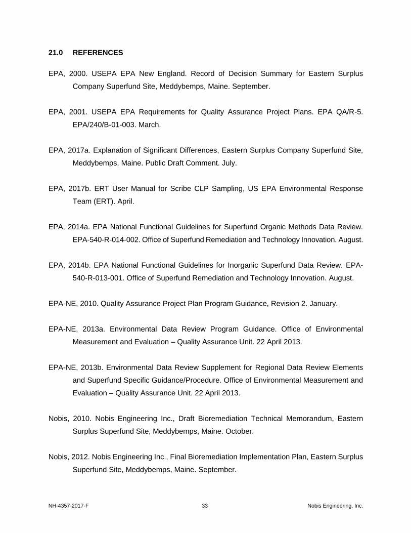
NH-4357-2017-F 33 Nobis Engineering, Inc.
21.0 REFERENCES
EPA, 2000. USEPA EPA New England. Record of Decision Summary for Eastern Surplus
Company Superfund Site, Meddybemps, Maine. September.
EPA, 2001. USEPA EPA Requirements for Quality Assurance Project Plans. EPA QA/R-5.
EPA/240/B-01-003. March.
EPA, 2017a. Explanation of Significant Differences, Eastern Surplus Company Superfund Site,
Meddybemps, Maine. Public Draft Comment. July.
EPA, 2017b. ERT User Manual for Scribe CLP Sampling, US EPA Environmental Response
Team (ERT). April.
EPA, 2014a. EPA National Functional Guidelines for Superfund Organic Methods Data Review.
EPA-540-R-014-002. Office of Superfund Remediation and Technology Innovation. August.
EPA, 2014b. EPA National Functional Guidelines for Inorganic Superfund Data Review. EPA-
540-R-013-001. Office of Superfund Remediation and Technology Innovation. August.
EPA-NE, 2010. Quality Assurance Project Plan Program Guidance, Revision 2. January.
EPA-NE, 2013a. Environmental Data Review Program Guidance. Office of Environmental
Measurement and Evaluation – Quality Assurance Unit. 22 April 2013.
EPA-NE, 2013b. Environmental Data Review Supplement for Regional Data Review Elements
and Superfund Specific Guidance/Procedure. Office of Environmental Measurement and
Evaluation – Quality Assurance Unit. 22 April 2013.
Nobis, 2010. Nobis Engineering Inc., Draft Bioremediation Technical Memorandum, Eastern
Surplus Superfund Site, Meddybemps, Maine. October.
Nobis, 2012. Nobis Engineering Inc., Final Bioremediation Implementation Plan, Eastern Surplus
Superfund Site, Meddybemps, Maine. September.

NH-4357-2017-F 34 Nobis Engineering, Inc.
Nobis, 2012. Nobis Engineering Inc., Draft Bioremediation Bench-Scale Test Technical
Memorandum, Eastern Surplus Superfund Site, Meddybemps, Maine. February.
Nobis, 2017. Nobis Engineering Inc., Draft Work Plan, Eastern Surplus Superfund Site,
Meddybemps, Maine. Remedial Design. July.
TtNUS, 1998. Tetra Tech NUS, Inc., Hydrogeologic Evaluations Technical Memorandum, Eastern
Surplus Superfund Site, Meddybemps, Maine. March.
TtNUS, 1999. Tetra Tech NUS, Inc., Remedial Investigation Report, Eastern Surplus Superfund
Site, Meddybemps, Maine. July.
TtNUS, 1999. Tetra Tech NUS, Inc., Feasibility Study Report, Eastern Surplus Superfund Site,
Meddybemps, Maine. October.
TtNUS, 1999. Tetra Tech NUS, Inc., Pre-Design Investigation Report, Eastern Surplus Superfund
Site, Meddybemps, Maine. September.
TtNUS, 2000. Tetra Tech NUS, Inc., Supplemental Bedrock Investigation Report, Eastern Surplus
Superfund Site, Meddybemps, Maine. February.
TtNUS, 2001. Tetra Tech NUS, Inc., Final Design Report (GWETS), Eastern Surplus Superfund
Site, Meddybemps, Maine. September.
TtNUS, 2003. Tetra Tech NUS, Inc., Draft In-Situ Oxidation Treatability Study, Eastern Surplus
Superfund Site, Meddybemps, Maine. January.
TtNUS, 2004. Tetra Tech NUS, Inc., Draft Implementation Plan for Bedrock Fracture
Enhancement, Eastern Surplus Superfund Site, Meddybemps, Maine. March.
TtNUS, 2006. Tetra Tech NUS, Inc., Draft Source Delineation Investigation, Eastern Surplus
Superfund Site, Meddybemps, Maine. August.

T
A
B
L
E
S

Table 3-1 Distribution List
Eastern Surplus Company Superfund Site Meddybemps, Maine
NH-4357-2017 Nobis Engineering, Inc.
QAPP Recipients Title Organization Telephone Number
Terrence Connelly Task Order Project Officer (TOPO) EPA (617) 918-1373
Nora Conlon Quality Assurance Project Plan Coordinator EPA (617) 918-8335
Rebecca Hewett State Project Manager MEDEP (207) 287-8554
Scott Harding Project Manager Nobis (603)-724-6235
Gail DeRuzzo Lead Chemist Nobis (978) 703-6021
David Gorhan Technical Lead Nobis (603) 513-1008
Joshua Stewart Field Operations Leader (FOL) Nobis (603) 513-7325

Table 4-1 Personnel Responsibilities and Qualifications
Eastern Surplus Company Superfund Site Meddybemps, Maine
Page 1 of 2
NH-4357-2017 Nobis Engineering Inc.
Name Organizational
Affiliation Responsibilities
Location of Personnel Resumes
Education and Experience
Qualifications
Scott Harding RAC 2 Program Manager
Nobis Manages the Nobis RAC 2 program, with the assistance of the Nobis Deputy RAC 2
Program Manager. Available upon request Refer to Resume
Chris Hagger Deputy RAC 2 Program
Manager Nobis
Assists the Nobis RAC 2 Program Manager with managing the Nobis RAC 2 program, reviews all monthly RAC 2 reports, and maintains direct contact with the NOBIS RAC 2
Project Managers and the EPA TOPO. Available upon request Refer to Resume
Tom Bobowski Corporate Health and
Safety Officer Nobis
Oversees company-wide health and safety protocol for all Nobis field activities. Interacts with the Project Health and Safety Officer. Reviews and approves the Site-
Specific Health and Safety Plan. Available upon request Refer to Resume
Gail DeRuzzo RAC 2 Program QA
Manager Nobis
Oversees periodic performance audits of field activities and data collection activities, conducts periodic program QA audits and reports to EPA, follows up on corrective
actions and ensures resolution of any technical advisory team concerns, oversees the maintenance of RAC 2 QA file for documentation of all of the above, directs and
coordinates periodic performance and systems audits of environmental data collection activities, prepares monthly reports summarizing any unresolved corrective action
recommendations for laboratory and field activities.
Available upon request Refer to Resume
Scott Harding Project Manager
Nobis
Reports to the RAC 2 Deputy Program Manager, monitors schedules for field, analytical,
and data validation activities associated with the field sampling program, coordinates review of the QAPP, coordinates analytical and sampling activities with the FOL,
coordinates and oversees all sampling and analytical data assessment activities, verifies that all sampling and analytical procedures are followed, verifies that all data validation activities are complete and validation deliverables are submitted to EPA, coordinates
with the reviewers in preparation of sampling plans and reports. Prepares monthly progress reports.
Available upon request Refer to Resume

Table 4-1 Personnel Responsibilities and Qualifications
Eastern Surplus Company Superfund Site Meddybemps, Maine
Page 2 of 2
NH-4357-2017 Nobis Engineering Inc.
Name Organizational
Affiliation Responsibilities
Location of Personnel Resumes
Education and Experience
Qualifications
Gail DeRuzzo Lead Chemist
Nobis
Functions as point of contact for RAS and non-RAS laboratories; oversees all analytical, sampling, and data assessment activities for the RAC 2 program; reviews RAS
modifications if required; coordinates with DAS laboratories and develops technical specifications; verifies that all sampling and analytical procedures are followed; reviews
all data validation and sampling and analysis plans; verifies that all data validation activities are complete and validation deliverables are submitted to EPA; and monitors
schedules for field, analytical, and data validation activities associated with the field sampling program.
Available upon request Refer to Resume
David Gorhan Technical Lead
Nobis
Functions as the point of contact between the FOL and the office. Coordinates and oversees all sampling events and analytical data assessment activities, verifies that all sampling and analytical procedures are followed, implements sample chain-of-custody protocols and performs sample shipments. Prepares or coordinates all project report
deliverables related to field activities.
Available upon request Refer to Resume
Joshua Stewart Field Operations Leader
(FOL) Nobis
Oversees all sampling events in the field and analytical data assessment activities, verifies that all sampling and analytical procedures are followed, implements sample
chain-of-custody protocols and performs sample shipments. Prepares or coordinates all project report deliverables related to field activities.
Available upon request Refer to Resume
Joshua Stewart Site Health and Safety
Officer Nobis
Serves as the Site Health and Safety Officer for all field activities. Ensures all activities are being performed in accordance with the Site-Specific H&S Plan.
Available upon request Refer to Resume

Table 6-1 Project Schedule Timeline
Eastern Surplus Company Superfund Site Meddybemps, Maine
NH-4357-2017 Nobis Engineering, Inc.
Activities
Dates
Deliverable Deliverable Due Date Anticipated Date(s) of Initiation
Anticipated Date of Completion
Preparation of Quality Assurance Project Plan (QAPP)
August 8, 2017 August 25, 2017 Draft QAPP Submitted August 29, 2017
QAPP Review by EPA August 28, 2017 September 12, 2017 QAPP Comments Comments Received September 12, 2017
QAPP – Final Revision September 13, 2017 September 15, 2017 Final QAPP Final September 15, 2017
Sampling September 18, 2017 September 22, 2017 Field Notes/Logs; Field
Data
Field data and notes will be placed in the project files one week after the final
sampling event.
Fixed Laboratory Analyses 1 day after sample
submittal (completing an SDG)
21-28 days after sample submittal
Data Packages EDDs
21-28 days after sample submittal
Data Review/Validation 1 day after data
package receipt (all data for the case)
21 days after data package receipt
Data Validation Memoranda
21 days after data package receipt
Data Evaluation Report (including Data Usability Evaluation)
1 day after data validation completed
60 days after data validation completed
Data Evaluation Technical Memo
TBD
Preliminary Design March 2018 April 2018 Design Criteria Report TBD
Final Design May 2018 June 2018 Final Specifications TBD
Notes:
SDG – Sample Delivery Group (usually 20 samples) TBD – To Be Determined
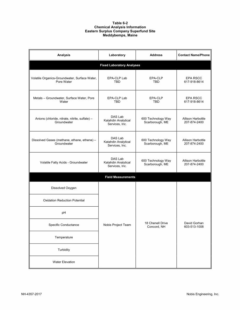
Table 6-2 Chemical Analysis Information
Eastern Surplus Company Superfund Site Meddybemps, Maine
NH-4357-2017 Nobis Engineering, Inc.
Analysis Laboratory Address Contact Name/Phone
Fixed Laboratory Analyses
Volatile Organics-Groundwater, Surface Water, Pore Water
EPA-CLP Lab TBD
EPA-CLP TBD
EPA RSCC 617-918-8614
Metals – Groundwater, Surface Water, Pore Water
EPA-CLP Lab TBD
EPA-CLP TBD
EPA RSCC 617-918-8614
Anions (chloride, nitrate, nitrite, sulfate) – Groundwater
DAS Lab Katahdin Analytical
Services, Inc.
600 Technology Way Scarborough, ME
Allison Harbottle 207-874-2400
Dissolved Gases (methane, ethane, ethene) – Groundwater
DAS Lab Katahdin Analytical
Services, Inc.
600 Technology Way Scarborough, ME
Allison Harbottle 207-874-2400
Volatile Fatty Acids - Groundwater DAS Lab
Katahdin Analytical Services, Inc.
600 Technology Way Scarborough, ME
Allison Harbottle 207-874-2400
Field Measurements
Dissolved Oxygen
Nobis Project Team 18 Chenell Drive
Concord, NH David Gorhan 603-513-1008
Oxidation Reduction Potential
pH
Specific Conductance
Temperature
Turbidity
Water Elevation

Table 6-3
Target Analyte List - Volatile Organic Compounds (VOCs) - Water
Eastern Surplus Company Superfund Site
Meddybemps, Maine
Page 1 of 2
1,1,1-Trichloroethane 71-55-6 - 200 10,000 - - 0.5 5
1,1,2,2-Tetrachloroethane 79-34-5 - - 2 - - 0.5 5
1,1,2-Trichloro-1,2,2-trifluoroethane 76-13-1 - - - - - 0.5 5
1,1,2-Trichloroethane* 79-00-5 3 5 6 3 IGCL 0.5 5
1,1-Dichloroethane* 75-34-3 5 - 60 5 IGCL 0.5 5
1,1-Dichloroethene** 75-35-4 - 7 40 - - 0.5 5
1,2,3-Trichlorobenzene 87-61-6 - - - - - 0.5 5
1,2,4-Trichlorobenzene 120-82-1 - 70 70 - - 0.5 5
1,2-Dibromo-3-chloropropane 96-12-8 - 0.2 0.4 - - 0.5 5
1,2-Dibromoethane 106-93-4 - 0.05 0.2 - - 0.5 5
1,2-Dichlorobenzene 95-50-1 - 600 200 - - 0.5 5
1,2-Dichloroethane 107-06-2 - 5 4 - - 0.5 5
1,2-Dichloropropane 78-87-5 - 5 10 - - 0.5 5
1,3-Dichlorobenzene 541-73-1 - - 1 - - 0.5 5
1,4-Dichlorobenzene 106-46-7 - 75 70 - - 0.5 5
2-Butanone** 78-93-3 - - 4,000 4,000 MEG 5 10
2-Hexanone 591-78-6 - - - - - 5 10
4-Methyl-2-pentanone 108-10-1 - - 500 - - 5 10
Acetone** 67-64-1 - - 6,000 6,000 MEG 5 10
Benzene 71-43-2 - 5 4 - - 0.5 5
Bromochloromethane 74-97-5 - - 100 - - 0.5 5
Bromodichloromethane 75-27-4 - - 6 - - 0.5 5
Bromoform 75-25-2 - - 40 - - 0.5 5
Bromomethane 74-83-9 - - 10 - - 0.5 5
Carbon disulfide 75-15-0 - - 600 - - 0.5 5
Carbon tetrachloride 56-23-5 - 5 5 - - 0.5 5
Chlorobenzene 108-90-7 - 100 100 - - 0.5 5
Chloroethane 75-00-3 - - 7 - - 0.5 5
Chloroform 67-66-3 - - 70 - - 0.5 5
Chloromethane* 74-87-3 3 - 20 3 IGCL 0.5 5
cis-1,2-Dichloroethene* 156-59-2 70 70 10 70 IGCL 0.5 5
cis-1,3-Dichloropropene 10061-01-5 - - 4 - - 0.5 5
Cyclohexane 110-82-7 - - - - - 0.5 5
Dibromochloromethane 124-48-1 - - 4 - - 0.5 5
Dichlorodifluoromethane 75-71-8 - - 1,000 - - 0.5 5
Ethylbenzene** 100-41-4 - 700 30 30 MEG 0.5 5
CLP Low
Water µg/L
Target AnalyteCAS
Number
CriteriaCOC
Project
Action
Limit4
µg/L
BasisROD
IGCL1
µg/L
MCL2
µg/L
2016
MEG3
µg/L
CLP Trace Water µg/L
Quantitation Limits5
NH-4357-2017 Nobis Engineering, Inc.

Table 6-3
Target Analyte List - Volatile Organic Compounds (VOCs) - Water
Eastern Surplus Company Superfund Site
Meddybemps, Maine
Page 2 of 2
CLP Low
Water µg/L
Target AnalyteCAS
Number
CriteriaCOC
Project
Action
Limit4
µg/L
BasisROD
IGCL1
µg/L
MCL2
µg/L
2016
MEG3
µg/L
CLP Trace Water µg/L
Quantitation Limits5
Isopropylbenzene (Cumene) 98-82-8 - - - - - 0.5 5
m,p-xylene* 179601-23-1 600 10,000 1,000 600 IGCL 0.5 5
Methyl acetate 79-20-9 - - - - - 0.5 5
Methyl tert-butyl ether 1634-04-4 - - 35 - - 0.5 5
Methylcyclohexane 108-87-2 - - - - - 0.5 5
Methylene chloride* 75-09-2 5 5 40 - - 0.5 5
o-xylene* 95-47-6 600 10,000 1,000 600 IGCL 0.5 5
Styrene 100-42-5 - 100 100 - - 0.5 5
Tetrachloroethene* 127-18-4 3 5 40 3 IGCL 0.5 5
Toluene** 108-88-3 - 1,000 600 600 MEG 0.5 5
trans-1,2-Dichloroethene** 156-60-5 - 100 100 100 MCL 0.5 5
trans-1,3-Dichloropropene 10061-02-6 - - 4 - - 0.5 5
Trichloroethene* 79-01-6 5 5 4 5 IGCL 0.5 5
Trichlorofluoromethane 75-69-4 - - 2,000 - - 0.5 5
Vinyl chloride** 75-01-4 - 2 0.2 0.2 MEG 0.5 -> 0.1 by CLP Mod 5
Notes:
QL to be obtained by CLP Mod for trace VOCs.
NT - not tested
µg/L = micrograms per liter
PALs not achieved by CLP Low QLs.
Low level samples are expected to have high levels of COCs, therefore, it is not expected that QLs will be reported.
Project Action Limits are based on the following:
1 U.S. EPA Record of Decision (ROD) Summary for Eastern Surplus Company Superfund Site, Meddybemps, Maine, September 2000. Interim
Groundwater Cleanup Levels (IGCL).
2 Federal Maximum Contaminant Limits (MCLs).
3 Maine Maximum Exposure Guidelines (MEGs) for Drinking Water, December 31, 2016.
4 The Project Action Limits (PALs) for the site COCs are based on ROD IGCLs. Non-COC PALs are selected based on hierarchy of: IGCL, MCL, or MEG,
whichever is lowest. Only the site COCs shown with asterisks (*) are listed with PALs.
Trace level CLP VOCs are required for analysis (i.e., low level analysis with 5 and 10 ppb QLs would not meet COC PALs). Additionally, vinyl chloride may
be requested as a CLP modification to report to 0.1 ug/L.
PALs not achieved by CLP Trace QLs.
* - denotes 2000 ROD COC
** - denotes non-COC but related to site contamination.
- means not available or not applicable
5 The Quantitation Limits (QLs) are from the CLP SOW SOM02.4.
NH-4357-2017 Nobis Engineering, Inc.

Table 6-4
Target Analyte List - Metals - Water
Eastern Surplus Company Superfund Site
Meddybemps, Maine
Page 1 of 2
Aluminum^ 7429-90-5 - 87 - 7,000 87 SW PL 200 20
Antimony* 7440-36-0 6 - 6 3 6 IGCL 60 2
Arsenic** 7440-38-2 - - 10 10 10 MCL 10 1
Barium^ 7440-39-3 - 4 2,000 1,000 4 SW PL 20010 - >2 by CLP
mod
Beryllium 7440-41-7 - - 4 10 - - 5 1
Cadmium* 7440-43-9 5 - 5 1 5 IGCL 5 1
Calcium 7440-70-2 - - - - - - 5,000 500
Chromium** 7440-47-3 - - 100 20 20 MEG 10 2
Cobalt 7440-48-4 - - - 10 - - 50 1
Copper 7440-50-8 - - 1300 500 - - 25 2
Iron 7439-89-6 - - - 5,000 - - 100 200
15 IGCL
0.5 SW PL
Magnesium 7439-95-4 - - - - - - 5,000 500
Manganese* 7439-96-5 200 - - 300 200 IGCL 15 1
Mercury7 7439-97-6 - - 2 2 - - 0.2 -
Nickel 7440-02-0 - - - 20 - - 40 1
10 101 -> 0.25 by
CLP modLead*^ 7439-92-1 15 0.5 15
Target AnalyteCAS
Number
CLP Quantitation Limits6
ROD
IGCL1
µg/L
ICP-AES
Water
µg/L
ICP-MS Water
µg/L
Criteria
MCL3
µg/L
2016 MEG4
µg/L
COC
Project
Action
Limit5
µg/L
BasisROD SW
PL2
µg/L
NH-4357-2017 Nobis Engineering, Inc.
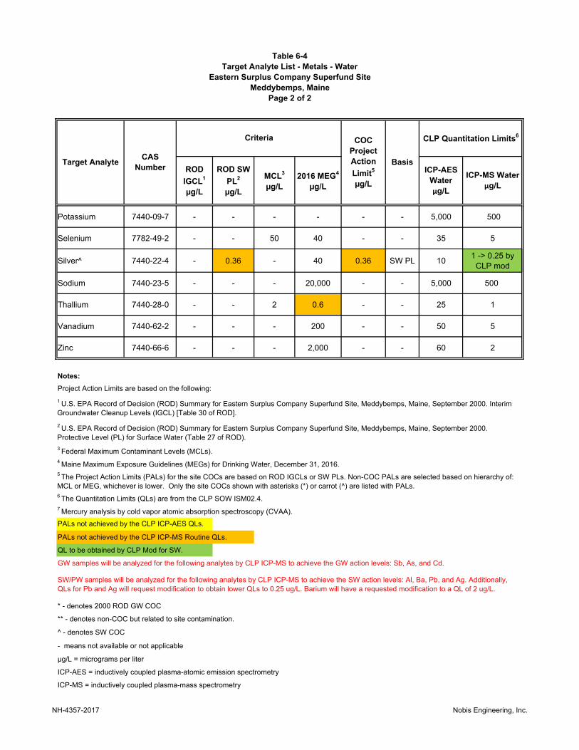
Table 6-4
Target Analyte List - Metals - Water
Eastern Surplus Company Superfund Site
Meddybemps, Maine
Page 2 of 2
Target AnalyteCAS
Number
CLP Quantitation Limits6
ROD
IGCL1
µg/L
ICP-AES
Water
µg/L
ICP-MS Water
µg/L
Criteria
MCL3
µg/L
2016 MEG4
µg/L
COC
Project
Action
Limit5
µg/L
BasisROD SW
PL2
µg/L
Potassium 7440-09-7 - - - - - - 5,000 500
Selenium 7782-49-2 - - 50 40 - - 35 5
Silver^ 7440-22-4 - 0.36 - 40 0.36 SW PL 101 -> 0.25 by
CLP mod
Sodium 7440-23-5 - - - 20,000 - - 5,000 500
Thallium 7440-28-0 - - 2 0.6 - - 25 1
Vanadium 7440-62-2 - - - 200 - - 50 5
Zinc 7440-66-6 - - - 2,000 - - 60 2
Notes:
PALs not achieved by the CLP ICP-MS Routine QLs.
QL to be obtained by CLP Mod for SW.
GW samples will be analyzed for the following analytes by CLP ICP-MS to achieve the GW action levels: Sb, As, and Cd.
- means not available or not applicable
4 Maine Maximum Exposure Guidelines (MEGs) for Drinking Water, December 31, 2016.
ICP-AES = inductively coupled plasma-atomic emission spectrometry
ICP-MS = inductively coupled plasma-mass spectrometry
Project Action Limits are based on the following:
1 U.S. EPA Record of Decision (ROD) Summary for Eastern Surplus Company Superfund Site, Meddybemps, Maine, September 2000. Interim
Groundwater Cleanup Levels (IGCL) [Table 30 of ROD].
3 Federal Maximum Contaminant Levels (MCLs).
µg/L = micrograms per liter
6 The Quantitation Limits (QLs) are from the CLP SOW ISM02.4.
* - denotes 2000 ROD GW COC
** - denotes non-COC but related to site contamination.
7 Mercury analysis by cold vapor atomic absorption spectroscopy (CVAA).
5 The Project Action Limits (PALs) for the site COCs are based on ROD IGCLs or SW PLs. Non-COC PALs are selected based on hierarchy of:
MCL or MEG, whichever is lower. Only the site COCs shown with asterisks (*) or carrot (^) are listed with PALs.
SW/PW samples will be analyzed for the following analytes by CLP ICP-MS to achieve the SW action levels: Al, Ba, Pb, and Ag. Additionally,
QLs for Pb and Ag will request modification to obtain lower QLs to 0.25 ug/L. Barium will have a requested modification to a QL of 2 ug/L.
2 U.S. EPA Record of Decision (ROD) Summary for Eastern Surplus Company Superfund Site, Meddybemps, Maine, September 2000.
Protective Level (PL) for Surface Water (Table 27 of ROD).
^ - denotes SW COC
PALs not achieved by the CLP ICP-AES QLs.
NH-4357-2017 Nobis Engineering, Inc.
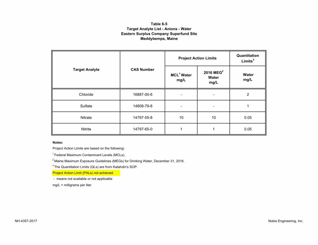
Table 6-5
Target Analyte List - Anions - Water
Eastern Surplus Company Superfund Site
Meddybemps, Maine
Quantitation
Limits3
Chloride 16887-00-6 - - 2
Sulfate 14808-79-8 - - 1
Nitrate 14797-55-8 10 10 0.05
Nitrite 14797-65-0 1 1 0.05
Notes:
1 Federal Maximum Contaminant Levels (MCLs).
2 Maine Maximum Exposure Guidelines (MEGs) for Drinking Water, December 31, 2016.
Project Action Limit (PALs) not achieved.
mg/L = milligrams per liter
- means not available or not applicable
Water
mg/L
Project Action Limits are based on the following:
3 The Quantitation Limits (QLs) are from Katahdin's SOP.
Target Analyte CAS Number2016 MEG
2
Water
mg/L
MCL1 Water
mg/L
Project Action Limits
NH-4357-2017 Nobis Engineering, Inc.

Table 6-6
Target Analyte List - Dissolved Gases - Water
Eastern Surplus Company Superfund Site
Meddybemps, Maine
Quantitation Limits2
Methane 74-82-8 - - 10
Ethane 74-84-0 - - 10
Ethene 74-85-1 - - 10
Notes:
1 Federal Maximum Contaminant Levels (MCLs).
2 Maine Maximum Exposure Guidelines (MEGs) for Drinking Water, December 31, 2016.
Project Action Limit (PALs) not achieved.
µg/L = micrograms per liter
- means not available or not applicable
Water µg/L
Project Action Limits are based on the following:
3 The Quantitation Limits (QLs) are from Katahdin's SOP.
Target Analyte CAS Number
MCL1
Water µg/L
2016 MEG2
Water µg/L
Project Action Limits
NH-4357-2017 Nobis Engineering, Inc.
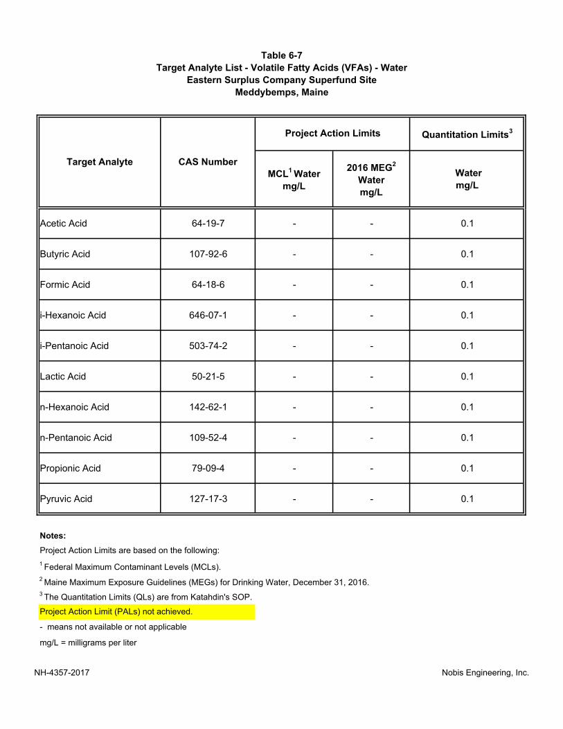
Table 6-7
Target Analyte List - Volatile Fatty Acids (VFAs) - Water
Eastern Surplus Company Superfund Site
Meddybemps, Maine
Quantitation Limits3
Acetic Acid 64-19-7 - - 0.1
Butyric Acid 107-92-6 - - 0.1
Formic Acid 64-18-6 - - 0.1
i-Hexanoic Acid 646-07-1 - - 0.1
i-Pentanoic Acid 503-74-2 - - 0.1
Lactic Acid 50-21-5 - - 0.1
n-Hexanoic Acid 142-62-1 - - 0.1
n-Pentanoic Acid 109-52-4 - - 0.1
Propionic Acid 79-09-4 - - 0.1
Pyruvic Acid 127-17-3 - - 0.1
Notes:
1 Federal Maximum Contaminant Levels (MCLs).
2 Maine Maximum Exposure Guidelines (MEGs) for Drinking Water, December 31, 2016.
mg/L = milligrams per liter
- means not available or not applicable
Water
mg/L
Project Action Limits are based on the following:
3 The Quantitation Limits (QLs) are from Katahdin's SOP.
Target Analyte CAS Number
MCL1 Water
mg/L
2016 MEG2
Water
mg/L
Project Action Limits
Project Action Limit (PALs) not achieved.
NH-4357-2017 Nobis Engineering, Inc.

Table 6-8
Field and Quality Control Sample Summary
Eastern Surplus Company Superfund Site
Meddybemps, Maine
No. of MSNo. of MSD or
DUP
VOCs Trace CLP L-1 4 1 1 1 0 1 1 9
VOCs Low CLP L-1 6 1 1 1 0 1 1 11
Anions Low DAS L-3 10 1 1 1 0 0 0 13
Dissolved Gases Low DAS L-4 10 1 0 1 0 0 0 12
Volatile Fatty Acids Low DAS L-5 10 1 1 1 0 0 0 13
VOCs Trace CLP L-1 5 0 0 0 0 0 0 5
VOCs Low CLP L-1 5 0 0 0 0 0 0 5
Metals Low CLP L-2 10 1 1 1 0 0 1 14
VOCs Trace CLP L-1 6 1 1 1 1 1 1 12
Metals Low CLP L-2 6 1 1 1 1 0 1 11
Notes:
SW/PW
GW
GW
Additional Groundwater Sampling
9 All sample quantities are estimated.
1 GW = groundwater; SW = surface water; PW = pore water
2 DAS=Delivery of Analytical Services; CLP = Contract Laboratory Program
3 Analytical Methods and SOPs are listed in Table 12-1. VOCs = volatile organic compounds.
4 If samples will be collected at different depths at the same location, each discrete sampling depth is counted as a separate sampling location/station.
5 Field duplicates are collected and analyzed at approximately a 5% rate.
6 Matrix quality control (QC) samples are collected and analyzed at approximately a 5% rate. Some tests will be a laboratory duplicate only, MS/MSD, or MS/DUP depending on the method.
MS=matrix spike; MSD=matrix spike duplicate; DUP=laboratory duplicate.
Groundwater Sampling
Trip
Blanks7
7 Equipment blanks will be collected if dedicated equipment is not available for the sampling process. Trip Blanks are only tested for VOCs.
8 Performance Evaluation (PE) samples are analyzed and submitted at approximately a 5% rate for indicated analyses.
No. of Field
Duplicate
Pairs5
No. of Matrix QC
Samples6 No. of
Equip.
Blanks7
No. of PE
Samples8
Total No. of
Samples to
Lab9
Medium/
Matrix1 Analytical Parameter
Laboratory
Type2
Analytical
Method/SOP3
No. of
Sample
Locations4
Conc.
Level
Surface Water and Pore Water Sampling
NH-4357-2017 Nobis Engineering, Inc.
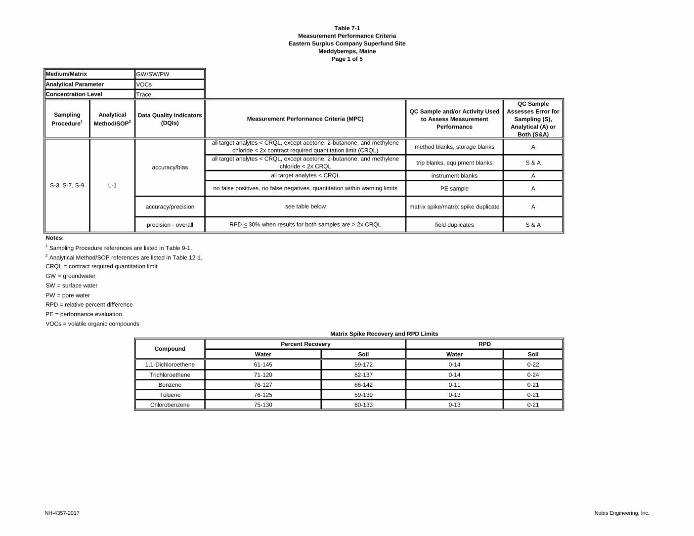
Table 7-1
Measurement Performance Criteria
Eastern Surplus Company Superfund Site
Meddybemps, Maine
Page 1 of 5
GW/SW/PW
VOCs
Trace
Sampling
Procedure1
Analytical
Method/SOP2
Data Quality Indicators
(DQIs)
QC Sample and/or Activity Used
to Assess Measurement
Performance
QC Sample
Assesses Error for
Sampling (S),
Analytical (A) or
Both (S&A)
method blanks, storage blanks A
trip blanks, equipment blanks S & A
instrument blanks A
PE sample A
accuracy/precision matrix spike/matrix spike duplicate A
precision - overall field duplicates S & A
Notes:
1 Sampling Procedure references are listed in Table 9-1.
2 Analytical Method/SOP references are listed in Table 12-1.
PW = pore water
Matrix Spike Recovery and RPD Limits
Percent Recovery RPD
Water Soil Water Soil
1,1-Dichloroethene 61-145 59-172 0-14 0-22
Trichloroethene 71-120 62-137 0-14 0-24
Benzene 76-127 66-142 0-11 0-21
Toluene 76-125 59-139 0-13 0-21
Chlorobenzene 75-130 60-133 0-13 0-21
RPD = relative percent difference
PE = performance evaluation
VOCs = volatile organic compounds
Compound
no false positives, no false negatives, quantitation within warning limits
see table below
RPD < 30% when results for both samples are > 2x CRQL
CRQL = contract required quantitation limit
GW = groundwater
SW = surface water
Medium/Matrix
Analytical Parameter
Concentration Level
Measurement Performance Criteria (MPC)
S-3, S-7, S-9 L-1
accuracy/bias
all target analytes < CRQL, except acetone, 2‑butanone, and methylene
chloride < 2x contract required quantitation limit (CRQL)
all target analytes < CRQL, except acetone, 2‑butanone, and methylene
chloride < 2x CRQL
all target analytes < CRQL
NH-4357-2017 Nobis Engineering, Inc.

Table 7-1
Measurement Performance Criteria
Eastern Surplus Company Superfund Site
Meddybemps, Maine
Page 2 of 5
GW/SW/PW
Metals
Low
Sampling
Procedure1
Analytical
Method/SOP2
Data Quality Indicators
(DQIs)
QC Sample and/or Activity Used
to Assess Measurement
Performance
QC Sample
Assesses Error for
Sampling (S),
Analytical (A) or
Both (S&A)
method blanks A
equipment blanks S & A
instrument blanks A
PE sample A
accuracy/precision matrix spike/matrix spike duplicate A
precision - overall field duplicates S & A
Notes:
1 Sampling Procedure references are listed in Table 9-1.
2 Analytical Method/SOP references are listed in Table 12-1.
PW = pore water
RPD = relative percent difference
PE = performance evaluation
no false positives, no false negatives, quantitation within warning limits
75-125% recovery, 20% RPD
RPD < 30% when results for both samples are > 2x CRQL
CRQL = contract required quantitation limit
GW = groundwater
SW = surface water
Medium/Matrix
Analytical Parameter
Concentration Level
Measurement Performance Criteria (MPC)
S-3, S-7, S-9 L-2
accuracy/bias
all target analytes < CRQL
all target analytes < CRQL
all target analytes < CRQL
NH-4357-2017 Nobis Engineering, Inc.

Table 7-1
Measurement Performance Criteria
Eastern Surplus Company Superfund Site
Meddybemps, Maine
Page 3 of 5
GW
Anions
Low
Sampling
Procedure1
Analytical
Method/SOP2
Data Quality Indicators
(DQIs)
QC Sample and/or Activity Used
to Assess Measurement
Performance
QC Sample
Assesses Error for
Sampling (S),
Analytical (A) or
Both (S&A)
method blanks A
equipment blanks S & A
instrument blanks A
Laboratory Control Samples A
accuracy/precision matrix spike/matrix spike duplicate A
precision - overall field duplicates S & A
Notes:
1 Sampling Procedure references are listed in Table 9-1.
2 Analytical Method/SOP references are listed in Table 12-1.
Medium/Matrix
Analytical Parameter
Concentration Level
Measurement Performance Criteria (MPC)
S-3, S-7, S-9 L-3
accuracy/bias
all target analytes < RL
all target analytes < RL
all target analytes < RL
RPD = relative percent difference
GW = groundwater
80-120% recovery
80-120% recovery, 20% RPD
RPD ≤ 30% when results for both samples are > 2x RL
RL = reporting limit
NH-4357-2017 Nobis Engineering, Inc.

Table 7-1
Measurement Performance Criteria
Eastern Surplus Company Superfund Site
Meddybemps, Maine
Page 4 of 5
GW
Dissolved Gases
Low
Sampling
Procedure1
Analytical
Method/SOP2
Data Quality Indicators
(DQIs)
QC Sample and/or Activity Used
to Assess Measurement
Performance
QC Sample
Assesses Error for
Sampling (S),
Analytical (A) or
Both (S&A)
method blanks A
equipment blanks S & A
instrument blanks A
Laboratory Control Samples A
accuracy/precision matrix spike/matrix spike duplicate A
precision - overall field duplicates S & A
Notes:
1 Sampling Procedure references are listed in Table 9-1.
2 Analytical Method/SOP references are listed in Table 12-1.
70-130% recovery
70-130% recovery, 30% RPD
RPD ≤ 30% when results for both samples are > 2x RL
RL = reporting limit
RPD = relative percent difference
GW = groundwater
Medium/Matrix
Analytical Parameter
Concentration Level
Measurement Performance Criteria (MPC)
S-3, S-7, S-9 L-4
accuracy/bias
all target analytes < RL
all target analytes < RL
all target analytes < RL
NH-4357-2017 Nobis Engineering, Inc.

Table 7-1
Measurement Performance Criteria
Eastern Surplus Company Superfund Site
Meddybemps, Maine
Page 5 of 5
GW
VFAs
Low
Sampling
Procedure1
Analytical
Method/SOP2
Data Quality Indicators
(DQIs)
QC Sample and/or Activity Used to
Assess Measurement Performance
QC Sample Assesses Error
for Sampling (S), Analytical
(A) or Both (S&A)
method blanks A
equipment blanks S & A
instrument blanks A
Laboratory Control Samples A
accuracy/precision matrix spike/matrix spike duplicate A
precision - overall field duplicates S & A
Notes:
1 Sampling Procedure references are listed in Table 9-1.
2 Analytical Method/SOP references are listed in Table 12-1.
VFA = volatile fatty acid
acetic acid, hexanoic acid, n-pentanoic acid - 70-140%; remaining analytes
80-120% recovery
acetic acid, hexanoic acid, n-pentanoic acid - 70-140%; remaining analytes
80-120% recovery; RPD ≤ 20%
RPD ≤ 30% when results for both samples are > 2x RL
RL = reporting limit
RPD = relative percent difference
GW = groundwater
Medium/Matrix
Analytical Parameter
Concentration Level
Measurement Performance Criteria (MPC)
S-3, S-7, S-9 L-4
accuracy/bias
all target analytes < RL
all target analytes < RL
all target analytes < RL
NH-4357-2017 Nobis Engineering, Inc.

Table 8-1
Sampling Investigations, Rationale, Locations, and SOPs
Eastern Surplus Company Superfund Site
Meddybemps, Maine
Media Investigation RationaleInvestigation
AreaSampling Frequency
1Sampling
Locations1 Sample Depths
Applicable
Sampling SOPsAnalytical Parameters
Estimated Total Field
SamplesField Screening Parameters
Groundwater
monitoring
Evaluate the current conditions of the
plume through a comprehensive
sampling round;
improve the CSM.
Northern Plume
One time event;
10 locations throughout
the Northern Plume area.
See Figure 6-1.
See Figure 6-1
Overburden wells (~25' bgs);
Shallow bedrock wells (`30' bgs);
Deep overburden wells (~40' bgs)
S-7, S-5, S-6VOCs,VFAs, anions, and
dissolved gases
10
(excludes QC samples)
During Low-Flow Sampling:
Temperature, Sp. Conductivity,
Dissolved Oxygen, pH, ORP,
Turbidity; see SOP S-8
Groundwater
monitoring
Evaluate the current conditions of the
plume through a comprehensive
sampling round;
improve the CSM.
Northern Plume
One time event;
10 locations throughout
the Northern Plume area.
See Figure 6-1.
See Figure 6-1
Overburden wells (~25' bgs);
Shallow bedrock wells (`30' bgs);
Deep overburden wells (~40' bgs)
S-7, S-5, S-6 VOCs, Metals10
(excludes QC samples)
During Low-Flow Sampling:
Temperature, Sp. Conductivity,
Dissolved Oxygen, pH, ORP,
Turbidity; see SOP S-8
Surface Water
Evaluate the connection from the
overburden/bedrock aquifers to surface
water; improve the CSM.
Dennys River
One time event;
3 locations along the
Dennys River.
See Figure 6-1.
See Figure 6-1Mid-water column
(depends on river depth)S-9, S-5, S-6 VOCs, Metals
3
(excludes QC samples)
During Sampling:
Temperature, Sp. Conductivity,
Dissolved Oxygen, pH, ORP,
Turbidity; see SOP-S-8
Pore Water
Evaluate the connection from the
overburden/bedrock aquifers to surface
water; improve the CSM.
Dennys River
One time event;
3 locations along the
Dennys River.
See Figure 6-1.
See Figure 6-1 0.5 feet below the riverbed S-3, S-5, S-6 VOCs, Metals3
(excludes QC samples)
During Sampling:
Temperature, Sp. Conductivity,
Dissolved Oxygen, pH, ORP,
Turbidity; see SOP S-8
Notes:
1 - Sample locations and frequency to be finalized based on results of site reconnaissance and field observations and results.
bgs - below ground surface
Aqueous
NH-4357-2017 Nobis Engineering, Inc.

Table 8-2
Well Information and Required Analyses
Eastern Surplus Company Superfund Site
Meddybemps, Maine
Page 1 of 4
Well ID Northing Easting
Reference
Elevation
(ft MSL)
Diameter
(inches)
Top of
Screen
(ft bgs)
Bottom of
Screen
(ft bgs)
Depth to
Bedrock
(ft bgs)
Screen Type Aquifer ZoneSampling
MethodAnalyses Required
IN-1B1 502620.5095 1279668.5608 180.42 1.25 15.0 30.00 11.00 Screen Northern Plume Bedrock Low-Flow Water level, L/M VOCs, metals
IN-1B2 502620.5381 1279668.4512 180.40 1.25 81.0 96.00 11.00 Screen Northern Plume Bedrock Low-Flow Water level, L/M VOCs, metals
IN-2B1 502606.0843 1279631.0690 180.63 1.25 12.0 22.00 10.50 Screen Northern Plume Bedrock Low-Flow Water level, TVOCs, metals
IN-2B2 502606.1038 1279631.2876 180.65 1.25 100.0 110.00 10.50 Screen Northern Plume Bedrock Water level
IN-3B 502656.4551 1279638.9243 182.78 6.00 8.0 48.00 6.00 Open Borehole Northern Plume Bedrock Low-Flow Water level, TVOCs, MNA parameters
IN-4B 502634.7300 1279611.8941 183.14 6.00 5.0 54.00 5.00 Open Borehole Northern Plume Bedrock Water level
IN-6B 502639.8143 1279682.4249 180.62 6.00 14.0 54.00 10.00 Open Borehole Northern Plume Bedrock Low-Flow Water level, L/M VOCs, metals
IN-7B 502609.5835 1279645.0751 180.37 6.00 11.5 52.00 10.00 Open Borehole Northern Plume Bedrock Low-Flow Water level, L/M VOCs, MNA parameters
MW-20B 502624.2317 1279637.4742 180.76 2.00 11.0 21.00 5.50 Screen Northern Plume Bedrock Low-Flow Water level, TVOCs, metals
MW-23B 502574.1913 1279657.6211 177.38 2.00 16.5 32.25 8.00 Screen Northern Plume Bedrock Low-Flow Water level, L/M VOCs, MNA parameters
MW-23S 502582.6744 1279658.1970 180.17 2.00 3.5 7.50 8.00 Screen Northern Plume Overburden Water level
MW-27B 502687.6601 1279751.6512 180.51 6.00 8.0 27.00 5.50 Open Borehole Northern Plume Bedrock Water level
MW-28B1 502678.1258 1279648.5072 182.53 1.25 23.0 42.00 5.00 Screen Northern Plume Bedrock Water level
MW-28B2 502678.0831 1279648.2143 182.56 1.25 63.0 78.00 5.00 Screen Northern Plume Bedrock Water level
MW-34B1 502651.5200 1279661.8243 181.22 1.25 6.0 21.00 7.00 Screen Northern Plume Bedrock Water level
MW-34B1R 502657.3429 1279663.6032 180.95 6.00 8.0 37.00 6.00 Open Borehole Northern Plume Bedrock Low-Flow Water level, L/M VOCs, MNA parameters
NH-4357-2017 Nobis Engineering, Inc.

Table 8-2
Well Information and Required Analyses
Eastern Surplus Company Superfund Site
Meddybemps, Maine
Page 2 of 4
Well ID Northing Easting
Reference
Elevation
(ft MSL)
Diameter
(inches)
Top of
Screen
(ft bgs)
Bottom of
Screen
(ft bgs)
Depth to
Bedrock
(ft bgs)
Screen Type Aquifer ZoneSampling
MethodAnalyses Required
MW-34B2 502651.3947 1279661.5695 181.21 1.25 51.0 66.00 7.00 Screen Northern Plume Bedrock Water level
MW-35B 502628.0251 1279644.4435 Not available 6.00 7.0 67.00 Not available Open Borehole Northern Plume Bedrock Water level
MW-35B1R 502632.5066 1279633.3311 182.41 4.00 20.0 50.00 7.00 Screen Northern Plume Bedrock Low-Flow Water level, TVOCs, metals
MW-36B1 502544.1764 1279688.2881 170.09 1.25 28.0 43.00 7.60 Screen Northern Plume Bedrock No purge Water level, L/M VOCs, MNA parameters
MW-36B2 502544.0775 1279688.3527 170.18 1.25 128.0 143.00 7.60 Screen Northern Plume Bedrock No purge Water level, TVOCs, MNA parameters
MW-39B 502530.5920 1279572.7565 173.34 6.00 15.3 215.00 15.00 Open Borehole Northern Plume Bedrock Water level
MW-3B 502618.1825 1279714.6288 179.75 2.00 13.3 23.30 9.00 Open Borehole Northern Plume Bedrock Water level
MW-40B 502482.1022 1279515.9324 171.28 6.00 21.8 220.00 21.30 Open Borehole Northern Plume Bedrock Water level
MW-41B1 502578.1002 1279641.3544 176.80 1.25 100.0 115.00 9.00 Screen Northern Plume Bedrock Water level
MW-41B2 502578.1883 1279641.3122 176.87 1.25 160.0 175.00 9.00 Screen Northern Plume Bedrock Water level
MW-42B1 502531.2375 1279545.8695 178.29 1.25 20.0 35.00 24.50 Screen Northern Plume Bedrock Water level
MW-42B2 502531.2427 1279545.8043 178.39 1.25 105.0 120.00 24.50 Screen Northern Plume Bedrock Water level
MW-42S 502533.4735 1279551.9074 179.76 2.00 11.0 16.00 -- Screen Northern Plume Overburden Water level
MW-43B1 502559.5007 1279575.4311 178.33 1.25 100.0 115.00 22.00 Screen Northern Plume Bedrock Water level
NH-4357-2017 Nobis Engineering, Inc.

Table 8-2
Well Information and Required Analyses
Eastern Surplus Company Superfund Site
Meddybemps, Maine
Page 3 of 4
Well ID Northing Easting
Reference
Elevation
(ft MSL)
Diameter
(inches)
Top of
Screen
(ft bgs)
Bottom of
Screen
(ft bgs)
Depth to
Bedrock
(ft bgs)
Screen Type Aquifer ZoneSampling
MethodAnalyses Required
MW-43B2 502559.4718 1279575.4199 178.47 1.25 150.0 165.00 22.00 Screen Northern Plume Bedrock Water level
MW-43S 502565.0171 1279581.4251 180.26 2.00 12.5 17.50Not
encounteredScreen Northern Plume Overburden Water level
MW-45S 502499.4400 1279545.2322 179.10 2.00 13.5 18.50Not
encounteredScreen Northern Plume Overburden Water level
MW-4B 502467.2977 1279489.3476 177.13 2.00 24.7 39.70 19.50 Screen Northern Plume Bedrock Water level
MW-51B 502626.4904 1279655.9371 181.03 6.00 20.0 50.00 8.00 Open Borehole Northern Plume Bedrock Low-Flow Water level, L/M VOCs, MNA parameters
MW-52B 502637.1404 1279665.4437 182.06 6.00 20.0 50.00 10.00 Open Borehole Northern Plume Bedrock Low-Flow Water level, TVOCs, MNA parameters
MW-53B 502651.6378 1279639.1130 Not available 6.00 11.0 102.00 9.00 Open Borehole Northern Plume Bedrock Water level
MW-54B 502638.8575 1279655.2765 181.38 6.00 14.0 47.00 7.00 Open Borehole Northern Plume Bedrock Low-Flow Water level, L/M VOCs, metals
MW-55B 502626.9609 1279652.4971 181.20 6.00 16.0 47.00 7.00 Open Borehole Northern Plume Bedrock Low-Flow Water level, TVOCs, metals
MW-56B1 502508.1660 1279584.7320 170.82 2.00 18.0 28.00 12.50 Screen Northern Plume Bedrock Low-Flow Water level, TVOCs, metals
MW-56B2 502508.1660 1279584.7320 170.92 2.00 84.0 94.00 12.50 Screen Northern Plume Bedrock Low-Flow Water level, L/M VOCs, metals
MW-57B1 502538.0850 1279635.2850 172.99 2.00 20.0 30.00 13.50 Screen Northern Plume Bedrock Low-Flow Water level, L/M VOCs, MNA parameters
MW-57B2 502538.0850 1279635.2850 172.74 2.00 102.0 112.00 13.50 Screen Northern Plume Bedrock No purge Water level, TVOCs, MNA parameters
MW-58B1 502739.9580 1279579.2880 184.87 2.00 30.0 40.00 10.50 Screen Northern Plume Bedrock Water level
MW-58B2 502739.9580 1279579.2880 184.93 2.00 125.0 140.00 10.50 Screen Northern Plume Bedrock Water level
RW-1 502646.0371 1279733.0196 179.23 6.00 12.0 30.00 4.00 Open Borehole Northern Plume Bedrock Water level
NH-4357-2017 Nobis Engineering, Inc.

Table 8-2
Well Information and Required Analyses
Eastern Surplus Company Superfund Site
Meddybemps, Maine
Page 4 of 4
Well ID Northing Easting
Reference
Elevation
(ft MSL)
Diameter
(inches)
Top of
Screen
(ft bgs)
Bottom of
Screen
(ft bgs)
Depth to
Bedrock
(ft bgs)
Screen Type Aquifer ZoneSampling
MethodAnalyses Required
RW-10 502514.6919 1279558.9574 177.43 6.00 18.0 33.00 23.00 Screen Northern Plume Bedrock Water level
RW-11 502494.6807 1279537.4423 177.51 6.00 23.0 38.00 28.00 Screen Northern Plume Bedrock Water level
RW-2 502626.9363 1279714.6987 177.59 4.00 8.0 29.50 5.00 Screen Northern Plume Bedrock Water level
RW-3 502604.9999 1279695.3823 177.66 4.00 14.0 43.50 4.50 Screen Northern Plume Bedrock Water level
RW-4 502585.1418 1279665.6393 177.87 4.00 13.5 34.50 11.00 Screen Northern Plume Bedrock Water level
RW-8 502572.5549 1279624.0107 177.53 6.00 11.5 217.00 16.50 Screen Northern Plume Bedrock Water level
RW-9 502551.3395 1279597.5689 175.43 6.00 13.5 28.50 17.50 Screen Northern Plume Bedrock Water level
PW-203 502429.7240 1279589.4130 NA NA NA NA NA NA Pore Water Push-point TVOCs, metals
PW-301 502508.5470 1279654.2400 NA NA NA NA NA NA Pore Water Push-point TVOCs, metals
PW-L10 502215.3540 1279476.7030 NA NA NA NA NA NA Pore Water Push-point TVOCs, metals
SW-203 502429.7240 1279589.4130 NA NA NA NA NA NA Surface Water Grab TVOCs, metals
SW-301 502508.5470 1279654.2400 NA NA NA NA NA NA Surface Water Grab TVOCs, metals
SW-L10 502215.3540 1279476.7030 NA NA NA NA NA NA Surface Water Grab TVOCs, metals
Notes:
ft MSL - Feet above mean sea level
ft bgs - feet below ground surface
TVOC - Trace volatile organic compounds; L/M VOC - Low/medium volatile organic compounds
MNA Parameters - Monitored natural attenuation parameters include volatile fatty acids, anions (chloride, sulfate, nitrate, and nitrite), and dissolved gasses (methane, ethane, and ethene).
NH-4357-2017 Nobis Engineering, Inc.
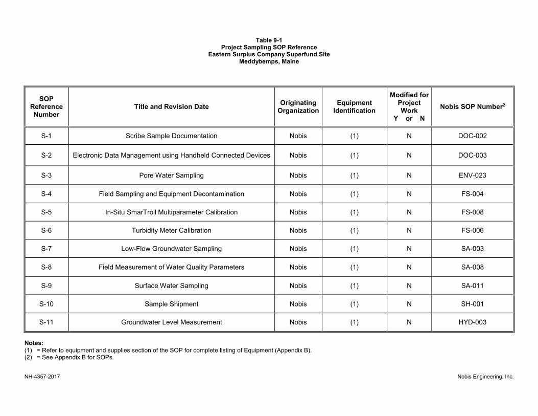
Table 9-1 Project Sampling SOP Reference
Eastern Surplus Company Superfund Site Meddybemps, Maine
NH-4357-2017 Nobis Engineering, Inc.
SOP Reference Number
Title and Revision Date Originating
Organization Equipment
Identification
Modified for Project Work
Y or N
Nobis SOP Number2
S-1 Scribe Sample Documentation Nobis (1) N DOC-002
S-2 Electronic Data Management using Handheld Connected Devices Nobis (1) N DOC-003
S-3 Pore Water Sampling Nobis (1) N ENV-023
S-4 Field Sampling and Equipment Decontamination Nobis (1) N FS-004
S-5 In-Situ SmarTroll Multiparameter Calibration Nobis (1) N FS-008
S-6 Turbidity Meter Calibration Nobis (1) N FS-006
S-7 Low-Flow Groundwater Sampling Nobis (1) N SA-003
S-8 Field Measurement of Water Quality Parameters Nobis (1) N SA-008
S-9 Surface Water Sampling Nobis (1) N SA-011
S-10 Sample Shipment Nobis (1) N SH-001
S-11 Groundwater Level Measurement Nobis (1) N HYD-003
Notes:
(1) = Refer to equipment and supplies section of the SOP for complete listing of Equipment (Appendix B). (2) = See Appendix B for SOPs.
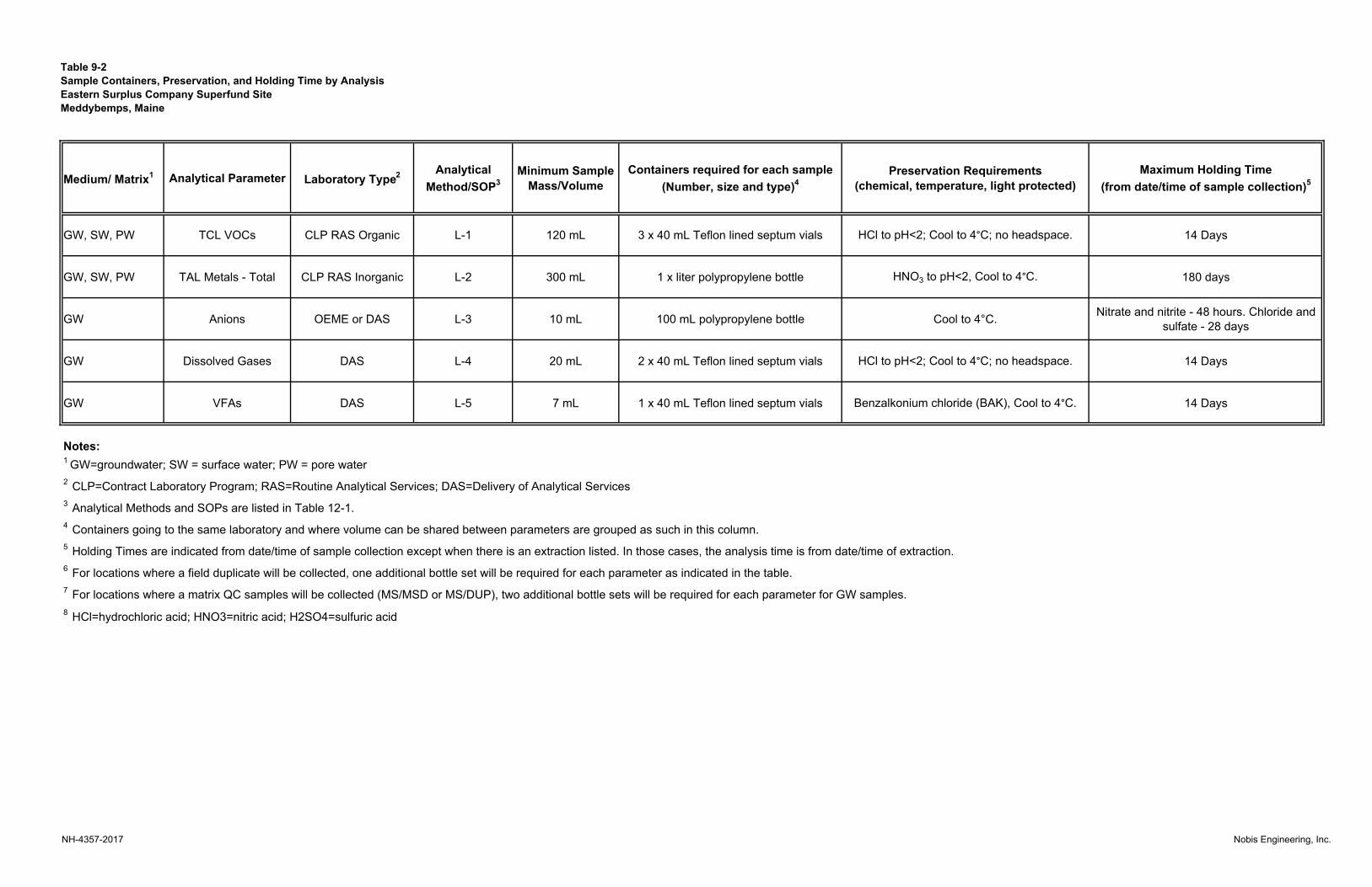
Table 9-2
Sample Containers, Preservation, and Holding Time by Analysis
Eastern Surplus Company Superfund Site
Meddybemps, Maine
Medium/ Matrix1 Analytical Parameter Laboratory Type
2Analytical
Method/SOP3
Minimum Sample
Mass/Volume
Containers required for each sample
(Number, size and type)4
Preservation Requirements
(chemical, temperature, light protected)
Maximum Holding Time
(from date/time of sample collection)5
GW, SW, PW TCL VOCs CLP RAS Organic L-1 120 mL 3 x 40 mL Teflon lined septum vials HCl to pH<2; Cool to 4°C; no headspace. 14 Days
GW, SW, PW TAL Metals - Total CLP RAS Inorganic L-2 300 mL 1 x liter polypropylene bottle HNO3 to pH<2, Cool to 4°C. 180 days
GW Anions OEME or DAS L-3 10 mL 100 mL polypropylene bottle Cool to 4°C. Nitrate and nitrite - 48 hours. Chloride and
sulfate - 28 days
GW Dissolved Gases DAS L-4 20 mL 2 x 40 mL Teflon lined septum vials HCl to pH<2; Cool to 4°C; no headspace. 14 Days
GW VFAs DAS L-5 7 mL 1 x 40 mL Teflon lined septum vials Benzalkonium chloride (BAK), Cool to 4°C. 14 Days
Notes:
8 HCl=hydrochloric acid; HNO3=nitric acid; H2SO4=sulfuric acid
6 For locations where a field duplicate will be collected, one additional bottle set will be required for each parameter as indicated in the table.
7 For locations where a matrix QC samples will be collected (MS/MSD or MS/DUP), two additional bottle sets will be required for each parameter for GW samples.
1 GW=groundwater; SW = surface water; PW = pore water
2 CLP=Contract Laboratory Program; RAS=Routine Analytical Services; DAS=Delivery of Analytical Services
3 Analytical Methods and SOPs are listed in Table 12-1.
4 Containers going to the same laboratory and where volume can be shared between parameters are grouped as such in this column.
5 Holding Times are indicated from date/time of sample collection except when there is an extraction listed. In those cases, the analysis time is from date/time of extraction.
NH-4357-2017 Nobis Engineering, Inc.

Table 10-1 Sample Identification System
Eastern Surplus Company Superfund Site Meddybemps, Maine
NH-4344-2017 Nobis Engineering, Inc.
Nomenclature Section Description Example
AAAA-BBCCCC- DDDDDDF
Sample identification ID ESRD-MW34B1-081517X
AAAA- Identifies the site and project phase ESRD – Eastern Surplus
Remedial Detail
BB Investigation location type MW – Monitoring Well
CC-
Investigation location type number (CC) will be a number of a given location (borehole or monitoring well)
For QA/QC samples (TB, FD), the type number is cumulative per-day and is not cumulatively tallied
over the duration of the project
34B1 – MW identification
DDDDDD Date of sample collection in 6-digit month, day, and year format 081517
(e.g. August 21, 2017)
E Field duplicate identifier. Default value is “X” for a normal field sample. “D” is designated for a
duplicate sample X
Notes:
Sample prefixes to be utilized in investigation locations (BB) are defined as follows:
MW = Monitoring Well IN = Injection Well (used as monitoring well) PW = Pore Water SW = Surface Water TB = trip blank FD = field duplicate

Table 11-1 Field Analytical Instrument Calibration
Eastern Surplus Company Superfund Site Meddybemps, Maine
Page 1 of 2
NH-4357-2017 Nobis Engineering, Inc.
Instrument Activity Frequency of Calibration Acceptance Criteria Corrective Action (CA) Person
Responsible for CA
Method/ Appendix Reference
pH Probe
Calibrate with three
temperature equilibrated standards to
bracket expected pH
values (4, 7, 10)
Initial calibration: beginning of each day
Calibration check: end of each day, and in response to erratic
readings
Initial calibration: +/- 0.05 ph units
Calibration check:
+/- 0.3 ph units
Rinse the probes carefully, use fresh buffer, and reanalyze the standard. Recalibrate or service as necessary. If still outside criteria,
use backup instrument. If necessary, consult owner’s manual for repair
instructions. If end of day calibration check is off, annotate previously obtained results.
FOL/Field Sampler
Appendix B
DO Probe
Calibrate with saturated DO
standard and 0.0 mg/L standard
Initial calibration: beginning of each day
Calibration check: end of each day, and in response to erratic
readings
Initial calibration:
< 0.5 mg/L for 0.0 mg/L standard; +/- 0.2 mg/L for
saturated solution
Calibration check: +/- 0.5 mg/L of saturated
solution
If DO reading exceeds criterion, then prepare new 0.0 mg/L standard, clean
probe and/or change membrane. Recalibrate or service as necessary. If end
of day calibration check is off, use professional judgment in interpreting
previously obtained results.
FOL/Field Sampler
Appendix B
Specific Conductance
Probe
Calibrate with one standard close to the expected
sample values
Initial calibration: beginning of each day
Calibration check: end of each day, and in response to erratic
readings
Initial calibration: +/- 20% of expected
Calibration check:
+/- 20% of expected
Rinse the probes carefully, use fresh solution, and reanalyze the standard.
Recalibrate or service as necessary. If still outside criteria, use backup instrument. If
necessary, consult owner’s manual for repair instructions. If end of day calibration check is off, annotate previously obtained
results.
FOL/Field Sampler
Appendix B

Table 11-1 Field Analytical Instrument Calibration
Eastern Surplus Company Superfund Site Meddybemps, Maine
Page 2 of 2
NH-4357-2017 Nobis Engineering, Inc.
Instrument Activity Frequency of Calibration Acceptance Criteria Corrective Action (CA) Person
Responsible for CA
Method/ Appendix Reference
Temperature Sensor
Calibrate against NIST- certified thermometer
Initial calibration: beginning of
each day
Calibration check: end of each day, and in response to erratic
readings
+/- 0.15° C of NIST-certified thermometer
Clean probe or service as necessary and recalibrate. Replace probe if necessary.
FOL/Field Sampler
Appendix B
Turbidity Meter
Standardize with a 1.00 and 10.00 NTU standards
Initial calibration: beginning of each day
Calibration check: end of each day, and in response to erratic
readings
Initial calibration: +/- 0.50 NTU of the 10.00 NTU
standard
Calibration check: +/- 0.50 NTU of the 10.00 NTU
standard
Wipe standard container cell, check orientation, and reanalyze the standard. If
still outside criteria, use backup instrument. If necessary, consult owner’s manual for
repair instructions. If end of day calibration check is off, use professional judgment in interpreting previously obtained results.
FOL/Field Sampler
Appendix B
ORP Probe Calibrate against Zobell solution
Initial calibration: beginning of
each day
Calibration check: end of each day, and in response to erratic
readings
Initial calibration: +/- 10 mv of true value
Calibration check:
+/- 10 mv of true value
Recalibrate. If still outside criterion, use back-up instrument. If end of day calibration check is off, use professional judgment in interpreting previously obtained results.
FOL/Field Sampler
Appendix B

Table 11-2 Field Analytical Instrument/Equipment Maintenance, Testing, and Inspection
Eastern Surplus Company Superfund Site Meddybemps, Maine
NH-4357-2017 Nobis Engineering, Inc.
Instrument Maintenance
Activity Testing Activity
Inspection Activity
Responsible Person
Frequency Acceptance Criteria Corrective
Action Reference*
In-Situ SmarTroll Cleaning,
replacement of probes
Operation Visual inspection for defective parts
FOL, Field Technician
Each probe prior to use
No visually defective parts; Conformance with manufacturer standards
Repair or use alternate
equipment
Instrument manuals
Turbidity Meter Cleaning,
replacement of sample tubes
Operation Visual inspection for defective parts
FOL, Field Technician
Each meter prior to use
No visually defective parts; Conformance with manufacturer standards
Repair or use alternate
equipment
Instrument manuals
Note:
*Instrument Manuals accompany instruments in the field.
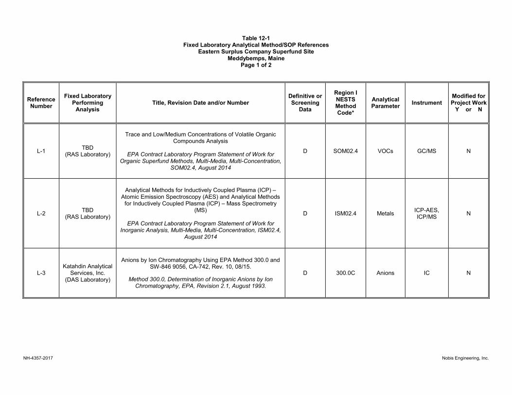
Table 12-1 Fixed Laboratory Analytical Method/SOP References
Eastern Surplus Company Superfund Site Meddybemps, Maine
Page 1 of 2
NH-4357-2017 Nobis Engineering, Inc.
Reference Number
Fixed Laboratory Performing
Analysis Title, Revision Date and/or Number
Definitive or Screening
Data
Region I NESTS Method Code*
Analytical Parameter
Instrument Modified for Project Work
Y or N
L-1 TBD
(RAS Laboratory)
Trace and Low/Medium Concentrations of Volatile Organic Compounds Analysis
EPA Contract Laboratory Program Statement of Work for
Organic Superfund Methods, Multi-Media, Multi-Concentration, SOM02.4, August 2014
D SOM02.4 VOCs GC/MS N
L-2 TBD
(RAS Laboratory)
Analytical Methods for Inductively Coupled Plasma (ICP) – Atomic Emission Spectroscopy (AES) and Analytical Methods
for Inductively Coupled Plasma (ICP) – Mass Spectrometry (MS)
EPA Contract Laboratory Program Statement of Work for
Inorganic Analysis, Multi-Media, Multi-Concentration, ISM02.4, August 2014
D ISM02.4 Metals ICP-AES, ICP/MS
N
L-3 Katahdin Analytical
Services, Inc. (DAS Laboratory)
Anions by Ion Chromatography Using EPA Method 300.0 and SW-846 9056, CA-742, Rev. 10, 08/15.
Method 300.0, Determination of Inorganic Anions by Ion Chromatography, EPA, Revision 2.1, August 1993.
D 300.0C Anions IC N
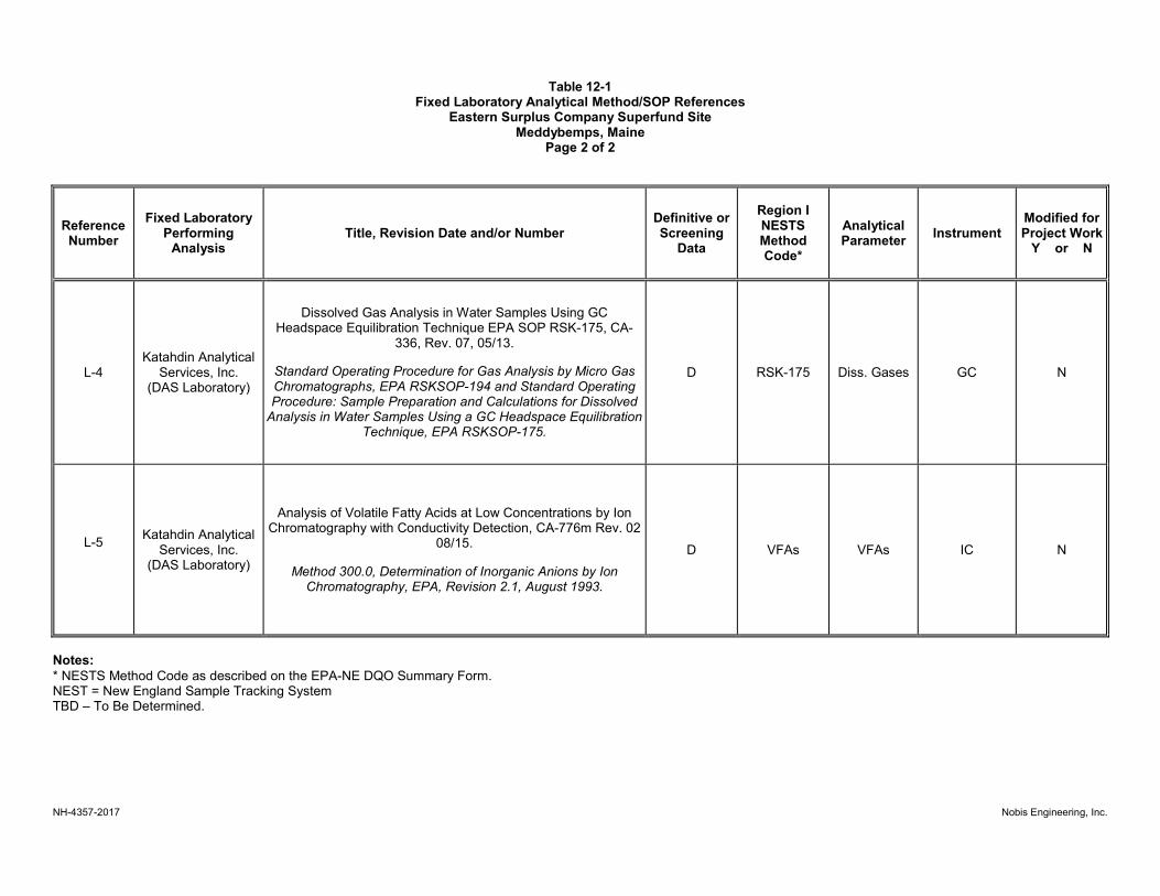
Table 12-1 Fixed Laboratory Analytical Method/SOP References
Eastern Surplus Company Superfund Site Meddybemps, Maine
Page 2 of 2
NH-4357-2017 Nobis Engineering, Inc.
Reference Number
Fixed Laboratory Performing
Analysis Title, Revision Date and/or Number
Definitive or Screening
Data
Region I NESTS Method Code*
Analytical Parameter
Instrument Modified for Project Work
Y or N
L-4 Katahdin Analytical
Services, Inc. (DAS Laboratory)
Dissolved Gas Analysis in Water Samples Using GC Headspace Equilibration Technique EPA SOP RSK-175, CA-
336, Rev. 07, 05/13.
Standard Operating Procedure for Gas Analysis by Micro Gas Chromatographs, EPA RSKSOP-194 and Standard Operating Procedure: Sample Preparation and Calculations for Dissolved
Analysis in Water Samples Using a GC Headspace Equilibration Technique, EPA RSKSOP-175.
D RSK-175 Diss. Gases GC N
L-5
Katahdin Analytical Services, Inc.
(DAS Laboratory)
Analysis of Volatile Fatty Acids at Low Concentrations by Ion Chromatography with Conductivity Detection, CA-776m Rev. 02
08/15.
Method 300.0, Determination of Inorganic Anions by Ion Chromatography, EPA, Revision 2.1, August 1993.
D VFAs VFAs IC N
Notes:
* NESTS Method Code as described on the EPA-NE DQO Summary Form. NEST = New England Sample Tracking System TBD – To Be Determined.

Table 12-2
Fixed Laboratory Instrument Maintenance and Calibration
Eastern Surplus Company Superfund Site
Meddybemps, Maine
Instrument ActivityList Maintenance, Testing and
Inspection ActivitiesFrequency of Calibration Acceptance Criteria
Corrective Action
(CA)
Person
Responsible for
CA
Method/SOP
Reference
IC - instrument receipt, major
instrument maintenance, when CC
fails
minimum RRF achieved and
maximum %RSD not exceeded, see
SOW
CC - every 12 hours of operation
following instrument tune
minimum RRF achieved for each
analyte and maximum %D not
exceeded, see SOW
IC - instrument receipt, major
instrument maintenance, when CC
fails
%R 80-120 for Hg; all others 90-
110%, see SOW
CC - every 10 samples %R 80-120 for Hg, all others 90-
110%, see SOW
IC - daily prior to blank and sample
analysis
correlation coefficient ≥0.995;
lowest standard %R = 50-150%; ICV
%R = 90-110%
CC - at beginning of run, every 10
samples, and end of run %R = 90-110%
SOM02.4, L-1
ICP-AES ICP-MS Hg Metals
Check connections, replace
disposables, clean the instrument,
change the nebulizer
See ISM02.4Laboratory QA
Manager TBDISM02.4, L-2
GC/MS VOC
Check connections, replace
disposables, bake out instrument,
recondition trap and column
See SOM02.4Laboratory QA
Manager TBD
L-3Ion Chromatograph AnionsCheck connections, replace
disposables, clean equipment
Recalibrate and
reanalyze
Leslie Dimond
Katahdin
NH-4357-2017 Nobis Engineering, Inc.
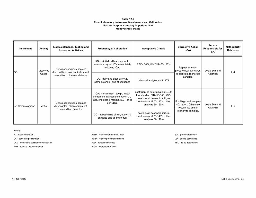
Table 12-2
Fixed Laboratory Instrument Maintenance and Calibration
Eastern Surplus Company Superfund Site
Meddybemps, Maine
Instrument ActivityList Maintenance, Testing and
Inspection ActivitiesFrequency of Calibration Acceptance Criteria
Corrective Action
(CA)
Person
Responsible for
CA
Method/SOP
Reference
ICAL - initial calibration prior to
sample analysis; ICV immediately
following ICAL
RSD≤ 30%; ICV %R=70-130%
CC - daily and after every 20
samples and at end of sequence%D for all analytes within 30%
ICAL - instrument receipt, major
instrument maintenance, when CC
fails, once per 6 months. ICV - once
per SDG.
coefficient of determination ≥0.99;
low standard %R=50-150; ICV -
acetic acid, hexanoic acid, n-
pentanoic acid 70-140%; other
analytes 80-120%
CC - at beginning of run, every 10
samples and at end of run
acetic acid, hexanoic acid, n-
pentanoic acid 70-140%; other
analytes 80-120%
Notes:
IC - initial calibration RSD - relative standard deviation %R - percent recovery
CC - continuing calibration RPD - relative percent difference QA - quality assurance
CCV - continuing calibration verification %D - percent difference TBD - to be determined
RRF - relative response factor SOW - statement of work
Repeat analysis,
prepare new standards,
recalibrate, reanalyze
samples.
Leslie Dimond
KatahdinL-4
L-5Ion Chromatograph VFAs
Check connections, replace
disposables, clean equipment,
recondition detector
If fail high and samples
ND; report. Otherwise,
recalibrate and/or
reanalyze samples.
Leslie Dimond
Katahdin
GCDissolved
Gases
Check connections, replace
disposables, bake out instrument,
recondition column or detector.
NH-4357-2017 Nobis Engineering, Inc.
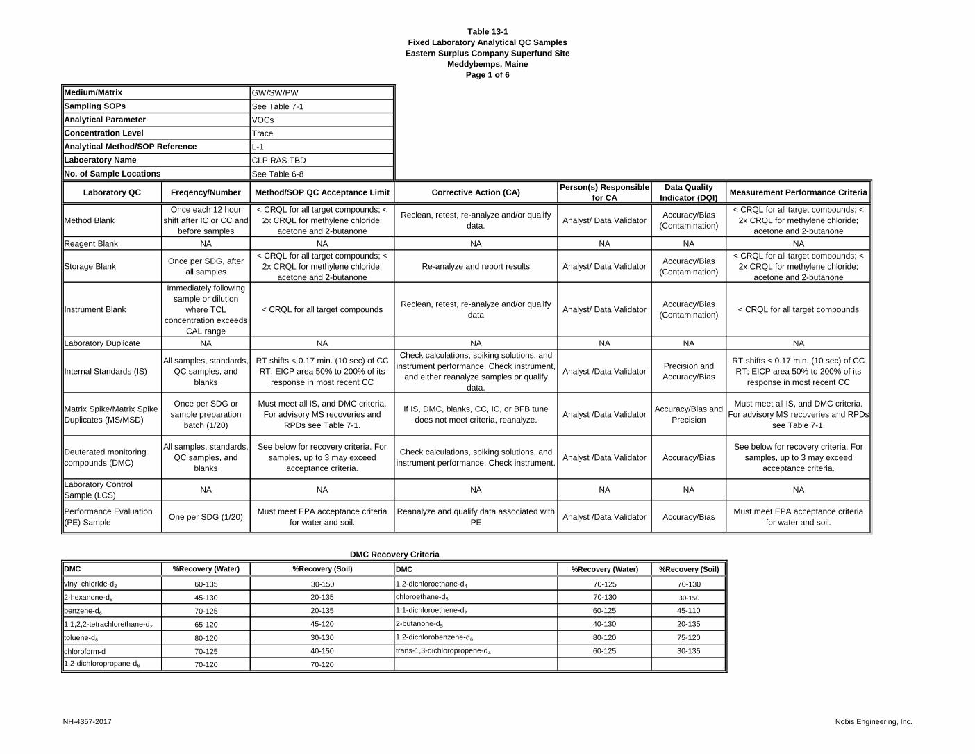
Table 13-1
Fixed Laboratory Analytical QC Samples
Eastern Surplus Company Superfund Site
Meddybemps, Maine
Page 1 of 6
GW/SW/PW
See Table 7-1
VOCs
Trace
L-1
CLP RAS TBD
See Table 6-8
Laboratory QC Freqency/Number Method/SOP QC Acceptance Limit Corrective Action (CA)Person(s) Responsible
for CA
Data Quality
Indicator (DQI)Measurement Performance Criteria
Method Blank
Once each 12 hour
shift after IC or CC and
before samples
< CRQL for all target compounds; <
2x CRQL for methylene chloride;
acetone and 2‑butanone
Reclean, retest, re-analyze and/or qualify
data.Analyst/ Data Validator
Accuracy/Bias
(Contamination)
< CRQL for all target compounds; <
2x CRQL for methylene chloride;
acetone and 2‑butanone
Reagent Blank NA NA NA NA NA NA
Storage BlankOnce per SDG, after
all samples
< CRQL for all target compounds; <
2x CRQL for methylene chloride;
acetone and 2‑butanone
Re-analyze and report results Analyst/ Data ValidatorAccuracy/Bias
(Contamination)
< CRQL for all target compounds; <
2x CRQL for methylene chloride;
acetone and 2‑butanone
Instrument Blank
Immediately following
sample or dilution
where TCL
concentration exceeds
CAL range
< CRQL for all target compoundsReclean, retest, re-analyze and/or qualify
dataAnalyst/ Data Validator
Accuracy/Bias
(Contamination)< CRQL for all target compounds
Laboratory Duplicate NA NA NA NA NA NA
Internal Standards (IS)
All samples, standards,
QC samples, and
blanks
RT shifts < 0.17 min. (10 sec) of CC
RT; EICP area 50% to 200% of its
response in most recent CC
Check calculations, spiking solutions, and
instrument performance. Check instrument,
and either reanalyze samples or qualify
data.
Analyst /Data ValidatorPrecision and
Accuracy/Bias
RT shifts < 0.17 min. (10 sec) of CC
RT; EICP area 50% to 200% of its
response in most recent CC
Matrix Spike/Matrix Spike
Duplicates (MS/MSD)
Once per SDG or
sample preparation
batch (1/20)
Must meet all IS, and DMC criteria.
For advisory MS recoveries and
RPDs see Table 7-1.
If IS, DMC, blanks, CC, IC, or BFB tune
does not meet criteria, reanalyze.Analyst /Data Validator
Accuracy/Bias and
Precision
Must meet all IS, and DMC criteria.
For advisory MS recoveries and RPDs
see Table 7-1.
Deuterated monitoring
compounds (DMC)
All samples, standards,
QC samples, and
blanks
See below for recovery criteria. For
samples, up to 3 may exceed
acceptance criteria.
Check calculations, spiking solutions, and
instrument performance. Check instrument.Analyst /Data Validator Accuracy/Bias
See below for recovery criteria. For
samples, up to 3 may exceed
acceptance criteria.
Laboratory Control
Sample (LCS)NA NA NA NA NA NA
Performance Evaluation
(PE) SampleOne per SDG (1/20)
Must meet EPA acceptance criteria
for water and soil.
Reanalyze and qualify data associated with
PEAnalyst /Data Validator Accuracy/Bias
Must meet EPA acceptance criteria
for water and soil.
DMC Recovery Criteria
DMC %Recovery (Water) %Recovery (Soil) DMC %Recovery (Water) %Recovery (Soil)
vinyl chloride-d3 60-135 30-150 1,2-dichloroethane-d4 70-125 70-130
2-hexanone-d5 45-130 20-135 chloroethane-d5 70-130 30-150
benzene-d6 70-125 20-135 1,1-dichloroethene-d2 60-125 45-110
1,1,2,2-tetrachlorethane-d2 65-120 45-120 2-butanone-d5 40-130 20-135
toluene-d8 80-120 30-130 1,2-dichlorobenzene-d6 80-120 75-120
chloroform-d 70-125 40-150 trans-1,3-dichloropropene-d4 60-125 30-135
1,2-dichloropropane-d6 70-120 70-120
No. of Sample Locations
Medium/Matrix
Sampling SOPs
Analytical Parameter
Concentration Level
Analytical Method/SOP Reference
Laboeratory Name
NH-4357-2017 Nobis Engineering, Inc.

Table 13-1
Fixed Laboratory Analytical QC Samples
Eastern Surplus Company Superfund Site
Meddybemps, Maine
Page 2 of 6
GW/SW/PW
See Table 7-1
Metals
Low
L-2
CLP RAS TBD
See Table 6-8
Laboratory QC Freqency/Number Method/SOP QC Acceptance Limit Corrective Action (CA)Person(s) Responsible
for CA
Data Quality
Indicator (DQI)Measurement Performance Criteria
Method Blank
Once per SDG or
sample preparation
batch (1/20)
< CRQL for all target compoundsReclean, retest, re-analyze and/or qualify
data.Analyst/ Data Validator
Accuracy/Bias
(Contamination)< CRQL for all target compounds
Reagent Blank NA NA NA NA NA NA
Interference Check
Sample (ICS)Beginning of each run
±20% of true value or ±2 times the
CRQLRecalibrate and reanalyze; qualify data Analyst /Data Validator Accuracy
±20% of true value or ±2 times the
CRQL
Instrument Blanks
(ICBs/CCBs)
ICB – after ICV; CCBs
– 10% or every 2
hours of operation;
after every CCV; at
beginning of the run
and after last sample.
< CRQL for all target analytesReclean, retest, re-analyze and/or qualify
dataAnalyst /Data Validator
Accuracy/Bias
(Contamination)< CRQL for all target analytes
Laboratory Duplicate
One per SDG or
sample preparation
batch (1/20)
20% RPD for results >5x CRQL or +/-
CRQL when results <5x CRQLData Qualified Analyst/Data Validator Precision
20% RPD for results >5x CRQL or +/-
CRQL when results <5x CRQL
Internal Standards (IS)
All samples, QC
samples for ICP/MS
testing.
Sample IS response of 60-125% of
calibration blank IS.
Dilute the sample 2x and reanalyze. Note in
the narrative if fails again.Analyst/Data Validator Accuracy
Sample IS response of 60-125% of
calibration blank IS.
Matrix Spike (MS) and
Post Digestion Spike
(PDS)
Once per SDG or
sample preparation
batch (1/20)
For advisory MS recoveries of 75-
125% are goals.Flag data and document in case narrative. Analyst /Data Validator Accuracy/Bias Advisory MS recoveries only.
Serial Dilutions (SD)
Once per SDG or
sample preparation
batch (1/20) for ICP-
AES only.
For analyte concentrations of >50x
MDL, %D from original result and SD
result should be <10%.
Data Qualified Analyst /Data Validator Bias (interference)
For analyte concentrations of >50x
MDL, %D from original result and SD
result should be <10%.
Laboratory Control
Sample (LCS)
Once per SDG or
sample preparation
batch
%R=80-120 for all analytes Recalibrate and reanalyze the LCS. Analyst Accuracy/Bias LCS must meet requirements stated.
Performance Evaluation
(PE) SampleOne per SDG (1/20)
Must meet EPA acceptance criteria
for water and soil.
Reanalyze and qualify data associated with
PEAnalyst /Data Validator Accuracy/Bias
Must meet EPA acceptance criteria
for water and soil.
No. of Sample Locations
Medium/Matrix
Sampling SOPs
Analytical Parameter
Concentration Level
Analytical Method/SOP Reference
Laboeratory Name
NH-4357-2017 Nobis Engineering, Inc.

Table 13-1
Fixed Laboratory Analytical QC Samples
Eastern Surplus Company Superfund Site
Meddybemps, Maine
Page 3 of 6
Anions
See Table 7-1
Anions
Low
L-3
DAS Katahdin
See Table 6-8 (10)
Laboratory QC Frequency/NumberMethod/SOP QC Acceptance
LimitCorrective Action (CA)
Person(s) Responsible
for CA
Data Quality
Indicator (DQI)Measurement Performance Criteria
Method BlankOnce per extraction
set, up to 20 samplestarget analytes < RL
Reclean, retest, re-analyze and/or
qualify data.Analyst/ Data Validator
Accuracy/Bias
(Contamination)target analtyes < RL
Reagent Blank NA NA NA NA NA NA
Instrument Blanks (CCBs)
CCBs – after each
CCV (every 10
sample)
target analytes < RLReclean, retest, re-analyze and/or
qualify dataAnalyst/Data Validator
Accuracy/Bias
(Contamination)target analtyes < RL
Laboratory Method
Duplicate
Once per sample
preparation batch
(1/20)
RPD<20%; result <10x RL, then
±RLCorrect problem and reanalyze. Analyst Precision RPD<20%; result <10x RL, then ±RL
Matrix Spike/matrix spike
duplicate (MS/MSD)
Once per sample
preparation batch
(1/20)
80-120% recovery; RPD 20% If LCS in control, narrate. Analyst /Data ValidatorAccuracy/
Precision80-120% recovery; RPD 20%
Laboratory Control
Sample (LCS)
Once per sample
preparation batch
(1/20)
80-120% Recovery Recalibrate and reanalyze the LCS. Analyst Accuracy/Bias 80-120% recovery
Performance Evaluation
(PE) SampleNA NA NA NA NA NA
No. of Sample Locations
Medium/Matrix
Sampling SOPs
Analytical Parameter
Concentration Level
Analytical Method/SOP Reference
Laboratory Name
NH-4357-2017 Nobis Engineering, Inc.

Table 13-1
Fixed Laboratory Analytical QC Samples
Eastern Surplus Company Superfund Site
Meddybemps, Maine
Page 4 of 6
GW
See Table 7-1
Dissolved Gases
Low
L-4
DAS Katahdin
See Table 6-8 (10)
Laboratory QC Frequency/NumberMethod/SOP QC Acceptance
LimitCorrective Action (CA)
Person(s) Responsible
for CA
Data Quality
Indicator (DQI)Measurement Performance Criteria
Method BlankOnce per extraction
set, up to 20 samplestarget analytes < RL
Reclean, retest, re-analyze and/or
qualify data.Analyst/ Data Validator
Accuracy/Bias
(Contamination)target analtyes < RL
Reagent Blank NA NA NA NA NA NA
Instrument Blanks (CCBs)
CCBs – after each
CCV (every 10
sample)
target analytes < RLReclean, retest, re-analyze and/or
qualify dataAnalyst/Data Validator
Accuracy/Bias
(Contamination)target analtyes < RL
Laboratory Method
Duplicate
Once per sample
preparation batch
(1/20)
RPD<30%; result <10x RL, then
±RLCorrect problem and reanalyze. Analyst Precision RPD<30%; result <10x RL, then ±RL
Matrix Spike/matrix spike
duplicate (MS/MSD)
Once per sample
preparation batch
(1/20)
70-130% recovery; RPD 30% If LCS in control, narrate. Analyst /Data ValidatorAccuracy/
Precision70-130% recovery; RPD 30%
Laboratory Control
Sample (LCS)
Once per sample
preparation batch
(1/20)
70-130% Recovery Recalibrate and reanalyze the LCS. Analyst Accuracy/Bias 70-130% recovery
Performance Evaluation
(PE) SampleNA NA NA NA NA NA
No. of Sample Locations
Medium/Matrix
Sampling SOPs
Analytical Parameter
Concentration Level
Analytical Method/SOP Reference
Laboratory Name
NH-4357-2017 Nobis Engineering, Inc.
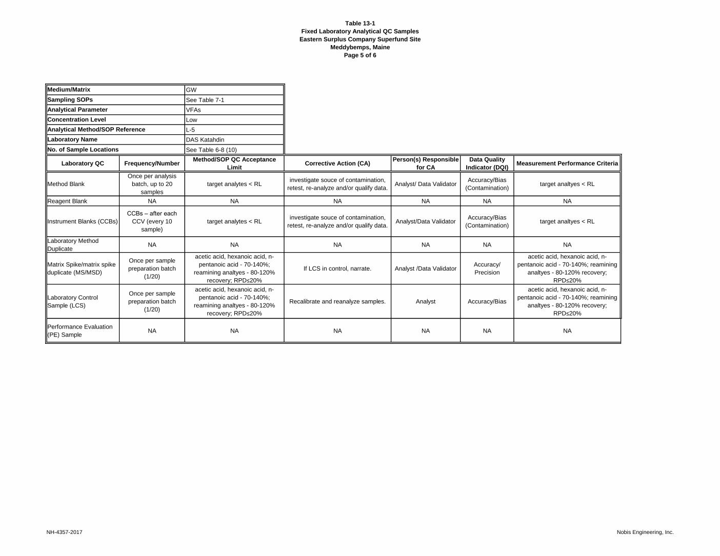
Table 13-1
Fixed Laboratory Analytical QC Samples
Eastern Surplus Company Superfund Site
Meddybemps, Maine
Page 5 of 6
GW
See Table 7-1
VFAs
Low
L-5
DAS Katahdin
See Table 6-8 (10)
Laboratory QC Frequency/NumberMethod/SOP QC Acceptance
LimitCorrective Action (CA)
Person(s) Responsible
for CA
Data Quality
Indicator (DQI)Measurement Performance Criteria
Method Blank
Once per analysis
batch, up to 20
samples
target analytes < RLinvestigate souce of contamination,
retest, re-analyze and/or qualify data.Analyst/ Data Validator
Accuracy/Bias
(Contamination)target analtyes < RL
Reagent Blank NA NA NA NA NA NA
Instrument Blanks (CCBs)
CCBs – after each
CCV (every 10
sample)
target analytes < RLinvestigate souce of contamination,
retest, re-analyze and/or qualify data.Analyst/Data Validator
Accuracy/Bias
(Contamination)target analtyes < RL
Laboratory Method
DuplicateNA NA NA NA NA NA
Matrix Spike/matrix spike
duplicate (MS/MSD)
Once per sample
preparation batch
(1/20)
acetic acid, hexanoic acid, n-
pentanoic acid - 70-140%;
reamining analtyes - 80-120%
recovery; RPD≤20%
If LCS in control, narrate. Analyst /Data ValidatorAccuracy/
Precision
acetic acid, hexanoic acid, n-
pentanoic acid - 70-140%; reamining
analtyes - 80-120% recovery;
RPD≤20%
Laboratory Control
Sample (LCS)
Once per sample
preparation batch
(1/20)
acetic acid, hexanoic acid, n-
pentanoic acid - 70-140%;
reamining analtyes - 80-120%
recovery; RPD≤20%
Recalibrate and reanalyze samples. Analyst Accuracy/Bias
acetic acid, hexanoic acid, n-
pentanoic acid - 70-140%; reamining
analtyes - 80-120% recovery;
RPD≤20%
Performance Evaluation
(PE) SampleNA NA NA NA NA NA
No. of Sample Locations
Medium/Matrix
Sampling SOPs
Analytical Parameter
Concentration Level
Analytical Method/SOP Reference
Laboratory Name
NH-4357-2017 Nobis Engineering, Inc.

Table 13-1
Fixed Laboratory Analytical QC Samples
Eastern Surplus Company Superfund Site
Meddybemps, Maine
Page 6 of 6
Notes:
CC – continuing calibration
CCB - continuning calibration blank
CCV - continuing calibration verification
CLP - contract laboratory program
%D - percent difference
DAS - delivery of analytical services
DFTPP - decafluorotriphenylphosphine
EICP – extracted ion current profile
ICB - initial calibration blank
ICV - initial calibration verification
ICP-MS - inductively coupled-mass spectrometry
LCS - laboratory control sample
MDL - method detection limit
NA – not applicable
NERL - New England Regional Laboratory
OEME - Office of Environmental Measurement and Evaluation
PAH - polycyclic aromatic hydrocarbons
QC – quality control
%R - % recovery
RAS - routine analytical services
RL - reporting limit
RPD – relative percent difference
RT – retention time
SDG – sample delivery group
SIM - selective ion monitoring
SOP - standard operation procedure
SVOCs - semivolatile organic compounds
TBD – to be determined
NH-4357-2017 Nobis Engineering, Inc.

Table 15-1 Project Documentation and Records
Eastern Surplus Company Superfund Site Meddybemps, Maine
NH-4357-2017 Nobis Engineering, Inc.
Sample Collection Records Field Analysis Records Fixed Laboratory Records Data Assessment Records Project Documents
Logbooks Telephone Logs Sample Receipt, Custody and
Tracking Records Data Validation and Usability Reports
Quality Assurance Project Plan
Chains of Custody Field Observations Standard Traceability Logs Performance Evaluation Sample
Results Project Billing Records
Airbills Field Notebooks Equipment Calibration Logs Sample Data Tracking Form Data Evaluation Report
Telephone Logs Reported Field Sample
Results Sample Preparation Logs SDG Tracking Form
Site Specific Health & Safety Plan
Scribe Files Run Logs Corrective Action Forms Design Criteria Report
Custody Seals Equipment Maintenance, Testing,
and Inspection Logs Telephone Logs Final Specifications
Site Health and Safety Logs Corrective Action Forms Electronic Validated Sample Results
Field logs/Diaries Method QC Checklists
Groundwater Monitoring Worksheets
Reported Results for Standards, QC Checks, and QC Samples
Surface Water/Pore Water Sampling Worksheets
Data Package Completeness
Checklists
Electronic Data Collection Files

Table 17-1 QA Management Reports
Eastern Surplus Company Superfund Site Meddybemps, Maine
NH-4357-2017 Nobis Engineering, Inc.
Type of Report Frequency
(daily, weekly monthly, quarterly, annually, etc.)
Projected Delivery Date(s)
Person(s) Responsible for Report Preparation, Title
and Organizational Affiliation
Report Recipients, Title, and Organizational Affiliation
Verbal Status Report
Daily At the end of each day Nobis Field Operations
Leader Nobis Project Manager
Verbal or Written Status Report
As necessary As necessary Nobis Project Manager EPA Task Order Project Officer
Written Monthly Status Reports
Monthly 20th calendar day of the month
following the fiscal month period Nobis Project Manager EPA Task Order Project Officer
Written Data Review Reports
One per Sample Delivery Group
21days after receipt of fully reconciled Sample Data Package
Nobis Data Validators EPA Task Order Project Officer, EPA Region
1 QA Unit
Data Evaluation Report
Following completion of sampling, analysis, and data validation activities
Approximately 3 months after completion of data review/validation
Nobis Project Manager EPA Task Order Project Officer
Audit Report Following completion of each audit, if applicable
7 days or sooner after completion of field audit; 2 weeks or sooner
after completion of RAC 2 program audits
Nobis Auditor Nobis Project Manager, Nobis RAC 2 QA
Officer, and Nobis Lead Chemist if relevant.

Table 18-1 Data Verification Process
Eastern Surplus Company Superfund Site Meddybemps, Maine
Page 1 of 2
NH-4357-2017 Nobis Engineering, Inc.
Verification Task Description I/E Responsible for Verification (Name,
Organization)
Sampling Sampling records, boring logs, and field analysis data will be reviewed daily or per sample for legibility,
accuracy, clarity, and completeness to ensure consistent and proper field techniques. I Nobis Field Operations Leader (FOL)
Sample Custody and Shipping
Chains-of-custody, sample labels, and shipping documents will be checked for completeness and accuracy by the field technician prior to shipping of samples.
I Nobis Field Operations Leader (FOL)
Sample Receipt Fixed laboratories will verify chain-of-custody documentation for all methods and samples. E TBD, RAS CLP Labs
Leslie Dimond, Katahdin
Laboratory Data Results of internal QA/QC sample analyses associated with every method of analysis will be generated by
the fixed laboratories E
TBD, RAS CLP Labs Leslie Dimond, Katahdin
Laboratory Data Packages
All data will be reviewed by the laboratory prior to shipment of data packages. Following an internal review process, fixed laboratories will document deviations from the analytical specifications and Table 13-1 in
the case narrative for the SDG and/or with data qualifiers. E
TBD, RAS CLP Labs Leslie Dimond, Katahdin
Laboratory Data
Results of PES submitted by Nobis, for analysis and scored by the EPA Region I, OEME, will be evaluated with respect to the DQOs defined in Section 5.0 and 7.0 of the QAPP and on Table 13-1.
I Nobis Lead Chemist and Nobis Validation
Staff

Table 18-1 Data Verification Process
Eastern Surplus Company Superfund Site Meddybemps, Maine
Page 2 of 2
NH-4357-2017 Nobis Engineering, Inc.
Verification Task Description I/E Responsible for Verification (Name,
Organization)
Data Validation
• All analytical data will be reviewed to Tier 1 level, stage 2A plus a review of field QC sample results (field duplicate, equipment blanks, and PE samples).
• DAS data will be reviewed to Tier 1 level, stage 2A with modification for methods.
• If the quality of any review suggests the need for further review or if the use of the data changes, then with approval from the TOPO, the level of the data validation may be elevated to a higher tier review.
• Validation reports will be generated. Critical deficiencies (incomplete data) will be identified, the laboratory and EPA contacted and corrective actions implemented to make the packages complete.
Issues that impact the data will be brought to the attention of the Nobis Lead Chemist in order to initiate corrective action, possibly in the form of reanalysis or re-sampling.
I Nobis Lead Chemist and Data Validation
Staff
Database Analytical results to which data validation qualifiers have been added are compiled into a database.
Queries made as part of generation of comparison tables from the database serve to evaluate completeness and usability of the results in the database.
I Nobis Lead Chemist
Notes:
I – Internal E - External

Table 18-2 Data Validation Summary
Eastern Surplus Company Superfund Site Meddybemps, Maine
Page 1 of 2
NH-4357-2017 Nobis Engineering, Inc.
Medium / Matrix
Analytical Parameter1 Validation Criteria2
Validation Criteria
Modified3
Data Validation Tier Level3
Modified Tier Level Used
Data Validator (Name, title and organizational
affiliation)
Responsibility for Data Validations (Name, title
and organizational affiliation)
GW, SW, PW
VOCs
EPA-NE Data Review Program Guidance, April 2013
EPA-NE Environmental Data Review Supplement, April 2013
EPA National Functional Guidelines for
Superfund Organic Methods Data Review (August 2014)
N Tier 1, stage 2A Yes – will also review field QC
Nobis Staff Nobis Lead Chemist
GW, SW, PW
Metals
EPA-NE Data Review Program Guidance, April 2013
EPA-NE Environmental Data Review Supplement, April 2013
EPA National Functional Guidelines for Inorganic
Superfund Data Review (August 2014)
N Tier 1, stage 2A Yes – will also review field QC
Nobis Staff Nobis Lead Chemist
GW Anions
EPA-NE Data Review Program Guidance, April 2013
EPA-NE Environmental Data Review Supplement, April 2013
EPA National Functional Guidelines for Inorganic
Superfund Data Review (August 2014)
Y – Modified for method
Tier 1, stage 2A Yes – will also review field QC
Nobis Staff Nobis Lead Chemist
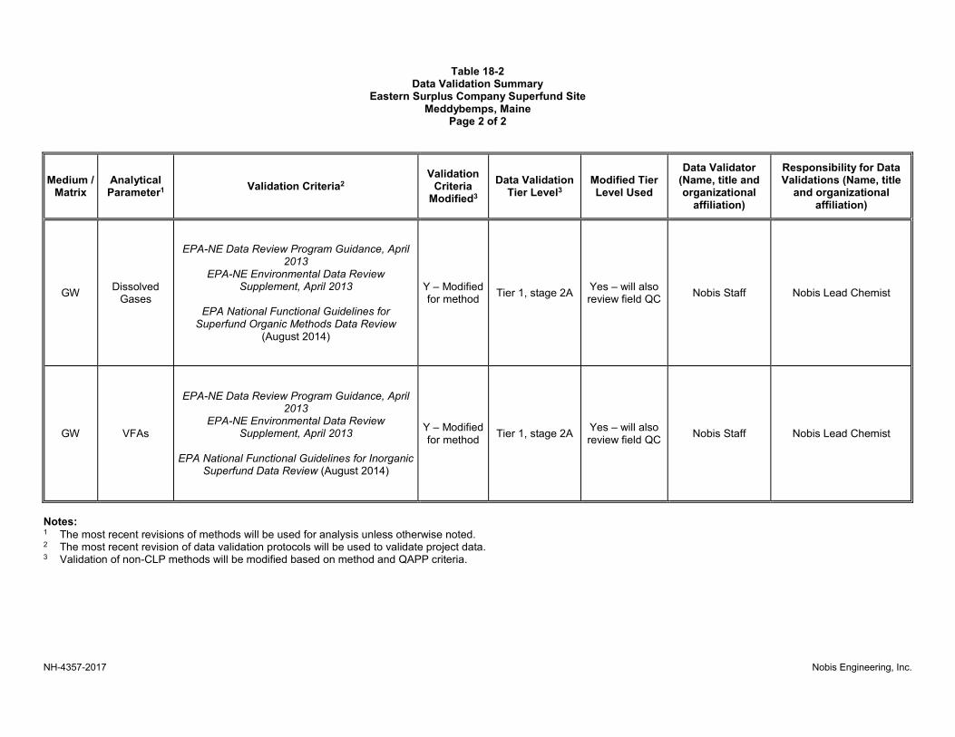
Table 18-2 Data Validation Summary
Eastern Surplus Company Superfund Site Meddybemps, Maine
Page 2 of 2
NH-4357-2017 Nobis Engineering, Inc.
Medium / Matrix
Analytical Parameter1 Validation Criteria2
Validation Criteria
Modified3
Data Validation Tier Level3
Modified Tier Level Used
Data Validator (Name, title and organizational
affiliation)
Responsibility for Data Validations (Name, title
and organizational affiliation)
GW Dissolved
Gases
EPA-NE Data Review Program Guidance, April
2013 EPA-NE Environmental Data Review
Supplement, April 2013
EPA National Functional Guidelines for Superfund Organic Methods Data Review
(August 2014)
Y – Modified for method
Tier 1, stage 2A Yes – will also review field QC
Nobis Staff Nobis Lead Chemist
GW VFAs
EPA-NE Data Review Program Guidance, April 2013
EPA-NE Environmental Data Review Supplement, April 2013
EPA National Functional Guidelines for Inorganic
Superfund Data Review (August 2014)
Y – Modified for method
Tier 1, stage 2A Yes – will also review field QC
Nobis Staff Nobis Lead Chemist
Notes: 1 The most recent revisions of methods will be used for analysis unless otherwise noted. 2 The most recent revision of data validation protocols will be used to validate project data. 3 Validation of non-CLP methods will be modified based on method and QAPP criteria.

F
I
G
U
R
E
S
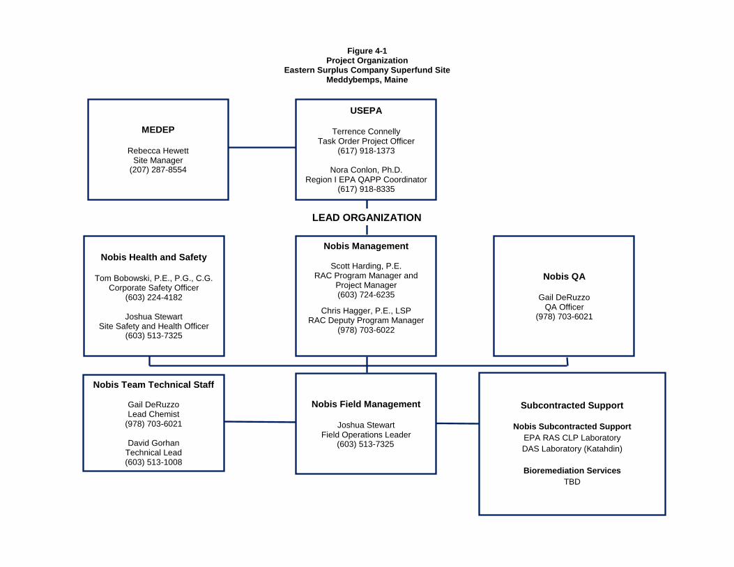
Figure 4-1 Project Organization
Eastern Surplus Company Superfund Site Meddybemps, Maine
MEDEP
Rebecca Hewett Site Manager
(207) 287-8554
USEPA
Terrence Connelly Task Order Project Officer
(617) 918-1373
Nora Conlon, Ph.D. Region I EPA QAPP Coordinator
(617) 918-8335
Nobis Health and Safety
Tom Bobowski, P.E., P.G., C.G. Corporate Safety Officer
(603) 224-4182
Joshua Stewart Site Safety and Health Officer
(603) 513-7325
Nobis Management
Scott Harding, P.E. RAC Program Manager and
Project Manager (603) 724-6235
Chris Hagger, P.E., LSP RAC Deputy Program Manager
(978) 703-6022
Nobis QA
Gail DeRuzzo QA Officer
(978) 703-6021
Nobis Team Technical Staff
Gail DeRuzzo Lead Chemist
(978) 703-6021
David Gorhan Technical Lead (603) 513-1008
Nobis Field Management
Joshua Stewart Field Operations Leader
(603) 513-7325
Subcontracted Support
Nobis Subcontracted Support
EPA RAS CLP Laboratory
DAS Laboratory (Katahdin)
Bioremediation Services
TBD
LEAD ORGANIZATION

=
=
=
=
=
=
==
==
=
=
=
=
=
=
=
=
=
=
= =
=
=
==
=
==
=
==
=
== ==
==
====
=
=
=
=
=
==
=
=
==
J JOJ JO
J JO
J JO
J JO
J JO
J JOJ JOJ JO
J JO
J JO
J JO
J JO
J JO
J JO
MM
BB
B
B
B BBBBBB
BB
B
BB
B
A
A
A
AA
AA
AA
AAA
AA
AAAA
AA
A
AAAA
A
A
AA
AA
A
A
A
AA
A
A
A
A
AA
A
A
A
AA
A
A
A
A
A
A
A
AA
A
&(- &(-&(-
&(-&(-
&(-&(-&(-
&(
-&(-
Non-Plume
Upgra
dient
East of
Dennys R
iver
Southern Plume
Northern Plume
Dennys River
Mill Pond
Meddybemps Lake
CHECKED BY: SWHPREPARED BY: DWGPROJECT NO. 80005 DATE: AUGUST 2017
FIGURE 5-1SITE PLAN
EASTERN SURPLUS COMPANYSUPERFUND SITE
MEDDYBEMPS, MAINE
Path:
R:\8
0000
Task
Orde
rs\80
115 E
aster
n Surp
lus R
D\Te
chnic
al Da
ta\GI
S\Figu
res\Fi
gure
5-1 Si
te Pla
n.mxd
0 100 20050
Feet
³1 inch = 100 feet
Legend&(- Extraction WellA Monitoirng Well
B TreeM Manhole
J JO Utility PoleOverhead UtilityProperty Line Adjacent
= FenceEdge of WetlandEdge of WaterExtraction System UtilityRoadAquifer Zone
!!
!!
! ! ! ! ! !
!!
!
!!!!!!!
Property Line
Notes:1. Location of all features is approximate. Map is for referencepurposes only. Nobis Engineering Inc. makes no claims, warranties,representations, expressed or implied, relating to the completeness,accuracy, or reliability of the data shown.

!
!
!!
!!
!!
!!
!!
!!
!!
!!
!!
!!
!!
!!
!!
!!
!!
!!
!!
!!
!!
!!
!!
!!
!!
!!
!!
!!
!!
!!
!!
!!
!!
!!
!!
!!
!!
!!
!!
!!
!!
!!
!!
!!
!!
!!
!!
!!
!!
!!
!!
!!
!!
!!
!!
!!
!!
!!
!!
!
!
!
!
!
!
! !
!
!
!
!
!
!
!
!
!
!
!
!
!
!
!
!
!
!
!
!
!
!
!
!
!
!
!
!
!
!
!
!
!
!
!
!
!
!
!
!
!
!
!
!
!
!
!!
!!
!!
!!
!!
!!
!!
!!
!!
!!
!
!
!!
!
!
!!
!!
!
!
!!
!!!!!
!
!!
!!
!!
!!!!!!
!!
!!
!!
!!!
!
!!
!!
!!
!!
!!
!!
!
!
!
!
!
!
!
!
!
!
!
!
!
!
!
!
!
!
!
!
!
!
!!
!!
!
!
!!
!!
!!
!!
!!
!!
!!
!!
!
!
!
!
!
!
!
!
!
!
!
!
!
!
!
!
!!
!!
!!
!!
!!
!!
!!
!!
!!
!!
!!
!
!
!!
! !! ! ! !
!!
!!
!
!
!
!!
!
!!
!!
!
!
!
!
!
!
!!
!!
!!
!
!
!
!
!
!
!
!
!
!
=
=
=
=
=
=
=
=
=
=
=
=
=
=
=
==
===
==
=
==
=
=
=
=
==
=
== ==
=
=
==
==
J JO
J JO
J JO
J JO
J JO
J JO
J JOJ JO
J JO
J JO
J JO
M
M
B
B
B BBB
B
BB
BB
B
BB
")")")
")
#*#*#*
#*
")")
")
")
&(- &(-
&(-
&(-
&(-
&(-
&(-
&(-
&(-
&(-
!.!.
!.!.
!.!.
A
A
AA
AA
A A
A
AA
AA
AA
AA
AA
A
A
A AA
AA
AA
A
A
A
A
A
A
AA
A
A
A
A
A
A
A
A
A
A
A
A
A
A
RW-1
IG-2DIG-2S
IN-6B
IN-3B
IN-4B
IN-7B
IG-1DIG-1S
MW-4B
MW-3B
MW-54B
MW-55B
IN-2B2
IN-1B2MW-20B
MW-23S
MW-23B
MW-43S
MW-45S
MW-42S
MW-51B
IN-1B1
MW-52B
MW-27B
MW-53B
IN-2B1
MW-56B2
MW-57B2
MW-56B1
MW-57B1
MW-34B2
MW-43B2
MW-42B2
MW-41B2
MW-36B2MW-36B1
MW-28B2
MW-43B1
MW-41B1
MW-42B1
MW-28B1
MW-34B1
MW-35B1R
MW-34B1R
RW-9
RW-8
RW-4
RW-3
RW-2
RW-11
RW-10
MW-40B
MW-39B
MW-35B
SW-L10PW-L10
SW-203PW-203
SW-301PW-301
CHECKED BY: SWHPREPARED BY: DWGPROJECT NO. 80115 DATE: AUGUST 2017
FIGURE 6-1SAMPLING LOCATIONS
EASTERN SURPLUS COMPANYSUPERFUND SITE
MEDDYBEMPS, MAINE
Path:
R:\8
0000
Task
Orde
rs\80
115 E
aster
n Surp
lus R
D\Te
chnic
al Da
ta\GI
S\Figu
res\Fi
gure
6-1 Sa
mplin
g Loc
ation
s.mxd
0 50 10025
Feet
³1 inch = 50 feet
LegendA Monitoirng Well to be SampledA Monitoirng Well Not to be Sampled!. Surface Water and Pore Water Location&(- Extraction Well#* 2012 Surface Water Sample Location") 2012 Porewater Sample Location
B TreeM Manhole
J JO Utility PoleOverhead UtilityProperty Line Adjacent
= FenceEdge of WetlandEdge of WaterExtraction System UtilityRoad
!!
!!
! ! ! ! ! !
!!
!
!!!!!!!
Property Line
Notes:1. Location of all features is approximate. Map is for referencepurposes only. Nobis Engineering Inc. makes no claims, warranties,representations, expressed or implied, relating to the completeness,accuracy, or reliability of the data shown.

A
P
P
E
N
D
I
C
E
S

A
P
P
E
N
D
I
X
A

UNCONTROLLED DOCUMENT

UNCONTROLLED DOCUMENT

KATAHDIN ANALYTICAL SERVICES SOP Number: CA-742-10 STANDARD OPERATING PROCEDURE Date Issued: 08/15 Page 3 of 34 TITLE: ANIONS BY ION CHROMATOGRAPHY USING EPA METHOD 300.0 AND SW-846 9056 Please acknowledge receipt of this standard operating procedure by signing and dating both of the spaces provided. Return the bottom half of this sheet to the QA Department.
I acknowledge receipt of copy of document SOP CA-742-10, titled ANIONS BY ION
CHROMATOGRAPHY USING EPA METHOD 300.0 AND SW-846 9056. Recipient: Date: KATAHDIN ANALYTICAL SERVICES STANDARD OPERATING PROCEDURE
I acknowledge receipt of copy of document SOP CA-742-10, titled ANIONS BY ION
CHROMATOGRAPHY USING EPA METHOD 300.0 AND SW-846 9056. Recipient: Date:
UNCONTROLLED DOCUMENT

KATAHDIN ANALYTICAL SERVICES SOP Number: CA-742-10 STANDARD OPERATING PROCEDURE Date Issued: 08/15 Page 4 of 32 TITLE: ANIONS BY ION CHROMATOGRAPHY USING EPA METHOD 300.0 AND SW-846 9056
1.0 SCOPE AND APPLICATION
This SOP describes the procedures used by Katahdin Analytical Services technical personnel to determine the concentration of the following inorganic anions using ion chromatography (IC) by EPA Method 300.0 and SW-846 9056, current version: Sulfate, Bromide, Phosphate-P, Chloride, Fluoride, Nitrate-N, and Nitrite-N. This method may be used for the analysis of the following matrices: Drinking water, Surface water, Mixed Domestic and Industrial Waste waters, Ground water, Reagent waters, solids (after aqueous extraction), and Leachates (when no acetic acid is used).
1.1 Definitions
Analytical Batch – A group of 20 or fewer samples that are analyzed together on the same day. Calibration Blank (CB) - A volume of laboratory reagent grade water fortified with the same matrix as the calibration standards but without the analytes. In most cases the CB will consist of laboratory reagent grade water.
Continuing Calibration Blank (CCB) – An aliquot of reagent water that is analyzed after each CCV to ensure continuing calibration accuracy. Continuing Calibration Verification (CCV) – A midrange standard containing all method analytes that is run at the beginning of each run, after every 10 samples, and at the end of each run to ensure continuing calibration accuracy. The CCV is prepared from the same source as the calibration standards. The CCV is sometimes called the Instrument Performance Check Solution (IPC). Laboratory Control Sample (LCS) / Initial Calibration Verification (ICV) – An aliquot of reagent water to which known amounts of the method analytes are added, and that is processed through the entire analytical procedure in the same manner as a sample. One LCS is processed and analyzed with each batch of 20 or fewer samples. The LCS/ICV is prepared from a different standard source than the calibration standards. LCSs provide a sample of known concentration to assess the accuracy of the analytical system, and when analyzed in duplicate may be used to a measure of precision for the analytical system. The LCS/ICV is sometimes called the Laboratory Fortified Blank (LFB). Laboratory Duplicate – A duplicate is a second aliquot of a sample that is analyzed to to assess the precision of the analysis. LOD – Limit of Detection. The smallest amount or concentration of an analyte that must be present in a sample to be detected at a 99% confidence level. At the LOD, the false negative rate is 1%.
UNCONTROLLED DOCUMENT

KATAHDIN ANALYTICAL SERVICES SOP Number: CA-742-10 STANDARD OPERATING PROCEDURE Date Issued: 08/15 Page 5 of 32 TITLE: ANIONS BY ION CHROMATOGRAPHY USING EPA METHOD 300.0 AND SW-846 9056
Matrix Spike (MS) – An aliquot of an environmental sample to which known quantities of the method analytes are added in the laboratory. The MS is analyzed exactly like a sample, and its purpose is to determine whether the sample matrix contributes bias to the analytical results. The background concentrations of the analytes in the sample matrix must be determined in a separate aliquot and the measured values in the MS corrected for the background concentrations. The MS is sometimes called the Laboratory Fortified Matrix (LFM). Method Blank (MB) – An aliquot of reagent water that is carried through the entire analytical procedure in the same manner as a sample. One method blank is processed and analyzed with each batch of 20 or fewer samples. Method Detection Limit (MDL) – The minimum concentration of an analyte that can be identified, measured, and reported with 99% confidence that the analyte concentration is greater than zero. Practical Quantitation Limit (PQL) – The lowest concentration of an analyte that is routinely reported by the laboratory; nominally three to five times the MDL.
1.2 Responsibilities
This method is restricted to use by, or under the supervision of analysts experienced in the analysis of anions by IC using EPA Method 300.0 and SW-846 9056. Each analyst must demonstrate and document their ability to generate acceptable results with this method. Refer to Katahdin SOP QA-805, current revision, “Personnel Training & Documentation of Capability”. It is the responsibility of all Katahdin technical personnel involved in analysis of anions by IC using EPA Method 300.0 or SW-846 9056 to read and understand this SOP, to adhere to the procedures outlined, and to properly document their data in the appropriate lab logbook. Any deviations from the test or irregularities with the samples should also be recorded in the lab logbook and reported to the Department Manager or designated qualified data reviewer responsible for this data. It is the responsibility of the Department Manager to oversee that members of their group follow this SOP, to ensure that their work is properly documented and to initiate periodic review of the associated logbooks.
1.3 Safety
Users of this procedure must be cognizant of inherent laboratory hazards, proper disposal procedures for contaminated materials and appropriate segregation of hazardous wastes. The toxicity or carcinogenicity of each reagent used in this method has not been precisely defined; however, each chemical should be treated as a potential health hazard. A reference file of material safety data sheets is available to
UNCONTROLLED DOCUMENT
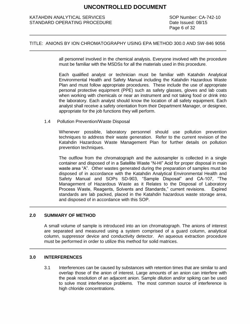
KATAHDIN ANALYTICAL SERVICES SOP Number: CA-742-10 STANDARD OPERATING PROCEDURE Date Issued: 08/15 Page 6 of 32 TITLE: ANIONS BY ION CHROMATOGRAPHY USING EPA METHOD 300.0 AND SW-846 9056
all personnel involved in the chemical analysis. Everyone involved with the procedure must be familiar with the MSDSs for all the materials used in this procedure. Each qualified analyst or technician must be familiar with Katahdin Analytical Environmental Health and Safety Manual including the Katahdin Hazardous Waste Plan and must follow appropriate procedures. These include the use of appropriate personal protective equipment (PPE) such as safety glasses, gloves and lab coats when working with chemicals or near an instrument and not taking food or drink into the laboratory. Each analyst should know the location of all safety equipment. Each analyst shall receive a safety orientation from their Department Manager, or designee, appropriate for the job functions they will perform.
1.4 Pollution Prevention/Waste Disposal Whenever possible, laboratory personnel should use pollution prevention
techniques to address their waste generation. Refer to the current revision of the Katahdin Hazardous Waste Management Plan for further details on pollution prevention techniques.
The outflow from the chromatograph and the autosampler is collected in a single
container and disposed of in a Satellite Waste “N-HI” Acid for proper disposal in main waste area “A”. Other wastes generated during the preparation of samples must be disposed of in accordance with the Katahdin Analytical Environmental Health and Safety Manual and SOPs SD-903, “Sample Disposal” and CA-107, “The Management of Hazardous Waste as it Relates to the Disposal of Laboratory Process Waste, Reagents, Solvents and Standards,” current revisions. Expired standards are lab packed, placed in the Katahdin hazardous waste storage area, and disposed of in accordance with this SOP.
2.0 SUMMARY OF METHOD
A small volume of sample is introduced into an ion chromatograph. The anions of interest are separated and measured using a system comprised of a guard column, analytical column, suppressor device and conductivity detector. An aqueous extraction procedure must be performed in order to utilize this method for solid matrices.
3.0 INTERFERENCES 3.1 Interferences can be caused by substances with retention times that are similar to and
overlap those of the anion of interest. Large amounts of an anion can interfere with the peak resolution of an adjacent anion. Sample dilution and/or spiking can be used to solve most interference problems. The most common source of interference is high chloride concentrations.
UNCONTROLLED DOCUMENT

KATAHDIN ANALYTICAL SERVICES SOP Number: CA-742-10 STANDARD OPERATING PROCEDURE Date Issued: 08/15 Page 7 of 32 TITLE: ANIONS BY ION CHROMATOGRAPHY USING EPA METHOD 300.0 AND SW-846 9056
3.2 The water dip or negative peak that elutes near and can interfere with the chloride peak can usually be eliminated by the adding the equivalent of 1mL of eluent concentrate to 100 mL of each sample.
3.3 The acetate anion elutes early during the chromatographic run. The retention times of
the anions also seem to differ when large amounts of acetate are present. Therefore, this method is not recommended for leachates of solid samples when acetic acid is used for pH adjustment.
3.4 Method interferences may be caused by contaminants in the water, reagents,
glassware, and other sample processing apparatus that lead to discrete artifacts or elevated baseline in the ion chromatograph.
3.5 Samples that contain particles larger than 0.45 and reagent solutions that contain
particles larger than 0.2 m require filtration to prevent damage to instrument columns and flow systems.
3.6 Any anion that is not retained by the column or only slightly retained will elute in the
area of fluoride and interfere. Known coelution is caused by carbonate and other small organic anions. At concentrations above 1.5 mg/L fluoride this interference may not be significant.
4.0 APPARATUS AND MATERIALS
4.1 Ion chromatograph capable of delivering 1 to 5 mL of eluent per minute at a pressure of 1000 to 4000 psi. The chromatograph is controlled with a Windows-based PC running Chromeleon software. The chromatograph must be equipped with an injection valve, a 10- to 100-uL sample loop, and set up with the following components.
4.1.1 Autosampler – Dionex Model AS-DV 4.1.2 Ion chromatography system – Dionex ICS-2000 with conductivity detection
4.1.3 Precolumn – A guard column placed before the separator column to protect
the separator column from fouling by particulates or organic constituents. Dionex Guard Cartridge AG18 or equivalent.
4.1.4 Separator column – A column packed with an anion exchange resin, suitable
for resolving the anions of interest. Dionex Ionpac AS18 or equivalent.
4.1.5 Conductivity suppressor – An ion exchange-based device that is capable of converting the eluent and separated anions into their respective acid forms. Dionex Micromembrane Suppressor Model ASRS 300 or equivalent.
UNCONTROLLED DOCUMENT
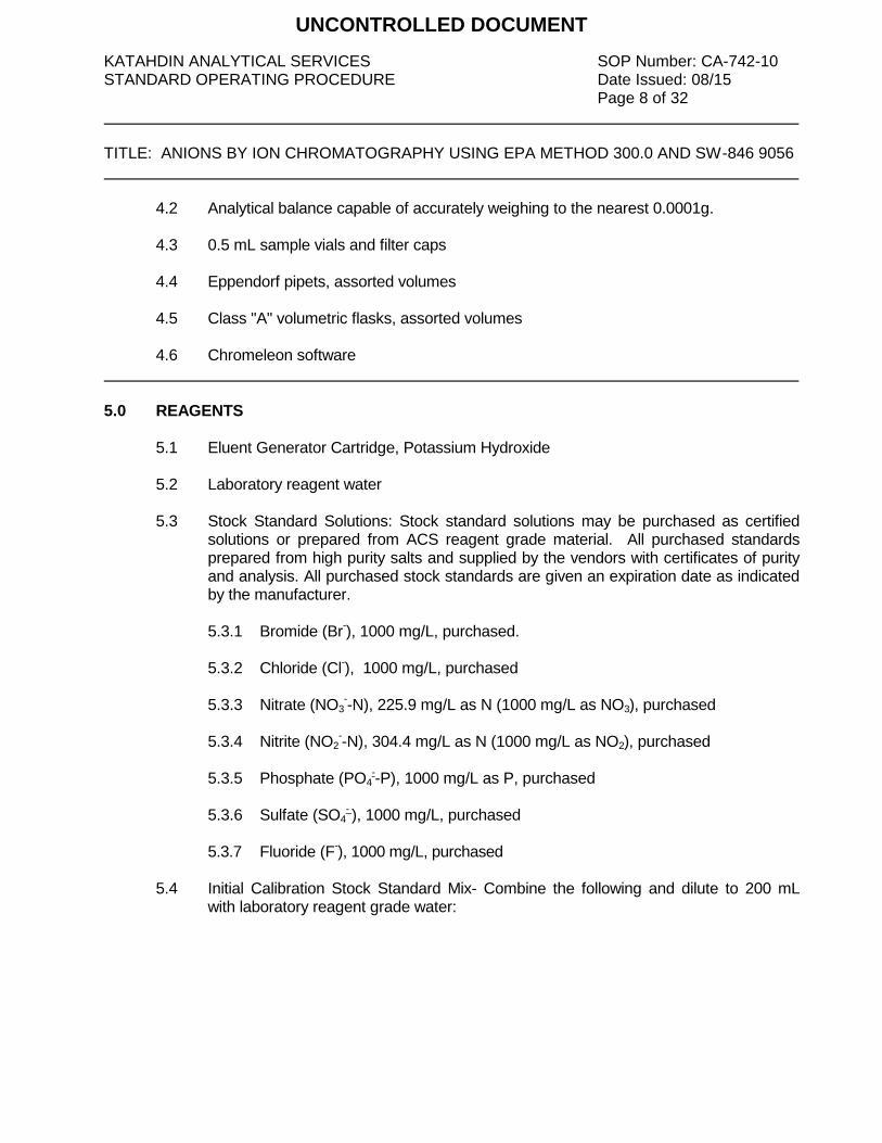
KATAHDIN ANALYTICAL SERVICES SOP Number: CA-742-10 STANDARD OPERATING PROCEDURE Date Issued: 08/15 Page 8 of 32 TITLE: ANIONS BY ION CHROMATOGRAPHY USING EPA METHOD 300.0 AND SW-846 9056
4.2 Analytical balance capable of accurately weighing to the nearest 0.0001g. 4.3 0.5 mL sample vials and filter caps 4.4 Eppendorf pipets, assorted volumes 4.5 Class "A" volumetric flasks, assorted volumes
4.6 Chromeleon software
5.0 REAGENTS
5.1 Eluent Generator Cartridge, Potassium Hydroxide
5.2 Laboratory reagent water
5.3 Stock Standard Solutions: Stock standard solutions may be purchased as certified solutions or prepared from ACS reagent grade material. All purchased standards prepared from high purity salts and supplied by the vendors with certificates of purity and analysis. All purchased stock standards are given an expiration date as indicated by the manufacturer.
5.3.1 Bromide (Br
-), 1000 mg/L, purchased.
5.3.2 Chloride (Cl
-), 1000 mg/L, purchased
5.3.3 Nitrate (NO3
--N), 225.9 mg/L as N (1000 mg/L as NO3), purchased
5.3.4 Nitrite (NO2
--N), 304.4 mg/L as N (1000 mg/L as NO2), purchased
5.3.5 Phosphate (PO4
--P), 1000 mg/L as P, purchased
5.3.6 Sulfate (SO4
- ), 1000 mg/L, purchased
5.3.7 Fluoride (F
-), 1000 mg/L, purchased
5.4 Initial Calibration Stock Standard Mix- Combine the following and dilute to 200 mL
with laboratory reagent grade water:
UNCONTROLLED DOCUMENT

KATAHDIN ANALYTICAL SERVICES SOP Number: CA-742-10 STANDARD OPERATING PROCEDURE Date Issued: 08/15 Page 9 of 32 TITLE: ANIONS BY ION CHROMATOGRAPHY USING EPA METHOD 300.0 AND SW-846 9056
Analyte
Amount of
Stock Std.
Added
(mL)
Concen-
tration in
Stock Std.
(mg/L)
Final
Volume of
Primary
Mixed Cal.
Std. (mL)
Final Conc.
In Primary
Mixed Cal.
Std. (mg/L)
Cl-
2.0 1000
200
10.0
NO2--N 2.63 304.4 4.0
NO3--N 3.54 225.9 4.0
Br-
4.0 1000 20.0
SO4-
4.0 1000 20.0
PO4--P 1.0 1000 5.0
F-
1.0 1000 5.0
NOTE: At any time a stock may be prepared with an abbreviated list of analytes and should be clearly labeled with the list of analytes contained.
5.5 Initial Calibration Working Standards – Dilute Initial Calibration Stock Standard as
follows to prepare the five-point level working calibration standards:
Work
-ing
Std.
ID
Amount
of
Primary
Mixed
Cal. Std.
Added
(mL)
Final
Volume
of
Working
Cal. Std.
(mL)
Analyte Conc. In Working Cal. Std. (mg/L)
Cl-
F- NO2
-
as N
NO3-
as N Br
- SO4
- PO4 as
P
#6 1 1 10 5 4 4 20 20 5
#5 0.5 1 5 2.5 2 2 10 10 2.5
#4 0.25 1 2.5 1.25 1 1 5 5 1.25
#3 0.1 1 1 0.5 0.4 0.4 2 2 0.5
#2 0.01 1 .1 0.05 0.04 0.04 0.2 0.2 0.05
Note: Standard #1 is the calibration blank 5.6 Continuing Calibration Verification Standard (CCV) – The CCV will be prepared using
the same stock as the calibration standards and will be prepared at the same concentration as calibration standard #5.
5.7 LCS/MS Stock Standard – LCS/MS Stock must be comprised of independent sources
for all analytes relative to the calibration standard stock. Combine the following using purchased standards from second source and dilute to 200 mL with laboratory reagent grade water: 7.5 mL of standard solution “A” and 7.5 mL of standard solution “B”.
UNCONTROLLED DOCUMENT
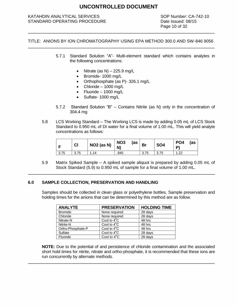
KATAHDIN ANALYTICAL SERVICES SOP Number: CA-742-10 STANDARD OPERATING PROCEDURE Date Issued: 08/15 Page 10 of 32 TITLE: ANIONS BY ION CHROMATOGRAPHY USING EPA METHOD 300.0 AND SW-846 9056
5.7.1 Standard Solution “A”- Multi-element standard which contains analytes in the following concentrations:
Nitrate (as N) – 225.9 mg/L
Bromide- 1000 mg/L
Orthophosphate (as P)- 326.1 mg/L
Chloride – 1000 mg/L
Fluoride – 1000 mg/L
Sulfate- 1000 mg/L 5.7.2 Standard Solution “B” – Contains Nitrite (as N) only in the concentration of
304.4 mg
5.8 LCS Working Standard – The Working LCS is made by adding 0.05 mL of LCS Stock Standard to 0.950 mL of DI water for a final volume of 1.00 mL. This will yield analyte concentrations as follows:
F Cl NO2 (as N) NO3 (as
N) Br SO4
PO4 (as
P)
3.75 3.75 1.14 .845 3.75 3.75 1.22
5.9 Matrix Spiked Sample – A spiked sample aliquot is prepared by adding 0.05 mL of
Stock Standard (5.9) to 0.950 mL of sample for a final volume of 1.00 mL.
6.0 SAMPLE COLLECTION, PRESERVATION AND HANDLING
Samples should be collected in clean glass or polyethylene bottles. Sample preservation and holding times for the anions that can be determined by this method are as follow.
ANALYTE PRESERVATION HOLDING TIME Bromide None required 28 days
Chloride None required 28 days
Nitrate-N Cool to 4oC 48 hrs
Nitrite-N Cool to 4oC 48 hrs
Ortho-Phosphate-P Cool to 4oC 48 hrs
Sulfate Cool to 4oC 28 days
Fluoride Cool to 4oC 28 days
NOTE: Due to the potential of and persistence of chloride contamination and the associated short hold times for nitrite, nitrate and ortho-phosphate, it is recommended that these ions are run concurrently by alternate methods.
UNCONTROLLED DOCUMENT

KATAHDIN ANALYTICAL SERVICES SOP Number: CA-742-10 STANDARD OPERATING PROCEDURE Date Issued: 08/15 Page 11 of 32 TITLE: ANIONS BY ION CHROMATOGRAPHY USING EPA METHOD 300.0 AND SW-846 9056
7.0 PROCEDURES
7.1 SAMPLE PREPARATION Refer to Katahdin Analytical Services SOP CA-106, “Basic Laboratory Technique”, current revision for information on sub-sampling.
7.1.1 Solid Samples Extraction – Add an amount of laboratory reagent grade water equal to ten times the weight of the dry sample. This slurry is mixed for ten minutes using a magnetic stirrer. The resulting slurry is allowed to stand or
may be centrifuged prior to filtration through 0.45 m filter. Hold times for analytes of interest should be considered to commence upon the generation of the extract.
7.2 TURNING ON INSTRUMENT
7.2.1 The instrument is configured as illustrated in Figure 1.
7.2.2 Open the chromeleon software
7.2.3 Click on the instrument tab in the lower left corner.
7.2.4 Click on buttons for pump, Eluent Generator, CR-TC, then suppressor, in that
order. The eluent should be set at 30mM, the suppressor should be set at 23mA, and the flow rate should be set at 0.30mL/min. The eluent fill level should be adjusted whenever water is added to the bottle. The column heater should be set at 30
o C. The run time is set in the instrument method for 16
min.
Note: If the water has been changed or the instrument has been off for a few days, the pump should be primed before turning the instrument on for the day. This is done by clicking the prime button on the instrument panel, opening the waste valve, and then clicking OK at the top of the screen. Allow to prime for five minutes or so before clicking the off button and closing the valve.
7.2.5 Monitor and record the backpressure on the HPLC pump. The pressure
should not exceed 3000 psi. If this occurs it would indicate the need to replace or clean the column, see column care and maintenance in the column manual.
7.3 CALIBRATION
7.3.1 A new calibration curve must be prepared at least one time every 6 months (daily for SW846 9056) or if one of the following occurs:
UNCONTROLLED DOCUMENT

KATAHDIN ANALYTICAL SERVICES SOP Number: CA-742-10 STANDARD OPERATING PROCEDURE Date Issued: 08/15 Page 12 of 32 TITLE: ANIONS BY ION CHROMATOGRAPHY USING EPA METHOD 300.0 AND SW-846 9056
7.3.1.1 The daily calibration verification is outside of the method criteria (Refer to section 8.0).
7.3.1.2 Major maintenance has been performed on the instrument (Refer to
maintenance log, Figure 2).
NOTE: If one of the above is true, a new calibration curve must be prepared even if it has been less than 6 months since the last calibration.
7.3.2 If a calibration curve is required, prepare the standards as described in section
5.0. Pipet 1 mL of each standard into the autosampler cups and push filter caps down into the vials using the filter cap tool.
7.3.3 Record the standards in the runlog (Figure 3) and load onto the autosampler.
Push the carousel release button on the autosampler to allow the wheel to turn. Push the button again to engage the wheel. To start a new sequence, open an old anion sequence in chromeleon by clicking on the data tab and double clicking the desired sequence. Old samples can be deleted by row. Click “save as” and use that day’s date as the sequence name. When entering the calibration points into the sample sequence, change the sample type to “calibration standard” and type the calibrator names in the level column. Two method blanks that will not be reported should be analyzed prior to calibration or sample run to ensure that there is no contamination present in the system. The instrument method and the processing method should not need to be changed. The volume column should read 25 uL for all samples. The “fill down” button can be clicked to renumber the position column. Resave the sequence and click the start button at the top of the screen.
7.3.4 When the calibration is finished, the calibration will need to be updated in the
processing method. This is done by double clicking on the processing method on the bottom of the data screen in the associated items table. The calibration tab should already be selected. Click the browse button in the global calibration settings box. Double click the desired sequence, then click update. Save the processing method. The chromatograms for the entire sequence can be printed by double clicking on any chromatogram in the ECD_1 column and clicking on report designer in the lower left corner. Click on the integration tab at the bottom of the screen, then click the chromeleon icon in the upper left to print. Click print and check apply to current sequence. Click OK.
7.3.5 To print out all of the calibration curve graphs highlight all of the points in the
sequence and right click to select print. Click the button next to report template and select the method folder. Double click on “test” and deselect all but the calibration box. Click OK to print.
7.3.6 The acceptance criteria for the calibration is a 0.995 correlation coefficient for
the full curve. Also, the standard at or below the PQL must be within 50% of
UNCONTROLLED DOCUMENT
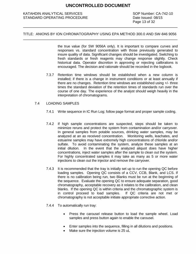
KATAHDIN ANALYTICAL SERVICES SOP Number: CA-742-10 STANDARD OPERATING PROCEDURE Date Issued: 08/15 Page 13 of 32 TITLE: ANIONS BY ION CHROMATOGRAPHY USING EPA METHOD 300.0 AND SW-846 9056
the true value (for SW 9056A only). It is important to compare curves and responses vs. standard concentration with those previously generated to insure quality of data. Significant changes should be investigated. Switching to fresh standards or fresh reagents may change response slightly. Check historical data. Operator discretion in approving or rejecting calibrations is encouraged. The decision and rationale should be recorded in the logbook.
7.3.7 Retention time windows should be established when a new column is
installed; if there is a change in instrument conditions or at least annually if there are no changes. Retention time windows are established using +/- three times the standard deviation of the retention times of standards run over the course of one day. The experience of the analyst should weigh heavily in the interpretation of chromatograms.
7.4 LOADING SAMPLES
7.4.1 Write sequence in IC Run Log; follow page format and proper sample coding.
7.4.2 If high sample concentrations are suspected, steps should be taken to minimize reruns and protect the system from contamination and/or carryover. In general samples from potable sources, drinking water samples, may be analyzed at an as received concentration. Monitoring wells, leachates, and estuarine samples may have extremely high concentrations of chloride and/or sulfate. To avoid contaminating the system, analyze these samples at an initial dilution. In the event that the analyzed aliquot does have higher concentrations, inject water samples after the sample to clean out the system. For highly concentrated samples it may take as many as 5 or more water injections to clean out the injector and remove the carryover.
7.4.3 It is recommended that the tray is initially set up to run the opening QC before loading samples. Opening QC consists of a CCV, CCB, Blank, and LCS. If there is no calibration being run, two Blanks must be run at the beginning of the sequence. Evaluate the opening QC to ensure adequate separation, good chromatography, acceptable recovery as it relates to the calibration, and clean blanks. If the opening QC is within criteria and the chromatographic system is in control proceed to load samples. If QC criteria are not met or chromatography is not acceptable initiate appropriate corrective action.
7.4.4 To automatically run tray:
Press the carousel release button to load the sample wheel. Load samples and press button again to enable the carousel.
Enter samples into the sequence, filling in all dilutions and positions.
Make sure the injection volume is 25 uL
UNCONTROLLED DOCUMENT
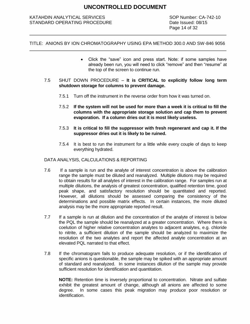
KATAHDIN ANALYTICAL SERVICES SOP Number: CA-742-10 STANDARD OPERATING PROCEDURE Date Issued: 08/15 Page 14 of 32 TITLE: ANIONS BY ION CHROMATOGRAPHY USING EPA METHOD 300.0 AND SW-846 9056
Click the “save” icon and press start. Note: if some samples have already been run, you will need to click “remove” and then “resume” at the top of the screen to continue run.
7.5 SHUT DOWN PROCEDURE – It is CRITICAL to explicitly follow long term
shutdown storage for columns to prevent damage.
7.5.1 Turn off the instrument in the reverse order from how it was turned on.
7.5.2 If the system will not be used for more than a week it is critical to fill the
columns with the appropriate storage solution and cap them to prevent
evaporation. If a column dries out it is most likely useless.
7.5.3 It is critical to fill the suppressor with fresh regenerant and cap it. If the
suppressor dries out it is likely to be ruined.
7.5.4 It is best to run the instrument for a little while every couple of days to keep
everything hydrated.
DATA ANALYSIS, CALCULATIONS & REPORTING
7.6 If a sample is run and the analyte of interest concentration is above the calibration range the sample must be diluted and reanalyzed. Multiple dilutions may be required to obtain results for all analytes of interest in the calibration range. For samples run at multiple dilutions, the analysis of greatest concentration, qualified retention time, good peak shape, and satisfactory resolution should be quantitated and reported. However, all dilutions should be assessed comparing the consistency of the determinations and possible matrix effects. In certain instances, the more diluted analysis may be the more appropriate reported result.
7.7 If a sample is run at dilution and the concentration of the analyte of interest is below
the PQL the sample should be reanalyzed at a greater concentration. Where there is coelution of higher relative concentration analytes to adjacent analytes, e.g. chloride to nitrite, a sufficient dilution of the sample should be analyzed to maximize the resolution of the two analytes and report the affected analyte concentration at an elevated PQL narrated to that effect.
7.8 If the chromatogram fails to produce adequate resolution, or if the identification of
specific anions is questionable, the sample may be spiked with an appropriate amount of standard and reanalyzed. In some instances dilution of the sample may provide sufficient resolution for identification and quantitation.
NOTE: Retention time is inversely proportional to concentration. Nitrate and sulfate exhibit the greatest amount of change, although all anions are affected to some degree. In some cases this peak migration may produce poor resolution or identification.
UNCONTROLLED DOCUMENT
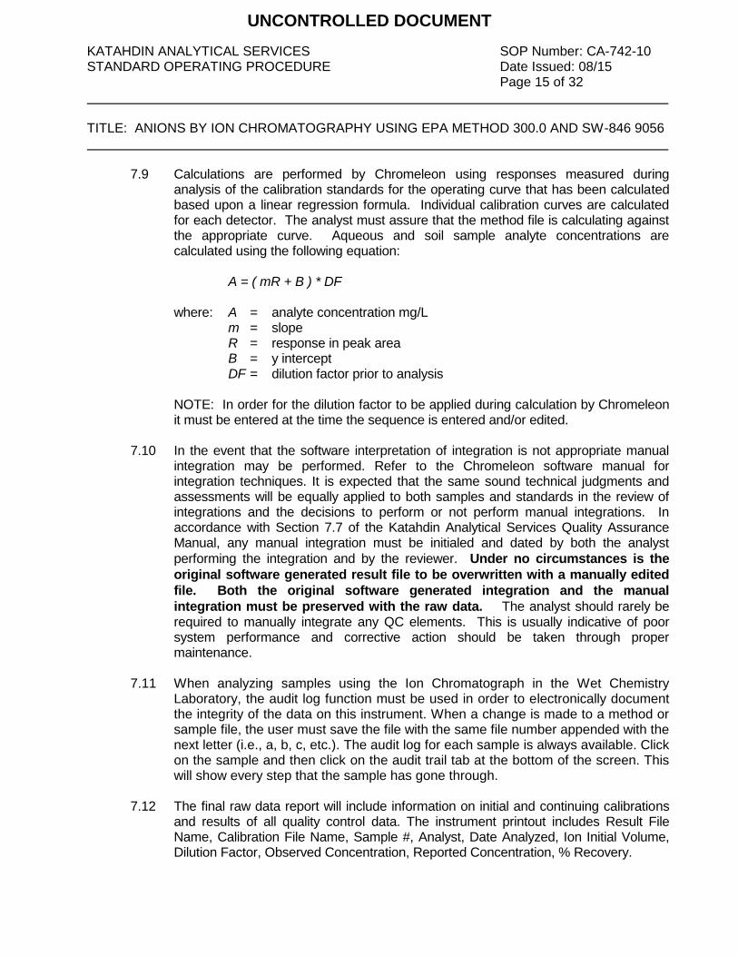
KATAHDIN ANALYTICAL SERVICES SOP Number: CA-742-10 STANDARD OPERATING PROCEDURE Date Issued: 08/15 Page 15 of 32 TITLE: ANIONS BY ION CHROMATOGRAPHY USING EPA METHOD 300.0 AND SW-846 9056
7.9 Calculations are performed by Chromeleon using responses measured during analysis of the calibration standards for the operating curve that has been calculated based upon a linear regression formula. Individual calibration curves are calculated for each detector. The analyst must assure that the method file is calculating against the appropriate curve. Aqueous and soil sample analyte concentrations are calculated using the following equation:
A = ( mR + B ) * DF
where: A = analyte concentration mg/L m = slope R = response in peak area
B = y intercept DF = dilution factor prior to analysis
NOTE: In order for the dilution factor to be applied during calculation by Chromeleon it must be entered at the time the sequence is entered and/or edited.
7.10 In the event that the software interpretation of integration is not appropriate manual integration may be performed. Refer to the Chromeleon software manual for integration techniques. It is expected that the same sound technical judgments and assessments will be equally applied to both samples and standards in the review of integrations and the decisions to perform or not perform manual integrations. In accordance with Section 7.7 of the Katahdin Analytical Services Quality Assurance Manual, any manual integration must be initialed and dated by both the analyst
performing the integration and by the reviewer. Under no circumstances is the
original software generated result file to be overwritten with a manually edited
file. Both the original software generated integration and the manual
integration must be preserved with the raw data. The analyst should rarely be required to manually integrate any QC elements. This is usually indicative of poor system performance and corrective action should be taken through proper maintenance.
7.11 When analyzing samples using the Ion Chromatograph in the Wet Chemistry
Laboratory, the audit log function must be used in order to electronically document the integrity of the data on this instrument. When a change is made to a method or sample file, the user must save the file with the same file number appended with the next letter (i.e., a, b, c, etc.). The audit log for each sample is always available. Click on the sample and then click on the audit trail tab at the bottom of the screen. This will show every step that the sample has gone through.
7.12 The final raw data report will include information on initial and continuing calibrations
and results of all quality control data. The instrument printout includes Result File Name, Calibration File Name, Sample #, Analyst, Date Analyzed, Ion Initial Volume, Dilution Factor, Observed Concentration, Reported Concentration, % Recovery.
UNCONTROLLED DOCUMENT

KATAHDIN ANALYTICAL SERVICES SOP Number: CA-742-10 STANDARD OPERATING PROCEDURE Date Issued: 08/15 Page 16 of 32 TITLE: ANIONS BY ION CHROMATOGRAPHY USING EPA METHOD 300.0 AND SW-846 9056
7.13 Sample preparation information is entered manually into the Katahdin Information Management System (KIMS). Instrument data files are then imported electronically into KIMS for calculation and reporting of sample results and quality control data. Refer to the current revision of SOP CA-762 (“W et Chemistry Data Entry and Review Using Katahdin Information Management System”) for further information.
7.14 A batch sheet is generated (Figure 4). Raw data and batch sheets are reviewed for
completeness and accuracy by the Department Manager or other qualified designee.
7.15 Printouts of instrument calibrations and sample data are filed in the lab for approximately 3 months for reference by analysts. Prior calibrations are archived and all are available in the TurboChrom database.
_________________________________________________________________________________
8.0 QUALITY CONTROL AND ACCEPTANCE CRITERIA
Refer to Table 1 for a summary of QC requirements, acceptance criteria, and corrective actions. Table 1 criteria are intended to be guidelines for analysts. The table does not cover all possible situations. If any of the QC requirements are outside the recovery ranges listed in Table 1, all associated samples must be evaluated against all the QC. In some cases data may be reported, but may be reanalyzed in other cases. Making new reagents and standards may be necessary if the standardization is suspect. The corrective actions listed in Table 1 may rely on analyst experience to make sound scientific judgments. These decisions are based on holding time considerations, remaining sample volume and client and project specific Data Quality Objectives. The Department Manager, Operations Manager, General Manager and/or Quality Assurance Officer may be consulted to evaluate data. Some samples may not be able to be reanalyzed within hold time. In these cases “qualified” data with narration may be advisable after consultation with the client. Table 2 is a summary of the QC criteria for work following DoD QSM version 4.2. Table 3 is a summary of the QC criteria for work following DoD QSM version 5.0. In some cases the standard QC requirements listed in this section and in Table 1 may not be sufficient to meet the Data Quality Objectives of the specific project. Much of the work performed at the lab is analyzed in accordance with specific QC requirements spelled out in a project specific Quality Assurance Project Plan (QAPP) or in a program specific Quality Systems Manual (QSM). The reporting limits, acceptance criteria and/or corrective actions may be different than those specified in this SOP. In these cases the appropriate information will be communicated to the Department Manager and/or senior chemists before initiation of the analyses so that specific product codes can be produced for the project. In addition, the work order notes for each project will describe the specific QAPP or QSM to be followed. 8.1 Initial Instrument Calibration – Instrument calibration, which is generated using a
blank the five standards listed in Section 5.6, is performed at least once every six months or whenever there is a significant change in instrument operating conditions or hardware. One of the calibration standards must be at or below the Practical
UNCONTROLLED DOCUMENT

KATAHDIN ANALYTICAL SERVICES SOP Number: CA-742-10 STANDARD OPERATING PROCEDURE Date Issued: 08/15 Page 17 of 32 TITLE: ANIONS BY ION CHROMATOGRAPHY USING EPA METHOD 300.0 AND SW-846 9056
Quantitation Limit for each analyte. The curve fit is accomplished using least squares linear regression, and the correlation coefficient for the curve must be at least 0.995. Sample results that exceed the calibration range of the instrument may not be reported; the sample must be diluted and reanalyzed until the measured concentration of the analyte is within the calibration range. Because calibration linearity is established each time the instrument is calibrated (at least every six months) and because sample results that fall outside the calibration range may not be reported, a separate linear calibration range study is not performed.
8.2 Lower Limit of Quantitation - The laboratory should establish the LLOQ for each
analyte as the lowest reliable laboratory reporting concentration or in most cases the lowest point in the calibration curve which is less than or equal to the desired regulatory action levels, based on the stated project requirements. Analysis of a standard prepared at the LLOQ concentration levels or use of the LLOQs as the lowest point calibration standard provides confirmation of the established sensitivity of the method. The LLOQ recoveries must be within 50% of the true values to verify the data reporting limit.
8.3 Continuing Calibration Verification (CCV) and Continuing Calibration Blank (CCB) –
Ongoing calibration accuracy is verified by analyzing a CCV standard (a mid-range check standard) and a CCB at the beginning of each run, after every ten samples, and at the end of each run. The recovery of each CCV must be within 90% - 110% of the true value for each analyte. The measured concentration of each analyte in the CCB must be below the Practical Quantitation Limit for the analyte. If a CCV or CCB fails, the analysis must be stopped, the problem corrected, and the previous ten samples must be reanalyzed, with the following exception. If one or both CCVs bracketing a sample result are biased high and the sample concentration is <PQL, the sample result may be reported. CCVs or CCBs that are biased high may be indicative of carryover or contamination in the system by high concentration samples.
NOTE: High bias for chloride may be indicative of chloride contamination in the injector. If the run is attended and chloride is an analyte of interest, halt the run and take corrective action if bias is observed.
8.4 Laboratory Control Sample (LCS) / Initial Calibration Verification (ICV) – One
LCS/ICV, prepared from a separate standard source from the Initial Instrument Calibration, must be analyzed with each batch of 20 or fewer samples. LCS/ICV recovery acceptance limits are 90% - 110% for EPA Method 300.0 and 80% - 120% for SW846 Method 9056. For DoD QSM 5.0, use QC acceptance criteria specified by DoD, if available). Otherwise use in-house control limits.
8.5 Method Blank (MB) – A method blank consisting of reagent water that filtered in the
same fashion as the associated samples must be analyted with each batch of 20 or fewer samples. The measured concentration of each analyte in the MB must be less
UNCONTROLLED DOCUMENT

KATAHDIN ANALYTICAL SERVICES SOP Number: CA-742-10 STANDARD OPERATING PROCEDURE Date Issued: 08/15 Page 18 of 32 TITLE: ANIONS BY ION CHROMATOGRAPHY USING EPA METHOD 300.0 AND SW-846 9056
than the PQL (for DoD QSM, no analyte may be detected in the MB at a concentration greater than ½ PQL or greater than 1/10 the amount measured in any sample). In the instance where there is a value in excess of the CCB, the filter source should be suspected as contributing contamination. Repeat the analysis with additional cartridges.
8.6 Matrix Spike (MS) Sample – Matrix spike samples must be prepared and analyzed at
a frequency of 10% (one sample in 10) for EPA Method 300.0 or 5% (one sample in 20) for SW846 Method 9056A. Matrix spikes is prepared by adding 0.05 mL of Primary Matrix Spike Mixed Standard (Section 5.9) to 1.0 mL of the filtered sample prior to loading. If the concentration of the spike is less than 25% of the native sample concentration the matrix spike recovery should not be calculated. The matrix spike recovery acceptance limits are 90% - 110% for EPA Method 300.0 and 80% - 120% for SW846 Method 9056A. If the recovery of any analyte falls outside the criteria range and the LCS and CCVs are within criteria, the poor recovery should be attributed to sample matrix.
For DoD QSM 5.0, use QC acceptance criteria specified by DoD, if available). Otherwise use in-house control limits.
8.7 Matrix Spike Duplicate (MSD) – Prepared at a frequency of one per 20 samples.
Acceptance limits are 80% - 120% recovery and ≤15% RPD.
8.8 Laboratory Duplicate (Dup) - One duplicate sample must be analyzed with each batch of 20 or fewer samples (one per 10 samples for DoD QSM). Analytes with measured
values > 5 times the PQL should achieve duplicate/MSD sample precision of 20% RPD (≤10% for DoD QSM).
_________________________________________________________________________________
9.0 METHOD PERFORMANCE
The method detection limit (MDL) is defined as the minimum concentration of a substance that can be measured and reported with 99% confidence that the value is above zero. The MDLs shall be determined and verified one time per type of instrument unless otherwise required by the method. A Limit of Detection (LOD) is an estimate of the minimum amount of a substance that an analytical process can reliably detect. An LOD is analyte and matrix specific and may be laboratory-dependent. LODs must be determined for all parameters for which the laboratory is accredited under the DoD Environmental Laboratory Accreditation Program. LOD’s must be verified for every preparation and analytical method combination and on every applicable instrument on a quarterly basis. The Limit of Quantitation (LOQ) is the minimum levels, concentrations, or quantities of a target variable (e.g., target analyte) that can be reported with a specified degree of confidence. The LOQ shall be set at the lowest point in the calibration curve for all analyses
UNCONTROLLED DOCUMENT

KATAHDIN ANALYTICAL SERVICES SOP Number: CA-742-10 STANDARD OPERATING PROCEDURE Date Issued: 08/15 Page 19 of 32 TITLE: ANIONS BY ION CHROMATOGRAPHY USING EPA METHOD 300.0 AND SW-846 9056
utilizing an initial calibration. LOQ’s must be verified quarterly for every preparation and analytical method combination and on every applicable instrument on a quarterly basis for all parameters included in the DoD Scope of Accreditation. The LOQ must be verified at least once annually if the analysis is not included in the DoD Scope of Accreditation. MDLs are filed with the Inorganic Department Manager and then with the QAO. LOD and LOQ verifications are filed with the QAO Refer to the current revision of Katahdin SOP QA-806, Method Detection Limit, Instrument Detection Limit and Reporting Limit Studies and Verifications, for procedures on determining the MDL. Refer to the current revisions of the applicable methods for other method performance parameters and requirements.
10.0 APPLICABLE DOCUMENTS/REFERENCES
"Methods for the Determination of Inorganic Substances in Environmental Samples", EPA - 600/R - 93 - 100, August 1993.
“Test Methods for the Evaluation of Solid Waste: Physical/Chemical Methods”, SW-846, Third Edition, Final Update IV, February 2007, Method 9056A. Katahdin SOP CA-101, Equipment Maintenance and Toubleshooting, current revision. Katahdin SOP CA-762, Wet Chemistry Data Entry and Review Using Katahdin Information Management System (KIMS) Katahdin SOP QA-806, Method Detection Limit, Instrument Detection Limit and Reporting Limit Studies and Verifications. Department of Defense Quality Systems Manual for Environmental Laboratories (DoD QSM), Current Version. The National Environmental Laboratory Accreditation Conference (NELAC) Standards, June 2003 The NELAC Institute, Laboratory Accreditation Standards, Volume 1, Management and Technical Requirements for Laboratories Performing Environmental Analysis, 10/06/2010. WISP717plus Autosampler Operator Manual Waters 510 HPLC Pump Manual Dionex 200i Manual
UNCONTROLLED DOCUMENT

KATAHDIN ANALYTICAL SERVICES SOP Number: CA-742-10 STANDARD OPERATING PROCEDURE Date Issued: 08/15 Page 20 of 32 TITLE: ANIONS BY ION CHROMATOGRAPHY USING EPA METHOD 300.0 AND SW-846 9056 LIST OF TABLES AND FIGURES Table 1 QC Requirements Table 2 DoD QSM 4.2 QC Criteria Table 3 DoD QSM 5.0 QC Criteria Table 4 Example Analytical Sequence with Acceptance Criteria Table 5 Summary of Method Modifications Figure 1 IC System Configuration Figure 2 Example of IC Maintenance Log Page Figure 3 Example of Anions by IC Runlog Page Figure 4 Example of IC Batch Sheet
UNCONTROLLED DOCUMENT
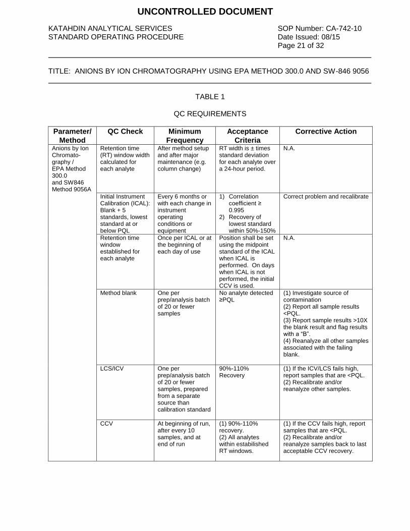
KATAHDIN ANALYTICAL SERVICES SOP Number: CA-742-10 STANDARD OPERATING PROCEDURE Date Issued: 08/15 Page 21 of 32 TITLE: ANIONS BY ION CHROMATOGRAPHY USING EPA METHOD 300.0 AND SW-846 9056
TABLE 1
QC REQUIREMENTS
Parameter/
Method
QC Check Minimum
Frequency
Acceptance
Criteria
Corrective Action
Anions by Ion Chromato-graphy / EPA Method 300.0 and SW846 Method 9056A
Retention time (RT) window width calculated for each analyte
After method setup and after major maintenance (e.g. column change)
RT width is ± times standard deviation for each analyte over a 24-hour period.
N.A.
Initial Instrument Calibration (ICAL): Blank + 5 standards, lowest standard at or below PQL
Every 6 months or with each change in instrument operating conditions or equipment
1) Correlation coefficient ≥ 0.995
2) Recovery of lowest standard within 50%-150%
Correct problem and recalibrate
Retention time window established for each analyte
Once per ICAL or at the beginning of each day of use
Position shall be set using the midpoint standard of the ICAL when ICAL is performed. On days when ICAL is not performed, the initial CCV is used.
N.A.
Method blank One per prep/analysis batch of 20 or fewer samples
No analyte detected ≥PQL
(1) Investigate source of contamination (2) Report all sample results <PQL. (3) Report sample results >10X the blank result and flag results with a “B”. (4) Reanalyze all other samples associated with the failing blank.
LCS/ICV One per prep/analysis batch of 20 or fewer samples, prepared from a separate source than calibration standard
90%-110% Recovery
(1) If the ICV/LCS fails high, report samples that are <PQL. (2) Recalibrate and/or reanalyze other samples.
CCV At beginning of run, after every 10 samples, and at end of run
(1) 90%-110% recovery. (2) All analytes within estabilished RT windows.
(1) If the CCV fails high, report samples that are <PQL. (2) Recalibrate and/or reanalyze samples back to last acceptable CCV recovery.
UNCONTROLLED DOCUMENT

KATAHDIN ANALYTICAL SERVICES SOP Number: CA-742-10 STANDARD OPERATING PROCEDURE Date Issued: 08/15 Page 22 of 32 TITLE: ANIONS BY ION CHROMATOGRAPHY USING EPA METHOD 300.0 AND SW-846 9056
TABLE 1
QC REQUIREMENTS (Continued)
Parameter/
Method
QC Check Minimum
Frequency
Acceptance
Criteria
Corrective Action
Anions by Ion Chromato-graphy / EPA Method 300.0 and SW846 Method 9056A
CCB Immediately following each CCV
No analyte detected ≥PQL
1) Investigate source of contamination (2) Report all sample results <PQL. (3) Report sample results >10X the blank result and flag results with a “B”. (4) Reanalyze all other samples associated with the failing CCB.
Matrix Spike One for every set of 10 samples (EPA 300.0) or one for every set of 20 samples (SW846 9056A)
90%-110% recovery (EPA 300.0) 80%-120% recovery (SW846 9056A)
(1) Evaluate the samples and associated QC: i.e. If the LCS results are acceptable, flag result and narrate. (2) If both the LCS and MS are unacceptable reprep and reanalyze the samples and QC. (3) Notate sample result in raw data if matrix interference suspected.
Matrix Spike Duplicate
One per 20 samples
(1) 90%-110% recovery (EPA 300.0) 80%-120% recovery (SW846 9056A) (2) RPD <15%
(1) Investigate problem and reanalyze sample in duplicate (2) If RPD still out, report original result with flagging and narration.
Sample Duplicate One per 20 samples
RPD <20% (1) Investigate problem and reanalyze sample in duplicate (2) If RPD still out, report original result with flagging and narration.
Demonstration of analyst proficiency; accuracy and precision
One time initially by each analyst performing the method and annually thereafter.
Must pass all applicable QC for method
Repeat analysis until able to perform passing QC; document successful performance in personnel training file
MDL study Refer to KAS SOP QA-806, “Method Detection Limit, Instrument Detection Limit and Reporting Limit Studies and Verifications”, current revision.
UNCONTROLLED DOCUMENT

KATAHDIN ANALYTICAL SERVICES SOP Number: CA-742-10 STANDARD OPERATING PROCEDURE Date Issued: 08/15 Page 23 of 32 TITLE: ANIONS BY ION CHROMATOGRAPHY USING EPA METHOD 300.0 AND SW-846 9056
TABLE 2
DoD QSM 4.2 QC REQUIREMENTS
QC Check Minimum
Frequency
Acceptance
Criteria
Corrective Action Flagging Criteria Comments
Demonstrate acceptable analytical capability
Prior to using any test method and at any time there is a significant change in instrument type, personnel, test method, or sample matrix.
QC acceptance criteria published by DoD, if available; otherwise use method-specified criteria.
Recalculate results; locate and fix problem, then rerun demonstration for those analytes that did not meet criteria (see Section C.1.f).
NA. This is a demonstration of analytical ability to generate acceptable precision and bias per the procedure in Appendix C. No analysis shall be allowed by analyst until successful demonstration of capability is complete.
LOD determination and verification
(Refer to current revision of SOP QA-806)
LOQ establishment and verification
(Refer to current revision of SOP QA-806)
Retention time (RT) window width calculated for each analyte
After method set-up and after major maintenance (e.g., column change).
RT width is ± 3 times standard deviation for each analyte RT over a 24-hour period.
NA. NA.
Initial calibration (ICAL) for all analytes (minimum three standards and one calibration blank)
ICAL prior to sample analysis.
r ≥ 0.995. Correct problem, then repeat ICAL.
Flagging criteria are not appropriate.
Problem must be corrected. No samples may be run until ICAL has passed.
Initial calibration verification (ICV) (second source)
Once after each ICAL, prior to beginning a sample run.
All analytes within ± 10% of true value and retention times within appropriate windows.
Correct problem and verify second source standard. Rerun second source verification. If that fails, correct problem and repeat ICAL.
Flagging criteria are not appropriate.
Problem must be corrected. No samples may be run until calibration has been verified.
Retention time window position establishment for each analyte
Once per multipoint calibration.
Position shall be set using the midpoint standard of the ICAL curve when ICAL is performed. On days when ICAL is not performed, the initial CCV is used.
NA. NA.
Midrange continuing calibration verification (CCV)
After every 10 field samples and at the end of the analysis sequence.
All project analytes within established retention time windows. Within ± 10% of true value.
Correct problem, then rerun calibration verification. If that fails, then repeat ICAL. Reanalyze all samples since the last successful calibration verification.
If reanalysis cannot be performed, data must be qualified and explained in the case narrative. Apply Q-flag to all results for the specific analyte(s) in all samples since the last acceptable calibration verification.
Problem must be corrected. Results may not be reported without a valid CCV. Flagging is only appropriate in cases where the samples cannot be reanalyzed. Retention time windows are updated per the method.
UNCONTROLLED DOCUMENT

KATAHDIN ANALYTICAL SERVICES SOP Number: CA-742-10 STANDARD OPERATING PROCEDURE Date Issued: 08/15 Page 24 of 32 TITLE: ANIONS BY ION CHROMATOGRAPHY USING EPA METHOD 300.0 AND SW-846 9056
TABLE 2
DoD QSM 4.2 QC REQUIREMENTS
QC Check Minimum
Frequency
Acceptance
Criteria
Corrective Action Flagging Criteria Comments
Method blank One per preparatory batch.
No analytes detected > ½ RL and > 1/10 the amount measured in any sample or 1/10 the regulatory limit (whichever is greater). Blank result must not otherwise affect sample results (see Box D-1).
Correct problem, then see criteria in Box D-1. If required, reprep and reanalyze method blank and all samples processed with the contaminated blank.
If reanalysis cannot be performed, data must be qualified and explained in the case narrative. Apply B-flag to all results for the specific analyte(s) in all samples in the associated preparatory batch.
Problem must be corrected. Results may not be reported without a valid method blank. Flagging is only appropriate in cases where the samples cannot be reanalyzed.
LCS containing all analytes to be reported
One per preparatory batch.
Laboratory in-house limits not to exceed ± 20%. Control limits may be not greater than ± 3 times the standard deviation of the mean LCS recovery. See Box D-3.
Correct problem, then reprep and reanalyze the LCS and all samples in the associated preparatory batch for failed analytes, if sufficient sample material is available (see full explanation in Appendix G).
If reanalysis cannot be performed, data must be qualified and explained in the case narrative. Apply Q-flag to specific analyte(s) in all samples in the associated preparatory batch.
Problem must be corrected. Results may not be reported without a valid LCS. Flagging is only appropriate in cases where the samples cannot be reanalyzed.
Matrix Spike (MS) One per preparatory batch per matrix (see Box D-7).
For matrix evaluation, use laboratory in-house LCS limits (not to exceed ± 20%).
Examine the project-specific DQOs. Contact the client as to additional measures to be taken.
For the specific analyte(s) in the parent sample, apply J-flag if acceptance criteria are not met.
For matrix evaluation only. If MS results are outside the LCS limits, the data shall be evaluated to determine the source of difference and to determine if there is a matrix effect or analytical error.
Matrix spike duplicate (MSD)
One per preparatory batch per matrix (see Box D-7).
For matrix evaluation, use laboratory in-house LCS limits (not to exceed ± 20%). RPD ≤ 15% (between MS and MSD).
Examine the project-specific DQOs. Contact the client as to additional measures to be taken.
For the specific analyte(s) in the parent sample, apply J-flag if acceptance criteria are not met.
The data shall be evaluated to determine the source of difference.
Sample duplicate (replicate)
The data shall be evaluated to determine the source of difference.
Apply J-flag if sample cannot be rerun or reanalysis does not correct problem.
Correct problem and reanalyze sample and duplicate.
One per every 10 samples.
%D ≤ 10% (between sample and sample duplicate).
Results reported between DL and LOQ
NA. NA. NA. Apply J-flag to all results between DL and LOQ.
UNCONTROLLED DOCUMENT

KATAHDIN ANALYTICAL SERVICES SOP Number: CA-742-10 STANDARD OPERATING PROCEDURE Date Issued: 08/15 Page 25 of 32 TITLE: ANIONS BY ION CHROMATOGRAPHY USING EPA METHOD 300.0 AND SW-846 9056
TABLE 3
DoD QSM 5.0 QC REQUIREMENTS
QC Check Minimum
Frequency
Acceptance
Criteria
Corrective Action Flagging Criteria Comments
Initial Calibration (ICAL) for all analytes
ICAL prior to sample analysis.
r2 ≥ 0.99. Correct problem, then repeat ICAL.
Flagging criteria are not appropriate.
Minimum 3 standards and a calibration blank. No samples shall be analyzed until ICAL has passed.
Retention Time window position establishment
Once per multipoint calibration.
Position shall be set using the midpoint standard of the ICAL curve when ICAL is performed. On days when ICAL is not performed, the initial CCV is used.
NA. NA. Established for each analyte.
Retention Time (RT) window width
At method set-up and after major maintenance (e.g., column change).
RT width is ± 3 times standard deviation for each analyte RT over a 24-hour period.
NA. NA. Calculated for each analyte.
Initial Calibration Verification (ICV)
Once after each ICAL, analysis of a second source standard prior to sample analysis.
All reported analytes within established RT windows. All reported analytes within ± 10% of true value.
Correct problem. Rerun ICV. If that fails, repeat ICAL.
Flagging criteria are not appropriate.
Freshly prepared ICV. No samples shall be analyzed until calibration has been verified.
Continuing Calibration Verification (CCV)
Before sample analysis; after every 10 field samples; and at the end of the analysis sequence.
All reported analytes within established retention time windows. All reported analytes within ± 10% of true value.
Recalibrate, and reanalyze all affected samples since the last acceptable CCV; or Immediately analyze two additional consecutive CCVs. If both pass, samples may be reported without reanalysis. If either fails, take corrective action(s) and re-calibrate; then reanalyze all affected samples since the last acceptable CCV.
If reanalysis cannot be performed, data must be qualified and explained in the case narrative. Apply Q-flag to all results for the specific analyte(s) in all samples since the last acceptable calibration verification.
Results may not be reported without a valid CCV. Flagging is only appropriate in cases where the samples cannot be reanalyzed. Retention time windows are updated per the method.
Method Blank (MB) One per preparatory batch.
No analytes detected > 1/2 LOQ or > 1/10 the amount measured in any sample or 1/10 the regulatory limit, whichever is greater.
Correct problem. If required, reprep and reanalyze MB and all samples processed with the contaminated blank.
If reanalysis cannot be performed, data must be qualified and explained in the case narrative. Apply B-flag to all results for the specific analyte(s) in all samples in the associated preparatory batch.
Results may not be reported without a valid method blank. Flagging is only appropriate in cases where the samples cannot be reanalyzed.
UNCONTROLLED DOCUMENT
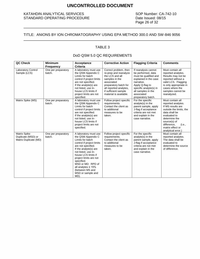
KATAHDIN ANALYTICAL SERVICES SOP Number: CA-742-10 STANDARD OPERATING PROCEDURE Date Issued: 08/15 Page 26 of 32 TITLE: ANIONS BY ION CHROMATOGRAPHY USING EPA METHOD 300.0 AND SW-846 9056
TABLE 3
DoD QSM 5.0 QC REQUIREMENTS
QC Check Minimum
Frequency
Acceptance
Criteria
Corrective Action Flagging Criteria Comments
Laboratory Control Sample (LCS)
One per preparatory batch.
A laboratory must use the QSM Appendix C Limits for batch control if project limits are not specified. If the analyte(s) are not listed, use in-house LCS limits if project limits are not specified.
Correct problem, then re-prep and reanalyze the LCS and all samples in the associated preparatory batch for all reported analytes, if sufficient sample material is available.
If reanalysis cannot be performed, data must be qualified and explained in the case narrative. Apply Q-flag to specific analyte(s) in all samples in the associated preparatory batch.
Must contain all reported analytes. Results may not be reported without a valid LCS. Flagging is only appropriate in cases where the samples cannot be reanalyzed.
Matrix Spike (MS) One per preparatory batch.
A laboratory must use the QSM Appendix C Limits for batch control if project limits are not specified. If the analyte(s) are not listed, use in-house LCS limits if project limits are not specified.
Follow project specific requirements. Contact the client as to additional measures to be taken.
For the specific analyte(s) in the parent sample, apply J-flag if acceptance criteria are not met and explain in the case narrative.
Must contain all reported analytes. If MS results are outside the limits, the data shall be evaluated to determine the source(s) of difference, (i.e., matrix effect or analytical error.)
Matrix Spike Duplicate (MSD) or Matrix Duplicate (MD)
One per preparatory batch.
A laboratory must use the QSM Appendix C Limits for batch control if project limits are not specified. If the analyte(s) are not listed, use in-house LCS limits if project limits are not specified. MSD or MD: RPD of all analytes ≤ 15% (between MS and MSD or sample and MD).
Follow project specific requirements. Contact the client as to additional measures to be taken.
For the specific analyte(s) in the parent sample, apply J-flag if acceptance criteria are not met and explain in the case narrative.
Must contain all reported analytes. The data shall be evaluated to determine the source of difference.
UNCONTROLLED DOCUMENT

KATAHDIN ANALYTICAL SERVICES SOP Number: CA-742-10 STANDARD OPERATING PROCEDURE Date Issued: 08/15 Page 27 of 32 TITLE: ANIONS BY ION CHROMATOGRAPHY USING EPA METHOD 300.0 AND SW-846 9056
TABLE 4
EXAMPLE ANALYTICAL SEQUENCE WITH ACCEPTANCE CRITERIA
Sample Number Instrument Runlog Acceptance Limit
1 CCV 90%-110%
2 CCB < PQL
3 ICV / LCS 90 -110% (300.0)
80%-120% (9056A)
4 Sample 1
5 Sample 2
6 Sample 3
7 Sample 4
8 Sample 5
9 Sample 6
10 Sample 7
11 Sample 8
12 Sample 9 -Duplicate 20% RPD (10% for DoD)
13 Sample 10 - Matrix
Spike 90 -110% (300.0)
80%-120% (9056A)
14 CCV 90%-110%
15 CCB < PQL
16 Sample 11
17 Sample 12
18 Sample 13
19 Sample 14
20 Sample 15
21 Sample 16
22 Sample 17
23 Sample 18
24 Sample 19
25 Sample 20 - Matrix
Spike 90 -110% (300.0)
80%-120% (9056A)
26 CCV 90%-110%
27 CCB < PQL
UNCONTROLLED DOCUMENT

KATAHDIN ANALYTICAL SERVICES SOP Number: CA-742-10 STANDARD OPERATING PROCEDURE Date Issued: 08/15 Page 28 of 32 TITLE: ANIONS BY ION CHROMATOGRAPHY USING EPA METHOD 300.0 AND SW-846 9056
TABLE 5
SUMMARY OF METHOD MODIFICATIONS
Topic Katahdin SOP CA-742-09
Method 300.0/9056, current
revisions Calibration
1) Calibration consists of blank + 5 standards
2) Linearity verified by performing calibration at least every 6 months, and diluting all samples exceeding calibration range
1) Calibration consists of blank + at least 3 standards
2) Linear range verification required every 6 months (Method 300.0)
QC – Method Blank
Acceptance limit < PQL Acceptance limit <MDL (Method 300.0) Acceptance limit <10% of LLOQ or regulatory limit or lowest sample (Method 9056A)
QC – LCS/ICV
Combined LCS and ICV with tighter acceptance limits (90%-110% recovery)
LCS acceptance limits 80%-120%, ICV acceptance limits 90%-110% (Method 9056A)
QC – Duplicate / Matrix Spike Duplicate
RPD acceptance limit ≤20%. RPD acceptance limit ≤15% for samples at or above midrange, ≤50% for samples near LLOQ (Method 9056A)
UNCONTROLLED DOCUMENT

KATAHDIN ANALYTICAL SERVICES SOP Number: CA-742-10 STANDARD OPERATING PROCEDURE Date Issued: 08/15 Page 29 of 32 TITLE: ANIONS BY ION CHROMATOGRAPHY USING EPA METHOD 300.0 AND SW-846 9056
FIGURE 1
IC SYSTEM CONFIGURATION
UNCONTROLLED DOCUMENT
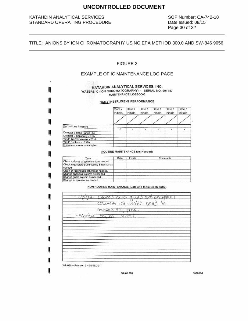
KATAHDIN ANALYTICAL SERVICES SOP Number: CA-742-10 STANDARD OPERATING PROCEDURE Date Issued: 08/15 Page 30 of 32 TITLE: ANIONS BY ION CHROMATOGRAPHY USING EPA METHOD 300.0 AND SW-846 9056
FIGURE 2
EXAMPLE OF IC MAINTENANCE LOG PAGE
UNCONTROLLED DOCUMENT

KATAHDIN ANALYTICAL SERVICES SOP Number: CA-742-10 STANDARD OPERATING PROCEDURE Date Issued: 08/15 Page 31 of 32 TITLE: ANIONS BY ION CHROMATOGRAPHY USING EPA METHOD 300.0 AND SW-846 9056
FIGURE 3
EXAMPLE OF ANIONS BY IC RUNLOG PAGE
UNCONTROLLED DOCUMENT
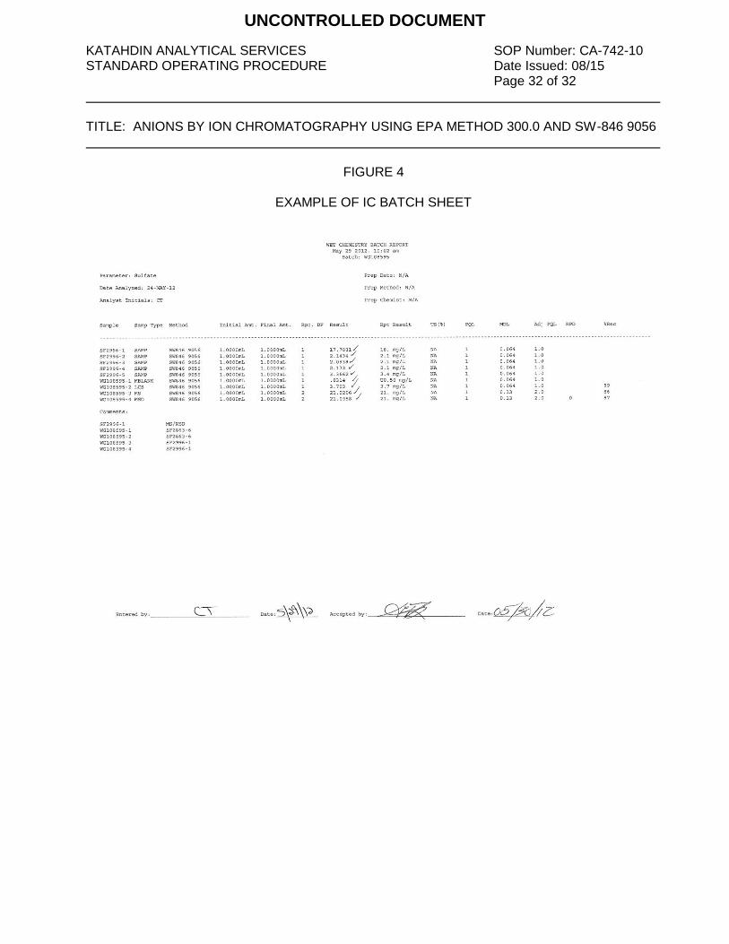
KATAHDIN ANALYTICAL SERVICES SOP Number: CA-742-10 STANDARD OPERATING PROCEDURE Date Issued: 08/15 Page 32 of 32 TITLE: ANIONS BY ION CHROMATOGRAPHY USING EPA METHOD 300.0 AND SW-846 9056
FIGURE 4
EXAMPLE OF IC BATCH SHEET
UNCONTROLLED DOCUMENT

ADDENDUMSOP NO CHANGE FORM
UNCONTROLLED DOCUMENT

UNCONTROLLED DOCUMENT

UNCONTROLLED DOCUMENT

UNCONTROLLED DOCUMENT

KATAHDIN ANALYTICAL SERVICES, INC. SOP Number: CA-336-06 STANDARD OPERATING PROCEDURE Date Issued: 05/13 Page 3 of 20 TITLE: DISSOLVED GAS ANALYSIS IN WATER SAMPLES USING GC HEADSPACE
EQUILIBRATION TECHNIQUE EPA SOP RSK-175 Please acknowledge receipt of this standard operating procedure by signing and dating both of the spaces provided. Return the bottom half of this sheet to the QA Department. I acknowledge receipt of copy of document SOP CA-336-06, titled “Dissolved Gas Analysis in Water Samples Using GC Headspace Equilibration Technique EPA SOP RSK-175”. Recipient: Date: KATAHDIN ANALYTICAL SERVICES, INC. STANDARD OPERATING PROCEDURE I acknowledge receipt of copy of document SOP CA-336-06, titled “Dissolved Gas Analysis in Water Samples Using GC Headspace Equilibration Technique EPA SOP RSK-175”. Recipient: Date:
UNCONTROLLED DOCUMENT

KATAHDIN ANALYTICAL SERVICES, INC. SOP Number: CA-336-06 STANDARD OPERATING PROCEDURE Date Issued: 05/13 Page 4 of 20 TITLE: DISSOLVED GAS ANALYSIS IN WATER SAMPLES USING GC HEADSPACE
EQUILIBRATION TECHNIQUE EPA SOP RSK-175 1.0 SCOPE AND APPLICATION
This SOP describes all aspects of the analysis of aqueous samples for Methane, Ethane and Ethene by RSK-175, as performed by Katahdin Analytical Services, Inc. including sample preparation, sample analysis, data review, standard preparation and instrument calibration.
1.1 Definitions:
ANALYTICAL BATCH: 20 or fewer samples which are analyzed together with the same method sequence and the same lots of reagents and with the manipulations common to each sample within the same time period or in continuous sequential time periods. METHOD BLANK (LABORATORY REAGENT BLANK): An artificial sample designed to determine if method analytes or other interferences are present in the laboratory environment, the reagents, or the apparatus. CALIBRATION STANDARD (WORKING STANDARD): A standard prepared from the stock standard that is used to calibrate the instrument response with respect to analyte concentration. INDEPENDENT CALIBRATION VERIFICATION (ICV): The ICV is obtained from a source external to the laboratory and different from the source of calibration standards. A reagent water blank is spiked with the ICV Standard and analyzed immediately following a calibration. LABORATORY CONTROL SAMPLE (LCS): A blank that has been spiked with the analyte(s) of interest and is analyzed exactly like a sample. Its purpose is to determine whether the methodology is in control, and whether the laboratory is capable of making accurate and precise measurements. The LCS is obtained from a source different from the source of the calibration standards. MATRIX SPIKE/MATRIX SPIKE DUPLICATE (MS/MSD): Predetermined quantities of stock standards of certain analytes are added to a sample matrix prior to sample analysis. Samples are split into duplicates, spiked and analyzed. Percent recoveries are calculated for each of the analytes detected. The relative percent difference between the samples is calculated and used to assess analytical precision. MS/MSD's are spiked with the same standard as the LCS. STANDARD CURVE (CALIBRATION CURVE): A curve that plots concentration of known analyte standard versus the instrument response to the analyte. KATAHDIN INFORMATION MANAGEMENT SYSTEM (KIMS): A complete multi-user system with the capabilities of integrating laboratory instrumentation,
UNCONTROLLED DOCUMENT

KATAHDIN ANALYTICAL SERVICES, INC. SOP Number: CA-336-06 STANDARD OPERATING PROCEDURE Date Issued: 05/13 Page 5 of 20 TITLE: DISSOLVED GAS ANALYSIS IN WATER SAMPLES USING GC HEADSPACE
EQUILIBRATION TECHNIQUE EPA SOP RSK-175
generating laboratory worksheets, providing complete Lab Order status and generating reports. KIMS utilizes these features through a database. PE NELSON TURBOCHROM: A data acquisition system that is used to collect chromatographic data. The system can also be used to archive raw data files. TARGET: A software system that combines full processing, reporting and comprehensive review capabilities, regardless of chromatographic vendor and data type. TARGET DB: An oracle database used to store and organize all Target data files.
1.2 Responsibilities This method is restricted to use by, or under the supervision of analysts experienced in
the analysis of Methane Ethane, Ethene by method RSK-175. Each analyst must demonstrate and document their ability to generate acceptable results with this method. Refer to Katahdin SOP QA-805, “Personnel Training & Documentation of Capability”, current revision.
It is the responsibility of all Katahdin technical personnel involved in the Methane
Ethane, Ethene by method RSK-175 to read and understand this SOP, adhere to the procedures outlined, and to properly document their data in the appropriate lab notebook. Any deviations from the test or irregularities with the samples should also be recorded in the lab notebook and reported to the Department Manager or designated qualified data reviewer responsible for this data.
It is the responsibility of the Department Manager to oversee that members of their
group follow this SOP, that their work is properly documented and to indicate periodic review of the associated logbooks.
1.3 Safety Users of this procedure must be cognizant of inherent laboratory hazards, proper
disposal procedures for contaminated materials and appropriate segregation of hazardous wastes. The toxicity or carcinogenicity of each reagent used in this method has not been precisely defined; however, each chemical should be treated as a potential health hazard. A reference file of material safety data sheets is available to all personnel involved in the chemical analysis. Everyone involved with the procedure must be familiar with the MSDSs for all the materials used in this procedure.
Each qualified analyst or technician must be familiar with Katahdin Analytical
Environmental Health and Safety Manual including the Katahdin Hazardous Waste Plan and must follow appropriate procedures. These include the use of appropriate
UNCONTROLLED DOCUMENT
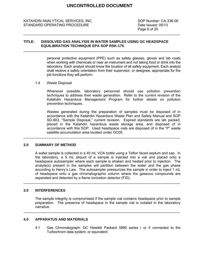
KATAHDIN ANALYTICAL SERVICES, INC. SOP Number: CA-336-06 STANDARD OPERATING PROCEDURE Date Issued: 05/13 Page 6 of 20 TITLE: DISSOLVED GAS ANALYSIS IN WATER SAMPLES USING GC HEADSPACE
EQUILIBRATION TECHNIQUE EPA SOP RSK-175
personal protective equipment (PPE) such as safety glasses, gloves and lab coats when working with chemicals or near an instrument and not taking food or drink into the laboratory. Each analyst should know the location of all safety equipment. Each analyst shall receive a safety orientation from their supervisor, or designee, appropriate for the job functions they will perform.
1.4 Waste Disposal Whenever possible, laboratory personnel should use pollution prevention
techniques to address their waste generation. Refer to the current revision of the Katahdin Hazardous Management Program for further details on pollution prevention techniques.
Wastes generated during the preparation of samples must be disposed of in
accordance with the Katahdin Hazardous Waste Plan and Safety Manual and SOP SD-903, “Sample Disposal,” current revision. Expired standards are lab packed, placed in the Katahdin hazardous waste storage area, and disposed of in accordance with this SOP. Used headspace vials are disposed of in the “P” waste satellite accumulation area located under GC05.
2.0 SUMMARY OF METHOD
A water sample is collected in a 40 mL VOA bottle using a Teflon faced septum and cap. In the laboratory, a 5 mL aliquot of a sample is injected into a vial and placed onto a headspace autosampler where each sample is shaken and heated prior to injection. The analyte(s) present in the samples will partition between the water and the gas phase according to Henry’s Law. The autosampler pressurizes the sample in order to inject 1 mL of headspace onto a gas chromatographic column where the gaseous compounds are separated and detected by a flame ionization detector (FID).
3.0 INTERFERENCES The sample integrity is compromised if the sample vial contains headspace prior to sample preparation. The presence of headspace in the sample vial is notated in the laboratory narrative.
4.0 APPARATUS AND MATERIALS
4.1 Gas Chromatograph: GC Hewlett Packard 5890 series I or II connected to the
Turbochrom data system, or equivalent
UNCONTROLLED DOCUMENT
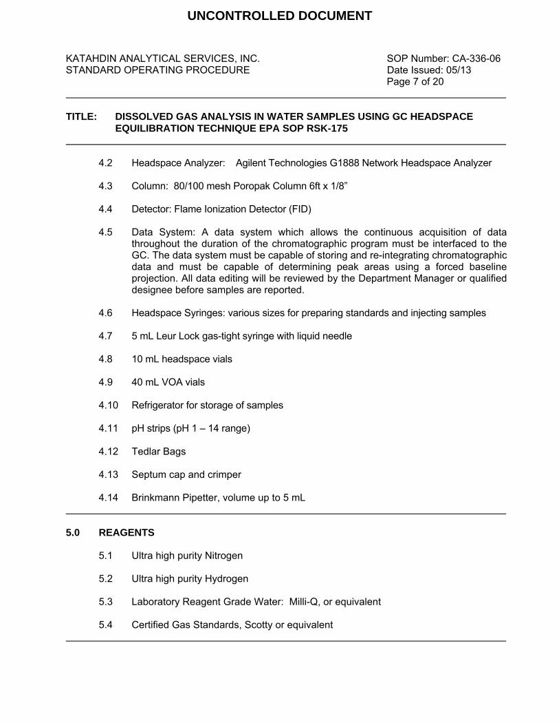
KATAHDIN ANALYTICAL SERVICES, INC. SOP Number: CA-336-06 STANDARD OPERATING PROCEDURE Date Issued: 05/13 Page 7 of 20 TITLE: DISSOLVED GAS ANALYSIS IN WATER SAMPLES USING GC HEADSPACE
EQUILIBRATION TECHNIQUE EPA SOP RSK-175
4.2 Headspace Analyzer: Agilent Technologies G1888 Network Headspace Analyzer
4.3 Column: 80/100 mesh Poropak Column 6ft x 1/8” 4.4 Detector: Flame Ionization Detector (FID) 4.5 Data System: A data system which allows the continuous acquisition of data
throughout the duration of the chromatographic program must be interfaced to the GC. The data system must be capable of storing and re-integrating chromatographic data and must be capable of determining peak areas using a forced baseline projection. All data editing will be reviewed by the Department Manager or qualified designee before samples are reported.
4.6 Headspace Syringes: various sizes for preparing standards and injecting samples 4.7 5 mL Leur Lock gas-tight syringe with liquid needle 4.8 10 mL headspace vials 4.9 40 mL VOA vials 4.10 Refrigerator for storage of samples 4.11 pH strips (pH 1 – 14 range) 4.12 Tedlar Bags 4.13 Septum cap and crimper 4.14 Brinkmann Pipetter, volume up to 5 mL
5.0 REAGENTS
5.1 Ultra high purity Nitrogen 5.2 Ultra high purity Hydrogen
5.3 Laboratory Reagent Grade Water: Milli-Q, or equivalent 5.4 Certified Gas Standards, Scotty or equivalent
UNCONTROLLED DOCUMENT

KATAHDIN ANALYTICAL SERVICES, INC. SOP Number: CA-336-06 STANDARD OPERATING PROCEDURE Date Issued: 05/13 Page 8 of 20 TITLE: DISSOLVED GAS ANALYSIS IN WATER SAMPLES USING GC HEADSPACE
EQUILIBRATION TECHNIQUE EPA SOP RSK-175 6.0 SAMPLE COLLECTION, PRESERVATION AND HANDLING
Samples are collected into 40 mL VOA vials. The vials have been preserved with 1:1 HCL prior to collection. Care should be taken so there are no air bubbles in the vials. Samples are stored at 4 (±2) °C until time of analysis. Samples must be analyzed within 14 days of sampling. Unpreserved samples must be analyzed within 7 days of sampling.
7.0 PROCEDURES
7.1 Preparing Samples for Analysis:
Allow samples to warm to room temperature prior to preparation. Inspect all VOA vials for bubbles and notate any bubbles in the logbook.
Purge all headspace vials with nitrogen for approximately ten seconds prior to injecting them with sample. The empty headspace vials are purged and then capped. The nitrogen line is located between the headspace sampler and the GC05 oven. Using a 5 mL Leur lock syringe, pull up 5 mL of Nitrogen from a Tedlar bag. While inverting a VOA vial push the syringe through the vial septa. Insert a second 5 mL syringe into the VOA vial. By injecting the 5 mL of nitrogen, 5 mL of sample will be displaced into the second syringe. Take the syringe containing the sample aliquot out of the VOA vial and immediately inject the aliquot through the headspace vial septa. The sample is now ready to be loaded onto the autosampler.
If a dilution is required in order to bring the sample within range of the calibration curve, the sample is prepared as above, but less than 5 mL of sample is injected into the vial. An aliquot of laboratory reagent grade water is used to bring the liquid volume to 5 mL. The laboratory reagent grade water is purged with the nitrogen line for approximately ten seconds before capping the headspace vials and adding sample. The amounts of sample and water are based on the factor needed to bring the sample within range of the upper half of the calibration curve. The amount of sample and water are notated in the logbook and the proper dilution factor is applied to the final result.
7.2 Standards Preparation
Using a pipetter, inject 5 mL DI water into a headspace vial, purge with nitrogen for approximately ten seconds and crimp the top. A gas standard is then injected into the vial. The standards are calibrated as µg/mL of water.
UNCONTROLLED DOCUMENT
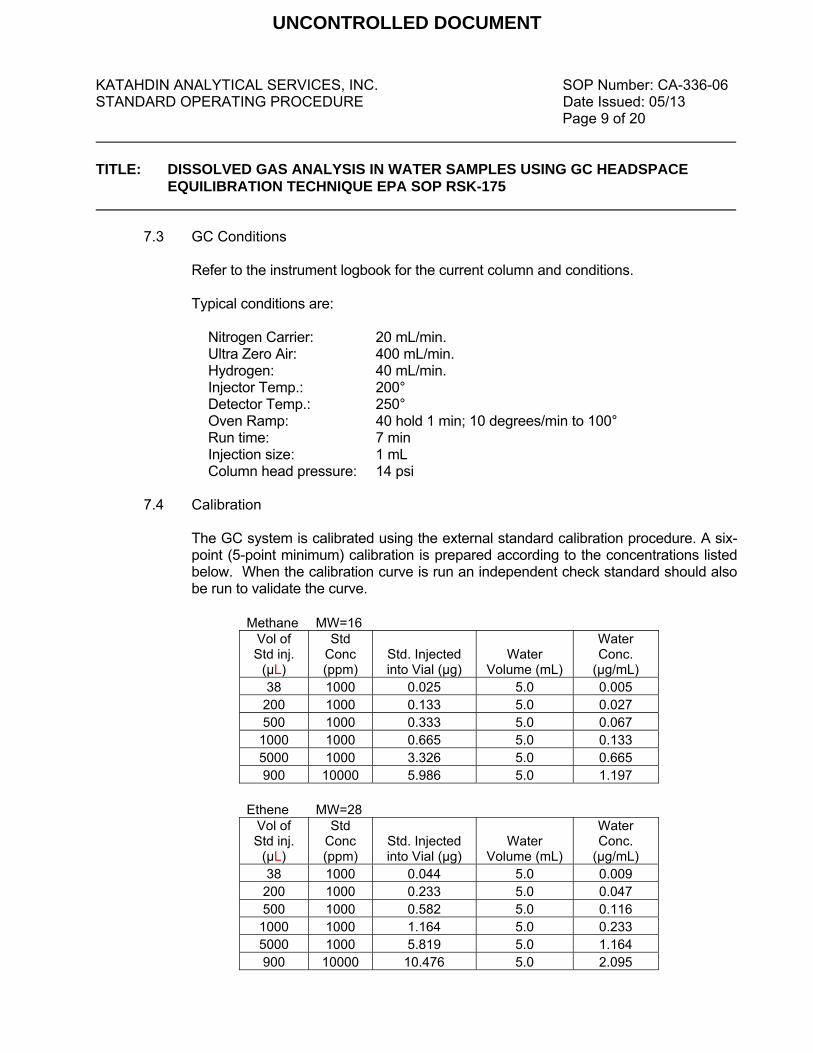
KATAHDIN ANALYTICAL SERVICES, INC. SOP Number: CA-336-06 STANDARD OPERATING PROCEDURE Date Issued: 05/13 Page 9 of 20 TITLE: DISSOLVED GAS ANALYSIS IN WATER SAMPLES USING GC HEADSPACE
EQUILIBRATION TECHNIQUE EPA SOP RSK-175
7.3 GC Conditions
Refer to the instrument logbook for the current column and conditions. Typical conditions are:
Nitrogen Carrier: 20 mL/min. Ultra Zero Air: 400 mL/min. Hydrogen: 40 mL/min. Injector Temp.: 200° Detector Temp.: 250° Oven Ramp: 40 hold 1 min; 10 degrees/min to 100° Run time: 7 min Injection size: 1 mL Column head pressure: 14 psi
7.4 Calibration
The GC system is calibrated using the external standard calibration procedure. A six-point (5-point minimum) calibration is prepared according to the concentrations listed below. When the calibration curve is run an independent check standard should also be run to validate the curve.
Methane MW=16
Vol of Std inj.
(µL)
Std Conc (ppm)
Std. Injected into Vial (µg)
Water Volume (mL)
Water Conc.
(µg/mL) 38 1000 0.025 5.0 0.005 200 1000 0.133 5.0 0.027 500 1000 0.333 5.0 0.067
1000 1000 0.665 5.0 0.133 5000 1000 3.326 5.0 0.665 900 10000 5.986 5.0 1.197
Ethene MW=28
Vol of Std inj.
(µL)
Std Conc (ppm)
Std. Injected into Vial (µg)
Water Volume (mL)
Water Conc.
(µg/mL) 38 1000 0.044 5.0 0.009 200 1000 0.233 5.0 0.047 500 1000 0.582 5.0 0.116
1000 1000 1.164 5.0 0.233 5000 1000 5.819 5.0 1.164 900 10000 10.476 5.0 2.095
UNCONTROLLED DOCUMENT

KATAHDIN ANALYTICAL SERVICES, INC. SOP Number: CA-336-06 STANDARD OPERATING PROCEDURE Date Issued: 05/13 Page 10 of 20 TITLE: DISSOLVED GAS ANALYSIS IN WATER SAMPLES USING GC HEADSPACE
EQUILIBRATION TECHNIQUE EPA SOP RSK-175
Ethane MW=30 Vol of Std inj.
(µL)
Std Conc (ppm)
Std. Injected into Vial (µg)
Water Volume (mL)
Water Conc.
(µg/mL) 38 1000 0.047 5.0 0.009 200 1000 0.249 5.0 0.050 500 1000 0.624 5.0 0.125
1000 1000 1.247 5.0 0.249 5000 1000 6.236 5.0 1.247 900 10000 11.224 5.0 2.245
Each calibration standard is injected using the technique that is used to introduce the actual samples into the GC. The Target system will calculate a peak height or area for each compound. A calibration curve can be prepared in Target using the peak height or area against the concentration of the standard. An average calibration applying a first order polynomial equation is used to prepare the curve. 7.4.1 Calculating the concentration of the calibration standard (x)
µg std. injected into vial = (ppmv of std.)(MW of gas)(mL injected) 24055 conc. = µg std. injected into vial__ amount of water in vial (mL)
7.4.2 An Independent Calibration Verification Standard (ICV) is analyzed immediately after calibration, before any samples are analyzed.
7.5 Retention Time Study Three injections are made of all the analytes throughout the course of a 72-hour period. A major peak from the envelope is chosen and a standard deviation is calculated using the three retention times for that peak. Plus or minus three times the standard deviation of the retention times for each standard is used to define the retention time window; however, the experience of the analyst should weight heavily in the interpretation of chromatograms. Retention time windows are calculated for each standard on each GC column and whenever a new GC column is installed. The data is kept on file in the laboratory.
UNCONTROLLED DOCUMENT

KATAHDIN ANALYTICAL SERVICES, INC. SOP Number: CA-336-06 STANDARD OPERATING PROCEDURE Date Issued: 05/13 Page 11 of 20 TITLE: DISSOLVED GAS ANALYSIS IN WATER SAMPLES USING GC HEADSPACE
EQUILIBRATION TECHNIQUE EPA SOP RSK-175
7.6 Sample Analysis
Each vial may only be analyzed once. If a second analysis is required, the sample must be re-prepped. The samples and standards are loaded onto the autosampler, which heats and shakes the vials. The autosampler then pressurizes the sample to fill the 1 mL sample loop. The 1 mL headspace sample is then injected into the GC instrument. Samples are analyzed in a set referred to as an analytical sequence. The sequence begins with instrument calibration as listed in section 7.4 followed by sample aliquots interspersed with mid-concentration calibration standards.
Before any samples are analyzed the instrument must be calibrated by analyzing a five-point (minimum) calibration or a mid-concentration standard (calibration verification standard). If a CV is run, the calculated concentration must not exceed a difference of ± 30%. Each sample analysis must be bracketed with an acceptable initial calibration and a closing CV, or an opening CV and a closing CV. The calibration standard must also be injected at intervals of not less than once every twenty samples (or every 12 hours), whichever is more frequent, and at the end of the analysis sequence.
If the CV fails, the instrument is checked for any obvious problems and maintenance is performed if deemed necessary. All samples that were injected after the last standard that last met the QC criteria must be evaluated to prevent mis-quantitations and possible false negative results, and re-injection of the sample extracts may be required. However, if the standard analyzed after a group of samples exhibits a response for an analyte that is above the acceptance limit, i.e. >30%, and the analyte was not detected in the specific samples analyzed during the analytical shift, then the analyses for those samples do not need to be reanalyzed, as the CV standard has demonstrated that the analyte would have been detected were it present. In contrast, if an analyte above the QC limits was detected in a sample analysis, then re-injection is necessary to ensure accurate quantitation. If an analyte was not detected in the sample and the standard response is more than 30% below the initial calibration response, then re-injection is necessary to ensure that the detector response has not deteriorated to the point that the analyte would not have been detected even though it was present. Absolute retention time windows are established using the mid-point of the window of that day if after analyzing the mid-point it is determined that one or more of the analytes fall outside of the previously established absolute retention time window. The daily retention time window equals the mid-point ±three times the standard deviations. The identification of methane, ethane and ethene is based on agreement between the retention times of peaks in the sample chromatogram with the retention time windows
UNCONTROLLED DOCUMENT

KATAHDIN ANALYTICAL SERVICES, INC. SOP Number: CA-336-06 STANDARD OPERATING PROCEDURE Date Issued: 05/13 Page 12 of 20 TITLE: DISSOLVED GAS ANALYSIS IN WATER SAMPLES USING GC HEADSPACE
EQUILIBRATION TECHNIQUE EPA SOP RSK-175
established through the analysis of standards of the target analytes. An analyte is tentatively identified when a peak from a sample falls within the daily retention time window. If the response for an analyte exceeds the calibration range of the system, the sample must be diluted and reanalyzed.
If the amount recovered is not detectable or below the PQL, then the compound is not considered to be present in the sample and is reported as <PQL.
When a GC system is determined to be out of control because either a CV can not pass or a six-point calibration does not meet the correlation coefficient criteria, instrument maintenance is likely necessary. Routine instrument maintenance may involve changing the septum, replacing the liner, or replacing the column. This information is recorded in the instrument run log (Figure 1). When an instrument requires more severe maintenance like replacing the FID or an electronic board, this information is written in the instrument maintenance logbook.
7.7 Calculations The concentration of an analyte is calculated by using the calibrated curve that is
prepared in Target. When an analyte is identified, Target displays a concentration when the file is processed through the appropriate calibrated method. Concentration (µg/L) = [(C) (0.005L)/(Vs)] (1000) Where: C = Concentration calculated by Target in µg/mL
Vs = Volume of sample purged in L
7.8 Data Review The initial data review is accomplished by the analyst who ran the samples. This review is of sufficient quality and detail to provide a list of samples that need to be reanalyzed or diluted and reanalyzed. The initial data review is performed in Target Review. This data review examines criteria that directly impact whether or not the sample needs to be reanalyzed and/or reextracted. These criteria include:
• QC criteria for method blank, LCS, MS/MSD, and calibration – refer to section 8.0.
• Chromatography: cleanups, manual integration.
UNCONTROLLED DOCUMENT

KATAHDIN ANALYTICAL SERVICES, INC. SOP Number: CA-336-06 STANDARD OPERATING PROCEDURE Date Issued: 05/13 Page 13 of 20 TITLE: DISSOLVED GAS ANALYSIS IN WATER SAMPLES USING GC HEADSPACE
EQUILIBRATION TECHNIQUE EPA SOP RSK-175
• Target compound detection: quantitation and false positives. • The requirement of the GC laboratory is that this initial data review be
completed no later than the end of the next workday. After the analyst has completed his or her initial data review, the information is then ready to be processed for reporting. Refer to section 7.10.
7.9 Chromatography Manual integrations are to be performed when chromatographic conditions preclude
the computer algorithm from correctly integrating the peak of concern. In no instance shall a manual integration be performed solely to bring a peak within criteria.
In Target Review, each peak of concern is examined by the primary analyst to
ensure that the peak was integrated properly by the computer algorithm. Should a manual integration be necessary (for instance, due to a split peak, peak tailing, or incomplete resolution of isomeric pairs), manual integration is performed in Target Review. An “M” qualifier will automatically be printed on the quantitation report summary indicating that a manual integration was performed. For specific procedures on how to manually integrate, refer to Katahdin SOP QA-812, “Manual Integration,” current revision.
7.9.1 Target Compound Detection
The chromatogram is evaluated to determine if a target analyte is indicated. The concentration of the analyte(s) is then evaluated to determine if it is above the PQL and within the calibration range.
7.10 Reporting After the chromatograms have been reviewed and any target analytes have been quantitated using Target, the necessary files are brought into KIMS. Depending on the QC level requested by the client, a Report of Analysis (ROA) and additional reports, such as LCS forms and chronology forms, are generated. The package is assembled to include the necessary forms and raw data. The data package is reviewed by the primary analyst and then forwarded to the secondary reviewer. The secondary reviewer validates the data and checks the package for any errors. When completed, the package is sent to the Department Manager for final review. A completed review checklist is provided with each package. The final data package from the Organics department is then processed by the Data Management department.
UNCONTROLLED DOCUMENT

KATAHDIN ANALYTICAL SERVICES, INC. SOP Number: CA-336-06 STANDARD OPERATING PROCEDURE Date Issued: 05/13 Page 14 of 20 TITLE: DISSOLVED GAS ANALYSIS IN WATER SAMPLES USING GC HEADSPACE
EQUILIBRATION TECHNIQUE EPA SOP RSK-175 8.0 QUALITY CONTROL AND ACCEPTANCE CRITERIA
Refer to Table 1 for a summary of QC requirements, acceptance criteria, and corrective actions. Table 1 criteria are intended to be guidelines for analysts. The table does not cover all possible situations. If any of the QC requirements are outside the recovery ranges listed in Table 1, all associated samples must be evaluated against the QC. In some cases data may be reported, but may be reanalyzed in other cases. Making new reagents and standards may be necessary if the standardization is suspect. The corrective actions listed in Table 1 may rely on analyst experience to make sound scientific judgments. These decisions are based on holding time considerations, remaining sample volume and client and project specific Data Quality Objectives. The Department Manager, Laboratory Operations Manager, and/or Quality Assurance Officer may be consulted to evaluate data. In some cases the standard QC requirements listed in this section and in Table 1 may not be sufficient to meet the Data Quality Objectives of the specific project. Much of the work performed at the lab is analyzed in accordance with specific QC requirements spelled out in a project specific Quality Assurance Project Plan (QAPP) or in a program specific Quality Systems Manual (QSM). The reporting limits, acceptance criteria and/or corrective actions may be different than those specified in this SOP. In these cases the appropriate information will be communicated to the Department Manager and/or senior chemists before initiation of the analyses so that specific product codes can be produced for the project. In addition, the work order notes for each project will describe the specific QAPP or QSM to be followed. Every instance of noncompliant method quality control requires the generation of a Nonconformance Report (NCR) describing the problem, suspected cause and final resolution. A NCR must be initiated as soon as possible.
8.1 Continuing Calibration Verification (CV)
A mid-level concentration standard is analyzed daily prior to sample analysis. The calibration standard must also be injected at intervals of not less than once every twenty samples (or every 12 hours), whichever is more frequent, and at the end of the analysis sequence. The acceptance criterion is ±30% of the expected value. If response of a compound, in the opening CV, fails to met the criterion, the system is checked, the standard reprepped and analyzed. In the event the criterion cannot be met, the instrument is recalibrated.
8.2 Independent Calibration Verification (ICV)
An ICV is a mid-level concentration standard using a source different from the source of the calibration standards. This can include a different lot from the same manufacturer. An ICV is analyzed immediately following a curve. The acceptance criterion is ±30% of the expected value. If the ICV fails to meet this criterion, the
UNCONTROLLED DOCUMENT

KATAHDIN ANALYTICAL SERVICES, INC. SOP Number: CA-336-06 STANDARD OPERATING PROCEDURE Date Issued: 05/13 Page 15 of 20 TITLE: DISSOLVED GAS ANALYSIS IN WATER SAMPLES USING GC HEADSPACE
EQUILIBRATION TECHNIQUE EPA SOP RSK-175
system is checked, and another ICV is analyzed. In the event the criterion cannot be met, the instrument is recalibrated.
8.3 Laboratory Control Sample (LCS)
An LCS is a mid-level concentration standard using a source different from the source of the calibration standards. This can include a different lot from the same manufacturer. An LCS is analyzed prior to sample analysis. The acceptance criterion is ±30% of the expected value. If the compound recovery fails to meet this criterion, the system is checked, and another LCS is prepped and analyzed. In the event the criterion cannot be met, the instrument is recalibrated.
8.4 Laboratory Blank
The Laboratory Blank is prepared by injecting 5 mL of DI water into a 10 mL headspace vial. A Laboratory Blank is analyzed between analysis of standards and project samples. If analytes are detected above the detection limit, the blank is reprepped and analyzed. If analytes are still detected above the detection limit, the possibility exists that all the vials in the batch contain contamination. In this case all samples and QC are reprepped in new vials.
8.5 Sample Duplicates
Sample duplicates are analyzed as required for certain clients. The duplicate is prepared using a second VOA sample using the procedures in section 7.1.
8.6 Detection Limits
An Method Detection Limit (MDL) study is preformed using a minimum of seven replicates at 1-2 times the Practical Quantitation Limit (PQL) or Reporting Limit (RL) described in 40 CFR Pt. 136 App. B. The MDL must be less than or equal to the detection limit.
Compound PQL or RL (µg/L)
Methane 10 Ethane 10 Ethene 10
8.7 Matrix Spikes and Matrix Spike Duplicates (MS/MSD)
For projects requiring MS/MSD sets, aliquots of the sample are prepared using the procedures in section 7.1. The MS/MSD’s are then spiked in the same fashion as the LCS. After analysis, the original sample amount is subtracted out and the % recovery is calculated. The acceptance criterion for MS/MSD sets are 70-130%
UNCONTROLLED DOCUMENT

KATAHDIN ANALYTICAL SERVICES, INC. SOP Number: CA-336-06 STANDARD OPERATING PROCEDURE Date Issued: 05/13 Page 16 of 20 TITLE: DISSOLVED GAS ANALYSIS IN WATER SAMPLES USING GC HEADSPACE
EQUILIBRATION TECHNIQUE EPA SOP RSK-175
recovery and 30% RPD. If the criteria are not met, the data is flagged and the incident is narrated. Since samples are analyzed using an autosampler, it is not possible to know in advance the concentration of the sample. Consequently, the concentration of analytes in the unspiked analysis may be greater than four times the concentration of the added spike, making the spike amount insignificant to the original concentration. In these situations, recoveries and RPD may not meet the acceptance criterion. In addition, as MS/MSD’s are typically taken from separate vials, sample heterogeneity may contribute to failed criteria.
9.0 METHOD PERFORMANCE
The method detection limit (MDL) is defined as the minimum concentration of a substance that can be measured and reported with 99% confidence that the value is above zero. The MDLs shall be determined and verified one time per type of instrument unless otherwise required by the method. A Limit of Detection (LOD) is an estimate of the minimum amount of a substance that an analytical process can reliably detect. An LOD is analyte and matrix specific and may be laboratory-dependent. LODs must be determined for all parameters for which the laboratory is accredited under the DoD Environmental Laboratory Accreditation Program. LOD’s must be verified for every preparation and analytical method combination and on every applicable instrument on a quarterly basis. The Limit of Quantitation (LOQ) is the minimum levels, concentrations, or quantities of a target variable (e.g., target analyte) that can be reported with a specified degree of confidence. The LOQ shall be set at the lowest point in the calibration curve for all analyses utilizing an initial calibration. LOQ’s must be verified quarterly for every preparation and analytical method combination and on every applicable instrument on a quarterly basis for all parameters included in the DoD Scope of Accreditation. The LOQ must be verified at least once annually if the analysis is not included in the DoD Scope of Accreditation. MDLs are filed with the Organic Department Manager and then with the QAO. LOD and LOQ verifications are filed with the QAO
Refer to the current revision of Method RSK-175 for other method performance parameters and requirements.
10.0 APPLICABLE DOCUMENTS/REFERENCES
“Analysis of Dissolved Methane, Ethane and Ethylene in Ground Water by a Standard Gas Chromatographic Technique”, EPA SOP RSK-175, Revision No. 0, 8/11/94
UNCONTROLLED DOCUMENT

KATAHDIN ANALYTICAL SERVICES, INC. SOP Number: CA-336-06 STANDARD OPERATING PROCEDURE Date Issued: 05/13 Page 17 of 20 TITLE: DISSOLVED GAS ANALYSIS IN WATER SAMPLES USING GC HEADSPACE
EQUILIBRATION TECHNIQUE EPA SOP RSK-175
Katahdin SOP CA-101, “Equipment Maintenance and Troubleshooting,” current revision. Department of Defense Quality Systems Manual for Environmental Laboratories (DoD QSM), Current Version. The National Environmental Laboratory Accreditation Conference (NELAC) Standards, June 2003. The NELAC Institute, Laboratory Accreditation Standards, Volume 1, Management and Technical Requirements for Laboratories Performing Environmental Analysis, 10/06/2010. Katahdin SOP QA-806, “Method Detection Limit, Instrument Detection Limit and Reporting Limit Studies and Verifications,” current revision.
LIST OF TABLES AND FIGURES Table 1 Summary of Calibration and QC Procedures Table 2 Summary of Method Modifications Figure 1 Example of Runlog
UNCONTROLLED DOCUMENT

KATAHDIN ANALYTICAL SERVICES, INC. SOP Number: CA-336-06 STANDARD OPERATING PROCEDURE Date Issued: 05/13 Page 18 of 20 TITLE: DISSOLVED GAS ANALYSIS IN WATER SAMPLES USING GC HEADSPACE
EQUILIBRATION TECHNIQUE EPA SOP RSK-175
TABLE 1
SUMMARY OF CALIBRATION AND QC PROCEDURES
QC Check Minimum Frequency Acceptance
Criteria Corrective Action
ICAL Initial calibration prior to sample analysis
RSD ≤ 30%
Investigate and repeat initial calibration
ICV Immediately following initial calibration
Recovery must be between 70% and 130%
Investigate; reprep. Repeat initial calibration if criteria cannot be met.
CV If initial calibration analyzed, daily and after 20 samples, and at end of sequence.
%D for all analytes within 30%
(1) Evaluate the samples: (2) If the %RPD >30% and sample
results are < PQL, narrate. (3) If %RPD >30% and is likely a result
of matrix interference, narrate. (4) Otherwise, reanalyze all samples
after last acceptable CV.
LCS One LCS per 20 samples Recovery must be between 70% and 130%
(1) Evaluate the samples and associated QC.
(2) If an MS/MSD was performed and acceptable, narrate.
(3) If the LCS recovery is high but the sample results are < PQL, narrate. Otherwise, reprep.
Method Blank One per batch of 20 or fewer samples
No analytes detected > PQL
(1) Investigate source of contamination (2) Evaluate the samples and associated
QC: i.e. If the blank results are above the PQL, report samples results which are < PQL >10X the blank concentration. Otherwise, reprep a blank and the remaining samples.
Matrix Spike/Matrix Spike Duplicate
One MS/MSD as requested by clients.
Recovery must be between 70% and 130%, RPD ≤30.
(1) Evaluate the samples and associated QC.
(2) If the LCS is acceptable, narrate. (3) If both the LCS and MS/MSD are
unacceptable, reprep the samples and QC.
Sample Duplicate If requested by the client %RPD of duplicate must be less than 30%.
(1) Check calculations for errors (2) Evaluate QC
Demonstration of capability - four replicate analyses of a QC check sample
One time per analyst initially and annually thereafter
All recoveries within method QC acceptance limits.
Investigate; reprep
MDL and/or LOD/LOQ Verification
Refer to KAS SOP QA-806, “Method Detection Limit, Instrument Detection Limit and Reporting Limit Studies and Verifications,” current revision.
UNCONTROLLED DOCUMENT
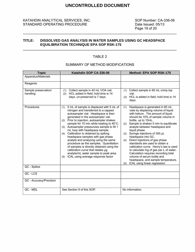
KATAHDIN ANALYTICAL SERVICES, INC. SOP Number: CA-336-06 STANDARD OPERATING PROCEDURE Date Issued: 05/13 Page 19 of 20 TITLE: DISSOLVED GAS ANALYSIS IN WATER SAMPLES USING GC HEADSPACE
EQUILIBRATION TECHNIQUE EPA SOP RSK-175
TABLE 2
SUMMARY OF METHOD MODIFICATIONS
Topic Katahdin SOP CA-336-06 Method: EPA SOP RSK-175 Apparatus/Materials
Reagents
Sample preservation/ handling
(1) Collect sample in 40 mL VOA vial. (2) HCL added in field; hold time is 14
days, un-preserved is 7 days.
(1) Collect sample in 60 mL crimp top vial.
(2) HCL is added in field; hold time is 14 days.
Procedures
(1) 5 mL of sample is displaced with 5 mL of nitrogen and transferred to a capped autosampler vial. Headspace is then generated in the autosampler vial.
(2) Prior to injection, autosampler shakes sample for 15 min while heating to 40°C.
(3) Autosampler pressurizes sample to fill 1 mL loop with headspace sample.
(4) Calibration is obtained by spiking headspace samples with gas phase analyte and analyzing using the same procedure as the samples. Quantitation of samples is directly obtained using the calibration curve that relates µg analyte/mL water sample to peak area.
(5) ICAL using average response factor
(1) Headspace is generated in 60 mL vials by displacing volume of liquid with helium. The amount of liquid should be 10% of sample volume in bottle, up to 10mL.
(2) Sample is shaken 5 min to equilibrate analyte between headspace and liquid phase.
(3) Syringe injections of 300 µL headspace into GC.
(4) Direct injections of gas phase standards are used to obtain a calibration curve. Henry’s law is used to calculate mg of gas per L of water. Calculation requires recording total volume of serum bottle and headspace, and sample temperature.
(5) ICAL using linear regression QC - Spikes
QC - LCS
QC - Accuracy/Precision
QC - MDL
See Section 9 of this SOP. No information.
UNCONTROLLED DOCUMENT

KATAHDIN ANALYTICAL SERVICES, INC. SOP Number: CA-336-06 STANDARD OPERATING PROCEDURE Date Issued: 05/13 Page 20 of 20 TITLE: DISSOLVED GAS ANALYSIS IN WATER SAMPLES USING GC HEADSPACE
EQUILIBRATION TECHNIQUE EPA SOP RSK-175
FIGURE 1
EXAMPLE OF RUNLOG
UNCONTROLLED DOCUMENT

ADDENDUMSOP NO CHANGE FORM
UNCONTROLLED DOCUMENT

UNCONTROLLED DOCUMENT

UNCONTROLLED DOCUMENT

UNCONTROLLED DOCUMENT
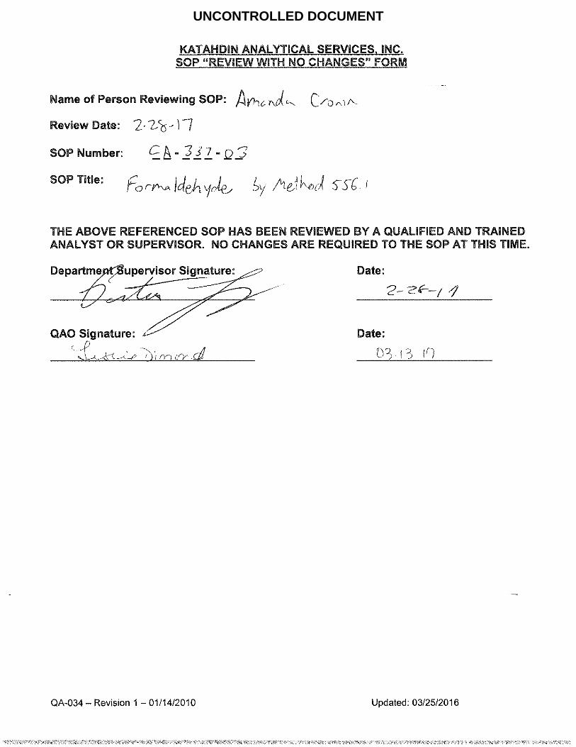
UNCONTROLLED DOCUMENT

UNCONTROLLED DOCUMENT

KATAHDIN ANALYTICAL SERVICES SOP Number: CA-776
STANDARD OPERATING PROCEDURE Revision History
Cover Page (cont.)
Page 2
TITLE: ANALYSIS OF VOLATILE FATTY ACIDS AT LOW CONCENTRATIONS BY ION
CHROMATOGRAPHY WITH CONDUCTIVITY DETECTION Revision History (cont.):
SOP Revision
Changes Approval Initials
Approval Date
Effective Date
UNCONTROLLED DOCUMENT
KATAHDIN ANALYTICAL SERVICES SOP Number: CA-776-02 STANDARD OPERATING PROCEDURE Date Issued: 08/15 Page 3 of 23
TITLE: ANALYSIS OF VOLATILE FATTY ACIDS AT LOW CONCENTRATIONS BY ION
CHROMATOGRAPHY WITH CONDUCTIVITY DETECTION Please acknowledge receipt of this standard operating procedure by signing and dating both of the spaces provided. Return the bottom half of this sheet to the QA Department.
I acknowledge receipt of copy of document SOP CA-776-02, titled ANALYSIS OF VOLATILE
FATTY ACIDS AT LOW CONCENTRATIONS BY ION CHROMATOGRAPHY WITH
CONDUCTIVITY DETECTION Recipient: Date: KATAHDIN ANALYTICAL SERVICES STANDARD OPERATING PROCEDURE
I acknowledge receipt of copy of document SOP CA-776-02, titled ANALYSIS OF VOLATILE
FATTY ACIDS AT LOW CONCENTRATIONS BY ION CHROMATOGRAPHY WITH
CONDUCTIVITY DETECTION Recipient: Date:
UNCONTROLLED DOCUMENT
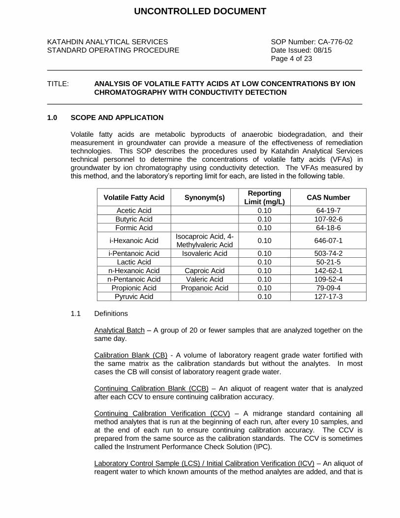
KATAHDIN ANALYTICAL SERVICES SOP Number: CA-776-02 STANDARD OPERATING PROCEDURE Date Issued: 08/15 Page 4 of 23
TITLE: ANALYSIS OF VOLATILE FATTY ACIDS AT LOW CONCENTRATIONS BY ION
CHROMATOGRAPHY WITH CONDUCTIVITY DETECTION
1.0 SCOPE AND APPLICATION
Volatile fatty acids are metabolic byproducts of anaerobic biodegradation, and their measurement in groundwater can provide a measure of the effectiveness of remediation technologies. This SOP describes the procedures used by Katahdin Analytical Services technical personnel to determine the concentrations of volatile fatty acids (VFAs) in groundwater by ion chromatography using conductivity detection. The VFAs measured by this method, and the laboratory’s reporting limit for each, are listed in the following table.
Volatile Fatty Acid Synonym(s) Reporting
Limit (mg/L) CAS Number
Acetic Acid 0.10 64-19-7
Butyric Acid 0.10 107-92-6
Formic Acid 0.10 64-18-6
i-Hexanoic Acid Isocaproic Acid, 4-Methylvaleric Acid
0.10 646-07-1
i-Pentanoic Acid Isovaleric Acid 0.10 503-74-2
Lactic Acid 0.10 50-21-5
n-Hexanoic Acid Caproic Acid 0.10 142-62-1
n-Pentanoic Acid Valeric Acid 0.10 109-52-4
Propionic Acid Propanoic Acid 0.10 79-09-4
Pyruvic Acid 0.10 127-17-3
1.1 Definitions
Analytical Batch – A group of 20 or fewer samples that are analyzed together on the same day. Calibration Blank (CB) - A volume of laboratory reagent grade water fortified with the same matrix as the calibration standards but without the analytes. In most cases the CB will consist of laboratory reagent grade water.
Continuing Calibration Blank (CCB) – An aliquot of reagent water that is analyzed after each CCV to ensure continuing calibration accuracy. Continuing Calibration Verification (CCV) – A midrange standard containing all method analytes that is run at the beginning of each run, after every 10 samples, and at the end of each run to ensure continuing calibration accuracy. The CCV is prepared from the same source as the calibration standards. The CCV is sometimes called the Instrument Performance Check Solution (IPC). Laboratory Control Sample (LCS) / Initial Calibration Verification (ICV) – An aliquot of reagent water to which known amounts of the method analytes are added, and that is
UNCONTROLLED DOCUMENT
KATAHDIN ANALYTICAL SERVICES SOP Number: CA-776-02 STANDARD OPERATING PROCEDURE Date Issued: 08/15 Page 5 of 23
TITLE: ANALYSIS OF VOLATILE FATTY ACIDS AT LOW CONCENTRATIONS BY ION
CHROMATOGRAPHY WITH CONDUCTIVITY DETECTION
processed through the entire analytical procedure in the same manner as a sample. One LCS is processed and analyzed with each batch of 20 or fewer samples. The LCS/ICV is prepared from a different standard source than the calibration standards. LCSs provide a sample of known concentration to assess the accuracy of the analytical system, and when analyzed in duplicate may be used to a measure of precision for the analytical system. The LCS/ICV is sometimes called the Laboratory Fortified Blank (LFB). Laboratory Duplicate – A duplicate is a second aliquot of a sample that is analyzed to assess the precision of the analysis. LOD – Limit of Detection. The smallest amount or concentration of an analyte that must be present in a sample to be detected at a 99% confidence level. At the LOD, the false negative rate is 1%. Matrix Spike (MS) – An aliquot of an environmental sample to which known quantities of the method analytes are added in the laboratory. The MS is analyzed exactly like a samples, and its purpose is to determine whether the sample matrix contributes bias to the analytical results. The background concentrations of the analytes in the sample matrix must be determined in a separate aliquot and the measured values in the MS corrected for the background concentrations. The MS is sometimes called the Laboratory Fortified Matrix (LFM). Method Blank (MB) – An aliquot of reagent water that is carried through the entire analytical procedure in the same manner as a sample. One method blank is processed and analyzed with each batch of 20 or fewer samples. Method Detection Limit (MDL) – The minimum concentration of an analyte that can be identified, measured, and reported with 99% confidence that the analyte concentration is greater than zero. Limit of Quantitation (LOQ) – The lowest concentration of an analyte that is routinely reported by the laboratory; nominally three to five times the MDL. Retention Time Marker – A mixture of non-target compounds that are detected by the method. This mixture is spiked into each sample and is used in the analysis to determine relative retention times, to detect and compensate for retention time shifts during the analysis.
1.2 Responsibilities
This method is restricted to use by, or under the supervision of analysts experienced in the analysis of volatile fatty acids by IC. Each analyst must demonstrate and document their ability to generate acceptable results with this method. Refer to
UNCONTROLLED DOCUMENT
KATAHDIN ANALYTICAL SERVICES SOP Number: CA-776-02 STANDARD OPERATING PROCEDURE Date Issued: 08/15 Page 6 of 23
TITLE: ANALYSIS OF VOLATILE FATTY ACIDS AT LOW CONCENTRATIONS BY ION
CHROMATOGRAPHY WITH CONDUCTIVITY DETECTION
Katahdin SOP QA-805, current revision, “Personnel Training & Documentation of Capability”. It is the responsibility of all Katahdin technical personnel involved in analysis of volatile fatty acids by IC to read and understand this SOP, to adhere to the procedures outlined, and to properly document their data in the appropriate lab logbook. Any deviations from the test or irregularities with the samples should also be recorded in the lab logbook and reported to the Department Manager or designated qualified data reviewer responsible for this data. It is the responsibility of the Department Manager to oversee that members of their group follow this SOP, to ensure that their work is properly documented and to initiate periodic review of the associated logbooks.
1.3 Safety
Users of this procedure must be cognizant of inherent laboratory hazards, proper disposal procedures for contaminated materials and appropriate segregation of hazardous wastes. The toxicity or carcinogenicity of each reagent used in this method has not been precisely defined; however, each chemical should be treated as a potential health hazard. A reference file of material safety data sheets is available to all personnel involved in the chemical analysis. Everyone involved with the procedure must be familiar with the MSDSs for all the materials used in this procedure. Each qualified analyst or technician must be familiar with Katahdin Analytical Environmental Health and Safety Manual including the Katahdin Hazardous Waste Plan and must follow appropriate procedures. These include the use of appropriate personal protective equipment (PPE) such as safety glasses, gloves and lab coats when working with chemicals or near an instrument and not taking food or drink into the laboratory. Each analyst should know the location of all safety equipment. Each analyst shall receive a safety orientation from their Department Manager, or designee, appropriate for the job functions they will perform.
1.4 Pollution Prevention/Waste Disposal Whenever possible, laboratory personnel should use pollution prevention
techniques to address their waste generation. Refer to the current revision of the Katahdin Hazardous Waste Management Plan for further details on pollution prevention techniques.
The outflow from the chromatograph and the autosampler is collected in a single
container and disposed of in a Satellite Waste “A” Acid for proper disposal in main waste area “A”. Other wastes generated during the preparation of samples must be disposed of in accordance with the Katahdin Analytical Environmental Health and
UNCONTROLLED DOCUMENT
KATAHDIN ANALYTICAL SERVICES SOP Number: CA-776-02 STANDARD OPERATING PROCEDURE Date Issued: 08/15 Page 7 of 23
TITLE: ANALYSIS OF VOLATILE FATTY ACIDS AT LOW CONCENTRATIONS BY ION
CHROMATOGRAPHY WITH CONDUCTIVITY DETECTION
Safety Manual and SOPs SD-903, “Sample Disposal” and CA-107, “The Management of Hazardous Waste as it Relates to the Disposal of Laboratory Process Waste, Reagents, Solvents and Standards,” current revisions. Expired standards are lab packed, placed in the Katahdin hazardous waste storage area, and disposed of in accordance with this SOP.
2.0 SUMMARY OF METHOD
Samples are pretreated to remove potentially interfering halogens, and the pretreated samples are spiked with preservatives and internal retention time marker compounds. A small volume of sample is introduced into an ion chromatograph, which consists of a guard column, an analytical column, a suppressor device, and an electrical conductivity detector. In the ion chromatograph, the potassium hydroxide eluent ionizes the VFAs, and their conjugate bases are separated by the anion exchange columns. The separated anions are converted back to their acid forms in the suppressor device prior to detection in the electrical conductivity detector.
3.0 INTERFERENCES 3.1 Interferences can be caused by substances with retention times that are similar to and
overlap those of the analytes of interest. Large amounts of an analyte can interfere with the peak resolution of an adjacent analyte. Sample dilution and/or matrix spiking can be used to resolve many interference problems.
3.2 Lactic acid co-elutes with hydroxy-isobutyric acid (HIBA). Either of these VFAs may
be present in groundwater samples, and studies have shown that they respond nearly equally in this method. The laboratory uses lactic acid in the calibration, and reports the measured peaks as lactic acid. Clients are made aware that any reported hits for lactic acid may be lactic acid, HIBA, or both.
3.3 Significant retention time shifts have been observed in this method due to variations in
the ionic strengths and pHs of samples. Internal retention time markers are used to detect retention time shifts and to reduce uncertainty in peak identification. Any uncertainties in peak identification must be resolved through the use of an analytical spike.
3.4 Method interferences may be caused by contaminants in the water, reagents,
glassware, and other sample processing apparatus that lead to discrete artifacts or elevated baseline in the ion chromatograph. Contamination is minimized through the use of cleaning procedures, clean sample handling techniques, and by minimizing the amount of sample handling required.
UNCONTROLLED DOCUMENT

KATAHDIN ANALYTICAL SERVICES SOP Number: CA-776-02 STANDARD OPERATING PROCEDURE Date Issued: 08/15 Page 8 of 23
TITLE: ANALYSIS OF VOLATILE FATTY ACIDS AT LOW CONCENTRATIONS BY ION
CHROMATOGRAPHY WITH CONDUCTIVITY DETECTION
4.0 APPARATUS AND MATERIALS
4.1 Ion chromatograph capable of delivering 0 to 5 mL of eluent per minute at a pressure of 1000 to 3000 psi. The chromatograph is controlled with a Windows-based PC running Chromeleon software. The chromatograph is equipped with an injection valve, a 10- to 100-uL sample loop, and consists of the following components.
4.1.1 Autosampler – Dionex Model AS-DV
4.1.2 Potassium hydroxide (KOH) eluent generator cartridge with eluent generator
system capable of producing eluent gradients ranging from 0 to 30 mM KOH.
4.1.3 Ion chromatography system – Dionex ICS-2000 2-mm system with conductivity detection.
4.1.4 Precolumn – A guard column (Dionex IonPac AG11-HC) placed before the
separator column to protect the separator column from fouling by particulates or organic constituents.
4.1.5 Separator column – A column (Dionex IonPac AS11-HC) packed with an
anion exchange resin, suitable for resolving the analytes of interest.
4.1.6 Conductivity suppressor – A self-regenerating ion exchange-based device that is capable of converting the eluent and separated anions into their respective acid forms. Dionex Micromembrane Suppressor Model ASRS 300 or equivalent.
4.2 Analytical balance capable of accurately weighing to the nearest 0.0001g. 4.3 0.5 mL sample vials and filter caps 4.4 Adjustable volume Eppendorf pipets, assorted volume ranges 4.5 Class "A" volumetric flasks, assorted volumes 4.6 VOA vials 4.7 Dionex Chromeleon software
5.0 REAGENTS
5.1 Laboratory reagent water
UNCONTROLLED DOCUMENT

KATAHDIN ANALYTICAL SERVICES SOP Number: CA-776-02 STANDARD OPERATING PROCEDURE Date Issued: 08/15 Page 9 of 23
TITLE: ANALYSIS OF VOLATILE FATTY ACIDS AT LOW CONCENTRATIONS BY ION
CHROMATOGRAPHY WITH CONDUCTIVITY DETECTION
5.2 D-quinic acid, 98%+ purity. This reagent is a white powder.
5.3 Lactic acid, 98%+ purity. This reagent is a white powder.
5.4 Pyruvic acid, 98%+ purity. This reagent is a viscous clear liquid.
5.5 Benzalkonium chloride (BAK). This reagent is a viscous clear liquid.
5.6 BAK field preservative – dissolve 12 grams BAK in laboratory reagent grade water and bring to a final volume of 1 liter.
5.7 Laboratory preservative / retention time marker solution – Measure 20 mL of BAK field
preservative into a 40 mL VOA vial. Dissolve 5 mg of d-quinic acid in that solution, and bring to a final volume of 40 mL with laboratory reagent grade water. Cap the VOA vial and mix.
5.8 Stock Standard Solutions: Stock standard solutions may be purchased as certified
solutions or prepared from reagent grade material. All purchased standards must be prepared from high purity materials and supplied by the vendors with certificates of purity and analysis. All purchased stock standards are given an expiration date as indicated by the manufacturer.
5.8.1 Custom lactic acid standard, 1000 ug/mL, purchased. 5.8.2 Custom 2-hydroxyisobutyric acid (HIBA) standard, 1000 ug/mL, purchased.
HIBA is used in method development and validation.
5.8.3 Custom acetic acid standard, 1000 ug/mL, purchased.
5.8.4 Custom propionic (propanoic) acid standard, 1000 ug/mL, purchased.
5.8.5 Custom formic acid standard, 1000 ug/mL, purchased.
5.8.6 Custom butyric acid standard, 1000 ug/mL, purchased.
5.8.7 Custom pyruvic acid standard, 1000 ug/mL, purchased.
5.8.8 Custom i-pentanoic (isovaleric) acid standard, 1000 ug/mL, purchased.
5.8.9 Custom n-pentanoic (valeric) acid standard, 1000 ug/mL, purchased.
5.8.10 Custom i-hexanoic (isocaproic) acid standard, 1000 ug/mL, purchased.
5.8.11 Custom n-hexanoic (caproic) acid standard, 1000 ug/mL, purchased.
UNCONTROLLED DOCUMENT
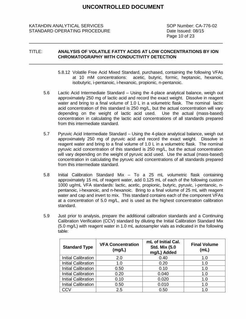
KATAHDIN ANALYTICAL SERVICES SOP Number: CA-776-02 STANDARD OPERATING PROCEDURE Date Issued: 08/15 Page 10 of 23
TITLE: ANALYSIS OF VOLATILE FATTY ACIDS AT LOW CONCENTRATIONS BY ION
CHROMATOGRAPHY WITH CONDUCTIVITY DETECTION
5.8.12 Volatile Free Acid Mixed Standard, purchased, containing the following VFAs at 10 mM concentrations: acetic, butyric, formic, heptanoic, hexanoic, isobutyric, i-pentanoic, i-hexanoic, propionic, n-pentanoic.
5.6 Lactic Acid Intermediate Standard – Using the 4-place analytical balance, weigh out
approximately 250 mg of lactic acid and record the exact weight. Dissolve in reagent water and bring to a final volume of 1.0 L in a volumetric flask. The nominal lactic acid concentration of this standard is 250 mg/L, but the actual concentration will vary depending on the weight of lactic acid used. Use the actual (mass-based) concentration in calculating the lactic acid concentrations of all standards prepared from this intermediate standard.
5.7 Pyruvic Acid Intermediate Standard – Using the 4-place analytical balance, weigh out
approximately 250 mg of pyruvic acid and record the exact weight. Dissolve in reagent water and bring to a final volume of 1.0 L in a volumetric flask. The nominal pyruvic acid concentration of this standard is 250 mg/L, but the actual concentration will vary depending on the weight of pyruvic acid used. Use the actual (mass-based) concentration in calculating the pyruvic acid concentrations of all standards prepared from this intermediate standard.
5.8 Initial Calibration Standard Mix – To a 25 mL volumetric flask containing
approximately 15 mL of reagent water, add 0.125 mL of each of the following custom 1000 ug/mL VFA standards: lactic, acetic, propionic, butyric, pyruvic, i-pentanoic, n-pentanoic, i-hexanoic, and n-hexanoic. Bring to a final volume of 25 mL with reagent water and cap and invert to mix. This standard contains each of the component VFAs at a concentration of 5.0 mg/L, and is used as the highest concentration calibration standard.
5.9 Just prior to analysis, prepare the additional calibration standards and a Continuing
Calibration Verification (CCV) standard by diluting the Initial Calibration Standard Mix (5.0 mg/L) with reagent water in 1.0 mL autosampler vials as indicated in the following table:
Standard Type VFA Concentration
(mg/L)
mL of Initial Cal.
Std. Mix (5.0
mg/L) Added
Final Volume
(mL)
Initial Calibration 2.0 0.40 1.0
Initial Calibration 1.0 0.20 1.0
Initial Calibration 0.50 0.10 1.0
Initial Calibration 0.20 0.040 1.0
Initial Calibration 0.10 0.020 1.0
Initial Calibration 0.50 0.010 1.0
CCV 2.5 0.50 1.0
UNCONTROLLED DOCUMENT
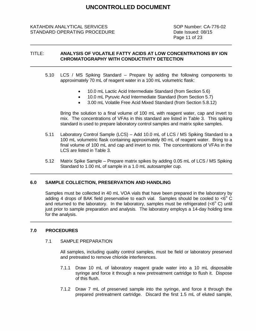
KATAHDIN ANALYTICAL SERVICES SOP Number: CA-776-02 STANDARD OPERATING PROCEDURE Date Issued: 08/15 Page 11 of 23
TITLE: ANALYSIS OF VOLATILE FATTY ACIDS AT LOW CONCENTRATIONS BY ION
CHROMATOGRAPHY WITH CONDUCTIVITY DETECTION
5.10 LCS / MS Spiking Standard – Prepare by adding the following components to approximately 70 mL of reagent water in a 100 mL volumetric flask:
10.0 mL Lactic Acid Intermediate Standard (from Section 5.6)
10.0 mL Pyruvic Acid Intermediate Standard (from Section 5.7)
3.00 mL Volatile Free Acid Mixed Standard (from Section 5.8.12) Bring the solution to a final volume of 100 mL with reagent water, cap and invert to
mix. The concentrations of VFAs in this standard are listed in Table 3. This spiking standard is used to prepare laboratory control samples and matrix spike samples.
5.11 Laboratory Control Sample (LCS) – Add 10.0 mL of LCS / MS Spiking Standard to a
100 mL volumetric flask containing approximately 80 mL of reagent water. Bring to a final volume of 100 mL and cap and invert to mix. The concentrations of VFAs in the LCS are listed in Table 3.
5.12 Matrix Spike Sample – Prepare matrix spikes by adding 0.05 mL of LCS / MS Spiking
Standard to 1.00 mL of sample in a 1.0 mL autosampler cup.
6.0 SAMPLE COLLECTION, PRESERVATION AND HANDLING
Samples must be collected in 40 mL VOA vials that have been prepared in the laboratory by adding 4 drops of BAK field preservative to each vial. Samples should be cooled to <6
o C
and returned to the laboratory. In the laboratory, samples must be refrigerated (<6o C) until
just prior to sample preparation and analysis. The laboratory employs a 14-day holding time for the analysis.
7.0 PROCEDURES
7.1 SAMPLE PREPARATION
All samples, including quality control samples, must be field or laboratory preserved and pretreated to remove chloride interferences.
7.1.1 Draw 10 mL of laboratory reagent grade water into a 10 mL disposable
syringe and force it through a new pretreatment cartridge to flush it. Dispose of this flush.
7.1.2 Draw 7 mL of preserved sample into the syringe, and force it through the
prepared pretreatment cartridge. Discard the first 1.5 mL of eluted sample,
UNCONTROLLED DOCUMENT
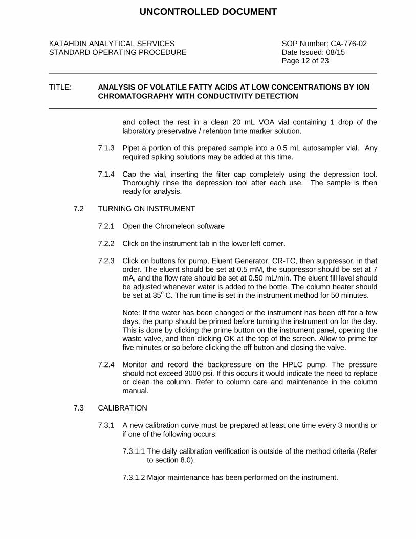
KATAHDIN ANALYTICAL SERVICES SOP Number: CA-776-02 STANDARD OPERATING PROCEDURE Date Issued: 08/15 Page 12 of 23
TITLE: ANALYSIS OF VOLATILE FATTY ACIDS AT LOW CONCENTRATIONS BY ION
CHROMATOGRAPHY WITH CONDUCTIVITY DETECTION
and collect the rest in a clean 20 mL VOA vial containing 1 drop of the laboratory preservative / retention time marker solution.
7.1.3 Pipet a portion of this prepared sample into a 0.5 mL autosampler vial. Any
required spiking solutions may be added at this time.
7.1.4 Cap the vial, inserting the filter cap completely using the depression tool. Thoroughly rinse the depression tool after each use. The sample is then ready for analysis.
7.2 TURNING ON INSTRUMENT
7.2.1 Open the Chromeleon software
7.2.2 Click on the instrument tab in the lower left corner.
7.2.3 Click on buttons for pump, Eluent Generator, CR-TC, then suppressor, in that
order. The eluent should be set at 0.5 mM, the suppressor should be set at 7 mA, and the flow rate should be set at 0.50 mL/min. The eluent fill level should be adjusted whenever water is added to the bottle. The column heater should be set at 35
o C. The run time is set in the instrument method for 50 minutes.
Note: If the water has been changed or the instrument has been off for a few
days, the pump should be primed before turning the instrument on for the day. This is done by clicking the prime button on the instrument panel, opening the waste valve, and then clicking OK at the top of the screen. Allow to prime for five minutes or so before clicking the off button and closing the valve.
7.2.4 Monitor and record the backpressure on the HPLC pump. The pressure
should not exceed 3000 psi. If this occurs it would indicate the need to replace or clean the column. Refer to column care and maintenance in the column manual.
7.3 CALIBRATION
7.3.1 A new calibration curve must be prepared at least one time every 3 months or if one of the following occurs:
7.3.1.1 The daily calibration verification is outside of the method criteria (Refer
to section 8.0). 7.3.1.2 Major maintenance has been performed on the instrument.
UNCONTROLLED DOCUMENT

KATAHDIN ANALYTICAL SERVICES SOP Number: CA-776-02 STANDARD OPERATING PROCEDURE Date Issued: 08/15 Page 13 of 23
TITLE: ANALYSIS OF VOLATILE FATTY ACIDS AT LOW CONCENTRATIONS BY ION
CHROMATOGRAPHY WITH CONDUCTIVITY DETECTION
NOTE: If one of the above is true, a new calibration curve must be prepared even if it has been less than 6 months since the last calibration.
7.3.2 If a calibration curve is required, prepare the standards as described in section 5.0. Pipet 1 mL of each standard into the autosampler cups and add 0.05 mL of Retention Time Marker Solution. Push filter caps down into the vials using the filter cap tool.
7.3.3 Record the standards in the runlog and load onto the autosampler. Push the
carousel release button on the autosampler to allow the wheel to turn. Push the button again to engage the wheel. To start a new sequence, open an old VFA sequence in Chromeleon by clicking on the data tab and double clicking the desired sequence. Old samples can be deleted by row. Click “save as” and use that day’s date as the sequence name. When entering the calibration points into the sample sequence, change the sample type to “calibration standard” and type the calibrator names in the level column. Two method blanks that will not be reported should be analyzed prior to calibration or sample run to ensure that there is no contamination present in the system. The instrument method and the processing method should not need to be changed. The volume column should read 25 uL for all samples. The “fill down” button can be clicked to renumber the position column. Resave the sequence and click the start button at the top of the screen.
7.3.4 When analysis of the calibration standards has finished, the calibration will
need to be updated in the processing method. This is done by double clicking on the processing method on the bottom of the data screen in the associated items table. The calibration tab should already be selected. Click the browse button in the global calibration settings box. Double click the desired sequence, then click update. Save the processing method. The chromatograms for the entire sequence can be printed by double clicking on any chromatogram in the ECD_1 column and clicking on report designer in the lower left corner. Click on the integration tab at the bottom of the screen, then click the chromeleon icon in the upper left to print. Click print and check apply to current sequence. Click OK.
7.3.5 To print out all of the calibration curve graphs highlight all of the points in the
sequence and right click to select print. Click the button next to report template and select the method folder. Double click on “test” and deselect all but the calibration box. Click OK to print.
7.3.6 Because the conductivities of weak acids do not correlate linearly with their
concentrations, calibrations for VFAs are performed using a quadratic equations with an offset. The acceptance criteria for the calibration is a coefficient of determination of at least 0.99.
UNCONTROLLED DOCUMENT

KATAHDIN ANALYTICAL SERVICES SOP Number: CA-776-02 STANDARD OPERATING PROCEDURE Date Issued: 08/15 Page 14 of 23
TITLE: ANALYSIS OF VOLATILE FATTY ACIDS AT LOW CONCENTRATIONS BY ION
CHROMATOGRAPHY WITH CONDUCTIVITY DETECTION
7.3.7 Retention time windows should be established when a new column is installed, if there is a change in instrument conditions or at least annually if there are no changes. Retention time windows are established using +/- three times the standard deviation of the retention times of standards run over the course of one day. However, significant retention time shifts can occur with this method, and these are monitored through the use of internal retention time markers. The experience of the analyst should weigh heavily in the interpretation of chromatograms.
7.4 LOADING SAMPLES
7.4.1 Write sequence in IC Run Log; follow page format and proper sample coding.
7.4.2 If high sample concentrations are suspected, steps should be taken to
minimize reruns and protect the system from contamination and/or carryover. Groundwater may have high concentrations of chloride, sulfate, or the analytes of interest. To avoid contaminating the system, analyze samples that are suspected to contain high levels of these substances at an initial dilution.
7.4.3 It is recommended that the tray is initially set up to run the opening QC before
loading samples. Opening QC consists of a CCV, CCB, Method Blank, and LCS. If there is no calibration being run, two blanks should be run at the beginning of the sequence to flush the system. Evaluate the opening QC to ensure adequate separation, good chromatography, acceptable recovery as it relates to the calibration, and clean blanks. If the opening QC is within criteria and the chromatographic system is in control proceed to load samples. If QC criteria are not met or chromatography is not acceptable initiate appropriate corrective action.
7.4.4 To automatically run tray:
Press the carousel release button to load the sample wheel. Load samples and press button again to enable the carousel.
Enter samples into the sequence, filling in all dilutions and positions.
Make sure the injection volume is 25 uL
Click the “save” icon and press start. Note: if some samples have already been run, you will need to click “remove” and then “resume” at the top of the screen to continue run.
UNCONTROLLED DOCUMENT

KATAHDIN ANALYTICAL SERVICES SOP Number: CA-776-02 STANDARD OPERATING PROCEDURE Date Issued: 08/15 Page 15 of 23
TITLE: ANALYSIS OF VOLATILE FATTY ACIDS AT LOW CONCENTRATIONS BY ION
CHROMATOGRAPHY WITH CONDUCTIVITY DETECTION
7.5 SHUT DOWN PROCEDURE – It is CRITICAL to explicitly follow long term
shutdown storage for columns to prevent damage.
7.5.1 Turn off the instrument in the reverse order from how it was turned on.
7.5.2 If the system will not be used for more than a week it is critical to fill the
columns with the appropriate storage solution and cap them to prevent
evaporation. If a column dries out it is most likely useless.
7.5.3 It is critical to fill the suppressor with fresh regenerant and cap it. If the
suppressor dries out it is likely to be ruined.
7.5.4 It is best to run the instrument for a little while every couple of days to keep
everything hydrated.
DATA ANALYSIS, CALCULATIONS & REPORTING
7.6 If a sample is run and the analyte of interest concentration is above the calibration range the sample must be diluted and reanalyzed. Multiple dilutions may be required to obtain results for all analytes of interest in the calibration range. For samples run at multiple dilutions, the analysis of greatest concentration, qualified retention time, good peak shape, and satisfactory resolution should be quantitated and reported. However, all dilutions should be assessed comparing the consistency of the determinations and possible matrix effects. In certain instances, the more diluted analysis may be the more appropriate reported result.
7.7 If a sample is run at dilution and the concentration of the analyte of interest is below
the LOQ the sample should be reanalyzed with less dilution if possible. When this is not possible, non-detected analyzes must be reported with elevated reporting limits.
7.8 If the chromatogram fails to produce adequate resolution, or if the identification of
specific analytes is questionable, the sample may be spiked with an appropriate amount of standard and reanalyzed. In some instances dilution of the sample may provide sufficient resolution for identification and quantitation.
Calculations are performed by Chromeleon using responses measured during analysis of the calibration standards for the operating curve that has been calculated based upon a linear regression formula. Individual calibration curves are calculated for each analyte. The analyst must assure that the method file is calculating against the appropriate curve.
NOTE: In order for the dilution factor to be applied during calculation by Chromeleon it must be entered at the time the sequence is entered and/or edited.
UNCONTROLLED DOCUMENT
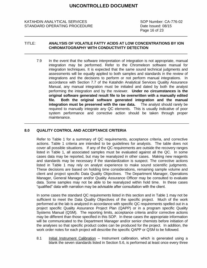
KATAHDIN ANALYTICAL SERVICES SOP Number: CA-776-02 STANDARD OPERATING PROCEDURE Date Issued: 08/15 Page 16 of 23
TITLE: ANALYSIS OF VOLATILE FATTY ACIDS AT LOW CONCENTRATIONS BY ION
CHROMATOGRAPHY WITH CONDUCTIVITY DETECTION
7.9 In the event that the software interpretation of integration is not appropriate, manual integration may be performed. Refer to the Chromeleon software manual for integration techniques. It is expected that the same sound technical judgments and assessments will be equally applied to both samples and standards in the review of integrations and the decisions to perform or not perform manual integrations. In accordance with Section 7.7 of the Katahdin Analytical Services Quality Assurance Manual, any manual integration must be initialed and dated by both the analyst
performing the integration and by the reviewer. Under no circumstances is the
original software generated result file to be overwritten with a manually edited
file. Both the original software generated integration and the manual
integration must be preserved with the raw data. The analyst should rarely be required to manually integrate any QC elements. This is usually indicative of poor system performance and corrective action should be taken through proper maintenance.
_________________________________________________________________________________
8.0 QUALITY CONTROL AND ACCEPTANCE CRITERIA
Refer to Table 1 for a summary of QC requirements, acceptance criteria, and corrective actions. Table 1 criteria are intended to be guidelines for analysts. The table does not cover all possible situations. If any of the QC requirements are outside the recovery ranges listed in Table 1, all associated samples must be evaluated against all the QC. In some cases data may be reported, but may be reanalyzed in other cases. Making new reagents and standards may be necessary if the standardization is suspect. The corrective actions listed in Table 1 may rely on analyst experience to make sound scientific judgments. These decisions are based on holding time considerations, remaining sample volume and client and project specific Data Quality Objectives. The Department Manager, Operations Manager, General Manager and/or Quality Assurance Officer may be consulted to evaluate data. Some samples may not be able to be reanalyzed within hold time. In these cases “qualified” data with narration may be advisable after consultation with the client.
In some cases the standard QC requirements listed in this section and in Table 1 may not be sufficient to meet the Data Quality Objectives of the specific project. Much of the work performed at the lab is analyzed in accordance with specific QC requirements spelled out in a project specific Quality Assurance Project Plan (QAPP) or in a program specific Quality Systems Manual (QSM). The reporting limits, acceptance criteria and/or corrective actions may be different than those specified in this SOP. In these cases the appropriate information will be communicated to the Department Manager and/or senior chemists before initiation of the analyses so that specific product codes can be produced for the project. In addition, the work order notes for each project will describe the specific QAPP or QSM to be followed. 8.1 Initial Instrument Calibration – Instrument calibration, which is generated using a
blank the seven standards listed in Section 5.6, is performed at least once every three
UNCONTROLLED DOCUMENT

KATAHDIN ANALYTICAL SERVICES SOP Number: CA-776-02 STANDARD OPERATING PROCEDURE Date Issued: 08/15 Page 17 of 23
TITLE: ANALYSIS OF VOLATILE FATTY ACIDS AT LOW CONCENTRATIONS BY ION
CHROMATOGRAPHY WITH CONDUCTIVITY DETECTION
months or whenever there is a significant change in instrument operating conditions or hardware. One of the calibration standards must be at or below the Limit of Quantitation for each analyte. The curve fit is accomplished using quadratic least squares analysis, and the coefficient of determination for the curve must be at least 0.99. Sample results that exceed the calibration range of the instrument may not be reported; the sample must be diluted and reanalyzed until the measured concentration of the analyte is within the calibration range. Because calibration linearity is established each time the instrument is calibrated (at least every three months) and because sample results that fall outside the calibration range may not be reported, a separate linear calibration range study is not performed.
8.2 Continuing Calibration Verification (CCV) and Continuing Calibration Blank (CCB) –
Ongoing calibration accuracy is verified by analyzing a CCV standard (a mid-range check standard) and a CCB at the beginning of each run, after every ten samples, and at the end of each run. The analyte recoveries for each CCV must be fall within the limits listed in Table 2. The measured concentration of each analyte in the CCB must be below the Limit of Quantitation for the analyte (for DOD projects, each analyte in the CCB must be below the LOD). If a CCV or CCB fails, the analysis must be stopped, the problem corrected, and the previous ten samples must be reanalyzed, with the following exception. If one or both CCVs bracketing a sample result are biased high and the sample concentration is <PQL, the sample result may be reported. CCVs or CCBs that are biased high may be indicative of carryover or contamination in the system by high concentration samples.
8.3 Laboratory Control Sample (LCS) / Initial Calibration Verification (ICV) – One
LCS/ICV, prepared from a separate standard source from the Initial Instrument Calibration, must be analyzed with each batch of 20 or fewer samples. LCS/ICV recovery acceptance limits are listed in Table 2.
8.4 Method Blank (MB) – A method blank consisting of reagent water that filtered in the
same fashion as the associated samples must be analyted with each batch of 20 or fewer samples. The measured concentration of each analyte in the MB must be less than the LOD (for DoD QSM, no analyte may be detected in the MB at a concentration greater than ½ LOD or greater than 1/10 the amount measured in any sample).
8.5 Matrix Spike (MS) Sample – Matrix spike samples must be prepared and analyzed at
a frequency of one per 20 or fewer samples. Matrix spike recovery acceptance limits are listed in Table 2. If the recovery of any analyte falls outside the acceptance range and the LCS and CCVs are within criteria, the poor recovery should be attributed to sample matrix.
8.6 Matrix Spike Duplicate (MSD) – Prepared at a frequency of one per 20 samples. The
recovery and relative percent difference acceptance limits are listed in Table 2.
UNCONTROLLED DOCUMENT

KATAHDIN ANALYTICAL SERVICES SOP Number: CA-776-02 STANDARD OPERATING PROCEDURE Date Issued: 08/15 Page 18 of 23
TITLE: ANALYSIS OF VOLATILE FATTY ACIDS AT LOW CONCENTRATIONS BY ION
CHROMATOGRAPHY WITH CONDUCTIVITY DETECTION
9.0 METHOD PERFORMANCE
The method detection limit (MDL) is defined as the minimum concentration of a substance that can be measured and reported with 99% confidence that the value is above zero. The MDLs shall be determined and verified one time per type of instrument unless otherwise required by the method. Limit of Detection (LOD) is an estimate of the minimum amount of a substance that an analytical process can reliably detect. An LOD is analyte and matrix specific and may be laboratory-dependent. LODs must be determined for all parameters for which the laboratory is accredited under the DoD Environmental Laboratory Accreditation Program. LOD’s must be verified for every preparation and analytical method combination and on every applicable instrument on a quarterly basis. The Limit of Quantitation (LOQ) is the minimum levels, concentrations, or quantities of a target variable (e.g., target analyte) that can be reported with a specified degree of confidence. The LOQ shall be set at the lowest point in the calibration curve for all analyses utilizing an initial calibration. LOQ’s must be verified quarterly for every preparation and analytical method combination and on every applicable instrument on a quarterly basis for all parameters included in the DoD Scope of Accreditation. The LOQ must be verified at least once annually if the analysis is not included in the DoD Scope of Accreditation. MDLs are filed with the Organic Department Manager and then with the QAO. LOD and LOQ verifications are filed with the QAO Refer to the current revision of Katahdin SOP QA-806, Method Detection Limit, Instrument Detection Limit and Reporting Limit Studies and Verifications, for procedures on determining the MDL. Refer to the current revisions of the applicable methods for other method performance parameters and requirements.
10.0 APPLICABLE DOCUMENTS/REFERENCES
“Test Methods for the Evaluation of Solid Waste: Physical/Chemical Methods”, SW-846, Third Edition, Final Update IV, February 2007, Method 9056A. Katahdin SOP CA-101, Equipment Maintenance and Troubleshooting, current revision. Katahdin SOP CA-762, Wet Chemistry Data Entry and Review Using Katahdin Information Management System (KIMS) Katahdin SOP QA-806, Method Detection Limit, Instrument Detection Limit and Reporting Limit Studies and Verifications.
UNCONTROLLED DOCUMENT
KATAHDIN ANALYTICAL SERVICES SOP Number: CA-776-02 STANDARD OPERATING PROCEDURE Date Issued: 08/15 Page 19 of 23
TITLE: ANALYSIS OF VOLATILE FATTY ACIDS AT LOW CONCENTRATIONS BY ION
CHROMATOGRAPHY WITH CONDUCTIVITY DETECTION
Department of Defense Quality Systems Manual for Environmental Laboratories (DOD QSM), Version 4.2, 10/25/2010.
Department of Defense (DoD) and Department of Energy (DOE) Consolidated Quality Systems Manual (QSM) for Environmental Laboratories, DoD QSM Version 5.0, March, 2013 The National Environmental Laboratory Accreditation Conference (NELAC) Standards, June 2003. The NELAC Institute, Laboratory Accreditation Standards, Volume 1, Management and Technical Requirements for Laboratories Performing Environmental Analysis, 10/06/2010. Dionex 2000 Manual
LIST OF TABLES AND FIGURES Table 1 QC Requirements Table 2 Quality Control Acceptance Limits Table 3 Concentrations of Analytes in Laboratory Control Samples, Matrix Spikes, and
Intermediate Spiking Standard
UNCONTROLLED DOCUMENT
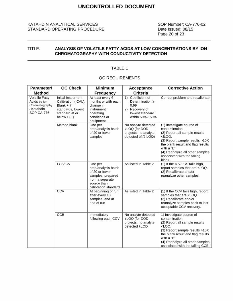
KATAHDIN ANALYTICAL SERVICES SOP Number: CA-776-02 STANDARD OPERATING PROCEDURE Date Issued: 08/15 Page 20 of 23
TITLE: ANALYSIS OF VOLATILE FATTY ACIDS AT LOW CONCENTRATIONS BY ION
CHROMATOGRAPHY WITH CONDUCTIVITY DETECTION
TABLE 1
QC REQUIREMENTS
Parameter/
Method
QC Check Minimum
Frequency
Acceptance
Criteria
Corrective Action
Volatile Fatty Acids by Ion Chromatography
/ Katahdin SOP CA-776
Initial Instrument Calibration (ICAL): Blank + 7 standards, lowest standard at or below LOQ
At least every 6 months or with each change in instrument operating conditions or equipment
1) Coefficient of Determination ≥ 0.99
2) Recovery of lowest standard within 50%-150%
Correct problem and recalibrate
Method blank One per prep/analysis batch of 20 or fewer samples
No analyte detected ≥LOQ (for DOD projects, no analyte detected ≥1/2 LOQ)
(1) Investigate source of contamination (2) Report all sample results <lLOQ. (3) Report sample results >10X the blank result and flag results with a “B”. (4) Reanalyze all other samples associated with the failing blank.
LCS/ICV One per
prep/analysis batch of 20 or fewer samples, prepared from a separate source than calibration standard
As listed in Table 2 (1) If the ICV/LCS fails high, report samples that are <LOQ. (2) Recalibrate and/or reanalyze other samples.
CCV At beginning of run, after every 10 samples, and at end of run
As listed in Table 2
(1) If the CCV fails high, report samples that are <LOQ. (2) Recalibrate and/or reanalyze samples back to last acceptable CCV recovery.
CCB Immediately following each CCV
No analyte detected ≥LOQ (for DOD projects, no analyte detected ≥LOD
1) Investigate source of contamination (2) Report all sample results <LOQ. (3) Report sample results >10X the blank result and flag results with a “B”. (4) Reanalyze all other samples associated with the failing CCB.
UNCONTROLLED DOCUMENT
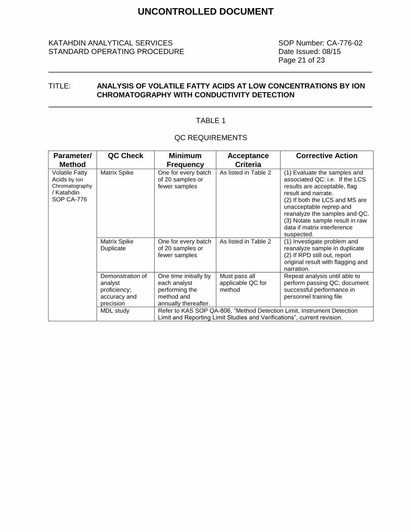
KATAHDIN ANALYTICAL SERVICES SOP Number: CA-776-02 STANDARD OPERATING PROCEDURE Date Issued: 08/15 Page 21 of 23
TITLE: ANALYSIS OF VOLATILE FATTY ACIDS AT LOW CONCENTRATIONS BY ION
CHROMATOGRAPHY WITH CONDUCTIVITY DETECTION
TABLE 1
QC REQUIREMENTS
Parameter/
Method
QC Check Minimum
Frequency
Acceptance
Criteria
Corrective Action
Volatile Fatty Acids by Ion Chromatography
/ Katahdin SOP CA-776
Matrix Spike One for every batch of 20 samples or fewer samples
As listed in Table 2
(1) Evaluate the samples and associated QC: i.e. If the LCS results are acceptable, flag result and narrate. (2) If both the LCS and MS are unacceptable reprep and reanalyze the samples and QC. (3) Notate sample result in raw data if matrix interference suspected.
Matrix Spike Duplicate
One for every batch of 20 samples or fewer samples
As listed in Table 2
(1) Investigate problem and reanalyze sample in duplicate (2) If RPD still out, report original result with flagging and narration.
Demonstration of analyst proficiency; accuracy and precision
One time initially by each analyst performing the method and annually thereafter.
Must pass all applicable QC for method
Repeat analysis until able to perform passing QC; document successful performance in personnel training file
MDL study Refer to KAS SOP QA-806, “Method Detection Limit, Instrument Detection Limit and Reporting Limit Studies and Verifications”, current revision.
UNCONTROLLED DOCUMENT

KATAHDIN ANALYTICAL SERVICES SOP Number: CA-776-02 STANDARD OPERATING PROCEDURE Date Issued: 08/15 Page 22 of 23
TITLE: ANALYSIS OF VOLATILE FATTY ACIDS AT LOW CONCENTRATIONS BY ION
CHROMATOGRAPHY WITH CONDUCTIVITY DETECTION
TABLE 2
QUALITY CONTROL ACCEPTANCE LIMITS
Analyte
LCS / CCV / Matrix
Spike Recovery
Limits
Matrix Spike
Duplicate RPD
Limits
LOQ Verification Limits
Acetic Acid 70% - 140% ≤ 20% 47% - 163%
Butyric Acid 80% - 120% ≤ 20% 67% - 133%
Formic Acid 80% - 120% ≤ 20% 67% - 133%
i-Hexanoic Acid 70% - 140% ≤ 20% 47% - 163%
i-Pentanoic Acid 80% - 120% ≤ 20% 67% - 133%
Lactic Acid 80% - 120% ≤ 20% 67% - 133%
n-Hexanoic Acid 70% - 140% ≤ 20% 47% - 163%
n-Pentanoic Acid 70% - 140% ≤ 20% 47% - 163%
Propionic Acid 80% - 120% ≤ 20% 67% - 133%
Pyruvic Acid 80% - 120% ≤ 20% 67% - 133%
UNCONTROLLED DOCUMENT

KATAHDIN ANALYTICAL SERVICES SOP Number: CA-776-02 STANDARD OPERATING PROCEDURE Date Issued: 08/15 Page 23 of 23
TITLE: ANALYSIS OF VOLATILE FATTY ACIDS AT LOW CONCENTRATIONS BY ION
CHROMATOGRAPHY WITH CONDUCTIVITY DETECTION
TABLE 3
CONCENTRATIONS OF ANALYTES IN LABORATORY CONTROL SAMPLES, MATRIX SPIKES, AND INTERMEDIATE SPIKING STANDARD
Analyte
Conc. (mg/L) in LCS
/ MS Spiking
Standard
Conc. (mg/L) in Prepared
Laboratory Control
Sample
Conc. (mg/L) in
Prepared
Matrix Spike
Acetic Acid 12.2 1.22 1.22
Butyric Acid 17.8 1.78 1.78
Formic Acid 9.99 0.999 0.999
i-Hexanoic Acid 23.3 2.33 2.33
i-Pentanoic Acid 21.1 2.11 2.11
Lactic Acid * 24.2 2.42 2.42
n-Hexanoic Acid 23.3 2.33 2.33
n-Pentanoic Acid 21.1 2.11 2.11
Propionic Acid 15.5 1.55 1.55
Pyruvic Acid * 30.1 3.01 3.01
*Note that the listed concentrations for lactic and pyruvic acids are nominal values and will
change according to the initial weights of these VFAs when preparing the intermediate standards.
UNCONTROLLED DOCUMENT

ADDENDUMSOP NO CHANGE FORM
UNCONTROLLED DOCUMENT

UNCONTROLLED DOCUMENT

A
P
P
E
N
D
I
X
B
Nobis Engineering, Inc.
Title: SCRIBE SAMPLE DOCUMENTATION SOP No: DOC-002
Rev.: 01
Date: September 2013
Page 2 of 14
provided by the EPA PE Repository or other PE sample vendor. These samples are identified on the COC with the PE sample ID provided by the EPA or vendor. Quality Assurance Project Plan (QAPP) – defines the data quality objectives for the project. Quality Assurance (QA) Samples – Samples that may be used for quality assurance include Trip Blank, Equipment Blank, Rinsate Blank, Field Duplicate, and Performance Evaluation Samples. These types of samples are given a different “Sample Type” than field samples. Sample Label – Printed adhesive label affixed to the sample container which includes sample information (i.e., sample number, station location, collection date and time, analysis, preservative, etc.) Scribe v.3.9.3 – Scribe supports the mission of EPA and contractor personnel who visit hazardous waste sites and take soil, air, water and other matrix samples. This software automates many of the processes that personnel follow to assure data quality for the analyses that are later conducted on those samples. Scribe was created to automate printing of sample documentation in the field, reduce the time spent completing sample collection and transfer documentation, and, facilitate electronic capture of data prior to and during field sampling activities. The program output is designed to upload all sampling data automatically to the EPA database through a website, a requirement of the Remedial Action Contract 2 (RAC2) contract. This task is performed by the Lead Chemist or designee following shipments. Traffic Report (TR) – This term is used synonymously with Chain of Custody. The report from the Scribe system that provides a listing of samples, analyses, dates and times of sampling, and where and when samples were shipped. This document is used to document samples shipped for analysis.
4.0 CAUTIONS
Scribe may not include all the pertinent site and sample information required for a project; therefore, check with the Project Manager, Lead Chemist, Technical Lead, etc. on the project to ensure that appropriate information is collected and documented. Additional sample tracking spreadsheets may be required to capture all of the required data.
5.0 PERSONNEL QUALIFICATIONS All samplers (field staff/scientist/geologist/engineer) should have a cursory knowledge of the program; however, only the Sample Manager and/or the FOL (or designee) shall require working knowledge of the SOP and the Scribe program. Scribe provides training files that are available from the ERT support site at: http://www.ertsupport.org/download.asp?PKNAME=SCRIBE&DKEY=SCRIBE. 6.0 EQUIPMENT AND SUPPLIES The following equipment is expected to be required for Scribe documentation:

Nobis Engineering, Inc.
Title: SCRIBE SAMPLE DOCUMENTATION SOP No: DOC-002
Rev.: 01
Date: September 2013
Page 3 of 14
Computer with Scribe Version 3.9.3 installed
Printer/photocopier (multi-use printer/scanner/copier unit is preferred, but not required)
Avery labels #5160 (1 X 2 5/8)
Field book (and/or data recording sheets)
Ball point pen (and or marker), indelible (black)
Sample containers with labels and the appropriate preservatives
Tape – clear, packing
Baggies 7.0 PROCEDURES The procedures required to complete sample management tasks using Scribe are provided in the following sections. 7.1 Office Preparation and Mobilization
7.1.1 Coordinate with the Lead Chemist to obtain the Case Assignment, performance
evaluation (PE) samples, applicable modifications, and turnaround times.
Provide the Nobis Lead Chemist with contact information as soon as established
at the site. If issues arise following shipments, resolution with field staff may be
necessary.
7.1.2 As an option, many of the procedures in Section 7.2 can be performed prior to sampling, if the sample IDs are known.
7.1.3 Scribe New Project Information Data Entry
The following steps outline the procedures to start a new project:
a. Open the Scribe software. The New Project Wizard will appear. If you have already started a project, select “Open Project”; otherwise, select “Next”.
b. Complete the Project Information. Refer to the Case Assignment for the required information. Select “Next”.
c. Browse to the location that you would like to save the database. For
convenience and portability select a location under the c:\ root directory on the site-designated computer. This will ensure that any employee using the site computer will be able to access the location. After the sampling effort is completed, all final files and project information should be saved to the project folder under “Analytical Information\Scribe”. Select “Finish”. Note that if the Site has internet connectivity, the database should always be saved in the “Analytical Information\Scribe” folder in the appropriate project folder on the server.
d. The full Scribe interface will open and default to the Site Info window.
Complete as much of the information in this window as possible. Leave any information not known blank. Throughout the user interface,

Nobis Engineering, Inc.
Title: SCRIBE SAMPLE DOCUMENTATION SOP No: DOC-002
Rev.: 01
Date: September 2013
Page 4 of 14
required fields will be highlighted in blue; these fields must be completed accurately before moving to the next step.
Site Action should be completed from the “Purpose” field on the CLP Case Assignment. If the information is not included in the dropdown menu, then input it.
EPA Contact is the EPA Task Order Project Officer (TOPO) assigned to the project and their telephone number.
Contractor Contact is the Nobis PM and their telephone number.
WA Number is the Work Assignment (Task Order [TO]) and is usually the end of the Nobis project number plus the phase of the project, the task Site Action, and the Spill ID. For example, the TO number for Eastern Surplus is 0005-RA-LR-0189. If you are unsure of your task order number, ask the PM.
The Contract Number is the appropriate EPA contract number associated with the project and site work. For example, the 2006 awarded Contract Number for EPA Region 1 RAC2 is EP-S1-06-03. If you are working on another contract, please ask the PM for the appropriate Contract Number.
Select Save at the bottom of the screen.
7.1.4 Scribe “Planning” Data Entry
The following information will be entered in different subsections under the “Planning” section. Navigate by selecting the appropriate subsection in the left frame.
a. Select “Events” on the left frame. In the main frame, input an Event ID
(e.g., Fall 2010 GW Sampling). The event name should describe what the sampling is for and when the sampling will occur and should be consistent throughout the project.
b. Select “Sampling Locations” from the left frame. Select “Add” from the bottom of the screen. Begin adding the different sampling locations for the sampling event if known (e.g., MW-12D, INN, SW-4, etc.). Enter all the information known for the location and select “Add” at the top of the screen to continue adding locations. Select “Save” at the bottom of the screen following your final location. You can scroll through using the Previous and Next buttons. It is noted that this step can be completed in the field at the time of sampling if the sample locations are not known prior to mobilization.
c. Select “Analyses” from the left frame. Select “Add” from the top of the
screen to add in any analyses that are not listed. Select “Filter” from the top of the screen and select each of the analyses for which you will be submitting. It is best to delete all analyses here and input only the ones

Nobis Engineering, Inc.
Title: SCRIBE SAMPLE DOCUMENTATION SOP No: DOC-002
Rev.: 01
Date: September 2013
Page 5 of 14
that you want to use. The name and abbreviation for the analyses should be approved by the Nobis Lead Chemist prior to mobilization to the field. When setting up new analyses, make sure to select the appropriate “Analyses Type”. VOCs and SVOCs should be organic, metals should be inorganic. DAS and other program analyses should be considered CLP generic. A spreadsheet of the default analyses are saved on the Nobis server in the R:\Field_Documentation\Scribe location. This spreadsheet can be uploaded to the Scribe database by Selecting File>Import>Custom Import and browsing to the file location.
d. Select “Sampler” from the left frame. Delete the pre-loaded sample
names listed and input active sampler’s names by selecting “Add” at the top of the screen.
e. Select “Lab List” from the left frame. Check to see that the laboratory on
the Case Assignment is listed and that the information is correct. If it is not, correct the information. Select “Add” to include any laboratories that are not currently in the list. Note that laboratories often change names through mergers and acquisitions. A spreadsheet of the default laboratories are saved on the Nobis server in the R:\Field_Documentation\Scribe location. This spreadsheet can be uploaded to the Scribe database by Selecting File>Import>Custom Import and browsing to the file location.
7.2 Field Procedures
7.2.1 Scribe “Sampling” Data Entry
The following steps will be completed once the samples are collected and delivered to the Sample Manager or FOL. Sample-specific information and analyses will be entered in different subsections under the “Sampling” section. Navigate by selecting the appropriate subsection (i.e., sample matrix) in the left frame. The steps described below use water samples as an example. The instructions are similar for the different matrices presented in the left frame.
a. Select “Water Sampling” from the left frame. Select the “Event ID” from the drop-down menu. Input the Sample ID into the Sample # field (e.g., ESLT-GW-MW18S-0111) and complete the remainder of the fields on the Sample Details tab. If the correct information is not included in a drop-down menu, then revise or add it, as appropriate.
b. Pay particular attention to the Sample Type pull down menu. Select the appropriate Sample Type from the drop-down list. Most samples will be designated as Field Samples. Field Duplicate needs to be designated for the duplicate sample itself as well as the parent sample and be appended with a sequential number. For example, ESLT-GW-MW18S-1008 / ESLT-GW-DUP03-1008 is the third field duplicate pair for the sampling event; both MW18S and Dup03 will be designated as the Sample Type “Field Duplicate 03”. Designate the remaining QA samples as appropriate. MS/MSD samples are always considered one sample

Nobis Engineering, Inc.
Title: SCRIBE SAMPLE DOCUMENTATION SOP No: DOC-002
Rev.: 01
Date: September 2013
Page 6 of 14
(with additional bottleware) and should be designated as Lab QC for the sample type.
c. Select the “Water Quality” tab. Input the stabilized monitoring parameter
readings from the sampling field sheets.
d. Select the “Analysis” tab. Before entering any data on the first sample, select the “CLP/Tag Settings” button at the bottom of the screen. Fill in the Case number from the laboratory assignment information. Input the next available CLP number obtained from the Lead Chemist. Note that EPA no longer requires the use of tags for the samples. If no specific Tag Number is required, Scribe will generate the first tag number of 1000.This step should only be required for the initial sample of the task; the remainder of the samples will auto-increment from the value that is input here.
e. Click in the “Analyses” field and select the applicable analysis from the
drop-down list. Notice the CLP and Tag fields automatically populate if the analysis is designated as a CLP analysis in Step c in Section 7.1.4. If the analysis is a DAS or other program analysis, input the appropriate sample number. Click in the “Container” field. Select the container used from the drop-down list. Click in the “No. of Containers” field and input “1” (even for VOAs), continue through the rest of the fields. If the correct information is not included in the drop-down menu, then revise as appropriate. Select the collection method; this is where the pump or sampler type can be input. Select the storage method (i.e., ice, dry ice, refrigerator). Select the preservative (e.g., HCl, HNO3, etc.). Select whether the sample is a matrix spike/matrix spike duplicate (MS/MSD). An MS/MSD sample is a laboratory QC sample that generally requires 3 times the sample volume for water samples.
f. For analyses with multiple containers, hit the “Copy Analyses” button at
the bottom of the screen. Copy the analyses until you have the appropriate number of sample containers. Ensure that the MS/MSD sample has sufficient number of containers.
g. For additional analyses (metals, PCBs, VOAs, etc.) press the “Add
Analysis” button at the bottom of the screen and complete the fields.
h. The “Assign From” button can be used for samples that have the identical analysis suite as previous samples. Press the “Assign From” button and enter the sample number (e.g., ESLT-GW-MW3S-0713) of the analyses you wish to copy.
i. To prepare a field duplicate sample, return to the “Sample Details” tab.
Click “Copy” along the top bar and Scribe will produce an identical copy of the sample that was just prepared. Update the sample number with the correct information and update the sample time. Click “Save”.

Nobis Engineering, Inc.
Title: SCRIBE SAMPLE DOCUMENTATION SOP No: DOC-002
Rev.: 01
Date: September 2013
Page 7 of 14
j. Press the “Next” button to move to the next sample. Select the “Sample
Details” tab and repeat Steps a through g in Section 7.2.1.
k. Press “Close” at the bottom of the screen and review the data input in the flat format to ensure completeness and accuracy.
7.2.2 Scribe Sample Management
The two main subsections used by Nobis Sample Managers under the Scribe Sample Management Section are the “Samples” and “Chain of Custody” subsections.
The following steps outline the procedures for creating a COC. It is critical that the appropriate COC format is selected.
a. Select “Chain of Custody” from the left frame. Select “Add” from the top
of the screen or “Add a Chain of Custody” from the bottom of the screen.
b. Click on the “COC Format” field (see below) and select the appropriate
COC format. You will need to create separate COCs if you are shipping
samples for CLP Organics and CLP Inorganic analyses. For DAS and
other program analyses select CLP Generic COCs. Once you select the
laboratory from the dropdown list, many of the fields will automatically
populate. Complete the remaining fields including the FedEx
airbill/tracking number, if applicable.
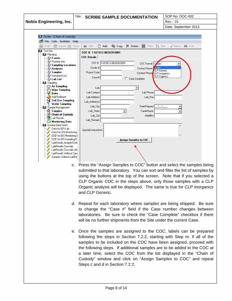
Nobis Engineering, Inc.
Title: SCRIBE SAMPLE DOCUMENTATION SOP No: DOC-002
Rev.: 01
Date: September 2013
Page 8 of 14
c. Press the “Assign Samples to COC” button and select the samples being
submitted to that laboratory. You can sort and filter the list of samples by
using the buttons at the top of the screen. Note that if you selected a
CLP Organic COC in the steps above, only those samples with a CLP
Organic analysis will be displayed. The same is true for CLP Inorganics
and CLP Generic.
d. Repeat for each laboratory where samples are being shipped. Be sure
to change the “Case #” field if the Case number changes between
laboratories. Be sure to check the “Case Complete” checkbox if there
will be no further shipments from the Site under the current Case.
e. Once the samples are assigned to the COC, labels can be prepared
following the steps in Section 7.2.2, starting with Step m. If all of the
samples to be included on the COC have been assigned, proceed with
the following steps. If additional samples are to be added to the COC at
a later time, select the COC from the list displayed in the “Chain of
Custody” window and click on “Assign Samples to COC” and repeat
Steps c and d in Section 7.2.2.

Nobis Engineering, Inc.
Title: SCRIBE SAMPLE DOCUMENTATION SOP No: DOC-002
Rev.: 01
Date: September 2013
Page 9 of 14
f. In the event that you want to remove a sample from the COC, select
“Samples” Tab and browse to the desired sample. Select the “COC
value” in the record and physically delete the value (using the delete key
on the keyboard, not the Delete button on the screen as that will delete
the entire sample).
g. Pull down the “File” menu on the menu bar and select “Backup Project”.
Browse to the location desired or use the default location (e.g.,
C:\Program Files (x86)\Scribe\BACKUP) and press Save.
h. Click the “Chain of Custody” tab and select the appropriate COC and
press the “Export” button at the top of the screen. Select “COC XML File
(*.xml)” (see below).

Nobis Engineering, Inc.
Title: SCRIBE SAMPLE DOCUMENTATION SOP No: DOC-002
Rev.: 01
Date: September 2013
Page 10 of 14
i. The correct COC should be checked, but if additional COCs are
required, check each of the COCs that require export and select OK. Be
sure that the “CLP Region Copy (Includes additional Site and Geospatial
Information” checkbox is checked (see below). Browse to the folder
desired and “Save” the file. Note that the *.xml file will open in Internet
Explorer (IE) where you can review the file. Close the IE window and
return to Scribe.
j. In the COC tab, ensure that the appropriate COC is highlighted and
press the “Print Chain of Custody” button at the bottom of the screen.
Select “Report Setup” and use the Report Header displayed below.
Select whether to print the “Lab Copy” or the “Region Copy” of the COC
and select OK. The Lab Copy of the COC should be included in the
cooler with the samples while the Region Copy will be sent to the Nobis
Lead Chemist and subsequently to the EPA. The Lab Copy of the COC
lacks Site and QC information that is displayed on the Region Copy to
ensure unbiased analyses from the laboratories.
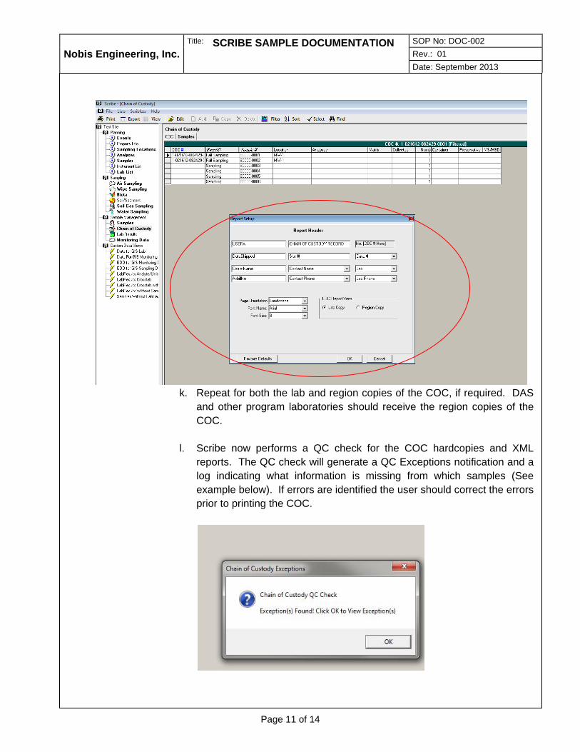
Nobis Engineering, Inc.
Title: SCRIBE SAMPLE DOCUMENTATION SOP No: DOC-002
Rev.: 01
Date: September 2013
Page 11 of 14
k. Repeat for both the lab and region copies of the COC, if required. DAS
and other program laboratories should receive the region copies of the
COC.
l. Scribe now performs a QC check for the COC hardcopies and XML
reports. The QC check will generate a QC Exceptions notification and a
log indicating what information is missing from which samples (See
example below). If errors are identified the user should correct the errors
prior to printing the COC.

Nobis Engineering, Inc.
Title: SCRIBE SAMPLE DOCUMENTATION SOP No: DOC-002
Rev.: 01
Date: September 2013
Page 12 of 14
m. There are different methods for printing labels in Scribe. However, it is best to print labels AFTER assigning the samples to a COC. The following procedures cover the most common method for printing sample bottle labels.
n. After the samples have been assigned to the appropriate COC, select
the “Samples” subsection on the left frame. In order to print select
sample labels and not all of the sample labels, select a column or value,
right click on it, and select Filter for a value. Generally, the “Remarks”
column can be used as a dummy value for filtering. In the Samples
view, enter a value in the column for all the samples that require a label
and filter for that value. Repeat that process with a new value for each
round of labels to print. It is recommended that a one digit numerical
value is used for efficiency. For example, input 1 for the first round of
samples being labeled, 2 for the second round, 3 for the third, etc.
o. Press the “Print Labels” button at the bottom of the screen and select
“Label Setup”.
p. In this section the label format for each job will be set up. Choose #5160
from the list and click “Next”.
Set up the labels as:
Line 1: Case # [CaseNumber] CLP #[CLP Sample #] Line 2: [Sample #] Line 3: Date: [Sample Date] Time: [Sample Time] Line 4: [Analyses] Pres: [Preservation]
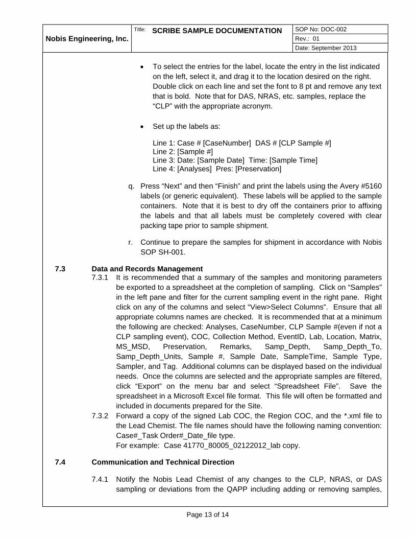
Nobis Engineering, Inc.
Title: SCRIBE SAMPLE DOCUMENTATION SOP No: DOC-002
Rev.: 01
Date: September 2013
Page 13 of 14
To select the entries for the label, locate the entry in the list indicated
on the left, select it, and drag it to the location desired on the right.
Double click on each line and set the font to 8 pt and remove any text
that is bold. Note that for DAS, NRAS, etc. samples, replace the
“CLP” with the appropriate acronym.
Set up the labels as:
Line 1: Case # [CaseNumber] DAS # [CLP Sample #] Line 2: [Sample #] Line 3: Date: [Sample Date] Time: [Sample Time] Line 4: [Analyses] Pres: [Preservation]
q. Press “Next” and then “Finish” and print the labels using the Avery #5160
labels (or generic equivalent). These labels will be applied to the sample
containers. Note that it is best to dry off the containers prior to affixing
the labels and that all labels must be completely covered with clear
packing tape prior to sample shipment.
r. Continue to prepare the samples for shipment in accordance with Nobis
SOP SH-001.
7.3 Data and Records Management 7.3.1 It is recommended that a summary of the samples and monitoring parameters
be exported to a spreadsheet at the completion of sampling. Click on “Samples”
in the left pane and filter for the current sampling event in the right pane. Right
click on any of the columns and select “View>Select Columns”. Ensure that all
appropriate columns names are checked. It is recommended that at a minimum
the following are checked: Analyses, CaseNumber, CLP Sample #(even if not a
CLP sampling event), COC, Collection Method, EventID, Lab, Location, Matrix,
MS_MSD, Preservation, Remarks, Samp_Depth, Samp_Depth_To,
Samp_Depth_Units, Sample #, Sample Date, SampleTime, Sample Type,
Sampler, and Tag. Additional columns can be displayed based on the individual
needs. Once the columns are selected and the appropriate samples are filtered,
click “Export” on the menu bar and select “Spreadsheet File”. Save the
spreadsheet in a Microsoft Excel file format. This file will often be formatted and
included in documents prepared for the Site.
7.3.2 Forward a copy of the signed Lab COC, the Region COC, and the *.xml file to
the Lead Chemist. The file names should have the following naming convention:
Case#_Task Order#_Date_file type.
For example: Case 41770_80005_02122012_lab copy.
7.4 Communication and Technical Direction
7.4.1 Notify the Nobis Lead Chemist of any changes to the CLP, NRAS, or DAS
sampling or deviations from the QAPP including adding or removing samples,
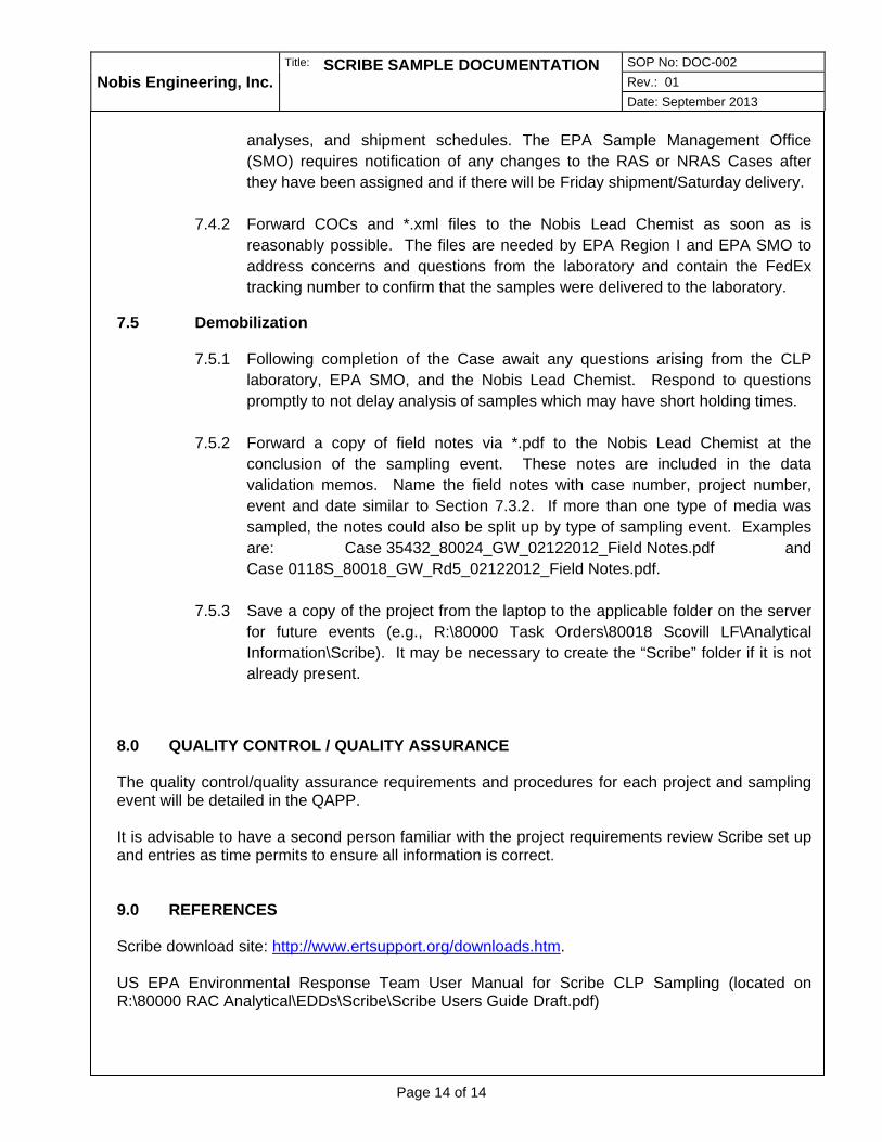
Nobis Engineering, Inc.
Title: SCRIBE SAMPLE DOCUMENTATION SOP No: DOC-002
Rev.: 01
Date: September 2013
Page 14 of 14
analyses, and shipment schedules. The EPA Sample Management Office
(SMO) requires notification of any changes to the RAS or NRAS Cases after
they have been assigned and if there will be Friday shipment/Saturday delivery.
7.4.2 Forward COCs and *.xml files to the Nobis Lead Chemist as soon as is
reasonably possible. The files are needed by EPA Region I and EPA SMO to
address concerns and questions from the laboratory and contain the FedEx
tracking number to confirm that the samples were delivered to the laboratory.
7.5 Demobilization
7.5.1 Following completion of the Case await any questions arising from the CLP
laboratory, EPA SMO, and the Nobis Lead Chemist. Respond to questions
promptly to not delay analysis of samples which may have short holding times.
7.5.2 Forward a copy of field notes via *.pdf to the Nobis Lead Chemist at the
conclusion of the sampling event. These notes are included in the data
validation memos. Name the field notes with case number, project number,
event and date similar to Section 7.3.2. If more than one type of media was
sampled, the notes could also be split up by type of sampling event. Examples
are: Case 35432_80024_GW_02122012_Field Notes.pdf and
Case 0118S_80018_GW_Rd5_02122012_Field Notes.pdf.
7.5.3 Save a copy of the project from the laptop to the applicable folder on the server
for future events (e.g., R:\80000 Task Orders\80018 Scovill LF\Analytical
Information\Scribe). It may be necessary to create the “Scribe” folder if it is not
already present.
8.0 QUALITY CONTROL / QUALITY ASSURANCE The quality control/quality assurance requirements and procedures for each project and sampling event will be detailed in the QAPP. It is advisable to have a second person familiar with the project requirements review Scribe set up and entries as time permits to ensure all information is correct. 9.0 REFERENCES Scribe download site: http://www.ertsupport.org/downloads.htm. US EPA Environmental Response Team User Manual for Scribe CLP Sampling (located on R:\80000 RAC Analytical\EDDs\Scribe\Scribe Users Guide Draft.pdf)

STANDARD OPERATING PROCEDURES
David Gorhan ________________
Prepared by
Josh Stewart, Erik Johnson ______
Reviewed by
Gail DeRuzzo
Approved by
Title: ELECTRONIC DATA MANAGEMENT USING HANDHELD CONNECTED DEVICES Nobis Engineering, Inc.
SOP No: DOC-003 Rev. 00 Date: April 2016
Page 1 of 11
1.0 SCOPE, APPLICATION, AND LIMITATIONS
This Standard Operating Procedure (SOP) has been prepared by Nobis Engineering, Inc. (Nobis) to specify the means and methods required to appropriately document data obtained in the field using handheld connected devices. Electronic data capture can be used to effectively and efficiently collect field data including site observations, water quality parameters, soil sample classification, monitoring well construction, etc. The storage and transfer of the data to the project file is critical, however, to prevent the accidental loss of data. This SOP will describe the steps required to document and transfer data using an Android powered tablet device. Currently, Nobis maintains several Samsung Galaxy Note 8 devices. If another device is used, replication of the steps outlined as close as possible is required, recognizing that names and locations of folders may be slightly different. This SOP is prepared assuming that the user has a limited knowledge of the electronic handheld connected devices. It is not intended to be a user’s guide for individual app lications (apps) or programs but rather a procedure for collecting, transferring, and storing data. 2.0 INTRODUCTION This procedure includes the minimum required steps and quality checks that the field technician, Sample Manager, and/or Field Operations Leader (FOL) (or designee) is to follow when collecting data electronically on handheld connected devices. This SOP addresses the technical requirements and required documentation to be completed following data collection. 3.0 DEFINITIONS Bluetooth – Wireless technology standard for exchanging data over short distances (using short-wavelength UHF radio waves in the ISM band from 2.4 to 2.485 GHz) from fixed and mobile devices, and building personal area networks. Handheld connected device – Any electronic device capable of editing and storing data and transferring the data to a computer, the internet, or a server through USB, Bluetooth, or wireless connection (e.g., smartphone, tablet, iPad). MicroSD card – SD stands for Secure Digital and is considered a solid-state storage media. SD memory comes in several physical sizes (i.e., original, mini, and micro) as well as storage capacities. The microSD card is generally used in portable devices like smartphones and tablets. S-Pen – The Samsung stylus that comes with certain tablet devices manufactured by Samsung. The S-Pen has additional functionality than a typical stylus when using it with certain Samsung tablets. USB – USB stands for Universal Serial Bus and is the industry standard that defines the cables, connectors and communications protocols used in a bus for connection, communication, and power supply between computers and electronic devices.
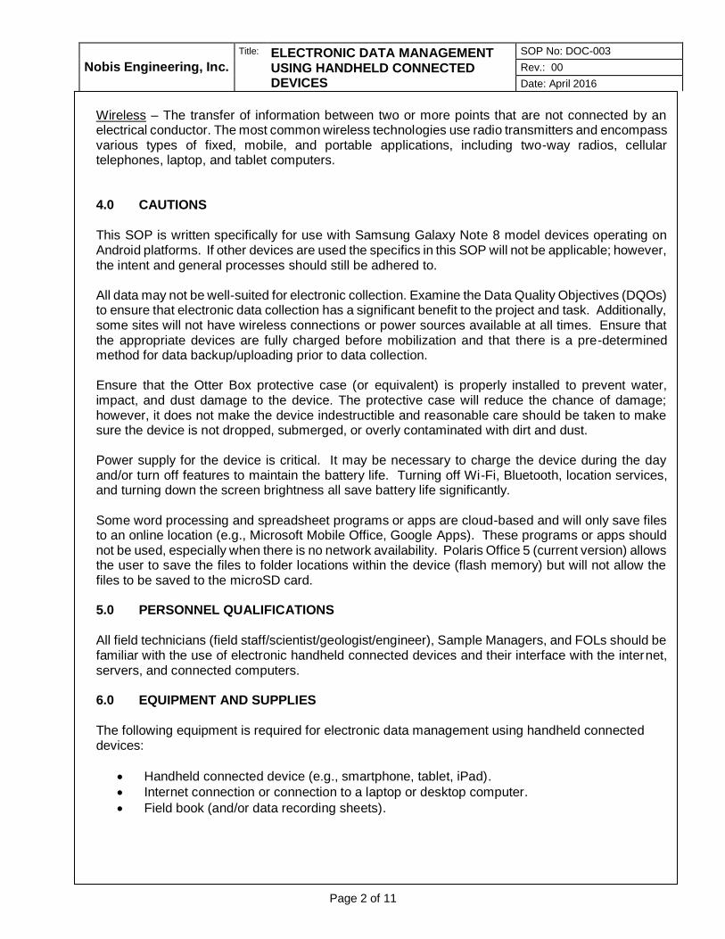
Nobis Engineering, Inc.
Title: ELECTRONIC DATA MANAGEMENT USING HANDHELD CONNECTED DEVICES
SOP No: DOC-003
Rev.: 00
Date: April 2016
Page 2 of 11
Wireless – The transfer of information between two or more points that are not connected by an electrical conductor. The most common wireless technologies use radio transmitters and encompass various types of fixed, mobile, and portable applications, including two-way radios, cellular telephones, laptop, and tablet computers. 4.0 CAUTIONS
This SOP is written specifically for use with Samsung Galaxy Note 8 model devices operating on Android platforms. If other devices are used the specifics in this SOP will not be applicable; however, the intent and general processes should still be adhered to. All data may not be well-suited for electronic collection. Examine the Data Quality Objectives (DQOs) to ensure that electronic data collection has a significant benefit to the project and task. Additionally, some sites will not have wireless connections or power sources available at all times. Ensure that the appropriate devices are fully charged before mobilization and that there is a pre-determined method for data backup/uploading prior to data collection. Ensure that the Otter Box protective case (or equivalent) is properly installed to prevent water, impact, and dust damage to the device. The protective case will reduce the chance of damage; however, it does not make the device indestructible and reasonable care should be taken to make sure the device is not dropped, submerged, or overly contaminated with dirt and dust. Power supply for the device is critical. It may be necessary to charge the device during the day and/or turn off features to maintain the battery life. Turning off Wi-Fi, Bluetooth, location services, and turning down the screen brightness all save battery life significantly. Some word processing and spreadsheet programs or apps are cloud-based and will only save files to an online location (e.g., Microsoft Mobile Office, Google Apps). These programs or apps should not be used, especially when there is no network availability. Polaris Office 5 (current version) allows the user to save the files to folder locations within the device (flash memory) but will not allow the files to be saved to the microSD card. 5.0 PERSONNEL QUALIFICATIONS
All field technicians (field staff/scientist/geologist/engineer), Sample Managers, and FOLs should be familiar with the use of electronic handheld connected devices and their interface with the internet, servers, and connected computers. 6.0 EQUIPMENT AND SUPPLIES The following equipment is required for electronic data management using handheld connected devices:
Handheld connected device (e.g., smartphone, tablet, iPad).
Internet connection or connection to a laptop or desktop computer.
Field book (and/or data recording sheets).

Nobis Engineering, Inc.
Title: ELECTRONIC DATA MANAGEMENT USING HANDHELD CONNECTED DEVICES
SOP No: DOC-003
Rev.: 00
Date: April 2016
Page 3 of 11
7.0 PROCEDURES
The procedures required to complete electronic data capture using handheld connected devices are provided in the following sections. 7.1 Office Preparation and Mobilization
7.1.1 Coordinate with the Project Manager (PM) and Lead Chemist to get approval to
collect data electronically on the assigned project or task. Some contracts may
require hand-written field sheets or documentation in a bound field logbook.
Coordinate with the PM, FOL, and other team members to use the same field log
sheets, etc. appropriate for the job.
7.1.2 Connect the handheld device to a laptop or desktop computer via USB, Bluetooth,
or wireless connection.
7.1.2.1 If Bluetooth is used for data transfer, the device and the computer must be Bluetooth enabled and the devices must be “paired”. a Open the Settings menu on the device by touching the Settings
gear icon on the home screen or the drag-down notification menu.

Nobis Engineering, Inc.
Title: ELECTRONIC DATA MANAGEMENT USING HANDHELD CONNECTED DEVICES
SOP No: DOC-003
Rev.: 00
Date: April 2016
Page 4 of 11
b Touch the Bluetooth menu on the left to activate the service and
touch the Scan button in the top-right corner of the screen to locate
the computer of choice.
c Alternately, the pairing can be done from the computer of choice by clicking in the system tray in the bottom right corner of the screen and clicking on the Bluetooth icon and selecting “Add a Device”. Make the device visible by entering the Bluetooth menu
as directed above and checking the box to make the device visible to other devices.
d Once the device is connected all necessary files can be transferred to the device including *.pdf, *.xlsx, and *.docx files such as the Quality Assurance Project Plan (QAPP), Health and Safety Plan (HASP), work plans, historical information, and field log sheets. Right click on the files needed for transfer in Windows Explorer and select Send to>Bluetooth. Select the appropriate device and click Next. A permission window will appear on the device. Accept the transfer and the file(s) will be transferred to the Download
folder on the device. e The files should be moved to the applicable project folder. If the
folder does not already exist, create a project folder on the device by opening the My Files app on the Home screen or in the app list.
Navigate to: /storage/extSdCard/NOBIS/Site Specific. Create the new folder by touching the Create Folder button in the upper-right corner. Use the Create Folder button to create a new folder with
the site name. f Navigate to the Download folder and find the transferred files.
Select the files to move and touch the Move button along the top.

Nobis Engineering, Inc.
Title: ELECTRONIC DATA MANAGEMENT USING HANDHELD CONNECTED DEVICES
SOP No: DOC-003
Rev.: 00
Date: April 2016
Page 5 of 11
Navigate to the desired folder and touch the Paste button in the upper-right corner of the screen.
7.1.2.2 If a USB connection is used, connect the device with the included cable to the computer using any USB port on the computer. a The Autoplay window will appear on the initial connection asking
what action to perform upon connection. b Check the box for “Always do this for this device” and select
“Open device to view files”. c The device will show up in Windows Explorer as a network drive
and can be navigated similar to any other drive. d Once the device is connected, all necessary files can be
transferred to the device including *.pdf, *.xlsx, and *.docx files such as the QAPP, HASP, work plans, historical information, and field log sheets.
e Drag and drop (copy and paste) files using Windows Explorer. If the appropriate project folder does not exist at /storage/extSdCard/NOBIS/Site Specific, create it by right clicking and selecting New Folder.
7.1.2.3 Touch the My Files icon on the home screen and navigate to the project
folder saved on the SD card and open the appropriate files to ensure that they transferred correctly. Currently, Polaris Office 5 is the preferred word processing and spreadsheet app and should be used for all *.docx and *.xlsx files. The app will also display *.pdf files.
7.2 Field Procedures
7.2.1 The device can be used for recording groundwater monitoring data, soil boring
and test pit observations, photographic documentation, etc. Appropriate files for
use in the field can be found on the Field Team Resources page of the Nobis
SharePoint site. All appropriate data will be recorded on the device that has
previously been recorded on hand-written field log sheets.
7.2.2 Blank field forms to be used as templates will be saved at \Card\NOBIS\Field
Forms. To use a form, select the applicable form(s), copy and paste them to the
project folder located at \Card\NOBIS\Site Specific. The template form can then
be opened and project details can be completed.
7.2.3 To enter data into a form navigate to the form you wish to use and tap it to open
it. The file will open in Polaris Office. Zoom in or out to view the form. Polaris
Office defaults to the view mode when a document is opened. To enter edit mode,
tap the edit button at the top of the screen. Once in edit mode, entering data into
a cell is similar to any computer: tap the cell you want to add data to and then tap
the formula bar box at the top of the sheet or double tap the cell you wish to edit.
7.2.4 Data can be entered using the S-pen or with finger taps and swipes. Once the S-
pen is removed from its mount on the bottom right corner of the device,
handwriting recognition becomes the default data entry method. It can be
changed to a virtual keyboard, if desired, by touching the small keyboard icon in
the bottom left corner of the screen.

Nobis Engineering, Inc.
Title: ELECTRONIC DATA MANAGEMENT USING HANDHELD CONNECTED DEVICES
SOP No: DOC-003
Rev.: 00
Date: April 2016
Page 6 of 11
7.2.5 Regardless of the chosen data entry method, double check each entry to ensure
that the device has interpreted the keyboard touch, handwriting, and/or voice
accurately. Fix any errors before proceeding to ensure accurate data capture.
Note: The field data must be complete and accurate when the
samples/sample data are turned in. If it is not complete and accurate, the
FOL and/or sample manager will not accept the samples and logs.
7.2.6 Save data often. When starting a new document from a template file in the Polaris
Office app, touch the top left icon and select Save As. Navigate to:
\Storage\emulated\0\Nobis Files, if necessary, and name the file using a
conventional naming structure that captures the date, location, and data type
(e.g., 2014-10-10 MW-45S Log Sheet.xlsx). Once the file is named, save
regularly by touching the icon in the upper left corner of the screen and selecting
Save.
7.2.7 Use the onboard camera to photo-document site observations such as site
conditions, soil samples, marketing photographs, and subcontractors. It may be
necessary to remove parts of the protective case and holster to expose the
camera lens. Rename the photos at the time of capture by viewing the photograph
in the Gallery mode and touching the Menu button on the bottom left corner of
the device. Select Rename and use a conventional naming structure that
identifies the photograph (e.g., TP-301 2-4 feet, 2014-10-10 vandalism to front
gate). Additionally an ID or notes can be drawn on the photograph by viewing the
photograph in the Gallery and following the steps detailed below:
1. Open the photo Gallery

Nobis Engineering, Inc.
Title: ELECTRONIC DATA MANAGEMENT USING HANDHELD CONNECTED DEVICES
SOP No: DOC-003
Rev.: 00
Date: April 2016
Page 7 of 11
2. Touch the Menu button on the bottom left corner of the device and
select Edit.
3. Choose Photo Editor.

Nobis Engineering, Inc.
Title: ELECTRONIC DATA MANAGEMENT USING HANDHELD CONNECTED DEVICES
SOP No: DOC-003
Rev.: 00
Date: April 2016
Page 8 of 11
4. In Photo Editor touch Decoration at the bottom right of the
screen.
5. Then touch Drawing.
6. Line color and thickness can be changed by touching the pen
button at the bottom of the screen.

Nobis Engineering, Inc.
Title: ELECTRONIC DATA MANAGEMENT USING HANDHELD CONNECTED DEVICES
SOP No: DOC-003
Rev.: 00
Date: April 2016
Page 9 of 11
7. Use the S-pen or finger to write on the photo and touch Done in
the upper right corner of the screen when finished.

Nobis Engineering, Inc.
Title: ELECTRONIC DATA MANAGEMENT USING HANDHELD CONNECTED DEVICES
SOP No: DOC-003
Rev.: 00
Date: April 2016
Page 10 of 11
8. Touch the Save Icon in the upper right corner of the screen to save
the edits and touch the Back button on the device to return to the
Gallery.
7.2.8 Data entered using Polaris Office 5 saved to the internal storage of the device
must be copied to the appropriate project folder on the SD card. Warning: Polaris
Office will not allow files to be saved directly to the SD card!
7.2.9 Data entry forms will be backed up to the SD card/uploaded to a secondary device
as soon as possible. On sites where wireless connectivity is possible, the files can
be emailed to the PM, FOL, or other designated person in the office using the
Gmail account set up on the device. Otherwise, use the steps in Section 7.1.2 to
transfer the files to a laptop computer in the field to ensure that the data is securely
stored on a hard drive. Note: If the device has been dedicated to one
employee, it may be prudent or more efficient to install the Outlook app from
the Google Play Store and connect to the employee’s Nobis email account.
7.3 Data and Records Management
All data collected in the field on the device will be backed up (saved to the SD card) and/or uploaded to a secondary computer with a hard drive or the project file stored on the company server. This can be done through email, USB, or Bluetooth methods to ensure the preservation of the data. Data can be transferred in the reverse of Section 7.1.2. Ultimately, all data including photographs, field forms, notes, and sketches must be stored in the project files located on the Nobis network. The data is typically stored in the Data or Technical Data folder under a subfolder named Field Notes and Forms, or similar. Once the data is completely transferred to the network it can be deleted from the device to conserve storage space for the next project.
7.4 Communication and Technical Direction
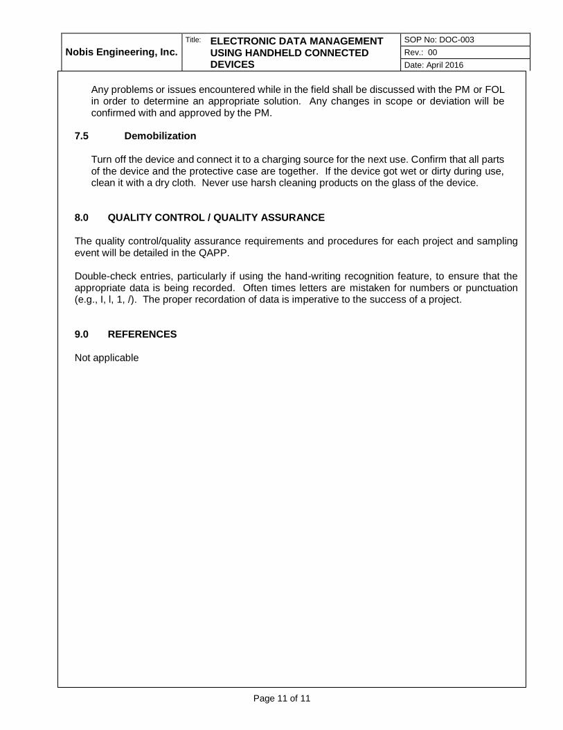
Nobis Engineering, Inc.
Title: ELECTRONIC DATA MANAGEMENT USING HANDHELD CONNECTED DEVICES
SOP No: DOC-003
Rev.: 00
Date: April 2016
Page 11 of 11
Any problems or issues encountered while in the field shall be discussed with the PM or FOL in order to determine an appropriate solution. Any changes in scope or deviation will be confirmed with and approved by the PM.
7.5 Demobilization
Turn off the device and connect it to a charging source for the next use. Confirm that all parts of the device and the protective case are together. If the device got wet or dirty during use, clean it with a dry cloth. Never use harsh cleaning products on the glass of the device.
8.0 QUALITY CONTROL / QUALITY ASSURANCE The quality control/quality assurance requirements and procedures for each project and sampling event will be detailed in the QAPP. Double-check entries, particularly if using the hand-writing recognition feature, to ensure that the appropriate data is being recorded. Often times letters are mistaken for numbers or punctuation (e.g., I, l, 1, /). The proper recordation of data is imperative to the success of a project. 9.0 REFERENCES Not applicable

STANDARD OPERATING PROCEDURES S. Bonis _____________________
Prepared by
B. Allen _____________________
Reviewed by
D. Gorhan ___________________
Approved by
Title: PORE WATER SAMPLING
Nobis Engineering, Inc.
SOP No: ENV-023 Rev.: 02 Date: Aug. 22, 2017
1.0 SCOPE, APPLICATION, AND LIMITATIONS This Standard Operating Procedure (SOP) has been prepared by Nobis Engineering, Inc. (Nobis) to specify the means and methods required to collect representative samples of groundwater near the groundwater/surface water interface using mini-piezometers in sediments. This SOP should be used whenever groundwater samples are collected from saturated material beneath water bodies to yield representative samples of groundwater at the groundwater/surface water interface. Sampling of porewater, to evaluate geochemical equilibria, biogeochemical reaction networks and ecological impacts is best accomplished with pore water diffusion equilibrators (“peepers”) designed for site specific conditions. 2.0 INTRODUCTION This procedure includes the minimum required steps and quality checks that project samplers are to follow when sampling groundwater through sediment using this technique. This SOP addresses the technical requirements and required documentation to be completed during sample collection. 3.0 DEFINITIONS Field Sheet – A form designed for the collection of pertinent field data for a single location in an organized and easy to use manner. Flow-Through Cell – A cell of 250 milliliter (mL) to 500 mL capacity designed to keep multi-parameter probes completely immersed in flowing water. The cell is designed to limit air bubbles and has an input port near the base and an output port near the top. The cell generally threads onto the multi-meter probe and seals with no head space during water flow. Guard Rod – A stiffening rod designed to provide additional strength to a mini-piezometer for insertion into the sediment below the water body. Mini-Piezometer – Sometimes referred to as a push-point sampler, the mini-piezometer is a small diameter tube with a 2 to 3-inch slotted segment near the pointed tip. The sampler is designed to be pushed into the sediment manually and connected to a device capable of drawing water from the sediment pores through the sampler, most often by a peristaltic pump (a syringe may also be used). Multi-Parameter Meter – A meter capable of continuous measurement of multiple geochemical parameters, most often pH, temperature, specific conductivity, oxidation/reduction potential, and dissolved oxygen. Appropriate meters will be capable of use with a flow-through cell. Pore Water – The water in the pore spaces of the sediment below a body of water. Quality Assurance Project Plan – Or QAPP, defines the data quality objectives for the project.

Nobis Engineering, Inc.
Title: PORE WATER SAMPLING SOP No: ENV-023
Rev.: 02
Date: August 22, 2017
Site-Specific Health and Safety Plan – A document intended to provide guidance beyond the Corporate Health and Safety Manual with respect to the specific conditions anticipated during activities on the work site. Turbidity Meter – A meter designed to measure the turbidity of a water sample, usually in nephelometric turbidity units (NTUs) Water Bodies – For the purpose of this SOP, a water body is defined as any persistent surface water, moving or stagnant. 4.0 CAUTIONS
4.1 This SOP does not address all of the hazards and environmental conditions that are
typically associated with working near water bodies in general and collecting pore water samples specifically.
4.2 A Site-Specific Health and Safety Plan is required prior to commencing sample
collection activities.
4.3 Among the factors that should be addressed in a Site-Specific Health and Safety Plan for pore water sample collection are: water depth, current, water temperature, irregular ground surfaces beneath the water body, and soft or unstable materials in the ground surface beneath the water body.
4.4 Boots or waders appropriate to the conditions should be used. A personal floatation
device (PFD) may be required under some conditions.
4.5 Familiarity with the water bodies where the samples will be collected is recommended for preparation of the Site-Specific Health and Safety Plan.
5.0 PERSONNEL QUALIFICATIONS All samplers (field staff/scientist/geologist/engineer) should be familiar with generally accepted environmental sample collection procedures and sufficiently trained in the pore water sample collection method and capable of executing it in a timely and efficient manner. 6.0 EQUIPMENT AND SUPPLIES The following equipment is expected to be required for pore water sampling:
• Site Work Plan (including Site Plan) and Site-Specific Health and Safety Plan;
• Field book (and/or data recording sheets with clipboard)
• Ball point pen (and or marker), indelible (black)
• Water level meter
• Mini-Piezometer (Push Point Sampler) sample collection device with guard rod
• Geo-Pump Series II Peristaltic Pump (or equivalent)
• Battery Jump Pack or alternative power supply
• Multi-parameter meter with flow-through cell and calibration standards or individual meters for pH and temperature

Nobis Engineering, Inc.
Title: PORE WATER SAMPLING SOP No: ENV-023
Rev.: 02
Date: August 22, 2017
• Lamotte 20/20 (or equivalent) turbidity meter (with calibration standards)
• Sample tubing (polyethylene and silicon)
• Sample containers with labels and the appropriate preservatives
• Cooler
• Meter stick
• Nitrile gloves
• Decontamination supplies
7.0 PROCEDURES
7.1 Prior to mobilization, consult records of recent meteorological conditions. Sample
collection may not be appropriate for all water bodies during or soon after prolonged or extreme weather events. The QAPP will establish the climatic / meteorological conditions under which samples should be collected.
7.2 Prior to initiating sample collection activities, all equipment will be calibrated as per the
manufacturers’ specifications and/or in accordance with the QAPP. Manufacturers’ literature and equipment-specific SOPs (e.g. FS-005 for calibration of the YSI 600 series multi-parameter meter) for each piece of equipment will be included in planning documents and will be made available to the field staff. Documentation of equipment calibration will be made on an equipment calibration log.
7.3 The following procedures will be used for pore water sample collection:
7.3.1 Position the monitoring and collection equipment in the proposed sediment pore water sample collection location. When installing the min-piezometer be sure to stand and/or anchor downstream of the sampling location to reduce interference caused by sediment disturbance.
7.3.2 Record sample location and information in field log book and/or field sample log sheet in accordance with the requirements specified in the QAPP.
7.3.3 Label and number the sample containers. Fill out the label in indelible ink and carefully and clearly address all categories and analyses. The required containers and handling are specified in the QAPP.
7.3.4 Insert the decontaminated guard rod into the mini-piezometer body completely
so that the hollow sampler tube is fully supported.
7.3.5 Holding the mini-piezometer and guard-rod together, push the sampling device into the sediment up to a depth of 6 inches (15 cm) using a gentle pushing and twisting motion. If the sediment thickness is less than 6 inches, note the probe depth achieved. A perforated split disk can be affixed to the tubing six inches above the sampling point to aid in depth placement.
7.3.6 When the desired depth is reached, remove the guard rod from the push point
sampler being careful not to disturb the position of the sampler. Once the guard rod is removed from the sampler the device should not be pushed further into

Nobis Engineering, Inc.
Title: PORE WATER SAMPLING SOP No: ENV-023
Rev.: 02
Date: August 22, 2017
sediments to avoid damaging the screened interval or clogging the device with sediment.
7.3.7 Using the meter stick, measure the depth of the water from the sediment to the
top of surface water and record the measurement within the log book or on the field sheets. Also measure the distance from the sediment surface to the top of the sampler. Subtracting this measurement from the total length of the sampler gives the sampler depth below the sediment surface.
7.3.8 Using the multi-parameter meter, measure and record the parameters specified
in the QAPP from the surface water adjacent to the sampler by placing the tubing intake into the water immediately above the sediment interface and record the measurements in the logbook or on the field sheet.
7.3.9 Attach the silicon peristaltic pump tubing onto the top of the push point sampler,
clamping the tubing to the top of the mini-piezometer to limit movement and ensure an adequate seal. Attach the other end of the silicon tubing to the water quality parameter meter flow-through cell.
7.3.10 Proceed with purging the push point sampler at a low-flow rate (50-200 mL/min)
using a peristaltic pump in a manner similar to the Low-Flow/Low-Stress Groundwater Sampling SOP SA-003. Record pore water parameters in 3 to 5-minute intervals. Ideally, water in the flow through cell should be completely evacuated between readings (i.e. calculate the intervals based on the flow rate and flow-through cell volume).
7.3.11 Compare the initial surface water parameters recorded above in 7.3.8 to the
sediment pore water parameters and evaluate whether surface water is being drawn down to the sampler intake using the criteria specified in the QAPP. If the pore water parameters measured do not confirm conclusively that only pore water is being drawn into sampler, refer to the QAPP for the appropriate corrective action.
7.3.12 When the water being purged is confirmed to be only pore water (usually after 3
readings), begin collecting the sample into pre-cleaned, pre-preserved (as appropriate) containers in accordance with methods identified in the SOP SA-003. Do not adjust the flow rate of the peristaltic pump while collecting the samples.
7.3.13 When sample collection is complete, turn off the pump and remove the tubing.
If the tubing is to be dedicated to that location, purge the tubing of water, place the tubing in a clearly labeled plastic zip-lock style bag, and store in a warm, dry location to prevent freezing and damage to the tubing. If the tubing is not dedicated, dispose of the tubing in an appropriate container. Remove the sampler from the sediment and decontaminate non-dedicated equipment in accordance with the QAPP.
7.3.14 Manage the samples in accordance with the QAPP, applying appropriate
temperature controls and chain of custody procedures.
Nobis Engineering, Inc.
Title: PORE WATER SAMPLING SOP No: ENV-023
Rev.: 02
Date: August 22, 2017
8.0 QUALITY CONTROL / QUALITY ASSURANCE The quality control / quality assurance requirements and procedures will be detailed in the QAPP. 9.0 REFERENCES Sediment Porewater Sampling Using a Micro Push Point, SOP#EH-03, East Helena Site, Montana, 2003. Master Quality Assurance Project Plan, EQA RFA #08036, New Hampshire Department of Environmental Services, Revision # 2, January 2009, SOP No. HWRB-16.

Nobis Engineering, Inc.
Title: PORE WATER SAMPLING SOP No: ENV-023
Rev.: 02
Date: August 22, 2017


Nobis Engineering, Inc. Title: FIELD SAMPLING EQUIPMENT
DECONTAMINATION
SOP No: FS-004
Rev.: 02
Date: May 2010
Page 2 of 4
6.0 EQUIPMENT AND SUPPLIES
• Detergent soap (Alconox)
• Deionized Water
• Solvent (e.g., isopropanol, methanol, hexane)
• Nitric acid solution
• Potable water
• Drip pans/buckets
• Brushes
• Polyethylene sheeting
• Spray bottles
• Pump sprayers
• Paper towels
• Temporary storage container for the decontamination liquid (IDW)
7.0 PROCEDURES
7.1 OFFICE PREPARATION AND MOBILIZATION
Prior to field work, ensure that appropriate equipment and supplies are acquired prior to leaving for the Site.
7.2 FIELD PROCEDURES
• Table 1 provides a basic description of common decontamination fluids and their respective uses. Whenever site-specific contamination is known, a specialized decontamination procedure may be developed.
• Prior to completion of sampling, gross contamination of the sampling equipment should be removed at the sample collection site, and managed appropriately.
• Contaminated sample collection equipment to be decontaminated should be brought to a centralized decontamination station or pad, which should be lined with plastic sheeting to prevent decontamination solutions and/or contamination from contacting the ground surface. If possible, the station or pad should contain drip pans or buckets at each stage of the process to collect dripping decontamination fluids. For larger pads, the pad should be sloped such that water drains to a sump area for removal and containerization.
Table 1
Decontamination Fluids and Their Applications
FLUIDS TYPICALLY USED APPLICATIONS
Potable Water Tap water All-purpose rinse
Distilled/Deionized Water deionized/distilled/
contaminant free water All-purpose rinse
Low-phosphate detergent 10% solution All-purpose cleaning
Sodium Carbonate 10% solution Neutralize acids and bases
Trisodium Phosphate 10% solution Organic compounds (including PCBs)

Nobis Engineering, Inc. Title: FIELD SAMPLING EQUIPMENT
DECONTAMINATION
SOP No: FS-004
Rev.: 02
Date: May 2010
Page 3 of 4
Calcium Hypochlorite 10% solution
"Disinfectant, oxidizes pesticides, fungicides, chlorinated phenols, dioxins, cyanides, ammonia, and other non-acidic inorganic wastes."
Hydrochloric, Nitric acids 10% solution Heavy metals
Citric, tantaric, oxalic acid/salts
5% solution Inorganic bases, alkali and caustic wastes
Organic Solvents Concentrated Organic compounds with poor solubility (e.g., oil and grease)
Notes: Adapted from ASTM D5088-02 Table 1 Applications of Various Solutions for Decontamination of Field
Equipment
• A typical decontamination station and procedure for decontaminating soil or other solid-matrix sample collection equipment includes the following steps:
− Wash and scrub using detergent, potable water, and brushes as necessary.
− When using a pump sprayer and potable water, rinse the soap and gross contamination from the equipment.
− Using a pesticide-grade isopropanol solution in a spray bottle, rinse the equipment thoroughly, with drippings collected in a drip pan or bucket.
− A 10% nitric acid solution may be utilized if sampling is to consist of trace metals analysis. It should be noted that nitric acid on stainless-steel may cause inadvertent leaching of the steel into the acid.
− If organic contamination (such as oils/greases, polychlorinated biphenyls, or other extractable organic compounds) is suspected, the use of an additional solvent in accordance with Table 1 should be considered.
− Rinse the equipment with deionized water
− Allow sampling equipment to air dry to the extent possible
− Wrap the equipment with aluminum foil for storage
• A typical decontamination station and procedure for decontaminating monitoring well sample collection equipment includes the following steps:
− To the extent possible purge water should be removed from the equipment prior to decontamination.
− Scrub the exterior of the equipment using brushes, potable water, and soap.
− Immerse the pump into a container of soapy water, and pump a sufficient amount of water through the pump to completely flush the equipment (and tubing if needed).
− Remove the equipment from the soap and water, and immerse it into a container of tap water. Operate the pump for a sufficient length of time to remove all soap and water from the system (i.e., until clear).
− Rinse the equipment with pesticide-grade isopropanol.
− Immerse the equipment into a container of deionized water and flush the system until all solvent and residual soap is removed.
− Allow all components to dry.
− Wrap the equipment with aluminum foil and/or plastic storage bag.

Nobis Engineering, Inc. Title: FIELD SAMPLING EQUIPMENT
DECONTAMINATION
SOP No: FS-004
Rev.: 02
Date: May 2010
Page 4 of 4
• Equipment utilized during the collection of groundwater samples, but not actually
involved in the collection of the sample (such as a water level meter, water quality meter sonde/flow-through cell) should be rinsed with soapy water, followed by a deionized water rinse and wipe-down.
All used decontamination solutions should be handled in accordance with project planning documents. In general, these fluids are contained as investigation-derived wastes (IDW), and transported/disposed of in accordance with applicable Local, State, and Federal regulations. This is particularly important when decontamination IDW includes solvents such as acids, methanol, acetone, and/or hexane. At the end of equipment use, rinse and decontaminate all components and store in its case. If there are any issues with the piece of the equipment, leave a note regarding the problem with the unit to alert the rental company upon return.
7.3 DATA RECORDS AND MANAGEMENT
Not applicable to this SOP.
7.4 COMMUNICATION AND TECHNICAL DIRECTION
If any problems, health and safety issues concerns, or incidents occur, the Field Operations Leader (FOL) and Health and Safety Officer must be contacted. Follow up will occur in adherence to the HASP. If deviations from this SOP or site-specific quality assurance project plan (QAPP) are made in the equipment decontamination process, documentation of these deviations must be made in the field log and communicated to the Project Manager and Lead Chemist.
8.0 QUALITY CONTROL / QUALITY ASSURANCE
After completing decontamination activities on field equipment, a visual evaluation shall be completed to assess the overall effectiveness of the procedure in removing gross-level contamination (i.e., remnants of soil or other obvious indication of possible contamination). Another commonly-applied practice is the collection of equipment rinse blanks. These samples are collected using a variety of methods, but all involve the use of high-purity water that is rinsed through/over the decontaminated field equipment in an effort to determine the overall effectiveness of the decontamination procedures. These samples should not be used in lieu of the visual inspection due to the fact the results of these samples may not be available for several days, if not weeks. Often, by that time, the field effort is completed, and no improvements on decontamination procedures can be made. The need for and method for collecting these samples should be included in project planning documents.
9.0 REFERENCES
• USEPA Environmental Response Team, 2004, USEPA Sampling Equipment Decontamination, SOP 006.
• U.S.EPA Region 9 Laboratory, Richmond, California, 1999. Field Sampling Guidance Document #1230 Sampling Equipment Decontamination.
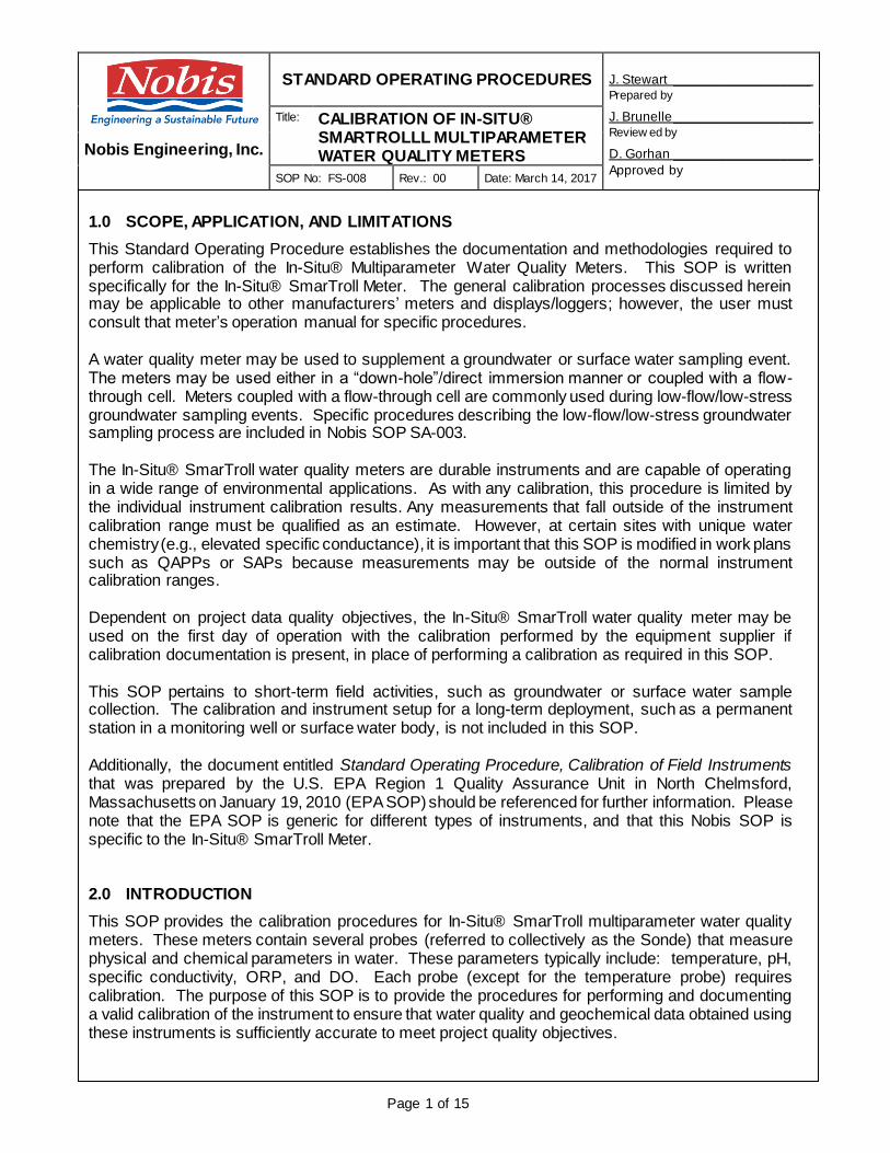
STANDARD OPERATING PROCEDURES J. Stewart __________________ Prepared by
J. Brunelle __________________ Review ed by
D. Gorhan __________________
Approved by
Title: CALIBRATION OF IN-SITU® SMARTROLLL MULTIPARAMETER WATER QUALITY METERS Nobis Engineering, Inc.
SOP No: FS-008 Rev.: 00 Date: March 14, 2017
Page 1 of 15
1.0 SCOPE, APPLICATION, AND LIMITATIONS
This Standard Operating Procedure establishes the documentation and methodologies required to perform calibration of the In-Situ® Multiparameter Water Quality Meters. This SOP is written specifically for the In-Situ® SmarTroll Meter. The general calibration processes discussed herein may be applicable to other manufacturers’ meters and displays/loggers; however, the user must consult that meter’s operation manual for specific procedures. A water quality meter may be used to supplement a groundwater or surface water sampling event. The meters may be used either in a “down-hole”/direct immersion manner or coupled with a flow-through cell. Meters coupled with a flow-through cell are commonly used during low-flow/low-stress groundwater sampling events. Specific procedures describing the low-flow/low-stress groundwater sampling process are included in Nobis SOP SA-003. The In-Situ® SmarTroll water quality meters are durable instruments and are capable of operating in a wide range of environmental applications. As with any calibration, this procedure is limited by the individual instrument calibration results. Any measurements that fall outside of the instrument calibration range must be qualified as an estimate. However, at certain sites with unique water chemistry (e.g., elevated specific conductance), it is important that this SOP is modified in work plans such as QAPPs or SAPs because measurements may be outside of the normal instrument calibration ranges. Dependent on project data quality objectives, the In-Situ® SmarTroll water quality meter may be used on the first day of operation with the calibration performed by the equipment supplier if calibration documentation is present, in place of performing a calibration as required in this SOP. This SOP pertains to short-term field activities, such as groundwater or surface water sample collection. The calibration and instrument setup for a long-term deployment, such as a permanent station in a monitoring well or surface water body, is not included in this SOP. Additionally, the document entitled Standard Operating Procedure, Calibration of Field Instruments that was prepared by the U.S. EPA Region 1 Quality Assurance Unit in North Chelmsford, Massachusetts on January 19, 2010 (EPA SOP) should be referenced for further information. Please note that the EPA SOP is generic for different types of instruments, and that this Nobis SOP is specific to the In-Situ® SmarTroll Meter. 2.0 INTRODUCTION
This SOP provides the calibration procedures for In-Situ® SmarTroll multiparameter water quality meters. These meters contain several probes (referred to collectively as the Sonde) that measure physical and chemical parameters in water. These parameters typically include: temperature, pH, specific conductivity, ORP, and DO. Each probe (except for the temperature probe) requires calibration. The purpose of this SOP is to provide the procedures for performing and documenting a valid calibration of the instrument to ensure that water quality and geochemical data obtained using these instruments is sufficiently accurate to meet project quality objectives.

Nobis Engineering, Inc.
Title: CALIBRATION OF IN-SITU® SMARTROLL MULTIPARAMETER WATER QUALITY METERS
SOP No: FS-008
Rev.: 00
Date: March 14, 2017
Page 2 of 15
The instrument must be calibrated each day prior to collecting water quality measurements (except the first day if data quality objectives allow use of the calibration performed by the equipment supplier) and a calibration check must be performed at the end of the day’s operations. Additional calibration checks may be performed throughout the day if data quality objectives require it or if questionable data are identified during use. The purpose of the calibration checks is to determine if the instrument has drifted out of calibration during the day’s operation. If erratic or conflicting readings are displayed during the day’s use, mid-day calibration checks may be needed with re-calibration completed if the instrument is out of specification. Measurement data collected since the last calibration that day and up to the point of a failed calibration check shall be qualified appropriately. (This shall include documentation on the field sampling form and the field instrument calibration form.) All calibrations and calibration checks must be documented in accordance with this SOP. 3.0 DEFINITIONS
°C Degrees Celsius DI Deionized DO Dissolved Oxygen EPA Environmental Protection Agency FOL Field Operations Leader HASP Health and Safety Plan HAZWOPER Hazardous Waste Operations and Emergency Response µS/cm microSiemens per centimeter mg/L milligrams per liter mm of Hg millimeters of mercury mS/cm milliSiemens per centimeter MSDS Material Safety Data Sheet mV millivolts NIST National Institute of Standards and Technology ORP Oxidation/Reduction Potential OSHA Occupational Safety and Health Administration PM Project Manager PPE Personal Protective Equipment

Nobis Engineering, Inc.
Title: CALIBRATION OF IN-SITU® SMARTROLL MULTIPARAMETER WATER QUALITY METERS
SOP No: FS-008
Rev.: 00
Date: March 14, 2017
Page 3 of 15
QAPP Quality Assurance Project Plan (a type of Work Plan) SAP Sampling and Analysis Plan (a type of Work Plan) SDS Safety Data Sheet SOP Standard Operating Procedure 4.0 CAUTIONS
• All proper PPE and clothing is to be worn as specified in associated HASPs.
• The standard solutions for calibrating specific conductivity contain iodine and potassium chloride. When using the standards, avoid inhalation, skin contact, eye contact, or ingestion. If skin contact occurs, immediately remove any contaminated clothing. Wash the affected areas thoroughly with copious amounts of water. If inhalation, eye contact, or ingestion occurs, consult the MSDS or SDS for prompt action, and in all cases seek medical attention immediately.
• The 0.0 mg/L DO solution contains sodium metabisulfite, and general health and safety precautions should be adopted to minimize unnecessary contact. If skin contact occurs, immediately remove any contaminated clothing. Wash the affected areas thoroughly with copious amounts of water. If inhalation, eye contact, or ingestion occurs, consult the MSDS/SDS for prompt action, and in all cases seek medical attention immediately.
• Standard solutions for pH calibration contain the following compounds:
pH 4 Solutions: Potassium Hydrogen Phthalate, Formaldehyde, Water; pH 7 Solutions: Sodium Phosphate (dibasic), Potassium Phosphate (Monobasic), Water; pH 10 Solutions: Potassium Borate (Tetra), Potassium Carbonate, Potassium Hydroxide,
Sodium (di) Ethylenediamine Tetra-Acetate, Water.
Avoid inhalation, skin contact, eye contact, or ingestion. If skin contact occurs, immediately remove any contaminated clothing. Wash the affected areas thoroughly with copious amounts of water. If inhalation, eye contact, or ingestion occurs, consult the MSDS/SDS for prompt action, and in all cases seek medical attention immediately.
• Standard solutions for ORP calibration (Zobell solution) contain the following compounds: potassium chloride, potassium ferrocyanide, trihydrate, and potassium ferricyanide. These compounds may be harmful by inhalation, ingestion, or skin absorption. These compounds can cause eye and skin irritation. This material is irritating to mucous membranes and the upper respiratory tract. The chemical, physical, and toxicological properties have not been thoroughly investigated. Ingestion of large quantities can cause weakness, gastrointestinal irritation, and circulatory disturbances.
5.0 PERSONNEL QUALIFICATIONS
Personnel calibrating and/or collecting samples using the In-Situ SmarTroll calibrated using this method should be familiar with this SOP and the particular equipment to be used in order to facilitate sampling and troubleshooting equipment problems more efficiently. Consulting the user’s manual for each meter is required. Consulting the EPA SOP may also be useful. At a minimum, all

Nobis Engineering, Inc.
Title: CALIBRATION OF IN-SITU® SMARTROLL MULTIPARAMETER WATER QUALITY METERS
SOP No: FS-008
Rev.: 00
Date: March 14, 2017
Page 4 of 15
calibration technicians should have an operational understanding of the instrument functions, the geochemical parameters measured, and the units of each measurement. All field personnel at waste sites are required to receive 40 hours of HAZWOPER training as prescribed by OSHA. This training must be refreshed annually with an 8-hour refresher course. 6.0 EQUIPMENT AND SUPPLIES
• Thermometer (with NIST traceability); or suitable documentation that the on-board temperature probe has been checked against a NIST-traceable thermometer within the past year;
• Barometer (if one is not included within the SmarTroll);
• pH Standards of 4, 7, and 10;
• Specific Conductance standards (calibrating with a 1413 µS/cm standard and checking with a 5000 µS/cm standard is recommended for most sites; refer to the specific conductivity calibration procedure for further discussion);
• 0.0 mg/L DO calibration solution;
• Zobell Solution (purchased pre-mixed, or in solid form for in-field preparation);
• SmarTroll Quick Cal Solution;
• Deionized (DI) water;
• Spray bottles (Containing DI water;)
• SmarTroll Sonde with attached pH, specific conductivity, DO, ORP, and temperature probes;
• Sonde communications cable;
• SmarTroll Android® or Apple® battery pack (Android® battery packs are recommended and work with our Tablets) with charge cable (or batteries);
• Android® based Tablet or Phone with the VuSitu App installed. (An Apple® iPod, iPad, or iPhone with iSitu app installed can be used when using the Apple® battery pack) (The Android® battery pack is rechargeable, the Apple® battery pack uses disposable batteries);
• Multiparameter Display System (with optional display data logger);
• SmarTroll low-flow kit (90ml flow cell, ground spike, base plate);
• SmarTroll Sonde calibration cup and or storage cup;
• SmarTroll Sonde probe guard;
• Sonde communications cable;
• User’s manual;
• Paper towels;
• Indelible pen; and
• Calibration Log Sheet (Attachment A).
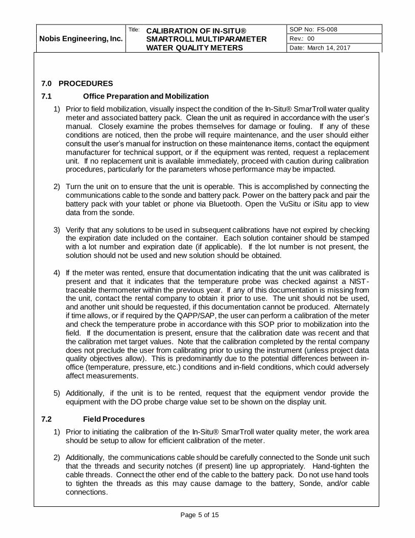
Nobis Engineering, Inc.
Title: CALIBRATION OF IN-SITU® SMARTROLL MULTIPARAMETER WATER QUALITY METERS
SOP No: FS-008
Rev.: 00
Date: March 14, 2017
Page 5 of 15
7.0 PROCEDURES
7.1 Office Preparation and Mobilization
1) Prior to field mobilization, visually inspect the condition of the In-Situ® SmarTroll water quality meter and associated battery pack. Clean the unit as required in accordance with the user’s manual. Closely examine the probes themselves for damage or fouling. If any of these conditions are noticed, then the probe will require maintenance, and the user should either consult the user’s manual for instruction on these maintenance items, contact the equipment manufacturer for technical support, or if the equipment was rented, request a replacement unit. If no replacement unit is available immediately, proceed with caution during calibration procedures, particularly for the parameters whose performance may be impacted.
2) Turn the unit on to ensure that the unit is operable. This is accomplished by connecting the
communications cable to the sonde and battery pack. Power on the battery pack and pair the battery pack with your tablet or phone via Bluetooth. Open the VuSitu or iSitu app to view data from the sonde.
3) Verify that any solutions to be used in subsequent calibrations have not expired by checking
the expiration date included on the container. Each solution container should be stamped with a lot number and expiration date (if applicable). If the lot number is not present, the solution should not be used and new solution should be obtained.
4) If the meter was rented, ensure that documentation indicating that the unit was calibrated is
present and that it indicates that the temperature probe was checked against a NIST-traceable thermometer within the previous year. If any of this documentation is missing from the unit, contact the rental company to obtain it prior to use. The unit should not be used, and another unit should be requested, if this documentation cannot be produced. Alternately if time allows, or if required by the QAPP/SAP, the user can perform a calibration of the meter and check the temperature probe in accordance with this SOP prior to mobilization into the field. If the documentation is present, ensure that the calibration date was recent and that the calibration met target values. Note that the calibration completed by the rental company does not preclude the user from calibrating prior to using the instrument (unless project data quality objectives allow). This is predominantly due to the potential differences between in-office (temperature, pressure, etc.) conditions and in-field conditions, which could adversely affect measurements.
5) Additionally, if the unit is to be rented, request that the equipment vendor provide the
equipment with the DO probe charge value set to be shown on the display unit. 7.2 Field Procedures
1) Prior to initiating the calibration of the In-Situ® SmarTroll water quality meter, the work area should be setup to allow for efficient calibration of the meter.
2) Additionally, the communications cable should be carefully connected to the Sonde unit such
that the threads and security notches (if present) line up appropriately. Hand-tighten the cable threads. Connect the other end of the cable to the battery pack. Do not use hand tools to tighten the threads as this may cause damage to the battery, Sonde, and/or cable connections.

Nobis Engineering, Inc.
Title: CALIBRATION OF IN-SITU® SMARTROLL MULTIPARAMETER WATER QUALITY METERS
SOP No: FS-008
Rev.: 00
Date: March 14, 2017
Page 6 of 15
3) Turn on the unit using the procedure detailed in section 7.1 step 2.
4) Enter the calibration menu within the VuSitu or iSitu app, the SmarTroll can be calibrated using the Quick Cal solution or each probe can be calibrated separately. For most projects calibrating with the Quick Cal solution and checking with individual standards is acceptable. The calibration of the sonde is completed by following the steps and pictures displayed in the app.
5) Ideally, the calibration solutions should be maintained at a temperature that closely-
represents the expected temperature of the water being measured. However, without the ability to carefully heat and/or cool solutions to that temperature, implementation of this in the field is not practical. Therefore, the solutions should be maintained at a stable temperature, out of direct sunlight, and not allowed to freeze (i.e., in a cooler or other stable-temperature environment). If seasonal conditions or site logistics do not allow for stable temperatures, alternate arrangements should be considered. Calibration standards should never be allowed to freeze, either during storage or use. Additionally, the solutions should be allowed to equilibrate at the ambient stable temperature if transferred from storage at a different temperature (for instance, bringing new solutions into a warm trailer from a cold outside storage unit) prior to calibration. Failure to allow the solutions to stabilize in temperature could lead to erratic or unsuccessful calibration. Also, the calibration solutions for the initial calibration and the end-of-day check calibration should be from the same lot and preferably from the same container.
6) Calibration of the In-Situ® SmarTroll multiparameter water quality meter is stored in the Sonde; the battery packs are interchangeable. If problems are encountered with a battery pack or cable during the day, different battery packs and/or cables may be connected to the Sonde without the need for recalibration. Likewise, one battery pack could be used to calibrate multiple Sondes, although it is unlikely this would be done in practice.
• Other Considerations
1) During the calibration process, it is imperative that calibration solutions are not contaminated by the previous solution or diluted by DI water used to rinse the Sonde and calibration cup. When calibrating for DO, the Sonde and the calibration cup must always be dried thoroughly after the 100% saturation check is completed and before the 0% DO solution is placed in the calibration cup to ensure that the 0% standard is not diluted. After the 0% DO check, and with all subsequent standards, the Sonde and cup should be rinsed with DI water, gently tapped to removed excess water and then dried thoroughly.
2) In practice, experience has shown that recycling calibration solutions requires strict attention to detail and close coordination between the calibration technicians to ensure that the solutions are not contaminated by mixing the wrong standards. The Field Operations Leader (FOL) will need to determine if the site logistics and the experience of the calibration technicians are appropriate for recycling and institute a procedure suitable for the consistent quality of the calibration procedures for the sampling event and the project.
• Initial Calibration Procedures
The following calibration procedures should be followed in the order indicated by this SOP.
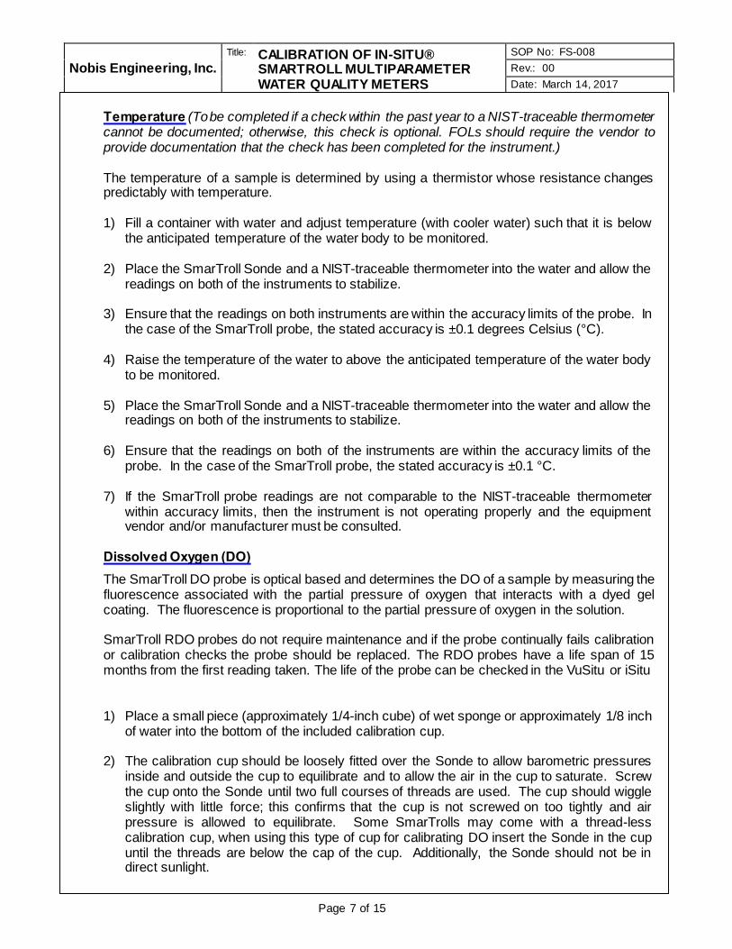
Nobis Engineering, Inc.
Title: CALIBRATION OF IN-SITU® SMARTROLL MULTIPARAMETER WATER QUALITY METERS
SOP No: FS-008
Rev.: 00
Date: March 14, 2017
Page 7 of 15
Temperature (To be completed if a check within the past year to a NIST-traceable thermometer cannot be documented; otherwise, this check is optional. FOLs should require the vendor to provide documentation that the check has been completed for the instrument.) The temperature of a sample is determined by using a thermistor whose resistance changes predictably with temperature. 1) Fill a container with water and adjust temperature (with cooler water) such that it is below
the anticipated temperature of the water body to be monitored.
2) Place the SmarTroll Sonde and a NIST-traceable thermometer into the water and allow the readings on both of the instruments to stabilize.
3) Ensure that the readings on both instruments are within the accuracy limits of the probe. In
the case of the SmarTroll probe, the stated accuracy is ±0.1 degrees Celsius (°C).
4) Raise the temperature of the water to above the anticipated temperature of the water body to be monitored.
5) Place the SmarTroll Sonde and a NIST-traceable thermometer into the water and allow the
readings on both of the instruments to stabilize.
6) Ensure that the readings on both of the instruments are within the accuracy limits of the probe. In the case of the SmarTroll probe, the stated accuracy is ±0.1 °C.
7) If the SmarTroll probe readings are not comparable to the NIST-traceable thermometer
within accuracy limits, then the instrument is not operating properly and the equipment vendor and/or manufacturer must be consulted.
Dissolved Oxygen (DO)
The SmarTroll DO probe is optical based and determines the DO of a sample by measuring the fluorescence associated with the partial pressure of oxygen that interacts with a dyed gel coating. The fluorescence is proportional to the partial pressure of oxygen in the solution. SmarTroll RDO probes do not require maintenance and if the probe continually fails calibration or calibration checks the probe should be replaced. The RDO probes have a life span of 15 months from the first reading taken. The life of the probe can be checked in the VuSitu or iSitu
1) Place a small piece (approximately 1/4-inch cube) of wet sponge or approximately 1/8 inch
of water into the bottom of the included calibration cup.
2) The calibration cup should be loosely fitted over the Sonde to allow barometric pressures inside and outside the cup to equilibrate and to allow the air in the cup to saturate. Screw the cup onto the Sonde until two full courses of threads are used. The cup should wiggle slightly with little force; this confirms that the cup is not screwed on too tightly and air pressure is allowed to equilibrate. Some SmarTrolls may come with a thread-less calibration cup, when using this type of cup for calibrating DO insert the Sonde in the cup until the threads are below the cap of the cup. Additionally, the Sonde should not be in direct sunlight.

Nobis Engineering, Inc.
Title: CALIBRATION OF IN-SITU® SMARTROLL MULTIPARAMETER WATER QUALITY METERS
SOP No: FS-008
Rev.: 00
Date: March 14, 2017
Page 8 of 15
3) From the calibration menu select the “RDO Saturation” option, then the 100% Saturation option (Note: For the In-Situ® SmarTroll Sondes, calibration of dissolved oxygen by the DO% procedure also results in the calibration of the DO mg/L mode.) and follow the steps displayed on screen.
4) Wait for the DO% reading value to stabilize and accept the calibration. View the calibration
report to get the current barometric pressure. Record the temperature and the barometric pressure after accepting the calibration on the Calibration Form included in Attachment A. Enter the live readings mode and record the DO reading in mg/L. Ensure that the DO reading in mg/L is within 2% (or 0.2 mg/L, whichever is greater) of the appropriate temperature and pressure-corrected oxygen solubility values shown on the table included in Attachment B. Thoroughly dry each of the probes and the calibration cup with a wipe to ensure that the check solution is not diluted or contaminated.
5) Post-calibration check: a) Place the probe in a 0.0 mg/L DO solution ensuring that no air bubbles are entrained in the Sonde. b) Verify that the unit displays a reading of <0.5 mg/L but ≥0.0 mg/L from the live readings mode and record on the Calibration Form included in Attachment A. If a reading of <0.5 mg/L is not reached or the unit reads <0.0 mg/L, the probe should be recalibrated or replaced. c) Rinse the Sonde and calibration cup with DI water and gently tap to remove excess water. Gently tap to remove excess moisture and thoroughly dry the Sonde and the cup.
Quick-Cal Multiple Sensor Calibration
The SmarTroll is capable of calibrating the conductivity, pH and ORP probes using one solution and one calibration procedure. This calibration process is preferred if project data quality objectives allow. If project data quality objectives require each probe to be calibrated individually or by more than a one-point calibration, then follow the procedures for calibration of individual probes presented in subsequent sections. 1) If not already done, rinse the Sonde with DI water, gently tap the Sonde to remove any
excess water/DO standard solutions and thoroughly dry the Sonde and the cup.
2) Fill the calibration cup to the fill line with Quick-Cal Solution and place the Sonde in the calibration cup.

Nobis Engineering, Inc.
Title: CALIBRATION OF IN-SITU® SMARTROLL MULTIPARAMETER WATER QUALITY METERS
SOP No: FS-008
Rev.: 00
Date: March 14, 2017
Page 9 of 15
3) From the calibration menu, select Quick-Cal (multi-sensor). Then confirm the probes you
wish to calibrate and select Next. Wait for the measurements to stabilize (they will be highlighted in green when stable). When stable select Accept and then select Done.
4) Rinse the probes and the cup with DI water, gently tap the Sonde and cup to remove any
excess water/Quick-Cal standard solutions and thoroughly dry the Sonde and the cup. Confirm the calibration by immersing the Sonde into the individual calibration solutions for conductivity, pH, and ORP. Remember to rinse and thoroughly dry the Sonde and the cup between each solution. Record calibration confirmation values on the Calibration Form included in Attachment A
pH
The pH of a sample is determined by measurement of an electrochemical voltage potential generated across a glass electrolyte-filled bulb. This potential is compared to that of a reference electrode of known hydrogen ion concentration. The difference is proportional and returns as a measure of hydrogen ion concentration (or pH). 1) If not already done, rinse the Sonde and calibration cup with DI water and gently tap the
Sonde to remove any excess water/DO standard solutions. Then, thoroughly dry the Sonde and the cup.
2) From the calibration menu, select the pH option. Then select the 3 point option. Place the
Sonde into the pH 4 standard solution. The VuSitu app will auto detect the standard and wait for stabilization. Ensure that no air bubbles are entrained on the Sonde. Allow the measurements to stabilize, they will be highlighted in green when stable. Once stable, select Accept. If an error message is noted, refer to the user’s manual for troubleshooting options.
3) Remove the Sonde from the pH 4 solution and rinse both the Sonde and calibration cup
with DI water. Again, gently tap the Sonde to remove excess rinse water. Then, thoroughly dry the Sonde and the cup.
4) Immerse the Sonde into pH 10 standard solution and to continue the calibration process
the VuSitu app will auto detect the pH value of the solution. When prompted, enter the pH standard value and press enter. Ensure that no air bubbles are entrained on the Sonde. Allow the measurements to stabilize, they will be highlighted in green when stable. Once stable select Accept.
5) Remove the Sonde from the pH 10 solution and rinse both the Sonde and calibration cup
with DI water. Again, gently tap the Sonde to remove excess rinse water. Then, thoroughly dry the Sonde and the cup.
6) Immerse the Sonde into pH 7 standard solution and to continue the calibration process the
VuSitu app will auto detect the pH value of the solution. When prompted, enter the pH standard value and press enter. Ensure that no air bubbles are entrained on the Sonde. Allow the measurements to stabilize, they will be highlighted in green when stable. Once stable select Accept.
Nobis Engineering, Inc.
Title: CALIBRATION OF IN-SITU® SMARTROLL MULTIPARAMETER WATER QUALITY METERS
SOP No: FS-008
Rev.: 00
Date: March 14, 2017
Page 10 of 15
7) While the Sonde is immersed in the pH 7 standard solution enter the live readings mode to
check that the unit reads in the acceptable range. Allow the probe to stabilize (no downward or upward trend to the reading when checked every 30 seconds). Ensure that no air bubbles are entrained on the Sonde. Ensure that the pH reading is within ±0.2 units of the solution value. Record the pH value reported by the unit. If the reading is within the acceptable range, press enter again to return to the calibration menu. If the values are not within specification, perform the calibration again. Repeated calibration failures should necessitate a call to the equipment manufacturer and/or vendor. If pH calibration is complete, remove the Sonde from the solution and rinse both the Sonde and calibration cup with DI water. Again, gently tap the Sonde to remove excess rinse water. Then, thoroughly dry the Sonde and the cup.
Specific Conductance
Specific conductance is used to measure the ability of an aqueous solution to carry an electrical current. Specific conductance is the solution’s conductance value corrected to 25°C. The measurement is made using four electrodes. Two electrodes drive a current through the solution; the remaining two detect a voltage drop. This voltage drop is converted into a conductance value in µS/cm. The value is further corrected to a temperature of 25°C to yield a specific conductance value. The specific conductivity calibration is a one-point calibration with a linearity check. There is often confusion as to which standard is used for the calibration and which is used for the linearity check. The check ensures that the instrument is capable of extrapolating beyond the calibrated point in a linear manner; therefore, the calibration point is the lower standard and the check is the higher standard. Field experience has confirmed that the most consistent results will be achieved in this way (i.e., calibrate with low, check with high). The two standards should be selected on a project specific basis based on previous field data (if available) and may be modified from one event to another based on additional data. The intent should be to bracket the values anticipated to be encountered. Experience has shown that standards with values too far apart will result in inconsistent results during calibration. Also, very low concentration standards are often unstable and problematic to use. These factors should be considered when choosing the appropriate standards for the project that will achieve the desired precision and accuracy in field measurements without resulting in inefficient calibration and/or instrument drift. The EPA SOP provides a discussion in Section 5.4, Step 6 that allows the use of a closer check standard when the bracket range is too great. Based on experience and the EPA’s acceptance of the limitations of bracketing expected values, calibrating with a 1413 µS/cm standard and checking with a 5000 µS/cm standard is recommended for most sites. If neither value is within the historical range for a site, alternative values should be considered. If the data quality objectives for a specific site include the need for greater precision and accuracy in conductivity measurements (i.e., the data is being used for decisions other than aquifer stability during low-flow sample collection), use of specific standards for specific wells may be considered. This decision should be based on the existing data for the site and should be made prior to mobilization during the planning phase of the project. The instrument vendor or In-Situ, Inc. may be able to provide additional guidance for problematic sites.
1) If not already done, rinse both the Sonde and calibration cup with DI water. Gently tap the
Sonde to remove excess rinse water. Then, thoroughly dry the Sonde and the cup.
2) From the calibration menu, select conductivity.

Nobis Engineering, Inc.
Title: CALIBRATION OF IN-SITU® SMARTROLL MULTIPARAMETER WATER QUALITY METERS
SOP No: FS-008
Rev.: 00
Date: March 14, 2017
Page 11 of 15
3) Place the Sonde it into the lower specific conductance standard solution, making sure that
the specific conductance probe is fully submerged. Ensure that no air bubbles are entrained on the Sonde.
4) Select Next, the VuSitu app will auto-detect the concentration of the calibration solution and will wait to stabilize.
5) Confirm the reference temperature of the calibration solution and tap the drop-down list if a
change is necessary, most will be 25°C. However, some may be referenced to 20°C.
6) After the specific conductance reading has stabilized, select Accept and the select Done.

Nobis Engineering, Inc.
Title: CALIBRATION OF IN-SITU® SMARTROLL MULTIPARAMETER WATER QUALITY METERS
SOP No: FS-008
Rev.: 00
Date: March 14, 2017
Page 12 of 15
7) After accepting the calibration, enter the live readings mode. The specific conductance value should read within 5% of the standard value. Record this value on the calibration form included in Attachment A.
8) Remove the Sonde from the solution and rinse both the Sonde and calibration cup with DI water. Gently tap the Sonde to remove excess rinse water. Then, thoroughly dry the Sonde and the cup.
9) Insert the Sonde into the second, higher concentration standard solution to verify linearity of the instrument. Ensure that no air bubbles are entrained on the Sonde.
10) While in live readings mode, allow the temperature and specific conductance to stabilize and record the value on the calibration form included in Attachment A. If the value is within 5% of the standard value, the calibration is complete. If the value is not within 5% of the standard value, recalibrate the probe.
11) Remove the Sonde from the conductivity solution and rinse both the Sonde and calibration
cup with DI water. Gently tap the Sonde to remove excess rinse water. Then, thoroughly dry the Sonde and the cup.
Oxidation/Reduction Potential (ORP)
The ORP of a solution is the electrometric difference measured in a solution between an inert indicator electrode and a reference electrode, measured in mV. The ORP probe on In-Situ® SmarTroll Sonde is part of the pH probe and the pH probe must be correctly calibrated before the ORP procedure can be done. The value of the Zobell solution used to calibrate the unit is temperature dependent over a linear range. This SOP requires that the reference table of Zobell values over a range of temperatures in Attachment C be used to determine the applicable value. The temperature used to determine the value of the Zobell solution must be the temperature of the Zobell solution; using a temperature of another standard measured previously is not acceptable.

Nobis Engineering, Inc.
Title: CALIBRATION OF IN-SITU® SMARTROLL MULTIPARAMETER WATER QUALITY METERS
SOP No: FS-008
Rev.: 00
Date: March 14, 2017
Page 13 of 15
1) If not already done, rinse both the Sonde and calibration cup with DI water. Gently tap the
Sonde to remove excess rinse water. Then, thoroughly dry the Sonde and the cup.
2) From the calibration menu, select ORP 3) Insert the Sonde into the Zobell standard solution. Ensure that no air bubbles are entrained
on the Sonde.
4) The VuSitu App will auto-detect the value of the standard and will wait for stabilization. 5) Locate the Zobell solution ORP value at the stabilized temperature displayed in the previous
step on the table included in Attachment C. Record this value and acceptance range on the field calibration form located in Attachment A.
6) After the ORP reading has stabilized, select Accept and then select Done.
7) After accepting the calibration, enter the live readings mode.
8) Ensure that the value displayed in the live reading mode is ±10mV of the ORP value recorded on the calibration form (Attachment A) from Step 5. If the temperature of the solution varies significantly from the value recorded previously, then the temperature of the Zobell solution is not equilibrated to ambient conditions and stable, or the measurement had not stabilized when originally recorded. Record the calibrated value on the calibration form located in Attachment A. If the value does not fall within the acceptance range, the probe will need to be recalibrated.
9) Remove the Sonde from the ORP solution and rinse rinse both the Sonde and calibration cup with DI water. Gently tap the Sonde to remove excess rinse water. Then, thoroughly dry the Sonde and the cup.
• Calibration Verification Check (or End-of-Day Check)
At a minimum, a calibration verification check must be performed at the conclusion of the day’s sample collection. This check verifies that the unit maintained a viable calibration during operation. Project data quality objectives may require that checks be completed at other times during the day. If the checks are completed during the day and the calibration has drifted out of specification, then the out-of-specification probes will require recalibration prior to being put back into service. Additionally, any measurements made with a meter that does not pass the end-of-day check must be qualified. The sample designators for all samples collected with an instrument that does not pass the end-of-day check should be listed on the calibration log, and possibly other documentation (such as the field sampling forms and the field log book) that may be required by the work plan. The calibration checks should be completed in the same order that the calibration was completed. The end-of-day calibration check is completed in the live readings mode. To ensure that a true assessment of the viability of the instrument readings is completed, the unit must not be put into the calibration mode between the last sample location of the day and the beginning of the end-of-day check. Recalibration to pass the end-of-day check is unacceptable.
1) Clean the Sonde with DI water. Gently tap the Sonde unit to remove excess water. Use
paper towels or similar absorbent sheets to dry the Sonde.
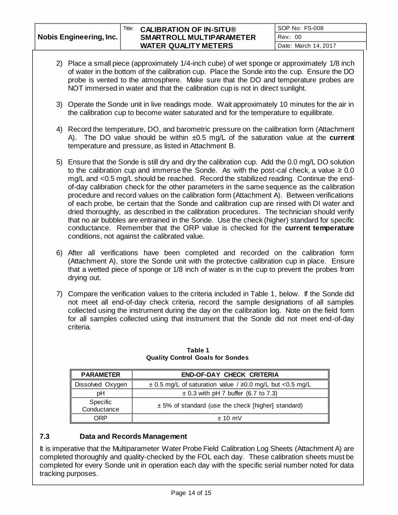
Nobis Engineering, Inc.
Title: CALIBRATION OF IN-SITU® SMARTROLL MULTIPARAMETER WATER QUALITY METERS
SOP No: FS-008
Rev.: 00
Date: March 14, 2017
Page 14 of 15
2) Place a small piece (approximately 1/4-inch cube) of wet sponge or approximately 1/8 inch
of water in the bottom of the calibration cup. Place the Sonde into the cup. Ensure the DO probe is vented to the atmosphere. Make sure that the DO and temperature probes are NOT immersed in water and that the calibration cup is not in direct sunlight.
3) Operate the Sonde unit in live readings mode. Wait approximately 10 minutes for the air in the calibration cup to become water saturated and for the temperature to equilibrate.
4) Record the temperature, DO, and barometric pressure on the calibration form (Attachment A). The DO value should be within ±0.5 mg/L of the saturation value at the current temperature and pressure, as listed in Attachment B.
5) Ensure that the Sonde is still dry and dry the calibration cup. Add the 0.0 mg/L DO solution to the calibration cup and immerse the Sonde. As with the post-cal check, a value ≥ 0.0 mg/L and <0.5 mg/L should be reached. Record the stabilized reading. Continue the end-of-day calibration check for the other parameters in the same sequence as the calibration procedure and record values on the calibration form (Attachment A). Between verifications of each probe, be certain that the Sonde and calibration cup are rinsed with DI water and dried thoroughly, as described in the calibration procedures. The technician should verify that no air bubbles are entrained in the Sonde. Use the check (higher) standard for specific conductance. Remember that the ORP value is checked for the current temperature conditions, not against the calibrated value.
6) After all verifications have been completed and recorded on the calibration form (Attachment A), store the Sonde unit with the protective calibration cup in place. Ensure that a wetted piece of sponge or 1/8 inch of water is in the cup to prevent the probes from drying out.
7) Compare the verification values to the criteria included in Table 1, below. If the Sonde did not meet all end-of-day check criteria, record the sample designations of all samples collected using the instrument during the day on the calibration log. Note on the field form for all samples collected using that instrument that the Sonde did not meet end-of-day criteria.
Table 1
Quality Control Goals for Sondes
PARAMETER END-OF-DAY CHECK CRITERIA
Dissolved Oxygen ± 0.5 mg/L of saturation value / ≥0.0 mg/L but <0.5 mg/L
pH ± 0.3 with pH 7 buffer (6.7 to 7.3)
Specific Conductance
± 5% of standard (use the check [higher] standard)
ORP ± 10 mV
7.3 Data and Records Management
It is imperative that the Multiparameter Water Probe Field Calibration Log Sheets (Attachment A) are completed thoroughly and quality-checked by the FOL each day. These calibration sheets must be completed for every Sonde unit in operation each day with the specific serial number noted for data tracking purposes.

Nobis Engineering, Inc.
Title: CALIBRATION OF IN-SITU® SMARTROLL MULTIPARAMETER WATER QUALITY METERS
SOP No: FS-008
Rev.: 00
Date: March 14, 2017
Page 15 of 15
Completed Multiparameter Water Probe Field Calibration Log Sheets will be given to the FOL at the end of each work day. These sheets are often scanned and incorporated into the FOL’s daily report to the PM. Once transferred to the PM (or designee), these sheets shall be incorporated into a project file and/or report documents. 7.4 Communication and Technical Direction
Any problems or issues encountered during the sampling event(s) shall be discussed with the PM or designated project technical lead in order to determine an appropriate solution. Any changes in scope or deviation will be confirmed with and approved by the PM. 7.5 Demobilization
Following completion of calibration, the In-Situ® SmarTroll multiparameter water quality meter should be carefully disassembled and packaged in its storage box, and stored in an environment that will minimize the potential for cross-contamination, freezing, and/or overheating. 8.0 QUALITY CONTROL/QUALITY ASSURANCE
The following general quality assurance procedures apply:
• All data must be documented on the calibration data sheet included in Attachment A. It may also be necessary to document certain information in the site logbooks and/or field sampling forms, as required by the work plan (i.e., QAPP, SAP, etc.).
• All instrumentation must be operated in accordance with operating instructions supplied by the manufacturer, unless otherwise specified in the work plan.
9.0 REFERENCES
U.S. Environmental Protection Agency; Standard Operating Procedure Calibration of Field Instruments, EQASOP-FieldCalibrat, June 3, 1998 (Revised January 19, 2010).
In-Situ Incorporated, SmarTroll MP Handheld Instrument for Android, User Manual. Revision 002. February 2016.

AT
TA
CH
ME
NT
A

SOP No: FS-005 Page: 1 of 1
MULTIPARAMETER WATER PROBE Rev. Date: Feb. 20, 2014 Rev.: 4
FIELD CALIBRATION LOG SHEET Completed by: (signature)
Reviewed by (FOL): (signature)
SITE INFORMATION INSTRUMENT INFORMATION
Site Name: Instrument Make/Model: passed morning cal check Y N (not used)
Project Number/Task: Instrument Serial No.: passed EoD cal check Y N
Personnel: Identification No.: if EoD cal check fails, list sample designators at bottom of form
Vendor documentation of cleaning and cal present? Y N with FOL Calibration of temp. probe to NIST thermometer verified? Y N DO membrane replaced today? Y N list other maintenance at bottom
Calibration Date: Time: End-of-Day (EoD) Calibration Check Date: Time:
Criteria UnitsStandard
Lot Number
Standard
Expiration Date
Reading /
Measured Value
"Check" Target
Value
"Check"
Measured ValueAcceptable Value
Standard Lot
Number
Standard
Expiration Date
Reading /
Measured Value
"Check"
Target Value"Check" Measured Value Acceptable Value
Dissolved Oxygen (DO)
DO Probe Charge 25-75 25-75
Barometric Preassure mm Hg
Temperature °C
100% Saturation mg/L
± 2% (or ±0.2 mg/L, whichever is greater) of target
value
± 0.5 mg/L to temp. corrected value
0.0 mg/L Dissolved Oxygen mg/L <0.5 ≥0 but <0.5 <0.5 ≥0 but <0.5
pH
pH 7 7 6.8-7.2 (±0.2) 7 6.7-7.3 (±0.3)
pH 4
pH 10
Specific Conductance
Specific Conductivity Calibration Standard (lower) µS/cm ±5 % of Target
Value
Specific Conductivity Check Standard (higher) µS/cm ±5 % of Target
Value ±5 % of Target Value
Oxidation/Reduction Potential (ORP)
Temperature °C
ORP mV ±10 mV ±10 mV
Other Criteria (Specify)
Comments:If the instrument did not pass the end-of-day cal check, note parameters that failed and list all samples designations from the day's work. List all maintenance (DO probe reconditioned, etc.). Use the back of the form for additional notes.Use calibration solutions from the same lot when performing calibration and EoD calibration checks whenever possible.°C=degrees Celsius mV=millivolts mg/L=milligrams per liter mm of Hg=millimeters of mercury µS/cm=microSiemens per centimeter (1,000 µS/cm = 1 mS/cm)
AT
TA
CH
ME
NT
B
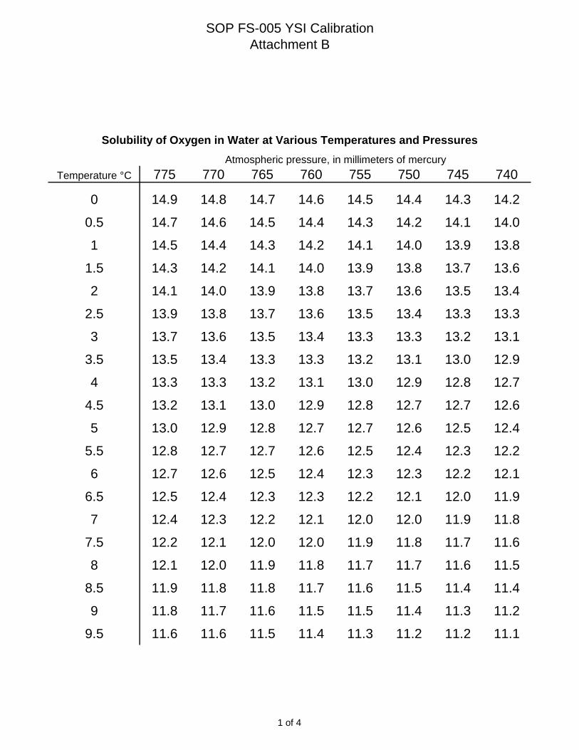
SOP FS-005 YSI Calibration
Attachment B
Solubility of Oxygen in Water at Various Temperatures and Pressures
Atmospheric pressure, in millimeters of mercury
Temperature °C 775 770 765 760 755 750 745 740
0 14.9 14.8 14.7 14.6 14.5 14.4 14.3 14.2
0.5 14.7 14.6 14.5 14.4 14.3 14.2 14.1 14.0
1 14.5 14.4 14.3 14.2 14.1 14.0 13.9 13.8
1.5 14.3 14.2 14.1 14.0 13.9 13.8 13.7 13.6
2 14.1 14.0 13.9 13.8 13.7 13.6 13.5 13.4
2.5 13.9 13.8 13.7 13.6 13.5 13.4 13.3 13.3
3 13.7 13.6 13.5 13.4 13.3 13.3 13.2 13.1
3.5 13.5 13.4 13.3 13.3 13.2 13.1 13.0 12.9
4 13.3 13.3 13.2 13.1 13.0 12.9 12.8 12.7
4.5 13.2 13.1 13.0 12.9 12.8 12.7 12.7 12.6
5 13.0 12.9 12.8 12.7 12.7 12.6 12.5 12.4
5.5 12.8 12.7 12.7 12.6 12.5 12.4 12.3 12.2
6 12.7 12.6 12.5 12.4 12.3 12.3 12.2 12.1
6.5 12.5 12.4 12.3 12.3 12.2 12.1 12.0 11.9
7 12.4 12.3 12.2 12.1 12.0 12.0 11.9 11.8
7.5 12.2 12.1 12.0 12.0 11.9 11.8 11.7 11.6
8 12.1 12.0 11.9 11.8 11.7 11.7 11.6 11.5
8.5 11.9 11.8 11.8 11.7 11.6 11.5 11.4 11.4
9 11.8 11.7 11.6 11.5 11.5 11.4 11.3 11.2
9.5 11.6 11.6 11.5 11.4 11.3 11.2 11.2 11.1
1 of 4

SOP FS-005 YSI Calibration
Attachment B
Solubility of Oxygen in Water at Various Temperatures and Pressures
Atmospheric pressure, in millimeters of mercury
Temperature °C 775 770 765 760 755 750 745 740
10 11.5 11.4 11.3 11.3 11.2 11.1 11.0 11.0
10.5 11.4 11.3 11.2 11.1 11.1 11.0 10.9 10.8
11 11.2 11.2 11.1 11.0 10.9 10.9 10.8 10.7
11.5 11.1 11.0 11.0 10.9 10.8 10.7 10.7 10.6
12 11.0 10.9 10.8 10.8 10.7 10.6 10.5 10.5
12.5 10.8 10.8 10.7 10.6 10.6 10.5 10.4 10.4
13 10.7 10.7 10.6 10.5 10.4 10.4 10.3 10.2
13.5 10.6 10.5 10.5 10.4 10.3 10.3 10.2 10.1
14 10.5 10.4 10.4 10.3 10.2 10.1 10.1 10.0
14.5 10.4 10.3 10.2 10.2 10.1 10.0 10.0 9.9
15 10.3 10.2 10.1 10.1 10.0 9.9 9.9 9.8
15.5 10.2 10.1 10.0 10.0 9.9 9.8 9.8 9.7
16 10.0 10.0 9.9 9.8 9.8 9.7 9.7 9.6
16.5 9.9 9.9 9.8 9.7 9.7 9.6 9.5 9.5
17 9.8 9.8 9.7 9.6 9.6 9.5 9.4 9.4
17.5 9.7 9.7 9.6 9.5 9.5 9.4 9.3 9.3
18 9.6 9.6 9.5 9.4 9.4 9.3 9.3 9.2
18.5 9.5 9.5 9.4 9.3 9.3 9.2 9.2 9.1
19 9.4 9.4 9.3 9.3 9.2 9.1 9.1 9.0
19.5 9.3 9.3 9.2 9.2 9.1 9.0 9.0 8.9
2 of 4
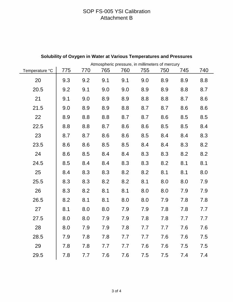
SOP FS-005 YSI Calibration
Attachment B
Solubility of Oxygen in Water at Various Temperatures and Pressures
Atmospheric pressure, in millimeters of mercury
Temperature °C 775 770 765 760 755 750 745 740
20 9.3 9.2 9.1 9.1 9.0 8.9 8.9 8.8
20.5 9.2 9.1 9.0 9.0 8.9 8.9 8.8 8.7
21 9.1 9.0 8.9 8.9 8.8 8.8 8.7 8.6
21.5 9.0 8.9 8.9 8.8 8.7 8.7 8.6 8.6
22 8.9 8.8 8.8 8.7 8.7 8.6 8.5 8.5
22.5 8.8 8.8 8.7 8.6 8.6 8.5 8.5 8.4
23 8.7 8.7 8.6 8.6 8.5 8.4 8.4 8.3
23.5 8.6 8.6 8.5 8.5 8.4 8.4 8.3 8.2
24 8.6 8.5 8.4 8.4 8.3 8.3 8.2 8.2
24.5 8.5 8.4 8.4 8.3 8.3 8.2 8.1 8.1
25 8.4 8.3 8.3 8.2 8.2 8.1 8.1 8.0
25.5 8.3 8.3 8.2 8.2 8.1 8.0 8.0 7.9
26 8.3 8.2 8.1 8.1 8.0 8.0 7.9 7.9
26.5 8.2 8.1 8.1 8.0 8.0 7.9 7.8 7.8
27 8.1 8.0 8.0 7.9 7.9 7.8 7.8 7.7
27.5 8.0 8.0 7.9 7.9 7.8 7.8 7.7 7.7
28 8.0 7.9 7.9 7.8 7.7 7.7 7.6 7.6
28.5 7.9 7.8 7.8 7.7 7.7 7.6 7.6 7.5
29 7.8 7.8 7.7 7.7 7.6 7.6 7.5 7.5
29.5 7.8 7.7 7.6 7.6 7.5 7.5 7.4 7.4
3 of 4
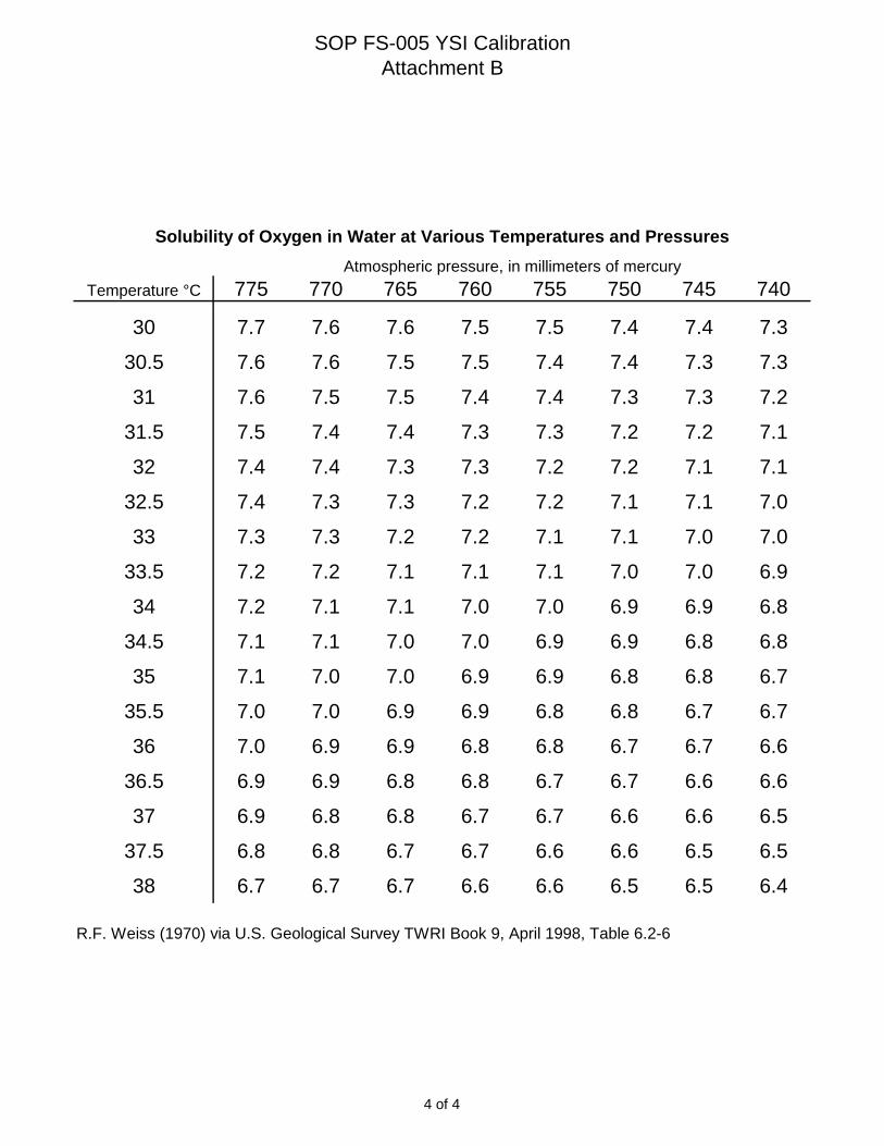
SOP FS-005 YSI Calibration
Attachment B
Solubility of Oxygen in Water at Various Temperatures and Pressures
Atmospheric pressure, in millimeters of mercury
Temperature °C 775 770 765 760 755 750 745 740
30 7.7 7.6 7.6 7.5 7.5 7.4 7.4 7.3
30.5 7.6 7.6 7.5 7.5 7.4 7.4 7.3 7.3
31 7.6 7.5 7.5 7.4 7.4 7.3 7.3 7.2
31.5 7.5 7.4 7.4 7.3 7.3 7.2 7.2 7.1
32 7.4 7.4 7.3 7.3 7.2 7.2 7.1 7.1
32.5 7.4 7.3 7.3 7.2 7.2 7.1 7.1 7.0
33 7.3 7.3 7.2 7.2 7.1 7.1 7.0 7.0
33.5 7.2 7.2 7.1 7.1 7.1 7.0 7.0 6.9
34 7.2 7.1 7.1 7.0 7.0 6.9 6.9 6.8
34.5 7.1 7.1 7.0 7.0 6.9 6.9 6.8 6.8
35 7.1 7.0 7.0 6.9 6.9 6.8 6.8 6.7
35.5 7.0 7.0 6.9 6.9 6.8 6.8 6.7 6.7
36 7.0 6.9 6.9 6.8 6.8 6.7 6.7 6.6
36.5 6.9 6.9 6.8 6.8 6.7 6.7 6.6 6.6
37 6.9 6.8 6.8 6.7 6.7 6.6 6.6 6.5
37.5 6.8 6.8 6.7 6.7 6.6 6.6 6.5 6.5
38 6.7 6.7 6.7 6.6 6.6 6.5 6.5 6.4
R.F. Weiss (1970) via U.S. Geological Survey TWRI Book 9, April 1998, Table 6.2-6
4 of 4

AT
TA
CH
ME
NT
C

Zobell Solution mV Values
Temp. (°C) mV Range ±10 mV
0 263.5 253.5 - 273.5
1 262.2 252.2 - 272.2
2 260.9 250.9 - 270.9
3 259.6 249.6 - 269.6
4 258.3 248.3 - 268.3
5 257 247.0 - 267.0
6 255.7 245.7 - 265.7
7 254.4 244.4 - 264.4
8 253.1 243.1 - 263.1
9 251.8 241.8 - 261.8
10 250.5 240.5 - 260.5
11 249.2 239.2 - 259.2
12 247.9 237.9 - 257.9
13 246.6 236.6 - 256.6
14 245.3 235.3 - 255.3
15 244 234.0 - 254.0
16 242.7 232.7 - 252.7
17 241.4 231.4 - 251.4
18 240.1 230.1 - 250.1
19 238.8 228.8 - 248.8
20 237.5 227.5 - 247.5
21 236.2 226.2 - 246.2
22 234.9 224.9 - 244.9
23 233.6 223.6 - 243.6
24 232.3 222.3 - 242.3
25 231 221.0 - 241.0
26 229.7 219.7 - 239.7
27 228.4 218.4 - 238.4
28 227.1 217.1 - 237.1
29 225.8 215.8 - 235.8
30 224.5 214.5 - 234.5
31 223.2 213.2 - 233.2
32 221.9 211.9 - 231.9
33 220.6 210.6 - 230.6
34 219.3 209.3 - 229.3
35 218 208.0 - 228.0
36 216.7 206.7 - 226.7
37 215.4 205.4 - 225.4
38 214.1 204.1 - 224.1


Nobis Engineering, Inc. Title: CALIBRATION OF TURBIDITY METERS SOP No: FS-006
Rev.: 04 Date: May 2011
Page 2 of 9
3.0 DEFINITIONS
DQO Data Quality Objectives EPA United States Environmental Protection Agency FOL Field Operations Leader HASP Health and Safety Plan mL milliliters MSDS Material Safety Data Sheet NTU Nephelometric Turbidity Units OSHA Occupation Safety and Health Administration PM Project Manager PPE Personal Protective Equipment QAPP Quality Assurance Project Plan SAP Sampling and Analysis Plan SOP Standard Operating Procedure 4.0 CAUTIONS
• All proper personal protection clothing and equipment is to be worn as specified in associated HASPs.
• The calibration standard for calibrating turbidity can contain styrene divinylbenzene
copolymer spheres. While the material is not volatile and has no known physical effects on skin, eyes, or from ingestion, general health and safety precautions should be adopted to minimize unnecessary contact. If skin contact occurs, immediately remove any contaminated clothing. Wash the affected areas thoroughly with copious amounts of water. If inhalation, eye contact, or ingestion occurs, consult the MSDS for prompt action, and in all cases seek medical attention immediately.
5.0 PERSONNEL QUALIFICATIONS
Personnel calibration and/or collecting samples using this method should be familiar with this SOP and the particular equipment to be used to facilitate sampling and troubleshooting equipment problems more efficiently. Consulting the user’s manual for each meter s required. Consulting the EPA SOP may also be useful. At a minimum, all calibration technicians should have an operational understanding of the instrument functions, the parameter measured, and the units of the measurement.
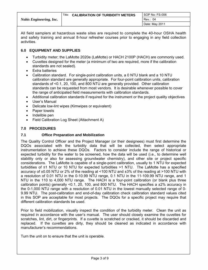
Nobis Engineering, Inc. Title: CALIBRATION OF TURBIDITY METERS SOP No: FS-006
Rev.: 04 Date: May 2011
Page 3 of 9
All field samplers at hazardous waste sites are required to complete the 40-hour OSHA health and safety training and annual 8-hour refresher courses prior to engaging in any field collection activities. 6.0 EQUIPMENT AND SUPPLIES
• Turbidity meter; the LaMotte 2020e (LaMotte) or HACH 2100P (HACH) are commonly used. • Cuvettes designed for the meter (a minimum of two are required, more if the calibration
standards are not sealed). • Extra batteries • Calibration standard. For single-point calibration units, a 0 NTU blank and a 10 NTU
calibration standard are generally appropriate. For four-point calibration units, calibration standards of <0.1, 20, 100, and 800 NTU are generally provided. Other calibration standards can be requested from most vendors. It is desirable whenever possible to cover the range of anticipated field measurements with calibration standards.
• Additional calibration standards if required for the instrument or the project quality objectives • User’s Manual • Delicate low-lint wipes (Kimwipes or equivalent) • Paper towels • Indelible pen • Field Calibration Log Sheet (Attachment A)
7.0 PROCEDURES
7.1 Office Preparation and Mobilization
The Quality Control Officer and the Project Manager (or their designees) must first determine the DQOs associated with the turbidity data that will be collected, then select appropriate instrumentation to achieve these DQOs. Factors to consider include the range of historical or expected turbidity for the water to be screened, how the data will be used (i.e., to determine well stability only or also for assessing groundwater chemistry), and other site or project specific considerations. The LaMotte is capable of a single-point calibration, usually to 1 NTU for expected turbidities of ≤1 NTU or 10 NTU for expected turbidities >1 NTU. The LaMotte has a specified accuracy of ±0.05 NTU or 2% of the reading at <100 NTU and ±3% of the reading at >100 NTU with a resolution of 0.01 NTU in the 0-10.99 NTU range, 0.1 NTU in the 11-109.99 NTU range, and 1 NTU in the 110 to 4,000 NTU range. The HACH is a four-point calibration (or blank plus three calibration points) generally <0.1, 20, 100, and 800 NTU. The HACH specifies a ±2% accuracy in the 0-1,000 NTU range with a resolution of 0.01 NTU in the lowest manually selected range of 0-9.99 NTU. The post-calibration and end-of-day calibration check calibration standard values cited in this SOP are acceptable for most projects. The DQOs for a specific project may require that different calibration standards be used. Prior to field mobilization, visually inspect the condition of the turbidity meter. Clean the unit as required in accordance with the user’s manual. The user should closely examine the cuvettes for scratches, lint, dirt, or fingerprints. If a cuvette is scratched or cracked, it should be discarded and replaced. If the cuvettes are dirty, they should be cleaned as indicated in accordance with manufacturer’s recommendations. Turn the unit on to ensure that the unit is operable.

Nobis Engineering, Inc. Title: CALIBRATION OF TURBIDITY METERS SOP No: FS-006
Rev.: 04 Date: May 2011
Page 4 of 9
Verify that any calibration standards to be used in subsequent calibrations are not expired (if an expiration date is included on the container). Each calibration standard container should be stamped with a lot number and expiration date (if applicable). If the lot number is not present, the calibration standard should not be used and new calibration standard should be obtained. If the meter was rented, ensure that documentation indicating that the unit was calibrated is present. If any of the required documentation is missing from the unit, the vendor should be contacted to obtain it prior to use in the field. The unit should not be used, and another unit should be requested, if this documentation cannot be produced. Alternately, if time does not allow instrument replacement, or if required by the sampling plan, the user can perform a calibration of the meter in accordance with this SOP prior to mobilization into the field. Review the vendor’s calibration documentation to ensure that the calibration date was recent and that the calibration met target values. Note that the calibration completed by the rental company does not excuse the user from calibrating; the instrument must be calibrated before use on a daily basis. Prepare copies of the Turbidity Meter Field Calibration Log Sheet for use in the field. Ensure sufficient quantities of calibration standards and undamaged cuvettes are prepared for the scope of the field work. 7.2 General Field Procedures
7.2.1. Ideally, the calibration standards should be maintained at a temperature that closely-represents the expected temperature of the water being measured. However, without the ability to carefully heat and/or cool calibration standards to that temperature, implementation of this in the field is not practical. Therefore, the calibration standards should be maintained at a stable temperature and out of direct sunlight (i.e., in a cooler with some ice or an ice pack or other stable-temperature environment). Additionally, the calibration standards should be allowed to stabilize at that temperature (for instance, bringing new calibration standards into a warm trailer from an outside storage unit) prior to calibration. Failure to allow the calibration standards to stabilize in temperature could lead to erratic calibration.
7.2.2. Ensure that the unit is clean and that the cuvettes are not dirty, scratched, or cracked
(see above). It is common to dedicate at least two cuvettes to calibration.
7.2.3. Turn the unit on and allow it to warm up for approximately 30 seconds. Initially, leave the instrument in the screen that appears when first turned on.
7.2.4. Generally, sealed prepared calibration standards are provided with a rental instrument.
If sealed prepared calibration standards are not provided, calibration standards are poured into clean cuvettes up to the graduation mark indicating the vessel is full. This is typically 10 mL. Place the cap on the cuvette.
7.2.5. Before use, gently invert the calibration standard at least twice to ensure that the
calibration standard is well mixed. Care must be taken to not create bubbles in the calibration standard that the instrument will interpret as suspended solids.
7.2.6. With either the LaMotte or HACH, the lid must never be opened while the instrument is
in an active mode (i.e., with the lamp operating in either calibration or read modes). Allowing ambient light into the chamber while the unit is in an active mode may result in the photosensor being overloaded and the instrument being rendered unusable without service

Nobis Engineering, Inc. Title: CALIBRATION OF TURBIDITY METERS SOP No: FS-006
Rev.: 04 Date: May 2011
Page 5 of 9
by a qualified technician. Nobis is generally not prepared or qualified to perform this level of service in the field.
7.2.7. LaMotte Procedure
1) Turn the instrument on and allow the appropriate warm-up time. LaMotte does not
specify a period; for uniformity, 5 minutes is recommended.
2) Clean the cuvette containing the 0 NTU calibration standard or blank with a lint-fee cloth or tissue. The reference line on the cuvette should be aligned with the notch at the top of the plastic collar (refer to the instrument manual for an illustration).
3) Insert the blank into the chamber aligning the notch with the reference arrow on the instrument. Close the chamber lid.
4) In the Main Menu screen, if the asterisk is not next to Measure, use the up and down arrows to move it there and press */OK. In the Turbidity screen, if the asterisk is not next to Scan Blank, use the up and down arrows to move it there and press */OK. The screen will display “Please Wait” for several seconds and then display the asterisk next to Scan Sample.
5) Leave the cuvette in the chamber with the lid closed and press */OK again. Again, “Please Wait” will display for several seconds and then the reading will be displayed.
6) The Scan Sample reading for the blank should be 0.00 NTU. If the reading is not 0.00 NTU, use the up or down arrows to select Scan Blank and repeat the procedure.
7) It may take up to three attempts of the Scan Blank/Scan Sample sequence to get a reading of 0.00 NTU. According to LaMotte, a very small positive or negative (e.g., a range of 0.02 to -0.02 NTU) reading is acceptable. Do not proceed until the required result is achieved.
8) Once the Scan Blank/Scan Sample is completed and the required Scan Sample reading of 0.00 NTU for the blank is achieved, prepare the calibration standard cuvette for the one-point calibration by gently inverting several times, if not done within the last several minutes, and clean with a lint-free cloth or tissue. For most applications, this will be the 10 NTU calibration standard and that is the assumed calibration value for the remainder of this description.
9) Place the calibration standard in the chamber, aligning the reference notch with the arrow on the deck of the instrument and close the lid. With Scan Sample selected, press */OK. The unit will display “Please Wait” for several seconds and then display the reading.
10) Remove the cuvette from the chamber and place it back in, ensuring that the notch is aligned with the arrow, and repeat the Scan Sample procedure. This should be repeated at least three times or until a consistent reading is achieved.
11) The last consistent reading should be used to calibrate the instrument. Aberrant or “outlier” readings should not be used; e.g., if three sequential readings of 9.89, 9.91, and 8.03 NTU are displayed, continue until another reading in the 9.9 NTU range is achieved.
12) Using the last consistent reading, select Calibration using the up or down arrows and press */OK. The first display number will be selected; if it is not appropriate for the calibration standard, use the arrows to scroll to the appropriate number and press

Nobis Engineering, Inc. Title: CALIBRATION OF TURBIDITY METERS SOP No: FS-006
Rev.: 04 Date: May 2011
Page 6 of 9
*/OK to select the second display number. Use the arrows to scroll to the appropriate number if it is not displayed and press */OK. Continue with this process until the display reads a value equal to the calibration standard and the asterisk is next to Set. To set (or accept) this calibration, press */OK.
13) Note that if a calibration number is set incorrectly and */OK is pressed to continue to the next number, the selection cannot be reversed to correct the error. If this occurs, turn the instrument off to cancel the calibration before final acceptance and restart the entire process from the beginning.
14) Perform a calibration check with the same calibration standard. After accepting the calibration the display will return to the Main Menu screen with Measure selected. Press */OK to enter the Turbidity screen and select Scan Sample using the up or down arrows. Press */OK and wait for the reading to display.
15) Enter the reading for the cal check in the Turbidity Meter Field Calibration Log Sheet. The reading displayed should be within 5% of the calibration standard value. If the displayed value is not within the acceptance range, repeat the entire calibration process.
16) The instrument must pass the check to be used for data collection. An instrument that repeatedly fails a calibration check must be removed from service and replaced.
7.2.8. HACH Procedure
The HACH is generally provided from the vendor with calibration standards of <0.1, 20, 100, and 800 NTU. If other calibration standard values are required to meet the project-specific DQOs, they should be specified at the time the instrument is ordered so that the vendor can set the instrument up for the calibration sequence and supply the appropriate calibration standards.
1) Turn the instrument on and allow the appropriate warm-up time. HACH does not specify a period; for uniformity, 5 minutes is recommended.
2) The HACH is in measurement mode when first turned on. To begin the calibration procedure, press the CAL button at the top of the left column of the keypad. The display will show CAL in the upper right. The value of the first calibration standard (000.1 NTU) and the sequential number of the calibration standard (0) will be flashing on the right.
3) If not already done, gently invert the calibration standard several times and clean the cuvette with a lint-free cloth or tissue.
4) Place the <0.1 calibration standard in the chamber, aligning the white arrow or diamond on the cuvette with the small reference tab on the deck of the instrument, and close the lid.
5) Press the READ button at the bottom center of the keypad. The display will count down from 60 seconds and then display the value of the next calibration standard (020.0 NTU) and the sequential number of the calibration standard (1) will be flashing on the right.
6) Repeat the sequence with the remaining calibration standards ensuring that each is gently agitated, the cuvettes are clean, and the marks are aligned.

Nobis Engineering, Inc. Title: CALIBRATION OF TURBIDITY METERS SOP No: FS-006
Rev.: 04 Date: May 2011
Page 7 of 9
7) After the final calibration standard, the display will return to the original calibration
screen with the value of the original calibration standard (000.1 NTU) and the sequential number of the calibration standard (0) flashing on the right.
8) At this point the calibration is complete. Press CAL again to accept and finalize the calibration. The instrument should return to the READ mode.
9) If CAL? is displayed at the upper right, or if E 1 or E 2 are displayed, an error has occurred during the process and the technician should refer to the manual before continuing.
10) Check the calibration by placing the 20 NTU calibration standard in the chamber and pressing READ. Enter the reading for the cal check in the Turbidity Meter Field Calibration Log Sheet.
11) The measured value should be within 5% (1 NTU) of the calibration standard value. If the calibration check is not acceptable, repeat the entire calibration procedure.
12) The instrument must pass the check to be used for data collection. An instrument that repeatedly fails a calibration check must be removed from service and replaced.
7.2.9. End-of-Day Calibration Check
At a minimum, an end-of-day calibration verification check must be performed at the conclusion of the workday. This check verifies that the unit maintained a viable calibration during operation. Project DQOs may also require that checks be completed at other times during the day. If the checks are completed during the day and the calibration has drifted out of specification, the turbidity instrument will require recalibration prior to being put back into service. If an instrument fails to pass an end-of-day (or other required) calibration check, documentation of the failure must be completed in the form of a notation on the field sampling form for each sample collected using the instrument during the period since the last calibration. Failure to pass a calibration check may result in the analytical data being qualified. To maintain the utility of the calibration check for assessing the viability of the data collected with the instrument, the check must be completed under the conditions that the instrument was used in the field. Re-calibration to pass an end-of-day check is unacceptable.
1) The end-of-day calibration check (and other checks if required by DQOs) is completed as a measurement.
2) The cuvette containing the appropriate calibration standard (usually the same calibration standard used for the initial post-calibration check) should be gently inverted several times to mix the calibration standard and cleaned with a lint-free cloth or tissue.
3) The calibration standard is measured as a field sample.
4) The value reported should be within 5% of the calibration standard value. If it is not, it is noted on the calibration log and, as described above, on the field sampling form for each sample collected during that day/work period.
7.2.10. Additional Considerations
This document addresses the procedures to be followed to ensure uniformity and quality between projects and technicians with respect to the proper calibration of the turbidity
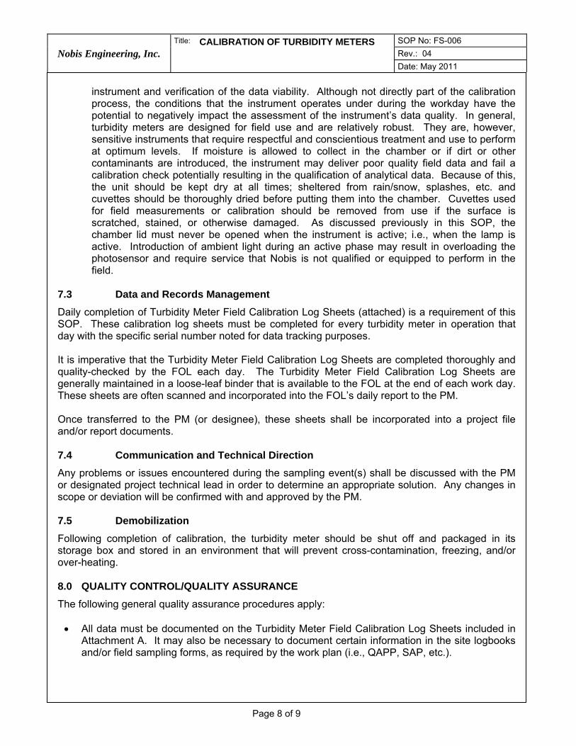
Nobis Engineering, Inc. Title: CALIBRATION OF TURBIDITY METERS SOP No: FS-006
Rev.: 04 Date: May 2011
Page 8 of 9
instrument and verification of the data viability. Although not directly part of the calibration process, the conditions that the instrument operates under during the workday have the potential to negatively impact the assessment of the instrument’s data quality. In general, turbidity meters are designed for field use and are relatively robust. They are, however, sensitive instruments that require respectful and conscientious treatment and use to perform at optimum levels. If moisture is allowed to collect in the chamber or if dirt or other contaminants are introduced, the instrument may deliver poor quality field data and fail a calibration check potentially resulting in the qualification of analytical data. Because of this, the unit should be kept dry at all times; sheltered from rain/snow, splashes, etc. and cuvettes should be thoroughly dried before putting them into the chamber. Cuvettes used for field measurements or calibration should be removed from use if the surface is scratched, stained, or otherwise damaged. As discussed previously in this SOP, the chamber lid must never be opened when the instrument is active; i.e., when the lamp is active. Introduction of ambient light during an active phase may result in overloading the photosensor and require service that Nobis is not qualified or equipped to perform in the field.
7.3 Data and Records Management
Daily completion of Turbidity Meter Field Calibration Log Sheets (attached) is a requirement of this SOP. These calibration log sheets must be completed for every turbidity meter in operation that day with the specific serial number noted for data tracking purposes. It is imperative that the Turbidity Meter Field Calibration Log Sheets are completed thoroughly and quality-checked by the FOL each day. The Turbidity Meter Field Calibration Log Sheets are generally maintained in a loose-leaf binder that is available to the FOL at the end of each work day. These sheets are often scanned and incorporated into the FOL’s daily report to the PM. Once transferred to the PM (or designee), these sheets shall be incorporated into a project file and/or report documents. 7.4 Communication and Technical Direction
Any problems or issues encountered during the sampling event(s) shall be discussed with the PM or designated project technical lead in order to determine an appropriate solution. Any changes in scope or deviation will be confirmed with and approved by the PM. 7.5 Demobilization
Following completion of calibration, the turbidity meter should be shut off and packaged in its storage box and stored in an environment that will prevent cross-contamination, freezing, and/or over-heating. 8.0 QUALITY CONTROL/QUALITY ASSURANCE
The following general quality assurance procedures apply: • All data must be documented on the Turbidity Meter Field Calibration Log Sheets included in
Attachment A. It may also be necessary to document certain information in the site logbooks and/or field sampling forms, as required by the work plan (i.e., QAPP, SAP, etc.).

Nobis Engineering, Inc. Title: CALIBRATION OF TURBIDITY METERS SOP No: FS-006
Rev.: 04 Date: May 2011
Page 9 of 9
• All instrumentation must be operated in accordance with operating instructions supplied by the
manufacturer, unless otherwise specified in the work plan. 9.0 REFERENCES
U.S. Environmental Protection Agency; Standard Operating Procedure, Calibration of Field Instruments, EQASOP-FieldCalibrat, June 3, 1998 (Revised January 19, 2010). Nobis Engineering, Inc., Calibration of Turbidity Meters, Revision 03, April 2010. HACH Cat. No. 46500-88 Portable Turbidity Meter 2100P Instrument and Procedure Manual, Hach Company, 4/08 9ed LaMotte 2020e/i Turbidity Meter Version 5.1 Code 1979-MN 12-07, LaMotte Company
AT
TA
CH
ME
NT
A

SOP No: FS‐006 Page: 1 of 1
TURBIDITY METER Date: May 2011 Rev.: 04
FIELD CALIBRATION LOG SHEET Field Reviewer (FOL):
SITE INFORMATION INSTRUMENT INFORMATION
Site Name: Make/Model LaMotte 2020e HACH 2100P Other_________________________________
Project Number/Task: Serial No. _____________________________________ Vendor __________________________________
Calibration Procedure (circle one): Blank/1-Point 4-Point Other Cal. Standards (NTU): 0 (Blank) 1 10 <0.1 20 100 800 Other (list in Comments)
List All Project Calibration Technicians: Sealed Standards In Use? Y N List standard lot nos. and expiration if provided:
CALIBRATION RECORD
Date/Time
Standard
Cuvette(s) in
Good Condition
Calibration Procedure
Successful
Calibration Check
Standard in Use
(NTU)
Calibration Check
Standard Reading
(NTU)
Calibration Check
Passed (± 5%)
Calibration
Technician InitialsFOL Review Initials
Comments / Samples Collected with Instrument Failing EOD Cal. Check (explain "other" - use back
of form as needed; note if instrument calibration difficult)
Initia
l
Y N Y N error Y N
EO
D
Y N Y N
Initia
l
Y N Y N error Y N
EO
D
Y N Y N
Initia
l
Y N Y N error Y N
DE
OD
Y N Y N
Initia
l
Y N Y N error Y N
EO
D
Y N Y N
Initia
l
Y N Y N error Y N
EO
D
Y N Y N
Initia
l
Y N Y N error Y N
EO
D
Y N Y N
Initia
l
Y N Y N error Y N
EO
D
Y N Y N
Initia
l
Y N Y N error Y N
EO
D
Y N Y N
Notes:
Detail issues, error messages, etc. - use back of form (include dates) as needed.
STANDARD OPERATING PROCEDURES J. Brunelle __________________
Prepared by
S. Bonis, G. DeRuzzo _________
Reviewed by
D. Gorhan __
Approved by
Title: Low Flow Groundwater Sampling
Nobis Engineering, Inc.
SOP No: SA-003 Rev.: 03 Date: March 2015
Page 1 of 12
1.0 SCOPE, APPLICATION, AND LIMITATIONS
This Standard Operating Procedure (SOP) establishes methodologies for low-flow / low-stress groundwater sample collection. This procedure includes the minimum required steps and quality checks that project samplers are to follow when sampling groundwater using this technique. This SOP addresses the technical requirements and required documentation to be completed during low-flow groundwater sampling. Nobis Engineering Inc. (Nobis) follows the U.S. Environmental Protection Agency (EPA) Region I Low Stress (low flow) Purging and Sampling Procedure for the Collection of Ground Water Samples from Monitoring Wells, Revision 3, January 19, 2010. Therefore, for additional detail regarding the Scope and Application of this procedure, please refer to this EPA document. Some project parameters and/or requirements may not be fully addressed by this SOP. Under some circumstances, the project work plans (e.g., Quality Assurance Project Plan (QAPP), Sampling and Analysis Plan (SAP), Field Sampling Plan (FSP), etc.) may be needed to clarify, expand, or modify the SOP. Project requirements written in such documents supersede this SOP, as project specific practices and procedures outlined in project specific work plans are approved by the governing body (EPA, state agency, U.S. Army Corps of Engineers (USACE), etc).
The EPA low flow method is intended for wells that can accommodate a positive lift pump (1.5-inch inside diameter or greater), have a screen (open) interval of 10 feet or less, and have a static water level above the top of the screen interval (i.e., fully saturated screen). Method modifications may be required on a project or well-specific basis if well conditions vary from these. 2.0 INTRODUCTION
This method of groundwater sample collection involves the minimal disturbance of the aquifer matrix to obtain a “representative” sample of groundwater containing mobile organic and inorganic constituents (including dissolved and mobile particulate organic and inorganic chemicals) and reduce or eliminate the inclusion of non-mobile particulates. The method requires pumping of groundwater at a sufficiently low rate to minimally influence the water level and limit migration of fines from the aquifer matrix into the water sample. Groundwater indicator field parameters recommended to be measured include: turbidity, dissolved oxygen, specific conductance, temperature, pH, and oxidation-reduction potential. These indicator parameters are used to determine when stabilization has been reached and sample collection can begin. 3.0 DEFINITIONS
DO Dissolved Oxygen
EPA Environmental Protection Agency
FID Flame Ionization Detector
FOL Field Operations Leader
FSP Field Sampling Plan

Nobis Engineering, Inc.
Title: Low Flow Groundwater Sampling SOP No: SA-003
Rev.: 03
Date: March 2015
Page 2 of 12
HASP Health and Safety Plan
low-flow Purge rates (usually less than 1 liter per minute) that stress the aquifer only minimally and minimize drawdown (ideally 0.3 feet or less once stabilized) so that samples can be collected with minimal alterations of the groundwater chemistry.
mg/L milligrams per liter
mL milliliter
mL/min milliliters per minute
mV millivolts
NTU Nephelometric Turbidity Units
ORP Oxidation-Reduction Potential
OSHA Occupational Safety and Health Administration
PCBs Polychlorinated Biphenyls
PID Photo Ionization Detector
QAPP Quality Assurance Project Plan
QC Quality Control
SAP Sampling and Analysis Plan
SOP Standard Operating Procedure
SVOCs Semi-Volatile Organic Compounds
USACE United States Army Corps of Engineers
VOA Volatile Organic Analysis
VOCs Volatile Organic Compounds
YSI Yellow Springs Instrument (multi-parameter meter)
4.0 CAUTIONS
Collecting groundwater samples using this method is generally not physically hazardous. Care should be taken to minimize slip/trip/fall hazards due to the presence of a large amount of equipment required for low flow sampling. Personal protective equipment (PPE), including the appropriate gloves specified in the site Health and Safety Plan (HASP) and eye protection, should be worn, as well as any other PPE specified in the HASP. Sample preservatives commonly include strong acids and bases. Care should be taken to prevent contact with these chemicals. Acids and bases should be stored separate from each other. When vapor hazards may be present, the HASP may require that a headspace reading be taken immediately upon opening the monitoring well. Refer to the site HASP for details regarding action levels, response actions, and other site-specific health and safety requirements.
5.0 PERSONNEL QUALIFICATIONS
Field personnel will be fully trained in low-flow techniques prior to the field event, including at a minimum: equipment calibration, pump operation, troubleshooting, sample collection, and

Nobis Engineering, Inc.
Title: Low Flow Groundwater Sampling SOP No: SA-003
Rev.: 03
Date: March 2015
Page 3 of 12
documentation. While it is assumed that the qualified technician is generally familiar with low flow methods and equipment, project planning should include sufficient preparation time prior to mobilization for field personnel to become familiar with the specific methods, equipment, and instruments to be used at the specific site. Additionally, the timeframe of the project should be sufficient for the qualified field personnel to fully complete the tasks required. Personnel collecting samples using this method must be familiar with this SOP and the particular equipment to be used to facilitate sampling and troubleshooting equipment problems more efficiently. Consult the user’s manual for each meter and the EPA SOP, as required. All field samplers at hazardous waste sites are required to complete the 40-hour Occupational Safety and Health Administration (OSHA) health and safety training and annual 8-hour refresher courses prior to engaging in any field collection activities. 6.0 EQUIPMENT AND SUPPLIES
The following are recommended for low flow sample collection:
Pump (bladder pumps and centrifugal pumps are preferred) constructed of stainless-steel. In some cases, dedicated plastic bladder pumps may be used. Non-dedicated bladder pumps need to have the bladder and other non-inert parts replaced between locations. Peristaltic pumps may be utilized with caution. When used, the inside diameter of the rotor head (usually silicon) tubing needs to match the inside diameter of the tubing installed in the monitoring well – rotor head tubing may be used for connections also.
Tubing will be dedicated to the well and be selected based on the type of contaminants that may be present. Teflon® or Teflon®-lined tubing is preferred when samples will be analyzed for volatile organic compounds (VOCs), semi-volatile organic compounds (SVOCs), pesticides, polychlorinated biphenyls (PCBs), and inorganic constituents. However, polyethylene tubing and silicone tubing may also be used in some cases when Teflon tubing is unavailable. The recommended inside diameter of the tubing is 1/4 inch or 3/8 inch
3-Way stopcock or “T” connector and clamp appropriately sized for the tubing in use
Water level meter
Power source (e.g., generator that is stationed at least 30-feet downwind of the well being sampled, compressed gas, battery, etc.)
Multiple parameter instrument (e.g., Yellow Springs Instrument [YSI]) with a clear flow-through cell (250 mL flow-through cell is preferred) – manual must accompany the instrument in the field. Documentation of vendor calibration should be requested at the time the instrument is ordered.
Turbidity meter (separate from the multiple parameter instrument) – manual must accompany the instrument in the field. Documentation of vendor calibration should be requested at the time the instrument is ordered.
Graduated cylinder(s) of appropriate volume
Stopwatch or other watch with display in seconds
5-Gallon buckets with 1/2 gallon graduations marked
Utility spring-clamps for tubing

Nobis Engineering, Inc.
Title: Low Flow Groundwater Sampling SOP No: SA-003
Rev.: 03
Date: March 2015
Page 4 of 12
Calibration standards or reagents
Decontamination supplies
Logbooks or tablets
Well parameter data logs (sheets) (Attachment A)
Site plan with well locations
Project work plans (i.e., QAPP, SAP, FSP, etc.) and additional project documentation, as appropriate
Low Stress (low flow) Purging and Sampling Procedure for the Collection of Groundwater Samples from Monitoring Wells, prepared by the U.S. EPA Region 1 Quality Assurance Unit in North Chelmsford, Massachusetts, January 19, 2010.
Sample containers; pre-preserved is preferred when appropriate
Labels
Well keys
Miscellaneous hand tools (minimum recommended: utility knife, standard and Phillips screwdrivers, slip-joint pliers, small and medium adjustable wrenches) – a tubing cutter is preferred over a utility knife for cutting rigid tubing in order to maintain tubing shape and avoid crimping
Safety cord when using submersible pumps
Vapor screening instruments (e.g., photo-ionization detector [PID], flame-ionization detector [FID] as required by HASP and/or project work plans [i.e., QAPP, SAP, FSP, etc.])
Radios and/or cell phones, as appropriate
Folding canopies or other appropriate shelter from sun or precipitation
Extra buckets for equipment transport
Appropriate protective gloves (see HASP)
Resealable plastic bags
Paper towels
Camp chair
Sample-holding cooler with loose ice for each sampler or team
Extra coolers for on-site interim storage / ice and sample management
Extra Batteries (e.g., 9V, C, and/or AA)
Paint pens for marking wells (generally available where welding supplies are sold)
Refer to Figure 1 for a generalized description of the generic arrangement of equipment for low flow sampling.
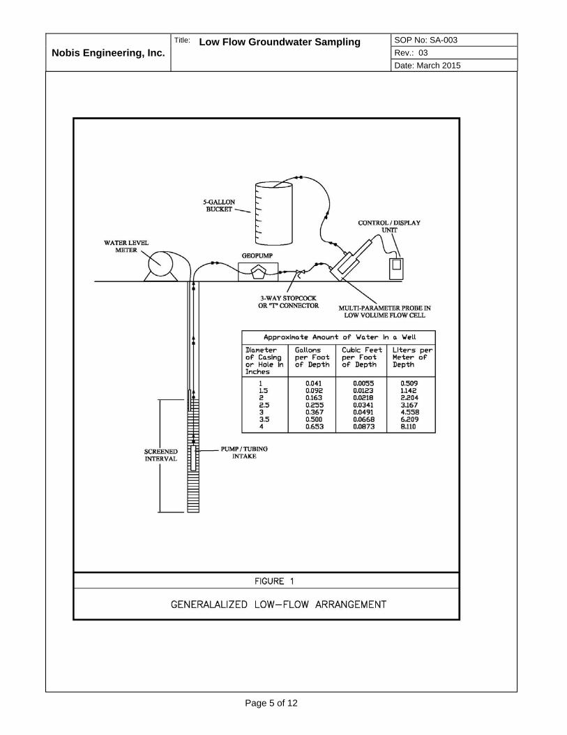
Nobis Engineering, Inc.
Title: Low Flow Groundwater Sampling SOP No: SA-003
Rev.: 03
Date: March 2015
Page 5 of 12

Nobis Engineering, Inc.
Title: Low Flow Groundwater Sampling SOP No: SA-003
Rev.: 03
Date: March 2015
Page 6 of 12
7.0 PROCEDURES
7.1 Office Preparation and Mobilizations
All field personnel should be familiar with the project work plans (i.e., QAPP, SAP, FSP, etc.) and have the opportunity to ask questions prior to beginning mobilization activities. All field equipment will be inspected by the Field Operations Leader (FOL) or designee prior to mobilization. When instruments requiring calibration are obtained from a vendor, documentation of calibration prior to delivery should be requested when the instruments are ordered. If documentation of pre-delivery calibration is provided, calibration prior to mobilization is considered to be completed. This does not supersede QAPP/SAP requirements for field calibration on site prior to daily use. If documentation of calibration by the vendor is not provided, field personnel should complete and document one full calibration of all instruments and equipment requiring calibration prior to mobilization for projects that require initial daily calibration to be performed prior to use. The data quality objectives for some projects may forgo re-calibration for single day field efforts if initial calibration is documented by the instrument vendor. Field technicians should refer to the project scope or consult with the project manager for clarification of the data quality objectives for projects that do not utilize other planning documents such as a QAPP/SAP. Reference Nobis SOP Nos. FS-005 and FS-006 for YSI and turbidity meter calibration procedures, respectively. Personnel should confirm that field instruments are complete and in working order prior to mobilization. The project manager or FOL should provide the field personnel with a list of required and suggested equipment including any tools or personal items not being provided by the project or listed in this SOP. The field personnel should be fully informed of the work site conditions including availability of shelter, climate controls, food, potable water, and project expectations (e.g., anticipated work day length, weather-related decisions, and other reasonably foreseeable conditions) so they can make appropriate decisions on personal gear. The FOL or designee is responsible for ensuring that all required equipment is organized, staged, and ready to mobilize. To the extent possible, all authorization, permission, and access issues should be resolved prior to mobilization. If samples are to be shipped, a shipper or parcel drop should be identified prior to mobilization and hours of operation confirmed. If expendable items such as gases are required, potential local sources should be researched prior to mobilization. Sample shipping and other SOPs should be referenced for further information.
7.2 Field Procedures
7.2.1. For most large-scale sampling efforts, a synoptic water level round where static water levels and total depths are measured and recorded for all locations is completed prior to initiating the low flow effort. The intent of the synoptic round is to measure water levels across all measuring points to obtain a “snapshot” of conditions at a given point in time. During the synoptic water level round, the condition of the wells should be noted as well as the presence and condition of tubing, dedicated pumps (where present), and other factors that may later impact purging and sample collection. This is also the appropriate time to verify well identity and add or refresh well markings to ensure correct identification during the subsequent sample collection efforts and in the future. Reference Nobis SOP No. HYD-003 for further information on measuring the groundwater level in wells. When the tubing, pump, or other equipment is to be installed or removed, it should be done after the static water level is measured during the synoptic round. If tubing is to be installed, repositioned, or replaced, water levels and turbidity should be allowed to stabilize prior to purging. Refer to the project work plan for other project-specific factors.
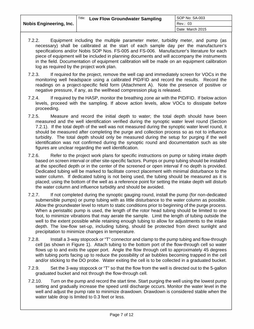
Nobis Engineering, Inc.
Title: Low Flow Groundwater Sampling SOP No: SA-003
Rev.: 03
Date: March 2015
Page 7 of 12
7.2.2. Equipment including the multiple parameter meter, turbidity meter, and pump (as
necessary) shall be calibrated at the start of each sample day per the manufacturer’s specifications and/or Nobis SOP Nos. FS-005 and FS-006. Manufacturer’s literature for each piece of equipment will be included in planning documents and will accompany the instruments in the field. Documentation of equipment calibration will be made on an equipment calibration log as required by the project work plan.
7.2.3. If required for the project, remove the well cap and immediately screen for VOCs in the monitoring well headspace using a calibrated PID/FID and record the results. Record the readings on a project-specific field form (Attachment A). Note the presence of positive or negative pressure, if any, as the wellhead compression plug is released.
7.2.4. If required by the HASP, monitor the breathing zone air with the PID/FID. If below action levels, proceed with the sampling. If above action levels, allow VOCs to dissipate before proceeding.
7.2.5. Measure and record the initial depth to water; the total depth should have been measured and the well identification verified during the synoptic water level round (Section 7.2.1). If the total depth of the well was not measured during the synoptic water level round, it should be measured after completing the purge and collection process so as not to influence turbidity. The total depth should only be measured during the setup for purging if the well identification was not confirmed during the synoptic round and documentation such as site figures are unclear regarding the well identification.
7.2.6. Refer to the project work plans for specific instructions on pump or tubing intake depth based on screen interval or other site-specific factors. Pumps or pump tubing should be installed at the specified depth or in the center of the screened or open interval if no depth is provided. Dedicated tubing will be marked to facilitate correct placement with minimal disturbance to the water column. If dedicated tubing is not being used, the tubing should be measured as it is placed; using the bottom of the well as a reference point for setting the intake depth will disturb the water column and influence turbidity and should be avoided.
7.2.7. If not completed during the synoptic gauging round, install the pump (for non-dedicated submersible pumps) or pump tubing with as little disturbance to the water column as possible. Allow the groundwater level to return to static conditions prior to beginning of the purge process. When a peristaltic pump is used, the length of the rotor head tubing should be limited to one foot, to minimize vibrations that may aerate the sample. Limit the length of tubing outside the well to the extent possible while retaining enough tubing to allow for adjustments to the intake depth. The low-flow set-up, including tubing, should be protected from direct sunlight and precipitation to minimize changes in temperature.
7.2.8. Install a 3-way stopcock or “T” connector and clamp to the pump tubing and flow-through cell (as shown in Figure 1). Attach tubing to the bottom port of the flow-through cell so water flows up to and exits the upper port. Angle the flow through cell to approximately 45 degrees with tubing ports facing up to reduce the possibility of air bubbles becoming trapped in the cell and/or sticking to the DO probe. Water exiting the cell is to be collected in a graduated bucket.
7.2.9. Set the 3-way stopcock or “T” so that the flow from the well is directed out to the 5-gallon graduated bucket and not through the flow-through cell.
7.2.10. Turn on the pump and record the start time. Start purging the well using the lowest pump setting and gradually increase the speed until discharge occurs. Monitor the water level in the well and adjust the pump rate to minimize drawdown. Drawdown is considered stable when the water table drop is limited to 0.3 feet or less.
Nobis Engineering, Inc.
Title: Low Flow Groundwater Sampling SOP No: SA-003
Rev.: 03
Date: March 2015
Page 8 of 12
a. Stable drawdown of less than 0.3 feet, while desirable, is not always feasible. Continued
drawdown may require additional purging to remove head and allow the well recharge rate to increase to match the pumping rate. The drawdown should never reach the screened interval. If the drawdown has exceeded 0.3 feet and stabilizes, calculate the volume of water between the initial water level and the stabilized water level. Add the volume of the water which occupies the pump's tubing to this calculation. This combined volume of water needs to be purged from the well after the water level has stabilized before samples are collected. The volume of drawdown should be less than the volume of water purged when parameter stability indicates adequate conditions for sample collection. When these conditions cannot be met, the actions taken should be fully documented and the FOL and/or quality control officer for the project should be consulted before collecting samples and submitting them for analysis. Continue with the following steps during drawdown to monitor purge water parameters and pumping conditions. When problematic wells are identified, establishing a well-specific procedure in the project planning is recommended.
b. If the water level cannot be stabilized, set the pump to the lowest setting and continue to record water levels in efforts to overcome drawdown issues. Estimate the drawdown rate and consult with the FOL or project manager for instructions. Be sure not to allow water to be drawn down into the screened interval of the well. If the water level approaches the screened interval, stop pump and allow the well to recharge while consulting the FOL and/or quality control officer for the project before collecting samples and submitting them for analysis. When problematic wells are identified, establishing a well-specific procedure in the project planning is recommended.
7.2.11. Measure the flow rate with a graduated cylinder and a stopwatch to calculate the purge rate in milliliters per minute (mL/min). Typical purge rates range between 100 mL/min to 400 mL/min but are dependent on the aquifer matrix composition. Historical flow rates are a good starting point; however, aquifer conditions can change seasonally and over time. Attempt to achieve historical purging flow rates if previously established; however, establish a new flow rate if those rates cause excessive drawdown. When using a bladder pump, the discharge rate should be capable of filling a 40 mL volatile organic analysis (VOA) vial with a single discharge while maintaining a smooth flow at a pressure that will not result in aeration of the sample.
7.2.12. If turbidity levels are excessive, additional purging while bypassing the flow-through cell may be necessary to avoid silt build up in the cell and around the multiple parameter instrument probes. There is no defined upper limit for turbidity with respect to directing the purge water to the flow-through cell; it is up to the field technician’s judgment. Visual indications of suspended material or discoloration and obvious silt accumulation in the purge bucket may be useful indicators. Historical records may be useful in determining what amount of turbidity is generally encountered. It is important to remember that there is no rush to begin collecting field parameter measurements; the purge time starts when the first water is drawn from the well. Allowing some additional purging before water is routed to the flow-through cell may ultimately decrease the overall time to reach parameter stability. Stabilizing the drawdown and avoiding silt accumulation in the flow-through cell are the initial priorities. When the flow rate has been established and turbidity is not excessive, redirect the flow through the 3-way stopcock or “T” to the flow-through cell. Silt levels should be monitored and the flow-through cell should be emptied if silt build up is occurring. This is to be avoided, however, as the DO probe will spike if exposed to ambient air and generally will take 15 minutes or more to stabilize again. Allowing excess turbidity to be purged out before allowing water to enter the flow cell is preferred, if possible. Additionally, if the flow-through cell is at the appropriate 45-degree angle (Section 7.2.8), silt that does enter the cell should settle away from the probes.

Nobis Engineering, Inc.
Title: Low Flow Groundwater Sampling SOP No: SA-003
Rev.: 03
Date: March 2015
Page 9 of 12
7.2.13. Collect all purge water in the graduated bucket. Generally, low-flow methods do not
include minimum purge volumes; refer to the project work plan for confirmation.
7.2.14. Record the indicator parameters and flow rate at intervals determined by the flow rate and flow-through cell volume. The generally accepted approach is to record parameter measurements at 5-minute intervals, however, the entire volume of water in the flow-through cell should be exchanged at least once between readings. To check this, divide the flow-through cell volume by the flow rate to result in minutes per turnover. Reading intervals shall not be less than 5 minutes; however, to ensure that water in the flow through cell is exchanged between readings, the length of the intervals may be increased if slower pumping rates are required.
When monitoring groundwater indicator field parameters and sampling under this SOP, the sampler must be aware of and avoid conditions that cause groundwater degassing, groundwater aeration, groundwater temperature fluctuation, in-well thermal currents, and cross-contamination. The field parameters measured during low flow have either direct or indirect temperature components. Stabilizing the temperature of the water between the time it is drawn into the tubing and the time it exits the flow-through cell will often shorten the time needed for the other field parameters to stabilize. Protecting the tubing and flow-through cell from direct sunlight is generally the most important component of stabilizing the purge water temperature and obtaining the most precise measurements capable through low flow methods.
7.2.15. Turbidity measurements should be collected before the flow-through cell. Use the 3-way stopcock or “T” to divert water directly into the measurement vial (also referred to as a cuvette). Where ambient groundwater temperatures are cool and/or surface humidity is high, condensation may form on the vial. It is acceptable to immerse the vial in water at stable surface air temperature for a few minutes to equilibrate the field measurement sample and wipe moisture off of the vial prior to placing it in the meter to be measured. If the turbidity vial is not being measured immediately after collection, remember to gently agitate the vial to re-entrain particulates that may have settled out. If turbidity measurement vials become stained with iron flocculent or other groundwater constituents, a rinse with a small amount of a 1:1 hydrochloric acid and water solution may remove the staining.
7.2.16. The tubing and flow-through cell should be monitored for air bubbles. Bubbles in the cell may be freed by gently tapping the cell. Stationary bubbles in the tubing may be worked toward the cell and eventually the outlet by lowering the tubing to encourage water to push the bubble(s) downstream. When using a peristaltic pump, persistent bubbles or intermittent flow may indicate that the tubing is too large for the flow rate, that the water level is at the limits of the pump’s capacity to lift it, or that the groundwater is effervescing due to geochemical characteristics. Whenever possible, arrange the equipment so that the pump is above the wellhead and the flow-through cell is above the pump. The tubing from the wellhead to the flow-through cell should be as short as is practical; loops and humps should be eliminated to the extent possible.
7.2.17. Continue purging until indicator parameters stabilize. Record the readings on the project-specific field form included in Attachment A. Stabilization is considered to be achieved after three consecutive readings for all parameters are within the following limits:
Turbidity - +/- 10% for values greater than 5 NTU; if three consecutive turbidity measurements are less than 5 NTU, consider the parameter stable.
DO - +/- 10% for values greater than 0.5 mg/L; if three consecutive measurements are less than 0.5 mg/L, consider the parameter stable.

Nobis Engineering, Inc.
Title: Low Flow Groundwater Sampling SOP No: SA-003
Rev.: 03
Date: March 2015
Page 10 of 12
Specific Conductance - +/- 3%
Temperature - +/- 3%
pH - +/- 0.1
ORP - +/- 10 mV
Calculate stability using the lowest and highest of three sequential readings for each parameter;
sequence is not important. Use the percent difference formula [(high-low)/high x 100] to calculate
percent difference and compare results to the stability criteria above. Examples of this
calculation are shown in Attachment B.
7.2.18. After the indicator parameters have stabilized according to the above criteria, record the stabilization time and collect analytical samples. Fill sample bottles directly from the tubing in the well by disconnecting the tubing from the 3-way stopcock or sample T. Do not collect samples from tubing after the stopcock or sample T or the flow-through cell – samples should be collected as close to the pump as possible. The project work plan may specify an order of sample collection based on project-specific factors. Typically, the flow rate shall not be changed during sample collection; however, the flow rate may be reduced after collection of non-VOC and non-gas samples if necessary to allow for “laminar flow” (undisrupted flow) during collection of VOC volumes. In this case, VOC and groundwater gas samples would be collected last among the laboratory and field analytes to preserve the flow rate for the remainder of the sampling suite. The pump rate is never increased to accommodate large volumes. If field analyses are to be completed, these sample volumes are generally collected after the samples to be submitted to a laboratory and at the stable pump rate. If field quality control (QC) samples are to be collected (i.e., field duplicate or matrix spike samples), then these QC samples are collected after the original field sample is collected for all parameters.
7.2.19. In certain situations which will be outlined in the project work plans, when turbidity meets the stabilization criteria but remains above 25 NTU’s, additional considerations are warranted. If total metals are being collected, an additional filtered sample for metals using a 0.45 micron in-line filter may be required by the work plans to also be collected to compare to the total metals sample. An alternative method would be to send the laboratory two samples: an unfiltered and unpreserved sample that the laboratory can filter within 24 hours of collection for dissolved metals analysis and a preserved sample for total metals analysis. It is preferable that the dissolved metals are field filtered if turbidity values are greater than 5 NTU.
7.2.20. Place samples in a cooler with loose ice immediately after collection. Transfer samples to the project sample manager as soon as possible for processing and shipping.
7.2.21. In general, limit purge water parameter monitoring to 2 hours and collect samples at the end of the 2-hour period, regardless of stabilization. The project work plan may provide guidance for extending the purge period based on parameter trends or other factors. There is no lower limit for the purge period. Once the water level and indicator parameters stabilize and the minimum volume is purged, i.e., the volume of the well tubing and any drawdown, the sample may be collected.
7.2.22. Problems, discrepancies, unexpected or unusual observations (such as contrasting DO and ORP values), and potential exceptions to the SAP or other project documentation should be communicated to the FOL at the time that they are recognized. At a minimum, the FOL

Nobis Engineering, Inc.
Title: Low Flow Groundwater Sampling SOP No: SA-003
Rev.: 03
Date: March 2015
Page 11 of 12
should be aware of such occurrences before purging is stopped and the work area broken down. Additional meter calibration may be warranted.
7.2.23. After collecting the samples, turn off the pump and monitoring equipment and remove the non-dedicated equipment (pump or tubing) from the well. Leave or re-install dedicated tubing in the well or dispose of appropriately. Refer to the project work plans for site-specific procedures.
7.2.24. Record the total volume accumulated in the graduated bucket. Complete all other required notes and documentation in the field book, tablet, or on the field log, as appropriate. The project work plans may provide additional information regarding the required data. Unless otherwise specified, duplication of data on field logs and in field books is not necessary.
7.2.25. Decontaminate all non-dedicated equipment that will be reused in accordance with the project work plan.
7.3 Data and Records Management
In most cases, the samples should be immediately returned to the staging area and turned over to the FOL or sample manager for processing and shipping. Unless site logistics prevent it, this should be done prior to breaking down and demobilizing from the well. Alternately, the sample manager or other site personnel may be available to courier samples to the staging area for appropriate storage. The samples will be transferred to holding coolers or refrigerators until they are packed for shipping. The FOL or sample manager will maintain a log of the samples that will include the sample designator (and well number if different), the analytical parameters, the number of containers, the collection date and time, and any notes regarding exceptions to the SAP or other project documentation and/or quality control. All field data logsheets, notes, and/or electronic filesshall accompany the samples and be turned in to the FOL with the samples after review by the sampler for completeness and accuracy. These documents serve as a chain of custody for the samples while they remain on-site. Communicate any significant observations not noted on the field log to the FOL. The FOL will review the field logsheets and other project specific field data (such as field analyses completed) on a daily basis. Discrepancies and/or omissions should be addressed as soon as possible, preferably the same day as sample collection and prior to the next sample collection. When it is logistically reasonable, it is preferred that copies be made as soon as possible as a backup. Likewise, the data should be provided to the project manager at the end of each sample day, if feasible. If electronic tablets are used, the field logsheets may be saved in the project files while in the field. The FOL will maintain a log of daily events to include, where applicable, the wells sampled, the sampler, the analytical parameters, problems or exceptions, duplicate or matrix QC samples collected, sample transfer/shipping dates and times, and general site conditions. Some or all of this information may be collected in the sample management software, Scribe. Refer to SOP No. DOC-002. 7.4 Communication and Technical Direction
Field personnel shall support one another and maintain open communications during all aspects of the field activities. When a technical point is in question, field personnel shall communicate with the FOL for clarification and/or additional direction. If the project work plans do not provide sufficient information, the FOL should consult with the project manager unless otherwise directed. Deviations, exceptions, and/or omissions from the project work plan or generally accepted practice should be communicated to the project manager as soon as feasible. The FOL will maintain records of all such
Nobis Engineering, Inc.
Title: Low Flow Groundwater Sampling SOP No: SA-003
Rev.: 03
Date: March 2015
Page 12 of 12
communications in a field book or other acceptable format detailing the issue, the outcome, and individuals involved in the decision. 7.5 Demobilization
The FOL is responsible for ensuring that all required data have been collected and that the site is secured before authorizing complete demobilization. The FOL should confirm with the project manager that the crew is authorized to begin demobilization unless otherwise directed. At a minimum, the site conditions should be no worse than at the beginning of field activities. The FOL or designee will ensure that all instruments and equipment are accounted for and either stowed for future use or transported to the office. In some cases, taking an inventory of equipment and expendables may be appropriate.
8.0 QUALITY CONTROL/QUALITY ASSURANCE
As discussed in Section 7.3, the FOL will review field logs and other documentation on a daily basis and address issues as soon as feasible. The requirements for field duplicates, trip blanks, equipment blanks, matrix spike/matrix spike duplicates, performance evaluation samples, temperature blanks, sample management/chain of custody procedures, shipping requirements, and custody seals will be specified in the SAP or other project work plans. Follow Nobis SOPs where established. 9.0 REFERENCES
US Environmental Protection Agency Region I; Low Stress (low flow) Purging and Sampling Procedure for the Collection of Ground Water Samples from Monitoring Wells, EQASOP-GW 001, July 31, 1996 (Revised January 19, 2010). ATTACHMENTS A Low-Flow Groundwater Sampling Field Log B Example Stability Calculations
A
TTA
CH
MEN
T A
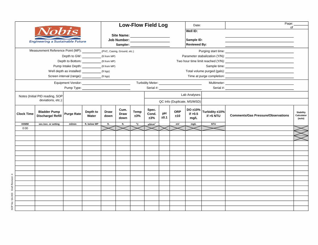
Page:
of
Well ID:
Site Name:
Job Number: Sample ID:
Sampler: Reviewed By:
Measurement Reference Point (MP): (PVC, Casing, Ground, etc.) Purging start time:
Depth to GW: (ft from MP) Parameter stabalization (Y/N):
Depth to Bottom: (ft from MP) Two hour time limit reached (Y/N):
Pump Intake Depth: (ft from MP) Sample time:
Well depth as installed: (ft bgs) Total volume purged (gals):
Screen interval (range): (ft bgs) Time at purge completion:
Equipment Vendor: Turbidity Meter: Multimeter:
Pump Type: Serial #: Serial #:
Clock TimeBladder Pump
Discharge/ RefillPurge Rate
Depth to
Water
Draw
down
Cum.
Draw
down
Temp
±3%
Spec.
Cond.
±3%
ORP
±10
DO ±10%
if >0.5
mg/L
Turbidity ±10%
if >5 NTU
HHMM sec./sec. or setting ml/min ft. below MP ft. ft. oC µS/cm
c mV mg/L NTU
0:00
SO
P N
o: S
A-0
03
D
raft R
evis
ion
: 4
pH
±0.1
Stability
Calculator
(auto)Comments/Gas Pressure/Observations
Low-Flow Field Log Date:
Notes (Initial PID reading, SOP
deviations, etc.): QC Info (Duplicate, MS/MSD)
Lab Analyses:

Page:
of
Well ID:
Site Name:
Job Number: Sample ID: 0
Sampler: Reviewed By: 0
Measurement Reference Point (MP): 0 (PVC, Casing, Ground, etc.) Purging start time: 0:00
Depth to GW: 0 (ft from MP) Parameter stabalization (Y/N): 0
Depth to Bottom: 0 (ft from MP) Two hour time limit reached (Y/N): 0
Pump Intake Depth: 0 (ft from MP) Sample time: 0:00
Well depth as installed: 0 (ft bgs) Total volume purged (gals): 0
Screen interval (range): 0 (ft bgs) Time at purge completion: 0:00
Equipment Vendor: Turbidity Meter: Multimeter: 0
Pump Type: Serial #: Serial #: 0
Clock TimeBladder Pump
Discharge/ RefillPurge Rate
Depth to
Water
Draw
down
Cum.
Draw
down
Temp
±3%
Spec.
Cond.
±3%
ORP
±10
DO ±10%
if >0.5
mg/L
Turbidity ±10%
if >5 NTU
HHMM sec./sec. or setting ml/min ft. below MP ft. ft. oC µS/cm mV mg/L NTU
0 0
0
Comments/Gas Pressure/ObservationsStability
Calculator
(auto)
Notes (Initial PID reading, SOP
deviations, etc.):0
Lab Analyses:0
QC Info (Duplicate, MS/MSD)0
1/0/1900
00
SO
P N
o: S
A-0
03
D
raft R
evis
ion
: 4
0
Low-Flow Field Log Date:
pH
±0.1
0
0

A
TTA
CH
MEN
T B

Attachment B
SA-003 Low-Flow Groundwater Sampling
Example Calculations
Parameter Stability Calculation percent difference formula [(high - low) / high] x 100 = percent difference
For three successive specific conductance readings of 530 µS/cm, 500 µS/cm, and 520 µS/cm; stability is defined as ±3%:
Use the highest and lowest readings of the three →
[(530 µS/cm – 500 µS/cm) / 530 µS/cm] x 100 = 5.6% → not stable
For three successive specific conductance readings of 530 µS/cm, 515 µS/cm, and 520 µS/cm; stability is defined as ±3%:
Use the highest and lowest readings of the three →
[(530 µS/cm – 515 µS/cm) / 530 µS/cm] x 100 = 2.8% → stable Well and Tubing Volumes
Tubing Volume Per Foot
for tubing OD (in.) 0.25 (1/4) 0.375 (3/8) 0.5 (1/2) 0.625 (5/8)
tubing ID (in.) = 0.17 0.25 (1/4) 0.375 (3/8) 0.5 (1/2)
volume (gal./ft.) = 0.0012 0.0026 0.0057 0.0102
Well Volume Per Foot
for casing ID (in.) 1.25 1.5 1.75 2 2.25 3 3.5 4 6
volume (gal./ft.) = 0.06 0.09 0.12 0.16 0.21 0.37 0.5 0.65 1.47
OD = outside diameter, ID = inside diameter
Minimum Purge Volume Calculation drawdown or tubing length (ft.) x volume per foot (gal./ft.) = Vd (gal.) or Vt (gal.)
for a 2-in. ID well with a 0.27-ft. drawdown and 30 ft. of 0.17-in tubing→
0.27 ft. x 0.16 gal./ft. = 0.043 gal. Vd
30 ft. x 0.0012 gal./ft. = 0.036 gal. Vt →
Vd + Vt = minimum purge volume → 0.043 gal. + 0.036 gal = 0.079 gal. minimum purge

Supporting Conversions and Tubing / Well Volume Calculations ID (in.) / 2 = radius (r) in.
π (Pi) ≈ 3.14
1 ft.3 = 1,728 in.3 or 1,728 cubic in. per cubic ft.
[in.3 x (1 ft. / 12 in.) x (1 ft. / 12 in.) x (1 ft. / 12 in.) = ft.3]
1 ft.3 = 7.48 gal. or 7.48 gallons per cubic foot
π x r2 = area of a circle (in.2) →
for a round cylinder, area (in.2) x length (in.) = volume of cylinder (in.3) →
volume of cylinder (in.3) x 1 ft.3 / 1,728 in.3 = volume of cylinder (ft.3) →
volume of cylinder (ft.3) x 7.48 gal. / ft.3 = volume of cylinder (gal.)
for a 2-in. ID well, the volume of water in a 1-ft. section is:
r = 1 in. → π x (1 in.)2 → 3.14 x 1 in.2 = 3.14 in.2 = cross section area →
the volume of 12 in. of 2-in. well = 3.14 in.2 x 12 in. = 37.68 in.3 →
37.68 in.3 x 1 ft.3 / 1,728 in.3 = 0.021 ft.3 →
0.021 ft.3 x 7.48 gal. / ft.3 = 0.16 gal.


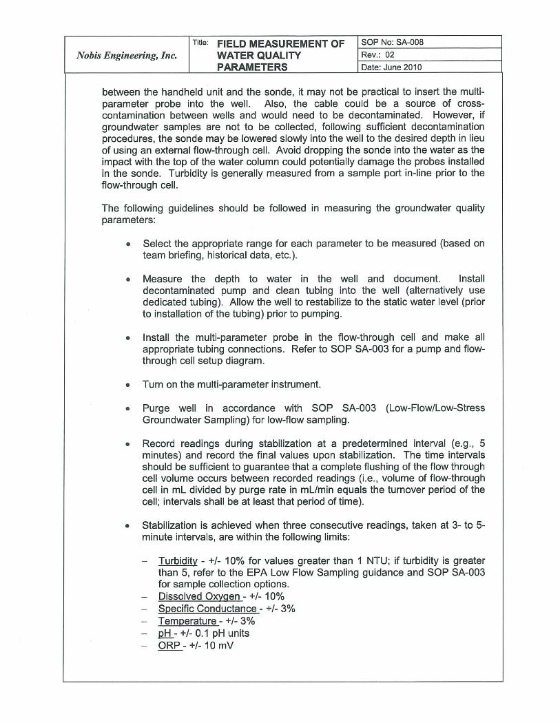


Nobis Engineering, Inc.
Title: SURFACE WATER SAMPLING SOP No: SA-011
Rev.: 04
Date: Feb. 19, 2014
Page 2 of 9
QAPP - Quality Assurance Project Plan QA/QC Officer - The Quality Control and Quality Assurance officer ensures that SOPs are followed, and addresses issues with equipment anomalies or malfunctions. SOP – Standard Operating Procedure
4.0 CAUTIONS
Entering surface water bodies or stretching to reach surface water bodies from the shore can be dangerous. The sampler should ensure they are on stable dry ground or appropriately secured according to the site-specific HASP. Precautions may include wearing waders to enter the surface water body, wearing a PFD, or sampling in teams of two people. Surface water may be cold in the winter months and added precautions for cold-stress should be considered. 5.0 PERSONNEL QUALIFICATIONS
Personnel collecting samples using this method should be familiar with this SOP and the particular equipment to be used to facilitate sampling and troubleshooting equipment problems more efficiently; in particular, familiarity with the YSI Model 6-Series Sonde multiparameter meter is required. Personnel will refer to the information provided by the equipment-rental company, laboratory, and/or manufacturer for product-specific information about the field equipment and sampling kits being used. All field personnel at waste sites are required to receive 40 hours of HAZWOPER training as prescribed by OSHA. This training must be refreshed annually with an 8-hour refresher course. 6.0 EQUIPMENT AND SUPPLIES
Grade stakes and handheld mallet
Sample pin flags
Indelible marker
Fiberglass tape
Engineers rule, 6 foot in length, or similar measuring device (e.g., water level meter, tape measure)
Flow meter (optional)
Syringe, 140 cubic centimeter capacity (or larger, if available)
Peristaltic pump, battery pack, and tubing (optional)
GPS unit with adequate accuracy in accordance with project requirements (optional)
YSI® Model 6-Series Sondes (which include the 600R, 600XL, 600XLM, 6820, 6920, and 6600 models), and the YSI® 650 MDS (Multiparameter Display System) display/logger
LaMotte 2020e or HACH 2100P turbidity meter
Filters, 0.45 micron (for sampling dissolved constituents)
Stopwatch (for measuring flow)
Dipper (i.e., extension arm that holds sample container)
Sample containers
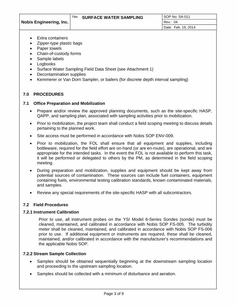
Nobis Engineering, Inc.
Title: SURFACE WATER SAMPLING SOP No: SA-011
Rev.: 04
Date: Feb. 19, 2014
Page 3 of 9
Extra containers
Zipper-type plastic bags
Paper towels
Chain-of-custody forms
Sample labels
Logbooks
Surface Water Sampling Field Data Sheet (see Attachment 1)
Decontamination supplies
Kemmerer or Van Dorn Sampler, or bailers (for discrete depth interval sampling) 7.0 PROCEDURES
7.1 Office Preparation and Mobilization
Prepare and/or review the approved planning documents, such as the site-specific HASP, QAPP, and sampling plan, associated with sampling activities prior to mobilization.
Prior to mobilization, the project team shall conduct a field scoping meeting to discuss details pertaining to the planned work.
Site access must be performed in accordance with Nobis SOP ENV-009.
Prior to mobilization, the FOL shall ensure that all equipment and supplies, including bottleware, required for the field effort are on-hand (or are en-route), are operational, and are appropriate for the intended tasks. In the event the FOL is not available to perform this task, it will be performed or delegated to others by the PM, as determined in the field scoping meeting.
During preparation and mobilization, supplies and equipment should be kept away from potential sources of contamination. These sources can include fuel containers, equipment containing fuels, environmental testing calibration standards, known contaminated materials, and samples.
Review any special requirements of the site-specific HASP with all subcontractors.
7.2 Field Procedures
7.2.1 Instrument Calibration
Prior to use, all instrument probes on the YSI Model 6-Series Sondes (sonde) must be cleaned, maintained, and calibrated in accordance with Nobis SOP FS-005. The turbidity meter shall be cleaned, maintained, and calibrated in accordance with Nobis SOP FS-006 prior to use. If additional equipment or instruments are required, these shall be cleaned, maintained, and/or calibrated in accordance with the manufacturer’s recommendations and the applicable Nobis SOP.
7.2.2 Stream Sample Collection
Samples should be obtained sequentially beginning at the downstream sampling location and proceeding to the upstream sampling location.
Samples should be collected with a minimum of disturbance and aeration.

Nobis Engineering, Inc.
Title: SURFACE WATER SAMPLING SOP No: SA-011
Rev.: 04
Date: Feb. 19, 2014
Page 4 of 9
Samples should be collected from areas of non-stagnant, non-turbulent water by one of the
following three methods: peristaltic pump, dipper bottle, or syringe. The method selected shall meet the project DQOs as defined in QAPPs, work plans, and/or sampling plans. Generally, the peristaltic pump method should be selected; however, the other methods are acceptable if the DQOs allow it. The peristaltic pump method allows for the least amount of disturbance to the water column and bed, allows for discreet sample intervals, and controls the amount of floating or suspended material from entering the sample container.
A. Peristaltic Pump Method:
Place approximately 12 inches of silicon tubing in the pump-head of the peristaltic pump. Place the pump on dry, level ground or on an overturned 5-gallon bucket or similar. Insert one end of 1/4–inch inside-diameter LDPE tubing into the discharge end of the silicon tubing in the pump head and extend the LDPE tubing to the bottom (inlet) port of the flow-through cell with the sonde installed. In between the pump head and the flow-through cell, a tee-fitting or stop-cock is installed to allow flow diversion for turbidity measurements. Connect a suitable length of LDPE tubing to the top (outlet) port of the flow-through cell to allow for discharge to a bucket or similar container.
Measure the water column using a water level indicator, measuring rod, or tape measure. The sample interval should be determined in the QAPP or sampling plan; otherwise, the mid-point of the water column should be used. Insert a suitable length of LDPE into the inlet side of the silicon tubing to allow for submersion of the LDPE tubing to the appropriate depth of the surface water body to be sampled. An extendable rod or a clean dowel may be attached to the sample-end of the tubing to ensure the intake remains at the correct interval. Use the least amount of tubing as possible when making connections as extra tubing can cause air bubbles, affecting temperature and other parameters measured during sampling.
Turn the pump on and confirm the direction of flow. The flow rate should be adjusted to not exceed 400 milliliters per minute. Record four sets of parameters in 5 minute intervals, including temperature, specific conductivity, acidity (pH), ORP, and DO using the sonde and the handheld display unit of the YSI® multiparameter meter. Collect and record four turbidity readings from the tee-fitting installed in-line prior to the flow-through cell. Record each of the readings on the field data sheet included in Attachment 1.
Begin to fill the appropriate sample containers as required by the QAPP or sampling plan by removing the tubing between the pump-head and the flow-through cell, and filling the containers directly from the pump-head discharge tubing. Sample in the order specified in the QAPP or sampling plan; otherwise, the following order is generally acceptable: VOCs, SVOCs, PCBs, total metals, and finally dissolved metals using a 0.45 micron field filter. Place the samples in a cooler filled with loose ice for delivery to the sample manager or the laboratory, as appropriate.
Once sampling is complete, discard the submerged piece of LDPE tubing and the silicon tubing in the pump-head, and decontaminate the remainder of the equipment and supplies in accordance with Nobis SOP FS-004.
B. Direct-Dip Method:
Immerse the sample containers upstream, with the mouth of the containers pointed upstream at a 45 degree angle from vertical. The mouth of the containers will be immersed to approximately mid-depth of the water column and filled. If the standing water is too shallow to immerse the containers or if the sample bottles are pre-preserved, smaller clean

Nobis Engineering, Inc.
Title: SURFACE WATER SAMPLING SOP No: SA-011
Rev.: 04
Date: Feb. 19, 2014
Page 5 of 9
glass or plastic containers, as appropriate, may be used to collect the surface water and decant into the sample containers.
If necessary, samples may be collected by tying the sample container to an extension arm (e.g., a clean dowel) and extending the sample container into the stream to avoid stepping into the water being sampled. If this is not feasible, enter the stream downstream from each sampling location and wade upstream to the sampling location. Prior to sampling, sediment that has been disturbed should be allowed to flush downstream.
Add preservative to the samples as required. In the event pre-preserved bottleware is used, the surface water sample should be collected first into an unused and unpreserved sample bottle as described above and then gently decanted into the preserved bottleware to prevent loss of the preservative into the water body.
C. Syringe Method:
Submerge a disposable, 140 cubic centimeter (or larger if available), plastic sampling syringe one to two inches below the surface of the water body sampling location, or as noted in the QAPP or site-specific sampling plan.
Draw one complete syringe volume of sample water into the syringe, being careful not to introduce any air into the syringe.
Remove syringe from beneath the water and dispense the contents into the sample container. If the sample is for dissolved metals analysis and requires filtering in the field, place the tip into a 0.45 micron filter. To dispense the syringe through the filter, first allow a small volume of sample water to pass through the filter and discharge back to the water body (a volume equal to the volume of the filter system), then collect the remaining sample water into the appropriate bottleware as specified in the QAPP.
Repeat this process until the desired volume of filtered surface water is obtained.
Additional Measurements:
Once the samples have been collected, measure the stream channel flow rate, if applicable. Measure (or estimate) the width and depth of the surface water body. Use a flow meter to measure the flow rate of the water body. In the event a flow meter is not utilized, measure a 10-foot distance along the stream channel, making sure the section is clear without obstacles or eddies. Record the length of time needed for a floating object (e.g., stick, leaf) to travel this distance with the stream flow. Convert this result to flow in feet/second and record on the field data sheet. Use the formula included in Section 7.3 to calculate the volumetric flow rate.
Illustrate a basic sketch of the sampling location including approximately 5 feet up and down stream of the sample location, debris, direction of flow, dimensions of the channel, and any potential tributaries or flow into the channel.
Take a photograph of the sample location, incorporating into the photograph a piece of paper or a dry-erase board with the location identified. A photograph of the peristaltic pump set-up (if this was the selected sampling method) would provide appropriate documentation for the project file.
Record the GPS coordinates of the sample location. In the event a GPS unit is not utilized for the sampling, place a sample location pin flag or grade stake with the sample identification written in permanent ink along the shore at the point perpendicular to the

Nobis Engineering, Inc.
Title: SURFACE WATER SAMPLING SOP No: SA-011
Rev.: 04
Date: Feb. 19, 2014
Page 6 of 9
sample collection location and note the distance from the steak to the sample collection location. Consider that pin flags may be more apt to be washed away than grade steaks.
7.2.3 Ponded Water Sample Collection
Surface samples from ponded water should be collected consistent with the methods described in Section 7.2.2, unless otherwise specified in the QAPP or the sampling plan. When discrete samples are desired from specific depth intervals in the water column, and the parameters to be measured do not require a Teflon® coated sampler, a standard Kemmerer or Van Dorn sampler may be used as described below.
The Kemmerer sampler is a brass cylinder with rubber stoppers that leave the ends of the sampler open while being lowered in a vertical position, thus allowing free passage of water through the cylinder. Kemmerer samplers are available on special order or are adaptable for sample collection for organic analysis by substituting Teflon for the rubber or plastic stoppers.
The Van Dorn sampler is made of plastic and is lowered in a horizontal position. Van Dorn samplers may not be recommended for organics as they rely on an elastic closing mechanism that can adversely affect samples. These samplers are readily available and are totally nonmetallic, which is very useful for sample collection for trace metal analysis.
With both the Kemmerer and the Van Dorn samplers, a messenger is sent down a line when the sampler is at the designated depth, which causes the stoppers to close the cylinder. The sampler is then raised to the surface and water is removed through a valve to fill respective sample containers for laboratory analysis and/or perform field measurements.
When collecting samples from multiple depths, care should be taken to not stir up the bottom sediment and thus bias the sample.
Bailers may also be used for surface water sampling given sufficient depth and little to no current if the study objectives do not necessitate a sample from a discrete interval of the water column. A standard bottom-loading bailer with a bottom check-valve is sufficient for many studies. As the bailer is lowered (somewhat horizontally with a slight incline downward toward the check valve) through the water column, water is continually displaced through the bailer until the desired depth is reached, at which point the bailer is retrieved. This technique may have limited success under conditions where the water column is too shallow to avoid disturbing the bed or where strong currents may carry the bailer away from the target interval.
7.2.4 Decontamination
All non-disposable equipment coming in contact with the sampled media must be decontaminated prior to use at a subsequent location. Refer to Nobis SOP FS-004 for general decontamination procedures. 7.3 Data and Records Management
All results of calibration must be documented and recorded in a calibration log book or on the calibration log sheets included in the appropriate Nobis SOPs. At a minimum, the following information should be recorded as part of the documentation: the instrument’s manufacturer, model number, instrument identification number, standards used to calibrate the instruments, calibration date, and the instrument readings.
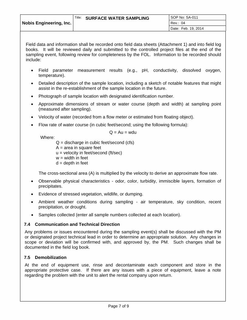
Nobis Engineering, Inc.
Title: SURFACE WATER SAMPLING SOP No: SA-011
Rev.: 04
Date: Feb. 19, 2014
Page 7 of 9
Field data and information shall be recorded onto field data sheets (Attachment 1) and into field log books. It will be reviewed daily and submitted to the controlled project files at the end of the sampling event, following review for completeness by the FOL. Information to be recorded should include:
Field parameter measurement results (e.g., pH, conductivity, dissolved oxygen, temperature).
Detailed description of the sample location, including a sketch of notable features that might assist in the re-establishment of the sample location in the future.
Photograph of sample location with designated identification number.
Approximate dimensions of stream or water course (depth and width) at sampling point (measured after sampling).
Velocity of water (recorded from a flow meter or estimated from floating object).
Flow rate of water course (in cubic feet/second; using the following formula):
Q = Au = wdu Where:
Q = discharge in cubic feet/second (cfs) A = area in square feet u = velocity in feet/second (ft/sec) w = width in feet d = depth in feet
The cross-sectional area (A) is multiplied by the velocity to derive an approximate flow rate.
Observable physical characteristics - odor, color, turbidity, immiscible layers, formation of precipitates.
Evidence of stressed vegetation, wildlife, or dumping.
Ambient weather conditions during sampling - air temperature, sky condition, recent precipitation, or drought.
Samples collected (enter all sample numbers collected at each location).
7.4 Communication and Technical Direction
Any problems or issues encountered during the sampling event(s) shall be discussed with the PM or designated project technical lead in order to determine an appropriate solution. Any changes in scope or deviation will be confirmed with, and approved by, the PM. Such changes shall be documented in the field log book. 7.5 Demobilization
At the end of equipment use, rinse and decontaminate each component and store in the appropriate protective case. If there are any issues with a piece of equipment, leave a note regarding the problem with the unit to alert the rental company upon return.
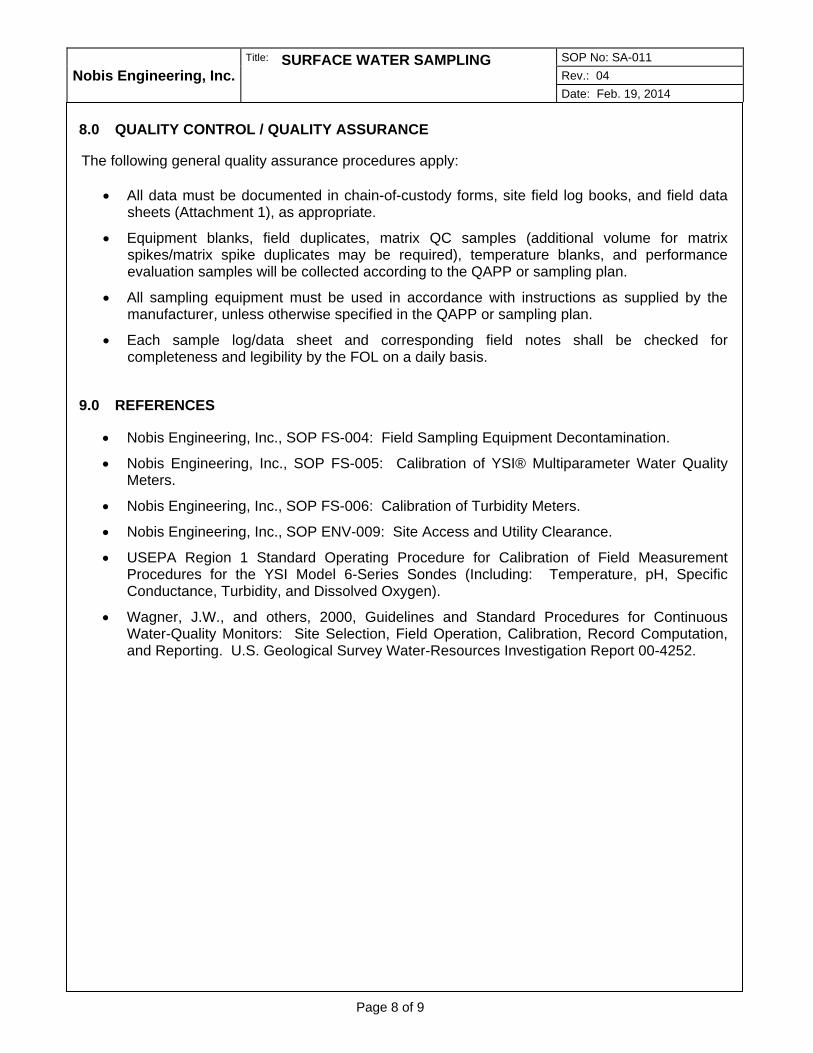
Nobis Engineering, Inc.
Title: SURFACE WATER SAMPLING SOP No: SA-011
Rev.: 04
Date: Feb. 19, 2014
Page 8 of 9
8.0 QUALITY CONTROL / QUALITY ASSURANCE
The following general quality assurance procedures apply:
All data must be documented in chain-of-custody forms, site field log books, and field data sheets (Attachment 1), as appropriate.
Equipment blanks, field duplicates, matrix QC samples (additional volume for matrix spikes/matrix spike duplicates may be required), temperature blanks, and performance evaluation samples will be collected according to the QAPP or sampling plan.
All sampling equipment must be used in accordance with instructions as supplied by the manufacturer, unless otherwise specified in the QAPP or sampling plan.
Each sample log/data sheet and corresponding field notes shall be checked for completeness and legibility by the FOL on a daily basis.
9.0 REFERENCES
Nobis Engineering, Inc., SOP FS-004: Field Sampling Equipment Decontamination.
Nobis Engineering, Inc., SOP FS-005: Calibration of YSI® Multiparameter Water Quality Meters.
Nobis Engineering, Inc., SOP FS-006: Calibration of Turbidity Meters.
Nobis Engineering, Inc., SOP ENV-009: Site Access and Utility Clearance.
USEPA Region 1 Standard Operating Procedure for Calibration of Field Measurement Procedures for the YSI Model 6-Series Sondes (Including: Temperature, pH, Specific Conductance, Turbidity, and Dissolved Oxygen).
Wagner, J.W., and others, 2000, Guidelines and Standard Procedures for Continuous Water-Quality Monitors: Site Selection, Field Operation, Calibration, Record Computation, and Reporting. U.S. Geological Survey Water-Resources Investigation Report 00-4252.

Nobis Engineering, Inc.
Title: SURFACE WATER SAMPLING SOP No: SA-011
Rev.: 04
Date: Feb. 19, 2014
Page 9 of 9
ATTACHMENT 1
The Surface Water Sampling Field Data Sheet is provided on the following page.

Date:
START: END:
E= N=
FT
FT
FT/S
CFS
WATER PARAMETERS
NOTES/OBSERVATIONS:
SAMPLER NAME AND SIGNATURE:
CHECKED BY: RECEIVED BY:
CLP / DAS SAMPLE ID
(as applicable)
APPROXIMATE SAMPLE LOCATION SKETCH (Include North Arrow)
PROJECT:
STATION:
SAMPLE ID:
QC SAMPLES:
VOCs
SVOCs
TAL Metals (total)
TAL Metals (dissolved)
Pesticides
PCBs
SAMPLE
COLLECTED
FIELD
FILTERED
BOTTLE TYPE/
VOLUME REQUIRED
COLLECTION
METHOD:
STREAM CHANNEL WIDTH
VELOCITY MEASURED
FLOW RATE CALCULATED
DATE:
STREAM CHANNEL DEPTH
FLOW RATE COMMENTS
JOB NUMBER:
(NTU)
SAMPLE TIME:
ASSOCIATED TRIP BLANK:
COORDINATE SYSTEM:
PHOTO ID:
( C° )SPECIFIC
CONDUCTIVITY
ACTIVITY TIME:
GPS COORDINATES:
DO(mg/L)
ORP(mV)
TURBIDITY
(µS/cm)
ANALYTICAL PARAMETERS
METHOD
NUMBER PRESERVATIVE
mL/minpH TIME TEMP
SOP No: SA-011 Attachment 1, Page 1 of 1
Rev.: 04Feb. 19, 2014
SURFACE WATER SAMPLING
FIELD DATA SHEET
Nobis Engineering, Inc. Attachment 1 Nobis SOP SA-011 Rev. 04


Nobis Engineering, Inc. Title: ENVIRONMENTAL SAMPLES:
PACKAGING AND SHIPPING
SOP No: SH-001
Rev.: 2
Date: January 2010
Page 2 of 6
4.0 CAUTIONS
When working with potentially hazardous materials follow the EPA, OSHA, and the safety practices as outlined in the site-specific HASP, QAPP, or other work plan document.
5.0 PERSONNEL QUALIFICATIONS
Personnel should be familiar with this SOP and should have had both general awareness hazardous materials shipping training (2 hours) and function-specific field shipping training. The general awareness hazardous materials shipping training can be taught by Nobis’ hazardous materials/dangerous goods shipper and the function specific field training can be taught by the Field Operations Leader. All field personnel at contaminated field sites are required to receive 40 hours of basic hazardous waste operations and emergency response (HAZWOPER) training as prescribed by OSHA. This training must be refreshed annually with an 8-hour refresher course. 6.0 EQUIPMENT AND SUPPLIES
• Cooler
• Environmental Samples in glass or plastic inner containers
• Labels (Dangerous Goods in Excepted Quantities, orientation arrows)
• Ink pen
• Packing materials (bubble wrap, Styrofoam, absorbent materials or similar) to prevent breakage, absorb leakage, and insulate environmental samples.
• Polyethylene zip-type bags large enough to contain the largest sample bottles
• Chain of Custody seals
• Large plastic trash bag to act as containment for the packing materials
• Packing tape
7.0 GENERAL PACKING PROCEDURES FOR ALL ENVIRONMENTAL SAMPLE
SHIPMENTS
7.1 Office Preparation and Mobilization
• Verify the required type and quantity of environmental samples per the QAPP or other work plan document.
• Ascertain which sample preservatives will be used for each type of environmental sample collected.
• Acquire all required supplies for sample collection, package, and shipment.

Nobis Engineering, Inc. Title: ENVIRONMENTAL SAMPLES:
PACKAGING AND SHIPPING
SOP No: SH-001
Rev.: 2
Date: January 2010
Page 3 of 6
7.2 Field Procedures
• Be certain that all individual containers are sufficiently tight, preserved, and labeled correctly.
• Clean the exterior of each sample container to ensure no visible contamination remains on the outside.
• Place sample containers within zip-type plastic baggies and remove all air from the baggie.
• If the cooler is equipped with a drain plug, ensure that it is taped in the closed position. Melt water from the shipping ice should not leak out of the cooler.
• Line the cooler with a trash bag.
• Place sample containers into the cooler, and pack sufficiently to prevent the sample containers from shifting during shipment.
• If the QAPP or other work plan document requires ice, place ice-filled zip-type bags on samples, so all samples are in contact with the ice. Place a sufficient amount of ice to retain the sample temperature between 2 and 6 degrees Celsius. Place a temperature blank (also in contact with the ice) with the samples in each cooler.
• Fill the remaining space in the cooler with packing material and close and secure the top of the trash bag.
• On the COC, sign the “Relinquished By” box and add the name of the courier or carrier and the airbill number (if applicable) in the subsequent “Received By” box.
• Place the COC into a plastic bag and tape it to the inside top of the cooler if shipping other than by private laboratory courier.
• Apply custody seals to the cooler such that the seals must be broken in order to open the cooler.
• Close the cooler and tape the cooler shut with strapping tape or similar high-strength shipping tape.
• If more than one cooler is being shipped under the same COC, copies of the COC should be placed into each additional cooler in the same manner as the original COC.
• Apply “UP Arrows” in the appropriate direction on at least two opposing sides of the cooler exterior.
• Add the appropriate shipping address labels and a return address to the cooler. If more than one cooler is being shipped to a particular recipient, label appropriately (e.g., if shipping three coolers, label one “1 of 3”, another “2 of 3”, etc.) so that the recipient is aware of the number of coolers that they should expect in the shipment.

Nobis Engineering, Inc. Title: ENVIRONMENTAL SAMPLES:
PACKAGING AND SHIPPING
SOP No: SH-001
Rev.: 2
Date: January 2010
Page 4 of 6
8.0 SPECIFIC PACKING PROCEDURES
8.1 Environmental samples where the contaminants are estimated to be less
than 1% of the total volume of the environmental media (drinking water,
surface water, groundwater, soil, or sediment)
• The procedures outlined in 7.0 above are sufficient.
8.2 Drinking water, surface water, or groundwater preserved with hydrochloric
acid (HCl), nitric acid (HNO3), sodium hydroxide (NaOH), or sulfuric acid
(H2SO4).
• The procedures outlined in 7.0 above are sufficient.
8.3 Soil or sediment samples preserved with methanol
• Because methanol is a flammable chemical preservative, these environmental samples will be shipped as Dangerous Goods in Excepted Quantities.
• Each sample vial must be glass with a threaded leak-proof cap.
• Each sample vial cannot contain more than 30 mL of methanol.
• Each shipping cooler cannot contain more than 500 mL of methanol.
• Intermediate packaging: Between the sample vial and the cooler there must be an intermediate package with sufficient absorbent material that will absorb the entire contents of the sample vials.
• Package tests: The completed package must be capable of withstanding without leakage: o Drops onto a solid surface from a height of 1.8 meters. The drop must be on each side of
the box and at one corner. o This package test should be done on each type of cooler, but need not be done on every
individual cooler. o At the start of every sampling event, this package test must be performed with sample
containers filled with water. It should be documented that the cooler survived the drop without any breakage or leakage.
• Each cooler must have a Dangerous Goods in Excepted Quantities Label with a “3” for flammable liquids. The label must be at least 100 mm by 100 mm and must be durable and clearly visible.
• There must be orientation arrow labels on two opposing sides of the cooler.
• For transportation by highway or rail, no shipping paper is required if the total contents are less than 500 mL of methanol.
• For transport by air, a shipping paper is not required; however, an airbill must include the statement “Dangerous Goods in Excepted Quantities” and indicate the number of packages.

Nobis Engineering, Inc. Title: ENVIRONMENTAL SAMPLES:
PACKAGING AND SHIPPING
SOP No: SH-001
Rev.: 2
Date: January 2010
Page 5 of 6
9.0 DATA AND RECORDS MANAGEMENT
A copy of the COC shall be retained by the shipper until the completed laboratory data package is received. In addition, a copy of the airbill shall also be retained for validation/custody purposes and payment. 10.0 COMMUNICATION AND TECHNICAL DIRECTION
Any problems or issues encountered while in the field shall be discussed with the Project Manager and Dangerous Goods Shipping Coordinator in order to derive an appropriate solution. If the environmental sample shipment is to include materials and quantities other than those discussed above, the Dangerous Goods Shipping Coordinator must be consulted in advance of the field sampling event. These procedures may have to be adjusted to accommodate additional requirements. 11.0 DEMOBILIZATION
Not applicable. 12.0 QUALITY ASSURANCE/QUALITY CONTROL
The Project Manager or Dangerous Goods Shipping Coordinator will periodically audit environmental sample shipments to verify compliance with these procedures on an annual basis. 13.0 REFERENCES
Nobis Engineering Inc. Standard Operating Procedure for Chain of Custody Code of Federal Regulations 40 CFR Part 261.4(d) Samples Code of Federal Regulations 49 CFR Part 173.4a Excepted Quantities Dangerous Goods Regulations, IATA, most current version.
STANDARD OPERATING PROCEDURES ___________________________
Prepared by
___________________________
Reviewed by
___________________________
Approved by
Title: ENVIRONMENTAL SAMPLES:
PACKAGING AND SHIPPING Nobis Engineering, Inc. SOP No: SH-001 Rev.: 2 Date: January 2010
Page 6 of 6
ATTACHMENT
Example Dangerous Goods in Excepted Quantities Label for soil and sediment samples preserved with methanol.
3


Nobis Engineering, Inc. Title: GROUNDWATER LEVEL
MEASUREMENT
SOP No: HYD-003
Rev.: 02
Date: 2010
Page 2 of 4
5.0 PERSONNEL QUALIFICATIONS
Nobis personnel will have been trained by other appropriate personnel (Field Operations Lead/Sample Manager/Project Manager) for taking water level measurements, LNAPL and DNAPL measurements, and storage activities.
6.0 EQUIPMENT AND SUPPLIES
Electronic water level meter (e.g., Solinst™) or Interface Probe if the presence of NAPL is suspected
Well keys and wrenches (include an extension for keys and wrenches to apply extra leverage), screwdriver, hammer
PID, or other monitoring equipment (as required by HASP)
Metal detector (project-specific)
Extra Batteries (9 Volt)
Well installation logs, boring logs
Field book (and/or data recording sheets, if used)
Permanent marker
Protective eyewear and nitrile gloves
Paper towels, Alconox and spring water and/or D.I. water
7.0 PROCEDURES
7.1 OFFICE PREPARATION AND MOBILIZATION
Prior to Site activities, water level meters and/or interface probes must be signed out from the Nobis office or rental meters must be acquired from equipment rental companies (e.g., Pine Environmental Services) or a manufacturer. Test equipment prior to leaving for the Site. 7.2 FIELD PROCEDURES
Check the condition of the standpipe or roadbox and protective seal, if any. Observe and record any abnormalities with the well such as a missing cap, run-on, evidence of tampering, missing/rusted/open lock, damaged roadbox or standpipe, etc. Record observations in the log book or on a sampling form.
Screen the wellhead during removal of the cap with a PID or other monitoring equipment, as required by the HASP. Follow requirements for use of personal protective equipment.
Record the type of measurement reference point used (i.e., roadbox, standpipe, mark on PVC).
If not already done, mark the measurement reference point either by etching or with indelible ink at the top of the PVC riser pipe or steel casing. The measurement reference point will generally be the highest point of the PVC riser or casing. Mark well number on the outside of well.
Water Level Measurement
Lower the water level meter's probe slowly into the well until the auditory signal indicates that water is reached.
Raise the probe above water level and slowly lower it again until the exact position of the water is indicated on the tape gauge.

Nobis Engineering, Inc. Title: GROUNDWATER LEVEL
MEASUREMENT
SOP No: HYD-003
Rev.: 02
Date: 2010
Page 3 of 4
Hold the cable or tape against the side of the PVC riser or steel casing at the reference point
designated for water level measurements and record the measured depth to the nearest 0.01 feet.
Well Depth
Slowly lower the water level meter’s probe to the bottom of the well and record to the nearest 0.01 feet. Compare to installed depth of well. Note whether the bottom of the well feels soft or solid.
If no additional work is to be performed, lock or secure the wellhead.
LNAPL (if suspected)
Check for the presence and measure the thickness of NAPL using a transparent bailer, product-water interface probe, or water-sensitive paste. If NAPL is observed, do not immerse the electronic water level meter unless specifically required by the Work Plan. Measure and record the thickness of NAPL.
To use a bailer to measure NAPL, lower it slowly into the water column using a polypropylene or nylon line. For LNAPL, hold the bailer so that the bottom check valve and approximately half the bailer's length are submerged.
For DNAPL, lower the bailer to the bottom of the well. Hold the bailer at the appropriate level for about 10 to 30 seconds to allow NAPL to enter the bailer. Remove the bailer and measure the thickness of the NAPL within the bailer with a tape measure.
If the well is known to contain NAPL, an interface probe should be used to give a more accurate measurement of the product thickness. Lower the probe down the well, similarly to the water level meter. The probe sounds differently when it has detected NAPL and when it has detected water. The difference between the two tones indicates the product thickness.
Decontamination
Inspect meter and tape for the presence of free product. If present, decontaminate accordingly.
If contaminants are suspected, perform a gross decontamination by wiping the tape with a paper towel as it is retrieved from the well; if LNAPL was present, use a hydrophobic absorbent pad.
Rinse with tap or bottled water.
Wash with Alconox™ (or equivalent) detergent wash.
Rinse with tap or bottled water.
Rinse with distilled/deionized water.
Containerize and handle decontamination wastes and wastewater in accordance with applicable Federal, State, and local regulation, and as specified in the sampling plan.
7.3 DATA AND RECORDS MANAGEMENT
On a log sheet or field book, the following items should be recorded.
Date and time
Type of well (roadbox, standpipe, etc.) and condition (no j-plug, missing bolts or lock)
Total depth to water (TDW)
Depth to water (DTW)
Depth of NAPL in well, using bailer method (if present)
Volume of NAPL removed (if any) and storage type.
Nobis Engineering, Inc. Title: GROUNDWATER LEVEL
MEASUREMENT
SOP No: HYD-003
Rev.: 02
Date: 2010
Page 4 of 4
7.4 COMMUNICATION AND TECHNICAL DIRECTION
All field notes should be copied and given to the Field Operations Lead/Sample Manager/Project Manager, depending on the Site. This information is required when groundwater contours for the site are developed. 7.5 DEMOBILIZATION
Decontaminate and clean off water level meter/interface probe.
Ensure that j-plugs are secure on wells
Lock well (if well requires lock)
Close up roadboxes and tighten in place with bolts. 8.0 QUALITY CONTROL / QUALITY ASSURANCE
Not applicable
9.0 REFERENCES
ASTM D4750-87(93): Test Method for Determining Subsurface Liquid Levels in A Borehole or Monitoring Well (Observation Well)
Site-specific Health and Safety Plan

A
P
P
E
N
D
I
X
C

Page 1 of 2 2465.0
Date: 08/30/2017 MA: Based on 2465.0
Title: TVOA Analytes at Lower CRQL for Vinyl Chloride
Method Source: SOM02.4 Method: TVOA
Matrix: Water
Summary of Modification
The purpose of this modified analysis is to analyze water samples for Trace Volatiles with a lower CRQL for the one analyte: Vinyl chloride. Unless specifically modified by this modification, all analyses, Quality Control (QC), and reporting requirements specified in the SOW listed in your current EPA agreement remain unchanged and in full force and effect.
I. Analyte Modifications Not applicable
Analyte CAS Number CRQL (ug/L)
Vinyl chloride 75-01-4 0.1
II. Calibration and QC Requirements Not applicable
The Laboratory shall:
• Analyze the lowest ICAL standard at concentrations equal to or less than the CRQLs for the target analytes in Section I.
• Perform a five-point initial calibration to establish the linear calibration ranges on GC/MS for the target analytes in Section I. The recommended ICAL standard concentrations are at 0.10, 0.50, 1.0, 2.0, and 5.0 ug/L.
• Perform the Continuing Calibration Verification (CCV) at mid-point ICAL standard (CS3) concentration at the same frequency as specified in SOW.
• Analyze all target analytes in Section I as separate standards at the specified concentrations.
• Add the same non-ketone DMC specified in the SOW at the same concentrations as the target analytes in the calibration standards.
• Add the same Internal Standard (IS) solution specified in the SOW to the calibration standards at concentration of 1.0 ug/L.
• The technical acceptance criteria for ICAL and CCV RRF, ICAL %RSD and CCV %D for the target analytes listed in Section I above shall be the same as listed in Table 4 in Exhibit D TVOA of the SOW.
• Analyze the method blanks at the same frequency and sequence as specified in the SOW. The
concentration of any target analyte in Section I in the method blank shall not exceed CRQL
listed in Section I.
• Analyze a Laboratory Fortified Blank (LFB), spiked with all target analytes in Section I at the
concentrations of 1xCRQLs. The LFB must be prepared using the method blank matrix
specified in Section 12.1.2.1 of Exhibit D, Trace Concentrations of Volatile Organic Compounds
Analysis; and must be analyzed after each method blank associated with the submitted

Page 2 of 2 2465.0
samples. The Percent Recovery (%R) for the LFB analytes shall be 65% - 131%. If the LFB %R is
not met, the LFB and all associated samples must be reanalyzed at no additional cost to EPA.
• Add the non-ketone DMC solution to all samples, blanks and LFB samples at the mid-point
ICAL standard concentration of 1.0 ug/L. Add the same IS solution to all samples, blanks and
LFB samples at the same concentration that is added to the calibration standard.
• %R for any of the associated DMCs to the target analytes Section I shall not exceed the QC
limits. The IS technical acceptance criteria specified in the SOW for the TVOA full scan
analysis shall remain in effect. If any of the associated DMCs or IS technical acceptance
criteria cannot be met for samples, reanalysis of the samples shall be performed at no
additional cost to EPA.
• All other technical acceptance criteria for ICALs, CCVs, blanks and samples remain the same as
specified in the SOW.
III. Preparation and Method Modifications Not applicable
The Laboratory shall:
• Perform a MDL study for the target analytes in Section I and make the results available upon
EPA’s request.
IV. Special Reporting Requirements Not applicable
The Laboratory shall:
• Report the CRQLs listed in Section I, adjusted according to the equation listed in Exhibit D,
even if the level of the corresponding target analytes in the low-point calibration standard
is below the CRQLs listed in Section I.
• Modify all applicable hardcopy forms to include the additional analytes in Section I and the
associated DMCs and ISs. This includes Forms 1, 2, 3, 6, 7 and 8 as appropriate.
• Report the LFB with the EPA Sample Number, VLFB## (where ## can be alpha numeric
characters) and the QC Type “Laboratory_Control_Sample” in the electronic deliverable. The
LFB (VLFB##) shall be reported on a modified Form 3A. The spike analytes, spike analyte
concentrations, Percent Recovery (%R) and QC limits shall be included on the form.
• Include the original and background-subtracted spectra of the associated peak for each target
analyte in Section I from the low point ICAL standard in the data deliverable.

Page 1 of 1 2754.0
Date: 08/10/2017 MA: Based on 2754.0
Title: ICP-MS Analysis with Lower CRQLs for Pb, Ag, and Ba
Method Source: ISM02.4 Method: ICP-MS
Matrix: Aqueous/Water
Summary of Modification
The purpose of this modified analysis is to analyze water samples by ICP-MS with lower CRQLs for the routine analytes Lead (Pb), Silver (Ag), and Barium (Ba). Unless specifically modified by this modification, all analyses, Quality Control (QC), and reporting requirements specified in the SOW listed in your current EPA agreement remain unchanged and in full force and effect.
I. Analyte Modifications Not applicable
Analyte CAS Number CRQL (µg/L)
Lead (Pb) 7439-92-1 0.25
Silver (Ag) 7440-22-4 0.25
Barium (Ba) 7440-39-3 2
II. Calibration and QC Requirements Not applicable
The Laboratory shall:
• Perform the Initial Calibration with at least one non-blank standard at or below the modified CRQLs.
• Evaluate the ICB and CCB against the modified CRQLs.
• Evaluate the Preparation Blanks using the modified CRQLs.
• Flag the Duplicates based on the modified CRQLs.
• Add Pb, Ag, and Ba to the LCS at two times the modified CRQLs.
• Use acceptance windows of +/- two times the modified CRQLs or ±20% whichever is applicable for
the ICS solutions.
III. Preparation and Method Modifications Not applicable
IV. Special Reporting Requirements Not applicable
• Report the “J” and “U” qualifiers in accordance with the requirements in Exhibit B, Section 3.4.2.2.5.2, using the modified CRQL.