
MECHATRONICS PAPER
72
APPLICATION OF MECHATRONICS ‘ HALL EFFECT SENSOR ’ D EFINATION: Mechatronics is the combination of mechanical engg, electronic engg, software engg, control engg, & systems design engg, to create useful products. Some of major applications of mechatronics are as : Mechatronics as the new language of the automobiles, ships, aircrafts. Engineering & manufacturing systems, medical equipment mechatronics & computer aided design. Sensing & control systems such as computer driven machine like CNC, milling machine, lathe machine. Mechatronics is centered on mechanics, electronics, computing, control engineering, molecular engineering (from nanochemistry and biology) which, combined, make possible the generation of simpler, more economical, reliable and versatile systems. The word "mechatronics" was coined by Mr. Tetsuro Mori the senior engineer of the Japanese company Yaskawa in 1969. An industrial robot is a prime example of a mechatronics system; it includes aspects of electronics, mechanics and computing, so it can carry out its day to day jobs. An emerging variant of this field is biomechatronics, whose purpose is to integrate mechanical parts with a human being, usually in the form of removable gadgets such as an exoskeleton. This is the "real-life" version of cyberware. Another emerging variant is Electronical or electronics design centric ECAD/MCAD co-design. Electronical is where the integration and co-design between the design team and design tools of an electronics centric system and the design team and design tools of that systems physical/mechanical enclosure takes place. As it is an emerging field, there are plenty of opportunities in this field.
Transcript of MECHATRONICS PAPER

APPLICATION OF MECHATRONICS‘ HALL EFFECT SENSOR ’
D EFINATION: Mechatronics is the combination of mechanicalengg, electronic engg, software engg, control engg, & systemsdesign engg, to create useful products. Some of majorapplications of mechatronics are as :
Mechatronics as the new language of the automobiles, ships, aircrafts. Engineering & manufacturing systems, medical equipment mechatronics &
computer aided design.
Sensing & control systems such as computer driven machine like CNC,milling machine, lathe machine.
Mechatronics is centered on mechanics, electronics, computing, control engineering, molecularengineering (from nanochemistry and biology) which, combined, make possible the generation ofsimpler, more economical, reliable and versatile systems. The word "mechatronics" was coined by Mr.Tetsuro Mori the senior engineer of the Japanese company Yaskawa in 1969. An industrial robot is aprime example of a mechatronics system; it includes aspects of electronics, mechanics andcomputing, so it can carry out its day to day jobs. An emerging variant of this field isbiomechatronics, whose purpose is to integrate mechanical parts with a human being, usually in theform of removable gadgets such as an exoskeleton. This is the "real-life" version of cyberware.Another emerging variant is Electronical or electronics design centric ECAD/MCAD co-design.Electronical is where the integration and co-design between the design team and design tools of anelectronics centric system and the design team and design tools of that systems physical/mechanicalenclosure takes place. As it is an emerging field, there are plenty of opportunities in this field.

The literal definition of mechatronics actually pretty straightforward ourniche lies around the intersection of mechanical engineering, electronics, & software.The semi-coherent pinwheel of death / Venn diagram shown below is anightmare to parse but actually does a decent job of summing up thedifferent areas that fall within our purview (with the qualification that we work onall of the intersection areas, not just the mechatronics one). However, neither the diagramnor the above definition resonates in any meaningful way with the vastmajority of people. Because of this, I think it is probably more effectiveto evangelize our field in terms of what mechatronics allows us to do asopposed to how we do it. It makes perfect sense; after all, is the blendingof mechanical systems with electrical systems and software. They can’tvisualize how the word is spelled or decipher its roots. Even if they dohappen to break the word down into mechanical systems, electronics, andsoftware, the conversation still requires a long winded explanation of howthese three fields fit together and the services we provide. Mechatronicsis a growing field that is becoming more and more prevalent in our lives.

Potential applications are: Engine management for both diesel and gasoline engines
Active safety systems
Body electrical systems
Body electronics Active steering systems
ENGINE DEVELOMMENTS Jetronic is a trade name for a type of automobile fuelinjection technology for petrol engines, developed and marketed by theGerman technology company Robert Bosch GmbH (commonly referred to asBosch), from the 1960s onwards. Bosch licensed the concept to manyautomobile manufacturers. There are several variations of the technology,which represent technological developments and refinements as time passed.
D-Jetronic (1967–1976) - Analog fuel injection. The 'D' is anabbreviation from German: "Druck", which means pressure. The depression(vacuum) is measured using a pressure sensor located in the intakemanifold, in order to calculate the duration of the fuel injection pulses.Originally, this system was just called Jetronic, but the name D-Jetronicwas later used to distinguish it from the newer versions.
K-Jetronic (1974–1988) - Mechanical fuel injection. The 'K'stands for German: "Kontinuierlich", meaning continuous. This is differentfrom pulsed injection systems, in that the fuel flows continuously from allinjectors, whilst the fuel pump pressurises the fuel up to approximately5 bar (72.5 psi). The air that is taken in is also weighed - to determine

the amount of fuel to inject. Commonly called 'Continuous Injection System'(CIS) in the USA. This system has no lambda loop or lambda control. K-Jetronic was installed into a number of Mercedes-Benz, Volkswagen Group,Ferrari, BMW, Volvo, Saab and Ford automobiles.
K-Jetronic (Lambda) - A variant of K-Jetronic with closed-loop lambda control, also named Ku-jetronic, the letter u denominates TheUSA. The system was developed to comply with Californian exhaust emissionregulations, and later replaced by KE-Jetronic. First introduced in theVolvo 265 in 1976.
KE-Jetronic (1985–1993) - Electronically controlledmechanical fuel injection. The ECU may be either analog or digital, and thesystem may or may not have closed-loop lambda control. Commonly known as'CIS-E' in the USA. The later KE3 (CIS-E III) variant features knocksensing capabilities.
L-Jetronic (1974–1989) - Analog fuel injection. The 'L' in itsname is derived from German: "Luft", meaning air. This system uses a vane-type air flow meter (AFM), which is taken from the German: LuftMassenMesser(LMM) in all Bosch documentation. Due to the use of custom-designedintegrated circuits, its ECU was much simpler and more reliable than thatused by D-Jetronic. It was used heavily in 1980s-era European cars.Licensing some of Bosch's L-Jetronic concepts and technologies, Lucas,Hitachi Automotive Products, NipponDenso, and others produced similar fuelinjection systems for Asian car manufacturers. Despite any physicalsimilarity between L-Jetronic components and those produced under licenseby other manufacturers, the non-Bosch systems should not be called L-Jetronic, and the parts are usually incompatible.
LE1-Jetronic, LE2-Jetronic, LE3-Jetronic (1981–1991) - This is a simplified and more modern variant of L-Jetronic. TheECU was much cheaper to produce due to more modern components, and was morestandardised than the L-Jetronic ECUs. The connections between AFM and ECUare simplified. Three variants of LE-Jetronic exist: LE1, the initialversion. LE2 (1984–), featured cold start functionality integrated in theECU, which does not require the cold start injector and thermo time switchused by older systems. LE3 (1989–), featuring miniaturised ECU with hybridtechnology, integrated into the junction box of the AFM.

LU-Jetronic (1983–1991) - The same as LE2-Jetronic,but with closed-loop lambda control. Initially designed forthe US market.
LH-Jetronic (1982–1998) - Digital fuel injection,introduced for California bound 1982 Volvo 240 models. The 'LH' stands forGerman: "Luftmasse-Hitzdraht" - the hotwire anemometer technology used todetermine the mass of air into the engine. This air mass meter is calledHLM2 (Hitzdraht-LuftMassenmesser 2) by Bosch. The LH-Jetronic was mostlyused by Scandinavian car manufacturers, and by sports and luxury carsproduced in small quantities, such as Porsche 928. The most common variantsare LH 2.2, which uses an Intel 8049 (MCS-48) microcontroller, and usuallya 4 kB programme memory, and LH 2.4, which uses a Siemens 80535microcontroller (a variant of Intel's 8051/MCS-51 architecture) and 16 or32 kB programme memory. LH-Jetronic 2.4 has adaptive lambda control, andsupport for a variety of advanced features; including electronic boostcontrol and fuel enrichment based on exhaust gas temperature (ex. VolvoB204GT/B204FT engines). Some later (post-1995) versions contain hardwaresupport for advanced diagnostics according to ISO 9141 (a.k.a. OBD-II) andimmobiliser functions. The 1995 and newer Volvo 940 vehicles are one suchexample.
Mono-Jetronic (1988–1995) - Digital fuel injection. Thissystem features one centrally positioned fuel injection nozzle. In the US,this kind of single-point injection was marketed as 'throttle bodyinjection' (TBI, by GM), or 'central fuel injection' (CFI, by Ford). Mono-Jetronic is different from all other known single-point systems, in that itonly relies on a throttle position sensor for judging the engine load.There are no sensors for air flow, or intake manifold vacuum. Mono-Jetronicalways had adaptive closed-loop lambda control, and due to the simpleengine load sensing, it is heavily dependent on the lambda sensor forcorrect functioning. The ECU uses an Intel 8051 microcontroller, andusually 16 kB of programme memory. Usually no advanced diagnostics.

Motronic Motronic is thetrade name given to a range ofdigital engine-managementsystems developed by RobertBosch GmbH, commonly known asBosch. Motronic ML1.x - Motronic ML1.x was one of the first digitalengine-management systems developed by Bosch. The basic idea behind thesystem was to fully integrate and regulate all major engine systemparameters, thereby enabling fuel delivery and spark timing controlfunctions to be controlled by the same unit, in an attempt to achieveoptimum efficiency, driveability and power output potential. These earlyMotronic systems integrated the spark timing element with then-existingJetronic fuel injection technology.It was originally developed and firstused in the BMW 7-Series, before being implemented on several Volvo andPorsche engines throughout the 1980s. It was also used on turbocharged AudiQuattro models during the early 1990s. The components of the Motronic ML1.xsystems for the most part remained unchanged during production, althoughthere are some differences in certain situations. The electronic controlunit (ECU) receives information regarding engine speed, crankshaft angle,coolant temperature and throttle position. An air flow meter also measuresthe volume of air entering the induction system.If the engine is naturallyaspirated, an air temperature sensor is located in the air flow meter towork out the air mass. However, if the engine is turbocharged, anadditional charge air temperature sensor is used to monitor the temperatureof the inducted air after it has passed through the turbocharger andintercoolr, in order to accurately and dynamically calculate the overallair mass main system characteristics
Fuel delivery, ignition timing, and dwell angle incorporated into the same ECU.
Crank position and engine speed is determined by a pair of sensors reading from the flywheel.

Separate constant idle speed system monitors and regulates base idle speed settings.
5th injector is used to provide extra fuel enrichment during different cold-start conditions.
Depending on application and version, an oxygen sensor may be fitted (the system was originally designed for leaded fuel).
No knock sensor.
Motronic 4.1 - The Motronic 4.1 system was used on Opel /Vauxhall eight-valve engines from 1987-1990, and some PSA Peugeot CitroënXU9J-series engines.The ECU software controls fuel enrichment during cold-start by altering the timing of the main injectors based on enginetemperature, no 5th injector is required. The idle speed is also fullycontrolled by the ECU, including fast-idle during warm-up (no thermo-timeswitch is required).The 4.1 system did not include provision for a knocksensor for timing adjustment. The ignition timing and fuel map could bealtered to take account of fuels with different octane ratings byconnecting a calibrated resistor (taking the form of an "octane codingplug" in the vehicle's wiring loom) to one of the ECU pins, the resistancedepending on the octane adjustment required. With no resistor attached thesystem would default to 98 octane. The ECU has a single output for theinjectors, resulting in all injectors firing simultaneously. The injectorsare opened twice for every revolution of the engine, injecting half therequired fuel each time
Motronic 1.1 & 1.3 - The Motronic 1.1 System was used byBMW from 1987. This was then superseded in 1988 by the Motronic 1.3 systemthat was also used by PSA on some XU9J-series engines (which previouslyused Motronic 4.1). The Motronic 1.1 and 1.3 systems are largely similar,the main improvement being the increased diagnostic capabilities ofMotronic 1.3. The 1.3 ECU can store many more detailed fault codes than1.1, and has a permanent 12-volt feed from the vehicle's battery whichallows it to log intermittent faults in memory across several trips.Motronic 1.1 can only advise of a few currently-occurring faults. Thesystems include a knock sensor for ignition timing adjustment and theoption for a lambda sensor, enabling their use with catalytic converter-equipped vehicles. The ECUs have 2 injection outputs, and the injectors arearranged in 2 "banks" which fire once every two engine revolutions. In anexample 4-cylinder engine, one output controls the injectors for cylinders1 and 3, and the other controls 2 and 4. The system uses a "cylinder ID"sensor mounted to the cam-shaft to detect which cylinders are approachingthe top of their stroke, therefore which injector bank should be fired.

During start-up (below 600 RPM), or if there is no signal from the cylinderID sensor, all injectors are fired simultaneously once per enginerevolution.
D-Jetronic - The D-Jetronic system developed by Bosch inthe early 1960's was the first mass-production electronic fuel injectionsystem. It was primarily based on patents that Bosch licensed from theBendix corporation. Bendix developed the basic idea of using an inductiveelement coupled to manifold vacuum as a component in a loop circuit("multivibrator") to develop the basic injection pulse width. The systemwas first used on the 1967 VW Type 3 motors. Bosch continued development ofthe system, and it was last used in the D-Jetronic form in about 1976.Variants of D-Jetronic were used by other manufacturers (Ford, Toyota,etc.) for many years, and various forms of "speed-density" injectionsystems similar to D-Jetronic are still in use today. Bosch developed manymore types of electronic fuel injection after D-Jetronic (L-Jetronic, K-Jetronic, etc.) that had improved characteristics, and still is a dominantforce in fuel injection systems today.
D-Jetronic References - Two papers were published in theBosch Technical Journal that gave overall descriptions of the D-Jetronicsystem, components, and operation. I have recently secured these documentsfrom the Bosch archivist and there are links below to the PDF files. Botharticles are in German. I have done a rough translation of the Schollarticle that is in text file format. The system as described in the Schollarticle is very similar to the implementation of D-Jetronic on the Porsche914 1.7 and 2.0L motors.
D-Jetronic Patents - Thanks to Dirk Wright, 914 owner andUSPTO employee, I have a good list of fundamental D-Jetronic relatedpatents, and I've found quite a few using those as a starting point. Hereare links to the patents at the USPTO web site, along with a shortdescription of the gist of each patent. NOTE - you may have to load theTIFF file applet to be able to view and print the patents, click on any ofthe patents below and follow the "Help" link for more information. Ifanyone can dig up patents on other D-Jetronic components, please let meknow and I'll include the numbers here. UPDATE: The USPTO has changed itsURL format since I first wrote this document. To avoid issues in the futurewith changing URL's, I'm only going to list the base URL for the USPTOsearch page below:
CAN (CAN bus or Controller–area network) The development of theCAN-bus started originally in 1983 at Robert Bosch GmbH (Robert Bosch GmbH is aGerman diversified technology-based corporation which was started in 1886 by Robert Bosch inStuttgart, Germany). The protocol was officially released in 1986 at theSociety of Automotive Engineers (SAE) congress in Detroit, Michigan. Thefirst CAN controller chips (It is called an integrated circuit. Generally it is a small, thinpiece of silicon on to which the transistors making up the microprocessor have been etched. A chipmay be as large as 25 mm on a side &can contain tens of millions of transistors) produced byIntel and Philips, came on the market in 1987. Bosch published the CAN 2.0specification in 1991CAN is used in the OBD-II vehicle diagnosticsstandard, mandatory for all cars and light trucks sold in the United Statessince 1996, and the EOBD standard, mandatory for all petrol vehicles soldin the European Union since 2001 and all diesel vehicles since 2004.It is avehicle bus standard designed to allow microcontrollers and devices tocommunicate with each other within a vehicle without a host computer. CANis a message based protocol, designed specifically for automotiveapplications but now also used in other areas such as industrial automationand medical equipment. These chips implement various communicationstandards that are used on cars, the most commonly used such standards isthe controlled Area Networking (CAN). This allows for communication speedsof upto 500kbps (kilobits per second). The CAN BUS communicate faults to acentral module , which stores the each module can communicate them to anoff-board diagonostic tool. This makes it easier to diagnose car problems.More and more electronic components are being used to implement functionsfor safe, clean, and economic driving. In order to coordinate theirperformance, it is necessary for the ECUs to communicate with each other.This leads to the setting up of a functional alliance. Today, theController Area Network (CAN) developed by Bosch is the global standard forelectronics networking in the vehicle. The advantages :
Wiring harnesses are superseded by a bus line
Lower weight
Simpler installation
Lower costs
ECM - In the Automobile industry an electronic control
unit (ECU) is a embedded electronic device, basically a digital computer,that read signals coming from sensors placed at various parts and in

different components of the car and depending on this information controlsvarious important units e.g. engine and automated operations within the carand also keeps a check on the performance of some key components used inthe car. An ECU is basically made up of hardware and software (firmware).The hardware is basically made up of various electronic components on aPCB. The most important of these components is a microcontroller chip alongwith an EPROM or a Flash memory chip. The software (firmware) is a set oflower-level codes that runs in the microcontroller. As engine computers(ECM) became more capable, much of the logic built into the transmission'svalve body was offloaded to the ECM (Some manufacturers use a separate computerdedicated to the transmission but sharing information with the engine management computer). Inthis case, solenoids turned on and off by the computer control shiftpatterns and gear ratios, rather than the spring-loaded valves in the valvebody. This allows for more precise control of shift points, shift quality,lower shift times, & (on some newer cars) semi-automatic control, where thedriver tells the computer when to shift. The result is an impressivecombination of efficiency and smoothness. Some computers even identify thedriver's style and adapt to best suit it. Before ECU's, fuel injection,ignition timing, and idle speed were directly controlled by mechanical &pneumatic sensors and actuators. Before ECU's, fuel injection, ignitiontiming, and idle speed were directly controlled by mechanical and pneumaticsensors and actuators.
MEMORY - computers have basically two types of memory:
a. Read only memory (ROM)b. Random access memory (RAM)
ROM & programmed READ ONLY MEMORY (PROM) hold the basic set of instructionson how the information is to be handled & also the vehicle –specific datae.g. type, axle ratio, alignment standards, etc. An E before PROM stands for‘ERASABLE’ , which means that the data in EPROM can be wiped out byexposure to ultra –violet light so that the same can be ‘double E-PROM’(EEPROM). A ROM chip is programmed with a permanent with a permanentcollection of pre-set bytes. The address but tells the ROM chip which byteto get & place on the data bus. When the RD (read) line changes state, theROM chip presents the selected byte onto the databus. RAM contains bytes ofinformation which can be put in, taken out, updated or rearranged asdesired. It is active & volatile. Ordinary RAM fades away once power goesoff. That is why the computer needs ROM. On a PC, the ROM is called BIOS(Basic Input /Output systems).
Hybrid digital designs Hybrid digital/analog designs were popular in themid 1980s. This used analog techniques to measure and process inputparameters from the engine, then used a look-up table stored in a digitalROM chip to yield pre computed output values. Later systems compute theseoutputs dynamically. The ROM type of system is amenable to tuning if oneknows the system well. The disadvantage of such systems is that the precomputed values are only optimal for an idealized, new engine. As theengine wears, the system is less able to compensate than a CPU basedsystem. Modern ECUs - use a microprocessor which can process theinputs from the engine sensors in real time. An electronic control unitcontains the hardware and software (firmware). The hardware consists ofelectronic components on a printed circuit board (PCB), ceramic substrateor a thin laminate substrate. The main component on this circuit board is amicrocontroller chip (CPU). The software is stored in the microcontrolleror other chips on the PCB, typically in EPROMs or flash memory so the CPUcan be re-programmed by uploading updated code or replacing chips. This isalso referred to as an Engine Management (EM). An ECU which monitors andcontrols the fuel injection & ignition systems in petrol engines, designedby Volkswagen Group (Volkswagen AG), in cooperation with Robert Bosch GmbH(Robert Bosch GmbH is a German diversified technology-based corporation which was started in 1886 by Robert Bosch in Stuttgart, Germany).
ECM also known as power-train control module (PCM) is a type of electronic controlunit that determines the amount of fuel, ignition timing and otherparameters an internal combustion engine needs to keep running. It doesthis by reading values from multidimensional maps which contain valuescalculated by sensor devices monitoring the engine. Power train ControlModule (PCM) is an automotive component, an ECU, used on motor vehicles. It

is generally a combined control unit, consisting of ECU and thetransmission control unit. It commonly controls more than 5 factors in thecar or truck
Before ECU's, fuel injection, ignition timing, and idle speed were directlycontrolled by mechanical and pneumatic sensors and actuators. In automotiveelectronics, ECU is a generic term for any embedded system that controlsone or more of the electrical systems or subsystems in a motor vehicle.Other terms for ECU include electronic control module (ECM), centralcontrol module (CCM), control unit, or control module. Taken together,these systems are sometimes referred to as the car's computer. (Technicallythere is no single computer but multiple ones.)Some modern motor vehicles have upto 80 ECU's. Managing the increasing complexity and number of ECU's in avehicle has become a key challenge for original equipment manufacturers(OEMs). Programmable ECUs - A special category of ECUs are those which areprogrammable. These units do not have a fixed behavior, but can bereprogrammed by the user. Programmable ECUs are required where significantaftermarket modifications have been made to a vehicle's engine. Examplesinclude adding or changing of a turbocharger, adding or changing of anintercooler, changing of the exhaust system, and conversion to run onalternative fuel. As a consequence of these changes, the old ECU may notprovide appropriate control for the new configuration. In these situations,a programmable ECU can be wired in. These can be programmed/mapped with alaptop connected using a serial or USB cable, while the engine is running.The programmable ECU may control the amount of fuel to be injected (fuelinjection is a system for mixing fuel with air in an internal combustion engine. It has become theprimary fuel delivery system used in gasoline automotive engines, having almost completelyreplacing carburetors) into each cylinder. This varies depending on theengine's RPM and the position of the gas pedal (or the manifold airpressure). The engine tuner can adjust this by bringing up a spreadsheet-like page on the laptop where each cell represents an intersection betweena specific RPM value and a gas pedal position (or the throttle position, asit is called). In this cell a number corresponding to the amount of fuel tobe injected is entered. This spreadsheet is often referred to as a fueltable or fuel map. Integrated circuits are attached to a printed circuitboard. By modifying these values while monitoring the exhausts using a wideband lambda probe to see if the engine runs rich or lean, the tuner canfind the optimal amount of fuel to inject to the engine at every differentcombination of RPM and throttle position. This process is often carried outat a dynamometer, giving the tuner a controlled environment to work in. Anengine dynamometer gives a more precise calibration for racingapplications. Tuners often utilize a chassis dynamometer for street andother high performance applications. Other parameters that are often map ableare as :

Ignition: Defines when the spark plug should fire for a cylinder. Rev. limit: Defines the maximum RPM that the engine is allowed to reach.
After this fuel and/or ignition is cut. Some vehicle have a "soft" cut-off before the "hard" cut-off.
Water temperature correction: Allows for additional fuel to be added when the engine is cold (choke) or dangerously hot.
Transient fueling: Tells the ECU to add a specific amount of fuel when throttle is applied. The term is "acceleration enrichment"
Low fuel pressure modifier: Tells the ECU to increase the injector fire timeto compensate for a loss of fuel pressure.
Closed loop lambda: Lets the ECU monitor a permanently installed lambda probe and modify the fueling to achieve stoichiometric (ideal) combustion. On traditional petrol powered vehicles this air: fuel ratio is 14.7 : 1
Some of the more advanced race ECUs include functionality such as launch control,limiting the power of the engine in first gear to avoid burnouts. Other examples of advancedfunctions are:
Waste gate control: Sets up the behavior of a turbocharger's waste gate, controlling boost.
Banked injection: Sets up the behavior of double injectors per cylinder, used to get a finer fuel injection control and atomization over a wide RPM range.
Variable cam timing: Tells the ECU how to control variable intake and exhaust cams.
Gear control: Tells the ECU to cut ignition during (sequential gearbox) up shifts or blip the throttle during downshifts.
Sophisticated engine management systems receive inputs from other sources, andcontrol other parts of the engine; for instance, some variable valve timing systemsare electronically controlled, and turbocharger waste gates can also be managed.They also may communicate with transmission control units or directly interfaceelectronically-controlled automatic transmissions, traction control systems, andthe like. The CAN bus automotive network is often used to achieve communicationbetween these devices. Modern ECUs sometimes include features such as cruise control, transmissioncontrol, anti-skid brake control, and anti-theft control, etc.
WORKING OF ECM - For any combination of input, the e checks the ‘look-uptables’ in its ROM to find the best values for the concerned parameter,e.g. pulse width, timing, dwell etc. The data is established by themanufacturer for each particular vehicle model by means of through testing,both on dynameters & actual driving. Optimum settings for performance, fuelefficiency, low emissions etc. are observed & burned into the ROM/PROMchip. The CPU (described in the following articles) then compares the inputs from

various sensors cuts the PROM data. Based this & other programming, ittakes decisions & then issues commands that ultimately control the relevantvehicle component e.g. Fuel injectors, solenoids, ignition coils, andsuspension units etc. to achieve the desired effect.
The pins on this connecter interface with sensors and control devices all overthe car.
A modern ECU might contain a 32-bit, 40-MHz processor. This may not soundfast compared to the 500- to 1,000-MHz processor you probably have in yourPC, but remember that the processor in your car is running much moreefficient code than the one in your PC. The code in an average ECU takes upless than 1 megabyte (MB) of memory. By comparison, you probably have atleast 2 gigabytes (GB) of programs on your computer -- that's 2,000 timesthe amount in an ECU .A race ECU is often equipped with a data loggerrecording all sensors for later analysis using special software in a PC.This can be useful to track down engine stalls, misfires or other undesiredbehaviors during a race by downloading the log data and looking foranomalies after the event. The data logger usually has a capacity between0.5 and 16 megabytes. In order to communicate with the driver, a race ECUcan often be connected to a "data stack", which is a simple dash boardpresenting the driver with the current RPM, speed and other basic enginedata. These race stacks, which are almost always digital, talk to the ECUusing one of several proprietary protocols running over CAN bus connectingto the DLC connector (Data Link Connector) usually located on the undersideof the dash, in line with the steering wheel
ECU CONTROLS: Control of fuel injection - For an engine with fuelinjection, an ECU will determine the quantity of fuel to inject based on a number ofparameters. If the throttle pedal is pressed further down, this will

open the throttle body and allow more air to be pulled into theengine. The ECU will inject more fuel according to how much air ispassing into the engine. If the engine has not warmed up yet, morefuel will be injected (causing the engine to run slightly 'rich'until the engine warms up).
Control of ignition timing - A spark ignition engine requires aspark to initiate combustion in the combustion chamber. An ECU can adjustthe exact timing of the spark (called ignition timing) to provide betterpower and economy. If the ECU detects knock, a condition which ispotentially destructive to engines, and "judges" it to be the result of theignition timing being too early in the compression stroke, it will delay(retard) the timing of the spark to prevent this. A second, more commonsource, cause, of knock/ping is operating the engine in too low of an RPMrange for the "work" requirement of the moment. In this case the knock/pingresults from the piston not being able to move downward as fast as theflame front is expanding, but this latter mostly applies only to manualtransmission equipped vehicles. The ECU controlling an automatictransmission would simply downshift the transmission if this were the causeof knock/ping.
Control of idle speed - Most engine systems have idle speedcontrol built into the ECU. The engine RPM is monitored by the crankshaftposition sensor which plays a primary role in the engine timing functionsfor fuel injection, spark events, and valve timing. Idle speed iscontrolled by a programmable throttle stop or an idle air bypass control steppermotor. Early carburetor based systems used a programmable throttle stopusing a bidirectional DC motor. Early TBI systems used an idle air controlstepper motor. Effective idle speed control must anticipate the engine loadat idle. Changes in this idle load may come from HVAC systems, powersteering systems, power brake systems, and electrical charging and supplysystems. Engine temperature and transmission status, and lift and durationof camshaft also may change the engine load and/or the idle speed valuedesired. A full authority throttle control system may be used to controlidle speed, provide cruise control functions and top speed limitation.
Control of variable valve timing - Some engines have VariableValve Timing. In such an engine, the ECU controls the time in the enginecycle at which the valves open. The valves are usually opened sooner athigher speed than at lower speed. This can optimize the flow of air intothe cylinder, increasing power and economy.

Electronic valve control - Experimental engines have beenmade and tested that have no camshaft, but has full electroniccontrol of the intake and exhaust valve opening, valve closing andarea of the valve opening. Such engines can be started and runwithout a starter motor for certain multi-cylinder enginesequipped with precision timed electronic ignition and fuelinjection. Such a static-start engine would provide the efficiency andpollution-reduction improvements of a mild hybrid-electric drive,but without the expense and complexity of an oversized startermotor.
ECU flashing - Many recent (around 1996 or newer) cars use OBD-II ECUs that are sometimes capable of having their programming changedthrough the OBD port. Automotive enthusiasts with modern cars takeadvantage of this technology when tuning their engines. Rather than use anentire new engine management system, one can use the appropriate softwareto adjust the factory equipped computer. By doing so, it is possible toretain all stock functions and wiring while using a custom tuned program.This should not be confused with "chip tuning", where the owner has ECU ROMphysically replaced with a different one—no hardware modification is(usually) involved with flashing ECUs, although special equipment isrequired. Factory engine management systems often have similar controls asaftermarket units intended for racing, such as 3-dimensional timing andfuel control maps. They generally do not have the ability to control extraancillary devices, such as variable valve timing if the factory vehicle wasa fixed geometry camshaft or boost control if the factory car was notturbocharged. MULTIPLEXING – It is a technique that can simplify thewiring in a car. In earlier cars , the wires from each switch run to thedevice they operate. With more & more devices at the driver’s command eachyear , it has become necessary to keep the wiring within the manageablelimit. In a multiplexed system, a module containing at least 1microprocessor consolidates input &outputs for an area of the car. For e.g.some cars have power window, power mirror , power lock & even power seatcontrols on the door . It is not practical in such a case , to run thethick bundle of wires that would come from such a system, out of the door.Instead we can have a driver’s door module which monitors all the switches.If for instance the driver presses the window switch, the door modulecloses the relay that provides power to the window motor, whereas if driverpresses the switch to adjust the passenger- side mirror, the driver’s doormodule sends a packet of data onto the communication bus of the car. Thispacket tells a different module to energize one of the powers – mirrormotor. In this way most of the signals leaving the driver’s door areconsolidated onto the 2 wires of the communication bus.

ENGINE MANAGEMENTAn engine management system designed originally to take advantage of thefirst generation of newly developed digital signal processing circuits.Changes in circuit technology, design and processing speed along withevolving emissions standards, resulted in the development of new engine managementsystems. These new system incorporated adaptive learning fuzzy logic,enhanced & expanded diagnostics, and the ability to meet total vehicleemissions standards. Engine management systems are designed to enhance fueleconomy, reduce tailpipe emissions and improve overall drivability over therange of operating conditions of interest. Engine management systemssupporting fuel-injection operation have become standard in all four-wheelers and are gaining increasing presence in two/three wheelers. Fuelinjection systems offer the benefits of reduced tailpipe emissions,improved drivability, improved startability and the promise of improvedfuel economy as compared to carbureted solutions.

Features - Fuel injection control is digital electronic. It is based on themeasurement engine load (this signal is provided by the Air Flow Sensor),and on engine speed (signal provided by the hall sender in thedistributor). These primary signals are compared to a 'map', or table ofvalues, stored in the ECM memory. The amount of fuel delivered iscontrolled by the duration of actuation of the fuel injector(s). This valueis taken from a programme in the ECM that has 16 points for load and 16points for speed. These 256 primary values are then modified by coolanttemp , intake air temperature, oxygen content of the exhaust, car batteryvoltage and throttle position - to provide 65,000 possible injectorduration points. The fuel injectors are wired in parallel, and are suppliedwith Constant System Voltage. The ECM switches the earth/ground on and offto control duration. All injectors operate at the same time(simultaneously, rather than sequentially) each crankshaft revolution; twocomplete revolutions being needed for each cylinder to receive the correctamount of fuel for each combustion cycle. Ignition system control is alsodigital electronic. The sensors that supply the engine load and enginespeed signals for injector duration provide information about the basicignition timing point. The signal sent to the Hall control unit is derivedfrom a programme in the ECM that is similar to the injector durationprogramme.
Engine knock control is used to allow the ignition timing to continuallyapproach the point of detonation. This is the point where the engine willproduce the most motive power, as well as the highest efficiency.Additional functions of the ECM include operation of the fuel pump byclosing the Ground for the fuel pump relay, and control of idle speed by athrottle plate bypass valve. The Idle Air Control Valve (IACV) receives achanging milliamp signal that varies the strength of an electromagnetpulling open the bypass valve. Idle speed stabilisation is enhanced by aprocess known as Idle Speed Control (ISC). This function (previously knownas Digital Idle Stabilization), allows the ECM to modify ignite. The Anti-lock Braking System (ABS), three-speed automatic transmission, & vehiclespeed sensor e not linked to this system. Outputs controlling engineoperation include signals to the following:
Fuel injectors Idle Air Control Valve
Hall control unit
Fuel pump relay
Oxygen sensor heater
IGNITION TIMING in a spark ignition internal combustion engine, is the processof setting the time that a spark will occur in the combustion chamber (during thepower stroke) relative to piston position and crankshaft angular velocity.Setting the correct ignition timing is crucial in the performance of an engine.The ignition timing affects many variables including engine longevity, fueleconomy, and engine power. Modern engines that are controlled by ECM use acomputer to control the timing throughout the engine's RPM range. Older enginesthat use mechanical spark distributors rely on inertia (by using rotating weightsand springs) and manifold vacuum in order to set the ignition timing throughoutthe engine's RPM range. There are many factors that influence ignition timing.These include which type of ignition system is used, engine speed and load, whichcomponents are used in the ignition system, and the settings of the ignitionsystem components. Usually, any major engine changes or upgrades will require achange to the ignition timing settings of the engine. Timing mark is anindicator used for setting the timing of the ignition system of an engine,typically found on the crankshaft pulley flywheel, being the largest radiusrotating at crankshaft speed and therefore the place where marks at one degreeintervals will be furthest apart. On older engines it is common to set the timingusing a timing light, which flashes in time with the ignition system (and henceengine rotation), so when shone on the timing marks makes them appear stationarydue to the stroboscopic effect. The ignition timing can then be adjusted to fireat the correct point in the engine's rotation, typically a few degrees before TDC& advancing with increasing engine speed. The timing can be adjusted by looseningand slightly rotating the distributor in its seat. Modern engines usually use a cranksensor directly connected to the engine management system . More generally, the dead centre isany position of a crank where the applied force is straight along its axis,meaning no turning force can be applied. Crank-driven machines rely on the energystored in a flywheel to overcome the dead centre, or are designed, in the case ofmulti-cylinder engines, so that dead centres can never exist on all cranks at thesame time.
OPEN LOOP - Open Loop operation refers to the time when the ECU isreading the engine sensors and using the internal fuel maps to determinethe appropriate amount of fuel to inject into the engine. The O2 sensor isnot used in this mode of fuel injection operation. During Open Loop modes,the PCM receives input signals and responds only according to preset PCMprogramming. Input from the oxygen (O2S) sensors is not monitored duringOpen Loop modes.CLOSE LOOP - Close Loop operation refers to a time when the ECU iscontrolling the fuel mixture based on input signals received from the

Oxygen Sensor. Fuel injection systems typically only operate in closed loopmode during cruising and low engine loads. When a heavy load is placed onthe engine, the ECU reverts to Open Loop operation. Not all Fuel Injectionsystems operate in closed loop mode. During Closed Loop modes, the PCM willmonitor the oxygen (O2S) sensors input. This input indicates tothe PCMwhether or not the calculated injector pulse width results in the idealair-fuel ratio. This ratio is14.7 parts air-to-1 part fuel. By monitoringthe exhaust oxygen content through the O2S sensor, the PCMcan fine tune theinjector pulse width. This is done to achieve optimum fuel economy combinedwith lowemission engine performance.
SENSORS are types of transducer (a device, usually
electrical, electronic, electro-mechanical, electromagnetic, photonic, orphotovoltaic that converts one type of energy to another for various purposesincluding measurement or information transfer ex. pressure sensors). In abroader sense (ex. in the Viable System Model ) a transducer is sometimesdefined as any device that converts a signal from one form to another. A verycommon device is an audio speaker, which converts electrical voltage variationsrepresenting music or speech, to mechanical cone vibration. The speaker cone inturn vibrates air molecules creating acoustical energy ) which uses one type ofenergy, a signal of some sort, and converts it into a reading for the purpose ofinformation transfer A sensor's sensitivity indicates how much the sensor'soutput changes when the measured quantity changes. For instance, if the mercuryin a thermometer moves 1cm when the temperature changes by 1°, the sensitivityis 1cm/1°. Sensors that measure very small changes must have very highsensitivities Sensor is a device that measures a physical quantity and convertsit into a signal which can be read by an observer or by an instrument. .A sensoris a device that measures a physical quantity and converts it into a signal whichcan be read by an observer or by an instrument.
I A T (On the throttle body) It measures the temp. of air at inlet of throttle body.

T PS (Throttle position sensor) This sensor along withthe vehicle speed sensor are the two main inputs for most RCM. Oldertransmissions use this to determine engine load, with the introduction ofdrive-by-wire technology, this is often a shared input between the ECU. Theinput is used to determine the optimum time and characteristics for a gearchange according to load on the engine. The rate of change is used todetermine whether a downshift is appropriate for overtaking, for example,the value of the TPS is also continually monitored during the journey andshift programmes are changed accordingly (economy, sport mode, etc). TheTCU can also reference this information with the vehicle speed sensor todetermine vehicle acceleration and compare this with a nominal value; ifthe actual value is much higher or lower (such as driving uphill or towinga trailer) the transmission will change its gearshift patterns to suit thesituation.
MAP (Manifold absolute pressure sensor) is one of the sensors usedin an internal combustion engines electronic control system. Engines thatuse a MAP sensor are typically fuel injected. The manifold absolutepressure sensor provides instantaneous manifold press information to theengine's ECU. The data is used to calculate air density and determine theengine's air mass flow rate, which in turn determines the required fuelmetering for optimum combustion. A fuel-injected engine may alternately usea MAF sensor to detect the intake airflow. A typical configuration employsone or the other, but seldom both. MAP sensor data can be converted toair mass data using the speed-density method. Engine speed (RPM) and airtemperature are also necessary to complete the speed-density calculation.The MAP sensor can also be used in OBD II (on-board diagnostics)applications to test the EGR valve for functionality; an applicationtypical in OBD II equipped General Motors engines on magnetically triggeredHall Effect semiconductor devices. Common mounting locations include themain crank pulley, the flywheel, and occasionally on the crankshaft itself.This sensor is the most important sensor in modern day engines. When itfails, there is a small chance the engine will start (engine will likelycut out after a few minutes of driving) but it mostly will not start.
MAF (mass air flow sensor) responds to the amount of a fluidflowing through a chamber containing the sensor. It is intended to beinsensitive to the density of the fluid. A mass air flow sensor is used tofind out the mass of air entering a fuel-injected engine. The air massinformation is necessary for ECU to balance and deliver the correct fuel

mass to the engine. Air changes its density as it expands and contractswith temperature and pressure. In automotive applications, air densityvaries with the ambient temperature and altitude, and this is an idealapplication for a mass sensor. There are two common types of mass airflowsensors in usage on gasoline engines. These are the van meter and the hotwire. Neither design employs technology that measures air mass directly.However, with an additional sensor or two, the engine's air mass flow ratecan be accurately determined.
Both approaches are used almost exclusively on electronic fuel injectionengines. Both sensor designs output a 0 - 5.0 volt or a PWM signal that isproportional to the air mass flow rate, and both sensors have IAT sensorincorporated into their housings. When a MAF is used in conjunction with anoxygen sensor, the engine's air/fuel ratio can be controlled veryaccurately. The MAF sensor provides the open-loop predicted air flowinformation (the measured air flow) to the ECU, and the oxygen sensorprovides closed-loop feedback in order to make minor corrections to thepredicted air mass. An air flow meter is used in some cars to measure thequantity of air going to the engine. All modern electronically controlled Dieselengines use air flow meter as it is the only possible means of determining theair intake for them. In the case of a gasoline engine the electronic control unitthen calculates how much fuel is needed to inject into the cylinder ports. In thediesel engine the ECM meters the fuel through the injectors into the enginescylinders during the compression stroke. The vane (flap) type air flow meters(Bosch L- Jetronic and early Motronic EFI systems or Hitachi) actually measureair volume, whereas the later "hot wire" and "hot film" air flow meters measurespeed of air flow.
VSS (wheel speed sensor or vehicle speed sensor) is a type oftachometer. It is a sender device used for reading the speed of a vehicle'swheel rotation. It usually consists of a toothed ring and pickup. Wheelspeed sensors are used in ABS. This sensor sends a varying frequencysignal to the TCU to determine the current rotational speed of the engine.The TCU uses this information to determine when a gear change should takeplace based in the various operating parameters. Wheel speed sensor - Modernautomatic transmissions also have a wheel speed sensor input to determinethe true speed of the vehicle to determine whether the vehicle is goingdownhill or uphill and also adapt gear changes according to road speeds,and also whether to decouple the torque converter at a standstill toimprove fuel consumption and reduce load on running gear. Each wheel on avehicle has its own speed sensor, which sends a signal to the control module.Proper ABS operations rely on accurate speed signals. The vehicle must havewheels & tires that are the same size and type to produce accurate signals. Ifthere is a difference in wheel and tire sizes, inaccurate wheel speed signalswill be generated.

Oxygen sensor (Lambda sensor) is an electronic devicethat measures the proportion of oxygen (O2) in the gas or liquid beinganalyzed. An oxygen sensor does is measure the amount of oxygen that isleft after combustion. This information is sent to the car's ECU/ECM byvarying the output voltage. The ECU/ECM then determines the amount of fuelthat is to be injected for the next combustion cycle and this repeats itsself over and over again. A faulty or dirty O2 sensor no longer has theability to measure the left over oxygen accurately. Usually, it reads lessoxygen than is actually present. The ECM/ECU interprets this as what iscalled a lean burn and injects more fuel than is needed. The end result isa richer burn and wasted fuel. This decreases horsepower, causes poordrivability and increases emmissions. The original sensing element is madewith a thimble-shaped zirconia ceramic coated on both the exhaust andreference sides with a thin layer of platinum and comes in both heated andunheated forms. This resulted in a sensor that both started operatingsooner and responded faster. The most common application is to measure theexhaust gas concentration of oxygen for internal combustion engines inautomobiles and other vehicles. There are many different ways of measuringoxygen and these include technologies such as zirconia, electrochemical(also known as Galvanic), infrared, ultrasonic and very recently laser.Each method has its own advantages and disadvantages. Lambda probes areused to reduce vehicle emissions by ensuring that engines burn their fuelefficiently and cleanly. By measuring the proportion of oxygen in theremaining exhaust gas, and by knowing the volume and temperature of the airentering the cylinders amongst other things, an ECU can use look-up tablesto determine the amount of fuel required to burn at the stoichiometricratio (14.7:1 air: fuel by mass for gasoline) to ensure completecombustion. There are two types of oxygen sensor -
Zirconia sensor
Titania sensor

CKP (Crankshaft position sensor) also known asthe crank position sensor is an electronic device used in an engine to record therate at which the crankshaft is spinning. They are made from magnets andwork on the principles of the Hall Effect (Hall effect is the production ofa voltage difference (the Hall voltage) across an electrical conductor,transverse to an electric current in the conductor and a magnetic fieldperpendicular to the current. Edwin Hall discovered this effect in 1879. TheHall coefficient is defined as the ratio of the induced electric field tothe product of the current density and the applied magnetic field. It is acharacteristic of the material from which the conductor is made, as itsvalue depends on the type, number and properties of the charge carriers thatconstitute the current.
This sensor is made of a toothed metal disk mounted on the crankshaft and astationary detector that covers a magnetic coil that the current passesthrough. As the metal teeth move past the coil, its magnetic field isdisturbed. This causes a stream of pulses in the current. The computer cancalculate the speed of the engine from the crankshaft's frequency of pulses.On modern engines with computer management there are various sensors to tellthe computer exactly what the engine requires in the line of fuel, when tospark the coil/s and so on. The engine needs so fire the sparks at thecorrect time and also inject the fuel at the right time. So a sensor isfitted to pick up exactly at what degree of rotation the crank is. It issometimes not even mounted near the crank but still called a crank anglesensor, it can even be in the distributor (Nissan and others). This is inthe form of a disc with many tiny slots or holes in it and has a lightemitting diode and a light sensing diode either side of the disc, as itturns the light is cut off and the computer detects this and can work outthe position of the crankshaft. It can also be in the form toothed disc muchlike a gear on the crank shaft or even use the flywheel to sense theposition using a halleffect sensor to detect the positon of the flywheel orcrankshaft pulley to determine exactly where the crank is positioned. It isa sensor that tells the ECM where #1 cylinder is. They are located ondifferent parts of the engine on different cars. The functional objectivefor the crankshaft position sensor is the task of sensing the engine RPM'sin order to determine the position and rotational speed of the crank. Enginemanagement systems use the information transmitted by the sensor to controlthings such as ignition timing and other important functions. The sensor canalso relate other crucial data including the relation of the valves to thepistons. While there are several competing objectives in the fuel injectionsystem it was primarily designed for controlling and improving:
power output

fuel efficiency
emissions performance
ability to accommodate alternative fuels
reliability
drive ability & smooth operation
initial cost
maintenance cost
diagnostic capability
range of environmental operation
Physical location - The crank position sensor can be found inseveral places. The front of the crank on the engine block below or next to thewater pump, on the main crank pulley or near the flywheel. The orientation ofeach make and model's engine is different, so the position sensor could be nearyour fender, near your front bumper or underneath in the back of the engine. Itreally depends on the car.
Signs of a problem - A bad crank position sensor can worsen the waythe engine idles, the pistons fire, or the acceleration behaviour. If the engineis revved up with a bad or faulty sensor, it may cause misfiring, motor vibrationor backfires. Accelerating might be hesitant, and abnormal shaking during engineidle might occur. In the worst case the car may not start. Faulty crankshaftsensor like going into safe mode your engine will not fire the engine ormiss fire.
A crank sensor is a component used in an internal combustion engine to monitorthe position or rotational speed of the crankshaft. This information is used byengine management systems to control ignition system timing and other engineparameters. Before electronic crank sensors were available, the distributor wouldhave to be manually adjusted to a timing mark on the engine. The crank sensor canbe used in combination with a similar camshaft position sensor to monitor therelationship between the pistons and valves in the engine, which is particularlyimportant in engines with variable valve timing. It is also commonly the primarysource for the measurement of engine speed in RPM. Crank sensors in enginesusually consist of magnets and an inductive coil, or they may be based onmagnetically triggered Hall effect semiconductor devices. Common mountinglocations include the main crank pulley, the flywheel, and occasionally on thecrankshaft itself. This sensor is the most important sensor in modern dayengines. When it fails, there is a small chance the engine will start (enginewill likely cut out after a few minutes of driving) but it mostly will not start.

Some engines, such as GM's Premium V family, use crank position sensors whichread a reluctor ring integral to the harmonic balancer. This is a much moreaccurate method of determining the position of the crankshaft, and allows thecomputer to determine within a few degrees the exact position of the crankshaft(and thereby all connected components) at any given time. Another type of cranksensor is used on bicycles to monitor the position of the crankset, usually forthe cadence readout of a cyclo computer. A crank sensor is a component used in aninternal combustion engine to monitor the position or rotational speed of thecrankshaft. This information is used by engine management systems to controlignition system timing and other engine parameters. Before electronic cranksensors were available, the distributor would have to be manually adjusted to atiming mark on the engine. Crank sensor is a component used in an IC engine tomonitor the position or rotational speed of the crankshaft. This information isused by engine management systems to control ignition system timing and otherengine parameters. Before electronic crank sensors were available, thedistributor would have to be manually adjusted to a timing mark on engine.
CMP (Cam shaft position sensor) A camshaft is ashaft to which a cam is fastened or of which a cam forms an integral part.The cam position sensor tells the ECU which stroke number one piston is onso it knows which cylinder to fire or inject fuel into. The crank positionsensor can only send a signal telling the ECU that number one piston is atTDC but it can’t tell it which stroke could be compression or exhaust. Thecam shaft sensor is a sensor that feeds information to the computer as tothe position of the cam shaft so that it knows when to add fuel. The camposition sensor on some common rail diesels only gives out a pulse while theengine is being cranked as once the ECU knows the position of number 1piston and its reference point to cam position it shuts the cam sensor downas it doesn't need a reference signal to maintain the correct firing order.An engine crankshaft sensor provides the signal for crankshaft position and speed(rpm).from this and other sensors the computer can adjust the ignition timing foroptimum conditions. The camshaft sensor tells the computer witch cylinder isfiring, so ignition timing can be adjusted for 'individual' cylinders. Prettysophisticated, that means for e.g. if cylinder 3 is running a little rich then thecomputer can weaken the mixture or change the timing for that cylinder only.Without this sensor the various adjustments would have to be averaged or bestguess. So, if the computer has individual cylinder control the power and fuelconsumption should be better and the exhaust emisions should be lower. A camshaftposition sensor sends a signal to the engine mangement system at any given time toaid the management system in adjusting the fuel injection timing / engine ignitiontiming. This ensures your engine runs better and more economically also. There isoften on modern engines a sensor for each camshaft, inlet camshaft and exhaust

camshaft. This cam shaft position sensor is a permanent magnet that senses the rotation of the camshaft.
A magnetic or halleffect sensor sends a signal to the computer relaying informationabout shaft speed, position and acceleration or deceleration. This informationdetermines when the fuel/air mixture needs to be ignited and how much mixture isneeded for the engine. A camshaft sensor is a either a magnetic (2 wire), or halleffect (3 wire) sensor, which tells the ECU on a motor vehicle what position thecamshaft is in, in much the same way as a crank shaft sensor tells the ECU whatposition the crankshaft is in. This then contributes towards the ignition and fuelinjection timing. On the internal combustion engine there are four strokes. Intake,Compression, Combustion and Exhaust. For the engine to cycle this it calculates howmany revolutions the crankshaft is making in comparison to the camshaft to allowproper timing. The camshaft spins faster than the crankshaft. The camshaft spinsfaster than the crankshaft. A camshaft testing system has a test sleeve, acontroller, and main voltage supply. The camshaft position sensor is placed intothe test sleeve. The controller activates the camshaft position sensor. The testsleeve has a test bar, which moves across the camshaft position sensor. Themovement of the test bar creates a magnetic field disruption. An indication is madeas to whether the camshaft position sensor can sense the magnetic field disruption.A signal indicator on the controller emits at least one flash of light if thecamshaft position sensor senses the magnetic field disruption. The crank sensor canbe used in combination with a similar camshaft position sensor to monitor therelationship between the pistons and valves in the engine, which is particularlyimportant in engines with variable valve timing. It is also commonly the primarysource for the measurement of engine speed in revolutions per minute. Crank sensorsin engines usually consist of magnets and an inductive coil, or they may be based.Did you know not replacing a failing cam shaft position sensor is likely to be thecause for stalling, rough running or even a no start condition leaving youstranded. When a cam shaft position sensor is not functioning properly the engineis not running correctly and can cause further damage. This is one of the manyinstances where sub sequential damage may add up to being more than the cost of theoriginal repair. If you notice that your vehicle is not running smoothly, stallingor hesitating make sure that you bring it in as soon as possible to have a properdiagnosis made.
ACTUATORS - A mechanism that causes a
device to be turned on or off, adjusted or moved. The motor andmechanism that moves the head assembly on a disk drive or an armof a robot is called an actuator. An actuator is a mechanicaldevice for moving or controlling a mechanism or system. Anactuator typically is a mechanical device that takes energy,

usually created by air, electricity, or liquid, and convertsthat into some kind of motion.
EGR (Exhaust Gas Recirculation) valve is an emissioncontrol device that sits between the exhaust and intakemanifolds on a vehicle engine and regulates the amount of spentexhaust gas that is mixed into the intake stream. Its purpose isto cool combustion chamber temperatures to the threshold thatreduces the formation of nitrogen oxides (NO x). The higher thecombustion temps, the higher the formation of NOx . On theother hand, some actuators are intrinsically linear, such aspiezoelectric. The EGR valve helps your car more efficientlyand completely burn fuel by recirculating a portion of yourexhaust and running it through the combustion process again.This results in a cooler, more complete burn of the fuel whichdecreases you car's noxious emissions by prohibiting theformation of some harmful gases.
PCV (PERGE CONTROLVALVE) The purpose of the positive crankcaseventilation (PCV) system, is to take the vapors produced in the crankcaseduring the normal combustion process, and redirecting them into theair/fuel intake system to be burned during combustion. These vapors dilutethe air/fuel mixture so they have to be carefully controlled and metered inorder to not affect the performance of the engine. This is the job of the

positive crankcase ventilation (PCV) valve. At idle, when the air/fuelmixture is very critical, just a little of the vapors are allowed in to theintake system. At high speed when the mixture is less critical and thepressures in the engine are greater, more of the vapors are allowed in tothe intake system. When the valve or the system is clogged, vapors willback up into the air filter housing or at worst, the excess pressure willpush past seals and create engine oil leaks. If the wrong valve is used orthe system has air leaks, the engine will idle rough, or at worst, engineoil will be sucked out of the engine.
MIL (malfunction indicator lamp) commonly referred to as the "CheckEngine Light" is an indicator of malfunction of the computerized enginemanagement system. It is found on the instrument console of mostautomobiles. When illuminated, it is typically either a amber or red color.On vehicles equipped with OBD-II, the light has two stages: steady(indicating a minor fault such as a loose gas cap or failing oxygen sensor& flashing (indicating a severe fault, that will eventually destroy thecatalytic converter, such as a misfire). When the MIL is lit, the ECMstores a fault code related to the malfunction, which can be retrieved witha scan tool (On-Board Diagnostics (OBD), in an automotive context, is ageneric term referring to a vehicle's self-diagnostic and reportingcapability. OBD systems give the vehicle owner or a repair technicianaccess to state of health information for various vehicle sub-systems. Theamount of diagnostic information available via OBD has varied widely sincethe introduction in the early 1980s of on-board vehicle computers, whichmade OBD possible. Early instances of OBD would simply illuminate MIL, if aproblem was detected—but would not provide any information as to the natureof the problem. Modern OBD implementations use a standardized fast digitalcommunications port to provide real time data in addition to a standardizedseries of diagnostic trouble codes, or DTCs, which allow one to rapidlyidentify and remedy malfunctions within the vehicle) & used for further

diagnosis. The malfunction indicator lamp is usually labeled with the textcheck engine, service engine soon, check engine soon, or a picture of anengine. The MIL appeared in the early 80s along with computerized enginecontrols. Even the earliest systems, such as GM's CCC (Computer CommandCarburetor) system had self diagnosis functionality. When the computerdetected a fault, it illuminated the MIL. Up until OBDII, on most cars theMIL could output codes, when two pins on the ALDL are jumped, the lightwould flash the codes, for instance (blink) (pause) (blink) (blink) forcode 12. Some manufacturers retained this feature even after OBDII, such asHonda.
Fuel injection
A system for mixing fuel with air in an internal combustion engine. It hasbecome the primary fuel delivery system used in gasoline automotiveengines, having almost completely replaced carburetors in the late 1980s.Afuel injection system is designed and calibrated specifically for thetype(s) of fuel it will handle. Most fuel injection systems are forgasoline or diesel applications. With the advent of electronic fuelinjection (EFI), the diesel and gasoline hardware has become similar. EFI'sprogrammable firmware has permitted common hardware to be used withdifferent fuels. Carburetors were the predominant method used to meter fuelon gasoline engines before the widespread use of fuel injection. A varietyof injection systems have existed since the earliest usage of the internalcombustion engine. The primary difference between carburetors and fuelinjection is that fuel injection atomizes the fuel by forcibly pumping itthrough a small nozzle under high pressure, while a carburetor relies onlow pressure created by intake air rushing through it to add the fuel tothe airstream. The fuel injector is only a nozzle and a valve: the powerto inject the fuel comes from a pump or a pressure container farther backin the fuel supply.

COMMON RAIL DISCHARGE IGNITIONThe solenoid or piezoelectric valves make possible fine electronic controlover the fuel injection time and quantity, and the higher pressure that thecommon rail technology makes available provides better fuel atomization. Inorder to lower engine noise the engine's electronic control unit can injecta small amount of diesel just before the main injection event ("pilot"injection), thus reducing its explosiveness and vibration, as well asoptimizing injection timing and quantity for variations in fuel quality,cold starting, and so on. Some advanced common rail fuel systems perform asmany as five injections per stroke. Common rail engines require no heatingup time and produce lower engine noise and emissions than older systems.Diesel engines have historically used various forms of fuel injection. Twocommon types include the unit injection system and the distributor/inlinepump systems.
THE APPLICATION OF HALL EFFECT SENSOR
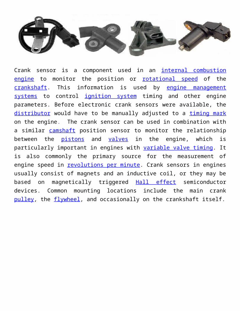
Crank sensor is a component used in an internal combustionengine to monitor the position or rotational speed of thecrankshaft. This information is used by engine managementsystems to control ignition system timing and other engineparameters. Before electronic crank sensors were available, thedistributor would have to be manually adjusted to a timing markon the engine. The crank sensor can be used in combination witha similar camshaft position sensor to monitor the relationshipbetween the pistons and valves in the engine, which isparticularly important in engines with variable valve timing. Itis also commonly the primary source for the measurement ofengine speed in revolutions per minute. Crank sensors in enginesusually consist of magnets and an inductive coil, or they may bebased on magnetically triggered Hall effect semiconductordevices. Common mounting locations include the main crankpulley, the flywheel, and occasionally on the crankshaft itself.

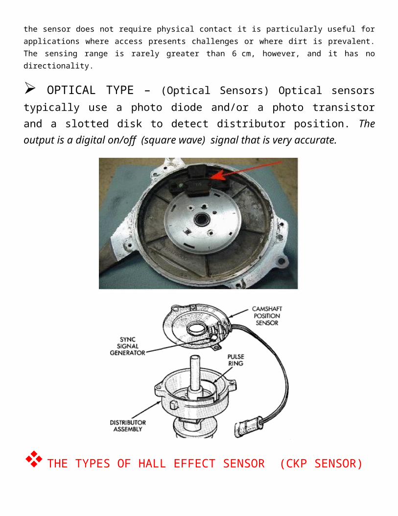
The CMP sensor provides the camshaft position information,called the CMP signal, which is used by the ECM for fuelsynchronization. On 2 wire Sensor engines, the distributorstator or Camshaft Position (CMP) sensor is a single Hall effectmagnetic switch. This is activated by a single vane, and isdriven by the camshaft. On Three Wire Sensor engines, theCamshaft Position (CMP) sensor is a variable reluctance sensor,which is triggered by the high-point mark on one of the camshaftsprockets. The Distributor engine does not use a separate CMPsensor. It utilizes a conventional distributor, equipped with aHall effect device, for this function. Engine speed is animportant input to the Engine Management System (EMS).Crankshaft speed and position are the basis for manycalculations made by the computer. Crankshaft position valuesare transmitted to the computer by pickup coils also known asPermanent Magnet (P/M) generators, Hall Effect sensors oroptical sensors. The Crankshaft Position Sensor (CKP) also knownas an engine speed sensor is typically located in closeproximity to the crankshaft.

Crankshaft position sensors are used primarily as the sparktiming input sensor. In other words, the position of the pistonin the cylinder is determined by the crankshaft position sensor.The crankshaft position sensor is used as an input for tractioncontrol. The engine speed (RPM) is one of the major inputs tothe traction control system. If the engine speed is high, theECM may retard ignition timing or shut off injectors to reduceengine torque to help restore traction of the drive wheels. Inaddition, the EMS uses the CKP sensor in conjunction with thecamshaft position sensor to calculate and perform misfirediagnostics.
A No Start / Intermittent Start condition – Can be caused by a faultycrankshaft position sensor due to loose connections, bad grounds, highresistance in the circuit, or opens in the circuit.
Engine Misfire Diagnostic Trouble Codes
TYPES OF CKP SENSOR – HALL EFFECT TYPE -

A proximity sensor is a sensor able to detect the presence of nearbyobjects without any physical contact. A proximity sensor often emits anelectromagnetic or electrostatic field, or a beam of electromagneticradiation (infrared, for instance), and looks for changes in the field orreturn signal. The object being sensed is often referred to as theproximity sensor's target. Different proximity sensor targets demanddifferent sensors. Solenoid-the component used to convert electric currentin to magnetic fields. Since the hall sensor converts magnetic fields into a voltage potential, the combination of the solenoid and hall sensorsimplements a current to voltage converter. The first problem to tackle ishow to convert current to magnetic fields efficiently. The second problemis how to couple the generated magnetic fields in to the hall sensor withlow loss. Although commonly called a gear tooth sensor, it is a solid-statespeed sensor that can detect the motion of various ferrous objects withsome type of discontinuous surface.
Functions – THE SIGNAL PROVIDED BY THE CKP SENSOR ENABLE THE ECM TO DETERMINES THEENGINE SPEED, CRANKSHAFT POSITION, MISFIRE DETECTION.
THE POSITION OF #1 (FIRST) CYLINDER AT TDC IS USED AS AREFERENCE FOR THE OTHERS IN THE FIRING ORDER.
IT DETECTS WHICH CYLINDER IS FIRING FOR SPARK & AS AREFERENCE TO TIME THE SEQUENTIAL FUEL INJECTOR.
Installation - Installed on the fly wheel for getting the desired signals for the engine management & waveforms.

The CKP sensor is being installed on the fly wheel which is fixed with clutch plate.
Technical Specifications
Supply voltage : 4 V to 5 V
Temperature range : - 40°C to + 150°C
Air gap range : 6 mm to 10 mm
INDUCTIVE TYPE - An inductive sensor is anelectronic proximity sensor, which detects metallic objects withouttouching them. The sensor consists of an induction loop. Electric currentgenerates a magnetic field, which collapses generating a current that fallsa asymptotically toward zero from its initial level when the inputelectricity ceases.
The inductance of the loop changes according to the material inside it andsince metals are much more effective inductors than other materials thepresence of metal increases the current flowing through the loop. Thischange can be detected by sensing circuitry, which can signal to some otherdevice whenever metal is detected. Common applications of inductive sensors includemetal detectors, traffic lights, car washes, and a host of automated industrial processes. Because
the sensor does not require physical contact it is particularly useful forapplications where access presents challenges or where dirt is prevalent.The sensing range is rarely greater than 6 cm, however, and it has nodirectionality.
OPTICAL TYPE – (Optical Sensors) Optical sensorstypically use a photo diode and/or a photo transistorand a slotted disk to detect distributor position. Theoutput is a digital on/off (square wave) signal that is very accurate.
THE TYPES OF HALL EFFECT SENSOR (CKP SENSOR)

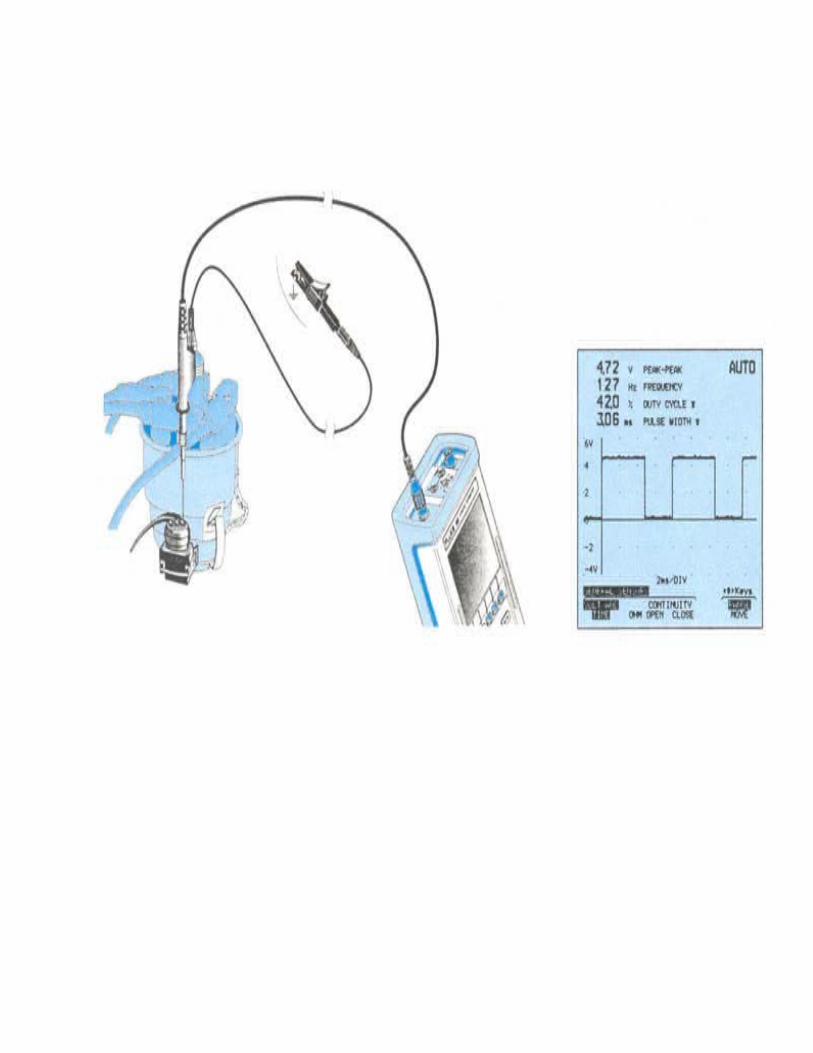
Three Wire Sensor - Hall effect crankshaft positionsensors typically have 3 terminals one for current feed, onefor ground & one for the output signal. The sensor must have voltageand ground to produce a signal, so check these terminals first withan analog voltmeter. Sensor output can be checked by disconnectingthe coil and cranking the engine to see if the sensor produces avoltage signal. The voltmeter needle should jump each time a shutterblade passes through the Hall Effect switch. If observed on anoscilloscope, a square wave form that changes in frequency, will appear on theoscilloscope screen.
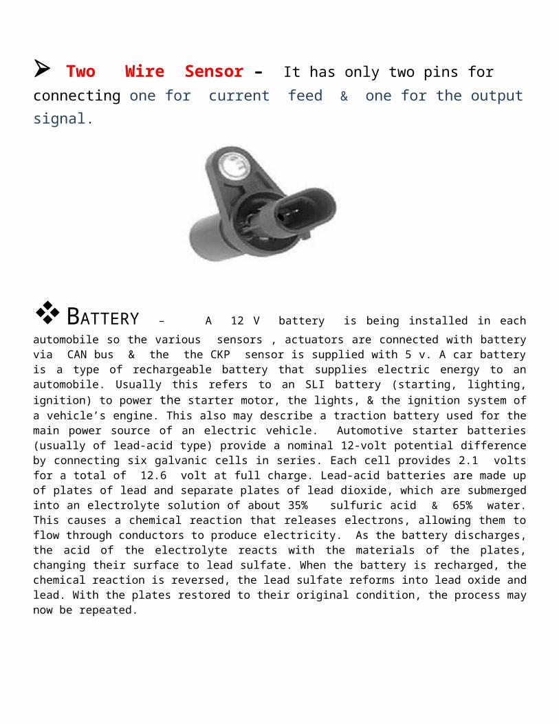
Two Wire Sensor – It has only two pins for connecting one for current feed & one for the outputsignal.
BATTERY – A 12 V battery is being installed in eachautomobile so the various sensors , actuators are connected with batteryvia CAN bus & the the CKP sensor is supplied with 5 v. A car batteryis a type of rechargeable battery that supplies electric energy to anautomobile. Usually this refers to an SLI battery (starting, lighting,ignition) to power the starter motor, the lights, & the ignition system ofa vehicle’s engine. This also may describe a traction battery used for themain power source of an electric vehicle. Automotive starter batteries(usually of lead-acid type) provide a nominal 12-volt potential differenceby connecting six galvanic cells in series. Each cell provides 2.1 voltsfor a total of 12.6 volt at full charge. Lead-acid batteries are made upof plates of lead and separate plates of lead dioxide, which are submergedinto an electrolyte solution of about 35% sulfuric acid & 65% water.This causes a chemical reaction that releases electrons, allowing them toflow through conductors to produce electricity. As the battery discharges,the acid of the electrolyte reacts with the materials of the plates,changing their surface to lead sulfate. When the battery is recharged, thechemical reaction is reversed, the lead sulfate reforms into lead oxide andlead. With the plates restored to their original condition, the process maynow be repeated.

TESTING OF CKP SENSORBy checking the voltage & resistance, for getting the desiredsignals, according to project it is mandatory for accuratesignals receiving.
Connect the leads of millimeter with CKP sensor &crosscheck the respective voltage & resistance.
Check the sensor connection & wiring. A faulty, such asa loose or corroded connection, can cause excessive resistancein the circuit. Check the sensor damage. If the sensor wiring isdamaged, it becomes the output of the sensor and will be weakerthan normal.

PRINCIPLE OF HALL EFFECT SENSOR
Introduction - The effect was discovered by “ Edwin H. Hall ” in1879, he discovered that a voltage is created if a magnetic field is exposedto an element. The voltage goes to zero if the magnetic field is shunted orblocked.
when a magnetic field is applied perpendicular to thedirection of a current flowing through a metal a voltage

is developed in the third perpendicular direction. Thechange in magnetic field induces a current, the changein intensity and direction of the current can measurethe velocity and direction object producing themagnetic field. “The basic physical principleunderlying the Hall effect is the Lorentz force. Whenan electron moves along a direction perpendicular to anapplied magnetic field , it experiences a force actingnormal to both directions and moves in response to thisforce and the force effected by the internal electricfield. For an n-type, bar-shaped semiconductor shown inthe carriers are predominately electrons of bulk densityn. We assume that a constant current I flows along thex-axis from left to right in the presence of a z-directed magnetic field. Electrons subject to theLorentz force initially drift away from the current linetoward the negative y-axis, resulting in an excesssurface electrical charge on the side of the sample.This charge results in the Hall voltage, a potentialdrop across the two sides of the sample.

The output voltage, called the Hall voltage, (VH) of thebasic Hall Element is directly proportional to thestrength of the magnetic field passing through thesemiconductor material (output ∝ H). This output voltagecan be quite small, only a few microvolts even whensubjected to strong magnetic fields so most commerciallyavailable Hall effect devices are manufactured withbuilt-in DC amplifiers, logic switching circuits andvoltage regulators to improve the sensors sensitivity,hysteresis and output voltage. This also allows the Halleffect sensor to operate over a wider range of powersupplies and magnetic field conditions.
Hall effect position sensors may be powered by either directcurrent (DC) or alternating current (AC) power, depending uponthe requirements of the system. The operating temperature rangeover which the device must operate is another importantparameter to consider when selecting Hall effect positionsensors. Hall Effect Sensors are available with either linear ordigital outputs. The output signal for linear (analogue) sensorsis taken directly from the output of the operational amplifierwith the output voltage being directly proportional to the

magnetic field passing through the Hall sensor. This output Hallvoltage is given as:
VH is the Hall Voltage in volts RH is the Hall Effect co-efficient
I is the current flow through the sensor in amps
t is the thickness of the sensor in mm (B is the Magnetic Flux density in Teslas)
There are two basic types of digital Hall effect sensor, Bipolarand Unipolar. Bipolar sensors require a positive magneticfield (south pole) to operate them and a negative field (northpole) to release them while unipolar sensors require only asingle magnetic south pole to both operate and release them asthey move in and out of the magnetic field. Most Hall effectdevices can not directly switch large loads as their outputdrive capabilities are very small around 10 to 20mA. For largecurrent loads an open-collector (current sinking) NPN Transistoris added to the output. This transistor operates in itssaturated region as a NPN sink switch which shorts the output

terminal to ground whenever the applied flux density is higherthan that of the "ON" preset point. This output transistor canbe either an open emitter, open collector or both providing apush-pull output configuration that can sink enough current todirectly drive many loads, including relays, motors, LEDs, andlamps. Hall effect sensors are coil of wires thatconvert magnetic fields into electrical voltages. Thesesensors can be used to detect the proximity of a magnetor a ferromagnetic object. A magnetic sensor uses apermanent magnet surrounded by a coil of wire. The notches of thecrankshaft (or camshaft) create a variable magnetic field strengtharound the coil. When a metallic section is close to the sensor, themagnetic field is stronger because metal is a better conductor ofmagnetic lines of force than air.

The sensor is also used in anti-lock brake systems in automobiles tosense the speed, position and/or direction of a rotating gear.Sensor output is a digital signal that is representativeof the profile of the object passing in front of thesensor.As the magnetic field between the sensor and a metalball changes the sensor can measure it’s proximity anddirection by measuring the direction and intensity ofthe current induced. The change in magnetic fieldinduces a current, the change in intensity and directionof the current can measure the velocity and directionobject producing the magnetic field. This sensormeasures the thickness of nonferrous materials with 1%accuracy by sandwiching the material being measuredbetween a magnetic probe on one side and a small targetsteel ball on the other side. It measures up to 10 mm.The Hall effect sensor is used to measure the magnetic

field, as a dc measurement, ac Hall effect measurementscan be made more precisely because they eliminate biasand are done with less noise”. A magnetic-resistive sensoris similar to a magnetic sensor but instead of producing an analogvoltage signal, the electronics inside the sensor itself generate adigital on/off signal or an output. The Hall-effect sensorfunctionality is based upon the Hall-effect. A sensor can sense the presence and in most cases theorientation of a magnetic field. A sensor can also be magnetically biased and sourcedwith a constant regulated current. With a magnetic bias, introduction or removal offerrous material in the magnetic field results in a measurablechange in the sensor voltage.
If a conductor carrying a current is immersed in amagnetic field, the charge carriers in the conductor mayexperience an additional force due to this field. Thecharge carriers are deflected to the side of theconductor as a result of this force, creating apotential difference across the conductor at rightangles to the current flow. This process is known as theHall Effect. To understand how the Hall effect works,consider the situation shown in the diagram below. Inthis situation, the electrons are forced downward by theaction of the magnetic field. This causes the top of theconductor to become positive with respect to the bottom.This causes a downward directed electric field todevelop in the conductor. This field produces an upwardforce on the electrons. Equilibrium is reached when theelectric force is equal to the magnetic force. Thiscondition is 1 satisfied when The induced electric fieldproduces a potential difference across the conductor at

a right angle to the direction of current flow. Itsmagnitude is where _ is the width of the conductor. Thisimplies that the Hall voltage is proportional to boththe electron drift velocity and the applied field. Notealso that in this instance that the Hall-inducedpotential decreases from top to bottom. Suppose insteadthat the charges carrying the current had been positive.In this case, the charges average drift velocity wouldbe in the same direction as the current; the magneticforce on them would again force them in the downwarddirection. In this case, the Hall potential thenincreases from top to bottom. The sign of the Hallvoltage can therefore be used to determine the sign ofthe charge carriers in a conductor.
They use the Hall effect, a voltage caused by current-flow in the presence of a magnetic field. Hall effectposition sensors function via an electrical potential(the Hall voltage) that is developed between the twoedges of a current-carrying conductor whose faces areperpendicular to an applied current flow. The presenceof a magnetic field is also required, as the Hallelement is the most basic magnetic field sensor. Halleffect position sensors require signal conditioning tomake the output usable for most applications. Typically,the signal-conditioning electronics include amplifierstage and temperature compensation. The measurement ofproximity, position, and the displacement of objects isessential in many different applications. Examplesinclude valve position, level detection, processcontrol, machine control, and security.
Performance specifications to consider when searchingfor Hall effect position sensors include operating

distance range, repeatability, selectable ranges, andminimum target distance. The operating distance range isthe absolute maximum range over which Hall effectposition sensors can provide sensible readings. Deviceswith various selectable ranges allow the sensor to befield-adjustable. Depending upon the technology used,these position sensors may require a minimum targetsize.
Hall effect position sensors differ in terms of bodystyle. Choices include barrel, limit switch, rectangular or block,slot, and ring. Barrel-style devices are cylindrical and,typically, threaded. Hall effect position sensors thatuse the limit-switch style are similar in appearance toa contact limit switch. These sensors are separated fromthe switching mechanism. Rectangular or block devicesare one-piece rectangular or block-shaped sensors. is aone piece rectangular or block shaped sensor. Slot-styleHall effect position sensors are designed to allow theobject being sensed to pass through a sensing slot.Ring-shaped devices are shaped like donuts. The objectpasses through the ring’s center. Hall Effect MagneticSensor.

About Magnetic Speed Sensors - Magnetic speed sensors use amagnet as the sensing element or sensed target in order tocapture rotational or linear speed. Typically, they are used asgear-tooth speed sensors or incorporated into stroboscopes ortachometers. Technology choices magnetic speed sensors includemagneto resistive, inductive, variable reluctance, and HallEffect. With magneto resistive sensors, the resistance of thesensing element is a function of the direction and magnitude(proximity) of an applied magnetic field. With inductivesensors, an oscillator circuit generates a radio frequency (RF)electromagnetic field that radiates from a ferrite core and coilassembly. The field is directed at the sensor face. When a metaltarget enters the field, eddy currents are induced into thesurfaces of the target. This causes a reduction in the amplitudeof the oscillator circuit (change in inductance). Most variablereluctance magnetic speed sensors are self-generating. In otherwords, they do not require an external power source. When amagnetic surface is passed in close proximity to the sensor, asmall voltage is induced. With Hall Effect magnetic speedsensors, a current is passed through a semiconductor material.

When a magnetic field is applied perpendicularly to the surfaceof the semiconductor, a voltage is developed. This Hall voltageis proportional to the applied field intensity, driving themagnetic speed sensor. Magnetic speed sensors carry displayoptions and control options. Display options include analogmeters, digital readouts, and video displays. Control optionsinclude analog front panels, digital front panels, or computercontrols. Body-style choices for magnetic speed sensors includebarrel, limit switch, rectangular or block, slot and ring. Otherfeatures for magnetic speed sensors include shielding, anintrinsically safe (IS) rating, short circuit protection, weldfield immunity, the sensing of non-magnetic targets, and thesensing of non-ferrous targets.
All passenger vehicles manufactured in 1980 and later have somesort of computerized engine management system. Computerizedengine management systems depend on a series of sensors thatprovide the information used to operate the engine at optimalefficiency. Current vehicle engine management systems primarilyuse Distributor less Ignition Systems, which eliminate many mechanicalcomponents and increase reliability and fuel efficiency. Itprovides data that enables the computer to know which cylindershould be fired at the crankshaft's present position. Thissensor is essential to ensuring that the engine cylinders arealways fired in the correct order. The Crankshaft Position Sensor isalways located somewhere on the engine in close proximity to thecrankshaft, usually near the harmonic balancer or in the engine blockaligned with a toothed wheel connected to the crankshaft. The CKPprovides the data that is used to compute the engine'srevolutions per minute (RPM), which is essential for propertransmission gear selection in relationship to vehicle speed andload. Hall effect gear tooth sensors are engineered with aninternal magnet to switch in the presence of ferrous targetssuch as gear teeth and blade tips and serve in applicationscalling for zero speed sensors. The Hall Effect gear toothsensor can detect fluctuations in the magnetic field and canalso be configured to detect the either the presence or absence

of a Ferro-magnetic target (i.e. a gear tooth). The Hall Effectgear sensor has the ability to sense a ferrous target while applying zerodrag on the target wheel with a sensitivity that detects gear teeth as smallas 0.10" wide and 0.10" deep. Air gaps of up to 1/8 inch arepossible, depending on mass of target (size of gear). HallEffect gear tooth sensors are used in industrial applications todetermine shaft or gear speed or direction by detecting fluctuations in themagnetic field. The Hall Effect technology fulfills a wide arrayof applications due to a Hall Effect sensor's ability to detectzero speed and the quadrature sensor's ability to detectdirection change. The Hall Effect gear tooth sensor's digitaloutput is easily read by computers, motion control devices,position monitors and digital to analog converters.

OSCILLOSCOPE –
The use of an Oscilloscope is a necessity for pinpointing vehicle faults. The scan tool (Scope) is one ofthe most valuable diagnostic tools available to themodern workshop today. It is commonly used to check:1. Supply voltage2. Voltage Drops (in power and earth circuits).3. AC Waveforms4. DC Waveforms (Square waves etc.)5. Pulse Signals.

Oscilloscope are used to measure voltage over a periodof time. An event that happens over a period of time iscalled frequency and in measured in Hertz per second.This signal should be test when the engine fail to startdue to lack ignition. The crankshaft sensor produces anAC voltage that is low while cranking and increasesafter the engine starts. AC voltage output is critical,low output can prevent an engine from starting, even ifthe signal pattern look good.

Here normal due to missing tooth on reluctor or flywheel. The missing
tooth is used by the ECM to determine crankshaft position.

See the Voltage at start-up & Voltage at higher cranking RPM.

Note the Engine Running & Note the higher voltageabove.
Most of Camshaft and Crankshaft Position Sensors are Hall-Effector Electronic Magnetic Inductive Sensors which are mounted closeto a toothed gear as the timing rotor. As the engine rotates,the sensor will signal to the ECU depending upon the positionof the timing rotor, the output signal from these units can bein either analogue or digital format (sine wave or square wave), a highquality CP / CKP sensors will enhance the engine efficiency, performance and on-boarddiagnos.


Ignition control during start-up Engine speed fluctuates duringstart of the engine, so the ECM cannot control the ignition timing.During that period, the ignition timing is fixed at 10° BTDC by usingthe 10° signal from the crankshaft position sensor. The CKPsensor is located in the transmission bell housingadjacent to the edge of the flex plate flywheel. Thesensor reacts to a toothed reluctor ring incorporatedinto the flex plate to ascertain engine speed andposition information. The sensor is located on a splitspacer and is secured in position by two tube spacersand nuts. The split spacer is 18 mm thick on vehiclesfitted with automatic transmission. The thickness of thesplit spacer determines how far the sensor protrudesthrough the cylinder block and, therefore, sets theposition of the sensor in relation to the reluctor ring.The sensor and the spacer are covered by a protectiveheat shield. The sensor has three wires attached to it;

two signal wires and a screen. The sensor earth screenis connected to chassis earth through the ECM.

The hall effect sensor can be implemented on any componentirrespective of tooth it may have,as shown in figure above.
Why use the Hall effect ? - The reasons for using aparticular technology or sensor vary according to theapplication. Cost, performance and availability are alwaysconsiderations. The features and benefits of a given technologyare factors that should be weighed along with the specificrequirements of the application in making this decision. Generalfeatures of Hall Effect based sensing devices are:• True solid state• High speed operation - over 100 kHz possible , Highlyrepeatable operation.• Operates with stationary input (zero speed)• No moving parts• Logic compatible input and output• Broad temperature range (- 40 to +150 C)
DIAGNOSIS of CKP sensor - FAULTY CKP sensor causes car not to start – on most models, the crankshaft position sensor is there to tell the computer when the #1 piston is onits power stroke so that the injectors are pulsed right before the intake

opens so that the fuel stays moving and vaporized without pooling up. Means- This indicates that a problem was detected in the crankshaft position sensorcircuit. Since it says circuit, that means the problem could lie in any partof the circuit - the sensor itself, the wiring or ECM, symptoms can include:
Hard starting or no start Rough running / misfiring
Loss of engine power
On diagnosis the P0340 trouble code COULD mean the reasons :
a wire or connector in the circuit could be grounded/shorted/broken the camshaft position sensor may have failed
the PCM may have failed
there exists an open circuit
the crankshaft position sensor may have failed.
Possible solutions with the PO340 OBD – TWO trouble code , diagnosis can be tricky at times. Here are some things to try:
Visually inspect all the wiring and connectors in the circuit Check for continuity in the circuit wiring
Check the operation (voltage) of the camshaft position sensor
Replace the camshaft position sensor as required
Check the crankshaft position circuit as well
Replace circuit wiring and/or connectors as required
Diagnose/replace the PCM as required.
If your diagnosis reveals a faulty crank sensor, the only optionis to replace it. With Hall effect sensors, the sensor must be

properly aligned with the interrupter ring to generate a cleansignal. Any rubbing or interference could cause idle problemsas well as sensor damage. Magnetic crankshaft position sensorsmust be installed with the proper air gap, which is usuallywithin .050 in of the reluctor wheel on the crankshaft . On-board diagnostics are into existence from the early 1980’s. Butin the recent years they have become highly sophisticated. Thusthere are highly reliable protocols just used for on-boarddiagnostics.
FAILURE OF CKP SENSOR - In Electric Throttle System , the signal producedby the CKP sensor is critical to engine running. There is no back-up strategyfor this sensor and failure of the signal will result in the engine stallingand/or failing to start. If the sensor fails when the engine is running, then theengine will stall, a fault code will be stored and details captured of thebattery voltage, engine coolant temperature and intake air temperature at thetime of the failure. If the signal fails when the engine is cranking, then theengine will not start and no fault will be stored, as the ECM will not detectthat an attempt had been made to start the engine. In both cases the tachometerwill also cease to function immediately and the MIL lamp will be permanentlyilluminated. During the power-down procedure, which occurs when the ignition isswitched off, the ECM stores details of the position of the CKP and CMP sensors.This enables the ECM to operate the injectors in the correct sequence immediatelythe engine cranks, to produce a quick engine start, which serves to reduceemissions when the engine is cold. Connection between the sensor and theharness is via a link harness and a two-way connector. Both wires go directly tothe ECM. The sensor produces the signal which enables the ECM to determine theangle of the crankshaft, and the engine rpm. From this, the point of ignition,fuel injection, etc. is calculated. If the signal wires are reversed a 3 degreesadvance in timing will occur, as the electronics within the ECM uses the fallingedge of the signal waveform as its reference / timing point for each tooth. Thereluctor is pressed into the flywheel and has a "tooth" pattern based on 36 teethat 10° intervals and approximately 5° wide: one of the teeth is removed toprovide a hardware reference mark which is 30 degrees BTDC No.1 cylinder.Because of the crankshaft sensor's orientation, the target wheel uses windowsstamped into the face, rather than actual teeth. The sensor operates bygenerating an output voltage caused by the change in magnetic field that occursas the windows pass in front of the sensor. The output voltage varies with thespeed of the windows passing the sensor, the higher the engine speed, the higher the
output voltage. Note that the output is also dependent on the air gap between thesensor and the teeth (the larger the gap, the weaker the signal, the lower the outputvoltage). The ECM transmits the engine speed to other vehicle control modules onCAN.
There are three primary engine malfunction symptoms that may be indicatorsof CPK malfunction. If the vehicle engine is experiencing cylindermisfires, the CPK may not be providing the computer with accurateinformation on piston position. If the vehicle hesitates duringacceleration, the CPK may not be providing cylinder position data to thecomputer fast enough to fire the appropriate cylinder to accelerate thevehicle in response to driver input. The most serious indication of CPKmalfunction is intermittent start, and eventually no start. When the sensorfails, the computer will register a malfunction code and illuminate thecheck engine light on the instrument panel. There may be an indication ofsensor failure due to defective electrical connections such as highresistance, or an open condition in the circuit going to the sensor orreturning to the vehicle engine control module. There are a number ofinternal engine problems that can cause the same symptoms as a defectiveCPK will. The most common problems that can be misdiagnosed as a faulty CPKare mechanical problems in the valve and timing mechanism, a faulty sparkplug or a defective DIS module. Inaccurate interpretation of diagnosticcodes can cause the mechanic to waste many hours looking for a problem thatdoes not exist in the CPK. Internal engine mechanical malfunctions cancause cylinder misfires, hesitation and no-start conditions. Sincesignificant engine disassembly may be required on some vehicles to reachthe CPK, a mechanic would be well advised to insure that the symptoms beingobserved are really caused by this sensor.
LIMITATIONS - Magnetic cores in some current sensors may retain a residualmagnetic field.
Differential Hall-effect sensors may not be as useful forplastic or non-ferrous gear systems.

In principle, it can be difficult to measure slightvariations in Hall voltage with great precision. Therefore,greater precision in control circuitry in many applications.
Some types of conductive material used in a Hall-effectsensor can be sensitive to temperature change.
Air gap can affect magnetic flux values as seen at thesensor.
Sensor only devises.
Good only in close proximity.
Must have a reference point.
Magnetic field must be present.
Must be calibrated.
Advantages - Low Voltage Drop
Low Power Dissipation
Presence of light is not necessary.
Dirt, grease, and other contaminations are seen through
without trouble.
Switching is performed cleanly with no bounce.
No contact is needed with metal or magnetic field source to
be sensed.
Sensors are relatively small and are not greatly affected by
vibration.
DISADVANTAGES - Bulky / Space RequirementsLimited frequency range (Bandwidth, Response Time)

Output NoiseOutput Stability -Stress, Temperature and MechanicalLimited sensitivityProgrammabilityHigh Cost
Hall Effect Sensor installation in the model –
The HALL EFFECT device is an edge detector, the outputis not analog. If you have a rotating shaft on a motor:
1. If you use a gear with teeth in front of the sensor then thesensor can also be used as a positional encoder that tells you when the shaft has rotated by a certain number of degrees
• The number of degrees between sensor output transitions depends on gear geometry and number of teeth on the gear.
• Can also be used to measure the distance of travel for a wheel by counting the number of digital transitions for a uniform gear.
2. Motor rotation speed information can be detected by measuring the time between output edges by reading the square wave form signals on the oscilloscope screen.

3. Motor shaft or wheel speed/velocity measurement4. Motor shaft or wheel distance measurement via counting ofedges. Gear at right has 60 teeth, so 60 rising edgeoutput transitions means that the gear has rotated one fullrevolution
5. Can also use a “single tooth” ( may be a screw) and obtainone output pulse per revolution
6. Advanced users : direction of rotation sensing - Mustuse a gear with wide teeth and narrow valleys or vice versa ,requires precise timer circuit to detect duty cycle of outputsignal , Duty cycle is ratio of t1 & t2. Be certain that the branded face of the sensorfaces the object to be sensed. Decrease the gap between thesensor face and the object to be sensed as much as possible.
Make sure that a magnet will stick to the object to besensed.
Use deep valleys between any teeth that you are trying tosense on a gear (shoot for at least 5mm tall teeth).
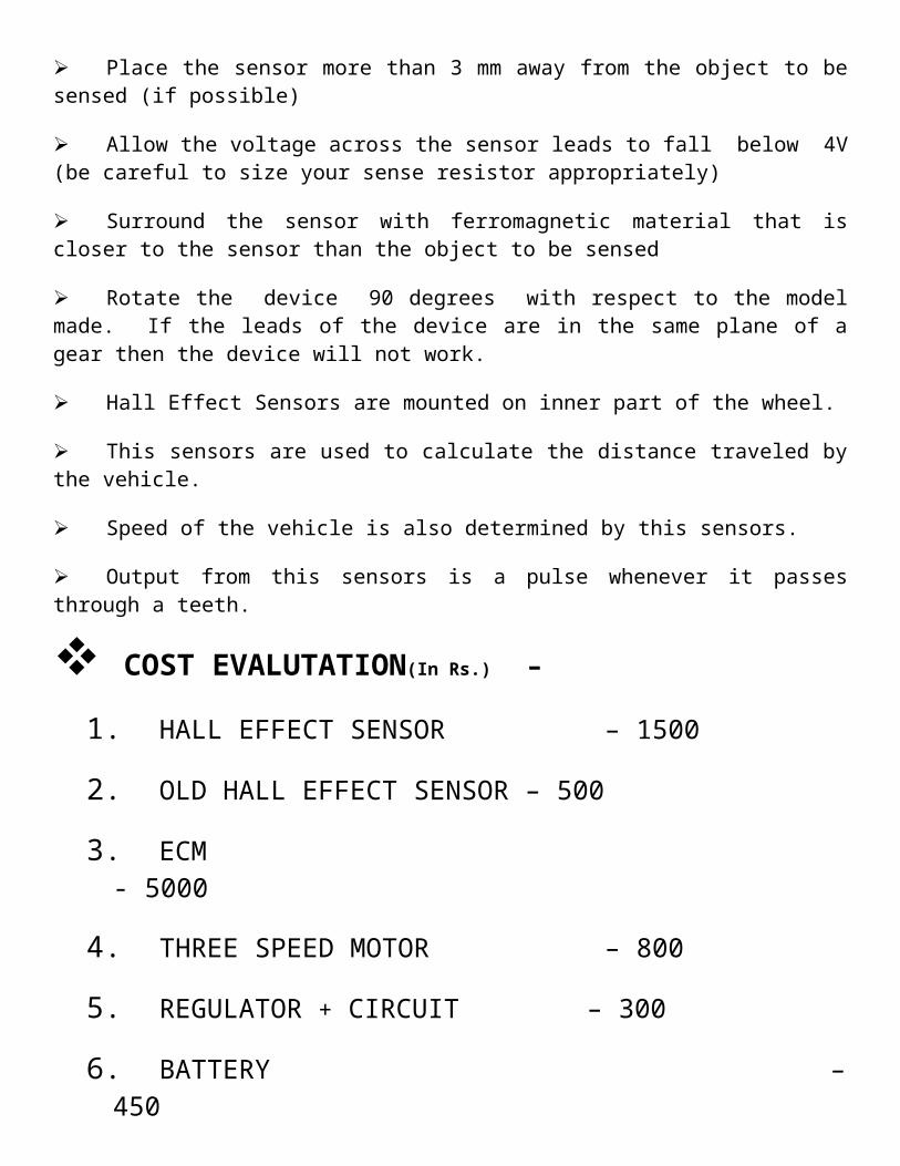
Place the sensor more than 3 mm away from the object to besensed (if possible)
Allow the voltage across the sensor leads to fall below 4V(be careful to size your sense resistor appropriately)
Surround the sensor with ferromagnetic material that iscloser to the sensor than the object to be sensed
Rotate the device 90 degrees with respect to the modelmade. If the leads of the device are in the same plane of agear then the device will not work.
Hall Effect Sensors are mounted on inner part of the wheel.
This sensors are used to calculate the distance traveled bythe vehicle.
Speed of the vehicle is also determined by this sensors.
Output from this sensors is a pulse whenever it passesthrough a teeth.
COST EVALUTATION(In Rs.) –
1. HALL EFFECT SENSOR – 1500
2. OLD HALL EFFECT SENSOR – 500
3. ECM- 5000
4. THREE SPEED MOTOR – 800
5. REGULATOR + CIRCUIT – 300
6. BATTERY –450

7. SHAFT- 500
8. PLY BASE –700
9. METAL STANDS - 1000
APPLICATIONS - In crankshaft/camshaft speed & position. In transmission & tachometer speed. For anti- skid traction control mechanisms inautomobiles. In typical gear based mechanisms.
I n industrial a reas – Gears are the mainmachine elements used for transmission of power, inchain link conveyor speed / distance, for detectinghigh or low motions. The failure of these elementscauses machine breakdown, resulting in the loss ofproductivity. In typical gear mechanisms this sensor canbe implemented with ease.

Therefore, it is necessary to analyze these elementsand detect the defects in advance before they makemachine shutdown so, our project deals with the analysis of theseelements using HALL EFFECT SENSOR.
BIBLIOGRAPHYBOSCH PARAMOBILE TRAINING CENTRE
IC ENGINE BOOKS
ADVANCED MECHATRONICS _TECHNICAL WEBSITES
AUTOMOBILES’ MAGAZINES
VARIOUS AUTOMOBILE WORKSHOPS.


