Measurement-Based Synthesis of Facial Microgeometry
10
EUROGRAPHICS 2013 / I. Navazo, P. Poulin (Guest Editors) Volume 32 (2013), Number 2 Measurement-Based Synthesis of Facial Microgeometry Paul Graham, Borom Tunwattanapong, Jay Busch, Xueming Yu, Andrew Jones, Paul Debevec, and Abhijeet Ghosh † USC Institute for Creative Technologies, Los Angeles, CA, USA (a) Rendering using 4K (b) Rendering using 4K (c) Rendering using synthesized (d) Comparison photograph geometry geometry and microscale BRDF microstructure Figure 1: (a) Rendering with scanned mesostructure (4K displacement map). (b) Rendering with scanned mesostructure (4K displacement map) and microstructure measured BRDF. (c) Rendering with synthesized microstructure (16K displacement map). (d) Photograph under flash illumination. See Fig. 3, Subject 2 for the skin patches used in microstructure synthesis. Abstract We present a technique for generating microstructure-level facial geometry by augmenting a mesostructure-level facial scan with detail synthesized from a set of exemplar skin patches scanned at much higher resolution. Ad- ditionally, we make point-source reflectance measurements of the skin patches to characterize the specular re- flectance lobes at this smaller scale and analyze facial reflectance variation at both the mesostructure and mi- crostructure scales. We digitize the exemplar patches with a polarization-based computational illumination tech- nique which considers specular reflection and single scattering. The recorded microstructure patches can be used to synthesize full-facial microstructure detail for either the same subject or to a different subject. We show that the technique allows for greater realism in facial renderings including more accurate reproduction of skin’s specular reflection effects. Categories and Subject Descriptors (according to ACM CCS): I.3.7 [COMPUTER GRAPHICS]: Three-Dimensional Graphics and Realism 1. Introduction The way our skin reflects light is influenced by age, genetics, health, emotion, sun exposure, substance use, and skin treat- ments. The importance of skin reflectance is underscored by the worldwide cosmetics industry which sells a myriad of † Currently at Imperial College London products to achieve specific skin appearance results. As vir- tual human characters become increasingly prevalent in lin- ear and interactive storytelling, the need for measuring, mod- eling, and rendering the subtleties of light reflection from skin also becomes increasingly important. While great strides have been made in simulating the scat- tering of light beneath skin [HK93, JMLH01, DJ05, DI11], somewhat less attention has been given to surface reflection. c 2013 The Author(s) Computer Graphics Forum c 2013 The Eurographics Association and Blackwell Publish- ing Ltd. Published by Blackwell Publishing, 9600 Garsington Road, Oxford OX4 2DQ, UK and 350 Main Street, Malden, MA 02148, USA.
-
Upload
independent -
Category
Documents
-
view
1 -
download
0
Transcript of Measurement-Based Synthesis of Facial Microgeometry

EUROGRAPHICS 2013 / I. Navazo, P. Poulin(Guest Editors)
Volume 32 (2013), Number 2
Measurement-Based Synthesis of Facial Microgeometry
Paul Graham, Borom Tunwattanapong, Jay Busch, Xueming Yu, Andrew Jones, Paul Debevec, and Abhijeet Ghosh †
USC Institute for Creative Technologies, Los Angeles, CA, USA
(a) Rendering using 4K (b) Rendering using 4K (c) Rendering using synthesized (d) Comparison photographgeometry geometry and microscale BRDF microstructure
Figure 1: (a) Rendering with scanned mesostructure (4K displacement map). (b) Rendering with scanned mesostructure (4Kdisplacement map) and microstructure measured BRDF. (c) Rendering with synthesized microstructure (16K displacementmap). (d) Photograph under flash illumination. See Fig. 3, Subject 2 for the skin patches used in microstructure synthesis.
Abstract
We present a technique for generating microstructure-level facial geometry by augmenting a mesostructure-levelfacial scan with detail synthesized from a set of exemplar skin patches scanned at much higher resolution. Ad-ditionally, we make point-source reflectance measurements of the skin patches to characterize the specular re-flectance lobes at this smaller scale and analyze facial reflectance variation at both the mesostructure and mi-crostructure scales. We digitize the exemplar patches with a polarization-based computational illumination tech-nique which considers specular reflection and single scattering. The recorded microstructure patches can be usedto synthesize full-facial microstructure detail for either the same subject or to a different subject. We show that thetechnique allows for greater realism in facial renderings including more accurate reproduction of skin’s specularreflection effects.
Categories and Subject Descriptors (according to ACM CCS): I.3.7 [COMPUTER GRAPHICS]: Three-DimensionalGraphics and Realism
1. Introduction
The way our skin reflects light is influenced by age, genetics,health, emotion, sun exposure, substance use, and skin treat-ments. The importance of skin reflectance is underscored bythe worldwide cosmetics industry which sells a myriad of
† Currently at Imperial College London
products to achieve specific skin appearance results. As vir-tual human characters become increasingly prevalent in lin-ear and interactive storytelling, the need for measuring, mod-eling, and rendering the subtleties of light reflection fromskin also becomes increasingly important.
While great strides have been made in simulating the scat-tering of light beneath skin [HK93, JMLH01, DJ05, DI11],somewhat less attention has been given to surface reflection.
c© 2013 The Author(s)Computer Graphics Forum c© 2013 The Eurographics Association and Blackwell Publish-ing Ltd. Published by Blackwell Publishing, 9600 Garsington Road, Oxford OX4 2DQ,UK and 350 Main Street, Malden, MA 02148, USA.

Graham et al. / Measurement-Based Synthesis of Facial Microgeometry
While the shine of our skin — the specular reflection fromthe epidermal cells of the stratum corneum — is a small frac-tion of the incident light, its lack of scattering provides aclear indication of skin’s surface shape and condition. Andunder concentrated light sources, the narrower specular lobeproduces highlights which can dominate appearance, espe-cially for smoother, oilier, or darker skin.
Current face scanning techniques [WMP∗06, MHP∗07,BBB∗10] as well as high-resolution scanning of facial casts(e.g. [XYZ], [ANCN10]) provide submillimeter precision,recording facial mesostructure at the level of pores, wrin-kles, and creases. Nonetheless, the effect of surface rough-ness continues to shape specular reflection at the level of mi-crostructure [TS67] — surface texture at the scale of mi-crons. The current absence of such microstructure may be areason why digital humans can still appear uncanny in close-ups, which are the shots most responsible for conveying thethought and emotion of a character.
In this work, we present a synthesis approach for increas-ing the resolution of mesostructure-level facial scans usingsurface microstructure digitized from skin samples about theface. We digitize the skin patches using macro photographyand polarized gradient illumination [MHP∗07] at approxi-mately 10 micron precision. Additionally, we make point-source reflectance measurements to characterize the spec-ular reflectance lobes at this smaller scale and analyze fa-cial reflectance variation at both the mesostructure and mi-crostructure scales. We then employ a constrained texturesynthesis algorithm based on Image Analogies [HJO∗01]to synthesize appropriate surface microstructure per-region,blending the regions to cover the whole entire face. Weshow that renderings made with microstructure-level geom-etry and reflectance models preserve the original scannedmesostructure and exhibit surface reflection which is signif-icantly more consistent with real photographs of the face.
2. Related Work
Our work builds on a variety of results in skin reflectancemodeling, surface detail acquisition, and texture synthesis.
2.1. Skin Reflectance Modeling
Physically-based models of light reflection from rough sur-faces are typically based on a microfacet distribution model[TS67, CT82]. BRDFs for rendering have been tabulatedfrom photographed foreheads under a sampling of light-ing conditions and viewing directions [MWL∗99]. Using amoving light source and camera to record a bidirectionaldatabase of skin samples, a texton histogram model has beenbuilt to detect skin abnormalities [CDMR05]. Ghosh et al.[GHP∗08] fit a microfacet BRDF model [APS00] to spec-ular reflectance data across various patches of human facesfrom high-resolution surface orientation measurements.
We acquire detailed surface shape and reflectance of ex-ample skin patches to increase the resolution of a larger-scale model. This approach echoes other work which extrap-olates detailed samples of reflectance over complete models,including sampling subsurface scattering parameters witha special probe [WMP∗06], and using a BRDF probe toadd detailed BRDFs to entire objects observed in relativelyfew lighting conditions [DWT∗10]. Our work also relatesto basis BRDF modeling [LKG∗03] and reflectance shar-ing [ZREB06].
2.2. Surface Detail Measurement
Key to our work is measuring surface detail from imagestaken with a fixed viewpoint and varying lighting. Clas-sic photometric stereo [Woo78] derives surface orientationsof Lambertian surfaces from three point-light directions.Bump maps produced from photometric stereo have beenused to increase the detail on rendered surfaces [RTG97].For semi-translucent materials such as skin, subsurface scat-tering blurs the surface detail recoverable from traditionalphotometric stereo significantly [RR08]. Specular surfacereflection analysis has been used to obtain more precisesurface orientation measurements of translucent materials[DHT∗00, RR08, WMP∗06, CGS06]. Ma et al. [MHP∗07]uses polarization difference imaging to isolate the specularreflection under gradient lighting conditions, allowing spec-ular surface detail to be recorded in a small number of im-ages. The GelSight system [JCRA11] pushes silver-coatedgel against a sample and uses photometric stereo to recordsurface microgeometry at the level of a few microns. Whilethis setup achieves the resolution required for our technique,it does not enable reflectance measurements. In our work, wemeasure microgeometry using a polarized gradient illumi-nation technique [GFT∗11] since it requires no contact withthe sample and permits the material’s actual reflectance to beobserved during measurement for BRDF fitting.
2.3. Texture Synthesis
Wei et al. [WLKT09] compiled a recent review of example-based texture synthesis. To summarize a few results, 2D tex-ture synthesis algorithms [HB95, EL99] have been extendedto arbitrary manifold surfaces [WL01, YHBZ01, LH06]and can also synthesize displacement maps [YHBZ01],measured reflectance properties [TZL∗02] and skin color[TOS∗03]. Some techniques [EF01, HJO∗01] permit texturetransfer, transforming a complete image so that it has tex-tural detail of a given sample. Super-resolution techniquesadd detail to a low-resolution image based on examples[HJO∗01, FJP02, LH05]. Especially relevant to our workare constrained texture synthesis techniques [WM04, RB07]which add plausible detail to a low-resolution image withoutchanging its low frequency content. In our work, we adaptthe Image Analogies [HJO∗01] framework to perform con-
c© 2013 The Author(s)c© 2013 The Eurographics Association and Blackwell Publishing Ltd.

Graham et al. / Measurement-Based Synthesis of Facial Microgeometry
strained texture synthesis of skin microstructure onto facialscans while preserving scanned facial mesostructure.
Some techniques have been proposed to increase the de-tail present in facial images and models, although at signifi-cantly coarser resolution than we address in our work. Facehallucination [LSZ01] creates recognizable facial images byperforming constrained facial texture synthesis onto a para-metric face model. Image processing applies facial detailfrom one subject to another, allowing image-based aging ef-fects [LZS04]. Most closely related to our work is Golovin-skiy et al. [GMP∗06], which synthesizes skin mesostruc-ture (but not microstructure) from higher-quality facial scansonto otherwise smooth facial shapes. In addition to work-ing at a very different scale than our work (we assume thatwrinkles, creases, and larger pores are already apparent inthe source scan), the synthesis method is based on match-ing per-region frequency statistics rather than patch-basedtexture synthesis, and is not designed to match to existingmesostructure.
Our process of sampling skin microgeometry follows re-cent work which models or measures materials at the microscale in order to better predict their appearance at normallyobservable larger scales. Observations of a cross-section ofwood from an electron micrograph have motivated reflec-tion models which better predicted anisotropic reflection ef-fects [MWAM05]. Direct use of Micro CT imaging of fabricsamples have been used to model the volumetric scatteringof complete pieces of cloth [ZJMB11].
3. Recording Skin Microstructure
3.1. Acquisition
We record the microstructure of skin patches using one oftwo systems to create polarized gradient illumination. Forboth, we stabilize the skin patch relative to the camera byhaving the subject place their skin against a 24mm × 16mmaperture in a thin metal plate. This plate is firmly secured30cm in front of the sensor of a Canon 1D Mark III cam-era with a Canon 100mm macro lens stopped down to f/16,just enough depth of field to image the sample when prop-erly focused. The lens achieves 1:1 macro magnification, soeach pixel of the 28mm × 19mm sensor images about sevensquare microns (7µm2) of skin.
Our small capture system (Fig. 2(a)) is a 12-light dome(half of a deltoidal icositetrahedron) similar to those usedfor acquiring Polynomial Texture Maps [MGW01], with theaddition that each light can produce either of two linear po-larization conditions. We modified the polarization orienta-tions of a multiview polarization pattern [GFT∗11] such thateach light is specifically optimized for a single viewpoint.The difference between images acquired under parallel andcross polarized states records the polarization-preserving re-flectance of the sample, attenuating subsurface reflectance.In approximately two seconds, we acquire polarized gradient
illumination conditions to record surface normals. We com-pensate for any subject motion using joint photometric align-ment [WGP∗10]. For BRDF fitting, we additionally capturea single-light image in both polarized lighting conditions.
(a) (b)
Figure 2: Acquisition setups for skin microgeometry (a) 12-light hemispherical dome (at end of camera lens) capturinga cheek patch. (b) LED sphere capturing the tip of the nose,with the camera inside the sphere.
For especially smooth or oily skin patches, the 12 light po-sitions can produce separated specular highlights, which canbias surface normal measurement. To address this, we placedthe macro photography camera and metal aperture frameinside the same 2.5m-diameter polarized LED sphere usedfor facial scanning (Fig. 2(b)). While the camera occludessome light directions from reaching the sample, the hemi-spherical coverage of the incident light directions is denserand more complete than the 12-light setup, allowing the gra-dient illumination to yield well-conditioned surface normalmeasurements for all patches we tested. Since a single LEDlight source was not bright enough to illuminate the samplefor specular BRDF observation, a pair of horizontally andvertically polarized camera flashes (Canon Speedlite 580EXII) were fired to record the point-light condition from closeto the normal direction. The camera mounts in both setupswere reinforced to remove mechanically vibrations and flex-ing which would blur the captured imagery.
3.2. Surface Normal and BRDF Estimation
We compute a per-pixel surface orientation map from the po-larized gradients, as well as specular and subsurface albedomaps. Figure 3 shows the geometry of five skin patches dig-itized for two subjects, including regions of the forehead,temple, cheek, nose, and chin. Due to the flat nature of theskin patches, we only visualize the x and y components ofthe surface normals with yellow and cyan colors respec-tively. Note that the skin microstructure is highly differen-tiated across both individuals and facial regions.
Using the polarization difference point-lit image, we alsotabulate a specular lobe shape and single scattering modelparameters [GHP∗08]. With light pressure, the skin pro-trudes slightly through the metal aperture frame, providing aslightly convex surface which exhibits a useful range of sur-face normals for BRDF estimation. Using a specular BRDF
c© 2013 The Author(s)c© 2013 The Eurographics Association and Blackwell Publishing Ltd.

Graham et al. / Measurement-Based Synthesis of Facial Microgeometry
Subject 1
Subject 2
(a) forehead (b) temple (c) cheek (d) nose (e) chin
Figure 3: Measured skin patches from different facial re-gions of two different subjects. (Top two rows) Caucasianmale subject. (Bottom two rows) Asian female subject. (Rowsone and three) Surface normals. (Rows two and four) Dis-placements.
model [TS67], we found that two lobes of a Beckmann distri-bution [CT82] fit the data well. In order to better fit the spec-ular and single scattering model parameters, we factor theobserved polarization-preserving reflection under constantfull-on illumination into two separate specular and singlescattering albedo maps. Here, we estimate the single scatter-ing albedo as the difference between observed polarizationpreserving reflectance and average hemispherical specularreflectance of a dielectric surface with index of refractionη = 1.33, which is about 0.063.
Figures 4 and 5 show skin patch samples and valida-tion renderings made using the estimated subsurface albedo,specular albedo, specular normals, and specular BRDF,showing close visual matches of the model to the pho-tographs. At this scale, where much of the surface rough-ness variation is evident geometrically, we found that a sin-gle two-lobe specular BRDF estimate to be sufficient overeach sample, and that variation in the reflectance parameterfits were quite modest (see Table 1) compared to the differ-ences observed at the mesostructure scale (see Table 2).
4. Facial Microstructure Synthesis
From the skin microstructure samples, we employ con-strained texture synthesis to generate skin microstructure foran entire face. To do this, we use the surface mesostructureevident in a full facial scan to guide the texture synthesis pro-cess for each facial region, and then merge the synthesizedfacial regions into a full map of the microstructure.
We begin with full facial scans recorded using a multiview
(a) Photograph (b) Rendering
(c) Photograph (d) Rendering
Figure 4: (a) Parallel-polarized photograph of a foreheadskin patch of a male subject, lit slightly from above. (b) Val-idation rendering of the patch under similar lighting usingthe surface normals, specular albedo, diffuse albedo, andsingle scattering maps estimated from the 12-light dome,showing visual similarity. (c,d) Similar images from a dif-ferent light source direction.
(a) Photograph (b) Rendering
(c) Photograph (d) Rendering
Figure 5: (a) Parallel-polarized photograph of a cheekpatch for a female subject, lit slightly from above. (b) Val-idation rendering of the cheek patch lit from a similar direc-tion using reflectance maps estimated from the LED sphere,showing a close match. (c,d) Corresponding images fromsubject’s nose patch, also showing a close match.
polarized gradient illumination technique [GFT∗11], whichproduces an ear-to-ear polygon mesh of approximately fivemillion polygons, 4K (4096× 4096 pixel) diffuse and specu-lar albedo maps, and a world-space normal map. We believeour technique could also work with other high-resolution fa-cial capture techniques [BBB∗10, XYZ].
We create the texture coordinate space for the facial scanusing the commercial product Unfold3D in a way which bestpreserves surface area and orientation with respect to the
c© 2013 The Author(s)c© 2013 The Eurographics Association and Blackwell Publishing Ltd.
Graham et al. / Measurement-Based Synthesis of Facial Microgeometry
Figure 6: A world-space normal map from the Subject 1 fa-cial scan, segmented into regions for texture synthesis.
original scan. This allows us to assume that the relative scaleand orientation of the patches is constant with respect to thetexture space; if this were not the case, then an anisometrictexture synthesis technique [LH06] could be employed.
We transform the normal map to tangent space, and usemultiresolution normal integration to construct the 4K dis-placement map which best agrees with the normal map.An artist segments this map into forehead, temples, nose,cheeks, and chin regions (Fig. 6). Regions overlap enoughso they can be blended together using linear-interpolation.
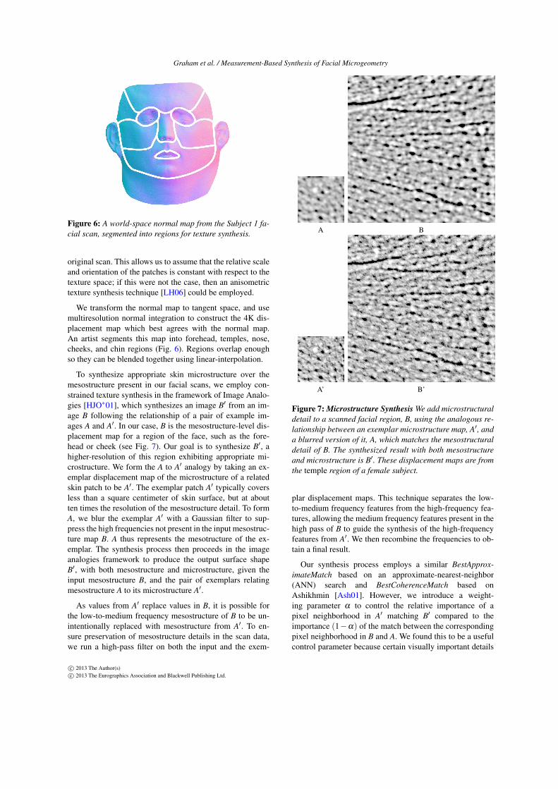
To synthesize appropriate skin microstructure over themesostructure present in our facial scans, we employ con-strained texture synthesis in the framework of Image Analo-gies [HJO∗01], which synthesizes an image B′ from an im-age B following the relationship of a pair of example im-ages A and A′. In our case, B is the mesostructure-level dis-placement map for a region of the face, such as the fore-head or cheek (see Fig. 7). Our goal is to synthesize B′, ahigher-resolution of this region exhibiting appropriate mi-crostructure. We form the A to A′ analogy by taking an ex-emplar displacement map of the microstructure of a relatedskin patch to be A′. The exemplar patch A′ typically coversless than a square centimeter of skin surface, but at aboutten times the resolution of the mesostructure detail. To formA, we blur the exemplar A′ with a Gaussian filter to sup-press the high frequencies not present in the input mesostruc-ture map B. A thus represents the mesotructure of the ex-emplar. The synthesis process then proceeds in the imageanalogies framework to produce the output surface shapeB′, with both mesostructure and microstructure, given theinput mesostructure B, and the pair of exemplars relatingmesostructure A to its microstructure A′.
As values from A′ replace values in B, it is possible forthe low-to-medium frequency mesostructure of B to be un-intentionally replaced with mesostructure from A′. To en-sure preservation of mesostructure details in the scan data,we run a high-pass filter on both the input and the exem-
A B
A’ B’
Figure 7: Microstructure Synthesis We add microstructuraldetail to a scanned facial region, B, using the analogous re-lationship between an exemplar microstructure map, A′, anda blurred version of it, A, which matches the mesostructuraldetail of B. The synthesized result with both mesostructureand microstructure is B′. These displacement maps are fromthe temple region of a female subject.
plar displacement maps. This technique separates the low-to-medium frequency features from the high-frequency fea-tures, allowing the medium frequency features present in thehigh pass of B to guide the synthesis of the high-frequencyfeatures from A′. We then recombine the frequencies to ob-tain a final result.
Our synthesis process employs a similar BestApprox-imateMatch based on an approximate-nearest-neighbor(ANN) search and BestCoherenceMatch based onAshikhmin [Ash01]. However, we introduce a weight-ing parameter α to control the relative importance of apixel neighborhood in A′ matching B′ compared to theimportance (1−α) of the match between the correspondingpixel neighborhood in B and A. We found this to be a usefulcontrol parameter because certain visually important details
c© 2013 The Author(s)c© 2013 The Eurographics Association and Blackwell Publishing Ltd.

Graham et al. / Measurement-Based Synthesis of Facial Microgeometry
that exist in A′ can be entirely absent in the lower frequencymesostructures maps A and B. We found that an α valuearound 0.5 produced good results.
We carry out the texture synthesis in a multiresolutionfashion, increasing the window size for the neighborhoodmatching from a 5×5 pixel window at the lowest level (4Kresolution) to a 13× 13 pixel window at the highest level(16K resolution) to match the increase in size of features ateach level of the synthesis. We also apply principle compo-nent analysis (PCA) in order to speed up the synthesis. Weuse PCA to reduce the dimensionality of the search space ton, where n× n is the original pixel window. PCA reducedthe synthesis time by a factor of three without any quali-tative decreases in the result. We employ equal weightingto BestApproximateMatch and BestCoherenceMatch by set-ting the coherence parameter κ = 1 in the synthesis process.Since the specular albedo map is highly correlated to the sur-face mesostructure and microstructure, we also synthesize a16K specular albedo map as a by-product of the microstruc-ture displacement synthesis process by borrowing the corre-sponding pixels from the specular albedo exemplar.
5. Results
5.1. Creating Renderings
Once we have synthesized microstructure-level displace-ment maps for a face, we can create renderings using thesubsurface albedo, specular albedo, and single scattering co-efficients using any standard rendering technique. To gen-erate the renderings in this section, we use a local specularreflection model with two lobes per skin region estimatedas described in Section 3. For efficiency, the subsurface re-flection is simulated using a hybrid normals rendering tech-nique [MHP∗07] from the gradient illumination data of thefull facial scan, though in practice a true scattering simula-tion would be preferable. Single scattering, estimated fromthe exemplars, is also rendered [GHP∗08]. We upscaled theoriginal scanned data to fill in the regions where we did notsynthesize microgeometry (lips, neck, eye brows, etc). Forthe upper eyelids, we synthesised microstructure using themeasured forehead microstructure exemplar.
5.2. Image Sizes and Resampling
In the rendering process, the subsurface albedo and subsur-face normal maps remain at the original 4K resolution ofthe facial scan, as does the polygon geometry. The synthe-sized 16K microstructure displacement map is converted toa normal map for rendering and used in conjunction withthe 16K synthesized specular albedo map. To avoid artifactsfrom normal map resampling or aliasing, full-face render-ings are created using an OpenGL GPU shader to a large16K (16384×16384 pixels) half float frame buffer, and thenresized to 4K using radiometrically linear pixel blending, re-quiring approximately 1GB of GPU memory.
Fig. 1 shows a high-resolution point-light rendering of afemale subject using a synthesized 16K microstructure dis-placement map (c) compared to using just the 4K mesostruc-ture displacement map from the original scan (a) and a 4krendering using the microscale measured BRDF (b) as wellas a reference photograph under flash illumiation (d). The16K rendering includes more high-frequency specular de-tail, and better exhibits skin’s characteristic effect of isolated"glints" far away from the center of the specular highlight. Asimilar result is shown in Fig. 8 where a point-light renderingof a male subject’s forehead using synthesized microstruc-ture is a better match to a validation photograph comparedto the rendering of the original scan with mesostructure de-tail.
Fig. 9 shows displacement maps (top row), normal maps(x and y components only, middle row), and point-lightrenderings (bottom row) of a male forehead region gener-ated with different synthesis processes. Fig. 9(a) shows aregion from an original mesostructure-only scan, with nosynthesis to add microstructure detail. The specular reflec-tion, rendered with corresponding mesoscale BRDF fit, isquite smooth as a result, and the skin reflection is not espe-cially realistic. Fig. 9(b) shows the result of our microstruc-ture synthesis process using an exemplar skin patch mea-surement from the same subject (the forehead of Subject 1in Fig. 3(a)). The specular reflection, rendered with a mi-croscale BRDF fit, is broken up and shows greater surfacedetail, while the mesostructure of the forehead crease is pre-served. Fig. 9(c) shows the result of using a forehead patchfrom a different male subject as the exemplar for adding mi-crostructure. Although the fine skin texture is different, thesynthesized geometry and rendering is still very plausible,suggesting cross-subject microstructure synthesis to be a vi-able option.
Fig. 9(d) tests the importance of the mesostructure con-straints during texture synthesis. This column was gener-ated by setting the α parameter to 1.0, ignoring mesostruc-ture matching constraints in the matching process, and thenblindly embossing the synthesized detail onto the mesostruc-ture of the original scan. Fig. 9(b), however, synthesizes de-tail in a way which tries to follow the mesostructure, so poresand creases in the scan will tend to draw upon similar ar-eas in the microstructure exemplar for their detail. As a re-sult, the constrained synthesis, column (Fig. 9(b)), producesa more plausible result which better reinforces the scannedmesostructure than the texture synthesis column (Fig. 9(d)).
Table 1 shows specular BRDF lobe fits for different skinpatches across two subjects measured using our microstruc-ture skin patch measurement setups. Table 2 presents com-parison Beckmann distribution fits for similar facial regionsobtained at the mesostructure scale from a face scan. Table 3shows the results of a cross-verification done by low-passfiltering the skin patches and measuring the BRDF fits ata "mesostructure scale." The parameter w is the weight of
c© 2013 The Author(s)c© 2013 The Eurographics Association and Blackwell Publishing Ltd.

Graham et al. / Measurement-Based Synthesis of Facial Microgeometry
(a) Rendering using original scan (b) Rendering using synthesized microstructure (c) Comparison photograph
Figure 8: Renderings of original facial scan with mesostructure detail (a), and with synthesized microgeometry (b) comparedto to a photograph under flash illumination (c). See Fig. 3, Subject 1 for the skin patches used in microstructure synthesis.
(a) Original (b) Same-subject (c) Cross-subject (d) UnconstrainedMesostructure Mesostructure Mesostructure Mesostructure
Figure 9: Microstructure synthesis with different exemplars and constraints. The top row shows displacement maps, the middlerow shows normal maps and the bottom row shows point-light renderings using the maps. (a) Original mesostructure. (b)With microstructure synthesized from the same subject. (c) With microstructure synthesized from a different subject. (d) Withoutconstraining the synthesis to match the underlying mesostructure.
the convex combination of the two lobes m1 and m2. Ascan be seen, the BRDF lobes estimates at the microstructurescale exhibit reduced specular roughness compared to themesostructure scale BRDF estimate as well as significantlyless variation across skin patches. This agrees with the the-ory that at sufficiently high resolution, the surface microge-ometry variation is responsible for the appearance of spec-ular roughness. Table 3 confirms that low-pass filtering the
microstructure also results in BRDF fits with wider rough-ness, similar to the mesostructure scale BRDF fits.
Fig. 10 shows comparison renderings of a small patchof forehead shown in Fig. 9, at different scales of model-ing. The original scanned data with mesostructure detail andmesoscale BRDF fit results in a broad specular reflectionthat misses the sharp "glints" (a). Rendering the scannedmesoscale surface detail with a microscale BRDF fit resultsin a qualitiative improvement in the result at this scale of vi-
c© 2013 The Author(s)c© 2013 The Eurographics Association and Blackwell Publishing Ltd.

Graham et al. / Measurement-Based Synthesis of Facial Microgeometry
Description Subject 1 Subject 2forehead m1=0.150, m2=0.050, w=0.88 m1=0.150, m2=0.050, w=0.60temple m1=0.150, m2=0.075, w=0.55 m1=0.175, m2=0.050, w=0.80cheek m1=0.150, m2=0.125, w=0.60 m1=0.100, m2=0.075, w=0.50nose m1=0.100, m2=0.075, w=0.80 m1=0.100, m2=0.050, w=0.50chin m1=0.125, m2=0.100, w=0.90 m1=0.150, m2=0.050, w=0.75
Table 1: Microscale two-lobe Beckmann distribution pa-rameters obtained for the different skin patches across twosubjects of Fig. 3.
Description Subject 1 Subject 2forehead m1=0.250, m2=0.125, w=0.85 m1=0.250, m2=0.125, w=0.80temple m1=0.225, m2=0.125, w=0.80 m1=0.225, m2=0.150, w=0.70cheek m1=0.275, m2=0.200, w=0.60 m1=0.225, m2=0.150, w=0.50nose m1=0.175, m2=0.100, w=0.65 m1=0.150, m2=0.075, w=0.80chin m1=0.250, m2=0.150, w=0.35 m1=0.300, m2=0.225, w=0.15
Table 2: Mesoscale two-lobe Beckman distribution parame-ters obtained for different facial regions across two subjects
sualization (b). However, the specular reflection still appearsa bit too smooth to be realistic. Rendering with synthesizedmicrostructure in conjunction with the microscale BRDF fitachieves the best qualitiative rendering result (c).
Figure 11 provides renderings of faces with synthesizedmicrostructure at 16K resolution. The renderings were cre-ated at 16K and filtered down to 4K for presentation. Here,we simulate a "parallel polarized" point lighting condition inorder to accentuate the observed specular highlights.
(a) Mesoscale scan (b) Mesoscale scan (c) Microscale scanwith Microscale BRDF BRDF
Figure 10: Rendering original scan data (geometry + BRDFfit) (a), compared to rendering scanned geometry with mi-croscale BRDF fit (b), and rendering with synthesized mi-crostructure + microscale BRDF fit (c).
6. Future Work
Our results suggest several avenues for future work. The ef-ficiency of our texture synthesis and rendering algorithmscould clearly be increased using GPU acceleration withmore advanced texture synthesis algorithms and accelera-tion transformations such as appearance-space texture syn-thesis [LH06] and PatchMatch [BSFG09]. We do not yet ad-dress real-time rendering, for which GPU-accelerated nor-mal distribution functions [TLQ∗05, HSRG07] will be re-quired. The complexity of skin microstructure may benefitfrom techniques developed for rendering especially high-frequency normal distributions such as car paint [RSK09].
We currently ignore the face’s velvety fine hair and the
Description Subject 1 Subject 2forehead m1=0.175, m2=0.150, w=0.60 m1=0.225, m2=0.100, w=0.60temple m1=0.200, m2=0.125, w=0.95 m1=0.225, m2=0.200, w=0.30cheek m1=0.225, m2=0.200, w=0.60 m1=0.275, m2=0.125, w=0.45nose m1=0.175, m2=0.125, w=0.95 m1=0.125, m2=0.050, w=0.85chin m1=0.225, m2=0.200, w=0.75 m1=0.325, m2=0.150, w=0.70
Table 3: Cross validation of microscale two-lobe distibutiondone at mesoscale resolution
asperity scattering [KP03] it contributes to skin reflectance.We believe that side lighting conditions during skin mea-surement could allow the hairs to be isolated, and models ofthe hairs could be added onto the synthesized textures, fur-ther increasing realism. It would also be of interest to recordthe effects of cosmetics on skin reflectance at the microstruc-ture scale, potentially enabling accurate simulations of cos-metic applications.
(a) (b)
Figure 12: (a) 15mm × 10mm forehead patch from a neu-tral expression, with marked reference point. (b) The sameforehead patch with a raised-eyebrows expression, exhibit-ing anisotropic microstructure, with submillimeter furrows.
Since actors are scanned in a variety of expressions, itwould be of interest to synthesize consistent microstructureacross expressions. This may not be straightforward, as wecan observe that microstructure changes dramatically as skinstretches and contracts (Fig. 12) in the course of expressionformation. We believe that recording skin microstructure un-der calibrated amounts of stress and shear will be useful formicrostructure dynamics simulation, increasing the realismof animated digital characters.
7. Conclusion
In this work, we have presented a practical technique foradding microstructure-level detail to high-resolution facialscans, as well as microscale skin BRDF analysis, allowingrenderings to exhibit considerably more realistic patterns ofspecular reflection. We believe this produces a significantimprovement in the realism of computer-generated digitalcharacters. Our initial experiments with cross-subject mi-crostructure synthesis also suggests the applicability of thistechnique to a wide variety of facial scans using a smalldatabase of measured microgeometry exemplars.
8. Acknowledgments
We would like to thank Rupa Upadhyay and Connie Siu forsitting as subjects; Kathleen Haase, Bill Swartout, Randy
c© 2013 The Author(s)c© 2013 The Eurographics Association and Blackwell Publishing Ltd.

Graham et al. / Measurement-Based Synthesis of Facial Microgeometry
Figure 11: Renderings from 16K displacement maps with synthesized microstructure. See supplemental material for high reso-lution images
Hill, and Randolph Hall for their support and assistance withthis work. We also thank our reviewers for their helpful sug-gestions and comments. This work was sponsored in partby NSF grant IIS-1016703, the University of Southern Cal-ifornia Office of the Provost and the U.S. Army Research,Development, and Engineering Command (RDECOM). Thecontent of the information does not necessarily reflect theposition or the policy of the US Government, and no officialendorsement should be inferred.
References[ANCN10] ACEVEDO G., NEVSHUPOV S., COWELY J., NOR-
RIS K.: An accurate method for acquiring high resolution skindisplacement maps. In ACM SIGGRAPH 2010 Talks (New York,NY, USA, 2010), SIGGRAPH ’10, ACM, pp. 4:1–4:1. 2
[APS00] ASHIKHMIN M., PREMOZE S., SHIRLEY P. S.: Amicrofacet-based BRDF generator. In Proceedings of ACM SIG-GRAPH 2000 (2000), pp. 65–74. 2
[Ash01] ASHIKHMIN M.: Synthesizing natural textures. In Pro-ceedings of the 2001 symposium on Interactive 3D graphics(New York, NY, USA, 2001), I3D ’01, ACM, pp. 217–226. 5
[BBB∗10] BEELER T., BICKEL B., BEARDSLEY P., SUMNERB., GROSS M.: High-quality single-shot capture of facial ge-ometry. ACM Trans. Graph. 29 (July 2010), 40:1–40:9. 2, 4
[BSFG09] BARNES C., SHECHTMAN E., FINKELSTEIN A.,GOLDMAN D. B.: Patchmatch: a randomized correspondencealgorithm for structural image editing. ACM Trans. Graph. 28(July 2009), 24:1–24:11. 8
[CDMR05] CULA O. G., DANA K. J., MURPHYF. P., RAO B. K.: Skin texture modeling. Interna-tional Journal of Computer Vision 62 (2005), 97–119.10.1023/B:VISI.0000046591.79973.6f. 2
[CGS06] CHEN T., GOESELE M., SEIDEL H. P.: Mesostructurefrom specularities. In CVPR (2006), pp. 1825–1832. 2
[CT82] COOK R. L., TORRANCE K. E.: A reflectance model forcomputer graphics. ACM TOG 1, 1 (1982), 7–24. 2, 4
[DHT∗00] DEBEVEC P., HAWKINS T., TCHOU C., DUIKER H.-P., SAROKIN W., SAGAR M.: Acquiring the reflectance field ofa human face. In ACM SIGGRAPH (2000). 2
[DI11] D’EON E., IRVING G.: A quantized-diffusion model
for rendering translucent materials. In ACM SIGGRAPH 2011papers (New York, NY, USA, 2011), SIGGRAPH ’11, ACM,pp. 56:1–56:14. 1
[DJ05] DONNER C., JENSEN H. W.: Light diffusion in multi-layered translucent materials. ACM TOG 24, 3 (2005), 1032–1039. 1
[DWT∗10] DONG Y., WANG J., TONG X., SNYDER J., LAN Y.,BEN-EZRA M., GUO B.: Manifold bootstrapping for svbrdf cap-ture. ACM Transactions on Graphics 29, 4 (July 2010), 98:1–98:10. 2
[EF01] EFROS A. A., FREEMAN W. T.: Image quilting for tex-ture synthesis and transfer. In Proceedings of the 28th annualconference on Computer graphics and interactive techniques(New York, NY, USA, 2001), SIGGRAPH ’01, ACM, pp. 341–346. 2
[EL99] EFROS A. A., LEUNG T. K.: Texture synthesis by non-parametric sampling. In Proceedings of the International Con-ference on Computer Vision-Volume 2 - Volume 2 (Washington,DC, USA, 1999), ICCV ’99, IEEE Computer Society, pp. 1033–.2
[FJP02] FREEMAN W., JONES T., PASZTOR E.: Example-basedsuper-resolution. Computer Graphics and Applications, IEEE 22,2 (mar/apr 2002), 56 –65. 2
[GFT∗11] GHOSH A., FYFFE G., TUNWATTANAPONG B.,BUSCH J., YU X., DEBEVEC P.: Multiview face capture usingpolarized spherical gradient illumination. In Proceedings of the2011 SIGGRAPH Asia Conference (New York, NY, USA, 2011),SA ’11, ACM, pp. 129:1–129:10. 2, 3, 4
[GHP∗08] GHOSH A., HAWKINS T., PEERS P., FREDERIKSENS., DEBEVEC P.: Practical modeling and acquisition of layeredfacial reflectance. ACM Transactions on Graphics 27, 5 (Dec.2008), 139:1–139:10. 2, 3, 6
[GMP∗06] GOLOVINSKIY A., MATUSIK W., PFISTER H.,RUSINKIEWICZ S., FUNKHOUSER T.: A statistical model forsynthesis of detailed facial geometry. ACM Transactions onGraphics 25, 3 (July 2006), 1025–1034. 3
[HB95] HEEGER D. J., BERGEN J. R.: Pyramid-based textureanalysis/synthesis. In Proceedings of the 22nd annual conferenceon Computer graphics and interactive techniques (New York,NY, USA, 1995), SIGGRAPH ’95, ACM, pp. 229–238. 2
[HJO∗01] HERTZMANN A., JACOBS C. E., OLIVER N., CUR-LESS B., SALESIN D. H.: Image analogies. In Proceedings of
c© 2013 The Author(s)c© 2013 The Eurographics Association and Blackwell Publishing Ltd.

Graham et al. / Measurement-Based Synthesis of Facial Microgeometry
the 28th annual conference on Computer graphics and interac-tive techniques (New York, NY, USA, 2001), SIGGRAPH ’01,ACM, pp. 327–340. 2, 5
[HK93] HANRAHAN P., KRUEGER W.: Reflection from layeredsurfaces due to subsurface scattering. In Proceedings of SIG-GRAPH 93 (1993), pp. 165–174. 1
[HSRG07] HAN C., SUN B., RAMAMOORTHI R., GRINSPUNE.: Frequency domain normal map filtering. ACM Trans. Graph.26 (July 2007). 8
[JCRA11] JOHNSON M. K., COLE F., RAJ A., ADELSON E. H.:Microgeometry capture using an elastomeric sensor. ACM Trans.Graph. 30 (Aug. 2011), 46:1–46:8. 2
[JMLH01] JENSEN H. W., MARSCHNER S. R., LEVOY M.,HANRAHAN P.: A practical model for subsurface light transport.In Proceedings of ACM SIGGRAPH 2001 (2001), pp. 511–518.1
[KP03] KOENDERINK J., PONT S.: The secret of velvety skin.Mach. Vision Appl. 14 (September 2003), 260–268. 8
[LH05] LEFEBVRE S., HOPPE H.: Parallel controllable texturesynthesis. In ACM SIGGRAPH 2005 Papers (New York, NY,USA, 2005), SIGGRAPH ’05, ACM, pp. 777–786. 2
[LH06] LEFEBVRE S., HOPPE H.: Appearance-space texturesynthesis. ACM Trans. Graph. 25 (July 2006), 541–548. 2, 5,8
[LKG∗03] LENSCH H. P. A., KAUTZ J., GOESELE M., HEI-DRICH W., SEIDEL H.-P.: Image-based reconstruction of spa-tial appearance and geometric detail. ACM TOG 22, 2 (2003),234–257. 2
[LSZ01] LIU C., SHUM H.-Y., ZHANG C.-S.: A two-step ap-proach to hallucinating faces: global parametric model and localnonparametric model. In Computer Vision and Pattern Recogni-tion, 2001. CVPR 2001. Proceedings of the 2001 IEEE ComputerSociety Conference on (2001), vol. 1, pp. I–192 – I–198 vol.1. 3
[LZS04] LIU Z., ZHANG Z., SHAN Y.: Image-based surface de-tail transfer. Computer Graphics and Applications, IEEE 24, 3(may-june 2004), 30 –35. 3
[MGW01] MALZBENDER T., GELB D., WOLTERS H.: Poly-nomial texture maps. In Proceedings of the 28th annual con-ference on Computer graphics and interactive techniques (NewYork, NY, USA, 2001), SIGGRAPH ’01, ACM, pp. 519–528. 3
[MHP∗07] MA W.-C., HAWKINS T., PEERS P., CHABERT C.-F., WEISS M., DEBEVEC P.: Rapid acquisition of specular anddiffuse normal maps from polarized spherical gradient illumina-tion. In Rendering Techniques (2007), pp. 183–194. 2, 6
[MWAM05] MARSCHNER S. R., WESTIN S. H., ARBREE A.,MOON J. T.: Measuring and modeling the appearance of finishedwood. ACM Trans. Graph. 24 (July 2005), 727–734. 3
[MWL∗99] MARSCHNER S. R., WESTIN S. H., LAFORTUNEE. P. F., TORRANCE K. E., GREENBERG D. P.: Image-basedBRDF measurement including human skin. In Rendering Tech-niques (1999). 2
[RB07] RAMANARAYANAN G., BALA K.: Constrained texturesynthesis via energy minimization. IEEE Transactions on Visu-alization and Computer Graphics 13 (January 2007), 167–178.2
[RR08] RAMELLA-ROMAN J. C.: Out of plane polarimetricimaging of skin: Surface and subsurface effect. In OpticalWaveguide Sensing and Imaging, Bock W. J., Gannot I., TanevS., (Eds.), NATO Science for Peace and Security Series B:Physics and Biophysics. Springer Netherlands, 2008, pp. 259–269. "10.1007/978-1-4020-6952-9_12". 2
[RSK09] RUMP M., SARLETTE R., KLEIN R.: Efficient re-sampling, compression and rendering of metallic and pearlescentpaint. In Vision, Modeling, and Visualization (Nov. 2009), Mag-nor M., Rosenhahn B., Theisel H., (Eds.), pp. 11–18. 8
[RTG97] RUSHMEIER H., TAUBIN G., GUÉZIEC A.: Applyingshape from lighting variation to bump map capture. In RenderingTechniques (1997), pp. 35–44. 2
[TLQ∗05] TAN P., LIN S., QUAN L., GUO B., SHUM H.-Y.:Multiresolution reflectance filtering. In Rendering Techniques2005: 16th Eurographics Workshop on Rendering (June 2005),pp. 111–116. 8
[TOS∗03] TSUMURA N., OJIMA N., SATO K., SHIRAISHIM., SHIMIZU H., NABESHIMA H., AKAZAKI S., HORI K.,MIYAKE Y.: Image-based skin color and texture analy-sis/synthesis by extracting hemoglobin and melanin informationin the skin. ACM TOG 22, 3 (2003), 770–779. 2
[TS67] TORRANCE K. E., SPARROW E. M.: Theory of off-specular reflection from roughened surfaces. J. Opt. Soc. Am.57 (1967), 1104–1114. 2, 4
[TZL∗02] TONG X., ZHANG J., LIU L., WANG X., GUO B.,SHUM H.-Y.: Synthesis of bidirectional texture functions on ar-bitrary surfaces. ACM Trans. Graph. 21 (July 2002), 665–672.2
[WGP∗10] WILSON C. A., GHOSH A., PEERS P., CHIANG J.-Y., BUSCH J., DEBEVEC P.: Temporal upsampling of per-formance geometry using photometric alignment. ACM Trans.Graph. 29 (April 2010), 17:1–17:11. 3
[WL01] WEI L.-Y., LEVOY M.: Texture synthesis over arbitrarymanifold surfaces. In Proceedings of the 28th annual conferenceon Computer graphics and interactive techniques (New York,NY, USA, 2001), SIGGRAPH ’01, ACM, pp. 355–360. 2
[WLKT09] WEI L.-Y., LEFEBVRE S., KWATRA V., TURK G.:State of the art in example-based texture synthesis. In Eurograph-ics 2009, State of the Art Report, EG-STAR (2009), EurographicsAssociation. 2
[WM04] WANG L., MUELLER K.: Generating sub-resolution de-tail in images and volumes using constrained texture synthesis. InProceedings of the conference on Visualization ’04 (Washington,DC, USA, 2004), VIS ’04, IEEE Computer Society, pp. 75–82. 2
[WMP∗06] WEYRICH T., MATUSIK W., PFISTER H., BICKELB., DONNER C., TU C., MCANDLESS J., LEE J., NGAN A.,JENSEN H. W., GROSS M.: Analysis of human faces using ameasurement-based skin reflectance model. ACM Transactionson Graphics 25, 3 (July 2006), 1013–1024. 2
[Woo78] WOODHAM R. J.: Photometric stereo: A reflectancemap technique for determining surface orientation from imageintensity. In Proc. SPIE’s 22nd Annual Technical Symposium(1978), vol. 155. 2
[XYZ] XYZRGB: 3D laser scanning - XYZ RGB Inc.http://www.xyzrgb.com/. 2, 4
[YHBZ01] YING L., HERTZMANN A., BIERMANN H., ZORIND.: Texture and shape synthesis on surfaces. In Proceedings ofthe 12th Eurographics Workshop on Rendering Techniques (Lon-don, UK, 2001), Springer-Verlag, pp. 301–312. 2
[ZJMB11] ZHAO S., JAKOB W., MARSCHNER S., BALA K.:Building volumetric appearance models of fabric using micro ctimaging. ACM Trans. Graph. 30 (Aug. 2011), 44:1–44:10. 3
[ZREB06] ZICKLER T., RAMAMOORTHI R., ENRIQUE S., BEL-HUMEUR P. N.: Reflectance sharing: Predicting appearance froma sparse set of images of a known shape. PAMI 28, 8 (2006),1287–1302. 2
c© 2013 The Author(s)c© 2013 The Eurographics Association and Blackwell Publishing Ltd.