ME8651-Design of Transmission Systems.pdf - SRM ...
21
SRM VALLIAMMAI ENGINEERING COLLEGE (An Autonomous Institution) SRM Nagar, Kattankulathur – 603 203 DEPARTMENT OF MECHANICAL ENGINEERING QUESTION BANK VI SEMESTER ME 8651 DESIGN OF TRANSMISSION SYSTEMS Regulation –R2017 Academic Year 2020-21 Prepared by: Mr.S.Sivalingam , Assistant Professor (Sr.G)/ Mechanical Mr.R.Srinivasan, Assistant Professor (Sr.G)/ Mechanical Mr.P.Ramu, Assistant Professor (O.G)/ Mechanical
-
Upload
khangminh22 -
Category
Documents
-
view
0 -
download
0
Transcript of ME8651-Design of Transmission Systems.pdf - SRM ...

SRM VALLIAMMAI ENGINEERING COLLEGE (An Autonomous Institution)
SRM Nagar, Kattankulathur – 603 203
DEPARTMENT OF MECHANICAL ENGINEERING
QUESTION BANK
VI SEMESTER
ME 8651 DESIGN OF TRANSMISSION SYSTEMS
Regulation –R2017
Academic Year 2020-21
Prepared by:
Mr.S.Sivalingam , Assistant Professor (Sr.G)/ Mechanical
Mr.R.Srinivasan, Assistant Professor (Sr.G)/ Mechanical
Mr.P.Ramu, Assistant Professor (O.G)/ Mechanical

SRM VALLIAMMAI ENGINEERING COLLEGE
SRM NAGAR, KATTANKULATHUR-603203
DEPARTMENT OF MECHANICAL ENGINEERING
QUESTION BANK
Subject: ME 8651 DESIGN OF TRANSMISSION SYSTEMS
Semester/Year: VI/III
UNIT I DESIGN OF FLEXIBLE ELEMENTS
Design of Flat belts and pulleys - Selection of V belts and pulleys – Selection of hoisting wire ropes and
pulleys – Design of Transmission chains and Sprockets.
PART-A
Q.No QUESTIONS BT Level Competence
1 Distinguish between open drive and cross drive of a belt drive. BT-1
Remembering
2 How the ends of flat belt joined? BT-1 Remembering
3 Define the term “ Crowning of pulley” BT-1 Remembering
4 In what ways the timing belts are superior to ordinary V-belts? BT-4 Remembering
5 List the types of belt drives used for power transmissions. BT-6
Creating
6 List the effect of centre distance and diameter of the pulley on the
life of a belt. BT-1
Remembering
7 Write notes on Slack adjuster. BT-2 Understanding
8 Mention the losses in belt drives. BT-3 Applying
9 Summarize the centrifugal effects on belts. BT-3 Applying
10 List the factors upon which the coefficient of friction between the
belts and pulley depends. BT-2
Understanding
11 Define maximum tension in a belt. List the few materials for belt
drives. BT-2
Understanding
12 Why slip is less in case of V-belts when compared to flat belts? BT-5
Evaluating
13 Sketch the cross section of V-belt and label its important parts. BT-4
Analysing
14 How the wire ropes are designed? Write any four rope applications. BT-4
Analysing
15 Sketch and name the different types of compound wire ropes. BT-5 Evaluating
16 Under what circumstances chain drives are preferred over V belt
drives? BT-6
Creating
17 List the factors that affects the working conditions of chain drive. BT-2 Understanding
18 Name four elements in a chain? Give any three applications of chain BT-1
Remembering

drives.
19 Write notes on chordal action in chain drives. BT-6
Creating
20 Define coefficient of friction. What do you meant by angle of
friction? BT-1
Remembering
PART-B
Q.No QUESTIONS BT Level Competence
1 Calculate the power capacity of the leather belt of 9mm x 250mm is
used to drive a CI pulley 900mm in diameter at 336rpm. If the active
arc on the smaller pulley is 120o and stress in tight side is 2Mpa.
The density of the leather may be taken as 980 kg/m3 and coefficient
of friction of leather on CI is 0.35.
BT-3
Applying
2 Design a flat belt drive for a fan running at 360rpm which is driven by
a 10 KW at1440 rpm motor. The belt drive is open type and the
distance between the pulley Centres is 2000 mm .The diameter of a
driven pulley is 1 m.
BT-6
Creating
3 Design a flat belt drive to transmit 20kW at 720rpm. The centre
distance is 3m and the speed ratio is 3. Diameter of rolling pulley is
1.2 m.
BT-6
Creating
4 Design a flat belt drive to transmit 15 KW at 480rpm from an engine
to line shaft at 1200 rpm. The Centre distance between the pulleys is 2
m .The diameter of engine pulley is 600 mm.
BT-6
Creating
5 A flat belt drive is required to transmit 12 KW from a motor running
at 720 rpm. The belt is 12 mm thick and has mass density of 0.001
gm/mm3. Permissible stress in the belt not to exceed
2.5 N/mm2.Diameter of driving pulley is 250 mm whereas the speed
of driven pulley is 240 rpm. The two shafts are 1.25 m apart,
coefficient of friction is 0.25. Determine the width of the belt.
BT-6
Creating
6 Design a suitable V-belt for a centrifugal pump running at 340 rpm is
to be driven by 100 KW motor at 1440 rpm. The drive is to work at
least 20 hours every day. Centre distance is 1.2 m.
BT-6
Creating
7 Design a V-belt drive to transmit 10kW at 400 rpm. The speed ratio
is 3. Centre distance between the pulleys is 600 mm and the drive is
crusher.
BT-6
Creating
8 Design a V-belt drive and calculate the actual belt tension and average
stress for the following data. Driven pulley diameter = 500 mm,
driver pulley diameter, d=150 mm, center distance C=925 mm,
speed N1 = 1000 rpm, N2 = 300 rpm and power, P = 7.5kW.
BT-6
Creating
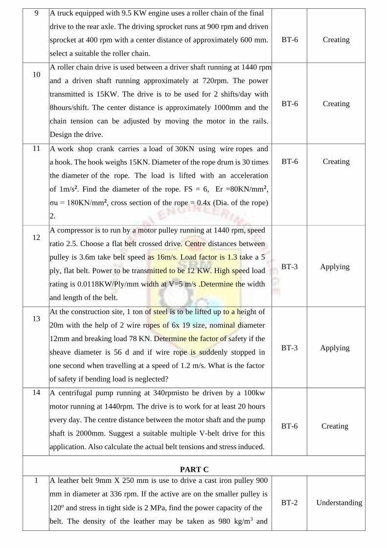
9 A truck equipped with 9.5 KW engine uses a roller chain of the final
drive to the rear axle. The driving sprocket runs at 900 rpm and driven
sprocket at 400 rpm with a center distance of approximately 600 mm.
select a suitable the roller chain.
BT-6
Creating
10 A roller chain drive is used between a driver shaft running at 1440 rpm
and a driven shaft running approximately at 720rpm. The power
transmitted is 15KW. The drive is to be used for 2 shifts/day with
8hours/shift. The center distance is approximately 1000mm and the
chain tension can be adjusted by moving the motor in the rails.
Design the drive.
BT-6
Creating
11 A work shop crank carries a load of 30KN using wire ropes and
a hook. The hook weighs 15KN. Diameter of the rope drum is 30 times
the diameter of the rope. The load is lifted with an acceleration
of 1m/s2. Find the diameter of the rope. FS = 6, Er =80KN/mm2,
σu = 180KN/mm2, cross section of the rope = 0.4x (Dia. of the rope)
2.
BT-6
Creating
12 A compressor is to run by a motor pulley running at 1440 rpm, speed
ratio 2.5. Choose a flat belt crossed drive. Centre distances between
pulley is 3.6m take belt speed as 16m/s. Load factor is 1.3 take a 5
ply, flat belt. Power to be transmitted to be 12 KW. High speed load
rating is 0.0118KW/Ply/mm width at V=5 m/s .Determine the width
and length of the belt.
BT-3
Applying
13 At the construction site, 1 ton of steel is to be lifted up to a height of
20m with the help of 2 wire ropes of 6x 19 size, nominal diameter
12mm and breaking load 78 KN. Determine the factor of safety if the
sheave diameter is 56 d and if wire rope is suddenly stopped in
one second when travelling at a speed of 1.2 m/s. What is the factor
of safety if bending load is neglected?
BT-3
Applying
14 A centrifugal pump running at 340rpmisto be driven by a 100kw
motor running at 1440rpm. The drive is to work for at least 20 hours
every day. The centre distance between the motor shaft and the pump
shaft is 2000mm. Suggest a suitable multiple V-belt drive for this
application. Also calculate the actual belt tensions and stress induced.
BT-6
Creating
PART C
1 A leather belt 9mm X 250 mm is use to drive a cast iron pulley 900
mm in diameter at 336 rpm. If the active are on the smaller pulley is
120o and stress in tight side is 2 MPa, find the power capacity of the
belt. The density of the leather may be taken as 980 kg/m3 and
BT-2
Understanding

coefficient of friction of leather on cast iron is 0.35.
2 Designs a chain drive to actuate a compressor from a 12 kW electric
motor at 900 rpm, the compressor begin 250 rpm, Minimum centre
distance should be 500 mm, the chain tension maybe adjusted by
shifting the motor on rails. The compressor is to work 8 hour/day.
BT-4
Analyzing
3 Design a flat belt drive to transmit 110 kW for a system consisting of
two pulleys of diameters 0.9 m and 1.2 m respectively, for a centre
distance of 3.6 m, belt speed of 20 m/s and coefficient of
friction =0.3.There is a slip of 1.2% at each pulley and 5% friction loss
at each shaft with 20% over load.
BT-6
Creating
4 Design a chain drive to actuate a compressor from 15 KW electric
motor running at 1000 rpm, the compressor speed being 350 rpm.
The minimum centre distance is 500 mm. The compressor operates
15 hours per day. The chain tension may be adjusted by shifting the
motor.
BT-3
Applying

UNIT II SPUR GEARS AND PARALLEL AXIS HELICAL GEARS
Speed ratios and number of teeth-Force analysis -Tooth stresses - Dynamic effects – Fatigue strength - Factor of
safety - Gear materials – Design of straight tooth spur & helical gears based on strength and wear considerations
– Pressure angle in the normal and transverse plane- Equivalent number of teeth-forces for helical gears
PART-A
Q.No QUESTIONS BT Level Competence
1 State law of gearing and summarize how interference can be
avoided in gear.
BT-2 Understanding
2 Name the profiles of spur gear. List the various methods of
manufacturing gears.
BT-1 Remembering
3 Describe the following (i) Pressure angle (ii) Diametrical pitch
(iii) module
BT-2 Understanding
4 List the different types of gear mechanism. BT-1 Remembering
5 Describe backlash. What factors influence backlash. BT-2 Understanding
6 Explain undercutting in gears. BT-5 Evaluating
7 Why is gear tooth subjected to dynamic load? BT-4 Analysing
8 Classify the main types of gear tooth failure. BT-3 Applying
9 Why dedendum value is more than addendum value? BT-5 Evaluating
10 Integrate the materials commonly used for gears. BT-6 Creating
11 Differentiate involute and cycloid profiles BT-4 Analyzing
12 Mention the advantages of nonmetallic gears. BT-6 Creating
13 How does failure by pitting happen in gears? BT-3 Applying
14 How number of teeth affects the design of gears? BT-3 Applying
15 Specify the conditions based on which gear cutters are selected. BT-4 Analyzing
16 Identify the forces and stresses that act on spur gear tooth? Give
their expressions.
BT-2 Understanding
17 Label (a) addendum (b) flank in simple sketch of a gear tooth BT-1 Remembering
18 State the advantages and disadvantages of helical and herringbone
Gear.
BT-1 Remembering
19 Name four important elements in chain. BT-1 Remembering
20 What is effect of increasing pressure angle in gears? BT-1 Remembering

PART-B
Q.No QUESTIONS BT Level Competence
1 Design a pair of straight spur gear drive for a stone crusher, the gears
are made of C40 steel. The pinion is to transmit 30 KW at 1200 rpm.
The gear ratio is 3. The gear is to work 8 hours/day 6days in a week
for 3 years.
BT-6
Creating
2 Design a spur gear pair to transmit 22.5KW at 900 rpm. Speed
reduction ratio is 2.5. Material for pinion and wheel are C15 steel
and cast iron grade 30 respectively. Take pressure angle 200 and
working life of gear is 10,000 hours.
BT-6
Creating
3 Design a spur gear drive required to transmit 45 KW at pinion speed
of 800 rpm. The velocity ratio is 3.5:1. The teeth are 200 full depth
involute with 18 teeth on the pinion. Both the pinion and gear are
made of steel with a maximum safe static stress of 180 N/mm2.
Assume medium shock condition.
BT-6
Creating
4 Design a straight spur gear drive to transmit 8KW. The pinion speed
is 720rpm and the speed ratio is 2. Both the gears are made of the
same surface hardened carbon steel with 55RC and core hardness
less than 350BHN. Ultimate strength is 720N/mm2 and yield
strength is 360 N/mm2.
BT-6
Creating
5 Design a spur gear to transmit 2 KW at 1440 rpm. Desired speed
ratio is 3. Use C45 steel for gears.
BT-6
Creating
6 A 37.5 kW power is transmitted at 450 rpm to a shaft running at
approximately 112 rpm through a spur gear drive. The load is steady
and continuous. Design the gear drive and check the design.
Assume the following materials: Pinion-heat treated cast steel;
Gear-High grade cast iron.
BT-6
Creating
7 Design a spur gear drive for a heavy machine tool with moderate
shocks. The pinion is transmitting 18KW at 1200 rpm with a gear
ratio of 3.5. Design the drive and check for elastic stress and plastic
deformation. Make a sketch and label important dimensions arrived.
BT-6
Creating
8 A motor shaft rotating at 1500 rpm has to transmit 15KW to a low
speed shaft with a speed reduction of 3:1. The teeth are 200 involute
with 25 teeth on the pinion. Both the pinion and gear are made of
steel with a maximum safe stress of 200 N/mm2. A safe stress of
40 N/mm2 may be taken for the shaft on which the gear is mounted
and also for the key. Design a spur gear drive to suit the above
conditions. Assume starting torque to be 25% higher than the
BT-6
Creating

running torque.
9 Design a helical gear to transmit 15 KW at 1440 rpm to the
following specification. Speed reduction is 3, Pressure angle is 200
and helix angle is 15 degree. The material for both the gears is C45
steel. Allowable static stress is 180 N/mm2, Surface endurance limit
is 800 N/mm2 and Young’s Modulus of material is 2 x 10⁵ N/mm2
BT-6
Creating
10 Design a helical gear for the following specification:
Power- 12.5KW, Pinion speed-1200 rpm, Gear Ratio - 3.5, Pressure
angle is 200, helix angle is 15 degree. Gear are expected to work 6
hours/day for 10 years.
BT-6
Creating
11 A helical gear with 30 degree helix angle has to transmit 35kW at
1500 rpm with a speed reduction ratio 2.5. If the pinion has 24 teeth
determine the necessary module, pitch diameter and face width for
20 degree full depth teeth. Assume 15Ni 2Cr 1 Mo15 material for
both pinion and wheel.
BT-3
Applying
12 A helical gear speed up drive is required to drive a centrifugal
compressor running at 3000rpm. The helical gear speed up unit is
driven by an electric motor running at 1000rpm. The compressor
requires a nominal input power of 12.5 KW. The helix angle of 250
may be assumed for the gears. Standard involute profile 200 full
depth system will be used for the gear teeth. The gear pair is
required to last for at least 10,000 hrs. Design the gear drive for the
following materials. Pinion: Heat treated cast steel, Gear: High
Grade cast iron.
BT-6
Creating
13 Design a pair of helical gears to transmit 37.5KW at 1750 rpm of
the pinion. The drive is subjected to heavy shock loading. The
speed reduction ratio is 4 and the helix angle is 150. Select suitable
material and design the gears. Check for working stresses and
sketch the drive.
BT-6
Creating
14 Design a helical gear drive to transmit the power of 14.7KW. Speed
ratio 6, pinion speed 1200rpm, helix angle is 250. Select suitable
materials and design the gear.
BT-6
Creating
PART C
1 Design a pair of spur gear to transmit 20 KW at a pinion speed of
1440 rpm. The transmission ratio is 4.Assume 15Ni2Cr1Mo15 for
pinion and C45 for gears
BT-6
Creating

2 For intermittent duty of an elevator, two cylindrical gears made of
alloys steel 40 Ni 2 Cr 1 Mo 28, and have to transmit12.5 kw at a
pinion speed of 1200 rpm. Design a gear pair for the following
specifications: Gear ratio: 3.5, pressure angle 200, involute full
depth, helix angle 150. Gears are expected to work 6 hrs a day for
10 years. Minimum number of teeth on pinion can be taken as 20
and IS quality 8
BT-3
Applying
3 Design a pair of helical gears to transmit 10 KW at 1000 rpm of
the pinion and wheel are made of C15 steel and cast iron grade 30
respectively. The pinion is to transmit 22 KW power at 900 rpm.
The gear ratio is 2.5, take pressure angle of 200 and helix angle is
150. The material for the both gears is NI2Cr1Mo28.Give details
of drive in tubular form.
BT-4
Analyzing
4 A speed reducing unit using spur gear is to be designed. Power to
be transmitted is 60 hp and is continuous with moderate shaft
loads. The speed of the shaft are 720 rpm and 144 rpm. The centre
distance is kept as small as possible. Select a suitable material and
design the gears. Give the details of the gear.
BT-2
Understanding

UNIT III BEVEL, WORM AND CROSS HELICAL GEARS
Straight bevel gear: Tooth terminology, tooth forces and stresses, equivalent number of teeth. Estimating the
dimensions of pair of straight bevel gears. Worm Gear: Merits and demerits terminology. Thermal capacity,
materials-forces and stresses, efficiency, estimating the size of the worm gear pair. Cross helical: Terminology-
helix angles-Estimating the size of the pair of cross helical gears.
PART-A
Q.No QUESTIONS BT Level Competence
1 Under what situation bevel gears are used. BT-2 Understanding
2 Write a short notes on Crown gear and Miter gear. BT-6 Creating
3 Mention two characteristics of hypoid gear. BT-4 Analysing
4 How bevel gears are manufactures. Summarize zero bevel gear BT-4 Analysing
5 Define back cone radius for a bevel gear. BT-3 Applying
6 Define the following term i) Cone distance ii) Face angle BT-1 Remembering
7 Show when do you prefer worm and worm wheel drive? BT-3 Applying
8 List the advantages of and disadvantages of worm gear drive. BT-1 Remembering
9 Illustrate reference angle? How is related to speed ratio of bevel
gear?
BT-1 Remembering
10 State the difference between angular gear and miter gear. BT-1 Remembering
11 Describe in which gear drive self-locking is available. BT-2 Understanding
12 Why is dynamic loading rarely considered in worm gear drives? BT-2 Understanding
13 Why is the efficiency of worm gear drive comparatively low? BT-2 Understanding
14 List the difference between bevel gear formation and other types
of gears.
BT-1 Remembering
15 Summarize the helix angle of worm. BT-2 Understanding
16 Name the contact occurred between the worm and wheel. How
this does differs from other gears?
BT-3 Applying
17 Differentiate between the spiral bevel gears and hypoid gears. BT-4 Analyzing
18 List the materials used for the manufacture of worm and
worm and wheel.
BT-1 Remembering
19 Explain why worm is made of harder material than worm wheel. BT-5 Evaluating
20 Explain crossed helical gear drive is not used for power
transmission.
BT-5 Evaluating
PART-B
Q.No QUESTIONS BT Level Competence
1 Design a pair of bevel gears to transmit 10 kW at 1440 rpm of the
pinion. The velocity ratio should be about 4. Material for gear is
1 5 N i 2 C r 1M o 1 5 / Steel. The tooth profiles of the gears are
of 20o composite form.
BT-6
Creating
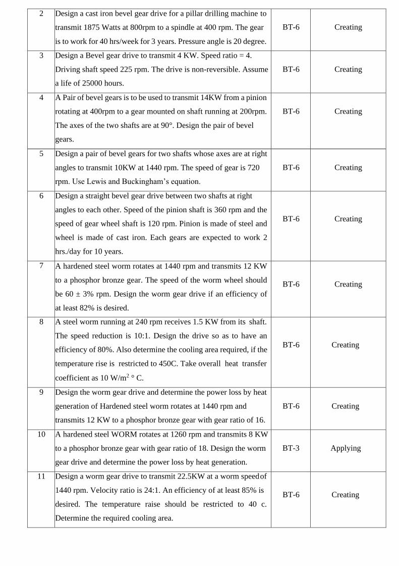
2 Design a cast iron bevel gear drive for a pillar drilling machine to
transmit 1875 Watts at 800rpm to a spindle at 400 rpm. The gear
is to work for 40 hrs/week for 3 years. Pressure angle is 20 degree.
BT-6
Creating
3 Design a Bevel gear drive to transmit 4 KW. Speed ratio = 4.
Driving shaft speed 225 rpm. The drive is non-reversible. Assume
a life of 25000 hours.
BT-6
Creating
4 A Pair of bevel gears is to be used to transmit 14KW from a pinion
rotating at 400rpm to a gear mounted on shaft running at 200rpm.
The axes of the two shafts are at 90°. Design the pair of bevel
gears.
BT-6
Creating
5 Design a pair of bevel gears for two shafts whose axes are at right
angles to transmit 10KW at 1440 rpm. The speed of gear is 720
rpm. Use Lewis and Buckingham’s equation.
BT-6
Creating
6 Design a straight bevel gear drive between two shafts at right
angles to each other. Speed of the pinion shaft is 360 rpm and the
speed of gear wheel shaft is 120 rpm. Pinion is made of steel and
wheel is made of cast iron. Each gears are expected to work 2
hrs./day for 10 years.
BT-6
Creating
7 A hardened steel worm rotates at 1440 rpm and transmits 12 KW
to a phosphor bronze gear. The speed of the worm wheel should
be 60 ± 3% rpm. Design the worm gear drive if an efficiency of
at least 82% is desired.
BT-6
Creating
8 A steel worm running at 240 rpm receives 1.5 KW from its shaft.
The speed reduction is 10:1. Design the drive so as to have an
efficiency of 80%. Also determine the cooling area required, if the
temperature rise is restricted to 450C. Take overall heat transfer
coefficient as 10 W/m2 ° C.
BT-6
Creating
9 Design the worm gear drive and determine the power loss by heat
generation of Hardened steel worm rotates at 1440 rpm and
transmits 12 KW to a phosphor bronze gear with gear ratio of 16.
BT-6
Creating
10 A hardened steel WORM rotates at 1260 rpm and transmits 8 KW
to a phosphor bronze gear with gear ratio of 18. Design the worm
gear drive and determine the power loss by heat generation.
BT-3
Applying
11 Design a worm gear drive to transmit 22.5KW at a worm speed of
1440 rpm. Velocity ratio is 24:1. An efficiency of at least 85% is
desired. The temperature raise should be restricted to 40 c.
Determine the required cooling area.
BT-6
Creating

12 Design a bevel gear drive, to transmit 10 KW power at 1440 rpm.
Gear ratio is 3, and life of gears 10,000 hrs. Pinion and gear are
made of C45 steel and minimum number of teeth as 20.
BT-6
Creating
13 A hardened steel work rotates at 1600 rpm and transmit 15KW to
a phosphor bronze gear. The speed of the worm wheel should be
65 ± 2% rpm. Design a worm gear drive if an efficiency of at least
82% is desired.
BT-6
Creating
14 Design a worm gear drive to transmit 22.5 KW at a worm speed of
1440 rpm. Velocity ratio is 24:1. An efficiency of at least 85% is
desired. The temperature raise should be restricted to 400C.
Determine the required cooling area.
BT-6
Creating
PART C
1 Design a bevel gear to transmit 3.5 KW with driving shaft speed
is 200 rpm. Speed ratio requires is 4. The drive is non- reversible.
Pinion is made of steel and wheel made of CI. Assume a life of
25,000 Hrs.
BT-6
Creating
2 Design a pair of right angled bevel gear to transmit 15KW at 750
rpm to another gear to run at 250 rpm. Not less than 20 teeth are
to be used on either gears. The pressure angle is 200. Assume a
gear life of 12000 hrs.
BT-3
Applying
3 2 KW power is applied to a worm shaft at 720 rpm. The worm is
of quadruple start with 50mm as pitch circle diameter. The worm
gear has 40 teeth with 5mm module. The pressure angle in the
diametric plane is 200.Determine (i) Lead angle of the worm
(ii) Velocity ratio (iii) Centre distance. Also calculate the
efficiency of worm gear drive and power lost in friction.
BT-4
Analyzing
4 A pair of straight tooth bevel gears has a velocity ratio of 4/3.
The pitch diameter of the pinion is 150 mm. The face width is
50mm. The pinion rotates at 240 rev/min. The teeth are 5mm
module, 14 1°Involutes. If 6 kW is transmitted, determine
(i) the tangential force at the Mean radius (ii) the pinion thrust
force (iii) the gear thrust force. Draw the free body diagrams
indicating the forces.
BT-2
Understanding
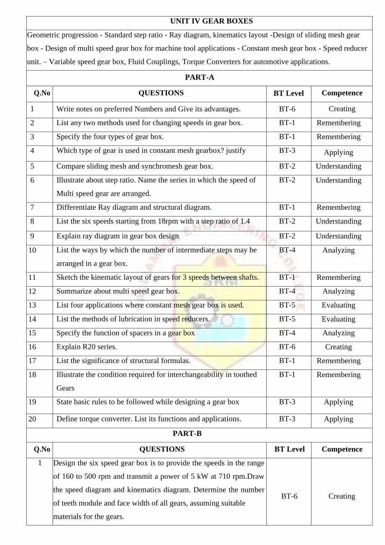
UNIT IV GEAR BOXES
Geometric progression - Standard step ratio - Ray diagram, kinematics layout -Design of sliding mesh gear
box - Design of multi speed gear box for machine tool applications - Constant mesh gear box - Speed reducer
unit. – Variable speed gear box, Fluid Couplings, Torque Converters for automotive applications.
PART-A
Q.No QUESTIONS BT Level Competence
1 Write notes on preferred Numbers and Give its advantages. BT-6 Creating
2 List any two methods used for changing speeds in gear box. BT-1 Remembering
3 Specify the four types of gear box. BT-1 Remembering
4 Which type of gear is used in constant mesh gearbox? justify BT-3 Applying
5 Compare sliding mesh and synchromesh gear box. BT-2 Understanding
6 Illustrate about step ratio. Name the series in which the speed of
Multi speed gear are arranged.
BT-2 Understanding
7 Differentiate Ray diagram and structural diagram. BT-1 Remembering
8 List the six speeds starting from 18rpm with a step ratio of 1.4 BT-2 Understanding
9 Explain ray diagram in gear box design BT-2 Understanding
10 List the ways by which the number of intermediate steps may be
arranged in a gear box.
BT-4 Analyzing
11 Sketch the kinematic layout of gears for 3 speeds between shafts. BT-1 Remembering
12 Summarize about multi speed gear box. BT-4 Analyzing
13 List four applications where constant mesh gear box is used. BT-5 Evaluating
14 List the methods of lubrication in speed reducers. BT-5 Evaluating
15 Specify the function of spacers in a gear box BT-4 Analyzing
16 Explain R20 series. BT-6 Creating
17 List the significance of structural formulas. BT-1 Remembering
18 Illustrate the condition required for interchangeability in toothed
Gears
BT-1 Remembering
19 State basic rules to be followed while designing a gear box BT-3 Applying
20 Define torque converter. List its functions and applications. BT-3 Applying
PART-B
Q.No QUESTIONS BT Level Competence
1 Design the six speed gear box is to provide the speeds in the range
of 160 to 500 rpm and transmit a power of 5 kW at 710 rpm.Draw
the speed diagram and kinematics diagram. Determine the number
of teeth module and face width of all gears, assuming suitable
materials for the gears.
BT-6
Creating

2 Design a 9 speed gear box for the following data.
Minimum speed: 180rpm, Maximum speed: 1800rpm.Using
standard step ratio, draw the speed diagram, kinematic layout. Also
find the number of teeth on each gear.
BT-6
Creating
3 Design a nine speed gear box for a machine to provide speeds
ranging from 100 to 1500 rpm. The input is from a motor of 5 kW
at 1440 rpm. Assume any alloy steel for the gear.
BT-6
Creating
4 Design 12 speed gear box for a minimum speed of 160 rpm and a
maximum speed of 2000 rpm. The input speed of motor is 1600
rpm. Draw the speed diagram, kinematic diagram and indicate the
number of teeth on each gear.
BT-6
Creating
5 Design the layout of a 12 speed gear box for a milling machine
having an output of speeds ranging from 100 to 1200 rpm. Power is
applied to the gear box from a 5kW induction motor at 1440 rpm.
Choose standard step ratio and construct the speed diagram. Decide
up on the various reduction ratios and number of teeth on each gear
wheel sketch the arrangement of the gear box.
BT-6
Creating
6 Design the headstock gear box of a lathe having nine spindle speeds
ranging from 50 to 1500 rpm. The power of the machine may be
taken as 6 kW and speed of the motor is 1450 rpm. Minimum
number of teeth on the gear is to be 2x3. (a) Draw the speed diagram
(b) Sketch the layout of the gear box. (c) Calculate the number of
teeth on all gears.
BT-6
Creating
7 Draw the ray diagram and kinematic lay out of a gear box for an all
geared headstock of a lathe. The maximum and minimum speeds are
to be 2800 and 63 rpm respectively. The number of steps is 12 and
drive is from a 3 kW electric motor running at 1440rpm.
BT-6
Creating
8 Select speeds for an 18 speeds GEAR BOX for a minimum speed of
35 rpm and maximum speed 650 rpm. Draw speed diagram and a
kinematic arrangement of the gear box showing the number of teeth
in all the gears.
BT-6
Creating
9 The spindle of a pillar drill is to run at 12 different speeds in the
range of 100 rpm and 355 rpm. Design a three stage gear box with a
standard step ratio. The gear box receives 5KW from an electric
motor running at 360rpm. Sketch the layout of the gear box,
indicating the number of teeth on each gear. Also sketch the speed
diagram.
BT-6
Creating

10 Design a 16 speed gear box for the following data. Minimum speed:
100rpm, step ratio: 1.25. The input is from a 5KW, 1000rpm motor.
Draw the speed diagram, kinematic diagram and indicate the number
of teeth on each gear.
BT-6
Creating
11 A 16 speed gear box is required to furnish output speeds in the range
of 100 to 560 rpm. Sketch the kinematic arrangement and draw the
speed diagram.
BT-6
Creating
12 The maximum and minimum speeds of nine speed box are to be
600rpm and 100rpm respectively. The drive is from an electric motor
giving 3KW at 1440rpm. Design the gear box. Construct the speed
diagram and sketch the arrangement of gear box.
BT-6
Creating
13 Design a six speed gear box for a machine to provide speeds ranging
from 100 rpm to 560 rpm. The input shaft speed is 560rpm. The
intermediate shaft to have three speeds. Assume any alloy steel for
the gears.
BT-6
Creating
14 Design a 12 speed gear box for a lathe. The min and max speeds
are 100 and 1200 rpm. Power is 5 Kw from 1440 rpm induction
motor.
BT-6 Creating
PART C
1 A six speed gear box is required to provide output speeds in the
range of 125 to 400 rpm with a step ratio of 1.25 and transmit a
power of 5 kW at 710 rpm. Draw the speed diagram and kinematics
diagram. Determine the number of teeth module and face width of
all gears, assuming suitable materials for the gears. Determine the
length of the gear box along the axis of the gear shaft.
BT-3
Applying
2 A machine tool gear box is to have 9 speeds. The gear box is driven
by an electric motor whose shaft rotational speed is 1400 rpm. The
gear box is connected to the motor by a belt drive. The maximum
and minimum speeds required at the gear box output are 1000 rpm.
and 200 rpm. respectively. Suitable speed reduction can also be
provided in the belt drive. What is the step ratio and what are the
values of 9 speeds? Sketch the arrangement. Obtain the number of
teeth on each gear and also the actual output speeds.
BT-4
Analyzing
3 In a milling machine, 18 different speeds in the range of 35 rpm and
650 rpm are required. Design a three stage gear box with a standard
step ratio. Sketch the layout of the gear box, indicating the number
of teeth n each gear. The gear box receives 3.6 kW from an electric
motor running at 1,440 rpm. Sketch also the speed diagram.
BT-2
Understanding

4 Sketch the arrangements of a six speed gear box. The minimum and
maximum speeds required are around 460 and 1400 rpm. Drove
speed is 1440 rpm. Construct speed diagram of the gear box and
obtain various reduction ratios. Use standard output speeds and
standard step ratio. Calculate number of teeth in each gear and verify
whether the actual output speeds are within + 2% of standard speeds.
BT-6
Creating

UNIT V CAMS, CLUTCHES AND BRAKES
Cam Design: Types-pressure angle and under cutting base circle determination-forces and surface stresses.
Design of plate clutches –axial clutches-cone clutches-internal expanding rim clutches- Electromagnetic
clutches. Band and Block brakes - external shoe brakes – Internal expanding shoe brake.
PART-A
Q.No QUESTIONS BT Level Competence
1 Mention a few applications of cams and state its advantages. BT-1 Remembering
2 List the significance of pressure angle in cam design. BT-1 Remembering
3 Define Jerk. Name the profile of the cam that gives no Jerk. BT-1 Remembering
4 Define pitch point in a cam. BT-2 Understanding
5 Name four profiles normally used in cams. BT-6 Creating
6 Explain the term undercutting in cam. BT-4 Analyzing
7 List the function of a clutch in a transmission system. BT-4 Analyzing
8 Name the factors upon which the torque capacity of a clutch
depends.
BT-1 Remembering
9 Name a few commonly used friction materials. BT-6 Creating
10 Specify the desirable properties of friction materials in clutch. BT-2 Understanding
11 Give examples of axial and radial friction clutches. BT-5 Evaluating
12 If a multidisc clutch has 6 discs in the driving shaft and 7 disc in
the driven shaft and find the number of contact surfaces.
BT-5 Evaluating
13 Classify clutches based on coupling methods. BT-3 Applying
14 List the effects of temperature rise in clutches. BT-1 Remembering
15 Why it is necessary to dissipate the heat generated during clutch
operation?
BT-2 Understanding
16 Summarize positive clutch. BT-3 Applying
17 Differentiate between uniform pressure and uniform war theories
adopted in design of clutches.
BT-2 Understanding
18 Under what conditions of a clutch, uniform rate of wear
assumptions is more valid?
BT-4 Analyzing
19 Narrate the axial force required at the engagement and dis
engagement of cone clutch.
BT-3 Applying
20 Distinguish between dry and wet operations of clutches. BT-1 Remembering

PART-B
Q.No QUESTIO
NS
BT Level Competence
1 A single plate sketch, effective on both sides, is required to transmit
25KW at 3000 rpm. Determine the outer and inner diameter of
frictional surfaces if the coefficient of friction is 0.25, ratio of
diameter is 1.25 and the maximum pressure is not to exceed 0.1
N/mm2. Determine (i) the face width required and (ii) the axial
spring force necessary to engage the clutch.
BT-3
Applying
2 A plate clutch with maximum diameter 60mm has maximum lining
pressure of 0.35 MPa. The power to be transmitted at 400 rpm is 135
KW and µ =0.3. Find inside diameter and spring force required to
engage the clutch. Springs with spring index 6 and material spring
steel with safe shear stress 600 MPa are used. Find the diameters if
6 spring are used.
BT-3
Applying
3 A multi disk clutch consists of five steel plates and four bronze
plates. The inner and outer diameters of friction disks are 75mm and
150mm respectively. The coefficient of friction is 0.1 and the
intensity of pressure is limited to 0.3. N/mm2. Assuming the
uniform wear theory, calculate (i) The required operating force, and
(ii) Power transmitting capacity at 750 rpm.
BT-3
Applying
4 A plate clutch has 3 discs on the driving shaft and 2 discs on
the drive shaft, providing 4 pairs of contact surfaces. The
outer diameter of contact surface is 240mm and inner diameter
is120mm. Assuming uniform pressure and µ =0.3, find the total
spring load for pressing the plates together to transmit 25KW at
1575 rpm. If there are 6 springs each of stiffness 13KN/m and
each of contact surfaces have worn away by1.25mm, find the
power that can be transmitted, assuming uniform wear.
BT-3
Applying
5 A multi disc wet clutch is to be designed for a machine tool driven
by an electric motor of 12.5 KW running at 1440 rpm. Space
restrictions limit the outside disc diameter to 100mm. Determine
the appropriate value of inside diameter, total number of discs and
clamping force.
BT-3
Applying
6 An engine developing 45kW at 1000 rpm id fitted with a cone
clutch built inside the fly wheel. The cone has a face angle of 12.5
degree and a maximum mean diameter of 500 mm. The coefficient
of friction is 0.2. The normal pressure on the clutch face is not
BT-3
Applying

exceeded 0.1N/mm 2. Determine (i) The face width required (ii) the
axial spring force necessary to engage the clutch.
7 A single block brake, the diameter of drum is 250mm and the angle
of contact is 90 degree, the operating force of 700N is applied at the
end of lever which is at 250mm from the center of the brake block.
Determine the torque that may be transmitted. Fulcrum is at 200mm
from the center of brake block with an offset of 50mm from the
surface of contact. The coefficient of friction is 0.35.
BT-3
Applying
8 A 360 mm radius Brake drum contacts a single shoe as shown in
figure-1and resists a torque of 250 Nm at 500 rpm. The co- efficient
of friction is 0.3. Determine
(i) The normal reaction on the shoe,
(ii) The force to be applied at the lever end for counter clockwise
rotation of the drum if e= 0,
(iii) The force to be applied at the lever end for clockwise
rotation of the drum if e=42 mm,
(iv) The force to be applied at the lever end for counter clockwise
rotation of the drum if e = 42 mm.
Fig-1
BT-3
Applying
9 The layout of a double block brake is shown in figure -2. The brake
is rated at 250N-m at 650rpm. The drum diameter is
250mm.assuming the co-efficient of friction as 0.3 and for
conditions of service a pV value of 1000 (Kpa) m/s may be
assumed. Determine (i) The spring force “S” required to set the
brake (ii) Width of shoes (iii) Which shoe will have greater rate
of wear?
BT-3
Applying

Fig-2
10 An internal expanding shoe brake has the following dimensions:
Diameter of the drum = 300 mm, distance between the fulcrum
centers is 80 mm, distance of fulcrum centers and that of cam axis,
both from the drum center=100 mm, distance of the line of action
of braking force from the cam axis = 90 mm, distance between the
points where the cam acts on the two brake shoes = 30 mm. Each
shoe subtends an angle of 90° at the drum Centre. If the braking
force is 750 N and the coefficient of friction is 0.3, Find the braking
torque on the drum. Assume the reaction between the brake shoes
and the drum passes through the point bisects the contact angle.
Also assume that forces exerted by the cam ends on the two shoes
are equal.
BT-3
Applying
11 A power of 20 Kw is to be transmitted through a cone clutch at
500 rpm. For uniform wear condition find the main dim of clutch
and shaft. Also determine the axial force required to engage the
clutch. Assume coefficient of friction as 0.25, the max normal
pressure on the friction surface is not to exceed 0.08 MPa and take
the design stress for the shaft material as 40 MPa.
BT-6
Creating
12 Design a differential band for a winch lifting a load of 20 KN
through a steel wire rope wound around a barrel of 600 mm dm.
The brake drum, keyed to barrel shaft is 800 mm diameter and the
angle of lap of the band over the drum is about 240 degree.
Operating arms of the brake are 50 mm and 250 mm. The length of
operating level is 1.6m.
BT-6
Creating
13 Derive the expression to determine the braking torque for an
internal expanding shoe brake.
BT-3
Applying
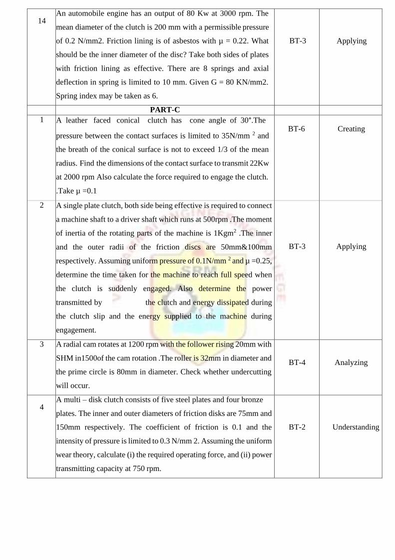
14 An automobile engine has an output of 80 Kw at 3000 rpm. The
mean diameter of the clutch is 200 mm with a permissible pressure
of 0.2 N/mm2. Friction lining is of asbestos with µ = 0.22. What
should be the inner diameter of the disc? Take both sides of plates
with friction lining as effective. There are 8 springs and axial
deflection in spring is limited to 10 mm. Given G = 80 KN/mm2.
Spring index may be taken as 6.
BT-3
Applying
PART-C
1 A leather faced conical clutch has cone angle of 30° .The
pressure between the contact surfaces is limited to 35N/mm 2 and
the breath of the conical surface is not to exceed 1/3 of the mean
radius. Find the dimensions of the contact surface to transmit 22Kw
at 2000 rpm Also calculate the force required to engage the clutch.
.Take µ =0.1
BT-6
Creating
2 A single plate clutch, both side being effective is required to connect
a machine shaft to a driver shaft which runs at 500rpm .The moment
of inertia of the rotating parts of the machine is 1Kgm2 .The inner
and the outer radii of the friction discs are 50mm&100mm
respectively. Assuming uniform pressure of 0.1N/mm 2 and µ =0.25,
determine the time taken for the machine to reach full speed when
the clutch is suddenly engaged. Also determine the power
transmitted by the clutch and energy dissipated during
the clutch slip and the energy supplied to the machine during
engagement.
BT-3
Applying
3 A radial cam rotates at 1200 rpm with the follower rising 20mm with
SHM in1500of the cam rotation .The roller is 32mm in diameter and
the prime circle is 80mm in diameter. Check whether undercutting
will occur.
BT-4
Analyzing
4 A multi – disk clutch consists of five steel plates and four bronze
plates. The inner and outer diameters of friction disks are 75mm and
150mm respectively. The coefficient of friction is 0.1 and the
intensity of pressure is limited to 0.3 N/mm 2. Assuming the uniform
wear theory, calculate (i) the required operating force, and (ii) power
transmitting capacity at 750 rpm.
BT-2
Understanding