Masters Thesis - Comparing Mental Models of Human Factors and Systems Engineers
36
Identifying Challenges in Implementing Cognitive Systems Engineering Analyses into Complex Systems Engineering Jerry A Gordon Embry Riddle Aeronautical University Department of Human Factors and Systems 29 November 2010 Dr Shawn Doherty Page 1
-
Upload
independent -
Category
Documents
-
view
0 -
download
0
Transcript of Masters Thesis - Comparing Mental Models of Human Factors and Systems Engineers

Identifying Challenges in Implementing Cognitive Systems
Engineering Analyses into Complex Systems Engineering
Jerry A Gordon
Embry Riddle Aeronautical University
Department of Human Factors and Systems
29 November 2010
Dr Shawn Doherty
Page 1

Table of Contents
INTRODUCTION..........................................................4
SYSTEMS ENGINEERING TEAM MENTAL MODELS....................................5FUNCTIONAL MODELING IN SYSML............................................7COGNITIVE SYSTEMS ENGINEERING............................................9THE FUNCTIONAL ALLOCATION PROCESS........................................11USING AND COMPARING MODELING SCHEMA......................................12DEFINING COMPLEXITY IN FUTURE PROBLEM DOMAINS.............................13PROBLEM STATEMENT.....................................................16
METHOD...............................................................17REQUIRED MATERIALS....................................................18SCENARIOS AND PARTICIPANTS..............................................19VARIABLES AND DATA COLLECTION...........................................20
References...........................................................21
Page 2

List of Figures
Figure 1 Function Block Diagram. This Figure illustrates
hierarchical nature of Functional Decomposition...........8
Figure 2 Example Activity Diagram used as EFFBD. This figure shows the decomposition of multiple levels................9Figure 3 Components of the Joint Cognitive System. This figuredepicts the differences in CSE and Technical perspectives..........................................................16Figure 4 Research Question and Hypothesis..................17
List of Tables
Table 1 -................................................14Table 2..................................................18
Page 3
Introduction
In recent years, Human Factors practitioners are
increasingly called to participate in complex system
development early in the development process. There are
certainly examples of systems which have involved
practitioners from both human and technical domains, and
this joint participation has improved the overall utility,
cost effectiveness and performance of these systems.
However, in other programs to where this participation has
been more difficult, and the overall value of including
human engineering not fully realized, the characteristics
leading to this failure are less well understood. In order
to explore these indicators for success, this thesis will
leverage mental model theory, and argue that graphical
models of a system developed by technical and human factors
practitioners are equivalent to some portion of the shared
team mental model. The central claim of the study is that
there will be a relationship between the characteristics

that make a system an open, complex system, and the degree
of agreement between concepts captured in the models
developed by technical and human factors practitioners.
The introduction starts with a justification for common
mental models between the technical and human factors
practitioners in the systems engineering team. Once the need
for common mental models is established, a basis for
measuring and comparing them must be developed. To that end,
the next sections start with traditional systems
engineering, and then describe the mechanisms employed by
the HF practitioners of interest here, “cognitive systems
engineers”. A description of the operational interface
between the two groups, “functional allocation”, follows
with a proposed mechanism to compare the two perspectives.
Since the overarching problem is tied to the development of
complex systems, to identify the challenges involved in
bringing CSE and traditional engineers together to develop
them, the introduction section concludes with a candidate

problem set and a summary of the overall goal of this
research.
Systems Engineering Team Mental Models
Empirically based science, as a process which moves from a
problem definition to a testable hypothesis, describes a set
of conditions, which when sensed, should yield predictable,
observable results. This relationship between sensed
conditions and expectation of future states is analogous to
Mica Endlsey’s truth model used in mental model research
involving situation awareness (Pew & Mavor, 1999). Similar
components for recognition of the situation and projection
of future states are present. Proceeding from the notion of
a “design as hypothesis” (Dekkar, Nice & Hoffman 2003), it
is possible to see the notion of a “system design” as a
critical component of the mental model of the team
engineering it.

A critical premise of this research is that engineering
teams, like any other team, rely on shared mental models to
conduct their work (Avnet, 2009). These mental models
involve both the understanding and tracking of
organizational processes used to manage the technical and
programmatic effort, as well as the system structure,
utility and behavior described by the system design as it
evolves towards final product. It is this understanding of
the system design which is the subject of the proposed
experiment.
The Object Management Group (OMG) was formed in the 1990’s
by three leaders in software engineering at IBM and proposed
the Unified Modeling Language (UML). The UML was originally
intended as an aid for software developers to exchange
design information, and in the ensuing years, it has matured
significantly. It has been adapted into the Systems Modeling
Premise #1 – Successful Performance of Human Factors and Technical practitioners working in concert on a system design team require congruence in their shared mental model of the state and purpose of the design.

Language (SYSML) as well, to capture the design elements of
not only software, but hardware, humans and other elements
of the system. The use of UML and SYSML provides a
semantically precise mechanism for capturing the elements of
design: utility, structure and behavior, as well as the
nature of the relationships between these elements
(Friedenthal, Moore & Steiner, 2008). These languages have
evolved sufficiently to enable systems design through a
“Model Based Systems Engineering” (MBSE) process, where the
subjective interpretation of the natural language in prose
specifications can be replaced with fixed relationships,
semantically precise graphical model elements and a system
of logical tools for validating the completeness and
consistency of these models. It is because of this richness
that this research assumes that validated UML/SYSML models
can be used to measure the mental models of design
practitioners working on a system.
Premise #2 – UML/SYSML graphical models are equivalent to the shared mental model of the current state and
The focus of this experiment is to compare the content of
design as it is understood by the technical and human
factors practitioners. However, there is an important
relationship between the flow of management and control
events (as they relate to team mental models) and the
creation of design artifacts. Classical systems engineering
(Kossiakoff & Sweet, 2003) describes this relationship as a
linear flow from utility (i.e. stakeholder requirements), to
behavior (i.e. functions) to structure (i.e. component
design). Complex systems engineering requires a non-linear,
iterative relationship, (Minai, Braha, & Bar-Yam, 2006) but
the basic artifacts of design still exist at some level of
maturity throughout.
Functional Modeling in SYSML
Systems engineering and software engineering originally
relied on a “structured” method, whereupon the system
functions were first decomposed and then allocated to
components. Structured methods would create a hierarchical
breakdown of system functions, which would then be allocated

to either hardware or software, and then to specific
components (Kossiakoff & Sweet, 2003). The Functional Block
Diagram (FBD) hierarchy used in structured methods is
depicted in figure 1.
Function 1.0
Function 1.1 Function 1.2 Function 1.3
Function 1.1.1 Function 1.1.2
Function 1.0
Function 1.1 Function 1.2 Function 1.3
Function 1.1.1 Function 1.1.2
Figure 1 Function Block Diagram. This Figure illustrates hierarchicalnature of Functional Decomposition
Current methods for systems engineering, evolving out of
software engineering, rely on Object Oriented (OO) methods.
Both Object-Oriented and Structured methods rely on the
notion of a “function” as a core construct defining system
behavior. Within UML and SYSML, the modeling language used
for object oriented methods, functions are defined within
activity diagrams. UML version 2.1 extended the earlier UML
activity diagram to include all of the information contained
within Enhanced Functional Flow Block Diagrams (EFFBD) used
by the earlier structured approaches (Friedenthal, Moore &
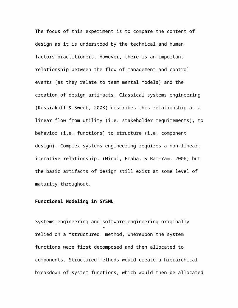
Steiner, 2008). UML activity diagrams still represent
decomposition with increased detail at each level, but they
convey more information as the relationship between
functions and data flows between functions, as well notions
of sequencing. An example EFFBD is depicted in figure 2.
Start CarPower From engine
Insert Key
Provide Start m otionDecouple Start signalfrom Engine
Transm it Start m otion to engine
Interlock signal
Torque couple
Level 1 decom position
Level 2 decom position
Figure 2 Example Activity Diagram used as EFFBD. This figure shows the decomposition of multiple levels
Cognitive Systems Engineering
Increasing levels of complexity in modern systems
development has led to the formation of a number of
disciplines and techniques to address this complexity.
Cognitive systems engineering (CSE) is a set of techniques
which draws on human factors methods and scientific
principles with the intent of addressing human issues in the

development of complex socio-technical systems directly
through the requirements process (Militello, Dominguez,
Lintern & Klein, 2010). CSE is a relatively new discipline,
and it continues to vie for acceptance as part of the
overall systems engineering process, although it has enjoyed
some early successes (Madni, 2010). A key portion of the CSE
process is the analysis of the human work involved in the
operations of the socio-technical system being designed.
CSE analysis techniques rely heavily on modeling, including
various approaches for describing the nature and purpose of
work, human performers of the work and information content
of the work space. These techniques evolved from the family
of Cognitive Task Analysis (CTA) techniques developed in the
1980’s by Jens Rasmussen and Kim Vicente to develop user
interfaces and training systems, among other uses (Jonassen,
D. Tessmer, M. & Hannum, W., 1999). One mechanism for
modeling cognitive work is the goals/means decomposition,
which describes a hierarchy of why work is performed tied to how
this work is performed (Jonassen et al, 1999).

One of the most recent approaches to CSE is the Applied
Cognitive Work Analysis (ACWA). While grounded heavily in
theory, the ACWA has evolved as a pragmatic answer to
addressing specific challenges in ensuring that complex
technical systems were developed with “affordances”; where
the work was designed to “intuitively fit” its users
(Hollnagel, 2003). A key construct of the ACWA process is
the development of a”functional abstraction network” (FAN).
This network describes the “goals-means decomposition” of
the workspace, and becomes the scaffolding upon which the
cognitive and information demands and characteristics of the
workspace are built. This goals-means decomposition is a
behavioral or functional description of the system, from the
perspective of the CSE/Human Factors practitioners
developing it.
One of the key elements of the workspace which are mated to
the FAN is the information and relationships requirements
(IRR). CSE practitioners have developed their own notations

for capturing the concepts of functional abstraction and
information exchange. However, this research assumes that
the combination of the elements within the FAN and the IRR
are functionally equivalent to the behavioral concepts
defined by the technical practitioners using UML and SYSML
modeling languages, and that a model translation algorithm
can be defined to capture FAN and IRR concepts as UML/SYSML
concepts.
The Functional Allocation Process
The functions identified during the functional analysis
phase of design (either the EFFBD of the technical
practitioners or the FAN of the CSE practitioners) must be
assigned to components that will satisfy them. In classical
systems engineering, this is a formal process that follows
only after functional analysis (through the requirements
definition process) is essentially complete. Similarly, in
the classic sense, human factors functional allocation
Premise # 3 – ACWA Functional and Information Requirements used by CSE practitioners can be mapped to equivalent concepts defined by the UML and SYSML meta-models.

proceeds from requirements to identify the impact on human
users, by mapping human task work to the software and
hardware functions that are supported by it. CSE, however,
in developing complex systems seeks to perform a “functional
synthesis” (Woods, D. & Hollnagel, E 2006), whereupon the
process is iterative with functional analysis, to more
correctly match the nature of (hardware and software) system
functions to human task-work in a more integrated whole that
optimizes the “total system” performance.
Thus the functional analysis and allocation process will
dictate in large measure what gets built, by defining what
it is expected to do. As the resultant hardware and software
is used by humans in a real-world operational setting, the
actual utility of the system and the capabilities it
provides becomes apparent. The process of systems
engineering evolved to try and focus on developing those end
state capabilities in a disciplined fashion, and CSE evolved
from the discovery that for systems of increasing
complexity, human concerns were becoming dominant in

dictating the utility and form of those final capabilities.
However, practical development of any real system requires
both sets of practitioners, and sustained performance of
this CSE/technical team requires that both sets develop and
maintain shared mental models of what is being built and why.
Using and Comparing Modeling Schema
One of the strengths of the UML is that it is a validated
internally consistent symbolic representation of the real
world. The validation of internal consistency was performed
by running a set of algorithms called Descriptive Logic (DL)
on the concepts, and relationships between them
(Nantajeewarawat, E. & Wuwongse, V. 2005). These algorithms
can demonstrate that the concepts in the language are
unambiguous and have natural start and stop points, as well
as prescriptive rules for combinations and compositions. The
same algorithms can be run against any model developed in
the language to determine that it is complete and
unambiguous as well. UML is implemented in a number of

toolsets provided by multiple vendors, and often include
model consistency checkers. UML models are intended to be
portable through multiple tools using the full definition of
the language by the use of Extensible Markup Language Meta-
Data Interchange (XMI) standards.
Similarly, Nantajeewarawat and Wuwongse have proposed a set
of metrics for comparing the consistency between two models
developed in the UML language, by using extensions of the DL
algorithms. Part of the consistency check s associated with
placement of concept characteristics in the various model
layers defined from the generic abstract to specific project
instances. For the sake of this research, the same tool
vendor will be used for all data development, so
inconsistencies in meta-model enhancements will be the same
for all datasets. However, a consistency check associated
with horizontal and vertical consistency; that concepts
defined in the model have the same parent/child and peer to
peer relationships, as well as semantic consistency, will be
key to understanding the mental model being measured in the

UML graphical model. This separate set of algorithms must
be developed to perform data analysis.
Defining Complexity in Future Problem Domains
Complexity is a term often used in engineering, but there is
little agreement as the exact definition. Similarly, while
there is recognition that there is a class of “complex”
systems which require qualitatively different approaches to
engineering that traditional systems engineering (Minai,
Braha Bar-Yam 2006), there a great deal of discussion on
specific criteria to classify a system as “complex”. A
generic abstract definition is that complexity is the
uncertainty involved in achieving (which may include proper
“understanding of”) stakeholder requirements (Suh, 2001).
There are a number of similar definitions that all stem from
interpretations of Shannon’s information theory.
Characteristics which present a more practical definition
from the chair of the International Council on Systems
Premise #4 – Descriptive Logic Algorithms run on UML/SYSML models can be used to measure the degree of similarity between the models

Engineering (INCOSE) Complex Systems Working Group (Sheard &
Mostashari, 2009), and the specific examples which will be
used for this research, is presented in table 1.
Table 1 - Mapping of Complex System Characteristics to Experiment System Definition
INCOSE Definition Interpretation for ExperimentComposed of autonomouscomponents High level of automated functions
Self organizing Co-located with users empowered to establishpriorities and missions
Emergent behavior - non linear
Difficulty in describing monotonic Measurements of Effectiveness (MOE) i.e. Q: what does it do? A: it depends
Adapt to environment Can be reconfigured in real timeIncrease in complexityover time Can add additional components in real time
A class of problems that is of topical interest and satisfy
all the characteristics of “complexity” is unmanned aircraft
systems (UAS). UAS are composed of remotely controlled
aircraft with varying levels of onboard automation (Sheridan
& Parasuraman, 2006), but those controllers are human
operators, who may utilize varying levels of automation in
their “ground control stations” (Cummings, Kirschbaum,
Sulmistras, & Platts, 2006). Moreover, UAS are designed to
carry a number of different payloads to perform a variety of
missions, and they have multiple levels of control which can

be passed between different human users and levels of
automation, in a large number of ultimate configurations.
During the past decade of operations in the Middle East, UAS
have gone from novelty item to a principal warfighting
platform. There number and utility is expected only to grow
in the future. CSE and related HF techniques are going to
be essential to the proper development, fielding, operations
and maintenance of these systems in the future. However,
this will require CSE to proceed from its current “initial
enthusiasm” (Madni, 2010) to a mature, repeatable discipline
with demonstrated Return on Investment (ROI). This will
require among other things, a proper understanding of the
characteristics of a system which will necessitate its use,
and, as the subject of this research, the characteristics of
those system development efforts which affect the success or
failure of introducing CSE principles in the large,
distributed teams that are often used to develop Defense and
Aerospace systems.

The impact of advances in automation on the human components
in systems is a well researched topic (Sheridan, &
Parasuraman, 2006). It has had an impact on the approaches
taken for functional analysis and allocation. The functional
allocation problem started with the “Machines and Better
at/Humans are Better at” approach that substituted machine
tasking for human tasking. It has migrated to recognition
that simple substitution is insufficient, and allocation on
that basis alone creates its own problems, such as
automation surprises (Woods & Hollnagel, 2006). For earlier
methods such as human centered design (Hollnagel, 2003).,
the technical and human factors perspectives still had the
human machine interface (HMI) as a common point of
reference, and it is reasonable to assume that the different
groups could use this common point to maintain consistent
mental models regarding the nature of the design; what they
were building and why. The requirements of a “joint
cognitive system”, which takes a qualitatively different
approach to understanding the nature of the system, still
has the HMI, but it is a final conclusion rather than a

starting point. In this case, the resultant understanding of
the system from the CSE perspective is likely to be very
different that the technical understanding. These elements
are depicted in figure 3.

Figure 3 Components of the Joint Cognitive System. This figure depicts thedifferences in CSE and Technical perspectives.
Hum an Contribution-cognitive and physical task work
M achine Contribution-Hardware and Software FunctionsOrganization as J oint Cognitive S ystem
Hum an M achine Interface
Social Network
Open System s Undergo Changes in Com position
Autom ation
CSE perspective starts here and works inward
System boundary
Problem Statement

The problem to be attacked in this research is trying to
understand the degree of shared understanding between
traditional engineers and CSE practitioners as they attack
the development of systems. It presumes that the use of
UML/SYSML tools to develop validated models of the system
under development can be used to measure the state of the
mental models of the two groups of practitioners. Using the
characteristics of complex systems defined previously in
table 1, the experiment will compare the degree of
consistency between the models developed separately by the
two sets of practitioners on two systems of similar size,
where one exhibits the characteristics of complexity, and
the other does not. The experiment will show that for the
non-complex system, the initial degree of consistency is
high. From this it can be assumed that putting the systems
engineers and CSE practitioners on a common team, that the
two models could be synchronized with relative ease. For the
complex system, this degree of initial consistency will be
low, and this discontinuity, exacerbated by the geographic
separation of distributed teams, may take so long or cost so

much to properly synchronize that the project budget and
schedule cannot sustain it. It is in these cases that the
proper value of CSE may not be realized, and cases such as
these will hamper its general acceptance and adoption. The
research question and hypothesis are listed in figure 3.
Figure 4 Research Question and Hypothesis
Method
The experiment will start with the creation of two notional
systems definitions. These systems will be based on two
battlespace deployments of UAS, one deployed on a ship for
use in maritime missions and one to operate in conjunction
with ground forces. These definitions will be modified to
represent the controlled levels of complexity, and will form
the basis for the design efforts which are being monitored.
Once the groups of participants are organized and trained,
the design efforts will be executed. The Systems engineering
Research Question Q1: Does the degree of complexity in a notional system definition affect the correlation between the functional architecture required to satisfy that system definition as understood separately by human factors and technologist practitioners.
H1: The level of agreement between the two team types will be lower in the complex case than in the closed case

and CSE teams will each have a domain appropriate toolset
for capturing the graphical models of their design, and this
same toolset will be used by teams of the same type
throughout. Following the design efforts, the CSE models
will be converted using the DR translator to UML/SYSML
models, equivalent to those used by the systems engineers.
The models will be validated, and extraneous concepts
deleted from the model repositories. The final models will
be compared for horizontal, vertical and semantic
compatibility on each level of complexity. Final results
will be analyzed and recorded.
Required Materials The systems engineering team will be provided the Enterprise
Architect toolset developed by Sparx Systems®. This toolset
will be used to capture a functional model of the system
definition using activity modeling. The system definitions
shall be captured in a requirements model provided to the
teams(although the definition will not be “requirements” in
the classical sense, requirement objects and block objects
are necessary for the model to pass the validation checker).

The CSE team will be provided a database tool for capturing
the elements of the Functional Abstraction Network and the
Information Relationship Requirements. The CORE® tool
developed by Vitech Corporation will also be provided to
provide a graphical aid for populating the database. The CSE
team will receive the same block and “requirements”
statements describing the system definition. Each team will
be provided access to a different UAS subject matter expert
who can answer technical questions. They will be located in
a laboratory or classroom environment for the duration of
the design exercise. Each design excursion will require
about 8 hours of work. Data reduction tools will include
SPSS to perform the analyses, the DL algorithms used to
validate the model, and a separately prepared test
instrument to perform text searches on the model components
to determine the values of the Dependent Variables (DV)
described in a follow-on section.
Scenarios and ParticipantsThe CSE and systems engineering (SYSENG) participants shall
be selected based on survey evaluations. The participants

should be technically competent but not highly experienced
in development of complex systems. Graduate Students who
have completed pre-requisite classes in systems engineering
and human factors analysis would be candidates. Each team
type will be split into two groups. The group size should be
even, with at least three members. The groups will be
separated to achieve a relatively uniform average and spread
for experience level. For counter balancing, each group will
receive different ordering of the complexity levels.
The scenarios are defined in the maritime and ground
domains. The system definitions will be created by a joint
team of HF and system engineering experts, to include
opportunities for approximately 40-60 leaf node functions
and at least three levels of decomposition. While artificial
constraints might be placed on the definition to make it a
“closed” system in this case, the participants are only to
address the open-system issues presented in the system
definition. The closed system shall have none of the
attributes listed in table 1. The highly automated system

will have at least 10% of its notional functions intended to
be automated. The open system will include desired
capabilities that present all of the features included in
table 1. The scenario presentations for each participant
group are summarized in table 2.
Table 2System Definition Scenario Presentation
participantgroup
BattlespaceDomain Complexity Level
OrderPresented
CSE 1 Maritime Closed 1CSE 2 Maritime Highly Automated 2CSE 1 Maritime Open/Complex 3CSE 2 Ground Closed 3CSE 1 Ground Highly Automated 2CSE 2 Ground Open/Complex 1SYSENG 1 Ground Closed 1SYSENG 2 Ground Highly Automated 2SYSENG 1 Ground Open/Complex 3SYSENG 2 Maritime Closed 3SYSENG 1 Maritime Highly Automated 2SYSENG 2 Maritime Open/Complex 1
The testing of the first hypothesis, looking for significant
difference (i.e. non agreement) between the models developed
by the CSE and SYSENG teams, is a between-groups analysis.
The testing of the second hypothesis, looking at the
relationship between the agreement of models developed by
the teams as the complexity level grows, is a within groups
analysis. The design is full factorial. Not every group will

see every combination of battlespace domain and complexity
level, but battlespace domain was varied to minimize
training and boredom residual effects, it is not a control
variable. The control group is the baseline “closed”
scenario as conducted for the four participant groups.
Variables and Data CollectionThe Independent Variable (IV) for the experiment is the
complexity of the system definition that is to me modeled.
It has three levels, as described above, closed, automated
and open. The Dependent Variables (DV) are the degrees of
agreement between the models developed by the CSE and SYSENG
teams. Three types of agreement are being evaluated:
DV1 Vertical agreement – degree to which concepts are
listed at the same level of abstraction such that
parent/child relationships are comprehended the same
way.
DV2 Horizontal agreement – degree to which concepts or
organized under the same parents within a given level,

such that peer to peer groupings are interpreted the
same way.
DV3 Semantic agreement – degree to which the same
concepts are decomposed
Semantic agreement is the most difficult to detect
automatically because small inconsequential changes between
teams may make ordinary text searches find “differences”. In
order to minimize these effects, a limited dictionary of
terms shall be provided to all team, strict non – verb –
object and tense rules will be used in the creation of
function definitions, and lower level concepts that
represent additional “non significant” decomposition levels
will be removed from the dataset. Two teams are used to
establish a baseline of natural variation in approach of
teams of the same type (i.e. SYSENG and CSE). For the level
comparison, agreement with either teams concepts will be
considered in-level agreement.
Even though there is only one IV, this study can evaluate
between groups effects because two different groups of each

practitioner type will execute models at the same level of
complexity. This is to evaluate whether the variability in
agreement due to level exceeds the natural variability
between teams of the same competency. Further studies might
examine the effects of other components of complexity
individually, but for this study, that was considered
infeasible. Automation was broken out as an individual level
to study as early work describing the “increased complexity”
of systems, the impact on systems design, and the need for
inclusion of human factors engineering, focused on
automation to the exclusion of the other aspects of “complex
open systems”.
References
Avnet, M. (2009). Socio-cognitive analysis of engineering systems design:
shared knowledge, process, and product. Unpublished Doctoral
Dissertation, Massachusetts Institute of Technology.
Retrieved 26 November, 2010 from
http://esd.mit.edu/people/dissertations/avnet.pdf

Cummings, M., Kirschbaum, A. , Sulmistras, A. , & Platts, J.
(2006). STANAG 4586 Human Supervisory Control Implications. Air and
Weapon Systems Dept, Dstl
Farnborough & the Office of Naval Research, Retrieved 26
November, 2010 from
http://web.mit.edu/aeroastro/labs/halab/papers/
STANAG_UVS.pdf
Dekkar, Nice & Hoffman (2003). From contextual inquiry to
designable futures: what do we need to get there?. IEEE
Intelligent Systems 18(2). 76-80. Retrieved from
http://www.ihmc.us/research/projects/EssaysOnHCC/DesignableF
utures.pdf
Friedenthal, S., Moore, A. & Steiner, R. (2008). A Practical
Guide to SYSML, The Systems Modeling Language. Ma. Morgan Kaufman
Press.
Hollnagel, E. (ed) (2003). Handbook of Cognitive Task
Design. NJ: Lawrence Erlbaum Associates.

Jonassen, D. Tessmer, M. & Hannum, W.(1999). Task Analysis
Methods for Instructional Design. NJ: Lawrence Erlbaum Assoc.
Kossiakoff & Sweet (2003). Systems Engineering Principles and Practice.
NJ: John Wiley and Sons
Madni. A. (2010). Integrating Humans with Software and
Systems: Technical Challebges and a Research Agenda. Systems
Engineering, The Journal of the International Council on Systems Engineering
13(3), 232-245.
Militello, l., Dominguez, C, Lintern, G. & Klein, G.(2010).
The Role of Cognitive Systems Engineering in the Systems
Engineering Design Process. Systems Engineering, The Journal of the
International Council on Systems Engineering 13(3), 261-273.
Minai, A. , Braha, D. & Bar-Yam, Y. (ed) (2006). Complex
Engineered Systems Science Meets Technology. NY: Springer.

Nantajeewarawat, E. & Wuwongse, V. (2005) Knowledge-Based
Inconsistency Detection in UML Models. In Chang, S.(ed) Handbook of
Software Engineering and Knowledge Engineering, Vol 3.
England: World Scientific Publishing.
Pew, R. & Mavor, A.(ed) (1999). Modeling Human and Organizational
Behavior. Washington DC: National Academy of Sciences
Press.
Sheard & Mostashari (2009). Principles of Complex Systems
for Systems Engineering. Systems Engineering, The Journal of the
International Council on Systems Engineering 12(4). 295-311.
Sheridan, T., & Parasuraman, R. (2006). Human-automation
interaction. Reviews of Human Factors and Ergonomics, 1, 89-
129.Parasuraman, R. (2000). Designing automation for human use: Empirical
studies and quantitative models. Ergonomics, 43, 931-951. Retrieved 26
November, 2010 from
http://archlab.gmu.edu/people/rparasur/Documents/Sheridan-
ParasuramanRevHFES06.pdf

Suh, N. (2001). Axiomatic Design: Advances and Applications. NY:Oxford
University Press
Woods, D. & Hollnagel, E (2006). Joint Cognitive Systems, Patterns in
Cognitive Systems Engineering. Fl: CRC Press.