
MASTER CATALOGUE - K2 Engineering Supplies Australia
400
MASTER CATALOGUE INNOVATIONS 2013 CUTTING TOOLS www.kennametal.com
-
Upload
khangminh22 -
Category
Documents
-
view
0 -
download
0
Transcript of MASTER CATALOGUE - K2 Engineering Supplies Australia

MASTER CATALOGUE
INNOVATIONS2013
METRIC
MASTER CATALOGUEINNOVATIONS
WORLD AND CORPORATE HEADQUARTERSKennametal Inc.1600 Technology WayLatrobe, PA 15650 USAPhone: 800 446 7738 (United States and Canada)E-mail: [email protected]
EUROPEAN HEADQUARTERSKennametal Europe GmbHRheingoldstrasse 50CH 8212 Neuhausen am RheinfallSwitzerlandPhone: 41 52 6750 100E-mail: [email protected]
ASIA-PACIFIC HEADQUARTERSKennametal Singapore Pte. Ltd.3A International Business ParkUnit #01-02/03/05, ICON@IBPSingapore 609935Phone: 65 6265 9222E-mail: [email protected]
INDIA HEADQUARTERS Kennametal India LimitedCIN: L27109KA1964PLC0015468/9th Mile, Tumkur RoadBangalore - 560 073Phone: +91 080 22198444 / +91 080 43281444E-mail: [email protected]
MASTER CATALOGUEINNOVATIONS
2013CUTTING TOOLS
www.kennametal.com
www.kennametal.com©2015 by Kennametal Inc., Latrobe, PA 15650 USAAll rights reserved. l A-11-02679EN_me
KMT_Master_Catalog_Cover_EN_65mm.indd Custom V 2/12/15 2:59 PM

www.kennametal.com
ENERGY
EARTHWORKS
AEROSPACE & DEFENSE
GENERAL ENGINEERING
TRANSPORTATION
1a_Front_Endleaf_Metric.qxp:Layout 1 3/13/12 3:29 PM Page A2

www.kennametal.com
ENERGY
EARTHWORKS
AEROSPACE & DEFENSE
GENERAL ENGINEERING
TRANSPORTATION
1a_Front_Endleaf_Metric.qxp:Layout 1 3/13/12 3:29 PM Page A2

Since its inception in 1938, Kennametal hasunderstood precisely how to improve manufacturingperformance and profitability — by introducingunparalleled products and services to reduceoperating costs and lead times.
These 2000+ pages bring you the latest in milling,holemaking, turning, and tooling systems productsand superior services — all specifically engineered to enhance overall productivity, even in the mostchallenging metalworking applications. Rely onKennametal to significantly boost manufacturingcompetitiveness. To learn more, contact your Kennametal Representative or Authorised Kennametal Distributor.
Visit us at www.kennametal.com.
1b_Front_Endleaf_Metric.qxp:Layout 1 3/13/12 3:51 PM Page ii

www.kennametal.com i
Table of Contents
Introduction . . . . . . . . . . . . . . . . . . . . . . . . . . . . . . . . . . . . . . . . . . . . . . . . . . . . . . . . . . . . . . . . . . . . . . . . .i–xvii
Services and Support . . . . . . . . . . . . . . . . . . . . . . . . . . . . . . . . . . . . . . . . . . . . . . . . . . . . . . . . . . . . . .xviii–xxxi
Stationary Tools
Turning Introduction . . . . . . . . . . . . . . . . . . . . . . . . . . . . . . . . . . . . . . . . . . . . . . . . . . . . . . . . . . . . .A0–A3
ISO Inserts . . . . . . . . . . . . . . . . . . . . . . . . . . . . . . . . . . . . . . . . . . . . . . . . . . . . . . . . . . . . . . . . . .B0–B130
PCBN/PCD Inserts . . . . . . . . . . . . . . . . . . . . . . . . . . . . . . . . . . . . . . . . . . . . . . . . . . . . . . . . . .B132–B197
O.D./I.D. Tooling . . . . . . . . . . . . . . . . . . . . . . . . . . . . . . . . . . . . . . . . . . . . . . . . . . . . . . . . . . . . .C0–C147
Grooving and Cut-Off . . . . . . . . . . . . . . . . . . . . . . . . . . . . . . . . . . . . . . . . . . . . . . . . . . . . . . . . . .D0–D145
Threading . . . . . . . . . . . . . . . . . . . . . . . . . . . . . . . . . . . . . . . . . . . . . . . . . . . . . . . . . . . . . . . . . . .E0–E103
Application Specific . . . . . . . . . . . . . . . . . . . . . . . . . . . . . . . . . . . . . . . . . . . . . . . . . . . . . . . . . . . .F0–F131
Rotating Tools
Holemaking Introduction . . . . . . . . . . . . . . . . . . . . . . . . . . . . . . . . . . . . . . . . . . . . . . . . . . . . . . . . . . .0–9
Solid Carbide Drills . . . . . . . . . . . . . . . . . . . . . . . . . . . . . . . . . . . . . . . . . . . . . . . . . . . . . . . . . . . . .G0–G97
Modular Drills . . . . . . . . . . . . . . . . . . . . . . . . . . . . . . . . . . . . . . . . . . . . . . . . . . . . . . . . . . . . . . . .H0–H47
Combination Tools . . . . . . . . . . . . . . . . . . . . . . . . . . . . . . . . . . . . . . . . . . . . . . . . . . . . . . . . . . . . . . .I0–I23
Indexable Drills . . . . . . . . . . . . . . . . . . . . . . . . . . . . . . . . . . . . . . . . . . . . . . . . . . . . . . . . . . . . . . . .J0–J79
Hole Finishing . . . . . . . . . . . . . . . . . . . . . . . . . . . . . . . . . . . . . . . . . . . . . . . . . . . . . . . . . . . . . . . .K0–K205
Taps . . . . . . . . . . . . . . . . . . . . . . . . . . . . . . . . . . . . . . . . . . . . . . . . . . . . . . . . . . . . . . . . . . . . . . .L0–L117
Solid End Milling . . . . . . . . . . . . . . . . . . . . . . . . . . . . . . . . . . . . . . . . . . . . . . . . . . . . . . . . . . . .M0–M143
Indexable Milling Introduction . . . . . . . . . . . . . . . . . . . . . . . . . . . . . . . . . . . . . . . . . . . . . . . . . . .N0–N19
Face Mills . . . . . . . . . . . . . . . . . . . . . . . . . . . . . . . . . . . . . . . . . . . . . . . . . . . . . . . . . . . . . . . . . . .O0–O153
Shoulder Mills . . . . . . . . . . . . . . . . . . . . . . . . . . . . . . . . . . . . . . . . . . . . . . . . . . . . . . . . . . . . . . . .P0–P87
Slotting Cutters . . . . . . . . . . . . . . . . . . . . . . . . . . . . . . . . . . . . . . . . . . . . . . . . . . . . . . . . . . . . . . .Q0–Q61
Copy Mills . . . . . . . . . . . . . . . . . . . . . . . . . . . . . . . . . . . . . . . . . . . . . . . . . . . . . . . . . . . . . . . . . . .R0–R123
Thread Mills . . . . . . . . . . . . . . . . . . . . . . . . . . . . . . . . . . . . . . . . . . . . . . . . . . . . . . . . . . . . . . . . . .S0–S15
Index by Order Number . . . . . . . . . . . . . . . . . . . . . . . . . . . . . . . . . . . . . . . . . . . . . . . . . . . . . . . . . . . . . .T2–T65
Index by Catalogue Number . . . . . . . . . . . . . . . . . . . . . . . . . . . . . . . . . . . . . . . . . . . . . . . . . . . . . . . .T66–T135
Global Contacts . . . . . . . . . . . . . . . . . . . . . . . . . . . . . . . . . . . . . . . . . . . . . . . . . . . . . . . . . . . . . . . . . . . . .U2–U3
Icon Legend . . . . . . . . . . . . . . . . . . . . . . . . . . . . . . . . . . . . . . . . . . . . . . . . . . . . . . . . . . . . . . . . . . . . . . . .U4–U7
KM_Master12_Intro_1_Metric_EN.qxp:Layout 1 4/2/12 10:01 AM Page 3

To learn more about our sustainable solutions for your industry, please contact your Kennametal Representative or Authorised Kennametal Distributor, or visit www.kennametal.com.
Less Environmental
Impact
KM_Master12_Intro_2–3_Metric_EN.qxp:Layout 1 3/12/12 8:37 AM Page ii

www.kennametal.com iii
EnvironmentKennametal’s intimate understanding of the energy marketplace — including customer
processes and applications — allows us to proactively address production and sustainability concerns with solutions tailored to your needs. We deliver superior value because we listen
closely to you, our customer, and innovate based on your feedback. Our goal is to help you be more competitive — both at home and on a global scale.
Best Practices in ProductivityAs your trusted partner for optimised production, Kennametal offers customers a unique commitment to research and development excellence, continually delivering highly innovative ways to enhance productivity. Certification to ISO 9001, QS 9000 TES, and VDA 6.4 provides the highest possible quality standards.
Best Performance, Less Environmental impactWith technology, we can do both. Kennametal helps customers focus on the root causes of unsustainable behavior in highly complex manufacturing systems, while at the same time improving cost structure, quality, and performance. In addition to offering the latest in metalcutting tools and technology, our Advanced Engineering team will analyse your existing production processes and help identify new methods to improve your overall performance.
KM_Master12_Intro_2–3_Metric_EN.qxp:Layout 1 3/12/12 8:38 AM Page iii

www.kennametal.comiv
Beyond BLAST™
An entirely different approach to machining high-temperature alloys. We determined that the most effective way to deliver coolant would be to channel it through the insert — ensuring that it hits exactly where itdoes the most good. That means, more efficient coolant delivery at a fraction of the cost of high-pressure coolant systems. By precisely controlling coolant application, Beyond BLAST enables you to lower your energy consumption, saving you even more money and reducingyour impact on the environment.
For more information, see pages F2–F11.
TurningProduct Highlights
Superhard Materials • PCBN and PCDAbrasion resistance and toughness are the two most important properties in assessing the efficiency of cutting tool materials. Abrasion resistance is primarily a function of hardness, and, in this respect, diamond (PCD) and cubic boron nitride (CBN) are superior to all other known materials.
For more information, see pages B132–B197.
KM_Master12_Intro_4–5_Metric_EN.qxp:Layout 1 3/26/12 11:58 AM Page iv

www.kennametal.com v
Beyond™ PVD GradesAdvanced PVD coatings using Beyond technology are well suited to resist the high temperatures associated with machining tough alloys. By offering increased tool life (by 30–40%), the general engineering, transportation, aerospace, energy, and earthworksmarkets can experience benefits in their profitability. They can also realise benefits by utilising the strength of the new PVD coating in combination with the broad product offering to perform turning, grooving, and cut-off operations in a wide array of materials and applications while maintaining consistent chip control and minimising insert edge wear.
For more information, see pages B2–B115.
Grooving and Cut-Off : -CL and -GUP GeometriesThe A2™ CL geometry maximises your cut-off productivity. The A2-CL geometry offers tighterchipbreaker capabilities when machining low-carbon steel, excellent chip evacuation in low- feed applications, and improved stability and rigidity. The A4-GUP geometry, available in moulded and precision-ground styles, provides a positive rake angle, enhanced chip control, and lower cutting forces. The -GUP geometry offers up to 180% longer tool life and higher productivity in steel, stainless steel, and high-temperature alloy materials.
For more information, see pages A2-CL: D13A4-GUP: D70, D73–D74.
Kennametal SelectKennametal Select products make it simple to get the most out of your inserts — and yourmoney. Every insert is gold, which exposes wear as the tool continues to be used. Thismakes it easy to detect when an insert is ready to be changed — maximising the product’svalue and protecting the workpiece. Also, because Kennametal Select inserts can be used in most applications, a single insert can take on any number of tasks, thus reducing yourinventory. Kennametal Select products are also reliable enough to cut steel, stainless steel,cast iron, and high-temperature alloys, enabling quick changes in workpiece materials without the need to swap inserts, saving time and money.
For more information, see pages F106–F130.
KM_Master12_Intro_4–5_Metric_EN.qxp:Layout 1 3/26/12 11:58 AM Page v

vi
GOdrill™ • Kennametal’s First MicrodrillThe all new GOdrill addresses drilling operations in a diameter range of 1–12,7mm (.0394–.5") in a broad variety of materials and applications, such as fuel systems or medical components. Due to its very unique design, the GOdrill expands the advantages of modular drills into the small diameter range: high-end grades, wear-indicator coating, and new, patented geometries enable full utilisation of the drill’s tool life capacity.
For more information, see pages G5–G14.
www.kennametal.com
Drill Fix™ DFS™
Drill Fix DFS combines the economical squared-outboard insert with the superior centring capabilities of the trigon inboard insert. The DFSindexable drills offer increased metal removal rates combined with high surface quality and hole straightness.
For more information, see pages J14–J22.
Hole Finishing with KennametalOnly Kennametal is capable of offering you the best, customised solution for your application. Kennametal owns the entire process chain, from raw material, insert pressing, tool body design, brazing, sintering, grinding, coating, and so on, up to reconditioning. Kennametal is the only source in the metalworking industry from where you can get all types of hole finishing tooling, from reaming and fine boring to motion tooling, directly from one hand. Therefore, Kennametal can offer you the best-fitting solution for your machining challenge, giving you the choice of tooling without any limitations in regard to portfolio or capability.
For more information, see pages K1–K205.
HolemakingProduct Highlights
KM_Master12_Intro_6–7_Metric_EN.qxp:Layout 1 3/26/12 2:43 PM Page vi

vii
HP Beyond™ Drills for Steel and Stainless SteelHP Beyond Series Solid Carbide Drills are designed specifically for stainless steeland steel applications, offering high performance and long tool life in regular steel,titanium, and iron materials. By combining unique Kennametal technologies, such as the HP point, flute geometry, and a new Beyond grade technology into one tool,the B2_HP Beyond is the ultimate high-volume production tool.
For more information, see pages G21–G37.
www.kennametal.com
KSEM PLUS™ Modular Drill SystemThe KSEM PLUS drill concept is simple but effective. It combines the benefits of the KSEM™ modular drill (high feeds and length-to-diameter [L/D] ratios) with the benefits of an indexable drill (high speeds and low consumable costs).
For more information, see pages H36–H47.
Beyond™ High-Performance Solid Carbide TapsSolid carbide taps offer higher productivity and outstanding performance in a wider range of materials than formerly possible. Get more production from a single tool and superior accuracyof product thread that surpasses the competition. Kennametal High-Performance Solid CarbideTaps are available in various specifications with enhanced precision and design, which translatesinto longer tool life, excellent performance, and exceptional wear resistance.
For more information, see pages L2–L29.
KM_Master12_Intro_6–7_Metric_EN.qxp:Layout 1 3/26/12 2:43 PM Page vii

viii
HARVI™ High-Performance End Mills for Roughing and Finishing with One ToolHARVI takes high-performance roughing, semi-finishing, slotting, and profiling to the next level. The line is designed to provide maximum metal removal rates and achieve supreme surface conditions. A wide range of diameters and corner radii are available from stock.
For more information, see pages M10–M25.
KCN05™ Diamond Coated Carbide RoutersKennametal has the correct milling solutions engineered for machining difficult CFRP (Carbon-Fibre Reinforced Polymer) and non-ferrous components. KCN05 solid carbiderouter products provide excellent tool life and produce smooth finishes with improved edge quality. The unique geometries are free cutting, reduce heat generation, and providehigh-quality machined surfaces.
For more information, see pages M65–M71.
www.kennametal.com
Solid End MillingProduct Highlights
KenFeed™ End Mills for High-Feed MillingA unique tool with new, 6-flute style for high productivity, the KenFeed end mill is specifically engineered to machine hardened steel up to 67 HRC at extreme speeds and feeds. Necked shanks provide extended reach in deep cavities and high feed rates up to 0,6mm per tooth on a 20mm tool. Machine hardened materials at 2–3x the metalremoval rate of competitive end mills. Wide range of cutting diameters, down to 6mm forsmall- and medium-pocket work. Innovative new geometry maximises metal removal ratesand lowers manufacturing costs.
For more information, see pages M26–M30.
KM_Master12_Intro_8–9_Metric_EN.qxp:Layout 1 3/12/12 12:40 PM Page viii

ix
GOmill™ • The Economical Milling Cutter LineThe GOmill line is specifically engineered to work on short length-of-cut applications in multiple workpiece materials, like soft and hard steels up to 48 HRC, stainless steels, high-temperature alloys, and cast iron. With the very short overall length and soft cutting geometries, the line is made to conform to the growing market of mill-turn machines. The 3-flute sharp and 4-flute chamfer versions support roughing, semi-finishing, and finishing applications; the 3-flute ball nose tool supports roughing and semi-finishing applications; and the 2-flute ball nose version supports finishing applications. All three geometries work in slotting as well as side milling applications up to 1 x D depth of cut.
For more information, see pages M117, M122, M126, M130.
www.kennametal.com
MaxiMet™ Carbide End Mills for High Metal Removal Rates and Superior Surface FinishesDesigned to significantly reduce machining time in aluminium! The innovative geometry designs include a wiper facet for superior surface finish on aluminium parts. MaxiMet takes roughing and finishing cuts with one tool. Slotting is effective up to full 1 x D axial depth. Side milling is effective up to 0,5 x D radial and 1,5 x D axial depth. The 3-flute series uses unequal flute spacing for chatter-free performance.Effective in a full range of machine speeds. Multiple corner radii and extended neckconfigurations are available as standard.
For more information, see pages M50–M53.
KM_Master12_Intro_8–9_Metric_EN.qxp:Layout 1 3/12/12 12:40 PM Page ix

www.kennametal.comx
Dodeka™ Series • Leader in Advanced Face Milling ApplicationsDodeka Mini and Dodeka MAX™ are the most comprehensive face milling boosters on the market today. Twelve true cutting edges per insert mean low cost per edge and high productivity. With Beyond™ premium milling grades, you will see up to 30% higher Metal Removal Rates (MRR), 25% lower cutting forces due to real soft cutting action, and up to 35% better tool life in light to heavy machining.
For more information, see pages O2–O29.
MEGA Series • Superior Heavy-Duty MillingWith four true cutting edges per heavy-duty MEGAinsert, you know you are getting the low cost per edgeand high productivity you need and have come to expectfrom Kennametal. The soft cutting edge design enables30% lower cutting forces, and the carbide shim providesprotection to the cutter body. Choose MEGA inserts forall of your steel and cast iron indexable milling needs.
For more information, see pages O30–O47.
Indexable MillingProduct Highlights
KM_Master12_Intro_10–11_Metric_EN.qxp:Layout 1 3/12/12 8:42 AM Page x

www.kennametal.com xi
Mill 1™ • High-Performance Shoulder Milling PlatformThe multifunctional Mill 1 platform works with all tool materials in shoulder, ramp, slot, plunge, and helical milling with one insert style to improve productivity and reduce inventory and machining costs. The super positive cutting rake, soft cutting action, and low cutting forces enable higher feed rates and spindle protection. Innovative insert and cutter body designs offer improved ramping capabilities.
For more information, see pages P2–P62.
Beyond BLAST™ • More Than Just the Right Tool — The Ultimate SolutionThe Beyond BLAST KSSM™ 45° and KSRM™ platforms utilise Precision Coolant Technology(PCT) to aggressively apply coolant directly to the cutting area. Not only does this reduce heat at the cutting edge, but it also assists with reducing tool and chip friction, increasing chip evacuation, and relieving shear stress.
For more information, see pages O48–O53.
Rodeka™ • The New Round Insert GenerationKennametal introduces a new and revolutionary double-sided round milling insert capable to run in multiple types of milling operations and workpiece materials, providing the latest double-sided insert technology to boost your productivity with the most efficient cost per edge.
For more information, see pages R12–R19.
KM_Master12_Intro_10–11_Metric_EN.qxp:Layout 1 3/12/12 8:42 AM Page xi

www.kennametal.comxii
New CatalogueNew Comprehensive Tooling Systems CatalogueKennametal is proud to present the latest Kennametal Tooling Systems catalogue with innovative products on more than 1,100 pages! In this catalogue, you will find information about KM Micro™, KM Mini™, KM™ Quick Change, KM4X™, HSK shank tools, BTKV and CVKV shank tools, BT shank tools, CV shank tools, DV shank tools, QC and R8 shank tools, straight shanks, collets and sleeves, and thermo shrinking machines.
To view the PDF, please go to www.kennametal.com
Tooling SystemsProduct Highlights
KM_Master12_Intro_12–13_Metric_EN.qxp:Layout 1 5/14/12 8:45 AM Page xii

xiii
KM™ Quick ChangeKM Quick Change Tooling is a central component in achieving dramatic improvement in machine and cutting tool use. It’s the choice of manufacturers requiring maximum machine output. The necessary tasks of changing, setting up, and gaging tools create an excess ofmachine downtime. For small batch manufacturing operations requiring these frequent setups,KM Quick Change Tooling is the most efficient method for reducing lost time and improving theoverall quality of the machining process by generating greater productivity and increasing profits.
HSK Shank ToolsERICKSON™ HSK Face Contact short taper tooling is manufactured from premium materials and to the latest DIN/ISO specification standards. Form A versions are generally used in machining centres and milling machines with automatic tool changers.
www.kennametal.com
KM4X™ • The New Choice for Heavy-Duty MillingKM4X is the latest version of the KM™ spindle interface targeted at heavy-duty machiningoperations and is a top choice for machining large, structural, tough-to-machine materials,like titanium, for the aerospace industry. The portfolio consists of rotating adaptors and static tooling to support the tough and heavy machining markets. Additional productsinclude spindle component packages as well as static clamping units to support turning and mill-turn opportunities.
KM_Master12_Intro_12–13_Metric_EN.qxp:Layout 1 5/14/12 8:46 AM Page xiii

www.kennametal.comxiv
Whether it’s a single tailored tool required to address a specific part feature or the development of a comprehensive manufacturing process for use on existing or newlyacquired production equipment, Kennametal’s team can manage the development, personnel training, and successful implementation of the complete solution.
Global implies just that. Globally coordinated manufacturing process development, implementation, and optimisation support at machine tool builders, end user engineering or corporate offices, and end user production facilities, regardless of their respective geographies. Well-organised, highly linked staff reside in the Americas, Europe, andAsia/Pacific regions. Globally standardised design and manufacturing systems enable highly coordinated project management and implementation results.
Key alliances with machine tool builders and other leading manufacturing technology enablers ensure a complete solution, optimising the entire process — not just portions of it. This results in the most effective and efficient manufacturing process possible, leading to low implementation time and cost and rapid return on investment.
For more information, please contact us at 1.866.646.7113.
Coordinated global resources with world-class manufacturing process development and implementation capabilities.
Engineered Solutions
KM_Master12_Intro_14–15_Metric_EN.qxp:Layout 1 3/12/12 8:43 AM Page xiv

www.kennametal.com xv
Energy Engineered Solutions
Kennametal is more than a supplier of tooling solutions. With a thorough understanding of the energy segment’s process and application challenges, we proactively address production concerns to deliver productivity to customers seeking peak performance indemanding environments. Kennametal’s success is based on our capabilities — our ability to work with you on customised solutions to optimise your results and our willingness to engage with a broad spectrum of materials, metalworking solutions, application and custom component manufacturing, and supply expertise. Our drive for success, enabledthrough our advanced materials sciences, application knowledge, and commitment to a sustainable environment, results in a broad portfolio of innovative, custom, wear-resistant solutions.
Energy
Please also see the new Kennametal Energy catalogue (B-11-02786).
KM_Master12_Intro_14–15_Metric_EN.qxp:Layout 1 3/12/12 8:43 AM Page xv

www.kennametal.comxvi
Traditionally, Kennametal has been a strong player in the transportation field, pioneering innovative solutions with automotive, shipbuilding, and railroad customers. We deliver global services and products that exceed our customers’ expectations and continually push the boundaries of science. In today’s competitive world, no one can support our customers better, and in turn, deliver the continued service and quality that has become Kennametal’s trademark.
Kennametal’s global reach has helped our customers standardise processes and products to improve both cost and quality. We offer an intimate understanding of the economics of the automotive value chain and unparalleled customised solutions tailored to your needs. We can deliver superior value by listening closely and innovating based on what our customers say. Our goal is to help you be more competitive, at home and on a global scale.
If it rolls, floats, or flies, If it rolls, floats, or flies,
Engineered Solutions
AutomotiveAutomotive Engineered Solutions
KM_Master12_Intro_16–17_Metric_EN.qxp:Layout 1 3/12/12 8:43 AM Page xvi

www.kennametal.com xvii
From lightweight composite materials to exotic alloys, Kennametal is committed to reducing risks and costs in the manufacture of aerospace and defense programs. We partner with customers to implement standard and customised solutions with minimum cost per part and high repeatability in mind. Kennametal has unique capabilities and resources to cover the total manufacturing equation from roughing to automated deburring and finishing. Kennametal's best-in-class technologies and services deliver up to 30% cost reduction and 60% cycle time reduction.
Aerospace component surfaces are one of the key battlegrounds in environmentally friendly manufacturing. Surface treatments not only improve appearance of the part but also enhance wear resistance, provide corrosion protection, and improve friction control. These subtle manufacturing enhancements provide big dividends in the form of fuel efficiency, reliability, performance, and longer part life.
Kennametal has a solution that delivers innovation and productivity.
AerospaceAerospace Engineered Solutions
KM_Master12_Intro_16–17_Metric_EN.qxp:Layout 1 3/12/12 8:43 AM Page xvii

www.kennametal.comxviii
( )
• Electrochemical Machining (ECM): Generator, fixture, and cathodesRadiusing, shaping, polishing, surface stress relief.
• Abrasive Flow Machining (AFM): Media and fixture designRadiusing, polishing, surface stress relief.
• Thermal Energy Method (TEM): Controlled combustionMinimising risk of hidden burrs and contamination.
• Fuel efficiency through fine flow tuning — Diesel Fuel System (DFS) and Gasoline Direct Injection (GDI).
• Emission reduction due to better spray shaping.
• Noise, friction, and wear reduction for automatic gearbox components.
• Air flow path enhancement to improve jet or helicopter turbine performance.
• Energy savings with centrifugal impeller pump increased efficiency.
• Surface stress relief on high-pressured thin wall component for extreme safety.
Core Technologies Offer
Kennametal Extrude Hone™
Precision Surface Management
KM_Master12_Service_18–19_Metric_EN.qxp:Layout 1 3/13/12 9:09 AM Page xviii

www.kennametal.com xix
( ) ,
• Engineering and Feasibility departments.
• Capital equipment solutions.
• Contract Shop activities (ramp up and production).
• Spare parts availability program.
• Metalcutting tooling combined with Precision Surface Management.
• Benefits of worldwide Kennametal logistics.
• Lean expertise to conduct global projects with customers.
• Cost per part solutions/Clic model for equipment.
• Parameters, cathodes, fixtures designs.
• Media design to part.
• Global Full Circle Program increases productivity resulting in less downtime of your equipment.
Easy Access to Service and Support
KM_Master12_Service_18–19_Metric_EN.qxp:Layout 1 3/13/12 9:09 AM Page xix

www.kennametal.comxx
( ) ,
Kennametal Extrude Hone™
• Improving closed pump impellers inner flow passage roughness to increase up to 11% peak efficiency and lower energy consumption.
• A coal-powered plant equipped with six boiler feed pumps can reduce parasitic loss, representing at least $500,000 annual savings (driving the pumps) by 1% of the power generated.
• This process and savings can also be applied to natural gas centrifugal closed pump impellers.
Proven Solution: Save Energy, Save Money
Precision Surface Management Matters
Kennametal Extrude Hone Abrasive Flow Machining (AFM) surface and flow enhancement solutions provide the energy segment with significant savings in pump efficiency improvements.
• The AFM process is the method of choice for material removal at the area of greatest restriction and surface improvement of passages not accessible by other methods.
• AFM has documented efficiency proven solutions in the automotive and aerospace industries.
• Two-way flow AFM process is a natural fit for closed impellers and diffusers.
• Inner flow passages of the impellers and diffusers benefit from AFM’s selective material removal as well as surface finish improvement — both contributing to improved pump efficiency.
Service and Support
Before After
KM_Master12_Service_20–21_Metric_EN.qxp:Layout 1 3/13/12 9:09 AM Page xx

www.kennametal.com xxi
( ) ,
Working with You
We have a strong focus on customer solutions, which helps develop an accurate understanding of industry needs. This is achieved through collaborative work with key players throughout the value chain:
Original Equipment Manufacturer (OEM)Our business expertise is providing OEMs with key components, such as pumps, that deliver greater efficiency.
FoundryKennametal Extrude Hone™ specialists can bring added value early in the manufacturing chain, so you can deliver more than just a key component and exceed expectations every time.
End UserCurrently in the best position to measure efficiency improvements, end users understand the direct impact ofsavings — anywhere along the value chain. They help us measure performance of the processed componentagainst non-processed, providing a better understanding of efficiency improvement related to the KennametalExtrude Hone AFM operation. The AFM Center of Excellence, in Irwin, PA, can perform feasibility testing withcustomer-specific parts to provide the optimal media needed for each process.
Media Is the Edge
The Kennametal Extrude Hone lab provides the energy industry with specific, engineeredmedias that deliver the highest performance for closed impeller polishing. We also havespecific media with dedicated characteristics to enhance productivity and quality when polishing a closed impeller.
Proven SolutionsDelivering Results throughout the Value Chain
KM_Master12_Service_20–21_Metric_EN.qxp:Layout 1 3/13/12 9:10 AM Page xxi

( )
www.kennametal.comxxii
Hydro Performance Test Lab *
head
(ft)
ove
rall
effic
ienc
y (%
)
100
90
80
70
60
50
40
30
20
10
0
600
500
400
300
200
100
* Testing by Hydro Aire in Chicago
Formed in 1969 by a small group of pump engineers in Chicago, Hydro Aire is now the largest independent pump rebuilder with service centers throughout the world. A complete 5000 hp, 42,000 GPM pump test stand, designed in compliance with Hydraulic Institute standard and API 610, is located in Chicago. This is the ONLY independent non-OEM facility with this capability able to generate pump efficiency curves using LabView software.
Kennametal Extrude Hone™
Abrasive Flow Machining for Pump Market Validation Testing
Efficiency (%)
Head (ft)
As Tested Pre-Polish
KM_Master12_Service_22-23_Metric_EN.qxp:Layout 1 3/13/12 9:10 AM Page xxii

www.kennametal.com xxiii
Test Component
mo
tor
inp
ut p
ow
er (h
p)
capacity (GPM)
150
100
50
00 250 500 750 1000 1250
Power (hp)
As Tested Pre-Polish
* Testing by Hydro Aire in Chicago
Hydro Performance Test Lab *
Pump Type: ITT Goulds 12BFPump Size: 3 x 4–10
Serial No.: G1162372
Stages: 1
SG: 1.00
NPSHr: n/a
Speed: 3600 RPM
Proving the Pump Efficiency Improvement from the AFM Process
We have selected a 100 hp 1,200 GPM, single impeller overhung process pump as an example to validate the potential efficiency improvement able to be achieved with the AFM process.
1) New PACO™ pump purchased, which is about 79% efficient according to the manufacturer’s data.
2) Pump tested and performance curve generated to confirm initial efficiency pre-AFM. Manufacturer data confirmed by our “before AFM” testing.
3) Pump was disassembled and impeller removed to AFM process. Pump was then reassembled.
4) Re-tested pump and generated performance curve.
Results: Peak efficiency gain of +11%, bringing the pump to 90% total efficiency! Gains were realized overthe full usable range of the pump with significant power savings at given pressure and flow rate.
KM_Master12_Service_22-23_Metric_EN.qxp:Layout 1 3/13/12 9:10 AM Page xxiii

www.kennametal.comxxiv
Kennametal ToolBOSS™
Secure, High-Capacity Solutions
EfficiencyMultiple drawers can be selected in one transaction, minimising the time required to manage large stock volumes.
Future-PortUSB interface, as well as a DCS expansion port, for use with RFID and other ancillary equipment.
High-Speed AccessRapid search and selection of an item is enhanced with LED identification system, guiding users to the correct drawer.
TraceabilitySoftware provides a complete audit trail, tracking component usage details.
ExpandabilityExpandable up to 10 units per system, providing up to 1.121 secure locations.
ToolBOSSTM quickly and consistently delivers quantifiable savings in hundreds of metalworking companies worldwide. Much more than a vending unit, the KennametalToolBOSS system is a secure, electronically locked tool storage cabinet that canestablish 24-hour tool control for high-value items. It issues tools, returns tools, sends to re-work, supports EDI ordering, and provides for multi-vendor security.
To learn more about ToolBOSS, contact your local Authorised Distributor or visit www.kennametal.com
KM_Master12_Service_24–25_Metric_EN.qxp:Layout 1 3/13/12 10:16 AM Page xxiv

www.kennametal.com xxv
Reconditioning Services
For more information or to find the nearest reconditioning location, contact your local Authorised Distributor or visit www.kennametal.com
Our Reconditioning Services help optimise the total value of your metalcutting tools throughout their entire life cycle by giving the “like-new” performance characteristics — with rapid turnaround time — so the tools you need are always on-hand and perform just like new.
Using Kennametal’s Reconditioning Services provides considerablesavings throughout the life of your cutting tools and can reduce your overall tooling costs more than 50%.
tool
ing
cost
per
hol
e
without regrinds
with one regrind
with two regrinds
with three regrinds
100%
90%
80%
70%
60%
50%
40%
30%
20%
10%
0%
52% cost reduction
Reduce Tooling Cost by More than 50%
Example: 4" (10,5mm) HP-Drill B225A10500 KC7315 Material: Alloy steel 30 RC
KM_Master12_Service_24–25_Metric_EN.qxp:Layout 1 3/13/12 10:16 AM Page xxv

xxvi
Service and Support
It’s easy for your company to be environmentally conscious with the Kennametal Carbide Recycling Program.
By sending us your used carbide tools, you help preserve and protect the environment and ensure that these products are recycled responsibly. Kennametal accepts any coated or non-coated carbide items, including inserts, drills, reamers, and taps.
Carbide RecyclingHelp Preserve and Protect Our Planet!
By using the Kennametal Carbide Recycling Program, you will receive:
• A partner who cares about a sustainable environment.
• Easy-to-use web portal to value your used carbide.
• Access to our popular Green Box™ options for carbide collection.
• Systematic and efficient disposal of carbide materials.
• Improved profitability.
Program is not currently available in all geographical areas. For more information, please visit www.kennametal.com/carbiderecycling
KM_Master12_Service_26–27_Metric_EN.qxp:Layout 1 3/13/12 9:10 AM Page xxvi

Cost per Part Services Program (CPP)
www.kennametal.com xxvii
• Monthly cost savings documented and captured in standardised KPI reports.
• Availability of Kennametal’s latest technology to increase productivity and lower cost of operations.
• Onsite technical support available on a constant basis.
• Billing based on the output of your plant that eliminates inventory risk.
Cost per Part Services Programs Are Designed to Take Advantage of Our Wear Solutions Expertise by Outsourcing Your Metalworking Requirements that:
Build a Long-Term Relationship with the Leader in MetalworkingSolutions that Provides:
• Improve productivity.
• Reduce risk.
• Manage inventory.
• Lower operational costs.
$138,601
$253,334
Productivity Savings
For more information, contact your local Authorised Distributor or visit www.kennametal.com
YTD Cost Savings TrackerSite GOAL — $300,000
Operational Savings
KM_Master12_Service_26–27_Metric_EN.qxp:Layout 1 3/13/12 9:11 AM Page xxvii

www.kennametal.comxxviii
Service Level Excellence
• Fast telephone response.
• Quick technical solutions.
• Efficient case management.
Services
• Operating parameters.
• Process optimisation.
• Hardware support.
• Tooling selection.
• Troubleshooting.
Best-in-Class Support Tools and Technology
• Materials database.
• Application calculators.
• Tooling performance experts.
Australia English 1800 674037 +1-724-539-6830 [email protected] Austria German 0800 202873 * 0800 202874 [email protected] Belgium English/French 0800 80850 * 0800 80868 [email protected] China Chinese 440-889-2238 21-5834-2200 [email protected] English 80889298 * 80889296 [email protected] Finland English 0800919412 * 0800919414 [email protected] France French 0805540367 * 0805540028 * [email protected] Germany German 0800 0006651 * 0800 0006649 [email protected] India English +1-724-539-8862 +1-724-539-6830 [email protected] Israel English 1809 449889 1809 449918 [email protected] Italy Italian 800 916561 * 800 917505 [email protected] Japan English 0120 225429 +1-724-539-6830 [email protected] Korea (South) English 080 728 0880 +1-724-539-6830 [email protected] Malaysia English 1800 812 990 * +1-724-539-6830 [email protected] Netherlands English 0800 0201130 * 0800 0201132 [email protected] New Zealand English 0800 450941 * 0800 450921 [email protected] Norway English 80010080 * 80010082 [email protected] Poland Polish 00800 4411887 * 00800 4411888 [email protected] Singapore English 1800 6221031 +1-724-539-6830 [email protected] South Africa English 0800 981643 * +1-724-539-6830 [email protected] Sweden English 020799246 020795474 [email protected] Taiwan English 0800 666 197 * +1-724-539-6830 [email protected] Thailand English 1800 4417820 * +1-724-539-6830 [email protected] United Kingdom English 0800 032 8339 * 0800 028 5803 * [email protected] USA English 800-835-3668 * 724-539-6830 [email protected]
Originating Country Language Phone Fax E-mail
Convenient Access Options:
Easy Access to Proven Metalworking Expertise!
Kennametal Customer Application Engineers assist customers and engineering groups throughout the worldwith expert tool selection and application recommendations for the entire range of Kennametal tooling.
Customer Application SupportGet Fast and Reliable Answers to Your Toughest Metalcutting Problems
Our Customer Application Support (CAS) Team is the metalworking industry’s leading help desk resource for tooling application solutions and problem resolution.
* Toll-free number.

www.kennametal.com xxix
When you need information quickly on a product or an extended product catalogue, skip the web search and long website URLs and scan the provided QR codes in this catalogue.
Scan the code at the top of the page to visit our website and online product catalogue.
QR Code is a registered trademark of Denso Wave Incorporated.
Helpful Information to Get You Scanning
QR codes are activated when scanned with a dedicated QR scanning application using the onboard camera of your smartphone or tablet.
If you currently have a QR scanner on your smartphone or tablet, look for codes to learn more information about our products. Don't have a QR scanner on your device? It’s simple to get one. Just go to your device’s application store, and search for a “QR code scanner”. Follow your application store’s directions on downloading an application, and then launch your QR scanner.
Kennametal QR CodesLooking for More Products or Product Information?
Use your smartphone or tablet to scan the QR codes throughout this catalogue.
Throughout the Kennametal Innovations Master Catalogue, you will find codes like the shown here that will activate links containing more information about various products and services offered.
The QR codes that you will find within this catalogue are designed to relate to the products or product families on the page where they are found. These codes will link you to expanded product information, such as application videos, informative drawings and animations, extra product charts and graphs, or simply to an expanded online catalogue of products offered by Kennametal for all your drilling, turning, and milling needs.
• With your scanner, centre the QR code in the camera window of your application.
• When the scanner locks onto the image, you will be on your way to the embedded information in the QR code.
• Once the webpage, video, or other information linked to the QR code opens or loads, you can freely interact.

MerchandiseNew Merchandise Available! Place Your Order Today!
Introducing a new line of Kennametal merchandise. Place an order for any of the following quality products with your Authorised Kennametal Distributor or visit www.kennametal.com.
www.kennametal.comxxx
Solid Performance Polo 100% polyester. No curl/rib-knit jacquard collar.Antimicrobial.
• Colour: charcoal
Extreme Colorblock Polo100% polyester. Moisture wicking, antimicrobial,and raglan sleeves.
• Colour: black/gold
Titleist® DT SoLo® Golf BallsThe new DT SoLo golf ball will appeal to a broadrange of golfers seeking the combination of longdistance, exceptional feel, responsive short gamecontrol, and cut-proof cover durability.
• Colour: white
Merchandise
Hanes® TAGLESS® T-Shirt 100% cotton. Pre-shrunk.
• Colour: black
Windbreaker Jacket Comfortable fit with a water-repellent shell and mesh lining, lower front pockets for added convenience. 100% polyester. Features elasticised cuffs and an open bottom with a drawstring cord.
• Colour: black
Extreme CapExtreme Cap is a classic unstructured cap madeof soft laundered cotton for a casual, comfortablefeel. Pre-curved visor and six sewn eyelets givethis cap the look of a traditional baseball cap.Fabric strap with slide buckle.
• Colour: black and camo
KM_Master12_Service_30–31_Metric_EN.qxp:Layout 1 3/13/12 9:11 AM Page xxx

www.kennametal.com xxxi
Dakota Multi-Tool4" closed. Silver anodised aluminium handles.Features spring-action needle nose and regularpliers, serrated knife blade, straight-edge knifeblade, can/bottle opener, file, 2 screwdrivers,Phillips head screwdriver, and more. Comes with nylon belt pouch. Boxed.
• Colour: grey
Jupiter FlashlightMetal, 17" white LED flashlight. Push buttonpower switch. Wrist strap. Three AAA batteriesincluded (not inserted).
• Colour: black
Bottle OpenerContemporary design, aluminium bottle opener/key tag. Ergonomic, curved construction improveshandling and safely opens metal bottle caps.
• Colour: black
Aluminium BottleThe ribbed aluminium bottle is BPA free and has a silicone color band with a matching drinking spout and lid.
• Colour: metal/black/yellow
Notebook Combo6-1/4" x 8-1/2". Double spiral binding, elastic pen loop on cover. 80 white-lined sheets (non-refillable).
• Colour: yellow
12 oz. Ceramic TumblerSilicone lid. Double-wall ceramic tumbler. 5.5"tall without the lid. Fits in most corporate coffeemachines. Includes 1-piece gift box. 11 oz.
• Colour: black with black lid
Majestic Ballpoint PenMajestic metal ballpoint pen with chrome trimand coloured centre band.
• Colour: black metal with chrome trim
Collapsible KoozieFits 16 oz. water bottles and longnecks.
• Colour: black
Visit www.kennametal.com to see all available merchandise and for ordering details.
KM_Master12_Service_30–31_Metric_EN.qxp:Layout 1 3/13/12 9:11 AM Page xxxi

KM_Master12_Service_32_Metric_EN.qxp:Layout 1 3/13/12 9:11 AM Page 1

www.kennametal.com
STATIONARY TOOLS
TURNING
Insert tab FRONT
Insert tab FRONT
2a_Stationary_Insert_Tab_FRONT_ME:Layout 1 3/13/12 1:20 PM Page 1

Insert tab BACK
Insert tab BACK
2b_Stationary_Insert_Tab__BACK_ME:Layout 1 3/13/12 1:22 PM Page 1

ISO Inserts . . . . . . . . . . . . . . . . . . . . . . . . . . . . . . . . . . . . . . . . . . . . . . . . . . . . . . . . . . . . . . . . . . . . . . .B0–B130
PCBN/PCD Inserts . . . . . . . . . . . . . . . . . . . . . . . . . . . . . . . . . . . . . . . . . . . . . . . . . . . . . . . . . . . . . . .B132–B197
O.D./I.D. Toolholders . . . . . . . . . . . . . . . . . . . . . . . . . . . . . . . . . . . . . . . . . . . . . . . . . . . . . . . . . . . . . . .C0–C147
Grooving and Cut-Off . . . . . . . . . . . . . . . . . . . . . . . . . . . . . . . . . . . . . . . . . . . . . . . . . . . . . . . . . . . . . .D0–D145
Threading . . . . . . . . . . . . . . . . . . . . . . . . . . . . . . . . . . . . . . . . . . . . . . . . . . . . . . . . . . . . . . . . . . . . . . . .E0–E103
Application Specific . . . . . . . . . . . . . . . . . . . . . . . . . . . . . . . . . . . . . . . . . . . . . . . . . . . . . . . . . . . . . . . .F0–F131
Turning Introduction . . . . . . . . . . . . . . . . . . . . . . . . . . . . . . . . . . . . . . . . . . . . . . . . . . . . . . . . . . . . . . . . . . . . . . . A0–A3
Table of Contents
KMT_master_STATIONARY_TOC_Metric.qxp:Layout 1 3/29/12 9:24 AM Page 1

www.kennametal.com
Turning ProductsOur latest Metalcutting Innovations are designed to deliver higher productivity, longer tool life, and increased application versatility.
Carbide Inserts
Beyond™ Technology
• PVD Grades KCU10™/KCU25™
• CVD Grades
Ceramic Inserts
Beyond Technology
• KYK10 and KYK25 Ceramic Grades for CI
• KYS25 and KYS30 Ceramic Grades for High-Temp
Superhard Inserts
• CBN Inserts with Chipbreaker
Kennametal Select Insert Line
Toolholders
• Kenclamp™
• Kenloc™
• Kenlever™
• Kendex™
Boring Bars
• Kenclamp
• Kenloc
• Kenlever
• Kendex
NEW!
NEW!
See Section B for more details.
ISO INSERTSSee Section C for more details.
TOOLHOLDERS
KM_Master12_Turning_A000_A001_Metric.qxp:Layout 1 3/7/12 1:47 PM Page A2

www.kennametal.com
For more information about the latest products and services from Kennametal, please contact your Kennametal Representative or Authorised Kennametal Distributor, or visit www.kennametal.com.
Beyond BLAST™
Fix-Perfect™
Top Notch Profiling
Tooling for Railroad
NEW!
NEW!
A2™, A3™, and A4™
Beyond™ Technology
• KCU25™ PVD Grade
• CBN Inserts
• A4 Clubhead Toolholders
Top Notch™ Grooving and Threading
Beyond Technology
• KCU25 PVD Grade
• CBN Inserts
LT Threading
See Sections D and E for more details.
THREADING, GROOVING, AND CUT-OFF (TG&C)
See Section F for more details.
APPLICATION SPECIFIC
KM_Master12_Turning_A000_A001_Metric.qxp:Layout 1 3/7/12 1:47 PM Page A3

www.kennametal.comA2
Step 1 • Select Insert Style
� ISO Turning Inserts
Kenloc™ Screw-On Kendex™ Positive Kendex Negative
Carbide: B38–B47Ceramic: B116
Superhard: B172–B174Carbide: B86–B93
Superhard: B185–B188Carbide: B82
Superhard: B183Ceramic: B120
Superhard: B180–B181
Carbide: B47–B56Ceramic: B117
Superhard: B174–B176Carbide: B93–B98
Superhard: B189–B192 — Ceramic: B121Superhard: B181
Carbide: B98–B100 Carbide: B82–B83Ceramic: B126–B127
Ceramic: B122Superhard: B180
Carbide: B57–B64Ceramic: B118
Superhard: B176–B177Carbide: B101–B104 Carbide: B83–B84
Ceramic: B127–B128Ceramic: B123–B124
Superhard: B180, B182
Carbide: B64–B71Ceramic: B118
Superhard: B177–B179Carbide: B104–B110
Superhard: B192–B194Carbide: B84–B85
Ceramic: B128Superhard: B183–B184
Ceramic: B124Superhard: B182
Carbide: B72–B76Ceramic: B118
Superhard: B178–B179
Carbide: B111–B112Superhard: B194–B195 — Ceramic: B124
Carbide: B76–B81Ceramic: B119
Superhard: B179Carbide: B112–B113 — Ceramic: B125
� Application Specific
C
D
� Threading, Grooving, and Cut-Off
LT Top Notch™ Threading Top Notch Grooving A4™ A3™ A2™
inserts E40–E64 E8–E21 D116–D131 D68–D79 D30–D33 D12–D16
toolholders E66–E71 E22–E34 D132–D139 D80–D107 D34–D57 D18–D24
Top Notch Profiling Kendex Mini K-Lock™
inserts F39–F44 F63 F59
toolholders F45–F46 F64–F65 F60–F61
V
W
T
S
R Carbide: B56–B57Ceramic: B117
Railroad/Bar Peeling
F80–F83, F91–F93,F103–F105
F68–F79, F85–F90,F95–F102
TurningInsert Selection Reference Guide Tool
Beyond BLAST™
F6–F9
F10–F11
Fix-Perfect™
F14–F28
F30–F37
KM_Master12_Turning_A002_A003_Metric.qxp:Layout 1 3/6/12 8:55 AM Page A2

www.kennametal.com A3
External Machining
conventional C6–C8 C42–C47 —
conventional C8–C9 C26–C27 C183 — C47–C49 —
conventional C9 C27 — — C50–C51 —
conventional C10–C12 C28–C30 C19–C20 C36–C37 C51–C53 C38–C39
conventional C12–C13 C30–C32 C21 — C53–C54 C40
conventional C13–C14 C32–C33 — — C55–C57 —
conventional C14–C15 C33 C22 C37 C57 —
Kenclamp™ Kenloc™ Kenlever™ Kendex™ Negative Screw-On Kendex Positive
C
D
R
S
T
V
W
C24–C26 C15–C17 C36
Step 2 • Select Application and Clamping System
Internal Machining
conventional C78 C87–C94 —
conventional C78–C79 C82 — C107–C108 C94–C97 —
conventional — — — — — —
conventional C80 C83 C105 C108–C109 C97–C98 C85
conventional C80 C83 C106 — C98–C102 C85–C86
conventional C81 C83 — — C102–C103 —
conventional C81 C84 C106 C109 C103–C104 —
Kenclamp Kenloc Kenlever Kendex Negative Screw-On Kendex Positive
C
D
R
S
T
V
W
C82 C105 C107
Insert Selection Reference Guide ToolTurning
KM_Master12_Turning_A002_A003_Metric.qxp:Layout 1 3/6/12 8:55 AM Page A3

KM_Master12_Turning_B000_B001_Metric.qxp:Layout 1 3/6/12 8:55 AM Page B2

ISO Inserts
Kennametal Inserts . . . . . . . . . . . . . . . . . . . . . . . . . . . . . . . . . . . . . . . . . . . . . . . . . . . . . . . . . . . . . . . . .B2–B23
Grades and Grade Descriptions . . . . . . . . . . . . . . . . . . . . . . . . . . . . . . . . . . . . . . . . . . . . . . . . . . . . . .B24–B31
Chip Control Geometries . . . . . . . . . . . . . . . . . . . . . . . . . . . . . . . . . . . . . . . . . . . . . . . . . . . . . . . . . . .B32–B37
ISO Carbide Inserts . . . . . . . . . . . . . . . . . . . . . . . . . . . . . . . . . . . . . . . . . . . . . . . . . . . . . . . . . . . . . . .B38–B115
ISO Ceramic Inserts . . . . . . . . . . . . . . . . . . . . . . . . . . . . . . . . . . . . . . . . . . . . . . . . . . . . . . . . . . . . .B116–B130
Superhard Materials • PCBN/PCD Inserts . . . . . . . . . . . . . . . . . . . . . . . . . . . . . . . . . . . . . . . . . . .B133–B197
www.kennametal.com B1
KM_Master12_Turning_B000_B001_Metric.qxp:Layout 1 3/6/12 8:55 AM Page B3

Kennametal, the trusted innovator in metalcutting technology, offers a complete range of indexable inserts for general turning operations. From roughing to finishing, Kennametal has the correct insert.
Plus, Kennametal offers the next generation in tooling with Beyond™. Harnessing advanced science and exceptional experience, our Beyond inserts deliver unparalleled levels of productivity, efficiency, dependability, and profitability.
Inserts for Every Turning Operation
Up to 30% Higher Productivity and Profitability• Achieve higher metal removal rates
(speed, feed, and depth of cut).
• Gain longer tool life.
Versatility• Products can be applied across a wide range of applications.
• Can be used in low- to high-speed applications.
Features and Benefits
Reliability• Deliver uniform wear for predictable tool life.
• Achieve reduced depth-of-cut notching.
• Virtually eliminate chip flow damage.
Complete Portfolio• The Beyond product portfolio can be used in a complete range
of steel, cast iron, and stainless steel ISO turning workpieces.
www.kennametal.comB2
KM_Master12_Turning_B002_B003_Metric.qxp:Layout 1 3/6/12 8:55 AM Page B2

Technical Details • Features
Post-Coat Treatment• Improves edge toughness.
• Long predictable tool life.
• Reduces depth-of-cut notching.
• Wide range of applications.
• Reduces stresses.
• Reduces microchipping.
• Improves coating adhesion.
Fine-Grained Alumina Layer• Provides coating integrity
at elevated speeds.
• Higher productivity and dependability at high cutting temperatures.
Post-Coat Grinding — Bottom
• Provides secure seating surface.
Micro-Polished Edges• Improves edge toughness.
• Provides smooth outer surface to reduce forces, friction, and workpiece sticking.
www.kennametal.com B3
KM_Master12_Turning_B002_B003_Metric.qxp:Layout 1 3/6/12 8:55 AM Page B3

www.kennametal.com B4
Language Version: KMT_Master_Catalog_B_004_005_Metric_NEW March 13, 2015 8:33 AM
Kennametal Inserts Catalogue Numbering System
Each character in our catalogue number signi� es a speci� c trait of that product. Use the following key columns and corresponding images to easily identify which attributes apply.
How Do Catalogue Numbers Work?
CNMG120408FP
C N M G 12
Insert Shape Insert Clearance Angle
Tolerance Class
Insert Features
Size
H Hexagon120° A Tolerances apply prior
to edge prep and coating
N
R
F
A
M
G
W
T
Q
U
B
H
C
J
Rε Rε
O Octagon135° B
P Pentagon108° C
R Round— D
Rε
S Square90° E
T Triangular60° F
CDEMV
Rhomboid80°55°75°86°35°
G
D = Theoretical diameter of the insert inscribed circle
S = ThicknessB = See � gures below
X SpecialDesign
WTrigon80°with enlargedcorner angles
N
L Rectangular90° P
ABN/K
Parallelogram85°82°55°
OIndicated for other clearance angles requiring descriptions.
toleranceclass
toleranceon “D”
toleranceon “B”
toleranceon “S”
C ±0,025 ±0,013 ±0,025
H ±0,013 ±0,013 ±0,025
E ±0,025 ±0,025 ±0,025
G ±0,025 ±0,025 ±0,013
M See tables on next page ±0,013
U See tables on next page ±0,013
Code for inchcutting edge length “L10”
“D”
inch mm C D R S T V W
1.2 (5) 3,97 S4 04 03 03 06 — —
1.5 (6) 4,76 04 05 04 04 08 08 S3
1.8 (7) 5,56 05 06 05 05 09 09 03
— 6,00 — — 06 — — — —
2 6,35 06 07 06 06 11 11 04
2.5 7,94 08 09 07 07 13 13 05
— 8,00 — — 08 — — — —
3 9,52 09 11 09 09 16 16 06
— 10,00 — — 10 — — — —
3.5 11,11 11 13 11 11 19 19 07
— 12,00 — — 12 — — — —
4 12,70 12 15 12 12 22 22 08
4.5 14,29 14 17 14 14 24 24 09
5 15,88 16 19 15 15 27 27 10
— 16,00 — — 16 — — — —
5.5 17,46 17 21 17 17 30 30 11
6 19,05 19 23 19 19 33 33 13
— 20,00 — — 20 — — — —
7 22,22 22 27 22 22 38 38 15
— 25,00 — — 25 — — — —
8 25,40 25 31 25 25 44 44 17
10 31,75 32 38 31 31 54 54 21
— 32,00 — — 32 — — — —
KMT_Master_Catalog_B_004_005_Metric_NEW.indd 4 3/13/15 8:55 AM

www.kennametal.com B5
Language Version: KMT_Master_Catalog_B_004_005_Metric_NEW March 13, 2015 8:33 AM
Kennametal Inserts Catalogue Numbering System
By referencing this easy-to-use guide, you can identify the correct product to meet your needs.
CNMG120408FP
04 08 FPThickness
SCorner
Radius “Rε”Hand of Insert
(optional)Cutting Edge
(optional)Chipbreaker
(optional)
R = Right hand F Sharp
L = Left hand E Rounded
N = Neutral T Chamfered
S Chamfered and Rounded
K Double-Chamfered
P Double-Chamferedand RoundedN
L
R
symbol thickness
mm mm
— 0,79
T0 1,00
01 1,59
T1 1,98
02 2,38
03 3,18
T3 3,97
04 4,76
05 5,56
06 6,35
07 7,94
9 9,52
11 11,11
12 12,70
symbol corner radius
mm mm
X0 0,04
01 0,1
02 0,2
04 0,4
08 0,8
12 1,2
16 1,6
20 2,0
24 2,4
28 2,8
32 3,2
00roundinsertM0
—
F = Sharp
FF = Fine Finishing
FN = Finishing Negative
MN = Medium Negative
RN = Roughing Negative
UN = Universal Medium
FP = Finishing Positive
MP = Medium Positive
RP = Roughing Positive
RM = Roughing Medium
RH = Roughing Heavy
FW = Finishing Wiper
MW = Medium Wiper
FS = Finishing Sharp
MS = Medium Sharp
RW = Roughing Wiper
HP = High Positive
UP = Universal Positive
K = Light-Feed Chip Control
UF = Ultra-Fine Finishing
LF = Light Finishing
MF = Medium Finishing
E = Hone Only
T = Negative Land
S = Negative Land Plus Hone
MP-K = Medium Positive
MG-P = Medium Positive
± Tolerance on “D” ± Tolerance on “B”
Class M Tolerance Class U Tolerance Class M Tolerance Class U Tolerance
“D”
Shapes S, T, C, R, & W
Shape D
ShapeV
Shapes S, T, & C “D”
Shapes S, T, C, R, & W
Shape D
Shape V
Shapes S, T, & C
mm mm mm mm mm mm mm mm mm mm3,97 0,05 – – – 3,97 0,08 – – –4,76 0,05 – – 0,08 4,76 0,08 – – 0,135,56 0,05 0,05 0,05 0,08 5,56 0,08 0,11 – 0,136,35 0,05 0,05 0,05 0,08 6,35 0,08 0,11 – 0,137,94 0,05 0,05 0,05 0,08 7,94 0,08 0,11 – 0,139,52 0,05 0,05 0,05 0,08 9,52 0,08 0,11 0,18 0,1311,11 0,08 0,08 0,08 0,13 11,11 0,13 0,15 – –12,70 0,08 0,08 0,08 0,13 12,70 0,13 0,15 0,25 0,2014,29 0,08 0,08 0,08 0,13 14,29 0,13 0,15 – –15,88 0,10 0,10 0,10 0,18 15,88 0,15 0,18 – 0,2717,46 0,10 0,10 0,10 0,18 17,46 0,15 0,18 – 0,2719,05 0,10 0,10 0,10 0,18 19,05 0,15 0,18 – 0,2722,22 0,13 – – 0,25 22,22 0,15 – – 0,3825,40 0,13 – – 0,25 25,40 0,18 – – 0,3831,75 0,15 – – 0,25 31,75 0,20 – – 0,38
KMT_Master_Catalog_B_004_005_Metric_NEW.indd 5 3/13/15 8:55 AM

www.kennametal.comB6
K M 25Secondary
Workpiece Material(optional)
InsertMaterial
PrimaryWorkpiece Material
(ISO 513)
C P
A system of grades, geometries, and application guidelines to provide optimal solutions for your metalcutting needs. It’s easy to determine which Kennametal chip-control cutting tool will work best in your specific workpiece materials and applications!
Brand ApplicationRange
Kennametal InsertsGrade Naming System
AFuture
Upgrades(optional)
K =Kennametal
P SteelM Stainless SteelK Cast IronN Non-Ferrous MaterialsS High-Temp AlloysH Hardened Materials
Blank = Carbide, uncoated
C = Carbide, coated
T = Cermet
Y = Ceramic
D = PCD
B = PCBN
S = Steel
Hardest
Toughest
fine finishing
finishing
medium to roughing
roughing
heaviest roughing
253035
10
1520
404550
A = Generation 1
B = Generation 2
C = Generation 3
etc.
5
K 2Material GroupCoating
Type
C 9 25Wear ApplicationRange/Toughness
Range
Hardest
Toughest
highly wear resistant
extremely tough
10
to
50
P SteelM Stainless SteelK Cast IronN Non-Ferrous MaterialsS High-Temp AlloysH Hardened Materials
9 = CVD(ChemicalVapor Deposition)
5 = PVD(PhysicalVapor Deposition)
� Grade • Beyond™
� Grade • Kenna Perfect™
NOTE: Application range does not apply to PCBN grades.
NOTE: Application range does not apply to PCBN grades.
1 =2 =3 =4 =5 =6 =0 = Universal Machining
U = Universal Machining
KM_Master12_Turning_B006_B007_Metric.qxp:Layout 1 3/6/12 8:56 AM Page B6

www.kennametal.com B7
Kennametal InsertsPositive and Negative Inserts
Positive Inserts
Screw-On Inserts
• Screw-On inserts are your first choice for I.D. turning of all materials and O.D. turning on small to mediumlathes.
• Available in flat-top and chip-control geometries with both moulded and ground peripheries. Suitable for all workpiece materials.
See pages: Carbide: B88–B115Superhard: B187–B197
Kendex™ and V-Bottom Inserts
• Kendex positive and V-bottom inserts are your first choice for productive machining of high-temperature alloys on medium to large lathes.
• Available in flat-top geometries with ground periphery.
See pages: Carbide: B84–B87Ceramic: B128–B130Superhard: B185–B186
See pages B128–B129 for V-bottom product listing.
Top Notch™ Profiling Inserts
• First choice for high-production profiling.
• Unique insert clamping design offers superior rigidity.
• Available in chip-control geometries with both moulded and ground peripheries. Suitable for all workpiece materials.
See pages F39–F44 for product listing.
K-Lock™ Inserts
• K-Lock inserts are ideal for deep grooving and profiling.
• A unique insert clamping system allows for unimpeded chip flow.
• Available in moulded and ground peripheries.
See page F59 for product listing.
Negative Inserts
Kenloc™ Inserts
• Kenloc inserts are your first choice for general machining of all materials on medium to large lathes.
• Kenloc inserts offer the best economy for high metal removal rates.
• Available in flat-top and chip-control geometries with both moulded and ground peripheries. Suitable for all workpiece materials.
See pages: Carbide: B40–B83Ceramic: B118–B121Superhard: B187–B197
Kendex Inserts
• Ceramic Kendex inserts are a great choice for productive machining of high-temp alloys.
• Kendex negative rake inserts are also recommended for the machining of hardened materials and cast irons.
• Available in flat-top geometries with moulded and ground peripheries.
• Wide selection of standard toolholders are offered.
See pages B122–B127 for product listing.
Top Notch Turning Inserts
• Ceramic Top Notch Turning inserts are your first choice for high-speed roughing and finishing of cast iron parts.
• Available in flat-top geometries with moulded and ground peripheries.
See pages B122–B127 for product listing.
Inse
rts
KM_Master12_Turning_B006_B007_Metric.qxp:Layout 1 3/6/12 8:56 AM Page B7

www.kennametal.comB8
How to Use
Kennametal’s three-step insert selection system makes choosing and applying the most productive tool as easy as 1, 2, 3. Tool recommendations are based on six workpiece material groups, optimising selection accuracy.
Need help in selecting a product?Additional information can be obtained by contactingKennametal’s Customer Application Support Team.Go to www.kennametal.com for your country’s phone number.
Example:
Insert Selection System
Six workpiece material groups
� Step 1 • Select the insert geometry Given: depths of cut = 1mmfeed = 0,4mm
Unknown: insert geometrySolution: -MN
� Step 2 • Select the grade Given: cutting conditions:lightly interrupted cut
Geometry: -MNUnknown: gradeSolution: KCP25
� Step 3 • Select the cutting speed Given: grade KCP25cutting conditionsmaterial CK15
Unknown: cutting speedSolution: 280 m/min
Insert Selection SystemKennametal Inserts
Inse
rts
KM_Master12_Turning_B008_B009_Metric.qxp:Layout 1 3/6/12 8:56 AM Page B8

www.kennametal.com B9
� Step 3 • Selecting the cutting speed
New Beyond™ Material Group Selection Guide:To optimise speed recommendations, Beyond material subgroups have been added to each of the six workpiece material groups.
� Step 2 • Select the grade
� Step 1 • Select the insert geometry
Insert Selection SystemKennametal Inserts
P SteelM Stainless SteelK Cast IronN Non-Ferrous MaterialsS High-Temp AlloysH Hardened Materials
feed rate (mm/rev)
dept
h of
cut
(in)
dept
h of
cut
(mm
)feed rate (in/rev)
Negative Inserts
-RN -RP* (positive)
-FNFinishing
-MNMedium
Machining
Roughing
-FFFine Finishing *-RP – Supplemental geometry for
high-strength materials
cutting condition -FF -FN -MN -RN -RP -11 -UF -LF -FP -MF -MP
heavily interrupted cut KCP10 KCP25 KCP30 KCP30/KCP40 KCP30/KCP40 — KC5010/KCP25 KCP25 KCU25/KCP25 KCP40 KCM25
lightly interrupted cut KCP10 KCP25 KCP25 KCP30/KCP40 KCP30/KCP40 — KC5010/KCP25 KCP25 KCP25 KCP25 KCP25
varying depth of cut, casting, or forging skin KCP05/KT315 KCP10 KCP10 KCP30/KCP40 KCP30/KCP40 KT315 KCP10 KCP10 KCP10 KCP10 KCP10
material group grade
135(450)
180(600)
225(800)
275(900)
320(1050)
360(1200)
410(1350)
455(1500)
495(1650) m/min SFM
P1
KCP05/KTP10 435 1450
KCP10 395 1320
KCP25 275 925
KCP30/KCP40 210 700
starting conditionsspeed — m/min (SFM)Low-Carbon (<0,3% C) and Free-Machining Steel
P 1–6M 1–3K 1–3N 1–8S 1–4H 1
steelstainless steel
cast ironnon-ferrous materials
high-temp alloyshardened materials
materialmaterial group
ISO codenumber of material
subgroups
Inse
rts
KM_Master12_Turning_B008_B009_Metric.qxp:Layout 1 3/6/12 8:56 AM Page B9

www.kennametal.comB10
Kennametal Inserts • Beyond™
Steel • Carbon, Alloy, and Tool Steels up to 450 HB (48 HRC)
-
-RWRough Wiper
� Step 1 • Select the insert geometry
� Step 2 • Select the grade
feed rate (mm/rev)
dept
h of
cut
(in)
dept
h of
cut
(mm
)
feed rate (in/rev)
Negative Wiper Inserts Positive Wiper Inserts
-MW Medium Wiper
-FWFinishing Wiper
-FWFinishing Wiper
-MWMedium Wiper
feed rate (mm/rev)
dept
h of
cut
(in)
dept
h of
cut
(mm
)
feed rate (in/rev)
Negative Insert Geometry Positive Insert Geometry
cutting condition -FW -MW -RW -FW -MWheavily interrupted cut – – KCP25 – KCP25lightly interrupted cut KCP10 KCP25 KCP25 KCP25 KCP25varying depth of cut, casting, or forging skin KCP05/KT315 KCP10 KCP10 KCP10/KCK20 KCP10/KCK20
smooth cut, pre-turned surface KCP05/KT315 KCP05 KCP10 KCP10/KT315 KT315/KT315
� Step 1 • Select the insert geometry
feed rate (mm/rev)
dept
h of
cut
(in)
dept
h of
cut
(mm
)
feed rate (in/rev)
feed rate (mm/rev)
dept
h of
cut
(in)
dept
h of
cut
(mm
)
feed rate (in/rev)
Positive Inserts
-LF -FPPositive
-UF-11
Negative Inserts
-MF -MPPositive
Medium Machining
Finishing
-RN -RP* (positive)
-FNFinishing
-MNMedium
Machining
Roughing
-FFFine Finishing Fine Finishing
*-RP – Supplemental geometry for high-strength materials
cutting condition -FF -FN -MN -RN -RP -11 -UF -LF -FP -MF -MP
heavily interrupted cut KCP10 KCP25 KCP30 KCP30/KCP40 KCP30/KCP40 — KC5010/KCP25 KCP25 KCU25/KCP25 KCP40 KCM25
lightly interrupted cut KCP10 KCP25 KCP25 KCP30/KCP40 KCP30/KCP40 — KC5010/KCP25 KCP25 KCP25 KCP25 KCP25
varying depth of cut, casting, or forging skin KCP05/KT315 KCP10 KCP10 KCP30/KCP40 KCP30/KCP40 KT315 KCP10 KCP10 KCP10 KCP10 KCP10
smooth cut, pre-turned surface KCP05/KT315 KCP05 KCP05 KCP30/KCP40 KCP30/KCP40 KT315 KCP05 KCP05/KT315 KCP05/KTP10 KCP05 KCP05
� Step 2 • Select the grade
Inse
rts
KM_Master12_Turning_B010_B011_Metric.qxp:Layout 1 3/22/12 1:54 PM Page B10

www.kennametal.com B11
Kennametal Inserts • Beyond™
Steel • Carbon, Alloy, and Tool Steels up to 450 HB (48 HRC)
� Step 3 • Select the cutting speed
material group grade
135(450)
180(600)
225(800)
275(900)
320(1050)
360(1200)
410(1350)
455(1500)
495(1650) m/min SFM
P0/P1
KCP05/KTP10 435 1450
KCP10 395 1320
KCP25 275 925
KCP30/KCP40 210 700
KT315 440 1450
KCU10/KC5010 280 925
starting conditionsspeed — m/min (SFM)Low-Carbon (<0,3% C) and Free-Machining Steel
material group grade
135(450)
180(600)
225(800)
275(900)
320(1050)
360(1200)
410(1350)
455(1500)
495(1650) m/min SFM
P2
KCP05/KTP10 240 800
KCP10 265 880
KCP25 195 650
KCP30/KCP40 150 500
KT315 270 880
KCU10/KC5010 200 650
starting conditionsspeed — m/min (SFM)Medium- and High-Carbon Steels (>0,3% C)
material group grade
135(450)
180(600)
225(800)
275(900)
320(1050)
360(1200)
410(1350)
455(1500)
495(1650) m/min SFM
P3
KCP05/KTP10 205 680
KCP10 190 630
KCP25 155 510
KCP30/KCP40 120 400
KT315 210 680
KCU10/KC5010 155 510
starting conditionsspeed — m/min (SFM)Alloy Steels and Tool Steels (≤330 HB) (≤35 HRC)
material group grade
60(200)
90(300)
120(400)
150(500)
180(600)
210(700)
240(800)
270(900)
300(1000) m/min SFM
P4
KCP05/KTP10 160 530
KCP10 145 480
KCP25 105 360
KCP30/KCP40 95 325
KT315 210 530
KCU10/KC5010 110 360
starting conditionsspeed — m/min (SFM)Alloy Steels and Tool Steels (340–450 HB) (36–48 HRC)
material group grade
120(400)
150(500)
180(600)
210(700)
240(800)
270(900)
300(1000)
330(1100)
360(1200) m/min SFM
P5
KCP05/KTP10 240 800
KCP10 215 720
KCP25 195 650
KCP30/KCP40 135 450
KT315 250 800
KCU10/KC5010 200 660
starting conditionsspeed — m/min (SFM)Ferritic, Martensitic, and PH Stainless Steels (≤330 HB) (≤35 HRC)
material group grade
105(350)
135(450)
165(550)
195(650)
225(750)
255(850)
285(950)
315(1050)
345(1150) m/min SFM
P6
KCP05/KTP10 200 660
KCP10 180 600
KCP25 150 500
KCP30/KCP40 105 350
KT315 200 660
KCU10/KC5010 150 500
starting conditionsspeed — m/min (SFM)Ferritic, Martensitic, and PH Stainless Steels (340–450 HB) (36–48 HRC)
Inse
rts
KM_Master12_Turning_B010_B011_Metric.qxp:Layout 1 3/22/12 1:54 PM Page B11

www.kennametal.comB12
-
� Step 2 • Select the grade
� Step 2 • Select the grade
� Step 1 • Select the insert geometry
Kennametal Inserts • Beyond™
Stainless Steel • Austenitic Stainless Steels
-FWFinishing Wiper
-MWMedium Wiper
-FWFinishing Wiper
-MWMedium Wiper
Negative Insert Geometry Positive Insert Geometry
Negative Insert Geometry
� Step 1 • Select the insert geometry
-RP -P
-LF ..GT-LF
Finishing
-11 -UF
-MPMedium Machining
-FP
-MU1-MS1
Negative Inserts Positive Inserts
Roughing
Finishing
Fine Finishing
-MP -UPMedium Machining
-FF
cutting condition -FF -FP -MP/-UP -P/-RPheavily interrupted cut KCU10/KC5010 KCM15 KCM35 KCM35lightly interrupted cut KCU10/KC5010 KCM15 KCM25 KCM25varying depth of cut, casting, or forging skin KT315 KCM15/KC5010 KCM15 KCM15/KCM25
smooth cut, pre-turned surface KT315 KCM15/KT315 KCM15/KU10 KCU10
feed rate (mm/rev)
dept
h of
cut
(in)
dept
h of
cut
(mm
)
feed rate (in/rev)
feed rate (mm/rev)
dept
h of
cut
(in)
dept
h of
cut
(mm
)
feed rate (in/rev)
feed rate (mm/rev)
dept
h of
cut
(in)
dept
h of
cut
(mm
)
feed rate (in/rev)
feed rate (mm/rev)
dept
h of
cut
(in)
dept
h of
cut
(mm
)
feed rate (in/rev)
Negative Wiper Inserts Positive Wiper Inserts
(continued)
Inse
rts
cutting condition -FW -MW -FW -MWheavily interrupted cut — — — —lightly interrupted cut KCM15 KCM25 KCM15 KCM15varying depth of cut, casting, or forging skin KCM15/KCU10/KC5010 KCM15 KCU10/KC5010 KCU10/KC5010
smooth cut, pre-turned surface KCM15/KT315 KCM15 KT315 KT315
KM_Master12_Turning_B012_B013_Metric.qxp:Layout 1 3/6/12 8:56 AM Page B12

www.kennametal.com B13
Kennametal Inserts • Beyond™
Stainless Steel • Austenitic Stainless Steels
� Step 2 • Select the grade (continued)
Positive Insert Geometry
cutting condition -11 -UF -LF -MP/-MF -FPheavily interrupted cut — KCU25/KC5025 KCM35 KCM25 KCU25/KCM25lightly interrupted cut — KCU10/KC5010 KCM25 KCM25 KCM15varying depth of cut, casting, or forging skin KT315 — KCM15/KCU10 KCM15 KCU10
smooth cut, pre-turned surface KT315 — KCM15/KT315 KCM15 KTP10
� Step 3 • Select the cutting speed
material group grade
90(300)
135(450)
180(600)
225(800)
270(900)
315(1050)
360(1200)
405(1350)
450(1500) m/min SFM
M1
KCM15 180 600
KCM25 150 500
KCM35 120 400
KT315 230 750
KCU10/KC5010 215 700
KCU25/KC5025 180 550
starting conditionsspeed — m/min (SFM)Austenitic Stainless Steel
material group grade
90(300)
135(450)
180(600)
225(800)
270(900)
315(1050)
360(1200)
405(1350)
450(1500) m/min SFM
M2
KCM15 165 550
KCM25 140 450
KCM35 105 350
KT315 215 700
KCU10/KC5010 200 650
KCU25/KC5025 165 500
starting conditionsspeed — m/min (SFM)Austenitic Stainless Steel
material group grade
90(300)
135(450)
180(600)
225(800)
270(900)
315(1050)
360(1200)
405(1350)
450(1500) m/min SFM
M3
KCM15 150 500
KCM25 120 400
KCM35 90 300
KT315 200 650
KCU10/KC5010 185 600
KCU25/KC5025 150 450
starting conditionsspeed — m/min (SFM)Austenitic Stainless Steel: Duplex (Ferritic and Austenitic Mixture)
Inse
rts
KM_Master12_Turning_B012_B013_Metric.qxp:Layout 1 3/6/12 8:56 AM Page B13

www.kennametal.comB14
Kennametal Inserts • Beyond™
Cast Iron • Grey and Ductile Irons • Wiper Inserts
� Step 2 • Select the grade
-FWFinishing Wiper
..MWMedium Wiper
Negative Wiper Inserts Positive Wiper Inserts
� Step 1 • Select the insert geometry
-MW -S...MW
-FW -FW-T-20FW
-FW-T-20FW
feed rate (mm/rev)
feed rate (in/rev)
dept
h of
cut
(in)
dept
h of
cut
(mm
)
feed rate (mm/rev)
feed rate (in/rev)
dept
h of
cut
(in)
dept
h of
cut
(mm
)
Finishing Wiper
Medium Wiper
Grey IronNegative Insert Geometry Positive Insert Geometry
Negative Insert Geometry Positive Insert GeometryDuctile Iron
cutting condition -FW -T-20FW -S...MW... -FW -MWheavily interrupted cut — KY3500 KB1345 — KCK20lightly interrupted cut KCK15 KY3500 KB1345 KCK20 KCK20varying depth of cut,casting, or forging skin KCK05/KT315 KYK10 KB1345 KCK20 KCK20
smooth cut, pre-turned surface KCK05/KT315 KYK25 KB1345 KCK20/KT315 KT315/KCK20
cutting condition -FW -T-20FW- -FW -MWheavily interrupted cut — — — —lightly interrupted cut KCK15 KY3500 KCK20 KCK20varying depth of cutcasting, or forging skin KCK05/KT315 KYK10 KCK20 KCK20
smooth cut, pre-turned surface KCK05/KT315 KYK25 KCK20/KT315 KCK20/KT315
Inse
rts
KM_Master12_Turning_B014_B015_Metric.qxp:Layout 1 3/6/12 2:06 PM Page B14

www.kennametal.com B15
Kennametal Inserts • Beyond™
Cast Iron • Grey and Ductile Irons • Wiper Inserts
� Step 3 • Select the cutting speed
material group grade
60(200)
150(500)
240(800)
330(1100)
420(1400)
510(1700)
600(2000)
690(2300)
780(2600) m/min SFM
K1
KCK05 450 1500
KCK15 360 1200
KCK20 300 1000
KT315 275 900
starting conditionsspeed — m/min (SFM)Grey Cast Iron
material group grade
60(200)
150(500)
240(800)
330(1100)
420(1400)
510(1700)
600(2000)
690(2300)
780(2600) m/min SFM
K2
KCK05 360 1200
KCK15 270 900
KCK20 240 800
KT315 275 900
starting conditionsspeed — m/min (SFM)Ductile, Compacted Graphite, and Malleable Cast Irons (<80 KSI tensile strength)
material group grade
60(200)
150(500)
240(800)
330(1100)
420(1400)
510(1700)
600(2000)
690(2300)
780(2600) m/min SFM
K3
KCK05 240 800
KCK15 215 725
KCK20 210 700
KT315 230 750
starting conditionsspeed — m/min (SFM)Ductile, Compacted Graphite, and Malleable Cast Irons (>80 KSI tensile strength)
Inse
rts
KM_Master12_Turning_B014_B015_Metric.qxp:Layout 1 3/6/12 2:06 PM Page B15

www.kennametal.comB16
Kennametal Inserts • Beyond™
Cast Iron • Grey and Ductile Irons
� Step 1 • Select the insert geometryNegative Inserts
� Step 2 • Select the grade
Positive Inserts
-MP
-FP
Roughing
..MA-S-20
Medium Machining-T-20
-RP
-S-20
Finishing
-MT
* Geometry can be used in medium machining operations to reduce tool pressure in high-strength metals.
Medium Machining
feed rate (mm/rev)
Finishing
-LF
Fine Finishing-11 -UF
-MT
-T-20
-C
dept
h of
cut
(in)
dept
h of
cut
(mm
)
feed rate (in/rev)
feed rate (mm/rev)
dept
h of
cut
(in)
dept
h of
cut
(mm
)
feed rate (in/rev)
-MT
-MT
-FN -T-20
-UN
Negative Insert Geometry Positive Insert Geometry
Carbide Grades
Grey Iron
Negative Insert GeometryDuctile Iron
cutting condition -FN -UN(-RP) -MAheavily interrupted cut KCK15 KCK20 KCK20lightly interrupted cut KCK15 KCK20 KCK20varying depth of cut, casting, or forging skin KCK05/KT315 KCK15 KCK15smooth cut, pre-turned surface KCK05/KT315 KCK05 KCK05
-MF -T-20-T-20
Positive Insert Geometry
cutting condition -11/-UF -LF -MF -FP -MP -MWheavily interrupted cut — KCK20 KCK20 KCK20 KCK20 KCK20lightly interrupted cut KCU10/KC5010 KCK20 KCK20 KCK20 KCK20 KCK20varying depth of cut, casting, or forging skin KCU10/KC5010 KCK15 KCK15 KCK20 KCK20 KCK20
smooth cut, pre-turned surface KT315 KCU10/KC5010 KCK15 KCK20 KCK20 KCK20
(continued)
-MP
-FP
cutting condition -FN -UN(-RP) -MA -LF -FP -MF -MP -MWheavily interrupted cut KCK15 KCK20 KCK20 KCK20 KCK20 KCK20 KCK20 KCK20lightly interrupted cut KCK15 KCK20 KCK20 KCK20 KCK20 KCK20 KCK20 KCK20varying depth of cut,casting, or forging skin KCK05/KT315 KCK15 KCK15 KCK15 KCK20 KCK15 KCK20 KCK20
smooth cut, pre-turned surface KCK05/KT315 KCK05 KCK05 KCK05 KCK20 KCK15 KCK20 KCK20
Inse
rts
KM_Master12_Turning_B016_B017_Metric.qxp:Layout 1 3/6/12 2:06 PM Page B16

www.kennametal.com B17
Kennametal Inserts • Beyond™
Cast Iron • Grey and Ductile Irons
material group grade
90(300)
135(450)
180(600)
225(750)
275(900)
320(1050)
360(1200)
410(1350)
460(1500)
500(1650)
550(1800)
600(1950) m/min SFM
K2
KT315 275 900
KCU10/KC5010 200 650
KYK25 430 1400
KY3500 365 1200
KYK10 365 1200
KCK05 360 1200
KCK15 270 900
KCK20 240 800
material group grade
90(300)
135(450)
180(600)
225(750)
275(900)
320(1050)
360(1200)
410(1350)
460(1500)
500(1650)
550(1800)
600(1950) m/min SFM
K3
KT315 230 750
KCU10/KC5010 150 500
KYK25 365 1200
KCK05 240 800
KCK15 215 725
KCK20 210 700
material group grade
60(200)
180(600)
305(1000)
430(1400)
550(1800)
675(2200)
800(2600)
920(3000)
1040(3400)
1160(3800) m/min SFM
K1
KT315 275 900
KB1340/KB1345 760 2500
KYK25 760 2500
KY3500 760 2500
KYK10 760 2500
KCK05 450 1500
KCK15 360 1200
KCK20 300 1000
� Step 3 • Select the cutting speed (Optimal speed depends on casting quality and disposition.)
� Step 2 • Select the grade (continued)
Negative Insert Geometry
Ceramic and PCBN Grades
Grey Iron
Negative Insert Geometry Positive Insert GeometryDuctile Iron
-T-20 -T-20 -T-20 -T-20 -T-20 -T-20cutting condition Finishing Medium Roughing Fine Finishing Finishing Mediumheavily interrupted cut — KY3500 KY3500 — KY3500 KY3500lightly interrupted cut — KYK25 KYK25 — KYK25 KYK25varying depth of cut, casting, or forging skin KYK25 KYK25 KYK25 KYK25 KYK25 KYK25
smooth cut, pre-turned surface KYK25 KYK25 KYK25 KYK25 KYK25 KYK25
-T-20 -T-20 -T-20cutting condition Finishing MT Medium Roughing -S20heavily interrupted cut KY3500 KCK20 KY3500 KY3500 KB1340lightly interrupted cut KY3500 KB1345 KYK10 KY3500 KB1340varying depth of cut, casting, or forging skin KYK10 KB1345 KYK10 KYK10 KB1340
smooth cut, pre-turned surface KYK25 KB1345 KYK25 KYK25 KB1340
starting conditionsspeed — m/min (SFM)Grey Cast Iron
starting conditionsspeed — m/min (SFM)Ductile, Compacted Graphite, and Malleable Cast Irons (<600 MPa tensile strength)
starting conditionsspeed — m/min (SFM)Ductile, Malleable, and Austempered Cast Irons (>600 MPa tensile strength)
Positive Insert Geometry-T-20 -T-20
cutting condition Fine Finishing Medium MT Cheavily interrupted cut — KY3500 KB1630/KB1345 KB1630/KB1345lightly interrupted cut — KY3500 KB1630/KB1345 KB1630/KB1345varying depth of cut, casting, or forging skin KY3500 KY3500 KB1630/KB1345 KB1630/KB1345smooth cut, pre-turned surface KY3500 KY3500 KB1630/KB1345 KB1630/KB1345
Inse
rts
KM_Master12_Turning_B016_B017_Metric.qxp:Layout 1 3/6/12 2:06 PM Page B17

www.kennametal.comB18
Kennametal Inserts • Beyond™
Non-Ferrous Materials • Aluminium Alloys
� Step 1 • Select the insert geometry
� Step 2 • Select the grade
� Step 3 • Select the cutting speed
Negative Wiper Inserts Positive Wiper Inserts
..GW-E(PCD)
..GP ..MS
..GA-F (PCD)
..MS-E (PCD)
..GA-E (PCD)Fine Finishing
feed rate (mm/rev)
feed rate (in/rev)
..GT-LFFinishing
..GW-F(PCD)
feed rate (mm/rev)
feed rate (in/rev)
dept
h of
cut
(in)
dept
h of
cut
(mm
)
..GT-HPMedium FinishingMedium Finishing
Finishing
Negative Insert Geometry Positive Insert Geometry..GA-E ..MS-E ..GA-F ..GW-E ..GW-F
cutting condition (PCD) (PCD) (PCD) ..GP ..MS (PCD) (PCD) ..GT-LF ..GT-HPheavily interrupted cut — — KD1400 KC5410/K313 KC5410 — KD1400 — KC5410lightly interrupted cut KD1405 KD1405 KD1400 KC5410/K313 KC5410 KD1405 KD1400 KC5410 KC5410varying depth of cut, casting, or forging skin
KD1405 KD1405 KD1425 KC5410/K313 KC5410 KD1405 KD1425 KC5410 KC5410
smooth cut, pre-turned surface KD1405 KD1405 KD1425 KC5410/K313 KC5410 KD1405 KD1425 KC5410 KC5410
material group grade
250(800)
500(1600)
750(2400)
1000(3200)
1250(4000)
1500(4800)
1750(5600)
2000(6400)
2250(7200)
2500 (8000) m/min SFM
N2KC5410 550 1800
KD1400 765 2500
starting conditionsspeed — m/min (SFM)
material group grade
250 (800)
500 (1600)
750 (2400)
1000 (3200) m/min SFM
N3KD1405 580 2000
KD1425 520 1700
starting conditionsspeed — m/min (SFM)High-Silicon Aluminium Alloys (hypereutectic >12,2% Si) and Magnesium Alloys
Low-Silicon Aluminium Alloys (hypoeutectic <12,2% Si) and Magnesium Alloys
dept
h of
cut
(in)
dept
h of
cut
(mm
)
Inse
rts
KM_Master12_Turning_B018_B019_Metric.qxp:Layout 1 3/22/12 1:55 PM Page B18

www.kennametal.com B19
Kennametal Inserts • Beyond™
Non-Ferrous Materials • Miscellaneous Workpiece Materials
� Additional Cutting Speed Recommendations for Miscellaneous Workpiece Materials
material group grade
250(800)
500(1600)
750(2400)
1000(3200) m/min SFM
N4
KD1400/ KD1405 520 1700
KD1425 500 1600
KC5410 275 900
K313 260 850
starting conditionsspeed — m/min (SFM)Copper-, Brass-, Zinc-Based on a Machinability Index Range of 70–100
material group grade
250(800)
500(1600)
750(2400)
1000(3200) m/min SFM
N5
KD1400/ KD1405 400 1300
KD1425 365 1200
KC5410 170 550
starting conditionsspeed — m/min (SFM)Nylon, Plastics, Rubbers, Phenolics, Resins, Fibreglass, and Glass
material group grade
250(800)
500(1600)
750(2400)
1000(3200) m/min SFM
N6KD1400/ KD1405 760 2500
KC5410 200 650
starting conditionsspeed — m/min (SFM)Carbon and Graphite Composites: Brush Alloys, Kevlar, and Graphite (280–400 HB) (30–43 HRC)
material group grade
250(800)
500(1600)
750(2400)
1000(3200) m/min SFM
N7KD1405 460 1500
KD1400 365 1200
starting conditionsspeed — m/min (SFM)MMCs (Aluminium-Based Metal Matrix Composites)
material group grade
250(800)
500(1600)
750(2400)
1000(3200) m/min SFM
NKC5410 215 700
K313 180 600
starting conditionsspeed — m/min (SFM)Tin Alloys, Cast: ASTM 823, Alloys 1, 2, 3, 11
Inse
rts
KM_Master12_Turning_B018_B019_Metric.qxp:Layout 1 3/22/12 1:55 PM Page B19

www.kennametal.comB20
Kennametal Inserts • Beyond™
High-Temp Alloys • Iron-, Cobalt-, and Nickel-Based and Titanium Alloys
� Step 1 • Select the insert geometryNegative Inserts
� Step 2 • Select the grade
Positive Insertsfeed rate (mm/rev)
feed rate (in/rev)
dept
h of
cut
(mm
)
dept
h of
cut
(in)
feed rate (mm/rev)
feed rate (in/rev)
dept
h of
cut
(mm
)
dept
h of
cut
(in)
MT-LF R.GV-TMedium Machining
..GT-HPFine Finishing
..GT-LF R.GV
-RPRoughing
-MS .NG
-UPMedium Machining
MT-FP
-FSFinishing
Negative Insert Geometry
cutting condition -FS .NG -MS -UP -RPheavily interrupted cut KCU25/KC5525 — KCU25/KC5525 KCM35 KCM25/KCM35lightly interrupted cut KCU10/KC5510 KYS30/KY1540 KCU25/KC5525 KCM25 KCM15KC5525varying depth of cut, KCU10/KC5510 KYS30/KY1540/ KCU10/KC5510 KCM15 KCU25/KC5525casting, or forging skin KYS25/KY4300smooth cut, KCU10/KC5510/ KYS25/KY4300 KCU10/KC5510 KCU10/KC5510 KCU10/KC5510pre-turned surface K313 K313
Positive Insert Geometry
cutting condition MT-LF R.GV-T ..GT-LF R.GVheavily interrupted cut KCU25/KC5025 — KCU25/KC5025 —lightly interrupted cut KCU25/KC5025 KYS30/KY1540 KCU25/KC5025 KYS30/KY1540varying depth of cut, KCU10/KC5510 KYS30/KY1540/ KCU10/KC5510 KYS30/KY1540/casting, or forging skin KYS25/KY4300 KYS25/KY4300smooth cut, KCU10/KC5510 KYS25/KY4300 KCU10/KC5510 KYS25/KY4300pre-turned surface K313 K313
..GT-HP—
KCU25/KC5025
KCU10/KC5510
KCU10/KC5510K313
-FPKCU25KCU25
KCU10/KU10
KCU10/KU10
Inse
rts
KM_Master12_Turning_B020_B021_Metric.qxp:Layout 1 3/6/12 8:57 AM Page B20

www.kennametal.com B21
Kennametal Inserts • Beyond™
High-Temp Alloys • Iron-, Cobalt-, and Nickel-Based and Titanium Alloys
� Step 3 • Select the cutting speed
material group grade
15(50)
45(150)
75(250)
105(350)
140(450)
170(550)
200(650)
230(750)
260(850)
290(950)
310(1050)
350(1150)
380(1250) m/min SFM
S1
K313/KU10 30 100
KCU10/KC5510/KC5010 55 180
KCU25/KC5525/KC5025 40 125
KYS25/KY4300 200 650
KYS30/KY1540 170 550
KCM15 55 180
KCM25/KCM35 40 125
starting conditionsspeed — m/min (SFM)Iron-Based, Heat-Resistant Alloys (135–320 HB) (≤34 HRC)
material group grade
15(50)
45(150)
75(250)
105(350)
140(450)
170(550)
200(650)
230(750)
260(850)
290(950)
310(1050)
350(1150)
380(1250) m/min SFM
S2
K313/KU10 35 110
KC5510/KC5010 60 195
KC5525/KC5025 30 100
KYS25/KY4300 220 720
KYS30/KY1540 185 600
KCM15 60 195
KCM25/KCM35 30 100
starting conditionsspeed — m/min (SFM)Cobalt-Based, Heat-Resistant Alloys (150–425 HB) (≤45 HRC)
material group grade
15(50)
45(150)
75(250)
105(350)
140(450)
170(550)
200(650)
230(750)
260(850)
290(950)
310(1050)
350(1150)
380(1250) m/min SFM
S3
K313/KU10 40 125
KCU10/KC5510/KC5010 70 225
KCU25/KC5525/KC5025 40 125
KYS25/KY4300 250 820
KYS30/KY1540 215 700
KCM15 70 225
KCM25/KCM35 40 125
starting conditionsspeed — m/min (SFM)Nickel-Based, Heat-Resistant Alloys (140–475 HB) (≤48 HRC)
material group grade
15(50)
45(150)
75(250)
105(350)
140(450)
170(550)
200(650)
230(750)
260(850)
290(950)
310(1050)
350(1150)
380(1250) m/min SFM
S4
K313/KU10 45 150
KC5510/KC5010/KC9225 70 225
KC5525/KC50225/KC9240 55 175
KCM15 70 225
KCM25/KCM35 55 175
starting conditionsspeed — m/min (SFM)Titanium and Titanium Alloys (110–450 HB) (≤48 HRC)In
sert
s
KM_Master12_Turning_B020_B021_Metric.qxp:Layout 1 3/6/12 8:58 AM Page B21

www.kennametal.comB22
-� Step 1 • Select the insert geometry
� Step 2 • Select the grade
� Step 2 • Select the grade
Positive Wiper Inserts
� Step 1 • Select the insert geometryPositive InsertsNegative Inserts
Kennametal Inserts • Beyond™
Hardened Materials • Hardened Steels and Irons 450–750 HB (48–65 HRC)
-S..MWMT (multitipped)
Medium Wiper
GA-FW
feed rate (mm/rev)
feed rate (in/rev)
dept
h of
cut
(in)
dept
h of
cut
(mm
)
-EFWC (full face)-EFWM (single tipped)
Finishing Wiper
-S..FWM (single tipped)
-S..FWMT(multitipped)
Fine Finishing Wiper
feed rate (mm/rev)
feed rate (in/rev)
dept
h of
cut
(in)
dept
h of
cut
(mm
)
-EFWMT (multitipped)
Finishing Wiper
-S..FWMT (multitipped)
Negative Wiper Inserts
-S-20Medium Machining
-S..ST (single tipped)-S..MT (multitipped)
Finishing
-T..10-T.20
-T.10-T.20
feed rate (mm/rev)
feed rate (in/rev)
dept
h of
cut
(in)
-T-15Medium Machining
-EC (full-face)-EM (single tipped)-EMT (multitipped)
Finishing
-T-20
feed rate (mm/rev)
feed rate (in/rev)
dept
h of
cut
(mm
)
dept
h of
cut
(mm
)
Fine Finishing
dept
h of
cut
(in)
-S....C (full face)-S....M (single tipped)-S....MT (multitipped)
Fine Finishing
Negative Insert Geometry Positive Insert Geometry
Negative Insert Geometry Positive Insert Geometry-T.10 -S..ST -S..C/-S..M -EC/-EM
cutting condition -T.20 -S..MT -S-20 -S..MT -T-20 -EMT -T-15heavily interrupted cut — KB1630/KB5630 KB1340 KB1630/KB5630 — KB1630/KB5630 —lightly interrupted cut — KB1625/KB5625 KB1340 KB1625/KB5625 KY4400 KB1625/KB5625 KY1615varying depth of cut, casting, or forging skin KY1615/KY44O0 KB1625/KB5625 — KB1625/KB5625 KY4400 KB1625/KB5625 KY1615
smooth cut, pre-turned surface KY1615/KY44O0 KB1610/KB5610 — KB1610/KB5610 KY4400 KB1610/KB5610 KY1615
Inse
rts
-S..FWM -EFWCcutting condition GA-FW -S..FWMT -EFWMT -S..FWMT -S..FWMT -EFWMheavily interrupted cut — KB5630 KB1625 — — —lightly interrupted cut — KB1610/KB5610 KB5625 KB9610 KB1610 KB5610varying depth of cut, casting, or forging skin KY4400 KB1610/KB5610 KB1610/KB5610 KB9610 KB1610 KB5610
smooth cut, pre-turned surface KY4400 KB9610 KB9610 KB9610 KB9610 KB9610
KM_Master12_Turning_B022_B023_Metric.qxp:Layout 1 3/6/12 8:58 AM Page B22

www.kennametal.com B23
� Step 3 • Select the cutting speed
Kennametal Inserts • Beyond™
Hardened Materials • Hardened Steels and Irons 450–750 HB (48–65 HRC)
material group grade
15(50)
45(150)
75(250)
110(350)
140(450)
170(550)
200(650)
230(750)
260(850) m/min SFM
H1
KY4400 135 450
KY1615 100 325
KB1610 140 460
KB1625 110 360
KB1630 90 295
KB5610 150 490
KB5625 120 400
KB5630 105 345
starting conditionsspeed — m/min (SFM)
Inse
rts
KM_Master12_Turning_B022_B023_Metric.qxp:Layout 1 3/6/12 8:58 AM Page B23

www.kennametal.comB24
05 10 15 20 25 30 35 40 45
KU10
M
K
N
C3S
K313
M
K
N
C3–C4S
K68
M
K
N
C3S
Unco
ated
Car
bide
Gra
des
PVD-
Coat
ed C
arbi
de G
rade
s
Grade DescriptionCoating
Composition: A hard, low binder content, WC/Co fine-grain grade.Application: The KU10 grade has excellent abrasion resistance for machining cast irons, austeniticstainless steels, non-ferrous metals, non-metals, and most high-temperature alloys. Use as ageneral-purpose grade for non-ferrous materials.
Composition: A hard, low binder content, unalloyed WC/Co fine-grain grade. Application: Exceptional edge wear resistance combined with very high strength for machiningtitanium, cast irons, austenitic stainless steels, non-ferrous metals, non-metals, and most high-temp alloys. Superior thermal deformation and depth-of-cut notch resistance. The grainstructure is well controlled for minimal pits and flaws, which contributes to long, reliable service.
KCU1
0
P
M
K
N
C3–C4
S
H
Composition: An advanced multilayer PVD coating over a very deformation-resistant unalloyedcarbide substrate. The new and improved coating improves edge stability with wide range speedand feed capabilities. Application: The KCU10 grade is ideal for finishing to general machining of most workpiecematerials at a wide range of speed and feed capabilities. Excellent for machining most steels,stainless steels, cast irons, non-ferrous materials, and super alloys with improved edge toughnessand higher cutting speed/feed capability.
Composition: A hard, low binder content, alloyed grade WC/Co fine-grain grade.Application: The K68 grade has excellent abrasion resistance for machining cast irons, austeniticstainless steels, non-ferrous metals, non-metals, and as an alternative to the K313 grade on mosthigh-temperature alloys. Use as a general-purpose grade for non-ferrous materials.
Grades and Grade Descriptions
P SteelM Stainless SteelK Cast IronN Non-Ferrous MaterialsS High-Temp AlloysH Hardened Materials
Coatings provide high-speedcapability and are engineered for finishing to heavy roughing.
wear resistance toughness
KCU2
5
P
M
K
N
C2, C6S
Composition: An advanced PVD grade with hard AlTiN coating and fine-grain unalloyed substrate.The new and improved coating improves edge stability with wide range speed and feed capabilities.Application: The KCU25 grade is ideal for general machining of most steels, stainless steels, high-temp alloys, titanium, irons, and non-ferrous materials in a wide range of speeds and feeds with improved edge toughness for interrupted cut and high feed rates.
KC50
10
P
M
K
N
C3–C4
S
H
Composition: An advanced PVD AlTiN coating over a very deformation-resistant unalloyed carbidesubstrate. The new and improved coating enables speeds to be increased by 50–100%.Application: The KC5010 grade is ideal for finishing to general machining of most workpiecematerials at higher speeds. Excellent for machining most steels, stainless steels, cast irons, non-ferrous materials, and super alloys under stable conditions. It also performs well machininghardened and short chipping materials.
Inse
rts
KM_Master12_Turning_B024_B025_Metric.qxp:Layout 1 3/6/12 8:58 AM Page B24

www.kennametal.com B25
Grades and Grade Descriptions
KC54
10 N
C3–C4
KC55
10
P
M
K
N
C3–C4S
H
KC55
25
P
M
K
N
C2–C6S
PVD-
Coat
ed C
arbi
de G
rade
sCV
D-Co
ated
Car
bide
Gra
des
Composition: A PVD TiB2 coating over a very deformation-resistant unalloyed substrate.Application: Designed for roughing, semi-finishing, and finishing of free machining (hypoeutectic<12,2% Si) aluminium, aluminium alloys, and magnesium alloys. The TiB2 coating is harder than TiN and TiAlN coatings and has an extremely smooth surface, resulting in reduced surface friction,speedy chip flow, and outstanding wear resistance. Built-up edge is prevented because this coatinghas a very low affinity for aluminium. The substrate is unalloyed and fine grained and offers sharpedges, smooth surfaces, and excellent thermal deformation resistance and edge integrity. Insertswith a ground periphery are polished before coating and have a sharp edge. Moulded inserts have a light hone.
Composition: An advanced PVD AlTiN-coated fine-grain tungsten carbide grade.Application: The KC5510 grade is specifically engineered for the productive machining of high-temp alloys. The fine-grain tungsten carbide 6% cobalt substrate has excellent toughness and deformation resistance while the advanced PVD coating enables metalcuttingspeeds double those of conventional PVD-coated cutting tools.
KCP0
5
P
K
C3–C4
Composition: An innovative, highly deformation-resistant, cobalt-enriched substrate with a speciallydesigned, adherent MTCVD-TiCN-Al2O3 coating.Application: For finishing to semi-finishing of most steels, ferritic, martensitic, and PH stainlesssteels and cast irons. Provides excellent combination of deformation resistance and insert edgestrength. The new coating combined with a state-of-the-art post-coat treatment provides high-productivity with long predictable tool life and superior workpiece surface finish.
Composition: Advanced PVD AlTiN-coated fine-grain high-cobalt carbide grade. Application: The KC5525 grade utilises the same advanced PVD coating as the KC5510 grade inconjunction with a fine-grained tungsten carbide 10% cobalt substrate. The higher cobalt enablesadded security in interrupted cuts while the fine-grained WC maintains hardness-resistingdeformation at higher speeds. Designed for medium to heavy interruptions in high-temp alloys.
P SteelM Stainless SteelK Cast IronN Non-Ferrous MaterialsS High-Temp AlloysH Hardened Materials
Coatings provide high-speedcapability and are engineered for finishing to heavy roughing.
wear resistance toughness
KCP1
0
P
K
C3, C7
Composition: A specially engineered cobalt-enriched carbide grade with thick MTCVD-TiCN-Al2O3coating for maximum wear resistance.Application: An excellent finishing to medium machining grade for a variety of workpiece materials,including most steels, ferritic, martensitic, and PH stainless steels, and cast irons. The cobalt-enriched substrate offers a balanced combination of deformation resistance and edge toughness,while the thick coating layers offer outstanding abrasion resistance and crater wear resistance forhigh-speed machining. Smooth coating provides resistance to edge build-up and microchipping andproduces excellent surface finishes.
05 10 15 20 25 30 35 40 45
KC50
25
P
M
K
N
C2, C6S
Grade DescriptionCoating
Composition: An advanced PVD-AlTiN-coated grade with a tough, ultra-fine-grain unalloyed substrate.Application: For general-purpose machining of most steels, stainless steels, high-temp alloys,titanium, irons, and non-ferrous materials. Speeds may vary from low to medium and will handleinterruptions and high feed rates.
Inse
rts
KM_Master12_Turning_B024_B025_Metric.qxp:Layout 1 3/6/12 8:58 AM Page B25

www.kennametal.comB26
05 10 15 20 25 30 35 40 45
KCP2
5
P
K
C2–C3, C6–C7
KCK0
5
P
K
C3–C4
KCK1
5
P
K
C3–C4
CVD-
Coat
ed C
arbi
de G
rade
s
Grade DescriptionCoating
Composition: A tough cobalt-enriched carbide grade with a newly designed multilayer MTCVD-TiCN-Al2O3 coating with superior interlayer adhesion.Application: Best general-purpose turning grade for most steels and ferritic and martensiticstainless steels. The substrate design ensures adequate deformation resistance with excellent insertedge strength. Coating layers offer good wear resistance over a wide range of machining conditionsand the post-coat treatment minimises microchipping and improves coating adhesion to substrateleading to long tool life and improved workpiece finishes.
KCP4
0
P
M
C5–C6
Composition: A tough carbide grade with a moderately thick TiN-MT-TiCN-Al2O3 coating.Application: For heavy roughing of carbon, alloy, and stainless steels. The substrate-coatingcombination provides unbelievable toughness and operational security allowing high metal removalrates even in most demanding interrupted cuts.
Composition: A multilayered coating with moderately thick MTCVD TiCN-Al2O3 layers over a highlydeformation-resistant carbide substrate.Application: Designed for high-speed machining of grey and ductile irons. The substrate andcoating architecture together with CW5 post-coat treatment ensure a tremendous tool life advantage,especially when cutting higher tensile strength ductile and grey irons where workpiece sizeconsistency and reliability of tool life are critical. Excellent both in straight and varied depths of cut.
KCK2
0
P
K
C2–C3
Composition: A specially toughened MTCVD-TICN-Al2O3 coating over a wear-resistant substrate. Application: The KCK20 grade is specifically engineered to maximise coating adhesion and edgestrength making this grade ideal in wet interrupted cutting of grey and ductile irons. It can be usedin a wide range of applications from finishing to roughing to maximise productivity whereverstrength and reliability are needed.
Composition: A multilayered coating with thick MTCVD TiCN-Al2O3 layers applied over a carbidesubstrate specifically engineered for cast irons.Application: Delivers consistent performance in high-speed machining of grey and ductile irons. The substrate design permits the insert to stay in the cut for a long time at high speeds with minimumdeformation. The thick CVD coating and post-coat treatment provide superior wear resistanceensuring long and consistent tool life. Can be applied both in straight and lightly interrupted cuts.
Grades and Grade Descriptions
P SteelM Stainless SteelK Cast IronN Non-Ferrous MaterialsS High-Temp AlloysH Hardened Materials
Coatings provide high-speedcapability and are engineered for finishing to heavy roughing.
wear resistance toughness
KCP3
0
P
C5–C6
Composition: A newly engineered, tough cobalt-enriched carbide grade with an advancedmultilayer TiN-MT-TiCN-Al2O3 coating.Application: For medium to rough machining of all carbon, alloy, and stainless steels. The substratedesign provides superior insert strength that is required for this application, and the multilayercoating adds wear resistance to the insert resulting in long tool life.
Inse
rts
KM_Master12_Turning_B026_B027_Metric.qxp:Layout 1 3/6/12 8:58 AM Page B26

www.kennametal.com B27
Grades and Grade Descriptions
KT31
5
P
M
K
C3, C7
KTP1
0
P
M
K
C3, C7
PVD-
Coat
ed C
erm
et G
rade
s
Composition: A multilayer PVD-TiN/TiCN/TiN-coated cermet turning grade.Application: Ideal for high-speed finishing to medium machining of most carbon and alloy steelsand stainless steels. Performs very well in cast and ductile iron applications, too. Provides long andconsistent tool life and will produce excellent workpiece finishes.
Composition: A multilayer, PVD-TiN/TiCN/TiN-coated cermet turning grade.Application: Ideal for high-speed finishing to medium machining of most carbon and alloy steelsand stainless steels. Performs very well in cast and ductile iron applications, too. Provides long andconsistent tool life and will produce excellent workpiece finishes.
P SteelM Stainless SteelK Cast IronN Non-Ferrous MaterialsS High-Temp AlloysH Hardened Materials
Coatings provide high-speedcapability and are engineered for finishing to heavy roughing.
wear resistance toughness
KCM
25
P
M
C1–C2
Composition: A multilayer CVD coating comprised of TiN-MT-TiCN-Al2O3 layers over a tough,cobalt-enriched carbide substrate.Application: This CVD-coated grade is designed for general-purpose machining of austeniticstainless steels at moderate speeds and feeds. KCM25 inserts offer an extraordinary combination of toughness, built-up edge resistance, and wear resistance in stainless steel applications.
KCM
35
P
M
C1–C2
Composition: A multilayer TiN-MT-TiCN-Al2O3 CVD coating over a super-tough substrate.Application: The KCM35 grade is engineered to take on the most brutal cast stainless steelmachining applications. The substrate withstands heavy interruptions, while the coating provides thewear resistance needed for long tool life. The polished surface resists edge build-up, even at slowcutting speeds. KCM35 grade is available in insert sizes and geometries appropriate for heavy feedsand large depths of cut.
05 10 15 20 25 30 35 40 45
KCM
15
P
M
C2–C3
Grade DescriptionCoating
Composition: A multilayer MTCVD-TiCN-Al2O3 coated carbide grade.Application: An excellent finishing to medium machining grade for austenitic stainless steels athigher speeds and covers a broad range of steel applications in the P20–25 range. KCM15 grade in combination with unique geometries have been designed to resist depth-of-cut notching andminimise burr formation. The post-coat treatment reduces coating stresses, improves coatingadhesion, minimises microchipping and edge build-up, and improves workpiece finish.
CVD-
Coat
ed C
arbi
de G
rade
s
Inse
rts
KM_Master12_Turning_B026_B027_Metric.qxp:Layout 1 3/6/12 8:58 AM Page B27

www.kennametal.comB28
Grades and Grade Descriptions
P SteelM Stainless SteelK Cast IronN Non-Ferrous MaterialsS High-Temp AlloysH Hardened Materials
Coatings provide high-speedcapability and are engineered for finishing to heavy roughing.
wear resistance toughness
05 10 15 20 25 30 35 40 45
KYS2
5
C4S
H
Grade DescriptionCoating
Composition: SiAlON ceramic with a multi-layered alumina-TiCN CVD coating.Application: Compliments the KYS30 grade when machining high-temp and nickel-based alloysand cast materials with high Brinell hardness. This advanced CVD coating provides excellentchemical and depth-of-cut notch resistance compared to whisker ceramics.
Cera
mic
Gra
des
KYS3
0
C4S
Composition: Latest and most advanced sialon material developed.Application: Combines excellent wear properties, fracture toughness, and thermal shock resistancefor general-purpose to finish machining of high-temp alloys. Provides superior depth-of-cut notchresistance compared to whisker ceramics.
KYK1
0 K
—
Composition: An advanced sialon ceramic grade.Application: Provides maximum wear resistance. Use for high-speed continuous turning of grey cast iron, including through scale.
KYK2
5 K
C3
Composition: Pure silicon nitride ceramic with an alumina CVD coating.Application: Excellent combination of toughness and edge wear resistance. Used for general-purpose machining of grey, ductile, or nodular cast irons.
Inse
rts
KM_Master12_Turning_B028_B029_Metric.qxp:Layout 1 3/6/12 2:07 PM Page B28

www.kennametal.com B29
Grades and Grade Descriptions
P SteelM Stainless SteelK Cast IronN Non-Ferrous MaterialsS High-Temp AlloysH Hardened Materials
Coatings provide high-speedcapability and are engineered for finishing to heavy roughing.
wear resistance toughness
05 10 15 20 25 30 35 40 45
KY43
00
M
C4S
H
KY35
00 K
C2
KY44
00
C4, C8H
Cera
mic
Gra
des
PCBN
–Po
lycr
ysta
lline
Cub
ic B
orn
Nitr
ide
Grad
es
Grade DescriptionCoating
Composition: Whisker ceramic with a matrix of AI2O3 + SiCW.Application: The SiC whiskers embedded in the micro structure give this ceramic excellenttoughness for cutting high-temp alloys and cast materials with high Brinell hardness.
Composition: Pure silicon nitride grade.Application: Maximum toughness. Used at high feed rates for rough machining of grey cast iron,including machining through interruptions.
KB13
40
K
—
Composition: A high CBN content, solid PCBN insert having multiple cutting edges.Application: Applied in roughing to finishing of fully pearlitic grey cast iron, chilled irons, high-chrome alloyed steels, sintered powdered metals, and heavy cuts in hardened steels (>45 HRC).Also use for finishing chilled cast iron and fully pearlitic cast iron. The solid PCBN insert offers bettersecurity and shock resistance compared to tipped PCBN inserts, while also enabling deeper depth-of-cut capabilities.
Composition: A PVD TiN coating over an aluminium oxide and titanium carbonitride compositeceramic (Al2O3/TiCN).Application: Used for finish turning of hardened steels and irons (greater than 45 HRC). Wherepossible, use under dry conditions in smooth or varied depths of cut. Can also be applied in finishturning of nickel alloys, cobalt alloys, and powder metals.
KB13
45 K
—H
Composition: A high CBN content, PCBN tip brazed onto a carbide insert.Application: Applied in roughing to finishing of fully pearlitic grey cast iron, chilled irons, high-chrome alloyed steels, sintered powdered metals, and heavy cuts in hardened steels (>45 HRC). Also use for finishing chilled cast iron and fully pearlitic cast iron. The tipped PCBN insert is available in a wide range of insert styles including positive rake geometries that are ideally suited for boring applications.
KB16
10
—H
Composition: A low CBN content, PCBN tip brazed onto a carbide insert.Application: Designed for precision finishing in smooth cuts on hardened steels (>45 HRC) whereoptimal surface finish is needed. Use on bearing steel, hot and cold work tool steels, high-speedsteels, die steels, case hardened steels, carburised and nitrided irons, and some hard coatings. Do not apply on soft steel.
Inse
rts
KM_Master12_Turning_B028_B029_Metric.qxp:Layout 1 3/6/12 2:07 PM Page B29

www.kennametal.comB30
Grades and Grade Descriptions
P SteelM Stainless SteelK Cast IronN Non-Ferrous MaterialsS High-Temp AlloysH Hardened Materials
Coatings provide high-speedcapability and are engineered for finishing to heavy roughing.
wear resistance toughness
05 10 15 20 25 30 35 40 45
KB16
25
—H
KB56
10
C4, C8 H
KB56
25
C4, C8H
PCBN
–Po
lycr
ysta
lline
Cub
ic B
orn
Nitr
ide
Grad
es
Grade DescriptionCoating
Composition: A medium CBN content, PCBN tip brazed onto a carbide insert.Application: Designed for roughing to finishing of hardened steels (>45 HRC) where optimal surfacefinish is needed. It can be used in continuous to interrupted cutting of bearing steel, hot and coldwork tool steels, high-speed steels, die steels, case-hardened steels, carburised and nitrided irons,and some hard coatings.
KB16
30 K
—S
H
Composition: A high CBN content, PCBN tip brazed onto a carbide insert.Application: Designed for roughing to finishing in interrupted cuts on hardened steels (>45 HRC). It can also be applied on grey cast iron, chilled irons, high-chrome alloyed steels, and sinteredpowdered metals. The tipped PCBN insert is available in a wide range of insert styles, includingpositive rake geometries, that are ideally suited for boring applications.
Composition: A low content PCBN grade with a PVD TiAlN coating for added wear resistance.Application: Designed for the precision machining of hardened steels (>45 HRC). The PVD coatingoffers improved wear resistance and excellent surface finish capabilities. It can be very effectivelyapplied on bearing steels, hot and cold work tool steels, high-speed steels, die steels, case-hardened steels, carburised and nitrided irons, and some hard coatings. Available in a multitipformat with a tremendous breadth of edge preps, insert styles, and wiper geometries.
Composition: A PVD TiAlN coating over a medium content, PCBN tip brazed onto a carbide insert.Application: Designed for roughing to finishing of hardened steels (>45 HRC). Use on bearing steel,hot and cold work tool steels, high-speed steels, die steels, case-hardened steels, carburised andnitrided irons, and some hard coatings.
KB56
30
K
C4, C8
S
H
Composition: A high content PCBN grade with a PVD AlTiN coating for added wear resistance.Application: Designed for roughing to finishing in hardened steels (>45 HRC), abrasive workpiecematerials such as sintered valve seat materials, powder metallurgy tool steels, and hard high-alloycast irons. The PVD coating provides resistance to crater wear and increased resistance to chipping.The tipped PCBN insert is available in a wide range of insert styles, including positive rakegeometries, that are ideally suited for boring applications.
Inse
rts
KM_Master12_Turning_B030_B031_Metric.qxp:Layout 1 3/6/12 8:59 AM Page B30

www.kennametal.com B31
Grades and Grade Descriptions
P SteelM Stainless SteelK Cast IronN Non-Ferrous MaterialsS High-Temp AlloysH Hardened Materials
Coatings provide high-speedcapability and are engineered for finishing to heavy roughing.
wear resistance toughness
05 10 15 20 25 30 35 40 45
KD14
00
N
—
S
KD14
05
N
—
S
KD14
25
N
—
PCD
–Po
lycr
ysta
lline
Dia
mon
d Gr
ades
Grade DescriptionCoating
Composition: An ultra-fine-grain, polycrystalline diamond (PCD) tip brazed onto a carbide substrate.Application: Designed for general-purpose turning of primarily non-ferrous materials. It can beapplied over a wide range of continuous to interrupted cuts where superior surface finish is needed.Use on low to medium silicon-content aluminium alloys, non-metallics, copper, and brass- and zinc-based alloys. The ultra-fine-grain diamond particle size enables superior surface finishes whileensuring the best mechanical shock resistance of any PCD cutting tool.
Composition: A pure CVD-deposited diamond-sheet tool brazed directly to a carbide substrate. Application: KD1405 is Kennametal’s most abrasion-resistant tool material for non-ferrous andnon-metallic materials. Best applied when abrasion resistance is the desired benefit.
Composition: A multimodal PCD grade with a range of grain sizes brazed onto a carbide substrate.Application: Engineered for extreme abrasion resistance, combined with good edge strength fordemanding applications. An ideal choice for high-silicon aluminium alloys, bi-metallic (AL/GCI)materials, MMC, carbon-fibre reinforced plastics, and other abrasive non-metallic materials.
Inse
rts
KM_Master12_Turning_B030_B031_Metric.qxp:Layout 1 3/6/12 8:59 AM Page B31

www.kennametal.comB32
� Select the geometry — based on feed rate and depth of cut
Chip Control GeometriesOverview
P SteelM Stainless SteelK Cast IronN Non-Ferrous MaterialsS High-Temp AlloysH Hardened Materials
operationinsert style application
insert geometry profile
feed rate — mm
0,04 0,063 0,01 0,16 0,25 0,4 0,63 1,0 1,6 2,5 5,0
0,1 0,16 0,25 0,4 0,63 1,0 1,6 2,5 4,0 6,3 10,0
depth of cut — mm
mediummachining
MG-MP
0,2–0,5
0,8–5,1
Chip Control Geometry Designation —example: MG-MP = CNMG-432MP
Feed Rate Range — for best results, use the centre 60% of the range
Machining Operation —for what the insert geometry is designed
Primary Workpiece Material Group
Pictorial View of Insert
Chipbreaker Geometry —section is through nose radius of insert
Depth-of-Cut Range —for all inserts in the program, select smaller inserts for lighter cuts and larger inserts for heavy cuts
P SteelM Stainless SteelK Cast IronN Non-Ferrous MaterialsS High-Temp AlloysH Hardened Materials
NOTE: For detailed grade and geometry recommendations,reference the Kennametal Beyond™ Selection System on pages B8–B23.
Inse
rts
KM_Master12_Turning_B032_B033_Metric.qxp:Layout 1 3/6/12 8:59 AM Page B32

www.kennametal.com B33
� Select the geometry — based on feed rate and depth of cut
P SteelM Stainless SteelK Cast IronN Non-Ferrous MaterialsS High-Temp AlloysH Hardened Materials
Chip Control GeometriesKenloc™ Inserts
operationinsert style application
insert geometry profile
feed rate — mm
0,04 0,063 0,01 0,16 0,25 0,4 0,63 1,0 1,6 2,5 5,0
0,1 0,16 0,25 0,4 0,63 1,0 1,6 2,5 4,0 6,3 10,0
depth of cut — mm
wiperfinishing
MG-FW
MG-FW1
wipermedium
machining
MG-MW
MG-MW1
wiper roughing
MM-RW
finefinishing
MG-FF
finishingsharp
GG-FSprecisionground
finishingGG-LF
precisionground
0,2–2,0
0,3–2,0
0,1–1,5
0,1–1,5
0,3–0,6
0,8–5,1
0,15–0,5
0,5–3
0,3–1,3
1,3–12,7
0,1–0,3
0,1–2,0
0,07–0,25
0,20 - 2,0
0,1 - 0,5
0,5–3,0
Inse
rts

www.kennametal.comB34
� Select the geometry — based on feed rate and depth of cut
Chip Control GeometriesKenloc™ Inserts
P SteelM Stainless SteelK Cast IronN Non-Ferrous MaterialsS High-Temp AlloysH Hardened Materials
operationinsert style application
insert geometry profile
feed rate — mm
0,04 0,063 0,01 0,16 0,25 0,4 0,63 1,0 1,6 2,5 5,0
0,1 0,16 0,25 0,4 0,63 1,0 1,6 2,5 4,0 6,3 10,0
depth of cut — mm
finishing
MG-FP
MG-FH
MG-FN
MG-FX
MP-K
medium machining
MG-MH
MG-MX
mediumsharp MG-MS
0,1–0,3
0,3–2,5
0,05–0,25
0,25–1
0,1–0,3
0,3–2,5
0,07–0,22
0,2–1
0,1–0,3
0,2–2,5
0,15–0,5
0,3–2
0,15–0,35
0,5–1,5
0,12–0,35
0,76–5,0
Inse
rts
KM_Master12_Turning_B034_B035_Metric.qxp:Layout 1 3/6/12 2:06 PM Page B34
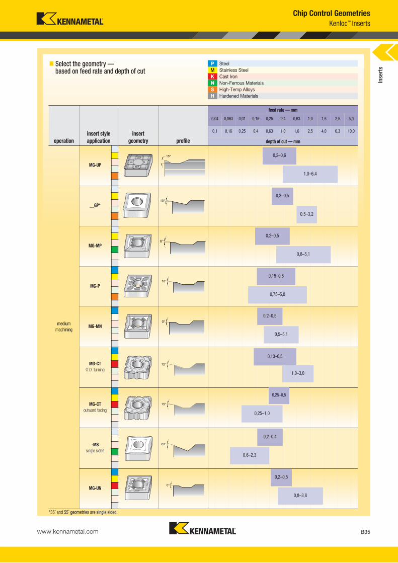
www.kennametal.com B35
� Select the geometry — based on feed rate and depth of cut
P SteelM Stainless SteelK Cast IronN Non-Ferrous MaterialsS High-Temp AlloysH Hardened Materials
*35˚ and 55˚ geometries are single sided.
Chip Control GeometriesKenloc™ Inserts
operationinsert style application
insert geometry profile
feed rate — mm
0,04 0,063 0,01 0,16 0,25 0,4 0,63 1,0 1,6 2,5 5,0
0,1 0,16 0,25 0,4 0,63 1,0 1,6 2,5 4,0 6,3 10,0
depth of cut — mm
mediummachining
MG-UP
__GP*
MG-MP
MG-P
MG-MN
MG-CTO.D. turning
MG-CToutward facing
-MSsingle sided
MG-UN
0,2–0,6
1,0–6,4
0,3–0,5
0,5–3,2
0,2–0,5
0,8–5,1
0,15–0,5
0,75–5,0
0,2–0,5
0,5–5,1
0,13–0,5
1,0–3,0
0,25–0,5
0,25–1,0
0,2–0,4
0,6–2,3
0,2–0,5
0,8–3,8
Inse
rts

www.kennametal.comB36
� Select the geometry — based on feed rate and depth of cut
Chip Control GeometriesKenloc™ Inserts
P SteelM Stainless SteelK Cast IronN Non-Ferrous MaterialsS High-Temp AlloysH Hardened Materials
operationinsert style application
insert geometry profile
feed rate — mm
0,04 0,063 0,01 0,16 0,25 0,4 0,63 1,0 1,6 2,5 5,0
0,1 0,16 0,25 0,4 0,63 1,0 1,6 2,5 4,0 6,3 10,0
depth of cut — mm
roughing
MG-RP
MG-RN
heavyroughing
MG
MM-RMsingle sided
MM-RP
MM-RHsingle sided
wiperfinishing
MT-FW
wiper,mediumfinishing
MT-MW
0,2–0,6
1,1–6,4
0,3–.025
1,1–6,4
0,3–0,8
1,1–5,7
0,3–1,0
1,3–12,7
0,2–1,0
1,3–10,0
0,4–1,3
1,3–12,7
0,1–0,3
0,2–1,5
0,1–0,5
0,4–3,3
Inse
rts
KM_Master12_Turning_B036_B037_Metric.qxp:Layout 1 3/6/12 8:59 AM Page B36

www.kennametal.com B37
� Select the geometry — based on feed rate and depth of cut
P SteelM Stainless SteelK Cast IronN Non-Ferrous MaterialsS High-Temp AlloysH Hardened Materials
Chip Control GeometriesScrew-On Inserts
operationinsert style application
insert geometry profile
feed rate — mm
0,04 0,063 0,01 0,16 0,25 0,4 0,63 1,0 1,6 2,5 5,0
0,1 0,16 0,25 0,4 0,63 1,0 1,6 2,5 4,0 6,3 10,0
depth of cut — mm
finefinishing
__GMprecisionground
MT-11
.MT-UF
finishing
GT-HPprecisionground
GT-LFprecisionground
MT-FP
MT-LF
mediummachining
MT-MP
MT-MF
0,1–0,2
0,2–1,0
0,1–0,3
0,2–1,3
0,1–0,3
0,1–1,3
0,2–0,4
0,6–2,3
0,2–0,4
0,8–2,3
0,2–0,4
0,8–2,3
0,2–0,4
1,1–2,3
0,063–0,25
0,16–1,6
0,01–0,4
0,4–2,3
Inse
rts
KM_Master12_Turning_B036_B037_Metric.qxp:Layout 1 3/6/12 8:59 AM Page B37

Primary ApplicationKennametal offers a complete portfolio of ISO-/ANSI-style inserts. Positive, negative, CVD, PVD, or uncoated, we have the insert to help increase productivity and achieve greater savings.
Plus, our carbide insert line contains Beyond™ technology. Beyond inserts offer you greater versatility, reliability,and up to 30% higher productivity.
Carbide Inserts
Beyond™ CVD Grades• Higher productivity and profitability — up to 300% higher.
• Lower cutting forces — Increase speeds and reduce cycle time.
• Extended tool life.
• Predictable tool life / Uniform wear.
• Resists chip flow damage.
• Consistent surface finish.
• Products can be applied across a wide range of applications.
• Use it in low speed to high speed applications.
• For finish to rough turning of steel, cast iron, stainless steel,and high temp alloy turning.
Beyond™ PVD GradesKCU10™
• PVD-coated grade with superior wear resistance at elevatedtemperatures, allowing higher metal cutting speeds.
• For use in all materials, especially stainless steels and high-temp alloys.
• Improved depth-of-cut notch resistance.
• Increase speed by 20–30% or feed by 10–15%.
• Use in finishing to medium applications.
KCU25™
• PVD-coated grade with superior edge toughness and excellentwear resistance. Medium to roughing applications.
• Use in all materials.
• Increase speed, feed, and depth of cut by 10–20%.
www.kennametal.comB38
KM_Master12_Turning_B038_B039_Metric.qxp:Layout 1 3/6/12 2:05 PM Page B38

www.kennametal.com B39
KM_Master12_Turning_B038_B039_Metric.qxp:Layout 1 3/6/12 2:05 PM Page B39

www.kennametal.comB40
D L10 Rεε
ISO catalogue number mm mm mmCNGG120401FS 12,70 12,90 0,1 � �
CNGG120402FS 12,70 12,90 0,2 � � � �
CNGG120404FS 12,70 12,90 0,4 � � � � �
CNGG120408FS 12,70 12,90 0,8 � � � � �
CNGG120412FS 12,70 12,90 1,2 � �
� CNGG-FS
D L10 Rεε
ISO catalogue number mm mm mm
CNGG120401LF 12,70 12,90 0,1 � � �
CNGG120402LF 12,70 12,90 0,2 � � �
CNGG120404LF 12,70 12,90 0,4 � � �
CNGG120408LF 12,70 12,90 0,8 � �
CNGG120412LF 12,70 12,90 1,2 � �
CNGG160608LF 15,88 16,12 0,8 � �
CNGG160612LF 15,88 16,12 1,2 � �
� CNGG-LF
� CNGP
D L10 Rεε
ISO catalogue number mm mm mm
CNGP120401 12,70 12,90 0,1 � � �
CNGP120402 12,70 12,90 0,2 � � �
CNGP120404 12,70 12,90 0,4 � � � � �
CNGP120408 12,70 12,90 0,8 � � � � �
CNGP120412 12,70 12,90 1,2 � � � �
CNGP120416 12,70 12,90 1,6 � � � �
P � � � � � � �
M � � � � � � �
K � � � �
N �
S � � � � � � � � � �
H
D L10 Rε
ISO catalogue number mm mm mm K
CP
05K
CP
10K
CP
25K
CP
30K
CP
40K
CK
05K
CK
15K
CK
20K
CM
15K
CM
25K
CM
35K
U10
K31
3K
68K
CS1
0K
CU
10K
C50
10K
C55
10K
CU
25K
C50
25K
C55
25K
C54
10K
T315
KTP
10
CNGG120404FBB 12,70 12,90 0,4 �
CNGG120408FBB 12,70 12,90 0,8 � �
ISO Carbide InsertsKenloc™ Inserts
� first choice� alternate choice
� CNGG-FBB
Inse
rts
KM_Master12_Turning_B040_B041_Metric.qxp:Layout 1 3/6/12 9:00 AM Page B40

www.kennametal.com B41
D L10 Rεε
ISO catalogue number mm mm mm
CNMA120404 12,70 12,90 0,4 � � �
CNMA120408 12,70 12,90 0,8 � � � � �
CNMA120412 12,70 12,90 1,2 � � � �
CNMA120416 12,70 12,90 1,6 � � �
CNMA160608 15,88 16,12 0,8 � �
CNMA160612 15,88 16,12 1,2 � � �
CNMA160616 15,88 16,12 1,6 � � �
CNMA190608 19,05 19,34 0,8 � �
CNMA190612 19,05 19,34 1,2 � � � �
CNMA190616 19,05 19,34 1,6 � � �
� CNMA
D L10 Rεε
ISO catalogue number mm mm mm
CNMG120404B 12,70 12,90 0,4 �
CNMG120408 12,70 12,90 0,8 � �
CNMG120412 12,70 12,90 1,2 �
CNMG160612 15,88 16,12 1,2 �
CNMG190608 19,05 19,34 0,8 � � �
CNMG190612 19,05 19,34 1,2 � � � � �
CNMG190616 19,05 19,34 1,6 � � �
CNMG250924 25,40 25,79 2,4 � � �
� CNMG
C2–C71 C72–C109 C110–C115 C116–C147 B10–B23 B24–B31 B32–B37
Inse
rts
KC
P05
KC
P10
KC
P25
KC
P30
KC
P40
KC
K05
KC
K15
KC
K20
KC
M15
KC
M25
KC
M35
KU
10K
313
K68
KC
S10
KC
U10
KC
5010
KC
5510
KC
U25
KC
5025
KC
5525
KC
5410
KT3
15K
TP10
ISO Carbide InsertsKenloc™ Inserts
� first choice� alternate choice
P � � � � � � �
M � � � � � � �
K � � � �
N �
S � � � � � � � � � �
H
KM_Master12_Turning_B040_B041_Metric.qxp:Layout 1 3/6/12 9:00 AM Page B41

www.kennametal.comB42
� CNMG-CT
� CNMG-FF
� CNMG-FN
D L10 Rεε
ISO catalogue number mm mm mmCNMG120408CT 12,70 12,90 0,8 � � � � �
CNMG120412CT 12,70 12,90 1,2 � � �
CNMG120416CT 12,70 12,90 1,6 �
D L10 Rε
ISO catalogue number mm mm mmCNMG090304FF 9,53 9,67 0,4 � � � �
CNMG090308FF 9,53 9,67 0,8 � � �
CNMG120404FF 12,70 12,90 0,4 � � � � �
CNMG120408FF 12,70 12,90 0,8 � � � � �
D L10 Rε
ISO catalogue number mm mm mmCNMG090304FN 9,53 9,67 0,4 � � �
CNMG090308FN 9,53 9,67 0,8 � � �
CNMG120402FN 12,70 12,90 0,2 � � �
CNMG120404FN 12,70 12,90 0,4 � � � � �
CNMG120408FN 12,70 12,90 0,8 � � � � �
CNMG120412FN 12,70 12,90 1,2 � � � � �
CNMG120416FN 12,70 12,90 1,6 � � �
Inse
rts
KC
P05
KC
P10
KC
P25
KC
P30
KC
P40
KC
K05
KC
K15
KC
K20
KC
M15
KC
M25
KC
M35
KU
10K
313
K68
KC
S10
KC
U10
KC
5010
KC
5510
KC
U25
KC
5025
KC
5525
KC
5410
KT3
15K
TP10
ISO Carbide InsertsKenloc™ Inserts
� first choice� alternate choice
P � � � � � � �
M � � � � � � �
K � � � �
N �
S � � � � � � � � �
H
KM_Master12_Turning_B042_B043_Metric.qxp:Layout 1 3/6/12 9:01 AM Page B42

www.kennametal.com B43
ISO Carbide InsertsKenloc™ Inserts
� first choice� alternate choice
� CNMG-FP
� CNMG-FW
P � � � � � � �
M � � � � � � �
K � � � �
N �
S � � � � � � � � �
H
D L10 Rεε
ISO catalogue number mm mm mm K
CP
05K
CP
10K
CP
25K
CP
30K
CP
40K
CK
05K
CK
15K
CK
20K
CM
15K
CM
25K
CM
35K
U10
K31
3K
68K
CS1
0K
CU
10K
C50
10K
C55
10K
CU
25K
C50
25K
C55
25K
C54
10K
T315
KTP
10
CNMG120404FP 12,70 12,90 0,4 � � � � �
CNMG120408FP 12,70 12,90 0,8 � � � � � �
CNMG120412FP 12,70 12,90 1,2 � � �
D L10 Rε
ISO catalogue number mm mm mmCNMG120404FW 12,70 12,90 0,4 � � � � �
CNMG120408FW 12,70 12,90 0,8 � � � � �
CNMG120412FW 12,70 12,90 1,2 � � � � �
D L10 Rε
ISO catalogue number mm mm mmCNMG120404MBB 12,70 12,90 0,4 �
CNMG120408MBB 12,70 12,90 0,8 � �
� CNMG-MBB
Inse
rts
C2–C71 C72–C109 C110–C115 C116–C147 B10–B23 B24–B31 B32–B37
KM_Master12_Turning_B042_B043_Metric.qxp:Layout 1 3/6/12 9:01 AM Page B43

www.kennametal.comB44
P � � � � � � �
M � � � � � � �
K � � � �
N �
S � � � � � � � � � �
H
D L10 Rε
ISO catalogue number mm mm mm K
CP
05K
CP
10K
CP
25K
CP
30K
CP
40K
CK
05K
CK
15K
CK
20K
CM
15K
CM
25K
CM
35K
U10
K31
3K
68K
CS1
0K
CU
10K
C50
10K
C55
10K
CU
25K
C50
25K
C55
25K
C54
10K
T315
KTP
10
CNMG090304MN 9,53 9,67 0,4 � � �
CNMG090308MN 9,53 9,67 0,8 � � �
CNMG090312MN 9,53 9,67 1,2 �
CNMG120404MN 12,70 12,90 0,4 � � � �
CNMG120408MN 12,70 12,90 0,8 � � � � �
CNMG120412MN 12,70 12,90 1,2 � � � � �
CNMG120416MN 12,70 12,90 1,6 � �
CNMG160608MN 15,88 16,12 0,8 � � �
CNMG160612MN 15,88 16,12 1,2 � � � �
CNMG160616MN 15,88 16,12 1,6 � �
CNMG190608MN 19,05 19,34 0,8 � � �
CNMG190612MN 19,05 19,34 1,2 � � � �
CNMG190616MN 19,05 19,34 1,6 � � �
ISO Carbide InsertsKenloc™ Inserts
� first choice� alternate choice
� CNMG-MN
D L10 Rεε
ISO catalogue number mm mm mmCNMG090308MP 9,53 9,67 0,8 � � � �
CNMG120404MP 12,70 12,90 0,4 � � � � �
CNMG120408MP 12,70 12,90 0,8 � � � � � � � � �
CNMG120412MP 12,70 12,90 1,2 � � � � � � � � �
CNMG120416MP 12,70 12,90 1,6 � � � �
CNMG160608MP 15,88 16,12 0,8 � � � � �
CNMG160612MP 15,88 16,12 1,2 � � � � � � �
CNMG160616MP 15,88 16,12 1,6 � � � �
CNMG190608MP 19,05 19,34 0,8 � � � �
CNMG190612MP 19,05 19,34 1,2 � � � � � � �
CNMG190616MP 19,05 19,34 1,6 � � � �
� CNMG-MP
Inse
rts
KM_Master12_Turning_B044_B045_Metric.qxp:Layout 1 3/6/12 9:01 AM Page B44

www.kennametal.com B45
P � � � � � � �
M � � � � � � �
K � � � �
N �
S � � � � � � � � �
H
D L10 Rε
ISO catalogue number mm mm mm K
CP
05K
CP
10K
CP
25K
CP
30K
CP
40K
CK
05K
CK
15K
CK
20K
CM
15K
CM
25K
CM
35K
U10
K31
3K
68K
CS1
0K
CU
10K
C50
10K
C55
10K
CU
25K
C50
25K
C55
25K
C54
10K
T315
KTP
10
CNMG120401MS 12,70 12,90 0,1 � � � �
CNMG120402MS 12,70 12,90 0,2 � � � � �
CNMG120404MS 12,70 12,90 0,4 � � � � �
CNMG120408MS 12,70 12,90 0,8 � � � � �
CNMG120412MS 12,70 12,90 1,2 � � � � �
CNMG120416MS 12,70 12,90 1,6 � � � �
CNMG160608MS 15,88 16,12 0,8 � � � �
CNMG160612MS 15,88 16,12 1,2 � � � � �
CNMG190608MS 19,05 19,34 0,8 � � � �
CNMG190612MS 19,05 19,34 1,2 � � � � �
CNMG190616MS 19,05 19,34 1,6 � � � �
ISO Carbide InsertsKenloc™ Inserts
� first choice� alternate choice
� CNMG-MS
D L10 Rεε
ISO catalogue number mm mm mmCNMG120408MW 12,70 12,90 0,8 � � �
CNMG120412MW 12,70 12,90 1,2 � � �
� CNMG-MW
D L10 Rεε
ISO catalogue number mm mm mm
CNMG120404P 12,70 12,90 0,4 � � �
CNMG120408P 12,70 12,90 0,8 � � � �
CNMG120412P 12,70 12,90 1,2 � � �
CNMG120416P 12,70 12,90 1,6 � � �
CNMG190612P 19,05 19,34 1,2 � �
� CNMG-P
Inse
rts
C2–C71 C72–C109 C110–C115 C116–C147 B10–B23 B24–B31 B32–B37
KM_Master12_Turning_B044_B045_Metric.qxp:Layout 1 3/6/12 9:02 AM Page B45

www.kennametal.comB46
P � � � � � � �
M � � � � � � �
K � � � �
N �
S � � � � � � � � � �
H
D L10 Rε
ISO catalogue number mm mm mm K
CP
05K
CP
10K
CP
25K
CP
30K
CP
40K
CK
05K
CK
15K
CK
20K
CM
15K
CM
25K
CM
35K
U10
K31
3K
68K
CS1
0K
CU
10K
C50
10K
C55
10K
CU
25K
C50
25K
C55
25K
C54
10K
T315
KTP
10
CNMG120408RBB 12,70 12,90 0,8 � �
ISO Carbide InsertsKenloc™ Inserts
� first choice� alternate choice
� CNMG-RBB
D L10 Rεε
ISO catalogue number mm mm mmCNMG190612RM 19,05 19,34 1,2 � � �
CNMG190616RM 19,05 19,34 1,6 � � � �
CNMG250924RM 25,40 25,79 2,4 � � � �
� CNMG-RM
D L10 Rεε
ISO catalogue number mm mm mmCNMG120408RN 12,70 12,90 0,8 � � � � �
CNMG120412RN 12,70 12,90 1,2 � � � � �
CNMG120416RN 12,70 12,90 1,6 � � � � �
CNMG160608RN 15,88 16,12 0,8 � � �
CNMG160612RN 15,88 16,12 1,2 � � � �
CNMG160616RN 15,88 16,12 1,6 � � �
CNMG190608RN 19,05 19,34 0,8 � � �
CNMG190612RN 19,05 19,34 1,2 � � � �
CNMG190616RN 19,05 19,34 1,6 � � � �
CNMG190624RN 19,05 19,34 2,4 � � �
� CNMG-RN
D L10 Rεε
ISO catalogue number mm mm mmCNMG120404RP 12,70 12,90 0,4 � � � � � � � � � �
CNMG120408RP 12,70 12,90 0,8 � � � � � � � � � � � � � � � � �
CNMG120412RP 12,70 12,90 1,2 � � � � � � � � � � � � � � � � �
CNMG120416RP 12,70 12,90 1,6 � � � � � � � � � � � �
CNMG160608RP 15,88 16,12 0,8 � � � � � � � � �
CNMG160612RP 15,88 16,12 1,2 � � � � � � � � � � � � � � � �
CNMG160616RP 15,88 16,12 1,6 � � � � � � � � �
CNMG190612RP 19,05 19,34 1,2 � � � � � � � � � � � � � � � �
CNMG190616RP 19,05 19,34 1,6 � � � � � � � � � � � � �
� CNMG-RP
Inse
rts
KM_Master12_Turning_B046_B047_Metric.qxp:Layout 1 3/6/12 9:02 AM Page B46

www.kennametal.com B47
P � � � � � � �
M � � � � � � �
K � � � �
N �
S � � � � � � � � � �
H
D L10 Rε
ISO catalogue number mm mm mm K
CP
05K
CP
10K
CP
25K
CP
30K
CP
40K
CK
05K
CK
15K
CK
20K
CM
15K
CM
25K
CM
35K
U10
K31
3K
68K
CS1
0K
CU
10K
C50
10K
C55
10K
CU
25K
C50
25K
C55
25K
C54
10K
T315
KTP
10
CNMG120404UN 12,70 12,90 0,4 � � �
CNMG120408UN 12,70 12,90 0,8 � � �
CNMG120412UN 12,70 12,90 1,2 � � �
CNMG120416UN 12,70 12,90 1,6 � � �
CNMG160608UN 15,88 16,12 0,8 � � �
CNMG160612UN 15,88 16,12 1,2 � � �
CNMG160616UN 15,88 16,12 1,6 � � �
CNMG190608UN 19,05 19,34 0,8 � � �
CNMG190612UN 19,05 19,34 1,2 � � �
CNMG190616UN 19,05 19,34 1,6 � � �
ISO Carbide InsertsKenloc™ Inserts
� CNMG-UN
D L10 Rεε
ISO catalogue number mm mm mmCNMG120404UP 12,70 12,90 0,4 � � �
CNMG120408UP 12,70 12,90 0,8 � � � � �
CNMG120412UP 12,70 12,90 1,2 � � � � �
CNMG160608UP 15,88 16,12 0,8 � � � �
CNMG160612UP 15,88 16,12 1,2 � � � � �
CNMG190608UP 19,05 19,34 0,8 � �
CNMG190612UP 19,05 19,34 1,2 � � �
CNMG190616UP 19,05 19,34 1,6 � � �
� CNMG-UP
D L10 Rεε
ISO catalogue number mm mm mmCNMM190612RH 19,05 19,34 1,2 � � � �
CNMM190616RH 19,05 19,34 1,6 � � � �
CNMM190624RH 19,05 19,34 2,4 � � �
CNMM250924RH 25,40 25,79 2,4 � � � �
� CNMM-RH
� first choice� alternate choice In
sert
s
C2–C71 C72–C109 C110–C115 C116–C147 B10–B23 B24–B31 B32–B37
KM_Master12_Turning_B046_B047_Metric.qxp:Layout 1 3/6/12 9:02 AM Page B47

www.kennametal.comB48
P � � � � � � �
M � � � � � � �
K � � � �
N �
S � � � � � � � � � �
H
D L10 Rε
ISO catalogue number mm mm mm K
CP
05K
CP
10K
CP
25K
CP
30K
CP
40K
CK
05K
CK
15K
CK
20K
CM
15K
CM
25K
CM
35K
U10
K31
3K
68K
CS1
0K
CU
10K
C50
10K
C55
10K
CU
25K
C50
25K
C55
25K
C54
10K
T315
KTP
10
CNMM120408RM 12,70 12,90 0,8 � � �
CNMM120412RM 12,70 12,90 1,2 � � � �
CNMM120416RM 12,70 12,90 1,6 � �
CNMM160612RM 15,88 16,12 1,2 � � �
CNMM160616RM 15,88 16,12 1,6 � � �
CNMM160624RM 15,88 16,12 2,4 � �
CNMM190612RM 19,05 19,34 1,2 � � � �
CNMM190616RM 19,05 19,34 1,6 � � � �
CNMM190624RM 19,05 19,34 2,4 � �
CNMM250924RM 25,40 25,79 2,4 � � � �
ISO Carbide InsertsKenloc™ Inserts
� first choice� alternate choice
� CNMM-RM
D L10 Rεε
ISO catalogue number mm mm mmCNMM120408RP 12,70 12,90 0,8 � � � � � � �
CNMM120412RP 12,70 12,90 1,2 � � � � � � � �
CNMM120416RP 12,70 12,90 1,6 � � � � �
CNMM160608RP 15,88 16,12 0,8 � �
CNMM160612RP 15,88 16,12 1,2 � � � � � � � �
CNMM160616RP 15,88 16,12 1,6 � � � � � � �
CNMM190612RP 19,05 19,34 1,2 � � � � � �
CNMM190616RP 19,05 19,34 1,6 � � � � � � �
CNMM190624RP 19,05 19,34 2,4 � � �
CNMM250924RP 25,40 25,79 2,4 � �
� CNMM-RP
D L10 Rεε
ISO catalogue number mm mm mm
CNMP120404 12,70 12,90 0,4 � � �
CNMP120408 12,70 12,90 0,8 � � �
CNMP120412 12,70 12,90 1,2 �
CNMP160608 15,88 16,12 0,8 �
CNMP160612 15,88 16,12 1,2 � �
CNMP190608 19,05 19,34 0,8 �
CNMP190612 19,05 19,34 1,2 � � �
� CNMP
Inse
rts
KM_Master12_Turning_B048_B049_Metric.qxp:Layout 1 3/6/12 9:03 AM Page B48

www.kennametal.com B49
P � � � � � � �
M � � � � � � �
K � � � �
N �
S � � � � � � � � � �
H
D L10 Rε
ISO catalogue number mm mm mm K
CP
05K
CP
10K
CP
25K
CP
30K
CP
40K
CK
05K
CK
15K
CK
20K
CM
15K
CM
25K
CM
35K
U10
K31
3K
68K
CS1
0K
CU
10K
C50
10K
C55
10K
CU
25K
C50
25K
C55
25K
C54
10K
T315
KTP
10
CNMP120404K 12,70 12,90 0,4 �
CNMP120408K 12,70 12,90 0,8 � �
CNMP120412K 12,70 12,90 1,2 �
ISO Carbide InsertsKenloc™ Inserts
� first choice� alternate choice
� CNMP-K
D L10 Rε
ISO catalogue number mm mm mm
CNMS120408 12,70 12,90 0,8 � �
CNMS160608 15,88 16,12 0,8 � �
CNMS190608 19,05 19,34 0,8 � �
CNMS190612 19,05 19,34 1,2 �
� CNMS
Inse
rts
C2–C71 C72–C109 C110–C115 C116–C147 B10–B23 B24–B31 B32–B37
KM_Master12_Turning_B048_B049_Metric.qxp:Layout 1 3/6/12 9:03 AM Page B49

www.kennametal.comB50
P � � � � � � �
M � � � � � � �
K � � � �
N �
S � � � � � � � � �
H
D L10 Rε
ISO catalogue number mm mm mm K
CP
05K
CP
10K
CP
25K
CP
30K
CP
40K
CK
05K
CK
15K
CK
20K
CM
15K
CM
25K
CM
35K
U10
K31
3K
68K
CS1
0K
CU
10K
C50
10K
C55
10K
CU
25K
C50
25K
C55
25K
C54
10K
T315
KTP
10
DNGG110402FS 9,52 11,63 0,2 � � � �
DNGG110404FS 9,52 11,63 0,4 � �
DNGG110408FS 9,52 11,63 0,8 � �
DNGG150401FS 12,70 15,50 0,1 � �
DNGG150402FS 12,70 15,50 0,2 � � � �
DNGG150604FS 12,70 15,50 0,4 � � � �
DNGG150404FS 12,70 15,50 0,4 � � � �
DNGG150608FS 12,70 15,50 0,8 � �
DNGG150408FS 12,70 15,50 0,8 � � � �
DNGG150412FS 12,70 15,50 1,2 � �
DNGG150416FS 12,70 15,50 1,6 � �
ISO Carbide InsertsKenloc™ Inserts
� first choice� alternate choice
� DNGG-FS
D L10 Rεε
ISO catalogue number mm mm mm
DNGG150402LF 12,70 15,50 0,2 � �
DNGG150404LF 12,70 15,50 0,4 � � �
DNGG150408LF 12,70 15,50 0,8 � �
� DNGG-LF
D L10 Rεε
ISO catalogue number mm mm mm
DNGP150401 12,70 15,50 0,1 � � �
DNGP150402 12,70 15,50 0,2 � � �
DNGP150404 12,70 15,50 0,4 � � � �
DNGP150408 12,70 15,50 0,8 � � � �
DNGP150604 12,70 15,50 0,4 � � � �
DNGP150608 12,70 15,50 0,8 � � � �
DNGP150612 12,70 15,50 1,2 �
� DNGP
Inse
rts
KM_Master12_Turning_B050_B051_Metric.qxp:Layout 1 3/6/12 9:03 AM Page B50

www.kennametal.com B51
P � � � � � � �
M � � � � � � �
K � � � �
N �
S � � � � � � � � � �
H
D L10 Rε
ISO catalogue number mm mm mm K
CP
05K
CP
10K
CP
25K
CP
30K
CP
40K
CK
05K
CK
15K
CK
20K
CM
15K
CM
25K
CM
35K
U10
K31
3K
68K
CS1
0K
CU
10K
C50
10K
C55
10K
CU
25K
C50
25K
C55
25K
C54
10K
T315
KTP
10
DNMA110408 9,53 11,63 0,8 � �
DNMA110412 9,53 11,63 1,2 �
DNMA150408 12,70 15,50 0,8 � � �
DNMA150412 12,70 15,50 1,2 � � �
DNMA150416 12,70 15,50 1,6 �
DNMA150608 12,70 15,50 0,8 � � �
DNMA150612 12,70 15,50 1,2 � � �
DNMA150616 12,70 15,50 1,6 �
ISO Carbide InsertsKenloc™ Inserts
� first choice� alternate choice
� DNMA
� DNMG
D L10 Rεε
ISO catalogue number mm mm mm
DNMG150404B 12,70 15,50 0,4 �
DNMG150408B 12,70 15,50 0,8 � �
DNMG150412B 12,70 15,50 1,2 �
DNMG150608B 12,70 15,50 0,8 �
Inse
rts
C2–C71 C72–C109 C110–C115 C116–C147 B10–B23 B24–B31 B32–B37
KM_Master12_Turning_B050_B051_Metric.qxp:Layout 1 3/6/12 9:04 AM Page B51

www.kennametal.comB52
P � � � � � � �
M � � � � � � �
K � � � �
N �
S � � � � � � � � �
H
D L10 Rε
ISO catalogue number mm mm mm K
CP
05K
CP
10K
CP
25K
CP
30K
CP
40K
CK
05K
CK
15K
CK
20K
CM
15K
CM
25K
CM
35K
U10
K31
3K
68K
CS1
0K
CU
10K
C50
10K
C55
10K
CU
25K
C50
25K
C55
25K
C54
10K
T315
KTP
10
DNMG110404CT 9,53 11,63 0,4 �
DNMG110408CT 9,53 11,63 0,8 � � �
DNMG150404CT 12,70 15,50 0,4 � � � � �
DNMG150408CT 12,70 15,50 0,8 � � � � �
DNMG150412CT 12,70 15,50 1,2 � � �
DNMG150604CT 12,70 15,50 0,3 � �
DNMG150608CT 12,70 15,50 0,7 � � � � �
DNMG150612CT 12,70 15,50 1,1 � � � � �
ISO Carbide InsertsKenloc™ Inserts
� first choice� alternate choice
� DNMG-CT
D L10 Rεε
ISO catalogue number mm mm mmDNMG110404FF 9,53 11,63 0,4 � � � � �
DNMG110408FF 9,53 11,63 0,8 � � � � �
DNMG150404FF 12,70 15,50 0,4 � � � � �
DNMG150408FF 12,70 15,50 0,8 � � � � �
DNMG150604FF 12,70 15,50 0,4 � � � � �
DNMG150608FF 12,70 15,50 0,8 � � � � �
� DNMG-FF
� DNMG-FND L10 Rεε
ISO catalogue number mm mm mmDNMG110404FN 9,53 11,63 0,4 � � � � �
DNMG110408FN 9,53 11,63 0,8 � � � � �
DNMG110412FN 9,53 11,63 1,2 � � �
DNMG150404FN 12,70 15,50 0,4 � � � � �
DNMG150408FN 12,70 15,50 0,8 � � � � �
DNMG150412FN 12,70 15,50 1,2 � � � �
DNMG150604FN 12,70 15,50 0,4 � � � � �
DNMG150608FN 12,70 15,50 0,8 � � � � �
DNMG150612FN 12,70 15,50 1,2 � � � � �
Inse
rts
KM_Master12_Turning_B052_B053_Metric.qxp:Layout 1 3/6/12 9:04 AM Page B52

www.kennametal.com B53
P � � � � � � �
M � � � � � � �
K � � � �
N �
S � � � � � � � � �
H
D L10 Rε
ISO catalogue number mm mm mm K
CP
05K
CP
10K
CP
25K
CP
30K
CP
40K
CK
05K
CK
15K
CK
20K
CM
15K
CM
25K
CM
35K
U10
K31
3K
68K
CS1
0K
CU
10K
C50
10K
C55
10K
CU
25K
C50
25K
C55
25K
C54
10K
T315
KTP
10
DNMG110404FP 9,53 11,63 0,4 � � � �
DNMG110408FP 9,53 11,63 0,8 � � � � �
DNMG150404FP 12,70 15,50 0,4 � � � �
DNMG150408FP 12,70 15,50 0,8 � � � � � �
DNMG150412FP 12,70 15,50 1,2 � � �
DNMG150604FP 12,70 15,50 0,4 � � � �
DNMG150608FP 12,70 15,50 0,8 � � � � � �
DNMG150612FP 12,70 15,50 1,2 � � � �
ISO Carbide InsertsKenloc™ Inserts
� first choice� alternate choice
� DNMG-FP
D L10 Rεε
ISO catalogue number mm mm mmDNMG110404FW 9,53 11,63 0,4 � � � � �
DNMG110408FW 9,53 11,63 0,8 � � � �
DNMG150404FW 12,70 15,50 0,4 � � � �
DNMG150408FW 12,70 15,50 0,4 � � � � �
DNMG150604FW 12,70 15,50 0,4 � � � � �
DNMG150608FW 12,70 15,50 0,4 � � � � �
� DNMG-FW
D L10 Rεε
ISO catalogue number mm mm mmDNMG110404MN 9,53 11,63 0,4 � � � �
DNMG110408MN 9,53 11,63 0,8 � � � �
DNMG110412MN 9,53 11,63 1,2 � �
DNMG150404MN 12,70 15,50 0,4 � � � �
DNMG150408MN 12,70 15,50 0,8 � � � � �
DNMG150412MN 12,70 15,50 1,2 � � � �
DNMG150416MN 12,70 15,50 1,6 � �
DNMG150604MN 12,70 15,50 0,4 � � � �
DNMG150608MN 12,70 15,50 0,8 � � � � �
DNMG150612MN 12,70 15,50 1,2 � � � �
DNMG150616MN 12,70 15,50 1,6 �
DNMG190612MN 15,88 19,38 1,2 � �
� DNMG-MN
Inse
rts
C2–C71 C72–C109 C110–C115 C116–C147 B10–B23 B24–B31 B32–B37
KM_Master12_Turning_B052_B053_Metric.qxp:Layout 1 3/6/12 9:04 AM Page B53

www.kennametal.comB54
P � � � � � � �
M � � � � � � �
K � � � �
N �
S � � � � � � � � �
H
D L10 Rε
ISO catalogue number mm mm mm K
CP
05K
CP
10K
CP
25K
CP
30K
CP
40K
CK
05K
CK
15K
CK
20K
CM
15K
CM
25K
CM
35K
U10
K31
3K
68K
CS1
0K
CU
10K
C50
10K
C55
10K
CU
25K
C50
25K
C55
25K
C54
10K
T315
KTP
10
DNMG110408MP 9,53 11,63 0,8 � � � �
DNMG110412MP 9,53 11,63 1,2 � � �
DNMG150404MP 12,70 15,50 0,4 � � � � �
DNMG150408MP 12,70 15,50 0,8 � � � � � � �
DNMG150412MP 12,70 15,50 1,2 � � � �
DNMG150604MP 12,70 15,50 0,4 � � � � �
DNMG150608MP 12,70 15,50 0,8 � � � � � � � � �
DNMG150612MP 12,70 15,50 1,2 � � � � � � �
ISO Carbide InsertsKenloc™ Inserts
� first choice� alternate choice
� DNMG-MP
D L10 Rεε
ISO catalogue number mm mm mmDNMG110408MS 9,53 11,63 0,8 � � � � �
DNMG150401MS 12,70 15,50 0,1 � �
DNMG150402MS 12,70 15,50 0,2 � � � �
DNMG150404MS 12,70 15,50 0,4 � � � � �
DNMG150604MS 12,70 15,50 0,4 � � � � �
DNMG150608MS 12,70 15,50 0,8 � � � � �
DNMG150408MS 12,70 15,50 0,8 � � � � �
DNMG150412MS 12,70 15,50 1,2 � � � �
DNMG150612MS 12,70 15,50 1,2 � � � � �
� DNMG-MS
D L10 Rεε
ISO catalogue number mm mm mmDNMG150408MW 12,70 15,50 0,4 � � �
DNMG150412MW 12,70 15,50 1,2 � � �
DNMG150608MW 12,70 15,50 0,4 � � �
DNMG150612MW 12,70 15,50 1,2 � � �
� DNMG-MW
Inse
rts
KM_Master12_Turning_B054_B055_Metric.qxp:Layout 1 3/6/12 9:05 AM Page B54

www.kennametal.com B55
P � � � � � � �
M � � � � � � �
K � � � �
N �
S � � � � � � � � �
H
D L10 Rε
ISO catalogue number mm mm mm K
CP
05K
CP
10K
CP
25K
CP
30K
CP
40K
CK
05K
CK
15K
CK
20K
CM
15K
CM
25K
CM
35K
U10
K31
3K
68K
CS1
0K
CU
10K
C50
10K
C55
10K
CU
25K
C50
25K
C55
25K
C54
10K
T315
KTP
10
DNMG150404P 12,70 15,50 0,4 � �
DNMG150408P 12,70 15,50 0,8 � � �
DNMG150604P 12,70 15,50 0,4 �
DNMG150608P 12,70 15,50 0,8 � �
ISO Carbide InsertsKenloc™ Inserts
� first choice� alternate choice
� DNMG-P
D L10 Rεε
ISO catalogue number mm mm mmDNMG190608RM 15,88 19,38 0,8 � �
DNMG190612RM 15,88 19,38 1,2 � �
� DNMG-RM
� DNMG-RN
D L10 Rεε
ISO catalogue number mm mm mmDNMG150408RN 12,70 15,50 0,8 � � � �
DNMG150412RN 12,70 15,50 1,2 � � �
DNMG150416RN 12,70 15,50 1,6 � �
DNMG150608RN 12,70 15,50 0,8 � � � � �
DNMG150612RN 12,70 15,50 1,2 � � � � �
DNMG150616RN 12,70 15,50 1,6 � � � �
DNMG190608RN 15,88 19,38 0,8 � � �
DNMG190612RN 15,88 19,38 1,2 � � �In
sert
s
C2–C71 C72–C109 C110–C115 C116–C147 B10–B23 B24–B31 B32–B37
KM_Master12_Turning_B054_B055_Metric.qxp:Layout 1 3/6/12 9:05 AM Page B55

www.kennametal.comB56
P � � � � � � �
M � � � � � � �
K � � � �
N �
S � � � � � � � � �
H
D L10 Rε
ISO catalogue number mm mm mm K
CP
05K
CP
10K
CP
25K
CP
30K
CP
40K
CK
05K
CK
15K
CK
20K
CM
15K
CM
25K
CM
35K
U10
K31
3K
68K
CS1
0K
CU
10K
C50
10K
C55
10K
CU
25K
C50
25K
C55
25K
C54
10K
T315
KTP
10
DNMG110408RP 9,53 11,63 0,8 � � � � � � � � �
DNMG110412RP 9,53 11,63 1,2 � � � �
DNMG150408RP 12,70 15,50 0,8 � � � � � � � � � � � � � � �
DNMG150412RP 12,70 15,50 1,2 � � � � � � � � � � � � � �
DNMG150416RP 12,70 15,50 1,6 � � � �
DNMG150608RP 12,70 15,50 0,8 � � � � � � � � � � � � � � � � �
DNMG150612RP 12,70 15,50 1,2 � � � � � � � � � � � � � � �
DNMG150616RP 12,70 15,50 1,6 � � � � � � �
ISO Carbide InsertsKenloc™ Inserts
� first choice� alternate choice
� DNMG-RP
D L10 Rεε
ISO catalogue number mm mm mmDNMG110408UN 9,53 11,63 0,8 � � �
DNMG110412UN 9,53 11,63 1,2 � � �
DNMG150408UN 12,70 15,50 0,8 � �
DNMG150412UN 12,70 15,50 1,2 � � �
DNMG150416UN 12,70 15,50 1,6 � �
DNMG150608UN 12,70 15,50 0,8 � � �
DNMG150612UN 12,70 15,50 1,2 � � �
DNMG150616UN 12,70 15,50 1,6 � �
� DNMG-UN
D L10 Rεε
ISO catalogue number mm mm mmDNMG110408UP 9,53 11,63 0,8 � � � �
DNMG110412UP 9,53 11,63 1,2 � � �
DNMG150404UP 12,70 15,50 0,4 � � � �
DNMG150408UP 12,70 15,50 0,8 � � � � �
DNMG150412UP 12,70 15,50 1,2 � � � � �
DNMG150604UP 12,70 15,50 0,4 � � �
DNMG150608UP 12,70 15,50 0,8 � � � � �
DNMG150612UP 12,70 15,50 1,2 � � � �
� DNMG-UP
Inse
rts
KM_Master12_Turning_B056_B057_Metric.qxp:Layout 1 3/6/12 9:05 AM Page B56

www.kennametal.com B57
P � � � � � � �
M � � � � � � �
K � � � �
N �
S � � � � � � � � � �
H
D L10 Rε
ISO catalogue number mm mm mm K
CP
05K
CP
10K
CP
25K
CP
30K
CP
40K
CK
05K
CK
15K
CK
20K
CM
15K
CM
25K
CM
35K
U10
K31
3K
68K
CS1
0K
CU
10K
C50
10K
C55
10K
CU
25K
C50
25K
C55
25K
C54
10K
T315
KTP
10
DNMM150408RM 12,70 15,50 0,8 �
DNMM150412RM 12,70 15,50 1,2 �
DNMM150608RM 12,70 15,50 0,8 � � �
DNMM150612RM 12,70 15,50 1,2 � � � �
DNMM150616RM 12,70 15,50 1,6 � �
ISO Carbide InsertsKenloc™ Inserts
� first choice� alternate choice
� DNMM-RM
D L10 Rεε
ISO catalogue number mm mm mmDNMM150608RP 12,70 15,50 0,8 � � �
DNMM150612RP 12,70 15,50 1,2 � � �
DNMM150616RP 12,70 15,50 1,6 � �
� DNMM-RP
D L10 Rεε
ISO catalogue number mm mm mm
DNMP150404 12,70 15,50 0,4 � �
DNMP150408 12,70 15,50 0,8 � �
DNMP150412 12,70 15,50 1,2 �
� DNMP
D L10 Rεε
ISO catalogue number mm mm mm
DNMP110408K 9,53 11,63 0,8 �
DNMP150404K 12,70 15,50 0,4 � �
DNMP150408K 12,70 15,50 0,8 � � �
DNMP150412K 12,70 15,50 1,2 �
DNMP190608K 15,88 19,38 0,8 �
� DNMP-K
Inse
rts
C2–C71 C72–C109 C110–C115 C116–C147 B10–B23 B24–B31 B32–B37
KM_Master12_Turning_B056_B057_Metric.qxp:Layout 1 3/6/12 9:06 AM Page B57

www.kennametal.comB58
P � � � � � � �
M � � � � � � �
K � � � �
N �
S � � � � � � � � � �
H
D L10 Rε
ISO catalogue number mm mm mm K
CP
05K
CP
10K
CP
25K
CP
30K
CP
40K
CK
05K
CK
15K
CK
20K
CM
15K
CM
25K
CM
35K
U10
K31
3K
68K
CS1
0K
CU
10K
C50
10K
C55
10K
CU
25K
C50
25K
C55
25K
C54
10K
T315
KTP
10
DNMS150408 12,70 15,50 0,8 � �
ISO Carbide InsertsKenloc™ Inserts
� first choice� alternate choice
� DNMS
D L10 Rεε
ISO catalogue number mm mm mmRCGX190600ELF 19,05 — — � �
� RCGX-LF
D L10 Rεε
ISO catalogue number mm mm mm
RNMA090300 9,53 — — �
RNMA120400 12,70 — — � � � �
RNMA150600 15,88 — — �
RNMA190600 19,05 — — �
RNMA250900 25,40 — — �
� RNMA
D L10 Rεε
ISO catalogue number mm mm mm
RNMG190600 19,05 — — � � �
RNMG250900 25,40 — — �
� RNMG
D L10 Rεε
ISO catalogue number mm mm mmRNMG090300RN 9,53 — — � �
RNMG120400RN 12,70 — — � � � � � �
RNMG150600RN 15,88 — — � � �
RNMG190600RN 19,05 — — � � � � �
RNMG250900RN 25,40 — — � � �
� RNMG-RN
Inse
rts
KM_Master12_Turning_B058_B059_Metric.qxp:Layout 1 3/6/12 9:06 AM Page B58

www.kennametal.com B59
P � � � � � � �
M � � � � � � �
K � � � �
N �
S � � � � � � � � � �
H
D L10 Rε
ISO catalogue number mm mm mm K
CP
05K
CP
10K
CP
25K
CP
30K
CP
40K
CK
05K
CK
15K
CK
20K
CM
15K
CM
25K
CM
35K
U10
K31
3K
68K
CS1
0K
CU
10K
C50
10K
C55
10K
CU
25K
C50
25K
C55
25K
C54
10K
T315
KTP
10
RNMG120400UN 12,70 — — � � �
ISO Carbide InsertsKenloc™ Inserts
� first choice� alternate choice
� RNMG-UN
D L10 Rεε
ISO catalogue number mm mm mm
SNGG090308FS 9,53 9,53 0,8 � �
SNGG120408FS 12,70 12,70 0,8 � �
� SNGG-FS
D L10 Rεε
ISO catalogue number mm mm mm
SNGG090308LF 9,53 9,53 0,8 � � �
SNGG120408LF 12,70 12,70 0,8 � �
SNGG150612LF 15,88 15,88 1,2 �
� SNGG-LF
D L10 Rεε
ISO catalogue number mm mm mm
SNGP120404 12,70 12,70 0,4 � � �
SNGP120408 12,70 12,70 0,8 � � �
� SNGP
Inse
rts
C2–C71 C72–C109 C110–C115 C116–C147 B10–B23 B24–B31 B32–B37
KM_Master12_Turning_B058_B059_Metric.qxp:Layout 1 3/6/12 9:06 AM Page B59

www.kennametal.comB60
P � � � � � � �
M � � � � � � �
K � � � �
N �
S � � � � � � � � � �
H
D L10 Rε
ISO catalogue number mm mm mm K
CP
05K
CP
10K
CP
25K
CP
30K
CP
40K
CK
05K
CK
15K
CK
20K
CM
15K
CM
25K
CM
35K
U10
K31
3K
68K
CS1
0K
CU
10K
C50
10K
C55
10K
CU
25K
C50
25K
C55
25K
C54
10K
T315
KTP
10
SNMA120408 12,70 12,70 0,8 � � � �
SNMA120412 12,70 12,70 1,2 � � �
SNMA120416 12,70 12,70 1,6 � � �
SNMA150612 15,88 15,88 1,2 � � �
SNMA150616 15,88 15,88 1,6 � �
SNMA190612 19,05 19,05 1,2 � � � �
SNMA190616 19,05 19,05 1,6 � � � �
ISO Carbide InsertsKenloc™ Inserts
� first choice� alternate choice
� SNMA
D L10 Rεε
ISO catalogue number mm mm mm
SNMG120408 12,70 12,70 0,8 � �
SNMG120412 12,70 12,70 1,2 �
SNMG120416B 12,70 12,70 1,6 �
SNMG190612 19,05 19,05 1,2 � � � � �
SNMG190616B 19,05 19,05 1,6 � � � � �
SNMG250924 25,40 25,40 2,4 � � � �
� SNMG
D L10 Rεε
ISO catalogue number mm mm mmSNMG090304FF 9,53 9,53 0,4 � � � �
SNMG090308FF 9,53 9,53 0,8 � � � �
SNMG120404FF 12,70 12,70 0,4 � � � �
SNMG120408FF 12,70 12,70 0,8 � � � �
� SNMG-FF
D L10 Rεε
ISO catalogue number mm mm mmSNMG090304FN 9,53 9,53 0,4 � � � �
SNMG090308FN 9,53 9,53 0,8 � � �
SNMG120404FN 12,70 12,70 0,4 � � � �
SNMG120408FN 12,70 12,70 0,8 � � � � �
SNMG120412FN 12,70 12,70 1,2 � � � �
SNMG120416FN 12,70 12,70 1,6 � �
� SNMG-FN
Inse
rts
KM_Master12_Turning_B060_B061_Metric.qxp:Layout 1 3/6/12 9:07 AM Page B60

www.kennametal.com B61
P � � � � � � �
M � � � � � � �
K � � � �
N �
S � � � � � � � � �
H
D L10 Rε
ISO catalogue number mm mm mm K
CP
05K
CP
10K
CP
25K
CP
30K
CP
40K
CK
05K
CK
15K
CK
20K
CM
15K
CM
25K
CM
35K
U10
K31
3K
68K
CS1
0K
CU
10K
C50
10K
C55
10K
CU
25K
C50
25K
C55
25K
C54
10K
T315
KTP
10
SNMG120404FP 12,70 12,70 0,4 � � �
SNMG120408FP 12,70 12,70 0,8 � � � �
SNMG120412FP 12,70 12,70 1,2 � � �
ISO Carbide InsertsKenloc™ Inserts
� first choice� alternate choice
� SNMG-FP
D L10 Rεε
ISO catalogue number mm mm mmSNMG120408FW 12,70 12,70 0,8 � � �
SNMG120412FW 12,70 12,70 1,2 � � �
� SNMG-FW
D L10 Rεε
ISO catalogue number mm mm mmSNMG090304MN 9,53 9,53 0,4 �
SNMG090308MN 9,53 9,53 0,8 � � �
SNMG090312MN 9,53 9,53 1,2 � �
SNMG120404MN 12,70 12,70 0,4 � � �
SNMG120408MN 12,70 12,70 0,8 � � � �
SNMG120412MN 12,70 12,70 1,2 � � � �
SNMG120416MN 12,70 12,70 1,6 � �
SNMG150612MN 15,88 15,88 1,2 � � �
SNMG150616MN 15,88 15,88 1,6 �
SNMG190612MN 19,05 19,05 1,2 � � �
SNMG190616MN 19,05 19,05 1,6 �
� SNMG-MN
Inse
rts
C2–C71 C72–C109 C110–C115 C116–C147 B10–B23 B24–B31 B32–B37
KM_Master12_Turning_B060_B061_Metric.qxp:Layout 1 3/6/12 9:07 AM Page B61

www.kennametal.comB62
P � � � � � � �
M � � � � � � �
K � � � �
N �
S � � � � � � � � �
H
D L10 Rε
ISO catalogue number mm mm mm K
CP
05K
CP
10K
CP
25K
CP
30K
CP
40K
CK
05K
CK
15K
CK
20K
CM
15K
CM
25K
CM
35K
U10
K31
3K
68K
CS1
0K
CU
10K
C50
10K
C55
10K
CU
25K
C50
25K
C55
25K
C54
10K
T315
KTP
10
SNMG120408MP 12,70 12,70 0,8 � � � � �
SNMG120412MP 12,70 12,70 1,2 � � � � � � �
SNMG120416MP 12,70 12,70 1,6 � � � �
SNMG150608MP 15,88 15,88 0,8 � �
SNMG150612MP 15,88 15,88 1,2 � � � �
SNMG150616MP 15,88 15,88 1,6 � � �
SNMG190612MP 19,05 19,05 1,2 � � � � �
SNMG190616MP 19,05 19,05 1,6 � � � �
ISO Carbide InsertsKenloc™ Inserts
� first choice� alternate choice
� SNMG-MP
D L10 Rεε
ISO catalogue number mm mm mmSNMG120408MS 12,70 12,70 0,8 � � � � �
SNMG120412MS 12,70 12,70 1,2 � � � �
SNMG150608MS 15,88 15,88 0,8 � �
SNMG150612MS 15,88 15,88 1,2 � �
SNMG190612MS 19,05 19,05 1,2 � � � �
� SNMG-MS
D L10 Rεε
ISO catalogue number mm mm mmSNMG120408MW 12,70 12,70 0,8 � �
SNMG120412MW 12,70 12,70 1,2 � �
� SNMG-MW
D L10 Rεε
ISO catalogue number mm mm mm
SNMG120408P 12,70 12,70 0,8 � �
SNMG120412P 12,70 12,70 1,2 � �
� SNMG-P
Inse
rts
KM_Master12_Turning_B062_B063_Metric.qxp:Layout 1 3/6/12 9:08 AM Page B62

www.kennametal.com B63
P � � � � � � �
M � � � � � � �
K � � � �
N �
S � � � � � � � � �
H
D L10 Rε
ISO catalogue number mm mm mm K
CP
05K
CP
10K
CP
25K
CP
30K
CP
40K
CK
05K
CK
15K
CK
20K
CM
15K
CM
25K
CM
35K
U10
K31
3K
68K
CS1
0K
CU
10K
C50
10K
C55
10K
CU
25K
C50
25K
C55
25K
C54
10K
T315
KTP
10
SNMG190612RM 19,05 19,05 1,2 � � �
SNMG190616RM 19,05 19,05 1,6 � � � �
SNMG250924RM 25,40 25,40 2,4 � � �
ISO Carbide InsertsKenloc™ Inserts
� first choice� alternate choice
� SNMG-RM
D L10 Rεε
ISO catalogue number mm mm mmSNMG090412RN 9,53 9,53 1,2 �
SNMG120408RN 12,70 12,70 0,8 � � � �
SNMG120412RN 12,70 12,70 1,2 � � � �
SNMG120416RN 12,70 12,70 1,6 � � � �
SNMG150608RN 15,88 15,88 0,8 � �
SNMG150612RN 15,88 15,88 1,2 � � � �
SNMG150616RN 15,88 15,88 1,6 � � � �
SNMG190608RN 19,05 19,05 0,8 � �
SNMG190612RN 19,05 19,05 1,2 � � � �
SNMG190616RN 19,05 19,05 1,6 � � � �
SNMG190624RN 19,05 19,05 2,4 � �
SNMG250924RN 25,40 25,40 2,4 �
� SNMG-RN
D L10 Rεε
ISO catalogue number mm mm mmSNMG120408RP 12,70 12,70 0,8 � � � � � � � � � � � � � � � �
SNMG120412RP 12,70 12,70 1,2 � � � � � � � � � � � � � � � � �
SNMG120416RP 12,70 12,70 1,6 � � � � �
SNMG150612RP 15,88 15,88 1,2 � � � � � � � � � � � �
SNMG150616RP 15,88 15,88 1,6 � � � � � � � �
SNMG190612RP 19,05 19,05 1,2 � � � � � � � � � � � � � �
SNMG190616RP 19,05 19,05 1,6 � � � � � � � � � � �
� SNMG-RP
Inse
rts
C2–C71 C72–C109 C110–C115 C116–C147 B10–B23 B24–B31 B32–B37
KM_Master12_Turning_B062_B063_Metric.qxp:Layout 1 3/6/12 9:08 AM Page B63

www.kennametal.comB64
P � � � � � � �
M � � � � � � �
K � � � �
N �
S � � � � � � � � � �
H
D L10 Rε
ISO catalogue number mm mm mm K
CP
05K
CP
10K
CP
25K
CP
30K
CP
40K
CK
05K
CK
15K
CK
20K
CM
15K
CM
25K
CM
35K
U10
K31
3K
68K
CS1
0K
CU
10K
C50
10K
C55
10K
CU
25K
C50
25K
C55
25K
C54
10K
T315
KTP
10
SNMG120408UN 12,70 12,70 0,8 � � �
SNMG120412UN 12,70 12,70 1,2 � � �
SNMG120416UN 12,70 12,70 1,6 � � �
SNMG150612UN 15,88 15,88 1,2 � � �
SNMG150616UN 15,88 15,88 1,6 � � �
SNMG190612UN 19,05 19,05 1,2 � � �
SNMG190616UN 19,05 19,05 1,6 � � �
ISO Carbide InsertsKenloc™ Inserts
� first choice� alternate choice
� SNMG-UN
D L10 Rεε
ISO catalogue number mm mm mmSNMG120408UP 12,70 12,70 0,8 � � � �
SNMG120412UP 12,70 12,70 1,2 � � � �
SNMG120416UP 12,70 12,70 1,6 � � �
SNMG150612UP 15,88 15,88 1,2 � � � � �
SNMG190612UP 19,05 19,05 1,2 � � �
� SNMG-UP
D L10 Rεε
ISO catalogue number mm mm mmSNMM190612RH 19,05 19,05 1,2 � � �
SNMM190616RH 19,05 19,05 1,6 � � � �
SNMM190624RH 19,05 19,05 2,4 � � � �
SNMM250724RH 25,40 25,40 2,4 � � � �
SNMM250732RH 25,40 25,40 3,2 �
SNMM250924RH 25,40 25,40 2,4 � � � �
� SNMM-RH
Inse
rts
KM_Master12_Turning_B064_B065_Metric.qxp:Layout 1 3/6/12 9:08 AM Page B64

www.kennametal.com B65
P � � � � � � �
M � � � � � � �
K � � � �
N �
S � � � � � � � � � �
H
D L10 Rε
ISO catalogue number mm mm mm K
CP
05K
CP
10K
CP
25K
CP
30K
CP
40K
CK
05K
CK
15K
CK
20K
CM
15K
CM
25K
CM
35K
U10
K31
3K
68K
CS1
0K
CU
10K
C50
10K
C55
10K
CU
25K
C50
25K
C55
25K
C54
10K
T315
KTP
10
SNMM120408RM 12,70 12,70 0,8 � �
SNMM120412RM 12,70 12,70 1,2 �
SNMM120416RM 12,70 12,70 1,6 � �
SNMM150612RM 15,88 15,88 1,2 � �
SNMM150616RM 15,88 15,88 1,6 � � �
SNMM190612RM 19,05 19,05 1,2 � � � �
SNMM190616RM 19,05 19,05 1,6 � � �
SNMM190624RM 19,05 19,05 2,4 � �
SNMM250724RM 25,40 25,40 2,4 � � �
SNMM250924RM 25,40 25,40 2,4 � � � �
ISO Carbide InsertsKenloc™ Inserts
� first choice� alternate choice
� SNMM-RM
D L10 Rεε
ISO catalogue number mm mm mmSNMM120408RP 12,70 12,70 0,8 � � � � �
SNMM120412RP 12,70 12,70 1,2 � � � �
SNMM150612RP 15,88 15,88 1,2 � � �
SNMM150616RP 15,88 15,88 1,6 � �
SNMM190612RP 19,05 19,05 1,2 � � �
SNMM190616RP 19,05 19,05 1,6 � � �
SNMM190624RP 19,05 19,05 2,4 � �
SNMM250724RP 25,40 25,40 2,4 � � �
SNMM250924RP 25,40 25,40 2,4 � �
� SNMM-RP
D L10 Rεε
ISO catalogue number mm mm mm
SNMP120408 12,70 12,70 0,8 �
SNMP150612 15,88 15,88 1,2 �
SNMP190612 19,05 19,05 1,2 � �
� SNMP
Inse
rts
C2–C71 C72–C109 C110–C115 C116–C147 B10–B23 B24–B31 B32–B37
KM_Master12_Turning_B064_B065_Metric.qxp:Layout 1 3/6/12 9:09 AM Page B65

www.kennametal.comB66
P � � � � � � �
M � � � � � � �
K � � � �
N �
S � � � � � � � � � �
H
D L10 Rε
ISO catalogue number mm mm mm K
CP
05K
CP
10K
CP
25K
CP
30K
CP
40K
CK
05K
CK
15K
CK
20K
CM
15K
CM
25K
CM
35K
U10
K31
3K
68K
CS1
0K
CU
10K
C50
10K
C55
10K
CU
25K
C50
25K
C55
25K
C54
10K
T315
KTP
10
SNMP120408K 12,70 12,70 0,8 � �
ISO Carbide InsertsKenloc™ Inserts
� first choice� alternate choice
� SNMP-K
D L10 Rεε
ISO catalogue number mm mm mm
SNMS120408 12,70 12,70 0,8 � �
SNMS120412 12,70 12,70 1,2 �
SNMS190612 19,05 19,05 1,2 � �
� SNMS
D L10 Rεε
ISO catalogue number mm mm mm
TNGG160402FS 9,53 16,50 0,2 � �
TNGG160404FS 9,53 16,50 0,4 � � � �
TNGG160408FS 9,53 16,50 0,8 � �
TNGG220408FS 12,70 22,00 0,8 � � �
� TNGG-FS
D L10 Rεε
ISO catalogue number mm mm mm
TNGG160402LF 9,53 16,50 0,2 � �
TNGG160404LF 9,53 16,50 0,4 � �
TNGG160408LF 9,53 16,50 0,8 � �
� TNGG-LF
Inse
rts
KM_Master12_Turning_B066_B067_Metric.qxp:Layout 1 3/6/12 9:09 AM Page B66

www.kennametal.com B67
P � � � � � � �
M � � � � � � �
K � � � �
N �
S � � � � � � � � �
H
D L10 Rε
ISO catalogue number mm mm mm K
CP
05K
CP
10K
CP
25K
CP
30K
CP
40K
CK
05K
CK
15K
CK
20K
CM
15K
CM
25K
CM
35K
U10
K31
3K
68K
CS1
0K
CU
10K
C50
10K
C55
10K
CU
25K
C50
25K
C55
25K
C54
10K
T315
KTP
10
TNGP160402 9,53 16,50 0,2 � � �
TNGP160404 9,53 16,50 0,4 � � �
TNGP160408 9,53 16,50 0,8 � � �
ISO Carbide InsertsKenloc™ Inserts
� first choice� alternate choice
� TNGP
D L10 Rεε
ISO catalogue number mm mm mm
TNMA160408 9,53 16,50 0,8 � � � �
TNMA160412 9,53 16,50 1,2 � � �
TNMA160416 9,53 16,50 1,6 � �
TNMA220408 12,70 22,00 0,8 � � � �
TNMA220412 12,70 22,00 1,2 � � � �
TNMA220416 12,70 22,00 1,6 � �
TNMA270616 15,88 27,50 1,6 � � �
� TNMA
D L10 Rεε
ISO catalogue number mm mm mm
TNMG160408B 9,53 16,50 0,8 �
TNMG160412 9,53 16,50 1,2 �
TNMG220408 12,70 22,00 0,8 �
TNMG220412 12,70 22,00 1,2 �
TNMG220416 12,70 22,00 1,6 �
TNMG330924 19,05 33,00 2,4 � � �
� TNMG
Inse
rts
C2–C71 C72–C109 C110–C115 C116–C147 B10–B23 B24–B31 B32–B37
KM_Master12_Turning_B066_B067_Metric.qxp:Layout 1 3/6/12 9:09 AM Page B67

www.kennametal.comB68
P � � � � � � �
M � � � � � � �
K � � � �
N �
S � � � � � � � � �
H
D L10 Rε
ISO catalogue number mm mm mm
TNMG110304FF 6,35 11,00 0,4 � �
TNMG110308FF 6,35 11,00 0,8 �
TNMG160404FF 9,53 16,50 0,4 � � � �
TNMG160408FF 9,53 16,50 0,8 � � � �
ISO Carbide InsertsKenloc™ Inserts
� first choice� alternate choice
� TNMG-FF
D L10 Rεε
ISO catalogue number mm mm mm K
CP
05K
CP
10K
CP
25K
CP
30K
CP
40K
CK
05K
CK
15K
CK
20K
CM
15K
CM
25K
CM
35K
U10
K31
3K
68K
CS1
0K
CU
10K
C50
10K
C55
10K
CU
25K
C50
25K
C55
25K
C54
10K
T315
KTP
10
TNMG220408CT 12,70 22,00 0,8 � �
TNMG220412CT 12,70 22,00 1,2 � � �
� TNMG-CT
D L10 Rεε
ISO catalogue number mm mm mmTNMG110304FN 6,35 11,00 0,4 � � � �
TNMG110308FN 6,35 11,00 0,8 � �
TNMG160404FN 9,53 16,50 0,4 � � � � �
TNMG160408FN 9,53 16,50 0,8 � � � � �
TNMG160412FN 9,53 16,50 1,2 � � � � �
TNMG220404FN 12,70 22,00 0,4 � � � �
TNMG220408FN 12,70 22,00 0,8 � � � �
TNMG220412FN 12,70 22,00 1,2 � �
� TNMG-FN
D L10 Rεε
ISO catalogue number mm mm mmTNMG160404FP 9,53 16,50 0,4 � � � � �
TNMG160408FP 9,53 16,50 0,8 � � � � �
TNMG160412FP 9,53 16,50 1,2 � � �
TNMG220404FP 12,70 22,00 0,4 � � � �
TNMG220408FP 12,70 22,00 0,8 � � � �
� TNMG-FP
Inse
rts
KM_Master12_Turning_B068_B069_Metric.qxp:Layout 1 3/6/12 9:10 AM Page B68

www.kennametal.com B69
P � � � � � � �
M � � � � � � �
K � � � �
N �
S � � � � � � � � �
H
D L10 Rε
ISO catalogue number mm mm mm K
CP
05K
CP
10K
CP
25K
CP
30K
CP
40K
CK
05K
CK
15K
CK
20K
CM
15K
CM
25K
CM
35K
U10
K31
3K
68K
CS1
0K
CU
10K
C50
10K
C55
10K
CU
25K
C50
25K
C55
25K
C54
10K
T315
KTP
10
TNMG160404FW 9,53 16,50 0,2 � � � � �
TNMG160408FW 9,53 16,50 0,4 � � � � �
TNMG160412FW 9,53 16,50 1,2 � � � �
ISO Carbide InsertsKenloc™ Inserts
� first choice� alternate choice
� TNMG-FW
D L10 Rεε
ISO catalogue number mm mm mmTNMG160404MN 9,53 16,50 0,4 � � � �
TNMG160408MN 9,53 16,50 0,8 � � � �
TNMG160412MN 9,53 16,50 1,2 � � � � �
TNMG220404MN 12,70 22,00 0,4 � � �
TNMG220408MN 12,70 22,00 0,8 � � � �
TNMG220412MN 12,70 22,00 1,2 � � � �
TNMG220416MN 12,70 22,00 1,6 �
� TNMG-MN
D L10 Rεε
ISO catalogue number mm mm mmTNMG160404MP 9,53 16,50 0,4 � � � � �
TNMG160408MP 9,53 16,50 0,8 � � � � � � �
TNMG160412MP 9,53 16,50 1,2 � � � �
TNMG220408MP 12,70 22,00 0,8 � � � �
TNMG220412MP 12,70 22,00 1,2 � � � �
TNMG220416MP 12,70 22,00 1,6 � � �
� TNMG-MP
Inse
rts
C2–C71 C72–C109 C110–C115 C116–C147 B10–B23 B24–B31 B32–B37
KM_Master12_Turning_B068_B069_Metric.qxp:Layout 1 3/6/12 9:10 AM Page B69

www.kennametal.comB70
P � � � � � � �
M � � � � � � �
K � � � �
N �
S � � � � � � � � �
H
D L10 Rε
ISO catalogue number mm mm mm K
CP
05K
CP
10K
CP
25K
CP
30K
CP
40K
CK
05K
CK
15K
CK
20K
CM
15K
CM
25K
CM
35K
U10
K31
3K
68K
CS1
0K
CU
10K
C50
10K
C55
10K
CU
25K
C50
25K
C55
25K
C54
10K
T315
KTP
10
TNMG160402MS 9,53 16,50 0,2 � � � �
TNMG160404MS 9,53 16,50 0,4 � � � � �
TNMG160408MS 9,53 16,50 0,8 � � � �
TNMG220404MS 12,70 22,00 0,4 � � � �
TNMG220408MS 12,70 22,00 0,8 � � � � �
TNMG220412MS 12,70 22,00 1,2 � � � � �
TNMG270608MS 15,88 27,50 0,8 � � �
TNMG270616MS 15,88 27,50 1,6 �
ISO Carbide InsertsKenloc™ Inserts
� first choice� alternate choice
� TNMG-MS
D L10 Rεε
ISO catalogue number mm mm mmTNMG160408MW 9,53 16,50 0,8 � � �
TNMG160412MW 9,53 16,50 1,2 � � �
� TNMG-MW
D L10 Rεε
ISO catalogue number mm mm mm
TNMG160404P 9,53 16,50 0,4 � �
TNMG160408P 9,53 16,50 0,8 � � �
TNMG220404P 12,70 22,00 0,4 � �
TNMG220408P 12,70 22,00 0,8 � �
TNMG220412P 12,70 22,00 1,2 � � �
� TNMG-P
D L10 Rεε
ISO catalogue number mm mm mmTNMG330924RM 19,05 32,99 2,4 � � �
� TNMG-RM
Inse
rts
KM_Master12_Turning_B070_B071_Metric.qxp:Layout 1 3/6/12 9:11 AM Page B70

www.kennametal.com B71
P � � � � � � �
M � � � � � � �
K � � � �
N �
S � � � � � � � � � �
H
D L10 Rε
ISO catalogue number mm mm mm K
CP
05K
CP
10K
CP
25K
CP
30K
CP
40K
CK
05K
CK
15K
CK
20K
CM
15K
CM
25K
CM
35K
U10
K31
3K
68K
CS1
0K
CU
10K
C50
10K
C55
10K
CU
25K
C50
25K
C55
25K
C54
10K
T315
KTP
10
TNMG160408RN 9,53 16,50 0,8 � � �
TNMG160412RN 9,53 16,50 1,2 � � �
TNMG220408RN 12,70 22,00 0,8 � � � �
TNMG220412RN 12,70 22,00 1,2 � � � �
TNMG220416RN 12,70 22,00 1,6 � �
TNMG270608RN 15,88 27,50 0,8 � � �
TNMG270612RN 15,88 27,50 1,2 � � � �
TNMG270616RN 15,88 27,50 1,6 � � �
TNMG330924RN 19,05 33,00 2,4 � � � �
ISO Carbide InsertsKenloc™ Inserts
� first choice� alternate choice
� TNMG-RN
D L10 Rεε
ISO catalogue number mm mm mmTNMG160408RP 9,53 16,50 0,8 � � � � � � � � � � � � � �
TNMG160412RP 9,53 16,50 1,2 � � � � � � � �
TNMG160416RP 9,53 16,50 1,6 � � � �
TNMG220408RP 12,70 22,00 0,8 � � � � � � � � � � � � �
TNMG220412RP 12,70 22,00 1,2 � � � � � � � � � � � � �
TNMG220416RP 12,70 22,00 1,6 � � � � � � � � �
TNMG220432RP 12,70 22,00 3,2 � � � � �
TNMG270612RP 15,88 27,50 1,2 � � � � � � � � � � �
TNMG270616RP 15,88 27,50 1,6 � � � � �
TNMG330924RP 19,05 33,00 2,4 � � � � �
� TNMG-RP
� TNMG-UN
D L10 Rεε
ISO catalogue number mm mm mmTNMG160408UN 9,53 16,50 0,8 � � �
TNMG160412UN 9,53 16,50 1,2 � � �
TNMG160416UN 9,53 16,50 1,6 � � �
TNMG220408UN 12,70 22,00 0,8 � � �
TNMG220412UN 12,70 22,00 1,2 � � �
TNMG220416UN 12,70 22,00 1,6 � �
Inse
rts
C2–C71 C72–C109 C110–C115 C116–C147 B10–B23 B24–B31 B32–B37
KM_Master12_Turning_B070_B071_Metric.qxp:Layout 1 3/6/12 9:11 AM Page B71

www.kennametal.comB72
P � � � � � � �
M � � � � � � �
K � � � �
N �
S � � � � � � � � � �
H
D L10 Rε
ISO catalogue number mm mm mm K
CP
05K
CP
10K
CP
25K
CP
30K
CP
40K
CK
05K
CK
15K
CK
20K
CM
15K
CM
25K
CM
35K
U10
K31
3K
68K
CS1
0K
CU
10K
C50
10K
C55
10K
CU
25K
C50
25K
C55
25K
C54
10K
T315
KTP
10
TNMG160404UP 9,53 16,50 0,4 � � �
TNMG160408UP 9,53 16,50 0,8 � � �
TNMG160412UP 9,53 16,50 1,2 � � �
TNMG220408UP 12,70 22,00 0,8 � � � �
TNMG220412UP 12,70 22,00 1,2 � � � �
ISO Carbide InsertsKenloc™ Inserts
� first choice� alternate choice
� TNMG-UP
D L10 Rεε
ISO catalogue number mm mm mmTNMM160408RM 9,53 16,50 0,8 � � �
TNMM160412RM 9,53 16,50 1,2 �
TNMM220408RM 12,70 22,00 0,8 � �
TNMM220412RM 12,70 22,00 1,2 � �
TNMM220416RM 12,70 22,00 1,6 � �
TNMM270612RM 15,88 27,50 1,2 � �
TNMM270616RM 15,88 27,50 1,6 � �
� TNMM-RM
D L10 Rεε
ISO catalogue number mm mm mmTNMM160408RP 9,53 16,50 0,8 � �
TNMM160412RP 9,53 16,50 1,2 �
TNMM220408RP 12,70 22,00 0,8 � �
TNMM220412RP 12,70 22,00 1,2 � � � � �
TNMM220416RP 12,70 22,00 1,6 � �
TNMM270616RP 15,88 27,50 1,6 �
� TNMM-RP
Inse
rts
KM_Master12_Turning_B072_B073_Metric.qxp:Layout 1 3/6/12 9:11 AM Page B72

www.kennametal.com B73
P � � � � � � �
M � � � � � � �
K � � � �
N �
S � � � � � � � � � �
H
D L10 Rε
ISO catalogue number mm mm mm K
CP
05K
CP
10K
CP
25K
CP
30K
CP
40K
CK
05K
CK
15K
CK
20K
CM
15K
CM
25K
CM
35K
U10
K31
3K
68K
CS1
0K
CU
10K
C50
10K
C55
10K
CU
25K
C50
25K
C55
25K
C54
10K
T315
KTP
10
TNMP160404 9,53 16,50 0,4 � �
TNMP160408 9,53 16,50 0,8 � �
TNMP160416 9,53 16,50 1,6 �
TNMP220404 12,70 22,00 0,4 �
TNMP220408 12,70 22,00 0,8 � � �
TNMP220412 12,70 22,00 1,2 �
TNMP220416 12,70 22,00 1,6 �
TNMP220424 12,70 22,00 2,4 �
ISO Carbide InsertsKenloc™ Inserts
� first choice� alternate choice
� TNMP
D L10 Rεε
ISO catalogue number mm mm mm
TNMP160404K 9,53 16,50 0,4 �
TNMP160408K 9,53 16,50 0,8 � �
TNMP220408K 12,70 22,00 0,8 �
� TNMP-K
D L10 Rεε
ISO catalogue number mm mm mm
TNMS160404 9,53 16,50 0,4 � �
TNMS160408 9,53 16,50 0,8 � �
TNMS220404 12,70 22,00 0,4 � �
TNMS220408 12,70 22,00 0,8 � �
TNMS220412 12,70 22,00 1,2 �
TNMS270608 15,88 27,50 0,8 � �
� TNMS
Inse
rts
C2–C71 C72–C109 C110–C115 C116–C147 B10–B23 B24–B31 B32–B37
KM_Master12_Turning_B072_B073_Metric.qxp:Layout 1 3/6/12 9:12 AM Page B73

www.kennametal.comB74
D L10 Rεε
ISO catalogue number mm mm mm
VNGG160401FS 9,53 16,61 0,1 � � � �
VNGG160402FS 9,53 16,61 0,2 � � � �
VNGG160404FS 9,53 16,61 0,4 � � � � �
VNGG160408FS 9,53 16,61 0,8 � � � � �
VNGG160412FS 9,53 16,61 1,2 �
� VNGG-FS
D L10 Rεε
ISO catalogue number mm mm mm
VNGG160402LF 9,53 16,61 0,2 � � �
VNGG160404LF 9,53 16,61 0,4 � � �
VNGG160408LF 9,53 16,61 0,8 � � �
VNGG220408LF 12,70 22,14 0,8 � �
� VNGG-LF
D L10 Rεε
ISO catalogue number mm mm mm
VNGP160401 9,53 16,61 0,1 � � � �
VNGP160402 9,53 16,61 0,2 � � �
VNGP220404 12,70 22,14 0,4 � �
VNGP220408 12,70 22,14 0,8 � � � �
VNGP220412 12,70 22,14 1,2 �
� VNGP
Inse
rts
ISO Carbide InsertsKenloc™ Inserts
� first choice� alternate choice
P � � � � � � �
M � � � � � � �
K � � � �
N �
S � � � � � � � � �
H
KM_Master12_Turning_B074_B075_Metric.qxp:Layout 1 3/6/12 9:12 AM Page B74

www.kennametal.com B75
P � � � � � � �
M � � � � � � �
K � � � �
N �
S � � � � � � � � � �
H
ISO Carbide InsertsKenloc™ Inserts
� first choice� alternate choice
� VNGP-K
D L10 Rεε
ISO catalogue number mm mm mm
VNMA160408 9,53 16,61 0,8 � � �
� VNMA
D L10 Rεε
ISO catalogue number mm mm mm
VNMG160408 9,53 16,61 0,8 �
VNMG160412 9,53 16,61 1,2 �
VNMG220408 12,70 22,14 0,8 �
VNMG220412 12,70 22,14 1,2 �
� VNMG
D L10 Rεε
ISO catalogue number mm mm mmVNMG160404FF 9,53 16,61 0,4 � � � � �
VNMG160408FF 9,53 16,61 0,8 � � � � �
� VNMG-FF
Inse
rts
D L10 Rε
ISO catalogue number mm mm mm
VNGP160404K 9,53 16,61 0,4 �
VNGP160408K 9,53 16,61 0,8 �
KC
P05
KC
P10
KC
P25
KC
P30
KC
P40
KC
K05
KC
K15
KC
K20
KC
M15
KC
M25
KC
M35
KU
10K
313
K68
KC
S10
KC
U10
KC
5010
KC
5510
KC
U25
KC
5025
KC
5525
KC
5410
KT3
15K
TP10
C2–C71 C72–C109 C110–C115 C116–C147 B10–B23 B24–B31 B32–B37
KM_Master12_Turning_B074_B075_Metric.qxp:Layout 1 3/6/12 9:12 AM Page B75

www.kennametal.comB76
P � � � � � � �
M � � � � � � �
K � � � �
N �
S � � � � � � � � � �
H
D L10 Rε
ISO catalogue number mm mm mm K
CP
05K
CP
10K
CP
25K
CP
30K
CP
40K
CK
05K
CK
15K
CK
20K
CM
15K
CM
25K
CM
35K
U10
K31
3K
68K
CS1
0K
CU
10K
C50
10K
C55
10K
CU
25K
C50
25K
C55
25K
C54
10K
T315
KTP
10
VNMG160404FN 9,53 16,61 0,4 � � � � �
VNMG160408FN 9,53 16,61 0,8 � � � � �
ISO Carbide InsertsKenloc™ Inserts
� first choice� alternate choice
� VNMG-FN
D L10 Rεε
ISO catalogue number mm mm mmVNMG160404FP 9,53 16,61 0,4 � � � �
VNMG160408FP 9,53 16,61 0,8 � � � � �
� VNMG-FP
D L10 Rεε
ISO catalogue number mm mm mmVNMG160404MN 9,53 16,61 0,4 � � � �
VNMG160408MN 9,53 16,61 0,8 � � � �
VNMG160412MN 9,53 16,61 1,2 � � �
� VNMG-MN
D L10 Rεε
ISO catalogue number mm mm mmVNMG160404MP 9,53 16,61 0,4 � � � � �
VNMG160408MP 9,53 16,61 0,8 � � � � �
VNMG160412MP 9,53 16,61 1,2 � � � �
� VNMG-MP
Inse
rts
KM_Master12_Turning_B076_B077_Metric.qxp:Layout 1 3/6/12 9:13 AM Page B76

www.kennametal.com B77
P � � � � � � �
M � � � � � � �
K � � � �
N �
S � � � � � � � � �
H
D L10 Rε
ISO catalogue number mm mm mm K
CP
05K
CP
10K
CP
25K
CP
30K
CP
40K
CK
05K
CK
15K
CK
20K
CM
15K
CM
25K
CM
35K
U10
K31
3K
68K
CS1
0K
CU
10K
C50
10K
C55
10K
CU
25K
C50
25K
C55
25K
C54
10K
T315
KTP
10
VNMG160401MS 9,53 16,61 0,1 � � � � �
VNMG160402MS 9,53 16,61 0,2 � � � � �
VNMG160404MS 9,53 16,61 0,4 � � � � �
VNMG160408MS 9,53 16,61 0,8 � � � � �
VNMG220404MS 12,70 22,14 0,4 � � � �
VNMG220408MS 12,70 22,14 0,8 � � � �
ISO Carbide InsertsKenloc™ Inserts
� first choice� alternate choice
� VNMG-MS
D L10 Rεε
ISO catalogue number mm mm mm
VNMG160404P 9,53 16,61 0,4 � � �
VNMG160408P 9,53 16,61 0,8 � � �
� VNMG-P
D L10 Rεε
ISO catalogue number mm mm mmVNMG160408RN 9,53 16,61 0,8 � �
VNMG160412RN 9,53 16,61 1,2 � �
VNMG220408RN 12,70 22,14 0,8 � � � �
VNMG220412RN 12,70 22,14 1,2 � � �
� VNMG-RN
D L10 Rεε
ISO catalogue number mm mm mmVNMG160408RP 9,53 16,61 0,8 � � � � � � � � � �
VNMG160412RP 9,53 16,61 1,2 � � � � � � � � � � � �
� VNMG-RP
Inse
rts
C2–C71 C72–C109 C110–C115 C116–C147 B10–B23 B24–B31 B32–B37
KM_Master12_Turning_B076_B077_Metric.qxp:Layout 1 3/6/12 9:13 AM Page B77

www.kennametal.comB78
P � � � � � � �
M � � � � � � �
K � � � �
N �
S � � � � � � � � � �
H
D L10 Rε
ISO catalogue number mm mm mm K
CP
05K
CP
10K
CP
25K
CP
30K
CP
40K
CK
05K
CK
15K
CK
20K
CM
15K
CM
25K
CM
35K
U10
K31
3K
68K
CS1
0K
CU
10K
C50
10K
C55
10K
CU
25K
C50
25K
C55
25K
C54
10K
T315
KTP
10
VNMG160404UN 9,53 16,61 0,4 � � �
VNMG160408UN 9,53 16,61 0,8 � � �
ISO Carbide InsertsKenloc™ Inserts
� first choice� alternate choice
� VNMG-UN
D L10 Rεε
ISO catalogue number mm mm mmVNMG160404UP 9,53 16,61 0,4 � � � �
VNMG160408UP 9,53 16,61 0,8 � � � �
VNMG160412UP 9,53 16,61 1,2 � � �
� VNMG-UP
D L10 Rεε
ISO catalogue number mm mm mm
VNMP160404 9,53 16,61 0,4 � �
VNMP160408 9,53 16,61 0,8 � �
� VNMP
� VNMP-K
D L10 Rεε
ISO catalogue number mm mm mm
VNMP160404K 9,53 16,61 0,4 � �
VNMP160408K 9,53 16,61 0,8 � � �
D L10 Rεε
ISO catalogue number mm mm mm
VNMS160404 9,53 16,61 0,4 � �
VNMS160408 9,53 16,61 0,8 � �
� VNMS
Inse
rts
KM_Master12_Turning_B078_B079_Metric.qxp:Layout 1 3/6/12 9:14 AM Page B78

www.kennametal.com B79
P � � � � � � �
M � � � � � � �
K � � � �
N �
S � � � � � � � � �
H
D L10 Rε
ISO catalogue number mm mm mmWNGG080401LF 12,70 8,69 0,1 � �
WNGG080402LF 12,70 8,69 0,2 � �
WNGG080404LF 12,70 8,69 0,4 � �
WNGG080408LF 12,70 8,69 0,8 � �
ISO Carbide InsertsKenloc™ Inserts
� first choice� alternate choice
� WNGG-LF
D L10 Rεε
ISO catalogue number mm mm mm K
CP
05K
CP
10K
CP
25K
CP
30K
CP
40K
CK
05K
CK
15K
CK
20K
CM
15K
CM
25K
CM
35K
U10
K31
3K
68K
CS1
0K
CU
10K
C50
10K
C55
10K
CU
25K
C50
25K
C55
25K
C54
10K
T315
KTP
10
WNGG080404FS 12,70 8,69 0,4 � �
WNGG080408FS 12,70 8,69 0,8 � �
� WNGG-FS
D L10 Rεε
ISO catalogue number mm mm mm
WNGP080408K 12,70 8,69 0,8 �
� WNGP-K
D L10 Rεε
ISO catalogue number mm mm mm
WNMA060408 9,53 6,52 0,8 � � �
WNMA060412 9,53 6,52 1,2 � �
WNMA080408 12,70 8,69 0,8 � � �
WNMA080412 12,70 8,69 1,2 � � �
WNMA080416 12,70 8,69 1,6 � � �
� WNMAIn
sert
s
C2–C71 C72–C109 C110–C115 C116–C147 B10–B23 B24–B31 B32–B37
KM_Master12_Turning_B078_B079_Metric.qxp:Layout 1 3/6/12 9:14 AM Page B79

www.kennametal.comB80
P � � � � � � �
M � � � � � � �
K � � � �
N �
S � � � � � � � � �
H
D L10 Rε
ISO catalogue number mm mm mm K
CP
05K
CP
10K
CP
25K
CP
30K
CP
40K
CK
05K
CK
15K
CK
20K
CM
15K
CM
25K
CM
35K
U10
K31
3K
68K
CS1
0K
CU
10K
C50
10K
C55
10K
CU
25K
C50
25K
C55
25K
C54
10K
T315
KTP
10
WNMG060404FF 9,53 6,52 0,4 � � � �
WNMG060408FF 9,53 6,52 0,8 � � � �
WNMG080404FF 12,70 8,69 0,4 � � � �
WNMG080408FF 12,70 8,69 0,8 � � � �
ISO Carbide InsertsKenloc™ Inserts
� first choice� alternate choice
� WNMG-FF
D L10 Rεε
ISO catalogue number mm mm mmWNMG060404FN 9,53 6,52 0,4 � � �
WNMG060408FN 9,53 6,52 0,8 � � � �
WNMG080404FN 12,70 8,69 0,4 � � � � �
WNMG080408FN 12,70 8,69 0,8 � � � � �
WNMG080412FN 12,70 8,69 1,2 �
� WNMG-FN
D L10 Rεε
ISO catalogue number mm mm mmWNMG060404FP 9,53 6,52 0,4 � � � �
WNMG060408FP 9,53 6,52 0,8 � � � � �
WNMG080404FP 12,70 8,69 0,4 � � � � � �
WNMG080408FP 12,70 8,69 0,8 � � � � � �
WNMG080412FP 12,70 8,69 1,2 � � �
� WNMG-FP
D L10 Rεε
ISO catalogue number mm mm mmWNMG060404FW 9,53 6,52 0,4 � � � � �
WNMG060408FW 9,53 6,52 0,8 � � � � �
WNMG060412FW 9,53 6,52 1,2 � � �
WNMG080404FW 12,70 8,69 0,4 � � � � �
WNMG080408FW 12,70 8,69 0,8 � � � � �
WNMG080412FW 12,70 8,69 1,2 � � � �
� WNMG-FW
Inse
rts
KM_Master12_Turning_B080_B081_Metric.qxp:Layout 1 3/6/12 9:14 AM Page B80

www.kennametal.com B81
P � � � � � � �
M � � � � � � �
K � � � �
N �
S � � � � � � � � � �
H
D L10 Rε
ISO catalogue number mm mm mm K
CP
05K
CP
10K
CP
25K
CP
30K
CP
40K
CK
05K
CK
15K
CK
20K
CM
15K
CM
25K
CM
35K
U10
K31
3K
68K
CS1
0K
CU
10K
C50
10K
C55
10K
CU
25K
C50
25K
C55
25K
C54
10K
T315
KTP
10
WNMG060404MN 9,53 6,52 0,4 � �
WNMG060408MN 9,53 6,52 0,8 � � �
WNMG060412MN 9,53 6,52 1,2 � �
WNMG080408MN 12,70 8,69 0,8 � � � � �
WNMG080412MN 12,70 8,69 1,2 � � � �
WNMG080416MN 12,70 8,69 1,6 �
ISO Carbide InsertsKenloc™ Inserts
� first choice� alternate choice
� WNMG-MN
D L10 Rεε
ISO catalogue number mm mm mmWNMG060404MP 9,53 6,52 0,4 � � � �
WNMG060408MP 9,53 6,52 0,8 � � � � � � �
WNMG060412MP 9,53 6,52 1,2 �
WNMG080408MP 12,70 8,69 0,8 � � � � � � �
WNMG080412MP 12,70 8,69 1,2 � � � � � �
� WNMG-MP
D L10 Rεε
ISO catalogue number mm mm mmWNMG060408MS 9,53 6,52 0,8 � � � � �
WNMG080401MS 12,70 8,69 0,1 � �
WNMG080402MS 12,70 8,69 0,2 � � � �
WNMG080404MS 12,70 8,69 0,4 � � � � �
WNMG080408MS 12,70 8,69 0,8 � � � � �
� WNMG-MS
Inse
rts
C2–C71 C72–C109 C110–C115 C116–C147 B10–B23 B24–B31 B32–B37
KM_Master12_Turning_B080_B081_Metric.qxp:Layout 1 3/6/12 9:14 AM Page B81

www.kennametal.comB82
P � � � � � � �
M � � � � � � �
K � � � �
N �
S � � � � � � � � � �
H
D L10 Rε
ISO catalogue number mm mm mm K
CP
05K
CP
10K
CP
25K
CP
30K
CP
40K
CK
05K
CK
15K
CK
20K
CM
15K
CM
25K
CM
35K
U10
K31
3K
68K
CS1
0K
CU
10K
C50
10K
C55
10K
CU
25K
C50
25K
C55
25K
C54
10K
T315
KTP
10
WNMG060408MW 9,53 6,52 0,8 � � �
WNMG060412MW 9,53 6,52 1,2 � �
WNMG080408MW 12,70 8,69 0,8 � � �
WNMG080412MW 12,70 8,69 1,2 � � �
ISO Carbide InsertsKenloc™ Inserts
� first choice� alternate choice
� WNMG-MW
D L10 Rεε
ISO catalogue number mm mm mm
WNMG080404P 12,70 8,69 0,4 � �
WNMG080408P 12,70 8,69 0,8 � � �
� WNMG-P
D L10 Rεε
ISO catalogue number mm mm mmWNMG060408RN 9,53 6,52 0,8 � �
WNMG060412RN 9,53 6,52 1,2 � �
WNMG080408RN 12,70 8,69 0,8 � � � � �
WNMG080412RN 12,70 8,69 1,2 � � � � �
WNMG080416RN 12,70 8,69 1,6 � � �
� WNMG-RN
Inse
rts
KM_Master12_Turning_B082_B083_Metric.qxp:Layout 1 3/6/12 9:15 AM Page B82

www.kennametal.com B83
P � � � � � � �
M � � � � � � �
K � � � �
N �
S � � � � � � � � �
H
D L10 Rε
ISO catalogue number mm mm mm K
CP
05K
CP
10K
CP
25K
CP
30K
CP
40K
CK
05K
CK
15K
CK
20K
CM
15K
CM
25K
CM
35K
U10
K31
3K
68K
CS1
0K
CU
10K
C50
10K
C55
10K
CU
25K
C50
25K
C55
25K
C54
10K
T315
KTP
10
WNMG060408RP 9,53 6,52 0,8 � � � � � � � � � �
WNMG060412RP 9,53 6,52 1,2 � � �
WNMG080408RP 12,70 8,69 0,8 � � � � � � � � � � � � � � � �
WNMG080412RP 12,70 8,69 1,2 � � � � � � � � � � � � � � � �
WNMG080416RP 12,70 8,69 1,6 � � � � � � � � �
ISO Carbide InsertsKenloc™ Inserts
� first choice� alternate choice
� WNMG-RP
D L10 Rεε
ISO catalogue number mm mm mmWNMG060404UN 9,53 6,52 0,4 � � �
WNMG060408UN 9,53 6,52 0,8 � � �
WNMG060412UN 9,53 6,52 1,2 � � �
WNMG080404UN 12,70 8,69 0,4 � � �
WNMG080408UN 12,70 8,69 0,8 � � �
WNMG080412UN 12,70 8,69 1,2 � � �
WNMG080416UN 12,70 8,69 1,6 � �
� WNMG-UN
D L10 Rεε
ISO catalogue number mm mm mmWNMG060408UP 9,53 6,52 0,8 � � �
WNMG080408UP 12,70 8,69 0,8 � � � � �
WNMG080412UP 12,70 8,69 1,2 � � � � �
� MG-UP
Inse
rts
C2–C71 C72–C109 C110–C115 C116–C147 B10–B23 B24–B31 B32–B37
KM_Master12_Turning_B082_B083_Metric.qxp:Layout 1 3/6/12 9:15 AM Page B83

www.kennametal.comB84
P � � � � � � �
M � � � � � � �
K � � � �
N �
S � � � � � � � � �
H
D L10 Rε
ISO catalogue number mm mm mm K
CP
05K
CP
10K
CP
25K
CP
30K
CP
40K
CK
05K
CK
15K
CK
20K
CM
15K
CM
25K
CM
35K
U10
K31
3K
68K
CS1
0K
CU
10K
C50
10K
C55
10K
CU
25K
C50
25K
C55
25K
C54
10K
T315
KTP
10
CPGN120304 12,70 12,90 0,4 � � �
CPGN120308 12,70 12,90 0,8 � � �
ISO Carbide InsertsKendex™ Positive Inserts
� first choice� alternate choice
� CPGN
D L10 Rεε
ISO catalogue number mm mm mm
RCGV060400 6,35 — — � � �
RCGV090700 9,53 — — � � �
RCGV120700 12,70 — — � � �
� RCGV
D L10 Rεε
ISO catalogue number mm mm mmRCGX060400MP 6,35 — — �
RCGX090700MP 9,53 — — �
RCGX120700MP 12,70 — — �
� RCGV-MP
Inse
rts
KM_Master12_Turning_B084_B085_Metric.qxp:Layout 1 3/6/12 9:16 AM Page B84

www.kennametal.com B85
D L10 Rεε
ISO catalogue number mm mm mm
RPGV060400 . 6,35 — — �
RPGV090700 9,53 — — � � �
RPGV120700 12,70 — — �
� RPGV
P � � � � � � �
M � � � � � � �
K � � � �
N �
S � � � � � � � � � �
H
D L10 Rε
ISO catalogue number mm mm mm K
CP
05K
CP
10K
CP
25K
CP
30K
CP
40K
CK
05K
CK
15K
CK
20K
CM
15K
CM
25K
CM
35K
U10
K31
3K
68K
CS1
0K
CU
10K
C50
10K
C55
10K
CU
25K
C50
25K
C55
25K
C54
10K
T315
KTP
10
RPGN120300 12,70 — — �
ISO Carbide InsertsKendex™ Positive Inserts
� first choice� alternate choice
� RPGN
D L10 Rεε
ISO catalogue number mm mm mmRPGX060400MP 6,35 — — �
RPGX090700MP 9,53 — — �
RPGV120700MP 12,70 — — � �
� RPGV-MP
D L10 Rεε
ISO catalogue number mm mm mm
SPGN090304 9,53 9,53 0,4 � � �
SPGN090308 9,53 9,53 0,8 � � � �
SPGN090312 9,53 9,53 1,2 � � �
SPGN120304 12,70 12,70 0,4 � � � �
SPGN120308 12,70 12,70 0,8 � � � �
SPGN120312 12,70 12,70 1,2 � � �
SPGN120316 12,70 12,70 1,6 � � �
SPGN120412 12,70 12,70 1,2 � � �
SPGN190408 19,05 19,05 0,8 �
SPGN190412 19,05 19,05 1,2 � � � �
SPGN190416 19,05 19,05 1,6 �
� SPGN
Inse
rts
C2–C71 C72–C109 C110–C115 C116–C147 B10–B23 B24–B31 B32–B37
KM_Master12_Turning_B084_B085_Metric.qxp:Layout 1 3/6/12 9:16 AM Page B85

www.kennametal.comB86
P � � � � � � �
M � � � � � � �
K � � � �
N �
S � � � � � � � � �
H
D L10 Rε
ISO catalogue number mm mm mm K
CP
05K
CP
10K
CP
25K
CP
30K
CP
40K
CK
05K
CK
15K
CK
20K
CM
15K
CM
25K
CM
35K
U10
K31
3K
68K
CS1
0K
CU
10K
C50
10K
C55
10K
CU
25K
C50
25K
C55
25K
C54
10K
T315
KTP
10
SPGR090308K 9,53 9,53 0,8 � �
SPGR120308K 12,70 12,70 0,8 �
ISO Carbide InsertsKendex™ Positive Inserts
� first choice� alternate choice
� SPGR–K
D L10 Rεε
ISO catalogue number mm mm mm
SPUN120304 12,70 12,70 0,4 �
SPUN120308 12,70 12,70 0,8 �
SPUN120312 12,70 12,70 1,2 �
SPUN190412 19,05 19,05 1,2 �
� SPUN
D L10 Rεε
ISO catalogue number mm mm mm
TPGN060104 3,97 6,88 0,4 �
TPGN110304 6,35 11,00 0,4 � � � �
TPGN110308 6,35 11,00 0,8 � � � �
TPGN160302 9,53 16,50 0,2 � � � �
TPGN160304 9,53 16,50 0,4 � � � �
TPGN160308 9,53 16,50 0,8 � � � �
TPGN160312 9,53 16,50 1,2 � � � �
TPGN160316 9,53 16,50 1,6 � � � �
TPGN220404 12,70 22,00 0,4 � � � �
TPGN220408 12,70 22,00 0,8 � � � �
TPGN220412 12,70 22,00 1,2 � � � �
TPGN220416 12,70 22,00 1,6 � � �
TPGN220432 12,70 22,00 3,2 �
� TPGN
Inse
rts
KM_Master12_Turning_B086_B087_Metric.qxp:Layout 1 3/6/12 9:16 AM Page B86

www.kennametal.com B87
P � � � � � � �
M � � � � � � �
K � � � �
N �
S � � � � � � � � �
H
D L10 Rε
ISO catalogue number mm mm mm K
CP
05K
CP
10K
CP
25K
CP
30K
CP
40K
CK
05K
CK
15K
CK
20K
CM
15K
CM
25K
CM
35K
U10
K31
3K
68K
CS1
0K
CU
10K
C50
10K
C55
10K
CU
25K
C50
25K
C55
25K
C54
10K
T315
KTP
10
TPGR110304K 6,35 11,00 0,4 � �
TPGR110308K 6,35 11,00 0,8 � �
TPGR160304K 9,53 16,50 0,4 � � �
TPGR160308K 9,53 16,50 0,8 � �
TPGR220404K 12,70 22,00 0,4 � � �
TPGR220408K 12,70 22,00 0,8 � �
ISO Carbide InsertsKendex™ Positive Inserts
� first choice� alternate choice
� TPGR–K
D L10 Rεε
ISO catalogue number mm mm mm
TPUN110304 6,35 11,00 0,4 �
TPUN110308 6,35 11,00 0,8 �
TPUN160304 9,53 16,50 0,4 �
TPUN160308 9,53 16,50 0,8 �
TPUN220408 12,70 22,00 0,8 �
TPUN220412 12,70 22,00 1,2 �
� TPUN
Inse
rts
C2–C71 C72–C109 C110–C115 C116–C147 B10–B23 B24–B31 B32–B37
KM_Master12_Turning_B086_B087_Metric.qxp:Layout 1 3/6/12 9:16 AM Page B87

www.kennametal.comB88
P � � � � � � �
M � � � � � � �
K � � � �
N �
S � � � � � � � � �
H
D L10 Rε
ISO catalogue number mm mm mm K
CP
05K
CP
10K
CP
25K
CP
30K
CP
40K
CK
05K
CK
15K
CK
20K
CM
15K
CM
25K
CM
35K
U10
K31
3K
68K
CS1
0K
CU
10K
C50
10K
C55
10K
CU
25K
C50
25K
C55
25K
C54
10K
T315
KTP
10
CCGT060202HP 6,35 6,45 0,2 � � � � � �
CCGT060204HP 6,35 6,45 0,4 � � � � � �
CCGT060208HP 6,35 6,45 0,8 � � � � �
CCGT09T302HP 9,53 9,67 0,2 � � � � � �
CCGT09T304HP 9,53 9,67 0,4 � � � � � � �
CCGT09T308HP 9,53 9,67 0,8 � � � � �
CCGT09T316HP 9,53 9,67 1,6 �
CCGT120401HP 12,70 12,90 0,1 � �
CCGT120402HP 12,70 12,90 0,2 � � � � �
CCGT120404HP 12,70 12,90 0,4 � � � � � � �
CCGT120408HP 12,70 12,90 0,8 � � � � � � �
ISO Carbide InsertsScrew-On Inserts
� first choice� alternate choice
� CCGT-HP
D L10 Rεε
ISO catalogue number mm mm mm
CCGT0602X0LF 6,35 6,45 0,0 �
CCGT060201LF 6,35 6,45 0,1 � � � � �
CCGT060202LF 6,35 6,45 0,2 � � � � �
CCGT060204LF 6,35 6,45 0,4 � � � � �
CCGT060208LF 6,35 6,45 0,8 � � �
CCGT09T3X0LF 9,53 9,67 0,0 �
CCGT09T301LF 9,53 9,67 0,1 � � � � �
CCGT09T302LF 9,53 9,67 0,2 � � � �
CCGT09T304LF 9,53 9,67 0,4 � � � � �
CCGT09T308LF 9,53 9,67 0,8 � � � � �
� CCGT-LF
D L10 Rεε
ISO catalogue number mm mm mm
CCMT06020411 6,35 6,45 0,4 �
CCMT09T30411 9,53 9,67 0,4 �
CCMT09T30811 9,53 9,67 0,8 �
CCMT12040411 12,70 12,90 0,4 �
CCMT12040811 12,70 12,90 0,8 �
� CCMT-11
Inse
rts
KM_Master12_Turning_B088_B089_Metric.qxp:Layout 1 3/23/12 10:09 AM Page B88

www.kennametal.com B89
D L10 Rεε
ISO catalogue number mm mm mm K
CP
05K
CP
10K
CP
25K
CP
30K
CP
40K
CK
05K
CK
15K
CK
20K
CM
15K
CM
25K
CM
35K
U10
K31
3K
68K
CS1
0K
CU
10K
C50
10K
C55
10K
CU
25K
C50
25K
C55
25K
C54
10K
T315
KTP
10
CCMT060202FP 6,35 6,45 0,2 � � � � � � �
CCMT060204FP 6,35 6,45 0,4 � � � � � � � � � �
CCMT060208FP 6,35 6,45 0,8 � � � � � � � � �
CCMT09T302FP 9,53 9,67 0,2 � � � � � �
CCMT09T304FP 9,53 9,67 0,4 � � � � � � � � � �
CCMT09T308FP 9,53 9,67 0,8 � � � � � � � � � �
CCMT120404FP 12,70 12,90 0,4 � � � � � � � �
CCMT120408FP 12,70 12,90 0,8 � � � � � � � �
CCMT120412FP 12,70 12,90 1,2 � � � � �
ISO Carbide InsertsScrew-On Inserts
� first choice� alternate choice
� CCMT-FP
D L10 Rεε
ISO catalogue number mm mm mmCCMT060202FW 6,35 6,45 0,2 � � �
CCMT060204FW 6,35 6,45 0,4 � � � � �
CCMT060208FW 6,35 6,45 0,8 � � � � �
CCMT09T304FW 9,53 9,67 0,4 � � � � �
CCMT09T308FW 9,53 9,67 0,8 � � � � �
� CCMT-FW
D L10 Rεε
ISO catalogue number mm mm mm
CCMT060202LF 6,35 6,45 0,2 � � � �
CCMT060204LF 6,35 6,45 0,4 � � � � � � � � � � � � � � �
CCMT060208LF 6,35 6,45 0,8 � � � � � � � � � � � �
CCMT09T302LF 9,53 9,67 0,2 � � � �
CCMT09T304LF 9,53 9,67 0,4 � � � � � � � � � � � � � � �
CCMT09T308LF 9,53 9,67 0,8 � � � � � � � � � � � � � �
CCMT120404LF 12,70 12,90 0,4 � � � � � � � � � �
CCMT120408LF 12,70 12,90 0,8 � � � � � � � � � � � � � �
CCMT120412LF 12,70 12,90 1,2 � � � � � �
� CCMT-LF
P � � � � � � �
M � � � � � � �
K � � � �
N �
S � � � � � � � � � �
H
Inse
rts
C2–C71 C72–C109 C110–C115 C116–C147 B10–B23 B24–B31 B32–B37
KM_Master12_Turning_B088_B089_Metric.qxp:Layout 1 3/23/12 10:10 AM Page B89

www.kennametal.comB90
D L10 Rεε
ISO catalogue number mm mm mm K
CP
05K
CP
10K
CP
25K
CP
30K
CP
40K
CK
05K
CK
15K
CK
20K
CM
15K
CM
25K
CM
35K
U10
K31
3K
68K
CS1
0K
CU
10K
C50
10K
C55
10K
CU
25K
C50
25K
C55
25K
C54
10K
T315
KTP
10
CCMT060204MF 6,35 6,45 0,4 � � � � � � � �
CCMT09T304MF 9,53 9,67 0,4 � � � � � � � �
CCMT09T308MF 9,53 9,67 0,8 � � � � � � � � �
CCMT09T312MF 9,53 9,67 1,2 � � � � �
CCMT120408MF 12,70 12,90 0,8 � � � � � � � �
CCMT120412MF 12,70 12,90 1,2 � � � � � � �
ISO Carbide InsertsScrew-On Inserts
� first choice� alternate choice
� CCMT-MF
D L10 Rεε
ISO catalogue number mm mm mmCCMT060204MP 6,35 6,45 0,4 � � � � � �
CCMT09T304MP 9,53 9,67 0,4 � � � � � �
CCMT09T308MP 9,53 9,67 0,8 � � � � � �
CCMT09T312MP 9,53 9,67 1,2 � �
CCMT120408MP 12,70 12,90 0,8 � � � � � �
CCMT120412MP 12,70 12,90 1,2 � � � �
� CCMT-MP
D L10 Rεε
ISO catalogue number mm mm mmCCMT09T304MW 9,53 9,67 0,40 � � � � �
CCMT09T308MW 9,53 9,67 0,80 � � � � �
CCMT120404MW 12,70 12,90 0,40 � � � � �
CCMT120408MW 12,70 12,90 0,80 � � � �
� CCMT-MW
D L10 Rεε
ISO catalogue number mm mm mmCCMT060204UF 6,35 6,45 0,4 � � � �
CCMT09T302UF 9,53 9,67 0,2 � � �
CCMT09T304UF 9,53 9,67 0,4 � � � �
CCMT09T308UF 9,53 9,67 0,8 � � � �
� CCMT-UF
P � � � � � � �
M � � � � � � �
K � � � �
N �
S � � � � � � � � � �
H
Inse
rts
KM_Master12_Turning_B090_B091_Metric.qxp:Layout 1 3/6/12 9:18 AM Page B90

www.kennametal.com B91
D L10 Rεε
ISO catalogue number mm mm mm K
CP
05K
CP
10K
CP
25K
CP
30K
CP
40K
CK
05K
CK
15K
CK
20K
CM
15K
CM
25K
CM
35K
U10
K31
3K
68K
CS1
0K
CU
10K
C50
10K
C55
10K
CU
25K
C50
25K
C55
25K
C54
10K
T315
KTP
10
CCMW060204 6,35 6,45 0,4 �
CCMW09T304 9,53 9,67 0,4 �
CCMW09T308 9,53 9,67 0,8 �
CCMW120408 12,70 12,90 0,8 �
CCMW120412 12,70 12,90 1,2 �
ISO Carbide InsertsScrew-On Inserts
� first choice� alternate choice
� CCMW
D T W
ISO catalogue number mm mm mm
right handCDG127050R 3,96 0,64 0,51 �
CDG127064R 3,96 1,02 0,64 �
CDG127076R 3,96 1,02 0,76 � �
CDG127102R 3,96 1,02 1,02 � �
Detail of 0,38mm (0,015") insert.
� CDG
D L10 Rεε
ISO catalogue number mm mm mm
CDHBS4T0S0 3,97 4,03 0,1 � � � �
CDHBS4T0X0 3,97 4,03 0,1 �
CDHBS4T002 3,97 4,03 0,2 � � � � � �
CDHBS4T004 3,97 4,03 0,4 � � � � � �
� CDHB
P � � � � � � �
M � � � � � � �
K � � � �
N �
S � � � � � � � � � �
H
Inse
rts
C2–C71 C72–C109 C110–C115 C116–C147 B10–B23 B24–B31 B32–B37
KM_Master12_Turning_B090_B091_Metric.qxp:Layout 1 3/6/12 9:18 AM Page B91

www.kennametal.comB92
D L10 Rεε
ISO catalogue number mm mm mm K
CP
05K
CP
10K
CP
25K
CP
30K
CP
40K
CK
05K
CK
15K
CK
20K
CM
15K
CM
25K
CM
35K
U10
K31
3K
68K
CS1
0K
CU
10K
C50
10K
C55
10K
CU
25K
C50
25K
C55
25K
C54
10K
T315
KTP
10
right handCDHHS4T002R 3,97 4,03 0,2 � � � � �
CDHHS4T004R 3,97 4,03 0,4 � � � �
left hand
CDHHS4T002L 3,97 4,03 0,2 � � � � �
CDHHS4T004L 3,97 4,03 0,4 � � � �
ISO Carbide InsertsScrew-On Inserts
� first choice� alternate choice
� CDHH
NOTE: Right-hand insert uses left-hand bars. Left-hand insert uses right-hand bars.
D T RC
ISO catalogue number mm mm mm
right handCDT127005R 3,96 0,64 0,05 � �
� CDT
D T W
ISO catalogue number mm mm mm
right handCPG190150R 6,35 1,65 1,52 �
left handCPG190150L 6,35 1,65 1,52 �
� CPG
D L10 Rεε
ISO catalogue number mm mm mm
CPGT060202K 6,35 6,45 0,2 � �
CPGT060204K 6,35 6,45 0,4 � � �
CPGT060208K 6,35 6,45 0,8 � �
CPGH09T301 9,53 9,67 0,1 � � � � �
CPGH09T302 9,53 9,67 0,2 � � � � � � �
CPGH09T304 9,53 9,67 0,4 � � � � � � �
CPGH09T308 9,53 9,67 0,8 � � � � � � � �
� CPGH (T)
P � � � � � � �
M � � � � � � �
K � � � �
N �
S � � � � � � � � � �
H
Inse
rts
KM_Master12_Turning_B092_B093_Metric.qxp:Layout 1 3/6/12 9:18 AM Page B92

www.kennametal.com B93
D L10 Rεε
ISO catalogue number mm mm mm K
CP
05K
CP
10K
CP
25K
CP
30K
CP
40K
CK
05K
CK
15K
CK
20K
CM
15K
CM
25K
CM
35K
U10
K31
3K
68K
CS1
0K
CU
10K
C50
10K
C55
10K
CU
25K
C50
25K
C55
25K
C54
10K
T315
KTP
10
CPGT060202HP 6,35 6,45 0,2 � � � � �
CPGT060204HP 6,35 6,45 0,4 � � � � �
CPGT060208HP 6,35 6,45 0,8 � � � � �
CPGT09T302HP 9,53 9,67 0,2 � � � � � �
CPGT09T304HP 9,53 9,67 0,4 � � � � � �
CPGT09T308HP 9,53 9,67 0,8 � � � � �
ISO Carbide InsertsScrew-On Inserts
� first choice� alternate choice
� CPGT-HP
D L10 Rεε
ISO catalogue number mm mm mm
CPGT060201LF 6,35 6,45 0,1 � � � � �
CPGT060202LF 6,35 6,45 0,2 � � � �
CPGT060204LF 6,35 6,45 0,4 � � � � � �
CPGT060208LF 6,35 6,45 0,8 � � � � �
CPGT09T302LF 9,53 9,67 0,2 � � � �
CPGT09T304LF 9,53 9,67 0,4 � � � � �
CPGT09T308LF 9,53 9,67 0,8 � � � �
� CPGT-LF
D L10 Rεε
ISO catalogue number mm mm mm
CPMT050202FP 5,56 5,65 0,2 � �
CPMT050204FP 5,56 5,65 0,4 � � � � �
CPMT060202FP 6,35 6,45 0,2 � � � � � �
CPMT060204FP 6,35 6,45 0,4 � � � � � � � � � �
CPMT060208FP 6,35 6,45 0,8 � � � � � � � �
CPMT09T302FP 9,53 9,67 0,2 � � � �
CPMT09T304FP 9,53 9,67 0,4 � � � � � � � � �
CPMT09T308FP 9,53 9,67 0,8 � � � � � � � � �
� CPMT-FP
P � � � � � � �
M � � � � � � �
K � � � �
N �
S � � � � � � � � � �
H
Inse
rts
C2–C71 C72–C109 C110–C115 C116–C147 B10–B23 B24–B31 B32–B37
KM_Master12_Turning_B092_B093_Metric.qxp:Layout 1 3/6/12 9:19 AM Page B93

www.kennametal.comB94
D L10 Rεε
ISO catalogue number mm mm mm K
CP
05K
CP
10K
CP
25K
CP
30K
CP
40K
CK
05K
CK
15K
CK
20K
CM
15K
CM
25K
CM
35K
U10
K31
3K
68K
CS1
0K
CU
10K
C50
10K
C55
10K
CU
25K
C50
25K
C55
25K
C54
10K
T315
KTP
10
CPMT060202FW 6,35 6,45 0,2 � � �
CPMT060204FW 6,35 6,45 0,4 � � � � �
CPMT060208FW 6,35 6,45 0,8 � � � � �
CPMT09T304FW 9,53 9,67 0,4 � � � � �
CPMT09T308FW 9,53 9,67 0,8 � � � � �
ISO Carbide InsertsScrew-On Inserts
� first choice� alternate choice
� CPMT-FW
D L10 Rεε
ISO catalogue number mm mm mm
CPMT050202LF 5,56 5,65 0,2 � �
CPMT050204LF 5,56 5,65 0,4 � � � �
CPMT060202LF 6,35 6,45 0,2 � � �
CPMT060204LF 6,35 6,45 0,4 � � � � � � � � � � � � � �
CPMT060208LF 6,35 6,45 0,8 � � � � � � � � � � � � �
CPMT09T302LF 9,53 9,67 0,2 � � � �
CPMT09T304LF 9,53 9,67 0,4 � � � � � � � � � � � � � �
CPMT09T308LF 9,53 9,67 0,8 � � � � � � � � � � � � � �
� CPMT-LF
D L10 Rεε
ISO catalogue number mm mm mmCPMT060208MF 6,35 6,45 0,8 � � � � � �
CPMT09T308MF 9,53 9,67 0,8 � � � � � � � �
CPMT09T312MF 9,53 9,67 1,2 � � � � �
� CPMT-MF
D L10 Rεε
ISO catalogue number mm mm mmCPMT060208MP 6,35 6,45 0,8 � � �
CPMT09T308MP 9,53 9,67 0,8 � � � � � �
CPMT09T312MP 9,53 9,67 1,2 �
� CPMT-MP
P � � � � � � �
M � � � � � � �
K � � � �
N �
S � � � � � � � � �
H
Inse
rts
KM_Master12_Turning_B094_B095_Metric.qxp:Layout 1 3/6/12 2:05 PM Page B94

www.kennametal.com B95
P � � � � � � �
M � � � � � � �
K � � � �
N �
S � � � � � � � � � �
H
D L10 Rε
ISO catalogue number mm mm mm K
CP
05K
CP
10K
CP
25K
CP
30K
CP
40K
CK
05K
CK
15K
CK
20K
CM
15K
CM
25K
CM
35K
U10
K31
3K
68K
CS1
0K
CU
10K
C50
10K
C55
10K
CU
25K
C50
25K
C55
25K
C54
10K
T315
KTP
10
CPMT09T304MW 9,53 9,67 0,4 � � � �
CPMT09T308MW 9,53 9,67 0,8 � � � � �
ISO Carbide InsertsScrew-On Inserts
� first choice� alternate choice
� CPMT-MW
D L10 Rεε
ISO catalogue number mm mm mmCPMT060204UF 6,35 6,45 0,4 � � � �
CPMT09T304UF 9,53 9,67 0,4 � � � �
� CPMT-UF
D T RC
ISO catalogue number mm mm mm
right handCPT190013R 6,35 1,65 0,13 � �
left handCPT190013L 6,35 1,65 0,13 � �
� CPT
D L10 Rεε
ISO catalogue number mm mm mmDCGT070202HP 6,35 7,75 0,2 � � � � � �
DCGT070204HP 6,35 7,75 0,4 � � � � � �
DCGT070208HP 6,35 7,75 0,8 � � � � �
DCGT11T302HP 9,53 11,63 0,2 � � � � � �
DCGT11T304HP 9,53 11,63 0,4 � � � � � � �
DCGT11T308HP 9,53 11,63 0,8 � � � � � � �
� DCGT-HPIn
sert
s
C2–C71 C72–C109 C110–C115 C116–C147 B10–B23 B24–B31 B32–B37
KM_Master12_Turning_B094_B095_Metric.qxp:Layout 1 3/6/12 2:06 PM Page B95

www.kennametal.comB96
P � � � � � � �
M � � � � � � �
K � � � �
N �
S � � � � � � � � � �
H
D L10 Rε
ISO catalogue number mm mm mm K
CP
05K
CP
10K
CP
25K
CP
30K
CP
40K
CK
05K
CK
15K
CK
20K
CM
15K
CM
25K
CM
35K
U10
K31
3K
68K
CS1
0K
CU
10K
C50
10K
C55
10K
CU
25K
C50
25K
C55
25K
C54
10K
T315
KTP
10
DCGT0702X0LF 6,35 7,75 0,0 �
DCGT070201LF 6,35 7,75 0,1 � � �
DCGT11T3X0LF 9,53 11,63 0,0 �
DCGT11T301LF 9,53 11,63 0,1 � � �
DCGT150408LF 12,70 15,50 0,8 � � �
ISO Carbide InsertsScrew-On Inserts
� first choice� alternate choice
� DCGT-LF
D L10 Rεε
ISO catalogue number mm mm mm
DCMT07020211 6,35 7,75 0,2 �
DCMT07020411 6,35 7,75 0,4 �
DCMT11T30411 9,53 11,63 0,4 �
DCMT11T30811 9,53 11,63 0,8 �
� DCMT-11
D L10 Rεε
ISO catalogue number mm mm mmDCMT070202FP 6,35 7,75 0,2 � � � � � �
DCMT070204FP 6,35 7,75 0,4 � � � � � � � � � �
DCMT070208FP 6,35 7,75 0,8 � � � �
DCMT11T302FP 9,53 11,63 0,2 � � � � � �
DCMT11T304FP 9,53 11,63 0,4 � � � � � � � � � �
DCMT11T308FP 9,53 11,63 0,8 � � � � � � � � � �
DCMT11T312FP 9,53 11,63 1,2 � �
DCMT150404FP 12,70 15,50 0,4 � � � �
DCMT150408FP 12,70 15,50 0,8 � � � � � �
� DCMT-FP
D L10 Rεε
ISO catalogue number mm mm mmDCMT11T304FW 9,53 11,63 0,2 � � � � �
DCMT11T308FW 9,53 11,63 0,8 � � � � �
� DCMT-FW
Inse
rts
KM_Master12_Turning_B096_B097_Metric.qxp:Layout 1 3/6/12 9:20 AM Page B96

www.kennametal.com B97
D L10 Rεε
ISO catalogue number mm mm mm K
CP
05K
CP
10K
CP
25K
CP
30K
CP
40K
CK
05K
CK
15K
CK
20K
CM
15K
CM
25K
CM
35K
U10
K31
3K
68K
CS1
0K
CU
10K
C50
10K
C55
10K
CU
25K
C50
25K
C55
25K
C54
10K
T315
KTP
10
DCMT070202LF 6,35 7,75 0,2 � � �
DCMT070204LF 6,35 7,75 0,4 � � � � � � � � � � � � �
DCMT11T302LF 9,53 11,63 0,2 � � � �
DCMT11T304LF 9,53 11,63 0,4 � � � � � � � � � � � � � � �
DCMT11T308LF 9,53 11,63 0,8 � � � � � � � � � � � � � � �
DCMT11T312LF 9,53 11,63 1,2 � � � � � �
DCMT150404LF 12,70 15,50 0,4 � � � � � �
DCMT150408LF 12,70 15,50 0,8 � � � � � �
� DCMT-LF
D L10 Rεε
ISO catalogue number mm mm mmDCMT11T304MF 9,53 11,63 0,4 � � � � � � �
DCMT11T308MF 9,53 11,63 0,8 � � � � � � � �
DCMT11T312MF 9,53 11,63 1,2 � � � � � �
� DCMT-MF
� DCMT-MP
D L10 Rεε
ISO catalogue number mm mm mmDCMT11T304MW 9,53 11,63 0,4 � � � �
DCMT11T308MW 9,53 11,63 0,8 � � � � �
� DCMT-MW
� first choice� alternate choice
ISO Carbide InsertsScrew-On Inserts
D L10 Rε
ISO catalogue number mm mm mmDCMT11T304MP 9,53 11,63 0,4 � � � �
DCMT11T308MP 9,53 11,63 0,8 � � � � � �
DCMT11T312MP 9,53 11,63 1,2 � � �
P � � � � � � �
M � � � � � � �
K � � � �
N �
S � � � � � � � � �
H
Inse
rts
C2–C71 C72–C109 C110–C115 C116–C147 B10–B23 B24–B31 B32–B37
KM_Master12_Turning_B096_B097_Metric.qxp:Layout 1 3/6/12 9:20 AM Page B97

www.kennametal.comB98
D L10 Rεε
ISO catalogue number mm mm mm K
CP
05K
CP
10K
CP
25K
CP
30K
CP
40K
CK
05K
CK
15K
CK
20K
CM
15K
CM
25K
CM
35K
U10
K31
3K
68K
CS1
0K
CU
10K
C50
10K
C55
10K
CU
25K
C50
25K
C55
25K
C54
10K
T315
KTP
10
DCMT070204UF 6,35 7,75 0,4 � � � �
DCMT11T302UF 9,53 11,63 0,2 � � � �
DCMT11T304UF 9,53 11,63 0,4 � � � �
DCMT11T308UF 9,53 11,63 0,8 � � � �
� DCMT-UF
D L10 Rεε
ISO catalogue number mm mm mm
DPGT070202HP 6,35 7,75 0,2 � � � � � �
DPGT070204HP 6,35 7,75 0,4 � � � � � �
DPGT070208HP 6,35 7,75 0,8 � � � � �
DPGT11T304HP 9,53 11,63 0,4 � � � � � �
DPGT11T308HP 9,53 11,63 0,8 � � � � � �
� DPGT-HP
D L10 Rεε
ISO catalogue number mm mm mm
DPGT070201LF 6,35 7,75 0,1 � � � � �
DPGT070202LF 6,35 7,75 0,2 � � � �
DPGT070204LF 6,35 7,75 0,4 � � � � �
DPGT11T301LF 9,53 11,63 0,1 � � � � �
DPGT11T302LF 9,53 11,63 0,2 � � � � �
DPGT11T304LF 9,53 11,63 0,4 � � � � �
DPGT11T308LF 9,53 11,63 0,8 � � � � �
� DPGT-LF
D L10 Rεε
ISO catalogue number mm mm mm
DPMT070202FP 6,35 7,75 0,2 � �
DPMT070204FP 6,35 7,75 0,4 � � � � � � �
DPMT070208FP 6,35 7,75 0,8 � �
DPMT11T302FP 9,53 11,63 0,2 � �
DPMT11T304FP 9,53 11,63 0,4 � � � � � � �
DPMT11T308FP 9,53 11,63 0,8 � � � � � � �
� DPMT-FP
ISO Carbide InsertsScrew-On Inserts
� first choice� alternate choice
P � � � � � � �
M � � � � � � �
K � � � �
N �
S � � � � � � � � � �
H
Inse
rts
KM_Master12_Turning_B098_B099_Metric.qxp:Layout 1 3/6/12 9:21 AM Page B98

D L10 Rε
ISO catalogue number mm mm mm
DPMT070202LF 6,35 7,75 0,2 � �
DPMT070204LF 6,35 7,75 0,4 � � � � � � � � � �
DPMT11T302LF 9,53 11,63 0,2 � � �
DPMT11T304LF 9,53 11,63 0,4 � � � � � � � � � � �
DPMT11T308LF 9,53 11,63 0,8 � � � � � � � � � �
D L10 Rε
ISO catalogue number mm mm mmDPMT11T308MP 9,53 11,63 0,8 � � �
www.kennametal.com B99
P � � � � � � �
M � � � � � � �
K � � � �
N �
S � � � � � � � � � �
H
D L10 Rε
ISO catalogue number mm mm mm K
CP
05K
CP
10K
CP
25K
CP
30K
CP
40K
CK
05K
CK
15K
CK
20K
CM
15K
CM
25K
CM
35K
U10
K31
3K
68K
CS1
0K
CU
10K
C50
10K
C55
10K
CU
25K
C50
25K
C55
25K
C54
10K
T315
KTP
10
DPMT070204FW 6,35 7,75 0,4 � �
DPMT070208FW 6,35 7,75 0,8 � � � �
DPMT11T304FW 9,53 11,63 0,2 �
DPMT11T308FW 9,53 11,63 0,8 �
ISO Carbide InsertsScrew-On Inserts
� first choice� alternate choice
� DPMT-FW
� DPMT-LF
D L10 Rεε
ISO catalogue number mm mm mmDPMT11T308MF 9,53 11,63 0,8 � � � � � � �
� DPMT-MF
� DPMT-MP
Inse
rts
C2–C71 C72–C109 C110–C115 C116–C147 B10–B23 B24–B31 B32–B37
KM_Master12_Turning_B098_B099_Metric.qxp:Layout 1 3/6/12 9:21 AM Page B99

www.kennametal.comB100
P � � � � � � �
M � � � � � � �
K � � � �
N �
S � � � � � � � � � �
H
D L10 Rε
ISO catalogue number mm mm mm K
CP
05K
CP
10K
CP
25K
CP
30K
CP
40K
CK
05K
CK
15K
CK
20K
CM
15K
CM
25K
CM
35K
U10
K31
3K
68K
CS1
0K
CU
10K
C50
10K
C55
10K
CU
25K
C50
25K
C55
25K
C54
10K
T315
KTP
10
DPMT070204UF 6,35 7,75 0,4 � � �
DPMT11T304UF 9,53 11,63 0,4 � �
DPMT11T308UF 9,53 11,63 0,8 �
ISO Carbide InsertsScrew-On Inserts
� first choice� alternate choice
� DPMT-UF
D L10 Rεε
ISO catalogue number mm mm mm
GPCD050102 3,97 5,61 0,2 � �
GPCD050104 3,97 5,61 0,4 � �
� GPCD
D L10 Rεε
ISO catalogue number mm mm mm
RCGH120400 12,70 — — � �
� RCGH
D L10 Rεε
ISO catalogue number mm mm mmRCGH09T300MP 9,53 — — �
RCGH120400MP 12,70 — — �
� RCGH-MP
D L10 Rεε
ISO catalogue number mm mm mmRCGT0803M0HP 8,00 — — � � � � � � �
RCGT10T3M0HP 10,00 — — � � � � � �
RCGT1204M0HP 12,00 — — � � � � � �
� RCGT-HP
Inse
rts
KM_Master12_Turning_B100_B101_Metric.qxp:Layout 1 3/6/12 9:22 AM Page B100

www.kennametal.com B101
P � � � � � � �
M � � � � � � �
K � � � �
N �
S � � � � � � � � � �
H
D L10 Rε
ISO catalogue number mm mm mm K
CP
05K
CP
10K
CP
25K
CP
30K
CP
40K
CK
05K
CK
15K
CK
20K
CM
15K
CM
25K
CM
35K
U10
K31
3K
68K
CS1
0K
CU
10K
C50
10K
C55
10K
CU
25K
C50
25K
C55
25K
C54
10K
T315
KTP
10
RCGT0803M0MS 8,00 — — � � � �
RCGT1204M0MS 12,00 — — � � � �
RCGT1606M0MS 16,00 — — � � � �
RCGX1003M0MS 10,00 — — � � �
ISO Carbide InsertsScrew-On Inserts
� first choice� alternate choice
� RCGT-MS
D L10 Rεε
ISO catalogue number mm mm mmRCGT0803M0RP 8,00 — — � �
RCGT1204M0RP 12,00 — — �
RCGX1003M0RP 10,00 — — �
RCMT1204M0RP 12,00 — — � � � �
RCMT1606M0RP 16,00 — — � � �
RCMT2006M0RP 20,00 — — � � �
RCMX1003M0RP 10,00 — — � � �
RCMX2507M0RP 25,00 — — � �
RCMX3209M0RP 32,00 — — �
� RCGT-RP
D L10 Rεε
ISO catalogue number mm mm mm
RCMT0602M0 6,00 — — � � � � � � � �
RCMT0803M0 8,00 — — � � � � � � �
RCMT10T3M0 10,00 — — � � � � � � �
RCMT1204M0 12,00 — — � � � � � �
RCMT1605M0 16,00 — — � � � � � �
RCMT2006M0 20,00 — — � � � � � � � �
RCMT060200 6,35 — — � � � �
RCMT09T300 9,53 — — � � � � � � �
RCMT120400 12,70 — — � �
� RCMT
Inse
rts
C2–C71 C72–C109 C110–C115 C116–C147 B10–B23 B24–B31 B32–B37
KM_Master12_Turning_B100_B101_Metric.qxp:Layout 1 3/6/12 9:22 AM Page B101

D L10 Rε
ISO catalogue number mm mm mmRCMT0602M0MP 6,00 — — �
RCMT0803M0MP 8,00 — — �
RCMT10T3M0MP 10,00 — — �
RCMT1204M0MP 12,00 — — �
RCMT1606M0MP 16,00 — — �
RCMT060200MP 6,35 — — �
RCMT120400MP 12,70 — — �
www.kennametal.comB102
ISO Carbide InsertsScrew-On Inserts
� first choice� alternate choice
� RCMT-MP
D L10 Rεε
ISO catalogue number mm mm mmRPGT060400MP 6,35 — — �
RPGT090700MP 9,53 — — �
RPGT120700MP 12,70 — — �
� RPGT-MP
D L10 Rεε
ISO catalogue number mm mm mmRCMT2006M0RH 20,00 — — � �
RCMX2507M0RH 25,00 — — � �
RCMX3209M0RH 32,00 — — � �
� RCMT-RH
D L10 Rεε
ISO catalogue number mm mm mmRCMT2006M0RM 20,00 — — �
� RCMT-RM
D L10 Rεε
ISO catalogue number mm mm mmRCGT0803M0RP 8,00 — — � �
RCMT1204M0RP 12,00 — — � � � �
RCMT1606M0RP 16,00 — — � � �
RCMT2006M0RP 20,00 — — � � �
RCMX1003M0RP 10,00 — — � � �
RCMX2507M0RP 25,00 — — � �
RCMX3209M0RP 32,00 — — �
� RCMT-RP
P � � � � � � �
M � � � � � � �
K � � � �
N �
S � � � � � � � � � �
H
Inse
rts
KC
P05
KC
P10
KC
P25
KC
P30
KC
P40
KC
K05
KC
K15
KC
K20
KC
M15
KC
M25
KC
M35
KU
10K
313
K68
KC
S10
KC
U10
KC
5010
KC
5510
KC
U25
KC
5025
KC
5525
KC
5410
KT3
15K
TP10
KM_Master12_Turning_B102_B103_Metric.qxp:Layout 1 3/6/12 9:23 AM Page B102

www.kennametal.com B103
D L10 Rεε
ISO catalogue number mm mm mm K
CP
05K
CP
10K
CP
25K
CP
30K
CP
40K
CK
05K
CK
15K
CK
20K
CM
15K
CM
25K
CM
35K
U10
K31
3K
68K
CS1
0K
CU
10K
C50
10K
C55
10K
CU
25K
C50
25K
C55
25K
C54
10K
T315
KTP
10
SCMT09T30411 9,53 9,53 0,4 �
SCMT09T30811 9,53 9,53 0,8 �
SCMT12040411 12,70 12,70 0,4 �
SCMT12040811 12,70 12,70 0,8 �
ISO Carbide InsertsScrew-On Inserts
� SCMT-11
� SCMT-FP
D L10 Rεε
ISO catalogue number mm mm mm
SCMT09T304LF 9,53 9,53 0,4 � � � � � � � � � � �
SCMT09T308LF 9,53 9,53 0,8 � � � � � � � � � � �
SCMT120404LF 12,70 12,70 0,4 � � � � � � � � �
SCMT120408LF 12,70 12,70 0,8 � � � � � � � � � � � � �
SCMT120412LF 12,70 12,70 1,2 � � � � � �
� SCMT-LF
D L10 Rεε
ISO catalogue number mm mm mmSCMT09T308MF 9,53 9,53 0,8 � � � � � � �
SCMT120408MF 12,70 12,70 0,8 � � � � � � � �
SCMT120412MF 12,70 12,70 1,2 � � � � �
� SCMT-MF
� first choice� alternate choice
P � � � � � � �
M � � � � � � �
K � � � �
N �
S � � � � � � � � � �
H
D L10 Rε
ISO catalogue number mm mm mmSCMT09T304FP 9,53 9,53 0,4 � � � � � � �
SCMT09T308FP 9,53 9,53 0,8 � � � � � � � �
SCMT120404FP 12,70 12,70 0,4 � � � �
SCMT120408FP 12,70 12,70 0,8 � � � � � � �
SCMT120412FP 12,70 12,70 1,2 � � � � �
Inse
rts
C2–C71 C72–C109 C110–C115 C116–C147 B10–B23 B24–B31 B32–B37
KM_Master12_Turning_B102_B103_Metric.qxp:Layout 1 3/6/12 9:23 AM Page B103

www.kennametal.comB104
P � � � � � � �
M � � � � � � �
K � � � �
N �
S � � � � � � � � � �
H
D L10 Rε
ISO catalogue number mm mm mm K
CP
05K
CP
10K
CP
25K
CP
30K
CP
40K
CK
05K
CK
15K
CK
20K
CM
15K
CM
25K
CM
35K
U10
K31
3K
68K
CS1
0K
CU
10K
C50
10K
C55
10K
CU
25K
C50
25K
C55
25K
C54
10K
T315
KTP
10
SCMT09T304MP 9,53 9,53 0,4 � � � � �
SCMT09T308MP 9,53 9,53 0,8 � � � � � �
SCMT120404MP 12,70 12,70 0,4 � � � �
SCMT120408MP 12,70 12,70 0,8 � � � � � �
SCMT120412MP 12,70 12,70 1,2 � � � �
ISO Carbide InsertsScrew-On Inserts
� first choice� alternate choice
� SCMT-MP
D L10 Rεε
ISO catalogue number mm mm mm
SCMW09T304 9,53 9,53 0,4 �
SCMW09T308 9,53 9,53 0,8 �
SCMW120408 12,70 12,70 0,8 �
SCMW120412 12,70 12,70 1,2 �
� SCMW
D L10 Rεε
ISO catalogue number mm mm mm
SPGH070208 7,94 7,00 0,8 �
SPGH090308 9,53 9,53 0,8 �
� SPGH
� SCMT-UF
D L10 Rεε
ISO catalogue number mm mm mmSCMT09T308UF 9,53 9,53 0,8 � � �
Inse
rts
KM_Master12_Turning_B104_B105_Metric.qxp:Layout 1 3/6/12 9:24 AM Page B104

www.kennametal.com B105
D L10 Rεε
ISO catalogue number mm mm mm K
CP
05K
CP
10K
CP
25K
CP
30K
CP
40K
CK
05K
CK
15K
CK
20K
CM
15K
CM
25K
CM
35K
U10
K31
3K
68K
CS1
0K
CU
10K
C50
10K
C55
10K
CU
25K
C50
25K
C55
25K
C54
10K
T315
KTP
10
SPGT09T304LF 9,53 9,53 0,4 � � � �
SPGT09T308LF 9,53 9,53 0,8 � � � �
ISO Carbide InsertsScrew-On Inserts
� first choice� alternate choice
� SPGT-LF
D L10 Rεε
ISO catalogue number mm mm mm
SPMT09T304FP 9,53 9,53 0,4 � � � � � �
SPMT09T308FP 9,53 9,53 0,8 � � � � � � � �
� SPMT-FP
D L10 Rεε
ISO catalogue number mm mm mm
SPMT09T304LF 9,53 9,53 0,4 � � � � � �
SPMT09T308LF 9,53 9,53 0,8 � � � � � � � � �
� SPMT-LF
D L10 Rεε
ISO catalogue number mm mm mmSPMT09T308MF 9,53 9,53 0,8 � � � � � �
SPMT120408MF 12,70 12,70 0,8 � � � � � � �
� SPMT-MF
P � � � � � � �
M � � � � � � �
K � � � �
N �
S � � � � � � � � � �
H
Inse
rts
C2–C71 C72–C109 C110–C115 C116–C147 B10–B23 B24–B31 B32–B37
KM_Master12_Turning_B104_B105_Metric.qxp:Layout 1 3/6/12 9:24 AM Page B105

www.kennametal.comB106
P � � � � � � �
M � � � � � � �
K � � � �
N �
S � � � � � � � � � �
H
D L10 Rε
ISO catalogue number mm mm mm K
CP
05K
CP
10K
CP
25K
CP
30K
CP
40K
CK
05K
CK
15K
CK
20K
CM
15K
CM
25K
CM
35K
U10
K31
3K
68K
CS1
0K
CU
10K
C50
10K
C55
10K
CU
25K
C50
25K
C55
25K
C54
10K
T315
KTP
10
SPMT09T308MP 9,53 9,53 0,8 � � � �
SPMT120408MP 12,70 12,70 0,8 � � �
ISO Carbide InsertsScrew-On Inserts
� first choice� alternate choice
� SPMT-MP
D L10 Rεε
ISO catalogue number mm mm mmSPMT09T304UF 9,53 9,53 0,4 � �
� SPMT-UF
D L10 Rεε
ISO catalogue number mm mm mm
TCGT110202HP 6,35 11,00 0,2 � � � � �
TCGT110204HP 6,35 11,00 0,4 � � � � � �
TCGT110208HP 6,35 11,00 0,8 � � � � �
TCGT16T302HP 9,53 16,50 0,2 � � � �
TCGT16T304HP 9,53 16,50 0,4 � � � � � �
TCGT16T308HP 9,53 16,50 0,8 � � � � � �
� TCGT-HP
D L10 Rεε
ISO catalogue number mm mm mm
TCGT1102X0LF 6,35 11,00 0,0 �
TCGT110201LF 6,35 11,00 0,1 � � �
TCGT110204LF 6,35 11,00 0,4 � � �
TCGT16T301LF 9,53 16,50 0,1 � �
TCGT16T302LF 9,53 16,50 0,2 � �
TCGT16T304LF 9,53 16,50 0,4 � � � �
TCGT16T308LF 9,53 16,50 0,8 � �
� TCGT-LF
Inse
rts
KM_Master12_Turning_B106_B107_Metric.qxp:Layout 1 3/6/12 9:24 AM Page B106

www.kennametal.com B107
P � � � � � � �
M � � � � � � �
K � � � �
N �
S � � � � � � � � � �
H
D L10 Rε
ISO catalogue number mm mm mm K
CP
05K
CP
10K
CP
25K
CP
30K
CP
40K
CK
05K
CK
15K
CK
20K
CM
15K
CM
25K
CM
35K
U10
K31
3K
68K
CS1
0K
CU
10K
C50
10K
C55
10K
CU
25K
C50
25K
C55
25K
C54
10K
T315
KTP
10
TCMT11020411 6,35 11,00 0,4 �
TCMT16T30411 9,53 16,50 0,4 �
TCMT16T30811 9,53 16,50 0,8 �
ISO Carbide InsertsScrew-On Inserts
� first choice� alternate choice
� TCMT-11
D L10 Rεε
ISO catalogue number mm mm mm
TCMT090204FP 5,56 9,63 0,4 � �
TCMT090208FP 5,56 9,63 0,8 � �
TCMT110202FP 6,35 11,00 0,2 � � � �
TCMT110204FP 6,35 11,00 0,4 � � � � � � � � � �
TCMT110208FP 6,35 11,00 0,8 � � � � � � � �
TCMT110304FP 6,35 11,00 0,4 � � �
TCMT110308FP 6,35 11,00 0,8 � � �
TCMT110312FP 6,35 11,00 1,2 � �
TCMT16T302FP 9,53 16,50 0,2 � � �
TCMT16T304FP 9,53 16,50 0,4 � � � � � � � � �
TCMT16T308FP 9,53 16,50 0,8 � � � � � � � �
TCMT16T312FP 9,53 16,50 1,2 � � � �
TCMT220408FP 12,70 22,00 0,8 � � � � � � �
� TCMT-FP
D L10 Rεε
ISO catalogue number mm mm mm
TCMT110202LF 6,35 11,00 0,2 � � �
TCMT110204LF 6,35 11,00 0,4 � � � � � � � � � � � � � �
TCMT110208LF 6,35 11,00 0,8 � � � � � � � � � � � �
TCMT16T302LF 9,53 16,50 0,2 � �
TCMT16T304LF 9,53 16,50 0,4 � � � � � � � � � � � � �
TCMT16T308LF 9,53 16,50 0,8 � � � � � � � � � � � �
TCMT16T312LF 9,53 16,50 1,2 � � � � � � �
TCMT220408LF 12,70 22,00 0,8 � � � � � �
� TCMT-LFIn
sert
s
C2–C71 C72–C109 C110–C115 C116–C147 B10–B23 B24–B31 B32–B37
KM_Master12_Turning_B106_B107_Metric.qxp:Layout 1 3/6/12 9:25 AM Page B107

www.kennametal.comB108
P � � � � � � �
M � � � � � � �
K � � � �
N �
S � � � � � � � � � �
H
D L10 Rε
ISO catalogue number mm mm mm K
CP
05K
CP
10K
CP
25K
CP
30K
CP
40K
CK
05K
CK
15K
CK
20K
CM
15K
CM
25K
CM
35K
U10
K31
3K
68K
CS1
0K
CU
10K
C50
10K
C55
10K
CU
25K
C50
25K
C55
25K
C54
10K
T315
KTP
10
TCMT110208MF 6,35 11,00 0,8 � � � � � �
TCMT16T308MF 9,53 16,50 0,8 � � � � � � � �
TCMT16T312MF 9,53 16,50 1,2 � � � � � �
ISO Carbide InsertsScrew-On Inserts
� first choice� alternate choice
� TCMT-MF
D L10 Rεε
ISO catalogue number mm mm mmTCMT110208MP 6,35 11,00 0,8 � � �
TCMT16T304MP 9,53 16,50 0,4 � � � � �
TCMT16T308MP 9,53 16,50 0,8 � � � � � �
TCMT16T312MP 9,53 16,50 1,2 � � �
� TCMT-MP
D L10 Rεε
ISO catalogue number mm mm mm
TCMT110204UF 6,35 11,00 0,4 � � �
TCMT110208UF 6,35 11,00 0,8 � � �
TCMT16T308UF 9,53 16,50 0,8 � � �
� TCMT-UF
� TCMW
D L10 Rε
ISO catalogue number mm mm mm
TCMW16T304 9,53 16,50 0,4 �
TCMW16T308 9,53 16,50 0,8 �
Inse
rts
KM_Master12_Turning_B108_B109_Metric.qxp:Layout 1 3/6/12 9:25 AM Page B108

www.kennametal.com B109
P � � � � � � �
M � � � � � � �
K � � � �
N �
S � � � � � � � � �
H
D L10 Rε
ISO catalogue number mm mm mm K
CP
05K
CP
10K
CP
25K
CP
30K
CP
40K
CK
05K
CK
15K
CK
20K
CM
15K
CM
25K
CM
35K
U10
K31
3K
68K
CS1
0K
CU
10K
C50
10K
C55
10K
CU
25K
C50
25K
C55
25K
C54
10K
T315
KTP
10
TPCB160302 9,53 16,50 0,2 �
TPCB160304 9,53 16,50 0,4 � � �
TPCB160308 9,53 16,50 0,8 � � �
TD6P 9,53 16,50 0,8 �
ISO Carbide InsertsScrew-On Inserts
� first choice� alternate choice
� TPCB
D L10 Rεε
ISO catalogue number mm mm mm
TDHB07T12S0 4,06 7,04 0,1 � � � � �
TDHB07T1202 4,06 7,04 0,2 � � � � �
TDHB07T1204 4,06 7,04 0,4 � � � �
TDHB07T1208 4,06 7,04 0,8 � � � �
� TDHB
D L10 Rεε
ISO catalogue number mm mm mm
right handTDHH07T1202R 4,06 7,04 0,2 � �
TDHH07T1204R 4,06 7,04 0,4 � � � �
left hand
TDHH07T1202L 4,06 7,04 0,2 � � � �
TDHH07T1204L 4,06 7,04 0,4 � � � �
� TDHH
D L10 Rεε
ISO catalogue number mm mm mm
TPCG110202L 6,35 11,00 0,2 �
TPCG110204L 6,35 11,00 0,4 � � �
TPCG110208L 6,35 11,00 0,8 �
� TPCG
NOTE: Right-hand insert uses left-hand bars. Left-hand insert uses right-hand bars.In
sert
s
C2–C71 C72–C109 C110–C115 C116–C147 B10–B23 B24–B31 B32–B37
KM_Master12_Turning_B108_B109_Metric.qxp:Layout 1 3/6/12 9:26 AM Page B109

www.kennametal.comB110
P � � � � � � �
M � � � � � � �
K � � � �
N �
S � � � � � � � � � �
H
D L10 Rε
ISO catalogue number mm mm mm K
CP
05K
CP
10K
CP
25K
CP
30K
CP
40K
CK
05K
CK
15K
CK
20K
CM
15K
CM
25K
CM
35K
U10
K31
3K
68K
CS1
0K
CU
10K
C50
10K
C55
10K
CU
25K
C50
25K
C55
25K
C54
10K
T315
KTP
10
TPCH110202 6,50 11,26 0,2 � � �
TPCH110204 6,50 11,26 0,4 �
ISO Carbide InsertsScrew-On Inserts
� first choice� alternate choice
� TPCH
D L10 Rεε
ISO catalogue number mm mm mm
TPGH160304 9,53 16,50 0,4 � � � �
TPGH160308 9,53 16,50 0,8 � � � �
� TPGH
D L10 Rεε
ISO catalogue number mm mm mm
TPGT110204K 6,35 11,00 0,4 � �
TPGT110208K 6,35 11,00 0,8 � �
TPGH16T304 9,53 16,50 0,4 � �
� TPGM
D L10 Rεε
ISO catalogue number mm mm mm
TPGT110202HP 6,35 11,00 0,2 � � � � � �
TPGT110204HP 6,35 11,00 0,4 � � � � � �
TPGT110208HP 6,35 11,00 0,8 � � � � �
TPGT16T302HP 9,53 16,50 0,2 � � � � �
TPGT16T304HP 9,53 16,50 0,4 � � � � � �
TPGT16T308HP 9,53 16,50 0,8 � � � � �
� TPGT-HP
Inse
rts
KM_Master12_Turning_B110_B111_Metric.qxp:Layout 1 3/6/12 9:26 AM Page B110

www.kennametal.com B111
P � � � � � � �
M � � � � � � �
K � � � �
N �
S � � � � � � � � � �
H
D L10 Rε
ISO catalogue number mm mm mm K
CP
05K
CP
10K
CP
25K
CP
30K
CP
40K
CK
05K
CK
15K
CK
20K
CM
15K
CM
25K
CM
35K
U10
K31
3K
68K
CS1
0K
CU
10K
C50
10K
C55
10K
CU
25K
C50
25K
C55
25K
C54
10K
T315
KTP
10
TPGT090202LF 5,56 9,63 0,2 � � � �
TPGT090204LF 5,56 9,63 0,4 � � � �
TPGT110201LF 6,35 11,00 0,1 � � �
TPGT110202LF 6,35 11,00 0,2 � � � �
TPGT110204LF 6,35 11,00 0,4 � � � �
TPGT110208LF 6,35 11,00 0,8 � � � �
TPGT16T304LF 9,53 16,50 0,4 � � � �
TPGT16T308LF 9,53 16,50 0,8 � � � �
ISO Carbide InsertsScrew-On Inserts
� first choice� alternate choice
� TPGT-LF
D L10 Rεε
ISO catalogue number mm mm mm
TPHB110202 6,35 11,00 0,2 �
TPHB160304 9,53 16,50 0,4 �
� TPHB
� TPMT-FP
D L10 Rεε
ISO catalogue number mm mm mm
TPMT090204FP 5,56 9,63 0,4 �
TPMT090208FP 5,56 9,63 0,8 � � � � � � � �
TPMT110202FP 6,35 11,00 0,2 � �
TPMT110204FP 6,35 11,00 0,4 � � � � � � � �
TPMT110208FP 6,35 11,00 0,8 � � � � � � �
TPMT110304FP 6,35 11,00 0,4 � �
TPMT110308FP 6,35 11,00 0,8 �
TPMT16T304FP 9,53 16,50 0,4 � � � � � � �
TPMT16T308FP 9,53 16,50 0,8 � � � � � � � �
TPMT16T312FP 9,53 16,50 1,2 � �
TPMT220408FP 12,70 22,00 0,8 � �
Inse
rts
C2–C71 C72–C109 C110–C115 C116–C147 B10–B23 B24–B31 B32–B37
KM_Master12_Turning_B110_B111_Metric.qxp:Layout 1 3/6/12 9:26 AM Page B111

www.kennametal.comB112
P � � � � � � �
M � � � � � � �
K � � � �
N �
S � � � � � � � � � �
H
ISO Carbide InsertsScrew-On Inserts
� first choice� alternate choice
� TPMT-LF
D L10 Rεε
ISO catalogue number mm mm mmTPMT110208MF 6,35 11,00 0,8 � � � � �
TPMT16T308MF 9,53 16,50 0,8 � � � � � � �
TPMT16T312MF 9,53 16,50 1,2 � � � �
� TPMT-MF
D L10 Rεε
ISO catalogue number mm mm mmTPMT110208MP 6,35 11,00 0,8 � �
TPMT16T308MP 9,53 16,50 0,8 � �
TPMT16T312MP 9,53 16,50 1,2 � �
� TPMT-MP
D L10 Rεε
ISO catalogue number mm mm mm
TPMT110202UF 6,35 11,00 0,2 � �
TPMT110204UF 6,35 11,00 0,4 � � �
TPMT16T304UF 9,53 16,50 0,4 � �
TPMT16T308UF 9,53 16,50 0,8 � �
� TPMT-UF
D L10 Rε
ISO catalogue number mm mm mm K
CP
05K
CP
10K
CP
25K
CP
30K
CP
40K
CK
05K
CK
15K
CK
20K
CM
15K
CM
25K
CM
35K
U10
K31
3K
68K
CS1
0K
CU
10K
C50
10K
C55
10K
CU
25K
C50
25K
C55
25K
C54
10K
T315
KTP
10
TPMT090202LF 5,56 9,63 0,2 � � �
TPMT090204LF 5,56 9,63 0,4 � � � � � � � � � � � �
TPMT110202LF 6,35 11,00 0,2 � � �
TPMT110204LF 6,35 11,00 0,4 � � � � � � � � � � � � �
TPMT110208LF 6,35 11,00 0,8 � � � � � � � � � � �
TPMT16T304LF 9,53 16,50 0,4 � � � � � � � � � �
TPMT16T308LF 9,53 16,50 0,8 � � � � � � � � � � � �
TPMT16T312LF 9,53 16,50 1,2 � � �
TPMT220408LF 12,70 22,00 0,8 � � � �
Inse
rts
KM_Master12_Turning_B112_B113_Metric.qxp:Layout 1 3/6/12 9:27 AM Page B112

www.kennametal.com B113
P � � � � � � �
M � � � � � � �
K � � � �
N �
S � � � � � � � � �
H
D L10 Rε
ISO catalogue number mm mm mm K
CP
05K
CP
10K
CP
25K
CP
30K
CP
40K
CK
05K
CK
15K
CK
20K
CM
15K
CM
25K
CM
35K
U10
K31
3K
68K
CS1
0K
CU
10K
C50
10K
C55
10K
CU
25K
C50
25K
C55
25K
C54
10K
T315
KTP
10
VBGT110302HP 6,35 11,07 0,2 � � � � �
VBGT110304HP 6,35 11,07 0,4 � � � � �
VBGT160404HP 9,53 16,61 0,4 � � � � � � �
VBGT160408HP 9,53 16,61 0,8 � � � � � � �
ISO Carbide InsertsScrew-On Inserts
� first choice� alternate choice
� VBGT-HP
D L10 Rεε
ISO catalogue number mm mm mm
VBGT1103X0LF 6,35 11,07 0,0 �
VBGT110301LF 6,35 11,07 0,1 � � � �
VBGT110302LF 6,35 11,07 0,2 � � � � �
VBGT110304LF 6,35 11,07 0,4 � � � � �
VBGT1604X0LF 9,53 16,61 0,0 �
VBGT160401LF 9,53 16,61 0,1 � � � �
VBGT160402LF 9,53 16,61 0,2 � � � � �
VBGT160404LF 9,53 16,61 0,4 � � � �
� VBGT-LF
D L10 Rεε
ISO catalogue number mm mm mm
VBMT11030211 6,35 11,07 0,2 �
VBMT11030411 6,35 11,07 0,4 �
VBMT16040411 9,53 16,61 0,4 �
VBMT16040811 9,53 16,61 0,8 �
� VBMT-11
Inse
rts
C2–C71 C72–C109 C110–C115 C116–C147 B10–B23 B24–B31 B32–B37
KM_Master12_Turning_B112_B113_Metric.qxp:Layout 1 3/6/12 9:27 AM Page B113

www.kennametal.comB114
P � � � � � � �
M � � � � � � �
K � � � �
N �
S � � � � � � � � � �
H
D L10 Rε
ISO catalogue number mm mm mm K
CP
05K
CP
10K
CP
25K
CP
30K
CP
40K
CK
05K
CK
15K
CK
20K
CM
15K
CM
25K
CM
35K
U10
K31
3K
68K
CS1
0K
CU
10K
C50
10K
C55
10K
CU
25K
C50
25K
C55
25K
C54
10K
T315
KTP
10
VBMT110302FP 6,35 11,07 0,2 � �
VBMT110304FP 6,35 11,07 0,4 � � � � � � � �
VBMT110308FP 6,35 11,07 0,8 � � � � � �
VBMT160402FP 9,53 16,61 0,2 � � � � �
VBMT160404FP 9,53 16,61 0,4 � � � � � � � � � �
VBMT160408FP 9,53 16,61 0,8 � � � � � � � � � �
VBMT160412FP 9,53 16,61 1,2 �
ISO Carbide InsertsScrew-On Inserts
� first choice� alternate choice
� VBMT-FP
D L10 Rεε
ISO catalogue number mm mm mm
VBMT110302LF 6,35 11,07 0,2 � � �
VBMT110304LF 6,35 11,07 0,4 � � � � � � � � � � � �
VBMT110308LF 6,35 11,07 0,8 � � � � � � � � � � �
VBMT160402LF 9,53 16,61 0,2 � � � � �
VBMT160404LF 9,53 16,61 0,4 � � � � � � � � � � � � � � �
VBMT160408LF 9,53 16,61 0,8 � � � � � � � � � � � � � � �
VBMT160412LF 9,53 16,61 1,2 � �
� VBMT-LF
D L10 Rεε
ISO catalogue number mm mm mmVBMT160404MP 9,53 16,61 0,4 � � �
VBMT160408MP 9,53 16,61 0,8 � � �
� VBMT-MP
D L10 Rεε
ISO catalogue number mm mm mmWCMT040204FP 6,35 4,34 0,4 � �
WCMT06T308FP 9,53 6,52 0,8 � �
� WCMT-FP
Inse
rts
KM_Master12_Turning_B114_B115_Metric.qxp:Layout 1 3/6/12 9:28 AM Page B114

www.kennametal.com B115
P � � � � � � �
M � � � � � � �
K � � � �
N �
S � � � � � � � � � �
H
D L10 Rε
ISO catalogue number mm mm mm K
CP
05K
CP
10K
CP
25K
CP
30K
CP
40K
CK
05K
CK
15K
CK
20K
CM
15K
CM
25K
CM
35K
U10
K31
3K
68K
CS1
0K
CU
10K
C50
10K
C55
10K
CU
25K
C50
25K
C55
25K
C54
10K
T315
KTP
10
WCMT040204LF 6,35 4,34 0,4 � �
WCMT06T308LF 9,53 6,52 0,8 � � �
ISO Carbide InsertsScrew-On Inserts
� first choice� alternate choice
� WCMT-LF
D L10 Rεε
ISO catalogue number mm mm mmWPMTS3T104FP 4,76 3,25 0,4 � �
WPMT040204FP 6,35 4,34 0,4 � � �
WPMT06T304FP 9,53 6,52 0,4 � � � �
WPMT06T308FP 9,53 6,52 0,8 � � � �
� WPMT-FP
D L10 Rεε
ISO catalogue number mm mm mmWPGTS30101UF 4,76 3,26 0,1 � �
WPGTS30102UF 4,76 3,26 0,2 � �
WPGT040202UF 6,35 4,34 0,2 �
� WPGT-UF
D L10 Rεε
ISO catalogue number mm mm mmWPMTS3T104LF 4,76 3,25 0,4 � �
WPMT040204LF 6,35 4,34 0,4 � � � � �
WPMT06T304LF 9,53 6,52 0,4 � � � � � �
WPMT06T308LF 9,53 6,52 0,8 � � � � � � � �
� WPMT-LFIn
sert
s
C2–C71 C72–C109 C110–C115 C116–C147 B10–B23 B24–B31 B32–B37
KM_Master12_Turning_B114_B115_Metric.qxp:Layout 1 3/6/12 9:28 AM Page B115

Primary ApplicationKennametal’s advanced materials, utilising Beyond™ technology, offer greater wear resistance and toughness, depending on the job.
KYK ceramic inserts are the first choice for high speed, continuous, and lightly interrupted turning applications in cast iron materials. Benefits include improved fracture toughness, better wear resistance, and extended application range. Combining KYK10™ and CVD-coated KYK25™ with our other ceramic grades for cast iron, Kennametal provides a complete,high-performance ceramic portfolio that can reduce machining cycle times and lower manufacturing costs.
KYS ceramic inserts are the first choice for high-speed applications in high-temp alloys. The multilayer coating offersenhanced chemical wear resistance versus uncoated grades. A superior sialon ceramic substrate provides excellent depth of cut notching resistance versus whisker-reinforced ceramics.
Ceramic Inserts
KYK10• Improved wear resistance and toughness
with 20% longer tool life than current KY1310™.
• Best suited for continuous turning of cast iron materials and in lightly interrupted cuts.
• Available in Kenloc,™ Kendex,™ and Top Notch™ turning insert styles.
KYK25• 12 micron thick coating provides excellent wear resistance
and pre-coat treatment allows for very consistent tool life and performance in cast iron applications.
• Up to 30% longer tool life vs. competitors’ CVD-coated ceramic grades.
• Available in Kenloc, Kendex, and Top Notch turning insert styles.
KY3500™
• The industry standard for high-speed turning.
• Excellent for roughing to finishing operations in wet or dry cuts with speeds up to 1.040 m/min.
• Performs well in difficult interrupted cuts in ductile or malleable cast iron (<70 KSI tensile strength) at speeds of 275–500 m/min.
Features and Benefits
www.kennametal.comB116
KM_Master12_Turning_B116_B117_Metric.qxp:Layout 1 3/6/12 9:28 AM Page B116

KYS25™
• Excellent surface finish, lower cutting forces, higher speeds.
• Advanced CVD coating provides excellent chemical and depth-of-cut notch resistance.
KYS30™
• Long, consistent tool life.
• Excellent toughness and depth-of-cut notch resistance.
• Performs in a wide variety of machining conditions, including interrupted cuts and applications involving scale.
www.kennametal.com B117
KM_Master12_Turning_B116_B117_Metric.qxp:Layout 1 3/6/12 9:28 AM Page B117

www.kennametal.comB118
ISO Ceramic InsertsKenloc™ Inserts
� first choice� alternate choice
� CNGA
� CNGA-FW
Inse
rts
D L10 Rεε
ISO catalogue number mm mm mm K
YS2
5K
YS3
0K
Y43
00K
YK
10K
YK
25K
Y35
00K
Y44
00
CNGA120404E 12,70 12,90 0,4 �
CNGA120408E 12,70 12,90 0,8 � �
CNGA120408T01020 12,70 12,90 0,8 � � �
CNGA120408T02020 12,70 12,90 0,8 � � �
CNGA120412E 12,70 12,90 1,2 �
CNGA120412E 12,70 12,90 1,2 � �
CNGA120412T01020 12,70 12,90 1,2 � � �
CNGA120412T02020 12,70 12,90 1,2 � � �
CNGA120416E 12,70 12,90 1,6 � �
CNGA120416T01020 12,70 12,90 1,6 �
CNGA120416T02020 12,70 12,90 1,6 � � �
CNGA160612T01020 15,88 16,12 1,2 �
CNGA160612T02020 15,88 16,12 1,2 � �
CNGA160616T02020 15,88 16,12 1,6 � �
CNGA190612T01020 19,05 19,34 1,2 � �
CNGA190612T02020 19,05 19,34 1,2 � � �
CNGA190616T01020 19,05 19,34 1,6 �
CNGA190616T02020 19,05 19,34 1,6 � �
PMK � � �
NS � � �
H � � �
D L10 Rε
ISO catalogue number mm mm mmCNGA120404EFW 12,70 12,90 0,4 �
CNGA120408EFW 12,70 12,90 0,8 �
CNGA120408T01020FW 12,70 12,90 0,8 � �
CNGA120412EFW 12,70 12,90 1,2 �
CNGA120412T01020FW 12,70 12,90 1,2 � � �
CNGA120412T02020FW 12,70 12,90 1,2 �
CNGA120416T01020FW 12,70 12,90 1,6 �
KM_Master12_Turning_B118_B119_Metric.qxp:Layout 1 3/6/12 9:28 AM Page B118

D L10 Rε
ISO catalogue number mm mm mm
RNGA120400T01525 12,70 — — �
www.kennametal.com B119
ISO Ceramic InsertsKenloc™ Inserts
� first choice� alternate choice
� DNGA
� DNGA-FW
� RNGAIn
sert
s
D L10 Rε
ISO catalogue number mm mm mm K
YS2
5K
YS3
0K
Y43
00K
YK
10K
YK
25K
Y35
00K
Y44
00
DNGA150404E 12,70 15,50 0,4 �
DNGA150404T01020 12,70 15,50 0,4 �
DNGA150408E 12,70 15,50 0,8 �
DNGA150408T01020 12,70 15,50 0,8 � � � �
DNGA150408T02020 12,70 15,50 0,8 � � �
DNGA150412T01020 12,70 15,50 1,2 � � �
DNGA150412T02020 12,70 15,50 1,2 � � �
DNGA150416T01020 12,70 15,50 1,6 �
DNGA150416T02020 12,70 15,50 1,6 � � �
DNGA150424T01020 12,70 15,50 2,4 �
DNGA150608T01020 12,70 15,50 0,8 �
DNGA150608T02020 12,70 15,50 0,8 �
DNGA150612T01020 12,70 15,50 1,2 �
DNGA150612T02020 12,70 15,50 1,2 �
DNGA150616T01020 12,70 15,50 1,6 �
DNGA150616T02020 12,70 15,50 1,6 �
D L10 Rε
ISO catalogue number mm mm mmDNGA150408EFW 12,70 15,50 0,8 �
DNGA150412EFW 12,70 15,50 1,2 �
PMK � � �
NS � � �
H � � �
C2–C71 C72–C109 C110–C115 C116–C147 B10–B23 B24–B31 B32–B37
KM_Master12_Turning_B118_B119_Metric.qxp:Layout 1 3/6/12 9:28 AM Page B119

www.kennametal.comB120
ISO Ceramic InsertsKenloc™ Inserts
� first choice� alternate choice
� SNGA
� TNGA
� VNGA
Inse
rts
D L10 Rεε
ISO catalogue number mm mm mm K
YS2
5K
YS3
0K
Y43
00K
YK
10K
YK
25K
Y35
00K
Y44
00
SNGA120408T01020 12,70 12,70 0,8 �
SNGA120408T02020 12,70 12,70 0,8 � � �
SNGA120412T01020 12,70 12,70 1,2 � � �
SNGA120412T02020 12,70 12,70 1,2 � � �
SNGA120416T01020 12,70 12,70 1,6 �
SNGA120416T02020 12,70 12,70 1,6 � �
SNGA150612T02020 15,88 15,88 1,2 �
SNGA150612T02020 15,88 15,88 1,2 �
SNGA150616T02020 15,88 15,88 1,6 �
SNGA190612T02020 19,05 19,05 1,2 �
SNGA190616T02020 19,05 19,05 1,6 �
D L10 Rε
ISO catalogue number mm mm mm
TNGA160404E 9,53 16,50 0,4 �
TNGA160404T01020 9,53 16,50 0,4 �
TNGA160408E 9,53 16,50 0,8 �
TNGA160408T01020 9,53 16,50 0,8 �
TNGA160408T02020 9,53 16,50 0,8 � �
TNGA160412T01020 9,53 16,50 1,2 �
TNGA160412T02020 9,53 16,50 1,2 �
TNGA160416T02020 9,53 16,50 1,6 � �
TNGA220408T01020 12,70 22,00 0,8 �
TNGA220412T01020 12,70 22,00 1,2 �
TNGA220412T02020 12,70 22,00 1,2 �
TNGA220416T02020 12,70 22,00 1,6 �
D L10 Rε
ISO catalogue number mm mm mm
VNGA160404T01020 9,53 16,61 0,4 �
VNGA160408T01020 9,53 16,61 0,8 �
VNGA160408T02020 9,53 16,61 0,8 �
VNGA220408T02020 12,70 22,14 0,8 �
PMK � � �
NS � � �
H � � �
KM_Master12_Turning_B120_B121_Metric.qxp:Layout 1 3/6/12 9:28 AM Page B120

www.kennametal.com B121
� WNGA-FW
ISO Ceramic InsertsKenloc™ Inserts
� first choice� alternate choice
� WNGA
Inse
rts
D L10 Rεε
ISO catalogue number mm mm mm K
YS2
5K
YS3
0K
Y43
00K
YK
10K
YK
25K
Y35
00K
Y44
00
WNGA080404T01020 12,70 8,69 0,4 �
WNGA080408EFW 12,70 8,69 0,8 �
WNGA080408T01020 12,70 8,69 0,8 � �
WNGA080408T01020FW 12,70 8,69 0,8 �
WNGA080408T02020 12,70 8,69 0,8 � �
WNGA080412EFW 12,70 8,69 1,2 �
WNGA080412T01020 12,70 8,69 1,2 �
WNGA080412T01020FW 12,70 8,69 1,2 �
WNGA080412T02020 12,70 8,69 1,2 � � �
WNGA080416T01020 12,70 8,69 1,6 �
WNGA080416T02020 12,70 8,69 1,6 � �
D L10 Rε
ISO catalogue number mm mm mmWNGA080408EFW 12,70 8,69 0,8 �
WNGA080408T01020FW 12,70 8,69 0,8 �
WNGA080412EFW 12,70 8,69 1,2 �
WNGA080412T01020FW 12,70 8,69 1,2 �
PMK � � �
NS � � �
H � � �
C2–C71 C72–C109 C110–C115 C116–C147 B10–B23 B24–B31 B32–B37
KM_Master12_Turning_B120_B121_Metric.qxp:Layout 1 3/6/12 9:28 AM Page B121

www.kennametal.comB122
ISO Ceramic InsertsKendex™ Negative Inserts
� first choice� alternate choice
� CNGN
� CNGX
� CNGX-FW
Inse
rts
D L10 Rεε
ISO catalogue number mm mm mm K
YS2
5K
YS3
0K
Y43
00K
YK
10K
YK
25K
Y35
00K
Y44
00
CNGN120404T01020 12,70 12,90 0,4 �
CNGN120408T01020 12,70 12,90 0,8 � � � �
CNGN120408T02020 12,70 12,90 0,8 � �
CNGN120412E 12,70 12,90 1,2 � �
CNGN120412T01020 12,70 12,90 1,2 � � � �
CNGN120412T02020 12,70 12,90 1,2 � � �
CNGN120416E 12,70 12,90 1,6 � �
CNGN120416T01020 12,70 12,90 1,6 � � �
CNGN120416T02020 12,70 12,90 1,6 �
CNGN120708T01020 12,70 12,90 0,8 � �
CNGN120712T01020 12,70 12,90 1,2 � � � �
CNGN120712T02020 12,70 12,90 1,2 � �
CNGN120716T01020 12,70 12,90 1,6 � � � �
CNGN120716T02020 12,70 12,90 1,6 � �
CNGN160412T02020 15,88 16,12 1,2 �
CNGN160716T02020 15,88 16,12 1,6 �
D L10 Rε
ISO catalogue number mm mm mm
CNGX120708T01020 12,70 12,90 0,8 � �
CNGX120708T02020 12,70 12,90 0,8 � � �
CNGX120712E 12,70 12,90 1,2 �
CNGX120712T01020 12,70 12,90 1,2 � �
CNGX120712T02020 12,70 12,90 1,2 � � �
CNGX120716E 12,70 12,90 1,6 �
CNGX120716T02020 12,70 12,90 1,6 � � �
CNGX160716T02020 15,88 16,12 1,6 � � �
D L10 Rε
ISO catalogue number mm mm mm
CNGX120708T01020FW 12,70 12,90 0,8 �
CNGX120712T01020FW 12,70 12,90 1,2 �
CNGX120716T01020FW 12,70 12,90 1,6 �
PMK � � �
NS � � �
H � � �
KM_Master12_Turning_B122_B123_Metric.qxp:Layout 1 3/6/12 9:29 AM Page B122

www.kennametal.com B123
ISO Ceramic InsertsKendex™ Negative Inserts
� first choice� alternate choice
� DNGN
� DNGX
� ENG
Inse
rts
D L10 Rεε
ISO catalogue number mm mm mm
ENGN130412T02020 12,70 13,15 1,2 �
ENGN130708T01020 12,70 13,15 0,8 �
ENGN130712T01020 12,70 13,15 1,2 �
ENGN130712T02020 12,70 13,15 1,2 �
ENGN130716T02020 12,70 13,15 1,6 �
D L10 Rε
ISO catalogue number mm mm mm
DNGX120708T02020 10,00 12,21 0,8 �
DNGX120712T02020 10,00 12,21 1,2 � �
DNGX120716T02020 10,00 12,21 1,6 � �
DNGX150708T01020 12,70 15,50 0,8 � �
DNGX150708T02020 12,70 15,50 0,8 � �
DNGX150712T01020 12,70 15,50 1,2 � �
DNGX150712T02020 12,70 15,50 1,2 � �
DNGX150716T01020 12,70 15,50 1,6 � �
DNGX150716T02020 12,70 15,50 1,6 �
D L10 Rε
ISO catalogue number mm mm mm K
YS2
5K
YS3
0K
Y43
00K
YK
10K
YK
25K
Y35
00K
Y44
00
DNGN150412T01020 12,70 15,50 1,2 �
DNGN150704T01020 12,70 15,50 0,4 �
DNGN150708T01020 12,70 15,50 0,8 � �
DNGN150712T01020 12,70 15,50 1,2 � �
DNGN150716T01020 12,70 15,50 1,6 � �
PMK � � �
NS � � �
H � � �
C2–C71 C72–C109 C110–C115 C116–C147 B10–B23 B24–B31 B32–B37
KM_Master12_Turning_B122_B123_Metric.qxp:Layout 1 3/6/12 9:29 AM Page B123

www.kennametal.comB124
ISO Ceramic InsertsKendex™ Negative Inserts
� first choice� alternate choice
� ENGX
� RNGN
Inse
rts
D L10 Rεε
ISO catalogue number mm mm mm K
YS2
5K
YS3
0K
Y43
00K
YK
10K
YK
25K
Y35
00K
Y44
00
ENGX130716T02020 12,70 13,15 1,6 �
D L10 Rε
ISO catalogue number mm mm mm
RNGN090300T01020 9,53 — — �
RNGN090400T00520 9,53 — — �
RNGN120300T01020 12,70 — — �
RNGN120400E 12,70 — — � �
RNGN120400T01020 12,70 — — � � � �
RNGN120400T02020 12,70 — — � � �
RNGN120700E 12,70 — — � � �
RNGN120700T00520 12,70 — — �
RNGN120700T00525 12,70 — — �
RNGN120700T01020 12,70 — — � � � �
RNGN120700T01025 12,70 — — � � �
RNGN120700T02020 12,70 — — � � �
RNGN120700T10015 12,70 — — �
RNGN120700T15015 12,70 — — �
RNGN150700T02020 15,88 — — �
RNGN150700T20015 15,88 — — �
RNGN190700E 19,05 — — � �
RNGN190700T01020 19,05 — — � �
RNGN190700T20015 19,05 — — �
RNGN250700T01020 25,40 — — �
RNGN250700T20015 25,40 — — �
RNGN250900E 25,40 — — �
PMK � � �
NS � � �
H � � �
KM_Master12_Turning_B124_B125_Metric.qxp:Layout 1 3/6/12 9:29 AM Page B124

www.kennametal.com B125
ISO Ceramic InsertsKendex™ Negative Inserts
� first choice� alternate choice
� SNGN
� SNGXIn
sert
s
D L10 Rεε
ISO catalogue number mm mm mm K
YS2
5K
YS3
0K
Y43
00K
YK
10K
YK
25K
Y35
00K
Y44
00
SNGN090308T01020 9,53 9,53 0,8 �
SNGN090308T02020 9,53 9,53 0,8 �
SNGN090312T01020 9,53 9,53 1,2 �
SNGN120408T01020 12,70 12,70 0,8 � � � �
SNGN120408T02020 12,70 12,70 0,8 � �
SNGN120412T01020 12,70 12,70 1,2 � � � �
SNGN120412T02020 12,70 12,70 1,2 � � �
SNGN120416T01020 12,70 12,70 1,6 � � � �
SNGN120416T02020 12,70 12,70 1,6 �
SNGN120424T02020 12,70 12,70 2,4 �
SNGN120432T02020 12,70 12,70 3,2 �
SNGN120704T01020 12,70 12,70 0,4 �
SNGN120708T01020 12,70 12,70 0,8 � � �
SNGN120712T01020 12,70 12,70 1,2 � � � �
SNGN120712T02020 12,70 12,70 1,2 � �
SNGN120716T01020 12,70 12,70 1,6 � � � �
SNGN120716T02020 12,70 12,70 1,6 �
SNGN120720T05020 12,70 12,70 2,0 �
SNGN150712T02020 15,88 15,88 1,2 �
SNGN190412T02020 19,05 19,05 1,2 �
SNGN190416T02020 19,05 19,05 1,6 �
SNGN190616E 19,05 19,05 1,6 � �
SNGN190616T01020 19,05 19,05 1,6 � �
SNGN190716T20015 19,05 19,05 1,6 �
SNGN190720T10015 19,05 19,05 2,0 �
SNGN190724E 19,05 19,05 2,4 � �
SNGN190724T20015 19,05 19,05 2,4 �
D L10 Rε
ISO catalogue number mm mm mm
SNGX120708T01020 12,70 12,70 0,8 �
SNGX120708T02020 12,70 12,70 0,8 �
SNGX120712T01020 12,70 12,70 1,2 � �
SNGX120712T02020 12,70 12,70 1,2 � � �
SNGX120716T01020 12,70 12,70 1,6 � �
SNGX120716T02020 12,70 12,70 1,6 � � �
SNGX150712T02020 15,88 15,88 1,2 � �
SNGX150716T02020 15,88 15,88 1,6 � � �
SNGX150724T02020 15,88 15,88 2,4 �
PMK � � �
NS � � �
H � � �
C2–C71 C72–C109 C110–C115 C116–C147 B10–B23 B24–B31 B32–B37
KM_Master12_Turning_B124_B125_Metric.qxp:Layout 1 3/6/12 9:29 AM Page B125

www.kennametal.comB126
ISO Ceramic InsertsKendex™ Negative Inserts
� first choice� alternate choice
� SNGX-FW
� TNGN
� VNGX
Inse
rts
D L10 Rεε
ISO catalogue number mm mm mm K
YS2
5K
YS3
0K
Y43
00K
YK
10K
YK
25K
Y35
00K
Y44
00
SNGX120712T01020FW 12,70 12,70 1,2 � �
D L10 Rε
ISO catalogue number mm mm mm
TNGN110308T01020 6,35 11,00 0,8 �
TNGN160408T01020 9,53 16,50 0,8 � �
TNGN160408T02020 9,53 16,50 0,8 �
TNGN160708T01020 9,53 16,50 0,8 � �
TNGN160412T01020 9,53 16,50 1,2 � �
TNGN160412T02020 9,53 16,50 1,2 �
TNGN160712T01020 9,53 16,50 1,2 �
TNGN220408T01020 12,70 22,00 0,8 �
TNGN220408T02020 12,70 22,00 0,8 �
TNGN220412T01020 12,70 22,00 1,2 � �
TNGN220416T01020 12,70 22,00 1,6 � �
TNGN220416T02020 12,70 22,00 1,6 � �
D L10 Rε
ISO catalogue number mm mm mm
VNGX160712T02020 9,53 16,61 1,2 �
VNGX160716T02020 9,53 16,61 1,6 �
PMK � � �
NS � � �
H � � �
KM_Master12_Turning_B126_B127_Metric.qxp:Layout 1 3/6/12 9:29 AM Page B126

www.kennametal.com B127
ISO Ceramic InsertsKendex™ Negative Inserts
� first choice� alternate choice
� WNGX
� WNGX-FW
Inse
rts
D L10 Rεε
ISO catalogue number mm mm mm K
YS2
5K
YS3
0K
Y43
00K
YK
10K
YK
25K
Y35
00K
Y44
00
WNGX080708T02020 12,70 8,69 0,8 � �
WNGX080712T02020 12,70 8,69 1,2 � � �
WNGX080716T02020 12,70 8,69 1,6 �
D L10 Rε
ISO catalogue number mm mm mm
WNGX080708T01020FW 12,70 8,69 0,8 �
WNGX080712T01020FW 12,70 8,69 1,2 �
WNGX080716T01020FW 12,70 8,69 1,6 �
PMK � � �
NS � � �
H � � �
C2–C71 C72–C109 C110–C115 C116–C147 B10–B23 B24–B31 B32–B37
KM_Master12_Turning_B126_B127_Metric.qxp:Layout 1 3/6/12 9:29 AM Page B127

www.kennametal.comB128
ISO Ceramic InsertsKendex™ Positive Inserts
� first choice� alternate choice
� RCGX
� RCGV-T
� RPGN
Inse
rts
D L10 Rεε
ISO catalogue number mm mm mm K
YS2
5K
YS3
0K
Y43
00K
YK
10K
YK
25K
Y35
00K
Y44
00
RCGX060400E 6,35 — — � �
RCGX060400T01020 6,35 — — �
RCGX090700E 9,53 — — � �
RCGX090700T00525 9,53 — — �
RCGX090700T01020 9,53 — — � � � �
RCGX120700E 12,70 — — �
RCGX120700E 12,70 — — � �
RCGX120700S20015 12,70 — — �
RCGX120700T01020 12,70 — — � � � �
RCGX120700T01025 12,70 — — � � �
RCGX151000T20015 15,88 — — �
RCGX191000T20015 19,05 — — �
RCGX251200T20015 25,40 — — �
D L10 Rε
ISO catalogue number mm mm mm
RCGX060600T00520 6,35 — — �
D L10 Rε
ISO catalogue number mm mm mm
RPGN060200E 6,35 — — �
RPGN090300E 9,53 — — � �
RPGN090300T00520 9,53 — — �
RPGN090300T01020 9,53 — — �
RPGN120400E 12,70 — — �
RPGN120400T01020 12,70 — — �
PMK � � �
NS � � �
H � � �
KM_Master12_Turning_B128_B129_Metric.qxp:Layout 1 3/6/12 9:30 AM Page B128

www.kennametal.com B129
ISO Ceramic InsertsKendex™ Positive Inserts
� first choice� alternate choice
� RPGX
� SCGN-FW
Inse
rts
D L10 Rεε
ISO catalogue number mm mm mm K
YS2
5K
YS3
0K
Y43
00K
YK
10K
YK
25K
Y35
00K
Y44
00
RPGX060400T00520 6,35 — — �
RPGX060400T01020 6,35 — — �
RPGX090700E 9,53 — — � �
RPGX090700T00520 9,53 — — �
RPGX090700T01020 9,53 — — � � �
RPGX120700E 12,70 — — � �
RPGX120700T00520 12,70 — — �
RPGX120700T01020 12,70 — — � � �
D L10 Rε
ISO catalogue number mm mm mmSCGN090408EFW 9,53 9,53 0,8 �
SCGN090408EFW 9,53 9,53 0,8 �
PMK � � �
NS � � �
H � � �
C2–C71 C72–C109 C110–C115 C116–C147 B10–B23 B24–B31 B32–B37
KM_Master12_Turning_B128_B129_Metric.qxp:Layout 1 3/6/12 9:30 AM Page B129

www.kennametal.comB130
ISO Ceramic InsertsKendex™ Positive Inserts
� first choice� alternate choice
� SPGN
� TPGN
Inse
rts
D L10 Rεε
ISO catalogue number mm mm mm K
YS2
5K
YS3
0K
Y43
00K
YK
10K
YK
25K
Y35
00K
Y44
00
SPGN090308T01020 9,53 9,53 0,8 �
SPGN120308T01020 12,70 12,70 0,8 �
D L10 Rε
ISO catalogue number mm mm mm
TPGN110304T01020 6,35 11,00 0,4 �
TPGN110308T00520 6,35 11,00 0,8 �
TPGN110308T01020 6,35 11,00 0,8 �
TPGN160304T01020 9,53 16,50 0,4 �
TPGN160308T00520 9,53 16,50 0,8 �
TPGN160308T01020 9,53 16,50 0,8 �
TPGN160308T02020 9,53 16,50 0,8 � �
TPGN160312T01020 9,53 16,50 1,2 �
TPGN160312T02020 9,53 16,50 1,2 � �
TPGN220408T02020 12,70 22,00 0,8 � �
TPGN220412T02020 12,70 22,00 1,2 �
PMK � � �
NS � � �
H � � �
KM_Master12_Turning_B130_B131_Metric.qxp:Layout 1 3/6/12 9:30 AM Page B130

Experience the advantages at your Authorised Kennametal Distributor or at www.kennametal.com.
www.kennametal.com
Beyond™ ISO Ceramic Insert ExpansionKYK10™, KYK25™, KYS25™, and KYS30™
The new Beyond ISO KYK Ceramic Inserts are the first choice for high speed, continuous, and lightly interrupted turningapplications in grey cast iron. These premium ceramic solutions for continuous cast iron turning applications offer improvedfracture toughness, better wear resistance, and extended application range. By combining KYK10 and CVD-coated KYK25 with Kennametal’s other ceramic grades for cast iron materials, Kennametal provides a complete, high-performance ceramicportfolio that can be optimised to reduce machining cycle times and lower overall manufacturing costs.
KYK10:• Best suited for continuous turning of cast iron
materials and in lightly interrupted cuts.
KYK25:• Excellent wear resistance and pre-coat treatment
allows for very consistent tool life and performance in a multitude of cast iron applications.
KYS25:• Excellent surface finish, lower cutting forces,
higher speeds.
KYS30:• Excellent toughness and depth-of-cut notch resistance.
KM_Master12_Turning_B130_B131_Metric.qxp:Layout 1 3/6/12 9:30 AM Page B131

KM_Master12_Turning_B132_B133_Metric.qxp:Layout 1 3/6/12 9:30 AM Page B132

Superhard Materials • PCBN and PCD
Superhard Tool Materials . . . . . . . . . . . . . . . . . . . . . . . . . . . . . . . . . . . . . . . . . . . . . . . . . . . . . . . . .B133–B173
Application Areas . . . . . . . . . . . . . . . . . . . . . . . . . . . . . . . . . . . . . . . . . . . . . . . . . . . . . . . . . . .B134–B135
PCBN . . . . . . . . . . . . . . . . . . . . . . . . . . . . . . . . . . . . . . . . . . . . . . . . . . . . . . . . . . . . . . . . . . . .B137–B163
PCD . . . . . . . . . . . . . . . . . . . . . . . . . . . . . . . . . . . . . . . . . . . . . . . . . . . . . . . . . . . . . . . . . . . . .B165–B173
Superhard Inserts . . . . . . . . . . . . . . . . . . . . . . . . . . . . . . . . . . . . . . . . . . . . . . . . . . . . . . . . . . . . . . .B174–B197
www.kennametal.com B133
KM_Master12_Turning_B132_B133_Metric.qxp:Layout 1 3/6/12 9:30 AM Page B133

www.kennametal.comB134
Superhard Tool MaterialsApplication Areas
� Properties of PCD and PCBN cutting tool materials
The current global metalcutting climate has put increased focus on high productivity and cost reductions coming fromcutting tools. These requirements lead to the rapid growth and implementation of cutting tools using superhard materials.As the name implies, these materials have a significant advantage in hardness over conventional tool materials, which from the end user point of view, translates into increased productivity (higher cutting speeds, longer tool life, etc.), lowertooling cost per part, and also, the ability to process materials previously un-machinable with conventional tooling.
The most widely known superhard materials are diamond and cubic boron nitride. Our industry uses the polycrystalline forms of these materials, i.e., polycrystalline diamond (PCD) and polycrystalline boron nitride (PCBN). PCD tooling is mainlytargeted at the machining of non-ferrous materials (e.g., aluminum alloys, plastics, CFRPs, composites, titanium alloys,ceramics, carbides, etc.) whereas PCBN targets iron-based alloys (e.g., cast irons, hard steels, iron-based composites, etc.)
Kennametal is at the forefront of developing and implementing superhard materials in our standard and special toolingsolutions across all our product lines. Kennametal's approach to superhard tooling starts with customer needs andconstraints. We then use fundamental research to develop the best superhard solutions that would make available the best value for the customer and respond to their specific demands.
� Where to use PCD and PCBN
Diamond and cubic boron nitride (CBN) are the most commonly known superhard materials. For cutting tools, they are used in their polycrystalline form, i.e., PCD and PCBN.
MCD
PCD
PCBN
cermets
oxide ceramics
nitrideceramics
uncoated carbides
micrograincarbides
coatedcarbides
ideal cutting tool material
HSS
CVDdiamond
toughness
hard
ness
PCBN
/PCD
Inse
rts
KM_Master12_Turning_B134_B135_Metric.qxp:Layout 1 3/23/12 9:54 AM Page B134

www.kennametal.com B135
Superhard Tool MaterialsApplication Areas
PCD
PCBN
nitride ceramics
oxide ceramics
cermets
cemented carbides
2000 4000 6000 5 10 15 0 1000 2000 50 100 150
400+
hardness Vickers(N/mm2)
fracture toughness, K1c(MPa/m2)
transverse rupturestrength (MPa)
thermal conductivity(W/m*K)
� Choosing between PCD and PCBN
It is primarily their thermochemical stability that determines the suitability of the two materials for specific areas ofapplication. For standard PCD, this means that it is restricted to workpiece materials where the cutting temperature does not exceed 700 ºC and has no affinity with carbon if diffusion wear of the cutting edge is to be avoided at elevatedtemperatures. Operations that satisfy these conditions are, for example, the machining of non-ferrous metals, wood, plastics, and minerals where PCD mainly competes against tungsten carbide and, to some extent, high-speed steel.
By contrast, PCBN is thermally stable up to approximately 1200 ºC and has high resistance to chemical attack. As a result,extreme temperatures, such as occur when machining hard ferrous metals, do not pose difficulties and can be used topromote self-induced hot cutting. Therefore, technical and economic benefits can be achieved, particularly in comparison with grinding, and in most cases, performance is significantly better than that attainable with conventional tool materials, such as tungsten carbides and ceramics.
There are limitations for PCBN, however, in the machining of austenitic steels and ferritic cast irons, where more reactivephases result in increased PCBN edge wear.
PCBN
/PCD
Inse
rts
KM_Master12_Turning_B134_B135_Metric.qxp:Layout 1 3/23/12 9:54 AM Page B135

KM_Master12_Turning_B136_B137_Metric.qxp:Layout 1 3/6/12 9:30 AM Page B136

www.kennametal.com B137
PCBNSuperhard Tool Materials
� PCBN
Boron Nitrogen
Increased productivity can be achieved with PCBN tools through:• Higher cutting speeds.• Higher feed rates.• Longer tool life.• Less machine downtime.
• More parts per machine means direct tool costs can be reduced.
• Very tight workpiece surface finish tolerances can be achieved on difficult-to-machine materials.
• PCBN can be used to machine ferrous materials in the hardened condition as an alternative to grinding, making it possibleto substantially reduce component machining times.
• PCBN offers environmental benefits — the generation of grinding sludge is eliminated and the chips can be recycled.
• Improved surface integrity of critical components.
B N
PCBN
/PCD
Inse
rts
KM_Master12_Turning_B136_B137_Metric.qxp:Layout 1 3/6/12 9:30 AM Page B137

www.kennametal.comB138
PCBNSuperhard Tool Materials
� Grinding vs. Hard Turning
Grinding• Size tolerance specifications beyond the
capability of turning.
• Surface finish requirements too tight for hard turning.
vs. Hard Turning• Size tolerance specifications beyond the
capability of turning.
• Complex geometry that makes single-pointturning more practical.
• Relatively high metal removal rates.
• Dry machining.
• Faster machine setup.
• Faster cycle times.
• I.D. and O.D. machining on one machine.
PCBN
/PCD
Inse
rts
KM_Master12_Turning_B138_B139_Metric.qxp:Layout 1 3/6/12 9:31 AM Page B138

www.kennametal.com B139
PCBNSuperhard Tool Materials
HardenedSteels
CastIrons
SuperalloysPowder
MetallurgySteels
� Where does PCBN work?
PCBN is suitable for machining a wide variety of workpiece materials, mainly ferrous alloys.
The application areas may be broadly categorised as follows:
Certain classes of PCBN materials are associated with each particular application.
For best cost performance, proper selection of the following is essential:
• Format of the insert.
• Grade.
• Edge prep.
• Application data.
PCBN
/PCD
Inse
rts
There are two principal material conditions where PCBN is used.
� PCBN is known as the second hardest material
Material Condition
Abrasive Wear Machining Hard Machining
High CBN (>60%) High and Low CBN
KM_Master12_Turning_B138_B139_Metric.qxp:Layout 1 3/6/12 9:31 AM Page B139

www.kennametal.comB140
PCBNSuperhard Tool Materials
� PCBN insert formats
� Kennametal inserts
This table shows approximate tip sizes of Kennametal CBN inserts depending on style and corner radius.Please note that the maximum cutting depth is not more than 80% of the tip length.
radiusinsert shape
S C, W T D, K V
R 0,2mm
R 0,4mm
R 0,8mm
R 1,2mm
R 1,6mm
Tipped Inserts
• Require a carrier and substrate for the insert.
• The tips are brazed to the substrate. Various brazing methods are applied.
• The substrate has to have a pocket that will accommodate and support the tip.
• In these types of tools, the braze joint represents the weak link, so the brazing operation is very important and should be carefully controlled and executed.
• The main advantage of tipped tools over full-faced inserts is the lower cost.
Full-Face Inserts
• Inserts are made from a presintered carbide/PCD or PCBN joint.
• Elimination of the brazing joint. Less delamination.
• Better heat absorption capacity.
• Can work at higher temperatures than tipped tools.
• Facilitate larger depth of cut compared to the same size tipped insert.
• The blanks are available with “A” and “W” ISO-style pin-lock holes.
Solid Inserts
• Inserts are made only from PCBN.
• No material joint.
• Best heat absorption capacity.
• Can work at highest temperatures.
tipped
full-face
solid
PCBN
/PCD
Inse
rts
KM_Master12_Turning_B140_B141_Metric.qxp:Layout 1 3/6/12 9:31 AM Page B140
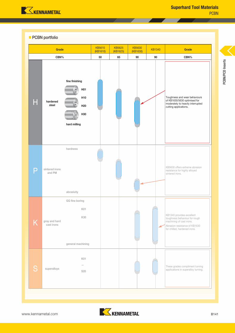
www.kennametal.com B141
PCBNSuperhard Tool Materials
PCBN
/PCD
Inse
rts
� PCBN portfolio
GradeKB5610(KB1610)
KB5625(KB1625)
KB5630(KB1630)
KB1340 Grade
CBN% 50 65 90 90 CBN%
H
fine finishing
hardenedsteel
hard milling
H20
H30
H10
H01
Toughness and wear behaviours of KB1630/5630 optimised formoderately to heavily interrupted cutting applications.
K
GG fine boring
gray and hardcast irons
general machining
K30
K01
KB1340 provides excellent toughness behaviour for roughmachining of cast irons.
Abrasion resistance of KB1630 for chilled, hardened irons.
S superalloysS20
—
K01
These grades compliment turningapplications in superalloy turning.
P
hardness
sintered ironsand PM
abrasivity
KB5630 offers extreme abrasionresistance for highly alloyed sintered irons.
KM_Master12_Turning_B140_B141_Metric.qxp:Layout 1 3/6/12 9:31 AM Page B141

IntroductionThis guide will help you choose the PCBN grade, edge preparations, nose radius, feed, and recommended speed range for your hard turning applications. These recommendations will establish a starting point for optimisation of the application. Where possible, this guide will lead you to standard line items. If this is not the case, the items can still be obtained through the QTSP (Quick-Turn Solutions Program) or ordered as specials.
We will classify hard turning operations as any turning or boring of ferrous-based workpiece materials with a hardness (HRC) higher than 45. For workpieces with lower hardness values, PCBN is not recommended.
To use the guide, you will need this application information:• Workpiece design: interruptions, shape, and frequency.
• Workpiece material specifications: hardness, superficial or through treatment, andcarbide forming alloying elements (that increase the abrasivity of the material).
• Depth of cut.
• Surface finish requirements.
• Preset conditions, such as specific nose radius, limited feed, etc.
• Setup limitations related to machine tool, fixturing, etc.
• Tool life criteria, e.g., surface finish, dimensional tolerance, cutting force, etc.
PCBN Hard Turning Selection System
www.kennametal.comB142
KM_Master12_Turning_B142_B143_Metric.qxp:Layout 1 3/6/12 9:31 AM Page B142

www.kennametal.com B143
Step 1 • Choosing the PCBN Grade
PCBN Hard Turning • Selection System Overview
Step 1, reference page B144–B145.
Step 2 • PCBN Edge Preparation Features
Step 2, reference page B145.
Step 3 • Selection of T-Land Angle
Step 3, reference page B145.
Step 4 • Selection of T-Land Width
Step 4, reference page B146.
Step 5 • Choosing the Speed Range
Step 5, reference page B147.
KM_Master12_Turning_B142_B143_Metric.qxp:Layout 1 3/6/12 9:31 AM Page B143

www.kennametal.comB144
PCBNSuperhard Tool Materials
Interruption FrequencyA wide spacing between interruptsemphasises crater wear resistance,whereas closer-located interrupts emphasise impact resistance.
How to Use
Identify your application conditions. The most far right parameter will then determine the recommended grade(s). If more than onegrade is intersected, it is recommended to first select the grade with the highest toughness (page B139) before optimising using theTroubleshooting Guide (pages B142–B143).
� Step 1 • Choosing the PCBN grade
Grade Selection for Hard Turning
0.20 0.30 0.40 0.50 0.60 0.70
Increased Cratering Resistance and Chemical Inertness
Increased Toughness
Tool Wear Type
ISO ClassHard Turning
H15 H20 H25 H30
Interruption SeverityThe angle between the cutting direction and the edge of the interruption has a big influence on the severity of an interrupt impact.
120º90º60º30º
Continuous/InterruptedMore continuous cutting needsmore crater wear resistance; moreinterrupts need more toughness.
Depth of Cut (mm)Larger depths of cut need stronger grades.
0.10
H10
0º
(continued)
KB5610™
KB5625™
KB5630™
PCBN
/PCD
Inse
rts
KM_Master12_Turning_B144_B145_Metric.qxp:Layout 1 3/6/12 9:31 AM Page B144

www.kennametal.com B145
PCBNSuperhard Tool Materials
Nose Radius and Feed vs. Surface Roughness
� Step 3 • Selection of T-land angle
How to Use
Using the grade selection and the Interruption Severity from Step 1, select edge preparation angle or hone only, E, from the tablebelow. Solutions in parenthesis are second options.
� Step 2 • PCBN edge preparation features
KB5610
KB5625
KB5630
input from Step 1
Selection of Preparation Angle
E (15°/25°)
15°/25°
15°/25°
20°/25°
15°/25°
15°/25°
NA
20°/25°
NA
25°
25°
NA
NA
25°/35°
20°/25°
10
8
6
4
2
0
0.4
0.8
1.2
0 0 .05 0 .1 0 .15 0 .2 0 .25
surf
ace
roug
hnes
s (R
z)
cratering resistance
impact resistance
surface finish
abrasive resistance
KB5610™ ******
******
******KB5630™
KB5625™
***
****
feed (f)
� Step 1 • Choosing the PCBN grade (continued)
Edge Preparation Specifications
E hone only 0,020mm
S01015 W x β = 0,1mm x 15°
S01025 W x β = 0,1mm x 25°
R 0.020mm,
W
α
β
W — Edge Prep Widthα — Clearance Angle
β — T-Land Angle
*** = Best
PCBN
/PCD
Inse
rts
KM_Master12_Turning_B144_B145_Metric.qxp:Layout 1 3/6/12 9:31 AM Page B145
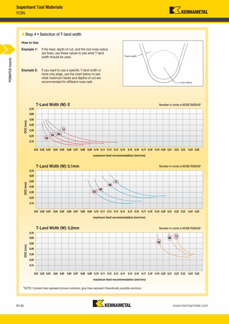
www.kennametal.comB146
PCBNSuperhard Tool Materials
� Step 4 • Selection of T-land width
How to Use
Example 1: If the feed, depth of cut, and the tool nose radiusare fixed, use these values to see what T-landwidth should be used.
Example 2: If you want to use a specific T-land width or hone only edge, use the chart below to see what maximum feeds and depths of cut are recommended for different nose radii.
Number in circle is NOSE RADIUS*
*NOTE: Colored lines represent proven solutions; grey lines represent theoretically possible solutions.
maximum feed recommendation (mm/rev)
0,70
0,01 0,02 0,03 0,04 0,05 0,06 0,07 0,08 0,09 0,10 0,11 0,12 0,13 0,14 0,15 0,16 0,17 0,18 0,19 0,20 0,21 0,22 0,23 0,24 0,25
0,60
0,50
0,40
0,30
0,20
0,10
DO
C (m
m)
maximum feed recommendation (mm/rev)
0,70
0,01 0,02 0,03 0,04 0,05 0,06 0,07 0,08 0,09 0,10 0,11 0,12 0,13 0,14 0,15 0,16 0,17 0,18 0,19 0,20 0,21 0,22 0,23 0,24 0,25
0,60
0,50
0,40
0,30
0,20
0,10
DO
C (m
m)
maximum feed recommendation (mm/rev)
0,70
0,01 0,02 0,03 0,04 0,05 0,06 0,07 0,08 0,09 0,10 0,11 0,12 0,13 0,14 0,15 0,16 0,17 0,18 0,19 0,20 0,21 0,22 0,23 0,24 0,25
0,60
0,50
0,40
0,30
0,20
0,10
DO
C (m
m)
12
12
120804
0804
02
080402
T-Land Width (W): E
T-Land Width (W): 0,1mm
T-Land Width (W): 0,2mm
Number in circle is NOSE RADIUS*
Number in circle is NOSE RADIUS*
PCBN
/PCD
Inse
rts
T-land width
nose radius
KM_Master12_Turning_B146_B147_Metric.qxp:Layout 1 3/6/12 9:32 AM Page B146

60
100
140
180
220
260
300
340
www.kennametal.com B147
PCBNSuperhard Tool Materials
How to Use
Using the application information, determine your position in the INPUT DATA table below and select the speed range area with which it intersects for each input parameter. If different speed ranges result, choose the lowest speed range.
The shaded area extends to the minimum and maximum speedsfor the application. The suggested starting speeds can be taken as the minimum line of this range.
� Step 5 • Choosing the speed range
Incr
easi
ngSp
eed
Productivity Impact Energy Heat GenerationTool Life
Workpiece Hardness (HRC)
Speed Range Selection for Hard Turning
0,20
45 50 55 60 65
0,30 0,40 0,50 0,60 0,70
Interruption SeverityThe angle between the cutting direction and the edge of the interruption has a big influence on the severity of an interrupt impact.
Depth of Cut (mm)Larger depths of cut need stronger grades.
0,10
Speed Range (m/min)
120º90º60º30º0º
INPU
T D
ATA
OU
TPU
T D
ATA
Cutting Speed Influence
PCBN
/PCD
Inse
rts
KM_Master12_Turning_B146_B147_Metric.qxp:Layout 1 3/6/12 9:32 AM Page B147

KB5610
KB5625
For hardened steels, grinding is no longer the preferred method in finish turning operations because hard turningnow drastically reduces cost per part. With high metal removal rates, faster machine setup, quicker cycle times,and greater flexibility, it is obviously the preferred method.
Despite these advantages, hard turning has sometimes had issues with poor chip control causing surfacescratching and bird-nest formations. Kennametal solved these problems by integrating special chipbreakinggeometries into two high-performance PCBN grades, giving customers total control of their hard machining.
Ideally, hardened steels are machined with a low or medium CBN content grade where the workpiece encountersfew interruptions. However, because of CBN’s structure, the industry had not been able to add chipbreakingtechnology to low content CBN inserts. KB5610™ with chipbreaker is, therefore, the first product of its type todeliver chipbreaking where it’s most needed. KB5625™ with chipbreaker provides a chipbreaking solution forapplications requiring more toughness.
Together, these tools give Kennametal customers industry-leading flexibility in choosing the right tool for the job.
Features • Chipbreaker for improved chip control.
• KB5610 ideal grade for continuous operations.
• KB5625 ideal grade for continuous and interrupted operations.
Benefits • Improved surface quality to reduce scrap rates.
• Reduction of machine stops due to swarf issues to improve machine availability.
• Reduction of bird-nest formation to reduce clean up time.
• Two grades to choose from for best performance.
CBN Inserts with Chipbreaker
www.kennametal.comB148
KM_Master12_Turning_B148_B149_Metric.qxp:Layout 1 3/6/12 9:32 AM Page B148

• Long chips.
• Bird-nest formation.
• Chips are broken.
CBN Inserts
Insert without Chipbreaker Insert with Chipbreaker
� Reverse gear face turning and chamfering
Workpiece: Reverse gearHardness: 58–62 HRC
� Hard material turning by using PCBN with chipbreaker
Workpiece: TubeHardness: 52–58 HRC
Competitor KennametalInsert: DNGG150412N-SV DNGM159412S0125MT CB1Grade: — KB5625vc: 235 m/min (775 SFM) 235 m/min (775 SFM)f: 0,25 mm/rev (.0098 in/rev) 0,35 mm/rev (.014 in/rev)ap: 0,26mm (.0098") 0,26mm (.0098")Pieces/edge: 600 900Chip shape: Snarling or infinite helix Coiled with 3 turns
Result: Better chip control, high productivity (by increased feed), and 1,5x tool life
Competitor KennametalInsert: DNGA150608S01020MT DNGM150408S01325M7CB1Grade: — KB5625vc: 120 m/min (400 SFM) 120 m/min (400 SFM)f: 0,15 mm/rev (.0059 in/rev) 0,15 mm/rev (.0059 in/rev)ap: 0,3mm (.012") 0,3mm (.012")Pieces/edge: 2 4Chip shape: Snarling or infinite helix Discontinuous
Result: Better chip control and double tool life
www.kennametal.com B149
KM_Master12_Turning_B148_B149_Metric.qxp:Layout 1 3/6/12 9:32 AM Page B149

www.kennametal.comB150
PCBNSuperhard Tool Materials
� High content PCBN grades: KB1340™, KB1630™, and KB5630™
General Application Area
Continuous and interrupted machining of ferrous alloys where the main wear mode is abrasive and a strong edge is required.
Primary Target Workpiece Materials
• Grey cast irons.
• High Cr content irons.
• Chilled and hardened irons.
• Co-, Ni-, and Fe-based hard facing alloys.
• Other alloys in which there is a high concentration of carbide forming elements, and the primary wear is abrasive.
� PCBN portfolio
GradeKB5630(KB1630)
KB1340 Grade
CBN% 90 90 CBN%
K
GG fine boring
grey and hardcast irons
K30
K01
KB1340 provides excellent toughness behaviour for roughmachining of cast irons.
Abrasion resistance of KB1630 for chilled, hardened irons.
PCBN
/PCD
Inse
rts
KM_Master12_Turning_B150_B151_Metric.qxp:Layout 1 3/6/12 9:32 AM Page B150

www.kennametal.com B151
PCBNSuperhard Tool Materials
� Machining grey cast iron
The largest application area for KB1340™ is machining of grey cast irons. Following are a few particulars of this application:
• GCI have to be machined dry. The application needs togenerate high levels of heat in order to create a protectiveoxide layer on the tool.
• It is important to confirm with the customer that the GCIhas been properly aged, and it has a sulphur content over 0,05%.
• The starting point for edge preparation should be 0,10mm (.004") x 20º for finishing (DOC <0,5mm) and 0,20mm (.008") x 20º for roughing.
• The edge preparation angle should increase if anyinterruptions are present, up to 35º.
• Lack of aging and/or low sulphur content can lead to a decrease in tool life of up to 10 times!
• A slow feed approach/engagement of the tool isrecommended to minimise chipping and notching.
Proper application of KB1340 — formation of protective layer, tool life should
exceed 70 km sliding distance.
Comparison of the life of PCBN cutting tools in machining twodifferent grey cast irons, primarily differing in sulphur content.
400 m/min 800 m/min
cutting speed, vc (m/min)
too
l life
(mm
)
25
20
15
10
5
0
0.008% S
0.09% S
� Application recommendations
High-content PCBN grades are intended for use in negative rake clamp-type toolholders, boring, recessing tools, andmilling heads. Due to the dynamic loads that occur in the machining of hard ferrous materials and the conditions underwhich these grades operate, frequently involving shocks from interrupted cutting, it is advisable to strengthen the toolsystem as much as possible and use dimpled inserts where possible.
workpiece material
speed feed depth of cut
m/min SFM mm in mm in
min max min max min max min max min max min max
hot-work tool steels — roughing 50 150 165 495 0,2 0,5 0,008 0,020 0,8 3,0 0,031 0,118
cold-work tool steels — roughing 50 150 165 495 0,2 0,5 0,008 0,020 0,8 3,0 0,031 0,118
grey cast iron — roughing 700 1200 2310 3960 0,2 0,6 0,008 0,024 0,5 3,0 0,020 0,118
grey cast iron — finishing 750 1500 2475 4950 0,1 0,3 0,004 0,012 — 0,5 0,000 0,020
CGI and NCI — roughing 50 300 165 990 0,2 0,5 0,008 0,020 0,5 2,0 0,020 0,079
chilled cast iron — roughing 30 150 99 495 0,2 0,6 0,008 0,024 0,5 3,0 0,020 0,118
chilled cast iron — finishing 30 150 99 495 0,1 0,3 0,004 0,012 — 0,5 0,000 0,020
hard facings — as per bearing steel 60 200 198 660 0,1 0,5 0,004 0,020 0,2 3,0 0,008 0,118
high Cr irons 80 250 264 825 0,1 0,6 0,004 0,024 0,2 3,0 0,008 0,118
PCBN
/PCD
Inse
rts
KM_Master12_Turning_B150_B151_Metric.qxp:Layout 1 3/6/12 9:32 AM Page B151

Dimple Clamps for Added Stability
Typical ApplicationContinuous cost pressures force manufacturers of grey cast iron brake disks to look for cost-cutting solutions. CBN inserts deliver high productivity and long tool life. Kennametal has developed the solid, high-content grade KB1340™, which provides superior performance when machining grey cast iron components, such as brake disks or fly wheels. To ensure secure seating in the toolholder, the inserts are available with dimple-design clamping. The clamps fit Ceramtec holders, which makes the conversion to Kennametal tooling easier.
Higher Productivity and Profitability• Ensures tight and rigid clamping.
• Dimpled insert with special clamping provides increased stability in the pocket.
• Ideal for use in heavy-duty machining applications.
• Cladded clamps for improved resistance against chip wash are available upon request.
• The shallow dimple design enables the use of less expensive 4,76mm (3/16") inserts.
• Round dimple design works with custom tooling where clamping direction must be offset due to space limitations.
www.kennametal.comB152
KM_Master12_Turning_B152_B153_Metric.qxp:Layout 1 3/6/12 9:32 AM Page B152

� Proven solutions
� Clamp selection chart
� Application recommendation
Competitor CBN Kennametal KB1340 Insert: N/A SNMN120416502020vc: 1100 m/min (3600 SFM) 1100 m/min (3600 SFM)f: 0,4 mm/rev (.016 in/rev) 0,4 mm/rev (.016 in/rev)ap: 2mm (.079") 2mm (.079")Performance: 1500 pieces 1700 pieces
Competitor Ceramic Kennametal CBN KB1340Insert: N/A CNGX433S0415FWvc: 800 m/min (2600 SFM) 1500 m/min (5000 SFM)f: 0,5 mm/rev (.02 in/rev) 0,5 mm/rev (.02 in/rev)ap: 1,5mm (.059") 1,5mm (.059")Performance: 120 pieces 4200 pieces
insert
vc: 800–1500 m/min
Certain melts of grey cast iron can exhibit poor machinability — by as much as two orders of magnitude — related to either insufficient aging or composition.
Good GG25 (0.05 S)62 km sliding distance @ 1500 m/min
clamp
MMANSI catalogue number ISO catalogue number catalogue number3968904CNGX433S0415 CNGX120412S01015 551.718 - 100˚ Corner3968904CNGX433S0415FW CNGX120412S01015FW 551.718 - 100˚ Corner
3968904CNGX434S0820 CNGX120416S02020 551.718 - 100˚ Corner
4094234DNGX434S0820 DNGX150416S02020 551.720
3968904SNGX434S0820 SNGX120416S02020 551.7183968904SNGX534S0820 SNGX150416S02020 551.718
4094236VNGX333S0820 VNGX160412S02020 551.721
3968904CNGF432 CNGF120408 551.718 - 100˚ Corner
4094235TNGX333EFW TNGX160412EFW 551.733
Workpiece: Brake diskMaterial: GGG 60
Featured Applications: Brake Disk Machining
www.kennametal.com B153
KM_Master12_Turning_B152_B153_Metric.qxp:Layout 1 3/6/12 9:32 AM Page B153

www.kennametal.comB154
PCBNSuperhard Tool Materials
� Grey cast iron brake disk machining • Ceramic vs. PCBN
PCBN increases productivity when machining grey iron brake disks (a) in terms of cutting speed (b) and tool life (c) comparedto silicon nitride ceramic.
� Brake disk machining example
Optimised Process
Tool Material: PCBN
Tool Life: 2000 brake disks
Starting Situation
Tool Material: black ceramic
Tool Life: 40 brake disks
(a) (b) (c)
cutting speed, vc (m/min)
0 200 400 600 800 1000
PCBN
siliconnitride
tool life (parts per edge)
0 2000 4000 6000 8000
PCBN
siliconnitride
Tool Change Time
94% 82%
Machining Time Saved
17.8%
0,2%
6%
PCBN
/PCD
Inse
rts
KM_Master12_Turning_B154_B155_Metric.qxp:Layout 1 3/6/12 9:32 AM Page B154

www.kennametal.com B155
PCBNSuperhard Tool Materials
� PM machining • Inlet/outlet valve
• Abrasive with hard particle content:
Martensite — 800 HK
WMoC — 1600 HK
VC — 2800 HK
• High porosity/Cu infiltrated.
• Co increases hot hardness.
• Macro-hardness <400 HV (<41 HRC).
• Derives wear resistance from hard particles.
Exhaust
• Principally, structure is hard steel.
• Minimal porosity on well sintered.
• Low/medium alloy content.
• Macro-hardness >400 HV (>41 HRC).
• Derives wear resistance from hardened matrix structure.
Intake
50 μm 50 μm
� PCBN portfolio
GradeKB5610(KB1610)
KB5625(KB1625)
KB5630(KB1630)
Grade
CBN% 50 65 90 CBN%
P
hardness
sintered ironsand PM
abrasivity
KB5630 offers extreme abrasionresistance for highly alloyed sintered irons.
PCBN
/PCD
Inse
rts
KM_Master12_Turning_B154_B155_Metric.qxp:Layout 1 3/6/12 9:32 AM Page B155

www.kennametal.comB156
PCBNSuperhard Tool Materials
� PCBN grade selection for valve seat machining
content of carbide formers (%)
ABRASIVE WEAR RESISTANCE
CH
EM
ICA
L W
EA
R R
ES
ISTA
NC
E
hard
ness
, HV
600
500
400
300
200
0 5 10 15 20
typical inlet valve seat iron
typical outlet valve seat iron
KB5610
KB5625
KB5630PCBN
/PCD
Inse
rts
KM_Master12_Turning_B156_B157_Metric.qxp:Layout 1 3/6/12 9:32 AM Page B156

www.kennametal.com B157
PCBNSuperhard Tool Materials
� PCBN grade selection for valve seat machining
material to be machined
short engagement (e.g., plunging)
long engagement(e.g., generating)
Soft matrix (≤300 HV), hard carbides, high porosity
1. Abrasion resistance2. Strength#1 Choice: KB5630™
1. Abrasion resistance2. Strength3. Chemical wear resistance#1 Choice: KB5630
Highly Abrasive
High Hardness
Both material types with single insert
1. Abrasion resistance2. Chemical wear resistance3. Strength#1 Choice: KB5630#2 Choice: KB5625™
1. Abrasion and chemical wearresistance
2. Strength#1 Choice: KB5625#2 Choice: KB5630
Hard matrix (≥400 HV), few carbides, low porosity
1. Chemical wear resistance2. Strength3. Abrasion resistance#1 Choice: KB5625#2 Choice: KB5610™
1. Chemical wear resistance2. Abrasion resistance3. Strength#1 Choice: KB5625#2 Choice: KB5610
PCBN
/PCD
Inse
rts
KM_Master12_Turning_B156_B157_Metric.qxp:Layout 1 3/6/12 9:32 AM Page B157

Clamping Design• One tool for turning, facing, grooving, and face grooving in O.D.
and I.D. applications — that means exceptionally fast cycle timesand no turret indexes.
• Extra-long clamping area, ground 120° bottom prism seating surface, and an exclusive top guide rail combine to deliver unsurpassed grooving and side-turning stability!
• Precise insert positioning is ensured for accurate cuts!
A4™ Grooving and Turning System
Applications
� Test result • A4
Tool: A4R0400M04800E KB1630Material: INCONEL® 718
Diameter: 983mmCutting Data Competitor KennametalSpeed: 180 m/min (600 SFM) 180 m/min (600 SFM)Feed: 0,13mm/rev (.0051 in/rev) 0,13mm/rev (.0051 in/rev)DOC: 8mm (.31") 8mm (.31")Diameter: 30mm (1.18") 30mm (1.18") Performance: 70–140 pieces 160–200 pieces
www.kennametal.comB158
KM_Master12_Turning_B158_B159_Metric.qxp:Layout 1 3/12/12 3:58 PM Page B158

Clamping DesignOur rigid clamping design prevents insert movement. This benefitensures excellent surface finish, improved productivity, and superiortool life and promotes perfect concentricity. The rugged bridgeclamp generates locking forces in three directions to provide superior resistance to side thrust and tangential forces.
Top Notch™ Grooving System
Applications
� Test result • Top Notch
Tool: WSP 4121129 Top Notch KB5625Material: DIN 16MnCr5/AISI 5115, 59–63 HRC Machine: Hard/soft machining
Cutting Data Competitor KennametalSpeed: 160 m/min (530 SFM) 160 m/min (530 SFM)Feed: 0,06 mm/rev (.0024 in/rev) 0,06 mm/rev (.0024 in/rev)DOC: 2mm (.079") 2mm (.079")Diameter: 39,5mm (1.56") 39,5mm (1.56")Performance: 70 pieces 90 pieces
www.kennametal.com B159
KM_Master12_Turning_B158_B159_Metric.qxp:Layout 1 3/12/12 3:58 PM Page B159

www.kennametal.comB160
PCBNSuperhard Tool Materials
Quick Optimisation Guide:Troubleshooting for Catastrophic Failure
Remedial Action1. Select more inert PCBN grade.
2. Select more abrasion-resistant PCBN grade.
3. Select stronger PCBN grade.
4. Reduce cutting speed.
5. Increase cutting speed.
6. Reduce nose radius.
7. Increase nose radius.
8. Increase chamfer angle.
9. Decrease chamfer angle.
10. Increase clearance angle.
11. Reduce clearance angle.
12. Increase edge hone dimension.
13. Reduce edge hone dimension.
14. Reduce feed and/or depth of cut.
15. Increase feed and/or depth of cut.
Tool Failure Criteria
Catastrophic Failure (loss of cutting edge)
Preceded by Extensive Crater Wear
Spalling on Rake Face Chipping on Flank Face
Yes No
1, 4, 12, 3 3, 8, 7, 12, 11, 14, 5
Example of catastrophic failure
Example of crater wear
PCBN
/PCD
Inse
rts
KM_Master12_Turning_B160_B161_Metric.qxp:Layout 1 3/6/12 9:33 AM Page B160

www.kennametal.com B161
PCBNSuperhard Tool Materials
Quick Optimisation Guide:Troubleshooting for Non-Catastrophic Failure
Remedial Action1. Select more inert PCBN grade.
2. Select more abrasion-resistant PCBN grade.
3. Select stronger PCBN grade.
4. Reduce cutting speed.
5. Increase cutting speed.
6. Reduce nose radius.
7. Increase nose radius.
8. Increase chamfer angle.
9. Decrease chamfer angle.
10. Increase clearance angle.
11. Reduce clearance angle.
12. Increase edge hone dimension.
13. Reduce edge hone dimension.
14. Reduce feed and/or depth of cut.
15. Increase feed and/or depth of cut.
Tool Failure Criteria
Non-Catastrophic Failure(workpiece-related failure)
Preceded by Extensive Flank Wear
Surface Finish Form Errors
Yes No
2, 10, 4 14, 13, 6, 3, 5
Example of flank wear
PCBN
/PCD
Inse
rts
KM_Master12_Turning_B160_B161_Metric.qxp:Layout 1 3/6/12 9:33 AM Page B161

Technical Details • Options for a Customisation
For more information, please contact a Kennametal Sales Representative, Authorised Kennametal Distributor, or visit www.kennametal.com.
www.kennametal.comB162
Standard inserts incorporate latest grade, coating, edge preparation, and manufacturing technology. They cover a wide range of applications and provide superior performance.
However, in some cases, further fine tuning is needed to reach the optimum performance point. Therefore, Kennametal has set up the Quick-Turn Solutions Program (QTSP) to allow edge preparation modifications on selected styles, grades, and formats to further enhance the tool performance.
Quick-Turn Solutions Program for CBN Inserts
Decide nose radius.
Add wiper.
Various shapes from which tochoose.
Multitipped, full tops, and solid inserts are part of the program.
Decide T-land width and angle.
Decide hone size.
Seven grades are available.High and low content, coated and uncoated.
KM_Master12_Turning_B162_B163_Metric.qxp:Layout 1 3/6/12 9:33 AM Page B162

W
α
β
W x β
R 0,020mm
E TD
R1 R2
Teardrop (TD) edges are advanced edge preparations used in heavily interrupted operations wherestandard edge preps fail. They can be ordered as specials.
Possible TD Edges
Teardrop (TD Edges) for Demanding Applications
W — Edge Prep Width
α — Clearance Angle
β — Edge Prep Angle — between rake face and K-land
www.kennametal.com B163
TD-Style Selection
DOC in mm
TDR
TDF
TDS
0 0,15 0,30 0,45 0,60 0,75
E
W x βTDR
TDF
TDS
Edge Preparation Specifications
hone only 0,020mm
width in 0,001mm x angle
ellipse based on 0,25 x 30°
ellipse based on 0,20 x 20°
ellipse based on 0,10 x 20°
KM_Master12_Turning_B162_B163_Metric.qxp:Layout 1 3/6/12 9:33 AM Page B163

KM_Master12_Turning_B164_B165_Metric.qxp:Layout 1 3/6/12 9:33 AM Page B164

Carbon
The current global metalcutting climate has put increased focus on high productivity and cost reductions coming fromcutting tools. These requirements lead to the rapid growth and implementation of cutting tools using superhard materials. As the name implies, these materials have a significant advantage in hardness over conventional tool materials, which fromthe end user point of view, translates into increased productivity (higher cutting speeds, longer tool life, etc.), lower toolingcost per part, and also, the ability to process materials previously un-machinable with conventional tooling.
The most widely known superhard materials are diamond and cubic boron nitride. Our industry uses the polycrystalline forms of these materials, i.e., polycrystalline diamond (PCD) and polycrystalline boron nitride (PCBN). PCD tooling is mainlytargeted at the machining of non-ferrous materials (e.g., aluminium alloys, plastics, CFRPs, composites, titanium alloys,ceramics, carbides, etc.) whereas PCBN targets iron-based alloys (e.g., cast irons, hard steels, iron-based composites, etc.)
Kennametal is at the forefront of developing and implementing superhard materials in our standard and special toolingsolutions across all our product lines. Kennametal’s approach to superhard tooling starts with customer needs andconstraints. We then use fundamental research to develop the best superhard solutions that would make available the best value for the customer and respond to their specific demands.
C
� PCD
www.kennametal.com B165
PCDSuperhard Tool Materials
PCBN
/PCD
Inse
rts
KM_Master12_Turning_B164_B165_Metric.qxp:Layout 1 3/6/12 9:33 AM Page B165

www.kennametal.comB166
PCDSuperhard Tool Materials
� Different kinds of PCD grades
Application demands determine the choice of cutting tool material. The important requirements of the material are:
• Abrasion resistance.
• Toughness and strength.
• Thermal behaviour.
� Comparison of different PCD grades
Increased Cutting Edge Quality (and Strength)
Increased Abrasion Resistance
Fine Grain Medium Grain Coarse Grain
Chipping can be defined as the formation of small notches on the cutting edge and generally occurs when the load at the cutting edge exceeds the strength of the material. An A390 alloy was used in edge milling tests to assess the chip resistance of the different PCD grades.
Abrasion is characterised by the development of grooves and ridges on the flank of the tool in the direction of sliding. The abrasion resistance of PCD was evaluated on a high silicon aluminium alloy, A390, in a continuous cutting operation.
Behaviour in Applications
grade characteristics:
grain size:
chip resistance:
abrasion resistance:
Behaviour in Applications
grade characteristics:
grain size:
chip resistance:
abrasion resistance:
KD1400™
0,5–1 μm
• • • • • • • • • •• • • • •
fine grain
2 μm
• • • • • • • • •• • •
medium grain
10 μm
• • • • • • • •• • • • •
coarse grain
25 μm
• • • • • • •• • • • • • •
KD1425™
2–30 μm
• • • • • •• • • • • • • •
KD1405™
0 μm
• • • • • • •• • • • • • • • • •
PCBN
/PCD
Inse
rts
KM_Master12_Turning_B166_B167_Metric.qxp:Layout 1 3/6/12 9:33 AM Page B166

www.kennametal.com B167
PCDSuperhard Tool Materials
� PCD grain size • Workpiece surface finish
� KD1400 advantages at a glance • Summary
0.3 0.4 0.5 0.6 0.7 0.8 Ra
coarse
medium
KD1425™
fine
KD1400™
A sharper cutting edge• Clean cuts on carbon fibres.• Permits larger nose radii for increased feed
and productivity without loss in finish.
A less serrated (smoother) cutting edge• Improved surface finish — potentially reducing
rough and intermediate honing.
Permits a more positive rake• Reduced cutting forces, delamination,
and burr formation.
Permits increased clearance• Providing for lower tool wear rates and lower push-off
forces — thereby improving process capability.
Provides unparalleled chip resistance• Suitable for heavy milling and interrupted turning
with positive edge geometries and longest tool life.
Comparable abrasion resistance to a coarse grade PCD• Covers the widest range of applications with
a single grade — reduce inventory and complexity.
This chart illustrates the influence of the PCD grain size on surface finish in turning 18% silicon aluminium alloys. The best finish is obtained with the submicron grade KD1400. While the grade KD1425 contains grains as large as 30 microns, this material’s unique multimodal grain size distribution results in a microstructure of closely packed diamond grains resulting in a smoother ground edge.
PCBN
/PCD
Inse
rts
KM_Master12_Turning_B166_B167_Metric.qxp:Layout 1 3/6/12 9:33 AM Page B167

www.kennametal.comB168
PCDSuperhard Tool Materials
� PCD grades application/workpiece material
� PCD application areas and parameter range
MMC
KD1425™
KD1400™
wrought AI alloys
superfinishing
finishinggeneral
machiningroughing
AISi alloys<13% Si
AISi alloys>13% Si
material machined operation
PCD grade
speed feed rate DOC
m/min SFM mm/rev in/rev mm in
min max min max min max min max min max min max
aluminium alloy turning
KD1400
1000 4000 3300 13200 0,1 0,4 0,004 0,016 0,1 4,0 0,004 0,157
4–8% Si milling 2000 5000 6600 16500 0,1 0,3 0,004 0,012 0,1 0,3 0,004 0,012
9–12% Si turning 700 3000 2310 9900 0,1 0,4 0,004 0,016 0,1 4,0 0,004 0,157
>13 Si
milling KD1400/KD1425 1000 3000 3300 9900 0,1 0,3 0,004 0,012 0,1 0,3 0,004 0,012
turning KD1425 300 1000 990 3300 0,1 0,4 0,004 0,016 0,1 4,0 0,004 0,157
milling KD1400 500 1500 1650 4950 0,1 0,3 0,004 0,012 0,1 0,3 0,004 0,012
cast iron roughing
KD1425
50 300 165 990 0,2 0,5 0,008 0,020 0,5 3,0 0,020 0,118
CGI/NCI finishing 50 400 165 1320 0,1 0,3 0,004 0,012 — 0,5 — 0,020
MMCturning/milling 300 700 990 2310 0,1 0,4 0,004 0,016 0,2 1,5 0,008 0,059
20% Sic/Al
copper alloysturning/milling KD1400 400 1300 1320 4290 0,03 0,3 0,001 0,012 0,05 2,0 0,002 0,079
copper, zinc, bass
tungsten carbide <16% Coturning KD1425
30 120 99 396 0,1 0,4 0,004 0,016 0,2 1,0 0,008 0,039
unsintered (green) 20 60 66 198 0,1 0,25 0,004 0,010 0,1 0,5 0,004 0,020
sintered — — — — — — — — — — — — — —
ceramicsturning KD1425
70 120 231 396 0,1 0,4 0,004 0,016 0,2 1,0 0,008 0,039
unsintered 50 100 165 330 0,1 0,25 0,004 0,010 0,1 0,5 0,004 0,020
sintered — — — — — — — — — — — — — —
plastics/compositesturning/milling KD1400/KD1425
300 990 990 8250 0,05 0,3 0,002 0,012 0,2 3,0 0,004 0,118
carbon/graphite 200 660 660 3300 0,05 0,5 0,002 0,020 0,1 3,0 0,004 0,118
APPLICATION SEVERITY
PCBN
/PCD
Inse
rts
KM_Master12_Turning_B168_B169_Metric.qxp:Layout 1 3/23/12 9:59 AM Page B168

www.kennametal.com B169
PCDSuperhard Tool Materials
� PCD tool failure modes
The gradual wear observed on diamond cutting tools can be divided into:
• Mechanically activated wear (abrasion, adhesion, and wear by microfracture).
• Tribochemical wear (dissolution/diffusion wear and formation of new chemical compounds).
Abrasion
The primary mode of mechanically activated wear for diamond cutting tools is abrasion, which is the removal of tool material by a scoring action of protruding asperities and hard phase inclusions in the workpiece and chip (e.g., silicon grains in aluminium-silicon alloys).
Abrasion is characterised by the development of grooves and ridges in the direction of the tool sliding against a newly machined surface of the workpiece or chip sliding against the rake face.
The severity of abrasion can be increased in cases where the workpiece material contains hard inclusions or when there is hard wear debris from the workpiece or the tool at the interface.
Tribochemical
Tribochemical wear is particularly relevant in the machining of titanium alloys when the carbon in the tool material diffuses into the adhered titanium layer to form a TiC boundary layer on the rake face of the tool.
This boundary quickly becomes saturated with tool constituents and can then act as a protective barrier against any further diffusion.
Attrition
When two surfaces slide over each other, particularly in the absence of a lubricant, some adhesion can occur at the points of contact. Adhesive wear (often called attrition) in cutting tools involves the mechanism in which individual grains or smallgrain aggregates are pulled out of the tool surfaces and are carried away at the underside of the chip or are torn away by the adherent workpiece. The term “plucking” is also used to describe the loss of tool particles from the edge or faces. For example, when the forces are high enough, the TiC boundary layer that forms in titanium machining can be removed from the rake face of the tool transporting with it a pulled-out diamond grain, to form a crater. Once this crater becomesexcessive, fracture of the tool could occur due to the geometrical weakening of the edge. Negative geometries tend toenhance the possibility of adhesive wear and built-up edge formation. Subsequent break-up (fracture) of the adhesivetool/workpiece joints results in attrition wear. The wear scars produced by attrition are rough, as opposed to the usuallysmooth wear surfaces generated by tribochemical wear.
Microfracture
When cutting tools are employed for continuous machining of high hardness materials or interrupted machining, small fractures can appear on the cutting edge. If fracturing is small, the cutting tool can usually still be used. Wear by microfracture involves a less severe form of fracture and includes chipping, spalling, and cracking whereby the cutting tool can be reused.
PCBN
/PCD
Inse
rts
KM_Master12_Turning_B168_B169_Metric.qxp:Layout 1 3/23/12 9:59 AM Page B169

www.kennametal.comB170
PCDSuperhard Tool Materials
Tool Failure and Wear:
Remedial Action1. Increase nose radius.
2. Reduced clearance angle.
3. Reduce feed.
4. Reduce cutting speed.
5. Reduce DOC.
6. Increase clearance angle.
7. Use a positive rake angle.
8. Add a small edge hone.
9. Use neutral rake angle.
10. Increase lead angle.
11. Select a tougher grade.
12. Select more abrasion-resistant grade.
13. Select a higher TRS grade.
14. Choose a more chemically inert grade.
15. Increase thickness.
16. Select a more thermally stable grade.
17. Use coolant.
Tool Failure Criteria
Catastrophic Failure (loss of cutting edge)
Fracture Thermal Degradation
Nose Breakage Extensive Flank Wear/Cracking
11, 1, 2, 15, 3, 4, 5 16, 17, 2, 4, 3, 5
PCBN
/PCD
Inse
rts
KM_Master12_Turning_B170_B171_Metric.qxp:Layout 1 3/6/12 9:34 AM Page B170

www.kennametal.com B171
PCDSuperhard Tool Materials
Tool Failure and Wear:
Remedial Action1. Increase nose radius.
2. Reduced clearance angle.
3. Reduce feed.
4. Reduce cutting speed.
5. Reduce DOC.
6. Increase clearance angle.
7. Use a positive rake angle.
8. Add a small edge hone.
9. Use neutral rake angle.
10. Increase lead angle.
11. Select a tougher grade.
12. Select more abrasion-resistant grade.
13. Select a higher TRS grade.
14. Choose a more chemically inert grade.
15. Increase thickness.
16. Select a more thermally stable grade.
17. Use coolant.
Tool Failure Criteria
Non-Catastrophic Failure(gradual/progressive wear)
Abrasion Adhesion Wear by Fracture Diffusion New Chemical
Compound
Grooves andRidges on Flank
BUE and Crater Wear
Chipping andSpalling Crater Wear Crater Wear
12, 6, 4, 3 7, 17, 4 13, 2, 8, 9, 5, 3, 1 14, 4, 17, 10, 1 14, 4, 17, 10, 1
PCBN
/PCD
Inse
rts
KM_Master12_Turning_B170_B171_Metric.qxp:Layout 1 3/6/12 9:34 AM Page B171

www.kennametal.comB172
PCDSuperhard Tool Materials
� Machining of carbides with superhards
Application Notes
• PCD tools should be used with a neutral geometry and 7º clearance.
• PCD edge preparation should be either F or E. An E edgepreparation is preferred for larger DOCs, low Co content, and interrupted machining.
• PCBN tools should be used in a negative geometry with 5º to 7º negative rake.
• PCBN edge preparation should be either E or S01025.
• Coolant application is recommended and very important,especially with PCD application where failure is determined by heat generation.
• PCD can also be applied for Co concentrations higher than19% as long as minimal heat is generated.
material machined operation
PCD grade
speed feed rate DOC
m/min SFM mm/rev in/rev mm in
min max min max min max min max min max min max
tungsten carbide <19% Co
unsintered (green) turning KD1425 30 120 99 396 0,1 0,4 0,004 0,016 0,2 1,0 0,008 0,039
sintered turning KD1425 20 80 66 264 0,1 0,25 0,004 0,010 0,1 0,5 0,004 0,020
tungsten carbide >19% Co
unsintered (green) turning KB1340 50 150 165 495 0,1 0,5 0,004 0,020 0,2 1,0 0,008 0,039
sintered turning KB1340 30 100 99 330 0,1 0,4 0,004 0,016 0,1 0,5 0,004 0,020
cobalt content
cutt
ing
sp
eed
5 10 15 Wt% 25
60
m/min
40
30
20
10
0
Machining Carbide with Superhards
PCD PCBN
KB1340
KB5630
KD1425
KD1400
PCBN
/PCD
Inse
rts
KM_Master12_Turning_B172_B173_Metric.qxp:Layout 1 3/6/12 9:34 AM Page B172

www.kennametal.com B173
PCDSuperhard Tool Materials
� CGI boring with turning insert
0 500 1000 1500 2000 2500 3000 3500 4000 4500
cermet200 m/min
660 SFM
number of bores
mixed ceramic200 m/min
660 SFM
coated carbide100 m/min
330 SFM
KB1610™
300 m/min990 SFM
KB1610200 m/min
660 SFM
KD1425™
200 m/min660 SFM
CGI Tool Life Results,Estimated Number of Bores
fn = 1 mm/rev (.0038 in/rev)ap = 0,25mm (.0098")
Six-Edge Tool Single-Edge Tool
TARGET
Machining Parameters
• Feed = 0,1mm (.0038")
• Depth of cut = 0,25mm (.0098")
Tool Life Criteria
• VB max = 0,3mm (.0098")
• Number of bores = 1500
PCBN
/PCD
Inse
rts
KM_Master12_Turning_B172_B173_Metric.qxp:Layout 1 3/6/12 9:34 AM Page B173

www.kennametal.comB174
PMK � �
N � � �
S � � �
H � � � � � � �
D L10 Rε
ISO catalogue number mm mm mm K
B13
40K
B13
45K
D14
00K
D14
05K
D14
25K
B16
10K
B16
25K
B16
30K
B56
10K
B56
25K
B56
30
CNGA120404E 12,70 12,90 0,4 �
CNGA120408E 12,70 12,90 0,8 �
Superhard InsertsKenloc™ Inserts
� first choice� alternate choice
� CNGA
D L10 Rεε
ISO catalogue number mm mm mmCNGA120408EMT 12,70 12,90 0,8 �
CNGA120412EMT 12,70 12,90 1,2 �
� CNGA-EMT
D L10 Rεε
ISO catalogue number mm mm mmCNGA120404FST 12,70 12,90 0,4 � �
CNGA120408FST 12,70 12,90 0,8 � �
� CNGA-FST
D L10 Rεε
ISO catalogue number mm mm mm
CNGA120404S01025FWMT 12,70 12,90 0,4 � � �
CNGA120404EFWMT 12,70 12,90 0,4 � �
CNGA120408EFWMT 12,70 12,90 0,8 � �
CNGA120408S01025FWMT 12,70 12,90 0,8 � � �
CNGA120412EFWMT 12,70 12,90 1,2 � �
CNGA120416S02015MWMT 12,70 12,90 1,6 �
� CNGA-FW/MW MT
PCBN
/PCD
Inse
rts
KM_Master12_Turning_B174_B175_Metric.qxp:Layout 1 3/6/12 9:34 AM Page B174

www.kennametal.com B175
PMK � �
N � � �
S � � �
H � � � � � � �
D L10 Rε
ISO catalogue number mm mm mm K
B13
40K
B13
45K
D14
00K
D14
05K
D14
25K
B16
10K
B16
25K
B16
30K
B56
10K
B56
25K
B56
30
CNGA120404S01025MT 12,70 12,90 0,4 � � � � � �
CNGA120408S01020MT 12,70 12,90 0,8 �
CNGA120408S02020MT 12,70 12,90 0,8 �
CNGA120408S01025MT 12,70 12,90 0,8 � � � � � �
CNGA120412S01025MT 12,70 12,90 1,2 � � � � �
CNGA120412S01020MT 12,70 12,90 1,2 �
CNGA120412T02020MT 12,70 12,90 1,2 �
CNGA120416S01020MT 12,70 12,90 1,6 �
Superhard InsertsKenloc™ Inserts
� first choice� alternate choice
� CNGA-MT
D L10 Rεε
ISO catalogue number mm mm mm
CNGA120404S01025ST 12,70 12,90 0,4 �
CNGA120408S01025ST 12,70 12,90 0,8 �
CNGA120412S01025ST 12,70 12,90 1,2 �
� CNGA-ST
D L10 Rεε
ISO catalogue number mm mm mm
CNGM120404S01325MTCB1 12,70 12,90 0,4 �
CNGM120408S01325MTCB1 12,70 12,90 0,8 �
CNGM120412S01325MTCB1 12,70 12,90 1,2 �
� CNGM-CB1
D L10 Rεε
ISO catalogue number mm mm mm
CNGM120404S01325MTCB2 12,70 12,90 0,4 �
CNGM120408S01325MTCB2 12,70 12,90 0,8 �
CNGM120412S01325MTCB2 12,70 12,90 1,2 �
� CNGM-CB2
PCBN
/PCD
Inse
rts
C2–C71 C72–C109 C110–C115 C116–C147 B10–B23 B24–B31 B32–B37
KM_Master12_Turning_B174_B175_Metric.qxp:Layout 1 3/6/12 9:34 AM Page B175

www.kennametal.comB176
D L10 Rεε
ISO catalogue number mm mm mmDNGA150408EMT 12,70 15,50 0,8 � �
DNGA150412EMT 12,70 15,50 1,2 �
� DNGA-EMT
PMK � �
N � � �
S � � �
H � � � � � � �
D L10 Rε
ISO catalogue number mm mm mm K
B13
40K
B13
45K
D14
00K
D14
05K
D14
25K
B16
10K
B16
25K
B16
30K
B56
10K
B56
25K
B56
30
CNMA120408S01025 12,70 12,90 0,8 �
CNMA120408S02020 12,70 12,90 0,8 �
CNMA120412S02020 12,70 12,90 1,2 �
Superhard InsertsKenloc™ Inserts
� first choice� alternate choice
� CNMA
D L10 Rεε
ISO catalogue number mm mm mm
CNMS120408E 12,70 12,90 0,8 �
� CNMS-E
D L10 Rεε
ISO catalogue number mm mm mmCNMS120404FST 12,70 12,90 0,4 � �
CNMS120408FST 12,70 12,90 0,8 � �
� CNMS-FST
D L10 Rεε
ISO catalogue number mm mm mm
DNGA150404E 12,70 15,50 0,4 �
DNGA150408E 12,70 15,50 0,8 �
� DNGA
PCBN
/PCD
Inse
rts
KM_Master12_Turning_B176_B177_Metric.qxp:Layout 1 3/6/12 9:35 AM Page B176

www.kennametal.com B177
� DNGA-FST
D L10 Rεε
ISO catalogue number mm mm mm
DNGA150404EFWMT 12,70 15,50 0,4 �
DNGA150408EFWMT 12,70 15,50 0,8 �
DNGA150412EFWMT 12,70 15,50 1,2 �
� DNGA-FW/MW MT
D L10 Rεε
ISO catalogue number mm mm mm
DNGA150404S01025MT 12,70 15,50 0,4 � � � � �
DNGA150408S01020MT 12,70 15,50 0,8 �
DNGA150408S01025MT 12,70 15,50 0,8 � � � � � �
DNGA150412S01025MT 12,70 15,50 1,2 � � �
� DNGA-MT
D L10 Rεε
ISO catalogue number mm mm mm
DNGM150408S01325MTCB1 12,70 15,50 0,8 �
DNGM150412S01325MTCB1 12,70 15,50 1,2 �
� DNGM-CB1
Superhard InsertsKenloc™ Inserts
� first choice� alternate choice
PMK � �
N � � �
S � � �
H � � � � � � �
D L10 Rε
ISO catalogue number mm mm mm K
B13
40K
B13
45K
D14
00K
D14
05K
D14
25K
B16
10K
B16
25K
B16
30K
B56
10K
B56
25K
B56
30
DNGA150404FST 12,70 15,50 0,4 � �
DNGA150408FST 12,70 15,50 0,8 � �
PCBN
/PCD
Inse
rts
C2–C71 C72–C109 C110–C115 C116–C147 B10–B23 B24–B31 B32–B37
KM_Master12_Turning_B176_B177_Metric.qxp:Layout 1 3/6/12 9:35 AM Page B177

www.kennametal.comB178
PMK � �
N � �� �
S � � �
H � � � � � � �
D L10 Rε
ISO catalogue number mm mm mm K
B13
40K
B13
45K
D14
00K
D14
05K
D14
25K
B16
10K
B16
25K
B16
30K
B56
10K
B56
25K
B56
30
DNGM150408S01325MTCB2 12,70 15,50 0,8 �
DNGM150412S01325MTCB2 12,70 15,50 1,2 �
Superhard InsertsKenloc™ Inserts
� first choice� alternate choice
� DNGM-CB2
D L10 Rεε
ISO catalogue number mm mm mm
DNMA110408S02020 9,53 11,63 0,8 �
DNMA110412S02020 9,53 11,63 1,2 �
� DNMA
� DNMS-FST
D L10 Rεε
ISO catalogue number mm mm mm
SNGA120408S01020FWMT 12,70 12,70 0,8 �
� SNGA-FW
NOTE: Other insert geometries available upon request.
D L10 Rε
ISO catalogue number mm mm mmDNGA150404FST 12,70 15,50 0,4 � �
DNGA150408FST 12,70 15,50 0,8 � �
PCBN
/PCD
Inse
rts
KM_Master12_Turning_B178_B179_Metric.qxp:Layout 1 3/6/12 9:35 AM Page B178

www.kennametal.com B179
PMK � �
N � � �
S � � �
H � � � � � � �
D L10 Rε
ISO catalogue number mm mm mm K
B13
40K
B13
45K
D14
00K
D14
05K
D14
25K
B16
10K
B16
25K
B16
30K
B56
10K
B56
25K
B56
30
SNGA120404S01025MT 12,70 12,70 0,4 �
SNGA120408S01025MT 12,70 12,70 0,8 � �
SNGA120412S01025MT 12,70 12,70 1,2 � �
Superhard InsertsKenloc™ Inserts
� first choice� alternate choice
� SNGA
D L10 Rεε
ISO catalogue number mm mm mm
SNMA120408S01025 12,70 12,70 0,8 �
SNMA120408S02020 12,70 12,70 0,8 �
SNMA120412S01025 12,70 12,70 1,2 �
SNMA120412S02020 12,70 12,70 1,2 �
� SNMA
D L10 Rεε
ISO catalogue number mm mm mmSNMS120408FST 12,70 12,70 0,8 �
SNMS120412FST 12,70 12,70 1,2 �
� SNMS-FST
D L10 Rεε
ISO catalogue number mm mm mm
TNGA160408EFWMT 9,53 16,50 0,8 �
TNGA160412EFWMT 9,53 16,50 1,2 �
� TNGA-FW MTPC
BN/P
CD In
sert
s
C2–C71 C72–C109 C110–C115 C116–C147 B10–B23 B24–B31 B32–B37
KM_Master12_Turning_B178_B179_Metric.qxp:Layout 1 3/6/12 9:35 AM Page B179

D L10 Rεε
ISO catalogue number mm mm mm
VNMS160404E 9,53 16,61 0,4 �
VNMS160408E 9,53 16,61 0,8 �
� VNMS-E
www.kennametal.comB180
PMK � �
N � � �
S � � �
H � � � � � � �
D L10 Rε
ISO catalogue number mm mm mm K
B13
40K
B13
45K
D14
00K
D14
05K
D14
25K
B16
10K
B16
25K
B16
30K
B56
10K
B56
25K
B56
30
TNGA160404S01025MT 9,53 16,50 0,4 � � �
TNGA160408S01020MT 9,53 16,50 0,8 �
TNGA160408S01025MT 9,53 16,50 0,8 � � � �
TNGA160412S01025MT 9,53 16,50 1,2 � � �
TNGA160416S01025MT 9,53 16,50 1,6 �
Superhard InsertsKenloc™ Inserts
� first choice� alternate choice
� TNGA
D L10 Rεε
ISO catalogue number mm mm mmTNMS160404FST 9,53 16,50 0,4 � �
TNMS160408FST 9,53 16,50 0,8 � �
� TNMS-FST
D L10 Rεε
ISO catalogue number mm mm mmVNGA160404FST 9,53 16,61 0,40 � �
VNGA160408FST 9,53 16,61 0,80 � �
� VNGA-FST
D L10 Rεε
ISO catalogue number mm mm mm
VNGA160404S01025MT 9,53 16,61 0,4 � � � � � �
VNGA160408S01025MT 9,53 16,61 0,8 � � � � � �
� VNGA-MT
PCBN
/PCD
Inse
rts
KM_Master12_Turning_B180_B181_Metric.qxp:Layout 1 3/6/12 9:35 AM Page B180

www.kennametal.com B181
� VNMS-FST
D L10 Rεε
ISO catalogue number mm mm mmWNGA080404FST 12,70 8,69 0,4 �
WNGA080408FST 12,70 8,69 0,8 � �
� WNGA-FST
D L10 Rεε
ISO catalogue number mm mm mm
WNGA080412S01020FWMT 12,70 8,69 1,2 �
� WNGA-FW/MT
D L10 Rεε max
ISO catalogue number mm mm mm mm
WNGA080404S01025MT 12,70 8,69 0,4 1,60 �
WNGA080408S01025MT 12,70 8,69 0,8 1,12 �
� WNGA
( ) , , ,
D L10 Rε
ISO catalogue number mm mm mm K
B13
40K
B13
45K
D14
00K
D14
05K
D14
25K
B16
10K
B16
25K
B16
30K
B56
10K
B56
25K
B56
30
VNMS160404FST 9,53 16,61 0,4 � �
VNMS160408FST 9,53 16,61 0,8 � �
Superhard InsertsKenloc™ Inserts
� first choice� alternate choice
PMK � �
N � � �
S � � �
H � � � � � � �
PCBN
/PCD
Inse
rts
C2–C71 C72–C109 C110–C115 C116–C147 B10–B23 B24–B31 B32–B37
KM_Master12_Turning_B180_B181_Metric.qxp:Layout 1 3/6/12 9:35 AM Page B181

www.kennametal.comB182
PMK � �
N � � �
S � � �
H � � � � � � �
D L10 Rε
ISO catalogue number mm mm mm K
B13
40K
B13
45K
D14
00K
D14
05K
D14
25K
B16
10K
B16
25K
B16
30K
B56
10K
B56
25K
B56
30
CNMN090308S02020 9,53 9,67 0,8 �
CNMN090312S02020 9,53 9,67 1,2 �
CNMN120408S02020 12,70 12,90 0,8 �
CNMN120412S02020 12,70 12,90 1,2 �
Superhard InsertsKendex™ Negative Inserts
� first choice� alternate choice
� CNMN
D L10 Rεε
ISO catalogue number mm mm mm
RNMN090300S02020 9,53 — — �
RNMN120300S02020 12,70 — — �
RNMN120400S02020 12,70 — — �
� RNMN
D L10 Rεε
ISO catalogue number mm mm mm
SNMN090308S02020 9,53 9,53 0,8 �
SNMN090312S02020 9,53 9,53 1,2 �
SNMN090316S02020 9,53 9,53 1,6 �
SNMN120308S02020 12,70 12,70 0,8 �
SNMN120312S02020 12,70 12,70 1,2 �
SNMN120316S02020 12,70 12,70 1,6 �
SNMN120416T02020 12,70 12,70 1,6 �
� SNMN
PCBN
/PCD
Inse
rts
KM_Master12_Turning_B182_B183_Metric.qxp:Layout 1 3/6/12 9:36 AM Page B182

www.kennametal.com B183
Superhard InsertsKendex™ Negative Dimple Inserts
� first choice� alternate choice
� CNGX
� CNGX-FW
� DNGX
PCBN
/PCD
Inse
rts
D L10 Rεε
ISO catalogue number mm mm mm
CNGX120412S01015 12,70 12,90 1,20 �
CNGX120416S02020 12,70 12,90 1,60 �
PMK � �
N � � �
S � � �
H � � � � � � �
D L10 Rε
ISO catalogue number mm mm mm
CNGX120412S01015FW 12,70 12,90 1,2 �
D L10 Rε
ISO catalogue number mm mm mm
DNGX150416S02020 12,70 15,50 1,6 �
� CNGF
D L10 Rεε
ISO catalogue number mm mm mm
CNGF120408 12,70 12,90 0,8 �
KB
1340
KB
1345
KD
1400
KD
1405
KD
1425
KB
1610
KB
1625
KB
1630
KB
5610
KB
5625
KB
5630
C2–C71 C72–C109 C110–C115 C116–C147 B10–B23 B24–B31 B32–B37
KM_Master12_Turning_B182_B183_Metric.qxp:Layout 1 3/6/12 9:36 AM Page B183

www.kennametal.comB184
35˚
SL10Rε
Superhard InsertsKendex™ Negative Dimple Inserts
� first choice� alternate choice
� VNGX
� TNGX-FW
insert clamp
MMISO
catalogue number3960807 CNGX120412S01015 551.718 - 100˚ Corner 551.716 - 80˚ Corner3960808 CNGX120412S01015FW 551.718 - 100˚ Corner 551.716 - 80˚ Corner
3960806 CNGX120416S02020 551.718 - 100˚ Corner 551.716 - 80˚ Corner3960811 DNGX150416S02020 551.720 551.720
3960812 SNGX120416S02020 551.718 551.7183960823 SNGX150416S02020 551.718 551.718
3960824 VNGX160412S02020 551.721 551.7213876843 CNGF120408 551.718 - 100˚ Corner 551.716 - 80˚ Corner
3960825 TNGX160412EFW 551.733 551.733
� Clamp Selection Chart
PCBN
/PCD
Inse
rts
D L10 Rε
ISO catalogue number mm mm mm
VNGX160412S02020 9,53 16,61 1,2 �
D L10 Rε
ISO catalogue number mm mm mmTNGX160412EFW 9,53 16,50 1,2 �
PMK � �
N � � �
S � � �
H � � � � � � �
� SNGX
D L10 Rεε
ISO catalogue number mm mm mm
SNGX120416S02020 12,70 12,70 1,6 �
SNGX150416S02020 15,88 15,88 1,6 �
KB
1340
KB
1345
KD
1400
KD
1405
KD
1425
KB
1610
KB
1625
KB
1630
KB
5610
KB
5625
KB
5630
KM_Master12_Turning_B184_B185_Metric.qxp:Layout 1 3/6/12 9:36 AM Page B184

www.kennametal.com B185
PMK � �
N � � �
S � � �
H � � � � � � �
D L10 Rε
ISO catalogue number mm mm mm K
B13
40K
B13
45K
D14
00K
D14
05K
D14
25K
B16
10K
B16
25K
B16
30K
B56
10K
B56
25K
B56
30
CPGN120304F 12,70 12,90 0,4 �
CPGN120308F 12,70 12,90 0,8 �
Superhard InsertsKendex™ Positive Inserts
� first choice� alternate choice
� CPG
D L10 Rεε
ISO catalogue number mm mm mm
CPGN120304S01015MT 12,70 12,90 0,4 �
CPGN120308S01015MT 12,70 12,90 0,8 �
� CPG-MT
D L10 Rεε
ISO catalogue number mm mm mm
TPGN110304F 6,35 11,00 0,4 �
TPGN110308F 6,35 11,00 0,8 �
TPGN160304F 9,53 16,50 0,4 �
TPGN160308F 9,53 16,50 0,8 �
TPGN160312F 9,53 16,50 1,2 �
TPGN220404F 12,70 22,00 0,4 �
TPGN220408F 12,70 22,00 0,8 �
� TPG
PCBN
/PCD
Inse
rts
C2–C71 C72–C109 C110–C115 C116–C147 B10–B23 B24–B31 B32–B37
KM_Master12_Turning_B184_B185_Metric.qxp:Layout 1 3/6/12 9:36 AM Page B185

www.kennametal.comB186
PMK � �
N � � �
S � � �
H � � � � � � �
D L10 Rε
ISO catalogue number mm mm mm K
B13
40K
B13
45K
D14
00K
D14
05K
D14
25K
B16
10K
B16
25K
B16
30K
B56
10K
B56
25K
B56
30
TPGN110304EM 6,35 11,00 0,4 �
TPGN110304S01020M 6,35 11,00 0,4 �
TPGN160304EM 9,53 16,50 0,4 �
TPGN160304S01020M 9,53 16,50 0,4 �
TPGN160308EM 9,53 16,50 0,8 �
Superhard InsertsKendex™ Positive Inserts
� first choice� alternate choice
� TPG-M
D L10 Rεε
ISO catalogue number mm mm mm
TPGN160304S01015MT 9,53 16,50 0,4 �
TPGN160308S01015MT 9,53 16,50 0,8 �
TPGN220404S01015MT 12,70 22,00 0,4 �
TPGN220408S01015MT 12,70 22,00 0,8 �
� TPG-MT
PCBN
/PCD
Inse
rts
KM_Master12_Turning_B186_B187_Metric.qxp:Layout 1 3/6/12 9:36 AM Page B186

www.kennametal.com B187
PMK � �
N � � �
S � � �
H � � � � � � �
D L10 Rε
ISO catalogue number mm mm mm K
B13
40K
B13
45K
D14
00K
D14
05K
D14
25K
B16
10K
B16
25K
B16
30K
B56
10K
B56
25K
B56
30
CCGW060202EC 6,35 6,45 0,2 �
CCGW060202S01015C 6,35 6,45 0,2 � � � �
CCGW060204S01015C 6,35 6,45 0,4 � � � � �
CCGW09T304S01015C 9,53 9,67 0,4 �
CCGW09T308EC 9,53 9,67 0,8 �
CCGW09T308S01015C 9,53 9,67 0,8 �
Superhard InsertsScrew-On Inserts
� first choice� alternate choice
� CCGW-C
D L10 Rεε
ISO catalogue number mm mm mmCCGW09T304EMT 9,53 9,67 0,4 �
� CCGW-EMT
D L10 Rεε
ISO catalogue number mm mm mmCCGW060204FST 6,35 6,45 0,4 � �
CCGW09T304FST 9,53 9,67 0,4 � �
CCGW09T308FST 9,53 9,67 0,8 � �
� CCGW-FST
D L10 Rεε
ISO catalogue number mm mm mm
CCGW060202EFWC 6,35 6,45 0,2 �
CCGW060204EFWC 6,35 6,45 0,4 �
CCGW09T304EFWC 9,53 9,67 0,4 �
CCGW09T308EFWC 9,53 9,67 0,8 �
� CCGW-FWC
PCBN
/PCD
Inse
rts
C2–C71 C72–C109 C110–C115 C116–C147 B10–B23 B24–B31 B32–B37
KM_Master12_Turning_B186_B187_Metric.qxp:Layout 1 3/6/12 9:36 AM Page B187

www.kennametal.comB188
PMK � �
N � � �
S � � �
H � � � � � � �
D L10 Rε
ISO catalogue number mm mm mm K
B13
40K
B13
45K
D14
00K
D14
05K
D14
25K
B16
10K
B16
25K
B16
30K
B56
10K
B56
25K
B56
30
CCGW060202EFWM 6,35 6,45 0,2 �
CCGW060204EFWM 6,35 6,45 0,4 �
CCGW09T304EFWM 9,53 9,67 0,4 �
CCGW09T308EFWM 9,53 9,67 0,8 �
Superhard InsertsScrew-On Inserts
� first choice� alternate choice
� CCGW-FWM
D L10 Rεε
ISO catalogue number mm mm mm
CCGW09T304S01015FWMT 9,53 9,67 0,4 �
CCGW09T308S01015FWMT 9,53 9,67 0,8 �
� CCGW-FWMT
D L10 Rεε
ISO catalogue number mm mm mmCCGW060202EM 6,35 6,45 0,2 �
CCGW060204S01015M 6,35 6,45 0,4 �
CCGW09T304S01015M 9,53 9,67 0,4 �
CCGW09T308S01015M 9,53 9,67 0,8 �
� CCGW-M
D L10 Rεε
ISO catalogue number mm mm mm
CCGW09T304S01015MT 9,53 9,67 0,4 � � � �
CCGW09T308S01015MT 9,53 9,67 0,8 � � � �
CCGW120404S01015MT 12,70 12,90 0,4 �
CCGW120408S01015MT 12,70 12,90 0,8 � �
� CCGW-MT
PCBN
/PCD
Inse
rts
KM_Master12_Turning_B188_B189_Metric.qxp:Layout 1 3/6/12 9:37 AM Page B188

www.kennametal.com B189
PMK � �
N � � �
S � � �
H � � � � � � �
D L10 Rε
ISO catalogue number mm mm mm K
B13
40K
B13
45K
D14
00K
D14
05K
D14
25K
B16
10K
B16
25K
B16
30K
B56
10K
B56
25K
B56
30
CDHBS4T0S0 3,97 4,03 0,1 �
CDHBS4T002 3,97 4,03 0,2 �
CDHBS4T004 3,97 4,03 0,4 �
Superhard InsertsScrew-On Inserts
� first choice� alternate choice
� CDHB
D L10 Rεε
ISO catalogue number mm mm mmCDHBS4T004FST 3,97 4,03 0,1 � �
CDHBS4T002FST 3,97 4,03 0,2 � �
� CDHB-FST
D L10 Rεε
ISO catalogue number mm mm mm
CPGW060204E 6,35 6,45 0,4 �
CPGW09T304E 9,53 9,67 0,4 �
CPGW09T308E 9,53 9,67 0,8 �
� CPGW-E
D L10 Rεε
ISO catalogue number mm mm mm
CPGW060202EFWC 6,35 6,45 0,2 �
CPGW060204EFWC 6,35 6,45 0,4 �
� CPGW-FWCPC
BN/P
CD In
sert
s
C2–C71 C72–C109 C110–C115 C116–C147 B10–B23 B24–B31 B32–B37
KM_Master12_Turning_B188_B189_Metric.qxp:Layout 1 3/6/12 9:37 AM Page B189

www.kennametal.comB190
PMK � �
N � � �
S � � �
H � � � � � � �
D L10 Rε
ISO catalogue number mm mm mm K
B13
40K
B13
45K
D14
00K
D14
05K
D14
25K
B16
10K
B16
25K
B16
30K
B56
10K
B56
25K
B56
30
CPGW060202EFWM 6,35 6,45 0,2 �
CPGW060204EFWM 6,35 6,45 0,4 �
CPGW060208EFWM 6,35 6,45 0,8 �
Superhard InsertsScrew-On Inserts
� first choice� alternate choice
� CPGW-FWM
D L10 Rεε
ISO catalogue number mm mm mm
CPGW09T304S01015FWMT 9,53 9,67 0,4 �
CPGW09T308S01015FWMT 9,53 9,67 0,8 �
� CPGW-FWMT
D L10 Rεε
ISO catalogue number mm mm mm
CPGW060204FWST 6,35 6,45 0,4 � �
CPGW09T308FWST 9,53 9,67 0,8 � �
CPGW120408FWST 12,70 12,90 0,8 � �
� CPGW-FWST
D L10 Rεε
ISO catalogue number mm mm mmCPGW060202FST 6,35 6,45 0,2 � �
CPGW060204FST 6,35 6,45 0,4 � �
CPGW060208FST 6,35 6,45 0,8 � �
CPGW09T304FST 9,53 9,67 0,4 � �
CPGW09T308FST 9,53 9,67 0,8 � �
CPGW120404FST 12,70 12,90 0,4 � �
CPGW120408FST 12,70 12,90 0,8 � �
� CPGW-ST
PCBN
/PCD
Inse
rts
KM_Master12_Turning_B190_B191_Metric.qxp:Layout 1 3/6/12 9:37 AM Page B190

www.kennametal.com B191
PMK � �
N � � �
S � � �
H � � � � � � �
D L10 Rε
ISO catalogue number mm mm mm K
B13
40K
B13
45K
D14
00K
D14
05K
D14
25K
B16
10K
B16
25K
B16
30K
B56
10K
B56
25K
B56
30
DCGW070202EC 6,35 7,75 0,2 �
DCGW070202S01015C 6,35 7,75 0,2 � � �
DCGW070204S01015C 6,35 7,75 0,4 � � � �
Superhard InsertsScrew-On Inserts
� first choice� alternate choice
� DCGW-C
D L10 Rεε
ISO catalogue number mm mm mm
DCGW070204EFWM 6,35 7,75 0,4 �
� DCGW-FWM
D L10 Rεε
ISO catalogue number mm mm mm
DCGW11T304EFWMT 9,53 11,63 0,4 �
DCGW11T308S01015FWMT 9,53 11,63 0,8 �
� DCGW-FWMT
D L10 Rεε
ISO catalogue number mm mm mmDCGW070202EM 6,35 7,75 0,2 � �
DCGW070204EM 6,35 7,75 0,4 �
DCGW070204S01015M 6,35 7,75 0,4 � �
DCGW11T304S01015M 9,53 11,63 0,4 �
DCGW11T308S01015M 9,53 11,63 0,8 �
� DCGW-M
PCBN
/PCD
Inse
rts
C2–C71 C72–C109 C110–C115 C116–C147 B10–B23 B24–B31 B32–B37
KM_Master12_Turning_B190_B191_Metric.qxp:Layout 1 3/6/12 9:37 AM Page B191

www.kennametal.comB192
D L10 Rεε
ISO catalogue number mm mm mmDCGW070204FST 6,35 7,75 0,4 � �
DCGW11T304FST 9,53 11,63 0,4 � �
� DCGW-ST
D L10 Rεε
ISO catalogue number mm mm mmDPGW070202EC 6,35 7,75 0,2 �
DPGW070204S01015C 6,35 7,75 0,4 �
DPGW070208S01015C 6,35 7,75 0,8 �
� DPGW-C
D L10 Rεε
ISO catalogue number mm mm mm
DPGW070202E 6,35 7,75 0,2 �
DPGW11T304E 9,53 11,63 0,4 �
� DPGW-E
D L10 Rεε
ISO catalogue number mm mm mmDPGW11T304EMT 9,53 11,63 0,4 �
� DPGW-EMT
� DCGW-MT
� first choice� alternate choice
Screw-On InsertsSuperhard Inserts
PMK � �
N � � �
S � � �
H � � � � � � �
D L10 Rε
ISO catalogue number mm mm mm K
B13
40K
B13
45K
D14
00K
D14
05K
D14
25K
B16
10K
B16
25K
B16
30K
B56
10K
B56
25K
B56
30
DCGW11T304S01015MT 9,53 11,63 0,4 � � � � �
DCGW11T308S01015MT 9,53 11,63 0,8 � � � � �
PCBN
/PCD
Inse
rts
KM_Master12_Turning_B192_B193_Metric.qxp:Layout 1 3/6/12 9:37 AM Page B192

www.kennametal.com B193
PMK � �
N � � �
S � � �
H � � � � � � �
D L10 Rε
ISO catalogue number mm mm mm K
B13
40K
B13
45K
D14
00K
D14
05K
D14
25K
B16
10K
B16
25K
B16
30K
B56
10K
B56
25K
B56
30
DPGW070202FST 6,35 7,75 0,2 � �
DPGW070204FST 6,35 7,75 0,4 � �
DPGW11T304FST 9,53 11,63 0,4 � �
Superhard InsertsScrew-On Inserts
� first choice� alternate choice
� DPGW-FST
D L10 Rεε
ISO catalogue number mm mm mm
DPGW070204S01015FWM 6,35 7,75 0,4 �
� DPGW-FWM
D L10 Rεε
ISO catalogue number mm mm mm
DPGW070204FWST 6,35 7,75 0,2 � �
DPGW11T304FWST 9,53 11,63 0,2 � �
� DPGW-FWST
D L10 Rεε
ISO catalogue number mm mm mmDPGW070202EM 6,35 7,75 0,2 �
DPGW070204S01015M 6,35 7,75 0,4 �
DPGW070208S01015M 6,35 7,75 0,8 �
DPGW11T304S01015M 9,53 11,63 0,4 �
DPGW11T308S01015M 9,53 11,63 0,8 �
� DPGW-M
PCBN
/PCD
Inse
rts
C2–C71 C72–C109 C110–C115 C116–C147 B10–B23 B24–B31 B32–B37
KM_Master12_Turning_B192_B193_Metric.qxp:Layout 1 3/6/12 9:37 AM Page B193

www.kennametal.comB194
PMK � �
N � � �
S � � �
H � � � � � � �
D L10 Rε
ISO catalogue number mm mm mm K
B13
40K
B13
45K
D14
00K
D14
05K
D14
25K
B16
10K
B16
25K
B16
30K
B56
10K
B56
25K
B56
30
DPGW11T304S01015MT 9,53 11,63 0,4 � � �
DPGW11T308S01015MT 9,53 11,63 0,8 � � �
Superhard InsertsScrew-On Inserts
� first choice� alternate choice
� DPGW-MT
D L10 Rεε
ISO catalogue number mm mm mmTCGW110202EM 6,35 11,00 0,2 �
TCGW110204S01015M 6,35 11,00 0,4 �
TCGW16T304S01015M 9,53 16,50 0,4 �
TCGW16T308S01015M 9,53 16,50 0,8 �
� TCGW-M
D L10 Rεε
ISO catalogue number mm mm mmTCGW110202EC 6,35 11,00 0,20 �
TCGW110202S01015C 6,35 11,00 0,20 �
TCGW110204S01015C 6,35 11,00 0,40 � �
� TCGW-C
D L10 Rεε
ISO catalogue number mm mm mmTCGW110204FST 6,35 11,00 0,40 � �
TCGW16T304FST 9,53 16,50 0,40 � �
� TCGW-FST
PCBN
/PCD
Inse
rts
KM_Master12_Turning_B194_B195_Metric.qxp:Layout 1 3/6/12 9:38 AM Page B194

www.kennametal.com B195
PMK � �
N � � �
S � � �
H � � � � � � �
D L10 Rε
ISO catalogue number mm mm mm K
B13
40K
B13
45K
D14
00K
D14
05K
D14
25K
B16
10K
B16
25K
B16
30K
B56
10K
B56
25K
B56
30
TCGW16T304S01015MT 9,53 16,50 0,4 �
Superhard InsertsScrew-On Inserts
� first choice� alternate choice
� TCGW-MT
D L10 Rεε
ISO catalogue number mm mm mm
TDHB07T1202 4,06 7,04 0,2 �
� TDHB
D L10 Rεε
ISO catalogue number mm mm mm
TPGW110208E 6,35 11,00 0,80 �
� TPGW
D L10 Rεε
ISO catalogue number mm mm mmTPGW110202EC 6,35 11,00 0,20 �
TPGW110204EC 6,35 11,00 0,40 �
TPGW110204S01015C 6,35 11,00 0,40 � � � � �
TPGW110208S01015C 6,35 11,00 0,80 � � � � �
� TPGW-C
PCBN
/PCD
Inse
rts
C2–C71 C72–C109 C110–C115 C116–C147 B10–B23 B24–B31 B32–B37
KM_Master12_Turning_B194_B195_Metric.qxp:Layout 1 3/6/12 9:38 AM Page B195

www.kennametal.comB196
� TPGW-FST
D L10 Rεε
ISO catalogue number mm mm mm K
B13
40K
B13
45K
D14
00K
D14
05K
D14
25K
B16
10K
B16
25K
B16
30K
B56
10K
B56
25K
B56
30
TPGW110204FST 6,35 11,00 0,4 � �
TPGW110208FST 6,35 11,00 0,8 � �
TPGW16T304FST 9,53 16,50 0,4 �
TPGW16T308FST 9,53 16,50 0,8 � �
Superhard InsertsScrew-On Inserts
� first choice� alternate choice
PMK � �
N � � �
S � � �
H � � � � � � �
D L10 Rεε
ISO catalogue number mm mm mmTPGW110202EM 6,35 11,00 0,2 �
TPGW110204S01015M 6,35 11,00 0,4 �
TPGW110208S01015M 6,35 11,00 0,8 �
TPGW16T304S01015M 9,53 16,50 0,4 �
TPGW16T308S01015M 9,53 16,50 0,8 �
� TPGW-M
D L10 Rεε
ISO catalogue number mm mm mm
TPGW16T308S01015MT 9,53 16,50 0,8 �
� TPGW-MT
D L10 Rεε
ISO catalogue number mm mm mm
VBGW160408E 9,53 16,61 0,8 �
� VBGW-E
PCBN
/PCD
Inse
rts
KM_Master12_Turning_B196_B197_Metric.qxp:Layout 1 3/6/12 9:38 AM Page B196

www.kennametal.com B197
PMK � �
N � � �
S � � �
H � � � � � � �
D L10 Rε
ISO catalogue number mm mm mm
VBGW160404S01015M 9,53 16,61 0,4 �
VBGW160408S01015M 9,53 16,61 0,8 �
� VBGW-M
D L10 Rεε
ISO catalogue number mm mm mm
VBGW160404S01015MT 9,53 16,61 0,4 � � � �
VBGW160408S01015MT 9,53 16,61 0,8 � � � �
� VBGW-MT
� VBGW-FST
D L10 Rεε
ISO catalogue number mm mm mm K
B13
40K
B13
45K
D14
00K
D14
05K
D14
25K
B16
10K
B16
25K
B16
30K
B56
10K
B56
25K
B56
30
VBGW110304FST 6,35 11,07 0,4 � �
VBGW160404FST 9,53 16,61 0,4 � �
Superhard InsertsScrew-On Inserts
� first choice� alternate choice
PCBN
/PCD
Inse
rts
C2–C71 C72–C109 C110–C115 C116–C147 B10–B23 B24–B31 B32–B37
KM_Master12_Turning_B196_B197_Metric.qxp:Layout 1 3/6/12 9:38 AM Page B197

KM_Master12_Turning_C000_C001_Metric.qxp:Layout 1 3/6/12 2:21 PM Page C2

Toolholders, Boring Bars, and Cartridges
Toolholders . . . . . . . . . . . . . . . . . . . . . . . . . . . . . . . . . . . . . . . . . . . . . . . . . . . . . . . . . . . . . . . . . . . . . . .C2–C71
Toolholder Selection Guide . . . . . . . . . . . . . . . . . . . . . . . . . . . . . . . . . . . . . . . . . . . . . . . . . . . . . . . .C2–C3
Kenclamp . . . . . . . . . . . . . . . . . . . . . . . . . . . . . . . . . . . . . . . . . . . . . . . . . . . . . . . . . . . . . . . . . . . .C6–C15
Kenlever . . . . . . . . . . . . . . . . . . . . . . . . . . . . . . . . . . . . . . . . . . . . . . . . . . . . . . . . . . . . . . . . . . . .C16–C22
Fix-Perfect . . . . . . . . . . . . . . . . . . . . . . . . . . . . . . . . . . . . . . . . . . . . . . . . . . . . . . . . . . . . . . . . . . . . . .C23
Kenloc . . . . . . . . . . . . . . . . . . . . . . . . . . . . . . . . . . . . . . . . . . . . . . . . . . . . . . . . . . . . . . . . . . . . .C24–C33
Wedgelock . . . . . . . . . . . . . . . . . . . . . . . . . . . . . . . . . . . . . . . . . . . . . . . . . . . . . . . . . . . . . . . . . . . . . .C34
Kendex . . . . . . . . . . . . . . . . . . . . . . . . . . . . . . . . . . . . . . . . . . . . . . . . . . . . . . . . . . . . . . . . . . . . .C36–C39
Screw-On . . . . . . . . . . . . . . . . . . . . . . . . . . . . . . . . . . . . . . . . . . . . . . . . . . . . . . . . . . . . . . . . . . .C40–C55
V-Bottom . . . . . . . . . . . . . . . . . . . . . . . . . . . . . . . . . . . . . . . . . . . . . . . . . . . . . . . . . . . . . . . . . . . . . . .C56
MTS . . . . . . . . . . . . . . . . . . . . . . . . . . . . . . . . . . . . . . . . . . . . . . . . . . . . . . . . . . . . . . . . . . . . . . .C58–C71
Boring Bars . . . . . . . . . . . . . . . . . . . . . . . . . . . . . . . . . . . . . . . . . . . . . . . . . . . . . . . . . . . . . . . . . . . . .C72–C115
Boring Bar Selection Guide . . . . . . . . . . . . . . . . . . . . . . . . . . . . . . . . . . . . . . . . . . . . . . . . . . . . . .C72–C73
Kenclamp . . . . . . . . . . . . . . . . . . . . . . . . . . . . . . . . . . . . . . . . . . . . . . . . . . . . . . . . . . . . . . . . . . .C76–C79
Kenloc . . . . . . . . . . . . . . . . . . . . . . . . . . . . . . . . . . . . . . . . . . . . . . . . . . . . . . . . . . . . . . . . . . . . .C80–C82
Kendex . . . . . . . . . . . . . . . . . . . . . . . . . . . . . . . . . . . . . . . . . . . . . . . . . . . . . . . . . . . . . . . . . . . . .C83–C84
Screw-On . . . . . . . . . . . . . . . . . . . . . . . . . . . . . . . . . . . . . . . . . . . . . . . . . . . . . . . . . . . . . . . . . .C85–C102
Kenlever . . . . . . . . . . . . . . . . . . . . . . . . . . . . . . . . . . . . . . . . . . . . . . . . . . . . . . . . . . . . . . . . . .C103–C104
MTS . . . . . . . . . . . . . . . . . . . . . . . . . . . . . . . . . . . . . . . . . . . . . . . . . . . . . . . . . . . . . . . . . . . . .C105–C107
Boring Heads . . . . . . . . . . . . . . . . . . . . . . . . . . . . . . . . . . . . . . . . . . . . . . . . . . . . . . . . . . . . . .C108–C115
Cartridges . . . . . . . . . . . . . . . . . . . . . . . . . . . . . . . . . . . . . . . . . . . . . . . . . . . . . . . . . . . . . . . . . . . . .C116–C147
Kenloc . . . . . . . . . . . . . . . . . . . . . . . . . . . . . . . . . . . . . . . . . . . . . . . . . . . . . . . . . . . . . . . . . . .C120–C129
Kenlever . . . . . . . . . . . . . . . . . . . . . . . . . . . . . . . . . . . . . . . . . . . . . . . . . . . . . . . . . . . . . . . . . .C130–C131
Kendex . . . . . . . . . . . . . . . . . . . . . . . . . . . . . . . . . . . . . . . . . . . . . . . . . . . . . . . . . . . . . . . . . . .C132–C136
Screw-On . . . . . . . . . . . . . . . . . . . . . . . . . . . . . . . . . . . . . . . . . . . . . . . . . . . . . . . . . . . . . . . . .C137–C147
www.kennametal.com C1
KM_Master12_Turning_C000_C001_Metric.qxp:Layout 1 3/6/12 2:21 PM Page C3

www.kennametal.comC2
Toolholder Selection Guide
tool path
insertshape
clampingstyle tu
rnin
g
prof
iling
faci
ng
plun
ging
cham
ferin
g
page(s)
Kenloc™
Kenclamp
� �
� �
Screw-OnMTS � �
Screw-On � �
MTS � �
Kenloc � � �
� � �
� � �
� � �
� � �
� � �
� � �
� � �
� � �
� � �
Kenclamp
Kenlever
Screw-On
MTS
� 117,5° Lead Angle
� 107,5° Lead Angle
� 97,5° Lead Angle
D
V
V
� 93° Lead AngleKenloc � � C26
Kenclamp
Screw-On
Kenlever
� �
� �
� �
MTS � �
Kenloc
Kenclamp
Screw-On
Wedgelock � �
� �
� �
� �
T
D
V
C24
C6
C16
C45
C62
C33
C15
C22
C57
C73
C34
Kenloc
Kenclamp
Kenlever
Screw-On
MTS
� � �Wedgelock™
C65
C55
C63
� � C47
C14
C33
C18
C34
C56
C13
C32
C64
C48
C8
� �
� 90° Lead AngleC
DC47
C44Screw-On
Screw-On
Screw-On C55
� �
� �
W
C32Kenloc � ��
C13Kenclamp � �
C21Kenlever™ � �
C41Kendex™ � �
C54Screw-On � �
C72MTS � �
� 85° Lead Angle
MTS � �
SC71
C
� 75° Lead Angle
Kenloc � �
Kenclamp
Kenlever
Kendex
Screw-On
MTS
Kenloc
Kenclamp
Kenlever
Screw-On
MTS
� 72,5° Lead Angle
T
tool path
insertshape
clampingstyle tu
rnin
g
prof
iling
faci
ng
plun
ging
cham
ferin
g
page(s)
E
� 95° Lead AngleC
V
S
C26
� � C6
�
�
� � C15
� �
� �
� �
� �
Kenloc � �
Kenclamp
Screw-On
�
� �
� �
� �
C46
C63
C29
C11
C20
C52
C68–C69
C33
C14
C57
C38
V
D
KM_Master12_Turning_C002_C003_Metric.qxp:Layout 1 3/6/12 2:21 PM Page C2

www.kennametal.com C3
Toolholder Selection Guide
Clamping Styles
• Uses Kenloc inserts.• Unique clamp design provides rigid clamping.• Ensures insert repeatability and seating.• Reduced chatter and improved tool life.
Kenclamp Style
MTS Style Modular Tooling System• Proven superior system in holding ceramic
inserts rigidly in turning and profiling operations.• Uses standard insert sizes — 80°, 75°, 55°,
square, and trigon.• This system offers the added versatility of using
optional hardware to hold standard Kendex and Kenloc inserts.
Screw-On Style• Top clamping by screw for Screw-On inserts.
Kenloc Style• Uses Kenloc inserts.• Lock pin and top clamp provide rigid clamping.• Wide variety of insert styles may be used.• Tools may be used with or without clamp.
Kendex Style• Uses Kendex inserts.• Chipbreaker option available for ceramic inserts.• Wide variety of insert styles may be used.
Wedgelock™ Style• Top and hole clamping for inserts with hole.
MTS �
� 70° Lead AngleE —
D
� 63° Lead AngleKenclamp � �
� 62,5° Lead AngleKenloc
Kenlever
Screw-On
� �
� �
� �
� 60° Lead Angle
Kenloc
Kendex
Screw-On
� � �
� 45° Lead Angle
S
C8Kenclamp™
� � � C17Kenlever™
� � � C47Screw-On
� � � C29Kenloc
� � � C12Kenclamp
� � � C19Kenlever
� � � C39Kendex™
� � � C52–C53Screw-On
� � � C70MTS
� � � C40Kendex
� � � C27Kenloc
� � � C9Kenclamp
� � � C23Fix-Perfect™
� � � C50–C51Screw-On
� � � C66MTS
R
tool path
insertshape
clampingstyle tu
rnin
g
prof
iling
faci
ng
plun
ging
cham
ferin
g
page(s)tool path
insertshape
clampingstyle tu
rnin
g
prof
iling
faci
ng
plun
ging
cham
ferin
g
page(s)
D
C9
C27
C18
C49
C31
—
—
T
T
� �
�
� � �
Kenloc™� �
� 50° Lead AngleC25
C
C
KM_Master12_Turning_C002_C003_Metric.qxp:Layout 1 3/6/12 2:21 PM Page C3

www.kennametal.comC4
ToolholdersCatalogue Numbering System
C RHand
ofTool
Tool Style or
Lead Angle
Insert Clearance
Angle
L N
How Do Catalogue Numbers Work?Each character in our catalogue number signifies a specific trait of thatproduct. Use the following key columns and corresponding imagesto easily identify which attributes apply.
Insert Shape
MInsert Holding
MethodAdditional
Information
C =Deep pocket forceramic insert
S =Single pocket locating wall
F =Straight shank, no offset
R =Right hand
L =Left hand
N =Neutral
R
L
N
NAC
B
C
D
E
H
K
L
M
O
OP
R
S
T
V
W
O
O
O
A
B15°
C
D
E
F
G
H,
J
K
L
M
P,
Q,
R
S
U
V,
Y
B
C
P
D
E
F
Kendex™
N
Top Notch™
Profiling
D
Kenclamp™
M
Kenloc™
S
Screw-On
P
Kenlever™
MCLNR2525M09
O.D.
/I.D.
Too
ling
KM_Master12_Turning_C004_C005_Metric.qxp:Layout 1 3/6/12 2:21 PM Page C4

www.kennametal.com C5
ToolholdersCatalogue Numbering System
25Shank
Dimensions
25Shank
DimensionsTool
Length
MAdditional
InformationInsertSize
09Insert
Thickness(optional)
04 = 4,76mm06 = 6,35mm
KC =Kenclamp™
H4 =Wedgelock™
clamping system
M =MTS clamping system for ceramicand PCBN inserts
Cutting Edge Length L10
HHexagon120°
Rhomboid80°55°75°86°35°
OOctagon135°
PPentagon108°
SSquare90°
TTriangular60°
CDEMV
WTrigon80°with enlargedcorner angles
LRectangular90°
ABK
Parallelogram85°82°55°
RRound—
32 A40 B50 C60 D70 E80 F90 G100 H110 J125 K140 L150 M160 N170 P180 Q200 R250 S300 T350 U400 V450 W500 Y
Special XDesign
L1 ISO
The 7th and 8th position shall be a significant two-digit number that indicates the holder cross section. If the dimension for the width “B” or the height “H” is represented by a one digit number, a 0 (zero) will be used in front of it.Example: 8mm = 08
MCLNR2525M09
O.D.
/I.D.
Too
ling
By referencing this easy-to-use guide, you canidentify the correct product to meet your needs.
KM_Master12_Turning_C004_C005_Metric.qxp:Layout 1 3/6/12 2:21 PM Page C5

www.kennametal.comC6
Kenclamp™ ToolholdersKenloc™ Inserts
See pages B40–B49 andB174–B176 for inserts.
� DCKN-KC 75°
catalogue number H B F L1 L2 B3gageinsert shim
shim screw
TorxPlus
clamp assembly
TorxPlus
slottedpin
optionallock pin
right handDCLNR1616H09KC03 16 16 20,0 100 30,0 6,0 CN..090308 ICSN332 KMSP315IP 15 IP CM234R ASSY 15 IP SSP025016M KLM34L9IP
DCLNR2020K09KC03 20 20 25,0 125 30,0 2,0 CN..090308 ICSN332 KMSP315IP 15 IP CM234R ASSY 15 IP SSP025016M KLM34L9IPDCLNR2020K12KC04 20 20 25,0 125 32,0 4,0 CN..120408 ICSN433 KMSP415IP 15 IP CM234R ASSY 15 IP SSP025016M KLM4615IP
DCLNR2525M12KC04 25 25 32,0 150 32,0 — CN..120408 ICSN443 KMSP415IP 15 IP CM234R ASSY 15 IP SSP025016M KLM46L15IPDCLNR2525M16KC06 25 25 32,0 150 33,0 — CN..160612 ICSN543 KMSP515IP 15 IP CM209R ASSY 15 IP SSP025016M KLM58L15IP
DCLNR3225P12KC04 32 25 32,0 170 32,0 — CN..120408 ICSN443 KMSP415IP 15 IP CM234R ASSY 15 IP SSP025016M KLM46L15IPDCLNR3225P16KC06 32 25 32,0 170 33,0 — CN..160612 ICSN543 KMSP515IP 15 IP CM209R ASSY 15 IP SSP025016M KLM58L15IP
DCLNR3232P16KC06 32 32 40,0 170 33,0 — CN..160612 ICSN543 KMSP515IP 15 IP CM209R ASSY 15 IP SSP025016M KLM58L15IPDCLNR3232P19KC06 32 32 40,0 170 40,0 — CN..190612 ICSN643 KMSP625IP 25 IP CM210R ASSY 25 IP SSP025016M KLM68L25IP
DCLNR4040S19KC06 40 40 50,0 250 40,0 — CN..190612 ICSN643 KMSP625IP 25 IP CM210R ASSY 25 IP SSP025016M KLM68L25IPDCLNR4040S25KC09 40 40 50,0 250 51,0 — CN..250924 ICSN846 KMSP825IP 25 IP CM236R ASSY 25 IP SSP025018M KLM81025IP
See pages B40–B49 andB174–B176 for inserts.
� DCLN-KC 95°
(continued)
catalogue number H B F L1 L2 L1A B3gageinsert shim
shim screw
TorxPlus
clamp assembly
TorxPlus
slottedpin
optionallock pin
right handDCKNR2020K12KC04 20 20 25,0 125 32,0 3,1 6,0 CN..120408 ICSN433 KMSP415IP 15 IP CM234R ASSY 15 IP SSP025016M KLM4615IP
DCKNR2525M12KC04 25 25 32,0 150 32,0 3,1 — CN..120408 ICSN443 KMSP415IP 15 IP CM234R ASSY 15 IP SSP025016M KLM4615IPDCKNR3225P12KC04 32 25 32,0 170 32,0 3,1 — CN..120408 ICSN443 KMSP415IP 15 IP CM234R ASSY 15 IP SSP025016M KLM46L15IP
DCKNR3232P16KC06 32 32 40,0 170 32,0 3,8 — CN..160612 ICSN543 KMSP515IP 15 IP CM209R ASSY 15 IP SSP025016M KLM58L15IPDCKNR3232P19KC06 32 32 40,0 170 38,0 4,6 — CN..190612 ICSN643 KMSP625IP 25 IP CM210R ASSY 25 IP SSP025016M KLM68L25IP
left handDCKNL2020K12KC04 20 20 25,0 125 32,0 3,1 6,0 CN..120408 ICSN433 KMSP415IP 15 IP CM234R ASSY 15 IP SSP025016M KLM4615IP
DCKNL2525M12KC04 25 25 32,0 150 32,0 3,1 — CN..120408 ICSN443 KMSP415IP 15 IP CM234R ASSY 15 IP SSP025016M KLM4615IPDCKNL3225P12KC04 32 25 32,0 170 32,0 3,1 — CN..120408 ICSN443 KMSP415IP 15 IP CM234R ASSY 15 IP SSP025016M KLM46L15IP
O.D.
/I.D.
Too
ling
KM_Master12_Turning_C006_C007_Metric.qxp:Layout 1 3/6/12 2:21 PM Page C6

www.kennametal.com C7
left handDCLNL1616H09KC03 16 16 20,0 100 30,0 6,0 CN..090308 ICSN332 KMSP315IP 15 IP CM234R ASSY 15 IP SSP025016M KLM34L9IP
DCLNL2020K09KC03 20 20 25,0 125 30,0 2,0 CN..090308 ICSN332 KMSP315IP 15 IP CM234R ASSY 15 IP SSP025016M KLM34L9IPDCLNL2020K12KC04 20 20 25,0 125 32,0 4,0 CN..120408 ICSN433 KMSP415IP 15 IP CM234R ASSY 15 IP SSP025016M KLM4615IP
DCLNL2525M12KC04 25 25 32,0 150 32,0 — CN..120408 ICSN443 KMSP415IP 15 IP CM234R ASSY 15 IP SSP025016M KLM46L15IPDCLNL2525M16KC06 25 25 32,0 150 33,0 — CN..160612 ICSN543 KMSP515IP 15 IP CM209R ASSY 15 IP SSP025016M KLM58L15IP
DCLNL3225P12KC04 32 25 32,0 170 32,0 — CN..120408 ICSN443 KMSP415IP 15 IP CM234R ASSY 15 IP SSP025016M KLM46L15IPDCLNL3225P16KC06 32 25 32,0 170 33,0 — CN..160612 ICSN543 KMSP515IP 15 IP CM209R ASSY 15 IP SSP025016M KLM58L15IP
DCLNL3232P16KC06 32 32 40,0 170 33,0 — CN..160612 ICSN543 KMSP515IP 15 IP CM209R ASSY 15 IP SSP025016M KLM58L15IPDCLNL3232P19KC06 32 32 40,0 170 40,0 — CN..190612 ICSN643 KMSP625IP 25 IP CM210R ASSY 25 IP SSP025016M KLM68L25IP
DCLNL4040S19KC06 40 40 50,0 250 40,0 — CN..190612 ICSN643 KMSP625IP 25 IP CM210R ASSY 25 IP SSP025016M KLM68L25IPDCLNL4040S25KC09 40 40 50,0 250 51,0 — CN..250924 ICSN846 KMSP825IP 25 IP CM236R ASSY 25 IP SSP025018M KLM81025IP
catalogue number H B F L1 L2 FAgage inset shim
shim screw
TorxPlus
clamp assembly
TorxPlus
slottedpin
optionallock pin
right handDCRNR2020K12KC04 20 20 25,0 125 32,0 3,1 CN..120406 ICSN433 KMSP415IP 15 IP CM234R ASSY 15 IP SSP025016M KLM4615IP
DCRNR2525M12KC04 25 25 32,0 150 32,0 3,1 CN..120406 ICSN443 KMSP415IP 15 IP CM234R ASSY 15 IP SSP025016M KLM46L15IPDCRNR3225P12KC04 32 25 32,0 170 32,0 3,1 CN..120408 ICSN443 KMSP415IP 15 IP CM234R ASSY 15 IP SSP025016M KLM46L15IP
DCRNR3232P16KC06 32 32 40,0 170 38,0 3,8 CN..160612 ICSN543 KMSP515IP 15 IP CM209R ASSY 15 IP SSP025016M KLM58L15IPDCRNR3232P19KC06 32 32 40,0 170 38,0 4,6 CN..190612 ICSN643 KMSP625IP 25 IP CM210R ASSY 25 IP SSP025016M KLM68L25IP
left handDCRNL2020K12KC04 20 20 25,0 125 32,0 3,1 CN..120406 ICSN433 KMSP415IP 15 IP CM234R ASSY 15 IP SSP025016M KLM4615IP
DCRNL2525M12KC04 25 25 32,0 150 32,0 3,1 CN..120406 ICSN443 KMSP415IP 15 IP CM234R ASSY 15 IP SSP025016M KLM46L15IPDCRNL3225P12KC04 32 25 32,0 170 32,0 3,1 CN..120408 ICSN443 KMSP415IP 15 IP CM234R ASSY 15 IP SSP025016M KLM46L15IP
DCRNL3232P16KC06 32 32 40,0 170 38,0 3,8 CN..160612 ICSN543 KMSP515IP 15 IP CM209R ASSY 15 IP SSP025016M KLM58L15IP
See pages B40–B49 andB174–B176 for inserts.
� DCRN-KC 75°
(DCLN-KC 95° continued)
catalogue number H B F L1 L2 B3gageinsert shim
shim screw
TorxPlus
clamp assembly
TorxPlus
slottedpin
optionallock pin
O.D.
/I.D.
Too
ling
Kenclamp™ ToolholdersKenloc™ Inserts
KM_Master12_Turning_C006_C007_Metric.qxp:Layout 1 3/6/12 2:21 PM Page C7

www.kennametal.comC8
ϒ
catalogue number H B F L1 L2 FA L1Agageinsert shim
shim screw
TorxPlus
clamp assembly
TorxPlus
slottedpin
optionallock pin
right handDCSNR2020K12KC04 20 20 25,0 125 35,0 8,5 8,5 CN..120408 ICSN433 KMSP415IP 15 IP CM234R ASSY 15 IP SSP025016M KLM4615IP
DCSNR2525M12KC04 25 25 32,0 150 35,0 8,5 8,5 CN..120408 ICSN443 KMSP415IP 15 IP CM234R ASSY 15 IP SSP025016M KLM46L15IPleft hand
DCSNL2020K12KC04 20 20 25,0 125 35,0 8,5 8,5 CN..120408 ICSN433 KMSP415IP 15 IP CM234R ASSY 15 IP SSP025016M KLM4615IPDCSNL2525M12KC04 25 25 32,0 150 35,0 8,5 8,5 CN..120408 ICSN443 KMSP415IP 15 IP CM234R ASSY 15 IP SSP025016M KLM46L15IP
Kenclamp™ ToolholdersKenloc™ Inserts
See pages B40–B49 andB174–B176 for inserts.
� DCSN-KC 45°
catalogue number H B F L1 L2 B3gageinsert shim
shim screw
TorxPlus
clamp assembly
TorxPlus
slottedpin
optionallock pin
right handDDJNR2020K11KC04 20 20 25,0 125 30,0 2,0 DN..110408 IDSN322 KMSP315IP 15 IP CM234R ASSY 15 IP SSP025016M KLM34L9IP
DDJNR2020K15KC06 20 20 25,0 125 32,0 4,0 DN..150608 IDSN433 KMSP415IP 15 IP CM234R ASSY 15 IP SSP025016M KLM46L15IPDDJNR2525M11KC04 25 25 32,0 150 30,0 — DN..110408 IDSN322 KMSP315IP 15 IP CM234R ASSY 15 IP SSP025016M KLM34L9IP
DDJNR2525M15KC06 25 25 32,0 150 32,0 — DN..150608 IDSN433 KMSP415IP 15 IP CM234R ASSY 15 IP SSP025016M KLM46L15IPDDJNR3225P15KC06 32 25 32,0 170 32,0 — DN..150608 IDSN433 KMSP415IP 15 IP CM234R ASSY 15 IP SSP025016M KLM46L15IP
DDJNR3232P15KC06 32 32 40,0 170 32,0 — DN..150608 IDSN433 KMSP415IP 15 IP CM234R ASSY 15 IP SSP025016M KLM46L15IPleft hand
DDJNL2020K11KC04 20 20 25,0 125 30,0 2,0 DN..110408 IDSN322 KMSP315IP 15 IP CM234R ASSY 15 IP SSP025016M KLM34L9IPDDJNL2020K15KC06 20 20 25,0 125 32,0 4,0 DN..150608 IDSN433 KMSP415IP 15 IP CM234R ASSY 15 IP SSP025016M KLM46L15IP
DDJNL2525M11KC04 25 25 32,0 150 30,0 — DN..110408 IDSN322 KMSP315IP 15 IP CM234R ASSY 15 IP SSP025016M KLM34L9IPDDJNL2525M15KC06 25 25 32,0 150 32,0 — DN..150608 IDSN433 KMSP415IP 15 IP CM234R ASSY 15 IP SSP025016M KLM46L15IP
DDJNL3225P15KC06 32 25 32,0 170 32,0 — DN..150608 IDSN433 KMSP415IP 15 IP CM234R ASSY 15 IP SSP025016M KLM46L15IPDDJNL3232P15KC06 32 32 40,0 170 32,0 — DN..150608 IDSN433 KMSP415IP 15 IP CM234R ASSY 15 IP SSP025016M KLM46L15IP
See pages B50–B58 andB176–B178 for inserts.
� DDJN-KC 93°
O.D.
/I.D.
Too
ling
KM_Master12_Turning_C008_C009_Metric.qxp:Layout 1 3/6/12 2:21 PM Page C8

www.kennametal.com C9
catalogue number H B F L1 L2 B3gageinsert shim
shim screw
TorxPlus
clamp assembly
TorxPlus
slottedpin
optionallock pin
right handDDNNR2020K15KC06 20 20 10,0 125 40,0 2,5 DN..150608 IDSN433 KMSP415IP 15 IP CM234R ASSY 15 IP SSP025016M KLM46L15IP
DDNNR2525M15KC06 25 25 12,5 150 40,0 — DN..150608 IDSN433 KMSP415IP 15 IP CM234R ASSY 15 IP SSP025016M KLM46L15IPleft hand
DDNNL2020K15KC06 20 20 10,0 125 40,0 2,5 DN..150608 IDSN433 KMSP415IP 15 IP CM234R ASSY 15 IP SSP025016M KLM46L15IPDDNNL2525M15KC06 25 25 12,5 150 40,0 — DN..150608 IDSN433 KMSP415IP 15 IP CM234R ASSY 15 IP SSP025016M KLM46L15IP
DDNNL3225P15KC06 32 25 12,5 170 40,0 — DN..150608 IDSN433 KMSP415IP 15 IP CM234R ASSY 15 IP SSP025016M KLM46L15IP
Kenclamp™ ToolholdersKenloc™ Inserts
See pages B50–B58 andB176–B178 for inserts.
� DDNN-KC 63°
catalogue number H B F L1 L2gageinsert shim
shim screw
TorxPlus
clamp assembly
TorxPlus
slottedpin
optionallock pin
right handDRGNR2525M12KC04 25 25 32,0 150 32,0 RN..120400 IRSN44 KMSP415IP 15 IP CM234R ASSY 15 IP SSP025016M KLM46L15IP
DRGNR3225P12KC04 32 25 32,0 170 32,0 RN..120400 IRSN44 KMSP415IP 15 IP CM234R ASSY 15 IP SSP025016M KLM46L15IPDRGNR4040S25KC09 40 40 50,0 250 48,0 RN..250900 IRSN84 KMSP825IP 25 IP CM236R ASSY 25 IP SSP025018M KLM81025IP
left handDRGNL3225P12KC04 32 25 32,0 170 32,0 RN..120400 IRSN44 KMSP415IP 15 IP CM234R ASSY 15 IP SSP025016M KLM46L15IP
DRGNL3232P15KC06 32 32 40,0 170 32,0 RN..150600 IRSN54 KMSP515IP 15 IP CM209R ASSY 15 IP SSP025016M KLM58L15IPDRGNL4040S25KC09 40 40 50,0 250 48,0 RN..250900 IRSN84 KMSP825IP 25 IP CM236R ASSY 25 IP SSP025018M KLM81025IP
See pages B58–B59 for inserts.
� DRGN-KC
O.D.
/I.D.
Too
ling
KM_Master12_Turning_C008_C009_Metric.qxp:Layout 1 3/6/12 2:22 PM Page C9

www.kennametal.comC10
catalogue number H B F L1 L2 FAgageinsert shim
shim screw
TorxPlus
clamp assembly
TorxPlus
slottedpin
optionallock pin
right handDSBNR4040S25KC09 40 40 35,0 250 52,0 5,9 SN..250924 ISSN846 KMSP825IP 25 IP CM236R ASSY 25 IP SSP025018M KLM81025IP
left handDSBNL2525M12KC04 25 25 22,0 150 32,0 3,0 SN..120408 ISSN443 KMSP415IP 15 IP CM234R ASSY 15 IP SSP025016M KLM46L15IP
DSBNL3232P15KC06 32 32 27,0 170 36,0 5,0 SN..150612 ISSN543 KMSP515IP 15 IP CM209R ASSY 15 IP SSP025016M KLM58L15IPDSBNL4040S25KC09 40 40 35,0 250 52,0 5,9 SN..250924 ISSN846 KMSP825IP 25 IP CM236R ASSY 25 IP SSP025018M KLM81025IP
Kenclamp™ ToolholdersKenloc™ Inserts
See pages B59–B66 andB178–B179 for inserts.
� DSBN-KC 75°
catalogue number H B F L1 L2gageinsert shim
shim screw
TorxPlus
clamp assembly
TorxPlus
slottedpin
optionallock pin
DSDNN2020K12KC04 20 20 10,0 125 36,0 SN..120408 ISSN433 KMSP415IP 15 IP CM234R ASSY 15 IP SSP025016M KLM4615IPDSDNN2525M12KC04 25 25 12,5 150 36,0 SN..120408 ISSN443 KMSP415IP 15 IP CM234R ASSY 15 IP SSP025016M KLM46L15IP
DSDNN2525M15KC06 25 25 12,5 150 42,0 SN..150612 ISSN543 KMSP515IP 15 IP CM209R ASSY 15 IP SSP025016M KLM58L15IPDSDNN3225P12KC04 32 25 12,0 170 36,0 SN..120408 ISSN443 KMSP415IP 15 IP CM234R ASSY 15 IP SSP025016M KLM46L15IP
DSDNN3232P19KC06 32 32 15,5 170 44,0 SN..190612 ISSN643 KMSP625IP 25 IP CM210R ASSY 25 IP SSP025016M KLM68L25IPDSDNN4040S25KC09 40 40 19,5 250 59,0 SN..250924 ISSN846 KMSP825IP 25 IP CM236R ASSY 25 IP SSP025018M KLM81025IP
See pages B59–B66 andB178–B179 for inserts.
� DSDN-KC 45°
O.D.
/I.D.
Too
ling
KM_Master12_Turning_C010_C011_Metric.qxp:Layout 1 3/6/12 2:22 PM Page C10

www.kennametal.com C11
-5˚-5˚
catalogue number H B F L1 L2 L1A B3gageinsert shim
shim screw
TorxPlus
clamp assembly
TorxPlus
slottedpin
optionallock pin
right handDSKNR2020K12KC04 20 20 25,0 125 32,0 3,1 8,0 SN..120408 ISSN433 KMSP415IP 15 IP CM234R ASSY 15 IP SSP025016M KLM4615IP
DSKNR2525M12KC04 25 25 32,0 150 32,0 3,1 4,0 SN..120408 ISSN443 KMSP415IP 15 IP CM234R ASSY 15 IP SSP025016M KLM46L15IPDSKNR3225P12KC04 32 25 32,0 170 32,0 3,1 — SN..120408 ISSN443 KMSP415IP 15 IP CM234R ASSY 15 IP SSP025016M KLM46L15IP
DSKNR3232P15KC06 32 32 40,0 170 32,0 3,8 — SN..150612 ISSN543 KMSP515IP 15 IP CM209R ASSY 15 IP SSP025016M KLM58L15IPDSKNR3232P19KC06 32 32 40,0 170 38,0 4,6 — SN..190612 ISSN643 KMSP625IP 25 IP CM210R ASSY 25 IP SSP025016M KLM68L25IP
left handDSKNL2525M12KC04 25 25 32,0 150 32,0 3,1 4,0 SN..120408 ISSN443 KMSP415IP 15 IP CM234R ASSY 15 IP SSP025016M KLM46L15IP
DSKNL3225P12KC04 32 25 32,0 170 32,0 3,1 — SN..120408 ISSN443 KMSP415IP 15 IP CM234R ASSY 15 IP SSP025016M KLM46L15IPDSKNL3232P15KC06 32 32 40,0 170 32,0 3,8 — SN..150612 ISSN543 KMSP515IP 15 IP CM209R ASSY 15 IP SSP025016M KLM58L15IP
Kenclamp™ ToolholdersKenloc™ Inserts
See pages B59–B66 andB178–B179 for inserts.
� DSKN-KC 75°
catalogue number H B F L1 L2 FAgageinsert shim
shim screw
TorxPlus
clamp assembly
TorxPlus
slottedpin
optionallock pin
right handDSRNR2020K12KC04 20 20 22,0 125 32,0 3,1 SN..120408 ISSN433 KMSP415IP 15 IP CM234R ASSY 15 IP SSP025016M KLM4615IP
DSRNR2525M12KC04 25 25 27,0 150 32,0 3,1 SN..120408 ISSN443 KMSP415IP 15 IP CM234R ASSY 15 IP SSP025016M KLM46L15IPDSRNR3232P15KC06 32 32 35,0 170 38,0 3,8 SN..150612 ISSN543 KMSP515IP 15 IP CM209R ASSY 15 IP SSP025016M KLM58L15IP
DSRNR3232P19KC06 32 32 35,0 170 42,0 4,6 SN..190612 ISSN643 KMSP625IP 25 IP CM210R ASSY 25 IP SSP025016M KLM68L25IPDSRNR4040S25KC09 40 40 43,0 250 52,0 5,9 SN..250924 ISSN846 KMSP825IP 25 IP CM236R ASSY 25 IP SSP025018M KLM81025IP
left handDSRNL2525M12KC04 25 25 27,0 150 32,0 3,1 SN..120408 ISSN443 KMSP415IP 15 IP CM234R ASSY 15 IP SSP025016M KLM46L15IP
DSRNL3232P15KC06 32 32 35,0 170 38,0 3,8 SN..150612 ISSN543 KMSP515IP 15 IP CM209R ASSY 15 IP SSP025016M KLM58L15IPDSRNL4040S25KC09 40 40 43,0 250 52,0 5,9 SN..250924 ISSN846 KMSP825IP 25 IP CM236R ASSY 25 IP SSP025018M KLM81025IP
See pages B59–B66 andB178–B179 for inserts.
� DSRN-KC 75°
O.D.
/I.D.
Too
ling
KM_Master12_Turning_C010_C011_Metric.qxp:Layout 1 3/6/12 2:22 PM Page C11

www.kennametal.comC12
catalogue number H B F L1 L2 FA L1Agageinsert shim
shim screw
TorxPlus
clamp assembly
TorxPlus
slottedpin
optionallock pin
right handDSSNR2020K12KC04 20 20 25,0 125 36,0 8,7 8,7 SN..120408 ISSN433 KMSP415IP 15 IP CM234R ASSY 15 IP SSP025016M KLM4615IP
DSSNR2525M12KC04 25 25 32,0 150 36,0 8,7 8,7 SN..120408 ISSN443 KMSP415IP 15 IP CM234R ASSY 15 IP SSP025016M KLM46L15IPDSSNR2525M15KC06 25 25 32,0 150 42,0 10,7 10,7 SN..150612 ISSN543 KMSP515IP 15 IP CM209R ASSY 15 IP SSP025016M KLM58L15IP
DSSNR3225P12KC04 32 25 32,0 170 35,4 8,7 8,7 SN..120408 ISSN443 KMSP415IP 15 IP CM234R ASSY 15 IP SSP025016M KLM46L15IPDSSNR3232P15KC06 32 32 40,0 170 40,3 10,7 10,7 SN..150612 ISSN543 KMSP515IP 15 IP CM209R ASSY 15 IP SSP025016M KLM58L15IP
DSSNR3232P19KC06 32 32 40,0 170 44,0 10,7 10,7 SN..190612 ISSN643 KMSP625IP 25 IP CM210R ASSY 25 IP SSP025016M KLM68L25IPleft hand
DSSNL2020K12KC04 20 20 25,0 125 36,0 8,7 8,7 SN..120408 ISSN433 KMSP415IP 15 IP CM234R ASSY 15 IP SSP025016M KLM4615IPDSSNL2525M12KC04 25 25 32,0 150 36,0 8,7 8,7 SN..120408 ISSN443 KMSP415IP 15 IP CM234R ASSY 15 IP SSP025016M KLM46L15IP
DSSNL3225P12KC04 32 25 32,0 170 35,4 8,7 8,7 SN..120408 ISSN443 KMSP415IP 15 IP CM234R ASSY 15 IP SSP025016M KLM46L15IPDSSNL3232P15KC06 32 32 40,0 170 40,3 10,7 10,7 SN..150612 ISSN543 KMSP515IP 15 IP CM209R ASSY 15 IP SSP025016M KLM58L15IP
DSSNL3232P19KC06 32 32 40,0 170 44,0 10,7 10,7 SN..190612 ISSN643 KMSP625IP 25 IP CM210R ASSY 25 IP SSP025016M KLM68L25IP
Kenclamp™ ToolholdersKenloc™ Inserts
See pages B59–B66 andB178–B179 for inserts.
� DSSN-KC 45°
catalogue number H B F L1 L2gageinsert shim
shim screw
TorxPlus
clamp assembly
TorxPlus
slottedpin
optionallock pin
right handDTFNR2020K16KC04 20 20 25,0 125 32,0 TN..160408 ITSN323 KMSP315IP 15 IP CM234R ASSY 15 IP SSP025016M KLM34L9IP
DTFNR2525M16KC04 25 25 32,0 150 32,0 TN..160408 ITSN323 KMSP315IP 15 IP CM234R ASSY 15 IP SSP025016M KLM34L9IPDTFNR2525M22KC04 25 25 32,0 150 34,0 TN..220408 ITSN443 KMSP415IP 15 IP CM234R ASSY 15 IP SSP025016M KLM46L15IP
DTFNR3232P27KC06 32 32 40,0 170 38,0 TN..270612 ITSN534 KMSP515IP 15 IP CM209R ASSY 15 IP SSP025016M KLM5815IPleft hand
DTFNL2020K16KC04 20 20 25,0 125 32,0 TN..160408 ITSN323 KMSP315IP 15 IP CM234R ASSY 15 IP SSP025016M KLM34L9IPDTFNL2525M16KC04 25 25 32,0 150 32,0 TN..160408 ITSN323 KMSP315IP 15 IP CM234R ASSY 15 IP SSP025016M KLM34L9IP
DTFNL2525M22KC04 25 25 32,0 150 34,0 TN..220408 ITSN443 KMSP415IP 15 IP CM234R ASSY 15 IP SSP025016M KLM46L15IPDTFNL3225P16KC04 32 25 32,0 170 32,0 TN..160408 ITSN323 KMSP315IP 15 IP CM234R ASSY 15 IP SSP025016M KLM34L9IP
DTFNL3225P22KC04 32 25 32,0 170 34,0 TN..220408 ITSN443 KMSP415IP 15 IP CM234R ASSY 15 IP SSP025016M KLM46L15IP
See pages B66–B73 andB179–B180 for inserts.
� DTFN-KC 90°
O.D.
/I.D.
Too
ling
KM_Master12_Turning_C012_C013_Metric.qxp:Layout 1 3/6/12 2:22 PM Page C12

www.kennametal.com C13
catalogue number H B F L1 L2 B3gageinsert shim
shim screw
TorxPlus
clamp assembly
TorxPlus
slottedpin
optionallock pin
right handDTGNR2020K16KC04 20 20 25,0 125 25,0 6,5 TN..160408 ITSN323 KMSP315IP 15 IP CM234R ASSY 15 IP SSP025016M KLM34L9IP
DTGNR2525M16KC04 25 25 32,0 150 25,0 — TN..160408 ITSN323 KMSP315IP 15 IP CM234R ASSY 15 IP SSP025016M KLM34L9IPDTGNR2525M22KC04 25 25 32,0 150 32,0 3,0 TN..220408 ITSN443 KMSP415IP 15 IP CM234R ASSY 15 IP SSP025016M KLM46L15IP
left handDTGNL2020K16KC04 20 20 25,0 125 25,0 6,5 TN..160408 ITSN323 KMSP315IP 15 IP CM234R ASSY 15 IP SSP025016M KLM34L9IP
DTGNL2525M16KC04 25 25 32,0 150 25,0 — TN..160408 ITSN323 KMSP315IP 15 IP CM234R ASSY 15 IP SSP025016M KLM34L9IP
Kenclamp™ ToolholdersKenloc™ Inserts
See pages B66–B73 andB179–B180 for inserts.
� DTGN-KC 90°
catalogue number H B F L1 L2gageinsert shim
shim screw
TorxPlus
clamp assembly
TorxPlus
slottedpin
optionallock pin
right handDVJNR2020K16KC04 20 20 25,0 125 46,0 VN..160408 IVSN322 KMSP315IP 15 IP CM215R ASSY 15 IP SSP025016M KLM34L9IP
DVJNR2525M16KC04 25 25 32,0 150 46,0 VN..160408 IVSN322 KMSP315IP 15 IP CM215R ASSY 15 IP SSP025016M KLM34L9IPDVJNR2525M22KC04 25 25 32,0 150 55,0 VN..220408 IVSN432 KMSP415IP 15 IP CM235R ASSY 15 IP SSP025016M KLM4615IP
DVJNR3225P16KC04 32 25 32,0 170 46,0 VN..160408 IVSN322 KMSP315IP 15 IP CM215R ASSY 15 IP SSP025016M KLM34L9IPDVJNR3225P22KC04 32 25 32,0 170 55,0 VN..220408 IVSN432 KMSP415IP 15 IP CM235R ASSY 15 IP SSP025016M KLM4615IP
left handDVJNL2020K16KC04 20 20 25,0 125 46,0 VN..160408 IVSN322 KMSP315IP 15 IP CM215R ASSY 15 IP SSP025016M KLM34L9IP
DVJNL2525M16KC04 25 25 32,0 150 46,0 VN..160408 IVSN322 KMSP315IP 15 IP CM215R ASSY 15 IP SSP025016M KLM34L9IPDVJNL2525M22KC04 25 25 32,0 150 55,0 VN..220408 IVSN432 KMSP415IP 15 IP CM235R ASSY 15 IP SSP025016M KLM4615IP
DVJNL3225P16KC04 32 25 32,0 170 46,0 VN..160408 IVSN322 KMSP315IP 15 IP CM215R ASSY 15 IP SSP025016M KLM34L9IPDVJNL3225P22KC04 32 25 32,0 170 55,0 VN..220408 IVSN432 KMSP415IP 15 IP CM235R ASSY 15 IP SSP025016M KLM4615IP
See pages B74–B78 andB180–B181 for inserts.
� DVJN-KC 93°
O.D.
/I.D.
Too
ling
KM_Master12_Turning_C012_C013_Metric.qxp:Layout 1 3/6/12 2:22 PM Page C13

www.kennametal.comC14
Kenclamp™ ToolholdersKenloc™ Inserts
See pages B74–B78 andB180–B181 for inserts.
� DVON-KC 117,5°
See pages B74–B78 andB180–B181 for inserts.
� DVVN-KC 72,5°
catalogue number H B F L1 L2 B3gageinsert shim
shim screw
TorxPlus
clamp assembly
TorxPlus
slottedpin
optionallock pin
right handDVONR2020K16KC04 20 20 27,0 125 38,0 5,0 VN..160408 IVSN322 KMSP315IP 15 IP CM215R ASSY 15 IP SSP025016M KLM34L9IP
DVONR2525M16KC04 25 25 32,0 150 38,0 — VN..160408 IVSN322 KMSP315IP 15 IP CM215R ASSY 15 IP SSP025016M KLM34L9IPDVONR3225P16KC04 32 25 32,0 170 38,0 — VN..160408 IVSN322 KMSP315IP 15 IP CM215R ASSY 15 IP SSP025016M KLM34L9IP
left handDVONL2020K16KC04 20 20 27,0 125 38,0 5,0 VN..160408 IVSN322 KMSP315IP 15 IP CM215R ASSY 15 IP SSP025016M KLM34L9IP
DVONL2525M16KC04 25 25 32,0 150 38,0 — VN..160408 IVSN322 KMSP315IP 15 IP CM215R ASSY 15 IP SSP025016M KLM34L9IPDVONL3225P16KC04 32 25 32,0 170 38,0 — VN..160408 IVSN322 KMSP315IP 15 IP CM215R ASSY 15 IP SSP025016M KLM34L9IP
catalogue number H B F L1 L2gageinsert shim
shim screw
TorxPlus
clamp assembly
TorxPlus
slottedpin
optionallock pin
DVVNN2020K16KC04 20 20 9,5 125 48,0 VN..160408 IVSN322 KMSP315IP 15 IP CM215R ASSY 15 IP SSP025016M KLM34L9IPDVVNN2525M16KC04 25 25 12,0 150 48,0 VN..160408 IVSN322 KMSP315IP 15 IP CM215R ASSY 15 IP SSP025016M KLM34L9IP
DVVNN2525M22KC04 25 25 12,0 150 57,0 VN..220408 IVSN432 KMSP415IP 15 IP CM235R ASSY 15 IP SSP025016M KLM4615IPDVVNN3225P16KC04 32 25 12,0 170 48,0 VN..160408 IVSN322 KMSP315IP 15 IP CM215R ASSY 15 IP SSP025016M KLM34L9IP
O.D.
/I.D.
Too
ling
KM_Master12_Turning_C014_C015_Metric.qxp:Layout 1 3/6/12 2:22 PM Page C14

www.kennametal.com C15
Kenclamp™ ToolholdersKenloc™ Inserts
See pages B79–B83 andB181 for inserts.
� DWLN-KC 95°
See pages B40–B49 andB174–B176 for inserts.
catalogue number H B F L1 L2 B3gageinsert shim
shim screw
TorxPlus
clamp assembly
TorxPlus
slottedpin
optionallock pin
right handDWLNR2020K06KC04 20 20 25,0 125 31,0 — WN..060408 IWSN322 KMSP315IP 15 IP CM234R ASSY 15 IP SSP025016M KLM34L9IP
DWLNR2020K08KC04 20 20 25,0 125 33,0 — WN..080408 IWSN433 KMSP415IP 15 IP CM234R ASSY 15 IP SSP025016M KLM4615IPDWLNR2525M06KC04 25 25 32,0 150 25,0 — WN..060408 IWSN322 KMSP315IP 15 IP CM234R ASSY 15 IP SSP025016M KLM34L9IP
DWLNR2525M08KC04 25 25 32,0 150 25,0 4,0 WN..080408 IWSN433 KMSP415IP 15 IP CM234R ASSY 15 IP SSP025016M KLM4615IPDWLNR3225P08KC04 32 25 32,0 170 25,0 4,0 WN..080408 IWSN433 KMSP415IP 15 IP CM234R ASSY 15 IP SSP025016M KLM4615IP
DWLNR3232P08KC04 32 32 40,0 170 25,0 — WN..080408 IWSN433 KMSP415IP 15 IP CM234R ASSY 15 IP SSP025016M KLM4615IPleft hand
DWLNL2020K06KC04 20 20 25,0 125 31,0 — WN..060408 IWSN322 KMSP315IP 15 IP CM234R ASSY 15 IP SSP025016M KLM34L9IPDWLNL2020K08KC04 20 20 25,0 125 33,0 — WN..080408 IWSN433 KMSP415IP 15 IP CM234R ASSY 15 IP SSP025016M KLM4615IP
DWLNL2525M06KC04 25 25 32,0 150 25,0 — WN..060408 IWSN322 KMSP315IP 15 IP CM234R ASSY 15 IP SSP025016M KLM34L9IPDWLNL2525M08KC04 25 25 32,0 150 25,0 4,0 WN..080408 IWSN433 KMSP415IP 15 IP CM234R ASSY 15 IP SSP025016M KLM4615IP
DWLNL3225P08KC04 32 25 32,0 170 25,0 4,0 WN..080408 IWSN433 KMSP415IP 15 IP CM234R ASSY 15 IP SSP025016M KLM4615IPDWLNL3232P08KC04 32 32 40,0 170 25,0 — WN..080408 IWSN433 KMSP415IP 15 IP CM234R ASSY 15 IP SSP025016M KLM4615IP
catalogue number H B F L1 L2 FAgageinsert shim
shimpin
punch pin lever
leverscrew
TorxPlus
right handPCBNR2525M12 25 25 22,0 150 26,0 3,1 CN..120408 512.112 513.023 515.018 511.023 514.123 15 IP
PCBNR2525M16 25 25 22,0 150 28,0 4,2 CN..160612 512.117 513.025 515.022 511.025 514.125 15 IPPCBNR3225P12 32 25 22,0 170 28,0 3,1 CN..120408 512.112 513.023 515.018 511.023 514.123 15 IP
PCBNR3225P16 32 25 22,0 170 28,0 4,2 CN..160612 512.117 513.025 515.022 511.025 514.125 15 IPPCBNR3232P16 32 32 27,0 170 38,0 4,2 CN..160612 512.117 513.025 515.022 511.025 514.125 15 IP
PCBNR3232P19 32 32 27,0 170 40,0 4,6 CN..190612 512.123 513.033 515.022 511.033 514.133 25 IPPCBNR4040S19 40 40 35,0 250 38,0 4,6 CN..190612 512.123 513.033 515.022 511.033 514.133 25 IP
left handPCBNL2020K12 20 20 17,0 125 26,0 3,1 CN..120408 512.112 513.023 515.018 511.023 514.123 15 IP
PCBNL2525M12 25 25 22,0 150 26,0 3,1 CN..120408 512.112 513.023 515.018 511.023 514.123 15 IPPCBNL2525M16 25 25 22,0 150 28,0 4,2 CN..160612 512.117 513.025 515.022 511.025 514.125 15 IP
PCBNL3225P16 32 25 22,0 170 28,0 4,2 CN..160612 512.117 513.025 515.022 511.025 514.125 15 IPPCBNL3232P16 32 32 27,0 170 38,0 4,2 CN..160612 512.117 513.025 515.022 511.025 514.125 15 IP
PCBNL3232P19 32 32 27,0 170 40,0 4,6 CN..190612 512.123 513.033 515.022 511.033 514.133 25 IPPCBNL4040S19 40 40 35,0 250 38,0 4,6 CN..190612 512.123 513.033 515.022 511.033 514.133 25 IP
� PCBN 75°
O.D.
/I.D.
Too
ling
KM_Master12_Turning_C014_C015_Metric.qxp:Layout 1 3/6/12 2:22 PM Page C15

www.kennametal.comC16
catalogue number H B F L1 L2 L1Agageinsert shim
shimpin
punch pin lever
leverscrew
TorxPlus
right handPCKNR2020K12 20 20 25,0 125 23,0 3,09 CN..120408 512.112 513.023 515.018 511.023 514.123 15 IP
PCKNR2525M12 25 25 32,0 150 23,0 3,09 CN..120408 512.112 513.023 515.018 511.023 514.123 15 IPPCKNR2525M16 25 25 32,0 150 30,0 3,80 CN..160612 512.117 513.025 515.022 511.025 514.125 15 IP
PCKNR3225P12 32 25 32,0 170 26,0 3,09 CN..120408 512.112 513.023 515.018 511.023 514.123 15 IPPCKNR3225P16 32 25 32,0 170 30,0 3,80 CN..160612 512.117 513.025 515.022 511.025 514.125 15 IP
PCKNR3232P19 32 32 40,0 170 40,0 4,63 CN..190612 512.123 513.033 515.022 511.033 514.133 25 IPleft hand
PCKNL2020K12 20 20 25,0 125 23,0 3,09 CN..120408 512.112 513.023 515.018 511.023 514.123 15 IPPCKNL2525M12 25 25 32,0 150 23,0 3,09 CN..120408 512.112 513.023 515.018 511.023 514.123 15 IP
PCKNL3225P12 32 25 32,0 170 26,0 3,09 CN..120408 512.112 513.023 515.018 511.023 514.123 15 IPPCKNL3225P16 32 25 32,0 170 30,0 3,80 CN..160612 512.117 513.025 515.022 511.025 514.125 15 IP
PCKNL3232P19 32 32 40,0 170 40,0 4,63 CN..190612 512.123 513.033 515.022 511.033 514.133 25 IP
Kenlever™ ToolholdersKenloc™ Inserts
See pages B40–B49 andB174–B176 for inserts.
� PCKN 75°
catalogue number H B F L1 L2gageinsert shim
shimpin
punch pin lever
leverscrew
TorxPlus
right handPCLNR1616H12 16 16 20,0 100 26,0 CN..120408 512.112 513.023 515.018 511.023 514.123 15 IP
PCLNR2020K12 20 20 25,0 125 26,0 CN..120408 512.112 513.023 515.018 511.023 514.123 15 IPPCLNR2525M12 25 25 32,0 150 26,0 CN..120408 512.112 513.023 515.018 511.023 514.123 15 IP
PCLNR2525M16 25 25 32,0 150 28,0 CN..160612 512.117 513.025 515.022 511.025 514.125 15 IPPCLNR2525M19 25 25 32,0 150 36,0 CN..190612 512.123 513.033 515.022 511.033 514.133 25 IP
PCLNR3225P12 32 25 32,0 170 26,0 CN..120408 512.112 513.023 515.018 511.023 514.123 15 IPPCLNR3225P16 32 25 32,0 170 38,0 CN..160612 512.117 513.025 515.022 511.025 514.125 15 IP
PCLNR3225P19 32 25 32,0 170 38,0 CN..190612 512.123 513.033 515.022 511.033 514.133 25 IPPCLNR3232P16 32 32 40,0 170 36,0 CN..160612 512.117 513.025 515.022 511.025 514.125 15 IP
PCLNR3232P19 32 32 40,0 170 36,0 CN..190612 512.123 513.033 515.022 511.033 514.133 25 IPPCLNR4040S19 40 40 50,0 250 36,0 CN..190612 512.123 513.033 515.022 511.033 514.133 25 IP
See pages B40–B49 andB174–B176 for inserts.
� PCLN 95°
(continued)
O.D.
/I.D.
Too
ling
KM_Master12_Turning_C016_C017_Metric.qxp:Layout 1 3/6/12 2:23 PM Page C16

www.kennametal.com C17
left handPCLNL1616H12 16 16 20,0 100 26,0 CN..120408 512.112 513.023 515.018 511.023 514.123 15 IP
PCLNL2020K12 20 20 25,0 125 26,0 CN..120408 512.112 513.023 515.018 511.023 514.123 15 IPPCLNL2525M12 25 25 32,0 150 26,0 CN..120408 512.112 513.023 515.018 511.023 514.123 15 IP
PCLNL2525M16 25 25 32,0 150 28,0 CN..160612 512.117 513.025 515.022 511.025 514.125 15 IPPCLNL2525M19 25 25 32,0 150 36,0 CN..190612 512.123 513.033 515.022 511.033 514.133 25 IP
PCLNL3225P12 32 25 32,0 170 26,0 CN..120408 512.112 513.023 515.018 511.023 514.123 15 IPPCLNL3225P16 32 25 32,0 170 38,0 CN..160612 512.117 513.025 515.022 511.025 514.125 15 IP
PCLNL3225P19 32 25 32,0 170 38,0 CN..190612 512.123 513.033 515.022 511.033 514.133 25 IPPCLNL3232P16 32 32 40,0 170 36,0 CN..160612 512.117 513.025 515.022 511.025 514.125 15 IP
PCLNL3232P19 32 32 40,0 170 36,0 CN..190612 512.123 513.033 515.022 511.033 514.133 25 IPPCLNL4040S19 40 40 50,0 250 36,0 CN..190612 512.123 513.033 515.022 511.033 514.133 25 IP
(PCLN 95° continued)
catalogue number H B F L1 L2 FA L1Agageinsert shim
shimpin
punch pin lever
leverscrew
TorxPlus
right handPCSNR2020K12 20 20 25,0 125 26,0 8,5 8,5 CN..120408 512.112 513.023 515.018 511.023 514.123 15 IP
PCSNR2525M12 25 25 32,0 150 28,0 8,5 8,5 CN..120408 512.112 513.023 515.018 511.023 514.123 15 IPPCSNR3225P12 32 25 32,0 170 32,0 8,5 8,5 CN..120408 512.112 513.023 515.018 511.023 514.123 15 IP
PCSNR3232P19 32 32 40,0 170 40,0 12,7 12,7 CN..190612 512.123 513.033 515.022 511.033 514.133 25 IPleft hand
PCSNL2020K12 20 20 25,0 125 26,0 8,5 8,5 CN..120408 512.112 513.023 515.018 511.023 514.123 15 IPPCSNL2525M12 25 25 32,0 150 28,0 8,5 8,5 CN..120408 512.112 513.023 515.018 511.023 514.123 15 IP
PCSNL3225P12 32 25 32,0 170 32,0 8,5 8,5 CN..120408 512.112 513.023 515.018 511.023 514.123 15 IPPCSNL3232P19 32 32 40,0 170 40,0 12,7 12,7 CN..190612 512.123 513.033 515.022 511.033 514.133 25 IP
See pages B40–B49 andB174–B176 for inserts.
� PCSN 45°
catalogue number H B F L1 L2gageinsert shim
shimpin
punch pin lever
leverscrew
TorxPlus
O.D.
/I.D.
Too
ling
Kenlever™ ToolholdersKenloc™ Inserts
KM_Master12_Turning_C016_C017_Metric.qxp:Layout 1 3/6/12 2:23 PM Page C17

www.kennametal.comC18
catalogue number H B F L1 L2 λλS°gageinsert shim
shimpin
punch pin lever
leverscrew
TorxPlus
right handPDJNR1616H11 16 16 20,0 100 22,0 -6.0 DN..110408 512.060 513.060 515.018 511.060 514.118 10 IP
PDJNR2020K11 20 20 25,0 125 30,0 -7.0 DN..110408 512.060 513.060 515.018 511.060 514.118 10 IPPDJNR2020K15 20 20 25,0 125 36,0 -7.0 DN..150608 512.153 513.023 515.018 511.024 514.128 15 IP
PDJNR2525M11 25 25 32,0 150 30,0 -7.0 DN..110408 512.060 513.060 515.018 511.060 514.118 10 IPPDJNR2525M15 25 25 32,0 150 36,0 -7.0 DN..150608 512.153 513.023 515.018 511.024 514.128 15 IP
PDJNR3225P15 32 25 32,0 170 38,0 -7.0 DN..150608 512.153 513.023 515.018 511.024 514.128 15 IPPDJNR3232P15 32 32 40,0 170 38,0 -7.0 DN..150608 512.153 513.023 515.018 511.024 514.128 15 IP
PDJNR4025R15 40 25 32,0 200 38,0 -7.0 DN..150608 512.153 513.023 515.018 511.024 514.128 15 IPleft hand
PDJNL1616H11 16 16 20,0 100 22,0 -6.0 DN..110408 512.060 513.060 515.018 511.060 514.118 10 IPPDJNL2020K11 20 20 25,0 125 30,0 -7.0 DN..110408 512.060 513.060 515.018 511.060 514.118 10 IP
PDJNL2020K15 20 20 25,0 125 36,0 -7.0 DN..150608 512.153 513.023 515.018 511.024 514.128 15 IPPDJNL2525M11 25 25 32,0 150 30,0 -7.0 DN..110408 512.060 513.060 515.018 511.060 514.118 10 IP
PDJNL2525M15 25 25 32,0 150 36,0 -7.0 DN..150608 512.153 513.023 515.018 511.024 514.128 15 IPPDJNL3225P15 32 25 32,0 170 38,0 -7.0 DN..150608 512.153 513.023 515.018 511.024 514.128 15 IP
PDJNL3232P15 32 32 40,0 170 38,0 -7.0 DN..150608 512.153 513.023 515.018 511.024 514.128 15 IPPDJNL4025R15 40 25 32,0 200 38,0 -7.0 DN..150608 512.153 513.023 515.018 511.024 514.128 15 IP
Kenlever™ ToolholdersKenloc™ Inserts
See pages B50–B58 andB176–B178 for inserts.
� PDJN 93°
catalogue number H B F L1 L2gageinsert shim
shimpin
punch pin lever
leverscrew
TorxPlus
right handPDNNR2020K11 20 20 10,0 125 24,0 DN..110408 512.060 513.060 515.018 511.060 514.118 10 IP
PDNNR2020K15 20 20 10,0 125 36,0 DN..150608 512.153 513.023 515.018 511.024 514.128 15 IPPDNNR2525M15 25 25 12,5 150 36,0 DN..150608 512.153 513.023 515.018 511.024 514.128 15 IP
PDNNR4025M15 40 25 12,5 150 36,0 DN..150608 512.153 513.023 515.018 511.024 514.128 15 IPleft hand
PDNNL2020K11 20 20 10,0 125 24,0 DN..110408 512.060 513.060 515.018 511.060 514.118 10 IPPDNNL2020K15 20 20 10,0 125 36,0 DN..150608 512.153 513.023 515.018 511.024 514.128 15 IP
PDNNL2525M11 25 25 12,5 150 30,0 DN..110408 512.060 513.060 515.018 511.060 514.118 10 IPPDNNL2525M15 25 25 12,5 150 36,0 DN..150608 512.153 513.023 515.018 511.024 514.128 15 IP
PDNNL4025M15 40 25 12,5 150 36,0 DN..150608 512.153 513.023 515.018 511.024 514.128 15 IP
See pages B50–B58 andB176–B178 for inserts.
� PDNN 62,5°
O.D.
/I.D.
Too
ling
KM_Master12_Turning_C018_C019_Metric.qxp:Layout 1 3/6/12 2:23 PM Page C18

www.kennametal.com C19
catalogue number H B F L1 L2 FAgageinsert shim
shimpin
punch pin lever
leverscrew
TorxPlus
right handPSBNR2020K12 20 20 17,0 125 26,0 3,1 SN..120408 512.063 513.023 515.018 511.023 514.123 15 IP
PSBNR2525M12 25 25 22,0 150 26,0 3,1 SN..120408 512.063 513.023 515.018 511.023 514.123 15 IPPSBNR2525M15 25 25 22,0 150 36,0 3,8 SN..150608 512.025 513.025 515.022 511.025 514.125 15 IP
PSBNR3225P12 32 25 22,0 170 26,0 3,1 SN..120408 512.063 513.023 515.018 511.023 514.123 15 IPPSBNR3232P15 32 32 27,0 170 33,0 3,8 SN..150608 512.025 513.025 515.022 511.025 514.125 15 IP
PSBNR3232P19 32 32 27,0 170 40,0 4,6 SN..190612 512.083 513.033 515.022 511.033 514.133 25 IPPSBNR4040S19 40 40 35,0 250 38,0 4,6 SN..190612 512.083 513.033 515.022 511.033 514.133 25 IP
PSBNR4040S25 40 40 35,0 250 47,0 5,9 SN..250724 512.092 513.038 515.028 511.038 514.138 30 IPleft hand
PSBNL2020K12 20 20 17,0 125 26,0 3,1 SN..120408 512.063 513.023 515.018 511.023 514.123 15 IPPSBNL2525M12 25 25 22,0 150 26,0 3,1 SN..120408 512.063 513.023 515.018 511.023 514.123 15 IP
PSBNL2525M15 25 25 22,0 150 36,0 3,8 SN..150608 512.025 513.025 515.022 511.025 514.125 15 IPPSBNL3225P12 32 25 22,0 170 26,0 3,1 SN..120408 512.063 513.023 515.018 511.023 514.123 15 IP
PSBNL3225P15 32 25 22,0 170 33,0 3,8 SN..150608 512.025 513.025 515.022 511.025 514.125 15 IPPSBNL3232P15 32 32 27,0 170 33,0 3,8 SN..150608 512.025 513.025 515.022 511.025 514.125 15 IP
PSBNL3232P19 32 32 27,0 170 40,0 4,6 SN..190612 512.083 513.033 515.022 511.033 514.133 25 IPPSBNL4040S19 40 40 35,0 250 38,0 4,6 SN..190612 512.083 513.033 515.022 511.033 514.133 25 IP
PSBNL4040S25 40 40 35,0 250 47,0 5,9 SN..250724 512.092 513.038 515.028 511.038 514.138 30 IP
Kenlever™ ToolholdersKenloc™ Inserts
See pages B59–B66 andB178–B179 for inserts.
� PSBN 75°
catalogue number H B F L1 L2gageinsert shim
shimpin
punch pin lever
leverscrew
TorxPlus
PSDNN1616H09 16 16 8,0 100 20,0 SN..090308 512.053 513.019 515.018 511.018 514.118 10 IPPSDNN2020K12 20 20 10,0 125 26,0 SN..120408 512.063 513.023 515.018 511.023 514.123 15 IP
PSDNN2525M12 25 25 12,5 150 26,0 SN..120408 512.063 513.023 515.018 511.023 514.123 15 IPPSDNN3225P12 32 25 12,5 170 28,0 SN..120408 512.063 513.023 515.018 511.023 514.123 15 IP
PSDNN3225P19 32 25 12,5 170 40,0 SN..190612 512.083 513.033 515.022 511.033 514.133 25 IPPSDNN3232P19 32 32 16,0 170 40,0 SN..190612 512.083 513.033 515.022 511.033 514.133 25 IP
PSDNN4040S25 40 40 20,0 250 47,0 SN..250724 512.092 513.038 515.028 511.038 514.138 30 IP
See pages B59–B66 andB178–B179 for inserts.
� PSDN 45°
O.D.
/I.D.
Too
ling
KM_Master12_Turning_C018_C019_Metric.qxp:Layout 1 3/6/12 2:23 PM Page C19

www.kennametal.comC20
catalogue number H B F L1 L2 L1Agageinsert shim
shimpin
punchpin lever
leverscrew
TorxPlus
right handPSKNR1616H09 16 16 20,0 100 20,0 2,2 SN..090308 512.053 513.019 515.018 511.018 514.118 10 IP
PSKNR2020K12 20 20 25,0 125 23,0 3,1 SN..120408 512.063 513.023 515.018 511.023 514.123 15 IPPSKNR2525M12 25 25 32,0 150 23,0 3,1 SN..120408 512.063 513.023 515.018 511.023 514.123 15 IP
PSKNR3232P15 32 32 40,0 170 33,0 3,8 SN..150608 512.025 513.025 515.022 511.025 514.125 15 IPPSKNR3232P19 32 32 40,0 170 37,5 4,6 SN..190612 512.083 513.033 515.022 511.033 514.133 25 IP
left handPSKNL2020K12 20 20 25,0 125 23,0 3,1 SN..120408 512.063 513.023 515.018 511.023 514.123 15 IP
PSKNL2525M12 25 25 32,0 150 23,0 3,1 SN..120408 512.063 513.023 515.018 511.023 514.123 15 IPPSKNL3232P19 32 32 40,0 170 37,5 4,6 SN..190612 512.083 513.033 515.022 511.033 514.133 25 IP
PSKNL4040S19 40 40 50,0 250 37,5 4,6 SN..190612 512.083 513.033 515.022 511.033 514.133 25 IP
Kenlever™ ToolholdersKenloc™ Inserts
See pages B59–B66 andB178–B179 for inserts.
� PSKN 75°
catalogue number H B F L1 L2 FA L1Agageinsert shim
shimpin
punchpin lever
leverscrew
TorxPlus
right handPSSNR2020K09 20 20 25,0 125 26,0 6,1 6,1 SN..090308 512.053 513.019 515.018 511.018 514.118 10 IP
PSSNR2020K12 20 20 25,0 125 28,0 8,3 8,3 SN..120408 512.063 513.023 515.018 511.023 514.123 15 IPPSSNR2525M12 25 25 32,0 150 28,0 8,3 8,3 SN..120408 512.063 513.023 515.018 511.023 514.123 15 IP
PSSNR2525M15 25 25 32,0 150 32,0 10,2 10,2 SN..150608 512.025 513.025 515.022 511.025 514.125 15 IPPSSNR3225P12 32 25 32,0 170 29,0 8,3 8,3 SN..120408 512.063 513.023 515.018 511.023 514.123 15 IP
PSSNR3232P15 32 32 40,0 170 32,0 10,2 10,2 SN..150608 512.025 513.025 515.022 511.025 514.125 15 IPPSSNR3232P19 32 32 40,0 170 37,5 12,5 12,5 SN..190612 512.083 513.033 515.022 511.033 514.133 25 IP
PSSNR4040S19 40 40 50,0 250 37,5 12,5 12,5 SN..190612 512.083 513.033 515.022 511.033 514.133 25 IPleft hand
PSSNL2020K12 20 20 25,0 125 28,0 8,3 8,3 SN..120408 512.063 513.023 515.018 511.023 514.123 15 IPPSSNL2525M12 25 25 32,0 150 28,0 8,3 8,3 SN..120408 512.063 513.023 515.018 511.023 514.123 15 IP
PSSNL2525M15 25 25 32,0 150 32,0 10,2 10,2 SN..150608 512.025 513.025 515.022 511.025 514.125 15 IPPSSNL3225P12 32 25 32,0 170 29,0 8,3 8,3 SN..120408 512.063 513.023 515.018 511.023 514.123 15 IP
PSSNL3232P19 32 32 40,0 170 37,5 12,5 12,5 SN..190612 512.083 513.033 515.022 511.033 514.133 25 IPPSSNL4040S19 40 40 50,0 250 37,5 12,5 12,5 SN..190612 512.083 513.033 515.022 511.033 514.133 25 IP
See pages B59–B66 andB178–B179 for inserts.
� PSSN 45°
O.D.
/I.D.
Too
ling
KM_Master12_Turning_C020_C021_Metric.qxp:Layout 1 3/6/12 2:23 PM Page C20

www.kennametal.com C21
catalogue number H B F L1 L2gageinsert shim
shimpin
punchpin lever
leverscrew
TorxPlus
right handPTGNR1616H16 16 16 20,0 100 20,0 TN..160408 512.013 513.018 515.018 511.018 514.118 10 IP
PTGNR2020K16 20 20 25,0 125 20,0 TN..160408 512.013 513.018 515.018 511.018 514.118 10 IPPTGNR2525M16 25 25 32,0 150 20,0 TN..160408 512.013 513.018 515.018 511.018 514.118 10 IP
PTGNR2525M22 25 25 32,0 150 26,0 TN..220408 512.023 513.023 515.018 511.023 514.123 15 IPleft hand
PTGNL1616H16 16 16 20,0 100 20,0 TN..160408 512.013 513.018 515.018 511.018 514.118 10 IPPTGNL2020K16 20 20 25,0 125 20,0 TN..160408 512.013 513.018 515.018 511.018 514.118 10 IP
PTGNL2525M16 25 25 32,0 150 20,0 TN..160408 512.013 513.018 515.018 511.018 514.118 10 IPPTGNL2525M22 25 25 32,0 150 26,0 TN..220408 512.023 513.023 515.018 511.023 514.123 15 IP
See pages B66–B73 andB179–B180 for inserts.
� PTGN 90°
catalogue number H B F L1 L2gageinsert shim
shimpin
punchpin lever
leverscrew
TorxPlus
right handPTFNR2020K16 20 20 25,0 125 20,0 TN..160408 512.013 513.018 515.018 511.018 514.118 10 IP
PTFNR2525M16 25 25 32,0 150 20,0 TN..160408 512.013 513.018 515.018 511.018 514.118 10 IPleft hand
PTFNL1616H16 16 16 20,0 100 20,0 TN..160408 512.013 513.018 515.018 511.018 514.118 10 IPPTFNL2020K16 20 20 25,0 125 20,0 TN..160408 512.013 513.018 515.018 511.018 514.118 10 IP
PTFNL2525M16 25 25 32,0 150 20,0 TN..160408 512.013 513.018 515.018 511.018 514.118 10 IP
Kenlever™ ToolholdersKenloc™ Inserts
See pages B66–B73 andB179–B180 for inserts.
� PTFN 90°
L2
O.D.
/I.D.
Too
ling
KM_Master12_Turning_C020_C021_Metric.qxp:Layout 1 3/6/12 2:23 PM Page C21

www.kennametal.comC22
catalogue number H B F L1 L2gageinsert shim
shimpin
punchpin lever
leverscrew
TorxPlus
right handPWLNR1616H06 16 16 20,0 100 14,0 WN..060404 512.134 513.018 515.018 511.018 514.118 10 IP
PWLNR2020K06 20 20 25,0 125 14,0 WN..060404 512.134 513.018 515.018 511.018 514.118 10 IPPWLNR2020K08 20 20 25,0 125 20,0 WN..080408 512.135 513.023 515.018 511.023 514.123 15 IP
PWLNR2525M08 25 25 32,0 150 26,0 WN..080408 512.135 513.023 515.018 511.023 514.123 15 IPPWLNR3225P08 32 25 32,0 170 26,0 WN..080408 512.135 513.023 515.018 511.023 514.123 15 IP
left handPWLNL1616H06 16 16 20,0 100 14,0 WN..060404 512.134 513.018 515.018 511.018 514.118 10 IP
PWLNL2020K06 20 20 25,0 125 14,0 WN..060404 512.134 513.018 515.018 511.018 514.118 10 IPPWLNL2020K08 20 20 25,0 125 20,0 WN..080408 512.135 513.023 515.018 511.023 514.123 15 IP
PWLNL2525M08 25 25 32,0 150 26,0 WN..080408 512.135 513.023 515.018 511.023 514.123 15 IPPWLNL3225P08 32 25 32,0 170 26,0 WN..080408 512.135 513.023 515.018 511.023 514.123 15 IP
Kenlever™ ToolholdersKenloc™ Inserts
See pages B79–B83 andB181 for inserts.
� PWLN 95°
O.D.
/I.D.
Too
ling
KM_Master12_Turning_C022_C023_Metric.qxp:Layout 1 3/6/12 2:23 PM Page C22

www.kennametal.com C23
catalogue number H B F L1 CDgageinsert shim
clampstud
clampscrew
wrench size clamp screw
PRCCN2020K08H1 20 20 14,0 125 16,0 RC..0803M0 — 119.069 121.408 2 mmPRCCN2020K10H1 20 20 15,0 125 24,0 RC..1003M0 169.325 119.069 121.408 2 mm
PRCCN2525M08H1 25 25 16,5 150 16,0 RC..0803M0 — 119.069 121.408 2 mmPRCCN2525M10H1 25 25 17,5 150 24,0 RC..1003M0 169.325 119.069 121.408 2 mm
PRCCN2525M12H1 25 25 18,5 150 24,0 RC..1204M0 169.322 119.071 121.512 2.5 mmPRCCN3225P16H1 32 25 20,5 170 33,0 RC..1606M0 169.327 410.081 121.616 3 mm
PRCCN3232P20H1 32 32 26,0 170 32,0 RC..2006M0 169.333 119.073 121.820 4 mmPRCCN4040S25H1 40 40 32,5 250 78,0 RC..2507M0 169.337 118.404 121.820 4 mm
Fix-Perfect™ ToolholdersScrew-On Inserts
See pages B101–B102 for inserts.
� PRCC
catalogue number H B F L1 L2gageinsert shim
clampstud
clampscrew
wrench size clamp screw
right handPRGCR2020K10H1 20 20 25,0 125 26,0 RC..1003M0 169.325 119.069 121.408 2 mm
PRGCR2525M08H1 25 25 29,0 150 26,0 RC..0803M0 — 119.069 121.408 2 mmPRGCR2525M10H1 25 25 30,0 150 26,0 RC..1003M0 169.325 119.069 121.408 2 mm
PRGCR2525M12H1 25 25 32,0 150 26,0 RC..1204M0 169.322 119.071 121.512 2.5 mmPRGCR3225P16H1 32 25 32,0 170 36,0 RC..1606M0 169.327 118.205 121.616 3 mm
PRGCR3232P20H1 32 32 40,0 170 40,0 RC..2006M0 169.333 119.073 121.820 4 mmPRGCR4040S25H1 40 40 50,0 250 47,0 RC..2507M0 169.337 118.404 121.820 4 mm
left handPRGCL2525M08H1 25 25 29,0 150 26,0 RC..0803M0 — 119.069 121.408 2 mm
PRGCL2525M10H1 25 25 30,0 150 26,0 RC..1003M0 169.325 119.069 121.408 2 mmPRGCL2525M12H1 25 25 32,0 150 26,0 RC..1204M0 169.322 119.071 121.512 2.5 mm
PRGCL3225P16H1 32 25 32,0 170 36,0 RC..1606M0 169.327 118.205 121.616 3 mmPRGCL3232P20H1 32 32 40,0 170 40,0 RC..2006M0 169.333 119.073 121.820 4 mm
PRGCL4040S25H1 40 40 50,0 250 47,0 RC..2507M0 169.337 118.404 121.820 4 mm
See pages B101–B102 for inserts.
� PRGC
O.D.
/I.D.
Too
ling
KM_Master12_Turning_C022_C023_Metric.qxp:Layout 1 3/6/12 2:23 PM Page C23

www.kennametal.comC24
catalogue number H B F L1 L2 L1Agageinsert shim
lock pin
hex (mm) clamp
clampscrew
hex (mm)
right handMCKNR2525M12 25 25 32,0 150 32,0 3,1 CN..120408 ICSN432 KLM46 2.5 mm CKM21 STCM20 3 mm
MCKNR3225P12 32 25 32,0 170 32,0 3,1 CN..120408 ICSN432 KLM46 2.5 mm CKM21 STCM20 3 mmMCKNR3225P16 32 25 32,0 170 33,0 3,6 CN..160612 ICSN533 KLM58 3 mm CKM21 STCM20 3 mm
MCKNR3232P19 32 32 40,0 170 38,0 4,4 CN..190612 ICSN633 KLM68 4 mm CKM12 STCM4 4 mmleft hand
MCKNL2525M12 25 25 32,0 150 32,0 3,1 CN..120408 ICSN432 KLM46 2.5 mm CKM21 STCM20 3 mmMCKNL3225P16 32 25 32,0 170 33,0 3,6 CN..160612 ICSN533 KLM58 3 mm CKM21 STCM20 3 mm
MCKNL3232P19 32 32 40,0 170 38,0 4,4 CN..190612 ICSN633 KLM68 4 mm CKM12 STCM4 4 mm
Kenloc™ ToolholdersKenloc Inserts
See pages B40–B49 andB174–B176 for inserts.
� MCKN 75°
catalogue number H B F L1 L2gageinsert shim
lock pin
hex (mm) clamp
clampscrew
hex (mm)
right handMCLNR1616H09 16 16 20,0 100 25,0 CN..090308 — KLM33 2 mm CKM6 STCM5 2.5 mm
MCLNR1616H12 16 16 20,0 100 32,0 CN..120408 ICSN432 KLM46 2.5 mm CKM21 STCM20 3 mmMCLNR2020K09 20 20 25,0 125 25,0 CN..090308 ICSN332 KLM34L 2 mm CKM6 STCM5 2.5 mm
MCLNR2020K12 20 20 25,0 125 32,0 CN..120408 ICSN432 KLM46 2.5 mm CKM21 STCM20 3 mmMCLNR2525M09 25 25 32,0 150 25,0 CN..090308 ICSN332 KLM34L 2 mm CKM6 STCM5 2.5 mm
MCLNR2525M12 25 25 32,0 150 32,0 CN..120408 ICSN432 KLM46 2.5 mm CKM21 STCM20 3 mmMCLNR2525M16 25 25 32,0 150 33,0 CN..160612 ICSN533 KLM58 3 mm CKM21 STCM20 3 mm
MCLNR2525M19 25 25 32,0 150 38,0 CN..190612 ICSN633 KLM68 4 mm CKM12 STCM4 4 mmMCLNR3225P12 32 25 32,0 170 32,0 CN..120408 ICSN432 KLM46 2.5 mm CKM21 STCM20 3 mm
MCLNR3225P16 32 25 32,0 170 33,0 CN..160612 ICSN533 KLM58 3 mm CKM21 STCM20 3 mmMCLNR3225P19 32 25 32,0 170 38,0 CN..190612 ICSN633 KLM68 4 mm CKM12 STCM4 4 mm
MCLNR3232P12 32 32 40,5 171 32,0 CN..120408 ICSN432 KLM46 2.5 mm CKM21 STCM20 3 mmMCLNR3232P16 32 32 40,5 171 33,0 CN..160612 ICSN533 KLM58 3 mm CKM21 STCM20 3 mm
MCLNR3232P19 32 32 40,0 170 38,0 CN..190612 ICSN633 KLM68 4 mm CKM12 STCM4 4 mmMCLNR4040R19 40 40 50,0 200 38,0 CN..190612 ICSN633 KLM68 4 mm CKM12 STCM4 4 mm
See pages B40–B49 andB174–B176 for inserts.
� MCLN 95°
(continued)
O.D.
/I.D.
Too
ling
KM_Master12_Turning_C024_C025_Metric.qxp:Layout 1 3/6/12 2:23 PM Page C24

www.kennametal.com C25
left handMCLNL1616H09 16 16 20,0 100 25,0 CN..090308 — KLM33 2 mm CKM6 STCM5 2.5 mm
MCLNL1616H12 16 16 20,0 100 32,0 CN..120408 ICSN432 KLM46 2.5 mm CKM21 STCM20 3 mmMCLNL2020K12 20 20 25,0 125 32,0 CN..120408 ICSN432 KLM46 2.5 mm CKM21 STCM20 3 mm
MCLNL2525M09 25 25 32,0 150 25,0 CN..090308 ICSN332 KLM34L 2 mm CKM6 STCM5 2.5 mmMCLNL2525M12 25 25 32,0 150 32,0 CN..120408 ICSN432 KLM46 2.5 mm CKM21 STCM20 3 mm
MCLNL2525M16 25 25 32,0 150 33,0 CN..160612 ICSN533 KLM58 3 mm CKM21 STCM20 3 mmMCLNL2525M19 25 25 32,0 150 38,0 CN..190612 ICSN633 KLM68 4 mm CKM12 STCM4 4 mm
MCLNL3225P12 32 25 32,0 170 32,0 CN..120408 ICSN432 KLM46 2.5 mm CKM21 STCM20 3 mmMCLNL3225P16 32 25 32,0 170 33,0 CN..160612 ICSN533 KLM58 3 mm CKM21 STCM20 3 mm
MCLNL3225P19 32 25 32,0 170 38,0 CN..190612 ICSN633 KLM68 4 mm CKM12 STCM4 4 mmMCLNL3232P12 32 32 40,5 171 32,0 CN..120408 ICSN432 KLM46 2.5 mm CKM21 STCM20 3 mm
MCLNL3232P16 32 32 40,5 171 33,0 CN..160612 ICSN533 KLM58 3 mm CKM21 STCM20 3 mmMCLNL3232P19 32 32 40,0 170 38,0 CN..190612 ICSN633 KLM68 4 mm CKM12 STCM4 4 mm
MCLNL4040R19 40 40 50,0 200 38,0 CN..190612 ICSN633 KLM68 4 mm CKM12 STCM4 4 mm
catalogue number H B F L1 L2gageinsert shim
lock pin
hex (mm) clamp
clampscrew
hex (mm)
MCMNN2020K12 20 20 10,0 125 32,0 CN..120408 ICSN432 KLM46 2.5 mm CKM21 STCM20 3 mmMCMNN2525M12 25 25 12,9 150 32,0 CN..120408 ICSN432 KLM46 2.5 mm CKM21 STCM20 3 mm
MCMNN3225P16 32 25 12,9 170 38,0 CN..160612 ICSN533 KLM58 3 mm CKM21 STCM20 3 mmMCMNN4040R19 40 40 20,0 200 42,0 CN..190612 ICSN633 KLM68 4 mm CKM12 STCM4 4 mm
See pages B40–B49 andB174–B176 for inserts.
� MCMN 50°
(MCLN 95° continued)
catalogue number H B F L1 L2gageinsert shim
lock pin
hex (mm) clamp
clampscrew
hex (mm)
O.D.
/I.D.
Too
ling
Kenloc™ ToolholdersKenloc Inserts
KM_Master12_Turning_C024_C025_Metric.qxp:Layout 1 3/6/12 2:23 PM Page C25

www.kennametal.comC26
Kenloc™ ToolholdersKenloc Inserts
See pages B40–B49 andB174–B176 for inserts.
� MCRN 75°
See pages B50–B58 andB176–B178 for inserts.
� MDJN 93°
catalogue number H B F L1 L2 FAgageinsert shim
lock pin
hex (mm) clamp
clampscrew
hex (mm)
right handMCRNR2020K12 20 20 25,0 125 32,0 3,3 CN..120408 ICSN432 KLM46 2.5 mm CKM21 STCM20 3 mm
MCRNR2525M12 25 25 32,0 150 32,0 3,3 CN..120408 ICSN432 KLM46 2.5 mm CKM21 STCM20 3 mmMCRNR3225P12 32 25 32,0 170 32,0 3,3 CN..120408 ICSN432 KLM46 2.5 mm CKM21 STCM20 3 mm
MCRNR3232P16 32 32 32,0 170 33,0 4,2 CN..160612 ICSN533 KLM58 3 mm CKM21 STCM20 3 mmMCRNR3232P19 32 32 40,0 170 38,0 4,6 CN..190612 ICSN633 KLM68 4 mm CKM12 STCM4 4 mm
left handMCRNL2020K12 20 20 25,0 125 32,0 3,3 CN..120408 ICSN432 KLM46 2.5 mm CKM21 STCM20 3 mm
MCRNL2525M12 25 25 32,0 150 32,0 3,3 CN..120408 ICSN432 KLM46 2.5 mm CKM21 STCM20 3 mmMCRNL3225P12 32 25 32,0 170 32,0 3,3 CN..120408 ICSN432 KLM46 2.5 mm CKM21 STCM20 3 mm
MCRNL3232P16 32 32 32,0 170 33,0 4,2 CN..160612 ICSN533 KLM58 3 mm CKM21 STCM20 3 mmMCRNL3232P19 32 32 40,0 170 38,0 4,6 CN..190612 ICSN633 KLM68 4 mm CKM12 STCM4 4 mm
catalogue number H B F L1 L2gageinsert shim
lock pin
hex (mm) clamp
clampscrew
hex (mm)
right handMDJNR1616H11 16 16 20,0 100 32,0 DN..110408 IDSN322 KLM34L 2 mm CKM7 STCM5 2.5 mm
MDJNR2020K11 20 20 25,0 125 32,0 DN..110408 IDSN322 KLM34L 2 mm CKM7 STCM5 2.5 mmMDJNR2020K15 20 20 25,0 125 36,0 DN..150612 IDSN432 KLM46L 2.5 mm CKM22 STCM20 3 mm
MDJNR2525M11 25 25 32,0 150 32,0 DN..110408 IDSN322 KLM34L 2 mm CKM7 STCM5 2.5 mmMDJNR2525M15 25 25 32,0 150 36,0 DN..150612 IDSN432 KLM46L 2.5 mm CKM22 STCM20 3 mm
MDJNR3225P15 32 25 32,0 170 36,0 DN..150612 IDSN432 KLM46L 2.5 mm CKM22 STCM20 3 mmMDJNR3232P15 32 32 40,5 173 32,0 DN..150608 IDSN432 KLM46L 2.5 mm CKM22 STCM20 3 mm
left handMDJNL1616H11 16 16 20,0 100 32,0 DN..110408 IDSN322 KLM34L 2 mm CKM7 STCM5 2.5 mm
MDJNL2020K11 20 20 25,0 125 32,0 DN..110408 IDSN322 KLM34L 2 mm CKM7 STCM5 2.5 mmMDJNL2020K15 20 20 25,0 125 36,0 DN..150612 IDSN432 KLM46L 2.5 mm CKM22 STCM20 3 mm
MDJNL2525M11 25 25 32,0 150 32,0 DN..110408 IDSN322 KLM34L 2 mm CKM7 STCM5 2.5 mmMDJNL2525M15 25 25 32,0 150 36,0 DN..150612 IDSN432 KLM46L 2.5 mm CKM22 STCM20 3 mm
MDJNL3225P15 32 25 32,0 170 36,0 DN..150612 IDSN432 KLM46L 2.5 mm CKM22 STCM20 3 mmMDJNL3232P15 32 32 40,5 173 32,0 DN..150608 IDSN432 KLM46L 2.5 mm CKM22 STCM20 3 mm
O.D.
/I.D.
Too
ling
KM_Master12_Turning_C026_C027_Metric.qxp:Layout 1 3/6/12 2:23 PM Page C26

www.kennametal.com C27
Kenloc™ ToolholdersKenloc Inserts
See pages B50–B58 andB176–B178 for inserts.
� MDNN 62,5°
See pages B58–B59 for inserts.
catalogue number H B F L1 L2gageinsert shim
lock pin
hex(mm) clamp
clampscrew
hex (mm)
right handMDNNR2525M15 25 25 12,5 150 41,0 DN..150612 IDSN432 KLM46L 2.5 mm CKM22 STCM20 3 mm
MDNNR3225P15 32 25 12,5 170 41,0 DN..150612 IDSN432 KLM46L 2.5 mm CKM22 STCM20 3 mmleft hand
MDNNL2525M15 25 25 12,5 150 41,0 DN..150612 IDSN432 KLM46L 2.5 mm CKM22 STCM20 3 mmMDNNL3225P15 32 25 12,5 170 41,0 DN..150612 IDSN432 KLM46L 2.5 mm CKM22 STCM20 3 mm
catalogue number H B F L1 L2gageinsert shim
lock pin
hex (mm) clamp
clampscrew
hex (mm)
right handMRGNR2525M12 25 25 32,0 150 32,0 RN..120400 IRSN43 KLM46 2.5 mm CKM21 STCM20 3 mm
MRGNR3232P19 32 32 40,0 170 38,0 RN..190600 IRSN63 KLM68 4 mm CKM12 STCM4 4 mmleft hand
MRGNL2525M12 25 25 32,0 150 32,0 RN..120400 IRSN43 KLM46 2.5 mm CKM21 STCM20 3 mmMRGNL3232P19 32 32 40,0 170 38,0 RN..190600 IRSN63 KLM68 4 mm CKM12 STCM4 4 mm
� MRGN
O.D.
/I.D.
Too
ling
KM_Master12_Turning_C026_C027_Metric.qxp:Layout 1 3/6/12 2:24 PM Page C27

www.kennametal.comC28
catalogue number H B F L1 L2 FAgageinsert shim
lock pin
hex (mm) clamp
clampscrew
hex (mm)
right handMSBNR2020K12 20 20 17,0 125 32,0 3,1 SN..120408 ISSN433 KLM46 2.5 mm CKM21 STCM20 3 mm
MSBNR2525M12 25 25 22,0 150 32,0 3,1 SN..120408 ISSN433 KLM46 2.5 mm CKM21 STCM20 3 mmMSBNR2525M15 25 25 22,0 150 35,0 3,8 SN..150612 ISSN533 KLM58 3 mm CKM21 STCM20 3 mm
MSBNR3225P12 32 25 22,0 170 32,0 3,1 SN..120408 ISSN433 KLM46 2.5 mm CKM21 STCM20 3 mmMSBNR3232P15 32 32 27,0 170 35,0 3,8 SN..150612 ISSN533 KLM58 3 mm CKM21 STCM20 3 mm
MSBNR3232P19 32 32 27,0 170 40,0 4,6 SN..190612 ISSN633 KLM68 4 mm CKM12 STCM4 4 mmMSBNR4040R19 40 40 35,0 200 40,0 4,6 SN..190612 ISSN633 KLM68 4 mm CKM12 STCM4 4 mm
left handMSBNL2020K12 20 20 17,0 125 32,0 3,1 SN..120408 ISSN433 KLM46 2.5 mm CKM21 STCM20 3 mm
MSBNL2525M12 25 25 22,0 150 32,0 3,1 SN..120408 ISSN433 KLM46 2.5 mm CKM21 STCM20 3 mmMSBNL2525M15 25 25 22,0 150 35,0 3,8 SN..150612 ISSN533 KLM58 3 mm CKM21 STCM20 3 mm
MSBNL3225P12 32 25 22,0 170 32,0 3,1 SN..120408 ISSN433 KLM46 2.5 mm CKM21 STCM20 3 mmMSBNL3232P15 32 32 27,0 170 35,0 3,8 SN..150612 ISSN533 KLM58 3 mm CKM21 STCM20 3 mm
MSBNL3232P19 32 32 27,0 170 40,0 4,6 SN..190612 ISSN633 KLM68 4 mm CKM12 STCM4 4 mmMSBNL4040R19 40 40 35,0 200 40,0 4,6 SN..190612 ISSN633 KLM68 4 mm CKM12 STCM4 4 mm
Kenloc™ ToolholdersKenloc Inserts
See pages B59–B66 andB178–B179 for inserts.
� MSBN 75°
catalogue number H B F L1 L2gageinsert shim
lock pin
hex (mm) clamp
clampscrew
hex (mm)
MSDNN1616H09 16 16 8,0 100 28,0 SN..090308 ISSN332 KLM34L 2 mm CKM19 STCM9 2.5 mmMSDNN2020K12 20 20 10,0 125 32,0 SN..120408 ISSN432 KLM46 2.5 mm CKM21 STCM20 3 mm
MSDNN2525M12 25 25 12,5 150 32,0 SN..120408 ISSN432 KLM46 2.5 mm CKM21 STCM20 3 mmMSDNN2525M15 25 25 12,5 150 35,0 SN..150612 ISSN533 KLM58 3 mm CKM21 STCM20 3 mm
MSDNN3225P12 32 25 12,5 170 32,0 SN..120408 ISSN432 KLM46 2.5 mm CKM21 STCM20 3 mmMSDNN3232P19 32 32 16,0 170 42,0 SN..190612 ISSN633 KLM68 4 mm CKM12 STCM4 4 mm
See pages B59–B66 andB178–B179 for inserts.
� MSDN 45°
O.D.
/I.D.
Too
ling
KM_Master12_Turning_C028_C029_Metric.qxp:Layout 1 3/6/12 2:24 PM Page C28

www.kennametal.com C29
catalogue number H B F L1 L2 L1Agageinsert shim
lock pin
hex (mm) clamp
clampscrew
hex (mm)
right handMSKNR2525M12 25 25 32,0 150 32,0 3,1 SN..120408 ISSN432 KLM46 2.5 mm CKM21 STCM20 3 mm
MSKNR3225P12 32 25 32,0 170 32,0 3,1 SN..120408 ISSN432 KLM46 2.5 mm CKM21 STCM20 3 mmMSKNR3232P15 32 32 40,0 170 35,0 3,7 SN..150612 ISSN533 KLM58 3 mm CKM21 STCM20 3 mm
MSKNR3232P19 32 32 40,0 170 40,0 4,6 SN..190612 ISSN633 KLM68 4 mm CKM12 STCM4 4 mmleft hand
MSKNL2020K12 20 20 25,0 125 32,0 3,1 SN..120408 ISSN432 KLM46 2.5 mm CKM21 STCM20 3 mmMSKNL2525M12 25 25 32,0 150 32,0 3,1 SN..120408 ISSN432 KLM46 2.5 mm CKM21 STCM20 3 mm
MSKNL2525M15 25 25 32,0 150 35,0 3,7 SN..150612 ISSN433 KLM46 2.5 mm CKM21 STCM20 3 mmMSKNL3225P12 32 25 32,0 170 32,0 3,1 SN..120408 ISSN432 KLM46 2.5 mm CKM21 STCM20 3 mm
MSKNL3232P15 32 32 40,0 170 35,0 3,7 SN..150612 ISSN533 KLM58 3 mm CKM21 STCM20 3 mmMSKNL3232P19 32 32 40,0 170 40,0 4,6 SN..190612 ISSN633 KLM68 4 mm CKM12 STCM4 4 mm
Kenloc™ ToolholdersKenloc Inserts
See pages B59–B66 andB178–B179 for inserts.
� MSKN 75°
catalogue number H B F L1 L2 FA L1Agageinsert shim
lock pin
hex (mm) clamp
clampscrew
hex (mm)
right handMSSNR2020K12 20 20 25,0 125 32,0 8,3 8,3 SN..120408 ISSN433 KLM46 2.5 mm CKM21 STCM20 3 mm
MSSNR2525M12 25 25 32,0 150 32,0 8,3 8,3 SN..120408 ISSN433 KLM46 2.5 mm CKM21 STCM20 3 mmMSSNR3232P19 32 32 40,0 170 40,0 12,5 12,5 SN..190612 ISSN633 KLM68 4 mm CKM12 STCM4 4 mm
MSSNR4040R19 40 40 50,0 200 40,0 12,5 12,5 SN..190612 ISSN633 KLM68 4 mm CKM12 STCM4 4 mmleft hand
MSSNL2020K12 20 20 25,0 125 32,0 8,3 8,3 SN..120408 ISSN433 KLM46 2.5 mm CKM21 STCM20 3 mmMSSNL2525M12 25 25 32,0 150 32,0 8,3 8,3 SN..120408 ISSN433 KLM46 2.5 mm CKM21 STCM20 3 mm
MSSNL3232P19 32 32 40,0 170 40,0 12,5 12,5 SN..190612 ISSN633 KLM68 4 mm CKM12 STCM4 4 mmMSSNL4040R19 40 40 50,0 200 40,0 12,5 12,5 SN..190612 ISSN633 KLM68 4 mm CKM12 STCM4 4 mm
See pages B59–B66 andB178–B179 for inserts.
� MSSN 45°
O.D.
/I.D.
Too
ling
KM_Master12_Turning_C028_C029_Metric.qxp:Layout 1 3/6/12 2:24 PM Page C29

www.kennametal.comC30
catalogue number H B F L1 L2 L1Agageinsert shim
lock pin
hex (mm) clamp
clampscrew
hex (mm)
right handMSZNR2525M12 25 25 32,0 150 25,0 8,5 SN..120408 ISSN432 KLM46 2.5 mm CKM21 STCM20 3 mm
left handMSZNL2525M12 25 25 32,0 150 25,0 8,5 SN..120408 ISSN432 KLM46 2.5 mm CKM21 STCM20 3 mm
Kenloc™ ToolholdersKenloc Inserts
See pages B59–B66 andB178–B179 for inserts.
� MSZN 45°
catalogue number H B F L1 L2gageinsert shim
lock pin
hex (mm) clamp
clampscrew
hex (mm)
right handMTANRS2020K16 20 20 20,5 125 32,0 TN..160408 ITSN322 KLM34L 2 mm CKM21 STCM20 3 mm
MTANRS2525M16 25 25 25,5 150 32,0 TN..160408 ITSN322 KLM34L 2 mm CKM21 STCM20 3 mmMTANRS2525M22 25 25 25,5 150 32,0 TN..220408 ITSN433 KLM46 2.5 mm CKM9 STCM4 4 mm
left handMTANLS2020K16 20 20 20,5 125 32,0 TN..160408 ITSN322 KLM34L 2 mm CKM21 STCM20 3 mm
MTANLS2525M16 25 25 25,5 150 32,0 TN..160408 ITSN322 KLM34L 2 mm CKM21 STCM20 3 mmMTANLS2525M22 25 25 25,5 150 32,0 TN..220408 ITSN433 KLM46 2.5 mm CKM9 STCM4 4 mm
See pages B66–B73 andB179–B180 for inserts.
� MTAN-S 90°
O.D.
/I.D.
Too
ling
KM_Master12_Turning_C030_C031_Metric.qxp:Layout 1 3/6/12 2:24 PM Page C30

www.kennametal.com C31
catalogue number H B F L1 L2gageinsert shim
lock pin
hex (mm) clamp
clampscrew
hex (mm)
MTENNS2020K16 20 20 10,0 125 32,0 TN..160408 ITSN322 KLM34L 2 mm CKM21 STCM20 3 mmMTENNS2525M16 25 25 12,0 150 32,0 TN..160408 ITSN322 KLM34L 2 mm CKM21 STCM20 3 mm
MTENNS2525M22 25 25 12,0 150 35,0 TN..220408 ITSN433 KLM46 2.5 mm CKM9 STCM4 4 mmMTENNS3225P22 32 25 12,0 170 35,0 TN..220408 ITSN433 KLM46 2.5 mm CKM9 STCM4 4 mm
Kenloc™ ToolholdersKenloc Inserts
See pages B66–B73 andB179–B180 for inserts.
� MTEN-S 60°
catalogue number H B F L1 L2gageinsert shim
lock pin
hex (mm) clamp
clampscrew
hex (mm)
right handMTFNR2020K16 20 20 25,0 125 32,0 TN..160408 ITSN322 KLM34L 2 mm CKM20 STCM11 3 mm
MTFNR2525M16 25 25 32,0 150 32,0 TN..160408 ITSN322 KLM34L 2 mm CKM20 STCM11 3 mmMTFNR2525M22 25 25 32,0 150 32,0 TN..220408 ITSN433 KLM46 2.5 mm CKM9 STCM4 4 mm
left handMTFNL2020K16 20 20 25,0 125 32,0 TN..160408 ITSN322 KLM34L 2 mm CKM20 STCM11 3 mm
MTFNL2525M16 25 25 32,0 150 32,0 TN..160408 ITSN322 KLM34L 2 mm CKM20 STCM11 3 mmMTFNL2525M22 25 25 32,0 150 32,0 TN..220408 ITSN433 KLM46 2.5 mm CKM9 STCM4 4 mm
See pages B66–B73 andB179–B180 for inserts.
� MTFN 90°
O.D.
/I.D.
Too
ling
KM_Master12_Turning_C030_C031_Metric.qxp:Layout 1 3/6/12 2:24 PM Page C31

www.kennametal.comC32
catalogue number H B F L1 L2gageinsert shim
lock pin
hex (mm) clamp
clampscrew
hex (mm)
right handMTGNR1616H16 16 16 20,0 100 32,0 TN..160408 ITSN322 KLM34L 2 mm CKM20 STCM11 3 mm
MTGNR2020K16 20 20 25,0 125 32,0 TN..160408 ITSN322 KLM34L 2 mm CKM21 STCM20 3 mmMTGNR2525M16 25 25 32,0 150 32,0 TN..160408 ITSN322 KLM34L 2 mm CKM21 STCM20 3 mm
MTGNR2525M22 25 25 32,0 150 32,0 TN..220408 ITSN433 KLM46 2.5 mm CKM9 STCM4 4 mmMTGNR3232P22 32 32 40,0 170 32,0 TN..220408 ITSN433 KLM46 2.5 mm CKM9 STCM4 4 mm
left handMTGNL2525M16 25 25 32,0 150 32,0 TN..160408 ITSN322 KLM34L 2 mm CKM21 STCM20 3 mm
MTGNL2525M22 25 25 32,0 150 32,0 TN..220408 ITSN433 KLM46 2.5 mm CKM9 STCM4 4 mmMTGNL3232P22 32 32 40,0 170 32,0 TN..220408 ITSN433 KLM46 2.5 mm CKM9 STCM4 4 mm
Kenloc™ ToolholdersKenloc Inserts
See pages B66–B73 andB179–B180 for inserts.
� MTGN 90°
catalogue number H B F L1 L2gageinsert shim
lock pin
hex (mm) clamp
clampscrew
hex (mm)
right handMVJNR2020K16 20 20 25,0 125 37,0 VN..160408 IVSN322 KLM34L 2 mm CKM31 STCM20 3 mm
MVJNR2525M16 25 25 32,0 150 37,0 VN..160408 IVSN322 KLM34L 2 mm CKM31 STCM20 3 mmMVJNR3225P16 32 25 32,0 171 37,0 VN..160408 IVSN322 KLM34L 2 mm CKM31 STCM20 3 mm
MVJNR3225P22 32 25 32,0 170 50,0 VN..220408 IVSN432 KLM46 2.5 mm CKM26 STCM4 4 mmMVJNR3232P16 32 32 40,5 171 37,0 VN..160408 IVSN322 KLM34L 2 mm CKM31 STCM20 3 mm
left handMVJNL2020K16 20 20 25,0 125 37,0 VN..160408 IVSN322 KLM34L 2 mm CKM31 STCM20 3 mm
MVJNL2525M16 25 25 32,0 150 37,0 VN..160408 IVSN322 KLM34L 2 mm CKM31 STCM20 3 mmMVJNL3225P16 32 25 32,0 171 37,0 VN..160408 IVSN322 KLM34L 2 mm CKM31 STCM20 3 mm
MVJNL3225P22 32 25 32,0 170 50,0 VN..220408 IVSN432 KLM46 2.5 mm CKM26 STCM4 4 mmMVJNL3232P16 32 32 40,5 171 37,0 VN..160408 IVSN322 KLM34L 2 mm CKM31 STCM20 3 mm
See pages B74–B78 andB180–B181 for inserts.
� MVJN 93°
O.D.
/I.D.
Too
ling
KM_Master12_Turning_C032_C033_Metric.qxp:Layout 1 3/6/12 2:24 PM Page C32

www.kennametal.com C33
catalogue number H B F L1 L2gageinsert shim
lock pin
hex (mm) clamp
clampscrew
hex (mm)
right handMVONR2525M16 25 25 32,0 150 30,0 VN..160408 IVSN322 KLM34L 2 mm CKM6 STCM5 2.5 mm
left handMVONL2525M16 25 25 32,0 150 30,0 VN..160408 IVSN322 KLM34L 2 mm CKM6 STCM5 2.5 mm
Kenloc™ ToolholdersKenloc Inserts
See pages B74–B78 andB180–B181 for inserts.
� MVON 117,5°
catalogue number H B F L1 L2gageinsert shim
lock pin
hex (mm) clamp
clampscrew
hex (mm)
MVVNN2020K16 20 20 10,0 125 42,0 VN..160408 IVSN322 KLM34L 2 mm CKM31 STCM20 3 mmMVVNN2525M16 25 25 12,5 150 42,0 VN..160408 IVSN322 KLM34L 2 mm CKM31 STCM20 3 mm
MVVNN2525M22 25 25 12,0 150 55,0 VN..220408 IVSN432 KLM46 2.5 mm CKM26 STCM4 4 mmMVVNN3225P16 32 25 12,5 170 42,0 VN..160408 IVSN322 KLM34L 2 mm CKM31 STCM20 3 mm
� MVVN 72,5°
catalogue number H B F L1 L2gageinsert shim
lock pin
hex (mm) clamp
clampscrew
hex (mm)
right handMWLNR2020K06 20 20 25,0 125 25,0 WN..060408 IWSN322 KLM34L 2 mm CKM6 STCM5 2.5 mm
MWLNR2525M06 25 25 32,0 150 25,0 WN..060408 IWSN322 KLM34L 2 mm CKM6 STCM5 2.5 mmMWLNR3232P08 32 32 40,3 171 32,0 WN..080408 IWSN433 KLM46 2.5 mm CKM7 STCM5 2.5 mm
left handMWLNL2020K06 20 20 25,0 125 25,0 WN..060408 IWSN322 KLM34L 2 mm CKM6 STCM5 2.5 mm
MWLNL2525M06 25 25 32,0 150 25,0 WN..060408 IWSN322 KLM34L 2 mm CKM6 STCM5 2.5 mmMWLNL3232P08 32 32 40,3 171 32,0 WN..080408 IWSN433 KLM46 2.5 mm CKM7 STCM5 2.5 mm
See pages B79–B83 andB181 for inserts.
� MWLN 95°
See pages B74–B78 andB180–B181 for inserts.
O.D.
/I.D.
Too
ling
KM_Master12_Turning_C032_C033_Metric.qxp:Layout 1 3/6/12 2:24 PM Page C33

www.kennametal.comC34
catalogue number H B F L1 L2gageinsert shim
lock pin
set screw
hex (mm)
clamp assembly
hex (mm)
right handMTJNR2020K16H4 20 20 25,0 125 32,0 TN..160408 512.125 513.125 192.159 3 mm 551.125 3 mm
MTJNR2525M16H4 25 25 32,0 150 32,0 TN..160408 512.125 513.125 192.159 3 mm 551.125 3 mmMTJNR2525M22H4 25 25 32,0 150 36,0 TN..220408 512.126 513.126 192.159 3 mm 551.126 3 mm
MTJNR3225P16H4 32 25 32,0 170 32,0 TN..160408 512.125 513.125 192.159 3 mm 551.125 3 mmMTJNR3225P22H4 32 25 32,0 170 36,0 TN..220408 512.126 513.126 192.159 3 mm 551.126 3 mm
left handMTJNL2020K16H4 20 20 25,0 125 32,0 TN..160408 512.125 513.125 192.159 3 mm 551.125 3 mm
MTJNL2525M16H4 25 25 32,0 150 32,0 TN..160408 512.125 513.125 192.159 3 mm 551.125 3 mmMTJNL2525M22H4 25 25 32,0 150 36,0 TN..220408 512.126 513.126 192.159 3 mm 551.126 3 mm
MTJNL3225P16H4 32 25 32,0 170 32,0 TN..160408 512.125 513.125 192.159 3 mm 551.125 3 mm
Wedgelock™ ToolholdersWedgelock Inserts
See pages B66–B73 andB179–B180 for inserts.
� MTJN 93°
catalogue number H B F L1 L2gageinsert shim
lock pin
set screw Torx
clamp assembly
hex (mm)
right handMWLNR2020K08H4 20 20 25,0 125 30,0 WN..080408 512.131 513.132 192.636 T15 551.131 3 mm
MWLNR2525M08H4 25 25 32,0 150 30,0 WN..080408 512.131 513.132 192.636 T15 551.131 3 mmMWLNR3225P08H4 32 25 32,0 170 30,0 WN..080408 512.131 513.132 192.636 T15 551.131 3 mm
left handMWLNL2020K08H4 20 20 25,0 125 30,0 WN..080408 512.131 513.132 192.636 T15 551.131 3 mm
MWLNL2525M08H4 25 25 32,0 150 30,0 WN..080408 512.131 513.132 192.636 T15 551.131 3 mmMWLNL3225P08H4 32 25 32,0 170 30,0 WN..080408 512.131 513.132 192.636 T15 551.131 3 mm
See pages B79–B83 andB181 for inserts.
� MWLN 95°
O.D.
/I.D.
Too
ling
KM_Master12_Turning_C034_C035_Metric.qxp:Layout 1 3/6/12 2:24 PM Page C34

Experience the advantages at your Authorised Kennametal Distributor or at www.kennametal.com.
www.kennametal.com
The ISO 26622 Standard
• Our unique three-surface taper contact design makes this the most rigid and accurate modular quick-change tooling system available.
• It’s highly versatile, too: can be fully and easily employed on your lathe, machining centre, multi-spindle, or mill-turn machine — significantly reducing your tool-change and part setup downtime!
KM™ Quick Change Tooling — the ISO 26622 Standard.
KM_Master12_Turning_C034_C035_Metric.qxp:Layout 1 3/6/12 2:24 PM Page C35

www.kennametal.comC36
Kendex™ ToolholdersKendex Positive Inserts
See pages B85–B86 andB130 for inserts.
� CSBP 75°
catalogue number H B F L1 L2gageinsert shim
shim screw
hex (mm) clamp
clampscrew
hex (mm)
CSDPN1212F09 12 12 6,0 80 25,0 SP..090308 SM820 MS959 — CKM7 STCM9 2.5 mmCSDPN1616H09 16 16 8,0 100 25,0 SP..090308 SM820 MS959 — CKM7 STCM9 2.5 mm
CSDPN2020K12 20 20 10,0 125 32,0 SP..120308 SM840 MS111 2 mm CKM10 STCM8 4 mmCSDPN2525M12 25 25 12,5 150 32,0 SP..120308 SM840 MS111 2 mm CKM9 STCM4 4 mm
See pages B85–B86 andB130 for inserts.
� CSDP 45°
O.D.
/I.D.
Too
ling
catalogue number H B F L1 L2 FAgageinsert shim
hex(mm)
shim screw clamp
clampscrew
hex(mm)
right handCSBPR2020K12 20 20 17,0 125 30,0 3,1 SP..120308 SM840 2 mm MS111 CKM10 STCM8 4 mm
CSBPR2525M12 25 25 22,0 150 30,0 3,1 SP..120308 SM840 2 mm MS111 CKM10 STCM8 4 mmleft hand
CSBPL2020K12 20 20 17,0 125 30,0 3,1 SP..120308 SM840 2 mm MS111 CKM10 STCM8 4 mmCSBPL2525M12 25 25 22,0 150 30,0 3,1 SP..120308 SM840 2 mm MS111 CKM10 STCM8 4 mm
KM_Master12_Turning_C036_C037_Metric.qxp:Layout 1 3/6/12 2:24 PM Page C36

www.kennametal.com C37
catalogue number H B F L1 L2 FA L1Agageinsert shim
shim screw
hex (mm) clamp
clampscrew
hex (mm)
right handCSSPR2020K12 20 20 25,0 125 32,0 8,7 8,3 SP..120308 SM840 MS111 2 mm CKM10 STCM8 4 mm
CSSPR2525M12 25 25 32,0 150 32,0 8,7 8,3 SP..120308 SM840 MS111 2 mm CKM9 STCM4 4 mmleft hand
CSSPL2525M12 25 25 32,0 150 32,0 8,7 8,3 SP..120308 SM840 MS111 2 mm CKM9 STCM4 4 mm
Kendex™ ToolholdersKendex Positive Inserts
See pages B85–B86 andB130 for inserts.
� CSSP 45°
catalogue number H B F L1 L2 FAgageinsert shim
shim screw
hex (mm) clamp
clampscrew
hex (mm)
right handCSTPR2020K09 20 20 17,0 125 20,0 4,3 SP..090308 SM820 MS959 — CKM7 STCM5 2.5 mm
CSTPR2020K12 20 20 17,0 125 30,0 5,9 SP..120308 SM840 MS111 2 mm CKM10 STCM8 4 mmleft hand
CSTPL2020K09 20 20 17,0 125 20,0 4,3 SP..090308 SM820 MS959 — CKM7 STCM5 2.5 mmCSTPL2020K12 20 20 17,0 125 30,0 5,9 SP..120308 SM840 MS111 2 mm CKM10 STCM8 4 mm
CSTPL2525M12 25 25 22,0 150 28,0 5,9 SP..120308 SM840 MS111 2 mm CKM12 STCM4 4 mm
See pages B86–B87 andB130 for inserts.
� CSTP 60°
O.D.
/I.D.
Too
ling
KM_Master12_Turning_C036_C037_Metric.qxp:Layout 1 3/6/12 2:24 PM Page C37

www.kennametal.comC38
catalogue number H B F L1 L2gageinsert shim
shim screw
hex (mm) clamp
clampscrew
hex (mm)
right handCTCPR2020K16 20 20 25,0 125 38,0 TP..160308 SM841 MS111 2 mm CKM13 STCM8 4 mm
Kendex™ ToolholdersKendex Positive Inserts
See pages B86–B87 andB130 for inserts.
� CTCP 90°
catalogue number H B F L1 L2gageinsert shim
shim screw
hex (mm) clamp
clampscrew
hex (mm)
CTCPN2510M11 25 10 10,0 150 26,0 TP..110304 SM819 MS960 — CKM7 STCM5 2.5 mmCTCPN2514M16 25 14 14,4 150 28,0 TP..160308 SM841 MS111 2 mm CKM13 STCM4 4 mm
CTCPN2518M22 25 18 19,2 150 41,0 TP..220408 SM837 MS125 2.5 mm CKM13 STCM4 4 mmCTCPN2520M22 25 20 20,2 150 41,0 TP..220408 SM837 MS125 2.5 mm CKM13 STCM4 4 mm
CTCPN4018R22 40 18 19,2 200 41,0 TP..220408 SM837 MS125 2.5 mm CKM13 STCM4 4 mmCTCPN4020R22 40 20 20,2 200 41,0 TP..220408 SM837 MS125 2.5 mm CKM13 STCM4 4 mm
See pages B86–B87 andB130 for inserts.
� CTCP 90°
catalogue number H B F L1 L2gageinsert shim
shim screw
hex (mm) clamp
clampscrew
hex (mm)
right handCTDPR1212F11 12 12 6,0 80 22,0 TP..110304 SM819 MS960 — CKM19 STCM9 2.5 mm
CTDPR2525M16 25 25 16,0 150 30,0 TP..160308 SM841 MS111 2 mm CKM9 STCM4 4 mmleft hand
CTDPL1212F11 12 12 6,0 80 22,0 TP..110304 SM819 MS960 — CKM19 STCM9 2.5 mm
See pages B86–B87 andB130 for inserts.
� CTDP 45°
O.D.
/I.D.
Too
ling
KM_Master12_Turning_C038_C039_Metric.qxp:Layout 1 3/6/12 2:24 PM Page C38

www.kennametal.com C39
catalogue number H B F L1 L2gageinsert shim
shim screw
hex (mm) clamp
clampscrew
hex (mm)
right handCTFPR2020K16 20 20 25,0 125 29,0 TP..160308 SM841 MS111 2 mm CKM10 STCM8 4 mm
CTFPR2525M16 25 25 32,0 150 29,0 TP..160308 SM841 MS111 2 mm CKM9 STCM4 4 mmleft hand
CTFPL2020K16 20 20 25,0 125 29,0 TP..160308 SM841 MS111 2 mm CKM10 STCM8 4 mmCTFPL2525M16 25 25 32,0 150 29,0 TP..160308 SM841 MS111 2 mm CKM9 STCM4 4 mm
Kendex™ ToolholdersKendex Positive Inserts
See pages B86–B87 andB130 for inserts.
� CTFP 90°
catalogue number H B F L1 L2gageinsert shim
shim screw
hex (mm) clamp
clampscrew
hex (mm)
right handCTGPR1212F11 12 12 16,0 80 20,0 TP..110304 SM819 MS960 — CKM19 STCM9 2.5 mm
CTGPR1616H11 16 16 20,0 100 20,0 TP..110304 SM819 MS960 — CKM19 STCM9 2.5 mmCTGPR2020K11 20 20 25,0 125 20,0 TP..110304 SM819 MS960 — CKM19 STCM9 2.5 mm
CTGPR2020K16 20 20 25,0 125 26,0 TP..160308 SM841 MS111 2 mm CKM10 STCM8 4 mmCTGPR2525M16 25 25 32,0 150 26,0 TP..160308 SM841 MS111 2 mm CKM9 STCM4 4 mm
CTGPR2525M22 25 25 32,0 150 30,0 TP..220408 SM837 MS125 2.5 mm CKM9 STCM4 4 mmleft hand
CTGPL1212F11 12 12 16,0 80 20,0 TP..110304 SM819 MS960 — CKM19 STCM9 2.5 mmCTGPL2020K16 20 20 25,0 125 26,0 TP..160308 SM841 MS111 2 mm CKM10 STCM8 4 mm
CTGPL2525M16 25 25 32,0 150 26,0 TP..160308 SM841 MS111 2 mm CKM9 STCM4 4 mm
See pages B86–B87 andB130 for inserts.
� CTGP 90°
O.D.
/I.D.
Too
ling
KM_Master12_Turning_C038_C039_Metric.qxp:Layout 1 3/6/12 2:25 PM Page C39

www.kennametal.comC40
catalogue number H B F L1 L2 B3gageinsert shim
shim screw hex
insert screw Torx
right handSCACR1010M06Q 10 10 10,0 150 11,0 — CC..060204 — — — MS1153 T7
SCACR1212M06Q 12 12 12,0 150 11,0 — CC..060204 — — — MS1153 T7SCACR1616K09Q 16 16 16,0 125 16,0 — CC..09T308 SKCP343 SRS3 3.5 mm MS1156 T15
left handSCACL0808M06Q 8 8 8,0 150 12,0 1,5 CC..060204 — — — MS1153 T7
SCACL1010M06Q 10 10 10,0 150 11,0 — CC..060204 — — — MS1153 T7
Screw-On ToolholdersScrew-On Inserts
See pages B88–B91 andB187–B188 for inserts.
� SCAC 90°
catalogue number H B F L1 L2gageinsert
insert screw Torx
right handSCDPR1212H06 12 12 7,0 100 14,0 CP..060203 MS1153 T7
left handSCDPL1212H06 12 12 7,0 100 14,0 CP..060203 MS1153 T7
See pages B92–B95 andB189–B190 for inserts.
� SCDP 45°
O.D.
/I.D.
Too
ling
KM_Master12_Turning_C040_C041_Metric.qxp:Layout 1 3/6/12 2:25 PM Page C40

www.kennametal.com C41
catalogue number H B F L1 L2gageinsert
insert screw Torx
right handSCEPR1010H06 10 10 6,5 100 12,0 CP..060203R. MS1153 T7
SCEPR1212H06 12 12 8,5 100 12,0 CP..060203R. MS1153 T7left hand
SCEPL1010H06 10 10 6,5 100 12,0 CP..060203L. MS1153 T7
See pages B92–B95 andB189–B190 for inserts.
catalogue number H B F L1 L2gageinsert
insert screw Torx
right handSCFCR1212N09 12 12 16,0 160 16,0 CC..09T308 MS1155 T15
left handSCFCL1212N09 12 12 16,0 160 16,0 CC..09T308 MS1155 T15
See pages B88–B91 andB187–B188 for inserts.
� SCFC 90°
Screw-On ToolholdersScrew-On Inserts
� SCEP 60°
O.D.
/I.D.
Too
ling
KM_Master12_Turning_C040_C041_Metric.qxp:Layout 1 3/6/12 2:25 PM Page C41

www.kennametal.comC42
catalogue number H B F L1 L2gageinsert
insert screw Torx
right handSCGCR1010M06 10 10 12,0 150 11,0 CC..060204 MS1153 T7
SCGCR1212N09 12 12 16,0 160 16,0 CC..09T308 MS1155 T15left hand
SCGCL1010M06 10 10 12,0 150 11,0 CC..060204 MS1153 T7SCGCL1212N09 12 12 16,0 160 16,0 CC..09T308 MS1155 T15
Screw-On ToolholdersScrew-On Inserts
See pages B88–B91 andB187–B188 for inserts.
� SCGC 90°
catalogue number H B F L1 L2 L1Agageinsert shim
shim screw hex
insert screw Torx
right handSCKCR1616H09 16 16 20,0 100 16,0 2,3 CC..09T308 SKCP343 SRS3 3.5 mm MS1156 T15
SCKCR2020K09 20 20 25,0 125 16,0 2,3 CC..09T308 SKCP343 SRS3 3.5 mm MS1156 T15
See pages B88–B91 andB187–B188 for inserts.
� SCKC 75°
O.D.
/I.D.
Too
ling
KM_Master12_Turning_C042_C043_Metric.qxp:Layout 1 3/6/12 2:25 PM Page C42

www.kennametal.com C43
catalogue number H B F L1 L2gageinsert shim
shim screw hex
insert screw Torx
right handSCLCR0808L06 8 8 10,0 140 11,0 CC..060204 — — — MS1153 T7
SCLCR1010M06 10 10 12,0 150 12,0 CC..060204 — — — MS1153 T7SCLCR1212N09 12 12 16,0 160 16,0 CC..09T308 — — — MS1155 T15
SCLCR1616H09 16 16 20,0 100 16,0 CC..09T308 SKCP343 SRS3 3.5 mm MS1156 T15SCLCR2020K09 20 20 25,0 125 16,0 CC..09T308 SKCP343 SRS3 3.5 mm MS1156 T15
SCLCR2020K12 20 20 25,0 125 20,0 CC..120408 SKCP453 SRS4 4 mm MS1158 T15SCLCR2525M09 25 25 32,0 150 16,0 CC..09T308 SKCP343 SRS3 3.5 mm MS1156 T15
SCLCR2525M12 25 25 32,0 150 19,8 CC..120408 SKCP453 SRS4 4 mm MS1158 T15left hand
SCLCL0808L06 8 8 10,0 140 11,0 CC..060204 — — — MS1153 T7SCLCL1010M06 10 10 12,0 150 12,0 CC..060204 — — — MS1153 T7
SCLCL1212N09 12 12 16,0 160 16,0 CC..09T308 — — — MS1155 T15SCLCL1616H09 16 16 20,0 100 16,0 CC..09T308 SKCP343 SRS3 3.5 mm MS1156 T15
SCLCL2020K09 20 20 25,0 125 16,0 CC..09T308 SKCP343 SRS3 3.5 mm MS1156 T15SCLCL2020K12 20 20 25,0 125 20,0 CC..120408 SKCP453 SRS4 4 mm MS1158 T15
SCLCL2525M09 25 25 32,0 150 16,0 CC..09T308 SKCP343 SRS3 3.5 mm MS1156 T15SCLCL2525M12 25 25 32,0 150 19,8 CC..120408 SKCP453 SRS4 4 mm MS1158 T15
Screw-On ToolholdersScrew-On Inserts
See pages B88–B91 andB187–B188 for inserts.
� SCLC 95°
catalogue number H B F L1 L2 B3gageinsert shim
shim screw hex
insert screw Torx
right handSCLCRF0808M06Q 8 8 8,0 150 12,0 1,5 CC..060204 — — — MS1153 T7
SCLCRF1010M06Q 10 10 10,0 150 11,0 — CC..060204 — — — MS1153 T7SCLCRF1212M06Q 12 12 12,0 150 11,0 — CC..060204 — — — MS1153 T7
SCLCRF1616K09Q 16 16 16,0 125 16,0 — CC..09T308 SKCP343 SRS3 3.5 mm MS1156 T15left hand
SCLCLF1616K09Q 16 16 16,0 125 16,0 — CC..09T308 SKCP343 SRS3 3.5 mm MS1156 T15
See pages B88–B91 andB187–B188 for inserts.
� SCLC-F 95°
O.D.
/I.D.
Too
ling
KM_Master12_Turning_C042_C043_Metric.qxp:Layout 1 3/6/12 2:25 PM Page C43

www.kennametal.comC44
catalogue number H B F L1 L2gageinsert
insert screw Torx
right handSCLPR1010M06 10 10 11,0 150 11,4 CP..060203 MS1153 T7
SCLPR1212M06 12 12 13,0 150 11,4 CP..060203 MS1153 T7left hand
SCLPL1212M06 12 12 13,0 150 11,4 CP..060203 MS1153 T7
Screw-On ToolholdersScrew-On Inserts
See pages B92–B95 andB189–B190 for inserts.
� SCLP 95°
catalogue number H B F L1 L2 FAgageinsert shim
shim screw hex
insert screw Torx
right handSCRCR1212N09 12 12 13,0 160 14,0 2,3 CC..09T308 — — — MS1155 T15
SCRCR1616H09 16 16 17,0 100 14,0 2,3 CC..09T308 SKCP343 SRS3 3.5 mm MS1156 T15
See pages B88–B91 andB187–B188 for inserts.
� SCRC 75°
O.D.
/I.D.
Too
ling
KM_Master12_Turning_C044_C045_Metric.qxp:Layout 1 3/6/12 2:25 PM Page C44

www.kennametal.com C45
catalogue number H B F L1 L2 FA L1Agageinsert shim
shim screw hex
insert screw Torx
SCSPR1010H06 10 10 6,0 100 14,0 4,2 4,2 CP..060203 — — — MS1153 T7
Screw-On ToolholdersScrew-On Inserts
See pages B92–B95 andB189–B190 for inserts.
� SCSP 45°
catalogue number H B F L1 L2 B3gageinsert shim
shim screw hex
insert screw Torx
right handSDACR1212M11Q 12 12 12,0 150 22,0 1,5 DC..11T308 — — — MS1155 T15
SDACR1616K11Q 16 16 16,0 125 22,0 — DC..11T308 SKDP343 SRS3 3.5 mm MS1156 T15left hand
SDACL0808M07Q 8 8 8,0 150 16,0 1,5 DC..070204 — — — MS1153 T7SDACL1212M11Q 12 12 12,0 150 22,0 1,5 DC..11T308 — — — MS1155 T15
See pages B95–B98 andB191–B192 for inserts.
� SDAC 90°
catalogue number H B F L1 L2gageinsert shim
shim screw hex
insert screw Torx
right handSDHCR1616H11 16 16 20,0 100 20,0 DC..11T308 SKDP343 SRS3 3.5 mm MS1156 T15
SDHCR2020K11 20 20 25,0 125 20,0 DC..11T308 SKDP343 SRS3 3.5 mm MS1156 T15SDHCR2525M11 25 25 32,0 150 20,0 DC..11T308 SKDP343 SRS3 3.5 mm MS1156 T15
SDHCR2525M15 25 25 32,0 150 25,0 DC..150408 SKDP453 SRS4 4 mm MS1158 T15left hand
SDHCL1616H11 16 16 20,0 100 20,0 DC..11T308 SKDP343 SRS3 3.5 mm MS1156 T15SDHCL2020K11 20 20 25,0 125 20,0 DC..11T308 SKDP343 SRS3 3.5 mm MS1156 T15
SDHCL2525M11 25 25 32,0 150 20,0 DC..11T308 SKDP343 SRS3 3.5 mm MS1156 T15SDHCL2525M15 25 25 32,0 150 25,0 DC..150408 SKDP453 SRS4 4 mm MS1158 T15
See pages B95–B98 andB191–B192 for inserts.
� SDHC 107,5°
O.D.
/I.D.
Too
ling
KM_Master12_Turning_C044_C045_Metric.qxp:Layout 1 3/6/12 2:25 PM Page C45

www.kennametal.comC46
catalogue number H B F L1 L2gageinsert shim
shim screw hex
insert screw Torx
right handSDJCR0808L07 8 8 10,0 140 16,0 DC..070204 — — — MS1153 T7
SDJCR1010M07 10 10 12,0 150 16,0 DC..070204 — — — MS1153 T7SDJCR1212N07 12 12 16,0 160 16,0 DC..070204 — — — MS1153 T7
SDJCR1212N11 12 12 16,0 160 22,0 DC..11T308 — — — MS1155 T15SDJCR1616H07 16 16 20,0 100 16,0 DC..070204 — — — MS1153 T7
SDJCR1616H11 16 16 20,0 100 22,0 DC..11T308 SKDP343 SRS3 3.5 mm MS1156 T15SDJCR2020K07 20 20 25,0 125 16,0 DC..070204 — — — MS1153 T7
SDJCR2020K11 20 20 25,0 125 22,0 DC..11T308 SKDP343 SRS3 3.5 mm MS1156 T15SDJCR2020K15 20 20 25,0 125 32,0 DC..150408 SKDP453 SRS4 4 mm MS1158 T15
SDJCR2525M11 25 25 32,0 150 22,0 DC..11T308 SKDP343 SRS3 3.5 mm MS1156 T15SDJCR2525M15 25 25 32,0 150 32,0 DC..150408 SKDP453 SRS4 4 mm MS1158 T15
left handSDJCL0808L07 8 8 10,0 140 16,0 DC..070204 — — — MS1153 T7
SDJCL1010M07 10 10 12,0 150 16,0 DC..070204 — — — MS1153 T7SDJCL1212N07 12 12 16,0 160 16,0 DC..070204 — — — MS1153 T7
SDJCL1212N11 12 12 16,0 160 22,0 DC..11T308 — — — MS1155 T15SDJCL1616H07 16 16 20,0 100 16,0 DC..070204 — — — MS1153 T7
SDJCL1616H11 16 16 20,0 100 22,0 DC..11T308 SKDP343 SRS3 3.5 mm MS1156 T15SDJCL2020K07 20 20 25,0 125 16,0 DC..070204 — — — MS1153 T7
SDJCL2020K11 20 20 25,0 125 22,0 DC..11T308 SKDP343 SRS3 3.5 mm MS1156 T15SDJCL2525M11 25 25 32,0 150 22,0 DC..11T308 SKDP343 SRS3 3.5 mm MS1156 T15
SDJCL2525M15 25 25 32,0 150 32,0 DC..150408 SKDP453 SRS4 4 mm MS1158 T15
Screw-On ToolholdersScrew-On Inserts
See pages B95–B98 andB191–B192 for inserts.
� SDJC 93°
O.D.
/I.D.
Too
ling
KM_Master12_Turning_C046_C047_Metric.qxp:Layout 1 3/6/12 2:25 PM Page C46

www.kennametal.com C47
catalogue number H B F L1 L2 B3gageinsert shim
shim screw hex
insert screw Torx
right handSDJCRF0808M07Q 8 8 8,0 150 16,0 1,5 DC..070204 — — — MS1153 T7
SDJCRF1010M07Q 10 10 10,0 150 16,0 — DC..070204 — — — MS1153 T7SDJCRF1212M07Q 12 12 12,0 150 16,0 — DC..070204 — — — MS1153 T7
SDJCRF1616K11Q 16 16 16,0 125 22,0 — DC..11T308 SKDP343 SRS3 3.5 mm MS1156 T15left hand
SDJCLF1212M07Q 12 12 12,0 150 16,0 — DC..070204 — — — MS1153 T7SDJCLF1616K11Q 16 16 16,0 125 22,0 — DC..11T308 SKDP343 SRS3 3.5 mm MS1156 T15
Screw-On ToolholdersScrew-On Inserts
See pages B95–B98 andB191–B192 for inserts.
� SDJC-F 93°
catalogue number H B F L1 L2gageinsert shim
shim screw hex
insert screw Torx
SDNCN0808L07 8 8 4,0 140 16,0 DC..070204 — — — MS1153 T7SDNCN1010M07 10 10 5,0 150 16,0 DC..070204 — — — MS1153 T7
SDNCN1212N07 12 12 6,0 160 16,0 DC..070204 — — — MS1153 T7SDNCN1616H11 16 16 8,0 100 22,0 DC..11T308 SKDP343 SRS3 3.5 mm MS1156 T15
SDNCN2020K11 20 20 10,0 125 22,0 DC..11T308 SKDP343 SRS3 3.5 mm MS1156 T15SDNCN2020K15 20 20 10,0 125 28,0 DC..150408 SKDP453 SRS4 4 mm MS1158 T15
SDNCN2525M15 25 25 12,5 150 28,0 DC..150408 SKDP453 SRS4 4 mm MS1158 T15
See pages B95–B98 andB191–B192 for inserts.
� SDNC 62,5°
catalogue number H B F L1 L2gageinsert shim
shim screw hex
insert screw Torx
SDPCN1212M11Q 12 12 6,0 150 22,0 DC..11T308 — — — MS1155 T15SDPCN1616K11Q 16 16 8,0 125 22,0 DC..11T308 SKDP343 SRS3 3.5 mm MS1156 T15
See pages B95–B98 andB191–B192 for inserts.
� SDPC 62,5°
O.D.
/I.D.
Too
ling
KM_Master12_Turning_C046_C047_Metric.qxp:Layout 1 3/6/12 2:25 PM Page C47

www.kennametal.comC48
catalogue number H B F L1 L2 CDgageinsert
insert screw Torx
right handSRACR1010M06 10 10 11,0 150 29,0 10,0 RC..0602M0 MS1153 T7
SRACR1212N08 12 12 13,0 160 31,0 12,0 RC..0803M0 MS1154 T9SRACR1616Q08 16 16 17,0 180 35,0 16,0 RC..0803M0 MS1154 T9
left handSRACL1616Q08 16 16 17,0 180 35,0 16,0 RC..0803M0 MS1154 T9
Screw-On ToolholdersScrew-On Inserts
See pages B100–B102 for inserts.
� SRAC
catalogue number H B F L1 CDgageinsert shim
shim screw hex
insert screw Torx
SRDCN0808L06 8 8 7,0 140 8,0 RC..0602M0 — — — MS1153 T7SRDCN1010M06 10 10 8,0 150 10,0 RC..0602M0 — — — MS1153 T7
SRDCN1212N06 12 12 9,0 160 12,0 RC..0602M0 — — — MS1153 T7SRDCN1212N08 12 12 10,0 160 12,0 RC..0803M0 — — — MS1154 T9
SRDCN1616H06 16 16 11,0 100 16,0 RC..0602M0 — — — MS1153 T7SRDCN1616H08 16 16 12,0 100 16,0 RC..0803M0 — — — MS1154 T9
SRDCN1616H10 16 16 13,0 100 16,0 RC..10T3M0 SKRN100300 SRS3 3.5 mm MS1156 T15SRDCN1616Q08 16 16 12,0 180 16,0 RC..0803M0 — — — MS1154 T9
SRDCN2020K08 20 20 14,0 125 20,0 RC..0803M0 — — — MS1154 T9SRDCN2020K10 20 20 15,0 125 20,0 RC..10T3M0 SKRN100300 SRS3 3.5 mm MS1156 T15
SRDCN2020K12 20 20 16,0 125 20,0 RC..1204M0 SKRN1203M0 SRS3 3.5 mm MS1156 T15SRDCN2525M08 25 25 16,5 150 25,0 RC..0803M0 — — — MS1154 T9
SRDCN2525M10 25 25 17,5 150 25,0 RC..10T3M0 SKRN100300 SRS3 3.5 mm MS1156 T15SRDCN2525M12 25 25 18,5 150 25,0 RC..1204M0 SKRN1203M0 SRS3 3.5 mm MS1156 T15
SRDCN2525M16 25 25 20,5 150 25,0 RC..1605M0 SKRN160400 SRS4 4 mm — T15
See pages B100–B102 for inserts.
� SRDC
O.D.
/I.D.
Too
ling
KM_Master12_Turning_C048_C049_Metric.qxp:Layout 1 3/6/12 2:26 PM Page C48

www.kennametal.com C49
catalogue number H B F L1 L2 FAgageinsert shim
shim screw hex
insert screw Torx
right handSSBCR1212N09 12 12 11,0 160 16,0 2,2 SC..09T308 — — — MS1155 T15
SSBCR2020K12 20 20 17,0 125 21,0 3,1 SC..120408 SKSP453 SRS4 4 mm MS1158 T15SSBCR2525M12 25 25 22,0 150 21,0 3,1 SC..120408 SKSP453 SRS4 4 mm MS1158 T15
left handSSBCL1616H09 16 16 13,0 100 16,0 2,2 SC..09T308 SKSP343 SRS3 3.5 mm MS1156 T15
Screw-On ToolholdersScrew-On Inserts
See pages B103–B104 for inserts.
� SSBC 75°
catalogue number H B F L1 CDgageinsert shim
shim screw hex
insert screw Torx
right handSRGCR1616H06 16 16 20,0 100 7,0 RC..0602M0 — — — MS1153 T7
SRGCR1616H10 16 16 20,0 100 7,9 RC..10T3M0 SKRN100300 SRS3 3.5 mm MS1156 T15SRGCR2020K08 20 20 25,0 125 9,0 RC..0803M0 — — — MS1154 T9
SRGCR2020K10 20 20 25,0 125 9,3 RC..10T3M0 SKRN100300 SRS3 3.5 mm MS1156 T15SRGCR2525M08 25 25 32,0 150 11,8 RC..0803M0 — — — MS1154 T9
SRGCR2525M10 25 25 32,0 150 12,1 RC..10T3M0 SKRN100300 SRS3 3.5 mm MS1156 T15SRGCR2525M12 25 25 32,0 150 12,7 RC..1204M0 SKRN1203M0 SRS3 3.5 mm MS1156 T15
left handSRGCL1616H06 16 16 20,0 100 7,0 RC..0602M0 — — — MS1153 T7
SRGCL1616H10 16 16 20,0 100 7,9 RC..10T3M0 SKRN100300 SRS3 3.5 mm MS1156 T15SRGCL2020K08 20 20 25,0 125 9,0 RC..0803M0 — — — MS1154 T9
SRGCL2525M08 25 25 32,0 150 11,8 RC..0803M0 — — — MS1154 T9SRGCL2525M10 25 25 32,0 150 12,1 RC..10T3M0 SKRN100300 SRS3 3.5 mm MS1156 T15
SRGCL2525M12 25 25 32,0 150 12,7 RC..1204M0 SKRN1203M0 SRS3 3.5 mm MS1156 T15
See pages B100–B102 for inserts.
� SRGC
O.D.
/I.D.
Too
ling
KM_Master12_Turning_C048_C049_Metric.qxp:Layout 1 3/6/12 2:26 PM Page C49

www.kennametal.comC50
catalogue number H B F L1 L2gageinsert shim
shim screw hex
insert screw Torx
SSDCN1212N09 12 12 6,0 160 18,0 SC..09T308 — — — MS1155 T15SSDCN1616H09 16 16 8,0 100 18,0 SC..09T308 SKSP343 SRS3 3.5 mm MS1156 T15
SSDCN2020K09 20 20 10,0 125 18,0 SC..09T308 SKSP343 SRS3 3.5 mm MS1156 T15
Screw-On ToolholdersScrew-On Inserts
See pages B103–B104 for inserts.
� SSDC 45°
catalogue number H B F L1 L2 L1Agageinsert shim
shim screw hex
insert screw Torx
right handSSKCR1616H09 16 16 20,0 100 16,0 2,2 SC..09T308 SKSP343 SRS3 3.5 mm MS1156 T15
SSKCR2020K12 20 20 25,0 125 22,0 3,1 SC..120408 SKSP453 SRS4 4 mm MS1158 T15left hand
SSKCL2020K12 20 20 25,0 125 22,0 3,1 SC..120408 SKSP453 SRS4 4 mm MS1158 T15
See pages B103–B104 for inserts.
� SSKC 75°
O.D.
/I.D.
Too
ling
KM_Master12_Turning_C050_C051_Metric.qxp:Layout 1 3/6/12 2:26 PM Page C50

www.kennametal.com C51
catalogue number H B F L1 L2 FA L1Agageinsert shim
shim screw hex
insert screw Torx
right handSSSCR1212N09 12 12 16,0 160 18,0 6,1 6,1 SC..09T308 — — — MS1155 T15
SSSCR1616H09 16 16 20,0 100 18,0 6,1 6,1 SC..09T308 SKSP343 SRS3 3.5 mm MS1156 T15SSSCR1616H12 16 16 20,0 100 25,0 8,3 8,3 SC..120408 SKSP453 SRS4 4 mm MS1158 T15
SSSCR2020K12 20 20 25,0 125 25,0 8,3 8,3 SC..120408 SKSP453 SRS4 4 mm MS1158 T15SSSCR2525M12 25 25 32,0 150 25,0 8,3 8,3 SC..120408 SKSP453 SRS4 4 mm MS1158 T15
left handSSSCL1212N09 12 12 16,0 160 18,0 6,1 6,1 SC..09T308 — — — MS1155 T15
SSSCL1616H09 16 16 20,0 100 18,0 6,1 6,1 SC..09T308 SKSP343 SRS3 3.5 mm MS1156 T15SSSCL1616H12 16 16 20,0 100 25,0 8,3 8,3 SC..120408 SKSP453 SRS4 4 mm MS1158 T15
SSSCL2020K12 20 20 25,0 125 25,0 8,3 8,3 SC..120408 SKSP453 SRS4 4 mm MS1158 T15SSSCL2525M12 25 25 32,0 150 25,0 8,3 8,3 SC..120408 SKSP453 SRS4 4 mm MS1158 T15
Screw-On ToolholdersScrew-On Inserts
See pages B103–B104 for inserts.
� SSSC 45°
catalogue number H B F L1 L2gageinsert shim
shim screw hex
insert screw Torx
right handSTFCR1616H11 16 16 20,0 100 16,0 TC..110204 — — — MS1153 T7
STFCR1616H16 16 16 20,0 100 20,0 TC..16T308 SKTP343 SRS3 3.5 mm MS1156 T15STFCR2020K16 20 20 25,0 125 20,0 TC..16T308 SKTP343 SRS3 3.5 mm MS1156 T15
STFCR2525M16 25 25 32,0 150 20,0 TC..16T308 SKTP343 SRS3 3.5 mm MS1156 T15left hand
STFCL1010M11 10 10 12,0 150 13,0 TC..110204 — — — MS1153 T7STFCL1212N11 12 12 16,0 160 13,0 TC..110204 — — — MS1153 T7
STFCL1616H16 16 16 20,0 100 20,0 TC..16T308 SKTP343 SRS3 3.5 mm MS1156 T15STFCL2020K16 20 20 25,0 125 20,0 TC..16T308 SKTP343 SRS3 3.5 mm MS1156 T15
STFCL2525M16 25 25 32,0 150 20,0 TC..16T308 SKTP343 SRS3 3.5 mm MS1156 T15
See pages B106–B108 andB194–B195 for inserts.
� STFC 90°
O.D.
/I.D.
Too
ling
KM_Master12_Turning_C050_C051_Metric.qxp:Layout 1 3/6/12 2:26 PM Page C51

www.kennametal.comC52
Screw-On ToolholdersScrew-On Inserts
See pages B106–B108 andB194–B195 for inserts.
� STGC 90°
0˚
0˚
catalogue number H B F L1 L2gageinsert
insert screw Torx
right handSTJCRF1212M11Q 12 12 12,0 150 16,0 TC..110204 MS1153 T7
left handSTJCLF1212M11Q 12 12 12,0 150 16,0 TC..110204 MS1153 T7
See pages B106–B108 andB194–B195 for inserts.
� STJC-F 90°
O.D.
/I.D.
Too
ling
catalogue number H B F L1 L2gageinsert shim
shim screw hex
insert screw Torx
right handSTGCR1010M11 10 10 12,0 150 16,0 TC..110204 — — — MS1153 T7
STGCR1212N11 12 12 16,0 160 16,0 TC..110204 — — — MS1153 T7STGCR1616H11 16 16 20,0 100 20,0 TC..110204 — — — MS1153 T7
STGCR1616H16 16 16 20,0 100 20,0 TC..16T308 SKTP343 SRS3 3.5 mm MS1156 T15STGCR2020K16 20 20 25,0 125 20,0 TC..16T308 SKTP343 SRS3 3.5 mm MS1156 T15
STGCR2525M16 25 25 32,0 150 20,0 TC..16T308 SKTP343 SRS3 3.5 mm MS1156 T15left hand
STGCL1010M11 10 10 12,0 150 16,0 TC..110204 — — — MS1153 T7STGCL1212N11 12 12 16,0 160 16,0 TC..110204 — — — MS1153 T7
STGCL1616H11 16 16 20,0 100 20,0 TC..110204 — — — MS1153 T7STGCL1616H16 16 16 20,0 100 20,0 TC..16T308 SKTP343 SRS3 3.5 mm MS1156 T15
STGCL2020K16 20 20 25,0 125 20,0 TC..16T308 SKTP343 SRS3 3.5 mm MS1156 T15STGCL2525M16 25 25 32,0 150 20,0 TC..16T308 SKTP343 SRS3 3.5 mm MS1156 T15
KM_Master12_Turning_C052_C053_Metric.qxp:Layout 1 3/6/12 2:26 PM Page C52

www.kennametal.com C53
catalogue number H B F L1 L2gageinsert
insert screw Torx
right handSVABR1010M11Q 10 10 10,0 150 22,0 VB..110304 MS1153 T7
SVABR1212M11Q 12 12 12,0 150 22,0 VB..110304 MS1153 T7SVABR1616K16Q 16 16 16,0 125 30,0 VB..160408 MS1155 T15
left handSVABL1212M11Q 12 12 12,0 150 22,0 VB..110304 MS1153 T7
SVABL1616K16Q 16 16 16,0 125 30,0 VB..160408 MS1155 T15
Screw-On ToolholdersScrew-On Inserts
See pages B113–B114 andB196–B197 for inserts.
� SVAB 90°
catalogue number H B F L1 L2gageinsert shim
shim screw hex
insert screw Torx
right handSVHBR1212N11 12 12 16,0 160 19,0 VB..110304 — — — MS1153 T7
SVHBR1616H11 16 16 20,0 100 19,0 VB..110304 — — — MS1153 T7SVHBR2020K11 20 20 25,0 125 26,0 VB..110304 — — — MS1153 T7
SVHBR2020K16 20 20 25,0 125 28,0 VB..160408 SKVN343 SRS3 3.5 mm MS1156 T15SVHBR2525M16 25 25 32,0 150 28,0 VB..160408 SKVN343 SRS3 3.5 mm MS1156 T15
left handSVHBL1212N11 12 12 16,0 160 19,0 VB..110304 — — — MS1153 T7
SVHBL1616H11 16 16 20,0 100 19,0 VB..110304 — — — MS1153 T7SVHBL2020K11 20 20 25,0 125 26,0 VB..110304 — — — MS1153 T7
SVHBL2020K16 20 20 25,0 125 28,0 VB..160408 SKVN343 SRS3 3.5 mm MS1156 T15SVHBL2525M16 25 25 32,0 150 28,0 VB..160408 SKVN343 SRS3 3.5 mm MS1156 T15
See pages B113–B114 andB196–B197 for inserts.
� SVHB 107,5°
O.D.
/I.D.
Too
ling
KM_Master12_Turning_C052_C053_Metric.qxp:Layout 1 3/6/12 2:26 PM Page C53

www.kennametal.comC54
catalogue number H B F L1 L2gageinsert shim
shim screw hex
insert screw Torx
right handSVJBR1212N11 12 12 16,0 160 22,0 VB..110304 — — — MS1153 T7
SVJBR1616H11 16 16 20,0 100 22,0 VB..110304 — — — MS1153 T7SVJBR1616H16 16 16 20,0 100 35,0 VB..160408 SKVN343 SRS3 3.5 mm MS1156 T15
SVJBR2020K11 20 20 25,0 125 26,0 VB..110304 — — — MS1153 T7SVJBR2020K16 20 20 25,0 125 35,0 VB..160408 SKVN343 SRS3 3.5 mm MS1156 T15
SVJBR2525M16 25 25 32,0 150 35,0 VB..160408 SKVN343 SRS3 3.5 mm MS1156 T15SVJBR3225P16 32 25 32,0 170 35,0 VB..160408 SKVN343 SRS3 3.5 mm MS1156 T15
left handSVJBL1212N11 12 12 16,0 160 22,0 VB..110304 — — — MS1153 T7
SVJBL1616H11 16 16 20,0 100 22,0 VB..110304 — — — MS1153 T7SVJBL1616H16 16 16 20,0 100 35,0 VB..160408 SKVN343 SRS3 3.5 mm MS1156 T15
SVJBL2020K11 20 20 25,0 125 26,0 VB..110304 — — — MS1153 T7SVJBL2020K16 20 20 25,0 125 35,0 VB..160408 SKVN343 SRS3 3.5 mm MS1156 T15
SVJBL2525M16 25 25 32,0 150 35,0 VB..160408 SKVN343 SRS3 3.5 mm MS1156 T15SVJBL3225P16 32 25 32,0 170 35,0 VB..160408 SKVN343 SRS3 3.5 mm MS1156 T15
Screw-On ToolholdersScrew-On Inserts
See pages B113–B114 andB196–B197 for inserts.
� SVJB 93°
catalogue number H B F L1 L2gageinsert
insert screw Torx
right handSVJBRF1010M11Q 10 10 10,0 150 23,0 VB..110304 MS1153 T7
SVJBRF1212M11Q 12 12 12,0 150 23,0 VB..110304 MS1153 T7SVJBRF1616K16Q 16 16 16,0 125 31,0 VB..160408 MS1155 T15
left handSVJBLF1010M11Q 10 10 10,0 150 23,0 VB..110304 MS1153 T7
SVJBLF1212M11Q 12 12 12,0 150 23,0 VB..110304 MS1153 T7SVJBLF1616K16Q 16 16 16,0 125 31,0 VB..160408 MS1155 T15
See pages B113–B114 andB196–B197 for inserts.
� SVJB-F 93°
O.D.
/I.D.
Too
ling
KM_Master12_Turning_C054_C055_Metric.qxp:Layout 1 3/6/12 2:26 PM Page C54

www.kennametal.com C55
catalogue number H B F L1 L2gageinsert shim
shim screw hex
insert screw Torx
SVVBN1212N11 12 12 6,0 160 26,0 VB..110304 — — — MS1153 T7SVVBN1616H11 16 16 8,0 100 26,0 VB..110304 — — — MS1153 T7
SVVBN1616H16 16 16 8,0 100 33,0 VB..160408 SKVN343 SRS3 3.5 mm MS1156 T15SVVBN2020K11 20 20 10,0 125 26,0 VB..110304 — — — MS1153 T7
SVVBN2020K16 20 20 10,0 125 33,0 VB..160408 SKVN343 SRS3 3.5 mm MS1156 T15SVVBN2525M16 25 25 12,5 150 33,0 VB..160408 SKVN343 SRS3 3.5 mm MS1156 T15
SVVBN3225P16 32 25 12,5 170 33,0 VB..160408 SKVN343 SRS3 3.5 mm MS1156 T15
Screw-On ToolholdersScrew-On Inserts
See pages B113–B114 andB196–B197 for inserts.
� SVVB 72,5°
catalogue number H B F L1 L2gageinsert shim
shim screw hex
insert screw Torx
right handSWLCR1212N06 12 12 16,0 160 16,0 WC..06T308 SKWP343 SRS3 3.5 mm MS1156 T15
SWLCR2020K06 20 20 25,0 125 16,0 WC..06T308 SKWP343 SRS3 3.5 mm MS1156 T15left hand
SWLCL2020K06 20 20 25,0 125 16,0 WC..06T308 SKWP343 SRS3 3.5 mm MS1156 T15
See pages B114–B115 for inserts.
� SWLC 95°
O.D.
/I.D.
Too
ling
KM_Master12_Turning_C054_C055_Metric.qxp:Layout 1 3/6/12 2:26 PM Page C55

www.kennametal.comC56
V-Bottom Round ToolholdersKendex™ Positive Inserts
See pages B85 and B129 for inserts.
H = H1� CRDP
NOTE: CRDP Toolholders are able to use RPGX and RCGX insert styles.
45˚
See pages B85 and B129 for inserts.
H = H1� CRGP
NOTE: CRGP Toolholders are able to use RPGX and RCGX insert styles.
catalogue number H B F L1 L2 CD H3gageinsert nest clamp
clampscrew hex
CRDPN2525M06V 25 25 12,5 151,3 — 19,0 — RPGX060400E NST1 CM214 MS1321 2.5 mmCRDPN3232P09V 32 32 16,0 171,3 — 29,0 — RPGX090700E NST2 CM219 CS412 3.5 mm
CRDPN2525M09V 25 25 12,5 151,3 — 29,0 — RPGX090700E NST2 CM219 CS412 3.5 mmCRDPN3232P12V 32 32 16,0 171,3 — 38,0 — RPGX120700E NST3 CM216 CS412 3.5 mm
CRDPN2525M12V 25 25 12,5 151,3 38,1 38,0 6,4 RPGX120700E NST3 CM216 CS412 3.5 mmCRDPN3232P15V 32 32 16,0 171,3 38,1 38,0 6,4 RPGX151000 NST4 CM217 MS1294 6 mm
CRDPN4040R19V 40 40 20,0 201,5 — 38,0 — RPGX191000 NST5 CM217 MS1294 6 mmCRDPN3232P19V 32 32 16,0 171,3 38,1 38,0 6,4 RPGX191000 NST5 CM217 MS1294 6 mm
CRDPN3232P25V 32 32 16,0 171,3 38,0 38,0 6,4 RPGX251200 NST6 CM218 MS1242 8 mm
catalogue number H B F L1 L2 H3 CDgageinsert nest clamp
clampscrew hex
right handCRGPR2525M06V 25 25 32,0 151,3 — — 7,0 RPGX060400E NST1 CM214 MS1321 2.5 mm
CRGPR3232P09V 32 32 40,0 171,3 — — 8,0 RPGX090700E NST2 CM219 CS412 3.5 mmCRGPR2525M09V 25 25 32,0 151,3 — — 7,0 RPGX090700E NST2 CM219 CS412 3.5 mm
CRGPR3232P12V 32 32 40,0 171,3 — — 8,0 RPGX120700E NST3 CM216 CS412 3.5 mmCRGPR2525M12V 25 25 32,0 151,3 27,1 6,4 7,0 RPGX120700E NST3 CM216 CS412 3.5 mm
CRGPR3232P15V 32 32 40,0 171,3 37,1 6,4 8,0 RPGX151000 NST4 CM217 MS1294 6 mmCRGPR4040R19V 40 40 50,0 201,5 — — 10,0 RPGX191000 NST5 CM217 MS1294 6 mm
CRGPR3232P19V 32 32 40,0 171,3 41,0 6,4 8,0 RPGX191000 NST5 CM217 MS1294 6 mmleft hand
CRGPL2525M06V 25 25 32,0 151,3 — — 7,0 RPGX060400E NST1 CM214 MS1321 2.5 mmCRGPL3232P09V 32 32 40,0 171,3 — — 8,0 RPGX090700E NST2 CM219 CS412 3.5 mm
CRGPL2525M09V 25 25 32,0 151,3 — — 7,0 RPGX090700E NST2 CM219 CS412 3.5 mmCRGPL3232P12V 32 32 40,0 171,3 — — 8,0 RPGX120700E NST3 CM216 CS412 3.5 mm
CRGPL2525M12V 25 25 32,0 151,3 27,1 6,4 7,0 RPGX120700E NST3 CM216 CS412 3.5 mmCRGPL3232P15V 32 32 40,0 171,3 37,1 6,4 8,0 RPGX151000 NST4 CM217 MS1294 6 mm
CRGPL4040R19V 40 40 50,0 201,5 — — 10,0 RPGX191000 NST5 CM217 MS1294 6 mmCRGPL3232P19V 32 32 40,0 171,3 41,0 6,4 8,0 RPGX191000 NST5 CM217 MS1294 6 mm
O.D.
/I.D.
Too
ling
KM_Master12_Turning_C056_C057_Metric.qxp:Layout 1 3/6/12 2:26 PM Page C56

Quick-Turn Solutions Program for CBN InsertsStandard inserts incorporate latest grade, coating, edge preparation, and manufacturing technology. They cover a wide range of applications and provide superior performance.
However, in some cases, further fine tuning is needed to reach the optimum performance point. Therefore, Kennametal has set up the Quick-Turn Solutions Program (QTSP) to allow edge preparation modifications on selected styles, grades, and formats to further enhance the tool performance.
For more information, please contact a Kennametal Sales Representative, Authorised Kennametal Distributor, or visit www.kennametal.com.
Technical Details • Options for a Customisation
www.kennametal.com C57
Decide nose radius.
Add wiper.
Various shapes fromwhich to choose.
Multitipped, full tops, and solid inserts are part of the program.
Decide T-land width and angle.
Decide hone size.
Seven grades are available.High and low content, coated and uncoated.
KM_Master12_Turning_C056_C057_Metric.qxp:Layout 1 3/6/12 2:26 PM Page C57

www.kennametal.comC58
MTS Toolholders-MX, -MN, and -MF for Kendex™ Negative Inserts and -MA for Kenloc™ Inserts
See pages B122 and B183 for inserts.
� CCKN 75° • MX
catalogue number H B F L1 L2 L1Agageinsert shim
shim screw
hex(mm)
clamp assembly
hex(mm)
right handCCKNR2525M12MX7 25 25 32,5 151 32,0 3,1 CNGX120708 552.221 554.252 2.5 mm 551.013 4 mm
CCKNR3225P12MX7 32 25 32,5 171 32,0 3,1 CNGX120708 552.221 554.252 2.5 mm 551.013 4 mmleft hand
CCKNL2525M12MX7 25 25 32,5 151 32,0 3,1 CNGX120708 552.221 554.252 2.5 mm 551.013 4 mm
� CCKN 75° • MN
catalogue number H B F L1 L2 L1Agageinsert shim
shim screw
hex(mm)
clamp assembly
hex(mm)
right handCCKNR3225P12MN7 32 25 32,5 171 32,0 3,1 CNGN120708 552.221 554.252 2.5 mm 551.255 4 mm
left handCCKNL2525M12MN4 25 25 32,5 151 32,0 3,1 CNGN120408 552.220 554.252 2.5 mm 551.255 4 mm
CCKNL2525M12MN7 25 25 32,5 151 32,0 3,1 CNGN120708 552.221 554.252 2.5 mm 551.255 4 mmCCKNL3225P12MN7 32 25 32,5 171 32,0 3,1 CNGN120708 552.221 554.252 2.5 mm 551.255 4 mm
� CCKN 75° • MF
catalogue number H B F L1 L2 L1Agageinsert shim
shim screw
hex(mm)
clamp assembly
hex(mm)
right handCCKNR2525M12MF7 25 25 32,5 151 32,0 3,1 CNGN120708 552.221 554.252 2.5 mm 551.252 4 mm
left handCCKNL2525M12MF4 25 25 32,5 151 32,0 3,1 CNGN120408 552.220 554.252 2.5 mm 551.252 4 mm
CCKNL2525M12MF7 25 25 32,5 151 32,0 3,1 CNGN120708 552.221 554.252 2.5 mm 551.255 4 mm
NOTE: MX — clamping version is shown.
Basic holder may be ordered separately:V.SKN R/L 2525M12
O.D.
/I.D.
Too
ling
KM_Master12_Turning_C058_C059_Metric.qxp:Layout 1 3/6/12 2:27 PM Page C58

www.kennametal.com C59
MTS Toolholders-MX, -MN, and -MF for Kendex™ Negative Inserts and -MA for Kenloc™ Inserts
� Spare Parts • -MX, -MN, -MF, and -MA Clamping Version
Lock Pin
554.016554.017554.018
Clamping ModeMN
Clamp Assembly
551.251551.255
Individual Clamping Elements
Clamping Element
551.333551.317
Pressure Plate
557.111557.111
Clamping ModeMX
Clamp Assembly
551.316551.332
Clamping ModeMA
Clamping ModeMF
Clamp Assembly
551.252551.253551.254551.256551.257551.258551.260551.261
Individual Clamping Elements
Clamping Element
551.317551.317551.317551.317551.317551.317551.317551.317
Chipbreaker
557.125557.126557.127557.120557.121557.122557.123557.124
O.D.
/I.D.
Too
ling
KM_Master12_Turning_C058_C059_Metric.qxp:Layout 1 3/6/12 2:27 PM Page C59

www.kennametal.comC60
catalogue number H B F L1 L2gageinsert shim
shim screw hex
clamp assembly hex
right handCCLNR2525M12-MX7 25 25 32,0 150 32,0 CN.X120708 552.221 554.252 2.5 mm 551.316 4 mm
CCLNR3225P12-MX7 32 25 32,0 170 32,0 CN.X120708 552.221 554.252 2.5 mm 551.316 4 mmleft hand
CCLNL2525M12-MX7 25 25 32,0 150 32,0 CN.X120708 552.221 554.252 2.5 mm 551.316 4 mmCCLNL3225P12-MX7 32 25 32,0 170 32,0 CN.X120708 552.221 554.252 2.5 mm 551.316 4 mm
catalogue number H B F L1 L2gageinsert shim
shim screw hex
thrust plate
clamp assembly hex
right handCCLNR2525M12-MN4 25 25 32,0 150 32,0 CN.N120408 552.220 554.252 2.5 mm 557.111 551.317 4 mm
CCLNR2525M12-MN7 25 25 32,0 150 32,0 CN.N120708 552.221 554.252 2.5 mm 557.111 551.317 4 mmCCLNR3225P12-MN4 32 25 32,0 170 32,0 CN.N120408 552.220 554.252 2.5 mm 557.111 551.317 4 mm
CCLNR3225P12-MN7 32 25 32,0 170 32,0 CN.N120708 552.221 554.252 2.5 mm 557.111 551.317 4 mmleft hand
CCLNL2525M12-MN4 25 25 32,0 150 32,0 CN.N120408 552.220 554.252 2.5 mm 557.111 551.317 4 mmCCLNL2525M12-MN7 25 25 32,0 150 32,0 CN.N120708 552.221 554.252 2.5 mm 557.111 551.317 4 mm
CCLNL3225P12-MN7 32 25 32,0 170 32,0 CN.N120708 552.221 554.252 2.5 mm 557.111 551.317 4 mm
catalogue number H B F L1 L2gageinsert shim
shim screw hex chipbreaker
clamp assembly hex
right handCCLNR2525M12-MF4 25 25 32,0 150 32,0 CN.N120408 552.220 554.252 2.5 mm 557.125 551.317 4 mm
CCLNR2525M12-MF7 25 25 32,0 150 32,0 CN.N120708 552.221 554.252 2.5 mm 557.125 551.317 4 mmleft hand
CCLNL2525M12-MF4 25 25 32,0 150 32,0 CN.N120408 552.220 554.252 2.5 mm 557.125 551.317 4 mmCCLNL2525M12-MF7 25 25 32,0 150 32,0 CN.N120708 552.221 554.252 2.5 mm 557.125 551.317 4 mm
MTS Toolholders-MX, -MN, and -MF for Kendex™ Negative Inserts and -MA for Kenloc™ Inserts
See pages B122 and B183 for inserts.
� CCLN 95° • MX
� CCLN 95° • MN
� CCLN 95° • MF
NOTE: MX — clamping version is shown.Basic holder may be ordered separately:V.CLN R/L 2525M12V.CLN R/L 3225P12V.CLN R/L 3225P16
O.D.
/I.D.
Too
ling
KM_Master12_Turning_C060_C061_Metric.qxp:Layout 1 3/6/12 2:27 PM Page C60

www.kennametal.com C61
catalogue number H B F L1 L2 FAgageinsert shim
shim screw hex
clamp assembly hex
right handCCRNR3225P16-MX7 32 25 27,0 170 35,0 4,2 CN.X160708 552.223 554.253 3 mm 551.316 4 mm
left handCCRNL3225P16-MX7 32 25 27,0 170 35,0 4,2 CN.X160708 552.223 554.253 3 mm 551.316 4 mm
catalogue number H B F L1 L2 FAgageinsert shim
shim screw hex
thrust plate
clamp assembly hex
right handCCRNR2525M12-MN7 25 25 27,0 150 35,0 3,1 CN.N120708 552.221 554.252 2.5 mm 557.111 551.317 4 mm
CCRNR3225P12-MN7 32 25 27,0 170 35,0 3,1 CN.N120708 552.221 554.252 2.5 mm 557.111 551.317 4 mmleft hand
CCRNL2525M12-MN7 25 25 27,0 150 35,0 3,1 CN.N120708 552.221 554.252 2.5 mm 557.111 551.317 4 mm
MTS Toolholders-MX, -MN, and -MF for Kendex™ Negative Inserts and -MA for Kenloc™ Inserts
See pages B122 and B183 for inserts.
� CCRN 75° • MX
� CCRN 75° • MN
NOTE: MX — clamping version is shown.Basic holder may be ordered separately:V.CRN R/L 2525M12V.CRN R/L 3225P12V.CRN R/L 3225P16
catalogue number H B F L1 L2gageinsert shim
shim screw hex
clamp assembly hex
right handCDHNR2525M12-MX7 25 25 32,0 150 30,0 DN.X120708 552.225 554.254 2.5 mm 551.316 4 mm
left handCDHNL3225P15-MX7 32 25 32,0 170 33,0 DN.X150708 552.228 554.252 2.5 mm 551.332 4 mm
See pages B123 and B183 for inserts.
� CDHN 107,5° • MX
NOTE: MN — clamping version is shown.Basic holder may be ordered separately:V.DHN R/L 2525M12V.DHN R/L 2525M15V.DHN R/L 3225P15
O.D.
/I.D.
Too
ling
KM_Master12_Turning_C060_C061_Metric.qxp:Layout 1 3/6/12 2:27 PM Page C61

www.kennametal.comC62
catalogue number H B F L1 L2gageinsert shim
shim screw hex
clamp assembly hex
right handCDJNR2525M12-MX7 25 25 32,0 150 38,0 DN.X120708 552.225 554.254 2.5 mm 551.316 4 mm
CDJNR2525M15-MX7 25 25 32,0 150 38,0 DN.X150708 552.228 554.252 2.5 mm 551.332 4 mmCDJNR3225P12MX7 32 25 32,5 171 38,0 DNGX120708 552.225 554.254 — 551.316 4 mm
left handCDJNL2525M12-MX7 25 25 32,0 150 38,0 DN.X120708 552.225 554.254 2.5 mm 551.316 4 mm
CDJNL2525M15-MX7 25 25 32,0 150 38,0 DN.X150708 552.228 554.252 2.5 mm 551.332 4 mmCDJNL3225P12MX7 32 25 32,5 171 38,0 DNGX120708 552.225 554.254 — 551.316 4 mm
catalogue number H B F L1 L2gageinsert shim
shim screw hex
thrust plate
clamp assembly hex
right handCDJNR2525M15-MN7 25 25 32,0 150 38,0 DN.N150708 552.228 554.252 2.5 mm 557.111 551.317 4 mm
CDJNR3225P15-MN7 32 25 32,0 170 38,0 DN.N150708 552.228 554.252 2.5 mm 557.111 551.317 4 mmleft hand
CDJNL2525M15-MN7 25 25 32,0 150 38,0 DN.N150708 552.228 554.252 2.5 mm 557.111 551.317 4 mmCDJNL3225P15-MN7 32 25 32,0 170 38,0 DN.N150708 552.228 554.252 2.5 mm 557.111 551.317 4 mm
catalogue number H B F L1 L2gageinsert shim
shim screw hex chipbreaker
clamp assembly hex
right handCDJNR2525M15-MF7 25 25 32,0 150 38,0 DN.N150708 552.228 554.252 2.5 mm 557.123 551.317 4 mm
left handCDJNL2525M15-MF7 25 25 32,0 150 38,0 DN.N150708 552.228 554.252 2.5 mm 557.124 551.317 4 mm
MTS Toolholders-MX, -MN, and -MF for Kendex™ Negative Inserts and -MA for Kenloc™ Inserts
See pages B123 and B183 for inserts.
� CDJN 93° • MX
� CDJN 93° • MN
� CDJN 93° • MF
NOTE: MX — clamping version is shown.Basic holder may be ordered separately:V.DJN R/L 2525M12V.DJN R/L 3225M15V.DJN R/L 3225P15
O.D.
/I.D.
Too
ling
KM_Master12_Turning_C062_C063_Metric.qxp:Layout 1 3/6/12 2:27 PM Page C62

www.kennametal.com C63
catalogue number H B F L1 L2gageinsert shim
shim screw hex
clamp assembly hex
right handCELNR2525M13-MX7 25 25 32,0 150 32,0 EN.X130708 552.240 554.252 2.5 mm 551.316 4 mm
left handCELNL2525M13-MX7 25 25 32,0 150 32,0 EN.X130708 552.240 554.252 2.5 mm 551.316 4 mm
catalogue number H B F L1 L2gageinsert shim
shim screw hex
thrust plate
clamp assembly hex
right handCELNR2525M13-MN7 25 25 32,0 150 32,0 EN.N130708 552.240 554.252 2.5 mm 557.111 551.317 4 mm
left handCELNL2525M13-MN7 25 25 32,0 150 32,0 EN.N130708 552.240 554.252 2.5 mm 557.111 551.317 4 mm
catalogue number H B F L1 L2gageinsert shim
shim screw hex chipbreaker
clamp assembly hex
right handCELNR2525M13-MF7 25 25 32,0 150 32,0 EN.N130708 552.240 554.252 2.5 mm 557.125 551.317 4 mm
left handCELNL2525M13-MF7 25 25 32,0 150 32,0 EN.N130708 552.240 554.252 2.5 mm 557.125 551.317 4 mm
MTS Toolholders-MX, -MN, and -MF for Kendex™ Negative Inserts
See pages B123–B124 for inserts.
� CELN 97,5° • MX
� CELN 97,5° • MN
� CELN 97,5° • MF
NOTE: MN — clamping version is shown.Basic holder may be ordered separately:V.ELN R/L 2525M13V.ELN R/L 3225P13
O.D.
/I.D.
Too
ling
KM_Master12_Turning_C062_C063_Metric.qxp:Layout 1 3/6/12 2:27 PM Page C63

www.kennametal.comC64
catalogue number H B F L1 L2gageinsert shim
shim screw hex
thrust plate
clamp assembly hex
CRDNN2525M12-MN4 25 25 12,5 150 30,0 RN.N120400 552.229 554.252 2.5 mm 557.111 551.333 4 mmCRDNN2525M12-MN7 25 25 12,5 150 30,0 RN.N120700 552.230 554.252 2.5 mm 557.111 551.333 4 mm
CRDNN3225P12-MN4 32 25 12,5 170 30,0 RN.N120400 552.229 554.252 2.5 mm 557.111 551.333 4 mmCRDNN3225P12-MN7 32 25 12,5 170 30,0 RN.N120700 552.230 554.252 2.5 mm 557.111 551.333 4 mm
MTS Toolholders-MN for Kendex™ Negative Inserts
See page B124 for inserts.
� CRDN • MN
NOTE: MN — clamping version is shown.Basic holder may be ordered separately:V.RDN N 2525M12V.RDN N 3225M12
-6˚
75˚
F
-6˚
catalogue number H B F L1 L2gageinsert shim
shim screw hex
thrust plate
clamp assembly hex
right handCRSNR2525M12-MN4 25 25 32,0 150 26,0 RN.N120400 552.229 554.252 2.5 mm 557.111 551.333 4 mm
CRSNR2525M12-MN7 25 25 32,0 150 26,0 RN.N120700 552.230 554.252 2.5 mm 557.111 551.333 4 mmCRSNR3225P12-MN4 32 25 32,0 170 26,0 RN.N120400 552.229 554.252 2.5 mm 557.111 551.333 4 mm
CRSNR3225P12-MN7 32 25 32,0 170 26,0 RN.N120700 552.230 554.252 2.5 mm 557.111 551.333 4 mmleft hand
CRSNL2525M12-MN4 25 25 32,0 150 26,0 RN.N120400 552.229 554.252 2.5 mm 557.111 551.333 4 mmCRSNL2525M12-MN7 25 25 32,0 150 26,0 RN.N120700 552.230 554.252 2.5 mm 557.111 551.333 4 mm
CRSNL3225P12-MN4 32 25 32,0 170 26,0 RN.N120400 552.229 554.252 2.5 mm 557.111 551.333 4 mmCRSNL3225P12-MN7 32 25 32,0 170 26,0 RN.N120700 552.230 554.252 2.5 mm 557.111 551.333 4 mm
See page B124 for inserts.
� CRSN • MN
NOTE: MN — clamping version is shown.Basic holder may be ordered separately:V.RSN R/L 2525M12V.RSN R/L 3225P12
O.D.
/I.D.
Too
ling
KM_Master12_Turning_C064_C065_Metric.qxp:Layout 1 3/6/12 2:27 PM Page C64

www.kennametal.com C65
catalogue number H B F L1 L2gageinsert shim
shim screw hex
clamp assembly hex
CSDNN2525M12MX7 25 25 12,5 151 36,0 SNGX120708 552.232 554.252 2.5 mm 551.316 4 mmCSDNN3225P12MX7 32 25 12,5 171 36,0 SNGX120708 552.232 554.252 2.5 mm 551.316 4 mm
catalogue number H B F L1 L2gageinsert shim
shim screw hex
clamp assembly hex
CSDNN2525M12MN4 25 25 12,5 151 36,0 SNGN120408 552.231 554.252 2.5 mm 551.255 4 mmCSDNN2525M12MN7 25 25 12,5 151 36,0 SNGN120708 552.232 554.252 2.5 mm 551.255 4 mm
CSDNN3225P12MN4 32 25 12,5 171 36,0 SNGN120408 552.231 554.252 2.5 mm 551.255 4 mmCSDNN3225P12MN7 32 25 12,5 171 36,0 SNGN120708 552.232 554.252 2.5 mm 551.255 4 mm
MTS Toolholders-MX, -MN, and -MF for Kendex™ Negative Inserts and -MA for Kenloc™ Inserts
See pages B125–B126 andB184 for inserts.
� CSDN • MX
� CSDN • MN
� CSDN • MF
NOTE: MN — clamping version is shown.Basic holder may be ordered separately:V.SRN R/L 2525M12V.SRN R/L 3225P12V.SRN R/L 3225P15
O.D.
/I.D.
Too
ling
catalogue number H B F L1 L2gageinsert shim
shim screw hex
clamp assembly hex
CSDNN2525M12MF4 25 25 12,5 151 36,0 SNGN120408 552.231 554.252 2.5 mm 551.252 4 mmCSDNN2525M12MF7 25 25 12,5 151 36,0 SNGN120708 552.232 554.252 2.5 mm 551.252 4 mm
CSDNN3225P12MF4 32 25 12,5 171 36,0 SNGN120408 552.231 554.252 2.5 mm 551.252 4 mmCSDNN3225P12MF7 32 25 12,5 171 36,0 SNGN120708 552.232 554.252 2.5 mm 551.252 4 mm
KM_Master12_Turning_C064_C065_Metric.qxp:Layout 1 3/6/12 2:27 PM Page C65

www.kennametal.comC66
catalogue number H B F L1 L2 L1Agageinsert shim
shim screw hex
thrust plate
clamp assembly hex
right handCSKNR2525M12-MN4 25 25 32,0 150 27,0 3,0 SN.N120408 552.231 554.252 2.5 mm 557.111 551.317 4 mm
CSKNR2525M12-MN7 25 25 32,0 150 27,0 3,0 SN.N120708 552.232 554.252 2.5 mm 557.111 551.317 4 mmleft hand
CSKNL2525M12-MN4 25 25 32,0 150 27,0 3,0 SN.N120408 552.231 554.252 2.5 mm 557.111 551.317 4 mmCSKNL2525M12-MN7 25 25 32,0 150 27,0 3,0 SN.N120708 552.232 554.252 2.5 mm 557.111 551.317 4 mm
MTS Toolholders-MX, -MN, and -MF for Kendex™ Negative Inserts and -MA for Kenloc™ Inserts
See pages B125–B126 andB184 for inserts.
� CSKN 75° • MN
NOTE: MX — clamping version is shown.Basic holder may be ordered separately:V.SKN R/L 2525M12
catalogue number H B F L1 L2 FAgageinsert shim
shim screw hex
clamp assembly hex
left handCSRNL3225P15-MX7 32 25 27,0 170 34,0 4,1 SN.X150708 552.234 554.253 3 mm 551.316 4 mm
See pages B125–B126 andB184 for inserts.
� CSRN 75° • MX
O.D.
/I.D.
Too
ling
KM_Master12_Turning_C066_C067_Metric.qxp:Layout 1 3/6/12 2:27 PM Page C66

www.kennametal.com C67
catalogue number H B F L1 L2 FAgageinsert shim
shim screw hex
thrust plate
clamp assembly hex
right handCSRNR2525M12-MN4 25 25 27,0 150 32,0 3,1 SN.N120408 552.231 554.252 2.5 mm 557.111 551.317 4 mm
CSRNR2525M12-MN7 25 25 27,0 150 32,0 3,1 SN.N120708 552.232 554.252 2.5 mm 557.111 551.317 4 mmCSRNR3225P12-MN4 32 25 27,0 170 32,0 3,1 SN.N120408 552.231 554.252 2.5 mm 557.111 551.317 4 mm
CSRNR3225P12-MN7 32 25 27,0 170 32,0 3,1 SN.N120708 552.232 554.252 2.5 mm 557.111 551.317 4 mmleft hand
CSRNL2525M12-MN4 25 25 27,0 150 32,0 3,1 SN.N120408 552.231 554.252 2.5 mm 557.111 551.317 4 mmCSRNL2525M12-MN7 25 25 27,0 150 32,0 3,1 SN.N120708 552.232 554.252 2.5 mm 557.111 551.317 4 mm
CSRNL3225P12-MN4 32 25 27,0 170 32,0 3,1 SN.N120408 552.231 554.252 2.5 mm 557.111 551.317 4 mmCSRNL3225P12-MN7 32 25 27,0 170 32,0 3,1 SN.N120708 552.232 554.252 2.5 mm 557.111 551.317 4 mm
catalogue number H B F L1 L2 FAgageinsert shim
shim screw hex chipbreaker
clamp assembly hex
right handCSRNR2525M12-MF4 25 25 27,0 150 32,0 3,1 SN.N120408 552.231 554.252 2.5 mm 557.126 551.317 4 mm
CSRNR2525M12-MF7 25 25 27,0 150 32,0 3,1 SN.N120708 552.232 554.252 2.5 mm 557.126 551.317 4 mmCSRNR3225P15-MF7 32 25 27,0 170 34,0 4,1 SN.N150708 552.234 554.253 3 mm 557.121 551.317 4 mm
left handCSRNL2525M12-MF4 25 25 27,0 150 32,0 3,1 SN.N120408 552.231 554.252 2.5 mm 557.127 551.317 4 mm
CSRNL2525M12-MF7 25 25 27,0 150 32,0 3,1 SN.N120708 552.232 554.252 2.5 mm 557.127 551.317 4 mmCSRNL3225P15-MF7 32 25 27,0 170 34,0 4,1 SN.N150708 552.234 554.253 3 mm 557.122 551.317 4 mm
MTS Toolholders-MX, -MN, and -MF for Kendex™ Negative Inserts and -MA for Kenloc™ Inserts
� CSRN 75° • MN
� CSRN 75° • MF
NOTE: MX — clamping version is shown.Basic holder may be ordered separately:V.SRN R/L 2525M12V.SRN R/L 3225P12V.SRN R/L 3225P15
O.D.
/I.D.
Too
ling
KM_Master12_Turning_C066_C067_Metric.qxp:Layout 1 3/6/12 2:28 PM Page C67

www.kennametal.comC68
catalogue number H B F L1 L2 FA L1Agageinsert shim
shim screw hex
clamp assembly hex
right handCSSNR2525M12-MX7 25 25 32,0 150 35,0 8,3 8,3 SN.X120708 552.232 554.252 2.5 mm 551.316 4 mm
CSSNR3225P15-MX7 32 25 32,0 159 37,0 10,6 10,6 SN.X150708 552.234 554.253 3 mm 551.316 4 mmleft hand
CSSNL2525M12-MX7 25 25 32,0 150 35,0 8,3 8,3 SN.X120708 552.232 554.252 2.5 mm 551.316 4 mm
catalogue number H B F L1 L2 FA L1Agageinsert shim
shim screw hex
thrust plate
clamp assembly hex
right handCSSNR2525M12-MN7 25 25 32,0 142 35,0 8,3 8,3 SN.N120708 552.232 554.252 2.5 mm 557.111 551.317 4 mm
CSSNR3225P12-MN4 32 25 32,0 162 35,0 8,3 8,3 SN.N120408 552.231 554.252 2.5 mm 557.111 551.317 4 mmCSSNR3225P12-MN7 32 25 32,0 162 35,0 8,3 8,3 SN.N120708 552.232 554.252 2.5 mm 557.111 551.317 4 mm
left handCSSNL2525M12-MN7 25 25 32,0 142 35,0 8,3 8,3 SN.N120708 552.232 554.252 2.5 mm 557.111 551.317 4 mm
CSSNL3225P12-MN4 32 25 32,0 162 35,0 8,3 8,3 SN.N120408 552.231 554.252 2.5 mm 557.111 551.317 4 mmCSSNL3225P12-MN7 32 25 32,0 162 35,0 8,3 8,3 SN.N120708 552.232 554.252 2.5 mm 557.111 551.317 4 mm
catalogue number H B F L1 L2 FA L1Agageinsert shim
shim screw hex chipbreaker
clamp assembly hex
right handCSSNR2525M12-MF7 25 25 32,0 142 35,0 8,3 8,3 SN.N120708 552.232 554.252 2.5 mm 557.125 551.317 4 mm
left handCSSNL2525M12-MF7 25 25 32,0 142 35,0 8,3 8,3 SN.N120708 552.232 554.252 2.5 mm 557.125 551.317 4 mm
MTS Toolholders-MX, -MN, and -MF for Kendex™ Negative Inserts and -MA for Kenloc™ Inserts
See pages B125–B126 andB184 for inserts.
� CSSN 45° • MX
� CSSN 45° • MN
� CSSN 45° • MF
NOTE: MN — clamping version is shown.Basic holder may be ordered separately:V.SSN R/L 2525M12V.SSN R/L 3225P12V.SSN R/L 3225P15
O.D.
/I.D.
Too
ling
KM_Master12_Turning_C068_C069_Metric.qxp:Layout 1 3/6/12 2:28 PM Page C68

www.kennametal.com C69
catalogue number H B F L1 L2 FAgageinsert shim
shim screw hex
clamp assembly hex
right handCSXNR2525M12-MX7 25 25 32,0 150 30,0 1,1 SN.X120708 552.232 554.252 2.5 mm 551.316 4 mm
CSXNR3225P12-MX7 32 25 32,0 170 30,0 1,1 SN.X120708 552.232 554.252 2.5 mm 551.316 4 mmleft hand
CSXNL2525M12-MX7 25 25 32,0 150 30,0 1,1 SN.X120708 552.232 554.252 2.5 mm 551.316 4 mmCSXNL3225P12-MX7 32 25 32,0 170 30,0 1,1 SN.X120708 552.232 554.252 2.5 mm 551.316 4 mm
catalogue number H B F L1 L2 FAgageinsert shim
shim screw hex
thrust plate
clamp assembly hex
right handCSXNR2525M12-MN4 25 25 32,0 150 30,0 1,1 SN.N120408 552.231 554.252 2.5 mm 557.111 551.317 4 mm
left handCSXNL2525M12-MN4 25 25 32,0 150 30,0 1,1 SN.N120408 552.231 554.252 2.5 mm 557.111 551.317 4 mm
catalogue number H B F L1 L2 FAgageinsert shim
shim screw hex chipbreaker
clamp assembly hex
right handCSXNR2525M12-MF7 25 25 32,0 150 30,0 1,1 SN.N120708 552.232 554.252 2.5 mm 557.126 551.317 4 mm
left handCSXNL2525M12-MF7 25 25 32,0 150 30,0 1,1 SN.N120708 552.232 554.252 2.5 mm 557.127 551.317 4 mm
MTS Toolholders-MX, -MN, and -MF for Kendex™ Negative Inserts and -MA for Kenloc™ Inserts
See pages B125–B126 andB184 for inserts.
� CSXN 85° • MX
� CSXN 85° • MN
� CSXN 85° • MF
NOTE: MN — clamping version is shown.Basic holder may be ordered separately:V.SXN R/L 2525M12V.SXN R/L 3225P12
O.D.
/I.D.
Too
ling
KM_Master12_Turning_C068_C069_Metric.qxp:Layout 1 3/6/12 2:28 PM Page C69

www.kennametal.comC70
catalogue number H B F L1 L2 L1Agageinsert shim
shim screw hex
clamp assembly hex
left handCSYNL3225P12-MX7 32 25 32,0 170 27,0 1,0 SN.X120708 552.232 554.252 2.5 mm 551.316 4 mm
catalogue number H B F L1 L2 L1Agageinsert shim
shim screw hex
thrust plate
clamp assembly hex
right handCSYNR2525M12-MN4 25 25 32,0 150 27,0 1,1 SN.N120408 552.231 554.252 2.5 mm 557.111 551.317 4 mm
CSYNR2525M12-MN7 25 25 32,0 150 27,0 1,1 SN.N120708 552.232 554.252 2.5 mm 557.111 551.317 4 mmleft hand
CSYNL2525M12-MN4 25 25 32,0 150 27,0 1,1 SN.N120408 552.231 554.252 2.5 mm 557.111 551.317 4 mmCSYNL2525M12-MN7 25 25 32,0 150 27,0 1,1 SN.N120708 552.232 554.252 2.5 mm 557.111 551.317 4 mm
MTS Toolholders-MX, -MN, and -MF for Kendex™ Negative Inserts and -MA for Kenloc™ Inserts
See pages B125–B126 andB184 for inserts.
� CSYN 85° • MX
� CSYN 85° • MN
NOTE: MN — clamping version is shown.Basic holder may be ordered separately:V.SYN R/L 2525M12V.SYN R/L 3225P12
catalogue number H B F L1 L2gageinsert shim
shim screw hex
thrust plate
clamp assembly hex
right handCTFNR2525M16-MN4 25 25 32,0 150 29,0 TN.N160408 552.235-H 554.254 2.5 mm 557.111 551.333 4 mm
left handCTFNL2525M16-MN4 25 25 32,0 150 29,0 TN.N160408 552.235-H 554.254 2.5 mm 557.111 551.333 4 mm
See pages B126 andB184 for inserts.
� CTFN 90° • MN
NOTE: MN — clamping version is shown.Basic holder may be ordered separately:V.TFN R/L 2525M16
O.D.
/I.D.
Too
ling
KM_Master12_Turning_C070_C071_Metric.qxp:Layout 1 3/6/12 2:28 PM Page C70

www.kennametal.com C71
catalogue number H B F L1 L2gageinsert shim
shim screw hex
thrust plate
clamp assembly hex
right handCTGNR2525M16-MN4 25 25 32,0 150 20,0 TN.N160408 552.235-H 554.254 2.5 mm 557.111 551.333 4 mm
CTGNR2525M16-MN7 25 25 32,0 150 20,0 TN.N160708 552.236 554.254 2.5 mm 557.111 551.333 4 mmleft hand
CTGNL2525M16-MN4 25 25 32,0 150 20,0 TN.N160408 552.235-H 554.254 2.5 mm 557.111 551.333 4 mmCTGNL2525M16-MN7 25 25 32,0 150 20,0 TN.N160708 552.236 554.254 2.5 mm 557.111 551.333 4 mm
MTS Toolholders-MN for Kendex™ Negative Inserts and -MA for Kenloc™ Inserts
See pages B126 andB184 for inserts.
� CTGN 90° • MN
NOTE: MN — clamping version is shown.Basic holder may be ordered separately:V.TGN R/L 2525M16
catalogue number H B F L1 L2gageinsert shim
shim screw hex
clamp assembly hex
right handCWLNR2525M08MX7 25 25 32,0 150 32,0 WN.X080708 552.210 554.252 2.5 mm 551.316 4 mm
CWLNR3225P08MX7 32 25 32,0 170 32,0 WN.X080708 552.210 554.252 2.5 mm 551.316 4 mmleft hand
CWLNL2525M08MX7 25 25 32,0 150 32,0 WN.X080708 552.210 554.252 2.5 mm 551.316 4 mm
See page B127 for inserts.
� CWLN 95° • MX
O.D.
/I.D.
Too
ling
KM_Master12_Turning_C070_C071_Metric.qxp:Layout 1 3/6/12 2:28 PM Page C71

www.kennametal.comC72
tool path
insertshape
clampingstyle bo
ring
back
bor
ing
prof
iling
page(s)
Kenclamp™ � �
� 117,5° Lead Angle
E
� 95° Lead AngleKenloc™
Kenclamp
Kenlever™
Screw-On
�
�
�
� C105
MTS
MTS
�
�
Kenloc �
C78
–
C84
C107
C90–C94
C78
C82
Screw-On � � C100–C101
� 93° Lead Angle
Kenclamp
Kenloc � �
� � C79
C82
tool path
insertshape
clampingstyle bo
ring
back
bor
ing
prof
iling
page(s)
Screw-On
� 90° Lead Angle
C87–C89
� 75° Lead Angle
Screw-On � C89
Kenloc � C83
Kenclamp � C80
Kenlever � C105
Kendex � C85
Screw-On � C97–C98
MTS � –
Kendex � –
Kenloc �
Kenclamp C80
C83
D
Kenclamp � ��
� 107,5° Lead Angle
C79
Screw-On � � C94–C95
Screw-On � �� C102
D
V
T
W
T
W
C�
�
�
�
�
�
Kenclamp � C81�
Kenlever � C106�
Screw-On � C103�
MTS � C109�
�
�
Screw-On � C95–C97�
Kenloc � C84�
Kendex™ � C86�
Screw-On � C104�
Kenclamp � C81�
Screw-On � � C103�
MTS � C108�
S
C
T
T
� �
� �
Kenlever C106� �
Kendex C85� �
Screw-On C98–C100�
� 60° Lead AngleScrew-On � � C102
C
� 45° Lead AngleMTS � C108
V
D
T
S
Boring Bar Selection Guide
KM_Master12_Turning_C072_C073_Metric.qxp:Layout 1 3/6/12 2:28 PM Page C72

www.kennametal.com C73
Boring Bar Selection Guide
Clamping Styles
• Suitable for Kenloc inserts.• Unique clamp design provides rigid clamping.• Ensures insert repeatability and seating.• Reduced chatter and improved tool life.
Kenclamp™ Style MTS Style• Proven superior system in holding ceramic inserts
rigidly in turning and profiling operations.• Uses standard insert sizes — 80°, 75°, 55°,
square, and trigon.• This system offers the added versatility of using
optional hardware to hold standard Kendex and Kenloc inserts.
Screw-On Style• Top clamping by screw for Screw-On inserts.
Kenlever™ Style• Proven superior system for holding ceramic
inserts rigidly in turning and profiling operations.
• Can be used on Kendex or Kenloc inserts using optional hardware.
Kenloc™ Style• Suitable for Kenloc inserts.• Lock pin and top clamp provide rigid clamping.• Wide variety of insert styles may be used.• Tools may be used with or without clamp.
Kendex™ Style• Suitable for Kendex inserts.• Chipbreaker option available for ceramic inserts.• Wide variety of insert styles may be used.
KM_Master12_Turning_C072_C073_Metric.qxp:Layout 1 3/6/12 2:28 PM Page C73

www.kennametal.comC74
ABar Type
32Bar
DiameterBar
Length
S SInsert ShapeInsert
HoldingMethod
M
A
B
C
D
E
H
K
L
M
O
P
R
S
T
V
W
C
Kendex™
N
Top Notch™
Profiling
D
Kenclamp™
M
Kenloc™
S
Screw-On
P
Kenlever™
Metric:A two-digit numberindicates the bardiameter in mm. If the diameter is represented by a one digit number, a 0 (zero) will be used in front of it. Example: 8mm = 08
L1 ISO32 = A40 = B50 = C60 = D70 = E80 = F90 = G100 = H110 = J125 = K140 = L150 = M160 = N170 = P180 = Q200 = R250 = S300 = T350 = U400 = V450 = W500 = YSpecial = XLength
Boring Bar
A
S
C
D
D
E
B
H
L
Steel bar with coolant
Steel bar without coolant
Carbide bar
DeVibrator bar with coolant
Tuneable bar with coolant
Carbide bar with coolant
DeVibrator
Interchangeable head
Heavy metal bar with coolant
How Do Catalogue Numbers Work?Each character in our catalogue number signifies a specific trait of thatproduct. Use the following key columns and corresponding imagesto easily identify which attributes apply.
Catalogue Numbering System
A32SMSKNR12
O.D.
/I.D.
Too
ling
KM_Master12_Turning_C074_C075_Metric.qxp:Layout 1 3/23/12 10:42 AM Page C74

www.kennametal.com C75
KBar Style
or Lead Angle
NInsert
ClearanceAngle
Hand of Tool
RAdditional
InformationInsert Size
12
M.. =TNT/MTS clamping systemsfor ceramic and PCBN inserts
D =Dual pocket
AP5 =Axial positive
KC =Kenclamp™
+ =Insert thickness
N
B
C
P
D
E
F
L =Left-handboring bar
R
L
R =Right-handboring bar
R
L
H
O
P
S
T
CDEMV
W
L
ABK
H
L10
L10
L10
L10
L10
L10
L10
L10
L10
D
Cutting EdgeLength L10
Boring Bar
E
F
K
L
L
P
Q
S
U
X
(E-style inserts)
Catalogue Numbering System
A32SMSKNR12
O.D.
/I.D.
Too
ling
By referencing this easy-to-use guide, you canidentify the correct product to meet your needs.
KM_Master12_Turning_C074_C075_Metric.qxp:Layout 1 3/23/12 10:42 AM Page C75

www.kennametal.comC76
catalogue number D D min F L1 CS γγF°gageinsert shim
shim screw
TorxPlus
clamp assembly
slottedpin
TorxPlus
right handA25RDCLNR12KC04 25 32,0 17,0 200 1/4-18 NPT -12.0 CN..120408 — — — CM234R ASSY SSP025016M 15 IP
A32SDCLNR12KC04 32 40,0 22,0 250 1/4-18 NPT -12.0 CN..120408 ICSN433 KMSP415IP 15 IP CM234R ASSY SSP025016M 15 IPA40TDCLNR12KC04 40 50,0 27,0 300 1/4-18 NPT -9.0 CN..120408 ICSN433 KMSP415IP 15 IP CM234R ASSY SSP025016M 15 IP
A40TDCLNR16KC06 40 50,0 27,0 300 1/4-18 NPT -12.0 CN..160612 ICSN533 KMSP515IP 15 IP CM209R ASSY SSP025018M 15 IPleft hand
A25RDCLNL12KC04 25 32,0 17,0 200 1/4-18 NPT -12.0 CN..120408 — — — CM234R ASSY SSP025016M 15 IPA32SDCLNL12KC04 32 40,0 22,0 250 1/4-18 NPT -12.0 CN..120408 ICSN433 KMSP415IP 15 IP CM234R ASSY SSP025016M 15 IP
A40TDCLNL12KC04 40 50,0 27,0 300 1/4-18 NPT -9.0 CN..120408 ICSN433 KMSP415IP 15 IP CM234R ASSY SSP025016M 15 IPA40TDCLNL16KC06 40 50,0 27,0 300 1/4-18 NPT -12.0 CN..160612 ICSN533 KMSP515IP 15 IP CM209R ASSY SSP025018M 15 IP
Kenclamp™ Boring BarsKenloc™ Inserts
Steel shank with through coolant.
See pages B40–B49 andB174–B176 for inserts.
� A-DCLN-KC 95°
Steel shank with through coolant.
See pages B50–B58 andB176–B178 for inserts.
catalogue number D D min F L1 L1A CS γγF°gageinsert shim
shim screw
TorxPlus
clamp assembly
slottedpin
TorxPlus
right handA25RDDPNR11KC04 25 37,0 22,0 200 4,8 1/4-18 NPT -10.0 DN..110408 IDSN322 KMSP315IP 9 IP CM234R ASSY SSP025016M 15 IP
A32SDDPNR15KC06 32 45,0 27,0 250 6,5 1/4-18 NPT -12.0 DN..150608 IDSN433 KMSP415IP 15 IP CM234R ASSY SSP025016M 15 IPA40TDDPNR15KC06 40 52,0 30,0 300 6,6 1/4-18 NPT -10.0 DN..150608 IDSN433 KMSP415IP 15 IP CM234R ASSY SSP025016M 15 IP
left handA25RDDPNL11KC04 25 37,0 22,0 200 4,8 1/4-18 NPT -10.0 DN..110408 IDSN322 KMSP315IP 9 IP CM234R ASSY SSP025016M 15 IP
A32SDDPNL15KC06 32 45,0 27,0 250 6,5 1/4-18 NPT -12.0 DN..150608 IDSN433 KMSP415IP 15 IP CM234R ASSY SSP025016M 15 IPA40TDDPNL15KC06 40 52,0 30,0 300 6,6 1/4-18 NPT -10.0 DN..150608 IDSN433 KMSP415IP 15 IP CM234R ASSY SSP025016M 15 IP
O.D.
/I.D.
Too
ling
� A-DDPN-KC 117,5°
KM_Master12_Turning_C076_C077_Metric.qxp:Layout 1 3/6/12 2:29 PM Page C76

www.kennametal.com C77
catalogue number D D min F L1 CS γγF° γP°gageinsert shim
shim screw
TorxPlus
clamp assembly
slottedpin
TorxPlus
right handA25RDDQNR11KC04 25 32,0 17,0 200 1/4-18 NPT -11.0 -7.0 DN..110408 — — — CM234R ASSY SSP025016M 15 IP
A32SDDQNR15KC06 32 40,0 22,0 250 1/4-18 NPT -12.0 -10.0 DN..150608 IDSN433 KMSP415IP 15 IP CM234R ASSY SSP025016M 15 IPA40TDDQNR15KC06 40 50,0 27,0 300 1/4-18 NPT -10.0 -10.0 DN..150608 IDSN433 KMSP415IP 15 IP CM234R ASSY SSP025016M 15 IP
left handA25RDDQNL11KC04 25 32,0 17,0 200 1/4-18 NPT -11.0 -7.0 DN..110408 — — — CM234R ASSY SSP025016M 15 IP
A32SDDQNL15KC06 32 40,0 22,0 250 1/4-18 NPT -12.0 -10.0 DN..150608 IDSN433 KMSP415IP 15 IP CM234R ASSY SSP025016M 15 IPA40TDDQNL15KC06 40 50,0 27,0 300 1/4-18 NPT -10.0 -10.0 DN..150608 IDSN433 KMSP415IP 15 IP CM234R ASSY SSP025016M 15 IP
Kenclamp™ Boring BarsKenloc™ Inserts
See pages B50–B58 andB176–B178 for inserts.
Steel shank with through coolant.
� A-DDQN-KC 107,5°
catalogue number D D min F L1 CS γγF° γP°gageinsert shim
shim screw
TorxPlus
clamp assembly
slottedpin
TorxPlus
right handA25RDDUNR11KC04 25 32,0 17,0 200 1/4-18 NPT -12.0 -5.0 DN..110408 — — — CM234R ASSY SSP025016M 15 IP
A32SDDUNR11KC04 32 40,0 22,0 250 1/4-18 NPT -12.0 -5.0 DN..110408 IDSN322 KMSP315IP 15 IP CM234R ASSY SSP025016M 15 IPA32SDDUNR15KC06 32 40,0 22,0 250 1/4-18 NPT -12.0 -6.0 DN..150608 IDSN433 KMSP415IP 15 IP CM234R ASSY SSP025016M 15 IP
A40TDDUNR15KC06 40 50,0 27,0 300 1/4-18 NPT -9.0 -5.0 DN..150608 IDSN433 KMSP415IP 15 IP CM234R ASSY SSP025016M 15 IPA50UDDUNR15KC06 50 63,0 35,0 350 1/4-18 NPT -7.0 -5.0 DN..150608 IDSN433 KMSP415IP 15 IP CM234R ASSY SSP025016M 15 IP
left handA25RDDUNL11KC04 25 32,0 17,0 200 1/4-18 NPT -12.0 -5.0 DN..110408 — — — CM234R ASSY SSP025016M 15 IP
A32SDDUNL11KC04 32 40,0 22,0 250 1/4-18 NPT -12.0 -5.0 DN..110408 IDSN322 KMSP315IP 15 IP CM234R ASSY SSP025016M 15 IPA32SDDUNL15KC06 32 40,0 22,0 250 1/4-18 NPT -12.0 -6.0 DN..150608 IDSN433 KMSP415IP 15 IP CM234R ASSY SSP025016M 15 IP
A40TDDUNL15KC06 40 50,0 27,0 300 1/4-18 NPT -9.0 -5.0 DN..150608 IDSN433 KMSP415IP 15 IP CM234R ASSY SSP025016M 15 IPA50UDDUNL15KC06 50 63,0 35,0 350 1/4-18 NPT -7.0 -5.0 DN..150608 IDSN433 KMSP415IP 15 IP CM234R ASSY SSP025016M 15 IP
See pages B50–B58 andB176–B178 for inserts.
Steel shank with through coolant.
� A-DDUN-KC 93°
O.D.
/I.D.
Too
ling
KM_Master12_Turning_C076_C077_Metric.qxp:Layout 1 3/6/12 2:29 PM Page C77

www.kennametal.comC78
catalogue number D D min F L1 L1A CS γγF° γP°gageinsert shim
shim screw
TorxPlus
clamp assembly
slottedpin
TorxPlus
right handA25RDSKNR12KC04 25 32,0 17,0 200 3,0 1/4-18 NPT -13.0 -15.0 SN..120408 — — — CM234R ASSY SSP025016M 15 IP
A32SDSKNR12KC04 32 40,0 22,0 250 3,0 1/4-18 NPT -14.0 -5.0 SN..120408 ISSN433 KMSP415IP 15 IP CM234R ASSY SSP025016M 15 IPA40TDSKNR12KC04 40 50,0 27,0 300 3,0 1/4-18 NPT -9.0 -5.0 SN..120408 ISSN433 KMSP415IP 15 IP CM234R ASSY SSP025016M 15 IP
A40TDSKNR15KC06 40 50,0 27,0 300 3,7 1/4-18 NPT -12.0 -5.0 SN..150612 ISSN533 KMSP515IP 15 IP CM209R ASSY SSP025018M 15 IPleft hand
A25RDSKNL12KC04 25 32,0 17,0 200 3,0 1/4-18 NPT -13.0 -15.0 SN..120408 — — — CM234R ASSY SSP025016M 15 IPA32SDSKNL12KC04 32 40,0 22,0 250 3,0 1/4-18 NPT -14.0 -5.0 SN..120408 ISSN433 KMSP415IP 15 IP CM234R ASSY SSP025016M 15 IP
A40TDSKNL12KC04 40 50,0 27,0 300 3,0 1/4-18 NPT -9.0 -5.0 SN..120408 ISSN433 KMSP415IP 15 IP CM234R ASSY SSP025016M 15 IPA40TDSKNL15KC06 40 50,0 27,0 300 3,7 1/4-18 NPT -12.0 -5.0 SN..150612 ISSN533 KMSP515IP 15 IP CM209R ASSY SSP025018M 15 IP
Kenclamp™ Boring BarsKenloc™ Inserts
See pages B59–B66 andB178–B179 for inserts.
Steel shank with through coolant.
� A-DSKN-KC 75°
catalogue number D D min F L1 CS γγF°gageinsert shim
shim screw
TorxPlus
clamp assembly
slottedpin
TorxPlus
right handA25RDTFNR16KC04 25 32,0 17,0 200 1/4-18 NPT -14.0 TN..160408 ITSN323 KMSP315IP 15 IP CM234R ASSY SSP025016M 15 IP
A32SDTFNR16KC04 32 40,0 22,0 250 1/4-18 NPT -12.0 TN..160408 ITSN323 KMSP315IP 15 IP CM234R ASSY SSP025016M 15 IPleft hand
A25RDTFNL16KC04 25 32,0 17,0 200 1/4-18 NPT -14.0 TN..160408 ITSN323 KMSP315IP 15 IP CM234R ASSY SSP025016M 15 IPA32SDTFNL16KC04 32 40,0 22,0 250 1/4-18 NPT -12.0 TN..160408 ITSN323 KMSP315IP 15 IP CM234R ASSY SSP025016M 15 IP
See pages B66–B73 andB179–B180 for inserts.
Steel shank with through coolant.
� A-DTFN-KC 90°
O.D.
/I.D.
Too
ling
KM_Master12_Turning_C078_C079_Metric.qxp:Layout 1 3/6/12 2:29 PM Page C78

www.kennametal.com C79
catalogue number D D min F L1 CS γγF°gageinsert shim
shim screw
TorxPlus
clamp assembly
slottedpin
TorxPlus
right handA32SDVUNR16KC04 32 40,0 22,0 250 1/4-18 NPT -9.0 VN..160408 IVSN322 KMSP315IP 15 IP CM234R ASSY SSP025016M 15 IP
A40TDVUNR16KC04 40 50,0 27,0 300 1/4-18 NPT -8.0 VN..160408 IVSN322 KMSP315IP 15 IP CM215R ASSY SSP025016M 15 IPleft hand
A32SDVUNL16KC04 32 40,0 22,0 250 1/4-18 NPT -9.0 VN..160408 IVSN322 KMSP315IP 15 IP CM234R ASSY SSP025016M 15 IPA40TDVUNL16KC04 40 50,0 27,0 300 1/4-18 NPT -8.0 VN..160408 IVSN322 KMSP315IP 15 IP CM215R ASSY SSP025016M 15 IP
Kenclamp™ Boring BarsKenloc™ Inserts
See pages B74–B78 andB180–B181 for inserts.
Steel shank with through coolant.
� A-DVUN-KC 93°
catalogue number D D min F L1 CS γγF°gageinsert shim
shim screw
TorxPlus
clamp assembly
slottedpin
TorxPlus
right handA25RDWLNR06KC04 25 32,0 17,0 200 1/4-18 NPT -14.0 WN..060408 — — — CM234R ASSY SSP025016M 15 IP
A25RDWLNR08KC04 25 32,0 17,0 200 1/4-18 NPT -12.0 WN..080408 — — — CM234R ASSY SSP025016M 15 IPA32SDWLNR08KC04 32 40,0 22,0 250 1/4-18 NPT -14.0 WN..080408 IWSN433 KMSP415IP 15 IP CM234R ASSY SSP025016M 15 IP
A40TDWLNR08KC04 40 50,0 27,0 300 1/4-18 NPT -14.0 WN..080408 IWSN433 KMSP415IP 15 IP CM234R ASSY SSP025016M 15 IPleft hand
A25RDWLNL06KC04 25 32,0 17,0 200 1/4-18 NPT -14.0 WN..060408 — — — CM234R ASSY SSP025016M 15 IPA25RDWLNL08KC04 25 32,0 17,0 200 1/4-18 NPT -12.0 WN..080408 — — — CM234R ASSY SSP025016M 15 IP
A32SDWLNL08KC04 32 40,0 22,0 250 1/4-18 NPT -14.0 WN..080408 IWSN433 KMSP415IP 15 IP CM234R ASSY SSP025016M 15 IPA40TDWLNL08KC04 40 50,0 27,0 300 1/4-18 NPT -14.0 WN..080408 IWSN433 KMSP415IP 15 IP CM234R ASSY SSP025016M 15 IP
See pages B79–B83 andB181 for inserts.
Steel shank with through coolant.
� A-DWLN-KC 95°
O.D.
/I.D.
Too
ling
KM_Master12_Turning_C078_C079_Metric.qxp:Layout 1 3/6/12 2:29 PM Page C79

www.kennametal.comC80
catalogue number D D min F L1 L2 CS γγF°gageinsert shim
lock pin
hex (mm) clamp
clampscrew
hex (mm)
right handA25RMCLNR09 25 32,0 17,0 200 40 1/4-18 NPT -12.0 CN..090308 — KLM33 2 mm CKM6 STCM5 2.5 mm
A25RMCLNR12 25 32,0 17,0 200 33 1/4-18 NPT -12.0 CN..120408 — KLM43 2 mm CKM21 STCM11 3 mmA32SMCLNR12 32 40,0 22,0 250 — 1/4-18 NPT -14.0 CN..120408 ICSN432 KLM46 2.5 mm CKM21 STCM20 3 mm
A40TMCLNR12 40 50,0 27,0 300 — 1/4-18 NPT -12.0 CN..120408 ICSN432 KLM46 2.5 mm CKM21 STCM20 3 mmA40TMCLNR16 40 50,0 27,0 300 — 1/4-18 NPT -11.0 CN..160608 ICSN533 KLM58 3 mm CKM21 STCM20 3 mm
A50UMCLNR12 50 63,0 35,0 350 — 1/4-18 NPT -12.0 CN..120408 ICSN432 KLM46 2.5 mm CKM21 STCM20 3 mmA50UMCLNR16 50 63,0 35,0 350 — 1/4-18 NPT -12.0 CN..160608 ICSN533 KLM58 3 mm CKM21 STCM20 3 mm
A50UMCLNR19 50 63,0 35,0 350 — 1/4-18 NPT -12.0 CN..190608 ICSN633 KLM68 4 mm CKM12 STCM4 4 mmleft hand
A25RMCLNL12 25 32,0 17,0 200 33 1/4-18 NPT -12.0 CN..120408 — KLM43 2 mm CKM21 STCM11 3 mmA32SMCLNL12 32 40,0 22,0 250 — 1/4-18 NPT -14.0 CN..120408 ICSN432 KLM46 2.5 mm CKM21 STCM20 3 mm
A40TMCLNL12 40 50,0 27,0 300 — 1/4-18 NPT -12.0 CN..120408 ICSN432 KLM46 2.5 mm CKM21 STCM20 3 mmA40TMCLNL16 40 50,0 27,0 300 — 1/4-18 NPT -11.0 CN..160608 ICSN533 KLM58 3 mm CKM21 STCM20 3 mm
A50UMCLNL12 50 63,0 35,0 350 — 1/4-18 NPT -12.0 CN..120408 ICSN432 KLM46 2.5 mm CKM21 STCM11 3 mmA50UMCLNL16 50 63,0 35,0 350 — 1/4-18 NPT -12.0 CN..160608 ICSN533 KLM58 3 mm CKM21 STCM20 3 mm
A50UMCLNL19 50 63,0 35,0 350 — 1/4-18 NPT -12.0 CN..190608 ICSN633 KLM68 4 mm CKM12 STCM4 4 mm
Kenloc™ Boring BarsKenloc Inserts
See pages B40–B49 andB174–B176 for inserts.
Steel shank with through coolant.
� A-MCLN 95°
See pages B50–B58 andB176–B178 for inserts.
Steel shank with through coolant.
catalogue number D D min F L1 L2 CS γγF° γP°gageinsert shim
lock pin
hex(mm) clamp
clampscrew
hex(mm)
right handA25RMDUNR11 25 32,0 17,0 200 40 1/4-18 NPT -14.0 -5.0 DN..110408 — KLM33L 2 mm CKM7 STCM5 2.5 mm
A25RMDUNR15 25 32,0 17,0 200 — 1/4-18 NPT -14.0 -5.0 DN..150408 IDSN432 KLM46L 2.5 mm CKM22 STCM11 3 mmA32SMDUNR11 32 40,0 22,0 250 50 1/4-18 NPT -12.0 -5.0 DN..110408 IDSN322 KLM34L 2 mm CKM7 STCM5 2.5 mm
A32SMDUNR15 32 40,0 22,0 250 — 1/4-18 NPT -12.0 -6.0 DN..150608 IDSN432 KLM46L 2.5 mm CKM22 STCM20 3 mmA40TMDUNR15 40 50,0 27,0 300 — 1/4-18 NPT -9.0 -5.0 DN..150608 IDSN432 KLM46L 2.5 mm CKM22 STCM20 3 mm
A50UMDUNR15 50 63,0 35,0 350 — 1/4-18 NPT -7.0 -5.0 DN..150608 IDSN432 KLM46L 2.5 mm CKM22 STCM20 3 mmleft hand
A25RMDUNL11 25 32,0 17,0 200 40 1/4-18 NPT -14.0 -5.0 DN..110408 — KLM33L 2 mm CKM7 STCM5 2.5 mmA25RMDUNL15 25 32,0 17,0 200 — 1/4-18 NPT -14.0 -5.0 DN..150408 IDSN432 KLM46L 2.5 mm CKM22 STCM11 3 mm
A32SMDUNL11 32 40,0 22,0 250 50 1/4-18 NPT -12.0 -5.0 DN..110408 IDSN322 KLM34L 2 mm CKM7 STCM5 2.5 mmA32SMDUNL15 32 40,0 22,0 250 — 1/4-18 NPT -12.0 -6.0 DN..150608 IDSN432 KLM46L 2.5 mm CKM22 STCM20 3 mm
A40TMDUNL15 40 50,0 27,0 300 — 1/4-18 NPT -9.0 -5.0 DN..150608 IDSN432 KLM46L 2.5 mm CKM22 STCM20 3 mmA50UMDUNL15 50 63,0 35,0 350 — 1/4-18 NPT -7.0 -5.0 DN..150608 IDSN432 KLM46L 2.5 mm CKM22 STCM20 3 mm
O.D.
/I.D.
Too
ling
� A-MDUN 93°
KM_Master12_Turning_C080_C081_Metric.qxp:Layout 1 3/6/12 2:29 PM Page C80

www.kennametal.com C81
catalogue number D D min F L1 L1A CS γγF°gageinsert shim
lock pin
hex (mm) clamp
clampscrew
hex (mm)
right handA25RMSKNR12 25 32,0 17,0 200 3,1 1/4-18 NPT -14.0 SN..120408 — KLM43 2 mm CKM21 STCM11 3 mm
A32SMSKNR12 32 40,0 22,0 250 3,1 1/4-18 NPT -14.0 SN..120408 ISSN432 KLM46 2.5 mm CKM21 STCM20 3 mmA40TMSKNR12 40 50,0 27,0 300 3,1 1/4-18 NPT -10.0 SN..120408 ISSN432 KLM46 2.5 mm CKM21 STCM20 3 mm
A40TMSKNR15 40 50,0 27,0 300 4,1 1/4-18 NPT -14.0 SN..150608 ISSN533 KLM58 3 mm CKM21 STCM20 3 mmA50UMSKNR19 50 63,0 35,0 350 4,6 1/4-18 NPT -12.0 SN..190608 ISSN633 KLM68 4 mm CKM12 STCM4 4 mm
left handA25RMSKNL12 25 32,0 17,0 200 3,1 1/4-18 NPT -14.0 SN..120408 — KLM43 2 mm CKM21 STCM11 3 mm
A32SMSKNL12 32 40,0 22,0 250 3,1 1/4-18 NPT -14.0 SN..120408 ISSN432 KLM46 2.5 mm CKM21 STCM20 3 mmA40TMSKNL12 40 50,0 27,0 300 3,1 1/4-18 NPT -10.0 SN..120408 ISSN432 KLM46 2.5 mm CKM21 STCM20 3 mm
A40TMSKNL15 40 50,0 27,0 300 4,1 1/4-18 NPT -14.0 SN..150608 ISSN533 KLM58 3 mm CKM21 STCM20 3 mmA50UMSKNL19 50 63,0 35,0 350 4,6 1/4-18 NPT -12.0 SN..190608 ISSN633 KLM68 4 mm CKM12 STCM4 4 mm
Kenloc™ Boring BarsKenloc Inserts
See pages B59–B66 andB178–B179 for inserts.
Steel shank with through coolant.
� A-MSKN 75°
catalogue number D D min F L1 CS γγF°gageinsert shim
lock pin
hex (mm) clamp
clampscrew
hex (mm)
right handA25RMTFNR16 25 32,0 17,0 200 1/4-18 NPT -14.0 TN..160408 ITSN322 KLM34L 2 mm CKM21 STCM20 3 mm
A32SMTFNR16 32 40,0 22,0 250 1/4-18 NPT -12.0 TN..160408 ITSN322 KLM34L 2 mm CKM21 STCM20 3 mmA40TMTFNR16 40 50,0 27,0 300 1/4-18 NPT -9.0 TN..160408 ITSN322 KLM34L 2 mm CKM21 STCM20 3 mm
A50UMTFNR22 50 63,0 35,0 350 1/4-18 NPT -7.0 TN..220412 ITSN433 KLM46 2.5 mm CKM9 STCM4 4 mmleft hand
A25RMTFNL16 25 32,0 17,0 200 1/4-18 NPT -14.0 TN..160408 ITSN322 KLM34L 2 mm CKM21 STCM20 3 mmA32SMTFNL16 32 40,0 22,0 250 1/4-18 NPT -12.0 TN..160408 ITSN322 KLM34L 2 mm CKM21 STCM20 3 mm
A40TMTFNL16 40 50,0 27,0 300 1/4-18 NPT -9.0 TN..160408 ITSN322 KLM34L 2 mm CKM21 STCM20 3 mmA50UMTFNL22 50 63,0 35,0 350 1/4-18 NPT -7.0 TN..220412 ITSN433 KLM46 2.5 mm CKM9 STCM4 4 mm
See pages B66–B73 andB179–B180 for inserts.
Steel shank with through coolant.
� A-MTFN 90°O.
D./I.
D. T
oolin
g
KM_Master12_Turning_C080_C081_Metric.qxp:Layout 1 3/6/12 2:29 PM Page C81

www.kennametal.comC82
catalogue number D D min F L1 CSgageinsert shim
lock pin
hex (mm) clamp
clampscrew
hex (mm)
right handA25RMVUNR16 25 37,0 22,0 200 1/4-18 NPT VN..160408 IVSN322 KLM34L 2 mm CKM31 STCM26 3 mm
A32SMVUNR16 32 40,0 22,0 250 1/4-18 NPT VN..160408 IVSN322 KLM34L 2 mm CKM31 STCM20 3 mmleft hand
A25RMVUNL16 25 37,0 22,0 200 1/4-18 NPT VN..160408 IVSN322 KLM34L 2 mm CKM31 STCM26 3 mmA32SMVUNL16 32 40,0 22,0 250 1/4-18 NPT VN..160408 IVSN322 KLM34L 2 mm CKM31 STCM20 3 mm
Kenloc™ Boring BarsKenloc Inserts
See pages B74–B78 andB180–B181 for inserts.
Steel shank with through coolant.
� A-MVUN 93°
catalogue number D D min F L1 L2 CS γγF°gageinsert shim
lock pin
hex (mm) clamp
clampscrew
hex (mm)
right handA25RMWLNR06 25 32,0 17,0 200 — 1/4-18 NPT -12.0 WN..060408 — KLM33L 2 mm CKM6 STCM5 2.5 mm
A25RMWLNR08 25 32,0 17,0 200 40 1/4-18 NPT -12.0 WN..080408 — KLM43 2 mm CKM20 STCM11 3 mmA32SMWLNR06 32 40,0 22,0 250 — 1/4-18 NPT -10.0 WN..060408 IWSN322 KLM34L 2 mm CKM6 STCM5 2.5 mm
A32SMWLNR08 32 40,0 22,0 250 50 1/4-18 NPT -14.0 WN..080408 IWSN433 KLM46 2.5 mm CKM20 STCM20 3 mmA40TMWLNR08 40 50,0 27,0 300 55 1/4-18 NPT -12.0 WN..080408 IWSN433 KLM46 2.5 mm CKM20 STCM20 3 mm
left handA25RMWLNL06 25 32,0 17,0 200 — 1/4-18 NPT -12.0 WN..060408 — KLM33L 2 mm CKM6 STCM5 2.5 mm
A25RMWLNL08 25 32,0 17,0 200 40 1/4-18 NPT -12.0 WN..080408 — KLM43 2 mm CKM20 STCM11 3 mmA32SMWLNL06 32 40,0 22,0 250 — 1/4-18 NPT -10.0 WN..060408 IWSN322 KLM34L 2 mm CKM6 STCM5 2.5 mm
A32SMWLNL08 32 40,0 22,0 250 50 1/4-18 NPT -14.0 WN..080408 IWSN433 KLM46 2.5 mm CKM20 STCM20 3 mmA40TMWLNL08 40 50,0 27,0 300 55 1/4-18 NPT -12.0 WN..080408 IWSN433 KLM46 2.5 mm CKM20 STCM20 3 mm
See pages B79–B83 andB181 for inserts.
Steel shank with through coolant.
� A-MWLN 95°
O.D.
/I.D.
Too
ling
KM_Master12_Turning_C082_C083_Metric.qxp:Layout 1 3/6/12 2:29 PM Page C82

www.kennametal.com C83
catalogue number D D min F L1 L1A CS γγF°gageinsert shim
shim screw
hex (mm) clamp
clampscrew
hex (mm)
right handA25RCSKPR12 25 32,0 17,0 200 3,1 1/4-18 NPT -2.0 SP..120308 SM840 MS110 2 mm CKM20 STCM11 3 mm
A32SCSKPR12 32 40,0 22,0 250 3,1 1/4-18 NPT 0.0 SP..120308 SM840 MS110 2 mm CKM10 STCM8 4 mmleft hand
A25RCSKPL12 25 32,0 17,0 200 3,1 1/4-18 NPT -2.0 SP..120308 SM840 MS110 2 mm CKM20 STCM11 3 mmA32SCSKPL12 32 40,0 22,0 250 3,1 1/4-18 NPT 0.0 SP..120308 SM840 MS110 2 mm CKM10 STCM8 4 mm
Kendex™ Boring BarsKendex Positive Inserts
See pages B85–B86 andB130 for inserts.
Steel shank with through coolant.
� A-CSKP 75°
catalogue number D D min F L1 L1A Agageinsert shim
shim screw clamp
clampscrew
hex (mm)
right handE16RCSKPR09 16 20,0 11,0 200 2,2 5,5 SP..090308 SM821 MS963 CKM19 STCM9 2.5 mm
left handE16RCSKPL09 16 20,0 11,0 200 2,2 5,5 SP..090308 SM821 MS963 CKM19 STCM9 2.5 mm
See pages B85–B86 andB130 for inserts.
Carbide shank with through coolant.
� E-CSKP 75°
catalogue number D D min F L1 CS γγF°gageinsert shim
shim screw
hex (mm) clamp
clampscrew
hex (mm)
right handA16RCTFPR11 16 20,0 11,0 200 1/8-27 NPT -4.0 TP..110304 — — — CKM19 STCM9 2.5 mm
A20QCTFPR11 20 25,0 13,0 180 1/8-27 NPT 0.0 TP..110304 SM815 MS961 — CKM19 STCM9 2.5 mmA25RCTFPR16 25 32,0 17,0 200 1/4-18 NPT -3.0 TP..160308 SM841 MS110 2 mm CKM10 STCM8 4 mm
A32SCTFPR16 32 40,0 22,0 250 1/4-18 NPT -3.0 TP..160308 SM841 MS110 2 mm CKM10 STCM8 4 mmA40VCTFPR16 40 48,0 27,0 400 1/4-18 NPT -3.0 TP..160308 SM841 MS110 2 mm CKM10 STCM8 4 mm
See pages B86–B87 andB136 for inserts.
Steel shank with through coolant.
� A-CTFP 90°
(continued)
O.D.
/I.D.
Too
ling
KM_Master12_Turning_C082_C083_Metric.qxp:Layout 1 3/6/12 2:30 PM Page C83

www.kennametal.comC84
left handA16RCTFPL11 16 20,0 11,0 200 1/8-27 NPT -4.0 TP..110304 — — — CKM19 STCM9 2.5 mm
A20QCTFPL11 20 25,0 13,0 180 1/8-27 NPT 0.0 TP..110304 SM815 MS961 — CKM19 STCM9 2.5 mmA25RCTFPL16 25 32,0 17,0 200 1/4-18 NPT -3.0 TP..160308 SM841 MS110 2 mm CKM10 STCM8 4 mm
A32SCTFPL16 32 40,0 22,0 250 1/4-18 NPT -3.0 TP..160308 SM841 MS110 2 mm CKM10 STCM8 4 mmA40VCTFPL16 40 48,0 27,0 400 1/4-18 NPT -3.0 TP..160308 SM841 MS110 2 mm CKM10 STCM8 4 mm
Kendex™ Boring BarsKendex Positive Inserts
catalogue number D D min F L1 CSgageinsert shim
shim screw clamp
clampscrew
hex (mm)
right handA16MCTUPR11 16 20,0 11,0 150 1/8-27 NPT TP..110304 SM815 MS961 CKM19 STCM9 2.5 mm
left handA16MCTUPL11 16 20,0 11,0 150 1/8-27 NPT TP..110304 SM815 MS961 CKM19 STCM9 2.5 mm
A20QCTUPL11 20 25,0 13,0 180 1/8-27 NPT TP..110304 SM815 MS961 CKM19 STCM9 2.5 mm
See pages B86–B87 andB130 for inserts.
Steel shank with through coolant.
� A-CTUP 93°
catalogue number D D min F L1 Agageinsert shim
shim screw clamp
clampscrew
hex (mm)
right handE16RCTUPR11 16 20,0 11,0 200 5,5 TP..110304 SM815 MS961 CKM19 STCM9 2.5 mm
left handE16RCTUPL11 16 20,0 11,0 200 5,5 TP..110304 SM815 MS961 CKM19 STCM9 2.5 mm
See pages B86–B87 andB130 for inserts.
Carbide shank with through coolant.
� E-CTUP 93°
catalogue number D D min F L1 CS γγF°gageinsert shim
shim screw
hex (mm) clamp
clampscrew
hex (mm)
(A-CTFP 90° continued)
O.D.
/I.D.
Too
ling
KM_Master12_Turning_C084_C085_Metric.qxp:Layout 1 3/6/12 2:30 PM Page C84

www.kennametal.com C85
catalogue number D D min F L1 CSgageinsert
insert screw Torx
right handA25TSCFCR12 25 32,0 17,0 300 1/4-18 NPT CC..120408 MS1157 T15
left handA25TSCFCL12 25 32,0 17,0 300 1/4-18 NPT CC..120408 MS1157 T15
Screw-On Boring BarsScrew-On Inserts
See pages B88–B91 andB187–B188 for inserts.
Steel shank with through coolant.
� A-SCFC 90°
catalogue number D D min D2 F L1 Agageinsert
insert screw Torx
right handE05HSCFDRS4 5 5,9 5,2 3,0 102 1,0 CD..S4T002 CC09 T6
E06HSCFDRS4 6 7,1 6,2 3,7 100 1,2 CD..S4T002 CC11 T6
See pages B91–B92 andB189 for inserts.
Carbide shank with through coolant.
� E-SCFD 90°
catalogue number D D min D2 F L1 L2 Agageinsert
insert screw Torx
right handA0510ESCFDRS412 10 5,9 5,16 3,1 70 12,7 1,0 CD..S4T002 CC11 T6
A0510ESCFDRS425 10 5,9 5,16 3,1 70 25,4 1,0 CD..S4T002 CC11 T6A0612ESCFDRS431 12 7,4 6,60 3,9 70 31,7 1,0 CD..S4T002 CC11 T6
See pages B91–B92 andB189 for inserts.
Necked steel shank with through coolant.
� A-SCFD 90°
O.D.
/I.D.
Too
ling
KM_Master12_Turning_C084_C085_Metric.qxp:Layout 1 3/6/12 2:30 PM Page C85

www.kennametal.comC86
catalogue number D D min D2 F L1 L2 A A1gageinsert
insert screw Torx
right handE0512XSCFDRS425 12 6,1 5,30 3,2 64 25,4 3,18 1,0 CD..S4T002 CC11 T6
E0512XSCFDRS450 12 6,1 5,30 3,2 89 50,8 3,18 1,0 CD..S4T002 CC11 T6E0616XSCFDRS463 16 7,4 6,50 3,9 127 63,5 3,18 1,2 CD..S4T002 CC11 T6
Screw-On Boring BarsScrew-On Inserts
See pages B91–B92 andB189 for inserts.
Necked carbide shank with through coolant.
� E-SCFD 90°
catalogue number D D min F L1 A CS γγF°gageinsert
insert screw Torx
right handA08JSCFPR06 8 11,0 6,0 110 2,4 — -8.0 CP..060204 MS1153 T7
A10KSCFPR06 10 13,0 7,0 125 3,2 — -6.0 CP..060204 MS1153 T7A12MSCFPR06 12 16,0 9,0 150 — 1/16-27 NPT -4.0 CP..060204 MS1153 T7
A16RSCFPR06 16 20,0 11,0 200 — 1/8-27 NPT -5.0 CP..060203 MS1153 T7A16RSCFPR09 16 20,0 11,0 200 — 1/8-27 NPT -4.0 CP..09T308 MS1155 T15
A20SSCFPR06 20 25,0 13,0 250 — 1/8-27 NPT -3.0 CP..060203 MS1153 T7A20SSCFPR09 20 25,0 13,0 250 — 1/8-27 NPT -2.0 CP..09T308 MS1155 T15
left handA08JSCFPL06 8 11,0 6,0 110 2,4 — -8.0 CP..060204 MS1153 T7
A10KSCFPL06 10 13,0 7,0 125 3,2 — -6.0 CP..060204 MS1153 T7A12MSCFPL06 12 16,0 9,0 150 — 1/16-27 NPT -4.0 CP..060204 MS1153 T7
A16RSCFPL06 16 20,0 11,0 200 — 1/8-27 NPT -5.0 CP..060203 MS1153 T7A16RSCFPL09 16 20,0 11,0 200 — 1/8-27 NPT -4.0 CP..09T308 MS1155 T15
A20SSCFPL06 20 25,0 13,0 250 — 1/8-27 NPT -3.0 CP..060203 MS1153 T7A20SSCFPL09 20 25,0 13,0 250 — 1/8-27 NPT -2.0 CP..09T308 MS1155 T15
See pages B92–B95 andB189–B190 for inserts.
Steel shank with through coolant.
� A-SCFP 90°
O.D.
/I.D.
Too
ling
KM_Master12_Turning_C086_C087_Metric.qxp:Layout 1 3/6/12 2:30 PM Page C86

www.kennametal.com C87
catalogue number D D min F L1 A γγF°gageinsert
insert screw Torx
right handE08KSCFPR06A 8 11,0 6,0 125,0 2,4 -8.0 CP..060204 MS1939 T7
E10MSCFPR06A 10 13,0 7,0 150,0 3,2 -4.0 CP..060204 MS1939 T7E12QSCFPR06 12 16,0 9,0 180,0 4,8 -3.0 CP..060204 MS1153 T7
left handE08KSCFPL06A 8 11,0 6,0 125,0 2,4 -8.0 CP..060204 MS1939 T7
E10MSCFPL06A 10 13,0 7,0 150,0 3,2 -4.0 CP..060204 MS1939 T7E12QSCFPL06 12 16,0 9,0 180,0 4,8 -3.0 CP..060204 MS1153 T7
Screw-On Boring BarsScrew-On Inserts
See pages B92–B95 andB189–B190 for inserts.
Carbide shank with through coolant.
� E-SCFP 90°
catalogue number D D min F L1 L1A CS γγF°gageinsert
insert screw Torx
right handA16RSCKPR09 16 20,0 11,0 200 2,3 1/8-27 NPT -4.0 CP..09T308 MS1155 T15
A20SSCKPR09 20 25,0 13,0 250 2,3 1/8-27 NPT -3.0 CP..09T308 MS1155 T15left hand
A16RSCKPL09 16 20,0 11,0 200 2,3 1/8-27 NPT -4.0 CP..09T308 MS1155 T15A20SSCKPL09 20 25,0 13,0 250 2,3 1/8-27 NPT -3.0 CP..09T308 MS1155 T15
See pages B92–B95 andB189–B190 for inserts.
Steel shank with through coolant.
� A-SCKP 75°
O.D.
/I.D.
Too
ling
KM_Master12_Turning_C086_C087_Metric.qxp:Layout 1 3/6/12 2:30 PM Page C87

www.kennametal.comC88
catalogue number D D min F L1 A CS γγF°gageinsert shim
shim screw
hex (mm)
insert screw Torx
right handA08JSCLCR06 8 11,0 6,0 110 2,4 — -8.0 CC..060204 — — — MS1939 T7
A10KSCLCR06 10 13,0 7,0 125 3,2 — -7.0 CC..060204 — — — MS1153 T7A12MSCLCR06 12 16,0 9,0 150 4,0 1/16-27 NPT -6.0 CC..060204 — — — MS1153 T7
A16RSCLCR09 16 20,0 11,0 200 — 1/8-27 NPT -7.0 CC..09T308 — — — MS1155 T15A20SSCLCR09 20 25,0 13,0 250 — 1/8-27 NPT -5.0 CC..09T308 — — — MS1155 T15
A25TSCLCR12 25 32,0 17,0 300 — 1/4-18 NPT -7.0 CC..120408 — — — MS1157 T15A32TSCLCR12 32 40,0 22,0 300 — 1/4-18 NPT -7.0 CC..120408 SKCP453 SRS4 4 mm MS1158 T15
left handA08JSCLCL06 8 11,0 6,0 110 2,4 — -8.0 CC..060204 — — — MS1939 T7
A10KSCLCL06 10 13,0 7,0 125 3,2 — -7.0 CC..060204 — — — MS1153 T7A12MSCLCL06 12 16,0 9,0 150 4,0 1/16-27 NPT -6.0 CC..060204 — — — MS1153 T7
A16RSCLCL09 16 20,0 11,0 200 — 1/8-27 NPT -7.0 CC..09T308 — — — MS1155 T15A20SSCLCL09 20 25,0 13,0 250 — 1/8-27 NPT -5.0 CC..09T308 — — — MS1155 T15
A25TSCLCL12 25 32,0 17,0 300 — 1/4-18 NPT -7.0 CC..120408 — — — MS1157 T15A32TSCLCL12 32 40,0 22,0 300 — 1/4-18 NPT -7.0 CC..120408 SKCP453 SRS4 4 mm MS1158 T15
Screw-On Boring BarsScrew-On Inserts
See pages B88–B91 andB187–B188 for inserts.
Steel shank with through coolant.
� A-SCLC 95°
catalogue number D D min D2 F L1 Agageinsert
insert screw Torx
right handA04XSCLDRS4 4 4,6 4,2 2,4 65 1,0 CD..S4T002 CC09 T6
A05XSCLDRS4 5 5,8 5,2 3,0 65 1,0 CD..S4T002 CC09 T6A06XSCLDRS4 6 7,1 6,2 3,7 64 1,0 CD..S4T002 CC11 T6
A08XSCLDRS4 8 9,1 8,2 4,7 76 2,0 CD..S4T002 CC11 T6left hand
A04XSCLDLS4 4 4,6 4,2 2,4 65 1,0 CD..S4T002 CC09 T6A05XSCLDLS4 5 5,8 5,2 3,0 65 1,0 CD..S4T002 CC09 T6
A06XSCLDLS4 6 6,9 6,2 3,7 65 1,0 CD..S4T002 CC11 T6A08XSCLDLS4 8 9,1 8,2 4,7 76 2,0 CD..S4T002 CC11 T6
See pages B91–B92 andB189 for inserts.
Steel shank with through coolant.
� A-SCLD 95°
O.D.
/I.D.
Too
ling
KM_Master12_Turning_C088_C089_Metric.qxp:Layout 1 3/6/12 2:30 PM Page C88

www.kennametal.com C89
catalogue number D D min D2 F L1 A γγP°gageinsert
insert screw Torx
right handE04HSCLDRS4 4 4,6 — 2,4 100 1,0 0.0 CD..S4T002 CC09 T6
E04MSCLDRS4 4 4,6 4,2 2,4 150 1,0 0.0 CD..S4T002 CC09 T6E05HSCLDRS4 5 5,9 — 3,0 101 1,0 5.0 CD..S4T002 CC09 T6
E05MSCLDRS4 5 5,9 5,2 3,0 150 1,0 0.0 CD..S4T002 CC09 T6E06HSCLDRS4 6 7,1 6,2 3,7 100 1,2 0.0 CD..S4T002 CC11 T6
E06MSCLDRS4 6 7,1 6,2 3,7 150 1,2 0.0 CD..S4T002 CC11 T6E08MSCLDRS4 8 9,1 — 4,7 150 2,4 5.0 CD..120605 CC11 T6
left handE04HSCLDLS4 4 4,6 4,2 2,4 100 1,0 0.0 CD..S4T002 CC09 T6
E04MSCLDLS4 4 4,6 4,2 2,4 150 1,0 0.0 CD..S4T002 CC09 T6E05HSCLDLS4 5 5,9 5,2 3,0 100 1,0 0.0 CD..S4T002 CC09 T6
E05MSCLDLS4 5 5,9 5,2 3,0 150 1,0 0.0 CD..S4T002 CC09 T6E06HSCLDLS4 6 7,1 6,2 3,7 100 1,2 0.0 CD..S4T002 CC11 T6
E06MSCLDLS4 6 7,1 6,2 3,7 150 1,2 0.0 CD..S4T002 CC11 T6E08MSCLDLS4 8 9,1 8,2 4,7 150 2,4 0.0 CD..S4T002 CC11 T6
Screw-On Boring BarsScrew-On Inserts
See pages B91–B92 andB189 for inserts.
Carbide shank with through coolant.
� E-SCLD 95°
catalogue number D D min D2 F L1 L2 Agageinsert
insert screw Torx
right handA0410ESCLDRS412 10 5,2 4,57 2,6 70 12,7 1,0 CD..S4T002 CC09 T6
A0410ESCLDRS425 10 5,2 4,70 2,6 70 25,4 1,0 CD..S4T002 CC09 T6A0412ESCLDRS412 12 5,2 4,57 2,6 70 12,7 1,0 CD..S4T002 CC09 T6
A0412ESCLDRS425 12 5,2 4,57 2,6 70 25,4 1,0 CD..S4T002 CC09 T6A0510ESCLDRS412 10 5,8 5,16 3,0 70 12,7 1,0 CD..S4T002 CC11 T6
A0510ESCLDRS425 10 5,8 5,16 3,0 70 25,4 1,0 CD..S4T002 CC11 T6A0510GSCLDRS4 10 6,0 — 3,2 90 25,0 3,2 CD..S4T002 MS1454 T5
A0610HSCLDRS4 10 7,6 — 3,8 100 32,0 3,2 CD..S4T002 MS1454 T5A0612ESCLDRS419 12 7,2 6,60 3,7 70 19,1 1,0 CD..S4T002 CC11 T6
See pages B91–B92 andB189 for inserts.
Necked steel shank with through coolant.
� A-SCLD 95°
O.D.
/I.D.
Too
ling
KM_Master12_Turning_C088_C089_Metric.qxp:Layout 1 3/6/12 2:30 PM Page C89

www.kennametal.comC90
catalogue number D D min D2 F L1 L2 Agageinsert
insert screw Torx
right handE0412DSCLDRS422 12 5,3 4,80 2,6 60 22,2 3,18 CD..S4T002 CC09 T6
E0412XSCLDRS447 12 5,3 4,80 2,6 86 47,6 3,18 CD..S4T002 CC09 T6E0416KSCLDRS447 16 5,3 4,80 2,6 124 47,6 3,18 CD..S4T002 CC09 T6
E0512XSCLDRS425 12 5,9 5,30 3,0 64 25,4 3,18 CD..S4T002 CC11 T6E0612ESCLDRS431 12 7,2 6,56 3,7 70 31,7 3,18 CD..S4T002 CC11 T6
E0612HSCLDRS463 12 7,2 6,56 3,7 100 63,5 3,18 CD..S4T002 CC11 T6E0616HSCLDRS431 16 7,2 6,56 3,7 95 31,7 3,18 CD..S4T002 CC11 T6
E0616XSCLDRS463 16 7,2 6,56 3,7 133 63,5 3,18 CD..S4T002 CC11 T6
Screw-On Boring BarsScrew-On Inserts
See pages B91–B92 andB189 for inserts.
Necked carbide shank with through coolant.
� E-SCLD 95°
catalogue number D D min F L1 A CS γγF°gageinsert
insert screw Torx
right handA08JSCLPR06 8 11,0 6,0 110 2,4 — -6.0 CP..060204 MS1939 T7
A10KSCLPR06 10 13,0 7,0 125 3,2 — -4.0 CP..060204 MS1939 T7A12MSCLPR06 12 16,0 9,0 150 4,0 1/16-27 NPT -3.0 CP..060204 MS1153 T7
A16RSCLPR06 16 20,0 11,0 200 — 1/8-27 NPT -5.0 CP..060203 MS1153 T7A16RSCLPR09 16 20,0 11,0 200 — 1/8-27 NPT -4.0 CP..09T308 MS1155 T15
A20SSCLPR06 20 25,0 13,0 250 — 1/8-27 NPT -3.0 CP..060203 MS1153 T7A20SSCLPR09 20 25,0 13,0 250 — 1/8-27 NPT -2.0 CP..09T308 MS1155 T15
left handA08JSCLPL06 8 11,0 6,0 110 2,4 — -6.0 CP..060204 MS1939 T7
A10KSCLPL06 10 13,0 7,0 125 3,2 — -4.0 CP..060204 MS1939 T7A12MSCLPL06 12 16,0 9,0 150 4,0 1/16-27 NPT -3.0 CP..060204 MS1153 T7
A16RSCLPL06 16 20,0 11,0 200 — 1/8-27 NPT -5.0 CP..060203 MS1153 T7A16RSCLPL09 16 20,0 11,0 200 — 1/8-27 NPT -4.0 CP..09T308 MS1155 T15
A20SSCLPL06 20 25,0 13,0 250 — 1/8-27 NPT -3.0 CP..060203 MS1153 T7A20SSCLPL09 20 25,0 13,0 250 — 1/8-27 NPT -2.0 CP..09T308 MS1155 T15
See pages B92–B95 andB189–B190 for inserts.
Steel shank with through coolant.
� A-SCLP 95°
O.D.
/I.D.
Too
ling
KM_Master12_Turning_C090_C091_Metric.qxp:Layout 1 3/6/12 2:30 PM Page C90

www.kennametal.com C91
Screw-On Boring BarsScrew-On Inserts
See pages B92–B95 andB189–B190 for inserts.
Carbide shank with through coolant.
See pages B92–B95 andB189–B190 for inserts.
Heavy metal bar with through coolant.
catalogue number D D min F L1 A γγF°gageinsert
insert screw Torx
right handE08KSCLPR06A 8 11,0 6,0 122 2,4 -6.0 CP..060204 MS1939 T7
E10MSCLPR06A 10 13,0 7,0 150 3,2 -4.0 CP..060204 MS1939 T7E12QSCLPR06 12 16,0 9,0 180 4,8 -3.0 CP..060204 MS1153 T7
E16RSCLPR09 16 20,0 11,0 200 5,5 -4.0 CP..09T308 MS1155 T15E20SSCLPR09 20 25,0 13,0 250 7,1 -2.0 CP..09T308 MS1155 T15
left handE08KSCLPL06A 8 11,0 6,0 122 2,4 -6.0 CP..060204 MS1939 T7
E10MSCLPL06A 10 13,0 7,0 150 3,2 -4.0 CP..060204 MS1939 T7E12QSCLPL06 12 16,0 9,0 180 4,8 -3.0 CP..060204 MS1153 T7
E16RSCLPL09 16 20,0 11,0 200 5,5 -4.0 CP..09T308 MS1155 T15E20SSCLPL09 20 25,0 13,0 250 7,1 -2.0 CP..09T308 MS1155 T15
catalogue number D D min F L1 L2 A γγF°gageinsert
insert screw Torx
right handL08KSCLPR06 8 11,0 6,0 123 17,62 2,4 -6.0 CPMT060204.. MS1939 T7
L10MSCLPR06 10 13,0 7,0 149 21,65 3,2 -4.0 CPMT060204.. MS1939 T7L12QSCLPR06 12 16,0 9,0 181 22,35 4,0 -3.0 CPMT060204.. MS1153 T7
L16RSCLPR09 16 20,0 11,0 203 28,57 4,0 -4.0 CPMT09T308.. MS1155 T15L20SSCLPR09 20 25,0 13,0 251 33,61 4,0 -2.0 CPMT09T308.. MS1155 T15
left handL08KSCLPL06 8 11,0 6,0 123 17,62 2,4 -6.0 CPMT060204.. MS1939 T7
L10MSCLPL06 10 13,0 7,0 149 21,65 3,2 -4.0 CPMT060204.. MS1939 T7L12QSCLPL06 12 16,0 9,0 181 22,35 4,0 -3.0 CPMT060204.. MS1153 T7
L16RSCLPL09 16 20,0 11,0 203 28,57 4,0 -4.0 CPMT09T308.. MS1155 T15L20SSCLPL09 20 25,0 13,0 251 33,61 4,0 -2.0 CPMT09T308.. MS1155 T15
O.D.
/I.D.
Too
ling
� E-SCLP 95°
� L-SCLP 95°
KM_Master12_Turning_C090_C091_Metric.qxp:Layout 1 3/6/12 2:30 PM Page C91

www.kennametal.comC92
catalogue number D D min F L1 L L4 CD A CS γγF°gageinsert
insert screw Torx
right handA10KSCXPR06 10 13,0 7,0 125 136,0 15,9 2,1 3,2 — -4.0 CP..060204 MS1153 T7
A12MSCXPR06 12 16,0 9,0 150 161,0 16,4 3,1 — 1/16-27 NPT -3.0 CP..060204 MS1153 T7A16RSCXPR09 16 20,0 11,0 200 218,0 17,8 3,2 — 1/8-27 NPT -4.0 CP..09T308 MS1155 T15
Screw-On Boring BarsScrew-On Inserts
See pages B92–B95 andB189–B190 for inserts.
Steel shank with through coolant.
� A-SCXP 95°
catalogue number D D min F L1 CS γγF°gageinsert
insert screw Torx
right handA12MSDQCR07 12 16,0 9,0 150 1/16-27 NPT -6.0 DC..070204 MS1153 T7
A16RSDQCR07 16 20,0 11,0 200 1/8-27 NPT -5.0 DC..070204 MS1153 T7A20SSDQCR11 20 25,0 13,0 250 1/8-27 NPT -5.0 DC..11T308 MS1155 T15
A25TSDQCR11 25 32,0 17,0 300 1/4-18 NPT -4.0 DC..11T308 MS1155 T15left hand
A12MSDQCL07 12 16,0 9,0 150 1/16-27 NPT -6.0 DC..070204 MS1153 T7A16RSDQCL07 16 20,0 11,0 200 1/8-27 NPT -5.0 DC..070204 MS1153 T7
A20SSDQCL11 20 25,0 13,0 250 1/8-27 NPT -5.0 DC..11T308 MS1155 T15A25TSDQCL11 25 32,0 17,0 300 1/4-18 NPT -4.0 DC..11T308 MS1155 T15
See pages B95–B98 andB191–B192 for inserts.
Steel shank with through coolant.
� A-SDQC 107,5°
O.D.
/I.D.
Too
ling
KM_Master12_Turning_C092_C093_Metric.qxp:Layout 1 3/6/12 2:31 PM Page C92

www.kennametal.com C93
catalogue number D D min F L1 CS γγF°gageinsert
insert screw Torx
right handA12MSDQPR07 12 16,0 9,0 150 1/16-27 NPT -2.0 DP..070204 MS1153 T7
A16RSDQPR07 16 20,0 11,0 200 1/8-27 NPT 0.0 DP..070204 MS1153 T7A20SSDQPR11 20 25,0 13,0 250 1/8-27 NPT -2.0 DP..11T308 MS1155 T15
A25TSDQPR11 25 32,0 17,0 300 1/4-18 NPT 0.0 DP..11T308 MS1155 T15left hand
A12MSDQPL07 12 16,0 9,0 150 1/16-27 NPT -2.0 DP..070204 MS1153 T7A16RSDQPL07 16 20,0 11,0 200 1/8-27 NPT 0.0 DP..070204 MS1153 T7
A20SSDQPL11 20 25,0 13,0 250 1/8-27 NPT -2.0 DP..11T308 MS1155 T15A25TSDQPL11 25 32,0 17,0 300 1/4-18 NPT 0.0 DP..11T308 MS1155 T15
Screw-On Boring BarsScrew-On Inserts
See pages B98–B100 andB192–B194 for inserts.
Steel shank with through coolant.
� A-SDQP 107,5°
catalogue number D D min F L1 A CS γγF°gageinsert shim
shim screw
hex (mm)
insert screw Torx
right handA10KSDUCR07 10 13,0 7,0 125 3,2 — -7.0 DC..070204 — — — MS1153 T7
A12MSDUCR07 12 16,0 9,0 150 — 1/16-27 NPT -4.0 DC..070204 — — — MS1153 T7A16RSDUCR07 16 20,0 11,0 200 — 1/8-27 NPT -4.0 DC..070204 — — — MS1153 T7
A16RSDUCR11 16 20,0 11,0 200 — 1/8-27 NPT -6.0 DC..11T308 — — — MS1155 T15A20SSDUCR11 20 25,0 13,0 250 — 1/8-27 NPT -5.0 DC..11T308 — — — MS1155 T15
A25TSDUCR11 25 32,0 17,0 300 — 1/4-18 NPT -4.0 DC..11T308 — — — MS1155 T15A32TSDUCR15 32 40,0 22,0 300 — 1/4-18 NPT -7.0 DC..150408 SKDP453 SRS4 4 mm MS1158 T15
left handA10KSDUCL07 10 13,0 7,0 125 3,2 — -7.0 DC..070204 — — — MS1153 T7
A12MSDUCL07 12 16,0 9,0 150 — 1/16-27 NPT -4.0 DC..070204 — — — MS1153 T7A16RSDUCL07 16 20,0 11,0 200 — 1/8-27 NPT -4.0 DC..070204 — — — MS1153 T7
A16RSDUCL11 16 20,0 11,0 200 — 1/8-27 NPT -6.0 DC..11T308 — — — MS1155 T15A20SSDUCL11 20 25,0 13,0 250 — 1/8-27 NPT -5.0 DC..11T308 — — — MS1155 T15
A25TSDUCL11 25 32,0 17,0 300 — 1/4-18 NPT -4.0 DC..11T308 — — — MS1155 T15A32TSDUCL15 32 40,0 22,0 300 — 1/4-18 NPT -7.0 DC..150408 SKDP453 SRS4 4 mm MS1158 T15
See pages B95–B98 andB191–B192 for inserts.
Steel shank with through coolant.
� A-SDUC 93°
O.D.
/I.D.
Too
ling
KM_Master12_Turning_C092_C093_Metric.qxp:Layout 1 3/6/12 2:31 PM Page C93

www.kennametal.comC94
Screw-On Boring BarsScrew-On Inserts
Steel shank with through coolant.
See pages B98–B100 andB192–B194 for inserts.
Carbide shank with through coolant.
See pages B98–B100 andB192–B194 for inserts.
catalogue number D D min F L1 CS γγF°gageinsert
insert screw Torx
right handA12MSDUPR07 12 16,0 9,0 150 1/16-27 NPT -2.0 DP..070204 MS1153 T7
A16RSDUPR07 16 20,0 11,0 200 1/8-27 NPT 0.0 DP..070204 MS1153 T7A20SSDUPR11 20 25,0 13,0 250 1/8-27 NPT -2.0 DP..11T308 MS1155 T15
A25TSDUPR11 25 32,0 17,0 300 1/4-18 NPT 0.0 DP..11T308 MS1155 T15left hand
A12MSDUPL07 12 16,0 9,0 150 1/16-27 NPT -2.0 DP..070204 MS1153 T7A16RSDUPL07 16 20,0 11,0 200 1/8-27 NPT 0.0 DP..070204 MS1153 T7
A20SSDUPL11 20 25,0 13,0 250 1/8-27 NPT -2.0 DP..11T308 MS1155 T15A25TSDUPL11 25 32,0 17,0 300 1/4-18 NPT 0.0 DP..11T308 MS1155 T15
catalogue number D D min F L1 A γγF°gageinsert
insert screw Torx
right handE12QSDUPR07 12 16,0 9,0 180 4,8 -2.0 DP..070204 MS1153 T7
E16RSDUPR07 16 20,0 11,0 200 5,5 0.0 DP..070204 MS1153 T7E20SSDUPR11 20 25,0 13,0 250 7,1 -2.0 DP..11T308 MS1155 T15
left handE12QSDUPL07 12 16,0 9,0 180 4,8 -2.0 DP..070204 MS1153 T7
E16RSDUPL07 16 20,0 11,0 200 5,5 0.0 DP..070204 MS1153 T7E20SSDUPL11 20 25,0 13,0 250 7,1 -2.0 DP..11T308 MS1155 T15
O.D.
/I.D.
Too
ling
� A-SDUP 93°
� E-SDUP 93°
KM_Master12_Turning_C094_C095_Metric.qxp:Layout 1 3/6/12 2:31 PM Page C94

www.kennametal.com C95
catalogue number D D min F L1 L L2 A γγF°gageinsert
insert screw Torx
right handL12QSDUPR07 12 16,0 9,0 181 181,170 22,4 4,0 -2.0 DP..070204.. MS1153 T7
L16RSDUPR07 16 20,0 11,0 199 199,410 25,4 4,0 0.0 DP..070204.. MS1153 T7L20SSDUPR11 20 25,0 13,0 251 251,450 33,6 4,0 -2.0 DP..11T308.. MS1155 T15
left handL12QSDUPL07 12 16,0 9,0 181 181,170 22,4 4,0 -2.0 DP..070204.. MS1153 T7
L16RSDUPL07 16 20,0 11,0 199 199,410 25,4 4,0 0.0 DP..070204.. MS1153 T7L20SSDUPL11 20 25,0 13,0 251 251,450 33,6 4,0 -2.0 DP..11T308.. MS1155 T15
Screw-On Boring BarsScrew-On Inserts
See pages B98–B100 andB192–B194 for inserts.
Heavy metal bar with through coolant.
� L-SDUP 93°
catalogue number D D min F L1 L L4 CD CSgageinsert
insert screw Torx
right handA12MSDXPR07 12 16,0 9,0 150 162,0 17,07 3,09 1/16-27 NPT DP..070204 MS1153 T7
A16RSDXPR07 16 20,0 11,0 200 212,0 18,15 3,20 1/8-27 NPT DP..070204 MS1153 T7A20SSDXPR11 20 25,0 13,0 250 270,0 50,80 4,31 1/8-27 NPT DP..11T308 MS1155 T15
left handA12MSDXPL07 12 16,0 9,0 150 162,0 17,07 3,09 1/16-27 NPT DP..070204 MS1153 T7
A16RSDXPL07 16 20,0 11,0 200 212,0 18,15 3,20 1/8-27 NPT DP..070204 MS1153 T7A20SSDXPL11 20 25,0 13,0 250 270,0 50,80 4,31 1/8-27 NPT DP..11T308 MS1155 T15
See pages B98–B100 andB192–B194 for inserts.
Carbide shank with through coolant.
� A-SDXP 95°
catalogue number D D min F L1 L1A CSgageinsert
insert screw Torx
right handA16RSSKCR09 16 20,0 11,0 200 2,2 1/8-27 NPT SC..09T308 MS1155 T15
See pages B103–B104 for inserts.
Steel shank with through coolants.
� A-SSKC 75°
O.D.
/I.D.
Too
ling
KM_Master12_Turning_C094_C095_Metric.qxp:Layout 1 3/6/12 2:31 PM Page C95

www.kennametal.comC96
catalogue number D D min F L1 L1A CSgageinsert
insert screw Torx
right handA20SSSKPR09 20 25,0 13,0 250 2,2 1/8-27 NPT SP..09T308 MS1155 T15
Screw-On Boring BarsScrew-On Inserts
See pages B104–B106 for inserts.
Steel shank with through coolant.
� A-SSKP 75°
catalogue number D D min F L1 A CS γγF°gageinsert shim
shim screw
hex (mm)
insert screw Torx
right handA10KSTFCR11 10 13,0 7,0 125 3,2 — -7.0 TC..110204 — — — MS1153 T7
A12MSTFCR11 12 16,0 9,0 150 — 1/16-27 NPT -6.0 TC..110204 — — — MS1153 T7A32TSTFCR16 32 40,0 22,0 300 — 1/4-18 NPT -2.0 TC..16T308 SKTP343 SRS3 3.5 mm MS1156 T15
left handA10KSTFCL11 10 13,0 7,0 125 3,2 — -7.0 TC..110204 — — — MS1153 T7
A12MSTFCL11 12 16,0 9,0 150 — 1/16-27 NPT -6.0 TC..110204 — — — MS1153 T7
Steel shank with through coolant.
See pages B106–B108 for inserts.
� A-STFC 90°
catalogue number D D min D2 F L1 Agageinsert
insert screw Torx
right handA06HSTFDR07 6 7,1 6,2 3,7 100 1,0 TD..07T1202 FC11 T7
A08HSTFDR07 8 9,2 8,2 4,8 100 2,0 TD..07T1202 FC14 T7left hand
A12MSTFDL11 12 13,2 12,2 6,8 150 3,0 TP..110202 QC26 T9
See pages B104 and B195 for inserts.
Steel shank with through coolant.
� A-STFD 90°
O.D.
/I.D.
Too
ling
KM_Master12_Turning_C096_C097_Metric.qxp:Layout 1 3/6/12 2:31 PM Page C96

www.kennametal.com C97
catalogue number D D min F L1 A CS γγF°gageinsert shim
shim screw
hex(mm)
insert screw Torx
right handA08JSTFPR09 8 11,0 6,0 110 2,4 — -8.0 TP..090204 — — — MS1933 T7
A10KSTFPR11 10 13,0 7,0 125 3,2 — -4.0 TP..110204 — — — MS1153 T7A12MSTFPR11 12 16,0 9,0 150 4,0 1/16-27 NPT -2.0 TP..110204 — — — MS1153 T7
A16RSTFPR11 16 20,0 11,0 200 — 1/16-27 NPT 0.0 TP..110204 — — — MS1153 T7A20SSTFPR16 20 25,0 13,0 250 — 1/8-27 NPT -2.0 TP..16T308 — — — MS1155 T15
A25TSTFPR16 25 32,0 17,0 300 — 1/4-18 NPT 0.0 TP..16T308 — — — MS1155 T15A32TSTFPR16 32 40,0 22,0 300 — 1/4-18 NPT -2.0 TP..16T308 SKTP343 SRS3 3.5 mm MS1156 T15
left handA08JSTFPL09 8 11,0 6,0 110 2,4 — -8.0 TP..090204 — — — MS1933 T7
A10KSTFPL11 10 13,0 7,0 125 3,2 — -4.0 TP..110204 — — — MS1153 T7A12MSTFPL11 12 16,0 9,0 150 4,0 1/16-27 NPT -2.0 TP..110204 — — — MS1153 T7
A16RSTFPL11 16 20,0 11,0 200 — 1/16-27 NPT 0.0 TP..110204 — — — MS1153 T7A20SSTFPL16 20 25,0 13,0 250 — 1/8-27 NPT -2.0 TP..16T308 — — — MS1155 T15
A25TSTFPL16 25 32,0 17,0 300 — 1/4-18 NPT 0.0 TP..16T308 — — — MS1155 T15
Screw-On Boring BarsScrew-On Inserts
See pages B109–B112 andB195–B196 for inserts.
Steel shank with through coolant.
� A-STFP 90°
catalogue number D D min F L1 A γγF°gageinsert
insert screw Torx
right handE08KSTFPR09A 8 11,0 6,0 125 2,4 -6.0 TP..090204 MS1933 T7
E10MSTFPR11A 10 13,0 7,0 150 3,2 -4.0 TP..110204 MS1153 T7E12QSTFPR11 12 16,0 9,0 180 4,8 -2.0 TP..110204 MS1153 T7
E16RSTFPR11 16 20,0 11,0 200 5,5 0.0 TP..110204 MS1153 T7E20SSTFPR16 20 25,0 13,0 250 7,1 -2.0 TP..16T308 MS1155 T15
left handE08KSTFPL09A 8 11,0 6,0 125 2,4 -6.0 TP..090204 MS1933 T7
E10MSTFPL11A 10 13,0 7,0 150 3,2 -4.0 TP..110204 MS1153 T7E12QSTFPL11 12 16,0 9,0 180 4,8 -2.0 TP..110204 MS1153 T7
E16RSTFPL11 16 20,0 11,0 200 5,5 0.0 TP..110204 MS1153 T7E20SSTFPL16 20 25,0 13,0 250 7,1 -2.0 TP..16T308 MS1155 T15
See pages B109–B112 andB195–B196 for inserts.
Carbide shank with through coolant.
� E-STFP 90°O.
D./I.
D. T
oolin
g
KM_Master12_Turning_C096_C097_Metric.qxp:Layout 1 3/6/12 2:31 PM Page C97

www.kennametal.comC98
Screw-On Boring BarsScrew-On Inserts
See pages B109–B112 andB195–B196 for inserts.
Heavy-metal bar with through coolant.
catalogue number D D min D2 F L1 Agageinsert
insert screw Torx
right handA06HSTLDR07 6 7,1 6,2 3,7 100 1,0 TD..07T1202 FC11 T7
A08HSTLDR07 8 9,2 8,2 4,8 100 2,0 TD..07T1202 FC14 T7A20RSTLDR6P 20 21,3 20,2 10,9 200 7,2 TD..160308 SC30 T10
See pages B109 and B195 for inserts.
Steel shank with through coolant.
� A-STLD 95°
catalogue number D D min F L1 L2 A γγF°gageinsert
insert screw Torx
right handL08KSTFPR09 8 11,0 6,0 125 19,1 2,4 -6.0 TP..090204.. MS1933 T7
L10MSTFPR11 10 13,0 7,0 151 23,7 3,2 -4.0 TP..110204.. MS1153 T7L12QSTFPR11 12 16,0 9,0 183 24,4 4,0 -2.0 TP..110204.. MS1153 T7
L16RSTFPR11 16 20,0 11,0 201 27,4 4,0 0.0 TP..110204.. MS1153 T7L20SSTFPR16 20 25,0 13,0 251 33,6 4,0 -2.0 TP..16T308.. MS1155 T15
left handL08KSTFPL09 8 11,0 6,0 125 19,1 2,4 -6.0 TP..090204.. MS1933 T7
L10MSTFPL11 10 13,0 7,0 151 23,7 3,2 -4.0 TP..110204.. MS1153 T7L12QSTFPL11 12 16,0 9,0 183 24,4 4,0 -2.0 TP..110204.. MS1153 T7
L16RSTFPL11 16 20,0 11,0 201 27,4 4,0 0.0 TP..110204.. MS1153 T7L20SSTFPL16 20 25,0 13,0 251 33,6 4,0 -2.0 TP..16T308.. MS1155 T15
O.D.
/I.D.
Too
ling
� L-STFP 90°
KM_Master12_Turning_C098_C099_Metric.qxp:Layout 1 3/6/12 2:31 PM Page C98

catalogue number D D min D2 F L1 L4 Agageinsert
insert screw Torx
right handA0512XSTLDR0725 12 7,0 5,16 3,2 76 25,4 1,0 TD..07T1202 FC11 T7
A0612XSTLDR0731 12 7,5 6,58 4,0 76 31,8 1,0 TD..07T1202 FC14 T7left hand
A0616HSTLDR0731 16 7,5 6,58 4,0 100 31,8 1,0 TD..07T1202 FC14 T7
www.kennametal.com C99
catalogue number D D min D2 F L1 Agageinsert
insert screw Torx
right handE06MSTLDR07 6 7,1 6,2 3,7 150 1,2 TD..07T1202 FC11 T7
E08MSTLDR07 8 9,2 8,2 4,8 150 2,4 TD..07T1202 FC14 T7left hand
E06MSTLDL07 6 7,1 6,2 3,7 150 1,2 TD..07T1202 FC11 T7E08MSTLDL07 8 9,2 8,2 4,8 150 2,4 TD..07T1202 FC14 T7
Screw-On Boring BarsScrew-On Inserts
See pages B109 and B195 for inserts.
Carbide shank with through coolant.
� E-STLD 95°
See pages B109 and B195 for inserts.
Necked steel shank with through coolant.
� A-STLD 95°
catalogue number D D min D2 F L1 L2 A A1gageinsert
insert screw Torx
right handE0612ESTLDR0731 12 7,5 6,35 4,0 70 31,7 3,18 1,2 TD..07T1202 FC14 T7
E0812XSTLDR0738 12 9,1 7,92 4,8 76 38,1 3,18 2,4 TD..07T1202 FC14 T7E0616XSTLDR0731 16 7,5 6,35 4,0 95 31,7 3,18 1,2 TD..07T1202 FC14 T7
See pages B109 and B195 for inserts.
Necked carbide shank with through coolant.
� E-STLD 95°
O.D.
/I.D.
Too
ling
KM_Master12_Turning_C098_C099_Metric.qxp:Layout 1 3/6/12 2:31 PM Page C99

www.kennametal.comC100
Screw-On Boring BarsScrew-On Inserts
See pages B109–B112 andB195–B196 for inserts.
Steel shank with through coolant.
catalogue number D D min F L1 CS γγF°gageinsert
insert screw Torx
right handA16RSVQBR11 16 20,0 11,0 200 1/8-27 NPT -7.0 VB..110304 MS1153 T7
A20SSVQBR11 20 25,0 13,0 250 1/8-27 NPT -6.0 VB..110304 MS1153 T7A25TSVQBR16 25 32,0 17,0 300 1/4-18 NPT -6.0 VB..160408 MS1155 T15
left handA16RSVQBL11 16 20,0 11,0 200 1/8-27 NPT -7.0 VB..110304 MS1153 T7
A20SSVQBL11 20 25,0 13,0 250 1/8-27 NPT -6.0 VB..110304 MS1153 T7A25TSVQBL16 25 32,0 17,0 300 1/4-18 NPT -6.0 VB..160408 MS1155 T15
See pages B113–B114 andB196–B197 for inserts.
Steel shank with through coolant.
� A-SVQB 107,5°
catalogue number D D min F L1 L1A A CS γγF°gageinsert
insert screw Torx
right handA10KSTWPR11 10 13,0 7,0 125 5,0 3,2 — -4.0 TP..110204 MS1153 T7
A12MSTWPR11 12 16,0 9,0 150 5,0 — 1/16-27 NPT -2.0 TP..110204 MS1153 T7A16RSTWPR11 16 20,0 11,0 200 5,0 — 1/8-27 NPT -2.0 TP..110204 MS1153 T7
left handA10KSTWPL11 10 13,0 7,0 125 5,0 3,2 — -4.0 TP..110204 MS1153 T7
A12MSTWPL11 12 16,0 9,0 150 5,0 — 1/16-27 NPT -2.0 TP..110204 MS1153 T7A16RSTWPL11 16 20,0 11,0 200 5,0 — 1/8-27 NPT -2.0 TP..110204 MS1153 T7
O.D.
/I.D.
Too
ling
� A-STWP 60°
KM_Master12_Turning_C100_C101_Metric.qxp:Layout 1 3/6/12 2:31 PM Page C100

www.kennametal.com C101
Screw-On Boring BarsScrew-On Inserts
See pages B113–B114 andB196–B197 for inserts.
Steel shank with through coolant.
catalogue number D D min F L1 A CS γγF°gageinsert
insert screw Torx
right handA10KSWLCR04 10 13,0 7,0 125 3,0 — -7.0 WC..040204 MS1153 T7
A12MSWLCR04 12 16,0 9,0 150 — 1/16-27 NPT -6.0 WC..040204 MS1153 T7A16RSWLCR06 16 20,0 11,0 200 — 1/8-27 NPT -7.0 WC..06T308 MS1155 T15
A20SSWLCR06 20 25,0 13,0 250 — 1/8-27 NPT -5.0 WC..06T308 MS1155 T15left hand
A12MSWLCL04 12 16,0 9,0 150 — 1/16-27 NPT -6.0 WC..040204 MS1153 T7A16RSWLCL06 16 20,0 11,0 200 — 1/8-27 NPT -7.0 WC..06T308 MS1155 T15
See pages B114–B115 for inserts.
Steel shank with through coolant.
� A-SWLC 95°
catalogue number D D min F L1 CSgageinsert
insert screw Torx
right handA20SSVUBR11 20 25,0 13,0 250 1/8-27 NPT VB..110304 MS1153 T7
A25TSVUBR16 25 32,0 17,0 300 1/4-18 NPT VB..160408 MS1155 T15left hand
A20SSVUBL11 20 25,0 13,0 250 1/8-27 NPT VB..110304 MS1153 T7A25TSVUBL16 25 32,0 17,0 300 1/4-18 NPT VB..160408 MS1155 T15
O.D.
/I.D.
Too
ling
� A-SVUB 93°
KM_Master12_Turning_C100_C101_Metric.qxp:Layout 1 3/6/12 2:32 PM Page C101

www.kennametal.comC102
catalogue number D D min D2 F L1 Agageinsert
insert screw Torx
right handA06HSWUPRS3 6 6,8 6,2 3,4 100 1,0 WP..S30102 CT11 T6
A08HSWUPRS3 8 8,8 8,2 4,4 100 2,0 WP..S30102 CT15 T6A12MSWUPR04 12 12,8 12,2 6,6 150 3,0 WP..040202 QTM26 T6
left handA06HSWUPLS3 6 6,8 6,2 3,4 100 1,0 WP..S30102 CT11 T6
Screw-On Boring BarsScrew-On Inserts
See page B115 for inserts.
Steel shank with through coolant.
� A-SWUP 93°
L1
FD
D2
93°
A
3°
catalogue number D D min D2 F L1 Agageinsert
insert screw Torx
right handE06MSWUPRS3 6 6,8 6,2 3,4 150 1,2 WP..S30104 CT11 T6
E08MSWUPRS3 8 8,8 8,2 4,4 150 2,4 WP..S30104 CT15 T6E10SSWUPR04 10 10,8 10,2 5,6 250 3,2 WP..040204 QTM20 T7
E12SSWUPR04 12 12,8 12,2 6,6 250 4,7 WP..040204 QTM26 T7left hand
E06MSWUPLS3 6 6,8 6,2 3,4 150 1,2 WP..S30104 CT11 T6E08MSWUPLS3 8 8,8 8,2 4,4 150 2,4 WP..S30104 CT15 T6
See page B115 for inserts.
Carbide shank with through coolant.
� E-SWUP 93°
O.D.
/I.D.
Too
ling
KM_Master12_Turning_C102_C103_Metric.qxp:Layout 1 3/6/12 2:32 PM Page C102

www.kennametal.com C103
catalogue number D D min F L1 L2 CS γγF°gageinsert shim
shimpin pin
togglelever
leverscrew
TorxPlus
right handA25TPCLNR12 25 32,0 17,0 300 40 1/4-18 NPT -12.0 CN..120408 — — — 511.022 514.122 10 IP
A32UPCLNR12 32 40,0 22,0 350 50 1/4-18 NPT -10.0 CN..120408 512.112 513.023 515.018 511.023 514.123 15 IPA40VPCLNR12 40 50,0 27,0 400 55 1/4-18 NPT -10.0 CN..120408 512.112 513.023 515.018 511.023 514.123 15 IP
A32UPCLNR16 32 50,0 22,0 350 50 1/4-18 NPT -10.0 CN..160612 512.117 513.025 515.022 511.025 514.125 15 IPA40VPCLNR16 40 50,0 27,0 400 55 1/4-18 NPT -11.0 CN..160612 512.117 513.025 515.022 511.025 514.125 15 IP
left handA25TPCLNL12 25 32,0 17,0 300 40 1/4-18 NPT -12.0 CN..120408 — — — 511.022 514.122 10 IP
A32UPCLNL12 32 40,0 22,0 350 50 1/4-18 NPT -10.0 CN..120408 512.112 513.023 515.018 511.023 514.123 15 IPA40VPCLNL12 40 50,0 27,0 400 55 1/4-18 NPT -10.0 CN..120408 512.112 513.023 515.018 511.023 514.123 15 IP
A32UPCLNL16 32 50,0 22,0 350 50 1/4-18 NPT -10.0 CN..160612 512.117 513.025 515.022 511.025 514.125 15 IPA40VPCLNL16 40 50,0 27,0 400 55 1/4-18 NPT -11.0 CN..160612 512.117 513.025 515.022 511.025 514.125 15 IP
Kenlever™ Boring BarsKenloc™ Inserts
See pages B40–B49 andB174–B176 for inserts.
Steel shank with through coolant.
� A-PCLN 95°
catalogue number D D min F L1 L2 L1A CSgageinsert shim
shimpin pin
togglelever
leverscrew
TorxPlus
right handA25TPSKNR12 25 30,0 17,0 300 43 3 1/4-18 NPT SN..120408 — — — 511.022 514.122 10 IP
A32UPSKNR12 32 40,0 22,0 350 52 3 1/4-18 NPT SN..120408 512.063 513.023 515.018 511.023 514.124 15 IPA40VPSKNR12 40 48,0 27,0 400 57 3 1/4-18 NPT SN..120408 512.063 513.023 515.018 511.023 514.124 15 IP
left handA25TPSKNL12 25 30,0 17,0 300 43 3 1/4-18 NPT SN..120408 — — — 511.022 514.122 10 IP
A32UPSKNL12 32 40,0 22,0 350 52 3 1/4-18 NPT SN..120408 512.063 513.023 515.018 511.023 514.124 15 IP
See pages B59–B66 andB178–B179 for inserts.
Steel shank with through coolant.
� A-PSKN 75°
O.D.
/I.D.
Too
ling
KM_Master12_Turning_C102_C103_Metric.qxp:Layout 1 3/6/12 2:32 PM Page C103

www.kennametal.comC104
catalogue number D D min F L1 L2 CS γγF°gageinsert shim
shimpin pin
togglelever
leverscrew
TorxPlus
right handA16RPTFNR11 16 20,0 11,0 200 28 1/8-27 NPT -14.0 TN..110304 — — — 511.011 514.111 8 IP
A20SPTFNR11 20 25,0 13,0 250 30 1/8-27 NPT -12.0 TN..110304 — — — 511.011 514.111 8 IPA25TPTFNR16 25 32,0 17,0 300 40 1/4-18 NPT -12.0 TN..160408 512.013 513.018 515.018 511.018 514.118 10 IP
A32UPTFNR16 32 40,0 22,0 350 50 1/4-18 NPT -10.0 TN..160408 512.013 513.018 515.018 511.018 514.118 10 IPA40VPTFNR22 40 48,0 27,0 400 55 1/4-18 NPT -10.0 TN..220408 512.023 513.023 515.018 511.023 514.123 15 IP
left handA16RPTFNL11 16 20,0 11,0 200 28 1/8-27 NPT -14.0 TN..110304 — — — 511.011 514.111 8 IP
A20SPTFNL11 20 25,0 13,0 250 30 1/8-27 NPT -12.0 TN..110304 — — — 511.011 514.111 8 IPA25TPTFNL16 25 32,0 17,0 300 40 1/4-18 NPT -12.0 TN..160408 512.013 513.018 515.018 511.018 514.118 10 IP
A32UPTFNL16 32 40,0 22,0 350 50 1/4-18 NPT -10.0 TN..160408 512.013 513.018 515.018 511.018 514.118 10 IPA40VPTFNL22 40 48,0 27,0 400 55 1/4-18 NPT -10.0 TN..220408 512.023 513.023 515.018 511.023 514.123 15 IP
Kenlever™ Boring BarsKenloc™ Inserts
See pages B66–B73 andB179–B180 for inserts.
Steel shank with through coolant.
� A-PTFN 90°
catalogue number D D min F L1 L2 CS γγF°gageinsert shim
shimpin pin
togglelever
leverscrew
TorxPlus
right handA16RPWLNR06 16 27,0 11,0 200 32 1/8-27 NPT -12.0 WN..060404 — — — 511.030 514.112 8 IP
A20SPWLNR06 20 25,0 13,0 250 32 1/8-27 NPT -14.0 WN..060408 — — — 511.030 514.112 8 IPA25RPWLNR08 25 32,0 17,0 200 40 1/4-18 NPT -12.0 WN..080408 512.135 513.023 515.018 511.023 514.123 15 IP
A32SPWLNR08 32 40,0 22,0 250 50 1/4-18 NPT -10.0 WN..080408 512.135 513.023 515.018 511.023 514.123 15 IPA40TPWLNR08 40 50,0 27,0 300 55 1/4-18 NPT -8.0 WN..080408 512.135 513.023 515.018 511.023 514.123 15 IP
left handA16RPWLNL06 16 27,0 11,0 200 32 1/8-27 NPT -12.0 WN..060404 — — — 511.030 514.112 8 IP
A20SPWLNL06 20 25,0 13,0 250 32 1/8-27 NPT -14.0 WN..060408 — — — 511.030 514.112 8 IPA25RPWLNL08 25 32,0 17,0 200 40 1/4-18 NPT -12.0 WN..080408 512.135 513.023 515.018 511.023 514.123 15 IP
A32SPWLNL08 32 40,0 22,0 250 50 1/4-18 NPT -10.0 WN..080408 512.135 513.023 515.018 511.023 514.123 15 IPA40TPWLNL08 40 50,0 27,0 300 55 1/4-18 NPT -8.0 WN..080408 512.135 513.023 515.018 511.023 514.123 15 IP
See pages B79–B83 andB181 for inserts.
Steel shank with through coolant.
� A-PWLN 95°
O.D.
/I.D.
Too
ling
KM_Master12_Turning_C104_C105_Metric.qxp:Layout 1 3/6/12 2:32 PM Page C104

www.kennametal.com C105
catalogue number D D min F L1 L2 γγF° γP°gageinsert shim
shim screw
hex (mm)
clamp assembly
hex (mm)
right handS32SCCLNR12MX7 32 40,0 22,0 251 42,8 -14.0 -5.0 CN.X120708 — — — 551.316 4 mm
S40T-CCLNR12-MX7 40 55,0 27,0 300 40,0 -14.0 -6.0 CN.X120708 552.221 554.252 2.5 mm 551.316 4 mmleft hand
S32SCCLNL12MX7 32 40,0 22,0 251 42,8 -14.0 -5.0 CN.X120708 — — — 551.316 4 mmS40T-CCLNL12-MX7 40 55,0 27,0 300 40,0 -14.0 -6.0 CN.X120708 552.221 554.252 2.5 mm 551.316 4 mm
catalogue number D D min F L1 L2 γγF° γP°gageinsert shim
shim screw
hex (mm)
thrust plate
clamp assembly
hex (mm)
right handS40T-CCLNR12-MN4 40 55,0 27,0 300 40,0 -14.0 -6.0 CN.N120408 552.220 554.252 2.5 mm 557.111 551.317 4 mm
S40T-CCLNR12-MN7 40 55,0 27,0 300 40,0 -14.0 -6.0 CN.N120708 552.221 554.252 2.5 mm 557.111 551.317 4 mmleft hand
S40T-CCLNL12-MN4 40 55,0 27,0 300 40,0 -14.0 -6.0 CN.N120408 552.220 554.252 2.5 mm 557.111 551.317 4 mmS40T-CCLNL12-MN7 40 55,0 27,0 300 40,0 -14.0 -6.0 CN.N120708 552.221 554.252 2.5 mm 557.111 551.317 4 mm
MTS Boring Bars-MX, -MN, and -MF for Kendex™ Negative Inserts and -MA for Kenloc™ Inserts
See pages B122 and B183 for inserts.
Steel shank without through coolant.
� S-CCLN 95° • MX
� S-CCLN 95° • MN
NOTE: MN clamping version is shown.
catalogue number D D min F L1 L2gageinsert shim
shim screw
hex (mm)
clamp assembly
hex (mm)
right handS40T-CDUNR15-MX7 40 55,0 27,0 300 50,0 DN.X150708 552.228 554.252 2.5 mm 551.332 4 mm
left handS40T-CDUNL15-MX7 40 55,0 27,0 300 50,0 DN.X150708 552.228 554.252 2.5 mm 551.332 4 mm
See pages B122 and B183 for inserts.
� S-CDUN 93° • MX
(continued)
Steel shank without through coolant.
O.D.
/I.D.
Too
ling
KM_Master12_Turning_C104_C105_Metric.qxp:Layout 1 3/6/12 2:32 PM Page C105

www.kennametal.comC106
catalogue number D D min F L1 L2gageinsert shim
shim screw
hex (mm)
thrust plate
clamp assembly
hex (mm)
right handS40T-CDUNR15-MN7 40 55,0 27,0 300 50,0 DN.N150708 552.228 554.252 2.5 mm 557.111 551.317 4 mm
left handS40T-CDUNL15-MN7 40 55,0 27,0 300 50,0 DN.N150708 552.228 554.252 2.5 mm 557.111 551.317 4 mm
MTS Boring Bars-MX, -MN, and -MF for Kendex™ Negative Inserts and -MA for Kenloc™ Inserts
� S-CDUN 93° • MN
NOTE: MN clamping version is shown.Basic holder may be ordered separately:S40T-V. DUN R/L 15
45°
L1
FD
45°
L2L1A
FA
minD
catalogue number D D min F L1 L2 FA L1Agageinsert shim
shim screw
hex (mm)
clamp assembly
hex (mm)
right handS40TCSSNR12MX7 40 55 27,0 300 67,0 8,23 8,50 SN.X120708 552.232 554.252 2.5 mm 551.316 4 mm
left handS40TCSSNL12MX7 40 55 27,0 300 67,0 8,23 8,50 SN.X120708 552.232 554.252 2.5 mm 551.316 4 mm
See pages B125–B126 andB184 for inserts.
� S-CSSN 45° • MX
(S-CDUN 93° • MX continued)
Steel shank without through coolant.
NOTE: MX clamping version is shown.Basic holder may be ordered separately:S40T-V.SSN R/L 12
O.D.
/I.D.
Too
ling
KM_Master12_Turning_C106_C107_Metric.qxp:Layout 1 3/6/12 2:32 PM Page C106

www.kennametal.com C107
MTS Boring Bars-MX, -MN, and -MF for Kendex™ Negative Inserts and -MA for Kenloc™ Inserts
See pages B125–B126 andB184 for inserts.
catalogue number D D min F L1 L2 L1Agageinsert shim
shim screw
hex (mm)
clamp assembly
hex (mm)
right handS40T-CSYNR12-MX7 40 55,0 27,0 300 67,0 0,97 SN.X120708 552.232 554.252 2.5 mm 551.316 4 mm
left handS40T-CSYNL12-MX7 40 55,0 27,0 300 67,0 0,97 SN.X120708 552.232 554.252 2.5 mm 551.316 4 mm
catalogue number D D min F L1 L2 L1Agageinsert shim
shim screw
hex (mm)
thrust plate
clamp assembly
hex (mm)
right handS40T-CSYNR12-MN7 40 55,0 27,0 300 67,0 0,97 SN.N120708 552.232 554.252 2.5 mm 557.111 551.317 4 mm
left handS40T-CSYNL12-MN7 40 55,0 27,0 300 67,0 0,97 SN.N120708 552.232 554.252 2.5 mm 557.111 551.317 4 mm
catalogue number D D min F L1 L2gageinsert shim
shim screw
hex (mm)
clamp assembly
hex (mm)
right handS40TCWLNR08MX7 40 80 27,0 300 55,0 WN.X080708 552.210 554.252 2.5 mm 551.316 4 mm
left handS40TCWLNL08MX7 40 80 27,0 300 55,0 WN.X080708 552.210 554.252 2.5 mm 551.316 4 mm
See page B127 for inserts.
� S-CWLN 95° • MX
NOTE: Basic holder may be ordered separately:S40T-V. WLN R/L 12
Steel shank without through coolant.
Steel shank without through coolant.
� S-CSYN 85° • MX
� S-CSYN 85° • MN
NOTE: MN clamping version is shown.Basic holder may be ordered separately:S40T-V.SYN R/L 08
NOTE: MN clamping version is shown.
O.D.
/I.D.
Too
ling
KM_Master12_Turning_C106_C107_Metric.qxp:Layout 1 3/6/12 2:32 PM Page C107

www.kennametal.comC108
DCS
L1
Interchangeable HeadsBoring Adaptors
Steel shank with through coolant.
Max 4:1 overhang ratio.
� BS
DCS
L1
Carbide shank with through coolant.
Max 6:1 overhang ratio.
� BC
DCS
L1
L12
Steel shank DeVibrator with through coolant.
Max 6:1 overhang ratio.
� BSD
catalogue number D L1 CSscrew
3 required screwhex
(mm)BC25T 25 260 RP1/4 MS322 MS322 3 mmBC32U 32 310 RP3/8 MS330 MS330 4 mm
BC40V 40 360 RP3/8 MS330 MS330 4 mmBC50W 50 410 RP3/8 MS339 MS339 5 mm
catalogue number D L1 CSscrew
3 required screwhex
(mm)BS32S 32 210 RP3/8 MS412 MS330 4 mmBS40T 40 260 RP3/8 MS412 MS330 4 mm
BS50U 50 310 RP3/8 MS337 MS339 5 mmBS60V 60 360 RP3/8 MS337 MS339 5 mm
catalogue number D L1 CS L12 L1 minscrew
3 required screwhex
(mm)BSD32U 32 310 RP3/8 200 200 MS330 MS330 4 mmBSD40V 40 360 RP3/8 248 228 MS330 MS330 4 mm
BSD50W 50 410 RP3/8 280 276 MS339 MS339 5 mm
O.D.
/I.D.
Too
ling
KM_Master12_Turning_C108_C109_Metric.qxp:Layout 1 3/23/12 10:46 AM Page C108

www.kennametal.com C109
L1
L12
DCS
catalogue number D L1 CS L12 L1 minscrew
3 required screw hexD25MTTB400 25 381 RP1/4 203 227 MS1499 MS319 3 mmD32MTTB447 32 422 RP3/8 267 332 MS325 MS1130 4 mm
D40MTTB530 40 492 RP3/8 305 300 MS326 MS330 4 mmD50MTTB700 50 670 RP3/8 470 309 MS337 MS339 5 mm
Interchangeable HeadsBoring Adaptors
Tunable steel shank with through coolant.
� D...TTB
catalogue numberCSWS
system size D L1 CS L12 L1 minD40MTTB560KM40 KM40 40 520 RP 3/8-19 305 330D50MTTB737KM40 KM40 50 697 RP 3/8-19 470 337
D60MTTB1000KM40 KM40 60 976 RP 3/8-19 686 396D80MTTB1120KM63 KM63 80 1060 RP 3/8-19 610 560
D100MTTB1330KM63 KM63 100 1384 RP 3/8-19 622 695
Tunable steel shank with through coolant and front end KM™ clamping unit.
� D...TTB-KM
O.D.
/I.D.
Too
ling
order number catalogue number D L1 CS L12CSWS
system size3954298 G50MTTB1026KM40 50 986 RP 3/8-19 300 KM403954299 G60MTTB1226KM40 60 1186 RP 3/8-19 381 KM40
3954300 G80MTTB1666KM63 80 1606 RP 3/8-19 480 KM633954301 G100MTTB2066KM63 100 1975 RP 3/8-19 600 KM63
• Carbide tunable boring bar with KM Quick Change connection.
� G-KM-TTB • Metric
KM_Master12_Turning_C108_C109_Metric.qxp:Layout 1 3/23/12 10:47 AM Page C109

www.kennametal.comC110
-5˚
catalogue number D F L1 D mingageinsert shim
lock pin
hex (mm) clamp
clampscrew
hex (mm)
right handH25MCLNR12 25 17 41 32 CN..120408 — KLM43 2 mm CKM7 STCM9 2.5 mm
H32MCLNR12 32 22 41 40 CN..120408 ICSN432 KLM46 2.5 mm CKM21 STCM20 3 mmH40MCLNR16 40 27 41 50 CN..160612 ICSN533 KLM58 3 mm CKM12 STCM4 4 mm
H40MCLNR19 40 27 41 50 CN..190612 ICSN633 KLM68 4 mm CKM12 STCM4 4 mmH50MCLNR12 50 35 41 63 CN..120408 ICSN432 KLM46 2.5 mm CKM20 STCM20 3 mm
H50MCLNR16 50 35 41 63 CN..160612 ICSN533 KLM58 3 mm CKM12 STCM4 4 mmH50MCLNR19 50 35 41 63 CN..190612 ICSN633 KLM68 4 mm CKM12 STCM4 4 mm
left handH25MCLNL12 25 17 41 32 CN..120408 — KLM43 2 mm CKM7 STCM9 2.5 mm
H32MCLNL12 32 22 41 40 CN..120408 ICSN432 KLM46 2.5 mm CKM21 STCM20 3 mmH40MCLNL16 40 27 41 50 CN..160612 ICSN533 KLM58 3 mm CKM12 STCM4 4 mm
H40MCLNL19 40 27 41 50 CN..190612 ICSN633 KLM68 4 mm CKM12 STCM4 4 mmH50MCLNL12 50 35 41 63 CN..120408 ICSN432 KLM46 2.5 mm CKM20 STCM20 3 mm
H50MCLNL16 50 35 41 63 CN..160612 ICSN533 KLM58 3 mm CKM12 STCM4 4 mmH50MCLNL19 50 35 41 63 CN..190612 ICSN633 KLM68 4 mm CKM12 STCM4 4 mm
Kenloc™ Boring HeadsKenloc Inserts
See pages B40–B49 andB174–B176 for inserts.
With through coolant.
� H-MCLN 95°
catalogue number D F L1 L1A L1S D mingageinsert shim
lock pin
hex (mm) clamp
clampscrew
hex (mm)
right handH25MDPNR11 25 19 37 5 41 32 DN..110408 IDSN322 KLM34L 2 mm CKM7 STCM5 2.5 mm
H32MDPNR15 32 25 35 7 41 43 DN..150408 IDSN442 KLM46L 2.5 mm CKM22 STCM20 3 mmH40MDPNR15 40 28 35 7 41 50 DN..150608 IDSN432 KLM46L 2.5 mm CKM22 STCM20 3 mm
H40MDPNR19 40 28 33 8 41 50 DN..190612 IDSN533 KLM58 3 mm CKM12 STCM4 4 mmH50MDPNR15 50 35 35 7 41 63 DN..150608 IDSN432 KLM46L 2.5 mm CKM22 STCM20 3 mm
H50MDPNR19 50 35 33 8 41 63 DN..190612 IDSN533 KLM58 3 mm CKM12 STCM4 4 mmleft hand
H25MDPNL11 25 19 37 5 41 32 DN..110408 IDSN322 KLM34L 2 mm CKM7 STCM5 2.5 mmH32MDPNL15 32 25 35 7 41 43 DN..150408 IDSN442 KLM46L 2.5 mm CKM22 STCM20 3 mm
H40MDPNL15 40 28 35 7 41 50 DN..150608 IDSN432 KLM46L 2.5 mm CKM22 STCM20 3 mmH40MDPNL19 40 28 33 8 41 50 DN..190612 IDSN533 KLM58 3 mm CKM12 STCM4 4 mm
H50MDPNL15 50 35 35 7 41 63 DN..150608 IDSN432 KLM46L 2.5 mm CKM22 STCM20 3 mmH50MDPNL19 50 35 33 8 41 63 DN..190612 IDSN533 KLM58 3 mm CKM12 STCM4 4 mm
See pages B50–B58 andB176–B178 for inserts.
With through coolant.
� H-MDPN 62,5°
O.D.
/I.D.
Too
ling
KM_Master12_Turning_C110_C111_Metric.qxp:Layout 1 3/6/12 2:32 PM Page C110

www.kennametal.com C111
catalogue number D2 F L1 D mingageinsert shim
lock pin
hex (mm) clamp
clampscrew
hex (mm)
right handH40MDUNR15 40 27 41 50 DN..150608 IDSN432 KLM46L 2.5 mm CKM22 STCM20 3 mm
H50MDUNR19 50 35 41 63 DN..190612 IDSN533 KLM58 3 mm CKM12 STCM4 4 mmleft hand
H50MDUNL19 50 35 41 63 DN..190612 IDSN533 KLM58 3 mm CKM12 STCM4 4 mm
Kenloc™ Boring HeadsKenloc Inserts
See pages B50–B58 andB176–B178 for inserts.
With through coolant.
� H-MDUN 93°
catalogue number D F L1 D mingageinsert shim
lock pin
hex (mm) clamp
clampscrew
hex (mm)
right handH32MVUNR16 32 25 41 43 VN..160408 IVSN322 KLM34L 2 mm CKM23 STCM20 3 mm
H40MVUNR16 40 27 41 50 VN..160408 IVSN322 KLM34L 2 mm CKM22 STCM20 3 mmH50MVUNR16 50 35 41 63 VN..160408 IVSN322 KLM34L 2 mm CKM22 STCM20 3 mm
H50MVUNR22 50 35 41 63 VN..220408 IVSN432 KLM46 2.5 mm CKM22 STCM20 3 mmleft hand
H32MVUNL16 32 25 41 43 VN..160408 IVSN322 KLM34L 2 mm CKM23 STCM20 3 mmH40MVUNL16 40 27 41 50 VN..160408 IVSN322 KLM34L 2 mm CKM22 STCM20 3 mm
H50MVUNL16 50 35 41 63 VN..160408 IVSN322 KLM34L 2 mm CKM22 STCM20 3 mmH50MVUNL22 50 35 41 63 VN..220408 IVSN432 KLM46 2.5 mm CKM22 STCM20 3 mm
See pages B74–B78 andB180–B181 for inserts.
With through coolant.
� H-MVUN 93°
O.D.
/I.D.
Too
ling
KM_Master12_Turning_C110_C111_Metric.qxp:Layout 1 3/6/12 2:33 PM Page C111

D
L1
F
5°5°
95°
95°
catalogue number D F L1 D mingageinsert
insert screw Torx
right handH25SCLCR09 25 17 20 32,000 CC..09T308 MS1155 T15
H25SCLCR12 25 17 25 32,000 CC..120408 MS1157 T15H32SCLCR09 32 22 25 40,000 CC..09T308 MS1155 T15
H32SCLCR12 32 22 25 40,000 CC..120408 MS1158 T15H40SCLCR09 40 27 41 50,000 CC..09T308 MS1156 T15
H40SCLCR12 40 27 41 50,000 CC..120408 MS1158 T15H50SCLCR09 50 35 41 63,000 CC..09T308 MS1156 T15
H50SCLCR12 50 35 41 63,000 CC..120408 MS1158 T15left hand
H25SCLCL09 25 17 20 32,000 CC..09T308 MS1155 T15H25SCLCL12 25 17 25 32,000 CC..120408 MS1157 T15
H32SCLCL09 32 22 25 40,000 CC..09T308 MS1155 T15H32SCLCL12 32 22 25 40,000 CC..120408 MS1158 T15
H40SCLCL09 40 27 41 50,000 CC..09T308 MS1156 T15H40SCLCL12 40 27 41 50,000 CC..120408 MS1158 T15
H50SCLCL09 50 35 41 63,000 CC..09T308 MS1156 T15H50SCLCL12 50 35 41 63,000 CC..120408 MS1158 T15
Screw-On Boring HeadsScrew-On Inserts
See pages B88–B91 andB187–B188 for inserts.
With through coolant.
� H-SCLC 95°
O.D.
/I.D.
Too
ling
www.kennametal.comC112
KM_Master12_Turning_C112_C113_Metric.qxp:Layout 1 3/7/12 9:05 AM Page C112

www.kennametal.com C113
catalogue number D F L1 D mingageinsert
insert screw Torx
right handH25SDUCR11 25 17 20 32 DC..11T308 MS1155 T15
H32SDUCR11 32 22 25 40 DC..11T308 MS1155 T15H40SDUCR11 40 27 41 50 DC..11T308 MS1156 T15
H50SDUCR11 50 35 41 63 DC..11T308 MS1156 T15left hand
H25SDUCL11 25 17 20 32 DC..11T308 MS1155 T15H32SDUCL11 32 22 25 40 DC..11T308 MS1155 T15
H40SDUCL11 40 27 41 50 DC..11T308 MS1156 T15H50SDUCL11 50 35 41 63 DC..11T308 MS1156 T15
Screw-On Boring HeadsScrew-On Inserts
See pages B95–B98 and B191–B192 for inserts.
With through coolant.
� H-SDUC 93°
catalogue number D F L1 D mingageinsert
insert screw Torx
right handH25SVUBR11 25 17 25 32 VB..110304 MS1153 T7
H32SVUBR11 32 22 25 40 VB..110304 MS1153 T7H32SVUBR16 32 22 25 40 VB..160408 MS1156 T15
H40SVUBR16 40 27 41 50 VB..160408 MS1156 T15H50SVUBR16 50 35 41 63 VB..160408 MS1156 T15
left handH25SVUBL11 25 17 25 32 VB..110304 MS1153 T7
H32SVUBL11 32 22 25 40 VB..110304 MS1153 T7H32SVUBL16 32 22 25 40 VB..160408 MS1156 T15
H40SVUBL16 40 27 41 50 VB..160408 MS1156 T15H50SVUBL16 50 35 41 63 VB..160408 MS1156 T15
See pages B113–B114 andB196–B197 for inserts.
With through coolant.
� H-SVUB 93°
O.D.
/I.D.
Too
ling
KM_Master12_Turning_C112_C113_Metric.qxp:Layout 1 3/7/12 9:05 AM Page C113

www.kennametal.comC114
F
5°
5°95°
L1
95°
D
catalogue number D F L1 D mingageinsert shim
shimpin lever
pin punch
lever lock screw
TorxPlus
right handH32PCLNR12 32 22 41 40 CN..120408 512.112 513.023 511.023 515.018 514.123 15 IP
H40PCLNR12 40 27 41 50 CN..120408 512.112 513.023 511.023 515.018 514.123 15 IPH50PCLNR12 50 35 41 63 CN..120408 512.112 513.023 511.023 515.018 514.123 15 IP
left handH32PCLNL12 32 22 41 40 CN..120408 512.112 513.023 511.023 515.018 514.123 15 IP
H40PCLNL12 40 27 41 50 CN..120408 512.112 513.023 511.023 515.018 514.123 15 IPH50PCLNL12 50 35 41 63 CN..120408 512.112 513.023 511.023 515.018 514.123 15 IP
Kenlever™ Boring HeadsKenloc™ Inserts
See pages B40–B49 andB174–B176 for inserts.
With through coolant.
� H-PCLN 95°
catalogue number D F L1 D mingageinsert shim
shimpin
pin punch
togglelever
lever lock screw
TorxPlus
right handH32PDUNR15 32 25 41 43 DN..150608 512.153 513.023 515.018 511.024 514.128 15 IP
H40PDUNR15 40 27 41 50 DN..150608 512.153 513.023 515.018 511.024 514.128 15 IPH50PDUNR15 50 35 41 63 DN..150608 512.153 513.023 515.018 511.024 514.128 15 IP
left handH32PDUNL15 32 25 41 43 DN..150608 512.153 513.023 515.018 511.024 514.128 15 IP
H40PDUNL15 40 27 41 50 DN..150608 512.153 513.023 515.018 511.024 514.128 15 IPH50PDUNL15 50 35 41 63 DN..150608 512.153 513.023 515.018 511.024 514.128 15 IP
See pages B50–B58 andB176–B178 for inserts.
With through coolant.
� H-PDUN 93°
O.D.
/I.D.
Too
ling
KM_Master12_Turning_C114_C115_Metric.qxp:Layout 1 3/6/12 2:33 PM Page C114

Check the Kennametal website!
Turning
Visit http://www.kennametal.com/turning/ to browse our electronic catalogue any time you’re looking for Kennametal’s best tooling solutions. It’s fast, free, and always available. The online e-catalogue is updated weekly with products and solutions for milling, turning, drilling, and tooling systems applications.
catalogue number D F L1 D mingageinsert shim
shimpin
pin punch
togglelever
lever lock screw
TorxPlus
right handH32PTFNR16 32 22 41 40 TN..160408 512.013 513.018 515.018 511.018 514.118 10 IP
H40PTFNR16 40 27 41 50 TN..160408 512.013 513.018 515.018 511.018 514.118 10 IPH50PTFNR16 50 35 41 63 TN..160408 512.013 513.018 515.018 511.018 514.118 10 IP
left handH32PTFNL16 32 22 41 40 TN..160408 512.013 513.018 515.018 511.018 514.118 10 IP
H40PTFNL16 40 27 41 50 TN..160408 512.013 513.018 515.018 511.018 514.118 10 IP
Kenlever™ Boring HeadsKenloc™ Inserts
See pages B66–B73 andB179–B180 for inserts.
With through coolant.
� H-PTFN 90°
O.D.
/I.D.
Too
ling
C115
KM_Master12_Turning_C114_C115_Metric.qxp:Layout 1 3/6/12 2:33 PM Page C115

Primary ApplicationModern machining operations demand high-quality, high-performance toolholders that provide straightforward design and application versatility.
Standard Kennametal cartridges are ideal for turning tools with one, or several, cutting edges. A wide range of cartridge sizes and styles provide numerous combinations and application possibilities.
Cartridges
Features and Benefits
www.kennametal.comC116
Kenloc™ Style (M-Clamping)• Used for Kenloc inserts.
• Lock pin and top clamp provide rigid clamping.
• Wide variety of insert styles may be used.
• Tools may be used with or without top clamp.
• Optional hardware available for thicker inserts.
• Extreme sturdy clamping system, specially designed for interrupted cuts.
• Tool is protected by a carbide shim.
Kenlever™ Style (P-Clamping*)• Proven superior system for holding ceramic inserts
rigidly in turning and profiling operations.
• Can be used on Kendex or Kenloc inserts using optional hardware.
• Lever-type clamping system for negative indexable inserts with hole to DIN 4988 and positive round inserts more than 20mm in diameter.
• Inserts with one- and two-side chip control geometrieshave positive rakes from 6–18º.
• Advantages include fast insert changes and no interference with chip flow.
*NOTE: P-style available in metric sizes only.
KM_Master12_Turning_C116_C117_Metric.qxp:Layout 1 3/6/12 2:33 PM Page C116

www.kennametal.com C117
Kendex™ Style (C-Clamping)• Suitable for Kendex inserts.
• Chipbreaker option available for ceramic inserts.
• Wide variety of insert styles may be used.
• Top clamping system for negative and positive indexableinserts to DIN 4968.
• Universal clamping system is robust and easy to handle.
• Some height-adjustable clamps enable the use of additional chipbreakers.
• Carbide shim provides additional tool protection.
Screw-On Style (S-Clamping)• Used for Screw-On inserts.
• Top clamping by screw.
• Screw clamping system for positive indexable inserts with countersunk hole to DIN 4967.
• Compact design using a minimum of spare parts for high reliability and cost efficiency.
• Toolholders with cutting edge heights greater than 16mm (.625") and insert ICs from 9,52mm (.375") are secured by a threaded bushing.
• Carbide shim provides additional tool protection.
KM_Master12_Turning_C116_C117_Metric.qxp:Layout 1 3/6/12 2:33 PM Page C117

www.kennametal.comC118
MInsert
Holding Method
How Do Catalogue Numbers Work?Each character in our catalogue number signifies a specific trait of thatproduct. Use the following key columns and corresponding imagesto easily identify which attributes apply.
CInsert Shape
Tool Style or
Lead Angle
C RHand of ToolInsert
Clearance Angle
N
L =Left-handboring bar
R =Right-handboring bar
R
L
N
B
C
P
D
E
F
C
D
R
S
T
W
A
B
C
D
E
F
G
H
J
K
L
M
P
Q
R
S
U
V
Y
C
Kendex™
M
Kenloc™
S
Screw-On
P
Kenlever™
CartridgesCatalogue Numbering System
MCCNR10CA-09
O.D.
/I.D.
Too
ling
KM_Master12_Turning_C118_C119_Metric.qxp:Layout 1 3/26/12 3:52 PM Page C118

www.kennametal.com C119
10Cartridge
Size
CCartridge
IdentificationCartridgeMounting
A 09Insert Size
-
A =Angular acc. ISO 5611
Cutting edge length L10C =Cartridge
H1 =Cutting edge height of cartridge, in millimetres
H1
Cd
Td
Dd
Wd
Sd
Rd
CartridgesCatalogue Numbering System
MCCNR10CA-09
O.D.
/I.D.
Too
ling
By referencing this easy-to-use guide, you canidentify the correct product to meet your needs.
KM_Master12_Turning_C118_C119_Metric.qxp:Layout 1 3/26/12 3:52 PM Page C119

www.kennametal.comC120
catalogue number D min F L1 γγF° γP°gageinsert
right handMCFNR10CA09 40 14,0 50 -9.0 -9.0 CN..090308/CN..322
MCFNR12CA12 50 20,0 55 -9.0 -5.0 CN..120408/CN..432MCFNR16CA12 60 25,0 63 -9.0 -5.0 CN..120408/CN..432
MCFNR20CA12 70 25,0 70 -9.0 -5.0 CN..120408\CN..432left hand
MCFNL10CA09 40 14,0 50 -9.0 -9.0 CN..090308/CN..322MCFNL12CA12 50 20,0 55 -9.0 -5.0 CN..120408/CN..432
MCFNL16CA12 60 25,0 63 -9.0 -5.0 CN..120408/CN..432
Kenloc™ CartridgesKenloc Inserts
See pages B40–B49 andB174–B176 for inserts.
� MCFN 90°
� Spare Parts
catalogue number D min F L1 L1A γγF° γP°gageinsert
right handMCKNR12CA12 50 20,0 55 3 -9.0 -5.0 CN..120408/CN..432
MCKNR16CA12 60 25,0 63 3 -9.0 -5.0 CN..120408/CN..432left hand
MCKNL12CA12 50 20,0 55 3 -9.0 -5.0 CN..120408/CN..432MCKNL16CA12 60 25,0 63 3 -9.0 -5.0 CN..120408/CN..432
D min shimlock pin hex clamp
clampscrew hex
radial adjusting screw hex
axialadjusting screw
mountingscrew hex washer
50 — KLM43 2 mm CKM34 STCM38 2 mm KUAM22 2 mm KUAM31 191.406 4 mm CSWM 060 05060 ICSN432 KLM46S 2.5 mm CKM34 STCM9 2.5 mm KUAM25 2.5 mm KUAM32 191.407 5 mm CSWM 080 050
See pages B40–B49 andB174–B176 for inserts.
� MCKN 75°
� Spare Parts
D min shimlock pin hex clamp
clamp screw hex
radial adjusting screw hex
axialadjusting screw
mountingscrew hex washer
40 — KLM33 2 mm CKM36 STCM38 2 mm KUAM28 2 mm KUAM30 191.405 4 mm CSWM 060 05050 — KLM43 2 mm CKM34 STCM38 2 mm KUAM22 2 mm KUAM31 191.406 4 mm CSWM 060 050
60 ICSN432 KLM46S 2.5 mm CKM34 STCM9 2.5 mm KUAM25 2.5 mm KUAM32 191.407 5 mm CSWM 080 05070 ICSN432 KLM46 2.5 mm CKM34 STCM9 2.5 mm KUAM25 2.5 mm KUAM32 191.407 5 mm CSWM 080 050
O.D.
/I.D.
Too
ling
KM_Master12_Turning_C120_C121_Metric.qxp:Layout 1 3/6/12 2:33 PM Page C120

www.kennametal.com C121
catalogue number D min F L1 γγF° γP°gageinsert
right handMCLNR12CA12 50 20,0 55 -9.0 -5.0 CN..120408/CN..432
MCLNR16CA12 60 25,0 63 -9.0 -5.0 CN..120408/CN..432MCLNR20CA12 70 25,0 70 -9.0 -5.0 CN..120408/CN..432
MCLNR25CA12 100 32,0 100 -9.0 -5.0 CN..120408/CN..432MCLNR25CA16 100 32,0 100 -9.0 -5.0 CN..160612/CN..543
MCLNR25CA19 100 32,0 100 -9.0 -5.0 CN..190612/CN..643left hand
MCLNL12CA12 50 20,0 55 -9.0 -5.0 CN..120408/CN..432MCLNL16CA12 60 25,0 63 -9.0 -5.0 CN..120408/CN..432
MCLNL20CA12 70 25,0 70 -9.0 -5.0 CN..120408/CN..432MCLNL25CA12 100 32,0 100 -9.0 -5.0 CN..120408/CN..432
MCLNL25CA16 100 32,0 100 -9.0 -5.0 CN..160612/CN..543MCLNL25CA19 100 32,0 100 -9.0 -5.0 CN..190612/CN..643
Kenloc™ CartridgesKenloc Inserts
See pages B40–B49 andB174–B176 for inserts.
� MCLN 95°
� Spare Parts
D min shimlock pin hex clamp
clampscrew hex
radial adjusting screw hex
axialadjusting screw
mountingscrew hex washer
50 — KLM43 2 mm CKM34 STCM38 2 mm KUAM22 2 mm KUAM31 191.406 4 mm CSWM 060 05060 ICSN432 KLM46S 2.5 mm CKM34 STCM9 2.5 mm KUAM25 2.5 mm KUAM32 191.407 5 mm CSWM 080 050
70 ICSN432 KLM46 2.5 mm CKM34 STCM9 2.5 mm KUAM25 2.5 mm KUAM32 191.407 5 mm CSWM 080 050100 ICSN432 KLM46 2.5 mm CKM37 STCM40 2.5 mm KUAM25 2.5 mm KUAM32 MS364 8 mm CSWM 100 080
100 ICSN533 KLM58 3 mm CKM41 STCM20 3 mm KUAM26 3 mm KUAM32 MS364 8 mm CSWM 100 080100 ICSN633 KLM68 4 mm CKM35 STCM8 4 mm KUAM27 4 mm KUAM32 MS364 8 mm CSWM 100 080
NOTE: Select spare parts based off of D min and the insert size selected.
O.D.
/I.D.
Too
ling
KM_Master12_Turning_C120_C121_Metric.qxp:Layout 1 3/6/12 2:34 PM Page C121

www.kennametal.comC122
catalogue number D min F L1 γγF° γP°gageinsert
right handMDJNR12CA11 50 20 55 -9.0 -9.0 DN..110408/DN..322
MDJNR16CA15 60 25 63 -9.0 -9.0 DN..150408/DN..3.532MDJNR20CA15 70 25 70 -8.5 -8.5 DN..150408/DN..3.532
left handMDJNL12CA11 50 20 55 -9.0 -9.0 DN..110408/DN..322
MDJNL16CA15 60 25 63 -9.0 -9.0 DN..150408/DN..3.532MDJNL20CA15 70 25 70 -8.5 -8.5 DN..150408/DN..3.532
D min shimlock pin hex clamp
clampscrew hex
radial adjusting screw hex
axialadjusting screw
mountingscrew hex washer
50 — KLM33L 2 mm CKM34 STCM38 2 mm KUAM22 2 mm KUAM31 191.406 4 mm CSWM 060 05060 IDSN432 KLM46S 2.5 mm CKM36 STCM9 2.5 mm KUAM25 2.5 mm KUAM32 191.407 5 mm CSWM 080 050
70 IDSN432 KLM46 2.5 mm CKM41 STCM40 2.5 mm KUAM25 2.5 mm KUAM32 191.407 5 mm CSWM 080 050
Kenloc™ CartridgesKenloc Inserts
� MDJN 93°
� Spare Parts
catalogue number D min F L1 γγF° γP°gageinsert
right handMDQNR16CA15 60 25,0 63 -9.0 -6.0 DN..150408/DN..3.532
MDQNR20CA15 70 25,0 70 -9.0 -8.0 DN..150408/DN..3.532left hand
MDQNL16CA15 60 25,0 63 -9.0 -6.0 DN..150408/DN..3.532MDQNL20CA15 70 25,0 70 -9.0 -8.0 DN..150408/DN..3.532
D min shimlock pin hex clamp
clampscrew hex
radial adjusting screw hex
axialadjusting screw
mountingscrew hex washer
60 IDSN432 KLM46S 2.5 mm CKM36 STCM9 2.5 mm KUAM25 2.5 mm KUAM32 191.407 5 mm CSWM 080 05070 IDSN432 KLM46 2.5 mm CKM34 STCM9 2.5 mm KUAM25 2.5 mm KUAM32 191.407 5 mm CSWM 080 050
� MDQN 107,5°
� Spare Parts
See pages B66–B73 andB179–B180 for inserts.
See pages B66–B73 andB179–B180 for inserts.
O.D.
/I.D.
Too
ling
KM_Master12_Turning_C122_C123_Metric.qxp:Layout 1 3/6/12 2:34 PM Page C122

www.kennametal.com C123
catalogue number D min F L1 L1A γγF° γP°gageinsert
right handMSKNR10CA09 40 14,0 50 2,22 -9.0 -5.0 SN..090308/SN..322
MSKNR12CA12 50 20,0 55 3,04 -9.0 -5.0 SN..120408/SN..432MSKNR16CA12 60 25,0 63 3,04 -9.0 -5.0 SN..120408/SN..432
MSKNR20CA15 70 25,0 70 3,74 -9.0 -5.0 SN..150612/SN..543MSKNR25CA19 100 32,0 100 4,56 -9.0 -5.0 SN..190612/SN..543
left handMSKNL10CA09 40 14,0 50 2,22 -9.0 -5.0 SN..090308/SN..322
MSKNL12CA12 50 20,0 55 3,04 -9.0 -5.0 SN..120408/SN..432MSKNL16CA12 60 25,0 63 3,04 -9.0 -5.0 SN..120408/SN..432
MSKNL20CA15 70 25,0 70 3,74 -9.0 -5.0 SN..150612/SN..543MSKNL25CA12 100 32,0 100 3,04 -9.0 -5.0 SN..120408/SN..432
D min shimlock pin hex clamp
clampscrew hex
radial adjusting screw hex
axialadjusting screw
mountingscrew hex washer
40 — KLM33 2 mm CKM36 STCM38 2 mm KUAM28 2 mm KUAM30 191.405 4 mm CSWM 060 05050 — KLM43 2 mm CKM34 STCM38 2 mm KUAM22 2 mm KUAM31 191.406 4 mm CSWM 060 050
60 ISSN432 KLM46S 2.5 mm CKM34 STCM9 2.5 mm KUAM25 2.5 mm KUAM32 191.407 5 mm CSWM 080 05070 SKSN566K KLM54 2.5 mm CKM37 STCM40 2.5 mm KUAM25 2.5 mm KUAM32 191.407 5 mm CSWM 080 050
100 ICSN432 KLM46 2.5 mm CKM34 STCM9 2.5 mm KUAM25 2.5 mm KUAM32 MS364 8 mm CSWM 100 080100 ICSN633 KLM68 4 mm CKM35 STCM8 4 mm KUAM27 4 mm KUAM32 MS364 8 mm CSWM 100 080
Kenloc™ CartridgesKenloc Inserts
See pages B59–B66 andB178–B179 for inserts.
� MSKN 75°
� Spare Parts
NOTE: Select spare parts based off of D min and the insert size selected.
O.D.
/I.D.
Too
ling
KM_Master12_Turning_C122_C123_Metric.qxp:Layout 1 3/6/12 2:34 PM Page C123

www.kennametal.comC124
catalogue number D min F L1 γγF° γP°gageinsert
right handMSRNR10CA09 40 14,0 50 -9.0 -5.0 SN..090308/SN..322
MSRNR12CA12 50 20,0 55 -9.0 -5.0 SN..120408/SN..432MSRNR16CA12 60 25,0 63 -9.0 -5.0 SN..120408/SN..432
MSRNR20CA15 70 25,0 70 -9.0 -5.0 SN..150612/SN..543left hand
MSRNL10CA09 40 14,0 50 -9.0 -5.0 SN..090308/SN..322MSRNL12CA12 50 20,0 55 -9.0 -5.0 SN..120408/SN..432
MSRNL16CA12 60 25,0 63 -9.0 -5.0 SN..120408/SN..432MSRNL20CA15 70 25,0 70 -9.0 -5.0 SN..150612/SN..543
D min shimlock pin hex clamp
clampscrew hex
radial adjusting screw hex
axialadjusting screw
mountingscrew hex washer
40 — KLM33 2 mm CKM36 STCM38 2 mm KUAM28 2 mm KUAM30 191.405 4 mm CSWM 060 05050 — KLM43 2 mm CKM34 STCM38 2 mm KUAM22 2 mm KUAM31 191.406 4 mm CSWM 060 050
60 ISSN432 KLM46S 2.5 mm CKM34 STCM9 2.5 mm KUAM25 2.5 mm KUAM32 191.407 5 mm CSWM 080 05070 SKSN566K KLM54 2.5 mm CKM37 STCM40 2.5 mm KUAM25 2.5 mm KUAM32 191.407 5 mm CSWM 080 050
Kenloc™ CartridgesKenloc Inserts
See pages B59–B66 andB178–B179 for inserts.
� MSRN 75°
� Spare Parts
O.D.
/I.D.
Too
ling
KM_Master12_Turning_C124_C125_Metric.qxp:Layout 1 3/6/12 2:34 PM Page C124

www.kennametal.com C125
catalogue number D min F L1 L1A λλS° γO°gageinsert
right handMSSNR10CA09 40 14,0 44 6,09 -13.0 0.0 SN..090308/SN..322
MSSNR12CA12 50 20,0 47 8,33 -13.0 0.0 SN..120408/SN..432MSSNR16CA12 60 25,0 53 8,33 -13.0 0.0 SN..120408/SN..432
MSSNR20CA15 70 25,0 60 10,25 -13.0 0.0 SN..150612/SN..543left hand
MSSNL10CA09 40 14,0 44 6,09 -13.0 0.0 SN..090308/SN..322MSSNL12CA12 50 20,0 47 8,33 -13.0 0.0 SN..120408/SN..432
MSSNL16CA12 60 25,0 53 8,33 -13.0 0.0 SN..120408/SN..432MSSNL20CA15 70 25,0 60 10,25 -13.0 0.0 SN..150612/SN..543
D min shimlock pin hex clamp
clampscrew hex
radial adjusting screw hex
axialadjusting screw
mountingscrew hex washer
40 — KLM33 2 mm CKM36 STCM38 2 mm KUAM28 2 mm KUAM30 191.405 4 mm CSWM 060 05050 — KLM43 2 mm CKM34 STCM38 2 mm KUAM22 2 mm KUAM31 191.406 4 mm CSWM 060 050
60 ISSN432 KLM46S 2.5 mm CKM36 STCM9 2.5 mm KUAM25 2.5 mm KUAM32 191.407 5 mm CSWM 080 05070 SKSN566K KLM54 2.5 mm CKM37 STCM40 2.5 mm KUAM25 2.5 mm KUAM32 191.407 5 mm CSWM 080 050
Kenloc™ CartridgesKenloc Inserts
See pages B59–B66 andB178–B179 for inserts.
� MSSN 45°
� Spare Parts
catalogue number D min F L1 FA λλS° γO°gageinsert
right handMSTNR10CA09 40 9,0 50 13,31 -11.0 0.0 SN..090308/SN..322
MSTNR12CA12 50 13,0 55 5,86 -11.0 0.0 SN..120408/SN..432left hand
MSTNL10CA09 40 9,0 50 13,31 -11.0 0.0 SN..090308/SN..322MSTNL16CA12 60 15,0 63 5,90 -11.0 0.0 SN..120408/SN..432
D min shimlock pin hex clamp
clampscrew hex
radial adjusting screw hex
axialadjusting screw
mountingscrew hex washer
40 — KLM33 2 mm CKM36 STCM38 2 mm KUAM28 2 mm KUAM30 191.405 4 mm CSWM 060 05050 — KLM43 2 mm CKM34 STCM38 2 mm KUAM22 2 mm KUAM31 191.406 4 mm CSWM 060 050
60 ISSN432 KLM46S 2.5 mm CKM34 STCM9 2.5 mm KUAM25 2.5 mm KUAM32 191.407 5 mm CSWM 080 050
See pages B59–B66 andB178–B179 for inserts.
� MSTN 60°
� Spare Parts
O.D.
/I.D.
Too
ling
KM_Master12_Turning_C124_C125_Metric.qxp:Layout 1 3/6/12 2:34 PM Page C125

www.kennametal.comC126
catalogue number D min F L1 L1A γγF° γP°gageinsert
right handMSYNR10CA09 40 14,0 50 0,75 -9.0 -5.0 SN..090308/SN..322
MSYNR12CA12 50 20,0 55 1,02 -9.0 -5.0 SN..120408/SN..432MSYNR16CA12 60 25,0 63 1,02 -9.0 -5.0 SN..120408/SN..432
MSYNR25CA19 100 32,0 100 1,54 -9.0 -5.0 SN..190612/SN..643left hand
MSYNL10CA09 40 14,0 50 0,75 -9.0 -5.0 SN..090308/SN..322MSYNL12CA12 50 20,0 55 1,02 -9.0 -5.0 SN..120408/SN..432
MSYNL16CA12 60 25,0 63 1,02 -9.0 -5.0 SN..120408/SN..432MSYNL20CA15 70 25,0 70 1,26 -9.0 -5.0 SN..150612/SN..543
D min shimlock pin hex clamp
clampscrew hex
radial adjusting screw hex
axialadjusting screw
mountingscrew hex washer
40 — KLM33 2 mm CKM36 STCM38 2 mm KUAM28 2 mm KUAM30 191.405 4 mm CSWM 060 05050 — KLM43 2 mm CKM34 STCM38 2 mm KUAM22 2 mm KUAM31 191.406 4 mm CSWM 060 050
60 ISSN432 KLM46S 2.5 mm CKM34 STCM9 2.5 mm KUAM25 2.5 mm KUAM32 191.407 5 mm CSWM 080 05060 ISSN432 KLM46S 2.5 mm CKM36 STCM9 2.5 mm KUAM25 2.5 mm KUAM32 191.407 5 mm CSWM 080 050
70 SKSN566K KLM54 2.5 mm CKM37 STCM40 2.5 mm KUAM25 2.5 mm KUAM33 191.407 6 mm CSWM 080 050100 ISSN633 KLM68 4 mm CKM34 STCM8 4 mm KUAM27 4 mm KUAM33 MS364 8 mm CSWM 100 080
Kenloc™ CartridgesKenloc Inserts
See pages B59–B66 andB178–B179 for inserts.
� MSYN 85°
� Spare Parts
O.D.
/I.D.
Too
ling
KM_Master12_Turning_C126_C127_Metric.qxp:Layout 1 3/6/12 2:34 PM Page C126

www.kennametal.com C127
catalogue number D min F L1 γF° γP°gageinsert
right handMTFNR12CA16 50 20,0 55 -9.0 -5.0 TN..160408/TN..332
MTFNR16CA16 60 25,0 63 -9.0 -5.0 TN..160408/TN..332MTFNR20CA22 70 25,0 70 -9.0 -5.0 TN..220408/TN..432
left handMTFNL12CA16 50 20,0 55 -9.0 -5.0 TN..160408/TN..332
MTFNL16CA16 60 25,0 63 -9.0 -5.0 TN..160408/TN..332MTFNL20CA22 70 25,0 70 -9.0 -5.0 TN..220408/TN..432
D min shimlock pin hex clamp clamping screw hex
radial adjusting screw hex
axialadjusting screw
mountingscrew hex washer
50 — KLM33L 2 mm CKM34 STCM38 2 mm KUAM22 2 mm KUAM31 191.406 4 mm CSWM 060 05060 ITSN322 KLM34L 2 mm CKM34 STCM9 2 mm KUAM25 2 mm KUAM32 191.407 5 mm CSWM 080 050
70 ITSN433 KLM46 2.5 mm CKM35 STCM37 2.5 mm KUAM25 2.5 mm KUAM32 191.407 5 mm CSWM 080 050
Kenloc™ CartridgesKenloc Inserts
See pages B66–B73 andB179–B180 for inserts.
� MTFN 90°
� Spare Parts
O.D.
/I.D.
Too
ling
KM_Master12_Turning_C126_C127_Metric.qxp:Layout 1 3/6/12 2:34 PM Page C127

www.kennametal.comC128
catalogue number D min F L1 γγF° γP°gageinsert
right handMTGNR12CA16 50 20,0 55 -9.0 -5.0 TN..160408/TN..332
MTGNR16CA16 60 25,0 63 -9.0 -5.0 TN..160408/TN..332MTGNR20CA22 70 25,0 70 -9.0 -5.0 TN..220408/TN..432
left handMTGNL12CA16 50 20,0 55 -9.0 -5.0 TN..160408/TN..332
MTGNL16CA16 60 25,0 63 -9.0 -5.0 TN..160408/TN..332MTGNL20CA22 70 25,0 70 -9.0 -5.0 TN..220408/TN..432
Kenloc™ CartridgesKenloc Inserts
See pages B66–B73 andB179–B180 for inserts.
� MTGN 90°
� Spare Parts
D min shimlock pin hex clamp
clampscrew hex
radial adjusting screw hex
axialadjusting screw
mountingscrew hex washer
50 — KLM33L 2 mm CKM34 STCM38 2 mm KUAM22 2 mm KUAM31 191.406 4 mm CSWM 060 05060 ITSN322 KLM34L 2 mm CKM34 STCM9 2.5 mm KUAM25 2.5 mm KUAM32 191.407 5 mm CSWM 080 050
70 ITSN433 KLM46 2.5 mm CKM35 STCM37 2.5 mm KUAM25 2.5 mm KUAM32 191.407 5 mm CSWM 080 050
O.D.
/I.D.
Too
ling
KM_Master12_Turning_C128_C129_Metric.qxp:Layout 1 3/6/12 2:36 PM Page C128

www.kennametal.com C129
D min shimlock pin hex clamp
clampscrew hex
radial adjusting screw hex
axialadjusting screw
mountingscrew hex washer
50 — KLM33L 2 mm CKM34 STCM38 2 mm KUAM22 2 mm KUAM31 191.406 4 mm CSWM 060 050
Kenloc™ CartridgesKenloc Inserts
See pages B66–B73 andB179–B180 for inserts.
� MTJN 93°
� Spare Parts
catalogue number D min F L1 γγF° γP°gageinsert
right handMTUNR16CA16 60 25,0 63 -9.0 -5.0 TN..160408/TN..332
MTUNR20CA22 70 25,0 70 -9.0 -5.0 TN..220408/TN..432left hand
MTUNL12CA16 50 20,0 55 -9.0 -5.0 TN..160408/TN..332MTUNL16CA16 60 25,0 63 -9.0 -5.0 TN..160408/TN..332
MTUNL20CA22 70 25,0 70 -9.0 -5.0 TN..220408/TN..432
See pages B66–B73 andB179–B180 for inserts.
� MTUN 93°
� Spare Parts
catalogue number D min F L1 γF° γP°gageinsert
right handMTJNR12CA16 50 20,0 55 -9.0 -5.0 TN..160408/TN..332
left handMTJNL12CA16 50 20,0 55 -9.0 -5.0 TN..160408/TN..332
D min shimlock pin hex clamp
clampscrew hex
radial adjusting screw hex
axialadjusting screw
mountingscrew hex washer
50 — KLM33L 2 mm CKM34 STCM38 2 mm KUAM22 2 mm KUAM31 191.406 4 mm CSWM 060 05060 ITSN322 KLM34L 2 mm CKM34 STCM9 2.5 mm KUAM25 2.5 mm KUAM32 191.407 5 mm CSWM 080 050
70 ITSN433 KLM46 — CKM35 STCM37 2.5 mm KUAM25 2.5 mm KUAM33 191.407 5 mm CSWM 080 05070 ITSN433 KLM46 — CKM37 STCM40 2.5 mm KUAM25 2.5 mm KUAM33 191.407 5 mm CSWM 080 050
NOTE: Select spare parts based off of D min and the insert size selected.
O.D.
/I.D.
Too
ling
KM_Master12_Turning_C128_C129_Metric.qxp:Layout 1 3/6/12 2:36 PM Page C129

www.kennametal.comC130
catalogue number D min F L1 λλS° γO°gageinsert
right handPCLNR12CA12 50 20,0 55 -6.0 -9.0 CN..120408/CN..432
PCLNR16CA12 60 25,0 63 -6.0 -7.0 CN..120408/CN..432left hand
PCLNL16CA12 60 25,0 63 -6.0 -7.0 CN..120408/CN..432
Kenlever™ CartridgesKenloc™ Inserts
See pages B40–B49 andB174–B176 for inserts.
� PCLN 95°
� Spare Parts
catalogue number D min F L1 L1A λλS° γO°gageinsert
right handPSKNR12CA-12 50 20,0 55 3 -8.0 -6.0 SN..120408/SN..432
left handPSKNL16CA-12 60 25,0 63 3 -6.0 -6.0 SN..120408/SN..432
See pages B59–B66 andB178–B179 for inserts.
� PSKN 75°
� Spare Parts
D min shimshimpin
togglelever
leverscrew
wrench sizelever screw
radial adjusting screw hex
axialadjusting screw
mountingscrew hex washer
50 — — 511.022 514.122 10 IP KUAM28 2 mm KUAM31 191.406 4 mm CSWM 060 05060 512.112 513.023 511.023 514.123 15 IP KUAM23 2.5 mm KUAM32 191.407 5 mm CSWM 080 050
D min shimshimpin
togglelever
leverscrew
wrench sizelever screw
radial adjusting screw hex
axialadjusting screw
mountingscrew hex washer
50 — — 511.022 514.122 10 IP KUAM28 2 mm KUAM31 191.406 4 mm CSWM 060 05060 512.063 513.023 511.023 514.123 15 IP KUAM23 2.5 mm KUAM32 191.407 5 mm CSWM 080 050
O.D.
/I.D.
Too
ling
KM_Master12_Turning_C130_C131_Metric.qxp:Layout 1 3/6/12 2:37 PM Page C130

www.kennametal.com C131
catalogue number D min F L1 FA L1A λλS° γO°gageinsert
right handPSSNR12CA-12 50 20,0 47 8,7 8,3 -10.0 0.0 SN..120408/SN..432
PSSNR16CA-12 60 25,0 53 8,7 8,3 -10.0 0.0 SN..120408/SN..432left hand
PSSNL12CA12 50 11,3 47 8,7 8,3 0.0 -10.0 SN..120408/SN..432PSSNL16CA12 60 16,3 53 8,7 8,3 0.0 -10.0 SN..120408/SN..432
See pages B59–B66 andB178–B179 for inserts.
� PSSN 45°
� Spare Parts
catalogue number D min F L1 γγF° γP°gageinsert
right handPTFNR12CA-16 50 20,0 55 -7.0 -6.0 TN..160408/TN..332
left handPTFNL12CA-16 50 20,0 55 -7.0 -6.0 TN..160408/TN..332
See pages B66–B73 andB179–B180 for inserts.
� PTFN 90°
� Spare Parts
Kenlever™ CartridgesKenloc™ Inserts
D min shimshimpin
togglelever
leverscrew
wrench sizelever screw
radial adjusting screw hex
axialadjusting screw
mountingscrew hex washer
50 — — 511.022 514.122 10 IP KUAM28 2 mm KUAM31 191.406 4 mm CSWM 060 05060 512.063 513.023 511.023 514.123 15 IP KUAM23 2.5 mm KUAM32 191.407 5 mm CSWM 080 050
D mintogglelever
leverscrew
wrench sizelever screw
radial adjusting screw hex
axialadjusting screw
mountingscrew hex washer
50 511.030 514.112 8 IP KUAM28 2 mm KUAM31 191.406 4 mm CSWM 060 050
O.D.
/I.D.
Too
ling
KM_Master12_Turning_C130_C131_Metric.qxp:Layout 1 3/6/12 2:37 PM Page C131

www.kennametal.comC132
catalogue number D min F L1 γγF° γP°gageinsert
right handCCLPR12CA12 50 20,0 55 3.5 3.5 CP..120308/CP..422
left handCCLPL12CA12 50 20,0 55 3.5 3.5 CP..120308/CP..422
D min clampclampscrew hex
radial adjusting screw hex
axialadjusting screw
mountingscrew hex washer
50 CKM34 STCM38 2 mm KUAM22 2 mm KUAM31 191.406 4 mm CSWM 060 050
Kendex™ CartridgesKendex Positive Inserts
See pages B84 and B185 for inserts.
� CCLP 95°
� Spare Parts
D min
L1L1A
15˚
F75˚
OS
catalogue number D min F L1 L1A λλS° γO°gageinsert
right handCSKPR10CA09 40 14,0 50 2,2 0.0 5.0 SP..090308/SP..322
CSKPR12CA12 50 20,0 55 3,1 0.0 5.0 SP..120308/SP..422CSKPR20CA12 70 25,0 70 3,1 0.0 5.0 SP..120308/SP..422
left handCSKPL12CA12 50 20,0 55 3,1 0.0 5.0 SP..120308/SP..422
CSKPL20CA12 70 25,0 70 3,1 0.0 5.0 SP..120308/SP..422
D min shimshim
screw hex clampclampscrew hex
radial adjusting screw hex
axialadjusting screw
mountingscrew hex washer
40 — — — CKM34 STCM38 2 mm KUAM28 2 mm KUAM30 191.405 4 mm CSWM 060 05050 — — — CKM34 STCM38 2 mm KUAM22 2 mm KUAM31 191.406 4 mm CSWM 060 050
70 SM840 MS109 2 mm CKM34 STCM38 2 mm KUAM24 2 mm KUAM32 191.407 5 mm CSWM 080 050
See pages B85–B86 and B130 for inserts.
� CSKP 75°
� Spare Parts
O.D.
/I.D.
Too
ling
KM_Master12_Turning_C132_C133_Metric.qxp:Layout 1 3/6/12 2:37 PM Page C132

75˚
www.kennametal.com C133
catalogue number D min F L1 FA λλS° γO°gageinsert
right handCSRPR10CA09 40 14,0 50 2,2 0.0 0.0 SP..090308/SP..322
CSRPR12CA12 50 20,0 55 3,0 3.0 0.0 SP..120308/SP..422left hand
CSRPL10CA09 40 14,0 50 2,2 0.0 0.0 SP..090308/SP..322CSRPL12CA12 50 20,0 55 3,0 3.0 0.0 SP..120308/SP..422
D min clampclampscrew hex
radial adjusting screw hex
axialadjusting screw
mountingscrew hex washer
40 CKM34 STCM38 2 mm KUAM28 2 mm KUAM30 191.405 4 mm CSWM 060 05050 CKM34 STCM38 2 mm KUAM22 2 mm KUAM31 191.406 4 mm CSWM 060 050
See pages B85–B86 and B130 for inserts.
� CSRP 75°
� Spare Parts
Kendex™ CartridgesKendex Positive Inserts
O.D.
/I.D.
Too
ling
KM_Master12_Turning_C132_C133_Metric.qxp:Layout 1 3/6/12 2:37 PM Page C133

www.kennametal.comC134
Kendex™ CartridgesKendex Positive Inserts
See pages B85–B86 andB130 for inserts.
� CSSP 45°
� Spare Parts
D min
L160˚FA
F
30˚
S
O
catalogue number D min F L1 FA λλS° γO°gageinsert
right handCSTPR10CA09 40 9,0 50 4,3 0.0 0.0 SP..090308/SP..322
D min clampclampscrew hex
radial adjusting screw hex
axialadjusting screw
mountingscrew hex washer
40 CKM34 STCM38 2 mm KUAM28 2 mm KUAM30 191.405 4 mm CSWM 060 050
See pages B85–B86 andB130 for inserts.
� CSTP 60°
� Spare Parts
catalogue number D min F L1 FA L1A λS° γO°gageinsert
right handCSSPR10CA09 40 14,0 44 6,5 6,1 0.0 0.0 SP..090308/SP..322
CSSPR12CA12 50 20,0 47 8,3 8,3 0.0 0.0 SP..120308/SP..422CSSPR16CA12 60 25,0 53 8,3 8,3 0.0 0.0 SP..120308/SP..422
left handCSSPL10CA09 40 14,0 44 6,5 6,1 0.0 0.0 SP..090308/SP..322
CSSPL12CA12 50 20,0 47 8,3 8,3 0.0 0.0 SP..120308/SP..422CSSPL16CA12 60 25,0 53 8,3 8,3 0.0 0.0 SP..120308/SP..422
CSSPL20CA12 70 25,0 60 8,3 8,3 0.0 0.0 SP..120308/SP..422
D min shimshim
screw hex clampclampscrew hex
radial adjusting screw hex
axialadjusting screw
mountingscrew hex washer
40 — — — CKM34 STCM38 2 mm KUAM28 2 mm KUAM30 191.405 4 mm CSWM 060 05050 — — — CKM34 STCM38 2 mm KUAM22 2 mm KUAM31 191.406 4 mm CSWM 060 050
60 SM840 CS109PKG 2 mm CKM34 STCM9 2.5 mm KUAM25 2.5 mm KUAM32 191.407 5 mm CSWM 080 05070 SM840 MS111 2 mm CKM20 STCM11 3 mm KUAM26 3 mm KUAM32 191.407 5 mm CSWM 080 050
O.D.
/I.D.
Too
ling
KM_Master12_Turning_C134_C135_Metric.qxp:Layout 1 3/6/12 2:39 PM Page C134

www.kennametal.com C135
catalogue number D min F L1 L1A λλS° γO°gageinsert
right handCSYPR10CA09 40 14,0 50 0,8 0.0 5.0 SP..090308/SP..322
left handCSYPL10CA09 40 14,0 50 0,8 0.0 5.0 SP..090308/SP..322
D min clampclampscrew hex
radial adjusting screw hex
axialadjusting screw
mountingscrew hex washer
40 CKM34 STCM38 2 mm KUAM28 2 mm KUAM30 191.405 4 mm CSWM 060 050
See pages B86–B87 andB130 for inserts.
� CSYP 85°
� Spare Parts
D min
L10˚
90˚F
F
P
catalogue number D min F L1 γγF° γP°gageinsert
right handCTFPR10CA11 40 14,0 50 0.0 5.0 TP..110304/TP..421
CTFPR12CA16 50 20,0 55 0.0 5.0 TP..160308/TP..322CTFPR16CA16 60 25,0 63 0.0 5.0 TP..160308/TP..322
CTFPR20CA22 70 25,0 70 0.0 5.0 TP..220408/TP..432left hand
CTFPL10CA11 40 14,0 50 0.0 5.0 TP..110304/TP..421CTFPL12CA16 50 20,0 55 0.0 5.0 TP..160308/TP..322
CTFPL16CA16 60 25,0 63 0.0 5.0 TP..160308/TP..322
D min shimshim
screw hex clampclampscrew hex
radial adjusting screw hex
axialadjusting screw
mountingscrew hex washer
40 — — — CKM34 STCM38 2 mm KUAM28 2 mm KUAM30 191.405 4 mm CSWM 060 05050 — — — CKM34 STCM38 2 mm KUAM22 2 mm KUAM31 191.406 4 mm CSWM 060 050
60 SM841 MS109 2 mm CKM34 STCM38 2 mm KUAM24 2 mm KUAM32 191.407 5 mm CSWM 080 05070 SM837 MS125 2.5 mm CKM35 STCM8 4 mm KUAM25 2.5 mm KUAM32 191.407 5 mm CSWM 080 050
Kendex™ CartridgesKendex Positive Inserts
See pages B86–B87 andB130 for inserts.
� CTFP 90°
� Spare Parts
O.D.
/I.D.
Too
ling
KM_Master12_Turning_C134_C135_Metric.qxp:Layout 1 3/6/12 2:39 PM Page C135

www.kennametal.comC136
catalogue number D min F L1 γγF° γP°gageinsert
right handCTGPR10CA11 40 14,0 50 3.0 0.0 TP..110304/TP..421
CTGPR12CA16 50 20,0 55 3.0 0.0 TP..160308/TP..322CTGPR16CA16 60 25,0 63 3.0 0.0 TP..160308/TP..322
CTGPR20CA22 70 25,0 70 3.0 0.0 TP..220408/TP..432left hand
CTGPL12CA16 50 20,0 55 3.0 0.0 TP..160308/TP..322CTGPL20CA22 70 25,0 70 3.0 0.0 TP..220408/TP..432
D min shimshim
screw hex clampclampscrew hex
radial adjusting screw hex
axialadjusting screw
mountingscrew hex washer
40 — — — CKM34 STCM38 2 mm KUAM28 2 mm KUAM30 191.405 4 mm CSWM 060 05050 — — — CKM34 STCM38 2 mm KUAM22 2 mm KUAM31 191.406 4 mm CSWM 060 050
60 SM841 MS109 2 mm CKM34 STCM38 2 mm KUAM24 2 mm KUAM32 191.407 5 mm CSWM 080 05070 SM837 MS125 2.5 mm CKM35 STCM8 4 mm KUAM25 2.5 mm KUAM32 191.407 5 mm CSWM 080 050
Kendex™ CartridgesKendex Positive Inserts
See pages B86–B87 andB130 for inserts.
� CTGP 90°
� Spare Parts
O.D.
/I.D.
Too
ling
KM_Master12_Turning_C136_C137_Metric.qxp:Layout 1 3/6/12 2:40 PM Page C136

www.kennametal.com C137
D min
L10˚
90˚F
F
P
catalogue number D min F L1 γγF° γP°gageinsert
right handSCFPR06CA05 20 8,0 25 0.0 0.0 CP..050204/CP..18151
SCFPR08CA06 25 10,0 32 0.0 0.0 CP..060204/CP..2151SCFPR10CA09 40 14,0 50 0.0 0.0 CPMT09T308
left handSCFPL06CA05 20 8,0 25 0.0 0.0 CP..050204/CP..18151
SCFPL08CA06 25 10,0 32 0.0 0.0 CP..060204/CP..2151
D mininsert screw Torx
radial adjusting screw hex
axialadjusting screw
mountingscrew hex washer
20 MS1933 T7 KUAM34 1.5 mm KUAM35 MS2173 2 mm CSWM 035 04025 MS1153 T7 KUAM34 1.5 mm KUAM20 MS2175 2.5 mm CSWM 040 050
40 MS1155 T15 KUAM28 2 mm KUAM30 191.405 4 mm CSWM 060 050
Screw-On CartridgesScrew-On Inserts
See pages B92–B95 andB189–B190 for inserts.
� SCFP 90°
� Spare Parts
catalogue number D min F L1 λλS° γO°gageinsert
right handSCGPR08CA06 25 10,0 32 0.0 0.0 CP..060204/CP..2151
left handSCGPL08CA06 25 10,0 32 0.0 0.0 CP..060204/CP..2151
D mininsert screw Torx
radial adjusting screw hex
axialadjusting screw
mountingscrew hex washer
25 MS1153 T7 KUAM34 1.5 mm KUAM20 MS2175 2.5 mm CSWM 040 050
See pages B92–B95 andB189–B190 for inserts.
� SCGP 90°
� Spare Parts
O.D.
/I.D.
Too
ling
KM_Master12_Turning_C136_C137_Metric.qxp:Layout 1 3/6/12 2:40 PM Page C137

www.kennametal.comC138
D min
L115˚
L1A
75˚F
P
F
catalogue number D min F L1 L1A γγF° γP°gageinsert
right handSCKPR08CA06 25 10,0 32 1,6 0.0 0.0 CP..060204/CP..2151
left handSCKPL08CA06 25 10,0 32 1,6 0.0 0.0 CP..060204/CP..2151
D mininsert screw Torx
radial adjusting screw hex
axialadjusting screw
mountingscrew hex washer
25 MS1153 T7 KUAM34 1.5 mm KUAM20 MS2175 2.5 mm CSWM 040 05025 MS1153 T7 KUAM34 2 mm KUAM20 MS2175 2.5 mm CSWM 040 050
Screw-On CartridgesScrew-On Inserts
See pages B92–B95 andB189–B190 for inserts.
� SCKP 75°
� Spare Parts
catalogue number D min F L1 γγF° γP°gageinsert
right handSCLCR12CA12 50 20,0 55 -3.0 0.0 CC..120408/CC..432
SCLCR16CA12 60 25,0 63 -3.0 0.0 CC..120408/CC..432left hand
SCLCL12CA12 50 20,0 55 -3.0 0.0 CC..120408/CC..432SCLCL16CA12 60 25,0 63 -3.0 0.0 CC..120408/CC..432
D mininsert screw Torx
radial adjusting screw hex
axialadjusting screw
mountingscrew hex washer
50 MS1157 T15 KUAM23 2.5 mm KUAM31 191.406 4 mm CSWM 060 05060 MS1157 T15 KUAM25 2.5 mm KUAM32 191.407 5 mm CSWM 080 050
See pages B88–B91 andB187–B188 for inserts.
� SCLC 95°
� Spare Parts
O.D.
/I.D.
Too
ling
KM_Master12_Turning_C138_C139_Metric.qxp:Layout 1 3/6/12 2:42 PM Page C138

www.kennametal.com C139
catalogue number D min F L1 γγF° γP°gageinsert
right handSCLPR06CA05 20 8,0 25 0.0 0.0 CP..050204/CP..18151
SCLPR08CA06 25 10,0 32 0.0 0.0 CP..060204/CP..2151SCLPR10CA09 40 14,0 50 0.0 0.0 CP..09T308/CP..3252
left handSCLPL06CA05 20 8,0 25 0.0 0.0 CP..050204/CP..18151
SCLPL08CA06 25 10,0 32 0.0 0.0 CP..060204/CP..2151SCLPL10CA09 40 14,0 50 0.0 0.0 CP..09T308/CP..3252
D mininsert screw Torx
radial adjusting screw hex
axialadjusting screw
mountingscrew hex washer
20 MS1933 T7 KUAM34 1.5 mm KUAM35 MS2173 2 mm CSWM 035 04025 MS1153 T7 KUAM34 1.5 mm KUAM20 MS2175 2.5 mm CSWM 040 050
40 MS1155 T15 KUAM28 2 mm KUAM30 191.405 4 mm CSWM 060 050
Screw-On CartridgesScrew-On Inserts
See pages B92–B95 andB189–B190 for inserts.
� SCLP 95°
� Spare Parts
catalogue number D min F L1 FA γγF° γP°gageinsert
right handSCRPR08CA06 25 10,0 32 1,5 0.0 0.0 CP..060204/CP..2151
left handSCRPL08CA06 25 10,0 32 1,5 0.0 0.0 CP..060204/CP..2151
D mininsert screw Torx
radial adjusting screw hex
axialadjusting screw
mountingscrew hex washer
25 MS1153 T7 KUAM34 1.5 mm KUAM20 MS2175 2.5 mm CSWM 040 050
See pages B92–B95 andB189–B190 for inserts.
� SCRP 75°
� Spare Parts
O.D.
/I.D.
Too
ling
KM_Master12_Turning_C138_C139_Metric.qxp:Layout 1 3/6/12 2:42 PM Page C139

www.kennametal.comC140
catalogue number D min F L1 γγF° γP°gageinsert
right handSCSPR06CA05 20 8,0 21 0.0 0.0 CP..050204/CP..18151
SCSPR08CA06 25 10,0 28 0.0 0.0 CP..060204/CP..2151left hand
SCSPL06CA05 20 8,0 21 0.0 0.0 CP..050204/CP..18151SCSPL08CA06 25 10,0 28 0.0 0.0 CP..060204/CP..2151
D mininsert screw Torx
radial adjusting screw hex
axialadjusting screw
mountingscrew hex washer
20 MS1933 T7 — — KUAM35 MS2173 2 mm CSWM 035 04025 MS1153 T7 KUAM34 1.5 mm KUAM20 MS2175 2.5 mm CSWM 040 050
Screw-On CartridgesScrew-On Inserts
See pages B92–B95 andB189–B190 for inserts.
� SCSP 45°
� Spare Parts
catalogue number D min F L1 FA γγF° γP°gageinsert
right handSCTPR06CA05 20 5,5 25 2,6 0.0 0.0 CP..050204/CP..18151
SCTPR08CA06 25 6,0 32 3,0 0.0 0.0 CP..060204/CP..2151left hand
SCTPL08CA06 25 6,0 32 3,0 0.0 0.0 CP..060204/CP..2151
D mininsert screw Torx
radial adjusting screw hex
axialadjusting screw
mountingscrew hex washer
20 MS1933 T7 — — KUAM35 MS2173 2 mm CSWM 035 04025 MS1153 T7 KUAM34 1.5 mm KUAM20 MS2175 2.5 mm CSWM 040 050
See pages B92–B95 andB189–B190 for inserts.
� SCTP 60°
� Spare Parts
O.D.
/I.D.
Too
ling
KM_Master12_Turning_C140_C141_Metric.qxp:Layout 1 3/6/12 2:43 PM Page C140

www.kennametal.com C141
catalogue number D min F L1 γγF° γP°gageinsert
right handSCWPR08CA06 25 10,0 32 0.0 0.0 CP..060204/CP..2151
left handSCWPL08CA06 25 10,0 32 0.0 0.0 CP..060204/CP..2151
D mininsert screw Torx
radial adjusting screw hex
axialadjusting screw
mountingscrew hex washer
25 MS1153 T7 KUAM34 1.5 mm KUAM20 MS2175 2.5 mm CSWM 040 050
Screw-On CartridgesScrew-On Inserts
See pages B92–B95 andB189–B190 for inserts.
� SCWP 60°
� Spare Parts
catalogue number D min F L1 γγF° γP°gageinsert
right handSDJPR10CA07 40 14,0 50 0.0 0.0 DP..070204/DP..2151
left handSDJPL10CA07 40 14,0 50 0.0 0.0 DP..070204/DP..2151
D mininsert screw Torx
radial adjusting screw hex
axialadjusting screw
mountingscrew hex washer
40 MS1153 T7 KUAM28 2 mm KUAM30 191.405 4 mm CSWM 060 050
See pages B98–B100 andB192–B194 for inserts.
� SDJP 93°
� Spare Parts
O.D.
/I.D.
Too
ling
KM_Master12_Turning_C140_C141_Metric.qxp:Layout 1 3/6/12 2:43 PM Page C141

www.kennametal.comC142
catalogue number D min F L1 γγF° γP°gageinsert
right handSDUPR10CA07 40 14,0 50 0.0 0.0 DP..070204/DP..2151
D mininsert screw Torx
radial adjusting screw hex
axialadjusting screw
mountingscrew hex washer
40 MS1153 T7 KUAM28 2 mm KUAM30 191.405 4 mm CSWM 060 050
Screw-On CartridgeScrew-On Inserts
See pages B98–B100 andB192–B194 for inserts.
� SDUP 93°
� Spare Parts
catalogue number D min F L1 γγF° γP°gageinsert
right handSRGCR08CA06 25 10,0 32 -4.0 0.0 RC..0602M0/RC..215
SRGCR10CA08 40 14,0 50 -3.0 0.0 RC..0803M0/RC..0803M0SRGCR12CA10 50 20,0 55 -3.0 0.0 RC..10T3M0/RC..10T3M0
left handSRGCL08CA06 25 10,0 32 -4.0 0.0 RC..0602M0/RC..215
SRGCL12CA10 50 20,0 55 -3.0 0.0 RC..10T3M0/RC..10T3M0
D mininsert screw Torx
radial adjusting screw hex
axialadjusting screw
mountingscrew hex washer
25 MS1153 T7 KUAM34 1.5 mm KUAM20 MS2175 2.5 mm CSWM 040 05040 MS1154 T9 KUAM28 2 mm KUAM30 191.405 4 mm CSWM 060 050
50 MS1155 T15 KUAM23 2.5 mm KUAM31 191.406 4 mm CSWM 060 050
See pages B100–B102 for inserts.
� SRGC
� Spare Parts
O.D.
/I.D.
Too
ling
KM_Master12_Turning_C142_C143_Metric.qxp:Layout 1 3/6/12 2:43 PM Page C142

www.kennametal.com C143
catalogue number D min F L1 γγF° γP°gageinsert
right handSSKCR12CA12 50 20,0 55 -3.0 0.0 SC..120408/SC..432
SSKCR16CA12 60 25,0 63 -3.0 0.0 SC..120408/SC..432left hand
SSKCL12CA12 50 20,0 55 -3.0 0.0 SC..120408/SC..432
D mininsert screw Torx
radial adjusting screw hex
axialadjusting screw
mountingscrew hex washer
50 MS1157 T15 KUAM23 2.5 mm KUAM31 191.406 4 mm CSWM 060 05060 MS1157 T15 KUAM25 2.5 mm KUAM32 191.407 5 mm CSWM 080 050
Screw-On CartridgesScrew-On Inserts
See pages B103–B104 for inserts.
� SSKC 75°
� Spare Parts
catalogue number D min F L1 γγF° γP°gageinsert
right handSSKPR10CA09 40 14,0 50 0.0 0.0 SP..09T308/SP..3252
left handSSKPL10CA09 40 14,0 50 0.0 0.0 SP..09T308/SP..3252
D mininsert screw Torx
radial adjusting screw hex
axialadjusting screw
mountingscrew hex washer
40 MS1155 T15 KUAM28 2 mm KUAM30 191.405 4 mm CSWM 060 050
See pages B104–B106 for inserts.
� SSKP 75°
� Spare Parts
O.D.
/I.D.
Too
ling
KM_Master12_Turning_C142_C143_Metric.qxp:Layout 1 3/6/12 2:43 PM Page C143

www.kennametal.comC144
catalogue number D min F L1 γγO° λS°gageinsert
right handSSRCR12CA12 50 20,0 55 0.0 -3.0 SC..120408/SC..432
left handSSRCL12CA12 50 20,0 55 0.0 -3.0 SC..120408/SC..432
D mininsert screw Torx
radial adjusting screw hex
axialadjusting screw
mountingscrew hex washer
50 MS1157 T15 KUAM23 2.5 mm KUAM31 191.406 4 mm CSWM 060 050
Screw-On CartridgesScrew-On Inserts
See pages B103–B104 for inserts.
� SSRC 75°
� Spare Parts
catalogue number D min F L1 γγF° γP°gageinsert
right handSSRPR10CA09 40 14,0 50 0.0 0.0 SP..09T308/SP..3252
left handSSRPL10CA09 40 14,0 50 0.0 0.0 SP..09T308/SP..3252
D mininsert screw Torx
radial adjusting screw hex
axialadjusting screw
mountingscrew hex washer
40 MS1155 T15 KUAM28 2 mm KUAM30 191.405 4 mm CSWM 060 050
See pages B104–B106 for inserts.
� SSRP 75°
� Spare Parts
O.D.
/I.D.
Too
ling
KM_Master12_Turning_C144_C145_Metric.qxp:Layout 1 3/6/12 2:45 PM Page C144

www.kennametal.com C145
catalogue number D min F L1 γγF° γP°gageinsert
right handSSSCR12CA12 50 20,0 47 -3.0 0.0 SC..120408/SC..432
SSSCR16CA12 60 25,0 53 0.0 0.0 SC..120408/SC..432left hand
SSSCL12CA12 50 20,0 47 -3.0 0.0 SC..120408/SC..432
D mininsert screw Torx
radial adjusting screw hex
axialadjusting screw
mountingscrew hex washer
50 MS1157 T15 KUAM23 2.5 mm KUAM31 191.406 4 mm CSWM 060 05060 MS1157 T15 KUAM25 2.5 mm KUAM32 191.407 5 mm CSWM 080 050
Screw-On CartridgesScrew-On Inserts
See pages B103–B104 for inserts.
� SSSC 45°
� Spare Parts
catalogue number D min F L1 γγF° γP°gageinsert
right handSSSPR10CA09 40 14,0 44 0.0 0.0 SP..09T308/SP..3252
SSSPR12CA09 50 20,0 47 0.0 0.0 SP..09T308/SP..3252left hand
SSSPL10CA09 40 14,0 44 0.0 0.0 SP..09T308/SP..3252
D mininsert screw Torx
radial adjusting screw hex
axialadjusting screw
mountingscrew hex washer
40 MS1155 T15 KUAM28 2 mm KUAM30 191.405 4 mm CSWM 060 05050 MS1155 T15 KUAM23 2.5 mm KUAM31 191.406 4 mm CSWM 060 050
See pages B104–B106 for inserts.
� SSSP 45°
� Spare Parts
O.D.
/I.D.
Too
ling
KM_Master12_Turning_C144_C145_Metric.qxp:Layout 1 3/6/12 2:45 PM Page C145

www.kennametal.comC146
catalogue number D min F L1 γγF° γP°gageinsert
right handSTFPR08CA09 25 10,0 32 0.0 0.0 TP..090204/TP..18151
STFPR10CA11 40 14,0 50 0.0 0.0 TP..110204/TP..2151STFPR12CA16 50 20,0 55 0.0 0.0 TP..16T308/TP..3252
STFPR16CA16 60 25,0 63 0.0 0.0 TP..16T308/TP..3252left hand
STFPL08CA09 25 10,0 32 0.0 0.0 TP..090204/TP..18151STFPL10CA11 40 14,0 50 0.0 0.0 TP..110204/TP..2151
STFPL12CA16 50 20,0 55 0.0 0.0 TP..16T308/TP..3252
D mininsert screw Torx
radial adjusting screw hex
axialadjusting screw
mountingscrew hex washer
25 MS1152 T7 KUAM34 1.5 mm KUAM20 MS2175 2.5 mm CSWM 040 05040 MS1153 T7 KUAM28 2 mm KUAM30 191.405 4 mm CSWM 060 050
50 MS1155 T15 KUAM23 2.5 mm KUAM31 191.406 4 mm CSWM 060 05060 MS1155 T15 KUAM25 4 mm KUAM32 191.407 5 mm CSWM 080 050
Screw-On CartridgesScrew-On Inserts
See pages B109–B112 andB195–B196 for inserts.
� STFP 90°
� Spare Parts
catalogue number D min F L1 γγF° γP°gageinsert
right handSTGPR08CA09 25 10,0 32 0.0 0.0 TP..090204/TP..18151
STGPR10CA11 40 14,0 50 0.0 0.0 TP..110204/TP..2151STGPR12CA16 50 20,0 55 0.0 0.0 TP..16T308/TP..3252
left handSTGPL08CA09 25 10,0 32 0.0 0.0 TP..090204/TP..18151
STGPL10CA11 40 14,0 50 0.0 0.0 TP..110204/TP..2151
D mininsert screw Torx
radial adjusting screw hex
axialadjusting screw
mountingscrew hex washer
25 MS1152 T7 KUAM34 1.5 mm KUAM20 MS2175 2.5 mm CSWM 040 05040 MS1153 T7 KUAM28 2 mm KUAM30 191.405 4 mm CSWM 060 050
50 MS1155 T15 KUAM23 2.5 mm KUAM31 191.406 4 mm CSWM 060 050
See pages B109–B112 andB195–B196 for inserts.
� STGP 90°
� Spare Parts
O.D.
/I.D.
Too
ling
KM_Master12_Turning_C146_C147_Metric.qxp:Layout 1 3/6/12 2:46 PM Page C146

www.kennametal.com C147
catalogue number D min F L1 γγF° γP°gageinsert
right handSTTPR08CA09 25 6,0 32 0.0 0.0 TP..090204/TP..18151
STTPR10CA11 40 9,0 50 0.0 0.0 TP..110204/TP..2151STTPR12CA16 50 13,0 55 0.0 0.0 TP..16T308/TP..3252
D mininsert screw Torx
radial adjusting screw hex
axialadjusting screw
mountingscrew hex washer
25 MS1152 T7 KUAM34 1.5 mm KUAM20 MS2175 2.5 mm CSWM 040 05040 MS1153 T7 KUAM28 2 mm KUAM30 191.405 4 mm CSWM 060 050
50 MS1155 T15 KUAM23 2.5 mm KUAM31 191.406 4 mm CSWM 060 050
Screw-On CartridgesScrew-On Inserts
See pages B109–B112 andB195–B196 for inserts.
� STTP 60°
� Spare Parts
catalogue number D min F L1 γγF° γP°gageinsert
right handSTWPR08CA09 25 10,0 28 0.0 0.0 TP..090204/TP..18151
STWPR10CA11 40 14,0 44 0.0 0.0 TP..110204/TP..2151STWPR12CA16 50 20,0 47 0.0 0.0 TP..16T308/TP..3252
STWPR16CA16 60 25,0 53 0.0 0.0 TP..16T308/TP..3252
D mininsert screw Torx
radial adjusting screw hex
axialadjusting screw
mountingscrew hex washer
25 MS1152 T7 KUAM34 1.5 mm KUAM20 MS2175 2.5 mm CSWM 040 05040 MS1153 T7 KUAM28 2 mm KUAM30 191.405 4 mm CSWM 060 050
50 MS1155 T15 KUAM23 2.5 mm KUAM31 191.406 4 mm CSWM 060 05060 MS1155 T15 KUAM25 2.5 mm KUAM32 191.407 5 mm CSWM 080 050
See pages B109–B112 andB195–B196 for inserts.
� STWP 60°
� Spare Parts
O.D.
/I.D.
Too
ling
KM_Master12_Turning_C146_C147_Metric.qxp:Layout 1 3/6/12 2:46 PM Page C147

KM_Master12_Turning_D000_D001_Metric.qxp:Layout 1 3/26/12 3:54 PM Page D2

Grooving and Cut-Off
Grooving Application Guide . . . . . . . . . . . . . . . . . . . . . . . . . . . . . . . . . . . . . . . . . . . . . . . . . . . . . . . . . . .D2–D3
Grades and Grade Descriptions . . . . . . . . . . . . . . . . . . . . . . . . . . . . . . . . . . . . . . . . . . . . . . . . . . . . . . .D4–D7
A2 Cut-Off . . . . . . . . . . . . . . . . . . . . . . . . . . . . . . . . . . . . . . . . . . . . . . . . . . . . . . . . . . . . . . . . . . . . . . . .D8–D25
A3 Deep Grooving . . . . . . . . . . . . . . . . . . . . . . . . . . . . . . . . . . . . . . . . . . . . . . . . . . . . . . . . . . . . . . . . .D26–D61
A4 Grooving and Turning . . . . . . . . . . . . . . . . . . . . . . . . . . . . . . . . . . . . . . . . . . . . . . . . . . . . . . . . . .D62–D111
Top Notch Grooving . . . . . . . . . . . . . . . . . . . . . . . . . . . . . . . . . . . . . . . . . . . . . . . . . . . . . . . . . . . . .D112–D139
KGF and KGT Cut-Off Inserts . . . . . . . . . . . . . . . . . . . . . . . . . . . . . . . . . . . . . . . . . . . . . . . . . . . . . .D142–D145
www.kennametal.com D1
KM_Master12_Turning_D000_D001_Metric.qxp:Layout 1 3/26/12 3:54 PM Page D3

www.kennametal.comD2
Grooving and Cut-OffGrooving Application Guide
Cut-Off Grooving Face Grooving
Application
Top Notch™
Groovinggenerallyrecommended for cuttingdepth/width ratios of 1,5 or less
Inserts• Cutting widths from 0,8–9,5mm.• Cutting depths from 1,27–12,70mm.• Chip control, positive rake, and neutral flat top
inserts are available.O.D. Application• Integral shank toolholders and KM™ heads
are available.I.D. Application• Boring bars with a 11,5mm minimum bore
diameter.
Minimum Face Groove Diameter Capabilities• Standard inserts: 54–330mm depending on size.• NF/NFD face grooving inserts: 24–57mm.• All have unlimited maximum diameter.Cutting Width Range• Standard inserts: 0,8–9,5mm.• NF/NFD face grooving inserts: 2–6,35mm.Cutting Depth Range• Standard inserts: 1,27–12,7mm.• NF/NFD face grooving inserts: 3,8–6,35mm.
A4™
Grooving and Turning
Cut-Off Capabilities• Cut-off widths from 1,5–4,05mm.• Satisfies extreme demands for rigidity and
dimensional accuracy.• Integral screw-clamping toolholders with 17mm
maximum cutting depth available.• Economical double-edge inserts.
Inserts• Cutting widths from 2–10,05mm.• Precision ground and moulded inserts — all
available with chip control.O.D. Application• Integral shank toolholders and modular
KM heads are available.• Cutting depths from 14–26mm.I.D. Application• Boring bars with 25mm minimum
bore diameter.• Cutting widths from 2–6,35mm.
Minimum Face Groove Diameter Capabilities• 16mm minimum diameter.• Unlimited maximum diameter.Cutting Width Range• Cutting widths from 2–10,05mm.Cutting Depth Range• Cutting depths from 12mm–24mm.
A3™ DeepGroovinggenerallyrecommended for cuttingdepth/width ratios of morethan 1,5
Inserts• Cutting widths from 2,36–10,05mm.• Precision ground and moulded inserts — all
available with chip control.O.D. Application• Integral shank toolholders and modular
KM heads are available.• Cutting depths from 10–32mm.I.D. Application• Boring bars with 32mm minimum bore diameter.
Minimum Face Groove Diameter Capabilities• 25mm minimum diameter.• Unlimited maximum diameter.Cutting Width Range• Cutting widths from 3–6,35mm.Cutting Depth Range• Cutting depths from 10–32mm.
A2™ Cut-Off
Cut-Off Capabilities• Cut-off widths from 1,4–8mm.• Left- and right-hand styles with 6–16°
lead angles.• Self-clamping blades and screw-clamping
integral shank toolholders are available.• Single-edge inserts for maximum depth
capability.
Groo
ving
and
Cut
-Off
KM_Master12_Turning_D002_D003_Metric.qxp:Layout 1 3/6/12 1:37 PM Page D2

www.kennametal.com D3
Grooving Application GuideGrooving and Cut-Off
Grooving and Turning Undercutting Profiling
Application
Top Notch™
Groovinggenerallyrecommended for cuttingdepth/width ratios of 1,5 or less
Top Notch Undercutting Capabilities• Undercutting insert widths from 2,4–4mm.• Economical double-ended inserts.
Recommended for Moderate to Heavy StockRemoval at Shallow Profile DepthsFull Radius Inserts• Cutting widths from 1,57–6,35mm.• Cutting depths from 2,39–6,35mm.O.D. Application• Integral shank toolholders and KM heads
are available.
A4™
Grooving and Turning
Recommended for Heavy Stock Removal,Particularly in Turning ApplicationsInserts• Cutting widths from 2–10,05mm.• Double-ended, precision ground, and moulded
inserts — all available with chip control.O.D. Application• Integral shank toolholders and modular
KM™ heads are available.• Cutting depths from 14–26mm.I.D. Application• Boring bars with 25mm minimum
bore diameter.• Cutting widths from 2–6,35mm.
Recommended for Heavy Stock RemovalFull Radius Inserts• Cutting widths from 2–10,05mm.O.D. Application• Integral shank toolholders and modular
KM heads are available.• Cutting depths from 14–26mm.
A3™ DeepGroovinggenerallyrecommended for cuttingdepth/width ratios of morethan 1,5
Recommended for Light CuttingInserts• Cutting widths from 2,36–10mm.• Precision ground and moulded inserts — all
available with chip control.O.D. Application• Integral shank toolholders and modular
KM heads are available.• Cutting depths from 10–32mm.I.D. Application• Boring bars with 32mm minimum bore diameter.
Full Radius Undercutting• Full radius inserts with cutting widths from
3–8mm at 45° lead angle.35° Insert Undercutting• 35° V-form inserts for profiling undercuts.• Toolholder lead angles of 45°, 93°, and 117.5°.
Recommended for Light Cutting• Full radius inserts with cutting widths
from 3–8mm.• 32mm maximum cutting depth.• Integral shank toolholders and modular
KM heads are available.• 35° V-form inserts are also available.
A2™ Cut-Off
Groo
ving
and
Cut
-Off
KM_Master12_Turning_D002_D003_Metric.qxp:Layout 1 3/6/12 1:37 PM Page D3

www.kennametal.comD4
area of use
toug
hnes
s
wea
r res
ista
nce
stan
dard
des
igna
tion
05 10 15 20 25 30 35 40 45
K68
M
K
N
C3S
K313
M
K
N
C3–C4S
KT31
5
P
M
K
C3, C7
Grad
e
Grade DescriptionCoating
Composition: A hard, low binder content, unalloyed WC/Co fine-grain grade.Application: The K68 grade has excellent abrasion resistance for machining cast irons, austeniticstainless steels, non-ferrous metals, non-metals, and as an alternative to the K313 grade on mosthigh-temp alloys. Use as a general-purpose grade for non-ferrous materials.
Composition: A hard, low binder content, unalloyed WC/Co fine-grain grade. Application: Exceptional edge wear resistance combined with very high strength for machining titanium, cast irons, austenitic stainless steels, non-ferrous metals, non-metals, and most high-tempalloys. Superior thermal deformation and depth-of-cut notch resistance. The grain structure is wellcontrolled for minimal pits and flaws, which contributes to long, reliable service.
Composition: A multilayered, PVD TiN/TiCN/TiN-coated cermet turning grade.Application: Ideal for high-speed finishing to medium machining of most carbon and alloy steelsand stainless steels. Performs very well in cast and ductile iron applications too. Provides long andconsistent tool life and will produce excellent workpiece finishes.
K102
5 (K
MF)
N
C2, C6S
Composition: Medium in hardness and binder content unalloyed WC/Co fine-grain grade.Application: For machining high-temp alloys, titanium, and non-ferrous workpiece materials underunfavourable conditions.
KCP1
0
P
M
K
C3, C7
Composition: A specially engineered cobalt-enriched carbide grade with thick MTCVD-TiCN-Al2O3coating for maximum crater-wear, deformation, and abrasion resistance for high-speed machining.Application: An excellent finishing to medium machining grade for a variety of workpiece materials including most steels, ferritic and martensitic stainless steels, and cast irons. The smooth coating provides good resistance to edge build-up and microchipping and producesexcellent surface finishes.
KCP2
5
P
M
K
C2–C3, C6–C7
Composition: A tough cobalt-enriched carbide grade with a newly designed multilayer MTCVD-TiCN-Al2O3 coating with superior interlayer adhesion. Application: General-purpose turning grade for most steels and ferritic and martensitic stainlesssteels. The substrate design ensures adequate deformation resistance along with excellent insertedge strength. Coating layers offer wear resistance and the post-coat treatment minimisesmicrochipping and improves coating adhesion to the substrate for long tool life.
Reduce cycle times. High speed and feed capability. Long tool life. New multilayer coating provides better wear resistance.
Grooving and Cut-OffGrades and Grade Descriptions
Groo
ving
and
Cut
-Off
KM_Master12_Turning_D004_D005_Metric.qxp:Layout 1 3/6/12 1:37 PM Page D4

www.kennametal.com D5
area of use
toug
hnes
s
wea
r res
ista
nce
stan
dard
des
igna
tion
05 10 15 20 25 30 35 40 45
KCU1
0
P
M
K
N
C3–C4S
H
KC50
10
P
M
K
N
C3–C4S
H
KC55
10
P
M
K
N
C3–C4S
H
Grad
e
Grade DescriptionCoating
Composition: An advanced multilayer PVD coating over a very deformation-resistant unalloyedcarbide substrate. The new and improved coating improves edge stability with wide range speedand feed capabilities. Application: The KCU10 grade is ideal for finishing to general machining of most workpiecematerials at a wide range of speed and feed capabilities. Excellent for machining most steels,stainless steels, cast irons, non-ferrous materials, and super alloys with improved edge toughnessand higher cutting speed/feed capability.
Composition: An advanced PVD TiAlN coating over a very deformation-resistant unalloyed carbide substrate. Application: The KC5010 grade is ideal for finishing to general machining of most workpiece materials at higher speeds. Excellent for machining most steels, stainless steels, cast irons, non-ferrous materials, and super alloys under stable conditions. It also performs well machininghardened and short chipping materials.
Composition: An advanced PVD TiAlN-coated fine-grain tungsten carbide grade.Application: The KC5510 grade is specifically engineered for the productive machining of high-temp alloys. The fine-grained tungsten carbide 6% cobalt substrate has excellent toughness and deformation resistance while the advanced PVD coating enables metal cuttingspeeds double those of conventional PVD-coated cutting tools.
KCU2
5
P
M
K
N
C2, C6S
Composition: An advanced PVD grade with hard AlTiN coating and ultra-fine-grain unalloyedsubstrate. The new and improved coating improves edge stability with wide range speed and feed capabilities.Application: The KCU25 grade is ideal for general machining of most steels, stainless steels, high-temp alloys, titanium, irons and non-ferrous materials, in a wide range of speeds and feeds,with improved edge toughness for interrupted cut and high feed rates.
KC50
25
P
M
K
N
C2, C6S
Composition: An advanced PVD TiAlN-coated grade with a tough, ultra-fine-grain unalloyed substrate.Application: For general-purpose machining of most steels, stainless steels, high-temp alloys,titanium, irons, and non-ferrous materials. Speeds may vary from low to medium and will handleinterruptions and high feed rates.
KC55
25
P
M
K
N
C2–C6S
Composition: Advanced PVD TiAlN-coated fine-grain high-cobalt carbide grade.Application: The KC5525 grade utilises the same advanced PVD coating as the KC5510 grade inconjunction with a fine-grained tungsten carbide 10% cobalt substrate. The higher cobalt enablesadded security in interrupted cuts while the fine-grained WC maintains hardness-resistingdeformation at higher speeds. Designed for medium to heavy interruptions in high-temp alloys.
Reduce cycle times. High speed and feed capability. Long tool life. New multilayer coating provides better wear resistance.
Grooving and Cut-OffGrades and Grade Descriptions
Groo
ving
and
Cut
-Off
KM_Master12_Turning_D004_D005_Metric.qxp:Layout 1 3/6/12 1:37 PM Page D5

www.kennametal.comD6
area of use
toug
hnes
s
wea
r res
ista
nce
stan
dard
des
igna
tion
05 10 15 20 25 30 35 40 45
KC54
10
N
C3–C4
KC91
10
P
K
C3, C7
KC91
25
P
K
C2–C3, C6–C7
Grad
e
Grade DescriptionCoating
Composition: PVD TiB2 coating over a thermal deformation-resistant unalloyed substrate. Application: The KC5410 grade is designed for roughing, semi-finishing, and finishing of freemachining (hypoeutectic <12,2% Si) aluminium, aluminium alloys, and magnesium alloys. Harderthan TiN and TiAlN coatings, TiB2 has an extremely smooth surface for improved surface friction,chip flow, and wear and built-up edge resistance. Unalloyed and fine-grained offering sharp edgesand excellent edge integrity. Inserts with a ground periphery are polished before coating; mouldedinserts have a light hone.
Composition: Specially engineered, cobalt-enriched carbide grade with thick K-MTCVD-TiCN coating layer, an Al2O3 layer of controlled grain size, and outer layers of TiCN and TiN for maximum abrasion and wear resistance for high-speed machining.Application: An excellent finishing to medium machining grade for a variety of workpiece materials including most steels, ferritic and martensitic stainless steels, and cast irons. A balanced combination of deformation resistance and edge toughness. The smooth coating resists built-up edge and microchipping. For rougher cutting, use the KC9125 grade.
Composition: A tough cobalt-enriched carbide grade with a newly designed multilayer K-MTCVDTiCNAl2O3-TiCN-TiN coating with superior interlayer adhesion. Application: General-purpose turning grade for most steels and ferritic and martensitic stainlesssteels. The substrate design ensures adequate deformation resistance along with excellent bulktoughness and insert edge strength. Coating layers offer wear resistance over a wide range ofmachining conditions and reduce frictional heat, minimise microchipping, and improve workpiecesurface finishes. Performs well in moderately heavy roughing to semi-finishing cuts. Use the KC9110grade for finishing cuts.
KC93
20
P
C3–C4
Composition: A proprietary specially toughened MTCVD-TICN and AI2O3 coating over a wear-resistant substrate.Application: KC9320 is specifically engineered to maximise coating adhesion and edge strengthmaking this grade ideal in wet interrupted cutting of ductile and gray irons. It can be in a wide rangeof applications from finishing to roughing to maximise productivity wherever strength and reliabilityare needed.
KY35
00 K
C2
Composition: Pure silicon nitride grade.Application: Maximum toughness; used at high feed rates for rough machining of grey cast iron,including machining through interruptions.
KD14
00
N
C4S
Composition: An ultra-fine-grain polycrystalline diamond (PCD) tip brazed onto a carbide substrate.Application: Designed for general-purpose turning of primarily non-ferrous materials. It can beapplied over a wide range of continuous to interrupted cuts where superior surface finish is needed.Use on low to medium silicon-content aluminum alloys, non-metallics, copper, and brass- and zinc-based alloys. The ultra-fine-grain diamond particle size enables superior surface finishes while ensuring the best mechanical shock resistance of any PCD cutting tool.
Reduce cycle times. High speed and feed capability. Long tool life. New multilayer coating provides better wear resistance.
Grooving and Cut-OffGrades and Grade Descriptions
Groo
ving
and
Cut
-Off
KM_Master12_Turning_D006_D007_Metric.qxp:Layout 1 3/6/12 1:37 PM Page D6

www.kennametal.com D7
area of use
toug
hnes
s
wea
r res
ista
nce
stan
dard
des
igna
tion
05 10 15 20 25 30 35 40 45
KD14
05
N
C4
KB16
30 K
—S
H
KB56
25
C4, C8H
Grad
e
Grade DescriptionCoating
Composition: A pure CVD deposited diamond sheet tool directly brazed to a carbide substrate.Application: The KD1405 grade is Kennametal’s and the industry’s most abrasion-resistant toolmaterial for non-ferrous and non-metallic materials. The KD1405 grade inserts are not as tough as the KD1400 and KD1425 grades but can withstand moderate interruptions when turning andtraditional face milling operations.
Composition: A high CBN content, PCBN tip brazed onto a carbide insert.Application: The KB1630 grade is designed for roughing to finishing in interrupted cuts on hardenedsteels (>45 HRC). It can also be applied on grey cast iron, chilled irons, high-chrome alloyed steels,and sintered powdered metals. The tipped PCBN insert is available in a wide range of insert stylesincluding positive rake geometries that are ideally suited for boring applications.
Composition: A PVD TiAlN coating over a low content, PCBN tip brazed onto a carbide insert.Application: Designed for roughing to finishing of hardened steels (>45 HRC). Use on bearing steel,hot and cold work tool steels, high-speed steels, die steels, case hardened steels, carburised andnitrided irons, and some hard coatings.
Reduce cycle times. High speed and feed capability. Long tool life. New multilayer coating provides better wear resistance.
Grooving and Cut-OffGrades and Grade Descriptions
Groo
ving
and
Cut
-Off
KM_Master12_Turning_D006_D007_Metric.qxp:Layout 1 3/6/12 1:37 PM Page D7

Features and Benefits
The A2 platform is the ideal system for parting operations on a wide variety of workpiece materials. It works well in smooth and interrupted cuts in both wet and dry operations. Now it is available in KCU25™ for superior edge toughness and excellent wear resistance.
A2™ Cut-Off • High-Performance Tools to Maximise Productivity!
Innovative A2 Insert Design• V-prisms on both top and bottom enable higher clamping
force to prevent insert movement, even when cutting at high-feed rates.
• The cutting edge has a molded-in chipbreaker ramp to direct chips away from the blade, extending blade life.
• Positive rake cutting action combined with Kennametal’s high-performance PVD coatings result in superior tool life and chip control.
A2™ Insert Stop Design• As cutting forces increase, clamping forces also increase
for secure holding power.
• Fixed insert stop ensures solid seating with every index and delivers up to 30% longer life.
• Cutting height is accurately controlled for maximum reliability and performance on even small-diameter parts.
self-activated clamping pressure
chipbreaker ramp
insertstop
www.kennametal.comD8
KM_Master12_Turning_D008_D009_Metric.qxp:Layout 1 3/6/12 1:37 PM Page D8

Quick and Easy Insert Indexing• A convenient indexing wrench is available to minimise downtime by
enabling fast removal and insertion without damage to the cutting edge.
www.kennametal.com D9
KM_Master12_Turning_D008_D009_Metric.qxp:Layout 1 3/6/12 1:37 PM Page D9

www.kennametal.comD10
� Step 1 • Select insert width and holder type
� Step 2 • Select the insert lead angle
max
imum
cut
-off
diam
eter
— in
(mm
)
insert width — in (mm)
blade height
19mm
26mm
32mm
52mm
IntegralShankToolholders
What you need to know:• Cut-off diameter.
• Part/machine requirements.
For required cut-off diameter, select insert width and holder type based on the part and machine requirement:
• To maximise rigidity, select the largest possibleblade height or an integral shank toolholder.
• Diameters shown are for cut-off to centre.Maximum cut-off depth to a through-holedepth is one half of the diameter.
• To determine depth capability for cut-off to athrough-hole on integral shank or reinforcedblades, please refer to listing for that tool inthis catalogue.
Toolholder Typeblade:
(self-clamping)blade:
(self-clamping, reinforced version)toolholder:
(with clamping screw)
• Frequently used tool.• Two insert seats.• Deepest depth-of-cut capability.
• Efficient tooling solution with improved stability.• Limited depth-of-cut capability.
• Shank tool with the highest stability.• Limited depth of cut.• Single insert seat.
Available in 26mm and 32mm heights
• Part type.
• Burr and centre stub considerations.
• Cut-off to centre or through hole.
neutral (0°) right/left 6–10° right/left 15–16°
insert type
recommendedapplication
• For cutting off solid workpieces.• Centre stub will form on cut-off part.• Eliminates lateral deflection.• Best for deep cut-off depths.
• For cutting off solid workpieces with reducedformation of centre stub.
• For cut-off to a through-hole with reduced burr.
• For thin-walled workpieces.• For cutting off small diameter workpieces
with minimal burr or centre stub.
tool life Best tool life Better tool life Good tool life
A2™ Cut-Off Inserts • 5 Easy Steps to Maximise ProductivityGrooving and Cut-Off
Groo
ving
and
Cut
-Off
KM_Master12_Turning_D010_D011_Metric.qxp:Layout 1 3/6/12 1:37 PM Page D10