maschine mikro mk3 manual - Native Instruments
807
MASCHINE MIKRO MK3 MANUAL
-
Upload
khangminh22 -
Category
Documents
-
view
0 -
download
0
Transcript of maschine mikro mk3 manual - Native Instruments

MASCHINE MIKRO MK3 MANUAL

The information in this document is subject to change without notice and does not represent acommitment on the part of Native Instruments GmbH. The software described by this docu-ment is subject to a License Agreement and may not be copied to other media. No part of thispublication may be copied, reproduced or otherwise transmitted or recorded, for any purpose,without prior written permission by Native Instruments GmbH, hereinafter referred to as NativeInstruments.
“Native Instruments”, “NI” and associated logos are (registered) trademarks of Native Instru-ments GmbH.
ASIO, VST, HALion and Cubase are registered trademarks of Steinberg Media TechnologiesGmbH.
All other product and company names are trademarks™ or registered® trademarks of their re-spective holders. Use of them does not imply any affiliation with or endorsement by them.
Document authored by: David Gover and Nico Sidi.
Software version: 2.8 (02/2019)
Hardware version: MASCHINE MIKRO MK3
Special thanks to the Beta Test Team, who were invaluable not just in tracking down bugs, butin making this a better product.
Disclaimer

NATIVE INSTRUMENTS GmbHSchlesische Str. 29-30D-10997 BerlinGermanywww.native-instruments.de
NATIVE INSTRUMENTS North America, Inc.6725 Sunset Boulevard5th FloorLos Angeles, CA 90028USAwww.native-instruments.com
NATIVE INSTRUMENTS K.K.YO Building 3FJingumae 6-7-15, Shibuya-ku,Tokyo 150-0001Japanwww.native-instruments.co.jp
NATIVE INSTRUMENTS UK Limited18 Phipp StreetLondon EC2A 4NUUKwww.native-instruments.co.uk
NATIVE INSTRUMENTS FRANCE SARL113 Rue Saint-Maur75011 ParisFrance
www.native-instruments.com
SHENZHEN NATIVE INSTRUMENTS COMPANY Limited5F, Shenzhen Zimao Center
111 Taizi Road, Nanshan District, Shenzhen,Guangdong
China
www.native-instruments.com
© NATIVE INSTRUMENTS GmbH, 2019. All rights reserved.
Contact

Table of Contents1 Welcome to MASCHINE .............................................................................................23
1.1 MASCHINE Documentation .......................................................................................................... 24
1.2 Document Conventions ............................................................................................................... 25
1.3 New Features in MASCHINE 2.8 .................................................................................................. 26
1.4 New Features in MASCHINE 2.7.10 ............................................................................................. 28
1.5 New Features in MASCHINE 2.7.8 ............................................................................................... 29
1.6 New Features in MASCHINE 2.7.7 ............................................................................................... 29
1.7 New Features in MASCHINE 2.7.4 ............................................................................................... 31
1.8 New Features in MASCHINE 2.7.3 ............................................................................................... 33
2 Quick Reference ........................................................................................................35
2.1 MASCHINE Project Overview ........................................................................................................ 35
2.1.1 Sound Content ........................................................................................................... 35
2.1.2 Arrangement .............................................................................................................. 37
2.2 MASCHINE Hardware Overview ................................................................................................... 40
2.2.1 MASCHINE MIKRO Hardware Overview ....................................................................... 40
2.2.1.1 Browser Section .........................................................................................41
2.2.1.2 Edit Section ...............................................................................................42
2.2.1.3 Performance Section ..................................................................................43
2.2.1.4 Transport Section ......................................................................................45
2.2.1.5 Pad Section ...............................................................................................46
2.2.1.6 Rear Panel .................................................................................................50
2.3 MASCHINE Software Overview ..................................................................................................... 51
2.3.1 Header ....................................................................................................................... 52
2.3.2 Browser ..................................................................................................................... 54
2.3.3 Arranger .................................................................................................................... 56
Table of Contents
MASCHINE MIKRO - Manual - 4

2.3.4 Control Area ............................................................................................................... 59
2.3.5 Pattern Editor ............................................................................................................ 60
3 Basic Concepts .........................................................................................................62
3.1 Important Names and Concepts ................................................................................................. 62
3.2 Adjusting the MASCHINE User Interface ..................................................................................... 65
3.2.1 Adjusting the Size of the Interface ............................................................................. 65
3.2.2 Switching between Ideas View and Song View ........................................................... 66
3.2.3 Showing/Hiding the Browser ...................................................................................... 67
3.2.4 Showing/Hiding the Control Lane .............................................................................. 67
3.3 Common Operations ................................................................................................................... 68
3.3.1 Adjusting Volume, Swing, and Tempo ........................................................................ 68
3.3.2 Undo/Redo ................................................................................................................. 71
3.3.3 Focusing on a Group or a Sound ................................................................................ 73
3.3.4 Switching Between the Master, Group, and Sound Level ........................................... 77
3.3.5 Navigating Channel Properties, Plug-ins, and Parameter Pages in the Control Area . 77
3.3.6 Navigating the Software Using the Controller ............................................................ 82
3.3.7 Using Two or More Hardware Controllers ................................................................... 82
3.3.8 Loading a Recent Project from the Controller ............................................................ 84
3.4 Native Kontrol Standard ............................................................................................................. 85
3.5 Stand-Alone and Plug-in Mode ................................................................................................... 86
3.5.1 Differences between Stand-Alone and Plug-in Mode ................................................. 86
3.5.2 Switching Instances .................................................................................................. 88
3.6 Preferences ................................................................................................................................. 88
3.6.1 Preferences – General Page ....................................................................................... 89
3.6.2 Preferences – Audio Page .......................................................................................... 93
3.6.3 Preferences – MIDI Page ............................................................................................ 95
Table of Contents
MASCHINE MIKRO - Manual - 5

3.6.4 Preferences – Default Page ....................................................................................... 97
3.6.5 Preferences – Library Page ........................................................................................ 101
3.6.6 Preferences – Plug-ins Page ..................................................................................... 109
3.6.7 Preferences – Hardware Page .................................................................................... 114
3.6.8 Preferences – Colors Page ......................................................................................... 114
3.7 Integrating MASCHINE into a MIDI Setup .................................................................................... 117
3.7.1 Connecting External MIDI Equipment ........................................................................ 117
3.7.2 Sync to External MIDI Clock ....................................................................................... 117
3.7.3 Send MIDI Clock ......................................................................................................... 118
3.7.4 Using MIDI Mode ........................................................................................................ 119
3.8 Syncing MASCHINE using Ableton Link ....................................................................................... 120
3.8.1 Connecting to a Network ............................................................................................ 121
3.8.2 Joining and Leaving a Link Session ........................................................................... 121
4 Browser ....................................................................................................................123
4.1 Browser Basics ........................................................................................................................... 123
4.1.1 The MASCHINE Library ............................................................................................... 123
4.1.2 Browsing the Library vs. Browsing Your Hard Disks ................................................... 124
4.2 Searching and Loading Files from the Library ............................................................................ 125
4.2.1 Overview of the Library Pane ..................................................................................... 125
4.2.2 Selecting or Loading a Product and Selecting a Bank from the Browser .................... 128
4.2.3 Selecting a Product Category, a Product, a Bank, and a Sub-Bank ........................... 133
4.2.3.1 Selecting a Product Category, a Product, a Bank, and a Sub-Bank on the
Controller ...................................................................................................137
4.2.4 Selecting a File Type .................................................................................................. 137
4.2.5 Choosing Between Factory and User Content ............................................................. 138
4.2.6 Selecting Type and Character Tags ........................................................................... 138
Table of Contents
MASCHINE MIKRO - Manual - 6

4.2.7 Performing a Text Search ........................................................................................... 142
4.2.8 Loading a File from the Result List ............................................................................ 143
4.3 Additional Browsing Tools .......................................................................................................... 148
4.3.1 Loading the Selected Files Automatically .................................................................. 148
4.3.2 Auditioning Instrument Presets ................................................................................. 149
4.3.3 Auditioning Samples ................................................................................................. 150
4.3.4 Loading Groups with Patterns ................................................................................... 150
4.3.5 Loading Groups with Routing .................................................................................... 151
4.3.6 Displaying File Information ........................................................................................ 151
4.4 Using Favorites in the Browser ................................................................................................... 152
4.5 Editing the Files’ Tags and Properties ........................................................................................ 155
4.5.1 Attribute Editor Basics .............................................................................................. 155
4.5.2 The Bank Page ........................................................................................................... 157
4.5.3 The Types and Characters Pages ............................................................................... 157
4.5.4 The Properties Page ................................................................................................... 160
4.6 Loading and Importing Files from Your File System .................................................................... 161
4.6.1 Overview of the FILES Pane ........................................................................................ 161
4.6.2 Using Favorites .......................................................................................................... 163
4.6.3 Using the Location Bar .............................................................................................. 164
4.6.4 Navigating to Recent Locations ................................................................................. 165
4.6.5 Using the Result List ................................................................................................. 166
4.6.6 Importing Files to the MASCHINE Library ................................................................... 169
4.7 Locating Missing Samples .......................................................................................................... 171
4.8 Using Quick Browse .................................................................................................................... 173
5 Managing Sounds, Groups, and Your Project ...............................................................175
5.1 Overview of the Sounds, Groups, and Master .............................................................................. 175
Table of Contents
MASCHINE MIKRO - Manual - 7

5.1.1 The Sound, Group, and Master Channels ................................................................... 176
5.1.2 Similarities and Differences in Handling Sounds and Groups ................................... 177
5.1.3 Selecting Multiple Sounds or Groups ......................................................................... 178
5.2 Managing Sounds ....................................................................................................................... 181
5.2.1 Loading Sounds ......................................................................................................... 183
5.2.2 Pre-listening to Sounds ............................................................................................. 184
5.2.3 Renaming Sound Slots .............................................................................................. 185
5.2.4 Changing the Sound’s Color ...................................................................................... 186
5.2.5 Saving Sounds ........................................................................................................... 187
5.2.6 Copying and Pasting Sounds ..................................................................................... 189
5.2.7 Moving Sounds .......................................................................................................... 192
5.2.8 Resetting Sound Slots ............................................................................................... 193
5.3 Managing Groups ....................................................................................................................... 194
5.3.1 Creating Groups ........................................................................................................ 196
5.3.2 Loading Groups ......................................................................................................... 197
5.3.3 Renaming Groups ...................................................................................................... 198
5.3.4 Changing the Group’s Color ....................................................................................... 199
5.3.5 Saving Groups ........................................................................................................... 200
5.3.6 Copying and Pasting Groups ..................................................................................... 202
5.3.7 Reordering Groups ..................................................................................................... 206
5.3.8 Deleting Groups ......................................................................................................... 207
5.4 Exporting MASCHINE Objects and Audio ..................................................................................... 208
5.4.1 Saving a Group with its Samples ............................................................................... 208
5.4.2 Saving a Project with its Samples ............................................................................. 210
5.4.3 Exporting Audio ......................................................................................................... 212
5.5 Importing Third-Party File Formats ............................................................................................. 218
Table of Contents
MASCHINE MIKRO - Manual - 8

5.5.1 Loading REX Files into Sound Slots ........................................................................... 218
5.5.2 Importing MPC Programs to Groups ........................................................................... 219
6 Playing on the Controller ...........................................................................................223
6.1 Adjusting the Pads ..................................................................................................................... 223
6.1.1 The Pad View in the Software .................................................................................... 223
6.1.2 Choosing a Pad Input Mode ....................................................................................... 225
6.1.3 Adjusting the Base Key .............................................................................................. 226
6.2 Adjusting the Key, Choke, and Link Parameters for Multiple Sounds .......................................... 227
6.3 Playing Tools .............................................................................................................................. 229
6.3.1 Mute and Solo ............................................................................................................ 229
6.3.2 Choke All Notes .......................................................................................................... 233
6.3.3 Groove ....................................................................................................................... 233
6.3.4 Level, Tempo, Tune, and Groove Shortcuts on Your Controller .................................... 235
6.3.5 Tap Tempo ................................................................................................................. 235
6.4 Performance Features ................................................................................................................. 236
6.4.1 Overview of the Perform Features .............................................................................. 236
6.4.2 Selecting a Scale and Creating Chords ..................................................................... 239
6.4.3 Scale and Chord Parameters ..................................................................................... 240
6.4.4 Creating Arpeggios and Repeated Notes ................................................................... 253
6.4.5 Swing on Note Repeat / Arp Output ........................................................................... 257
6.5 Using Lock Snapshots ................................................................................................................ 257
6.5.1 Creating a Lock Snapshot .......................................................................................... 257
7 Working with Plug-ins ...............................................................................................259
7.1 Plug-in Overview ........................................................................................................................ 259
7.1.1 Plug-in Basics ........................................................................................................... 259
7.1.2 First Plug-in Slot of Sounds: Choosing the Sound’s Role ........................................... 263
Table of Contents
MASCHINE MIKRO - Manual - 9

7.1.3 Loading, Removing, and Replacing a Plug-in ............................................................ 264
7.1.4 Adjusting the Plug-in Parameters ............................................................................. 270
7.1.5 Bypassing Plug-in Slots ............................................................................................ 270
7.1.6 Using Side-Chain ...................................................................................................... 272
7.1.7 Moving Plug-ins ........................................................................................................ 272
7.1.8 Alternative: the Plug-in Strip ..................................................................................... 273
7.1.9 Saving and Recalling Plug-in Presets ....................................................................... 273
7.1.9.1 Saving Plug-in Presets ..............................................................................274
7.1.9.2 Recalling Plug-in Presets ..........................................................................275
7.1.9.3 Removing a Default Plug-in Preset ............................................................276
7.2 The Sampler Plug-in ................................................................................................................... 277
7.2.1 Page 1: Voice Settings / Engine ................................................................................. 279
7.2.2 Page 2: Pitch / Envelope ............................................................................................ 281
7.2.3 Page 3: FX / Filter ...................................................................................................... 283
7.2.4 Page 4: Modulation .................................................................................................... 285
7.2.5 Page 5: LFO ............................................................................................................... 286
7.2.6 Page 6: Velocity / Modwheel ...................................................................................... 288
7.3 Using Native Instruments and External Plug-ins ........................................................................ 289
7.3.1 Opening/Closing Plug-in Windows ............................................................................. 289
7.3.2 Using the VST/AU Plug-in Parameters ....................................................................... 292
7.3.3 Setting Up Your Own Parameter Pages ...................................................................... 293
7.3.4 Using VST/AU Plug-in Presets .................................................................................... 298
7.3.5 Multiple-Output Plug-ins and Multitimbral Plug-ins ................................................. 300
8 Using the Audio Plug-in .............................................................................................302
8.1 Loading a Loop into the Audio Plug-in ........................................................................................ 306
8.2 Editing Audio in the Audio Plug-in .............................................................................................. 307
Table of Contents
MASCHINE MIKRO - Manual - 10

8.3 Using Loop Mode ........................................................................................................................ 308
8.4 Using Gate Mode ........................................................................................................................ 310
9 Using the Drumsynths ................................................................................................312
9.1 Drumsynths – General Handling ................................................................................................. 313
9.1.1 Engines: Many Different Drums per Drumsynth ......................................................... 313
9.1.2 Common Parameter Organization .............................................................................. 313
9.1.3 Shared Parameters .................................................................................................... 316
9.1.4 Various Velocity Responses ....................................................................................... 316
9.1.5 Pitch Range, Tuning, and MIDI Notes ........................................................................ 316
9.2 The Kicks .................................................................................................................................... 317
9.2.1 Kick – Sub ................................................................................................................. 319
9.2.2 Kick – Tronic .............................................................................................................. 321
9.2.3 Kick – Dusty .............................................................................................................. 324
9.2.4 Kick – Grit ................................................................................................................. 325
9.2.5 Kick – Rasper ............................................................................................................ 328
9.2.6 Kick – Snappy ............................................................................................................ 329
9.2.7 Kick – Bold ................................................................................................................ 331
9.2.8 Kick – Maple .............................................................................................................. 333
9.2.9 Kick – Push ............................................................................................................... 334
9.3 The Snares .................................................................................................................................. 336
9.3.1 Snare – Volt ............................................................................................................... 338
9.3.2 Snare – Bit ................................................................................................................ 340
9.3.3 Snare – Pow .............................................................................................................. 342
9.3.4 Snare – Sharp ........................................................................................................... 343
9.3.5 Snare – Airy ............................................................................................................... 345
9.3.6 Snare – Vintage ......................................................................................................... 347
Table of Contents
MASCHINE MIKRO - Manual - 11

9.3.7 Snare – Chrome ......................................................................................................... 349
9.3.8 Snare – Iron ............................................................................................................... 351
9.3.9 Snare – Clap ............................................................................................................. 353
9.3.10 Snare – Breaker ......................................................................................................... 355
9.4 The Hi-hats ................................................................................................................................. 357
9.4.1 Hi-hat – Silver ........................................................................................................... 358
9.4.2 Hi-hat – Circuit ......................................................................................................... 360
9.4.3 Hi-hat – Memory ........................................................................................................ 362
9.4.4 Hi-hat – Hybrid .......................................................................................................... 364
9.4.5 Creating a Pattern with Closed and Open Hi-hats ..................................................... 366
9.5 The Toms .................................................................................................................................... 367
9.5.1 Tom – Tronic .............................................................................................................. 369
9.5.2 Tom – Fractal ............................................................................................................ 371
9.5.3 Tom – Floor ................................................................................................................ 375
9.5.4 Tom – High ................................................................................................................ 377
9.6 The Percussions .......................................................................................................................... 378
9.6.1 Percussion – Fractal .................................................................................................. 380
9.6.2 Percussion – Kettle .................................................................................................... 383
9.6.3 Percussion – Shaker .................................................................................................. 385
9.7 The Cymbals ............................................................................................................................... 389
9.7.1 Cymbal – Crash ......................................................................................................... 391
9.7.2 Cymbal – Ride ........................................................................................................... 393
10 Using the Bass Synth .................................................................................................396
10.1 Bass Synth – General Handling .................................................................................................. 397
10.1.1 Parameter Organization ............................................................................................. 397
10.1.2 Bass Synth Parameters ............................................................................................. 399
Table of Contents
MASCHINE MIKRO - Manual - 12

11 Working with Patterns ...............................................................................................401
11.1 Pattern Basics ............................................................................................................................ 401
11.1.1 Pattern Editor Overview ............................................................................................. 402
11.1.2 Navigating the Event Area ......................................................................................... 404
11.1.3 Following the Playback Position in the Pattern .......................................................... 406
11.1.4 Jumping to Another Playback Position in the Pattern ................................................. 407
11.1.5 Group View and Keyboard View .................................................................................. 408
11.1.6 Adjusting the Arrange Grid and the Pattern Length ................................................... 410
11.1.7 Adjusting the Step Grid and the Nudge Grid .............................................................. 413
11.2 Recording Patterns in Real Time ................................................................................................ 416
11.2.1 Recording Your Patterns Live ..................................................................................... 417
11.2.2 Using the Metronome ................................................................................................. 419
11.2.3 Recording with Count-in ............................................................................................ 420
11.3 Recording Patterns with the Step Sequencer .............................................................................. 422
11.3.1 Step Mode Basics ...................................................................................................... 422
11.3.2 Editing Events in Step Mode ...................................................................................... 424
11.4 Editing Events ............................................................................................................................ 425
11.4.1 Editing Events with the Mouse: an Overview ............................................................. 425
11.4.2 Creating Events/Notes ............................................................................................... 428
11.4.3 Selecting Events/Notes .............................................................................................. 429
11.4.4 Editing Selected Events/Notes ................................................................................... 431
11.4.5 Deleting Events/Notes ............................................................................................... 434
11.4.6 Cut, Copy, and Paste Events/Notes ............................................................................ 436
11.4.7 Quantizing Events/Notes ........................................................................................... 439
11.4.8 Quantization While Playing ........................................................................................ 441
11.4.9 Doubling a Pattern .................................................................................................... 442
Table of Contents
MASCHINE MIKRO - Manual - 13

11.4.10 Adding Variation to Patterns ..................................................................................... 442
11.5 Recording and Editing Modulation ............................................................................................. 443
11.5.1 Which Parameters Are Modulatable? ......................................................................... 444
11.5.2 Recording Modulation ................................................................................................ 446
11.5.3 Creating and Editing Modulation in the Control Lane ................................................ 447
11.6 Creating MIDI Tracks from Scratch in MASCHINE ....................................................................... 452
11.7 Managing Patterns ..................................................................................................................... 454
11.7.1 The Pattern Manager and Pattern Mode .................................................................... 455
11.7.2 Selecting Patterns and Pattern Banks ....................................................................... 456
11.7.3 Creating Patterns ...................................................................................................... 459
11.7.4 Deleting Patterns ....................................................................................................... 460
11.7.5 Creating and Deleting Pattern Banks ........................................................................ 461
11.7.6 Naming Patterns ....................................................................................................... 463
11.7.7 Changing the Pattern’s Color .................................................................................... 465
11.7.8 Duplicating, Copying, and Pasting Patterns .............................................................. 466
11.7.9 Moving Patterns ........................................................................................................ 469
11.8 Importing/Exporting Audio and MIDI to/from Patterns ................................................................ 470
11.8.1 Exporting Audio from Patterns ................................................................................... 470
11.8.2 Exporting MIDI from Patterns ..................................................................................... 472
11.8.3 Importing MIDI to Patterns ........................................................................................ 474
12 Audio Routing, Remote Control, and Macro Controls ....................................................483
12.1 Audio Routing in MASCHINE ....................................................................................................... 484
12.1.1 Sending External Audio to Sounds ............................................................................. 485
12.1.2 Configuring the Main Output of Sounds and Groups ................................................. 489
12.1.3 Setting Up Auxiliary Outputs for Sounds and Groups ................................................. 494
12.1.4 Configuring the Master and Cue Outputs of MASCHINE ............................................. 497
Table of Contents
MASCHINE MIKRO - Manual - 14

12.1.5 Mono Audio Inputs ..................................................................................................... 502
12.1.5.1 Configuring External Inputs for Sounds in Mix View ..................................503
12.2 Using MIDI Control and Host Automation .................................................................................... 506
12.2.1 Triggering Sounds via MIDI Notes .............................................................................. 507
12.2.2 Triggering Scenes via MIDI ........................................................................................ 513
12.2.3 Controlling Parameters via MIDI and Host Automation .............................................. 514
12.2.4 Selecting VST/AU Plug-in Presets via MIDI Program Change ..................................... 522
12.2.5 Sending MIDI from Sounds ........................................................................................ 523
12.3 Creating Custom Sets of Parameters with the Macro Controls ................................................... 527
12.3.1 Macro Control Overview ............................................................................................. 527
12.3.2 Assigning Macro Controls Using the Software ........................................................... 528
13 Controlling Your Mix ..................................................................................................535
13.1 Mix View Basics .......................................................................................................................... 535
13.1.1 Switching between Arrange View and Mix View ......................................................... 535
13.1.2 Mix View Elements ..................................................................................................... 536
13.2 The Mixer .................................................................................................................................... 537
13.2.1 Displaying Groups vs. Displaying Sounds .................................................................. 539
13.2.2 Adjusting the Mixer Layout ........................................................................................ 541
13.2.3 Selecting Channel Strips ........................................................................................... 542
13.2.4 Managing Your Channels in the Mixer ....................................................................... 543
13.2.5 Adjusting Settings in the Channel Strips ................................................................... 545
13.2.6 Using the Cue Bus ..................................................................................................... 549
13.3 The Plug-in Chain ....................................................................................................................... 551
13.4 The Plug-in Strip ........................................................................................................................ 552
13.4.1 The Plug-in Header .................................................................................................... 554
13.4.2 Panels for Drumsynths and Internal Effects .............................................................. 556
Table of Contents
MASCHINE MIKRO - Manual - 15

13.4.3 Panel for the Sampler ................................................................................................ 557
13.4.4 Custom Panels for Native Instruments Plug-ins ........................................................ 560
13.4.5 Undocking a Plug-in Panel (Native Instruments and External Plug-ins Only) ............ 564
14 Using Effects .............................................................................................................567
14.1 Applying Effects to a Sound, a Group or the Master .................................................................... 567
14.1.1 Adding an Effect ........................................................................................................ 567
14.1.2 Other Operations on Effects ....................................................................................... 574
14.1.3 Using the Side-Chain Input ....................................................................................... 575
14.2 Applying Effects to External Audio .............................................................................................. 578
14.2.1 Step 1: Configure MASCHINE Audio Inputs ................................................................ 578
14.2.2 Step 2: Set up a Sound to Receive the External Input ................................................ 579
14.2.3 Step 3: Load an Effect to Process an Input ................................................................ 579
14.3 Creating a Send Effect ............................................................................................................... 580
14.3.1 Step 1: Set Up a Sound or Group as Send Effect ........................................................ 581
14.3.2 Step 2: Route Audio to the Send Effect ...................................................................... 583
14.3.3 A Few Notes on Send Effects ...................................................................................... 583
14.4 Creating Multi-Effects ................................................................................................................ 584
15 Effect Reference ........................................................................................................587
15.1 Dynamics .................................................................................................................................... 588
15.1.1 Compressor ............................................................................................................... 588
15.1.2 Gate ........................................................................................................................... 591
15.1.3 Transient Master ....................................................................................................... 594
15.1.4 Limiter ....................................................................................................................... 596
15.1.5 Maximizer .................................................................................................................. 600
15.2 Filtering Effects .......................................................................................................................... 603
15.2.1 EQ .............................................................................................................................. 603
Table of Contents
MASCHINE MIKRO - Manual - 16

15.2.2 Filter .......................................................................................................................... 605
15.2.3 Cabinet ...................................................................................................................... 609
15.3 Modulation Effects ..................................................................................................................... 611
15.3.1 Chorus ....................................................................................................................... 611
15.3.2 Flanger ...................................................................................................................... 612
15.3.3 FM ............................................................................................................................. 613
15.3.4 Freq Shifter ................................................................................................................ 615
15.3.5 Phaser ....................................................................................................................... 616
15.4 Spatial and Reverb Effects ......................................................................................................... 617
15.4.1 Ice ............................................................................................................................. 617
15.4.2 Metaverb ................................................................................................................... 619
15.4.3 Reflex ........................................................................................................................ 620
15.4.4 Reverb (Legacy) ......................................................................................................... 621
15.4.5 Reverb ....................................................................................................................... 623
15.4.5.1 Reverb Room .............................................................................................623
15.4.5.2 Reverb Hall ................................................................................................626
15.4.5.3 Plate Reverb ..............................................................................................629
15.5 Delays ......................................................................................................................................... 630
15.5.1 Beat Delay ................................................................................................................. 630
15.5.2 Grain Delay ................................................................................................................ 632
15.5.3 Grain Stretch ............................................................................................................. 634
15.5.4 Resochord .................................................................................................................. 636
15.6 Distortion Effects ........................................................................................................................ 638
15.6.1 Distortion ................................................................................................................... 638
15.6.2 Lofi ............................................................................................................................ 640
15.6.3 Saturator ................................................................................................................... 641
Table of Contents
MASCHINE MIKRO - Manual - 17

15.7 Perform FX .................................................................................................................................. 645
15.7.1 Filter .......................................................................................................................... 646
15.7.2 Flanger ...................................................................................................................... 648
15.7.3 Burst Echo ................................................................................................................. 650
15.7.4 Reso Echo .................................................................................................................. 653
15.7.5 Ring ........................................................................................................................... 656
15.7.6 Stutter ....................................................................................................................... 658
15.7.7 Tremolo ...................................................................................................................... 661
15.7.8 Scratcher ................................................................................................................... 664
16 Working with the Arranger .........................................................................................667
16.1 Arranger Basics .......................................................................................................................... 667
16.1.1 Navigating Song View ................................................................................................ 670
16.1.2 Following the Playback Position in Your Project ......................................................... 672
16.1.3 Performing with Scenes and Sections using the Pads ............................................... 673
16.2 Using Ideas View ........................................................................................................................ 677
16.2.1 Scene Overview .......................................................................................................... 677
16.2.2 Creating Scenes ........................................................................................................ 679
16.2.3 Assigning and Removing Patterns ............................................................................. 679
16.2.4 Selecting Scenes ....................................................................................................... 682
16.2.5 Deleting Scenes ......................................................................................................... 684
16.2.6 Creating and Deleting Scene Banks .......................................................................... 685
16.2.7 Clearing Scenes ......................................................................................................... 685
16.2.8 Duplicating Scenes .................................................................................................... 685
16.2.9 Reordering Scenes ..................................................................................................... 687
16.2.10 Making Scenes Unique .............................................................................................. 688
16.2.11 Appending Scenes to Arrangement ............................................................................ 689
Table of Contents
MASCHINE MIKRO - Manual - 18
16.2.12 Naming Scenes .......................................................................................................... 689
16.2.13 Changing the Color of a Scene .................................................................................. 690
16.3 Using Song View ......................................................................................................................... 692
16.3.1 Section Management Overview .................................................................................. 692
16.3.2 Creating Sections ...................................................................................................... 694
16.3.3 Assigning a Scene to a Section .................................................................................. 695
16.3.4 Selecting Sections and Section Banks ....................................................................... 696
16.3.5 Reorganizing Sections ............................................................................................... 700
16.3.6 Adjusting the Length of a Section .............................................................................. 702
16.3.6.1 Adjusting the Length of a Section Using the Software ...............................703
16.3.6.2 Adjusting the Length of a Section Using the Controller .............................705
16.3.7 Clearing a Pattern in Song View ................................................................................ 705
16.3.8 Duplicating Sections ................................................................................................. 705
16.3.8.1 Making Sections Unique ............................................................................707
16.3.9 Removing Sections .................................................................................................... 707
16.3.10 Renaming Scenes ...................................................................................................... 708
16.3.11 Clearing Sections ...................................................................................................... 710
16.3.12 Creating and Deleting Section Banks ........................................................................ 710
16.3.13 Working with Patterns in Song view ........................................................................... 710
16.3.13.1 Creating a Pattern in Song View ................................................................711
16.3.13.2 Selecting a Pattern in Song View ...............................................................711
16.3.13.3 Clearing a Pattern in Song View ................................................................711
16.3.13.4 Renaming a Pattern in Song View .............................................................711
16.3.13.5 Coloring a Pattern in Song View ................................................................712
16.3.13.6 Removing a Pattern in Song View ..............................................................712
16.3.13.7 Duplicating a Pattern in Song View ...........................................................712
Table of Contents
MASCHINE MIKRO - Manual - 19
16.3.14 Enabling Auto Length ................................................................................................ 713
16.3.15 Looping ...................................................................................................................... 714
16.3.15.1 Setting the Loop Range in the Software .....................................................714
16.3.15.2 Activating or Deactivating a Loop Using the Controller .............................715
16.4 Playing with Sections ................................................................................................................. 715
16.4.1 Jumping to another Playback Position in Your Project ............................................... 716
16.5 Triggering Sections or Scenes via MIDI ....................................................................................... 717
16.6 The Arrange Grid ......................................................................................................................... 719
16.7 Quick Grid ................................................................................................................................... 720
17 Sampling and Sample Mapping ..................................................................................722
17.1 Opening the Sample Editor ......................................................................................................... 722
17.2 Recording Audio ......................................................................................................................... 724
17.2.1 Opening the Record Page .......................................................................................... 724
17.2.2 Selecting the Source and the Recording Mode ........................................................... 725
17.2.3 Arming, Starting, and Stopping the Recording .......................................................... 729
17.2.5 Checking Your Recordings ......................................................................................... 731
17.2.6 Location and Name of Your Recorded Samples .......................................................... 734
17.3 Editing a Sample ........................................................................................................................ 735
17.3.1 Using the Edit Page ................................................................................................... 735
17.3.2 Audio Editing Functions ............................................................................................. 739
17.4 Slicing a Sample ........................................................................................................................ 743
17.4.1 Opening the Slice Page .............................................................................................. 743
17.4.2 Adjusting the Slicing Settings ................................................................................... 744
17.4.3 Manually Adjusting Your Slices ................................................................................. 746
17.4.4 Applying the Slicing ................................................................................................... 750
17.5 Mapping Samples to Zones ........................................................................................................ 754
Table of Contents
MASCHINE MIKRO - Manual - 20

17.5.1 Opening the Zone Page .............................................................................................. 754
17.5.2 Zone Page Overview ................................................................................................... 755
17.5.3 Selecting and Managing Zones in the Zone List ........................................................ 756
17.5.4 Selecting and Editing Zones in the Map View ............................................................ 761
17.5.5 Editing Zones in the Sample View ............................................................................. 765
17.5.6 Adjusting the Zone Settings ...................................................................................... 767
17.5.7 Adding Samples to the Sample Map .......................................................................... 770
18 Appendix: Tips for Playing Live ..................................................................................772
18.1 Preparations ............................................................................................................................... 772
18.1.1 Focus on the Hardware .............................................................................................. 772
18.1.2 Customize the Pads of the Hardware ......................................................................... 772
18.1.3 Check Your CPU Power Before Playing ....................................................................... 772
18.1.4 Name and Color Your Groups, Patterns, Sounds and Scenes ..................................... 773
18.1.5 Consider Using a Limiter on Your Master ................................................................... 773
18.1.6 Hook Up Your Other Gear and Sync It with MIDI Clock ................................................ 773
18.1.7 Improvise ................................................................................................................... 773
18.2 Basic Techniques ....................................................................................................................... 773
18.2.1 Use Mute and Solo ..................................................................................................... 773
18.2.2 Create Variations of Your Drum Patterns in the Step Sequencer ................................ 774
18.2.3 Use Note Repeat ........................................................................................................ 774
18.2.4 Set Up Your Own Multi-effect Groups and Automate Them ........................................ 774
18.3 Special Tricks ............................................................................................................................. 774
18.3.1 Changing Pattern Length for Variation ...................................................................... 774
18.3.2 Using Loops to Cycle Through Samples ..................................................................... 775
18.3.3 Load Long Audio Files and Play with the Start Point .................................................. 775
Table of Contents
MASCHINE MIKRO - Manual - 21

19 Troubleshooting ........................................................................................................776
19.1 Knowledge Base ......................................................................................................................... 776
19.2 Technical Support ....................................................................................................................... 776
19.3 Registration Support .................................................................................................................. 777
19.4 User Forum ................................................................................................................................. 777
20 Glossary ...................................................................................................................778
Index ........................................................................................................................786
Table of Contents
MASCHINE MIKRO - Manual - 22

1 Welcome to MASCHINE
Thank you for buying MASCHINE!
MASCHINE is a groove production studio that implements the familiar working style of classi-cal groove boxes along with the advantages of a computer based system. MASCHINE is idealfor making music live, as well as in the studio. It’s the hands-on aspect of a dedicated instru-ment, the MASCHINE hardware controller, united with the advanced editing features of theMASCHINE software.
Creating beats is often not very intuitive with a computer, but using the MASCHINE hardwarecontroller to do it makes it easy and fun. You can tap in freely with the pads or use Note Re-peat to jam along. Alternatively, build your beats using the step sequencer just as in classicdrum machines.
Patterns can be intuitively combined and rearranged on the fly to form larger ideas. You can tryout several different versions of a song without ever having to stop the music.
Since you can integrate it into any sequencer that supports VST, AU, or AAX plug-ins, you canreap the benefits in almost any software setup, or use it as a stand-alone application. You cansample your own material, slice loops and rearrange them easily.
However, MASCHINE is a lot more than an ordinary groovebox or sampler: it comes with aninspiring 7-gigabyte library, and a sophisticated, yet easy to use tag-based Browser to give youinstant access to the sounds you are looking for.
What’s more, MASCHINE provides lots of options for manipulating your sounds via internal ef-fects and other sound-shaping possibilities. You can also control external MIDI hardware and3rd-party software with the MASCHINE hardware controller, while customizing the functions ofthe pads, knobs and buttons according to your needs utilizing the included Controller Editorapplication. We hope you enjoy this fantastic instrument as much as we do. Now let’s get go-ing!
—The MASCHINE team at Native Instruments.
Welcome to MASCHINE
MASCHINE MIKRO - Manual - 23
1.1 MASCHINE Documentation
Native Instruments provide many information sources regarding MASCHINE. The main docu-ments should be read in the following sequence:
1. MASCHINE MIKRO Quick Start Guide: This animated online guide provides a practical ap-proach to help you learn the basic of MASCHINE MIKRO. The guide is available from theNative Instruments website: https://www.native-instruments.com/maschine-mikro-quick-start/
2. MASCHINE Manual (this document): The MASCHINE Manual provides you with a compre-hensive description of all MASCHINE software and hardware features.
Additional documentation sources provide you with details on more specific topics:
► Online Support Videos: You can find a number of support videos on The Official Native In-struments Support Channel under the following URL: https://www.youtube.com/NIsupport-EN. We recommend that you follow along with these instructions while the respective ap-plication is running on your computer.
Other Online Resources: If you are experiencing problems related to your Native Instrumentsproduct that the supplied documentation does not cover, there are several ways of getting help:
▪ Knowledge Base
▪ User Forum
▪ Technical Support
▪ Registration Support
You will find more information on these subjects in the chapter Troubleshooting.
MASCHINE documents are available in PDF. You can also access these documents from the appli-cation’s Help menu or the following location:www.native-instruments.com.
Please check the Native Instruments website regularly for up-to-date and localized versions of thesedocuments.
Welcome to MASCHINE
MASCHINE Documentation
MASCHINE MIKRO - Manual - 24

1.2 Document Conventions
This section introduces you to the signage and text highlighting used in this manual. This man-ual uses particular formatting to point out special facts and to warn you of potential issues.The icons introducing these notes let you see what kind of information is to be expected:
This document uses particular formatting to point out special facts and to warn you of poten-tial issues. The icons introducing the following notes let you see what kind of information canbe expected:
The speech bubble icon indicates a useful tip that may often help you to solve a task more effi-ciently.
The exclamation mark icon highlights important information that is essential for the given context.
The red cross icon warns you of serious issues and potential risks that require your full attention.
Furthermore, the following formatting is used:
▪ Text appearing in (drop-down) menus (such as Open…, Save as… etc.) in the software andpaths to locations on your hard disk or other storage devices is printed in italics.
▪ Text appearing elsewhere (labels of buttons, controls, text next to checkboxes etc.) in thesoftware is printed in blue. Whenever you see this formatting applied, you will find thesame text appearing somewhere on the screen.
▪ Text appearing on the displays of the controller is printed in light grey. Whenever you seethis formatting applied, you will find the same text on a controller display.
▪ Text appearing on labels of the hardware controller is printed in orange. Whenever you seethis formatting applied, you will find the same text on the controller.
▪ Important names and concepts are printed in bold.
Welcome to MASCHINE
Document Conventions
MASCHINE MIKRO - Manual - 25

▪ References to keys on your computer’s keyboard you’ll find put in square brackets (e.g.,“Press [Shift] + [Enter]”).
► Single instructions are introduced by this play button type arrow.
→ Results of actions are introduced by this smaller arrow.
Naming Convention
Throughout the documentation we will refer to MASCHINE controller (or just controller) as thehardware controller and MASCHINE software as the software installed on your computer.
The term “effect” will sometimes be abbreviated as “FX” when referring to elements in the MA-SCHINE software and hardware. These terms have the same meaning.
Button Combinations and Shortcuts on Your Controller
Most instructions will use the “+” sign to indicate buttons (or buttons and pads) that must bepressed simultaneously, starting with the button indicated first. E.g., an instruction such as:
“Press SHIFT + PLAY”
means:
1. Press and hold SHIFT.
2. While holding SHIFT, press PLAY and release it.
3. Release SHIFT.
1.3 New Features in MASCHINE 2.8
The following new features have been added to MASCHINE:
Sounds.com Integration
▪ Browse on Sounds.com, create your own collections of loops and one-shots and send themdirectly to the MASCHINE browser.
Welcome to MASCHINE
New Features in MASCHINE 2.8
MASCHINE MIKRO - Manual - 26

Improvements to the Browser
▪ Samples are now cataloged in separate Loops and One-shots tabs in the Browser.
▪ Previews of loops selected in the Browser will be played in sync with the current project.When a loop is selected with Prehear turned on, it will begin playing immediately in-syncwith the project if transport is running. If a loop preview starts part-way through the loop,the loop will play once more for its full length to ensure you get to hear the entire looponce in context with your project.
▪ Filters and product selections will be remembered when switching between content typesand Factory/User Libraries in the Browser.
▪ Browser content synchronization between multiple running instances. When running multi-ple instances of MASCHINE, either as Standalone and/or as a plug-in, updates to the Li-brary will be synced across the instances. For example, if you delete a sample from yourUser Library in one instance, the sample will no longer be present in the other instances.Similarly, if you save a preset in one instance, that preset will then be available in the oth-er instances, too.
▪ Edits made to samples in the Factory Libraries will be saved to the Standard User Directo-ry.
For more information on these new features, refer to the following chapter ↑4, Browser.
Improvements to the MASCHINE MIKRO MK3 Controller
▪ You can now set sample Start and End points using the controller. For more informationrefer to ↑17.3.1, Using the Edit Page.
Improved Support for A-Series Keyboards
▪ When Browsing with A-Series keyboards, you can now jump quickly to the results list byholding SHIFT and pushing right on the 4D Encoder.
▪ When Browsing with A-Series keyboards, you can fast scroll through the Browser results listby holding SHIFT and twisting the 4D Encoder.
▪ Mute and Solo Sounds and Groups from A-Series keyboards. Sounds are muted in TRACKmode while Groups are muted in IDEAS.
Welcome to MASCHINE
New Features in MASCHINE 2.8
MASCHINE MIKRO - Manual - 27

▪ Adjust Pattern Length with A-Series keyboards. Push the 4D Encoder on a Pattern inIDEAS. Twist for 1 bar increments, or hold SHIFT and twist for finer increments. Pressagain to set.
▪ Clear patterns from A-Series keyboards by holding SHIFT and pressing STOP.
1.4 New Features in MASCHINE 2.7.10
The following new features have been added to MASCHINE:
New Hardware Support
▪ Support for KOMPLETE KONTROL A-Series keyboards.
MASCHINE MIKRO MK3 Improvements
▪ MASCHINE MIKRO MK3: MIDI mode added. For more information, refer to ↑3.7.4, UsingMIDI Mode.
▪ MASCHINE MIKRO MK3: ability to set focused parameter from the software. This meansthat when you click on a plug-in parameter in the Control Panel of the software, the param-eter will become focused on the controller when in Plug-in mode.
Audio Plug-in Improvements
▪ Added Edit Tab to Audio plug-in: Like the Sampler plug-in, you can now perform destruc-tive audio edits to loops loaded into the Audio plug-in via the new Edit tab.
▪ Added Usable Play Range for Audio plug-in: in the Edit tab of the Audio plug-in, there arenow Playable Range Start and End markers which can be used to isolate only a portion ofthe loaded audio file that you wish to loop. The timeline along the top of the waveform nowshows musical units rather than samples.
For more information on editing audio, refer to ↑8, Using the Audio Plug-in.
General Improvements
▪ Items can now be dragged from the Browser to external locations.
Welcome to MASCHINE
New Features in MASCHINE 2.7.10
MASCHINE MIKRO - Manual - 28

1.5 New Features in MASCHINE 2.7.8
The following new features have been added to MASCHINE:
New Hardware Support
▪ Support for KOMPLETE KONTROL S88 MK2
▪ Support for MASCHINE MIKRO MK3 hardware
1.6 New Features in MASCHINE 2.7.7
The following new features have been added to MASCHINE:
Audio plug-in Improvements
▪ Added a Formant mode to the Audio plug-in which preserves formants when pitching anaudio loop up or down. This can be particularly useful when working with vocal material.For more information, refer to ↑8, Using the Audio Plug-in.
▪ The Engine Modes are now listed in order of CPU load, from lowest (Re-pitch) to highest(Formant).
▪ The Take Recording workflow has been improved by muting the previously-playing Takewhen you trigger a new recording so you're not distracted hearing the old Take while tryingto record a new one. If you abort the recording, the previously-playing Take will be restored.
▪ The Pattern Recording workflow has been improved by muting the previously-playing Pat-tern when you trigger a new recording so you're not distracted hearing the old Pattern whiletrying to record a new one. If you abort the recording, the previously-playing Pattern will berestored.
▪ When you drag a bounced audio file from the Pattern Editor dragger to a Sound Slot orGroup, MASCHINE will now load this into an Audio plug-in instead of a Sampler.
▪ When Exporting loop content from MASCHINE, the Project Tempo will now be written intothe files. MASCHINE will read this tempo when later loading this file into the Audio plug-in.
Welcome to MASCHINE
New Features in MASCHINE 2.7.8
MASCHINE MIKRO - Manual - 29

▪ MASCHINE now writes both the Tempo and Loop tags to recordings made with Loop mode.Tempo is attached to recordings made in Sync mode. These recordings will therefore al-ways be in sync with the project when loading them into an Audio plug-in.
Pattern Editor
▪ The number of tools available in the software for editing the Patterns has been reduceddue to redundant functionality. Instead of an arrow, a pencil, and an eraser, there is nowjust a pencil tool which can be toggled on and off. When the pencil is off, the mouse willbehave as it did when using the arrow tool (and the mouse will look like a normal arrow inthis mode). When the pencil is on, this enables the same pencil/paint functionality as be-fore (and the mouse will look like a pencil when in this mode). For more information, see↑11.4.1, Editing Events with the Mouse: an Overview.
▪ There are some changes to keyboard shortcut behavior as they relate to view switching inthe pattern editor:
◦ W = toggle between Group view and Keyboard view
◦ S = toggle Sampling view on/off
◦ E = toggle Pencil/Paint on/off
Recording
▪ You can now engage count-in recording from the software while the playhead is moving viaCommand + Shift + Space (macOS) or Ctrl + Shift + Space (Windows).
General Improvements
▪ There are now previews of all Groups/Kits and Sounds in the MASCHINE Factory Library. Inorder for the previews to be available, you must first install the Factory Library v1.3.2 up-date.
▪ The "Use latest version of NI plug-ins" preference has had its functionality extended toproject loading (previously, it was limited to the loading of presets). For example, if youmade a project that used REAKTOR 5 but you also have REAKTOR 6 installed, enablingthis preference will cause REAKTOR 6 to be loaded in all instances when loading up theproject. When running in Standalone mode, a dialog box will be presented showing whichplug-ins were updated. This function will also happen automatically if you only have the
Welcome to MASCHINE
New Features in MASCHINE 2.7.7
MASCHINE MIKRO - Manual - 30

newest plug-in version installed, regardless of whether the preference is enabled or not, toensure you can load the older project rather than getting the annoying "Could not load 1 ormore plug-ins" error. For more information, see ↑3.6.6, Preferences – Plug-ins Page.
1.7 New Features in MASCHINE 2.7.4
The following new features have been added to MASCHINE:
Audio Plug-in Improvements
▪ Added a new Target parameter to the Loop recording mode of the Sampling Page which de-termines what should be done with a new recording when the recording is complete. Takesimply adds the new recording to the Audio Pool of the current plug-in, Sound puts thenew recording into an Audio plug-in in the next unoccupied Sound Slot (useful for layeringthe recording with whatever else is in the current Pattern, like a guitar looper pedal), andPattern puts the new recording into an Audio plug-in in the next unoccupied Sound Slotand additionally creates a new Pattern where only this loop is being played (useful for cap-turing different versions of a part and quickly reviewing them by switching Patterns). Formore information, refer to ↑17.2, Recording Audio.
▪ Added a new workflow to MASCHINE JAM which automates the use of the new Target pa-rameter for fast sampling and layering. Holding the IN 1 button enables this new Loop Re-cording mode (it’s also helpful to pin this mode on by holding IN 1 and pressing the SONGbutton). While this new Loop Recording mode is active, pressing an existing Pattern willtrigger a recording of a new loop which is then added as a new Sound in the existing Pat-tern; doing this repeatedly allows you to quickly layer recordings on top of each other. Al-ternatively, pressing an empty Pattern button will trigger a recording and will then placethat recording in a new Sound Slot and a new Pattern will be created where only the newloop is playing back. When pressing the IN 1 button, External Input 1 is selected as thesource for the recording. Pressing GRP while in the Loop Recording mode will select thefocused Group as the source. Pressing MST will select MASCHINE’s Master output as thesource (for resampling what is currently playing). For more information, refer to the MA-SCHINE JAM Manual available from Help menu.
▪ Added footswitch control of Sampling. When in the Sampling page, or when the Loop Re-cording mode is enabled on MASCHINE JAM, a connected footswitch can be used to con-trol recording. Pressing the footswitch will arm a recording according to the current set-
Welcome to MASCHINE
New Features in MASCHINE 2.7.4
MASCHINE MIKRO - Manual - 31

tings. Pressing the footswitch again before recording has actually started will cancel the re-cording. If recording is in progress, pressing the footswitch once will stop the recording,double-pressing will abort the recording (any recorded audio to that point will be discard-ed). If the recording is complete, holding the footswitch down for a few moments will trig-ger Undo so you can try another take. For more information, refer to the MASCHINE JAMManual available from Help menu, or to the following section when using MASCHINE MK3or MASCHINE STUDIO: Using the Footswitch for Recording Audio.
▪ Improved the automatic tempo detection of the Audio plug-in so that it now chooses a tem-po that’s closest to your current project tempo. For example, if your project tempo is 170BPM and you load a loop which should be 174 BPM, MASCHINE will now set the SourceTempo as 174 BPM instead of 87 BPM as it did previously.
▪ Added a Re-Pitch sync mode to the Audio plug-in which simply retunes/repitches the loop(like speeding up or slowing down a record) to make it conform to the Project tempo. Thismode requires significantly less CPU power than the default mode, but you will not be ableto retune the loop at all (any pitches programmed in Gate mode will be ignored—only thetiming of the programmed notes will be used to gate the playing audio). For more informa-tion refer to ↑8, Using the Audio Plug-in.
MASCHINE MK3 Improvements
▪ Added Ableton Live DAW Integration for MASCHINE MK3 - Mixer and basic DAW Control.Access Ableton Live Mixer via MASCHINE MK3 hardware: Volume, Pan, Mute / Solo / Armstates are visible on screens. Also access essential controls: Play / Stop / Record / Sessionrecord, Clip Navigation, Launch & Record, Quantize, Undo / Redo, Automation Toggle, TapTempo, and Loop Toggle. For more information refer to Host Integration.
General Improvements
▪ Improved the Take management system (previously called “Recording History”) for theSampler and Audio plug-ins such that Takes are now saved and recalled as part of theProject.
▪ Improved external audio recording by implementing basic recording latency compensation.This compensation will be in effect when recording from an External Input and with theMonitoring parameter turned Off. The system currently works based upon the overall laten-cy reported by the selected audio interface.
Welcome to MASCHINE
New Features in MASCHINE 2.7.4
MASCHINE MIKRO - Manual - 32

▪ Removed the function where a right click will remove Events in the Pattern Editor. Instead,the context menu is opened. Events can still be deleted using double-click as well as usingthe "Paint" and "Erase" tools. For more information refer to ↑11.4.5, Deleting Events/Notes.
▪ Changed the behavior of right-click in the Arranger. This no longer removes Patterns fromScenes. It now opens a context menu with many useful options for arranging. For more in-formation on using the Pattern context menu within Song view refer to ↑16.3.13, Workingwith Patterns in Song view.
▪ Improved behavior and cursor icons for resizing Events in the Pattern Editor. The activearea for resizing Events is increased.
1.8 New Features in MASCHINE 2.7.3
The following new features have been added to MASCHINE:
Audio Plug-in Improvements
▪ Added the ability to enable and disable Audio plug-in playback per Pattern when in Loopmode. Double-clicking the waveform will toggle playback for the selected Pattern. Alterna-tively, the loops can be enabled or disabled via the STEP page on the hardware controllers.For more details see ↑8.3, Using Loop Mode.
▪ Added a Loop recording mode to the Record tab, and the Record tab is now available forboth Sampler and Audio plug-ins. When choosing the new Loop mode, the start of record-ing will be quantized to the start of the Pattern. Furthermore, when the recording is com-plete, the loop will automatically be loaded into an Audio plug-in and will immediately be-gin playback. For more details see ↑17.2, Recording Audio.
MASCHINE Controller Improvements
▪ Added Ideas View on MASCHINE MK3 and MASCHINE STUDIO. Access Ideas view withthe MASCHINE MK3 hardware. For more details see ↑16.2, Using Ideas View.
▪ Added Event Editing on MASCHINE MK3 with 4-Directional Encoder. Select, nudge, pitch-shift and change the length of notes with the 4-Directional Encoder in the events window(on hardware screens). For more details see ↑11.4, Editing Events.
▪ Added Apple Logic DAW Integration for MASCHINE MK3, Mixer and basic DAW Control.
Welcome to MASCHINE
New Features in MASCHINE 2.7.3
MASCHINE MIKRO - Manual - 33

◦ Access Logic Mixer via MASCHINE MK3 hardware (Volume, Pan, Mute / Solo statesare visible on screens).
◦ Access Essential Controls: Play / Stop / Record / Quantize, Undo / Redo, AutomationToggle, Tap Tempo, and Loop Toggle.
General Improvements
▪ Added additional Scales from KOMPLETE KONTROL into MASCHINE. For more details see↑6.4.2, Selecting a Scale and Creating Chords.
▪ Added loading of Perform FX at the end of a Group plug-in chain.
▪ Fixed an issue the broke Pattern Duplicate on the MASCHINE MIKRO.
▪ Fixed an issue where the MASCHINE Transport Loop would influence Ideas View playbackwhen hosted in a DAW.
▪ Fixed a crash that could occur when zooming horizontally in the Arranger with special char-acters in Section names.
▪ Fixed some issues around renaming Scenes and Sections.
▪ Removed 32-bit versions of standalone application and plug-in.
▪ Added Velocity Curves to Controller Editor for MASCHINE MK3.
▪ Removed the modal dialog at startup that suggests to download sound preview files fromNative Access. The preview files are still available for installation in Native Access.
Welcome to MASCHINE
New Features in MASCHINE 2.7.3
MASCHINE MIKRO - Manual - 34

2 Quick Reference
This chapter introduces you to the main areas and concepts of MASCHINE. In the followingsections, you will find:
▪ Information that will help you in your every-day work with your controller (Using Your Con-troller).
▪ An overview of a MASCHINE Project and a description of both its structure and content(↑2.1, MASCHINE Project Overview).
▪ A basic reference of your hardware controller, naming and quickly describing each of itscontrol elements (↑2.2, MASCHINE Hardware Overview).
▪ A basic reference of the MASCHINE software (↑2.3, MASCHINE Software Overview).
For a comprehensive description of every feature and setting, please refer to the Manual.
2.1 MASCHINE Project Overview
A MASCHINE Project contains all the information stored with a MASCHINE-produced piece ofmusic.
▪ The Project references all the sound content: the instruments, sounds and samples, and allthe effects that you apply to them.
▪ The Project also contains the arrangement of your song: how Patterns are built from eventswhich trigger Sounds, and how they are arranged into a song structure using Scenes andSections.
The following section will explain these two aspects in detail.
2.1.1 Sound Content
The sound content aspect of a MASCHINE Project includes all the instruments and effectscontained in your Project file, and how these are structured.
Quick Reference
MASCHINE Project Overview
MASCHINE MIKRO - Manual - 35

2
3
1
The sound content aspect of a MASCHINE Project with Ideas view selected.
▪ Groups (1) are available in Banks. Each Bank contains eight Groups (A-H) and each Groupcontains sixteen Sound slots (1–16) (2). Each Sound slot can be filled with samples orplug-ins.
▪ You can influence the sound on these three channels: the Project (or Master) channel, theGroup channel, and the Sound channel. The relevant controls are situated in the Controlarea (3), which can be used for accessing Plug-in parameters or Channel properties.
▪ The Control area has three tabbed sections corresponding to each channel: MASTER,GROUP, and SOUND.
◦ The controls in the SOUND section affect the sound of the selected Sound (1–16).
◦ The controls in the GROUP section affect the sound of the selected Group (A–H), i.e.the sound of all its Sound slots.
Quick Reference
MASCHINE Project Overview
MASCHINE MIKRO - Manual - 36

◦ The controls in the MASTER section affect the sound at the main outputs of MA-SCHINE, i.e. the sound of all Groups and all Sounds.
2.1.2 Arrangement
The MASCHINE Project is about building patterns, and putting those patterns into a loop or asong structure. In MASCHINE, the process of creating ideas is separated from the process ofarrangement to provide a more flexible and creative approach. To reflect this the Arrangementarea is split into two views: Ideas view and Song view which you can easily switch between us-ing your controller. The two views reflect the same content but in different ways.
Ideas View
The Ideas view is best equipped to help you develop your Patterns and Scenes. Here you cre-ate and record your Patterns and then combine them by assigning them to Scenes. Once youhave created a number of Scenes that are ready to be arranged you can add them to the Songview.
Quick Reference
MASCHINE Project Overview
MASCHINE MIKRO - Manual - 37

1 2 3
4
5
67The Ideas view of a MASCHINE Project optimized for creating Patterns and building Scenes.
The workflow of creating ideas in MASCHINE is as follows:
▪ You load samples or plug-ins into the Sound slots (7) of the selected Group (2).
▪ You record instances of your Sounds by playing the pads (1-16). A recorded instance of aSound is called an event (6).
▪ Together, the events add up to a Pattern (1) for the selected Group.
▪ All of this takes place in the Pattern Editor (5), where you can create several Patterns foreach of your Groups.
Quick Reference
MASCHINE Project Overview
MASCHINE MIKRO - Manual - 38

▪ In the upper half of the software, the Ideas view (4) allows you to combine your Patternsfrom each Group.
▪ Here you combine your Patterns (1) into Scenes (3).
Song view
In the Song view Scenes are assigned to Sections and placed on the Timeline of the Arranger,where you can move them around to develop an arrangement.
1 2
The Song view of a MASCHINE Project.
The workflow of creating an arrangement in MASCHINE is as follows:
▪ Create Sections on the Timeline of the Arranger (1).
▪ Assign each Scene to a Section (2).
Quick Reference
MASCHINE Project Overview
MASCHINE MIKRO - Manual - 39

▪ Change the position of a Section by dragging the Sections slot.
2.2 MASCHINE Hardware Overview
2.2.1 MASCHINE MIKRO Hardware Overview
This section quickly describes the areas and control elements on your hardware controller.
The top panel of your controller includes the following sections:
1
2
3
4
5
Overview of the MASCHINE controller’s top panel and its main sections.
(1) Browser section: This section contains dedicated buttons that provide access to recentProjects, the Browser, and Favorites. For more information on this section, see ↑2.2.1.1,Browser Section.
Quick Reference
MASCHINE Hardware Overview
MASCHINE MIKRO - Manual - 40

(2) Edit section: This section holds the Encoder, a multifunctional element used in various con-texts with the Arrow buttons. The three Quick Edit buttons nearby allow you to adjust the vol-ume, tempo, and swing of your Sounds, Groups, and Project. In Step mode, they let you quick-ly change the velocity, position, and tune of the selected events. For more information on thissection, see ↑2.2.1.2, Edit Section.
(3) Performance section: The Smart Strip and the four function buttons above it make up ahighly versatile and intuitive tool for enriching your performance. The NOTE REPEAT buttonprovides access to the Note Repeat and Arp feature, while the LOCK button allows you to storeand recall snapshots during your set. The Group button enables you to quickly access eachGroup when used in combination with the top eight pads 9–16. For more information on thissection, see ↑2.2.1.3, Performance Section.
(4) Transport section: Start, stop and restart playback, activate record and tap the tempo, sim-ply by pressing the dedicated buttons. Use SHIFT to access the secondary functions of yourcontroller. For more information on this section, see ↑2.2.1.4, Transport Section.
(5) Pad section: Access the various controller modes using the column of mode buttons on theleft-hand side of this section. Use the 16 pads to play your Sounds. Above the pads, the PadInput Mode buttons let you choose how the pads will behave: e.g., they can trigger all Soundsin your Group, different notes of a single Sound, specific chords of a single Sound, or createand edit events in the step sequencer. Besides playing the Sounds, the pads provide access tomany editing and selection commands depending on the selected controller mode. For moreinformation on this section, see ↑2.2.1.5, Pad Section.
2.2.1.1 Browser Section
Use the Browser section to access the Browser Results List, and open recent Projects.
1
2
3
6
5
4
The Browser section on your controller.
Quick Reference
MASCHINE Hardware Overview
MASCHINE MIKRO - Manual - 41

(1) Project button: View Projects that have been recently opened. Turn the Encoder to scrollthe list, and press the Encoder to load the selected Project. Press SHIFT + Project button toaccess MIDI mode. For more information on MIDI Mode refer to ↑3.7.4, Using MIDI Mode.
(2) Favorites button: View Favorites directly using the controller. Turn the Encoder to scroll thelist, press the Encoder to load the selected item.
(3) Browser button: Access the Browser and use the Encoder to scroll the Results List, andpress the Encoder to load a selected item.
2.2.1.2 Edit Section
The Edit section holds the Encoder, a multifunctional element to be used in various contextswith the Arrow buttons. The three Quick Edit buttons allow you to easily adjust the volume, tem-po and swing of the Sounds, the Groups and the Project. This section also provides quick ac-cess to the Sample Editor.
1
2
4
5
3
6
The Edit section on the controller.
(1) Display: The LCD display will provide you with all essential information, no need to glanceat the computer screen.
(2) Encoder: The Encoder combines the functionalities of a button, and of an endless rotary en-coder. Hence, it can be pushed and rotated. These aspects make it a versatile control elementthat can be used for adjusting parameters, and entering values.
Quick Reference
MASCHINE Hardware Overview
MASCHINE MIKRO - Manual - 42

(3) Quick Edit buttons: Enable either VOLUME (Velocity), SWING (Position), or TEMPO (Tune)to quickly adjust the volume, swing, or tempo of your Project via the Encoder (1). In Stepmode the Quick Edit buttons allow you to adjust the velocity, the position, and the pitch (key)of the selected events. See, ↑3.3.1, Adjusting Volume, Swing, and Tempo for a practical exam-ple of how to use these features.
(4) PLUG-IN button: Press PLUG-IN (Macro) to access Control mode (the default mode on yourcontroller) and directly display the Plug-in(s) loaded in the selected Sound/Group or the Mas-ter. This provides instant access to all Plug-ins’ parameters via the Arrow buttons (6), whichcan be adjusted using the Encoder. Press SHIFT + PLUG-IN (Macro) to access Macro controls.
(5) SAMPLING button: Press the SAMPLING button to access the Sample Editor. To learn moreabout sampling with MASCHINE, see ↑17, Sampling and Sample Mapping.
(6) Arrow buttons: The Arrows buttons are highlighted to indicate when extra pages containingfeatures or parameters are available via the display.
2.2.1.3 Performance Section
The Performance section provides you with various tools shaped for live performance.
1
2
3 654
The Performance section on the controller.
Quick Reference
MASCHINE Hardware Overview
MASCHINE MIKRO - Manual - 43

(1) Strip Mode buttons: The PITCH, MOD, PERFORM, and NOTES buttons let you select thefunction of the Smart Strip (2). Press the Strip Mode buttons to enable or disable the corre-sponding function:
▪ Enable PITCH or MOD to send MIDI Pitchbend or Modulation data to the selected Soundusing the Smart Strip. While doing this, press REC in the Transport section to record youractions as MIDI automation into your Pattern.
▪ Enable PERFORM and use the Smart Strip to control the Perform FX (if any) for the select-ed Group. Press SHIFT + PERFORM (FX Select) to quickly select and load a Perform FX forthat Group. After loading an effect you can control it using the Smart Strip.
▪ Enable NOTES and use the Smart Strip to play what’s loaded on the pads: Sounds, notesor chords, depending on the current Pad Input mode. If you hold certain pads, only thesepads are triggered by the strip; otherwise, all pads are triggered. For example, with pads inKeyboard mode, you can touch the strip for single notes, slide your finger for progressivenote strums, use two fingers for instant jumps between notes, but that’s not all: You canuse the Smart Strip in combination with the Note Repeat, Arp, and Chord engines for end-less creative possibilities.
If no Strip Mode button is active, the Smart Strip is disabled.
(2) Smart Strip: The Smart Strip puts control of several parameters literally at your fingertips:Depending on the Strip Mode button (1) selected above the Smart Strip, use it to apply pitchbend or modulation to the Sound(s) played on the pads, apply and tweak Perform FX in realtime, or play Sounds by strumming on the strip, even with two fingers. Above the Smart Strip,a LED bar indicates the current value or note set on the strip.
(3) GROUP button: When you hold the GROUP button, the top eight pads 9–16 allow you toselect the Group you want to work in. Dimmed blue pads show Groups, while the fully lit col-ored pad shows the selected Group — the name of this Group will show in the display. Unlitpads indicate Groups that do not exist. Press SHIFT + GROUP to enter Step mode.
If you want to use more than eight Groups in your Project, hold SHIFT and press the Groupbuttons to select and access other banks of Groups.
These buttons are also used to solo and mute Groups on the fly when SOLO or MUTE buttonsare held; this is great for jamming out your Project and performing live. See Using Solo andMute for more on the Solo and Mute features.
Quick Reference
MASCHINE Hardware Overview
MASCHINE MIKRO - Manual - 44

If the VOLUME, SWING, or TEMPO button is active in the Edit section above (see ↑2.2.1.2,Edit Section), hold a Group button and turn the Encoder to change the volume, tune or swingfor that individual Group. For more details on this, see ↑3.3.1, Adjusting Volume, Swing, andTempo.
(4) AUTO button: In MASCHINE, modulation of almost any parameter on the Sound and Grouplevel is achieved with one-touch simplicity. Press and hold the AUTO button while turning theEncoder to record modulation for the selected parameter.
(5) LOCK button: Press LOCK at any time to create a snapshot of all modulable parameters inyour Project. Subsequently, change any of these parameters during your performance or studiosession, then press the dim lit LOCK button again to recall the snapshot with the original pa-rameter values. Lock is a powerful tool for extensive modulations, but also very useful to com-pare mixes, or to switch up snapshots during a live performance.
(6) NOTE REPEAT button: Note Repeat is a convenient way to play, record beats, and melodies.When your pads are in Pad Mode, the Note Repeat engine repeats the selected Sound auto-matically at a given rate. When your pads are in Keyboard or Chord mode, NOTE REPEAT pro-vides instead access to the flexible and versatile arpeggiator to play Sounds in note sequences.The arpeggios are created according to both the pads you hold and the scale and chords youhave configured. Press SHIFT + NOTE REPEAT (Arp) to directly switch your pads in Keyboardmode and activate the Arp engine. To use Note Repeat you must press and hold it, but in Arpmode it is automatically pinned. To learn more about Note Repeat, see Using Note Repeat.
2.2.1.4 Transport Section
The Transport section holds various transport tools as well as the SHIFT button used in variouscontexts.
1 2 3 8
6 754
The Transport section on your controller.
(1) PLAY button: Press PLAY to activate playback.
Quick Reference
MASCHINE Hardware Overview
MASCHINE MIKRO - Manual - 45

(2) REC button: During playback, press REC to begin recording. Or when playback is off, pressSHIFT + REC to begin recording with the Count-in. Press REC a second time to stop recording.Hold the REC button to access Pattern Preset mode, this allows you to select the desired Pat-tern Length before recording new Patterns.
(3) STOP button: Press STOP to stop playback.
(4) RESTART button: Press the RESTART button at any time to restart from the beginning of thecurrent loop range.
(5) ERASE button: During playback, hold ERASE and any number of pads or Group buttons toerase the events for the corresponding Sounds or Groups on the fly. Use the shortcut ERASE +EVENTS + pad to quickly erase all events triggered by that pad in your Pattern. If you automat-ed a parameter, hold ERASE and turn the Encoder to erase the automation of the selected pa-rameter. Press SHIFT + ERASE + any pad or Group button to completely remove the Sound orGroup in that slot.
(6) TAP button: Repeatedly tap the TAP button to set the desired tempo. Press SHIFT + TAP toquickly enable/disable the metronome.
(7) FOLLOW button: If you activate FOLLOW, time-related displays (like the Pattern Editor) areupdated as the playhead goes beyond the current part, so that you always see where the play-head is. Press SHIFT + FOLLOW to open Grid mode and adjust the grids to define how variousMASCHINE objects can be moved or resized: Perform grid (for transitions between Sections),Arrange grid (for Pattern length and Section length), Step grid (for events), and Nudge grid (forevents as well).
(8) SHIFT button: While the most important features are accessible through dedicated buttons,many shortcuts are available by holding the SHIFT button and pressing pads 1–16 or severalother buttons. You can also use the SHIFT button to change parameters in finer incrementswhen entering values with the Encoder.
2.2.1.5 Pad Section
The Pad section includes numerous features. Use the 16 pads to play your Sounds. Above thepads, the Pad Input Mode buttons let you choose how the pads will react to your hits: e.g., youcan trigger all Sounds in your Group, play different notes of a single Sound, specific chords ofthat Sound, or create and edit events in the step sequencer.
Besides playing Sounds, the pads provide access to many editing and selection commands de-pending on the controller mode selected from the column of Mode buttons left of the pads.
Quick Reference
MASCHINE Hardware Overview
MASCHINE MIKRO - Manual - 46

Additionally, when you hold SHIFT, the pads provide you with useful shortcuts and commandsfor your everyday work with MASCHINE.
1
2
3
4
5
6
7
8
14 10 11 12 13
9
The Pad section on your controller: the Mode buttons (1) to (8), the pads (9), and the Pad Input Mode buttons (10) to (14).
Mode Buttons
The Mode buttons (1) to (8) are located in the column left of the pads. They switch the padsand your controller to a series of modes dedicated to specific workflows:
(1) MUTE button: Enters Mute mode. In this mode, you can instantly mute Sounds and Groupsby pressing the corresponding pads and Group buttons. This is good for getting on top of yourproduction when you have many sounds playing and especially useful for performing live. Mut-ed Sounds/Groups are represented by half-lit pads, while audible Sounds/Groups are represent-ed by fully lit pads.
(2) SOLO button: Enters Solo mode. In this mode, you can instantly solo any Sound or Group(equals muting all other Sounds/Groups) by pressing its pad or Group button. This is useful totweak the Sound or for performing live. The pad of the soloed Sound or Group is fully lit, whileall other pads (representing the muted Sounds/Groups) are dimmed.
Quick Reference
MASCHINE Hardware Overview
MASCHINE MIKRO - Manual - 47

(3) SELECT button: Enters Select mode. This mode allows you to select a Sound without trigger-ing it, or select specific events of a particular Sound, which is useful for limiting quantization,nudging notes and other operations specific to the selected events. Press ERASE + SELECT +pad to quickly erase all events triggered by that pad in your Pattern or notes at that pitch whenin Keyboard mode.
(4) DUPLICATE button: Enters Duplicate mode. Use the Duplicate mode to swiftly create anoth-er instance of any Sound, Pattern, Group or Scene. This can be useful for creating variations ortrying out something new while preserving the current state of your work.Press SHIFT +DUPLICATE to quickly double the current Pattern.
(5) VARIATION button: Enters Variation mode. This lets you introduce “happy accidents” in yourPatterns. The Variation mode provides you with two features: Humanize adds natural rhythmicfluctuations to programmed sequences, while Random provides randomly generated variationsof your beats and melodies. Press SHIFT + VARIATION to enter Navigate mode. When workingon large Projects, it is sometimes necessary to look at the computer screen. With Navigatemode there is no need to use the mouse and search for scroll bars or magnifying glasses. Justuse the pads and the displays to zoom in and out or scroll through Patterns and Scenes. SeeControlling the Software Views from Your Controller for more information.
(6) EVENTS button: Enters Events mode. This mode allows you to select particular events inyour Pattern and modify their position, pitch (key), velocity and length. You can also pressEVENTS + pad to quickly select all events triggered by that pad in your Pattern.
(7) PATTERN button: Enters Pattern mode. Pattern mode allows you to manage all Patterns inthe selected Group: create new empty Patterns or duplicates of existing ones, switch betweendifferent Patterns, etc. Dimmed pads represent existing Patterns, the fully lit pad representsthe selected Pattern.
(8) SCENE button: Enters Scene mode (in Ideas view) or Section mode (in Song view). UseScene mode to access your Scenes and Section mode to arrange your song:
▪ Use Scene mode to create, select and manage Scenes to prepare them for assignment toSections in the Arranger. During playback, you can switch Scenes for quick on-the-fly ar-rangement by pressing the pads; half-lit pads show existing Scenes, while fully lit padsshow the selected Scene. When you are satisfied with a Scene you can append it to theArranger.
Quick Reference
MASCHINE Hardware Overview
MASCHINE MIKRO - Manual - 48
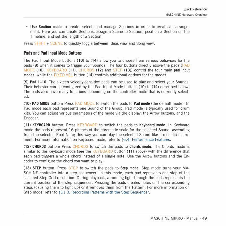
▪ Use Section mode to create, select, and manage Sections in order to create an arrange-ment. Here you can create Sections, assign a Scene to Section, position a Section on theTimeline, and set the length of a Section.
Press SHIFT + SCENE to quickly toggle between Ideas view and Song view.
Pads and Pad Input Mode Buttons
The Pad Input Mode buttons (10) to (14) allow you to choose from various behaviors for thepads (9) when it comes to trigger your Sounds. The four buttons directly above the pads (PADMODE (10), KEYBOARD (11), CHORDS (12) and STEP (13)) control the four main pad inputmodes, while the FIXED VEL button (14) controls additional options for the modes.
(9) Pad 1–16: The sixteen velocity-sensitive pads can be used to play and select your Sounds.Their behavior can be configured by the Pad Input Mode buttons (10) to (14) described below.The pads also have many functions depending on the controller mode that is currently select-ed.
(10) PAD MODE button: Press PAD MODE to switch the pads to Pad mode (the default mode). InPad mode each pad represents one Sound of the Group. Pad mode is typically used for drumkits. You can adjust various parameters of the mode via the display, the Arrow buttons, and theEncoder.
(11) KEYBOARD button: Press KEYBOARD to switch the pads to Keyboard mode. In Keyboardmode the pads represent 16 pitches of the chromatic scale for the selected Sound, ascendingfrom the selected Root Note; this way you can play the selected Sound like a melodic instru-ment. For more information on Keyboard mode, refer to ↑6.4, Performance Features.
(12) CHORDS button: Press CHORDS to switch the pads to Chords mode. The Chords mode issimilar to the Keyboard mode (see the KEYBOARD button (11) above) with the difference thateach pad triggers a whole chord instead of a single note. Use the Arrow buttons and the En-coder to configure the chord you want to play.
(13) STEP button: Press STEP to switch the pads to Step mode. Step mode turns your MA-SCHINE controller into a step sequencer. In this mode, each pad represents one step of theselected Step Grid resolution. During playback, a running light through the pads represents thecurrent position of the step sequencer. Pressing the pads creates notes on the correspondingsteps (causing them to light up) or it removes them from the Pattern. For more information onStep mode, refer to ↑11.3, Recording Patterns with the Step Sequencer.
Quick Reference
MASCHINE Hardware Overview
MASCHINE MIKRO - Manual - 49

(14) FIXED VEL button: Press FIXED VEL to enable/disable the Fixed Velocity option. By default,the pads are sensitive to velocity: The harder you hit them, the louder the sound will be. WithFixed Velocity enabled, your pads play at the same volume no matter how hard you hit them.For example, this can be very handy when you are triggering slices of a loop from your padsand want to have all slices at the same volume. Fixed Velocity is available in all four pad inputmodes: Group, Keyboard, Chords and Step (see above for more info on these). Press SHIFT +FIXED VEL to enable/disable the 16 Velocities option. In this mode your pads play the samenote (pitch) of the focused Sound but with 16 different velocity values. This can be useful toplay or program complex drum fills. The display indicates the velocity values for each pad. Thepitch of the played note is defined by the Base Key. The 16 Velocities option is only availablein Pad mode, i.e. when PAD MODE (10) is enabled.
2.2.1.6 Rear Panel
The rear panel of the MASCHINE controller holds the USB, and Kensington Lock sockets.
The rear panel of the MASCHINE controller.
(1) USB socket: Connects the MASCHINE controller to your computer via USB 2.0/3.0.
(2) Kensington Lock slot: Attach a Kensington Lock to secure your device from theft.
Quick Reference
MASCHINE Hardware Overview
MASCHINE MIKRO - Manual - 50

2.3 MASCHINE Software Overview
1
2
3
4
5
The MASCHINE software.
(1) Header: The Header contains the main controls for the MASCHINE software including theDisplay area, the Transport controls, and the Master Volume slider. You can also use this areato toggle the Browser, toggle the Mixer view, connect to your hardware controller and monitorthe CPU usage of your computer.
(2) Browser: The Browser is your tool for managing, finding, tagging and categorizing Projects,Groups, Sounds, Instruments, Effects and Samples. Using the search facility you can quicklyfind things and Prehear (audition) Samples.
(3) Arranger: This area has two views: Ideas view and Song view. Ideas view is for creating andexperimenting with musical ideas free from the timeline. Song view is for organizing your musi-cal ideas into a song on the Timeline.
Quick Reference
MASCHINE Software Overview
MASCHINE MIKRO - Manual - 51

(4) Control area: The Control area allows you to control parameters and settings for each of thePlug-in slots at each Project level (Sound, Group and Master). This area can hold settings forGroups, Sounds, Plug-ins (internal or VST/AU plug-ins), MIDI, routing.
(5) Pattern Editor: The Pattern Editor features both step programming and real-time recordingand is the basis for each Pattern. Patterns for each Group can be created here and then as-signed to Scenes in the Arranger. The Pattern Editor also lets you edit modulation for theSound, Group, and Plug-in (Internal or External) parameters.
2.3.1 Header
1
2
3 4 5
7
8
9
106
The Header.
(1) MASCHINE menu: Click the MASCHINE menu to access the software menus. This menu isparticularly useful in Full screen mode and when MASCHINE is used as a plug-in in a host ap-plication.
(2) Browser button: Use the Browser button to toggle the Browser. The Browser is your tool formanaging, finding, tagging and categorizing Projects, Groups, Sounds, Instruments, Effectsand Samples. From the Browser you can directly search your computer or an external drive toadd new files. You may also prehear (audition) Samples directly from the Browser and applynew tags.
(3) Mix view button: Click the Mix view button to access the Mix view. The Mix view providesyou with quick access to the level and routing settings of all your Sounds, Groups, and theMaster. In addition, it provides you with an intuitive interface for adjusting the parameters ofall your Plug-ins.
(4) Transport controls: The Transport controls contain buttons such as Play, Restart, Record andLoop.
Quick Reference
MASCHINE Software Overview
MASCHINE MIKRO - Manual - 52

(5) Display area: The Display area provides control regarding Ableton Link, time signature, tem-po, global swing, Follow and Performance Grid (Including Retrigger)
(6) Controller icon: This area displays an icon each MASCHINE controllers connected to yourcomputer.
(7) Master Volume slider: Shows and adjusts the level of the MASCHINE audio output.
(8) CPU meter: The CPU meter represents the current load on your computer’s processor and isconstantly measured; it should not go above 70% to avoid clicks and interruptions. You cansave CPU power by sampling the audio output of MASCHINE if necessary using export (formore information, please refer to the Manual).
(9) Audio Engine button: Click the Audio Engine button to disable the entire sound processing ofMASCHINE.
(10) NI logo: The NI logo and MASCHINE logo open the About screen which displays the ver-sion number and edition of your MASCHINE software.
Quick Reference
MASCHINE Software Overview
MASCHINE MIKRO - Manual - 53

2.3.2 Browser
1 2
3 45
6
7
8
11 129 10
The Browser.
(1) Library tab: Use the Library tab to access your computer's hard drives via MASCHINE's se-lectors and filters.
(2) Files tab: Use the Files tab to access your computer’s hard drives.
Quick Reference
MASCHINE Software Overview
MASCHINE MIKRO - Manual - 54

(3) File Type selector: This contains seven icons representing the different file types of MA-SCHINE. From left to right the file types are: Projects, Groups, Sounds, Instruments, Effects,Loops and One-shots. Clicking one of them causes only the files of the selected type to be dis-played.
(4) Content selector: Use the Content selector to switch between Factory Content (button off)and User Content (button on).
(5) Product selector: The Product selector allows you to browse and select any content of thesame File Type as is selected in the File Type selector above.
(6) Tag Filter: The Tag Filter allows you to search based on tags. You can quickly find filesbased on the Types and Characters categories by clicking the tags.
(7) Search field: Use the Search field to quickly find files based on their name or tagged attrib-ute. Select the type of file you are looking for from the File Type selector and enter the nameor category of a file into the Search field to perform a search. Results are displayed in the Re-sults list below.
(8) Results list: The Results list displays all files that match your query.
(9) Autoload: This button automatically loads the selected loop or one-shot in the Results listso you can to listen in context and in tempo with your Project while it is playing.
(10) The Prehear button (speaker icon) allows you to quickly audition the item selected in theResults list when Preview files have been downloaded and installed using Native Access. Thevolume level of the file being auditioned is set by the slider.
Audition control volume slider.
When browsing Groups, the +PATTERNS and +ROUTING buttons appear in the Control bar ofthe Browser.
+PATTERNS and +ROUTING in the Control bar of the Browser.
Use the +ROUTING button to load the audio and MIDI routings stored in the Group (potentiallyoverwriting previous routings in the selected Group). When the +ROUTING button is off, anyaudio and MIDI routings saved in the Group will not be loaded, preserving any existing routingsin the active Group.
Quick Reference
MASCHINE Software Overview
MASCHINE MIKRO - Manual - 55

Use the +PATTERNS button to load a Group with its saved Pattern. When +PATTERNS is se-lected the Sounds and Patterns of the selected Group are loaded. When +PATTERNS is dese-lected, only the Sounds of the selected Group are loaded so you can try them with your existingpattern.
(11) Information: Click the Information icon to view details of the selected file.
(12) Tag Editor: Use the Tag Editor to edit Tags applied to files and to add Tags to new files.Native Instruments content is read only, however, Types and Characters properties can be edit-ed in User content. You can show/hide the Tag Editor by clicking the EDIT button at the bot-tom right.
2.3.3 Arranger
The Arranger is has two different views: Ideas view and Song view. Each view has a specificpurpose in the workflow of creating a song, but essentially they represent the same content.The Ideas view allows you to experiment with your musical ideas without being tied to a time-line or any kind of arrangement. Here you can create Patterns for each Group and combinethem into a Scene. The Song view allows you to structure your song by allowing you to assignthe Scenes you created in the Ideas view to Sections, and move them around to quickly createa larger musical structure.
Switching between Ideas View and Song view
The Arranger View button.
► Click the Arranger View button to switch between the Ideas view and the Song view.
→ When the button is unlit Ideas view is active, when the button is lit Song view is active.
Quick Reference
MASCHINE Software Overview
MASCHINE MIKRO - Manual - 56

The Ideas View
1
2
3The Ideas view for creating and experimenting with musical ideas free from the Timeline.
(1) Scenes: This area displays all the current Scenes in your project. After creating a Scene byclicking the + symbol, you can build the Scene by selecting a Pattern from each Group. Byclicking each Scene name (Scene slot) you can switch between Scenes to see how your musi-cal ideas work together.
Using your mouse you can right-click the Scene slot and select to Append to Arrangement fromthe menu and then arrange your song in the Song view. You can also use the right-click menuto Clear, Duplicate, or Delete Scenes, as well as organize your Scenes by selecting the Renameor Color options
(2) Pattern area: All Patterns in your Song are represented here. You can double-click a blankslot to create and new Pattern or click an existing Pattern to assign it to the selected Scene.Once assigned, a Pattern will become highlighted, click it again to remove it from the selectedScene. Using your mouse you can right-click the name of a Pattern and select to Clear, Dupli-cate, or Delete a Pattern. You can also organize your Patterns by selecting the Rename or Coloroptions.
(3) Groups: The Group slots can hold one Group each. Select the desired slot to load a Groupinto it and display the Group’s content (Sounds, Patterns…) in the Pattern Editor (see ↑2.3.5,Pattern Editor) and the Group’s Channel properties and Plug-in parameters in the Control area(see ↑2.3.4, Control Area). To mute a Group click the Group letter, for example A1, and right-click on the letter to solo the Group. Using your mouse you can also right-click the name of aGroup to access the many options available to manage them.
Quick Reference
MASCHINE Software Overview
MASCHINE MIKRO - Manual - 57
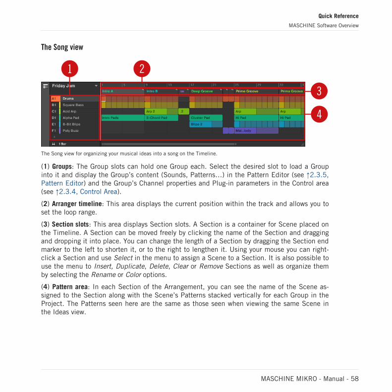
The Song view
3
4
21
The Song view for organizing your musical ideas into a song on the Timeline.
(1) Groups: The Group slots can hold one Group each. Select the desired slot to load a Groupinto it and display the Group’s content (Sounds, Patterns…) in the Pattern Editor (see ↑2.3.5,Pattern Editor) and the Group’s Channel properties and Plug-in parameters in the Control area(see ↑2.3.4, Control Area).
(2) Arranger timeline: This area displays the current position within the track and allows you toset the loop range.
(3) Section slots: This area displays Section slots. A Section is a container for Scene placed onthe Timeline. A Section can be moved freely by clicking the name of the Section and draggingand dropping it into place. You can change the length of a Section by dragging the Section endmarker to the left to shorten it, or to the right to lengthen it. Using your mouse you can right-click a Section and use Select in the menu to assign a Scene to a Section. It is also possible touse the menu to Insert, Duplicate, Delete, Clear or Remove Sections as well as organize themby selecting the Rename or Color options.
(4) Pattern area: In each Section of the Arrangement, you can see the name of the Scene as-signed to the Section along with the Scene’s Patterns stacked vertically for each Group in theProject. The Patterns seen here are the same as those seen when viewing the same Scene inthe Ideas view.
Quick Reference
MASCHINE Software Overview
MASCHINE MIKRO - Manual - 58
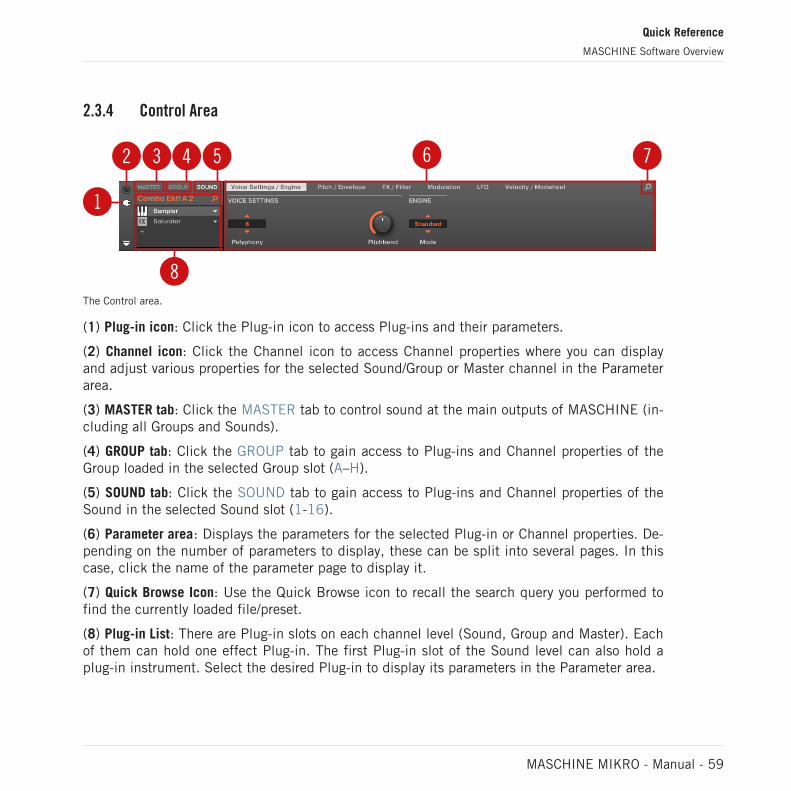
2.3.4 Control Area
2 3 4 5
1
8
6 7
The Control area.
(1) Plug-in icon: Click the Plug-in icon to access Plug-ins and their parameters.
(2) Channel icon: Click the Channel icon to access Channel properties where you can displayand adjust various properties for the selected Sound/Group or Master channel in the Parameterarea.
(3) MASTER tab: Click the MASTER tab to control sound at the main outputs of MASCHINE (in-cluding all Groups and Sounds).
(4) GROUP tab: Click the GROUP tab to gain access to Plug-ins and Channel properties of theGroup loaded in the selected Group slot (A–H).
(5) SOUND tab: Click the SOUND tab to gain access to Plug-ins and Channel properties of theSound in the selected Sound slot (1-16).
(6) Parameter area: Displays the parameters for the selected Plug-in or Channel properties. De-pending on the number of parameters to display, these can be split into several pages. In thiscase, click the name of the parameter page to display it.
(7) Quick Browse Icon: Use the Quick Browse icon to recall the search query you performed tofind the currently loaded file/preset.
(8) Plug-in List: There are Plug-in slots on each channel level (Sound, Group and Master). Eachof them can hold one effect Plug-in. The first Plug-in slot of the Sound level can also hold aplug-in instrument. Select the desired Plug-in to display its parameters in the Parameter area.
Quick Reference
MASCHINE Software Overview
MASCHINE MIKRO - Manual - 59

2.3.5 Pattern Editor
3
2
1
6 874 5 9
10
11
12
1314
The Pattern Editor.
(1) Sample Editor button: Click this button to open/close the Sample Editor.
(2) Keyboard view button: Click this button to display the Keyboard view.
(3) Group view button: Click this button to display the Group view.
(4) Audition button: Click this button to audition a Sound when it is selected from the Soundslots (6).
(5) Sound properties icon: Click this icon to quickly access the Key, Choke, and Link settingsfor the selected Sound.
Quick Reference
MASCHINE Software Overview
MASCHINE MIKRO - Manual - 60
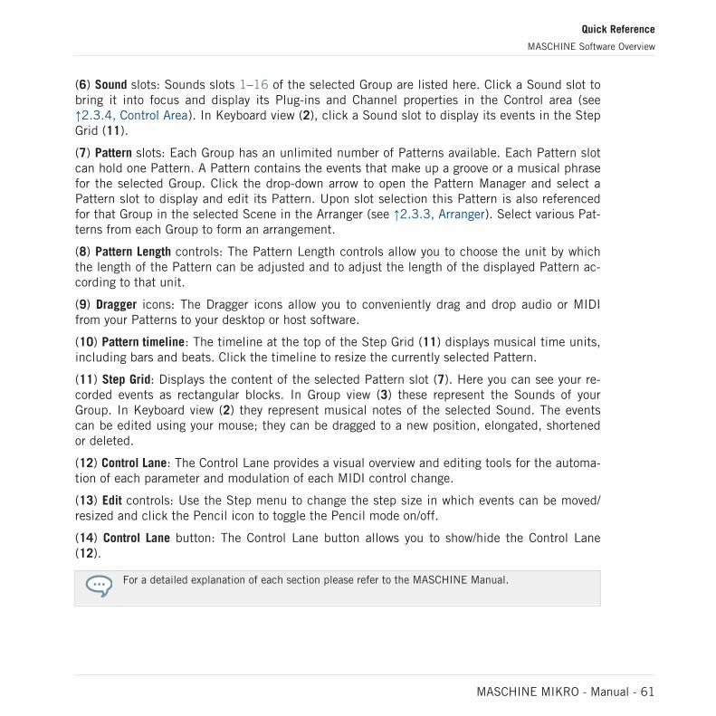
(6) Sound slots: Sounds slots 1–16 of the selected Group are listed here. Click a Sound slot tobring it into focus and display its Plug-ins and Channel properties in the Control area (see↑2.3.4, Control Area). In Keyboard view (2), click a Sound slot to display its events in the StepGrid (11).
(7) Pattern slots: Each Group has an unlimited number of Patterns available. Each Pattern slotcan hold one Pattern. A Pattern contains the events that make up a groove or a musical phrasefor the selected Group. Click the drop-down arrow to open the Pattern Manager and select aPattern slot to display and edit its Pattern. Upon slot selection this Pattern is also referencedfor that Group in the selected Scene in the Arranger (see ↑2.3.3, Arranger). Select various Pat-terns from each Group to form an arrangement.
(8) Pattern Length controls: The Pattern Length controls allow you to choose the unit by whichthe length of the Pattern can be adjusted and to adjust the length of the displayed Pattern ac-cording to that unit.
(9) Dragger icons: The Dragger icons allow you to conveniently drag and drop audio or MIDIfrom your Patterns to your desktop or host software.
(10) Pattern timeline: The timeline at the top of the Step Grid (11) displays musical time units,including bars and beats. Click the timeline to resize the currently selected Pattern.
(11) Step Grid: Displays the content of the selected Pattern slot (7). Here you can see your re-corded events as rectangular blocks. In Group view (3) these represent the Sounds of yourGroup. In Keyboard view (2) they represent musical notes of the selected Sound. The eventscan be edited using your mouse; they can be dragged to a new position, elongated, shortenedor deleted.
(12) Control Lane: The Control Lane provides a visual overview and editing tools for the automa-tion of each parameter and modulation of each MIDI control change.
(13) Edit controls: Use the Step menu to change the step size in which events can be moved/resized and click the Pencil icon to toggle the Pencil mode on/off.
(14) Control Lane button: The Control Lane button allows you to show/hide the Control Lane(12).
For a detailed explanation of each section please refer to the MASCHINE Manual.
Quick Reference
MASCHINE Software Overview
MASCHINE MIKRO - Manual - 61

3 Basic Concepts
This chapter will reintroduce you to MASCHINE’s main elements and terminology and explainhow they relate to one another. You will also learn how to set up your audio interface and howto connect MIDI devices.
Before reading this chapter it is strongly recommended that you read the MASCHINE Getting Start-ed first.
3.1 Important Names and Concepts
We will start with a list (in alphabetical order) of the most important concepts and names.
Arranger
The Arranger is the big area located in the upper part of the MASCHINE window, right underthe Header. The Arranger has two views: Ideas view and Song view. Ideas view allows you todevelop your ideas independent from the timeline. The song view will enable you to combineSections (references to Scenes) and arrange them into a song.
Browser
The Browser is the front end for accessing all the elements of your MASCHINE Projects:Projects, Groups, Sounds, instruments and effect presets, and Samples. Each of these can bestored and tagged in a way that allows you easy access to all of them. MASCHINE’s factorylibrary has already been completely tagged, including the factory libraries of any Native Instru-ments products installed on your computer. You can also import your files into the Library andtag them as well. To learn more about the Browser, please read chapter ↑4, Browser.
Effect
MASCHINE comes with many different effects in the form of Internal Plug-ins. You may alsouse Native Instruments or third-party VST/AU effect plug-ins. Each Sound, each Group, andthe Master can hold any number of effects that can be applied as insert effects. The flexible
Basic Concepts
Important Names and Concepts
MASCHINE MIKRO - Manual - 62

routing system also allows you to create send effects, multi-effects, and side-chains. For moredetails on using effects in MASCHINE, refer to chapter ↑14, Using Effects. You will find anexhaustive description of all internal effects included in MASCHINE in chapter ↑15, EffectReference.
Event
Events are the individual drum hits or notes that make up a Pattern. In the Pattern Editor,events are visually represented by rectangles in the Event area. Depending on the current viewin the Pattern Editor, you can see events for all Sounds slots (Group view) or for the selectedSound slot only (Keyboard view). Events are described in more detail in chapter ↑11, Workingwith Patterns.
Group
A Group contains 16 Sound slots. In addition to the Effect Plug-ins applied to each individualSound, a Group can have its own insert effect. These affect all the Sounds in the Group. AGroup can also contain any number of Patterns (grouped into banks of 16 Patterns each). Re-fer to chapter ↑5, Managing Sounds, Groups, and Your Project for more information on Groups.
Ideas View
The Ideas view allows you to experiment with your musical ideas without being tied to a time-line or arrangement. You can create Patterns for each Group and combine them into a Scene.Scenes can then be added to Sections in the Song view to create a larger musical structure.
Master
This is where all audio signals from each of the Groups and Sounds come together and getmixed. The Master channel can also host any number of insert effects of its own, these effectsare applied to all Groups and the Sounds within them. More information on the Master can befound in chapter ↑5, Managing Sounds, Groups, and Your Project.
Pattern
A Pattern is a sequence that plays Sounds from a Group. It belongs to that Group and will besaved together with the Group. In every Scene you can choose for each Group which of its Pat-terns has to be played. More information on Patterns can be found in chapter ↑11, Workingwith Patterns.
Basic Concepts
Important Names and Concepts
MASCHINE MIKRO - Manual - 63

Plug-in
Each Sound, each Group, and the Master can hold any number of Plug-ins. Plug-ins can beinstruments or effects, and they can be internal (included with MASCHINE), from other NativeInstruments products (instruments or effects), or external (third-party VST/AU plug-ins). Instru-ment and Effect Plug-ins can be loaded in the first Plug-in slot of Sounds. The other Plug-inslots of Sounds, as well as the Plug-in slots of Groups and of the Master can hold Effect Plug-ins only. At each level (Sound, Group, and Master), Plug-ins process the audio in series, ac-cording to the order in which they are stacked up. Refer to chapter ↑7, Working with Plug-ins.
Project
A Project contains all data needed for a song: Groups with their Patterns, all Scenes and allsettings, modulation, effects, routings, Sounds, and Samples. It’s like a snapshot of the entirestate of MASCHINE. Please read the MASCHINE Getting Started for a complete overview ofthe MASCHINE Project structure.
Scene
A Scene is a combination of Patterns for each Group. They can be used to combine Patterns inorder to create musical ideas. Scenes are created in the Ideas view and then added to Sectionsin the Song view to create an arrangement. Refer to chapter ↑16.3, Using Song View for moreinformation on Scenes.
Section
A Section is a reference to a specific Scene on the Timeline of the Song view. They are used toarrange the Scenes into a larger musical structure. The benefit of using Sections is that anychanges made to a Scene are replicated in each Section where the Scene is referenced there-fore making the process of changing parts of a song quick and easy.
Song view
Song view will enable you to combine Sections (references to Scenes) and arrange them into asong in the Arranger.
Basic Concepts
Important Names and Concepts
MASCHINE MIKRO - Manual - 64

Sound
Sounds are the building blocks of all sound content in MASCHINE. A Sound is made up of anynumber of Plug-ins. Each Sound of the selected Group is mapped to one of the 16 pads on thehardware controller, so you can play the Sounds by pressing the pads. Refer to chapter ↑5,Managing Sounds, Groups, and Your Project for more information on Sounds.
Please refer to chapter ↑20, Glossary at the end of this Manual for more definitions.
3.2 Adjusting the MASCHINE User Interface
The MASCHINE software user interface is very flexible. You can choose what to display andwhat not, allowing you to focus on your workflow. This section shows you how to adjust the MA-SCHINE GUI to suit your needs.
3.2.1 Adjusting the Size of the Interface
From the View menu in the Application Menu Bar and from the View submenu in the MA-SCHINE menu you can select one of four different sizes to display MASCHINE’s software GUI:
The View menu in the Application Menu Bar (Windows depicted).
Basic Concepts
Adjusting the MASCHINE User Interface
MASCHINE MIKRO - Manual - 65
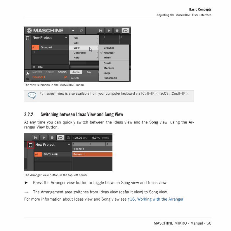
The View submenu in the MASCHINE menu.
Full screen view is also available from your computer keyboard via [Ctrl]+[F] (macOS: [Cmd]+[F]).
3.2.2 Switching between Ideas View and Song View
At any time you can quickly switch between the Ideas view and the Song view, using the Ar-ranger View button.
The Arranger View button in the top left corner.
► Press the Arranger view button to toggle between Song view and Ideas view.
→ The Arrangement area switches from Ideas view (default view) to Song view.
For more information about Ideas view and Song view see ↑16, Working with the Arranger.
Basic Concepts
Adjusting the MASCHINE User Interface
MASCHINE MIKRO - Manual - 66
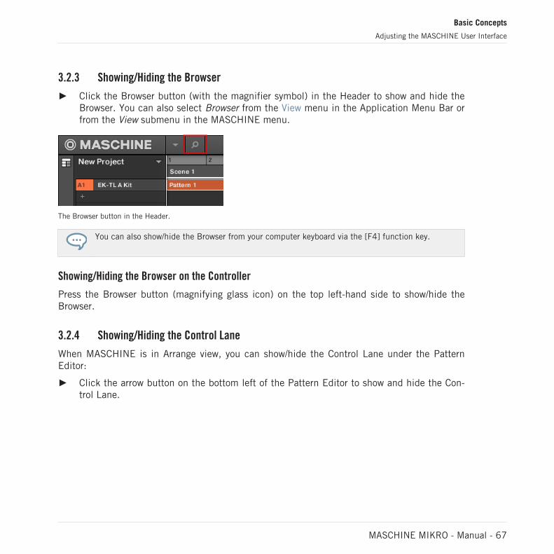
3.2.3 Showing/Hiding the Browser
► Click the Browser button (with the magnifier symbol) in the Header to show and hide theBrowser. You can also select Browser from the View menu in the Application Menu Bar orfrom the View submenu in the MASCHINE menu.
The Browser button in the Header.
You can also show/hide the Browser from your computer keyboard via the [F4] function key.
Showing/Hiding the Browser on the Controller
Press the Browser button (magnifying glass icon) on the top left-hand side to show/hide theBrowser.
3.2.4 Showing/Hiding the Control Lane
When MASCHINE is in Arrange view, you can show/hide the Control Lane under the PatternEditor:
► Click the arrow button on the bottom left of the Pattern Editor to show and hide the Con-trol Lane.
Basic Concepts
Adjusting the MASCHINE User Interface
MASCHINE MIKRO - Manual - 67

Click the arrow button at the bottom left of the Pattern Editor to show/hide the Control Lane.
3.3 Common Operations
This sections introduces a few very common operations in MASCHINE you will encounter innumerous situations.
3.3.1 Adjusting Volume, Swing, and Tempo
At any time you can quickly adjust volume levels, swing, and the overall tempo of your Projectusing the Quick Edit buttons.
3.3.1.1 Adjusting Volume, Swing and Tempo in the MASCHINE Software
Adjusting Volume
To adjust the various volume levels in the software, the following controls are at your disposal:
► To adjust the overall output level, click and drag the Master Volume slider located on theright part of the Header, at the top of the window.
Basic Concepts
Common Operations
MASCHINE MIKRO - Manual - 68

Use the Master Volume slider in the Header to adjust the overall volume of MASCHINE.
You can also use Mix view to adjust your Sound and Group levels. Mix view gives you quick accessto the level and routing settings of all your Sounds, Groups, and the Master. In addition, it providesyou with an intuitive interface for adjusting the parameters of all your Plug-ins. More on this in sec-tion The Mix View.
Adjusting Swing
To adjust the overall Swing of your song, you can use the display in the Header, at the top ofthe MASCHINE window:
The SWING control in the Header.
► To adjust the Swing value of your Project, click the SWING value, hold the mouse buttonand drag vertically.
Adjusting Tempo
To adjust the overall Tempo of your song, you can use the display in the Header, at the top ofthe MASCHINE window:
The BPM control in the Header.
► To adjust the Tempo (Beats Per Minute) value of your Project, click the BPM value, holdthe mouse button and drag vertically.
3.3.1.2 Adjusting Volume, Swing, Tempo and Tune on Your Controller
Adjusting Volume
► Press the VOLUME button next to the Encoder.
Basic Concepts
Common Operations
MASCHINE MIKRO - Manual - 69
→ The VOLUME button lights up. You can now adjust the volume for your overall Project, foreach Group, and for each Sound individually using the Encoder:
▪ To adjust the overall volume, turn the Encoder. Hold SHIFT to adjust the value in finer in-crements.
▪ To adjust the volume of a particular Group, hold its Group button (A–H) and turn the En-coder. Hold SHIFT to adjust the value in finer increments.
▪ To adjust the volume of an individual Sound, press and hold its pad and turn the Encoder.Hold SHIFT to adjust the value in finer increments.
As you adjust the volume, the display indicates the current value.
It is recommended you try this while your Pattern is playing, you will immediately hear the effect ofyour changes.
Adjusting Swing
Now adjust the overall swing of your Project. The Swing feature shifts some of the playednotes, hereby adding some “groove” to your Pattern. The procedure is similar to the one descri-bed above for the volume:
► Press the SWING button next to the Encoder.
→ The SWING button lights up. You can now adjust the swing for your overall Project, foreach Group, and for each Sound individually using the Encoder:
▪ To adjust the overall swing, turn the Encoder. Hold SHIFT to adjust the value in finer incre-ments.
▪ To adjust the swing of a particular Group, hold its Group button (A–H) and turn the Encod-er. Hold SHIFT to adjust the value in finer increments.
▪ To adjust the swing of an individual Sound, press and hold its pad and turn the Encoder.Hold SHIFT to adjust the value in finer increments.
As you adjust the swing, the display indicates the current value.
Adjusting Tempo
► Press the TEMPO button next to the Encoder.
Basic Concepts
Common Operations
MASCHINE MIKRO - Manual - 70

→ The TEMPO button lights up. You can now adjust the tempo for your overall Project, foreach Group, and for each Sound individually using the Encoder:
▪ To adjust the overall tempo, turn the Encoder. Hold SHIFT to adjust the value in finer in-crements.
As you adjust the tempo, the display indicates the current value.
It is recommended you try this while your Pattern is playing, you will immediately hear the effect ofyour changes.
When you are done with your volume, swing, and tempo changes, press the lit VOLUME,SWING, or TEMPO button to deactivate it.
3.3.2 Undo/Redo
Undoing and re-doing your last actions can be useful to cancel operations you have performedor to compare two versions before and after a change. You can undo nearly everything you didafter loading or creating your Project.
Note: If you save your Project, you will no longer be able to undo or redo any actions performed be-fore saving!
MASCHINE provides two different undo/redo features, each of them being suited for specificsituations:
▪ Step Undo allows you to cancel your last single action.
▪ Take Undo allows you to cancel your last group of actions.
Step Undo
Step Undo/Redo is the classic undo/redo found in most applications. It cancels or re-executeseach single action you have performed.
In the software use the following keyboard shortcuts for the Step Undo and Step Redo func-tions:
Basic Concepts
Common Operations
MASCHINE MIKRO - Manual - 71
► To cancel your last action (Step Undo), press [Ctrl]+[Shift]+[Z] ([Cmd]+ [Shift]+ [Z] onmacOS). To re-execute your last action (Step Redo), press [Ctrl]+ [Shift]+ [Y] ([Cmd]+[Shift]+ [Y] on macOS). You can also select Undo Step and Redo Step from the Editmenu in the Application Menu Bar or from the Edit submenu in the MASCHINE menu.
The commands in the Edit menu additionally shows which action will be undone/redone!
Take Undo
Suppose you have just recorded a 16th-note hi-hat beat over four bars, but then decide to can-cel it. Normally you would have to cancel the 64 notes one at a time, repeatedly calling theundo function 64 times in a row. This is what Take Undo has been made for!
Take Undo/Redo is an extended undo/redo available while recording that allows you to cancelor re-execute a whole group of actions at once.
Take Undo/Redo is the default undo/redo in MASCHINE. In the software use the common key-board shortcuts for the Undo and Redo functions:
► To cancel your last group of actions, press [Ctrl]+[Z] ([Cmd]+[Z] on macOS). To re-exe-cute your last group of actions, press [Ctrl]+[Y] ([Cmd]+[Y] on macOS). You can also se-lect Undo and Redo from the Edit menu in the Application Menu Bar or from the Editsubmenu in the MASCHINE menu.
The commands in the Edit menu additionally shows which action will be undone/redone!
Undo/Redo on the Controller
Both Take Undo and Step Undo are also available on your controller:
1. To undo a take, press SHIFT + pad 1 (UNDO).
2. To redo a take, press SHIFT + pad 2 (REDO).
3. To undo a step, press SHIFT + pad 3 (STEP UNDO).
4. To redo a step, press SHIFT + pad 4 (STEP REDO).
Take Undo is available in following situations:
Basic Concepts
Common Operations
MASCHINE MIKRO - Manual - 72

▪ Recording in Control mode
▪ Recording in Step mode
▪ Recording modulation
Outside of these three situations, Take Undo has the same effect as Step Undo (see above).
3.3.3 Focusing on a Group or a Sound
To display the content and parameters of a particular Sound or Group, you first need to put itin focus.
Setting the focus on a Sound or Group is slightly different than selecting it: The focus defineswhat will be displayed, whereas the selection defines what will be affected by your edits. Notethat a focused Sound/Group is always selected. The distinction is of importance because youcan select multiple Sounds or Groups to apply your edits to all of them at once! See section↑5.1.3, Selecting Multiple Sounds or Groups for more on this.
We show here how to put Sounds and Groups in focus when the MASCHINE software is in Arrangeview (default view). For instructions on putting Sounds and Groups in focus in Mix view, please re-fer to chapter ↑13.2.3, Selecting Channel Strips.
Setting the Focus on a Group
► To put a Group in focus, click this Group in the Group List of the Arranger:
Basic Concepts
Common Operations
MASCHINE MIKRO - Manual - 73

→ The focused Group is highlighted. The Pattern Editor displays the Sounds and Patterns ofthat Group.
The focused Group is highlighted and the Pattern Editor show its content.
If the desired Group does not appear in the Group List, use the scroll bar at the right end of theArranger or turn your mouse wheel while hovering the Arranger to display any hidden Groups. Youcan also extend the Arranger by dragging its lower right corner vertically with the mouse.
You can also select multiple Groups at once to apply changes to all of them. See section ↑5.1.3,Selecting Multiple Sounds or Groups for more information.
Basic Concepts
Common Operations
MASCHINE MIKRO - Manual - 74

Setting the Focus on a Sound
To put a Sound in focus:
1. Set the focus to the Group containing the desired Sound by clicking it in the Group Liston the left of the Arranger (see above).
The focused Group is highlighted. The Pattern Editor displays the Sounds and Patterns ofthat Group.
2. Click the desired Sound slot in the Sound List of the Pattern Editor:
→ The focused Sound slot is highlighted.
Basic Concepts
Common Operations
MASCHINE MIKRO - Manual - 75

The focused Sound slot is highlighted.
If the desired Sound does not appear in the Sound List, use the scroll bar at the right end of thePattern Editor or turn your mouse wheel while hovering the Pattern Editor to display any hiddenSounds.
You can also select multiple Sounds at once to apply changes to all of them. See section ↑5.1.3,Selecting Multiple Sounds or Groups for more information.
Focusing on a Group using the Hardware
1. If necessary, press GROUP + the Left or Right Arrow button below the display to switch tothe Group bank containing that Group.
2. Press GROUP + the pad 9–16 of the desired Group.
The corresponding Group is now in focus.
Focusing on a Sound using the Hardware
1. If you want to set the focus on a Sound located in another Group, first set the focus on itsGroup as described above.
2. Press SELECT + the pad of the desired Sound (or simply press its pad if pads are in PadMode).
→ The corresponding Sound is now in focus.
For information on how to quickly switch between the Master, Group, and Sound level in thesoftware, see section ↑3.3.4, Switching Between the Master, Group, and Sound Level.
Basic Concepts
Common Operations
MASCHINE MIKRO - Manual - 76

You can also select multiple Sounds at once to apply changes to all of them. See section ↑5.1.3,Selecting Multiple Sounds or Groups for more information.
3.3.4 Switching Between the Master, Group, and Sound Level
At any time you can quickly switch the Control area between the parameters of the Master, thefocused Group, and the focused Sound.
Click the desired tab to switch the display of the Control area.
► Click the MASTER, GROUP or SOUND tab in the top left corner of the Control area to dis-play the Plug-in parameters or Channel properties of the Master, the focused Group or thefocused Sound, respectively.
→ The selected tab lights up. The name of your Project, the focused Group or the focusedSound appears under the MASTER, GROUP, and SOUND tabs (the Muddy Matt Sound inthe picture above), and the rest of the Control area displays the Plug-in parameters andChannel properties of the Master, the focused Group or the focused Sound, respectively.
3.3.5 Navigating Channel Properties, Plug-ins, and Parameter Pages in the Control Area
We describe here how to display/edit any Plug-in parameters or Channel properties located inany Sound, Group or the Master.
To select a particular Plug-in or a particular set of Channel properties, you first need to displaythe parameters of the Master, the desired Group or Sound.
1. To display the parameters of a particular Group or Sound, put it in focus by clicking it inthe Group List or Sound List, respectively (see section ↑3.3.3, Focusing on a Group or aSound).
2. In the top left corner of the Control area, click the MASTER, GROUP or SOUND tab todisplay the parameters of the Master, the focused Group or the focused Sound, respec-tively.
Basic Concepts
Common Operations
MASCHINE MIKRO - Manual - 77

→ The Control area now displays the Plug-in parameters and Channel properties of the de-sired Sound, desired Group or the Master.
Selecting Channel Properties
1. At the far left of the Control area, click the Channel icon (showing a little knob) to displaythe Channel properties:
The button lights up. The Channel Property selector appears in the left part of the Controlarea, showing a square of four buttons representing the various sets of Channel propertiesavailable for the selected Sound, Group or the Master:
2. Click the desired button (Input, Output, Groove, or Macro) in the Channel Property selec-tor to select that set of Channel properties.
→ The selected button is highlighted and the parameters of the selected Channel propertiesappear in the Parameter area (the right and biggest part of the Control area).
Basic Concepts
Common Operations
MASCHINE MIKRO - Manual - 78

Selecting a Plug-in
1. At the far left of the Control area, click the little Plug-in icon to display the Plug-ins:
The icon lights up. The Plug-in List appears in the left part of the Control area, showing astack of all Plug-ins loaded in the selected Sound, Group or the Master:
2. Click the desired Plug-in slot in the Plug-in List to select that Plug-in.
→ The parameters of the selected Plug-in appear in the Parameter area (the right and biggestpart of the Control area).
If the Plug-in List only shows a “+” sign, it means that there are no Plug-ins loaded in this Sound,Group or the Master. Clicking the “+” sign allows you to load a new Plug-in: see section ↑7.1.3,Loading, Removing, and Replacing a Plug-in for more on this.
Navigating Parameter Pages
In some situations, the selected Plug-in or Channel properties provide more parameters thanthe display(s) of your controller and the Parameter area in the software can show at once. Ex-amples of this are the parameters for the Groups’ or Sounds’ Output properties and those forthe Sampler Plug-in. In these cases, the parameters are divided into several Parameter pagesthat you can easily navigate with the hardware and software.
In the software the names of the available pages are displayed at the top of the Parameterarea. The name of the page currently displayed is highlighted.
► Click the desired page name at the top of the Parameter area to show the correspondingParameter page.
Basic Concepts
Common Operations
MASCHINE MIKRO - Manual - 79

The Parameter pages of the Sound’s Output properties: Audio (currently displayed), Aux, and MIDI.
If all page names cannot be displayed at once at the top of the Parameter area, two small ar-rows are displayed on the left to click through the pages:
► Click the left or right arrow to access additional pages.
Adjusting the Parameters
In the Parameter area, each parameter includes a control element and a label. Following typesof control elements are available:
Basic Concepts
Common Operations
MASCHINE MIKRO - Manual - 80

Element Action
Knob: Click the knob and drag your mouse vertically to changethe parameter value. Hold [Shift] on your computer keyboard anddrag your mouse to adjust the value in finer increments.
Button: Click the button to switch its state. When the button isenabled, it shows a small colored LED.
Selector: Click the displayed value to open the drop-down list,and click another value in the list to select it.
Navigating Plug-ins, and Parameter Pages using the Controller
On the controller, do the following:
1. Set the focus on the desired Sound, Group or the Master (see section ↑3.3.3, Focusing ona Group or a Sound).
2. At the top of the controller, press the PLUG-IN.
3. If you have more than one Plug-in loaded, use the Arrow buttons to navigate them.
4. Press the Encoder to display the parameter properties of the selected Plug-in.
5. Use the Arrow buttons to navigate through each parameter, or SHIFT + Arrow buttons tonavigate the parameter pages of the selected Plug-in.
6. Turn Encoder to adjust the value of the selected parameter. Hold SHIFT while turning theencoder to adjust the value in finer increments.
7. Press Plug-in again to return to the top level if you want to navigate the plug-ins again.
Basic Concepts
Common Operations
MASCHINE MIKRO - Manual - 81

3.3.6 Navigating the Software Using the Controller
You can use the controller to adjust the position and zoom factor in the software.
To access the Navigation mode:
► Press SHIFT + VARIATION (Navigate).
Navigating the Pattern Editor
To control the position and zoom factor in the Pattern Editor from your controller:
Action Shortcut
Scroll Pattern Editor left Press pad 1
Scroll Pattern Editor right Press pad 3
Zoom in to Pattern Editor Press pad 6
Zoom out of Pattern Editor Press pad 2
Navigating Song View
To control the position and zoom factor in the Song view from your controller:
Action Shortcut
Scroll Arranger left Press pad 9
Scroll Arranger right Press pad 11
Zoom in (Arranger) Press pad 14
Zoom out (Arranger) Press pad 10
3.3.7 Using Two or More Hardware Controllers
If two or more MASCHINE controllers of different types are connected to your computer, onlyone controller can be used to control the MASCHINE software at a time.
Basic Concepts
Common Operations
MASCHINE MIKRO - Manual - 82
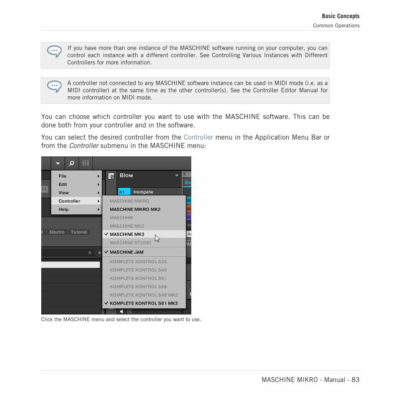
If you have more than one instance of the MASCHINE software running on your computer, you cancontrol each instance with a different controller. See Controlling Various Instances with DifferentControllers for more information.
A controller not connected to any MASCHINE software instance can be used in MIDI mode (i.e. as aMIDI controller) at the same time as the other controller(s). See the Controller Editor Manual formore information on MIDI mode.
You can choose which controller you want to use with the MASCHINE software. This can bedone both from your controller and in the software.
You can select the desired controller from the Controller menu in the Application Menu Bar orfrom the Controller submenu in the MASCHINE menu:
Click the MASCHINE menu and select the controller you want to use.
Basic Concepts
Common Operations
MASCHINE MIKRO - Manual - 83

Hardware
On the controller you want to use with the MASCHINE software, do the following:
▪ MASCHINE (MK3) controller: Press SHIFT + PLUG-IN, turn the 4-D encoder to select thedesired instance, and press the 4-D encoder or Button 4 to load it.
▪ MASCHINE STUDIO controller: Press SHIFT + PLUG-IN, turn the jog wheel to select thedesired instance, and press the jog wheel or Button 8 to load it.
▪ MASCHINE (MK1 & MK2) controller: Press SHIFT + STEP, turn Knob 8 (or press But-ton 5/6) to select the desired instance, and press Button 8 to load it.
▪ MASCHINE MIKRO (MK1 & MK2) controller: Press SHIFT + F2, turn the Control encoderto select the desired instance, and press the Control encoder to load it.
▪ MASCHINE JAM controller: Press SHIFT + H (INSTANCE), turn the Control encoder to se-lect the desired instance, and press the Control encoder to load it.
▪ KOMPLETE KONTROL Keyboard MK1: Press INSTANCE and turn the Control encoder toselect the desired instance, and press the Control encoder to load it.
▪ KOMPLETE KONTROL Keyboard MK2: Press INSTANCE and turn the 4-D encoder to se-lect the desired instance, and press the 4-D encoder to load it.
3.3.8 Loading a Recent Project from the Controller
Your controller has a dedicated mode that conveniently allows you to use the controller to loada Project that was recently opened.
To load a recent Project from the controller:
1. Press the Project button (MASCHINE logo) at the top on the left-hand side of the control-ler.
2. Turn the Encoder to find the recent Project you want to load.
3. Press the Encoder to load the selected Project.
Basic Concepts
Common Operations
MASCHINE MIKRO - Manual - 84

3.4 Native Kontrol Standard
Native Kontrol Standard (NKS) is a software instrument format that allows third-party develop-ers to integrate with MASCHINE and KOMPLETE KONTROL hardware and software at thesame deep level as KOMPLETE Instruments.
The Native Kontrol Standard includes:
▪ Seamless integration into the MASCHINE and KOMPLETE KONTROL Browser for a unifiedbrowsing experience.
▪ Full parameter mapping for instant hands-on control.
▪ Support of KOMPLETE KONTROL S-SERIES features such as the Light Guide.
NKS instruments can be found in the MASCHINE Browser next to your KOMPLETE Instru-ments. All of their presets are fully tagged, so filtering in the Browser gives you matching re-sults from both KOMPLETE Instruments and NKS instruments (see section ↑4.2.6, SelectingType and Character Tags). And when you load a preset from an NKS instrument, its parametersare mapped to the controls on your KOMPLETE KONTROL S-SERIES keyboard in a meaningfulway, just like any preset from your KOMPLETE Instruments.
NKS instruments are automatically added to your Library when you start MASCHINE or KOM-PLETE KONTROL for the first time after installing the instrument (except KONTAKT instru-ments with NKS support, see below). The folders containing the preset files for NKS supportcan be managed in the Factory pane on the Library page of the Preferences (see section↑3.6.5, Preferences – Library Page).
Installing KONTAKT Instruments with NKS Support
Third-party developers of KONTAKT instruments provide you with a folder that contains all in-strument files, including presets and samples. Instead of running an installer, this folder needsto be stored on the hard drive. The instrument can then be activated with Native Access, whichalso adds it to the MASCHINE and KOMPLETE KONTROL Libraries. If you are using KON-TAKT, the instrument is automatically added to your KONTAKT Browser too.
To activate your KONTAKT instrument with NKS support and add it to the MASCHINE Library,follow the steps below:
Basic Concepts
Native Kontrol Standard
MASCHINE MIKRO - Manual - 85

1. Start the stand-alone version of the MASCHINE software.
2. In the File menu click on Manage Products….
3. Click on Add a serial in the top-left corner of Native Access.
4. Enter the serial number of the instrument and click ADD SERIAL.
5. Click BROWSE and open the folder containing the instrument files in the file dialog.
6. Click on INSTALL to add the instrument to your MASCHINE Library.
→ The instrument is installed. MASCHINE automatically scans for the new content and addsit to the MASCHINE Browser.
The MASCHINE, and KOMPLETE KONTROL Libraries, and the KONTAKT Browser reference the in-strument files contained in the folder. It is recommended to not delete or move the folder after-wards, or otherwise MASCHINE, KOMPLETE KONTROL, and KONTAKT will not be able to find theinstrument files. If an instrument cannot be found, use the Rescan function on the Preferences’Library page to update the Library with the correct folder location (see section ↑3.6.5, Preferences– Library Page).
3.5 Stand-Alone and Plug-in Mode
You can run the MASCHINE software as a stand-alone application or integrate it into your fa-vorite host by loading it as a plug-in. The MASCHINE software is available in the VST, AudioUnit, and AAX plug-in formats. For further information on plug-in compatibility and for a de-tailed description of how to use plug-ins in your host, please refer to the documentation in-cluded with your host software.
3.5.1 Differences between Stand-Alone and Plug-in Mode
Transport Functions
The most noticeable difference between the stand-alone and plug-in mode of MASCHINE re-lates to the interaction with MASCHINE’s sequencer. Indeed, when MASCHINE is used as aplug-in within a host sequencer software (e.g., Cubase or Pro Tools), MASCHINE’s sequenceris exclusively controlled by the host application: you cannot, e.g., manually start, stop or re-
Basic Concepts
Stand-Alone and Plug-in Mode
MASCHINE MIKRO - Manual - 86

start the playback in MASCHINE, nor modify the tempo or the time signature of your Projectwithin the MASCHINE plug-in itself — these are synchonized to your host’s own transportfunctions and tempo settings. As a direct consequence, when MASCHINE is used as a plug-inthe Restart and Play buttons as well as the Tempo and Time Signature fields are grayed outand inactive in the MASCHINE Header. Obviously you cannot control MASCHINE’s playbackand tempo settings from your MASCHINE controller either.
However from your controller you can directly control the transport functions of your host applica-tion instead. See section Controlling your Host’s Transport Functions in Plug-in Mode for more in-formation.
Audio and MIDI Handling
When MASCHINE is used in stand-alone mode, it directly communicates with your audio andMIDI interface. You can select which physical audio/MIDI ports have to be used on your inter-face, and configure crucial audio settings like the sample rate. All this is done via the Audioand MIDI Settings panel (for more information on this, please refer to ↑3.7, Integrating MA-SCHINE into a MIDI Setup).
On the contrary, When MASCHINE is used as a plug-in within a host application, the commu-nication with your audio and MIDI interfaces is managed by the host — the MASCHINE plug-in only communicates with the host. Native Instruments’ Online Knowledge Base provideshow-tos that will help you route the MASCHINE plug-in to multiple tracks/outputs in the majorhosts:
▪ How to route MASCHINE to multiple outputs in Ableton Live:http://www.native-instruments.com/knowledge/questions/1705
▪ How to route MASCHINE to multiple outputs in Cubase:http://www.native-instruments.com/knowledge/questions/1707
▪ How to route MASCHINE to multiple outputs in Pro Tools:http://www.native-instruments.com/knowledge/questions/1709
▪ How to route MASCHINE to multiple outputs in Logic Pro:http://www.native-instruments.com/knowledge/questions/1711
For all details on the audio and MIDI configuration of your host application, please refer to its docu-mentation.
Basic Concepts
Stand-Alone and Plug-in Mode
MASCHINE MIKRO - Manual - 87

Multiple Plug-in Instances
When you are using MASCHINE as a plug-in within a host application, you can open multipleMASCHINE instances. Actually, you can load as many instances of MASCHINE as your com-puter and your host application can handle CPU-wise. In contrast to the stand-alone applica-tion, they are always synced to the host. In plug-in mode you can also send MIDI ProgramChange messages from your host to switch between MASCHINE’s Scenes or between patchesof other plug-ins loaded into MASCHINE, or record automation for MASCHINE parameters. Tolearn more about these, have a look at chapter ↑16.5, Triggering Sections or Scenes via MIDIand ↑12.2, Using MIDI Control and Host Automation.
3.5.2 Switching Instances
When two or more instances of the MASCHINE software are running (e.g., as plug-ins on dif-ferent tracks of your DAW), you must choose which instance you want to control from yourhardware controller. You can do this both from your controller and in the software.
► To select your controller from a particular MASCHINE instance, click the Connect buttonin the MASCHINE Header of that instance.
Click the Connect button to connect the controller to that instance.
3.6 Preferences
The Preferences panel lets you specify various settings for MASCHINE.
► To open the Preferences panel, click Preferences… in the Maschine menu (macOS) orFile menu (Windows) of the Application Menu Bar, or in the File submenu of the MA-SCHINE menu:
Basic Concepts
Stand-Alone and Plug-in Mode
MASCHINE MIKRO - Manual - 88

Preferences… in the File menu of the Application Menu Bar (Windows depicted), and in the File submenu of the MA-SCHINE menu.
The following pages are available in the Preferences panel:
▪ General: see ↑3.6.1, Preferences – General Page.
▪ Audio: see ↑3.6.2, Preferences – Audio Page.
▪ MIDI: see ↑3.6.3, Preferences – MIDI Page.
▪ Default: see ↑3.6.4, Preferences – Default Page.
▪ Library: see ↑3.6.5, Preferences – Library Page.
▪ Plug-ins: see ↑3.6.6, Preferences – Plug-ins Page.
▪ Hardware: see ↑3.6.7, Preferences – Hardware Page.
▪ Colors: see ↑3.6.8, Preferences – Colors Page.
3.6.1 Preferences – General Page
The General page holds all of the global settings for MASCHINE.
► To display the General page, click the General tab on the left of the Preferences panel.
Basic Concepts
Preferences
MASCHINE MIKRO - Manual - 89

The Preferences – General page.
Setting Description
Startup
Reload Last Project Click this checkbox to automatically reload the last Project onstartup.
Recording Audio
Basic Concepts
Preferences
MASCHINE MIKRO - Manual - 90

Setting Description
Prefer Project Folder If this checkbox is marked, the Samples you record will be putin a subdirectory of the folder where your Project is saved. Ifnot, your recordings will be saved in the generic Recordingsfolder in your standard user directory (see section ↑3.6.4,Preferences – Default Page).
Metronome
Enabled Check this box to activate the metronome. You can also enablethe metronome by clicking the Metronome button in theMASCHINE Header, for more information see section: ↑11.2.2,Using the Metronome.
Auto-Enable whenRecording
Click the checkbox to enable the Auto-Enable option. Thisautomatically turns on the metronome when you start recordinga Pattern.
When you start recording a Pattern (typically by pressing REC onyour controller), the metronome is automatically enabled. Whenyou exit recording (e.g., by pressing the lit REC button) themetronome returns to its state before the recording (this can beon or off).
The Auto-Enable option can be activated/deactivated both in thesoftware and from your controller.
The Auto-Enable option does not affect the Count-in: Even ifAuto-Enable is disabled, the metronome turns on when youpress SHIFT + REC to start the Count-in. For more informationon configuring Count-in, refer to section: ↑11.2.3, Recordingwith Count-in.
Volume Click the slider to adjust the volume of the metronome.
Signature Select the time interval between each tick of the metronome. Bydefault the metronome indicates the beats (the quarter notes,1/4). Here you can select another note value for the ticks.
Basic Concepts
Preferences
MASCHINE MIKRO - Manual - 91

Setting Description
Count-in Length Select the duration of the Count-in, i.e. how long themetronome will sound before the recording actually starts.
Link
Enabled Click the checkbox to enable the Link protocol by default.Applications that support Ableton Link can join a Link sessionwhen connected to the same network. For more information onLink please refer to section: ↑3.8, Syncing MASCHINE usingAbleton Link.
Input
Quantize Input Quantize automatically quantizes your input toMASCHINE as you record.
Select one of the following Input Quantization modes:
None: Input Quantization is disabled. Events you play or recordon the pads are not quantized.Record: Input Quantization is applied only when you record thepads.Play/Rec: Input Quantization is applied both when you play onthe pads and when you record them.
In Play/Rec mode the quantization applied while playing isslightly different from the quantization applied while recording:When recording, all events are quantized to the closest step —possibly ahead of the event. When playing, on the other hand,events occurring in the first half of the steps are left untouched(since you cannot bring them forward in the timeline!) whereasevents occurring in the second half of the steps are quantized tothe next step.
Basic Concepts
Preferences
MASCHINE MIKRO - Manual - 92

Setting Description
Usage Data Tracking
Allow usage data tracking Here you can select to enable or disable Usage Data Tracking.
Usage Data Tracking technology enables MASCHINE toautomatically track anonymous usage data that you can chooseto share with us.
All users should keep Data Tracking enabled as it provides avaluable tool for understanding the performance of NativeInstruments applications when they are used in real lifesituations. The data sent to Native Instruments is one hundredpercent anonymous and will not affect performance.
For more detailed information about Usage Data Tracking,please refer to the following Knowledge Base article on theNative Instruments website:https://support.native-instruments.com/hc/en-us/articles/209545029
3.6.2 Preferences – Audio Page
The Audio page holds settings related to your audio interface.
The Routings section allows you to configure the connections between the virtual inputs/out-puts of MASCHINE and the physical inputs/outputs of your audio interface.
► To display the Audio page, click the Audio tab on the left of the Preferences panel.
Setting Description
Interface
Driver Select your audio driver from the drop-down menu.
Device Select the available devices if you have more than one audiointerface connected.
Status This confirms whether your audio interface is currently running.
Basic Concepts
Preferences
MASCHINE MIKRO - Manual - 93

Setting Description
Sample Rate This displays the selected sample rate of your audio interface.Restart MASCHINE after changing the sample rate.
ASIO Config (Windows only) Click Open Panel to access specific controls related to youraudio interface. Please consult the documentation that camewith your audio interface for more information.
Latency macOS: This slider allows you to adjust the latency of your audiointerface in samples. Lower values result in a more immediateplaying response but are heavier on both the CPU and the audiodriver, and may result in audible clicks and pops. Larger valuesare easier on the CPU, but introduce a larger latency (i.e., theremay be a small delay in sound playback when you play on thepads). You should therefore experiment with this setting so thatit is as low as possible without overloading your CPU orintroducing any audio artifacts.
Windows: When using an ASIO driver, the Audio and MIDISettings panel displays an ASIO Config button instead of theLatency slider. Click this button to open the settings window ofthe selected ASIO driver.
Routings
Input Click Inputs to display the Routing Inputs. Here you can selectwhich inputs on your audio interface should be used for the fourstereo inputs of MASCHINE. Select the inputs of your audiointerface on the right column by clicking the fields: you will bepresented with a drop-down menu with all the available Inputs.The choices made here will determine which inputs can be usedwhen sampling external sources, for example.
Output Click Output to display the Routing Outputs. Here you arepresented with a list of the 16 stereo outputs from MASCHINE:In the right column, you can assign them to the outputs of youraudio interface. Click the fields in the right column to select thedesired outputs via a drop-down menu.
Basic Concepts
Preferences
MASCHINE MIKRO - Manual - 94

3.6.3 Preferences – MIDI Page
The MIDI page allows you to set up the MIDI input and output ports that you want to use withMASCHINE.
► To display the MIDI page, click the MIDI tab on the left of the Preferences panel.
Basic Concepts
Preferences
MASCHINE MIKRO - Manual - 95

Setting Description
Sync
Mode Click the drop-down menu to set the MIDI Sync mode preferencefor MASCHINE:
Off: No MIDI sync mode is selected.
Master (Send Clock): If MASCHINE is running as a stand-aloneapplication, it can also send a MIDI Clock signal to any device thatis capable of receiving MIDI Clock. This could be hardware such asa drum machine, another groove box, or even another softwaresequencer.
Slave (Receive Clock): If MASCHINE is running as a stand-aloneapplication, it can be controlled externally via MIDI Clock by anydevice that is capable of sending MIDI Clock. This could behardware such as a drum machine, another groove box orsequencer, or even another software sequencer.
Please note that the Slave (Receive Clock) option is not availablewhen LINK is active. For more information on Link see ↑3.8,Syncing MASCHINE using Ableton Link.
Clock Offset (appearswhen Mode is set toSlave)
Click and move the Clock Offset slider to compensate for delay thatmay occur during MIDI data transmission. Delayed MIDI Clock datawill cause external devices to respond too late, thus making yourtrack sound out of sync.
By adjusting the Clock Offset value you can set an amount oflatency to be compensated (in milliseconds). MASCHINE will thensend MIDI Clock events ahead of time as defined.
Devices
Inputs Click Input to display a list of all the available MIDI inputs of yoursystem. You can activate/deactivate each input by clicking thefields in the Status column, which displays the current status of thecorresponding port.
Basic Concepts
Preferences
MASCHINE MIKRO - Manual - 96

Setting Description
Outputs Click Output to display a list of all the available MIDI outputs ofyour system. You can activate/deactivate each output by clickingthe fields in the Status column, which displays the current status ofthe corresponding port.
3.6.4 Preferences – Default Page
The Default page allows you to define the default settings that will be used for each newProject.
► To display the Default page, click the Default tab on the left of the Preferences panel.
Basic Concepts
Preferences
MASCHINE MIKRO - Manual - 97

The Preferences – Default page.
Basic Concepts
Preferences
MASCHINE MIKRO - Manual - 98

Setting Description
Project
Standalone Here you can select a Project to load automatically when youstart a new Project in MASCHINE used as a stand-aloneapplication. The field displays the location of the TemplateProject selected for use. Click the folder icon to select anotherTemplate Project. Any Project file can be used as a template;this can be from the MASCHINE Library, or you could create afile, for example with your preferred instruments and effectsalready loaded into the Plug-in slots. If you have already set aTemplate Project, click the cross icon to unset it and start newProjects from scratch instead.
Plug-in Here you can select a Project to load automatically whenMASCHINE is used as a plug-in within a Digital AudioWorkstation. The field displays the location of the TemplateProject selected for use. Click the folder icon to select anotherTemplate Project. Any Project file can be used as a template;this can be from the MASCHINE Library, or you can create afile, for example with your preferred instruments and effectsloaded into the Plug-in slots. If you have already set a TemplateProject, click the cross icon to unset it and start new Projectsfrom scratch instead.
Metronome Settings
Down Beat Sample and UpBeat Sample
Here you can select audio files to be used as up and down beatof the metronome, respectively. The fields display the locationsof the audio files selected for use. Click the fields to selectother files. Click the little crosses on the right of the fields toremove the custom audio files and use the default metronomesounds instead.
Scene / Section
Basic Concepts
Preferences
MASCHINE MIKRO - Manual - 99

Setting Description
Duplicate Select from the drop-down menu how the Duplicate function inMASCHINE will operate when duplicating Scenes.
Scene Only
Only the Scene is duplicated. The result is a new unlinkedScene with the same Patterns referenced.
Scene and Patterns
The Scene itself and additionally all Patterns are duplicated.The new Scene and Patterns are now completely independentfrom the originals.
Link when duplicatingSections
Click the checkbox to enable a linked copy of a Section whenusing the Duplicate function. By default this feature is disabled.
When enabled, the Duplicate function will create a linked copyof a Section. A linked copy will automatically be updated whenany instance of a linked Section is edited. This way, you don’tneed to keep track of which Section is the “original.”
Pattern
Length Enter the default length of new Patterns. The length ismeasured in bars, beats, and sixteenths. To adjust the value,click the desired number (bars, beats or sixteenths) and dragyour mouse vertically. For more information on Pattern Lengthrefer to: ↑11.1.6, Adjusting the Arrange Grid and the PatternLength.
Sound Lane Height Select the default height of the Sound lane in the Pattern Editorby choosing between normal 1x or 2x zoom from the menu. 1xdisplays all sixteen sounds, and 2x displays only the first eightSounds of a Group, making it easier to edit events.
Basic Concepts
Preferences
MASCHINE MIKRO - Manual - 100

Setting Description
Sound
Default MIDI Input Mode MASCHINE allows you to play your Sound(s) via MIDI notes, forexample, from a MIDI keyboard. By default and without anyconfiguration, incoming MIDI notes on any MIDI port and anyMIDI channel will trigger the pitch of the focused Sound. Inaddition, you can select that a Sound receives no MIDI input,and also define the default setting for MIDI input by selectingthe Default MIDI Input Mode preference.
Select one of the following MIDI input mode options from thedrop-down menu:
Focus: MIDI input from any connected controller can be used totrigger the focused (selected) Sound slot.None: The selected Sound will not receive MIDI data.
3.6.5 Preferences – Library Page
The Library page allows you to edit the locations of all MASCHINE library files (both factoryand user) that appear in the LIBRARY pane of the Browser.
The LIBRARY pane of the Browser is described in section ↑4.2, Searching and Loading Files fromthe Library.
► To display the Library page click the Library tab on the left of the Preferences panel.
At the top of the page, the Factory and User buttons allow you to switch between the Factorypane and the User pane.
Factory Pane
► To display the Factory pane, click the Factory button at the top of the Library page.
Basic Concepts
Preferences
MASCHINE MIKRO - Manual - 101

The Preferences panel – the Library page’s Factory pane.
The Factory pane displays all factory libraries available. These includes the MASCHINE FactoryLibrary, libraries imported from other NI products, as well as installed MASCHINE EXPAN-SIONS.
These libraries will appear in the Factory view of the Browser’s Library pane.
Basic Concepts
Preferences
MASCHINE MIKRO - Manual - 102

Element Description
Location column Displays the path of each library. If you have moved any library toanother location on your computer, click the folder icon on the left ofthat library and select its new path.
Product column Displays the name of each product. These names cannot be edited.
Rescan button If you have made any change to a library (e.g., changed its location),select it in the list and click the Rescan button to rescan that library.
User Pane
► To display the User pane, click the User button at the top of the Library page.
Basic Concepts
Preferences
MASCHINE MIKRO - Manual - 103

The Preferences panel – the Library page’s User pane.
The User pane displays all user libraries currently in use. This includes the standard MA-SCHINE user directory as well as any other user directory you might have defined. These libra-ries will appear in the User view of the Browser’s Library pane.
Basic Concepts
Preferences
MASCHINE MIKRO - Manual - 104

Element Description
Location column Displays the path of each library. If you have moved any library toanother location on your computer, click the folder icon on the left ofthat library and select its new path.
Alias column Displays the alias stored for each library. Click an alias to edit it.Defining aliases for your user folders is not mandatory, but it can beof great help when working on different computers (see descriptionbelow). After adding a location (see Add below), click the field in thenew row and in the Alias column to set the alias for that newlocation. The alias of the default user folder, Standard UserDirectory, cannot be edited — this is the location where all your userfiles will be stored by default.
Add button Click Add to manually add directories to the user library. See belowfor more details.
Remove button Click Remove to remove the selected user library. Files will only beremoved from the MASCHINE Browser, not from your hard disk.
Rescan button If you have made any change to a library (e.g., added/removed files),select it in the list and click the Rescan button to rescan that library.
Scan user content forchanges at start-upcheckbox
Click this checkbox to allow MASCHINE to scan for changes to theUser content directory during start-up.
You can resize the Preferences panel at your convenience using the usual method on your operatingsystem. You can also resize each column by clicking and dragging the border between both columnheaders.
User Content Folder Included in MASCHINE’s User Paths
Products from Native Instruments will store user-generated content in a centralized User Con-tent folder. In MASCHINE this User Content folder is automatically added to the list of userdirectories in the User pane of the Library page in the Preferences panel, and as a conse-quence its files are available in the MASCHINE Browser.
Basic Concepts
Preferences
MASCHINE MIKRO - Manual - 105

The User Content folder can neither be renamed nor removed from the list. You can modify itspath in the Location column.
Standard User Directory Cannot Be Removed
The Standard User Directory can neither be renamed nor removed from the list in the Userpane of the Library page in the Preferences panel. You can modify its path in the Location col-umn.
Cancelling Library Rescan
In the Library page of the Preferences panel, the Rescan button allows you to rescan the se-lected library (or all your libraries if none is selected) so that the MASCHINE Browser mirrorsany changes you have made to the files. Clicking this Rescan button triggers the scan and anUpdating Database dialog shows you the progress of the scan.
The Updating Database dialog includes a CANCEL button allowing you to interrupt the scan-ning process without harming the database permanently:
The Updating Database dialog now includes a Cancel button.
Basic Concepts
Preferences
MASCHINE MIKRO - Manual - 106

► Click CANCEL in the Updating Database dialog to interrupt the scan.A Cancel Rescan dialog opens up asking you to confirm that you want to cancel the scan:
The dialog warns you that cancelling the scan may lead to inconsistencies or missingitems in your MASCHINE Library.
▪ If you still want to cancel the scan, click CANCEL RESCAN at the bottom right, and thescan will be cancelled.
▪ If you prefer instead not to cancel the scan, click CONTINUE or press [Esc] on your com-puter keyboard, and the scan will go on.
If you cancelled the scan, any inconsistencies or missing items in your MASCHINE Library willbe resolved by rescanning the same path(s) again (via the Rescan button mentioned above).
In opposition to the rescan process described here, you cannot cancel the import of files into theMASCHINE Library (via the FILES pane of the Browser or via the Library page of the Preferencespanel) nor the process of applying changes to the file tags and properties (via the Attribute Editor inthe Browser).
Using Aliases
The aliases available in the Alias column act as references to the paths shown in the Locationcolumn. When you save a Project, the saved data includes both the path and the alias for eachfile used in the Project. This will allow you to use a Project on different computers even if thefiles used in the Project (e.g., Samples) are stored in different locations on each computer:Simply define the same alias for these locations on each computer, and MASCHINE will re-place the path saved on the first computer with the path set to the same alias on the secondcomputer in order to retrieve the files on this second computer, therefore avoiding the possibil-ity of missing Samples.
Basic Concepts
Preferences
MASCHINE MIKRO - Manual - 107

Adding Folders to the User Library
In the User pane of the Library page, you can add other folders to the user content of your MA-SCHINE Library. To do this:
1. Click Add at the bottom of the pane.A folder selection dialog opens up.
2. In the dialog, navigate to the desired folder on your computer and click OK (Choose onmacOS).
→ All MASCHINE-compatible files found in the selected folder are added to your user con-tent in MASCHINE.
Furthermore, the imported files will have their attributes (product/bank/sub-bank, Type/Sub-Type/Mode tags, as well as properties) set as follows:
▪ For all file types, any attributes already in the files will be retained.
▪ For Samples, if the product/bank/sub-bank attributes are empty, they will be set to thefolders in which the Samples are located:
◦ The product will be set to the name of the folder you have selected.
◦ If Samples reside in a subfolder of this folder, the subfolder name will be used asbank.
◦ If Samples reside in a subfolder of this subfolder, the name of the lower subfolder willbe used as sub-bank.
By adding a folder to the user content of your MASCHINE Library, you make their files availa-ble in the Browser’s LIBRARY pane for quick searching and loading! For more information onhow to use the LIBRARY pane of the Browser, please refer to section ↑4.2, Searching andLoading Files from the Library.
Paths to folders added via the IMPORT button in the Browser’s FILES pane will also show up here.The only difference between adding folders via the Add button in Preferences panel, describedhere, and via the IMPORT button in the FILES pane of the Browser is that the latter allows you todirectly tag the files as they are imported. See section ↑4.6.5, Using the Result List for more infor-mation on how to import folders via the FILES pane.
Basic Concepts
Preferences
MASCHINE MIKRO - Manual - 108

Please note that the selected folder cannot contain, or be contained within, a folder alreadylisted in the User or Factory pane. If MASCHINE detects such a folder as you press OK(Choose on macOS) in the folder selection dialog, a Duplicate Location message appears: ClickOK to return to the folder selection dialog and select another folder on your computer.
Removing Folders from the User Library
You can also remove any user folder from your Library — except the default user.
3.6.6 Preferences – Plug-ins Page
The Plug-ins page allows you to manage the Native Instruments and External Plug-ins you wantto use in MASCHINE.
► To display the Plug-ins page, click the Plug-ins tab on the left of the Preferences panel.
At the top of the page, the Manager and Locations buttons allow you to switch between theManager pane and the Locations pane.
Manager Pane
► To display the Manager pane, click the Manager button at the top of the Plug-ins page.
In the Manager pane of the Plug-ins page, you can enable/disable VST/AU plug-ins, rescantheir directories, and set default presets for your Native Instruments and External Plug-ins.
When a Native Instruments or External Plug-in is disabled, it will not be available for loading(from the various Plug-in menus in the software and from the Plug-in Browser on your control-ler). If, for example, you do not use certain VST plug-ins in MASCHINE, it could be useful todisable them so that they do not overload the list of available Plug-ins.
For more information on Native Instruments Plug-ins, External Plug-ins, and other Plug-ins in MA-SCHINE, please refer to chapter ↑7, Working with Plug-ins.
Basic Concepts
Preferences
MASCHINE MIKRO - Manual - 109

The Preferences panel – the Plug-ins page’s Manager pane.
Basic Concepts
Preferences
MASCHINE MIKRO - Manual - 110
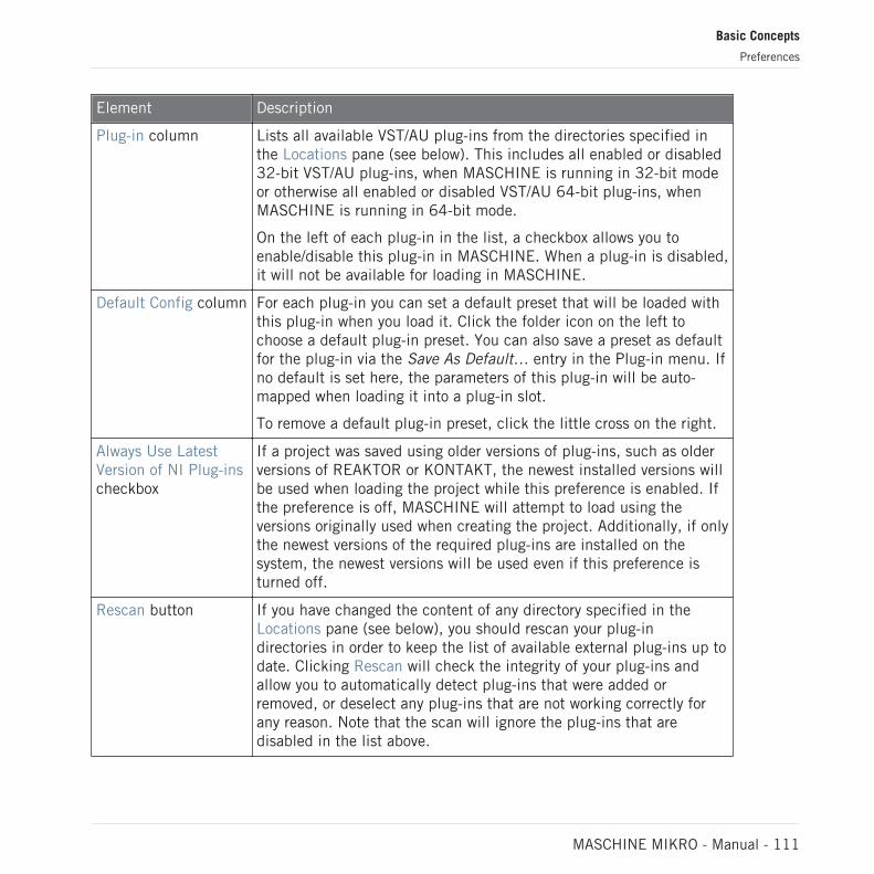
Element Description
Plug-in column Lists all available VST/AU plug-ins from the directories specified inthe Locations pane (see below). This includes all enabled or disabled32-bit VST/AU plug-ins, when MASCHINE is running in 32-bit modeor otherwise all enabled or disabled VST/AU 64-bit plug-ins, whenMASCHINE is running in 64-bit mode.
On the left of each plug-in in the list, a checkbox allows you toenable/disable this plug-in in MASCHINE. When a plug-in is disabled,it will not be available for loading in MASCHINE.
Default Config column For each plug-in you can set a default preset that will be loaded withthis plug-in when you load it. Click the folder icon on the left tochoose a default plug-in preset. You can also save a preset as defaultfor the plug-in via the Save As Default… entry in the Plug-in menu. Ifno default is set here, the parameters of this plug-in will be auto-mapped when loading it into a plug-in slot.
To remove a default plug-in preset, click the little cross on the right.
Always Use LatestVersion of NI Plug-inscheckbox
If a project was saved using older versions of plug-ins, such as olderversions of REAKTOR or KONTAKT, the newest installed versions willbe used when loading the project while this preference is enabled. Ifthe preference is off, MASCHINE will attempt to load using theversions originally used when creating the project. Additionally, if onlythe newest versions of the required plug-ins are installed on thesystem, the newest versions will be used even if this preference isturned off.
Rescan button If you have changed the content of any directory specified in theLocations pane (see below), you should rescan your plug-indirectories in order to keep the list of available external plug-ins up todate. Clicking Rescan will check the integrity of your plug-ins andallow you to automatically detect plug-ins that were added orremoved, or deselect any plug-ins that are not working correctly forany reason. Note that the scan will ignore the plug-ins that aredisabled in the list above.
Basic Concepts
Preferences
MASCHINE MIKRO - Manual - 111

Manager Pane: Use NI Audio Units Checkbox (macOS Only)
On macOS, the Manager pane contains an additional Use NI Audio Units checkbox. Check thisbox to include the Audio Units (AU) versions of your Native Instruments plug-ins in the soft-ware’s Plug-in menus and in the controller’s Plug-in Browser:
▪ If this checkbox is disabled (default setting), the AU versions of your Native Instrumentsplug-ins are still listed in the list above but they are disabled (checkbox unchecked): Theseplug-ins won’t appear in the Native Instruments submenu of the Plug-in menus (software)or in the Plug-in Browser (controller). Additionally, the remaining entries for Native Instru-ments plug-ins (all of them VST) won’t display the (VST) mention next to their name.
▪ If you enable the Use NI Audio Units checkbox, all Native Instruments’ AU plug-ins are en-abled in the list above and are available for loading in MASCHINE. In order to distinguishthem from the VST versions, plug-in entries in the Native Instruments submenu of thePlug-in menus and in the Plug-in Browser will display either (VST) or (AU) after their name.
You can also enable or disable Native Instruments’ AU plug-ins individually in the list via thecheckboxes described above — as soon as you enable one of them, the Use NI Audio Unitscheckbox is automatically activated.
The Use NI Audio Units checkbox relates only to AU plug-ins from Native Instruments. AU plug-insfrom third-party manufacturers are not affected by this setting.
When the Use NI Audio Units checkbox is disabled or the AU version of a Native Instruments plug-in is disabled, you can still load Projects that use AU plug-ins.
Location Pane
► To display the Location pane, click the Location button at the top of the Plug-ins page.
In the Locations section of the Plug-ins page, you can manage the various plug-in directoriesyou want to use in MASCHINE.
Basic Concepts
Preferences
MASCHINE MIKRO - Manual - 112

The Preferences panel – the Plug-ins page’s Locations pane.
The Locations pane also contains the following controls:
Element Description
Plug-in column Lists all plug-in directories used in MASCHINE. Click the folder iconon the left of an entry to change the path of that plug-in directory.
Add button Click Add to add plug-in directories.
Basic Concepts
Preferences
MASCHINE MIKRO - Manual - 113

Element Description
Remove button Click Remove to remove the selected directory.
Rescan button If you have changed the content of a directory (such as installed orremoved plug-ins), you should rescan your plug-in directories in orderto keep the list of available plug-ins up to date. Click Rescan tocheck the integrity of your plug-ins, this will allow you toautomatically detect plug-ins that are added or removed, or disableany plug-ins that are not working correctly for any reason.
3.6.7 Preferences – Hardware Page
The Hardware page enables you to customize how the pads react to your playing and to adjustthe brightness of the displays.
► To display the Hardware page, click the Hardware tab on the left of the Preferences panel.
→ The settings of connected Native Instruments controllers can be selected and adjusted.
3.6.8 Preferences – Colors Page
The Colors page enables you to choose default colors for your Scenes, Groups, and Sounds.
► To display the Colors page click the Colors tab on the left of the Preferences panel.
Basic Concepts
Preferences
MASCHINE MIKRO - Manual - 114
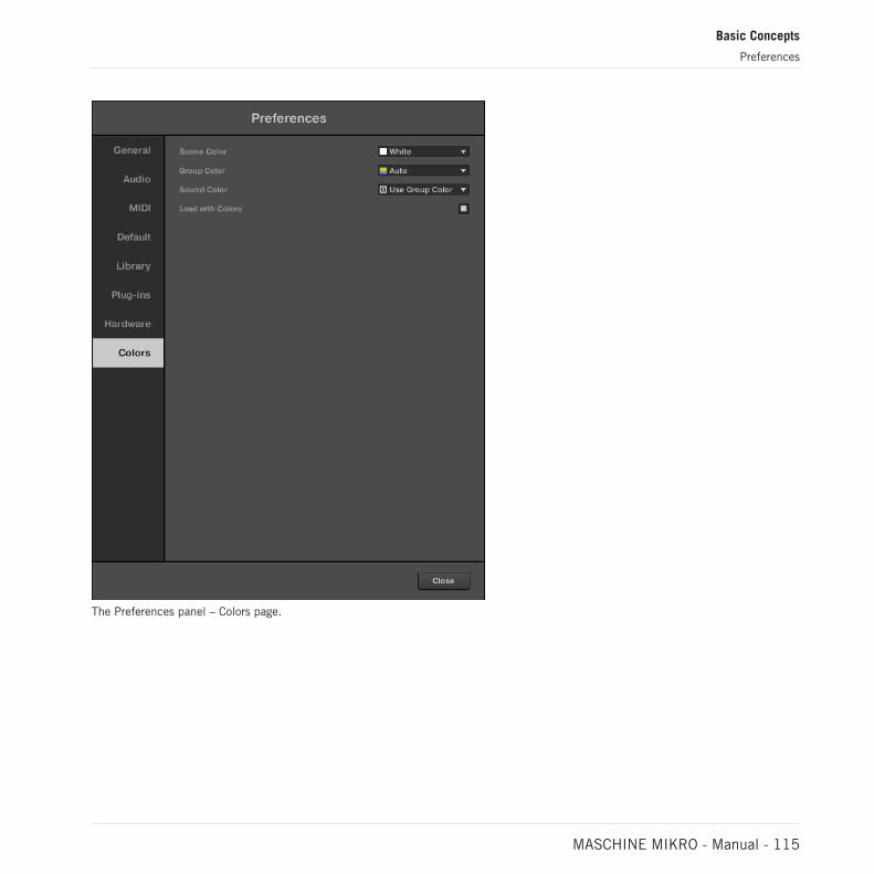
The Preferences panel – Colors page.
Basic Concepts
Preferences
MASCHINE MIKRO - Manual - 115

Setting Description
Scene Default Select the default color for your Scenes. In the menu, you canselect the desired color from the 16-color palette or White(default setting). The color selected as default is highlighted inthe menu. If you select Auto each Scene will have a differentdefault color.
Group Default Select the default color for your Groups. In the menu, you canchoose the desired color from the 16-color palette. The colorselected as default is highlighted in the menu. If you selectAuto (default setting) each Group will have a different defaultcolor.
Sound Default Select the default color for your Sounds. In the menu, you canchoose the desired color from the 16-color palette. The colorselected as default is highlighted in the menu. If you selectAuto each Sound will have a different default color. If you selectUse Group Color (default setting) Sounds will by default mirrorthe color of the Group to which they belong.
Load with Colors Click the checkbox to save your Color settings with yourMASCHINE files (Projects, Groups, Sounds, etc.). If youuncheck Load with Colors (checked by default), saved colors willnot be used next time you load the files. The default colors setin this Colors page will be used instead.
Please note that the settings in this Colors page define default colors: These colors will only be usedwhen creating a new Project, resetting a Group/Sound, or when Load with Colors is unchecked (seeabove). To change the color of particular objects (Sounds, Groups, Patterns, and Scenes) in yourProject, use the Color submenu in the object’s context menu in the software. See ↑5.2.4, Changingthe Sound’s Color, ↑5.3.4, Changing the Group’s Color, ↑11.7.7, Changing the Pattern’s Color, and↑16.2.13, Changing the Color of a Scene for more information, respectively.
As long as an object (Scene, Sound, Group or Pattern) has the default color, this color is not attach-ed to the object but instead to its “position” in the respective list: In particular, if you move theobject to another position the default color will not follow the object — the object will instead takethe default color of its new position.
Basic Concepts
Preferences
MASCHINE MIKRO - Manual - 116

3.7 Integrating MASCHINE into a MIDI Setup
You can quickly integrate MASCHINE into a MIDI setup.
You can use MIDI in MASCHINE in various ways. Notably:
▪ You can synchronize a MIDI Clock signal between MASCHINE and other MIDI devices:↑3.7.2, Sync to External MIDI Clock and ↑3.7.3, Send MIDI Clock.
▪ If you connect a MIDI keyboard to the MIDI IN, you can directly play the focused Soundwith it without having to set anything up.
▪ You can let particular Sounds and Groups react to incoming MIDI data and send MIDI datato the desired port. More on these in section ↑12.2, Using MIDI Control and Host Automa-tion.
▪ You can also switch Scenes remotely by sending MIDI Note or MIDI Program Change mes-sages to MASCHINE. More on this in section ↑16.5, Triggering Sections or Scenes viaMIDI.
3.7.1 Connecting External MIDI Equipment
To connect your external MIDI equipment, hook it up to your MIDI interface and activate thecorresponding MIDI inputs and/or outputs in the MIDI page of the Preferences panel (see↑3.6.3, Preferences – MIDI Page).
3.7.2 Sync to External MIDI Clock
If MASCHINE is running as a stand-alone application, it can be controlled externally via MIDIClock by any device that is capable of sending MIDI Clock. This could be hardware such as adrum machine, another groovebox or sequencer, or even another software sequencer.
If you use MASCHINE as a plug-in, it is automatically synced to the host application so you don’thave to activate external MIDI sync! See section ↑3.5, Stand-Alone and Plug-in Mode for more in-formation on using MASCHINE as a plug-in.
To configure MASCHINE to receive MIDI Clock from an external device:
Basic Concepts
Integrating MASCHINE into a MIDI Setup
MASCHINE MIKRO - Manual - 117

1. Select Preferences entry from the File menu.
2. Select the MIDI page.
3. In the Sync section select Slave (Receive Clock) from the menu.
4. Select the Input button to see a list of connected devices.
5. Check the name of the device sending MIDI clock (the device you want MASCHINE tosync with).
→ MASCHINE can now receive MIDI Clock from an external device
You must define at least one MIDI input device in the Devices section of the MIDI page to enableMASCHINE to sync.
When Slave (Receive Clock) is selected, the Play button in the MASCHINE Header and thePLAY button on your controller are deactivated.
If you want to configure MASCHINE to react to other MIDI messages than MIDI Clock, in particularif you want to control MASCHINE notes and parameters via MIDI, please refer to section ↑12.2, Us-ing MIDI Control and Host Automation, where this is described in detail.
3.7.3 Send MIDI Clock
If MASCHINE is running as a stand-alone application, it can also send a MIDI Clock signal toany device that is capable of receiving MIDI Clock. This could be hardware such as a drummachine, another groovebox, or even another software sequencer.
If you use MASCHINE as a plug-in, it cannot send any MIDI Clock signal. See section ↑3.5, Stand-Alone and Plug-in Mode for more information on using MASCHINE as a plug-in.
To configure MASCHINE to receive MIDI Clock from an external device:
1. Select Preferences entry from the File menu.
2. Select the MIDI page.
3. In the Sync section select Master (Send Clock) from the menu.
Basic Concepts
Integrating MASCHINE into a MIDI Setup
MASCHINE MIKRO - Manual - 118

→ MASCHINE will send a MIDI Clock signal to any connected device that is capable of re-ceiving MIDI Clock.
You can adjust the MIDI Clock offset in the MIDI page of the Preferences panel. See ↑3.6.3, Prefer-ences – MIDI Page for more information.
If you want MASCHINE to send other MIDI messages than MIDI Clock, in particular if you want tocontrol other MIDI-capable devices via the notes played in MASCHINE, please refer to section↑12.2.5, Sending MIDI from Sounds.
3.7.4 Using MIDI Mode
Your controller provides a fixed MIDI Mode implementation which allows you to directly controlother MIDI devices using a fixed implementation of MIDI Control Change messages.
To access MIDI Mode on your controller:
► Press SHIFT + Project button (top left hand side).
→ The controller enters MIDI Mode.
In MIDI mode the controls on your device are mapped as depicted in the following image:
Basic Concepts
Integrating MASCHINE into a MIDI Setup
MASCHINE MIKRO - Manual - 119

MIKRO MIDI Mode Mapping
3.8 Syncing MASCHINE using Ableton Link
Ableton Link is a protocol that synchronizes beat, phase and tempo of Link-enabled applica-tions on the same computer or over a shared network. This means you can conveniently keepapplications synchronized across different devices or join a group jam with others with minimalsetup. Connecting applications via Link provides you with the ability to synchronize them to ashared timeline and change the tempo globally from each of the connected applications.
Basic Concepts
Syncing MASCHINE using Ableton Link
MASCHINE MIKRO - Manual - 120

3.8.1 Connecting to a Network
Applications that support Ableton Link can join a Link session when connected to the samenetwork. To enable Link within MASCHINE, simply make sure the computer running MA-SCHINE is connected to the same local network as the other applications you want to link to.This can either be a local network or an ad-hoc (computer-to-computer) connection.
To ensure maximum security and reliability while using Link, there are several things you maywant to consider:
▪ For reliability, connect to the local network using a router via an Ethernet cable.
▪ If you do use a Wi-Fi network, be sure to use a password to prevent excluded users fromjoining your session.
▪ For the most secure and reliable connection, create a Link session via a direct connectionfrom one computer to another using a Thunderbolt or Ethernet cable.
For more general information on setting up and using Link, please refer to the Link FAQs arti-cle located on the Ableton website:
https://help.ableton.com/hc/en-us/articles/209776125-Link-FAQs.
3.8.2 Joining and Leaving a Link Session
It is possible to join a Link session at any time by clicking the LINK button. When anotherLink-enabled application is connected, a moving bar within the LINK button is displayed eventhough MASCHINE’s transport is not running. This bar represents the global phase of Link thatall participating applications lock into.
After clicking the Play button, playback will resume on the downbeat once the moving barwithin the LINK button is filled. The first participant to join the session sets the initial tempo,from then on any participant in the session can change the tempo in their respective applica-tion. If multiple participants change the tempo at the same time, the last tempo change willtake effect.
To start or join a Link session, proceed as follows:
Basic Concepts
Syncing MASCHINE using Ableton Link
MASCHINE MIKRO - Manual - 121

1. Click the LINK button located in the header.
2. Start MASCHINE’s playback by clicking the play button.
3. To stop using Link, and leave the session, click LINK again.
While connected, the LINK button displays how many other Link-enabled applications are con-nected via Link. The example below indicates that there are two other applications connected.
Active Link session with two other instances connected.
When Link is active, it is not possible to synchronize MASCHINE to incoming MIDI Clock as a slave.Link will take priority. Sending MIDI Clock from MASCHINE as a master is still possible.
Basic Concepts
Syncing MASCHINE using Ableton Link
MASCHINE MIKRO - Manual - 122

4 Browser
The Browser is the place where you can organize and categorize all of your Projects, Groups,Sounds, Plug-in presets, and Samples. This is done by tagging them, which means categoriz-ing them by using keywords. Given that the MASCHINE software has some advantages over thehardware in this case, such as a very big screen and a QWERTY-keyboard, we will start with thesoftware first.
4.1 Browser Basics
This section describes some general concepts about the Browser.
4.1.1 The MASCHINE Library
To organize, find, keep track of, and provide you thousands of files at any time ready for load-ing, MASCHINE makes use of a Library. The MASCHINE Library not only contains the factorycontent included with MASCHINE, but also any other factory content (e.g., from MASCHINEEXPANSIONS or other Native Instruments products) as well as your own user content.
To help you find the right file quickly and efficiently, the Library implements various techni-ques that go far beyond the classic folder structure of your operating system. For example,each file included in the Library can be described according to following aspects:
▪ The file type: Project, Group, Sound, etc.
▪ The content type of the file, i.e. whether it originates from a product’s factory library or if itwas created by a user.
▪ The product which the files comes from — this can include, e.g., a hierarchical structurewith a product category, a particular product, and possibly a bank and sub-bank of thisproduct.
▪ A variable amount of tags used to describe various characteristics of the file, for example,the type of effect, the sonic character, the context in which it is used — in a word, any-thing that might help you find the file.
Browser
Browser Basics
MASCHINE MIKRO - Manual - 123

Note that the Library is the only other way to display and access your files: You could also navigateto the same files in your file system. The (substantial) difference lies in the fact that the Libraryorganizes your files in a musically relevant way.
Which Files are Included in the MASCHINE Library?
The files included in the MASCHINE Library are all MASCHINE-relevant files found in the fold-ers whose paths are listed in the Library page of the Preferences panel. For more informationon how to manage these library folders, please refer to ↑3.6.4, Preferences – Default Page.
4.1.2 Browsing the Library vs. Browsing Your Hard Disks
The Browser is your interface to the MASCHINE Library. It provides all necessary tools tosearch for the files you require — and suggest other files you might not have thought of. Be-side this, the Browser also allows you to navigate your file system in a classic way. Both aredescribed in the next section.
The Browser provides two operation modes, each of them providing its own tools:
▪ The Library pane allows you to browse the MASCHINE Library. This is the preferred way tosearch for files meeting particular musical requirements. This pane also allows you to tagyour own files to your liking.
▪ The Files pane allows you to browse your hard disks by using the hierarchical folder struc-ture of your operating system. For example you can use it to navigate files that have notbeen imported into the MASCHINE Library — and you can import them from there!
In contrast to the software, the Browser on your controller can only load files that have already beenadded to the Library. You cannot directly access specific directories on your hard disks with theBrowser using the controller. This is why you should always import all your files to the Library andtag them using the software beforehand.
Switching Between Library and Files Pane
► To show the Library pane or the Files pane of the Browser, click the corresponding tab atthe top of the Browser.
Browser
Browser Basics
MASCHINE MIKRO - Manual - 124

Click the desired tab to show the corresponding pane of the Browser.
The Library pane is described in section ↑4.2, Searching and Loading Files from the Library,and the Files tab is described in section ↑4.6, Loading and Importing Files from Your File Sys-tem.
4.2 Searching and Loading Files from the Library
The Browser’s Library pane allows you to search for any file in the MASCHINE Library.
► To display the Library pane, click the Library tab in the top left corner of the Browser.
4.2.1 Overview of the Library Pane
The Library pane contains following elements:
Browser
Searching and Loading Files from the Library
MASCHINE MIKRO - Manual - 125

1 2 3
4
5
6
7
8
9The elements of the Library pane.
(1) Library tab: Click the Library tab to open the Library pane described here.
(2) File Type selector: This contains seven icons, each representing the different files types ofMASCHINE. From the left to right the file types are Project, Group, Sound, Instrument presets,Effect presets, Loops, and One-Shots. Only the selected file type is displayed in the Result list(8). See section ↑4.2.4, Selecting a File Type.
Browser
Searching and Loading Files from the Library
MASCHINE MIKRO - Manual - 126

(3) Content selector: Select the User icon to display user content. When the User icon is lit onlyuser content is shown in the Result list. When the User icon is unlit only factory content isshown in the Results list. (8). See section ↑4.2.5, Choosing Between Factory and User Con-tent.
(4) Product selector: In the drop-down menu you can select a particular product, product cate-gory, and sometimes the bank and sub-bank of the selected product. Again, only the filesmatching your selection will be displayed in the Result list (8). See section ↑4.2.3, Selecting aProduct Category, a Product, a Bank, and a Sub-Bank.
(5) TYPES filter: allows you to search for files based on applied Type and Sub-Type tags. Seesection ↑4.2.6, Selecting Type and Character Tags.
(6) CHARACTER filter (Instrument/Effect presets only): allows you to search for files based onapplied Character tags. See section ↑4.2.6, Selecting Type and Character Tags.
(7) Search field: Enter any character string into the Search field to limit the search results tothe files containing this string. See section ↑4.2.7, Performing a Text Search.
(8) Result list: The Result list displays all files that match your query, as specified via the vari-ous tools above. See section ↑4.2.8, Loading a File from the Result List.
(9) Control bar: At the bottom of the Browser, the Control bar provides a few useful tools whenbrowsing the MASCHINE Library, some of them depending on your selection in the File Typeselector (2):
▪ For all file types except Project, click the Autoload button at the far left of the Control bar toautomatically load the selected file in order to hear it in context with the rest of yourProject while it is playing. See section ↑4.3.1, Loading the Selected Files Automatically.
▪ For Instruments Presets and Samples, enable the Prehear button and adjust the volume fad-er next to it in order to pre-listen to the selected items directly from the Browser in order tomake a quick selection. See section ↑4.3.3, Auditioning Samples and ↑4.3.2, AuditioningInstrument Presets.
▪ For Groups, enable the Load Patterns checkbox to load the Group’s Patterns together withthe Group. See section ↑4.3.4, Loading Groups with Patterns.
▪ For all files, click the Information button (showing a little “i”) near the EDIT button to dis-play more information on the selected file(s). See section ↑4.3.6, Displaying File Informa-tion.
Browser
Searching and Loading Files from the Library
MASCHINE MIKRO - Manual - 127

▪ For all files, click the EDIT button at the far right of the bar to open the Attribute Editor andmodify the tags and properties assigned to the selected file(s). See section ↑4.5, Editingthe Files’ Tags and Properties.
Overview of the Search Workflow in the Library Pane
When searching for files via the Library pane, you can progressively refine your search by fol-lowing this typical top-to-bottom workflow.
The first two steps are mandatory:
1. Choose a file type in the File Type selector (2).
2. Select between factory content and user content in the Content selector (3).
The next steps are optional. They can be useful to further refine your search and limit thenumber of search results to a reasonable amount:
1. Choose a product category or a product in the Product selector (4). If you have selected aproduct you can further choose a particular bank and sub-bank of this product, if any.
2. Select tags in the TYPES filter (5) and the CHARACTER filter (6) for Instrument and Ef-fect presets to describe what you are looking for.
At any time in the procedure described above, you can use the Search field (7) to quickly per-form a text search among the entries in the Result list (8).
The above steps are described in detail in the following sections.
4.2.2 Selecting or Loading a Product and Selecting a Bank from the Browser
The Product selector allows you to limit your search to a certain product category, a particularproduct, or a specific bank of the product. You can also load a product along with its defaultpreset file directly from the Product selector (see below).
By default there is no particular selection in the Product selector; it reads All Instruments:
Browser
Searching and Loading Files from the Library
MASCHINE MIKRO - Manual - 128
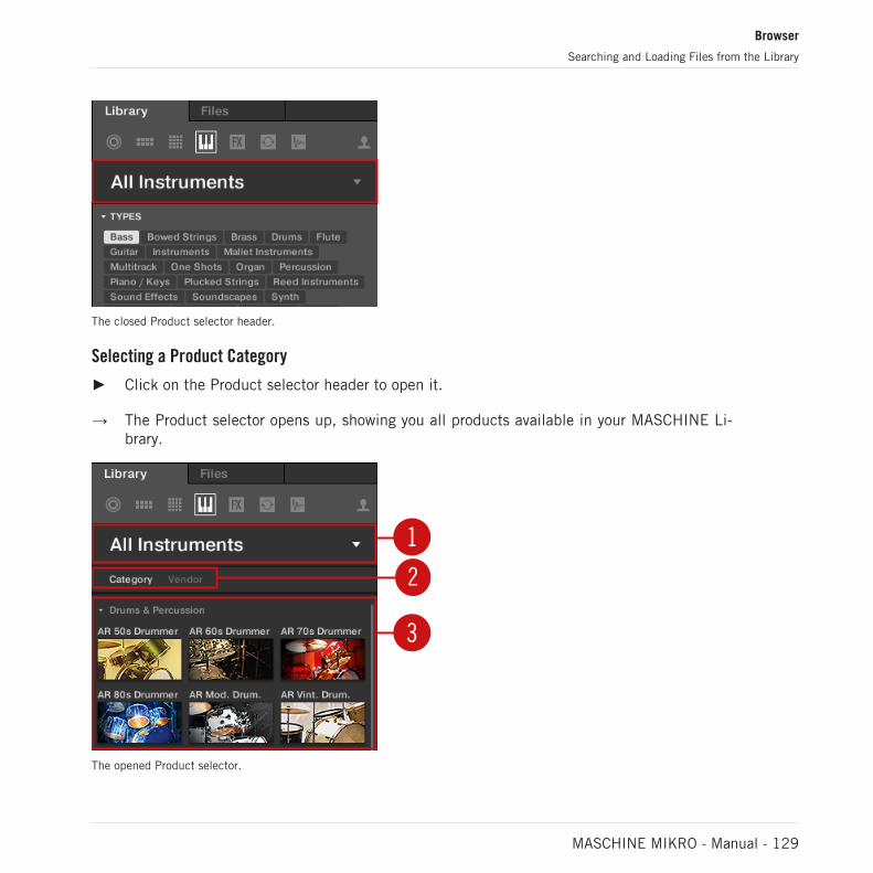
The closed Product selector header.
Selecting a Product Category
► Click on the Product selector header to open it.
→ The Product selector opens up, showing you all products available in your MASCHINE Li-brary.
1
2
3
The opened Product selector.
Browser
Searching and Loading Files from the Library
MASCHINE MIKRO - Manual - 129

(1) Product selector header: The header shows the selected product. If nothing has been select-ed, a generic label (All Instruments) is shown. Click on the header to close the Product selec-tor.
(2) Category/Vendor selector: Allows you to sort the Product list by Category or by Vendor.
(3) Product list: Shows all products that are available in your MASCHINE Library.
If Category is selected in the Category/Vendor selector, the Product list is sorted by the follow-ing categories:
▪ Drums & Percussion
▪ Sampled Instruments
▪ Synthesizers
▪ Other / Sounds.com
If Vendor is selected in the Category / Vendor selector, the Product list is sorted by the namesof the manufacturers.
► To select a product and show only the preset files associated with it, click on the productin the list.
→ Upon your selection, the Product selector automatically closes, the product name andicon appear in the header, and the tag filter and results list below will be filtered accord-ingly.
Products are shown in the Product selector only if the Library contains files for them. If a particularproduct does not show up, make sure that you have installed the latest updates using Native Ac-cess.
Browser
Searching and Loading Files from the Library
MASCHINE MIKRO - Manual - 130

Resetting the Product Selection
► To reset the selection made in the Product selector, click the little cross at the right ofthe product name:
→ The product selection is cancelled. The Product selector displays the generic label All In-struments. The tag filter and the results list under the Product selector now include filesfor all products.
Selecting a Bank
When you select specific products in the Product list (see description above), an additionalBank menu appears under the closed Product selector:
The Bank menu showing All Banks for POLYPLEX
The Bank menu allows you to select a particular bank of files for the selected product (POLY-PLEX in the picture above).
Banks can be additional Libraries (for example MASSIVE Expansions), different versions of theoriginal Factory Library (for example FM7 Legacy and FM8 Factory Library), or any other con-tent categorization specific to a particular product (for example different sets of drum soundsfor POLYPLEX).
Browser
Searching and Loading Files from the Library
MASCHINE MIKRO - Manual - 131
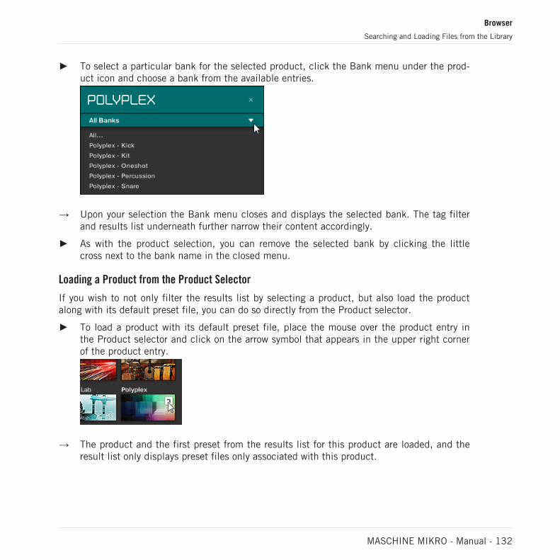
► To select a particular bank for the selected product, click the Bank menu under the prod-uct icon and choose a bank from the available entries.
→ Upon your selection the Bank menu closes and displays the selected bank. The tag filterand results list underneath further narrow their content accordingly.
► As with the product selection, you can remove the selected bank by clicking the littlecross next to the bank name in the closed menu.
Loading a Product from the Product Selector
If you wish to not only filter the results list by selecting a product, but also load the productalong with its default preset file, you can do so directly from the Product selector.
► To load a product with its default preset file, place the mouse over the product entry inthe Product selector and click on the arrow symbol that appears in the upper right cornerof the product entry.
→ The product and the first preset from the results list for this product are loaded, and theresult list only displays preset files only associated with this product.
Browser
Searching and Loading Files from the Library
MASCHINE MIKRO - Manual - 132

4.2.3 Selecting a Product Category, a Product, a Bank, and a Sub-Bank
The Product selector allows you to limit your search to a certain product category, a particularproduct, a specific bank of the product, or even a sub-bank in this bank.
By default there is no particular selection in the Product selector: It reads All Projects, AllGroups, All Sounds, All Instruments, All Effects or All Samples according to the type of fileselected in the File Type selector above (see section ↑4.2.4, Selecting a File Type):
The closed Product selector without any Instrument selected.
Selecting a Product or a Product Category
► Click the Product selector to open it.
→ The Product selector opens up and displays the following:
Browser
Searching and Loading Files from the Library
MASCHINE MIKRO - Manual - 133

1
2
3
The opened Product selector (for Instrument presets).
(1) Product selector header: The header shows the product or the selected product category —if there is no selection it shows a generic label (All Instruments in the picture above) corre-sponding to the type of file selected in the File Type selector above. Click the header to closethe Product selector.
(2) Product Category filter: Shows the categories of the products that have files available in theMASCHINE Library. Click a category of a product to select/deselect it. Selecting a categorylimits the number of products shown in the Product list below (3). Only one category can be
Browser
Searching and Loading Files from the Library
MASCHINE MIKRO - Manual - 134

selected at a time. You can also select a category and close the Product selector by clicking itsheader (1) again: The header (1) will display the category that you have just selected, and theTYPES filter (and CHARACTER filter, if present) along with the Result list will be filtered bythat category.
(3) Product list: Shows the products for which files are available in the MASCHINE Library.Click the desired product in the list. Upon your selection the Product selector automaticallycloses, the product name and icon appear in the header, and the tag filter and Result list be-low will be filtered accordingly.
The closed Product selector with an Instrument selected.
Product categories and products are shown in the Product selector only if the MASCHINE Librarycontains files for them. For example, if a Native Instruments effect from the KOMPLETE family isinstalled on your computer but you haven’t saved any user presets for it in MASCHINE yet, its prod-uct icon will not be available in the Product selector when the user content is selected in the Con-tent selector. Similarly, if you haven’t updated a particular Native Instruments effect/instrument,the icon for that product might not be available in the Product selector when the factory content isselected in the Content selector — to prevent this, make sure that all your Native Instruments prod-ucts are up to date.
Resetting the Product Selection
► To reset the selection made in the Product selector, click the little cross at the right ofthe product name:
→ The product selection is cancelled. The Product selector displays the generic label corre-sponding to the selected file type (Project, Group, Sound, Instrument preset, Effect presetor Sample). The tag filter and the Result list under the Product selector now include filesfor all products.
Browser
Searching and Loading Files from the Library
MASCHINE MIKRO - Manual - 135

Selecting a Bank and a Sub-Bank
When you select specific products in the Product list (see description above), an additionalBank menu appears under the closed Product selector:
The Bank menu showing All Banks for REAKTOR Effects.
This Bank menu allows you to select a particular bank of files for the selected product (MA-SCHINE in the picture above).
► To select a particular bank for the selected product, click the Bank menu under the prod-uct icon and choose a bank from the available entries.
→ Upon your selection the Bank menu closes and displays the selected bank. The tag filterand Result list underneath further narrow their content accordingly.
Banks can be, e.g., additional libraries (e.g., MASSIVE EXPANSIONS), different versions of theoriginal Factory Library (e.g., FM7 Legacy and FM8 Factory Library), or any other content categori-zation specific to a particular product.
Similarly, some banks are split into several sub-banks. In that case a Sub-Bank menu appearsunder the Bank menu and allows you to select a particular sub-bank. As with the productabove, you can remove the selected bank and sub-bank by clicking the little cross at the rightof the bank or sub-bank name in the closed menu.
Browser
Searching and Loading Files from the Library
MASCHINE MIKRO - Manual - 136

Products and Banks for User Content
When you save your own MASCHINE files, they are automatically assigned to products, banks,and sub-banks as follows:
▪ When you save Projects, Groups or Sounds, they are automatically set to the Maschineproduct.
▪ When you save Instrument or Effect presets:
◦ Presets for Internal Plug-ins: The product is set to Maschine, while the bank is set tothe particular Internal Plug-in for which the preset has been saved (e.g., Sampler,Kick, Flanger, etc.).
◦ Presets for Native Instruments Plug-ins: The product is set to the particular Native In-struments effect or instrument. The bank and sub-bank will vary with each Native In-struments product.
◦ Presets for External Plug-ins: The product is set to the manufacturer of the VST/AUplug-in, and the bank is set to the particular VST/AU plug-in for which the preset hasbeen saved. The sub-bank is left empty. In addition, the preset is assigned to the Ex-ternal Plug-ins product category.
4.2.3.1 Selecting a Product Category, a Product, a Bank, and a Sub-Bank on theController
4.2.4 Selecting a File Type
The File Type selector shows six icons representing the different file types of MASCHINE:
1
2
3
4
5
6
7
The File Type selector.
Browser
Searching and Loading Files from the Library
MASCHINE MIKRO - Manual - 137

(1) Project: (.mxprj)
(2) Groups: (.mxgrp)
(3) Sounds: (.mxsnd)
(4) Instrument Plug-in presets: (.mxinst)
(5) Effect Plug-in presets: (.mxfx)
(6) Loops: (.wav, .aiff)
(7) One-Shots: (.wav, .aiff)
► Click the desired icon in the File Type selector to display only the files of that type in theResult list.
→ The selected icon is highlighted and the files are filtered accordingly.
4.2.5 Choosing Between Factory and User Content
The Content selector represents the factory content, and the user content:
The Content selector.
► Click the Content selector (icon is lit) to browse only user content or click the Content se-lector again (icon unlit) to browse only factory content.
4.2.6 Selecting Type and Character Tags
The tag filter that appears under the Product selector allows you to search for files according toparticular characteristics, effect type, sonic character, etc.
Browser
Searching and Loading Files from the Library
MASCHINE MIKRO - Manual - 138

TYPES and CHARACTERS filters for the Massive MASSIVE Plug-in.
► Click tags to filter files based on the selected type and character tags. Click the selectedtags again to deselect them and broaden the search.
Tags for Projects, Groups and Sounds: 3 Type Levels
For Projects, Groups and Sounds tags are structured into three hierarchical levels globallycalled Types. You can select them via the TYPES filter:
▪ At first the TYPES filter displays the available top-level tags only.
▪ As soon as you select a tag at the top level, the second level appears underneath with sub-tags of the selected tag.
▪ The hierarchical structure means that the sets of sub-tags are specific to each tag of thelevel above.
Example: Imagine that you are looking for a bass synth
Browser
Searching and Loading Files from the Library
MASCHINE MIKRO - Manual - 139

▪ You have already selected the Maschine product in the Product selector, and the Maschine2.0 Library bank of this product (for more information on this, see section ↑4.2.3, Select-ing a Product Category, a Product, a Bank, and a Sub-Bank). For now the TYPES filtershows only top-level tags.
▪ In order to find a bass, you first select the Instruments Type from the TYPES filter.
▪ In the second level, you select the Bass Sub-Type.
▪ Now the third level appears with Sub-Types like Acoustic, Electric, etc.
▪ By selecting any of these tags, say, Electric, you will narrow your search to this particularSub-Type of basses.
This allows you to quickly find various Samples (even for different instruments) with similarcharacteristics — here, an acoustic sound.
Tags for Instrument, Effect, and Sample Presets: 2 Type Levels and 1 Character Level
For Instrument, Effect and Sample presets, tags can be of two kinds: Type or Character. Youcan select them via the TYPES and CHARACTERS filter, respectively:
▪ The TYPES filter works as described above for all other file types, except that only two hier-archical levels are available. See above for a detailed description.
▪ The CHARACTERS filter provides an additional level that is independent from the Type lev-els:
◦ In general, Character tags will rather refer to technical terms (e.g., Arpeggiated, Per-cussive, Synthetic, etc.).
◦ The CHARACTERS filter is always displayed. You can start your search with theCHARACTERS filter before (or even without) using the TYPES filter.
◦ However, the list of tags available in the CHARACTERS filter will vary depending onthe tags selected in the TYPES filter. If no file contains both the Type and Charactertags that you have selected, the Type tags will prevail and the Character tags will bedeselected.
If you don’t select any tag in the TYPES or the CHARACTERS filter, the Result list will include allfiles satisfying any of their tags.
Browser
Searching and Loading Files from the Library
MASCHINE MIKRO - Manual - 140

Selecting Multiple Tags from the Same Level
In both TYPES and CHARACTERS filter you can select multiple tags from the same level:
1. Hold [Shift] on your computer keyboard and click two tags at a particular level to selectthese tags and all tags in-between.
2. Hold [Ctrl] ([Cmd] on macOS) on your computer keyboard and click any number of tags ata particular level to select these particular tags.
→ The Result list will include all files satisfying at least one of the selected tags.
Opening and Collapsing the Attributes Sections
The Attributes sections (TYPES and CHARACTERS) in the Browser Library can be collapsed tomake more room for the results list on smaller display resolutions.
To collapse the Attributes sections:
► Click the small triangle located to the left of the Attributes (TYPES or CHARACTERS).
→ The Attribute sections will collapse results will be shown depending on the amount ofspace available. Click the triangle again to reopen the sections.
Browser
Searching and Loading Files from the Library
MASCHINE MIKRO - Manual - 141
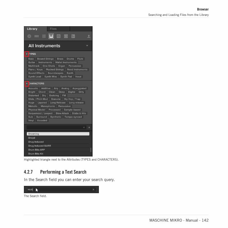
Highlighted triangle next to the Attributes (TYPES and CHARACTERS).
4.2.7 Performing a Text Search
In the Search field you can enter your search query.
The Search field.
Browser
Searching and Loading Files from the Library
MASCHINE MIKRO - Manual - 142

► Click in the Search field and type the desired text to limit the results to files containingthis text.
The search will be performed on the file paths, the file names, the products/banks/sub-banks,the tags, and the properties directly as you type. If you want to search for a combination of twowords (e.g. “bass” and “analog”) just enter both words in the Search field with a space in be-tween. As you start typing, the list of matches will start narrowing in the Result list below.
On the right of the Search field, click the Reset button (showing a little cross) to reset both textsearch and tag search. The Product selection is not affected.
4.2.8 Loading a File from the Result List
The Result list shows all the files that match your query:
The Result list showing kicks from the MASCHINE Library.
If the list is too long to fit in the display, use your mouse wheel or drag the scroll bar on theright to show the remaining items.
The Result list allows you to:
Browser
Searching and Loading Files from the Library
MASCHINE MIKRO - Manual - 143

▪ Select the desired file(s).
▪ Load the selected file(s) into your Project (or load another Project).
▪ Delete the selected file(s) from your hard disk and from the Library.
▪ Navigate to the selected file(s) in your operating system.
▪ See, and possibly edit, the attributes of the selected file(s) by clicking the EDIT button atthe bottom right of the Browser. For more information on this, please refer to section ↑4.5,Editing the Files’ Tags and Properties.
Selecting Files in the Result List
► To select a single file in the Result list, click its entry.
You can also select multiple files in the Result list in order to process them all at once.
To select adjacent files in the list, do the following:
► Hold [Shift] on your computer keyboard and click two files in the Result list to selectthese files and all files in-between.
To select distant files in the list, do the following:
► Hold [Ctrl] ([Cmd] on macOS) and click all the files you want to select.
Loading Files via Double-Click
Double-clicking one of the matches will load the respective file. Depending on what file typeyou have selected, the file will be loaded to different locations within MASCHINE:
▪ If it is a Project it will load all associated files replacing all files currently in memory. Ifyour current Project contains unsaved changes a dialog will appear asking you if you wantto save them. This is to prevent you from losing changes by accidentally loading a newProject without saving the old one.
▪ If it is a Group, it will be loaded into the Group currently in focus.
▪ If it is a Sound, it will be loaded into the Sound slot currently in focus.
▪ If it is an Instrument preset, it will be loaded into the first Plug-in slot of the Sound slotcurrently in focus.
▪ If it is an Effect preset, it will be loaded into the selected Plug-in slot.
Browser
Searching and Loading Files from the Library
MASCHINE MIKRO - Manual - 144

▪ If it is a Sample, it will be loaded into the Sound slot currently in focus. The Sampler Plug-in will be automatically loaded in the first Plug-in slot in order to play the Sample. TheSample will spread over the entire velocity and note range.
The file loaded will replace the object previously at that position or in this slot, if any! If needed,you can undo/redo your action via the shortcuts [Ctrl] + [Z]/[Y] (Windows) or [Cmd] + [Z]/[Y] (ma-cOS).
Loading Files via Drag and Drop
Except for Projects, you can also load files from the Result list into the desired location viadrag and drop. This notably has the following benefits:
▪ You can load the file into a Group or a Sound slot that is not currently focused, or into aPlug-in slot that is not selected.
▪ You can load a Sample into its own Zone in the Zone page of the Sample Editor: A newZone will be created for that Sample. See section ↑17.5.7, Adding Samples to the SampleMap for more information.
Drag and drop of Groups and Sounds is possible only in Arrange view.
Loading Multiple Files at Once via Drag and Drop
Once you have selected multiple files from the Result list (see description above), you can dragand drop them to the relevant locations in MASCHINE. By doing this, please keep in mind thefollowing:
▪ When dragging several Groups onto the Group List, you have following options:
◦ If you drop the Groups between two existing Groups (where the insertion line appears),the dropped Groups will be inserted between these two Groups.
◦ If you drop the Groups onto an existing Group, the dropped Groups will replace thatGroup and the following ones.
◦ If you drop the Groups onto the “+” at the end of the Group List, the Groups will beappended to the existing Groups in the Group List.
▪ When dragging several Sounds, you have following options:
Browser
Searching and Loading Files from the Library
MASCHINE MIKRO - Manual - 145
◦ If you drop the Sounds onto an existing Group, the Sounds will be loaded in the emptySound slots of that Group — if there are not enough empty Sound slots, the Soundswill be loaded in the first Sound slots of the Group, replacing the Sounds previouslyloaded in these slots.
◦ If you drop the Sounds onto the “+” at the end of the Group List, the Sounds will beloaded in a new Group appended to the existing Groups.
◦ If you drop the Sounds onto the Sound List, the Sounds will be loaded in adjacentSound slots, starting from the slot onto which you dropped them.
▪ When dragging several Instrument presets, you have the same options as when dragging sev-eral Sounds (see above). Each Instrument preset will be loaded into in its own Sound, andthe Sound will take the name of the preset.
▪ When dragging several Effect presets, you have following options:
◦ If you drop the Effect presets onto a Group in the Group List or onto a Sound in theSound List, they will be appended to the existing Plug-ins in the Plug-in List of thatGroup or Sound.
◦ If you drop the Effect presets between two existing Plug-ins in the Plug-in List of anychannel, they will be inserted between these two Plug-ins.
◦ If you drop the Effect presets onto an existing Plug-in in the Plug-in List of any chan-nel, they will replace that Plug-in and the following ones.
▪ When dragging several Samples, you have following options:
◦ If you drop the Samples onto an existing Group, onto the “+” at the end of the GroupList, or onto the Sound List, you have the same options as when dragging severalSounds (see above). Each Sample will be loaded in its own Sound with a SamplerPlug-in in the first Plug-in slot in order to play the Sample. The Sample will spreadover the entire velocity and note range.
◦ You can also drop the Samples onto the Zone page of the Sample Editor. In that caseall Samples will be loaded in the focused Sound and a Zone will be created for eachSample. For more details, see section ↑17.5.7, Adding Samples to the Sample Map.
You cannot load multiple Projects at once.
Browser
Searching and Loading Files from the Library
MASCHINE MIKRO - Manual - 146

Drag and drop of Groups and Sounds is possible only in Arrange view.
Deleting Files in the Result List
You can delete user files directly from the Result list:
1. Right-click ([Ctrl]-click on macOS) the desired user file and select Delete from the contextmenu. If you want to delete several files at once, first select them as described above,and right-click ([Ctrl]-click on macOS) ([Ctrl]-click on macOS) any of them.A warning dialog opens to inform you that the file will be not only removed from the MA-SCHINE Library but also deleted from your hard disk.
2. Click OK to confirm the deletion (or Cancel to keep the file).
→ The file is deleted from the MASCHINE Library and from your hard disk.
When browsing factory content, the Delete entry is not available in the context menu.
Navigating to the Files in Your Operating System
If you want to find out the location of a particular file shown in the Result list, do the follow-ing:
► Right-click ([Ctrl]-click on macOS) any file shown in the Result list and select Find in Ex-plorer (Find in Finder on macOS) from the context menu to open an Explorer/Finder win-dow pointing to the folder containing that file on your operating system.
4.2.8.1 Loading a File from the Result List on the Controller
► Press the Browse button (Magnifying glass on the top-right –hand side).
→ A list of files corresponding to the settings you chose in the Browser appear in the soft-ware and on the controller.
1. Turn the Encoder to select an entry in the list.
2. Press the Encoder to load the selected entry.
Browser
Searching and Loading Files from the Library
MASCHINE MIKRO - Manual - 147

→ The selected file is loaded in the focused Group, the focused Sound, or the selected Plug-in slot (if it’s an Instrument Plug-in, it will be loaded in the first Plug-in slot of the fo-cused Sound).
Check that the desired Group or Sound slot is focused and/or the desired Plug-in slot is selectedbefore loading the file from the Browser to avoid loading it at the wrong place! To set the focus to aGroup or a Sound slot, you can use Group buttons A–H and the pads without leaving Browse mode(see section ↑3.3.3, Focusing on a Group or a Sound to know how to do it). To select a particularPlug-in slot, you will need to temporarily leave Browse mode and select the right slot (see section↑3.3.4, Switching Between the Master, Group, and Sound Level and ↑3.3.5, Navigating ChannelProperties, Plug-ins, and Parameter Pages in the Control Area for more information). In any case,don’t hesitate to press SHIFT + pad 1 / SHIFT + pad 2 to undo/redo your actions.
4.3 Additional Browsing Tools
At the bottom of the Browser, the Control bar provides various useful tools that will help youquickly find and check the files you need.
The Control bar at the bottom of the Browser.
Some of the tools are available only for specific file types. The next sections describe each ofthese tools.
The EDIT button (Library pane) or IMPORT button (Files pane) at the far right of the Control barallows you to edit the attributes of the files selected in the Result list above (in the Files pane,these are the files being imported to the Library, whereas in the Library pane these are files alreadyin the Library). Please refer to section ↑4.5, Editing the Files’ Tags and Properties for more informa-tion!
4.3.1 Loading the Selected Files Automatically
► Click the Autoload button to enable/disable Autoload.
The Autoload button.
Browser
Additional Browsing Tools
MASCHINE MIKRO - Manual - 148

When Autoload is enabled, any item that you select in the Result list of the Library pane orFiles pane is automatically loaded into the focused Group or Sound slot or into the selectedPlug-in slot, replacing any content currently in that location. This allows you to listen to thisitem in context with the rest of your Project while it is playing.
Autoload is not available when browsing Projects.
Autoload is not available when browsing Samples with Prehear enabled — see section ↑4.3.3, Audi-tioning Samples.
Autoload is not only useful to look for an appropriate Sound, Group, Plug-in preset or Sample, butcan also be very inspiring: With a Pattern playing, browse through your Library with Autoload acti-vated and listen to Sounds and Samples you normally would not use in that context.
4.3.2 Auditioning Instrument Presets
When you are browsing Instrument presets, a Prehear button and Prehear Volume slider appearnext to the Autoload button.
The Prehear controls.
► Click the Prehear button (showing a little speaker icon) to enable/disable Prehear.
When Prehear is enabled, you can directly hear Instrument presets as you select them in theResult list of the Library pane or Files pane.
► Drag the Prehear Volume slider next to the Prehear button to adjust the volume of the In-strument presets you are pre-listening to.
The Prehear signal is sent to the Cue bus of MASCHINE. This allows you to pre-listen to Instru-ment presets on a distinct output pair (e.g., in your headphones) without affecting MA-SCHINE’s main output. For more information on the Cue bus, see section ↑13.2.6, Using theCue Bus.
Browser
Additional Browsing Tools
MASCHINE MIKRO - Manual - 149

4.3.3 Auditioning Samples
When you are browsing Samples, a Prehear button and Prehear Volume slider appear next tothe Autoload button.
The Prehear controls.
► Click the Prehear button (showing a little speaker icon) to enable/disable Prehear.
When Prehear is enabled, you can directly hear Samples as you select them in the Result listof the Library pane or Files pane.
► Drag the Prehear Volume slider next to the Prehear button to adjust the volume of theSamples you are pre-listening to.
The Prehear signal is sent to the Cue bus of MASCHINE. This allows you to pre-listen to Sam-ples on a distinct output pair (e.g., in your headphones) without affecting MASCHINE’s mainoutput! For more information on the Cue bus, see section ↑13.2.6, Using the Cue Bus.
Prehear and Autoload are mutually exclusive: Only one of them can be active at a time. For moreinformation on the Autoload feature, see section ↑4.3.1, Loading the Selected Files Automatically.
4.3.4 Loading Groups with Patterns
Every Group from the factory library includes a set of Patterns that illustrate possible uses ofthat Group. Similarly, when you save a Group of your own to the Library for later use, all Pat-terns you have created for that Group will be saved with the Group.
When browsing Groups, you can choose to load each Group with or without its Patterns. This isdone by clicking the + PATTERNS button at the bottom of the Browser:
▪ + PATTERNS button enabled: Groups will be loaded together with their Patterns. This al-lows you to use the Patterns you have saved with the Groups. Upon loading, all Patterns ofthe focused Group will be replaced, and a Clip referencing the first Pattern will be createdin the selected Scene.
Browser
Additional Browsing Tools
MASCHINE MIKRO - Manual - 150

▪ + PATTERNS button disabled: Groups will be loaded without their Patterns. This allowsyou to load another set of Sounds while keeping your current Patterns. Notably, this can bevery useful to try another drum kit with your current Patterns.
+PATTERNS is only available when browsing Groups.
4.3.5 Loading Groups with Routing
When the file type Groups is selected, the +ROUTING button is available in the Control bar ofthe Browser. When the +ROUTING button is enabled the audio and MIDI routings stored in theGroup are also loaded (potentially overwriting previous routings in the selected Group). Whenthe +ROUTING button is off, any audio and MIDI routings saved in the Group will not be load-ed, thus preserving any existing routings in the active Group.
4.3.6 Displaying File Information
The Information button.
► Click the Information button (showing a little “i”) next to the EDIT button in the right partof the Control bar to display information on the file(s) selected in the Result list.
→ A box appears above with various information on the selected file(s): File Format, Datemodified, File Size, Type, as well as the Author and Vendor properties, if any (see section↑4.5, Editing the Files’ Tags and Properties).
Browser
Additional Browsing Tools
MASCHINE MIKRO - Manual - 151

The Information box provides various information on the selected file(s).
If the selected files have different characteristics, the corresponding fields in the Informationbox will read multi.
4.4 Using Favorites in the Browser
Favorites in the MASCHINE browser allow you to quickly view and browse your most frequentlyused items. This includes Projects, Groups, Sounds, Instrument presets, Effect presets, Loopsand One-shots. Any of these items can be assigned as a Favorite. The Favorites serve as anadditional filter in the Browser. When activated, the results list will only show items that havebeen assigned as a Favorite, and also match all other selected filters, including the searchquery entered into the search field. Favorites are available for both the factory content and theuser content.
Here are some important notes regarding the use of Favorites:
▪ Favorites are automatically shared across MASCHINE and KOMPLETE KONTROL browserdatabases on one computer.
▪ Favorites are independent of the file's location: if a file is moved, it retains its favorite tag.
▪ Favorites are persistent: If a file location is rescanned or deleted and later added again tothe database, all files retain their favorite tags.
Browser
Using Favorites in the Browser
MASCHINE MIKRO - Manual - 152
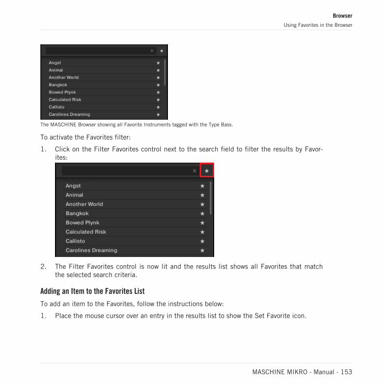
The MASCHINE Browser showing all Favorite Instruments tagged with the Type Bass.
To activate the Favorites filter:
1. Click on the Filter Favorites control next to the search field to filter the results by Favor-ites:
2. The Filter Favorites control is now lit and the results list shows all Favorites that matchthe selected search criteria.
Adding an Item to the Favorites List
To add an item to the Favorites, follow the instructions below:
1. Place the mouse cursor over an entry in the results list to show the Set Favorite icon.
Browser
Using Favorites in the Browser
MASCHINE MIKRO - Manual - 153

2. Click on the Set Favorite icon to add the corresponding item to the Favorites.
→ The item is added to the Favorites, indicated by the lit Set Favorite icon next to its name:
You can add any item in the results list to the Favorites, no matter if it is selected or not. The SetFavorites icon will appear as soon as you place the mouse cursor over the entry.
Removing a Preset from the Favorites List
To remove a preset from the Favorites, follow the instructions below:
Browser
Using Favorites in the Browser
MASCHINE MIKRO - Manual - 154

► Click on the lit Set Favorite icon to remove the corresponding item from the Favorites.
→ The item is removed from the Favorites, indicated by the hidden Set Favorite icon. Thenext time you select the Favorites filter, the item will not be shown in the results list.
Using Favorites with the Controller
You can view Favorites directly using the controller. This lets you access your most frequentlyused items without touching the computer's mouse and keyboard.
Activating the Favorites filter
To activate the Favorites filter from your controller:
1. Press the Favorites button (star icon on the top right-hand side).
2. The Favorites filter is now activated and the results list shows all Favorites that match theselected search criteria in the software.
4.5 Editing the Files’ Tags and Properties
The Attribute Editor allows you to assign or edit tags and properties to your MASCHINE files tomake it easier to find them later when browsing the MASCHINE Library in the Library pane(see section ↑4.2, Searching and Loading Files from the Library).
4.5.1 Attribute Editor Basics
The Attribute Editor is used in the following situations:
Browser
Editing the Files’ Tags and Properties
MASCHINE MIKRO - Manual - 155
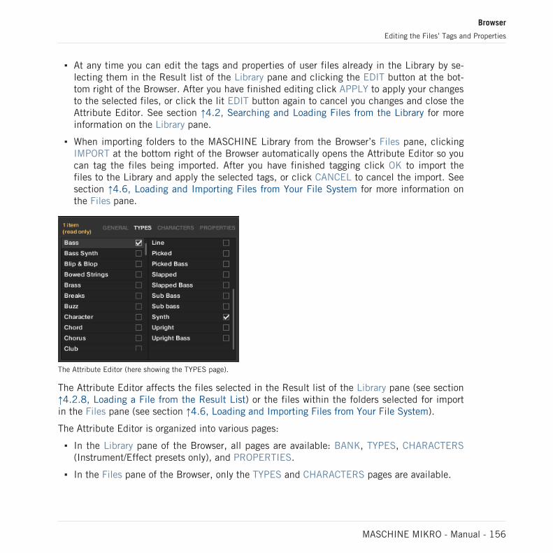
▪ At any time you can edit the tags and properties of user files already in the Library by se-lecting them in the Result list of the Library pane and clicking the EDIT button at the bot-tom right of the Browser. After you have finished editing click APPLY to apply your changesto the selected files, or click the lit EDIT button again to cancel you changes and close theAttribute Editor. See section ↑4.2, Searching and Loading Files from the Library for moreinformation on the Library pane.
▪ When importing folders to the MASCHINE Library from the Browser’s Files pane, clickingIMPORT at the bottom right of the Browser automatically opens the Attribute Editor so youcan tag the files being imported. After you have finished tagging click OK to import thefiles to the Library and apply the selected tags, or click CANCEL to cancel the import. Seesection ↑4.6, Loading and Importing Files from Your File System for more information onthe Files pane.
The Attribute Editor (here showing the TYPES page).
The Attribute Editor affects the files selected in the Result list of the Library pane (see section↑4.2.8, Loading a File from the Result List) or the files within the folders selected for importin the Files pane (see section ↑4.6, Loading and Importing Files from Your File System).
The Attribute Editor is organized into various pages:
▪ In the Library pane of the Browser, all pages are available: BANK, TYPES, CHARACTERS(Instrument/Effect presets only), and PROPERTIES.
▪ In the Files pane of the Browser, only the TYPES and CHARACTERS pages are available.
Browser
Editing the Files’ Tags and Properties
MASCHINE MIKRO - Manual - 156
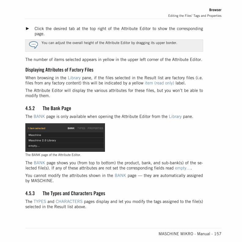
► Click the desired tab at the top right of the Attribute Editor to show the correspondingpage.
You can adjust the overall height of the Attribute Editor by dragging its upper border.
The number of items selected appears in yellow in the upper left corner of the Attribute Editor.
Displaying Attributes of Factory Files
When browsing in the Library pane, if the files selected in the Result list are factory files (i.e.files from any factory content) this will be indicated by a yellow item (read only) label.
The Attribute Editor will display the various attributes for these files, but you won’t be able tomodify them.
4.5.2 The Bank Page
The BANK page is only available when opening the Attribute Editor from the Library pane.
The BANK page of the Attribute Editor.
The BANK page shows you (from top to bottom) the product, bank, and sub-bank(s) of the se-lected file(s). If any of these attributes are not set the corresponding fields read empty….
You cannot modify the attributes shown in the BANK page — they are automatically assignedby MASCHINE.
4.5.3 The Types and Characters Pages
The TYPES and CHARACTERS pages display and let you modify the tags assigned to the file(s)selected in the Result list above.
Browser
Editing the Files’ Tags and Properties
MASCHINE MIKRO - Manual - 157

▪ The TYPES page is available for all file types when opening the Attribute Editor both fromthe Library pane and the Files pane. Various columns are displayed, depending on the filetype selected (see section ↑4.2.6, Selecting Type and Character Tags):
▪ The CHARACTERS page is available when opening the Attribute Editor from the Librarypane to edit the tags of Instrument and Effect presets. When opening the Attribute Editorfrom the Files pane to import new files, the CHARACTERS page is always available, howev-er it will be taken into account only if Instrument or Effect presets are imported. TheCHARACTERS page shows only one column:
Browser
Editing the Files’ Tags and Properties
MASCHINE MIKRO - Manual - 158

Displaying Tags
▪ In both TYPES and CHARACTERS pages, tags assigned to the selected files are markedwith a check mark right of their name.
▪ In the TYPES page, click the name of a tag to select it and display its Sub-Types in thenext column to the right. In each column only one tag can be selected.
Assigning Tags
► Click the empty check box right of the desired tag name to assign this tag to the selectedfiles.
→ A check mark appears in the check box.
Additionally, when you check a tag on the TYPES page:
▪ If another column is available on the right the tag you check is automatically selected andits Sub-Types appear in the next column (if any), allowing you to directly refine your de-scription by checking the desired Sub-Types in this next column.
▪ If you check a Sub-Type tag whose parent tag was not checked in the previous column onthe left, this parent tag will be automatically checked as well.
Be as precise as possible when tagging your files in order to be able to find what you are looking forlater.
Unassigning Tags
► Click the check mark right of the desired tag to unassign this tag from the selected files.
→ The check mark disappears.
In the TYPES page, if you uncheck a tag for which some Sub-Type tags were selected in the col-umns on the right, these will automatically unassigned as you unassign their parent tag.
Creating New Tags
You can also create your own tags both in the TYPES and CHARACTERS pages:
Browser
Editing the Files’ Tags and Properties
MASCHINE MIKRO - Manual - 159

► To create a new tag in any column, click the “+” symbol at the bottom of the column,enter the desired tag name with your computer keyboard and press [Enter] to confirm.
Adding a new Sub-Type for the Loops Type.
Deleting Tags
Tags in the TYPES and CHARACTERS pages cannot be deleted manually. However, if a tag isnot assigned to any file anymore, it will be automatically removed from its column.
4.5.4 The Properties Page
The PROPERTIES page is only available when opening the Attribute Editor from the Librarypane.
The PROPERTIES page of the Attribute Editor.
The PROPERTIES page displays three additional attributes of the selected files:
▪ Vendor: Use this field to indicate the manufacturer of the selected files. Click the down-pointing arrow on the right to quickly select any Vendor attribute already in use in otherfiles of the Library.
▪ Author: Use this field to indicate the author of the selected files. Click the down-pointingarrow on the right to quickly select any Author attribute already in use in other files of theLibrary.
▪ Comment: Use this field to add any other information about the selected files.
Browser
Editing the Files’ Tags and Properties
MASCHINE MIKRO - Manual - 160

As with the other pages of the Attribute Editor, the fields in the PROPERTIES page can be modifiedonly if you have selected user files in the Result list. The attributes of factory files cannot be edited.
4.6 Loading and Importing Files from Your File System
The Browser’s FILES pane allows you to browse your file system and import the desired foldersto your MASCHINE Library.
► To display the FILES pane, click the FILES tab in the top left corner of the Browser.
4.6.1 Overview of the FILES Pane
The FILES pane contains following elements:
Browser
Loading and Importing Files from Your File System
MASCHINE MIKRO - Manual - 161

4
5
6
1 2 3
The elements of the FILES pane.
(1) FILES tab: Click the FILES tab to open the FILES pane described here.
(2) Favorite bar: Displays all your Favorites. Click any Favorite to directly jump to that particularpath and display its content in the Result list (5). See section ↑4.6.2, Using Favorites.
(3) Location bar: Displays the selected path. The Location bar provides various tools to quicklynavigate your file system. See section ↑4.6.3, Using the Location Bar.
Browser
Loading and Importing Files from Your File System
MASCHINE MIKRO - Manual - 162

(4) Recent Locations button: Click this button to see a list of the last visited locations and quick-ly jump any of them. See section ↑4.6.4, Navigating to Recent Locations.
(5) Result list: The Result list displays the content (files and folders) of the folder loaded in theLocation bar (3). Only MASCHINE-compatible files are displayed. See section ↑4.6.5, Usingthe Result List.
(6) Control bar: At the bottom of the Browser, the Control bar provides a few useful tools whenbrowsing your file system, some of them depending on the type of the files selected in the Re-sult list:
▪ For all file types except Project, click the Autoload button at the far left of the Control bar toautomatically load the selected file in order to hear it in context with the rest of yourProject while it is playing. See section ↑4.3.1, Loading the Selected Files Automatically.
▪ For Samples, enable the Prehear button and adjust the volume fader next to it in order topre-listen to the selected Samples directly from the Browser in order to make a quick se-lection. See section ↑4.3.3, Auditioning Samples.
▪ For Groups, enable the Load Patterns checkbox to load the Group’s Patterns together withthe Group. See section ↑4.3.4, Loading Groups with Patterns.
▪ For all files, click the Information button (showing a little “i”) near the EDIT button to dis-play more information on the selected file(s). See section ↑4.3.6, Displaying File Informa-tion.
▪ When a folder is selected, click the IMPORT button at the far right of the bar to import theselected folder to the MASCHINE Library. Clicking the IMPORT button will open the Attrib-ute Editor so you can assign tags to the selected files about to be imported. See section↑4.5, Editing the Files’ Tags and Properties.
4.6.2 Using Favorites
Located at the top of the FILES pane, the Favorite bar displays all your Favorites.
The Favorite bar, at the top of the FILES pane.
Favorites are shortcuts to specific locations in your file system.
Browser
Loading and Importing Files from Your File System
MASCHINE MIKRO - Manual - 163

► Click any Favorite in the Favorite bar to jump to that location.
→ The selected location is loaded in the Location bar and its content appears in the Resultlist.
Favorites can be useful if you often return to the same location while browsing your file systemin the FILES pane: Save this location as a Favorite, and at any time you will be only one clickaway from that location!
The default Favorites are the roots of each of your hard disks, your desktop folder, and youruser folder.
Adding and Removing Favorites
You can add your own Favorites to the Favorite bar. This is done in the Result list:
1. Navigate to the parent folder containing the folder you want to use as Favorite, so thatthis folder appears in the Result list.
2. In the Result list, right-click ([Ctrl]-click on macOS) the desired folder and select Add toFavorites from the context menu.
You can also remove any Favorite from the Favorite bar:
► To remove a Favorite, right-click it ([Ctrl]-click it on macOS) in the Favorite bar and selectRemove from Favorites.
4.6.3 Using the Location Bar
The Location bar shows and lets you modify the selected path. At any time the Result list willdisplay the content of the path shown here.
The Location bar.
Browser
Loading and Importing Files from Your File System
MASCHINE MIKRO - Manual - 164
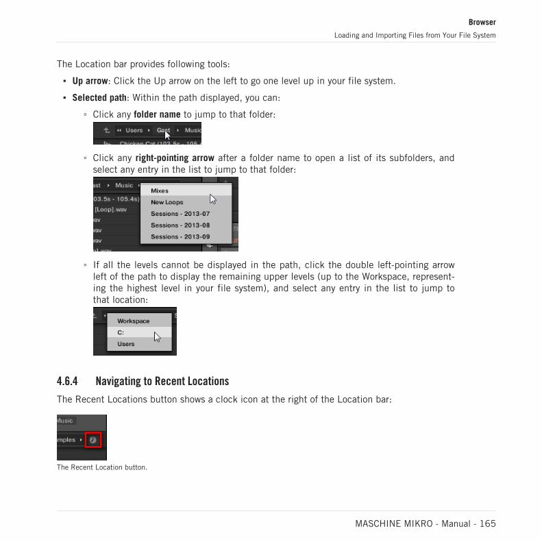
The Location bar provides following tools:
▪ Up arrow: Click the Up arrow on the left to go one level up in your file system.
▪ Selected path: Within the path displayed, you can:
◦ Click any folder name to jump to that folder:
◦ Click any right-pointing arrow after a folder name to open a list of its subfolders, andselect any entry in the list to jump to that folder:
◦ If all the levels cannot be displayed in the path, click the double left-pointing arrowleft of the path to display the remaining upper levels (up to the Workspace, represent-ing the highest level in your file system), and select any entry in the list to jump tothat location:
4.6.4 Navigating to Recent Locations
The Recent Locations button shows a clock icon at the right of the Location bar:
The Recent Location button.
Browser
Loading and Importing Files from Your File System
MASCHINE MIKRO - Manual - 165

The last 10 locations you have visited are stored by MASCHINE and available here:
► Click the Recent Location button and select any recently visited location from the list.
→ This location is loaded in the Location bar and its content displayed in the Result list.
4.6.5 Using the Result List
The Result list of the FILES pane shows the files and folders found in the path loaded in theLocation bar above (see section ↑4.6.3, Using the Location Bar).
Only MASCHINE-compatible files are shown in the Result list.
The Result list of the FILES pane.
If the list is too long to fit in the display, use your mouse wheel or drag the scroll bar on theright to show the remaining items.
Browser
Loading and Importing Files from Your File System
MASCHINE MIKRO - Manual - 166

In front of each file, an icon indicates the type of the file:
Icons for various file types.
Navigating Your File System in the Result List
You can further browse your file system in the Result list by opening any of the displayed fold-er:
► Double-click a folder to display its content.
To return to the previous folder or to select any folder outside the folder currently displayed,use the various tools located above the Result list:
▪ Favorites: ↑4.6.2, Using Favorites.
▪ Location bar: ↑4.6.3, Using the Location Bar.
▪ Recent Locations button: ↑4.6.4, Navigating to Recent Locations.
Selecting Files and Folders in the Result List
► To select a single file or folder in the Result list, click its entry.
You can also select multiple files and folders in the Result list in order to process them all atonce.
To select adjacent files in the list, do the following:
► Hold [Shift] on your computer keyboard and click two files in the Result list to selectthese files and all files in-between.
To select distant files in the list, do the following:
► Hold [Ctrl] ([Cmd] on macOS) and click all the files you want to select.
Browser
Loading and Importing Files from Your File System
MASCHINE MIKRO - Manual - 167

Loading Files from the Result List
You can load files from the Result list using the same methods as in the Result list of theLIBRARY pane: via double-click or via drag-and-drop. For all details, please refer to section↑4.2.8, Loading a File from the Result List.
Additional Features in the Result List
► Right-click ([Ctrl]-click on macOS) any entry in the Result list to open a context menuwith additional commands.
The context menu in the Result list of the FILES pane (Windows depicted).
Following commands are available:
Command Description
Add to Favorites (folders only) Adds the selected folder to your Favorites. See section↑4.6.2, Using Favorites for more information.
Import to Library (folders only) Imports the selected folder(s) into the Library. See section↑4.6.5, Using the Result List for more information.
Refresh Refreshes the display of the list, in case items have beenmodified in that folder.
Find in Exporer / Find in Finder Opens an Explorer/Finder window pointing to the selectedfolder.
Browser
Loading and Importing Files from Your File System
MASCHINE MIKRO - Manual - 168
Command Description
Sort by Name Sorts the Result list according to the item names.
Sort by Date Sorts the Result list according to the item dates.
4.6.6 Importing Files to the MASCHINE Library
Apart from the huge MASCHINE factory library, you might want to use your own samples or anyMASCHINE files you received from other users. As described previously, you can load them di-rectly from the FILES pane. If this can come in handy, e.g., to quickly check received files in aMASCHINE context, it can get tedious when using the files on a regular basis. Furthermore,you won’t be able to find and load them from your controller nor from the LIBRARY pane (seesection ↑4.2, Searching and Loading Files from the Library).
For this you will have to import the files into the Library first. Importing files does not meanthey will be moved from the directory they currently reside in, they will only be referenced bythe Browser. That’s why whenever you move files, make sure to update the paths to their re-spective directories in the Library page of the Preferences panel, as described in section↑3.6.4, Preferences – Default Page.
This section describes how to import files into the MASCHINE Library. When working on a Project,you can also save individual objects (Project, Groups, Sounds, Plug-in presets, or Samples) of theProject to the Library for later use. This will be described in each object-specific section, later inthis manual.
MASCHINE supports WAVE (.wav) and AIFF (.aiff) sample formats at a sample rate of 44.1 kHz orgreater and a bit depth of 16 bits, 24 bits or 32 bits float.
The FILES pane allows you to import whole folders. All MASCHINE-compatible files found inthe selected folder(s) will be imported.
To import a folder, do the following:
1. Click the FILES tab at the top of the Browser to open the FILES pane.
2. In the FILES pane, navigate to the folder containing the folder you want to import. To dothis, use the various tools described in the previous sections.
Browser
Loading and Importing Files from Your File System
MASCHINE MIKRO - Manual - 169

3. Select the desired folder as described above.
4. Click the IMPORT button at the bottom right of the Browser.You will be presented with the Attribute Editor.
5. In the Attribute Editor, tag the files you are about to import to the Library as described insection ↑4.5, Editing the Files’ Tags and Properties.
6. When you are done, click OK at the bottom right of the Browser to import the files to theLibrary.
→ All MASCHINE-compatible files found in the selected folder(s) are imported to your Li-brary. They are added as user content (User icon selected in the Content selector of theLIBRARY pane, see section ↑4.2.5, Choosing Between Factory and User Content). Fur-thermore, the paths of the imported folders are added to the list of user libraries in theUser pane of the Library page in the Preferences panel — see section ↑3.6.4, Preferences– Default Page for more information on this.
If the folder(s) you are importing contain different types of files (e.g., Samples, Sounds, andGroups), the various imported files will be available by selecting the corresponding types in the FileType selector (see section ↑4.2.4, Selecting a File Type).
You can also apply/remove tags at any time after they are imported. However, it may be best to tagfiles on import, since it will make it easier to find them later.
Other Attributes Set During Import
In addition to the Type (and possibly) Mode tags that you can manually assign to the files be-ing imported (see above), other attributes are automatically set as follows:
▪ For all file types, any attributes already assigned to the files will be retained.
▪ For Samples, if the product/bank/sub-bank attributes are empty, they will be set to thefolders in which the Samples are located:
◦ The product will be set to the name of the folder you have selected.
◦ If Samples reside in a subfolder of this folder, the subfolder name will be used asbank.
Browser
Loading and Importing Files from Your File System
MASCHINE MIKRO - Manual - 170

◦ If Samples reside in a subfolder of this subfolder, the name of the lower subfolder willbe used as sub-bank.
4.7 Locating Missing Samples
If you are loading a MASCHINE Project and one or more referenced Sample(s) cannot be foundfor any reason, a dialog in which you can locate the missing Samples will appear.
The Missing Sample dialog allows you to locate missing Samples.
Sounds referencing missing Samples are marked with an exclamation mark. Additionally, theirGroups are also marked with an exclamation mark when selected.
The Missing Sample dialog shows you which Sample cannot be found. Three buttons at thebottom of the dialog let you choose between following actions:
▪ IGNORE: Click this button to continue loading your Project without locating the missingSample. You will be able to locate it at a later time (see below).
▪ IGNORE ALL: Click this button to ignore the missing Sample as well as all other missingSamples, if any. You will be able to locate them at a later time (see below).
▪ LOCATE: Clicking this button opens a Locate selection dialog in which you can manuallylocate the missing Sample. Navigate to the desired Sample in your file system and clickOpen. Consequently, your Project uses the newly selected Sample in place of the missingone. If other Samples are missing, MASCHINE tries to trace their path starting from thepath you just indicated.
Browser
Locating Missing Samples
MASCHINE MIKRO - Manual - 171

Locating or Purging Missing Samples at a Later Time
When Sample references cannot be resolved, two additional Purge Missing Samples and FindMissing Samples appear in the context menu of the affected Sound(s) in the Sound List.
The Purge Missing Samples and the Find Missing Samples entries in the context menu of a Sound whose Sample is missing.
1. Select Purge Missing Samples from the Sound slot’s context menu to remove the missingSample(s) from that Sound.
2. Select Find Missing Samples from the Sound slot’s context menu to open the MissingSample dialog again and locate missing Samples for that Sound.
The same commands also appear in the context menu of the parent Group in the Group List,as well as in the in the File submenu of the MASCHINE menu (in the MASCHINE Header):
▪ In the context menu of the parent Group, these commands will affect all Sounds with miss-ing Samples in that Group.
▪ In the File submenu of the MASCHINE menu, these commands will affect all Sounds withmissing Samples in your Project.
Browser
Locating Missing Samples
MASCHINE MIKRO - Manual - 172

4.8 Using Quick Browse
Quick Browse is a feature that allows you to quickly recall a search query you performed to getto a given file. Let’s say you have loaded a kick Sample after browsing the Library, then loadeda snare Sample to another Sound slot and now you realize you are not satisfied with that kickSample, but you heard a nice kick Sample just before you chose the current one. Normally youwould now have to try to remember the name or the tags you used to find it, or browse all kickSamples (given that the MASCHINE Library already has several hundreds of kick Samples, thismay take a considerable amount of time). With Quick Browse you can restore the query withjust one click.
Quick Browse is available for Samples, Plug-ins presets (Instruments and Effects), Sounds,Groups. Depending on the type of file you are looking for, the Quick Browse function is activat-ed by clicking the magnifying glass in either of the following locations:
▪ Quick Browse for Projects, Groups and Sounds: Click the magnifying glass right of the coloredfile name appearing in the upper left part of the Control area to recall the search query thatwas used for that file. That file will be:
◦ The focused Group if the GROUP tab is selected above:
◦ The focused Sound if the SOUND tab is selected above:
Browser
Using Quick Browse
MASCHINE MIKRO - Manual - 173

▪ Quick Browse for Instrument/Effect presets and for Samples: Click the magnifying glass in theupper right corner of the Control area to recall the search query that was used for the Plug-in in the selected slot:
◦ If a Sampler Plug-in is selected, it will recall the search query used for the Sampleloaded in that Sampler. If several Samples are loaded in the Sampler, it will recall thesearch query for the Sample in the selected Zone in the Zone List.
◦ If any other Instrument or Effect Plug-in is selected, it will recall the search queryused for the Plug-in preset loaded in that Plug-in (the preset name appears next to themagnifying glass):
Upon your click on the magnifying glass, the search query for the corresponding file will berestored in the LIBRARY or FILES pane of the Browser (depending on which of both panes wasused to find the file). The file will be shown in the Result list — if necessary, the list will bescrolled to display the file. You can then choose other results for that query from the Resultlist.
The Quick Browse function is also available from your controller! See below for more information.
If No Search Query Was Used for a File…
If a file of your Project wasn’t loaded via a search in the Browser, obviously there is no searchquery to be retrieved! Nevertheless, Quick Browse will try various techniques to find out wherethe file “comes from.” For example, if you have loaded a file via drag and drop from your desk-top or any other location on your computer, Quick Browse will display the FILES pane pointingto that location.
Browser
Using Quick Browse
MASCHINE MIKRO - Manual - 174

5 Managing Sounds, Groups, and Your Project
This chapter explains how to handle the various objects that structure any MASCHINE Project:Sounds, Groups, and the Master.
5.1 Overview of the Sounds, Groups, and Master
In a MASCHINE Project, objects are organized into three hierarchic levels, from the lowest tothe highest:
▪ Sounds are played by the pads. They are loaded into Sound slots. In the software, in Ar-range view Sound slots are displayed in the column at the left of the Pattern Editor: the Sound List (1). Each Sound of the selected Group is by default mapped to one of the 16pads on the MASCHINE hardware controller, so you can play all Sounds of a Group bypressing the pads. Sounds are made up of any number of Plug-ins that process the audioin series. Sounds are the only objects in MASCHINE that can accept Instrument Plug-ins— these go in the Sounds’ first Plug-in slot. The type of the Plug-in (Instrument or Effect)loaded in this first Plug-in slot will define the Sound’s role (audio source or bussing point,respectively). For more information on Plug-ins and how they define the Sound’s role,please refer to section ↑7.1, Plug-in Overview.
▪ Groups contain 16 Sound slots each with all their parameters. The 16 pads on your control-ler can play one entire Group at a time. In the software, in Arrange view Group are dis-played in the column at the left of the Arranger: the Group List (2). A MASCHINE Projectcan have any number of Groups, which are organized in banks of eight Groups each. EachGroup can have any number of insert effects, which will globally apply to all Sounds con-tained in that Group, as well as any number of Patterns organized in banks of 16 Patternseach. More on Patterns in chapter ↑11, Working with Patterns.
▪ The Master is the place where all signals from the Groups are being mixed together. Justlike the Groups and Sounds, the Master can host any number of insert effects.
Managing Sounds, Groups, and Your Project
Overview of the Sounds, Groups, and Master
MASCHINE MIKRO - Manual - 175

1
2
The Group List (1) and the Sound List (2) in the Arrange view of the software.
5.1.1 The Sound, Group, and Master Channels
From a routing point of view, each Sound, each Group, and the Master represents a distinctchannel in MASCHINE. The channels of the 16 Sounds in a Group are mixed together and sentto the Group channel, where their sum will be processed by the Group’s Plug-ins, if any. Simi-larly, the channels of all Groups in your Project are mixed together and sent to the Masterchannel, where their sum will be processed by the Master’s Plug-ins, if any. The resulting sig-nal is sent to MASCHINE’s outputs.
Each channel provides various set of Channel properties that adjust the input, output, groove,and Macro Control settings for that particular Sound, Group, or for the Master, independentlyof the Plug-ins it contains. Please refer to chapter ↑12, Audio Routing, Remote Control, andMacro Controls and section ↑6.3.3, Groove for more details on these.
Managing Sounds, Groups, and Your Project
Overview of the Sounds, Groups, and Master
MASCHINE MIKRO - Manual - 176
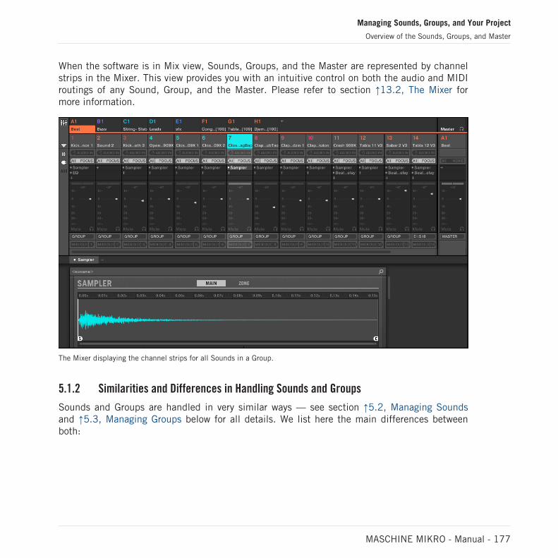
When the software is in Mix view, Sounds, Groups, and the Master are represented by channelstrips in the Mixer. This view provides you with an intuitive control on both the audio and MIDIroutings of any Sound, Group, and the Master. Please refer to section ↑13.2, The Mixer formore information.
The Mixer displaying the channel strips for all Sounds in a Group.
5.1.2 Similarities and Differences in Handling Sounds and Groups
Sounds and Groups are handled in very similar ways — see section ↑5.2, Managing Soundsand ↑5.3, Managing Groups below for all details. We list here the main differences betweenboth:
Managing Sounds, Groups, and Your Project
Overview of the Sounds, Groups, and Master
MASCHINE MIKRO - Manual - 177

▪ In each Group you always have a fixed number of Sound slots — namely 16. Some of theseSound slots might be empty, and you can have gaps in your slots (i.e. some empty Soundslots between other slots containing Sounds), depending on how you prefer to play yourSounds from your pads. You cannot create Sound slots, but instead you can load/unloadSounds to/from the 16 existing Sound slots in each Group.
▪ In your Project you can have any number of Groups. You can create, fill up, and deleteGroups as you see fit. If you delete a Group, all following Groups are shifted up in theGroup List to fill the gap. If you use more than eight Groups, another Group bank is auto-matically created.
5.1.3 Selecting Multiple Sounds or Groups
In MASCHINE you can select multiple Sounds or multiple Groups at once. This notably allows youto change a parameter value for all selected Sounds/Groups at a time!
To achieve this, MASCHINE distinguishes the “focus” from the “selection”:
▪ The focus determines what is displayed in the Control area and on your controller. For ex-ample, by clicking a Sound in the Sound List you are putting the focus on that Sound, andthe Control area and your controller will display its parameters (Channel properties, Plug-ins, etc.). For the focus, the following rule applies:At each level (Sound and Group) there is always one object, and only one, in focus.The focused object is highlighted in the Sound/Group List, and the background of its lead-ing letter and/or number has the color of the object itself.
The Sound Vocal AhHa is focused (and selected).
Managing Sounds, Groups, and Your Project
Overview of the Sounds, Groups, and Master
MASCHINE MIKRO - Manual - 178

▪ The selection, on the other hand, determines what will be affected by your actions (e.g.,adjusting a parameter). For example, the focused Sound (i.e. the one you clicked in theSound List) is implicitly selected — nothing special here: This just means that the Soundwhose parameters are currently displayed will be indeed affected by the changes you do onthese parameters. But you can select additional objects on top of the focused object, there-by extending your selection. Selected objects are highlighted in the Sound/Group List buttheir leading letter and/or number stays gray.
Other Sounds were added to the selection (but they are not focused).
More precisely, if a Group or a Sound is currently focused, you can additionally select otherGroups or Sounds, respectively. These will be also affected by your edits on the focused Groupor Sound.
You cannot select Sounds and Groups simultaneously.
Each Group remembers its own Sound selection and focus.
When setting the focus to a new Sound or Group, following rules apply:
▪ If you set the focus to a Sound or Group which is not selected, both the focus and the se-lection are moved to this new Sound or Group.
Managing Sounds, Groups, and Your Project
Overview of the Sounds, Groups, and Master
MASCHINE MIKRO - Manual - 179

▪ If you set the focus to a Sound or Group which is already included in the current selection,the focus is moved to this new Sound or Group but the selection is preserved. This notablyallows you to check the parameters of any selected Sound or Group while keeping the abili-ty to modify parameters for the entire selection.
What Is Affected by the Multiple Selection, and How?
When multiple Sounds or multiple Groups are selected, any change in the following settings ofthe focused Sound/Group will be mirrored in the other selected Sounds/Groups, respectively:
▪ Channel properties: Parameter adjustments apply to all selected Sounds/Groups for any pa-rameter in any set of Channel properties. See chapter ↑12, Audio Routing, Remote Control,and Macro Controls for more information on the Channel properties.
▪ Plug-ins: Parameter adjustments apply to all selected Sounds/Groups that have the samePlug-in loaded in the same Plug-in slot. See chapter ↑7, Working with Plug-ins for moreinformation on Plug-ins.
▪ Pad view: Base key, Choke group, and Link group settings apply to all selected Sounds. Seesection ↑6.1, Adjusting the Pads for more information on these settings.
▪ You can move multiple Sound slots or multiple Groups at once. See section ↑5.2.7, MovingSounds and ↑5.3.7, Reordering Groups for more information.
▪ You can reset multiple Sound slots and delete multiple Groups at once. See section ↑5.2.8,Resetting Sound Slots and ↑5.3.8, Deleting Groups for more information.
The adjustments made in the Assignment area are never mirrored in any other selected Sound/Group.
Furthermore, the exact influence on the equivalent parameter in the affected Sounds/Groupsdepends on the type of parameter:
▪ Continuous parameters (knob): the values in all selected Sounds/Groups are incremented/decremented by the same amount as the value in the focused Sound/Group. Values areclipped when they reach their range limit.
▪ Discrete parameter (button or selector): the values in all selected Sounds/Groups are set tothe value of the focused Sound/Group.
Managing Sounds, Groups, and Your Project
Overview of the Sounds, Groups, and Master
MASCHINE MIKRO - Manual - 180

Selecting Multiple Sounds/Groups in the Software
To select multiple Sounds or multiple Groups in the MASCHINE software, simply use the com-mon keyboard shortcuts of your operating system: in the Sound List or the Pad view forSounds, and in the Group List for Groups. Following actions are available:
Action Function
Selecting Objects (Sounds or Groups)
Click unselected object Selects the object and sets the focus to it.
Click selected object Sets the focus to this object while retainingthe selection.
[Ctrl]-click ([Cmd]-click on macOS)unselected object
Adds the object to the selection.
[Ctrl]-click ([Cmd]-click on macOS) selectedobject
Deselects the object — except for the focusedobject, which cannot be deselected.
[Shift]-click object Selects all objects between the focused oneand the [Shift]-clicked one.
[Ctrl] + [A] ([Cmd] + [A] on macOS) if someobjects are not selected
Selects all objects in the list.
[Ctrl] + [A] ([Cmd] + [A] on macOS) if allobjects are selected in the list
Deselect all objects except the focused one,which cannot be deselected.
The shortcuts mentioned in the table above are valid in following areas of the MASCHINE win-dow:
▪ To select multiple Groups, use these shortcuts in the Group List.
▪ To select multiple Sounds, use these shortcuts in the Sound List or in the Pad view (seesection ↑6.1.1, The Pad View in the Software).
5.2 Managing Sounds
This section describes the global editing functions available for Sounds and Sound slots.
Managing Sounds, Groups, and Your Project
Managing Sounds
MASCHINE MIKRO - Manual - 181

Sounds: Sound List or Pad View
With the exception of naming Sound slots, all procedures described in the following sectionsare available both in the Sound List and in the Pad view. The Pad view is an alternative repre-sentation of your Sound slots that puts emphasis on their relationship with the pads on yourcontroller.
The Pad view.
The Pad view can be shown by activating the Pad View button above the Sound List:
The Pad View button.
► Click the Pad View button to show or hide the Pad view.
→ The Pad view replaces the Sound List on the left of the Pattern Editor.
In the Pad view, each cell represents a pad on your controller and corresponds to a Sound slotin the current Group. You can select Sound slots in either the Sound List or the Pad view asyou see fit, both selections are strictly equivalent.
In addition to the Sound management features described in the following sections, the Pad viewprovides extra settings affecting the behavior of your pads. See section ↑6.1, Adjusting the Pads formore information.
Managing Sounds, Groups, and Your Project
Managing Sounds
MASCHINE MIKRO - Manual - 182
5.2.1 Loading Sounds
You can load a readymade Sound from the Browser or from your operating system. The Soundcan be included in the MASCHINE Library or any EXPANSION PACK but it can also be aSound you have created yourself and saved for later use.
You have many methods at your disposal to load a Sound:
▪ Drag and drop: Select the desired Sound in the Browser or in your operating system anddrag it onto the desired Sound slot in the Sound List (or the corresponding cell of the padgrid in Pad view, see above) to load it in that Sound slot. Any Sound previously loaded inthat slot will be replaced.
▪ Double-click: Double-click the Sound in the Browser or the Sound file in your operating sys-tem to replace the focused Sound in the Sound List.
▪ Context menu: Right-click ([Ctrl]-click on macOS) the desired Sound slot in the Sound Listor the corresponding cell of the pad grid in Pad view, and select Open… in the contextmenu. In the Load Sound dialog that opens, navigate to the desired Sound file on yourcomputer and click Open to load it. The loaded Sound will replace the current Sound load-ed in that slot.
You can also recall the search query that was used to find the Sound currently loaded in the fo-cused Sound slot. See section ↑4.8, Using Quick Browse for more information.
In your operating system, Sound files have the extension “.mxsnd” (MASCHINE 2) or “.msnd” (MA-SCHINE 1.x).
Please refer to chapter ↑4, Browser for more information on the Browser.
Loading Sounds on Your Controller
On your controller, use the Browser to load Sounds:
▪ You can browse your MASCHINE Library for the desired Sound. For more information onhow to do this, please refer to section ↑4.2, Searching and Loading Files from the Library.
Managing Sounds, Groups, and Your Project
Managing Sounds
MASCHINE MIKRO - Manual - 183
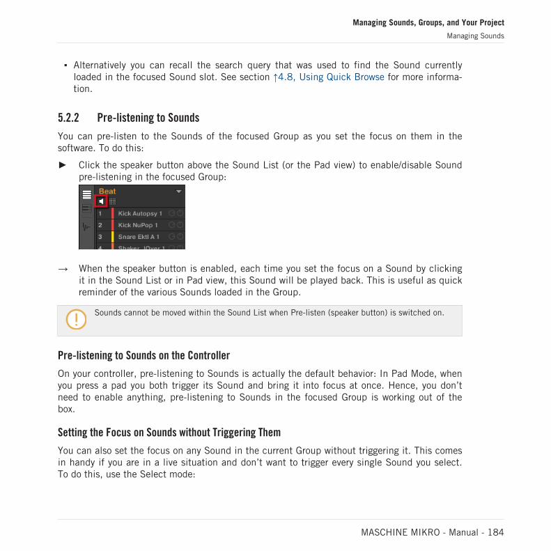
▪ Alternatively you can recall the search query that was used to find the Sound currentlyloaded in the focused Sound slot. See section ↑4.8, Using Quick Browse for more informa-tion.
5.2.2 Pre-listening to Sounds
You can pre-listen to the Sounds of the focused Group as you set the focus on them in thesoftware. To do this:
► Click the speaker button above the Sound List (or the Pad view) to enable/disable Soundpre-listening in the focused Group:
→ When the speaker button is enabled, each time you set the focus on a Sound by clickingit in the Sound List or in Pad view, this Sound will be played back. This is useful as quickreminder of the various Sounds loaded in the Group.
Sounds cannot be moved within the Sound List when Pre-listen (speaker button) is switched on.
Pre-listening to Sounds on the Controller
On your controller, pre-listening to Sounds is actually the default behavior: In Pad Mode, whenyou press a pad you both trigger its Sound and bring it into focus at once. Hence, you don’tneed to enable anything, pre-listening to Sounds in the focused Group is working out of thebox.
Setting the Focus on Sounds without Triggering Them
You can also set the focus on any Sound in the current Group without triggering it. This comesin handy if you are in a live situation and don’t want to trigger every single Sound you select.To do this, use the Select mode:
Managing Sounds, Groups, and Your Project
Managing Sounds
MASCHINE MIKRO - Manual - 184

1. Select PAD MODE.
2. Press SELECT.
3. Press the pad containing the desired Sound.
The Sound is focused without being triggered.
5.2.3 Renaming Sound Slots
By default, Sound slots are named Sound 1–16. If you load a Sound, a Plug-in preset or aSample (e.g., from the Browser) into the Sound slot, the Sound slot takes the Sound’s, preset’sor Sample’s name.
You can also rename Sound slots manually. Naming is only available from within the software,but any changes will also show up on your controller.
To rename a Sound slot:
1. Double-click the name of the desired Sound slot or right-click ([Ctrl]-click on macOS) theSound slot and select Rename from the context menu.The Sound slot’s name is now highlighted and editable.
2. Modify the name of the Sound slot via your computer keyboard. Press [Enter] on yourcomputer keyboard to confirm.
If you use MASCHINE as a plug-in, some hosts will utilize the [Enter] key, as it is mapped to somefunction of the host software. In this case, click anywhere else in the MASCHINE plug-in window toconfirm the name you have entered.
Managing Sounds, Groups, and Your Project
Managing Sounds
MASCHINE MIKRO - Manual - 185

5.2.4 Changing the Sound’s Color
You can change the color of each individual Sound in the software. To do this:
1. Right-click ([Ctrl]-click on macOS) the desired Sound slot in the Sound List or in the Padview and select Color from the context menu.A Color Palette appears. In the Palette, the current color of the Sound is highlighted.
2. Select the desired color in the Palette. You can also choose to set the Sound back to thedefault color corresponding to its position in the list by selecting Default in the Color Pa-lette.
→ The pads of the MASCHINE STUDIO, MASCHINE MK3, MASCHINE MK2, and MA-SCHINE MIKRO MK2 controllers mirror the Sound colors you have selected.
Editing Multiple Sounds
You can apply the following commands to multiple selections of Sounds:
▪ Sounds:
◦ Changing the selected Sounds’ color.
◦ Cutting, copying, and pasting the selected Sounds.
◦ Resetting the selected Sounds.
These commands are available in the Sounds’ context menu.
Managing Sounds, Groups, and Your Project
Managing Sounds
MASCHINE MIKRO - Manual - 186

Notes on Changing the Color of Multiple Sounds
When opening the Color Palette (in order to set a new color setting for the selected Sounds):
▪ If the selected Sounds have the same color setting (a particular color or the default color),this color is highlighted in the Color Palette.
▪ If the selected Sounds have different color settings, no setting is highlighted in the ColorPalette.
When you select a new color setting from the Color Palette it is applied to all selected Sounds.
By default Sounds inherit the color of their Group. But you can choose another default color forSounds in Preferences > Colors > Sound Default. See section ↑3.6.8, Preferences – Colors Page formore information.
Once you have set a custom color for a Sound as described above, the Sound will retain its colorwhen you move it in the Sound List, and the color will be stored with the Sound when you save theSound for later use. Note that you can select the same color as the one used by default: In thatcase the color (even unchanged) will be considered as a custom color and will follow the Sound asyou move it.
5.2.5 Saving Sounds
You can save your Sounds as individual files (extension “.mxsnd”). This can be only done inthe software.
Saving Your Modifications into the Original Sound File
If you have made changes to a Sound loaded in your Project, you can save your modificationsas follows:
Managing Sounds, Groups, and Your Project
Managing Sounds
MASCHINE MIKRO - Manual - 187

► Right-click (on macOS: [Ctrl]-click) the Sound slot in the Sound List or in the Pad viewand select Save from the context menu:
→ Your modifications are saved to the Sound file.
Even if you don’t save a Sound individually, its current settings will still be saved with your Project.But once a Sound is saved and tagged, it is available in the Browser for use in other Groups andProjects.
You cannot save changes to factory files — these files are read-only. If you run the Save com-mand on a factory file, it automatically turns into the Save As… command: a Save Sound dia-log opens and lets you save your modified Sound to your user library. See next paragraph formore details. The same happens with Sounds you have built from scratch.
Saving Your Modified Sound as a New Sound
If you want to save modifications you have made on a Sound originating from a factory library,or if you don’t want to overwrite the original Sound with your modified version, or if there is nooriginal version of your Sound (i.e. you built it from scratch), you can save it as a new Soundfile:
Managing Sounds, Groups, and Your Project
Managing Sounds
MASCHINE MIKRO - Manual - 188

► Right-click (on macOS: [Ctrl]-click) the Sound slot in the Sound List or in the Pad viewand select Save As… from the context menu:
A Save Sound dialog appears. By default, the Sound file inherits the name of its Sound slotand it will be saved in your Standard User Directory (as defined in Preferences > Library >User, see section ↑3.6.4, Preferences – Default Page for more information).
1. If you wish, choose another path and/or type another name with your computer keyboard.
2. Press [Enter] to confirm and close the Save Sound dialog.
→ Your Sound is now saved.
The Sound will be added to the user library and is ready to be tagged in the Browser — seesection ↑4.5, Editing the Files’ Tags and Properties for more information on this.
Even if you don’t save a Sound individually, its current settings will still be saved with your Project.But once a Sound is saved and tagged, it is available in the Browser for use in other Groups andProjects.
5.2.6 Copying and Pasting Sounds
You can copy and paste Sounds across Sound slots (and thereby across pads) and Groups inyour Project.
Managing Sounds, Groups, and Your Project
Managing Sounds
MASCHINE MIKRO - Manual - 189

In the software, Sounds are copied without their note content in the Pattern. To include the notecontent in the copying operation, use DUPLICATE on your controller (see below)!
To copy and paste Sounds in the software:
1. Right-click (on macOS: [Ctrl]-click) the Sound slot (in the Sound List or in the Pad view)containing the Sound you want to copy.
2. In the context menu, choose Copy to copy the Sound.
3. To paste the Sound, right-click (macOS: [Ctrl]-click) another Sound slot (this can also bein another Group, in this case first click the desired Group in the Group List of the Arrang-er) and select Paste from the context menu.
→ All parameters of the Sound will be copied except for the source’s Pattern content. TheSound previously loaded in that Sound slot will be replaced.
Cutting, Copying, and Pasting Multiple Sounds
The cutting procedure for multiple Sounds and Groups is as follows:
▪ When you cut a selection of Sounds, they are placed into the clipboard and removed fromthe Sound List. Their Sound slots are reset to their default state.
Managing Sounds, Groups, and Your Project
Managing Sounds
MASCHINE MIKRO - Manual - 190

The copying procedure for multiple Sounds is as follows:
When you copy a selection of Sounds, they are both placed into the clipboard and kept in theSound List.
The pasting procedure for multiple Sounds is as follows:
▪ When you paste a selection of Sounds onto a Sound slot, the pasted Sounds replace thecurrent Sound in that slot and in the following slots — if the last Sound slot is reached,the remaining copied Sounds won’t be pasted at all. Note that this is not affected by anymultiple selection you might have made when pasting. Example: If you paste the Sounds 1,2, 4, and 7 onto the Sound slot 14, the duplicates of the Sounds 1, 2, and 4 will replaceany existing Sounds in the Sound slots 14, 15, and 16, respectively, while the Sound 7won’t be pasted at all.
If you want to copy a Sound more than once, just keep on choosing Paste from the context menu onother Sound slots: the source Sound stays in the clipboard, ready for the next use!
When you copy/paste Sounds in the software, the entire content of the copied Sound(s) is past-ed, including their events. Notably, pasting a Sound into a Sound slot of a different Group willcreate the needed Patterns if they do not exist, and replace the events for that Sound slot in anexisting Patterns.
In the sentence above, “existing Patterns” means the Patterns with the same IDs (i.e. the same po-sition in the Pattern List) as in the source Group. Example: If the source Sound contains events inPattern 1, 2, and 3 of its Group and you paste that Sound into another Group that only has Pattern1 and 4, Pattern 2 and 3 will be automatically created to host the events of the pasted Sound.
Duplicating Sounds on Your Controller
On your controller in Control mode, do the following to copy a Sound from one pad to another:
1. Press and hold DUPLICATE.
2. If you want to duplicate a Sound including its Pattern content, turn the encoder to enablethe Copy Events option.
3. Press the pad of the Sound you want to copy.The pad of the Sound starts blinking.
Managing Sounds, Groups, and Your Project
Managing Sounds
MASCHINE MIKRO - Manual - 191

4. Press the pad of the target Sound slot (this can also be in another Group, in this case firstpress GROUP, then the pad of the desired Group, then GROUP again to deactivate it).
→ All parameters of the Sound will be copied (including the Pattern content for that Soundif you have enabled the Copy Events option). The copied Sound will replace any Soundpreviously loaded in the target Sound slot.
5.2.7 Moving Sounds
You can reorder Sounds via drag-and-drop in the software. It can be helpful to organize yourSounds more conveniently. Notably, this allows you to move your Sounds to other pads, andcreate a Group that is easier to play from the pads.
You can select multiple Sounds to move them all at once! See ↑5.1.3, Selecting Multiple Sounds orGroups for more information.
To move one or more Sounds:
1. Click and hold the desired Sound slot(s) in the Sound List or in the Pad view.
2. While holding the mouse button, drag your mouse toward the desired location in theSound List or in the Pad view.As the mouse cursor moves an insertion line appears at the potential places where youcan drop the Sound slot(s).
3. When the insertion line appears at the desired location in the Sound List or in the Padview, release the mouse button.
Managing Sounds, Groups, and Your Project
Managing Sounds
MASCHINE MIKRO - Manual - 192
→ Each Sound takes its new place in the Group. On your controller, the Sounds will be trig-gered by the pads whose numbers appear left of the Sound slots in the Sound List or onthe cells in the Pad view.
You can also drag Sounds to another Group in the Group List of the Arranger: The Sounds willbe inserted in the first empty Sound slots of that Group, and that Group will automatically getthe focus. However, in that case the Pattern content of the Sounds won’t be moved.
Sounds cannot be moved within the Sound List when Pre-listen (speaker button) is switched on.
If you drag the Sound(s) to the “+” at the end of the Group List, a new Group is automatically creat-ed and your Sound(s) will be moved to the first Sound slot(s) of that Group.
5.2.8 Resetting Sound Slots
Resetting a Sound slot will remove the Sound it contains and put all its settings (Channelproperties, name, color…) back to their default values.
You can select multiple Sound slots to reset them all at once! See ↑5.1.3, Selecting MultipleSounds or Groups for more information.
► To reset a Sound slot, select it in the Sound List or in the Pad view and press [Del] onyour computer keyboard, or right-click (on macOS: [Ctrl]-click) the Sound slot and chooseReset from the context menu.
→ The content of the Sound slot is removed and the Sound slot is reset to its default set-tings and name.
Managing Sounds, Groups, and Your Project
Managing Sounds
MASCHINE MIKRO - Manual - 193

Resetting a Sound slot.
Resetting a Sound Slot on Your Controller
► To reset a Sound slot, hold SHIFT + ERASE and then press the pad related to the Soundyou want to reset.
→ The Sound is removed from the pad, and the pad is turned off.
5.3 Managing Groups
This section describes the global editing functions available for Groups.
Group Menu
Many of the functions described in the following sections are available in the following twocontext menus:
Managing Sounds, Groups, and Your Project
Managing Groups
MASCHINE MIKRO - Manual - 194

▪ The context menu of the Groups in the Group List, opened via a right-click ([Ctrl]-click onmacOS) on the desired Group:
▪ The context menu of the focused Group in the Pattern Editor, opened via a right-click([Ctrl]-click on macOS) on the Group name in the top left corner of the Pattern Editor:
Both context menus are equivalent: Use either menu as you see fit.
Managing Sounds, Groups, and Your Project
Managing Groups
MASCHINE MIKRO - Manual - 195

5.3.1 Creating Groups
Creating a Group will add a new empty Group at the end of the Group List. You can then fillthis Group with the Sounds of your choice.
► To create a Group, click the “+” at the end of the Group List.
→ A new empty Group is created at the end of the Group List with the default name andcolor.
Creating Groups on the Controller
On your controller:
► Press and hold the GROUP button.
→ Existing Groups are indicated by the lit pads 9–16:
▪ The focused Group is indicated by the fully lit pad.
▪ The other Groups of your Project are indicated by half-lit pads, each pad showing the colorof the corresponding Group.
▪ In the last Group bank the last half-lit pad is white: It doesn’t correspond to any existingGroup, but instead allows you to create another Group in your Project.
To create a new Group:
► While holding GROUP, press the dimmed white pad 9–16.
→ A new empty Group is created after the existing Groups with the default name and color.
Managing Sounds, Groups, and Your Project
Managing Groups
MASCHINE MIKRO - Manual - 196
Automatic Group Bank Management
In MASCHINE Group banks are managed automatically, so that you don’t have to create or de-lete them manually. Group are always adjacent in the Group List: you cannot have any gap inthe Group List — nor in any Group bank. When you create a new Group, the following happens:
▪ As long as the last Group bank contains less than eight Groups, the new Group is createdin that bank.
▪ If the last bank already contains eight Groups, a new Group bank is automatically createdafter the existing bank(s) and the new Group is created in that new bank.
5.3.2 Loading Groups
You can load a readymade Group from the Browser or from your operating system. The Groupcan be included in the MASCHINE Library or any EXPANSION PACK but it can also be aGroup you have created yourself and saved for later use.
You have many methods at your disposal to load a Group whether you are in Ideas view or Songview:
▪ Drag and drop: Select the desired Group in the Browser or Group file in your operating sys-tem and drag it onto the Group List:
◦ Drag it onto an existing Group to replace this Group in the Group List.
◦ Drag it between two Groups to insert it between both.
◦ Drag onto the “+” at the end of the Group List to append it to the existing Groups.
▪ Double-click: Double-click the Group in the Browser or the Group file in your operating sys-tem to replace the focused Group in the Group List.
▪ Context menu: Right-click ([Ctrl]-click on macOS) the desired Group in the Group List or theGroup name in the top left corner of the Pattern Editor and select Open… in the contextmenu. In the Load Group dialog that opens, navigate to the desired Group file on your com-puter and click Open to load it. The loaded Group will replace the current Group in theGroup List.
You can also recall the search query that was used to find the Group currently loaded in the focusedGroup slot. See section ↑4.8, Using Quick Browse for more information.
Managing Sounds, Groups, and Your Project
Managing Groups
MASCHINE MIKRO - Manual - 197

In your operating system, Group files have the extension “.mxgrp” (MASCHINE 2) or “.mgrp” (MA-SCHINE 1.x).
To learn more about the Browser, refer to ↑4, Browser.
Loading Groups on Your Controller
On your controller, use the Browser to load Groups:
▪ You can browse your MASCHINE Library for the desired Group. For more information onhow to do this, please refer to section ↑4.2, Searching and Loading Files from the Library.
▪ Alternatively you can recall the search query that was used to find the Group currentlyloaded in the focused Sound slot. See section ↑4.8, Using Quick Browse for more informa-tion.
5.3.3 Renaming Groups
By default, new Groups are named Group Ax–Hx, “x” indicating the bank number (Group A1–H1, Group A2–H2, etc.).
You can rename Groups as you see fit. Naming is only available from within the software, butany changes will also show up on your controller.
Group renaming is performed like Sound renaming:
1. Double-click the name of the desired Group in the Group List or right-click ([Ctrl]-click onmacOS) the Group and select Rename from the context menu.The Group name is now highlighted and editable.
2. Modify the name of the Group. Press [Enter] on your computer keyboard to confirm.
Managing Sounds, Groups, and Your Project
Managing Groups
MASCHINE MIKRO - Manual - 198

If you use MASCHINE as a plug-in, some hosts will utilize the [Enter] key, as it is mapped to somefunction of the host software. In this case, click anywhere else in the MASCHINE plug-in window toconfirm the name you have entered.
5.3.4 Changing the Group’s Color
You can change the color of each individual Group in the software. To do this:
1. Right-click ([Ctrl]-click on macOS) the desired Group in the Group List or the Group namein the top left corner of the Pattern Editor and select Color from the context menu.A Color Palette appears. In the Palette, the current color of the Group is highlighted.
2. Select the desired color in the Palette. You can also choose to set the Group back to thedefault color corresponding to its position in the list by selecting Default in the Color Pa-lette.
→ The Group buttons of the MASCHINE MK3, MASCHINE STUDIO, MASCHINE MK2 con-trollers, and the pads of the MASCHINE MIKRO MK3, MASCHINE MIKRO MK2 controller(when you hold the GROUP button) mirror the Group colors you have selected.
Managing Sounds, Groups, and Your Project
Managing Groups
MASCHINE MIKRO - Manual - 199

By default each Group has a different color. But you can choose a common default color for Groupsin Preferences > Colors > Group Default. See section ↑3.6.8, Preferences – Colors Page for moreinformation.
Once you have set a custom color for a Group as described above, the Group will retain its colorwhen you move it in the Group List, and the color will be stored with the Group when you save theGroup for later use. Note that you can select the same color as the one used by default: In that casethe color (even unchanged) will be considered as a custom color and will follow the Group as youmove it.
5.3.5 Saving Groups
You can save your Groups as individual files (extension “.mxgrp”). This can be only done in thesoftware.
Saving Your Modifications into the Original Group File
If you have made changes to a Group loaded in your Project, you can save your modificationsas follows:
Managing Sounds, Groups, and Your Project
Managing Groups
MASCHINE MIKRO - Manual - 200

► Right-click (on macOS: [Ctrl]-click) the Group in the Group List or the Group name in thetop left corner of the Pattern Editor and select Save from the context menu:
→ Your modifications are saved to the Sound file.
Even if you don’t save a Group individually, its current settings will still be saved with your Project.But once a Group is saved and tagged, it is available in the Browser for use in other Projects.
You cannot save changes to factory files — these files are read-only. If you run the Save com-mand on a factory file, it automatically turns into the Save As… command: a Save Group dia-log opens and lets you save your modified Group to your user library. See next paragraph formore details. The same happens with Groups you have built from scratch.
Saving Your Modified Group as a New Group
If you want to save modifications you have made on a Group originating from a factory library,or if you don’t want to overwrite the original Group with your modified version, or if there is nooriginal version of your Group (i.e. you built it from scratch), you can save it as a new Groupfile:
Managing Sounds, Groups, and Your Project
Managing Groups
MASCHINE MIKRO - Manual - 201

1. Right-click (on macOS: [Ctrl]-click) the Group in the Group List or the Group name in thetop left corner of the Pattern Editor and select Save As… from the context menu:
A Save Group dialog appears. By default, the Group file will be saved in your StandardUser Directory (as defined in Preferences > Library > User, see section ↑3.6.4, Preferen-ces – Default Page for more information).
2. If you wish, choose another path and/or type another name with your computer keyboard.
3. Press [Enter] to confirm and close the Save Group dialog.
→ Your Group is now saved.
The Group will be added to the Library and is ready to be tagged in the Browser — see section↑4.5, Editing the Files’ Tags and Properties for more information on this.
You can also save a Group together with all the Samples used in this Group. This can be useful touse a drum kit on another computer or share it with other users. See section ↑5.4.1, Saving a Groupwith its Samples for more information.
5.3.6 Copying and Pasting Groups
You can copy and paste Groups in your Project.
Managing Sounds, Groups, and Your Project
Managing Groups
MASCHINE MIKRO - Manual - 202

To copy and paste Groups in the software:
1. Right-click (on macOS: [Ctrl]-click) the Group you want to copy in the Group List or theGroup name in the top left corner of the Pattern Editor.
2. In the context menu, choose Copy to copy the Group.
Managing Sounds, Groups, and Your Project
Managing Groups
MASCHINE MIKRO - Manual - 203
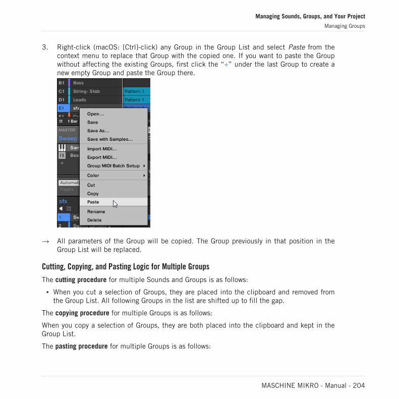
3. Right-click (macOS: [Ctrl]-click) any Group in the Group List and select Paste from thecontext menu to replace that Group with the copied one. If you want to paste the Groupwithout affecting the existing Groups, first click the “+” under the last Group to create anew empty Group and paste the Group there.
→ All parameters of the Group will be copied. The Group previously in that position in theGroup List will be replaced.
Cutting, Copying, and Pasting Logic for Multiple Groups
The cutting procedure for multiple Sounds and Groups is as follows:
▪ When you cut a selection of Groups, they are placed into the clipboard and removed fromthe Group List. All following Groups in the list are shifted up to fill the gap.
The copying procedure for multiple Groups is as follows:
When you copy a selection of Groups, they are both placed into the clipboard and kept in theGroup List.
The pasting procedure for multiple Groups is as follows:
Managing Sounds, Groups, and Your Project
Managing Groups
MASCHINE MIKRO - Manual - 204

▪ When you paste a selection of Groups onto an existing Group, the pasted Groups replacethat Group and the following Groups. Example: If you paste the Groups A1 and B1 onto theGroup E2, the duplicates of A1 and B1 will replace the Groups E2 and F2, respectively (if,say, F2 didn’t exist it is automatically created).
If you want to duplicate a Group more than once, just keep choosing Paste from the context menuon other Groups: the source Group stays in the clipboard, ready for the next use.
When you copy/paste Sounds or Groups in the software, the entire content of the copiedSound(s) or Group(s) is pasted, including their events and Patterns. Notably, pasting a Soundinto a Sound slot of a different Group will create the needed Patterns if they do not exist, andreplace the events for that Sound slot in an existing Patterns.
In the sentence above, “existing Patterns” means the Patterns with the same IDs (i.e. the same po-sition in the Pattern List) as in the source Group. Example: If the source Sound contains events inPattern 1, 2, and 3 of its Group and you paste that Sound into another Group that only has Pattern1 and 4, Pattern 2 and 3 will be automatically created to host the events of the pasted Sound.
You can also duplicate a Group in Ideas view and Song view by clicking the Group slot while holdingthe [Alt] key (or [Ctrl] key on PC), and dragging the mouse. After the mouse is released a duplicatecopy of the Group is created.
Duplicating Groups on Your Controller
On your controller in Control mode, do the following to copy a Group to another:
1. Press DUPLICATE.
2. Press and hold GROUP.
3. If you want to duplicate a Group including its Patterns, turn the Encoder to enable theCopy Patterns option.
4. Press the pad of the Group you want to copy.The pad starts blinking.
Managing Sounds, Groups, and Your Project
Managing Groups
MASCHINE MIKRO - Manual - 205

5. Press the pad of your target Group (this can also be in another Group bank, in this casefirst press the Left/Right Arrow button under the display to select the Group bank). If youwant to paste the Group without affecting the existing Groups, press the dim white padafter the last colored pad to create the new Group and automatically paste the copiedGroup there.
→ All parameters of the Group (all included Sounds, Group effects, Group’s Channel proper-ties) will be copied (including its Patterns in the Arranger if you have enabled the CopyPattern option). The copied Group will replace the Group previously at that position in theGroup List.
You will notice that once you have pasted the Group, the target pad starts blinking itself, indi-cating that it is ready to be pasted again: Therefore, to duplicate a Group more than once,once you have pressed the source pad you just have to press all the desired target pads in arow.
5.3.7 Reordering Groups
You can reorder Groups via drag-and-drop in the Ideas view or Song view of the software. Forconvenience it can be helpful to organize your Groups.
You can select multiple Groups to reorder them all at once! See ↑5.1.3, Selecting Multiple Soundsor Groups for more information.
Reordering Groups is performed like reordering Sounds:
1. Click and hold the Group.
2. While holding the mouse button, drag your mouse horizontally in Ideas view or verticallyin Song view toward the desired location in the Group List.
⇨ As the mouse cursor moves, an insertion line appears at the potential places where youcan drop the Group.
3. When the insertion line appears at the desired location, release the mouse button.
→ The Group takes its new place in the Group List. This new place is also mirrored on thepads of your controller.
Managing Sounds, Groups, and Your Project
Managing Groups
MASCHINE MIKRO - Manual - 206

5.3.8 Deleting Groups
Deleting a Group will remove it from the Group List.
It is not possible to have a Project without any Groups; attempting to delete the last remainingGroup in a Project will simply reset the Group to the default values.
You can select multiple Groups to delete them all at once! See ↑5.1.3, Selecting Multiple Soundsor Groups for more information.
► To delete a Group, select it in the Group List and press [Del] on your computer keyboard.You can also right-click (on macOS: [Ctrl]-click) the Group in the Group List or the Groupname in the top left corner of the Pattern Editor and choose Delete from the contextmenu.
→ The Group is removed. All following Group are shifted up in the Group List to fill the gap.If the last Group bank is empty after the Groups have been shifted, the bank is deleted.
Deleting a Group.
Managing Sounds, Groups, and Your Project
Managing Groups
MASCHINE MIKRO - Manual - 207

Deleting a Group on Your Controller
On your controller in Control mode, do the following to delete a Group:
► To delete a Group, hold SHIFT + ERASE + GROUP and press the pad 9–16 of the Groupyou want to delete. If the Group is in another Group bank, first press the Left/Right Arrowbuttons under the display to select the Group bank.
→ The Group is removed. All following Group are shifted left to fill the gap.
5.4 Exporting MASCHINE Objects and Audio
This section describes how to save single Groups or whole Projects for use in another MA-SCHINE installation, and how to export audio from various sources in your Project.
You can also export your Patterns as audio or MIDI files via drag and drop. This is described in sec-tion ↑11.8.1, Exporting Audio from Patterns and ↑11.8.2, Exporting MIDI from Patterns.
5.4.1 Saving a Group with its Samples
Sometimes it is useful to have the ability to save a Group with its Samples outside of the MA-SCHINE Library. If you want to take a Group to another studio or if you want to backup orshare a custom drum kit with all the related files, this comes in handy.
To save a Group with its Samples:
Managing Sounds, Groups, and Your Project
Exporting MASCHINE Objects and Audio
MASCHINE MIKRO - Manual - 208

1. Right-click (on macOS: [Ctrl]-click) the Group in the Group List left of the Arranger andselect Save with Samples… from the context menu:
You will be presented with the Save Group with Samples panel:
2. In this panel, adjust the settings (see table below) and click Save to confirm or Close tocancel the operation.
Managing Sounds, Groups, and Your Project
Exporting MASCHINE Objects and Audio
MASCHINE MIKRO - Manual - 209

Controls Description
Group Displays the name and location of the Group file to be created.The Samples will be put in a folder with the same name in thesame location. By default, the Group file inherits the name ofthe Group in the Project and it will be saved in the “Groups”subfolder of your Standard User Directory (as defined inPreferences > Library > User, see section ↑3.6.4, Preferences –Default Page for more information). Click the folder icon on theright to choose another name and/or path.
Delete Unused Files Enable this checkbox to delete unused files, thereby minimizingthe amount of audio data to be exported.
This command is also available from the Group menu opened by right-clicking ([Ctrl]-clicking onmacOS)) the Group name above the Sound List, in the top left corner of the Pattern Editor.
You can also save your whole Project with its Samples. See section ↑5.4.2, Saving a Project with itsSamples.
5.4.2 Saving a Project with its Samples
Sometimes it is useful to have the ability to save all Samples used in your Project outside ofthe MASCHINE Library. If you want to take a Project to another studio or if you want to backupa production with all the related files, this comes in handy.
Managing Sounds, Groups, and Your Project
Exporting MASCHINE Objects and Audio
MASCHINE MIKRO - Manual - 210

1. Choose Save Project with Samples… from the File menu or the File submenu in the MA-SCHINE menu:
You will be presented with the Save Project with Samples panel:
2. In this panel, adjust the settings (see table below) and click Save to confirm or Close tocancel the operation.
Managing Sounds, Groups, and Your Project
Exporting MASCHINE Objects and Audio
MASCHINE MIKRO - Manual - 211

Element Description
Project Displays the name and location of the Project file to be created. TheSamples will be put in a folder with the same name in the samelocation. By default, the Project file inherits the name of the Projectand it will be saved in the “Projects” subfolder of your Standard UserDirectory (as defined in Preferences > Library > User, see section↑3.6.4, Preferences – Default Page for more information). Click thefolder icon on the right to select another name and/or path.
Delete Unused Files Enable this checkbox to delete unused files, thereby minimizing theamount of audio data to be exported.
You can also save single Groups with their Samples. See ↑5.4.1, Saving a Group with its Samples.
5.4.3 Exporting Audio
Use the Export Audio panel in the software to export as your complete arrangement as audiofrom the Song view, or render individual Scenes or Sections as audio files in from the Ideasview.
You can also export the audio of particular Patterns via drag and drop. The audio will be exportedaccording to the settings described here, except for the exported region, the particular Sound/Groupexported, and the name of the exported audio file. See section ↑11.8.1, Exporting Audio from Pat-terns for more information.
The Export Audio panel is available from both the Ideas view and Arrangement view. In theIdeas view the Export Audio panel can be used to export individual Scenes, or all Scenes atonce.
In the Song view, the Export Audio panel can be used to export your complete Project arrange-ment or individual Sections of the arrangement depending on the Loop range. The exact lengthof the exported audio file depends on the Loop Optimize setting in the Option section (see de-scription below).
The Export Audio panel also contains options that allow you to select the source you want toexport such as the Master, Groups, or Sounds.
Managing Sounds, Groups, and Your Project
Exporting MASCHINE Objects and Audio
MASCHINE MIKRO - Manual - 212

To export audio from MASCHINE:
1. Set the Loop Range to the region that you want to export.
2. Choose Export Audio… from the File menu or from the File submenu in the MASCHINEmenu.
You will be presented with the Export Scenes as Audio panel (see picture below).
3. Select the Range and Source and then the destination (see description below).
4. If you wish, adjust the export options in the Options section (see description below).
5. At the bottom of the panel, click Export to start the export process, or Close to cancel theoperation and close the panel without exporting anything.
Export Scenes/Arrangement as Audio Panel
The Export Audio panel allows you to select the source and destination as well as make varioussettings for the audio you want to export from the Ideas view or Arrangement view.
Managing Sounds, Groups, and Your Project
Exporting MASCHINE Objects and Audio
MASCHINE MIKRO - Manual - 213

The Export Scenes as Audio panel.
The following parameters are available in the Export Audio panel, which is split into three dis-tinct sections: Source, Options, and Destination.
Source Section
The Source section allows you to define exactly what will be exported.
Managing Sounds, Groups, and Your Project
Exporting MASCHINE Objects and Audio
MASCHINE MIKRO - Manual - 214

Element Description
Range Set the range for the audio you want to export. The options here willdiffer depending on whether MASCHINE is in Ideas view or Song view.
In Ideas view the following options are available:
All: Select this option to export all Scenes as audio.
Selected: Select this option to export the selected Scene as audio.
In Song view the following options are available:
All: Select this option to export all Sections in the arrangement asaudio.
Loop: Select this option to export the selected Section of thearrangement as audio.
Source Select what you want to export. The content of the Output list under themenu depends on your selection in the menu:
Master Output: Select this to export the Master output signal (includingall Groups and Sounds and their effects) to one audio file. The Outputlist underneath contains only one entry: Master Output. This entry ischecked and grayed out (you cannot uncheck it).
Group Outputs: Select this to export the output signals of specificGroups to individual audio files. The Output list underneath shows allGroups available for exporting. Empty Groups (i.e. Groups containingonly empty Sound slots) are not listed. Click the check boxes of thedesired entries in the list to include/exclude the corresponding Groups.Only Groups with a check mark will be exported.
Sound Outputs: Select this to export the output signals of specificSounds to individual audio files. When this entry is selected, theOutput list underneath shows all Sounds available for exporting. EmptySound slots are not listed. The entries are organized as a tree withGroups at the root and Sounds within each Group. By default all Groupsare collapsed and all Groups and Sounds are checked. Click the littlearrow left of a Group to show/hide its Sounds. Click the check boxes ofthe desired entries in the list to include/exclude the corresponding
Managing Sounds, Groups, and Your Project
Exporting MASCHINE Objects and Audio
MASCHINE MIKRO - Manual - 215

Element Description
Sounds. Only Sounds with a check mark will be exported. The checkbox of Group entries allow to check/uncheck all Sounds of the Group atonce. If some of the Sounds only are checked in a Group, the Group is“dimmed checked.”
Options Section
The Options section allows you to make settings related to the quality of the audio export.
Element Description
Options
Normalize Check this option to normalize your audio as it is exported, i.e. theexported audio will be brought to the highest possible level withoutclipping (0 dBFS).
Loop Optimize Optimize the audio file for use as a loop:
Check Loop Optimize to keep the exact Loop Range when exportingaudio. Any effect tail will be rendered into the beginning of the audiofile. Additionally, the file metadata will include the tempo (in BPM) andlength (in bars).
Uncheck Loop Optimize to prolong the audio file when exporting audio,for example, to keep the tail of a reverb. The end of the exported audiowill always correspond to a bar division.
Split By Section Check this option to export audio within the loop braces. If the loopspans multiple Sections, individual audio files for each Section withinthe selected area will be created. Please note, if you only select oneSection and export, you will not gain any advantage by using thisfeature.
Type Select the required audio format : uncompressed WAV or AIFF. Theaudio format type selected here also affects audio exported using theAudio Dragger icon available in the Pattern Editor.
Managing Sounds, Groups, and Your Project
Exporting MASCHINE Objects and Audio
MASCHINE MIKRO - Manual - 216
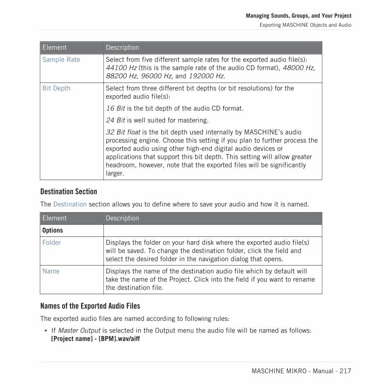
Element Description
Sample Rate Select from five different sample rates for the exported audio file(s):44100 Hz (this is the sample rate of the audio CD format), 48000 Hz,88200 Hz, 96000 Hz, and 192000 Hz.
Bit Depth Select from three different bit depths (or bit resolutions) for theexported audio file(s):
16 Bit is the bit depth of the audio CD format.
24 Bit is well suited for mastering.
32 Bit float is the bit depth used internally by MASCHINE’s audioprocessing engine. Choose this setting if you plan to further process theexported audio using other high-end digital audio devices orapplications that support this bit depth. This setting will allow greaterheadroom, however, note that the exported files will be significantlylarger.
Destination Section
The Destination section allows you to define where to save your audio and how it is named.
Element Description
Options
Folder Displays the folder on your hard disk where the exported audio file(s)will be saved. To change the destination folder, click the field andselect the desired folder in the navigation dialog that opens.
Name Displays the name of the destination audio file which by default willtake the name of the Project. Click into the field if you want to renamethe destination file.
Names of the Exported Audio Files
The exported audio files are named according to following rules:
▪ If Master Output is selected in the Output menu the audio file will be named as follows:[Project name] - [BPM].wav/aiff
Managing Sounds, Groups, and Your Project
Exporting MASCHINE Objects and Audio
MASCHINE MIKRO - Manual - 217

▪ If Group Outputs is selected in the Output menu the audio files will be named as follows:[Project name] - [Group order number] [Group index (letter + number)] [Group name] -[BPM].wav/aiffThe Group order number is a two-digit number indicating the “order of appearance” of theGroup in the Group List. This ensures that an alphabetical listing of the exported files willreflect the structure of your Project.
▪ If Sound Outputs is selected in the Output menu the audio files will be named as follows:[Project name] - [Sound name] - [BPM].wav/aiff
In addition, if the name of the file about to be exported is already used in the destination folder, ahyphen followed by an index number is added to the name (e.g., “ - 1,” “ - 2,” “ - 3,”) to avoid anyfile being overwritten.
5.5 Importing Third-Party File Formats
5.5.1 Loading REX Files into Sound Slots
MASCHINE supports REX (ReCycle) files to be loaded. REX files are loops that are alreadysliced and mapped to MIDI notes.
Only REX2 files are currently supported.
▪ The Samples are loaded into the Sound slot. A new Pattern is created in that Group anddirectly loaded in the Pattern Editor (switch the Pattern Editor to Keyboard view to bettersee the Pattern — see section ↑11.1.5, Group View and Keyboard View). This Pattern con-tains the sequence data of the REX file. For each REX file you import a Pattern will be cre-ated and added.
Managing Sounds, Groups, and Your Project
Importing Third-Party File Formats
MASCHINE MIKRO - Manual - 218
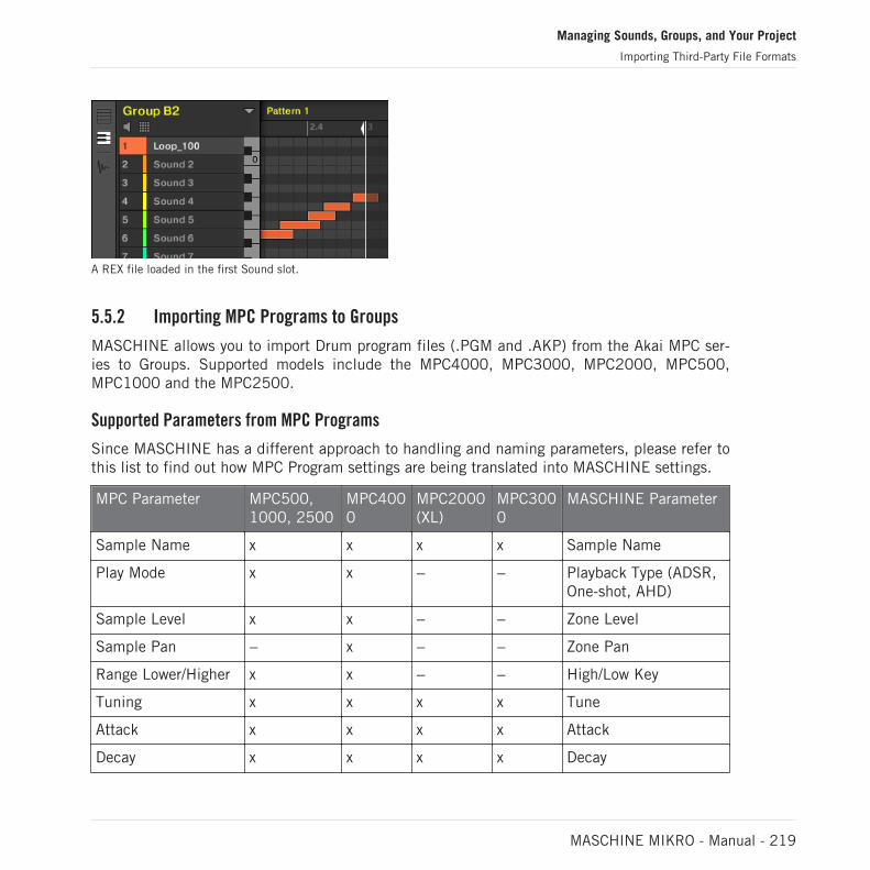
A REX file loaded in the first Sound slot.
5.5.2 Importing MPC Programs to Groups
MASCHINE allows you to import Drum program files (.PGM and .AKP) from the Akai MPC ser-ies to Groups. Supported models include the MPC4000, MPC3000, MPC2000, MPC500,MPC1000 and the MPC2500.
Supported Parameters from MPC Programs
Since MASCHINE has a different approach to handling and naming parameters, please refer tothis list to find out how MPC Program settings are being translated into MASCHINE settings.
MPC Parameter MPC500,1000, 2500
MPC4000
MPC2000(XL)
MPC3000
MASCHINE Parameter
Sample Name x x x x Sample Name
Play Mode x x − − Playback Type (ADSR,One-shot, AHD)
Sample Level x x − − Zone Level
Sample Pan − x − − Zone Pan
Range Lower/Higher x x − − High/Low Key
Tuning x x x x Tune
Attack x x x x Attack
Decay x x x x Decay
Managing Sounds, Groups, and Your Project
Importing Third-Party File Formats
MASCHINE MIKRO - Manual - 219

MPC Parameter MPC500,1000, 2500
MPC4000
MPC2000(XL)
MPC3000
MASCHINE Parameter
Voice Overlap x − x x Polyphony
Filter1 Type x − − − Filter Type
Filter1 Frequency x − x x Filter Cutoff
Filter1 Resonance x − x x Filter Resonance
Filter1 Velocity toFrequency
x − − − Velocity Cutoff
Mixer Level x x x x Track Level
Mixer Pan x − x x Track Pan
Velocity to Level x − − − Velocity to Volume
Mute Group x − − − Choke Group
Importing MPC Program Files
1. To import an MPC Program file, open the Browser in the MASCHINE software and clickthe FILES tab.
Managing Sounds, Groups, and Your Project
Importing Third-Party File Formats
MASCHINE MIKRO - Manual - 220
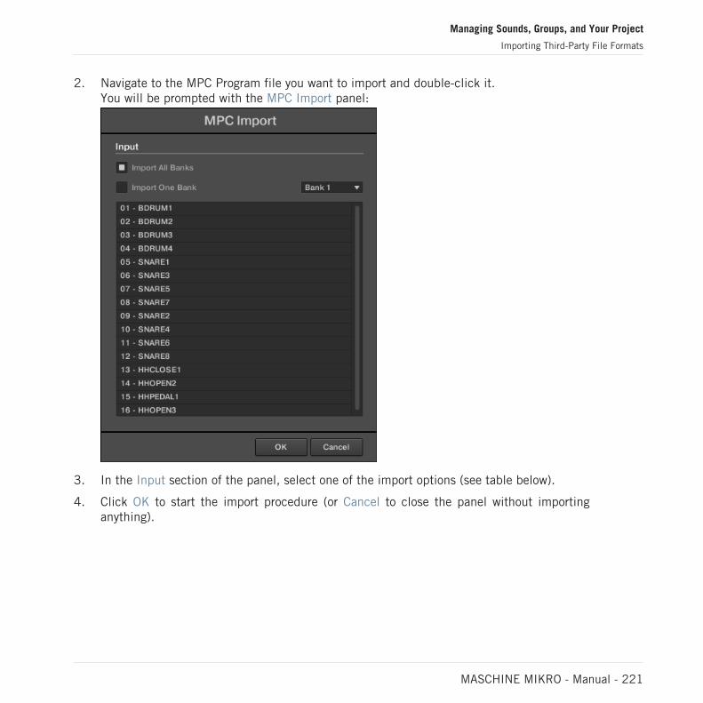
2. Navigate to the MPC Program file you want to import and double-click it.You will be prompted with the MPC Import panel:
3. In the Input section of the panel, select one of the import options (see table below).
4. Click OK to start the import procedure (or Cancel to close the panel without importinganything).
Managing Sounds, Groups, and Your Project
Importing Third-Party File Formats
MASCHINE MIKRO - Manual - 221

Control Description
Import All Banks Select this to import all Banks of the MPC Program file. EachBank will be loaded into a separate Group.
Import One Bank Select this if you only want to import a single Bank. Use thedrop-down menu to the right to select which Bank you want toimport. The list below shows you a preview of the sounds in theselected MPC Bank.
Managing Sounds, Groups, and Your Project
Importing Third-Party File Formats
MASCHINE MIKRO - Manual - 222

6 Playing on the Controller
This chapter describes the numerous features available in MASCHINE to adjust and enhanceyour playing, both during live performances and when recording Patterns.
6.1 Adjusting the Pads
You can optimize and fine-tune the way the pads of your controller react to your playing:
▪ Choose a pad mode that best fit your playing needs: ↑6.1.1, The Pad View in the Software.
▪ Adjust the base key to set the pitch of the notes played by your pads: Adjusting the BaseKey.
▪ Set Choke groups to selectively cancel Sounds when other Sounds are triggered: UsingChoke Groups.
▪ Create Link groups to trigger several Sounds by pressing only one pad: Using Link Groups.
Most of the settings for your pads are available both in the software via the Pad view (see↑6.1.1, The Pad View in the Software), and on your controller via the Pad Mode (see section↑6.1.2, Choosing a Pad Input Mode).
6.1.1 The Pad View in the Software
In the software the settings for your pads are available in the Pad view, which is enabled viathe Pad View button above the Sound List in the Pattern Editor:
The Pad View button.
► Click the Pad View button to show or hide the Pad view.
When the Pad View button is enabled, the Pad view replaces the Sound List below:
Playing on the Controller
Adjusting the Pads
MASCHINE MIKRO - Manual - 223

The Pad view replaces the Sound List.
At the top of the Pad view, the grid of pads gives you access to all Sound slots of the currentGroup. The focused pad is fully lit; other pads containing a Sound are dim lit; pads withoutany Sound are off. The following actions are available in the grid:
▪ Click any pad to select the corresponding Sound slot. Upon selection, the parameters un-derneath, as well as the Control area above are updated accordingly.
▪ Drag and drop a pad to move it to another location in the grid. This is strictly equivalent tomoving Sound slots in the Sound List (see section ↑5.2.7, Moving Sounds).
▪ Right-click ([Ctrl]-click on macOS) any pad to open the same context menu as in theSound List — the management commands available in this menu are described in section↑5.2, Managing Sounds.
You can select multiple pads in the grid of pads as you can in the Sound List, and adjust parame-ters in the Pad view and in the Control area for all of them simultaneously. For more information onmultiple selection, see section ↑5.1.3, Selecting Multiple Sounds or Groups.
Under the grid of pads, you find following parameters:
Playing on the Controller
Adjusting the Pads
MASCHINE MIKRO - Manual - 224

Parameter Description
Key Adjusts the base key for the selected pad. See section Adjusting theBase Key below.
Choke Configures the Choke Group for the selected pad. See section UsingChoke Groups below.
Link Configures Pad Link for the selected pad. See section Using LinkGroups below.
6.1.2 Choosing a Pad Input Mode
By default, your pads play all Sounds of the selected Group — we call this Pad Mode. Further-more they are velocity sensitive, meaning they will play louder if you hit them harder. You canchange this behavior and choose another pad mode in order to adapt your pads to various sit-uations.
Using Pad Mode
The PAD MODE button located above the pads allows you to switch the controller to Padmode. This will map the Sounds contained in your Group to the pads.
► To enter Pad mode, press PAD MODE.
→ The display now shows the name of the selected Sound.
Using the 16 Velocities and Fixed Velocity Options
When using the controller in Pad mode, you can apply either of two additional options whichsupport your playing in specific situations.
▪ The Fixed Velocity option is available when your pads are in Pad mode (default mode) orKeyboard mode. With this option enabled, your pads play at the same volume no matterhow hard you hit the pads. To enable the Fixed Velocity option, press FIXED VEL. Pressagain to disable.
▪ In 16 Velocities mode your pads all play the same note of the focused Sound but with six-teen different velocity values. This can be useful to play or program complex drum fills.The right display indicates the velocity values for each pad (all are shown in the color of
Playing on the Controller
Adjusting the Pads
MASCHINE MIKRO - Manual - 225

the focused Sound). The pitch of the played note is defined by the base key (see sectionAdjusting the Base Key). To enable 16 Velocities mode, press SHIFT + FIXED VEL. Pressagain to disable. The 16 Velocities mode is not available in Keyboard mode.
Using Keyboard Mode
The KEYBOARD button located above the pads activates and deactivates Keyboard mode. Inthis mode your pads play the focused Sound at sixteen different pitches. This is well suited formelodic instruments. The right display indicates the pitches played by each pad (all are shownin the color of the focused Sound).
To activate Keyboard Mode:
1. Select a Sound by pressing the pad it is assigned to.
2. Enter Keyboard Mode by pressing KEYBOARD.
→ If you hit the pads now, they all play the same Sound, but each with a different pitch.
The pitch mapped to each pad is aligned to the scale defined by the Scale Type parameter.See ↑6.4.2, Selecting a Scale and Creating Chords for more information on scales.
6.1.3 Adjusting the Base Key
In Pad mode, the base key defines the key (or pitch) at which the selected Sound will beplayed when its pad is pressed. In Keyboard mode, it defines the key played by pad 1 on yourcontroller; pads 2–16 will then play keys from [base key + 1 semitone] up to [base key + 15semitones].
The base key also affects the pitch of events created via the step sequencer. See section ↑11.3.1,Step Mode Basics for more information on this.
Adjusting the base key only affects the notes played by the pads of your controller. It does not af-fect the notes recorded in your Patterns. To adjust the key of notes in Patterns, please refer to sec-tion ↑5.1.3, Selecting Multiple Sounds or Groups.
You can select multiple pads and quickly change the base key for all of them at once! See section↑11.4, Editing Events to know how to do this.
Playing on the Controller
Adjusting the Pads
MASCHINE MIKRO - Manual - 226

Adjusting the Base Key in the Software
By default the base key of every Sound slot is C3 (i.e. middle C in the MASCHINE convention).To change the base key of the selected pad(s) / Sound slot(s) in the software:
1. Click the Pad View button above the Sound List in the Pattern Editor to show the Padview for the focused Group.
2. Click the Key value and drag your mouse vertically, or double-click it, enter a new valueon your computer keyboard, and press [Enter] to confirm.
To change the base key of the selected Sound on your controller:
1. Press PAD MODE to enter Pad Mode.
2. To adjust the base key in semitones, turn the Encoder.
3. To adjust the base key in octaves, press SHIFT and turn the Encoder.
→ The new base key is indicated in the display.
6.2 Adjusting the Key, Choke, and Link Parameters for Multiple Sounds
In the software, if you select multiple Sounds with different Key, Choke and/or Link values, thecorresponding parameters in Pad view now display MULTI. On your controller in Pad Mode, thecorresponding parameters now display (MULTI).
Moreover, you can adjust these parameters for the selected Sounds as described below.
Adjusting the Key Parameter for Multiple Sounds with different Key Values
► Click and drag the MULTI label next to Key to transpose the base key of all selectedSounds. While dragging, the field displays a +/-x value indicating the transposition thatwill apply to all Sounds as you release the mouse button.
Playing on the Controller
Adjusting the Key, Choke, and Link Parameters for Multiple Sounds
MASCHINE MIKRO - Manual - 227

Sound slots 1 to 4 are selected. If they have different Key values, a MULTI label appears (left). When you drag it (middle), atranspose value appears (right) that will be applied to all selected Sounds when you will release the mouse button.
This is also true when adjusting the parameter from your controller.
Adjusting the Choke or Link Parameter for Multiple Sounds with different Choke or Link Values
► Click the MULTI label next to Choke or Link and select the desired value from the list toset all selected Sounds to that same Choke or Link group, respectively. This also appliesto the Master/Slave setting next to it.
Sound slots 1 to 4 are selected. If they have different Choke values, a MULTI label appears (left). When you click it andselect a new Choke or Link group from the list (middle), this new group is applied to all selected Sounds.
Playing on the Controller
Adjusting the Key, Choke, and Link Parameters for Multiple Sounds
MASCHINE MIKRO - Manual - 228

6.3 Playing Tools
On top of the various pad settings described in the previous section (see ↑6.1, Adjusting thePads), MASCHINE also offers you a series of intuitive playing tools particularly useful whenplaying live:
▪ Mute and Solo allow you to selectively mute and solo Sounds and Groups: ↑6.3.1, Muteand Solo.
▪ Choke All Notes allow you to cut all playing audio: ↑6.3.2, Choke All Notes.
▪ Groove allows you to give a shuffling flair to individual Sounds/Groups or to your entireProject: ↑6.3.3, Groove.
▪ Hardware Shortcuts give you a quick access to the most important parameters of each chan-nel (Sound, Group, and Master): ↑6.3.4, Level, Tempo, Tune, and Groove Shortcuts onYour Controller.
6.3.1 Mute and Solo
Muting is used to silence a Sound or a Group, whereas Solo is pretty much the opposite: Solo-ing a Sound or a Group mutes all other Sounds in that Group or all other Groups, respectively,so that you can listen to the selected Sound or Group alone. The combination of both is a use-ful means to play live and to test different sequences together.
When used on Sounds, the Solo only applies to the current Group: The Sounds in other Groupswon’t be affected.
We describe here how to mute/solo Groups and Sounds in the Arrange view of the software, but youcan also do this from Mix view via the Mute button available in each channel strip of the Mixer! Seesection ↑13.2.5, Adjusting Settings in the Channel Strips for more information.
Audio Mute vs. Event Mute
At the Group level, the Mute function is an audio mute: The whole audio output of the mutedGroup will be bypassed. At the Sound level, the Mute function is by default a trigger mute: thePattern content (the events) for the muted Sound will not be triggered — but any audio re-maining from past events for this Sound will still be audible until it fades away. You can
Playing on the Controller
Playing Tools
MASCHINE MIKRO - Manual - 229

change this behavior by enabling the Audio Mute button in the Audio page of the Sound’s Out-put properties (see section ↑12.1.2, Configuring the Main Output of Sounds and Groups) aswell as in Solo and Mute mode on your controller: Activating the audio mute for Sounds willensure that not only the events are muted, but any remaining audio as well.
To momentarily mute all audio from all Sounds and Groups at once, please refer to section ↑6.3.2,Choke All Notes.
Mute and Solo in the Software
Soloing a Sound
1. To solo a Sound, right-click (on macOS: [Ctrl]-click) the number on the left side of theSound slot in the Pattern Editor.
Soloing the first kick Sound.
2. To unsolo a Sound, right-click (on macOS: [Ctrl]-click) the number again.
Soloing a Group
1. To solo a Group, right-click (on macOS: [Ctrl]-click) the Group index (letter + number) onthe left side of the Group in the Arranger:
Playing on the Controller
Playing Tools
MASCHINE MIKRO - Manual - 230

Soloing a Group.
2. To unsolo a Group, right-click (on macOS: [Ctrl]-click) the Group index again.
Muting a Sound
1. To mute a Sound, click the number on the left side of the Sound slot in the Pattern Edi-tor.
Muting a Sound.
2. To unmute the Sound, click the number again.
By default, the Mute on Sounds is an event mute: events for muted Sounds are not triggered, butthe audio coming from previous events might still be audible (reverb tail, etc.). You can also acti-vate audio mute for Sounds to mute both events and audio — see the beginning of this section formore information.
Playing on the Controller
Playing Tools
MASCHINE MIKRO - Manual - 231

Muting a Group
1. To mute a Group, click the Group index (letter + number) on the left side of the Group inthe Arranger:
Muting a Group.
2. To unmute the Group, click the Group index again.
Soloing Sounds and Groups on the Controller
1. Press SOLO to enter Solo mode.
2. To solo a Sound, press the related pad.
3. To solo a Group, press GROUP followed by the related pads 9–16.
Muting Sounds and Groups
1. Press MUTE to enter Mute mode.
2. To mute a Sound, press the related pad.
3. To mute a Group, press GROUP followed by the desired pads 9–16.
In both Solo and Mute modes you will note that on your controller the unmuted pads andGroup buttons are fully lit while the muted ones are dim lit (and the empty ones are off).
Since soloing a Sound mutes all Sounds except one, the MUTE button can then be used to “re-lease” Sounds that have been muted. You can use this technique to create a breakdown: Solo a giv-en Sound such as a kick drum, then build the track up again by bringing the muted Sounds back inone at a time while holding the MUTE button.
Playing on the Controller
Playing Tools
MASCHINE MIKRO - Manual - 232

6.3.2 Choke All Notes
The Choke All Notes feature allows you to kill any note or event currently playing in yourProject. This affects the audio coming from all Plug-ins (Internal, Native Instruments, and Ex-ternal).
Choke All Notes is only available on your controller:
► Press SHIFT + MUTE to choke all playing notes.
Choke All Notes can be useful in various situations:
▪ as a creative tool in a live performance, e.g., to create stutter beaks
▪ as a workflow aid, to stop long one-shot Samples that continue playing after you have stop-ped the sequencer
▪ as a first panic button, if you are not sure where in your Project a particular sound is com-ing from, and you want to get rid of it.
Contrary to the Mute function, Choke All Notes is not turning any Group/Sound into another state.Instead, all audio voices currently playing are instantaneously killed. The killed voices cannot be re-activated and are freed up for subsequent notes according to the polyphony setting. Voices triggeredby subsequent notes will play normally.
6.3.3 Groove
The groove controls the rhythmic relationship between events in the selected channel (Sound,Group or Master). By shifting some of the events, you can e.g. give a shuffling, ternary touch toyour Patterns.
The groove can be adjusted for each channel individually via its Groove properties.
A groove configured for a channel affects all its contained channels:
▪ At the Sound level, the Groove properties settings of a Sound affect that single Sound.
▪ At the Group level, the Groove properties settings of a Group affect all Sounds of theGroup. The Group’s swing is added to the groove set for each individual Sound via its ownGroove properties.
Playing on the Controller
Playing Tools
MASCHINE MIKRO - Manual - 233

▪ At the Master level, the Groove properties affect all Sounds of all Groups. The Master’sswing is added to the groove set for each individual Group and Sound via their own Grooveproperties.
The Groove properties have a single Parameter page: Swing.
Please refer to section ↑3.3.5, Navigating Channel Properties, Plug-ins, and Parameter Pages in theControl Area to know how to display and navigate sets of Channel properties.
The Groove properties for a Sound in the software.
Controls Description
SWING Section
Amount Adjusts the amount of swing, i.e. the amount by which someevents are shifted. At 0 % events are not shifted. Raise theAmount value to increase the strength of the swing.
Cycle Determines on what musical resolution the groove is applied.This directly affects which events will be shifted. Values aremeasured in fractions of a whole note.
Invert Allows you to invert the groove so that instead of being delayedin the Pattern events will be triggered ahead of time.
How Groove Affects the Rhythm: An Example
Take a simple, regular one-bar rhythm with a hit on each eighth note. We set the Cycle param-eter to 1/2, which is one half note, that is two beats.
The following picture shows you how this rhythm would sound with the following settings:
▪ Top: Amount at 0.0 % (no groove).
Playing on the Controller
Playing Tools
MASCHINE MIKRO - Manual - 234

▪ Middle: Amount at 100.0 % and Invert off.
▪ Bottom: Amount at 100.0 % and Invert enabled.
This is how the same regular rhythm would be heard with various groove settings.
The picture above only illustrates how the groove function affects the sound — adjusting the Grooveproperties will not effectively move events in the Patterns displayed in the Pattern Editor!
6.3.4 Level, Tempo, Tune, and Groove Shortcuts on Your Controller
Your controller provides extra shortcuts for various important parameters. Most of these param-eters are already available in the Channel properties of the Sounds, Groups, and Master. Theshortcuts detailed here give you an additional quick access to them — especially useful duringlive performance.
6.3.5 Tap Tempo
You can quickly define the tempo of your Project via the TAP button in the Transport section ofthe controller:
► Repeatedly tap the TAP button to set the desired tempo.
You can also use the TEMPO button to adjust the current tempo:
Playing on the Controller
Playing Tools
MASCHINE MIKRO - Manual - 235

► Press the TEMPO button and turn the Encoder to quickly adjust the tempo of yourProject.
Press and turn the Encoder (or hold SHIFT while you turn it) to adjust the value in finer incrementswhen the TEMPO button is enabled.
These shortcuts control the Tempo parameter of MASCHINE. In the software this parameter isavailable in the Header:
The Tempo parameter in the software’s Header.
6.4 Performance Features
The Performance features of MASCHINE are inspired by similar features available in KOM-PLETE KONTROL and on the KOMPLETE KONTROL S-SERIES keyboards. This tight integra-tion offers a familiar and seamless workflow.
6.4.1 Overview of the Perform Features
The Perform features include the following engines:
▪ The Scale and Chords engine allows you to assign the pads to notes within specific scales,and to play chords according to the selected scale by hitting single pads.
▪ The Arp engine allows you to create arpeggios based on the pads you press or the chord cur-rently triggered.
Designed to enrich the melodic content of your Projects, these engines are available when yourpads are in Keyboard mode. Furthermore, they are designed to be used live and, as such, theyare available only from your hardware controller (like Note Repeat).
When your pads are in Pad Mode, you can use the Note Repeat engine, Choke groups, andLink groups as in previous MASCHINE versions.
Playing on the Controller
Performance Features
MASCHINE MIKRO - Manual - 236

The Control Signal Flow—Pads in Keyboard Mode
The following diagram illustrates MASCHINE s signal flow between your hits on the pads inKeyboard mode and the resulting sounds:
The signal flow including the new Perform features (Scale, Chord, and Arp) when your pads are in Keyboard mode.
In this picture, blue cells represent modules sending “control” signals, i.e. triggering messages(e.g., the note messages sent by the pads as you press them), whereas red cells representmodules sending audio signals (e.g., the sounds produced by the Instrument loaded in theSound slot as it receives the aforementioned note messages).
In this diagram you will notice the following:
▪ The Scale and Chord modules can feed the Arp module, the Scale module can also affectthe Chord module, as we will see later.
▪ The notes played on your pads are first sent to the Perform features (Scale, Chord, and Arpengines), which send the resulting notes to the Pattern Editor. In other terms, you can re-cord the generated scales, chords or arpeggiated notes into your Patterns. However, thePerform features do not process the content of your Patterns.
Playing on the Controller
Performance Features
MASCHINE MIKRO - Manual - 237

The Control Signal Flow—Pads in Pad Mode
The following diagram illustrates signal flow between your hits on the pads in Pad Mode andthe resulting sounds:
The signal flow including the Perform features (Note Repeat, Choke Group, and Link Group) when your pads are in PadMode.
In this picture you will notice the following:
▪ Note Repeat takes the place of the Scale, Chord, and Arp modules between the live inputon the pads and the Pattern Editor. In other terms, Note Repeat won’t process your Pat-terns but you can record its output into a Pattern.
▪ The Choke Group and Link Group modules affect both your hits on the pads and the con-tent of your Patterns, but their result cannot be recorded into Patterns.
Playing on the Controller
Performance Features
MASCHINE MIKRO - Manual - 238

6.4.2 Selecting a Scale and Creating Chords
MASCHINE comes equipped with a vast amount of scales and chords that you can select anduse to play your Sounds. This opens up possibilities to play an instrument such as a piano ac-cording to, e.g., the minor pentatonic scale without hitting a “false” pad (note) on your control-ler, or to play chords that always fit by hitting single pads.
The Scale and Chord engine is available only when your pads are in Keyboard mode.
This section provides a hands-on introduction to the use of scales and chords from your con-troller. The corresponding parameters will be described in detail in section ↑6.4.3, Scale andChord Parameters.
Selecting a Scale
Let’s choose a particular scale, say, minor pentatonic. On your controller, do the following:
1. Switch the focus to a Sound slot containing a polyphonic instrument, or load one into thedesired Sound slot.
2. Press KEYBOARD to enter Keyboard Mode.
3. Press the Right Arrow button to access the Bank parameter.
4. Turn the Encoder to select a Bank.
5. Press the Right Arrow button to access the Type parameter.
6. Turn the Encoder to select a scale type.
→ Hit a few pads: They trigger only notes from the selected scale. The pads corresponding tothe root note (C3 by default) and its octaves are fully lit.
Now let’s start the scale on D3 instead of C3:
1. Press the Left Arrow button twice to select the RootNote parameter.
2. Turn the Encoder clockwise to set a new root note.
Playing on the Controller
Performance Features
MASCHINE MIKRO - Manual - 239

→ Hit a few pads: They trigger the notes from the scale based on the new selected root note.Furthermore all your pads were shifted in semitones so that pad 1 still triggers the rootnote of the selected scale.
Creating Chords
Now we want the pads to trigger chords instead of single notes. First we want chords based onthe selected scale:
1. Press CHORDS to enter Chord mode.
2. Press the Right Arrow button to access the Mode parameter.
3. Turn the Encoder to select Harmonizer.
4. Press the Right Arrow button to access the Type parameter.
5. Turn the Encoder to select a chord type.
→ Hit a few pads: Each pad triggers a chord. No matter which pad you hit, all chords usenotes within the selected scale.
Finally, let’s try the other chord mode available:
1. Press the Left Arrow button to select the MODE parameter.
2. Turn the Encoder to select Chord Set.
→ The light from the pads on the top row of your controller go off and the pads are disabled.The other 12 pads trigger various chords. You can switch to another set of 12 chords byselecting the Type parameter again and turning the Encoder. These chords are not boundto the scale anymore, however they are still based on the selected root note.
The last selected Scale is automatically assigned when a new Group is created.
6.4.3 Scale and Chord Parameters
This section describes the Scale and Chord engine and its parameters, and provides a list of allscales and chords available on your controller.
Playing on the Controller
Performance Features
MASCHINE MIKRO - Manual - 240

General Notes on Scales and Chords
▪ The Scale and Chord parameters are the same for all Sound slots in a particular Group, youcan have different Scale and Chord parameters for each Group. The Scale and Chord pa-rameters of each Group are saved with the Project. However, when you save a Group theScale and Chord parameters are not saved with the Group.
▪ The Scale and Chord engine processes live input from the pads of your controller only. In-put from third-party MIDI controllers and data recorded in the Pattern Editor are not proc-essed by the Scale and Chord engine.
KOMPLETE KONTROL S-SERIES owners: Input from your KOMPLETE KONTROL S-SERIES key-board can also be processed by the Scale and Chord engine. This is described in section Using thePerform Features.
▪ The output of the Scale and Chord engine is recorded into the Pattern Editor.
▪ The Scale and Chord parameters cannot be modulated nor automated in MASCHINE.
▪ Of course, if a Sound slot contains a KOMPLETE instrument providing control notes (e.g.,key switches) on particular keys, these notes will not be triggered by the Scale and Chordengine.
Available Scales
The Scale engine is controlled via two parameters:
▪ Root Note (C3 by default): Defines both the root note of the scale and the particular keytriggered by pad 1. As a direct consequence, pad 1 always triggers the root note of the se-lected scale.
The Root Note parameter replaces the Base Key parameter found in the Keyboard mode of previousMASCHINE versions and still available in Pad Mode. Although the Root Note is edited in the sameway as the Base Key on your controller, keep in mind that both are independent of each other. Com-pared to the Base Key, the Root Note additionally defines the starting note of the selected scale.Furthermore, like all Scale and Chord parameters, the Root Note is common to all Sound slots inthe Group, whereas the Base Key is set for each Sound slot independently.
Playing on the Controller
Performance Features
MASCHINE MIKRO - Manual - 241

▪ Scale Type (Chromatic by default): Selects the scale pattern whose notes will be mappedonto the pads of your controller: The Root Note is on pad 1, the 2nd note of the selectedScale Type is on pad 2, etc. Once all notes are mapped, the next pad triggers the root notein the next octave. The Root Note and its octaves are indicated by fully lit pads, while otherpads are dimmed.
Following scale types are available:
Main Scales
Scale Bank Type Degree Formula
Chromatic Main Chrom 1 ♭2 2 ♭3 3 4 ♭5 5 ♭6 6 ♭7 7
Major Main Major 1 2 3 4 5 6 7
Minor Main Minor 1 2 ♭3 4 5 ♭6 ♭7
Harm Min Main Harm Min 1 2 ♭3 4 5 ♭6 7
Maj Pent Main Maj Pent 1 2 3 5 6
Min Pent Main Min Pent 1 ♭3 4 5 ♭7
Blues Main Blues 1 ♭3 4 ♯4 5 ♭7
Japanese Main Japanese 1 2 ♭3 5 ♭6
Freygish Main Freygish 1 ♭2 3 4 5 ♭6 ♭7
Gypsy Main Gypsy 1 2 ♭3 ♯4 5 ♭6 7
Arabic Main Arabic 1 ♭2 3 4 5 ♭6 7
Altered Main Altered 1 ♭2 ♯2 3 ♯4 ♭6 ♭7
Whole Tone Main WH Tone 1 2 3 ♯4 ♯5 ♭7
H-W Dim Main H-W Dim 1 ♭2 ♯2 3 ♯4 5 6 ♭7
W-H Dim Main W-H Dim 1 2 ♭3 4 ♯4 ♯5 6 7
Playing on the Controller
Performance Features
MASCHINE MIKRO - Manual - 242

Modes Scales:
Scale Bank Type Degree Formula
Ionian Modes Ionian 1 2 3 4 5 6 7
Dorian Modes Dorian 1 2 ♭3 4 5 6 ♭7
Phrygian Modes Phrygian 1 ♭2 ♭3 4 5 ♭6 ♭7
Lydian Modes Lydian 1 2 3 ♯4 5 6 7
Mixolydian Modes Mixolyd 1 2 3 4 5 6 ♭7
Aeolian Modes Aeolian 1 2 ♭3 4 5 ♭6 ♭7
Locrian Modes Locrian 1 ♭2 ♭3 4 ♭5 ♭6 ♭7
Ionian b2 Modes Ion b2 1 ♭2 3 4 5 6 7
Dorian b5 Modes Dor b5 1 2 ♭3 4 ♭5 6 ♭7
Harm Phryg Modes Har Phry 1 ♭2 ♭3 4 5 ♭6 7
Phryg Major Modes Phry Maj 1 ♭2 ♭3 4 5 6 7
Lydian b3 Modes Lyd b3 1 2 ♭3 ♯4 5 6 7
Major Locrian Modes Maj Loc 1 2 3 4 ♭5 ♭6 ♭7
Minor Locrian Modes Min Loc 1 2 ♭3 4 ♭5 ♭6 ♭7
Super Locrian Modes Sup Loc 1 ♭2 ♭3 ♭4 ♭5 ♭6 ♭7
Playing on the Controller
Performance Features
MASCHINE MIKRO - Manual - 243

Jazz Scales
Scale Bank Type Degree Formula
Lydian ♭7 Jazz Lyd ♭7 1 2 3 ♯4 5 6 ♭7
Altered Jazz Altered 1 ♭2 ♯2 3 ♯4 ♭6 ♭7
Diminished Jazz Diminshd 1 ♭2 ♯2 3 ♯4 5 6 ♭7
Mixo b13 Jazz Mix b13 1 2 3 4 5 ♭6 ♭7
Mixo b9 b13 Jazz Mixb9b13 1 ♭2 3 4 5 ♭6 ♭7
Lydian ♭7 b2 Jazz Lyd ♭7b2 1 ♭2 3 ♯4 5 6 ♭7
Bebop Jazz Bebop 1 2 3 4 5 6 ♭7 7
Whole Tone Jazz Whole Tn 1 2 3 ♯4 ♯5 ♭7
Blues Maj Jazz Blues Ma 1 2 ♭3 3 5 6
Blues Min Jazz Blues Mi 1 ♭3 4 ♯4 5 ♭7
Blues Combined Jazz BluesCmb 1 2 ♭3 3 4 ♯4 5 6 ♭7
Lydian #5 Jazz Lyd #5 1 2 3 ♯4 ♯5 6 7
Jazz Minor Jazz Jazz Mi 1 2 ♭3 4 5 6 7
Half Dim Jazz Half Dim 1 2 ♭3 4 ♭5 ♭6 ♭7
Augmented Jazz Augmentd 1 ♭3 3 5 ♯5 7
Playing on the Controller
Performance Features
MASCHINE MIKRO - Manual - 244

World Scales
Scale Bank Type Degree Formula
Hungarian Min World Hung Min 1 2 ♭3 ♯4 5 ♭6 7
Hungarian Maj World Hung Maj 1 ♯2 3 ♯4 5 6 ♭7
Neapolitan World Neapoltn 1 ♭2 ♭3 4 5 ♭6 7
Spanish World Spanish 1 ♭2 ♭3 3 4 5 ♭6 ♭7
Greek World Greek 1 2 ♭3 ♭4 5 ♭6 ♭7
Jewish 1 World Jewish 1 1 ♭2 3 4 5 ♭6 ♭7
Jewish 2 World Jewish 2 1 2 ♭3 ♯4 5 6 ♭7
Indian 1 World Indian 1 1 ♭2 ♭3 ♯4 5 ♭6 7
Indian 2 World Indian 2 1 2 ♭3 ♯4 5 6 7
Indian 3 World Indian 3 1 ♭2 2 4 5 ♭6 6
Indian 4 World Indian 4 1 ♯2 3 4 5 ♯6 7
Mid East 1 World M East 1 1 ♭2 3 4 5 ♭6 7
Mid East 2 World M East 2 1 ♭2 3 4 ♭5 ♭6 7
Mid East 3 World M East 3 1 ♭2 ♭3 4 ♭5 6 ♭7
Mid East 4 World M East 4 1 ♭2 3 4 ♭5 6 ♭7
Playing on the Controller
Performance Features
MASCHINE MIKRO - Manual - 245

5-Tone Scales
Scale Bank Type Degree Formula
Penta I 5-Tone Pent I 1 2 3 5 6
Penta II 5-Tone Pent II 1 2 4 5 ♭7
Penta III 5-Tone Pent III 1 ♭3 4 ♭6 ♭7
Penta IV 5-Tone Pent IV 1 2 4 5 6
Penta V 5-Tone Pent V 1 ♭3 4 5 ♭7
Hirajoshi 5-Tone Hira 1 2 ♭3 5 b6
Insen 5-Tone Insen 1 ♭2 4 5 ♭7
Kokin Joshi 5-Tone Kokin 1 2 4 5 b6
Akebono 5-Tone Akebono 1 2 ♭3 5 6
Ryukuan 5-Tone Ryukuan 1 3 4 5 7
Abhogi 5-Tone Abhogi 1 2 ♭3 4 6
Bhupkali 5-Tone Bhupkali 1 2 3 5 b6
Hindolam 5-Tone Hindolam 1 ♭3 4 ♭6 ♭7
Bhupalam 5-Tone Bhupalam 1 ♭2 ♭3 5 b6
Amritavarshini 5-Tone Amrita 1 3 ♯4 5 7
Playing on the Controller
Performance Features
MASCHINE MIKRO - Manual - 246
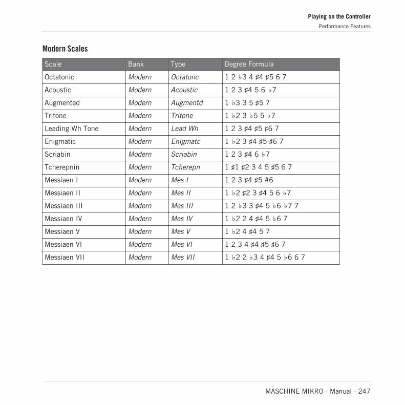
Modern Scales
Scale Bank Type Degree Formula
Octatonic Modern Octatonc 1 2 ♭3 4 ♯4 ♯5 6 7
Acoustic Modern Acoustic 1 2 3 ♯4 5 6 ♭7
Augmented Modern Augmentd 1 ♭3 3 5 ♯5 7
Tritone Modern Tritone 1 ♭2 3 ♭5 5 ♭7
Leading Wh Tone Modern Lead Wh 1 2 3 ♯4 ♯5 ♯6 7
Enigmatic Modern Enigmatc 1 ♭2 3 ♯4 ♯5 ♯6 7
Scriabin Modern Scriabin 1 2 3 ♯4 6 ♭7
Tcherepnin Modern Tcherepn 1 ♯1 ♯2 3 4 5 ♯5 6 7
Messiaen I Modern Mes I 1 2 3 ♯4 ♯5 #6
Messiaen II Modern Mes II 1 ♭2 ♯2 3 ♯4 5 6 ♭7
Messiaen III Modern Mes III 1 2 ♭3 3 ♯4 5 ♭6 ♭7 7
Messiaen IV Modern Mes IV 1 ♭2 2 4 ♯4 5 ♭6 7
Messiaen V Modern Mes V 1 ♭2 4 ♯4 5 7
Messiaen VI Modern Mes VI 1 2 3 4 ♯4 ♯5 ♯6 7
Messiaen VII Modern Mes VII 1 ♭2 2 ♭3 4 ♯4 5 ♭6 6 7
Playing on the Controller
Performance Features
MASCHINE MIKRO - Manual - 247
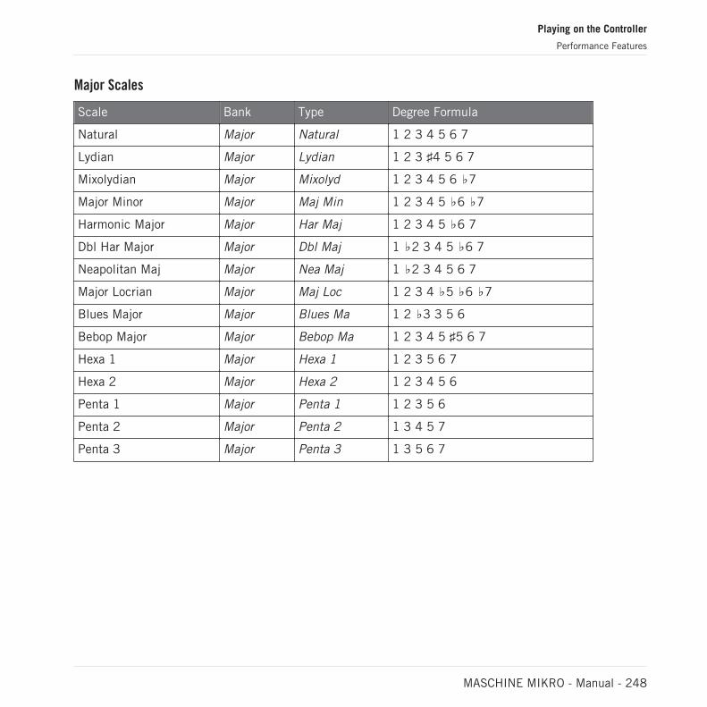
Major Scales
Scale Bank Type Degree Formula
Natural Major Natural 1 2 3 4 5 6 7
Lydian Major Lydian 1 2 3 ♯4 5 6 7
Mixolydian Major Mixolyd 1 2 3 4 5 6 ♭7
Major Minor Major Maj Min 1 2 3 4 5 ♭6 ♭7
Harmonic Major Major Har Maj 1 2 3 4 5 ♭6 7
Dbl Har Major Major Dbl Maj 1 ♭2 3 4 5 ♭6 7
Neapolitan Maj Major Nea Maj 1 ♭2 3 4 5 6 7
Major Locrian Major Maj Loc 1 2 3 4 ♭5 ♭6 ♭7
Blues Major Major Blues Ma 1 2 ♭3 3 5 6
Bebop Major Major Bebop Ma 1 2 3 4 5 ♯5 6 7
Hexa 1 Major Hexa 1 1 2 3 5 6 7
Hexa 2 Major Hexa 2 1 2 3 4 5 6
Penta 1 Major Penta 1 1 2 3 5 6
Penta 2 Major Penta 2 1 3 4 5 7
Penta 3 Major Penta 3 1 3 5 6 7
Playing on the Controller
Performance Features
MASCHINE MIKRO - Manual - 248

Minor Scales
Scale Bank Type Degree Formula
Natural Minor Natural 1 2 ♭3 4 5 ♭6 ♭7
Dorian Minor Dorian 1 2 ♭3 4 5 6 ♭7
Phrygian Minor Phrygian 1 ♭2 ♭3 4 5 ♭6 ♭7
Minor Major Minor Min Maj 1 2 ♭3 4 5 6 7
Harmonic Minor Minor Har Min 1 2 ♭3 4 5 ♭6 7
Dbl Har Minor Minor Dbl Min 1 2 ♭3 ♯4 5 ♭6 7
Neapolitan Min Minor Nea Min 1 ♭2 ♭3 4 5 ♭6 7
Minor Locrian Minor Min Loc 1 2 ♭3 4 ♭5 ♭6 ♭7
Blues Min Minor Blues Mi 1 ♭3 4 ♯4 5 ♭7
Bebop Minor Minor Bebop Mi 1 2 ♭3 4 5 ♭6 ♭7 7
Hexa 1 Minor Hexa 1 1 2 ♭3 5 ♭6 ♭7
Hexa 2 Minor Hexa 2 1 2 ♭3 4 5 b6
Penta 1 Minor Penta 1 1 2 ♭3 5 b6
Penta 2 Minor Penta 2 1 ♭3 4 5 ♭7
Penta 3 Minor Penta 3 1 ♭3 5 ♭6 ♭7
By default, the Chromatic scale is selected — in other terms, by default your pads play everysemitone, however, the last selected Scale is automatically assigned when a new Group is cre-ated.
The Scale Type parameter is not available if the Chord Mode parameter is set to Chord Set.
Playing on the Controller
Performance Features
MASCHINE MIKRO - Manual - 249

Available Chords
The Chord engine can automatically generate chords depending on the pad you hit and possi-bly the selected scale. The Chord engine is controlled via two parameters:
▪ Chord Mode (Off by default): Selects from three different modes for generating chords:
◦ Off: No chords will be generated. Only the notes corresponding to the pads that you hitwill be played.
◦ Harmonizer: Generates chords based on the pads you hit and using notes from the se-lected scale, as specified by the Root Note and Scale Type parameters (see above).Use the Chord Type parameter to choose the particular notes to be used in the chord(see below). As the chord is triggered, pads of all included notes flash.
◦ Chord Set: This special mode maps a set of chords onto the first 12 pads of your con-troller. These chords are not bound to any scale type, they are only affected by the se-lected Root Note. Use the Chord Type parameter to choose a particular set of chordsto be mapped onto the pads (see below). In this mode, only the pad you actuate flash-es.
▪ Chord Type: Selects which chords will be mapped to your pads. The available chord typesdepend on the selected Chord Mode and Scale Type:
◦ If Chord Mode is set to Harmonizer, the Chord Type parameter offers different chordsdepending on whether Scale Type is set to Chromatic or to any other scale. All availa-ble chords are listed in the tables below.
◦ If Chord Mode is set to Chord Set, the Chord Type parameter provides 16 differentsets of 12 chords each (8 major sets and 8 minor sets): Major 1, Major 2, …, Major 8,and Minor 1, Minor 2, …, Minor 8. The 12 chords are mapped onto the first 12 pads.Pads 13–16 are disabled.
When Chord Mode is set to Harmonizer and Scale Type is set to Chromatic, since this scale in-cludes all semitones the chords can use any of them. Chord Type offers following chords:
Chord Type Semitones Added above Played Note
Octave 12
Perfect 4 5
Perfect 5 7
Playing on the Controller
Performance Features
MASCHINE MIKRO - Manual - 250

Chord Type Semitones Added above Played Note
Major 4 and 7
Minor 3 and 7
Suspended 4 5 and 7
Major 7 4, 7, and 11
Minor 7 3, 7, and 10
Dominant 7 4, 7, and 10
Dominant 9 4, 7, 10, and 14
Minor 7♭5 3, 6, and 10
Diminished 7 3, 6, and 9
Augmented 4 and 8
Quartal 5, 10, and 15
Trichord 5 and 11
When Chord Mode is set to Harmonizer and Scale Type is set to any other scale than Chromatic,the chords are bound to the particular notes included in the specified scale. Chord Type offersfollowing chords:
Chord Type Notes Added to Played Note
Octave Octave
1-3 3rd
1-5 5th
1-3-5 3rd and 5th
1-4-5 4th and 5th
1-3-5-7 3rd, 5th, and 7th
1-4-7 4th and 7th
Playing on the Controller
Performance Features
MASCHINE MIKRO - Manual - 251
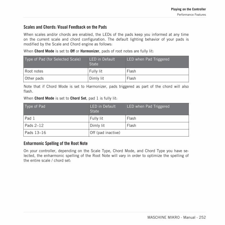
Scales and Chords: Visual Feedback on the Pads
When scales and/or chords are enabled, the LEDs of the pads keep you informed at any timeon the current scale and chord configuration. The default lighting behavior of your pads ismodified by the Scale and Chord engine as follows:
When Chord Mode is set to Off or Harmonizer, pads of root notes are fully lit:
Type of Pad (for Selected Scale) LED in DefaultState
LED when Pad Triggered
Root notes Fully lit Flash
Other pads Dimly lit Flash
Note that if Chord Mode is set to Harmonizer, pads triggered as part of the chord will alsoflash.
When Chord Mode is set to Chord Set, pad 1 is fully lit:
Type of Pad LED in DefaultState
LED when Pad Triggered
Pad 1 Fully lit Flash
Pads 2–12 Dimly lit Flash
Pads 13–16 Off (pad inactive)
Enharmonic Spelling of the Root Note
On your controller, depending on the Scale Type, Chord Mode, and Chord Type you have se-lected, the enharmonic spelling of the Root Note will vary in order to optimize the spelling ofthe entire scale / chord set:
Playing on the Controller
Performance Features
MASCHINE MIKRO - Manual - 252

Condition Enharmonic Spelling
Scale Type is set toChromatic
AllKeys
C C# D D# E F F# G G# A A#
Scale Type is not set toChromatic
C C# D E♭ E F F# G A♭ A B♭ B
Chord Mode is set toChord Set and ChordType is set to Major 1-8
C D♭ D E♭ E F F# G A♭ A B♭ B
Chord Mode is set toChord Set and ChordType is set to Minor1-8
C C# D D# E F F# G G# A B♭ B
Erasing Notes
When erasing notes from your controller, the notes effectively deleted vary with the Chord Modecurrently selected:
▪ If Chord Mode is set to Off, the notes with the pitch corresponding to the pressed pad aredeleted.
▪ If Chord Mode is set to Harmonizer, only the notes with the pitch of the pressed pad aredeleted. The other notes in the triggered chord are not deleted.
▪ If Chord Mode is set to Chord Set, no notes are deleted, in other words erasing is disabled.
6.4.4 Creating Arpeggios and Repeated Notes
MASCHINE includes a flexible and versatile Arp engine, an arpeggiator that effectively lets youplay your Sounds in note sequences. The arpeggios are created according to both the pads youhold and the chords configured with the Scale and Chord engine (see section ↑6.4.2, Selectinga Scale and Creating Chords).
If you have enabled chords, you can even press more than one pad to include the notes of all corre-sponding chords into your arpeggio!
Playing on the Controller
Performance Features
MASCHINE MIKRO - Manual - 253
Like the Scale and Chord engine, the Arp engine is dedicated to Keyboard mode.
The Arp engine can be seen as a melodic extension of the Note Repeat: Actually, Arp replacesand extends Note Repeat in Keyboard mode. Instead of playing repeated notes at a constantpitch you can play sequences of notes at different pitches.
Arp and Note Repeat have similar modes on your controller: Depending on whether your padsare in Pad Mode or Keyboard mode, pressing NOTE REPEAT on your controller will switch toNote Repeat mode or Arp mode, respectively. Arp mode simply adds a few parameters to thosefound in Note Repeat mode.
General Notes on the Note Repeat and Arp Engine
▪ The Note Repeat / Arp parameters are the same for all Sound slots in all Groups of yourProject. These parameters are saved with the Project.
▪ The Note Repeat / Arp engine processes live input from the pads of your controller only.Input from third-party MIDI controllers and data recorded in the Pattern Editor are notprocessed by the Scale and Chord engine.
▪ The Note Repeat / Arp engine detects and makes use of any changes in the pressure youapply on each single pad you hold (Polyphonic Aftertouch). This allows you to generate ar-peggios and repeated notes with varying velocities!
▪ The output of the Note Repeat / Arp engine is recorded into the Pattern Editor.
▪ The Note Repeat / Arp parameters cannot be modulated nor automated in MASCHINE.
▪ You can use Note Repeat and Arp even if the transport is not running: In this case the NoteRepeat / Arp engine will use its own central clock. This clock will be reset as soon as youstart the playback.
KOMPLETE KONTROL S-SERIES owners: The central clock is shared by all connected devices, sothat e.g. repeated notes triggered from your MASCHINE controller and arpeggios triggered from yourKOMPLETE KONTROL S-SERIES keyboard will be synchronized even if the transport is not running.
Using Note Repeat in Pad Mode
Check that your Pattern is playing, if not, press PLAY to start the sequencer.
Playing on the Controller
Performance Features
MASCHINE MIKRO - Manual - 254

1. Press and hold NOTE REPEAT, then hold any pad.The Sound of the pad is repeatedly triggered at the rate shown at the bottom of the con-troller’s display.
2. Turn the Encoder to select another repetition rate.
→ This is a handy way to add live ornaments to your Pattern.
You can also use Note Repeat to program your Pattern (e.g., record a continuous hi-hat).
Note Repeat mode seamlessly switches to Arp mode as soon as you switch your pads from PadMode to Keyboard mode (see below): All current values (including the LOCK state) are retained.
Using Arp in Keyboard mode and Chords mode
If your pads are in Keyboard mode or Chords mode, pressing NOTE REPEAT (Arp) switchesyour controller to Arp mode:
In Pad Mode, Keyboard mode and Chords mode you can customize the way the notes of theplayed chord will be arpeggiated by adjusting following settings.
► Press the Arrow buttons to access following settings, and turn the Encoder to adjust val-ues.
Playing on the Controller
Performance Features
MASCHINE MIKRO - Manual - 255

Element Description
TYPE Sets the sequential order of the arpeggiated notes. Turn the Encoderto choose from following settings:
UP starts from the root note and plays the notes up through thechord.
DOWN plays the notes the other way around.
UP-DOWN plays the notes in both directions alternatively.
PLAYED plays the notes in the order you pressed down thecorresponding pads on your controller. If you have configured chords,the arpeggio will first play all notes of the chord triggered by the firstpad you pressed, then all notes of the chord triggered by the secondpad you pressed, etc.
CHORD plays all notes of the chord together repeatedly.
RATE Adjusts the note length, hence the rate of the arpeggio. Availablevalues are 1 BAR and a series of note values going from 1/2 (halfnote) until 1/128 (a hundred twenty-eighth note).
UNIT Selects from three variations of the original note length defined bythe RATE parameter: NORMAL plays the original note length (defaultsetting), TRIPLET plays triplets of the original note length (faster,three notes in the duration of two original notes), and DOTTED playsdotted versions of the original note length (slower, two notes in theduration of three original notes). Under Button 5–8, triplet values areindicated by a “T” and dotted values by a “D” next to the note value.
Arp mode seamlessly switches to Note Repeat mode as soon as you switch your pads from Keyboardmode to Pad Mode (see above): All current values (including the LOCK state) are retained.
Playing on the Controller
Performance Features
MASCHINE MIKRO - Manual - 256

6.4.5 Swing on Note Repeat / Arp Output
The Swing engines (at the Master, Group, and Sound level) process notes coming from the Pat-tern Editor and from the Arp engine (pads in Keyboard mode) or Note Repeat engine (pads in PadMode). In other terms, the swing is applied not only to your Patterns but also to any live se-quence generated by the Arp or Note Repeat engine.
The applied swing is not recorded in the Pattern Editor. For an overview of the signal flow startingfrom your pads, have a look at the diagrams in section ↑6.4.1, Overview of the Perform Features.
For example, when you play live beats on top of a running Pattern, you can use Note Repeatwithout destroying the Pattern’s groove: the repeated notes will be processed using the sameswing parameters as the playing Pattern.
When the playback is not running, the swing is still applied to the output of Arp (Keyboard mode) orNote Repeat (Pad Mode). If you press PLAY on your controller, the playback starts immediately andthe swing cycle is reset.
6.5 Using Lock Snapshots
Lock allows you to create a snapshot of your current settings that you can quickly recall. Asnapshot contains every modulatable parameter in your Project, including your Solo and Mutesettings.
Lock snapshots are not only a powerful tool for recalling extensive modulations, but also veryuseful to compare mixes, or to use during a live performance.
6.5.1 Creating a Lock Snapshot
Use the Lock button to capture, update or recall a single Lock snapshot.
To create a Lock snapshot:
1. Press the PLUG-IN.
2. Press LOCK to take a snapshot.
Playing on the Controller
Performance Features
MASCHINE MIKRO - Manual - 257

⇨ The LOCK button is highlighted to indicate a single snapshot has been taken. You are nowfree to change parameters or Mute and Solo settings, safe in the knowledge you can recallyour snapshot.
3. Press LOCK to recall the snapshot.
→ The Lock snapshot is recalled and the LOCK button ceases to be highlighted.
Playing on the Controller
Using Lock Snapshots
MASCHINE MIKRO - Manual - 258

7 Working with Plug-ins
Plug-ins are the building blocks of all sound in MASCHINE. They can be used at all three lev-els of the MASCHINE audio routing system: in Sounds, in Groups, and in the Master.
This chapter includes various general or specific Plug-in topics:
▪ An overview of Plug-ins and how to handle them (↑7.1, Plug-in Overview).
▪ An exhaustive description of an essential Internal Instrument Plug-in in charge of playingback all sample content in MASCHINE: the Sampler (↑7.2, The Sampler Plug-in).
▪ Specific information on Native Instruments and External Plug-ins (↑7.3, Using Native In-struments and External Plug-ins).
7.1 Plug-in Overview
This section describes Plug-ins in general: where you can find them, how you can adjust theirsettings, and how you can manage them.
7.1.1 Plug-in Basics
In Arrange view, the content and settings of the focused Sound/Group or the Master are dis-played in the Control area (in the middle of the software window):
Working with Plug-ins
Plug-in Overview
MASCHINE MIKRO - Manual - 259

The Control area displaying the content of the Sound Kick Ordinance of the selected Sound slot 1.
Sounds, Groups, and the Master can each hold any number of Plug-ins. These are stacked upin the Plug-in List, on the left of the Control area.
Working with Plug-ins
Plug-in Overview
MASCHINE MIKRO - Manual - 260

► To show the Plug-in List, click the little Plug-in icon at the far left of the Control area:
In the Plug-in List, the processing order is always from top to bottom.
In addition to Plug-ins, each Sound, each Group, and the Master also provide a set of global set-tings called Channel properties. These are described in section ↑6.3.3, Groove and in chapter ↑12,Audio Routing, Remote Control, and Macro Controls.
Different Types of Plug-ins
Plug-ins can be of different types:
Working with Plug-ins
Plug-in Overview
MASCHINE MIKRO - Manual - 261

Instrument Plug-ins Effect Plug-ins
Internal Plug-ins Audio, Sampler, Drumsynth, BassSynth
MASCHINE internal effects
Native InstrumentsPlug-ins
VST/AU instrument plug-ins fromNative Instruments’ range ofproducts
VST/AU effect plug-ins fromNative Instruments’ range ofproducts
External Plug-ins Third-party VST/AU instrumentplug-ins
Third-party VST/AU effect plug-ins
▪ Instruments: These Plug-ins generate sound. Instrument Plug-ins can only be loaded in thefirst Plug-in slot of Sounds. Following Plug-ins are available:
◦ Audio: Included with MASCHINE, the Audio Plug-in allows audio loops to play back intime with the tempo of your Project. Adding audio with the Loops tag from the Brows-er to the Sound slot will automatically load the Audio Plug-in in the first Plug-in slotof the Sound. See ↑8, Using the Audio Plug-in for more details.
◦ Sampler: Included with MASCHINE, the Sampler Plug-in allows the selected Sound toplay back Samples. Adding a Sample to the Sound slot will automatically load theSampler in the first Plug-in slot of the Sound. See ↑7.2, The Sampler Plug-in for moredetails.
◦ Drumsynths: Included with MASCHINE, these Plug-ins are mini-synths specialized ingenerating drum sounds. See chapter ↑9, Using the Drumsynths for more details.
◦ Bass Synth: Included with MASCHINE, this Plug-in is a monophonic synthesizer speci-alized in generating bass sounds. See chapter ↑10, Using the Bass Synth for more de-tails.
◦ Native Instruments: You can use all Native Instruments KOMPLETE instruments instal-led on your computer as VST/AU plug-ins (e.g., MASSIVE, which is included with MA-SCHINE). Products from Native Instruments are tightly integrated in MASCHINE.
◦ External: You can also use VST/AU instrument plug-ins from any third-party manufac-turers.
▪ Effects: These Plug-ins modify the audio coming from the previous Plug-in slot (or from theincoming audio if the Effect is loaded in the first Plug-in slot of a Sound). Effect Plug-inscan be loaded in any Plug-in slot. Following Plug-ins are available:
Working with Plug-ins
Plug-in Overview
MASCHINE MIKRO - Manual - 262

◦ Internal Effects: These are the Effect Plug-ins included with MASCHINE. To read everydetails about each of the MASCHINE internal effects, and how to use them, pleaserefer to chapter ↑12, Audio Routing, Remote Control, and Macro Controls and ↑15,Effect Reference.
◦ Native Instruments: You can use all Native Instruments KOMPLETE effects installed onyour computer as VST/AU plug-ins. Products from Native Instruments are tightly inte-grated in MASCHINE.
◦ External: You can also use VST/AU effect plug-ins from any third-party manufacturers.
What to Load, and Where
The type of Plug-in that you can load depends on the selected level (Sound, Group or Master)and slot:
▪ Effect Plug-ins (both internal and external) can be loaded in all Plug-in slots at all levels(Sound, Group, Master).
▪ Instrument Plug-ins (both internal and external) can only be loaded in the first Plug-in slotof Sounds.
7.1.2 First Plug-in Slot of Sounds: Choosing the Sound’s Role
The Plug-in loaded in the first Plug-in slot of a Sound will determine the general role of thisSound:
▪ If the first Plug-in slot holds an Instrument Plug-in (Sampler, Drumsynth, Native Instru-ments or External Instrument, see above), the Sound will generate its own audio.
▪ If the first Plug-in slot holds an Effect Plug-in (Internal, Native Instruments or External), theSound will be available as bussing point for other signals (from within MASCHINE, andpossibly from the outside world). This notably allows you to build up send effects or to ap-ply effects to external audio. See section ↑14.3.1, Step 1: Set Up a Sound or Group asSend Effect for more information.
You can also sample directly to a Sound slot. This will automatically load a Sampler in its first Plug-in slot. Read chapter ↑15, Effect Reference for more details on this.
Working with Plug-ins
Plug-in Overview
MASCHINE MIKRO - Manual - 263

7.1.3 Loading, Removing, and Replacing a Plug-in
The procedure to load a Plug-in with its default settings is common to all levels (Sound, Group,and Master) and all Plug-in types (Internal, Native Instruments, and External, as well as Instru-ment and Effect):
1. Set the focus to the Sound, Group or the Master where you want to load the Plug-in (seesection ↑3.3.3, Focusing on a Group or a Sound). In the picture below we click an emptySound slot in the Sound List of the Pattern Editor and click the SOUND tab in the Controlarea above.
The Control area will now show the content (Channel properties or Plug-ins) of the Soundwe have just selected.
2. At the far left of the Control area, click the little plug icon to display the Plug-ins.
This displays the Plug-in List on the left of the Control area:
Working with Plug-ins
Plug-in Overview
MASCHINE MIKRO - Manual - 264

The Plug-in List is still empty, because we selected an empty Sound slot. The only visibleelement in the list is a “+” icon at the top left.
3. Click the slot with the “+” icon at the top of the Plug-in List.This opens the Plug-in menu where you can select the desired Plug-in for loading (see be-low for a detailed description of the entries contained in the Plug-in menu).
→ Upon your selection the selected Plug-in sits at the top of the Plug-in List, in the firstPlug-in slot of the Sound (in our example). In addition, some Native Instruments and Ex-ternal Plug-ins will automatically open in a floating window (see section ↑7.3.1, Opening/Closing Plug-in Windows for more on this).
You will notice that the “+” sign has moved to the next slot. Clicking it would allow you to loada Plug-in into the next Plug-in slot of that Sound, and so on.
Instead of using the Plug-in menu to load a Plug-in with its default settings, you can also use theBrowser to load a particular preset for a Plug-in. In particular, this can come in handy to insert anew Plug-in between two existing Plug-ins of the Plug-in List. Please refer to chapter ↑4.2, Search-ing and Loading Files from the Library for more information.
Working with Plug-ins
Plug-in Overview
MASCHINE MIKRO - Manual - 265

Removing and Replacing a Plug-in
Once you have loaded a Plug-in into a Plug-in slot, the slot shows the name of the loadedPlug-in, preceded by an icon describing the type of Plug-in (Instrument or Effect), and fol-lowed by a down-pointing arrow:
A few Plug-ins loaded.
This down-pointing arrow lets you open the Plug-in menu for slots already hosting a Plug-in.
► In the Plug-in List, click the down-pointing arrow at the right of a Plug-in name to openthe Plug-in menu for that slot. You can also right-click ([Ctrl]-click on macOS) the Plug-inname in the slot.
This will notably allow you to remove the loaded Plug-in from the slot:
Working with Plug-ins
Plug-in Overview
MASCHINE MIKRO - Manual - 266

► To remove the Plug-in currently loaded in a slot, open its Plug-in menu and select Noneat the top of the menu.
→ The Plug-in is unloaded from the slot. All following Plug-ins are shifted one slot upwardsto fill the gap.
Furthermore, the Plug-in menu also allows you to replace the loaded Plug-in with another one:
► To replace the Plug-in currently loaded in a slot, open its Plug-in menu and select anotherPlug-in in the menu.
→ The original Plug-in is replaced with the newly selected one. The rest of the Plug-in Liststays untouched.
You can also recall the search query that was used to find the Plug-in preset currently loaded in thePlug-in slot (see section ↑4.8, Using Quick Browse for more information).
Working with Plug-ins
Plug-in Overview
MASCHINE MIKRO - Manual - 267

Content of the Plug-in Menu
The entries in the Plug-in menu differ according to the Plug-in slot from which you are callingthe menu:
▪ The first Plug-in slots of Sounds accepts both Instrument and Effect Plug-ins. The entriesavailable in their Plug-in menu are listed in the following table.
▪ All other Plug-in slots at the Sound, Group, and Master level only accept Effect Plug-ins.Therefore, their Plug-in menus and submenus provide the same entries except all entriesfor Instrument Plug-ins.
The Plug-in menus can have following entries, from top to bottom:
Plug-in Menu Entry Description
Plug-ins
Presets submenu (onlywhen a Native Instrumentsor External Plug-in isloaded)
Lists all VST/AU presets made available to MASCHINE by theVST/AU plug-in. This allows you to use your favorite presets ofthe VST/AU plug-in directly inside MASCHINE. See section↑7.3.4, Using VST/AU Plug-in Presets for more information.
None Select None to remove the Plug-in currently loaded (see previousparagraph).
Native Instrumentssubmenu
Lists available Native Instruments’ Instruments (first Plug-in slotof Sounds only) and Effects. For products working both asInstrument and Effect, the Effect Plug-in name is followed bythe mention FX. If necessary each entry is followed by the plug-in type between brackets: (VST) or (AU). See section ↑7.3, UsingNative Instruments and External Plug-ins for more information.
External submenu Lists the available External Plug-ins, i.e. the available VST/AUinstrument (first Plug-in slot of Sounds only) and effect plug-insfrom third-party manufacturers. Each entry is followed by theplug-in type between brackets: (VST) or (AU). See section ↑7.3,Using Native Instruments and External Plug-ins for moreinformation.
Working with Plug-ins
Plug-in Overview
MASCHINE MIKRO - Manual - 268
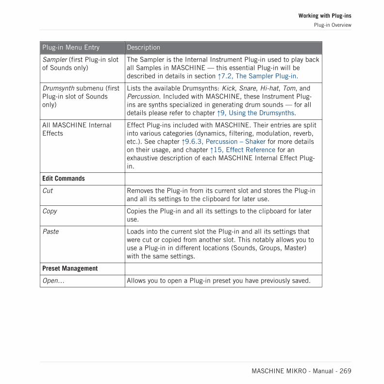
Plug-in Menu Entry Description
Sampler (first Plug-in slotof Sounds only)
The Sampler is the Internal Instrument Plug-in used to play backall Samples in MASCHINE — this essential Plug-in will bedescribed in details in section ↑7.2, The Sampler Plug-in.
Drumsynth submenu (firstPlug-in slot of Soundsonly)
Lists the available Drumsynths: Kick, Snare, Hi-hat, Tom, andPercussion. Included with MASCHINE, these Instrument Plug-ins are synths specialized in generating drum sounds — for alldetails please refer to chapter ↑9, Using the Drumsynths.
All MASCHINE InternalEffects
Effect Plug-ins included with MASCHINE. Their entries are splitinto various categories (dynamics, filtering, modulation, reverb,etc.). See chapter ↑9.6.3, Percussion – Shaker for more detailson their usage, and chapter ↑15, Effect Reference for anexhaustive description of each MASCHINE Internal Effect Plug-in.
Edit Commands
Cut Removes the Plug-in from its current slot and stores the Plug-inand all its settings to the clipboard for later use.
Copy Copies the Plug-in and all its settings to the clipboard for lateruse.
Paste Loads into the current slot the Plug-in and all its settings thatwere cut or copied from another slot. This notably allows you touse a Plug-in in different locations (Sounds, Groups, Master)with the same settings.
Preset Management
Open… Allows you to open a Plug-in preset you have previously saved.
Working with Plug-ins
Plug-in Overview
MASCHINE MIKRO - Manual - 269

Plug-in Menu Entry Description
Save As… Allows you to save the current Plug-in settings as a preset forlater use. This preset will appear in the Browser.
Save As Default… (onlywhen a Native Instrumentsor External Plug-in isloaded)
Allows you to save the current Plug-in settings as a defaultpreset. This default preset will be recalled each time you loadthe Plug-in from the Plug-in menu.
Note that the first two submenus Native Instruments and External only show the Plug-ins that areenabled in the Plug-ins page of the Preferences panel. For more on this, see section ↑3.6.6, Prefer-ences – Plug-ins Page.
The edit commands (Cut, Copy, and Paste) and preset management commands (Open, Save As…,and Save As Default…) available at the bottom of the Plug-in menu will be covered in section↑7.1.7, Moving Plug-ins and ↑7.1.9, Saving and Recalling Plug-in Presets, respectively.
7.1.3.1 Loading, Removing, and Replacing a Plug-in on your Controller
7.1.4 Adjusting the Plug-in Parameters
The procedure for adjusting the Plug-in parameters is common to all types of Plug-ins and allsets of Channel properties. It is described in section ↑3.3.5, Navigating Channel Properties,Plug-ins, and Parameter Pages in the Control Area.
Native Instruments and External Plug-ins only: You can also adjust the Plug-in parameters via theown user interface of the VST/AU plug-in. More on this in ↑7.3, Using Native Instruments and Ex-ternal Plug-ins.
7.1.5 Bypassing Plug-in Slots
You can bypass (or “mute”) any Plug-in slot. When a Plug-in slot is bypassed, the Plug-in itcontains is temporarily removed from the signal flow and does not process the audio passingthrough the slot. Instead, the incoming audio is directly sent to the next Plug-in slot for furtherprocessing (or to the channel’s output if you bypass its last Plug-in slot).
Working with Plug-ins
Plug-in Overview
MASCHINE MIKRO - Manual - 270
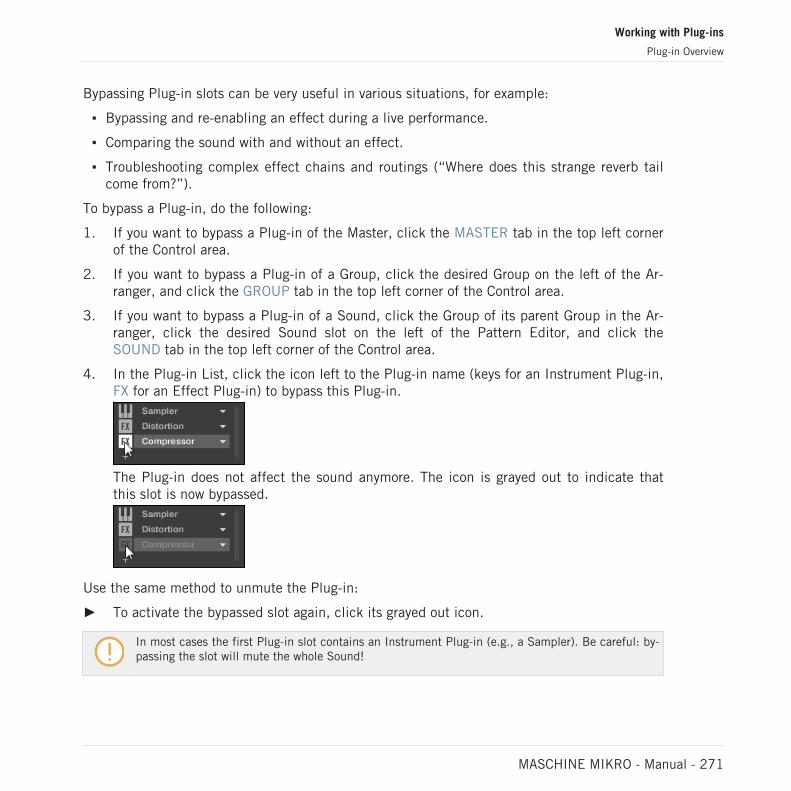
Bypassing Plug-in slots can be very useful in various situations, for example:
▪ Bypassing and re-enabling an effect during a live performance.
▪ Comparing the sound with and without an effect.
▪ Troubleshooting complex effect chains and routings (“Where does this strange reverb tailcome from?”).
To bypass a Plug-in, do the following:
1. If you want to bypass a Plug-in of the Master, click the MASTER tab in the top left cornerof the Control area.
2. If you want to bypass a Plug-in of a Group, click the desired Group on the left of the Ar-ranger, and click the GROUP tab in the top left corner of the Control area.
3. If you want to bypass a Plug-in of a Sound, click the Group of its parent Group in the Ar-ranger, click the desired Sound slot on the left of the Pattern Editor, and click theSOUND tab in the top left corner of the Control area.
4. In the Plug-in List, click the icon left to the Plug-in name (keys for an Instrument Plug-in,FX for an Effect Plug-in) to bypass this Plug-in.
The Plug-in does not affect the sound anymore. The icon is grayed out to indicate thatthis slot is now bypassed.
Use the same method to unmute the Plug-in:
► To activate the bypassed slot again, click its grayed out icon.
In most cases the first Plug-in slot contains an Instrument Plug-in (e.g., a Sampler). Be careful: by-passing the slot will mute the whole Sound!
Working with Plug-ins
Plug-in Overview
MASCHINE MIKRO - Manual - 271

7.1.6 Using Side-Chain
Some Plug-ins provide side-chaining. This allows you to control their influence on the audio viaanother audio signal sent to their secondary, side-chain input. This extra routing feature is de-scribed in details in section ↑14.1.3, Using the Side-Chain Input.
7.1.7 Moving Plug-ins
MASCHINE allows you to move Plug-ins across the Plug-in List and across Sounds and Groups.
Moving Plug-ins Within the Plug-in List
► To move a Plug-in in the Plug-in List, click its name and drag your mouse vertically. Whileyou are holding the mouse button, an insertion line appears at the place in the Plug-inList where the Plug-in would land if dropped. Drag your mouse until the insertion line isat the desired location, then release the mouse button to drop the Plug-in onto this newlocation.
→ The Plug-in takes its new place between the existing Plug-ins while keeping the exactsame settings. All other Plug-ins sitting between its old and new location are shifted oneslot upwards/downwards to fill the gap.
Dragging Plug-ins can be very useful if you want to quickly change the effects’ processing order inthe channel.
Moving Plug-ins Across Sounds and Groups
Moving Plug-ins is not only possible within the same Sound but also across Sounds, acrossGroups, across levels (e.g., from a Sound to a Group) or across Sounds in different Groups!
To move a Plug-in to another Sound, Group or the Master, do the following:
1. Click the down-pointing arrow of the slot containing the Plug-in that you want to move.
Working with Plug-ins
Plug-in Overview
MASCHINE MIKRO - Manual - 272
2. In the Plug-in menu that opens, select Cut.
3. Select the Sound, Group or the Master where you want to move the Plug-in (see section↑3.3.3, Focusing on a Group or a Sound).
4. Click the down-pointing arrow of the target slot (the slot where you want to move the Plug-in to).
5. In the Plug-in menu that opens, select Paste.
→ The Plug-in with all its parameters has now been moved from its original location to itstarget location.
Duplicating Plug-ins Across Sounds and Groups
Instead of selecting Cut in the Plug-in menu of the original slot (see above), select Copy to du-plicate the Plug-in to another slot!
7.1.8 Alternative: the Plug-in Strip
You can also manipulate your Plug-ins via the Plug-in Strip in the Mix view of MASCHINE. Youwill find all details on this feature in section ↑13.4, The Plug-in Strip.
7.1.9 Saving and Recalling Plug-in Presets
All settings and assignments of a Plug-in can be saved as Plug-in presets. Once saved, Plug-inpresets can be accessed from the Browser, both in the software and from your controller (seesection ↑4.2, Searching and Loading Files from the Library). This is a very quick and conven-ient way to recall Plug-ins with their parameters already set to specific values. In addition aPlug-in preset can be assigned as the default preset so the Plug-in opens with that preset auto-matically loaded.
The MASCHINE file format for Native Instruments plug-ins allows you to save a preset in theformat native to the plug-in and freely exchange files between the plug-in instrument in stand-alone mode, MASCHINE, and KOMPLETE KONTROL.
To use this feature you must ensure all installed Native Instruments plug-ins are up-to-date. Pleasecheck Service Center or log-in to your Native Instruments account to find the latest updates.
Working with Plug-ins
Plug-in Overview
MASCHINE MIKRO - Manual - 273
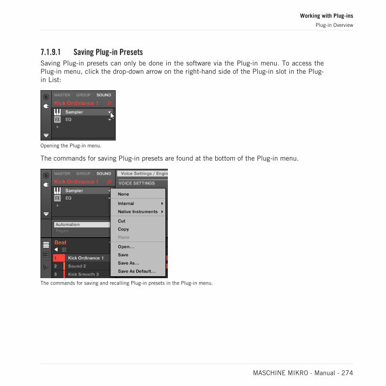
7.1.9.1 Saving Plug-in Presets
Saving Plug-in presets can only be done in the software via the Plug-in menu. To access thePlug-in menu, click the drop-down arrow on the right-hand side of the Plug-in slot in the Plug-in List:
Opening the Plug-in menu.
The commands for saving Plug-in presets are found at the bottom of the Plug-in menu.
The commands for saving and recalling Plug-in presets in the Plug-in menu.
Working with Plug-ins
Plug-in Overview
MASCHINE MIKRO - Manual - 274

Plug-in Menu Entry Description
Save Saves your changes to the preset currentlyloaded.
Save As… Saves the current Plug-in settings as a newpreset on your hard disk.
Save As Default… Saves the current settings and assignments asthe default preset for the Plug-in. This defaultpreset will be loaded with this Plug-in thenext time it is opened.
Remove Default Preset Removes the default preset for the currentplug-in. This menu item only appears after apreset has been saved using the Save AsDefault... menu item.
The Save As… and Save As Default… commands notably allow you to import into the MASCHINElibrary your user presets for Native Instruments instruments/effects as well as both factory and userpresets for third-party instruments/effects! See ↑7.3.4, Using VST/AU Plug-in Presets section formore on this.
7.1.9.2 Recalling Plug-in Presets
All Plug-in presets you saved using the Plug-in menu are available in the Browser, both in thesoftware and from your controller. You can find each Plug-in preset automatically placed in thecorresponding “Instrument” or “Effect” category in the File Type selector of the Browser’s LI-BRARY pane. Furthermore, user presets are available when selecting the User content in theContent selector of the Browser’s LIBRARY pane.
For more information on how to load Plug-in presets in the Browser, and how to assign tags to thePlug-in presets that you saved, please refer to chapter ↑4, Browser.
In addition, the MASCHINE library already provides a collection of Plug-in presets for MA-SCHINE Internal Plug-ins. Furthermore, any Native Instruments product installed on your com-puter will have its own factory library already imported into the MASCHINE Browser so that youcan browse and load its presets directly from MASCHINE, ready for loading.
Working with Plug-ins
Plug-in Overview
MASCHINE MIKRO - Manual - 275

You can assign tags to the Plug-in presets that you saved. This is done in the Browser in the MA-SCHINE software. For more information, please refer to section ↑4.5, Editing the Files’ Tags andProperties.
KOMPLETE products and MASCHINE EXPANSIONS have to be updated to ensure their full integra-tion into the MASCHINE Library. To update any Native Instruments product installed on your com-puter, please start the Service Center.
You can also load a Plug-in preset from the Plug-in menu by selecting the Open… command,then navigating your file system and selecting the desired preset file (extension “.mxinst” forInstrument Plug-in presets, “.mxfx” for Effect Plug-in presets, or “.mfxp” for MASCHINE 1.xModule presets).
7.1.9.3 Removing a Default Plug-in Preset
For each plug-in you can set a default preset that is loaded automatically every time the plug-in is opened. If the default plug-in preset is no longer required, use the Plug-in menu to re-move the saved default preset.
To remove the default preset of a plug-in using the Plug-in menu:
1. Click the Sound containing the Plug-in.
2. Click the Plug-in drop-down menu.
Working with Plug-ins
Plug-in Overview
MASCHINE MIKRO - Manual - 276

3. Click Remove Default Preset in the menu to remove the default preset.
→ The default plug-in preset is removed and the plug-in will load with its initialized settingsnext time it is opened.
You can also use the Plug-in Manager in the Preferences panel to gain an overview of your de-fault plug-in presets and also remove them if required.
Removing the default preset for a plug-in is a software only feature.
7.2 The Sampler Plug-in
The Sampler Plug-in allows you to play back any Sample in MASCHINE — including allGroups, Sounds and Samples of the factory library. The Sampler comes with an extensive setof parameters that offer various ways to further shape each of your Sounds individually. Youcan tune, change basic dynamics and apply effects as well as different modulation options.
Working with Plug-ins
The Sampler Plug-in
MASCHINE MIKRO - Manual - 277

Many of these parameters can be modulated and automated! For more information, see section↑11.5, Recording and Editing Modulation and ↑12.2.3, Controlling Parameters via MIDI and HostAutomation, respectively.
In case MASCHINE cannot find the Sample(s) loaded in a Sampler Plug-in, a Missing Sample dia-log will appear and help you locate the missing Sample(s) again. Please refer to section ↑4.7, Lo-cating Missing Samples for more information.
This section describes the specific parameters found in the Sampler. For a general descriptionof the features and characteristics of Plug-ins (including the Sampler), please refer to section↑7.1, Plug-in Overview.
We show here the Sampler parameters as they appear in the Control area of the Arrange view. TheSampler also provides a custom panel in the Plug-in Strip of the Mix view. This panel is describedin section ↑13.4.3, Panel for the Sampler.
The Sampler parameters are organized in 6 pages:
▪ Page 1: Voice Settings / Engine: ↑7.2.1, Page 1: Voice Settings / Engine.
▪ Page 2: Pitch / Envelope: ↑7.2.2, Page 2: Pitch / Envelope.
▪ Page 3: FX / Filter: ↑7.2.3, Page 3: FX / Filter.
▪ Page 4: Modulation: ↑7.2.4, Page 4: Modulation.
▪ Page 5: LFO: ↑7.2.5, Page 5: LFO.
▪ Page 6: Velocity / Modwheel: ↑7.2.6, Page 6: Velocity / Modwheel.
These Parameter pages can be selected for displaying/editing via the usual way as described insection ↑3.3.5, Navigating Channel Properties, Plug-ins, and Parameter Pages in the ControlArea. For example:
► To display a particular Parameter page in the software, click its label at the top of theControl area.
Working with Plug-ins
The Sampler Plug-in
MASCHINE MIKRO - Manual - 278
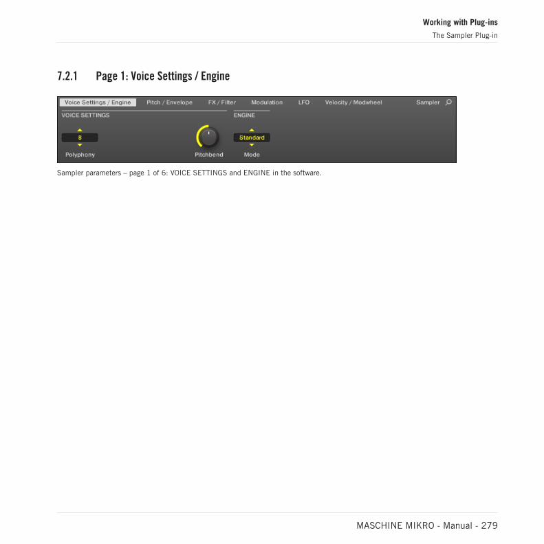
7.2.1 Page 1: Voice Settings / Engine
Sampler parameters – page 1 of 6: VOICE SETTINGS and ENGINE in the software.
Working with Plug-ins
The Sampler Plug-in
MASCHINE MIKRO - Manual - 279

Parameter Description
VOICE SETTINGS
Polyphony Here you can define a voice limit for the Sound, that is the maximumnumber of voices (notes) the Sampler can play simultaneously. Oncethis polyphony has been reached, triggering any additional note willkill the “oldest” note still playing (i.e. the note that was triggeredfirst). The available values are 1, 2, 4, 8 (default), 16, 32, and 64.You can also set this to Legato — in that case the polyphony is set to1 and the Sampler performs a continuous pitch transition betweenconsecutive notes.
Glide If Legato is selected for the Polyphony parameter, this allows toadjust the duration of the transition between consecutive notes.
Pitchbend Here you can adjust how the Sound reacts on incoming MIDIPitchbend messages from an external MIDI controller or your hostapplication. For more information on how to setup your Sounds toreceive MIDI, refer to section ↑12.2.1, Triggering Sounds via MIDINotes.
ENGINE
Mode This allows you to select between different models for the samplingengine. Besides the default Standard setting, the other optionsMP60 and S1200 emulate the sound of two legendary Samplers thatare often used in Hip-Hop and similar genres of music. The lattercomes in various flavors offering different filtering: S1200 (nofiltering), S1200 L (for Low, i.e. low-pass filtering), S1200 LM (forLow-Mid, i.e. low-mid-pass filtering), S1200 HM (for High-Mid, i.e.mid-high-pass filtering), and S1200 High (for High, i.e. high-passfiltering).
Working with Plug-ins
The Sampler Plug-in
MASCHINE MIKRO - Manual - 280

7.2.2 Page 2: Pitch / Envelope
Sampler parameters – page 2 of 6: PITCH / GATE and AMPLITUDE ENVELOPE in the software.
Parameter Description
PITCH / GATE
Tune Defines the basic pitch of your Sample: turn the knob to the right fora higher pitch and to the left for a lower pitch.
Start Determines the start point of the Sample. This parameter can also bemodulated by the Velocity control, see ↑7.2.5, Page 5: LFO.
Reverse If Reverse is activated, the Sample will be played backwards.
Type Selects from three different types of amplitude envelopes. See belowfor more information.
AMPLITUDE ENVELOPE
The AMPLITUDE ENVELOPE section allows you to tailor your Sample in terms of its loudnessover time.
The Type selector.
The Type selector allows you to choose from three different types of amplitude envelopes. De-pending on the selected type, the available parameters in the AMPLITUDE ENVELOPE sectionwill differ (see table below):
Working with Plug-ins
The Sampler Plug-in
MASCHINE MIKRO - Manual - 281
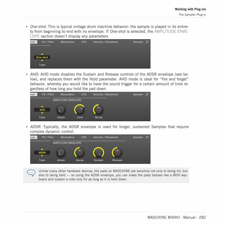
▪ One-shot: This is typical vintage drum machine behavior: the sample is played in its entire-ty from beginning to end with no envelope. If One-shot is selected, the AMPLITUDE ENVE-LOPE section doesn’t display any parameters.
▪ AHD: AHD mode disables the Sustain and Release controls of the ADSR envelope (see be-low), and replaces them with the Hold parameter. AHD mode is ideal for “fire and forget”behavior, whereby you would like to have the sound trigger for a certain amount of time re-gardless of how long you hold the pad down.
▪ ADSR: Typically, the ADSR envelope is used for longer, sustained Samples that requirecomplex dynamic control.
Unlike many other hardware devices, the pads on MASCHINE are sensitive not only to being hit, butalso to being held — so using the ADSR envelope, you can make the pads behave like a MIDI key-board and sustain a note only for as long as it is held down.
Working with Plug-ins
The Sampler Plug-in
MASCHINE MIKRO - Manual - 282

Parameter Description
AMPLITUDE ENVELOPE
Attack (AHD andADSR)
Attack determines how quickly the Sound reaches full volume afterbeing triggered.
Hold (AHD only) Hold determines how long the envelope will stay at its maximumlevel.
Decay (AHD andADSR)
Decay determines how fast the envelope drops to the Sustain level inADSR mode; in AHD mode, it is used to adjust how fast the Sounddies down. This parameter can also be modulated by the Velocitycontrol, see ↑7.2.5, Page 5: LFO.
Sustain (ADSR only) Sustain determines the constant level being kept after Decay untilthe note ends. This can also be controlled by an external MIDIcontroller or keyboard using the MIDI Control Change 64.
Release (ADSR only) Release determines how long the sound takes to fade out after thenote has ended.
7.2.3 Page 3: FX / Filter
Sampler parameters – page 3 of 6: FX and FILTER in the software.
FX
This is a small selection of basic effects, not to be mixed up with the collection of Effect Plug-ins covered in depth in chapter ↑15, Effect Reference.
Working with Plug-ins
The Sampler Plug-in
MASCHINE MIKRO - Manual - 283
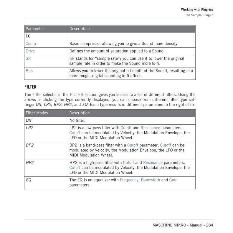
Parameter Description
FX
Comp Basic compressor allowing you to give a Sound more density.
Drive Defines the amount of saturation applied to a Sound.
SR SR stands for “sample rate”: you can use it to lower the originalsample rate in order to make the Sound more lo-fi.
Bits Allows you to lower the original bit depth of the Sound, resulting in amore rough, digital sounding lo-fi effect.
FILTER
The Filter selector in the FILTER section gives you access to a set of different filters. Using thearrows or clicking the type currently displayed, you can choose from different filter type set-tings: Off, LP2, BP2, HP2, and EQ. Each type results in different parameters to the right of it:
Filter Modes Description
Off No filter.
LP2 LP2 is a low-pass filter with Cutoff and Resonance parameters.Cutoff can be modulated by Velocity, the Modulation Envelope, theLFO or the MIDI Modulation Wheel.
BP2 BP2 is a band-pass filter with a Cutoff parameter. Cutoff can bemodulated by Velocity, the Modulation Envelope, the LFO or theMIDI Modulation Wheel.
HP2 HP2 is a high-pass filter with Cutoff and Resonance parameters.Cutoff can be modulated by Velocity, the Modulation Envelope, theLFO or the MIDI Modulation Wheel.
EQ The EQ is an equalizer with Frequency, Bandwidth and Gainparameters.
Working with Plug-ins
The Sampler Plug-in
MASCHINE MIKRO - Manual - 284
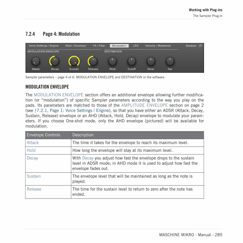
7.2.4 Page 4: Modulation
Sampler parameters – page 4 of 6: MODULATION ENVELOPE and DESTINATION in the software.
MODULATION ENVELOPE
The MODULATION ENVELOPE section offers an additional envelope allowing further modifica-tion (or “modulation”) of specific Sampler parameters according to the way you play on thepads. Its parameters are matched to those of the AMPLITUDE ENVELOPE section on page 2(see ↑7.2.1, Page 1: Voice Settings / Engine), so that you have either an ADSR (Attack, Decay,Sustain, Release) envelope or an AHD (Attack, Hold, Decay) envelope to modulate your param-eters. If you choose One-shot mode, only the AHD envelope (pictured) will be available formodulation.
Envelope Controls Description
Attack The time it takes for the envelope to reach its maximum level.
Hold How long the envelope will stay at its maximum level.
Decay With Decay you adjust how fast the envelope drops to the sustainlevel in ADSR mode; in AHD mode it is used to adjust how fast theenvelope fades out.
Sustain The envelope level that will be maintained as long as the note isplayed.
Release The time for the sustain level to return to zero after the note hasended.
Working with Plug-ins
The Sampler Plug-in
MASCHINE MIKRO - Manual - 285

DESTINATION
This is where you define modulation targets for the modulation envelope, i.e. the parametersyou want this envelope to control. The knobs adjust the amount of modulation for the followingtargets:
Parameter Modulation Destination
Pitch Tune parameter of the PITCH / GATE section on the Pitch / Envelopepage (page 2).
Cutoff Cutoff parameter of the FILTER section (with filter types LP2, HP2,BP2 only) on the FX / Filter page (page 3).
Drive Drive parameter of the FX section on the FX / Filter page (page 3).
Pan Pan parameter on the Audio page of the Sound’s Output properties(see ↑12.1.2, Configuring the Main Output of Sounds and Groups formore information).
7.2.5 Page 5: LFO
Sampler parameters – page 5 of 6: LFO and DESTINATION in the software.
LFO
The LFO (Low Frequency Oscillator) is another modulation source based on waveforms withdifferent shapes.
Working with Plug-ins
The Sampler Plug-in
MASCHINE MIKRO - Manual - 286
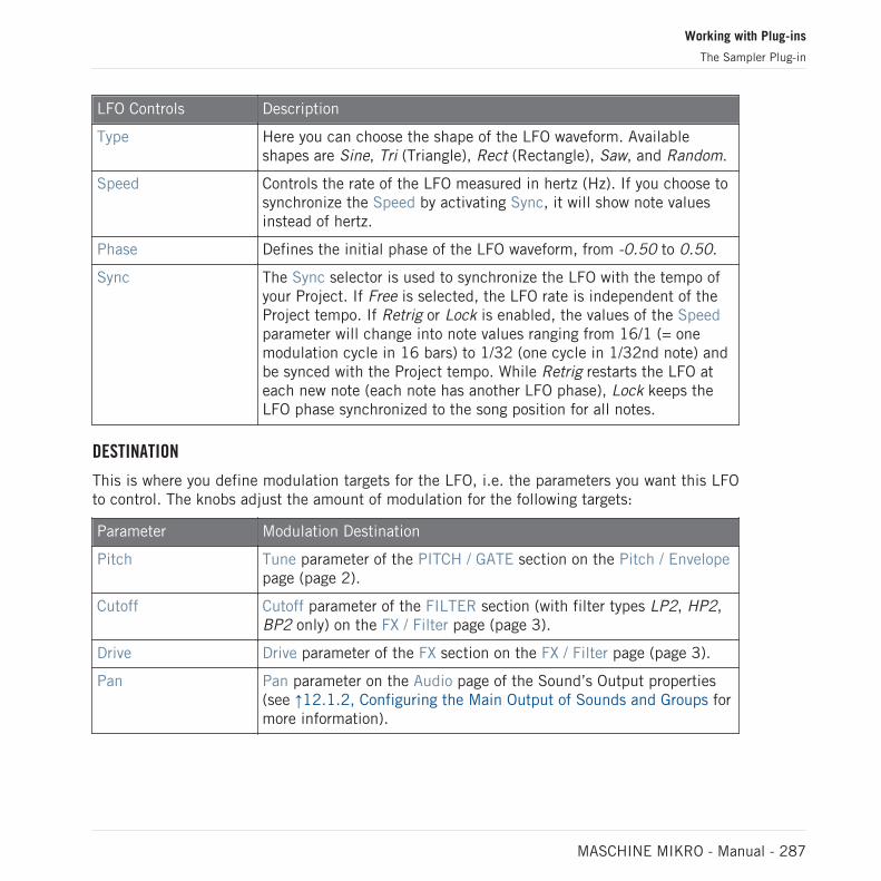
LFO Controls Description
Type Here you can choose the shape of the LFO waveform. Availableshapes are Sine, Tri (Triangle), Rect (Rectangle), Saw, and Random.
Speed Controls the rate of the LFO measured in hertz (Hz). If you choose tosynchronize the Speed by activating Sync, it will show note valuesinstead of hertz.
Phase Defines the initial phase of the LFO waveform, from -0.50 to 0.50.
Sync The Sync selector is used to synchronize the LFO with the tempo ofyour Project. If Free is selected, the LFO rate is independent of theProject tempo. If Retrig or Lock is enabled, the values of the Speedparameter will change into note values ranging from 16/1 (= onemodulation cycle in 16 bars) to 1/32 (one cycle in 1/32nd note) andbe synced with the Project tempo. While Retrig restarts the LFO ateach new note (each note has another LFO phase), Lock keeps theLFO phase synchronized to the song position for all notes.
DESTINATION
This is where you define modulation targets for the LFO, i.e. the parameters you want this LFOto control. The knobs adjust the amount of modulation for the following targets:
Parameter Modulation Destination
Pitch Tune parameter of the PITCH / GATE section on the Pitch / Envelopepage (page 2).
Cutoff Cutoff parameter of the FILTER section (with filter types LP2, HP2,BP2 only) on the FX / Filter page (page 3).
Drive Drive parameter of the FX section on the FX / Filter page (page 3).
Pan Pan parameter on the Audio page of the Sound’s Output properties(see ↑12.1.2, Configuring the Main Output of Sounds and Groups formore information).
Working with Plug-ins
The Sampler Plug-in
MASCHINE MIKRO - Manual - 287

7.2.6 Page 6: Velocity / Modwheel
Sampler parameters – page 6 of 6: VELOCITY DESTINATION and MODWHEEL DESTINATION in the software.
VELOCITY DESTINATION
This section allows you to use the input velocity in order to modulate various parameters.
Parameter Modulation Destination
Start Start parameter of the PITCH / GATE section on the Pitch / Envelopepage (page 2). Positive values shift the Sample start position later intime as you play harder, negative values shift it closer to thebeginning of the Sample as you play harder.
Tip: a typical example for this parameter is setting it so that theinitial attack transient of a snare drum is heard only at high velocityvalues. This makes it sound “snappier” when you play hard, and“muffled” or muted when you play softly.
Decay Decay parameter of the AMPLITUDE ENVELOPE section on thePitch / Envelope page (page 2).
Cutoff Cutoff parameter of the FILTER section (with filter types LP2, HP2,BP2 only) on the FX / Filter page (page 3).
Volume This allows you to modulate the volume, which is what velocitynormally is used for.
MODWHEEL DESTINATION
Here you can determine how incoming MIDI data sent by the Modulation Wheel affects variousparameters.
Working with Plug-ins
The Sampler Plug-in
MASCHINE MIKRO - Manual - 288

Parameter Modulation Destination
Start Start parameter of the PITCH / GATE section on the Pitch / Envelopepage (page 2).
Cutoff Cutoff parameter of the FILTER section (with filter types LP2, HP2,BP2 only) on the FX / Filter page (page 3).
LFO Depth Use this knob to adjust how much the Modulation Wheel affects thedepth of the LFO modulation (for all targets) defined on the LFOpage (page 5).
Pan Pan parameter on the Audio page of the Sound’s Output properties(see ↑12.1.2, Configuring the Main Output of Sounds and Groups formore information).
7.3 Using Native Instruments and External Plug-ins
MASCHINE allows you to load VST/AU plug-ins from Native Instruments (Native InstrumentsPlug-ins) or any third-party manufacturer (External Plug-ins) and to use them like the MA-SCHINE Internal Plug-ins.
As with Internal Plug-ins, the following rules apply for loading Native Instruments and ExternalPlug-ins:
▪ An Instrument Plug-in can be loaded only in the first Plug-in slot of a Sound.
▪ An Effect Plug-in can be loaded in any Plug-in slot of any Sound, any Group, or of the Mas-ter.
The following sections describe additional features and tasks specific to Native Instrumentsand/or External Plug-ins compared to Internal Plug-ins. For all other tasks (e.g., loading, ad-justing Plug-in parameters, etc.), please refer to section ↑7.1, Plug-in Overview.
7.3.1 Opening/Closing Plug-in Windows
When you load a Native Instruments or External Plug-in into a Plug-in slot, you can open afloating window containing the user interface of that Native Instruments or third-party instru-ment/effect.
Working with Plug-ins
Using Native Instruments and External Plug-ins
MASCHINE MIKRO - Manual - 289
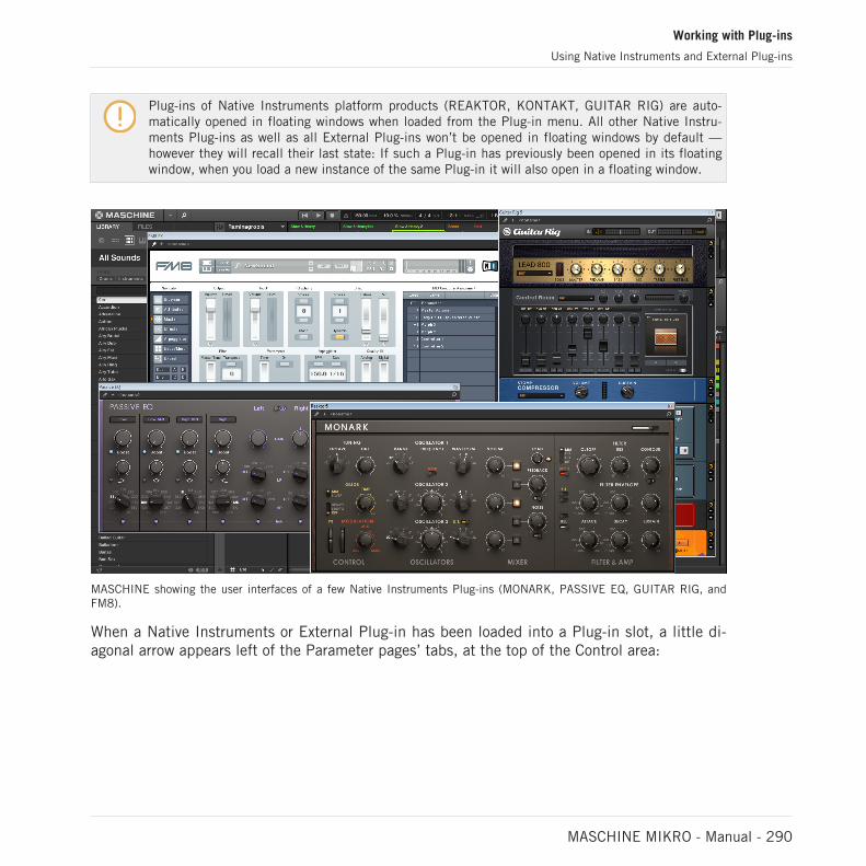
Plug-ins of Native Instruments platform products (REAKTOR, KONTAKT, GUITAR RIG) are auto-matically opened in floating windows when loaded from the Plug-in menu. All other Native Instru-ments Plug-ins as well as all External Plug-ins won’t be opened in floating windows by default —however they will recall their last state: If such a Plug-in has previously been opened in its floatingwindow, when you load a new instance of the same Plug-in it will also open in a floating window.
MASCHINE showing the user interfaces of a few Native Instruments Plug-ins (MONARK, PASSIVE EQ, GUITAR RIG, andFM8).
When a Native Instruments or External Plug-in has been loaded into a Plug-in slot, a little di-agonal arrow appears left of the Parameter pages’ tabs, at the top of the Control area:
Working with Plug-ins
Using Native Instruments and External Plug-ins
MASCHINE MIKRO - Manual - 290

The little diagonal arrow next to the Parameter pages’ tabs.
► To open or close the floating window of a Native Instruments or External Plug-in, selectthis Plug-in and click the little diagonal arrow at the left of the Parameter pages’ tabs (atthe top of the Control area). You can also double-click the Plug-in name in the list.
You can also close any floating window via the common button provided by your operating system atthe top left or right corner of the window.
MASCHINE will always show the open floating windows of the focused Sound, Group or Masterwhen selected. When you set the focus to another Sound, Group or the Master, all open float-ing windows disappear, possibly replaced by those for Native Instruments and/or External Plug-ins loaded in the newly focused Sound/Group/Master.
Plug-in selection is described in section ↑3.3.5, Navigating Channel Properties, Plug-ins, and Pa-rameter Pages in the Control Area.
Native Instruments Plug-ins: Default, Additional, and Edit View
Native Instruments Plug-ins provide the following extra features in the floating window:
▪ Plug-in Header: This is the same as in the Plug-in’s panel in the Plug-in Strip (software inMix view), with an additional Edit button described below. For more information, please re-fer to section ↑13.4.4, Custom Panels for Native Instruments Plug-ins.
▪ Default view and Additional view: Each Native Instruments Plug-in can provide one or twocustom views including reduced sets of controls. The Default view is available for every Na-tive Instruments Plug-in, while the Additional view is available for specific Native Instru-ments Plug-ins only. If a Native Instruments Plug-in provides an Additional view, you canswitch between Default and Additional view by clicking the “+” button in the Plug-in Head-er:
Working with Plug-ins
Using Native Instruments and External Plug-ins
MASCHINE MIKRO - Manual - 291

These views are also available in the Plug-in’s panel in the Plug-in Strip (Mix view in thesoftware). For more information, please refer to section ↑13.4.4, Custom Panels for NativeInstruments Plug-ins.
▪ Edit view: The Edit view shows the full user interface of the original Native Instrumentsproduct. You can show/hide the Edit view by clicking the Edit button (showing a pencilicon) in the Plug-in Header:
7.3.2 Using the VST/AU Plug-in Parameters
The parameters of Native Instruments and External Plug-ins offer various ways to shape eachinstrument/effect individually. Of course, you can adjust these parameters using the Plug-in’sown user interface (see section ↑7.3.1, Opening/Closing Plug-in Windows above). But MA-SCHINE also allows quick and convenient access to the parameters of any Native Instrumentsor External Plug-in: upon loading these parameters are auto-mapped and organized into Param-eter pages that will appear both in the software’s Control area and on your controller in Controlmode — exactly like Internal Plug-ins.
Having the Plug-in parameters on Parameter pages in MASCHINE has the following benefits:
▪ You can step through the Parameter pages and tweak each parameter on your controller viathe usual workflow directly after loading the Native Instruments or External Plug-in (seesection ↑3.3.5, Navigating Channel Properties, Plug-ins, and Parameter Pages in the Con-trol Area).
▪ The Plug-in parameters can be automated the same way as any other parameters (see sec-tion ↑11.5, Recording and Editing Modulation).
▪ The current state of the Plug-in parameters can be saved to the Browser as a preset for to-tal recall of the Plug-in (see section ↑7.1.9, Saving and Recalling Plug-in Presets for moreon this).
Working with Plug-ins
Using Native Instruments and External Plug-ins
MASCHINE MIKRO - Manual - 292

An auto-mapped Parameter page of the Massive Plug-in in the software.
Furthermore, for Native Instruments Plug-ins these Parameter pages group the Plug-in parame-ters in an intelligent way that fits the particular workflows of each Plug-in. For example in theMASSIVE Plug-in, the eight Macro Controls of MASSIVE will be grouped into a single Parame-ter page, the main parameters for Oscillator 1 will be grouped into another Parameter page,etc.
7.3.3 Setting Up Your Own Parameter Pages
As with any Plug-in, the parameters of a Native Instruments or External Plug-in are organizedinto pages. Each Plug-in can have any number of pages, each containing 8 knobs, which canbe assigned to the parameters of the VST/AU instrument or effect.
Parameter pages may be assigned automatically using auto-mapping (see section ↑7.3.2, Usingthe VST/AU Plug-in Parameters above) or created individually via Learn mode. With Learnmode, you can create custom pages containing only the desired parameters arranged to fit yourpersonal workflow. Moreover, you can create sections of parameters within each custom Pa-rameter page, and define custom labels for parameters, sections, and entire Parameter pages.
Note that parameters of Native Instruments and External Plug-ins are systematically assigned toknobs (not to switches nor selectors) in MASCHINE — this is also true in the MASCHINE software.
A parameter of a Native Instruments or External Plug-in can be assigned to one knob only!
To begin assigning parameters, do the following:
1. Select the Plug-in for which you want to customize parameter assignments.
Working with Plug-ins
Using Native Instruments and External Plug-ins
MASCHINE MIKRO - Manual - 293

2. Click the down-pointing arrow in the bottom left corner of the Control area to reveal theAssignment area underneath:
3. Click the Pages tab in the left part of the Assignment area:
→ The Pages tab lights up and the Pages pane appears on its right. You are now ready toassign parameters to the Parameter pages.
The Pages tab can be clicked only for Native Instruments or External Plug-ins and for the Macroproperties. For all other Plug-ins and Channel properties, parameters and Parameter pages are noteditable, and the Pages tab is grayed out and inactive. For more information on the Macro proper-ties and defining Macro Controls, please refer to ↑12.3, Creating Custom Sets of Parameters withthe Macro Controls.
When the Pages pane of the Assignment area is open, you also notice a few changes in theControl area above:
Working with Plug-ins
Using Native Instruments and External Plug-ins
MASCHINE MIKRO - Manual - 294
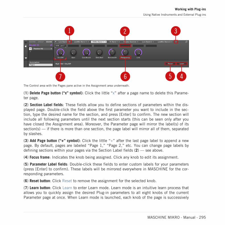
1 2 3
46 57The Control area with the Pages pane active in the Assignment area underneath.
(1) Delete Page button (“x” symbol): Click the little “x” after a page name to delete this Parame-ter page.
(2) Section Label fields: These fields allow you to define sections of parameters within the dis-played page. Double-click the field above the first parameter you want to include in the sec-tion, type the desired name for the section, and press [Enter] to confirm. The new section willinclude all following parameters until the next section starts (this can be seen only after youhave closed the Assignment area). Moreover, the Parameter page will mirror the label(s) of itssection(s) — if there is more than one section, the page label will mirror all of them, separatedby slashes.
(3) Add Page button (“+” symbol): Click the little “+” after the last page label to append a newpage. By default, pages are labeled “Page 1,” “Page 2,” etc. You can change page labels bydefining sections within your pages via the Section Label fields (2) — see above.
(4) Focus frame: Indicates the knob being assigned. Click any knob to edit its assignment.
(5) Parameter Label fields: Double-click these fields to enter custom labels for your parameters(press [Enter] to confirm). These labels will be mirrored everywhere in MASCHINE for the cor-responding parameters.
(6) Reset button: Click Reset to remove the assignment for the selected knob.
(7) Learn button: Click Learn to enter Learn mode. Learn mode is an intuitive learn process thatallows you to quickly assign the desired Plug-in parameters to all eight knobs of the currentParameter page at once. When Learn mode is launched, each knob of the page is successively
Working with Plug-ins
Using Native Instruments and External Plug-ins
MASCHINE MIKRO - Manual - 295

focused starting with the knob selected for editing — indicated by the Focus frame (4). Thenext parameter you touch in the plug-in’s user interface (see section ↑7.3.1, Opening/ClosingPlug-in Windows) will be assigned to the focused knob. Once a knob is assigned, the next knobto the right will become the focal point, and so on until the last knob is assigned. Once com-plete, Learn mode is automatically deactivated. Alternatively, at any time you can click Learnagain if you want to stop assigning parameters. When Learn mode is active, you can manuallychange the focus of the knobs by clicking the desired knob in the Parameter area.
Once you have organized plug-in parameters into Parameter pages, you can also use MASCHINEMacro Controls to pick the most commonly used parameters, e.g., for live performances. For moreinformation about Macro Controls, please refer to section ↑12.3, Creating Custom Sets of Parame-ters with the Macro Controls.
Parameter Slots - Context Menu
When the Assignment area is opened and the Pages tab is selected, a right-click on an as-signed or unassigned Parameter slot’s label brings up a context menu.
The parameter slots’ context menu.
The context menu contains following items:
Working with Plug-ins
Using Native Instruments and External Plug-ins
MASCHINE MIKRO - Manual - 296

Menu Item Description Keyboard Shortcuts
Rename Rename the Parameter. Ctrl + R / Cmd + R
Learn Activates the Learn Mode.
Reset Reset the Parameter.
Cut Cut the Parameter to paste it inanother position.
Ctrl + X / Cmd + X
Copy Copy the Parameter. Ctrl + C / Cmd + C
Paste Paste a cut or copied Macro to a newposition. Paste is only available if anapplicable Parameter is in theclipboard: Paste is only available onthe same Plug-in, this Plug-in can beplaced somewhere else.
Ctrl + V / Cmd + V
Pages Name - Context Menu
When the Assignment Area is opened and the Pages tab is selected, a right-click on a Pagename at the top of the Parameter area opens a context menu.
The Parameter pages’ context menu.
The context menu contains the following items:
Working with Plug-ins
Using Native Instruments and External Plug-ins
MASCHINE MIKRO - Manual - 297
Menu Item Description Keyboard Shortcuts
Delete Deletes current Page with allassignments.
Clear All Clears all the assignments, anddeletes all of the Pages.
7.3.4 Using VST/AU Plug-in Presets
For some of your Native Instruments or third-party VST/AU plug-ins, you might already have aset of factory or user presets (or patches, programs, etc.) that you like to use. MASCHINE letsyou directly load these presets and save them as Plug-in presets within MASCHINE. Savingyour VST/AU presets as Plug-in presets within MASCHINE will notably allow you to accessthem from the MASCHINE Browser, in the software as well as from your controller!
Saving presets can be done in the MASCHINE software only.
Accessing Factory Presets of Native Instruments’ Instruments/Effects
Accessing factory presets of your Native Instruments instruments and effects is straightfor-ward: factory presets of all Native Instruments instruments/effects installed on your computerare already integrated into the MASCHINE library! You will find them directly in the Browser byselecting the corresponding file type (Instruments or Effects) in the File Type selector, then se-lecting the factory content by clicking the NI logo on the right, then choosing the desired NIproduct in the drop-down list underneath — and of course, you will find all these presets inthe same locations in the Browser on your controller.
You can also add to the MASCHINE library the user presets you might have created for any NativeInstruments product installed on your computer. To do this, simply add the corresponding path(s) tothe list found on the User pane of the Library page in the Preferences panel. See section ↑3.6.4,Preferences – Default Page for more details.
Working with Plug-ins
Using Native Instruments and External Plug-ins
MASCHINE MIKRO - Manual - 298

Accessing Other VST/AU Presets
To access user presets of your Native Instruments instruments/effects as well as both factoryand user presets of your third-party VST/AU plug-ins, you first need to load the correspondingNative Instruments or External Plug-in into a Plug-in slot.
1. Load the desired Native Instruments or External Plug-in into a Plug-in slot (see section↑7.1.3, Loading, Removing, and Replacing a Plug-in).
2. Open the Plug-in menu by clicking the little arrow at the right of the Plug-in slot.The Plug-in menu now contains an additional Presets submenu located under the NativeInstruments and External submenus:
This submenu provides the list of all presets that your VST/AU plug-in has made availableto the host — MASCHINE in this case.
3. Select the desired preset in this submenu.
→ The preset is loaded into the Plug-in.
Each VST/AU instrument or effect might handle its presets (or patches, programs…) different-ly. Please refer to the plug-in documentation to find out how to reveal its presets (or a particu-lar set of presets) to the host.
For example, in MASSIVE, ABSYNTH 5, and FM8, you need to enable the Program List and fill itup with the desired patches in order to expose these and see them appear in the Presets submenuof the Plug-in menus in MASCHINE.
Working with Plug-ins
Using Native Instruments and External Plug-ins
MASCHINE MIKRO - Manual - 299

Some VST/AU plug-ins can run both as instrument and effect plug-ins. When loading a preset forsuch a plug-in, check that the preset can be effectively loaded in the current Plug-in slot — in par-ticular, take care to load presets for instruments in the first Plug-in slot of Sounds only! To avoidany mistake, one solution is to name your VST/AU presets explicitly (e.g., by adding a suffix “[FX]”to the effect presets).
MASCHINE allows you also to change the preset in your Native Instruments or third-party VST/AU plug-in via MIDI Program Change messages. For more information, see section ↑12.2.3,Controlling Parameters via MIDI and Host Automation.
Saving VST/AU Presets as MASCHINE Plug-in Presets
Once you have loaded a VST/AU preset (user preset of a Native Instruments instrument/effector any preset of a third-party VST/AU instrument or effect) using the method described above,you can save it as a Plug-in preset in MASCHINE via the Save As… or Save As Default… com-mands of the Plug-in menu (see section ↑7.1.9, Saving and Recalling Plug-in Presets). Oncethis is done, your preset will be available as a user preset in the Instrument or Effect categoryof the MASCHINE Browser.
7.3.5 Multiple-Output Plug-ins and Multitimbral Plug-ins
MASCHINE allows an extended use of multiple-output Plug-ins as well as multitimbral Plug-ins.
Multiple-Output Plug-ins
Multiple-output Plug-ins are Plug-ins with more than one audio stereo output.
When a multiple-output Plug-in is loaded into a Sound, MASCHINE uses its available outputsas follows:
▪ The Plug-in’s first output pair is inserted in the usual Plug-in signal chain: This output pairis fed into the input of the next Plug-in slot (or sent to the channel output if the Plug-in isin the last Plug-in slot).
Working with Plug-ins
Using Native Instruments and External Plug-ins
MASCHINE MIKRO - Manual - 300

▪ The Plug-in’s additional outputs are made available as audio sources for other Sounds ofthe same Group (they appear in the Source menu in the Audio page of the Input propertiesfor these Sounds). This can be used to build advanced routings in MASCHINE. For moreinformation on configuring audio inputs for Sounds, please refer to section ↑12.1.1, Send-ing External Audio to Sounds.
Multitimbral Plug-ins
Multitimbral Plug-ins are Plug-ins that can receive MIDI on top of the host control.
When a multitimbral Plug-in is loaded into a Sound, the other Sounds of the same Group cansend MIDI data to this Plug-in: The Plug-in will appear as additional port in the Dest. menu onthe MIDI page of the Output properties for these Sounds. For more information on configuringMIDI output for Sounds, please refer to section ↑12.2.5, Sending MIDI from Sounds.
Working with Plug-ins
Using Native Instruments and External Plug-ins
MASCHINE MIKRO - Manual - 301
8 Using the Audio Plug-in
The Audio Plug-in can playback Samples (drums, percussion, basslines, guitar riffs, etc.) insync with the tempo of your Project. It has two modes: Loop mode and Gate mode.
▪ Loop mode is the default setting where the loaded loop will play continuously wheneverthere is an active Pattern in the Group. You can see the waveform of the Sample in thePattern Editor to understand how it aligns with the Pattern.
▪ Gate mode is similar to the Loop mode where the loaded loop will play continuously. How-ever, the loop will only be audible in locations where you place notes in the Pattern. Fur-thermore, when using Stretch mode the pitch of the loop will be transposed based on thepitch of the note (e.g. note C3 will play the Sample at its original pitch, while C4 plays theSample one octave higher than normal).
The Audio plug-in specializes in keeping audio loops playing in-sync with your Project, and hasthe optional ability to do so without influencing the key of the loop. Furthermore, you cantranspose the loop while it plays so that it fits the key of your song.
You can quickly audition your Samples from within the Browser and then drag and drop themdirectly onto a Sound. If you drag a Sample containing the Loops tag onto an empty Sound theAudio module will load automatically.
Once a loop has been loaded, it will appear as a waveform of the Sample in the Pattern Editor,allowing you to edit the Sample by adjusting the Patten Length, the overall tuning, adjust thesource tempo and length of the Sample, or add MIDI events to regions of the loop for selectiveplayback and pitching. For more fine adjustments you can edit events in a close-up view bytoggling the close-up view in the Pattern editor.
For more information on recording your own loops, refer to the chapter: ↑17, Sampling and SampleMapping.
Loading the Audio Plug-in
The Audio Plug-in can be loaded onto any Sound within a Group. As a MASCHINE Plug-in, itsupports all usual Plug-in workflows. Hence, to know how to load, remove, replace, insert,move, copy/paste the Audio Plug-in, as well as how to adjust the Audio Plug-in parameters andload/save default presets, refer to the section ↑7, Working with Plug-ins.
Using the Audio Plug-in
MASCHINE MIKRO - Manual - 302

Once an Audio Plug-in is loaded it becomes visible in both the MASCHINE software and on thecontroller.
MASCHINE Audio Plug-in
Here is an overview of the Audio Plug-in parameters:
Element Description
PLAYBACK Section
Mode Select the mode of playback: Loop or Gate.
Loop: The default mode for playback, in this mode the Sample isheard with the Pattern (as with any regular MIDI event) without theneed to trigger it. In this mode, Playback and Source parameters canbe manipulated such as Tune, Pitchbend, Tempo, and Length.
Gate: When Gate mode is selected the Sample is only heard whentriggered by a MIDI note event. The Sample is heard for the durationof the MIDI note event, and the note can also be used to pitch theSample for melodic effect.
Fade (Gate mode only) Set a simple fade-in/fade-out amount to avoid pops or clicks that mayoccur when using the Gate mode. To increase the fade of Gate mode,turn the Fade knob clockwise by clicking and dragging upwards. Todecrease the fade, turn the Fade knob counter-clockwise by clickingand dragging downwards. Press the [SHIFT] key on your computerkeyboard while turning the knob to increase or decrease the fade infiner increments.
Using the Audio Plug-in
MASCHINE MIKRO - Manual - 303

Element Description
Tune Transpose the tune (range: -36 – +36 semitones) of the Audio Plug-in. You can use this knob to set the playback pitch of the loop to 'C',and then the loop's pitch will match the pitch of Notes programmedinto the Pattern.
To increase the tuning of the Sample in semitones, turn the Tuneknob clockwise by clicking and dragging upwards. To decrease thetuning of the Sample in semitones, turn the Tune knob counter-clockwise by clicking and dragging downwards. Press the [SHIFT] keyon your computer keyboard while turning the knob to increase ordecrease the tuning in cents.
Pitchbend Set the Pitchbend range (-12 – +12) for the Audio Plug-in which isrelative to the Tune. This parameter controls the effect of the PitchWheel/Slider on your MIDI controller.
To increase the range of the Pitchbend, turn the Pitchbend knobclockwise by clicking and dragging upwards. To decrease the range ofthe Pitchbend, turn the Pitchbend knob counter-clockwise byclicking and dragging downwards. Press the [SHIFT] key on yourcomputer keyboard while turning the knob to increase or decrease thePitchbend range in cents.
ENGINE Section
Re-pitch This playback engine simply matches the tempo of the Loop to theProject’s tempo by changing the playback rate of the Loop, andplayback rate changes will result in pitch changes to the loop. Like avinyl record, playing it faster will also cause the pitch of the loop torise, whereas slowing it down causes the overall pitch to drop. Thismode is therefore more suitable for non-pitched material, like drumsand percussion, and has the benefit that the transients of soundsremain sharp and also uses significantly less CPU than the otherEngine modes. Since tempo and pitch are not independentlyadjustable with this Engine, any pitch automation you may have donevia Events entered in Gate mode will be ignored, only the rhythm ofthe Events will be used to gate the Loop on and off.
Using the Audio Plug-in
MASCHINE MIKRO - Manual - 304

Element Description
Stretch This playback engine provides complete independence betweentempo and pitch. With this engine, you can change the tempo of aloop without changing its pitch, you can change its pitch withoutchanging its tempo, or you can change both the tempo and pitchsimultaneously. This mode even allows you to automate pitchchanges by entering Events into the Pattern Editor while using Gatemode. As this mode provides complete tempo and pitchindependence, and also works on polyphonic material, it requiresmore CPU power than other Engines.
Formant This playback engine is best suited to pitched (tonal) audio as itpreserves the formant of the sound. By preserving the formant, itretains the intrinsic character and avoids any shifts in pitch thatwould normally result in the undesirable cartoonlike effects on vocalswhen they are pitched upwards or downwards.
SOURCE Section
Tempo Set the original tempo of your Sample so that the Audio Plug-in canaccurately play it in sync, no matter what tempo you choose for yourProject. This is useful if MASCHINE has miscalculated the tempowhile importing the Sample. However, be aware that changing Tempoduring playback could affect the synchronization of your Sample.
To increase Tempo click and drag upwards. To decrease the Tempo,click and drag downwards. Press the [SHIFT] button on yourcomputer keyboard while dragging to set finer increments.
Length Set the original length of your Sample so that the Audio Plug-in canaccurately play it in sync, no matter what tempo you choose for yourProject. This is useful if MASCHINE has miscalculated the lengthwhile importing the Sample. However, be aware that changing Lengthduring playback could affect the synchronization of your Sample.
To increase Length click and drag upwards. To decrease the Length,click and drag downwards. Press the [SHIFT] key on your computerkeyboard while dragging to set finer increments.
Using the Audio Plug-in
MASCHINE MIKRO - Manual - 305

8.1 Loading a Loop into the Audio Plug-in
You can use the Sampler Plug-in to record sound directly from a microphone, or from an elec-tric instrument (such as an electric guitar) connected to your soundcard, to create your ownloops. Alternatively, you can quickly audition loops within the MASCHINE Library by using theLoops tag in the Browser to find one you want. To learn how to filter for loops using the Brows-er, refer to the section ↑4.2.6, Selecting Type and Character Tags.
It is possible to load a Sample tagged as Loops directly from the Browser by dragging anddropping it onto an empty Sound, which will place the Sample directly within the Pattern. Asthe Sample is loaded into the Pattern a waveform of the Sample will become visible and MA-SCHINE will seamlessly determine tempo information from the Sample and automatically timestretch it to fit the tempo of your Project. You can begin playback immediately after it hasloaded.
Pattern Editor with the Audio Plug-in in Loop mode loaded on Sound 4.
Using the Audio Plug-in
Loading a Loop into the Audio Plug-in
MASCHINE MIKRO - Manual - 306

By default the Audio Plug-in will playback in Loop mode, meaning the Sample will be repeatedfor the duration of the Pattern regardless of the length of the Sample. If you want to chop theloop and pitch it, switch to Gate mode. For more information on Gate mode, refer the followingsection ↑8.3, Using Loop Mode.
If you are using a Sample with the Sampler Plug-in and decide you want to use it with the AudioPlug-in, you can quickly switch from one Plug-in to another using the controller. This functionalitycan be handy if attempting to load a loop which does not have the Loops tag as these files will loadinto the Sampler Plug-in if they are missing the Loops tag. For more information on selecting plug-ins, refer to the section Browser Plug-in Slot Selection.
8.2 Editing Audio in the Audio Plug-in
The Audio Plug-in contains an Edit tab which, when clicked, opens the audio plug-in editingfeatures. Here you can change the Playable Range Start and End markers to isolate only a por-tion of the loaded audio file that you wish to loop, and also perform destructive audio edits toloops loaded into the Audio plug-in.
To access the Audio Plug-in Editor in the software, do the following:
1. In the Sound List left of the Pattern Editor, click the desired Sound to put it under focus.For more details on how to set the focus to a Sound, please see section ↑3.3.3, Focusingon a Group or a Sound.
2. Click the Sample Editor button on the left of the Pattern Editor to switch to the SampleEditor.
The Sample Editor appears and displays the Sample content of the focused Sound.
3. In the Sample Editor, click the desired tab at the top to access the corresponding page:
▪ The Record page allows you to record audio: ↑17.2, Recording Audio.
Using the Audio Plug-in
Editing Audio in the Audio Plug-in
MASCHINE MIKRO - Manual - 307

▪ The Edit page allows you to apply destructive edits to existing audio: ↑17.3, Editing a Sam-ple.
The destructive audio editing features here are the same as those found in the Sample Editor,for more information on using the destructive audio editing features, refer to ↑17.3, Editing aSample.
8.3 Using Loop Mode
Loop mode is the default mode for the Audio Plug-in and is used to playback an audio file intime with your Project. When loaded into a Sound, the audio appears as a waveform in the Pat-tern Editor and is repeated for the entirety of the Pattern. A detailed overview of the waveformis displayed in Keyboard view.
If the Pattern Length is decreased to a length shorter than the audio, Pattern playback will endup looping back to the start before the entire audio has played, the Pattern Length must be atleast as long as the audio in order to hear the entire audio playing in the Pattern. If the PatternLength is increased to a length longer than the audio, the audio will be automatically looped asneeded to fill the entire length of the Pattern, and these iterations will be visualized with dark-er versions of the waveform. For more information on changing the Pattern Length, refer to thesection ↑11.1.6, Adjusting the Arrange Grid and the Pattern Length.
The process of using Loop mode is as follows; load an audio file onto a Sound, select Loopmode from the parameters of the Audio Plug-in.
Using the Audio Plug-in
Using Loop Mode
MASCHINE MIKRO - Manual - 308

The Audio Plug-in with a bass recording in Loop mode.
Enabling and Disabling Audio per Pattern
When using Loop mode with the Audio plug-in, it is possible to enable and disable audio in thecurrent Pattern in the Pattern Editor. By default, when audio is recorded using the Audio plug-in, or if it is tagged as a ‘Loop’ and loaded directly from the Browser, it will be enabled in thePattern and play back when you press Play.
To disable audio and temporarily remove it from the Pattern simply double-click its waveform.By clicking the same area again the audio can be reactivated for the Pattern.
Using the Audio Plug-in
Using Loop Mode
MASCHINE MIKRO - Manual - 309

8.4 Using Gate Mode
Gate mode is used to chop and pitch selected parts of your Sample by applying MIDI noteevents in the Keyboard view of the Pattern Editor or by recording them using your controller.Each event is a gate for the Sample; the length determines the duration of playback, andplacement on the scale determines the pitch. By chopping and pitching the loop you can cre-ate melodies or even use it for effect on drums.
In Keyboard view, MIDI note events are visually layered on top of the Samples’ waveform andcan be edited or deleted at any time, and more importantly, the Sample can be changed at anytime while retaining the MIDI note events in the Pattern, meaning you can keep the phrasingand melody but use a different Sample for the playback.
Gate mode in the Pattern Editor with a Sample and MIDI events.
Using the Audio Plug-in
Using Gate Mode
MASCHINE MIKRO - Manual - 310
The process of using Gate mode is as follows; load a loop onto a Sound, select Gate mode fromthe parameters of the Audio Plug-in and then add MIDI events in the Pattern in the regionswhere you want to chop and pitch your Sample, or press play on your controller and use thepads to pitch the Sample. For more information on recording and editing events, refer to chap-ter ↑11, Working with Patterns.
To zoom into a Pattern, double-click on the vertical scroll bar to the right of the Pattern Editor.
Using the Audio Plug-in
Using Gate Mode
MASCHINE MIKRO - Manual - 311

9 Using the Drumsynths
Drumsynths are a powerful set of monophonic Internal Instrument Plug-ins (i.e. InstrumentPlug-ins included with MASCHINE) that allow you to generate individual, fine-tuned drumsounds for your music productions. Like any other Instrument Plug-in, you can load them onlyin the first Plug-in slot of Sounds.
Drumsynths have been designed for extreme playability, both from the high-quality pads ofyour MASCHINE controller and from any velocity-sensitive MIDI keyboard. They allow you toquickly build custom drum sounds and give you full control over the characteristics of the vari-ous drums — don’t hesitate to tweak them during your live performance or automate them likeany other Plug-in!
See section ↑11.5, Recording and Editing Modulation for more information on automation.
In this chapter you will find:
▪ An overview of the Drumsynths and a presentation of their common features: ↑9.1, Drum-synths – General Handling.
▪ A detailed description of each particular Drumsynth:
◦ The Kick Plug-in: ↑9.2, The Kicks.
◦ The Snare Plug-in: ↑9.3, The Snares.
◦ The Hi-hat Plug-in: ↑9.4, The Hi-hats.
◦ The Tom Plug-in: ↑9.5, The Toms.
◦ The Percussion Plug-in: ↑9.6, The Percussions.
We describe here the specific handling and parameters of the Drumsynths. For a description of thefeatures and characteristics of Plug-ins in general (including the Drumsynths), please refer to sec-tion ↑7.1, Plug-in Overview.
Using the Drumsynths
MASCHINE MIKRO - Manual - 312

9.1 Drumsynths – General Handling
This section describes the general use and features of the Drumsynths.
Managing Drumsynths
Drumsynths are MASCHINE Plug-ins and, as such, they support all usual Plug-in actions andprocedures. Hence, to know how to load, remove, replace, insert, move, copy/paste Drum-synths, as well as how to adjust the Drumsynth parameters and load/save presets, please referto section ↑7.1, Plug-in Overview, where these are described in detail.
9.1.1 Engines: Many Different Drums per Drumsynth
Each of the available Drumsynths (Kick, Snare, Hi-hat, Tom, and Percussion) actually providesmany different drums: Indeed, each Drumsynth allows you to select a particular engine for gen-erating the drum sound. In the same Drumsynth each engine will have its own algorithm, pa-rameters, and sonic characteristics — it is in fact an entirely distinct drum. For example, theKick provides eight different engines! Some engines will create acoustic drums while otherswill rather produce electronic sounds.
In each Drumsynth the first parameter (Engine) lets you select the engine you want to use.Most of the other parameters will depend on the selected engine.
9.1.2 Common Parameter Organization
All Drumsynths have a similar parameter organization, both in the Control area of the Arrangeview and in the Plug-in Strip of the Mix view.
Common Parameter Pages in the Control Area (Arrange View)
In Arrange view, the parameters of all Drumsynths are grouped in similar ways in the Controlarea:
Using the Drumsynths
Drumsynths – General Handling
MASCHINE MIKRO - Manual - 313

All Drumsynths share the same parameter organization in the Control area.
▪ Their parameters are grouped into the same three Parameter pages:
◦ The Main page groups the most important parameters for each drum type. Here youcan select the engine to be used, the tuning, the decay, etc.
◦ The Advanced page provides access to more complex and finer adjustments to thedrum sounds.
◦ The Modulation page allows to adjust the playability of the drum by setting its velocityresponse.
▪ The Main page always starts with a MAIN section. The other sections on the page differ witheach Drumsynth and engine.
Common Layout in the Plug-in Strip (Mix View)
In Mix view, the Plug-in panels of all Drumsynths have a similar layout in the Plug-in Strip:
Using the Drumsynths
Drumsynths – General Handling
MASCHINE MIKRO - Manual - 314

All Drumsynths share the same global layout in the Plug-in Strip.
▪ In the top part of the panel you can adjust the Tune parameter, select the desired engine,adjust the velocity response, and adjust the Decay parameter (or the Filter parameter forthe Shaker engine of the Percussion).
▪ In the bottom part of the panel you find the other parameters adjusting the sound of theselected engine.
For more information on the various Plug-in panels found in the Plug-in Strip, please refer to sec-tion ↑13.4, The Plug-in Strip.
Using the Drumsynths
Drumsynths – General Handling
MASCHINE MIKRO - Manual - 315

9.1.3 Shared Parameters
Within each Drumsynth, some parameters are shared between several engines (e.g., the Tuneparameter). Shared parameters have the advantage of keeping their position when you switch toanother engine in the Drumsynth. This allows you to compare the sound of various enginesmore easily.
The ranges of some shared parameters are different across engines. For example this is the case ofthe Tune parameter: When switching to another engine, the tuning might not stay the same al-though the knob position is kept.
Determining which parameters are shared among engines is straightforward: If you find a pa-rameter in more than one engine, it is shared between these engines.
If you switch to another Drumsynth (e.g., if you replace the Kick sitting in a Plug-in slot with a Hi-hat) parameter positions will not be kept!
9.1.4 Various Velocity Responses
Each engine of each Drumsynth has a different response to the velocity of the notes you areplaying. Globally, engines can be grouped into two general categories:
▪ Acoustic sounding engines are heavily velocity-dependant: the velocity affects many charac-teristics of the generated sound, which allows you to play these drums very expressively.
▪ Electronic sounding engines are generally less velocity-dependent. Most of them only usevelocity to modulate the output volume of the sound.
The overall velocity sensitivity for both acoustic and electronic types of engines can be adjust-ed on the Modulation page via the Velocity control.
9.1.5 Pitch Range, Tuning, and MIDI Notes
All Drumsynths can be played chromatically: the pitch of the sound will be affected by thenotes that you play on your MIDI keyboard (or on your pads in Keyboard mode).
Using the Drumsynths
Drumsynths – General Handling
MASCHINE MIKRO - Manual - 316

For all engines, the Tune parameter lets you define which pitch will be played when hitting thepad of that Sound (with pads in Pad Mode) or playing the middle C (MIDI note 60) base note.
In the MASCHINE convention the MIDI note 60 is noted C3.
The engines have different pitch ranges:
▪ Most engines have limited pitch ranges: For example, in the Snare, the Chrome engine canplay pitches from MIDI note 60 to 84, while the Iron engine can play pitches from MIDInote 46 to 70. If the pitch of an incoming MIDI note falls outside the pitch range of theengine, the pitch will be bounded to that engine’s allowable pitch range.
▪ Some engines have an unlimited pitch range: For example the Kick’s Sub engine, the Tom’sFractal and Tronic engines, and the Percussion’s Fractal engine.
In some drum engines it is impossible to set an exact tuning in MIDI notes. For them the Tuneparameter is set in percents (from 0 % to 100 %).
9.2 The Kicks
The Kick Drumsynth can generate a myriad of kick sounds.
The Kick in the Control area (Main page depicted).
Using the Drumsynths
The Kicks
MASCHINE MIKRO - Manual - 317
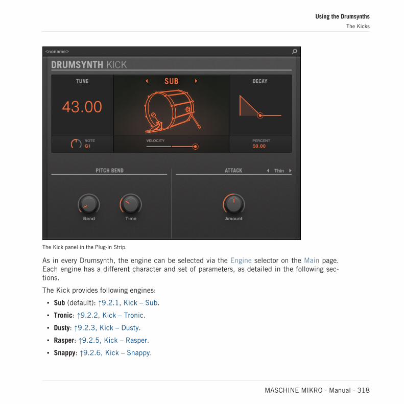
The Kick panel in the Plug-in Strip.
As in every Drumsynth, the engine can be selected via the Engine selector on the Main page.Each engine has a different character and set of parameters, as detailed in the following sec-tions.
The Kick provides following engines:
▪ Sub (default): ↑9.2.1, Kick – Sub.
▪ Tronic: ↑9.2.2, Kick – Tronic.
▪ Dusty: ↑9.2.3, Kick – Dusty.
▪ Rasper: ↑9.2.5, Kick – Rasper.
▪ Snappy: ↑9.2.6, Kick – Snappy.
Using the Drumsynths
The Kicks
MASCHINE MIKRO - Manual - 318

▪ Bold: ↑9.2.7, Kick – Bold.
▪ Maple: ↑9.2.8, Kick – Maple.
▪ Push: ↑9.2.9, Kick – Push.
For more information on engines, see ↑9.1.1, Engines: Many Different Drums per Drumsynth. Forgeneral information on the Kick and the other Drumsynths, see ↑9.1, Drumsynths – General Han-dling.
9.2.1 Kick – Sub
The Sub engine is the default engine of the Kick.
Based on the kick from a classic analog drum machine, the Sub kick is a clean, subby, sine-based kick drum which can be very effectively abused as a sub bass, tom or even a bleepy leadif tuned up and played chromatically on the keyboard.
The parameters described below are presented as they appear in the Control area (Arrange view).The same parameters are available in the Plug-in panel within the Plug-in Strip (Mix view). See↑13.4, The Plug-in Strip for more information on this.
Main Page
Element Description
MAIN Section
Engine Selects the engine used in the Kick Plug-in. If you change thissetting, please refer to ↑9.2, The Kicks.
Tune Adjusts the pitch of the drum played by the middle C, measured inMIDI note numbers and cents. Available values range from 31.00 to55.00. The default value is 43.00. For more details see ↑9.1.5,Pitch Range, Tuning, and MIDI Notes.
Decay Adjusts the duration of the sound’s tail, measured as a percentage.Available values range from 0.0 to 100.0 % (default: 50.0 %).
Using the Drumsynths
The Kicks
MASCHINE MIKRO - Manual - 319

Element Description
Bend Adjusts the amplitude of the pitch envelope applied throughout thesound duration (punch), measured as a percentage. Available valuesrange from 0.0 to 100.0 % (default: 6,8 %). At zero, the soundstays at its original pitch during its entire decaying phase. As theBend value is increased, an increasing amount of pitch envelope isapplied. This means that the pitch of the drum starts at a highervalue and falls to the original value as the sound decays. Thegreater the Bend value, the higher the starting pitch.
Time Adjusts the decay time of the pitch envelope, measured as apercentage. Available values range from 0.0 to 100.0 % (default:30 %). Note that if the Time value is too long compared to theDecay value, you won’t hear the entire pitch drop but only itsbeginning — i.e. you will hear a higher pitch than the one set byTune.
ATTACK Section
Mode Selects the style of the attack: Thin selects a thin-sounding click,Thick selects a slightly rounder click with added noise, and Noiseuses just a noise burst for a less clicky attack.
Color Only available if Thick or Noise is selected in the Mode selector.Adjusts the color of the attack, measured as a percentage. Availablevalues range from 0.0 to 100.0 % (default: 50.0 %). At lowervalues the attack is duller. Increase the Color value to get a moreincisive attack.
Amount Adjusts the level of the attack. Available values range from 0.0 %(soft attack) to 100.0 % (maximum attack). The default value is50.0 %.
Advanced Page
For this engine the Advanced page does not contain any parameters.
Using the Drumsynths
The Kicks
MASCHINE MIKRO - Manual - 320

Modulation Page
As with all other engines and Drumsynths, the Modulation page contains one parameter: Veloc-ity.
Element Description
SCALE Section
Velocity Adjusts the velocity response of the drum. Available values rangefrom -100.0 % to 100.0 % (default value). At zero (mid course),the drum is played at full velocity, no matter how hard you hit thekeys (or pads). From that mid position, by turning the knob to theright you increase the positive velocity response and make the drummore and more sensitive to the velocities at which you hit the keys/pads. From the mid position, turning the knob to the left as theinverse effect: the harder you hit the key/pad, the softer theresulting drum sound will be.
9.2.2 Kick – Tronic
Fat, punchy and warm, the Tronic kick is based on another classic analog kick drum which hasprovided the backbone to countless dance and electronic records for the past 30 years. TheTronic kick takes this classic a step further with extended parameter ranges and chromaticplayability, but also adds a specially designed distortion section capable of a wide range of tex-tures, from subtly rounded to all-out gabber assault.
The parameters described below are presented as they appear in the Control area (Arrange view).The same parameters are available in the Plug-in panel within the Plug-in Strip (Mix view). See↑13.4, The Plug-in Strip for more information on this.
Main Page
Element Description
MAIN Section
Engine Selects the engine used in the Kick Plug-in. If you change thissetting, please refer to ↑9.2, The Kicks.
Using the Drumsynths
The Kicks
MASCHINE MIKRO - Manual - 321

Element Description
Tune Adjusts the pitch of the drum played by the middle C, measured inMIDI note numbers and cents. Available values range from 31.00 to55.00. The default value is 43.00. For more details see ↑9.1.5,Pitch Range, Tuning, and MIDI Notes.
Decay Adjusts the duration of the sound’s tail, measured as a percentage.Available values range from 0.0 to 100.0 % (default: 50.0 %).
Bend Adjusts the amount of pitch envelope applied throughout the soundduration, measured as a percentage. Available values range from0.0 to 100.0 % (default: 6.8 %). Low values give a more gentlesound. As Bend is increased, the kick becomes more punchy; athigher values, the pitch envelope is more clearly audible as anactual pitch bend.
Impact Adjusts the amount of attack. Available values range from 0.0 %(soft attack) to 100 % (maximum attack). The default value is75.0 %.
Advanced Page
The Advanced page contains controls for the distortion.
Element Description
DISTORTION Section
Gain Adjusts the distortion gain, measured as a percentage. Availablevalues range from 0.0 to 100.0 % (default: 70.0 %). Increase Gainto get a more distorted drum sound.
Tone Adjusts the color of the distortion, measured as a percentage.Available values range from 0.0 to 100.0 % (default: 25.0 %).
Using the Drumsynths
The Kicks
MASCHINE MIKRO - Manual - 322

Element Description
Bias Adjusts the timbre of the distortion, measured as a percentage.Available values range from 0.0 to 100.0 % (default: 50.0 %). Atzero, the distortion is symmetrical and introduces mostly oddharmonics. As the Bias value is increased, the distortion becomesmore asymmetric and more even harmonics are introduced,resulting in a different tonality, especially at more subtle Gainsettings.
Mix Adjusts the mix between the clean and distorted signal, measuredas a percentage. Available values range from 0.0 to 100.0 %(default: 50.0 %). At zero, none of the distorted drum will be heard.At 100.0 %, only the distorted drum will be heard.
Changes to the distortion parameters are only audible when the Mix parameter is set above 0 %.
Modulation Page
As with all other engines and Drumsynths, the Modulation page contains one parameter: Veloc-ity.
Element Description
SCALE Section
Velocity Adjusts the velocity response of the drum. Available values rangefrom -100.0 % to 100.0 % (default value). At zero (mid course),the drum is played at full velocity, no matter how hard you hit thekeys (or pads). From that mid position, by turning the knob to theright you increase the positive velocity response and make the drummore and more sensitive to the velocities at which you hit the keys/pads. From the mid position, turning the knob to the left as theinverse effect: the harder you hit the key/pad, the softer theresulting drum sound will be.
Using the Drumsynths
The Kicks
MASCHINE MIKRO - Manual - 323

9.2.3 Kick – Dusty
The Dusty kick is an electronic kick with an organic feel. It’s capable of broken, dusty soundsbut can also open up to a thundering warehouse boom.
The parameters described below are presented as they appear in the Control area (Arrange view).The same parameters are available in the Plug-in panel within the Plug-in Strip (Mix view). See↑13.4, The Plug-in Strip for more information on this.
Main Page
Element Description
MAIN Section
Engine Selects the engine used in the Kick Plug-in. If you change thissetting, please refer to ↑9.2, The Kicks.
Tune Adjusts the pitch of the drum played by the middle C, measured asa percentage. Available values range from 0.0 to 100.0 % (default:50.0 %). For more details see ↑9.1.5, Pitch Range, Tuning, andMIDI Notes.
Decay Adjusts the duration of the sound’s tail, measured as a percentage.Available values range from 0.0 to 100.0 % (default: 50.0 %).
Impact Adjusts the amount of attack and click, measured as a percentage.Available values range from 0.0 % (soft attack) to 100.0 %(maximum attack). The default value is 75.0 %.
CHARACTER Section
Filter Adjusts the timbre of the drum, measured as a percentage.Available values range from 0.0 to 100.0 % (default: 40.0 %).Increase the value to produce richer high frequencies.
Noise Adjusts the amount of noise, measured as a percentage. Availablevalues range from 0.0 to 100.0 % (default: 10.0 %).
Using the Drumsynths
The Kicks
MASCHINE MIKRO - Manual - 324

Advanced Page
For this engine the Advanced page does not contain any parameters.
Modulation Page
As with all other engines and Drumsynths, the Modulation page contains one parameter: Veloc-ity.
Element Description
SCALE Section
Velocity Adjusts the velocity response of the drum. Available values rangefrom -100.0 % to 100.0 % (default value). At zero (mid course),the drum is played at full velocity, no matter how hard you hit thekeys (or pads). From that mid position, by turning the knob to theright you increase the positive velocity response and make the drummore and more sensitive to the velocities at which you hit the keys/pads. From the mid position, turning the knob to the left as theinverse effect: the harder you hit the key/pad, the softer theresulting drum sound will be.
9.2.4 Kick – Grit
The Grit kick is a modern electronic kick drum to suit a wide range of styles. It’s quite versa-tile: with a long decay it has a deep, boomy and airy tonality, but tightened up, it can thumpwith the best of them. At high tunings, especially with extreme “Aero Grind” and “AeroAmount” values, it becomes very gritty and bitcrushed, great for IDM and electro.
The parameters described below are presented as they appear in the Control area (Arrange view).The same parameters are available in the Plug-in panel within the Plug-in Strip (Mix view) — formore information please refer to section 9.4 “The Plug-in Strip” in the MASCHINE 2.0 Manual.
Using the Drumsynths
The Kicks
MASCHINE MIKRO - Manual - 325

Main Page
Element Description
MAIN Section
Engine Selects the engine used in the Kick Plug-in. If you change thissetting, please refer to section 10.2 “The Kicks” in theMASCHINE 2.0 Manual.
Tune Adjusts the pitch of the drum played by the middle C, measured inMIDI note numbers and cents. Available values range from 31.00 to55.00. The default value is 43.00.
Decay Adjusts the duration of the sound’s tail, measured as a percentage.Available values range from 0.0 to 100.0% (default: 50.0%).
Bend Adjusts the amount of pitch envelope applied to the kick, measuredas a percentage. Available values range from 0.0 to 100.0%(default: 6.8%).
Impact Adjusts the amount of click or initial attack, measured as apercentage. Available values range from 0.0 to 100.0% (default:75.0%).
Gate When enabled, the decay of the drum is choked by the end of thenote. When disabled, the drum plays as a one-shot sound, i.e. untilthe end of its tail, no matter when the note is released, although thesound duration will still depend on the Decay parameter (seeabove). Switching Gate on and setting the Decay parameter to ahigh value while playing short notes can result in a punchier, moreaggressive character than simply using short Decay values with Gateoff.
AERO Section
Using the Drumsynths
The Kicks
MASCHINE MIKRO - Manual - 326

Element Description
Grind Adjusts the grittiness of the “aero” component of the sound,measured as a percentage. Available values range from 0.0 to100.0% (default: 45.0%). Low values produce a boomyreverberation. High values result in a crushed, digital “air”squashed into the drum sound. Note that this parameter will onlyhave an effect if Amount is set to a non-zero value (see below).
Amount Controls the amount of air or grit in the kick sound, measured as apercentage. Available values range from 0.0 to 100.0% (default:20.0%).
Advanced Page
For this engine the Advanced page does not contain any parameters.
Modulation Page
Like with all other engines and Drumsynths, the Modulation page contains one parameter: Ve-locity.
Element Description
SCALE Section
Velocity Adjusts the velocity response of the drum. Available values rangefrom -100.0% to 100.0% (default value). At zero (mid course), thedrum is played at full velocity, no matter how hard you hit the keys(or pads). From that mid position, by turning the knob to the rightyou increase the positive velocity response and make the drum moresensitive to the velocity at which you hit the keys/pads. From themid position, turning the knob to the left as the inverse effect: theharder you hit the key/pad, the softer the resulting drum sound willbe.
Using the Drumsynths
The Kicks
MASCHINE MIKRO - Manual - 327
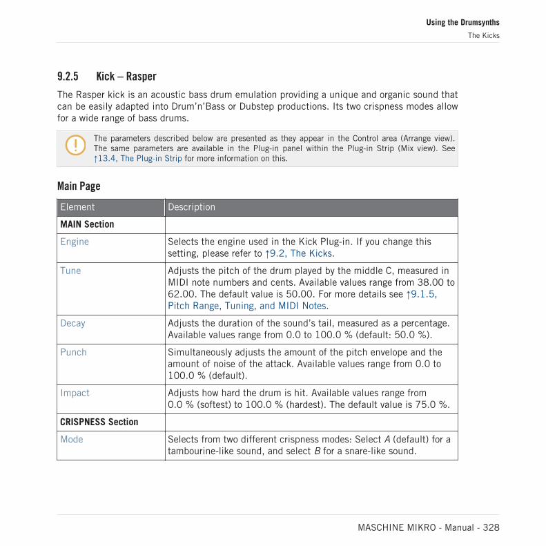
9.2.5 Kick – Rasper
The Rasper kick is an acoustic bass drum emulation providing a unique and organic sound thatcan be easily adapted into Drum’n’Bass or Dubstep productions. Its two crispness modes allowfor a wide range of bass drums.
The parameters described below are presented as they appear in the Control area (Arrange view).The same parameters are available in the Plug-in panel within the Plug-in Strip (Mix view). See↑13.4, The Plug-in Strip for more information on this.
Main Page
Element Description
MAIN Section
Engine Selects the engine used in the Kick Plug-in. If you change thissetting, please refer to ↑9.2, The Kicks.
Tune Adjusts the pitch of the drum played by the middle C, measured inMIDI note numbers and cents. Available values range from 38.00 to62.00. The default value is 50.00. For more details see ↑9.1.5,Pitch Range, Tuning, and MIDI Notes.
Decay Adjusts the duration of the sound’s tail, measured as a percentage.Available values range from 0.0 to 100.0 % (default: 50.0 %).
Punch Simultaneously adjusts the amount of the pitch envelope and theamount of noise of the attack. Available values range from 0.0 to100.0 % (default).
Impact Adjusts how hard the drum is hit. Available values range from0.0 % (softest) to 100.0 % (hardest). The default value is 75.0 %.
CRISPNESS Section
Mode Selects from two different crispness modes: Select A (default) for atambourine-like sound, and select B for a snare-like sound.
Using the Drumsynths
The Kicks
MASCHINE MIKRO - Manual - 328

Element Description
Decay Adjusts the duration of the crispness effect, measured as apercentage. Available values range from 0.0 to 100.0 % (default:34.0 %).
Amount Adjusts the amount of crispness, measured as a percentage.Available values range from 0.0 to 100.0 % (default: 50.0 %).
Advanced Page
For this engine the Advanced page does not contain any parameters.
Modulation Page
As with all other engines and Drumsynths, the Modulation page contains one parameter: Veloc-ity.
Element Description
SCALE Section
Velocity Adjusts the velocity response of the drum. Available values rangefrom -100.0 % to 100.0 % (default value). At zero (mid course),the drum is played at full velocity, no matter how hard you hit thekeys (or pads). From that mid position, by turning the knob to theright you increase the positive velocity response and make the drummore and more sensitive to the velocities at which you hit the keys/pads. From the mid position, turning the knob to the left as theinverse effect: the harder you hit the key/pad, the softer theresulting drum sound will be.
9.2.6 Kick – Snappy
The Snappy kick is an acoustic bass drum emulation that provides control over the mic oscilla-tion before the hit via the Snap control. It’s capable of a mid-range bass drum sound that canbe tweaked via the extended punch parameters.
Using the Drumsynths
The Kicks
MASCHINE MIKRO - Manual - 329

The parameters described below are presented as they appear in the Control area (Arrange view).The same parameters are available in the Plug-in panel within the Plug-in Strip (Mix view). See↑13.4, The Plug-in Strip for more information on this.
Element Description
MAIN Section
Engine Selects the engine used in the Kick Plug-in. If you change thissetting, please refer to ↑9.2, The Kicks.
Tune Adjusts the pitch of the drum played by the middle C, measured inMIDI note numbers and cents. Available values range from 36.00 to60.00. The default value is 48.00. For more details see ↑9.1.5,Pitch Range, Tuning, and MIDI Notes.
Decay Adjusts the duration of the sound’s tail, measured as a percentage.Available values range from 0.0 to 100.0 % (default: 50.0 %).
Snap Emulates the air movement caused by the beater before the drum ishit. Therefore, it produces a snap in the waveform the length ofwhich can be controlled through this parameter. Available valuesrange from 0.0 to 100.0 % (default: 50.0 %).
Impact Adjusts how hard the drum is hit, measured as a percentage.Available values range from 0.0 % (softest) to 100.0 % (hardest).The default value is 75.0 %.
PUNCH Section
Mode Selects from two different punch modes: A (default) and B.
Decay Adjusts the duration of the punch, measured as a percentage.Available values range from 0.0 to 100.0 % (default: 50.0 %).
Amount Adjusts the amount of punch, measured as a percentage. Availablevalues range from 0.0 to 100.0 % (default).
Advanced Page
For this engine the Advanced page does not contain any parameters.
Using the Drumsynths
The Kicks
MASCHINE MIKRO - Manual - 330

Modulation Page
As with all other engines and Drumsynths, the Modulation page contains one parameter: Veloc-ity.
Element Description
SCALE Section
Velocity Adjusts the velocity response of the drum. Available values rangefrom -100.0 % to 100.0 % (default value). At zero (mid course),the drum is played at full velocity, no matter how hard you hit thekeys (or pads). From that mid position, by turning the knob to theright you increase the positive velocity response and make the drummore and more sensitive to the velocities at which you hit the keys/pads. From the mid position, turning the knob to the left as theinverse effect: the harder you hit the key/pad, the softer theresulting drum sound will be.
9.2.7 Kick – Bold
The Bold kick is an acoustic bass drum emulation that provides an aggressive character and apunchy and dirty sound. It is capable of a range of sounds, from rock-like kicks to more snappyand tight sub-kicks.
The parameters described below are presented as they appear in the Control area (Arrange view).The same parameters are available in the Plug-in panel within the Plug-in Strip (Mix view). See↑9.1.5, Pitch Range, Tuning, and MIDI Notes for more information on this.
Main Page
Element Description
MAIN Section
Engine Selects the engine used in the Kick Plug-in. If you change thissetting, please refer to ↑9.2, The Kicks.
Using the Drumsynths
The Kicks
MASCHINE MIKRO - Manual - 331

Element Description
Tune Adjusts the pitch of the drum played by the middle C, measured asa percentage. Available values range from 0.0 to 100.0 % (default:50.0 %). For more details see ↑9.1.5, Pitch Range, Tuning, andMIDI Notes.
Decay Adjusts the duration of the sound’s tail, measured as a percentage.Available values range from 0.0 to 100.0 % (default: 50.0 %).
Punch Simultaneously adjusts the amplitude and decay time of the noisein the attack. Available values range from 0.0 to 100.0 % (default).
Impact Adjusts how hard the drum is hit, measured as a percentage.Available values range from 0.0 % (softest) to 100.0 % (hardest).The default value is 75.0 %.
Advanced Page
For this engine the Advanced page does not contain any parameters.
Modulation Page
As with all other engines and Drumsynths, the Modulation page contains one parameter: Veloc-ity.
Element Description
SCALE Section
Velocity Adjusts the velocity response of the drum. Available values rangefrom -100.0 % to 100.0 % (default value). At zero (mid course),the drum is played at full velocity, no matter how hard you hit thekeys (or pads). From that mid position, by turning the knob to theright you increase the positive velocity response and make the drummore and more sensitive to the velocities at which you hit the keys/pads. From the mid position, turning the knob to the left as theinverse effect: the harder you hit the key/pad, the softer theresulting drum sound will be.
Using the Drumsynths
The Kicks
MASCHINE MIKRO - Manual - 332

9.2.8 Kick – Maple
The Maple kick is an acoustic bass drum emulation that provides a realistic and organic sound.It is suitable for any production where a supporter kick is needed. It fits perfectly with acousticinstruments and its room parameters make it fit seamlessly into any mix.
The parameters described below are presented as they appear in the Control area (Arrange view).The same parameters are available in the Plug-in panel within the Plug-in Strip (Mix view). See↑9.1.5, Pitch Range, Tuning, and MIDI Notes for more information on this.
Main Page
Element Description
MAIN Section
Engine Selects the engine used in the Kick Plug-in. If you change thissetting, please refer to ↑9.2, The Kicks.
Tune Adjusts the pitch of the drum played by the middle C, measured inMIDI note numbers and cents. Available values range from 42.00 to54.00. The default value is 48.00. For more details see ↑9.1.5,Pitch Range, Tuning, and MIDI Notes.
Decay Adjusts the duration of the sound’s tail, measured as a percentage.Available values range from 0.0 to 100.0 % (default: 50.0 %).
Skin Tune Adjusts the fine-tuning of the skin of the drum, measured as apercentage. Available values range from 0.0 to 100.0 % (default:50.0 %).
Impact Adjusts how hard the drum is hit, measured as a percentage.Available values range from 0.0 % (softest) to 100.0 % (hardest).The default value is 75.0 %.
ROOM Section
Mode Selects from two different noise types that simulate the room inwhich the drum is played. Available modes are A (default) and B.
Using the Drumsynths
The Kicks
MASCHINE MIKRO - Manual - 333

Element Description
Size Adjusts the size of the room, measured as a percentage. Availablevalues range from 0.0 to 100.0 % (default: 50.0 %).
Amount Adjusts the amount of room effect applied to the drum sound,measured as a percentage. Available values range from 0.0 to100.0 % (default: 75.0 %).
Advanced Page
For this engine the Advanced page does not contain any parameters.
Modulation Page
As with all other engines and Drumsynths, the Modulation page contains one parameter: Veloc-ity.
Element Description
SCALE Section
Velocity Adjusts the velocity response of the drum. Available values rangefrom -100.0 % to 100.0 % (default value). At zero (mid course),the drum is played at full velocity, no matter how hard you hit thekeys (or pads). From that mid position, by turning the knob to theright you increase the positive velocity response and make the drummore and more sensitive to the velocities at which you hit the keys/pads. From the mid position, turning the knob to the left as theinverse effect: the harder you hit the key/pad, the softer theresulting drum sound will be.
9.2.9 Kick – Push
The Push kick is an acoustic bass drum emulation that provides an aggressive and brazensound. It is essential for mixes where a dirty, tight and powerful kick is required. Its versatilityalso allows for noisy and clicky kicks.
Using the Drumsynths
The Kicks
MASCHINE MIKRO - Manual - 334

The parameters described below are presented as they appear in the Control area (Arrange view).The same parameters are available in the Plug-in panel within the Plug-in Strip (Mix view). See↑13.4, The Plug-in Strip for more information on this.
Main Page
Element Description
MAIN Section
Engine Selects the engine used in the Kick Plug-in. If you change thissetting, please refer to ↑9.2, The Kicks.
Tune Adjusts the pitch of the drum played by the middle C, measured asa percentage. Available values range from 0.0 to 100.0 % (default:50.0 %). For more details see ↑9.1.5, Pitch Range, Tuning, andMIDI Notes.
Decay Adjusts the duration of the sound’s tail, measured as a percentage.Available values range from 0.0 to 100.0 % (default: 50.0 %).
Punch Simultaneously adjusts the amount of the pitch envelope and theamount of noise of the attack. Available values range from 0.0 to100.0 % (default).
Impact Adjusts how hard the drum is hit. Available values range from0.0 % (softest) to 100.0 % (hardest). The default value is 75.0 %.
Advanced Page
For this engine the Advanced page does not contain any parameters.
Modulation Page
As with all other engines and Drumsynths, the Modulation page contains one parameter: Veloc-ity.
Using the Drumsynths
The Kicks
MASCHINE MIKRO - Manual - 335

Element Description
SCALE Section
Velocity Adjusts the velocity response of the drum. Available values rangefrom -100.0 % to 100.0 % (default value). At zero (mid course),the drum is played at full velocity, no matter how hard you hit thekeys (or pads). From that mid position, by turning the knob to theright you increase the positive velocity response and make the drummore and more sensitive to the velocities at which you hit the keys/pads. From the mid position, turning the knob to the left as theinverse effect: the harder you hit the key/pad, the softer theresulting drum sound will be.
9.3 The Snares
The Snare Drumsynth can generate a multitude of snare sounds.
The Snare in the Control area (Main page depicted).
Using the Drumsynths
The Snares
MASCHINE MIKRO - Manual - 336

The Snare panel in the Plug-in Strip.
As with every Drumsynth, the engine can be selected via the Engine selector on the Main page.Each engine has a different character and set of parameters, as detailed in the following sec-tions.
The Snare provides following engines:
▪ Volt (default): ↑9.3.1, Snare – Volt
▪ Bit: ↑9.3.2, Snare – Bit
▪ Pow: ↑9.3.3, Snare – Pow
▪ Sharp: ↑9.3.4, Snare – Sharp
▪ Airy: ↑9.3.5, Snare – Airy
Using the Drumsynths
The Snares
MASCHINE MIKRO - Manual - 337

▪ Vintage: ↑9.3.6, Snare – Vintage
▪ Chrome: ↑9.3.7, Snare – Chrome
▪ Iron: ↑9.3.8, Snare – Iron
▪ Clap: ↑9.3.9, Snare – Clap
For more information on engines, see ↑9.1.1, Engines: Many Different Drums per Drumsynth. Forgeneral information on the Snare and the other Drumsynths, see ↑9.1, Drumsynths – General Han-dling.
9.3.1 Snare – Volt
The Volt engine is the default engine of the Snare.
The Volt snare is an electronic snare based on a family of analog classics.
The parameters described below are presented as they appear in the Control area (Arrange view).The same parameters are available in the Plug-in panel within the Plug-in Strip (Mix view). See↑13.4, The Plug-in Strip for more information on this.
Main Page
Element Description
MAIN Section
Engine Selects the engine used in the Snare Plug-in. If you change thissetting, please refer to ↑9.3, The Snares.
Tune Adjusts the pitch of the drum played by the middle C, measured inMIDI note numbers and cents. Available values range from 53.00 to77.00. The default value is 65.00. For more details see ↑9.1.5,Pitch Range, Tuning, and MIDI Notes.
Decay Adjusts the duration of the sound’s tail, measured as a percentage.Available values range from 0.0 to 100.0 % (default: 50.0 %).
Using the Drumsynths
The Snares
MASCHINE MIKRO - Manual - 338

Element Description
Gate When enabled, the decay of the drum is choked by the end of theMIDI note. When disabled (default), the drum plays as a one-shotsound, i.e. until the end of its tail, no matter when the note isreleased.
Osc Mode Selects the oscillator mode: If you select Tonal (default), the engineuses two oscillators running in parallel, the higher of which is extrasensitive to velocity for increased expressivity. If you select Punchy,the engine uses one oscillator with a pitch envelope.
Osc Mix Only available if Tonal is selected in the Osc Mode selector (seeabove). Adjusts the mix between both oscillators, measured as apercentage. Available values range from 0.0 to 100.0 % (default:50.0 %).
Punch Only available if Punchy is selected in the Mode selector (seeabove). Adjusts the amplitude of the pitch envelope (punch),measured as a percentage. Available values range from 0.0 to100.0 % (default: 25.0 %).
NOISE Section
Color Adjusts the tone of the “snare” portion of the sound, measured as apercentage. Available values range from 0.0 to 100.0 % (default:50.0 %).
Amount Adjusts the level of the “snare” portion of the sound, measured as apercentage. Available values range from 0.0 to 100.0 % (default:25.0 %).
Advanced Page
For this engine the Advanced page does not contain any parameters.
Modulation Page
As with all other engines and Drumsynths, the Modulation page contains one parameter: Veloc-ity.
Using the Drumsynths
The Snares
MASCHINE MIKRO - Manual - 339

Element Description
SCALE Section
Velocity Adjusts the velocity response of the drum. Available values rangefrom -100.0 % to 100.0 % (default value). At zero (mid course),the drum is played at full velocity, no matter how hard you hit thekeys (or pads). From that mid position, by turning the knob to theright you increase the positive velocity response and make the drummore and more sensitive to the velocities at which you hit the keys/pads. From the mid position, turning the knob to the left as theinverse effect: the harder you hit the key/pad, the softer theresulting drum sound will be.
9.3.2 Snare – Bit
The Bit snare is a thin, harsh, digital snare.
The parameters described below are presented as they appear in the Control area (Arrange view).The same parameters are available in the Plug-in panel within the Plug-in Strip (Mix view). See↑13.4, The Plug-in Strip for more information on this.
Main Page
Element Description
MAIN Section
Engine Selects the engine used in the Snare Plug-in. If you change thissetting, please refer to ↑9.3, The Snares.
Tune Adjusts the pitch of the drum played by the middle C, measured asa percentage. Available values range from 0.0 % to 100.0 %(default: 50.0 %). For more details see ↑9.1.5, Pitch Range,Tuning, and MIDI Notes.
Decay Adjusts the duration of the sound’s tail, measured as a percentage(default: 50.0 %).
Using the Drumsynths
The Snares
MASCHINE MIKRO - Manual - 340

Element Description
Gate When enabled, the decay of the drum is choked by the end of theMIDI note. When disabled (default), the drum plays as a one-shotsound, i.e. until the end of its tail, no matter when the note isreleased.
Grit Adjusts the intensity of the bitcrushing, measured as a percentage.Available values range from 0.0 to 100.0 % (default: 30 %).
NOISE Section
Color Adjusts the tone of the digital noise, measured as a percentage.Available values range from 0.0 to 100.0 % (default: 50.0 %).
Amount Adjusts the level of the digital noise, measured as a percentage.Available values range from 0.0 to 100.0 % (default: 25.0 %).
Advanced Page
For this engine the Advanced page does not contain any parameters.
Modulation Page
As with all other engines and Drumsynths, the Modulation page contains one parameter: Veloc-ity.
Element Description
SCALE Section
Velocity Adjusts the velocity response of the drum. Available values rangefrom -100.0 % to 100.0 % (default value). At zero (mid course),the drum is played at full velocity, no matter how hard you hit thekeys (or pads). From that mid position, by turning the knob to theright you increase the positive velocity response and make the drummore and more sensitive to the velocities at which you hit the keys/pads. From the mid position, turning the knob to the left as theinverse effect: the harder you hit the key/pad, the softer theresulting drum sound will be.
Using the Drumsynths
The Snares
MASCHINE MIKRO - Manual - 341

9.3.3 Snare – Pow
The Pow snare is a shot of filtered noise, useful as an electro snare, an effect or a layer in acombined snare sound.
The parameters described below are presented as they appear in the Control area (Arrange view).The same parameters are available in the Plug-in panel within the Plug-in Strip (Mix view). See↑13.4, The Plug-in Strip for more information on this.
Main Page
Element Description
MAIN Section
Engine Selects the engine used in the Snare Plug-in. If you change thissetting, please refer to ↑9.3, The Snares.
Tune Adjusts the pitch of the drum played by the middle C, measured asa percentage. Available values range from 0.0 % to 100.0 %(default: 50.0 %). For more details see ↑9.1.5, Pitch Range,Tuning, and MIDI Notes.
Decay Adjusts the duration of the sound’s tail, measured as a percentage(default: 50.0 %).
Bend Adjusts the pitch sweep of the sound, measured as a percentage.Available values range from -100.0 % to 100.0 % (default: 0.0 %).
Focus Adjusts the attack of the sound as well as the speed and shape ofthe pitch envelope, to produce a different quality of attack andsharpness. Available values range from 0.0 to 100 % (default:50.0 %).
Advanced Page
For this engine the Advanced page does not contain any parameters.
Using the Drumsynths
The Snares
MASCHINE MIKRO - Manual - 342

Modulation Page
As with all other engines and Drumsynths, the Modulation page contains one parameter: Veloc-ity.
Element Description
SCALE Section
Velocity Adjusts the velocity response of the drum. Available values rangefrom -100.0 % to 100.0 % (default value). At zero (mid course),the drum is played at full velocity, no matter how hard you hit thekeys (or pads). From that mid position, by turning the knob to theright you increase the positive velocity response and make the drummore and more sensitive to the velocities at which you hit the keys/pads. From the mid position, turning the knob to the left as theinverse effect: the harder you hit the key/pad, the softer theresulting drum sound will be.
9.3.4 Snare – Sharp
The Sharp snare is an acoustic snare drum emulation inspired by the sound of 1970s discosnares.
The parameters described below are presented as they appear in the Control area (Arrange view).The same parameters are available in the Plug-in panel within the Plug-in Strip (Mix view). See↑13.4, The Plug-in Strip for more information on this.
Main Page
Element Description
MAIN Section
Engine Selects the engine used in the Snare Plug-in. If you change thissetting, please refer to ↑9.3, The Snares.
Using the Drumsynths
The Snares
MASCHINE MIKRO - Manual - 343

Element Description
Tune Adjusts the pitch of the drum played by the middle C, measured asa percentage. Available values range from 0.0 % to 100.0 %(default: 50.0 %). For more details see ↑9.1.5, Pitch Range,Tuning, and MIDI Notes.
Decay Adjusts the duration of the sound’s tail, measured as a percentage.Available values range from 0.0 % to 100.0 % (default: 50.0 %).
Skin Tune Adjusts the fine-tuning of the skin of the drum, measured as apercentage. Available values range from 0.0 to 100.0 % (default:50.0 %).
Impact Adjusts how hard the drum is hit, measured as a percentage.Available values range from 0.0 % (softest) to 100.0 % (hardest).The default value is 75.0 %.
Body Adjusts the level of the snare body independently from the wireslevel adjusted on the Advanced page (see below). Available valuesrange from 0.0 to 100.0 % (default: 75.0 %).
Noise Adjusts the level and duration of the wires sound applied to thedrum, measured as a percentage. Available values range from 0.0 to100.0 % (default: 40.0 %).
Advanced Page
For this engine the Advanced page does not contain any parameters.
Modulation Page
As with all other engines and Drumsynths, the Modulation page contains one parameter: Veloc-ity.
Using the Drumsynths
The Snares
MASCHINE MIKRO - Manual - 344

Element Description
SCALE Section
Velocity Adjusts the velocity response of the drum. Available values rangefrom -100.0 % to 100.0 % (default value). At zero (mid course),the drum is played at full velocity, no matter how hard you hit thekeys (or pads). From that mid position, by turning the knob to theright you increase the positive velocity response and make the drummore and more sensitive to the velocities at which you hit the keys/pads. From the mid position, turning the knob to the left as theinverse effect: the harder you hit the key/pad, the softer theresulting drum sound will be.
9.3.5 Snare – Airy
The Airy snare is an acoustic snare drum model that provides a realistic metallic snare sound.The two modes available on its Advanced page relate to different tension levels of the snarewires, which allows for a wide range of snares that will cut through very well into a mix.
The parameters described below are presented as they appear in the Control area (Arrange view).The same parameters are available in the Plug-in panel within the Plug-in Strip (Mix view). See↑13.4, The Plug-in Strip for more information on this.
Main Page
Element Description
MAIN Section
Engine Selects the engine used in the Snare Plug-in. If you change thissetting, please refer to ↑9.3, The Snares.
Tune Adjusts the pitch of the drum played by the middle C, measured inMIDI note numbers and cents. Available values range from 52.00 to76.00. The default value is 64.00. For more details see ↑9.1.5,Pitch Range, Tuning, and MIDI Notes.
Using the Drumsynths
The Snares
MASCHINE MIKRO - Manual - 345

Element Description
Decay Adjusts the duration of the sound’s tail, measured as a percentage.Available values range from 0.0 to 100.0 % (default: 50.0 %).
Skin Tune Adjusts the fine-tuning of the skin of the drum, measured as apercentage. Available values range from 0.0 to 100.0 % (default:50.0 %).
Impact Adjusts how hard the drum is hit, measured as a percentage.Available values range from 0.0 % (softest) to 100 % (hardest). Thedefault value is 75.0 %.
Advanced Page
The Advanced page contains parameters controlling the wires’ sound of the drum.
Element Description
SPECTRA Section
Mode Selects from two different noise types that simulate the wires of thedrum. Available modes are A (default) and B.
Tune Provides an independent tuning of the snare noise. It relates to thetension of the snare wires on a real snare drum. Available valuesrange from 0.0 to 100.0 % (default: 50.0 %).
Decay Adjusts the length of the sound of the snare wires, independentlyfrom the main Decay parameter on the Main page. Available valuesrange from 0.0 % to 100.0 % (default: 40.0 %).
Amount Adjusts the amount of snare wire sound applied to the drum,measured as a percentage. Available values range from 0.0 to100.0 % (default: 75.0 %).
Modulation Page
As with all other engines and Drumsynths, the Modulation page contains one parameter: Veloc-ity.
Using the Drumsynths
The Snares
MASCHINE MIKRO - Manual - 346

Element Description
SCALE Section
Velocity Adjusts the velocity response of the drum. Available values rangefrom -100.0 % to 100.0 % (default value). At zero (mid course),the drum is played at full velocity, no matter how hard you hit thekeys (or pads). From that mid position, by turning the knob to theright you increase the positive velocity response and make the drummore and more sensitive to the velocities at which you hit the keys/pads. From the mid position, turning the knob to the left as theinverse effect: the harder you hit the key/pad, the softer theresulting drum sound will be.
9.3.6 Snare – Vintage
The Vintage snare is an acoustic snare drum emulation that provides the sound of old, woodysnares. The character of the sound comes from its broad spectrum that allows for a wide rangeof snares via a subtle use of the Tune parameters.
The parameters described below are presented as they appear in the Control area (Arrange view).The same parameters are available in the Plug-in panel within the Plug-in Strip (Mix view). See↑13.4, The Plug-in Strip for more information on this.
Main Page
Element Description
MAIN Section
Engine Selects the engine used in the Snare Plug-in. If you change thissetting, please refer to ↑9.3, The Snares.
Tune Adjusts the pitch of the drum played by the middle C, measured inMIDI note numbers and cents. Available values range from 61.00 to79.00. The default value is 70.00. For more details see ↑9.1.5,Pitch Range, Tuning, and MIDI Notes.
Using the Drumsynths
The Snares
MASCHINE MIKRO - Manual - 347

Element Description
Decay Adjusts the duration of the sound’s tail, measured as a percentage.Available values range from 0.0 to 100.0 % (default: 50.0 %).
Skin Tune Adjusts the fine-tuning of the skin of the drum, measured as apercentage. Available values range from 0.0 to 100.0 % (default:50.0 %).
Impact Adjusts how hard the drum is hit, measured as a percentage.Available values range from 0.0 % (softest) to 100.0 % (hardest).The default value is 75.0 %.
Advanced Page
The Advanced page contains parameters controlling the wires’ sound of the drum.
Element Description
SPECTRA Section
Mode Selects from two different noise types that simulate the wires of thedrum. Available modes are A (default) and B.
Tune Provides an independent tuning of the snare noise. It relates to thewires tension of a real snare drum. Available values range from 0.0to 100.0 % (default: 50.0 %).
Decay Controls the length of the snare wire sound independently from themain Decay parameter on the Main page. Available values rangefrom 0.0 to 100.0 % (default: 40.0 %).
Amount Adjusts the amount of snare wire sound applied to the drum,measured as a percentage. Available values range from 0.0 to100.0 % (default: 75.0 %).
Modulation Page
As with all other engines and Drumsynths, the Modulation page contains one parameter: Veloc-ity.
Using the Drumsynths
The Snares
MASCHINE MIKRO - Manual - 348

Element Description
SCALE Section
Velocity Adjusts the velocity response of the drum. Available values rangefrom -100.0 % to 100.0 % (default value). At zero (mid course),the drum is played at full velocity, no matter how hard you hit thekeys (or pads). From that mid position, by turning the knob to theright you increase the positive velocity response and make the drummore and more sensitive to the velocities at which you hit the keys/pads. From the mid position, turning the knob to the left as theinverse effect: the harder you hit the key/pad, the softer theresulting drum sound will be.
9.3.7 Snare – Chrome
The Chrome snare is an acoustic snare drum emulation with a bright sound. The two modesavailable on its Advanced page relate to different snare wire characteristics: noisy and crispy.
The parameters described below are presented as they appear in the Control area (Arrange view).The same parameters are available in the Plug-in panel within the Plug-in Strip (Mix view). See↑13.4, The Plug-in Strip for more information on this.
Main Page
Element Description
MAIN Section
Engine Selects the engine used in the Snare Plug-in. If you change thissetting, please refer to ↑9.3, The Snares.
Tune Adjusts the pitch of the drum played by the middle C, measured inMIDI note numbers and cents. Available values range from 60.00 to84.00. The default value is 72.00. For more details see ↑9.1.5,Pitch Range, Tuning, and MIDI Notes.
Decay Adjusts the duration of the sound’s tail, measured as a percentage.Available values range from 0.0 to 100.0 % (default: 50.0 %).
Using the Drumsynths
The Snares
MASCHINE MIKRO - Manual - 349

Element Description
Skin Tune Adjusts the fine-tuning of the skin of the drum, measured as apercentage. Available values range from 0.0 to 100.0 % (default:50.0 %).
Impact Adjusts how hard the drum is hit. Available values range from0.0 % (softest) to 100.0 % (hardest). The default value is 75.0 %.
Advanced Page
The Advanced page contains parameters controlling the wires’ sound of the drum.
Element Description
SPECTRA Section
Mode Selects from two different noise types that simulate the snare wiresof the drum. Available modes are A (default) and B.
Tune Provides an independent tuning of the snare noise. It relates to thesnare wire tension of a real snare drum. Available values range from0.0 to 100.0 % (default: 50.0 %).
Decay Controls the length of the snare wire sound independently from themain Decay parameter on the Main page. Available values rangefrom 0.0 to 100.0 % (default: 40.0 %).
Amount Adjusts the amount of snare wire sound applied to the drum,measured as a percentage. Available values range from 0.0 to100.0 % (default: 75.0 %).
Modulation Page
As with all other engines and Drumsynths, the Modulation page contains one parameter: Veloc-ity.
Using the Drumsynths
The Snares
MASCHINE MIKRO - Manual - 350

Element Description
SCALE Section
Velocity Adjusts the velocity response of the drum. Available values rangefrom -100.0 % to 100.0 % (default value). At zero (mid course),the drum is played at full velocity, no matter how hard you hit thekeys (or pads). From that mid position, by turning the knob to theright you increase the positive velocity response and make the drummore and more sensitive to the velocities at which you hit the keys/pads. From the mid position, turning the knob to the left as theinverse effect: the harder you hit the key/pad, the softer theresulting drum sound will be.
9.3.8 Snare – Iron
The Iron snare is an acoustic snare drum model that is capable of a metallic, bright sound.The two modes available on its Advanced page select from two different snare wire characteris-tics.
The parameters described below are presented as they appear in the Control area (Arrange view).The same parameters are available in the Plug-in panel within the Plug-in Strip (Mix view). See↑13.4, The Plug-in Strip for more information on this.
Main Page
Element Description
MAIN Section
Engine Selects the engine used in the Snare Plug-in. If you change thissetting, please refer to ↑9.3, The Snares.
Tune Adjusts the pitch of the drum played by the middle C, measured inMIDI note numbers and cents. Available values range from 46.00 to70.00. The default value is 58.00. For more details see ↑9.1.5,Pitch Range, Tuning, and MIDI Notes.
Using the Drumsynths
The Snares
MASCHINE MIKRO - Manual - 351

Element Description
Decay Adjusts the duration of the sound’s tail, measured as a percentage.Available values range from 0.0 to 100.0 % (default: 50.0 %).
Skin Tune Adjusts the fine-tuning of the skin of the drum, measured as apercentage. Available values range from 0.0 to 100.0 % (default:50.0 %).
Impact Adjusts how hard the drum is hit, measured as a percentage.Available values range from 0.0 % (softest) to 100.0 % (hardest).The default value is 75.0 %.
Body Adjusts the level of the snare body independently from level of thesnare wires, which is adjusted on the Advanced page (see below).Available values range from 0.0 to 100.0 % (default: 75.0 %).
Advanced Page
The Advanced page contains parameters controlling the wires’ sound of the drum.
Element Description
SPECTRA Section
Mode Selects from two different noise types that simulate the snare wiresof the drum. Available modes are A (default) and B.
Decay Controls the length of the snare wires’ sound independently fromthe main Decay parameter on the Main page. Available values rangefrom 0.0 to 100.0 % (default: 40.0 %).
Amount Adjusts the amount of snare wire sound applied to the drum,measured as a percentage. Available values range from 0.0 to100.0 % (default: 75.0 %).
Modulation Page
As with all other engines and Drumsynths, the Modulation page contains one parameter: Veloc-ity.
Using the Drumsynths
The Snares
MASCHINE MIKRO - Manual - 352

Element Description
SCALE Section
Velocity Adjusts the velocity response of the drum. Available values rangefrom -100.0 % to 100.0 % (default value). At zero (mid course),the drum is played at full velocity, no matter how hard you hit thekeys (or pads). From that mid position, by turning the knob to theright you increase the positive velocity response and make the drummore and more sensitive to the velocities at which you hit the keys/pads. From the mid position, turning the knob to the left as theinverse effect: the harder you hit the key/pad, the softer theresulting drum sound will be.
9.3.9 Snare – Clap
A stalwart of electronic music, the classic analog clap never really sounded like a group of peo-ple clapping - but that makes it all the more iconic!
The parameters described below are presented as they appear in the Control area (Arrange view).The same parameters are available in the Plug-in panel within the Plug-in Strip (Mix view). See↑13.4, The Plug-in Strip for more information on this.
Main Page
Element Description
MAIN Section
Engine Selects the engine used in the Snare Plug-in. If you change thissetting, please refer to ↑9.3, The Snares.
Tune Adjusts the pitch of the drum played by the middle C, measured asa percentage. Available values range from 0.0 % to 100.0 %(default: 50.0 %). For more details see ↑9.1.5, Pitch Range,Tuning, and MIDI Notes.
Using the Drumsynths
The Snares
MASCHINE MIKRO - Manual - 353
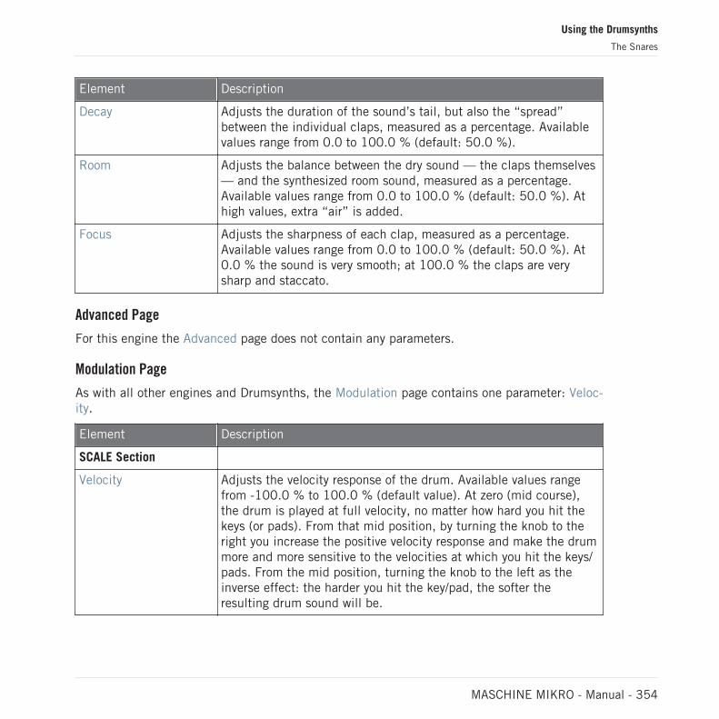
Element Description
Decay Adjusts the duration of the sound’s tail, but also the “spread”between the individual claps, measured as a percentage. Availablevalues range from 0.0 to 100.0 % (default: 50.0 %).
Room Adjusts the balance between the dry sound — the claps themselves— and the synthesized room sound, measured as a percentage.Available values range from 0.0 to 100.0 % (default: 50.0 %). Athigh values, extra “air” is added.
Focus Adjusts the sharpness of each clap, measured as a percentage.Available values range from 0.0 to 100.0 % (default: 50.0 %). At0.0 % the sound is very smooth; at 100.0 % the claps are verysharp and staccato.
Advanced Page
For this engine the Advanced page does not contain any parameters.
Modulation Page
As with all other engines and Drumsynths, the Modulation page contains one parameter: Veloc-ity.
Element Description
SCALE Section
Velocity Adjusts the velocity response of the drum. Available values rangefrom -100.0 % to 100.0 % (default value). At zero (mid course),the drum is played at full velocity, no matter how hard you hit thekeys (or pads). From that mid position, by turning the knob to theright you increase the positive velocity response and make the drummore and more sensitive to the velocities at which you hit the keys/pads. From the mid position, turning the knob to the left as theinverse effect: the harder you hit the key/pad, the softer theresulting drum sound will be.
Using the Drumsynths
The Snares
MASCHINE MIKRO - Manual - 354

9.3.10 Snare – Breaker
The Breaker snare is an acoustic high pitched snare drum that cuts through perfectly into mix-es containing heavy bass. The adjustment of the wires spectrum provides a great range ofsnares. It also works very well with the Rasper Kick.
The parameters described below are presented as they appear in the Control area (Arrange view).The same parameters are available in the Plug-in panel within the Plug-in Strip (Mix view). See↑13.4, The Plug-in Strip for more information on this.
Main Page
Element Description
MAIN Section
Engine Selects the engine used in the Snare plug-in. For more informationon the available engines, please refer to section ↑9.3, The Snares.
Tune Adjusts the pitch of the drum played by the middle C, measured inMIDI note numbers and cents. Available values range from 61.00(NOTE C#3) to 85.00 (NOTE C#5). The default value is 73.00(NOTE C#4).
Decay Adjusts the duration of the sound’s tail, measured as a percentage.Available values range from 0.0 to 100.0% (default: 50.0%).
Skin Tune Adjusts the fine-tuning of the skin of the drum, measured as apercentage. Available values range from 0.0 to 100.0% (default:50.0%).
Impact Adjusts the amount of click or initial attack, measured as apercentage. Available values range from 0.0 to 100.0% (default:75.0%).
Advanced Page
For this engine the Advanced page does not contain any parameters.
Using the Drumsynths
The Snares
MASCHINE MIKRO - Manual - 355

Element Description
SPECTRA Section
Mode Selects from two different noise types that simulate the wires of thedrum. Available modes are A (default) and B.
Tune Provides an independent tuning of the snare noise. It relates to thetension of the snare wires on a real snare drum. Available valuesrange from 0.0 to 100.0% (default: 50.0%).
Decay Adjusts the length of the sound of the snare wires, independentlyfrom the main Decay parameter on the Main page. Available valuesrange from 0.0% to 100.0% (default: 40.0%).
Amount Adjusts the amount of snare wire sound applied to the drum,measured as a percentage. Available values range from 0.0 to100.0% (default: 75.0%).
Modulation Page
Like with all other engines and Drumsynths, the Modulation page contains one parameter: Ve-locity.
Element Description
SCALE Section
Velocity Adjusts the velocity response of the drum. Available values rangefrom -100.0% to 100.0% (default value). At zero (mid course), thedrum is played at full velocity, no matter how hard you hit the keys(or pads). From that mid position, by turning the knob to the rightyou increase the positive velocity response and make the drum moresensitive to the velocity at which you hit the keys/pads. From themid position, turning the knob to the left as the inverse effect: theharder you hit the key/pad, the softer the resulting drum sound willbe.
Using the Drumsynths
The Snares
MASCHINE MIKRO - Manual - 356
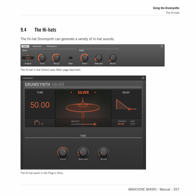
9.4 The Hi-hats
The Hi-hat Drumsynth can generate a variety of hi-hat sounds.
The Hi-hat in the Control area (Main page depicted).
The Hi-hat panel in the Plug-in Strip.
Using the Drumsynths
The Hi-hats
MASCHINE MIKRO - Manual - 357

As in every Drumsynth, the engine can be selected via the Engine selector on the Main page.Each engine has a different character and set of parameters, as detailed in the following sec-tions.
The Hi-hat provides following engines:
▪ Silver (default): ↑9.4.1, Hi-hat – Silver.
▪ Circuit: ↑9.4.2, Hi-hat – Circuit.
▪ Memory: ↑9.4.3, Hi-hat – Memory.
In addition, we mention how to use Choke groups with Hi-hat Plug-ins to emulate a closed vs.open hi-hat set up: ↑9.4.5, Creating a Pattern with Closed and Open Hi-hats.
For more information on engines, see ↑9.1.1, Engines: Many Different Drums per Drumsynth. Forgeneral information on the Snare and the other Drumsynths, see ↑9.1, Drumsynths – General Han-dling.
9.4.1 Hi-hat – Silver
The Silver engine is the default engine of the Hi-hat.
A classic analog hi-hat that can also be used as percussion or sound effect.
The parameters described below are presented as they appear in the Control area (Arrange view).The same parameters are available in the Plug-in panel within the Plug-in Strip (Mix view). See↑13.4, The Plug-in Strip for more information on this.
Main Page
Element Description
MAIN Section
Engine Selects the engine used in the Hi-hat Plug-in. If you change thissetting, please refer to ↑9.4, The Hi-hats.
Using the Drumsynths
The Hi-hats
MASCHINE MIKRO - Manual - 358

Element Description
Tune Adjusts the pitch of the cymbal played by the middle C, measuredas a percentage. Available values range from 0.0 % to 100.0 %(default: 50.0 %). For more details see ↑9.1.5, Pitch Range,Tuning, and MIDI Notes.
Decay Adjusts the duration of the sound, measured as a percentage. Ashort decay produces a closed hat; a long decay gives an open hi-hat or cymbal. Available values range from 0.0 to 100.0 % (default:65.0 %).
Gate When enabled, the decay of the cymbal is choked by the end of thenote. When disabled (default), the cymbal plays as a one-shotsound, i.e. until the end of its tail, no matter when the note isreleased, although the sound duration will still depend on the Decayparameter (see above).
TONE Section
Color Adjusts the center frequency of the filter applied to the sound,measured in hertz. Available values range from 932.3 Hz to16.7 kHz (default: 7.4 kHz). The default position gives a standardmetallic analog hi-hat. Colored down, the sound is much moremelodic and in the midrange, good for percussion or effects. In away this parameter is a more effective tuning control than the Tuneparameter itself. Note that the Color parameter also followskeyboard tracking (i.e. the key/pad you play) along with the Tuneparameter, limited to the range of the parameter.
Saturate Adjusts the amount of analog-style saturation applied to the soundfor increased thickness, measured as a percentage. Available valuesrange from 0.0 to 100.0 % (default: 19.0 %).
Noise Adusts the mix between an oscillator bank and white noise as thesignal source, measured as a percentage. Available values rangefrom 0.0 % (oscillator bank only) to 100.0 % (white noise only).The default value is 10.0 %.
Using the Drumsynths
The Hi-hats
MASCHINE MIKRO - Manual - 359

Advanced Page
For this engine the Advanced page does not contain any parameters.
Modulation Page
As with all other engines and Drumsynths, the Modulation page contains one parameter: Veloc-ity.
Element Description
SCALE Section
Velocity Adjusts the velocity response of the drum. Available values rangefrom -100.0 % to 100.0 % (default value). At zero (mid course),the drum is played at full velocity, no matter how hard you hit thekeys (or pads). From that mid position, by turning the knob to theright you increase the positive velocity response and make the drummore and more sensitive to the velocities at which you hit the keys/pads. From the mid position, turning the knob to the left as theinverse effect: the harder you hit the key/pad, the softer theresulting drum sound will be.
9.4.2 Hi-hat – Circuit
Similar to the Silver hi-hat, the Circuit hi-hat uses a more complex oscillator for a more digital,robotic sound.
The parameters described below are presented as they appear in the Control area (Arrange view).The same parameters are available in the Plug-in panel within the Plug-in Strip (Mix view). See↑13.4, The Plug-in Strip for more information on this.
Using the Drumsynths
The Hi-hats
MASCHINE MIKRO - Manual - 360

Main Page
Element Description
MAIN Section
Engine Selects the engine used in the Hi-hat Plug-in. If you change thissetting, please refer to ↑9.4, The Hi-hats.
Tune Adjusts the pitch of the cymbal played by the middle C, measuredas a percentage. Available values range from 0.0 % to 100.0 %(default: 50.0 %). For more details see ↑9.1.5, Pitch Range,Tuning, and MIDI Notes.
Decay Adjusts the duration of the sound, measured as a percentage. Ashort decay produces a closed hat; a long decay gives an open hi-hat or cymbal. Available values range from 0.0 to 100.0 % (default:65.0 %).
Gate When enabled, the decay of the cymbal is choked by the end of thenote. When disabled (default), the cymbal plays as a one-shotsound, i.e. until the end of its tail, no matter when the note isreleased, although the sound duration will still depend on the Decayparameter (see above).
TONE Section
Color Adjusts the center frequency of the filter applied to the sound,measured in hertz. Available values range from 932.3 Hz to16.7 kHz (default: 7.4 kHz). The default position gives a standardmetallic analog hi-hat. Colored down, the sound is much moremelodic and in the midrange, good for percussion or effects. In away this parameter is a more effective tuning control than the Tuneparameter itself. Note that the Color parameter also followskeyboard tracking (i.e. the key/pad you play) along with the Tuneparameter, limited to the range of the parameter.
Saturate Adjusts the amount of analog-style saturation applied to the soundfor increased thickness, measured as a percentage. Available valuesrange from 0.0 to 100.0 % (default: 19.0 %).
Using the Drumsynths
The Hi-hats
MASCHINE MIKRO - Manual - 361

Element Description
Seed Selects a random sequence to control the waveform produced bythe oscillator. Each of the 31 seed values available produces adifferent set of random pitches and harmonics.
Dissonance Affects the randomization of the oscillator, measured as apercentage. Available values range from 0.0 to 100.0 % (default:25.0 %). Higher values introduce more randomization, resulting ina more noisy sound. Lower values produce a more melodic,oscillator-like sound.
Advanced Page
For this engine the Advanced page does not contain any parameters.
Modulation Page
As with all other engines and Drumsynths, the Modulation page contains one parameter: Veloc-ity.
Element Description
SCALE Section
Velocity Adjusts the velocity response of the drum. Available values rangefrom -100.0 % to 100.0 % (default value). At zero (mid course),the drum is played at full velocity, no matter how hard you hit thekeys (or pads). From that mid position, by turning the knob to theright you increase the positive velocity response and make the drummore and more sensitive to the velocities at which you hit the keys/pads. From the mid position, turning the knob to the left as theinverse effect: the harder you hit the key/pad, the softer theresulting drum sound will be.
9.4.3 Hi-hat – Memory
The Memory hi-hat is similar to a typical sample-based cymbal but with a modern twist, usinganalyzed and reconstructed timbres rather than just a recorded sample.
Using the Drumsynths
The Hi-hats
MASCHINE MIKRO - Manual - 362

The parameters described below are presented as they appear in the Control area (Arrange view).The same parameters are available in the Plug-in panel within the Plug-in Strip (Mix view). See↑13.4, The Plug-in Strip for more information on this.
Main Page
Element Description
MAIN Section
Engine Selects the engine used in the Hi-hat Plug-in. If you change thissetting, please refer to ↑9.4, The Hi-hats.
Tune Adjusts the pitch of the cymbal played by the middle C, measuredas a percentage. Available values range from 0.0 % to 100.0 %(default: 50.0 %). For more details see ↑9.1.5, Pitch Range,Tuning, and MIDI Notes.
Decay Adjusts the duration of the sound, measured as a percentage.Available values range from 0.0 to 100.0 % (default: 65.0 %). Ashort decay produces a closed hat; a long decay gives an open hi-hat or cymbal.
Gate When enabled, the decay of the cymbal is choked by the end of thenote. When disabled (default), the cymbal plays as a one-shotsound, i.e. until the end of its tail, no matter when the note isreleased, although the sound duration will still depend on the Decayparameter (see above).
Source Selects the sampled timbre to be used as source. Six modes areavailable — A (default), B, C, D, E, and F — each corresponding toa different cymbal.
TONE Section
Color Adjusts the frequency curve of the sound, measured as apercentage. Available values range from 0.0 to 100.0 % (default:71.5 %). Higher settings produce a brighter sound; lower settingsproduce a more boxy sound.
Using the Drumsynths
The Hi-hats
MASCHINE MIKRO - Manual - 363

Element Description
Strike Adjusts the attack of the cymbal, measured as a percentage.Available values range from 0.0 to 100.0 % (default: 75.0 %).
Distress Introduces even more lo-fi grit, crushing and distortion. Availablevalues range from 0.0 % (default) to 100.0 %.
Advanced Page
For this engine the Advanced page does not contain any parameters.
Modulation Page
As with all other engines and Drumsynths, the Modulation page contains one parameter: Veloc-ity.
Element Description
SCALE Section
Velocity Adjusts the velocity response of the drum. Available values rangefrom -100.0 % to 100.0 % (default value). At zero (mid course),the drum is played at full velocity, no matter how hard you hit thekeys (or pads). From that mid position, by turning the knob to theright you increase the positive velocity response and make the drummore and more sensitive to the velocities at which you hit the keys/pads. From the mid position, turning the knob to the left as theinverse effect: the harder you hit the key/pad, the softer theresulting drum sound will be.
9.4.4 Hi-hat – Hybrid
The Hybrid hi-hat is an acoustic emulation with a distinctive sound, crossing over from acous-tic to electronic timbres. It provides authentic acoustic features such as sizzling availablethrough the Rattle parameter, and special electronic characteristics provided by the Metallicparameter. By automating these parameters you can create great sounding hi-hat figures.
Using the Drumsynths
The Hi-hats
MASCHINE MIKRO - Manual - 364

The parameters described below are presented as they appear in the Control area (Arrange view).The same parameters are available in the Plug-in panel within the Plug-in Strip (Mix view) — formore information please refer to section ↑13.4, The Plug-in Strip.
Main Page
Element Description
MAIN Section
Engine Selects the engine used in the Hybrid plug-in. For more informationon the available engines, please refer to section ↑9.4, The Hi-hats.
Tune Adjusts the pitch of the cymbal played by the middle C, measuredas a percentage. Available values range from 0.0% to 100.0%(default: 50.0%).
Decay Adjusts the duration of the sound’s tail, measured as a percentage.Available values range from 0.0 to 100.0% (default: 65.0%).
TONE Section
Color Adjusts the cutoff frequency of several low-pass filters in order toachieve the desired timbre. Available values range from 0.0 to100% (default: 71.5%).
Metallic Adjusts an enharmonic metallic character, measured as apercentage. Available values range from 0.0 to 100.0% (default:0.0%).
Strike Adjusts the amount of click or initial attack, measured as apercentage. Available values range from 0.0 to 100.0% (default:80.0%).
Character Adjusts a wider range of timbers from noisy to metallic, measuredas a percentage. Available values range from 0.0 to 100.0%(default: 25.0%).
Using the Drumsynths
The Hi-hats
MASCHINE MIKRO - Manual - 365

Advanced Page
Element Description
HYBRID Section
Bend Adjusts the amount of a pitch envelope for sound design purposes.It is a bipolar control ranging from -100.0 to 100.0% (default:0.0%)
Rattle Adjusts the amount of sizzling from the hi-hat. It is more noticeablewith long decays. Available values range from 0.0 to 100.0%(default: 50.0%).
Modulation Page
Like with all other engines and Drumsynths, the Modulation page contains one parameter: Ve-locity.
Element Description
SCALE Section
Velocity Adjusts the velocity response of the drum. Available values rangefrom -100.0% to 100.0% (default value). At zero (mid course), thedrum is played at full velocity, no matter how hard you hit the keys(or pads). From that mid position, by turning the knob to the rightyou increase the positive velocity response and make the drum moresensitive to the velocity at which you hit the keys/pads. From themid position, turning the knob to the left as the inverse effect: theharder you hit the key/pad, the softer the resulting drum sound willbe.
9.4.5 Creating a Pattern with Closed and Open Hi-hats
Don’t hesitate to use a few Hi-hat Plug-ins within a Choke group! Indeed, by loading two Hi-hatPlug-ins with different settings in two different Sounds (one for the closed hi-hat, one for theopen hi-hat), then assigning both Sounds to the same Choke group, and leaving both as Masterin the group, you can recreate mutually exclusive hi-hat sounds that cancel each other out
Using the Drumsynths
The Hi-hats
MASCHINE MIKRO - Manual - 366

when played, like on a real drum set. By the way you are not limited to two hi-hat sounds —e.g., you could add to the same Choke group a third Sound containing a half-opened hi-hat. Toknow how to do this, please refer to section Using Choke Groups where Choke groups are ex-plained in detail.
With a single Hi-hat Plug-in, you could also recreate an open-closed hi-hat behavior by disablingGate and modulating the Decay in your Pattern. This rather advanced task might give you even finercontrol over the duration of your various hi-hat sounds, and thereby help you to give your hi-hattrack a “human” feel. Furthermore, since this method makes use of a single Sound you can quicklymodify other parameters of your Hi-hat Plug-in — your changes will seamlessly apply to all your hi-hat variants!
9.5 The Toms
The Tom Drumsynth can generate a variety of tom sounds.
The Tom in the Control area (Main page depicted).
Using the Drumsynths
The Toms
MASCHINE MIKRO - Manual - 367

The Tom panel in the Plug-in Strip.
As in every Drumsynth, the engine can be selected via the Engine selector on the Main page.Each engine has a different character and set of parameters, as detailed in the following sec-tions.
The Tom provides following engines:
▪ Tronic (default): ↑9.5.1, Tom – Tronic.
▪ Fractal: ↑9.5.2, Tom – Fractal.
▪ Floor: ↑9.5.3, Tom – Floor.
Using the Drumsynths
The Toms
MASCHINE MIKRO - Manual - 368

For more information on engines, see ↑9.1.1, Engines: Many Different Drums per Drumsynth. Forgeneral information on the Snare and the other Drumsynths, see ↑9.1, Drumsynths – General Han-dling.
9.5.1 Tom – Tronic
The Tronic engine is the default engine of the Tom.
A fat, analog-style tom with two tunable oscillators plus a tunable FM oscillator.
The parameters described below are presented as they appear in the Control area (Arrange view).The same parameters are available in the Plug-in panel within the Plug-in Strip (Mix view). See↑13.4, The Plug-in Strip for more information on this.
Main Page
Element Description
MAIN Section
Engine Selects the engine used in the Tom Plug-in. If you change thissetting, please refer to ↑9.5, The Toms.
Tune Adjusts the pitch of the drum played by the middle C, measured inMIDI note numbers and cents. Available values range from 36.00 to60.00. The default value is 36.00. For more details see ↑9.1.5,Pitch Range, Tuning, and MIDI Notes.
Decay Adjusts the duration of the sound’s tail, measured as a percentage.Available values range from 0.0 to 100.0 % (default: 50.0 %).
Using the Drumsynths
The Toms
MASCHINE MIKRO - Manual - 369

Element Description
Bend Adjusts the pitch sweep of the sound, measured as a percentage.Available values range from -100.0 % to 100.0 % (default: 0.0 %).At zero the sound stays at its original pitch during its entiredecaying phase. At higher values, the pitch bends upwards. At lowervalues, the pitch bends downwards.
Impact Adjusts the amount of attack, measured as a percentage. Availablevalues range from 0.0 % (soft attack) to 100.0 % (maximumattack). The default value is 80.0 %.
Advanced Page
The Advanced page contains parameters controlling the individual oscillators.
Element Description
HARMONICS Section
Interval Adjusts the interval between the two oscillators, measured insemitones and cents. Available values range from -0.50 to 13.50(default: 6.50). At low values the oscillators are tuned closetogether, giving a detuned sound which can be used for basslines.
FM Freq Adjusts the frequency of the FM oscillator, measured as apercentage. Available values range from 0.0 to 100.0 % (default:50.0 %).
FM Decay Adjusts the decay of the FM oscillator, measured as a percentage.Available values range from 0.0 to 100.0 % (default: 35.0 %).Short decays are useful to supplement the attack or impact of thetom. Long decays can be used to embellish the tone or timbre ofthe tom, especially when applied subtly (see FM Amount below).
FM Amount Adjusts the amount of frequency modulation applied by the FMoscillator, measured as a percentage. Available values range from0.0 to 100.0 % (default: 10.0 %). At 0.0 % there is no frequencymodulation so the other FM controls (FM Freq and FM Decay) haveno effect.
Using the Drumsynths
The Toms
MASCHINE MIKRO - Manual - 370

Modulation Page
As with all other engines and Drumsynths, the Modulation page contains one parameter: Veloc-ity.
Element Description
SCALE Section
Velocity Adjusts the velocity response of the drum. Available values rangefrom -100.0 % to 100.0 % (default value). At zero (mid course),the drum is played at full velocity, no matter how hard you hit thekeys (or pads). From that mid position, by turning the knob to theright you increase the positive velocity response and make the drummore and more sensitive to the velocities at which you hit the keys/pads. From the mid position, turning the knob to the left as theinverse effect: the harder you hit the key/pad, the softer theresulting drum sound will be.
9.5.2 Tom – Fractal
The Fractal tom is a modern electronic tom with a broad sonic range from pure and analog-sounding through organic and percussive through bell-like to totally alien. It uses a tone oscil-lator and a feedback oscillator bank (like the one used in the Fractal engine of the Percussion,see ↑9.6.1, Percussion – Fractal), the balance between which is controlled by the Mix parame-ter on the Advanced page. The tone oscillator on its own produces a simple analog-style bleepytom. The addition of the feedback oscillator bank facilitates a much wider range of sounds.
The parameters described below are presented as they appear in the Control area (Arrange view).The same parameters are available in the Plug-in panel within the Plug-in Strip (Mix view). See↑13.4, The Plug-in Strip for more information on this.
Using the Drumsynths
The Toms
MASCHINE MIKRO - Manual - 371

Main Page
Element Description
MAIN Section
Engine Selects the engine used in the Tom Plug-in. If you change thissetting, please refer to ↑9.5, The Toms.
Tune Adjusts the pitch of the drum played by the middle C, measured inMIDI note numbers and cents. Available values range from 48.00 to72.00. The default value is 48.00. For more details see↑9.1.5,Pitch Range, Tuning, and MIDI Notes. Note that the pitch of thisinstrument is heavily dependent on the settings on the Advancedpage (see below).
Decay Adjusts the duration of the sound’s tail, measured as a percentage.Available values range from 0.0 to 100.0 % (default: 50.0 %).
Bend Adjusts the pitch sweep of the sound, measured as a percentage.Available values range from -100.0 % to 100.0 % (default: 0.0 %).At zero the sound stays at its original pitch during its entiredecaying phase. At higher values, the pitch bends upwards. At lowervalues, the pitch bends downwards.
Impact Adjusts the amount of attack, measured as a percentage. Availablevalues range from 0.0 % (soft attack) to 100.0 % (maximumattack). The default value is 80.0 %.
Using the Drumsynths
The Toms
MASCHINE MIKRO - Manual - 372

Element Description
Color Adjusts a simple filter which affects the brightness of the sound.Available values range from 0.0 to 100.0 % (default: 50.0 %).
Glide The tuning of the Fractal tom is locked for each note; in other wordsthe change in tuning is applied only when a new note is received.When the Glide parameter is set higher than zero, the pitch glidessmoothly to the new tuning. The Glide parameter then defines theduration this glide takes, measured in milliseconds: as you increasethe Glide value, the glide gets slower and more audible. This alsoapplies when the tom is played across the keyboard. Availablevalues range from None (no glide) to 350.0 ms (slowest glide). Thedefault value is 5.5 ms.
Advanced Page
The Advanced page contains parameters controlling the individual oscillators.
Element Description
HARMONICS Section
KTr. Mode (KeyTracking Mode)
Selects from two key tracking modes: Harmonic (default) andDissonant.
In Harmonic mode all oscillators track the Tune parameter (on theMain page, see above) and your keyboard evenly. Therefore, thedrum stays in tune with itself as the Tune parameter is adjusted,and can be played chromatically across the keyboard.
In Dissonant mode the oscillators track the Tune parameter of yourkeyboard/pads unevenly. Therefore, the drum produces dissonant,detuned harmonics when the Tune parameter is adjusted or whenyou play different notes.
Mix Adjusts the mix between the tone oscillator and the feedbackoscillator bank, measured as a percentage. Available values rangefrom 0.0 % (tone oscillator only) to 100.0 % (feedback oscillatorbank only). The default value is 5.0 %.
Using the Drumsynths
The Toms
MASCHINE MIKRO - Manual - 373

Element Description
Transpose Adjusts the pitch transposition of the feedback oscillator bank only,measured in semitones and cents. This is useful for tuning it to thetone oscillator. Available values range from -12.00 to 12.00semitones (default: 0.00).
Freq A Adjusts the pitch of oscillator A within the feedback oscillator bank,measured as a percentage. Available values range from 0.0 to100.0 % (default).
Freq B Adjusts the pitch of oscillator B within the feedback oscillator bank,measured as a percentage. Available values range from 0.0 to100.0 % (default: 75.0 %). Note that this control has no effectwhen FM and AM are set to zero (see below).
FM Adjusts the amount of frequency modulation within the feedbackoscillator bank, measured as a percentage. Frequency modulationtends to add bell-like, ringing overtones. Available values rangefrom 0.0 to 100.0 % (default: 50.0 %).
AM Adjusts the amount of amplitude modulation within the feedbackoscillator bank, measured as a percentage. Amplitude modulationtends to add brash, bright overtones. Available values range from0.0 to 100.0 % (default: 50.0 %).
Modulation Page
As with all other engines and Drumsynths, the Modulation page contains one parameter: Veloc-ity.
Using the Drumsynths
The Toms
MASCHINE MIKRO - Manual - 374

Element Description
SCALE Section
Velocity Adjusts the velocity response of the drum. Available values rangefrom -100.0 % to 100.0 % (default value). At zero (mid course),the drum is played at full velocity, no matter how hard you hit thekeys (or pads). From that mid position, by turning the knob to theright you increase the positive velocity response and make the drummore and more sensitive to the velocities at which you hit the keys/pads. From the mid position, turning the knob to the left as theinverse effect: the harder you hit the key/pad, the softer theresulting drum sound will be.
9.5.3 Tom – Floor
The Floor Tom is an acoustic tom that provides the emulation of a complete set of toms. Al-though it is more suitable for floor and low toms, it is also capable of producing interestingmid and high toms. Furthermore the control over the pitch bend and the mute parameters al-low for a wide range of sounds.
The parameters described below are presented as they appear in the Control area (Arrange view).The same parameters are available in the Plug-in panel within the Plug-in Strip (Mix view). See↑13.4, The Plug-in Strip for more information on this.
Main Page
Element Description
MAIN Section
Engine Selects the engine used in the Tom Plug-in. If you change thissetting, please refer to ↑9.5, The Toms.
Tune Adjusts the pitch of the drum played by the middle C, measured inMIDI note numbers and cents. Available values range from 48.00 to62.00. The default value is 48.00. For more details see ↑9.1.5,Pitch Range, Tuning, and MIDI Notes.
Using the Drumsynths
The Toms
MASCHINE MIKRO - Manual - 375

Element Description
Decay Adjusts the duration of the sound’s tail, measured as a percentage.Available values range from 0.0 to 100.0 % (default: 50.0 %).
Tension Adjusts the tension of the drum skin, measured as a percentage,allowing for a longer and bigger pitch bend. Available values rangefrom 0.0 to 100.0 % (default).
Impact Adjusts how hard the drum is hit, measured as a percentage.Available values range from 0.0 % (softest) to 100.0 % (hardest).The default value is 80.0 %.
Flex Adjusts the elasticity of the skin, measured as a percentage,allowing for a greater pitch bend when the drum is hit. Availablevalues range from 0.0 to 100.0 % (default: 30.0 %).
MUTE Section
Skin Adjusts the amount of damping applied to the drum skin, measuredas a percentage. Available values range from 0.0 % (default) to100.0 %.
Air Adjusts the amount of damping applied to the air, measured as apercentage. Available values range from 0.0 to 100.0 % (default:50.0 %).
Advanced Page
For this engine the Advanced page does not contain any parameters.
Modulation Page
As with all other engines and Drumsynths, the Modulation page contains one parameter: Veloc-ity.
Using the Drumsynths
The Toms
MASCHINE MIKRO - Manual - 376
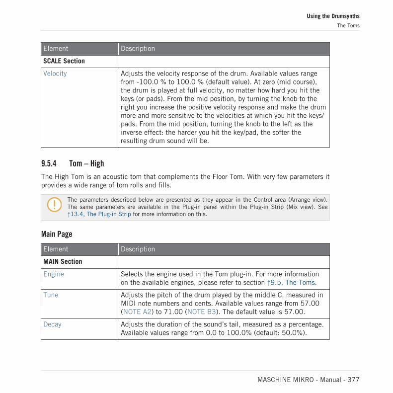
Element Description
SCALE Section
Velocity Adjusts the velocity response of the drum. Available values rangefrom -100.0 % to 100.0 % (default value). At zero (mid course),the drum is played at full velocity, no matter how hard you hit thekeys (or pads). From the mid position, by turning the knob to theright you increase the positive velocity response and make the drummore and more sensitive to the velocities at which you hit the keys/pads. From the mid position, turning the knob to the left as theinverse effect: the harder you hit the key/pad, the softer theresulting drum sound will be.
9.5.4 Tom – High
The High Tom is an acoustic tom that complements the Floor Tom. With very few parameters itprovides a wide range of tom rolls and fills.
The parameters described below are presented as they appear in the Control area (Arrange view).The same parameters are available in the Plug-in panel within the Plug-in Strip (Mix view). See↑13.4, The Plug-in Strip for more information on this.
Main Page
Element Description
MAIN Section
Engine Selects the engine used in the Tom plug-in. For more informationon the available engines, please refer to section ↑9.5, The Toms.
Tune Adjusts the pitch of the drum played by the middle C, measured inMIDI note numbers and cents. Available values range from 57.00(NOTE A2) to 71.00 (NOTE B3). The default value is 57.00.
Decay Adjusts the duration of the sound’s tail, measured as a percentage.Available values range from 0.0 to 100.0% (default: 50.0%).
Using the Drumsynths
The Toms
MASCHINE MIKRO - Manual - 377

Element Description
Tension Adjusts the tension of the drum skin, measured as a percentage,allowing for a longer and bigger pitch bend. Available values rangefrom 0.0 to 100.0% (default).
Impact Adjusts the amount of click or initial attack, measured as apercentage. Available values range from 0.0 to 100.0% (default:80.0%).
Advanced Page
For this engine the Advanced page does not contain any parameters.
Modulation Page
Like with all other engines and Drumsynths, the Modulation page contains one parameter: Ve-locity.
Element Description
SCALE Section
Velocity Adjusts the velocity response of the drum. Available values rangefrom -100.0% to 100.0% (default value). At zero (mid-course), thedrum is played at full velocity, no matter how hard you hit the keys(or pads). From that mid position, by turning the knob to the rightyou increase the positive velocity response and make the drum moresensitive to the velocity at which you hit the keys/pads. From themid position, turning the knob to the left as the inverse effect: theharder you hit the key/pad, the softer the resulting drum sound willbe.
9.6 The Percussions
The Percussion Drumsynth can generate a variety of percussion sounds.
Using the Drumsynths
The Percussions
MASCHINE MIKRO - Manual - 378

The Percussion in the Control area (Main page depicted).
The Percussion panel in the Plug-in Strip.
As in every Drumsynth, the engine can be selected via the Engine selector on the Main page.Each engine has a different character and set of parameters, as detailed in the following sec-tions.
The Percussion provides following engines:
Using the Drumsynths
The Percussions
MASCHINE MIKRO - Manual - 379

▪ Fractal (default): ↑9.6.1, Percussion – Fractal.
▪ Kettle: ↑9.6.2, Percussion – Kettle.
▪ Shaker: ↑9.6.3, Percussion – Shaker.
For more information on engines, see ↑9.1.1, Engines: Many Different Drums per Drumsynth. Forgeneral information on the Snare and the other Drumsynths, see ↑9.1, Drumsynths – General Han-dling.
9.6.1 Percussion – Fractal
The Fractal engine is the default engine of the Percussion.
The Fractal percussion mode is based on the feedback oscillator bank from the Fractal tom(see ↑9.5.2, Tom – Fractal). It’s capable of a broad range of sounds, from bell-like to metallic,cymbal-like, subby, melodic, weird and twisted, and is intended to be played across the key-board.
The parameters described below are presented as they appear in the Control area (Arrange view).The same parameters are available in the Plug-in panel within the Plug-in Strip (Mix view). See↑13.4, The Plug-in Strip for more information on this.
Main Page
Element Description
MAIN Section
Engine Selects the engine used in the Percussion Plug-in. If you changethis setting, please refer to ↑9.6, The Percussions.
Tune Adjusts the pitch of the drum played by the middle C, measured inMIDI note numbers and cents. Available values range from 60.00 to108.00. The default value is 84.00. For more details see ↑9.1.5,Pitch Range, Tuning, and MIDI Notes. Note that the pitch of thisinstrument is heavily dependent on the settings on the Advancedpage (see below).
Using the Drumsynths
The Percussions
MASCHINE MIKRO - Manual - 380

Element Description
Decay Adjusts the duration of the sound’s tail, measured as a percentage.Available values range from 0.0 to 100.0 % (default: 50.0 %).
Tune Hold When Tune Hold is enabled, the tuning behavior is that of theFractal tom: the tuning is fixed until the next note is received (see↑9.5.1, Tom – Tronic). This allows you to create arpeggiatedpatterns by adjusting the Tune parameter while a sequence of notesis playing.
When Tune Hold is disabled (default), the tuning behavior is that ofthe other modules: the tuning responds immediately when youadjust the Tune parameter.
Glide Adjusts the glide between the pitch of new notes, measured inmilliseconds. When the Glide parameter is set higher than zero, thepitch glides smoothly to the new tuning. The Glide parameter thendefines the duration this glide takes. Available values range fromNone (no glide, default) to 762.8 ms.
Impact Adjusts the amount of attack, measured as a percentage. Availablevalues range from 0.0 % (soft attack) to 100.0 % (maximumattack). The default value is 60.0 %.
Advanced Page
The Advanced page contains parameters controlling the individual oscillators.
Using the Drumsynths
The Percussions
MASCHINE MIKRO - Manual - 381

Element Description
HARMONICS Section
KTr. Mode (KeyTracking Mode)
Selects from two key tracking modes: Harmonic (default) andDissonant.
In Harmonic mode all oscillators track the Tune parameter (on theMain page, see above) and your keyboard evenly. Therefore, thedrum stays in tune with itself as the Tune parameter is adjusted,and can be played chromatically across a keyboard or the pads.
In Dissonant mode the oscillators track the Tune parameter you’reyour keyboard) unevenly. Therefore, the drum produces dissonant,detuned harmonics when the Tune parameter is adjusted or whenyou play different notes on a keyboard or the pads.
Freq A Adjusts the pitch of oscillator A within the feedback oscillator bank,measured as a percentage. Available values range from 0.0 to100.0 % (default: 50.0 %).
Freq B Adjusts the pitch of oscillator B within the feedback oscillator bank,measured as a percentage. Available values range from 0.0 to100.0 % (default: 50.0 %). Note that this parameter has no effectwhen FM and AM are set to zero (see below).
Freq C Adjusts the pitch of oscillator C within the feedback oscillator bank,measured as a percentage. Available values range from 0.0 to100.0 % (default: 29.1 %). Note that this parameter has no effectwhen FM and AM are set to zero (see below).
FM Adjusts the amount of frequency modulation within the feedbackoscillator bank, measured as a percentage. Frequency modulationtends to add bell-like, ringing overtones. Available values rangefrom 0.0 to 100.0 % (default: 34.4 %).
AM Adjusts the amount of amplitude modulation within the feedbackoscillator bank, measured as a percentage. Amplitude modulationtends to add brash, bright overtones. Available values range from0.0 to 100.0 % (default: 18.6 %).
Using the Drumsynths
The Percussions
MASCHINE MIKRO - Manual - 382

Modulation Page
As with all other engines and Drumsynths, the Modulation page contains one parameter: Veloc-ity.
Element Description
SCALE Section
Velocity Adjusts the velocity response of the drum. Available values rangefrom -100.0 % to 100.0 % (default value). At zero (mid course),the drum is played at full velocity, no matter how hard you hit thekeys (or pads). From that mid position, by turning the knob to theright you increase the positive velocity response and make the drummore and more sensitive to the velocities at which you hit the keys/pads. From the mid position, turning the knob to the left as theinverse effect: the harder you hit the key/pad, the softer theresulting drum sound will be.
9.6.2 Percussion – Kettle
The Kettle percussion is an acoustic timpani emulation that provides an orchestral and richsound.
The parameters described below are presented as they appear in the Control area (Arrange view).The same parameters are available in the Plug-in panel within the Plug-in Strip (Mix view). See↑13.4, The Plug-in Strip for more information on this.
Main Page
Element Description
MAIN Section
Engine Selects the engine used in the Percussion Plug-in. If you changethis setting, please refer to ↑9.6, The Percussions.
Using the Drumsynths
The Percussions
MASCHINE MIKRO - Manual - 383

Element Description
Tune Adjusts the pitch of the drum played by the middle C, measured inMIDI note numbers and cents. Available values range from 33.00 to57.00. The default value is 45.00. For more details see ↑9.1.5,Pitch Range, Tuning, and MIDI Notes.
Decay Adjusts the duration of the sound’s tail, measured as a percentage.Available values range from 0.0 to 100.0 % (default: 50.0 %).
Puff Adjusts the amount of feedback noise applied to the drum,measured as a percentage. Available values range from 0.0 to100.0 % (default: 25.0 %).
Damp Adjusts the damping amount, measured as a percentage. Availablevalues range from 0.0 % (default) to 100.0 %.
Impact Adjusts the amount of attack. Available values range from 0.0 %(soft attack) to 100.0 % (maximum attack). The default value is60.0 %.
Advanced Page
For this engine the Advanced page does not contain any parameters.
Modulation Page
As with all other engines and Drumsynths, the Modulation page contains one parameter: Veloc-ity.
Using the Drumsynths
The Percussions
MASCHINE MIKRO - Manual - 384

Element Description
SCALE Section
Velocity Adjusts the velocity response of the drum. Available values rangefrom -100.0 % to 100.0 % (default value). At zero (mid course),the drum is played at full velocity, no matter how hard you hit thekeys (or pads). From that mid position, by turning the knob to theright you increase the positive velocity response and make the drummore and more sensitive to the velocities at which you hit the keys/pads. From the mid position, turning the knob to the left as theinverse effect: the harder you hit the key/pad, the softer theresulting drum sound will be.
9.6.3 Percussion – Shaker
The Shaker is a versatile electronic shaker/maraca engine.
The parameters described below are presented as they appear in the Control area (Arrange view).The same parameters are available in the Plug-in panel within the Plug-in Strip (Mix view). See↑13.4, The Plug-in Strip for more information on this.
Main Page
Element Description
MAIN Section
Engine Selects the engine used in the Percussion Plug-in. If you changethis setting, please refer to ↑9.6, The Percussions.
Tune Adjusts the center frequency of the filter applied to the noisesource, which will define the pitch of the drum played by themiddle C, measured as a percentage. Available values range from0.0 % to 100.0 % (default: 50.0 %). For more details see ↑9.1.5,Pitch Range, Tuning, and MIDI Notes.
Using the Drumsynths
The Percussions
MASCHINE MIKRO - Manual - 385

Element Description
Filter Adjusts the bandwidth of the filter applied to the noise source,measured as a percentage. Higher settings result in a wider filter.Lower settings result in a narrower filter, measured as a percentage.Available values range from 0.0 to 100.0 % (default: 70.0 %).
Grain Adjusts the timbre of the noise source, measured as a percentage.Higher settings emulate the grainy sound of a real shaker. Availablevalues range from 0.0 to 100.0 % (default: 50.0 %). Furthermorethe Grain parameter is assigned to velocity: lower velocity shakescontain more grain.
ENVELOPE Section
Mode Selects from two envelope modes: Realistic (default) and Machine.
In Realistic mode the envelope uses curved attack and releasestages for a more natural sound.
In Machine mode the envelope uses linear attack, hold, and releasestages for a static, machine-like sound.
In Performer mode, instead of producing a one-shot sound like mostdrums, the shaker plays a rhythmic pattern like a real shaker. Inthis mode, simply hold the note for as long as you want the patternto play.
Attack Adjusts the duration of the envelope’s attack stage, measured as apercentage. Available values range from 0.0 to 100.0 % (default:40.0 %).
Hold (Machine modeonly)
Adjusts the duration of the envelope’s hold stage, i.e. the timeduring which the envelope is held at its highest point, measured asa percentage. Available values range from 0.0 % (default) to100.0 %.
Using the Drumsynths
The Percussions
MASCHINE MIKRO - Manual - 386

Element Description
Accent (Performermode only)
Controls the amount of emphasis on certain notes within the shakerpattern, measured as a percentage. At low values, the groove isstatic and the notes rather quiet, as if the shaker were being shakenvery gently and uniformly. As the parameter is increased, key notesin the pattern are emphasized, creating a classic shaker groove.High values simulate a shaker that is being shaken by someone whois having a lot of fun! Available values range from 0.0 to 100.0%(default: 70.0%).
Fill (Performer modeonly)
The Fill parameter is designed to be set to None by default andplayed manually during performance or automated in thesequencer. By default, the shaker plays a pattern according to theRate parameter on the Advanced page (see below).
When the Fill parameter is set to Double, the speed of the pattern isdoubled. When set to Triple, the shaker plays rapid triplets. Usethis to insert improvised fills into your shaker parts to add varietyand interest.
Release Adjusts the duration of the envelope’s release stage, measured as apercentage. Available values range from 0.0 to 100.0 % (default:35.0 %).
Advanced Page
The Advanced page contains parameters only when the Shaker engine is in Performer mode(see Mode parameter above). These parameters further adjust the envelope.
ENVELOPE Section
Using the Drumsynths
The Percussions
MASCHINE MIKRO - Manual - 387
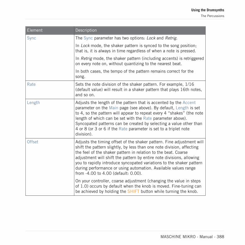
Element Description
Sync The Sync parameter has two options: Lock and Retrig.
In Lock mode, the shaker pattern is synced to the song position;that is, it is always in time regardless of when a note is pressed.
In Retrig mode, the shaker pattern (including accents) is retriggeredon every note on, without quantizing to the nearest beat.
In both cases, the tempo of the pattern remains correct for thesong.
Rate Sets the note division of the shaker pattern. For example, 1/16(default value) will result in a shaker pattern that plays 16th notes,and so on.
Length Adjusts the length of the pattern that is accented by the Accentparameter on the Main page (see above). By default, Length is setto 4, so the pattern will appear to repeat every 4 “shakes” (the notelength of which can be set with the Rate parameter above).Syncopated patterns can be created by selecting a value other than4 or 8 (or 3 or 6 if the Rate parameter is set to a triplet notedivision).
Offset Adjusts the timing offset of the shaker pattern. Fine adjustment willshift the pattern slightly, by less than one note division, affectingthe feel of the shaker pattern in relation to the beat. Coarseadjustment will shift the pattern by entire note divisions, allowingyou to rapidly introduce syncopated variations to the shaker patternduring performance or using automation. Available values rangefrom -4.00 to 4.00 (default: 0.00).
On your controller, coarse adjustment (changing the value in stepsof 1.0) occurs by default when the knob is moved. Fine-tuning canbe achieved by holding the SHIFT button while turning the knob.
Using the Drumsynths
The Percussions
MASCHINE MIKRO - Manual - 388

Element Description
Swing Adjusts the amount of swing or shuffle in the shaker pattern. Highervalues will result in a pattern with more swing. Note that Swingalone will result in quite a mechanical feel — for a more humanfeel it is recommended to add some Twist as well (see below).Available values range from 0.0 to 100.0% (default: 0.0%).
Twist The Twist parameter “skews” the groove of the shaker pattern. Onits own, with the Swing parameter set to zero, it can sound verystrange and lopsided. However, used sparingly in conjunction withSwing, the Twist parameter gives the pattern a flowing, naturalgroove, just like a real person playing a shaker. Available valuesrange from 0.0 to 100.0% (default: 0.0%).
Modulation Page
As with all other engines and Drumsynths, the Modulation page contains one parameter: Veloc-ity.
Element Description
SCALE Section
Velocity Adjusts the velocity response of the drum. Available values rangefrom -100.0 % to 100.0 % (default value). At zero (mid course),the drum is played at full velocity, no matter how hard you hit thekeys (or pads). From that mid position, by turning the knob to theright you increase the positive velocity response and make the drummore and more sensitive to the velocities at which you hit the keys/pads. From the mid position, turning the knob to the left as theinverse effect: the harder you hit the key/pad, the softer theresulting drum sound will be.
9.7 The Cymbals
The Cymbal Drumsynth can generate a variety of cymbal sounds.
Using the Drumsynths
The Cymbals
MASCHINE MIKRO - Manual - 389

The Crash engine selected for the Cymbal in the Control area (Main page depicted).
The Crash engine selected on the Cymbal panel in the Plug-in Strip.
As in every Drumsynth, the engine can be selected via the Engine selector on the Main page.Each engine has a different character and set of parameters, as detailed in the following sec-tions.
Using the Drumsynths
The Cymbals
MASCHINE MIKRO - Manual - 390

The Cymbal provides following engines:
▪ Crash (default): ↑9.7.1, Cymbal – Crash.
▪ Ride: ↑9.7.2, Cymbal – Ride.
For more information on engines, see ↑9.1.1, Engines: Many Different Drums per Drumsynth. Forgeneral information on the Cymbals and the other Drumsynths, see ↑9.1, Drumsynths – GeneralHandling.
9.7.1 Cymbal – Crash
The Crash engine creates a wide range of cymbals: from a typical 909-like crash to moreacoustic sounding timbres. Its parameters provide a great range of expression and spectral var-iation.
The parameters described below are presented as they appear in the Control area (Arrange view).The same parameters are available in the Plug-in panel within the Plug-in Strip (Mix view) — formore information please refer to section ↑13.4, The Plug-in Strip.
Main Page
Element Description
MAIN Section
Engine Selects the engine used in the Cymbal plug-in. Available enginesinclude Crash and Ride.
Tune Adjusts the pitch of the drum played by the middle C, measured inMIDI note numbers and cents. Available values range from 0.00 to100.0% (default value is 30.0%).
Decay Adjusts the duration of the sound’s tail, measured as a percentage.Available values range from 0.0 to 100.0% (default: 70.0%).
Impact Adjusts the amount of click or initial attack, measured as apercentage. Available values range from 0.0 to 100.0% (default:70.0%).
Using the Drumsynths
The Cymbals
MASCHINE MIKRO - Manual - 391

Element Description
Width Adjusts the perceived stereo image, measured as a percentage. Atzero the sound is mono, at 100.0% the sound is a wide stereoimage, replicating the effect of recording with overhead stereomicrophones. Available values range from 0.0 to 100.0% (default:50.0%).
COLOR Section
Density Adjusts the more complexity to the sound, measured as apercentage. Available values range from 0.0 to 100.0% (default:100.0%)
Tone Adjusts the balance of the spectral content, measured as apercentage. Available values range from 0.0 to 100.0% (default:50.0%).
Mode Selects from three different modes Metallic, Normal, or Soft(default: Metallic).
Advanced Page
For this engine the Advanced page does not contain any parameters.
Modulation Page
Like with all other engines and Drumsynths, the Modulation page contains one parameter: Ve-locity.
Using the Drumsynths
The Cymbals
MASCHINE MIKRO - Manual - 392

Element Description
SCALE Section
Velocity Adjusts the velocity response of the drum. Available values rangefrom -100.0% to 100.0% (default value). At zero (mid course), thedrum is played at full velocity, no matter how hard you hit the keys(or pads). From that mid position, by turning the knob to the rightyou increase the positive velocity response and make the drum moresensitive to the velocity at which you hit the keys/pads. From themid position, turning the knob to the left as the inverse effect: theharder you hit the key/pad, the softer the resulting drum sound willbe.
9.7.2 Cymbal – Ride
The Ride engine is an acoustic emulation that allows the cymbal to be hit in many differentways through the use of the Edge and Bell parameters. The sonic palette ranges from soft Jazz-like rides to more noisy cymbals.
The parameters described below are presented as they appear in the Control area (Arrange view).The same parameters are available in the Plug-in panel within the Plug-in Strip (Mix view) — formore information please refer to section ↑13.4, The Plug-in Strip.
Main Page
Element Description
MAIN Section
Engine Selects the engine used in the Cymbal plug-in. Available enginesinclude Crash and Ride.
Tune Adjusts the pitch of the drum played by the middle C, measured inMIDI note numbers and cents. Available values range from 0.00 to1.00. The default value is 0.30.
Decay Adjusts the duration of the sound’s tail, measured as a percentage.Available values range from 0.0 to 100.0% (default: 70.0%).
Using the Drumsynths
The Cymbals
MASCHINE MIKRO - Manual - 393

Element Description
Impact Adjusts the amount of click or initial attack, measured as apercentage. Available values range from 0.0 to 100.0% (default:70.0%).
Width Adjusts the perceived stereo image, measured as a percentage. Atzero the sound is mono, at 100.0% the sound is a wide stereoimage, replicating the effect of recording with overhead stereomicrophones. Available values range from 0.0 to 100.0% (default:50.0%).
STRIKE Section
Edge Adjusts the point where the cymbal is hit, measured as apercentage. Hitting the edge of the cymbal (100%) creates a morechaotic sound, hitting it near the center (0.0%) creates a morehigh-pitched sound. Available values range from 0.0 to 100.0%(default: 50.0%)
Bell Adjusts the high-frequencies on a narrow band, measured as apercentage. (default: 0.0%)
Advanced Page
Element Description
HYBRID Section
Character Adjusts a wider range of timbers between more noisy to moremetallic ones, measured as a percentage. Available values rangefrom 0.0 to 100.0% (default: 20.0%).
Tail Adjusts the length of the sound tail through an envelope. Availablevalues range from 0.0 to 100.0% (default: 100.0%).
Modulation Page
Like with all other engines and Drumsynths, the Modulation page contains one parameter: Ve-locity.
Using the Drumsynths
The Cymbals
MASCHINE MIKRO - Manual - 394

Element Description
SCALE Section
Velocity Adjusts the velocity response of the drum. Available values rangefrom -100.0% to 100.0% (default value). At zero (mid course), thedrum is played at full velocity, no matter how hard you hit the keys(or pads). From that mid position, by turning the knob to the rightyou increase the positive velocity response and make the drum moresensitive to the velocity at which you hit the keys/pads. From themid position, turning the knob to the left as the inverse effect: theharder you hit the key/pad, the softer the resulting drum sound willbe.
Using the Drumsynths
The Cymbals
MASCHINE MIKRO - Manual - 395
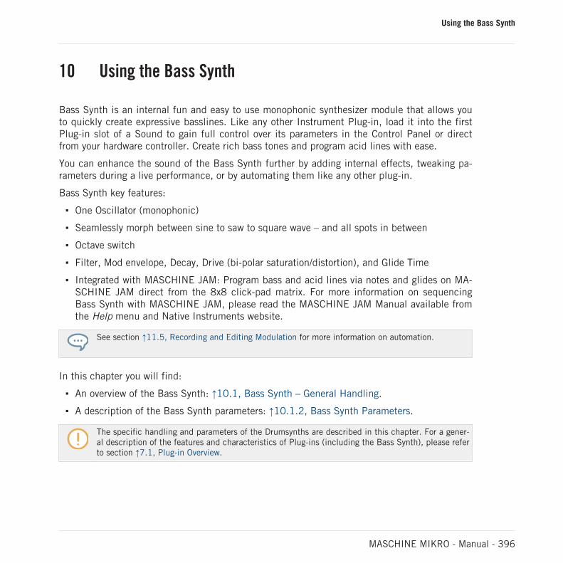
10 Using the Bass Synth
Bass Synth is an internal fun and easy to use monophonic synthesizer module that allows youto quickly create expressive basslines. Like any other Instrument Plug-in, load it into the firstPlug-in slot of a Sound to gain full control over its parameters in the Control Panel or directfrom your hardware controller. Create rich bass tones and program acid lines with ease.
You can enhance the sound of the Bass Synth further by adding internal effects, tweaking pa-rameters during a live performance, or by automating them like any other plug-in.
Bass Synth key features:
▪ One Oscillator (monophonic)
▪ Seamlessly morph between sine to saw to square wave – and all spots in between
▪ Octave switch
▪ Filter, Mod envelope, Decay, Drive (bi-polar saturation/distortion), and Glide Time
▪ Integrated with MASCHINE JAM: Program bass and acid lines via notes and glides on MA-SCHINE JAM direct from the 8x8 click-pad matrix. For more information on sequencingBass Synth with MASCHINE JAM, please read the MASCHINE JAM Manual available fromthe Help menu and Native Instruments website.
See section ↑11.5, Recording and Editing Modulation for more information on automation.
In this chapter you will find:
▪ An overview of the Bass Synth: ↑10.1, Bass Synth – General Handling.
▪ A description of the Bass Synth parameters: ↑10.1.2, Bass Synth Parameters.
The specific handling and parameters of the Drumsynths are described in this chapter. For a gener-al description of the features and characteristics of Plug-ins (including the Bass Synth), please referto section ↑7.1, Plug-in Overview.
Using the Bass Synth
MASCHINE MIKRO - Manual - 396
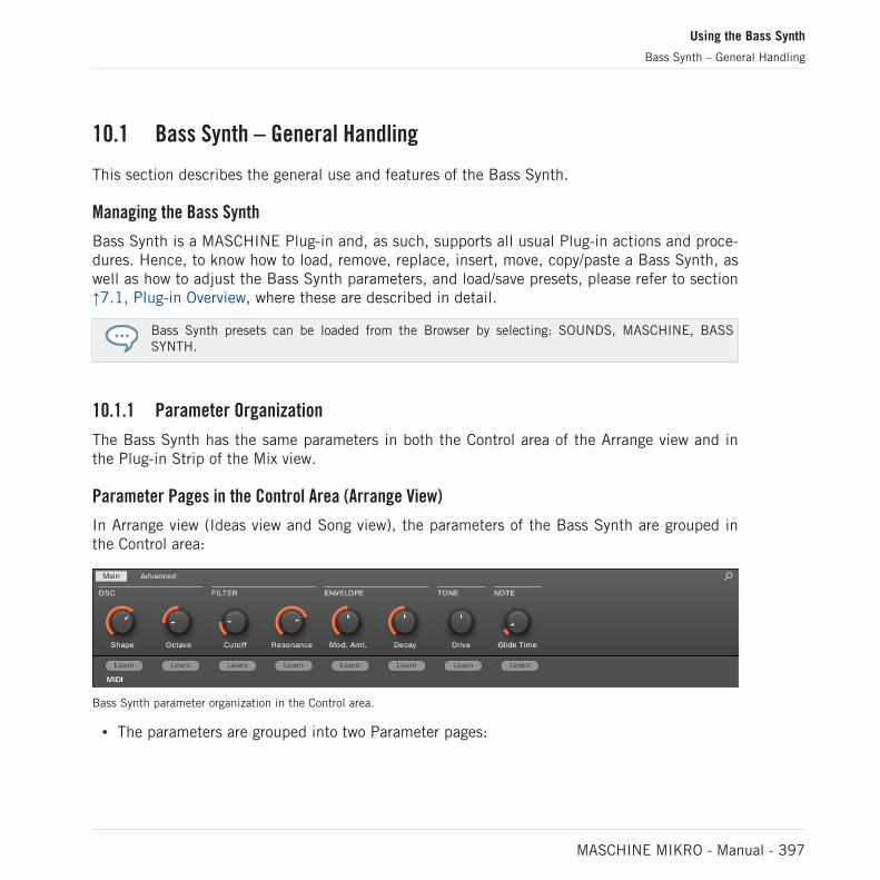
10.1 Bass Synth – General Handling
This section describes the general use and features of the Bass Synth.
Managing the Bass Synth
Bass Synth is a MASCHINE Plug-in and, as such, supports all usual Plug-in actions and proce-dures. Hence, to know how to load, remove, replace, insert, move, copy/paste a Bass Synth, aswell as how to adjust the Bass Synth parameters, and load/save presets, please refer to section↑7.1, Plug-in Overview, where these are described in detail.
Bass Synth presets can be loaded from the Browser by selecting: SOUNDS, MASCHINE, BASSSYNTH.
10.1.1 Parameter Organization
The Bass Synth has the same parameters in both the Control area of the Arrange view and inthe Plug-in Strip of the Mix view.
Parameter Pages in the Control Area (Arrange View)
In Arrange view (Ideas view and Song view), the parameters of the Bass Synth are grouped inthe Control area:
Bass Synth parameter organization in the Control area.
▪ The parameters are grouped into two Parameter pages:
Using the Bass Synth
Bass Synth – General Handling
MASCHINE MIKRO - Manual - 397

◦ The Main page groups the most important parameters. Here you can adjust the Shapeof the oscillator waveform, the filter Cutoff and Resonance, the envelope modulation(Mod. Amt.) and envelope Decay amounts, the Drive amount and the Glide Time.
◦ The Advanced page provides access to the Glide on/off parameter.
Common Layout in the Plug-in Strip (Mix View)
In Mix view, the Plug-in panel of the Bass Synth in the Plug-in Strip provides easy access toparameters and visualization of the oscillator waveform:
The Bass Synth layout in the Plug-in Strip.
▪ In the top row of the panel are the envelope Mod. Amt. (modulation amount) and Decayparameters, followed by the main Shape (oscillator waveform), the Octave range, and theDrive parameters.
▪ In the bottom row of the panel you find the filter Cutoff, Resonance and Glide Time param-eters.
For more information on the various Plug-in panels found in the Plug-in Strip, please refer to sec-tion ↑13.4, The Plug-in Strip.
Using the Bass Synth
Bass Synth – General Handling
MASCHINE MIKRO - Manual - 398

10.1.2 Bass Synth Parameters
Available from the both the Control area of the Arrange view and in the Plug-in Strip of the Mixview, the parameters are as follows:
The parameters described are presented as they appear in the Control area (Arrange view). Thesame parameters are available in the Plug-in panel within the Plug-in Strip (Mix view). See ↑13.4,The Plug-in Strip for more information on this.
Main Page
Element Description
OSC Section
Shape Adjusts the waveform shape continuously from sine to square. Toadjust the waveform shape, turn the Shape knob by clicking anddragging upwards or downwards. The waveform shape can beviewed in the Plug-in Strip of the Mix view.
Octave Transposes the base key of the Bass Synth (range: -3 – 3). Totranspose the base key, turn the Octave knob by clicking anddragging upwards or downwards.
Filter Section
Cutoff Adjusts the frequency of the low-pass filter (range: 14.6 Hz – 23.7KHz). To adjust the cutoff frequency, turn the Cutoff knob byclicking and dragging upwards or downwards.
Resonance Adjusts the amount of boost around the cutoff frequency (range:0.0% – 120%), Resonance can start to self-oscillate whenincreasing the amount over 100.0 %. To adjust the amount ofresonance, turn the Resonance knob by clicking and draggingupwards or downwards.
Envelope Section
Using the Bass Synth
Bass Synth – General Handling
MASCHINE MIKRO - Manual - 399

Element Description
Mod. Amt. Adjusts the amount of envelope applied to the filter cutoff (range:0.0% – 100%). To increase the amount of modulation applied tothe Cutoff, turn the Mod. Amt. knob clockwise by clicking anddragging upwards.
Decay Adjusts the rate at which the sound fades to silence (range: 0.0% –100%). To increase the decay amount, turn the Decay knobclockwise by clicking and dragging upwards.
Tone Section
Drive Adjusts the amount of drive (range: -100% – 100%); -100%increases the input level for the filter, driving the signal internallyinto saturation, and 100% controls the drive level of the distortionat the end of the signal chain. To adjust the amount of drive, turnthe Drive knob by clicking and dragging upwards or downwards.
Note Section
Glide Time Adjusts the time it takes to glide from one pitch to the next (range:10 ms – 1000 ms). To adjust the amount of glide time, turn theGlide Time knob by clicking and dragging upwards or downwards.
Advanced Page
For this module the Advanced page contains just one parameter.
Element Description
Note Section
Glide Globally enables the glide parameter. Once set to on, the note willcontinuously play in a monophonic manner.
Using the Bass Synth
Bass Synth – General Handling
MASCHINE MIKRO - Manual - 400

11 Working with Patterns
Creating a Pattern is where the fun starts, because the sequencer really is the core of MA-SCHINE. Both your controller and the software provide you with many powerful tools to createand edit your own beats.
This chapter is organized as follows:
▪ General points on Patterns and the Pattern Editor: ↑11.1, Pattern Basics.
▪ How to record Patterns in real time from your controller: ↑11.2, Recording Patterns in RealTime.
▪ How to record Patterns with the step sequencer of your controller: ↑11.3, Recording Pat-terns with the Step Sequencer.
▪ How to create and modify events/notes in your Patterns: ↑11.4, Editing Events.
▪ How to create and modify modulation in your Patterns: ↑11.5, Recording and Editing Mod-ulation.
▪ How to create MIDI tracks in your Patterns: ↑11.6, Creating MIDI Tracks from Scratch inMASCHINE.
▪ How to organize your Patterns in your Project: ↑11.7, Managing Patterns.
▪ How to import/export MIDI to/from Patterns, and how to export audio from Patterns: ↑11.8,Importing/Exporting Audio and MIDI to/from Patterns.
11.1 Pattern Basics
A Pattern contains the events (also called “notes”) that make up a groove or a musical phraseusing the Sounds of the selected Group. It also contains the modulation data (if any) modifyingthe value of parameters in that Group or any of its Sounds. The Pattern belongs to that Groupand is saved together with the Group. In each Group you can have an unlimited number of Pat-terns. Patterns are grouped into Pattern banks containing up to 16 Patterns each.
Working with Patterns
Pattern Basics
MASCHINE MIKRO - Manual - 401
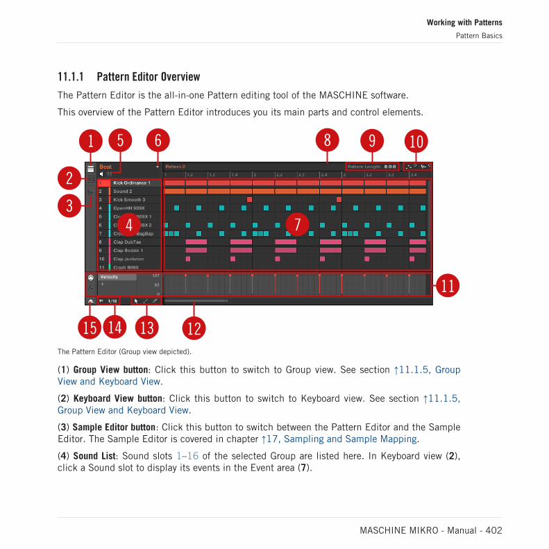
11.1.1 Pattern Editor Overview
The Pattern Editor is the all-in-one Pattern editing tool of the MASCHINE software.
This overview of the Pattern Editor introduces you its main parts and control elements.
2
4 7
11
65 8 9 10
14 13 1215
1
3
The Pattern Editor (Group view depicted).
(1) Group View button: Click this button to switch to Group view. See section ↑11.1.5, GroupView and Keyboard View.
(2) Keyboard View button: Click this button to switch to Keyboard view. See section ↑11.1.5,Group View and Keyboard View.
(3) Sample Editor button: Click this button to switch between the Pattern Editor and the SampleEditor. The Sample Editor is covered in chapter ↑17, Sampling and Sample Mapping.
(4) Sound List: Sound slots 1–16 of the selected Group are listed here. In Keyboard view (2),click a Sound slot to display its events in the Event area (7).
Working with Patterns
Pattern Basics
MASCHINE MIKRO - Manual - 402

(5) Pad View button: Click this button to switch between the Sound List (4) and the Pad view.The Pad view is an alternate representation of your Sound slots that focuses on the pads ofyour controller. In Pad view you can adjust how the Sounds should be triggered by your pads.See section ↑6.1.1, The Pad View in the Software.
(6) Pattern Manager button: Opens/closes the Pattern Manager. The Pattern Manager gives youaccess to various management commands for your Patterns. Notably, it allows you to select thePattern you want to edit in the Pattern Editor and use in the current Scene of the Arranger. Italso provides various Pattern management commands (see section ↑11.7.1, The Pattern Man-ager and Pattern Mode).
(7) Event area: Displays the content of the selected Pattern. Here you can see your recordedevents as rectangular blocks. In Group view (1) these represent the Sounds of your Group. InKeyboard view (2) they represent musical notes of the selected Sound. The length of each rec-tangular block represents the duration of the event, and its transparency indicates the eventvelocity (the softer the hit, the more transparent the event). You can edit events using yourmouse; you can drag them to a new position, elongate/shorten them, create and delete themusing various Edit modes (13). The Event area also displays the Step Grid divisions, a set ofregularly spaced vertical lines defining the resolution of your edits. You can make all your editssnap to the desired Step Grid via the Step Grid settings (14).
(8) Pattern timeline: The timeline at the top of the Event area (7) displays musical time units,including bars and beats. Click anywhere in the timeline to move the playhead to that position(see section ↑11.1.4, Jumping to Another Playback Position in the Pattern). Drag the whitePattern Length marker horizontally to adjust the Pattern Length (this can also be done via thePattern Length controls (9), see section ↑11.1.6, Adjusting the Arrange Grid and the PatternLength).
(9) Pattern Length controls: The Pattern Length controls allow you to choose the increment bywhich the length of the Pattern can be adjusted, and to adjust the length of the displayed Pat-tern according to that increment. See section ↑11.1.6, Adjusting the Arrange Grid and the Pat-tern Length.
(10) MIDI and Audio Dragger: The MIDI Dragger and the Audio Dragger allow you to convenientlydrag and drop MIDI or audio from your Patterns to your desktop or host software, respectively.See section ↑11.8.1, Exporting Audio from Patterns and ↑11.8.2, Exporting MIDI from Pat-terns for more information.
Working with Patterns
Pattern Basics
MASCHINE MIKRO - Manual - 403

(11) Control Lane: The Control Lane provides a visual overview and editing tools for the modula-tion and the MIDI/host automation of each parameter. See section ↑11.5, Recording and Edit-ing Modulation and ↑12.2, Using MIDI Control and Host Automation for more information.
(12) Horizontal zooming scroll bar: Click the main part of the scroll bar and drag your mousehorizontally to scroll through the Event area on the horizontal axis (time), or drag it vertically tozoom in/out on this time axis. You can also click the left or right handle of the scroll bar anddrag it horizontally to zoom in/out while keeping the opposite border of the display at a fixedposition in the Pattern. Double-click the main part of the bar to reset the zoom and display theentire Pattern. In Keyboard view (2) you will find a vertical zooming scroll bar with similar func-tionality at the right of the Pattern Editor. See section ↑11.1.2, Navigating the Event Area formore information.
(13) Edit Mode selector: The Edit Mode selector lets you choose from three different modeswhen editing the content of the Pattern: Select, Paint, and Erase mode. See ↑11.4.1, EditingEvents with the Mouse: an Overview for more information.
(14) Step Grid settings: Use the Step Grid button to enable/disable the Step Grid, and the StepSize menu to change the Step Grid resolution. See section ↑11.1.7, Adjusting the Step Gridand the Nudge Grid for more information.
(15) Control Lane button: Click the Control Lane button to show/hide the Control Lane (11).
11.1.2 Navigating the Event Area
The Event area in the Pattern Editor can be scrolled and zoomed in or out to fit your currentneeds.
Navigating the Pattern Editor Horizontally (Time)
A zooming scroll bar is available at the bottom of the Pattern Editor. This tool allows you toboth scroll and zoom in/out horizontally in the Event area and the Control Lane on the timeaxis:
Working with Patterns
Pattern Basics
MASCHINE MIKRO - Manual - 404

12 3The zooming scroll bar at the bottom of the Pattern Editor.
Use the horizontal zooming scroll bar as follows:
▪ Click the main part (1) of the scroll bar and hold the mouse button, then:
◦ Drag your mouse horizontally to scroll through the Event area on the time axis (com-mon scroll bar behavior).
◦ Drag your mouse vertically to zoom in or out of the Event area on the time axis. Thecenter of the zoom operation will be exactly where you placed your mouse cursor whenyou clicked.
▪ Click the left handle (2) of the scroll bar, hold the mouse button, and drag your mouse hori-zontally to zoom in or out of the Event area while keeping the right border of the display ata fix positioned in the Pattern.
▪ Similarly, click the right handle (3) of the scroll bar, hold the mouse button, and drag yourmouse horizontally to zoom in or out of the Event area while keeping the left border of thedisplay at a fixed position in the Pattern.
▪ Double-click the main part (1) to reset the zoom and display the entire Pattern.
The Event area and the Control Lane (if visible) always stay in sync on the time axis. See section↑11.5.3, Creating and Editing Modulation in the Control Lane for more information on the ControlLane.
Navigating the Pattern Editor Vertically (Sounds or Pitches)
When the Pattern Editor is in Group view, a classic scroll bar is available right of the PatternEditor. It allows you to scroll to hidden Sound slots in case all of them don’t fit in the PatternEditor.
Working with Patterns
Pattern Basics
MASCHINE MIKRO - Manual - 405

When the Pattern Editor is in Keyboard view, a vertical zooming scroll bar is available on theright of the Pattern Editor allowing you to both scroll and zoom in/out vertically on the pitchaxis. It works in the same way as the horizontal bar described above.
For more information on the Group and Keyboard view, see section ↑11.1.5, Group View and Key-board View.
You can also adjust the height of the Pattern Editor in order to display more/less Sound slots atonce by resizing the Arranger above — see section ↑16.1.1, Navigating Song View.
11.1.3 Following the Playback Position in the Pattern
To have the Song view of the Arranger and Pattern Editor display the song position and scrollautomatically, turn on the Follow button.
Activate the Follow button to follow the playhead.
► To follow the playhead position during playback, click the Follow button in the MA-SCHINE Header.
→ The Follow button lights up in the MASCHINE Header. The Song and Pattern Editor willnow display the current position.
The Follow function is automatically disabled as soon as you manually scroll in the Arranger or thePattern area (in the software or from your controller).
The Follow function affects both the Pattern Editor and the Song view of the Arranger simulta-neously (see section ↑16.1.2, Following the Playback Position in Your Project for more infor-mation on the Follow function in Song view).
Following the Playback Position on the Controller
► To follow the playhead position during playback, press FOLLOW.
→ The FOLLOW button lights up, and the software follows the playback position of the song.
Working with Patterns
Pattern Basics
MASCHINE MIKRO - Manual - 406

The Follow function is disabled as soon as you manually scroll to another position in the song.
11.1.4 Jumping to Another Playback Position in the Pattern
You can use the timeline above the Event area to set the playback to the desired position. Forexample, this can be useful to check a particular transition between events in your Patternwithout waiting for the whole Loop Range to be looped.
In the timeline above the Event area, a playhead (the little white vertical line) indicates thecurrent play position in the Pattern.
The playhead in the timeline shows you the current play position.
At any time you can jump to another position in the Pattern:
► Click anywhere in the timeline of the Event area to move the playhead to that position inthe Pattern.
Moving the playhead to another position in the timeline of the Pattern Editor automatically moves itto the corresponding position in the Arranger. However, using the timeline of the Pattern Editor youcannot jump outside the Pattern currently displayed. To do this, use the timeline of the Arranger(see ↑16.4.1, Jumping to another Playback Position in Your Project) or use your controller (see be-low).
Depending on the playback state, the following will happen:
Working with Patterns
Pattern Basics
MASCHINE MIKRO - Manual - 407

▪ If playback is off, the playhead jumps to the closest step before your mouse cursor, accord-ing to the current Step Grid settings. If the Step Grid is disabled, the playhead jumps tothe exact position you have clicked.
For more information on the Step Grid, see section ↑11.1.7, Adjusting the Step Grid and the NudgeGrid.
▪ If playback is on, the playhead jumps to the closest position near your mouse cursor thatretains the current playhead position relative to the Pattern Grid division. This allows seam-less jumps that don’t break the rhythm of your music. If the Pattern Grid is set to Off (i.e.disabled) or Quick, the playhead position is retained relative to the current bar.
For more information on the Pattern Grid, see section ↑11.1.6, Adjusting the Arrange Grid and thePattern Length.
Example with playback on: Assuming that your Pattern is four bars long and the Pattern Gridresolution is set to one bar, if you click around the 1.4 mark (4th beat of the 1st bar) in thetimeline when the playhead reaches the 3.3 mark (3rd beat of the 3rd bar), the playhead willjump from the 3.3 to the 1.3 mark (3rd beat of the 1st bar) and continue from there.
11.1.5 Group View and Keyboard View
The Pattern Editor allows you to edit the events for all 16 Sound slots of the selected Group:this is called the Group view.
► Click the Group View button (showing little rows) on the left of the Pattern Editor toswitch it to Group view:
In Group view each row of the Event area represents a different Sound slot.
Working with Patterns
Pattern Basics
MASCHINE MIKRO - Manual - 408

In Group view, the Pattern Editor shows the events for all Sounds in the Group.
This view is well suited for rhythmic instruments (e.g., a drum kit), since you can see and editthe events for all Sounds at once, without worrying about the pitch of the events you create oredit.
The Keyboard View
Alternatively, you can switch the Pattern Editor to Keyboard view:
► Click the Keyboard View button (showing a little keyboard) on the left of the Pattern Edi-tor to switch it to Keyboard view:
→ The Event area now only shows notes for the selected Sound. By adding or editing notes,you can choose their pitch in semitones depending on where you place them on the verti-cal axis, the lowest note being the lowest row.
Working with Patterns
Pattern Basics
MASCHINE MIKRO - Manual - 409
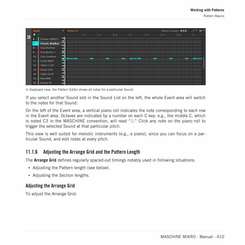
In Keyboard view, the Pattern Editor shows all notes for a particular Sound.
If you select another Sound slot in the Sound List on the left, the whole Event area will switchto the notes for that Sound.
On the left of the Event area, a vertical piano roll indicates the note corresponding to each rowin the Event area. Octaves are indicated by a number on each C key: e.g., the middle C, whichis noted C3 in the MASCHINE convention, will read “3.” Click any note on the piano roll totrigger the selected Sound at that particular pitch.
This view is well suited for melodic instruments (e.g., a piano), since you can focus on a par-ticular Sound, and edit notes at every pitch.
11.1.6 Adjusting the Arrange Grid and the Pattern Length
The Arrange Grid defines regularly spaced-out timings notably used in following situations:
▪ Adjusting the Pattern length (see below).
▪ Adjusting the Section lengths.
Adjusting the Arrange Grid
To adjust the Arrange Grid:
Working with Patterns
Pattern Basics
MASCHINE MIKRO - Manual - 410
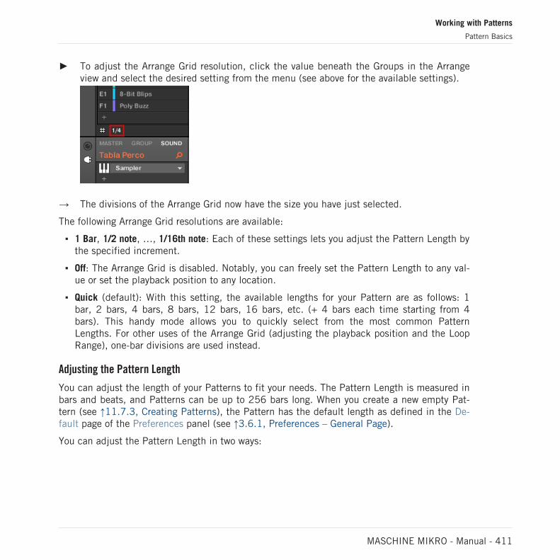
► To adjust the Arrange Grid resolution, click the value beneath the Groups in the Arrangeview and select the desired setting from the menu (see above for the available settings).
→ The divisions of the Arrange Grid now have the size you have just selected.
The following Arrange Grid resolutions are available:
▪ 1 Bar, 1/2 note, …, 1/16th note: Each of these settings lets you adjust the Pattern Length bythe specified increment.
▪ Off: The Arrange Grid is disabled. Notably, you can freely set the Pattern Length to any val-ue or set the playback position to any location.
▪ Quick (default): With this setting, the available lengths for your Pattern are as follows: 1bar, 2 bars, 4 bars, 8 bars, 12 bars, 16 bars, etc. (+ 4 bars each time starting from 4bars). This handy mode allows you to quickly select from the most common PatternLengths. For other uses of the Arrange Grid (adjusting the playback position and the LoopRange), one-bar divisions are used instead.
Adjusting the Pattern Length
You can adjust the length of your Patterns to fit your needs. The Pattern Length is measured inbars and beats, and Patterns can be up to 256 bars long. When you create a new empty Pat-tern (see ↑11.7.3, Creating Patterns), the Pattern has the default length as defined in the De-fault page of the Preferences panel (see ↑3.6.1, Preferences – General Page).
You can adjust the Pattern Length in two ways:
Working with Patterns
Pattern Basics
MASCHINE MIKRO - Manual - 411

► To adjust the Pattern Length, click the Pattern Length: field and drag it up to make thePattern longer or drag it down to make it shorter. You can also double-click the displayedvalue, enter a new value with your computer keyboard, and press [Enter] to confirm.
or
► To adjust the Pattern Length, drag the end marker of the Pattern (white arrow) in thetimeline:
With either method, the available lengths will depend on the current Pattern Grid resolution(see above).
Reducing the length of a Pattern might exclude the last events from the Pattern. Howeverthese events are not deleted: They simply appear darker in the Event area and will be includedback into the Pattern next time you extend it.
Events beyond the Pattern’s end can be edited in the software. However, you cannot edit themfrom the controller. See section ↑11.4, Editing Events for more information on editing events.
Adjusting the Pattern Length and Arrange Grid on the Controller
On your controller, the length of the selected Pattern, along with the Arrange Grid resolutionused to modify this length, can both be adjusted using Pattern mode, and Grid mode.
Using the Pattern mode
In Pattern mode you can adjust the Pattern Length of the current Pattern:
1. Press PATTERN to enter Pattern mode.
2. Press the pad relevant to the Pattern you want to adjust.
Working with Patterns
Pattern Basics
MASCHINE MIKRO - Manual - 412

3. Turn the Encoder (LENGTH) to adjust the Pattern Length in relation to the current resolu-tion of the Pattern Grid.
Adjusting the Grid
In Grid mode you can adjust the various grids used in MASCHINE, including the Arrange Gridresolution. The Arrange Grid changes the size of steps by which Section Lengths and PatternLengths can be adjusted.
1. Press SHIFT + FOLLOW (Grid) to enter Grid mode.
2. Press the Arrow buttons to navigate to the Arrange Grid setting.
3. Turn the Encoder to select a resolution.
11.1.7 Adjusting the Step Grid and the Nudge Grid
The Step Grid defines regularly spaced-out timings (the “steps”) at which your events/notes canbe created, moved, etc. The Step Grid resolution corresponds to the step size, which directlyaffects the precision of all Pattern editing actions, including quantization (see ↑11.4.7, Quan-tizing Events/Notes section for more on quantization).
The Step Grid also affects the step sequencer on your controller: Increasing the Step Grid resolution(i.e. decreasing the step size) will make more steps available in your Pattern for placing events. See↑11.4.2, Creating Events/Notes for more information on the step sequencer.
In the Pattern Editor, the Step Grid is indicated by the gray vertical lines in the Event area:
The vertical lines represent the Step Grid in the Event area.
Working with Patterns
Pattern Basics
MASCHINE MIKRO - Manual - 413

By default the Step Grid is active and the step size is 1/16th. However you may use anotherstep size or disable the Step Grid completely, as described below.
Depending on the current zoom factor and Step Grid resolution, if the vertical lines of the Step Gridare too close to each other they will be hidden to avoid convoluting the display. For example, thiscould be the case if you display 6 or 8 bars and choose a Step Grid resolution of 1/64th.
Regardless of the current Step Grid resolution, the gray lines on the beats (quarter notes) and theblack lines on the bars (notes) are always visible in the Event area.
Enabling or Disabling the Step Grid
► To enable or disable the Step Grid, click the Step Grid button (showing a little grid icon)in the bottom left corner of the Pattern Editor.
The Step Grid is enabled.
Adjusting the Step Grid
The Step Grid resolution can be adjusted via the Step Size menu, showing a value next to thegrid icon at the bottom left of the Pattern Editor:
The Step Size menu lets you adjust the Step Grid resolution.
► To select the step size that will apply to all your editing actions, click the value next tothe grid icon at the bottom left of the Pattern Editor and choose the desired step sizefrom the drop-down menu. Values range from 1 Bar to 1/128 and also include triplet val-ues. The default value is 1/16th note.
The Nudge Grid
In addition to the Step Grid described above, a secondary grid specifically controls the timingsat which existing events/notes can be nudged in the Pattern: the Nudge Grid.
Working with Patterns
Pattern Basics
MASCHINE MIKRO - Manual - 414

Nudging events means shifting them a small amount ahead or behind their current position. See↑11.4.4, Editing Selected Events/Notes for more information.
The Nudge Grid is based on the Step Grid:
▪ The Nudge Grid is active when the Step Grid is active. If the Step Grid is disabled, nudgingevents will shift them at the maximum resolution of the sequencer.
▪ By default, the Nudge Grid resolution is half a step, meaning that events will be nudged byhalf a step at a time.
▪ If you set the Nudge Grid resolution to a full step, the Nudge Grid will mirror the Step Gridand you can nudge events with the same resolution as when creating or quantizing events.
▪ You can also set the Nudge Grid resolution to a smaller fraction of the Step Grid resolution.This allows you to nudge events with even finer increments.
The Nudge Grid resolution can be adjusted in the context menu of the Event area:
► To adjust the Nudge Grid, right-click ([Ctrl]-click on macOS) on the background of theEvent area, select Nudge Grid in the menu, and choose a resolution from the values avail-able in the submenu: Step, Step/2, Step/4, Step/8, and Step/16:
Working with Patterns
Pattern Basics
MASCHINE MIKRO - Manual - 415

The Nudge Grid is not indicated in the Event area of the Pattern Editor.
Adjusting the Step Grid and the Nudge Grid on Your Controller
You can adjust the Step Grid and Nudge Grid resolution using your controller.
To adjust the Step Grid resolution:
1. Hold SHIFT + FOLLOW (Grid) to enter Grid mode.
2. Press the Arrow buttons to navigate to the Step setting.
3. Turn the Encoder to select a resolution.
To change the Nudge Grid resolution:
1. Hold SHIFT + FOLLOW (Grid) to enter Grid mode.
2. Press the Right Arrow buttons to navigate to the Step Nudge setting.
3. Turn the Encoder to select a resolution.
The new Nudge Grid resolution is directly in use, provided that the Step Grid is enabled.
11.2 Recording Patterns in Real Time
This section describes the various ways, features, and aids available on your controller to re-cord Patterns as you play them in real time:
▪ The most common method is called overdub recording. Alternatively you can use replacerecording. Both are described in section ↑11.2.1, Recording Your Patterns Live.
▪ Right before you record a new Pattern, you can quickly enter Record Prepare mode to ad-just a few important settings for your Pattern: The Record Prepare Mode.
▪ At any time you can enable and customize the metronome: ↑11.2.2, Using the Metronome.
▪ You can also start the recording with a count-in: ↑11.2.3, Recording with Count-in.
▪ While recording you can let MASCHINE automatically quantize what you play on the pads:Quantizing while Recording.
Working with Patterns
Recording Patterns in Real Time
MASCHINE MIKRO - Manual - 416

11.2.1 Recording Your Patterns Live
In Control mode your controller provides many tools to live record Patterns for the focusedGroup.
Take your time to set up the pad sensitivity and velocity scaling to your personal taste — you willhave even more fun playing and recording with your controller! These settings can be found in Pref-erences > Hardware > Pads. See ↑3.6.6, Preferences – Plug-ins Page for more information.
Overdub Mode
Overdub mode is the most usual recording mode. In this mode all pad hits are added asevents/notes, no matter if the Pattern already contains events.
Recording a Pattern: press PLAY then REC and hit some pads!
1. Press PLAY to start the sequencer.The PLAY button lights up.
2. Press REC to begin recording.The REC button lights up.
3. Now hit the pads you want to record and listen to what happens.Each hit will create an event in the Pattern Editor, the event length depends on how longyou hold the pad. Events continue to be added to the Pattern, even as the Pattern cycles.
4. When you’re done, press REC again to stop recording the pads.The REC button turns off. The sequencer keeps playing until you press PLAY again.
Working with Patterns
Recording Patterns in Real Time
MASCHINE MIKRO - Manual - 417

Replace Mode
When recording in Replace mode the events of the selected Sound(s) are replaced by what youplay.
1. Select the Sound(s) of which you want to replace events: In Pad Mode you can selectmultiple Sounds (see section ↑5.1.3, Selecting Multiple Sounds or Groups); in Keyboardmode only the focused Sound (the one played by your pads) will have its events replaced.
2. Press PLAY to start the sequencer.The PLAY button lights up.
3. Press ERASE + REC to begin recording in Replace mode.The ERASE and REC buttons light up.
4. Hit the pads you want to record.Each hit will create an event in the Pattern Editor, the event length depends on how longyou hold the pad. Existing events for the selected Sound(s) are deleted as they arereached by the playhead.
5. When you’re done, press REC again to stop recording the pads.The ERASE and REC buttons turn off. The sequencer keeps playing until you press PLAYagain.
In order to prevent you from erasing events accidentally, in following situations Replace modeis automatically disengaged (ERASE turns off) and the recording continues in Overdub mode:
▪ When the playback loops (whether at the end of the Loop Range or at the end of yourProject).
▪ When you stop the sequencer (by pressing the lit PLAY button).
▪ When you jump to another location in the Project (see section ↑11.1.4, Jumping to Anoth-er Playback Position in the Pattern).
▪ When you switch your controller to another mode (by pressing, e.g., SCENE, PATTERN,etc.).
▪ When you set the focus to another Group.
You can also manually disengage Replace mode and switch to Overdub mode:
► While recording in Replace mode, press the lit ERASE button to disengage Replace mode.
Working with Patterns
Recording Patterns in Real Time
MASCHINE MIKRO - Manual - 418
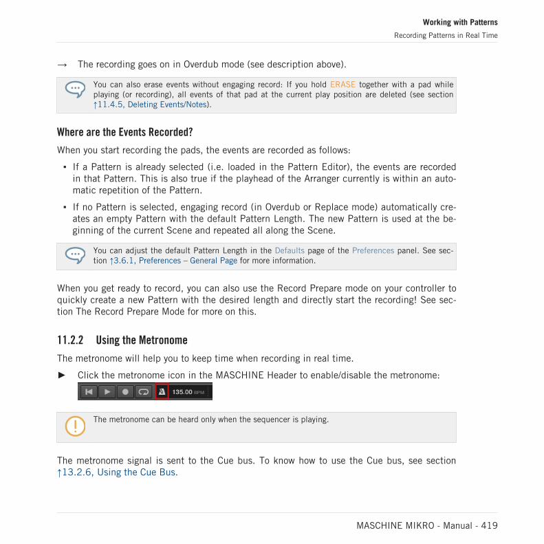
→ The recording goes on in Overdub mode (see description above).
You can also erase events without engaging record: If you hold ERASE together with a pad whileplaying (or recording), all events of that pad at the current play position are deleted (see section↑11.4.5, Deleting Events/Notes).
Where are the Events Recorded?
When you start recording the pads, the events are recorded as follows:
▪ If a Pattern is already selected (i.e. loaded in the Pattern Editor), the events are recordedin that Pattern. This is also true if the playhead of the Arranger currently is within an auto-matic repetition of the Pattern.
▪ If no Pattern is selected, engaging record (in Overdub or Replace mode) automatically cre-ates an empty Pattern with the default Pattern Length. The new Pattern is used at the be-ginning of the current Scene and repeated all along the Scene.
You can adjust the default Pattern Length in the Defaults page of the Preferences panel. See sec-tion ↑3.6.1, Preferences – General Page for more information.
When you get ready to record, you can also use the Record Prepare mode on your controller toquickly create a new Pattern with the desired length and directly start the recording! See sec-tion The Record Prepare Mode for more on this.
11.2.2 Using the Metronome
The metronome will help you to keep time when recording in real time.
► Click the metronome icon in the MASCHINE Header to enable/disable the metronome:
The metronome can be heard only when the sequencer is playing.
The metronome signal is sent to the Cue bus. To know how to use the Cue bus, see section↑13.2.6, Using the Cue Bus.
Working with Patterns
Recording Patterns in Real Time
MASCHINE MIKRO - Manual - 419
You can customize the metronome in various ways in the Preferences panel:
▪ You can adjust the metronome’s volume and time signature in the Preferences’ Generalpage (see section ↑3.6.1, Preferences – General Page for more details).
▪ You can select custom sounds for the metronome’s downbeats and upbeats in the Prefer-ences’ Default page (see section ↑3.6.4, Preferences – Default Page for more details).
The time signature of the metronome can be set to differ from the time signature of your Project.This can be useful to record unusual rhythms in a Pattern. Reminder: the time signature of yourProject is defined in the MASCHINE Header (MASCHINE in stand-alone mode) or by your host ap-plication (MASCHINE running as a plug-in).
On the controller:
► Press SHIFT + TAP (Metro) in the Transport section to activate or deactivate the metro-nome.
11.2.3 Recording with Count-in
Count-in allows you to start the metronome before the sequencer and recording begins. This isvery handy if you want to start recording a Pattern exactly on the downbeat.
When recording starts with a Count-in, the following happens:
▪ The playhead jumps to the beginning of the Loop Range.
▪ You hear the metronome alone during the count-in phase (1, 2 or 4 bars).
▪ After the count-in phase, the recording starts in Overdub mode (see ↑11.2.1, RecordingYour Patterns Live). The metronome turns off if it was off before the Count-in, otherwise itstays on.
You can adjust the metronome’s volume, time signature, and downbeat/upbeat sounds. See section↑11.2.2, Using the Metronome for more information.
If the current Loop Range does not start at the beginning of a bar (i.e. on a downbeat), thecount-in phase will start with a downbeat, count the selected duration (1, 2 or 4 bars), andthen add the offset between the beginning of the bar in which the beginning of the LoopRange is placed and the actual beginning of the Loop Range:
Working with Patterns
Recording Patterns in Real Time
MASCHINE MIKRO - Manual - 420

Count-in when the Loop Range starts at the beginning of a bar…
…and when the Loop Range doesn’t start at the beginning of a bar.
You can also use the Count-in to start a recording in Replace mode.
Adjusting the Count-in Duration
You can choose how long the metronome should be heard before the recording actually starts.In the software this is done via the Count-in Length setting in the General page of the Prefer-ences panel. Available values are 1 bar, 2 bars, and 4 bars. See section ↑3.6.1, Preferences –General Page for more details on the Count-in and metronome settings available in the Prefer-ences panel.
On your controller:
► Press SHIFT + REC to start the Count-in and record in Overdub mode.
or
► Press SHIFT + ERASE + REC to start the Count-in and record in Replace mode (see sec-tion ↑11.2.1, Recording Your Patterns Live for more information on the Replace mode).
You can adjust the duration of the Count-in using the software, see ↑3.6.1, Preferences – GeneralPage.
Working with Patterns
Recording Patterns in Real Time
MASCHINE MIKRO - Manual - 421

11.3 Recording Patterns with the Step Sequencer
If you are familiar with classic drum machines you may want to program your Pattern using thestep sequencer.
11.3.1 Step Mode Basics
On your controller the step sequencer is available via the Step mode. The Step mode allows youto program the steps to be played by the focused Sound in the current Group.
► Press STEP to switch your controller to Step mode.
In Step mode each pad of your controller represents one step of a 16-step sequence for thefocused Sound. The size of the steps depends on the current Step Grid settings. Lit pads indi-cate when events are on the corresponding steps.
For more information on the Step Grid, see section ↑11.1.7, Adjusting the Step Grid and the NudgeGrid.
In Step mode events are created with following settings:
▪ The event pitch is set to the Sound’s base key. To know how to change the base key of yourSounds, see section Adjusting the Base Key.
▪ The event velocity is defined by how hard you hit the pads, unless you have enabled theFixed Velocity option (see below).
▪ The event length is set to one step (hence, it depends on the current Step Grid settings).
▪ Obviously, the event position is defined by the pad you hit.
Checking Your Sequence
In Step Mode the pads provide an overview of the first bar of a four-bar Pattern:
▪ Individual events in your Pattern are represented by lit pads.
▪ The playback position in the Pattern is indicated by a playhead travelling from left to right.
To switch the pads to another part of the sequence, you have two possibilities:
Working with Patterns
Recording Patterns with the Step Sequencer
MASCHINE MIKRO - Manual - 422

► Press FOLLOW to enable/disable the Follow function.
→ When Follow is enabled, your pads automatically switch to the next 16 steps as soon asthe playback position reaches the end of the portion currently displayed.
This Follow function is always synchronized with the Follow function in the software. See ↑11.1.3,Following the Playback Position in the Pattern for more information.
Otherwise you can manually switch to the previous/next steps:
► Turn the Encoder to manually switch to the previous/next 16 steps on your pads.
Doubling Your Pattern
You can quickly double the content of the Pattern:
► Press SHIFT + DUPLICATE (Double) to double the content of the Pattern.
→ The length of the Pattern is doubled. All events in the original Pattern are duplicated tothe second half of the extended Pattern. Any events that were located beyond the originalPattern’s end are moved beyond the extended Pattern’s end.
You can otherwise double your Pattern via Pattern mode — see section ↑11.4.9, Doubling a Patternfor more information.
Preparing the Next Events
You can adjust the velocity of the next events that you will create by pressing the pads. Thevelocity of the events you create depends on the state of the Fixed Velocity option:
► Press FIXED VEL to enable/disable the Fixed Velocity option.
▪ If Fixed Velocity is enabled, all events you create will have the velocity set by turning theControl encoder. The Fixed Velocity value is momentarily shown on the display as you turnthe Controller encoder.
▪ If Fixed Velocity is disabled, the velocity of each event will depend on how hard you hit thepad when creating the event.
Working with Patterns
Recording Patterns with the Step Sequencer
MASCHINE MIKRO - Manual - 423

These parameters affect only your next hits on the pads: They don’t modify the velocity of ex-isting events.
11.3.2 Editing Events in Step Mode
In Step mode you can quickly adjust the parameters of events on particular steps.
Quick Edit Shortcuts for the Selected Steps
You can quickly adjust the velocity, position, and pitch of any events via the Quick Edit short-cuts:
1. Press and hold the pad(s) of the step(s) you want to edit.
2. To adjust the velocity, press the VOLUME (Velocity) button and turn the Encoder.
3. To finely adjust the position, press the SWING (Position) button and turn the Encoder.
4. To adjust the pitch, press TEMPO (Tune) button and turn the Encoder.
→ The adjusted value appears on the display. When you are done, release the pad(s).
Editing Events in Step Mode on the Controller
In Step mode on your controller, each event you create is automatically selected (and the pre-vious selection is dropped). You can then adjust the pitch and position of this last createdevent via the various commands available on your pads while holding SHIFT — see section↑11.4.4, Editing Selected Events/Notes, ↑11.4.5, Deleting Events/Notes, ↑11.4.6, Cut, Copy,and Paste Events/Notes, and ↑11.4.7, Quantizing Events/Notes for more information on theavailable commands.
Working with Patterns
Recording Patterns with the Step Sequencer
MASCHINE MIKRO - Manual - 424
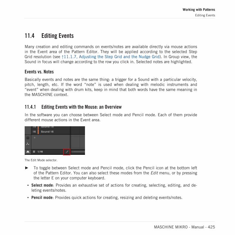
11.4 Editing Events
Many creation and editing commands on events/notes are available directly via mouse actionsin the Event area of the Pattern Editor. They will be applied according to the selected StepGrid resolution (see ↑11.1.7, Adjusting the Step Grid and the Nudge Grid). In Group view, theSound in focus will change according to the row you click in. Selected notes are highlighted.
Events vs. Notes
Basically events and notes are the same thing: a trigger for a Sound with a particular velocity,pitch, length, etc. If the word “note” is used when dealing with melodic instruments and“event” when dealing with drum kits, keep in mind that both words have the same meaning inthe MASCHINE context.
11.4.1 Editing Events with the Mouse: an Overview
In the software you can choose between Select mode and Pencil mode. Each of them providedifferent mouse actions in the Event area.
The Edit Mode selector.
► To toggle between Select mode and Pencil mode, click the Pencil icon at the bottom leftof the Pattern Editor. You can also select these modes from the Edit menu, or by pressingthe letter E on your computer keyboard.
▪ Select mode: Provides an exhaustive set of actions for creating, selecting, editing, and de-leting events/notes.
▪ Pencil mode: Provides quick actions for creating, resizing and deleting events/notes.
Working with Patterns
Editing Events
MASCHINE MIKRO - Manual - 425

Listed here are all available mouse actions from the Mouse Edit modes. For more details onspecific actions, please refer to the other sections in ↑11.4, Editing Events.
Mouse in Select Mode
The following table is an overview of available mouse actions in Select mode (works in bothGroup view and Keyboard view, see ↑11.1.5, Group View and Keyboard View).
Action Function
Creating Notes
(see ↑11.4.2, Creating Events/Notes fordetails)
Double-click in Event area’s background Creates a note.
Deleting Notes
(see ↑11.4.5, Deleting Events/Notes fordetails)
Double-click note Delete selected notes.
Right-click (macOS: [Ctrl]-click) and selectDelete from the menu.
Delete selected notes.
Selecting Notes
(see ↑11.4.3, Selecting Events/Notes fordetails)
Click unselected note Select a note.
[Shift] + click unselected note Add note to current selection.
[Shift] + click selected note Remove note from selection.
Drag in Event area’s background Multiple selection (selection frame).
Click in Event area’s background Deselect all notes.
Working with Patterns
Editing Events
MASCHINE MIKRO - Manual - 426

Action Function
Editing Selected Notes*
(see ↑11.4.4, Editing Selected Events/Notesfor details)
Drag note horizontally Moves selected notes in time according to theStep Grid.
[Ctrl] + drag note horizontally
(macOS: [Cmd] + drag note)
Freely moves selected notes in time (overridesthe Step Grid quantization).
[Alt] + drag note Duplicates selected notes. When you draghorizontally, the copies are moved in timeaccording to the Step Grid.
Drag left/right note border Moves the start/end of selected notesaccording to the Step Grid, thereby resizingthe notes.
[Ctrl] + drag left/right note border
(macOS: [Cmd] + drag left/right border)
Freely moves the start/end of selected notes(overrides the Step Grid quantization),thereby resizing the notes.
Drag note vertically Group view: Moves selected notes to anotherSound of the Group.
Keyboard view: Transposes selected notes.
* When editing, mouse actions can be performed on any of the selected notes — they will ap-ply to all selected notes.
Mouse in Pencil Mode
When Pencil mode is enabled, you can use the mouse draw events or notes:
► Click in the background of the Event area and drag the mouse with the button pressed toset notes wherever you move the cursor. Notes are created for the selected Sound.
The other way round:
Working with Patterns
Editing Events
MASCHINE MIKRO - Manual - 427

► Click a note and move the mouse cursor with the button pressed to erase all notes underthe mouse cursor. Only Notes for the selected Sound are erased.
11.4.2 Creating Events/Notes
In the software you can create new events anywhere in the Event area using your mouse. Theprocedure depends on the active Mouse Edit mode (Select or Pencil).
Each event is created at the beginning of the step in which your mouse cursor is located, ac-cording to the Step Grid settings. If the Step Grid is disabled, the event is created at the exactposition of your mouse cursor.
In Group view you can create events at the base key for all Sounds in the Group, no matterwhich Sound is focused. In Keyboard view you can create events at all keys (pitches) for thefocused Sound — you need to set the focus to another Sound in order to create events for thatSound.
Mouse in Select Mode
► To create a new event in Select mode, double-click at the desired location in the back-ground of the Event area.
Mouse in Pencil Mode
► To create a new event in Pencil mode, simply click at the desired location. Click and holdyour mouse and move the cursor horizontally to quickly create a series of events.
Creating Events beyond the Pattern’s End
If you create an event beyond the end of the Pattern in the Event area, the Pattern is automati-cally extended to the next Pattern Grid division after the new event so that the Pattern includesthis new event.
For more information on the Pattern Length and the Pattern Grid, see section ↑11.1.6, Adjustingthe Arrange Grid and the Pattern Length.
Working with Patterns
Editing Events
MASCHINE MIKRO - Manual - 428

Your controller offers numerous ways to create events — on your controller this is referred to as“recording Patterns.” For details on this please refer to section ↑11.2, Recording Patterns inReal Time and ↑11.3, Recording Patterns with the Step Sequencer.
11.4.3 Selecting Events/Notes
Use Select mode to select events/notes in your Pattern. Select mode is the default mode indi-cated by the unhighlighted Pencil icon. Notably, the Select mode allows you to define whichevents you apply your edits.
Select mode indicated by the unhighlighted Pencil icon.
Action Function
Selecting Events
Click unselected event Select event
[Shift] + click unselected event Add event to current selection
[Shift] + click selected event Remove event from selection
Drag in Event area’s background Multiple selection (selection frame)
Click in Event area’s background Deselect all events
Selecting All Events
You can select all events displayed in the Event area via the usual keyboard shortcut on youroperating system:
► Click anywhere in the Event area and press [Ctrl] + [A] ([Cmd] + [A] on macOS) on yourcomputer keyboard to select all displayed events.
Working with Patterns
Editing Events
MASCHINE MIKRO - Manual - 429

→ If the Pattern Editor is in Group view this will select all events for all Sounds in the Pat-tern. If the Pattern Editor is in Keyboard view this will select all events at all pitches forthe focused Sound.
Selecting Events/Notes on the Controller
Using your controller you can select particular events from the selected Pattern. This will allowyou to edit them without affecting the other events.
For example in Pad Mode this can be very useful to quickly quantize a few drum instruments inyour kit without affecting the rest of the kit: Press SHIFT + SELECT + the pads of the desireddrums then press SHIFT + pad 5 (QUANTIZE), and you’re done!
You can select notes and events using the pads. Depending on the current pad mode (PadMode or Keyboard mode, see ↑6.1.1, The Pad View in the Software), events will be selecteddifferently:
▪ In Pad Mode (the default mode of the pads), each pad represents a specific Sound:
◦ Unlit pads indicate Sounds for which the Pattern has no events. Nothing happenswhen you press them.
◦ Dimmed pads indicate Sounds for which events can be selected: Press any dimmedpad to add all events for that Sound to the selection. The pad turns fully lit to indicatethat all its events are selected. You can press any additional dimmed pad to add itsevents to the selection. Pressing a dimmed pad additionally switches the focus to thecorresponding Sound.
◦ Fully lit pads indicate Sounds for which all events are selected: Press any lit pad toremove all its events from the selection (the pad turns dim lit).
▪ In Keyboard mode, each pad represents a specific pitch of the focused Sound:
◦ Unlit pads indicate pitches at which the Pattern has no notes. Nothing happens whenyou press them.
◦ Dimmed pads indicate pitches at which notes can be selected: Press any dimmed padto add all notes at that pitch to the selection. The pad turns fully lit to indicate thatall its notes are selected. You can press any additional dimmed pad to add its notes tothe selection.
Working with Patterns
Editing Events
MASCHINE MIKRO - Manual - 430

Fully lit pads indicate pitches at which all notes are selected: Press any lit pad to remove all itsnotes from the selection (the pad turns dim lit).
11.4.4 Editing Selected Events/Notes
Once you have selected particular events, you can edit them in various ways.
In the software you can edit events with your mouse only if Select mode is selected in the EditMode selector. Select mode is the default mode indicated by the unhighlighted Pencil icon:
Select mode indicated by the unhighlighted Pencil icon.
Action Function
Editing Selected Notes
Drag note horizontally Moves selected notes in time according to the Step Grid(see quantizing rules below).
[Ctrl] + drag note horizontally
(macOS: [Cmd] + drag note)
Freely moves selected notes in time (overrides the StepGrid quantization).
[Alt] + drag note Duplicates selected notes. When you drag horizontally, thecopies are moved in time according to the Step Grid (seequantizing rules below).
Drag left/right note border Moves the start/end of selected notes according to the StepGrid, thereby resizing the notes (see quantizing rulesbelow).
Working with Patterns
Editing Events
MASCHINE MIKRO - Manual - 431

Action Function
[Ctrl] + drag left/right noteborder
(macOS: [Cmd] + drag left/rightborder)
Freely moves the start/end of selected notes (overrides theStep Grid quantization), thereby resizing the notes.
Drag note vertically Group view: Moves selected notes to another Sound of theGroup.
Keyboard view: Transposes selected notes.
Double-click note Deletes selected notes.
Right-click (macOS: [Ctrl]-click) Deletes selected notes.
If multiple notes are selected, mouse actions can be performed on any of the selected notes —they will apply to all selected notes.
If you perform any of the actions listed above on a note not included in the current selection,the selection is dropped and the note you are editing will be the only note affected by youredit.
Quantization when Editing a Single Event/Note
By default, all dragging actions on the time axis are quantized according to the Step Grid:
▪ When you drag a note (or its duplicate) horizontally, its original offset with the Step Grid ispreserved, unless you drag the note near a grid line — in that case it will snap to the grid.
▪ When you resize a note by dragging its start/end border, the new start/end border will snapto the Step Grid.
To override the quantization and freely adjust the note position or size, hold [Ctrl] ([Cmd] on ma-cOS) while dragging!
Quantization when Editing Multiple Events/Notes at Once
When you drag multiple notes (or their duplicates) on the time axis or resize them according tothe Step Grid, the various notes in the selection are affected as follows:
▪ The note you click is moved or resized according to the quantizing rule described above.
Working with Patterns
Editing Events
MASCHINE MIKRO - Manual - 432

▪ All other notes in the selection are moved or resized by the same amount (regardless oftheir own quantizing rules). When resizing, if the notes have different lengths the lengthdifferences are retained as long as no event becomes shorter than one step.
For example, if you have a drum roll, a flam or any custom sequence happening right before a beat,this allows you to move the whole sequence to another beat with a perfect timing while keeping itsfeel untouched.
Dragging vs. Nudging
Dragging with the mouse is different from the Nudge command on your controller:
▪ Whereas dragging is based on the Step Grid, the Nudge command is based on the NudgeGrid (see section ↑11.1.7, Adjusting the Step Grid and the Nudge Grid).
▪ Whereas you can drag notes beyond the end of the Pattern, nudged notes reaching the endof the Pattern are automatically sent to the beginning of the Pattern.
▪ If a note is not on a Step Grid division, dragging it with Step Grid enabled will alternatebetween snapping to Step Grid divisions and snapping to positions that preserve its originaloffset with the Step Grid (see quantization rule above).
In the software the Nudge command is not available with your mouse but via a keyboard short-cut:
► Press [Alt] + the left/right cursor key on your computer keyboard to nudge the selectednotes by one Nudge Grid division. If no event is selected, all events in the Pattern will beaffected.
See the hardware section below for more information on the Nudge command.
Nudge Events and Notes
Nudging allows you to shift selected events by the Nudge Grid resolution (the events’ offsetsrelative to the Nudge Grid are preserved).
The Nudge Grid is based on the Step Grid and allows you to define even smaller jumps than theStep Grid divisions to move your events more precisely. See section ↑11.1.7, Adjusting the StepGrid and the Nudge Grid for more details.
Working with Patterns
Editing Events
MASCHINE MIKRO - Manual - 433

► Press SHIFT + pad 7 (NUDGE <) to nudge the selected events to the left, or SHIFT + pad8 (NUDGE >) to nudge the selected events to the right. If nothing is selected, all event/notes in the Pattern will be affected.
Setting the Step Grid to “Off” and then using Nudge will shift events in extremely small incre-ments. This can be used to creatively add groove to Patterns — for example, shifting the snaredrum so that it is ever so slightly late, or “in the pocket” (something a funk drummer does natural-ly!).
Transpose Events and Notes
You can transpose selected events by semitones or octaves to match their pitch to your require-ments.
1. To transpose the selected events down in semitones press SHIFT + pad 13 (SEMI-TONE -); to transpose the selected events up press SHIFT + pad 14 (SEMITONE +). Ifnothing is selected, all event/notes in the Pattern will be affected.
2. To transpose the selected events down in octaves press SHIFT + pad 15 (OCTAVE -); totranspose the selected events up press SHIFT + pad 16 (OCTAVE +). If nothing is select-ed, all events in the Pattern will be affected.
11.4.5 Deleting Events/Notes
In the software you can delete events in the Event area using your mouse. The procedure de-pends on the active Mouse Edit mode (Select or Pencil).
Mouse in Select Mode
► To delete events in a Pattern, double-click them, alternatively, right-click (macOS: [Ctrl]-click) and select Delete from the menu. This also works when multiple events are select-ed.
If some events are selected, you can also press [Del] or [Backspace] on your computer key-board to delete them. See section ↑11.4.3, Selecting Events/Notes to know how to selectevents.
Working with Patterns
Editing Events
MASCHINE MIKRO - Manual - 434

Mouse in Pencil Mode
► To delete an event, simply click it. Click and hold an event and move the cursor to quicklydelete series of events.
The quickest and easiest way to delete events is the following:
1. Press EVENTS.
2. Press ERASE + the desired pad to delete from the Pattern all events for that Sound (ifpads are in Pad Mode) or all notes at that pitch for the focused Sound (if pads are in Key-board mode).
For more information on Pad modes, please refer to section ↑6.1.1, The Pad View in the Software.
As soon as you hold ERASE, some pads light up to indicate where there is something to delete:
▪ If your pads are in Pad Mode, the lit pads show you the Sounds for which the Pattern con-tains events.
▪ If your pads are in Keyboard mode, the lit pads show you the pitches (of the focusedSound) for which the Pattern contains events.
In other terms you don’t need to press any unlit pad, since there are no events to delete there.While holding ERASE you can press several pads to delete their events.
If you accidentally deleted events, press SHIFT + UNDO to undo it.
Deleting the Selected Events or Notes
Once you have selected particular events (see ↑11.4.3, Selecting Events/Notes for more onthis), you can delete them from the Pattern:
► Press SHIFT + pad 9 (CLEAR) to erase the selected events. If nothing is selected, allevent/notes in the Pattern will be affected.
Deleting Events or Notes while Playing
If the sequencer is currently playing, you can selectively erase events at the play position:
Working with Patterns
Editing Events
MASCHINE MIKRO - Manual - 435

► While the Pattern is playing, hold ERASE + the desired pad to progressively delete theevents for that Sound (if pads are in Pad Mode) or the notes at that pitch for the focusedSound (if pads are in Keyboard mode) as they are reached by the playhead.
→ As long as you hold the pad, the corresponding events are deleted as the playhead moveson.
You can use this to selectively erase notes at a particular place in the Pattern.
This might take some time getting used to, especially when the tempo is very fast, but you can al-ways use undo/redo (SHIFT + pad 1, SHIFT + pad 2) to get back to where you were before.
Deleting Events for the Entire Group at Playback Position
Using your controller you can erase events for all Sounds in the Group at the playback position.
► While the Pattern is playing, hold ERASE + GROUP + the desired pad 9–16 to progres-sively delete events for all Sounds in that Group as they are reached by the playhead.
11.4.6 Cut, Copy, and Paste Events/Notes
You can also cut, copy and paste selected events to another location in the same Pattern or toa different Pattern and for the same Sound or another one (possibly in another Group).
To cut, copy, and paste the selected events/notes in the software, do the following:
1. To cut or copy the selected events, press [Ctrl] + [X] or [Ctrl] + [C] ([Cmd] + [X] or [Cmd]+ [C] on macOS), respectively. You can also right-click ([Ctrl]-click on macOS) in thebackground of the Event area and select Cut or Copy from the context menu.The selected events are placed in the clipboard, ready to be pasted. If you selected theCut command, they are additionally removed from their original location.
2. If you want to paste the events in another Pattern, open the Pattern Manager, double-click the Pattern in which you want to paste the events (see section ↑11.7.1, The PatternManager and Pattern Mode for more information on the Pattern Manager).
3. Click anywhere in the Event area of the newly selected Pattern.
4. To paste the events, press [Ctrl] + [V] ([Cmd] + [V] on macOS). You can also right-click([Ctrl]-click on macOS) the desired location in the background of the Event area and se-lect Paste from the context menu.
Working with Patterns
Editing Events
MASCHINE MIKRO - Manual - 436

→ The events will be pasted according to the rules described hereinafter. If no event is se-lected, all displayed events will be affected: in Keyboard view these are all events of thefocused Sound; in Group view these are all events of all Sounds within the Group (seesection ↑11.1.5, Group View and Keyboard View for more information on Group view andKeyboard view).
If you have copied events from multiple Sounds as the Pattern Editor was in Group view, and thenswitch to Keyboard view before pasting the events, only the copied events from the Sound previous-ly focused will be pasted in the new focused Sound.
Pasting Rules
The location at which the cut or copied events will be pasted depends on the following:
▪ In any case the first pasted event will be quantized to the current Step Grid, and the fol-lowing pasted events will retain their time offset to this first event.
▪ If you paste the events via the Paste command from the context menu of the Event area’sbackground:
◦ The first copied event is pasted at the closest step near the mouse cursor on the timeaxis.
◦ In Group view the events copied from the topmost Sound in the Sound List are pastedonto the focused Sound. In Keyboard view the events copied from the highest pitchare pasted at the pitch of the row in which the mouse cursor is located.
◦ All copied events retain their position relative to each other, both on the time axis andon the vertical axis (Sound List in Group view, pitches in Keyboard view).
◦ If some of the pasted events go beyond the Pattern’s end, the Pattern is extended tothe next Pattern Grid division after the last pasted event.
▪ If you paste the events via the shortcut on your computer keyboard while playback is on:
◦ If you haven’t changed the Sound focus, events are pasted one step after the originalevents.
◦ If you have changed the Sound focus, events are pasted at the same timings as theoriginal events. In Group view the events copied from the topmost Sound in the SoundList are pasted onto the focused Sound, and the other events will retain their verticalposition relative to these topmost events.
Working with Patterns
Editing Events
MASCHINE MIKRO - Manual - 437

▪ If you paste the events via the shortcut on your computer keyboard while playback is off:
◦ If you haven’t changed the Sound focus or the playhead position, events are pastedone step after the original events.
◦ If you haven’t changed the Sound focus but changed the playhead position, events areinserted with the first event starting at the playhead position. All following events willretain their position relative to the first event.
◦ If you have changed the Sound focus without changing the playhead position, eventsare inserted at the same timings as the original events. In Group view the events cop-ied from the topmost Sound in the Sound List are pasted onto the focused Sound, andthe other events will retain their vertical position relative to these topmost events.
◦ If you have changed both the Sound focus and the playhead position (e.g., by clickingin the timeline above the Event area, see section ↑11.1.4, Jumping to Another Play-back Position in the Pattern), events are inserted with the first event starting at theplayhead position. In Group view the events copied from the topmost Sound in theSound List are pasted onto the focused Sound, and all copied events retain their posi-tion relative to each other, both on the time axis and on the vertical axis (Sound Listin Group view, pitches in Keyboard view).
Cut, Copy, and Paste Events/Notes on Your Controller
To copy and paste selected events from your controller:
1. To copy the selected events, press SHIFT + pad 11 (COPY).
2. If you want to cut the selected events before pasting them, press SHIFT + pad 9 (CLEAR)to delete the original events.
3. To paste them, press SHIFT + pad 12 (PASTE).
→ The events will be pasted according to the same rules as when using the keyboard short-cuts in the software (see above). If no event is selected, all displayed events will be af-fected: in Keyboard view these are all events of the focused Sound; in Group view theseare all events of all Sounds within the Group (see section ↑11.1.5, Group View and Key-board View for more information on Group view and Keyboard view).
You can also copy events from one Pattern to another: to do this, copy the selected events, selectthe Pattern you want to copy them to and then paste them.
Working with Patterns
Editing Events
MASCHINE MIKRO - Manual - 438

11.4.7 Quantizing Events/Notes
Quantization is the process of moving events to the closest steps. You can quantize your notesat any time, no matter how you recorded them. They will be quantized according to the stepsize (i.e. Step Grid resolution) selected. If you turn the Step Grid off, no quantization will beapplied. See section ↑11.1.7, Adjusting the Step Grid and the Nudge Grid above for more in-formation on the Step Grid and the step size.
There are two strengths of quantization:
▪ Full quantization: Moves each event directly onto the closest step of the current Step Grid.This allows a perfectly regular rhythm.
▪ Half quantization (50%): Moves each event half way toward the closest step of the currentStep Grid. This allows a tighter rhythm while retaining a human feel.
In addition, if you record notes from a MIDI keyboard or using the pads, and create unwanteddouble notes where you don’t want them; MASCHINE automatically detects and removes thesedouble notes while quantizing.
Quantizing Events via the Pattern Editor Context Menu
Quantize and Quantize 50% are available from the Pattern Editor context menu. This menuprovides the same functionality as pressing QUANTIZE and QUANTIZE 50% on the MA-SCHINE hardware.
Working with Patterns
Editing Events
MASCHINE MIKRO - Manual - 439

Quantize and Quantize 50% in the Pattern Editor context menu.
To apply full or half quantization using the MASCHINE software:
1. Select the events in the Pattern Editor you want to quantize. If nothing is selected, thewhole Pattern will be quantized.
2. To apply full quantization to the selected events, right-click the mouse and select Quan-tize from the context menu.
3. To apply only a small amount of quantization to keep the groove you created after record-ing your pattern, right-click the mouse and select Quantize 50% from the context menu.
4. To undo/redo Quantize use hotkeys: Ctrl+Z/Ctrl+Y (Cmd+Z/Cmd+Y on macOS).
Using Quantization on the Controller
You can quantize your notes at any time, no matter how you recorded them. They will be quan-tized according to the step size (i.e. Step Grid resolution) selected. If you turn the Step Gridoff, no quantization will be applied. See section ↑11.1.7, Adjusting the Step Grid and theNudge Grid for more information on the Step Grid and the step size.
You can also choose to have notes automatically quantized as you record them on the pads! Seesection Quantizing while Recording for more information.
Working with Patterns
Editing Events
MASCHINE MIKRO - Manual - 440

To apply full or half quantization:
1. Select the events you wish to quantize. If nothing is selected, the whole Pattern contentwill be quantized. See ↑11.4.3, Selecting Events/Notes to know how to select events.
2. To apply full quantization to the selected events, press SHIFT + pad 5 (QUANTIZE).
3. To apply only a bit of quantization to keep the groove you created by playing your noteslive, press SHIFT + pad 6 (QUANTIZE 50%).
You can repeatedly apply QUANTIZE 50% until you are happy; you could for example apply it untilthe notes are close enough to the Step Grid to sound tight, but loose enough to maintain their basic“feel.” If it is too quantized for you, just press SHIFT + pad 1 to undo the last change.
11.4.8 Quantization While Playing
Input Quantization mode allows you to quantize events also as you play them on the pads.
The Input Quantization settings previously available have been renamed to include the new In-put Quantization mode — now Input Quantization can be set to following modes in the Prefer-ences:
▪ None: Input Quantization is disabled. Events you play or record on the pads are not quan-tized.
▪ Record: Input Quantization is applied only when you record the pads.
▪ Play/Rec: Input Quantization is applied both when you play on the pads and when you re-cord them.
In Play/Rec mode the quantization applied while playing is slightly different from the quantizationapplied while recording: When recording, all events are quantized to the closest step — possiblyahead of the event. When playing, on the other hand, events occurring in the first half of the stepsare left untouched (since you cannot bring them forward in the timeline!) whereas events occurringin the second half of the steps are quantized to the next step.
Choosing an Input Quantization Mode
In the software the Input Quantization can be configured via the Quantize setting available inthe Input section at the bottom of the General page in the Preferences panel:
Working with Patterns
Editing Events
MASCHINE MIKRO - Manual - 441

► Click the Quantize menu and select the desired Input Quantization mode from the threemodes available (see their description above).
11.4.9 Doubling a Pattern
Your controller provides a useful shortcut to double the length and content of the current Pat-tern. In the software, you can do this for example by copying all events, putting the Playheadindicator at the end of the Pattern, and pasting the events (the Pattern Length is automaticallydoubled).
To double the length and content of a Pattern:
1. Hold PATTERN to enter Pattern mode.
2. Select the desired Pattern by pressing its pad.
3. Press SHIFT + DUPLICATE (Double).
→ The Pattern is doubled.
Keep in mind that doubling a Pattern twice results in a Pattern that is four times as long.
11.4.10 Adding Variation to Patterns
Variation provides an abundance of inspiration and even “happy accidents” when applied toyour workflow. The variation engine contains two modes:
▪ Humanize: This mode adds natural rhythmic fluctuations to programmed sequences.
▪ Random: This mode provides randomly generated patterns or variations of your beats andmelodies based on customizable values.
Variation is available in both Pad mode and Keyboard mode and can be applied to a Sound. InKeyboard mode the Variation Random mode contains extra parameters that allow you to addvariety to melodic content.
Working with Patterns
Editing Events
MASCHINE MIKRO - Manual - 442

When adding Variation to your Patterns, please be aware Random mode conforms to the selectedScale.
To access Variation mode:
1. Press SELECT + Sound (1–16).
2. Press VARIATION to access the Variation controls.
3. Press the Left or Right Arrow to access Humanize or Randomize mode.
4. Turn the Encoder to choose an amount.
5. Press the Encoder to apply the set amount.
11.5 Recording and Editing Modulation
One of the really cool features of MASCHINE is the ability to modulate nearly all MASCHINEparameters both on the controller and in the software in a very easy way.
In MASCHINE, modulation means the automatic change of MASCHINE parameters from an in-ternal source (e.g., manual changes recorded via Auto-write…). Value changes are:
▪ Temporary: The modified value is valid only until the end of the Clip: When the Scene islooped or when playback is restarted, the parameter value is reset to its non-modulated val-ue.
▪ Relative (knobs only): For continuous parameters (these parameters are controlled by a ro-tary knob in the software), the new parameter value is defined as deviation from the actualvalue. Note that for selectors and buttons, modulation defines instead absolute values.
Modulation vs. Automation
Although both deal with automatic change of MASCHINE parameters, modulation and automa-tion have to be distinguished. The following table summarizes the main differences:
Working with Patterns
Recording and Editing Modulation
MASCHINE MIKRO - Manual - 443

Modulation Automation
Source of control Internal (e.g., changesrecorded via Auto-write)
External (e.g., an externalMIDI sequencer or anautomation track in your host)
Duration of the change Temporary (until the end ofthe Clip)
Permanent
Target parameters At the Sound and Grouplevels only (see below)
At all levels (Sound, Group,and Master)
Nature of the change(continuous parameters only)
Relative (defines a deviationto the non-modulated value)
Absolute (defines a new valueregardless of the non-automated value)
This section describes how to use modulation in MASCHINE — for more information on using auto-mation, please refer to section ↑12.2.3, Controlling Parameters via MIDI and Host Automation.
Please note that modulation and automation are not mutually exclusive: You can modulate aparameter in MASCHINE and automate it (e.g., from your host) simultaneously! As a result,the parameter value will deviate (according to the recorded modulation) from its moving valuedefined by the automation.
Example: Let’s assume that you have recorded some modulation for the Cutoff parameter of a FilterPlug-in in order to create a filter sweep. Since modulation is defined relative to the non-modulatedvalue, by manually adjusting the Cutoff parameter you can shift the entire sweep across frequen-cies. By assigning this Cutoff parameter to a MIDI control or an automation ID (see section↑12.2.3, Controlling Parameters via MIDI and Host Automation to know how to do this) you can cre-ate a filter sweep that automatically moves across frequencies!
11.5.1 Which Parameters Are Modulatable?
All the modulatable parameters are found in Plug-ins or Channel properties (e.g., you cannotmodulate the Pattern Length or the Step Grid resolution). This means that all modulatable pa-rameters are found in a Parameter page of the Control area (when the software is in Arrangeview).
Working with Patterns
Recording and Editing Modulation
MASCHINE MIKRO - Manual - 444

In order to be modulatable, parameters of Plug-ins and Channel properties have to meet fol-lowing requirements:
▪ The parameter must be controlled by a knob or a button in the software. Most parameterscontrolled by selectors (e.g., for selecting an operating mode or a filter type) cannot bemodulated — however there are a few exceptions.
▪ The parameter must be at the Group or Sound level. Parameters at the Master level cannotbe modulated.
This second rule is also true for Plug-ins: if a Plug-in is loaded at the Master level, its parameterswill not be modulatable — but the same Plug-in loaded at the Group or Sound level will have itsparameters modulatable.
Almost all parameters meeting these requirements can be modulated, the only exceptions be-ing:
▪ Plug-ins:
◦ Saturator: in Tube mode, the Bass Overload button (MAIN section) and Bypass button(EQ section).
◦ Percussion (Drumsynth): in Fractal mode, the Tune Hold button in the Main page.
▪ Channel properties:
◦ Sound’s and Group’s Output properties: the Cue button in the Audio page.
◦ Group’s Input properties: the Root Note knob in the MIDI page.
At the Sound and Group level the same parameters are both automatable and modulatable. Formore information on automation please refer to section ↑12.2.3, Controlling Parameters via MIDIand Host Automation.
Also note that your Macro Controls will be modulatable if, and only if, their target parametersare themselves modulatable. For more information on Macro Controls please refer to section↑12.3, Creating Custom Sets of Parameters with the Macro Controls.
Working with Patterns
Recording and Editing Modulation
MASCHINE MIKRO - Manual - 445

11.5.2 Recording Modulation
If you take a closer look at the knobs in the software Parameter pages of the Control area youwill notice they have an outer ring that changes its color to light grey as soon as you hover overit with the cursor.
Drag the outer ring of the knobs to record modulation.
► To record modulation for a knob in real time, click its outer ring and then drag it up anddown during playback.
→ Your movement are recorded into the Pattern and will be recalled as the playback is loop-ed.
As soon as you create modulation for a parameter, the following happens:
▪ On the outer ring of the knob, the colored section (usually indicating the current parametervalue) is replaced by a little segment indicating the modulated value. During playback thislittle segment follows the movement you have just recorded. The non-modulated value ofthe parameter is still indicated by the little white segment on the knob itself. Since modu-lation is defined relative to this non-modulated value, you can turn the knob to define thereference value from which the recorded modulation will deviate.
▪ A modulation track is created for this parameter in the Modulation pane of the Control area(at the bottom of the Pattern Editor) containing the modulation points you have just record-ed. You can further edit the modulation track from there — see section ↑11.5.3, Creatingand Editing Modulation in the Control Lane.
Removing Modulation
You can also use the outer ring to remove the entire modulation for the knob:
► To remove the entire modulation for a knob, simply right-click (on macOS: [Ctrl]+click) itsouter ring.
Working with Patterns
Recording and Editing Modulation
MASCHINE MIKRO - Manual - 446

You can also create and edit modulation tracks directly in the Control Lane. See section The RecordPrepare Mode for more information.
To modulate a parameter with the controller:
1. Press PLUG-IN.
2. Navigate to the parameter you want to modulate. To do this, put the focus on the desiredGroup or Sound (see ↑3.3.3, Focusing on a Group or a Sound), navigate to the desiredPlug-in or set of Channel properties, and finally to the Parameter page and the particularparameter (see ↑3.3.5, Navigating Channel Properties, Plug-ins, and Parameter Pages inthe Control Area).
3. Make sure the song is playing (PLAY must be lit).
4. Hold AUTO to enter Auto-write mode and turn the Control encoder to change the parame-ter value.
→ Your modulation is recorded. Each Encoder movement is stored in your Pattern as anmodulation event. It will be automatically played with your Pattern upon its next cycle.
From your controller you can also delete all modulation events for all parameters of the chan-nel:
Press SHIFT + pad 10 (CLR AUTO) to delete all modulation for all parameters of the focusedSound or Group.
11.5.3 Creating and Editing Modulation in the Control Lane
You can also create, select, and edit individual modulation points in the Modulation pane of theControl Lane.
Displaying the Modulation Pane in the Control Lane
1. To see and edit modulation for parameters of a Sound, click the desired Sound in theSound List (left of the Pattern Editor) and click the SOUND tab in the Control area.
2. To see and edit modulation for parameters of a Group, click the desired Group in theGroup List (left of the Arranger) and click the GROUP tab in the Control area.
Working with Patterns
Recording and Editing Modulation
MASCHINE MIKRO - Manual - 447

3. If the Control Lane is not visible at the bottom of the Pattern Editor, click the up-pointingarrow in the bottom left corner of the Pattern Editor to show it.
4. Click the little bar icon left of the Control Lane to display the Modulation pane.
→ The Modulation pane appears.
The Modulation pane showing the modulation track for the Decay parameter (see on the left).
The Modulation pane contains following elements:
▪ The left part shows the Modulator List showing all parameters currently modulated in thefocused Sound or Group. Click any entry to display the modulation track for that parameteron the right. Click the “+” symbol at the end of the list to add a modulation track for an-other parameter (see below). If the list is too small to display all entries at once, a verticalscroll bar appears on the right to navigate the list.
▪ The right and biggest part shows the modulation track for the particular parameter selectedin the Modulator List on the left:
◦ Each modulation track contains a variable number of modulation points, each of themdefining a new value for the parameter.
◦ The zoom factor and scroll position of the modulation track is always synchronized tothose of the Event area above.
Working with Patterns
Recording and Editing Modulation
MASCHINE MIKRO - Manual - 448

◦ Left of the modulation track, a vertical scale indicates the value range for that param-eter. In the modulation track you can create, edit, and delete modulation points (seebelow).
The range of the vertical value scale left of the modulation track depends on the current, non-modu-lated value of the selected parameter: Since modulation points set new values relative to the non-modulated value of the parameter, this scale allows you to see at any time the real values that willbe set by the various modulation points in the track.
You can adjust the height of the Control Lane by dragging its upper border with the mouse.
As soon as some modulation is recorded for a parameter in a particular Pattern of the Group,the corresponding Modulator and modulation track appear for all Patterns of the Group. Thetrack will be empty for Patterns in which you haven’t recorded any modulation for this parame-ter yet. Similarly, if you delete this Modulator in the Modulator List and its modulation track(see below to know how) in a Pattern, it will be deleted in all other Patterns of the Group as well.
Editing Modulation Points
You can create, edit, and delete modulation points in the displayed modulation track with yourmouse. As for the Event area above, the mouse behavior in the Control Lane will depend on theMouse Edit mode selected in the Edit Mode selector, at the bottom left of the Pattern Editor:
2 31The Edit Mode selector.
All actions in the Control Lane are quantized according to the Step Grid. For more informationon the Step Grid, please refer to section ↑11.1.7, Adjusting the Step Grid and the Nudge Grid.
Working with Patterns
Recording and Editing Modulation
MASCHINE MIKRO - Manual - 449

Mouse Edit Mode Available Mouse Actions
(1) Select mode To create modulation points, double-click in the Control Lane — otherpoints on this step will be replaced.
To delete a modulation point, right-click it ([Ctrl]-click it on macOS).
To edit an existing modulation point, drag it vertically (you can also dragthe horizontal segment following the point instead). When hovering themouse over a modulation point or the following segment, the parametervalue at this point appears. The displayed value is updated as you dragyour mouse vertically.
You can select several modulation points in the Control Lane togetherby clicking and dragging a rectangle around them; now you can editthem together by dragging them up or down — they will keep theirrelative offsets until any of them reaches the minimum or maximumvalue.
(2) Paint mode Click and drag to set modulation points wherever you move the cursor.
(3) Erase mode Click and drag to delete modulation points wherever you move thecursor.
Adding a Modulation Track
As soon as you record modulation for a new parameter in the software or from your controller, anew modulation track is automatically created and contains your recorded movements in formof modulation points. But you can also create a new modulation track from scratch in the Con-trol Lane. Here is how.
At the end of the Modulator List (in the left part of the Control Lane) you can use the “+” sym-bol to create a new modulation track.
Click the “+” symbol to add a new modulation track.
Working with Patterns
Recording and Editing Modulation
MASCHINE MIKRO - Manual - 450

To create a new modulation track:
1. To create a new modulation track for a parameter of a Sound, click the desired Sound inthe Sound List (left of the Pattern Editor) and click the SOUND tab in the Control area.
2. To create a new modulation track for a parameter of a Group, click the desired Group inthe Group List (left of the Arranger) and click the GROUP tab in the Control area.
3. In the Modulation pane click the “+” symbol at the end of the Modulator List to create anew empty modulation track.A new Modulator X entry appears at the end of the list (X is an ordering number) and it isautomatically selected. The corresponding modulation track is still empty. Moreover youcannot create any modulation point in the track yet, you first need to assign it to a param-eter of your choice.
4. Right-click ([Ctrl]-click on macOS) the Modulator X label to open a structured menu con-taining all modulatable parameters in that channel.
5. Navigate the structure of the menu down to the desired parameter: For a parameter locat-ed in Channel properties select Sound > [set of Channel properties] > [Parameter page] >[parameter]. For a parameter located in a Plug-in select [Plug-in name] > [Parameterpage] > [parameter].
Once you have selected a parameter in the menu the parameter name appears in place ofModulator X in the Modulator List and the modulation track on the right is editable.
→ In the modulation track you can now add and edit modulation points for the selected pa-rameter as described above. The modulation track is added to all Patterns of the Groupand you can directly create different modulation points in other Patterns for that track.
Working with Patterns
Recording and Editing Modulation
MASCHINE MIKRO - Manual - 451

When you load a Plug-in in a channel (Sound or Group) its modulatable parameters will automati-cally show up in the menu of available parameters when this channel is focused.
Resetting a Modulation Track
► To reset the modulation track of a parameter, right-click ([Ctrl]-click on macOS) the de-sired entry in the Modulator List and select Reset Modulator at the top of the menu.
→ All modulation points are deleted in all Patterns of the Group and you can start designinga new modulation for that parameter from scratch.
Re-Assigning a Modulation Track
► To change the parameter assignment of a modulation track, right-click ([Ctrl]-click on ma-cOS) the desired entry in the Modulator List and select another parameter from the hier-archical menu as described above.
→ Upon your selection all modulation points are deleted and the track is assigned to the newparameter. The previous parameter is not modulated anymore.
Removing a Modulation Track
► To remove a modulation track, hover its entry in the Modulator List with the mouse andclick the little cross that appears on its right.
→ The modulation track and its entry in the Modulator List are removed from the Modulationpane for all Patterns. The parameter is not modulated anymore.
11.6 Creating MIDI Tracks from Scratch in MASCHINE
Within MASCHINE you can create MIDI tracks from scratch for any Sound of your Project. MA-SCHINE’s MIDI automation tracks can have two purposes:
Working with Patterns
Creating MIDI Tracks from Scratch in MASCHINE
MASCHINE MIKRO - Manual - 452

▪ When playback is on, the content of these tracks is sent in real time as MIDI data via theMIDI output of the Sound (if enabled). Configuring the MIDI output of Sounds is done inthe MIDI page of the Sound’s Output properties — see section ↑12.2.5, Sending MIDIfrom Sounds for more information.
▪ When exporting your Pattern as a MIDI file for use in another environment, MIDI automa-tion tracks will be included in the exported MIDI file. See section ↑11.8.2, Exporting MIDIfrom Patterns for more information.
You cannot create MIDI tracks for Groups nor for the Master.
Creating and editing MIDI tracks is done in the MIDI pane of the Control Lane:
Create MIDI tracks in the MIDI pane of the Control Lane.
1. Click the desired Sound in the Sound List on the left of the Pattern Editor.
2. If the Control Lane is not visible at the bottom of the Pattern Editor, click the up-pointingarrow in the bottom left corner of the Pattern Editor to show it.
3. Click the MIDI socket icon left of the Control Lane to display the MIDI pane.
Working with Patterns
Creating MIDI Tracks from Scratch in MASCHINE
MASCHINE MIKRO - Manual - 453
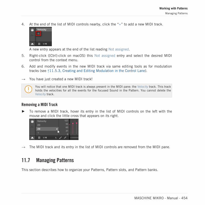
4. At the end of the list of MIDI controls nearby, click the “+” to add a new MIDI track.
A new entry appears at the end of the list reading Not assigned.
5. Right-click ([Ctrl]-click on macOS) this Not assigned entry and select the desired MIDIcontrol from the context menu.
6. Add and modify events in the new MIDI track via same editing tools as for modulationtracks (see ↑11.5.3, Creating and Editing Modulation in the Control Lane).
→ You have just created a new MIDI track!
You will notice that one MIDI track is always present in the MIDI pane: the Velocity track. This trackholds the velocities for all the events for the focused Sound in the Pattern. You cannot delete theVelocity track.
Removing a MIDI Track
► To remove a MIDI track, hover its entry in the list of MIDI controls on the left with themouse and click the little cross that appears on its right.
→ The MIDI track and its entry in the list of MIDI controls are removed from the MIDI pane.
11.7 Managing Patterns
This section describes how to organize your Patterns, Pattern slots, and Pattern banks.
Working with Patterns
Managing Patterns
MASCHINE MIKRO - Manual - 454

11.7.1 The Pattern Manager and Pattern Mode
In the software, all Pattern management operations are done in the Pattern Manager:
► To open the Pattern Manager, click the Pattern Manager button (a down-pointing arrow) atthe left of the name of the selected Pattern.
→ The Pattern Manager appears underneath.
Use the Pattern Manager to manage your Patterns.
Working with Patterns
Managing Patterns
MASCHINE MIKRO - Manual - 455

▪ On the left you can see the list of the 16 Pattern slots in the selected Pattern bank. Slotscontaining a Pattern show a colored bar on the left along with the Pattern name. The otherslots contain no Pattern. The selected Pattern is highlighted (the Basics - Return Pattern inthe picture above).
▪ On the right you can see the various Pattern banks in form of pad grids — a pad grid is asquare of 4x4 cells representing the pads of your controller. In each Pattern bank the col-ored cells indicate Pattern slots containing a Pattern, while unlit cells indicate empty Pat-tern slots. The selected Pattern bank is surrounded by a white border (the first bank in thepicture above). If there are too many Pattern banks to fit into the Pattern Manager’s height,use the scroll wheel of your mouse to display the other banks.
▪ The Pattern slots on the left and the cells in the selected pad grid on the right are strictlyequivalent: you can use either the slots or the corresponding cells to execute all the man-agement commands described in the next sections.
Closing the Pattern Manager
► To close the Pattern Manager, click anywhere outside it.
Pattern Mode on Your Controller
Pattern mode is where you select and manage your Patterns.
► To enter Pattern mode on your controller, press PATTERN.
→ Your controller switches to Pattern mode. This is indicated by the lit PATTERN button.
Now the pads on your controller represent the 16 Pattern slots of the current Pattern bank:
▪ The fully lit pad indicates the selected Pattern slot.
▪ Dim lit pads indicate Pattern slots containing a Pattern.
▪ Unlit pads represent empty Pattern slots.
11.7.2 Selecting Patterns and Pattern Banks
In the topmost row of the Pattern Editor, you can see on the left the name of the Pattern se-lected:
Working with Patterns
Managing Patterns
MASCHINE MIKRO - Manual - 456

The selected Pattern is named Basics.
Selecting a Pattern:
1. Open the Pattern Manager (see ↑11.7.1, The Pattern Manager and Pattern Mode).
2. If it is not already selected, select the Pattern bank containing the desired Pattern byclicking its pad grid on the right.
The selected Pattern bank is surrounded by a white border, and the left part of the Pat-tern Manager displays the Pattern slots in that bank.
3. Select the desired Pattern by clicking its name in the list on the left or by clicking its cellin the selected pad grid on the right.
→ The selected Pattern is loaded in the Pattern Editor and its events appear in the Eventarea. Furthermore, this Pattern is referenced by a Clip for the selected Group in the cur-rent Scene in the Arranger. This Clip replaces any previous Clip for the Group in thatScene (see chapter ↑16.3, Using Song View for more on this).
Working with Patterns
Managing Patterns
MASCHINE MIKRO - Manual - 457

Selecting a Pattern
► To select a Pattern in the current Pattern bank, press PATTERN + the dim lit pad corre-sponding to the cell of the desired Pattern on the right display.
→ Selecting a Pattern has the following consequences:
▪ This Pattern is displayed in the software’s Pattern Editor. You can then modify it both fromyour controller and in the software.
▪ This Pattern is referenced by a Clip for the selected Group in the current Scene. This Clipreplaces any previous Clip for the Group in that Scene (see chapter ↑16.3, Using SongView for more on this).
Selecting Patterns and Pattern Banks on the Controller
Selecting a Pattern Bank
To select a Pattern located in another Pattern bank, you first need to select another Patternbank:
1. Press and hold PATTERN to enter Pattern mode.
2. Press the Right Arrow button to select Bank.
3. Turn the Encoder to select a Pattern bank.
Selecting a Pattern
► To select a Pattern in the current Pattern bank, press PATTERN + the dim lit pad corre-sponding to this Pattern.
→ When a Pattern is selected:
▪ This Pattern is displayed in the software’s Pattern Editor. You can then modify it both fromyour controller and in the software.
▪ This Pattern is referenced for the selected Group in the current Scene. This Pattern repla-ces any previous Pattern selected for the Group in that Scene (see chapter ↑16.3, UsingSong View for more on this).
Working with Patterns
Managing Patterns
MASCHINE MIKRO - Manual - 458

11.7.3 Creating Patterns
First of all, you don’t need to explicitly create a new empty Pattern before filling it with events:
▪ If no Pattern is selected, as soon as you create an event (in the empty Event area of thesoftware or by recording pads on your controller) a new Pattern will be created for it! Seesection ↑11.4.2, Creating Events/Notes for more information on creating events.
▪ If you double-click in a cell of the Arranger, a Clip is created referencing a new empty Pat-tern for the corresponding Group at that location in your arrangement (see section ↑16.2.3,Assigning and Removing Patterns).
You can still manually create a new empty Pattern in the software:
1. Open the Pattern Manager (see ↑11.7.1, The Pattern Manager and Pattern Mode).
2. If it is not already selected, click the desired pad grid on the right to select the Patternbank where you want to create a Pattern.
The selected Pattern bank is surrounded by a white border, and the left part of the Pat-tern Manager displays the Pattern slots in that bank.
3. Click any empty Pattern slot in the list on the left or click any dark cell in the selectedpad grid on the right to create a new empty Pattern there.
Working with Patterns
Managing Patterns
MASCHINE MIKRO - Manual - 459

→ A new empty Pattern is created in the selected Pattern slot. The new Pattern is loaded inthe Pattern Editor with an empty Event area. Furthermore, this Pattern is referenced by aClip for the selected Group in the current Scene in the Arranger. This Clip replaces anyprevious Clip for the Group in that Scene (see chapter ↑16.3, Using Song View for moreon this).
11.7.3.1 Creating a New Pattern on Your Controller
► To create a new empty Pattern in the current Pattern bank, press PATTERN + any unlitpad.
→ A new empty Pattern is created at this position in the current Pattern bank. Additionally:
▪ The new Pattern is selected and displayed in the software’s Pattern Editor. You can thenmodify it both from your controller and in the software.
▪ The new Pattern is referenced by a Clip for the selected Group in the current Scene. ThisClip replaces any previous Clip for the Group in that Scene (see chapter ↑16.3, Using SongView for more on this).
You don’t need to explicitly create a new empty Pattern before filling it with events: If no Pattern isselected, as soon as you record events a new Pattern will be created for them! See section ↑11.4.2,Creating Events/Notes for more information on creating events.
11.7.4 Deleting Patterns
To delete a Pattern:
1. Open the Pattern Manager (see ↑11.7.1, The Pattern Manager and Pattern Mode).
2. If necessary, select the Pattern bank containing the desired Pattern by clicking its padgrid on the right.The selected Pattern bank is surrounded by a white border and its Patterns appear in thelist on the left.
Working with Patterns
Managing Patterns
MASCHINE MIKRO - Manual - 460
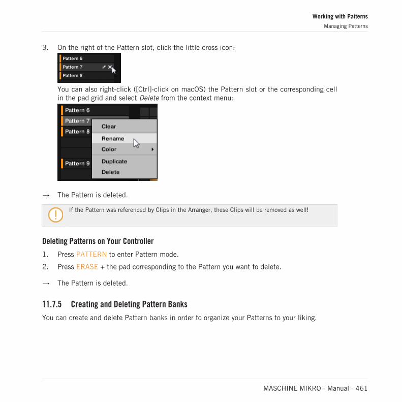
3. On the right of the Pattern slot, click the little cross icon:
You can also right-click ([Ctrl]-click on macOS) the Pattern slot or the corresponding cellin the pad grid and select Delete from the context menu:
→ The Pattern is deleted.
If the Pattern was referenced by Clips in the Arranger, these Clips will be removed as well!
Deleting Patterns on Your Controller
1. Press PATTERN to enter Pattern mode.
2. Press ERASE + the pad corresponding to the Pattern you want to delete.
→ The Pattern is deleted.
11.7.5 Creating and Deleting Pattern Banks
You can create and delete Pattern banks in order to organize your Patterns to your liking.
Working with Patterns
Managing Patterns
MASCHINE MIKRO - Manual - 461
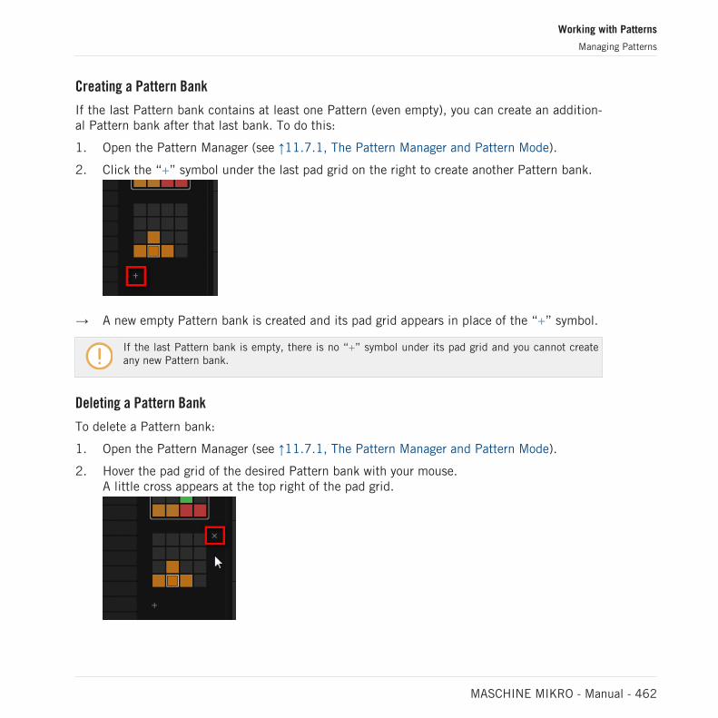
Creating a Pattern Bank
If the last Pattern bank contains at least one Pattern (even empty), you can create an addition-al Pattern bank after that last bank. To do this:
1. Open the Pattern Manager (see ↑11.7.1, The Pattern Manager and Pattern Mode).
2. Click the “+” symbol under the last pad grid on the right to create another Pattern bank.
→ A new empty Pattern bank is created and its pad grid appears in place of the “+” symbol.
If the last Pattern bank is empty, there is no “+” symbol under its pad grid and you cannot createany new Pattern bank.
Deleting a Pattern Bank
To delete a Pattern bank:
1. Open the Pattern Manager (see ↑11.7.1, The Pattern Manager and Pattern Mode).
2. Hover the pad grid of the desired Pattern bank with your mouse.A little cross appears at the top right of the pad grid.
Working with Patterns
Managing Patterns
MASCHINE MIKRO - Manual - 462

3. Click the little cross to delete that Pattern bank.
→ The Pattern bank is deleted including all its Patterns, if any. The following banks areshifted up to fill the gap.
If the Patterns of the deleted Pattern bank were referenced by Clips in the Arranger, these Clips willbe removed as well!
11.7.6 Naming Patterns
You can replace the Patterns’ default names with custom names of your own. This can be donein the Pattern Editor, in the Pattern Manager or in the Arranger.
Renaming Patterns in the Pattern Editor
To rename the selected Pattern in the Pattern Editor:
1. Double-click the Pattern name at the top left of the Pattern Editor:
2. Type a name and press [Enter] on your computer keyboard to confirm (or press [Esc] tocancel you change).
→ The Pattern is renamed. In the Arranger, all Clips referencing this Pattern in the Arrangerwill mirror the new Pattern name.
Renaming Patterns in the Pattern Manager
To rename any Pattern even if it is not selected:
1. Open the Pattern Manager (see ↑11.7.1, The Pattern Manager and Pattern Mode).
Working with Patterns
Managing Patterns
MASCHINE MIKRO - Manual - 463

2. If necessary, select the Pattern bank containing the desired Pattern by clicking its padgrid on the right.The selected Pattern bank is surrounded by a white border and its Patterns appear in thelist on the left.
3. On the right of the Pattern slot, click the little pen icon:
You can also right-click ([Ctrl]-click on macOS) the Pattern slot or the corresponding cellin the pad grid and select Rename from the context menu:
The Pattern name gets highlighted and editable.
4. Type a name and press [Enter] on your computer keyboard to confirm (or press [Esc] tocancel you change).
→ The Pattern is renamed. In the Arranger, all Clips referencing this Pattern will mirror thenew Pattern name.
If you use MASCHINE as a plug-in, some hosts will utilize the [Enter] key, as it is mapped to somefunction of the host software. In this case, click anywhere else in the MASCHINE plug-in window toconfirm the name you have entered.
Renaming Patterns in the Arranger
You can also rename a Pattern in the Arranger via any Clip referencing this Pattern:
Working with Patterns
Managing Patterns
MASCHINE MIKRO - Manual - 464

1. Double-click any Clip referencing the Pattern you want to name.The Clip turns to a text field and waits for your input.
2. Type a name and press [Enter] on your computer keyboard to confirm.
→ The Pattern is renamed. All Clips referencing this Pattern will mirror the new Patternname.
If you use MASCHINE as a plug-in, some hosts will utilize the [Enter] key, as it is mapped to somefunction of the host software. In this case, click anywhere else in the MASCHINE plug-in window toconfirm the name you have entered.
11.7.7 Changing the Pattern’s Color
By default, Patterns take the color of the Group they belong to. But you can adapt the color ofeach individual Pattern to your needs. To do this:
1. Open the Pattern Manager (see ↑11.7.1, The Pattern Manager and Pattern Mode).
2. If necessary, select the Pattern bank containing the desired Pattern by clicking its padgrid on the right.The selected Pattern bank is surrounded by a white border and its Patterns appear in thelist on the left.
Working with Patterns
Managing Patterns
MASCHINE MIKRO - Manual - 465
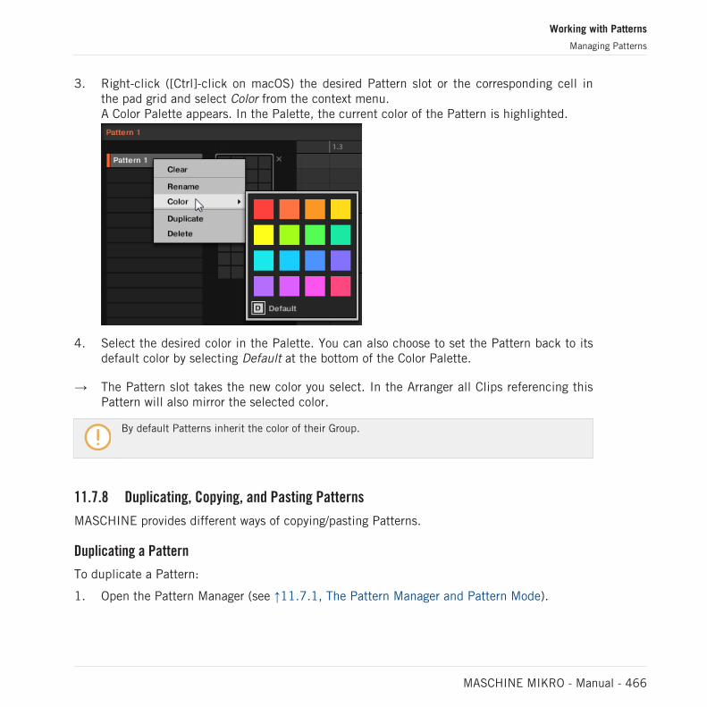
3. Right-click ([Ctrl]-click on macOS) the desired Pattern slot or the corresponding cell inthe pad grid and select Color from the context menu.A Color Palette appears. In the Palette, the current color of the Pattern is highlighted.
4. Select the desired color in the Palette. You can also choose to set the Pattern back to itsdefault color by selecting Default at the bottom of the Color Palette.
→ The Pattern slot takes the new color you select. In the Arranger all Clips referencing thisPattern will also mirror the selected color.
By default Patterns inherit the color of their Group.
11.7.8 Duplicating, Copying, and Pasting Patterns
MASCHINE provides different ways of copying/pasting Patterns.
Duplicating a Pattern
To duplicate a Pattern:
1. Open the Pattern Manager (see ↑11.7.1, The Pattern Manager and Pattern Mode).
Working with Patterns
Managing Patterns
MASCHINE MIKRO - Manual - 466

2. If necessary, select the Pattern bank containing the desired Pattern by clicking its padgrid on the right.The selected Pattern bank is surrounded by a white border and its Patterns appear in thelist on the left.
3. Right-click ([Ctrl]-click on macOS) the Pattern slot or the corresponding cell in the padgrid and select Duplicate from the context menu:
→ A Pattern copy is inserted right after the original Pattern in the Pattern bank — all follow-ing Patterns are shifted to the next slot.
Copying and Pasting a Pattern
To cut or copy the content of a Pattern and paste it in another Pattern, do the following:
1. Click the Event area’s background to deselect any selected events (your mouse must be inSelect mode).
Working with Patterns
Managing Patterns
MASCHINE MIKRO - Manual - 467

2. Right-click (on macOS: [Ctrl]+click) the Event area’s background and choose Copy fromthe slot’s context menu:
3. Select the Group in which you want to paste the Pattern’s content.
4. Open the Pattern Manager, select (or create) an empty Pattern, and close the PatternManager again.The selected (or created) Pattern appears in the Pattern Editor.
5. Right-click (on macOS: [Ctrl]-click) the Event area’s background and choose Paste fromthe context menu to paste the Pattern.
If events are selected in the Pattern, the copy/paste operation will apply to these events only! See↑11.7.1, The Pattern Manager and Pattern Mode for more on this.
Duplicating, Copying, and Pasting Patterns on Your Controller
While the duplicating method described above is the quickest one, you can also copy a Patternto the Pattern slot of your choice via the DUPLICATE button of your controller:
1. Press PATTERN to enter Pattern mode.
2. Press and hold DUPLICATE, then also press the pad of the Pattern you want to copy.
→ The pad starts flashing.
► Press the target pad for the Pattern copy.
Working with Patterns
Managing Patterns
MASCHINE MIKRO - Manual - 468
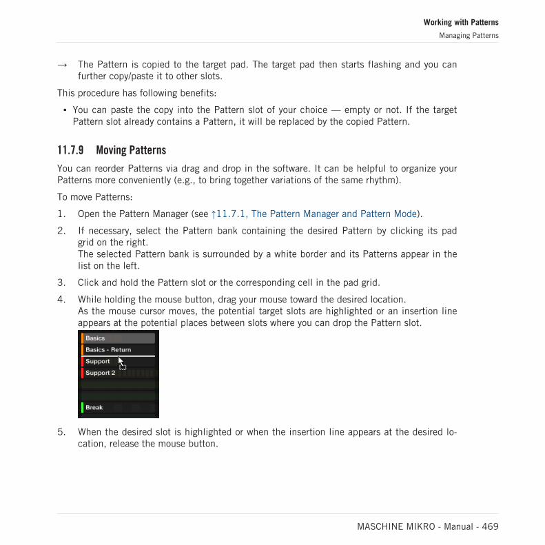
→ The Pattern is copied to the target pad. The target pad then starts flashing and you canfurther copy/paste it to other slots.
This procedure has following benefits:
▪ You can paste the copy into the Pattern slot of your choice — empty or not. If the targetPattern slot already contains a Pattern, it will be replaced by the copied Pattern.
11.7.9 Moving Patterns
You can reorder Patterns via drag and drop in the software. It can be helpful to organize yourPatterns more conveniently (e.g., to bring together variations of the same rhythm).
To move Patterns:
1. Open the Pattern Manager (see ↑11.7.1, The Pattern Manager and Pattern Mode).
2. If necessary, select the Pattern bank containing the desired Pattern by clicking its padgrid on the right.The selected Pattern bank is surrounded by a white border and its Patterns appear in thelist on the left.
3. Click and hold the Pattern slot or the corresponding cell in the pad grid.
4. While holding the mouse button, drag your mouse toward the desired location.As the mouse cursor moves, the potential target slots are highlighted or an insertion lineappears at the potential places between slots where you can drop the Pattern slot.
5. When the desired slot is highlighted or when the insertion line appears at the desired lo-cation, release the mouse button.
Working with Patterns
Managing Patterns
MASCHINE MIKRO - Manual - 469

→ The Pattern takes its new place. If you drop the Pattern onto a slot, the current Pattern inthat slot is replaced (if any). The Clips that were referencing this Pattern will referencethe moved Pattern instead.
Of course, all Clips referencing the moved Patterns still reference it after the move.
You can also drag a Pattern from the pad grid onto the Pad List, and inversely!
11.8 Importing/Exporting Audio and MIDI to/from Patterns
In the Pattern Editor you can quickly export MIDI and audio from Patterns and import MIDI toPatterns via drag and drop.
11.8.1 Exporting Audio from Patterns
The Audio drag-and-drop function allows you to export audio from the selected Pattern ontoyour desktop or into your host software by simply dragging it onto the target location or appli-cation. This function is only available in the software.
The audio will be exported as a WAV audio file and according to the current settings of theExport Audio panel (see section ↑5.4.3, Exporting Audio for more information on these set-tings) with following exceptions:
▪ The exported range will be based on the selected Pattern, regardless of the current LoopRange. Note that the Loop Optimize setting will be respected.
▪ The exported audio will only include the focused Group (in Group view) or the focusedSound (in Keyboard view) — in other words it will include what you see in the Event area.
▪ The audio file will be named as follows:
◦ Export in Group view: [Group name] - [Pattern name] - [BPM].wav
◦ Export in Keyboard view: [Group name] - [Pattern name] [Sound name] - [BPM].wav
To render Patterns to audio files:
Working with Patterns
Importing/Exporting Audio and MIDI to/from Patterns
MASCHINE MIKRO - Manual - 470

1. Select the Pattern you want to export audio from (see section ↑11.7.2, Selecting Patternsand Pattern Banks).
2. If you want to export multiple Sounds of the Group, switch the Pattern Editor to Groupview, mute the Sounds you want to exclude from the exported audio file (see section↑6.3.1, Mute and Solo), and check that the Group itself is not muted — otherwise theexported audio file will be silent!
3. If you want to export a single Sound in the Group, you can switch the Pattern Editor toKeyboard view, put the focus on the desired Sound, and check that this Sound is notmuted (see section ↑6.3.1, Mute and Solo) — otherwise the exported audio file will besilent! Alternatively you can let the Pattern Editor in Group view and solo this Sound.
4. In the top right corner of the Pattern Editor, click and hold the Audio Dragger icon:
5. While holding the mouse button, drag the icon to start the export.A pop-up message will inform you about the rendering status:
As soon as rendering is finished, the mouse cursor displays the name of the Pattern youare dragging.
→ You can now drag the exported audio file to your desktop, into an audio channel of yourhost application, or even to another Sound or Group in MASCHINE!
If you drop the audio file onto a Group, it will be loaded into the first empty Sound slot of thisGroup.
Working with Patterns
Importing/Exporting Audio and MIDI to/from Patterns
MASCHINE MIKRO - Manual - 471

11.8.2 Exporting MIDI from Patterns
You can export MIDI files from selected Patterns. This is useful if you want to use or edit themin another application. This function is only available in the software.
The MIDI file will be exported according to the Channel and Transpose parameters in the MIDIpage of the Output properties of each exported Sound — see section ↑12.2.5, Sending MIDIfrom Sounds for more on these parameters.
You can export MIDI files using two methods: via drag-and-drop or via the Group/Sound con-text menu.
Exporting MIDI via Drag-and-Drop
You can render the selected Pattern to a MIDI file by simply dragging it onto the target locationon your operating system or directly into a MIDI channel of your host software:
1. Select the Pattern you want to export MIDI from (see section ↑11.7.2, Selecting Patternsand Pattern Banks).
2. If you want to export MIDI from the entire Group, switch the Pattern Editor to Group view.If you want instead to export MIDI from the focused Sound only, switch the Pattern Editorto Keyboard view. See section ↑11.1.5, Group View and Keyboard View to know how to dothis.
3. In the top right corner of the Pattern Editor, click and hold the MIDI Dragger icon:
As you start dragging the icon the mouse cursor displays the name of the Pattern you areabout to export:
4. Drag the icon to your desktop or onto a MIDI channel of your host application.
→ The MIDI file is exported to the selected location.
Working with Patterns
Importing/Exporting Audio and MIDI to/from Patterns
MASCHINE MIKRO - Manual - 472

You can even drag the MIDI Dragger icon onto another Sound or Group in MASCHINE! In this casethe MIDI file will be directly imported into a Pattern of the selected Group according to the rulesdescribed in section ↑11.8.3, Importing MIDI to Patterns.
Exporting MIDI via the Context Menu
You can also render the selected Pattern to a MIDI file on your hard disk using the ExportMIDI… entry in the context menu of the Sound or Group:
1. Select the Pattern you want to export MIDI from (see section ↑11.7.2, Selecting Patternsand Pattern Banks).
2. To export MIDI from the entire Group, switch the Pattern Editor to Group view and right-click ([Ctrl]-click on macOS) the desired Group in the Group List (left of the Arranger) toopen its context menu. You can also right-click ([Ctrl]-click on macOS) the Group nameabove the Sound List.To export MIDI from a particular Sound only, right-click ([Ctrl]-click on macOS) the de-sired Sound slot in the Sound List (left of the Pattern Editor) to open its context menu.
3. Select Export MIDI… in the context menu (the picture below shows the context menu fora Sound).
4. In the Export MIDI dialog that opens, navigate to the desired location on your computer,type a name for the MIDI file and click Save to confirm.
Working with Patterns
Importing/Exporting Audio and MIDI to/from Patterns
MASCHINE MIKRO - Manual - 473

→ The MIDI file is exported to the selected location.
Sounds which do not contain note events in a Group Pattern are exported as empty MIDItracks. This way, if you are exporting multiple Patterns and some Sounds in the Group onlyhave notes in some of these Patterns, you will get a consistent assignment of notes to MIDItracks across all exported Patterns. Also, when you export a Pattern and then re-import it intoMASCHINE, the notes will always be mapped to the correct Sounds.
11.8.3 Importing MIDI to Patterns
You can import MIDI files (extension “.mid”) to Patterns. This allows you to use in MASCHINEMIDI files prepared with another application. This function is only available in the software.
Importing MIDI data into a Pattern that already contains data (note, modulation tracks, and MIDItracks) will replace that data. As always, this can be undone both in the software or from your con-troller (see section ↑3.3.2, Undo/Redo).
You can import MIDI files into Groups or into individual Sounds. You can do this via threemethods: via the context menu of the Group/Sound, via drag-and-drop, or via the FILES paneof the Browser. You can even import multiple MIDI files at once. The following paragraphs de-scribe each of these situations.
Importing a MIDI File to a Group
You can import a MIDI file to a whole Group. In particular, this allows you to import a drumbeat for an entire drum kit. You can do this via the Group’s context menu or via drag-and-drop.
Method 1: via the Group’s context menu
1. In the Group List (left of the Arranger), click the Group in which you want to import theMIDI file.This sets the focus to that Group and displays its Patterns in the Pattern Editor under-neath.
2. Select the Pattern in which you want to import the MIDI file.
Working with Patterns
Importing/Exporting Audio and MIDI to/from Patterns
MASCHINE MIKRO - Manual - 474

3. Right-click ([Ctrl]-click on macOS) the Group in the Group List and select Import MIDI…from the context menu.
You can alternatively right-click ([Ctrl]-click on macOS) the Group name in the headerabove the Sound List and select the same entry.
4. In the Import MIDI dialog that opens, navigate to the desired MIDI file on your computerand click Open to confirm.
→ The MIDI file will be imported to the selected Pattern of the Group according to the im-port rules described below.
Method 2: via drag and drop
1. In the Group List (left of the Arranger), click the Group in which you want to import theMIDI file.This sets the focus to that Group and displays its Patterns in the Pattern Editor under-neath.
2. Select the Pattern in which you want to import the MIDI file.
3. Navigate to the desired MIDI file in the Explorer/Finder of your operating system or in theFILES pane of the MASCHINE Browser.
Working with Patterns
Importing/Exporting Audio and MIDI to/from Patterns
MASCHINE MIKRO - Manual - 475

4. Drag the MIDI file onto the desired Group in the Group List left of the Arranger.
→ The MIDI file will be imported to the selected Pattern of the Group according to the im-port rules described below.
If the Pattern Editor is in Group view, you can also drag the MIDI file directly onto the Event area toimport it to the Group!
MIDI to Group – import rules: When you import a MIDI file into a Group, MASCHINE assumesthat the MIDI file contains data for different instruments (e.g., a drum kit), and the import willbe performed accordingly. Your MIDI file will be imported as follows:
▪ The imported MIDI data will replace any existing data (notes, MIDI tracks, and modulationtracks) in the selected Pattern.
▪ If the MIDI file contains data on a single MIDI channel: MIDI notes will be imported to thedifferent Sounds of your Group according to their pitch:
◦ The MIDI note data will be allocated to the various Sounds in your Group according tothe Root Note parameter in the MIDI page of the Group’s Input properties — see sec-tion ↑12.2.1, Triggering Sounds via MIDI Notes. This parameter defines the lowestnote in the Group, which is tied to Sound slot 1.Example: If Root Note is set to C1 (which corresponds to MIDI note number 36 in theMASCHINE convention), all notes with MIDI note number 36 in the MIDI file will beimported to the first Sound (in Sound slot 1); all notes with MIDI note number 37 willbe imported to the second Sound (in Sound slot 2); etc.
Working with Patterns
Importing/Exporting Audio and MIDI to/from Patterns
MASCHINE MIKRO - Manual - 476

◦ For each Sound, MIDI notes will be imported at the default root note C3 — this en-sures that the imported MIDI data will correctly trigger all MASCHINE factory kits.
◦ The MIDI CC data will be copied to all Sounds for which MIDI notes have been im-ported.
▪ If the MIDI file contains data on multiple MIDI channels, the data from the individual chan-nels will be imported to individual Sounds:
◦ If any channel from the MIDI file corresponds to the MIDI input channel of a particu-lar Sound in your Group, the data on that channel will be imported to that Sound. TheMIDI input channel of each Sound is defined by the Channel parameter in the MIDIpage of the Sound’s Input properties — see section ↑12.2.1, Triggering Sounds viaMIDI Notes.
◦ For all other channels of the MIDI file (i.e. channels that doesn’t correspond to anyMIDI input channel of a Sound in your Group), the data from individual channels willbe imported to individual Sounds that have not received any data during the currentimport yet: the channel with the lowest number will be imported to the Sound with thelowest slot number, and so on.Example: if the MIDI file contains data on channels 2, 3, and 5, and the MIDI inputchannel isn’t defined in any Sound of your Group, Sound slot 1 will receive the datafrom channel 2, Sound slot 2 from channel 3, and Sound slot 3 from channel 5.
Importing a MIDI File to a Sound
You can import a MIDI file to a single Sound. For example, this can be useful to import a me-lodic part for a single instrument. You can do this from the Sound’s context menu, via drag-and-drop, or via the FILES pane of the Browser.
Method 1: via the Sound’s context menu
1. In the Group List (left of the Arranger), click the Group containing the Sound for whichyou want to import the MIDI file.This sets the focus to that Group and displays its Sounds and Patterns in the Pattern Edi-tor underneath.
2. Select the Pattern in which you want to import the MIDI file.
Working with Patterns
Importing/Exporting Audio and MIDI to/from Patterns
MASCHINE MIKRO - Manual - 477

3. Right-click ([Ctrl]-click on macOS) the desired Sound in the Sound List and select ImportMIDI… from the context menu.
4. In the Import MIDI dialog that opens, navigate to the desired MIDI file on your computerand click Open to confirm.
→ The MIDI file will be imported to the selected Pattern for that Sound according to the im-port rules described below.
Method 2: via drag and drop
1. In the Group List (left of the Arranger), click the Group containing the Sound for whichyou want to import the MIDI file.This sets the focus to that Group and displays its Sounds and Patterns in the Pattern Edi-tor underneath.
2. Select the Pattern in which you want to import the MIDI file.
3. Navigate to the desired MIDI file in the Explorer/Finder of your operating system or in theFILES pane of the MASCHINE Browser.
Working with Patterns
Importing/Exporting Audio and MIDI to/from Patterns
MASCHINE MIKRO - Manual - 478

4. Drag the MIDI file onto the desired Sound in the Sound List (left of the Pattern Editor).
→ The MIDI file will be imported to the selected Pattern for that Sound according to the im-port rules described below.
If the Pattern Editor is in Keyboard view, you can also drag the MIDI file directly onto the Eventarea to import it into the focused Sound!
Method 3: using the FILES pane of the Browser
1. In the Group List (left of the Arranger), click the Group containing the Sound for whichyou want to import the MIDI file.This sets the focus to that Group and displays its Sounds and Patterns in the Pattern Edi-tor underneath.
2. Select the Pattern in which you want to import the MIDI file.
3. Set the focus to the desired Sound by clicking it in the Sound List (left of the PatternEditor).
Working with Patterns
Importing/Exporting Audio and MIDI to/from Patterns
MASCHINE MIKRO - Manual - 479

4. Open the FILES pane of the Browser and navigate to the desired MIDI file (see section↑4.6, Loading and Importing Files from Your File System to know how to use the FILESpane).
5. Double-click the MIDI file or click it and press [Enter] on your computer keyboard.
→ The MIDI file will be imported to the selected Pattern for the focused Sound according tothe import rules described below.
MIDI to Sound – import rules: When you import a MIDI file into a Sound via its context menu,MASCHINE assumes that the MIDI file contains data for one single instrument (e.g., a bass ora lead synthesizer), and the import will be performed accordingly. Your MIDI file will be im-ported as follows:
▪ The imported MIDI data will replace any existing data (notes, MIDI tracks, and modulationtracks) for that Sound in the selected Pattern. For the other Sounds the Pattern contentwon’t be affected.
▪ Any channel information in the MIDI file will be disregarded. All notes will appear in thesame Pattern for that particular Sound. If the same MIDI note number and MIDI CC num-ber are used in different channels in the MIDI file, the note and automation data will bemerged. Conflicts will be resolved as follows:
◦ Note duplicates: only the longest note is kept.
◦ Modifiers (Mod Wheel, Pitch Bend, etc.), Velocity, and MIDI CCs: higher values arekept.
Importing Multiple MIDI Files to a Sound or a Group
You can even select multiple MIDI files and import them all to a Sound or Group at once!
Contrary to the single-file import described above, importing multiple files doesn’t replace thecontent of the selected Pattern — instead, for each MIDI file in the selection a new Patternwill be created.
As a consequence, when importing multiple MIDI files you don’t need to select any particular Pat-tern beforehand.
To import multiple MIDI files to a Group:
Working with Patterns
Importing/Exporting Audio and MIDI to/from Patterns
MASCHINE MIKRO - Manual - 480

1. Select multiple MIDI files in your operating system or in the FILES pane of the Browser.
2. Drag and drop the multiple selection onto the desired Group in the Group List.
→ New Patterns will be created for that Group. Apart from this, each new Pattern receivingthe data from one of the MIDI files. Apart from this, each MIDI file will be imported as asingle MIDI file to that Group — see above for a detailed description.
To import multiple MIDI files to a Sound:
1. Select multiple MIDI files in your operating system or in the FILES pane of the Browser.
Working with Patterns
Importing/Exporting Audio and MIDI to/from Patterns
MASCHINE MIKRO - Manual - 481

2. Drag and drop the multiple selection onto the desired Sound in the Sound List.
→ New Patterns will be created for that Sound in the Group, each new Pattern receiving thedata from one of the MIDI files. Only this Sound will contain notes in these new Patterns.Apart from this, each MIDI file will be imported as a single MIDI file to that Sound — seeabove for a detailed description.
Alternatively, if you have selected the MIDI files in the FILES pane of the Browser, simply press[Enter] on your computer keyboard to import the multiple selection to the focused Sound!
Working with Patterns
Importing/Exporting Audio and MIDI to/from Patterns
MASCHINE MIKRO - Manual - 482

12 Audio Routing, Remote Control, and Macro Controls
This chapter describes a few important topics and features of MASCHINE’s routing and assign-ment system. Understanding these will be of great help in numerous MASCHINE workflows:
▪ We will explain how MASCHINE’s audio routing works and how to take advantage of itsflexibility: ↑12.1, Audio Routing in MASCHINE.
▪ We will describe how to route MIDI signals to and from your Sounds and Groups, and howto control MASCHINE parameters via MIDI and host automation: ↑12.2, Using MIDI Con-trol and Host Automation.
▪ We will show how to use the powerful Macro Controls to greatly improve your live experi-ence by putting the desired parameters at your fingertips: ↑12.3, Creating Custom Sets ofParameters with the Macro Controls.
The Channel Properties
Most of the features described here can be accessed via the Channel properties. Channel prop-erties are global settings that apply to a particular Sound, Group, or to the Master independ-ently of which Plug-ins are loaded in its Plug-in slots.
Channel properties are organized into four sets. Similar sets of properties are available for allchannels (Sounds, Groups, and Master): Input properties (unavailable for the Master), Outputproperties, Groove properties, and Macro properties.
You can access Channel properties and their parameters via the same procedure as for Plug-ins, both in the software and from your controller. Please refer to section ↑3.3.5, NavigatingChannel Properties, Plug-ins, and Parameter Pages in the Control Area for a detailed descrip-tion.
The Input properties, Output properties, and Macro properties are covered in the following sec-tions. For more information on the Groove properties, please refer to section ↑6.3.3, Groove.
Audio Routing, Remote Control, and Macro Controls
MASCHINE MIKRO - Manual - 483

12.1 Audio Routing in MASCHINE
MASCHINE offers a powerful audio routing system that you can finely customize to fit yourspecific needs.
To make it short, by default the various channels of MASCHINE are structured in a simple, hi-erarchical way:
▪ At the bottom level, each Sound has its own channel. The output of the Sound’s channel issent to its parent Group.
▪ At the mid-level, each Group has its own channel, which sums all channels of the includedSounds. The output of the Group’s channel is sent to the Master.
▪ At the top level, the Master has its own channel, which sums the channels of all Groupsand ends up at the main output of MASCHINE. The output of the Master’s channel is sentto your amplification system (in stand-alone mode) or to your host application (in plug-inmode).
This default basic configuration can be customized in numerous ways. Using the audio settingsavailable in the Input and Output properties at the Sound, Group, and Master level, you canbuild complex routings that cover a wide range of situations, as you will see in the next sec-tions:
▪ Feed external audio to the input of your Sounds: ↑12.1.1, Sending External Audio toSounds.
▪ Adjust the main output of your Sounds and Groups, and route it to various destinations:↑12.1.2, Configuring the Main Output of Sounds and Groups.
▪ Send auxiliary outputs of your Sounds and Groups to other destinations: ↑12.1.3, SettingUp Auxiliary Outputs for Sounds and Groups.
▪ Choose the destination and settings for the Master output (MASCHINE’s main output) aswell as for the Cue bus used for pre-listening: ↑12.1.4, Configuring the Master and CueOutputs of MASCHINE.
Audio Routing, Remote Control, and Macro Controls
Audio Routing in MASCHINE
MASCHINE MIKRO - Manual - 484

Mix View or Arrange View?
When it comes to adjusting audio and MIDI routings, the Mix view can sometimes be the mostefficient way to do: The familiar mixing desk layout allows you to quickly find the parametersyou are looking for and adjust the routing on the fly. Hence, in the following sections we de-scribe the procedures in both Arrange view and Mix view. For more details on the Mix view,please refer to chapter ↑13, Controlling Your Mix.
You will also find useful examples of the various routings described here in chapter ↑14, UsingEffects.
Configuring the Audio Routing from Your Controller
All the procedures described in the following sections make use of the Channel properties. Asa consequence, they can also be done from your controller! To do this, switch your controller toControl mode and navigate to the desired Channel properties as described in section ↑3.3.5,Navigating Channel Properties, Plug-ins, and Parameter Pages in the Control Area.
12.1.1 Sending External Audio to Sounds
Each Sound can be configured to receive external audio signals. These audio signals can becoming from the following sources:
▪ Outside MASCHINE (from your audio interface if MASCHINE is used in stand-alone mode,or from your host if MASCHINE is used in plug-in mode).
▪ Additional outputs of multiple-output Plug-ins that might be loaded somewhere else in yourProject.
Each Sound can use one external stereo input. The same external signal can be fed into anynumber of Sounds.
For example, this allows you to have any external audio signal be processed by the Plug-insloaded in that Sound, and more generally, integrate external audio signals into the MASCHINErouting and processing system. See also section ↑14.2, Applying Effects to External Audio foran example of use and step-by-step instructions.
The configuration of external audio inputs for a Sound is done on the Audio page of theSound’s Input properties.
Audio Routing, Remote Control, and Macro Controls
Audio Routing in MASCHINE
MASCHINE MIKRO - Manual - 485

The Audio page of the Input properties is available for Sounds only.
MASCHINE 1.x owners: The Audio page of the Sound’s Input properties replaces and extends thefeatures of the Input Module available in previous MASCHINE versions.
The Audio page of the Input properties for a Sound in the software.
Please refer to section ↑3.3.5, Navigating Channel Properties, Plug-ins, and Parameter Pages in theControl Area to know how to access the Audio page of the Input properties in the software and fromyour controller.
Controls Description
AUDIO Section
Source Selects an external audio input to be routed to the Sound. Availableentries are None (no external input) and the four external stereoinputs Ext. 1–4, as well as any additional output(s) of multiple-output Plug-ins loaded in other Sounds of the same Group. Checkthe Routing page of the Audio and MIDI Settings panel to route thephysical inputs of your audio interface to the virtual audio inputs ofMASCHINE.
Gain Adjusts the gain of the incoming signal.
Audio Routing, Remote Control, and Macro Controls
Audio Routing in MASCHINE
MASCHINE MIKRO - Manual - 486

If MASCHINE is running as a plug-in, the external stereo inputs Ext. 1–4 available in the Sourceselector of the MAIN section will correspond to virtual inputs in your host. This allows you to sendmixer channels from your DAW to individual Sounds within MASCHINE, for example. Please refer toyour host documentation to know how to route signals to the virtual audio inputs of your MASCHINEplug-in.
As any Parameter page of any Channel properties or Plug-in, this page is also available on your con-troller. To access it and change its parameters, simply use the common workflow described in↑3.3.5, Navigating Channel Properties, Plug-ins, and Parameter Pages in the Control Area. Further-more, you will find a step-by-step use case in ↑14.2, Applying Effects to External Audio.
Configuring External Inputs for Sounds in Mix View
You can also easily send external audio to Sounds in MASCHINE’s Mixer:
1. Click the Mix View button on the left of the Arranger to switch from Arrange view to Mixview:
2. Open the extended view of the Mixer by clicking the down-pointing arrow on the left of theMixer:
3. Check that the IO button is active on the left of the Mixer — if not, click it to enable itand display the input/output settings of each channel strip.
Audio Routing, Remote Control, and Macro Controls
Audio Routing in MASCHINE
MASCHINE MIKRO - Manual - 487

4. If the Mixer currently displays the Group channels, in the top row of the Mixer double-click the header of the Group containing the Sound you want to configure. If the Mixercurrently displays the Sound channels, single-click the header of the desired Group.
The Mixer displays the channel strips of all Sounds in the selected Group.
5. At the top of the channel strip of the Sound you want to configure, click the first fieldunder the Sound name and select the desired external input in the menu.
This is equivalent to setting the Source parameter described above.
Audio Routing, Remote Control, and Macro Controls
Audio Routing in MASCHINE
MASCHINE MIKRO - Manual - 488

6. Turn the little knob on its left to adjust the input gain.
This is equivalent to setting the Gain parameter described above.
12.1.2 Configuring the Main Output of Sounds and Groups
By default the outputs of all Sounds in a Group are sent to this Group, where they are mixedtogether and processed by the Plug-ins loaded in the Group, if any. Similarly, by default theoutputs of all Groups are sent to the Master, where they are mixed together and processed bythe Plug-ins loaded in the Master, if any.
This default behavior can be customized to your liking: You can adjust the level and panoramicposition of the channel output, or send it to the Cue bus for pre-listening. Furthermore, youcould send individual Sounds or whole Groups to other pairs of outputs on your audio interfacein order to process them separately at a later stage. The output routing configuration is doneon the Audio page of the Output properties for Sounds and Groups.
We describe here the Audio page of the Output properties for Sounds and Groups only. The equiva-lent page for the Master will be described in section ↑12.1.4, Configuring the Master and Cue Out-puts of MASCHINE.
The Audio page of the Output properties (here for a Sound) in the software.
Audio Routing, Remote Control, and Macro Controls
Audio Routing in MASCHINE
MASCHINE MIKRO - Manual - 489

Please refer to section ↑3.3.5, Navigating Channel Properties, Plug-ins, and Parameter Pages in theControl Area to know how to access the Audio page of the Output properties in the software andfrom your controller.
Controls Description
AUDIO Section
Dest. Selects where you want to send the main audio output of yourchannel.
For Sounds, available options are None (no output), Master, Group(parent Group, default setting), any other Group or any other Soundacting as bussing point (i.e. containing an Effect Plug-in in its firstPlug-in slot), as well as the 16 external stereo outputs Ext. 1–16.
For Groups, available options are None (no output), Master (defaultsetting), any other Group acting as bussing point (i.e. containing anEffect Plug-in in its first Plug-in slot), any Sound acting as bussingpoint in any other Group, as well as the 16 external stereo outputsExt. 1–16.
The available bussing points are labeled as described below.
Cue When Cue is enabled, the main output of the channel is sent to theCue bus instead of its normal target (defined in Dest., see above).For example, this is very useful to pre-listen a channel before youmix it in your performance. See also section ↑13.2.6, Using theCue Bus for more information.
Note that when Cue is enabled, the channel’s Aux 1 and Aux 2outputs are muted as well — but they are not sent to the Cue bus(see ↑12.1.3, Setting Up Auxiliary Outputs for Sounds and Groups).
Level Adjusts the overall volume level of the channel.
Audio Routing, Remote Control, and Macro Controls
Audio Routing in MASCHINE
MASCHINE MIKRO - Manual - 490

Controls Description
Pan Defines the pan position of the channel in the stereo field.
Audio Mute (Soundsonly)
If you enable Audio Mute, muting this Sound will not only bypassits events but also mute its audio output, thereby muting any audiotails from notes already played. See section ↑6.3.1, Mute and Solofor more information.
If MASCHINE is running as a plug-in, the external stereo outputs Ext. 1–16 available in the Dest.selector of the MAIN section will correspond to virtual outputs in your host. This allows you to sendindividual Sounds or Groups from MASCHINE to their own mixer channels within your DAW, for ex-ample.
Labels for Bussing Points in the Dest. Selector
The various bussing points available in the Dest. selector (described in the table above) are la-belled differently in the drop-down menu and in the display of the selector:
▪ In the drop-down menu they are labeled as follows:
◦ For Groups: [Group name] (e.g., Drums).
◦ For Sounds: [Group name]: [Sound name]-[input number] (e.g., Drums: Kick-1).
▪ In the selector display they are labeled as follows:
◦ For Groups: [Group letter+number] (e.g., A2).
◦ For Sounds: [Group letter+number]:S[Sound number]-[input number] (e.g., A2:S4-1 forthe first input of the Sound 4 of Group A2).
On your controller the bussing points available in the DEST. parameter are labeled as in the selectordisplay described above.
Level and Pan Shortcuts for Sounds and Group
You can quickly access the Level and Pan parameters described above via the little knobsavailable in the Sound List and in the Group List, at the left of the Pattern Editor and the Ar-ranger, respectively: For each channel (Sound or Group) the left knob adjusts the level and theright knob adjusts the panoramic position.
Audio Routing, Remote Control, and Macro Controls
Audio Routing in MASCHINE
MASCHINE MIKRO - Manual - 491

The pair of knobs for each Sound/Group allows you to quickly adjust the channel level and panoramic position.
For Sound slots, the knobs are visible only when the Pattern Editor is in Pad Mode. In Keyboardmode, the knobs are not visible.
Configuring the Main Outputs of Sounds and Groups in Mix View
You can also easily configure the outputs of your Sounds and Groups in MASCHINE’s Mixer:
1. Click the Mix View button on the left of the Arranger to switch from Arrange view to Mixview:
Audio Routing, Remote Control, and Macro Controls
Audio Routing in MASCHINE
MASCHINE MIKRO - Manual - 492

2. Open the extended view of the Mixer by clicking the down-pointing arrow on the left of theMixer:
Navigate to the channel of which you want to configure the output: for a Sound click theheader of its parent Group (or double-click it if the Mixer currently displays the Groupchannel strips), and for a Group simply ensure that its channel strip is visible (double-click the Group header if the Mixer currently displays the Sound channel strips).
3. To adjust the level, panoramic position or Cue state of a channel, use the channel’s fader,balance control (above the fader) or headphone button (below the fader), respectively.
This is equivalent to setting the Level, Pan, and Cue parameters described above, respec-tively.
Audio Routing, Remote Control, and Macro Controls
Audio Routing in MASCHINE
MASCHINE MIKRO - Manual - 493

4. To select another destination for the channel’s output, click the first area under the levelmeter, and select the desired destination in the menu.
This is equivalent to setting the Dest. parameter described above.
12.1.3 Setting Up Auxiliary Outputs for Sounds and Groups
Each Sound or Group of your Project provides two auxiliary outputs that you can route to addi-tional targets. For example, you can send a definable amount of the channel’s audio output toother channels for further processing. This is notably used in send effects — see section↑14.3, Creating a Send Effect to learn how to set up a classic send effect.
The auxiliary outputs of a Sound/Group are configured on the Aux page of the Output proper-ties.
There is no Aux page in the Output properties of the Master.
Audio Routing, Remote Control, and Macro Controls
Audio Routing in MASCHINE
MASCHINE MIKRO - Manual - 494

The Aux page of the Output properties (here for a Group) in the software.
Please refer to section ↑3.3.5, Navigating Channel Properties, Plug-ins, and Parameter Pages in theControl Area to know how to access the Aux page of the Output properties in the software and fromyour controller.
Controls Description
AUX 1 / AUX 2 Section
Dest. Selects where you want to send the Aux 1 or Aux 2 output of yourchannel. Available options are the same as for the Dest. selector ofthe Audio page (see ↑12.1.2, Configuring the Main Output ofSounds and Groups), except that for Aux 1 and Aux 2 the defaultdestination is None — in other terms there are no auxiliary sendsdefined by default.
Level Adjusts the level of the signal sent to the Aux 1 or Aux 2 output.
Order If Order is set to Pre, the channel will be fed into Aux 1 or Aux 2before the Level and Pan settings of the MAIN section on the Audiopage are applied. If Order is set to Post (default setting), the Leveland Pan settings of the main output also affect the signals sent tothe auxiliary outputs.
If MASCHINE is running as a plug-in, the external stereo outputs Ext. 1–16 available in the Dest.selectors of the AUX 1 and AUX 2 section will correspond to virtual outputs in your host. This allowsyou to send auxiliary outputs of individual Sounds or Groups from MASCHINE to their own mixerchannels within your DAW, for example.
Setting Up the Auxiliary Outputs of Sounds and Groups in Mix View
You can also easily set up auxiliary outputs for your Sounds and Groups in MASCHINE’s Mixer:
Audio Routing, Remote Control, and Macro Controls
Audio Routing in MASCHINE
MASCHINE MIKRO - Manual - 495

1. Click the Mix View button on the left of the Arranger to switch from Arrange view to Mixview:
2. Open the extended view of the Mixer by clicking the down-pointing arrow on the left of theMixer:
3. Check that the AUX button is active on the left of the Mixer — if not, click it to enable itand display the settings for the auxiliary outputs of each channel strip.
4. Navigate to the channel of which you want to configure an auxiliary output: for a Soundclick the header of its parent Group (or double-click it if the Mixer currently displays theGroup channel strips), and for a Group simply ensure that its channel strip is visible (dou-ble-click the Group header if the Mixer currently displays the Sound channel strips).
Audio Routing, Remote Control, and Macro Controls
Audio Routing in MASCHINE
MASCHINE MIKRO - Manual - 496

5. In the channel strip of the desired Sound or Group, click the AUX 1 or AUX 2 label (de-fault labels) at the bottom of the strip and select the desired destination in the menu.
This is equivalent to setting the Dest. parameter described above.
6. Adjust the level for that auxiliary output via the little knob at the right of the menu.
This is equivalent to setting the Level parameter described above.
7. Set the pre/post state of the auxiliary output by clicking the Post (or Pre) label right underthe menu.
This is equivalent to setting the Order parameter described above.
12.1.4 Configuring the Master and Cue Outputs of MASCHINE
All channels routed to the Master are mixed together and processed by the Plug-ins loaded inthe Master, if any. The result is then sent to the Master output (that is, MASCHINE’s main out-put).
Audio Routing, Remote Control, and Macro Controls
Audio Routing in MASCHINE
MASCHINE MIKRO - Manual - 497

Besides, all channels currently routed to the Cue bus for pre-listening are mixed together andsent to the Cue output.
For more information on how to use the Cue bus, see section ↑13.2.6, Using the Cue Bus.
You can choose to which outputs (on your audio interface or in your host) both Master and Cueoutputs should be sent, and adjust their respective levels and panoramic positions. This isdone on the Audio page of the Output properties for the Master.
The Audio page of the Output properties for the Master in the software.
Please refer to section ↑3.3.5, Navigating Channel Properties, Plug-ins, and Parameter Pages in theControl Area to know how to access the Audio page of the Output properties in the software andfrom your controller.
Controls Description
AUDIO Section
Output Selects where you want to send the master output of yourMASCHINE Project. Available options are the 16 external stereooutputs Ext. 1–16.
Level Adjusts the overall volume level of the master output. This controlis the same as the Master Volume slider in the Header, at the topright corner of MASCHINE’s window.
Pan Defines the panoramic position of the master output in the stereofield.
CUE Section
Audio Routing, Remote Control, and Macro Controls
Audio Routing in MASCHINE
MASCHINE MIKRO - Manual - 498

Controls Description
Output Selects where you want to send the Cue bus of your MASCHINEProject. Available options are the 16 external stereo outputs Ext. 1–16. By selecting a different output from the one used for the mainstereo output, you can effectively pre-listen on this additionaloutput (e.g., on your headphones) any channel(s) currently sent tothe Cue bus. To send a channel to the Cue bus, enable the Cueswitch in the Audio page of its Output properties (see section↑12.1.2, Configuring the Main Output of Sounds and Groups).
Level Adjusts the level of the Cue output.
Pan Defines the panoramic position of the Cue output in the stereofield.
If MASCHINE is running as a plug-in, the external stereo outputs Ext. 1–16 available in the Outputselector of the MAIN and CUE sections will correspond to virtual outputs in your host.
Configuring the Master and Cue Outputs in Mix View
You can also easily configure the Master and Cue outputs of MASCHINE in the Mixer. Bothshare the same channel strip at the far right of the Mixer.
To display the Master/Cue channel strip, do the following:
1. Click the Mix View button on the left of the Arranger to switch from Arrange view to Mixview:
2. Open the extended view of the Mixer by clicking the down-pointing arrow on the left of theMixer:
Audio Routing, Remote Control, and Macro Controls
Audio Routing in MASCHINE
MASCHINE MIKRO - Manual - 499

3. Click the background of the last header in the top right corner of the Mixer.
The Master/Cue channel strip appears underneath.
In this Master/Cue channel strip, do the following to configure the output of the Master chan-nel:
1. Click Master in the strip’s header to show the controls for the Master channel.
2. To adjust the level and panoramic position of the main output, use the channel’s faderand balance control (above the fader), respectively.
This is equivalent to setting the Level or Pan parameters in the MAIN section, respectively(see above).
Audio Routing, Remote Control, and Macro Controls
Audio Routing in MASCHINE
MASCHINE MIKRO - Manual - 500
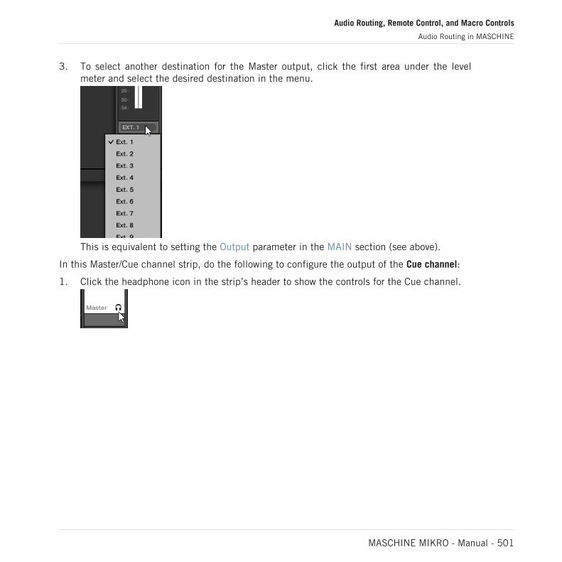
3. To select another destination for the Master output, click the first area under the levelmeter and select the desired destination in the menu.
This is equivalent to setting the Output parameter in the MAIN section (see above).
In this Master/Cue channel strip, do the following to configure the output of the Cue channel:
1. Click the headphone icon in the strip’s header to show the controls for the Cue channel.
Audio Routing, Remote Control, and Macro Controls
Audio Routing in MASCHINE
MASCHINE MIKRO - Manual - 501

2. To adjust the level and panoramic position of the Cue output, use the channel’s fader andbalance control (above the fader), respectively.
This is equivalent to setting the Level or Pan parameters in the CUE section, respectively(see above).
3. To select another destination for the Cue output, click the first area under the level meterand select the desired destination in the menu.
This is equivalent to setting the Output parameter in the MAIN section (see above).
12.1.5 Mono Audio Inputs
Each Sound can be configured to receive external stereo or mono audio signals. You may useaudio signals from outside MASCHINE (from your audio interface if MASCHINE is used instand-alone mode, or from your host if MASCHINE is used in plug-in mode).
Audio Routing, Remote Control, and Macro Controls
Audio Routing in MASCHINE
MASCHINE MIKRO - Manual - 502
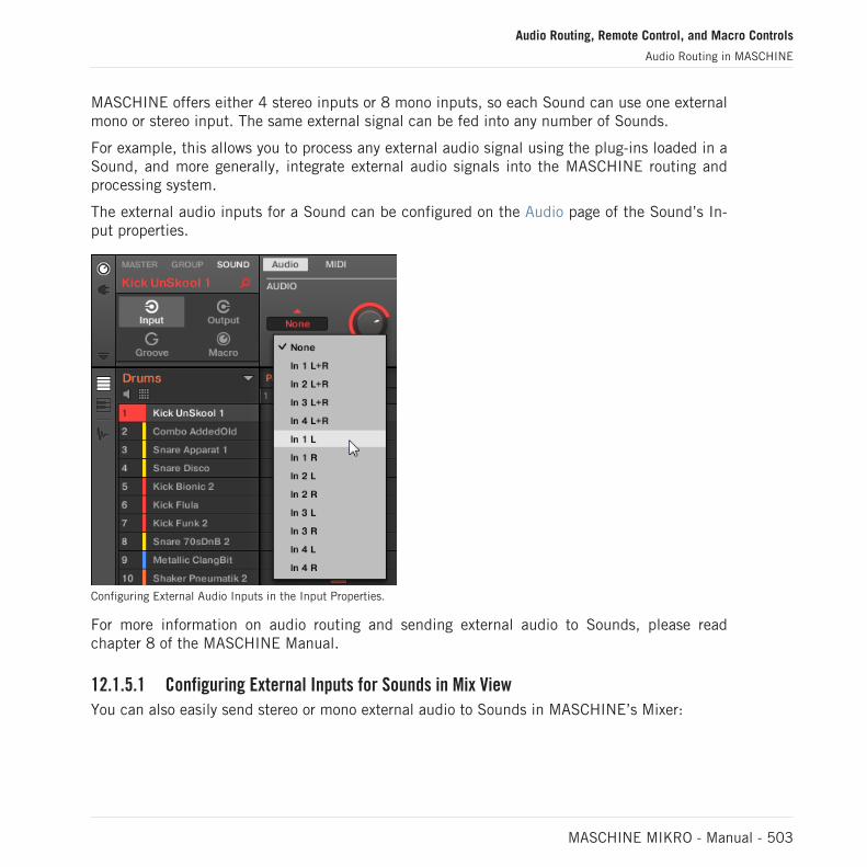
MASCHINE offers either 4 stereo inputs or 8 mono inputs, so each Sound can use one externalmono or stereo input. The same external signal can be fed into any number of Sounds.
For example, this allows you to process any external audio signal using the plug-ins loaded in aSound, and more generally, integrate external audio signals into the MASCHINE routing andprocessing system.
The external audio inputs for a Sound can be configured on the Audio page of the Sound’s In-put properties.
Configuring External Audio Inputs in the Input Properties.
For more information on audio routing and sending external audio to Sounds, please readchapter 8 of the MASCHINE Manual.
12.1.5.1 Configuring External Inputs for Sounds in Mix View
You can also easily send stereo or mono external audio to Sounds in MASCHINE’s Mixer:
Audio Routing, Remote Control, and Macro Controls
Audio Routing in MASCHINE
MASCHINE MIKRO - Manual - 503

1. Click the Mix View button on the left of the Arranger to switch from Arrange view to Mixview:
2. Open the extended view of the Mixer by clicking the down-pointing arrow on the left of theMixer:
3. Check that the IO button is active on the left of the Mixer — if not, click it to enable itand display the input/output settings of each channel strip.
Audio Routing, Remote Control, and Macro Controls
Audio Routing in MASCHINE
MASCHINE MIKRO - Manual - 504
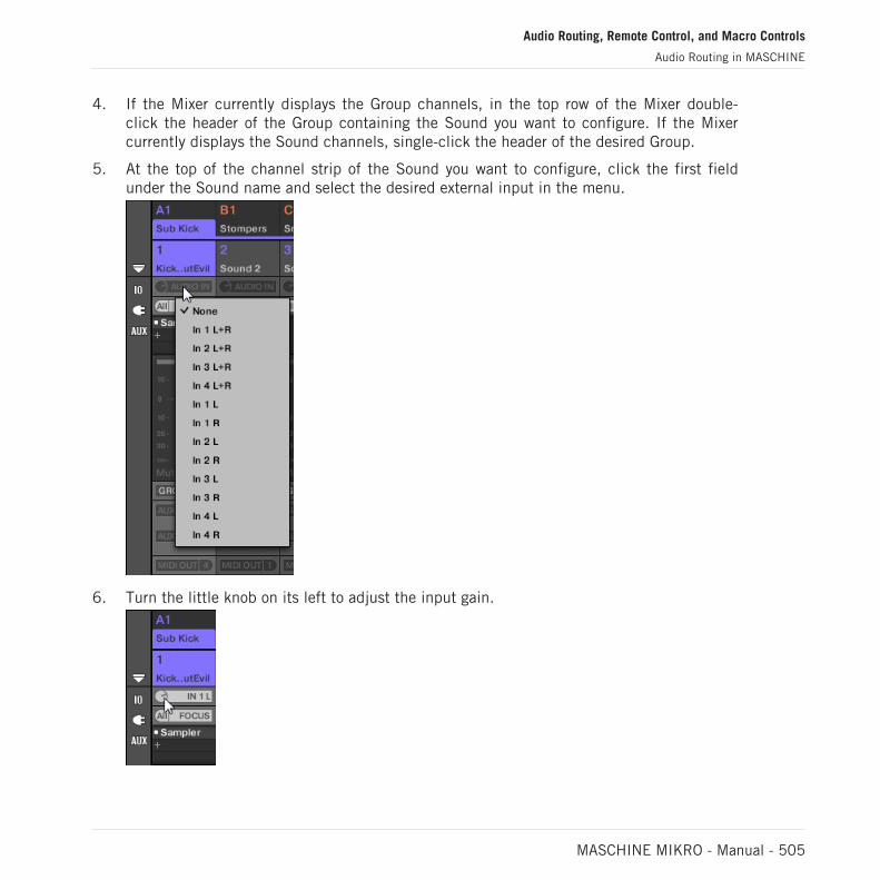
4. If the Mixer currently displays the Group channels, in the top row of the Mixer double-click the header of the Group containing the Sound you want to configure. If the Mixercurrently displays the Sound channels, single-click the header of the desired Group.
5. At the top of the channel strip of the Sound you want to configure, click the first fieldunder the Sound name and select the desired external input in the menu.
6. Turn the little knob on its left to adjust the input gain.
Audio Routing, Remote Control, and Macro Controls
Audio Routing in MASCHINE
MASCHINE MIKRO - Manual - 505

12.2 Using MIDI Control and Host Automation
MASCHINE provides you with flexible MIDI remote control and host automation facilities thatcan be used in many situations.
Incoming MIDI and Host Automation
MASCHINE’s Master, Groups and Sounds can be controlled via MIDI and the host (when MA-SCHINE is running as a plug-in), both globally and individually:
▪ By default, all MIDI data incoming on the enabled MIDI input port(s) will be received bythe focused Sound of the focused Group. See ↑3.6.3, Preferences – MIDI Page to find in-formation on how to enable/disable MIDI input ports in MASCHINE.
▪ Triggering Sounds via MIDI notes: By default, incoming MIDI notes will trigger the focusedSound. You can change this default behavior and map incoming MIDI notes differently inorder to adapt MASCHINE to your requirements. The appropriate MIDI settings can be con-figured in the MIDI page of the Input properties, both for individual Sounds and for entireGroups. These are described in section ↑12.2.1, Triggering Sounds via MIDI Notes.
▪ Controlling parameters via MIDI messages and host automation: You can control parameters ofChannel properties and Plug-ins in your channels (Sounds, Groups, and Master) via MIDImessages and host automation (when MASCHINE is running as a plug-in). This is descri-bed in section ↑12.2.3, Controlling Parameters via MIDI and Host Automation.
▪ Switching Plug-in Patches via MIDI Program Change messages: You can use MIDI ProgramChange messages to recall particular patches (or programs, presets, etc.) for Native Instru-ments and External Plug-ins loaded at the Sound level. This is described in section↑12.2.4, Selecting VST/AU Plug-in Presets via MIDI Program Change.
When MASCHINE is running as a plug-in in a host, you can also trigger your Scenes using MIDInotes or MIDI Program Change messages. Please refer to section ↑16.5, Triggering Sections orScenes via MIDI for more information on this.
Audio Routing, Remote Control, and Macro Controls
Using MIDI Control and Host Automation
MASCHINE MIKRO - Manual - 506

Outgoing MIDI
You can also sending MIDI data from Sounds. For example, when MASCHINE is running as aplug-in in a host environment, this allows you to record your performance on the pads as aMIDI pattern in your host application. This is described in section ↑12.2.5, Sending MIDI fromSounds.
12.2.1 Triggering Sounds via MIDI Notes
MASCHINE allows you play your Sound(s) via MIDI (e.g., from a MIDI keyboard).
By default and without any configuration, incoming MIDI notes on any MIDI port and any MIDIchannel will trigger different pitches of the Sound slot currently focused.
To play one or more Sounds via MIDI notes independently of the Sound currently focused, youneed to configure the MIDI input settings of your Sound(s) or of their Group, i.e. define howthe Sound(s) or the Group should react to incoming MIDI notes. This is done in the MIDI pageof the Group or the Sounds Input properties.
There is no MIDI page in the Input properties of the Master.
When configuring these MIDI input settings, keep in mind the following:
▪ MIDI input settings for a Group affect all Sounds in the Group: Each Sound will be triggeredby a different MIDI note. Typically, this allows you to quickly set up a MIDI remote controlfor an entire drum kit.
▪ MIDI input settings for a Sound affect only that Sound: Incoming MIDI notes will trigger dif-ferent notes of this Sound. Typically, this allows you to control a melodic instrument viaMIDI. More precisely, the incoming MIDI notes will be routed to the first Plug-in slot of theSound.
If the Sound has no Plug-ins, incoming MIDI notes will be forwarded to the Sound’s MIDI output, ifenabled (see section ↑12.2.5, Sending MIDI from Sounds).
Audio Routing, Remote Control, and Macro Controls
Using MIDI Control and Host Automation
MASCHINE MIKRO - Manual - 507
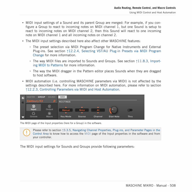
▪ MIDI input settings of a Sound and its parent Group are merged: For example, if you con-figure a Group to react to incoming notes on MIDI channel 1, but one Sound is setup toreact to incoming notes on MIDI channel 2, then this Sound will react to one incomingnote on MIDI channel 1 and all incoming notes on channel 2.
▪ The MIDI input settings described here also affect other MASCHINE features:
◦ The preset selection via MIDI Program Change for Native Instruments and ExternalPlug-ins. See section ↑12.2.4, Selecting VST/AU Plug-in Presets via MIDI ProgramChange for more information.
◦ The way MIDI files are imported to Sounds and Groups. See section ↑11.8.3, Import-ing MIDI to Patterns for more information.
◦ The way the MIDI dragger in the Pattern editor places Sounds when they are draggedto host software.
▪ MIDI automation (i.e. controlling MASCHINE parameters via MIDI) is not affected by thesettings described here. For more information on MIDI automation, please refer to section↑12.2.3, Controlling Parameters via MIDI and Host Automation.
The MIDI page of the Input properties (here for a Group) in the software.
Please refer to section ↑3.3.5, Navigating Channel Properties, Plug-ins, and Parameter Pages in theControl Area to know how to access the MIDI page of the Input properties in the software and fromyour controller.
The MIDI input settings for Sounds and Groups provide following parameters:
Audio Routing, Remote Control, and Macro Controls
Using MIDI Control and Host Automation
MASCHINE MIKRO - Manual - 508

Controls Description
MIDI ROUTING Section
Key Mode (Pad Modeonly)
Enables the MIDI note input for the selected Group (disabled bydefault). Please refer to your host documentation to find out how toroute MIDI signals to your MASCHINE plug-in.
Key Mode offers the following options:
Off: Select this option to disable MIDI note input for the selectedGroup.
Drumkit: Select this option to conveniently configure the MIDI noteinput for the selected Group and place each Sound on a specifickey chromatically across the keyboard starting from C2 upwards.
If nothing is loaded on a Sound nothing can be triggered, and if youuse a Native Instruments KOMPLETE KONTROL S-series keyboardthe Light Guide will remain white to indicate that nothing loaded.Additionally, KOMPLETE KONTROL S-series keyboards have adedicated KEY MODE button to quickly active the Drumkit optionfor the selected Group in MASCHINE.
By selecting Drumkit you also affect how MIDI is exported fromMASCHINE to another host sequencer when using the MIDI draggerin the Pattern editor, for more information on the how to drag anddrop MIDI from your Patterns to your desktop or host softwareplease read: ↑11.8, Importing/Exporting Audio and MIDI to/fromPatterns.
Manual: This option allows you to configure the MIDI note inputbased on your own preferences, including the Source, Channel,Start Note and Thru settings.
Audio Routing, Remote Control, and Macro Controls
Using MIDI Control and Host Automation
MASCHINE MIKRO - Manual - 509

Controls Description
Source (stand-alone andin Manual mode only)
Select the MIDI port on which the Sound or Group will receive MIDInotes. Available entries are None (MIDI note input disabled, defaultsetting), All (MIDI notes are received on all enabled input ports),and each enabled MIDI input port. You can enable the desired MIDIinput ports of your MIDI interfaces in the MIDI page of the Audioand MIDI Settings panel (see section ↑3.6.3, Preferences – MIDIPage). Note that when None is selected for both a Sound and itsparent Group, if the Sound is focused it will receive MIDI notesfrom all MIDI ports and on all MIDI channels.
Channel (Manual modeonly)
Select the MIDI channel on which the Sound or Group will receiveMIDI notes. If you select All (default setting), the Sound or Groupwill receive MIDI notes from all channels.
The Channel parameter of a Sound is also used when importing amulti-channel MIDI file to its Group — see section ↑11.8.3,Importing MIDI to Patterns for more on this.
Start Note (Manualmode only)
Define the MIDI root note for that Group (C1 by default). The MIDIroot note and the upper 15 MIDI notes (from [Root Note] until[Root Note + 15]) will trigger the root note of Sound slot 1–16,respectively. Incoming MIDI notes outside this range will be ignoredby the Group.
The Start Note parameter is also used when importing a single-channel MIDI file to the Group — see section ↑11.8.3, ImportingMIDI to Patterns for more on this.
Thru (Manual modeonly)
Switch this parameter on to send incoming events through to theMIDI outputs. This can be useful if you want to record notes playedfrom MASCHINE into your host sequencer, and then play themback from there, using MASCHINE as the sound source.
Switch this parameter off to stop incoming events from beingrouted to the outputs.
Audio Routing, Remote Control, and Macro Controls
Using MIDI Control and Host Automation
MASCHINE MIKRO - Manual - 510

Some of these parameters also affect MIDI file import: The Channel parameter of a Sound will beused when importing a multi-channel MIDI file to its Group, while the Root Note parameter will beused when importing a single-channel MIDI file to the Group. For more information on MIDI file im-port please refer to section ↑11.8.3, Importing MIDI to Patterns.
If MASCHINE is running as a plug-in in a host and you have configured your Scenes to be triggeredvia MIDI notes, the Scene trigger has priority over any Sound trigger set to the same MIDI channel.To configure MIDI control for Scenes, please refer to section ↑16.5, Triggering Sections or Scenesvia MIDI.
Configuring MIDI Note Input for Sounds and Groups in Mix View
You can also easily configure the MIDI note input of your Sounds and Groups in MASCHINE’sMixer:
1. Click the Mix View button on the left of the Arranger to switch from Arrange view to Mixview:
2. Open the extended view of the Mixer by clicking the down-pointing arrow on the left of theMixer:
Audio Routing, Remote Control, and Macro Controls
Using MIDI Control and Host Automation
MASCHINE MIKRO - Manual - 511

3. Check that the IO button is active on the left of the Mixer — if not, click it to enable itand display the input/output settings of each channel strip.
4. Above the fader area in the channel strip of the Sound or Group you want to configure,click the bigger field on the right (labeled MIDI IN by default) and select the desired MIDIport in the menu.
This is equivalent to setting the Source parameter described above.If MASCHINE is running as a plug-in you see a MIDI IN button instead. Click it to enablethe MIDI input from the host.
This is equivalent to enabling the Active button described above.
Audio Routing, Remote Control, and Macro Controls
Using MIDI Control and Host Automation
MASCHINE MIKRO - Manual - 512

5. Click the little field on its left to select a MIDI channel.
This is equivalent to the Channel parameter described above.
12.2.2 Triggering Scenes via MIDI
The MASCHINE hardware SCENE mode can be configured to send out MIDI (Notes/ProgramChanges) which can be used to trigger scenes. When MASCHINE runs as a Plug-in this MIDIdata is sent to the host application. When MASCHINE runs as a stand-alone application thisMIDI data is send out to all activated MIDI output devices.
MIDI Scene Change program change messages can be used to record a Scene performance toa host application, and all recorded Scene performances can be then be saved within your hostand sent back to MASCHINE for playback and trigger Scenes in the recorded order.
Sending MIDI Scene Change Messages
To enable or disable the MIDI Scene Change feature, do the following:
1. Click Edit > MIDI Change.
2. In the submenu that opens, select the source you want to use for changing the MIDI Pro-gram Change messages. A list of connected controller names appear in the drop-downmenu, or you can select None to disable the feature.
3. Then from the drop-down menu select MIDI Note to trigger your Scenes via MIDI notes, orProgram Change to trigger your Scenes via MIDI Program Change messages.
Audio Routing, Remote Control, and Macro Controls
Using MIDI Control and Host Automation
MASCHINE MIKRO - Manual - 513
4. If necessary, reopen the same submenu and select the MIDI channel the Scene changesshould receive MIDI messages from (channel 1 by default).
MIDI Scene change has priority over Lock change. If you select the same MIDI Source and Channelfor Lock and Scene changes, only Scenes will be triggered by the corresponding events coming fromthe MIDI source. Corresponding Lock snapshots will not be recalled.
5. For more information on MIDI Lock Changes refer to Triggering Lock Snapshots via MIDI.
12.2.3 Controlling Parameters via MIDI and Host Automation
You can assign many parameters of the Channel properties and Plug-ins located in your variouschannels (Sounds, Groups, and Master) of your Project to MIDI messages in order to controland automate them via MIDI.
In addition, when MASCHINE is running as a plug-in, you can assign these parameters to auto-mation IDs in order to control and automate them via host automation tracks in your host.
Configuring MIDI and host automation is possible in the software only.
In MASCHINE, automation means the control of MASCHINE parameters from an external source(MIDI or host application). Value changes are:
▪ Permanent: The new parameter value stays valid until a new value is defined (via MIDI/hostor manually), even when the playback is looped or restarted.
▪ Absolute: The new parameter value is defined regardless of its current value.
Automation vs. Modulation
Although both deal with automatic change of MASCHINE parameters, automation and modula-tion have to be distinguished. The following table summarizes the main differences:
Audio Routing, Remote Control, and Macro Controls
Using MIDI Control and Host Automation
MASCHINE MIKRO - Manual - 514

Modulation Automation
Source of control Internal (e.g., changesrecorded via Auto-write)
External (e.g., an externalMIDI sequencer or anautomation track in your host)
Duration of the change Temporary (until the end ofthe Clip)
Permanent
Target parameters At the Sound and Grouplevels only
At all levels (Sound, Group,and Master)
Nature of the change(continuous parameters only)
Relative (defines a deviationto the non-modulated value)
Absolute (defines a new valueregardless of the non-automated value)
This section describes how to use automation in MASCHINE — for more information on usingmodulation, please refer to section ↑11.5, Recording and Editing Modulation.
Please note that modulation and automation are not mutually exclusive: You can modulate aparameter in MASCHINE and automate it (e.g., from your host) simultaneously! As a result,the parameter value will deviate (according to the recorded modulation) from its moving valuedefined by the automation.
Using the Automation Pane in the Assignment Area
MIDI and host control can be configured in the Automation pane of the Assignment area:
The Automation pane of the Assignment area.
1. Click the down-pointing arrow in the bottom left corner of the Control area to reveal theAssignment area underneath:
Audio Routing, Remote Control, and Macro Controls
Using MIDI Control and Host Automation
MASCHINE MIKRO - Manual - 515

2. In the left part of the Assignment area, click the Automation tab:
→ The Automation tab lights up and the Automation pane appears on its right. You are nowready to configure MIDI and host automation for the parameters in the current Parameterpage.
Once the Assignment area is open, when you switch to other Parameter pages the Assignment areafollows your selection: it always shows the assignments for the page currently displayed above.
MASCHINE 1.x owners: In previous MASCHINE versions MIDI/host automation was only possiblevia the Macro Controls. Now MIDI/host automation and Macro Controls are unrelated: MIDI/host au-tomation can be configured directly on parameters, independently of your Macro Control assign-ments. Macro Controls now specifically serve as shortcuts (or “aliases”) for parameters — see sec-tion ↑12.3, Creating Custom Sets of Parameters with the Macro Controls for more information.
The Automation pane holds two tabs:
▪ MIDI tab: Click the MIDI tab to assign MIDI messages to automatable parameters. You canthen remote control and automate MASCHINE parameters from any MIDI-capable device orsoftware. Possible MIDI messages are Pitch wheel, Program Change, and MIDI CC 0–127.
▪ Host tab: Click the Host tab to assign automation IDs to automatable parameters if MA-SCHINE is running as a plug-in. You can then remote control and automate MASCHINEparameters from your host application.
Under each automatable parameter of the current Parameter page, the Automation pane showsan Assignment field showing the current assignment for this parameter, if any. If the parameterhas no assignment yet, the Assignment field reads Learn (MIDI tab) or Enable (Host tab). Ifthe parameter cannot be automated, its Assignment field is grayed out and inactive (see belowto know which parameters can be automated).
Audio Routing, Remote Control, and Macro Controls
Using MIDI Control and Host Automation
MASCHINE MIKRO - Manual - 516

A MIDI CC assignment for the current Parameter page.
A few host automation assignments for the current Parameter page.
The following paragraphs describe in more details how to assign MIDI controls and host auto-mation IDs to MASCHINE parameters.
Which MASCHINE Parameters Are Automatable?
All the automatable parameters are found in Plug-ins or Channel properties (e.g., you cannotautomate the Pattern Length or the color of a Scene). In the software in Mix view, this meansthat all automatable parameters are found in some Parameter page of the Control area.
In order to be automatable, parameters of Plug-ins and Channel properties have to meet onesingle requirement:
▪ In order to be automatable, a parameter must be controlled by a knob or a button in the soft-ware — most parameters controlled by selectors (e.g., for selecting an operating mode or afilter type) cannot be automated.
Almost all parameters meeting this requirement are automatable, the only exceptions being:
Audio Routing, Remote Control, and Macro Controls
Using MIDI Control and Host Automation
MASCHINE MIKRO - Manual - 517

▪ Plug-ins:
◦ Saturator: in Tube mode, the Bass Overload button (MAIN section) and Bypass button(EQ section).
◦ Percussion (Drumsynth): in Fractal mode, the Tune Hold button in the Main page.
▪ Channel properties:
◦ Sound’s and Group’s Output properties: the Cue button in the Audio page.
◦ Group’s Input properties: the Root Note knob in the MIDI page.
◦ Master’s Groove properties: the Amount knob and Invert toggle in the Swing page.
You will notice that the rules for automatable parameters are the same as for modulatable parame-ters except that modulatable parameters can only be found in Sounds and Groups (not in the Mas-ter). In other words, at the Sound and Group level the same parameters are both automatable andmodulatable. For more information on modulation please refer to section ↑11.5, Recording and Ed-iting Modulation.
Also note that your Macro Controls will be automatable if, and only if, the parameters they arecontrolling are themselves automatable. For more information on Macro Controls please refer tosection ↑12.3, Creating Custom Sets of Parameters with the Macro Controls.
Assigning Host Automation IDs to Parameters (MASCHINE as Plug-in)
1. Click the down-pointing arrow in the bottom left corner of the Control area to open theAssignment area underneath.
Audio Routing, Remote Control, and Macro Controls
Using MIDI Control and Host Automation
MASCHINE MIKRO - Manual - 518

2. On the left of the Assignment area, click the Automation tab to show the Automationpane, then in this pane click the Host tab.
3. Click the Enable label in the Assignment field under any unassigned parameter to auto-matically assign that parameter to the next free automation ID.
→ The Assignment field displays the automation ID for that parameter. The parameter isready to be controlled from your host.
Removing an automation ID is also straightforward:
► Click the non-empty Assignment field under any assigned parameter to remove the auto-mation ID currently assigned to that parameter.
Audio Routing, Remote Control, and Macro Controls
Using MIDI Control and Host Automation
MASCHINE MIKRO - Manual - 519

→ The previous automation ID is removed from the Assignment field and the parameter isnot available anymore for host automation.
For more information on how to automate VST/AU plug-in parameters from your host, please refer toyour host documentation.
Assigning MIDI Controls to Parameters
Assigning a MIDI control to a parameter in MASCHINE is done via an intuitive Learn mode:
1. Click the down-pointing arrow in the bottom left corner of the Control area to open theAssignment area underneath.
2. On the left of the area, click the Automation tab to show the Automation pane, then inthis pane click the MIDI tab.
In this tab, the Assignment fields for automatable parameters read Learn.
Audio Routing, Remote Control, and Macro Controls
Using MIDI Control and Host Automation
MASCHINE MIKRO - Manual - 520

3. Click Learn in the Assignment field of a parameter to enter Learn mode for that parame-ter.The Assignment field shows a blinking Learning.
4. Move the desired control element (knob, button, etc.) on your MIDI controller.
→ The Assignment field automatically displays the MIDI message type received (CC number,PC for Program Change, or PW for Pitchbend). The parameter is ready to be controlled viaMIDI.
Note that the assignments you create will receive MIDI messages on all channels of all enabledMIDI ports.
For the Learn mode and the resulting MIDI control to work, MIDI must be correctly configured inMASCHINE. If MASCHINE is running as stand-alone application this is done in the MIDI page ofthe Preferences panel — for more details please refer to section ↑3.6.3, Preferences – MIDI Page.If MASCHINE is running as a plug-in in a host application the MIDI configuration is done in thehost — see section ↑3.5, Stand-Alone and Plug-in Mode.
If there is already a MIDI assignment for the parameter, the new MIDI assignment will replacethe previous one. If you change your mind and don’t want to assign any new MIDI control,while Learn is blinking click the Assignment field again or press [Esc] on your computer key-board.
You cannot assign the same MIDI control to more than one parameter in MASCHINE: If a MIDI con-trol is already assigned to a parameter, when you assign it to another parameter its first assignmentis automatically deleted.
If you want to simply remove a MIDI assignment without recording a new one, do the following:
Audio Routing, Remote Control, and Macro Controls
Using MIDI Control and Host Automation
MASCHINE MIKRO - Manual - 521

► Right-click ([Ctrl]-click on macOS) the non-empty Assignment field under a parameterand select Unlearn in the menu to remove the MIDI assignment for that parameter.
→ The MIDI assignment is removed from the Assignment field and the parameter is not con-trollable via MIDI anymore.
Of course, this procedure also works for Native Instruments and External Plug-ins loaded inMASCHINE.
12.2.4 Selecting VST/AU Plug-in Presets via MIDI Program Change
If you have a Native Instruments or third-party VST/AU plug-in loaded in a Sound, you can re-motely switch presets (or patches, programs, etc.) in your plug-in via MIDI Program Changemessages.
For this to work, your plug-in must expose its presets (or a particular set of presets) to the host.Each VST/AU instrument or effect might handle its presets (or patches, programs…) different-ly. Please refer to the plug-in documentation to know how to make its presets available to thehost.
For example, in MASSIVE, ABSYNTH 5, and FM8, you need to enable the Program List and fill itup with the desired patches in order to expose these to MASCHINE and switch between them viaMIDI Program Change messages.
The Native Instruments or third-party VST/AU plug-in will listen to Program Change messagesaccording to the Source and Channel settings you have defined on the MIDI page of the Inputproperties for the respective Sound — this page is described in detail in section ↑12.2.1, Trig-gering Sounds via MIDI Notes above.
Audio Routing, Remote Control, and Macro Controls
Using MIDI Control and Host Automation
MASCHINE MIKRO - Manual - 522
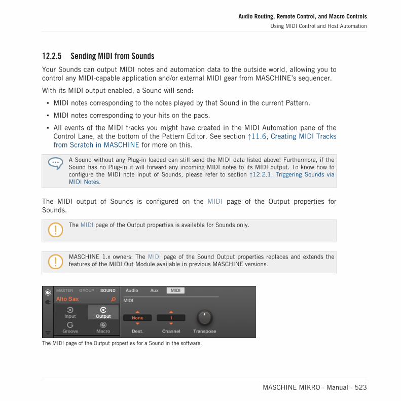
12.2.5 Sending MIDI from Sounds
Your Sounds can output MIDI notes and automation data to the outside world, allowing you tocontrol any MIDI-capable application and/or external MIDI gear from MASCHINE’s sequencer.
With its MIDI output enabled, a Sound will send:
▪ MIDI notes corresponding to the notes played by that Sound in the current Pattern.
▪ MIDI notes corresponding to your hits on the pads.
▪ All events of the MIDI tracks you might have created in the MIDI Automation pane of theControl Lane, at the bottom of the Pattern Editor. See section ↑11.6, Creating MIDI Tracksfrom Scratch in MASCHINE for more on this.
A Sound without any Plug-in loaded can still send the MIDI data listed above! Furthermore, if theSound has no Plug-in it will forward any incoming MIDI notes to its MIDI output. To know how toconfigure the MIDI note input of Sounds, please refer to section ↑12.2.1, Triggering Sounds viaMIDI Notes.
The MIDI output of Sounds is configured on the MIDI page of the Output properties forSounds.
The MIDI page of the Output properties is available for Sounds only.
MASCHINE 1.x owners: The MIDI page of the Sound Output properties replaces and extends thefeatures of the MIDI Out Module available in previous MASCHINE versions.
The MIDI page of the Output properties for a Sound in the software.
Audio Routing, Remote Control, and Macro Controls
Using MIDI Control and Host Automation
MASCHINE MIKRO - Manual - 523
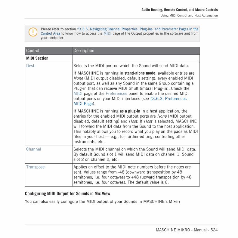
Please refer to section ↑3.3.5, Navigating Channel Properties, Plug-ins, and Parameter Pages in theControl Area to know how to access the MIDI page of the Output properties in the software and fromyour controller.
Control Description
MIDI Section
Dest. Selects the MIDI port on which the Sound will send MIDI data.
If MASCHINE is running in stand-alone mode, available entries areNone (MIDI output disabled, default setting), every enabled MIDIoutput port, as well as any Sound in the same Group containing aPlug-in that can receive MIDI (multitimbral Plug-in). Check theMIDI page of the Preferences panel to enable the desired MIDIoutput ports on your MIDI interfaces (see ↑3.6.3, Preferences –MIDI Page).
If MASCHINE is running as a plug-in in a host application, theentries for the enabled MIDI output ports are None (MIDI outputdisabled, default setting) and Host. If Host is selected, MASCHINEwill forward the MIDI data from the Sound to the host application.This notably allows you to record what you play on the pads as MIDIfiles in your host — e.g., for further editing, controlling otherinstruments, etc.
Channel Selects the MIDI channel on which the Sound will send MIDI data.By default Sound slot 1 will send MIDI data on channel 1, Soundslot 2 on channel 2, etc.
Transpose Applies an offset to the MIDI note numbers before the notes aresent. Values range from -48 (downward transposition by 48semitones, i.e. four octaves) to +48 (upward transposition by 48semitones, i.e. four octaves). The default value is 0.
Configuring MIDI Output for Sounds in Mix View
You can also easily configure the MIDI output of your Sounds in MASCHINE’s Mixer:
Audio Routing, Remote Control, and Macro Controls
Using MIDI Control and Host Automation
MASCHINE MIKRO - Manual - 524

1. Click the Mix View button on the left of the Arranger to switch from Arrange view to Mixview:
2. Open the extended view of the Mixer by clicking the down-pointing arrow on the left of theMixer:
3. Check that the IO button is active on the left of the Mixer — if not, click it to enable itand display the input/output settings of each channel strip.
4. If the Mixer currently displays the Group channels, in the top row of the Mixer double-click the header of the Group containing the Sound you want to configure. If the Mixercurrently displays the Sound channels, single-click the header of the desired Group.
The Mixer displays the channel strips of all Sounds in the selected Group.
Audio Routing, Remote Control, and Macro Controls
Using MIDI Control and Host Automation
MASCHINE MIKRO - Manual - 525

5. At the bottom of the channel strip of the Sound you want to configure, click the biggerfield left and select the desired MIDI port in the menu.
This is equivalent to setting the Dest. parameter described above.
6. Click the little field on its right to select a MIDI channel.
This is equivalent to the Channel parameter described above.
Audio Routing, Remote Control, and Macro Controls
Using MIDI Control and Host Automation
MASCHINE MIKRO - Manual - 526

12.3 Creating Custom Sets of Parameters with the Macro Controls
Macro Controls enable you to control in one same location a selection of parameters comingfrom different sources. Available in every channel (Sounds, Groups, and Master), Macro Con-trols are very useful for playing live since you can choose a set of parameters from various sour-ces to manipulate on one screen without having to switch screens.
MASCHINE 1.x owners: In MASCHINE 1.x Macro Controls were additionally used to automate MA-SCHINE parameters via MIDI or host automation. This is not the case in MASCHINE 2.0 anymore:automation and Macro Controls now are totally independent. Now MASCHINE parameters can be di-rectly assigned to MIDI controls or host automation IDs (as described in section ↑12.1.4, Configur-ing the Master and Cue Outputs of MASCHINE), while Macro Controls are plain shortcuts of the de-sired parameters, at all levels of MASCHINE, and without any limitation in number.
The Macro Controls are available in the Macro properties.
The Macro properties (here for a Sound) in the software.
Please refer to section ↑3.3.5, Navigating Channel Properties, Plug-ins, and Parameter Pages in theControl Area to know how to access the Macro properties in the software and from your controller.
12.3.1 Macro Control Overview
Each Macro Control can be assigned to one destination with the full range of the selected pa-rameter. On the other hand, the same parameter can be the destination of more than one Mac-ro Control.
To know which parameters you can assign to a Macro Control, consider this single rule:
Audio Routing, Remote Control, and Macro Controls
Creating Custom Sets of Parameters with the Macro Controls
MASCHINE MIKRO - Manual - 527

A Macro Control of a channel can control any parameter located in the properties or Plug-ins of thatchannel or of any underlying channel. In other words:
▪ For Sounds: You can assign the Macro Controls of a Sound to any parameters in its proper-ties or Plug-ins. It is also possible to assign MIDI Control Change messages, Pitchbend andProgram Changes to Macro Controls in order to control external MIDI devices.
▪ For Groups: You can assign the Macro Controls of a Group to any parameters in its proper-ties or Plug-ins as well as any parameters in any Sound inside the Group.
▪ For the Master: You can assign the Macro Controls to any parameters found in the proper-ties or Plug-ins of any channel in your Project.
Obviously, the Macro properties (even of a different channel) are not available as targets for anyMacro Control.
Linking the same parameter to more than one Macro Control can be useful in the following example:If a parameter of a Sound is particularly important, you can link it to the same knob in the MacroControls of that Sound, of its parent Group, and of the Master. By doing this, you ensure that theparameter is always available on the same knob when you switch between the Master, Group, andSound level (but not if you switch to another Sound or Group, of course).
Macro Control Shortcut on the Controller
On your controller, a dedicated button allows you to quickly access your Macro Controls at anytime:
Press SHIFT + PLUG-IN (Macro) to directly switch to the Macro Controls of the focused chan-nel (Sound, Group or Master).
12.3.2 Assigning Macro Controls Using the Software
Macro Controls can be assigned in two different ways. The quickest and easiest way is to cre-ate a Macro Control directly from a parameter. The other more elaborate method is to use thePages Pane in the Assignment Area.
Audio Routing, Remote Control, and Macro Controls
Creating Custom Sets of Parameters with the Macro Controls
MASCHINE MIKRO - Manual - 528

Assigning Macro Controls from Parameters
Assigning a parameter as a Macro from a Channel or Plug-in properties is quick and easy. Youcan simply right-click ([Ctrl]-click on macOS) a parameter name and select which Macro levelyou want to assign it to.
To assign a Macro Control directly from a parameter:
1. Select Channel or Plug-in icon depending on where the parameter you want to assign issituated.
2. Select the level where the parameter is, this can be on the MASTER, GROUP or SOUNDlevel.
3. Right-click ([Ctrl]-click on macOS) the name of the parameter (the text below the knob,switch, or menu) you want to assign and select either Create Master Macro, Create GroupMacro, or Create Sound Macro depending on the options available, and to which level youwant to assign the parameter as a Macro Control.
⇨ The parameter is assigned as a Macro and you can see your assignments by selectingMacro in the Channel properties and selecting the Macro level (MASTER, GROUP orSOUND) where you assigned the Macro Control.
4. To remove a Macro, right-click the parameter again and select Remove Macro.
→ The selected Macro is removed.
Assigning Macro Controls Using the Pages Pane
Assigning Macro Controls is done in the Pages pane of the Assignment area when the Macroproperties are selected. The procedure is similar to the procedure used when assigning param-eters of VST/AU plug-ins to Parameter pages in MASCHINE (see section ↑7.3.3, Setting UpYour Own Parameter Pages).
Opening the Pages Pane in the Assignment Area
First of all, you need to open the Pages pane of the Assignment area for Macro properties. Todo this:
1. Select the Macro properties of the desired channel (Sound, Group, or Master) as descri-bed in section ↑3.3.5, Navigating Channel Properties, Plug-ins, and Parameter Pages inthe Control Area.
Audio Routing, Remote Control, and Macro Controls
Creating Custom Sets of Parameters with the Macro Controls
MASCHINE MIKRO - Manual - 529

2. Click the down-pointing arrow in the bottom left corner of the Control area to reveal theAssignment area underneath:
3. Click the Pages tab in the left part of the Assignment area:
→ The Pages tab lights up and the Pages pane appears on its right. You are now ready toassign Macro Controls to parameters.
Once the Assignment area is open, when you switch to other Parameter pages the Assignment areafollows your selection: it always shows the assignments for the page currently displayed above.
The Pages tab can be clicked only for Plug-ins, External MIDI device Control Change assignments,and for Macro properties. For all other Plug-ins and Channel properties, parameters and Parameterpages are not editable, and the Pages tab is grayed out and inactive. For more information on howto assign parameters of Native Instruments or External Plug-ins to Parameter pages, please refer to↑7.3.3, Setting Up Your Own Parameter Pages.
When the Pages pane of the Assignment area is open, you also notice a few changes in theControl area above.
Audio Routing, Remote Control, and Macro Controls
Creating Custom Sets of Parameters with the Macro Controls
MASCHINE MIKRO - Manual - 530

1 2 3
7 6 5 4The Control area with Macro Properties displayed and the Pages pane active in the Assignment area underneath.
(1) Delete Page button (“x” symbol): Click the little “x” after a page name to delete this Parame-ter page.
(2) Add Page button (“+” symbol): Click the little “+” after the last page label to append a newpage. By default, pages are labeled “Page 1,” “Page 2,” etc. You can change page labels bydefining sections within your pages via the Section Label fields (3).
(3) Section Label fields: These fields allow you to define sections of parameters within the dis-played page. Double-click the field above the first parameter you want to include in the sec-tion, type the desired name for the section, and press [Enter] to confirm. The new section willinclude all following parameters until the next section starts (this can be seen only after youhave closed the Assignment area). Moreover, the Parameter page will mirror the label(s) of itssection(s) — if there are more than one section, the page label will mirror all of them, separat-ed by slashes.
(4) Reset button: Click Reset to remove the Macro Control assignment for the selected knob.
(5) Parameter Label fields: Double-click these fields to enter custom labels for your parameters(press [Enter] to confirm). These labels will be mirrored everywhere in MASCHINE for the cor-responding parameters.
(6) Focus frame: Indicates the Macro Control being assigned. Click any Macro Control to displayand edit its assignment in the Target selector below (4).
Audio Routing, Remote Control, and Macro Controls
Creating Custom Sets of Parameters with the Macro Controls
MASCHINE MIKRO - Manual - 531

(7) Target selector: Displays and selects the target parameter of the selected Macro Control in-dicated by the Focus frame (5). This multi-level drop-down widget allows you to quickly navi-gate through the structure of the channel to the desired parameter. The detailed procedure isexplained in the next paragraph.
Selecting a Parameter in the Target Selector
The Target selector (see picture above) allows you to choose from all available parameters foreach Macro Control.
The Target selector allows you to quickly select the desired parameter.
This tool is similar to a menu containing several levels of submenus—with the notable differ-ence that every intermediary selection stays visible for faster switching.
When assigning a new, unassigned Macro Control, do the following:
1. Click the Select menu (for now the only menu of the Target selector).The menu is organized into subcategories: Settings (listing the properties of the currentchannel), Slots (listing the Plug-ins loaded in the current channel), and possibly a thirdcategory listing the channels included at the next level: if you’re editing the Macro proper-ties of the Master you will see the Groups subcategory listing all Groups of your Project,and if you are editing the Macros of a Group you will see the Sounds subcategory listingall Sounds in that Group, and if you are editing the Macro properties of a Sound you willsee the MIDI menu item which upon selection lists all available Control Change messagesthat can be assigned to a Macro Control.
The Macro Control menu item Select > MIDI lists the full range of MIDI Control Change messagesfrom 0-127 which can be individually assigned to a Macro Control in order to control parameters onan external MIDI device. If you are unsure which MIDI Control Change message can be used to con-trol a particular parameter, please check the documentation that came with your MIDI device fordetails.
Audio Routing, Remote Control, and Macro Controls
Creating Custom Sets of Parameters with the Macro Controls
MASCHINE MIKRO - Manual - 532

2. Upon your selection in the previous menu, the menu takes the name of your selection,and another menu may appear to the right which allows you to refine your search (e.g., bylisting all Parameter pages of the selected Plug-in or Channel properties). This continuesuntil a parameter is reached and you select it.
→ Upon the selection of a parameter, the Macro Control is assigned to this parameter.
Note that the whole path to this parameter stays visible in the Target selector: this lets youmodify a single selection without starting from the topmost channel and going through the en-tire selection process again:
► To modify a particular item in the selection shown by the Target selector, click it and se-lect another item for that level.
→ Items on the left of the selected item (i.e. at a higher level) stay untouched, while itemson its right (i.e. at a lower level) are reset.
Macro Assignment – Context Menu
When the Assignment area is opened and the Pages tab is selected, right-click on an assignedor unassigned Macro slot to access the context menu.
The Macro properties context menu.
The context menu contains following items:
Audio Routing, Remote Control, and Macro Controls
Creating Custom Sets of Parameters with the Macro Controls
MASCHINE MIKRO - Manual - 533

Menu Item Description Keyboard Shortcuts
Rename Rename the Macro. Ctrl + R / Cmd + R
Reset Reset the Macro.
Cut Cut the Macro to paste it in anotherposition.
Ctrl + X / Cmd + X
Copy Copy the Macro. Ctrl + C / Cmd + C
Paste Paste a cut or copied Macro to a newposition.
Ctrl + V / Cmd + V
Assignment Area Pages – Context Menu
When the Assignment Area is opened and the Pages tab is selected, right-click on a Pageopens a context menu.
The Control Area Assignment Pages context menu.
The context menu contains the following items:
Menu Item Description Keyboard Shortcuts
Delete Deletes current Page with allassignments.
Clear All Clears all the assignments, anddeletes all of the Pages.
Audio Routing, Remote Control, and Macro Controls
Creating Custom Sets of Parameters with the Macro Controls
MASCHINE MIKRO - Manual - 534

13 Controlling Your Mix
The default view of the MASCHINE software is the Arrange view, which contains the Arrangerat the top, the Control area in the middle, and the Pattern Editor / Sampler Editor at the bot-tom. The Arrange view is best suited to organize your melodies and rhythms in the timeline:With it you can for example finely tailor your Patterns for each of your Groups in the PatternEditor, and put them together as Clips in the Arranger to build a complete song.
The Mix view is the other main view of MASCHINE. Instead of focusing on the time-dependentaspects of your Project, it gives you quick access to the level and routing settings of all yourSounds, Groups, and the Master. In addition, it provides you with an intuitive interface for ad-justing the parameters of all your Plug-ins.
The Mix view can come in handy at various stages of your work, e.g., when building customdrum kits, setting up send effects, creating advanced routings… and, last but not least, duringlive performances.
13.1 Mix View Basics
This section describes the basic operation of the Mix view.
Mix View vs. Arranger Views
It is important to note that the Mix view does not provide any additional settings that are notavailable in Arrange view. In other words, every action done in Mix view can also be done in theArranger views (Ideas view and Song view). The purpose of the Mix view is rather to organizethe information and settings in a different way that is better suited for particular workflows,notably those involving levels and routings.
In the rest of the chapter, for each procedure in Mix view we will quickly mention the equiva-lent procedure in Arrange view or point to the corresponding description in this manual.
13.1.1 Switching between Arrange View and Mix View
You can switch the MASCHINE software at any time between the Arranger views (Ideas viewand Song view) and Mix view:
Controlling Your Mix
Mix View Basics
MASCHINE MIKRO - Manual - 535

The Mix View button.
► Click the Mix View button at the top left of the Arranger to switch between the Arrangeviews and the Mix view.
13.1.2 Mix View Elements
When you switch the MASCHINE software to Mix view, the Arranger, the Control area, and thePattern Editor disappear and are replaced with the following three elements:
1
2
3
The Mix view, with the Mixer (1) at the top, the Plug-in Chain (2) in the middle, and the Plug-in Strip (3) at the bottom.
Controlling Your Mix
Mix View Basics
MASCHINE MIKRO - Manual - 536

(1) Mixer: At the top, the Mixer shows you at a glance the level and routing settings for allSounds of the focused Group, or all Groups in your Project. You can change these settings onthe fly, select or put the focus on any channel, etc. At the far right you can control the settingsfor the parent channel — the Group channel if the Mixer displays Sound channels, or the Mas-ter/Cue channel if the Mixer displays Group channels. See section ↑13.2, The Mixer for a de-tailed description.
(2) Plug-in Chain: In the middle, the Plug-in Chain lists all Plug-ins loaded in the focusedchannel (Sound, Group, or Master). See section ↑13.3, The Plug-in Chain for a detailed de-scription.
(3) Plug-in Strip: At the bottom, the Plug-in Strip displays the series of Plug-ins loaded in thefocused channel (Sound, Group, or Master). You can directly adjust the parameters of eachPlug-in in its own interface. See section ↑13.4, The Plug-in Strip for a detailed description.
13.2 The Mixer
Sitting in the top part of the Mix view, the Mixer is ideal to quickly see and adjust the level androuting settings of different channels in one go.
Controlling Your Mix
The Mixer
MASCHINE MIKRO - Manual - 537

The Mixer in the MASCHINE software.
The Mixer provides a classic mixing desk layout containing a certain number of channel strips.The particular channel strips displayed along with their precise layout depend on the following:
▪ Which of the Sound or Group level is selected for displaying: ↑13.2.1, Displaying Groupsvs. Displaying Sounds.
▪ Whether the Mixer is minimized or not, and which sections are enabled for display:↑13.2.2, Adjusting the Mixer Layout.
Controlling Your Mix
The Mixer
MASCHINE MIKRO - Manual - 538

13.2.1 Displaying Groups vs. Displaying Sounds
The Mixer provides two display modes, allowing you to focus on the current context:
▪ Group level: The Mixer shows channel strips for all Groups of your Project.
▪ Sound level: The Mixer shows channel strips for all Sound slots in the focused Group.
Both display modes are described in the following paragraphs.
If the MASCHINE window is too small to display all channel strips, an horizontal scroll bar ap-pears at the bottom of the Mixer to navigate to the hidden channels.
If necessary, use the scroll bar to show hidden channels.
Whether the scroll bar appears or not, the output strip at the far right of the Mixer is always visible.
Mixer Displaying the Group Level
The Mixer can display all Groups at once:
12
3
In this mode the desk’s input strips (1) represent all Groups of your Project, while the outputstrip at the far right (2) represents the Master/Cue channel. At the top of the Mixer you see theheaders of all your Groups and of the Master/Cue channel (3). The focused channel is high-lighted.
Controlling Your Mix
The Mixer
MASCHINE MIKRO - Manual - 539

Mixer Displaying the Sound Level
The Mixer can alternatively display the Sounds slots of a particular Group:
1 2
3 4
In this mode the desk’s input strips (1) represent all Sounds of the focused Group, while theoutput strip at the far right (2) represents that focused Group. At the top of the Mixer you seetwo rows:
▪ The first row (3) contains the headers of all your Groups and of the Master/Cue channel.The header of the focused Group (or of the Master/Cue at the far right) is highlighted.
▪ The second row (4) contains the headers of the Sound slots in the focused Group. Theheader of the focused Sound slot (or of the parent Group at the far right) is highlighted.
Switching the Mixer Between Group and Sound Level
At any time you can switch between both display modes:
► To switch the Mixer display between all Groups of your Project and all Sound slots in aparticular Group, double-click the background of any Group header at the top of the Mix-er.
→ If the Mixer was displaying Sound strips beforehand, it will display all Group strips in-stead, and the Group you have double-clicked will be focused. If the Mixer was displayingGroup strips beforehand, it will instead display all Sound strips of the Group that you havedouble-clicked. The last focused Sound slot in that Group will be focused again.
Controlling Your Mix
The Mixer
MASCHINE MIKRO - Manual - 540
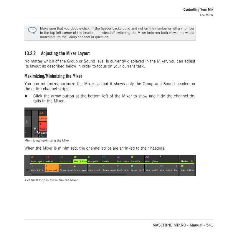
Make sure that you double-click in the header background and not on the number or letter+numberin the top left corner of the header — instead of switching the Mixer between both views this wouldmute/unmute the Group channel in question!
13.2.2 Adjusting the Mixer Layout
No matter which of the Group or Sound level is currently displayed in the Mixer, you can adjustits layout as described below in order to focus on your current task.
Maximizing/Minimizing the Mixer
You can minimize/maximize the Mixer so that it shows only the Group and Sound headers orthe entire channel strips:
► Click the arrow button at the bottom left of the Mixer to show and hide the channel de-tails in the Mixer.
Minimizing/maximizing the Mixer.
When the Mixer is minimized, the channel strips are shrinked to their headers:
A channel strip in the minimized Mixer.
Controlling Your Mix
The Mixer
MASCHINE MIKRO - Manual - 541
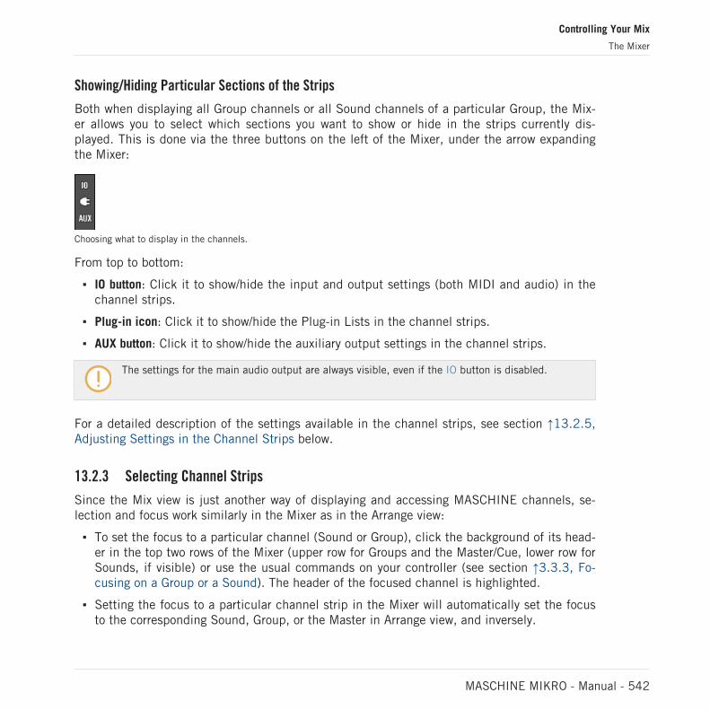
Showing/Hiding Particular Sections of the Strips
Both when displaying all Group channels or all Sound channels of a particular Group, the Mix-er allows you to select which sections you want to show or hide in the strips currently dis-played. This is done via the three buttons on the left of the Mixer, under the arrow expandingthe Mixer:
Choosing what to display in the channels.
From top to bottom:
▪ IO button: Click it to show/hide the input and output settings (both MIDI and audio) in thechannel strips.
▪ Plug-in icon: Click it to show/hide the Plug-in Lists in the channel strips.
▪ AUX button: Click it to show/hide the auxiliary output settings in the channel strips.
The settings for the main audio output are always visible, even if the IO button is disabled.
For a detailed description of the settings available in the channel strips, see section ↑13.2.5,Adjusting Settings in the Channel Strips below.
13.2.3 Selecting Channel Strips
Since the Mix view is just another way of displaying and accessing MASCHINE channels, se-lection and focus work similarly in the Mixer as in the Arrange view:
▪ To set the focus to a particular channel (Sound or Group), click the background of its head-er in the top two rows of the Mixer (upper row for Groups and the Master/Cue, lower row forSounds, if visible) or use the usual commands on your controller (see section ↑3.3.3, Fo-cusing on a Group or a Sound). The header of the focused channel is highlighted.
▪ Setting the focus to a particular channel strip in the Mixer will automatically set the focusto the corresponding Sound, Group, or the Master in Arrange view, and inversely.
Controlling Your Mix
The Mixer
MASCHINE MIKRO - Manual - 542

▪ When the Mixer displays the Sound strips of a Group, when you click another Group headerin the top row the Mixer will stay at the Sound level and directly display to the Sound stripsof this other Group.
▪ You can select more than one channel strip among the strips displayed. The focused stripis always selected. The multiple selection follows the same rules as in Arrange view (seesection ↑5.1.3, Selecting Multiple Sounds or Groups).
Whichever channel strip is focused, the Plug-in Strip at the bottom of the Mix view shows the Plug-ins loaded in that particular channel (see section ↑13.4, The Plug-in Strip).
13.2.4 Managing Your Channels in the Mixer
The Mixer provides the same Sound and Group management commands as the Arrange view,with similar procedures. Most of them are available via the channel’s context menu:
► To open the channel’s context menu, right-click ([Ctrl]-click on macOS) the background ofthe channel header:
Opening the context menu of a channel automatically sets the focus on that channel.
Controlling Your Mix
The Mixer
MASCHINE MIKRO - Manual - 543

The channel’s context menu provides the exact same entries as in Arrange view.
Following management commands are available in the Mixer:
Management Command Action
Renaming channels Double-click the channel name in the header, type the desiredname on your computer keyboard, and press [Enter] to confirm(or [Esc] to cancel). You can also open the channel’s contextmenu and select Rename.
See section ↑5.2.3, Renaming Sound Slots and ↑5.3.3,Renaming Groups.
Changing the channel’scolor
Open the channel’s context menu and select Color.
See section ↑5.2.4, Changing the Sound’s Color and ↑5.3.4,Changing the Group’s Color.
Copying/pasting channels Open the channel’s context menu and select Copy or Paste.
See section ↑5.2.6, Copying and Pasting Sounds and ↑5.3.6,Copying and Pasting Groups.
Resetting Sound channels Open the Sound channel’s context menu and select Reset.
See section ↑5.2.8, Resetting Sound Slots.
Deleting Group channels Open the Group channel’s context menu and select Delete.
See section ↑5.3.8, Deleting Groups.
Saving channels Open the channel’s context menu and select Save As….
See section ↑5.2.5, Saving Sounds and ↑5.3.5, Saving Groups.
You cannot move Sounds and Groups via drag and drop in the Mixer. This is only possible in Ar-range view — see section ↑5.2.7, Moving Sounds and ↑5.3.7, Reordering Groups for more details.
Controlling Your Mix
The Mixer
MASCHINE MIKRO - Manual - 544

13.2.5 Adjusting Settings in the Channel Strips
The layout of Sound and Group strips is close to that of a classical mixing desk. The signaltravels from top to bottom: from the input routing settings at the top, it passes through the var-ious Plug-ins loaded in the channel, then goes through the pan and level controls, and finallyarrives to the output routing settings at the bottom.
The settings available in each channel strip mirror most of the parameters found in the Chan-nel properties displayed in the Control area of the Arrange view, allowing you to adjust them ina more intuitive and visual way (see the list of available parameters at the end of this section).
Adjusting Settings on the Fly
The Mixer provides an interesting feature not available in Arrange view: You can quicklychange the settings in any channel strip currently displayed without having to put the channelunder focus beforehand: Simply click the desired setting in any of the displayed channel stripsto modify it — the current selection/focus will stay untouched.
Tip: Use the Parent Channel Strip at the Far Right
In both display modes of the Mixer, the rightmost channel strip (the “output” strip of the mix-ing desk) represents the parent channel:
▪ If the Mixer currently shows all Groups, the rightmost strip represents the Master (or Cue)channel.
▪ If the Mixer currently shows the Sounds of the focused Group, the rightmost strip repre-sents that Group.
In particular, at the Sound level this allows you to quickly check the level and adjust the set-tings of the parent Group without having to switch the Mixer display to the Group level.
For example, if a kick drum is too loud in a drum kit, while decreasing its level you can check at thefar right how your change affects the overall Group level — and you can quickly adjust this Grouplevel if needed.
Controlling Your Mix
The Mixer
MASCHINE MIKRO - Manual - 545

Available Settings in Sound/Group Channel Strips
We list here all the elements available in a full channel strip. For each element we indicate thebasic operation and the corresponding parameter in Arrange view.
If some of the settings are not visible, check that the Mixer is not minimized and that the relevantbutton is enabled at the left of the Mixer — see section ↑13.2.2, Adjusting the Mixer Layout formore information.
12
34
5
6
7
8A complete channel strip in the Mixer (Sound on the left, Group and Master on the right).
(1) Header: Displays the name and index (letter + number) of the Group or number of theSound. Headers in the Mixer’s top row are for Groups, headers in the second row (Sound levelonly) are for Sounds. If the rest of a channel strip is currently not visible, its header additional-ly shows a mini level indicator in its top right corner. Following actions are available:
Controlling Your Mix
The Mixer
MASCHINE MIKRO - Manual - 546

▪ Switch the Mixer display between Sounds and Groups (see section ↑13.2.1, DisplayingGroups vs. Displaying Sounds).
▪ Focus/select particular channels (see section ↑13.2.3, Selecting Channel Strips).
▪ Rename the channel: Double-click its current name, type a new name on your computerkeyboard, and press [Enter] to confirm (or [Esc] to cancel). You can also use the Renameentry in the channel’s context menu.
▪ Other management commands: Right-click ([Ctrl]-click on macOS) the header backgroundto open the channel’s context menu (see section ↑13.2.4, Managing Your Channels in theMixer).
(2) Audio input settings (Sound strips only): Allows you to adjust the audio input routing. Visibleonly if the IO button is enabled on the left of the Mixer. Click the AUDIO IN label to select anaudio input, and adjust its level via the little knob on the left. These controls are equivalent tothe Source and Gain parameters in the Audio page of the Sound’s Input properties. See sec-tion ↑12.1.1, Sending External Audio to Sounds for more information.
(3) MIDI input settings: Allows you to adjust the MIDI input routing. Visible only if the IO buttonis enabled on the left of the Mixer. Click the MIDI IN label to select a MIDI input port, thenselect a channel via the little menu on its right. These controls are equivalent to the Sourceand Channel selectors in the MIDI page of the Sound’s and Group’s Input properties, respec-tively. See section ↑12.2.1, Triggering Sounds via MIDI Notes for more information.
(4) Plug-in List: Shows the Plug-ins loaded in the channel. Visible only if the Plug-in icon isenabled on the left of the Mixer. Following actions are available:
▪ Click the little “+” symbol to open the Plug-in menu and load a new Plug-in at the end ofthe list.
▪ Right-click (macOS: [Ctrl]-click) an existing Plug-in to replace it with another Plug-in or toremove it (to do this, select None in the menu).
▪ Click a Plug-in name to select it. If this Plug-in is currently hidden in the Plug-in Strip un-der the Mixer, it automatically scrolls to show the interface of that Plug-in (see section↑13.4, The Plug-in Strip).
▪ Click the little square left of a Plug-in to bypass it (the bypassed Plug-in is grayed out) orre-insert it in the signal chain.
▪ Drag and drop Plug-ins to move them across the list.
Controlling Your Mix
The Mixer
MASCHINE MIKRO - Manual - 547
This Plug-in List is the exact equivalent of the Plug-in List in the Control area of the Arrangeview. For all details, see section ↑7.1, Plug-in Overview.
(5) Fader section: Allows you to adjust the channel’s level, panoramic position, Mute and Cuestate. Following actions are available:
▪ Drag the fader vertically to adjust the level of the channel. This is equivalent to the Levelparameter in the Audio page of the channel’s Output properties (see ↑12.1.2, Configuringthe Main Output of Sounds and Groups). Additionally, the level meter shows you at anytime the level of the channel. The peak level value appears in gray above the level meterand fader. If this peak value exceeds zero, it turns white to indicate clipping; click the val-ue to reset it.
▪ Drag the little horizontal slider at the top to adjust the panoramic position of the channel inthe stereo field. This is equivalent to the Pan parameter in the Audio page of the channel’sOutput properties (see ↑12.1.2, Configuring the Main Output of Sounds and Groups).
▪ Click the Mute button to mute the channel, or right-click ([Ctrl]-click on macOS) it to muteall other channels (Solo function). See section ↑6.3.1, Mute and Solo for more information.
▪ Click the little headphones button to send the channel to / remove it from the Cue bus. Thisis equivalent to the Cue parameter in the Audio page of the channel’s Output properties.See section ↑13.2.6, Using the Cue Bus for more information.
(6) Main audio output menu: Selects the destination of the channel’s main audio output. By de-fault Sound channels are output to their parent Group, Group channels are output to the Mas-ter, and the Master is output to the first stereo pair of outputs. Click the label to select anotherdestination. This control is equivalent to the Dest. selector in the Audio page of the Outputproperties for the Sounds and Groups (see ↑12.1.2, Configuring the Main Output of Soundsand Groups) and for the Master (see ↑12.1.4, Configuring the Master and Cue Outputs of MA-SCHINE).
(7) Aux routing settings: Allows you to adjust the routing for both auxiliary outputs. Visible onlyif the AUX button is enabled on the left of the Mixer. Click the AUX 1 or AUX 2 label to selecta destination for this aux output, adjust its level via the little knob on the right, and choose itspre/post tapping point by clicking the Post or Pre label. These controls are equivalent to theDest., Level, and Order parameters in the Aux page of the Sound’s and Group’s Output proper-ties, respectively (see ↑12.1.3, Setting Up Auxiliary Outputs for Sounds and Groups).
Controlling Your Mix
The Mixer
MASCHINE MIKRO - Manual - 548

(8) MIDI output settings (Sound strips only): Allows you to select a MIDI output. Visible only ifthe IO button is enabled on the left of the Mixer. Click the MIDI OUT label to select a MIDIoutput port, then select a channel via the additional menu on the right. These controls areequivalent to the Dest. and Channel selectors in the MIDI page of the Sound’s Output proper-ties (see ↑12.2.5, Sending MIDI from Sounds).
Parameter modulation is not indicated in the Mixer. As a consequence, the value of modulated pa-rameters might change even if their control elements stay at a fixed position in the Mixer. For exam-ple, if the fader of a channel strip is fully down but the channel level is being modulated, the chan-nel’s actual level might temporarily exceed the fader position, leading to an audible signal (and visi-ble meter activity!) although the fader is fully down. In Arrange view, on the other hand, the Controlarea indicates the modulation of continuous parameters via the ring around their knob. See section↑11.5, Recording and Editing Modulation for more on modulating parameters.
Available Settings in the Master and Cue Channel Strips
The Master and the Cue channel strips are similar to the Sound/Group channel strips describedabove, except for the following elements (numbers refer to the picture in the previous para-graph):
▪ The Mute button in the Fader section (5) is not available.
▪ The audio input settings (2) and MIDI input settings (3) are not available.
▪ The aux routing settings (7) and MIDI output settings (8) are not available.
▪ There is no Plug-in List (4) in the Cue channel strip.
13.2.6 Using the Cue Bus
MASCHINE provides a dedicated Cue bus. This Cue bus allows you to route any channel(Sound or Group) on a separate output while leaving the main MASCHINE output untouched.For example, you can use it to prepare any Sound or Group in your headphones during a livesession: first send the empty channel to the Cue bus, then load the desired Sound or Groupfrom the Browser (or create one from scratch), add any Plug-ins, adjust any parameters in thatchannel, record Patterns for that Group as you see fit, and when you are ready, insert it backinto your performance!
The Cue bus is also used for following features:
▪ Pre-listening to Samples in the Browser (see section ↑4.3.3, Auditioning Samples).
Controlling Your Mix
The Mixer
MASCHINE MIKRO - Manual - 549

▪ Metronome (see section ↑11.2.2, Using the Metronome).
▪ Pre-listening functions in the Sample Editor when recording (see section ↑17.2.2, Select-ing the Source and the Recording Mode) or slicing Samples (see section ↑17.4, Slicing aSample).
Sending Sound and Group Channels to the Cue Bus
► In any channel strip, click the little headphones button to send this channel to the Cuebus.
→ The headphones button lights on. The channel is not sent to its defined destination any-more but instead to the Cue bus.
To remove the channel from the Cue bus and send it back to its normal destination defined inits output settings, simply click again on the headphones button.
You can send any number of Sound and Group channels to the Cue bus simultaneously.
In Arrange view, the equivalent of the headphones button is the Cue switch found on the Audiopage of the Sound’s and Group’s Output properties (see section ↑12.1.2, Configuring the Main Out-put of Sounds and Groups).
The mute and solo of channels don’t apply when these channels are sent to the Cue bus: What issent to the Cue bus is always played back via the Cue channel, regardless of the original channelbeing muted or not.
Adjusting the Cue Channel in the Mixer
All signals on the Cue bus arrive on the Cue channel strip. You can display the Cue channelstrip in the Mixer as follows:
1. Click the header of the Master/Cue strip in the top right corner of the Mixer.
If the Mixer was showing Sound channels, it switches to the Group level. The Master/Cuechannel strip appears and is put under focus.
Controlling Your Mix
The Mixer
MASCHINE MIKRO - Manual - 550

2. Click the headphone icon in the Master header.
→ The Master channel strip switches to the Cue channel strip. Here you can adjust the Cuechannel’s level and panoramic position, along with the destination you want to send theCue channel to. As destination, choose for example another output pair into which youwill have plugged your headphones. These settings are described in section ↑12.1.4, Con-figuring the Master and Cue Outputs of MASCHINE.
13.3 The Plug-in Chain
In the middle of the Mix view, right under the Mixer, you see an horizontal bar listing all Plug-ins loaded in the focused channel: the Plug-in Chain. In the Plug-in Chain, Plug-ins are ar-ranged into an horizontal series, the audio travelling from left to right through each Plug-in ofthat channel.
A Plug-in Chain with the Compressor selected and the EQ bypassed.
Except for its horizontal layout, the Plug-in Chain has the same functionality as the Plug-inList found in the channel strips of the Mixer above — namely to organize the Plug-ins of thatchannel:
▪ Click a Plug-in name to select it. If this Plug-in is currently hidden in the Plug-in Strip un-derneath, it automatically scrolls to show the interface of that Plug-in.
▪ Click the little “+” icon at the end of the chain and select a Plug-in in the Plug-in menu toload it at the end of the chain, or right-click (macOS: [Ctrl]-click) a Plug-in name to re-place this Plug-in with another one. See section ↑7.1.3, Loading, Removing, and Replacinga Plug-in for more information.
Controlling Your Mix
The Plug-in Chain
MASCHINE MIKRO - Manual - 551

▪ Click the little square on the left of a Plug-in name to bypass this Plug-in slot (bypassedslots are grayed out). Click the little square again to unmute the Plug-in slot and insert thePlug-in back into the processing chain. See section ↑7.1.5, Bypassing Plug-in Slots formore information.
▪ Right-click (macOS: [Ctrl]-click) a Plug-in name and use the Open…, Save As…, and SaveAs Default… (Native Instruments and External Plug-ins only) commands to manage yourPlug-in presets. See section ↑7.1.9, Saving and Recalling Plug-in Presets and ↑7.3.4, Us-ing VST/AU Plug-in Presets for more information.
You cannot move Plug-ins within the Plug-in Chain. To do this, use for example the Plug-in List inthe channels of the Mixer above (see the Plug-in List description in section ↑13.2.5, Adjusting Set-tings in the Channel Strips).
13.4 The Plug-in Strip
In the lower part of the MASCHINE window, the Mix view provides an intuitive representationof all Plug-ins loaded in the channel (Sound, Group, or Master) currently under focus: the Plug-in Strip. The Plug-in Strip shows the loaded Plug-ins as a series of Plug-in panels, each Plug-inhaving its own panel.
As in the little Plug-in Chain above, the Plug-ins are arranged into an horizontal series, the au-dio travelling from left to right through each Plug-in of that channel.
The Plug-in Strip of a channel, with a distinct interface for each Plug-in.
In the Plug-in Strip the Plug-in panels vary with the type of Plug-in (Internal, Native Instru-ments or External):
Controlling Your Mix
The Plug-in Strip
MASCHINE MIKRO - Manual - 552

▪ For all types of Plug-ins, the panel shows a Plug-in Header at the top: ↑13.4.1, The Plug-inHeader.
▪ Internal Effects and Drumsynths have their own custom panels: ↑13.4.2, Panels for Drum-synths and Internal Effects.
▪ The Sampler Plug-in has a special, extended panel: ↑13.4.3, Panel for the Sampler.
▪ Native Instruments Plug-ins provide dedicated panels inspired from the user interface ofeach particular Native Instruments product: ↑13.4.4, Custom Panels for Native Instru-ments Plug-ins.
▪ Native Instruments and External Plug-ins can also be undocked and opened in a floatingwindow: ↑13.4.5, Undocking a Plug-in Panel (Native Instruments and External Plug-insOnly).
Navigating the Plug-in Strip
If the MASCHINE window is not wide enough for all your Plug-in panels to be displayed in thePlug-in Strip to be displayed entirely, click the name of the desired Plug-in in the Plug-inChain above to make the Plug-in Strip scroll to its panel:
Click a Plug-in in the Plug-in Chain to display its panel in the Plug-in Strip below.
If the MASCHINE window is not wide enough for all Plug-in panels to be displayed at once, anhorizontal scroll bar appears at the bottom of the Plug-in Strip to display the hidden part.
Controlling Your Mix
The Plug-in Strip
MASCHINE MIKRO - Manual - 553
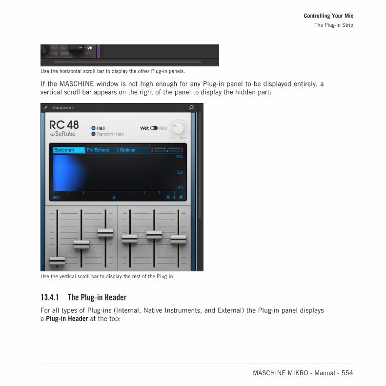
Use the horizontal scroll bar to display the other Plug-in panels.
If the MASCHINE window is not high enough for any Plug-in panel to be displayed entirely, avertical scroll bar appears on the right of the panel to display the hidden part:
Use the vertical scroll bar to display the rest of the Plug-in.
13.4.1 The Plug-in Header
For all types of Plug-ins (Internal, Native Instruments, and External) the Plug-in panel displaysa Plug-in Header at the top:
Controlling Your Mix
The Plug-in Strip
MASCHINE MIKRO - Manual - 554
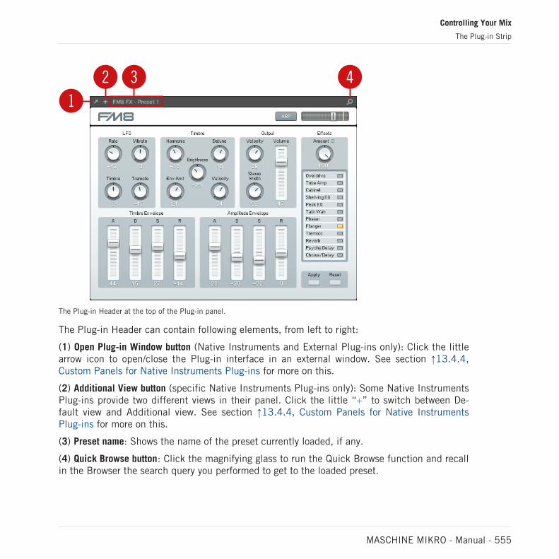
12 3 4
The Plug-in Header at the top of the Plug-in panel.
The Plug-in Header can contain following elements, from left to right:
(1) Open Plug-in Window button (Native Instruments and External Plug-ins only): Click the littlearrow icon to open/close the Plug-in interface in an external window. See section ↑13.4.4,Custom Panels for Native Instruments Plug-ins for more on this.
(2) Additional View button (specific Native Instruments Plug-ins only): Some Native InstrumentsPlug-ins provide two different views in their panel. Click the little “+” to switch between De-fault view and Additional view. See section ↑13.4.4, Custom Panels for Native InstrumentsPlug-ins for more on this.
(3) Preset name: Shows the name of the preset currently loaded, if any.
(4) Quick Browse button: Click the magnifying glass to run the Quick Browse function and recallin the Browser the search query you performed to get to the loaded preset.
Controlling Your Mix
The Plug-in Strip
MASCHINE MIKRO - Manual - 555

13.4.2 Panels for Drumsynths and Internal Effects
For Drumsynths and Internal Effects, the panels in the Plug-in Strip provide intuitive visualrepresentations of the Plug-ins and their parameters.
The Plug-in panel of a Drumsynth and two Internal Effects.
As with all other Plug-ins, the panels for Drumsynths and Internal Effects show the Plug-inHeader at the top. This Header contains the name of the current preset and the Quick Browseicon — see section ↑13.4.1, The Plug-in Header above for more details.
Although parameters are organized differently than in the Parameter pages of the Arrange view,the panels for Drumsynths and Internal Effects contain the exact same parameters as the Pa-rameter pages in Arrange view.
The only exceptions are the Compressor, the Gate, and the Limiter: their panels contain an addi-tional level meter not available in the Control area (gain reduction for the Compressor, and inputlevel for the Gate and the Limiter).
Controlling Your Mix
The Plug-in Strip
MASCHINE MIKRO - Manual - 556

For an exhaustive description of the parameters available in each panel, please refer to chapter↑9, Using the Drumsynths for Drumsynths and chapter ↑15, Effect Reference for Internal Ef-fects.
Parameter modulation is not indicated in the panel for Internal Plug-ins. As a consequence, the val-ue of modulated parameters might change even if their control element doesn’t move in the panel.See section ↑11.5, Recording and Editing Modulation for more on modulating parameters.
13.4.3 Panel for the Sampler
For the Sampler, the Plug-in Strip provides a custom panel containing a judicious mix of pa-rameters available in the three first pages of the Control area along with parameters availablein the Zone page of the Sample Editor.
As with all other Plug-ins, the panel for the Sampler shows the Plug-in Header at the top. ThisHeader contains the name of the current preset and the Quick Browse icon — see section↑13.4.1, The Plug-in Header above for more details.
The Sampler panel contains two distinct panes: MAIN and ZONE. These can be displayed byclicking the MAIN and ZONE button in the Pane selector at the top of the Sampler interface,respectively.
Parameter modulation is not indicated in the panel for Internal Plug-ins. As a consequence, the val-ue of modulated parameters might change even if their control element doesn’t move in the panel.See section ↑11.5, Recording and Editing Modulation for more on modulating parameters.
Controlling Your Mix
The Plug-in Strip
MASCHINE MIKRO - Manual - 557

Sampler – MAIN Pane
1
2
3
4
56
7
The Sampler in the Plug-in Strip.
(1) Pane selector: Click MAIN or ZONE to show the corresponding pane in the Plug-in.
(2) Sample waveform: Shows the waveform or the Sample used in the selected Zone. It providesthe same features as the waveform found in the Sample view of the Zone page in the SampleEditor: Start and End markers, zooming, etc. For more details, see section ↑17, Sampling andSample Mapping.
(3) VOICE & ENGINE section: Allows you to adjust the Polyphony, Glide, and Mode parameterfrom the Voice Settings / Engine page in the Control area, and the Reverse button from thePitch/Envelope page in the Control area. For more details, see section ↑7.2.1, Page 1: VoiceSettings / Engine and ↑7.2.2, Page 2: Pitch / Envelope, respectively.
Controlling Your Mix
The Plug-in Strip
MASCHINE MIKRO - Manual - 558

(4) AMP ENVELOPE section: Allows you to adjust the Type parameter and the envelope parame-ters from the Pitch/Envelope page in the Control area. For more details, see section ↑7.2.2,Page 2: Pitch / Envelope.
(5) SATURATION, LO FI, and FILTER sections: Allows you to adjust the parameters from the FX/Filter page in the Control area. For more details, see section ↑7.2.3, Page 3: FX / Filter.
(6) TUNE section: Allows you to adjust the Tune parameter from the Pitch/Envelope page in theControl area. For more details, see section ↑7.2.2, Page 2: Pitch / Envelope.
(7) PLAY and LOOP sections: Allow you to adjust the play range and loop settings of the selectedzone, respectively. These provide the same parameters as the PLAY RANGE and LOOP sectionsfound in the Zone page of the Sample Editor. For more details, see section ↑17, Sampling andSample Mapping.
Sampler – ZONE Pane
1
4 2
3
Controlling Your Mix
The Plug-in Strip
MASCHINE MIKRO - Manual - 559

The Sampler in the Plug-in Strip.
(1) Pane selector: Click MAIN or ZONE to show the corresponding pane in the Plug-in.
(2) Sample Map: Allows you to adjust the key and velocity ranges of your Zones. This the sameas the Map view available in the Zone page of the Sample Editor. For more details, see section↑17, Sampling and Sample Mapping.
(3) TUNE / MIX and MAP sections: Allow you to adjust the tuning and gain parameters as well asthe key and velocity ranges of your Zones. These are the same as the TUNE and MAP sectionsfrom the Zone page of the Sample Editor. For more details, see section ↑17.5.6, Adjusting theZone Settings.
(4) Zone List: Allows you to manage your Zones. This is the same as the Zone List available inthe Zone page of the Sample Editor. For more details, see section ↑17, Sampling and SampleMapping.
As with all Internal Plug-ins, parameter modulation is not indicated in the panel for the Sampler. Asa consequence, the value of modulated parameters might change even if their control elementdoesn’t move in the panel. See section ↑11.5, Recording and Editing Modulation for more on mod-ulating parameters.
13.4.4 Custom Panels for Native Instruments Plug-ins
The panels for Native Instruments Plug-ins provide an extra feature: one or two custom viewsthat group the most important parameters of the Plug-in into a clear and concise interfacewhile retaining the overall feel and look of each Native Instruments product:
▪ The Default view is available for every Native Instruments Plug-in.
▪ An Additional view, only available for particular Native Instruments Plug-ins, provides an al-ternate set of controls for the Plug-in.
For example:
Controlling Your Mix
The Plug-in Strip
MASCHINE MIKRO - Manual - 560

▪ ABSYNTH 5’s Default view shows the main elements of the Perform window of AB-SYNTH 5:
Controlling Your Mix
The Plug-in Strip
MASCHINE MIKRO - Manual - 561

▪ MASSIVE’s Default view shows specific parts of the Synth view (the eight Macro Controls atthe top and the Modulation pages underneath):
Controlling Your Mix
The Plug-in Strip
MASCHINE MIKRO - Manual - 562
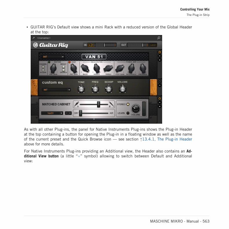
▪ GUITAR RIG’s Default view shows a mini Rack with a reduced version of the Global Headerat the top:
As with all other Plug-ins, the panel for Native Instruments Plug-ins shows the Plug-in Headerat the top containing a button for opening the Plug-in in a floating window as well as the nameof the current preset and the Quick Browse icon — see section ↑13.4.1, The Plug-in Headerabove for more details.
For Native Instruments Plug-ins providing an Additional view, the Header also contains an Ad-ditional View button (a little “+” symbol) allowing to switch between Default and Additionalview:
Controlling Your Mix
The Plug-in Strip
MASCHINE MIKRO - Manual - 563

Click the little “+” in the Header to switch between Default and Additional view.
macOS users: The VST plug-in of a Native Instruments product must be installed for this product’sDefault view (and Additional view, if any) to appear in the Plug-in Strip. If you normally use the AUversion of this Native Instruments product, please check that its VST version is also installed onyour computer to ensure the perfect integration of this plug-in into MASCHINE. You can show/hidethe AU version of Native Instruments plug-ins in the Plug-in menu (software) and Plug-in Browser(controller) via the Use NI Audio Units checkbox in the Plug-ins page of the Preferences panel —see section ↑3.6.6, Preferences – Plug-ins Page for more information.
You can also undock any Native Instruments Plug-in and open it in a separate floating window.In the floating window you can notably switch between the Default view and the full user inter-face of the original Native Instruments product — see section ↑13.4.5, Undocking a Plug-inPanel (Native Instruments and External Plug-ins Only) for more information.
13.4.5 Undocking a Plug-in Panel (Native Instruments and External Plug-ins Only)
You can undock the panel of a Native Instruments or External Plug-in and open it in its ownfloating window by clicking the little diagonal arrow in the Plug-in Header:
Click the little diagonal arrow to open the Plug-in in a floating window.
► To undock a Native Instruments or External Plug-in and open it in its dedicated floatingwindow, click the little diagonal arrow on the left of the Plug-in Header.
→ The Plug-in shows up in its own floating window.
Controlling Your Mix
The Plug-in Strip
MASCHINE MIKRO - Manual - 564

When undocking Native Instruments Plug-ins, their panel in the Plug-in Strip is replaced by a thinPlug-in placeholder (see below).
Plug-ins of Native Instruments platform products (REAKTOR, KONTAKT, GUITAR RIG) are auto-matically opened in floating windows when loaded from the Plug-in menu.
MASCHINE will always show the open floating windows of the focused channel (Sound, Groupor Master). In this channel you can have as many open floating windows as you see fit. Whenyou set the focus to another channel, all open floating windows disappear, possibly replaced bythose for Native Instruments and/or External Plug-ins loaded in the newly focused channel(Sound, Group or Master).
The Plug-in floating window is the same as in Arrange view — see section ↑7.3.1, Opening/ClosingPlug-in Windows for more on this.
Undocking a Native Instruments Plug-in
When you open a Native Instruments Plug-in its own floating window, following things addi-tionally happen:
▪ In the Plug-in Strip the Plug-in panel is replaced with a thin vertical Plug-in placeholdercontaining only the little diagonal arrow — this allows you to dock the Plug-in back into thePlug-in Strip (see below).
Controlling Your Mix
The Plug-in Strip
MASCHINE MIKRO - Manual - 565

▪ The floating window also displays the Plug-in Header at the top. In addition to the Header’selements described in section ↑13.4.4, Custom Panels for Native Instruments Plug-ins,this Header contains an additional Edit button (showing a pencil icon) allowing you toswitch to the Edit view, which shows the full interface of the original Native Instrumentsproduct:
Closing the Plug-in’s Floating Window
► To dock a Native Instruments or External Plug-in back into the Plug-in Strip and close itsdedicated floating window, click the little diagonal arrow in the Plug-in placeholder (Na-tive Instruments Plug-ins) or in the header of the generic Plug-in panel (External Plug-ins)in the Plug-in Strip.
You can also close any floating window via the common button provided by your operating system atthe top left or right corner of the window. The Plug-in will be inserted back into the Plug-in Strip.
Controlling Your Mix
The Plug-in Strip
MASCHINE MIKRO - Manual - 566

14 Using Effects
At each Project level (Sound, Group and Master) it is possible to add effects in form of Plug-ins. Each Sound, each Group and the Master can have an unlimited number of insert effectsloaded in their Plug-ins slots. In each Plug-in slot you can load an Internal, Native Instrumentsor External Effect Plug-in.
The processing order is always from top to bottom, both in the Plug-in List of the Control area(in Ideas view and Song view) and in the channel strip of the Mixer (in Mix view). In the Plug-in Strip of the Mix view the processing order is from left to right.
For Sounds, the first Plug-in slot is often hosting an Instrument Plug-in (Sampler, Drumsynth, Na-tive Instruments or External Plug-in) — this allows the Sound to generate its own audio. If insteadyou plug an effect to the first Plug-in slot of a Sound, this Sound will act as a bussing point forother Sounds and Groups, and you will find this Sound in the various Dest. selectors in the Outputproperties of other Sounds and Groups. See section ↑14.1, Applying Effects to a Sound, a Group orthe Master below for more information.
Most of the features used in the procedures mentioned in this chapter have been already de-scribed in chapter ↑7, Working with Plug-ins — in MASCHINE, effects are just a certain typeof Plug-ins. Nevertheless, we illustrate them here with various effect-oriented examples. Fur-thermore, from time to time we will use the Mix view instead of the default Arrange view —indeed, the intuitive routing facilities of the Mixer make it particularly well suited for quicklysetting up advanced effect routings.
14.1 Applying Effects to a Sound, a Group or the Master
The procedures for applying an effect at the Sound, Group or Master level are very similar.
14.1.1 Adding an Effect
Let’s add an Effect Plug-in somewhere in the Project. We first describe the detailed procedurein Arrange view, then we will show the equivalent procedure in Mix view.
Using Effects
Applying Effects to a Sound, a Group or the Master
MASCHINE MIKRO - Manual - 567
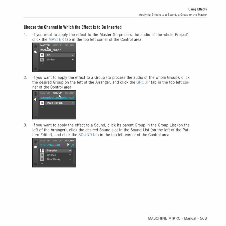
Choose the Channel in Which the Effect Is to Be Inserted
1. If you want to apply the effect to the Master (to process the audio of the whole Project),click the MASTER tab in the top left corner of the Control area.
2. If you want to apply the effect to a Group (to process the audio of the whole Group), clickthe desired Group on the left of the Arranger, and click the GROUP tab in the top left cor-ner of the Control area.
3. If you want to apply the effect to a Sound, click its parent Group in the Group List (on theleft of the Arranger), click the desired Sound slot in the Sound List (on the left of the Pat-tern Editor), and click the SOUND tab in the top left corner of the Control area.
Using Effects
Applying Effects to a Sound, a Group or the Master
MASCHINE MIKRO - Manual - 568

Load the Effect in a New Slot
1. At the far left of the Control area, click the little Plug-in icon to display the Plug-ins of theselected channel:
The icon lights up. The Plug-in List appears nearby, showing a stack of all Plug-ins al-ready loaded in the channel:
In the Plug-in List each Plug-in has its own slot.
2. Click the “+” icon under the last Plug-in in the list (or at the top if the list is empty).
The Plug-in menu opens and shows a list of all available Effect Plug-ins.
Using Effects
Applying Effects to a Sound, a Group or the Master
MASCHINE MIKRO - Manual - 569

If you have selected a Sound and its Plug-in List is empty, the Plug-in menu also showsall available Instrument Plug-ins.
3. Click the desired entry in the list. If you have VST/AU effect plug-ins installed you mayalso load them from the menu by selecting the Native Instruments (for Native Instrumentsproducts) or External (for third-party products) submenu at the top of the list.
→ Upon your selection the effect is loaded in a new Plug-in slot at the end of the list anddirectly starts to process the audio of the channel. The effect parameters are displayed inthe Parameter area on the right (in the example underneath we selected the Phaser effectin the Plug-in menu).
Using Effects
Applying Effects to a Sound, a Group or the Master
MASCHINE MIKRO - Manual - 570

Notes and Hints on Loading Effects in the Software
▪ Instead of clicking the “+” icon to load the effect in a new slot, you can also click thedown-pointing arrow on the right of an existing slot to open the Plug-in menu: The effectselected in the menu will replace the Plug-in currently loaded in that slot.
▪ Instead of using the Plug-in menu, you can also use the Browser to load a particular presetfor an effect. In particular, this can come in handy to insert a new effect between two ex-isting Plug-ins in the Plug-in List. Please refer to section ↑4.2, Searching and LoadingFiles from the Library for more information. Alternatively you can use Quick Browse to re-call the search query that was used to load a particular Plug-in preset — see section ↑4.8,Using Quick Browse for more information on this.
▪ For all details on the parameters for each MASCHINE effect, please refer to chapter ↑15,Effect Reference.
▪ For additional, specific information on VST/AU plug-ins, see ↑7.3, Using Native Instru-ments and External Plug-ins.
▪ If you created a nice effect setting, you can put it to further use by saving it as a Plug-inpreset. For more details, see ↑7.1.9, Saving and Recalling Plug-in Presets.
Adding an Effect in Mix View
You can also load effects in Mix view. The procedure is quite similar to the one describedabove for the Arrange view.
Reminder: To switch the Mixer display between all Groups of your Project and all Sound slots in aparticular Group, double-click the background of any Group header at the top of the Mixer. See sec-tion ↑13.2.1, Displaying Groups vs. Displaying Sounds for more information.
First, display the Plug-in List in Mix view:
1. Click the Mix View button (showing three little faders) at the left of the Arranger to switchfrom Arrange view to Mix view:
Using Effects
Applying Effects to a Sound, a Group or the Master
MASCHINE MIKRO - Manual - 571

2. If it’s not already open, open the extended view of the Mixer by clicking the down-pointingarrow at the left of the Mixer:
3. Check that the Plug-in icon is active on the left of the Mixer — if not, click it to displaythe Plug-in List in each channel strip.
Then, put the focus on the channel (Master, Group or Sound) in which you want to load theeffect:
1. To set the focus to the Master channel: In the top right corner of the Mixer, click in theblank space above the Master label and headphones icon to set the focus to the Master/Cue channel strip.
If necessary click Master in that header to switch from the Cue channel to the Masterchannel.
2. To set the focus to a Group channel: If the Mixer is currently displaying the Group channelstrips, click the header of the desired Group at the top of the Mixer. If the Mixer is cur-rently displaying Sound channel strips, double-click the header of the desired Group atthe top of the Mixer.
Using Effects
Applying Effects to a Sound, a Group or the Master
MASCHINE MIKRO - Manual - 572

3. To set the focus to a Sound channel: If the Mixer is currently displaying the Group channelstrips, in the Mixer’s top row double-click the blank space in the header of the Group con-taining the desired Sound, then click the header of the desired Sound in the row below. Ifthe Mixer is currently displaying Sound channel strips, in the top row click the header ofthe Group containing the desired Sound, then click the header of this Sound in the rowbelow.
Finally, load the effect in the focused channel strip:
► In the Plug-in List of the focused channel, click the little “+” to append the effect to thelist, or right-click ([Ctrl]-click on macOS) an existing Plug-in slot to replace its currentPlug-in, and select the desired effect in the Plug-in menu that opens.
→ The effect is loaded and directly starts to process the audio of the channel. The effect al-so appears in the Plug-in Strip under the Mixer, allowing you to adjust its parameters.
In fact you don’t need to explicitly put the focus on the channel in which you want to load the ef-fect: You only have to make that channel visible in the Mixer! You can then directly click the “+”symbol or right-click ([Ctrl]-click on macOS) an existing Plug-in slot to load the effect in that chan-nel. Nevertheless, setting the focus on the channel has the advantage of displaying the new effectin the Plug-in Strip under the Mixer for adjusting its parameters — you can do this afterwards.
For more information on the Mixer and the Mix view in MASCHINE, please refer to section ↑13.2,The Mixer.
Using Effects
Applying Effects to a Sound, a Group or the Master
MASCHINE MIKRO - Manual - 573

14.1.2 Other Operations on Effects
You can manipulate effects like any other Plug-in loaded in a Plug-in slot. This notably in-cludes adjusting the effect parameters, removing effects, moving effects to other Plug-in slots,saving and recalling effect presets, etc.
Here we provide a reminder of every operation available on the effects both in Arrange viewand Mix view.
Concerning the procedures listed below, the only difference between Arrange view and Mix view isthe way to open the Plug-in menu: In Arrange view you open it by clicking the Plug-in slot’s down-pointing arrow, whereas in Mix view you open it by right-clicking ([Ctrl]-clicking on macOS) the ef-fect name in the Plug-in List.
Action Procedure
All Effects
Insert an effect after anexisting Plug-in
From the Browser or from your operating system, drag anddrop the desired effect preset between two existing Plug-inslots.
Replace an effect Open the Plug-in menu, and select another effect from themenu.
Remove an effect Open the Plug-in menu, and select None from the menu.
Move an effect within thePlug-in List
Click and hold the effect in the Plug-in List, drag your mouseto the desired location (an insertion line appears where theeffect will be dropped), and release the mouse button.
Move an effect to anotherchannel (Sound, Group, orMaster)
First, open the source slot’s Plug-in menu and select Cut.Then open the Plug-in menu of the desired slot in the targetchannel (Sound, Group, or Master) and select Paste.
Duplicate an effect First, open the source slot’s Plug-in menu and select Copy.Then open the Plug-in menu of the desired slot in the targetchannel (Sound, Group, or Master) and select Paste.
Using Effects
Applying Effects to a Sound, a Group or the Master
MASCHINE MIKRO - Manual - 574

Action Procedure
Bypass an effect Click the FX icon (in Arrange view) or the little square (in Mixview) at the left of the effect name in the Plug-in List. Clickagain to re-enable the effect.
Save the current effectsettings as preset
Open the Plug-in menu, and select Save As… at the bottomof the menu.
Recall an effect preset Use the Browser (see chapter ↑4, Browser), or open the Plug-in menu and select Open… at the bottom of the menu.
Native Instruments and ExternalEffects
Open/close the effect window Arrange view: Click the little window icon in the top leftcorner of the Parameter area (at the left of the first page tab).
Mix view: In the Plug-in Strip under the Mixer, click the littlearrow in the top left corner of the effect panel.
Save the current settings asdefault preset for this effect
Open the Plug-in menu, and select Save As Default… at thebottom of the menu.
For detailed information on these topics, please refer to ↑7.1, Plug-in Overview. For more de-tails on the specific operations available for Native Instruments and External Effects, see ↑7.3,Using Native Instruments and External Plug-ins.
14.1.3 Using the Side-Chain Input
For certain Plug-ins, MASCHINE allows you to use a side-chain input to control how the effectsprocess the audio.
What Is a Side-Chain Input?
If we consider an effect unit that processes the signal incoming at its main input, side-chainingmeans using a secondary signal (the “side-chain signal”) fed to a secondary input of the unit(the “side-chain input”) to control the behavior of the processing. Usually the amplitude of theside-chain signal will determine how much the main signal will be processed by the unit.
Using Effects
Applying Effects to a Sound, a Group or the Master
MASCHINE MIKRO - Manual - 575

In music production the side-chain signal is most of the time another audio track of theproject. A common example is the use of the kick drum track as side-chain for the compres-sion of the bass track: on each kick the compressor will compress the bass more, resulting in atypical pumping effect between kick and bass that can be heard in various styles of dance mu-sic.
The Side-Chain Parameter Page
The following Internal, Native Instruments, and External Plug-ins support side-chaining:
▪ Internal Plug-ins: Compressor, Maximizer, Limiter, Gate, Filter.
▪ AU plug-ins (Native Instruments and External): Any AU plug-in with side-chain input.
▪ VST plug-ins (Native Instruments and External): Any VST plug-in with multiple inputs.
When you load any of these Plug-ins in a Sound or a Group, a Side-Chain Input Parameterpage appears at the end of the page list.
Side-chaining is not possible at the Master level (i.e. if the Plug-in is loaded in a Plug-in slot of theMaster).
The Side-Chain Input page of the Compressor Plug-in in the Control area.
Please refer to section ↑3.3.5, Navigating Channel Properties, Plug-ins, and Parameter Pages in theControl Area to know how to access Parameter pages.
The parameters of the side-chain input are not available in the Plug-in panel of the Plug-in Strip.
Using Effects
Applying Effects to a Sound, a Group or the Master
MASCHINE MIKRO - Manual - 576

Parameter Description
INPUT Section
Source Selects the audio signal you want to use as side-chain signal tocontrol the Plug-in. Available options are None (side-chaindisabled, default setting), the outputs of all (other) Sounds , andthe outputs of all (other) Groups.
In the menu these outputs are labeled as follows:
For Groups: [Group name] (e.g., Drums)
For Sounds: [Group name]: [Sound name] (e.g., Drums: Kick)
In the selector display these outputs are labeled as follows:
For Groups: [Group name] (e.g., Drums)
For Sounds: [Group letter+number]:S[Sound number] (e.g., A1:S4 forthe Sound 4 of Group A1)
Gain Adjusts the input level of the side-chain signal fed into the Plug-in.
FILTER Section
Filter Activates a filter on the side-chain input. This filter can be useful toselect only a specific frequency range of the side-chain signal tocontrol the Plug-in.
Center Freq Adjusts the center frequency of the filter.
Width Adjusts the bandwidth of the filter.
On your controller the outputs available in the SOURCE parameter are labeled as in the display ofthe Source selector described above.
Note that the settings of the Side-Chain Input page stay in place when you switch to another Plug-in supporting side-chain. This notably allows you to try different compressors or different compres-sion presets without losing the side-chain setup.
Using Effects
Applying Effects to a Sound, a Group or the Master
MASCHINE MIKRO - Manual - 577

14.2 Applying Effects to External Audio
MASCHINE’s flexible routing facilities allow you to apply effects to external audio as well. Thisexternal audio can come from the inputs of your audio interface if MASCHINE is used instand-alone mode, or from your host if MASCHINE is used as a plug-in.
To do this, we will choose a Sound and make use of the Audio page in its Input properties.
14.2.1 Step 1: Configure MASCHINE Audio Inputs
MASCHINE’s audio input configuration can be done in the software only. Furthermore, thisconfiguration is necessary only if you use MASCHINE as stand-alone application.
If you are using MASCHINE as a plug-in in a host application, MASCHINE can receive audio fromyour host on any of its eight mono virtual inputs. To know how to route audio in your host to thevirtual inputs of the MASCHINE plug-in, please refer to your host documentation. When this isdone, go directly to section ↑14.2.2, Step 2: Set up a Sound to Receive the External Input.
MASCHINE in Stand-Alone Mode
Please make sure that you have connected an external audio signal source to your audio inter-face and that the inputs of the audio interface are activated. To do this:
1. Select the Preferences… entry from the File menu to open the Preferences panel.
2. In the Audio page click the Input button, activate the desired inputs by clicking their fieldin the Port column and selecting a physical input from the drop-down menu, then clickClose.
→ Audio signals coming from external sources plugged in the inputs selected here will nowbe routed to the MASCHINE inputs shown in the first column.
See ↑3.6.2, Preferences – Audio Page for more information on the Audio page of the Preferencespanel.
Using Effects
Applying Effects to External Audio
MASCHINE MIKRO - Manual - 578

MASCHINE in Plug-in Mode
If MASCHINE is running as a plug-in in a host environment, the MASCHINE plug-in can re-ceive audio from the host only. Please refer to your host documentation to find out how toroute audio channels to the virtual audio inputs of the MASCHINE plug-in.
In this example, we will assume that you routed some audio channels of your host to the firstvirtual input pair of MASCHINE.
14.2.2 Step 2: Set up a Sound to Receive the External Input
We describe here the procedure in Arrange view. You can also do this in Mix view — see section↑12.1.1, Sending External Audio to Sounds.
▪ Now the external audio is routed to your Sound! You can adjust the level of the incomingsignal via the Gain knob.
You will find a detailed reference of the Audio page of the Sounds’ Input properties in section↑12.1.1, Sending External Audio to Sounds.
14.2.3 Step 3: Load an Effect to Process an Input
Here we describe the procedure in Arrange view. You can also do this in Mix view — see section↑14.1.1, Adding an Effect.
You can now insert an Effect Plug-in into this Sound so that it processes the incoming audio.
1. At the far left of the Control area, click the Plug-in icon to display the Plug-ins of theSound:
The icon lights up. The Plug-in List appears nearby. Since we have chosen an empty
Using Effects
Applying Effects to External Audio
MASCHINE MIKRO - Manual - 579

Sound in section ↑14.2.2, Step 2: Set up a Sound to Receive the External Input above,the Plug-in List should be empty:
2. Click the “+” icon at the top of the Plug-in List. The Plug-in menu opens and shows a list of all available Instrument and Effect Plug-ins.
3. Click the desired effect in the list. If you have VST/AU effect plug-ins installed you mayalso load them from the menu by selecting the Native Instruments (Native Instrumentsproducts) or External (third-party products) submenu at the top of the list.
→ Upon your selection the effect is loaded in a new Plug-in slot and directly starts to proc-ess your external audio!
14.3 Creating a Send Effect
Sometimes you may want to have a classic send effect, for example a reverb which can beshared by multiple sound sources. To make use of a send effect, you need to:
▪ Step 1: Set up a Sound or Group as send effect. This is done by loading an effect into itsfirst Plug-in slot: ↑14.3.1, Step 1: Set Up a Sound or Group as Send Effect.
▪ Step 2: Route a portion of the desired audio signals from their original Sounds and Groupsto that send effect. This is done via the Output properties of the corresponding Sounds andGroups: ↑14.3.2, Step 2: Route Audio to the Send Effect.
Using Effects
Creating a Send Effect
MASCHINE MIKRO - Manual - 580

14.3.1 Step 1: Set Up a Sound or Group as Send Effect
The procedure to set up a Sound or Group as a send effect is straightforward: You just need toload an effect into its first Plug-in slot — MASCHINE will take care of the rest and make itavailable as destination for other channels of your Project!
The procedure in Arrange view is described here. You can also do this in Mix view — see section↑14.1.1, Adding an Effect.
In this example we will use an empty Sound:
1. Choose the empty Sound you want to use as send effect: On the left of the Arranger clickthe Group containing that Sound, on the left of the Pattern Editor click the desired Soundslot, and click the SOUND tab in the top left corner of the Control area.
2. At the far left of the Control area, click the Plug-in icon to display the Plug-ins of theSound:
The icon lights up. The Plug-in List appears. Since we have chosen an empty Sound, thePlug-in List should be empty:
Using Effects
Creating a Send Effect
MASCHINE MIKRO - Manual - 581

3. Click the “+” icon at the top of the Plug-in List.
The Plug-in menu opens and shows a list of all available Instrument and Effect Plug-ins.
4. Click the desired effect in the list. If you have VST/AU effect plug-ins installed you mayalso load them from the menu by selecting the Native Instruments (Native Instrumentsproducts) or External (third-party products) submenu at the top of the list.
→ Upon selection the effect is loaded and its parameters are displayed in the Parameterarea. When you load an effect into the first Plug-in slot of a Sound, MASCHINE automati-cally configures the Sound’s input to receive any signal(s) coming from other Sounds andGroups in your Project and sends them through its own Plug-in slots — in other words,you now have a send effect.
You could also load an effect preset from the Browser instead of using the Plug-in menu. For moreinformation on how to load effect presets, see ↑4.2, Searching and Loading Files from the Library.
Now that the effect is loaded, we suggest that you rename the Sound slot to the Plug-in name:this will be of great help when routing other signals to that send effect (see section ↑14.3.2,Step 2: Route Audio to the Send Effect below). To rename the Sound slot:
1. Double-click the name of the Sound slot in the Sound List.The name becomes highlighted, ready to be edited.
2. Type the name of the Plug-in, and press [Enter] on your computer keyboard to confirm.
Using Effects
Creating a Send Effect
MASCHINE MIKRO - Manual - 582

→ The Sound slot now mirrors the Plug-in name.
For more information on renaming Sound slots, see section ↑5.2.3, Renaming Sound Slots.
14.3.2 Step 2: Route Audio to the Send Effect
Once you have configured a Sound or Group as send effect (see ↑14.3.1, Step 1: Set Up aSound or Group as Send Effect), you can send the output of any other Sounds and Groups tothat Sound or Group. For this purpose, each Sound and each Group is equipped with an addi-tional two auxiliary outputs available in its Output properties.
Here we describe the procedure in Arrange view. You can also do this in Mix view — see section↑12.1.2, Configuring the Main Output of Sounds and Groups.
You can repeat the process to route more Sounds/Groups to the same send effect, or route thesame Sound/Group to an additional send effect send using AUX 2.
14.3.3 A Few Notes on Send Effects
When working with send effects, please keep in mind the following:
▪ You cannot send the Master output to send effects.
▪ You cannot send a send effect’s output to itself, nor the output of a Group to one of its ownSounds.
However, you can:
▪ Chain several Sounds configured as send effects by sending the output of a send effect in-to another send effect using the method described above (see ↑14.3.2, Step 2: Route Au-dio to the Send Effect).
▪ Use the Effect Plug-ins loaded in a Group to simultaneously process its own Sounds andother Sounds/Groups sent to it.
This opens up virtually endless routing possibilities!
Using Effects
Creating a Send Effect
MASCHINE MIKRO - Manual - 583

When setting up complex routings, please take care to avoid feedback loops!
In addition, the following points are worth noting:
▪ CPU load: Send effects can be of great help to save CPU power. Using one reverb for manySounds and Groups instead of loading another reverb in each Sound/Group makes a big dif-ference on the CPU load. You can adjust at which extent the reverb must be applied oneach Sound/Group via the respective Level controls in their Output properties.
▪ MIDI control: As with any other Sound, Sounds used as send effects can be controlled viaMIDI! This is not only true for all effect parameters (see ↑12.2.3, Controlling Parametersvia MIDI and Host Automation), but also for effects that require incoming notes (e.g., a vo-coder). See ↑12.2.1, Triggering Sounds via MIDI Notes for more information.
▪ Use Patterns: You can create Patterns for your send effects to make them more lively. Sim-ply record some automation in Control or Step mode for the desired effect parameters — oreven record notes for effects requiring incoming notes (e.g., the vocoder mentioned above).
14.4 Creating Multi-Effects
Creating a multi-effect unit is basically the same thing as creating a series of Sounds as sendeffects within a Group and arrange them as you see fit. Following the procedure described inthe previous section ↑14.3, Creating a Send Effect, in every Sound of the Group you can setup a send effect containing any number of effects, the only limit being the processing power ofyour computer! You can route Sounds within the Group to your liking: You can chain them all,keep them as separate effects to be used in parallel, build any combination of both, etc.
Organizing Your Effects into Several Sounds
If you plan to build a multi-effects containing more than a few Effect Plug-ins in series, youhave many ways at your disposal. Since you can have any number of Effect Plug-ins in eachSound, you can set up the whole sequence of effects in series into one single Sound. Howeverit might be judicious to split your sequence of effects across several Sounds whose outputs aresent into the inputs of the next Sound (thereby re-building an equivalent sequence of effects).Doing this can have several advantages, e.g.:
Using Effects
Creating Multi-Effects
MASCHINE MIKRO - Manual - 584

▪ The Sound List lets you keep a better overview of your effect sequence than the tiny Plug-in List in a single Sound.
▪ You can rename and colorize each Sound individually according to the effect(s) it contains.
▪ You have a better control on your whole effect sequence from your controller.
▪ You can easily re-arrange your effect sequence by changing the routing between yourSounds.
To use several Sounds plugged in series, use the procedure described in the previous section↑14.3, Creating a Send Effect to send the output of each Sound to the input of the next one inthe sequence.
Which of the Main, Aux 1, and Aux 2 Output To Use?
Each Sound provides three distinct outputs: Main, Aux 1, and Aux 2. If you want to build aseries of effects split across several Sounds, for each Sound in the series you have to send oneof these outputs to the input of the next Sound. For this we recommend you to use the mainoutput of the Sound rather than any of its auxiliary outputs because it provides a few usefuladditional features not available on the auxiliary outputs:
▪ Cue switch: You can send the Main output of any Sound to the Cue bus and pre-listen thechannel on a distinct MASCHINE output (typically your headphones). Note that enablingthe Cue switch automatically mutes both Aux 1 and Aux 2 outputs as well, but it doesn’tsend them to the Cue bus!
▪ Hardware control: Your controller provides various shortcuts allowing a quicker and easiercontrol of your Sounds’ Main output.
These can be of great help when building complex multi-effects!
Saving Your Multi Effects
You can then save the whole multi-effect Group for later use. This can be useful if you like acertain combination of effects for your live setup or in the studio. Although this is overkill, youcan afterwards still add more effects on the multi-effect Group itself — imagine for exampledistinct send effects in different Sounds, but all of them being further processed by the sameset of effects at the Group level.
Using Effects
Creating Multi-Effects
MASCHINE MIKRO - Manual - 585

However, take time to name every Sound in this multi-effect Group after the effect(s) insertedand to give it a name that allows you to recognize it as an effect; remember that you will bechoosing this effect from a potentially large list in your user library. In the MASCHINE Librarythere are already a number of multi-effect Groups tagged Multi FX:
Groups of the Multi FX type in the LIBRARY pane.
Using Effects
Creating Multi-Effects
MASCHINE MIKRO - Manual - 586

15 Effect Reference
MASCHINE provides a healthy selection of more than 20 different Effect Plug-ins that can bequickly applied to Sounds, Groups and the Master, all as insert effects. By using MASCHINE’spowerful routing system, it is also easy to setup send effects, build complex effect chains orapply an effect to an external source that is connected to your audio interface, such as an in-strument, vocals or a turntable. We recommend you load a Project from the factory library toget to know how effects can be used.
This chapter will describe the effects and their parameters. Fore more information on how touse effects within your Project, please read chapter ↑14, Using Effects.
Available Effects
Many types of effects are available and nearly all applications are represented. You will ofcourse find traditional effects such as delays, reverbs and distortions, as well as engineeringtools such as EQs, dynamics, and filters. But we have also provided you with a series of uniqueand unusual effects such as Reflex, Ice, and Resochord.
Effects are organized into following categories:
▪ Dynamics: Compressor, Gate, Transient Master, Limiter, and Maximizer. See section ↑15.1,Dynamics.
▪ Filtering effects: EQ and Filter. See section ↑15.2, Filtering Effects.
▪ Modulation effects: Chorus, Flanger, FM, Freq Shifter, and Phaser. See section ↑15.3, Mod-ulation Effects.
▪ Spatial and Reverb effects: Ice, Metaverb, Reflex, Reverb, and Plate Reverb. See section↑15.4, Spatial and Reverb Effects.
▪ Delays: Beat Delay, Grain Delay, Grain Stretch, and Resochord. See section ↑15.5, Delays.
▪ Distortion effects: Distortion, Lofi, and Saturation. See section ↑15.6, Distortion Effects.
▪ Performance FX: Designed for spontaneous, tactile control in recording or live performance,these complex multi-effects alter motion, space, dynamics, and more for added expression.See section ↑15.7, Perform FX.
Effect Reference
MASCHINE MIKRO - Manual - 587

15.1 Dynamics
15.1.1 Compressor
This is a classic compression effect to control the dynamic information of an audio signal. Youcan use the Compressor to fatten up your drums or to control signals that have a very wide dy-namic range.
In addition to the legacy Classic mode, the Compressor provides an alternate Feedback mode. Ifthis effect is used in a Sound or a Group, it also provides a Side-Chain Input page (in the Con-trol area and on your controller).
The Compressor panel in the Plug-in Strip.
Main Page
The Compressor in the Control area: Main page.
Effect Reference
Dynamics
MASCHINE MIKRO - Manual - 588

Parameter Description
MODE Section
Mode Selects between two operation modes: Classic (default setting)and Feedback. Whereas Classic mode generates a cleaner andmore precise compression, Feedback mode introduces a subtlechange in transient shape and frequency responsiveness. Thememory-based envelope detection along with the knee-dependent ratio and gain give this mode a typical vintage feel.
DEPTH Section
Threshold This value determines the threshold at which the Compressorstarts to work.
Knee This parameter defines how the Compressor starts to work: witha low setting, the transition into compression is soft, whereaswith a high setting, the Compressor abruptly starts to work oncethe threshold is reached.
Amount The amount of compression effect, often called ratio in typicalapplications.
TIME Section
Attack Use Attack to adjust how fast the Compressor reacts on theincoming signal: the more you dial it to the right, the slower itwill react. Longer Attack times let more transients through.
Release The time the compressor will take to stop compressing after theinput signal falls below the threshold. With longer release timesit takes more time to get back to normal.
OUTPUT Section
Gain Use Gain to adjust the volume of the resulting signal;sometimes called “make-up gain” as it can be used tocompensate for any reduction in the signal induced by thesettings above.
Effect Reference
Dynamics
MASCHINE MIKRO - Manual - 589
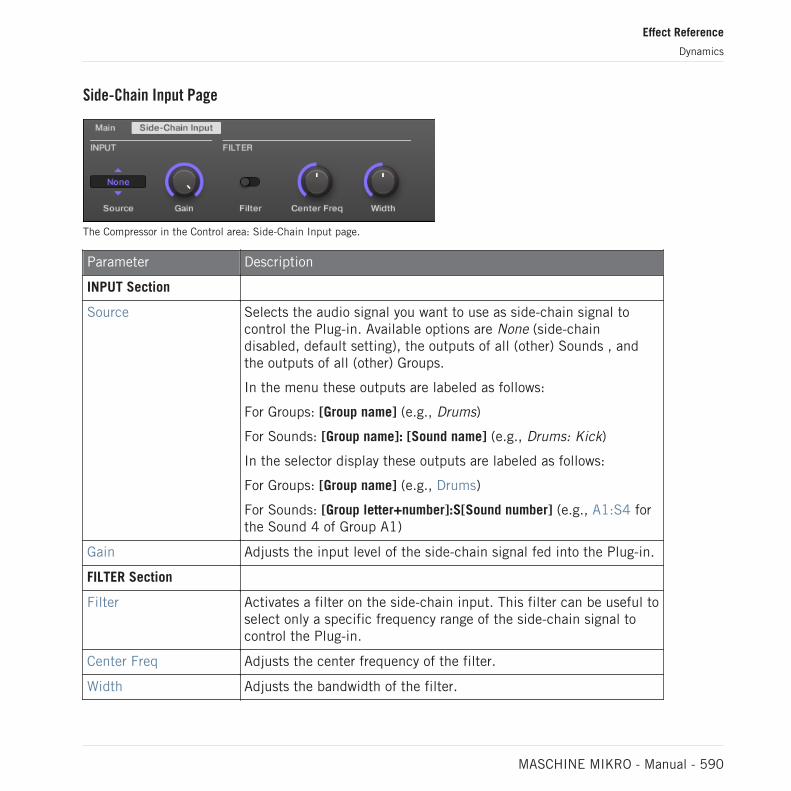
Side-Chain Input Page
The Compressor in the Control area: Side-Chain Input page.
Parameter Description
INPUT Section
Source Selects the audio signal you want to use as side-chain signal tocontrol the Plug-in. Available options are None (side-chaindisabled, default setting), the outputs of all (other) Sounds , andthe outputs of all (other) Groups.
In the menu these outputs are labeled as follows:
For Groups: [Group name] (e.g., Drums)
For Sounds: [Group name]: [Sound name] (e.g., Drums: Kick)
In the selector display these outputs are labeled as follows:
For Groups: [Group name] (e.g., Drums)
For Sounds: [Group letter+number]:S[Sound number] (e.g., A1:S4 forthe Sound 4 of Group A1)
Gain Adjusts the input level of the side-chain signal fed into the Plug-in.
FILTER Section
Filter Activates a filter on the side-chain input. This filter can be useful toselect only a specific frequency range of the side-chain signal tocontrol the Plug-in.
Center Freq Adjusts the center frequency of the filter.
Width Adjusts the bandwidth of the filter.
Effect Reference
Dynamics
MASCHINE MIKRO - Manual - 590

On your controller the outputs available in the SOURCE parameter are labeled as in the display ofthe Source selector described above.
For more information on how to use the side-chain input, please refer to section ↑14.1.3, Using theSide-Chain Input.
Level Meters in the Compressor Panel (Plug-in Strip)
In the Plug-in Strip, the Compressor panel offers a few extra features not available in the Con-trol area:
▪ The Threshold and Gain faders (corresponding to the Threshold and Gain parameters of theMain page in the Control area) provide level meters for visual monitoring of the input andoutput levels. In particular, by comparing the input level with the position of the Thresholdfader, you can easily see you which parts of the signal will be compressed, and adjust theThreshold fader accordingly.
▪ An additional GR level meter indicates the gain reduction currently applied by the Compres-sor to the input signal.
15.1.2 Gate
The Gate cuts any part of the input signal which falls below the input threshold. This can beused to rhythmically chop the signal and make it stutter or sound staccato.
If this effect is used in a Sound or a Group, it also provides a Side-Chain Input page (in theControl area and on your controller).
Effect Reference
Dynamics
MASCHINE MIKRO - Manual - 591

The Gate panel in the Plug-in Strip.
Main Page
The Gate in the Control area: Main page.
Parameter Description
DEPTH Section
Threshold This value determines the threshold at which the Gate starts towork. Higher values will let only the loudest parts of the signalthrough the Gate.
TIME Section
Attack Use Attack to adjust how fast the Gate reacts to the incomingsignal: the more you dial it to the right, the slower it will react,resulting in a softer transition between the gated and the notgated parts of the signal.
Hold The Hold parameter is used to determine how long the gatedsignal is held; lower values will result in a more "choppy" effect.
Effect Reference
Dynamics
MASCHINE MIKRO - Manual - 592

Parameter Description
Release The time the Gate will take to release the input signal after itrises above the threshold.
OUTPUT Section
Mix Mix lets you adjust the amount of the effect in relation to thedry original audio signal.
Side-Chain Input Page
The Gate in the Control area: Side-Chain Input page.
Parameter Description
INPUT Section
Source Selects the audio signal you want to use as side-chain signal tocontrol the Plug-in. Available options are None (side-chaindisabled, default setting), the outputs of all (other) Sounds , andthe outputs of all (other) Groups.
In the menu these outputs are labeled as follows:
For Groups: [Group name] (e.g., Drums)
For Sounds: [Group name]: [Sound name] (e.g., Drums: Kick)
In the selector display these outputs are labeled as follows:
For Groups: [Group name] (e.g., Drums)
For Sounds: [Group letter+number]:S[Sound number] (e.g., A1:S4 forthe Sound 4 of Group A1)
Effect Reference
Dynamics
MASCHINE MIKRO - Manual - 593

Parameter Description
Gain Adjusts the input level of the side-chain signal fed into the Plug-in.
FILTER Section
Filter Activates a filter on the side-chain input. This filter can be useful toselect only a specific frequency range of the side-chain signal tocontrol the Plug-in.
Center Freq Adjusts the center frequency of the filter.
Width Adjusts the bandwidth of the filter.
On your controller the outputs available in the SOURCE parameter are labeled as in the display ofthe Source selector described above.
For more information on how to use the side-chain input, please refer to section ↑14.1.3, Using theSide-Chain Input.
Input Level Meter in the Gate Panel (Plug-in Strip)
In the Plug-in Strip, the Gate panel offers an extra feature not available in the Control area:The Threshold fader (corresponding to the Threshold parameter of the Main page in the Controlarea) provides a level meter for visual monitoring of the input level. By comparing this inputlevel with the position of the Threshold fader, you can easily see you which parts of the signalwill pass through the Gate.
15.1.3 Transient Master
The Transient Master allows you to emphasize or attenuate the transients of your audio materi-al by modifying the envelopes of every attack and sustain phase. For example, by increasingthe attacks of a snare or a kick, you can build powerful percussive sounds without running therisk of damaging their natural sounding. Unlike other dynamic effects (compressors, limiters,etc.), the Transient Master does not use the input signal level to decide when to come into ef-
Effect Reference
Dynamics
MASCHINE MIKRO - Manual - 594
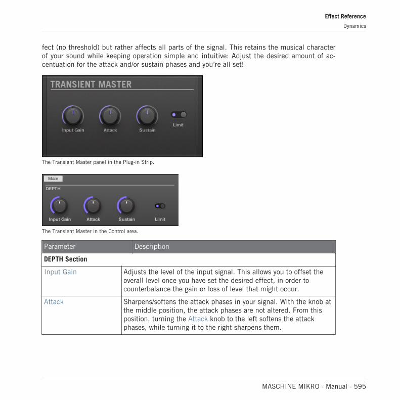
fect (no threshold) but rather affects all parts of the signal. This retains the musical characterof your sound while keeping operation simple and intuitive: Adjust the desired amount of ac-centuation for the attack and/or sustain phases and you’re all set!
The Transient Master panel in the Plug-in Strip.
The Transient Master in the Control area.
Parameter Description
DEPTH Section
Input Gain Adjusts the level of the input signal. This allows you to offset theoverall level once you have set the desired effect, in order tocounterbalance the gain or loss of level that might occur.
Attack Sharpens/softens the attack phases in your signal. With the knob atthe middle position, the attack phases are not altered. From thisposition, turning the Attack knob to the left softens the attackphases, while turning it to the right sharpens them.
Effect Reference
Dynamics
MASCHINE MIKRO - Manual - 595

Parameter Description
Sustain Prolongs/shortens the sustain phases in your signal. With the knobat the middle position, the sustain phases are not altered. From thisposition, turning the Sustain knob to the left shortens the sustainphases, while turning it to the right prolongs them.
Limit Activates a hard limiter at the output, preventing the output signalfrom clipping. This can be useful when the Attack knob is set to ahigh value as this may produce amplified attack phases whichbecome too loud.
15.1.4 Limiter
The Limiter does two things: firstly it ensures that the signal level stays below 0 dB, thus pre-venting digital clipping. But it can also increase the overall perceived volume by reducing thethreshold. It is recommended to place the Limiter in a Master Plug-in slot. However, pleasenote that the Limiter introduces a small latency.
If this effect is used in a Sound or a Group, it also provides a Side-Chain Input page (in theControl area and on your controller).
The Limiter panel in the Plug-in Strip.
Effect Reference
Dynamics
MASCHINE MIKRO - Manual - 596

Main Page
The Limiter in the Control area: Main page.
Element Description
MODE Section
Mode Selects from two different limiter types. The available modes areLegacy and Transparent.
DEPTH Section(Transparent modeonly)
Threshold This value determines the threshold where the Limiter kicks in. If youuse it to prevent your signal from clipping, leave it at 0 dB; if youwant to make your signal louder, dial the Knob to the left. Availablevalues range in decibels from -40.0 dB to 0.0 dB (default: 0.0 dB).
Release The time the limiter will take to stop limiting after the input signalfalls below the threshold. With longer release times it takes moretime to get back to normal. Available values can be adjusted inmilliseconds from 1.0ms to 500.0ms (default: 1.0ms).
OUTPUT Section
Ceiling Adjusts the maximum output level, or ceiling. The signal will not riseabove this. Available values range in decibels from -40.0 dB to -0.3dB (default: -0.3 dB).
Effect Reference
Dynamics
MASCHINE MIKRO - Manual - 597

Side-Chain Input Page
The Limiter in the Control area: Side-Chain Input page.
The Modulation page contains one parameter: Velocity.
Effect Reference
Dynamics
MASCHINE MIKRO - Manual - 598

Element Description
INPUT Section
Source Selects the audio signal you want to use as side-chain signal to controlthe Plug-in. Available options are None (side-chain disabled, defaultsetting), the outputs of all (other) Sounds, and the outputs of all(other) Groups.
In the menu these outputs are labeled as follows:
▪ For Groups: [Group name] (e.g., Drums)
▪ For Sounds: [Group name]: [Sound name] (e.g., Drums: Kick)
▪ In the selector display these outputs are labeled as follows:
▪ For Groups: [Group name] (e.g., Drums)
▪ For Sounds: [Group letter+number]:S[Sound number] (e.g., A1:S4 forthe Sound 4 of Group A1)
Gain Adjusts the input level of the side-chain signal fed into the Plug-in.Available values range from 0.00 dB to 1.00 (default: 1.00).
FILTER Section
Filter Activates a filter on the side-chain input. This filter can be useful toselect only a specific frequency range of the side-chain signal tocontrol the Plug-in. Available values are off and on (default: off).
Center Freq Adjusts the center frequency of the filter. Available values range inkilohertz from 20.0 Hz to 20.0 kHz (default: 632.5 kHz).
On your controller the outputs available in the SOURCE parameter are labeled as in the display ofthe Source selector described above.
For more information on how to use the side-chain input, please refer to section ↑14.1.3, Using theSide-Chain Input.
Effect Reference
Dynamics
MASCHINE MIKRO - Manual - 599
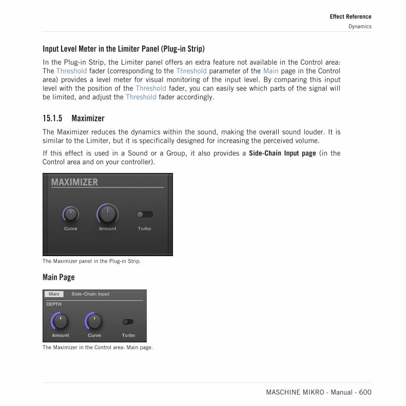
Input Level Meter in the Limiter Panel (Plug-in Strip)
In the Plug-in Strip, the Limiter panel offers an extra feature not available in the Control area:The Threshold fader (corresponding to the Threshold parameter of the Main page in the Controlarea) provides a level meter for visual monitoring of the input level. By comparing this inputlevel with the position of the Threshold fader, you can easily see which parts of the signal willbe limited, and adjust the Threshold fader accordingly.
15.1.5 Maximizer
The Maximizer reduces the dynamics within the sound, making the overall sound louder. It issimilar to the Limiter, but it is specifically designed for increasing the perceived volume.
If this effect is used in a Sound or a Group, it also provides a Side-Chain Input page (in theControl area and on your controller).
The Maximizer panel in the Plug-in Strip.
Main Page
The Maximizer in the Control area: Main page.
Effect Reference
Dynamics
MASCHINE MIKRO - Manual - 600

Parameter Description
DEPTH Section
Amount This parameter is used to adjust the amount of the Maximizereffect. Turn the knob clockwise to increase the loudness of thesignal.
Curve Controls the compression knee; higher values tend to result infaster and more aggressive gain control.
Turbo Turbo intensifies the effect the Maximizer has on the signal bycausing the maximizing algorithm to be applied twice.
Side-Chain Input Page
The Maximizer in the Control area: Side-Chain Input page.
Effect Reference
Dynamics
MASCHINE MIKRO - Manual - 601

Parameter Description
INPUT Section
Source Selects the audio signal you want to use as side-chain signal tocontrol the Plug-in. Available options are None (side-chaindisabled, default setting), the outputs of all (other) Sounds , andthe outputs of all (other) Groups.
In the menu these outputs are labeled as follows:
For Groups: [Group name] (e.g., Drums)
For Sounds: [Group name]: [Sound name] (e.g., Drums: Kick)
In the selector display these outputs are labeled as follows:
For Groups: [Group name] (e.g., Drums)
For Sounds: [Group letter+number]:S[Sound number] (e.g., A1:S4 forthe Sound 4 of Group A1)
Gain Adjusts the input level of the side-chain signal fed into the Plug-in.
FILTER Section
Filter Activates a filter on the side-chain input. This filter can be useful toselect only a specific frequency range of the side-chain signal tocontrol the Plug-in.
Center Freq Adjusts the center frequency of the filter.
Width Adjusts the bandwidth of the filter.
On your controller the outputs available in the SOURCE parameter are labeled as in the display ofthe Source selector described above.
For more information on how to use the side-chain input, please refer to section ↑14.1.3, Using theSide-Chain Input.
Effect Reference
Dynamics
MASCHINE MIKRO - Manual - 602

15.2 Filtering Effects
15.2.1 EQ
Use the EQ to boost or cut selective frequencies of the audio signal. The EQ is mainly a tool totailor your audio signal to taste by cutting out selected frequencies or boosting others, but canalso be used as a DJ-style cut-and-boost effect. Please note that in the Control area and onyour controller the EQ parameters are spread over two pages.
The EQ panel in the Plug-in Strip.
Freq / Gain Page
The EQ in the Control area: Freq / Gain page.
Effect Reference
Filtering Effects
MASCHINE MIKRO - Manual - 603

Parameter Description
LOW Section
Freq Frequency selector for the low frequency band. Ranges from 20 Hzto 8 kHz.
Gain This determines how much the selected frequency is increased/attenuated by.
LOW-MID Section
Freq Frequency selector for the first mid-frequency band. Ranges from40 Hz to 16 kHz.
Gain This determines how much the selected frequency is increased/attenuated by.
HIGH-MID Section
Freq Frequency selector for the second mid-frequency band. Rangesfrom 40 Hz to 16 kHz.
Gain This determines how much the selected frequency is increased/attenuated by.
HIGH Section
Freq Frequency selector for the high frequency band. Ranges from 50 Hzto 20 kHz.
Gain This determines how much the selected frequency is increased/attenuated by.
Effect Reference
Filtering Effects
MASCHINE MIKRO - Manual - 604

Width / Output Page
The EQ in the Control area: Width / Output page.
Parameter Description
LOW-MID Section
Width Bandwidth control for the first mid-frequency band.
HIGH-MID Section
Width Bandwidth control for the second mid-frequency band.
OUTPUT Section
Gain Gain control for the EQ altogether.
15.2.2 Filter
Filter with selectable characteristics that can be modulated via LFO or envelope. There aremany applications for a filter: it can be used to emulate a synthesizer more realistically or tofilter out selected frequencies and create filter-sweeps.
If this effect is used in a Sound or a Group, it provides a Side-Chain Input page (in the Controlarea and on your controller).
Effect Reference
Filtering Effects
MASCHINE MIKRO - Manual - 605

The Filter panel in the Plug-in Strip.
Main Page
The Filter in the Control area: Main page.
Parameter Description
TYPE Section
Mode Select between four different filter modes: LP (low-pass), BP (band-pass), HP (high-pass), and Notch. Depending on the modeselected, the following parameters vary as indicated.
FREQ Section
Cutoff Controls the cutoff frequency of the filter.
Resonance Controls the amount of resonance, i.e. the amount of amplificationnear the cutoff frequency. It is not available with filter mode Notch.
MOD Section
Effect Reference
Filtering Effects
MASCHINE MIKRO - Manual - 606

Parameter Description
Amount Defines how much the Filter gets modulated by the modulationsource.
Source Select between three different modulation sources: LFO, LFO Sync,and Envelope. Depending on your choice for the modulation source,the following parameters appear to the right:
Source: LFO Articulates the opening and closing of the filter using an LFO. Usethis setting in combination with Speed, and LFO Shape.
Speed Defines the speed of the modulation in hertz ranging from 0.03 Hzup to 16 Hz.
LFO Shape Defines how the LFO evolves over time.
Source: LFO Sync Articulates the opening and closing of the filter using an LFO insync to the tempo of the Project. Use this setting in combinationwith Speed, LFO Shape, and Phase.
Speed Defines the speed of the modulation in note values from 16/1 (onecycle every 16 bars) up to 1/32 note.
LFO Shape Defines how the LFO evolves over time.
Phase Adjusts the start phase of the LFO.
Source: Envelope Articulates the opening and closing of the filter using an envelope.Use this setting in combination with Decay, Smooth, and Shape.
Decay Adjusts how fast the envelope fades out.
Smooth Smooths the shape of the envelope.
Shape Changes the shape of the envelope.
Effect Reference
Filtering Effects
MASCHINE MIKRO - Manual - 607

Side-Chain Input Page
The Filter in the Control area: Side-Chain Input page.
Parameter Description
INPUT Section
Source Selects the audio signal you want to use as side-chain signal tocontrol the Plug-in. Available options are None (side-chaindisabled, default setting), the outputs of all (other) Sounds , andthe outputs of all (other) Groups.
In the menu these outputs are labeled as follows:
For Groups: [Group name] (e.g., Drums)
For Sounds: [Group name]: [Sound name] (e.g., Drums: Kick)
In the selector display these outputs are labeled as follows:
For Groups: [Group name] (e.g., Drums)
For Sounds: [Group letter+number]:S[Sound number] (e.g., A1:S4 forthe Sound 4 of Group A1)
Gain Adjusts the input level of the side-chain signal fed into the Plug-in.
FILTER Section
Filter Activates a filter on the side-chain input. This filter can be useful toselect only a specific frequency range of the side-chain signal tocontrol the Plug-in.
Center Freq Adjusts the center frequency of the filter.
Width Adjusts the bandwidth of the filter.
Effect Reference
Filtering Effects
MASCHINE MIKRO - Manual - 608

On your controller the outputs available in the SOURCE parameter are labeled as in the display ofthe Source selector described above.
For more information on how to use the side-chain input, please refer to section ↑14.1.3, Using theSide-Chain Input.
15.2.3 Cabinet
The Cabinet Emulation is a cabinet and microphone component that proves full control over allthe (post-amp) stages of recording a guitar tone. Cabinet Emulation includes the four cabinettypes, and the variable positioning of six different microphones.
The Cabinet Emulation effect in the Plug-in Strip.
The Cabinet Emulation in the Control area (Main page depicted).
Effect Reference
Filtering Effects
MASCHINE MIKRO - Manual - 609

Main Page
Element Description
CABINET Section
Cabinet Selects from four different cabinet types, which includes:
▪ American Cabinet
▪ British Cabinet
▪ Vintage Cabinet
▪ Modern Cabinet
MICROPHONE Section
Microphone Selects from six different microphone types, which includes:
▪ Dynamic 57
▪ Dynamic 421
▪ Dynamic 441
▪ Ribbon 121
▪ Condenser 47
▪ Condenser 67
Distance Adjusts the distance of the microphone from the cabinet. Availablevalues range from 0.0 to 100.0% (default: 0.0%).
OUTPUT Section
Mix Adjusts the ratio between the effect (wet) signal and original (dry)signals. Available values range from 0.0 to 100.0% (default:100.0%).
Effect Reference
Filtering Effects
MASCHINE MIKRO - Manual - 610
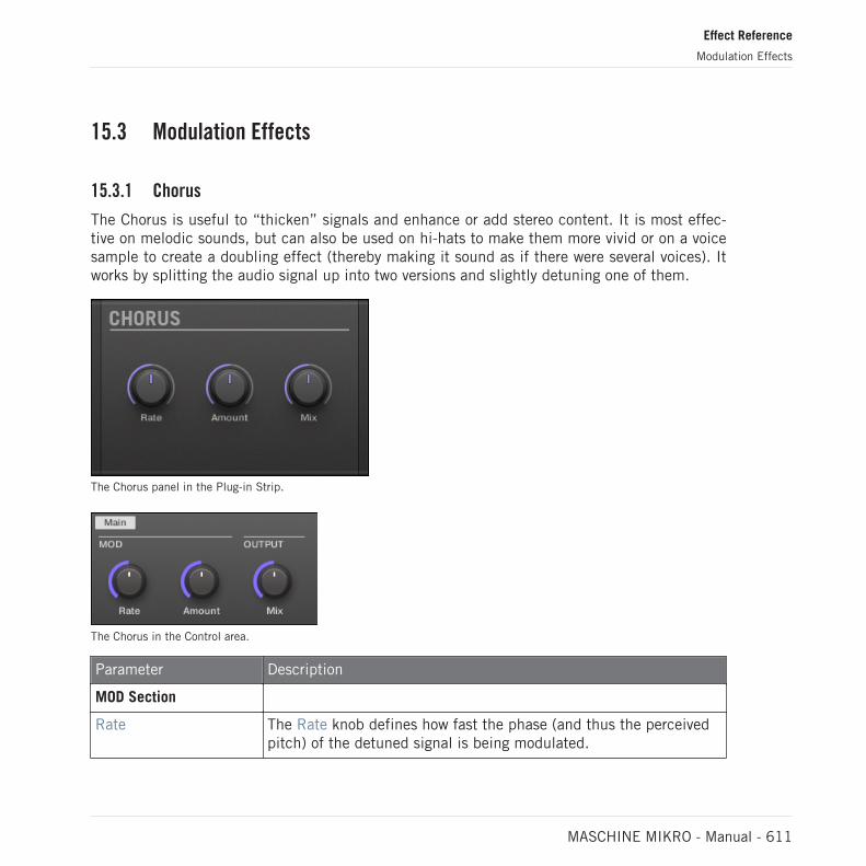
15.3 Modulation Effects
15.3.1 Chorus
The Chorus is useful to “thicken” signals and enhance or add stereo content. It is most effec-tive on melodic sounds, but can also be used on hi-hats to make them more vivid or on a voicesample to create a doubling effect (thereby making it sound as if there were several voices). Itworks by splitting the audio signal up into two versions and slightly detuning one of them.
The Chorus panel in the Plug-in Strip.
The Chorus in the Control area.
Parameter Description
MOD Section
Rate The Rate knob defines how fast the phase (and thus the perceivedpitch) of the detuned signal is being modulated.
Effect Reference
Modulation Effects
MASCHINE MIKRO - Manual - 611
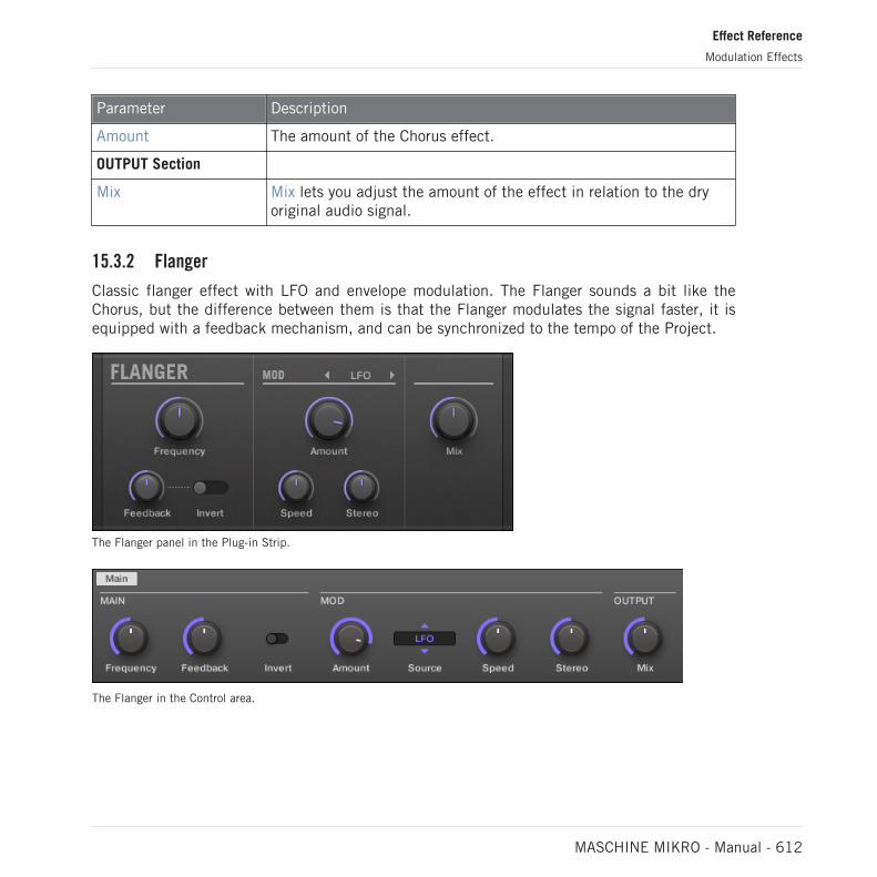
Parameter Description
Amount The amount of the Chorus effect.
OUTPUT Section
Mix Mix lets you adjust the amount of the effect in relation to the dryoriginal audio signal.
15.3.2 Flanger
Classic flanger effect with LFO and envelope modulation. The Flanger sounds a bit like theChorus, but the difference between them is that the Flanger modulates the signal faster, it isequipped with a feedback mechanism, and can be synchronized to the tempo of the Project.
The Flanger panel in the Plug-in Strip.
The Flanger in the Control area.
Effect Reference
Modulation Effects
MASCHINE MIKRO - Manual - 612

Parameter Description
MAIN Section
Frequency This defines the center frequency of the Flanger.
Feedback Adjusts the amount of output signal fed back into the input.
Invert Inverts the Flanger.
MOD Section
Amount This defines how much the Flanger gets modulated by themodulation source.
Source Here you can select the modulation source of the Flanger: availableoptions are LFO, LFO Sync, and Envelope. Depending on yourselection, the parameter to the right will change.
Speed (LFO) Defines the speed of the LFO in a range from 0.03 Hz up to 8 Hz.
Speed (LFO Sync) Defines the speed of the LFO in note values from 16/1 (one cycleevery 16 bars) up to 1/16 note.
Shape (Envelope) Change the shape of the envelope here.
Stereo This parameter widens the stereo field of the effect.
OUTPUT Section
Mix Mix lets you adjust the amount of the effect in relation to the dryoriginal audio signal.
15.3.3 FM
FM modulates the frequency of the audio signal based on FM synthesis. High frequency set-tings are useful for adding a subtle “gritty” texture to the input signal.
Effect Reference
Modulation Effects
MASCHINE MIKRO - Manual - 613

The FM panel in the Plug-in Strip.
FM in the Control area.
Parameter Description
FREQ Section
Rate This is for adjusting the speed of the FM modulation.
Split The Split control determines the extent to which the FM effectis applied to high frequencies via a crossover. Turn to the rightto affect higher frequencies. It can be useful to eliminate noiseartifacts caused by FM of very high signals.
With high Split settings, the effect becomes more “gritty” andcrackling.
DEPTH Section
Contour Contour determines the extent to which the input volume affectsthe intensity of the effect.
Amount Determines the amount of the FM effect.
Effect Reference
Modulation Effects
MASCHINE MIKRO - Manual - 614

15.3.4 Freq Shifter
The Freq Shifter shifts selected frequencies of the audio signal by a user-specified amount.With high frequencies it sounds like a pitch shifter; with low frequencies it sounds like a spe-cial chorus.
The Freq Shifter panel in the Plug-in Strip.
The Freq Shifter in the Control area.
Parameter Description
FREQ Section
Coarse This is used to define the basic frequency of the Freq Shifter.
Fine Fine-tune the frequency here.
OUTPUT Section
Feedback Adjusts the amount of output signal fed back into the input.Increasing this parameter will increase the intensity of theeffect.
Effect Reference
Modulation Effects
MASCHINE MIKRO - Manual - 615

Parameter Description
Stereo This parameter widens the stereo field of the effect.
Invert Inverts the settings of the Freq Shifter.
Mix Mix lets you adjust the amount of the effect in relation to thedry original audio signal.
15.3.5 Phaser
Classic phaser with LFO and envelope modulation.
The Phaser panel in the Plug-in Strip.
The Phaser in the Control area.
Parameter Description
MAIN Section
Frequency This defines the center frequency of the Phaser.
Effect Reference
Modulation Effects
MASCHINE MIKRO - Manual - 616

Parameter Description
Feedback Adjusts the amount of output signal fed back into the input.
8Pole Activating this causes the Phaser to use the 8Pole mode,resulting in a more intense phasing effect.
MOD Section
Amount This defines how much the Phaser gets modulated by themodulation source.
Source Here you can select the modulation source of the Phaser:available options are LFO, LFO Sync, and Envelope. Dependingon your selection, the parameter to the right will change.
Speed (LFO) Defines the speed of the LFO in a range from 0.03 Hz up to8 Hz.
Speed (LFO Sync) Defines the speed of the LFO in note values from 16/1 (onecycle every 16 bars) up to 1/16 note.
Shape (Envelope) Change the shape of the envelope here.
Stereo This parameter widens the stereo field of the effect.
OUTPUT Section
Mix Mix lets you adjust the amount of the effect in relation to thedry original audio signal.
15.4 Spatial and Reverb Effects
15.4.1 Ice
This is a special reverb for getting cold and metallic sound. Ice includes a bank of self-oscillat-ing filters for interesting and colorful effects. In the Project “Come Into My Disco” from theMASCHINE factory library, you can hear how it creates deep soundscapes during the break inScene 6.
Effect Reference
Spatial and Reverb Effects
MASCHINE MIKRO - Manual - 617
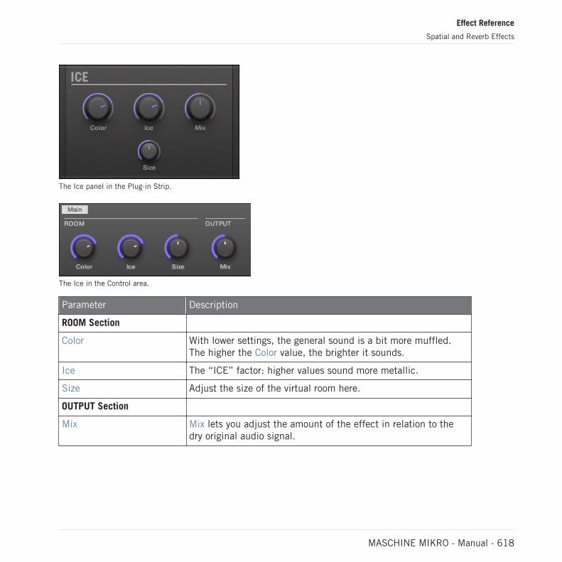
The Ice panel in the Plug-in Strip.
The Ice in the Control area.
Parameter Description
ROOM Section
Color With lower settings, the general sound is a bit more muffled.The higher the Color value, the brighter it sounds.
Ice The “ICE” factor: higher values sound more metallic.
Size Adjust the size of the virtual room here.
OUTPUT Section
Mix Mix lets you adjust the amount of the effect in relation to thedry original audio signal.
Effect Reference
Spatial and Reverb Effects
MASCHINE MIKRO - Manual - 618

15.4.2 Metaverb
Like the Reverb, the Metaverb adds spatial room information. However, in contrast to the Re-verb it has a much more “synthetic” sound, which is particularly suited for melodic content.
The Metaverb panel in the Plug-in Strip.
The Metaverb in the Control area.
Parameter Description
ROOM Section
Size Adjust the size of the virtual room here.
EQ Section
Low Low band EQ to cut or boost bass frequencies.
High High band EQ to cut or boost high frequencies.
POSITION Section
Effect Reference
Spatial and Reverb Effects
MASCHINE MIKRO - Manual - 619

Parameter Description
Pan This pans the dry signal. This is useful because the dry signalcan not be panned after the effect without panning the reverbitself, which is unnatural.
OUTPUT Section
Mix Mix lets you adjust the amount of the effect in relation to thedry original audio signal.
15.4.3 Reflex
This is a special resonating reverb. At moderate settings the Reflex can be useful to emulatesmall, “tight” rooms. At more extreme settings, it can produce interesting artificial, metallictextures.
Automating the Color parameter usually yields very pleasing results.
The Reflex panel in the Plug-in Strip.
Effect Reference
Spatial and Reverb Effects
MASCHINE MIKRO - Manual - 620

The Reflex in the Control area.
Parameter Description
ROOM Section
Color At lower settings, the general sound is a bit more muffled; thehigher the settings, the brighter it sounds.
Smooth With this parameter, you can soften the metallic character ofReflex.
Size Adjust the size of the virtual room here.
OUTPUT Section
Mix Mix lets you adjust the amount of the effect in relation to thedry original audio signal.
15.4.4 Reverb (Legacy)
This reverb is best for most common applications. The Reverb adds room information to thesignal, making it sound more spacious and natural. It is particularly suited to drum sounds,but also useful to add a more “natural” sound for all sorts of other signals.
Effect Reference
Spatial and Reverb Effects
MASCHINE MIKRO - Manual - 621

The Reverb panel in the Plug-in Strip.
The Reverb in the Control area.
Parameter Description
ROOM Section
Room This allows you to choose one of four basic characteristics of theReverb: General, Bright, Guitar, and Shatter.
Size Adjust the size of the virtual room here.
EQ Section
Low Low band EQ to cut or boost bass frequencies.
High High band EQ to cut or boost high frequencies.
POSITION Section
Pan This pans the dry signal. This is useful because the dry signalcan not be panned after the effect without panning the reverbitself, which is unnatural.
Effect Reference
Spatial and Reverb Effects
MASCHINE MIKRO - Manual - 622

Parameter Description
Stereo This parameter widens the stereo field of the effect.
OUTPUT Section
Freeze Enabling Freeze both mutes the dry signal and traps the currentstate of the Reverb output in a temporary buffer to make it lastmuch longer. This is a powerful tool for playing live: Bysimultaneously tweaking the Mix knob nearby, you can createstriking breaks! Setting the EQ’s Low and High controls togenerous values will further increase the effect.
Mix Mix lets you adjust the amount of the effect in relation to thedry original audio signal.
15.4.5 Reverb
The Reverb effect provides three different modes which are described in this section.
The Room Reverb panel in the Plug-in Strip.
15.4.5.1 Reverb Room
The Room mode is suited to drum and percussive sounds, and particularly sounds good whenused on snares. Modulate the Room Size, and Pre Delay parameters to create special effects.
Effect Reference
Spatial and Reverb Effects
MASCHINE MIKRO - Manual - 623

The Reverb effect in the Plug-in Strip.
The Reverb in the Control area (Main page depicted).
Main Page
Element Description
ROOM Section
Mode Allows you to choose one of three basic modes of Reverb: Room,Hall, and Plate (default: Room).
Reverb Time Adjusts the reverb decay time. Turn clockwise to increase decay.Available values range can be adjusted in seconds from 0.5s to20.2s (default: 1.0s).
Reverb Size Adjust the size of the simulated room. Turn clockwise to increasethe perceived size of the room and reverb reflections. Availablevalues range from 0.0 to 100.0% (default: 20.0%).
COLOR Section
Effect Reference
Spatial and Reverb Effects
MASCHINE MIKRO - Manual - 624

Element Description
Damping Adjusts damping of the high frequencies in the reverb signal.Damping refers to the rate at which the high frequencies decay.This effect causes the sound to become gradually muffled andwarmer. Available values range from 0.0 to 100.0% (default:50.0%).
Modulation Sets the modulation amount. A value of 0 turns the delaymodulation off. Available values range from 0.0 to 100.0%(default: 50.0%).
Diffusion Controls the density of the reflections in the virtual room. A lowdiffusion setting makes the reflections sound more distinct, likeclosely spaced echoes. A high diffusion setting creates reflectionsso close they sound more like noise, in which echoes areindistinguishable. Available values range from 0.0 to 100.0%(default: 80.0%).
Pre Delays Adjusts the initial delay between the original signal and the firstreverberant sound. At higher values this can also be used in manycreative ways. Available values can be adjusted in milliseconds from0.0ms to 250.0ms (default: 0.0ms).
OUTPUT Section
Mix Adjusts the ratio between the effect (wet) signal and original (dry)signals. Available values range from 0.0 to 100.0% (default:50.0%).
EQ page
The EQ page contains parameters to adjust the EQ of the reverb.
Effect Reference
Spatial and Reverb Effects
MASCHINE MIKRO - Manual - 625

Element Description
EQ Section
High Cut Adjusts the high frequencies in the reverberated signal. Availablevalues range in kilohertz from 20.0 kHz to 2.0 kHz (default: 20.0kHz).
Low Shelf Adjusts the low-frequency content in the reverberated signal.Available values range in decibels from -0.0 dB to -12.0 dB(default: -0.0 dB).
15.4.5.2 Reverb Hall
The Reverb Hall mode is a spacious and natural reverb that is particularly suited to tonalsounds. When used with a high Reverb Time setting it provides a very lush reverb making italso suitable for ambient or experimental music. Modulate the Room Size, and Pre Delay pa-rameters to create special effects.
The Reverb effect in the Plug-in Strip.
Effect Reference
Spatial and Reverb Effects
MASCHINE MIKRO - Manual - 626
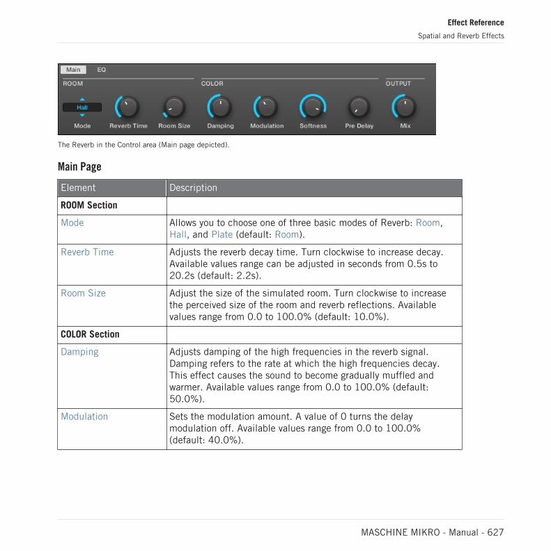
The Reverb in the Control area (Main page depicted).
Main Page
Element Description
ROOM Section
Mode Allows you to choose one of three basic modes of Reverb: Room,Hall, and Plate (default: Room).
Reverb Time Adjusts the reverb decay time. Turn clockwise to increase decay.Available values range can be adjusted in seconds from 0.5s to20.2s (default: 2.2s).
Room Size Adjust the size of the simulated room. Turn clockwise to increasethe perceived size of the room and reverb reflections. Availablevalues range from 0.0 to 100.0% (default: 10.0%).
COLOR Section
Damping Adjusts damping of the high frequencies in the reverb signal.Damping refers to the rate at which the high frequencies decay.This effect causes the sound to become gradually muffled andwarmer. Available values range from 0.0 to 100.0% (default:50.0%).
Modulation Sets the modulation amount. A value of 0 turns the delaymodulation off. Available values range from 0.0 to 100.0%(default: 40.0%).
Effect Reference
Spatial and Reverb Effects
MASCHINE MIKRO - Manual - 627

Element Description
Softness Alters the balance between early reflections and the late reverb tail.It also changes the amount of diffusion present. It allows you tosoften the attack of the reverb and push it more into thebackground, so it doesn't muddy the dry sound so much. Availablevalues range from 0.0 to 100.0% (default: 90.0%).
Pre Delay Adjusts the initial delay between the original signal and the firstreverberant sound. At higher values this can also be used in manycreative ways. Available values can be adjusted in milliseconds from0.0ms to 250.0ms (default: 0.0ms).
OUTPUT Section
Mix Adjusts the ratio between the effect (wet) signal and original (dry)signals. Available values range from 0.0 to 100.0% (default:50.0%).
EQ page
The EQ page contains parameters to adjust the EQ of the reverb.
Element Description
EQ Section
High Cut Adjusts the high frequencies in the reverberated signal. Availablevalues range in kilohertz from 20.0 kHz to 2.0 kHz (default: 20.0kHz).
Low Shelf Adjusts the low-frequency content in the reverberated signal.Available values range in decibels from -0.0 dB to -12.0 dB(default: -0.0 dB).
Effect Reference
Spatial and Reverb Effects
MASCHINE MIKRO - Manual - 628

15.4.5.3 Plate Reverb
This effect emulates a plate reverberator. Partly inspired by a legendary plate reverb system,this efficient reverb effect can be used in numerous situations. Its controls make the Plate Re-verb easy to use while still flexible and unique sounding. The Plate Reverb is the best choice ifa vintage metallic sound is desired. It is particularly good for vocals, but popular for other ma-terial as well, such as snare drums.
The Plate Reverb effect in the Plug-in Strip.
The Plate Reverb in the Control area.
Parameter Description
MAIN Section
Mode Allows you to choose one of three basic modes of Reverb: Room,Hall, and Plate (default: Room).
Decay Adjusts the damping of the plate, which directly affects thedecay time of the reverb.
Effect Reference
Spatial and Reverb Effects
MASCHINE MIKRO - Manual - 629

Parameter Description
EQ Section
Low Shelf Controls the low-frequency content in the reverberated signal.
High Damp Adjusts the damping of the high frequencies in the reverberatedsignal.
Pre Delay Adjusts the time between the original signal and the earlyreflections.
OUTPUT Section
Mix Mix lets you adjust the amount of the effect in relation to thedry original audio signal.
15.5 Delays
15.5.1 Beat Delay
The Beat Delay is specialized for creating delays that are synced to the tempo. If you wonderhow this sounds, load up the Project “Big Stream” from the MASCHINE factory library: theBeat Delay is used in various Groups here and offers a lot of rhythmic sonic possibilities.Please note that in the Control area and on your controller the Beat Delay parameters arespread over two pages.
The Beat Delay panel in the Plug-in Strip.
Effect Reference
Delays
MASCHINE MIKRO - Manual - 630

Main Page
The Beat Delay in the Control area: Main page.
Parameter Description
DELAY Section
Time The Time parameter defines the delay length in note values. Theavailable values depend on the unit defined by the Unitparameter on the Unit page (see below). They range from half aunit to 16 units.
Offset This parameter is used to shift the start of the delay in relationto the tempo.
Feedback Adjusts the amount of output signal fed back into the input.Higher values produce more copies of the signal and longerdecays.
Crossover Allows for panning the feedback signal rhythmically in thestereo field.
Color Defines the basic frequency of the feedback circuit: lowervalues result in a deeper sound, whereas higher values brightenthe sound.
Split Controls the difference in frequency between left and rightchannel. At full left, this control is disabled.
OUTPUT Section
Effect Reference
Delays
MASCHINE MIKRO - Manual - 631

Parameter Description
Stereo This parameter widens the stereo field of the effect. Values gofrom -100.0 % to 100 % — negative values inverse the stereofield of the effect.
Mix Mix lets you adjust the amount of the effect in relation to thedry original audio signal.
Unit Page
The Beat Delay in the Control area: Unit page.
Parameter Description
UNIT Section
Unit Defines the unit used by the Time and Offset parameters on theMain page.
15.5.2 Grain Delay
By chopping the input into small “grains” and rearranging them as a cloud, the Grain Delay isuseful for creating ambient textures. Increase Size, Space and Density to quickly transform anysound into an evolving ambient texture. As a unique experimental effect, it is best experiencedfirsthand. Please note that in the Control area and on your controller the Grain Delay parame-ters are spread over two pages.
Effect Reference
Delays
MASCHINE MIKRO - Manual - 632

The Grain Delay panel in the Plug-in Strip.
Main Page
The Grain Delay in the Control area: Main page.
Parameter Description
GRAIN Section
Pitch Determines the pitch of the grains: low values result in a deep,slowly repeating grain, high values speed up the grain, making itsound faster and higher.
Size Defines the length of the grains.
Jitter Introduces artifacts into the grains.
Reverse Produces a reverse playback of the grain.
CLOUD Section
Space Determines the spacing between the grain clouds: the higherthe value, the bigger the space between the clouds.
Effect Reference
Delays
MASCHINE MIKRO - Manual - 633

Parameter Description
Density Creates a more “dense” cloud: higher values create feedback-like effects.
Mod The amount of modulation introduced to the grain cloud.
Mix Mix lets you adjust the amount of the effect in relation to thedry original audio signal.
Output Page
The Grain Delay in the Control area: Output page.
Parameter Description
OUTPUT Section
Stereo This parameter widens the stereo field of the effect. Values gofrom 0 % (no stereo) to 100 % (full stereo).
15.5.3 Grain Stretch
The Grain Stretch effect uses granular synthesis to manipulate the speed and pitch of the in-coming signal.
Effect Reference
Delays
MASCHINE MIKRO - Manual - 634

The Grain Stretch panel in the Plug-in Strip.
The Grain Stretch in the Control area.
Parameter Description
MASTER Section
On Enables the effect. Every time this control is switched on, theGrain Stretch effect buffers incoming audio for 32 x 1/16thstep.
TIME Section
Stretch Defines the time-stretch amount. Set to 50.0 % for half speed.
Loop Sets a loop length, in 1/16th steps.
PITCH Section
Pitch Adjusts the pitch of the grains.
Link When on, grain size is corrected by the pitch.
Size Adjusts the size of the grains.
Effect Reference
Delays
MASCHINE MIKRO - Manual - 635

Parameter Description
OUTPUT Section
Mix Mix lets you adjust the amount of the effect in relation to thedry original audio signal.
15.5.4 Resochord
The Resochord is a bank of 6 comb filters, each of which is individually tuned according to theselected chord. The results are most effective with non-melodic content (like drums) as the Re-sochord will print its own harmonic content on to any input material.
The Resochord panel in the Plug-in Strip.
The Resochord in the Control area.
Effect Reference
Delays
MASCHINE MIKRO - Manual - 636

Parameter Description
PITCH Section
Mode Here you can select between the two modes of the Resochord:Chord and String. In Chord mode, the 6 combs are tunedaccording to various chords. In String mode, the 6 combs arecentered around one frequency and can be spread for anintense chorus-like effect. Depending on your selection theother parameters in the Pitch area will change.
Spread (String mode) Allows you to define how big the difference in tuning is betweencombs.
Style (Chord mode) You can select between different chord-styles such as minor ormajor.
Chord (Chord mode) Here you can choose from different chords to be applied to youraudio signal.
Tune It allows you to transpose the Resochord in semitones.
COLOR Section
Brightness This is to determine the basic sound characteristic of theResochord: higher values will brighten the sound by adding highfrequencies.
Feedback Adjusts the amount of output signal fed back into the input.
Decay With Decay you adjust how fast the Resochord fades out.
OUTPUT Section
Mix Mix lets you adjust the amount of the effect in relation to thedry original audio signal.
Effect Reference
Delays
MASCHINE MIKRO - Manual - 637

15.6 Distortion Effects
15.6.1 Distortion
The Distortion effect contains two modes of distortion: Mullholland and Analog.
The Distortion panel in the Plug-in Strip.
The Distortion in the Control area.
Mullholland Mode
Mullholland mode combines overdrive, feedback and modulation, this produces a heavy distor-tion/fuzz effect, comparable to distortion stomp-boxes for guitars. This effect is special be-cause of the feedback it creates.
Effect Reference
Distortion Effects
MASCHINE MIKRO - Manual - 638

Parameter Description
MAIN Section
Mode Select a distortion type: Mullholland or Analog.
Drive Determines the basic amount of distortion.
Color At lower settings, the general sound is a bit more muffled; thehigher the settings, the brighter it sounds.
Feedback Adjust the amount of output signal fed back into the input.
Tone General tonal characteristic of the feedback signal.
Tone Mod Modulation introduced in the feedback signal.
OUTPUT Section
Mix Mix lets you adjust the amount of the effect in relation to thedry original audio signal.
GATE Section
Gate The Gate button is used to cancel out feedback loopsintroduced by high Feedback settings.
Release This parameter determines how fast the distorted sound diesdown when the Gate is enabled.
Analog Distortion
Analog mode adds grit to Drums and Percussion, Lead Synths and Guitars.
Element Description
MODE Section
Mode Select a distortion type: Mullholland or Analog.
DISTORTION Section
Saturation Sets the amount of saturation applied to the signal. Available valuesrange from 0.0 to 100.0% (default: 25.0%).
Effect Reference
Distortion Effects
MASCHINE MIKRO - Manual - 639

Element Description
Bass Attenuates the low frequencies of the distortion effect. Availablevalues range from 0.0 to 100.0% (default: 100.0%).
Tone Sets the frequency for the high cut filter. Filtering the harmonicallyrich distorted signal produces a softer tone. Available values rangefrom 0.0 to 100.0% (default: 100.0%).
Focus Switches the frequency range of the processed signal, pulling itslightly further forwards in the mix. The effect is more pronouncedwhen Definition is set to lower values.
Definition Determines how pronounced the distortion effect is. Availablevalues range from 0.0 to 100.0% (default: 50.0%).
OUTPUT Section
Mix Mix lets you adjust the amount of the effect in relation to the dryoriginal audio signal. Available values range from 0.0 to 100.0%(default: 100.0%).
15.6.2 Lofi
The Lofi effect reduces the bit depth (or bit resolution) and Sample rate of the audio signal foran interesting “vintage” effect at subtle settings, and heavy digital distortion at extreme set-tings.
The Lofi panel in the Plug-in Strip.
Effect Reference
Distortion Effects
MASCHINE MIKRO - Manual - 640

The Lofi in the Control area.
Parameter Description
RESAMPLE Section
SR SR stands for Sample Rate and ranges from CD-quality(44.1 kHz) to 99.5 Hz which results in a hissy crackle.
BITCRUSH Section
Bits Introduces a distortion based on bit reduction.
Smooth Reduces the aliasing introduced by the Lofi effect.
Stereo Widens the stereo field of the effect.
OUTPUT Section
Mix Mix lets you adjust the amount of the effect in relation to thedry original audio signal.
15.6.3 Saturator
The Saturator is a flexible tool allowing you to apply various types of saturations to your signal.The Saturator offers three modes: Classic (legacy mode), Tape, and Tube. You can select thedesired mode via the Mode selector. Since the three modes provide different sets of parame-ters, each of them is described separately below.
Effect Reference
Distortion Effects
MASCHINE MIKRO - Manual - 641
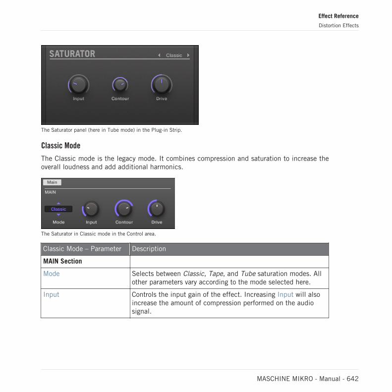
The Saturator panel (here in Tube mode) in the Plug-in Strip.
Classic Mode
The Classic mode is the legacy mode. It combines compression and saturation to increase theoverall loudness and add additional harmonics.
The Saturator in Classic mode in the Control area.
Classic Mode – Parameter Description
MAIN Section
Mode Selects between Classic, Tape, and Tube saturation modes. Allother parameters vary according to the mode selected here.
Input Controls the input gain of the effect. Increasing Input will alsoincrease the amount of compression performed on the audiosignal.
Effect Reference
Distortion Effects
MASCHINE MIKRO - Manual - 642
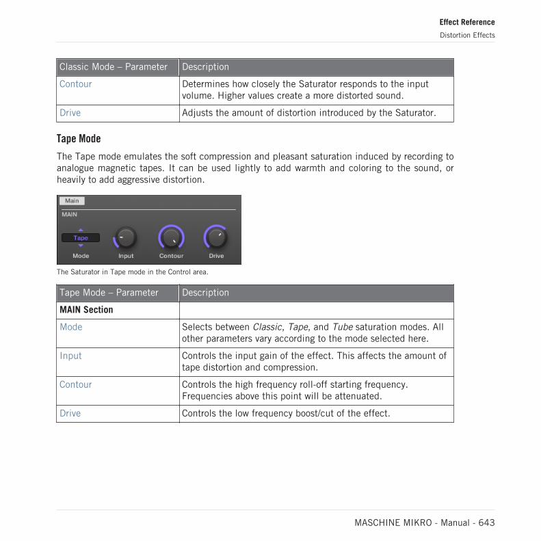
Classic Mode – Parameter Description
Contour Determines how closely the Saturator responds to the inputvolume. Higher values create a more distorted sound.
Drive Adjusts the amount of distortion introduced by the Saturator.
Tape Mode
The Tape mode emulates the soft compression and pleasant saturation induced by recording toanalogue magnetic tapes. It can be used lightly to add warmth and coloring to the sound, orheavily to add aggressive distortion.
The Saturator in Tape mode in the Control area.
Tape Mode – Parameter Description
MAIN Section
Mode Selects between Classic, Tape, and Tube saturation modes. Allother parameters vary according to the mode selected here.
Input Controls the input gain of the effect. This affects the amount oftape distortion and compression.
Contour Controls the high frequency roll-off starting frequency.Frequencies above this point will be attenuated.
Drive Controls the low frequency boost/cut of the effect.
Effect Reference
Distortion Effects
MASCHINE MIKRO - Manual - 643

Tube Mode
The Tube mode emulates the smooth saturation of overdriven tube amplifiers. It is equippedwith a feedback-driven dynamic compression and an additional EQ section allowing you to fineadjust the frequency content to be processed.
The Saturator in Tube mode in the Control area.
Tube Mode – Parameter Description
MAIN Section
Mode Selects between Classic, Tape, and Tube saturation modes. Allother parameters vary according to the mode selected here.
Charge In Tube mode the Saturator provides a negative feedback loopthat attenuates the level at the Saturator’s input according tothe amount of low frequencies at its output. This notablyprevents the bass content “polluting” the saturation. TheCharge parameter allows you to adjust the amount of feedback.At 0 (full left) the feedback loop is disabled. Increase theCharge value to strengthen the effect. Higher values additionallygenerate an interesting compression-like effect.
Overload Boosts the low frequencies of the input signal. Used togetherwith the Charge parameter (see above) it provides you with apowerful tool to produce a richer, fatter sound.
Drive Adjusts the level of the input signal. This directly affects theamount of tube distortion.
EQ Section
Bypass Enable this button to bypass the EQ section.
Effect Reference
Distortion Effects
MASCHINE MIKRO - Manual - 644

Tube Mode – Parameter Description
Bass Adjusts the level of the low frequency band.
Treble Adjusts the level of the high frequency band.
OUTPUT Section
Gain Adjusts the output level of the effect. Use this to compensatefor changes in volume caused by input gain and signalcompression.
15.7 Perform FX
Designed for spontaneous, tactile control in recording or live performance, these eight complexmulti-effects alter motion, space, dynamics, and more for added expression.
▪ Filter: The Filter is a raw-sounding, analog-modelled LP/BP/HP filter with additional satura-tion parameters and resonance that can be pushed into self-oscillation. For more informa-tion see section ↑15.7.1, Filter.
▪ Flanger: The Flanger is a comb filter effect. It can behave like a standard flanger or phaserbut can also go pretty wild and sound more like a creative delay if you push the decay anddelay time. Various tone-shaping controls are available. For more information see section↑15.7.2, Flanger.
▪ Brst Echo: The Burst Echo is a warm, versatile echo with plenty of character. It's great as adub echo but can also be used for quite extreme sound design. For more information seesection ↑15.7.3, Burst Echo.
▪ Reso Echo: The Reso Echo is a crazy psychedelic echo which can be tightened up into apunchy resonator. For more information see section ↑15.7.4, Reso Echo.
▪ Ring: Based on a bank of ring modulators, the Ring effect adds a bell-like quality to melod-ic sound sources. An additional plate reverb lets you pick out individual notes with your fin-ger and have them ring out for several seconds. For more information see section ↑15.7.5,Ring.
▪ Stutter: Stutter is a beat-mangling effect, great for adding glitches and fills to drum pat-terns and more. For more information see section ↑15.7.6, Stutter.
Effect Reference
Perform FX
MASCHINE MIKRO - Manual - 645

▪ Tremolo: Tremolo is a tremolo/vibrato effect, useful for adding expression and movement onthe fly. For more information see section ↑15.7.7, Tremolo.
▪ Scratcher: At its most basic, Scratcher allows you to apply a turntable "brake" to the incom-ing signal and then scratch it, as if on vinyl. But an additional pitchshifter delay, linked tothe Smart Strip position, adds a wealth of sonic possibilities, from simple thickening to ali-en-sounding sweeps. For more information see section ↑15.7.8, Scratcher.
For information on how to control a Perform FX parameter using the Smart Strip, refer to Per-form Mode.
15.7.1 Filter
An analog-modeled High, Low, and Band-pass filter capable of yielding raw, natural-soundingresults using saturation and resonance. Roll off the highs for a thick, murky veil, or use theresonance to create sounds that float into self-oscillation infinity.
Filter Perform FX in the Plug-in Strip.
Effect Reference
Perform FX
MASCHINE MIKRO - Manual - 646

Filter Perform FX in the Control area.
Main Page
Parameter Description
MODE Section
Mode Select an effect.
TOUCHSTRIP Section
Engage Activates the filter.
Frequency Sets the cutoff frequency according to the min/max rangeparameters.
FILTER
Type Selects from Low Pass, Band Pass and High Pass modes.
Resonance Sets the resonance of the filter. Values over 100% will leadto self-oscillation—be careful! Turn down the Output Gain(and turn up the Saturation to compensate) in order to avoidextremely loud ringing. Note that the resonance will soundmore pronounced at lower saturation settings and vice versa.
Setup Page
Parameter Description
RANGE Section
Min. Freq Sets the lower limit for cutoff frequency.
Effect Reference
Perform FX
MASCHINE MIKRO - Manual - 647

Parameter Description
Max. Freq Sets the upper limit for cutoff frequency.
SATURATION Section
Saturation Sets the input gain of the filter.
Out Level Sets the output gain of the filter.
15.7.2 Flanger
A comb filter effect with more than a few tricks up its sleeve. Get performance-ready flanger orphaser effects, or expose its wild side – setting higher decay and frequency values unleashesping-pong delay-like flutter effects.
Flanger Perform FX in the Plug-in Strip.
Effect Reference
Perform FX
MASCHINE MIKRO - Manual - 648

Flanger Perform FX in the Control area.
Main Page
Parameter Description
MODE
Mode Select an effect.
TOUCHSTRIP
Engage Activates the effect.
Frequency Controls the volume of the comb filter.
FLANGER
Decay Controls the decay time.
SATURATION Controls the saturation in the feedback path, producing adirtier, compressed sound.
STEREO Controls the stereo spread of the effect.
Effect Reference
Perform FX
MASCHINE MIKRO - Manual - 649

Setup Page
Parameter Description
COLOR
Polarity Flips the phase of the signal in the feedback loop. Negativepolarity lowers the pitch by an octave and produces a slightlyhollower sound.
Tone Offers the choice between Flanger mode, essentially astraightforward comb filter or short delay, and Phaser mode,which shifts the phase of the signal in the feedback loop toproduce a more rounded, hollow tone.
15.7.3 Burst Echo
A warm, versatile echo with plenty of character, designed for spontaneous splashes of echo.Strong, responsive attacks that taper off into hazy trails are perfect for dub and can also betweaked for more extreme sound design.
Effect Reference
Perform FX
MASCHINE MIKRO - Manual - 650

Burst Echo Perform FX in the Plug-in Strip.
Burst Echo Perform FX in the Control area.
Effect Reference
Perform FX
MASCHINE MIKRO - Manual - 651

Main Page
Parameter Description
MODE
Mode Select an effect.
TOUCHSTRIP
Engage Activates the effect. When activated, feeds a burst of signalinto the effect according to the length set by the Feedparameter.
TS Assign Assigns the control to Feedback or Time.
Feedback: Sets the delay feedback when the effect isactivated. The feedback is reduced when the effect isdisengaged.
ECHO
Time Controls the delay time, either continuously or in quantizeddivisions according to the Time Mode.
Time Mode Sets the rhythm mode of the delay, either in quantized notedivisions (Straight/Dotted/Free) or unquantized (milliseconds).
Filter Adjusts the LP and HP filter in the feedback loop. At 0%, thefilter is fully open. At higher values, the HPF frequencyincreases and LPF frequency decreases for more aggressivefiltering.
Wet Level Adjusts the volume of the delayed signal.
Effect Reference
Perform FX
MASCHINE MIKRO - Manual - 652

Setup Page
Parameter Description
ROUTING
Mix Mode Mix mode sets the routing of the signal:
▪ In Mix mode, the dry signal is passed unprocessed andthe wet signal is added on top according to the Wet Levelparameter.
▪ In Replace mode, the dry signal is muted after the firstrepetition, leaving only the delay tail audible until the ef-fect is released.
▪ In Wet Only mode, the dry signal is muted entirely, whichis useful for placing the effect on a send.
Feed Sets the length of the burst of audio to feed into the delayinput whenever the effect is initially activated. Shorter burstlengths (e.g. 100-150ms) are useful for picking out notes ordrum hits. Longer burst lengths (up to a second) can be usedto repeat musical phrases. Set to maximum (>99%), the feedis continuous, deactivating burst mode entirely and simplyfeeding the delay whenever the effect is on.
15.7.4 Reso Echo
A complex resonant echo with advanced feedback and saturation that verge on psychedelictendencies. Echoes range from a tight, punchy resonant hum to ambiguous howling soundsfrom another dimension.
Effect Reference
Perform FX
MASCHINE MIKRO - Manual - 653

Reso Echo Perform FX in the Plug-in Strip.
Reso Echo Perform FX in the Control area.
Effect Reference
Perform FX
MASCHINE MIKRO - Manual - 654

Main Page
Parameter Description
MODE
Mode Select an effect.
TOUCHSTRIP
Engage Activates the effect.
Frequency Controls the frequency of the filters in the filter bank, alteringthe tonality of the signal.
ECHO
Time Sets the delay time.
Feedback Sets the delay feedback.
Pump Controls the amount of compression applied to the feedbackloop.
Wet Level Controls the volume of the delayed signal.
Mix Mode Sets the routing of the signal:
- In Mix mode, the dry signal is passed unprocessed and thewet signal is added on top according to the Wet Levelparameter.
- In Insert mode, the dry signal is processed with a filter andthe wet signal is added on top. The Wet Level parameter is anoutput level control for the whole effect while engaged.
- In Wet Only mode, the dry signal is muted entirely, which isuseful for placing the effect on a send.
Effect Reference
Perform FX
MASCHINE MIKRO - Manual - 655

Setup Page
COLOUR
Saturation Controls the amount of saturation applied to the feedbackpath.
Resonance Controls the resonance of the filters in the filter bank. Moreresonance emphasizes the "singing" effect.
15.7.5 Ring
Built on a carefully selected bank of ring modulators, Ring adds a bell-like quality to melodicsound sources. Using the additional plate reverb, tweak a knob or Smart Strip to hand-pick in-dividual notes and keep them ringing into the stratosphere.
Ring Perform FX in the Plug-in Strip.
Effect Reference
Perform FX
MASCHINE MIKRO - Manual - 656

Ring Perform FX in the Control area.
Main Page
Parameter Description
MODE
Mode Select an effect.
TOUCHSTRIP
Engage Activates the effect.
Frequency Controls the frequency of the ring modulators.
OSC
Spread Controls the frequency spread of the ring modulators. At lowSpread values, the ring modulators converge to a singlemodulation frequency. At higher Spread values, the oscillatorfrequencies become further apart.
Glide Sets the smoothing rate of the control position, allowing forpitch slides as you activate different values.
REVERB
Rev Time Controls the decay time of the plate reverb.
Rev Mix Controls the dry/wet mix of the plate reverb.
MIX
Dry/Wet Controls the dry/wet mix of the overall effect.
Effect Reference
Perform FX
MASCHINE MIKRO - Manual - 657

Setup Page
Parameter Description
ROUTING
Mix Mode Mix mode sets the routing of the signal:
▪ In Mix mode, the dry signal is passed unprocessed andthe wet signal is added on top according to the Wet Levelparameter.
▪ In Wet Only mode, the dry signal is muted entirely, leav-ing silence except when the effect is activated. This isuseful for using Ring as an instrument with a sustainedsound (e.g. a pad) as source material.
15.7.6 Stutter
Turn the intensity up, and down again with Stutter. This beat-mangling effect adds creative dy-namics like glitches, fills, and expressive pitch-bending crescendos to drum patterns andmore.
Effect Reference
Perform FX
MASCHINE MIKRO - Manual - 658

Stutter Perform FX in the Plug-in Strip.
Stutter Perform FX in the Control area.
Effect Reference
Perform FX
MASCHINE MIKRO - Manual - 659
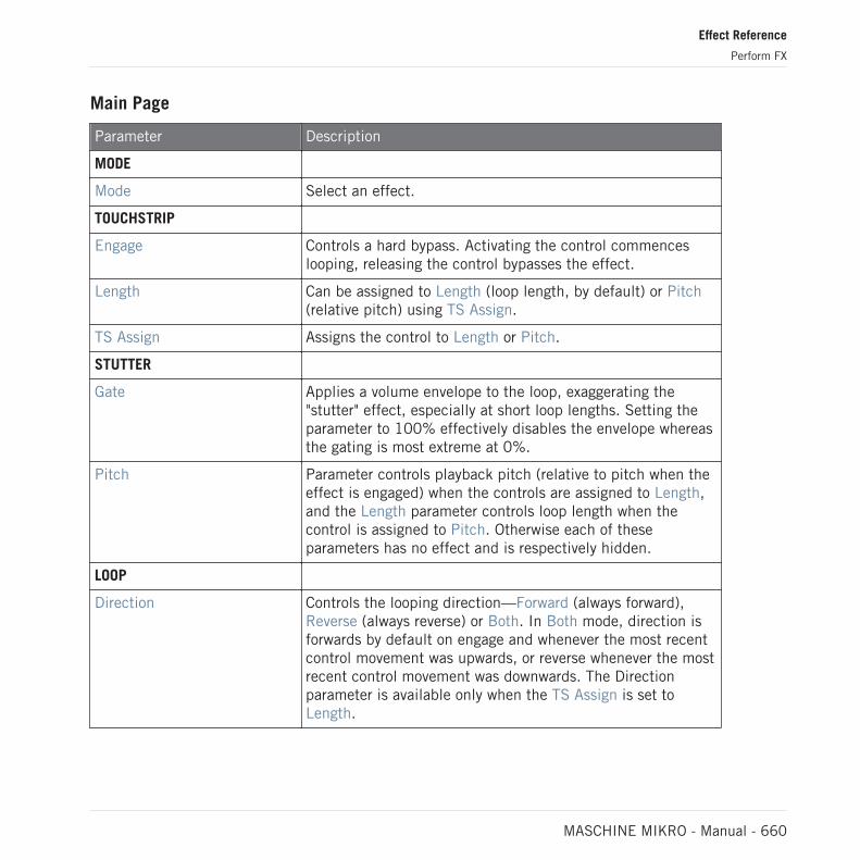
Main Page
Parameter Description
MODE
Mode Select an effect.
TOUCHSTRIP
Engage Controls a hard bypass. Activating the control commenceslooping, releasing the control bypasses the effect.
Length Can be assigned to Length (loop length, by default) or Pitch(relative pitch) using TS Assign.
TS Assign Assigns the control to Length or Pitch.
STUTTER
Gate Applies a volume envelope to the loop, exaggerating the"stutter" effect, especially at short loop lengths. Setting theparameter to 100% effectively disables the envelope whereasthe gating is most extreme at 0%.
Pitch Parameter controls playback pitch (relative to pitch when theeffect is engaged) when the controls are assigned to Length,and the Length parameter controls loop length when thecontrol is assigned to Pitch. Otherwise each of theseparameters has no effect and is respectively hidden.
LOOP
Direction Controls the looping direction—Forward (always forward),Reverse (always reverse) or Both. In Both mode, direction isforwards by default on engage and whenever the most recentcontrol movement was upwards, or reverse whenever the mostrecent control movement was downwards. The Directionparameter is available only when the TS Assign is set toLength.
Effect Reference
Perform FX
MASCHINE MIKRO - Manual - 660

Parameter Description
Quantize Quantizes the loop length and start point to the song positionand tempo. When Quantize is off, the loop length iscontinuously variable and measured in milliseconds, and noquantization takes place. Quantization is especiallymeaningful if direction is set to Reverse or Both, since it'sduring reverse playback where a poorly timed loop will soundcompletely off-time.
15.7.7 Tremolo
A no-frills tremolo and vibrato effect that’s perfect for creating motion and wobble on the fly.Instantly add expression with multiple modes, Rate, and Depth ranges, and use the Stereoknob to create auto-pan motion effects.
Tremolo Perform FX in the Plug-in Strip.
Effect Reference
Perform FX
MASCHINE MIKRO - Manual - 661

Tremolo Perform FX in the Control area.
Effect Reference
Perform FX
MASCHINE MIKRO - Manual - 662
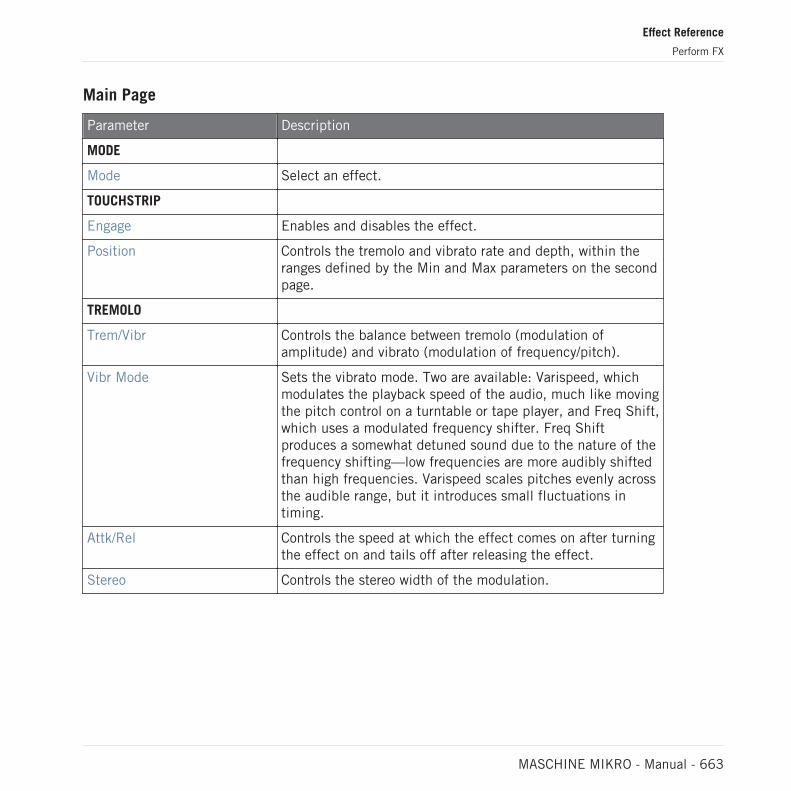
Main Page
Parameter Description
MODE
Mode Select an effect.
TOUCHSTRIP
Engage Enables and disables the effect.
Position Controls the tremolo and vibrato rate and depth, within theranges defined by the Min and Max parameters on the secondpage.
TREMOLO
Trem/Vibr Controls the balance between tremolo (modulation ofamplitude) and vibrato (modulation of frequency/pitch).
Vibr Mode Sets the vibrato mode. Two are available: Varispeed, whichmodulates the playback speed of the audio, much like movingthe pitch control on a turntable or tape player, and Freq Shift,which uses a modulated frequency shifter. Freq Shiftproduces a somewhat detuned sound due to the nature of thefrequency shifting—low frequencies are more audibly shiftedthan high frequencies. Varispeed scales pitches evenly acrossthe audible range, but it introduces small fluctuations intiming.
Attk/Rel Controls the speed at which the effect comes on after turningthe effect on and tails off after releasing the effect.
Stereo Controls the stereo width of the modulation.
Effect Reference
Perform FX
MASCHINE MIKRO - Manual - 663

Setup Page
Parameter Description
DEPTH RANGE
Depth Min Controls the amplitude of the modulation when the parameterposition is set to 0%.
Depth Max Controls the amplitude of the modulation when the parameterposition is set to 100%.
DEPTH RANGE
Rate Min Controls the rate of the modulation when the parameterposition is set to 0%.
Rate Max Controls the rate of the modulation when the parameterposition is set to 100%.
15.7.8 Scratcher
Scratcher warps your sounds with turntable motion effects that can get other-worldly. Apply a‘brake’ to a sound, then scratch with it – just like on vinyl. Or use the pitch shifter delay tothicken the sound and create alien-sounding sweeps.
Effect Reference
Perform FX
MASCHINE MIKRO - Manual - 664

Scratcher Perform FX in the Plug-in Strip.
Scratcher Perform FX in the Control area.
Effect Reference
Perform FX
MASCHINE MIKRO - Manual - 665

Main Page
Parameter Description
MODE
Mode Select an effect.
TOUCHSTRIP
Engage Engages the turntable brake, enabling scratch control. Whenreleased, the effect is bypassed entirely.
Position Controls the brake speed (higher = slower brake), the scratchposition (higher = forward) and the delay time (higher =longer delay time).
SWIRL
Delay Time Controls the delay time range. Longer values produce a delayeffect. Shorter values result in a comb filtering effect. ThePosition parameter acts as a further scale factor on this delaytime.
Feedback Controls the delay feedback.
Freq Shift Controls a frequency shifter in the delay feedback loop. At 12o'clock, the frequency shifter is disabled. Swirling, alien andmetallic sounds can be made by enabling the frequencyshifter and increasing the feedback.
Wet Level Controls the level of the delay effect.
Effect Reference
Perform FX
MASCHINE MIKRO - Manual - 666

16 Working with the Arranger
The Arranger is the big area located in the upper part of the MASCHINE window, right underthe Header.
The MASCHINE Arranger has two different views: Ideas view and Song view which are also re-flected on your controller. Each view has a specific purpose in the workflow of creating a song,but essentially they represent the same content. The Ideas view allows you to experiment withyour musical ideas without being tied to a timeline or any kind of arrangement. Here you cancreate Patterns for each Group and combine them into a Scene.
Alternatively, the Song view allows you to structure your song by allowing you to assign theScenes you created in the Ideas view to Sections on the Timeline, and move them around toquickly create a larger musical structure.
16.1 Arranger Basics
The Arranger has two different views: Ideas view and Song view. Each view has a specific pur-pose in the workflow of creating a song, but essentially they represent the same content.
Switching between Ideas View and Song view
The Arranger View button.
► Click the Arranger View button to switch between the Ideas view and the Song view.
→ When the button is unlit Ideas view is active, when the button is lit Song view is active.
Working with the Arranger
Arranger Basics
MASCHINE MIKRO - Manual - 667
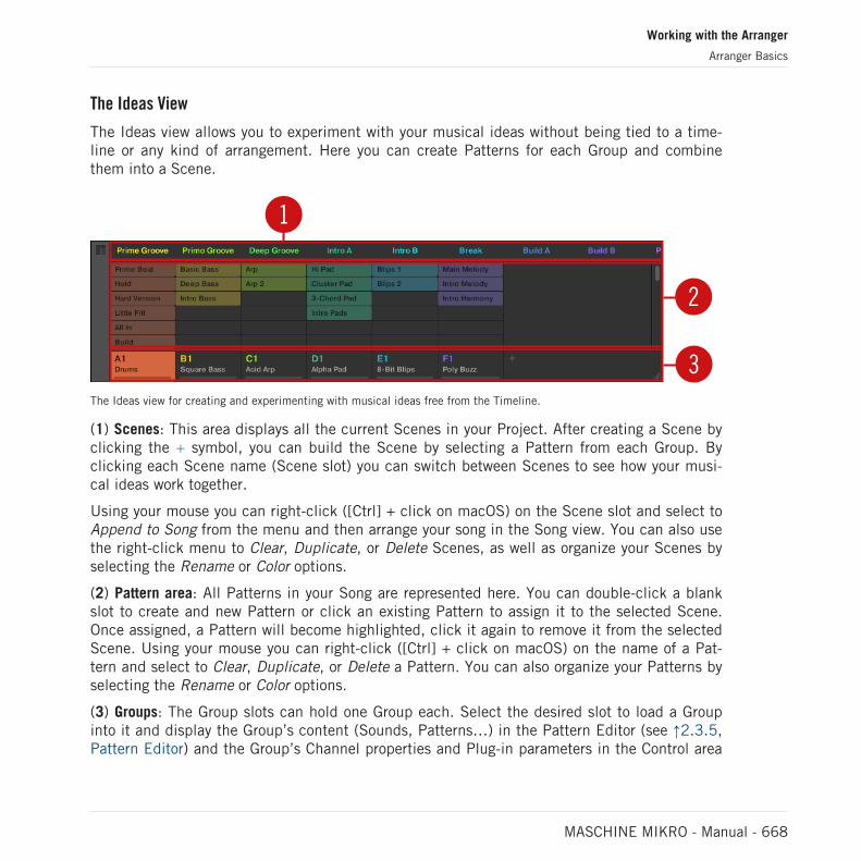
The Ideas View
The Ideas view allows you to experiment with your musical ideas without being tied to a time-line or any kind of arrangement. Here you can create Patterns for each Group and combinethem into a Scene.
1
2
3The Ideas view for creating and experimenting with musical ideas free from the Timeline.
(1) Scenes: This area displays all the current Scenes in your Project. After creating a Scene byclicking the + symbol, you can build the Scene by selecting a Pattern from each Group. Byclicking each Scene name (Scene slot) you can switch between Scenes to see how your musi-cal ideas work together.
Using your mouse you can right-click ([Ctrl] + click on macOS) on the Scene slot and select toAppend to Song from the menu and then arrange your song in the Song view. You can also usethe right-click menu to Clear, Duplicate, or Delete Scenes, as well as organize your Scenes byselecting the Rename or Color options.
(2) Pattern area: All Patterns in your Song are represented here. You can double-click a blankslot to create and new Pattern or click an existing Pattern to assign it to the selected Scene.Once assigned, a Pattern will become highlighted, click it again to remove it from the selectedScene. Using your mouse you can right-click ([Ctrl] + click on macOS) on the name of a Pat-tern and select to Clear, Duplicate, or Delete a Pattern. You can also organize your Patterns byselecting the Rename or Color options.
(3) Groups: The Group slots can hold one Group each. Select the desired slot to load a Groupinto it and display the Group’s content (Sounds, Patterns…) in the Pattern Editor (see ↑2.3.5,Pattern Editor) and the Group’s Channel properties and Plug-in parameters in the Control area
Working with the Arranger
Arranger Basics
MASCHINE MIKRO - Manual - 668

(see ↑2.3.4, Control Area). To mute a Group click the Group letter, for example A1, and right-click ([Ctrl] + click on macOS) on the letter to solo the Group. Using your mouse you can alsoright-click ([Ctrl] + click on macOS) on the name of a Group to access the many options availa-ble to manage them.
The Song View
The Song view allows you to structure your song by allowing you to assign the Scenes you cre-ated in the Ideas view to Sections, and move them around to quickly create a larger musicalstructure.
3
4
21
The Song view for organizing your musical ideas into a song on the Timeline.
(1) Groups: The Group slots can hold one Group each. Select the desired slot to load a Groupinto it and display the Group’s content (Sounds, Patterns…) in the Pattern Editor (see ↑2.3.5,Pattern Editor) and the Group’s Channel properties and Plug-in parameters in the Control area(see ↑2.3.4, Control Area).
(2) Song timeline: This area displays the current position within the track and allows you to setthe loop range.
(3) Section slots: This area displays Section slots. A Section is a container for Scene placed onthe Timeline. A Section can be reordered by clicking the name of the Section and draggingand dropping it into place. You can change the length of a Section by dragging the Section endmarker to the left to shorten it, or to the right to lengthen it. Using your mouse you can right-click ([Ctrl] + click on macOS) a Section and use Select in the menu to assign a Scene to aSection. It is also possible to use the menu to Insert, Duplicate, Delete, Clear or Remove Sec-tions as well as organize them by selecting the Rename or Color options.
Working with the Arranger
Arranger Basics
MASCHINE MIKRO - Manual - 669

(4) Pattern area: In each Section of the Arrangement, you can see the name of the Scene as-signed to the Section along with the Scene's Patterns stacked vertically for each Group in theProject. The Patterns seen here are the same as those seen when viewing the same Scene inthe Ideas view.
16.1.1 Navigating Song View
Song view can be scrolled and zoomed in or out to fit your current needs.
Navigating Song View Horizontally
A zooming scroll bar is available at the bottom of the Arranger in Song view. This tool allowsyou to scroll and zoom in/out horizontally in the Event area and the Control Lane on the timeaxis:
12 3The zooming scroll bar at the bottom of Song view in the Arranger.
Use the horizontal zooming scroll bar as follows:
▪ Click the main part (1) of the scroll bar and hold the mouse button, then:
◦ Drag your mouse horizontally to scroll through Song view on the time axis (commonscroll bar behavior).
◦ Drag your mouse vertically to zoom in or out of Song view on the time axis.
▪ Click the left handle (2) of the scroll bar, hold the mouse button, and drag your mouse hori-zontally to zoom in or out of Song view while keeping the right border of the display at afixed position in the song.
▪ Similarly, click the right handle (3) of the scroll bar, hold the mouse button, and drag yourmouse horizontally to zoom in or out of Song view while keeping the left border of the dis-play at a fixed position in the song.
Working with the Arranger
Arranger Basics
MASCHINE MIKRO - Manual - 670

▪ Double-click the main part (1) to reset the zoom and display all of the Sections in your ar-rangement.
Navigating the Arranger Vertically
A classic scroll bar is available right of the Arranger. It allows you to scroll to view hiddenGroups in if they do not fit in the Arranger.
The classic scroll bar right of the Arranger.
You can also adjust the height of the Arranger in order to display more/less Groups at once bydragging its bottom right corner vertically with your mouse:
Drag the handle to adjust the Arranger’s height.
You can also control the position and zoom factor in the Song view from your controller:
Working with the Arranger
Arranger Basics
MASCHINE MIKRO - Manual - 671

► Press SHIFT + VARIATION (Navigate) to enter Navigation mode.
Action Shortcut
Scroll Arranger left Press pad 9
Scroll Arranger right Press pad 11
Zoom in (Arranger) Press pad 14
Zoom out (Arranger) Press pad 10
16.1.2 Following the Playback Position in Your Project
If the Arranger doesn’t display the entire Loop Range currently selected, at some point theplayhead will go beyond the portion of your Project currently displayed in the Arranger and youmight loose track of the playback position. To prevent this, you can force the Arranger to followthe playhead:
Activate the Follow button to keep following the playhead in the Arranger.
► To follow the playhead position in the Arranger during playback, click the Follow button inthe MASCHINE Header.
→ The Follow button lights up in the MASCHINE Header. The Arranger will now switch tothe next portion of your Project (with the same zoom factor) as soon as the playheadreaches the end of the portion currently displayed. This way, you always see the portion ofyour Project that is currently played.
The Follow function will be automatically disabled as soon as you manually scroll in the Arranger orthe Pattern Editor (in the software or from your controller).
Working with the Arranger
Arranger Basics
MASCHINE MIKRO - Manual - 672

The Follow function affects both the Pattern Editor and the Arranger simultaneously (see sec-tion ↑11.1.3, Following the Playback Position in the Pattern for more information on the Fol-low function in the Pattern Editor).
To follow the playhead position during playback:
► Press the FOLLOW button in the Transport section (at the bottom of your controller).
→ The FOLLOW button lights up. In the software the Arranger will now switch to the nextportion of your Project (with the same zoom factor) as soon as the playhead reaches theend of the portion currently displayed. This way, you always see the portion that is cur-rently played.
The Follow function will be automatically disabled as soon as you manually scroll to another portionof the Arranger or of the Pattern Editor.
The Follow function simultaneously affects various displays in the software and on your con-troller:
▪ In the software the Follow function affects both the Pattern Editor and the Arranger.
▪ On your controller the Follow function affects the displays in Arrange mode (for both SEC-TION and PATTERN pages), Events mode, Step mode, and Note Repeat mode. Additional-ly, in Step mode the Follow function affects the pads: With Follow enabled, when the play-head has gone across all 16 steps shown by the pads on your controller, the pads automati-cally switch to the next 16 steps of the Pattern, if any. See section ↑11.4.2, CreatingEvents/Notes for more information on Step mode.
16.1.3 Performing with Scenes and Sections using the Pads
MASCHINE provides you with settings to fine-tune the timing of the jump between the Scenesand Sections:
▪ The Perform Grid lets you quantize the Scene transitions: You can choose the point at whichthe playback will leave the current Scene (Ideas view) or Section (Song view). For example,you might not want a newly selected loop to fire off immediately — you might want it towait until the next bar line. The available quantization values are: one bar, one half note,
Working with the Arranger
Arranger Basics
MASCHINE MIKRO - Manual - 673
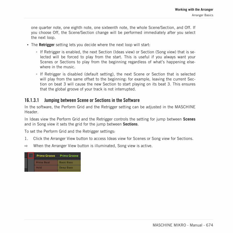
one quarter note, one eighth note, one sixteenth note, the whole Scene/Section, and Off. Ifyou choose Off, the Scene/Section change will be performed immediately after you selectthe next loop.
▪ The Retrigger setting lets you decide where the next loop will start:
◦ If Retrigger is enabled, the next Section (Ideas view) or Section (Song view) that is se-lected will be forced to play from the start. This is useful if you always want yourScenes or Sections to play from the beginning regardless of what’s happening else-where in the music.
◦ If Retrigger is disabled (default setting), the next Scene or Section that is selectedwill play from the same offset to the beginning: for example, leaving the current Sec-tion on beat 3 will cause the new Section to start playing on its beat 3. This ensuresthat the global groove of your track is not interrupted.
16.1.3.1 Jumping between Scene or Sections in the Software
In the software, the Perform Grid and the Retrigger setting can be adjusted in the MASCHINEHeader.
In Ideas view the Perform Grid and the Retrigger controls the setting for jump between Scenesand in Song view it sets the grid for the jump between Sections.
To set the Perform Grid and the Retrigger settings:
1. Click the Arranger View button to access Ideas view for Scenes or Song view for Sections.
⇨ When the Arranger View button is illuminated, Song view is active.
Working with the Arranger
Arranger Basics
MASCHINE MIKRO - Manual - 674

2. To adjust the Perform Grid, click the Performance Grid menu in the Header and select thedesired division from the menu:
→ The next time you select a new Scene/Section or group of Scenes/Sections for looping, theswitch will happen on the next division selected here.
► To enable/disable the Retrigger setting, click the Performance Grid menu in the Headerand select Retrigger from the menu.
→ The next time you select a new Scene/Section or group of Scenes/Sections for looping, thenew loop will start from the beginning of the first Scene/Section (Retrigger enabled) orfrom the same position as where it left the current Scene/Section (Retrigger disabled).
Working with the Arranger
Arranger Basics
MASCHINE MIKRO - Manual - 675
16.1.3.2 Jumping to Other Scenes using the Controller
In Ideas view the Perform Grid and the Retrigger controls the setting for jump between Scenes,and in Song view it sets the jump between Sections.
Setting the Perform Grid and Retrigger Settings
To set the Perform Grid and the Retrigger settings:
1. Press SCENE to select Scene mode or SHIFT + SCENE (Section) Section mode.
2. If you want to set the Perform Grid and the Retrigger settings for Scenes, select Scenemode, for Sections, select Section mode.
3. Press SHIFT + FOLLOW (Grid) to enter Grid mode.
4. Use the Arrow buttons to select Perform.
⇨ In the display you see the current Scene/Section Sync value. The default value Scene/Section means that the next time you select a new Scene/Section or loop range, theswitch will happen once the current Scene/Section has played to the end.
5. Turn the Encoder to select the desired value, for example 1/4 (quarter note).
→ The next time you select a new Scene/Section or loop range, the switch will happen onthe next quarter note.
Adjusting the Scene Retrigger Setting
To adjust the Scene Retrigger setting:
1. Press SCENE (Section) to select Scene mode.
2. In the display you see the current Retrigger value (Off by default).
3. Turn the Encoder to select On.
→ The next time you select a new Section or loop range, it will start from the beginning.
Adjusting the Section Retrigger Setting
To adjust the Section Retrigger setting:
Working with the Arranger
Arranger Basics
MASCHINE MIKRO - Manual - 676

1. Press SHIFT + SCENE (Section) to select Section mode.
2. Press the Right Arrow button to access Retrigger.
3. In the display you see the current Retrigger value (Off by default).
4. Turn the Control knob to select On.
The next time you select a new Section or loop range, it will start from the beginning.
Make sure you have created at least one Section before you try to set the Retrigger setting; other-wise, the setting will not be available.
16.2 Using Ideas View
The Ideas view allows you to experiment with your musical ideas without being tied to a time-line or any kind of arrangement. Here you can create Patterns for each Group and combinethem into a Scene.
In Ideas view, MASCHINE provides a perfect overview of all your Scenes, Patterns and Groups.Here you can create a Scene by selecting a Pattern for each Group, duplicate your Scenes,clear a Scene and more importantly trigger your Scenes to so you can hear how they soundwhen played in a particular order.
Pressing a pad in Scene mode will trigger a Scene and in turn trigger all the assigned Patterns.In addition to creating ideas, Scene mode is fantastic for improvisation during a performance.
16.2.1 Scene Overview
In the software, all Scenes can be managed from the Ideas view:
► To open Ideas view, click the Arranger View button on the left of the Arranger.
→ When the button is unlit Ideas view is active, when the button is lit Song view is active.
Working with the Arranger
Using Ideas View
MASCHINE MIKRO - Manual - 677

The Ideas view.
▪ At the top you can see Scene slots. The selected Scene is highlighted.
▪ The selected Scene displays the selected Patterns for the current Scene.
Scene Mode on the Controller
The Scene mode focuses on Scene selection and manipulation.
To enter Scene mode on your controller:
► Press SCENE (Section) to enter Scene mode.
→ The software switches to Scene mode. This is indicated by the illuminated SCENE (Sec-tion) button.
In Scene mode you see all Scene slots of the selected Scene bank represented as a square of4x4 cells:
▪ The highlighted cell indicates the selected Scene slot.
▪ Cells showing a name represent Scene slots containing a Scene.
▪ Empty cells represent empty Scene slots.
This grid of cells shown in the right display corresponds to the pads of your controller, whichhave the same functionality as in Scene Arrange mode:
▪ The fully lit pad indicates the selected Scene slot.
▪ Dim lit pads indicate Scene slots containing a Scene.
▪ Unlit pads represent empty Scene slots.
Working with the Arranger
Using Ideas View
MASCHINE MIKRO - Manual - 678
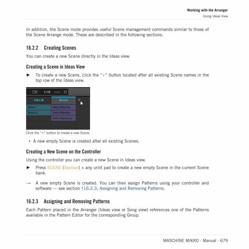
In addition, the Scene mode provides useful Scene management commands similar to those ofthe Scene Arrange mode. These are described in the following sections.
16.2.2 Creating Scenes
You can create a new Scene directly in the Ideas view.
Creating a Scene in Ideas View
► To create a new Scene, click the “+” button located after all existing Scene names in thetop row of the Ideas view.
Click the “+” button to create a new Scene.
▪ A new empty Scene is created after all existing Scenes.
Creating a New Scene on the Controller
Using the controller you can create a new Scene in Ideas view.
► Press SCENE (Section) + any unlit pad to create a new empty Scene in the current Scenebank.
→ A new empty Scene is created. You can then assign Patterns using your controller andsoftware — see section ↑16.2.3, Assigning and Removing Patterns.
16.2.3 Assigning and Removing Patterns
Each Pattern placed in the Arranger (Ideas view or Song view) references one of the Patternsavailable in the Pattern Editor for the corresponding Group.
Working with the Arranger
Using Ideas View
MASCHINE MIKRO - Manual - 679

In the Ideas view, each column represents a Group. After selecting a Scene it is possible toassign and remove Patterns by clicking the Pattern slots.
Any changes made in Ideas view or Song view are one and the same.
Assigning and Removing a Pattern in Ideas View
1. Select a Scene slot.
2. Then click the Pattern slot you want to assign or remove for that Scene.
→ Upon your selection, the Pattern is inserted into the selected Scene:
▪ The Pattern replaces any previous Pattern for that Group in the Scene.
▪ The Pattern displays its name and color.
▪ The corresponding Pattern will now be played by that Scene.
▪ Additionally this Pattern is loaded in the Pattern Editor, ready to be modified.
Working with the Arranger
Using Ideas View
MASCHINE MIKRO - Manual - 680

Patterns and the Pattern Editor are described in chapter ↑11, Working with Patterns.
Creating a New Empty Pattern in Ideas View
You can also create a new empty Pattern in Ideas view:
► In the Ideas view, double-click the empty Pattern slot located in the column of the de-sired Group.
→ A new empty Pattern is created.
Removing a Pattern in Ideas View
You can also remove a Pattern from a Scene in Ideas view:
► Click the highlighted Pattern for any Group to remove it from the Scene.
→ The Pattern is removed from the Scene:
▪ The corresponding Pattern will not be played by that Scene anymore.
▪ The Pattern itself is left untouched.
Assigning a Pattern to a Scene on the Controller
Assigning a Pattern is done in Pattern mode.
First select the Scene to which you want to assign a Pattern:
1. Press SCENE.
2. Press the pad corresponding to the Scene to which you want to assign a Pattern.
Then create the Pattern for the desired Group:
1. Press GROUP + the pad 9–16 of the Group from which you want to select a Pattern.
2. Press PATTERN.
Your pads give you an overview of the available Patterns. Dim lit pads indicate the availablePatterns. If a Pattern already exists in the selected Scene for that Group, the referenced Pat-tern is highlighted and its pad is fully lit.
Working with the Arranger
Using Ideas View
MASCHINE MIKRO - Manual - 681

► Press the desired pad to select the Pattern you want to use in that Scene.
→ If you have pressed a dim lit pad, a Pattern is inserted into the selected Scene. If youhave pressed an unlit pad, a new empty Pattern is automatically created in the selectedScene. In both cases, any Pattern previously existing for that Group in the Scene will bereplaced.
Furthermore, the following happens:
▪ In the Arranger (Ideas view and Song view) the Pattern displays the name and color of thePattern.
▪ The corresponding Pattern will now be played by that Scene.
▪ Additionally this Pattern is loaded in the Pattern Editor, ready to be modified.
For further information regarding the Pattern mode, please refer to section ↑11.7, Managing Pat-terns.
16.2.4 Selecting Scenes
You can select the desired Scene in the Ideas view.
Selecting a Scene in the Ideas View
To select a Scene in the Ideas view, do the following:
► Select the desired Scene by clicking its name at the top of the Ideas View:
Working with the Arranger
Using Ideas View
MASCHINE MIKRO - Manual - 682

→ The Scene name is now highlighted to indicate that this Scene is selected.
Once a Scene Has Been Selected…
Once you have selected a Scene, the following happens:
▪ The selected Patterns slots for the focused Scene are highlighted. The Pattern slot with awhite frame is displayed in the Pattern Editor. Unselected Pattern slots are dimmed. Ifthere are no Patterns slots select for the Scene in focus, or if there are no Patterns at all,the Pattern Editor is empty.
▪ If playback is off the playhead immediately jumps to the beginning of the selected Scene.If playback is on the playhead jumps according to the Perform Grid settings.
Selecting Scenes and Scene Banks on the Controller
Selecting a Scene Bank
To select a Scene located in another Scene bank:
1. Press SCENE (Section).
2. Press the Right Arrow button to select Bank.
3. Turn the Encoder to select a Scene bank.
If the last Scene bank is selected and not empty, pressing Button 8 will create a new, empty Pat-tern bank — see section ↑16.2.6, Creating and Deleting Scene Banks for more information.
Selecting a Scene
To select a Scene in the current Scene bank:
► Press SCENE (Section) + the dim lit pad corresponding to the cell of the desired Sceneon the right display. Alternatively you can press SCENE + Page buttons to select the pre-vious/next Scene.
After your selection, the following happens:
▪ The Pattern Editor displays the Pattern for the focused Group in this Scene. If there is noPattern for the focused Group in the Scene you have just selected, the Pattern Editor isempty.
Working with the Arranger
Using Ideas View
MASCHINE MIKRO - Manual - 683

If playback is off the playhead immediately jumps to the beginning of the selected Scene. Ifplayback is on the playhead jumps according to the Perform Grid settings — see section Jump-ing to Other Scenes.
16.2.5 Deleting Scenes
To delete a Scene in the Ideas view:
► In the top row of the Ideas view, right-click ([Ctrl]-click on macOS) the name of the Sceneyou want to delete and select Delete from the context menu:
→ The Scene is deleted with all its Patterns. Scenes to the right shift to fill the gap.
Instead of deleting the Scene, which removes it entirely, you can also clear the Scene: This will onlyremove its content — the Scene will stay in your arrangement, but empty. For more information onclearing Scenes, see section ↑16.2.7, Clearing Scenes.
Deleting Scenes on the Controller
To delete a Scene on your controller:
1. Press SCENE (Section) to enter Scene mode.
2. If required, press the Right Arrow button and turn the Encoder to select the desired Scenebank.
3. Press ERASE + the pad corresponding to the Scene you want to delete.
→ The Scene is deleted with all its Patterns. Scenes to the right shift to fill the gap.
Working with the Arranger
Using Ideas View
MASCHINE MIKRO - Manual - 684
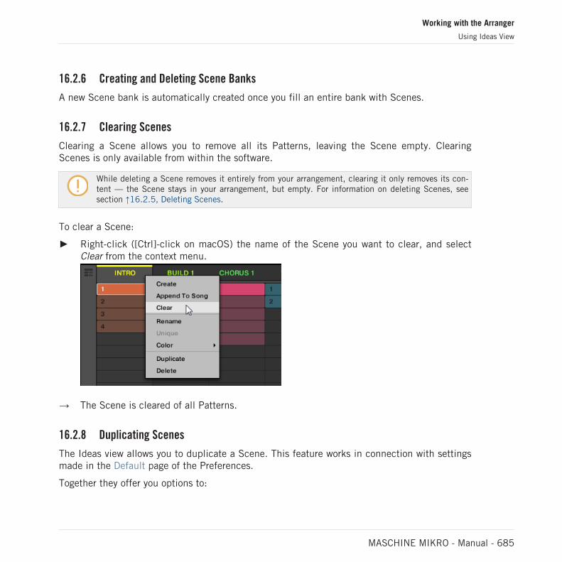
16.2.6 Creating and Deleting Scene Banks
A new Scene bank is automatically created once you fill an entire bank with Scenes.
16.2.7 Clearing Scenes
Clearing a Scene allows you to remove all its Patterns, leaving the Scene empty. ClearingScenes is only available from within the software.
While deleting a Scene removes it entirely from your arrangement, clearing it only removes its con-tent — the Scene stays in your arrangement, but empty. For information on deleting Scenes, seesection ↑16.2.5, Deleting Scenes.
To clear a Scene:
► Right-click ([Ctrl]-click on macOS) the name of the Scene you want to clear, and selectClear from the context menu.
→ The Scene is cleared of all Patterns.
16.2.8 Duplicating Scenes
The Ideas view allows you to duplicate a Scene. This feature works in connection with settingsmade in the Default page of the Preferences.
Together they offer you options to:
Working with the Arranger
Using Ideas View
MASCHINE MIKRO - Manual - 685

▪ duplicate Scenes
▪ duplicate Scenes and Patterns
▪ link when duplicating Sections
For more information on the Default page of the Preferences, read: ↑3.6.4, Preferences – De-fault Page.
Duplicating a Scene in the Software
To duplicate a Scene in the software:
► Right-click ([Ctrl]-click on macOS), and select Duplicate from the context menu.
▪ The selected Scene is duplicated in accordance with the setting in the Default page of thePreferences.
You can also duplicate a Scene by clicking the Scene slot header while holding [Alt] key (or [Ctrl]on PC), and dragging the mouse. After the mouse is released a duplicate copy of the Scene is creat-ed.
Duplicating a Scene on Your Controller
To duplicate a Scene on your controller:
1. Press SCENE (Section) to enter Scene mode.
2. Press the pad corresponding to the Scene you want to duplicate.
3. Press any unlit pad to duplicate the Scene.
Working with the Arranger
Using Ideas View
MASCHINE MIKRO - Manual - 686

→ The selected Scene is duplicated in accordance with the setting in the Default page of thePreferences. For more information, read: ↑3.6.4, Preferences – Default Page.
16.2.9 Reordering Scenes
Reordering Scenes in Ideas view allows you to visually organize your ideas and also place eachidea on a specific pad of your controller. The reordering of Scenes will not affect your arrange-ment.
In the software you can reorder Scenes in the Ideas view.
To reorder Scenes:
1. Click and hold the Scene name in the Ideas view.
2. While holding the mouse button, drag your mouse horizontally to the desired location.As the mouse cursor moves, an insertion line appears at the potential places where youcan drop the Scene.
3. When the insertion line appears at the desired location, release the mouse button.
Working with the Arranger
Using Ideas View
MASCHINE MIKRO - Manual - 687

→ The Scene takes its new place. On your controller in Scene mode, you can now select thisScene via the pad corresponding to its new location.
16.2.10 Making Scenes Unique
If a Scene is referencing the same Patterns you can make a separate (unique) copy of theScene and its Patterns by selecting Unique. This allows you to work on a new separate copy ofthe Scene and its Pattern in isolation. Use Unique in combination with the Duplicate option.For more information on the Duplicate option, read: ↑16.2.8, Duplicating Scenes.
To make a Scene unique in the Ideas view:
► In the top row of the Ideas view, right-click ([Ctrl]-click on macOS) the name of the Sceneyou want to make unique and select Unique from the context menu:
→ A unique copy of the Scene and its Patterns are created.
This option is only available if the selected Scene is referencing the same Patterns as anotherScene.
Working with the Arranger
Using Ideas View
MASCHINE MIKRO - Manual - 688

16.2.11 Appending Scenes to Arrangement
Once you are satisfied with a Scene you can append it directly to your arrangement in the Songview.
Appending a Scene to the Arrangement in the Software
► In the top row of the Ideas view, right-click ([Ctrl]-click on macOS) the name of the Sceneyou want to append to the arrangement and select Append To Arrangement from the con-text menu:
▪ A Section containing the appended Scene is created and added to the end of your arrange-ment. You can then click and drag the Section slot (containing the Scene) to an appropri-ate place on the Timeline of the Arranger.
16.2.12 Naming Scenes
By default, Scenes are named Scene 1, Scene 2, Scene 3, etc. You can rename Scenes anduse custom names of your own. Naming is only available from within the software, but anychanges will also show up on your controller.
Renaming Scenes in the Arranger
To rename a Scene in the Arranger:
Working with the Arranger
Using Ideas View
MASCHINE MIKRO - Manual - 689

1. Double-click the Scene name at the top of the Arranger:
You can also right-click ([Ctrl]-click on macOS) the Scene slot or the corresponding cell inthe pad grid and select Rename from the context menu:
The Scene name gets highlighted and editable.
2. Type a name and press [Enter] on your computer keyboard to confirm (or press [Esc] tocancel you change).
→ The Scene is renamed.
If you use MASCHINE as a plug-in, some hosts will utilize the [Enter] key, as it is mapped to somefunction of the host software. In this case, click anywhere else in the MASCHINE plug-in window toconfirm the name you have entered.
16.2.13 Changing the Color of a Scene
You can change the color of each Scene in the software. To do this:
Working with the Arranger
Using Ideas View
MASCHINE MIKRO - Manual - 690

1. Right-click ([Ctrl]-click on macOS) the name of the desired Scene in the Arranger or inthe Scene Manager, and select Color from the context menu.A Color Palette appears. In the Palette, the current color of the Scene is highlighted.
2. Select the desired color in the Palette. You can also choose to set the Scene back to itsdefault color by selecting Default at the bottom of the Color Palette.
→ The Scene slot takes the new color you select.
By default, Scenes are white. But you can choose another default color for Scenes in Preferences >Colors > Scene Default. See section ↑3.6.8, Preferences – Colors Page for more information.
Once you have set a custom color for a Scene as described above, the Scene will retain its colorwhen you move it in the Song view, and the color will be stored with the Scene when you save yourProject. Note that you can select the same color as the one used by default: In this case the color(even unchanged) will be considered as a custom color and will follow the Scene as you move it.
Working with the Arranger
Using Ideas View
MASCHINE MIKRO - Manual - 691

16.3 Using Song View
In MASCHINE, a song is made of a variable number of Scenes, which represent the differentparts of the song, for example, intro, verse, chorus, break, another verse. By assigning yourScenes to Sections to the Timeline in the Song view you can start to organize your track.
The Song view is where you can sequence Scenes to create your final arrangement. This proc-ess involves creating a Section on the Timeline and assigning a Scene to it. Any Scene thatexists in the Ideas view can be assigned to a Section in the Song view. You can change thelength of the Section (determining the playback length of the Scene) or re-order the Sectionsas you see fit. You can also re-use the same Scene in multiple Sections in the timeline, or youcan choose to assign no Scene to the Section at all.
One powerful aspect of the relationship between the Ideas view and Song view is that the con-tent in these two areas are actually one-in-the-same. This means that if you make a change toa Scene it will affect all other instances of that Scene automatically. If you place a Scene inthree different Sections of the Timeline and then proceed to change the Patterns assigned tothat Scene, the other two instances of that Scene also play the newly-assigned Patterns. It’stherefore very easy to make changes to individual Patterns and Scenes after the arrangementhas been made and immediately hear the results in the context of the arrangement, and thosechanges can be made in either Ideas or Song view.
16.3.1 Section Management Overview
In the software, all Sections can be managed from the Song view.
To open the Section Manager:
1. To open Song view, click the Arranger View button on the left of the Arranger.
⇨ The Song view appears on the right.
Working with the Arranger
Using Song View
MASCHINE MIKRO - Manual - 692

2. To open the Section Manager, click the drop-down menu on the left of the arrangement.
→ The Section Manager appears on the right.
Use the Section Manager to manage your Sections.
▪ On the left you can see the list of the 16 Section slots in the selected Section bank. Slotscontaining a Section show a colored or white bar on the left along with the Section name.The other slots contain no Section. The selected Section is highlighted (Intro A in the im-age above).
▪ On the right you can see the various Section banks in form of pad grids, a pad grid is asquare of 4x4 cells representing the pads of your controller. In each Section bank the col-ored cells indicate Section slots containing a Section, while unlit cells indicate empty Sec-tion slots. The selected Section bank is surrounded by a white border (bank 2 in the pic-ture above). If there are too many Section banks to fit into the Section Manager’s height,use the scroll wheel of your mouse to display the other banks.
▪ The Section slots on the left and the cells in the selected pad grid on the right are strictlyequivalent: you can use either the slots or the corresponding cells to execute all the man-agement commands described in the next sections.
Working with the Arranger
Using Song View
MASCHINE MIKRO - Manual - 693

Closing the Section Manager
► To close the Section Manager, click anywhere outside it.
Section Manager vs. Arranger’s Top Row
If all Section operations can be done in the Section Manager, most of them can also be donein the top row of the Arranger:
The top row of the Arranger.
The only difference between the Section Manager and the Arranger’s top row is that the Sec-tion Manager allows you to manage your Section banks, which is impossible in the Arranger’stop row. Apart from this, actions in the Arranger’s top row and in the Section Manager arestrictly equivalent.
The Section Mode on the Controller
The Section mode is where you select and manage your Sections.
► To enter Section mode on your controller, press SHIFT + SCENE (Section).
→ Your controller switches to Section mode. This is indicated by the lit SCENE (Section)button.
Now the pads on your controller represent the 16 Section slots of the current Section bank:
▪ The fully lit pad indicates the selected Section slot.
▪ Dim lit pads indicate Section slots referencing a Scene.
▪ Unlit pads represent empty Section slots.
In addition, the Section mode provides useful Section management commands. These are de-scribed in the following sections.
16.3.2 Creating Sections
You can create a new Section directly in the Song view.
Working with the Arranger
Using Song View
MASCHINE MIKRO - Manual - 694

Creating a Section using the Software
► To create a new Section, click the “+” button located after all existing Section names inthe top row of the Song view.
Click the “+” button to create a new Section.
▪ A new empty Section is created after all existing Sections. You can then assign a Sceneusing your controller and software, see section: ↑16.3.3, Assigning a Scene to a Section.
Creating a New Section on Your Controller
To create a new Section on your controller:
1. Press SHIFT + SCENE (Section) to enter Song view.
2. Press any unlit pad to create a new empty Section in the current Section bank.
A new empty Section is created. You can then assign a Scene using your controller and soft-ware, see section: ↑16.3.3, Assigning a Scene to a Section.
16.3.3 Assigning a Scene to a Section
Now you have created an empty Section on the timeline of the Arranger, you can now add aScene from the Ideas view to the Song view.
To add a Scene to a Section on the timeline of the Arranger:
Working with the Arranger
Using Song View
MASCHINE MIKRO - Manual - 695

► Right-click ([Cmd] + click on macOS) a Section slot and select Append in the contextmenu, then for example, select Scene 2 from the submenu.
→ The selected Scene is added to the Section.
By repeating this for each new Section, you can quickly add Scenes to the Arranger.
To add a Scene to a Section in the Song view using your controller:
1. Press SHIFT + SCENE (Section) to access the Song view.
2. Press the right arrow button to select SCENE.
3. Turn the Encoder to select the Scene you want to add to the Section.
→ The selected Scene is added to the Section.
By repeating this for each new Section, you can quickly add Scenes to the Arranger.
16.3.4 Selecting Sections and Section Banks
You can select the desired Section via the Section Manager or directly in the Song view.
Selecting a Section in the Song view
To select a Section in the Song view, do the following:
Working with the Arranger
Using Song View
MASCHINE MIKRO - Manual - 696

► Select the desired Section by clicking its name at the top of the Song view:
→ The Section name is now highlighted and underlined to indicate that this Section is se-lected.
Selecting a Section and a Section Bank in the Section Manager
To select a Section in the Section Manager, do the following:
1. Open the Section Manager (see ↑16.3.1, Section Management Overview).
2. If it is not already selected, select the Section bank containing the desired Section byclicking its pad grid on the right.
The selected Section bank is surrounded by a white border, and the left part of the Sec-tion Manager displays the Section slots in that bank.
Working with the Arranger
Using Song View
MASCHINE MIKRO - Manual - 697
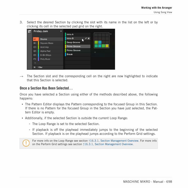
3. Select the desired Section by clicking the slot with its name in the list on the left or byclicking its cell in the selected pad grid on the right.
→ The Section slot and the corresponding cell on the right are now highlighted to indicatethat this Section is selected.
Once a Section Has Been Selected…
Once you have selected a Section using either of the methods described above, the followinghappens:
▪ The Pattern Editor displays the Pattern corresponding to the focused Group in this Section.If there is no Pattern for the focused Group in the Section you have just selected, the Pat-tern Editor is empty.
▪ Additionally, if the selected Section is outside the current Loop Range:
◦ The Loop Range is set to the selected Section.
◦ If playback is off the playhead immediately jumps to the beginning of the selectedSection. If playback is on the playhead jumps according to the Perform Grid settings.
For more info on the Loop Range see section ↑16.3.1, Section Management Overview. For more infoon the Perform Grid settings see section ↑16.3.1, Section Management Overview.
Working with the Arranger
Using Song View
MASCHINE MIKRO - Manual - 698

Selecting Sections and Section Banks on the Controller
Selecting a Section Bank
To select a Section located in another Section bank:
1. Press SHIFT + SCENE (Section) to access the Song view.
2. Press the Right Arrow button to select Bank.
3. Turn the Encoder to select the Bank you want to add to the Section.
→ The desired Bank is selected.
If the last Section bank is selected and not empty, pressing Button 8 will create a new, empty Sec-tion bank, see section ↑16.3.12, Creating and Deleting Section Banks for more information.
Selecting a Section
To select a Section in the current Section bank:
1. Press SHIFT + SCENE (Section) to access the Song view.
2. Press the dim lit pad corresponding to the Section you want to select.
→ The Section is selected.
Upon your selection, the following happens:
▪ The Pattern Editor displays the Pattern corresponding to the focused Group in this Section.If there is no Pattern for the focused Group in the Section you have just selected, the Pat-tern Editor is empty.
▪ If you have selected the Section by pressing a pad, or if you have selected a Section out-side the current Loop Range:
◦ The Loop Range is set to the selected Section, see section Selecting a Loop Range.
◦ If playback is off the playhead immediately jumps to the beginning of the selectedSection. If playback is on the playhead jumps according to the Perform Grid settings,see section Jumping to Other Scenes.
Working with the Arranger
Using Song View
MASCHINE MIKRO - Manual - 699

If you have selected a Section within the current Loop Range via the Arrow buttons, the LoopRange and the playback position stay untouched.
Selecting Sections and Section Banks on the Controller
Selecting a Section Bank
To select a Section located in another Section bank:
1. Press SHIFT + SCENE to enter Song view.
2. Press and hold SCENE to enter Scene mode (or pin it by pressing SCENE + CONTROL).
3. Press SHIFT + Left/Right Arrow button to select the previous/next Section bank, respec-tively.
If the last Section bank is selected and not empty, pressing SHIFT + Right Arrow button will createa new, empty Section bank, see section ↑16.3.12, Creating and Deleting Section Banks for moreinfo.
Selecting a Section
► To select a Section in the current Section bank, press SCENE + the dim lit pad corre-sponding to this Section.
Upon your selection, the following happens:
▪ The Pattern Editor displays the Pattern for the focused Group in this Section. If there is noPattern for the focused Group in the Section you have just selected, the Pattern Editor isempty.
▪ The Loop Range is set to the selected Section, see section Selecting a Loop Range.
▪ If playback is off the playhead immediately jumps to the beginning of the selected Section.If playback is on the playhead jumps according to the Perform Grid settings, see sectionJumping to Other Scenes.
16.3.5 Reorganizing Sections
Reordering Sections is essential to organize your Sections and arrange your song.
In the software you can reorganize sections both in the Arranger and in the Section Manager.
Working with the Arranger
Using Song View
MASCHINE MIKRO - Manual - 700

To move a Section:
1. Click and hold the Section name in the Arranger.
2. While holding the mouse button, drag your mouse horizontally in the Arranger to the de-sired location.As the mouse cursor moves, an insertion line appears at the potential places where youcan drop the Section.
3. When the insertion line appears at the desired location, release the mouse button.
→ The Section takes its new place. On your controller in Section mode, you can now selectthis Section via the pad corresponding to its new location.
Moving a Section using the Controller
To move a Section using your controller:
1. Press SHIFT + SCENE (Section) to access the Song view.
Working with the Arranger
Using Song View
MASCHINE MIKRO - Manual - 701

2. Press the Right Arrow button to select Position.
3. Press the pad of the Section you want to move.
4. Turn the Encoder to change the position of the selected Section.
→ The Section takes its new place. In Section mode you can now select this Section via thepad corresponding to its new location.
16.3.6 Adjusting the Length of a Section
Here are a few rules on how Sections, Scenes and Patterns are displayed within the Arranger:
By default the length of a Section is automatically set to the longest Pattern used within thereferenced Scene (Auto Length), unless the length of the Section is manually set to a specificbar range (Manual Length).
▪ Auto Length: By default, the length of a Section corresponds to the longest Pattern used inthe referenced Scene. Inserting a new Pattern that is longer than the Section automaticallyextends the Section. Removing the longest Pattern from the Section automatically shrinksthe Section. Extending/shrinking the longest Pattern automatically extends/shrinks the Sec-tion accordingly.
▪ Manual Length: A Section can be manually adjusted to a set length. This can be shorter orlonger than the Pattern contained within the referenced Scene. Inserting or removing Pat-terns from the Scene will not alter the length of the Section, however the length of a Sec-tion can be altered by dragging the mouse directly in the timeline or by using your MA-SCHINE controller.
▪ If a Pattern is shorter than the Section it is placed in, it is automatically repeated until theend of the Section (the last repetition might be shortened). These repetitions are automati-cally generated and cannot be edited. They reference the same Pattern placed at the be-ginning of the Section. Repetitions of a Pattern are indicated by darker blocks in the Ar-
Working with the Arranger
Using Song View
MASCHINE MIKRO - Manual - 702
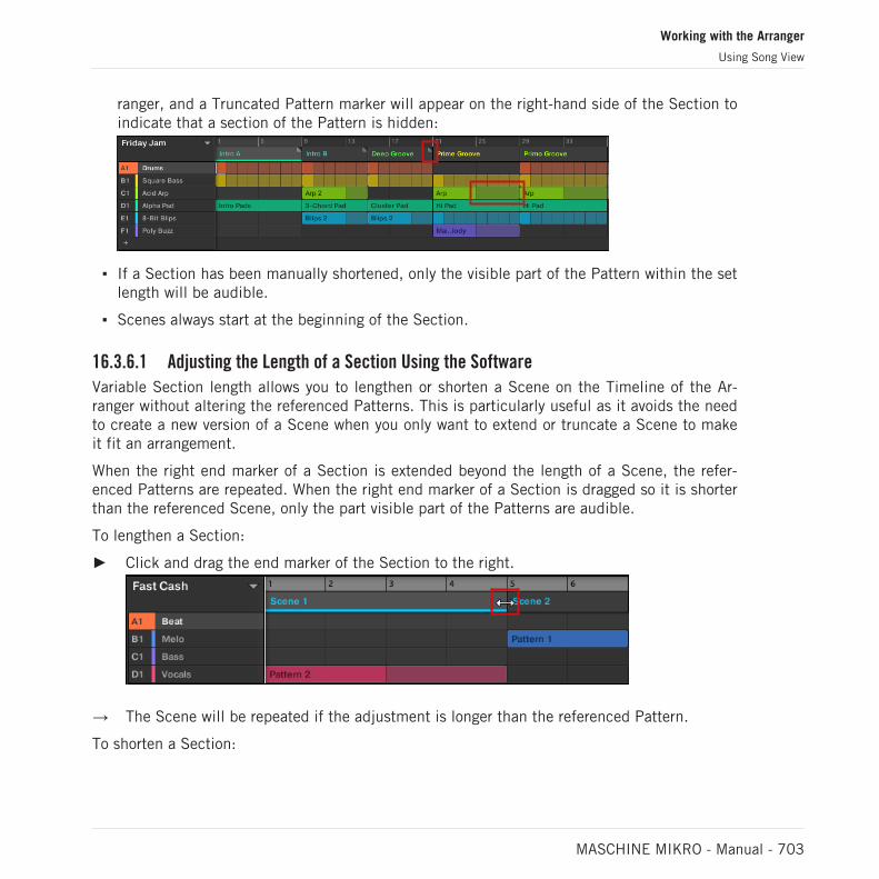
ranger, and a Truncated Pattern marker will appear on the right-hand side of the Section toindicate that a section of the Pattern is hidden:
▪ If a Section has been manually shortened, only the visible part of the Pattern within the setlength will be audible.
▪ Scenes always start at the beginning of the Section.
16.3.6.1 Adjusting the Length of a Section Using the Software
Variable Section length allows you to lengthen or shorten a Scene on the Timeline of the Ar-ranger without altering the referenced Patterns. This is particularly useful as it avoids the needto create a new version of a Scene when you only want to extend or truncate a Scene to makeit fit an arrangement.
When the right end marker of a Section is extended beyond the length of a Scene, the refer-enced Patterns are repeated. When the right end marker of a Section is dragged so it is shorterthan the referenced Scene, only the part visible part of the Patterns are audible.
To lengthen a Section:
► Click and drag the end marker of the Section to the right.
→ The Scene will be repeated if the adjustment is longer than the referenced Pattern.
To shorten a Section:
Working with the Arranger
Using Song View
MASCHINE MIKRO - Manual - 703

► Click and drag the end marker of the Section to the left.
→ The Scene will be shortened, and if the adjustment is shorter than the referenced Patterna small Truncated Clip marker will appear on the right-hand side of the Section to indi-cate that a part of the Scene is hidden. Only the visible part of the Scene will be audibleduring playback.
When adjusting the size of a Section the following rules apply:
▪ The value set in the Arrange Grid is used for length increments. For more information onArrange Grid, read: ↑16.6, The Arrange Grid.
▪ When [Shift] is pressed while changing the length, the value set in the Step Grid is used.For more information on Step Grid, read: ↑11.1.7, Adjusting the Step Grid and the NudgeGrid.
▪ The minimum length a Section marker can be dragged without modifier is one Arrange Gridincrement.
▪ When [Shift] is pressed, the minimum length a Section marker can be dragged is one StepGrid increment.
▪ The minimum length of a Section equals the minimum Scene length. This can only be ach-ieved if Arrange Grid or Step Grid is set to Off.
Working with the Arranger
Using Song View
MASCHINE MIKRO - Manual - 704

16.3.6.2 Adjusting the Length of a Section Using the Controller
To adjust the length of a Section using your hardware controller:
1. Press SHIFT + SCENE (Section) to enter Song view.
2. Select the pad relating to the Section you want to adjust.
3. Press the Right Arrow button to access Length.
4. Turn the Encoder to adjust the length of the Section as required. Turning the knob coun-terclockwise will shorten the Section, turning it clockwise will lengthen the Section.
5. Press SHIFT and turn the Encoder to change the Section length in smaller increments.
→ The Section length is adjusted accordingly.
16.3.7 Clearing a Pattern in Song View
Clearing a Pattern allows you to remove all its contents, leaving the Pattern empty.
To clear a Pattern in Song view:
1. Right-click ([Ctrl]-click on macOS) the name of the Pattern you want to clear.
2. Select Clear from the context menu.
→ The Pattern is cleared of all its contents.
16.3.8 Duplicating Sections
The Song view allows you to duplicate a Section. This feature works in connection with settingsmade in the Default page of the Preferences.
Together they offer you options to:
▪ duplicate Scenes,
▪ duplicate Scenes and Patterns,
▪ link when duplicating Sections
Working with the Arranger
Using Song View
MASCHINE MIKRO - Manual - 705
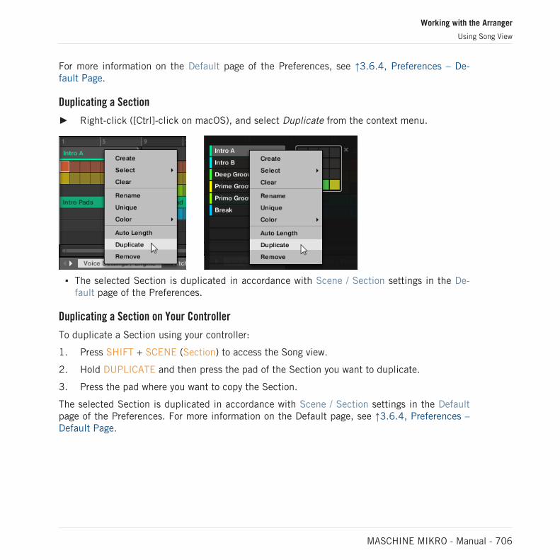
For more information on the Default page of the Preferences, see ↑3.6.4, Preferences – De-fault Page.
Duplicating a Section
► Right-click ([Ctrl]-click on macOS), and select Duplicate from the context menu.
▪ The selected Section is duplicated in accordance with Scene / Section settings in the De-fault page of the Preferences.
Duplicating a Section on Your Controller
To duplicate a Section using your controller:
1. Press SHIFT + SCENE (Section) to access the Song view.
2. Hold DUPLICATE and then press the pad of the Section you want to duplicate.
3. Press the pad where you want to copy the Section.
The selected Section is duplicated in accordance with Scene / Section settings in the Defaultpage of the Preferences. For more information on the Default page, see ↑3.6.4, Preferences –Default Page.
Working with the Arranger
Using Song View
MASCHINE MIKRO - Manual - 706

16.3.8.1 Making Sections Unique
At any time, you can make a linked Section totally unique. This will create a new Section inthe same location, and will also create new Patterns. You are then free to edit the Patterns inthe Section, or the data in the Patterns, without affecting any of the original Sections. This isgreat for when you want to introduce variations into a song structure that’s been made withlinked Sections.
To make a Section unique in the MASCHINE software:
1. Right-click (or ([Ctrl]-click on OS X) the Section you want to make unique in the Timeline.The context menu will open.
2. Click Unique.
→ The Section will become independent of any Sections it was linked to and the Patternscan be edited without affecting any the original Sections.
16.3.9 Removing Sections
To remove a Section from the arrangement:
Working with the Arranger
Using Song View
MASCHINE MIKRO - Manual - 707

► In the top row of the Song view, right-click ([Ctrl]-click on macOS) the name of the Sec-tion you want to remove and select Remove from the context menu:
→ The Section is removed from the arrangement. The next Sections shift ahead to fill thegap.
Instead of removing the Section, which removes it entirely, you can also clear the Section: This willonly remove its content, the Section will stay in your arrangement, but empty. For more informationon clearing Sections, see section ↑16.3.11, Clearing Sections.
Removing Sections on the Controller
To remove a Section using your controller:
1. Press SHIFT + SCENE (Section) to access the Song view.
2. Press ERASE + the pad corresponding to the Section you want to remove.
→ The Section is removed from the arrangement.
16.3.10 Renaming Scenes
Sections are displayed in the software using the names of the Scene they reference. Sectionsdo not have separate names from the Scene they represent. On the controller, they are refer-enced by their position, for example, #4.
Working with the Arranger
Using Song View
MASCHINE MIKRO - Manual - 708
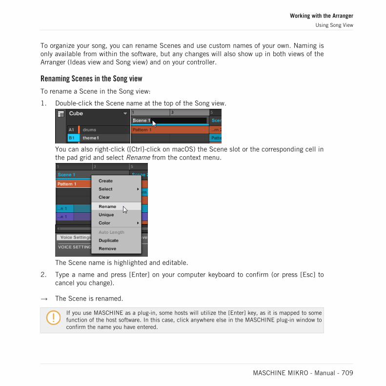
To organize your song, you can rename Scenes and use custom names of your own. Naming isonly available from within the software, but any changes will also show up in both views of theArranger (Ideas view and Song view) and on your controller.
Renaming Scenes in the Song view
To rename a Scene in the Song view:
1. Double-click the Scene name at the top of the Song view.
You can also right-click ([Ctrl]-click on macOS) the Scene slot or the corresponding cell inthe pad grid and select Rename from the context menu.
The Scene name is highlighted and editable.
2. Type a name and press [Enter] on your computer keyboard to confirm (or press [Esc] tocancel you change).
→ The Scene is renamed.
If you use MASCHINE as a plug-in, some hosts will utilize the [Enter] key, as it is mapped to somefunction of the host software. In this case, click anywhere else in the MASCHINE plug-in window toconfirm the name you have entered.
Working with the Arranger
Using Song View
MASCHINE MIKRO - Manual - 709
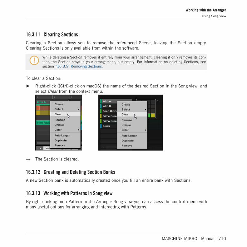
16.3.11 Clearing Sections
Clearing a Section allows you to remove the referenced Scene, leaving the Section empty.Clearing Sections is only available from within the software.
While deleting a Section removes it entirely from your arrangement, clearing it only removes its con-tent, the Section stays in your arrangement, but empty. For information on deleting Sections, seesection ↑16.3.9, Removing Sections.
To clear a Section:
► Right-click ([Ctrl]-click on macOS) the name of the desired Section in the Song view, andselect Clear from the context menu.
→ The Section is cleared.
16.3.12 Creating and Deleting Section Banks
A new Section bank is automatically created once you fill an entire bank with Sections.
16.3.13 Working with Patterns in Song view
By right-clicking on a Pattern in the Arranger Song view you can access the context menu withmany useful options for arranging and interacting with Patterns.
Working with the Arranger
Using Song View
MASCHINE MIKRO - Manual - 710

16.3.13.1 Creating a Pattern in Song View
In Song view use the right-click context menu to create a new Pattern within a Section.
To create a new Pattern in Song view:
► Right-click ([Ctrl]-click on macOS) an empty cell the Section where you want to create anew Pattern, and click Create in the menu.
→ A new empty Pattern is created within the selected Section.
16.3.13.2 Selecting a Pattern in Song View
In Song view use the right-click context menu to select an alternative Pattern for a Section.
To select a Pattern in Song view:
► Right-click ([Ctrl]-click on macOS) the Pattern you want to change, and click Select in themenu.
→ A new Pattern is selected for this Scene and will appear in each Section where the Sceneis used.
16.3.13.3 Clearing a Pattern in Song View
In Song view use the right-click context menu to clear the contents of a Pattern. Clearing thecontents will remove all events and audio loops from the Pattern.
To clear the contents of a Pattern in Song view:
► Right-click ([Ctrl]-click on macOS) the Pattern you want to clear, and click Clear in themenu.
→ The contents of the selected Pattern are cleared.
16.3.13.4 Renaming a Pattern in Song View
In Song view use the right-click context menu to rename a Pattern within a Section.
To rename a Pattern in Song view:
Working with the Arranger
Using Song View
MASCHINE MIKRO - Manual - 711

► Right-click ([Ctrl]-click on macOS) the name of the Pattern you want to rename, and clickRename in the menu.
→ The Pattern is renamed.
16.3.13.5 Coloring a Pattern in Song View
In Song view use the right-click context menu to change the color of a Pattern within a Sec-tion.
To recolor a Pattern in Song view:
1. Right-click ([Ctrl]-click on macOS) the Pattern you want to recolor, and select Color in themenu.
2. Select a new color.
→ The selected Pattern is recolored.
16.3.13.6 Removing a Pattern in Song View
In Song view use the right-click context menu to remove a Pattern from a Section.
To remove a Pattern from a Section in Song view:
► Right-click ([Ctrl]-click on macOS) the name of the Pattern you want to remove, and clickRemove in the menu.
→ The Pattern is removed from the Section but not deleted. You can add the Pattern back tothe Scene by using Select in the right-click menu.
For more information on Select see ↑16.3.13.2, Selecting a Pattern in Song View.
16.3.13.7 Duplicating a Pattern in Song View
In Song view use the right-click context menu to duplicate a Pattern within the selectedScene.
To duplicate a Pattern in Song view:
► Right-click ([Ctrl]-click on macOS) the Pattern you want to duplicate, and click Duplicatein the menu.
Working with the Arranger
Using Song View
MASCHINE MIKRO - Manual - 712

→ The selected Pattern is duplicated. The duplicate Pattern will take the place of the exist-ing Pattern in the Scene and appear in each Section where the Scene is used in the ar-rangement.
16.3.14 Enabling Auto Length
By default a Section is set to Auto Length allowing it to resize automatically to the contentwithin the Section. If the length of a Section is manually adjusted by truncating or lengtheningthe Section end marker, Auto Length is discarded and the Section automatically set to ManualLength.
Using the software or controller it is possible to quickly reset a Section to back to Auto Lengthin order to return to the Section to its default state and reveal any truncated (hidden) content.When Auto Length is enabled, the Manual Length settings are discarded and the Section is re-sized according to the Patterns in the assigned Scene, and will continue to resize with the con-tent unless the length is again manually adjusted.
To enable Auto Length for a Section in the software:
1. Right-click ([Ctrl]+click on macOS) on the Section.
2. Click Auto Length in the menu.
→ Auto Length is enabled and the selected Section is automatically resized to fit the contentof the Patterns within the assigned Scene. Any manual adjustments that were previouslymade are discarded.
Working with the Arranger
Using Song View
MASCHINE MIKRO - Manual - 713

To enable Auto Length for a Section using your controller:
1. Press SHIFT + SCENE (Section) to enter Song view.
2. Press the corresponding pad to select a Section.
3. Press the Arrow buttons to select Length.
4. Turn the Encoder to select Auto.
→ The selected Section is automatically resized to fit the content of the Patterns within theassigned Scene.
16.3.15 Looping
Activate a Loop to repeatedly play a section of the Arrangement. Once a loop is activated theSections within the range of the Loop play until the loop is deactivated. You can use the rangeto repeatedly play a particular part of a song. This can be good for composing, practicing a partbefore recording, recording multiple takes, etc. The loop range is permanently visible, (evenwhen it is deactivate) and the range of the loop can be altered at any time using the left andright end points.
16.3.15.1 Setting the Loop Range in the Software
Set the start, end and position of the loop using the dedicated Loop range in the Timeline. Thevalue set in the Arrange Grid is used for Loop range increments and movement of the looprange itself.
To adjust the Loop range using the software:
► Drag the left or right end of the Loop marker to make it longer.
→ The Loop range is elongated.
Working with the Arranger
Using Song View
MASCHINE MIKRO - Manual - 714

To move the Loop using the software:
► Click and drag the Loop range left or right.
→ The whole Loop range is moved.
Activating or Deactivating a Loop in the Software
To activate a Loop using the software:
► Click the Loop button in the header to activate or deactivate the loop.
→ When the Loop is activated the Sections within the Loop range are repeated.
16.3.15.2 Activating or Deactivating a Loop Using the Controller
Activating or Deactivating a Loop Using the Controller
To activate a Loop using the controller:
► Press SHIFT + RESTART (Loop) to activate or deactivate the loop.
→ When the loop is activated the Scenes within the Loop range are repeated.
16.4 Playing with Sections
MASCHINE provides you with various tools to precisely control which Section has to be played,and when.
Working with the Arranger
Using Song View
MASCHINE MIKRO - Manual - 715

Studio Track or Live Performance?
If you are composing a studio track that you plan to export as is, you can arrange your Sectionsso that your whole track can be played in one go from the very first Section to the very last one.
Please refer to section ↑5.4.3, Exporting Audio for information on exporting audio.
Alternatively, if you are preparing a track for performing live, you will probably want to switchback and forth between different Scenes in Ideas view during your performance.
This may also be necessary if you are composing a studio track in your host sequencer andwant to control which Scenes or Sections the MASCHINE plug-in has to play. This is where theMASCHINE tools described in the following sections come in handy.
16.4.1 Jumping to another Playback Position in Your Project
You can use the timeline above the Scene headers in the Song view to set the playback to thedesired position.
In the timeline and across the entire height of the Song view, the playhead (a white verticalline) indicates the current play position in your Project.
The playhead shows you the current play position.
At any time you can jump to another position in your Project:
► Click anywhere in the timeline to move the playhead to that position in the Project.
Depending on the playback state, the following will happen:
Working with the Arranger
Playing with Sections
MASCHINE MIKRO - Manual - 716

▪ If playback is off, the playhead jumps to the closest Perform Grid division. If the PerformGrid is set to Off (i.e. disabled), the playhead jumps to the exact position you have clicked.If the Perform Grid is set to Quick, the playhead jumps to the beginning of the bar youhave clicked in.
▪ If playback is on, the playhead jumps to the closest position near your mouse cursor andretains the playhead position relative to the Perform Grid division. This allows seamlessjumps that don’t break the rhythm of your music. If the Perform Grid is set to Off (i.e. disa-bled) or Quick, the playhead position is retained relative to the current bar.
You can also change the playback position by switching to another Scene. The moment at which thejump will occur depends on the Perform Grid setting. See section ↑11.1.6, Adjusting the ArrangeGrid and the Pattern Length for more information.
16.5 Triggering Sections or Scenes via MIDI
You can trigger and change Sections and Scenes using MIDI Note or MIDI Program Changemessages sent from your host to the MASCHINE plug-in or MIDI controller.
When this feature is enabled, MIDI notes or Program Change messages are linked to the first128 Section slots or Scenes (depending on your settings) whether they are empty or not:
Section/Scene Slot MIDI Note Number Program Change Number
1 0 1
2 1 2
3 2 3
… … …
128 127 128
MIDI Note numbers: Host applications use various conventions to name MIDI notes. For example, inMASCHINE, MIDI note number 0 is referred to as C-2 and MIDI note number 60 (middle C) as C3.Please refer to the documentation of your host to know which convention is used.
Working with the Arranger
Triggering Sections or Scenes via MIDI
MASCHINE MIKRO - Manual - 717

Program Change numbers: Some host applications send Program Change numbers in the range [0–127] instead of [1–128]. In that case, the PC number 0 will trigger Section/Scene slot 1, PC 1 willtrigger Section/Scene slot 2, etc. Please refer to the documentation of your host to know in whichrange it sends Program Change numbers.
To enable or disable Section/Scene MIDI Change feature, do the following:
► Click Edit > MIDI Change from the menu.
→ The MIDI Change dialog appears.
In the MIDI Change dialog:
1. In Scene option click the Enabled checkbox to enable Scenes in the Ideas view to be trig-gered. In Section option, click the Enabled checkbox to enable Sections in the Song viewto be triggered.
2. In the Source submenu, select the name of your controller.
3. In the Trigger submenu for Scene and Section, select MIDI Note to trigger via MIDI notes,Program Change to trigger via MIDI Program Change messages, or None (default setting)to disable MIDI Change completely.
Working with the Arranger
Triggering Sections or Scenes via MIDI
MASCHINE MIKRO - Manual - 718

4. In the Channel submenu, select the MIDI channel the Scenes or Sections should receiveMIDI messages from.
16.6 The Arrange Grid
The Arrange Grid is used to quantize all modifications related to the timeline. The value sethere is used for following features:
▪ Loop start / length
▪ Loop position
▪ Pattern length
▪ Scene length
▪ Song Clip start / length
▪ Playhead relocation
The Arrange Grid setting is located at the bottom left corner of the Arranger area and can beactivated/deactivated by toggling the Grid symbol.
1. Click the Grid symbol next to the value to enable the Arrange Grid.
Working with the Arranger
The Arrange Grid
MASCHINE MIKRO - Manual - 719

2. Click the current Arrange Grid value to open the drop-down menu.
3. Select a new value for the Arrange Grid.
→ The selected Arrange Grid value is applied.
On your controller:
1. Press the SHIFT + FOLLOW (Grid) button to access the Grid page.
2. Press the Right Arrow button to access Arrange.
3. Turn the Encoder to select an Arrange Grid value.
→ The selected Arrange Grid value is applied.
16.7 Quick Grid
The Quick Grid setting allows you to quickly and conveniently set the most common Patternlengths using your controller.
Quick Grid is only accessible from your controller.
Working with the Arranger
Quick Grid
MASCHINE MIKRO - Manual - 720

When the Quick Grid is used, the following rules apply:
▪ The available Pattern lengths are as follows:1 bar, 2 bars, 4 bars, 8 bars, 12 bars, 16 bars,etc. (+ 4 bars each time starting from 4 bars).
▪ The Quick Grid is exclusively applied to Pattern Length. For all other features related to theGrid (for example, adjusting the playback position or the Loop Range), the Arrange Grid isused.
▪ The Quick Grid setting is global and applies to all Patterns.
▪ When the Quick Grid is set to OFF, the Arrange Grid is used.
Working with the Arranger
Quick Grid
MASCHINE MIKRO - Manual - 721

17 Sampling and Sample Mapping
MASCHINE allows you to record internal or external audio signals without having to stop thesequencer. This is a useful feature if you want to record your own Samples, or rearrange loopsthat you have created yourself using MASCHINE.
You can apply various types of destructive processing to the recorded audio or to any Sampleyou want to use in a Sound.
The slicing feature allows you to slice loops in order to make them playable at any tempo with-out changing their pitch or timing. It is also useful to extract single Samples from loops (e.g., asnare sound from a drum loop) quickly or to rearrange loops by editing or muting their Slices,changing the order of the Slices, applying a different quantization or adding Swing.
Last but not least you can map your Samples to particular Zones, thereby creating multi-sam-ple Sounds with individual velocity and note ranges, volume and panning. This is useful to em-ulate the behavior of classic instruments and synthesizers, but also allows for a large amountof Samples in only one Sound.
All this can be done in the Sample Editor.
Make sure you check out the tutorial videos regarding sampling on the Native Instrumentswebsite (http://www.native-instruments.com).
Before recording an external source please consult the documentation that came with your audiointerface for information on connecting audio devices and instruments.
17.1 Opening the Sample Editor
To access the Sample Editor in the software, do the following:
1. In the Sound List left of the Pattern Editor, click the desired Sound to put it under focus.For more details on how to set the focus to a Sound, please see section ↑3.3.3, Focusingon a Group or a Sound.
Sampling and Sample Mapping
Opening the Sample Editor
MASCHINE MIKRO - Manual - 722

2. Click the Sample Editor button on the left of the Pattern Editor to switch to the SampleEditor.
The Sample Editor appears and displays the Sample content of the focused Sound.
3. In the Sample Editor, click the desired tab at the top to access the corresponding page:
▪ The Record page allows you to record audio: ↑17.2, Recording Audio.
▪ The Edit page allows you to apply destructive edits to existing Samples: ↑17.3, Editing aSample.
▪ The Slice page allows you to create Slices from your existing Samples: ↑17.4, Slicing aSample.
▪ The Zone page allows you to assign your Samples to particular note and velocity ranges(called Zones) in your Sound and to adjust various playback settings for each Zone individ-ually: ↑17.5, Mapping Samples to Zones.
Entering Sampling Mode on the Controller
The equivalent to the Sample Editor on your controller is the Sampling mode. To enter Sam-pling mode, do the following:
1. With your controller in Pad Mode, press the pad of the Sound in which you want to recordthe Sample. For more details on how to set the focus to a Sound, please see section↑3.3.3, Focusing on a Group or a Sound.
2. Press SAMPLING to enter Sampling mode and access the Sample content of the focusedSound.
In the software:
▪ The Record page allows you to record audio: ↑17.2, Recording Audio.
▪ The Edit page allows you to apply destructive edits to existing Samples: ↑17.3, Editing aSample.
Sampling and Sample Mapping
Opening the Sample Editor
MASCHINE MIKRO - Manual - 723

▪ The Slice page allows you to create Slices from your existing Samples: ↑17.4, Slicing aSample.
▪ The Zone page allows you to assign your Samples to particular note and velocity ranges(called Zones) in your Sound and to adjust various playback settings for each Zone individ-ually: ↑17.5, Mapping Samples to Zones.
The Sample Editor in the software is always in sync with the Sampling mode on your controller: En-tering/leaving Sampling mode on your controller will automatically show/hide the Sample Editor inthe software, and inversely. The page currently displayed in the Sample Editor / Sampling mode isalso in sync.
17.2 Recording Audio
MASCHINE provides everything you need to record audio.
17.2.1 Opening the Record Page
In the software, recording audio is done in the Sample Editor. By default the Sample Editor ison the blank Record page and no further tabs are visible. The Record page tab, plus additionaltabs, will become visible once audio has been recorded.
The Record page looks as follows:
Sampling and Sample Mapping
Recording Audio
MASCHINE MIKRO - Manual - 724
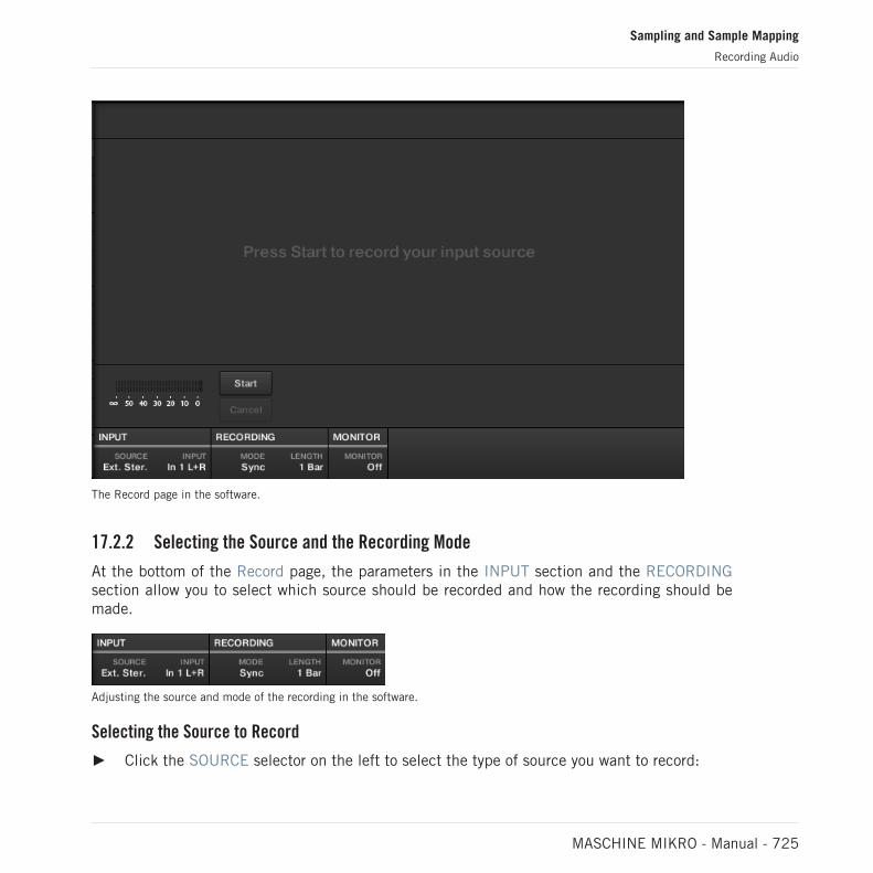
The Record page in the software.
17.2.2 Selecting the Source and the Recording Mode
At the bottom of the Record page, the parameters in the INPUT section and the RECORDINGsection allow you to select which source should be recorded and how the recording should bemade.
Adjusting the source and mode of the recording in the software.
Selecting the Source to Record
► Click the SOURCE selector on the left to select the type of source you want to record:
Sampling and Sample Mapping
Recording Audio
MASCHINE MIKRO - Manual - 725
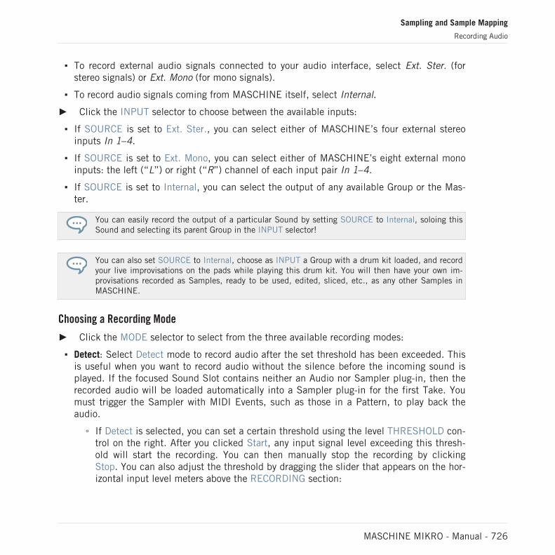
▪ To record external audio signals connected to your audio interface, select Ext. Ster. (forstereo signals) or Ext. Mono (for mono signals).
▪ To record audio signals coming from MASCHINE itself, select Internal.
► Click the INPUT selector to choose between the available inputs:
▪ If SOURCE is set to Ext. Ster., you can select either of MASCHINE’s four external stereoinputs In 1–4.
▪ If SOURCE is set to Ext. Mono, you can select either of MASCHINE’s eight external monoinputs: the left (“L”) or right (“R”) channel of each input pair In 1–4.
▪ If SOURCE is set to Internal, you can select the output of any available Group or the Mas-ter.
You can easily record the output of a particular Sound by setting SOURCE to Internal, soloing thisSound and selecting its parent Group in the INPUT selector!
You can also set SOURCE to Internal, choose as INPUT a Group with a drum kit loaded, and recordyour live improvisations on the pads while playing this drum kit. You will then have your own im-provisations recorded as Samples, ready to be used, edited, sliced, etc., as any other Samples inMASCHINE.
Choosing a Recording Mode
► Click the MODE selector to select from the three available recording modes:
▪ Detect: Select Detect mode to record audio after the set threshold has been exceeded. Thisis useful when you want to record audio without the silence before the incoming sound isplayed. If the focused Sound Slot contains neither an Audio nor Sampler plug-in, then therecorded audio will be loaded automatically into a Sampler plug-in for the first Take. Youmust trigger the Sampler with MIDI Events, such as those in a Pattern, to play back theaudio.
◦ If Detect is selected, you can set a certain threshold using the level THRESHOLD con-trol on the right. After you clicked Start, any input signal level exceeding this thresh-old will start the recording. You can then manually stop the recording by clickingStop. You can also adjust the threshold by dragging the slider that appears on the hor-izontal input level meters above the RECORDING section:
Sampling and Sample Mapping
Recording Audio
MASCHINE MIKRO - Manual - 726

Any input level reaching the slider position will start the recording. Double-click theslider to reset the threshold to its default value (-12 dB).
▪ Sync: Select Sync to start recording audio in time with the Pattern Grid. If the focusedSound Slot contains neither an Audio nor Sampler plug-in, then the recorded Sample willbe loaded automatically into a Sampler plug-in as the first Take. You must trigger the Sam-pler with MIDI Events, such as those in a Pattern, to play back the audio.
◦ When Sync is selected recording starts in sync with the sequencer after you clickStart. Recording will begin at the start of the next bar. The LENGTH control on theright allows you to choose a length for the recording: either 1, 2, 4, 8, or 16 bars, orchoose Free if you do not want to set a duration limit to the recording. At any time youcan click Stop to end recording, and the recording will stop at the next bar.
▪ Loop: Select Loop to record audio that you intend to play back in-sync with your Projectusing the Audio plug-in. It records audio in the same way as Sync however, when Loopmode is selected, an additional parameter appears called Target. In Loop mode the record-ing is loaded into an Audio plug-in so that you can immediately hear the results. The Tar-get parameter dictates how MASCHINE loads new recordings into the Audio plug-in:
◦ Take: Select this to record each new Take into the focused Sound slot. After a Take isrecorded it will become visible in the Audio Pool and is automatically selected forplayback. You can review all the Takes you’ve captured in the Audio Pool, and you canalso select any of these Takes to make it the one that actively plays back in the Audioplug-in.
◦ Sound: Select this Target to enable a layered workflow similar to that achieved withguitar loop pedals. When using this mode, each recording that you make will be load-ed into an empty Sound Slot in the current Group and Pattern and will begin playingback. Therefore, each recording that you make will play back layered on top of all theprevious recordings made in that particular Group and Pattern. By layering each newTake onto a new Sound you can quickly build a whole pattern. You can continue thisprocess until all empty Sound slots in the Group are used up, then after that, eachadditional recording will simply be recorded as a new Take into the last Sound of theGroup that contains an Audio plug-in (and the previous Takes will still be preserved ifyou want to switch back to them).
Sampling and Sample Mapping
Recording Audio
MASCHINE MIKRO - Manual - 727

◦ Pattern: Select this Target to record in a similar way to the Sound Target describedabove, except that each new recording will also be assigned to a new Pattern on itsown. This mode can be useful when you want to record different variations of a partand then review the variations easily by playing each Pattern. For example, the firstrecording made will be placed into an Audio plug-in in the first available Sound Slotin the Group, and then a new Pattern will be created where only this new recording isplaying back. Making another recording will result in the recording being loaded intoanother unused Sound Slot, and another new Pattern will be made where only thismost recent recording is playing. If you then switch back to the previous Pattern,you’ll hear only the previous recording (the newest will automatically be disabled inthe previous Pattern).
Monitoring the Input Signal
Visually controlling the input signal.
The level meters above the RECORDING section show you at any time the level of the selectedaudio source. For example, this can come in handy to adjust the appropriate threshold in De-tect mode. For this purpose, in Detect mode the level meters additionally provide a fader ad-justing the threshold level, this fader is a strict equivalent to the THRESHOLD control descri-bed above. This way, you can easily visualize when the input signal exceeds the current thresh-old (and hence, when it would start the recording) and adjust that threshold accordingly.
Monitoring the input signal.
Furthermore, if you have selected an external signal (Ext. Ster. or Ext. Mono selected inSOURCE), an additional MONITOR section appears on the right. In this section, activate theMONITOR button to send the input signal to the Cue bus of MASCHINE, allowing you to hearon a separate channel (e.g., your headphones) the audio source that is about to be recorded.
For more information on how to use the Cue bus, please refer to section ↑13.2.6, Using the CueBus.
Sampling and Sample Mapping
Recording Audio
MASCHINE MIKRO - Manual - 728

17.2.3 Arming, Starting, and Stopping the Recording
The Start and Cancel buttons.
► Click Start to arm the recording.
After the recording has been armed, its behavior will depend on the recording mode you haveselected (via the MODE selector, see section ↑17.2.2, Selecting the Source and the RecordingMode above):
▪ When recording in Detect mode:
◦ The recording will start as soon as the input signal exceeds the THRESHOLD value.Until then the Start button turns to a Waiting button and the Waiting for input… mes-sage appears in the information bar above the waveform display. During this waitingphase you can also start the recording manually by clicking the Waiting button or can-cel the recording by clicking Cancel.
◦ Once the recording has started, click Stop to stop the recording (it stops immediately)or Cancel to cancel the recording (the recorded audio will not be saved).
▪ When recording in Sync mode:
◦ The recording will start at the next bar. Until then the Start button reads a flashingWaiting label and the Waiting for the next bar… message appears in the informationbar above the waveform display.
◦ Once the recording has started, the audio is recorded for the duration set by theLENGTH control (see section ↑17.2.2, Selecting the Source and the Recording Modeabove). You can also click Stop beforehand to stop the recording at the next bar, orCancel to cancel the recording (in that case the recorded audio will not be saved).
▪ When recording in Loop mode:
◦ The recording will start at the beginning of the Pattern. Until then the Start buttonreads a flashing Waiting label and the Waiting for end of Pattern… message appearsin the information bar above the waveform display.
Sampling and Sample Mapping
Recording Audio
MASCHINE MIKRO - Manual - 729

◦ Once the recording has started, the audio is recorded for the duration set by theLENGTH control (see section ↑17.2.2, Selecting the Source and the Recording Modeabove). You can also click Stop beforehand to stop the recording at the next bar, orCancel to cancel the recording (in that case the recorded audio will not be saved).
If you want to start and stop the recording manually, you can set the MODE to Detect, dial theTHRESHOLD down to OFF, and start the recording by clicking Start. To stop recording, click Stop.
In any case the recorded audio will be stored in the Sound that was under focus as you startedthe recording.
When Recording is Complete
When the recording is done, the following things happen:
▪ Each Take is named and stored as a file on your hard disk (see section ↑17.2.6, Locationand Name of Your Recorded Samples).
▪ Its waveform appears in the waveform display and its name appears in the information barabove.
▪ The recording is automatically appended to the Audio Pool of the Sound and selected (seesection ↑17.2.5, Checking Your Recordings below).
▪ A Sampler Plug-in is automatically loaded in the first Plug-in slot of the Sound, ready toplay your new recording. All Plug-ins previously loaded in that Sound are removed. Howev-er, when recording in Loop mode, an Audio plug-in will be loaded. If there was already aSample Plug-in in the Slot when engaging Loop recording, it will not change the Samplerto an Audio plug-in, it will remain as a Sampler and you will need to manually change theplug-in to Audio if you wish. In this case all recorded takes will be preserved.
▪ The Sound slot takes the name of your recording.
▪ If the Sampler Plug-in was used in Detect mode or Sync mode, the recording is mapped toa new Zone covering the entire key and velocity ranges in the Zone page, which makes yournew sample directly playable from the pad of its Sound slot (or from all your pads if padsare in Keyboard mode). Any existing Zones will be replaced. The sample must then be trig-gered using MIDI Events in the Pattern Editor. For more information on Zones, see section↑17.5, Mapping Samples to Zones.
Sampling and Sample Mapping
Recording Audio
MASCHINE MIKRO - Manual - 730

▪ If the Audio Plug-in was used in Loop mode, the last recorded Take will automatically playback with the Pattern.
Note that any MIDI Events for that Sound in the current Pattern will remain. As a consequence,your recording might directly start to play at the pitch defined by the existing MIDI Events.
17.2.4 Arming, Starting, and Stopping the Recording on Your Controller
1. Press SAMPLING.
2. Press the Encoder (Start) to arm the recording.
→ After the recording has been armed, its behavior will depend on the recording mode youhave selected via the software, see section ↑17.2.2, Selecting the Source and the Record-ing Mode.
► To stop recording, press the Encoder (Cancel).
17.2.5 Checking Your Recordings
You can visualize the last recordings you have made in the current Sound:
Sampling and Sample Mapping
Recording Audio
MASCHINE MIKRO - Manual - 731

1
2
3
4
5
The waveform display and the information bar displaying a recording.
(1) Waveform display
Shows the waveform of the recording currently selected in the Audio Pool (5) — by defaultyour last recording:
▪ Use the scroll wheel of your mouse to zoom in/out. You can also use the zooming scroll bar(2).
▪ When the Sample is played back (e.g., by pressing the pad or by clicking the little playicon in the information bar (4)), a playhead indicator (white vertical line) shows you the cur-rent play position within the waveform.
▪ Right-click (macOS: [Ctrl]-click) anywhere in the waveform to open a context menu with thefollowing commands:
Sampling and Sample Mapping
Recording Audio
MASCHINE MIKRO - Manual - 732

Command Description
Open containing folder Opens the folder on your hard disk containing the Sample, providingquick access to the original file.
Save Sample As… Opens a Save Sample As dialog allowing to save the recorded Sampleunder another name and/or to another location on your computer.
(2) Zooming scroll bar
Click the main part of the scroll bar and drag your mouse horizontally to scroll through thewaveform on the horizontal axis (time), or drag it vertically to zoom in/out on the same timeaxis. You can also click the left or right handle of the scroll bar and drag it horizontally to zoomin/out while keeping the opposite border of the display at a fix position in the waveform. Dou-ble-click the main part of the bar to reset the zoom and display the entire waveform. Alterna-tively you can use the scroll wheel of your mouse when hovering the waveform display (1) tozoom in/out.
(3) Timeline
Shows the time scale in bars (Sync mode) or seconds (Detect mode).
(4) Information bar
Displays the file name and the length of the recorded Sample. Click and hold the little playicon on the left to listen to the Sample on the Cue bus (see section ↑13.2.6, Using the CueBus for more information). Click the little circle (or pair of circle) at the far right to switch thewaveform display (1) between single-channel and two-channel display.
(5) Audio Pool
All the takes you have made since you opened the current Project are stored in the Audio Pooland displayed as mini waveforms under the waveform display. The following actions are availa-ble:
▪ Click any take to display the recording, you can then further edit this recording via the oth-er pages of the Sample Editor. When selected, a recording is also automatically mapped toa new Zone covering the entire key and velocity ranges in the Zone page. Any existingZones will be replaced.
▪ Click and hold the little play icon in the bottom right corner to listen to the Sample on theCue bus without loading it in the waveform nor in the Zone page.
Sampling and Sample Mapping
Recording Audio
MASCHINE MIKRO - Manual - 733
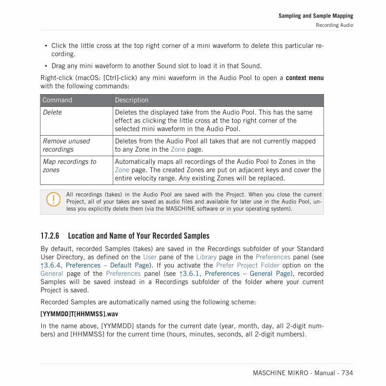
▪ Click the little cross at the top right corner of a mini waveform to delete this particular re-cording.
▪ Drag any mini waveform to another Sound slot to load it in that Sound.
Right-click (macOS: [Ctrl]-click) any mini waveform in the Audio Pool to open a context menuwith the following commands:
Command Description
Delete Deletes the displayed take from the Audio Pool. This has the sameeffect as clicking the little cross at the top right corner of theselected mini waveform in the Audio Pool.
Remove unusedrecordings
Deletes from the Audio Pool all takes that are not currently mappedto any Zone in the Zone page.
Map recordings tozones
Automatically maps all recordings of the Audio Pool to Zones in theZone page. The created Zones are put on adjacent keys and cover theentire velocity range. Any existing Zones will be replaced.
All recordings (takes) in the Audio Pool are saved with the Project. When you close the currentProject, all of your takes are saved as audio files and available for later use in the Audio Pool, un-less you explicitly delete them (via the MASCHINE software or in your operating system).
17.2.6 Location and Name of Your Recorded Samples
By default, recorded Samples (takes) are saved in the Recordings subfolder of your StandardUser Directory, as defined on the User pane of the Library page in the Preferences panel (see↑3.6.4, Preferences – Default Page). If you activate the Prefer Project Folder option on theGeneral page of the Preferences panel (see ↑3.6.1, Preferences – General Page), recordedSamples will be saved instead in a Recordings subfolder of the folder where your currentProject is saved.
Recorded Samples are automatically named using the following scheme:
[YYMMDD]T[HHMMSS].wav
In the name above, [YYMMDD] stands for the current date (year, month, day, all 2-digit num-bers) and [HHMMSS] for the current time (hours, minutes, seconds, all 2-digit numbers).
Sampling and Sample Mapping
Recording Audio
MASCHINE MIKRO - Manual - 734

17.3 Editing a Sample
The Edit page of the Sample Editor in the software and its equivalent the EDIT page of theSampling mode on your controller allow you to adjust the start and end points of a Sample orSlice and to apply various destructive audio processing functions to any part of the Sample.
Sample Editing can only be done in the Sampler plug-in, not using the Audio plug-in. If you want toedit a Sample in the Audio plug-in, you must first switch it to a Sampler Plug-in, make the edit,and then switch back to the Audio Plug-in again.
Which Sample Is Shown in the Edit Page?
The Edit page (EDIT page on your controller) always displays the Sample of the Zone currentlyselected (see section ↑17.5.3, Selecting and Managing Zones in the Zone List for more infor-mation on selecting Zones), and all your actions in that page will affect this particular Sample.For example:
▪ If you have just recorded a Sample, it will directly appear here. If you have recorded morethan one Sample, the Sampled selected in the Recording History (by default the last re-corded Sample) will appear here, see section ↑17.2.5, Checking Your Recordings for moreinformation on the Recording History.
▪ If the Sample in that Sound is already split into Slices, each Slice has its own Zone andthe Slice of the focused Zone will appear here. See section ↑17.4, Slicing a Sample formore information on slicing Samples.
17.3.1 Using the Edit Page
► In the Sample Editor, click the Edit tab at the top to open the Edit page.
The Edit page looks as follows:
Sampling and Sample Mapping
Editing a Sample
MASCHINE MIKRO - Manual - 735

1
2
3
4
7
5 6The Edit page in the software.
(1) Waveform display
Shows the waveform of the Sample for the focused Zone. The waveform display provides fol-lowing tools:
▪ Drag any Sample onto the waveform to replace the current Sample for the focused Zone. Ifthere is no Sample loaded yet, this automatically loads a Sampler Plug-in in the Sound andcreates a Zone over the entire key and velocity ranges for the dragged Sample.
▪ Use the scroll wheel of your mouse to zoom in/out. You can also use the zooming scroll bar(4).
▪ Play range: The S and E markers indicate the start and end points of the play range, re-spectively. Drag them with the mouse to modify the portion of the Sample that will beplayed back. This can also be done using the controls in the PLAY RANGE section (5).
Sampling and Sample Mapping
Editing a Sample
MASCHINE MIKRO - Manual - 736

▪ Loop range: If a loop has been defined in the Sample, it is also indicated on the waveform.You can then adjust the loop by dragging its borders, and move the entire loop by draggingits title bar. Loops can be created and adjusted in the Zone page — see section ↑17.5.4,Selecting and Editing Zones in the Map View. Note that the loop will always stay within theplay range. Therefore, when moving the Sample’s start and end points closer to each other,keep in mind that it might also shrink the loop!
▪ Playhead indicator: When the Sample is played back (e.g., by pressing the pad or by click-ing the little play icon in the information bar (2)), a playhead indicator (white vertical line)shows you the current play position within the waveform.
▪ Selection range: Click and drag your mouse to create a selection range. The selection rangedefines the portion to which the audio processing functions of the Audio Toolbar (7) will beapplied. Adjust the current selection range by dragging its borders or move it by draggingits top part. Double-click anywhere in the waveform to set the selection range to the playrange (i.e. to select everything between the S and E markers). You can also select particu-lar ranges via the context menu (see below) and via the controls in the SELECTION RANGEsection (6).
▪ Context menu: Right-click (macOS: [Ctrl]-click) anywhere in the waveform to open a contextmenu with the following commands:
Command Description
Deselect Cancels the current selection range.
Select All Selects the entire Sample.
Select Play Range Selects the play range, i.e. the region between the S and E markers.This is equivalent to double-clicking anywhere in the waveform.
Select Loop Selects the loop range.
Open containing folder Opens the folder on your hard disk containing the Sample, providingquick access to the original file.
Save Sample As… Opens a Save Sample As dialog allowing to save the Sample underanother name and/or to another location on your computer.
(2) Information bar
Sampling and Sample Mapping
Editing a Sample
MASCHINE MIKRO - Manual - 737

Displays the file name and the length of the recorded Sample. Click and hold the little playicon on the left to play back the whole Sample on the Cue bus (see section ↑13.2.6, Using theCue Bus for more information). Click the little circle (or pair of circle) at the far right to switchthe waveform display (1) between single-channel and two-channel display.
(3) Timeline
Shows the time scale in seconds.
(4) Zooming scroll bar
Click the main part of the scroll bar and drag your mouse horizontally to scroll through thewaveform on the horizontal axis (time), or drag it vertically to zoom in/out on the same timeaxis. You can also click the left or right handle of the scroll bar and drag it horizontally to zoomin/out while keeping the opposite border of the display at a fix position in the waveform. Dou-ble-click the main part of the bar to reset the zoom and display the entire waveform. Alterna-tively you can use the scroll wheel of your mouse when hovering the waveform display (1) tozoom in/out.
(5) PLAY RANGE section
Adjusts the range that will be played when you trigger a note. Adjust the play start and endpoints in the Sample via the Start and End parameters. You can also do it by dragging thewhite markers labeled S and E on the waveform display (1) using the mouse as describedabove.
(6) SELECTION RANGE section
Adjusts the range to which audio processing functions will be applied. You can also select therange by dragging your mouse on the waveform display (1) as described above.
(7) Audio Toolbar
Provides a set of destructive audio processing functions to modify your Sample. The functionswill be applied to the current selection range. The available functions are described in section↑17.3.2, Audio Editing Functions below.
You can also edit the play and loop ranges on the Zone page. See section ↑17.5.6, Adjusting theZone Settings for more information.
Sampling and Sample Mapping
Editing a Sample
MASCHINE MIKRO - Manual - 738

Using the EDIT Page on Your Controller
In Sampling mode, the right Page button provides access to the Edit page so you can trim thestart and end points of a loop or one-shot sample using your controller. These parameters ad-just the range that is played when you trigger a note.
Access the Play Range parameters using the Page buttons.
Parameter Description
START Adjusts the start point of the play range in the Sample.
END Adjusts the end point of the play range in the Sample.
Press SHIFT + turn the Encoder to adjust the start and end points of the sample in fine incre-ments. If necessary, you can refer to the software to see a visual overview of the sample wave-form to help when editing.
17.3.2 Audio Editing Functions
In the Edit page, the Audio Toolbar provides various audio functions. These will be performedon the selected region of the Sample, as defined by the Start and End parameters of the SE-LECTION RANGE section (see ↑17.3.1, Using the Edit Page above).
► To apply any audio function to the selected region in your Sample, click the desired iconin the Audio Toolbar.
These audio editing functions are destructive, i.e. they modify the audio material in the Sample.However, your original Sample will not be modified: For each audio function that you perform, anew, distinct copy of the Sample will be saved!
The playback settings of the Sample (e.g., tune, amplitude envelope, etc.) can be adjusted on theZone page. See section ↑17.5.4, Selecting and Editing Zones in the Map View for more information.
The Audio Toolbar.
Sampling and Sample Mapping
Editing a Sample
MASCHINE MIKRO - Manual - 739

The Audio Toolbar provides following audio processing functions:
Command Description
TRUNCATE This deletes the part of the Sample that is outside of the selectedregion.
NORM. (Normalize) This adjusts the level of the selected region to the maximum possiblevalue without clipping.
REVERSE This reverses the selected region of the Sample.
FADE IN This applies a fade in to the selected region of the Sample.
FADE OUT This applies a fade out to the selected region of the Sample.
DC CORRECT This removes the DC offset. DC offset (“Direct Current offset”) is anundesirable constant shift in the signal level that might beintroduced by some audio processing units. This offset can notablywaste some of the available headroom.
SILENCE This silences the selected region of the Sample.
CUT This deletes the selected region from the Sample and places it intothe clipboard for later use.
COPY This copies the selected region of the Sample to the clipboard forlater use.
PASTE This pastes the cut/copied region of the Sample, replacing the regionof the Sample currently selected.
DUPL. (Duplicate) This duplicates the selected region of the Sample. The copy isplaced right after the original region.
STRETCH This allows you to apply time stretching and/or pitch shifting to theselected region of the Sample. See below for a detailed description.
Time Stretching / Pitch Shifting
When you select STRETCH in the Audio Toolbar, the bottom of the Edit page switches to thefollowing set of controls:
Sampling and Sample Mapping
Editing a Sample
MASCHINE MIKRO - Manual - 740

The stretch controls at the bottom of the Edit page.
These controls allow you to adjust the parameters of the time stretching / pitch shifting func-tion before applying it to the selected region. Pitch shifting and time stretching can be appliedindependently.
The following parameters are available:
Parameter Description
STRETCH section
TUNE Adjusts the detuning (pitch shifting) to be applied (in semitones andcents). Leave this value to 0.00 to leave the original pitch untouched.
FORMANT C(Formant Correction)
Enables/disables the formant correction. Formant correction allows thepitch-shifted audio to retain the timbre (or “color”) of the originalaudio as much as possible. This is especially useful for melodicinstruments.
MODE Selects between Beat and Free mode:
In Beat mode, the new tempo is defined relative to the time signature(the beats and bars) of the original audio. This can be useful if yousampled a loop with a clearly defined rhythm (e.g., a drum loop).
In Free mode, the new tempo is defined independently from the timesignature of the source. This is more suited for non-rhythmic Samples.In this mode only one parameter is available: SPEED (see below).
AUTO DTCT (AutoDetection, Beatmode only)
If enabled, MASCHINE automatically detects the tempo of the originalaudio.
Sampling and Sample Mapping
Editing a Sample
MASCHINE MIKRO - Manual - 741

Parameter Description
SRC BPM (SourceBPM, Beat modeonly)
Allows to define the tempo of the original audio (in BPM). This tempois defined in different ways according to the AUTO DTCT value:
If AUTO DTCT is enabled, you can set the length (in bars) of theoriginal audio. You can choose between 1/2, 1, and 2 bars. Thenumber between brackets indicates the resulting tempo (in BPM)derived from the number of bars you have set and the computedtempo value.
If AUTO DTCT is disabled, you can directly define the tempo of theoriginal audio (in BPM).
NEW BPM
(Beat Mode only)
Defines the target tempo of the time-shifted audio (in BPM).
LENGTH (StretchLength, Beat modewith Auto Detectionenabled only)
If AUTO DTCT is enabled, you can define the length of the targetaudio (in bars). Please note that any change to the SRC BPM value(see above) will be automatically mirrored by this LENGTH value. Onceyou have set the number of bars in the source audio, you can set hereanother number of bars, thereby dividing or multiplying the tempo ofthe target audio. Available values are 1/16, 1/8, 1/4, 1/2, 1, 2, 4, and8 bars, as well as the corresponding triplet values.
SPEED
(Free mode only)
Adjusts the new tempo relative to the original tempo (in percentage).The minimum value is 10 %.
In Beat mode, if you set a target tempo that is smaller than a tenth of the original tempo, the Applybutton will be disabled. Set a higher target tempo to enable the Apply button again!
► Once you have set the parameters to the desired values, click Apply to apply the pitchshifting and/or time stretching to the selected region in the Sample, or Cancel to let theSample untouched.
Sampling and Sample Mapping
Editing a Sample
MASCHINE MIKRO - Manual - 742

17.4 Slicing a Sample
Slicing allows you to chop up loops to extract single Sounds (the drum sounds of a drum loopfor example), but it's also good for preparing a loop to be played back at another tempo withoutchanging its pitch or timing. The resulting Slices can then be exported to different notes of thesame Sound or to different Sounds of the same Group.
The Slice page of the Sample Editor in the software and its equivalent the SLICE page of theSampling mode on your controller allow you to slice your Samples in various ways.
The typical workflow for slicing your Samples is as follows:
1. Open the Slice page (SLICE page on the controller): ↑17.4.1, Opening the Slice Page.
2. Choose a method for slicing along with a few settings depending on the chosen method:↑17.4.2, Adjusting the Slicing Settings.
3. If you wish, manually adjust the proposed Slices: ↑17.4.3, Manually Adjusting Your Sli-ces.
4. Apply the slicing to your Sample and export the Slices — whether in place or to anotherSound/Group: ↑17.4.4, Applying the Slicing.
See also
2 Selecting and Managing Zones in the Zone List [➙ 756]
2 Recording Audio [➙ 724]
17.4.1 Opening the Slice Page
In the software, slicing a Sample is done in the Slice page of the Sample Editor.
► In the Sample Editor, click the Slice tab at the top to open the Slice page.
The Slice page looks as follows:
Sampling and Sample Mapping
Slicing a Sample
MASCHINE MIKRO - Manual - 743

The Slice page in the software.
17.4.2 Adjusting the Slicing Settings
At the bottom of the Slice page, you can adjust the settings used to define where the variousSlices will be created in the Sample.
Adjust the slicing settings at the bottom of the Slice page.
Any change to these settings will directly affect the number and position of the Slice markersdisplayed on the waveform above.
At any time you can prelisten to the proposed Slices on the Cue bus (see section ↑13.2.6, Us-ing the Cue Bus for more information) by pressing the lit pads or clicking the Slices on thewaveform display.
Following parameters are available:
Sampling and Sample Mapping
Slicing a Sample
MASCHINE MIKRO - Manual - 744

Parameter Description
SLICER Section
MODE Here you can select either Split, Grid, Detect or Manual:
Detect mode: The Sample will be sliced according to its transients.
Split mode: The Sample will be sliced into equally spread Slices.
Grid mode: The Sample will be sliced according to note values.
Manual mode: Manually enter slice points using the pads on yourcontroller, or adjust the start and end points of a slice.
SLICES (Split andGrid mode only)
When MODE is set to Split (see above), SLICES lets you choose theamount of Slices: 4, 8, 16 or 32.
When MODE is set to Grid (see above), SLICES lets you choose thelength of the Slices in note values: 4th, 8th,16th or 32nd notes.
AUTO-SNAP (Manualmode only)
The Sample Slicer Manual mode Auto-Snap feature automaticallyaligns Slice points to the nearest transient as you manually triggerthe slicing from the pads. It can be turned off so that slice points areinstead placed exactly where you trigger them. In order to use Auto-Snap, you must wait for analysis to be performed on the sampleyou’re slicing—the analysis is very quick but will take longer for longaudio files.
SENSITIVITY (Detectmode only)
When MODE is set to Detect (see above), SENSITIVITY lets youadjust the sensitivity of the transient detection. Higher values willcause more Slices to be detected because more transients will berecognized, lower values will result in less Slices. This parametershould be adjusted until all the musically significant slices are beingdetected in the waveform.
APPLY Section
Sampling and Sample Mapping
Slicing a Sample
MASCHINE MIKRO - Manual - 745

Parameter Description
MONO The Sample Slicer Mono option when activated automatically setsthe Voice and Choke Group of all sample slices to 1 when slicing to aGroup.
This time saving feature is useful when you don’t want to have lots ofsamples triggered or repeating at the same time, for example, whenyou slice a drum loop and trigger the individual hits to form a newpattern. When Mono is selected and the slices are applied to aGroup, the sampler polyphony is automatically set to 1 so only onevoice will play at a time. The Choke Group is also automatically set to1 so each new pad that is hit will always take priority over theprevious one by cancelling it out. This behavior can be found onvintage drum machines (typically used to “choke” the open hi-hatwith the closed one), but also in monophonic synthesizers that areonly capable of playing one note at a time.
BPM (BPM Mode) Selects how the tempo is defined: If you select Auto, MASCHINE willcalculate the tempo automatically. If you select Manual, you canenter the tempo in BPM manually.
ADJUST If BPM is set to Auto, you can choose between the tempo thatMASCHINE detected, or half or double of that tempo. If BPM is setto Manual, you can adjust the tempo manually.
ENGINE Section (Detect mode only)
ZERO-X (ZeroCrossing, Detect modeonly)
When MODE is set to Detect, activate ZERO-X to force the detectedSlices to be created on the closest locations where the audio signalcrosses the zero value. This can be helpful to avoid clicks whenplaying back Slices in another sequence.
17.4.3 Manually Adjusting Your Slices
In addition to the Detect, Split, Grid, and Manual modes that create Slices automatically (seesection ↑17.4.2, Adjusting the Slicing Settings above), you can also adjust Slices manually us-ing your mouse, the waveform display, and the various edit tools at your disposal.
Sampling and Sample Mapping
Slicing a Sample
MASCHINE MIKRO - Manual - 746

You can directly adjust your Slices manually by selecting Manual in the MODE selector, or startfrom MASCHINE’s proposed Slices as described in section ↑17.4.2, Adjusting the Slicing Settingsand fine-adjust these Slices manually — in that case the MODE selector automatically switches toManual.
3
4
1
2
5
Manually adjusting your Slices.
(1) Waveform display
Shows the selected Sample with a couple of spread vertical lines in the waveform: this iswhere the Slices are going to be applied (i.e. cut).
▪ Hover a Slice with the mouse to select it (it is highlighted). Little “S” and “E” markers ap-pear at the bottom of the Slice borders to indicate the start and end point of that Slice,respectively.
▪ Use the scroll wheel of your mouse to zoom in/out. You can also use the zooming scroll bar(2).
▪ When the entire Sample or a particular Slice is played back, a playhead indicator (white ver-tical line) shows you the current play position within the waveform.
Sampling and Sample Mapping
Slicing a Sample
MASCHINE MIKRO - Manual - 747
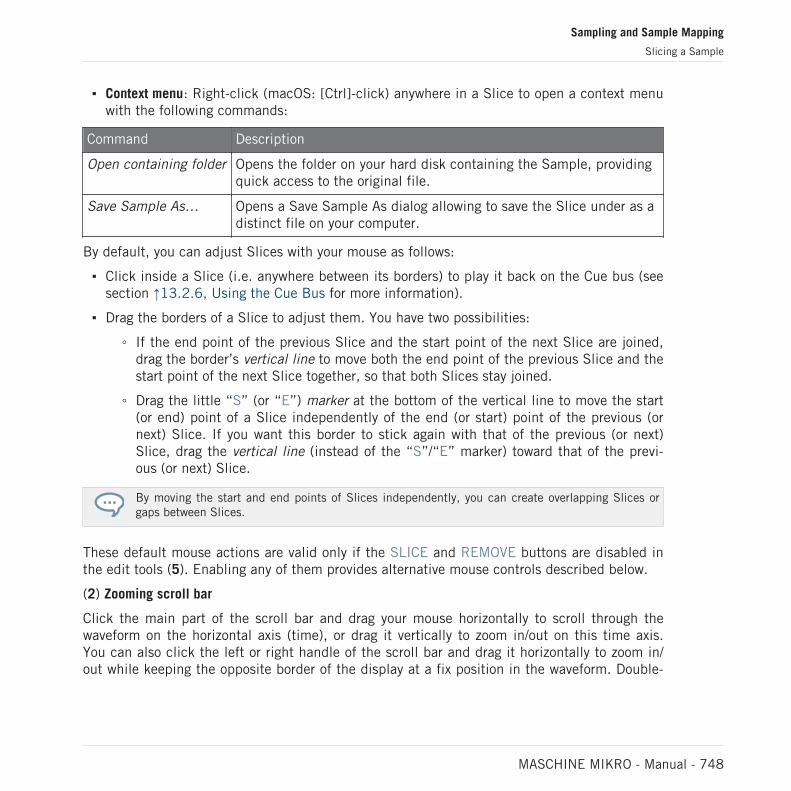
▪ Context menu: Right-click (macOS: [Ctrl]-click) anywhere in a Slice to open a context menuwith the following commands:
Command Description
Open containing folder Opens the folder on your hard disk containing the Sample, providingquick access to the original file.
Save Sample As… Opens a Save Sample As dialog allowing to save the Slice under as adistinct file on your computer.
By default, you can adjust Slices with your mouse as follows:
▪ Click inside a Slice (i.e. anywhere between its borders) to play it back on the Cue bus (seesection ↑13.2.6, Using the Cue Bus for more information).
▪ Drag the borders of a Slice to adjust them. You have two possibilities:
◦ If the end point of the previous Slice and the start point of the next Slice are joined,drag the border’s vertical line to move both the end point of the previous Slice and thestart point of the next Slice together, so that both Slices stay joined.
◦ Drag the little “S” (or “E”) marker at the bottom of the vertical line to move the start(or end) point of a Slice independently of the end (or start) point of the previous (ornext) Slice. If you want this border to stick again with that of the previous (or next)Slice, drag the vertical line (instead of the “S”/“E” marker) toward that of the previ-ous (or next) Slice.
By moving the start and end points of Slices independently, you can create overlapping Slices orgaps between Slices.
These default mouse actions are valid only if the SLICE and REMOVE buttons are disabled inthe edit tools (5). Enabling any of them provides alternative mouse controls described below.
(2) Zooming scroll bar
Click the main part of the scroll bar and drag your mouse horizontally to scroll through thewaveform on the horizontal axis (time), or drag it vertically to zoom in/out on this time axis.You can also click the left or right handle of the scroll bar and drag it horizontally to zoom in/out while keeping the opposite border of the display at a fix position in the waveform. Double-
Sampling and Sample Mapping
Slicing a Sample
MASCHINE MIKRO - Manual - 748

click the main part of the bar to reset the zoom and display the entire waveform. Alternativelyyou can use the scroll wheel of your mouse when hovering the waveform display (1) to zoom in/out.
(3) Timeline
Shows the time scale in seconds.
(4) Information bar
Displays the file name and the length of the selected Sample. Click and hold the little playicon on the left to play back the whole Sample on the Cue bus (see section ↑13.2.6, Using theCue Bus for more information). Click the little circle (or pair of circle) at the far right to switchthe waveform display (1) between single-channel and two-channel display.
(5) Edit tools
The three buttons in the edit tools allow you to add or remove Slices:
▪ SLICE: When the SLICE button is enabled, the default mouse behavior in the waveformdisplay is replaced by the following:
◦ Click inside a Slice to split it into two Slices at that location.
◦ Adjust the borders of existing Slices as described above in the waveform display (1).
▪ REMOVE: When the REMOVE button is enabled, over the waveform display the mousepointer turns into a rubber icon and the default mouse actions are replaced by the follow-ing:
◦ Click the start border of a Slice to delete that border and merge the Slice with the pre-vious one.
◦ Click inside a Slice (i.e. anywhere between its borders) to remove the entire Slice. Thecorresponding part of the Sample is grayed out and won’t be exported as Slice.
▪ DELETE ALL: Click the DELETE ALL button to delete all proposed Slices and start slicingfrom scratch again.
The SLICE and REMOVE buttons are mutually exclusive.
Sampling and Sample Mapping
Slicing a Sample
MASCHINE MIKRO - Manual - 749

With SLICE or REMOVE enabled, you can still prelisten to your individual Slices by pressing thecorresponding pads on your controller!
17.4.4 Applying the Slicing
Once you are satisfied with the proposed and/or manually adjusted Slices (see section↑17.4.2, Adjusting the Slicing Settings), you can apply the slicing in order to actually cut theoriginal Sample and create these Slices. This is done via the three elements at the bottomright of the Slice page:
1 23You can apply the slicing in various ways.
(1) Apply button
Sampling and Sample Mapping
Slicing a Sample
MASCHINE MIKRO - Manual - 750

Exports the Slices to the same Sound. If you click Apply, the Slices will be mapped to individ-ual notes of this Sound, the Sample Editor will be replaced by the Pattern Editor in Keyboardview, and the pads of your controller will switch to Keyboard mode so that you can directly playyour Slices on the pads. Additionally, depending on the setting of the Pattern Creation selector(3), some notes can be automatically created for each Slice (see below).
(2) Slice Dragger
Drag the Slice Dragger to export the Slices to any other Sound or Group:
▪ If you drag to a Sound (in the Sound List at the left of the Sample Editor):
◦ The Slices will be mapped to individual notes of this Sound, starting with the bottomC (C-2 in MASCHINE convention). The base key of the Sound will be set to the bot-tom C as well (see section Adjusting the Base Key for more information on the basekey). Any previous content in the Sound will be replaced.
◦ The Sample Editor will be replaced by the Pattern Editor in Keyboard view.
◦ The pads of your controller will switch to Keyboard mode so that you can directly playyour Slices on the pads.
◦ Depending on the setting of the Pattern Creation selector (3), notes will be automati-cally created for each Slice (see below).
In other words, the Apply button (1) is just a shortcut for dragging the Slice Dragger to the focusedSound itself!
▪ If you drag to a Group (in the Group List at the left of the Arranger):
◦ The Slices will be mapped to individual Sound slots, replacing their current content (ifany). Only the first 16 Slices will be exported.
◦ The Sample Editor will be replaced by the Pattern Editor in Group view.
◦ The pads of your controller will switch to Group mode so that you can directly playyour Slices on the pads.
◦ Depending on the setting of the Pattern Creation selector (3), notes will be automati-cally created for each Slice (see below).
(3) Pattern Creation selector
Sampling and Sample Mapping
Slicing a Sample
MASCHINE MIKRO - Manual - 751

Selects from three modes controlling the automatic note creation upon Slice export. The modeselected here will be used both when clicking the Apply button (1) and when using the SliceDragger (2). Following options are available:
▪ Create Pattern (default setting): Upon Slice export a new Pattern will be created with onenote for each pitch (if Slices are exported to a Sound) or one note for each Sound (if Slicesare exported to a Group) so that the Pattern reproduces the original, unsliced Sample.
▪ Replace Pattern: Upon Slice export a sequence of notes will be created in the current Pat-tern so that the Pattern reproduces the original, unsliced Sample. If the sequence is short-er than the current Pattern it will be repeated to fill the Pattern; if the sequence is longerthan the Pattern the Pattern will be extended according to the Pattern Grid and the contentof other Sounds will be repeated.
◦ If Slices are exported to a Sound, the sequence of notes will contain one note for eachpitch. Any existing notes for that Sound will be replaced. Notes for other Sounds inthe Pattern will stay untouched.
◦ If Slices are exported to a Group the sequence of notes will contain one note for eachSound containing a Slice. Any existing notes for these Sounds will be replaced. Notesfor other Sounds in the Pattern will stay untouched.
▪ No Pattern: No Pattern is created, and the current Pattern is left untouched.
Play around with the slicing feature by removing some of these notes, quantizing or completely rear-ranging them!
The notes in the picture above represent the Slices and trigger them in order to play the Sam-ple with correct timing and pitch. If you change the tempo of your Project, you will hear thatthe loop automatically adjusts to the new tempo.
Exporting Single Slices
You can also export an individual Slice to another Sound by drag-and-drop:
Sampling and Sample Mapping
Slicing a Sample
MASCHINE MIKRO - Manual - 752

Dragging an individual Slice to another Sound.
Applying a Sliced Sample to a Sound
If you drag a Slice to a Group in the Group List (at the left of the Arranger), it will be exportedto the first Sound slot of that Group. Any Sound loaded in that Sound slot will be replaced.
When applying a sliced sample to a Sound in an otherwise empty Group, the root note of theSounds in that Group is set to C-2, matching the key zones of the slices.
The root note parameter is shared among all Sounds in a Group. However, when applying slicesto a Sound, these slices will always start at the lowest possible note, to make room for themaximum number of slices. If you already have Sounds in a Group, the root note is notchanged after applying slices, in order to not change the behavior of the existing Sounds. Thiswill, however, lead to a mismatch in how you accessed slices across Pads in the Sampling /Slice tab and how they are laid out in the Sound you applied them to. You will typically play aroot note of C3 with Pad 1, while the lowest slice will start at C-2. To avoid this mismatch, andto access slices on a Sound exactly as you created them in the Sampling / Slice screen, applyslices to a Sound in a Group where you have not loaded anything to the other Sounds. Thisalso works when you start by loading a Sample into a Sound in a Group where you have not yetloaded anything else.
Sampling and Sample Mapping
Slicing a Sample
MASCHINE MIKRO - Manual - 753

17.5 Mapping Samples to Zones
Mapping Samples is a way to create Sounds with more than one Sample across the MIDI key-board and with different velocities. You can create and adjust Zones that define a key (or pitch)range and a velocity range for each Sample included in the Sound. In other terms, the Samplewill be triggered only if the played note is within its Zone’s key range and velocity range.
The Zones can overlap, allowing you to trigger different Samples at once or triggering differentSamples depending on how hard you hit the pads. You can adjust various playback settings forthe Sample of each Zone individually. The set of all Zones define the Sample Map (or “Map” forshort) of the Sound.
17.5.1 Opening the Zone Page
Mapping is done in the Zone page of the Sample Editor.
► Select a Sound slot, then open the Sample Editor (by clicking the button with the wave-form icon on the left of the Pattern Editor), and click the Zone tab to show the Zone page.
The Zone page (here for an empty Sound).
Sampling and Sample Mapping
Mapping Samples to Zones
MASCHINE MIKRO - Manual - 754

17.5.2 Zone Page Overview
The Zone page provides following elements:
1 2
3
4
5
6
The Zone page: an overview.
(1) Zone List button: Shows/hides the Zone List (4).
(2) Sample View button: Switches the Zone page between Map view and Sample view (5).
(3) Information bar: Displays the file name and the length of the Sample in the focused Zone.Click and hold the little play icon on the left to play back the whole Sample on the Cue bus(see section ↑13.2.6, Using the Cue Bus for more information). Click the little circle (or pair ofcircle) at the far right to switch the waveform display (1) between single-channel and two-channel display.
Sampling and Sample Mapping
Mapping Samples to Zones
MASCHINE MIKRO - Manual - 755

(4) Zone List: Shows all Zones in a list. The Zone List can be shown/hidden by clicking theZone List button (1). Click an entry in the list to set the focus to that Zone. You can also selectmultiple Zones, move them via drag and drop, and add/delete Zones in the list. See section↑17.5.3, Selecting and Managing Zones in the Zone List for a complete description of theZone List.
(5) Map view / Sample view: The Map view is the default view (pictured above). It shows andlets you edit all Zones contained in your Sound. The Sample view shows the waveform of theSample for the focused Zone and lets you edit some of its settings. Click the Sample View but-ton (2) to switch between the Map view and the Sample view (the Sample view is visible whenthe Sample View button is enabled). The Map and Sample views are explained in detail in sec-tion ↑17.5.4, Selecting and Editing Zones in the Map View and ↑17.5.5, Editing Zones in theSample View, respectively.
(6) Zone settings: Displays the parameters for the focused Zone. See section ↑17.5.6, Adjustingthe Zone Settings for a detailed description of the available parameters.
17.5.3 Selecting and Managing Zones in the Zone List
The Zone List shows all Zones of the focused Sound.
The Zone List in the Zone page.
► Click the Zone List button next to the Slice tab to show/hide the Zone List.
The Zone List allows you to add, remove, replace, select, and reorder Zones in the list.
Sampling and Sample Mapping
Mapping Samples to Zones
MASCHINE MIKRO - Manual - 756

You can adjust the width of the Zone List by dragging its right border.
Adding a New Zone to the Zone List
You can add a new Zone to the Zone List in two ways:
► Drag a Sample from the Browser’s LIBRARY or FILES pane or from your operating systemonto the empty area in the Zone List.
or
1. Click the “+” at the end of the Zone List.
A Load Sample dialog opens up.
2. Navigate to the desired audio file on your operating system and press [Enter] to confirm.
→ A new Zone is created at the end of the list containing the dragged or selected Sample.
You can drag and drop several Samples at once: It will creates as many new Zones!
You can also add Zones to your Sound by dragging and dropping Samples directly onto the SampleMap of the Map view. See section ↑17.5.7, Adding Samples to the Sample Map for more on this.
Replacing the Sample of an Existing Zone
You can also put a new Sample into an existing Zone, thereby replacing the Sample currentlycontained in that Zone. Again, you have two methods at your disposal:
Sampling and Sample Mapping
Mapping Samples to Zones
MASCHINE MIKRO - Manual - 757

► Drag a Sample from the Browser’s LIBRARY or FILES pane or from your operating systemonto the desired entry in the Zone List.
or
1. Right-click ([Ctrl]-click on macOS) the desired entry in the Zone List and select LoadSample… in the menu that opens.
A Load Sample dialog opens up.
2. Navigate to the desired audio file on your operating system and press [Enter] to confirm.
→ The dragged or selected Sample replaced the previous Sample in the target Zone.
Selecting a Zone in the List
► Click any Zone entry in the Zone List to put it under focus.
→ The focused Zone gets highlighted in color both in the list and in the Map view (if visible).In addition:
▪ The focused Zone is displayed in the Sample view and its settings appear in the Zone set-tings at the bottom of the page. See section ↑17.5.6, Adjusting the Zone Settings for moreinformation on these settings.
▪ The focused Zone also appears on the Edit and Slice pages, which allows you to furtherprocess of its contained Sample. For more information on the Edit and Slice pages, pleaserefer to section ↑17.3, Editing a Sample and ↑17.4, Slicing a Sample, respectively.
Sampling and Sample Mapping
Mapping Samples to Zones
MASCHINE MIKRO - Manual - 758

Selecting Multiple Zones in the List
You can select several Zones in the list at once using the common methods of your operatingsystem. The basic rules for multiple selection are the following:
▪ The focused Zone is automatically selected. It is highlighted in the color of the Sound andits waveform and parameters are displayed in the Slice page’s Sample view and Zone set-tings as well as on the Edit and Slice pages.
▪ The other selected Zones are highlighted in white. Their settings are not displayed any-where, however they will be affected by your actions in the Zone List and in the Map view(see section ↑17.5.4, Selecting and Editing Zones in the Map View for more on this).
Mouse/Keyboard Action Command
Multiple Selection
Hold [Ctrl] ([Cmd] on macOS) andclick several entries in the list
Selects all clicked Zones. Click a selected Zone todeselect it (i.e. remove it from the selection).
Hold [Shift] and click two entries Selects both Zones and all Zones in-between.
Press [Ctrl]+[A] ([Cmd]+[A] onmacOS)
Selects/deselects all Zones in the list. Whendeselecting, only the focused Zone remains selected.
Deleting Zones from the List
To remove one or more Zone(s) from the Zone List:
1. Select the Zone(s) you want to remove.
2. Press [Del] or [Backspace] on your computer keyboard.
→ The selected Zones are removed from the Zone List and from the Sample Map, and thecorresponding Samples are not used in the Sound anymore.
After you have selected the Zone(s) you want to remove, you can also use the context menu:
1. Select the Zone(s) you want to remove.
Sampling and Sample Mapping
Mapping Samples to Zones
MASCHINE MIKRO - Manual - 759

2. Right-click ([Ctrl]-click on macOS) any of the selected Zones.A menu opens up.
3. In that menu selects Delete to remove the focused Zone only, or Delete Selected to re-move all selected Zones.
Moving Zones in the List
You can move your Zones across the Zone List via drag and drop:
1. Select the Zone(s) you want to move.
2. Click and hold the mouse button, and drag your mouse vertically.As the mouse pointer moves, an insertion line appears at various places between the ex-isting entries.
3. When the insertion line indicates the desired location, release the mouse button to dropthe selected Zone(s) to this new place.
Moving Zones allow you to reorder the Zone List. This can come in handy before you run the Map asDrum Kit command from the Sample Map’s context menu, so that your Samples are well ordered inthe new mapping. See section ↑17.5.4, Selecting and Editing Zones in the Map View for more in-formation on the Sample Map.
Sampling and Sample Mapping
Mapping Samples to Zones
MASCHINE MIKRO - Manual - 760

17.5.4 Selecting and Editing Zones in the Map View
The Map view is visible when the Sample View button (showing a little waveform icon at theright of the Zone tab) is disabled.
Disable the Sample View button to see the Map view.
The Map view contains following elements:
1
2
4
3
The Map view of the Zone page.
(1) Sample Map
The Sample Map shows all Zones contained in your Sound.
▪ The horizontal axis represents keys (or pitches) from C-2 to G8, while the vertical axis rep-resents velocities from 0 to 127.
Sampling and Sample Mapping
Mapping Samples to Zones
MASCHINE MIKRO - Manual - 761

▪ Each Zone is depicted as a rectangle defining a specific key range (the rectangle’s width)and a velocity range (the rectangle’s height). Any note played within these key and velocityranges will trigger the Sample of that Zone.
▪ You can zoom in/out both horizontally and vertically via the zooming scroll bars (3) and (4),respectively.
▪ Each Zone header displays the name of the corresponding Sample.
▪ Click a Zone in the Map to put it under focus. The focused Zone is highlighted; its informa-tion and parameters are displayed in the Zone settings at the bottom of the Zone page.
▪ You can select multiple Zones at once: All your mouse actions within the Map view (mov-ing, resizing, etc.) will affect all selected Zones — see the next paragraph for more detailson the available selection and edit commands in the Map.
You can also add a Sample by dragging it directly onto the Sample Map. See section ↑17.5.7, Add-ing Samples to the Sample Map for more information.
(2) Virtual keyboard
Below the Mapping view, the virtual keyboard represents the entire key scale. The root note ofthe selected Zone is indicated by the colored key. You can drag this key with the mouse tomodify the root key.
(3) Horizontal zooming scroll bar
Click the main part of the scroll bar and drag your mouse horizontally to scroll through theSample Map on the horizontal axis (pitch), or drag it vertically to zoom in/out on this pitch ax-is. You can also click the left or right handle of the scroll bar and drag it horizontally to zoomin/out while keeping the opposite border of the display at a fix position in the Sample Map.Double-click the main part of the bar to reset the zoom and display the entire pitch range.
(4) Vertical zooming scroll bar
Click the main part of the scroll bar and drag your mouse vertically to scroll through the Sam-ple Map on the vertical axis (velocity), or drag it horizontally to zoom in/out on this velocity ax-is. You can also click the top or bottom handle of the scroll bar and drag it vertically to zoomin/out while keeping the opposite border of the display at a fix position in the Sample Map.Double-click the main part of the bar to reset the zoom and display the entire velocity range.
Sampling and Sample Mapping
Mapping Samples to Zones
MASCHINE MIKRO - Manual - 762

Available Actions in the Map
You can select and edit Zones with your mouse and your keyboard in the Map. Following ac-tions are available:
Mouse/Keyboard Action Command
Selection Commands
Click a Zone Puts this Zone under focus. The focused Zone ishighlighted. You can edit the focused Zone and theplayback settings of its Sample via the Zone settingsat the bottom of the Zone page, as well as process theSample’s audio material on the Edit page and/or slicethe Sample on the Slice page.
Hold [Ctrl] ([Cmd] on macOS) andclick several Zones
Selects all clicked Zones. Click a selected Zone todeselect it (i.e. remove it from the selection).
Hold [Shift] and click two Zones Selects both Zones and all Zones in-between.
Click and drag a selection frame inthe Sample Map
Selects all Zones within or overlapping the frame.
Press [Ctrl]+[A] ([Cmd]+[A] onmacOS)
Selects/deselects all Zones. When deselecting, onlythe focused Zone remains selected.
Edit Commands
Drag the left/right border of a Zone Adjusts the key range for the selected Zones.
Drag the higher/lower border of aZone
Adjusts the velocity range for the selected Zones.
Drag a corner of a Zone Simultaneously adjusts the lowest/highest note andthe lowest/highest velocity of the selected Zone(s) —depending on the corner.
Click inside a Zone and drag Moves the selected Zone(s) across the Sample Map.Note that the Root Key of each Zone is movedaccordingly.
Sampling and Sample Mapping
Mapping Samples to Zones
MASCHINE MIKRO - Manual - 763

Mouse/Keyboard Action Command
Double-click a Zone Extends the key and velocity ranges of the Zone sothat it fits the key and velocity limits of the neighborZones. This can be very useful to quickly fill up anykey or velocity gap between Zones.
Right-click ([Cmd]-click on macOS) aZone
Opens the Sample Map menu (see below).
Press [Del] or [Backspace] Removes the selected Zone(s) from the Sample Map.
You can also adjust the key and velocity ranges in the Zone settings at the bottom of the Zone page.See ↑17.5.6, Adjusting the Zone Settings for a detailed description.
For more information on the Edit and Slice pages, please refer to section ↑17.3, Editing a Sampleand ↑17.4, Slicing a Sample, respectively.
Sample Map Menu
The Sample Map menu contains additional editing facilities.
► Right-click ([Ctrl]-click on macOS) a Zone to open the Sample Map menu.
The commands in the Sample Map menu will affect all selected Zones. The menu provides fol-lowing commands:
Command Description
Delete Removes the selected Zone(s) from the Sample Map.
Map as Drum Kit Reduces the selected Zones to one note over the full velocity rangeand puts the Zones next to each other upwards from the middle C(C3). The actual note assigned to each Zone depends on the Zoneposition in the Zone List: The topmost Zone will be mapped tomiddle C (C3), the Zone underneath to C#3, etc.
Sampling and Sample Mapping
Mapping Samples to Zones
MASCHINE MIKRO - Manual - 764

17.5.5 Editing Zones in the Sample View
The Sample view is visible when the Sample View button (showing a little waveform icon at theright of the Zone tab) is enabled.
Enable the Sample View button to see the Sample view.
The Sample view contains following elements:
5
21
4 3The Sample view of the Zone page.
(1) Waveform display
Shows the waveform of the Sample for the focused Zone. The waveform display provides fol-lowing tools:
Sampling and Sample Mapping
Mapping Samples to Zones
MASCHINE MIKRO - Manual - 765

▪ Use the scroll wheel of your mouse to zoom in/out. You can also use the zooming scroll bar(3).
▪ Play range markers (4) and loop markers (5): See below.
▪ Playhead indicator: When the Sample is played back (e.g., by pressing the pad or by click-ing the little play icon in the information bar above the waveform), a playhead indicator(white vertical line) shows you the current play position within the waveform.
▪ Context menu: Right-click (macOS: [Ctrl]-click) anywhere in the waveform to open a contextmenu with the following commands:
Command Description
Open containing folder Opens the folder on your hard disk containing the Sample, providingquick access to the original file.
Save Sample As… Opens a Save Sample As dialog allowing to save the Sample of thefocused Zone under another name and/or to another location on yourcomputer.
(2) Timeline
Shows the time scale in seconds.
(3) Zooming scroll bar
Click the main part of the scroll bar and drag your mouse horizontally to scroll through thewaveform on the horizontal axis (time), or drag it vertically to zoom in/out on this time axis.You can also click the left or right handle of the scroll bar and drag it horizontally to zoom in/out while keeping the opposite border of the display at a fix position in the waveform. Double-click the main part of the bar to reset the zoom and display the entire waveform. Alternativelyyou can use the scroll wheel of your mouse when hovering the waveform display (1) to zoom in/out.
(4) Play range markers
The S and E markers indicate the start and end points of the play range, respectively. Dragthem with the mouse to modify the portion of the Sample that will be played back. This canalso be done in the PLAY RANGE section of the Zone settings, under the waveform display(see section ↑17.5.6, Adjusting the Zone Settings).
(5) Loop markers
Sampling and Sample Mapping
Mapping Samples to Zones
MASCHINE MIKRO - Manual - 766

If a loop has been defined in the Sample, it is also indicated on the waveform. You can thenadjust the loop by dragging its borders, and move the entire loop by dragging its title bar.Loops can be created and adjusted in the LOOP section of the Zone settings, under the wave-form display (see section ↑17.5.6, Adjusting the Zone Settings). Note that the loop will alwaysstay within the play range. Therefore, when moving the Sample’s start and end points closer toeach other (see above), keep in mind that it might also shrink the loop!
17.5.6 Adjusting the Zone Settings
At the bottom of the Zone page, the Zone settings allow you to adjust how each Zone should beplayed back.
The Zone settings in the software.
The various sections always display the values for the focused Zone.
If the MASCHINE window is not wide enough to display all Zone settings at once, a horizontal barappears underneath to scroll to the desired section of parameters.
Following parameters are available:
(1) PLAY RANGE section
The parameters in the PLAY RANGE section allow you to adjust the portion of Sample that willbe played back when the Zone is triggered.
Parameter Description
START Adjusts the playback’s start point in the Sample of the focusedZone.
END Adjusts the playback’s end point in the Sample of the focusedZone.
(2) LOOP section
The parameters in the LOOP section allow you to define and adjust a portion that will play inloop while the note is held.
Sampling and Sample Mapping
Mapping Samples to Zones
MASCHINE MIKRO - Manual - 767

Parameter Description
ACTIVE Enable this to define a loop in the Sample of the focused Zone.When the play position reaches the loop, the playback is loopedas long as the note is held. This can be useful to loop either awhole Sample or part of it, e.g., to simulate a longer tone. Note:this technique requires that you set the Sampler’s Type selectorto AHD or ADSR on the Pitch / Envelope page (see ↑7.2.2, Page2: Pitch / Envelope).
START Adjusts the loop’s start point.
END Adjusts the loop’s end point.
XFADE (Crossfade) Allows you to blend a little of the material near the loop startand end points in order to get a smoother, less abrupt loop. Thisis particularly helpful if the loop is inducing any clicks.
Alternatively you can also adjust the loop’ start and end points by dragging the borders of theloop in the Sample view, and move the entire loop by dragging its title bar.
By moving the loop’s start and end points closer to each other you can shrink the loop to very smallvalues on-the-fly, thereby creating very interesting glitch effects in a live situation.
The loop will always stay within the play range of the Sample. Therefore, when moving the Sample’splayback start and end points closer to each other, keep in mind that it might also shrink the loop!
(3) TUNE / MIX section
The TUNE / MIX section contains parameters controlling pitch- and level-related aspects of theSample playback.
Parameter Description
TUNE Sets the tuning of the focused Zone.
GAIN Sets the gain of the focused Zone.
Sampling and Sample Mapping
Mapping Samples to Zones
MASCHINE MIKRO - Manual - 768

Parameter Description
PAN Sets the panorama position of the focused Zone.
ROOT KEY Adjusts the root key of the focused Zone, that is the key atwhich the Sample will be played back at its original pitch. Theroot key is also indicated by the colored key on the virtualkeyboard; to change it, you can drag it to another note on thekeyboard.
(4) ENVELOPE section
This amplitude envelope can be used to get rid of clicks after slicing; you can either apply it tothe Zone of the whole Sample or to individual Zones for selected Slices.
Parameter Description
ATTACK Adjusts how quickly the Sample/Slice reaches full volume after beingtriggered.
DECAY Adjusts how fast the Sample/Slice dies down.
(5) MAP section
The MAP section contains the parameters defining the key and velocity ranges of the Zone.
Parameter Description
KEY LO (Lowest Key) Sets the lowest note (key) of the focused Zone. Alternatively,you can drag the left border of the Zone in the Map.
KEY HI (Highest Key) Set the highest note (key) of the focused Zone. Alternatively,you can drag the right border of the Zone in the Map.
VEL LO (Lowest Velocity) Defines the lowest velocity of the focused Zone. Alternatively,you can drag the lower border of the Zone in the Map.
VEL HI (Highest Velocity) Defines the highest velocity of the focused Zone. Alternatively,you can drag the higher border of the Zone in the Map.
Sampling and Sample Mapping
Mapping Samples to Zones
MASCHINE MIKRO - Manual - 769

17.5.7 Adding Samples to the Sample Map
You can add Samples directly to the Map view of the Zone page.
To see the Map view, make sure that the Sample View button is disabled next to the Zone tab at thetop of the Sample Editor. If this is not the case, click it to disable it.
► To add a new Sample, select one from the Browser or from your operating system anddrag it onto the Sample Map of the Map view (the biggest part in the middle of the Zonepage). Once your mouse is hovering the Sample Map, and before you release the mousebutton:
▪ Drag your mouse horizontally to choose the root key of the new Zone.
▪ Drag your mouse vertically to adjust the key range: With your mouse in the lower half of theSample Map the Zone will cover the root key only; dragging your mouse up in the upperhalf of the Sample Map will extend the Zone’s key range up to one octave above the rootkey; with your mouse at the top of the Sample Map, the Zone will cover the entire key-board.
▪ As you release the mouse button, the Zone is created.
You can add other Samples to the Sound via this method.
The key range of several Zones can overlap, as can the velocity range.
Adding Multiple Samples at Once
You can also drag several Samples to the Sample Map at once:
1. Hold [Ctrl] ([Cmd] on macOS) or [Shift] on your computer keyboard and click the desiredSamples in the Browser or in your operating system.
2. Drag the selected Samples to the Sample Map.
→ This will create multiple adjacent Zones. The width (i.e. key range) of these Zones willagain depend on where they are dropped in the Sample Map: The higher you drop, thewider each Zone will be. Dragging to the top part layers all Zones across the entire key-board.
Sampling and Sample Mapping
Mapping Samples to Zones
MASCHINE MIKRO - Manual - 770

The placement of the Zones depends on the original Samples’ position in the selection list:The first Sample selected will get the Zone with the lowest key range, the second Sample se-lected will get the Zone just over the previous one, etc.
Sampling and Sample Mapping
Mapping Samples to Zones
MASCHINE MIKRO - Manual - 771

18 Appendix: Tips for Playing Live
MASCHINE is a very hands-on tool for producing music as well as for performing live. Here wehave specifically gathered some tips to help you when playing live. If you are used to playinglive, you may not need them, but maybe you will find some new ideas to integrate into yourset.
18.1 Preparations
18.1.1 Focus on the Hardware
In a live situation it is not very comfortable or intuitive to look back and forth from your laptopscreen running the MASCHINE software to the MASCHINE hardware controller.
18.1.2 Customize the Pads of the Hardware
Take your time to setup the pad sensitivity and velocity scaling to your personal taste (see sec-tion ↑3.6.6, Preferences – Plug-ins Page to learn how to do that) — you will have even morefun playing MASCHINE.
18.1.3 Check Your CPU Power Before Playing
Some things can be embarrassing, if for example, you are on stage and your computer starts tohave problems because it cannot handle the amount of effects you are using. Although theMASCHINE software is programmed very efficiently, this might happen if your computer isquite old. So before you get on stage, give your live set a thorough performance check by firstplaying it at home. Have a look at the CPU meter in the MASCHINE software’s Header to en-sure it never turns red. If necessary, increase the Latency value (see ↑3.6.1, Preferences –General Page).
Appendix: Tips for Playing Live
Preparations
MASCHINE MIKRO - Manual - 772

18.1.4 Name and Color Your Groups, Patterns, Sounds and Scenes
18.1.5 Consider Using a Limiter on Your Master
This sounds rather conservative, but if you want to avoid digital distortion caused by an over-load of your audio interface, this is a useful safety measure. However, you might experience asomewhat squashed and dull sound if you overuse the Limiter by feeding a lot of loud signalsto it. Try it out and see what works best for you! See ↑15.1.4, Limiter for more information.
18.1.6 Hook Up Your Other Gear and Sync It with MIDI Clock
18.1.7 Improvise
It is nice if a live set is working out exactly the way you planned it, but sometimes, this can getboring for you as well as for the audience. Something unexpected or even plain mistakes canbe the key for inspiring tracks and performances as well as just jamming around with yourSounds and Samples!
18.2 Basic Techniques
18.2.1 Use Mute and Solo
Mute and Solo are a good way to build up a live set especially on the MASCHINE controller asyou can mute and solo Groups and Sounds at the same time.
Since soloing a Sound mutes all Sounds except one, the MUTE button can then be used to“release” Sounds that have been muted. You can use this technique to create a breakdown:Solo a given Sound such as a kick drum, then build the track up again by bringing the mutedSounds back in one at a time with the MUTE button. See ↑18.2.3, Use Note Repeat for moreon this.
Appendix: Tips for Playing Live
Preparations
MASCHINE MIKRO - Manual - 773

18.2.2 Create Variations of Your Drum Patterns in the Step Sequencer
You can easily create interesting drum patterns by adding or removing steps in the step se-quencer. Breaks and build-ups like snare rolls or a double-tempo hi-hat can be created on thefly. See ↑11.3, Recording Patterns with the Step Sequencer for more information on the stepsequencer.
18.2.3 Use Note Repeat
Note Repeat is a very useful tool for playing live: use it to add some additional drums, drop insome effect sounds, play a bassline or a melody. Note Repeat is also interesting to use withtonal Sounds and you can access it from Keyboard mode to create synthesizer-like arpeggios.See Note Repeat for more information.
18.2.4 Set Up Your Own Multi-effect Groups and Automate Them
You can setup multi-effect Groups containing all the effects you want to use in a live set. Youcan find several multi-effect Groups in the LIBRARY pane of the Browser to give you an idea ofwhat works for you. To be able to quickly change and modulate the effect settings, you can setmodulation for the multi-effect as Patterns from within the MASCHINE software. By using Pat-terns for the multi-effect Group you could for example trigger a filter sweep or a wild modulat-ed Beat Delay. See section ↑14.4, Creating Multi-Effects for more details!
18.3 Special Tricks
18.3.1 Changing Pattern Length for Variation
Try a short Pattern Grid resolution like a quarter or eighth note and change the Pattern Length(see section ↑11.1.6, Adjusting the Arrange Grid and the Pattern Length) to create variationsof a Pattern. If you select an even smaller value like 1/64th you can create stuttering breaksand rolls.
Appendix: Tips for Playing Live
Basic Techniques
MASCHINE MIKRO - Manual - 774

18.3.2 Using Loops to Cycle Through Samples
You can use loops to cycle through Samples, creating glitches and stuttering breaks or interest-ing soundscapes. Just enter the ZONE page in Sampling mode on your controller, switch onthe ACTIVE parameter on the LOOP page and play with the parameters for the start and endpoint of the loop. Use the SHIFT button to change the values in smaller increments. See↑7.2.1, Page 1: Voice Settings / Engine for more on this. Note: this technique requires thatyou choose either AHD or ADSR as the Amplitude Envelope in the Sampler’s Parameter pages(see ↑17.5.4, Selecting and Editing Zones in the Map View).
18.3.3 Load Long Audio Files and Play with the Start Point
You can adjust the start point of a Sample in the Sampler’s Parameter pages (see ↑7.2.1, Page1: Voice Settings / Engine). If you load a long audio file, you can create interesting variationsby tweaking (…or modulating) the start point.
Appendix: Tips for Playing Live
Special Tricks
MASCHINE MIKRO - Manual - 775

19 Troubleshooting
If you are experiencing problems related to your Native Instruments product that the supplieddocumentation does not cover, there are several ways of getting help.
Before getting help please make sure you have downloaded the latest MASCHINE software from Na-tive Access.
19.1 Knowledge Base
The Online Knowledge Base gathers useful information about your Native Instruments productand can be of great help to solve possible issues you may encounter. You can reach the Knowl-edge Base via: www.native-instruments.com/knowledge.
19.2 Technical Support
If no Knowledge Base entry matches your problem, or if the matching entry does not solve theproblem, you can use the Online Support Form to contact the Technical Support team of Na-tive Instruments. The Online Support Form will ask you to enter information about your hard-ware and software setup. This information is essential for our Support team to be able to pro-vide you with quality assistance. You can reach the Online Support via: www.native-instru-ments.com/suppform.
When communicating with the Native Instruments Support team, keep in mind that the moredetails you can provide about your hardware, your operating system, the version of the softwareyou are running, and the problem you are experiencing, the better they will be able to help you.
In your description, you should mention:
▪ How to reproduce the problem
▪ What you have already tried to fix the problem
▪ A description of your setup, including all hardware and the version of your software
Troubleshooting
Knowledge Base
MASCHINE MIKRO - Manual - 776

▪ The brand and specifications of your computer
When installing new software or software updates, a Readme file is included that contains latebreaking news and new information that was not yet included in the documentation. Please openand read this Readme file before contacting Technical Support.
19.3 Registration Support
If problems occur during the product activation procedure, please contact our RegistrationSupport team: www.native-instruments.com/regsuppfrm.
19.4 User Forum
In the Native Instruments User Forum, you can discuss product features directly with otherusers and with experts moderating the forum. Please be aware that the Technical Supportteam does not participate in the forum. If you’re encountering an issue that can’t be solved byother users, contact Native Instruments’ Technical Support team via the online support as de-scribed above. You can reach the User Forum via: http://www.native-instruments.com/forum.
Troubleshooting
Registration Support
MASCHINE MIKRO - Manual - 777

20 Glossary
In this glossary you will find short definitions for numerous terms used in the MASCHINE con-text. If you have any doubts about the meaning of a word, this is the place to check!
Arranger
The Arranger is the big area located in the upper part of the MASCHINE window, right underthe Header. It contains two views: Ideas view and Song View.
Song View
The Song view allows you to combine Sections (references to Scenes), and arrange them into asong on the Timeline.
Autoload
When Autoload is enabled, any Group, Sound, Pattern, Plug-in preset (instrument or effect), orSample that you select in the Browser is instantly loaded into the selected Group slot, Soundslot, Pattern slot or Plug-in slot. This way, you can listen to this object in the current context ofyour song.
Browser
The Browser is the front end for accessing all MASCHINE objects: Projects, Groups, Sounds,Patterns, presets for instrument and effect Plug-ins, and Samples. Each of these can be stor-ed, “tagged,” and categorized in a way that allows you easy access to all of them. MA-SCHINE’s factory library is already completely tagged, and you can also import your own filesto the Library and tag them as well.
Bussing Point
A bussing point is a point in the signal flow that can accept signals coming from various loca-tions in the audio routing system. In MASCHINE for example, the first Plug-in slot of a Soundusually contains a sound source (which you will hear by pressing the corresponding pad onyour controller). If you load an effect plug-in in this first Plug-in slot, though, the Sound won’tgenerate audio itself but instead it becomes available for other Sounds and Groups to process
Glossary
MASCHINE MIKRO - Manual - 778
their audio. You then only have to set up the desired Sound(s) and Group(s) of your Project tosend some of their audio to this bussing point. This basically is the way to set up send effectsin MASCHINE!
Channel Properties
Channel properties are sets of parameters available at each Project level (i.e. for each Sound,each Group, and for the Master) that are independent of the Plug-ins loaded in that Sound/Group/Master. Like the Plug-in parameters, in the software the Channel properties are dis-played in the Control area. For example, the volume, pan or swing controls are properties oftheir respective Sound/Group/Master channel.
Control Area
The Control area is located in the middle of the MASCHINE window, between the Arranger(above) and the Pattern Editor (below). This area allows you to adjust all Plug-in parametersand Channel properties for the selected Sound/Group or the Master level: routing, effects, Mac-ro Controls, etc.
Control Lane
Located at the bottom of the Pattern Editor in the MASCHINE window, the Control Lane showsand lets you edit the recorded automation in form of automation points for each automated pa-rameter. You can add, remove, or manipulate existing automation points as well as add newparameters to automate.
Control Mode
Control mode is the default mode of your controller. In this mode, you can play or record youractions in real-time. Control mode also allows you to easily adjust any parameter of yourGroups and Sounds via the Control section of your controller.
Effect (FX)
An effect modifies the audio material it receives. MASCHINE already includes many differenteffects. You may also use VST/AU plug-in effects. Effects can be loaded as Plug-ins in anyPlug-in slot of the Sound, Group, and Master levels. MASCHINE’s flexible routing allows younot only to apply insert effects but also to create send effects and multi-effects.
Glossary
MASCHINE MIKRO - Manual - 779

Event
Events are the individual drum hits or notes that make up a Pattern. In the Pattern Editor,events are visually represented by rectangles in the Step Grid. Depending on the current viewin the Pattern Editor, you can see events for all Sounds slots (Group view) or for the selectSound slots only (Keyboard view).
Groove Properties
The Groove properties control the rhythmic relationship between events for the selected Group/Sound or the Master level. By shifting some of the events, you can e.g. give a shuffling, ternarytouch to your Patterns. The main parameter of the Groove properties is the Swing control.
Group
A Group contains 16 Sound slots, each of which can hold one Sound. In addition to the effectsapplied to individual Sounds, a Group can have insert effects loaded in its Plug-in slots. Theseaffect all the Sounds in the Group. A Group can also contain an unlimited amount of Patternsorganized into Pattern Banks.
Group View
Group view is the view of the Pattern Editor in which events for all 16 Sound slots of the se-lected Group are visible and editable. In Group view, each row of the Step Grid represents adifferent Sound slot. This mode is well suited for rhythmic instruments (e.g., a drum kit).
Ideas View
The Ideas view allows you to experiment with your musical ideas without being tied to a time-line or arrangement. You can create Patterns for each Group and combine them into a Scene.These Scenes can then be added to Sections in the Song view to create a larger musical struc-ture.
Insert Effect
An insert effect is an effect directly inserted in the signal path of the audio to be processed.
Glossary
MASCHINE MIKRO - Manual - 780
Header
The Header is the topmost row of controls in the MASCHINE software window. It containsglobal settings, such as the Master Volume slider, the Transport controls, controls for globalswing, tempo, time signature, etc.
Keyboard View
Keyboard view is the view of the Pattern Editor in which only events of the selected Sound arevisible and editable. The Keyboard view provides a vertical on-screen keyboard that indicatesthe pitch of each event (one row per semi-tone). This mode is well suited for melodic instru-ments (e.g., synthesizer). The Keyboard view of the Pattern Editor and the Keyboard mode onyour controller are bound together: If you enable Keyboard view in the Pattern Editor, your con-troller automatically switches to Keyboard mode, and inversely.
Macro Control
Each Sound/Group/Master channel provides a page of eight Macro Controls to which you canassign almost any parameter from that level or the underlying one. This way you can define for,e.g., each Group or Sound a set of eight parameters that are quickly accessible. Furthermore,Macro Controls can be assigned to MIDI CCs to be controlled by an external MIDI controller orapplication. Last but not least, if you use MASCHINE as a plug-in in a host, Macro Controls areavailable for modulation in your host too.
Master
The Master is where all audio signals from each of the Groups and Sounds come together andget mixed. The Master bus can also have insert effects loaded in its Plug-in slots. These ef-fects are applied to all Groups and the Sounds within them.
Modulation
Modulation allows you to record changes of parameter values so that you don’t need to actuatethese parameters in real-time. Any modulated parameter is displayed both in the Control Lane(at the bottom of the Pattern Editor) and as a movement of the chosen parameter itself in theControl area.
Glossary
MASCHINE MIKRO - Manual - 781
Mute and Solo
Muting allows you to bypass a Sound or a Group, whereas Soloing is pretty much the opposite:It mutes all other Sounds or Groups so that only the soloed Sound or Group is played. Thecombination of muting and soloing is a useful means both to play live and to test different se-quences together.
Pad Mode
Your controller offers various Pad modes that allow you to play your Sounds from the pads indifferent ways: Depending on the selected Pad mode, you can either assign one Sound to all16 pads (Keyboard mode and 16 Velocities mode) or trigger each Sound with a distinct pad(default mode and Fixed Velocity mode). The Keyboard mode on your controller and the Key-board view in the software’s Pattern Editor are bound together: If you enter Keyboard mode onthe controller, Keyboard view gets automatically enabled in the software, and inversely.
Parameter Pages
The Parameter pages constitute the biggest part of the Control area in the MASCHINE window.They contain the adjustable Plug-in parameters and Channel properties of the selected Sound/Group or those of the Master.
Pattern
A Pattern is a sequence that plays Sounds from a Group. Patterns are the building blocks forScenes. One Pattern from each Group can be added to a Scene. You can reference the samePattern in different Scenes. When you modify a Pattern in the Pattern Editor, all references tothis Pattern are updated in the Arranger.
Pattern Editor
Located at the bottom of the MASCHINE window, the Pattern Editor allows you to selectSound slots (on the left), display and edit your Patterns, change the Step Grid settings andcreate/edit automation.
Glossary
MASCHINE MIKRO - Manual - 782

Plug-in
A Plug-in is an instrument or effect unit, either Internal or External (by Native Instruments or athird-party manufacturer), that can be loaded into a Plug-in slot to produce or alter sound.When a Plug-in is loaded into a Plug-in slot, the Plug-in appears in the Plug-in List in the leftpart of the Control area.
Prehear
The Prehear feature allows you to listen to Samples directly from the Browser without loadingthem into Sound slots first. This way, you can quietly choose a Sample before modifying any-thing in your Project.
Project
A Project contains all data needed for a song: all Groups, Patterns, Sounds, Samples, Scenesand all settings, automation, effects, routings, etc. It’s like a snapshot of the entire state ofMASCHINE.
Quantization
To quantize a Pattern is to make its events snap to a set of equally distributed locations knownas steps. This ensures that these events are on beat. You can also let MASCHINE automaticallyquantize events that you play and/or record live. Quantization makes it easier to get a rhythmgoing, but too much use can make the Pattern seem stiff or lifeless.
Sample
A Sample is any piece of audio that can be used e.g. to build a drum kit or a melodic instru-ment, or as a distinct loop in your song. You can load one or more Samples into each Soundslot.
Sample Editor
The Sample Editor can be displayed in place of the Pattern Editor. The Sample Editor is theall-in-one editor for Samples. It notably allows you to record Samples, edit them, split theminto slices and map them across notes and velocities on your keyboard.
Glossary
MASCHINE MIKRO - Manual - 783

Scene
A Scene is a combination of Patterns for each Group. They can be used to combine Patterns inorder to create musical ideas. Scenes are created in the Ideas view and then added to Sectionsin the Song view to create an arrangement.
Section
Sections are references to a specific Scenes on the Timeline of the Song view and are used toarrange the Scenes into a larger musical structure. The benefit of using Sections is that anychanges made to a Scene are replicated in each Section where the Scene is referenced there-fore making the process of changing parts of a song quick and easy.
Send Effect
A send effect is an effect available for audio signals located on other Sounds and/or Groups.These audio signals can be routed to a variable extent to the send effect for the effect to proc-ess them. Send effects notably allow you to reuse the same effect on different Sounds and/orGroups, thereby limiting the overall CPU load.
Sequencer
Generally speaking, a sequencer is a hardware unit or software tool that arranges musical se-quences, e.g. drum patterns or chord progressions. Hardware sequencers typically function asa set of steps, where every step can be filled with musical content. The steps are then playedback as a musical sequence. MASCHINE has its own sequencing abilities: you can record andplay single Patterns as well as arrange Patterns into Scenes and Scenes into full songs.
Solo
See Mute and Solo.
Sound
Sounds are the building blocks of all sound content in MASCHINE. They are organized intoGroups that can hold up to 16 Sounds each. Sounds can be played directly from the pads onyour controller. A Sound can be loaded with Plug-ins of various types (sound source or effect,Internal or External, etc.).
Glossary
MASCHINE MIKRO - Manual - 784

Step
Steps are elementary time blocks. They are notably used to apply quantization or to composePatterns from your controller in Step mode. All steps together make up the Step Grid. In thesoftware’s Pattern Editor, steps are visualized by vertical lines. You can adjust the step size,e.g., to apply different quantization to different events or to divide the Step Grid into finerblocks to edit your Pattern more precisely.
Step Grid
The Step Grid is a set of parallel lines that divide the Pattern into steps. By changing the reso-lution of the Step Grid (i.e. the step size), you can adjust the note values at which you canquantize your Pattern and the number of steps available in Step mode on your controller.
Step Mode
In Step mode, your controller can be used as a traditional step sequencer, where each of the16 pads represent a step in the Step Grid. Just as on classical drum machines, a light repre-senting the sequence runs from pad 1 up to pad 16, highlighting each step during playback.Select a Sound and put events at chosen steps in the sequence by pressing the correspondingpads. By repeating the process Sound by Sound you build up the whole Pattern.
Swing
The Swing parameter allows you to shift some of the events in your Pattern to create a shuf-fling effect.
Glossary
MASCHINE MIKRO - Manual - 785

IndexNumerics16 Velocities
in Pad mode [225]
4-D encoder
adjusting the volume, swing, tempo andtune [69] [70]
AAbleton Link
connecting to a network [121]
joining a Link Session [121]
Adjusting Plug-in parameters [81]
Amplitude Envelope (Sampler) [281]
Arrange Grid [410]
Arranger
definition [62] [778]
switching views [56] [667]
Arranger View button [56] [667]
Arrow buttons [43]
ASIO driver [94]
Assigning Macro Controls
from parameters [529]
MIDI CC Messages [529]
Pages Pane [529]
Assigning Patterns [679]
Attribute Editor [155]
AU plug-ins [289]
Audio
rendering from Patterns [470]
Audio driver (selecting) [93]
Index
MASCHINE MIKRO - Manual - 786

Audio Engine button [53]
Audio input [485] [578]
Audio interface [773]
input and output routing [93]
selecting inputs and outputs [93]
settings [93]
Audio Plug-in [302]
editor [307]
Fade [303]
Formant [305]
Gate mode [302] [310]
Length [305]
loading [302]
Loop mode [302] [308]
Mode [303]
Parameters [303]
Pitchbend [304]
Re-pitch [304]
Stretch [305]
Tempo [305]
Tune [304]
Audio Type
exporting audio [216]
AUTO button [45]
Autoload [148]
definition [778]
BBase key [226]
Beat Delay [630]
Bit depth
exporting audio [217]
reducing (effect) [640]
BP2 (Filter mode) [284]
Browser [51]
+ PATTERNS button [150]
+PATTERNS button [55]
+ROUTING button [55]
button [52]
definition [62] [778]
File Type selector [137]
in-depth [123]
load with Patterns [150]
showing and hiding [67]
Browser button [42]
Bussing point [778]
Bypassing
Plug-in slots [270]
Index
MASCHINE MIKRO - Manual - 787

CChannel
Groove properties [233]
Input properties (Audio page) [485] [578]
Macro properties [527]
Output properties (Audio page) [489]
Output properties (Aux page) [494]
Channel icon [59]
Channel Properties [483]
definition [779]
Groove [233]
Input [485] [578]
Macro [527]
Output [489] [494] [497]
Channel Property selector [59]
CHARACTER Filter [127]
Choke All Notes [233]
CHORDS button [49]
Chorus [611]
Classic saturation [642]
Clear
Scene (software) [685] [705]
Section (software) [710]
Clear a Pattern
Song view [711]
Color
Group [199]
Pattern [465]
Scene [690]
Sound [186]
Color a Pattern
Song view [712]
Compressor [588]
Content selector [55]
Control area [52]
definition [779]
Control Lane [447]
definition [779]
Control mode
definition [779]
Control section [42]
Controller
Control section [42]
Edit section [42]
overview [40]
Pad section [46]
Performance section [43]
rear panel [50]
selecting Pad mode [225]
Transport section [45]
Index
MASCHINE MIKRO - Manual - 788

Controller settings [114]
Controlling external MIDI devices using MacroControls [529]
Copy/paste
Group [202]
Pattern (controller) [468]
Pattern content (software) [467]
Sound [189]
Count-in [420]
length [92]
CPU meter [53]
CPU power [772]
Create a Pattern
Song view [711]
Cue
adjusting the output [497]
Cut/copy/paste
events/notes (controller) [438]
events/notes (software) [436]
DDelay effects [630]
Delete
events/notes (software) [434]
Group [207]
Digital distortion [640]
Display [42]
Display area [53]
Display brightness [114]
Distortion [638]
Analog [639]
avoiding [773]
Mullholland [638]
Driver
selecting an audio driver [93]
Drum program files
importing [219]
Duplicate
Group [202]
Pattern (software) [466]
Sound [189]
Duplicate a Pattern
Song view [712]
DUPLICATE button [48]
Duplicating
Index
MASCHINE MIKRO - Manual - 789

Making Sections Unique [707]
Dynamics effects [588]
EEDIT page
controller [739]
Edit page (software) [735]
Edit section [42]
Effect categories
delays [630]
distortions [638]
dynamics [588]
filtering [603]
modulation [611]
spatial and reverbs [617]
Effects [567] [587]
applying [567]
applying to external audio [578]
Beat Delay [630]
Chorus [611]
Compressor [588]
creating a send effect [580]
definition [62] [779]
Distortion:Analog [639]
Distortion:Mullholland [638]
EQ [603]
Filter [605]
Flanger [612]
Index
MASCHINE MIKRO - Manual - 790
FM [613]
Freq Shifter [615]
Gate [591]
Grain Delay [632]
Grain Stretch [634]
Ice [617]
insert effect [780]
Limiter [596]
loading [567]
Lofi [640]
manipulating [574]
Maximizer [600]
Metaverb [619]
multi-effect [584]
Phaser [616]
Plate Reverb [629]
Reflex [620]
Resochord [636]
Reverb [621]
Saturator [641]
send effect [580]
send effect definition [784]
Transient Master [594]
Encoder [42]
EQ [603]
EQ (Filter mode) [284]
Equalizer [603]
ERASE button [46]
Event
definition [780]
Events
cut/copy/paste (controller) [438]
cut/copy/paste (software) [436]
definition [63]
deleting (software) [434]
editing with the mouse [425]
moving (controller) [433]
moving (software) [431]
nudging (controller) [433]
nudging (software) [433]
paste (controller) [438]
paste (software) [436]
quantizing [439]
resizing (software) [431]
selecting (controller) [430]
transposing (controller) [434]
transposing (software) [432]
EVENTS button [48]
Events vs. notes [425]
Export
Index
MASCHINE MIKRO - Manual - 791

MIDI from Pattern [472]
Exporting audio
from Patterns [470]
External audio [485] [578]
External Plug-ins [289]
FFavorites [152]
Add [152]
Remove [152]
Show [152]
Favorites button [42]
File type
selecting in Browser [137]
File Type selector [55] [126]
FILES pane [161]
Files tab [54]
Filter [605]
Filter (Sampler) [284]
Filtering effects [603]
FIXED VEL button [50]
Fixed Velocity [225]
Flanger [612]
FM [613]
FOLLOW button [46]
Frequency Shifter [615]
GGate [591]
Gate mode [310]
Grain Delay [632]
Grain Stretch [634]
Groove [233]
Groove properties [233]
definition [780]
Group
applying effects to [567]
color [199]
copying and pasting [202]
creating [196]
definition [63] [780]
deleting [207]
duplicating [202]
Groove properties [233]
Group List [175]
Input properties (MIDI page) [507]
introduction [175]
load with Patterns [150]
Macro properties [527]
moving [206]
multi-effect [584] [774]
muting and soloing [229]
Index
MASCHINE MIKRO - Manual - 792

naming [198]
Output properties (Audio page) [489]
Output properties (Aux page) [494]
pasting [202]
saving [200]
saving with Samples [208]
set up as send effect [581]
soloing [229]
triggering Sounds via MIDI notes [507]
GROUP button [44]
Group index [230]
Group List [175]
Group mode (controller) [225]
quick erasing events [435]
selecting events [430]
GROUP tab [59]
Group view [60]
definition [780]
Groups [58] [669]
HHeader [51]
Audio Engine button [53]
Browser button [52]
CPU meter [53]
definition [781]
Display area [53]
MASCHINE menu [52]
Master Volume slider [53]
NI logo [53]
Transport controls [52]
Help [776]
Host automation [514]
HP2 (Filter mode) [284]
Index
MASCHINE MIKRO - Manual - 793

IIce [617]
Ideas view
definition [63] [780]
Groups [57] [668]
Pattern area [57] [668]
Scenes [57] [668]
Import
MIDI to Pattern [474]
IMPORT button [170]
Importing your files into the Library [169]
Input properties
Audio page [485] [578]
Insert effect [780]
KKey [226]
KEYBOARD button [49] [226]
Keyboard mode
activating [226]
Scale [226]
using [226]
Keyboard mode (controller) [226]
quick erasing events [435]
selecting notes [430]
Keyboard view [60]
definition [781]
Index
MASCHINE MIKRO - Manual - 794

LLatency [94] [772]
LFO [605] [612] [616]
Library [123]
importing your own files [169]
Library pane [125]
Library tab [54]
Limiter [596]
using [773]
Load
Group with Patterns [150]
Plug-in [264]
Loading
Projects using the controller [84]
LOCK button [45]
Lock feature
using [257]
Lock snapshot
basics [257]
creating [257]
Lofi [640]
Loop mode [308]
Loop Optimize
exporting audio [216]
LP2 (Filter mode) [284]
MMacro Control
definition [781]
Macro Controls [527]
Macro Controls (controller) [528]
Making Sections Unique [707]
MASCHINE Library [123]
MASCHINE menu [52]
MASCHINE software
stand-alone or plug-in [86]
Master
applying effects to [567]
definition [63] [781]
Groove properties [233]
introduction [175]
Macro properties [527]
Output properties [497]
MASTER tab [59]
Master Volume slider [53]
Maximizer [600]
Metaverb [619]
Metro button [420]
Metronome [419]
signature [91]
volume [91]
Index
MASCHINE MIKRO - Manual - 795

MIDI [23]
automation [514]
connecting external equipment [117]
controlling parameters via [514]
disabling MIDI Scene Change [513]
enabling MIDI Scene Change [513]
exporting from Pattern [472]
importing to Pattern [474]
sending MIDI from Sounds [523]
synchronizing [96] [117] [118]
triggering Sounds via MIDI notes [507]
MIDI Clock [96] [117] [118]
MIDI Mode [119]
Accessing [42]
Missing Samples [171]
MOD button [44]
Mode buttons [47]
Modulation [443]
definition [781]
drawing with mouse [449]
modulatable parameters [444]
recording in Control mode (controller) [447]
Modulation effects [611]
Modulation Envelope (Sampler) [285]
Move
events/notes (software) [431]
Group [206]
Pattern [469]
Plug-in [272]
Scene (software) [687]
Section (controller) [701]
Sections (software) [700]
Sound [192]
Move events/notes (controller) [433]
Multi-effect [584] [774]
Mute [773]
definition [782]
Plug-in slot [270]
Sound or Group [229]
MUTE (controller) [232]
MUTE button [47]
Index
MASCHINE MIKRO - Manual - 796
NName
Group [198]
Pattern [463]
Scene [689]
Sound slot [185]
Native Instruments Plug-ins [289]
Native Kontrol Standard [85]
Navigate [82]
Pattern Editor [82]
Song view [82]
Navigating Plug-ins [81]
NI logo [53]
NKS [85]
Normalize
exporting audio [216]
Note Repeat [254] [774]
NOTE REPEAT button [45]
Notes
cut/copy/paste (controller) [438]
cut/copy/paste (software) [436]
deleting (software) [434]
editing with the mouse [425]
moving (controller) [433]
moving (software) [431]
nudging (controller) [433]
nudging (software) [433]
paste (controller) [438]
paste (software) [436]
quantizing [439]
resizing (software) [431]
selecting (controller) [430]
transposing (controller) [434]
transposing (software) [432]
NOTES button [44]
Nudge events/notes (controller) [433]
Nudge events/notes (software) [433]
OOctaves
transposing events/notes by [434]
Output properties
Audio page [489] [497]
Aux page [494]
Overdub mode (controller) [417]
Overview
hardware controller [40]
structure of a Project [35]
Index
MASCHINE MIKRO - Manual - 797

PPad Input Mode buttons [49]
Pad input modes [49]
PAD MODE button [49]
Pad mode options
16 Velocities [225]
Fixed Velocity [225]
Pad modes
definition [782]
Pad modes (controller) [225]
Pad section [46]
Pad sensitivity [114]
Pads [49]
recording [417]
Parameter
creating snapshots using Lock [257]
Scale TYPE [226]
Parameter area [59]
Parameter page
definition [782]
navigating [79]
Parameter pages
controlling parameters via host automation[514]
controlling parameters via MIDI [514]
Pattern [401]
adding variation [442]
adjusting length (controller) [412]
adjusting length (software) [411]
color [465]
copying and pasting (controller) [468]
creating (controller) [460]
creating (software) [459]
cut/copy/paste content (software) [467]
cut/copy/paste events/notes (controller)[438]
cut/copy/paste events/notes (software) [436]
definition [63] [782]
deleting (software) [460]
deleting events/notes (software) [434]
doubling (controller) [442]
duplicating (software) [466]
editing (software) [402]
exporting MIDI from [472]
importing MIDI to [474]
load with Group [150]
moving [469]
moving events/notes (controller) [433]
moving events/notes (software) [431]
nudging events/notes (controller) [433]
nudging events/notes (software) [433]
Index
MASCHINE MIKRO - Manual - 798

paste content (software) [467]
paste events/notes (controller) [438]
paste events/notes (software) [436]
pasting (controller) [468]
quantizing events/notes [439]
recording in Control mode (controller) [417]
recording in Step mode (controller) [422]
removing [679]
renaming [463]
rendering audio from [470]
resizing events/notes (software) [431]
selecting (controller) [458]
selecting (software) [456]
selecting events/notes (controller) [430]
step sequencer (controller) [422]
transposing events/notes (controller) [434]
transposing events/notes (software) [432]
Pattern bank
creating (software) [461]
deleting (software) [462]
selecting (controller) [458]
PATTERN button [48]
Pattern Editor [52] [402]
definition [782]
Pattern Length [411]
Pattern Manager [455]
Pattern mode [456]
Pattern Variation
accessing mode [443]
Humanize mode [442]
Random mode [442]
PERFORM button [44]
Perform FX
selecting and loading [44]
Perform Grid [673]
Performance section [43]
Phaser [616]
PITCH button [44]
Pitch scale [226]
Plate Reverb [629]
PLAY button [45]
Plug-in [86]
adjusting parameters [270]
bypassing [270]
definition [64] [783]
loading [264]
moving [272]
muting [270]
saving presets [273]
PLUG-IN button [43]
Index
MASCHINE MIKRO - Manual - 799
Plug-in icon [59]
Plug-in slot
bypassing [270]
muting [270]
Plug-ins
External [289]
Native Instruments [289]
Preferences [88]
:Routings [93]
Audio page [93]
Colors page [114]
Default page [97]
General page [89]
Hardware page [114]
Library page [101]
MIDI page [95]
Plug-ins page [109]
Prehear [149] [150]
definition [783]
Pre-listening Samples [149] [150]
Preset
External Plug-ins [298]
Native Instruments Plug-ins [298]
saving Plug-in presets [273]
using VST/AU presets [298]
Product selector [55]
Project
definition [64] [783]
overview and structure [35]
saving with Samples [210]
Project button [42] [84]
QQuantization
definition [783]
quantizing after recording [439]
Quick Browse [173]
Quick Edit buttons [43]
Quick Reference [35]
Index
MASCHINE MIKRO - Manual - 800

RRear panel [50]
REC button [46]
Record
Count-in [420]
Overdub mode [417]
Replace mode [418]
Record page (software) [724]
Redo [71]
Reflex [620]
Remove a Pattern
Song view [712]
Rename a Pattern
Song view [711]
Repeating notes
Note Repeat [254]
Replace mode (controller) [418]
Reset
Sound slot [193]
Resize
events/notes (software) [431]
Pattern (controller) [412]
Pattern (software) [411]
Resochord [636]
RESTART button [46]
Result list
in FILES pane [163] [166]
in Library pane [127] [143]
Retrigger Scenes [674]
Retrigger Sections [674]
Reverb [621]
Reverberation effects [617]
REX files
importing to Sounds [218]
Root key
setting [769]
Routing [567]
Index
MASCHINE MIKRO - Manual - 801

SSample
definition [783]
exporting with Group [208]
exporting with Project [210]
importing into Library [169]
missing [171]
pre-listening [149] [150]
Sample Editor [722]
definition [783]
Sample rate
exporting audio [217]
reducing (effect) [640]
selecting [94]
Sampler Plug-in [277]
Amplitude Envelope [281]
Sampling
editing (software) [735]
mapping (software) [754]
recording (software) [724]
slicing (software) [743]
SAMPLING button [43]
Sampling mode (controller) [723]
Saturator [641]
Save
Group [200]
Group with Samples [208]
Plug-in preset [273]
Project with Samples [210]
Sound [187]
Scale
in Keyboard mode [226]
Scales
5-Tone [246]
Jazz [244]
Main [242]
Major [248]
Minor [249]
Modern [247]
Modes [243]
World [245]
Scene
appending (software) [689]
clearing (software) [685] [705]
color [690]
creating (controller) [679]
creating (software) [679]
definition [64] [784]
deleting (controller) [684]
deleting (software) [684]
Index
MASCHINE MIKRO - Manual - 802

duplicating (controller) [685] [686]
jumping to another [673]
naming [689]
reordering (software) [687]
Retrigger [674]
selecting (controller) [683]
selecting (software) [682]
transitions [673]
unique (software) [688]
Scene bank
creating (hardware) [685]
creating (software) [685]
selecting (controller) [683]
selecting (software) [682]
SCENE button [48] [694]
Scene mode (controller) [678]
Search field [55] [127]
Search results [143]
Section [692]
adjusting the length (hardware) [705]
adjusting the length (software) [702] [703]
assigning (controller) [696]
assigning (software) [695]
clearing (software) [710]
creating (controller) [695]
creating (software) [694]
definition [64] [784]
duplicating (controller) [706]
duplicating (software) [705]
jumping to another [673]
moving (controller) [701]
removing (controller) [708]
removing (software) [707]
selecting (controller) [699] [700]
selecting (software) [696]
Section bank
creating (hardware) [710]
creating (software) [710]
selecting (controller) [699] [700]
selecting (software) [696]
Section mode [694]
Sections
moving (software) [700]
Select
events/notes (controller) [430]
Select a Pattern
Song view [711]
SELECT button [48]
Selecting
Pad mode (controller) [225]
Index
MASCHINE MIKRO - Manual - 803

Semitones
transposing events/notes by [434]
Send effect [580]
definition [784]
Send MIDI Clock [96] [118]
Sequencer
definition [784]
SHIFT button [46]
Slice [743]
exporting (software) [751]
Slice page (software) [743]
Smart Strip [44]
Snapshots [257]
Solo [773]
definition [782]
Sound or Group [229]
SOLO (controller) [232]
SOLO button [47]
Song [692]
Song view [692]
Clear a Pattern [711]
Color a Pattern [712]
Create a Pattern [711]
definition [64] [778]
Duplicate a Pattern [712]
Groups [58] [669]
Pattern area [58] [670]
Remove a Pattern [712]
Rename a Pattern [711]
Sections [58] [669]
Select a Pattern [711]
Timeline [58] [669]
Working with Patterns [710]
Sound
applying effects to [567]
Color [186]
copying and pasting [189]
definition [65] [784]
duplicating [189]
Groove properties [233]
Input properties (Audio page) [485] [578]
Input properties (MIDI page) [507]
introduction [175]
Macro properties [527]
moving [192]
muting and soloing [229]
naming [185]
Output properties (Audio page) [489]
Output properties (Aux page) [494]
Output properties (MIDI page) [523]
Index
MASCHINE MIKRO - Manual - 804

pasting [189]
resetting slot [193]
saving [187]
sending MIDI [523]
set up as send effect [581]
soloing [229]
Sound List [175]
triggering via MIDI notes [507]
Sound List [175]
Sound slot
naming [185]
number [230]
resetting [193]
SOUND tab [59]
Soundcard [773]
input and output routing [93]
selecting inputs and outputs [93]
settings [93]
Stand-alone application [86]
Step
definition [785]
STEP button [49]
Step Grid [61] [413]
definition [785]
Step mode
definition [785]
Step mode (controller) [422]
Step sequencer (controller) [422]
Step Undo/Redo [71] [72]
STOP button [46]
Strip Mode buttons [44]
Swing
definition [785]
quickly adjusting from the controller(Sound/Group/Project) [70]
SWING button [43] [70]
Sync to External MIDI Clock [96] [117]
Index
MASCHINE MIKRO - Manual - 805

TTag Filter [55]
using [138]
Tags
assigning Types and Sub-Types [159]
creating [159]
Take Undo/Redo [72]
TAP (Metro) button [420]
TAP button [46] [235]
Tape saturation [643]
Template Project
plug-in [99]
stand-alone [99]
Tempo
Tap [235]
TEMPO button [43]
Text search [55]
using in Browser [142]
Threshold [591] [596]
Touch Strip [44]
Transient Master [594]
Transport controls [52]
Transport section [45]
Transpose
events/notes (controller) [434]
events/notes (software) [432]
Triggering Scenes via MIDI [513]
Troubleshooting [776]
Tube saturation [644]
TYPES Filter [127]
UUndo [71]
USB socket [50]
VVariation
accessing mode [443]
adding to Pattern [442]
VARIATION button [48]
Velocity scaling [114]
View
switching [65]
Volume [53]
quickly adjusting from the controller (Mas-ter/Group/Sound) [69] [70]
VOLUME button [43] [69] [70]
VST plug-ins [289]
VST/AU
definition [783]
Index
MASCHINE MIKRO - Manual - 806

WWorking with Patterns
Song view [710]
ZZone page
software [754]
Index
MASCHINE MIKRO - Manual - 807