Marine Exhaust Gas Treatment Systems for Compliance with ...
49
Citation: Zannis, T.C.; Katsanis, J.S.; Christopoulos, G.P.; Yfantis, E.A.; Papagiannakis, R.G.; Pariotis, E.G.; Rakopoulos, D.C.; Rakopoulos, C.D.; Vallis, A.G. Marine Exhaust Gas Treatment Systems for Compliance with the IMO 2020 Global Sulfur Cap and Tier III NO x Limits: A Review. Energies 2022, 15, 3638. https:// doi.org/10.3390/en15103638 Academic Editor: Efstathios (Stathis) - Alexandros Tingas Received: 2 April 2022 Accepted: 8 May 2022 Published: 16 May 2022 Publisher’s Note: MDPI stays neutral with regard to jurisdictional claims in published maps and institutional affil- iations. Copyright: © 2022 by the authors. Licensee MDPI, Basel, Switzerland. This article is an open access article distributed under the terms and conditions of the Creative Commons Attribution (CC BY) license (https:// creativecommons.org/licenses/by/ 4.0/). energies Review Marine Exhaust Gas Treatment Systems for Compliance with the IMO 2020 Global Sulfur Cap and Tier III NO x Limits: A Review Theodoros C. Zannis 1 , John S. Katsanis 1 , Georgios P. Christopoulos 2 , Elias A. Yfantis 3 , Roussos G. Papagiannakis 4 , Efthimios G. Pariotis 1 , Dimitrios C. Rakopoulos 5 , Constantine D. Rakopoulos 6, * and Athanasios G. Vallis 2 1 Naval Architecture and Marine Engineering Section, Hellenic Naval Academy, 18539 Piraeus, Greece; [email protected] (T.C.Z.); [email protected] (J.S.K.); [email protected] (E.G.P.) 2 Hellenic Navy, Hellenic Navy Fleet, Salamis Naval Base, 18901 Salamis, Greece; [email protected] (G.P.C.); [email protected] (A.G.V.) 3 Marine and Offshore Science, Technology and Engineering Centre (MOSTEC), Cyprus Marine and Maritime Institute (CMMI), P.O. Box 40930, Larnaca 6023, Cyprus; [email protected] 4 Thermodynamics and Propulsion Systems Section, Hellenic Air Force Academy, 13671 Dekelia, Greece; [email protected] 5 Centre for Research & Technology Hellas (CERTH), Chemical Process and Energy Resources Institute, 50200 Ptolemais, Greece; [email protected] 6 Department of Thermal Engineering, School of Mechanical Engineering, National Technical University of Athens, Zografou Campus, 9 Heroon Polytechniou Street, 15780 Athens, Greece * Correspondence: [email protected]; Tel.: +30-210-7723529 Abstract: In the present work, the contemporary exhaust gas treatment systems (EGTS) used for SO x , PM, and NO x emission mitigation from shipping are reviewed. Specifically, after-treatment technologies such as wet scrubbers with seawater and freshwater solution with NaOH, hybrid wet scrubbers, wet scrubbers integrated in exhaust gas recirculation (EGR) installations, dry scrubbers, inert gas wet scrubbers and selective catalytic reduction (SCR) systems are analyzed. The operational principles and the construction specifications, the performance characteristics and the investment and operation of the reviewed shipping EGTS are thoroughly elaborated. The SCR technology is comparatively evaluated with alternative techniques such as LNG, internal engine modifications (IEM), direct water injection (DWI) and humid air motor (HAM) to assess the individual NO x emission reduction potential of each technology. Detailed real data for the time several cargo vessels spent in shipyards for seawater scrubber installation, and actual data for the purchase cost and the installation cost of seawater scrubbers in shipyards are demonstrated. From the examination of the constructional, operational, environmental and economic parameters of the examined EGTS, it can be concluded that the most effective SO x emission abatement system is the closed-loop wet scrubbers with NaOH solution which can practically eliminate ship SO x emissions, whereas the most effective NO x emission mitigation system is the SCR which cannot only offer compliance of a vessel with the IMO Tier III limits but can also practically eliminate ship NO x emissions. Keywords: exhaust gas treatment systems; IMO 2020 global sulfur cap: IMO NO x Tier II/III limits; scrubbers; selective catalytic reduction (SCR) 1. Introduction 1.1. General Concepts The main gaseous constituents of exhaust gases generated by marine diesel engines are carbon dioxide (CO 2 ), water vapor (H 2 O), nitrogen (N 2 ) and oxygen (O 2 )[1]. As known, in-cylinder available nitrogen and oxygen react at high temperatures in the reaction zone of combustion flame, generating nitrogen oxides (NO x ) which are primarily a mixture of Energies 2022, 15, 3638. https://doi.org/10.3390/en15103638 https://www.mdpi.com/journal/energies
-
Upload
khangminh22 -
Category
Documents
-
view
3 -
download
0
Transcript of Marine Exhaust Gas Treatment Systems for Compliance with ...

Citation: Zannis, T.C.; Katsanis, J.S.;
Christopoulos, G.P.; Yfantis, E.A.;
Papagiannakis, R.G.; Pariotis, E.G.;
Rakopoulos, D.C.; Rakopoulos, C.D.;
Vallis, A.G. Marine Exhaust Gas
Treatment Systems for Compliance
with the IMO 2020 Global Sulfur Cap
and Tier III NOx Limits: A Review.
Energies 2022, 15, 3638. https://
doi.org/10.3390/en15103638
Academic Editor: Efstathios (Stathis) -
Alexandros Tingas
Received: 2 April 2022
Accepted: 8 May 2022
Published: 16 May 2022
Publisher’s Note: MDPI stays neutral
with regard to jurisdictional claims in
published maps and institutional affil-
iations.
Copyright: © 2022 by the authors.
Licensee MDPI, Basel, Switzerland.
This article is an open access article
distributed under the terms and
conditions of the Creative Commons
Attribution (CC BY) license (https://
creativecommons.org/licenses/by/
4.0/).
energies
Review
Marine Exhaust Gas Treatment Systems for Compliance withthe IMO 2020 Global Sulfur Cap and Tier III NOx Limits:A ReviewTheodoros C. Zannis 1 , John S. Katsanis 1, Georgios P. Christopoulos 2, Elias A. Yfantis 3,Roussos G. Papagiannakis 4, Efthimios G. Pariotis 1 , Dimitrios C. Rakopoulos 5 , Constantine D. Rakopoulos 6,*and Athanasios G. Vallis 2
1 Naval Architecture and Marine Engineering Section, Hellenic Naval Academy, 18539 Piraeus, Greece;[email protected] (T.C.Z.); [email protected] (J.S.K.); [email protected] (E.G.P.)
2 Hellenic Navy, Hellenic Navy Fleet, Salamis Naval Base, 18901 Salamis, Greece;[email protected] (G.P.C.); [email protected] (A.G.V.)
3 Marine and Offshore Science, Technology and Engineering Centre (MOSTEC), Cyprus Marine and MaritimeInstitute (CMMI), P.O. Box 40930, Larnaca 6023, Cyprus; [email protected]
4 Thermodynamics and Propulsion Systems Section, Hellenic Air Force Academy, 13671 Dekelia, Greece;[email protected]
5 Centre for Research & Technology Hellas (CERTH), Chemical Process and Energy Resources Institute,50200 Ptolemais, Greece; [email protected]
6 Department of Thermal Engineering, School of Mechanical Engineering, National Technical University ofAthens, Zografou Campus, 9 Heroon Polytechniou Street, 15780 Athens, Greece
* Correspondence: [email protected]; Tel.: +30-210-7723529
Abstract: In the present work, the contemporary exhaust gas treatment systems (EGTS) used forSOx, PM, and NOx emission mitigation from shipping are reviewed. Specifically, after-treatmenttechnologies such as wet scrubbers with seawater and freshwater solution with NaOH, hybrid wetscrubbers, wet scrubbers integrated in exhaust gas recirculation (EGR) installations, dry scrubbers,inert gas wet scrubbers and selective catalytic reduction (SCR) systems are analyzed. The operationalprinciples and the construction specifications, the performance characteristics and the investmentand operation of the reviewed shipping EGTS are thoroughly elaborated. The SCR technology iscomparatively evaluated with alternative techniques such as LNG, internal engine modifications(IEM), direct water injection (DWI) and humid air motor (HAM) to assess the individual NOx
emission reduction potential of each technology. Detailed real data for the time several cargo vesselsspent in shipyards for seawater scrubber installation, and actual data for the purchase cost and theinstallation cost of seawater scrubbers in shipyards are demonstrated. From the examination of theconstructional, operational, environmental and economic parameters of the examined EGTS, it can beconcluded that the most effective SOx emission abatement system is the closed-loop wet scrubberswith NaOH solution which can practically eliminate ship SOx emissions, whereas the most effectiveNOx emission mitigation system is the SCR which cannot only offer compliance of a vessel with theIMO Tier III limits but can also practically eliminate ship NOx emissions.
Keywords: exhaust gas treatment systems; IMO 2020 global sulfur cap: IMO NOx Tier II/III limits;scrubbers; selective catalytic reduction (SCR)
1. Introduction1.1. General Concepts
The main gaseous constituents of exhaust gases generated by marine diesel enginesare carbon dioxide (CO2), water vapor (H2O), nitrogen (N2) and oxygen (O2) [1]. As known,in-cylinder available nitrogen and oxygen react at high temperatures in the reaction zoneof combustion flame, generating nitrogen oxides (NOx) which are primarily a mixture of
Energies 2022, 15, 3638. https://doi.org/10.3390/en15103638 https://www.mdpi.com/journal/energies

Energies 2022, 15, 3638 2 of 49
nitrogen monoxide (NO) and nitrogen dioxide (NO2) with the latter in small quantities [1].In addition, marine diesel engines burning sulfur-containing fuels such as heavy-fueloil (HFO) emit sulfur oxides (SOx). Marine diesel engines are also significant emittersof carbon monoxide (CO), total unburned hydrocarbons (THC) and particulate matter(PM) [2]. Hence, marine diesel-emitted CO2, NOx, CO, THC and SOx are the main gaseousspecies in conjunction with particulate emissions (PM) that have the highest negativeimpact on the environment and on human health [3]. For this reason and with concern formaritime SOx emissions, the International Maritime Organization (IMO) has issued specificlimits for marine fuel sulfur content to control marine diesel-emitted SOx values. TheIMO fuel sulfur limits are higher on a global level compared to the ones specified for SOxEmission Controlled Areas (SECAs) [3]. According to IMO Regulation 2.9 [3], sulfur oxidesand PM emission controls apply to all fuels, on-board combustion systems, including mainand auxiliary engines with boilers and inert gas generators. Previously mentioned controlsinclude those that are implemented inside Emission Control Areas (ECAs), which aretargeted to curtail SOx and PM emissions, and those that are implemented globally outsideECAs and are attained by controlling the maritime fuel sulfur percentage as it is bunkeredand used on-board. As evidenced from IMO Regulations 14.1 and 14.4 [3], fuel sulfur limits,which are provided as %m/m, have undergone specific modifications during recent years.The chronological evolution of the sulfur content of maritime fuels, both globally and inSECAs, is given in Table 1 [2].
Table 1. Marine fuel sulfur contents that have been legislated by the International Maritime Organi-zation (IMO) according to the MARPOL Annex VI and are effective in both SOx Emission ControlAreas (SECAs) and globally. (Table was genuinely generated using data from ref. [3]).
Year of IssuePermitted Fuel Sulfur Content (% m/m)
SECAs Worldwide
2000 1.5%4.5%
2010.071.0%
20123.5%
20150.1%
2020 0.5%
The establishment of the IMO Global Sulfur Cap of 0.5% on 1 January 2020 changed thescenery of fuel supply and availability [3]. Though the technological solutions to complywith the IMO Global Sulfur Cap are numerous, the selection of a certain solution is quitedifficult because it is based on various technical, environmental and economic criteria [3].In addition to the maritime fuel sulfur limit of 0.5% which is implemented globally, there isan additional requirement by the IMO for a 0.1% maritime fuel sulfur limit in SECAs suchas the North American coastline, the Caribbean Sea, the North Sea and the Baltic Sea [3].It is also worth mentioning that maritime vessels using exhaust after-treatment systems areallowed to use high sulfur fuel oil (HSFO) [4].
In addition to maritime SOx emissions, the IMO, with increasing concern about mar-itime NOx emissions, has issued specific NOx emission limits from marine engines bothinside and outside NOx Emission Control Areas (NECAs) [5]. NOx emission limits ing/kWh that have been issued by IMO inside and outside NECAs are given in Table 2.

Energies 2022, 15, 3638 3 of 49
Table 2. NOx emission limits from marine engines that have issued by IMO according to MARPOLAnnex VI. (Table was genuinely generated using data from ref. [5]).
Tier Year of IssueNitrogen Oxides Concentration Limit, g/kWh
RPM ** < 130 130 ≤ RPM < 2000 RPM ≥ 2000
Tier I 2000 17.0 45 * RPM−0.2 9.8
Tier II 2011 14.4 44 * RPM−0.23 7.7
Tier III 2016 * 3.4 9 * RPM−0.2 1.96* In Nitrogen Oxides Emission Control Areas (Tier II limits are effective outside NE-CAs); ** Engine speed inrotations per minute.
To fulfill the limitations of fuel sulfur content as dictated by the IMO [3] both insideand outside SECAs, ships can operate with low sulfur conventional fuels that complywith the IMO fuel sulfur regulations. Alternatively, ships can operate with alternativefuels that contain extremely low sulfur or do not contain sulfur [6]. Such alternative fuelsthat have been used in the maritime industry are liquefied natural gas (LNG), biofuels,dimethyl ether (DME), methanol and ethanol, ammonia and hydrogen, which are fuelsthat do not contain sulfur [6]. However, the use of these alternative fuels in ships, thoughcontributing significantly to the minimization of SOx emissions, is accompanied by manydrawbacks such as their bunkering availability, high production cost, variable on-boardstorage capacity and others. Hence, taking into consideration that the use of high sulfur fuelwill be continued because it is compliant with existing marine diesel engines and existingbunkering and on-board infrastructure and also taking into consideration the IMO’s fuelsulfur limits inside and outside SECAs, one of the most prominent ways to ensure thatexisting and future vessels comply with the IMO’s SOx and PM emission regulations is forthem to use exhaust gas treatment systems (EGTS) [7].
The main exhaust after-treatment systems that are utilized nowadays in maritimevessels are comprised of wet scrubbers operating either as open-loop systems with seawa-ter as the scrubbing medium or as closed-loop systems with aqueous solution of NaOHas the scrubbing medium [8]. The careful examination of the literature has shown thatvarious solutions have been suggested to curtail NOx emissions generated from marineengines and combustion systems and to comply with the IMO Tier II limits that are effectiveglobally. According to a recent study, the available marine NOx reduction technologies forcompliance with Tier III NOx limits were amended. Furthermore, this study examined theoperational principles and progress of various NOx reduction technologies and thoroughlyassessed and criticized the advantages and the disadvantages of these technologies. Aswitnessed, the implementation of exhaust gas recirculation (EGR) technology can lead tomarine engine operation compliant with Tier III NOx limits without taking into consid-eration the increased engine fuel consumption. EGR is one of the most promising andwell-proven NOx-controlling technologies, which has proven quite effective over the yearsin curtailing in-cylinder NOx formation in marine internal combustion engines. ThoughEGR is highly effective in reducing NOx formation inside the cylinders of marine engines,it results in a significant deterioration of brake-specific fuel oil consumption (SFOC) andof soot emissions. For this reason, a detailed examination of the impact of various EGRpercentages on NOx, SFOC and soot emissions is required prior to its implementation inmarine diesel engines. In addition, it was shown that the application of SCR systems in theexhaust of marine engines and combustion systems is the most effective way to achieve theIMO NOx Tier III values. However, despite the continuous optimization of SCR units, theproblem of catalyst progressive pollution seriously narrows their broad implementation.Another important issue for the in-cylinder control of pollutant emissions from marineengines is the successful turbo matching with the engine because it allows the feeding of theengine with adequate amounts of intake air at all engine loads. Successful turbo matchingis a crucial factor that affects the selection of either a high pressure or a low-pressure SCRsystem. Significant NOx reduction rates can be attained with natural gas marine engines,

Energies 2022, 15, 3638 4 of 49
but additional technologies are required for natural gas engines to comply with NOx TierIII limits. Other technologies such as variable valve timing and Miller cycle, two-stageturbocharging and fuel/water emulsion can contribute significantly to the control of NOxvalues emitted from marine engines, but these technologies are scarcely used indepen-dently, almost always being used in conjunction with other technologies instead. Thesetechnologies can be used in combination with EGR, SCR and natural gas technologiesfor the optimization of marine engine fuel economy and polluting behavior. Hence, themost effective and promising technology for the direct compliance of marine engines withNOx Tier III standards is the exhaust gas treatment using SCR technology [9]. Recently,Lion et al. [10] examined the operational principles, the effectiveness and the advantagesand disadvantages of internal measures for NOx reduction from marine engines and ex-haust gas cleaning technologies such as SOx scrubbers and SCR systems. They found thatscrubbers are highly effective in reducing SOx emissions from marine combustion systems,especially in the case of alkali dosage control, and the SCR system is the most effectiveNOx reduction technology for commercial vessels. Similar conclusions were drawn in therecent review studies for marine emission reduction strategies published by Ni et al. [11]and Deng et al. [12].
1.2. Literature Review
Numerous theoretical, experimental and review studies have thoroughly examinedvarious marine exhaust gas treatment technologies used for compliance with the IMO’ssulfur content standards and NOx emission limits. The results of 16 of these studiesare listed in Table 3. The main objectives of these studies were the examination of theperformance characteristics and the efficiency of open-loop and closed-loop scrubbersand SCR catalysts, the investigation of the influence of exhaust gas recirculation (EGR)technology for NOx reduction in conjunction with seawater scrubbers for SOx curtailmentand the assessment of the impact of low sulfur fuels and LNG conversion on SOx reductionin contrast to the use of marine EGTS. The main findings of the reviewed studies listed inTable 3 are that marine scrubbers are highly effective in reducing SOx and PM emissions.SCR catalysts are also highly effective in curtailing NOx emissions, and in the case oflow-sulfur fuels, the investment cost of the marine EGTS is associated with low-sulfur fuelprice scenarios.
Table 3. Consolidation of the results of the literature review on marine exhaust gas treatment systems.For each study examined in the literature and listed in this table its type (experimental, theoretical orreview), its main objectives and its main conclusions are shown along with its reference.
No. Type of the Study Main Objectives of the Study Main Conclusions of the Study Reference
1 Experimental
The polluting behavior oflow-pressure an EGR system
operating in combination with aseawater scrubber on a LPG
carrier, which operatedwith HSFO.
(1) Increased back pressure due to thescrubber operation and small fuel penaltydue combustion efficiency worsening from
the use of EGR were evidenced.(2) A 70% NOx reduction and simultaneousdramatic reduction (98%) of SOx emissions,which was interpreted as compliance withNOx Tier III values and maritime fuel sulfur
limits in ECAs were observed.(3) It was witnessed Adequate performanceof the water wash treatment unit resulting
in the receipt of good quality water samplescompared to all measured compounds
was witnessed.
[13]

Energies 2022, 15, 3638 5 of 49
Table 3. Cont.
No. Type of the Study Main Objectives of the Study Main Conclusions of the Study Reference
2 Theoretical/CaseStudy
The environmental and economicrepercussions from the
implementation of fuel sulfurdirective in the Scandinavian
industry, i.e., transition from heavyfuel oil (HFO) to marine diesel
oil (MDO).
It was found that before the decision of theindustry and the owners, there was aprofound requirement for extensive
feasibility studies and elaborative researchrelevant to the upcoming environmental
decisions for SOx ECAs and theirrepercussions on maritime logistics,
economy, and environment.
[14]
3 Theoretical/CaseStudy
The economic burden and pollutantemissions as functions of thereduction choices in pollutantEmission Control Areas were
thoroughly investigated.
(1) It was evidenced that the optimumsolution is a function of the engine size, theengine fuel consumption inside ECAs and
the projected future fuel prices.(2) It was found that the investment cost forthe sulfur reduction technologies must be
fully covered from fuel saving inside ECAs,which favors MGO or LFO compared to
scrubbing systems or LNG.
[15]
4 Theoretical/CaseStudy
(1) Two different SOx emissionreduction technologies, namely, the
use of low sulfur fuel oil andscrubbers, were comparatively
evaluated from an economic andenvironmental perspective.(2) The effectiveness of the
investments of SOx scrubbingsystem installations for compliance
with the requirements of VIMARPOL 73/78 was analyzed.
It was found that the investments inexhaust gas scrubbing systems are effective
under any fuel price option examined.[16]
5 Experimental
(1) Construction of a selectivecatalytic reduction (SCR) system.(2) The on-board NOx reduction
effectiveness of the investigated SCRmodule was examined.
The proposed SCR system is highlyeffective in reducing NOx emissions fromthe marine engines of the maritime vessel
under examination.
[17]
6 Experimental
The relative influence of fuel sulfurcontent and water on the
performance indicators and theeffectiveness of a SCR system wasinvestigated. The impact of fuel
sulfur percentage on the NOxreduction potential of a commercial
SCR catalyst fed with urea at lowtemperatures was analyzed.
(1) It was shown that the addition of SO2 inthe absence of water enhances NOxreduction rates and promotes the
conversion of NH3 with an increased N2Oformation (This effect appeared to be
independent from temperature).(2) It was found that the addition of H2O inthe absence of SO2 results in NOx reduction
and in the curtailment of N2O formation.(3) It was witnessed that in the presence of
SO2 and water, NOx reduction potentialis curtailed.
[18]
7 Experimental
The influence of the KCl poisoningon the performance indicators of
MnOx catalyst, which is a keycomponent of the SCR system,
was investigated.
(1) It was shown that at low temperatures,MnO2-based catalysts indicate superior
performance compared toconventional catalysts.
(2) It was found that SCR catalyticperformance was related directly to the
oxygen availability of MnOx catalyst.(3) It was witnessed that the presence of KClnegatively affected the performance of SCRcatalyst at low temperatures mainly due to
oxygen mobility of MnOx species.
[19]

Energies 2022, 15, 3638 6 of 49
Table 3. Cont.
No. Type of the Study Main Objectives of the Study Main Conclusions of the Study Reference
8 Experimental
The PM and SO2 emissionreduction potential from a marine
engine equipped with anopen-loop seawater scrubber
was examined.
(1) It was shown that a seawater scrubbereffectively reduced SO2 emissions at levelslike the ones corresponding to <0.1% fuel
sulfur content (0.1% is the allowed fuelsulfur percentage in SECAs since 2015).
(2) It was realized that the use of a seawaterscrubber resulted in the reduction of PM
emissions by 75% compared to conventionalmarine engine operation.
(3) The use of a seawater scrubbing systemalso results in a significant reduction of
polycyclic aromatic hydrocarbons (PAHs).(4) It was also found that the captured SO2
resulted in the reduction of pH and in ahigh sulfuric acids concentration in the
water effluent.(5) PM emission reduction with a seawater
scrubber is the same as with the oneattained with a fuel transition from HFO to
marine gas oil (MGO).
[20]
9 Experimental
The following three methodologiescomplying with both ECA
regulations for sulfur and Tier IIIfor NOx were evaluated: (a) heavyfuel oil (HFO) in combination with
SCR and an open-loop seawaterpurifier, (b) marine gas oil (MGO)
in combination with SCR, (c)liquefied natural gas (LNG).
(1) All methodologies reduce the impact onparticles, photochemical ozone formation,acidification, and terrestrial eutrophication
potential in the life cycle.(2) It was necessary to adjust the slip of
ammonia from the use of SCR and the slipof methane from the LNG engine.
(3) Methane slip could possibly be reducedby engine modifications or
oxidation catalysts.
[21]
10 Theoretical/CaseStudy
The environmental impacts of thefollowing exhaust gas reduction
methodologies were compared: (a)selective catalytic reduction (SCR),(b) seawater treatment (SWS), (c)
MGO, (d) LNG conversion.
(1) The use of LNG conversion or acombined system (SCR + SWS) or
(SCR + MGO) can be applied to the ship.(2) High NOx and SOx emission reduction
rates can be achieved using a combinedsystem (SCR + SWS).
(3) The LNG conversion process achievesthe greatest reduction of PM emissions,while it is the only method that reduces
CO2 emissions.(4) LNG conversion can economicallyachieve the required emission levels
according to international regulations.
[22]
11 Theoretical/CaseStudy
Various ship emission reductionstrategies were compared for
compliance with the IMO SOx andNOx emission standards.
(1) The use of SCR and seawaterpurification seemed to be the best on-board
reduction technologies.(2) LNG appears to be the most efficient
type of fuel.(3) The type of ship and the operation area
play an important role in choosing theappropriate strategy.
[23]
12 Theoretical/Literaturereview
The effects of maritime emissions(i.e., particulate matter, gaseous
pollutants, etc.) on urban airquality in Europe’s coastal areas
were examined.
(1) Emissions from shipping contribute to1–7% of ambient air.
(2) Contributions to environmental NO2levels range between 7% and 24%.
[24]

Energies 2022, 15, 3638 7 of 49
Table 3. Cont.
No. Type of the Study Main Objectives of the Study Main Conclusions of the Study Reference
13 Theoretical/SimulationModel
(1) It was estimated theincremental cost of reducingNOx and SOx from maritimevessels working in Emission
Control Areas (ECAs).(2) It was comparatively
evaluated the following fiveemission abatement methods:(a) SCR, (b) Humid Air Motor
and Internal EngineModification (HAM/IEM),
(c) scrubbers, (d) marine gas oil(MGO), and (e) wet scrubbers
and LNG.
(1) Increased sensitivity of NOx reductionmethods to functional behavior, with theHAM/IEM combination performing well
for exclusive circulation.(2) A Tier-III HAM / IEM combination can
prove to be a worthwhile investment fortechnology vendors.
(3) SOx reduction methods are generallyindependent of functional behavior.
(4) MGO is the most expensive solution butsimple to operate.
(5) The scrubbing system is economical andrelatively insensitive to operating behavior.(6) LNG successfully competes with MGO
and scrubber.(7) LNG performs better in terms of cost.
[25]
14 Experimental
The abatement potential of acombined system comprised ofcatalyst and seawater scrubber
was examined.
(1) A significant reduction in emissionswas achieved.
(2) The proposed emission abatementsystem can be used with sulfur fuel content
up to 0.4%, whereas problems occurredwhen 2% fuel sulfur percentage was used.(3) Manipulation of scrubber operation is
necessary to improve NOx reductionthrough the catalyst.
[26]
15 Theoretical/SimulationModel
The requirements for thereduction of harmful emissions
in ports and coastal areaswithout investigating the overall
cooling effect of maritimetransport were investigated.
(1) The use of 2.7% sulfur HFO outside theECA in combination with clean fuels withinthe ECA is appropriate both to maintain the
global cooling effect of shipping and toreduce harmful emissions near land.
(2) Combustion of low-grade fuels on thehigh seas offers cooling benefits.
(3) Hybrid power settings have a lowerenvironmental impact than standard engine
solutions and a lower annual fuel bill.
[27]
16Theoretical/Simulation
Model + LiteratureReview
How changes in CO2 taxationmay affect the time schedule and
routing of maritime vesselswas examined.
The increase of the carbon tax cansubstantially change the planning of shipservices, incur additional costs for route
services and improveenvironmental sustainability.
[28]
1.3. Motivation, Methodology and Innovative Aspects of the Present Work
From the elaborative investigation of existing literature in the field of gaseous andparticulate emissions from shipping and the NOx, SOx, and PM emission abatement tech-nologies, it can be concluded that there is a lack of consolidated information about theoperational principles and the construction specifications of modern exhaust gas treatmentsystems used for SOx, PM, and NOx emission mitigation. Moreover, there is no detailedanalysis or direct comparison between exhaust gas treatment technologies and other alter-native techniques used to curtail SOx, PM, and NOx emissions from shipping. In addition,until now no single study has detailed results about the performance characteristics andthe investment and operation cost of the most important contemporary exhaust gas treat-ment technologies used for SOx and NOx emission mitigation in ships. Finally, and mostimportantly, its actual data about the time required for seawater scrubber installation in avessel and the actual purchase and the installation cost of seawater scrubbers on variouscargo vessels has never before been published.

Energies 2022, 15, 3638 8 of 49
For this reason, the primary goal of the present review study is the detailed analysisand evaluation of the literature about the operational principles and the constructionspecifications of the major modern exhaust gas treatment systems used for SOx, PM andNOx emission mitigation in ships. These SOx after-treatment technologies include wetscrubbers with seawater, caustic soda and hybrid scrubbers, wet scrubbers integrated inEGR installations, dry SOx abatement scrubbers with packing material and inert gas wetscrubbers. The main NOx after-treatment technology that is reviewed in the present studyis the SCR technology. In addition, in the present study the SCR technology is directlycompared with alternative NOx reduction technologies such as EGR, direct water injection(DWI), HAM and the use of LNG and internal engine modifications (IEM) to prioritizethe optimal solution for existing and future vessels. Details are also provided about theperformance characteristics and the investment and operational cost of SOx, PM, and NOxafter-treatment shipping technologies. Unlike the existing literature, the present studyprovides realistic data about the time several vessels spent in a shipyard for seawaterscrubber installation. Moreover, another virtue of this investigation that differentiates thepresent article from the existing literature is that detailed real data about the purchase costand the installation of seawater open-loop scrubbers in cargo vessels at shipyards in EastAsa are presented. The facts about the operational behavior, the performance characteristicsand the investment and operational cost of the reviewed EGTS are comparatively evaluated,and the optimal EGTS is proposed for both SOx and PM emission mitigation and NOxemission mitigation in ships.
2. Operational Principles and Key Characteristics of Marine Exhaust GasTreatment Systems2.1. General Description
According to the literature [29], two basic types of treatment systems of exhaust gasesgenerated from marine compression ignition engines and from marine combustion systems,e.g., exhaust gas boilers, exist. These two basic exhaust gas treatment systems are used forSOx and particulate matter (PM) mitigation. Details about both are listed below:
• Aqueous—wet exhaust gas treatment and SOx and PM curtailment systems, orwet scrubbers.
• Dry flue gas treatment and SOx mainly reduction systems (dry scrubbers).• The aqueous SOx and PM mitigation systems are divided into three categories [30]:• Open circuit or open-loop aqueous scrubbing systems, usually based on the use of
seawater as flue gas scrubbing and SOx and PM mitigating medium in speciallydesigned counterflow heat exchangers that are called scrubbers [31].
• Closed circuit or closed-loop aqueous scrubbing systems usually based on the use ofan aqueous solution of fresh water and alkaline medium (usually sodium hydroxide(caustic soda), NaOH) as exhaust gas scrubbing, and SOx and PM mitigation mediumin specially designed counterflow heat exchangers [32].
• Aqueous hybrid scrubbing systems which can function as either open-loop systemswith seawater or closed-loop systems with aqueous solution of NaOH [33].
Moreover, exhaust gas treatment systems exist that are modified versions or applica-tions of the previously mentioned SOx and PM mitigation systems:
• The aqueous exhaust gas treatment and scrubbing systems (scrubbers) that operateas sub-systems of exhaust gas recirculation (EGR) installations in marine engines.As known, EGR is used in marine engines for the reduction of the in-cylinder NOxformation rate. Hence, the integrated EGR systems equipped with wet scrubbers areprimarily used to mitigate NOx formation inside the cylinders through exhaust gasrecirculation, and they employ wet scrubbers to curtail SOx and PM emissions. Theemployment of the aqueous gas treatment systems of this category, besides SOx andPM mitigation, result in the curtailment of the fouling and corrosion phenomena ofthe marine diesel due to aqueous exhaust gas cleaning [34,35].

Energies 2022, 15, 3638 9 of 49
• Inert gas aqueous systems that use small-size aqueous SOx and PM mitigation sys-tems to clean and convert exhaust gas to inert gas can further be used for tankerevacuation [36].
Marine aqueous exhaust gas treatment and mainly SOx reduction systems have beencommercially dominant. Since 2011, dry exhaust gas treatment and SOx mitigation systemshave been commercially available from only one manufacturer. As can be realized, themain objective of both aqueous and dry exhaust gas treatment systems is the sorptionand the rejection of SOx emissions from exhaust gases generated from marine combustionsystems. One additional virtue of these systems is the sorption of particulate emissions ofmarine-generated exhaust gases, thus reducing the heavy metals, the soot, the polyaromatichydrocarbons (PAH) and the sulfur contained in the particulate matter [37].
The main exhaust gas treatment technology implemented in marine diesel engineexhaust to reduce NOx emissions, is the selective catalytic reduction (SCR). SCR technologyoperates by combining the use of ammonia (NH3), which is typically produced from aurea solution, with one catalyst that is placed on a ceramic monolith to convert nitrogenoxides (NOx) to nitrogen (N2) and water (H2O). In the next paragraphs of this section,we thoroughly analyze the operational principles and the constructional peculiarities ofaqueous and dry SOx, PM, and NOx mitigation systems [38].
2.2. Wet Exhaust Gas Cleaning and SOx Reduction Systems with Seawater or with Caustic Soda(SOx Scrubbers)
Before describing the operation principles and the constructional peculiarities ofaqueous SOx mitigation after-treatment systems, it is very important to delineate thechemistry of aqueous sorption of sulfur oxides from marine-generated exhaust gases. SOxcontainment chemistry is almost the same for all aqueous flue gas treatment systems, andit can be described from the following chemical reactions [39]:
SO2 + H2O→ H2SO3 (1)
SO3 + H2O→ H2SO4 (2)
The sulfurous acid will be ionized in the presence of water with regular acidity,formulating bisulfite and sulfite ions according to the following reactions [40]:
H2SO3 ↔ H+ + HSO−3 ↔ 2H+ + SO2−3 (3)
Inside seawater, which contains oxygen, the sulfite ions will be oxidized and providesulfate roots:
SO2−3 +
12
O2 → SO2−4 (4)
In addition, the sulfuric acid which is produced from the SO3 fraction that exists inexhaust gases will undergo pertinent chemical reactions with the previous ones, providingsulfate roots and additional acidity (H+ ions) [41]:
H2SO4 ↔ H+ + HSO−4 ↔ 2H+ + SO2−4 (5)
The reduction of pH (acidity increase) that results from the previously mentionedchemical reactions which are conducted during the scrubbing process of exhaust gases,is inactivated mainly by the physical alkalinity of the seawater providing satisfactoryfreshwater quantities. The natural alkalinity of the seawater is mainly the result of thepresence of the natural bicarbonate root (HCO3
−) [42].The basic scrubbing chemistry of SOx emissions from aqueous exhaust gas treatment
systems that are using fresh water is almost the same as the one of the seawater wetscrubbers. However, in this case, the absence of a natural alkaline medium in the watershould be compensated for by the addition of a proper alkaline medium. Most commercially

Energies 2022, 15, 3638 10 of 49
available wet scrubbers use sodium hydroxide, NaOH (or caustic soda), as an alkaline SOxcapture medium.
The sodium hydroxide appears with the form of ions in an aqueous solution asdescribed by the following chemical reaction:
NaOH + H2O→ Na+ + OH− + H2O (6)
Similar to the seawater exhaust gas treatment, the exhaust gas treatment with freshwater (depending on the solution pH) will oxidize exhaust gas containing SO2 and SO3ions and convert them into sulfate ions, generating in parallel additional acidity (H+ ions).In the presence of caustic soda, the roots of sulfuric, bisulfite and sulfite salt will create amixture of sodium sulfate, sodium bicarbonate and sodium sulfate [36]:
2Na+ + SO2−4 → Na2SO4 (7)
Na+ + HSO−3 → NaHSO3 (8)
2Na+ + SO2−3 → Na2SO3 (9)
The hydroxide ions will inactivate the produced acidity by reacting with H+ ions andproduce fresh water:
H+ + OH− → H2O (10)
An aqueous exhaust gas treatment installation is basically comprised of the wetscrubber which is placed in the exhaust of one or more marine internal combustion engines,and which is followed, in the majority of the cases, by an effluent water treatment unit andby an effluent water discharge unit. A schematic view of the operation principle of theon-board installation of an aqueous exhaust gas treatment system with seawater (seawaterscrubber) is shown in Figure 1 [29].
Energies 2021, 14, x FOR PEER REVIEW 9 of 46
scrubbers. However, in this case, the absence of a natural alkaline medium in the water should be compensated for by the addition of a proper alkaline medium. Most commer-cially available wet scrubbers use sodium hydroxide, NaOH (or caustic soda), as an alka-line SOx capture medium.
The sodium hydroxide appears with the form of ions in an aqueous solution as de-scribed by the following chemical reaction:
+ −+ → + +2 2NaOH H O Na OH H O (6)
Similar to the seawater exhaust gas treatment, the exhaust gas treatment with fresh water (depending on the solution pH) will oxidize exhaust gas containing SO2 and SO3 ions and convert them into sulfate ions, generating in parallel additional acidity (H+ ions). In the presence of caustic soda, the roots of sulfuric, bisulfite and sulfite salt will create a mixture of sodium sulfate, sodium bicarbonate and sodium sulfate [36]:
+ −+ →24 2 42Na SO Na SO (7)
+ −+ →3 3Na HSO NaHSO (8)
+ −+ →23 2 32Na SO Na SO (9)
The hydroxide ions will inactivate the produced acidity by reacting with H+ ions and produce fresh water:
+ −+ → 2H OH H O (10)
An aqueous exhaust gas treatment installation is basically comprised of the wet scrubber which is placed in the exhaust of one or more marine internal combustion en-gines, and which is followed, in the majority of the cases, by an effluent water treatment unit and by an effluent water discharge unit. A schematic view of the operation principle of the on-board installation of an aqueous exhaust gas treatment system with seawater (seawater scrubber) is shown in Figure 1 [29].
Figure 1. Schematic view of the on-board installation of an open-loop wet SOx scrubbing system operating with seawater. (Figure was genuinely generated using data from ref. [29]).
A closed-loop SOx capture installation with a freshwater solution of NaOH as scrub-bing medium is shown in Figure 2 [29], while in Figure 3 a hybrid SOx mitigation scrubber which can operate as either an open-loop or a closed-loop installation [29] is shown.
Figure 1. Schematic view of the on-board installation of an open-loop wet SOx scrubbing systemoperating with seawater. (Figure was genuinely generated using data from ref. [29]).
A closed-loop SOx capture installation with a freshwater solution of NaOH as scrub-bing medium is shown in Figure 2 [29], while in Figure 3 a hybrid SOx mitigation scrubberwhich can operate as either an open-loop or a closed-loop installation [29] is shown.
Energies 2022, 15, 3638 11 of 49Energies 2021, 14, x FOR PEER REVIEW 10 of 46
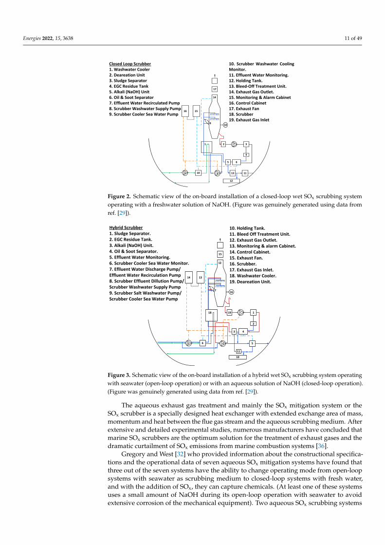
Figure 2. Schematic view of the on-board installation of a closed-loop wet SOx scrubbing system operating with a freshwater solution of NaOH. (Figure was genuinely generated using data from ref. [29]).
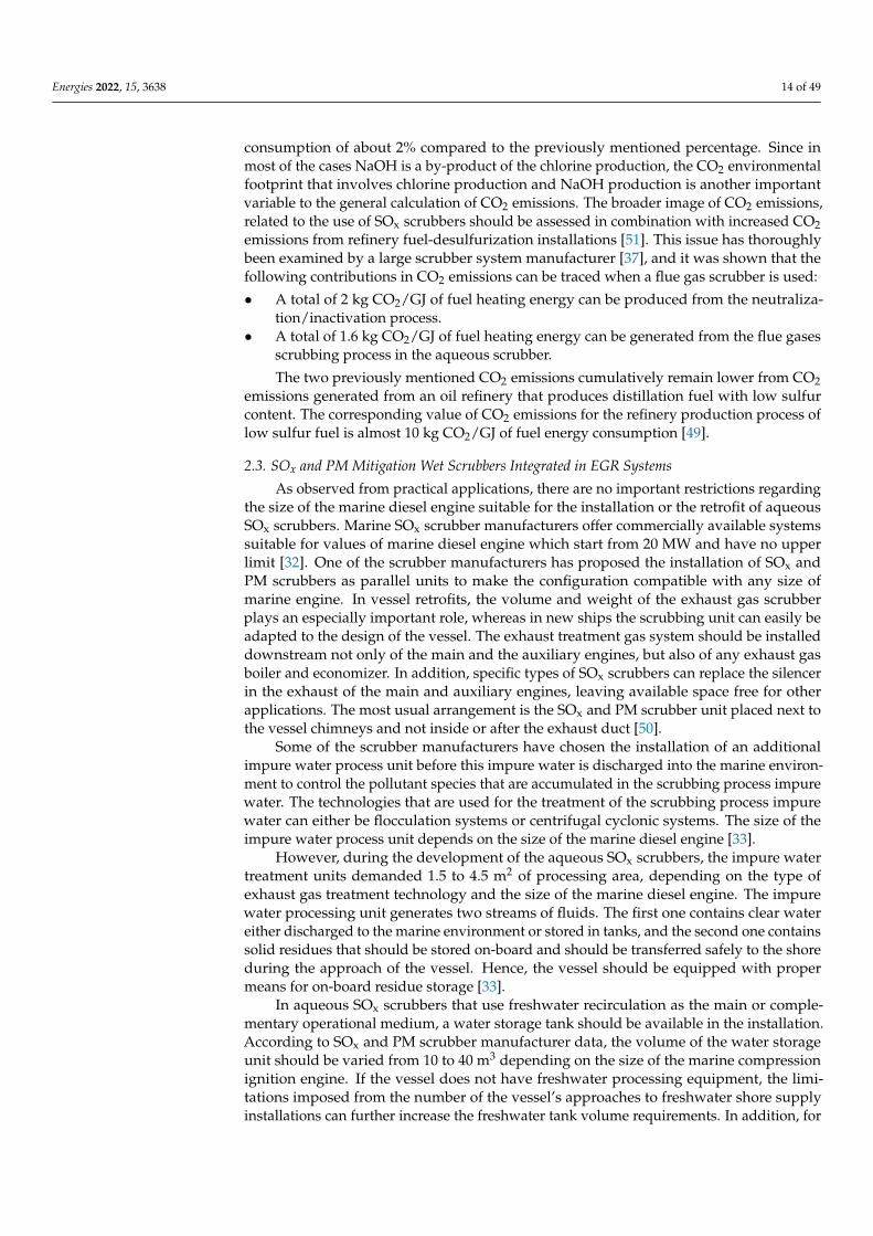
Figure 3. Schematic view of the on-board installation of a hybrid wet SOx scrubbing system operat-ing with seawater (open-loop operation) or with an aqueous solution of NaOH (closed-loop opera-tion). (Figure was genuinely generated using data from ref. [29]).
The aqueous exhaust gas treatment and mainly the SOx mitigation system or the SOx scrubber is a specially designed heat exchanger with extended exchange area of mass, momentum and heat between the flue gas stream and the aqueous scrubbing medium. After extensive and detailed experimental studies, numerous manufacturers have con-cluded that marine SOx scrubbers are the optimum solution for the treatment of exhaust gases and the dramatic curtailment of SOx emissions from marine combustion systems [36].
Gregory and West [32] who provided information about the constructional specifica-tions and the operational data of seven aqueous SOx mitigation systems have found that three out of the seven systems have the ability to change operating mode from open-loop systems with seawater as scrubbing medium to closed-loop systems with fresh water, and with the addition of SOx, they can capture chemicals. (At least one of these systems uses a small amount of NaOH during its open-loop operation with seawater to avoid extensive corrosion of the mechanical equipment). Two aqueous SOx scrubbing systems manufac-turers use exclusively closed-loop systems, and two corresponding manufacturers use only seawater during the exhaust gas scrubbing process. Extremely detailed technical
17
16 15
10 13
6
4
32
14
19 18
9 8
7
Closed Loop Scrubber1. Washwater Cooler2. Deareation Unit3. Sludge Separator4. EGC Residue Tank5. Alkali (NaOH) Unit6. Oil & Soot Separator7. Effluent Water Recirculated Pump8. Scrubber Washwater Supply Pump9. Scrubber Cooler Sea Water Pump
5
12
11
1
10. Scrubber Washwater Cooling Monitor.11. Effluent Water Monitoring.12. Holding Tank.13. Bleed-Off Treatment Unit.14. Exhaust Gas Outlet.15. Monitoring & Alarm Cabinet16. Control Cabinet17. Exhaust Fan18. Scrubber19. Exhaust Gas Inlet
15
14 13
6
4
2
119
12
17 16
9 8
7
Hybrid Scrubber1. Sludge Separator.2. EGC Residue Tank.3. Alkali (NaOH) Unit.4. Oil & Soot Separator.5. Effluent Water Monitoring.6. Scrubber Cooler Sea Water Monitor.7. Eflluent Water Discharge Pump/Effluent Water Recirculation Pump8. Scrubber Effluent Dillution Pump/Scrubber Washwater Supply Pump9. Scrubber Salt Washwater Pump/Scrubber Cooler Sea Water Pump
3
10
5
18
11
10. Holding Tank.11. Bleed Off Treatment Unit.12. Exhaust Gas Outlet.13. Monitoring & alarm Cabinet.14. Control Cabinet.15. Exhaust Fan.16. Scrubber.17. Exhaust Gas Inlet.18. Washwater Cooler.19. Deareation Unit.
Figure 2. Schematic view of the on-board installation of a closed-loop wet SOx scrubbing systemoperating with a freshwater solution of NaOH. (Figure was genuinely generated using data fromref. [29]).
Energies 2021, 14, x FOR PEER REVIEW 10 of 46
Figure 2. Schematic view of the on-board installation of a closed-loop wet SOx scrubbing system operating with a freshwater solution of NaOH. (Figure was genuinely generated using data from ref. [29]).
Figure 3. Schematic view of the on-board installation of a hybrid wet SOx scrubbing system operat-ing with seawater (open-loop operation) or with an aqueous solution of NaOH (closed-loop opera-tion). (Figure was genuinely generated using data from ref. [29]).
The aqueous exhaust gas treatment and mainly the SOx mitigation system or the SOx scrubber is a specially designed heat exchanger with extended exchange area of mass, momentum and heat between the flue gas stream and the aqueous scrubbing medium. After extensive and detailed experimental studies, numerous manufacturers have con-cluded that marine SOx scrubbers are the optimum solution for the treatment of exhaust gases and the dramatic curtailment of SOx emissions from marine combustion systems [36].
Gregory and West [32] who provided information about the constructional specifica-tions and the operational data of seven aqueous SOx mitigation systems have found that three out of the seven systems have the ability to change operating mode from open-loop systems with seawater as scrubbing medium to closed-loop systems with fresh water, and with the addition of SOx, they can capture chemicals. (At least one of these systems uses a small amount of NaOH during its open-loop operation with seawater to avoid extensive corrosion of the mechanical equipment). Two aqueous SOx scrubbing systems manufac-turers use exclusively closed-loop systems, and two corresponding manufacturers use only seawater during the exhaust gas scrubbing process. Extremely detailed technical
17
16 15
10 13
6
4
32
14
19 18
9 8
7
Closed Loop Scrubber1. Washwater Cooler2. Deareation Unit3. Sludge Separator4. EGC Residue Tank5. Alkali (NaOH) Unit6. Oil & Soot Separator7. Effluent Water Recirculated Pump8. Scrubber Washwater Supply Pump9. Scrubber Cooler Sea Water Pump
5
12
11
1
10. Scrubber Washwater Cooling Monitor.11. Effluent Water Monitoring.12. Holding Tank.13. Bleed-Off Treatment Unit.14. Exhaust Gas Outlet.15. Monitoring & Alarm Cabinet16. Control Cabinet17. Exhaust Fan18. Scrubber19. Exhaust Gas Inlet
15
14 13
6
4
2
119
12
17 16
9 8
7
Hybrid Scrubber1. Sludge Separator.2. EGC Residue Tank.3. Alkali (NaOH) Unit.4. Oil & Soot Separator.5. Effluent Water Monitoring.6. Scrubber Cooler Sea Water Monitor.7. Eflluent Water Discharge Pump/Effluent Water Recirculation Pump8. Scrubber Effluent Dillution Pump/Scrubber Washwater Supply Pump9. Scrubber Salt Washwater Pump/Scrubber Cooler Sea Water Pump
3
10
5
18
11
10. Holding Tank.11. Bleed Off Treatment Unit.12. Exhaust Gas Outlet.13. Monitoring & alarm Cabinet.14. Control Cabinet.15. Exhaust Fan.16. Scrubber.17. Exhaust Gas Inlet.18. Washwater Cooler.19. Deareation Unit.
Figure 3. Schematic view of the on-board installation of a hybrid wet SOx scrubbing system operatingwith seawater (open-loop operation) or with an aqueous solution of NaOH (closed-loop operation).(Figure was genuinely generated using data from ref. [29]).
The aqueous exhaust gas treatment and mainly the SOx mitigation system or theSOx scrubber is a specially designed heat exchanger with extended exchange area of mass,momentum and heat between the flue gas stream and the aqueous scrubbing medium. Afterextensive and detailed experimental studies, numerous manufacturers have concluded thatmarine SOx scrubbers are the optimum solution for the treatment of exhaust gases and thedramatic curtailment of SOx emissions from marine combustion systems [36].
Gregory and West [32] who provided information about the constructional specifica-tions and the operational data of seven aqueous SOx mitigation systems have found thatthree out of the seven systems have the ability to change operating mode from open-loopsystems with seawater as scrubbing medium to closed-loop systems with fresh water,and with the addition of SOx, they can capture chemicals. (At least one of these systemsuses a small amount of NaOH during its open-loop operation with seawater to avoidextensive corrosion of the mechanical equipment). Two aqueous SOx scrubbing systems

Energies 2022, 15, 3638 12 of 49
manufacturers use exclusively closed-loop systems, and two corresponding manufacturersuse only seawater during the exhaust gas scrubbing process. Extremely detailed technicalspecifications for SOx mitigation scrubbers are not available in the literature since scrubbermanufacturers are reluctant to provide all the technical details. However, there is a variationfrom systems that guide the exhaust gas stream through an inlet duct to a swallow watertank to cyclonic scrubbing systems, which achieve SOx mitigation through centrifugationand scrubbing of exhaust gases [36]. Despite that, the SOx capture rate appears to besimilar between different constructional layout scrubbers, although the mitigation rate ofPM emissions varies significantly with the configuration of the SOx and PM scrubber. Thisfact motivated specific scrubber manufacturers to examine various pre-processing exhaustgas treatment systems [32]. These pre-processing initiatives comprise injection nozzles andventuri-type adjustable nozzles. The use of venturi nozzles results in flow strangulation.leading to lower outlet pressure and higher outlet exhaust gas velocities. These parameterson a combinatory basis result in the increase of turbulence levels and significantly enhancethe SOx and PM emissions capture rate [36]. However, the increased pressure strangulationin venturi nozzles can lead to high values of back pressure at the marine engine exhaust;hence, it can disrupt the critical balance of pollutant mitigation degree at optimum levelswith a parallel compromise of the operational efficiency and fuel consumption of marinediesel engines. The contemporary technical challenges that SOx and PM scrubbers face arethe following according to the MEPC 56/INF. 5/Annex 1 2007 [36]:
• The preservation of exhaust gas buoyancy phenomenon (i.e., the avoidance of ex-cess temperature reduction of exhaust gases during their scrubbing process by theaqueous medium).
• The simultaneous minimization of the space captured and the weight and the energyconsumption by the SOx and PM mitigation aqueous gas treatment system.
• The minimization of the pressure drop of the exhaust gas stream.• Hot corrosion avoidance of the SOx scrubber constructional elements from exhaust
gases that contain sulfur and possibly acid sulfate roots.• The avoidance of exhaust gas vapor condensation and appearance of water droplets
at the SOx and PM scrubber outlet.
The on-board aqueous SOx scrubbers have three different waste fluid streams [43]:
• The effluent water from the scrubber which is either ejected to the sea or guided to anon-board wastewater treatment plant.
• The heavy residues that are rejected from the on-board wastewater treatment plant orfrom the freshwater recirculation process.
• The flue gases that contain the remaining pollutant species which were not capturedfrom the aqueous flue gas treatment process.
One of the most critical questions regarding the aqueous exhaust gas scrubbing processand SOx capture is the rejection of the effluent water from the scrubbing process. Gregoryand West [32] tried to address this question and suggested that the aqueous exhaust gastreatment systems with seawater or caustic soda are not highly effective regarding SOxcapture. However, they are effective in capturing particulate emissions and lubricant oilwith capture rates more than 80%. Hence, the on-board existence of an effluent watertreatment installation is essential. This effluent water treatment installation will have theability to capture and reject the particulate matter and lubricant oil that are carried inprocessed exhaust gases [44]. Effluent water flows from seawater scrubbers and scrubbersoperating with an aqueous solution of NaOH are quite different, both in their compositionand quantity. A seawater scrubber will reject the total amount of effluent water in all cases,except for a small quantity of water that is drawn from the residue stream in operationalwastewater process installations. The caustic soda scrubber under normal conditions couldreject a small amount of impure water to counterbalance the pollutant species that arecontained in the scrubbing process water. The impure water rejection rates in both typesof scrubbers, i.e., open-loop and closed-loop, will vary depending on the design of the

Energies 2022, 15, 3638 13 of 49
exhaust gas scrubber. However, for simplicity reasons, generally accepted values of impurewater rejection rates can be found in MEPC 58/23 Annex 16 of 2008 [45]:
• The impure water rejection rate from a SOx scrubber with seawater as the scrubbingmedium is 45 m3/MWh.
• The impure water rejection rate from a SOx scrubber with caustic soda varies from0.1 to 0.3 m3/MWh (The indicative recirculation rate is 20 m3/MWh).
According to the MEPC 56/INF.5/Annex 1 of 2007, three different fluids are presentin SOx scrubbers [46]:
• Exhaust gases that are generated from marine diesel engines (Exhaust gases areproduced from the combustion of intake air with fuel. Lubricant oil can also be presentin exhaust gases depending on the engine status and the operational conditions).
• Seawater or fresh water with NaOH which are used for scrubbing exhaust gases.• Impure water which may contain combustion products and chemical additives.
In addition to the previously mentioned sources, there will be contributions to theimpure water of the exhaust gas scrubbing process from the wear of engine metal partsand possibly from corrosion products, e.g., seawater corrosion products. In cases where themarine SOx scrubbers are equipped with impure water processing units, a stream of heavyresidues will be produced in parallel with the discharge of processed water. This includesSOx scrubbers with seawater where the effluent water stream should be processed andsystems where the small stream of impure water discharged from a freshwater scrubberwill be processed by any processing installation [47]. Heavy residue process technologiesindicate a considerable degree of differentiation, and for seawater scrubbers, the chal-lenge is the effective processing of large quantities of effluent water (almost 45 m3/MWh).In the present situation, cyclonic systems and flocculation systems for exhaust gas process-ing are under testing. The same processing technologies are used in exhaust gas processingunits with caustic soda, but in this case, the quantities of impure water are considerablylower compared to the previously mentioned case (0.1 to 0.3 m3/MWh). Moreover, theconcentration of pollutants in the small stream of impure water in freshwater scrubbersis considerably higher compared to the corresponding concentration of the impure waterdischarged stream from seawater scrubbers, thus resulting in the production of a higherresidue fraction [48]. The on-board incineration of heavy residue is not allowed. Thus,the existence of a specially designed unit for the on-board storage of scrubbing processdischarged residues is required. The generated quantities of heavy residues and theircomposition are not often found in the literature, as it appears that most of the publishedstudies concentrate on the operational effectiveness of the exhaust gas scrubbers and onthe composition of the process discharged water. However, a large marine engine manufac-turer [49] reported that the quantity of heavy residues produced from its own aqueous SOxscrubber is almost 0.1 to 0.4 kg/MWh, whereas Ritchie et al. [47] reported heavy residueproduction of 0.2 kg/MWh from a seawater SOx scrubber installed on the coastal ship“Pride of Kent” [50].
Undoubtedly, aqueous SOx scrubbers significantly reduce the negative environmentalfootprint of the vessels on which they are installed by removing sulfur constituents, partic-ulate matter and some metallic constituents from flue gases that are generated from vesselcombustion systems. However, there is relative uncertainty about the size distributionof the particulate emissions captured in an aqueous scrubber. Though the higher sizeparticulates contribute to the “optical gaseous pollution” because they are visible as blacksmoke, the smaller size particulates (PM2.5 which refer to particulates with size smallerthan 2.5 µm) have considerably more detrimental repercussions on the human population.
The amount of CO2 emitted from a vessel equipped with SOx scrubber will be highercompared to a conventional vessel due to the higher fuel consumption of about 2% in dieselengines, which is the outcome of the back pressure that the SOx after-treatment systemimposes on the main and auxiliary engines. This has been reported from large aqueousscrubber manufacturers [37]. One of these manufacturers has estimated an additional fuel
Energies 2022, 15, 3638 14 of 49
consumption of about 2% compared to the previously mentioned percentage. Since inmost of the cases NaOH is a by-product of the chlorine production, the CO2 environmentalfootprint that involves chlorine production and NaOH production is another importantvariable to the general calculation of CO2 emissions. The broader image of CO2 emissions,related to the use of SOx scrubbers should be assessed in combination with increased CO2emissions from refinery fuel-desulfurization installations [51]. This issue has thoroughlybeen examined by a large scrubber system manufacturer [37], and it was shown that thefollowing contributions in CO2 emissions can be traced when a flue gas scrubber is used:
• A total of 2 kg CO2/GJ of fuel heating energy can be produced from the neutraliza-tion/inactivation process.
• A total of 1.6 kg CO2/GJ of fuel heating energy can be generated from the flue gasesscrubbing process in the aqueous scrubber.
The two previously mentioned CO2 emissions cumulatively remain lower from CO2emissions generated from an oil refinery that produces distillation fuel with low sulfurcontent. The corresponding value of CO2 emissions for the refinery production process oflow sulfur fuel is almost 10 kg CO2/GJ of fuel energy consumption [49].
2.3. SOx and PM Mitigation Wet Scrubbers Integrated in EGR Systems
As observed from practical applications, there are no important restrictions regardingthe size of the marine diesel engine suitable for the installation or the retrofit of aqueousSOx scrubbers. Marine SOx scrubber manufacturers offer commercially available systemssuitable for values of marine diesel engine which start from 20 MW and have no upperlimit [32]. One of the scrubber manufacturers has proposed the installation of SOx andPM scrubbers as parallel units to make the configuration compatible with any size ofmarine engine. In vessel retrofits, the volume and weight of the exhaust gas scrubberplays an especially important role, whereas in new ships the scrubbing unit can easily beadapted to the design of the vessel. The exhaust treatment gas system should be installeddownstream not only of the main and the auxiliary engines, but also of any exhaust gasboiler and economizer. In addition, specific types of SOx scrubbers can replace the silencerin the exhaust of the main and auxiliary engines, leaving available space free for otherapplications. The most usual arrangement is the SOx and PM scrubber unit placed next tothe vessel chimneys and not inside or after the exhaust duct [50].
Some of the scrubber manufacturers have chosen the installation of an additionalimpure water process unit before this impure water is discharged into the marine environ-ment to control the pollutant species that are accumulated in the scrubbing process impurewater. The technologies that are used for the treatment of the scrubbing process impurewater can either be flocculation systems or centrifugal cyclonic systems. The size of theimpure water process unit depends on the size of the marine diesel engine [33].
However, during the development of the aqueous SOx scrubbers, the impure watertreatment units demanded 1.5 to 4.5 m2 of processing area, depending on the type ofexhaust gas treatment technology and the size of the marine diesel engine. The impurewater processing unit generates two streams of fluids. The first one contains clear watereither discharged to the marine environment or stored in tanks, and the second one containssolid residues that should be stored on-board and should be transferred safely to the shoreduring the approach of the vessel. Hence, the vessel should be equipped with propermeans for on-board residue storage [33].
In aqueous SOx scrubbers that use freshwater recirculation as the main or comple-mentary operational medium, a water storage tank should be available in the installation.According to SOx and PM scrubber manufacturer data, the volume of the water storageunit should be varied from 10 to 40 m3 depending on the size of the marine compressionignition engine. If the vessel does not have freshwater processing equipment, the limi-tations imposed from the number of the vessel’s approaches to freshwater shore supplyinstallations can further increase the freshwater tank volume requirements. In addition, for

Energies 2022, 15, 3638 15 of 49
the periodic vessel operation without pollutant emissions, an additional process water tankshould be installed in closed-loop scrubbers with fresh water and NaOH.
Freshwater consumption from the exhaust gas treatment system demands the on-board freshwater production or the periodic vessel supply with fresh water from pertinentshore installations. The installation of an on-board freshwater production system obviouslyincreases the overall energy consumption of the vessel due to, for example, the powerconsumption of the recirculation pumps, whereas the periodic vessel supply with freshwater explicitly affects the capacity of the freshwater tank. The solution that should beselected depends mainly on the operational profile of the vessel, especially if a large part ofit is in SOx Emission Control Areas (SECAs) and on the on-board space availability. Theaddition of alkaline chemicals in the exhaust gas treatment process requires the availabilityof a corresponding on-board storage tank [51,52]. The capacity of this storage tank willmainly depend on the vessel routes, the potentiality for connection to shore supply stationsand the required desulfurization levels. However, most of the manufacturers recommendthe use of storage tanks with capacity of 10 m3 or higher for this purpose [50].
As evidenced from Figure 4, in the specific system, part of the exhaust gases afterthe engine turbocharger are guided to a pre-scrubber fed with an aqueous solution offresh water and NaOH. Afterwards, the gases are guided into the main scrubbing unitor to the exhaust gas scrubber, where exhaust gases are treated and pollutant speciessuch as SOx, PM and potentially heavy metals are mitigated [53]. After this process, thequantity of cooled exhaust gas that has been treated in the scrubber and cleaned frompollutant constituents and species that are hazardous for the engine are guided to the EGRcooler where they are further cooled [54,55]. After the EGR cooler, the exhaust gases areguided through a water mist catcher (WMC) where they are dried. Next, they are guidedthrough a blower to the engine intake system to be mixed with the intake charged air andthrough in-cylinder combustion of the intake mixture with the injected fuel to achieve anin-cylinder curtailment of the NOx formation rate. Recirculated exhaust gas flow to thediesel engine intake system is adjusted by a proper valve [56,57]. The impure water andthe heavy residues produced from the scrubbing process in the main scrubber are collectedand guided to a storage tank where they are mixed with an aqueous solution of NaOH.The impure water with the residues and the NaOH aqueous solution are guided througha pump to an impure fluid processing unit where the heavy residues are collected andstored in a specially designed on-board tank [58]. After this process, the impure waterwith the NaOH aqueous solution passes through a second unit which filters the water andcollects it in clean form. The clean water is transferred through a three-way valve; onepart of the clean water quantity is stored in the heavy residue tank, while the other part isdischarged to the sea. After the previously mentioned filtering, the aqueous solution ofNaOH is transferred to the pre-scrubber unit and to the main scrubber unit for capturingthe SOx and PM emissions contained in the exhaust gases [34,35].
The intake pressure of exhaust gases to the SOx and PM mitigation scrubber is almost4 bar(a), whereas the corresponding intake temperature is expected to be about 400 ◦C. Thehigher exhaust gas pressure due to their recirculation before the turbine of the turbochargerin conjunction with the fact that only a fraction of engine exhaust gases is recirculated(typically EGR rate varies from 20 to 40% of the total generated exhaust gas flow rate)allows the EGR scrubber to have a significantly smaller size compared to the conventionalexhaust gas scrubber used in marine engines without EGR [36].
The impure discharged water from EGR scrubbers should comply with the IMOcriteria for the quality of the water that is discharged to the sea. As it happens in the caseof a conventional scrubbing and SOx mitigation system, an EGR scrubber will captureconsiderable quantities of particulate matter that will be accumulated in the dischargedwater. One of the best known pilot installations with an EGR system is equipped with ascrubbing process impure water cleaning unit. Specific water quantities after cleaning aredischarged to the sea in accordance with the IMO regulations for water quality, whereasthe residues are guided to the on-board residue tank [36].

Energies 2022, 15, 3638 16 of 49Energies 2021, 14, x FOR PEER REVIEW 15 of 46
Figure 4. Graphical representation of an EGR system installed on a marine diesel engine for NOx emissions reduction. The specific installation incorporates a closed-loop system with scrubbers op-erating with fresh water and NaOH for the reduction of marine diesel engine emitted SOx and PM. (Figure was genuinely generated using data from refs. [34,35]).
The intake pressure of exhaust gases to the SOx and PM mitigation scrubber is almost 4 bar(a), whereas the corresponding intake temperature is expected to be about 400 °C. The higher exhaust gas pressure due to their recirculation before the turbine of the turbo-charger in conjunction with the fact that only a fraction of engine exhaust gases is recircu-lated (typically EGR rate varies from 20 to 40% of the total generated exhaust gas flow rate) allows the EGR scrubber to have a significantly smaller size compared to the con-ventional exhaust gas scrubber used in marine engines without EGR [36].
The impure discharged water from EGR scrubbers should comply with the IMO cri-teria for the quality of the water that is discharged to the sea. As it happens in the case of a conventional scrubbing and SOx mitigation system, an EGR scrubber will capture con-siderable quantities of particulate matter that will be accumulated in the discharged wa-ter. One of the best known pilot installations with an EGR system is equipped with a scrubbing process impure water cleaning unit. Specific water quantities after cleaning are discharged to the sea in accordance with the IMO regulations for water quality, whereas the residues are guided to the on-board residue tank [36].
NOx and SOx emissions after EGR and scrubbing will be lower compared to the ones of the conventional engine operation. However, there will be an increase of gaseous emis-sions due to the power consumption of the EGR installation. Additionally, Gregory and West [32] have reported an increase of specific fuel oil consumption (SFOC) and CO emis-sions when the EGR installation operated to achieve the maximum NOx reduction. In this case, the modification of engine settings can counterbalance a part of the previously neg-ative effect on SFOC [36].
2.4. Inert Gas SOx Scrubbers Inert gas scrubbers are designed to remove sulfur and PM emissions from gases used
to replace inert gas in tanks and pipes during unloading of a gas or liquid shipment. Inert gas scrubbers are aqueous scrubbers and are like exhaust gas scrubbers regarding their operational principle, but they are smaller in size due to the management of lower gas volumes and consume seawater at a relatively higher level compared to the exhaust gas scrubbers. This can be attributed to the high requirement for gas cooling because the peak temperature at the tankers’ decks is 37 °C. In most of the cases, the inert gas scrubbers are seawater scrubbers, but an alternative technical solution will be the use of scrubbers with recirculated fresh water where the seawater would additionally be used for cooling [36].
Figure 4. Graphical representation of an EGR system installed on a marine diesel engine for NOx
emissions reduction. The specific installation incorporates a closed-loop system with scrubbersoperating with fresh water and NaOH for the reduction of marine diesel engine emitted SOx and PM.(Figure was genuinely generated using data from refs. [34,35]).
NOx and SOx emissions after EGR and scrubbing will be lower compared to theones of the conventional engine operation. However, there will be an increase of gaseousemissions due to the power consumption of the EGR installation. Additionally, Gregoryand West [32] have reported an increase of specific fuel oil consumption (SFOC) and COemissions when the EGR installation operated to achieve the maximum NOx reduction.In this case, the modification of engine settings can counterbalance a part of the previouslynegative effect on SFOC [36].
2.4. Inert Gas SOx Scrubbers
Inert gas scrubbers are designed to remove sulfur and PM emissions from gases usedto replace inert gas in tanks and pipes during unloading of a gas or liquid shipment. Inertgas scrubbers are aqueous scrubbers and are like exhaust gas scrubbers regarding theiroperational principle, but they are smaller in size due to the management of lower gasvolumes and consume seawater at a relatively higher level compared to the exhaust gasscrubbers. This can be attributed to the high requirement for gas cooling because the peaktemperature at the tankers’ decks is 37 ◦C. In most of the cases, the inert gas scrubbers areseawater scrubbers, but an alternative technical solution will be the use of scrubbers withrecirculated fresh water where the seawater would additionally be used for cooling [36].
Inert gas scrubbers clean mainly the flue gases that are generated from on-boardexhaust gas boilers since the maximum O2 limit in the inert gas is 8%. Flue gases fromexhaust gas boilers usually contain 3% to 5% O2, whereas diesel engine exhaust gasesusually contain oxygen that varies from 7% to 15% As a result, they do not cover therequirements of inert gases. The inert gas scrubbers are used mainly in crude oil tankersand in chemical tankers. A typical inert gas treatment installation for SOx and PM captureis shown in Figure 5. The specific gas treatment unit operates with seawater as the SOxcapture medium [38].

Energies 2022, 15, 3638 17 of 49
Energies 2021, 14, x FOR PEER REVIEW 16 of 46
Inert gas scrubbers clean mainly the flue gases that are generated from on-board ex-haust gas boilers since the maximum O2 limit in the inert gas is 8%. Flue gases from ex-haust gas boilers usually contain 3% to 5% O2, whereas diesel engine exhaust gases usually contain oxygen that varies from 7% to 15% As a result, they do not cover the requirements of inert gases. The inert gas scrubbers are used mainly in crude oil tankers and in chemical tankers. A typical inert gas treatment installation for SOx and PM capture is shown in Figure 5. The specific gas treatment unit operates with seawater as the SOx capture me-dium [38].
Figure 5. Inert gas/flue gas aqueous scrubbing system with seawater. (Figure was genuinely gener-ated using data from refs. [36,38]).
As the inert gas generators and hence the inert gas scrubbers are considered safe sys-tems and are operational only for certain time periods during the unloading process of the vessel, the quality of the processed impure water does not fall under the limits of the IMO. There is limited effluent water analysis for inert gas scrubbers. In inert gas scrubbers, high water quantities (0.015 m3/Nm3 gas) are used. For this reason, the requirements of temperature should be satisfied, and the concentrations of the effluent species including particulate matter should be exceedingly small. The commercially available flue gas treat-ment systems with scrubbers operate with only one pass of flue gases from the scrubber. There are no impure water processing units; hence, there is no heavy residue quantity that should be removed later from the ship. The produced particulate matter is directly dis-patched to the sea.
2.5. Dry Exhaust Gas Treatment and SOx Capture Systems Dry exhaust gas treatment and SOx capture systems are used extensively in shore
installations for the desulfurization of industrial flue gases. The operation of all dry ex-haust gas cleaning systems is based on the use of limestone or hydrated lime to clean SOx from the flue gases. Even though the dry exhaust gas treatment process is a proven SOx reduction method, it has certain disadvantages such as the supply and the storage of lime products and the storage and the shore disposal of the used reactants. Dry exhaust gas treatment systems used for marine applications are based on a packing material bed from hydrated lime (calcium hydroxide). The maximization of the area of the dry exhaust gas cleaning system and the conservation for long time of the exhaust gases in contact with the packing material optimizes the removal of sulfur and particulate matter from the ex-haust gas stream. The dry capture of sulfur oxides is based on the following chemical reactions [36]:
Figure 5. Inert gas/flue gas aqueous scrubbing system with seawater. (Figure was genuinelygenerated using data from refs. [36,38]).
As the inert gas generators and hence the inert gas scrubbers are considered safesystems and are operational only for certain time periods during the unloading process ofthe vessel, the quality of the processed impure water does not fall under the limits of theIMO. There is limited effluent water analysis for inert gas scrubbers. In inert gas scrubbers,high water quantities (0.015 m3/Nm3 gas) are used. For this reason, the requirements oftemperature should be satisfied, and the concentrations of the effluent species includingparticulate matter should be exceedingly small. The commercially available flue gastreatment systems with scrubbers operate with only one pass of flue gases from the scrubber.There are no impure water processing units; hence, there is no heavy residue quantitythat should be removed later from the ship. The produced particulate matter is directlydispatched to the sea.
2.5. Dry Exhaust Gas Treatment and SOx Capture Systems
Dry exhaust gas treatment and SOx capture systems are used extensively in shoreinstallations for the desulfurization of industrial flue gases. The operation of all dry exhaustgas cleaning systems is based on the use of limestone or hydrated lime to clean SOx from theflue gases. Even though the dry exhaust gas treatment process is a proven SOx reductionmethod, it has certain disadvantages such as the supply and the storage of lime productsand the storage and the shore disposal of the used reactants. Dry exhaust gas treatmentsystems used for marine applications are based on a packing material bed from hydratedlime (calcium hydroxide). The maximization of the area of the dry exhaust gas cleaningsystem and the conservation for long time of the exhaust gases in contact with the packingmaterial optimizes the removal of sulfur and particulate matter from the exhaust gas stream.The dry capture of sulfur oxides is based on the following chemical reactions [36]:
SO2 + Ca(OH)2 +12
O2 → CaSO4 + H2O (11)
SO3 + Ca(OH)2 + O2 → CaSO4 + 2H2O (12)
The previously mentioned reactions are exothermic, i.e., they release heat allowing theexhaust gas treatment system to thermally contribute to the efficiency of the exhaust gasboiler through proper installation. A typical dry exhaust gas treatment and desulfurizationinstallation is shown in Figure 6 [30]. Dry exhaust gas cleaning systems do not reject impuresubstances to the maritime environment such as the aqueous exhaust gas treatment systemsdo. The used packing material is discharged to specific shore installations. According to onedry exhaust gas cleaning systems manufacturer, the residues of these units can be used inshore industrial installations for high temperature desulfurization based on the remaining
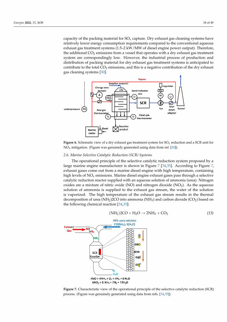
Energies 2022, 15, 3638 18 of 49
capacity of the packing material for SOx capture. Dry exhaust gas cleaning systems haverelatively lower energy consumption requirements compared to the conventional aqueousexhaust gas treatment systems (1.5–2 kW/MW of diesel engine power output). Therefore,the additional CO2 emissions from a vessel that operates with a dry exhaust gas treatmentsystem are correspondingly low. However, the industrial process of production anddistribution of packing material for dry exhaust gas treatment systems is anticipated tocontribute to the total CO2 emissions, and this is a negative contribution of the dry exhaustgas cleaning systems [30].
Energies 2021, 14, x FOR PEER REVIEW 17 of 46
+ + → +2 2 2 4 21SO Ca(OH) O CaSO H O2
(11)
( )+ + → +3 2 4 22SO Ca OH O CaSO 2H O
(12)
The previously mentioned reactions are exothermic, i.e., they release heat allowing the exhaust gas treatment system to thermally contribute to the efficiency of the exhaust gas boiler through proper installation. A typical dry exhaust gas treatment and desulfuri-zation installation is shown in Figure 6 [30]. Dry exhaust gas cleaning systems do not reject impure substances to the maritime environment such as the aqueous exhaust gas treat-ment systems do. The used packing material is discharged to specific shore installations. According to one dry exhaust gas cleaning systems manufacturer, the residues of these units can be used in shore industrial installations for high temperature desulfurization based on the remaining capacity of the packing material for SOx capture. Dry exhaust gas cleaning systems have relatively lower energy consumption requirements compared to the conventional aqueous exhaust gas treatment systems (1.5–2 kW/MW of diesel engine power output). Therefore, the additional CO2 emissions from a vessel that operates with a dry exhaust gas treatment system are correspondingly low. However, the industrial pro-cess of production and distribution of packing material for dry exhaust gas treatment sys-tems is anticipated to contribute to the total CO2 emissions, and this is a negative contri-bution of the dry exhaust gas cleaning systems [30].
Figure 6. Schematic view of a dry exhaust gas treatment system for SOx reduction and a SCR unit for NOx mitigation. (Figure was genuinely generated using data from ref. [30]).
2.6. Marine Selective Catalytic Reduction (SCR) Systems The operational principle of the selective catalytic reduction system proposed by a
large marine engine manufacturer is shown in Figure 7 [34,35]. According to Figure 7, exhaust gases come out from a marine diesel engine with high temperature, containing high levels of NOx emissions. Marine diesel engine exhaust gases pass through a selective catalytic reduction reactor supplied with an aqueous solution of ammonia (urea). Nitro-gen oxides are a mixture of nitric oxide (NO) and nitrogen dioxide (NO2). As the aqueous solution of ammonia is supplied to the exhaust gas stream, the water of the solution is vaporized. The high temperature of the exhaust gas stream results in the thermal decom-position of urea (NH2)2CO into ammonia (NH3) and carbon dioxide (CO2) based on the following chemical reaction [34,35]:
+ → +2 2 3 2(NH )2CO H O 2NH CO (13)
The chemical reactions that take place inside the selective catalytic reduction reactor are the following:
Figure 6. Schematic view of a dry exhaust gas treatment system for SOx reduction and a SCR unit forNOx mitigation. (Figure was genuinely generated using data from ref. [30]).
2.6. Marine Selective Catalytic Reduction (SCR) Systems
The operational principle of the selective catalytic reduction system proposed by alarge marine engine manufacturer is shown in Figure 7 [34,35]. According to Figure 7,exhaust gases come out from a marine diesel engine with high temperature, containinghigh levels of NOx emissions. Marine diesel engine exhaust gases pass through a selectivecatalytic reduction reactor supplied with an aqueous solution of ammonia (urea). Nitrogenoxides are a mixture of nitric oxide (NO) and nitrogen dioxide (NO2). As the aqueoussolution of ammonia is supplied to the exhaust gas stream, the water of the solutionis vaporized. The high temperature of the exhaust gas stream results in the thermaldecomposition of urea (NH2)2CO into ammonia (NH3) and carbon dioxide (CO2) based onthe following chemical reaction [34,35]:
(NH2)2CO + H2O→ 2NH3 + CO2 (13)
Energies 2021, 14, x FOR PEER REVIEW 18 of 46
+ + → +3 2 2 24NO 4NH O 4N 6H O (14)
+ → +2 3 2 26NO 8NH 7N 12H O (15)
As can be concluded from the above two chemical reactions, the nitric oxide (NO) reacts with ammonia (NH3) and is converted to nitrogen (N2) and water (H2O), whereas the nitrogen dioxide (NO2) reacts with ammonia (NH3) and is converted to nitrogen (N2) and water (H2O). It is obvious that both nitrogen (N2) and water (H2O) are chemical spe-cies without negative repercussions on human health and the environment. The SCR re-actor is manufactured from a ceramic monolith which operates as a chemical catalyst to facilitate the chemical reactions of NO and NO2 conversion to harmless N2 and H2O [34,35].
As observed from Figure 7, the marine diesel engine exhaust gases from the exhaust gas receiver are guided to the duct where the vaporization of the injected urea solution and its mixing with the exhaust gas stream is conducted. Afterwards, the gaseous mixture is supplied to the SCR system reactor, where the mixture of NO and NO2 is converted to N2 and H2O. As known, large two-stroke marine diesel engines are characterized by high brake efficiency and low trapping efficiency; so, the exhaust gas temperature exiting the turbocharger is relatively low and varies from 230 to 260 °C depending on engine load and ambient conditions. These low exhaust gas temperatures are problematic for the op-eration of the SCR system when heavy fuel oil (HFO), which contains high sulfur content, is used. Thus, with respect to the highest fuel flexibility, it has been a priority that marine diesel engines generate an exhaust gas stream with the proper temperature for the optimal operation of the SCR system. The inlet exhaust gas temperature to the SCR system should ideally vary from 330 to 350 °C when the marine diesel engine operates with HFO [34,35].
Figure 7. Characteristic view of the operational principle of the selective catalytic reduction (SCR) process. (Figure was genuinely generated using data from refs. [34,35]).
3. Applications of Marine Exhaust Gas Treatment Systems 3.1. Wet Closed-Loop and Open-Loop SOx Scrubbers
Many manufacturers of marine aqueous exhaust gas treatment systems have signifi-cant experience from similar shore applications (mainly as desulfurization units of flue gases that are generated from industrial installations and oil refineries). Other manufac-turers of marine aqueous exhaust gas cleaning systems transfer their experience from the construction and installation of corresponding exhaust gas treatment and inert gas pro-duction systems for the maritime industry.
It should be clarified that starting in 2011 and after 20 years from the first testing installation, the aqueous exhaust gas scrubbers have shown considerable technological evolution. It should be noted that for more than 30 years the aqueous exhaust gas
Figure 7. Characteristic view of the operational principle of the selective catalytic reduction (SCR)process. (Figure was genuinely generated using data from refs. [34,35]).

Energies 2022, 15, 3638 19 of 49
The chemical reactions that take place inside the selective catalytic reduction reactorare the following:
4NO + 4NH3 + O2 → 4N2 + 6H2O (14)
6NO2 + 8NH3 → 7N2 + 12H2O (15)
As can be concluded from the above two chemical reactions, the nitric oxide (NO)reacts with ammonia (NH3) and is converted to nitrogen (N2) and water (H2O), whereasthe nitrogen dioxide (NO2) reacts with ammonia (NH3) and is converted to nitrogen (N2)and water (H2O). It is obvious that both nitrogen (N2) and water (H2O) are chemical specieswithout negative repercussions on human health and the environment. The SCR reactor ismanufactured from a ceramic monolith which operates as a chemical catalyst to facilitatethe chemical reactions of NO and NO2 conversion to harmless N2 and H2O [34,35].
As observed from Figure 7, the marine diesel engine exhaust gases from the exhaustgas receiver are guided to the duct where the vaporization of the injected urea solutionand its mixing with the exhaust gas stream is conducted. Afterwards, the gaseous mixtureis supplied to the SCR system reactor, where the mixture of NO and NO2 is convertedto N2 and H2O. As known, large two-stroke marine diesel engines are characterized byhigh brake efficiency and low trapping efficiency; so, the exhaust gas temperature exitingthe turbocharger is relatively low and varies from 230 to 260 ◦C depending on engineload and ambient conditions. These low exhaust gas temperatures are problematic for theoperation of the SCR system when heavy fuel oil (HFO), which contains high sulfur content,is used. Thus, with respect to the highest fuel flexibility, it has been a priority that marinediesel engines generate an exhaust gas stream with the proper temperature for the optimaloperation of the SCR system. The inlet exhaust gas temperature to the SCR system shouldideally vary from 330 to 350 ◦C when the marine diesel engine operates with HFO [34,35].
3. Applications of Marine Exhaust Gas Treatment Systems3.1. Wet Closed-Loop and Open-Loop SOx Scrubbers
Many manufacturers of marine aqueous exhaust gas treatment systems have signif-icant experience from similar shore applications (mainly as desulfurization units of fluegases that are generated from industrial installations and oil refineries). Other manufac-turers of marine aqueous exhaust gas cleaning systems transfer their experience fromthe construction and installation of corresponding exhaust gas treatment and inert gasproduction systems for the maritime industry.
It should be clarified that starting in 2011 and after 20 years from the first testinginstallation, the aqueous exhaust gas scrubbers have shown considerable technologicalevolution. It should be noted that for more than 30 years the aqueous exhaust gas treatmentsystems have operated as exhaust gas treatment and inert gas production systems [36].
The first prototype aqueous exhaust gas treatment system with seawater was installedin a ship in 1991. Specifically, the installation was made in the passenger ferry KronprinsHarald of the Color Line Company [36]. In 1993, an aqueous exhaust gas treatment systemwith seawater was installed in the oil tanker MT Fjordshell. Another company processeda part of the exhaust gas stream of the icebreaker Louis S. St.-Laurent in 1998, and incooperation with a large marine engine manufacturer installed a prototype exhaust gastreatment unit to mitigate mainly SOx emissions in the Ro/Pax Ferry Leif Ericson in 2001 [36]
In recent years, many manufacturers of aqueous exhaust gas processing systems haveinstalled exhaust gas cleaning systems in ships. These installations include the systemsinstalled in the Ro-Ro Ficaria Seaways, the Ro-Ro Pride of Kent, in the cruise ship Zaandamand in the chemical tankers Baru and Suula [36].
One SOx scrubber manufacturer has its own systems placed on a barge. Inside theharbor, the barge can come close to the ship in which the exhaust gas processing will takeplace, and the exhaust gas cleaning systems of the barge can capture unwanted gaseousemissions emitted from the diesel engines and exhaust gas boilers of the ship [29].

Energies 2022, 15, 3638 20 of 49
The main challenge that the on-board installation of a SOx scrubber must face concernsthe purchasing and the transfer of the consumables (mainly caustic soda) that are requiredfor the operation of the exhaust gas treatment systems. Caustic soda is consumed witha rate ranging between 1 and 15 L per hour and per MW of engine power. The higherthe consumption of caustic soda is, the higher the SOx capture from exhaust gases in thescrubber [29].
The consumed quantity of caustic soda required for the achievement of specific SOxreductions in diesel engine gaseous emissions in comparison to those achieved by specificfuel sulfur content are the following:
• Quantity of 11 L caustic soda with 50% w/w NaOH/MWh achieves SOx emissionsequivalent to 2.9% sulfur in fuel oil.
• Quantity of 8 L caustic soda with 50% w/w NaOH/MWh achieves SOx emissionsequivalent to 2.4% sulfur in fuel oil.
• Quantity of 4 L caustic soda with 50% w/w NaOH/MWh achieves SOx emissionsequivalent to 1.4% sulfur in fuel oil.
• Quantity of 1 L caustic soda with 50% w/w NaOH/MWh achieves SOx emissionsequivalent to 0.9% sulfur in fuel oil.
3.2. Wet SOx and PM Scrubbers Integrated in Marine EGR Systems
One of the best known applications of a “dual” NOx and SOx mitigation system isthe wet SOx and PM scrubber integrated in an EGR system installed in the containershipAlexander Maersk. The on-board space requirements for the EGR installation are expectedto be reduced as the experimental prototype installations are progressively converted tocommercially available units. Preliminary estimations report that 15 to 20 m3 of on-boardcaptured space are required for the EGR installation per 10 MW of diesel engine power [36].
3.3. Inert Gas Wet SOx Scrubbers
Inert gas scrubbers as parts of gas treatment systems are widely recognized as effectivemeans of deactivating oil and chemical cargo, especially where higher grades of inert gasesare not required (since the source is the flue gas boiler exhaust). Typical operational pa-rameters in the case of inert gas scrubbers are the cooling requirements and the subsequenthigh seawater consumption demands which range from 0.010 to 0.020 m3/Nm3 of inertgas [36].
3.4. Dry SOx Scrubbers
In the present situation, only one manufacturer has commercially available dry ex-haust gas cleaning and SOx mitigation systems for marine applications. This manufacturerhas installed a testing dry SOx scrubber in the cargo ship MV Timbus which carried cel-lulose from Sweden to Holland [30]. The specific system was approved by class in April2010. The dry SOx scrubber in the present phase of development has significant on-boardspace requirements. Both the dry exhaust gas processing unit and the storage facilities ofthe unprocessed and the processed packing material have considerable on-board spacerequirements [36]. The on-board space requirement for the packing material dependsobviously on the operational profile of the ship and the availability of the unprocessed andprocessed packing material. A scrubber system manufacturer [59] guarantees the supplyof new packing material when this is required and plans the construction of a packingmaterial supply system in significant harbors around the world. Although the limestoneis a directly available commercial product, its supply can set limitations to the number ofships in which its installation is suitable [30].
3.5. Marine Selective Catalytic Reduction (SCR) Systems
The selective catalytic reduction, which uses ammonia as reductive mean, was patentedin the USA in 1957. From this year and on, thousands of SCR systems have been manufac-tured and installed in shore applications from industrial installations and electric power

Energies 2022, 15, 3638 21 of 49
generation units to trains and cars. The maritime sector has more than two decades oftechnological experience with SCR systems. The first marine applications of SCR systemswere conducted by large marine engine manufacturers [60]. Between 1989 and 1992, a well-known engine manufacturer tested the viability of SCR systems through their installation infour vessels in San Francisco Bay and received a certificate of acceptable operation of thesesystem regarding their achieved NOx reduction from the corresponding maritime transportmanagement body in the San Francisco Bay (Bay Area Air Quality Management District(BAAQMD). In addition, between 1999 and 2000, another large engine manufacturer in-stalled SCR systems in three two-stroke main diesel engines of Ro-Ro vessels attainingNOx emissions of 2 g/kWh that were lower than Tier III values for 10 years of continuousoperation. The use of SCR systems was expanded in 2000 and 2001 in LPG carriers. Today,SCR technology is widely accepted and is a highly effective NOx reduction technology withmore than 500 examples of applications in the maritime sector until 2013 (see Figure 8) [60].
Energies 2021, 14, x FOR PEER REVIEW 20 of 46
3.4. Dry SOx Scrubbers In the present situation, only one manufacturer has commercially available dry ex-
haust gas cleaning and SOx mitigation systems for marine applications. This manufacturer has installed a testing dry SOx scrubber in the cargo ship MV Timbus which carried cellu-lose from Sweden to Holland [30]. The specific system was approved by class in April 2010. The dry SOx scrubber in the present phase of development has significant on-board space requirements. Both the dry exhaust gas processing unit and the storage facilities of the unprocessed and the processed packing material have considerable on-board space requirements [36]. The on-board space requirement for the packing material depends ob-viously on the operational profile of the ship and the availability of the unprocessed and processed packing material. A scrubber system manufacturer [59] guarantees the supply of new packing material when this is required and plans the construction of a packing material supply system in significant harbors around the world. Although the limestone is a directly available commercial product, its supply can set limitations to the number of ships in which its installation is suitable [30].
3.5. Marine Selective Catalytic Reduction (SCR) Systems The selective catalytic reduction, which uses ammonia as reductive mean, was pa-
tented in the USA in 1957. From this year and on, thousands of SCR systems have been manufactured and installed in shore applications from industrial installations and electric power generation units to trains and cars. The maritime sector has more than two decades of technological experience with SCR systems. The first marine applications of SCR sys-tems were conducted by large marine engine manufacturers [60]. Between 1989 and 1992, a well-known engine manufacturer tested the viability of SCR systems through their in-stallation in four vessels in San Francisco Bay and received a certificate of acceptable op-eration of these system regarding their achieved NOx reduction from the corresponding maritime transport management body in the San Francisco Bay (Bay Area Air Quality Management District (BAAQMD). In addition, between 1999 and 2000, another large en-gine manufacturer installed SCR systems in three two-stroke main diesel engines of Ro-Ro vessels attaining NOx emissions of 2 g/kWh that were lower than Tier III values for 10 years of continuous operation. The use of SCR systems was expanded in 2000 and 2001 in LPG carriers. Today, SCR technology is widely accepted and is a highly effective NOx reduction technology with more than 500 examples of applications in the maritime sector until 2013 (see Figure 8) [60].
Figure 8. Number of vessels with installed SCR system from 1987 to 2013 (Figure was genuinely generated using numerical data from ref. [60]). Figure 8. Number of vessels with installed SCR system from 1987 to 2013 (Figure was genuinelygenerated using numerical data from ref. [60]).
An important study was published in 2013 in which shipowners and operators gath-ered data for a significant number of vessels, engines, fuel types, and equipment manufac-turers that they used to develop SCR technologies. Almost 1250 SCR systems have beeninstalled in ships during the last decade. These ships have assembled more than 80,000 hof technological experience from the use of SCR systems during the last two decades. SCRtechnology has been implemented in different types of ships and marine engines withvarious types of fuels. Figure 9 shows the various types of ships that today use SCR systemsincluding ferries, oil tankers, container ships, icebreakers, cargo ships, work boats, cruiseships and warships. Almost half of the ships that use SCR systems are ships that carrypeople and products, including RoPax, RoRo, cargo ships, ferries, high speed catamarans,container ships, RoRo cargo ships, cruise ships, tankers, LPG carriers and chemical tankers.Patrol boats (15%) and supply vessels (14%) are the second and the third most dominantship type equipped with SCR system [60].
Although SCR technology was first installed in the exhaust of main marine dieselengines, SCR systems have been used for NOx mitigation in the exhaust of auxiliary enginesand exhaust gas boilers. According to the study of IACCSEA [61], 67% of the ships thatwere examined in this study were equipped with SCR systems in their main marine engines,23% of the examined ships had SCR systems installed in their auxiliary engines, and 9%of the examined ships used SCR systems for NOx mitigation in the flue gases generatedfrom gas boilers [60,61]. In addition, SCR technology has successfully been operated inboth engines and boilers with a variety of fuels, including low sulfur and high sulfur fuels.Almost half of the ships that were examined in the study of IACCSEA [61], used marine gasoil (MGO) or heavy fuel oil (HFO) almost at the same levels, whereas 22% of the examined

Energies 2022, 15, 3638 22 of 49
cases in the specific study used light diesel oil, and 14% used marine diesel oil (MDO). In thespecific study, a smaller number of engines operated with combinations of the previouslymentioned fuels. According to the data of the study [61] and in combination with theconclusions of other studies [60], it is proven beyond doubt that SCR technology can beimplemented in various types of ships with different fuel requirements which cannot beconsidered as limiting factors for the application of SCR technology. Many manufacturershave invested in SCR technology in the last 25 years from the first application of thistechnology to the maritime industry. A significant number of companies in Europe, theUSA and Asia possess SCR technologies that are capable of satisfying current and futurelimits of NOx emissions from ships [60].
Energies 2021, 14, x FOR PEER REVIEW 21 of 46
An important study was published in 2013 in which shipowners and operators gath-ered data for a significant number of vessels, engines, fuel types, and equipment manu-facturers that they used to develop SCR technologies. Almost 1250 SCR systems have been installed in ships during the last decade. These ships have assembled more than 80,000 h of technological experience from the use of SCR systems during the last two decades. SCR technology has been implemented in different types of ships and marine engines with various types of fuels. Figure 9 shows the various types of ships that today use SCR sys-tems including ferries, oil tankers, container ships, icebreakers, cargo ships, work boats, cruise ships and warships. Almost half of the ships that use SCR systems are ships that carry people and products, including RoPax, RoRo, cargo ships, ferries, high speed cata-marans, container ships, RoRo cargo ships, cruise ships, tankers, LPG carriers and chem-ical tankers. Patrol boats (15%) and supply vessels (14%) are the second and the third most dominant ship type equipped with SCR system [60].
Although SCR technology was first installed in the exhaust of main marine diesel engines, SCR systems have been used for NOx mitigation in the exhaust of auxiliary en-gines and exhaust gas boilers. According to the study of IACCSEA [61], 67% of the ships that were examined in this study were equipped with SCR systems in their main marine engines, 23% of the examined ships had SCR systems installed in their auxiliary engines, and 9% of the examined ships used SCR systems for NOx mitigation in the flue gases generated from gas boilers [60,61]. In addition, SCR technology has successfully been op-erated in both engines and boilers with a variety of fuels, including low sulfur and high sulfur fuels. Almost half of the ships that were examined in the study of IACCSEA [61], used marine gas oil (MGO) or heavy fuel oil (HFO) almost at the same levels, whereas 22% of the examined cases in the specific study used light diesel oil, and 14% used marine diesel oil (MDO). In the specific study, a smaller number of engines operated with combi-nations of the previously mentioned fuels. According to the data of the study [61] and in combination with the conclusions of other studies [60], it is proven beyond doubt that SCR technology can be implemented in various types of ships with different fuel requirements which cannot be considered as limiting factors for the application of SCR technology. Many manufacturers have invested in SCR technology in the last 25 years from the first application of this technology to the maritime industry. A significant number of compa-nies in Europe, the USA and Asia possess SCR technologies that are capable of satisfying current and future limits of NOx emissions from ships [60].
Figure 9. Distribution of installed SCR systems per vessel type. (Figure was genuinely generated using data from ref. [60]).
In SCR system applications, a variety of catalysts is used. The most suitable catalysts for marine applications appear to be vanadium catalysts due to their low cost and low sensitivity to the fuel sulfur content [49,50]. SCR catalysts should be replaced periodically to ensure the effective operation of SCR systems. SCR systems require intermediate in-spections every 2.5 years and full inspections every 5 years. The used catalysts should be
Figure 9. Distribution of installed SCR systems per vessel type. (Figure was genuinely generatedusing data from ref. [60]).
In SCR system applications, a variety of catalysts is used. The most suitable catalystsfor marine applications appear to be vanadium catalysts due to their low cost and lowsensitivity to the fuel sulfur content [49,50]. SCR catalysts should be replaced periodicallyto ensure the effective operation of SCR systems. SCR systems require intermediate in-spections every 2.5 years and full inspections every 5 years. The used catalysts should beprocessed due to heavy metals that can be deposited after a period on the SCR catalysts.For this reason, one company has moved on to the regeneration of the used catalysts andto their reinstatement for commercial use. The effective lifetime of a marine SCR catalystcan be in the order of 5 to 6 years, whereas SCR catalyst manufacturers guarantee theircontinuous operation for almost 16,000 h [60]. For ships that operate for a small percentageof their lifetime inside NOx emission areas (NECAs), the lifetime of SCR catalysts can beextended, especially in the case of use of maritime fuel with 0.1% sulfur [50,60].
Today, there are various technologies for the extension of the marine diesel engineoperational conditions to engine loads, where the SCR system operates effectively, underdevelopment. Marine diesel engine exhaust gas temperatures can be increased to besuitable for the exhaust gas processing from SCR systems under various techniques whichinclude the reduction of intake air mass and the use of exhaust gas preheating before theirentrance to the SCR unit. In addition, these techniques include the adjustment of fuelinjection timing or the bypass of part of the generated exhaust gas mass flow rate through aheated hydrolysis catalyst which allows the urea injection at low exhaust gas temperaturesof about 150 ◦C. They also include the heating of the urea quantity adjustment systembefore its injection into the exhaust gas stream for maximization of the effectiveness of thecatalytic reduction system. For ships with more than one diesel engine, the interruptionof the operation of one or more engines and the operation of a smaller number of enginesat higher power output has been proposed. Under another strategy, at low engine loads,a part of the SCR catalyst can be bypassed through the condensation of the exhaust gasvolume and its transportation into a smaller catalyst volume by sustaining at the same timethe turbulent flow of the exhaust gases and the catalyst temperature. In 2011 a successful

Energies 2022, 15, 3638 23 of 49
sea trial of a SCR system that managed to operate effectively for diesel engine operation atextremely low load (10% of full engine load) was completed [35,60].
In addition, the type of operation of the marine diesel engine (two-stroke or four-stroke) can allow the implementation of different control techniques of the SCR–enginesystem. Specifically, in four-stroke diesel engines, the SCR catalyst can be placed afterthe turbocharger. It has been observed that SCR systems coupled to four-stroke dieselengines can be operated efficiently at extremely low loads of 10% to 15% of full engineload. In two-stroke diesel engines, the catalyst is placed before the entrance of the exhaustgases to the turbine of the turbocharger, where the values of exhaust gas temperature andpressure are high. This technique has the advantage of allowing the SCR system to operateefficiently using a smaller reactor size. For two-stroke diesel engines, the placement ofthe SCR catalyst upstream of the turbocharger turbine can ensure the reduction of NOxemissions to 25% of the corresponding NOx emissions of the conventional diesel operation.In some cases, it can offer even higher NOx reductions. A SCR system placement techniquebefore the turbocharger turbine has successfully been used for more than a decade in shipsequipped with two-stroke diesel engines which required the control of NOx emissions whenthey operated at low engine loads close to the shore. In 2011, a diesel engine was approved,which used a small volume SCR system with high exhaust gas pressure and temperatureand satisfied the IMO Tier III limits for NOx emissions for diesel engine operation at 10%of full engine load, whereas it generated extremely low CO2 emissions [60].
Overall, it can be stated that the requirement of urea supply of marine SCR systems isexpected to be low compared to other applications of those systems. The application ofSCR technology in vehicles is estimated to lead to a total urea consumption of 6 milliontons. The existing maritime sector requires urea consumption less than 1% of all installedSCR systems at all applications. The Environmental Protection Agency (EPA) in the USAestimates that the total urea consumption in NOx emission areas in North America will beclose to 454,000 tons in 2020, or it will be smaller than 10% of the total urea consumption invehicle applications in 2015. Since SCR applications in vehicles are expected to consumeno more than 5% of the global needs in urea production, this denotes that the total ureaconsumption for marine applications in 2020 will be significantly lower than 1% of theglobal needs [60].
4. Performance Characteristics of Marine Exhaust Gas Treatment Systems4.1. Wet Closed-Loop and Open-Loop SOx Scrubbers
The sulfur capture rates from the exhaust gas stream depend on the aqueous meanflow rate in the SOx and PM capture scrubber. According to Ritchie et al. [47], a series ofexperimental tests in a SOx scrubber showed that the sulfur capture rate from exhaust gasesvaried from 65% to 94%. The only varying parameter in these tests was the water massflow rate, which was reduced in the case of the sulfur capture rate being 65%, whereas itwas increased in the case of the SOx capture rate being maximized and reached the limit of94% [30].
In general, the manufacturers of SOx capture aqueous systems report extremely highcapture rates of sulfur from the exhaust gas stream which vary from 90% to 99% withfavorable operating conditions of the SOx scrubbing system. Of more importance is thestudy of the exhaust gas cleaning rate from SOx emissions of the commercially availableaqueous mitigation systems by comparing the maximum fuel sulfur content that thesesystems can process and to provide gaseous emissions equivalent to the emissions that aregenerated from the combustion of maritime fuel with 0.1% sulfur. The capture rates that aredescribed below are based on information obtained from SOx capture aqueous scrubbingsystems, and they are not confirmed in all cases from independent reports. As shown below,the aqueous systems with fresh water and alkaline and the hybrid systems demonstratethe highest SOx capture effectiveness. The closed-loop systems and the hybrid systemscan manage high fuel sulfur contents under specific conditions [30]. Hence, the followingconclusions can be derived for the effectiveness of SOx aqueous scrubbing systems:

Energies 2022, 15, 3638 24 of 49
• The effectiveness of the aqueous hybrid SOx scrubber is 3% sulfur in fuel without limit.This value is confirmed by three major manufacturers. The effectiveness without limitdemands overestimated the liquid cleaning system, the free water flow rate, and thehigh SOx capturing chemical consumption.
• The effectiveness of the seawater SOx scrubber is 3.5% sulfur in fuel. This value isconfirmed by two major manufacturers. Both manufacturers declare 3.5% sulfur infuel as maximum percentage.
• The effectiveness of the caustic soda SOx scrubber is 3.5% up to 5% sulfur in fuel. Thisvalue is confirmed by two major manufacturers.
The corresponding capture rates of PM, NOx and CO2 emissions are described belowin Table 4. The facts that will be presented below in Table 4 have been obtained frommanufacturers of aqueous pollutant mitigation systems from marine diesel engines. Thereare indications from ongoing investigations that the facts to be presented below are ratheroptimistic, and for this reason, under a risk assessment analysis it can be more logical if a50% efficiency is considered.
Table 4. PM, NOx and CO2 capture rates from aqueous exhaust gas processing systems coupledto marine diesel engines. The classification of the capture rates is conducted according to the typeof aqueous exhaust gas processing system. (All values have been derived from available data ofmanufacturers of corresponding systems, and the table was genuinely generated using data fromref. [32]).
Pollutant Aqueous Exhaust GasProcessing System Capture Rate (%)
PM
Hybrid system 60 to >90
Seawater scrubber 70 to 90
Freshwater scrubber 65 to 95
NOx
Hybrid system 0 up to “less than 10”
Seawater scrubber 0 to 2.5
Freshwater scrubber 7
CO2
Hybrid system 0 to 15
Seawater scrubber 0
Freshwater scrubber 0
The aqueous scrubber has the capacity to capture particulate emissions (PM); thus,it is expected to find other pollutant species to the impure water that is rejected from anaqueous scrubber. The amount and the composition of the particulate matter that is emittedfrom marine diesel engines was affected by the combustion process and the type of fuelused. The composition of the particulate matter emitted from marine diesel engines, can bedivided into three basic groups according to the IMO MEPC 56/INF.5/Annex 1 2007 [32]:
• Metal oxides and sulfates: These are generated mainly from the fuel type that is used,but also in the quantity of these emissions, which will appear in the effluent waterdischarge from an aqueous SOx scrubber and can contribute the engine lubricant oil orthe engine and scrubber corrosion products. In aqueous scrubbers, the scrubbing waterof the exhaust gases can contain specific species that contribute to the productionof metal oxides and sulfates. This phenomenon is not considered to be anothersource of pollution, and the specific subject is generally not expected to be especiallyimportant. However, the background values should be taken into consideration whenthe concentration of dangerous species in the effluent discharged water is monitored.
• Carbon (Soot): Soot and carbon particles are considered as stable species of the exhaustgases. The smaller soot particles (with diameter smaller than 2.5 µm) cause seriousrespiratory problems in humans. A previous study showed that the carbonaceous soot

Energies 2022, 15, 3638 25 of 49
was comprised mainly of soot particles of intermediate and high diameter which arenot easily inhaled by humans. However, more studies are required for the determina-tion of the soot particle size distribution that can be captured from aqueous exhaustgas scrubbers.
• Other organic species: These typically contain polyaromatic hydrocarbons (PAHs)and PAHs products, aldehydes, alkanes, alkenes and a small quantity of unburnedfuel or unburned fuel constituents. Many species of the PAHs and of their products,especially the nitric PAHs, has been verified as responsible for genetic mutations andcarcinogenesis. Hence, the monitoring of the concentrations of the PAHs and theirproducts in the scrubber-discharged impure water is necessary.
Theoretically, there is the potentiality of CO2 removal that exists in the exhaust gasesof marine diesel engines with the use of aqueous exhaust gas scrubbers that operate withthe addition of an aqueous NaOH solution. This observation is theoretically based on thefollowing chemical reaction [36]:
2NaOH + CO2 → Na2CO3 + H2O (16)
However, the preferred chemical reaction in the aqueous scrubber is the sulfur capture.Therefore, there is a need for high amounts of NaOH which can be used not only for sulfurcapture but also for the removal of CO2. The production of NaOH has a direct effect on theformulation of the CO2 environmental footprint (carbon footprint). The sodium hydroxideis basically a byproduct of the chlorine production through the seawater electrolysis.Depending on the environmental footprint expressed as CO2 emissions, which is requiredfor the electric power generation that is necessary for the seawater electrolysis, the aqueousCO2 capture from marine diesel engine exhaust gases in corresponding scrubbers in thepresence of NaOH can be proven unprofitable based on the total lifecycle carbon footprintexpressed in CO2 emissions [30].
In the past, interesting numerical and experimental studies, which thoroughly ex-amined the operational performance of various types of open-loop and closed-loop wetscrubbers have been performed. The type of each study (i.e., theoretical, or experimental),its main objectives and its main conclusions along with its citation are listed in Table 5.Specifically, Table 5 contains 28 reviewed studies extracted from the literature. The mainobjective of the studies listed in Table 5 is the investigation (either numerically or experi-mentally) of the effect of various scrubbing mediums either under open-loop or closed-loopinstallations on the performance characteristics and the efficiency of SOx and PM emissionreduction. The main findings of these studies are that the marine closed-loop scrubbers aremore effective compared to marine open-loop scrubbers in significantly reducing SOx andPM emissions because they facilitate the adjustment of the scrubbing medium dose, and theclosed scrubbing systems noticeably lower the risk of negatively affecting the surroundingseawater environment.
Table 5. Consolidation of the results of the literature review on scrubber systems. For each studylisted in this table its type (theoretical, experimental or review study), its main objectives and its mainconclusions along with its citation is mentioned.
No. Type of the Study Main Objectives of the Study Main Conclusions of the Study Reference
1 Theoretical/SimulationModel
The effect of (a) using sodiumpersulfate aqueous scrubbing, (b)
temperature and (c) Na2S2O8, FeSO4and H2O2 concentrations on NO and
SO2 emission concentrationswas examined.
(1) Increased persulfate concentrationleads to an increase in NO removal at
various temperatures. (2) SO2 wasalmost completely eliminated in the
range of 55–85 ◦C. (3) NO removal of93.5–99% with the addition of
Na2S2O8 and Fe2+. (4) SO2 removal
was as high as 98.4% both at 35 ◦C andat 80 ◦C.
[62]

Energies 2022, 15, 3638 26 of 49
Table 5. Cont.
No. Type of the Study Main Objectives of the Study Main Conclusions of the Study Reference
2 Theoretical/Case Study
An extensive and detailed reportproviding information on variousmethods for compliance with the
IMO sulfur content standards,including alternative fuels such as
LNG, LPG, CNG, biofuels,ammonia, and hydrogen and EGTS.
Provides detailed information on howthe specific class can support owners
and operators during thedecision-making process of the suitable
SOx abatement technique.
[63]
3 Experimental
The operational behavior and theSO2 capture efficiency of a seawater
scrubber located on a marineapplication was examined.
(1) Seawater indicated superiorperformance compared to distilled
water. (2) The efficiency of the scrubberwas enhanced by increasing the liquidflow rate and the gas residence time,(3) SO2 capture efficiencies up to 93%
were realized.
[64]
4 Experimental/DetailedReport
The effect of fuel sulfur content onmarine engine lubrication was
investigated, and it specificsuggestions concerning the most
suitable lubricant oils that should beused were provided.
(1) Fuels with lower than 0.50% sulfurcontent will drive demand towards
lower base number (BN) cylinder oils.(2) The use of HSFO with sulfur content
potentially higher than 3.5% coupledwith the use of scrubber technology will
drive the demand towards higher BNcylinder oils.
[65]
5 Theoretical/SimulationModel
The environmental policyconstraints for acidic exhaust gas of
open-loop marine scrubbers’discharges from ships was
examined. The focus was on theunderlying phenomena that
primarily affect the disposal ofacidic discharges in seawater.
Significant jet deflection was observedduring an open-loopscrubber discharge.
[66]
6Experimental &
Theoretical/SimulationModel
The ability of an open-loop seawaterscrubber for sulfur dioxide removalfrom exhaust gas was investigated.The investigation was focused onthe examination of the followingthree absorbing methodologies:
(a) seawater; (b) NaOH addition toseawater; and (c) by using distilled
water as benchmark.
(1) The seawater was able to absorb alimited quantity of SO2 at very low
equilibrium partial pressure. (2) Theaddition of NaOH allowed slightly
higher solubility levels compared withonly seawater. (3) For SO2 concentrationup to 500 ppmv, an absorption efficiency
above 98% can be achieved.
[67]
7 Theoretical/CaseStudy-Stochastic Model
How the existing fleet can beadapted to the new emission
regulations was explored. Thefollowing techniques were
considered: (a) the use of low-sulfurmarine diesel oils and (b) the
installation of scrubbers.
(1) The net present value of thescrubbers’ investment and the
investment in the change of fuel typesfor different assumptions depends onthe mode of operation of the vessels.(2) Significant data were provided onthe relationship between increases infuel consumption and CO2 emissions
due to the use of scrubbing systems andhow these affect the financial analysis ofwhether these incremental emissions are
to be compensated under a CO2pricing mechanism.
[68]

Energies 2022, 15, 3638 27 of 49
Table 5. Cont.
No. Type of the Study Main Objectives of the Study Main Conclusions of the Study Reference
8 Theoretical &Experimental Report
An extensive and detailed reportproviding information about thedecisions taken during the recent
IMO committee meetings.
(1) The 0.5% fuel sulfur limit is asignificant reduction from the current
global limit of 3.50% m/m which has beenestablished since 2012. (2) The only
regular exception to the use of 0.50% fuelsulfur will be for the relatively small
number of ships that choose to use the‘equivalent’ compliance mechanisms in
accordance with Regulation 4 of MARPOLAnnex VI such as LNG fuel or the fitting
of an exhaust gas treatment system.
[69]
9 Theoretical/Case Study
The impact of the “global sulfurcap” on the tribological behavior
of two-stroke marine dieselengines was examined.
(1) The operation with high-sulfurresidual fuels allows a smooth transition
for marine diesel engines in 2020 andbeyond. (2) Cylinder lubrication systems
might be optimized by new parametersettings for the extended residence time of
the lubricant instead of aiming atconstantly feeding fresh lubricant for acid
neutralization onto the cylinder linerrunning surface. (3) Reduced additivationneeded for acid neutralization in cylinderlubricants is providing potential to focus
on higher oxidation stability, depositcontrol, and lubricity for difficult
operating conditions.
[70]
10 Theoretical/SimulationModel
The fluid dynamics and SO2absorption in an open spray tower
desulfurization reactor wasinvestigated.
The proposed model is a powerful tool fordesigning and optimizing an open spraydesulfurization tower, e.g., enabling the
numerical evaluation of the best positionof the spray nozzles, the distance between
the spray plumes, the size of the wallrings, the number of operating spray jets
and other critical parameters.
[71]
11 Theoretical/SimulationModel
The operational performance of aSO2 scrubber was examined and
optimized. The results of thespecific study represent a
preliminary work for SO2 removalbased on different nozzle designs.
(1) The slurry injection quantityconsiderably affects the improvement ofthe scrubber efficiency. (2) The high inlet
velocity of the slurry flow positivelyaffects the SO2 removal efficiency.
[72]
12 Theoretical/SimulationModel
The desulfurization efficiency ofan integrated magnesium-based
seawater scrubber wasinvestigated. Various parameterswere considered such as: (a) the
ratio of liquid to gas (VL/VG), (b)the pH and (c) the velocity of the
empty container.
(1) The VL/VG and pH parameters arethe most effective factors influencing the
desulfurization performance. (2) Thedesulfurization efficiency is greater than
90% under optimized conditionsVL/VG = 10.39 L/m3 and pH = 7.66.
[73]

Energies 2022, 15, 3638 28 of 49
Table 5. Cont.
No. Type of the Study Main Objectives of the Study Main Conclusions of the Study Reference
13 Theoretical/Case Study
The effect of the followingalternatives used to reduce
sulfur emissions on theinvestment and operating costs
of a ship and a shippingcompany was investigated
financially. Solutions: (a) switchto higher quality and lowersulfur fuels (referred to as
distillates), (b) install flue gascleaning facilities (referred to asscrubbers) and (c) retrofit of an
existing LNG engine.
(1) There is a difference in the direction ofrecognition and response regarding SOx
regulation between LC and SMC shippingcompanies. (2) SOx regulations affect the
activities of a shipping company.(3) Governments and related bodies may lead
active investment in shipping companiesthrough reasonable political incentives such
as the Green Shipping Award, the GreenAward Certification and the NOx Fund.
[74]
14 Theoretical/SimulationModel
The lifetime cost of a scrubbingsystem and a fuel changeapproach were compared.
(1) The scrubber system seems to be moreattractive to shipping companies that have a
higher ECA port call density on theircommercial lines, while the fuel change
approach is more suitable for ships operatingin loops with fewer ECA port calls. (2) Thereis a knowledge gap in the literature, namelythat a ship’s sailing plan should be includedin the evaluation of sulfur emission control
methods for the ECA regulation and differentmethods of compliance.
[75]
15 Theoretical/Case Study
(1) The study examined the linkbetween innovation policy and
environmental legislation.(2) The study applied
technological and legal materialthat illustrates the context ofmarine laundry systems as
technological responses to morerigid environmental regulations,
examining their impact onmarket potential and change.
(1) Demand for environmental innovation hasgradually increased as the date for the IMO
regulations expired due to the need andgovernment support for the adoption of thistechnology. (2) Environmental regulationscan lead to innovation, and for this reasongovernment support in R&D to produce
innovative products is extremely important,as market demand alone may not be
enough—before environmentalregulations—to persuade manufacturers to
develop new environmentally soundtechnologies. (3) In cases where innovation is
driven by environmental regulations,government support is also required for its
adoption and implementation, as higherinitial market prices usually complicate the
assessment of the economic feasibility ofenvironmental innovation compared toestablished technologies, leading to a
resistance to adopt or implement them.
[76]
16 Theoretical/FinancialSimulation Models
The limitations of the financialevaluation of technologies
assisting compliance with thesulfur regulations in MARPOL
Annex VI were identified.
The proposed methodology could improvethe understanding of the problem and
support decisions and could help operatorsselect the necessary technical alternatives in a
better way.
[77]

Energies 2022, 15, 3638 29 of 49
Table 5. Cont.
No. Type of the Study Main Objectives of the Study Main Conclusions of the Study Reference
17Experimental & Theo-
retical/SimulationModel
The following were investigated:(1) the removal of SO2 from
seawater in a spray tower, (2) theeffect of: (a) the flow rate ofliquid to gas, (b) the initialconcentration of SO2 in the
gaseous phase, (c) the initial gastemperature and (d) the nozzle
type, relative to the SO2removal efficiency.
(1) The effective factors in order ofimportance are: (a) the liquid flow, (b) the gasflow, (c) the SO2 concentration in gas phase
and (d) the inlet gas temperature. (2) At highgas temperatures, an increase in evaporationrate leads to an increase in resistance againstSO2 transfer from gas to liquid phase up to adistinctive temperature. (3) The suitability ofseawater for SO2 absorption in spray towers
was revealed.
[78]
18Theoretical/Cost-
benefitanalysis.
The costs and benefits of the twoSOx reduction methodologies
were examined: (a) SOxscrubbers and (b) use of MGO.
(1) Investing in MGO on a container shiptends to be more attractive than SWS. (2) TheSWS installed on a new ship is generally moreattractive than on an ex-post. (3) An old shipis not suitable for scrubber installation when
its remaining life is less than 4 years.
[79]
19Theoretical/Cost-
benefitanalysis.
The main goal of the study wasto identify the best options, i.e.,
the lowest reduction costsdepending on its type, size and
functional model.
(1) For ships with high fuel consumption,on-board cleaning and continuous HFO use
provide the lowest cost. (2) In a case withcrude oil prices below USD 50 per barrel,
diesel is an interesting reduction option forsmaller vessels currently using HFO. (3) Thedesulfurized HFO has production costs whichmake it a competitive reduction option for all
ships except the largest fuel consumers.(4) With scrubber systems, it encourages theoperation of vessels at higher speeds. Fuelconsumption and CO2 emissions per ton
increase as higher speeds require more powerinput in proportion to the transport
work performed.
[80]
20 Theoretical/LiteratureReview
The environmental impacts ofexhaust gas scrubber discharge
were investigated.
(1) It is not clear whether scrubbers willbecome the standard way to reduce air
pollution from shipping for decades to come.(2) It is not clear whether scrubbing systems
are currently the most environmentallyfriendly technology. (3) Importantinformation is provided on policy
recommendations and on removingoperational and investment uncertainty for
the shipping industry.
[81]
21 Theoretical/Case Study
Two technologies used forreduction SOx emissions, i.e.,
(a) low sulfur fuel and(b) scrubber were
elaboratively examined.
Comparing the technologies, it is observedthat: (1) the technology chosen does not
matter because each will require additionalcosts, i.e., capital cost and operating cost, lossof profits due to reduced load capacity; (2) theevaluation of the return on investment should
be carried out by comparing the differenttechnologies (in this case scrubber and lowsulfur fuel) that meet the requirements of
MARPOL 73/78; (3) the effectiveness of theinvestment in technology was assessed bycash flow modeling during the invoicing
period covering the period from theintroduction of the technology to the
completion of the fiscal year.
[82]

Energies 2022, 15, 3638 30 of 49
Table 5. Cont.
No. Type of the Study Main Objectives of the Study Main Conclusions of the Study Reference
22 Theoretical/Case Study
The repercussions of smokestackand scrubber release of acidicoxides in the Baltic Sea were
thoroughly examined.
(1) As shipping is projected to become a majorsource of strong acid deposition in the Baltic
Sea, the long-term effects on pH andalkalinity have been shown to be significantly
lower than estimated from previous scopestudies. (2) An important contribution to this
difference is the effective extraction ofacidification of surface waters.
[83]
23 Theoretical/Case Study
The well-to-wake energyconsumption and GHG
emissions of several major SOxabatement solutions used in
marine transportationwere investigated.
(1) An HFO scrubbing system has thepotential to reduce SOx emissions with lower
energy consumption and greenhouse gasemissions compared to the transition to lowsulfur fuel production at the refinery. (2) Asensitivity analysis covering a number of
system parameters revealed that fluctuationsin the intensity of greenhouse gas emissions
from the tank and the energy efficiency of themain engine have the highest effects
on emissions.
[84]
24 Theoretical/Report
All available restrictions on theprocess of selecting fuels and
propulsion equipment formaritime compliance with the
IMO regulations on SOxemissions were examined.
The specific study: (a) provides variousalternatives for compliance with “global
sulfur cap 2020”, and (b) the advantages anddisadvantages of each method
were highlighted.
[85]
25 Experimental
The following methodologiesused to control exhaust
emissions in marine dieselengines were examined, i.e.,
(a) using only seawater,(b) electrolysis with electrolyzed
alkaline seawater.
(1) With a seawater scrubber system. SOxremoval could be achieved nearly perfectly
leading to a sufficient reduction of PM.(2) Seawater electrolysis is more suitable for
absorption of NOx and CO2.
[86]
26 Theoretical/SimulationModel
The mechanism of SO2 seawaterabsorption was investigated.
(1) The absorption capacity of typicalseawater is about twice that of brackish waterwith almost zero salinity. (2) The absorption
capacity decreases with both salinity andalkalinity. (3) The cleaning efficiency of 66%,which corresponds to compliance with the
limits of the SOx emission control zones(SECA) when operating on fuel containing
4.5% w/w sulfur, requires a minimum waterflow rate of 40–63 kg/(kWh depending on the
composition of the seawater in terms ofsalinity and alkalinity.
[87]
27 Experimental
(1) A comparative studybetween seawater and distilled
water was carried out to examinethe effect of seawater alkalinity.
(2) The liquid phase wasanalyzed for alkalinity, pH andsulfate content before and afterthe tests. (3) The spray dropletsize distribution was measuredas a function of fluid flow rate.
(1) Seawater performed better than distilledwater, taking advantage of its inherent
alkalinity. (2) The desulfurization efficiencywas improved by increasing the liquid flow
rate and gas residence time and by decreasingthe SO2 concentration.
[88]
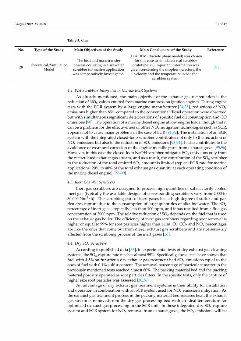
Energies 2022, 15, 3638 31 of 49
Table 5. Cont.
No. Type of the Study Main Objectives of the Study Main Conclusions of the Study Reference
28 Theoretical/SimulationModel
The heat and mass transferprocess occurring in a seawaterscrubber for marine applicationwas comparatively investigated.
(1) A DPM (discrete phase model) was chosenfor this case to simulate a real scrubber
prototype. (2) Important information wasgiven concerning the droplets trajectory, the
velocity and the temperature inside thescrubber system.
[89]
4.2. Wet Scrubbers Integrated in Marine EGR Systems
As already mentioned, the main objective of the exhaust gas recirculation is thereduction of NOx values emitted from marine compression ignition engines. During enginetests with the EGR system by a large engine manufacturer [34,35], reductions of NOxemissions higher than 85% compared to the conventional diesel operation were observedbut with simultaneous significant deteriorations of specific fuel oil consumption and COemissions [90]. The operation of a marine diesel engine at low engine loads, though that itcan be a problem for the effectiveness of other NOx mitigation technologies such as SCR,appears not to cause major problems in the case of EGR [91,92]. The installation of an EGRsystem with the integrated closed-loop scrubber contributes not only to the reduction ofNOx emissions but also to the reduction of SOx emissions [93,94]. It also contributes to theavoidance of wear and corrosion of the engine metallic parts from exhaust gases [95,96].However, in this case the closed-loop NaOH scrubber mitigates SOx emissions only fromthe recirculated exhaust gas stream, and as a result, the contribution of the SOx scrubberto the reduction of the total emitted SOx amount is limited (typical EGR rate for marineapplications: 20% to 40% of the total exhaust gas quantity at each operating condition ofthe marine diesel engine) [97–99].
4.3. Inert Gas Wet Scrubbers
Inert gas scrubbers are designed to process high quantities of satisfactorily cooledinert gas (typically the available designs of corresponding scrubbers vary from 2000 to30,000 Nm3/h). The scrubbing part of inert gases has a high degree of sulfur and par-ticulates capture due to the consumption of large quantities of alkaline water. The SO2percentage of inert gas is typically less than 100 ppm, and it has resulted from a flue gasconcentration of 3000 ppm. The relative reduction of SO2 depends on the fuel that is usedon the exhaust gas boiler. The efficiency of inert gas scrubbers regarding soot removal ishigher or equal to 99% for soot particles higher than 1 µm. O2, CO2 and NOx percentagesare like the ones that come out from diesel exhaust gas scrubbers and are not seriouslyaffected from the scrubbing process of the inert gases [36].
4.4. Dry SOx Scrubbers
According to published data [36], in experimental tests of dry exhaust gas cleaningsystems, the SOx capture rate reaches almost 99%. Specifically, these tests have shown thatfuel with 4.5% sulfur after a dry exhaust gas treatment had SOx emissions equal to theones of fuel with 0.1% sulfur content. The removal percentage of particulate matter in thepreviously mentioned tests reached almost 80%. The packing material bed and the packingmaterial porosity operated as soot particles filters. In the specific tests, only the capture ofhigher size soot particles was assessed [30,36].
An advantage of dry exhaust gas treatment systems is their ability for installationand operation in combination with an SCR system used for NOx emissions mitigation. Asthe exhaust gas treatment process in the packing material bed releases heat, the exhaustgas stream is removed from the dry gas processing bed with an ideal temperature foroptimized exhaust gas processing in the SCR unit. In these integrated dry SOx capturesystem and SCR system for NOx removal from exhaust gases, the SOx emissions will be

Energies 2022, 15, 3638 32 of 49
cleaned before they enter the SCR unit. This results in the reduction of SCR unit size andthe higher anticipated lifetime of the SCR unit catalyst [30,36].
The most toxic substance for the operation of the SCR unit is SO3. SO3 reacts withammonia (NH3), and this leads to the production of ammonium sulfate which can causefouling of the SCR unit catalyst. The lower the sulfur percentage in the exhaust gases thatenter the SCR unit is, the higher the anticipated lifetime of the SCR catalyst. The SCRunit can also operate at lower temperatures without the risk of fouling when the sulfurpercentage in exhaust gases is low. A SCR unit can remove 80% to 95% of NOx emissionsfrom the exhaust gas stream practically making the strictest IMO NOx limits (Tier III) atleast at high engine loads, which are required for the optimized operational performanceof the SCR unit [30,36], achievable.
Theoretically, the dry exhaust gas treatment unit also has the capacity for CO2 removal.This can be attained based on the following chemical reaction:
Ca(OH)2 + CO2 → CaCO3 + H2O (17)
However, this will result in higher CO2 emissions at the end because the limestone isproduced with limestone calcification at 900 ◦C, as follows:
CaCO3(s)→ CaO(s) + CO2(g) (18)
The produced calcium oxide (CaO) undergoes cooling and hydrogenation.
4.5. Selective Catalytic Reduction—SCR
It is quite interesting to compare the NOx reduction potential of SCR to other NOxreduction technologies, which can either be implemented inside marine diesel engines orin the exhaust of marine diesel engines [100–102]. Such a comparison will facilitate theassessment of the comparative effectiveness of SCR compared to other alternative NOxreduction technologies [103–105]. For this reason, in Figure 10 the NOx reduction potentialsof different NOx mitigation technologies are shown. These are implemented either insidediesel engines (called “internal measures”), or outside diesel engines in their exhaust line(called “external measures”). Figure 10 shows the lower and the higher limit of the NOxreduction potential variation of each technology [60].
Energies 2021, 14, x FOR PEER REVIEW 30 of 46
Figure 10. Comparison of the NOx reduction potential of various technologies that are implemented inside diesel engines (internal measures) and outside diesel engines at their exhaust (external measures). IEM means internal engine modification. All other abbreviated NOx reduction technol-ogies have already been explained in the main text. (Figure was genuinely generated using data from ref. [60]).
At this point it is important to review several important theoretical and experimental studies that have been performed to assess the operational behavior of marine SCR sys-tems and to quantify their performance characteristics. The results of this targeted litera-ture review are consolidated in Table 6, which contains 15 already published studies. In Table 6 for each study, its type is shown (theoretical, experimental or review study) along with its main objectives, and its main conclusions and its citation. As evidenced from the examination of Table 6, the key objectives of these studies were the examination of the impact of marine SCR catalysts on NOx emission reduction in contrast with other NOx reduction technologies that can be implemented inside marine engines (i.e., internal measures) and the assessment of the performance characteristics and the NOx reduction efficiency of marine SCR catalysts. The most important findings of the studies shown in Table 6 are that marine SCR catalysts are highly effective in curtailing NOx emissions that are generated from combustion systems installed in various types of vessels, and their NOx reduction efficiency is considerably higher compared to all available NOx reduction measures that can be implemented inside marine engines and marine combustion systems such as EGR, humid air motor or conversion of conventional combustion systems to op-erate with LNG. Hence, a SCR catalyst is proven to be the most effective means for reduc-ing NOx species generated from marine engines and marine combustion systems with, however, considerations about its investment and operational cost.
Table 6. Consolidation of the review results for marine SCR systems. For each published study listed in this table is shown by type (theoretical, experimental or review study), its main objectives and its main conclusions along with its reference.
No Type of the
Study Main Objectives of the Study Main Conclusions of the Study Reference
1 Experimental The performance indicators of a marine SCR
catalyst was investigated.
(1) Substrates must be durable to: (a) survive the high sulfur content of marine fuels and (b) provide cost and pressure drop
benefits. (2) Extruded honeycomb substrates offer advantages in system volume and provide increased catalyst surface (in direct com-
pensation with increased pressure drop). (3) Higher cell densities can be more easily clogged by the dep-osition of soot and/or sulfate particles on the inlet surface of the monolithic converter as well as on the channel walls and cata-
lyst coating, ultimately leading to unacceptable flow restriction or catalytic flow suppression.
[106]
20%
50%
70%
20% 20%
80%
40%30%
60%
80%
50% 50%
98%90%
0%
20%
40%
60%
80%
100%
120%
IEM DWI HAM FEW EGR SCR LNG
NOx r
educ
tion
Pote
ntia
l
Lower Limit Higher Limit
Figure 10. Comparison of the NOx reduction potential of various technologies that are implementedinside diesel engines (internal measures) and outside diesel engines at their exhaust (external mea-sures). IEM means internal engine modification. All other abbreviated NOx reduction technologieshave already been explained in the main text. (Figure was genuinely generated using data fromref. [60]).
At this point it is important to review several important theoretical and experimen-tal studies that have been performed to assess the operational behavior of marine SCR

Energies 2022, 15, 3638 33 of 49
systems and to quantify their performance characteristics. The results of this targetedliterature review are consolidated in Table 6, which contains 15 already published studies.In Table 6 for each study, its type is shown (theoretical, experimental or review study)along with its main objectives, and its main conclusions and its citation. As evidencedfrom the examination of Table 6, the key objectives of these studies were the examinationof the impact of marine SCR catalysts on NOx emission reduction in contrast with otherNOx reduction technologies that can be implemented inside marine engines (i.e., internalmeasures) and the assessment of the performance characteristics and the NOx reductionefficiency of marine SCR catalysts. The most important findings of the studies shown inTable 6 are that marine SCR catalysts are highly effective in curtailing NOx emissions thatare generated from combustion systems installed in various types of vessels, and theirNOx reduction efficiency is considerably higher compared to all available NOx reductionmeasures that can be implemented inside marine engines and marine combustion systemssuch as EGR, humid air motor or conversion of conventional combustion systems to operatewith LNG. Hence, a SCR catalyst is proven to be the most effective means for reducing NOxspecies generated from marine engines and marine combustion systems with, however,considerations about its investment and operational cost.
Table 6. Consolidation of the review results for marine SCR systems. For each published study listedin this table is shown by type (theoretical, experimental or review study), its main objectives and itsmain conclusions along with its reference.
No. Type of the Study Main Objectives of the Study Main Conclusions of the Study Reference
1 ExperimentalThe performance indicators of a
marine SCR catalystwas investigated.
(1) Substrates must be durable to:(a) survive the high sulfur content ofmarine fuels and (b) provide cost and
pressure drop benefits.(2) Extruded honeycomb substrates offer
advantages in system volume and provideincreased catalyst surface (in direct
compensation with increasedpressure drop).
(3) Higher cell densities can be more easilyclogged by the deposition of soot and/orsulfate particles on the inlet surface of the
monolithic converter as well as on thechannel walls and catalyst coating,
ultimately leading to unacceptable flowrestriction or catalytic flow suppression.
[106]
2 Theoretical/SimulationModel
The control rules in an SCR-DeNOxinstallation for a marine diesel
engine working at full loadconditions were elaborated.
The velocity distribution at the inlet of thecatalyst layers, which can be affected by theposition, size and angle of the gate leaves,
plays an important role in the NOx removalefficiency of SCR systems.
[107]
3 Theoretical/SimulationModel
The operational performance of acompact diesel after-treatment
system combining an SCR systemwith a reactive muffler was
investigated.
(1) The system is capable of increasing NH3homogeneity and improving NOx
reduction efficiency.(2) In the integrated SCR—muffler, the
pressure loss was significantly increasedcompared to a simple SCR system.
[108]

Energies 2022, 15, 3638 34 of 49
Table 6. Cont.
No. Type of the Study Main Objectives of the Study Main Conclusions of the Study Reference
4 Theoretical/AssessmentStudy
The effects of the main importantcharacteristics (i.e., composition,temperature, etc.) of the exhaustgases from a low-speed marine
diesel engine on the performancecharacteristics of a SCR system
were investigated.
(1) The weighted average NOx value of thelow sulfur exhaust gas complied with the
requirements of the IMO Tier III regulationswhen the low speed diesel engine wasmated to the high pressure SCR system.
(2) The weighted average NOx value underthe high sulfur exhaust was slightly higher
than that required by the IMO Tier III.(3) For both strategies, the engine exhaust
performance meets the requirements of theIMO Tier III.
(4) The cleaning bypass configurationdesign appears to have less impact on the
initial performance of the engine.
[109]
5 Theoretical/SimulationModel
For marine SCR applications, theeffect of static mixer geometry on
flow mixing and pressure dropwas investigated.
(1) Regardless of the type, the presence of amixer leads to an improvement of the
mixing efficiency by about 20%.(2) There was a compensatory relationship
between uniformity and pressure drop.(3) In terms of mixing efficiency and
pressure drop, the vortex type stirrer seemsto be more suitable than the line type mixer.
[110]
6Experimental and Theo-
retical/SimulationModel
The operational impact of a marineSCR-urea system on the reduction of
NOx emissions was examined.
(1) The increase of the catalyst length leadsto an increased total denitrification rate.(2) The increased length of the catalyst
negatively affects the oxidation reaction rateof ammonia.
[111]
7 Experimental
The operating principles (a) and thebehavior concerning the NOx
reduction, of a scrubber system(components: exhaust heat
exchangers, catalyzed particulatefilter (CPF), diesel oxidation catalyst(DOC), packed bed wet scrubber),
working on the principle ofabsorption of NOx species into
water (b) were examined.
(1) NOx emissions absorption rangedfrom 4–66%.
(2) The average NOx absorption of the cycleranged from 15–58%.
(3) NOx absorption varies depending on:(a) the residence time of the gas, (b) the
absorption surface, (c) the temperature and(d) the NOx concentration.
[112]
8 Theoretical/SimulationModel
The control strategy of a marine SCRsystem was examined.
Nitrogen oxide slip function controlrequires a massive pre-study of the catalyst
NOx reduction capacity to set anappropriate control target for each
operating condition.
[113]
9 Theoretical/SimulationModel
The transient thermal response of ahigh pressure SCR system for a TierIII two-stroke marine diesel engine
was investigated.
(1) It is possible to predict the thermalresponse of a marine SCR after-treatment
system under transient engine loadingconditions. (2) It is possible to predict the
transient inertial response of the SCRduring acceleration, deceleration, and
operating conditions of the low load engine.
[114]
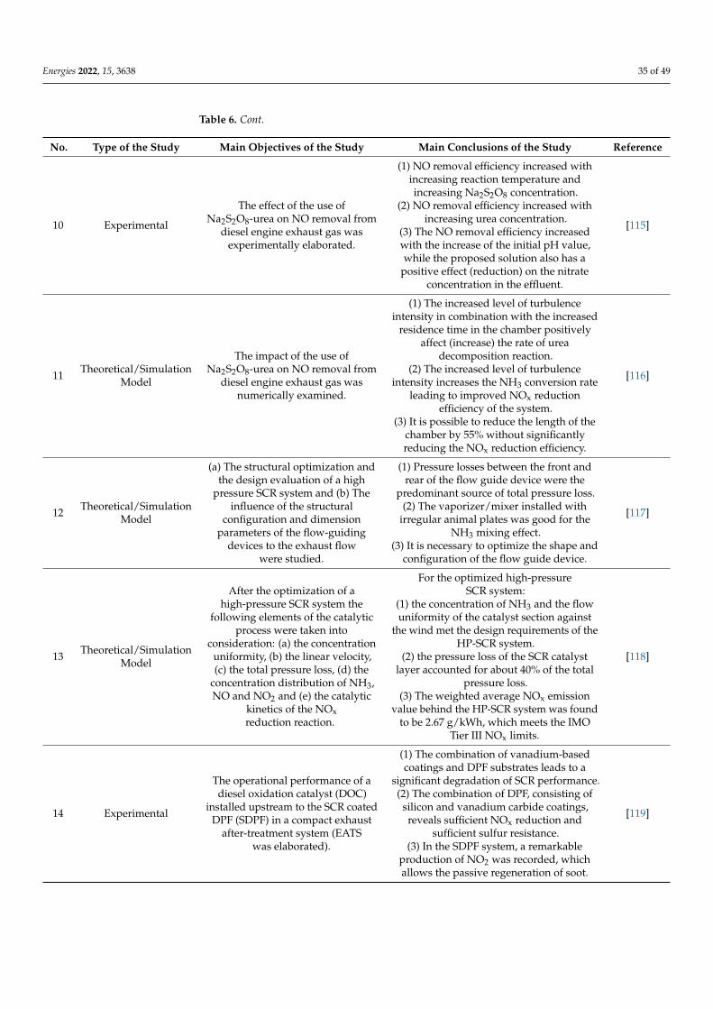
Energies 2022, 15, 3638 35 of 49
Table 6. Cont.
No. Type of the Study Main Objectives of the Study Main Conclusions of the Study Reference
10 Experimental
The effect of the use ofNa2S2O8-urea on NO removal from
diesel engine exhaust gas wasexperimentally elaborated.
(1) NO removal efficiency increased withincreasing reaction temperature andincreasing Na2S2O8 concentration.
(2) NO removal efficiency increased withincreasing urea concentration.
(3) The NO removal efficiency increasedwith the increase of the initial pH value,while the proposed solution also has a
positive effect (reduction) on the nitrateconcentration in the effluent.
[115]
11 Theoretical/SimulationModel
The impact of the use ofNa2S2O8-urea on NO removal from
diesel engine exhaust gas wasnumerically examined.
(1) The increased level of turbulenceintensity in combination with the increased
residence time in the chamber positivelyaffect (increase) the rate of urea
decomposition reaction.(2) The increased level of turbulence
intensity increases the NH3 conversion rateleading to improved NOx reduction
efficiency of the system.(3) It is possible to reduce the length of the
chamber by 55% without significantlyreducing the NOx reduction efficiency.
[116]
12 Theoretical/SimulationModel
(a) The structural optimization andthe design evaluation of a high
pressure SCR system and (b) Theinfluence of the structural
configuration and dimensionparameters of the flow-guiding
devices to the exhaust flowwere studied.
(1) Pressure losses between the front andrear of the flow guide device were the
predominant source of total pressure loss.(2) The vaporizer/mixer installed with
irregular animal plates was good for theNH3 mixing effect.
(3) It is necessary to optimize the shape andconfiguration of the flow guide device.
[117]
13 Theoretical/SimulationModel
After the optimization of ahigh-pressure SCR system the
following elements of the catalyticprocess were taken into
consideration: (a) the concentrationuniformity, (b) the linear velocity,(c) the total pressure loss, (d) the
concentration distribution of NH3,NO and NO2 and (e) the catalytic
kinetics of the NOxreduction reaction.
For the optimized high-pressureSCR system:
(1) the concentration of NH3 and the flowuniformity of the catalyst section against
the wind met the design requirements of theHP-SCR system.
(2) the pressure loss of the SCR catalystlayer accounted for about 40% of the total
pressure loss.(3) The weighted average NOx emission
value behind the HP-SCR system was foundto be 2.67 g/kWh, which meets the IMO
Tier III NOx limits.
[118]
14 Experimental
The operational performance of adiesel oxidation catalyst (DOC)
installed upstream to the SCR coatedDPF (SDPF) in a compact exhaust
after-treatment system (EATSwas elaborated).
(1) The combination of vanadium-basedcoatings and DPF substrates leads to a
significant degradation of SCR performance.(2) The combination of DPF, consisting of
silicon and vanadium carbide coatings,reveals sufficient NOx reduction and
sufficient sulfur resistance.(3) In the SDPF system, a remarkable
production of NO2 was recorded, whichallows the passive regeneration of soot.
[119]

Energies 2022, 15, 3638 36 of 49
Table 6. Cont.
No. Type of the Study Main Objectives of the Study Main Conclusions of the Study Reference
15 Experimental
The operating performance of anelectrostatic water spray cleaner
was studied to evaluate itsefficiency for the simultaneous
removal of NOx and dieselparticles (DPM).
Overall, the electrostatic water spray purifierseems to be a promising alternative methodfor controlling DPM emissions by both mass
and number. Especially:(1) For a given gas flow rate, the removal of
the DPM is enhanced by increasing theapplied voltage.
(2) The overall DPM removal efficiency washigher than 97% due to electrostatic attraction.(3) The removal of NOx emissions depends on
the chlorine concentration in the seawaterand the engine loads.
[120]
5. Economic Evaluation of Marine Exhaust Gas Treatment Systems5.1. Wet Open-Loop and Closed-Loop Scrubbers
The capital cost of the installation of a SOx scrubber on a vessel depends heavilyon the size of the main and the auxiliary engines, the type of fuel, and the investmentcost of the on-board constructional modifications that are required for the installation ofthe SOx capture system [121]. According to the literature, the capital cost of an aqueousSOx scrubber used for the exhaust gas treatment from 1 MW power diesel engine, canbe close to USD 1 million, whereas the corresponding cost for an aqueous SOx scrubberthat can be installed in the exhaust of a 20 MW power diesel engine range from USD 3 to5 million [122]. Additional economic data are related to the energy consumption of theexhaust gas treatment system. This energy consumption cost obviously will mainly dependon the size of the main and the auxiliary engines and so from the size of the SOx scrubber.Indicative results for the power consumption (in kW/MW of engine power) of a hybridaqueous SOx scrubber, a seawater SOx scrubber, and a freshwater scrubber are provided inTable 7 [36].
Table 7. Power consumption of three types of SOx scrubbers. (Table was genuinely generated usingdata from ref. [36]).
SOx ScrubberType
Power Consumption(kW/MW of Engine Power)
Hybrid scrubber 10–23
Seawater scrubber 10–30
Freshwater scrubber 6–110
Indicative results for the operation cost of a hybrid SOx scrubber, a seawater scrubber,and a freshwater scrubber that have been collected by Gregory and West [32] consideringcombustion of heavy fuel oil with 2.7% sulfur content for 300 days/year, are shown inTable 8 [36].
The exhaust gas treatment system and its mechanical devices (pumps, pipelines,valves etc.) are exposed to a corrosive environment, especially in the case of seawater usein the SOx scrubber, which can corrode equipment from gray steel and stainless steel, e.g.,SS316 steel. The manufacturers of scrubbing equipment faced with the corrosive effect ofthe SOx capture chemical substances in different ways. Some use nickel alloys, whereasothers use titanium or nonmetallic material such as epoxy material and composites. Thegradual degradation of the constructional quality and the potential replacement of theexhaust gas treatment installation will raise the total cost of the construction materialsfurther burdening the carbon footprint of the exhaust gas treatment system [32].

Energies 2022, 15, 3638 37 of 49
Table 8. Operation cost of three types of SOx scrubbers. The classification has been made basedon the operational principle of each system. The values have been obtained from correspondingmanufacturers of these systems. (Table was genuinely generated using data from refs. [32,36]).
SOx Scrubber Type Operation Cost
Hybrid scrubber Not available
Seawater scrubber 3% of the investment cost
Freshwater scrubber 5 USD/MWh
≈0.5 to 2.5 × 10⁶ USD
In a previous study [47], an effort was made to estimate the cost per emission ton,which is reduced with SO2 reduction techniques in the engine exhaust compared to thechange from a high sulfur fuel to a low sulfur fuel. The alternative scenarios that wereexamined in this study are the following [47]:
• Use of a seawater SOx scrubber.• Change from heavy fuel oil with 2.7% sulfur to marine fuel with 1.5% sulfur.• Change from heavy fuel oil with 2.7% sulfur to marine fuel with 0.5% sulfur.
In the specific study [47], the previously mentioned SO2 emission reduction scenarioswere examined by considering the following SO2 capture percentages:
• Use of a seawater SOx scrubber: 75%.• Change from heavy fuel oil with 2.7% sulfur to marine fuel with 1.5% sulfur: 44%.• Change from heavy fuel oil with 2.7% sulfur to marine fuel with 0.5% sulfur: 81%.
The results of the previously mentioned study [47] are presented in Table 9.
Table 9. Cost per ton of emitted pollutants reduced from the use of seawater scrubbers and from thechange to low sulfur fuel. (Table was generated using data from refs. [36,47]).
SOx ReductionMeasure Vessel Type
Small SizeVessel
(€/ton SO2)
Medium SizeVessel (€/ton
SO2)
Large SizeVessel (€/ton
SO2)
Seawater scrubber New building 390 351 320
Seawater scrubber Retrofit 576 535 504
Fuel change from 2.7%sulfur
to 1.5% sulfur
New build-ing/Retrofit 2053 (1230) 2050 (1230) 2045 (1230)
Fuel change from 2.7%sulfur
to 0.5% sulfur
New build-ing/Retrofit 1439 (1690) 1438 (1690) 1434 (1690)
The previously mentioned calculations [36,47] fall with further uncertainties such as:
• Intrinsic variations of the retrofit cost due to the special characteristics of each vessel.• The maintenance levels of the mechanical equipment.• The operating conditions and the loading factors of each vessel.• Variations in the sulfur contents of all examined fuels.
Reynolds [46] in a second study examined the cost advantage of the exhaust gastreatment systems compared to the change from a fuel with high sulfur content to a fuelwith low sulfur content, and he concluded that with 2015 as a starting year, the vesselsthat are consuming at least 4000 metric tons of fuel per year inside Emission ControlAreas (ECAs) should use an exhaust gas treatment system. The specific study [46] furtherreports that a key turning point in the differences of the fuel costs is when the fuel sulfurcontents become so small that their removal from the marine fuels is either impossibleor has extremely high cost. It is considered that fuel sulfur contents equal to or lower
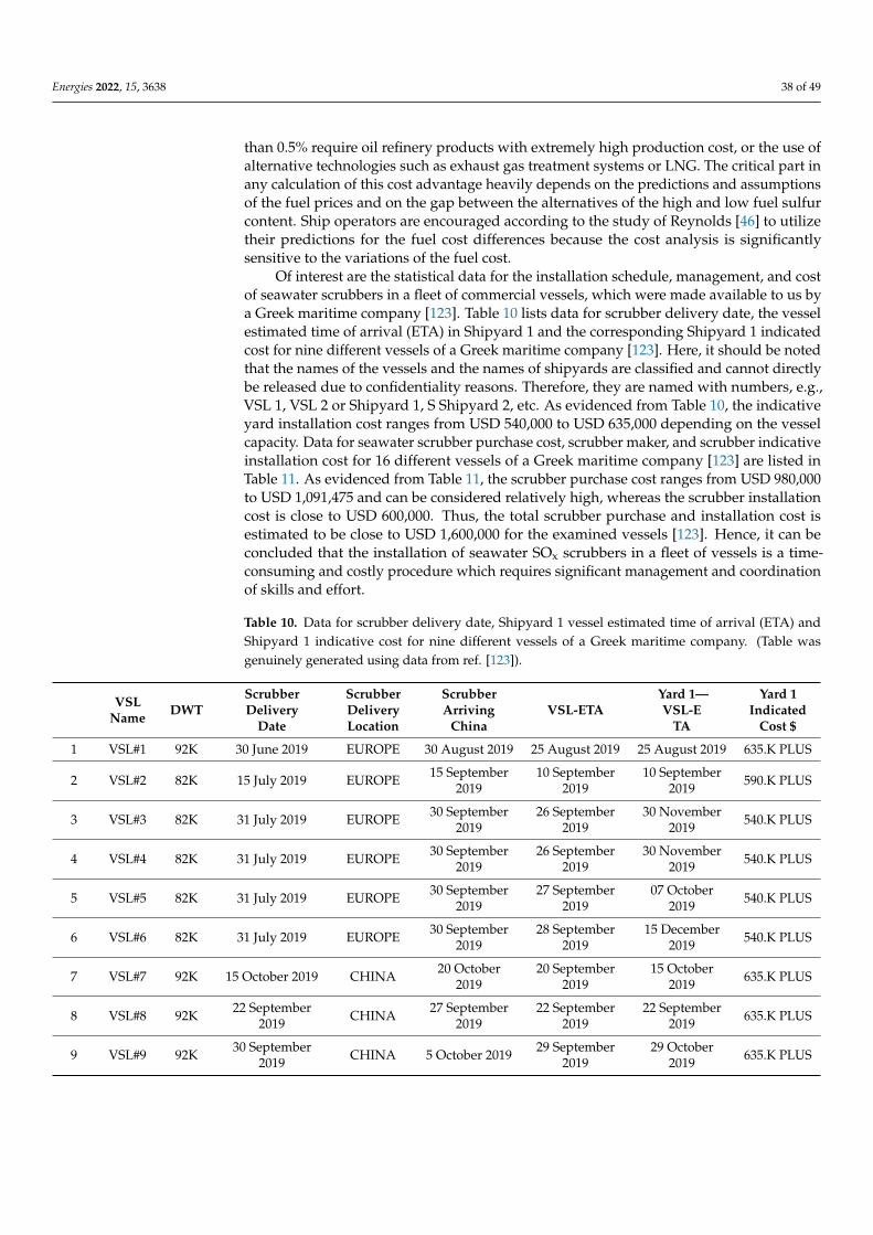
Energies 2022, 15, 3638 38 of 49
than 0.5% require oil refinery products with extremely high production cost, or the use ofalternative technologies such as exhaust gas treatment systems or LNG. The critical part inany calculation of this cost advantage heavily depends on the predictions and assumptionsof the fuel prices and on the gap between the alternatives of the high and low fuel sulfurcontent. Ship operators are encouraged according to the study of Reynolds [46] to utilizetheir predictions for the fuel cost differences because the cost analysis is significantlysensitive to the variations of the fuel cost.
Of interest are the statistical data for the installation schedule, management, and costof seawater scrubbers in a fleet of commercial vessels, which were made available to us bya Greek maritime company [123]. Table 10 lists data for scrubber delivery date, the vesselestimated time of arrival (ETA) in Shipyard 1 and the corresponding Shipyard 1 indicatedcost for nine different vessels of a Greek maritime company [123]. Here, it should be notedthat the names of the vessels and the names of shipyards are classified and cannot directlybe released due to confidentiality reasons. Therefore, they are named with numbers, e.g.,VSL 1, VSL 2 or Shipyard 1, S Shipyard 2, etc. As evidenced from Table 10, the indicativeyard installation cost ranges from USD 540,000 to USD 635,000 depending on the vesselcapacity. Data for seawater scrubber purchase cost, scrubber maker, and scrubber indicativeinstallation cost for 16 different vessels of a Greek maritime company [123] are listed inTable 11. As evidenced from Table 11, the scrubber purchase cost ranges from USD 980,000to USD 1,091,475 and can be considered relatively high, whereas the scrubber installationcost is close to USD 600,000. Thus, the total scrubber purchase and installation cost isestimated to be close to USD 1,600,000 for the examined vessels [123]. Hence, it can beconcluded that the installation of seawater SOx scrubbers in a fleet of vessels is a time-consuming and costly procedure which requires significant management and coordinationof skills and effort.
Table 10. Data for scrubber delivery date, Shipyard 1 vessel estimated time of arrival (ETA) andShipyard 1 indicative cost for nine different vessels of a Greek maritime company. (Table wasgenuinely generated using data from ref. [123]).
VSLName DWT
ScrubberDelivery
Date
ScrubberDeliveryLocation
ScrubberArriving
ChinaVSL-ETA
Yard 1—VSL-E
TA
Yard 1Indicated
Cost $
1 VSL#1 92K 30 June 2019 EUROPE 30 August 2019 25 August 2019 25 August 2019 635.K PLUS
2 VSL#2 82K 15 July 2019 EUROPE 15 September2019
10 September2019
10 September2019 590.K PLUS
3 VSL#3 82K 31 July 2019 EUROPE 30 September2019
26 September2019
30 November2019 540.K PLUS
4 VSL#4 82K 31 July 2019 EUROPE 30 September2019
26 September2019
30 November2019 540.K PLUS
5 VSL#5 82K 31 July 2019 EUROPE 30 September2019
27 September2019
07 October2019 540.K PLUS
6 VSL#6 82K 31 July 2019 EUROPE 30 September2019
28 September2019
15 December2019 540.K PLUS
7 VSL#7 92K 15 October 2019 CHINA 20 October2019
20 September2019
15 October2019 635.K PLUS
8 VSL#8 92K 22 September2019 CHINA 27 September
201922 September
201922 September
2019 635.K PLUS
9 VSL#9 92K 30 September2019 CHINA 5 October 2019 29 September
201929 October
2019 635.K PLUS

Energies 2022, 15, 3638 39 of 49
Table 11. Seawater scrubber purchase cost, scrubber maker and scrubber indicative installationcost for 16 different vessels of a Greek maritime company. (Table was generated using data fromref. [123]).
VSL Name Scrubber Cost Scrubber Installation Cost
1 VSL#1 $1,149,225 $580,000
2 VSL#2 $1,091,475 $580,000
3 VSL#3 $1,091,475 $580,000
4 VSL#4 $1,091,475 $580,000
5 VSL#5 $1,085,700 $580,000
6 VSL#6 $1,027,950 $580,000
7 VSL#7 $1,027,950 $580,000
8 VSL#8 $1,027,950 $580,000
9 VSL#9 $1,027,950 $580,000
10 VSL#10 $1,027,950 N/A YET
11 VSL#11 $1,027,950 N/A YET
12 VSL#12 $1,200,000 $600,000
13 VSL#13 $1,200,000 $600,000
14 VSL#14 $980,000 $580,000
15 VSL#15 $980,000 N/A YET
16 VSL#16 $980,000 N/A YET
5.2. Wet SOx Scrubbers Integrated in EGR Systems
The stage of development of EGR technology does not yet allow its detailed economicassessment. One crucial factor that will affect the rate of development of EGR systems andpossibly their future market price is whether the EGR technology will succeed in providingNOx emissions from large two-stroke marine diesel engines, which will satisfy the strictestIMO standards (Tier III) for ships operating inside Emission Control Areas. Up to now, theER technology is considered a most promising technology regarding the achievement ofTier III standard [124,125].
5.3. Wet Inert Gas Scrubbers
There are no available specific economic data in the literature for the market pricesand the operation cost of inert gas scrubbers. However, the power consumption of thesesystems is reported to be 0.01 kW per Nm3/h of gas, and it depends on the special powerconsumption requirements of the pumps of each installation.
5.4. Dry SOx Scrubbers
The commercially available dry exhaust gas treatment systems have the followingindicative investment cost values [36,126]:
• For 1 MW power engine, the investment cost is USD 0.5 million.• For 20 MW power engine, the investment cost is USD 4 million.
Taking into consideration the relatively low values of investment cost compared to theavailable information for the dry SOx scrubbers, the most important conclusion is that theseprices vary almost at the same levels with the pertinent investment costs of the aqueousSOx scrubbers.
In addition, the corresponding annual operation costs of the dry exhaust gas treatmentand SOx capture systems according to published data [36,127] are the following:
• For 1 MW power engine, the annual operation cost is USD 43,500.• For 20 MW power engine, the annual operation cost is USD 477,200.

Energies 2022, 15, 3638 40 of 49
These operation costs include power consumption cost, packing material cost, mainte-nance cost, and labor cost. It appears from the accumulated information for the dry exhaustgas treatment systems that one significant advantage of these systems is power consump-tion. A general picture about the power consumption of the dry SOx capture systems is thatit reaches up to 10% of the corresponding power consumption of an aqueous SOx mitigationsystem for similar diesel engine power (1.5–2 kW/MW of engine power) [128,129]. Thepreviously mentioned prices do not include energy consumption for production, transport,and distribution of the packing materials that the dry exhaust gas cleaning systems requireto be efficient [36,130,131].
The preferred handling process of the used packing material is the removal of thepacking material from the dry exhaust gas treatment system with a remaining pollutantcapture activity. This residue can be an attractive product for the desulfurization of hightemperature flue gases generated from land-based industrial installations. Therefore, theused packing material in most of the cases will not contribute negatively to the total lifetimecost of the dry exhaust gas cleaning and SOx mitigation systems [132].
5.5. SCR Systems
The continuous development of SCR technology and its increasing market share hasled to a reduction of its investment cost. In addition, the stabilization of the materials costwith the parallel increase of the market demand denotes an increase of the SCR systeminstallations, which creates competition in the market and reductions in the investmentcost of these systems. This led to higher availability of SCR systems at more reasonablepurchasing prices [60].
The International Association for Catalytic Control of Ship Emissions to Air (IACC-SEA) developed an estimation model for the installation and operation cost of SCR systems.The application of this model provides an indicative calculation of the investment cost andof the operation cost, as well as of the benefits that are expected from the SCR marine appli-cations [60]. Using as example a 10 MW power diesel engine, which provides propulsionto a 20,000 DWT vessel, uses HFO and operates 1500 h annually in NECAs, the total invest-ment cost (including the installation cost of the system) will be approximately USD 725,000.The highest portion of the operation cost required for the fulfillment of the IMO Tier IIIstandards initiating from a higher level of NOx emissions equal to the IMO Tier I standards,will vary from USD 3 to 5 million depending on the urea cost, whereas the recharging ofthe catalyst will require USD 500,000. In addition, there will be a deterioration of the fuelconsumption due to the increased back pressure to the engine exhaust from the operationof the SCR system, and there will also be a potential efficiency improvement of the enginewhen the cooperative operation of the engine and the SCR system is optimized [60].
Without taking into consideration that the deterioration of the specific fuel oil con-sumption due to the back pressure from the SCR system operation will be approximately2%, the improvement of the specific fuel consumption by 4% due to the optimized operationof the marine diesel engine and SCR system combined installation will lead to a fuel costsaving of approximately USD 625,000. This is equal to a total (without discounts) operationcost that varies from USD 104,000 to USD 224,000 dollars per year or approximately 900 to2000 per ton of reduced NOx emissions [60].
It is expected that the operation cost of marine SCR systems will continue to decrease.This conclusion is drawn because there is a reduction tendency of the operation of SCRsystems used in land applications. Taking into consideration a small degree of uncertainty,the cost for the ammonia-based reagents has stayed relatively constant during the last fewyears, whereas the catalyst unit cost has decreased in the USA by almost five times between1980 and 2005. It is estimated that it will stay almost constant until 2015 for new catalystsand will slightly be decreased for the regenerated catalysts. The expected lifetime has beenincreased from 1 to 10 years, contributing to the realistic reduction of the operation andmaintenance cost of the SCR systems [60].

Energies 2022, 15, 3638 41 of 49
The operational efficiency of SCR systems that are used for NOx mitigation in land-based coal-fired electric power stations from the mid-1980s until 2000 has been increased,the investment cost has been decreased by 86%, and the operation and management costhas been reduced by 58% compared to the initial values. The future estimates for thecontinuous regeneration of SCR systems predict an additional investment cost reductionof 7.4%, and a corresponding operation and maintenance cost reduction by 15.8% until2020. The variations of the SCR technology cost that have been evaluated in these analysesreflect the effect of the technological developments, and the competition on the investmentcost and on the operation cost of the SCR systems, which are linked with the continuousstringent environmental limits that motivate the technological development and evolution.This phenomenon has appeared in the SOx reduction technologies, also denoting that theapplication of the continuous stringent environmental regulations and limits will lead tofurther investment cost and operation cost reductions of the exhaust gas treatment systemssoon ahead [60].
In addition, to the already thoroughly described technologies considered for fulfillmentof the global sulfur cap and the IMO NOx Tier III limits, there are additional technologiesalready proposed in the literature, which can be used for seriously reducing NOx valuesemitted from marine combustion systems. One of these technologies is the utilization ofnon-thermal plasma (NTP) in combustion-emitted exhaust gases for significantly reducingNOx and SOx emissions. According to Deng et al. [12], NTP technology can reduceNOx and SOx emissions by 60% and 80%, respectively. NTP technology can effectivelyoxidize nitrogen oxide to nitrogen dioxide in, a SCR system and perform a fast reaction.Cho et al. [133] performed an experimental study for the reduction of NOx emissions froma diesel engine with NTP in combination with a high pressure SCR system, and theyobserved that NTP technology can effectively improve the NOx conversion efficiency of aSCR system at low temperature.
At this point, it is worth emphasizing that the broad use of either seawater scrubbers orclosed-loop scrubbers with fresh water and NaOH and the broad use of SCR technology willdrastically contribute to the elimination of the serious polluting issue of maritime vesselsin all coastal countries of the world because it has been proven that maritime pollution canseriously impair nutrition and degrade the quality of air and waters. Characteristic is theexample of China where, according to Liu et al. [134] and Zhang et al. [135], the detrimentaleffects of maritime pollution on local air and water quality can seriously be mitigated withthe implementation of various shipping-related emission control measures such as marineEGTS such as the ones examined in the present review study.
6. Overall Comparative Assessment, Advantages, and Disadvantages
In the present review study, the operational principles and the construction specifica-tions, the performance characteristics and the economic facts of modern marine exhaust gastreatment systems used for SOx, PM, and NOx mitigation, were thoroughly analyzed. Thedetailed analysis of the gaseous and particulate emission marine after-treatment systemsresulted in the following conclusions for each pollutant mitigation system:
• Seawater scrubbers or open-loop scrubbers: These are heavy and bulky heat, mass,and momentum exchange systems between the exhaust gas stream and the seawaterstream. Due to is alkalinity, the seawater stream can capture large quantities of SOx,PM, and heavy metals from the stream of exhaust gases that are generated fromthe on-board combustion systems. The SOx and PM mitigation efficiency dependheavily on the alkalinity of the local seawater, considering also that seawater alkalinityvaries significantly around the world. The on-board installation of seawater scrubbersrequires the existence of an impure scrubber-discharged water processing unit for thecapture and on-board storage of the heavy residues and of the processed effluent water.Marine seawater scrubbers are bulky installations characterized by high complexityand parasitic losses due to the operation of their auxiliary equipment. Moreover, theiroperation is associated with significant corrosion to the engines and, in general, to
Energies 2022, 15, 3638 42 of 49
the machinery equipment in case of seawater leakages due to scrubber cracks. Hence,caution is required during their installation and their operation with continuousmonitoring of the exhaust gas stream and of the seawater stream to avoid potentialoperational problems or heavy seawater leakage.
• Freshwater scrubbers or closed-loop scrubbers: These marine exhaust gas treatmentsystems operate under the same principle as seawater scrubbers. In this case, thevariable alkalinity of the seawater is replaced by the almost constant alkalinity ofthe NaOH aqueous solution that circulates in the installation in a closed-loop. Thesesystems require transport and on-board storage of fresh water and NaOH, and theyindicate higher auxiliary requirements and thus parasitic losses compared to the open-loop seawater scrubbers. Closed-loop freshwater scrubbers have lower dischargedimpure water processing requirements compared to the open-loop systems becausethe quantity of effluent water discharged from the closed-loop scrubbers is lowercompared to seawater scrubbers. Another virtue of a caustic soda scrubber is thatthe alkalinity of the scrubbing medium can be adjusted through the adjustment ofthe NaOH dosage unlike the open-loop scrubbers where their efficiency is exposed tothe variable seawater alkalinity. Thus, closed-loop scrubbers can achieve higher SOxcapture rates compared to open-loop scrubbers, and they can also be highly effectivein reducing SOx emissions, even in the case of high sulfur marine fuels. Moreover,open-loop and closed-loop scrubbers require continuous monitoring of the pressureand temperature of the exhaust gas stream and the scrubbing medium stream to ensurereliable operation and to avoid leakage or excessive fouling of the scrubbers, whichcan create serious back-pressure issues and significant deterioration of the specific fueloil consumption of the on-board engines.
• Hybrid scrubbers: These systems can operate as either open-loop or closed-loopscrubbers; they are large, heavy, and bulky installations, where the exhaust gas streamexchanges heat, mass, and momentum with the alkaline medium, which dependingon the mode of hybrid scrubber operation can be seawater or caustic soda. Owingto their high complexity, high parasitic losses and high investment and operationcost, hybrid scrubbers have more limited application compared to open-loop and toclosed-loop scrubbers.
• Aqueous SOx and PM mitigation scrubbers that are integrated in EGR installations:These aqueous scrubbers are mainly used by one major marine engine manufacturer asheat exchangers to reduce the temperature of the recirculated exhaust gases before theyare introduced back to the engine intake for curtailing in-cylinder NOx formation rate.These integrated scrubbers cause not only a reduction of recirculated gas temperaturebut also manage to capture significant quantities of SOx and PM emissions carriedin the recirculated gas stream. For this reason, they are proposed by a large marineengine manufacturer as a technology capable of mitigating not only NOx emissionsbut also SOx and PM emissions. It should be emphasized, however, that the totalSOx emissions that are captured with the integrated scrubber, is considerably lowercompared to a closed-loop or an open-loop scrubber because in the EGR scrubber thescrubbing medium interacts only with a portion ranging from 20% to 40% of the totalexhaust gases generated from a marine engine at each operating point.
• Aqueous inert gas scrubbers: These scrubbers can process and capture SOx and PMemissions from inert gases generated from the evacuation of oil tankers or chemicaltankers, and for this reason they are suitable only for these limited applications.
• Dry scrubbers: The operation of these systems is based on the processing of the exhaustgas stream from a large dry surface SOx and PM capture medium (usually, limestone).Dry exhaust gas treatment systems are used extensively for the processing of industrialflue gases in land-based installations, but their use in the maritime industry (if any) isvery limited due to the problems associated with the supply and on-board storage ofthe limestone and the packing material.

Energies 2022, 15, 3638 43 of 49
• SCR systems: The efficiency of SCR systems is based on reaching the proper exhaustgas temperature at the entrance of the SCR reactor because the chemical reactions onthe catalyst are optimized for a specific temperature frame. The control of exhaust gastemperature for optimized SCR system operation requires the installation and opera-tion of exhaust gas temperature control devices in case the exhaust gas temperature isnot suitable for optimized SCR operation such as in the case of low engine loads of amain marine two-stroke diesel engine. Today, marine SCR systems are highly effectivein mitigating NOx emissions, and in many cases, they can practically eliminate NOxemissions, thus providing the opportunity for a vessel to comply with the strictestIMO NOx Tier III limits. The main drawbacks of the marine SCR systems are theirrelatively high installation and operation cost, which is burdened by the installation ofexhaust gas temperature control devices and by the supply and on-board handlingcost of the urea.
In general, it can be stated that the modern aqueous SOx scrubbers can attain SOxcapture rates that vary from 90% to 99% and hence can practically eliminate SOx emissionsfrom ships. As a conclusive remark, the SOx capture rates per exhaust gas treatment andSOx mitigation system are provided in Table 12. Specifically, Table 12 gives the sulfurcontents that a maritime fuel should have after exhaust gas processing from an aqueousor dry exhaust gas treatment systems. The SOx emissions should be equivalent to theones generated from the combustion of a marine fuel with 0.1% sulfur content. FromTable 12, it can be concluded that higher SOx mitigation percentages appear in the case of aclosed-loop freshwater scrubber and in the case of a dry scrubber [36].
Table 12. Consolidation of data for SOx capture rate per type of exhaust gas treatment system. (Tablewas genuinely generated using data from ref. [36]).
SOx Mitigation System
Maximum Fuel Sulfur Content for Which SOxEmissions Are Attained,
Which Are Equivalent to the Ones of Fuel with0.1% Sulfur Content.
Hybrid SOx scrubber 3–3.5%
Seawater SOx scrubber 3.5%
Freshwater SOx scrubber 3.5–5%
Dry SOx capture system 4.5%
The continuous technological development, the competition in marine SOx mitigationsystems, and the high production cost of very low or ultra-low sulfur fuels from oil refineriesaround the world, the incapacity of efficient on-board mixing low-sulfur fuels with highsulfur fuels for fuel mixture sulfur content adjustment and the potential generation ofresidues from the on-board use of very low or ultra-low sulfur fuels, is anticipated to resultin the broadening of the market share of marine exhaust gas treatments and SOx and PMmitigation systems.
The increasing focus of the IMO for dramatic suppression or even elimination ofmarine NOx emissions in combination with the continuous technological advancementand the intense commercial competition between SCR systems manufacturers is expectedto lead to a significant reduction of costs of marine SCR systems soon.
7. Conclusions
In this investigation, the operational principles, the constructional specifications, themain performance characteristics, and the economic facts of marine EGTS were thoroughlydescribed and discussed. The main conclusions of the present review study are summarizedas follows:

Energies 2022, 15, 3638 44 of 49
• SOx and PM scrubbers are the only possible current solution for complying with theIMO global sulfur cap in the maritime industry in case conventional high-sulfur fuelscontinue to be needed for marine combustion systems.
• Contemporary open-loop and closed-loop scrubbers are high effective in reducingSOx and PM emissions, and they can practically eliminate SOx emissions.
• In most vessel applications, open-loop seawater scrubbers are used because they aremost cost-effective compared to closed-loop scrubbers, but their effectiveness varieswith seawater salinity. On the other hand, closed-loop scrubbers are the most effectivesystems in reducing SOx emissions mainly due to alkali dosage adjustment, but theyhave high operational cost compared to seawater scrubbers.
• SCR is the most effective EGTS for practically eliminating NOx emissions generatedfrom marine combustion systems. SCR systems are more effective in reducing NOxemissions compared to all other engine “internal measures”. The operation of modernSCR systems in commercial vessels can lead to marine engines’ operation with outputNOx values considerably lower compared to the strictest IMO NOx Tier III limits.
Author Contributions: Conceptualization, T.C.Z.; methodology, T.C.Z., J.S.K., E.G.P., E.A.Y. andC.D.R.; validation, R.G.P., T.C.Z., E.G.P., A.G.V. and D.C.R.; investigation, T.C.Z., J.S.K., G.P.C.,E.A.Y., C.D.R., A.G.V. and D.C.R.; data curation, T.C.Z., J.S.K., R.G.P., E.G.P., A.G.V. and G.P.C.;writing—original draft preparation, T.C.Z., J.S.K., R.G.P., E.G.P., E.A.Y., A.G.V. and C.D.R.;writing—review and editing, R.G.P., E.A.Y., G.P.C., E.G.P., C.D.R., A.G.V. and T.C.Z.; supervision,J.S.K., E.A.Y., C.D.R. and D.C.R. All authors have read and agreed to the published version ofthe manuscript.
Funding: Part of this research has been co-financed by the European Union and Greek national fundsthrough the Operational Program Competitiveness, Entrepreneurship, and Innovation, under the callResearch-Create-Innovate (project code: T2EDK-03241).
Informed Consent Statement: Not applicable.
Acknowledgments: Authors wish to express their sincere gratitude to a Greek maritime companyfor the availability of invaluable raw data.
Conflicts of Interest: The authors declare no conflict of interest.
References1. Heywood, J.B. Internal Combustion Engine Fundamentals, 1st ed.; McGraw-Hill: New York, NY, USA, 1988.2. Dieselnet. IMO Marine Engine Regulations. 2020. Available online: https://dieselnet.com/standards/inter/imo.php (accessed
on 2 April 2022).3. IMO. Sulfur Oxides (SOx) and Particulate Matter (PM)—Regulation 14. Available online: http://www.imo.org/en/OurWork/
Environment/PollutionPrevention/AirPollution/Pages/Sulfur-oxides-(SOx)-%E2%80%93-Regulation-14.aspx (accessed on2 April 2022).
4. European Commission. Report from the Commission to the European Parliament and the Council on Implementation andCompliance with the Sulfur Standards for Marine Fuels Set Out in Directive (EU) 2016/802 Relating to a Reduction in the SulfurContent of Certain Liquid Fuels, Brussels. 16 April 2018. Available online: https://op.europa.eu/en/publication-detail/-/publication/9050f35b-4155-11e8-b5fe-01aa75ed71a1/language-en/format-PDF (accessed on 2 April 2022).
5. IMO. Nitrogen Oxides (NOx)—Regulation 13. Available online: http://www.imo.org/en/OurWork/Environment/PollutionPrevention/AirPollution/Pages/Nitrogen-oxides-(NOx)-%E2%80%93-Regulation-13.aspx (accessed on 2 April 2022).
6. Deniz, C.; Zincir, B. Environmental and economical assessment of alternative marine fuels. J. Clean. Prod. 2016, 113, 438–449.[CrossRef]
7. Notteboom, T.; Delhaye, E.; Vanherle, K. Analysis of the Consequences of Low Sulfur Fuel Requirements. University of AntwerpenTransport and Mobility. 2010. Available online: https://www.schonescheepvaart.nl/downloads/rapporten/doc_1361790123.pdf(accessed on 2 April 2022).
8. Guo, M.; Fu, Z.; Ma, D.; Ji, N.; Song, C.; Liu, Q. A short review of treatment methods of marine diesel engine exhaust gases.Procedia Eng. 2015, 121, 938–943. [CrossRef]
9. Lu, X.; Geng, P.; Chen, Y. NOx Emission reduction technology for marine engine based on Tier-III: A Review. J. Therm. Sci. 2020,29, 1242–1268. [CrossRef]
10. Lion, S.; Vlaskos, I.; Taccani, R. A review of emissions reduction technologies for low and medium speed marine Diesel enginesand their potential for waste heat recovery. Energy Convers. Manag. 2020, 207, 112553. [CrossRef]

Energies 2022, 15, 3638 45 of 49
11. Ni, P.; Wang, X.; Li, H. A review on regulations, current status, effects and reduction strategies of emissions for marine dieselengines. Fuel 2020, 279, 118477. [CrossRef]
12. Deng, J.; Wang, X.; Wei, Z.; Wang, L.; Wang, C.; Chen, Z. A review of NOx and SOx emission reduction technologies for marinediesel engines and the potential evaluation of liquefied natural gas fuelled vessels. Sci. Total Environ. 2021, 766, 144319. [CrossRef]
13. Ushakov, S.; Stenersen, D.; Einang, P.-M.; Ask, T.-O. Meeting future emission regulation at sea by combining low-pressure EGRand seawater scrubbing. J. Mar. Sci. Technol. 2020, 25, 482–497. [CrossRef]
14. Hämäläinen, E. Estimated impacts of the sulfur directive on the Nordic industry. Eur. Transp. Res. Rev. 2015, 7, 8. [CrossRef]15. Lindstad, H.; Sandaas, I.; Strømman, A.H. Assessment of cost as a function of abatement options in maritime emission control
areas. Transp. Res. Part D Transp. Environ. 2015, 38, 41–48. [CrossRef]16. Panasiuk, I.; Turkina, L. The evaluation of investments efficiency of SOx scrubber installation. Transp. Res. Part D Transp. Environ.
2015, 40, 87–96. [CrossRef]17. Hirata, K.; Niki, Y.; Kawada, M.; Iida, M. Development of Marine SCR System and Field Test on Ship. International Symposium
on Marine Engineering (ISME) BEXCO, Busan, October 2009. Available online: https://www.nmri.go.jp/oldpages2/power-sys/center/hirata/184_Koichi_Hirata.pdf (accessed on 2 April 2022).
18. Magnusson, M.; Fridell, E.; Ingelsten, H.H. The influence of sulfur dioxide and water on the performance of a marine SCR catalyst.Appl. Catal. B Environ. 2012, 111, 20–26. [CrossRef]
19. Cimino, S.; Lisi, L.; Tortorelli, M. Low temperature SCR on supported MnOx catalysts for marine exhaust gas cleaning: Effect ofKCl poisoning. Chem. Eng. J. 2016, 283, 223–230. [CrossRef]
20. Fridell, E.; Salo, K. Measurements of abatement of particles and exhaust gases in a marine gas scrubber. Proc. Inst. Mech. Eng. PartM J. Eng. Marit. Environ. 2016, 230, 154–162. [CrossRef]
21. Brynolf, S.; Magnusson, M.; Fridell, E.; Andersson, K. Compliance possibilities for the future ECA regulations through the use ofabatement technologies or change of fuels. Transp. Res. Part D Transp. Environ. 2014, 28, 6–18. [CrossRef]
22. Ammar, N.R.; Seddiek, I.S. Eco-environmental analysis of ship emission control methods: Case study RO-RO cargo vessel. Ocean.Eng. 2017, 137, 166–173. [CrossRef]
23. Seddiek, I.S.; Elgohary, M.M. Eco-friendly selection of ship emissions reduction strategies with emphasis on SOx and NOxemissions. Int. J. Nav. Archit. Ocean Eng. 2014, 6, 737–748. [CrossRef]
24. Viana, M.; Hammingh, P.; Colette, A.; Querol, X.; Degraeuwe, B.; de Vlieger, I.; van Aardenne, J. Impact of maritime transportemissions on coastal air quality in Europe. Atmos. Environ. 2014, 90, 96–105. [CrossRef]
25. Nikopoulou, Z. Incremental costs for reduction of air pollution from ships: A case study on North European emission controlarea. Marit. Policy Manag. 2017, 44, 1056–1077. [CrossRef]
26. Boscarato, I.; Hickey, N.; Kašpar, J.; Prati, M.-V.; Mariani, A. Green shipping: Marine engine pollution abatement using a combinedcatalyst/seawater scrubber system. 1. Effect of catalyst. J. Catal. 2015, 328, 248–257. [CrossRef]
27. Lindstad, H.; Eskeland, G.S.; Psaraftis, H.; Sandaas, I.; Strømman, A.H. Maritime shipping and emissions: A three-layered,damage-based approach. Ocean. Eng. 2015, 110, 94–101. [CrossRef]
28. Dulebenets, M.A. Green vessel scheduling in liner shipping: Modeling carbon dioxide emission costs in sea and at ports of call.Int. J. Transp. Sci. Tech. 2018, 7, 26–44. [CrossRef]
29. ABS. Exhaust Gas Scrubber Systems: Status and Guidance. 2013. Available online: https://ww2.eagle.org/content/dam/eagle/publications/2013/Scrubber_Advisory.pdf (accessed on 2 April 2022).
30. EGC Handbook 2012. A Practical Guide to Exhaust Gas Cleaning Systems for the Maritime Industry. 2012. Available online:https://www.egcsa.com/wp-content/uploads/EGCSA-Handbook-2012-A5-size-.pdf (accessed on 2 April 2022).
31. Macdonald, F.; Rojon, I. (Eds.) Fathom Maritime Intelligence. Marine Scrubbers: The Guide 2015. 2015. Available online:http://www.fathommaritimeintelligence.com/uploads/2/5/3/9/25399626/scrubber_guide_sample_pages.pdf (accessed on2 April 2022).
32. Gregory, D.; West, M. EGCSA Handbook; Exhaust Gas Cleaning Systems Association: London, UK, 2010.33. Watanabe, Y.; Koyanagi, S. Development and installation of marine-use hybrid SOx scrubber system that complies with IMO SOx
emission regulations. Mitsubishi Heavy Ind. Tech. Rev. 2016, 53, 48.34. MAN Diesel & Turbo. Tier III NOx Technologies—Comparison of EGR with SCR, Presentation; MAN Diesel & Turbo: Augsburg,
Germany, 2013.35. MAN Diesel & Turbo. Marine Engine IMO Tier II and Tier III Programme 2015; Report. May 2022. Available online: https:
//mandieselturbo.com/docs/default-source/sales-force-package/marine_engine_programme_2015.pdf?sfvrsn (accessed on2 April 2022).
36. Kjølholt, J.; Aakre, S.; Jürgensen, C.; Lauridsen, J. Assessment of Possible Impacts of Scrubber Water Discharges on the MarineEnvironment. Environmental Project No. 1431, Danish Ministry of Environment, Environmental Protection Agency. 2012.Available online: https://www2.mst.dk/Udgiv/publications/2012/06/978-87-92903-30-3.pdf (accessed on 2 April 2022).
37. Krystallon, H. Sea Water Scrubbing—Does It Contribute to Increased Global CO2 Emission? Danish Ministry of the Environment:Littlehampton, UK, 2007.
38. Hamworthy. Moss Flue Gas System, Inert Gas Systems; Hamworthy: Moss, Norway, 2007.39. Henriksson, T. SOx scrubbing of marine exhaust gases. Wartsila Tech. J. 2007, 55–58.

Energies 2022, 15, 3638 46 of 49
40. Høy-Petersen, N. Answers to Specific Questions and General Information from Clean Marine, Oslo, Norway 2011. Availableonline: www.cleanmarine.com (accessed on 2 April 2022).
41. Hufnagl, M.; Liebezeit, G.; Behrends, B. Effects of Sea Water Scrubbing; Final Report; BP Marine: Navi Mumbai, India, 2005.42. Kircher, D.; Stotz, T. Holland America Line Sea water scrubber demonstration project. In Proceedings of the Faster Freight,
Cleaner Air Northwest Conference, Seattle, WA, USA, 17 September 2008.43. Kullas-Nyman, B.-M. Exhaust gas scrubbing systems: Technical and economic aspects. In Proceedings of the Wärtsilä Presentation,
Maritime Stakeholder Event, Brussels, Belgium, 1 June 2011.44. Lloyd’s Register. Understanding Exhaust Gas Treatment Systems: Guidance for Shipowners and Operators. June 2012. Avail-
able online: https://www.rtu.lv/writable/public_files/RTU_understanding_exhaust_gas_treatment_systems.pdf (accessed on2 April 2022).
45. Oikawa, K.; Yongsiri, C.; Takeda, K.; Harimoto, T. Seawater flue gas desulfurization: Its technical implications and performanceresults. Environ. Prog. 2004, 22, 67–73. [CrossRef]
46. Reynolds, K. Exhaust gas cleaning systems selection guide. In Ship Operations Cooperative Program; U.S. Department of Transporta-tion: Elliot City, MD, USA, 2011.
47. Ritchie, A.; de Jonge, E.; Hugi, C.; Cooper, D. Service Contract on Ship Emissions: Assignment, Abatement and Market-Based Instruments,Task 2c-SO2 Abatement; European Commission Directorate General Environment: Brussels, Belgium, 2005.
48. Scala, F.; Lancia, A.; Nigro, R.; Volpicelli, G. Spray-dry desulfurization of flue gas from heavy oil combustion. J. Air Waste Manag.Assoc. 2005, 55, 20–29. [CrossRef]
49. Wärtsilä. Wärtsilä Low-Speed Engines NOx—Emission—Tier III Solutions. INTERTANKO Annual Event, Technical Workshop—AirEmissions NOx Tier III; Wärtsilä: Athens, Greece, 2015.
50. Wärtsilä. Wärtsilä Environmental Technologies, Wartsila Environmental Product Guide; Wärtsilä: Athens, Greece, 2015.51. Sun, X.; Meng, F.; Yang, F. Application of seawater to enhance SO2 removal from simulated flue gas through hollow fiber
membrane contactor. J. Membr. Sci. 2008, 312, 6–14. [CrossRef]52. Tasin, A. Introduction to Scrubber Technologies; Wärtsilä Presentation: Newark, NJ, USA, 2015.53. Kouremenos, D.A.; Hountalas, D.T.; Binder, K.B.; Raab, A.; Schnabel, M.H. Using advanced injection timing and EGR to improve
DI diesel engine efficiency at acceptable NO and soot levels. SAE Trans. 2001, 110, 55–68. [CrossRef]54. Ladommatos, N.; Abdelhalim, S.; Zhao, H.; Hu, Z. The dilution, chemical and thermal effects of exhaust gas recirculation on
diesel emission—Part 1: Effect of reducing inlet charge oxygen. SAE Trans. 1996. [CrossRef]55. Ladommatos, N.; Abdelhalim, S.; Zhao, H.; Hu, Z. The dilution, chemical and thermal effects of exhaust gas recirculation on
diesel emission—Part 2: Effects of carbon dioxide. SAE Trans. 1996. [CrossRef]56. Ladommatos, N.; Abdelhalim, S.; Zhao, H.; Hu, Z. The dilution, chemical and thermal effects of exhaust gas recirculation on
diesel emission—Part 3: Effects of water vapour. SAE Trans. 1997. [CrossRef]57. Ladommatos, N.; Abdelhalim, S.; Zhao, H.; Hu, Z. The dilution, chemical and thermal effects of exhaust gas recirculation on
diesel emission—Part 4: Effects of carbon dioxide and water vapour. SAE Trans. 1997, 106, 1844–1862. [CrossRef]58. Ladommatos, N.; Balian, R.; Horrocks, R.; Cooper, L. The effect of exhaust gas recirculation on soot formation in a high-speed
direct-injection diesel engine. SAE Trans. 1996. [CrossRef]59. Couple Systems. The Very New Exhaust Gas Cleaning System; Couple Systems: Bardowick, Germany, 2010.60. Azzara, A.; Rutherford, D.; Wang, H. Feasibility of IMO Annex VI Tier III Implementation Using Selective Catalytic Reduction.
The International Council on Clean Transportation (ICCT) 2014, Working Paper 2014-4. Available online: https://theicct.org/sites/default/files/publications/ICCT_MarineSCR_Mar2014.pdf (accessed on 2 April 2022).
61. International Association for Catalytic Control of Ship Emissions to Air (IACCSEA). 2020. Available online: https://www.iaccsea.com/wp-content/uploads/2018/12/IACCSEA-Marine-SCR-Technical-and-operational-capabilities-2013.pdf (accessedon 2 April 2022).
62. Kang, X.; Ma, X.; Yin, J.; Gao, X. A study on simultaneous removal of NO and SO2 by using sodium persulfate aqueous scrubbing.Chin. J. Chem. Eng. 2018, 26, 1536–1544. [CrossRef]
63. ABS, Global Sulfur Cap—2020. Available online: https://ww2.eagle.org/content/dam/eagle/advisories-and-debriefs/ABS_Debrief_Global_Sulfur_Cap_16385.pdf (accessed on 2 April 2022).
64. Caiazzo, G.; Langella, G.; Miccio, F.; Scala, F. An experimental investigation on seawater SO2 scrubbing for marine application.Environ. Progress Sustain. Energy 2013, 32, 1179–1186. [CrossRef]
65. Chevron, Marine Lubricants White Paper, The 2020 Global Sulfur Cap and the Role of Cylinder Oil Lubricants. Availableonline: https://www.chevronmarineproducts.com/content/dam/chevron-marine/white-papers/2020%20Global%20Cap%20Whitepaper%20DESKTOP.pdf (accessed on 2 April 2022).
66. Ülpre, H.; Eames, I. Environmental policy constraints for acidic exhaust gas scrubber discharges from ships. Mar. Pollut. Bull.2014, 88, 292–301. [CrossRef]
67. Flagiello, D.; Erto, A.; Lancia, A.; Di Natale, F. Experimental and modelling analysis of seawater scrubbers for sulfur dioxideremoval from flue-gas. Fuel 2018, 214, 254–263. [CrossRef]
68. Abadie, L.-M.; Goicoechea, N.; Galarraga, I. Adapting the shipping sector to stricter emissions regulations: Fuel switching orinstalling a scrubber? Transp. Res. Part D Transp. Environ. 2017, 57, 237–250. [CrossRef]

Energies 2022, 15, 3638 47 of 49
69. International Chamber of Shipping. Guidance to Shipping Companies and Crews on Preparing for Compliance withthe 2020 ‘Global Sulfur Cap’ for Ships’ Fuel Oil in Accordance with MARPOL Annex VI, 1 July 2019. Available online:https://www.ics-shipping.org/docs/default-source/resources/guidance-for-compliance-with-the-2020-global-sulfur-cap-july-2019.pdf?sfvrsn=24 (accessed on 2 April 2022).
70. Rass, K.; Affolter, S.; Mader, R.; Rozmyslowicz, B.; Stark, M.; Weber, M.F. Impact of Sulfur Cap 2020 on Two-Stroke Engine Tribol-ogy Aspects. 19th CIMAC Congress, Paper 437, Vancouver, Canada, 10–14 June 2019. Available online: https://www.wingd.com/en/documents/general/papers/impact-of-sulfur-cap-2020-on-2-stroke-engine-tribology-cimac2019-paper-437-k-rass/ (ac-cessed on 2 April 2022).
71. Marocco, L. Modeling of the fluid dynamics and SO2 absorption in a gas–liquid reactor. Chem. Eng. J. 2010, 162, 217–226.[CrossRef]
72. Brown, K.; Kalata, W.; Schick, R. Optimization of SO2 Scrubber using CFD Modeling. Procedia Eng. 2014, 83, 170–180. [CrossRef]73. Tang, X.-J.; Li, T.; Yu, H.; Zhu, Y.-M. Prediction model for desulfurization efficiency of on-board magnesium-base seawater
scrubber. Ocean Eng. 2014, 76, 98–104. [CrossRef]74. Kim, A.-R.; Seo, Y.-J. The reduction of SOx emissions in the shipping industry: The case of Korean companies. Mar. Policy 2019,
100, 98–106. [CrossRef]75. Gu, Y.; Wallace, S.W. Scrubber: A potentially overestimated compliance method for the Emission Control Areas. The importance
of involving a ship’s sailing pattern in the evaluation. Transp. Res. Part D Transp. Environ. 2017, 55, 51–66. [CrossRef]76. Makkonen, T.; Inkinen, T. Sectoral and technological systems of environmental innovation: The case of marine scrubber systems.
J. Clean. Prod. 2018, 200, 110–121. [CrossRef]77. Schinas, O.; Stefanakos, C.N. Selecting technologies towards compliance with MARPOL Annex VI: The perspective of operators.
Transp. Res. Part D Transp. Environ. 2014, 28, 28–40. [CrossRef]78. Darake, S.; Hatamipour, M.S.; Rahimi, A.; Hamzeloui, P. SO2 removal by seawater in a spray tower: Experimental study and
mathematical modeling. Chem. Eng. Res. Des. 2016, 109, 180–189. [CrossRef]79. Jiang, L.; Kronbak, J.; Christensen, L.-P. The costs and benefits of sulfur reduction measures: Sulfur scrubbers versus marine gas
oil. Transp. Res. Part D Transp. Environ. 2014, 28, 19–27. [CrossRef]80. Lindstad, H.E.; Rehn, C.-F.; Eskeland, G.S. Sulfur abatement globally in maritime shipping. Transp. Res. Part D Transp. Environ.
2017, 57, 303–313. [CrossRef]81. Endres, S.; Maes, F.; Hopkins, F.; Houghton, K.; Mårtensson, E.M.; Oeffner, J.; Quack, B.; Singh, P.; Turner, D. A new perspective at
the ship-air-sea-interface: The environmental impacts of exhaust gas scrubber discharge. Front. Mar. Sci. 2018, 5, 139. [CrossRef]82. Turkina, L.; Panasiuk, I. Optimization of production of ship hull parts. In Proceedings of the 15th International Conference
Transport Means 2011, Kaunas, Lithuania, 20–21 October 2011.83. Turner, D.R.; Edman, M.; Gallego-Urrea, J.-A.; Claremar, B.; Hassellov, I.-M.; Omstedt, A.; Rutgersson, A. The potential future
contribution of shipping to acidification of the Baltic Sea. Ambio 2018, 47, 368–378. [CrossRef]84. Ma, H.; Steernberg, K.; Riera-Palou, X.; Tait, N. Well-to-wake energy and greenhouse gas analysis of SOx abatement options for
the marine industry. Transp. Res. Part D Transp. Environ. 2012, 17, 301–308. [CrossRef]85. Kackur, J. Wartsila, Shipping in the 2020 Era—Selection of Fuel and Propulsion Machinery, Business White Paper. Available
online: https://www.motorship.com/__data/assets/pdf_file/0036/986319/White-Paper_Shipping-in-the-2020-era_Pre-final.pdf (accessed on 2 April 2022).
86. An, S.; Nishida, O. New application of seawater and electrolyzed seawater in air pollution control of marine diesel engine. JSMEInt. J. Ser. B Fluids Therm. Eng. 2003, 46, 206–213. [CrossRef]
87. Andreasen, A.; Mayer, S. Use of seawater scrubbing for SO2 removal from marine engine exhaust gas. Energy Fuels 2007, 21,3274–3279. [CrossRef]
88. Caiazzo, G.; Di Nardo, A.; Langella, G.; Scala, F. Seawater scrubbing desulfurization: A model for SO2 absorption in fall-downdroplets. Environ. Prog. Sustain. Energy 2012, 31, 277–287. [CrossRef]
89. Caiazzo, G.; Miccio, F.; Scala, F. Modeling Heat and Mass Transfer in a Seawater Scrubber for Marine Application: SomeImprovements Based on a CFD Simulation. XXXVI Meeting of the Italian Section of the Combustion Institute. 2013. Availableonline: http://www.combustion-institute.it/proceedings/XXXVI-ASICI/papers/36proci2013.VI1.pdf (accessed on 2 April 2022).
90. Rakopoulos, C.D.; Giakoumis, E.G.; Hountalas, D.T.; Rakopoulos, D.C. The Effect of Various Dynamic, Thermodynamic and DesignParameters on the Performance of a Turbocharged Diesel Engine Operating under Transient Load Conditions; SAE Technical Paper2004-01-0926; SAE International: New York, NY, USA, 2004. [CrossRef]
91. Kosmadakis, G.M.; Rakopoulos, D.C.; Rakopoulos, C.D. Methane/hydrogen fueling a spark-ignition engine for studying NO,CO and HC emissions with a research CFD code. Fuel 2016, 185, 903–915. [CrossRef]
92. Rakopoulos, D.C.; Rakopoulos, C.D.; Giakoumis, E.G.; Kosmadakis, G.M. Numerical and experimental study by quasi-dimensional modeling of combustion and emissions in variable compression ratio high-speed spark-ignition engine. ASCE J.Energy Eng. 2021, 147, 04021032. [CrossRef]
93. Papagiannakis, R.G.; Hountalas, D.T.; Rakopoulos, C.D.; Rakopoulos, D.C. Combustion and Performance characteristics of a DiDiesel Engine Operating from Low to High Natural Gas Supplement Ratios at Various Operating Conditions; SAE Technical Paper No.2008-01-1392; SAE International: New York, NY, USA, 2008. [CrossRef]
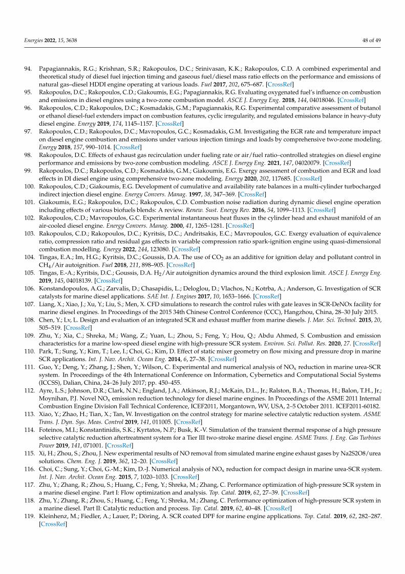
Energies 2022, 15, 3638 48 of 49
94. Papagiannakis, R.G.; Krishnan, S.R.; Rakopoulos, D.C.; Srinivasan, K.K.; Rakopoulos, C.D. A combined experimental andtheoretical study of diesel fuel injection timing and gaseous fuel/diesel mass ratio effects on the performance and emissions ofnatural gas–diesel HDDI engine operating at various loads. Fuel 2017, 202, 675–687. [CrossRef]
95. Rakopoulos, D.C.; Rakopoulos, C.D.; Giakoumis, E.G.; Papagiannakis, R.G. Evaluating oxygenated fuel’s influence on combustionand emissions in diesel engines using a two-zone combustion model. ASCE J. Energy Eng. 2018, 144, 04018046. [CrossRef]
96. Rakopoulos, C.D.; Rakopoulos, D.C.; Kosmadakis, G.M.; Papagiannakis, R.G. Experimental comparative assessment of butanolor ethanol diesel-fuel extenders impact on combustion features, cyclic irregularity, and regulated emissions balance in heavy-dutydiesel engine. Energy 2019, 174, 1145–1157. [CrossRef]
97. Rakopoulos, C.D.; Rakopoulos, D.C.; Mavropoulos, G.C.; Kosmadakis, G.M. Investigating the EGR rate and temperature impacton diesel engine combustion and emissions under various injection timings and loads by comprehensive two-zone modeling.Energy 2018, 157, 990–1014. [CrossRef]
98. Rakopoulos, D.C. Effects of exhaust gas recirculation under fueling rate or air/fuel ratio–controlled strategies on diesel engineperformance and emissions by two-zone combustion modeling. ASCE J. Energy Eng. 2021, 147, 04020079. [CrossRef]
99. Rakopoulos, D.C.; Rakopoulos, C.D.; Kosmadakis, G.M.; Giakoumis, E.G. Exergy assessment of combustion and EGR and loadeffects in DI diesel engine using comprehensive two-zone modeling. Energy 2020, 202, 117685. [CrossRef]
100. Rakopoulos, C.D.; Giakoumis, E.G. Development of cumulative and availability rate balances in a multi-cylinder turbochargedindirect injection diesel engine. Energy Convers. Manag. 1997, 38, 347–369. [CrossRef]
101. Giakoumis, E.G.; Rakopoulos, D.C.; Rakopoulos, C.D. Combustion noise radiation during dynamic diesel engine operationincluding effects of various biofuels blends: A review. Renew. Sust. Energy Rev. 2016, 54, 1099–1113. [CrossRef]
102. Rakopoulos, C.D.; Mavropoulos, G.C. Experimental instantaneous heat fluxes in the cylinder head and exhaust manifold of anair-cooled diesel engine. Energy Convers. Manag. 2000, 41, 1265–1281. [CrossRef]
103. Rakopoulos, C.D.; Rakopoulos, D.C.; Kyritsis, D.C.; Andritsakis, E.C.; Mavropoulos, G.C. Exergy evaluation of equivalenceratio, compression ratio and residual gas effects in variable compression ratio spark-ignition engine using quasi-dimensionalcombustion modelling. Energy 2022, 244, 123080. [CrossRef]
104. Tingas, E.A.; Im, H.G.; Kyritsis, D.C.; Goussis, D.A. The use of CO2 as an additive for ignition delay and pollutant control inCH4/Air autoignition. Fuel 2018, 211, 898–905. [CrossRef]
105. Tingas, E.-A.; Kyritsis, D.C.; Goussis, D.A. H2/Air autoignition dynamics around the third explosion limit. ASCE J. Energy Eng.2019, 145, 04018139. [CrossRef]
106. Konstandopoulos, A.G.; Zarvalis, D.; Chasapidis, L.; Deloglou, D.; Vlachos, N.; Kotrba, A.; Anderson, G. Investigation of SCRcatalysts for marine diesel applications. SAE Int. J. Engines 2017, 10, 1653–1666. [CrossRef]
107. Liang, X.; Xiao, J.; Xu, Y.; Liu, S.; Men, X. CFD simulations to research the control rules with gate leaves in SCR-DeNOx facility formarine diesel engines. In Proceedings of the 2015 34th Chinese Control Conference (CCC), Hangzhou, China, 28–30 July 2015.
108. Chen, Y.; Lv, L. Design and evaluation of an integrated SCR and exhaust muffler from marine diesels. J. Mar. Sci. Technol. 2015, 20,505–519. [CrossRef]
109. Zhu, Y.; Xia, C.; Shreka, M.; Wang, Z.; Yuan, L.; Zhou, S.; Feng, Y.; Hou, Q.; Abdu Ahmed, S. Combustion and emissioncharacteristics for a marine low-speed diesel engine with high-pressure SCR system. Environ. Sci. Pollut. Res. 2020, 27. [CrossRef]
110. Park, T.; Sung, Y.; Kim, T.; Lee, I.; Choi, G.; Kim, D. Effect of static mixer geometry on flow mixing and pressure drop in marineSCR applications. Int. J. Nav. Archit. Ocean Eng. 2014, 6, 27–38. [CrossRef]
111. Guo, Y.; Deng, Y.; Zhang, J.; Shen, Y.; Wilson, C. Experimental and numerical analysis of NOx reduction in marine urea-SCRsystem. In Proceedings of the 4th International Conference on Information, Cybernetics and Computational Social Systems(ICCSS), Dalian, China, 24–26 July 2017; pp. 450–455.
112. Ayre, L.S.; Johnson, D.R.; Clark, N.N.; England, J.A.; Atkinson, R.J.; McKain, D.L., Jr.; Ralston, B.A.; Thomas, H.; Balon, T.H., Jr.;Moynihan, P.J. Novel NOx emission reduction technology for diesel marine engines. In Proceedings of the ASME 2011 InternalCombustion Engine Division Fall Technical Conference, ICEF2011, Morgantown, WV, USA, 2–5 October 2011. ICEF2011-60182.
113. Xiao, Y.; Zhao, H.; Tian, X.; Tan, W. Investigation on the control strategy for marine selective catalytic reduction system. ASMETrans. J. Dyn. Sys. Meas. Control 2019, 141, 011005. [CrossRef]
114. Foteinos, M.I.; Konstantinidis, S.K.; Kyrtatos, N.P.; Busk, K.-V. Simulation of the transient thermal response of a high pressureselective catalytic reduction aftertreatment system for a Tier III two-stroke marine diesel engine. ASME Trans. J. Eng. Gas TurbinesPower 2019, 141, 071001. [CrossRef]
115. Xi, H.; Zhou, S.; Zhou, J. New experimental results of NO removal from simulated marine engine exhaust gases by Na2S2O8/ureasolutions. Chem. Eng. J. 2019, 362, 12–20. [CrossRef]
116. Choi, C.; Sung, Y.; Choi, G.-M.; Kim, D.-J. Numerical analysis of NOx reduction for compact design in marine urea-SCR system.Int. J. Nav. Archit. Ocean Eng. 2015, 7, 1020–1033. [CrossRef]
117. Zhu, Y.; Zhang, R.; Zhou, S.; Huang, C.; Feng, Y.; Shreka, M.; Zhang, C. Performance optimization of high-pressure SCR system ina marine diesel engine. Part I: Flow optimization and analysis. Top. Catal. 2019, 62, 27–39. [CrossRef]
118. Zhu, Y.; Zhang, R.; Zhou, S.; Huang, C.; Feng, Y.; Shreka, M.; Zhang, C. Performance optimization of high-pressure SCR system ina marine diesel. Part II: Catalytic reduction and process. Top. Catal. 2019, 62, 40–48. [CrossRef]
119. Kleinhenz, M.; Fiedler, A.; Lauer, P.; Döring, A. SCR coated DPF for marine engine applications. Top. Catal. 2019, 62, 282–287.[CrossRef]

Energies 2022, 15, 3638 49 of 49
120. Ha, T.-H.; Nishida, O.; Fujita, H.; Wataru, H. Simultaneous removal of NOx and fine diesel particulate matter (DPM) byelectrostatic water spraying scrubber. J. Mar. Eng. Technol. 2014, 8, 45–53. [CrossRef]
121. Zis, T.; Psaraftis, H.N. Operational measures to mitigate and reverse the potential modal shifts due to environmental legislation.Marit. Policy Manag. 2019, 46, 117–132. [CrossRef]
122. Lehtoranta, K.; Aakko-Saksa, P.; Murtonen, T.; Vesala, H.; Ntziachristos, L.; Rönkko, T.; Karjalainen, P.; Kuittinen, N.; Timonen, H.Particulate mass and nonvolatile particle number emissions from marine engines using low-sulfur fuels, natural gas, or scrubbers.Environ. Sci. Technol. 2019, 53, 3315–3322. [CrossRef] [PubMed]
123. Greek Shipowner. Personal communication, 2020.124. DNV GL. Global Sulfur Cap 2020, Compliance Options and Implications for Shipping—Focus on Scrubbers. Available online:
https://www.dnvgl.com/maritime/publications/global-sulfur-cap-2020.html (accessed on 2 April 2022).125. Yang, Z.L.; Zhang, D.; Caglayan, O.; Jenkinson, I.D.; Bonsall, S.; Wang, J.; Huang, M.; Yan, X.P. Selection of techniques for reducing
shipping NOx and SOx emissions. Transp. Res. Part D Transp. Environ. 2012, 17, 478–486. [CrossRef]126. Claremar, B.; Haglund, K.; Rutgersson, A. Ship emissions and the use of current air cleaning technology: Contributions to air
pollution and acidification in the Baltic Sea. Earth Syst. Dyn. 2017, 8, 901–919. [CrossRef]127. Bouman, E.A.; Lindstad, E.; Rialland, A.I.; Strømman, A.H. State-of-the-art technologies, measures, and potential for reducing
GHG emissions from shipping—A review. Transp. Res. Part D Transp. Environ. 2017, 52, 408–421. [CrossRef]128. Williams, P.J. Use of seawater as makeup water for wet flue gas desulfurization systems. In Proceedings of the EPRI-DOE-EPA
Combined Utility Air Pollutant Control Symposium, Atlanta, GA, USA, 16–20 August 1999.129. International Maritime Organization. Investigation of Appropriate Control Measures (Abatement Technologies) to Reduce
Black Carbon Emissions from International Shipping 2015. Available online: http://www.imo.org/en/OurWork/Environment/PollutionPrevention/AirPollution/Documents/Air%20pollution/Black%20Carbon.pdf (accessed on 2 April 2022).
130. DNV GL. Global Sulfur Cap 2020. Get Insights on Compliance Options and Implications for Shipping. Focus on Scrubbers; DNV GL:Bærum, Norway, 2019.
131. DNV GL. Global Sulfur Cap 2020. Know the Different Choices and Challenges for On-Time Compliance; DNV GL: Bærum, Norway, 2020.132. The Swedish Club, Sulfur Guide, Dealing with the Sulfur Cap 2020 and Beyond. Available online: https://www.swedishclub.
com/media_upload/files/Publications/Loss%20Prevention/Sulfur-Guide%202019%20www.pdf (accessed on 2 April 2022).133. Cho, B.K.; Lee, J.H.; Crellin, C.C.; Olson, K.L.; Hilden, D.L.; Kim, M.K.; Kim, P.S.; Heo, I.; Oh, S.H.; Nam, I.-S. Selective catalytic
reduction of NOx by diesel fuel: Plasma-assisted HC/SCR system. Catal. Today 2012, 191, 20–24. [CrossRef]134. Liu, B.; Wu, X.; Liu, X.; Gong, M. Assessment of ecological stress caused by maritime vessels based on a comprehensive model
using AIS data: Case study of the Bohai Sea, China. Ecol. Indic. 2021, 126, 107592. [CrossRef]135. Zhang, Y.; Yang, X.; Brown, R.; Yang, L.; Morawska, L.; Ristovski, Z.; Fu, Q.; Huang, C. Shipping emissions and their impacts on
air quality in China. Sci. Total Environ. 2017, 581–582, 186–198. [CrossRef]