March 27, 2018 Kimberly D. Bose, Secretary Federal Energy ...
48
625 Liberty Avenue, Suite 1700 | Pittsburgh, PA 15222 844-MVP-TALK | [email protected] www.mountainvalleypipeline.info March 27, 2018 Kimberly D. Bose, Secretary Federal Energy Regulatory Commission 888 First Street NE Washington, DC 20426 Re: Mountain Valley Pipeline, LLC Docket No. CP16-10-000 Variance Request No. MVP-1 Dear Ms. Bose: On October 13, 2017, the Federal Energy Regulatory Commission issued an order granting a Certificate of Public Convenience and Necessity to Mountain Valley Pipeline, LLC. In this filing, Mountain Valley requests a variance to clarify its General Blasting Plan (Variance Request No. MVP-1). A detailed variance request form and supporting documents are attached. Mountain Valley requests approval by March 28, 2018. If you have any questions, please do not hesitate to contact me at (412) 553-5786 or [email protected]. Thank you. Respectfully submitted, MOUNTAIN VALLEY PIPELINE, LLC by and through its operator, EQM Gathering Opco, LLC By: Matthew Eggerding Senior Counsel, Midstream Attachments cc: All Parties Paul Friedman, OEP Lavinia DiSanto, Cardno, Inc. Doug Mooneyhan, Cardno, Inc.
-
Upload
khangminh22 -
Category
Documents
-
view
4 -
download
0
Transcript of March 27, 2018 Kimberly D. Bose, Secretary Federal Energy ...

625 Liberty Avenue, Suite 1700 | Pittsburgh, PA 15222 844-MVP-TALK | [email protected] www.mountainvalleypipeline.info
March 27, 2018
Kimberly D. Bose, Secretary Federal Energy Regulatory Commission 888 First Street NE Washington, DC 20426
Re: Mountain Valley Pipeline, LLC Docket No. CP16-10-000 Variance Request No. MVP-1
Dear Ms. Bose:
On October 13, 2017, the Federal Energy Regulatory Commission issued an order granting a Certificate of Public Convenience and Necessity to Mountain Valley Pipeline, LLC.
In this filing, Mountain Valley requests a variance to clarify its General Blasting Plan (Variance Request No. MVP-1). A detailed variance request form and supporting documents are attached. Mountain Valley requests approval by March 28, 2018.
If you have any questions, please do not hesitate to contact me at (412) 553-5786 or [email protected]. Thank you.
Respectfully submitted,
MOUNTAIN VALLEY PIPELINE, LLC by and through its operator, EQM Gathering Opco, LLC
By:
Matthew Eggerding Senior Counsel, Midstream
Attachments cc: All Parties
Paul Friedman, OEP Lavinia DiSanto, Cardno, Inc. Doug Mooneyhan, Cardno, Inc.

Mountain Valley Pipeline Project
Docket No. CP-16-10
General Blasting Plan
April 2016 (revised March 2018) Revised Changes Highlighted in “Yellow”

General Blasting Plan
2
TABLE OF CONTENTS
1 INTRODUCTION .......................................................................................................... 4
2 PROJECT ALIGNMENT ............................................................................................... 4
3 GEOLOGIC SETTING .................................................................................................. 5
3.1 Regional Physiographic Setting .............................................................................. 5
3.2 Regional Geology ................................................................................................... 5
3.3 Active Faults ........................................................................................................... 5
3.4 Areas of Shallow Bedrock ....................................................................................... 5
3.5 Coal ........................................................................................................................ 5
3.6 Sand, Gravel, Clay, and Crushed Rock .................................................................. 6
4 BLASTING SPECIFICATIONS ..................................................................................... 6
4.1 Specifications ......................................................................................................... 6
5 PRE-BLAST INSPECTIONS ........................................................................................ 7
6 MONITORING OF BLASTING ACTIVITIES ................................................................. 7
7 BLASTING REQUIREMENTS ...................................................................................... 8
7.1 General Provisions ................................................................................................. 9
7.2 Storage Use at Sites ............................................................................................. 11
7.3 Pre-Blast Operations ............................................................................................ 12
Dyno Nobel Unimax TM (or equivalent) ................................................... 13
Dyno Nobel Unigel TM (or equivalent) ..................................................... 13
Dyno Nobel Dynomax ProTM (or equivalent) ............................................ 13
Dyno Nobel NONEL TM 17 or 25 Millisecond Delay Connectors or Dyno
Nobel NONEL EZ Det TM (or equivalent) ............................................................. 13
Dyno Nobel NONEL TM Nonelectric Shock Tube System Detonator (or equivalent) ............................................................................................................ 13
Dyno Nobel 1062 Bulk Emulsion (or equivalent) ..................................... 13
7.4 Discharging Explosives ......................................................................................... 14

General Blasting Plan
3
7.5 Waterbody Crossing Blasting Procedures ............................................................ 15
7.6 Karst Terrain Blasting Procedures ........................................................................ 16
7.7 Wetland Crossing Blasting Procedures ................................................................ 16
7.8 Rock Disposal Due to Blasting ............................................................................. 17
7.9 Disposal of Explosive Materials ............................................................................ 17
7.10 Blasting Records ..................................................................................... 17
8 POST-BLASTING INSPECTION ................................................................................ 19
APPENDIX A ...................................................................................................... 20
PRE-BLAST SURVEY ....................................................................................... 20
APPENDIX B ...................................................................................................... 26
BLAST REPORT ................................................................................................ 26
APPENDIX C ..................................................................................................... 33
SEISMOGRAPH REPORT................................................................................. 33
APPENDIX D ..................................................................................................... 35
POST-BLAST SURVEY REPORT ..................................................................... 35

General Blasting Plan
4
1 INTRODUCTION
The Mountain Valley Pipeline Blasting Plan (Plan) outlines the procedures and safety measures that the contractor will adhere to while implementing blasting activities during the construction of the Mountain Valley Pipeline (MVP). This Plan addresses blasting for the proposed route alignment filed with the Federal Energy Regulatory Commission (FERC).
The MVP Project is a natural gas pipeline system that spans approximately 303 miles from northwestern West Virginia (Wetzel County) to southern Virginia (Pittsylvania County). The MVP will be constructed and owned by Mountain Valley Pipeline, LLC, which is a joint venture of EQT Midstream Partners, LP; NextEra US Gas Assets, LLC; Con Edison Gas Midstream, LLC; WGL Midstream; and RGC Midstream, LLC. This Plan includes a brief description of the pipeline alignment and overall physiographic setting and bedrock geology in the vicinity of the MVP Project. Information on shallow bedrock soils and bedrock outcropping is taken from MVP Project’s Resource Report 6 – Geological Resources. A map depicting the location of MVP Project’s various pipeline routes is provided in Figure 1.2-1, MVP Project Overview Resource Report 1 – General Project Description.
Information for blast and rip characteristics of the bedrock may be evaluated, at least in a general sense, and applied toward an appropriate bedrock excavation method. The hard and intact nature of the unweathered sedimentary bedrock (sandstones, limestones, and shales) dictates what blasting methods will be utilized. Soft bedrock, such as weathered sandstones, limestones, and shales may possibly be removed by ripping or mechanical means.
Other geologic features may control the effects of blasting. Rock fabric, or the arrangements of minerals, determines intrinsic rock strength, and thus influences rock excavation. Joint spacing, bedding, and foliation also influence rock excavation.
2 PROJECT ALIGNMENT
The proposed FERC jurisdictional facilities described in this report will consist of approximately 303 miles of 42-inch diameter pipeline, installing three new compressor stations that consist of approximately 171,600 horsepower of compression, aboveground sites for interconnections, main line block valves, launchers and receivers, control systems, and other facilities, as further described in Resource Report 1 - General Project Description.
The proposed pipeline, compressor stations, and interconnect facilities are summarized below:
• Pipeline – Facilities would include: Installation of approximately 303 miles of 42-inch diameter pipeline with a 1,480 pounds per square inch gauge (psig) maximum allowable operating pressure (MAOP), with portions of the pipeline paralleling existing buried natural gas pipelines. The pipeline will be located in the West Virginia Counties of Braxton, Doddridge, Fayette, Greenbrier, Harrison, Lewis, Monroe, Nicholas, Summers, Webster, and Wetzel, and the Virginia Counties of Craig, Giles, Franklin, Montgomery, Pittsylvania, and Roanoke. The proposed pipeline will extend from Equitrans’ existing transmission system in Wetzel County, West Virginia to Transcontinental Gas Pipeline Company’s (TRANSCO) Zone 5 Compressor Station 165 in Pittsylvania County, Virginia.
• Compression – The MVP Project will consist of the construction of three new compressor stations, totaling approximately 171,600 horsepower of new compression.
• Interconnections – The MVP Project will have a total of four (4) interconnections at Equitrans Mobley in Wetzel County, WV; MarkWest Sherwood in Doddridge County, WV; Columbia Pipeline Group WB in Braxton County, WV; and TRANSCO Zone 5 Compressor Station 165 in Pittsylvania County, Virginia.

General Blasting Plan
5
3 GEOLOGIC SETTING
The proposed Project route begins in Wetzel County, West Virginia, and proceeds in a southeasterly direction through eleven (11) West Virginia counties and six (6) Virginia counties. Along the proposed Project route, topography ranges from 586 to 3,741 feet above mean sea level (amsl) and crosses over several synclines and anticlines, as well as mineral resources, abandoned mines, active coal permit boundaries, oil and gas wells, and other mineral resources that are discussed in detail by Resource Report 6 – Geological Resources.
3.1 Regional Physiographic Setting
The proposed Project route crosses four physiographic provinces, including the Appalachian Plateau, Valley and Ridge, Blue Ridge, and Piedmont provinces that are discussed in detail by Resource Report 6 – Section 6.1.1.
3.2 Regional Geology
The Project traverses geology of numerous timeframes and rock types, as discussed in detail in Resource Report 6 – Section6.1.3.
3.3 Active Faults
The MVP alignment was evaluated for the presence of Quaternary-age faulting and the potential for ground movement and failure (Draper Aden Associates 2015c). The findings of the evaluation are discussed in detail in Resource Report 6 – Section 6.4.1.3.
3.4 Areas of Shallow Bedrock
The pipeline will be installed to allow a minimum cover of 36 inches in areas of shallow bedrock. Therefore, the proposed Project area was evaluated for areas where bedrock might be encountered above a depth of 80 inches (Resource Report 6 - Appendix 6-A and 6-B).
Areas where shallow bedrock may be encountered are discussed in detail in Resource Report 6 – Section 6.2.
Where unrippable subsurface rock is encountered, approved alternative methods of excavation will first be explored including: rock trenching machines, rock saws, hydraulic rams, jack hammers, blasting, etc. The alternative method to be used will be dependent on the proximity to: structures, pipelines, wells, cables, water resources, etc., and the capabilities of the alternative excavation method. Should blasting for ditch excavation be necessary, care will be taken to prevent damage to underground structures (e.g., cables, conduits, and pipelines) or to springs, water wells, or other water sources. Blasting mats or padding will be used as necessary to prevent the scattering of loose rock (fly-rock). All blasting will be conducted during daylight hours and will not begin until occupants of nearby buildings, stores, residences, places of business, and farms have been notified. Where competent sandstone bedrock occurs in the stream bed, blasting may be used to reduce bedrock so the trench can be excavated. Specific locations requiring blasting will be determined in the field, based on the limitations of the mechanical excavation equipment.
3.5 Coal
Coal seams and mines are discussed in detail in Resource Report 6 – Section 6.3.3.
No blasting is foreseen to occur within the limits of an active surface mine or an active deep mine. Any blasting to occur within these mineral areas would require a notice of the planned blasting. This notice would allow the mining company to confirm that no mining is occurring. However, if an area of blasting is found to be within an active mine area, the mining company will participate in the development of the Blasting Plan for that length of pipeline trench within the active mining

General Blasting Plan
6
area. The mining company will be provided with a five (5) working day notice (minimum). This notice will be both verbal and written.
3.6 Sand, Gravel, Clay, and Crushed Rock
Sand, gravel, clay, and crushed rock quarries are discussed in detail in Resource Report 6 – Section 6.3.1.
No blasting is foreseen to occur within the limits of an active quarry surface mine or an active underground quarry mine. Any blasting to occur within active mining areas would require a notice of the planned blasting. This notice would allow the quarry/mining company to confirm that no mining is occurring. However, if an area of blasting is found to be within an active mine area, the mining company will participate in the development of the blasting plan for that length of pipeline trench within the active mining area. The mining company will be provided with a five (5) working day notice (minimum). This notice will be both verbal and written.
4 BLASTING SPECIFICATIONS
Blasting for pipeline facilities grade or trench excavation, compressor station and interconnect site development will be considered only after all other reasonable means of excavation have been evaluated and determined to be unlikely to achieve the required results. MVP may specify locations (foreign line crossings, nearby structures, etc.) where consolidated rock will be removed by approved mechanical equipment, such as rock trenching machines, rock saws, hydraulic rams, or jack hammers, instead of blasting. Areas where blasting may be required will be surveyed for features, such as karst terrain, structures, utilities, and wells. The pre-construction condition of human- occupied buildings will be documented. Occupied buildings and their condition within 150 feet of the blasting area will be documented as to their pre-blast condition, as set forth in Appendix A - Pre-Blast Survey, and their condition after blasting, as set forth in Appendix D - Post-Blast Survey. MVP will provide verbal notification, followed by written documentation, to the buildings’ occupant(s) of any blasting activity during both pre-construction and post-construction within 150 feet of a blast location.
If blasting is conducted within 150 feet of an active water well, as necessary, MVP will conduct a pre-construction evaluation of the well. Upon request by a landowner who had a pre-construction test, a post-construction test will be performed. Landowners will be contacted by an MVP representative, and a qualified independent contractor will conduct the testing. Wells within 150 feet of proposed Project work areas are tabulated in Resource Report 2 - Water Use and Quality.
MVP will evaluate, on a timely basis, landowner complaints regarding damage resulting from blasting to wells, homes, or outbuildings. If the damage is substantiated, MVP will negotiate a settlement with the landowner that may include repair or replacement.
Before any blasting occurs, Contractor will complete a project/site-specific blasting plan and provide it to MVP for review. No blasting shall be done without prior approval of MVP. In no event shall explosives be used where, in the opinion of MVP, such use will endanger existing facilities. The Contractor shall obtain MVP approval, and provide forty-eight (48) hours notice prior to the use of any explosives. MVP will provide at least a 24-hour notice to occupants of nearby (within 150 feet of blasting area) buildings, stores, residences, businesses, farms, and other occupied areas prior to initiating blasting operations. These notices will be verbal, followed by written documentation of the 24-hour notice.
4.1 Specifications
Blasting shall adhere to the following federal, state, county, township, local, and MVP standards and regulations. These standards and regulations are to be considered as the minimum requirements. Should there be a conflict between jurisdictions, standards, and regulations, the most stringent jurisdictions, standards, and regulations shall be followed.
These blasting requirements for the MVP Project are as follows:

General Blasting Plan
7
• MVP Project, Resource Report 6 - Geological Resources, Docket No. PF15- 3.
• MVP, Design and Construction Manual, Design Standard, Pipeline, 4.11 Blasting Proximate to Buried Pipelines.
• MVP, Design and Construction Manual, Design Standard, Pipeline, 4.17 Blasting Activities During Construction.
• 29 CFR 1926 Subpart U – Blasting and the Use of Explosives.
• 27 CFR 555 Subpart K, U. S. Bureau of Alcohol, Tobacco, and Firearms.
• 30 CFR 816.68 Mine Safety and Health Administration (MSHA).
• 49 CFR Part 192 USDOT.
• 27 CFR Part 55.
• 30 CFR '715.19.
• National Fire Protection Association 495.
• U. S. Bureau of Mines Report of Investigations 8507.
• West Virginia 199 CSR 1 Title 199 Series 1.
• Virginia 4 VAC25-130-816.11, 4 VAC25-130-816.64, 4 VAC25-110-210, and 3 VAC25-150-250.
5 PRE-BLAST INSPECTIONS
As required by Resource Report 6 – Geological Resources, MVP shall conduct pre- blast surveys, with landowner permission, to assess the conditions of structures, wells, springs, and utilities within 150 feet of the proposed construction ROW. Should local or state ordinances require inspections in excess of 150 feet from the work, the local or state ordinances shall prevail. The survey will include, at a minimum:
• Informal discussions to familiarize the adjacent property owners with blasting effects and planned precautions to be taken on this project;
• Determination of the existence and location of site-specific structures, utilities, septic systems, and wells;
• Detailed examination, photographs, and/or video records of adjacent structures and utilities; and
• Detailed mapping and measurement of large cracks, crack patterns, and other evidence of structural distress.
The results will be summarized in a Pre-Blast Condition Report that will include photographs and be completed prior to the commencement of blasting. The pre-blast conditions will be documented with the information outlined by “Pre-Blast Survey, MVP Project”. This Pre-Blast Survey Form is considered the minimum information needed. Appendix BP-A presents the Pre-Blast Survey Form. The completion of the Pre-Blast Survey Form is in addition to all other local, county, township, state, or federal reporting/survey data collection and reports.
6 MONITORING OF BLASTING ACTIVITIES
During blasting, MVP contractors will take precautions to minimize damage to adjacent areas and structures. Precautions include:

General Blasting Plan
8
• Dissemination of blast warning signals in the area of blasting.
• Backfilling with subsoil (no topsoil to be used) or blasting mats or other approved methods.
• Blast warning in congested areas, in shallow water bodies, or near structures that could be damaged by fly-rock.
• Use of matting or other suitable cover, as necessary, to prevent fly-rock from damaging adjacent protected natural resources.
• Posting warning signals, flags, and/or barricades.
• Following Federal, State, Local, and MVP procedures and regulations for safe storage, handling, loading, firing, and disposal of explosive materials.
• Manning adjacent pipelines at valves for emergency response, as appropriate.
• Posting of portable signage, portable barricades, and visual survey of the blast area access ways to prevent unauthorized entrance into the blast zone by spectators and/or intruders.
• Maintain communications between all persons involved for security of the blast zone during any and all blasting/firing.
Excessive vibration will be controlled by limiting the size of charges and by using charge delays, which stagger each charge in a series of explosions.
If the Contractor has to blast near buildings or wells, a qualified independent Contractor will inspect structures or wells within 150 feet, or farther if required by local or state regulations, of the construction right-of-way prior to blasting, and with landowner permission. Post-blast inspections by company’s representative will also be performed, as warranted. All blasting will be performed by registered blasters and monitored by experienced blasting inspectors. Recording seismographs will be installed by the Contractor at selected monitoring stations under the observation of MVP personnel. During construction, the Contractor will submit blast reports for each blast and keep detailed records as described in Section 7.10.
As appropriate, effects of each discharge will be monitored at the closest adjacent facilities by seismographs.
If a charge greater than eight pounds per delay is used, the distance of monitoring will be in accordance with the U. S. Bureau of Mines Report of Investigations 8507.
To maximize its responsiveness to the concerns of affected landowners, MVP will evaluate all complaints of well or structural damage associated with construction activities, including blasting. A toll-free landowner hotline will be established by MVP for landowners to use in reporting complaints or concerns. In the unlikely event that blasting activities temporarily impair a water well, MVP will provide alternative sources of water or otherwise compensate the owner. If well or structural damage is substantiated, MVP will either compensate the owner for damages or arrange for a new well to be drilled.
7 BLASTING REQUIREMENTS
MVP has standard practices for blasting operations, as outlined by Sections 1.0 and 4.0 of this Blasting Plan. The potential for blasting along the pipeline to affect any wetland, municipal water supply, waste disposal site, well, septic system, spring, or pipelines will be minimized by controlled blasting techniques and by using mechanical methods for rock excavation as much as possible. Controlled blasting techniques have been effectively employed by MVP and other companies to protect active gas pipelines within 15 feet of trench excavation. The following text presents details of procedures for powder blasting.

General Blasting Plan
9
7.1 General Provisions
• The contractor will provide all personnel, labor, and equipment to perform necessary blasting operations related to the work. The Contractor will provide a permitted blaster possessing all permits required by the local, county, township, and states in which blasting is required during construction, and having a working knowledge of state and local laws and regulations that pertain to explosives.
• Project blasting will be done in accordance with 27 CFR Part 55, 30 CFR '715.19, National Fire Protection Association 495 – Explosive Materials Code; the above referenced Specification; and all other state and local laws, when required; and regulations applicable to obtaining, transporting, storing, handling, blast initiation, ground motion monitoring, and disposal of explosive materials and/or blasting agents.
• The Contractor shall be responsible for supplying explosives and blasting materials that are perchlorate-free in order to eliminate the potential for perchlorate contamination of ground water, except that detonators containing non-combined amounts of perchlorate, such as Dyno Nobel NONEL EZ Det or equivalent, are an industry standard and shall be permitted. Further, while the use of bulk ammonium nitrate is prohibited, the use of emulsion type explosives, including those having ammonium nitrate as a constituent, such as Dyna 1062 Bulk Emulsion or equivalent, shall be permitted, as these types of explosives are considered industry standard for area blasting related to large scale earthwork construction.
• The contractor shall be responsible for securing and complying with all necessary permits required for the transportation, storage, and use of explosives. The Contractor shall be responsible for all damages or liabilities occurring on or off the right-of-way resulting from the use of explosives. When the use of explosives is necessary to perform the work, the Contractor shall use utmost care not to endanger life or adjacent property, and shall comply with all applicable laws, rules, and regulations governing the storage, handling, and use of such explosives. MVP will conduct a pre- and post- surficial leak survey along the centerline of each adjacent live pipeline to the planned blast area. The surficial leak survey will be conducted by MVP’s employees and/or designated representative, with the surficial leak survey extending a minimum of 100- feet (both directions) past the limits of the planned blast area.
• Blasting activities will strictly adhere to all MVP, local, state, and federal regulations and requirements applying to controlled blasting and blast vibration limits in regard to structures, underground gas pipelines, and underground utilities. In addition to following state and federal blasting guidelines, MVP will contact each governmental agency (if project is not undertaken within twelve months as of the date of this Blasting Plan) along the proposed route to determine local ordinances or guidelines for blasting (refer to Table 7.1.1).
General Blasting Plan
10
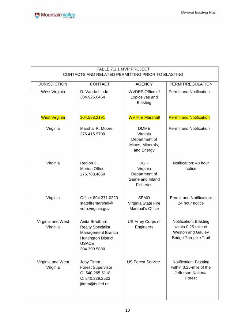
TABLE 7.1.1 MVP PROJECT CONTACTS AND RELATED PERMITTING PRIOR TO BLASTING
JURISDICTION CONTACT AGENCY PERMIT/REGULATION
West Virginia D. Vande Linde 304.926.0464
WVDEP Office of Explosives and
Blasting
Permit and Notification
West Virginia 304.558.2191 WV Fire Marshall Permit and Notification
Virginia Marshal R. Moore 276.415.9700
DMME Virginia
Department of Mines, Minerals,
and Energy
Permit and Notification
Virginia Region 3 Marion Office 276.783.4860
DGIF Virginia
Department of Game and Inland
Fisheries
Notification: 48 hour notice
Virginia Office: 804.371.0220 statefiremarshal@ vdfp.virginia.gov
SFMO Virginia State Fire Marshal’s Office
Permit and Notification: 24 hour notice
Virginia and West Virginia
Anita Bradburn Realty Specialist Management Branch Huntington District USACE 304.399.5890
US Army Corps of Engineers
Notification: Blasting within 0.25-mile of
Weston and Gauley Bridge Turnpike Trail
Virginia and West Virginia
Joby Timm Forest Supervisor O: 540.265.5118 C: 540.339.2523 [email protected]
US Forest Service Notification: Blasting within 0.25-mile of the
Jefferson National Forest

General Blasting Plan
11
The Construction Contractor will be made aware of all applicable procedures and local requirements, and it will ultimately be the Contractor’s responsibility to notify officials and receive appropriate blasting permits and authorization.
Typically, local regulations require copies of the blasting Contractor’s Certificate of Insurance and License. In some jurisdictions, a Certificate of Bond will also be required, as well as a qualified person hired to oversee the blasting procedure.
The MVP Chief Blasting Inspector (CBI) or designated representative shall have the opportunity to witness all rock excavations or other use of explosives. The Contractor shall conduct all blasting operations in a safe manner which will not cause harm to the existing pipelines and structures in the vicinity. If the CBI determines that any project blasting operations have been conducted in an unsafe manner, the CBI will notify the Contractor of the unsafe activity. If any further unsafe actions occur on the part of the blasting firm, the CBI will request the Contractor terminate the Contract of the blasting firm and hire another blasting company.
Any failure to comply with the appropriate law and/or regulations is the sole liability of the Contractor. The Contractor and the Contractor’s permitted blaster shall be responsible for the conduct of all blasting operations, which shall be subject to inspection requirements.
A Blasting Fact Sheet will be distributed to landowners where blasting is proposed and affected landowners will be contacted prior to any blasting activities.
7.2 Storage Use at Sites
Explosives and related materials shall be stored in approved facilities required under the applicable provisions contained in 27 CFR Part 55, Commerce in Explosives. The handling of explosives may be performed by the person holding a permit to use explosives or by other employees under his or her direct supervision, provided that such employees are at least 21 years of age. While explosives are being handled or used, smoking shall not be permitted, and no one near the explosives shall possess matches, open light, or other fire or flame within 50 feet of the explosives, in accordance with OSHA requirements. Suitable devices or lighting safety fuses are exempt from this requirement. No person shall handle explosives while under the influence of intoxicating liquors or narcotics at any time during construction of the Project. Original containers or Class II magazines shall be used for taking detonators and other explosives from storage magazines to the blasting area. Partial reels of detonating cord do not need to be in closed containers, unless transported over public highways. Containers of explosives shall not be opened in any magazine or within 50 feet of any magazine. In opening kegs, or wooden cases, no sparking metal tools shall be used; wooden wedges and either wood, fiber or rubber mallets shall be used. Non-sparking metallic slitters may be used for opening fiberboard cases.
No explosive materials shall be located or stored where they may be exposed to flame, excessive heat, sparks, or impact.
Explosives or blasting equipment that are obviously deteriorated or damaged shall not be used. Explosive materials shall be protected from unauthorized possession and shall not be abandoned.
No attempt shall be made to fight a fire if it is determined the fire cannot be contained or controlled before it reaches explosive materials. In such cases, all personnel shall be immediately evacuated to a safe location and the area shall be guarded from entry by spectators or intruders.
No firearms shall be discharged into or in the vicinity of a vehicle containing explosive materials or into or in the vicinity of a location where explosive materials are being handled, used, or stored.
Contractor shall maintain a daily and/or blast inventory record of all explosive materials transported, used, and returned to off-site storage, when no storage is located on the blast site.

General Blasting Plan
12
7.3 Pre-Blast Operations
The Contractor is required to submit a planned schedule of blasting operations to the CBI or his designated representative for approval, prior to commencement of any blasting or pre-blast operation, which indicates the maximum charge weight per delay, hole size, spacing, depth, and blast layout. If blasting is to be conducted adjacent to an existing pipeline, approval must be received from the pipeline’s Engineering Department. The Contractor shall provide this schedule to the CBI at least five working days prior to any pre-blast operation for approval and use. Where residences or other structures are within 150 feet of the blasting operation, the CBI may require notification in excess of five days. The blasting schedule is to include the blast geometry, drill hole dimensions, type and size of charges, stemming, and delay patterns and should also include a location survey of any dwelling or structures that may be affected by the proposed operation. Face material shall be carefully examined before drilling to determine the possible presence of unfired explosive material. Drilling shall not be started until all remaining butts of old holes are examined for unexploded charges, and if any are found, they shall be re-fired before work proceeds. No person shall be allowed to deepen the drill holes that have contained explosives.
Drill holes shall be large enough to permit free insertion of cartridges of explosive materials. Drill holes shall not be collared in bootlegs or in holes that have previously contained explosive materials. Holes shall not be drilled where there is a danger of intersecting another hole containing explosive material. Charge loading shall be spread throughout the depth of the drill hole or at the depths or rock concentration in order to obtain the optimum breakage of rock.
Loading and firing shall be performed or supervised only by a person possessing an appropriate blasting permit and license. All drill holes shall be inspected and cleared of any obstruction before loading. No holes shall be loaded, except those to be fired in the next round of blasting. After loading, all remaining explosives shall be immediately returned to an authorized magazine.
A maximum loading factor of 4.0 pounds of explosive per cubic yard of rock shall not be exceeded. However, should this loading fail to effectively break up the rock, a higher loading factor shall be allowed if the charge weight per delay is reduced by a proportional amount and approved by the CBI. The minimum safe distance from the blasting area to a live buried pipeline is placed at 10 feet measured horizontally from the edge of the blasting area to the outer edge of the affected pipeline. The site-by-site minimum safe distance between blasting areas and adjacent live natural gas pipelines will be calculated each time blasting is to occur using PIPEBLAST computer modeling program or other recognized industrial standards and applying the measured site conditions. The minimum safe distance and supporting calculations and site measurements are to be submitted for approval to MVP’s CBI at least 48 hours before blasting is to occur.
All blasts will be monitored to ensure the peak particle velocity does not exceed the following specified maximum velocities:
• Four (4) inches per second for underground, welded, steel pipeline.
• Two (2) inches per second for underground, coupled, steel pipelines; above ground and underground structures; or water wells.
The MVP Engineering Department may approve higher peak particle velocities in writing, given site-specific conditions.
The maximum amplitude of the elastic wave created by any blast shall not exceed 0.0636 inches.
The type of explosive and initiation system to be used is as follows:

General Blasting Plan
13
Dyno Nobel Unimax TM (or equivalent)
An extra-gelatin dynamite with a specific gravity of 1.51 g/cc, a detonation rate of 17,400 f/s (unconfined) and a calculated energy of 1,055 c/g. The cartridge size will generally be 2” x 8” (1.25 lbs/cartridge) or 2” x 16” (2.50 lbs/cartridge).
Dyno Nobel Unigel TM (or equivalent)
A semi-gelatin dynamite with a specific gravity of 1.30 g/cc, a detonation rate of 14,200 f/s (unconfined) and a calculated energy of 955 c/g. The cartridge size will generally be 2” x 8” (1.15 lbs/cartridge) or 2” x 26” (2.30 lbs/cartridge).
Dyno Nobel Dynomax ProTM (or equivalent)
A propagation-resistant dynamite, with a specific gravity of 1.45 g/cc, a detonation rate of 19,700 f/s (unconfined) and a calculated energy of 1,055 c/g. The cartridge size will generally be 2” x 8” (1.225 lbs/cartridge) or 2” x 16” (24.45 lbs/cartridge).
Dyno Nobel NONEL TM 17 or 25 Millisecond Delay Connectors or Dyno Nobel NONEL EZ Det TM (or equivalent) A nonelectric delay detonator with a 25/350, 25/500, or 25/700 millisecond delay.
Dyno Nobel NONEL TM Nonelectric Shock Tube System Detonator (or equivalent)
The Shock Tube will be used to initiate all shots. The Shock Tube will be attached at one point only for initiation of the entire shot and will not be used for down hole priming.
Dyno Nobel 1062 Bulk Emulsion (or equivalent)
An emulsion/gel product commonly used for area blasting such as road alignments or large pads. It contains the following major components: ammonium nitrate (30 to 80% w/w, calcium nitrate, sodium nitrate, and No. 2 diesel fuel (1 to 8% w/w).
Each borehole shall be primed with NONEL EZ Det system. The total grains of the detonator system should be limited to prevent blowing stemming out of the drill hole. Boreholes shall be delayed with a minimum of 25 milliseconds (“ms”). Slightly longer delays may be used over steep hills with prior approval of the CBI. Primers shall not be assembled closer than 50 feet (15.25 m) from any magazine. Primers shall be made up only when and as required for immediate needs.
Blasting shall not be permitted if any part of the live pipeline lies within the perimeter of the crater zone, regardless of size of the blast/shot. Crater zone shall be defined as a circle created by turning a radius along the ground surface equal to the length of the depth below the surfaces where the shot is placed.
Tamping shall be done only with wood rods without exposed metal parts, but non- sparking metal connectors may be used for jointed poles. Plastic tamping poles may be used, provided the authority having jurisdiction has approved them. Violent tamping shall be avoided.
Recommended stemming material shall consist of crushed stone with d50 – 3/8 inch, which will not bridge over like dirt and will completely fill voids in the hole.

General Blasting Plan
14
When safety fuse is used, the burning rate shall be determined and in no case shall fuse lengths less than 120 seconds be used. The blasting cap shall be securely attached to the safety fuse with a standard ring type cap crimper.
Pneumatic loading of blasting agents in blast holes primed with electric blasting caps or other static-sensitive initiation systems shall comply with the following requirements:
• A positive grounding device shall be used for the equipment to prevent accumulation of static electricity;
• A semi-conductive discharge hose shall be used; and
• A qualified person shall evaluate all systems to assure they will adequately dissipate static charges under field conditions.
No blasting caps or other detonators shall be inserted in the explosives without first making a hole in the cartridge for the cap with a wooden punch of proper size or standard cap crimper.
After loading for a blast is completed, all excess blasting caps or electric blasting caps and other explosives shall immediately be removed from the area and returned to their separate storage magazines.
7.4 Discharging Explosives
Persons authorized to prepare explosive charges or conduct blasting operations shall use every reasonable precaution, including, but not limited to, warning signals, flags, barricades, or woven wire mats to ensure the safety of the general public and workmen.
The Contractor shall obtain MVP’s approval and provide them at least 24-hour notice prior to the use of any explosives. The Contractor shall comply with local and state requirements for pre-blast notifications, such as the One-Calls of West Virginia and Virginia, which require a 72 hour, minimum, notice.
Whenever blasting is being conducted in the vicinity (within 150 feet) of gas, electric, water, fire alarm, telephone, telegraph, and other utilities, the blaster shall notify the appropriate representatives of such utilities at least 24-hours in advance of blasting. Verbal notice shall be confirmed with written notice. In an emergency, the local authority issuing the original permit may waive this time limit. MVP’s CBI is to be notified, both verbally and copied, with the written notice for notifications.
Blasting operations, except by special permission of the authority having jurisdiction and MVP, shall be conducted during daylight hours.
When blasting is done in congested areas or in proximity to a significant natural resource, structure, railway, highway, or any other installation that may be damaged, the blast shall be backfilled before firing or covered with a mat, constructed so it is capable of preventing fragments from being thrown. In addition, all other possible precautions shall be taken to prevent damage to livestock and other property and inconvenience to the property owner or tenant during blasting operations. Any rock scattered outside the right-of-way by blasting operations shall immediately be hauled off or returned to the right-of-way.
Precautions shall be taken to prevent accidental discharge of blasting caps from currents induced by lightning, adjacent power lines, dust and snow storms, or other sources of extraneous electricity. These precautions shall include:

General Blasting Plan
15
• Suspension of all blasting operations and removal of all personnel from the blasting area during the approach and progress of an electrical storm; and
• The use of lightning detectors is mandatory.
No blast shall be fired until the blaster in charge has made certain that all surplus explosive materials are in a safe place, all persons and equipment are at a safe distance or under sufficient cover, and an adequate warning signal has been given.
No loaded holes shall be left unattended or unprotected. Explosive shall not be primed or fused until immediately before the blast. After each blasting sequence, the Blasting Contractor shall inspect the site for cut-offs and misfires. All explosives or blasting agents shall be verified as discharged prior to starting/resuming excavation.
Only the person making connections between the cap and fuse system shall fire the shot. All connections should be made from the bore hole back to the source of ignition. If there are any misfires while using cap and fuse, all persons shall remain away from the charge for at least 15 minutes. Misfires shall be handled under the direction of the person in charge of the blasting and the construction right-of-way shall be carefully searched for the unexploded charges.
Explosives shall not be extracted from a hole that has once been charged or has misfired unless it is impossible to detonate the unexploded charge by insertion of a fresh additional primer.
7.5 Waterbody Crossing Blasting Procedures
Blasting should not be conducted within or near a stream channel without prior consultation and approval from the appropriate federal, state, and local authorities having jurisdiction to determine what protective measures must be taken to minimize damage to the environment and aquatic life of the stream. At a minimum, a five work day notice must be provided to the appropriate federal, state, and/or local authorities. In addition to the blasting permits a separate permit and approvals are required for blasting within the waters of the states of West Virginia and Virginia.
Rock drill or test excavation will occur within the limits of a flowing stream only after the streamflow has been redirected and maintained via dam and pump or flume crossing, as presented in Resource Report 2 - Section 2.1.4 Waterbody Crossing Methods. For those streams that have no flow at the time of rock drill or test excavation activities, the rock testing will be conducted in the streambed and the streambed disturbance created by the rock testing will be restored within the same day of disturbance.
Rock drill or test excavation and resulting blasting will only occur once the streamflow has been redirected and maintained via dam and pump or flume crossing method. For these crossings of flowing streams, work will commence immediately after the initial disturbance and continue until the stream crossing is completely installed and the streambed restored. Stream crossing methods and crossing mitigation measures are presented in Resource Report 2 - Section 2.1.
To facilitate planning for blasting activities for waterbody crossings, rock drilled or test excavations may be used in waterbodies to test the ditch-line during mainline blasting operations to evaluate the presence of rock in the trench-line. The excavation of the test pit or rock drilling is not included in the time window requirements for completing the crossing. For testing and any subsequent blasting operations, streamflow will be maintained through the site. When blasting is required, the FERC timeframes for completing in-stream construction begin when the removal of blast rock from the waterbody is started. If, after removing the blast rock, additional blasting is required, a new timing window will be determined in consultation with the Environmental Inspector. If blasting impedes the flow of the waterbody, the Contractor can use a backhoe to restore the stream flow

General Blasting Plan
16
without triggering the timing window. The complete waterbody crossing procedures are included in MVP’s E&SCP.
MVP will immediately halt all construction activities if the loss of streamflow occurs after a blasting event. The construction contractor and MVP’s Environmental Inspector will immediately evaluate the loss of water and develop a Contingency Plan to restore streamflow. This Contingency Plan will be provided to the local, state, and federal agencies having jurisdiction over the stream impacted, for their review and approval. Congruent with the contractor’s and MVP’s Environmental Inspector’s evaluation, temporary emergency contingency measures will be employed to halt the loss of streamflow. Immediately upon the agencies’ approval of the Contingency Plan, the contractor will implement the measures outlined in the agency-approved Contingency Plan.
The temporary emergency contingency measures and the agency-approved Contingency Plan measures will be implemented in accordance with Resource Report 2
- Section 2.2.5 Construction and Operation Impacts and Mitigation.
7.6 Karst Terrain Blasting Procedures
Karst Terrain Mitigation Plan has been developed for the Karst Terrain areas identified (Resource Report Appendix 6-D, D.2). This Karst Terrain Mitigation Plan will be followed should any blasting be required for grade and trench excavation.
Blasting in a Karst Terrain will only be considered after all other reasonable means of excavating have been evaluated and determined to be unlikely to achieve the required grade.
Blasting should not be conducted within or near a Karst Area without MVP’s Karst Specialist (KS) review and the Karst Blasting Plan obtaining approval from the appropriate federal, state and local authorities having jurisdiction to determine protective measures that must be taken to minimize damage to the Karst Terrain. At a minimum, the individual Karst Terrain Blasting Plan will be provided to the appropriate federal, state and local authorities for review and approval five working days prior to conducting the blasting.
Blasting will be conducted in a manner that will not compromise the structural integrity of the karst hydrology of known karst structures. If rock is required to be blasted to achieve grade, then the following parameters will be adhered to:
• The excavation will be carefully inspected for any voids, openings or other tell-tale signs of solution activity by MVP’s KS.
• If the rock removal intercepts an open void, channel, or cave, the work in that area will be stopped until a remedial assessment can be carried out by MVP’s KS.
• All use of explosives will be limited to low-force charges that are designed to transfer the explosive force only to the rock which is designated for removal (e.g., maximum charge of 2 inches per second ground acceleration).
7.7 Wetland Crossing Blasting Procedures
Wetland Crossings Mitigation Plan has been developed for the wetland crossings identified (Resource Report 2 - Section 2.3 Wetland Resources). This Wetland Crossings Mitigation Plan will be followed should any blasting be required for trench excavation.
Blasting for trench excavation crossing a wetland will only be considered after all other reasonable means of excavating have been evaluated and determined to be unlikely to achieve the required trench grade.

General Blasting Plan
17
Blasting should not be conducted within or near a wetland without MVP’s Environmental Inspector review and development of a Wetland Crossing Blasting Plan that includes protective measures to minimize damage to wetlands. At a minimum, the individual Wetland Crossing Blasting Plan will be provided to the appropriate federal, state and local authorities for review and approval five working days prior to conducting the blasting.
Blasting will be conducted in a manner that will not compromise the structural integrity of the wetland hydrology of known wetlands. If rock is required to be blasted to achieve trench grade, then the following parameters will be adhered to:
• The excavation will be carefully inspected for any voids, openings, fractures, or other tell-tale signs of dewatering activity by MVP’s Environmental Inspector.
• If the rock removal intercepts an open void, channel, or fracture, the work in that area will be stopped until a remedial assessment can be carried out by MVP’s Environmental Inspector.
• All use of explosives will be limited to low-force charges that are designed to transfer the explosive force only to the rock which is designated for removal (e.g., maximum charge of 2 inches per second ground acceleration).
7.8 Rock Disposal Due to Blasting
During the course of blasting for grade and trench excavation excess rock fragments that are deemed as unacceptable for trench backfill may be incurred. This excess rock may be used in the restoration of the disturbed right-of-way limits, with the rock buried within the reclamation limits of the right-of-way. With the acceptance, approval and signed individual landowner agreements for the placement of this excess rock, the rock placement will be to a depth that will help stabilize the right-of-way restoration and will be below the root zones of the cover vegetation.
If the excess rock is to be removed from the construction area, it is to be hauled to an approved local- and state-permitted disposal site. This disposal facility will need to demonstrate that it is permitted to accept and dispose of the excess rock from the blasting operations. MVP will obtain a copy of the disposal facility’s permit, as issued by the local jurisdiction having authority over the disposal facility and the disposal site within.
7.9 Disposal of Explosive Materials
All explosive materials that are obviously deteriorated or damaged shall not be used and shall be destroyed according to applicable local, state, and federal requirements.
Empty containers and packages and paper or fiberboard packing materials that have previously contained explosive materials shall not be reused for any purpose. Such packaging materials shall be destroyed by burning (outside of the construction right-of- way) at an approved outdoor location or by other approved method. All personnel shall remain at a safe distance from the disposal area.
All other explosive materials will be transported from the job site in approved magazines per local and/or state regulations.
7.10 Blasting Records
A record of each blast shall be made and submitted, along with seismograph reports, to MVP’s CBI. The record shall contain the following minimum data for each blast:
• Name of company or contractor;
• Location, date and time of blast;

General Blasting Plan
18
• Name, signature and license number of contractor and blaster in charge;
• Blast location referenced to the pipeline station/milepost;
• Picture record of the blast area disturbance and of blasted trench;
• Type of material blasted;
• Number of holes, depth of burden and stemming, and spacing;
• Diameter and depth of holes;
• Volume of rock in shot;
• Types of explosives used, specific gravity, energy release, pounds of explosive per delay, and total pounds of explosive per shot;
• Delay type, interval, total number of delays and holes per delay;
• Maximum amount of explosives per delay period of 17 milliseconds or greater;
• Power factor;
• Method of firing and type of circuit;
• Direction and distance in feet to nearest structure and utility neither owned or leased by the person conducting the blasting;
• Weather conditions;
• Type and height or length of stemming;
• If mats or other protection were used; and
• Type of detonators used and delay periods used.
Within 48 hours following a blast, a Blast Report is to be provided to the MVP’s CBI. The Blast Report shall provide the information outlined by “Blast Report MVP Project”. This Blast Report form is considered the minimum information needed. Appendix BP-B presents the Blast Report form. In addition to the completed Blast Report, the blast design is to be attached and made part of the Blast Report. The Blast Report MVP Project is in addition to all other local, county, township, state, or federal reporting requirements. Copies of these Blast Reports are to be provided to the CBI.
At the conclusion of each blasting event, the Blasting Contractor is to conduct and inventory blasting/explosive materials with a written inventory report attached to the Blast Report. All blasting/explosive materials are to be accounted for. Any discrepancies are to be immediately reported to the governing agencies and the MVP’s CBI.
The person taking the seismograph reading shall accurately indicate the exact location of the seismograph, if used, and shall also show the distance of the seismograph from the blast.
Seismograph records, where required, should include:
• Name of person and firm operating and analyzing the seismograph record;
• Seismograph serial number;
• Seismograph reading; and
• Maximum number of holes per delay period of 17 milliseconds or greater.

General Blasting Plan
19
Within 72 hours following a blast, at sites monitored by a seismograph, a Seismograph Report is to be provided to the MVP’s CBI. Appendix BP-C presents the Seismograph Report Form for the MVP Project. In addition to the completed Seismograph Report, the seismograph readings and written interpretations are to be attached to the report. This reporting is in addition to all other local, county, township, state, or federal reporting requirements. Copies of these Seismograph Reports are to be provided to the CBI.
8 POST-BLASTING INSPECTION
An independent contractor, with landowner permission, will examine the condition of structures within 150 feet, or as required by state or local ordinances, of the construction area after completion of blasting operations, to identify any changes in the conditions of the these properties or confirm any damages noted by the landowner. The independent contractor, with landowner approval, will conduct a resampling of wells within 150 feet, or as required by state or local ordinances, of the construction area. Should any damage or change occur during the blasting operations, an additional survey of the affected property may be made.
Upon receiving notice that a structure or other damages have possibly occurred due to the blasting operations, the Blasting contractor is to conduct a post-blast conditions survey. The post-blast conditions survey shall be conducted within 48 hours after being notified or at the landowner’s schedule and permission. The post-blast conditions will be documented with the information outlined by “Post-Blast Survey for the MVP Project”. This post-blast form is considered the minimum information needed. Appendix BP-D presents the Post-Blast Survey form.

General Blasting Plan
20
APPENDIX A
PRE-BLAST SURVEY
Mountain Valley Pipeline Project

General Blasting Plan
21
PRE-BLAST SURVEY MOUNTAIN VALLEY PIPELINE PROJECT
STRUCTURE INFORMATION
OCCUPANT INFORMATION
SURVEYOR'S INFORMATION STRUCTURE LOCATION MAP Survey Map: 8 ½” x 11” copy of construction alignment sheet or site specific plan/drawing showing Mountain Valley Pipeline and structure surveyed. Attach map to survey. SITE PLAN SKETCH Site Plan: 8 ½” x 11” sketch showing all structures and relative locations, driveways, sidewalks, outbuildings, water wells, septic systems' components, and other man-made features as applicable. Use arrows to show site grade and slope. Include a North arrow and direction and distance to Mountain Valley Pipeline. The site plan sketch shall show the distance from the blast’s end points to the adjacent natural gas pipeline(s).
Owner Name: Mailing Address: Telephone No.: Street Address or Physical Address: Latitude: Longitude: County/Township: State: Nearest Pipeline Station/Milepost: Company Structure No.:
Occupant Name: Mailing Address: Telephone No.:
Company Conducting Survey: Mailing Address: Telephone No.: Contact Person to Discuss Survey: Name of Approved Surveyor: State of Approval:

General Blasting Plan
22
Exterior Inspection (Check all that apply)
Page 2
Age of Structure
_____________________years
estimated provided by owner or occupant other (explain)
Use of Structure
private dwelling commercial building retail factory office warehouse/storage
multi-family dwelling single-family rental apartment building other (explain)
Type of Structure
conventional dwelling mobile home mobile home with frame addition modular commercial (describe) other (explain) single story two story other (describe) _________________
Frame Materials
conventional wood frame timber frame steel masonry
Foundation Material
poured concrete stone block cinder block concrete block other (explain) ______________________
Foundation Type
crawl space full basement partial basement block on footing with center piers piers/posts/pillars with underpinning piers/posts/pillars w/out underpinning other (describe) If dwelling is a mobile home, are
tie-downs in use? yes no Exterior Finish Materials
brick concrete block cinder block stone stucco brick or stone laminate wood siding aluminum siding vinyl siding shingle (describe type) ________________ other (explain) _______________________

General Blasting Plan
23
Exterior Inspection (cont.)
(Check all that apply) Page 3
Roofing Material(s)
shingles
asphalt cedar or other wood other (explain) _______________
slate tile tin or other metal tar & chip tarpaper other (explain) _____________________
Gutters installed yes no Down spouts installed yes no
Routed away from foundation yes no
Sidewalk/Walkway Material(s)
concrete wood brick pavers/patio blocks flagstone other (explain) _____________
Roof Configuration
sloped flat
Chimney Material
block
brick stone metal other (explain)
Driveway Material(s)
concrete asphalt
gravel tar & chip other (explain)
Exterior Photos Labeled to Match Checklist Items.
Comments (including a description of any substandard construction): _____________________________________________________________________________________________________________________________________________________________________________________________________________________________________________________________________________________________________________________________________________________________________________________________________________________________________________________________________________________________________________________________________________________________________________________________________________________________________________________________________________________________________________________________________________________________

General Blasting Plan
24
Well/Water Supply System (check all that apply) Page 4
Public Service Water Supply (if not checked, complete the remainder of this page, and include a water analysis of untreated water).
domestic irrigation domestic garden irrigation commercial crops livestock combined domestic and agricultural commercial (explain) __________________________ no water source at the site (explain) _____________________________ cistern
Size ___gallons Age ___years
Supplied by: rainwater spring runoff/stream
Location: aboveground buried
Material: concrete plastic metal other (explain) ______
spring stream other (explain) ______
dug well
Depth ____ft. age ______ brick lining stone lining other (explain)
Pump type & size ________________ __________________________________
drilled well steel casing plastic casing other (explain)
Casing depth ______ ft. Casing diameter_______in. Well screen/liner diameter _____ in. Depth____ft. to ____ft. Well screen type ____________
Vent type/size _____________________ Well driller ________________________ Pump type & size __________________
Water Quantity
Has well ever gone dry yes no Has well capacity ever been measured yes no If yes, list data (recharge rate): ______ gpm How many people use this water supply? Water Quality
Does the water cause staining? yes no
Stain color: ______ Item stained: ______
Are there particulates (solids) in the water yes no
If yes describe the particles (color, texture):________
Does the water have an odor? yes no If yes, describe the odor _____________________________

General Blasting Plan
24
Water Well/Septic-Sewage System Page 5
Well/Water Supply (continued)
Is there a treatment system? yes no Type of treatment: ___________ Is the water sampling point prior to treatment? yes no
Sampling Information
May the well be unsealed to measure depth to and of water? yes no Depth of water: _____ft Ground level to water: ______ft. May the well be pumped to measure other recharge characteristics? yes no
Recharge rate ________gpm Date sampled: _________________________ Date measured: _______________________ Well sample no.: ______________________
Septic/Sewage Treatment System public service system aeration system package plant septic tank
concrete plastic metal other (explain)
drain field other (explain)
Location Information
Water well Latitude Longitude
Springs Latitude Longitude
Septic/sewage Latitude Longitude
Attach lab analysis of the pre-treatment water and any available written well documentation. Provide source of documentation. Photos of water well(s), water supply, water treatment system, and septic/sewage treatment system and area.
Interior Inspection
Provide written documentation of any defects. Written documentation must be accompanied by photos or room sketches for each interior room.
Each interior room sketch must include type of construction materials and covering for each wall, the floor and the ceiling.
Each wall that is found to be defect free must be labeled "room completely surveyed" or "no defects observed".
Show areas hidden from view (hidden by furniture, etc.).
Interior photos of a room should be appropriately labeled to match written documentation to the photo (i.e. room and wall number).
Include a key to abbreviations used.
Include a floor plan sketch with rooms labeled and indicate direction of progression of the inspection.
Comments (include any substandard construction):

General Blasting Plan
25
Additional Buildings Page 6
Additional Building (attach additional sheets for each additional building). Type of building
barn garage well house storage other (explain) ________________ Age _________________________
estimated owner provided
Exterior finish material ________________ Frame materials _____________________ Roof materials ______________________ Floor materials _____________________ Foundation materials ________________ Is interior finished yes no
Interior finish ____________________ Provide written documentation and photos of exterior and interior with room sketches for each interior room of the additional building.
Comments Owner/resident: ___________________________________________________________________________________________________________________________________________________________________________________________________________________________________________________________________________________________________________________________________________________________________________________________________________________ Surveyor: _______________________________________________________________________________________________________________________________________________________________________________________________________________________________________________________________________________________________________________________________________________________________________________________________________________________________________________________________________________________

General Blasting Plan
26
APPENDIX B
BLAST REPORT
Mountain Valley Pipeline Project

General Blasting Plan
27
BLAST REPORT MOUNTAIN VALLEY PIPELINE PROJECT
Blasting Company:_________________________________________________________________________ Address:__________________________________________________________________________________ _________________________________________________________________________________________ _________________________________________________________________________________________ Blast Location: _________________________to ____________________ ________________ _____ Pipeline Station/Milepost Pipeline Station/Milepost County/Township State Blast Area: __________________________________ ______________________________________________
Picture(s) of Blast Area Disturbance Picture(s) of Blasted Trench Blast Date and Time:_________________________________ ____________________________________
Date Military Time Blaster: __________________________________________________________________________________
Signature of Blaster ______________________________________________________________________________________________________________
Printed Name of Blaster _______________________________________________________________________________________________________________
Blaster's License Number _______________________________________________________________________________________________________________
Blasting Company Name _______________________________________________________________________________________________________________
Blasting Company License Number ______________________________________________________________________________________________________________
Signature of Blasting Company Person in Charge _______________________________________________________________________________________________________________
Printed Name of Person in Charge Type of Material Blasted:_____________________________________________________________________ (Geologist Description) ________________________________________________________________________________________ Blast Design:______________________________________________________________________________
Number of Holes and Diameter _________________________________________________________________________________________
Depth of Burden _________________________________________________________________________________________
Stemming and Spacing ________________________________________________________________________________________
Depth of Holes _________________________________________________________________________________________
Stemming Type and Height/Length

General Blasting Plan
28
BLAST REPORT MOUNTAIN VALLEY PIPELINE PROJECT
Page 2 Volume of Shot:_____________________________________________________________________________________________
Rock Volume of Shot
Explosives and Delays:____________________________________________________________________________________ Type of Explosives Used
____________________________________________________________________________________________________________________________
Specific Gravity and Energy Release
___________________________________________________________________________________________________________________________ Pounds of Explosive per Delay
___________________________________________________________________________________________________________________________
Total Pounds of Explosive per Shot
___________________________________________________________________________________________________________________________ Type of Delay and Interval
___________________________________________________________________________________________________________________________
Total Number of Delays and Holes per Delay
____________________________________________________________________________________________________________________________ Maximum Amount of Explosives per Delay Period of 17 Milliseconds or Greater
____________________________________________________________________________________________________________
Power Factor
Firing:______________________________________________________________________________________________________ Method of Firing
____________________________________________________________________________________________________________
Type of Circuit
Nearest Structure:__________________________________________________________________________________________ Compass Direction and Distance in Feet to Nearest Structure
___________________________________________________________________________________________________________________________
Nearest Structure Description
Weather:___________________________________________________________________________________________________ Temperature, Wind and Sky Conditions at Start of Hole Loading
____________________________________________________________________________________________________________
Temperature, Wind and Sky Conditions at Time of Blast Protection:__________________________________________________________________________________________________
Mats Description and Weight
____________________________________________________________________________________________________________________________ Other than Mats Blast Protection
Detonator/Delay: ________________________________________________________________________________________________________
Type of Detonator Used
____________________________________________________________________________________________________________________________ Delay Period(s) Used

General Blasting Plan
29
BLAST REPORT MOUNTAIN VALLEY PIPELINE PROJECT
Page 3 Safety Measures: ______________________________________________________________________
Safety Measures Implemented to Protect Blast Area from Unauthorized Personnel _____________________________________________________________________________________
Location of Measure ____________________________________________________________________________________
Dates Safety Measures Placed/Removed _____________________________________________________________________________________
Comments _____________________________________________________________________________________
Safety Measures Implemented to Protect Blast Area from Unauthorized Personnel _____________________________________________________________________________________
Location of Measure ____________________________________________________________________________________
Dates Safety Measures Placed/Removed ____________________________________________________________________________________
Comments ____________________________________________________________________________________
Safety Measures Implemented to Protect Blast Area from Unauthorized Personnel ____________________________________________________________________________________
Location of Measure _____________________________________________________________________________________
Dates Safety Measures Placed/Removed _____________________________________________________________________________________
Comments _____________________________________________________________________________________
Safety Measures Implemented to Protect Blast Area from Unauthorized Personnel _____________________________________________________________________________________
Location of Measure _____________________________________________________________________________________
Dates Safety Measures Placed/Removed
_____________________________________________________________________________________ Comments

General Blasting Plan
30
BLAST REPORT MOUNTAIN VALLEY PIPELINE PROJECT
Page 4 Safety Measures:_______________________________________________________________________
Safety Measures Implemented to Protect Blast Area from Unauthorized Personnel _____________________________________________________________________________________
Location of Measure _____________________________________________________________________________________
Dates Safety Measures Placed/Removed _____________________________________________________________________________________
Comments _____________________________________________________________________________________
Safety Measures Implemented to Protect Blast Area from Unauthorized Personnel _____________________________________________________________________________________
Location of Measure _____________________________________________________________________________________
Dates Safety Measures Placed/Removed _____________________________________________________________________________________
Comments Communications Systems: ________________________________________________________________
Used to Maintain Safe Blast Area _____________________________________________________________________________________
Location and Use _____________________________________________________________________________________
Comments _____________________________________________________________________________________
Used to Maintain Safe Blast Area ____________________________________________________________________________________
Location and Use _____________________________________________________________________________________
Comments

General Blasting Plan
31
BLAST REPORT MOUNTAIN VALLEY PIPELINE PROJECT
Page 5 Communications Systems:________________________________________________________________
Used to Maintain Safe Blast Area
__________________________________________________________________________________________________________ Location and Use
___________________________________________________________________________________________________________
Comments
___________________________________________________________________________________________________________ Used to Maintain Safe Blast Area
__________________________________________________________________________________________________________
Location and Use
___________________________________________________________________________________________________________ Comments
___________________________________________________________________________________________________________
Used to Maintain Safe Blast Area
__________________________________________________________________________________________________________ Location and Use
___________________________________________________________________________________________________________
Comments
___________________________________________________________________________________________________________ Notices of Blast:
___________________________________________________________________________________________________________
Company/Person
___________________________________________________________________________________________________________ Verbal Date Military Time
___________________________________________________________________________________________________________
Written Notice Date
___________________________________________________________________________________________________________ Written Notice Provided By
___________________________________________________________________________________________________________
Company/Person
___________________________________________________________________________________________________________ Verbal Date Military Time
__________________________________________________________________________________________________________
Written Notice Date
___________________________________________________________________________________________________________ Written Notice Provided By

General Blasting Plan
32
BLAST REPORT MOUNTAIN VALLEY PIPELINE PROJECT
Page 6 Notices of Blast:_______________________________________________________________________ Company/Person
___________________________________________________________________________________________________________
Verbal Date Military Time
___________________________________________________________________________________________________________ Written Notice Date
___________________________________________________________________________________________________________
Written Notice Provided By
__________________________________________________________________________________________________________ Company/Person
__________________________________________________________________________________________________________
Verbal Date Military Time
__________________________________________________________________________________________________________ Written Notice Date
__________________________________________________________________________________________________________
Written Notice Provided By
__________________________________________________________________________________________________________ Company/Person
___________________________________________________________________________________________________________ Verbal Date Military Time
___________________________________________________________________________________________________________
Written Notice Date
___________________________________________________________________________________________________________ Written Notice Provided By
___________________________________________________________________________________________________________
Company/Person
___________________________________________________________________________________________________________ Verbal Date Military Time
__________________________________________________________________________________________________________
Written Notice Date
___________________________________________________________________________________________________________ Written Notice Provided By

General Blasting Plan
33
APPENDIX C
SEISMOGRAPH REPORT
Mountain Valley Pipeline Project

General Blasting Plan
34
SEISMOGRAPH REPORT MOUNTAIN VALLEY PIPELINE PROJECT
Seismograph Company:______________________________________________________________ Address:___________________________________________________________________________ _______________________________________________________________________________________________________ Blast Location: _____________________to___________________ ______________ ________ Pipeline Station/Milepost Pipeline Station/Milepost County/Township State Blast Date and Time:_________________________________________________________________ Date Military Time Seismograph Locations:______________________________________________________________ Seismograph Serial Number Location Description
____________________________________________________________________________________________________________ Distance from Blast in Feet and Location Compass Direction
____________________________________________________________________________________________________________
Seismograph Reading
____________________________________________________________________________________________________________ Seismograph Serial Number Location Description
____________________________________________________________________________________________________________
Distance from Blast in Feet and Location Compass Direction
____________________________________________________________________________________________________________ Seismograph Reading
___________________________________________________________________________________________________________
Seismograph Serial Number Location Description
___________________________________________________________________________________________________________ Distance from Blast in Feet and Location Compass Direction
___________________________________________________________________________________________________________
Seismograph Reading
___________________________________________________________________________________________________________ Seismograph Serial Number Location Description
___________________________________________________________________________________________________________
Distance from Blast in Feet and Location Compass Direction
___________________________________________________________________________________________________________ Seismograph Reading
Holes per Delay:____________________________________________________________________
Maximum Number of Holes per Delay Period of 17 Milliseconds or Greater Person Analyzing Readings:___________________________________________________________
Signature of Seismograph Reader
________________________________________________________________________________________ Printed Name
______________________________________________________________________________________________________________
Name of Company/Firm Analyzing Readings
The seismograph report, copy of seismograph readings, and location sketch and description documenting the location of each seismograph are to be attached to the Blast Report for each blast where seismograph readings are required.

General Blasting Plan
35
APPENDIX D
POST-BLAST SURVEY REPORT
Mountain Valley Pipeline Project

General Blasting Plan
36
POST-BLAST SURVEY MOUNTAIN VALLEY PIPELINE PROJECT
STRUCTURE INFORMATION
Owner Name: Mailing Address: Telephone No.: Street Address or Physical Address: Latitude: Longitude: County/Township: State: Nearest Pipeline Station/Milepost: Company Structure No.:
OCCUPANT INFORMATION
Occupant Name: Mailing Address: Telephone No.:
SURVEYOR'S INFORMATION
Company Conducting Survey: Mailing Address: Telephone No.: Contact Person to Discuss Survey: Name of Approved Surveyor: State of Approval:
REQUEST FOR POST-BLAST SURVEY
Name of Company/Person Requesting Post-Blasting Survey: Mailing Address: Telephone No.: Physical Address: Statement of Damage:
STRUCTURE LOCATION MAP
Survey Map: 8 ½” x 11” copy of construction alignment sheet or site specific plan/drawing showing Mountain Valley Pipeline and structure surveyed. Attach map to survey.
SITE PLAN SKETCH
Site Plan: 8 ½” x 11” sketch showing all structures and relative locations, driveways, sidewalks, outbuildings, water wells, septic systems' components, and other man-made features as applicable. Use arrows to show site grade and slope. Include a North arrow and direction and distance to Mountain Valley Pipeline. The site plan sketch shall show the distance from the blast’s end points to the adjacent natural gas pipeline(s).

General Blasting Plan
37
Exterior Inspection (Check all that apply)
Page 2 Age of Structure ______________years estimated provided by owner or occupant other (explain)______________ Use of Structure private dwelling commercial building
retail factory office warehouse/storage
multi-family dwelling single-family rental apartment building other (explain)______________ Type of Structure conventional dwelling mobile home mobile home with frame addition modular commercial (describe)_________ other (explain)_______________ single story two story
other (describe)________
Frame Materials conventional wood frame timber frame steel masonry
Foundation Material poured concrete stone block cinder block concrete block other (explain) Foundation Type crawl space full basement partial basement block on footing with center piers piers/posts/pillars with underpinning piers/posts/pillars w/out underpinning other (describe) If dwelling is a mobile home, are tie-downs in use? yes no Exterior Finish Materials brick concrete block cinder block stone stucco brick or stone laminate wood siding aluminum siding vinyl siding shingle (describe type) other (explain)

General Blasting Plan
38
Exterior Inspection (cont.) (Check all that apply)
Page 3 Roofing Material(s) shingles asphalt cedar or other wood other (explain) slate tile tin or other metal tar & chip tarpaper other (explain) Gutters installed yes no Down spouts installed yes no Routed away from foundation yes no Sidewalk/Walkway Material(s) concrete wood brick pavers/patio blocks flagstone other (explain)
Roof Configuration sloped flat Chimney Material block brick stone metal other (explain) Driveway Material(s) concrete asphalt gravel tar & chip other (explain)
Exterior Photos Labeled to Match Checklist Items.
Comments (including a description of any substandard construction):
________________________________________________________________________________________________________________________________________________________________________________________________________________________________________________________________________________________________________________________________________________________________________________________________________________________________________________________________________________________________________________________________________________

General Blasting Plan
39
Well/Water Supply System (check all that apply) Page 4
Public Service Water Supply (if not checked, complete the remainder of this page, and include a water analysis of untreated water). Water Use domestic irrigation domestic garden irrigation commercial crops livestock combined domestic and agricultural commercial (explain) _______________________ no water source at the site (explain) __________________________ cistern Size _________gallons Age _________years Supplied by:
rainwater spring runoff/stream
Location: aboveground buried
Material: concrete plastic metal other (explain)__________
spring stream other (explain) dug well depth ____ ft. age _____
brick lining stone lining other (explain) Pump type & size______ ______________________
drilled well
steel casing plastic casing other (explain) Casing depth _____ft. Casing diameter ______in.
Well screen/liner diameter _____ in. Depth ____ft. to _____ft. Well screen type_____________ Vent type/size_______________ Well driller _________________ Pump type & size ____________ Water Quantity Has well ever gone dry yes no Has well capacity ever been measured yes no If yes, list data (recharge rate): ________gpm How many people use this water supply? _____________________ Water Quality Does the water cause staining? yes no
Stain color:_______________ Items stained:_____________
Are there particulates (solids) in the water? yes no
If yes describe the particles (color, texture):__________
Does the water have an odor? yes no If yes describe the odor

General Blasting Plan
40
Water Well/Septic-Sewage System Page 5
Well/Water Supply (continued) Is there a treatment system? yes no Type of treatment: _____________ Is the water sampling point prior to treatment? yes no Sampling Information May the well be unsealed to measure depth to and of water? yes no
Depth of water:___________ft. Ground level to water: _____ft.
May the well be pumped to measure recharge characteristics? yes no
Recharge rate ________gpm Date measured: ________________ Date sampled: _________________ Well sample no.: _______________
Septic/Sewage Treatment System public service system aeration system package plant septic tank
concrete plastic metal other (explain)__________
drain field other (explain)________________ Location Information water well
latitude longitude springs
latitude longitude septic/sewage
latitude longitude Attach lab analysis of the pre-treatment water and any available written well documentation. Provide source of documentation. Photos of water well(s), water supply, water treatment system, and septic/sewage treatment system and area. Interior Inspection Provide written documentation of any defects. Written documentation must be accompanied by photos or room sketches for each interior room.
Each interior room sketch must include type of construction materials and covering for each wall, the floor and the ceiling. Each wall that is found to be defect free must be labeled "room completely surveyed" or "no defects observed". Show areas hidden from view (hidden by furniture, etc.). Interior photos of a room should be appropriately labeled to match written documentation to the photo (i.e. room and wall number). Include a key to abbreviations used. Include a floor plan sketch with rooms labeled and indicate direction of progression of the inspection.
Comments (include any substandard construction): _________________________________________________________________________________________________________________________________________________________________________________________________________________________________

General Blasting Plan
41
Additional Buildings
Page 6 Additional Building (attach additional sheets for each additional building). Type of building
barn garage well house storage other (explain)_________________
Age_________________________________ estimated owner provided
Exterior finish material __________________ Frame materials_______________________ Roof materials_________________________ Floor materials_________________________ Foundation materials____________________ Is interior finished yes no Interior finish___________________________ Provide written documentation and photos of exterior and interior with room sketches for each interior room of the additional building.
Comments Owner/resident:_____________________________________________________________________________________________________________________________________________________________________________________________________________________________________________ Surveyor:__________________________________________________________________________________________________________________________________________________________________________________________________________________________________________________

General Blasting Plan
42
DAMAGE SUMMARY
Page 7 Damaged Facility:___________________________________________________________________
List Facility Damaged Type of Damage:____________________________________________________________________
(Attach sketch of damaged facility, facility location, and photograph) Date of Blast and Time:______________________________________________________________
Date (Attach copy of blast design and blast report) Military Time
Pipeline Trench Location: __________________to_________________ __________ ______
Pipeline Station/Milepost Pipeline Station/Milepost County/Township State Pipeline Trench to Damage Location:__________________________________________________
Distance from Blasting Site (in Feet) and Location Compass Direction Seismograph Report:_______________________________________________________________
(Attach Seismograph Report) Pipeline Trench Fracture Zone:______________________________________________________
Length in Feet Width in Feet Changes Implemented Blast Design:___________________________________________________
Weight of Change ______________________________________________________________________________________________________
Distribution of Change in Blast Hole ______________________________________________________________________________________________________
Weight of Explosive per Delay
_______________________________________________________________________________________________________ Shot Hole Pattern
_______________________________________________________________________________________________________
Supplier/Manufacturer of Explosive
_______________________________________________________________________________________________________ Explosive Grade
Ground Geology: __________________________________________________________________
List Changes Before Blast and After Blast
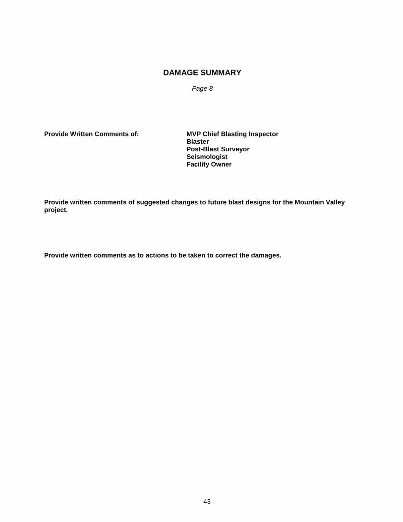
43
DAMAGE SUMMARY
Page 8 Provide Written Comments of: MVP Chief Blasting Inspector
Blaster Post-Blast Surveyor Seismologist Facility Owner
Provide written comments of suggested changes to future blast designs for the Mountain Valley project. Provide written comments as to actions to be taken to correct the damages.