Manual of Airworthiness Maintenance – Processes (MAM-P)
449
Manual of Airworthiness Maintenance – Processes (MAM-P) MAM-P Issue 2.1 (Aug 21)
-
Upload
khangminh22 -
Category
Documents
-
view
2 -
download
0
Transcript of Manual of Airworthiness Maintenance – Processes (MAM-P)
Manual of Airworthiness Maintenance – Processes (MAM-P)
MAM-P Issue 2.1 (Aug 21)
MAM-P UNCONTROLLED COPY WHEN PRINTED
Front Page Page 2 of 2
UNCONTROLLED COPY WHEN PRINTED Issue 1.2 May 20
Intentionally Blank for Print Pagination
UNCONTROLLED COPY WHEN PRINTED MAM-P
Issue 1.2 May 20
UNCONTROLLED COPY WHEN PRINTED Chapter 0.0.1 Page 1 of 4
....................................................................................................................................................................
..................................................................................................................................................................
.........................................................................................................................................................................
.....................................................................................
....................................................................................................................................................................................
.................................................................................................................................................................
............................................................................................................................................................................
Chapter 0.0.1
Foreword
TABLE OF CONTENTS
Paragraph Page
1 Governance 11.1 Military Aviation Authority. 11.2 Regulatory Structure 11.3 MAM-P and Governance 22 Applicability 22.1 MAM-P Applicability 22.2 Tri-Service Process 23 Deviation Requests 34 Change Requests 34.1 Expedited Change Request 35 Responsibilities 36 Commercial Implications 47 MAM-P Release 4
1 Governance
1.1 Military Aviation Authority
In support of his legal requirements, the Secretary of State (SofS) for Defence has established, by Charter, the UK’s Defence Safety Authority (DSA) to be responsible for all Defence Safety Regulators. As part of the DSA, the Military Aviation Authority (MAA) regulates all Defence aviation activities. Including Defence Air Environment (DAE) Safety Health, Environment Fire policy as detailed in DSA01.1 Defence Policy for Health, Safety and Environment Protection. This is achieved through the establishment and maintenance of an appropriate Regulatory framework, extending across the acquisition, operating and Continuing Airworthiness domains within the UK DAE.
1.2 Regulatory Structure
Director MAA is the owner of the MAA Regulatory Publications (MRP) and has the authority to issue them on behalf of the SofS. There are 3 levels of documentation within the MRP, as outlined below:
1 Overarching documents:
1.1 MAA01: MAA Regulatory Policy.
1.2 MAA02: MAA Master Glossary.
1.3 MAA03: MAA Regulatory Processes.
2 Regulatory Articles (RA):
2.1 1000 Series: General Regulations (GEN).
MAM-P UNCONTROLLED COPY WHEN PRINTED
Chapter 0.0.1 Page 2 of 4
UNCONTROLLED COPY WHEN PRINTED Issue 1.2 May 20
2.2 2000 Series: Flying Regulations (FLY).
2.3 3000 Series: Air Traffic Management Regulations (ATM).
2.4 4000 Series: Continuing Airworthiness Engineering Regulations (CAE).
2.5 5000 Series: Type Airworthiness Engineering Regulations (TAE).
3 MAA Manuals:
3.1 Manual of Air Safety. (MAS)
3.2 Manual of Air System Safety Cases (MASSC).
3.3 Manual of Post-Crash Management.
3.4 Manual of Military Air Traffic Management.
3.5 Display Flying Handbook.
3.6 Defence Aerodrome Manual (DAM).
3.7 Manual of Airworthiness Maintenance-Documentation (MAM-D).
3.8 Manual of Air System Integrity Management (MASIM).
The contents of each series are published on the MAA website: https://www.gov.uk/government/organisations/military-aviation-authority
1.3 MAM-P and Governance
The Manual of Airworthiness Maintenance-Processes (MAM-P) is not part of the MRP and sits as ‘first among equals’ alongside single-Service Mid-Level Orders (MLO). This MAM-P is the prime source of reference for ‘shop floor’ maintainers that supports compliance with the MRP. The Continuing Airworthiness Advisory Group (CAAG) is the steering group for the MAM-P and is supported by a Management Group (MG), whose stakeholders include both Command and MAA representation. It is expected that most issues associated with this MAM-P will be managed by this MG. The Commands are co-sponsors of MAM-P content with the MAA remaining as the Publication Authority. The MAA will ensure the content of the MAM-P is aligned with MRP.
2 Applicability
2.1 MAM-P Applicability
The MAM-P content is to be interpreted as Orders within the meaning of the Armed Forces Act and is applicable to all Service personnel in the DAE. It supports the RA 4000 – 4849 Continuing Airworthiness Engineering series of Regulations, providing process and procedural guidance for ‘shop floor’ maintainers and managers, to ensure compliance with this series of Regulations. The MAM-P will have primacy over MLO, except for any deviation therein, as authorized by the appropriate Command (see Paragraph 3). Tri-Service processes will be maintained to avoid divergence, but if any content is deemed too low a level and single-Service specific, it will be removed to the relevant single-Service MLO.
2.2 Tri-Service Process
The MAM-P content is based upon Command acceptance of such content (with compromise where applicable) that will include items not relevant to all three Services. Provided there are no objections to its inclusion in the MAM-P a Tri-Service process may be interpreted as being utilized by at least two Commands, and no single-Service objecting to its inclusion in the MAM-P.
UNCONTROLLED COPY WHEN PRINTED MAM-P
Issue 1.2 May 20
UNCONTROLLED COPY WHEN PRINTED Chapter 0.0.1 Page 3 of 4
Note:
General enquiries regarding MAM-P content are to be directed to the relevant single Service Command engineering policy desks – see para 4.
3 Deviation Requests
If an individual unit has a requirement to deviate from MAM-P Tri-Service processes, approval should be requested from the relevant Command engineering policy desk, not the MAA. Deviations from the MAM-P will ultimately be approved by the responsible Command.
4 Change Requests
Requests for amendment to this publication are to be submitted using a MOD Form 765 Unsatisfactory Feature Report, see MAM-P Chapter 10.1 Management and Amendment of Technical Information. Once the originator has completed part 1 of the form, it is to be emailed to, [email protected] and copied to the single-Service Command engineering policy desk. Once received, the request will be scrutinized by the originator’s Command MAM-P Management Group (MG) representative. If acceptable, the Command representative will endorse part 2 and discuss at the next MAM-P MG for consideration in the next up-issue. Once the MAM-P MG has sentenced the proposal, the originator will receive feedback from their Command representative. When an amendment has been accepted, it will be processed for amendment and published at the next suitable opportunity.
Note:
Single-Service Command engineering policy desks:
Royal Navy: NAVY CSAV-EPP WO
Army: Army Cap-AM-ESAvn-Policy-WO
Royal Air Force: Air 38Gp-A4 Aw Pol (MULTIUSER)
Joint Helicopter Command: JHC-CapMan-EngAssrnc-0Mailbox
For amendments that effect a change to Airworthiness risk or are deemed a significant alteration to extant content; the MAM-P MG are to seek approval from the CAAG.
4.1 Expedited Change Request
When an issue has been identified that may have an adverse effect on Air Safety, an expedient amendment process will be instigated by the Commands and/or MAA.
5 Responsibilities
The processes contained within the MAM-P do not absolve any person from using their best judgement to ensure the safety of Air Systems and personnel. Where authorized Individuals issue their own amplifying orders or instructions, they are not to be more permissive than or countermand the Regulations, MAM-P content and/or MLO.
MAM-P UNCONTROLLED COPY WHEN PRINTED
Chapter 0.0.1 Page 4 of 4
UNCONTROLLED COPY WHEN PRINTED Issue 1.2 May 20
6 Commercial Implications
The MRP will be applied through contract to those commercial organizations designing, producing, maintaining, handling, controlling or operating Air Systems on the UK Military Air System Register (MAR) and associated equipment. Compliance with the MAM-P will not in itself relieve any person from any legal obligations imposed upon them. The MAM-P has been devised solely for the use of the UK Ministry of Defence (MOD), its contractors in the execution of contracts for the MOD and those organizations that have requested to operate their Air Systems on the UK MAR. To the extent permitted by law, the MOD hereby excludes all liability whatsoever and howsoever arising (including, but without limitation, liability resulting from negligence) for any loss or damage however caused when MAM-P is used for any other purpose.
7 MAM-P Release
The co-sponsors agreed to the content of the MAM-P at initial issue at the 16th CAAG dated 26th Nov 19. The MAM-P MG are empowered to embody all subsequent changes approved through the change request process or the CAAG SG.

MAM-P UNCONTROLLED COPY WHEN PRINTED
Chapter 0.1 Page 4 of 4
UNCONTROLLED COPY WHEN PRINTED Issue 1.2 May 20
Intentionally Blank for Print Pagination
UNCONTROLLED COPY WHEN PRINTED MAM-P
Issue 2.1 Aug 21
UNCONTROLLED COPY WHEN PRINTED Chapter 0.1 Page 1 of 4
Chapter 0.1
Table of Contents
Chapter Title Issue
Preliminaries
0.0.1 Foreword Issue 1.2
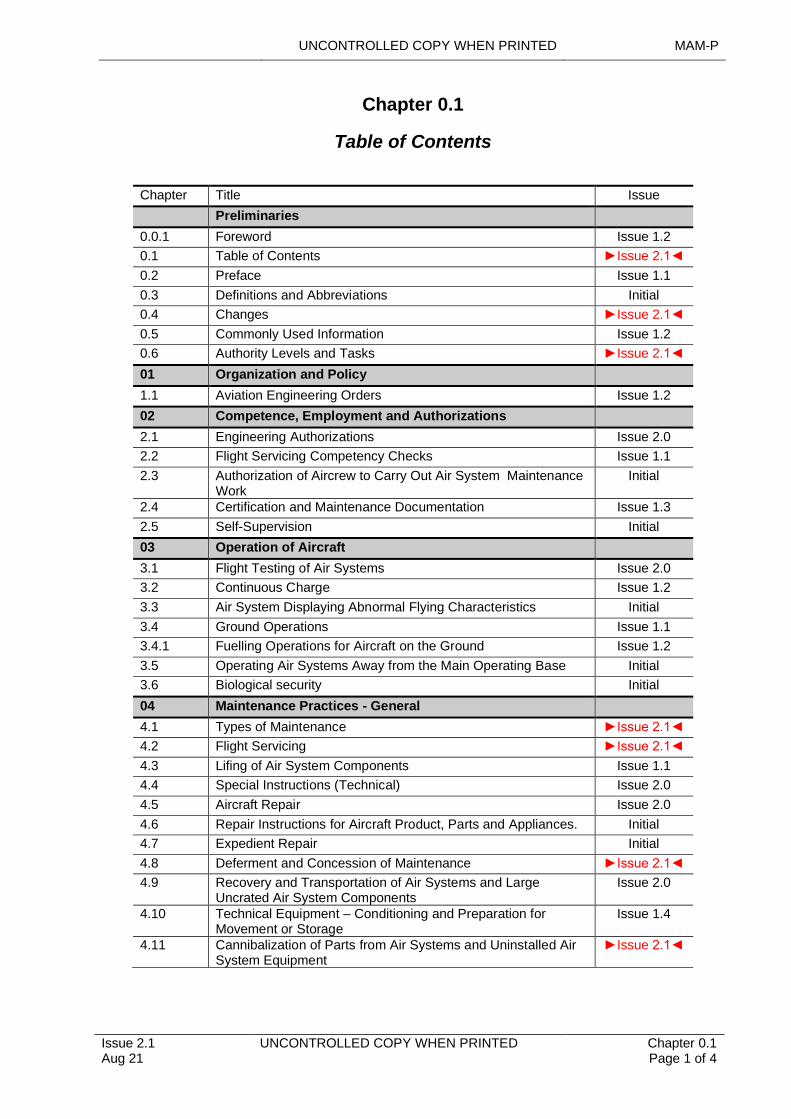
0.1 Table of Contents ►Issue 2.1◄
0.2 Preface Issue 1.1
0.3 Definitions and Abbreviations Initial
0.4 Changes ►Issue 2.1◄
0.5 Commonly Used Information Issue 1.2
0.6 Authority Levels and Tasks ►Issue 2.1◄
01 Organization and Policy
1.1 Aviation Engineering Orders Issue 1.2
02 Competence, Employment and Authorizations
2.1 Engineering Authorizations Issue 2.0
2.2 Flight Servicing Competency Checks Issue 1.1
2.3 Authorization of Aircrew to Carry Out Air System Maintenance Work
Initial
2.4 Certification and Maintenance Documentation Issue 1.3
2.5 Self-Supervision Initial
03 Operation of Aircraft
3.1 Flight Testing of Air Systems Issue 2.0
3.2 Continuous Charge Issue 1.2
3.3 Air System Displaying Abnormal Flying Characteristics Initial
3.4 Ground Operations Issue 1.1
3.4.1 Fuelling Operations for Aircraft on the Ground Issue 1.2
3.5 Operating Air Systems Away from the Main Operating Base Initial
3.6 Biological security Initial
04 Maintenance Practices - General
4.1 Types of Maintenance ►Issue 2.1◄
4.2 Flight Servicing ►Issue 2.1◄
4.3 Lifing of Air System Components Issue 1.1
4.4 Special Instructions (Technical) Issue 2.0
4.5 Aircraft Repair Issue 2.0
4.6 Repair Instructions for Aircraft Product, Parts and Appliances. Initial
4.7 Expedient Repair Initial
4.8 Deferment and Concession of Maintenance ►Issue 2.1◄
4.9 Recovery and Transportation of Air Systems and Large Uncrated Air System Components
Issue 2.0
4.10 Technical Equipment – Conditioning and Preparation for Movement or Storage
Issue 1.4
4.11 Cannibalization of Parts from Air Systems and Uninstalled Air System Equipment
►Issue 2.1◄
MAM-P UNCONTROLLED COPY WHEN PRINTED
Chapter 0.1 Page 2 of 4
UNCONTROLLED COPY WHEN PRINTED Issue 2.1 Aug 21
Chapter Title Issue
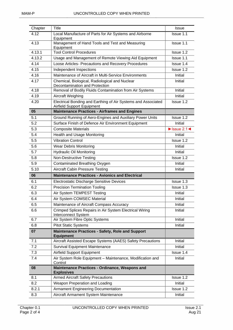
4.12 Local Manufacture of Parts for Air Systems and Airborne Equipment
Issue 1.1
4.13 Management of Hand Tools and Test and Measuring Equipment
Issue 1.1
4.13.1 Tool Control Procedures Issue 1.2
4.13.2 Usage and Management of Remote Viewing Aid Equipment Issue 1.1
4.14 Loose Articles- Precautions and Recovery Procedures Issue 1.4
4.15 Independent Inspections Issue 1.2
4.16 Maintenance of Aircraft in Multi-Service Environments Initial
4.17 Chemical, Biological, Radiological and Nuclear Decontamination and Protection
Initial
4.18 Removal of Bodily Fluids Contamination from Air Systems Initial
4.19 Aircraft Weighing Initial
4.20 Electrical Bonding and Earthing of Air Systems and Associated Airfield Support Equipment
Issue 1.2
05 Maintenance Practices - Airframes and Engines
5.1 Ground Running of Aero-Engines and Auxiliary Power Units Issue 1.2
5.2 Surface Finish of Defence Air Environment Equipment Initial
5.3 Composite Materials ►Issue 2.1◄
5.4 Health and Usage Monitoring Initial
5.5 Vibration Control Issue 1.2
5.6 Wear Debris Monitoring Initial
5.7 Hydraulic Oil Monitoring Initial
5.8 Non-Destructive Testing Issue 1.2
5.9 Contaminated Breathing Oxygen Initial
5.10 Aircraft Cabin Pressure Testing Initial
06 Maintenance Practices - Avionics and Electrical
6.1 Electrostatic Discharge Sensitive Devices Issue 1.3
6.2 Precision Termination Tooling Issue 1.3
6.3 Air System TEMPEST Testing Initial
6.4 Air System COMSEC Material Initial
6.5 Maintenance of Aircraft Compass Accuracy Initial
6.6 Crimped Splices Repairs in Air System Electrical Wiring Interconnect System
Initial
6.7 Air System Fibre Optic Systems Initial
6.8 Pitot Static Systems Initial
07 Maintenance Practices - Safety, Role and Support Equipment
7.1 Aircraft Assisted Escape Systems (AAES) Safety Precautions Initial
7.2 Survival Equipment Maintenance Initial
7.3 Airfield Support Equipment Issue 1.4
7.4 Air System Role Equipment – Maintenance, Modification and Control
Initial
08 Maintenance Practices - Ordinance, Weapons and Explosives
8.1 Armed Aircraft Safety Precautions Issue 1.2
8.2 Weapon Preperation and Loading Initial
8.2.1 Armament Engineering Documentation Issue 1.2
8.3 Aircraft Armament System Maintenance Initial
UNCONTROLLED COPY WHEN PRINTED MAM-P
Issue 2.1 Aug 21
UNCONTROLLED COPY WHEN PRINTED Chapter 0.1 Page 3 of 4
Chapter Title Issue
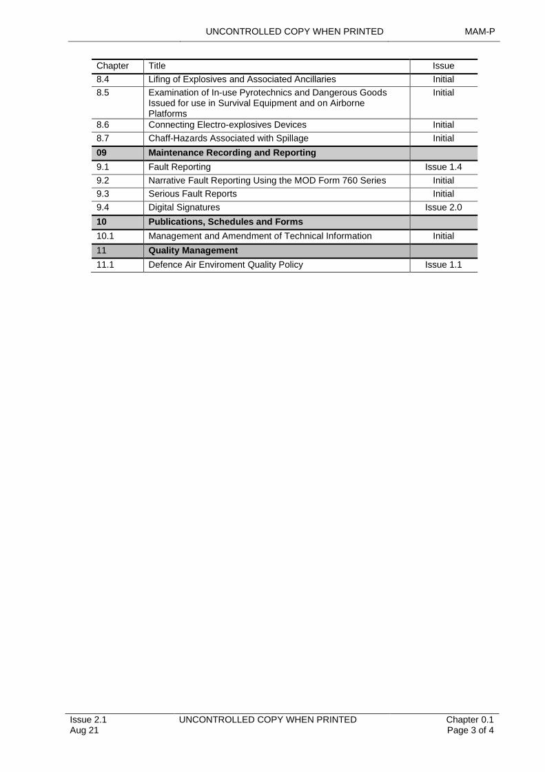
8.4 Lifing of Explosives and Associated Ancillaries Initial
8.5 Examination of In-use Pyrotechnics and Dangerous Goods Issued for use in Survival Equipment and on Airborne Platforms
Initial
8.6 Connecting Electro-explosives Devices Initial
8.7 Chaff-Hazards Associated with Spillage Initial
09 Maintenance Recording and Reporting
9.1 Fault Reporting Issue 1.4
9.2 Narrative Fault Reporting Using the MOD Form 760 Series Initial
9.3 Serious Fault Reports Initial
9.4 Digital Signatures Issue 2.0
10 Publications, Schedules and Forms
10.1 Management and Amendment of Technical Information Initial
11 Quality Management
11.1 Defence Air Enviroment Quality Policy Issue 1.1
MAM-P UNCONTROLLED COPY WHEN PRINTED
Chapter 0.1 Page 4 of 4
UNCONTROLLED COPY WHEN PRINTED Issue 2.1 Aug 21
Intentionally Blank for Print Pagination
UNCONTROLLED COPY WHEN PRINTED MAM-P
Initial Issue Nov 19
UNCONTROLLED COPY WHEN PRINTED Chapter 0.2 Page 1 of 4
.......................................................................................................
..........................................................................
.................................................................................................................................................................................................................................................................................................
......................................................................................................................................................
............................................................................
...................................................................................................................................................................................
...............................................................................................
...............................................................................................
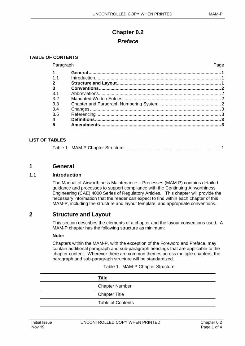
Chapter 0.2
Preface
TABLE OF CONTENTS
Paragraph Page
1 General 11.1 Introduction 12 Structure and Layout 13 Conventions 23.1 Abbreviations 23.2 Mandated Written Entries 23.3 Chapter and Paragraph Numbering System 23.4 Changes 33.5 Referencing 34 Definitions 35 Amendments 3
LIST OF TABLES
Table 1. MAM-P Chapter Structure. 1
1 General
1.1 Introduction
The Manual of Airworthiness Maintenance – Processes (MAM-P) contains detailed guidance and processes to support compliance with the Continuing Airworthiness Engineering (CAE) 4000 Series of Regulatory Articles. This chapter will provide the necessary information that the reader can expect to find within each chapter of this MAM-P, including the structure and layout template, and appropriate conventions.
2 Structure and Layout
This section describes the elements of a chapter and the layout conventions used. A MAM-P chapter has the following structure as minimum:
Note:
Chapters within the MAM-P, with the exception of the Foreword and Preface, may contain additional paragraph and sub-paragraph headings that are applicable to the chapter content. Wherever there are common themes across multiple chapters, the paragraph and sub-paragraph structure will be standardized.
Table 1. MAM-P Chapter Structure.
Title
Chapter Number
Chapter Title
Table of Contents
MAM-P UNCONTROLLED COPY WHEN PRINTED
Chapter 0.2 Page 2 of 4
UNCONTROLLED COPY WHEN PRINTED Initial Issue Nov 19
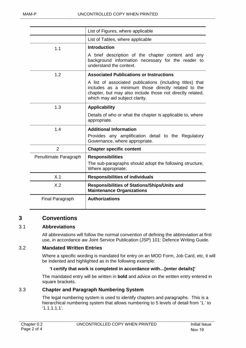
List of Figures, where applicable
List of Tables, where applicable
1.1 Introduction
A brief description of the chapter content and any background information necessary for the reader to understand the context.
1.2 Associated Publications or Instructions
A list of associated publications (including titles) that includes as a minimum those directly related to the chapter, but may also include those not directly related, which may aid subject clarity.
1.3 Applicability
Details of who or what the chapter is applicable to, where appropriate.
1.4 Additional Information
Provides any amplification detail to the Regulatory Governance, where appropriate.
2 Chapter specific content
Penultimate Paragraph Responsibilities
The sub-paragraphs should adopt the following structure, Where appropriate:
X.1 Responsibilities of individuals
X.2 Responsibilities of Stations/Ships/Units and Maintenance Organizations
Final Paragraph Authorizations
3 Conventions
3.1 Abbreviations
All abbreviations will follow the normal convention of defining the abbreviation at first use, in accordance aw Joint Service Publication (JSP) 101: Defence Writing Guide.
3.2 Mandated Written Entries
Where a specific wording is mandated for entry on an MOD Form, Job Card, etc, it will be indented and highlighted as in the following example:
‘I certify that work is completed in accordance with…[enter details]’
The mandated entry will be written in bold and advice on the written entry entered in square brackets.
3.3 Chapter and Paragraph Numbering System
The legal numbering system is used to identify chapters and paragraphs. This is a hierarchical numbering system that allows numbering to 5 levels of detail from ‘1.’ to ‘1.1.1.1.1’.
UNCONTROLLED COPY WHEN PRINTED MAM-P
Initial Issue Nov 19
UNCONTROLLED COPY WHEN PRINTED Chapter 0.2 Page 3 of 4
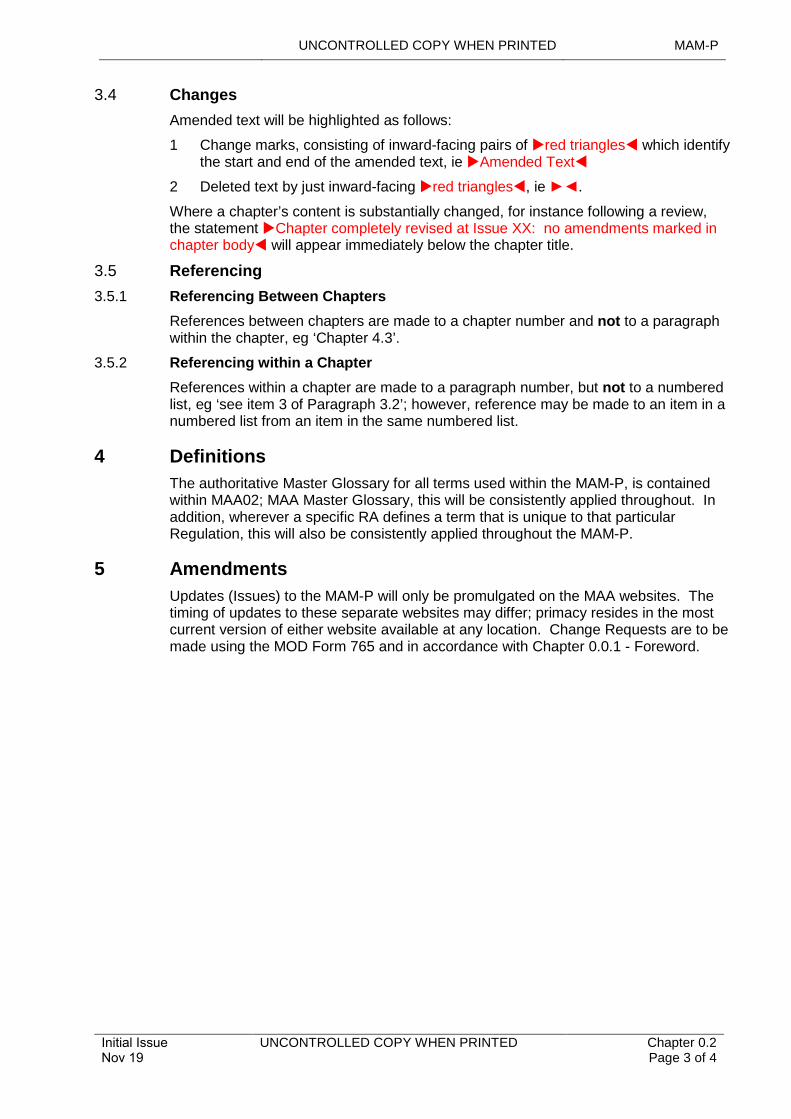
3.4 Changes
Amended text will be highlighted as follows:
1 Change marks, consisting of inward-facing pairs of red triangles which identify the start and end of the amended text, ie Amended Text
2 Deleted text by just inward-facing red triangles, ie ►◄.
Where a chapter’s content is substantially changed, for instance following a review, the statement Chapter completely revised at Issue XX: no amendments marked in chapter body will appear immediately below the chapter title.
3.5 Referencing
3.5.1 Referencing Between Chapters
References between chapters are made to a chapter number and not to a paragraph within the chapter, eg ‘Chapter 4.3’.
3.5.2 Referencing within a Chapter
References within a chapter are made to a paragraph number, but not to a numbered list, eg ‘see item 3 of Paragraph 3.2’; however, reference may be made to an item in a numbered list from an item in the same numbered list.
4 Definitions
The authoritative Master Glossary for all terms used within the MAM-P, is contained within MAA02; MAA Master Glossary, this will be consistently applied throughout. In addition, wherever a specific RA defines a term that is unique to that particular Regulation, this will also be consistently applied throughout the MAM-P.
5 Amendments
Updates (Issues) to the MAM-P will only be promulgated on the MAA websites. The timing of updates to these separate websites may differ; primacy resides in the most current version of either website available at any location. Change Requests are to be made using the MOD Form 765 and in accordance with Chapter 0.0.1 - Foreword.

MAM-P UNCONTROLLED COPY WHEN PRINTED
Chapter 0.2 Page 4 of 4
UNCONTROLLED COPY WHEN PRINTED Initial Issue Nov 19
Intentionally Blank for Print Pagination
UNCONTROLLED COPY WHEN PRINTED MAM-P
Initial Issue Nov 19
UNCONTROLLED COPY WHEN PRINTED Chapter 0.3 Page 1 of 2
.........................................................................................................................................................................................................
Chapter 0.3
Definitions and Abbreviations
TABLE OF CONTENTS
Paragraph Page
1 General 11.1 Introduction 1
1 General
1.1 Introduction
The content of this chapter has been transferred to MAA02 - Military Aviation Authority Master Glossary. This Ghost Chapter is left in as a signpost for the reader.

MAM-P UNCONTROLLED COPY WHEN PRINTED
Chapter 0.3 Page 2 of 2
UNCONTROLLED COPY WHEN PRINTED Initial Issue Nov 19
Intentionally Blank for Print Pagination
UNCONTROLLED COPY WHEN PRINTED MAM-P
................................
...............................................................................................
......................................................................
Issue 2.1 Aug 21
...........................................................................................................
UNCONTROLLED COPY WHEN PRINTED Chapter 0.4 Page 1 of 4
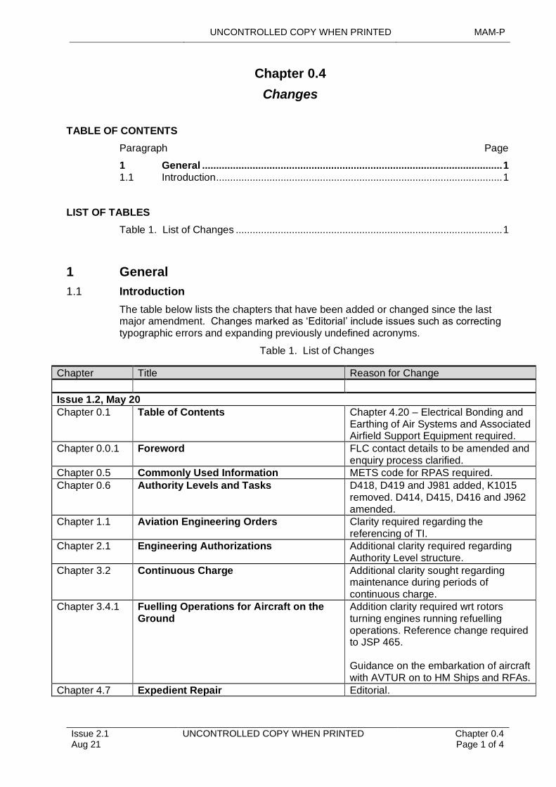
Chapter 0.4
Changes
TABLE OF CONTENTS
Paragraph Page
1 General 1 1.1 Introduction 1
LIST OF TABLES
Table 1. List of Changes 1
1 General
1.1 Introduction
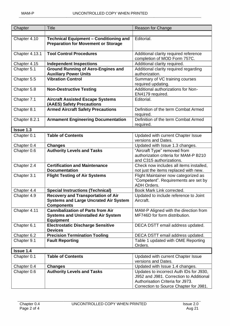
The table below lists the chapters that have been added or changed since the last major amendment. Changes marked as ‘Editorial’ include issues such as correcting typographic errors and expanding previously undefined acronyms.
Table 1. List of Changes
Chapter Title Reason for Change
Issue 1.2, May 20
Chapter 0.1 Table of Contents Chapter 4.20 – Electrical Bonding and Earthing of Air Systems and Associated Airfield Support Equipment required.
Chapter 0.0.1 Foreword FLC contact details to be amended and enquiry process clarified.
Chapter 0.5 Commonly Used Information METS code for RPAS required.
Chapter 0.6 Authority Levels and Tasks D418, D419 and J981 added, K1015 removed. D414, D415, D416 and J962 amended.
Chapter 1.1 Aviation Engineering Orders Clarity required regarding the referencing of TI.
Chapter 2.1 Engineering Authorizations Additional clarity required regarding Authority Level structure.
Chapter 3.2 Continuous Charge Additional clarity sought regarding maintenance during periods of continuous charge.
Chapter 3.4.1 Fuelling Operations for Aircraft on the Ground
Addition clarity required wrt rotors turning engines running refuelling operations. Reference change required to JSP 465.
Guidance on the embarkation of aircraft with AVTUR on to HM Ships and RFAs.
Chapter 4.7 Expedient Repair Editorial.
MAM-P UNCONTROLLED COPY WHEN PRINTED
Chapter 0.4 Page 2 of 4
UNCONTROLLED COPY WHEN PRINTED Issue 2.0 Aug 21
Chapter Title Reason for Change
Chapter 4.10 Technical Equipment – Conditioning and Preparation for Movement or Storage
Editorial.
Chapter 4.13.1 Tool Control Procedures Additional clarity required reference completion of MOD Form 757C.
Chapter 4.15 Independent Inspections Additional clarity required.
Chapter 5.1 Ground Running of Aero-Engines and Auxiliary Power Units
Additional clarity required regarding authorization.
Chapter 5.5 Vibration Control Summary of VC training courses required updating.
Chapter 5.8 Non-Destructive Testing Additional authorizations for Non-EN4179 required.
Chapter 7.1 Aircraft Assisted Escape Systems (AAES) Safety Precautions
Editorial.
Chapter 8.1 Armed Aircraft Safety Precautions Definition of the term Combat Armed required.
Chapter 8.2.1 Armament Engineering Documentation Definition of the term Combat Armed required.
Issue 1.3
Chapter 0.1 Table of Contents Updated with current Chapter Issue versions and Dates.
Chapter 0.4 Changes Updated with Issue 1.3 changes.
Chapter 0.6 Authority Levels and Tasks “Aircraft Type” removed from authorization criteria for MAM-P B210 and C315 authorizations.
Chapter 2.4 Certification and Maintenance Documentation
Check now includes all items installed, not just the items replaced with new.
Chapter 3.1 Flight Testing of Air Systems Flight Maintainer now categorized as “Competent”. Requirements are set by ADH Orders.
Chapter 4.4 Special Instructions (Technical) Book Mark Link corrected.
Chapter 4.9 Recovery and Transportation of Air Systems and Large Uncrated Air System Components
Updated to include reference to Joint Aircraft.
Chapter 4.11 Cannibalization of Parts from Air Systems and Uninstalled Air System Equipment
MAM-P Aligned with the direction from MF746D for form distribution.
Chapter 6.1 Electrostatic Discharge Sensitive Devices
DECA DSTT email address updated.
Chapter 6.2 Precision Termination Tooling DECA DSTT email address updated.
Chapter 9.1 Fault Reporting Table 1 updated with OME Reporting Orders.
Issue 1.4
Chapter 0.1 Table of Contents Updated with current Chapter Issue versions and Dates.
Chapter 0.4 Changes Updated with Issue 1.4 changes.
Chapter 0.6 Authority Levels and Tasks Updates to incorrect Auth IDs for J930, J952 and J981. Correction to Additional Authorisation Criteria for J973. Correction to Source Chapter for J981.
UNCONTROLLED COPY WHEN PRINTED MAM-P
Issue 2.1 Aug 21
UNCONTROLLED COPY WHEN PRINTED Chapter 0.4 Page 3 of 4
Chapter Title Reason for Change
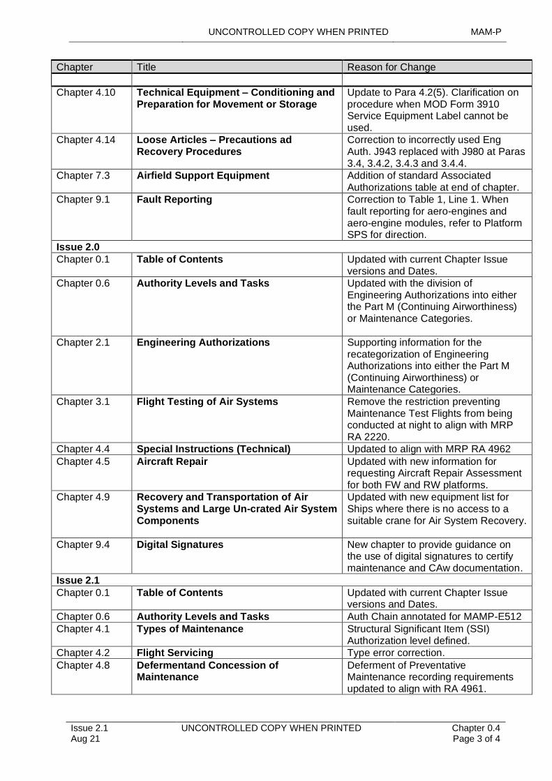
Chapter 4.10 Technical Equipment – Conditioning and Preparation for Movement or Storage
Update to Para 4.2(5). Clarification on procedure when MOD Form 3910 Service Equipment Label cannot be used.
Chapter 4.14 Loose Articles – Precautions ad Recovery Procedures
Correction to incorrectly used Eng Auth. J943 replaced with J980 at Paras 3.4, 3.4.2, 3.4.3 and 3.4.4.
Chapter 7.3 Airfield Support Equipment Addition of standard Associated Authorizations table at end of chapter.
Chapter 9.1 Fault Reporting Correction to Table 1, Line 1. When fault reporting for aero-engines and aero-engine modules, refer to Platform SPS for direction.
Issue 2.0
Chapter 0.1 Table of Contents Updated with current Chapter Issue versions and Dates.
Chapter 0.6 Authority Levels and Tasks Updated with the division of Engineering Authorizations into either the Part M (Continuing Airworthiness) or Maintenance Categories.
Chapter 2.1 Engineering Authorizations Supporting information for the recategorization of Engineering Authorizations into either the Part M (Continuing Airworthiness) or Maintenance Categories.
Chapter 3.1 Flight Testing of Air Systems Remove the restriction preventing Maintenance Test Flights from being conducted at night to align with MRP RA 2220.
Chapter 4.4 Special Instructions (Technical) Updated to align with MRP RA 4962
Chapter 4.5 Aircraft Repair Updated with new information for requesting Aircraft Repair Assessment for both FW and RW platforms.
Chapter 4.9 Recovery and Transportation of Air Systems and Large Un-crated Air System Components
Updated with new equipment list for Ships where there is no access to a suitable crane for Air System Recovery.
Chapter 9.4 Digital Signatures New chapter to provide guidance on the use of digital signatures to certify maintenance and CAw documentation.
Issue 2.1
Chapter 0.1 Table of Contents Updated with current Chapter Issue versions and Dates.
Chapter 0.6 Authority Levels and Tasks Auth Chain annotated for MAMP-E512
Chapter 4.1 Types of Maintenance Structural Significant Item (SSI) Authorization level defined.
Chapter 4.2 Flight Servicing Type error correction.
Chapter 4.8 Defermentand Concession of Maintenance
Deferment of Preventative Maintenance recording requirements updated to align with RA 4961.
MAM-P UNCONTROLLED COPY WHEN PRINTED
Chapter 0.4 Page 4 of 4
UNCONTROLLED COPY WHEN PRINTED Issue 2.0 Aug 21
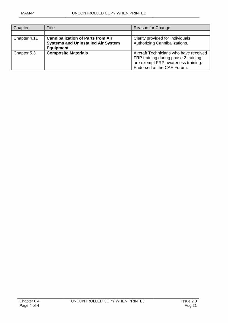
Chapter Title Reason for Change
Chapter 4.11 Cannibalization of Parts from Air Systems and Uninstalled Air System Equipment
Clarity provided for Individuals Authorizing Cannibalizations.
Chapter 5.3 Composite Materials Aircraft Technicians who have received FRP training during phase 2 training are exempt FRP awareness training. Endorsed at the CAE Forum.
UNCONTROLLED COPY WHEN PRINTED MAM-P
Issue 1.2 May 20
UNCONTROLLED COPY WHEN PRINTED Chapter 0.5 Page 1 of 4
.............................................................................................................
............................................................. ...............................................................................
............................................................................................................
.........................................................................................
..................................................................................
Chapter 0.5
Commonly Used Information
TABLE OF CONTENTS
Paragraph Page
1 General 12 Aviation Station/Ship/Unit Location Codes 13 Army Aviation Unit Identification Codes 24 Military Equipment Tools Solutions (METS) Generated Platform
Identification Codes 3
LIST OF TABLES
Table 1. Station/Ship/Unit Location Codes. 1Table 2. Army Aviation Unit Location Codes. 2Table 3. METS Generated Platform Identification Codes 3
1 General
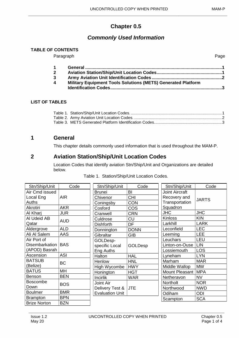
This chapter details commonly used information that is used throughout the MAM-P.
2 Aviation Station/Ship/Unit Location Codes
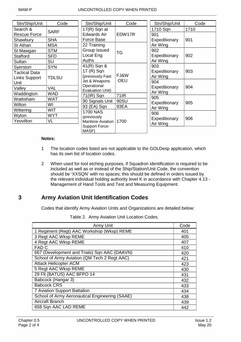
Location Codes that identify aviation Stn/Ship/Unit and Organizations are detailed below.
Table 1. Station/Ship/Unit Location Codes.
Stn/Ship/Unit Code
Air Cmd issued Local Eng Auths
AIR
Akrotiri AKRAl Kharj JURAl Udeid AB Qatar
AUD
Aldergrove ALDAli Al Salem AASAir Port of Disembarkation (APOD) Basrah
BAS
Ascension ASIBATSUB (Belize)
BC
BATUS MHBenson BENBoscombe Down
BOS
Boulmer BMRBrampton BPNBrize Norton BZN
Stn/Ship/Unit Code
Brunei BIChivenor CHIConingsby CONCosford COSCranwell CRNCuldrose CUDishforth DFDonnington DONNGibraltar GIBGOLDesp-specific Local Eng Auths
GOLDesp
Halton HALHenlow HNLHigh Wycombe HWYHonington HGTIncirlik WARJoint Air Delivery Test & Evaluation Unit
JTE
Stn/Ship/Unit Code
Joint Aircraft Recovery and Transportation Squadron
JARTS
JHC JHCKinloss KINLarkhill LARKLeconfield LECLeeming LEELeuchars LEULinton-on-Ouse LINLossiemouth LOSLyneham LYNMarham MARMiddle Wallop MWMount Pleasant MPANetheravon NVNortholt NORNorthwood NWDOdiham ODIScampton SCA
MAM-P UNCONTROLLED COPY WHEN PRINTED
Chapter 0.5 Page 2 of 4
UNCONTROLLED COPY WHEN PRINTED Issue 1.2 May 20
Stn/Ship/Unit Code
Search & Rescue Force
SARF
Shawbury SHASt Athan MSASt Mawgan STMStafford SFDSultan SUSyerston SYNTactical Data Links Support Unit
TDLSU
Valley VALWaddington WADWattisham WATWilton WIWittering WITWyton WYTYeovilton VL
Stn/Ship/Unit Code
17(R) Sqn at Edwards Air Force Base
EDW17R
22 Training Group issued Local Eng Auths
TG
41(R) Sqn & 17 (R) Sqn (previously Fast Jet & Weapons Operational Evaluation Unit)
FJ&W OEU
71(IR) Sqn 71IR90 Signals Unit 90SU93 (EA) Sqn 93EA1700 NAS (previously Maritime Aviation Support Force-MASF)
1700
Stn/Ship/Unit Code
1710 Sqn 1710901 Expeditionary Air Wing
901
902 Expeditionary Air Wing
902
903 Expeditionary Air Wing
903
904 Expeditionary Air Wing
904
905 Expeditionary Air Wing
905
Notes:
906 Expeditionary Air Wing
906
1 The location codes listed are not applicable to the GOLDesp application, which has its own list of location codes.
2 When used for tool etching purposes, if Squadron identification is required to be included as well as or instead of the Ship/Station/Unit Code, the convention should be ‘XXSQN’ with no spaces; this should be defined in orders issued by the relevant individual holding authority level K in accordance with Chapter 4.13 - Management of Hand Tools and Test and Measuring Equipment.
3 Army Aviation Unit Identification Codes
Codes that identify Army Aviation Units and Organizations are detailed below:
Table 2. Army Aviation Unit Location Codes.
Army Unit Code
1 Regiment (Regt) AAC Workshop (Wksp) REME 4013 Regt AAC Wksp REME 405
FAD C 4104 Regt AAC Wksp REME 407
667 (Development and Trials) Sqn AAC (DAAVN) 420School of Army Aviation (QM Tech 2 Regt AAC) 421Attack Helicopter ACM 4235 Regt AAC Wksp REME 43029 Flt (BATUS) AAC BFPO 14 431Babcock (Hangar 3) 432Babcock CRS 4337 Aviation Support Battalion 434School of Army Aeronautical Engineering (SAAE) 438Aircraft Branch 439658 Sqn AAC LAD REME 442
UNCONTROLLED COPY WHEN PRINTED MAM-P
Issue 1.2 May 20
UNCONTROLLED COPY WHEN PRINTED Chapter 0.5 Page 3 of 4
Army Unit Code47 RA Wksp REME 44332 RA LAD REME 447Apache Depth HUB 448Wattisham Forward Support 452
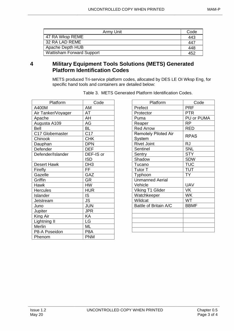
4 Military Equipment Tools Solutions (METS) Generated Platform Identification Codes
METS produced Tri-service platform codes, allocated by DES LE OI Wksp Eng, for specific hand tools and containers are detailed below:
Table 3. METS Generated Platform Identification Codes.
Platform CodeA400M AMAir Tanker/Voyager ATApache AHAugusta A109 AGBell BLC17 Globemaster C17Chinook CHKDauphan DPNDefender DEFDefender/Islander DEF-IS or
ISDDesert Hawk DH3Firefly FFGazelle GAZGriffin GRHawk HWHercules HURIslander IS
Jetstream
JSJuno JUNJupiter JPRKing Air KALightning II LGMerlin MLP8-A Poseidon P8APhenom PNM
Platform CodePrefect PRFProtector PTRPuma PU or PUMAReaper RPRed Arrow REDRemotely Piloted Air System
RPAS
Rivet Joint RJSentinel SNLSentry STYShadow SDWTucano TUCTutor T TUTTyphoon TYUnmanned Aerial Vehicle UAVViking T1 Glider VKWatchkeeper WKWildcat WTBattle of Britain A/C BBMF

MAM-P UNCONTROLLED COPY WHEN PRINTED
Chapter 0.5 Page 4 of 4
UNCONTROLLED COPY WHEN PRINTED Issue 1.2 May 20
Intentionally Blank for Print Pagination
UNCONTROLLED COPY WHEN PRINTED MAM-P
............................................. .........................................
Issue 2.1 Aug 21
.......................................................................
........................................................................................................
UNCONTROLLED COPY WHEN PRINTED Chapter 0.6 Page 1 of 30
.....................................................................................................................................................................................................................................................................................................................................................................................................................................................................................................................................
Chapter 0.6
Authority Levels and Tasks
.............................................................................................
TABLE OF CONTENTS
............................................................
Paragraph
.........................................................................................................................................................................................................................
................................................................
Page
.......................
1 General
......................................................................................................................................
........................................................................... 1 ................................1.1 Introduction 1 2 Record of Engineering Authorizations 1 3 Engineering Authorization Chain 2
LIST OF TABLES
Table 1. Authority Level A. 3 Table 2. Authority Level B. 3 Table 3. Authority Level C 5 Table 4. Authority Level D 8 Table 5. Authority Level E. 10 Table 6. Authority Level F. 11 Table 7. Authority Level G 13 Table 8. Authority Level H 13 Table 9. Authority Level J. 14 Table 10. Authority Level K. 23 Table 11. Aircrew Authorizations 26 Table 12. Limitation(s) Placed on Specific Authorization(s) 27 Table 13. Additional Authorization(s). 28 Table 14. Authorization and Tradesman’s Declaration. 29
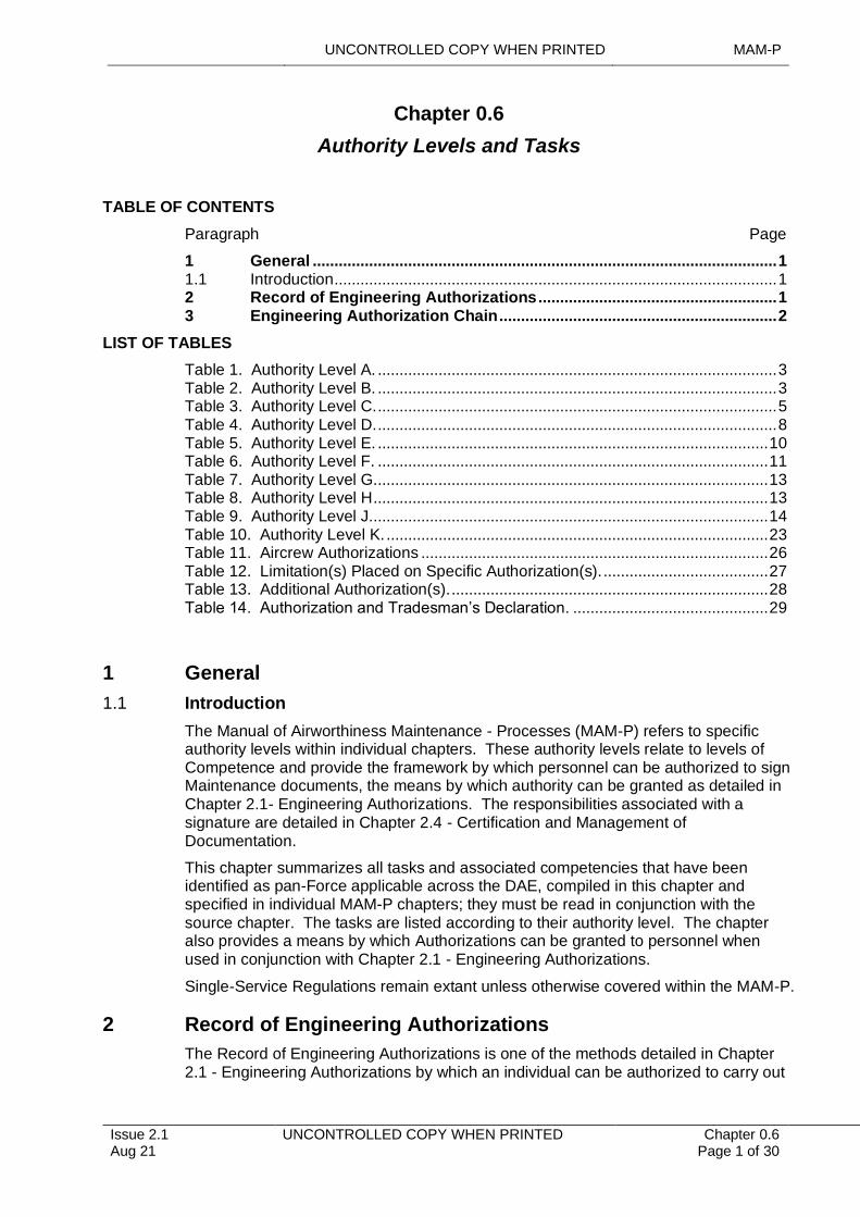
1 General
1.1 Introduction
The Manual of Airworthiness Maintenance - Processes (MAM-P) refers to specific authority levels within individual chapters. These authority levels relate to levels of Competence and provide the framework by which personnel can be authorized to sign Maintenance documents, the means by which authority can be granted as detailed in Chapter 2.1- Engineering Authorizations. The responsibilities associated with a signature are detailed in Chapter 2.4 - Certification and Management of Documentation.
This chapter summarizes all tasks and associated competencies that have been identified as pan-Force applicable across the DAE, compiled in this chapter and specified in individual MAM-P chapters; they must be read in conjunction with the source chapter. The tasks are listed according to their authority level. The chapter also provides a means by which Authorizations can be granted to personnel when used in conjunction with Chapter 2.1 - Engineering Authorizations.
Single-Service Regulations remain extant unless otherwise covered within the MAM-P.
2 Record of Engineering Authorizations
The Record of Engineering Authorizations is one of the methods detailed in Chapter 2.1 - Engineering Authorizations by which an individual can be authorized to carry out
MAM-P UNCONTROLLED COPY WHEN PRINTED
Chapter 0.6 Page 2 of 30
UNCONTROLLED COPY WHEN PRINTED Issue 2.1 Aug 21
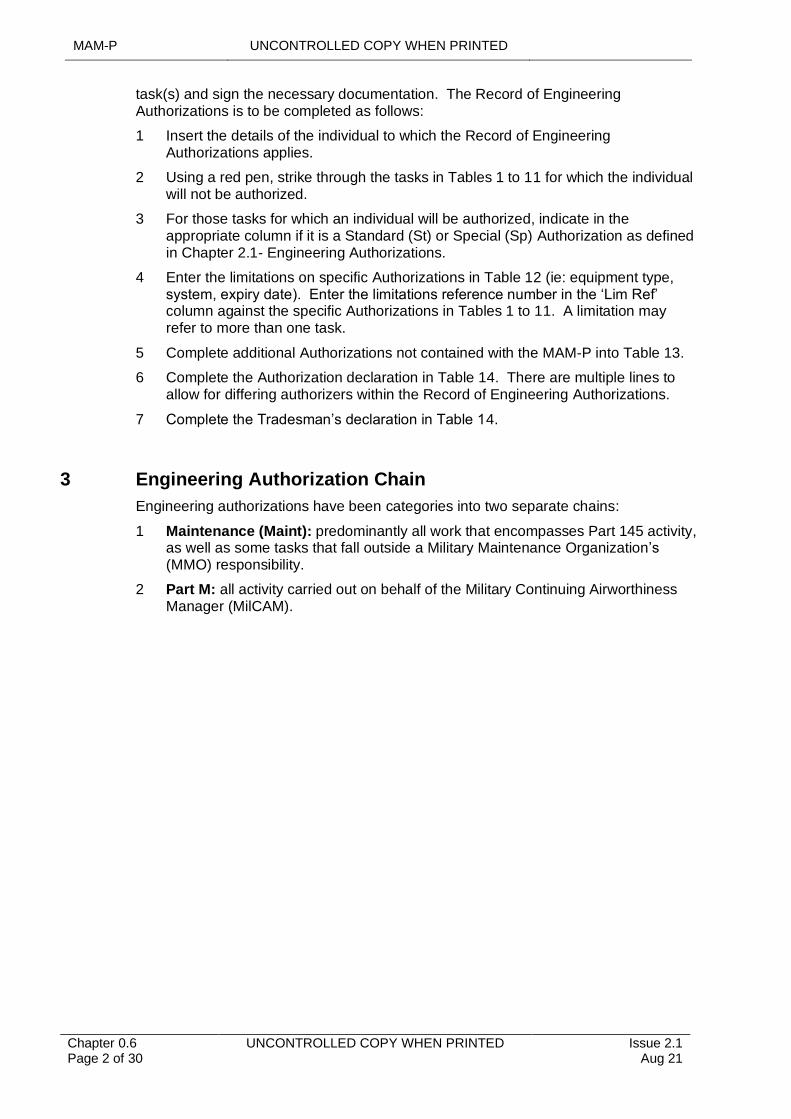
task(s) and sign the necessary documentation. The Record of Engineering Authorizations is to be completed as follows:
1 Insert the details of the individual to which the Record of Engineering Authorizations applies.
2 Using a red pen, strike through the tasks in Tables 1 to 11 for which the individual will not be authorized.
3 For those tasks for which an individual will be authorized, indicate in the appropriate column if it is a Standard (St) or Special (Sp) Authorization as defined in Chapter 2.1- Engineering Authorizations.
4 Enter the limitations on specific Authorizations in Table 12 (ie: equipment type, system, expiry date). Enter the limitations reference number in the ‘Lim Ref’ column against the specific Authorizations in Tables 1 to 11. A limitation may refer to more than one task.
5 Complete additional Authorizations not contained with the MAM-P into Table 13.
6 Complete the Authorization declaration in Table 14. There are multiple lines to allow for differing authorizers within the Record of Engineering Authorizations.
7 Complete the Tradesman’s declaration in Table 14.
3 Engineering Authorization Chain
Engineering authorizations have been categories into two separate chains:
1 Maintenance (Maint): predominantly all work that encompasses Part 145 activity, as well as some tasks that fall outside a Military Maintenance Organization’s (MMO) responsibility.
2 Part M: all activity carried out on behalf of the Military Continuing Airworthiness Manager (MilCAM).
UNCONTROLLED COPY WHEN PRINTED MAM-P
Issue 2.1 Aug 21
UNCONTROLLED COPY WHEN PRINTED Chapter 0.6 Page 3 of 30
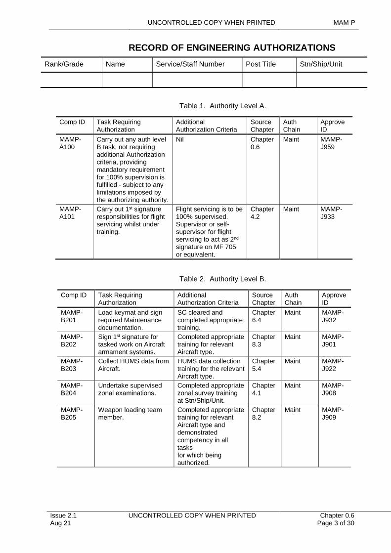
RECORD OF ENGINEERING AUTHORIZATIONS
Rank/Grade Name Service/Staff Number Post Title Stn/Ship/Unit
Table 1. Authority Level A.
Comp ID Task Requiring Authorization
Additional Authorization Criteria
Source Chapter
Auth Chain
Approve ID
MAMP-A100
Carry out any auth level B task, not requiring additional Authorization criteria, providing mandatory requirement for 100% supervision is fulfilled - subject to any limitations imposed by the authorizing authority.
Nil Chapter0.6
Maint MAMP-J959
MAMP-A101
Carry out 1st signatureresponsibilities for flight servicing whilst under training.
Flight servicing is to be100% supervised. Supervisor or self-supervisor for flight servicing to act as 2nd
signature on MF 705 or equivalent.
Chapter4.2
Maint MAMP-J933
Table 2. Authority Level B.
Comp ID Task Requiring Authorization
Additional Authorization Criteria
Source Chapter
Auth Chain
Approve ID
MAMP-B201
Load keymat and sign required Maintenance documentation.
SC cleared and completed appropriate training.
Chapter 6.4
Maint MAMP-J932
MAMP-B202
Sign 1st signature for tasked work on Aircraft armament systems.
Completed appropriate training for relevant Aircraft type.
Chapter 8.3
Maint MAMP-J901
MAMP-B203
Collect HUMS data from Aircraft.
HUMS data collection training for the relevant Aircraft type.
Chapter 5.4
Maint MAMP-J922
MAMP- B204
Undertake supervised zonal examinations.
Completed appropriate zonal survey training at Stn/Ship/Unit.
Chapter 4.1
Maint MAMP-J908
MAMP-B205
Weapon loading team member.
Completed appropriate training for relevant Aircraft type and demonstrated competency in all tasks for which being authorized.
Chapter 8.2
Maint MAMP-J909
MAM-P UNCONTROLLED COPY WHEN PRINTED
Chapter 0.6 Page 4 of 30
UNCONTROLLED COPY WHEN PRINTED Issue 2.1 Aug 21
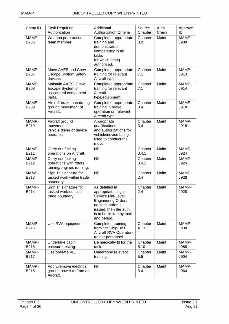
Comp ID Task Requiring Authorization
Additional Authorization Criteria
Source Chapter
Auth Chain
Approve ID
MAMP- B206
Weapon preparation team member.
Completed appropriate training and demonstrated competency in all tasks for which being authorized.
Chapter 8.2
Maint MAMP-J909
MAMP- B207
Move AAES and Crew Escape System Safety devices.
Completed appropriate training for relevant Aircraft type.
Chapter 7.1
Maint MAMP-J913
MAMP- B208
Maintain AAES, Crew Escape System or associated component parts.
Completed appropriate training for relevant Aircraft type/equipment.
Chapter 7.1
Maint MAMP-J914
MAMP- B209
Aircraft brakeman during ground movement of Aircraft.
Completed appropriate training in brake operation on relevant Aircraft type.
Chapter 3.4
Maint MAMP-J918
MAMP- B210
Aircraft ground movement vehicle driver or device operator.
Appropriate qualifications and authorizations for vehicle/device being used to conduct the move.
Chapter 3.4
Maint MAMP-J918
MAMP- B211
Carry out fueling operations on Aircraft.
Nil Chapter 3.4.1
Maint MAMP-J924
MAMP- B212
Carry out fueling operations with rotors turning/engines running.
Nil Chapter 3.4.1
Maint MAMP-J924
MAMP- B213
Sign 1st signature for tasked work within trade boundary.
Nil Chapter 2.4
Maint MAMP-J928
MAMP- B214
Sign 1st signature for tasked work outside trade boundary.
As detailed in appropriate single Service Mid-Level Engineering Orders. If no such order is issued, then the auth is to be limited by task and period.
Chapter 2.4
Maint MAMP-J928
MAMP- B215
Use RVA equipment. Completed training from Stn/Ship/Unit Aircraft RVA Operator-trainer personnel.
Chapter 4.13.2
Maint MAMP-J938
MAMP- B216
Undertake cabin pressure testing.
Be medically fit for the task.
Chapter 5.10
Maint MAMP-J958
MAMP- B217
Use/operate VE. Undergone relevant training.
Chapter 5.5
Maint MAMP-J904
MAMP- B218
Apply/remove electrical ground power to/from an Aircraft.
Nil Chapter 3.4
Maint MAMP-J964
UNCONTROLLED COPY WHEN PRINTED MAM-P
Issue 2.1 Aug 21
UNCONTROLLED COPY WHEN PRINTED Chapter 0.6 Page 5 of 30
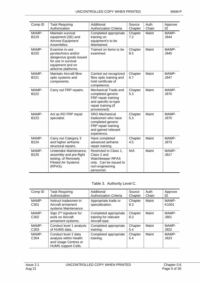
Comp ID Task Requiring Authorization
Additional Authorization Criteria
Source Chapter
Auth Chain
Approve ID
MAMP- B219
Maintain survival equipment (SE) and Aircrew Equipment Assemblies.
Completed appropriate training on equipment's to be Maintained.
Chapter 7.2
Maint MAMP-J944
MAMP- B220
Examine in-use pyrotechnics and/or dangerous goods issued for use in survival equipment and on airborne platforms.
Trained on items to be examined.
Chapter 8.5
Maint MAMP-J945
MAMP- B221
Maintain Aircraft fibre optic systems and components.
Carried out recognized fibre optic training and hold certificate of competence.
Chapter 6.7
Maint MAMP-J947
MAMP- B222
Carry out FRP repairs. Mechanical Trade and completed generic FRP repair training and specific-to-type repair training (if provisioned).
Chapter 5.3
Maint MAMP-J970
MAMP- B223
Act as RO FRP repair specialist.
SRO Mechanical tradesmen who have completed generic FRP repair training and gained relevant experience.
Chapter 5.3
Maint MAMP-J970
MAMP- B224
Carry out Category 3 and higher airframe structural repairs.
Have completed advanced airframe repair training.
Chapter 4.5
Maint MAMP-J973
MAMP- B225
Undertake Maintenance, assembly and pre-flight testing, of Remotely Piloted Air Systems (RPAS).
Restricted to Class 1, Class 2 and Watchkeeper RPAS only. Can be issued to non-engineering personnel.
N/A Maint MAMP-J917
Table 3. Authority Level C.
Comp ID Task Requiring Authorization
Additional Authorization Criteria
Source Chapter
Auth Chain
Approve ID
MAMP- C301
Instruct tradesmen in Aircraft armament systems Maintenance.
Appropriate trade or specialization.
Chapter 8.3
Maint MAMP-K1001
MAMP- C302
Sign 2nd signature for work on Aircraft armament systems.
Completed appropriate training for relevant Aircraft type.
Chapter 8.3
Maint MAMP-J901
MAMP- C303
Conduct level 1 analysis of HUMS data.
Completed appropriate training.
Chapter 5.4
Maint MAMP-J922
MAMP-C304
Conduct level 2 data analysis within Health and Usage Centres or HUMS support Cells.
Completed appropriate training.
Chapter 5.4
Maint MAMP-J923
MAM-P UNCONTROLLED COPY WHEN PRINTED
Chapter 0.6 Page 6 of 30
UNCONTROLLED COPY WHEN PRINTED Issue 2.1 Aug 21
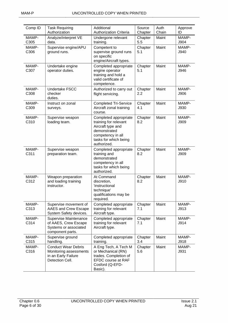
Comp ID Task Requiring Authorization
Additional Authorization Criteria
Source Chapter
Auth Chain
Approve ID
MAMP- C305
Analyze/interpret VE data.
Undergone relevant training.
Chapter 5.5
Maint MAMP-J904
MAMP- C306
Supervise engine/APU ground runs.
Competent to supervise ground runs on specific engine/Aircraft types.
Chapter 5.1
Maint MAMP-J940
MAMP- C307
Undertake engine operator duties.
Completed appropriate engine operator training and hold a valid certificate of competence.
Chapter 5.1
Maint MAMP-J946
MAMP- C308
Undertake FSCC checker duties.
Authorized to carry out
flight servicing.Chapter 2.2
Maint MAMP-J906
MAMP- C309
Instruct on zonal surveys.
Completed Tri-Service Aircraft zonal training course.
Chapter 4.1
Maint MAMP-J930
MAMP- C310
Supervise weapon loading team.
Completed appropriate training for relevant Aircraft type and demonstrated competency in all tasks for which being authorized.
Chapter 8.2
Maint MAMP-J909
MAMP- C311
Supervise weapon preparation team.
Completed appropriate training and demonstrated competency in all tasks for which being authorized.
Chapter 8.2
Maint MAMP-J909
MAMP- C312
Weapon preparation and loading training instructor.
At Command discretion, 'instructional technique' qualifications may be required.
Chapter 8.2
Maint MAMP-J910
MAMP- C313
Supervise movement of AAES and Crew Escape System Safety devices.
Completed appropriate training for relevant Aircraft type.
Chapter 7.1
Maint MAMP-J913
MAMP- C314
Supervise Maintenance of AAES, Crew Escape Systems or associated component parts.
Completed appropriate training for relevant Aircraft type.
Chapter 7.1
Maint MAMP-J914
MAMP- C315
Supervise ground handling.
Completed appropriate training.
Chapter 3.4
Maint MAMP-J918
MAMP- C316
Conduct Wear Debris Monitoring assessments in an Early Failure Detection Cell.
A Eng Tech, A Tech M or Mechanical (RN) trades. Completion of EFDC course at RAF Cosford (Q-EFD-Basic).
Chapter 5.6
Maint MAMP-J931
UNCONTROLLED COPY WHEN PRINTED MAM-P
Issue 2.1 Aug 21
UNCONTROLLED COPY WHEN PRINTED Chapter 0.6 Page 7 of 30
Comp ID Task Requiring Authorization
Additional Authorization Criteria
Source Chapter
Auth Chain
Approve ID
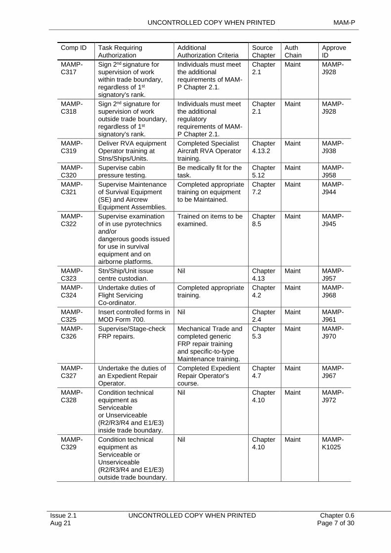
MAMP- C317
Sign 2nd signature for supervision of work within trade boundary, regardless of 1st
signatory's rank.
Individuals must meet the additional requirements of MAM-P Chapter 2.1.
Chapter 2.1
Maint MAMP-J928
MAMP- C318
Sign 2nd signature for supervision of work outside trade boundary, regardless of 1st
signatory's rank.
Individuals must meet the additional regulatory requirements of MAM-P Chapter 2.1.
Chapter 2.1
Maint MAMP-J928
MAMP- C319
Deliver RVA equipment Operator training at Stns/Ships/Units.
Completed Specialist Aircraft RVA Operator training.
Chapter4.13.2
Maint MAMP-J938
MAMP- C320
Supervise cabin pressure testing.
Be medically fit for the task.
Chapter 5.12
Maint MAMP-J958
MAMP- C321
Supervise Maintenance of Survival Equipment (SE) and Aircrew Equipment Assemblies.
Completed appropriate training on equipment to be Maintained.
Chapter 7.2
Maint MAMP-J944
MAMP- C322
Supervise examination of in use pyrotechnics and/or dangerous goods issued for use in survival equipment and on airborne platforms.
Trained on items to be examined.
Chapter 8.5
Maint MAMP-J945
MAMP- C323
Stn/Ship/Unit issue centre custodian.
Nil Chapter 4.13
Maint MAMP-J957
MAMP- C324
Undertake duties of Flight Servicing Co-ordinator.
Completed appropriate training.
Chapter 4.2
Maint MAMP-J968
MAMP- C325
Insert controlled forms in MOD Form 700.
Nil Chapter 2.4
Maint MAMP-J961
MAMP- C326
Supervise/Stage-check FRP repairs.
Mechanical Trade and completed generic FRP repair training and specific-to-type Maintenance training.
Chapter 5.3
Maint MAMP-J970
MAMP- C327
Undertake the duties of an Expedient Repair Operator.
Completed Expedient Repair Operator's course.
Chapter 4.7
Maint MAMP-J967
MAMP- C328
Condition technical equipment as Serviceable or Unserviceable (R2/R3/R4 and E1/E3) inside trade boundary.
Nil Chapter 4.10
Maint MAMP-J972
MAMP- C329
Condition technical equipment as Serviceable or Unserviceable (R2/R3/R4 and E1/E3) outside trade boundary.
Nil Chapter 4.10
Maint MAMP-K1025
MAM-P UNCONTROLLED COPY WHEN PRINTED
Chapter 0.6 Page 8 of 30
UNCONTROLLED COPY WHEN PRINTED Issue 2.1 Aug 21
Comp ID Task Requiring Authorization
Additional Authorization Criteria
Source Chapter
Auth Chain
Approve ID
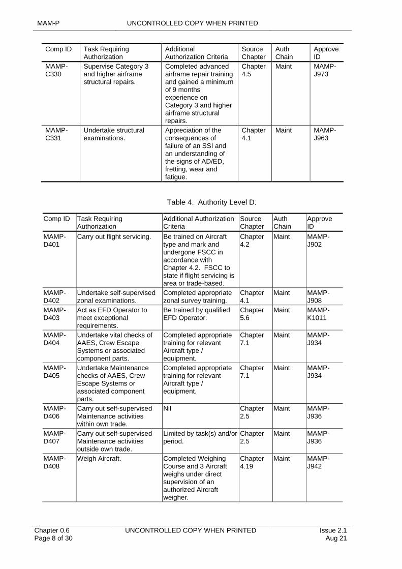
MAMP-C330
Supervise Category 3and higher airframe structural repairs.
Completed advancedairframe repair training and gained a minimum of 9 months experience onCategory 3 and higher airframe structural repairs.
Chapter4.5
Maint MAMP-J973
MAMP-C331
Undertake structuralexaminations.
Appreciation of theconsequences of failure of an SSI and an understanding of the signs of AD/ED, fretting, wear and fatigue.
Chapter4.1
Maint MAMP-J963
Table 4. Authority Level D.
Comp ID Task Requiring Authorization
Additional Authorization Criteria
Source Chapter
Auth Chain
Approve ID
MAMP- D401
Carry out flight servicing. Be trained on Aircraft type and mark and undergone FSCC in accordance with Chapter 4.2. FSCC to state if flight servicing is area or trade-based.
Chapter 4.2
Maint MAMP-J902
MAMP- D402
Undertake self-supervised zonal examinations.
Completed appropriate zonal survey training.
Chapter 4.1
Maint MAMP-J908
MAMP- D403
Act as EFD Operator to meet exceptional requirements.
Be trained by qualified EFD Operator.
Chapter 5.6
Maint MAMP-K1011
MAMP- D404
Undertake vital checks of AAES, Crew Escape Systems or associated component parts.
Completed appropriate training for relevant Aircraft type / equipment.
Chapter 7.1
Maint MAMP-J934
MAMP-D405
Undertake Maintenance checks of AAES, Crew Escape Systems or associated component parts.
Completed appropriate training for relevant Aircraft type / equipment.
Chapter 7.1
Maint MAMP-J934
MAMP- D406
Carry out self-supervised Maintenance activities within own trade.
Nil Chapter 2.5
Maint MAMP-J936
MAMP- D407
Carry out self-supervised Maintenance activities outside own trade.
Limited by task(s) and/or period.
Chapter 2.5
Maint MAMP-J936
MAMP- D408
Weigh Aircraft. Completed Weighing Course and 3 Aircraft weighs under direct supervision of an authorized Aircraft weigher.
Chapter 4.19
Maint MAMP-J942
UNCONTROLLED COPY WHEN PRINTED MAM-P
Issue 2.1 Aug 21
UNCONTROLLED COPY WHEN PRINTED Chapter 0.6 Page 9 of 30
Comp ID Task Requiring Authorization
Additional Authorization Criteria
Source Chapter
Auth Chain
Approve ID
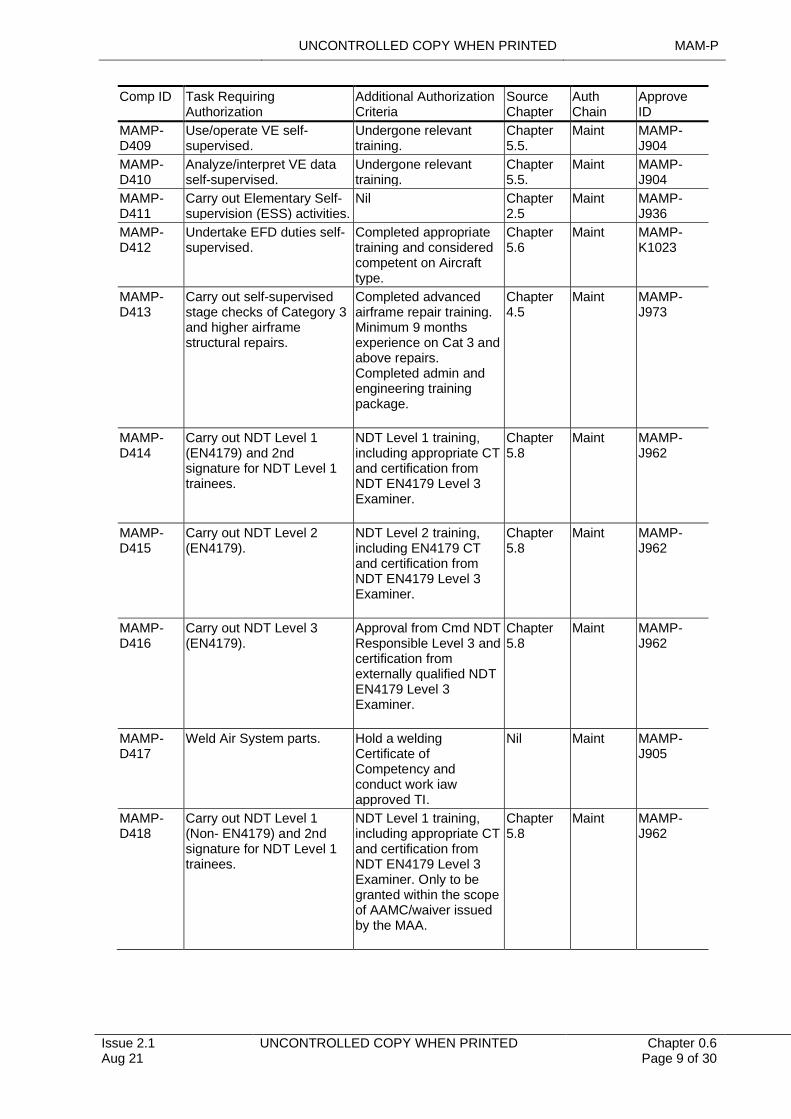
MAMP- D409
Use/operate VE self-supervised.
Undergone relevant training.
Chapter 5.5.
Maint MAMP-J904
MAMP- D410
Analyze/interpret VE data self-supervised.
Undergone relevant training.
Chapter 5.5.
Maint MAMP-J904
MAMP- D411
Carry out Elementary Self-supervision (ESS) activities.
Nil Chapter 2.5
Maint MAMP-J936
MAMP- D412
Undertake EFD duties self-supervised.
Completed appropriate training and considered competent on Aircraft type.
Chapter 5.6
Maint MAMP-K1023
MAMP- D413
Carry out self-supervised stage checks of Category 3 and higher airframe structural repairs.
Completed advanced airframe repair training. Minimum 9 months experience on Cat 3 and above repairs. Completed admin and engineering training package.
Chapter 4.5
Maint MAMP-J973
MAMP- D414
Carry out NDT Level 1 (EN4179) and 2nd signature for NDT Level 1 trainees.
NDT Level 1 training, including appropriate CT and certification from NDT EN4179 Level 3 Examiner.
Chapter 5.8
Maint MAMP-J962
MAMP- D415
Carry out NDT Level 2 (EN4179).
NDT Level 2 training, including EN4179 CT and certification from NDT EN4179 Level 3 Examiner.
Chapter 5.8
Maint MAMP-J962
MAMP- D416
Carry out NDT Level 3 (EN4179).
Approval from Cmd NDT Responsible Level 3 and certification from externally qualified NDT EN4179 Level 3 Examiner.
Chapter 5.8
Maint MAMP-J962
MAMP- D417
Weld Air System parts. Hold a welding Certificate of Competency and conduct work iaw approved TI.
Nil Maint MAMP-J905
MAMP- D418
Carry out NDT Level 1 (Non- EN4179) and 2nd signature for NDT Level 1 trainees.
NDT Level 1 training, including appropriate CT and certification from NDT EN4179 Level 3 Examiner. Only to be granted within the scope of AAMC/waiver issued by the MAA.
Chapter 5.8
Maint MAMP-J962

MAM-P UNCONTROLLED COPY WHEN PRINTED
Chapter 0.6 Page 10 of 30
UNCONTROLLED COPY WHEN PRINTED Issue 2.1 Aug 21
Comp ID Task Requiring Authorization
Additional Authorization Criteria
Source Chapter
Auth Chain
Approve ID
MAMP- D419
Carry out NDT Level 2 (Non- EN4179).
NDT Level 2 training, including appropriate CT and certification fromNDT EN4179 Level 3Examiner. Only to be granted within the scope of AAMC/waiver issued by the MAA.
Chapter 5.8
Maint MAMP-J962
Table 5. Authority Level E.
Comp ID
Task Requiring Authorization
Additional Authorization Criteria
Source Chapter
Auth Chain
Approve ID
MAMP-E501
Undertake independent inspections in source trade.
Nil Chapter 4.15
Maint MAMP-J929
MAMP- E502
Weapon preparation and loading training examiner.
Be a Senior Rate/SNCO
Chapter 8.2
Maint MAMP-J910
MAMP- E503
Give instruction on AAES and Crew Escape System Safety precautions, devices and conditions.
Nil Chapter 7.1
Maint MAMP-J912
MAMP-E504
Conduct Early Failure Detection assessments in an EFD Cell following appropriate training.
Be a Senior Rate/Rank in the A Eng Tech, A Tech M or Mechanical (RN) trades. Completion of Q- EFD-Basic course at RAF Cosford.
Chapter 5.6
Maint MAMP-J931
MAMP- E505
Undertake repetition pitot static sense and leak tests.
Nil Chapter 6.8
Maint MAMP-J919
MAMP-E506
Undertake independent inspections outside source trade.
Nil Chapter 4.15
Maint MAMP-J929
MAMP- E507
Co-ordinate MWOs. Individuals must meet the additional requirements of MAM-P Chapter 2.1.
Chapter 2.4
Maint MAMP-J928
MAMP- E508
Undertake independent checks of AAES, Crew Escape Systems or associated component parts.
Completed appropriate training for relevant Aircraft type/equipment.
Chapter 7.1
Maint MAMP-J934
MAMP- E509
Undertake duties of Flying Maintainer (FM).
Completed appropriate training iaw Chapter 3.1, Chapter 5.5 and hold a CofC issued by an MTP of the appropriate Aircraft type.
Chapter 3.1
Maint MAMP-J939
UNCONTROLLED COPY WHEN PRINTED MAM-P
Issue 2.1 Aug 21
UNCONTROLLED COPY WHEN PRINTED Chapter 0.6 Page 11 of 30
Comp ID
Task Requiring Authorization
Additional Authorization Criteria
Source Chapter
Auth Chain
Approve ID
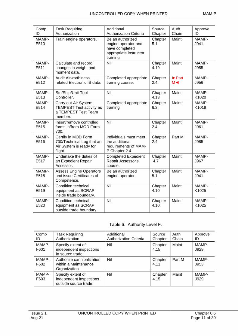
MAMP- E510
Train engine operators. Be an authorized engine operator and have completed appropriate instructor training.
Chapter 5.1
Maint MAMP-J941
MAMP- E511
Calculate and record changes in weight and moment data.
Nil Chapter 4.19
Maint MAMP-J955
MAMP- E512
Audit Airworthiness related Electronic IS data.
Completed appropriate training course.
Chapter 2.4
►Part M◄
MAMP-J956
MAMP- E513
Stn/Ship/Unit Tool Controller.
Nil Chapter 4.13
Maint MAMP-K1020
MAMP-E514
Carry out Air System TEMPEST Test activity as a TEMPEST Test Team member.
Completed appropriate training.
Chapter 6.3
Maint MAMP-K1019
MAMP- E515
Insert/remove controlled forms in/from MOD Form 700.
Nil Chapter 2.4
Maint MAMP-J961
MAMP- E516
Certify in MOD Form 700/Technical Log that an Air System is ready for flight.
Individuals must meet the additional requirements of MAM-P Chapter 2.4.
Chapter 2.4
Part M MAMP-J985
MAMP- E517
Undertake the duties of an Expedient Repair Assessor.
Completed Expedient Repair Assessor's course.
Chapter 4.7
Maint MAMP-J967
MAMP- E518
Assess Engine Operators and issue Certificates of Competence.
Be an authorized engine operator.
Chapter 5.1
Maint MAMP-J941
MAMP- E519
Condition technical equipment as SCRAP inside trade boundary.
Nil Chapter 4.10
Maint MAMP-K1025
MAMP- E520
Condition technical equipment as SCRAP outside trade boundary.
Nil Chapter 4.10.
Maint MAMP-K1025
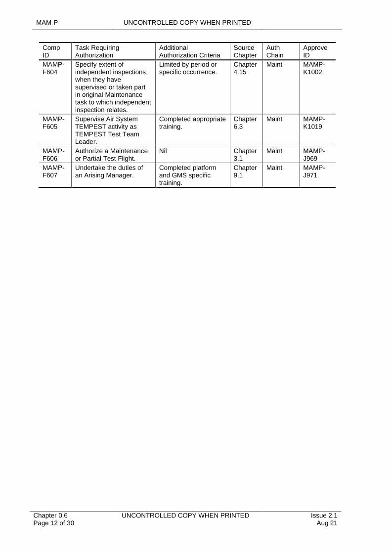
Table 6. Authority Level F.
Comp ID
Task Requiring Authorization
Additional Authorization Criteria
Source Chapter
Auth Chain
Approve ID
MAMP- F601
Specify extent of independent inspections in source trade.
Nil Chapter 4.15
Maint MAMP-J929
MAMP- F602
Authorize cannibalization within a Maintenance Organization.
Nil Chapter 4.11
Part M MAMP-J953
MAMP- F603
Specify extent of independent inspections outside source trade.
Nil Chapter 4.15
Maint MAMP-J929
MAM-P UNCONTROLLED COPY WHEN PRINTED
Chapter 0.6 Page 12 of 30
UNCONTROLLED COPY WHEN PRINTED Issue 2.1 Aug 21
Comp ID
Task Requiring Authorization
Additional Authorization Criteria
Source Chapter
Auth Chain
Approve ID
MAMP- F604
Specify extent of independent inspections, when they have supervised or taken part in original Maintenance task to which independent inspection relates.
Limited by period or specific occurrence.
Chapter 4.15
Maint MAMP-K1002
MAMP- F605
Supervise Air System TEMPEST activity as TEMPEST Test Team Leader.
Completed appropriate training.
Chapter 6.3
Maint MAMP-K1019
MAMP- F606
Authorize a Maintenance or Partial Test Flight.
Nil Chapter 3.1
Maint MAMP-J969
MAMP- F607
Undertake the duties of an Arising Manager.
Completed platform and GMS specific training.
Chapter 9.1
Maint MAMP-J971
UNCONTROLLED COPY WHEN PRINTED MAM-P
Issue 2.1 Aug 21
UNCONTROLLED COPY WHEN PRINTED Chapter 0.6 Page 13 of 30
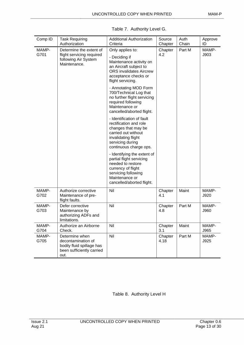
Table 7. Authority Level G.
Comp ID Task Requiring Authorization
Additional Authorization Criteria
Source Chapter
Auth Chain
Approve ID
MAMP-G701
Determine the extent of flight servicing required following Air System Maintenance.
Only applies to:
- Deciding if Maintenance activity on an Aircraft subject to ORS invalidates Aircrew acceptance checks or flight servicing.
- Annotating MOD Form 700/Technical Log that no further flight servicing required following Maintenance or cancelled/aborted flight.
- Identification of fault rectification and role changes that may be carried out without invalidating flight servicing during continuous charge ops.
- Identifying the extent of partial flight servicing needed to restore currency of flight servicing following Maintenance or cancelled/aborted flight.
Chapter 4.2
Part M MAMP-J903
MAMP-G702
Authorize corrective Maintenance of pre-flight faults.
Nil Chapter 4.1
Maint MAMP-J920
MAMP-G703
Defer corrective Maintenance by authorizing ADFs and limitations.
Nil Chapter 4.8
Part M MAMP-J960
MAMP-G704
Authorize an Airborne Check.
Nil Chapter 3.1
Maint MAMP-J965
MAMP-G705
Determine when decontamination of bodily fluid spillage has been sufficiently carried out.
Nil Chapter 4.18
Part M MAMP-J925
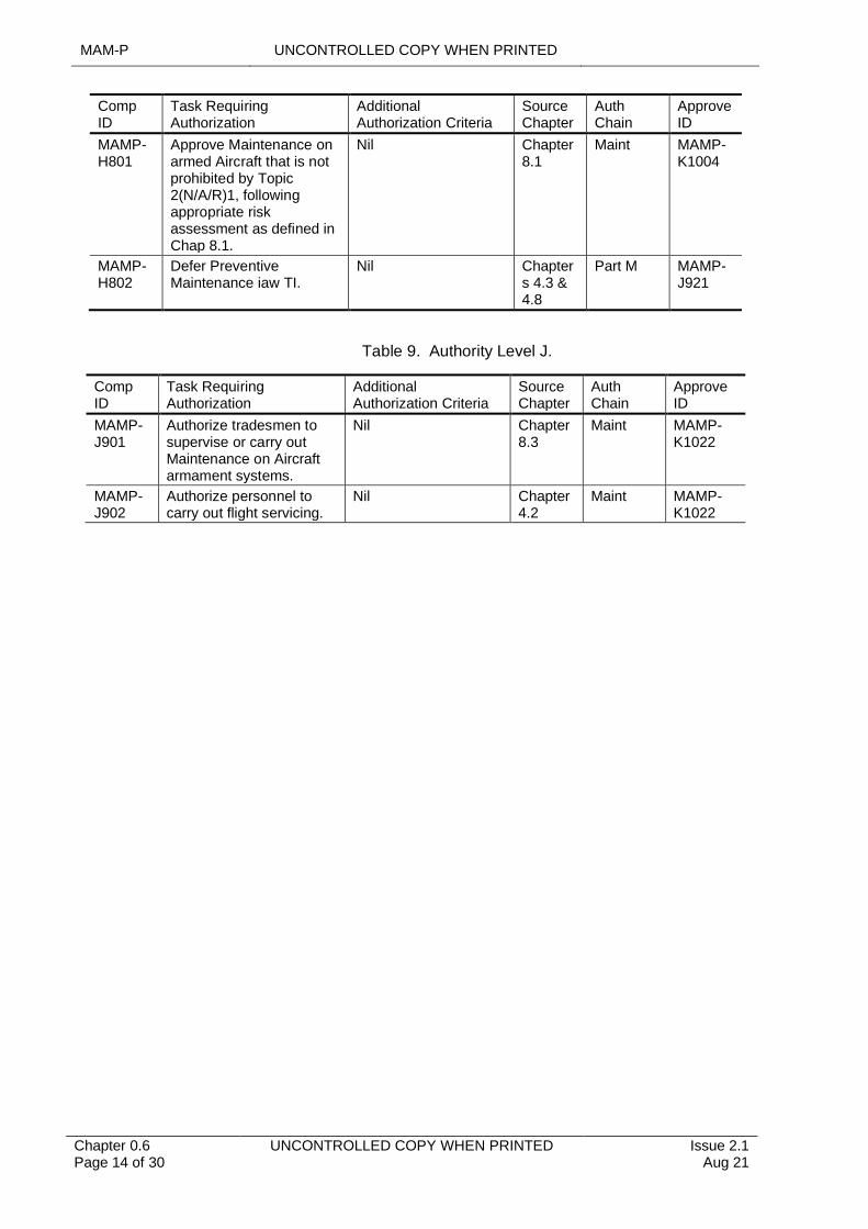
Table 8. Authority Level H
MAM-P UNCONTROLLED COPY WHEN PRINTED
Chapter 0.6 Page 14 of 30
UNCONTROLLED COPY WHEN PRINTED Issue 2.1 Aug 21
Comp ID
Task Requiring Authorization
Additional Authorization Criteria
Source Chapter
Auth Chain
Approve ID
MAMP- H801
Approve Maintenance on armed Aircraft that is not prohibited by Topic 2(N/A/R)1, following appropriate risk assessment as defined in Chap 8.1.
Nil Chapter 8.1
Maint MAMP-K1004
MAMP- H802
Defer Preventive Maintenance iaw TI.
Nil Chapters 4.3 & 4.8
Part M MAMP-J921
Table 9. Authority Level J.
Comp ID
Task Requiring Authorization
Additional Authorization Criteria
Source Chapter
Auth Chain
Approve ID
MAMP-J901
Authorize tradesmen to supervise or carry out Maintenance on Aircraft armament systems.
Nil Chapter 8.3
Maint MAMP-K1022
MAMP-J902
Authorize personnel to carry out flight servicing.
Nil Chapter 4.2
Maint MAMP-K1022
UNCONTROLLED COPY WHEN PRINTED MAM-P
Issue 2.1 Aug 21
UNCONTROLLED COPY WHEN PRINTED Chapter 0.6 Page 15 of 30
Comp ID
Task Requiring Authorization
Additional Authorization Criteria
Source Chapter
Auth Chain
Approve ID
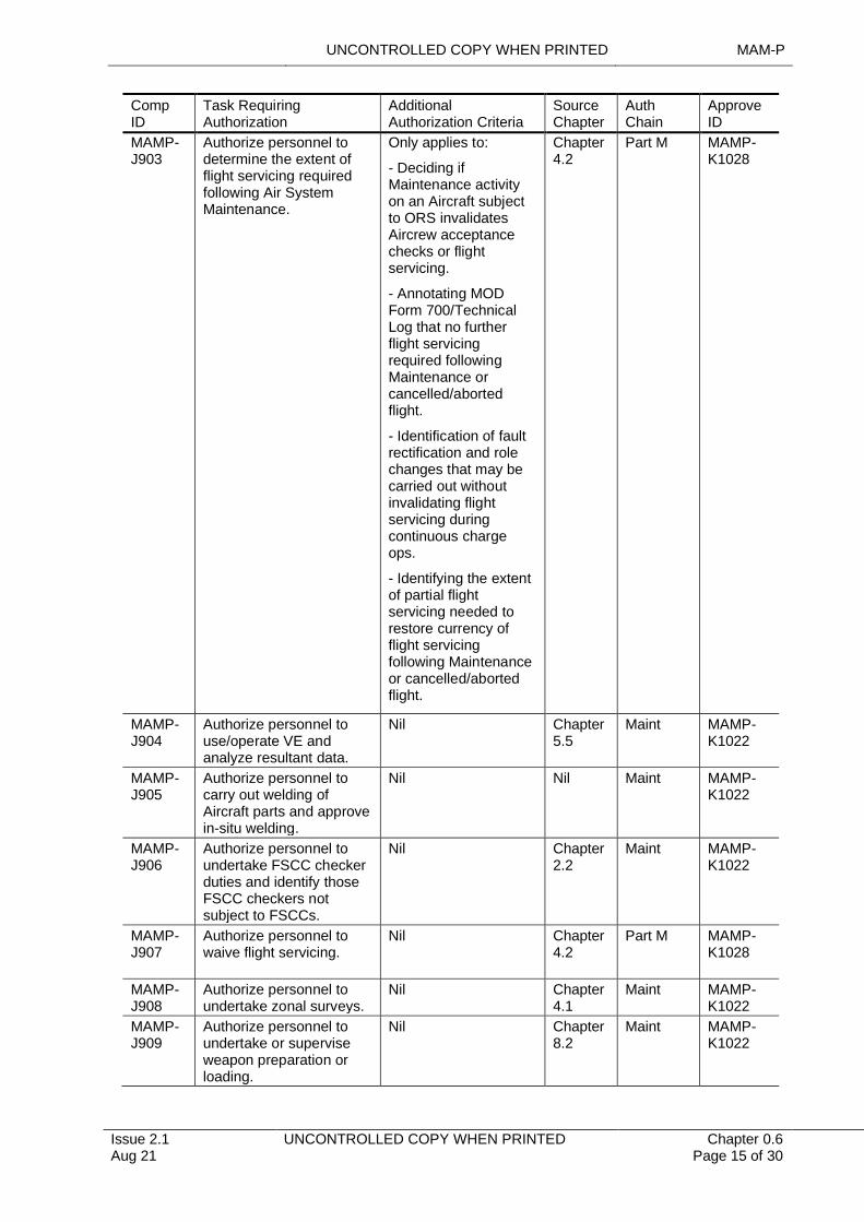
MAMP-J903
Authorize personnel to determine the extent of flight servicing required following Air System Maintenance.
Only applies to:
- Deciding if Maintenance activity on an Aircraft subject to ORS invalidates Aircrew acceptance checks or flight servicing.
- Annotating MOD Form 700/Technical Log that no further flight servicing required following Maintenance or cancelled/aborted flight.
- Identification of fault rectification and role changes that may be carried out without invalidating flight servicing during continuous charge ops.
- Identifying the extent of partial flight servicing needed to restore currency of flight servicing following Maintenance or cancelled/aborted flight.
Chapter 4.2
Part M MAMP-K1028
MAMP-J904
Authorize personnel to use/operate VE and analyze resultant data.
Nil Chapter 5.5
Maint MAMP-K1022
MAMP-J905
Authorize personnel to carry out welding of Aircraft parts and approve in-situ welding.
Nil Nil Maint MAMP-K1022
MAMP-J906
Authorize personnel to undertake FSCC checker duties and identify those FSCC checkers not subject to FSCCs.
Nil Chapter 2.2
Maint MAMP-K1022
MAMP-J907
Authorize personnel to waive flight servicing.
Nil Chapter 4.2
Part M MAMP-K1028
MAMP-J908
Authorize personnel to undertake zonal surveys.
Nil Chapter 4.1
Maint MAMP-K1022
MAMP-J909
Authorize personnel to undertake or supervise weapon preparation or loading.
Nil Chapter 8.2
Maint MAMP-K1022
MAM-P UNCONTROLLED COPY WHEN PRINTED
Chapter 0.6 Page 16 of 30
UNCONTROLLED COPY WHEN PRINTED Issue 2.1 Aug 21
Comp ID
Task Requiring Authorization
Additional Authorization Criteria
Source Chapter
Auth Chain
Approve ID
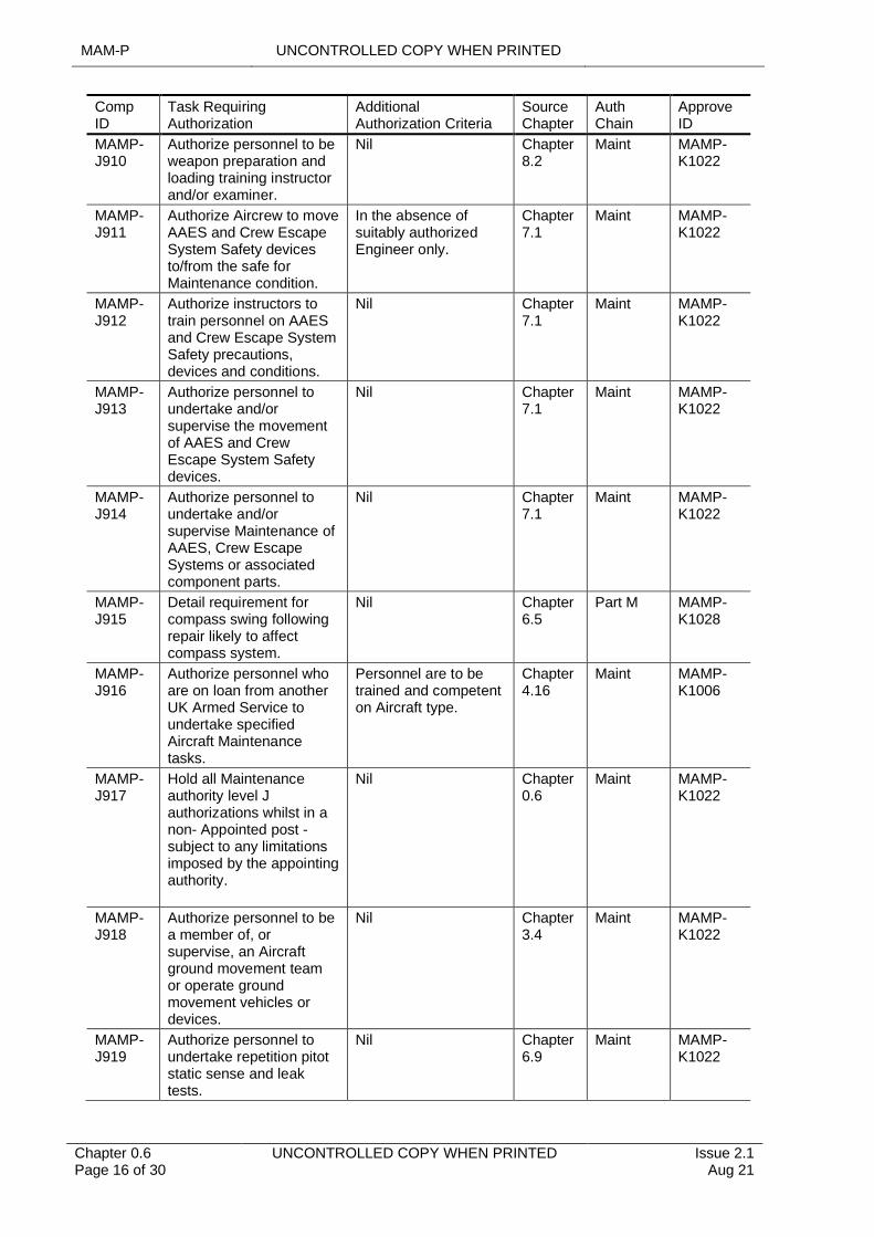
MAMP-J910
Authorize personnel to be weapon preparation and loading training instructor and/or examiner.
Nil Chapter 8.2
Maint MAMP-K1022
MAMP-J911
Authorize Aircrew to move AAES and Crew Escape System Safety devices to/from the safe for Maintenance condition.
In the absence of suitably authorized Engineer only.
Chapter 7.1
Maint MAMP-K1022
MAMP-J912
Authorize instructors to train personnel on AAES and Crew Escape System Safety precautions, devices and conditions.
Nil Chapter 7.1
Maint MAMP-K1022
MAMP-J913
Authorize personnel to undertake and/or supervise the movement of AAES and Crew Escape System Safety devices.
Nil Chapter 7.1
Maint MAMP-K1022
MAMP-J914
Authorize personnel to undertake and/or supervise Maintenance of AAES, Crew Escape Systems or associated component parts.
Nil Chapter 7.1
Maint MAMP-K1022
MAMP-J915
Detail requirement for compass swing following repair likely to affect compass system.
Nil Chapter 6.5
Part M MAMP-K1028
MAMP-J916
Authorize personnel who are on loan from another UK Armed Service to undertake specified Aircraft Maintenance tasks.
Personnel are to be trained and competent on Aircraft type.
Chapter 4.16
Maint MAMP-K1006
MAMP-J917
Hold all Maintenance authority level J authorizations whilst in a non- Appointed post - subject to any limitations imposed by the appointing authority.
Nil Chapter 0.6
Maint MAMP-K1022
MAMP-J918
Authorize personnel to be a member of, or supervise, an Aircraft ground movement team or operate ground movement vehicles or devices.
Nil Chapter 3.4
Maint MAMP-K1022
MAMP-J919
Authorize personnel to undertake repetition pitot static sense and leak tests.
Nil Chapter 6.9
Maint MAMP-K1022
UNCONTROLLED COPY WHEN PRINTED MAM-P
Issue 2.1 Aug 21
UNCONTROLLED COPY WHEN PRINTED Chapter 0.6 Page 17 of 30
Comp ID
Task Requiring Authorization
Additional Authorization Criteria
Source Chapter
Auth Chain
Approve ID
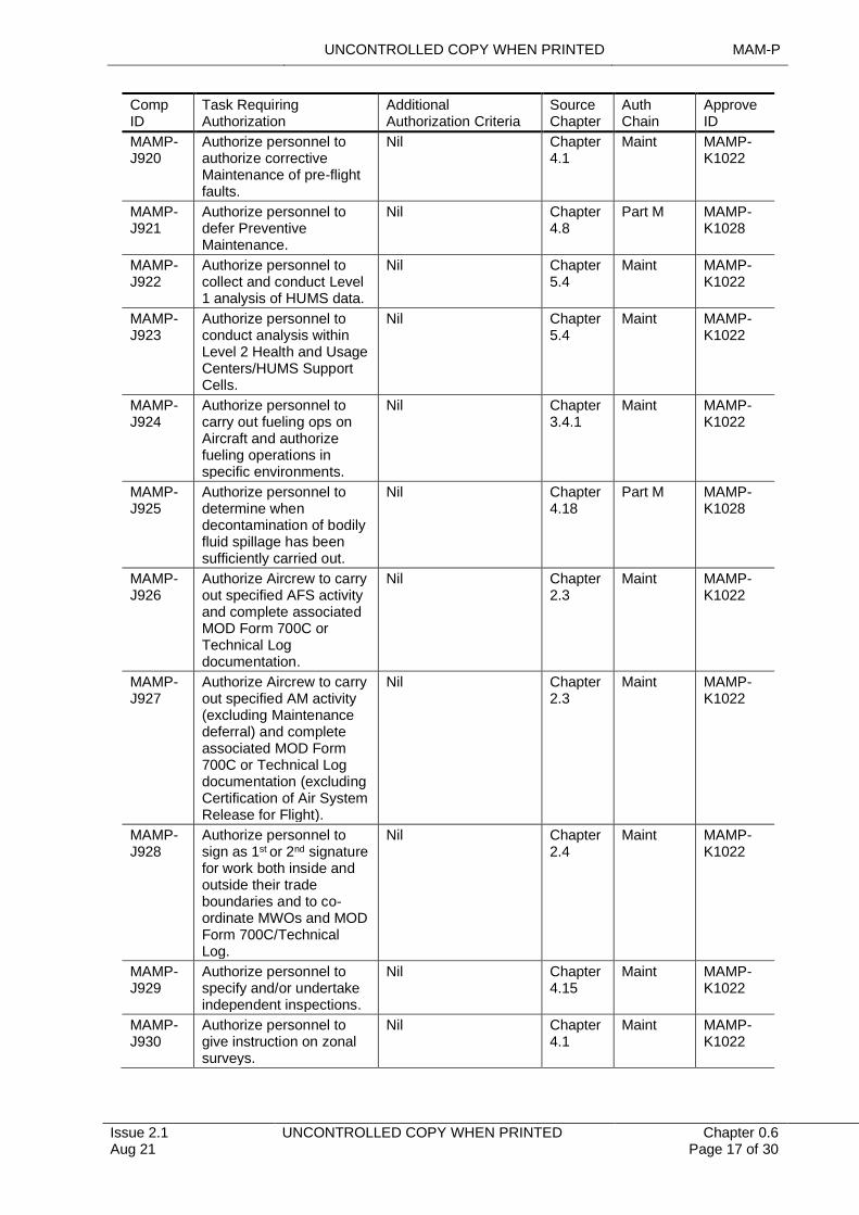
MAMP-J920
Authorize personnel to authorize corrective Maintenance of pre-flight faults.
Nil Chapter 4.1
Maint MAMP-K1022
MAMP-J921
Authorize personnel to defer Preventive Maintenance.
Nil Chapter 4.8
Part M MAMP-K1028
MAMP-J922
Authorize personnel to collect and conduct Level 1 analysis of HUMS data.
Nil Chapter 5.4
Maint MAMP-K1022
MAMP-J923
Authorize personnel to conduct analysis within Level 2 Health and Usage Centers/HUMS Support Cells.
Nil Chapter 5.4
Maint MAMP-K1022
MAMP-J924
Authorize personnel to carry out fueling ops on Aircraft and authorize fueling operations in specific environments.
Nil Chapter 3.4.1
Maint MAMP-K1022
MAMP-J925
Authorize personnel to determine when decontamination of bodily fluid spillage has been sufficiently carried out.
Nil Chapter 4.18
Part M MAMP-K1028
MAMP-J926
Authorize Aircrew to carry out specified AFS activity and complete associated MOD Form 700C or Technical Log documentation.
Nil Chapter 2.3
Maint MAMP-K1022
MAMP-J927
Authorize Aircrew to carry out specified AM activity (excluding Maintenance deferral) and complete associated MOD Form 700C or Technical Log documentation (excluding Certification of Air System Release for Flight).
Nil Chapter 2.3
Maint MAMP-K1022
MAMP-J928
Authorize personnel to sign as 1st or 2nd signature for work both inside and outside their trade boundaries and to co-ordinate MWOs and MOD Form 700C/Technical Log.
Nil Chapter 2.4
Maint MAMP-K1022
MAMP-J929
Authorize personnel to specify and/or undertake independent inspections.
Nil Chapter 4.15
Maint MAMP-K1022
MAMP-J930
Authorize personnel to give instruction on zonal surveys.
Nil Chapter 4.1
Maint MAMP-K1022
MAM-P UNCONTROLLED COPY WHEN PRINTED
Chapter 0.6 Page 18 of 30
UNCONTROLLED COPY WHEN PRINTED Issue 2.1 Aug 21
Comp ID
Task Requiring Authorization
Additional Authorization Criteria
Source Chapter
Auth Chain
Approve ID
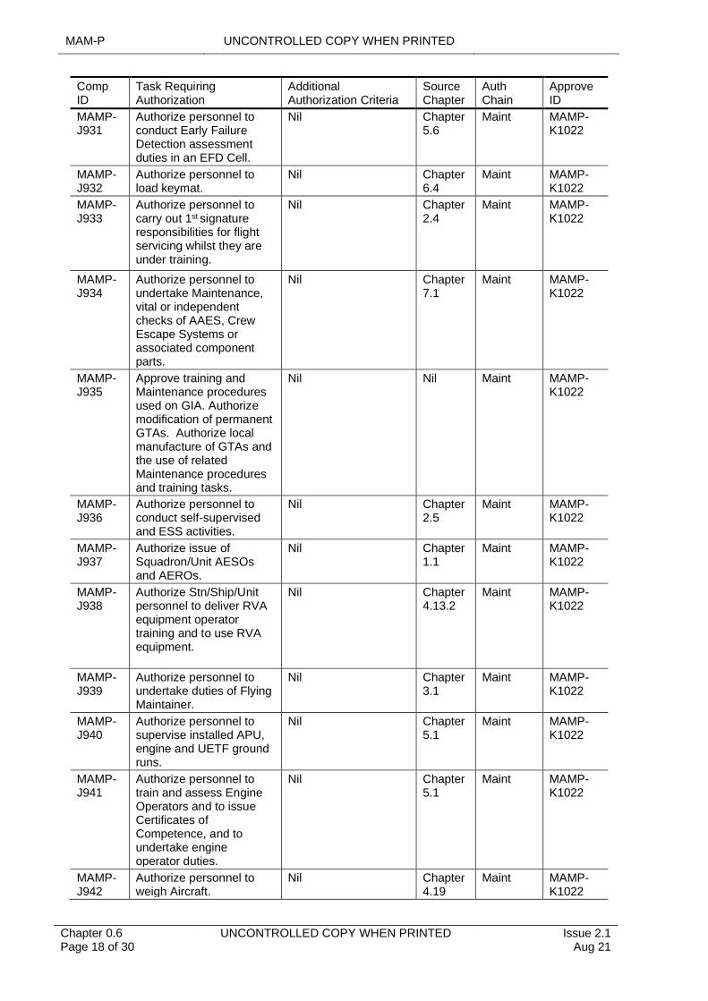
MAMP-J931
Authorize personnel to conduct Early Failure Detection assessment duties in an EFD Cell.
Nil Chapter 5.6
Maint MAMP-K1022
MAMP-J932
Authorize personnel to load keymat.
Nil Chapter 6.4
Maint MAMP-K1022
MAMP-J933
Authorize personnel to carry out 1st signature responsibilities for flight servicing whilst they are under training.
Nil Chapter 2.4
Maint MAMP-K1022
MAMP-J934
Authorize personnel to undertake Maintenance, vital or independent checks of AAES, Crew Escape Systems or associated component parts.
Nil Chapter 7.1
Maint MAMP-K1022
MAMP-J935
Approve training and Maintenance procedures used on GIA. Authorize modification of permanent GTAs. Authorize local manufacture of GTAs and the use of related Maintenance procedures and training tasks.
Nil Nil Maint MAMP-K1022
MAMP-J936
Authorize personnel to conduct self-supervised and ESS activities.
Nil Chapter 2.5
Maint MAMP-K1022
MAMP-J937
Authorize issue of Squadron/Unit AESOs and AEROs.
Nil Chapter 1.1
Maint MAMP-K1022
MAMP-J938
Authorize Stn/Ship/Unit personnel to deliver RVA equipment operator training and to use RVA equipment.
Nil Chapter 4.13.2
Maint MAMP-K1022
MAMP-J939
Authorize personnel to undertake duties of Flying Maintainer.
Nil Chapter 3.1
Maint MAMP-K1022
MAMP-J940
Authorize personnel to supervise installed APU, engine and UETF ground runs.
Nil Chapter 5.1
Maint MAMP-K1022
MAMP-J941
Authorize personnel to train and assess Engine Operators and to issue Certificates of Competence, and to undertake engine operator duties.
Nil Chapter 5.1
Maint MAMP-K1022
MAMP-J942
Authorize personnel to weigh Aircraft.
Nil Chapter 4.19
Maint MAMP-K1022

UNCONTROLLED COPY WHEN PRINTED MAM-P
Issue 2.1 Aug 21
UNCONTROLLED COPY WHEN PRINTED Chapter 0.6 Page 19 of 30
Comp ID
Task Requiring Authorization
Additional Authorization Criteria
Source Chapter
Auth Chain
Approve ID
MAMP-J943
Authorize personnel to defer subsequent loose article searches after initial search carried out and clear Aircraft for unrestricted flight if loose article has not been recovered.
Nil Chapter 4.14
Part M MAMP-K1028
MAMP-J944
Authorize personnel to undertake Maintenance of SE and Aircrew Equipment Assemblies as either 1st or 2nd signature or as self-supervisor.
Nil Chapter 7.2
Maint MAMP-K1022
MAMP-J945
Authorize personnel to undertake and/or supervise examination of in-use pyrotechnics and/or dangerous goods.
Nil Chapter 8.5
Maint MAMP-K1022
MAMP-J946
Authorize personnel to undertake engine operator duties.
Nil Chapter 5.1
Maint MAMP-K1022
MAMP-J947
Authorize personnel to carry out fibre optic Maintenance.
Nil Chapter 6.7
Maint MAMP-K1022
MAMP-J948
State Safety precautions required when foreign military Aircraft land and there is no/insufficient advance knowledge of its armament state.
Nil Chapter 8.1
Maint MAMP-K1016
MAMP-J949
Hold all Maintenance authority level J authorizations whilst in an Appointed post - subject to any limitations imposed by the appointing authority.
Post identified by organization with executive responsibility for Airworthiness as detailed in RA 1006.
Chapter 2.1
Maint RA1006
MAMP-J950
Carry out Maintenance authority level J tasks other than the granting of authorizations.
Nil Chapter 2.1
Maint MAMP-K1022
MAMP-J951
Grant Maintenance authorizations in the absence of a standard authority level J.
Nil Nil Maint MAMP-K1022
MAMP-J952
Waive flight servicing. Minimum authority level H and when there is no Unit authority level J available.
Chapter 4.2
Part M MAMP-J907
MAM-P UNCONTROLLED COPY WHEN PRINTED
Chapter 0.6 Page 20 of 30
UNCONTROLLED COPY WHEN PRINTED Issue 2.1 Aug 21
Comp ID
Task Requiring Authorization
Additional Authorization Criteria
Source Chapter
Auth Chain
Approve ID
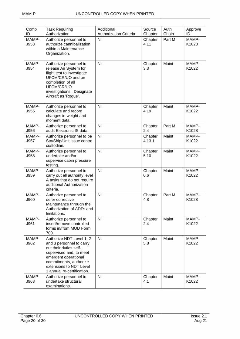
MAMP-J953
Authorize personnel to authorize cannibalization within a Maintenance Organization.
Nil Chapter 4.11
Part M MAMP-K1028
MAMP-J954
Authorize personnel to release Air System for flight test to investigate UFCM/CR/UO and on completion of all UFCM/CR/UO investigations. Designate Aircraft as 'Rogue'.
Nil Chapter 3.3
Maint MAMP-K1022
MAMP-J955
Authorize personnel to calculate and record changes in weight and moment data.
Nil Chapter 4.19
Maint MAMP-K1022
MAMP-J956
Authorize personnel to audit Electronic IS data.
Nil Chapter 2.4
Part M MAMP-K1028
MAMP-J957
Authorize personnel to be Stn/Ship/Unit issue centre custodian.
Nil Chapter 4.13.1
Maint MAMP-K1022
MAMP-J958
Authorize personnel to undertake and/or supervise cabin pressure testing.
Nil Chapter 5.10
Maint MAMP-K1022
MAMP-J959
Authorize personnel to carry out all authority level A tasks that do not require additional Authorization criteria.
Nil Chapter 0.6
Maint MAMP-K1022
MAMP-J960
Authorize personnel to defer corrective Maintenance through the Authorization of ADFs and limitations.
Nil Chapter 4.8
Part M MAMP-K1028
MAMP-J961
Authorize personnel to insert/remove controlled forms in/from MOD Form 700.
Nil Chapter 2.4
Maint MAMP-K1022
MAMP-J962
Authorize NDT Level 1, 2 and 3 personnel to carry out their duties self-supervised and, to meet emergent operational commitments, authorize extensions to NDT Level 1 annual re-certification.
Nil Chapter 5.8
Maint MAMP-K1022
MAMP-J963
Authorize personnel to undertake structural examinations.
Nil Chapter 4.1
Maint MAMP-K1022
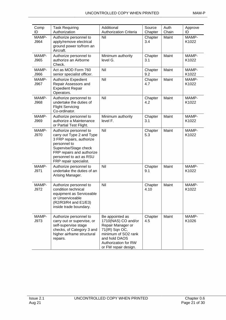
UNCONTROLLED COPY WHEN PRINTED MAM-P
Issue 2.1 Aug 21
UNCONTROLLED COPY WHEN PRINTED Chapter 0.6 Page 21 of 30
Comp ID
Task Requiring Authorization
Additional Authorization Criteria
Source Chapter
Auth Chain
Approve ID
MAMP-J964
Authorize personnel to apply/remove electrical ground power to/from an Aircraft.
Nil Chapter 3.4
Maint MAMP-K1022
MAMP-J965
Authorize personnel to authorize an Airborne Check.
Minimum authority level G.
Chapter 3.1
Maint MAMP-K1022
MAMP-J966
Act as MOD Form 760 senior specialist officer.
Nil Chapter 9.2
Maint MAMP-K1022
MAMP-J967
Authorize Expedient Repair Assessors and Expedient Repair Operators.
Nil Chapter 4.7
Maint MAMP-K1022
MAMP-J968
Authorize personnel to undertake the duties of Flight Servicing Co-ordinator.
Nil Chapter 4.2
Maint MAMP-K1022
MAMP-J969
Authorize personnel to authorize a Maintenance or Partial Test Flight.
Minimum authority level F.
Chapter 3.1
Maint MAMP-K1022
MAMP-J970
Authorize personnel to carry out Type 2 and Type 3 FRP repairs, authorize personnel to Supervise/Stage check FRP repairs and authorize personnel to act as RSU FRP repair specialist.
Nil Chapter 5.3
Maint MAMP-K1022
MAMP-J971
Authorize personnel to undertake the duties of an Arising Manager.
Nil Chapter 9.1
Maint MAMP-K1022
MAMP-J972
Authorize personnel to condition technical equipment as Serviceable or Unserviceable (R2/R3/R4 and E1/E3) inside trade boundary.
Nil Chapter 4.10
Maint MAMP-K1022
MAMP-J973
Authorize personnel to carry out or supervise, or self-supervise stage checks, of Category 3 and higher airframe structural repairs.
Be appointed as 1710(NAS) CO and/or Repair Manager or 71(IR) Sqn OC, minimum of SO2 rank and hold DAOS Authorization for RW or FW repair design.
Chapter 4.5
Maint MAMP-K1026
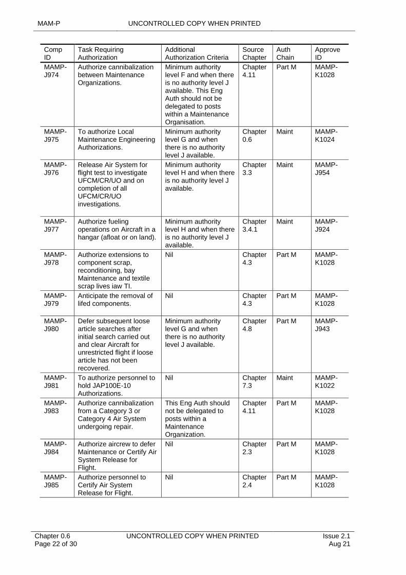
MAM-P UNCONTROLLED COPY WHEN PRINTED
Chapter 0.6 Page 22 of 30
UNCONTROLLED COPY WHEN PRINTED Issue 2.1 Aug 21
Comp ID
Task Requiring Authorization
Additional Authorization Criteria
Source Chapter
Auth Chain
Approve ID
MAMP-J974
Authorize cannibalization between Maintenance Organizations.
Minimum authority level F and when there is no authority level J available. This Eng Auth should not be delegated to posts within a Maintenance Organisation.
Chapter 4.11
Part M MAMP-K1028
MAMP-J975
To authorize Local Maintenance Engineering Authorizations.
Minimum authority level G and when there is no authority level J available.
Chapter 0.6
Maint MAMP-K1024
MAMP-J976
Release Air System for flight test to investigate UFCM/CR/UO and on completion of all UFCM/CR/UO investigations.
Minimum authority level H and when there is no authority level J available.
Chapter 3.3
Maint MAMP-J954
MAMP-J977
Authorize fueling operations on Aircraft in a hangar (afloat or on land).
Minimum authority level H and when there is no authority level J available.
Chapter 3.4.1
Maint MAMP-J924
MAMP-J978
Authorize extensions to component scrap, reconditioning, bay Maintenance and textile scrap lives iaw TI.
Nil Chapter 4.3
Part M MAMP-K1028
MAMP-J979
Anticipate the removal of lifed components.
Nil Chapter 4.3
Part M MAMP-K1028
MAMP-J980
Defer subsequent loose article searches after initial search carried out and clear Aircraft for unrestricted flight if loose article has not been recovered.
Minimum authority level G and when there is no authority level J available.
Chapter 4.8
Part M MAMP-J943
MAMP-J981
To authorize personnel to hold JAP100E-10 Authorizations.
Nil Chapter 7.3
Maint MAMP-K1022
MAMP-J983
Authorize cannibalization from a Category 3 or Category 4 Air System undergoing repair.
This Eng Auth should not be delegated to posts within a Maintenance Organization.
Chapter 4.11
Part M MAMP-K1028
MAMP-J984
Authorize aircrew to defer Maintenance or Certify Air System Release for Flight.
Nil Chapter 2.3
Part M MAMP-K1028
MAMP-J985
Authorize personnel to Certify Air System Release for Flight.
Nil Chapter 2.4
Part M MAMP-K1028
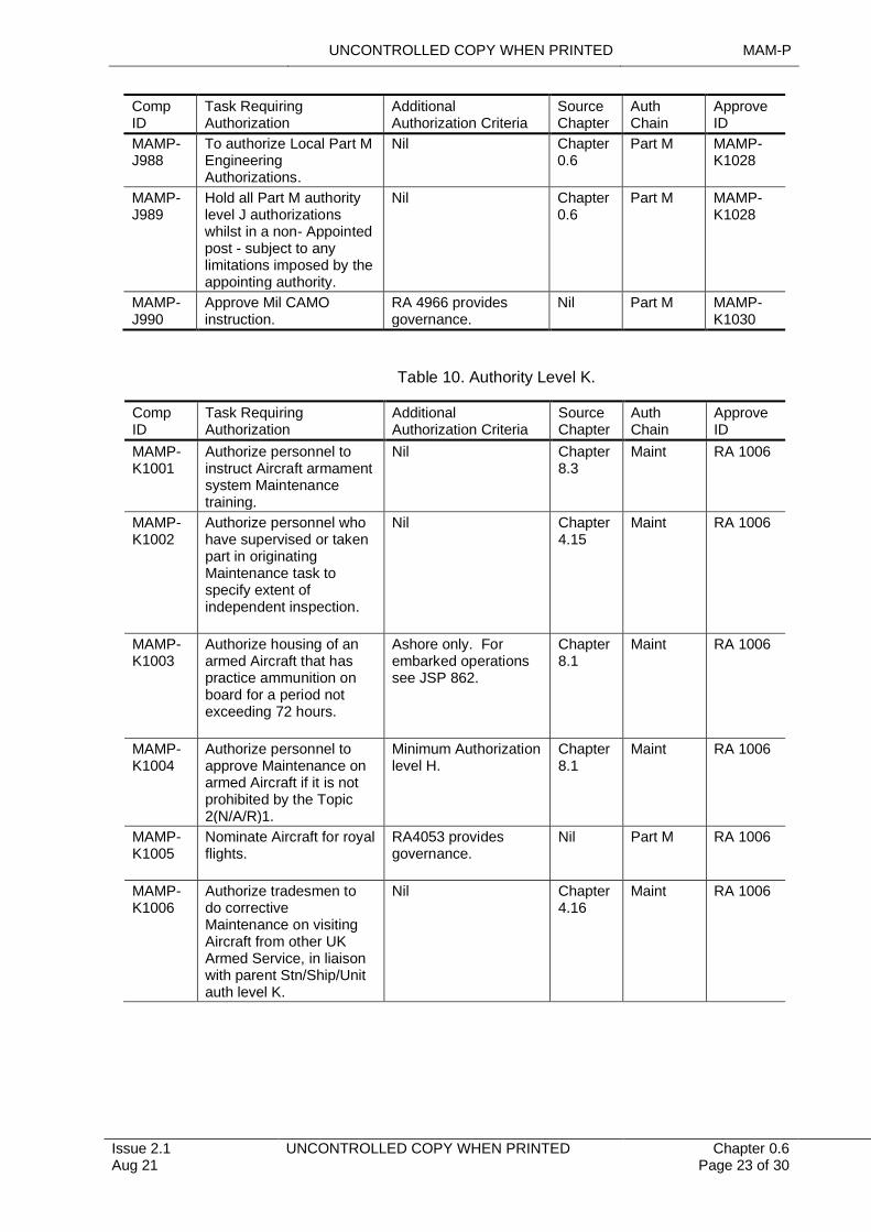
UNCONTROLLED COPY WHEN PRINTED MAM-P
Issue 2.1 Aug 21
UNCONTROLLED COPY WHEN PRINTED Chapter 0.6 Page 23 of 30
Comp ID
Task Requiring Authorization
Additional Authorization Criteria
Source Chapter
Auth Chain
Approve ID
MAMP-J988
To authorize Local Part M Engineering Authorizations.
Nil Chapter 0.6
Part M MAMP-K1028
MAMP-J989
Hold all Part M authority level J authorizations whilst in a non- Appointed post - subject to any limitations imposed by the appointing authority.
Nil Chapter 0.6
Part M MAMP-K1028
MAMP-J990
Approve Mil CAMO instruction.
RA 4966 provides governance.
Nil Part M MAMP-K1030
Table 10. Authority Level K.
Comp ID
Task Requiring Authorization
Additional Authorization Criteria
Source Chapter
Auth Chain
Approve ID
MAMP-K1001
Authorize personnel to instruct Aircraft armament system Maintenance training.
Nil Chapter 8.3
Maint RA 1006
MAMP-K1002
Authorize personnel who have supervised or taken part in originating Maintenance task to specify extent of independent inspection.
Nil Chapter 4.15
Maint RA 1006
MAMP-K1003
Authorize housing of an armed Aircraft that has practice ammunition on board for a period not exceeding 72 hours.
Ashore only. For embarked operations see JSP 862.
Chapter 8.1
Maint RA 1006
MAMP-K1004
Authorize personnel to approve Maintenance on armed Aircraft if it is not prohibited by the Topic 2(N/A/R)1.
Minimum Authorization level H.
Chapter 8.1
Maint RA 1006
MAMP-K1005
Nominate Aircraft for royal flights.
RA4053 provides governance.
Nil Part M RA 1006
MAMP-K1006
Authorize tradesmen to do corrective Maintenance on visiting Aircraft from other UK Armed Service, in liaison with parent Stn/Ship/Unit auth level K.
Nil Chapter 4.16
Maint RA 1006
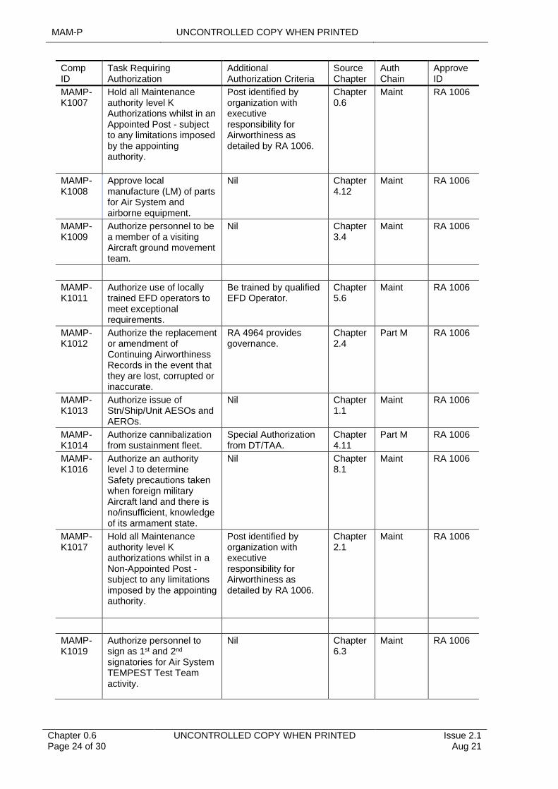
MAM-P UNCONTROLLED COPY WHEN PRINTED
Chapter 0.6 Page 24 of 30
UNCONTROLLED COPY WHEN PRINTED Issue 2.1 Aug 21
Comp ID
Task Requiring Authorization
Additional Authorization Criteria
Source Chapter
Auth Chain
Approve ID
MAMP-K1007
Hold all Maintenance authority level K Authorizations whilst in an Appointed Post - subject to any limitations imposed by the appointing authority.
Post identified by organization with executive responsibility for Airworthiness as detailed by RA 1006.
Chapter 0.6
Maint RA 1006
MAMP-K1008
Approve local manufacture (LM) of parts for Air System and airborne equipment.
Nil Chapter 4.12
Maint RA 1006
MAMP-K1009
Authorize personnel to be a member of a visiting Aircraft ground movement team.
Nil Chapter 3.4
Maint RA 1006
MAMP-K1011
Authorize use of locally trained EFD operators to meet exceptional requirements.
Be trained by qualified EFD Operator.
Chapter 5.6
Maint RA 1006
MAMP-K1012
Authorize the replacement or amendment of Continuing Airworthiness Records in the event that they are lost, corrupted or inaccurate.
RA 4964 provides governance.
Chapter 2.4
Part M RA 1006
MAMP-K1013
Authorize issue of Stn/Ship/Unit AESOs and AEROs.
Nil Chapter 1.1
Maint RA 1006
MAMP-K1014
Authorize cannibalization from sustainment fleet.
Special Authorization from DT/TAA.
Chapter 4.11
Part M RA 1006
MAMP-K1016
Authorize an authority level J to determine Safety precautions taken when foreign military Aircraft land and there is no/insufficient, knowledge of its armament state.
Nil Chapter 8.1
Maint RA 1006
MAMP-K1017
Hold all Maintenance authority level K authorizations whilst in a Non-Appointed Post - subject to any limitations imposed by the appointing authority.
Post identified by organization with executive responsibility for Airworthiness as detailed by RA 1006.
Chapter 2.1
Maint RA 1006
MAMP-K1019
Authorize personnel to sign as 1st and 2nd
signatories for Air System TEMPEST Test Team activity.
Nil Chapter 6.3
Maint RA 1006
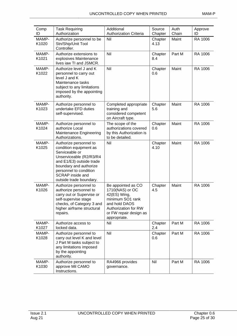
UNCONTROLLED COPY WHEN PRINTED MAM-P
Issue 2.1 Aug 21
UNCONTROLLED COPY WHEN PRINTED Chapter 0.6 Page 25 of 30
Comp ID
Task Requiring Authorization
Additional Authorization Criteria
Source Chapter
Auth Chain
Approve ID
MAMP-K1020
Authorize personnel to be Stn/Ship/Unit Tool Controller.
Nil Chapter 4.13
Maint RA 1006
MAMP-K1021
Authorize extensions to explosives Maintenance lives iaw TI and JSMCR.
Nil Chapter 8.4
Part M RA 1006
MAMP-K1022
Authorize level J and K personnel to carry out level J and K Maintenance tasks subject to any limitations imposed by the appointing authority.
Nil Chapter 0.6
Maint RA 1006
MAMP-K1023
Authorize personnel to undertake EFD duties self-supervised.
Completed appropriate training and considered competent on Aircraft type.
Chapter 5.6
Maint RA 1006
MAMP-K1024
Authorize personnel to authorize Local Maintenance Engineering Authorizations.
The scope of the authorizations covered by this Authorization is to be detailed.
Chapter 0.6
Maint RA 1006
MAMP-K1025
Authorize personnel to condition equipment as Serviceable or Unserviceable (R2/R3/R4 and E1/E3) outside trade boundary and authorize personnel to condition SCRAP inside and outside trade boundary.
Nil Chapter 4.10
Maint RA 1006
MAMP-K1026
Authorize personnel to authorize personnel to carry out or Supervise or self-supervise stage checks, of Category 3 and higher airframe structural repairs.
Be appointed as CO 1710(NAS) or OC 42(ES) Wing, minimum SO1 rank and hold DAOS Authorization for RW or FW repair design as appropriate.
Chapter 4.5
Maint RA 1006
MAMP-K1027
Authorize access to locked data.
Nil Chapter 2.4
Part M RA 1006
MAMP-K1028
Authorize personnel to carry out level K and level J Part M tasks subject to any limitations imposed by the appointing authority.
Nil Chapter 0.6
Part M RA 1006
MAMP-K1030
Authorize personnel to approve Mil CAMO Instructions.
RA4966 provides governance.
Nil Part M RA 1006
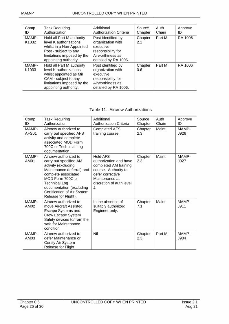
MAM-P UNCONTROLLED COPY WHEN PRINTED
Chapter 0.6 Page 26 of 30
UNCONTROLLED COPY WHEN PRINTED Issue 2.1 Aug 21
Comp ID
Task Requiring Authorization
Additional Authorization Criteria
Source Chapter
Auth Chain
Approve ID
MAMP-K1032
Hold all Part M authoritylevel K authorizations whilst in a Non-Appointed Post - subject to any limitations imposed by the appointing authority.
Post identified byorganization with executive responsibility for Airworthiness as detailed by RA 1006.
Chapter2.1
Part M RA 1006
MAMP-K1033
Hold all Part M authority level K authorizations whilst appointed as Mil CAM - subject to any limitations imposed by the appointing authority.
Post identified byorganization with executive responsibility for Airworthiness as detailed by RA 1006.
Chapter0.6
Part M RA 1006
Table 11. Aircrew Authorizations
Comp ID
Task Requiring Authorization
Additional Authorization Criteria
Source Chapter
Auth Chain
Approve ID
MAMP-AFS01
Aircrew authorized to carry out specified AFS activity and complete associated MOD Form 700C or Technical Log documentation.
Completed AFS training course.
Chapter 2.3
Maint MAMP-J926
MAMP-AM01
Aircrew authorized to carry out specified AM activity (excluding Maintenance deferral) and complete associated MOD Form 700C or Technical Log documentation (excluding Certification of Air System Release for Flight).
Hold AFS authorization and have completed AM training course. Authority to defer corrective Maintenance at discretion of auth level J.
Chapter 2.3
Maint MAMP-J927
MAMP- AM02
Aircrew authorized to move Aircraft Assisted Escape Systems and Crew Escape System Safety devices to/from the safe for Maintenance condition.
In the absence of suitably authorized Engineer only.
Chapter 7.1
Maint MAMP-J911
MAMP- AM03
Aircrew authorized to defer Maintenance or Certify Air System Release for Flight.
Nil Chapter 2.3
Part M MAMP-J984

UNCONTROLLED COPY WHEN PRINTED MAM-P
Issue 2.1 Aug 21
UNCONTROLLED COPY WHEN PRINTED Chapter 0.6 Page 27 of 30
Table 12. Limitation(s) Placed on Specific Authorization(s).
Lim Ref Limitation From To
1
2
3
4
5
6
7
8
9
10
11
12
13
14
15
16
17
18
19
20
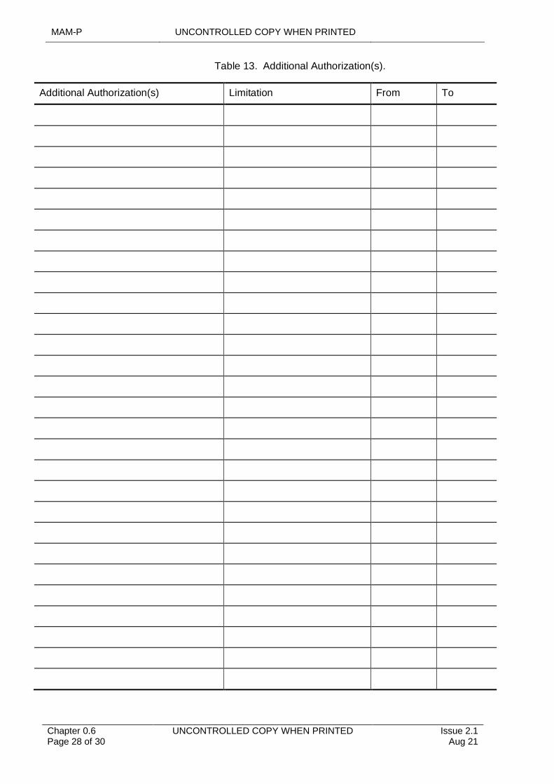
MAM-P UNCONTROLLED COPY WHEN PRINTED
Chapter 0.6 Page 28 of 30
UNCONTROLLED COPY WHEN PRINTED Issue 2.1 Aug 21
Table 13. Additional Authorization(s).
Additional Authorization(s) Limitation From To
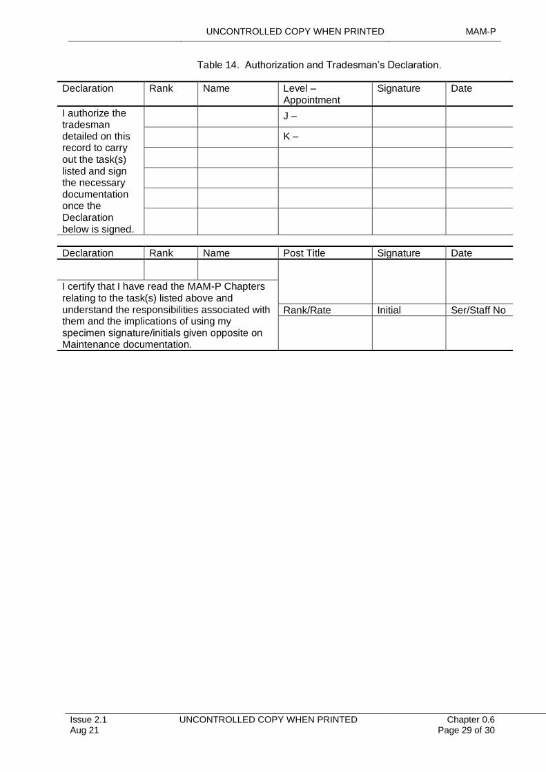
UNCONTROLLED COPY WHEN PRINTED MAM-P
Issue 2.1 Aug 21
UNCONTROLLED COPY WHEN PRINTED Chapter 0.6 Page 29 of 30
Table 14. Authorization and Tradesman’s Declaration.
Declaration Rank Name Level – Appointment
Signature Date
I authorize the tradesman detailed on this record to carry out the task(s) listed and sign the necessary documentation once the Declaration below is signed.
J –
K –
Declaration Rank Name Post Title Signature Date
I certify that I have read the MAM-P Chapters relating to the task(s) listed above and understand the responsibilities associated with them and the implications of using my specimen signature/initials given opposite on Maintenance documentation.
Rank/Rate Initial Ser/Staff No
MAM-P UNCONTROLLED COPY WHEN PRINTED
Chapter 0.6 Page 30 of 30
UNCONTROLLED COPY WHEN PRINTED Issue 2.1 Aug 21
Intentionally Blank for Print Pagination
UNCONTROLLED COPY WHEN PRINTED MAM-P
Issue 1.2 May 20
UNCONTROLLED COPY WHEN PRINTED Chapter 1.1 Page 1 of 6
.........................................................................................................................................................
...................
............................................................................................................................................................
............................................................................................................
..........................................................................................................................................................................
...........................................................................................................................................
................................................................................................................................................................................................................
........................................................................................
..............................................................................................................................
..........................................................................................................................................................
.......................................................................................................
Chapter 1.1
Aviation Engineering Orders
TABLE OF CONTENTS
Paragraph Page
1 General 11.1 Introduction 11.2 Associated Publications or Instructions 11.3 Additional Information 22 Deconfliction and Amalgamation of Orders 23 Scope, Structure and Layout of Station/Ship/Unit Aviation Engineering
Standing Orders 33.1 Scope 33.2 Structure 33.3 Layout 44 AESO Issue, Review, Amendment and Withdrawal 45 AESO Reading and Recording 46 AEROs 47 Squadron/Unit Aviation Engineering Standing Orders 57.1 Squadron/Unit AESOs 57.2 Deployed Squadron/Unit AEROs 58 Authorizations 5
LIST OF TABLES
Table 1. AESOs, Book 1 – Function, Organization and Responsibilities. 3Table 2. AESOs Book 2 – Orders 3Table 3. Associated Authorizations 5
1 General
1.1 Introduction
Aviation Engineering Orders are a method of publicizing low level engineering instructions to a wider audience. The instructions will be publicized as Aviation Engineering Standing Orders (AESOs) and Aviation Engineering Routine Orders (AEROs). This chapter describes the purpose, scope, layout and format of AESOs and AEROs, and defines how they are issued and reviewed.
1.2 Associated Publications or Instructions
1 RA 1006 – Delegation of Engineering Authorizations
2 RA 1023 – Chief Air Engineers – Air Safety Responsibilities
3 RA 4009 – Aviation Engineering Orders
4 RA 4810 – Technical Information (MRP 145.A.45)
5 RA 4815 – Maintenance Procedures and Safety and Quality Policy (MRP 145.A.65)
6 RA 4947 – Continuing Airworthiness Management - MRP Part M Sub Part G
MAM-P UNCONTROLLED COPY WHEN PRINTED
Chapter 1.1 Page 2 of 6
UNCONTROLLED COPY WHEN PRINTED Issue 1.2 May 20
7 RA 4966 – Military Continuing Airworthiness Management Organization Instructions - MRP Part M Sub Part C
8 JSP 940 – MOD Policy for Quality
9 BRd 2 – Paragraph. 1102 – Roles and Responsibilities of the Air Station Air Engineer Officer
10 BRd 2 – Paragraph 1103 – Roles and Responsibilities of the Ship Air Engineer Officer
11 AP100B-01 Order 1.1 – Annex C – Responsibilities of Chief Air Engineer (DDH) within the Overall Airworthiness Framework
12 AP7400 – Continuing Airworthiness Engineering (Army)
1.3 Additional Information
The Military Continuing Airworthiness Manager (Mil CAM) is to ensure that local engineering instructions are promulgated in Aviation Engineering Orders and / or local procedures. These orders may be discrete documents or may form part of a broader Station/Ship/Unit (Stn/Ship/Unit) Publication, embracing non-aviation engineering and supply instructions that are an integral part of the Stn/Ship/Unit function. They may also include orders relating to collocated Depth Organizations. The content of this chapter is to be considered as recommended practice.
Squadron(Sqn)/Unit authority Level Js may also issue orders as described at paragraph 7. These orders facilitate the expansion of and compliance with regulations or higher level instructions in order to account for local environment/conditions.
Note:
1 The primary purpose of local orders and procedures will be to take account of the local conditions and/or to achieve a more efficient task scheduling. They may refer to the Air System/Equipment Document Set (ADS/EDS) but are not to duplicate or be used to replace any Technical Information (TI) within the ADS/EDS. Where local orders and procedures refer to the ADS/EDS, this should be included in the list of Reference Publications, including its latest amendment state. Subsequent local orders and procedures may refer to specific procedures within the ADS/EDS, without the need to refer to the ADS/EDS amendment state.
2 Local orders and procedures are not to be used to correct errors or omissions in the ADS/EDS; the appropriate method for correcting the ADS/EDS is detailed at RA 4810 and Chapter 10.1 – Management and Amendment of Technical Information.
3 They form part of the Quality Management System (QMS) in accordance with (iaw) JSP 940, RA 4815 and Chapter 11.1 – Defence Air Environment Quality Policy.
2 Deconfliction and Amalgamation of Orders
When multiple DDHs are operating from the same Stn/Ship/Unit or Site, engineering activity is to be coordinated between all DDH CAEs, who are to ensure that AESOs and AEROs are amalgamated, where possible, in order to promote efficient use of shared facilities and to avoid conflicting orders.
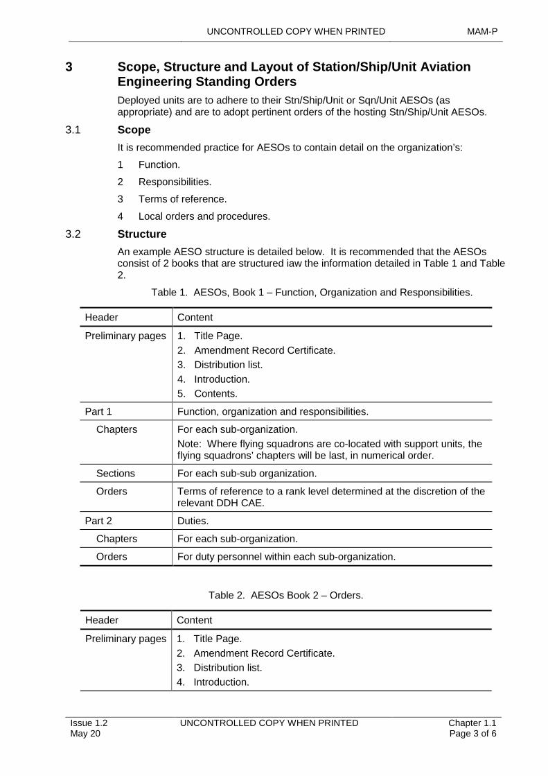
UNCONTROLLED COPY WHEN PRINTED MAM-P
Issue 1.2 May 20
UNCONTROLLED COPY WHEN PRINTED Chapter 1.1 Page 3 of 6
3 Scope, Structure and Layout of Station/Ship/Unit Aviation Engineering Standing Orders
Deployed units are to adhere to their Stn/Ship/Unit or Sqn/Unit AESOs (as appropriate) and are to adopt pertinent orders of the hosting Stn/Ship/Unit AESOs.
3.1 Scope
It is recommended practice for AESOs to contain detail on the organization’s:
1 Function.
2 Responsibilities.
3 Terms of reference.
4 Local orders and procedures.
3.2 Structure
An example AESO structure is detailed below. It is recommended that the AESOs consist of 2 books that are structured iaw the information detailed in Table 1 and Table 2.
Table 1. AESOs, Book 1 – Function, Organization and Responsibilities.
Header Content
Preliminary pages 1. Title Page.
2. Amendment Record Certificate.
3. Distribution list.
4. Introduction.
5. Contents.
Part 1 Function, organization and responsibilities.
Chapters For each sub-organization.
Note: Where flying squadrons are co-located with support units, the flying squadrons’ chapters will be last, in numerical order.
Sections For each sub-sub organization.
Orders Terms of reference to a rank level determined at the discretion of the relevant DDH CAE.
Part 2 Duties.
Chapters For each sub-organization.
Orders For duty personnel within each sub-organization.
Table 2. AESOs Book 2 – Orders.
Header Content
Preliminary pages 1. Title Page.
2. Amendment Record Certificate.
3. Distribution list.
4. Introduction.
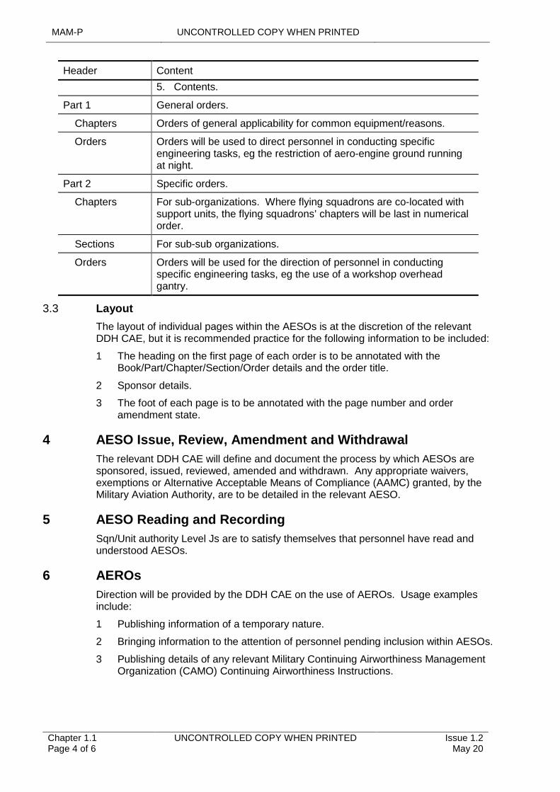
MAM-P UNCONTROLLED COPY WHEN PRINTED
Chapter 1.1 Page 4 of 6
UNCONTROLLED COPY WHEN PRINTED Issue 1.2 May 20
Header Content
5. Contents.
Part 1 General orders.
Chapters Orders of general applicability for common equipment/reasons.
Orders Orders will be used to direct personnel in conducting specific engineering tasks, eg the restriction of aero-engine ground running at night.
Part 2 Specific orders.
Chapters For sub-organizations. Where flying squadrons are co-located with support units, the flying squadrons’ chapters will be last in numerical order.
Sections For sub-sub organizations.
Orders Orders will be used for the direction of personnel in conducting specific engineering tasks, eg the use of a workshop overhead gantry.
3.3 Layout
The layout of individual pages within the AESOs is at the discretion of the relevant DDH CAE, but it is recommended practice for the following information to be included:
1 The heading on the first page of each order is to be annotated with the Book/Part/Chapter/Section/Order details and the order title.
2 Sponsor details.
3 The foot of each page is to be annotated with the page number and order amendment state.
4 AESO Issue, Review, Amendment and Withdrawal
The relevant DDH CAE will define and document the process by which AESOs are sponsored, issued, reviewed, amended and withdrawn. Any appropriate waivers, exemptions or Alternative Acceptable Means of Compliance (AAMC) granted, by the Military Aviation Authority, are to be detailed in the relevant AESO.
5 AESO Reading and Recording
Sqn/Unit authority Level Js are to satisfy themselves that personnel have read and understood AESOs.
6 AEROs
Direction will be provided by the DDH CAE on the use of AEROs. Usage examples include:
1 Publishing information of a temporary nature.
2 Bringing information to the attention of personnel pending inclusion within AESOs.
3 Publishing details of any relevant Military Continuing Airworthiness Management Organization (CAMO) Continuing Airworthiness Instructions.
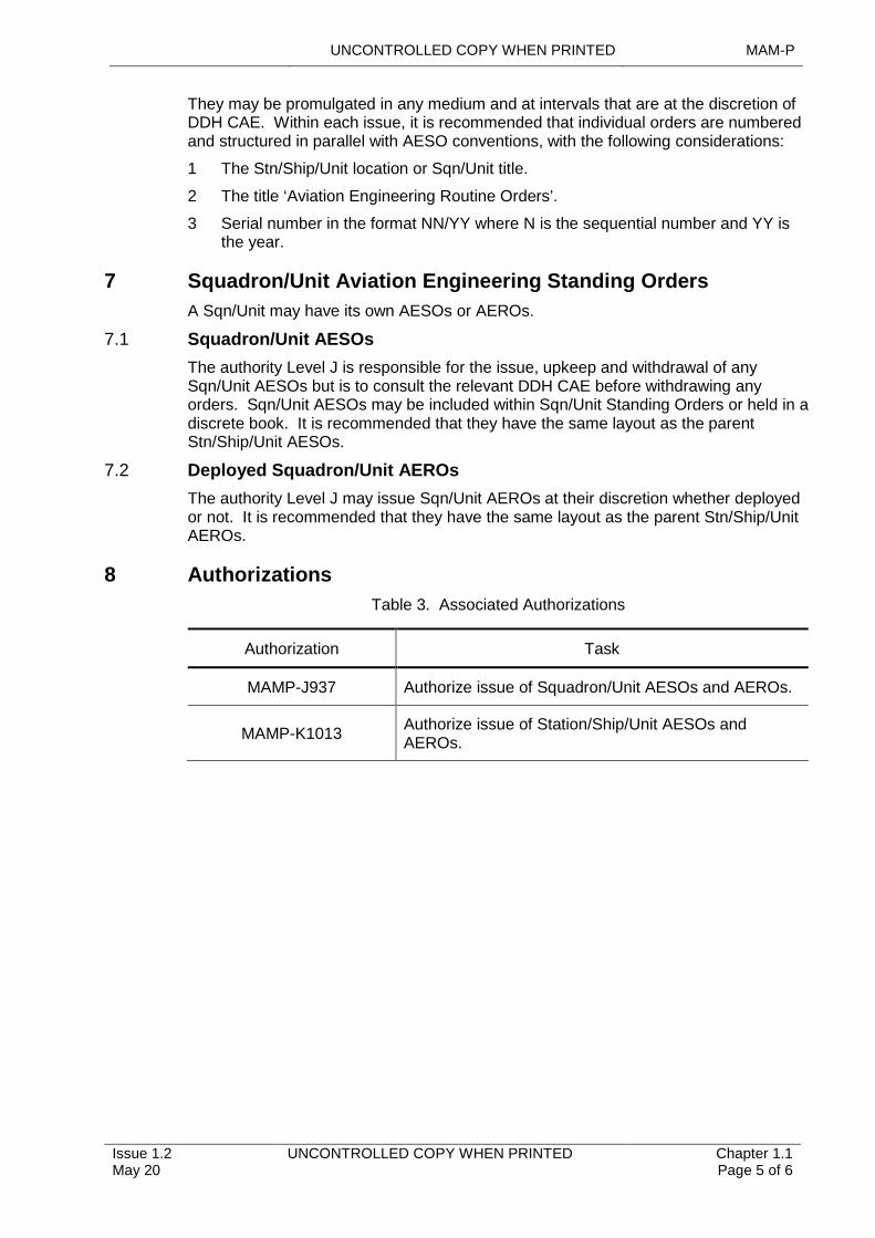
UNCONTROLLED COPY WHEN PRINTED MAM-P
Issue 1.2 May 20
UNCONTROLLED COPY WHEN PRINTED Chapter 1.1 Page 5 of 6
They may be promulgated in any medium and at intervals that are at the discretion of DDH CAE. Within each issue, it is recommended that individual orders are numbered and structured in parallel with AESO conventions, with the following considerations:
1 The Stn/Ship/Unit location or Sqn/Unit title.
2 The title ‘Aviation Engineering Routine Orders’.
3 Serial number in the format NN/YY where N is the sequential number and YY is the year.
7 Squadron/Unit Aviation Engineering Standing Orders
A Sqn/Unit may have its own AESOs or AEROs.
7.1 Squadron/Unit AESOs
The authority Level J is responsible for the issue, upkeep and withdrawal of any Sqn/Unit AESOs but is to consult the relevant DDH CAE before withdrawing any orders. Sqn/Unit AESOs may be included within Sqn/Unit Standing Orders or held in a discrete book. It is recommended that they have the same layout as the parent Stn/Ship/Unit AESOs.
7.2 Deployed Squadron/Unit AEROs
The authority Level J may issue Sqn/Unit AEROs at their discretion whether deployed or not. It is recommended that they have the same layout as the parent Stn/Ship/Unit AEROs.
8 Authorizations
Table 3. Associated Authorizations
Authorization Task
MAMP-J937 Authorize issue of Squadron/Unit AESOs and AEROs.
MAMP-K1013Authorize issue of Station/Ship/Unit AESOs and AEROs.

MAM-P UNCONTROLLED COPY WHEN PRINTED
Chapter 1.1 Page 6 of 6
UNCONTROLLED COPY WHEN PRINTED Issue 1.2 May 20
Intentionally Blank for Print Pagination
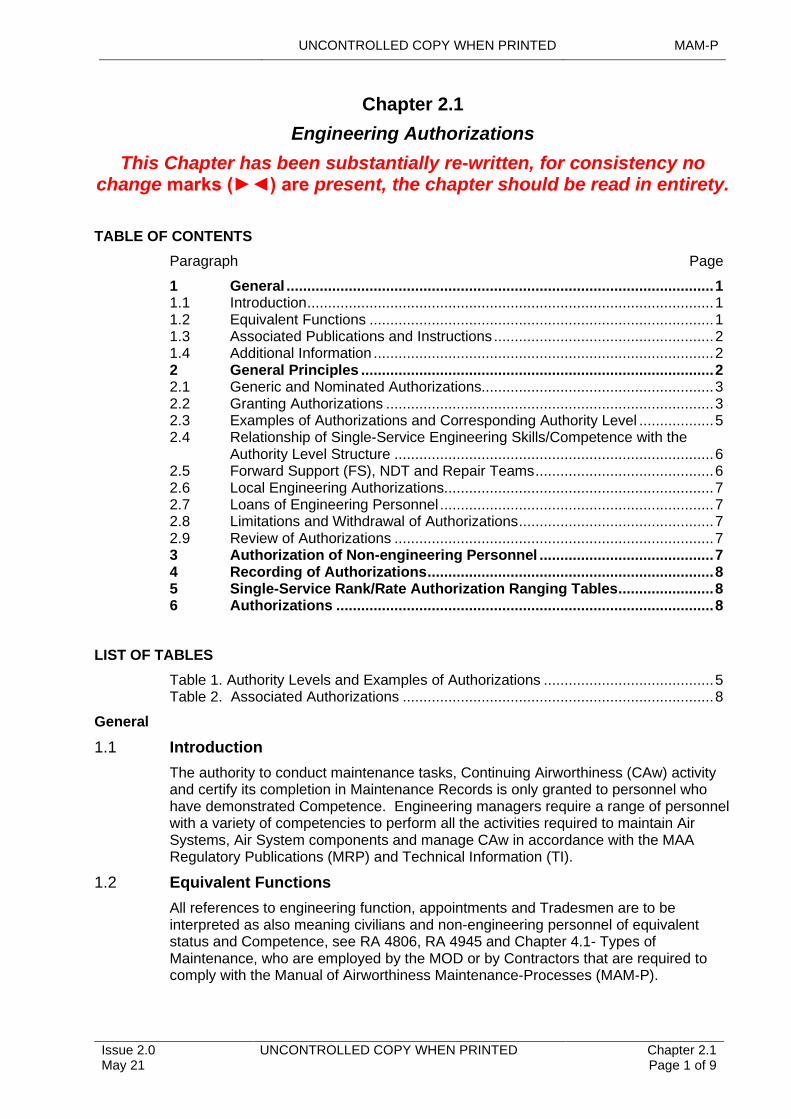
UNCONTROLLED COPY WHEN PRINTED MAM-P
Issue 2.0 May 21
UNCONTROLLED COPY WHEN PRINTED Chapter 2.1 Page 1 of 9
....................................................................................................................
..................................................................................................................
...............................................................................................................
............................................................................................................................
...................................................................................................................................
........................................................................................................................
.................................................................................................
.............................................................................................................................................
.......................................................................................................................................
.....................................................................................................................................................................................
.......................................................................................................
Chapter 2.1
Engineering Authorizations
This Chapter has been substantially re-written, for consistency no change marks (►◄) are present, the chapter should be read in entirety.
TABLE OF CONTENTS
Paragraph Page
1 General 11.1 Introduction 11.2 Equivalent Functions 11.3 Associated Publications and Instructions 21.4 Additional Information 22 General Principles 22.1 Generic and Nominated Authorizations 32.2 Granting Authorizations 32.3 Examples of Authorizations and Corresponding Authority Level 52.4 Relationship of Single-Service Engineering Skills/Competence with the
Authority Level Structure 62.5 Forward Support (FS), NDT and Repair Teams 62.6 Local Engineering Authorizations 72.7 Loans of Engineering Personnel 72.8 Limitations and Withdrawal of Authorizations 72.9 Review of Authorizations 73 Authorization of Non-engineering Personnel 74 Recording of Authorizations 85 Single-Service Rank/Rate Authorization Ranging Tables 86 Authorizations 8
LIST OF TABLES
Table 1. Authority Levels and Examples of Authorizations 5Table 2. Associated Authorizations 8
General
1.1 Introduction
The authority to conduct maintenance tasks, Continuing Airworthiness (CAw) activity and certify its completion in Maintenance Records is only granted to personnel who have demonstrated Competence. Engineering managers require a range of personnel with a variety of competencies to perform all the activities required to maintain Air Systems, Air System components and manage CAw in accordance with the MAA Regulatory Publications (MRP) and Technical Information (TI).
1.2 Equivalent Functions
All references to engineering function, appointments and Tradesmen are to be interpreted as also meaning civilians and non-engineering personnel of equivalent status and Competence, see RA 4806, RA 4945 and Chapter 4.1- Types of Maintenance, who are employed by the MOD or by Contractors that are required to comply with the Manual of Airworthiness Maintenance-Processes (MAM-P).
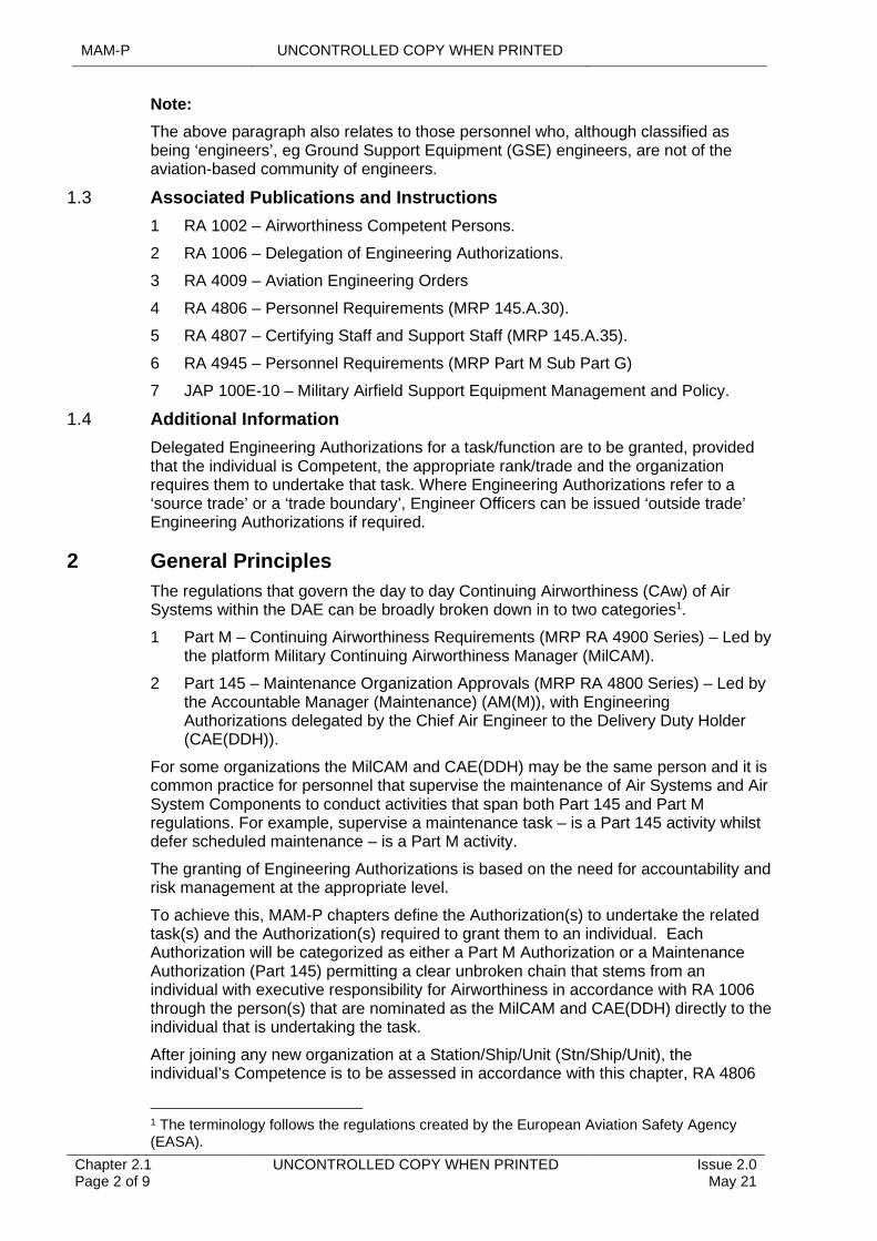
MAM-P UNCONTROLLED COPY WHEN PRINTED
Chapter 2.1 Page 2 of 9
UNCONTROLLED COPY WHEN PRINTED Issue 2.0 May 21
Note:
The above paragraph also relates to those personnel who, although classified as being ‘engineers’, eg Ground Support Equipment (GSE) engineers, are not of the aviation-based community of engineers.
1.3 Associated Publications and Instructions
1 RA 1002 – Airworthiness Competent Persons.
2 RA 1006 – Delegation of Engineering Authorizations.
3 RA 4009 – Aviation Engineering Orders
4 RA 4806 – Personnel Requirements (MRP 145.A.30).
5 RA 4807 – Certifying Staff and Support Staff (MRP 145.A.35).
6 RA 4945 – Personnel Requirements (MRP Part M Sub Part G)
7 JAP 100E-10 – Military Airfield Support Equipment Management and Policy.
1.4 Additional Information
Delegated Engineering Authorizations for a task/function are to be granted, provided that the individual is Competent, the appropriate rank/trade and the organization requires them to undertake that task. Where Engineering Authorizations refer to a ‘source trade’ or a ‘trade boundary’, Engineer Officers can be issued ‘outside trade’ Engineering Authorizations if required.
2 General Principles
The regulations that govern the day to day Continuing Airworthiness (CAw) of Air Systems within the DAE can be broadly broken down in to two categories1.
1 Part M – Continuing Airworthiness Requirements (MRP RA 4900 Series) – Led by the platform Military Continuing Airworthiness Manager (MilCAM).
2 Part 145 – Maintenance Organization Approvals (MRP RA 4800 Series) – Led by the Accountable Manager (Maintenance) (AM(M)), with Engineering Authorizations delegated by the Chief Air Engineer to the Delivery Duty Holder (CAE(DDH)).
For some organizations the MilCAM and CAE(DDH) may be the same person and it is common practice for personnel that supervise the maintenance of Air Systems and Air System Components to conduct activities that span both Part 145 and Part M regulations. For example, supervise a maintenance task – is a Part 145 activity whilst defer scheduled maintenance – is a Part M activity.
The granting of Engineering Authorizations is based on the need for accountability and risk management at the appropriate level.
To achieve this, MAM-P chapters define the Authorization(s) to undertake the related task(s) and the Authorization(s) required to grant them to an individual. Each Authorization will be categorized as either a Part M Authorization or a Maintenance Authorization (Part 145) permitting a clear unbroken chain that stems from an individual with executive responsibility for Airworthiness in accordance with RA 1006 through the person(s) that are nominated as the MilCAM and CAE(DDH) directly to the individual that is undertaking the task.
After joining any new organization at a Station/Ship/Unit (Stn/Ship/Unit), the individual’s Competence is to be assessed in accordance with this chapter, RA 4806
1 The terminology follows the regulations created by the European Aviation Safety Agency (EASA).
UNCONTROLLED COPY WHEN PRINTED MAM-P
Issue 2.0 May 21
UNCONTROLLED COPY WHEN PRINTED Chapter 2.1 Page 3 of 9
and/or RA4945; where applicable, paying attention to any specific regulatory requirements, as summarized at Paragraph 2.2.2. An individual holding the relevant Part M or Maintenance category Level J or K Authorization, which itself will have been cascaded from an individual with executive responsibility for Airworthiness may then grant the individual the necessary Authorization(s) to carry out the required tasks within that appointment/draft.
2.1 Generic and Nominated Authorizations
The Part M or Maintenance category, Level J or K Authorization holder (as appropriate) granting the Authorization(s) are to make sure that the individual being authorized holds any additional criteria, as detailed in the relevant source chapter.
In addition to Part M and Maintenance categories, MAM-P Engineering Authorizations are further divided into 2 groups:
1 Generic Engineering Authorizations that are granted by virtue of trade, Rank/Rate or appointment.
2 Engineering Authorizations granted to nominated individuals in response to an operational/maintenance necessity or to enhance an organization’s effectiveness or efficiency. They are not solely dependent on the rank/rate of an individual and are normally granted for specific tasks or specific periods. Examples of this second group of Authorizations may include:
2.1 Undertaking a task normally carried out by someone of a higher rank.
2.2 Undertaking the additional responsibilities required for exercises and detachments.
2.3 Undertaking the responsibilities of 1st and/or 2nd signature for work in another trade group.
2.4 Tasks requiring specialist training (eg Non-Destructive Team (NDT) or Vibration Equipment (VE) operator).
The policy for granting Engineering Authorizations is set by each single-Service in their appropriate orders.
Organizations may limit the number of qualified personnel authorized to undertake a task to retain a higher level of currency through frequent practice.
2.2 Granting Authorizations
Personnel holding the relevant Part M or Maintenance category Level J or K Engineering Authorization may grant MAM-P Engineering Authorizations. Arrangements for local Authorizations are at Paragraph 2.6.
Note:
In those exceptional cases where there is no individual holding the relevant Part M or Maintenance category Level J or K Authorization required to grant MAM-P Authorizations, an individual with defined executive responsibility for Airworthiness may instead grant them using the processes detailed in this chapter; RA 1006 refers.
2.2.1 Assessment of Competence
Prior to the Level J or K holder granting a Part M or Maintenance category Authorization, they are to assess the individual’s Competence to be awarded the Authorization.
A Competent person is one who has enough theoretical knowledge, practical ability and experience of the relevant subject matter to complete the tasks required of them in a satisfactory manner. The elements of Competence are:
MAM-P UNCONTROLLED COPY WHEN PRINTED
Chapter 2.1 Page 4 of 9
UNCONTROLLED COPY WHEN PRINTED Issue 2.0 May 21
1 Theoretical knowledge – The completion of individual training and an understanding of the responsibilities associated with the task.
2 Practical ability – Comprehension of the subject matter, operational situation and any local considerations, plus a detailed knowledge of engineering principles, including hands on physical skills.
3 Experience - Gained through observation or practice, resulting from theoretical knowledge and practical ability.
The content of the assessment of Competence is at the discretion of the Part M or Maintenance category Level J or K holder and may contain some or all the following:
3.1 The content of any related record of Competency Assessment held by the individual or organization.
3.2 Any relevant course certificates held by the individual.
3.3 Direct observation of the individual’s workmanship.
3.4 An interview with the individual.
3.5 Personal knowledge of the individual.
3.6 Information provided by the individual’s immediate supervisors/managers.
Note:
The individual assessing and certifying competence on a formal Record of Competency Assessment is to be suitably trained, competent and authorized, to carry out the assessment. All Competence Assessment Records are to contain details of the activity, limitations, relevant training courses and periods or conditions of validity. They should also record the assessors name and appointment.
2.2.2 Certifying and Support Staff with Supervisory Responsibilities
RA 4807 places specific regulatory requirements on the Authorization of personnel undertaking the duties of ‘3rd signature’ (known as ‘Certifying Staff’) and ‘2nd signature’ (known as Support Staff with Supervisory Responsibilities); the role of these individuals is explained further in Chapter 2.4 - Certification and Management of Maintenance Documentation. As such, the following criteria is to be met by an individual prior to receiving 2nd signature and/or 3rd signature Authorizations:
1 Staff receiving these Authorizations are to have first completed the applicable Air System type training and had the associated qualification annotated on their training record.
2 Staff receiving these Authorizations are to be at least 21 years of age, as detailed in RA4807(13), unless a regulatory waiver has been granted by the MAA for that particular group of individuals (eg individuals who have attended an accelerated training scheme) or work on a particular Air System type.
3 Once authorized, individuals holding 2nd signature or 3rd signature Authorizations are to maintain at least 6 months of relevant Air System Maintenance experience in any consecutive 2-year period, as detailed in RA 4807(3).
2.2.3 Level J or K ‘by appointment’ Authorizations
Personnel holding MAMP-J949 (Maintenance) and/or J989 (Part M) or MAMP-K1007 (Maintenance) and/or K1033 (Part M) (Authorizations relating to ‘by appointment’ posts – ie those personnel assessed Competent and appointed in accordance with RA 1006) may grant, subject to any limitation imposed by their relevant higher authority, all Authorizations appropriate to their Authorization permitted within individual MAM-P chapters and the Standard and Special Authorization range in their respective single-Service engineering policy.
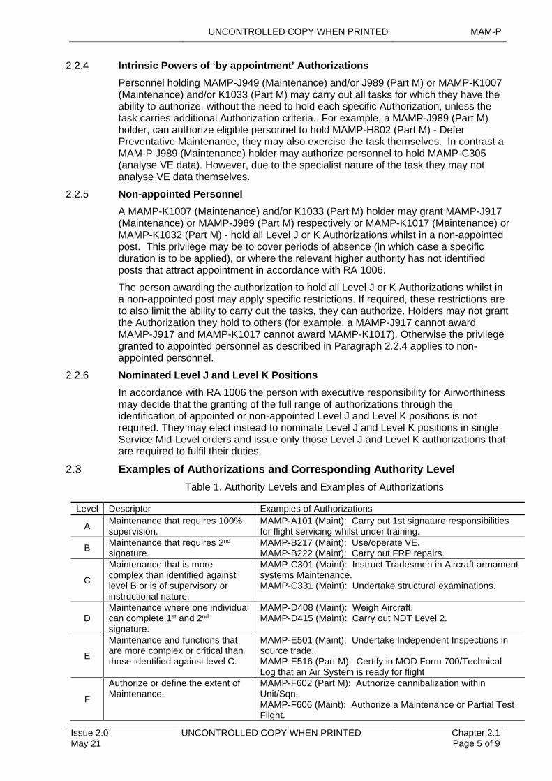
UNCONTROLLED COPY WHEN PRINTED MAM-P
Issue 2.0 May 21
UNCONTROLLED COPY WHEN PRINTED Chapter 2.1 Page 5 of 9
2.2.4 Intrinsic Powers of ‘by appointment’ Authorizations
Personnel holding MAMP-J949 (Maintenance) and/or J989 (Part M) or MAMP-K1007 (Maintenance) and/or K1033 (Part M) may carry out all tasks for which they have the ability to authorize, without the need to hold each specific Authorization, unless the task carries additional Authorization criteria. For example, a MAMP-J989 (Part M) holder, can authorize eligible personnel to hold MAMP-H802 (Part M) - Defer Preventative Maintenance, they may also exercise the task themselves. In contrast a MAM-P J989 (Maintenance) holder may authorize personnel to hold MAMP-C305 (analyse VE data). However, due to the specialist nature of the task they may not analyse VE data themselves.
2.2.5 Non-appointed Personnel
A MAMP-K1007 (Maintenance) and/or K1033 (Part M) holder may grant MAMP-J917 (Maintenance) or MAMP-J989 (Part M) respectively or MAMP-K1017 (Maintenance) or MAMP-K1032 (Part M) - hold all Level J or K Authorizations whilst in a non-appointed post. This privilege may be to cover periods of absence (in which case a specific duration is to be applied), or where the relevant higher authority has not identified posts that attract appointment in accordance with RA 1006.
The person awarding the authorization to hold all Level J or K Authorizations whilst in a non-appointed post may apply specific restrictions. If required, these restrictions are to also limit the ability to carry out the tasks, they can authorize. Holders may not grant the Authorization they hold to others (for example, a MAMP-J917 cannot award MAMP-J917 and MAMP-K1017 cannot award MAMP-K1017). Otherwise the privilege granted to appointed personnel as described in Paragraph 2.2.4 applies to non-appointed personnel.
2.2.6 Nominated Level J and Level K Positions
In accordance with RA 1006 the person with executive responsibility for Airworthiness may decide that the granting of the full range of authorizations through the identification of appointed or non-appointed Level J and Level K positions is not required. They may elect instead to nominate Level J and Level K positions in single Service Mid-Level orders and issue only those Level J and Level K authorizations that are required to fulfil their duties.
2.3 Examples of Authorizations and Corresponding Authority Level
Table 1. Authority Levels and Examples of Authorizations
Level Descriptor Examples of Authorizations
AMaintenance that requires 100% supervision.
MAMP-A101 (Maint): Carry out 1st signature responsibilities for flight servicing whilst under training.
BMaintenance that requires 2nd
signature.MAMP-B217 (Maint): Use/operate VE. MAMP-B222 (Maint): Carry out FRP repairs.
C
Maintenance that is more complex than identified against level B or is of supervisory or instructional nature.
MAMP-C301 (Maint): Instruct Tradesmen in Aircraft armament systems Maintenance. MAMP-C331 (Maint): Undertake structural examinations.
DMaintenance where one individual can complete 1st and 2nd
signature.
MAMP-D408 (Maint): Weigh Aircraft. MAMP-D415 (Maint): Carry out NDT Level 2.
E
Maintenance and functions that are more complex or critical than those identified against level C.
MAMP-E501 (Maint): Undertake Independent Inspections in source trade. MAMP-E516 (Part M): Certify in MOD Form 700/Technical Log that an Air System is ready for flight
F
Authorize or define the extent of Maintenance.
MAMP-F602 (Part M): Authorize cannibalization within Unit/Sqn. MAMP-F606 (Maint): Authorize a Maintenance or Partial Test Flight.
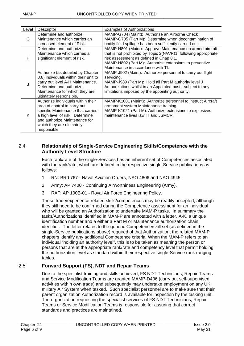
MAM-P UNCONTROLLED COPY WHEN PRINTED
Chapter 2.1 Page 6 of 9
UNCONTROLLED COPY WHEN PRINTED Issue 2.0 May 21
Level Descriptor Examples of Authorizations
GDetermine and authorize Maintenance which carries an increased element of Risk.
MAMP-G704 (Maint): Authorize an Airborne Check MAMP-G705 (Part M): Determine when decontamination of bodily fluid spillage has been sufficiently carried out.
H
Determine and authorize Maintenance which carries a significant element of risk.
MAMP-H801 (Maint): Approve Maintenance on armed aircraft that is not prohibited by Topic 2(N/A/R)1, following appropriate risk assessment as defined in Chap 8.1. MAMP-H802 (Part M): Authorise extensions to preventive Maintenance in accordance with TI.
J
Authorize (as detailed by Chapter 0.6) individuals within their unit to carry out level A-H Maintenance. Determine and authorize Maintenance for which they are ultimately responsible.
MAMP-J902 (Maint): Authorize personnel to carry out flight servicing. MAMP-J989 (Part M): Hold all Part M authority level J Authorizations whilst in an Appointed post - subject to any limitations imposed by the appointing authority.
K
Authorize individuals within their area of control to carry out specific Maintenance that carries a high level of risk. Determine and authorize Maintenance for which they are ultimately responsible.
MAMP-K1001 (Maint): Authorize personnel to instruct Aircraft armament system Maintenance training MAMP-K1021 (Part M): Authorize extensions to explosives maintenance lives iaw TI and JSMCR.
2.4 Relationship of Single-Service Engineering Skills/Competence with the Authority Level Structure
Each rank/rate of the single-Services has an inherent set of Competences associated with the rank/rate, which are defined in the respective single-Service publications as follows:
1 RN: BRd 767 - Naval Aviation Orders, NAO 4806 and NAO 4945.
2 Army: AP 7400 - Continuing Airworthiness Engineering (Army).
3 RAF: AP 100B-01 - Royal Air Force Engineering Policy.
These trade/experience-related skills/competences may be readily accepted, although they still need to be confirmed during the Competence assessment for an individual who will be granted an Authorization to undertake MAM-P tasks. In summary the tasks/Authorizations identified in MAM-P are annotated with a letter, A-K, a unique identification number and a either a Part M or Maintenance authorization chain identifier. The letter relates to the generic Competence/skill set (as defined in the single-Service publications above) required of that Authorization, the related MAM-P chapters identify any additional Competence criteria. When the MAM-P refers to an individual “holding an authority level”, this is to be taken as meaning the person or persons that are at the appropriate rank/rate and competency level that permit holding the authorization level as standard within their respective single-Service rank ranging tables.
2.5 Forward Support (FS), NDT and Repair Teams
Due to the specialist training and skills achieved, FS NDT Technicians, Repair Teams and Service Modification Teams are granted MAMP-D406 (carry out self-supervised activities within own trade) and subsequently may undertake employment on any UK military Air System when tasked. Such specialist personnel are to make sure that their parent organization Authorization record is available for inspection by the tasking unit. The organization requesting the specialist services of FS NDT Technicians, Repair Teams or Service Modification Teams is responsible for assuring that correct standards and practices are maintained.
UNCONTROLLED COPY WHEN PRINTED MAM-P
Issue 2.0 May 21
UNCONTROLLED COPY WHEN PRINTED Chapter 2.1 Page 7 of 9
2.6 Local Engineering Authorizations
Where a MilCAM or CAE(DDH) considers that there is a requirement for Authorizations that are not detailed in the MAM-P, they are to be published in Aviation Engineering Standing Orders (AESOs) issued in accordance with RA 4009 and Chapter 1.1- Aviation Engineering Orders. These Authorizations are known as Local Engineering Authorizations (LEAs). Typical examples of LEAs include opening and closing hangar doors or operating overhead cranes. The MilCAM or CAE(DDH) is to identify who may hold the MAMP-J975 (Maint) or MAMP-J988 (Part M) Authorizations (to authorize LEAs) in AESOs and who may hold the relevant local Authorizations. Where there is a need to standardize local Authorizations across several Ships/Stn/Units or an Air System fleet, the MilCAM is to issue instructions to control this.
2.7 Loans of Engineering Personnel
Engineering personnel that are loaned between organizations for specific tasks or for specific periods of employment may, with agreement between the organization’s Level J holders retain the Authorizations granted by their parent organization, without the need for further recorded Authorization.
However, receiving organizations must grant Engineering Authorizations formally in the following situations:
1 For detachments or protracted periods of loan.
2 Where there are significant differences in local conditions or procedures at the receiving organization.
Personnel on loan are to make sure that their parent organization Authorization record is available for inspection by the receiving organization.
2.8 Limitations and Withdrawal of Authorizations
Many Engineering Authorizations are permissive in nature. Therefore, the intelligent use of limitations is important to make sure that individuals are only authorized to carry out tasks for which they are Competent. For example, a person holding Engineering Authorization MAMP-B211 (Carry out fuelling operations on Aircraft) will, by default, be authorized to carry out fuelling operations on all platform types, in all locations and conditions. Stipulating a specific aircraft type or location as a limitation, will make sure that the individual is only authorized within the limits of their Competency.
All Engineering Authorizations are subject to the continued demonstration of Competence and/or currency. Any Engineering Authorization may be withdrawn, suspended or limited, at the discretion of the relevant granting Level J or K Authorization holder if there are doubts about an individual’s continuing competency and/or currency. Additionally, a Level H Authorization holder who is responsible for a maintenance team during an independent detachment or deployed flight may suspend Engineering Authorizations held by subordinates in accordance with the criteria above.
2.9 Review of Authorizations
Unless directed otherwise in single-Service orders, on supersession of an Authorizing Officer, existing Engineering Authorizations may remain extant. New Authorizing Officers may, using a risk-based approach, choose an accelerated schedule for review and re-Authorization. The selected approach to Authorizations is to be promulgated by the new Authorizing Officer as soon as practicable after taking up his position, not to exceed one month.
3 Authorization of Non-engineering Personnel
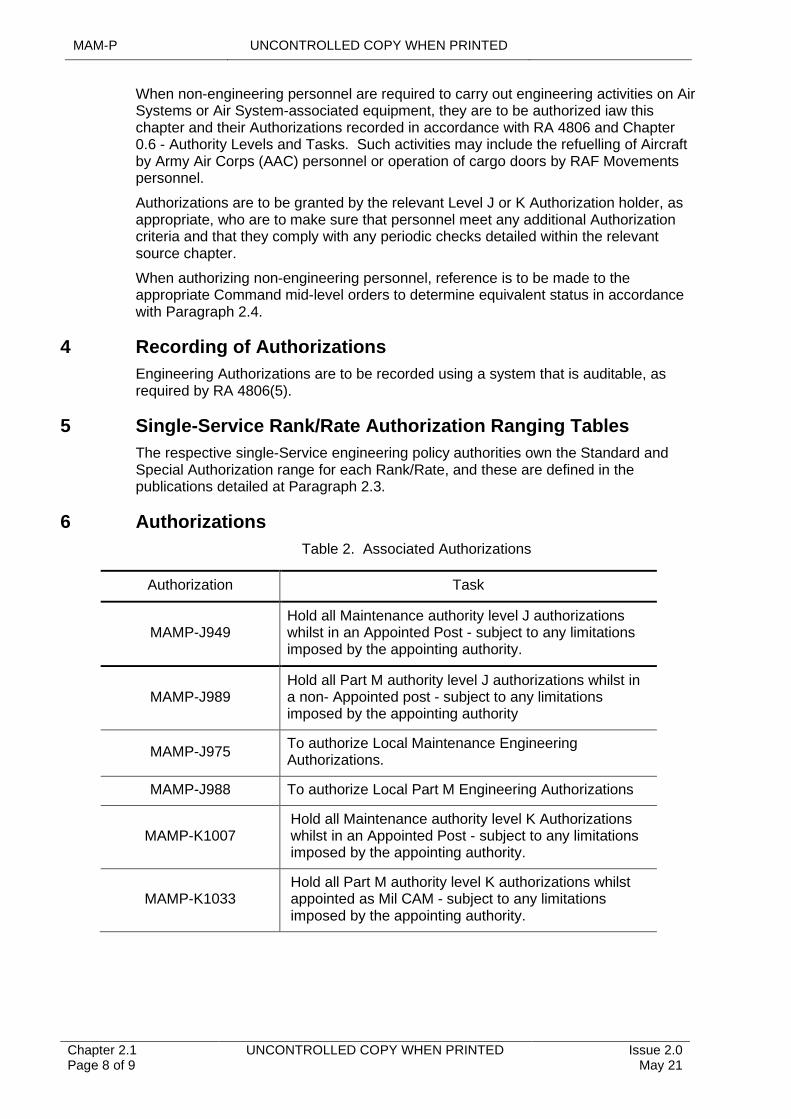
MAM-P UNCONTROLLED COPY WHEN PRINTED
Chapter 2.1 Page 8 of 9
UNCONTROLLED COPY WHEN PRINTED Issue 2.0 May 21
When non-engineering personnel are required to carry out engineering activities on Air Systems or Air System-associated equipment, they are to be authorized iaw this chapter and their Authorizations recorded in accordance with RA 4806 and Chapter 0.6 - Authority Levels and Tasks. Such activities may include the refuelling of Aircraft by Army Air Corps (AAC) personnel or operation of cargo doors by RAF Movements personnel.
Authorizations are to be granted by the relevant Level J or K Authorization holder, as appropriate, who are to make sure that personnel meet any additional Authorization criteria and that they comply with any periodic checks detailed within the relevant source chapter.
When authorizing non-engineering personnel, reference is to be made to the appropriate Command mid-level orders to determine equivalent status in accordance with Paragraph 2.4.
4 Recording of Authorizations
Engineering Authorizations are to be recorded using a system that is auditable, as required by RA 4806(5).
5 Single-Service Rank/Rate Authorization Ranging Tables
The respective single-Service engineering policy authorities own the Standard and Special Authorization range for each Rank/Rate, and these are defined in the publications detailed at Paragraph 2.3.
6 Authorizations
Table 2. Associated Authorizations
Authorization Task
MAMP-J949Hold all Maintenance authority level J authorizations whilst in an Appointed Post - subject to any limitations imposed by the appointing authority.
MAMP-J989Hold all Part M authority level J authorizations whilst in a non- Appointed post - subject to any limitations imposed by the appointing authority
MAMP-J975To authorize Local Maintenance Engineering Authorizations.
MAMP-J988 To authorize Local Part M Engineering Authorizations
MAMP-K1007Hold all Maintenance authority level K Authorizations whilst in an Appointed Post - subject to any limitations imposed by the appointing authority.
MAMP-K1033Hold all Part M authority level K authorizations whilst appointed as Mil CAM - subject to any limitations imposed by the appointing authority.
UNCONTROLLED COPY WHEN PRINTED MAM-P
Issue 2.0 May 21
UNCONTROLLED COPY WHEN PRINTED Chapter 2.1 Page 9 of 9
Intentionally Blank for Print Pagination
UNCONTROLLED COPY WHEN PRINTED MAM-P
Issue 1.1 Feb 20
UNCONTROLLED COPY WHEN PRINTED Chapter 2.2 Page 1 of 4
...........................................................................
..................................................................................................................................................................
..............................................................................................................................................................
.......................................................................................................................................................................................................
....................................................................................................................................
...............................................................................................................................................
.........................................................................................................................................................................................................
Chapter 2.2
Flight Servicing Competency Checks
TABLE OF CONTENTS
Paragraph Page
1 General 11.1 Introduction 11.2 Associated Publications and Instructions 12 Flight Servicing 13 Flight Servicing Competency Check (FSCC) 13.1 Content of FSCC 13.2 Frequency 23.3 Recording 23.4 Personnel Carrying Out the FSCC 23.5 FSCC Failure 24 Flight Servicing by Aircrew 35 Authorizations 3
LIST OF TABLES
Table 1. Associated Authorizations 3
1 General
1.1 Introduction
Flight servicing is one of the principle processes utilized within the Defence Air Environment (DAE) to maintain the Airworthiness of Air Systems. It is imperative that high standards of workmanship are employed at all times when carrying out these activities.
1.2 Associated Publications and Instructions
1 RA 4806 – Personnel Requirements (MRP 145.A.30)
2 RA 4807 – Certifying Staff and Support Staff (MRP 145.A.35)
3 BRd 767 – Naval Aviation Orders
4 AP7400 – Continuing Airworthiness Engineering (Army)
5 AP100B-01 – Royal Air Force Engineering Policy
2 Flight Servicing
The process concerning flight servicing is contained within Chapter 4.2 – Flight Servicing. The following paragraphs detail the specific activities and responsibilities to maintain the required Competency of those personnel who undertake flight servicing.
3 Flight Servicing Competency Check (FSCC)
3.1 Content of FSCC
The FSCC is to check that personnel are:
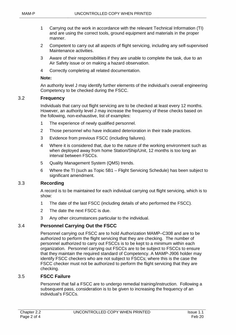
MAM-P UNCONTROLLED COPY WHEN PRINTED
Chapter 2.2 Page 2 of 4
UNCONTROLLED COPY WHEN PRINTED Issue 1.1 Feb 20
1 Carrying out the work in accordance with the relevant Technical Information (TI) and are using the correct tools, ground equipment and materials in the proper manner.
2 Competent to carry out all aspects of flight servicing, including any self-supervised Maintenance activities.
3 Aware of their responsibilities if they are unable to complete the task, due to an Air Safety issue or on making a hazard observation.
4 Correctly completing all related documentation.
Note:
An authority level J may identify further elements of the individual’s overall engineering Competency to be checked during the FSCC.
3.2 Frequency
Individuals that carry out flight servicing are to be checked at least every 12 months. However, an authority level J may increase the frequency of these checks based on the following, non-exhaustive, list of examples:
1 The experience of newly qualified personnel.
2 Those personnel who have indicated deterioration in their trade practices.
3 Evidence from previous FSCC (including failures).
4 Where it is considered that, due to the nature of the working environment such as when deployed away from home Station/Ship/Unit, 12 months is too long an interval between FSCCs.
5 Quality Management System (QMS) trends.
6 Where the TI (such as Topic 5B1 – Flight Servicing Schedule) has been subject to significant amendment.
3.3 Recording
A record is to be maintained for each individual carrying out flight servicing, which is to show:
1 The date of the last FSCC (including details of who performed the FSCC).
2 The date the next FSCC is due.
3 Any other circumstances particular to the individual.
3.4 Personnel Carrying Out the FSCC
Personnel carrying out FSCC are to hold Authorization MAMP–C308 and are to be authorized to perform the flight servicing that they are checking. The number of personnel authorized to carry out FSCCs is to be kept to a minimum within each organization. Personnel carrying out FSCCs are to be subject to FSCCs to ensure that they maintain the required standard of Competency. A MAMP-J906 holder may identify FSCC checkers who are not subject to FSCCs; where this is the case the FSCC checker must not be authorized to perform the flight servicing that they are checking.
3.5 FSCC Failure
Personnel that fail a FSCC are to undergo remedial training/instruction. Following a subsequent pass, consideration is to be given to increasing the frequency of an individual’s FSCCs.
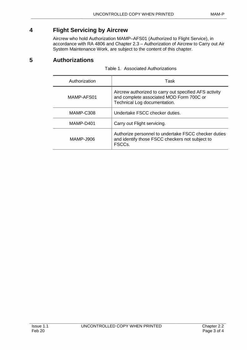
UNCONTROLLED COPY WHEN PRINTED MAM-P
Issue 1.1 Feb 20
UNCONTROLLED COPY WHEN PRINTED Chapter 2.2 Page 3 of 4
4 Flight Servicing by Aircrew
Aircrew who hold Authorization MAMP–AFS01 (Authorized to Flight Service), in accordance with RA 4806 and Chapter 2.3 – Authorization of Aircrew to Carry out Air System Maintenance Work, are subject to the content of this chapter.
5 Authorizations
Table 1. Associated Authorizations
Authorization Task
MAMP-AFS01Aircrew authorized to carry out specified AFS activity and complete associated MOD Form 700C or Technical Log documentation.
MAMP-C308 Undertake FSCC checker duties.
MAMP-D401 Carry out Flight servicing.
MAMP-J906Authorize personnel to undertake FSCC checker duties and identify those FSCC checkers not subject to FSCCs.
MAM-P UNCONTROLLED COPY WHEN PRINTED
Chapter 2.2 Page 4 of 4
UNCONTROLLED COPY WHEN PRINTED Issue 1.1 Feb 20
Intentionally Blank for Print Pagination
UNCONTROLLED COPY WHEN PRINTED MAM-P
Initial Issue Nov 19
UNCONTROLLED COPY WHEN PRINTED Chapter 2.3 Page 1 of 6
...........................................................................
......................................................................................
...............................................................................................................................................................................
........................................................................................................................
.............................................................................................................................................
...................................................................................................................
......................................................................................................................................................
.........................................................................................................................................................................................................
Chapter 2.3
Authorization of Aircrew to Carry Out Air System Maintenance Work
TABLE OF CONTENTS
Paragraph Page
1 General 11.1 Introduction 11.2 Associated Publications and Instructions 11.3 Applicability 12 Breakdown of ‘Maintenance Work’ 23 Aircrew Engineering Authorizations 23.1 Authority to Flight Service (AFS) 23.2 Authority to Maintain (AM) 23.3 Self-supervision 34 Training for Aircrew to Carry Out Maintenance Work 34.1 AFS Authorization 34.2 AM Authorizations 55 Authorization and Validity of AFS and AM 55.1 Method of Recording AFS and AM Authorizations 6
LIST OF TABLES
Table 1. Associated Authorizations 6
1 General
1.1 Introduction
To increase the flexibility of Air System operations, Aircrew may be authorized to undertake or participate in Preventive and Corrective Maintenance activities, as detailed in Chapter 4.1 – Types of Maintenance, on the applicable Air System. These are activities that may be carried out solely by Aircrew, or by Aircrew supplementing the Maintenance organization. This chapter details the procedure for authorizing the Aircrew concerned and identifies their responsibilities.
1.2 Associated Publications and Instructions
1 RA 2211 – Authorization of Aircrew to Carry Out Maintenance Tasks
2 RA 4054 – Ground Handling Operations
3 RA 4657 – Weapon Loading and Armed Aircraft Maintenance
4 RA 4806 – Personnel Requirements (MRP 145.A.30)
5 RA 4812 – Certification of Air System Release and Component Release (MRP 145.A.50)
6 Manual of Airworthiness Maintenance – Documentation (MAM-D)
1.3 Applicability
This chapter is applicable to any Aircrew that may be required to carry out Preventive or Corrective Maintenance activities on an Air System. It is not applicable to those

MAM-P UNCONTROLLED COPY WHEN PRINTED
Chapter 2.3 Page 2 of 6
UNCONTROLLED COPY WHEN PRINTED Initial Issue Nov 19
Aircrew who are required to undertake flying activities in direct support of an Air System Maintenance task, eg flight test/check or engine ground runs.
2 Breakdown of ‘Maintenance Work’
There are 2 distinct aspects to Preventive or Corrective Maintenance:
1 The act of doing the Maintenance.
2 The completion of the associated documentation.
Both aspects are of equal importance. Completion of the documentation also breaks down into 2 distinct areas:
1 That associated with the individual Maintenance task.
2 That associated with the final step of Certification of Air System Release for Flight recorded using MOD Form 700 documentation or equivalent in accordance with (iaw) RA 4812.
The responsibilities associated with these areas, in addition to the requirements for documentation signatures, are detailed in Chapter 2.4 – Certification and Maintenance Documentation.
3 Aircrew Engineering Authorizations
Aircrew required to undertake Maintenance activities, that includes flight servicing, are to be authorized by the appropriately authorized Authority Level J.
Notes:
1 The provision of 1st, 2nd and 3rd signatures on Maintenance documentation applies both to flight servicing and Maintenance activities.
2 Issue of Authority to Maintain (AM) is based on the Aircrew holding a current Authority to Flight Service (AFS). Exceptionally, where there is a requirement for an Aircrew member to undertake a limited range of minor Corrective Maintenance tasks, the Authority Level J may waive the requirement to hold an AFS.
3.1 Authority to Flight Service (AFS)
AFS encompasses a range of activities associated with carrying out flight servicing. The following, non-exhaustive, list gives examples of the major elements of the AFS Authorization:
1 Flight servicing.
2 System replenishments.
3 Fuelling operations.
4 Loading and unloading of internally carried pyrotechnics.
5 Supervision of ground handling.
Consequently, the AFS Authorization is to explicitly detail the scope of the activities which apply, including Certification of Air System Release recorded using MOD Form 700C or equivalent (provided that no Corrective Maintenance has been carried out) and removing controlled pages.
3.2 Authority to Maintain (AM)
AM covers the following activities:
1 Minor Corrective or Preventive Maintenance.

UNCONTROLLED COPY WHEN PRINTED MAM-P
Initial Issue Nov 19
UNCONTROLLED COPY WHEN PRINTED Chapter 2.3 Page 3 of 6
2 Role changes.
3 Defer Corrective Maintenance.
4 Record limitations.
Aircrew holding AM may be authorized to carry out one or more of these activities, including Certification of Air System Release recorded using MOD Form 700C or equivalent and removing controlled pages.
The Air System Support Policy Statement (SPS) (such as the Topic 2(N/A/R)1 or equivalent) may promulgate a list of Air System items/systems on which Aircrew may authorize the deferment of Corrective Maintenance or record limitations. The relevant holder of authority MAMP-J927 is not to grant authority to defer Corrective Maintenance outside this list but may restrict further the scope of Corrective Maintenance deferment. The award of AM is to detail the scope of this authority by incorporating the list of items/systems to which the award applies. If a Fault occurs that is not detailed within this list of items/systems, the Aircrew are to consult a relevant holder of authority MAMP-J927 to determine possible latitude within the list.
Note:
The Authorization to defer Corrective Maintenance or record limitations is only to be employed when Aircrew are away from the parent Station/Ship/Unit and when no suitably authorized engineering personnel are available.
3.3 Self-supervision
There are occasions where only one member of the Aircrew is required to operate an Air System; this could be a single-seat Air System where only one Aircrew is on board. Maintenance activities undertaken in these situations will require the Aircrew to act as a self-supervisor, iaw Chapter 4.1 – Types of Maintenance. Therefore, the training given to such Aircrew is to include the principles and responsibilities of a self-supervisor.
4 Training for Aircrew to Carry Out Maintenance Work
Prior to AFS or AM Authorization, the individual is to have undertaken the appropriate local training, which is normally to be carried out by the relevant Maintenance organization or recognized Air System engineering training school. This training is to be formulated to provide a complete background to their responsibilities, including completion of the relevant aspects of the MOD Form 700C or equivalent and the associated elements of the Maintenance task, eg tool control, hazards and dangers, precautions to be taken with Fuels, Lubricants, Associated Products (FLAP) plus an electronic Information System (IS) training to the appropriate level. This training is to be of both a theoretical and practical nature, where the Aircrew is to show Competency, through examination, to hold the relevant Authorization. The following lists detail the minimum scope of topics for each Authorization, which is to be covered by the training, and the aims of that specific element of training.
Note:
The training given to Aircrew, based on the lists below, is to be suitably tailored and approved by an Authority Level J, to cover those flight-servicing activities associated with the individual’s required Authorization.
4.1 AFS Authorization
Prior to AFS Authorization, and subject to the scope of the required Authorization, the individual Aircrew is to:
1 Understand the periodicity of the AFS Authorization.
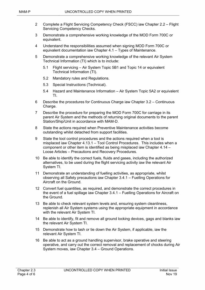
MAM-P UNCONTROLLED COPY WHEN PRINTED
Chapter 2.3 Page 4 of 6
UNCONTROLLED COPY WHEN PRINTED Initial Issue Nov 19
2 Complete a Flight Servicing Competency Check (FSCC) iaw Chapter 2.2 – Flight Servicing Competency Checks.
3 Demonstrate a comprehensive working knowledge of the MOD Form 700C or equivalent.
4 Understand the responsibilities assumed when signing MOD Form 700C or equivalent documentation iaw Chapter 4.1 – Types of Maintenance.
5 Demonstrate a comprehensive working knowledge of the relevant Air System Technical Information (TI) which is to include:
5.1 Flight servicing – Air System Topic 5B1 and Topic 14 or equivalent Technical Information (TI).
5.2 Mandatory rules and Regulations.
5.3 Special Instructions (Technical).
5.4 Hazard and Maintenance Information – Air System Topic 5A2 or equivalent TI.
6 Describe the procedures for Continuous Charge iaw Chapter 3.2 – Continuous Charge.
7 Describe the procedure for preparing the MOD Form 700C for carriage in its parent Air System and the methods of returning original documents to the parent Station/Ship/Unit in accordance with MAM-D.
8 State the actions required when Preventive Maintenance activities become outstanding whilst detached from support facilities.
9 State the tool control procedures and the actions required when a tool is misplaced iaw Chapter 4.13.1 – Tool Control Procedures. This includes when a component or other item is identified as being misplaced iaw Chapter 4.14 – Loose Articles – Precautions and Recovery Procedures.
10 Be able to identify the correct fuels, fluids and gases, including the authorized alternatives, to be used during the flight servicing activity iaw the relevant Air System TI.
11 Demonstrate an understanding of fuelling activities, as appropriate, whilst observing all Safety precautions iaw Chapter 3.4.1 – Fuelling Operations for Aircraft on the Ground.
12 Convert fuel quantities, as required, and demonstrate the correct procedures in the event of a fuel spillage iaw Chapter 3.4.1 – Fuelling Operations for Aircraft on the Ground.
13 Be able to check relevant system levels and, ensuring system cleanliness, replenish all Air System systems using the appropriate equipment in accordance with the relevant Air System TI.
14 Be able to identify, fit and remove all ground locking devices, gags and blanks iaw the relevant Air System TI.
15 Demonstrate how to lash or tie down the Air System, if applicable, iaw the relevant Air System TI.
16 Be able to act as a ground handling supervisor, brake operative and steering operative, and carry out the correct removal and replacement of chocks during Air System moves, iaw Chapter 3.4 – Ground Operations.
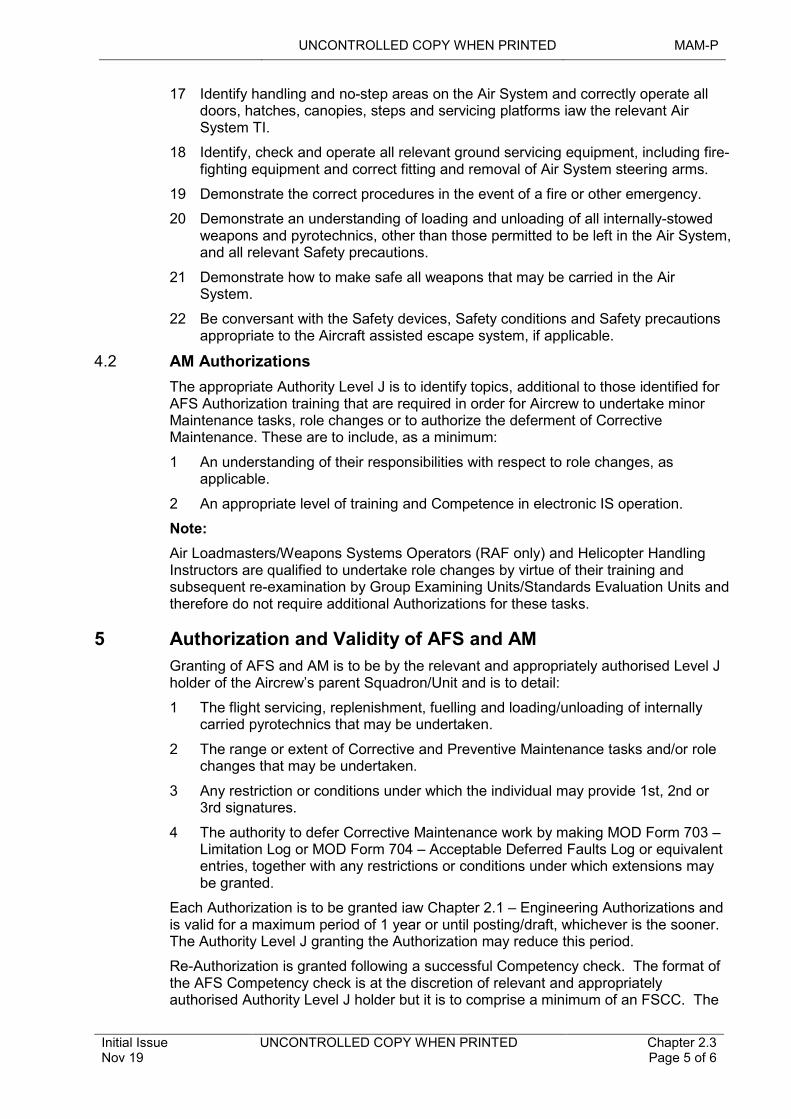
UNCONTROLLED COPY WHEN PRINTED MAM-P
Initial Issue Nov 19
UNCONTROLLED COPY WHEN PRINTED Chapter 2.3 Page 5 of 6
17 Identify handling and no-step areas on the Air System and correctly operate all doors, hatches, canopies, steps and servicing platforms iaw the relevant Air System TI.
18 Identify, check and operate all relevant ground servicing equipment, including fire-fighting equipment and correct fitting and removal of Air System steering arms.
19 Demonstrate the correct procedures in the event of a fire or other emergency.
20 Demonstrate an understanding of loading and unloading of all internally-stowed weapons and pyrotechnics, other than those permitted to be left in the Air System, and all relevant Safety precautions.
21 Demonstrate how to make safe all weapons that may be carried in the Air System.
22 Be conversant with the Safety devices, Safety conditions and Safety precautions appropriate to the Aircraft assisted escape system, if applicable.
4.2 AM Authorizations
The appropriate Authority Level J is to identify topics, additional to those identified for AFS Authorization training that are required in order for Aircrew to undertake minor Maintenance tasks, role changes or to authorize the deferment of Corrective Maintenance. These are to include, as a minimum:
1 An understanding of their responsibilities with respect to role changes, as applicable.
2 An appropriate level of training and Competence in electronic IS operation.
Note:
Air Loadmasters/Weapons Systems Operators (RAF only) and Helicopter Handling Instructors are qualified to undertake role changes by virtue of their training and subsequent re-examination by Group Examining Units/Standards Evaluation Units and therefore do not require additional Authorizations for these tasks.
5 Authorization and Validity of AFS and AM
Granting of AFS and AM is to be by the relevant and appropriately authorised Level J holder of the Aircrew’s parent Squadron/Unit and is to detail:
1 The flight servicing, replenishment, fuelling and loading/unloading of internally carried pyrotechnics that may be undertaken.
2 The range or extent of Corrective and Preventive Maintenance tasks and/or role changes that may be undertaken.
3 Any restriction or conditions under which the individual may provide 1st, 2nd or 3rd signatures.
4 The authority to defer Corrective Maintenance work by making MOD Form 703 – Limitation Log or MOD Form 704 – Acceptable Deferred Faults Log or equivalent entries, together with any restrictions or conditions under which extensions may be granted.
Each Authorization is to be granted iaw Chapter 2.1 – Engineering Authorizations and is valid for a maximum period of 1 year or until posting/draft, whichever is the sooner. The Authority Level J granting the Authorization may reduce this period.
Re-Authorization is granted following a successful Competency check. The format of the AFS Competency check is at the discretion of relevant and appropriately authorised Authority Level J holder but it is to comprise a minimum of an FSCC. The
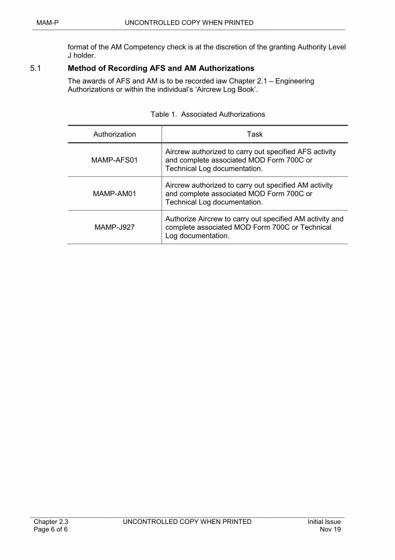
MAM-P UNCONTROLLED COPY WHEN PRINTED
Chapter 2.3 Page 6 of 6
UNCONTROLLED COPY WHEN PRINTED Initial Issue Nov 19
format of the AM Competency check is at the discretion of the granting Authority Level J holder.
5.1 Method of Recording AFS and AM Authorizations
The awards of AFS and AM is to be recorded iaw Chapter 2.1 – Engineering Authorizations or within the individual’s ‘Aircrew Log Book’.
Table 1. Associated Authorizations
Authorization Task
MAMP-AFS01Aircrew authorized to carry out specified AFS activity and complete associated MOD Form 700C or Technical Log documentation.
MAMP-AM01Aircrew authorized to carry out specified AM activity and complete associated MOD Form 700C or Technical Log documentation.
MAMP-J927Authorize Aircrew to carry out specified AM activity and complete associated MOD Form 700C or Technical Log documentation.
UNCONTROLLED COPY WHEN PRINTED MAM-P
Issue 1.3 Feb 21
UNCONTROLLED COPY WHEN PRINTED Chapter 2.4 Page 1 of 6
................................................................................................................
..................................................................................................................................................................................
...................................................................................................................................................................................
...............................................................................................................................................................
.....................................................................................................
......................................................................................................................................................
.........................................................................................................................................................................................................
Chapter 2.4
Certification and Management of Maintenance Documentation
TABLE OF CONTENTS
Paragraph Page
1 General 11.1 Introduction 11.2 Associated Publications and Instructions 11.3 Applicability 22 Principles 23 Certifying Self-Supervision and Elementary Self-Supervision activity 24 Responsibilities 34.1 1st Signature Responsibilities 34.2 2nd Signature Responsibilities 34.3 3rd Signature Responsibilities 45 Management of Electronic IS Documentation 45.1 Data Management 46 Authorizations 5
LIST OF TABLES
Table 1. Equivalence of Terms in the RA 4800-4849 series. 2Table 2. Associated Authorizations 5
1 General
1.1 Introduction
In the interest of Safety and Airworthiness there is a chain of individual responsibilities for Maintenance work and a system for recording any work carried out. Once certified, Maintenance documents constitute legally binding certificates and are to be managed accordingly. It is an offence to certify a Maintenance document without first ensuring its accuracy. This chapter details the responsibilities accepted by individuals when they sign Maintenance documentation and the control measures required to assure their content and through life management. These responsibilities are equally applicable to the electronic certification of Air System Maintenance when using an electronic Information System (IS).
Note:
An individual is to immediately inform their chain of command if, during any stage of a Maintenance operation, they consider themselves unable to complete an operation in accordance with (iaw) the relevant Technical Information (TI) and instructions, or there are any Human Factors affecting the safe completion of an operation.
1.2 Associated Publications and Instructions
1 RA 1223 – Airworthiness Information Management
2 RA 4801 – Certifying Staff
3 RA 4806 – Personnel Requirements (MRP 145.A.30)
4 RA 4807 – Certifying Staff and Support Staff (MRP 145.A.35)
MAM-P UNCONTROLLED COPY WHEN PRINTED
Chapter 2.4 Page 2 of 6
UNCONTROLLED COPY WHEN PRINTED Issue 1.3 Feb 21
5 RA 4812 – Certification of Air System Release and Component Release (MRP 145.A.50)
6 RA 4813 – Maintenance Records (MRP 145.A.55)
7 RA 4961 – Aircraft Maintenance Programme and Military Continuing Airworthiness Organizations Responsibilities for Air System Release - MRP Part M Sub Part C
8 Manual of Airworthiness Maintenance – Documentation (MAM-D)
1.3 Applicability
This chapter is applicable to all personnel responsible for certifying Airworthiness Maintenance activity and the management of Maintenance documentation within the Defence Air Environment (DAE).
2 Principles
To ensure the Quality and completeness of Maintenance work, the documentation associated with the task is certified at 3 key stages:
1 1st signature – Completed by the Tradesman/operator.
2 2nd signature – Completed by the Supervisor.
3 3rd signature – Completed by the Co-ordinator.
In corresponding Regulatory Articles (RAs), some alternative terminology is used in order to provide parity with contractor Maintenance. While these terms are detailed in Table 1 below for completeness, the more commonly used terms 1st, 2nd and 3rd signature will continue to be used throughout this chapter.
Table 1. Equivalence of Terms in the RA 4800-4849 series.
MAM-P TERM RA 4800-4849 SERIES TERM
1st signature Support Staff
2nd signature Support Staff with Supervisory Responsibilities
3rd signature Certifying Staff
Each of these stages has specific responsibilities. At each stage the individual who has carried out the work detailed is to certify for having carried out that work. When one or more individuals are involved with a Maintenance task, each person is to identify and certify the work that they have carried out themselves.
Notes:
Specific guidance on the compilation of Maintenance documentation and detailed Instructions for Use for the MOD Form 700 series can be found in the Manual of Maintenance Documentation (MAM-D).
3 Certifying Self-Supervision and Elementary Self-Supervision activity
When certifying an activity as a self-supervisor, as defined in RA 4806 and Chapter 2.5 - Self-Supervision, the individual certifying the Maintenance documentation accepts the responsibilities of both 1st and 2nd signature.
UNCONTROLLED COPY WHEN PRINTED MAM-P
Issue 1.3 Feb 21
UNCONTROLLED COPY WHEN PRINTED Chapter 2.4 Page 3 of 6
Additionally, for managerial tasks (eg cross-referencing), there is only a requirement to certify the 2nd signature field.
4 Responsibilities
4.1 1st Signature Responsibilities
The Tradesman signing as 1st signature is responsible for the Quality and completeness of their work. The signature certifies that:
1 The task was undertaken and completed iaw all applicable TI and any additional instructions issued by the task supervisor.
2 Where replacement components have been installed, they have been physically checked to ensure that they are the correct item as identified in the relevant Parts Catalogue and/or TI, and to the correct Modification state. Replacement consumable items are to be similarly checked, noting the need to positively identify that reused items are correct if they have previously been removed.
3 A loose article check has been carried out iaw Chapter 4.14 - Loose Articles – Precautions and Recovery Procedures.
4 A localised, unaided visual survey has been made, as far as possible, for any fault(s) such as fluid leaks and seeps, cracks, scorching, incorrect fitment, insulation damage on adjacent exposed cables or looms, contamination, insecurity of attachment or poor routeing of cables and pipes.
5 All detachable panels and access doors removed or opened during the Maintenance task have been closed or refitted.
6 Tool control procedures have been carried out iaw RA 4808 and Chapter 4.13.1-Tool Control Procedures.
4.2 2nd Signature Responsibilities
The individual signing as 2nd signature certifies that:
1 The Tradesman tasked:
1.1 Is authorized and Competent to do the job.
1.2 Had been adequately briefed (including the need for any stage inspections or functional tests).
1.3 Had access to the correct tools, equipment, TI to the correct amendment state and any associated instructions necessary to complete the task.
2 The work has been completed, to their satisfaction, iaw all relevant TI.
3 The entries detailing the work carried out on the Maintenance documentation are explicit, complete and legible and, where applicable, quote the TI reference and amendment state.
4 Any associated stage checks, and functional tests have been correctly documented and, if required, correctly transferred to an associated Maintenance document.
5 Any requirement for independent inspections has been correctly identified and documented.
Note:
For Maintenance activities that are not self-supervised, the 2nd signature holder is to spend sufficient time on the activity to assure themselves of its Quality and completeness. In doing this, they are to take into account the difficulty and nature of
MAM-P UNCONTROLLED COPY WHEN PRINTED
Chapter 2.4 Page 4 of 6
UNCONTROLLED COPY WHEN PRINTED Issue 1.3 Feb 21
the task, the skill and experience of the 1st signature holder and the prevailing circumstances.
4.3 3rd Signature Responsibilities
There are 2 instances where a 3rd signature is required:
1 When a Maintenance task has been completed and the associated documentation is to be coordinated.
2 When certifying Air System release.
4.3.1 Completion of a Maintenance Task
The individual signing 3rd signature is responsible for ensuring the correct completion of the Maintenance documentation and certifies that:
1 All documentation for the task is present and correct.
2 The Maintenance Work Order has been correctly co-ordinated prior to closing the relevant Maintenance Log entry.
3 The relevant electronic IS has been updated, where applicable.
4.3.2 Certifying that an Air System is Ready for Flight
RA 4807 and MAM-D detail the responsibilities associated with coordinating an Air System Technical Log (MOD Form 700 or electronic IS equivalent) prior to flight.
5 Management of Electronic IS Documentation
Electronic IS documentation is to be appropriately managed to ensure the integrity of the information. The following paragraphs detail generic instructions; specific instructions for individual electronic IS will be detailed in the associated TI.
Note:
For clarity, throughout this chapter electronic IS Maintenance documentation is referred to as electronic IS data.
5.1 Data Management
Electronic IS data is managed in the following ways:
1 Data backup. The strategy taken to ensure that data can be restored, to that point in time, when Air System Airworthiness is assured following a catastrophic electronic IS failure.
2 Archiving. The process of removing a quantity of data from an electronic IS for storage elsewhere, to optimize system performance.
3 Data retrieval. The process of accessing data previously removed from the live system.
4 Copying. A copy is a read-only electronic duplication of data at a specific point in time, not be confused with archiving. A copy is subject to the same rules that govern paper copies and are to be clearly marked to indicate that it is a copy and therefore not subject to amendment.
5 Auditing. Auditing is part of Maintenance Data Management and is to be conducted as detailed in the relevant TI or local procedures by suitably authorized (MAMP-E512) personnel.
UNCONTROLLED COPY WHEN PRINTED MAM-P
Issue 1.3 Feb 21
UNCONTROLLED COPY WHEN PRINTED Chapter 2.4 Page 5 of 6
6 Data locking. To support an investigation (eg a Service Inquiry into an Air Incident or Accident) there may be a need to quarantine specific data. This action, known as data locking, is required to ensure that data integrity is maintained.
6.1 Access to locked data. Access to locked data, including copies and the live system, are controlled through a means acceptable to both the Continuing Airworthiness Management Organization (CAMO) and the relevant individual holding authority level K, so as not to prejudice any investigation.
6.2 Data unlocking. Data unlocking is the release of data back on to the system for full read/write access post locking. Access is strictly controlled and is only authorized in exceptional circumstances (eg when required by the Defence Accident Investigation Branch (DAIB) in the case of a Service Inquiry).
7 Amendment and configuration control. TAA approved processes for correcting errors and ensuring the integrity and Airworthiness of the data.
8 Transfer of data. TAA approved processes to safely export and import data between Stn/Ship/Units, support agencies and industry.
6 Authorizations
Table 2. Associated Authorizations
Authorization Task
MAMP-B213Sign 1st signature for tasked work within trade boundary.
MAMP-B214Sign 1st signature for tasked work outside trade boundary.
MAMP-C317Sign 2nd signature for supervision of work within trade boundary, regardless of 1st signatory's rank.
MAMP-C318Sign 2nd signature for supervision of work outside trade boundary, regardless of 1st signatory's rank.
MAMP-C325 Insert controlled forms in MOD Form 700.
MAMP-D406Carry out self-supervised Maintenance activities within own trade.
MAMP-D407Carry out self-supervised Maintenance activities outside own trade.
MAMP-E507 Co-ordinate MWOs.
MAMP-E516Certify in MOD Form 700/Technical Log that an Air System is ready for flight.
MAMP-E512 Audit Airworthiness related Electronic IS data
MAMP-E515 Insert/remove controlled forms in/from MOD Form 700.
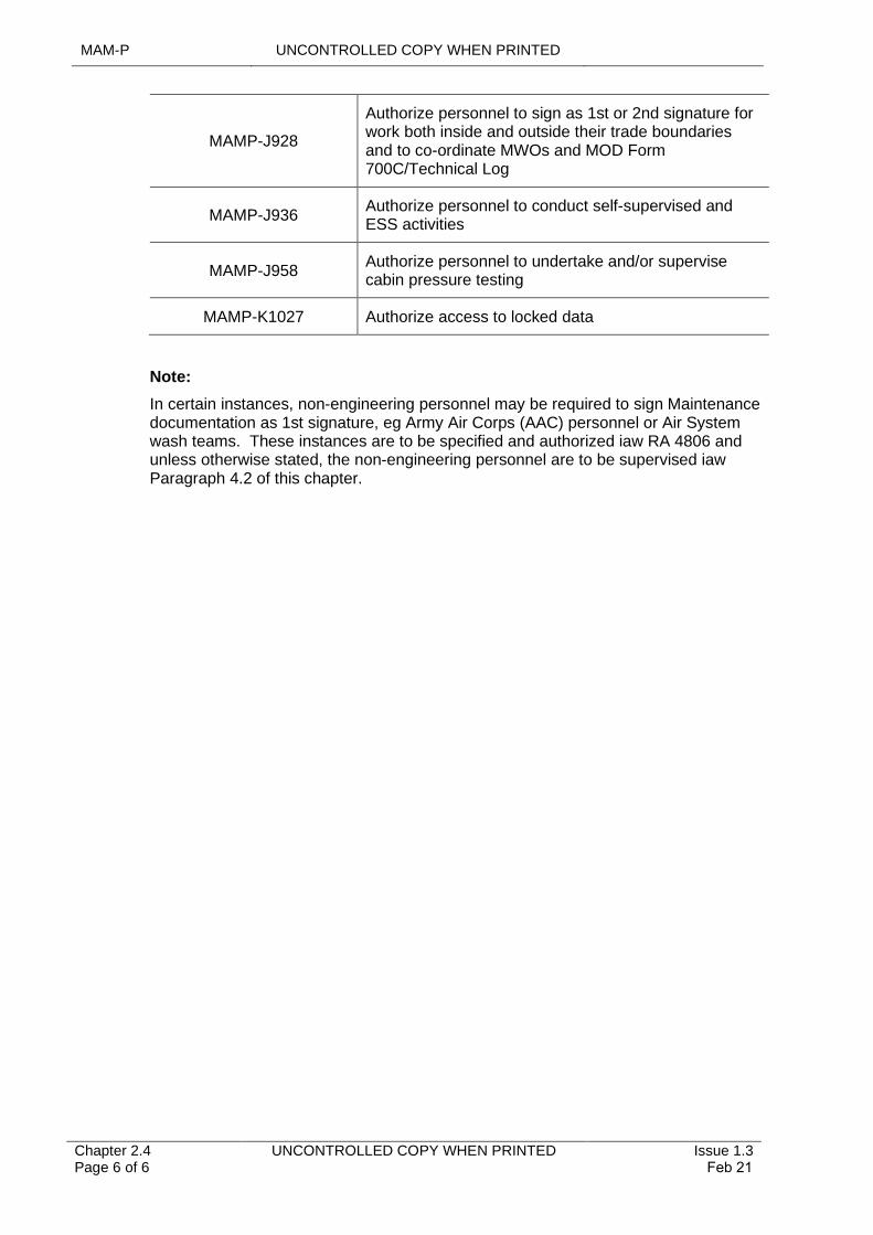
MAM-P UNCONTROLLED COPY WHEN PRINTED
Chapter 2.4 Page 6 of 6
UNCONTROLLED COPY WHEN PRINTED Issue 1.3 Feb 21
MAMP-J928
Authorize personnel to sign as 1st or 2nd signature for work both inside and outside their trade boundaries and to co-ordinate MWOs and MOD Form 700C/Technical Log
MAMP-J936Authorize personnel to conduct self-supervised and ESS activities
MAMP-J958Authorize personnel to undertake and/or supervise cabin pressure testing
MAMP-K1027 Authorize access to locked data
Note:
In certain instances, non-engineering personnel may be required to sign Maintenance documentation as 1st signature, eg Army Air Corps (AAC) personnel or Air System wash teams. These instances are to be specified and authorized iaw RA 4806 and unless otherwise stated, the non-engineering personnel are to be supervised iaw Paragraph 4.2 of this chapter.
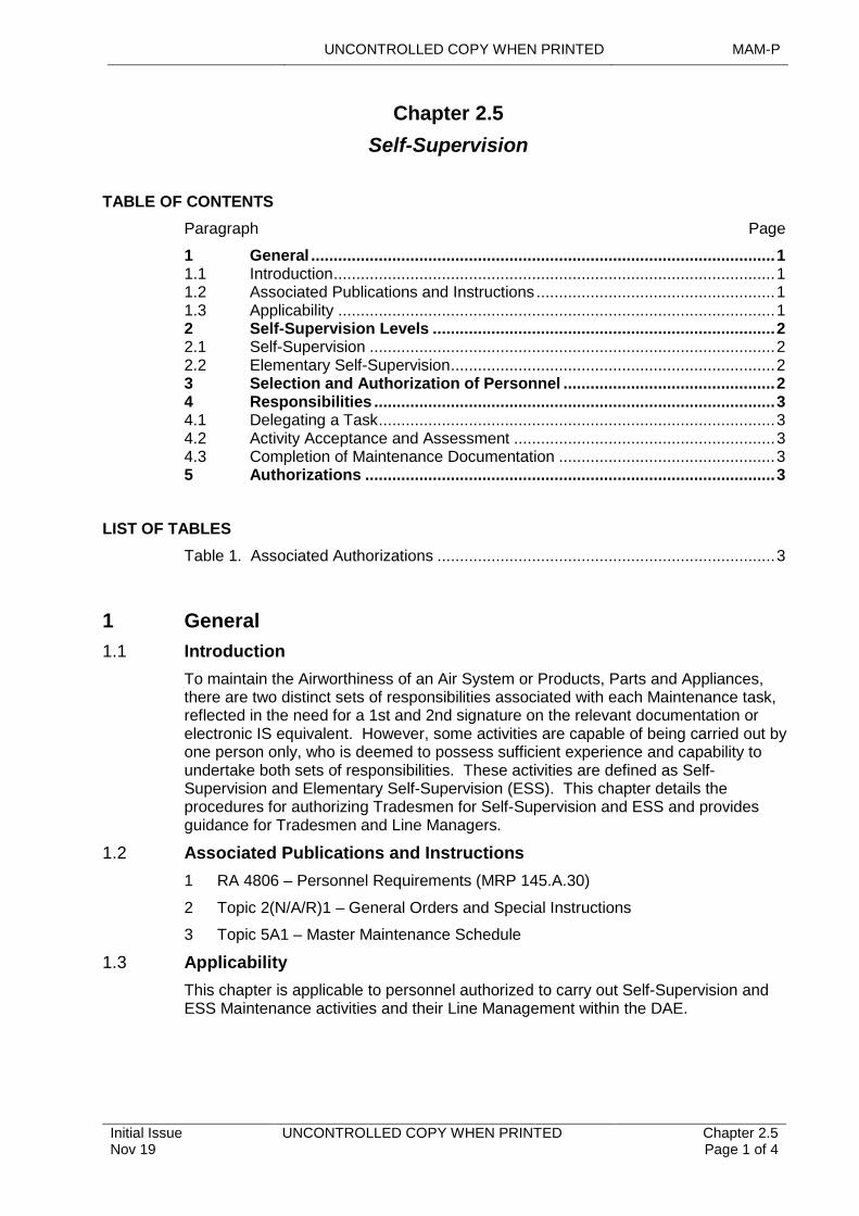
UNCONTROLLED COPY WHEN PRINTED MAM-P
Initial Issue Nov 19
UNCONTROLLED COPY WHEN PRINTED Chapter 2.5 Page 1 of 4
...........................................................................
...........................................................................................................................................
..................................................................................................................................................
........................................................................................................................................
..................................................................................................................................................................
.............................................................................................................................................................................
.......................................................................................................................................................
.......................................................................................................
Chapter 2.5
Self-Supervision
TABLE OF CONTENTS
Paragraph Page
1 General 11.1 Introduction 11.2 Associated Publications and Instructions 11.3 Applicability 12 Self-Supervision Levels 22.1 Self-Supervision 22.2 Elementary Self-Supervision 23 Selection and Authorization of Personnel 24 Responsibilities 34.1 Delegating a Task 34.2 Activity Acceptance and Assessment 34.3 Completion of Maintenance Documentation 35 Authorizations 3
LIST OF TABLES
Table 1. Associated Authorizations 3
1 General
1.1 Introduction
To maintain the Airworthiness of an Air System or Products, Parts and Appliances, there are two distinct sets of responsibilities associated with each Maintenance task, reflected in the need for a 1st and 2nd signature on the relevant documentation or electronic IS equivalent. However, some activities are capable of being carried out by one person only, who is deemed to possess sufficient experience and capability to undertake both sets of responsibilities. These activities are defined as Self-Supervision and Elementary Self-Supervision (ESS). This chapter details the procedures for authorizing Tradesmen for Self-Supervision and ESS and provides guidance for Tradesmen and Line Managers.
1.2 Associated Publications and Instructions
1 RA 4806 – Personnel Requirements (MRP 145.A.30)
2 Topic 2(N/A/R)1 – General Orders and Special Instructions
3 Topic 5A1 – Master Maintenance Schedule
1.3 Applicability
This chapter is applicable to personnel authorized to carry out Self-Supervision and ESS Maintenance activities and their Line Management within the DAE.
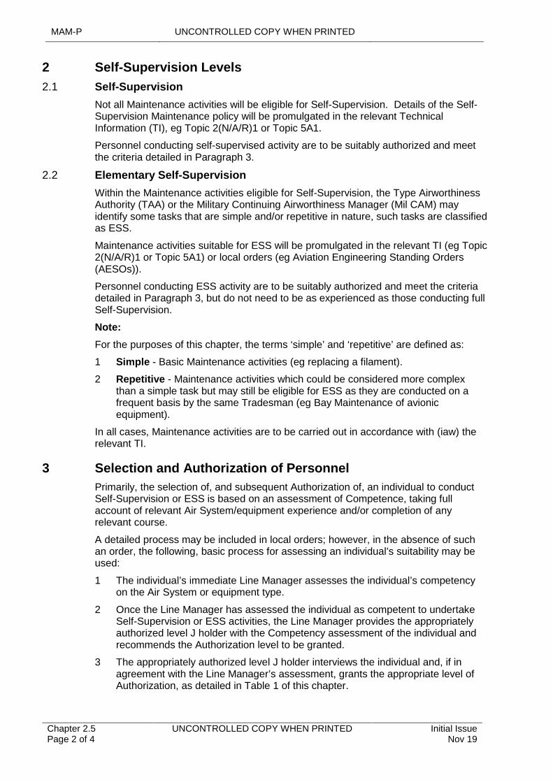
MAM-P UNCONTROLLED COPY WHEN PRINTED
Chapter 2.5 Page 2 of 4
UNCONTROLLED COPY WHEN PRINTED Initial Issue Nov 19
2 Self-Supervision Levels
2.1 Self-Supervision
Not all Maintenance activities will be eligible for Self-Supervision. Details of the Self-Supervision Maintenance policy will be promulgated in the relevant Technical Information (TI), eg Topic 2(N/A/R)1 or Topic 5A1.
Personnel conducting self-supervised activity are to be suitably authorized and meet the criteria detailed in Paragraph 3.
2.2 Elementary Self-Supervision
Within the Maintenance activities eligible for Self-Supervision, the Type Airworthiness Authority (TAA) or the Military Continuing Airworthiness Manager (Mil CAM) may identify some tasks that are simple and/or repetitive in nature, such tasks are classified as ESS.
Maintenance activities suitable for ESS will be promulgated in the relevant TI (eg Topic 2(N/A/R)1 or Topic 5A1) or local orders (eg Aviation Engineering Standing Orders (AESOs)).
Personnel conducting ESS activity are to be suitably authorized and meet the criteria detailed in Paragraph 3, but do not need to be as experienced as those conducting full Self-Supervision.
Note:
For the purposes of this chapter, the terms ‘simple’ and ‘repetitive’ are defined as:
1 Simple - Basic Maintenance activities (eg replacing a filament).
2 Repetitive - Maintenance activities which could be considered more complex than a simple task but may still be eligible for ESS as they are conducted on a frequent basis by the same Tradesman (eg Bay Maintenance of avionic equipment).
In all cases, Maintenance activities are to be carried out in accordance with (iaw) the relevant TI.
3 Selection and Authorization of Personnel
Primarily, the selection of, and subsequent Authorization of, an individual to conduct Self-Supervision or ESS is based on an assessment of Competence, taking full account of relevant Air System/equipment experience and/or completion of any relevant course.
A detailed process may be included in local orders; however, in the absence of such an order, the following, basic process for assessing an individual’s suitability may be used:
1 The individual’s immediate Line Manager assesses the individual’s competency on the Air System or equipment type.
2 Once the Line Manager has assessed the individual as competent to undertake Self-Supervision or ESS activities, the Line Manager provides the appropriately authorized level J holder with the Competency assessment of the individual and recommends the Authorization level to be granted.
3 The appropriately authorized level J holder interviews the individual and, if in agreement with the Line Manager’s assessment, grants the appropriate level of Authorization, as detailed in Table 1 of this chapter.
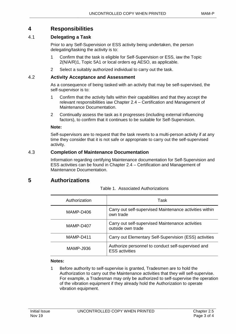
UNCONTROLLED COPY WHEN PRINTED MAM-P
Initial Issue Nov 19
UNCONTROLLED COPY WHEN PRINTED Chapter 2.5 Page 3 of 4
4 Responsibilities
4.1 Delegating a Task
Prior to any Self-Supervision or ESS activity being undertaken, the person delegating/tasking the activity is to:
1 Confirm that the task is eligible for Self-Supervision or ESS, iaw the Topic 2(N/A/R)1, Topic 5A1 or local orders eg AESO, as applicable.
2 Select a suitably authorized individual to carry out the task.
4.2 Activity Acceptance and Assessment
As a consequence of being tasked with an activity that may be self-supervised, the self-supervisor is to:
1 Confirm that the activity falls within their capabilities and that they accept the relevant responsibilities iaw Chapter 2.4 – Certification and Management of Maintenance Documentation.
2 Continually assess the task as it progresses (including external influencing factors), to confirm that it continues to be suitable for Self-Supervision.
Note:
Self-supervisors are to request that the task reverts to a multi-person activity if at any time they consider that it is not safe or appropriate to carry out the self-supervised activity.
4.3 Completion of Maintenance Documentation
Information regarding certifying Maintenance documentation for Self-Supervision and ESS activities can be found in Chapter 2.4 – Certification and Management of Maintenance Documentation.
5 Authorizations
Table 1. Associated Authorizations
Authorization Task
MAMP-D406Carry out self-supervised Maintenance activities within own trade
MAMP-D407Carry out self-supervised Maintenance activities outside own trade
MAMP-D411 Carry out Elementary Self-Supervision (ESS) activities
MAMP-J936Authorize personnel to conduct self-supervised and ESS activities
Notes:
1 Before authority to self-supervise is granted, Tradesmen are to hold the Authorization to carry out the Maintenance activities that they will self-supervise. For example, a Tradesman may only be authorized to self-supervise the operation of the vibration equipment if they already hold the Authorization to operate vibration equipment.
MAM-P UNCONTROLLED COPY WHEN PRINTED
Chapter 2.5 Page 4 of 4
UNCONTROLLED COPY WHEN PRINTED Initial Issue Nov 19
2 If an individual holds an Authorization that specifically states that the associated task is a self-supervised activity, there is no additional requirement to grant that individual any of the Authorizations in the table above. For example, Flight Servicing is an ESS activity; personnel holding Authorization MAMP-D401 are not required to hold the ESS Authorization MAMP-D406/7 to carry out this activity.
UNCONTROLLED COPY WHEN PRINTED MAM-P
Issue 2.0 May 21
UNCONTROLLED COPY WHEN PRINTED Chapter 3.1 Page 1 of 4
...........................................................................
...................................................................................................................
.......................................................................................................................................................
..........................................................................................................................................................
.............................................................................................................
...................................................................................................................................................
..................................................................................................................................................
.........................................................................................................................................................................................................
Chapter 3.1
Flight Testing of Air Systems
TABLE OF CONTENTS
Paragraph Page
1 General 11.1 Introduction 11.2 Associated Publications and Instructions 12 Flight Testing 22.1 Maintenance Test Flight (MTF) 22.2 Partial Test Flight (PTF) 23 Airborne Check (AC)/Taxi Check 24 Flight Testing during Continuous Charge 35 Flight Test Qualifications 35.1 Engineer Qualifications 36 Authorizations 36.1 MTF/PTF Engineering Authorization 36.2 Airborne Check Engineering Authorizations 36.3 Flying Maintainer Authorizations 4
LIST OF TABLES
Table 1. Associated Authorizations 4
1 General
1.1 Introduction
Flight testing is conducted to ensure that the overall performance or handling qualities of an Air System or Airborne Equipment have not fallen below defined standards of acceptance. Flight testing may be conducted at a set periodicity, following Preventive Maintenance or to confirm the Airworthiness of an Air System after Fault investigation, rectification or replacement of components when checks for correct operation cannot be carried out on the ground.
Note:
This chapter excludes Maintenance activity associated with RA 2370 – Test and Evaluation.
1.2 Associated Publications and Instructions
1 RA 2210 – Preventive Maintenance and Continuous Charge Operations
2 RA 2340 – Flying of Passengers on UK Military Aircraft
3 RA 4051 – Airborne Checks
4 RA 4253 – Loose Articles – Recovery Procedures
5 RA 4806 – Personnel Requirements (MRP 145.A.30)
6 RA 4813 – Maintenance Records (MRP 145.A.55)
7 Maintenance of Airworthiness Maintenance - Documentation (MAM-D)
MAM-P UNCONTROLLED COPY WHEN PRINTED
Chapter 3.1 Page 2 of 4
UNCONTROLLED COPY WHEN PRINTED Issue 2.0 May 21
2 Flight Testing
The requirements for a flight test and subsequent remedial actions is to be entered in the Air System MOD Form 700 or equivalent in accordance with (iaw) RA 4813 and MAM-D. The extent of a flight test will vary as detailed below.
2.1 Maintenance Test Flight (MTF)
A MTF is conducted to confirm the performance and Serviceability of an Air System and will encompass the full Flight Test Schedule (FTS). MTFs are not to be flown under Continuous Charge iaw RA 2210 and Chapter 3.2 - Continuous Charge►◄. All MTFs are to be conducted within the constraints of the Release To Service (RTS) and are to take place on the following occasions:
1 At the frequency detailed in the Air System Technical Information (TI) (such as the Topic 5A1 – Master Maintenance Schedule (or equivalent)).
2 As part of the Air System transfer process.
3 As directed by the Air System DT, Military Continuing Airworthiness Maintenance Organization (Mil CAMO) or by an authority level J.
2.2 Partial Test Flight (PTF)
A PTF is conducted to confirm the performance and Serviceability of an Air System. The content of the test flight will involve selected elements of the FTS as required. PTFs may be undertaken at night or combined with a routine flight at the discretion of the Aircrew officer authorizing the flight. All PTFs are to be conducted within the constraints of the RTS and are to take place on the following occasions:
1 When Maintenance activity that is considered to have an effect on an Air System’s performance or handling requires checks for correct operation that cannot be carried out on the ground.
2 As required in the Air System Technical Information.
3 As advised by the Air System DT, Military Continuing Airworthiness Maintenance Organization (Mil CAMO) or requested by an authority level J.
4 When degradation of performance or handling is suspected, and a flight test is required to investigate the Fault.
5 When mandated in the FTS PTF matrix (if issued by the relevant DT).
Where the Safety and Serviceability of the system can only be fully proven in flight the system Serviceability assessment is to be carried out by Aircrew. All other test flights require the Aircrew to return the Air System to the Maintenance Organization (MO) for a technical debrief before the Air System may be released for further flight.
3 Airborne Check (AC)/Taxi Check
Local orders and procedures will be promulgated to govern the use of AC/taxi check. An AC or taxi check is an engineering requirement not covered by the FTS, or where the testing of the system or component iaw the FTS is deemed inappropriate. An AC or taxi check may be called up as part of an investigation/diagnostic process or in-flight monitoring of a system, sub-system or component, which cannot be fully functioned whilst stationary on the ground. The procedure on how to raise an AC or taxi check is detailed in RA 4813 and MAM-D.
An AC is not to be used repeatedly in circumstances when an amendment to the FTS is more appropriate. If an AC is required in order to search for a lost article, local
UNCONTROLLED COPY WHEN PRINTED MAM-P
Issue 2.0 May 21
UNCONTROLLED COPY WHEN PRINTED Chapter 3.1 Page 3 of 4
orders and procedures will be promulgated iaw RA 4253, and reference is to be Chapter 4.14 - Loose Articles – Precautions and Recovery Procedures.
4 Flight Testing during Continuous Charge
Only PTFs and ACs in which the Aircrew can affirm component/system Serviceability may be routinely conducted under Continuous Charge or as part of an operational or training mission. Further guidance on Continuous Charge is contained Chapter 3.2 – Continuous Charge.
Recording requirements for conducting a PTF whilst on Continuous Charge are detailed in MAM-D.
5 Flight Test Qualifications
5.1 Engineer Qualifications
5.1.1 Introduction
Personnel required to undertake Maintenance tasks while airborne are to be classified as Supernumerary Crew iaw RA 2340.
5.1.2 Flying Maintainers (FM)
A FM can carry out the following Maintenance activities:
1 Self-supervise airborne Air System Maintenance iaw the Air System TI. This may include adjustments to systems in flight, such as fuel computer trimming.
2 Carry out airborne Fault diagnosis.
3 Operate Vibration Equipment (VE) iaw Chapter 5.5 – Vibration Control, complete post-flight analysis of data and recommend subsequent rectification measures.
4 Sit in a seat that has access to flying controls in order to carry out these duties, provided that the FM has carried out recognized ‘front seat’ training and has become “throttle qualified”, or is under close supervision by a member of Aircrew in either the jump seat or within close proximity.
5.1.3 Non-FM Engineering Personnel Involved in Flight Testing
A Non-FM can carry out the following Maintenance task:
1 Non-FM engineering personnel are classified as Supernumerary Crew and limited to observational tasks only. Operation of onboard systems is not permitted.
6 Authorizations
6.1 MTF/PTF Engineering Authorization
Engineering personnel required to authorize an MTF or PTF are to hold Authorization MAMP-F606, awarded iaw RA 4806 and Chapter 2.1 – Engineering Authorizations.
6.2 Airborne Check Engineering Authorizations
Engineering personnel required to authorize an AC are to hold Authorization MAMP-G704, awarded iaw RA 4806 and Chapter 2.1 – Engineering Authorizations.
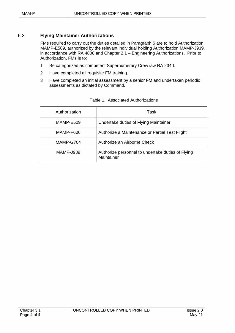
MAM-P UNCONTROLLED COPY WHEN PRINTED
Chapter 3.1 Page 4 of 4
UNCONTROLLED COPY WHEN PRINTED Issue 2.0 May 21
6.3 Flying Maintainer Authorizations
FMs required to carry out the duties detailed in Paragraph 5 are to hold Authorization MAMP-E509, authorized by the relevant individual holding Authorization MAMP-J939, in accordance with RA 4806 and Chapter 2.1 – Engineering Authorizations. Prior to Authorization, FMs is to:
1 Be categorized as competent Supernumerary Crew iaw RA 2340.
2 Have completed all requisite FM training.
3 Have completed an initial assessment by a senior FM and undertaken periodic assessments as dictated by Command.
Table 1. Associated Authorizations
Authorization Task
MAMP-E509 Undertake duties of Flying Maintainer
MAMP-F606 Authorize a Maintenance or Partial Test Flight
MAMP-G704 Authorize an Airborne Check
MAMP-J939 Authorize personnel to undertake duties of Flying Maintainer
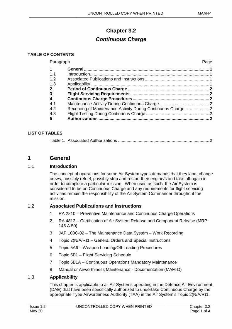
UNCONTROLLED COPY WHEN PRINTED MAM-P
Issue 1.2 May 20
UNCONTROLLED COPY WHEN PRINTED Chapter 3.2 Page 1 of 4
...........................................................................
...............................................................................................................................................
.............................................................
................................................................................................................................
....................................................................................................................................................................
.......................................................................................................................................................
.......................................................................................................
Chapter 3.2
Continuous Charge
TABLE OF CONTENTS
Paragraph Page
1 General 11.1 Introduction 11.2 Associated Publications and Instructions 11.3 Applicability 12 Period of Continuous Charge 23 Flight Servicing Requirements 24 Continuous Charge Procedures 24.1 Maintenance Activity During Continuous Charge 24.2 Recording of Maintenance Activity During Continuous Charge 24.3 Flight Testing During Continuous Charge 25 Authorizations 2
LIST OF TABLES
Table 1. Associated Authorizations 2
1 General
1.1 Introduction
The concept of operations for some Air System types demands that they land, change crews, possibly refuel, possibly stop and restart their engine/s and take off again in order to complete a particular mission. When used as such, the Air System is considered to be on Continuous Charge and any requirements for flight servicing activities remain the responsibility of the Air System Commander throughout the mission.
1.2 Associated Publications and Instructions
1 RA 2210 – Preventive Maintenance and Continuous Charge Operations
2 RA 4812 – Certification of Air System Release and Component Release (MRP 145.A.50)
3 JAP 100C-02 – The Maintenance Data System – Work Recording
4 Topic 2(N/A/R)1 – General Orders and Special Instructions
5 Topic 5A6 – Weapon Loading/Off-Loading Procedures
6 Topic 5B1 – Flight Servicing Schedule
7 Topic 5B1A – Continuous Operations Mandatory Maintenance
8 Manual or Airworthiness Maintenance - Documentation (MAM-D)
1.3 Applicability
This chapter is applicable to all Air Systems operating in the Defence Air Environment (DAE) that have been specifically authorized to undertake Continuous Charge by the appropriate Type Airworthiness Authority (TAA) in the Air System’s Topic 2(N/A/R)1.
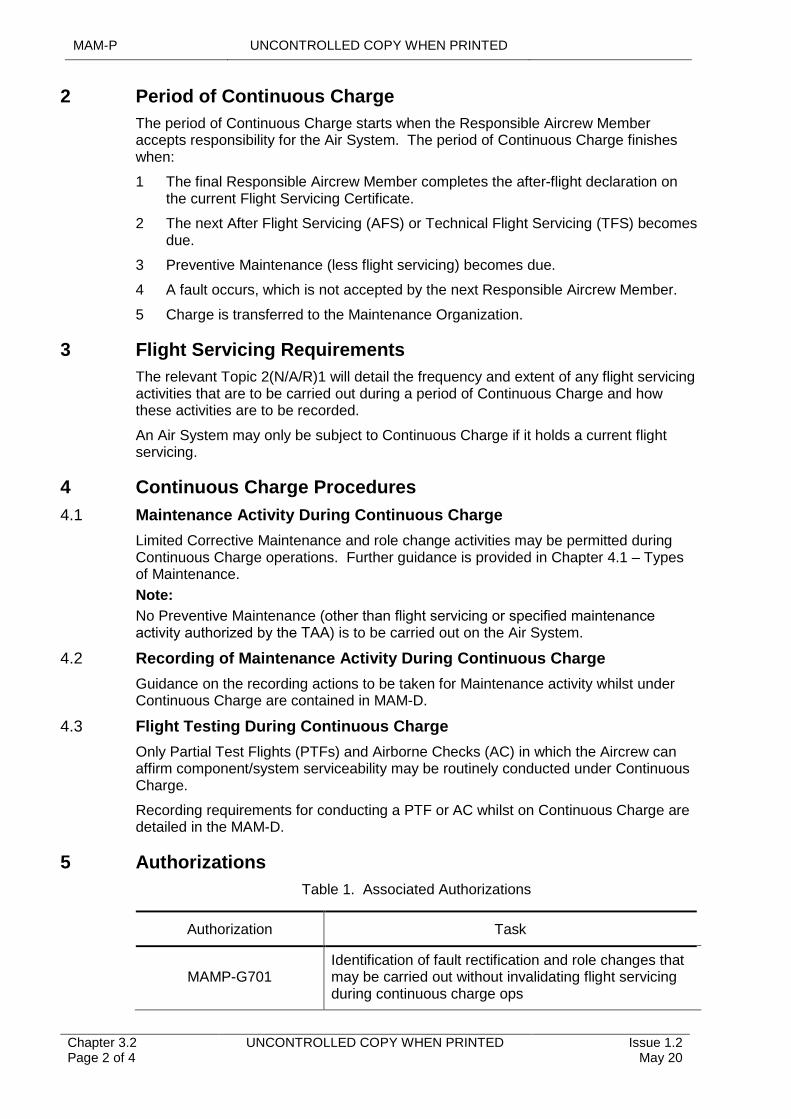
MAM-P UNCONTROLLED COPY WHEN PRINTED
Chapter 3.2 Page 2 of 4
UNCONTROLLED COPY WHEN PRINTED Issue 1.2 May 20
2
3
4
4.1
Period of Continuous Charge
The period of Continuous Charge starts when the Responsible Aircrew Member accepts responsibility for the Air System. The period of Continuous Charge finishes when:
1 The final Responsible Aircrew Member completes the after-flight declaration on the current Flight Servicing Certificate.
2 The next After Flight Servicing (AFS) or Technical Flight Servicing (TFS) becomes due.
3 Preventive Maintenance (less flight servicing) becomes due.
4 A fault occurs, which is not accepted by the next Responsible Aircrew Member.
5 Charge is transferred to the Maintenance Organization.
Flight Servicing Requirements
The relevant Topic 2(N/A/R)1 will detail the frequency and extent of any flight servicing activities that are to be carried out during a period of Continuous Charge and how these activities are to be recorded.
An Air System may only be subject to Continuous Charge if it holds a current flight servicing.
Continuous Charge Procedures
Maintenance Activity During Continuous Charge
Limited Corrective Maintenance and role change activities may be permitted during Continuous Charge operations. Further guidance is provided in Chapter 4.1 – Types of Maintenance.
Note:
No Preventive Maintenance (other than flight servicing or specified maintenance activity authorized by the TAA) is to be carried out on the Air System.
4.2 Recording of Maintenance Activity During Continuous Charge
Guidance on the recording actions to be taken for Maintenance activity whilst under Continuous Charge are contained in MAM-D.
4.3 Flight Testing During Continuous Charge
Only Partial Test Flights (PTFs) and Airborne Checks (AC) in which the Aircrew can affirm component/system serviceability may be routinely conducted under Continuous Charge.
Recording requirements for conducting a PTF or AC whilst on Continuous Charge are detailed in the MAM-D.
5 Authorizations
Table 1. Associated Authorizations
Authorization Task
MAMP-G701 Identification of fault rectification and role changes that may be carried out without invalidating flight servicing during continuous charge ops
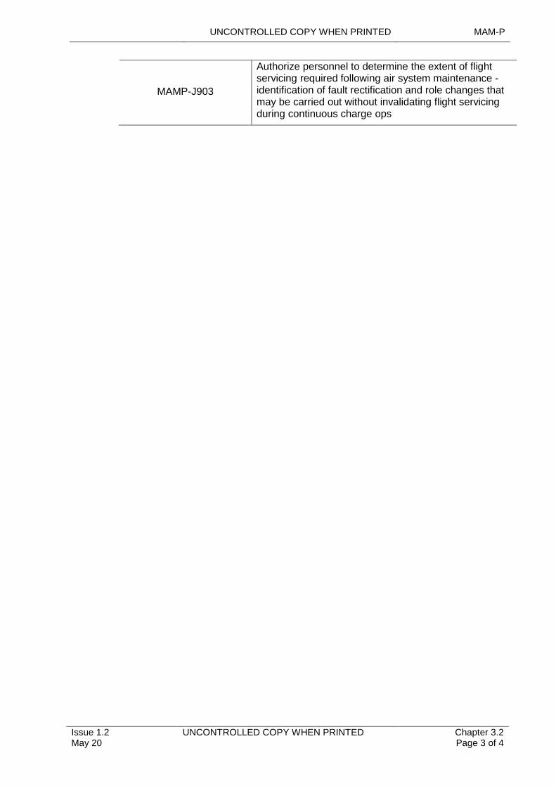
UNCONTROLLED COPY WHEN PRINTED MAM-P
Issue 1.2 May 20
UNCONTROLLED COPY WHEN PRINTED Chapter 3.2 Page 3 of 4
MAMP-J903
Authorize personnel to determine the extent of flight servicing required following air system maintenance - identification of fault rectification and role changes that may be carried out without invalidating flight servicing during continuous charge ops

MAM-P UNCONTROLLED COPY WHEN PRINTED
Chapter 3.2 Page 4 of 4
UNCONTROLLED COPY WHEN PRINTED Issue 1.2 May 20
Intentionally Blank for Print Pagination
UNCONTROLLED COPY WHEN PRINTED MAM-P
Initial Issue Nov 19
UNCONTROLLED COPY WHEN PRINTED Chapter 3.3 Page 1 of 4
...........................................................................
......................................................................................................................................................................
.....................................................................................................................................................................................
.............................................................................................................
.................................................................................................................................................
..........................................................................................................................................................................
...........................................................................................
...................................................................................................................................................
................................................................................................................
.......................................................................................................................................................
.......................................................................................................
Chapter 3.3
Air Systems Displaying Abnormal Flying Characteristics
TABLE OF CONTENTS
Paragraph Page
1 General 11.1 Introduction 11.2 Associated Publications and Instructions 11.3 Additional Information 22 Uncommanded Flying Control Movements (UFCMs) 22.2 Control Restrictions (CRs) 22.3 Unusual Occurrences (UOs) 23 Actions in Response to an Air System Displaying Abnormal Flying
Characteristics 23.1 Immediate Actions 23.2 Maintenance Actions 33.3 External Assistance 33.4 Flight Tests and/or Airborne Checks 33.5 Certification of Air System Release and Air System Release for Flight 33.6 Reporting 34 Rogue Aircraft 35 Responsibilities 45.1 Maintenance Organization 46 Authorizations 4
LIST OF TABLES
Table 1. Associated Authorizations 4
1 General
1.1 Introduction
Air Systems occasionally display abnormal flying characteristics, the causes of which, if not investigated carefully, may remain unresolved. Air Systems with simple flying controls may experience mechanical failure or control restrictions; however, Air Systems are becoming more reliant on full authority Flight Control Systems (FCSs) and, as these are increasingly being integrated with other systems, Faults such as unexplained control movements are becoming increasingly difficult to diagnose. Air Systems experiencing Uncommanded Flying Control Movements (UFCMs), Control Restrictions (CRs), Unusual Occurrences (UOs) or other unacceptable flying characteristics pose potentially serious Airworthiness risks need to be thoroughly investigated. Orders and procedures will be promulgated to specify the actions to be taken when an Air System exhibits a UFCM, CR, UO or other unacceptable flying characteristics. This chapter details the general management of these conditions.
1.2 Associated Publications and Instructions
1 RA 1410 – Occurrence Reporting and Management
2 RA 2220 – Maintenance Test Flights
3 RA 4947 – Continuing Airworthiness Management - MRP Part M Sub Part G
MAM-P UNCONTROLLED COPY WHEN PRINTED
Chapter 3.3 Page 2 of 4
UNCONTROLLED COPY WHEN PRINTED Initial Issue Nov 19
4 RA 4051 – Airborne Checks
5 RA 4061 – Air Systems Displaying Abnormal Flying Characteristics
6 RA 4806 – Personnel Requirements (MRP 145.A.30)
1.3 Additional Information
The boundaries of what constitutes abnormal flying characteristics will vary according to Air System type with regard to the specific features of the Air System FCS. The applicability, scope and investigation of abnormal flying characteristics for each Air System are promulgated by the Type Airworthiness Authority (TAA) within the Air System Technical Information (TI).
2 Uncommanded Flying Control Movements (UFCMs)
UFCMs are defined as any:
1 Unexplained change of Air System in-flight attitude without a legitimate flying control input;
2 Movement of flying control input controls when there should be none;
3 Movement of flying control surfaces or systems without a corresponding legitimate input.
2.2 Control Restrictions (CRs)
CRs are defined as:
1 An inability to move the flying control input system to any position within its normal range of travel;
2 A condition when a greater than normal force is required to move a flying control input;
3 The failure of a flying control surface or system to respond correctly to a flying control input.
2.3 Unusual Occurrences (UOs)
UOs are defined as any other abnormal flying condition involving a primary flying control system, which is not classified as a UFCM or CR, which results in a Defence Air Safety Occurrence Report (DASOR) being raised in accordance with (iaw) RA 1410.
3 Actions in Response to an Air System Displaying Abnormal Flying Characteristics
To aid the initial investigation, the Air System is to be retained as closely as possible to its UFCM/CR/UO event condition. Therefore, immediately after such an event is reported, a strictly controlled investigation process is to be followed to prevent the loss or masking of important fault indicators due to:
1 Air System engine shutdown;
2 Maintenance activities;
3 Interruption of Air System electrical power or FCSs.
3.1 Immediate Actions
The immediate actions following a UFCM/CR/UO event are:
1 Confirm declaration of an occurrence by the Air System Commander;
UNCONTROLLED COPY WHEN PRINTED MAM-P
Initial Issue Nov 19
UNCONTROLLED COPY WHEN PRINTED Chapter 3.3 Page 3 of 4
2 Suspend all Maintenance activities other than those needed to make the Air System safe;
3 Implement a formal investigation process as detailed within the TI and/or local orders and procedures;
4 Inform the Military Continuing Airworthiness Management Organization (Mil CAMO).
Note:
Whenever possible, the Air System is to be retained in the UFCM/CR/UO event or post-flight condition, to enable Maintenance personnel to conduct initial investigations. In order to prevent loss of potentially vital data, it may be necessary to keep an Air System in a flight configuration.
3.2 Maintenance Actions
On declaration of a UFCM/CR/UO event, Maintenance personnel are to refer to relevant instructions in the TI and local instructions and where appropriate, initiate the immediate actions. Some of these actions may entail Aircrew-assisted investigation and debrief at the Air System prior to engine shutdown.
3.3 External Assistance
Investigation and subsequent rectification of UFCM/CR/UO events are the responsibility of the Maintenance Organization; however, external assistance may be sought through the Mil CAMO.
3.4 Flight Tests and/or Airborne Checks
Conditions when flight tests may be required to assist with investigations will be detailed within the TI. It may be appropriate to impose additional constraints on such flights when they form part of an investigation. These flight tests are to be authorized by a minimum of authority level J holding Authorization MAMP-J954. Additional information see Chapter 3.1- Flight Testing of Air Systems.
3.5 Certification of Air System Release and Air System Release for Flight
Orders will be promulgated to state the Competence requirements of those individuals that will be Authorized to Release an Air System for flight.
3.6 Reporting
Due to the potential Airworthiness risks posed by a UFCM/CR/UO event, a DASOR is to be raised for all occurrences iaw RA 1410.
4 Rogue Aircraft
When an Air System continues to exhibit abnormal flying characteristics, following a thorough investigation and every reasonable effort to rectify the Fault, and the condition is confirmed during UFCM/CR/UO flight test or airborne checks the Aircraft could be designated rogue. Orders and procedures will be promulgated to ensure the correct management of rogue Aircraft and specifying the competence requirements of the individuals that will authorize an Aircraft as rogue.
If further diagnosis proves to be unsuccessful, the Maintenance organization is to report the rogue Aircraft to the CAMO who will determine the next course of action.
MAM-P UNCONTROLLED COPY WHEN PRINTED
Chapter 3.3 Page 4 of 4
UNCONTROLLED COPY WHEN PRINTED Initial Issue Nov 19
5 Responsibilities
5.1 Maintenance Organization
The Maintenance organization is to ensure:
1 It has a responsive UFCM/CR/UO event management and investigation capability.
2 A suitably qualified individual is appointed to control and manage the investigation.
3 Immediate action, investigation and reporting procedures are understood and followed.
4 Authority is obtained prior to releasing the Air System for flight iaw Paragraphs 3.5 and 6.
6 Authorizations
Individuals meeting the correct competence requirements will be granted Authorization MAMP-J954 and may:
1 Release an Air System for flight after UFCM/CR/UO investigations.
2 Release Air System for flight test or airborne check to investigate UFCM/CR/UO.
3 Designate an Aircraft as rogue.
When it is impractical for the authority level J to sign the relevant documentation, MAMP-J976 may be delegated to individuals, with minimum authority level H, meeting the competency requirements detailed in RA 4806 and Chapter 2.1 – Engineering Authorizations:
1 Release an Air System for flight test or flight after a UFCM/CR/UO investigation.
2 Release an Air System for flight test to investigate a UFCM/CR/UO.
Table 1. Associated Authorizations
Authorization Task
MAMP-J954 Authorize personnel to release Air System for flight test to investigate UFCM/CR/UO and on completion of all UFCM/CR/UO investigations. Designate Aircraft as 'Rogue'.
MAMP-J976 Release Air System for flight test to investigate UFCM/CR/UO and on completion of all UFCM/CR/UO investigations.
UNCONTROLLED COPY WHEN PRINTED MAM-P
Issue 1.1 Feb 20
UNCONTROLLED COPY WHEN PRINTED Chapter 3.4 Page 1 of 6
...........................................................................
........................................................................................................................
......................................................................................................
.............................................................................................................................................................................................
.............................................................................................................................................
......................................................................................
................................................................................................................................
..........................................................................................................................................................
.......................................................................................................
Chapter 3.4
Ground Operations
TABLE OF CONTENTS
Paragraph Page
1 General 11.1 Introduction 11.2 Associated Publications or Instructions 12 Ground Handling of Aircraft 22.1 Ground Handling Team Composition 22.2 Aircraft Ground Handling Precautions 23 Aircraft Ground Handling in Particular Environments 43.1 Operational/Exercise Situations 43.2 At Night or in Poor Visibility 43.3 Environmental Limits 43.4 At Sea 44 Aircraft Arrival and Departure 45 Ground Operation of Airfield Support Equipment 55.1 Self-propelled ASE and Mechanically-operated vehicles 56 Authorizations 5
LIST OF TABLES
Table 1. Associated Authorizations 5
1 General
1.1 Introduction
This chapter identifies the general precautions and actions to minimize the Safety risk to Air Systems and personnel when ground handling Aircraft, other than taxiing. It details additional precautions to be taken in particular environments, including Aircraft arrival and departure.
1.2 Associated Publications or Instructions
1 RA 2307 – Rules of the Air
2 RA 4054 – Ground Handling Operations
3 JSP 800 – Defence Movement and Transport Regulations
4 JAP 100E-10 – Military Airfield Support Equipment Management and Policy
5 BRd 766 – Embarked Aviation Orders
6 Defence Logistics Framework (DLF)
7 NATO Standard AFSP-2 – Air System Marshalling Signals for Military Operations via Defence Gateway
MAM-P UNCONTROLLED COPY WHEN PRINTED
Chapter 3.4 Page 2 of 6
UNCONTROLLED COPY WHEN PRINTED Issue 1.1 Feb 20
2 Ground Handling of Aircraft
2.1 Ground Handling Team Composition
All ground handling operations are to be conducted by personnel who have been assessed as Competent and authorized in accordance with (iaw) Chapter 2.1 – Engineering Authorizations. A ground handling team is to consist of:
1 A ground handling Supervisor.
2 An Aircraft brakeman, if appropriate.
3 A towing vehicle driver or alternatively a winch operator, if used.
4 Steering arm operator if a steering arm is in use.
5 Chockmen, as required.
6 Safety personnel, as required.
Note:
If visiting Aircraft need to be moved and there are no suitably authorized personnel by Air System type, the relevant authority level K of the hosting Station/Unit (Stn/Unit) may authorize personnel with appropriate authorizations for other Air System types to act as members of the visiting Aircraft ground handling team.
Non-engineering personnel (such as RN Air System Handler Branch) who receive generic Aircraft ground handling training and Authorizations, are not limited by Aircraft type. When required to move unfamiliar Aircraft, the Responsible Aircrew Member or ground handling Supervisor is to ensure that the ground handling team is briefed prior to the move, with no need for further Authorization.
2.2 Aircraft Ground Handling Precautions
The ground handling Supervisor is to ensure that they and the team adhere to the following precautions:
1 Team members are to be briefed on the intended activity, Safety precautions, sequence of events and any local movement orders/procedures that are in place.
2 All personnel are to be familiar with the danger zones for the Aircraft type being moved.
3 Personnel are to be familiar with local Aircraft movement orders.
4 Towing vehicle drivers are to hold an Airfield driving permit, iaw DLF, Defence Movement and Transport Regulations.
5 All personnel involved in ground handling are to wear suitable high-visibility clothing.
Note:
Local Orders are to detail the requirement for any additional distinctive garments to be worn eg arm bands.
6 Effective communications are to exist between all members of the ground handling team at all times. Ground handling Supervisors, where practicable, may use a blast-type whistle to complement their verbal commands
7 When conducting movements where communication is challenging (such as in a CBRN environment or noisy operating areas), extra care is to be taken to ensure that the ground handling team is briefed on the signals that may replace verbal commands.

UNCONTROLLED COPY WHEN PRINTED MAM-P
Issue 1.1 Feb 20
UNCONTROLLED COPY WHEN PRINTED Chapter 3.4 Page 3 of 6
8 Where appropriate, verbal clearance for the move is to be obtained from local operational controllers.
9 The ground handling Supervisor is not to undertake any other ground handling task, unless:
9.1 They are acting as the winch operator in a Hardened Aircraft Shelter (HAS) and then only when winch controls permit sufficient freedom of movement around the HAS to maintain sight of all ground handling personnel.
9.2 They are part of a Glider Ground Handling Team that, under normal conditions, is considered a 2-man operation iaw Aircraft Support Policy Statement.
10 The ground handling Supervisor is to position themselves so that they have a clear all-round view of the ground handling team, the intended route and, as far as practicable, the Aircraft.
11 The Aircraft is to be made safe to move, with all Safety devices enabled or fitted iaw the Air System Technical Information (TI).
12 The ground handling Supervisor, through the brakeman, is to ensure that the braking system, if applicable, is Serviceable and that there is sufficient brake pressure for the move. When conducting movements on Aircraft with Unserviceable brake systems, local engineering management is to specify any additional precautions prior to authorizing the move.
13 All ground locks are to be fitted securely and ladders/panels secured, iaw TI.
14 Nose/tail wheels are to be unlocked and/or nose wheel steering disconnected as required by Air System TI.
15 Unless required for the proposed activity and designed to be towed whilst connected to the Aircraft, Ground Support Equipment (GSE) is to be disconnected and positioned clear of the proposed route.
16 Loose equipment is to be secured.
17 Aircraft control surfaces are set to prevent fouling during the move.
18 Towing equipment appropriate to tow the specific Aircraft is to be Serviceable and correctly fitted.
19 Where applicable, the Aircraft wheels are to be chocked. Chocks are not be removed until instructed by the ground handling Supervisor.
20 Personnel are not permitted on the external surfaces of the Aircraft during the move.
21 Chockmen, where applicable, are to remain alongside the wheels and are never to get ahead of the wheels in the direction of travel. Local orders may grant permission for chockmen to travel as Passengers in authorized vehicles or in the Aircraft being towed, provided they are in a position to enable the timely placement of chocks when required.
22 Aircraft are to be moved at a pace as detailed in the relevant TI.
23 The route is to be checked prior to move, and assessed clear of obstructions at all stages taking into consideration the ground conditions (soft/undulating), any overhead clearances and grounding hazards.
MAM-P UNCONTROLLED COPY WHEN PRINTED
Chapter 3.4 Page 4 of 6
UNCONTROLLED COPY WHEN PRINTED Issue 1.1 Feb 20
3 Aircraft Ground Handling in Particular Environments
3.1 Operational/Exercise Situations
Local Commanders may reduce or remove the requirement for personnel involved in ground handling to wear distinctive garments for operational/exercise reasons. Tactical and operational requirements specific to the operation of Aircraft at Forward Arming and Refuelling Points are to be promulgated in local orders.
3.2 At Night or in Poor Visibility
The following additional precautions are to be followed at night or in poor weather:
1 Maximum permissible lighting (Night Vision Device (NVD) compatible, if appropriate), including floodlighting, Aircraft navigation lights and towing vehicle lights, are to be used.
2 The Supervisor and Safety personnel are to be appropriately dressed, including distinctive garments, where appropriate, and use illuminated marshalling wands to clearly indicate orders and safe clearances.
3 The Supervisor is to consider the use of additional Safety personnel if hazards are expected on the route.
3.3 Environmental Limits
Additional precautions are to be taken, iaw the relevant TI and local instructions, to ensure the Safety of the Aircraft and personnel. Limits for the specific Aircraft are detailed in the TI. Precautions are also to be taken to secure GSE and other loose items in the vicinity of Aircraft.
3.4 At Sea
For ground handling of Aircraft at sea refer to BRd 766.
4 Aircraft Arrival and Departure
Manual ground handling and Aircraft arrival/departure procedures are to be conducted iaw the appropriate Air System TI. The processes detailed below are to be adhered to when Aircraft arrive or depart.
The following actions are to be adhered to when attending Aircraft arrival and departure:
1 The minimum number of authorised personnel attending an Aircraft arrival and departure is to be detailed in local orders.
2 Movement of Airfield Support Equipment (ASE) within 5 metres of the Aircraft is to be supervised by a marshaller.
3 The arrival and departure team are to ensure that:
3.1 The area is Foreign Object Debris (FOD) free and all non-essential GSE is returned to the appropriate stowage.
3.2 All blanks and covers are removed/fitted as necessary.
3.3 Aircraft Safety devices are removed/fitted and properly stowed as required.
3.4 Assistance is provided to strap in Aircrew, if required.
3.5 Aircraft steps are removed/fitted as necessary.
3.6 First Aid Fire Fighting Appliances (FAFFA) are appropriately positioned and manned.
3.7 Personnel are available to marshal the Aircraft, as required.
UNCONTROLLED COPY WHEN PRINTED MAM-P
Issue 1.1 Feb 20
UNCONTROLLED COPY WHEN PRINTED Chapter 3.4 Page 5 of 6
3.8 Personnel are available to place chocks and connect ground power etc, as required.
3.9 Personnel, vehicles and equipment are clear of Aircraft danger zones.
3.10 Assistance is provided to conduct engine starts, as required.
3.11 Ground power and other connecting leads are removed as directed by the Pilot or authorized crew member conducting the start procedure, and associated Aircraft panels secured.
3.12 Chocks are removed/inserted as directed by the Pilot or authorized crew member conducting the start procedure.
Note:
When an Aircraft has landed or requires to depart without the required arrival/departure personnel, the Responsible Aircrew Member will take sole responsibility for parking or departing the Aircraft, in iaw any instructions passed by Air Traffic Control (ATC). To assist, the Responsible Aircrew Member may stop short of the final parking area and direct an appropriately trained member(s) of his crew to act as the marshaller(s).
5 Ground Operation of Airfield Support Equipment
Airfield Support Equipment (ASE) must be positioned safely and suitably secured so as not to pose a hazard to the Air System and used in accordance with TI. ASE with engines running is not to be left unattended, unless specifically authorized in the ASE TI. It is to be returned to the appropriate storage area when not in use.
5.1 Self-propelled ASE and Mechanically-operated vehicles
1 All operators are to be suitably authorized.
2 They are only to be used for the purpose for which they are designed.
3 When manoeuvred within 5 metres of an Air System they are to be marshalled by a safety person, except where local conditions and procedures negate this requirement.
4 They are not to approach within 15 metres of an aircraft undergoing maintenance to an open fuel system.
5 The operator must ensure that there is adequate clearance between the ASE and the Air System, unless the ASE is designed to be in contact with the Air System, and must advise the safety person of their intentions.
6 When parked within 5 metres of an Air System on land, they are to have wheels chocked. At sea, all unattended ASE must be securely lashed to the deck at all times.
7 Vehicles with petrol engines must not be brought into hangars unless authorized by the person responsible for the hangar.
6 Authorizations
Table 1. Associated Authorizations
Authorization Task
MAMP–B209 Aircraft brakeman during ground movement of Aircraft
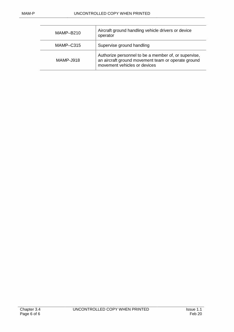
MAM-P UNCONTROLLED COPY WHEN PRINTED
Chapter 3.4 Page 6 of 6
UNCONTROLLED COPY WHEN PRINTED Issue 1.1 Feb 20
MAMP–B210Aircraft ground handling vehicle drivers or device operator
MAMP–C315 Supervise ground handling
MAMP-J918Authorize personnel to be a member of, or supervise, an aircraft ground movement team or operate ground movement vehicles or devices
UNCONTROLLED COPY WHEN PRINTED MAM-P
Issue 1.2 May 20
UNCONTROLLED COPY WHEN PRINTED Chapter 3.4.1 Page 1 of 6
...........................................................................
.......................................................................................................................................................................
...........................................................................................................
......................................................
..........................................................
............................................................
..............................................................................................................................
.....................................................................................................................................
..........................................................................................................................................
.........................................................................................................................................................................................................
Chapter 3.4.1
Fuelling Operations for Aircraft on the Ground
TABLE OF CONTENTS
Paragraph Page
1 General 11.1 Introduction 11.2 Associated Publications or Instructions 11.3 Additional Information 22 General Safety Precautions 23 Emergency Fuelling Operations 34 Bonding Procedures 35 Rotors Turning/Engine Running Refuelling 36 Fuelling Procedures in Specific Environments 46.1 Fuelling Operations in Hangars6.2 Concurrent Fuelling Operations and Loading/Unloading of Cargo 46.3 Fuelling Operations with Passengers On-board 56.4 Emplaning/Deplaning Casualties During Fuelling Operations 57 Fuelling of Air System Belonging to Other Nations 58 Disposal of Fuel Removed from Aircraft 69 Draining and Venting of Fuel Tanks 610 Testing of Aviation Fuel 611 Authorizations 6
LIST OF TABLES
1
1.1
1.2
Error! Bookmark not defined.
Table 1. Associated Authorizations 6
General
Introduction
This chapter identifies the precautions to be followed to minimize the Safety Risk to both Aircraft and personnel during Aircraft fuelling operations, in any environment.
Associated Publications or Instructions
1 RA 1910 – Quality Assurance of Aviation Fuels from non-MOD Sources
2 RA 2309 – Flight Procedures
3 JSP 317 – Defence Fuels Policy, Organisation and Safety Regulations
4 JSP 360 – Use of Military Aerodromes by Civil Aircraft
5 JSP 375 – Management of Health and Safety in Defence
6 JSP 465 – Part 2 Volume 3 -Guidance on Defence Meteorological Services
7 Defence Logistic Framework (DLF)
8 BRd 766 – Embarked Aviation Orders
9 BR 1754 – Regulations for the Safe Storage and Handling of Petroleum Products in HM Ships and Submarines
MAM-P UNCONTROLLED COPY WHEN PRINTED
Chapter 3.4.1 Page 2 of 6
UNCONTROLLED COPY WHEN PRINTED Issue 1.2 May 20
1.3 Additional Information
For fuelling operations on civilian Aircraft, the conditions stated in the DLF and Use of Military Airfields by British and Foreign Civil Aircraft are to be complied with.
2 General Safety Precautions
When conducting Aircraft fuelling operations the following precautions apply:
1 Before fuelling operations commence, appropriately authorized personnel are to ensure the fuelling equipment is Serviceable.
2 Before fuelling operations commence, appropriately authorized personnel are to ensure the Aircraft is prepared to receive fuel in accordance with (iaw) the Technical Instruction (TI).
3 Aircraft and fuelling equipment is to be electrically bonded iaw Paragraph 4.
4 The fuelling point and fuelling equipment is to be manned by Competent personnel at all times during the fuelling operation.
5 Before fuelling operations commence, appropriately authorized personnel are to ensure the fuel dispenser contains the correct fuel, iaw JSP 317 and TI.
6 Fuelling equipment is to be sited outside the Aircraft fire hazard areas.
7 Appropriate first aid fire-fighting equipment is to be suitably located to enable immediate use.
8 Personnel in the immediate vicinity of the Aircraft are to be advised that fuelling is taking place.
9 Fuelling operations are to cease in the event of a spillage and are not to recommence until the spillage has been cleaned up.
10 Liquid oxygen (LOX) systems are not to be replenished during fuelling operations but, when necessary, LOX packs may be changed during operational re-arm servicing iaw the appropriate TI.
11 Before fuelling operations commence, supervisors are to ensure that Personal Protective Equipment (PPE) is provided and worn by all personnel involved in Air System fuelling. As a minimum iaw JSP 317, the following PPE appropriate for fuelling operations is to be worn:
11.1 Safety Boots.
11.2 Coveralls.
11.3 Gloves.
11.4 Goggles or Visor.
12 Locally produced Risk Assessments for Aircraft refuelling are to include any additional PPE in accordance with JSP 317 to suit the task/conditions/environment.
13 Personnel are not to wear studded or metal tipped footwear.
14 Radiation Hazard (RADHAZ) precautions are be followed iaw the TI.
15 When a thunderstorm Risk/level high warning has been issued, or thunderstorm activity is apparent in the vicinity of an Aircraft, fuelling operations are to cease.
UNCONTROLLED COPY WHEN PRINTED MAM-P
Issue 1.2 May 20
UNCONTROLLED COPY WHEN PRINTED Chapter 3.4.1 Page 3 of 6
3 Emergency Fuelling Operations
There may be a requirement to conduct fuelling in remote locations or/and use emergency fuel from Non-MOD or NATO sources:
1 When there is no access to on-site Meteorological Office, the Local Commander (if available), or the authority level J, may upon receipt of a generic thunderstorm Risk, assess the situation (see JSP 465 for guidance), provided there is no evidence of thunderstorm activity within 10km of the site, allow fuelling operations to proceed.
2 Authority to use emergency fuels detailed in accordance with the Aircraft leading particulars, is vested with local engineering management.
3 The amounts of emergency fuel used, and the duration the Aircraft is allowed to operate on emergency fuels is detailed in the Aircraft TI. All emergency fuel used and durations are to be correctly recorded iaw the appropriate TI.
4 The relevant Military Continuing Airworthiness Management Organisation (Mil CAMO) and Delivery Team (DT) are to be informed at the earliest opportunity that an Aircraft has been operating with emergency fuel.
4 Bonding Procedures
The following procedures are to be adhered to during fuelling operations on land:
1 Ensure that the fuel bowser earth mechanism is touching the ground.
2 Connect the bowser bonding lead to an appropriate earth point on the Aircraft.
3 Connect the hose bonding mechanism to a conducting part of the Aircraft or specific bonding point, if available.
4 Connect the fuelling hose and commence fuelling.
5 When fuelling is complete, firstly disconnect the fuelling hose, then the bowser bonding lead and the hose bonding mechanism.
Note:
For hydrant refuelling the bonding procedures at Paragraph 4 sub-items 3, 4, 5 are to be followed.
5 Rotors Turning/Engine Running Refuelling
Due to the increased Risk associated with rotors turning/engine running refuelling, the following additional precautions are to be taken:
1 Rotors turning/engine running refuelling is only to be conducted on Air Systems cleared for the task, iaw the relevant TI and Release to Service.
2 All personnel operating beneath the rotor disc or connecting the fuel hose to the aircraft during rotors turning/engine running refuelling are to be authorized.
3 Rotors turning/engines running refuelling is to be at the discretion of the Responsible Aircrew Member.
4 The fuelling hose is to be routed so that it does not foul or damage Aircraft components and is clear of Aircraft heat sources.
5 Fuelling equipment is only to be connected when the Aircrew has signalled that they are ready for refuelling.
6 Personnel not directly involved in the fuelling process (and, where applicable, rearming) are to be kept clear.
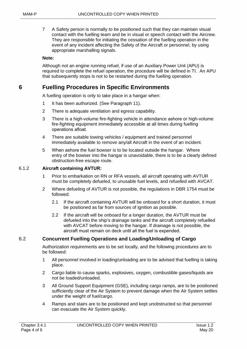
MAM-P UNCONTROLLED COPY WHEN PRINTED
Chapter 3.4.1 Page 4 of 6
UNCONTROLLED COPY WHEN PRINTED Issue 1.2 May 20
7 A Safety person is normally to be positioned such that they can maintain visual contact with the fuelling team and be in visual or speech contact with the Aircrew. They are responsible for initiating the cessation of the fuelling operation in the event of any incident affecting the Safety of the Aircraft or personnel, by using appropriate marshalling signals.
Note:
Although not an engine running refuel, if use of an Auxiliary Power Unit (APU) is required to complete the refuel operation, the procedure will be defined in TI. An APU that subsequently stops is not to be restarted during the fuelling operation.
6 Fuelling Procedures in Specific Environments
A fuelling operation is only to take place in a hangar when:
1 It has been authorized. (See Paragraph 11).
2 There is adequate ventilation and egress capability.
3 There is a high-volume fire-fighting vehicle in attendance ashore or high-volume fire-fighting equipment immediately accessible at all times during fuelling operations afloat.
4 There are suitable towing vehicles / equipment and trained personnel immediately available to remove any/all Aircraft in the event of an incident.
5 When ashore the fuel bowser is to be located outside the hangar. Where entry of the bowser into the hangar is unavoidable, there is to be a clearly defined obstruction-free escape route.
6.1.2 Aircraft containing AVTUR:
1 Prior to embarkation on RN or RFA vessels, all aircraft operating with AVTUR must be completely defueled, to unusable fuel levels, and refuelled with AVCAT.
2 Where defueling of AVTUR is not possible, the regulations in DBR 1754 must be followed.
2.1 If the aircraft containing AVTUR will be onboard for a short duration, it must be positioned as far from sources of ignition as possible.
2.2 If the aircraft will be onboard for a longer duration, the AVTUR must be defueled into the ship’s drainage tanks and the aircraft completely refuelled with AVCAT before moving to the hangar. If drainage is not possible, the aircraft must remain on deck until all the fuel is expended.
6.2 Concurrent Fuelling Operations and Loading/Unloading of Cargo
Authorization requirements are to be set locally, and the following procedures are to be followed:
1 All personnel involved in loading/unloading are to be advised that fuelling is taking place.
2 Cargo liable to cause sparks, explosives, oxygen, combustible gases/liquids are not be loaded/unloaded.
3 All Ground Support Equipment (GSE), including cargo ramps, are to be positioned sufficiently clear of the Air System to prevent damage when the Air System settles under the weight of fuel/cargo.
4 Ramps and stairs are to be positioned and kept unobstructed so that personnel can evacuate the Air System quickly.
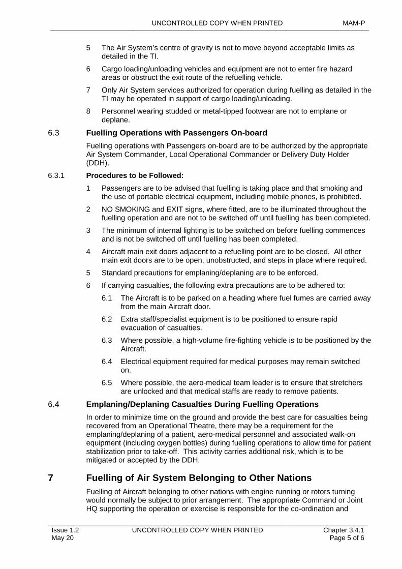
UNCONTROLLED COPY WHEN PRINTED MAM-P
Issue 1.2 May 20
UNCONTROLLED COPY WHEN PRINTED Chapter 3.4.1 Page 5 of 6
5 The Air System’s centre of gravity is not to move beyond acceptable limits as detailed in the TI.
6 Cargo loading/unloading vehicles and equipment are not to enter fire hazard areas or obstruct the exit route of the refuelling vehicle.
7 Only Air System services authorized for operation during fuelling as detailed in the TI may be operated in support of cargo loading/unloading.
8 Personnel wearing studded or metal-tipped footwear are not to emplane or deplane.
6.3 Fuelling Operations with Passengers On-board
Fuelling operations with Passengers on-board are to be authorized by the appropriate Air System Commander, Local Operational Commander or Delivery Duty Holder (DDH).
6.3.1 Procedures to be Followed:
1 Passengers are to be advised that fuelling is taking place and that smoking and the use of portable electrical equipment, including mobile phones, is prohibited.
2 NO SMOKING and EXIT signs, where fitted, are to be illuminated throughout the fuelling operation and are not to be switched off until fuelling has been completed.
3 The minimum of internal lighting is to be switched on before fuelling commences and is not be switched off until fuelling has been completed.
4 Aircraft main exit doors adjacent to a refuelling point are to be closed. All other main exit doors are to be open, unobstructed, and steps in place where required.
5 Standard precautions for emplaning/deplaning are to be enforced.
6 If carrying casualties, the following extra precautions are to be adhered to:
6.1 The Aircraft is to be parked on a heading where fuel fumes are carried away from the main Aircraft door.
6.2 Extra staff/specialist equipment is to be positioned to ensure rapid evacuation of casualties.
6.3 Where possible, a high-volume fire-fighting vehicle is to be positioned by the Aircraft.
6.4 Electrical equipment required for medical purposes may remain switched on.
6.5 Where possible, the aero-medical team leader is to ensure that stretchers are unlocked and that medical staffs are ready to remove patients.
6.4 Emplaning/Deplaning Casualties During Fuelling Operations
In order to minimize time on the ground and provide the best care for casualties being recovered from an Operational Theatre, there may be a requirement for the emplaning/deplaning of a patient, aero-medical personnel and associated walk-on equipment (including oxygen bottles) during fuelling operations to allow time for patient stabilization prior to take-off. This activity carries additional risk, which is to be mitigated or accepted by the DDH.
7 Fuelling of Air System Belonging to Other Nations
Fuelling of Aircraft belonging to other nations with engine running or rotors turning would normally be subject to prior arrangement. The appropriate Command or Joint HQ supporting the operation or exercise is responsible for the co-ordination and
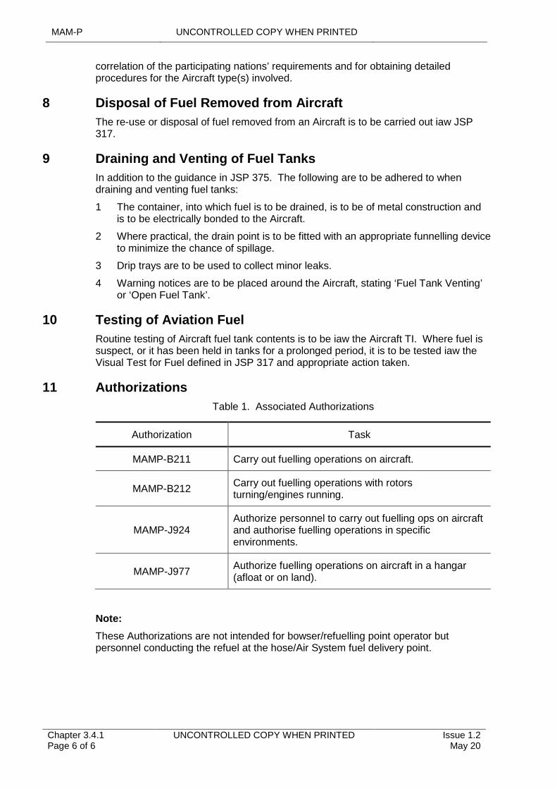
MAM-P UNCONTROLLED COPY WHEN PRINTED
Chapter 3.4.1 Page 6 of 6
UNCONTROLLED COPY WHEN PRINTED Issue 1.2 May 20
correlation of the participating nations’ requirements and for obtaining detailed procedures for the Aircraft type(s) involved.
8 Disposal of Fuel Removed from Aircraft
The re-use or disposal of fuel removed from an Aircraft is to be carried out iaw JSP 317.
9 Draining and Venting of Fuel Tanks
In addition to the guidance in JSP 375. The following are to be adhered to when draining and venting fuel tanks:
1 The container, into which fuel is to be drained, is to be of metal construction and is to be electrically bonded to the Aircraft.
2 Where practical, the drain point is to be fitted with an appropriate funnelling device to minimize the chance of spillage.
3 Drip trays are to be used to collect minor leaks.
4 Warning notices are to be placed around the Aircraft, stating ‘Fuel Tank Venting’ or ‘Open Fuel Tank’.
10 Testing of Aviation Fuel
Routine testing of Aircraft fuel tank contents is to be iaw the Aircraft TI. Where fuel is suspect, or it has been held in tanks for a prolonged period, it is to be tested iaw the Visual Test for Fuel defined in JSP 317 and appropriate action taken.
11 Authorizations
Table 1. Associated Authorizations
Authorization Task
MAMP-B211 Carry out fuelling operations on aircraft.
MAMP-B212Carry out fuelling operations with rotors turning/engines running.
MAMP-J924Authorize personnel to carry out fuelling ops on aircraft and authorise fuelling operations in specific environments.
MAMP-J977Authorize fuelling operations on aircraft in a hangar (afloat or on land).
Note:
These Authorizations are not intended for bowser/refuelling point operator but personnel conducting the refuel at the hose/Air System fuel delivery point.
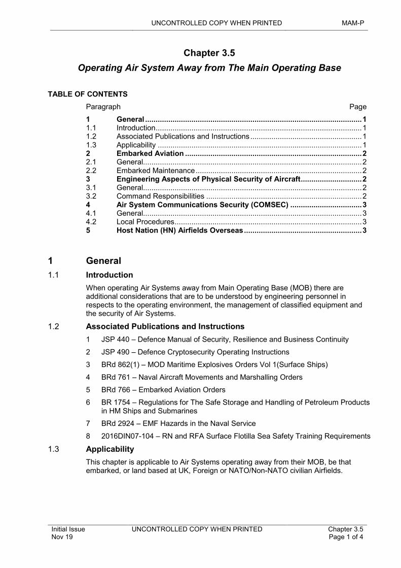
UNCONTROLLED COPY WHEN PRINTED MAM-P
Initial Issue Nov 19
UNCONTROLLED COPY WHEN PRINTED Chapter 3.5 Page 1 of 4
.................................................................................................................................................
..........................................................................................................................................
..................................................................................................................................................................................
............................................................................................................
............................................................................................................................................................................................
......................................................................................................................................................
.........................................................................................................................................................................................................
Chapter 3.5
Operating Air System Away from The Main Operating Base
TABLE OF CONTENTS
Paragraph Page
1 General 11.1 Introduction 11.2 Associated Publications and Instructions 11.3 Applicability 12 Embarked Aviation 22.1 General 22.2 Embarked Maintenance 23 Engineering Aspects of Physical Security of Aircraft 23.1 General 23.2 Command Responsibilities 24 Air System Communications Security (COMSEC) 34.1 General 34.2 Local Procedures 35 Host Nation (HN) Airfields Overseas 3
1 General
1.1 Introduction
When operating Air Systems away from Main Operating Base (MOB) there are additional considerations that are to be understood by engineering personnel in respects to the operating environment, the management of classified equipment and the security of Air Systems.
1.2 Associated Publications and Instructions
1 JSP 440 – Defence Manual of Security, Resilience and Business Continuity
2 JSP 490 – Defence Cryptosecurity Operating Instructions
3 BRd 862(1) – MOD Maritime Explosives Orders Vol 1(Surface Ships)
4 BRd 761 – Naval Aircraft Movements and Marshalling Orders
5 BRd 766 – Embarked Aviation Orders
6 BR 1754 – Regulations for The Safe Storage and Handling of Petroleum Products in HM Ships and Submarines
7 BRd 2924 – EMF Hazards in the Naval Service
8 2016DIN07-104 – RN and RFA Surface Flotilla Sea Safety Training Requirements
1.3 Applicability
This chapter is applicable to Air Systems operating away from their MOB, be that embarked, or land based at UK, Foreign or NATO/Non-NATO civilian Airfields.
MAM-P UNCONTROLLED COPY WHEN PRINTED
Chapter 3.5 Page 2 of 4
UNCONTROLLED COPY WHEN PRINTED Initial Issue Nov 19
2 Embarked Aviation
2.1 General
Operating at sea brings with its inherent risks and associated activity that is to be understood by engineering personnel operating in the maritime environment. The Ship’s Commanding Officer is responsible for the Safety and conduct of all operations involving the ship and therefore has authority over all embarked personnel. Ships may have an Air Department which is responsible for aviation operations and an Air Engineering Department (AED) which is responsible for:
1 Engineering Support.
2 Survival Equipment Maintenance.
3 Aviation Weapons.
4 Environmental Safety Audits.
5 Embarked Quality Assurance.
2.2 Embarked Maintenance
Operating and maintaining Air Systems onboard ships is acutely different from operating in the land environment, this is to be considered during both the planning and operating phases of any embarked aviation operating period. Engineering personnel operating in an embarked environment are to make themselves conversant with the following publications:
1 BRd 862(1) – MOD Maritime Explosive Orders Vol 1 (Surface Ships).
2 BRd 761 – Naval Aircraft Movements and Marshalling Orders.
3 BRd 766 – Embarked Aviation Orders.
4 BR 1754 – Regulations for The Safe Storage and Handling of Petroleum Products in HM Ships and Submarines.
5 BRd 2924 – EMF Hazards in the Naval Service.
6 2016DIN07-104 – RN and RFA Surface Flotilla Sea Safety Training Requirements.
Allied to the above publications, engineering personnel should ensure that any maritime specific environmental Maintenance procedures detailed within the Air System Technical Instruction (TI) are implemented and adhered to.
Queries relating to aviation facilities or support onboard RN and Royal Fleet Auxiliary (RFA) Ships should be directed to the Carrier Strike and Aviation (CSAV) Division, Aviation Facilities Team within Navy Command Headquarters (NCHQ).
3 Engineering Aspects of Physical Security of Aircraft
3.1 General
When UK military Air Systems containing classified equipment are operating from a UK or foreign civilian Airfield, their physical security is an operational matter and should be conducted in accordance with JSP 440.
3.2 Command Responsibilities
When operating from UK or Foreign civilian Airfield Commands are responsible for:
1 Determining any security measures to be implemented over and above those stated in JSP 440 dependent on assessment of the operating location.
UNCONTROLLED COPY WHEN PRINTED MAM-P
Initial Issue Nov 19
UNCONTROLLED COPY WHEN PRINTED Chapter 3.5 Page 3 of 4
2 Detailing the actions to be taken in the event that security seals applied are found broken.
4 Air System Communications Security (COMSEC)
4.1 General
Procedures governing the management of COMSEC material are contained in JSP 440, JSP 490 and Chapter 6.4 - Air System COMSEC Material.
4.2 Local Procedures
There will be occasions when COMSEC material will need to be transferred between Air Systems or be installed on Air Systems that will be operating away from the MOB. On such occasions local procedures should be implemented to ensure that the COMSEC Custodian is kept informed of the exact location of all COMSEC material.
5 Host Nation (HN) Airfields Overseas
When it is necessary to operate Air Systems from HN Airfields overseas, the relevant Host Nation (HN) Aircraft Armament regulations are to be compared with the equivalent Defence Air Environment (DAE) regulations and the more stringent observed. Prior to any deployment, a review of the HN Ordnance Munitions and Explosive (OME) facilities is to take place to ensure that the regulations governing the Maintenance activities in the Aircraft Topic 2(N/A/R)1 will not be subsequently infringed.

MAM-P UNCONTROLLED COPY WHEN PRINTED
Chapter 3.5 Page 4 of 4
UNCONTROLLED COPY WHEN PRINTED Initial Issue Nov 19
Intentionally Blank for Print Pagination

UNCONTROLLED COPY WHEN PRINTED MAM-P
Initial Issue Nov 19
UNCONTROLLED COPY WHEN PRINTED Chapter 3.6 Page 1 of 4
.......................................................................................................................................................................
...........................................................................................................
.....................................................................................................................
......................................................................................................................................................
.........................................................................................................................................................................................................
Chapter 3.6
Biological Security
TABLE OF CONTENTS
Paragraph Page
1 General 11.1 Introduction 11.2 Associated Publications and Instructions 11.3 Applicability 12 Biological Security Implications for Air Systems 13 Compliance Process 13.1 Cleaning and Disinfecting Air Systems and Equipment 23.2 Fumigation of Air Systems 23.3 Biosecurity Certificate 24 Sources of Advice 3
1 General
1.1 Introduction
The term ‘Biological Security’ encompasses a number of different but related threats. In simple terms a biological security policy is required to stop the spread of diseases affecting humans, animals and flora, and the spread of pests, flora and fauna to a country or region where they do not currently, or naturally, occur. MOD biological security policies are detailed in JSP 800 Leaflet 25 – Biosecurity.
1.2 Associated Publications and Instructions
1 JSP 375 – Management of Health and Safety in Defence
2 JSP 800 – Defence Movement and Transport Regulations
3 AP 100C-75 – Support to Operations
4 DAP 3150 – Manual of Movements
1.3 Applicability
This chapter is not applicable, to Air System Nuclear, Biological, and Chemical (NBC) decontamination policy. Detail on Air System NBC decontamination policy can be found in Chapter 4.17 – Chemical, Biological, Radiological and Nuclear Decontamination.
2 Biological Security Implications for Air Systems
For complete MOD biological security policies refer to JSP 800 - Leaflet 25 – Biosecurity. However, the following paragraphs provide simple and general guidance for Air System procedures.
3 Compliance Process
The biological security policy for any country visited can be found in JSP 800 which will detail disinfection and fumigation requirements.
MAM-P UNCONTROLLED COPY WHEN PRINTED
Chapter 3.6 Page 2 of 4
UNCONTROLLED COPY WHEN PRINTED Initial Issue Nov 19
3.1 Cleaning and Disinfecting Air Systems and Equipment
When cleaning or disinfecting of an Air System or Products, Parts and Appliances is required, consideration is to be given to the potential damage that can be caused to Air Systems, by using cleaning products that are not approved for use in the Air System Technical Information (TI). If the TI does not specify appropriate cleaning/disinfecting materials, advice is to be sought from the Type Airworthiness Authority (TAA).
3.1.1 Clean Only
If mandatory disinfection is not required, Air System and Parts, Products and Appliances are to be cleaned in accordance with the TI, in order to remove mud, soil and organic material.
3.1.2 Full Disinfection
If mandatory disinfection is required, affected Air Systems and Products, Parts and Appliances are to be cleaned in accordance with Paragraph 3.1.1 and then disinfected, see (Note 1), using the chemicals and procedures detailed in the MOD’s ‘Use of Disinfectants’ policy, see (Note 2). If these recommended chemicals and procedures are not compliant with TI, advice is to be sought from the TAA.
The requirement to disinfect can be waived by the Commanding Officer if the equipment has only been stored at, and Air Systems have only been operating from, secure locations and the Air System and/or Products Part and Appliances have been on a hard-standing at all times.
Note:
1 Disinfection is only required to decontaminate those parts of the Air System, and Air System Products, Parts and Appliances that have come into contact with mud, soil or organic material.
2 The ‘Use of Disinfectants’ policy is detailed in JSP 800.
3.1.3 Quarantine
Quarantine is an alternative to mandatory disinfection when returning to the UK. Quarantine is to be undertaken in as remote a hard-standing location as possible, on a secure Airfield for a period of not less than 21 days. During this period, the Air System may be maintained but not flown and every care is to be taken to prevent contamination of the host country by personnel who have been in contact with the Air System during quarantine. Quarantine does not negate the requirement for cleaning iaw Paragraph 3.1.1; however, this can, in very exceptional circumstances, be carried out during quarantine if cleaning prior to departure was not possible (eg extraction under fire). In such cases, dedicated Air System washing facilities are to be used for Air System and Products, Parts and Appliances to prevent contamination of the local environment.
3.2 Fumigation of Air Systems
If fumigation of an Air System and/or Products, Parts and Appliances is required, it is to be carried out in accordance with the policy found in JSP 800 and is also to be compliant with TI.
3.3 Biosecurity Certificate
Once cleaning, disinfection and fumigation has been carried out, a Biosecurity Certificate is to be completed as detailed in JSP 800.

UNCONTROLLED COPY WHEN PRINTED MAM-P
Initial Issue Nov 19
UNCONTROLLED COPY WHEN PRINTED Chapter 3.6 Page 3 of 4
4 Sources of Advice
Advice on biological security is to be sought from the relevant Command in the first instance, who are to seek guidance from HQ Army, SHA SO1 EH Pol, who is the Defence Specialist Advisor Environmental Health, Senior Health Advisor (Army) Department.

MAM-P UNCONTROLLED COPY WHEN PRINTED
Chapter 3.6 Page 4 of 4
UNCONTROLLED COPY WHEN PRINTED Initial Issue Nov 19
Intentionally Blank for Print Pagination

UNCONTROLLED COPY WHEN PRINTED MAM-P
..............................................................................
...............................................................................................
Issue 2.1 Aug 21
....................................................................................................................
................................................................
UNCONTROLLED COPY WHEN PRINTED Chapter 4.1 Page 1 of 6
.................................................................................................................................
...............................................................................
........................................................................................................................
......................................................................................
Chapter 4.1
...................................
Types of Maintenance
................................................................
TABLE OF CONTENTS
................................
................................
Paragraph
................................................................................................................
...............................................................................................................
....................
Page
................................
1 General
...............................................................................................................
.............................................................................................
1 ................................1.1 Introduction................................
...........................................................................................................1
1.2 Associated Publications and Instructions 2 2 Preventive Maintenance 2 2.1 Servicing Maintenance 2 2.2 Condition-based Maintenance 2 2.3 Faults Discovered During Preventive Maintenance 2 3 Corrective Maintenance 2 3.1 Corrective Maintenance of Materiel 2 3.2 Air System Maintenance whilst under Aircrew Charge (Pre-flight
Maintenance) 3 3.3 Inspect and Repair as Necessary (IRAN) 3 3.4 Corrective Maintenance of Software 3 4 Contingency Maintenance 3 5 Maintenance in Periods of Abnormal Usage 4 6 Aircraft Not Flown for Extended Periods 4 7 Anti-deterioration Maintenance of Equipment in Store 4 8 Modifications 4 9 Zonal Surveys 4 9.1 Training and Authority Levels 5 10 Structural Significant Item (SSI) Examination 5 11 Authorizations 5
LIST OF TABLES
Table 1. Associated Authorizations 5
1 General
1.1 Introduction
This chapter details the processes for Air System and equipment Maintenance within the Defence Air Environment (DAE), and the principles on which it is based.
Maintenance is a combination of the engineering and supporting administrative actions taken to retain materiel in a Serviceable condition or to restore it to serviceability. The function of Maintenance within the DAE is to maintain the Air System and related equipment in a condition such that they are capable of fulfilling their declared purpose throughout their required life.
The Maintenance philosophy for an Air System or item of equipment, including software, will be detailed in a multi-disciplinary Support Policy Statement which will be promulgated in either the Air System or Commodity Topic 2(N/A/R)1 or equipment Topic 5W as determined by the Delivery Team.
MAM-P UNCONTROLLED COPY WHEN PRINTED
Chapter 4.1 Page 2 of 6
UNCONTROLLED COPY WHEN PRINTED Issue 2.1 Aug 21
1.2 Associated Publications and Instructions
1 RA 4961 – Aircraft Maintenance Programme and Military Continuing Airworthiness Organizations Responsibilities for Air System Release – MRP Part M Sub Part C.
2 RA 5320 – Air System Maintenance Schedule – Design Guidelines.
3 RA 5401 – Provision of Technical information.
4 JAP(D) 100C-22 – Guide to Developing and Sustaining Preventive Maintenance Programmes.
5 JAP 100V-21 – Aircraft Storage.
6 JSP 317 – Defence Fuels Policy Organisation and Safety Regulations.
2 Preventive Maintenance
Preventive Maintenance is undertaken at predetermined intervals to maintain an Air System or Products, Parts and Appliances in a Serviceable condition and to minimize the amount of Corrective Maintenance. Preventive Maintenance tasks may be retained as individual tasks, allowing completion as operations dictate or may be grouped by periodicity and allocated to the appropriate level of Maintenance. This grouping defines the Maintenance schedule, which may be based either on units of usage or calendar time and may, if appropriate, have an upper limit specified in the other unit of measure (eg every 3 years or 500 flying hours, whichever is reached first).
Within the DAE Preventive Maintenance also includes: servicing and condition-based Maintenance.
2.1 Servicing Maintenance
Servicing is that Maintenance required to determine the condition of an Air System or other item of equipment after a period of use and to prepare for its next period of use. It comprises the checking and replenishment of consumables and may include such minor Maintenance as the replacement of bulbs and the identification of signs of un-serviceability.
2.2 Condition-based Maintenance
Condition-based Maintenance is initiated as a result of knowledge of the condition of an item gained from routine or continuous monitoring (eg wear debris monitoring, NDT techniques and, in some applications, built-in test).
2.3 Faults Discovered During Preventive Maintenance
Faults discovered during Preventive Maintenance are to become Corrective Maintenance tasks and are to be actioned appropriately.
3 Corrective Maintenance
3.1 Corrective Maintenance of Materiel
Corrective Maintenance embraces those Maintenance activities carried out after a Fault has occurred in order to restore an item to a Serviceable state. Maintenance activities undertaken when a Fault is indicated, but in the event not confirmed, are also Corrective Maintenance. A Fault may be identified from the application of condition-monitoring techniques as part of Preventive Maintenance. When a Fault is reported or detected the main equipment concerned becomes Unserviceable and the unserviceability is formalized by raising the appropriate work order entry.
UNCONTROLLED COPY WHEN PRINTED MAM-P
Issue 2.1 Aug 21
UNCONTROLLED COPY WHEN PRINTED Chapter 4.1 Page 3 of 6
3.2 Air System Maintenance whilst under Aircrew Charge (Pre-flight Maintenance)
When the Responsible Aircrew Member has accepted responsibility for the Air System (including Continuous Charge), no further Maintenance activities are normally undertaken. However, if a Fault becomes apparent after the Aircrew Acceptance Certificate has been signed, limited Corrective Maintenance activity and role changes may be authorized by an individual holding Authorization MAMP–G702, providing the following criteria has been met:
1 The work carried out is at the specific request of the Responsible Aircrew Member.
2 The Responsible Aircrew Member remains in charge of the Air System.
3 The level of Maintenance activity required is within the permitted limits defined in the associated Technical Information, where applicable.
4 The work can be completed in less time than a certified turn-round servicing.
5 The work boundaries can be precisely defined.
Notes:
1 If all associated remedial action (eg functional test of the affected system) cannot be completed, this requirement is to be recorded in the Limitation Log or Acceptable Deferred Fault Log, as applicable.
2 Recording action for pre-flight Maintenance can be found in the MAM-D Part 1 Chapter 2.1 Maintenance Recording - General Principles.
3.3 Inspect and Repair as Necessary (IRAN)
IRAN is a methodology intended to ensure that the most cost-effective Corrective Maintenance activities are undertaken to return an item to a condition to meet operational commitments. It is rarely necessary to return a faulty component to ‘as new’ condition; consideration is always to be given to repairing an identified Fault, rather than Reconditioning whole equipment.
3.4 Corrective Maintenance of Software
Faults in software may require changes to the design and hence are generally corrected as part of pre-planned program updates embodying multiple change requirements.
4 Contingency Maintenance
In operational or combat conditions the Operating Duty Holder may decide to implement Contingency Maintenance (CTY). CTY allows Maintenance requirements to be relaxed and other forms of Preventive and condition-based Maintenance to be suspended. Whilst CTY may improve Air System availability in the short term, it will require Operating Duty Holder (ODH) Risk Management. CTY requirements will be identified in the Air System TI. Additionally, Air System and equipment expedient repair procedures may be required.
CTY is achieved by one of or a combination of the following:
1 Stopping certain Maintenance activities.
2 Decreasing the frequency of Preventive Maintenance activities.
MAM-P UNCONTROLLED COPY WHEN PRINTED
Chapter 4.1 Page 4 of 6
UNCONTROLLED COPY WHEN PRINTED Issue 2.1 Aug 21
5 Maintenance in Periods of Abnormal Usage
There may be occasions additional Preventive Maintenance is required to maintain the condition of Air System or equipment being operated under adverse conditions, at below-average utilization rates, or which are not flown for extended periods. Examples might include, cold and hot weather operations, saline environments, high humidity or desert conditions or Air System in storage.
6 Aircraft Not Flown for Extended Periods
Unless the procedures detailed in JAP 100V-21 have been applied, the condition of Aircraft not flown for 28 days are to be assessed to determine the anti-deterioration measures to be taken. A re-assessment is to be carried out each subsequent 28 days.
1 In addition to the anti-deterioration measures published in the platform TI, the following non-exhaustive list is also to be considered:
2 Fill all systems to the levels detailed in the Aircraft TI. Note that for vented systems, sufficient air space is to be left to allow for any expansion of the fluid.
3 Drain and remove drop tanks and ferry tanks.
4 Raise Aircraft on jacks or trestles.
5 Test fuels and lubricants as detailed in JSP 317.
6 Apply short-term reserve standards as detailed in JAP 100V-21.
7 Anti-deterioration Maintenance of Equipment in Store
In the context of anti-deterioration Maintenance of equipment in store, the term ‘in store’ means both in store within the supply organization and in forward stores but excludes:
1 Complete Aircraft, for which procedures appear in JAP 100V-21.
2 Equipment governed by other specialist Regulations, eg aero-engines, explosives, armament stores and dehumidification.
Such Maintenance will only be used in instances where ageing, corrosion, growth of mould or other conditions would adversely affect the equipment concerned to an extent that is unacceptable from a cost or operational availability point of view. Shelf-life will be authorized and promulgated in the appropriate Topic 5A1 and Topic 5W only when it is known that the equipment concerned will deteriorate with age regardless of any pre-storage Maintenance or precautions undertaken, eg lithium battery life.
8 Modifications
Modifications are an integral feature of the overall Maintenance philosophy of an Air System or other item of equipment. Sustainment, enhancement, perfective or adaptive Modification action is taken primarily to reflect changes in operational requirements or to improve equipment and personnel Safety. Such action can also improve reliability and maintainability.
9 Zonal Surveys
Zonal surveys are a general visual examination of a specified zone, carried out before and after cleaning, to detect damage, deterioration and discrepancies and assess the
UNCONTROLLED COPY WHEN PRINTED MAM-P
Issue 2.1 Aug 21
UNCONTROLLED COPY WHEN PRINTED Chapter 4.1 Page 5 of 6
general condition of the zone. Zones may contain structure, systems, equipment and components that are already subject to individual directed Maintenance tasks identified elsewhere in the Maintenance schedule. Zonal surveys look for Faults, multiple Faults and the interaction of Faults. For example, a single Fault may be constant seepage: a small fluid leak that may go unnoticed between replenishments, although the cumulative contamination damage induced in adjacent equipment, wiring or structure may be substantial.
9.1 Training and Authority Levels
The authority levels and training requirements for zonal surveys are as follows:
1 Personnel required to act as Unit Zonal Survey Training Instructors within Air Cmd and JHC are to have completed the revised Zonal Survey Instructor training course, CN3209, and hold Authorization MAMP-C309.
2 Personnel required to carry out self-supervised zonal surveys are to have completed zonal survey training at their Stn/Ship/Unit and hold Authorization MAMP-D402.
3 Personnel required to carry out supervised zonal surveys are to have completed zonal survey training at their Stn/Ship/Unit and hold Authorization MAMP-B204.
10 Structural Significant Item (SSI) Examination
SSIs are defined as any detail, element or assembly, which contributes significantly to carrying flight, ground, pressure or control loads and whose failure could affect the Structural Integrity necessary for the continued safe and controlled flight of the Air System and therefore:
1 The identification of SSIs and the requirement for SSI examinations to be conducted will be detailed in the relevant TI.
2 SSI examinations are only to be conducted by individuals assessed as competent and suitably authorized ► holding Authorization level MAMP-C331. ◄
11 Authorizations
Table 1. Associated Authorizations
Authorization Task
MAMP-B204Completed appropriate zonal survey training at Ship/Stn/Unit.
MAMP-C309 Completed Tri-Service Aircraft zonal training course.
►MAMP-C331 Undertake structural examinations. ◄
MAMP-D402 Completed appropriate zonal survey training.
MAMP-J908 Authorize personnel to undertake zonal surveys.
MAMP-J920Authorize personnel to authorize corrective Maintenance of pre-flight faults.
MAM-P UNCONTROLLED COPY WHEN PRINTED
Chapter 4.1 Page 6 of 6
UNCONTROLLED COPY WHEN PRINTED Issue 2.1 Aug 21
MAMP-J930Authorize personnel to give instruction on zonal surveys.
MAMP-J963Authorize personnel to undertake structural examinations.
UNCONTROLLED COPY WHEN PRINTED MAM-P
............................................................................
..............................................
...........
Issue 2.1 Aug 21
................................................................................................................................................................................
...........................
UNCONTROLLED COPY WHEN PRINTED Chapter 4.2 Page 1 of 14
...............................................................................................................................................................................................................................
.................................................................................................................................................
Chapter 4.2
Flight Servicing
..........................................................................................................
..................
TABLE OF CONTENTS
................................
Paragraph
.............................................................................................................................
.........................................................................................................................
........................................
Page
.........
1 General
................................................................................................................................................................
...........................................................................
1
.........................
1.1 Introduction
...................................................................................................................................................................
.......................................
2
................................
1.2 Associated Publications and Instructions
..........................................................................................................
.............................................................
2
................................
1.3 Additional Information
...........................................................................................
.....................................................................
2
...........................
2 Types of Flight Servicing
.........................................................................................
.....................................................................................
2
................................
2.1 Flight Servicing Regimes............
.............................................................................................................................................................
2
.....................
2.2 After Flight (AF), Before Flight (BF) and Turn Round (TR) Servicing
.......................................................................................................................
......
3
................................
2.3 Process for Applying AF, BF and TR System
...........................................................................................................................................
3
................................
2.4 Technical Flight Servicing (TFS) and Daily Flight Servicing (DFS) 4 3 Operational Readiness Servicing (ORS) 5 4 Operational Re-Arm (ORA) Servicing 5 5 Post-Taxi Recovery (PTR) Servicing 5 6 Replenishment Servicing (RS) 6 7 Essential Check (EC) Servicing 6 8 Servicing of Air Systems in Multi-Service Environments 6 9 Aircrew Checks 6 10 Waiving of Flight Servicing 7 10.1 Limitations 7 10.2 Authorization 7 10.3 Aircrew Instructions 7 11 Validity of Flight Servicing 7 11.1 Validity Periods 7 11.2 Extensions to Validity Periods 7 11.3 Effects of Maintenance Activity on Flight Servicing 7 11.4 Effect of Cancelled or Aborted Flight on a Flight Servicing 8 11.5 Recording Action 8 12 Flight Servicing Using an Area-Based Flight Servicing Schedule (FSS)9 13 Responsibilities 9 13.1 Engineering Tradesmen 9 13.2 Flight Servicing Co-ordinator 9 13.3 MOD Form 700C Co-ordinator 10 13.4 Aircrew 10 14 Training and Authorizations 11 14.1 Carrying Out Flight Servicing 11 14.2 Co-ordination Activities 12 14.3 Determining the Validity of, or Restoring, Flight Servicing 12 14.4 Waiving Flight Servicing 12 14.5 Aircrew 12
LIST OF FIGURES
Figure 1. Process for Maintaining Valid Flight Servicing 4
LIST OF TABLES
Table 1. Associated Authorizations 12
1 General
MAM-P UNCONTROLLED COPY WHEN PRINTED
Chapter 4.2 Page 2 of 14
UNCONTROLLED COPY WHEN PRINTED Issue 2.1 Aug 21
1.1 Introduction
Flight servicing comprises those Preventive Maintenance activities required to determine the condition of an Air System prior to, or on completion of, a period of flying.
1.2 Associated Publications and Instructions
1 RA 1220(5) – Support Policy Statement.
2 RA 1223 – Airworthiness Information Management.
3 RA 2210 – Preventative Maintenance and Continuous Charge Operations.
4 RA 2301 – Responsibility for an Air System.
5 RA 4806 – Personnel Requirements (MRP 145.A.30).
6 RA 4808 – Equipment, Tools and Material (MRP 145.A.40).
7 RA 4812 – Certification of Air System Release and Component Release (MRP 145.A.50).
8 RA 4813 – Maintenance Records (MRP 145.A.55).
9 RA 4947 – Continuing Airworthiness Management - MRP Part M Sub Part G.
10 RA 4961 – Aircraft Maintenance Programme and Military Continuing Airworthiness Organizations Responsibilities for Air System Release - MRP Part M Sub Part C.
1.3 Additional Information
This chapter is applicable to all organizations in the Defence Air Environment (DAE) responsible for the flight servicing of military Air Systems. The replenishment of consumables, such as oils, gases and domestics, are flight servicing activities and are included in the relevant Technical Information (TI). Refuelling or defueling is not a flight servicing activity, but it will be carried out whilst flight servicing is in progress and the Air System Type Airworthiness Authority (TAA) will include the appropriate procedure in the relevant TI. Similarly, carrying out a re-role (including weapon loading and unloading) is not a flight servicing activity and is to be carried out in accordance with (iaw) the appropriate TI.
1 Throughout this chapter, the term “MOD Form 700C” is used to denote both the hard copy MOD Air System Maintenance document and any TAA approved electronic Information System (IS).
2 References to Maintenance documentation, forms and certificates include any TAA approved electronic equivalents hosted on an electronic IS that supports Airworthiness Information Management (AIM).
3 RA 4812 regulates the requirement for a ‘Certification of Air System Release’, which is satisfied through co-ordination of the MOD Form 707B, and ‘Air System Release for Flight’ which is satisfied through the co-ordination of the MOD Form 700C, with the appropriate signature on the MOD Form 705. In order to avoid confusion, the term ‘Certification of Air System Release’ and ‘Air System Release for Flight’ have not been introduced to the procedures below.
2 Types of Flight Servicing
2.1 Flight Servicing Regimes
The TAA will specify the flight servicing regime in TI, which may include the following:
1 After Flight (AF), Before Flight (BF) and Turn Round (TR) servicing.
2 Technical Flight Servicing (TFS) and Daily Flight Servicing (DFS).
UNCONTROLLED COPY WHEN PRINTED MAM-P
Issue 2.1 Aug 21
UNCONTROLLED COPY WHEN PRINTED Chapter 4.2 Page 3 of 14
Note:
Replenishment Servicing (RS), Essential Check (EC), Operational Re-Arm (ORA) and Post-Taxi Recovery (PTR) servicing may also be used in conjunction with either a normal Flight Servicing Schedule (FSS) or an Operational Readiness Servicing (ORS) regime.
2.2 After Flight (AF), Before Flight (BF) and Turn Round (TR) Servicing
2.2.1 AF Servicing
An AF servicing comprises those Preventive Maintenance activities necessary to determine the condition of an Air System immediately after a flight, in addition to those Maintenance requirements that arise at the frequency of the AF servicing. An AF servicing is to be carried out:
1 As soon as possible after each flight, except when a TR servicing is to be carried out.
2 When the expiry point of the AF has been reached and the Air System is due to fly.
2.2.2 BF Servicing
BF servicing comprises those Maintenance activities necessary to prepare the Air System for its next flight. When a BF servicing is required immediately after an AF, a combined AF/BF servicing may be carried out. A BF servicing is to be started as near as possible to the time of take-off and remains valid for the period specified in the ADS. Unless otherwise specified in the ADS, this validity period runs from the time that the BF servicing is commenced.
2.2.3 TR Servicing
When an Air System has landed and is expected to fly again within the validity period of the AF, the requirement for flight servicing may be met by a TR servicing. A TR servicing is to commence as soon as possible after flight. It comprises Preventive Maintenance activities to determine the condition of an Air System immediately after a flight and to prepare it for its next flight. A TR servicing remains valid for the period specified in the ADS. Unless otherwise specified in the ADS, this validity period runs from the time that the TR servicing is commenced.
Note:
Paragraph 11.3 details the effects of Maintenance activities on the validity of an AF, BF or TR servicing.
2.3 Process for Applying AF, BF and TR System
This refers to the time gap between Air System landing and when the TR would be started. For example, if the validity of a TR is 8 hrs and the TR is not commenced within 8 hrs of an Air System landing, an AF/BF servicing is to be carried out to enable continued flying. See figure 1.
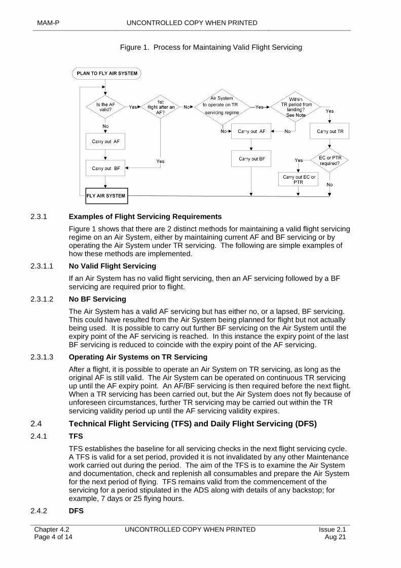
MAM-P UNCONTROLLED COPY WHEN PRINTED
Chapter 4.2 Page 4 of 14
UNCONTROLLED COPY WHEN PRINTED Issue 2.1 Aug 21
Figure 1. Process for Maintaining Valid Flight Servicing
2.3.1 Examples of Flight Servicing Requirements
Figure 1 shows that there are 2 distinct methods for maintaining a valid flight servicing regime on an Air System, either by maintaining current AF and BF servicing or by operating the Air System under TR servicing. The following are simple examples of how these methods are implemented.
2.3.1.1 No Valid Flight Servicing
If an Air System has no valid flight servicing, then an AF servicing followed by a BF servicing are required prior to flight.
2.3.1.2 No BF Servicing
The Air System has a valid AF servicing but has either no, or a lapsed, BF servicing. This could have resulted from the Air System being planned for flight but not actually being used. It is possible to carry out further BF servicing on the Air System until the expiry point of the AF servicing is reached. In this instance the expiry point of the last BF servicing is reduced to coincide with the expiry point of the AF servicing.
2.3.1.3 Operating Air Systems on TR Servicing
After a flight, it is possible to operate an Air System on TR servicing, as long as the original AF is still valid. The Air System can be operated on continuous TR servicing up until the AF expiry point. An AF/BF servicing is then required before the next flight. When a TR servicing has been carried out, but the Air System does not fly because of unforeseen circumstances, further TR servicing may be carried out within the TR servicing validity period up until the AF servicing validity expires.
2.4 Technical Flight Servicing (TFS) and Daily Flight Servicing (DFS)
2.4.1 TFS
TFS establishes the baseline for all servicing checks in the next flight servicing cycle. A TFS is valid for a set period, provided it is not invalidated by any other Maintenance work carried out during the period. The aim of the TFS is to examine the Air System and documentation, check and replenish all consumables and prepare the Air System for the next period of flying. TFS remains valid from the commencement of the servicing for a period stipulated in the ADS along with details of any backstop; for example, 7 days or 25 flying hours.
2.4.2 DFS
UNCONTROLLED COPY WHEN PRINTED MAM-P
Issue 2.1 Aug 21
UNCONTROLLED COPY WHEN PRINTED Chapter 4.2 Page 5 of 14
DFS is the servicing that is required to prepare the Air System for flight(s) during the next 24 hours and is valid from the commencement of the servicing within the TFS period. DFS checks and replenishes all consumables, as well as preparing the Air System’s documentation for the next period of flying. The first 24 hrs following TFS does not require DFS to be carried out, since TFS incorporates the initial DFS.
The following information will be promulgated in the ADS:
1 The procedure for applying for an extension to this period, if applicable.
2 What Level of servicing is required, following a Preventive Maintenance activity.
If the currency of TFS or DFS is likely to expire during a flight, the relevant servicing is to be carried out before commencement of that flight.
Note:
Paragraph 11.3 details the effects of Maintenance activities on the validity of DFS or TFS.
3 Operational Readiness Servicing (ORS)
An ORS regime may be used when an Air System undergoes a sustained period of operational standby. An ORS is to comprise the Preventive Maintenance, and weapon loading/unloading activities if applicable, necessary to maintain an Air System in a state of continuous operational readiness for up to 30 days, unless otherwise stipulated in the relevant ADS. An ORS schedule is a substitute for the Air System’s basic FSS, the requirements of which are suspended throughout the period of operational standby. ORS is sub-divided into three phases:
1 Preparation For Standby (PFS) phase. PFS prepares the Air System for flight and the specified period of operational readiness. It includes the contents of an AF/BF servicing or TFS, weapon loading (if applicable), and any other Maintenance activities that would become due during the standby period. It is valid for the first 24 hrs on standby.
2 Standby Servicing (SS) phase. The SS is carried out at subsequent daily intervals to maintain the Air System in a Serviceable condition whilst it is on standby. It often comprises Maintenance activities drawn from the BF servicing, TR servicing, DFS or replenishment schedules and any Maintenance that may be necessary on any weapons fitment.
3 Release From Standby (RFS) phase. When an Air System is no longer required to be maintained at a state of operational readiness, an RFS is carried out. It comprises the Maintenance activities of an AF servicing or TFS and a weapon unload, if applicable.
EC may also be carried out during a period of operational standby to maintain the Serviceability of high-loss systems. If the Air System taxies, but does not fly, it may be returned to operational readiness by carrying out a PTR. If the Air System flies from operational standby in an ORS regime, on returns it can be restored to operational standby by carrying out a PFS or prepared for a single flight via a TR servicing/DFS or Operational Re-arm (ORA) servicing.
4 Operational Re-Arm (ORA) Servicing
ORA servicing is designed to make an operational Air System ready for flight in the shortest elapsed time. It combines elements of the TR servicing/DFS or RS, as applicable, with refuelling and loading of weapons and/or external stores, as required. An ORA remains valid for the validity period of a TR servicing, DFS or RS.
5 Post-Taxi Recovery (PTR) Servicing
MAM-P UNCONTROLLED COPY WHEN PRINTED
Chapter 4.2 Page 6 of 14
UNCONTROLLED COPY WHEN PRINTED Issue 2.1 Aug 21
A PTR servicing is the Maintenance necessary after an Air System has been started and taxied but has subsequently returned without having flown. A PTR servicing restores, but does not extend, the validity of the Air System’s current flight servicing.
6 Replenishment Servicing (RS)
RS is to contain the minimum mandatory Maintenance activities necessary whenever an Air System lands and stops its engine(s) between flights. RS, if required, is to be carried out as soon as possible after an Air System lands and remains valid as promulgated in the ADS.
On completion of replenishing fuel, oxygen, water or oil systems, the details are to be recorded on the relevant Flight Servicing Certificate (FSC) (MOD Form 705) or Oil Replenishment Record (MOD Form 737) iaw its instructions for use. The signature of the Tradesman undertaking the replenishment signifies that:
1 The replenishment has been carried out iaw the appropriate TI.
2 Any hand tools used have been accounted for, in iaw RA 4808 and Chapter 4.13.1 – Tool Control Procedures.
3 The correct grade of fuel, oil, etc, has been used.
4 The correct quantity has been recorded.
7 Essential Check (EC) Servicing
Where Air Systems lose their contents through natural leakage at a rate that poses an unacceptable constraint on the validity of a particular flight servicing, an EC servicing schedule will be promulgated in the ADS. Such a schedule is to be limited to repeating any flight servicing activities necessary to ensure that those systems remain Serviceable within the validity period of the associated flight servicing. The frequency of any EC servicing will be promulgated in the ADS. An EC servicing may be repeated as often as necessary within the validity period of the associated flight servicing, but it does not extend its validity.
8 Servicing of Air Systems in Multi-Service Environments
Servicing of Air Systems in multi-Service environments, including cross-servicing if authorized, is detailed in RA 4806 and Chapter 4.16 – Maintenance of Aircraft in Multi-Service Environments.
9 Aircrew Checks
The responsible Aircrew member is to carry out checks as detailed in the ADS. These checks are vital since it is possible for an Air System to be cleared for flight although not in a fit condition for flight due to wings or rotors being folded, covers and blanks still in position, etc. Under operational conditions it is not always possible for the Aircrew member to carry out these pre-flight checks personally. In such circumstances, arrangements are to be made for a responsible Tradesman to carry them out and report personally to the Aircraft Commander that they have been done. The Aircraft Commander is responsible for ensuring that this report is made before flight.
Air System acceptance checks by Aircrew are not flight servicing and do not form part of the Maintenance arrangements for the Air System. For Air Systems subject to ORS, the Aircrew will carry out the Air System acceptance checks, following completion of the ORS. However, a person holding Authorization MAMP–G701, in consultation with the relevant Aircrew, is to decide whether the Air System acceptance check has been invalidated by a Maintenance activity on that Air System.
UNCONTROLLED COPY WHEN PRINTED MAM-P
Issue 2.1 Aug 21
UNCONTROLLED COPY WHEN PRINTED Chapter 4.2 Page 7 of 14
10 Waiving of Flight Servicing
10.1 Limitations
Flight servicing is only to be waived if specifically authorized in the ADS and if it is operationally essential to generate an Air System. The ADS will detail the limitations that may be imposed as a result of flight servicing being waived. This may include restrictions on:
1 Duration of any flight.
2 Elapsed time, ie the period of time over which flight servicing may be waived.
3 The number of landings and/or number of system operations.
In addition, the ADS will also detail any specific Maintenance activities that are to be carried out, including the restrictions on subsequent flight servicing (ie an AF/BF servicing is to be completed rather than a TR servicing).
10.2 Authorization
When operational circumstances demand, and provided the conditions at Paragraph 10.1 are met, flight servicing between successive flights may be waived on the authority of:
1 A person holding authority Level J (which is to include MAMP-J907).
2 A person holding Authorization MAMP–J952 when no unit authority level J (holding MAMP-J907) is available.
3 The Aircraft Commander, in consultation with an authority Level J.
The statement:
‘Flight servicing waived by: Authority Level J/Aircraft Commander*: [Insert Name]’. (* Delete as applicable)
Is to be entered in the flight servicing block on the relevant Flight Servicing Certificate (FSC). This entry is to be counter-signed by either the authority Level J or the Aircraft Commander.
10.3 Aircrew Instructions
Units are to consider promulgating local instructions to inform Aircrew of the limitations and restrictions associated with the waiving of flight servicing. These instructions are to include, as a minimum:
1 A verbatim extract from Paragraph 10.2 above.
2 A statement of the limitations imposed in the ADS on the waiving of flight servicing.
11 Validity of Flight Servicing
11.1 Validity Periods
The TAA will determine the validity periods of the various forms of flight servicing most suited to the Air System type and publish them in the ADS.
11.2 Extensions to Validity Periods
Due to the inherent flexibility of the flight servicing systems there is no reason, other than an operational emergency, to extend the validity period of a servicing. However, the TAA may include within the ADS the process for obtaining extensions (if applicable) to the flight servicing periods pertinent to the Air System type.
11.3 Effects of Maintenance Activity on Flight Servicing
11.3.1 TFS and ►DFS◄ or BF and TR Servicing
MAM-P UNCONTROLLED COPY WHEN PRINTED
Chapter 4.2 Page 8 of 14
UNCONTROLLED COPY WHEN PRINTED Issue 2.1 Aug 21
Maintenance activities may invalidate TFS and DFS or BF and TR servicing because they may have disturbed or affected the systems or baselines that were confirmed during the flight servicing. A decision is to be made by an individual holding the appropriate Level G Authorization, as to which one of the following options are required to restore the current flight servicing:
1 Carry out a full flight servicing.
2 Carry out a partial flight servicing which restores the affected systems or baselines and record the decision iaw Paragraph 11.5.
3 Carry out no further flight servicing and record the decision iaw Paragraph 11.5.
Note:
A partial flight servicing does not increase the validity period of the current flight servicing.
11.3.2 AF Servicing
The AF servicing comprises Preventative Maintenance activities which are carried out immediately after flight. Any further Maintenance activities carried out will not invalidate the current flight servicing but will require a BF servicing to be carried out within the AF servicing validity period. During protracted Maintenance activities, the individual responsible for co-ordinating the MOD Form 700C may elect to carry out additional AF servicing as and when required.
11.4 Effect of Cancelled or Aborted Flight on a Flight Servicing
If the Aircraft Commander has signed the acceptance certificate on the FSC, but the flight is subsequently cancelled or aborted before the Air System has flown, the effect on the validity of the flight servicing is to be determined, in consultation with the Aircraft Commander if necessary. Paragraph 11.3 details the actions required to restore the current flight servicing.
11.5 Recording Action
Following an assessment on the effects on a flight servicing following Maintenance or flight cancellation/aborted flight, the recording action detailed in either Paragraph 11.5.1 or 11.5.2 are to be carried out as appropriate. Full details of the recording action required for a specific Air System’s FSC are given in the instructions for use for that form.
11.5.1 No Flight Servicing Required
Where any of the situations detailed in Paragraphs 11.3.1, 11.3.2 or 11.4 have not invalidated a flight servicing, the FSC is to be annotated with one of the following statements and signed by an individual authorized as detailed at Paragraph 14.3:
‘No Flight Servicing Required Following Work at SNOW(s): [Enter SNOW of any work carried out]’
or
‘No Flight Servicing Required Following Cancelled / Aborted* Flight’
(* Delete as applicable)
11.5.2 Partial Flight Servicing
If a partial flight servicing will restore the currency of the existing flight servicing, the FSC is to be annotated with the following statement and signed by an individual authorized as detailed at Paragraph 14.3:
‘Partial Flight Servicing to be carried out: [enter details of elements to be completed]’
In addition, the Tradesman who carries out this work is to sign the FSC.
UNCONTROLLED COPY WHEN PRINTED MAM-P
Issue 2.1 Aug 21
UNCONTROLLED COPY WHEN PRINTED Chapter 4.2 Page 9 of 14
12 Flight Servicing Using an Area-Based Flight Servicing Schedule (FSS)
If authorized by the TAA, flight servicing may be carried out using an area-based system, detailed in the relevant Air System FSS. This system divides the Air System into distinct work areas and will require activities to be done by individuals who would then be working outside their normal trade boundary.
13 Responsibilities
13.1 Engineering Tradesmen
Engineering Tradesmen are to undertake the work as detailed by the flight servicing co-ordinator and sign in the appropriate flight servicing blocks. A signature in the flight servicing block certifies that the flight servicing has been undertaken iaw the appropriate TI and, where required, oil replenishments undertaken have been recorded on the appropriate MOD Form or the electronic IS equivalent has been completed. Additionally, certification of the FSC by a Tradesman signifies that any hand tools, used for that aspect of the flight servicing they have undertaken, have been accounted for.
Flight servicing is an Elementary Self-Supervised (ESS) activity, however, personnel holding Authorization MAMP-D401 are not required to hold the ESS Authorization MAMP-D411 to carry out this activity. The Tradesman carrying it out is to be made aware that they assume the responsibilities of 1st and 2nd signature, as detailed in RA 4806 and Chapter 2.4 – Certification and Maintenance Documentation, for this activity. However, if the risk of error in a particular servicing is high, for example at night, in poor weather, at the end of a shift period or at an austere location, the conduct of the activity is to be carefully managed.
13.2 Flight Servicing Co-ordinator
13.2.1 Responsibilities
The flight servicing co-ordinator is to define the type of flight servicing required, eg AF servicing, DFS, EC, etc. They are also responsible for:
1 Entering any additional requirements in any numbered spare lines and detailing the appropriate Tradesmen to undertake and sign for the work.
2 Identifying in the spare lines any items contained in the flight servicing schedules, eg oxygen replenishment, which they have delegated to Tradesmen other than those directed to undertake the flight servicing.
3 Striking through any designated or spare lines not required.
4 Ensuring that, on completion of their task, all Tradesmen involved in the flight servicing, including any delegated tasks, have signed for their work in the appropriate signature blocks and are authorized to do so.
5 Updating the ‘valid until’ Time/Date/Month (TDM) and airframe hours.
13.2.2 Certification on FSC
The flight servicing co-ordinator is to sign on the relevant FSC to certify that they have satisfied their self that:
1 An entry has been raised in the Aircraft Maintenance Log (MOD Form 707A) for each Fault found during the flight servicing.
2 The flight servicing has been completed satisfactorily.
3 The appropriate columns have been completed in the Supplementary Flight Servicing Certificate (MOD Form 705(SSC)).

MAM-P UNCONTROLLED COPY WHEN PRINTED
Chapter 4.2 Page 10 of 14
UNCONTROLLED COPY WHEN PRINTED Issue 2.1 Aug 21
4 If applicable, flight servicing details have been updated in the appropriate electronic IS.
5 The recorded fuel state meets the figure requested for the next planned sortie.
6 The flying hours and component running hours recorded in the flying log and/or equipment-running log have been calculated correctly from the previous sortie details and the totals prior to that sortie.
7 A careful check of oil state figures has been made, paying particular attention to the amount put in.
13.3 MOD Form 700C Co-ordinator
When all the necessary flight servicing has been completed, the MOD Form 700C co-ordinator releases the Air System for Flight by signing the co-ordinating certificate of the relevant FSC. This signature certifies that, from examination of the MOD Form 700C and, if appropriate, any electronic IS documentation:
1 No limitations or acceptable deferred Faults are due for rectification or removal.
2 The flying hours and component running hours recorded in the flying log and equipment running logs have been calculated correctly from the previous sortie details and the totals prior to that sortie.
3 Any flying requirements have been entered in the Aircraft Maintenance Log and the relevant FSC annotated appropriately.
4 With the exception of the scenario of helicopter main rotor blade and tail pylon fold systems as described in Chapter 4.15 – Independent Inspections iaw RA 4813 and Chapter 2.4 –Certification and Maintenance Documentation.
5 No Preventive Maintenance or component replacements are due or will become due during the planned sortie iaw RA 4961.
6 An authorized Tradesman has certified all entries in the Acceptable Deferred Husbandry Log (MOD Form 704A).
7 All hand tools have been accounted for iaw RA 4808 and Chapter 4.13.1 – Tool Control Procedures.
8 The appropriate flight servicing has been completed and certified.
13.4 Aircrew
The responsibility for the Air System is transferred to the Aircraft Commander when the MOD Form 700C is signed as defined in RA 2301. They are repeated below for the convenience of Maintenance personnel, but RA 2301 remains the authority.
13.4.1 Aircrew Acceptance
The responsible Aircrew member accepts the Air System by signing the acceptance certificate of the FSC. This signature certifies that, after scrutiny of the MOD Form 700C, the Aircrew member is satisfied that:
1 Any limitations are acceptable for the intended sortie.
2 All acceptable deferred Faults have been acknowledged.
3 The recorded state of the Air System in respect of fuel, oxygen, etc, is acceptable for the intended sortie.
4 The armament state of the Air System, as certified on the appropriate FSC or Role Equipment and Expendable Stores certificate (MOD Form 706), is as ordered by the authorizing officer.
UNCONTROLLED COPY WHEN PRINTED MAM-P
Issue 2.1 Aug 21
UNCONTROLLED COPY WHEN PRINTED Chapter 4.2 Page 11 of 14
5 The documentary check of the MOD Form 700C has been carried out and the co-ordinating certificate of the FSC has been signed by the MOD Form 700C co-ordinator.
6 Any flying and/or ground run requirements have been adequately briefed and understood.
7 If applicable, any Aircrew-accepted Faults, as entered in the Aircraft Maintenance Log or continuous operation certificate (MOD F705C) if on continuous charge, are acceptable.
13.4.2 After-Flight Declaration
The Aircrew member responsible for the Air System is to complete the After Flight Certificate in the FSC. This signature returns the responsibility for the Air System to the Maintenance organization and certifies that:
1 The Air System has been returned to the finally armed state iaw the Air System Flight Reference Cards, or that no explosive armament stores are fitted.
2 All known Aircrew-accepted Faults as detailed in the acceptable Faults block were deemed acceptable.
3 An Aircraft Maintenance Log (MOD Form 707A) entry has been raised for each Fault that became evident whilst responsible for the Air System, including pre-flight Faults.
4 The results of any flying requirements undertaken have been entered in the Aircraft Flying Requirements Certificate (MOD Form 707B(AFRC)) iaw MOD Form 799/5(AFRC).
5 The flying log and equipment running log (MOD Form 724) or electronic IS equivalent have been completed.
6 Where applicable, the Oil Replenishment Record (MOD Form 737) has been completed for any oil replenishments carried out whilst responsible for the Air System.
7 The hours flown and cumulative hours flown in the appropriate documentation as required.
8 Where applicable, the Aircrew Assisted Escape System has been made safe.
A significant proportion of Faults reported by Aircrew result in components, particularly radio, electrical and instrument components, being removed from the Air System and subjected to testing that fails to find any Fault. To avoid unnecessary expenditure of time, manpower and spares, plus loss of Air System availability, full and complete debriefing of Aircrew by qualified Maintenance personnel is essential.
14 Training and Authorizations
14.1 Carrying Out Flight Servicing
Personnel required to carry out flight servicing are to hold Authorization MAMP–D401 and have:
1 Completed training iaw RA 4806 and Chapter 2.1 – Engineering Authorizations, for each type/mark of Air System and regime of flight servicing that they are required to carry out.
2 Carried out and passed a flight servicing Competence check iaw Chapter 2.2 – Flight Servicing Competency Checks.
Note:
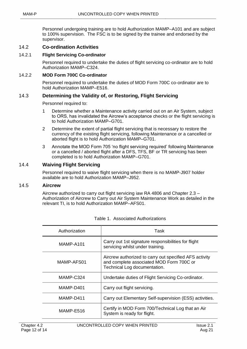
MAM-P UNCONTROLLED COPY WHEN PRINTED
Chapter 4.2 Page 12 of 14
UNCONTROLLED COPY WHEN PRINTED Issue 2.1 Aug 21
Personnel undergoing training are to hold Authorization MAMP–A101 and are subject to 100% supervision. The FSC is to be signed by the trainee and endorsed by the supervisor.
14.2 Co-ordination Activities
14.2.1 Flight Servicing Co-ordinator
Personnel required to undertake the duties of flight servicing co-ordinator are to hold Authorization MAMP–C324.
14.2.2 MOD Form 700C Co-ordinator
Personnel required to undertake the duties of MOD Form 700C co-ordinator are to hold Authorization MAMP–E516.
14.3 Determining the Validity of, or Restoring, Flight Servicing
Personnel required to:
1 Determine whether a Maintenance activity carried out on an Air System, subject to ORS, has invalidated the Aircrew’s acceptance checks or the flight servicing is to hold Authorization MAMP–G701.
2 Determine the extent of partial flight servicing that is necessary to restore the currency of the existing flight servicing, following Maintenance or a cancelled or aborted flight is to hold Authorization MAMP–G701.
3 Annotate the MOD Form 705 ‘no flight servicing required’ following Maintenance or a cancelled / aborted flight after a DFS, TFS, BF or TR servicing has been completed is to hold Authorization MAMP–G701.
14.4 Waiving Flight Servicing
Personnel required to waive flight servicing when there is no MAMP-J907 holder available are to hold Authorization MAMP–J952.
14.5 Aircrew
Aircrew authorized to carry out flight servicing iaw RA 4806 and Chapter 2.3 – Authorization of Aircrew to Carry out Air System Maintenance Work as detailed in the relevant TI, is to hold Authorization MAMP–AFS01.
Table 1. Associated Authorizations
Authorization Task
MAMP-A101Carry out 1st signature responsibilities for flight servicing whilst under training.
MAMP-AFS01Aircrew authorized to carry out specified AFS activity and complete associated MOD Form 700C or Technical Log documentation.
MAMP-C324 Undertake duties of Flight Servicing Co-ordinator.
MAMP-D401 Carry out flight servicing.
MAMP-D411 Carry out Elementary Self-supervision (ESS) activities.
MAMP-E516Certify in MOD Form 700/Technical Log that an Air System is ready for flight.
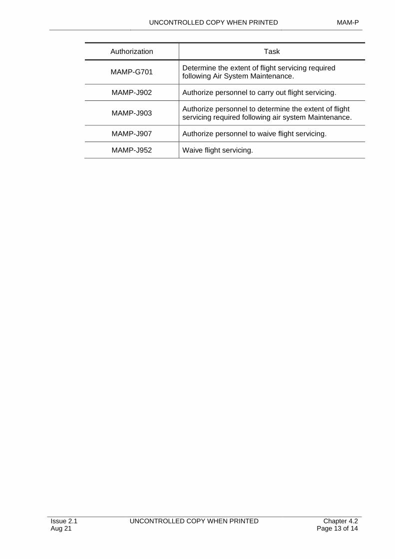
UNCONTROLLED COPY WHEN PRINTED MAM-P
Issue 2.1 Aug 21
UNCONTROLLED COPY WHEN PRINTED Chapter 4.2 Page 13 of 14
Authorization Task
MAMP-G701Determine the extent of flight servicing required following Air System Maintenance.
MAMP-J902 Authorize personnel to carry out flight servicing.
MAMP-J903Authorize personnel to determine the extent of flight servicing required following air system Maintenance.
MAMP-J907 Authorize personnel to waive flight servicing.
MAMP-J952 Waive flight servicing.

MAM-P UNCONTROLLED COPY WHEN PRINTED
Chapter 4.2 Page 14 of 14
UNCONTROLLED COPY WHEN PRINTED Issue 2.1 Aug 21
Intentionally Blank for Print Pagination
UNCONTROLLED COPY WHEN PRINTED MAM-P
Issue 1.1 Feb 20
UNCONTROLLED COPY WHEN PRINTED Chapter 4.3 Page 1 of 8
...........................................................................
.................................................................................................................................
.........................................................................
............................................................................................................
............................................................................................................................
.........................................................................................................................................................
...............................................................................................................................................................
.....................................................................................................................................................................
.....................................................................................................................................
.....................................................................................................
..........................................................................................................................................................
...............................................................................................................................................................................................
..................................................................................................................................................................................
......................................................................................................................................................
.........................................................................................................................................................................................................
Chapter 4.3
Lifing of Air System Components
TABLE OF CONTENTS
Paragraph Page
1 General 11.1 Introduction 11.2 Associated Publications and Instructions 21.3 Applicability 22 Component Failure 22.1 Failure Modes 22.2 Critical Failure Mode 22.3 Critical Components 23 Technical Information (TI) Relating to Component Lives 23.1 Component Lives 23.2 Penalty Factor Numbering (PFN) 34 Review of Lifing Measures 34.1 Procedures for Life Assessment Sampling Programmes 34.2 Stn/Ship/Unit Responsibilities 35 Recording of Life Consumption 35.1 Engineering Record Cards 45.2 Control of ERC's 45.3 Loss of ERC's 45.4 Types and Relationship of ERCs 45.5 Airframe 45.6 Assembly/Engineering Change Unit (ECU) 45.7 Component 45.8 Reporting of Component Change and Modification/Repair 56 Latitudes to Component Life 56.1 Anticipation of Component Lives at Stn/Ship/Unit 56.2 Extension of Component Lives at Command or Stn/Ship/Unit 56.3 Components Removed from Air Systems 67 Unlifed Components Liable to Fatigue Damage 68 Authorizations 7
LIST OF TABLES
Table 1. Associated Authorizations 7
1 General
1.1 Introduction
Certain components within Air Systems have a greater probability of failure with increased age and usage and are to be replaced on a predetermined basis because:
1 Failure in use is to be minimalized or eliminated to prevent Airworthiness or Safety implications.
2 Their replacement will increase Air System availability or decrease replacement cost.
MAM-P UNCONTROLLED COPY WHEN PRINTED
Chapter 4.3 Page 2 of 8
UNCONTROLLED COPY WHEN PRINTED Issue 1.1 Feb 20
These components are subject to lifing procedures detailed in this chapter.
1.2 Associated Publications and Instructions
1 RA 4814 – Occurrence Reporting (MRP 145.A.60)
2 RA 4947 –- Continuing Airworthiness Management - MRP Part M Sub Part G
3 DAP 108A-0006-2(NA/R)1 –- Survival Equipment and Aircrew Equipment Assemblies
4 JAP(D) 100C-22 –- Guide to Developing and Sustaining Preventive Maintenance Programmes
5 Joint Service Munitions Control Register (JSMCR)
6 Knowledge in Defence (KiD)
7 Topic 2(N/A/R)1 –- General Orders, Special Instructions and Modifications
8 Topic 5A1 -– Master Maintenance Schedule
9 Topic 5K –– Schedule of Component Lives (RN only)
1.3 Applicability
This chapter is applicable to Air System components used in the Defence Air Environment (DAE), with the exception of:
Explosives and aerospace components that contain explosives or ancillaries (eg suspension lugs), whose lifing details are contained in Chapter 8.4 – Lifing of Explosives and Associated Ancillaries.
2 Component Failure
2.1 Failure Modes
The term ‘failure mode’ refers to the process that leads to the ultimate failure of a component. Typical failure modes include fatigue, overload, ageing (of explosives or textiles), avionic and mechanical wear, cracking, corrosion and general deterioration. A component can suffer from one or more failure modes.
2.2 Critical Failure Mode
The term ‘critical failure mode’ refers to a failure mode that causes a failure likely to result in the loss of the Air System concerned, loss of Airworthiness or likely to endanger the life of any person concerned with its operation or Maintenance.
2.3 Critical Components
A significant item that has a critical failure mode is described as a ‘critical component’. The term ‘critical component’ is not applied to components that are duplicated to maintain the integrity of the critical function of a system or sub-system.
3 Technical Information (TI) Relating to Component Lives
3.1 Component Lives
Component lives are published in the Component Life Register (CLR) and Component Replacement List (CRL) of the relevant Topic 5A1 or equivalent publication and, if appropriate, the Topic 5K. Equipment and AS DTs may provide guidance on lifing terminology where it differs from that detailed at para 3.1. This may be applicable, for example, in the support of non-UK procured AS and equipment, i.e. F35 Lightning and P8.
UNCONTROLLED COPY WHEN PRINTED MAM-P
Issue 1.1 Feb 20
UNCONTROLLED COPY WHEN PRINTED Chapter 4.3 Page 3 of 8
The following are the approved abbreviations for component lives:
1 Critical Failure Mode – C.
2 Fatigue life – F.
3 Explosive life – E.
4 Textile life – T.
5 Bay Maintenance life – BM.
6 Reconditioning life – R.
7 Scrap life – Scrap.
8 Provisional life – P.
9 Shelf Life – SL.
Note:
The annotation for shelf life indicates those components that require periodic Maintenance whilst held in storage.
3.2 Penalty Factor Numbering (PFN)
Where the same component may be used on different marks or types of Air System, there may be a requirement to factor the life of the component due to differing operating conditions. Where component lives have a usage factor applied, the Penalty Factor Number (PFN) for each application is to be detailed in the Air System Topic 5A1 (CRL and/or CLR). Where a Type Airworthiness Authority (TAA) considers that an explanation of the management of PFNs is required, it is to be contained in the Air System Topic 2(N/A/R)1.
4 Review of Lifing Measures
Components are assessed during the introduction into service and a life is established. In cases where there is insufficient evidence to determine a lifing philosophy for a component, a provisional life may be promulgated. Components with provisional lives are shown with a suffix (P) in the CRL and may be subject to life sampling procedures.
4.1 Procedures for Life Assessment Sampling Programmes
For a component that is subject to a life assessment sampling programme, the sampling requirement will be published in the Mandatory Fault Reporting Instructions (MFRIs), details of which are at RA 4814 and Chapter 9.2 – Narrative Fault Reporting Using the MOD Form 760 series.
4.2 Stn/Ship/Unit Responsibilities
A Stn/Ship/Unit that removes a component in response to an MFRI life sampling requirement are to:
1 Inform the TAA when a component is approaching its provisional life.
2 Complete an MOD Form 760 iaw the requirements of RA 4814 and Chapter 9.2 – Narrative Fault Reporting Using the MOD Form 760 series. The MOD Form 760 is to be annotated ‘For life sampling examination’.
3 Despatch the component as instructed in the MFRI.
5 Recording of Life Consumption
A record of life consumed is to be maintained for every lifed component. This record is normally kept within the Air System technical log (eg MOD Form 700C); however,
MAM-P UNCONTROLLED COPY WHEN PRINTED
Chapter 4.3 Page 4 of 8
UNCONTROLLED COPY WHEN PRINTED Issue 1.1 Feb 20
TAAs may require that some components have their engineering histories recorded on Engineering Record Cards (ERCs). Instructions for the use of ERCs are contained in the Manual of Airworthiness Maintenance - Documentation (MAM-D). Alternatively, a record of life consumed may be maintained, if appropriate, wholly by an electronic system and a hard copy of the ERC printed when required.
5.1 Engineering Record Cards
ERC requirements will be published in the Topic 5A1, including details of the type of ERC to be used for each component and instructions on the disposal of ERCs when Air Systems are withdrawn from Service.
5.2 Control of ERC's
When using the MOD Form 700 series, ERCs constitute Part D of the Air System MOD Form 700 and are to, where possible, be retained with the MOD Form 700C on the user unit. When a component is removed for Maintenance, the ERC is to be completed with details of the removal and the life consumed. The ERC is then to be attached to the MOD Form 731 and dispatched with the item.
5.3 Loss of ERC's
The loss of an ERC is to be reported to appropriate Level J who is to quarantine the associated component, initiate an investigation and report their findings to the TAA and Military Continuing Airworthiness Manager (Mil CAM). If after the investigation the ERC is not found, the TAA are to authorize the issue of a duplicate, or issue disposal instructions as necessary.
5.4 Types and Relationship of ERCs
ERCs are designed to complement each other when used in connection with major assemblies such as airframes, whilst specific ERCs required to support specific Air System and associated components are listed in the relevant Topic 5A1. The relationship between various MOD Form 700 series ERCs is given below.
5.5 Airframe
The master ERC for an airframe is the MOD Form 744 – Airframe Record Card. The associated ERCs are:
1 MOD Form 745 – Maintenance and Repair Record Card.
2 MOD Form 746 – Modification Embodiment Record Card.
3 MOD Form 747 – SI/STI Record Card.
4 MOD Form 747A – SI Applications Record.
5 MOD Form 748 – Miscellaneous Record Card.
6 MOD Form 751 – Aircraft Basic Weight and Moment Record Card.
7 MOD Form 753 – Inspection Test and Modification Certificate.
5.6 Assembly/Engineering Change Unit (ECU)
The master ERC for an assembly or ECU is the MOD Form 749 or MOD Form 749B series – Assembly Record Card. The associated ERCs are:
1 MOD Form 753 –- Inspection Test and Modification Certificate.
2 MOD Form 749(ECLS) –- Engine Cyclic Life Supplement.
5.7 Component
An ERC for a component will be selected from one of the following:
UNCONTROLLED COPY WHEN PRINTED MAM-P
Issue 1.1 Feb 20
UNCONTROLLED COPY WHEN PRINTED Chapter 4.3 Page 5 of 8
1 MOD Form 735 –- Component Log Card (Anglo-French).
2 MOD Form 735A –- Component Record Card.
3 MOD Form 735B –- Engineering Log Card (Tri-National).
A component will also have a MOD Form 753 – Inspection Test and Modification Certificate.
5.8 Reporting of Component Change and Modification/Repair
5.8.1 Component Change Reporting Using Electronic Information System (IS)
In addition to maintaining records of component lives, Stations(Stn)/Ships/Units who use electronic IS for Maintenance data recording are to report removals and installations of lifed components, other than those that are solely calendar life expired, on the appropriate form in the MOD Form 707 series. In addition, certain fatigue-lifed assemblies are noted in blocks on the Air System Flying Log and Fatigue Data Sheet (eg MOD Form 725); such blocks are to be annotated iaw the associated instructions form use (eg MOD Form 799/4F (platform)).
5.8.2 Modification/Repair of Fatigue-Lifed Components
When a fatigue-lifed component (life in Fatigue Index, Fatigue Hours or Damage Index) has been subject to Modification or repair that affects the fatigue life, the fatigue life expired at the time of this action is to be recorded on the ERC. In addition, for Air System with fatigue analysis carried out by Management Information – Faults and Fatigue (MI F&F), they are to be informed when the Modification/repair is carried out. MI F&F will then inform the Maintenance organization of the latest value of fatigue life consumed on the component. The Maintenance organization are to enter the details provided on the appropriate ERC.
6 Latitudes to Component Life
To facilitate Maintenance planning and avoid unnecessary restrictions on Air System availability, some flexibility in the application of authorized lives to individual components is essential.
A TAA may, after considering all the relevant factors, authorize variations in the application of life anticipations and extensions on components, other than those subject to a fatigue life, that are either greater in magnitude or more widely applicable than those detailed in Paragraphs 6.2 and 6.3. When circumstances dictate, a TAA may also restrict or prohibit the application of extensions. TAAs will publish details of such latitude variations in their Support Policy Statement in the Topic 2(N/A/R)1 or, where applicable, in the appropriate TI.
6.1 Anticipation of Component Lives at Stn/Ship/Unit
Anticipation of Maintenance activities has resource implications; therefore, when anticipating a component life expiry, every effort is to be made to ensure that the implications of such action (such as shortage of components, increased Maintenance burden etc) are fully considered. Where a TAA publishes anticipation latitudes that require the use of an Engineering Authorization, personnel holding MAMP-J979 can anticipate component life expiry in accordance with applicable Topic 2(N/A/R)1 direction or TI.
6.2 Extension of Component Lives at Command or Stn/Ship/Unit
6.2.1 Provisional life
The extension of a component subject to a provisional life is prohibited at Command or Stn/Ship/Unit level.
MAM-P UNCONTROLLED COPY WHEN PRINTED
Chapter 4.3 Page 6 of 8
UNCONTROLLED COPY WHEN PRINTED Issue 1.1 Feb 20
6.2.2 Fatigue Life
The extension of a component fatigue life is prohibited at Command or Stn/Ship/Unit level.
6.2.3 Explosive Life
The extension of an explosive life is prohibited at Command or Stn/Ship/Unit level regardless of whether it applies to either critical or non-critical failure modes. Chapter 8.4 – Lifing of Explosives and Associated Ancillaries refer.
Note:
Provided extension is permitted in the TI, extensions to explosives Maintenance lives may be authorized by an individual holding Authorization MAMP-K1021.
6.2.4 Textile Life
1 The extension of textile scrap lives allotted to safeguard against critical failure modes of components is prohibited at Command or Stn/Ship/Unit level.
2 Personnel holding Authorization MAMP-J978 may authorize extensions iaw TI for textile scrap lives allotted to safeguard against non-critical failure modes of components.
6.2.5 Bay Maintenance Life
Personnel holding Authorization MAMP-J978 may authorize extensions iaw TI to bay Maintenance lives.
6.2.6 Reconditioning Life
Personnel holding Authorization MAMP-J978 may authorize extensions iaw TI on Reconditioning lives allotted to safeguard against either critical or non-critical failure modes.
6.2.7 Scrap Life
Personnel holding Authorization MAMP-J978 may authorize extensions to scrap lives iaw TI, except where extensions would cause fatigue or explosive lives to be exceeded.
Note:
Before extending a component life, a check is to be made as to whether that component contains an explosive sub-component. If it does, the extension granted is not to compromise the life of the explosive component; see Chapter 8.4 – Lifing of Explosives and Associated Ancillaries.
6.3 Components Removed from Air Systems
If a component, which is extended to align with an Air System/parent assembly extension, is subsequently removed from the Air System/parent assembly the extension is invalidated.
7 Unlifed Components Liable to Fatigue Damage
Some components that have a critical function and are susceptible to fatigue damage, and which may or may not have been separately provisioned, are not normally lifed because:
1 Their fatigue lives equal or exceed those of their parent assemblies, and
2 They are not expected, during normal Maintenance, to be transferred between parent assemblies, eg between airframes.
UNCONTROLLED COPY WHEN PRINTED MAM-P
Issue 1.1 Feb 20
UNCONTROLLED COPY WHEN PRINTED Chapter 4.3 Page 7 of 8
If, exceptionally, such a component is transferred from its original parent assembly to another, there is an obvious risk that the fatigue life of the component may be exceeded. To safeguard against this eventuality, TAAs will identify such components and arrange for them to be listed in the preliminary pages of the Topic 5A1 under the heading ‘Log Card Required on Transfer between Parent Assemblies’. Where such components need to be transferred from the Air System that are being, or have been, withdrawn from Service, Military Continuing Airworthiness Management Organizations (Mil CAMOs), iaw RA 4947, are to ensure that fatigue records for the donor Air System are retained for as long as such components may be required.
If a listed component, or a component which the Mil CAM believes ought to have been listed, is transferred between parent assemblies, the Mil CAMO is to:
1 Open an ERC for the component and, pending action by the TAA, assign to the component a fatigue life equal to that of the parent assembly.
2 Determine and enter on the ERC the fatigue life consumed by the component at the time of transfer, together with the Air System tail number or other identification of the donor assembly and, where possible, the date the component was fitted. In the absence of any other information, the component life consumed is to be assumed to be that of the donor assembly and the ERC to be annotated ‘estimate’.
3 Report details of the transfer to the TAA.
The TAA is to consider, assess and, where appropriate, promulgate a life for the component. Any component life so promulgated is to be annotated ‘Log card required on transfer between parent assemblies’. A TAA who decides not to promulgate a life is to provide the CAMO reporting the transfer with instructions on the lifing or other action to be taken.
8 Authorizations
Table 1. Associated Authorizations
Authorization Task
MAMP-J978Authorize extensions to component scrap, Reconditioning, bay Maintenance and textile scrap lives iaw TI.
MAMP-J979 Anticipate the removal of lifed components.
MAMP-K1021Authorize extensions to explosives Maintenance lives iaw TI and JSMCR.

MAM-P UNCONTROLLED COPY WHEN PRINTED
Chapter 4.3 Page 8 of 8
UNCONTROLLED COPY WHEN PRINTED Issue 1.1 Feb 20
Intentionally Blank for Print Pagination
UNCONTROLLED COPY WHEN PRINTED MAM-P
Issue 2.0 May 21
UNCONTROLLED COPY WHEN PRINTED Chapter 4.4 Page 1 of 2
........................................................................................................................................................................
.........................................................................................................................................................................
.......................................................................................................................................................
.......................................................................................................
Chapter 4.4
Special Instructions (Technical)
TABLE OF CONTENTS
Paragraph Page
1 General 11.1 Introduction 11.2 Associated Publications and Instructions 11.3 Applicability 12 Categories of Instructions 13 Application and Compliance 14 Recording 2
1
1.1
General Introduction
Special Instructions (Technical) (SI(T)) are instructions, issued by, or on behalf of, the Type Airworthiness Authority (TAA) or Commodity Delivery Team (DT), to undertake a work package to identify, monitor, repair or prevent the occurrence or re-occurrence of a potential Fault.
1.2 Associated Publications and Instructions
1 RA 4962 – Special Instructions (Technical) - MRP Part M Sub Part C
2 RA 4947 – Continuing Airworthiness Management - MRP Part M Sub Part G
3 RA 5405 – Special Instructions (Technical)
1.3 Applicability
This chapter is applicable to all units responsible for operation, Maintenance or storage of Air Systems and associated Products, Parts and Appliances.
2 Categories of Instructions
There are 2 main types of SI(T)s:
1 Urgent Technical Instructions (UTI) – Raised when an action is necessary within 14 days or 25 Flying Hours.
2 Routine Technical Instructions (RTI) – Raised for less urgent action.
SI(T) are instructions to invoke rapid action and are not intended to circumvent more formal action, such as modification or Maintenance schedule amendment.
3 Application and Compliance
The TAA or DT will specify in the SI(T) on which Air Systems and/or equipment the instruction is to be satisfied and will detail the timescales and reporting requirements. Squadron(Sqn)/Ship/Units are to ensure that these requirements are complied with.
Sqn/Ship/Units are to ensure that any pertinent Military Continuing Airworthiness Management Organization orders are complied with, as outlined in the respective Continuing Airworthiness Management Exposition.
MAM-P UNCONTROLLED COPY WHEN PRINTED
Chapter 4.4 Page 2 of 2
UNCONTROLLED COPY WHEN PRINTED Issue 2.0 May 21
4 Recording
SI(T)s are classed as Maintenance tasks and are therefore to be recorded in the appropriate Maintenance Log (eg MOD Form 700 or electronic IS equivalent).
For recurring SI(T)s ►◄the Forecast Log (eg MOD Form 721 series or electronic IS equivalent) is to be updated.
UNCONTROLLED COPY WHEN PRINTED MAM-P
Issue 2.0 May 21
UNCONTROLLED COPY WHEN PRINTED Chapter 4.5 Page 1 of 12
.....................................................................................................
..................................................................................................
................................................................................................................................................
............................................................................................................................................
.....................................................................................................................
...................................................................................................................................................
..............................................................................................................................................
......................................................................
..............................................................................................................................................................
..........................................................................................................................
......................................................................................................................................................................
.......................................................................................................................................................................................
..............................................................................................................................................................................................
..................................................................................................................................................
....................................................................................................................................
.........................................................................................................................................................................................................
.......................................................................................................................................
.........................................................................................................................................................................................................
Chapter 4.5
Aircraft Repair
TABLE OF CONTENTS
Paragraph Page
1 General 11.1 Introduction 11.2 Associated Publications and Instructions 21.3 Additional Information 22 Service Repair Organizations (SROs) 23 SRO Functions and Responsibilities 23.1 SRO Functions 23.2 SRO Responsibilities 33.3 Maintenance Organization Responsibilities 33.4 Nearest Aviation Unit 44 Assessment and Categorization 44.1 Assessment 44.2 Categorization 45 Repair of Air Systems 65.1 General 65.2 Repair Priorities 65.3 Recording of Repair Work. 76 Cannibalization 77 Allotment and Disposal of Category 4 Air Systems 77.1 Category 4 (FLY) 77.2 Other Category 4 Air Systems 88 Special Arrangements for Defence Air Environment (DAE) Air
Systems/USAF Air Systems 88.1 General 88.2 Repair of Allied, Non-USAF Air Systems in the UK 88.3 Repair of DAE Air Systems Abroad 89 Message Formats 910 Further Contact Information 911 Authorizations to Conduct Repair Work 1111.1 General 1111.2 1710 (NAS) Repair Manager and 71(IR) Sqn OC 1211.3 CO 1710 (NAS) and OC 42(ES) Wing 1212 Authorizations 12
LIST OF TABLES
Table 1. Repair Categories and Definitions 5Table 2. Request for Assessment, Categorization and Repair 9Table 3. Confirmation of Categorization and Allocation of Repair 10Table 4. Associated Authorizations 12
1 General
1.1 Introduction
MAM-P UNCONTROLLED COPY WHEN PRINTED
Chapter 4.5 Page 2 of 12
UNCONTROLLED COPY WHEN PRINTED Issue 2.0 May 21
This chapter details the arrangements within the Defence Air Environment (DAE) for the assessment, categorization and other services repair Air Systems that are beyond the repair capabilities or resources of the Maintenance organization or Forward Maintenance organization.
1.2 Associated Publications and Instructions
1 RA 4815(2) – Procedures for Good Maintenance Practices (MRP 145.A.65(b))
2 RA 4812 – Certification of Air System Release and Component Release (MRP 145.A.50)
3 RA 4963(1) – Modifications and Repairs - MRP Part M Subpart C
4 RA 4964 – Continuing Airworthiness Management Records (MRP Part M Sub Part C)
5 RA 5865 – Repairs (MRP 21 Subpart M)
6 JSP 440 – Defence Manual of Security, Resilience and Business Continuity
7 Manual of Post-Crash Management (MPCM)
8 DMIDS – Defence Messaging Integrated Directory Service
9 Appropriate Air System Document Set
1.3 Additional Information
The DAE’s Air System Repair Organization (RO) is to be used to repair DAE Air Systems that are beyond the repair capability of the Maintenance organization or their Forward Maintenance organization. Where damage has resulted from an accident or incident, the Maintenance organization is to make the request for assessment and categorization for any damage they deem to require repair as early as possible. Where damage has been sustained as a result of engineering reasons, the unit that discovers the Fault is to make the request.
2 Service Repair Organizations (SROs)
Air System repair capability is provided by 2 SROs both of whom have Design Organisation Approval status:
1 Fixed-wing Air System repairs: 71(Inspection and Repair) Squadron (71(IR) Sqn).
2 Rotary-wing Air System repairs: 1710 Naval Air Squadron (NAS).
3 SRO Functions and Responsibilities
3.1 SRO Functions
The SROs are responsible for co-ordinating and controlling the following functions:
1 Within the boundaries of Paragraph 1.1, repairing:
1.1 UK Military Air Systems (MA), including those on loan to QinetiQ and the Defence Science & Technology Laboratory (Dstl), in the UK and overseas.
1.2 Allied MA, other than USAF Air Systems in the UK.
1.3 Non-allied foreign MA in the UK or on British military Airfields overseas.
2 Considering and, when practicable, actioning requests from the appropriate authorities for assistance with repairing:
2.1 UK MA maintained by civilian Contractors.
UNCONTROLLED COPY WHEN PRINTED MAM-P
Issue 2.0 May 21
UNCONTROLLED COPY WHEN PRINTED Chapter 4.5 Page 3 of 12
2.2 Air Systems owned by QinetiQ, Defence Science Technology Laboratory (Dstl), or the Department of Trade and Industry.
2.3 USAF Air Systems in the UK.
3 In times of crisis; seeking direction on repair priorities from operational headquarters, central staffs or war headquarters.
4 During peacetime; determining repair priorities iaw timescales agreed between the SROs and relevant Commands and Delivery Teams (DTs).
3.2 SRO Responsibilities
When tasked, the SROs are responsible for:
1 Assessing Air System damage and recommending its categorization iaw Paragraph 4.
2 Designing and approving repairs within the scope of the SRO’s Design Approval Organization Scheme (DAOS) Approval.
3 Undertaking repairs to Category 3 (SER) & Category 4 (SER) fixed-wing Air Systems (71(IR) Sqn) (see Table 1 for details).
4 Undertaking repairs to Category 3 (SER) & Category 4 (SER) rotary-wing Air Systems (1710 NAS) (see Table 1 for details).
5 Assisting Maintenance organization with repairs to Category 2 Air Systems as appropriate.
6 Undertaking structural repairs to Air System components, when requested by DTs.
7 Providing advice to the Joint Aircraft Recovery and Transportation Squadron (JARTS) prior to salvage or transportation of crashed Air Systems.
8 Providing technical data sheets on working practices and procedures (71(IR) Sqn only).
3.3 Maintenance Organization Responsibilities
The Maintenance organization of an Air System allocated by the relevant CAMO, Air System type fleet manager, that requires SRO assistance with a repair has the following responsibilities:
3.3.1 Before Repair
1 Requesting assessment and categorization from an SRO
2 Providing assistance to the SRO carrying out the assessment and categorization of the Air System, if requested.
3 Preparing the Air System for repair, removing components and providing assistance as requested by the SRO.
4 Implementing armament Safety precautions.
5 Safeguarding classified equipment, storing any special airborne radio Products, Parts and Appliances and disposing of that Products, Parts and Appliances iaw instructions issued by the Command, where appropriate.
6 Taking appropriate measures to prevent deterioration of the Air System condition, without causing further damage, eg fitting blanks, etc.
7 Undertaking preservation work that may be required on the Air System, its systems and Products, Parts and Appliances.
MAM-P UNCONTROLLED COPY WHEN PRINTED
Chapter 4.5 Page 4 of 12
UNCONTROLLED COPY WHEN PRINTED Issue 2.0 May 21
8 Implementing any Engineering Orders and procedures necessary for the Safety of the Air System.
9 Providing Maintenance records as requested.
10 Notifying the SRO if the Air System is to be transferred to another unit before the repair is effected.
11 Arranging Non-Destructive Testing (NDT) resources, where appropriate.
12 Providing authorized personnel to undertake the work detailed if the nearest aviation unit does not have suitably qualified personnel.
3.3.2 During Repair
1 Arranging for any work to be undertaken that may be required on any system and sub-system in support of the repair.
2 Arranging NDT resources as required.
3 Re/defueling the Air System as requested by the SRO team undertaking the repair.
3.3.3 Post-repair Recovery
1 Arranging the replacement of removed Products, Parts and Appliances or components necessary for flight after repair.
2 Preparing, inspecting and certifying the Air System for flight.
3 Conducting flight tests.
3.4 Nearest Aviation Unit
The individual holding authority level K responsible for the Forward Maintenance unit or embarked aviation unit requiring Category 3 or 4 damage repair are to provide a site engineer of authority level J (authority level H when an authority level J is not embarked). Provided that suitably qualified personnel are available, the site engineer, in consultation with the President of the Service Inquiry (if appointed) and the Maintenance organization, is responsible for undertaking the work detailed at Paragraph 3.3.1 on that Air System. This work does not assume post-crash management. For post-crash management immediate actions, see the Manual of Post-Crash Management.
When the Air System is to be repaired at the nearest unit, or on site, and when the Maintenance organization does not provide a working party; the nearest aviation unit, in consultation with the Maintenance organization, via the Air System Command, is additionally responsible for undertaking the work detailed at sub-Paragraphs 3.3.2 and 3.3.3 on that Air System.
4 Assessment and Categorization
4.1 Assessment
Requests for assessment and categorization considered by the Maintenance organization as beyond their or their Forward Maintenance organization capabilities are to be made iaw Paragraph 10 and Table 2.
Upon receipt of a request for categorization, the SRO concerned will co-ordinate and conduct an assessment.
4.2 Categorization
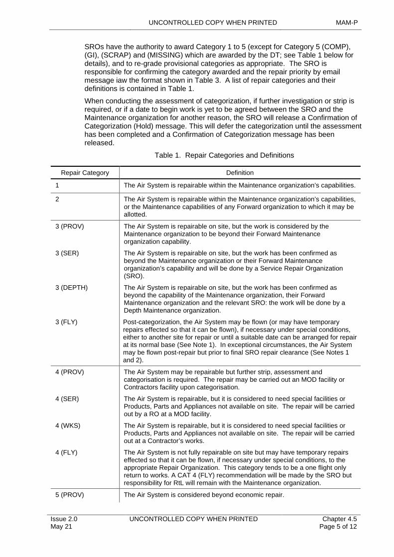
UNCONTROLLED COPY WHEN PRINTED MAM-P
Issue 2.0 May 21
UNCONTROLLED COPY WHEN PRINTED Chapter 4.5 Page 5 of 12
SROs have the authority to award Category 1 to 5 (except for Category 5 (COMP), (GI), (SCRAP) and (MISSING) which are awarded by the DT; see Table 1 below for details), and to re-grade provisional categories as appropriate. The SRO is responsible for confirming the category awarded and the repair priority by email message iaw the format shown in Table 3. A list of repair categories and their definitions is contained in Table 1.
When conducting the assessment of categorization, if further investigation or strip is required, or if a date to begin work is yet to be agreed between the SRO and the Maintenance organization for another reason, the SRO will release a Confirmation of Categorization (Hold) message. This will defer the categorization until the assessment has been completed and a Confirmation of Categorization message has been released.
Table 1. Repair Categories and Definitions
Repair Category Definition
1 The Air System is repairable within the Maintenance organization’s capabilities.
2 The Air System is repairable within the Maintenance organization’s capabilities, or the Maintenance capabilities of any Forward organization to which it may be allotted.
3 (PROV) The Air System is repairable on site, but the work is considered by the Maintenance organization to be beyond their Forward Maintenance organization capability.
3 (SER)
3 (DEPTH)
3 (FLY)
The Air System is repairable on site, but the work has been confirmed as beyond the Maintenance organization or their Forward Maintenance organization’s capability and will be done by a Service Repair Organization (SRO).
The Air System is repairable on site, but the work has been confirmed as beyond the capability of the Maintenance organization, their Forward Maintenance organization and the relevant SRO: the work will be done by a Depth Maintenance organization.
Post-categorization, the Air System may be flown (or may have temporary repairs effected so that it can be flown), if necessary under special conditions, either to another site for repair or until a suitable date can be arranged for repair at its normal base (See Note 1). In exceptional circumstances, the Air System may be flown post-repair but prior to final SRO repair clearance (See Notes 1 and 2).
4 (PROV)
4 (SER)
4 (WKS)
4 (FLY)
The Air System may be repairable but further strip, assessment and categorisation is required. The repair may be carried out an MOD facility or Contractors facility upon categorisation.
The Air System is repairable, but it is considered to need special facilities or Products, Parts and Appliances not available on site. The repair will be carried out by a RO at a MOD facility.
The Air System is repairable, but it is considered to need special facilities or Products, Parts and Appliances not available on site. The repair will be carried out at a Contractor’s works.
The Air System is not fully repairable on site but may have temporary repairs effected so that it can be flown, if necessary under special conditions, to the appropriate Repair Organization. This category tends to be a one flight only return to works. A CAT 4 (FLY) recommendation will be made by the SRO but responsibility for RtL will remain with the Maintenance organization.
5 (PROV) The Air System is considered beyond economic repair.
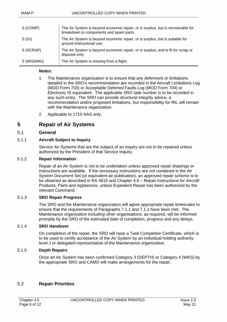
MAM-P UNCONTROLLED COPY WHEN PRINTED
Chapter 4.5 Page 6 of 12
UNCONTROLLED COPY WHEN PRINTED Issue 2.0 May 21
5 (COMP) The Air System is beyond economic repair, or is surplus, but is recoverable for breakdown to components and spare parts.
5 (GI) The Air System is beyond economic repair, or is surplus, but is suitable for ground instructional use.
5 (SCRAP)
5 (MISSING)
The Air System is beyond economic repair, or is surplus, and is fit for scrap or disposal only.
The Air System is missing from a flight.
Notes:
1 The Maintenance organization is to ensure that any deferment or limitations detailed in the SRO’s recommendation are recorded in the Aircraft Limitations Log (MOD Form 703) or Acceptable Deferred Faults Log (MOD Form 704) or Electronic IS equivalent. The applicable SRO task number is to be recorded in any such entry. The SRO can provide structural integrity advice, a recommendation and/or proposed limitations, but responsibility for RtL will remain with the Maintenance organization.
2 Applicable to 1710 NAS only.
5 Repair of Air Systems
5.1 General
5.1.1 Aircraft Subject to Inquiry
Service Air Systems that are the subject of an inquiry are not to be repaired unless authorized by the President of that Service Inquiry.
5.1.2 Repair Information
Repair of an Air System is not to be undertaken unless approved repair drawings or instructions are available. If the necessary instructions are not contained in the Air System Document Set (or equivalent air publication), an approved repair scheme is to be obtained as described in RA 4815 and Chapter 4.6 – Repair Instructions for Aircraft Products, Parts and Appliances, unless Expedient Repair has been authorized by the relevant Command.
5.1.3 SRO Repair Progress
The SRO and the Maintenance organization will agree appropriate repair timescales to ensure that the requirements of Paragraphs 7.1.1 and 7.1.2 have been met. The Maintenance organization including other organisations, as required, will be informed promptly by the SRO of the estimated date of completion, progress and any delays.
5.1.4 SRO Handover
On completion of the repair, the SRO will raise a Task Completion Certificate, which is to be used to certify acceptance of the Air System by an individual holding authority level J or delegated representative of the Maintenance organization.
5.1.5 Depth Repairs
Once an Air System has been confirmed Category 3 (DEPTH) or Category 4 (WKS) by the appropriate SRO and CAMO will make arrangements for the repair.
5.2 Repair Priorities
UNCONTROLLED COPY WHEN PRINTED MAM-P
Issue 2.0 May 21
UNCONTROLLED COPY WHEN PRINTED Chapter 4.5 Page 7 of 12
5.2.1 Grading
Category 3 and 4 tasks will be graded ‘Routine’ or ‘Urgent’ priority, as follows:
1 ‘Routine’ is the default grading.
2 The ‘Urgent’ grading may be allocated to those tasks that are to be completed in the shortest possible time for Safety reasons or to meet essential operational requirements. Use of this grading are to be authorized by the relevant Command in consultation with the Air System DT.
3 Where there are conflicting requirements for tasks, the SRO will consult with CAMO and Commands as necessary.
5.3 Recording of Repair Work
Repair work is to be recorded iaw Chapter 4.6 – Repair Instructions for Aircraft Products, Parts and Appliances. In addition, details of Category 3 or 4 repairs are to be entered onto Maintenance Work Orders (MWO) by the SRO or Depth Maintenance organization as appropriate. Suitable cross-reference to the worksheets or job cards are to be made in the Air System’s MOD Form 700 or electronic equivalent by:
1 The SRO in the case of an SRO repair task.
2 The Maintenance organization in the case of a Depth Maintenance organization repair task.
In the absence of specific structural integrity management guidance from the TAA in the Topic 2(N/A/R)1, completed MWOs relating to such repairs are to be retained in accordance with CAMO direction. The SRO may copy any repair documentation that they wish to retain for management purposes.
In the event of a Category 3 or 4 repair being undertaken on an assembly neither fitted nor allocated to an Air System (eg tail plane undergoing repair in a Maintenance bay), the completed MWOs relating to that repair are to accompany the assembly and be retained with the archive documents of any Air System on which the assembly is fitted. Where appropriate, details of the repair are to be recorded on MOD Form 702 (Weight and Balance Data – Basic Weight and Moment), MOD Form 745 (Maintenance & Repair Record Card), MOD Form 735A (Component Record Card), or bespoke form as required iaw the platform Topic 2(N/A/R)1. For electronic IS, eg GOLDesp & LITS, the appropriate sanction or asset activity is to be raised to record the repair.
6 Cannibalization
Components are not to be cannibalized from Category 3 or 4 Air Systems except to meet urgent operational needs. Such cannibalization is to be authorized by the Continuing Airworthiness Management Organization (CAMO) of the relevant Air System iaw RA 4812, RA 4963(1) and Chapter 4.11 – Cannibalization of Parts from Air Systems and Uninstalled Air System Equipment.
7 Allotment and Disposal of Category 4 Air Systems
When an Air System is confirmed as requiring Category 4 repair, the Air System DT in conjunction with the CAMO are to make a formal allotment iaw Chapter 4.9 – Recovery and Transportation of Air Systems and Large Uncrated Air System Components as soon as repair facilities are available. Until an Air System is allotted for repair, it is normally to remain at the unit at which it was categorized.
7.1 Category 4 (FLY)
MAM-P UNCONTROLLED COPY WHEN PRINTED
Chapter 4.5 Page 8 of 12
UNCONTROLLED COPY WHEN PRINTED Issue 2.0 May 21
When an Air System is confirmed as Category 4 (FLY), the Maintenance organization are to arrange the transfer of the Air System.
7.2 Other Category 4 Air Systems
The unit at which the Air System was categorized are to request the assistance of the Joint Aircraft Recovery and Transportation Squadron (JARTS) to transport the Air System to the repair facility. The Maintenance organization are to forward the Air System’s Maintenance documentation to the repair facility concerned when the Air System is allotted; see Chapter 4.9 – Recovery and Transportation of Air Systems and Large Uncrated Air System Components.
8 Special Arrangements for Defence Air Environment (DAE) Air Systems/USAF Air Systems
8.1 General
In principle, the USAF is responsible for all repair operations on USAF Air Systems in the UK. However, it has been agreed between the USAF and the MOD that, in appropriate circumstances, each air force will render repair assistance to the other; such repairs are to be coordinated via the relevant SRO.
A USAF mobile repair team will normally repair USAF Air Systems that have sustained minor damage on site. However, when the Air System is at a MOD unit, MOD personnel may undertake minor repairs within the unit’s capacity, at the request of the USAF. Similarly, the USAF will assist, on request, with minor repair to damaged MOD Air Systems located at USAF bases in the UK.
When requested, each may assist the other concerning the repair of Air Systems that become damaged in the UK, although each organization remains responsible for assessing and categorizing its own Air Systems.
Procedures for requesting assistance are as follows:
1 MOD units are to make requests for USAF assistance to the appropriate SRO.
2 The RO are to forward all requests for USAF assistance to the Senior RAF Officer (S RAF O), HQ Third Air Force, USAF, RAF Mildenhall.
3 USAF requests for MOD assistance will be made to the S RAF O, HQ Third Air Force, USAF, RAF Mildenhall who will forward all requests to the appropriate RO.
8.2 Repair of Allied, Non-USAF Air Systems in the UK
Such repairs will be & via the relevant SRO.
8.3 Repair of DAE Air Systems Abroad
When a DAE Air System requires assessment, categorization and repair abroad, other than on a British military base, the request for assessment and categorization is to follow the procedure detailed at Paragraph 4. Responsibility for advising the British Military Attaché or Advisor to the country concerned rests with the Maintenance organization or their Commands. The Attaché or Advisor will, wherever possible, also arrange for:
1 Safeguarding valuable and/or secret Products, Parts and Appliances and storing special airborne radio equipment pending receipt of disposal instructions from the Maintenance organization.
2 Protecting the Air System from deterioration.
UNCONTROLLED COPY WHEN PRINTED MAM-P
Issue 2.0 May 21
UNCONTROLLED COPY WHEN PRINTED Chapter 4.5 Page 9 of 12
9
10
3 Making safe and, when necessary, removing and storing ejection seats, conventional armament equipment, explosive and pyrotechnic stores.
4 Providing assistance to the relevant RO.
Message Formats
Requests for assessment, categorization and repair is to be sent by the most suitable means, supported by an email message, and are to accord with the requirements stated in Table 2 and Table 3.
Notes:
1 Fixed-wing Aircraft Repair Assessment may be requested via the 71(IR) Sqn SharePoint site.
2 Rotary-wing Aircraft Repair Assessment may be requested via the 1710 NAS ARTIMS (Aircraft Repair Task Information Management System). The link for this can be found in the Repair area of the 1710 NAS SharePoint Site.
Further Contact Information
1 For fixed wing assessment and categorization requests, in addition to an email message iaw Table 2, 71(IR) Sqn can be contacted via the following:
Email: [email protected]
Tel: normal working hours – via MOD Operator
Duty Surveyor (24 hr cover): out of hours via MOD Operator
2 For rotary wing assessment and categorization requests, in addition to an email message iaw Table 2, 1710 NAS can be contacted via the following:
Email: [email protected]
Tel: normal working hours – via MOD Operator
1710NAS Duty Technical Senior Rate (24 hr cover): via MOD Operator.
Table 2. Request for Assessment, Categorization and Repair
Identifier Content
Protective marking: According to circumstances iaw JSP 440 – Defence Manual of Security.
Priority: According to circumstances for action addressees (Priority for grade ‘Urgent’ – all others ‘Routine’). CC addressees are to be ‘Routine’.
To: For fixed-wing Air Systems:
a. 71(IR) Sqn A4 Force Element RAF Wittering. b. Maintenance organization, if message is originated elsewhere.
For rotary-wing Air Systems:
a. 1710 (NAS) Repair. b. Maintenance organization, if message is originated elsewhere.
MAM-P UNCONTROLLED COPY WHEN PRINTED
Chapter 4.5 Page 10 of 12
UNCONTROLLED COPY WHEN PRINTED Issue 2.0 May 21
Identifier Content
CC: For fixed-wing and rotary-wing:
a. ODH (for Air Systems based at QinetiQ or any other non-Command organization).
b. Air System DT.
c. Air System’s parent Command.
d. Air System’s CAMO.
e. Air System’s Group or Ship (If applicable).
f. Originating unit’s parent Command, if not already an addressee.
g. Air System type Role Equipment Control Centre (If applicable).
h. HQ AAC (Army only).
i. Supporting Air System workshop REME (Army only).
j. Avn EFSO Middle Wallop (Army Air Systems).
Text: The text is to begin, “For CO Service Repair Organization, Request Categorization”.
a. State reference of accident report or any other relevant report.
b. State Air System type, role, mark and serial number.
c. State airframe hours flown to date.
d. State designation of unit holding Air System on charge.
e. State present location of Air System by giving name of a Service unit, a latitude and longitude, or a bearing and distance from a prominent landmark.
f. State Originators’ Reference Number, cause of arising and whether an investigation will take place.
g. Describe damage in broad detail.
h. State provisional repair category.
j. Is deferred repair envisaged?
k. Can Air System be flown out? State whether before or after temporary repair.
l. Is replacement Air System required?
m. State recommended repair priority. (If graded Urgent, state that relevant DT/Command concurs).
n. Give rank, name and telephone number of a working contact.
Table 3. Confirmation of Categorization and Allocation of Repair
Identifier Content
Protective marking: According to circumstances iaw JSP 440 – Defence Manual of Security.
Priority: According to circumstances for action addressees. Routine for CC addressees.
To: Messages relating to fixed-wing and rotary-wing Air Systems:
a. Unit at which Air System is located.
b. Maintenance organization; if not, the unit at which Air System is located.
c. Air System DT for all Category 3 and 4 (FLY) Air Systems.

UNCONTROLLED COPY WHEN PRINTED MAM-P
Issue 2.0 May 21
UNCONTROLLED COPY WHEN PRINTED Chapter 4.5 Page 11 of 12
Identifier Content
CC: Messages relating to fixed-wing and rotary-wing Air Systems:
a. ODH (for Air Systems based at QinetiQ or any other non-Command organization).
b. Air System DT.
c. Air System’s parent Command.
d. Air System’s CAMO.
e. Defence AAIB (if categorized as a result of a flying accident).
f. RNFSC Yeovilton (RN Air Systems – if categorized as a result of a flying accident).
g. Avn EFSO Middle Wallop (Army Air Systems).
h. Any other information addressee included in the Request for Assessment, Categorization and Repair message if applicable.
Text: The text is to begin “Confirmation of Air System Categorization”.
a. Reference of request categorization message and relevant accident or incident report reference.
b. Air System/Products, Parts and Appliances type, mark, role and serial number.
c. Airframe hours flown.
d. Unit holding Air System on charge.
e. Present location of Air System.
f. Cause of arising.
g. Details of damage.
h. Confirmed Air System repair category and deferment of repair if applicable.
j. Repair priority.
k. RO to which repair has been allocated.
l. RO Task Number or contract number, or the statement: ‘DT is requested to raise requisition covering…. [Insert estimated figure].… man-hours.’
11 Authorizations to Conduct Repair Work
11.1 General
Air System repairs at Category 3 and above require additional quality control procedures to ensure a durable airworthy repair. The act of repair can be a self-supervised activity. The SRO tradesmen required to carry out, supervise or stage check repairs at Category 3 or above are to hold the appropriate Air System Authorizations as detailed below:
Personnel required to:
1 Carry out Category 3 and higher airframe structural repairs is to:
1.1 Have completed advanced airframe repair training.
1.2 Be awarded Air System MAMP-B224 by a holder of Air System MAMP-J973.
2 Supervise Category 3 and higher airframe structural repairs are to:
2.1 Have completed advanced airframe repair training.
2.2 Have gained a minimum of 9 months experience on Category 3 and higher airframe structural repairs.
MAM-P UNCONTROLLED COPY WHEN PRINTED
Chapter 4.5 Page 12 of 12
UNCONTROLLED COPY WHEN PRINTED Issue 2.0 May 21
2.3 Be awarded Air System MAMP-C330 by a holder of Air System MAMP-J973.
3 Carry out self-supervised stage checks of Category 3 and higher airframe structural repairs are to:
3.1 Have completed advanced airframe repair training.
3.2 Have gained a minimum of 9 months experience on Category 3 and higher airframe structural repairs.
3.3 Have completed an administrative and engineering training package.
3.4 Be awarded Air System MAMP-D413 by a holder of Air System MAMP-J973.
11.2 1710 (NAS) Repair Manager and 71(IR) Sqn OC
Personnel required to fill the 1710 (NAS) Repair Manager and 71(IR)Sqn OC appointments are to:
1 Be a minimum of OF3 rank.
2 Hold DAOS Air System for RW or FW repair design.
3 Be awarded Air System MAMP-J973 by the holder of Air System MAMP-K1026.
11.3 CO 1710 (NAS) and OC 42(ES) Wing
Personnel appointed to be CO 1710 (NAS) and OC 42(ES) Wing are to:
1 Be a minimum of OF4 rank.
2 Hold DAOS Air System for RW repair design (CO 1710 (NAS) only).
3 Hold Air System MAMP-K1026 by their appointment.
12 Authorizations
Table 4. Associated Authorizations
Authorization Task
MAMP-B224Carry out Category 3 and higher airframe structural repairs.
MAMP-C330Supervise Category 3 and higher airframe structural repairs.
MAMP-D413Carry out self-supervised stage checks of Category 3 and higher airframe structural repairs.
MAMP-J973Authorize personnel to carry out or supervise, or self-supervise stage checks, of Category 3 and higher airframe structural repairs.
MAMP-K1026Authorize personnel to authorize personnel to carry out or supervise or self-supervise stage checks, of Category 3 and higher airframe structural repairs.
UNCONTROLLED COPY WHEN PRINTED MAM-P
Initial Issue Nov 19
UNCONTROLLED COPY WHEN PRINTED Chapter 4.6 Page 1 of 9
..............................................................................................................................
.....................................................................
.....................................................................
...................................................................................................................................................
...............................................................................................................................................................................
............................................................................................................................................................................................................
............................................................................................
.....................................................................................................................................
.........................................................................................................................................................................
..................................................
..............................................................................................................................................
..................................................................................................................................................................................
.........................................................................................................................
.......................................................................................................................................................
.........................................................................................................................................................................................................
Chapter 4.6
Repair Instructions for Aircraft Products, Parts and Appliances
TABLE OF CONTENTS
Paragraph Page
1 General 11.1 Introduction 11.2 Associated Publications and Instructions 22 Definitions 23 Range and Scope of Authority 23.1 Air Systems and Air System Equipment 23.2 Aerospace Equipment 23.3 Data Sheets 33.4 Service Design Organizations (SDOs) 33.5 Internal Procedures 34 Approval of Repair Instructions and Design Drawings 35 Requests by Station/Ships/Units for Repair Instructions 35.1 Priority of Request 45.2 Follow-up Information 45.3 Incorporation of Repair Instructions in TI 46 Recording of Repairs 47 General Assembly (GA) Drawings for Use During Airframe Repair 48 Damage Reporting 58.1 Pictorial 58.2 Fasteners 58.3 Corrosion and Scoring 58.4 Heat Damage 68.5 Adjacent Repairs and Modifications 69 Message Formats 6
LIST OF TABLES
Table 1. Request for Repair Instruction 6Table 2. Approval of Repair Instruction 7Table 3. Upgrade Priority of Repair Instruction Request 8Table 4. Request for Drawings 9
1 General
1.1 Introduction
Repair instructions approved by a Type Airworthiness Authority (TAA) are normally found in the Technical Information (TI) or equivalent documentation, Special Instructions (Technical) (SI(T)) or modification leaflets. However, meeting Urgent Operational Requirements (UORs) or urgent Maintenance needs, catering for the introduction of new aerospace Products, Parts and Appliances or adopting GEMS suggestion scheme proposals; may require formal design services that, if provided by the Design Organization (DO), may be prohibitively expensive or time-consuming.
The Design Approval Organisation Scheme (DAOS) approved Service Design Organisations (SDO) embedded within the Air System Service Repair Organizations
MAM-P UNCONTROLLED COPY WHEN PRINTED
Chapter 4.6 Page 2 of 9
UNCONTROLLED COPY WHEN PRINTED Initial Issue Nov 19
(SROs) (see Chapter 4.5 – Aircraft Repair) provide an alternative source for repair instructions and Aerospace Products, Parts and Appliances design services within the scope of the organisation's DAOS Approval. This chapter details the SDO status of the SROs, the range and scope of repair services available from the SROs, initial points of contact, damage reporting, formats for requests for repair instruction services, priorities, priority upgrading and arrangements for obtaining General Assembly (GA) drawings.
1.2 Associated Publications and Instructions
1 RA 4806(6) – Specialized Services (MRP 145.A.30(f))
2 RA 4809 – Acceptance of Components (MRP 145.A.42)
3 RA 4813 – Maintenance Records (MRP 145.A.55)
4 RA 5850 – Military Design Approved Organisation (MRP 21 Sub Part J)
5 RA 5865 – Repairs (MRP 21 Part M)
6 JSP 440 – Defence Manual of Security, Resilience and Business Continuity
7 TI Parts Catalogue and Associated Information
8 TI Master Maintenance Schedule
9 TI Repair and Reconditioning Instructions
10 AP 100E-01A – Maintenance, Lifing and Management of Aero-Engines, Their Components and Accessories
2 Definitions
A repair instruction request may include the following:
1 Repair scheme: Engineering drawings authorized by the TAA or either Design Organisation (DO) or SDO under the privilege per RA5850.
2 Production permit: Authorizes a divergence from an existing standard repair scheme, authorized and issued before production commences.
3 Raise-in-issue: The extended application or change to an existing repair scheme.
4 Concession: A divergence from an existing standard or repair scheme authorized during production.
5 Design drawings: Engineering drawings authorized by the relevant RO for the manufacture of Air System structure, structural components or aerospace equipment.
3 Range and Scope of Authority
3.1 Air Systems and Air System Equipment
The SDOs may design, approve and amend Air System repair instructions, subject to the organization meeting the following requirements:
1 Inclusion in the Design Approved Organization Scheme (DAOS), which also specifies the scope of the design Approval.
3.2 Aerospace Equipment
SDOs may prepare and approve drawings, concessions, production permits and raises-in-issue of locally produced designs for:
UNCONTROLLED COPY WHEN PRINTED MAM-P
Initial Issue Nov 19
UNCONTROLLED COPY WHEN PRINTED Chapter 4.6 Page 3 of 9
1 Lifting tackle.
2 Ground Support Equipment.
3 Role equipment.
4 Air System mock-ups.
5 Jigs, fixtures and gauges.
6 Mechanical test equipment.
3.3 Data Sheets
SDOs may prepare and approve technical data sheets covering standard working practices and procedures on aerospace equipment.
3.4 Service Design Organizations (SDOs)
There are two SDOs both of which hold Design Organisation approved status:
1 For fixed-wing Air Systems: 71 (Inspection and Repair) Squadron (71(IR) Sqn). The Repair Design Authority (RDA) is the SDO embedded within 71(IR) Sqn SRO. For Air System structure, components and aerospace equipment, 71(IR) Sqn is authorized to:
1.1 Carry out the design, Approval and amendment of Air System repair instructions to all MOD Air Systems.
1.2 Prepare and approve concessions and production permits against designs in the categories above that are produced by other DOs.
1.3 Prepare for Approval by other DOs, the raise-in-issue of drawings produced by agencies external to 71(IR) Sqn.
1.4 Carry out design, Approval and post-design services.
2 For rotary-wing Air Systems: 1710 Naval Air Squadron (1710 NAS) For rotary-wing Air System structure and structural components, 1710 NAS is authorized to design and approve repair schemes and concessions for structural damage, within the support policies authorized by Air System/Products, Parts and Appliances DTs.
Note
1710 NAS also provides support to the Watchkeeper platform.
3.5 Internal Procedures
SDOs will publish local instructions to ensure that their internal procedures for the design, Approval and amendment of Air System repair instructions accord with the requirements of the ‘Application for Inclusion in the DAOS’ set out in the 5000 Series of RAs.
4 Approval of Repair Instructions and Design Drawings
Repair instructions may be approved by the DO, TAAs and SROs using the format at Table 2. Parts and drawings used in repair schemes are to be marked in accordance with RA 4809 and Chapter 4.5 – Aircraft Repair.
5 Requests by Station/Ships/Units for Repair Instructions
Requests for repair instructions are to be made by e-mail using the format at Table 1. All requests are to specify an initial target date for completion of the task. The initial points of contact for any request for repair instructions not contained in a Technical
MAM-P UNCONTROLLED COPY WHEN PRINTED
Chapter 4.6 Page 4 of 9
UNCONTROLLED COPY WHEN PRINTED Initial Issue Nov 19
Information (TI) are as follows, unless the appropriate TAA has issued specific instructions:
1 For fixed-wing Air Systems – the Repair and Design Authority (RDA), 71(IR) Sqn, A4 Force Element, RAF Wittering, Peterborough, Cambridgeshire, PE8 6HB.
2 For rotary-wing Air Systems – 1710 NAS Repair Office, Unicorn Building PP88, Unicorn Road, Portsmouth, PO1 3GX.
3 For non-structural items – the Air System, Products, Parts and Appliances or system DT.
4 For aero-engines – as contained in:
4.1 AP 100E-01A Leaflet 100.4.2.
4.2 AP 100E-01A Leaflet 101.
4.3 The Air System Topic 5A1, where AP 100E-01A is not available.
5.1 Priority of Request
Station/Ships/Units (Stn/Ships/Units) are to state the priority they wish to be allocated to the preparation of a repair instruction as follows:
1 Routine – for Air Systems and Products, Parts and Appliances undergoing maintenance.
2 Urgent – for Air Systems on the ground solely awaiting repair instructions.
If the target date cannot be met and there is a UOR or other urgent requirement, the task may be upgraded to ‘Urgent’ by the TAA, using the format at Table 3.
5.2 Follow-up Information
E-mail requests are to be followed up with full damage details. Follow-up information is to be sent by appropriate means to the appropriate authority. For repair instructions to airframes or to structural components, the information detailed at paragraph 8 is to be included.
5.3 Incorporation of Repair Instructions in TI
If the RO considers that an airframe repair instruction is to be incorporated into the Air System document set or equivalent publication, a recommendation is to be made to the appropriate TAA. The TAA are to consider the recommendation and take appropriate amendment action or inform the SRO of the reasons why the repair instruction is not to be included.
6 Recording of Repairs
Recording of all repairs is to be in accordance with RA 4813 and Chapter 2.4 – Certification and Maintenance Documentation, taking into account maintenance and repair record cards, Engineering Record Cards (ERC) and basic weight and moment record cards.
7 General Assembly (GA) Drawings for Use During Airframe Repair
In addition to holding copies of current repair instructions, the ROs hold some GA drawings. Stns/Ships/Units requiring copies of GA drawings may request them from the 71(IR) Sqn Technical Library or 1710 NAS by e-mail, using the format at Table 4.
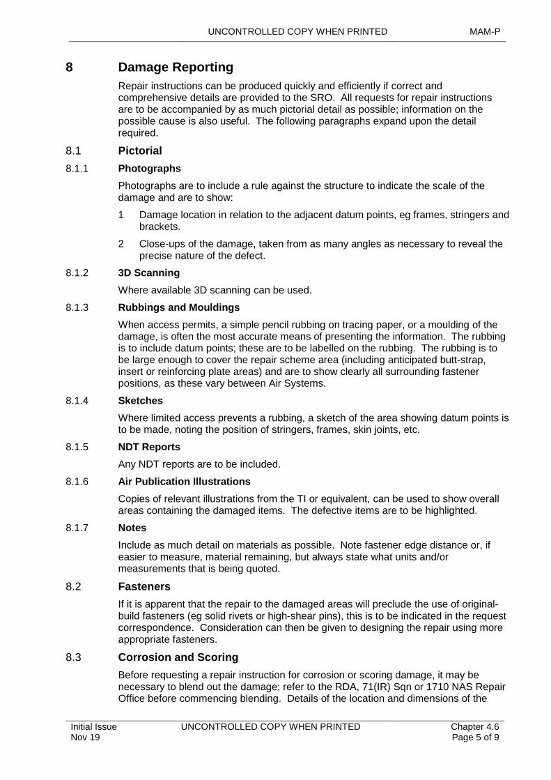
UNCONTROLLED COPY WHEN PRINTED MAM-P
Initial Issue Nov 19
UNCONTROLLED COPY WHEN PRINTED Chapter 4.6 Page 5 of 9
8 Damage Reporting
Repair instructions can be produced quickly and efficiently if correct and comprehensive details are provided to the SRO. All requests for repair instructions are to be accompanied by as much pictorial detail as possible; information on the possible cause is also useful. The following paragraphs expand upon the detail required.
8.1 Pictorial
8.1.1 Photographs
Photographs are to include a rule against the structure to indicate the scale of the damage and are to show:
1 Damage location in relation to the adjacent datum points, eg frames, stringers and brackets.
2 Close-ups of the damage, taken from as many angles as necessary to reveal the precise nature of the defect.
8.1.2 3D Scanning
Where available 3D scanning can be used.
8.1.3 Rubbings and Mouldings
When access permits, a simple pencil rubbing on tracing paper, or a moulding of the damage, is often the most accurate means of presenting the information. The rubbing is to include datum points; these are to be labelled on the rubbing. The rubbing is to be large enough to cover the repair scheme area (including anticipated butt-strap, insert or reinforcing plate areas) and are to show clearly all surrounding fastener positions, as these vary between Air Systems.
8.1.4 Sketches
Where limited access prevents a rubbing, a sketch of the area showing datum points is to be made, noting the position of stringers, frames, skin joints, etc.
8.1.5 NDT Reports
Any NDT reports are to be included.
8.1.6 Air Publication Illustrations
Copies of relevant illustrations from the TI or equivalent, can be used to show overall areas containing the damaged items. The defective items are to be highlighted.
8.1.7 Notes
Include as much detail on materials as possible. Note fastener edge distance or, if easier to measure, material remaining, but always state what units and/or measurements that is being quoted.
8.2 Fasteners
If it is apparent that the repair to the damaged areas will preclude the use of original-build fasteners (eg solid rivets or high-shear pins), this is to be indicated in the request correspondence. Consideration can then be given to designing the repair using more appropriate fasteners.
8.3 Corrosion and Scoring
Before requesting a repair instruction for corrosion or scoring damage, it may be necessary to blend out the damage; refer to the RDA, 71(IR) Sqn or 1710 NAS Repair Office before commencing blending. Details of the location and dimensions of the
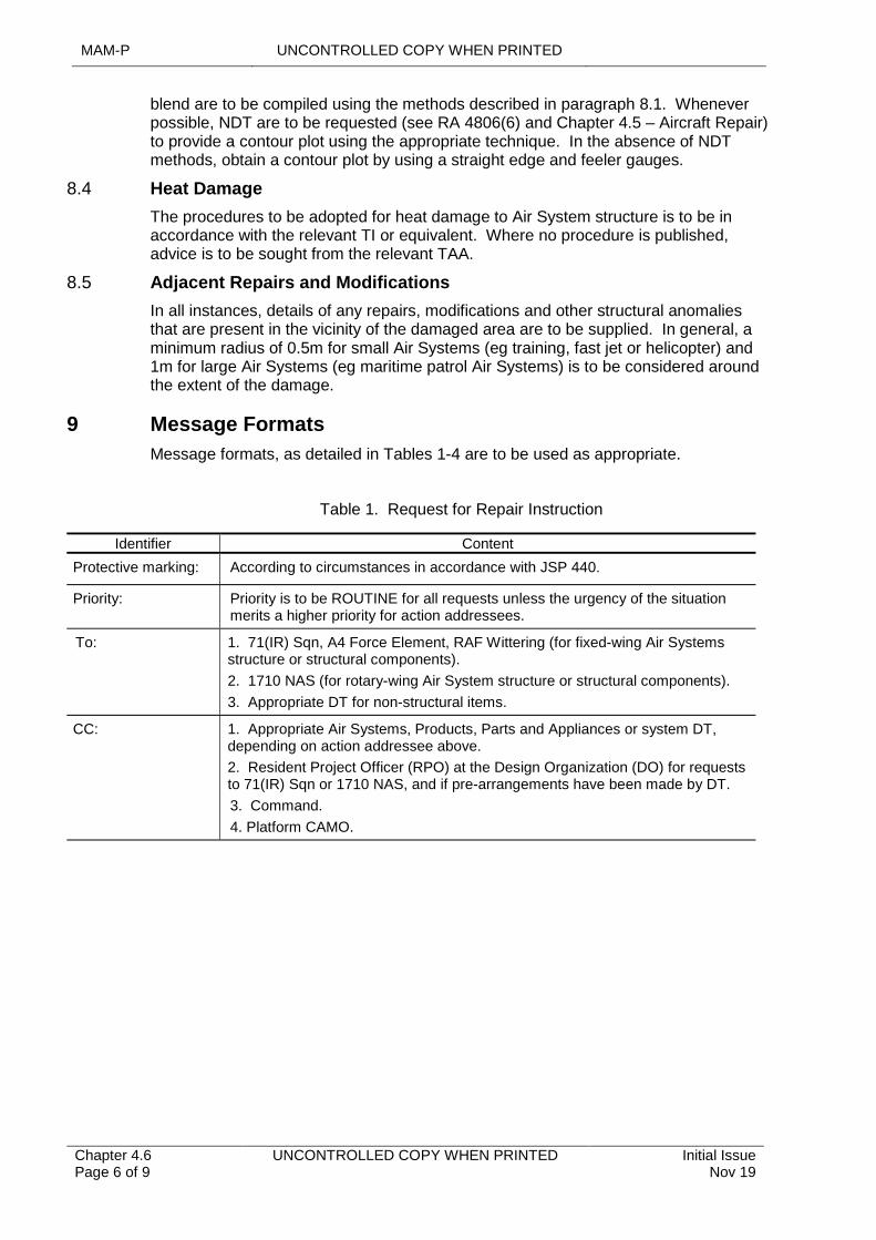
MAM-P UNCONTROLLED COPY WHEN PRINTED
Chapter 4.6 Page 6 of 9
UNCONTROLLED COPY WHEN PRINTED Initial Issue Nov 19
blend are to be compiled using the methods described in paragraph 8.1. Whenever possible, NDT are to be requested (see RA 4806(6) and Chapter 4.5 – Aircraft Repair) to provide a contour plot using the appropriate technique. In the absence of NDT methods, obtain a contour plot by using a straight edge and feeler gauges.
8.4 Heat Damage
The procedures to be adopted for heat damage to Air System structure is to be in accordance with the relevant TI or equivalent. Where no procedure is published, advice is to be sought from the relevant TAA.
8.5 Adjacent Repairs and Modifications
In all instances, details of any repairs, modifications and other structural anomalies that are present in the vicinity of the damaged area are to be supplied. In general, a minimum radius of 0.5m for small Air Systems (eg training, fast jet or helicopter) and 1m for large Air Systems (eg maritime patrol Air Systems) is to be considered around the extent of the damage.
9 Message Formats
Message formats, as detailed in Tables 1-4 are to be used as appropriate.
Table 1. Request for Repair Instruction
Identifier Content
Protective marking: According to circumstances in accordance with JSP 440.
Priority: Priority is to be ROUTINE for all requests unless the urgency of the situation merits a higher priority for action addressees.
To: 1. 71(IR) Sqn, A4 Force Element, RAF Wittering (for fixed-wing Air Systems structure or structural components).
2. 1710 NAS (for rotary-wing Air System structure or structural components).
3. Appropriate DT for non-structural items.
CC: 1. Appropriate Air Systems, Products, Parts and Appliances or system DT, depending on action addressee above.
2. Resident Project Officer (RPO) at the Design Organization (DO) for requests to 71(IR) Sqn or 1710 NAS, and if pre-arrangements have been made by DT.
3. Command.
4. Platform CAMO.

UNCONTROLLED COPY WHEN PRINTED MAM-P
Initial Issue Nov 19
UNCONTROLLED COPY WHEN PRINTED Chapter 4.6 Page 7 of 9
Identifier Content
Text: Text is to begin ‘REQUEST FOR REPAIR INSTRUCTION’ and is to be in the format detailed below. All paragraphs are to be completed. If the information required is not available, or a paragraph is not considered appropriate to the particular case, insert a suitable statement.
1. Air System type, mark and serial number or, if request relates to a component/Products, Parts and Appliances not fitted to an Air System, description, part number, management code, stock number and serial number.
2. Air System custodian, Stn/Ship/Unit or, for a component/equipment, unit holding item on charge.
3. Present location of Air System or component/equipment.
4. Present fatigue life, flying hours and landings of Air System.
5. Originator’s Reference Number and probable cause of damage or Fault requiring repair.
6. Exact location of damage or Fault on a recognized Air System location system.
7. Brief description of damage or Fault.
8. Reference to figures in air publications or to drawings that illustrate area concerned. If an extension of applicability or divergence from an existing repair instruction is envisaged, include precise references to original instruction, together with details of suggested amendment.
9. Brief details of information that will be forwarded in accordance with Paragraph 8, together with addressees to whom it will be sent.
10. Modifications, SI(T) or other engineering instructions relevant to request.
11. Whether request is for specific or general application.
12. Target date and priority.
13. Rank, name, appointment and telephone number of the originator of request.
Table 2. Approval of Repair Instruction
Identifier Content
Protective marking: According to circumstances in accordance with JSP 440.
Priority: Priority is to be ROUTINE for all messages unless the urgency of the situation merits a higher priority for action addressees.
To: 1. Unit at which Air System is located.
2. Air System custodian, if not the unit at which Air System is located.
3. Platform CAMO.
4. Other action addressees as appropriate.
CC: 1. Appropriate Air System, Products, Parts and Appliances or system DT, depending on action addressee above.
2. Resident Project Officer (RPO) if info addressee on Request for Repair instruction.
3. Command.
4. Other info addressees as appropriate.
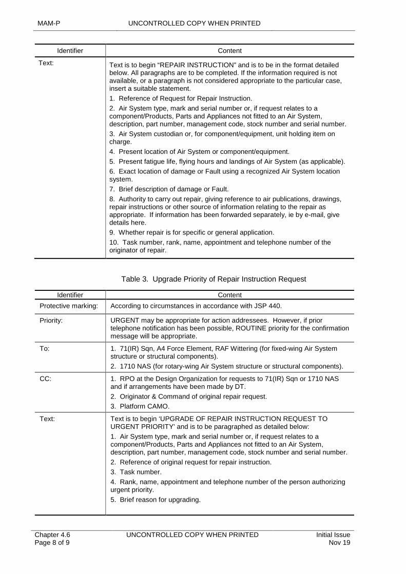
MAM-P UNCONTROLLED COPY WHEN PRINTED
Chapter 4.6 Page 8 of 9
UNCONTROLLED COPY WHEN PRINTED Initial Issue Nov 19
Identifier Content
Text: Text is to begin “REPAIR INSTRUCTION” and is to be in the format detailed below. All paragraphs are to be completed. If the information required is not available, or a paragraph is not considered appropriate to the particular case, insert a suitable statement.
1. Reference of Request for Repair Instruction.
2. Air System type, mark and serial number or, if request relates to a component/Products, Parts and Appliances not fitted to an Air System, description, part number, management code, stock number and serial number.
3. Air System custodian or, for component/equipment, unit holding item on charge.
4. Present location of Air System or component/equipment.
5. Present fatigue life, flying hours and landings of Air System (as applicable).
6. Exact location of damage or Fault using a recognized Air System location system.
7. Brief description of damage or Fault.
8. Authority to carry out repair, giving reference to air publications, drawings, repair instructions or other source of information relating to the repair as appropriate. If information has been forwarded separately, ie by e-mail, give details here.
9. Whether repair is for specific or general application.
10. Task number, rank, name, appointment and telephone number of the originator of repair.
Table 3. Upgrade Priority of Repair Instruction Request
Identifier Content
Protective marking: According to circumstances in accordance with JSP 440.
Priority: URGENT may be appropriate for action addressees. However, if prior telephone notification has been possible, ROUTINE priority for the confirmation message will be appropriate.
To: 1. 71(IR) Sqn, A4 Force Element, RAF Wittering (for fixed-wing Air System structure or structural components).
2. 1710 NAS (for rotary-wing Air System structure or structural components).
CC: 1. RPO at the Design Organization for requests to 71(IR) Sqn or 1710 NAS and if arrangements have been made by DT.
2. Originator & Command of original repair request.
3. Platform CAMO.
Text: Text is to begin ‘UPGRADE OF REPAIR INSTRUCTION REQUEST TO URGENT PRIORITY’ and is to be paragraphed as detailed below:
1. Air System type, mark and serial number or, if request relates to a component/Products, Parts and Appliances not fitted to an Air System, description, part number, management code, stock number and serial number.
2. Reference of original request for repair instruction.
3. Task number.
4. Rank, name, appointment and telephone number of the person authorizing urgent priority.
5. Brief reason for upgrading.
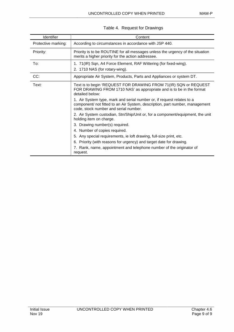
UNCONTROLLED COPY WHEN PRINTED MAM-P
Initial Issue Nov 19
UNCONTROLLED COPY WHEN PRINTED Chapter 4.6 Page 9 of 9
Table 4. Request for Drawings
Identifier Content
Protective marking: According to circumstances in accordance with JSP 440.
Priority: Priority is to be ROUTINE for all messages unless the urgency of the situation merits a higher priority for the action addressee.
To: 1. 71(IR) Sqn, A4 Force Element, RAF Wittering (for fixed-wing).
2. 1710 NAS (for rotary-wing).
CC: Appropriate Air System, Products, Parts and Appliances or system DT.
Text: Text is to begin ‘REQUEST FOR DRAWING FROM 71(IR) SQN or REQUEST FOR DRAWING FROM 1710 NAS’ as appropriate and is to be in the format detailed below:
1. Air System type, mark and serial number or, if request relates to a component/ not fitted to an Air System, description, part number, management code, stock number and serial number.
2. Air System custodian, Stn/Ship/Unit or, for a component/equipment, the unit holding item on charge.
3. Drawing number(s) required.
4. Number of copies required.
5. Any special requirements, ie loft drawing, full-size print, etc.
6. Priority (with reasons for urgency) and target date for drawing.
7. Rank, name, appointment and telephone number of the originator of request.

UNCONTROLLED COPY WHEN PRINTED MAM-P
Initial Issue Nov 19
UNCONTROLLED COPY WHEN PRINTED Chapter 4.7 Page 1 of 6
...........................................................................
................................................................................................................
..........................................................................................................................................................
.............................................................................................................................................................................................
...............................................................................................................................................................................................................................................................................................
..................................................................................................................................................................................
..............................................................
.......................................................................................................................
.......................................................................................................................
..........................................................................................................
...........................................................................................................................................
.......................................................................................................................................................
.......................................................................................................
Chapter 4.7
Expedient Repair
TABLE OF CONTENTS
Paragraph Page
1 General 11.1 Introduction 11.2 Associated Publications and Instructions 12 General Principles of ER 23 Authorization of an ER Regime 23.1 Airworthiness Considerations 23.2 Criteria for a Command to Authorize an ER Regime 23.3 Command Authorization to Invoke an ER Regime 34 Implementation of ER 34.1 Local Engineering Commander (LEC) 34.2 ER Assessor (ERA) Requirements 44.3 ER Operator (ERO) Requirements 45 Training and Authorizations 55.1 ERA 55.2 ERO 55.3 LEC 56 Documenting ER Decisions 57 Recovery 58 Responsibilities 58.1 Stations/Ships/Units 58.2 Responsibilities of Commands 68.3 Continuing Airworthiness Management Organization (CAMO) 69 Authorizations 6
LIST OF TABLES
Table 1. Associated Authorizations 6
1 General
1.1 Introduction
There may be occasions when, due to a lack of either time or resources and the need to meet an overriding operational requirement, it is necessary to undertake repairs (which may include repairs to structural, mechanical, electrical, avionic and weapon systems) to an Aircraft that are outside the limits for normal peacetime operations detailed in the Technical Information (TI). Such a repair, which generates a level of operational capability, potentially at the expense of a reduced level of Airworthiness or longer-term Aircraft structural and systems integrity, is termed an Expedient Repair (ER).
1.2 Associated Publications and Instructions
1 RA 4812 – Certification of Air System Release and Component Release (MRP 145.A.50)
2 RA 4813 – Maintenance Records (MRP 145.A.55)
MAM-P UNCONTROLLED COPY WHEN PRINTED
Chapter 4.7 Page 2 of 6
UNCONTROLLED COPY WHEN PRINTED Initial Issue Nov 19
3 AP101A-1500-0 – Joint Service Aircraft Battle Damage Repair Manual
4 SRM – Aircraft type-specific Structural Repair Manual
5 Topic 6 – Aircraft type-specific Repair Manual
6 Topic 6C – Aircraft type-specific ABDR Repair Manual
2 General Principles of ER
ER is designed to restore operational capability by providing rapid repair solutions for military registered Air Systems both in deployed and non-deployed environments. Depending on the operational imperative, local resources and Air System suitability, ER can include the application of Aircraft Battle Damage Repair (ABDR) techniques or other temporary restorative repair. However, formal recovery action is to be carried out for all ER in accordance with (iaw) Paragraph 7. The fundamental principle of ER is that the repair solution is to always aim to achieve the greatest degree of restoration within the constraints of time and available resources.
The two-common links for all ER are:
1 An ER involves the application of a repair solution that is neither taken wholly from the TI nor from a previous, fully restorative and permanent, repair solution produced by the Designer or 1710 Naval Air Squadron (1710 NAS) or 71 IR Squadron (71 IR Sqn) and hence may have Airworthiness considerations.
2 The repair process, from damage assessment through repair scheme development to implementation of repair, is achieved in the most expeditious manner that resources, local conditions and operational constraints allow.
3 Authorization of an ER Regime
3.1 Airworthiness Considerations
Duty Holders are responsible for operating their Air System fleet within the Release to Service documentation/criteria and for maintaining their Air System fleet iaw the TI authorized by the Type Airworthiness Authority (TAA). However, during operations, resources and lines of communication may become degraded, so generating a need to increase local responsibility for engineering decisions. Commands are to assess operational situations and decide whether Local Engineering Commanders (LECs) are likely to need to undertake ER to support the Operational Commander’s requirements.
LECs are responsible for the ER decisions that they make. These decisions should be commensurate with the authority granted them by the Commands and are to reflect both the operational situation and their ER assessments. In addition, the LEC is to ensure that the Local Operational Commander is fully aware of any potential reduction in Airworthiness, and the associated Risk, that an individual ER imposes on an Air System.
3.2 Criteria for a Command to Authorize an ER Regime
The criteria that a Command are to consider before authorizing ER will depend on the operational circumstances and the level of support available. It follows that any decision to invoke ER is to balance the Airworthiness Risk against the operational necessity. Consultation between the Command and the appropriate TAAs, and other organizations such as 1710 NAS, 71(IR) and Business Units within Defence Equipment & Support (DE&S), is necessary to maintain continuity and relevance. Factors affecting a decision on how and when to invoke ER include:
1 The alternative operational solutions that are available and consistent with the operational imperative.
UNCONTROLLED COPY WHEN PRINTED MAM-P
Initial Issue Nov 19
UNCONTROLLED COPY WHEN PRINTED Chapter 4.7 Page 3 of 6
2 The level of ER decision-making authority granted to the LEC.
3 The lines of communication and levels of Equipment Support available, ie is there an accessible Main Operating Base or Logistic Support Site or is the Sqn/Unit operating in isolation.
4 The availability and deployability of the following resources:
4.1 Technical Information (TI) support (eg technical authority/design support).
4.2 Logistics support (eg spares, manufacturing or cannibalization options).
4.3 Ground support equipment (including tools and test equipment).
4.4 Personnel of the appropriate Competence (including ER assessors, technicians and AD FS(Air) deployable repair teams).
4.5 Aircraft recovery assets (including 1710 NAS deployable aircraft recovery teams).
5 The Command shall monitor the operational situation to ensure that the criteria for invoking an ER regime remain valid.
3.3 Command Authorization to Invoke an ER Regime
Under normal circumstances repairs are to be carried out iaw:
1 The TI.
2 Specific repair schemes prepared by the platform Designer,1710 NAS or 71(IR) Sqn.
Note:
The techniques contained in AP 101A-1500-0 and the Aircraft Topic 6C are not to be used unless specifically authorized by the TAA or ER has been authorized by the Command.
To move to an ER regime, the appropriate Duty Holder is to accept the increased Airworthiness Risk. During the transition to a period of increased operational activity, a Command, unless it has already established its ER regime via a standing instruction, are to state clearly the authority granted to LECs to invoke ER and define any associated restrictions via an engineering operation order or equivalent.
Where ER Assessors (ERAs) and ER Operators (EROs) are available to the LEC, they are to be authorized iaw Command instructions.
4 Implementation of ER
4.1 Local Engineering Commander (LEC)
There will be circumstances where an Air System returns from a sortie in which it has suffered damage not normally encountered or expected, which has degraded its operational effectiveness. As a consequence, if an ER regime has been authorized by the Command, the relevant LEC may decide that the damaged Air System could be returned to flight by means of an ER. Therefore, the LEC are to:
1 Confirm that an Command authorized ER regime is in place.
2 Task an authorized ERA to assess the damage and formulate an ER iaw Paragraph 4.2.
3 Balance the Airworthiness/Safety Risk of implementing an ER with the competing operational necessity.
4 Carry out a Risk analysis of the ramifications of implementing the proposed ER.
MAM-P UNCONTROLLED COPY WHEN PRINTED
Chapter 4.7 Page 4 of 6
UNCONTROLLED COPY WHEN PRINTED Initial Issue Nov 19
5 Consult the:
5.1 Local Operational Commander, where practicable, and confirm that the operational imperative justifies any potential reduction in Airworthiness and the longer-term effect to structural and system integrity.
5.2 TAA where practicable.
5.3 Consult with/request assistance from any local Repair Support Unit (RSU) teams from 1710 NAS that may be deployed specifically for assistance in the ER role.
6 Authorize the ER.
7 Report full details of the ER to the Command, the Continuing Airworthiness Management Organization (CAMO), and TAA when implemented, as ER schemes require Approval/recovery by the relevant authority at the earliest opportunity; see Paragraph 7.
8 Have knowledge of the location of previous repairs in the location of ER activity to fully understand the overall Risk.
4.2 ER Assessor (ERA) Requirements
The ERA are to:
1 Assess damage to an Aircraft's structure and systems to determine the degree of degradation on Airworthiness and functionality.
2 Determine the Aircraft repairability, based on an assessment of the impact to structural or systems integrity and/or Safety-related functions of Aircraft systems and immediate operational and resource constraints.
3 Independently scheme a structural or system repair using information, principles and techniques contained within the TI, ABDR publications and generic repair manual and be able to communicate the repair scheme to the ERO, understanding their Competence and resource limitations.
4 Produce an effective repair scheme and supervise its implementation to return the Aircraft to an operationally capable state, potentially with a reduced level of Airworthiness or long-term structural integrity.
5 Advise the LEC/Authorising Officer on the effect of ER proposal on long term structural and system integrity and potential limitations to operational capability post repair.
6 Determine when the repair of damage to structure and Aircraft systems is outside the capabilities of the unit and implement the process of requesting assistance from external agencies such as 1710 NAS, the TAA or the Designer.
7 Understand the process for authorizing and reporting an ER.
8 Have a thorough working knowledge of the appropriate Command ER instructions.
9 Supervise the ERO who is implementing the ER.
Note:
The subsequent repair is to be commensurate with the time and resources available for its application.
4.3 ER Operator (ERO) Requirements
The ERO is to:
1 Carry out repairs to Aircraft structure and systems iaw the TI.
UNCONTROLLED COPY WHEN PRINTED MAM-P
Initial Issue Nov 19
UNCONTROLLED COPY WHEN PRINTED Chapter 4.7 Page 5 of 6
2 Carry out ER to structure and/or systems as directed and supervised by the ERA, utilizing specialist ABDR/ER tools and techniques where necessary.
3 Have either documented training or experience in the use of Aircraft fasteners, fabrication and repair of structural components, and repair and replacement of system components.
5 Training and Authorizations
5.1 ERA
Personnel required to be ERAs are to have completed the relevant ERA training course and are to be granted Authorization MAMP-E517 by an individual holding Authorization MAMP-J967.
5.2 ERO
Personnel required to be EROs are to have completed the relevant ERO training course or trade training course which meets the requirements of the ERO as detailed in Paragraph 5.3 and are to be granted Authorization MAMP-C327 by an individual holding Authorization MAMP-J967.
5.3 LEC
Personnel required to be LECs are to be granted Authorization MAMP-J967 by an individual holding Authorization MAMP-K1017.
6 Documenting ER Decisions
To maintain the Airworthiness Audit trail and to assist in formulating recovery plans, all ER measures are to be documented. When the ER involves the recovery of structural integrity, this is to be recorded in a database. Repairs are to be documented iaw RA 4813 and Chapter 2.4 – Certification and Maintenance Documentation. All other repairs that either fall short of this standard and require subsequent recovery or impose limitations in terms of life and/or capability, is to be recorded on MOD Form 703 or MOD Form 704 as appropriate or electronic equivalent.
Note:
The process for recording Maintenance activities is detailed primarily in RA 4813 and Chapter 2.4 – Certification and Maintenance Documentation.
7 Recovery
The use of ER will require the TAA, in consultation with the CAMO, to determine any actions required to recover in full the structural integrity and system capability of the Air System.
The level of recovery required will depend on the impact of the ER. As soon as it is practicable, an operational LEC are to forward to the TAA, via its Command and CAMO, details of any ER measures taken on its Aircraft. The TAA is to then dictate, at the earliest opportunity and iaw RA 4812 and Chapter 4.8 – Deferment and Concession of Maintenance, any necessary recovery action. In determining this action, advice may be sought from a Subject Matter Expert (SME) within MAA Cert S and TI and 1710 NAS.
8 Responsibilities
8.1 Stations/Ships/Units
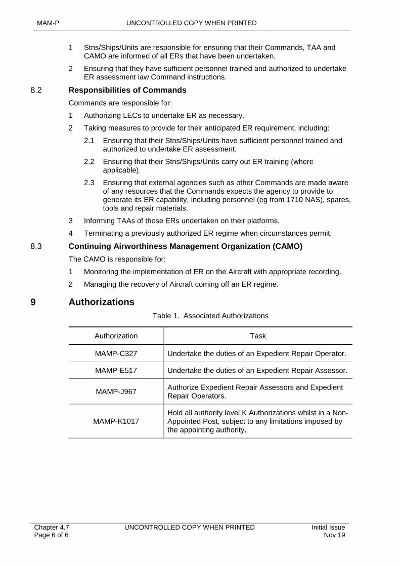
MAM-P UNCONTROLLED COPY WHEN PRINTED
Chapter 4.7 Page 6 of 6
UNCONTROLLED COPY WHEN PRINTED Initial Issue Nov 19
1 Stns/Ships/Units are responsible for ensuring that their Commands, TAA and CAMO are informed of all ERs that have been undertaken.
2 Ensuring that they have sufficient personnel trained and authorized to undertake ER assessment iaw Command instructions.
8.2 Responsibilities of Commands
Commands are responsible for:
1 Authorizing LECs to undertake ER as necessary.
2 Taking measures to provide for their anticipated ER requirement, including:
2.1 Ensuring that their Stns/Ships/Units have sufficient personnel trained and authorized to undertake ER assessment.
2.2 Ensuring that their Stns/Ships/Units carry out ER training (where applicable).
2.3 Ensuring that external agencies such as other Commands are made aware of any resources that the Commands expects the agency to provide to generate its ER capability, including personnel (eg from 1710 NAS), spares, tools and repair materials.
3 Informing TAAs of those ERs undertaken on their platforms.
4 Terminating a previously authorized ER regime when circumstances permit.
8.3 Continuing Airworthiness Management Organization (CAMO)
The CAMO is responsible for:
1 Monitoring the implementation of ER on the Aircraft with appropriate recording.
2 Managing the recovery of Aircraft coming off an ER regime.
9 Authorizations
Table 1. Associated Authorizations
Authorization Task
MAMP-C327 Undertake the duties of an Expedient Repair Operator.
MAMP-E517 Undertake the duties of an Expedient Repair Assessor.
MAMP-J967Authorize Expedient Repair Assessors and Expedient Repair Operators.
MAMP-K1017Hold all authority level K Authorizations whilst in a Non-Appointed Post, subject to any limitations imposed by the appointing authority.
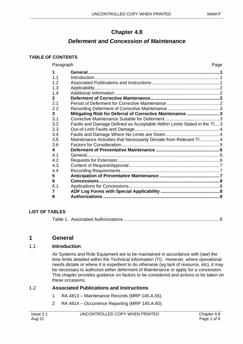
UNCONTROLLED COPY WHEN PRINTED MAM-P
..............................................................................
...............................................................................................
Issue 2.1 Aug 21
..........................................................................................................................
..................................
UNCONTROLLED COPY WHEN PRINTED Chapter 4.8 Page 1 of 9
.................................................................................................................................................................................................
.............................................................................................................................................................
............................................
Chapter 4.8
Deferment and Concession of Maintenance
....................................................................................................................
................................................
TABLE OF CONTENTS
................................................
Paragraph
.....................................................................................................................
.......................................................................
..........
Page
................................
1 General
...................................................................................................
...........................................................................................
1
................................
1.1 Introduction
.......................................................................................................................
...................................................................................................... 1 ...........
1.2 Associated Publications and Instructions
................................................................................................
1 1.3 Applicability 2 1.4 Additional Information 2 2 Deferment of Corrective Maintenance 2 2.1 Period of Deferment for Corrective Maintenance 2 2.2 Recording Deferment of Corrective Maintenance 3 3 Mitigating Risk for Deferral of Corrective Maintenance 3 3.1 Corrective Maintenance Suitable for Deferment 3 3.2 Faults and Damage Defined as Acceptable Within Limits Stated in the TI 3 3.3 Out-of-Limit Faults and Damage 4 3.4 Faults and Damage Where No Limits are Given 4 3.5 Maintenance Activities that Necessarily Deviate from Relevant TI 4 3.6 Factors for Consideration 5 4 Deferment of Preventative Maintenance 6 4.1 General 6 4.2 Requests for Extension 6 4.3 Content of Request/Approval 7 4.4 Recording Requirements 7 5 Anticipation of Preventative Maintenance 7 6 Concessions 8 6.1 Applications for Concessions 8 7 ADF Log Forms with Special Applicability 8 8 Authorizations 8
LIST OF TABLES
Table 1. Associated Authorizations 8
1 General
1.1 Introduction
Air Systems and Role Equipment are to be maintained in accordance with (iaw) the time limits detailed within the Technical Information (TI). However, where operational needs dictate or where it is expedient to do otherwise (eg lack of resource, etc), it may be necessary to authorize either deferment of Maintenance or apply for a concession. This chapter provides guidance on factors to be considered and actions to be taken on these occasions.
1.2 Associated Publications and Instructions
1 RA 4813 – Maintenance Records (MRP 145.A.55).
2 RA 4814 – Occurrence Reporting (MRP 145.A.60).
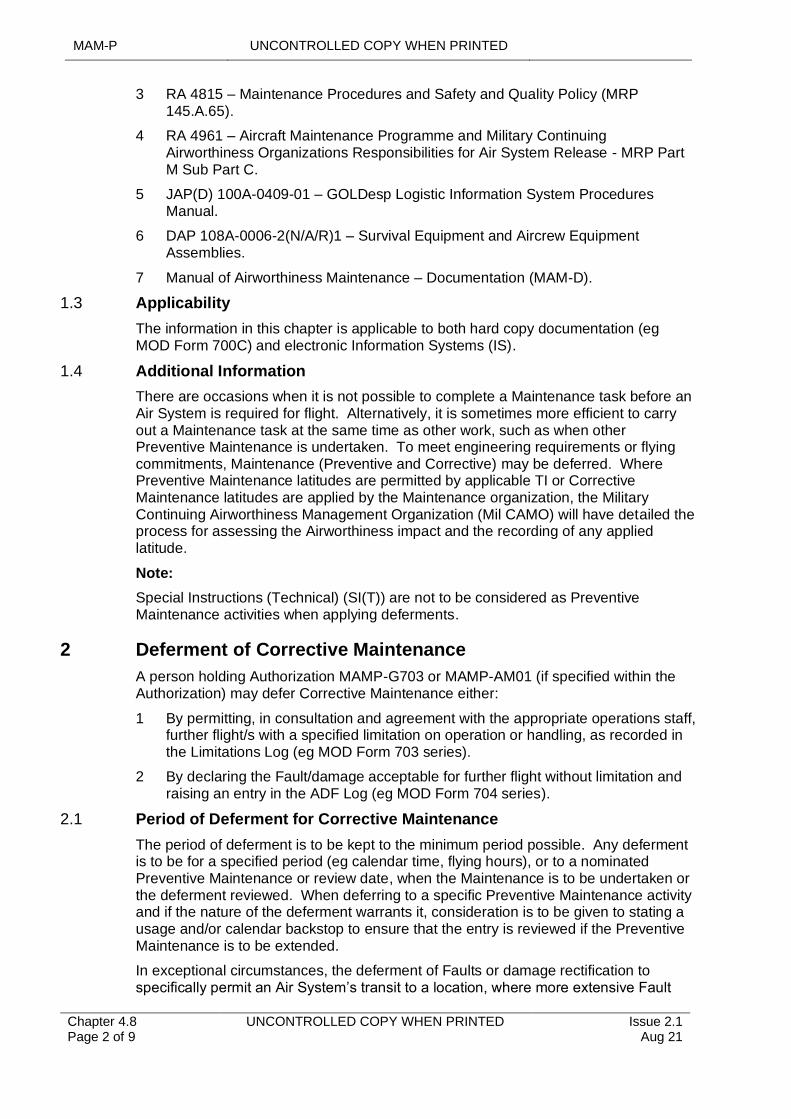
MAM-P UNCONTROLLED COPY WHEN PRINTED
Chapter 4.8 Page 2 of 9
UNCONTROLLED COPY WHEN PRINTED Issue 2.1 Aug 21
3 RA 4815 – Maintenance Procedures and Safety and Quality Policy (MRP 145.A.65).
4 RA 4961 – Aircraft Maintenance Programme and Military Continuing Airworthiness Organizations Responsibilities for Air System Release - MRP Part M Sub Part C.
5 JAP(D) 100A-0409-01 – GOLDesp Logistic Information System Procedures Manual.
6 DAP 108A-0006-2(N/A/R)1 – Survival Equipment and Aircrew Equipment Assemblies.
7 Manual of Airworthiness Maintenance – Documentation (MAM-D).
1.3 Applicability
The information in this chapter is applicable to both hard copy documentation (eg MOD Form 700C) and electronic Information Systems (IS).
1.4 Additional Information
There are occasions when it is not possible to complete a Maintenance task before an Air System is required for flight. Alternatively, it is sometimes more efficient to carry out a Maintenance task at the same time as other work, such as when other Preventive Maintenance is undertaken. To meet engineering requirements or flying commitments, Maintenance (Preventive and Corrective) may be deferred. Where Preventive Maintenance latitudes are permitted by applicable TI or Corrective Maintenance latitudes are applied by the Maintenance organization, the Military Continuing Airworthiness Management Organization (Mil CAMO) will have detailed the process for assessing the Airworthiness impact and the recording of any applied latitude.
Note:
Special Instructions (Technical) (SI(T)) are not to be considered as Preventive Maintenance activities when applying deferments.
2 Deferment of Corrective Maintenance
A person holding Authorization MAMP-G703 or MAMP-AM01 (if specified within the Authorization) may defer Corrective Maintenance either:
1 By permitting, in consultation and agreement with the appropriate operations staff, further flight/s with a specified limitation on operation or handling, as recorded in the Limitations Log (eg MOD Form 703 series).
2 By declaring the Fault/damage acceptable for further flight without limitation and raising an entry in the ADF Log (eg MOD Form 704 series).
2.1 Period of Deferment for Corrective Maintenance
The period of deferment is to be kept to the minimum period possible. Any deferment is to be for a specified period (eg calendar time, flying hours), or to a nominated Preventive Maintenance or review date, when the Maintenance is to be undertaken or the deferment reviewed. When deferring to a specific Preventive Maintenance activity and if the nature of the deferment warrants it, consideration is to be given to stating a usage and/or calendar backstop to ensure that the entry is reviewed if the Preventive Maintenance is to be extended.
In exceptional circumstances, the deferment of Faults or damage rectification to specifically permit an Air System’s transit to a location, where more extensive Fault
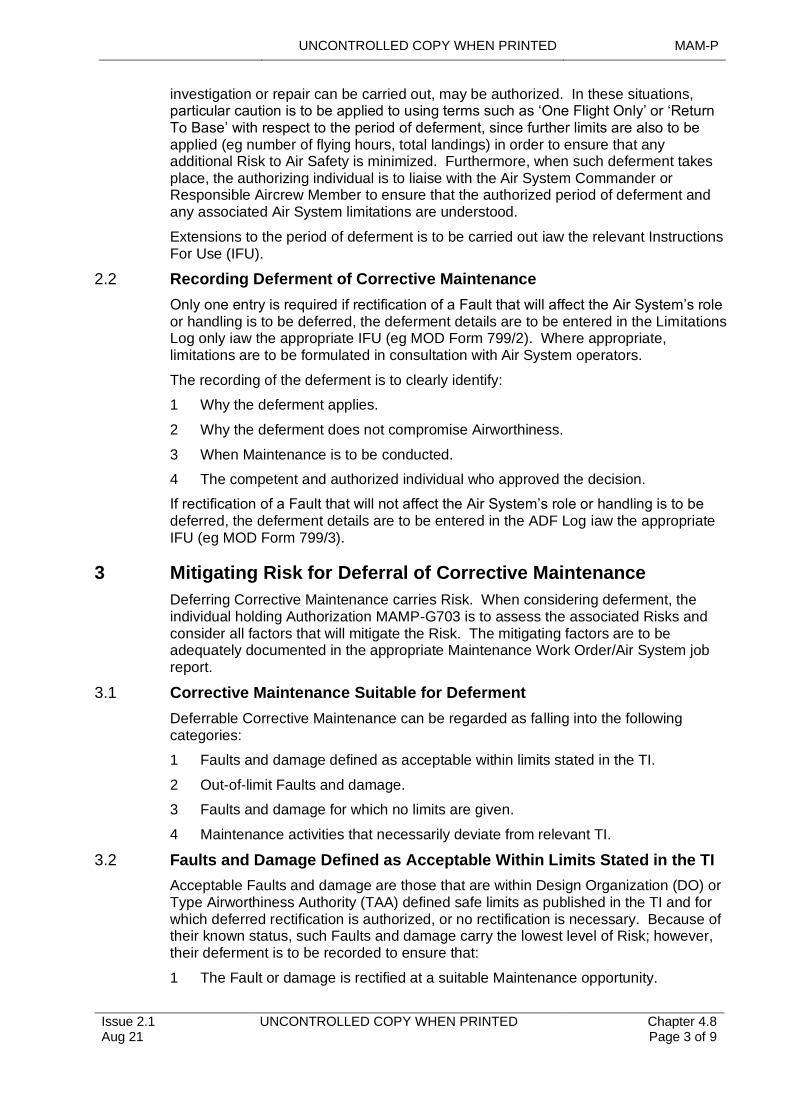
UNCONTROLLED COPY WHEN PRINTED MAM-P
Issue 2.1 Aug 21
UNCONTROLLED COPY WHEN PRINTED Chapter 4.8 Page 3 of 9
investigation or repair can be carried out, may be authorized. In these situations, particular caution is to be applied to using terms such as ‘One Flight Only’ or ‘Return To Base’ with respect to the period of deferment, since further limits are also to be applied (eg number of flying hours, total landings) in order to ensure that any additional Risk to Air Safety is minimized. Furthermore, when such deferment takes place, the authorizing individual is to liaise with the Air System Commander or Responsible Aircrew Member to ensure that the authorized period of deferment and any associated Air System limitations are understood.
Extensions to the period of deferment is to be carried out iaw the relevant Instructions For Use (IFU).
2.2 Recording Deferment of Corrective Maintenance
Only one entry is required if rectification of a Fault that will affect the Air System’s role or handling is to be deferred, the deferment details are to be entered in the Limitations Log only iaw the appropriate IFU (eg MOD Form 799/2). Where appropriate, limitations are to be formulated in consultation with Air System operators.
The recording of the deferment is to clearly identify:
1 Why the deferment applies.
2 Why the deferment does not compromise Airworthiness.
3 When Maintenance is to be conducted.
4 The competent and authorized individual who approved the decision.
If rectification of a Fault that will not affect the Air System’s role or handling is to be deferred, the deferment details are to be entered in the ADF Log iaw the appropriate IFU (eg MOD Form 799/3).
3 Mitigating Risk for Deferral of Corrective Maintenance
Deferring Corrective Maintenance carries Risk. When considering deferment, the individual holding Authorization MAMP-G703 is to assess the associated Risks and consider all factors that will mitigate the Risk. The mitigating factors are to be adequately documented in the appropriate Maintenance Work Order/Air System job report.
3.1 Corrective Maintenance Suitable for Deferment
Deferrable Corrective Maintenance can be regarded as falling into the following categories:
1 Faults and damage defined as acceptable within limits stated in the TI.
2 Out-of-limit Faults and damage.
3 Faults and damage for which no limits are given.
4 Maintenance activities that necessarily deviate from relevant TI.
3.2 Faults and Damage Defined as Acceptable Within Limits Stated in the TI
Acceptable Faults and damage are those that are within Design Organization (DO) or Type Airworthiness Authority (TAA) defined safe limits as published in the TI and for which deferred rectification is authorized, or no rectification is necessary. Because of their known status, such Faults and damage carry the lowest level of Risk; however, their deferment is to be recorded to ensure that:
1 The Fault or damage is rectified at a suitable Maintenance opportunity.
MAM-P UNCONTROLLED COPY WHEN PRINTED
Chapter 4.8 Page 4 of 9
UNCONTROLLED COPY WHEN PRINTED Issue 2.1 Aug 21
2 The Fault or damage is monitored to check for further degradation.
3 Repetitive reporting of the Fault or damage is eliminated.
Recording of ADFs and damage is normally made in the ADF Log, unless the Fault or damage is the subject of a purpose-designed ADF Log (eg MOD Form 704C); see Paragraph 7.
3.3 Out-of-Limit Faults and Damage
Out-of-limits Faults and damage are those that are beyond DO or TAA defined limits published in the TI and would usually require immediate rectification. In such cases deferment, may carry an increased level of Risk. Thus, greater Risk mitigation measures, such as limiting the relevant aspects of the flight envelope will need to be considered and it is to be clearly determined that the requirement outweighs any additional Airworthiness Risks before any deferment is authorized. As soon as is practicable, cases are to be referred to the Mil CAMO and TAA for advice on the Airworthiness risk, stressing the urgency. Whilst awaiting further guidance, deferment may be granted and is to be recorded in the Limitation or ADF Log as appropriate.
3.4 Faults and Damage Where No Limits are Given
In cases where a Fault or damage is not recognized in the TI, the level of Risk is uncertain, as historical data and experience of such Faults and damage is unlikely to be available. Consequently, the Risk Assessment, which may be recorded in the Maintenance Log (eg MOD Form 707A) is likely to require more of the mitigating factors listed at Paragraph 3.6 to be considered, and it is to be clearly determined that the requirement outweighs any additional Airworthiness Risks before any deferment is authorized. The person authorizing the deferment is to notify the Mil CAMO as soon as is practicable for advice on the Airworthiness Risk. Deferment may be granted and is to be recorded in the Limitations or ADF Log as appropriate.
3.5 Maintenance Activities that Necessarily Deviate from Relevant TI
There may be occasions when a Maintenance activity cannot comply with a relevant TI (eg through resource deficiencies or the TI itself proves to be unworkable). In normal circumstances, the Maintenance is to remain incomplete until resources are available, or amendments to TI are approved and promulgated (see RA 4810 and Chapter 10.1–Management and Amendment of Technical Information). However, a requirement may necessitate a Maintenance activity being completed prior to resources becoming available or a TI amendment being approved by the TAA. In all circumstances the Mil CAMO are to be informed, who will then manage the deviation from a Continuing Airworthiness perspective and engage with the TAA/Delivery Team (DT) as required.
Notes:
1 Resource deficiencies are defined as a lack of Ground Support Equipment, Special to Type Test Equipment, tools, or Suitably Qualified and Experienced Personnel (SQEP).
2 Unworkable TI is defined as TI that cannot be complied with because the descriptive or procedural information is incomplete, inconsistent or illogical.
3 This category is not to be used for deferring Faults and damage that is either in or out of TI limits or for where no limits are given, as detailed in Paragraph 3.1.
The action required to resolve the issue is as follows:
When a Maintenance activity cannot be completed to meet an operational requirement due to a lack of resources or the inability to follow the relevant TI, a Risk Assessment is to be carried out considering the factors listed in Paragraph 3.2 to establish the
UNCONTROLLED COPY WHEN PRINTED MAM-P
Issue 2.1 Aug 21
UNCONTROLLED COPY WHEN PRINTED Chapter 4.8 Page 5 of 9
degree of Risk. If the Risk is considered acceptable, the Risk Assessment, detailing either the lack of resources or the inability to follow TI, is to be documented and the deviation authorized as follows:
1 The related Maintenance Work Order is to include the following information:
1.1 Details of the reasons for the deviation (eg resource shortage, operational requirement, unworkable TI, etc).
1.2 Details of any alternative Maintenance activity carried out to allow the deviation to be safely deferred (ie why/how the deferment does not compromise Airworthiness).
1.3 In the case of unworkable TI, details of action taken iaw RA 4810 and Chapter 10.1 – Management and Amendment of Technical Information Procedure to notify the error to the TI sponsor (and TAA if not the TI sponsor).
1.4 Endorsement by a person holding Authorization MAMP-G703 stating that the circumstances justify proceeding with the deviation and that deviation is authorized.
1.5 Reference to a Limitations or ADF Log entry authorized by a person holding Authorization MAMP-G703 is to be raised when subsequent recovery action is required.
1.6 Details of when the Maintenance is to be conducted.
2 The related Limitations or ADF Log entry is to:
2.1 Provide details of the deviation and the required recovery action.
2.2 State the operational justification for proceeding with the deviation.
2.3 Be authorized by a person holding Authorization MAMP-G703.
2.4 Be deferred for review for a period not exceeding 7 calendar days: hastening action is to be taken if there has been no response from the TAA for TI-related issues or the relevant Command for other resource issues, within this timescale.
2.5 In the case of unworkable TI, include the reference of the urgent amendment proposal raised iaw RA 4810 and Chapter 10.1 – Management and Amendment of Technical Information.
3 The deviation is to be notified to the Mil CAMO and the TAA at the very earliest practicable opportunity as directed by the Mil CAM.
3.6 Factors for Consideration
Before deciding whether to defer Corrective Maintenance, a person holding Authorization MAMP-G703 is to assess the consequences and/or hazards and associated Risk of deferment. The following factors, which are neither prescriptive nor exhaustive, are to be considered:
1 Presence of concessions or prescribed Fault/damage limits authorized within theTI.
2 Personal knowledge and experience, knowledge and experience of local experts and relevant information.
3 Consequences or likelihood of failure.
4 Consequences or likelihood of further deterioration.
MAM-P UNCONTROLLED COPY WHEN PRINTED
Chapter 4.8 Page 6 of 9
UNCONTROLLED COPY WHEN PRINTED Issue 2.1 Aug 21
5 Precedence based on same or similar occurrences.
6 Imposition of limitations to reduce further deterioration/possibility of failure.
7 Aircrew experience/workload/tasking.
8 Flight profile/duration/prevailing conditions.
9 Period of deferment.
10 Ongoing examinations of the Fault/damage and any limits of tolerable further degradation.
11 Frequency of examinations.
12 Remedial actions to prevent further damage.
13 Action to assist future examinations (eg removing paint around cracks or marking crack length).
14 Photographs or sketches of the Fault/damage for comparison on future examination and transmission to specialists.
15 Documenting, if appropriate, for future trend analysis.
16 Contacting the Mil CAMO and TAA for further advice or knowledge of previous occurrences, particularly for new/unusual damage.
17 Challenging the Mil CAMO and TAA if it is believed that prescribed limits are too restrictive.
18 Narrative Fault reporting iaw RA 4814 and Chapter 9.2 – Narrative Fault Reporting Using MOD Form 760 Series or serious Fault signal procedure iaw RA 4814 and Chapter 9.3 – Serious Fault Reports.
19 Assessment and categorization iaw RA 4815 and Chapter 4.5 – Aircraft Repair.
20 Requesting new Repair instructions iaw RA 4815 and Chapter 4.6 – Repair Instructions for Aircraft Products, Parts and Appliances.
4 Deferment of Preventative Maintenance
4.1 General
Unless otherwise directed by the TAA or Mil CAM, an individual holding authority MAMP-H802 may defer any Preventive Maintenance activity as prescribed by the TI. However, the following constraints apply:
1 The Preventive Maintenance activity is to be one for which they are ultimately responsible. If the Maintenance activity is one for which they are not ultimately responsible, the agreement of the appropriate individual holding authority level K, Mil CAM and/or TAA is to be obtained.
2 Any upper usage hour or calendar limit for the Preventive Maintenance being deferred is not to be exceeded.
3 Any more frequent Preventive Maintenance is either deferred or carried out as a penalty Preventive Maintenance.
4 Due to the complex lifing of some Survival Equipment (SE) and Aircrew Equipment Assemblies, extensions to Preventive Maintenance as prescribed by TI, may only be authorized by the appropriate individual holding authority level K, with due regard to the details in DAP 108A-0006-2(N/A/R)1.
4.2 Requests for Extension
UNCONTROLLED COPY WHEN PRINTED MAM-P
Issue 2.1 Aug 21
UNCONTROLLED COPY WHEN PRINTED Chapter 4.8 Page 7 of 9
All requests for extensions are to have an Audit trail. Requests for extensions to components are to be submitted to the relevant TAA via the Mil CAMO who is to liaise with the appropriate Commodity DT in assessing implications to the Safety Assessment.
4.3 Content of Request/Approval
A request for an extension is to include the following:
1 Air System/component type and Serial Number (CLR reference if applicable).
2 Current airframe hours or component life consumed.
3 Type of Maintenance or life due, any extensions already granted, and the amount of extension required.
4 Reason for request.
5 Airframe hours or date when Maintenance is due, or component life expires and, for explosive stores, the storage life and installed life expiry dates.
6 Airframe hours or date when Maintenance will be due, or component life will expire, if extension granted.
7 Planned date of Maintenance or component change.
8 For explosive stores only: Date of Manufacture, Lot Number.
The reply to a request for an extension is to be titled ‘EXTENSION REQUEST APPROVAL/REFUSAL’, as appropriate, and is to include the following:
1 Air System/component type and Serial Number.
2 Originator’s Reference and DTG.
3 Type of Maintenance or life.
4 Percentage/amount of extension granted.
5 When event is due with extension.
6 Additional information.
Note:
Additional information may include supplementary Maintenance requirements, MOD Form 760 requirements, disposal instructions etc.
4.4 Recording Requirements
A decision to anticipate or defer Preventive Maintenance is to be recorded on the appropriate MOD Form 700 or electronic IS equivalent, raised for the Preventive Maintenance. The entry is to state the following:
1 ►Why the deferment applies.
2 Why the deferment does not compromise Airworthiness.
3 When Maintenance is to be conducted.
4 The competent and authorized individual who approved the decision.◄
The revised timing for the Air System Preventive Maintenance is also to be recorded in the MOD Form 700 (or equivalent), in the appropriate forecast log and Maintenance record. If applicable, electronic IS-based recording is to be amended iaw the appropriate procedures.
5 Anticipation of Preventative Maintenance
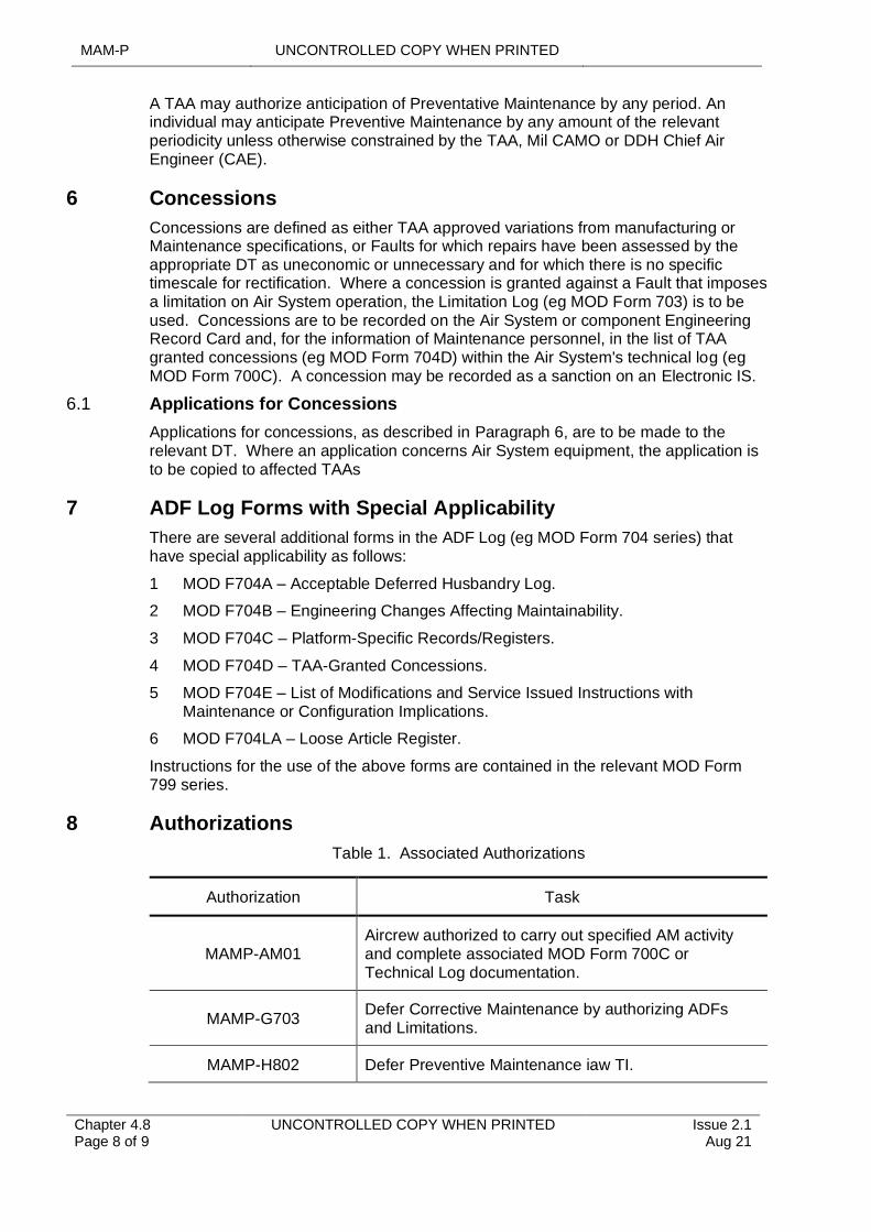
MAM-P UNCONTROLLED COPY WHEN PRINTED
Chapter 4.8 Page 8 of 9
UNCONTROLLED COPY WHEN PRINTED Issue 2.1 Aug 21
A TAA may authorize anticipation of Preventative Maintenance by any period. An individual may anticipate Preventive Maintenance by any amount of the relevant periodicity unless otherwise constrained by the TAA, Mil CAMO or DDH Chief Air Engineer (CAE).
6 Concessions
Concessions are defined as either TAA approved variations from manufacturing or Maintenance specifications, or Faults for which repairs have been assessed by the appropriate DT as uneconomic or unnecessary and for which there is no specific timescale for rectification. Where a concession is granted against a Fault that imposes a limitation on Air System operation, the Limitation Log (eg MOD Form 703) is to be used. Concessions are to be recorded on the Air System or component Engineering Record Card and, for the information of Maintenance personnel, in the list of TAA granted concessions (eg MOD Form 704D) within the Air System's technical log (eg MOD Form 700C). A concession may be recorded as a sanction on an Electronic IS.
6.1 Applications for Concessions
Applications for concessions, as described in Paragraph 6, are to be made to the relevant DT. Where an application concerns Air System equipment, the application is to be copied to affected TAAs
7 ADF Log Forms with Special Applicability
There are several additional forms in the ADF Log (eg MOD Form 704 series) that have special applicability as follows:
1 MOD F704A – Acceptable Deferred Husbandry Log.
2 MOD F704B – Engineering Changes Affecting Maintainability.
3 MOD F704C – Platform-Specific Records/Registers.
4 MOD F704D – TAA-Granted Concessions.
5 MOD F704E – List of Modifications and Service Issued Instructions with Maintenance or Configuration Implications.
6 MOD F704LA – Loose Article Register.
Instructions for the use of the above forms are contained in the relevant MOD Form 799 series.
8 Authorizations
Table 1. Associated Authorizations
Authorization Task
MAMP-AM01Aircrew authorized to carry out specified AM activity and complete associated MOD Form 700C or Technical Log documentation.
MAMP-G703Defer Corrective Maintenance by authorizing ADFs and Limitations.
MAMP-H802 Defer Preventive Maintenance iaw TI.
UNCONTROLLED COPY WHEN PRINTED MAM-P
Issue 2.1 Aug 21
UNCONTROLLED COPY WHEN PRINTED Chapter 4.8 Page 9 of 9
Intentionally Blank for Print Pagination
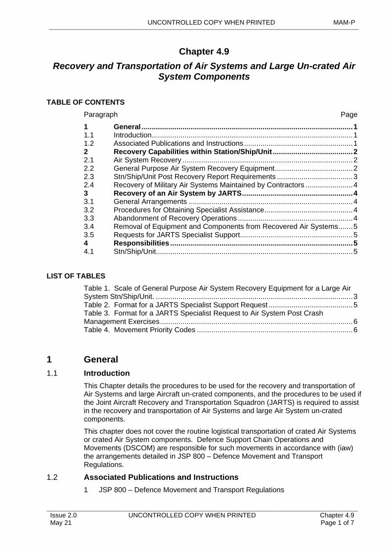
UNCONTROLLED COPY WHEN PRINTED MAM-P
Issue 2.0 May 21
UNCONTROLLED COPY WHEN PRINTED Chapter 4.9 Page 1 of 7
..........................................................................................................................................................................
.........................................................................................................................................
.........................................................................................................................................................................................
..............................................................
...................................................................................................
......................................................................................................................................
............................................................
.........................................................................................................................
............................................................................................
.........................................................................................................................................................................................................
Chapter 4.9
Recovery and Transportation of Air Systems and Large Un-crated Air System Components
TABLE OF CONTENTS
Paragraph Page
1 General 11.1 Introduction 11.2 Associated Publications and Instructions 12 Recovery Capabilities within Station/Ship/Unit 22.1 Air System Recovery 22.2 General Purpose Air System Recovery Equipment 22.3 Stn/Ship/Unit Post Recovery Report Requirements 32.4 Recovery of Military Air Systems Maintained by Contractors 43 Recovery of an Air System by JARTS 43.1 General Arrangements 43.2 Procedures for Obtaining Specialist Assistance 43.3 Abandonment of Recovery Operations 43.4 Removal of Equipment and Components from Recovered Air Systems 53.5 Requests for JARTS Specialist Support 54 Responsibilities 54.1 Stn/Ship/Unit 5
LIST OF TABLES
Table 1. Scale of General Purpose Air System Recovery Equipment for a Large Air System Stn/Ship/Unit. 3Table 2. Format for a JARTS Specialist Support Request 5Table 3. Format for a JARTS Specialist Request to Air System Post Crash Management Exercises 6Table 4. Movement Priority Codes 6
1 General
1.1 Introduction
This Chapter details the procedures to be used for the recovery and transportation of Air Systems and large Aircraft un-crated components, and the procedures to be used if the Joint Aircraft Recovery and Transportation Squadron (JARTS) is required to assist in the recovery and transportation of Air Systems and large Air System un-crated components.
This chapter does not cover the routine logistical transportation of crated Air Systems or crated Air System components. Defence Support Chain Operations and Movements (DSCOM) are responsible for such movements in accordance with (iaw) the arrangements detailed in JSP 800 – Defence Movement and Transport Regulations.
1.2 Associated Publications and Instructions
1 JSP 800 – Defence Movement and Transport Regulations
MAM-P UNCONTROLLED COPY WHEN PRINTED
Chapter 4.9 Page 2 of 7
UNCONTROLLED COPY WHEN PRINTED Issue 2.0 May 21
2 Manual of Post-Crash Management
3 Topic 2(N/A/R) – General Orders, Special Instructions and Modifications
2 Recovery Capabilities within Station/Ship/Unit
Station/Ship/Unit (Stn/Ship/Unit) will have varying Air System recovery capabilities depending upon their single-Service requirements and operating environments. These capabilities are to be used for the recovery and/or transportation of Air Systems and large components when:
1 The task is within the resources of the Stn/Ship/Unit.
2 Personnel are suitably trained/authorized.
3 The appropriate procedure is documented in the Air System’s Technical Information (TI).
Additionally, an individual holding authority level K may decide to undertake a recovery or transportation task if, for urgent operational reasons, it is not possible to wait for specialist assistance.
JARTS provides a specialist Air System recovery and transportation service for Air Systems and large un-crated Air System components. When a recovery or transportation task is beyond the capability of a Stn/Ship/Unit JARTS may be requested to undertake the task.
2.1 Air System Recovery
Whenever there is a requirement to recover an Air System, the individual holding authority level K is to assess whether the Stn/Ship/Unit has the capability to undertake the recovery task or whether specialist support is required from JARTS. However, the individual holding authority level K may decide to undertake a recovery task without specialist assistance if:
1 The Air System has ditched and is in immediate danger of sinking.
2 There is an operationally imperative reason for recovering the Air System.
All Air System recovery operations are to be carried out with Safety as the primary consideration. Additionally, although every effort is to be made to minimize obstruction of an Airfield or disruption to the public, recovery is to neither cause further damage to the Air System or other property, nor prejudice any investigation. Exceptionally, when a crashed or otherwise immobile Air System is blocking an Air System operating surface for which there is an extremely urgent operational need, the individual holding authority level K may order the clearance of the Air System from the operating surface by any available means. In these circumstances, the individual holding authority level K is to ensure that suitable photographs are taken as evidence prior to clearing the Air System or Air System wreckage.
Any decision to recover an Air System without JARTS support from a Stn/Ship/Unit that is not the Air System’s parent Stn/Ship/Unit are to be made jointly by the individual holding authority level K responsible for the recovery location and the individual holding authority level K of the Air System’s parent Stn/Ship/Unit.
2.2 General Purpose Air System Recovery Equipment
Where a Stn/Ship/Unit has access to a suitably sized crane, the Stn/Ship/Unit is to hold and maintain a quantity of Air System recovery equipment; the recommended equipment scale for large Stn/Ship/Unit detailed is at Table 1. Where access to a crane is not feasible, the Stn/Ship/Unit is to hold and maintain an alternative set of Air System recovery equipment; the recommended equipment is at Table 2. Smaller
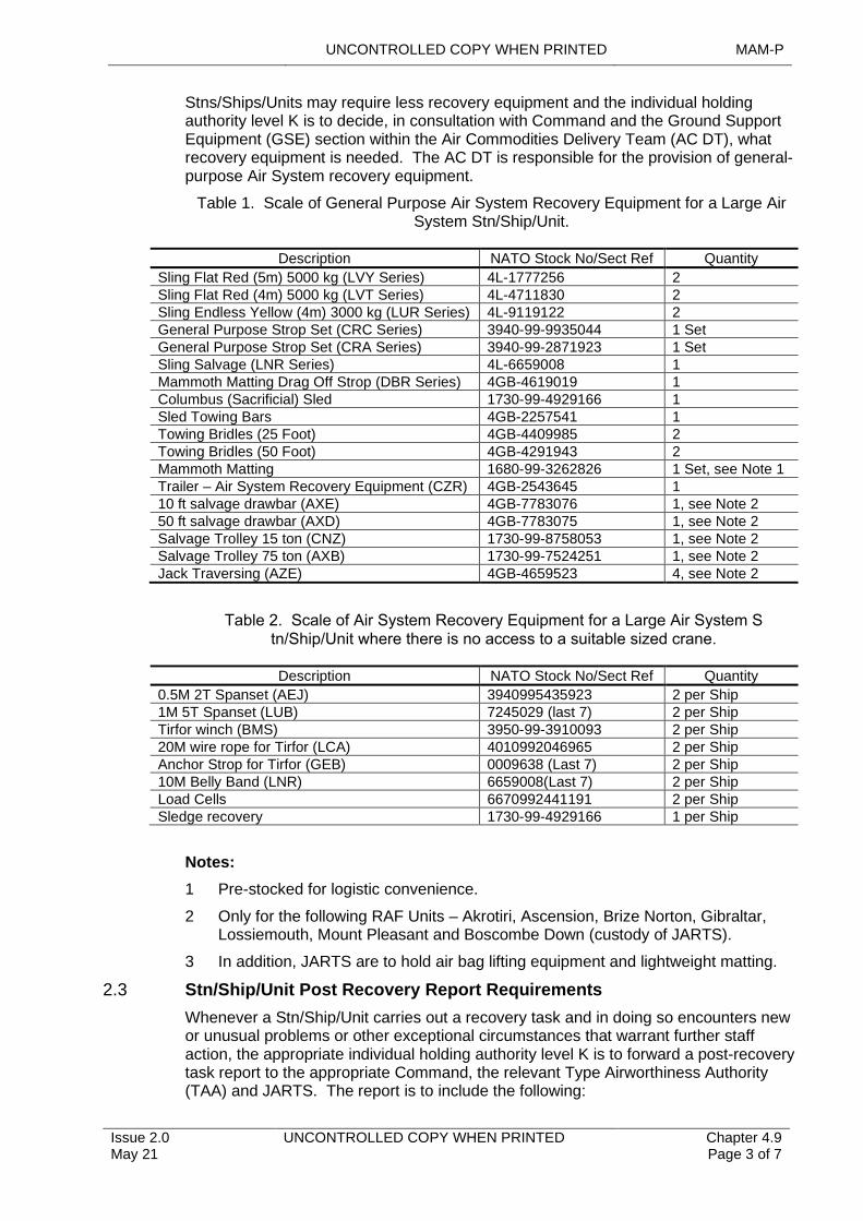
UNCONTROLLED COPY WHEN PRINTED MAM-P
Issue 2.0 May 21
UNCONTROLLED COPY WHEN PRINTED Chapter 4.9 Page 3 of 7
Stns/Ships/Units may require less recovery equipment and the individual holding authority level K is to decide, in consultation with Command and the Ground Support Equipment (GSE) section within the Air Commodities Delivery Team (AC DT), what recovery equipment is needed. The AC DT is responsible for the provision of general-purpose Air System recovery equipment.
Table 1. Scale of General Purpose Air System Recovery Equipment for a Large Air System Stn/Ship/Unit.
Table 2. Scale of Air System Recovery Equipment for a Large Air System Stn/Ship/Unit where there is no access to a suitable sized crane.
Notes:
1 Pre-stocked for logistic convenience.
2 Only for the following RAF Units – Akrotiri, Ascension, Brize Norton, Gibraltar, Lossiemouth, Mount Pleasant and Boscombe Down (custody of JARTS).
3 In addition, JARTS are to hold air bag lifting equipment and lightweight matting.
2.3 Stn/Ship/Unit Post Recovery Report Requirements
Whenever a Stn/Ship/Unit carries out a recovery task and in doing so encounters new or unusual problems or other exceptional circumstances that warrant further staff action, the appropriate individual holding authority level K is to forward a post-recovery task report to the appropriate Command, the relevant Type Airworthiness Authority (TAA) and JARTS.
Description NATO Stock No/Sect Ref Quantity
The report is to include the following:
Sling Flat Red (5m) 5000 kg (LVY Series) 4L-1777256 2Sling Flat Red (4m) 5000 kg (LVT Series) 4L-4711830 2Sling Endless Yellow (4m) 3000 kg (LUR Series) 4L-9119122 2General Purpose Strop Set (CRC Series) 3940-99-9935044 1 SetGeneral Purpose Strop Set (CRA Series) 3940-99-2871923 1 SetSling Salvage (LNR Series) 4L-6659008 1Mammoth Matting Drag Off Strop (DBR Series) 4GB-4619019 1Columbus (Sacrificial) Sled 1730-99-4929166 1Sled Towing Bars 4GB-2257541 1Towing Bridles (25 Foot) 4GB-4409985 2Towing Bridles (50 Foot) 4GB-4291943 2Mammoth Matting 1680-99-3262826 1 Set, see Note 1Trailer – Air System Recovery Equipment (CZR) 4GB-2543645 110 ft salvage drawbar (AXE) 4GB-7783076 1, see Note 250 ft salvage drawbar (AXD) 4GB-7783075 1, see Note 2Salvage Trolley 15 ton (CNZ) 1730-99-8758053 1, see Note 2Salvage Trolley 75 ton (AXB) 1730-99-7524251 1, see Note 2Jack Traversing (AZE) 4GB-4659523 4, see Note 2
Description NATO Stock No/Sect Ref Quantity
0.5M 2T Spanset (AEJ) 3940995435923 2 per Ship 1M 5T Spanset (LUB) 7245029 (last 7) 2 per Ship
Tirfor winch (BMS) 3950-99-3910093 2 per Ship 20M wire rope for Tirfor (LCA) 4010992046965 2 per Ship
Anchor Strop for Tirfor (GEB) 0009638 (Last 7) 2 per Ship 10M Belly Band (LNR) 6659008(Last 7) 2 per Ship
Load Cells 6670992441191 2 per Ship Sledge recovery 1730-99-4929166 1 per Ship
MAM-P UNCONTROLLED COPY WHEN PRINTED
Chapter 4.9 Page 4 of 7
UNCONTROLLED COPY WHEN PRINTED Issue 2.0 May 21
1 A brief description of the occurrence that necessitated the recovery.
2 A summary of the recovery operation, including details of equipment used and its effectiveness.
3 Any recommendations, in terms of equipment or training that would facilitate any similar recovery tasks.
2.4 Recovery of Military Air Systems Maintained by Contractors
When a Contractor is responsible for the Maintenance of military Air System, the contract is to specify the Contractor’s responsibility for Air System recovery. Generally, a Contractor would be required to undertake only simple recovery tasks, employing procedures documented in the Air System’s TI. More complex recovery tasks could be included if considered necessary and appropriate. A Contractor that is unable to meet its recovery obligations may seek assistance from JARTS through the contract manager. Whenever JARTS undertakes a recovery task that should have been undertaken under the terms of a Maintenance contract, JARTS is to provide full cost details to the contract manager for cost recovery action.
3 Recovery of an Air System by JARTS
3.1 General Arrangements
Whenever the recovery of an Air System is beyond the capabilities of a Stn/Ship/Unit, JARTS is to carry out the recovery task. Requests for JARTS specialist support are to be made iaw Paragraph 3.5; however, if the Air System has crashed, detailed Post-Crash Management procedures are contained in the Manual of Post Crash Management (MPCM).
When the Air System accident/incident is subject to a formal investigation, recovery actions are not to be undertaken without the permission of the President of the Service Inquiry/Unit Inquiry or Accident Investigation Officer, with the following exceptions:
1 When there is an extremely urgent operational need to clear an Air System operating surface as detailed in Paragraph 2.1.
2 When the wreckage constitutes a significant or dangerous obstruction, in which case the Civil Police can order removal of the wreckage. If this is the case the MOD Incident Officer is to request that suitable photographs are taken as evidence and advise or assist in removing the wreckage to a suitable position.
3.2 Procedures for Obtaining Specialist Assistance
In addition to support provided by JARTS, other units can be tasked to supply specialist assistance outside JARTS’s area of expertise. The procedures for obtaining further specialist assistance from external organizations are detailed in the MPCM.
3.3 Abandonment of Recovery Operations
When the investigating authority, in consultation with the appropriate Command and DT, assesses that the recovery of a crashed Air System, either on land or in the sea, is either impracticable or uneconomic, recovery operations are only halted when all of the following conditions have been satisfied:
1 The crashed Air System will not present an obstruction or continuing hazard.
2 All explosive armament stores and other dangerous equipment or substances have been removed or rendered harmless.
3 Undamaged items that cannot be removed have been broken up so that they cannot be recovered and used for their original purpose.
UNCONTROLLED COPY WHEN PRINTED MAM-P
Issue 2.0 May 21
UNCONTROLLED COPY WHEN PRINTED Chapter 4.9 Page 5 of 7
4 There are no outstanding security issues.
5 All necessary environmental protection measures have been taken and the Defence Land Agent is content for recovery work to cease.
When a recovery task has been abandoned, the recovery team is to report details of the Air System to the local Civil Police.
3.4 Removal of Equipment and Components from Recovered Air Systems
Equipment and components are not be removed from an Air System undergoing investigation except at the request of the investigating authority. If the investigating authority requires a component to be removed, the task is to be undertaken by a Competent Tradesman approved by the President of the Service Inquiry/Unit Inquiry or Accident Investigation Officer. Once the investigating authority has released the Air System back to the custodian/DT, subsequent removal of equipment and components will depend on the Air System’s Repair category as detailed below:
1 Removal of equipment and components from Category 3 or 4 Air Systems, requires Authorization from the appropriate Military Continuing Airworthiness Management Organization (Mil CAMO) iaw Chapter 4.5 – Aircraft Repair.
2 Removal of equipment and components from Category 5 Air Systems requires Authorization from the appropriate TAA.
Components removed from a damaged Air System are to have their Serviceability verified before being fitted to other Air Systems. In particular, any components removed from crashed Air Systems are to be conditioned Unserviceable R3/4 iaw Chapter 4.10 – Technical Equipment – Conditioning and Preparation for Movement or Storage, to ensure that they are subjected to detailed examination before any further use.
3.5 Requests for JARTS Specialist Support
Requests for JARTS specialist support are to be made by E-mail and include all of the information detailed in Table 2. For Air System Post Crash Management Exercise Support, requests for JARTS specialist support are to be made as per Table 3. Note that not all Paragraphs are applicable to recovery task requests.
4 Responsibilities
4.1 Stn/Ship/Unit
1 Assessing whether they have the capability to undertake a recovery or transportation task.
2 Undertaking those recovery or transportation tasks that are within their capability.
3 Attempting to undertake all recovery or transportation tasks when, for urgent operational reasons, it is not possible to wait for specialist assistance.
4 Ordering the clearance, by any means available, of a crashed or otherwise immobile Air System when it is blocking an Air System operating surface for which there is an extremely urgent operational need.
5 Deciding, in consultation with the Command and the GSE section within the AC DT, the scale of Air System recovery equipment that their Stn/Ship/Unit is to hold.
6 Forwarding, when necessary, a post-recovery task report to their Command, the relevant TAA and JARTS.
Table 2. Format for a JARTS Specialist Support Request
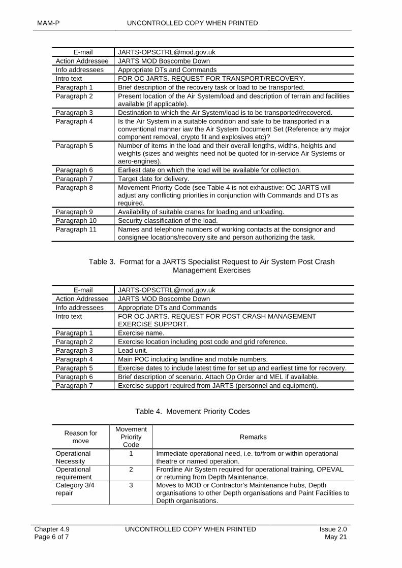
MAM-P UNCONTROLLED COPY WHEN PRINTED
Chapter 4.9 Page 6 of 7
UNCONTROLLED COPY WHEN PRINTED Issue 2.0 May 21
Table 3. Format for a JARTS Specialist Request to Air System Post Crash Management Exercises
E-mail [email protected]
Table 4. Movement Priority Codes
Action Addressee JARTS MOD Boscombe Down
Info addressees Appropriate DTs and Commands
Intro text FOR OC JARTS. REQUEST FOR TRANSPORT/RECOVERY.
Paragraph 1 Brief description of the recovery task or load to be transported.
Paragraph 2 Present location of the Air System/load and description of terrain and facilities available (if applicable).
Paragraph 3 Destination to which the Air System/load is to be transported/recovered.
Paragraph 4 Is the Air System in a suitable condition and safe to be transported in a conventional manner iaw the Air System Document Set (Reference any major component removal, crypto fit and explosives etc)?
Paragraph 5 Number of items in the load and their overall lengths, widths, heights and weights (sizes and weights need not be quoted for in-service Air Systems or aero-engines).
Paragraph 6 Earliest date on which the load will be available for collection.
Paragraph 7 Target date for delivery.
Paragraph 8 Movement Priority Code (see Table 4 is not exhaustive: OC JARTS will adjust any conflicting priorities in conjunction with Commands and DTs as required.
Paragraph 9 Availability of suitable cranes for loading and unloading.
Paragraph 10 Security classification of the load.
Paragraph 11 Names and telephone numbers of working contacts at the consignor and consignee locations/recovery site and person authorizing the task.
E-mail [email protected]
Action Addressee JARTS MOD Boscombe Down
Info addressees Appropriate DTs and Commands
Intro text FOR OC JARTS. REQUEST FOR POST CRASH MANAGEMENT EXERCISE SUPPORT.
Paragraph 1 Exercise name.
Paragraph 2 Exercise location including post code and grid reference.
Paragraph 3 Lead unit.
Paragraph 4 Main POC including landline and mobile numbers.
Paragraph 5 Exercise dates to include latest time for set up and earliest time for recovery.
Paragraph 6 Brief description of scenario. Attach Op Order and MEL if available.
Paragraph 7 Exercise support required from JARTS (personnel and equipment).
Reason for move
Movement Priority Code
Remarks
Operational Necessity
1 Immediate operational need, i.e. to/from or within operational theatre or named operation.
Operational requirement
2 Frontline Air System required for operational training, OPEVAL or returning from Depth Maintenance.
Category 3/4 repair
3 Moves to MOD or Contractor’s Maintenance hubs, Depth organisations to other Depth organisations and Paint Facilities to Depth organisations.
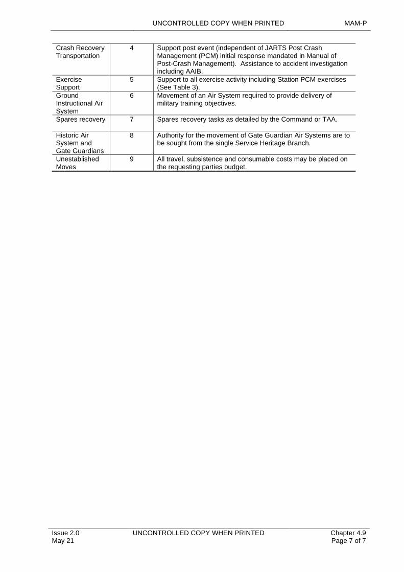
UNCONTROLLED COPY WHEN PRINTED MAM-P
Issue 2.0 May 21
UNCONTROLLED COPY WHEN PRINTED Chapter 4.9 Page 7 of 7
Crash Recovery Transportation
4 Support post event (independent of JARTS Post Crash Management (PCM) initial response mandated in Manual of Post-Crash Management). Assistance to accident investigation including AAIB.
Exercise Support
5 Support to all exercise activity including Station PCM exercises (See Table 3).
Ground Instructional Air System
6 Movement of an Air System required to provide delivery of military training objectives.
Spares recovery 7 Spares recovery tasks as detailed by the Command or TAA.
Historic Air System and Gate Guardians
8 Authority for the movement of Gate Guardian Air Systems are to be sought from the single Service Heritage Branch.
Unestablished Moves
9 All travel, subsistence and consumable costs may be placed on the requesting parties budget.
UNCONTROLLED COPY WHEN PRINTED MAM-P
...........................................................................
...........................................................................................
...............................................................................................
...........................................................................................................................................................................................
................................................
.........................................................................................................................................................
........................................................................................................................................................................................................................................
....................................................................................................................................................................................
...................................................................................................................................................................................
.................................................................................................
......................................................................................................................................................
.........................................................................................................................................................................................................
Chapter 4.10
Technical Equipment – Conditioning and Preparation for Movement or Storage
TABLE OF CONTENTS
Paragraph Page
1 General1.1 Introduction
11
1.2 Associated Publications and Instructions 11.3 Applicability 2 1.4 Terminology 2 1.5 Technical Equipment 2 1.6 Conditioners 2 1.7 Conditioning Terms 2 2 Conditioning 3 2.1 Conditioning Exceptions 3 3 Factors Affecting Conditioning Decisions 3 3.1 Conditioning by Logistic Services (Log Svcs) 3 3.2 Conditioning by Logistics Personnel 3 3.3 Faulty Technical Equipment 4 3.4 Conditioning as ‘Scrap’ 4 3.5 Inventory Holders and the Condition ‘Scrap’ 4 4 Preparation of Conditioned Technical Equipment for Movement or
Storage 4 4.1 Physical Preparation 4 4.2 Technical Equipment Labelling 5 4.3 Conditioning and Technical Equipment Label Completion 5 5 Authorizations 7
LIST OF TABLES
Table 1. Associated Authorizations 7
1 General
1.1 Introduction
Conditioning is the determination of the serviceability state of technical equipment. Any item returned to the supply/logistics organization having been assessed and conditioned as Serviceable may be re-issued to another user without further action to confirm serviceability. Any item returned to the supply/logistics organization having been assessed as Unserviceable will enter a repair process that has been agreed between the item’s Delivery Team (DT) and the supply chain. Conditioning an item of technical equipment requires an authorized person to determine and state whether the item is Serviceable or not.
1.2 Associated Publications and Instructions
1 RA 4809 – Acceptance of Components (MRP 145.A.42)
2 RA 4812 – Certification of Air System Release and Component Release (MRP 145.A.50)
Issue 1.4 Apr 21
UNCONTROLLED COPY WHEN PRINTED Chapter 4.10 Page 1 of 8
MAM-P UNCONTROLLED COPY WHEN PRINTED
3 JSP 515 – The MOD Hazardous Stores Information System.
4 Dangerous Goods Manual
5 DEFCON 627 Quality Assurance – Requirement for a Certificate of Conformity
6 Defence Logistics Framework
7 Topic 2(N/A/R)1 – General Orders and Special Instructions.
8 Topic 5W – Summary of Component Repair Plans
1.3 Applicability
Materiel Accounting (MA) and Logistics Transformation
MA principles are defined in the Defence Logistic Framework (DLF). Fundamentally it is the process of maintaining records of the quantities, condition and Configuration of items of materiel which have been received, held and issued, in such a way that the source, current location and description of the item can be determined. Each item of materiel has an MA Classification code. The DLF provides a descriptor for each of the following MA Classification codes:
1 Permanent (P).
2 Limited (L).
3 Consumable (C).
1.4 Terminology
The following paragraphs identify the terminology to be used when conditioning technical equipment in accordance with (iaw) the circumstances identified at Paragraph 2.
1.5 Technical Equipment
Technical equipment is to be interpreted as meaning all equipment associated with Products, Parts and Appliances and Air System Ground Support Equipment (GSE).
1.6 Conditioners
Conditioners are personnel authorized to determine the condition of an item of technical equipment and certify the associated paperwork.
1.7 Conditioning Terms
Conditioners are to use the following conditioning terms:
1 Serviceable: Technical equipment that is fit for immediate use and capable of performing its designed function. Serviceable equipment may be identified as either A1: Serviceable New or A2: Serviceable Used.
2 Unserviceable: Unserviceable technical equipment that is unfit for immediate use and incapable of performing its designed function, is to be allocated the following conditioning terms:
1 R2, R3 and R4.
2 E0 Unspecified Reasons.
3 E1Unserviceable Ban, Quarantine or Testing.
4 E3 Under Defect Investigation.
These terms are drawn from DLF; the definitions of these terms are to be promulgated in the relevant Support Policy Statement (SPS).
Chapter 4.10 Page 2 of 8
UNCONTROLLED COPY WHEN PRINTED Issue 1.4 Apr 21
UNCONTROLLED COPY WHEN PRINTED MAM-P
3 Scrap: An item of P or L class technical equipment that is unfit for its designed use to the extent that it cannot be repaired economically.
2 Conditioning
Technical equipment is to be conditioned:
1 Prior to transfer between Maintenance organizations.
2 Prior to movement within the same Maintenance organization from one work location to another for further Maintenance or reinstallation.
3 When the item is the subject of cannibalization and is transferred between Station(Stn)/Ship/Unit, see RA 4812.
4 Prior to return to the supply/logistic organization for whatever reason.
2.1 Conditioning Exceptions
Technical equipment conditioning need not be undertaken:
1 When Serviceable technical equipment is removed from an Air System for the sole purpose of routine replenishment, eg a Lox Converter. However, when the equipment is removed for replenishment, local procedures are to ensure that these items are segregated from similar equipment that has been conditioned. Should the serviceability of the equipment undergoing replenishment become suspect at any time, it is to be conditioned.
2 If the equipment is subject to its own specialist documentation, eg Magnetic Debris Plugs on issue from, or return to, an Early Failure Detection Centre.
3 When equipment is received from industry as new or following repair and the packaging is un-broached. The accompanying MOD Form 640 or equivalent document, and, when applicable, a Certificate of Conformity as detailed in DEFCON 627, will be retained by Logistic Services (Log Svcs) at the point of initial receipt into the Joint Support Chain (JSC). Copies may be requested to provide confirmation that the item was Serviceable when dispatched.
3 Factors Affecting Conditioning Decisions
3.1 Conditioning by Logistic Services (Log Svcs)
In some cases, where an item of technical equipment is received at a Log Svcs site without a MOD Form 731, MOD Form 3910 or equivalent Contractor’s label attached, the only means by which its identity and condition may be established would be to return it to the originator, if known, or to a user unit for further conditioning. To minimize unnecessary movement of equipment, appropriately authorized conditioners within a Log Svcs site may apply any of the defined conditioning terms to an item of equipment following test at the Log Svcs site to establish its identity and condition.
3.2 Conditioning by Logistics Personnel
In cases where a Serviceable item sustains damage during transit which renders it unfit for use and it would be inefficient to continue to its planned destination for technical conditioning, Logistics personnel may condition the item as Unserviceable if approved in appropriate single Service orders. The MOD Form 731 should be annotated as ‘Damaged in Transit’ and the item returned to the appropriate Repair Organization (RO) as determined by the appropriate DT or Command, who should also identify any requirement to initiate a Quality Occurrence Report (QOR) iaw the DLF.
Issue 1.4 Apr 21
UNCONTROLLED COPY WHEN PRINTED Chapter 4.10 Page 3 of 8
MAM-P UNCONTROLLED COPY WHEN PRINTED
3.3 Faulty Technical Equipment
If the item of technical equipment under consideration is the subject of Narrative Fault Reporting using the MOD Form 760 as detailed in Chapter 9.2 - Narrative Fault Reporting using the MOD Form 760 series, the condition ‘Scrap’ is not to be applied.
3.4 Conditioning as ‘Scrap’
Unless authority is promulgated by the DT, the condition ‘Scrap’ is not be applied to any Class P item. Class L items may only be scrapped when a repair capability does not exist as confirmed by the relevant DT.
However, items that have been destroyed, or which are impossible to reclaim or repair, may be conditioned Scrap locally by an authorized individual. Items subject to ongoing investigation are not to be scrapped.
Items conditioned as Scrap should be damaged/deformed/dented/cut/distorted beyond repair/use to ensure they do not re-enter the supply chain and subsequently used.
3.5 Inventory Holders and the Condition ‘Scrap’
A conditioner who has been authorized to condition items of P and L technical equipment as ‘Scrap’ are not to exercise that Authorization in respect of any item they hold on inventory charge.
4 Preparation of Conditioned Technical Equipment for Movement or Storage
4.1 Physical Preparation
The person conditioning an item of technical equipment is to ensure that it is correctly prepared for subsequent movement and storage. Engineering responsibility for such preparation includes:
1 Taking all packaging and documentary Safety measures ordered for the protection of Service personnel and the public during subsequent handling and movement of the item.
2 Taking the initial packing measures required to assist in protecting the item against damage during movement or deterioration whilst in store, eg fitment of blanks to plugs, sockets and openings, fitment of protective shrouds and covers and removal of internal dry batteries.
3 Ensuring that the item is not deficient of any components other than when such deficiencies is the cause, or unavoidable result, of a Fault recorded on the equipment label for an item that is Unserviceable.
4 Ensuring that all accessories supplied as part of the item, eg connectors, adapters and test leads, are securely attached to, or packaged together with, the item.
5 If the item is one for which an Engineering Record Card (ERC) is kept, see Chapter 4.3 - Lifed Components, and the item is being returned to the supply organization, enclosing the ERC in a protective cover and attaching it securely to the item unless a purpose-designed pocket is provided on or in the Special-to-Contents Container (STCC).
6 Completing and signing as the authorized conditioner the appropriate equipment and Safety labels, attaching them securely to the item and providing duplicate labels for attachment to any external packaging.
7 Packing the item in a STCC or permanent storage and transit container, whenever such a container has been provisioned for the item and is specified for
Chapter 4.10 Page 4 of 8
UNCONTROLLED COPY WHEN PRINTED Issue 1.4 Apr 21
UNCONTROLLED COPY WHEN PRINTED MAM-P
storage and transportation forward of the Stn/Ship/Unit supply organization and ensuring that the duplicate MOD Form 731 and any Safety labels required are securely attached to the exterior of the container.
8 If the item contains a substance that presents a hazard under normal handling, or if the item has been damaged or has had its protective covers removed thereby exposing a Hazardous Substance, sealing the item in a suitable container and fixing an appropriate hazard warning label to the container.
4.2 Technical Equipment Labelling
The following labels are to be used to show the condition of technical equipment:
1 MOD Form 731, Equipment Conditioning Label. Two labels are to be raised; one for attachment to the item and the second label, protected by polythene, to be secured to the external packaging. For technical equipment of any class that is conditioned ‘Scrap’ and returned to the supply organization, see item 3 below.
2 MOD Form 760E, Faulty Equipment Label. This label is to be used if the technical equipment is subject to MOD Form 760 action. Two labels are to be raised; one for attachment to the item and the second label, protected by polythene, to be secured to the external packaging.
3 MOD Form 3910C, Scrap Label. This label is to be used for technical equipment of any class that is conditioned ‘Scrap’ by an individual holding AuthorizationMAMP-E519 or MAMP-E520 and returned to the supply organization for disposal.
4 MOD Form 640, Advice and Inspection Note. This note may be found on equipment received from industry as new or following repair and provides confirmation that the item was Serviceable when dispatched from the Contractor’s premises and receipted into JSC and/or Log Svcs site. In some instances, a Contractor may issue several identical items to a Log Svcs site on one MOD Form 640. The Log Svcs site may issue single items from this consignment. Certified copies for each item are acceptable as confirmation that the item was Serviceable when dispatched from the Contractor’s premises.
5 MOD Form 3910, Serviceable Equipment Label for C Class items is to be used and attached to equipment when issuing or returning any Serviceable (A1/A2) item(s) back into or from the supply organisation, with Batch, Date Packed & Manufacturer’s details completed where possible. Where not possible, and item(s) are subject to Air Platform fitments, DT Auth or confirmed Batch Detail is to be gained and captured on any Issue Paperwork or return F3910s.
6 The use and acceptance of additional Technical Equipment labels European Aviation Safety Agency (EASA) Form 1, European Military Airworthiness Requirements (EMAR) Form 1, Federal Aviation Administration (FAA) Form 8130-3 and UK MAA Form 1 is to be found in Air System Technical Information (TI).
Note:
The MOD Form 3910 is an equipment label only; it is not a conditioning label and may be signed by personnel not authorized to condition equipment.
4.3 Conditioning and Technical Equipment Label Completion
Conditioners are to ensure that all information called for on the equipment or Safety label has been correctly entered Including:
1 In the case of an item of equipment conditioned Unserviceable this should be using MOD Form 731 following the instructions on MOD Poster 301A.
1.1 If the item is subject to an Occurrence Report (see Chapter 9.1 - Fault Reporting), the following annotation or stamp is to be added in red:
Issue 1.4 Apr 21
UNCONTROLLED COPY WHEN PRINTED Chapter 4.10 Page 5 of 8
MAM-P UNCONTROLLED COPY WHEN PRINTED
“QOR”
1.2 If the item is subject to a Quality Occurrence Report (see RA 4815 and Chapter 11.1 - Defence Air Environment Quality Policy), the following annotation or stamp is to be added in red:
“QOR”
1.3 If the item is subject to MOD Form 760 Investigation (see Chapter 9.2 - Narrative Fault Reporting using the MOD Form 760 series), the following annotation or stamp is to be added in red:
“F760”
2 In the case of an item of equipment containing a Hazardous Substance (see JSP 515 and Dangerous Goods Manual) that would not normally present a hazard to personnel handling the item in transit or storage, an endorsement on the relevant equipment conditioning label stating the name of the Hazardous Substance eg:
‘Contains [insert name of Hazardous Substance, eg mercury, sulphuric acid, asbestos, compressed nitrogen].
NOTE: Hazard not present when handled under normal circumstances.
3 In the case of an item of equipment containing a Hazardous Substance that does present a hazard under normal handling, or if the item has been damaged or has had its protective covers removed thereby exposing a Hazardous Substance, an endorsement on the relevant equipment conditioning label as in item 2 above, but without the note.
4 In the case of an item of equipment requiring the application of Safety measures before handling, other than those associated with a Hazardous Substance:
4.1 Identification of the hazard concerned.
4.2 Details of the Safety precautions taken to make the item safe for handling on a Hazard Information Label, Modular Warning System Label-F/Pkg/822 or F/Pkg/823.
5 If there is insufficient space on an equipment label for the entry of all the information required, the information is to be entered on a sheet of paper that is to be stapled to the reverse side of the label.
6 Having ensured that the item has been correctly prepared for movement and storage and that the necessary information has been entered on the relevant equipment-conditioning label, the conditioner is to complete the Conditioning and Safety Certificate.
7 Whenever a new equipment conditioning label is attached to an item of equipment, any previous equipment label is to be removed and destroyed.
Chapter 4.10 Page 6 of 8
UNCONTROLLED COPY WHEN PRINTED Issue 1.4 Apr 21
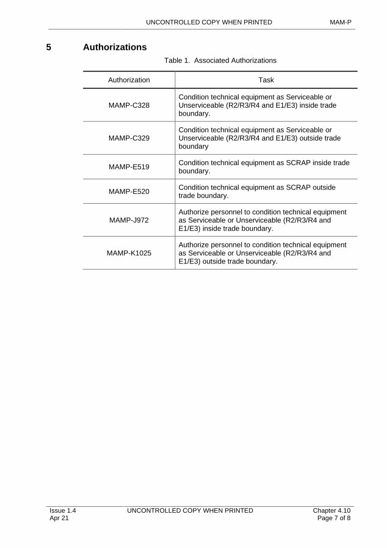
UNCONTROLLED COPY WHEN PRINTED MAM-P
Issue 1.4 Apr 21
UNCONTROLLED COPY WHEN PRINTED Chapter 4.10 Page 7 of 8
5 Authorizations
Table 1. Associated Authorizations
Authorization Task
MAMP-C328Condition technical equipment as Serviceable or Unserviceable (R2/R3/R4 and E1/E3) inside trade boundary.
MAMP-C329Condition technical equipment as Serviceable or Unserviceable (R2/R3/R4 and E1/E3) outside trade boundary
MAMP-E519Condition technical equipment as SCRAP inside trade boundary.
MAMP-E520Condition technical equipment as SCRAP outside trade boundary.
MAMP-J972Authorize personnel to condition technical equipment as Serviceable or Unserviceable (R2/R3/R4 and E1/E3) inside trade boundary.
MAMP-K1025Authorize personnel to condition technical equipment as Serviceable or Unserviceable (R2/R3/R4 and E1/E3) outside trade boundary.

MAM-P UNCONTROLLED COPY WHEN PRINTED
Intentionally Blank for Print Pagination
Chapter 4.10 Page 8 of 8
UNCONTROLLED COPY WHEN PRINTED Issue 1.4 Apr 21
UNCONTROLLED COPY WHEN PRINTED MAM-P
..............................................................................
...............................................................................................
Issue 2.1 Aug 21
.................................................................................................................
.............................................................................................
UNCONTROLLED COPY WHEN PRINTED Chapter 4.11 Page 1 of 5
.........................................................................................................................
.........................................................................................................................................
............................................................................................
.....................................
Chapter 4.11
Cannibalization of Parts from Air Systems and Uninstalled Air System Equipment
.......................................................................................
.......................................................................................................................
TABLE OF CONTENTS
................................
Paragraph
......................................................................................................................................
.............................................................................................................................
Page
................................1 General ........................................................................................................... 1 1.1 Introduction 1 1.2 Associated Publications and Instructions 1 1.3 Applicability 2 2 Control of Cannibalization 2 2.1 General 2 2.2 Criteria to be Met Before Cannibalization 2 2.3 Authorization of Cannibalization 2 3 Procedural Responsibilities During Cannibalization 3 3.1 Individual Authorizing Cannibalization 3 3.2 Individual Supervising Removal 3 3.3 Individual Supervising Installation 4 4 Use of an Electronic Information System (IS) to Manage Cannibalization
4 5 Responsibilities 5 5.1 Command 5 5.2 Military Continuing Airworthiness Management Organization (CAMO) 5 6 Authorizations 5
LIST OF TABLES
Table 1. Associated Authorizations 5
1 General
1.1 Introduction
Cannibalization is the removal of Serviceable parts from an Air System or uninstalled Air System equipment in order to make other Air Systems Serviceable. Cannibalization may be necessary if Stations (Stns)/Ships/Units are to meet specific tasking. In addition, it may be necessary to cannibalize an item to ensure that an Air System meets its scheduled rollout date following Maintenance/Modification.
1.2 Associated Publications and Instructions
1 RA 4809 – Acceptance of Components (MRP 145.A.42)
2 RA 4812(4) – Certification of Component Release and Cannibalization (MRP 145.A.50(d))
3 RA 4963 – Modification and Repairs – MRP Part M Sub Part C
4 JSP 440 – The Defence Manual of Security, Resilience and Business Continuity
5 JSP 490 – Defence Cryptosecurity Operating Instructions
6 JAP 100V-21 – Aircraft Storage
7 Topic 2(N/A/R)1 – General Orders and Special Instructions
MAM-P UNCONTROLLED COPY WHEN PRINTED
Chapter 4.11 Page 2 of 5
UNCONTROLLED COPY WHEN PRINTED Issue 2.1 Aug 21
8 MOD Form 746D – Aircraft/Equipment Cannibalization Certificate
1.3 Applicability
This Chapter is not applicable to Role Equipment transfer from one Air System to another, which is not classified as Cannibalization under the terms of this Chapter.
2 Control of Cannibalization
2.1 General
Cannibalization is to be controlled to ensure that it does not result in:
1 Individual Air Systems being excessively stripped.
2 The true supply situation being hidden, with possible adverse effects on the future provisioning of cannibalized parts.
3 The unnecessary introduction of Faults during the removal and refitting of components and line replaceable units.
2.2 Criteria to be Met Before Cannibalization
Cannibalization may be necessary when all of the following circumstances apply:
1 The part is required urgently to restore an Air System to serviceability.
2 A demand of the appropriate priority has been requested.
3 All supply solutions have been checked for possible sources of uninstalled spares on the Stn/Ship/Unit. All possible supply solutions utilising Integrated Logistic Operating Centres (ILOC) for any available off-Stn/Ship/Unit spares have been checked and the delivery forecast (or, for a bay-maintained part, the bay output forecast), is such that the part will not be available within the required timescale.
4 Repair or local purchase (if appropriate) of the part would not be achievable within the necessary timescale.
5 When local manufacture, in accordance with RA 4809 and Chapter 4.12 – Local Manufacture of Parts for Air Systems and Airborne Equipment, has been considered and ruled out.
6 A request to the appropriate Delivery Team (DT) for an extension or concession has been rejected, if applicable.
Where possible, if the part is to be transferred between lifed assemblies, including engines, the residual life on the part fitted is to be at least equal to that of the part being removed. In cases where there is insufficient life remaining, full details of the part concerned and the time at which it is due for replacement is to be entered in the appropriate Engineering Record Card (ERC) and any control authority notified; unless otherwise stated in the Air System Technical Information (TI).
2.3 Authorization of Cannibalization
Unless local orders place additional restrictions on Cannibalization, it is to be authorized as follows:
1 Cannibalization internally within a Maintenance organization (eg a Squadron or workshop) is to be authorized by personnel holding MAMP–F602, as authorized by the relevant individual holding MAMP-J953.
2 Cannibalization within a Stn/Ship is to be authorized by personnel holding MAMP-J974.
UNCONTROLLED COPY WHEN PRINTED MAM-P
Issue 2.1 Aug 21
UNCONTROLLED COPY WHEN PRINTED Chapter 4.11 Page 3 of 5
3 Cannibalization between Forward and Depth organizations is to be coordinated and controlled through the relevant Mil CAMO and authorized by the Fleet Manager or equivalent.
4 Cannibalization between organizations at different Stns/Ships/Units is to be coordinated and controlled by the relevant donor Command, ILOC or by the relevant Mil CAMO on behalf of the Command.
5 Cannibalization between Stns/Ships/Units and the Sustainment fleet is to be authorized by a level K, holding MAMP-K1014 on behalf of the Type Airworthiness Authority (TAA).
Note:
1 Cannibalization of Cat 3 or Cat 4 Air Systems undergoing repair requires prior approval from the Mil CAMO, as referenced in RA 4963.
2 Cannibalization of Cat 5 Air Systems is only to be carried out with the authority of the appropriate TAA.
3 Procedural Responsibilities During Cannibalization
3.1 Individual Authorizing Cannibalization
The individual authorizing Cannibalization is to:
1 Ensure the requirement to cannibalize meets the criteria at Paragraph 2.2.
2 Inform the Cannibalization task supervisor of the nominated Air System or equipment from which the part is to be cannibalized and issue the unique MOD Form 746D serial number, or:
3 Ensure that the donor Unit has raised the MOD Form 746D and completed both Parts A and B, as appropriate.
4 Ensure any Maintenance documentation/electronic Information System (IS) entries such as Acceptable Deferred Faults, Limitations or Concessions are transferred with the cannibalized part.
3.2 Individual Supervising Removal
►The individual supervising the removal of the part from the donor Air System or equipment is to:
1 Ensure Part A of the MOD Form 746D (Aircraft/equipment Cannibalization Certificate) has been completed.
2 Complete and distribute as detailed on the MOD Form 746D Part B.
3 Ensure there are no outstanding Maintenance documentation/electronic IS entries (such as Acceptable Deferred Faults, Limitations or Concessions) for the part being cannibalized.
4 Ensure a part is not to be cannibalized from a high-level assembly, for example engine or gearbox, that is subject to an ongoing Narrative Fault Reporting in accordance with (iaw) Chapter 9.2 – Narrative Fault Reporting Using the MOD Form 760 series.
5 Ensure that any component/part that holds/stores sensitive data, (including cryptographic material (CRYPTO)) is handled/transferred iaw JSP 440, JSP 490 and any local security/CRYPTO orders.
6 Ensure the removal is recorded on the appropriate Maintenance documentation/electronic IS for the donor Air System or equipment, together with details of the demand number of the replacement part.
MAM-P UNCONTROLLED COPY WHEN PRINTED
Chapter 4.11 Page 4 of 5
UNCONTROLLED COPY WHEN PRINTED Issue 2.1 Aug 21
7 Ensure that if the part is for another Unit, a Certificate of Component Release is issued in the form of a MOD Form 731 (Equipment Conditioning Label), iaw RA 4812(4). The Certificate of Component Release is annotated in one of the following ways:
7.1 If the receiving unit is confirming that the part is ‘fit for use’ before installation, the remarks field on the ‘Serviceable’ side of the MOD Form 731 is to be annotated with the words:
‘The part was Serviceable prior to removal from the donor Air System or equipment. Any conditioning required prior to installation is the responsibility of the receiving Unit.’
7.2 If the part has been removed from an Air System that is in storage (Immediate Readiness Reserve and either Short, Medium or Long-Term Reserve, as defined in JAP 100V-21), its serviceability will be in doubt. In this case, the remarks field on the ‘Serviceable’ side of the MOD Form 731 is to be annotated with the words:
‘This part has been removed from a stored Air System and serviceability cannot be guaranteed. Part to be conditioned at receiving unit.’
7.3 If the donor unit has carried out serviceability checks or tests on behalf of the receiving unit, the ‘Serviceable’ side of the MOD Form 731 is to be completed without a caveat.
8 Ensure that if the part is for another Unit, the removed part is transferred to the receiving Unit through the appropriate supply system.
9 Ensure that all orifices or plugs and sockets exposed by the removal of the part are blanked off and all necessary measures taken to prevent deterioration and system contamination. ◄
3.3 Individual Supervising Installation
The individual supervising the installation of the cannibalized part is to ensure that:
1 The part is of the correct Modification state, including software state, for the receiving Air System or equipment.
2 Before installation, the part is certified Serviceable, having been examined and tested, as appropriate.
3 The demand state or priority for the receiving Air System or equipment is updated.
4 Maintenance records (documentation/electronic IS) received with the donor part, containing information such as Acceptable Deferred Faults, Limitations or Concessions, are to be correctly recorded in the receiving organisation's documentation/electronic IS.
4 Use of an Electronic Information System (IS) to Manage Cannibalization
Cannibalization involves a number of organizations and is one of many inter-related logistic processes that can be more effectively managed using an electronic IS. Therefore, rather than manage Cannibalization using the hard copy MOD Form 746D, it is permissible for Stns/Ships/Units and Mil CAMOs to use an electronic IS based Cannibalization management system, provided that, as a minimum, the electronic IS:
1 Ensures that Cannibalization is controlled and managed in accordance with this Chapter.
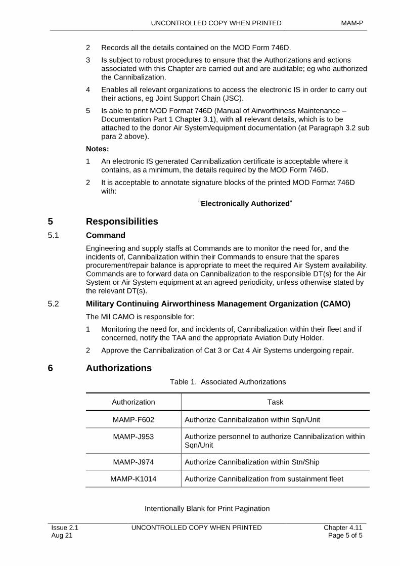
UNCONTROLLED COPY WHEN PRINTED MAM-P
Issue 2.1 Aug 21
UNCONTROLLED COPY WHEN PRINTED Chapter 4.11 Page 5 of 5
2 Records all the details contained on the MOD Form 746D.
3 Is subject to robust procedures to ensure that the Authorizations and actions associated with this Chapter are carried out and are auditable; eg who authorized the Cannibalization.
4 Enables all relevant organizations to access the electronic IS in order to carry out their actions, eg Joint Support Chain (JSC).
5 Is able to print MOD Format 746D (Manual of Airworthiness Maintenance – Documentation Part 1 Chapter 3.1), with all relevant details, which is to be attached to the donor Air System/equipment documentation (at Paragraph 3.2 sub para 2 above).
Notes:
1 An electronic IS generated Cannibalization certificate is acceptable where it contains, as a minimum, the details required by the MOD Form 746D.
2 It is acceptable to annotate signature blocks of the printed MOD Format 746D with:
“Electronically Authorized”
5 Responsibilities
5.1 Command
Engineering and supply staffs at Commands are to monitor the need for, and the incidents of, Cannibalization within their Commands to ensure that the spares procurement/repair balance is appropriate to meet the required Air System availability. Commands are to forward data on Cannibalization to the responsible DT(s) for the Air System or Air System equipment at an agreed periodicity, unless otherwise stated by the relevant DT(s).
5.2 Military Continuing Airworthiness Management Organization (CAMO)
The Mil CAMO is responsible for:
1 Monitoring the need for, and incidents of, Cannibalization within their fleet and if concerned, notify the TAA and the appropriate Aviation Duty Holder.
2 Approve the Cannibalization of Cat 3 or Cat 4 Air Systems undergoing repair.
6 Authorizations
Table 1. Associated Authorizations
Authorization Task
MAMP-F602 Authorize Cannibalization within Sqn/Unit
MAMP-J953 Authorize personnel to authorize Cannibalization within Sqn/Unit
MAMP-J974 Authorize Cannibalization within Stn/Ship
MAMP-K1014 Authorize Cannibalization from sustainment fleet
Intentionally Blank for Print Pagination
UNCONTROLLED COPY WHEN PRINTED MAM-P
Issue 1.1 Feb 20
UNCONTROLLED COPY WHEN PRINTED Chapter 4.12 Page 1 of 7
....................................................................................................................
..................................................................................................................................................................
...............................................................................................................................................................................................
............................................................................................................................................................................................................
........................................................................................................
..............................................................................................................................
.............................................................................................................................................................................................................
..............................................................................................................................................................
.......................................................................................................................................................
.......................................................................................................
Chapter 4.12
Local Manufacture of Parts for Air Systems and Airborne Equipment
TABLE OF CONTENTS
Paragraph Page
1 General 11.1 Introduction 11.2 Associated Publications and Instructions 11.3 Applicability 22 Authority to Locally Manufacture 22.1 Normal Manufacture 22.2 Special Manufacture 23 Local Manufacturing Requirements Paragraphs 33.1 Normal Manufacture 33.2 Special Manufacture – Additional Requirements 33.3 Concessions 44 Marking, Recording and Labelling of Locally Manufactured Parts 44.1 Marking 44.2 Recording 54.3 Labelling 65 Responsibilities 65.1 Authorizing Authority Level K 66 Authorizations 7
LIST OF TABLES
Table 1. DECA, 71(IR) Sqn and 1710 NAS Code Letters. 5Table 2. Associated Authorizations 7
1 General
1.1 Introduction
The Local Manufacture (LM) of parts for Air Systems and Airborne Equipment by Stn/Ship/Unit is permitted within the detailed terms of this chapter. Such work is classified as either 'normal' or 'special' manufacture. This chapter defines the circumstances under which the LM of parts for Air Systems or Airborne Equipment may be permitted.
1.2 Associated Publications and Instructions
1 RA 4809 – Acceptance of Components (MRP 145.A.42)
2 RA 4964 – Continuing Airworthiness Management Records – MRP Part M Sub Part C
3 RA 4965 – Local Manufacture Assurance - MRP Part M Sub Part C
4 RA 5850 – Military Design Approved Organization (MRP 21 Subpart J)
5 Illustrated parts Catalogue (such as Topic 3A), where the annotation ‘LM’ (local manufacture), ‘ECC’ (Electrical Cable Chart) or ‘PC’ (Pipe Chart) indicates that
MAM-P UNCONTROLLED COPY WHEN PRINTED
Chapter 4.12 Page 2 of 7
UNCONTROLLED COPY WHEN PRINTED Issue 1.1 Feb 20
the part is not provisioned but is to be manufactured locally from the material specified.
6 Modification Leaflets and Special Instructions (Technical) (SI(T)s), where precise instructions, including drawings, are provided to facilitate the LM of parts.
7 Air System Repair Manual (such as Topic 6), which contains specific instructions on the extent and pattern of Authorized Repairs and the techniques to be used.
8 DAP 101A-0300-1 – Aircraft Rigid Pipelines
9 DAP 101A-0301-1 – Aircraft Flexible Hoses with Re-usable End Fittings
10 DAP 119G-0002-1 – Heat Treatment of Aluminium Alloys, General and Technical Information
11 DAP 119G-0008-1 – Welding in the Defence Aviation Environment, General and Technical Information
12 Repair scheme drawings supplied by an approved Design Organization (DO), 71 (Inspection and Repair) Squadron (71(IR)Sqn), 1710 Naval Air Squadron (1710 NAS) or Type Airworthiness Authorities (TAA) that authorize LM.
13 AP(D) 100E-15 – Military Aviation Workshop Support Management and Policy
14 AP 119A-0301-1 – Metals and Alloys
15 Def Stan 05-69 – Standard Colour Scheme of Metallic Materials for Aerospace Applications
1.3 Applicability
This chapter is applicable to the manufacture of any item that has a discrete part number and applies to the manufacture of parts for Air Systems and Airborne Equipment that are authorized in accordance with (iaw) Paragraph 2.
2 Authority to Locally Manufacture
2.1 Normal Manufacture
Stn/Ship/Unit are authorized to LM parts for Air Systems and Airborne Equipment iaw those formal instructions contained in the relevant Technical Information (TI). Work undertaken under these provisions is regarded as normal manufacture.
2.2 Special Manufacture
The LM of parts for Air Systems and Airborne Equipment outside the provisions of Paragraph 2.1 is regarded as 'special' manufacture and is not permitted without having first determined availability of the required part through either normal supply channels and/or by approaching the Delivery Team (DT) responsible for the Air System or equipment. Having determined that the required part cannot be provided through normal supply channels to meet the demand priority, the decision to locally manufacture a part for an Air System or Airborne Equipment rests with the individual holding Authorization MAMP-K1008. Before authorizing any 'special' manufacture at a Depth Maintenance organization, the individual holding Authorization MAMP-K1008 is to gain Approval from the relevant DT. When assessing the requirement for 'special' manufacture, consideration is to be given to the following:
1 Whether the part is necessary to satisfy operational, engineering, supply or economic requirements.
2 Whether the part can be obtained or manufactured through local purchase arrangements.
UNCONTROLLED COPY WHEN PRINTED MAM-P
Issue 1.1 Feb 20
UNCONTROLLED COPY WHEN PRINTED Chapter 4.12 Page 3 of 7
3 The structure or functional importance of the part and the consequence of failure.
4 Whether inter-changeability will be affected in terms of the fit, form or function.
5 The availability of drawings, material specifications, tools, materials and specialist process requirements, and the capabilities and skill levels of the available Tradesmen.
6 Whether 'special' manufacture represents the best solution to meet the requirement.
3 Local Manufacturing Requirements Paragraphs
3.1 Normal Manufacture
The LM of parts for Air Systems and Airborne Equipment is not to be undertaken unless the requirements detailed below are satisfied at the point of manufacture, or the concessions at Paragraph 3.3 are applied. When authorized, the following requirements apply to normal manufacture:
1 Except for the concessions detailed at Paragraph 3.3, parts are to be manufactured iaw the relevant TI.
2 Proof of conformity to specification is to be available for all materials used. For metallic and some non-metallic materials this is usually provided by an Approved Certificate of Conformity which is delivered directly from the Contractor. Metallic materials may also be identified with overall/line marking or colour coding as detailed in Def Stan 05-69 – Standard Colour Scheme of Metallic Materials for Aerospace Applications. The same regulations also apply to foreign sourced materials where the appropriate DT is to obtain the necessary manufacturer’s release certificate.
3 Any locally manufactured/fabricated part is to be subjected to an inspection stage before, and preferably independently from, any inspection of its installation. The inspection is to establish full compliance with the relevant approved data, and the part is to be unambiguously identified as fit for use by stating conformity to the TI.
4 To preserve the traceability of materials after receipt in the manufacturing area, each Station/Ship/Unit locally manufacturing parts are to operate a controlled material storage system and record the issue of material by identity and quantity against specific tasks or Air System references. A system for maintaining the identity of materials through all stages of LM is also to be in operation.
5 Test pieces are to be used for the proving of heat treatment processes, with samples submitted to 1710 NAS or 71(IR) Sqn for laboratory testing iaw AP 119G-0002-1 - Heat Treatment of Aluminium Alloys, General and Technical Information.
3.2 Special Manufacture – Additional Requirements
In addition to the requirements for the LM of parts for Air Systems and Airborne Equipment, the following requirements apply to special manufacture:
1 The individual holding Authorization MAMP-K1008 is to determine the level and extent of quality control checks during and following completion of the manufacturing task.
2 Once a special manufactured part is fitted to an Air System, the Military Continuing Airworthiness Manager (Mil CAM), in consultation with the individual holding Authorization MAMP-K1008 is to decide if it is to remain fitted or is to be replaced when a part becomes available through normal supply channels. Any
MAM-P UNCONTROLLED COPY WHEN PRINTED
Chapter 4.12 Page 4 of 7
UNCONTROLLED COPY WHEN PRINTED Issue 1.1 Feb 20
special manufactured part fitted to an Air System is subject to an Acceptable Deferred Fault (MOD F704) entry.
3 An undocumented metal, for which the DT has been unable to obtain any form of release certificate, can only be used subject to a sample being tested and its material specification correctly determined. The test house is to issue a certificate detailing the material specification and condition and a batch number to uniquely identify the material. This batch number is to be marked on the metal before it can be authorized for use by the individual holding Authorization MAMP-K1008.
3.3 Concessions
3.3.1 Approval by the Type Airworthiness Authority (TAA)
Any concessions to LM requirements at Paragraphs 3.1 and 3.2 are to be approved, in writing, by the TAA with advice from the DO, if appropriate, unless the provisions at Paragraph 3.3.2 apply.
On occasions when the DO is operating with an invoked privilege from the TAA or Commodity Delivery Team Leader (DTL) and is approached for advice on a proposed LM concession, either through a resident Contractor’s representative or other contractual agreement, correspondence is to be copied to the TAA or Commodity DTL and the Mil CAMO.
3.3.2 Approval by the Authorizing Authority Level K
Where there is an operational need, an individual holding Authorization MAMP-K1008 may approve concessions to the LM requirements at Paragraph 3.1. This includes occasions when it may be necessary to use the original, or an identical part, as a manufacturing pattern due to the approved instructions and/or drawings not being available, or the time required to obtain such instructions and/or drawings being unacceptable. When approved, LM of the part is to be treated as special manufacture and is to be conducted iaw Paragraph 3.2 and the remaining applicable local manufacturing requirements at Paragraph 3.1, together with the following additional requirements:
1 The individual holding Authorization MAMP-K1008 is to personally certify the work recording document to signify Approval of the concession. This may include occasions when there is a period of time awaiting the results of off-unit material proving tests.
2 Details of any authorized concessions are to be forwarded to the TAA and Mil CAMO at the earliest opportunity.
3 An Acceptable Deferred Fault (MOD Form 704) entry, unless a concession has been approved by the TAA (see Paragraph 3.3.1).
4 Marking, Recording and Labelling of Locally Manufactured Parts
4.1 Marking
4.1.1 General Requirements
Where space and design constraints permit, LM parts are to be marked to show a traceability reference, together with the relevant drawing or part number. For Station/Ship/Unit, the traceability reference comprises 2 elements:
1 The first element identifies the local manufacturing unit by using the appropriate Unit/Location Code, as detailed in Chapter 0.5 – Commonly Used Information.
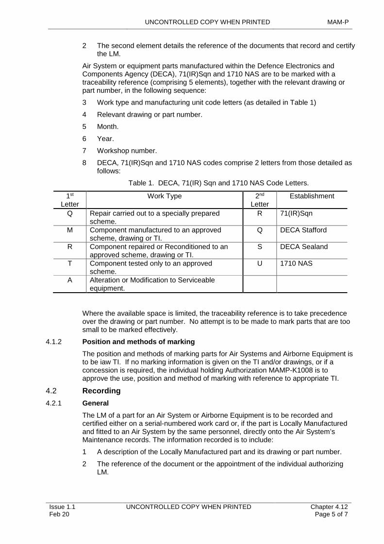
UNCONTROLLED COPY WHEN PRINTED MAM-P
Issue 1.1 Feb 20
UNCONTROLLED COPY WHEN PRINTED Chapter 4.12 Page 5 of 7
2 The second element details the reference of the documents that record and certify the LM.
Air System or equipment parts manufactured within the Defence Electronics and Components Agency (DECA), 71(IR)Sqn and 1710 NAS are to be marked with a traceability reference (comprising 5 elements), together with the relevant drawing or part number, in the following sequence:
3 Work type and manufacturing unit code letters (as detailed in Table 1)
4 Relevant drawing or part number.
5 Month.
6 Year.
7 Workshop number.
8 DECA, 71(IR)Sqn and 1710 NAS codes comprise 2 letters from those detailed as follows:
Table 1. DECA, 71(IR) Sqn and 1710 NAS Code Letters.
1st
LetterWork Type 2nd
LetterEstablishment
Q Repair carried out to a specially prepared scheme.
R 71(IR)Sqn
M Component manufactured to an approved scheme, drawing or TI.
Q DECA Stafford
R Component repaired or Reconditioned to an approved scheme, drawing or TI.
S DECA Sealand
T Component tested only to an approved scheme.
U 1710 NAS
A Alteration or Modification to Serviceable equipment.
Where the available space is limited, the traceability reference is to take precedence over the drawing or part number. No attempt is to be made to mark parts that are too small to be marked effectively.
4.1.2 Position and methods of marking
The position and methods of marking parts for Air Systems and Airborne Equipment is to be iaw TI. If no marking information is given on the TI and/or drawings, or if a concession is required, the individual holding Authorization MAMP-K1008 is to approve the use, position and method of marking with reference to appropriate TI.
4.2 Recording
4.2.1 General
The LM of a part for an Air System or Airborne Equipment is to be recorded and certified either on a serial-numbered work card or, if the part is Locally Manufactured and fitted to an Air System by the same personnel, directly onto the Air System’s Maintenance records. The information recorded is to include:
1 A description of the Locally Manufactured part and its drawing or part number.
2 The reference of the document or the appointment of the individual authorizing LM.
MAM-P UNCONTROLLED COPY WHEN PRINTED
Chapter 4.12 Page 6 of 7
UNCONTROLLED COPY WHEN PRINTED Issue 1.1 Feb 20
3 Certification of the satisfaction of any particular inspection and LM requirements that may be applicable.
Where appropriate, an entry is to also be made in the Air System, component or equipment record/log card, or equivalent electronic data record, indicating LM.
4.2.2 Mil CAMO records
In accordance with RA 4964 and RA 4965, to ensure traceability and the retention of Airworthiness related documentation the Mil CAMO is to maintain a centralized record of all parts Locally Manufactured to enable coherent reporting action to the relevant TAA. The Mil CAMO is to ensure that the following information relating to both normal and special manufacture of parts is recorded, either by retention of Air System Maintenance records or in any other convenient format:
1 The date of LM and, if known, when fitted to the Air System and Airborne Equipment.
2 A description of the part and its drawing and/or part number.
3 The serial number of the work card or Maintenance document that recorded and certified LM.
4 Details of any heat treatment processes during LM, including copies of proof testing records.
5 The specification reference, batch details and Certificate of Conformity reference for each item of material used in LM.
6 The serial number of the Air System or Airborne Equipment, if known, to which the part was fitted.
The recording requirements of Items 1, 2, 3 and 6 above are to be satisfied for any parts received after LM at another Station/Ship/Unit. However, if the parts received are batch-produced Class C parts, Item 6 above does not apply.
4.3 Labelling
Except when LM parts are made or prepared for immediate fitting by the same personnel, an appropriately completed Certification of Component Release (MOD F731, or equivalent) is to be attached to every part before release for fitting. If 2 or more identical small parts have been made from one batch of stock material by the same processes, all such parts may be attached to, and included on, a single Certification of Component Release. The information recorded is to include the drawing or part number and the reference of the document that recorded and certified LM, regardless of whether that information is marked on the part.
5 Responsibilities
5.1 Authorizing Authority Level K
The individual holding MAMP-K1008 who is authorizing LM is responsible for:
1 Ensuring that Intellectual Property Rights (IPR) are not infringed.
2 Authorizing the LM of an Air System or Airborne Equipment part iaw the guidance given at Paragraph 2.
3 Seeking any necessary concessions to local manufacturing requirements from the TAA or, in operational circumstances, personally authorizing a concession and advising the TAA and Mil CAMO at the earliest opportunity.
UNCONTROLLED COPY WHEN PRINTED MAM-P
Issue 1.1 Feb 20
UNCONTROLLED COPY WHEN PRINTED Chapter 4.12 Page 7 of 7
4 Determining the level and extent of quality control checks during and following completion of the LM task.
5 In consultation with the Mil CAMO, identifying whether a Locally Manufactured part may remain fitted to an Air System, or whether it is to be replaced when a part becomes available through normal supply channels.
6 Ensure that a record of all parts locally manufactured by their Maintenance organizations is provided to the Mil CAMO iaw Paragraph 4.2.2.
6 Authorizations
Table 2. Associated Authorizations
Authorization Task
MAMP-K1008Approve local manufacture (LM) of parts for Air System and Airborne Equipment.
UNCONTROLLED COPY WHEN PRINTED
Chapter 4.13
Management of Hand Tools and Test and Measuring Equipment
TABLE OF CONTENTS
Paragraph Page
1 General 1 1.1 Introduction 1 1.2 Associated Publications and Instructions 1 1.3 Additional Information 2 2 Control Principles 2 2.1 General 2 2.2 Availability and Use of Tools 2 2.3 Marking of Tools. 3 2.4 Storage of Hand Tools 4 2.5 Tool Checks 5
Issue 1.1 UNCONTROLLED COPY WHEN PRINTED Chapter 4.13Feb 20 Page 1 of 10
.......................................................................................................................................................................................................
.....................................................................................................................................
............................................................................................................................................................................................
................................................................................................................................................................
................................................................................................................................................................................
..................................................................................................................................................................
................................
..............................................................................................................
...................................................................................................................................................................
.................................................................................................................
..........................................................................................................................
.................................................................................................
......................................................................................................................................................................................
..........................................................................................................................................................................................
.........................................................................................................................................................
2.6 Consumable Tools 5 3 Hand Tool Provisioning 5 3.1 Organizations Responsible for Hand Tool Provisioning 5 3.2 Type Airworthiness Authority (TAA) and Commodity Delivery Team (DT) 6 3.3 OIP– Military Equipment Tools Solutions (METS) 6 4 METS Controlled Tool Kits 6 4.1 Repair of Tool Kits 6 4.2 Replacement Hand Tools 6 4.3 Alterations and Modifications to Tool Kits 6 4.4 Application for Additional Tool Kits 6 4.5 Return of Surplus Tool Kits 7 4.6 Service-designed and Manufactured Tools 7 5 Reporting of OIP - Managed Faulty/Defective Hand Tools 7 6 Contractor Tool Control 7 7 Responsibilities 7 7.1 Squadron/Unit 7 7.2 Stn/Ship/Unit 8 8 Authorizations 9
LIST OF TABLES
Table 1. Examples of Tool Codes. 3 Table 2. Associated Authorizations 9
1 General
1.1 Introduction
The control and management of hand tools is essential to Flight Safety and the Maintenance of Airworthiness and is good engineering practice. This chapter details the general principles for the management of hand tools, in order to reduce the risk of a hand tool being misplaced and becoming a loose article hazard.
1.2 Associated Publications and Instructions
1 RA 4808 – Equipment, Tools and Material (MRP 145.A.40)
MAM-P UNCONTROLLED COPY WHEN PRINTED
Chapter 4.13 Page 2 of 10
UNCONTROLLED COPY WHEN PRINTED Issue 1.1 Feb 20
2 RA 4809 – Acceptance of Components (MRP 145.A.42)
3 Manual of Airworthiness Maintenance-Documentation (MAM-D)
4 JAP 100E-10 - Military Airfield Support Equipment Management & Policy
5 DAP 119G-0919-3A – Aircraft and Workshop Tool Outfits Schedule of Spares and Containers
6 Defence Logistics Framework
7 The Management of Test and Measurement Equipment Handbook
1.3 Additional Information
For the purposes of this chapter, the term ‘hand tools’ includes both general purpose and special-to-type tooling, and those items of Test and Measurement Equipment (TME) that could be misplaced and become a loose article hazard. Further information on TME policy is documented within Supportability Engineering Policy for Support and Test Equipment, and is promulgated by the Support Directorate within DE&S. This identifies the Defence Logistics Framework (DLF) and the DES LE OI Test and Measurement Equipment Handbook as sources of further information.
2 Control Principles
2.1 General
The tool control measures required in engineering organisations may vary depending on the particular Flight Safety risk associated with them. Within engineering organisations undertaking Maintenance on equipment that cannot be fitted to an Air System, tool control measures may be relaxed at the discretion of the relevant individual holding authority level K. Where the general principles are to be relaxed the relevant individual holding authority level K is to determine the tool control procedures to be applied.
To ensure the necessary degree of overall control, the relevant individual holding authority level K is to nominate an individual to act as Tool Controller for their Stn/Ship/Unit. Responsibilities of the Stn/Ship/Unit Tool Controller are detailed at Paragraph 7.2.2. Normally tools are stored in secure areas, known as Issue Centres, and tool issue and return are to be strictly controlled. The responsibilities of the Issue Centre custodian and Issue Centre staff are detailed at Paragraph 7.1.2 and Paragraph 7.1.3 respectively.
Note:
Where tooling arrives with Air System spares and/or modification kits, care is to be taken to ensure that appropriate tool control procedures are adopted in regard to their issue and management.
2.2 Availability and Use of Tools
The Stn/Ship/Unit is to have available and use the necessary equipment and tools to perform its intended scope of work.
2.2.1 Modified Tools
Hand tools are not to be modified unless authorized by the relevant Air System Type Airworthiness Authority (TAA).
2.2.2 Locally Manufactured Tools
All locally manufactured tools to be used on Air Systems or Air System components are to have the design specifications authorized by the relevant Air System TAA before the tool is manufactured.
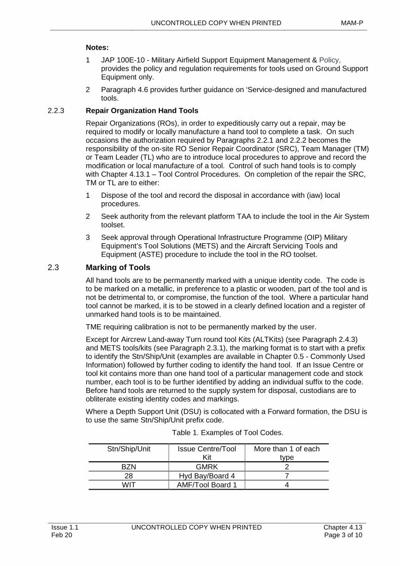
UNCONTROLLED COPY WHEN PRINTED MAM-P
Issue 1.1 Feb 20
UNCONTROLLED COPY WHEN PRINTED Chapter 4.13 Page 3 of 10
Notes:
1 JAP 100E-10 - Military Airfield Support Equipment Management & Policy, provides the policy and regulation requirements for tools used on Ground Support Equipment only.
2 Paragraph 4.6 provides further guidance on ‘Service-designed and manufactured tools.
2.2.3 Repair Organization Hand Tools
Repair Organizations (ROs), in order to expeditiously carry out a repair, may be required to modify or locally manufacture a hand tool to complete a task. On such occasions the authorization required by Paragraphs 2.2.1 and 2.2.2 becomes the responsibility of the on-site RO Senior Repair Coordinator (SRC), Team Manager (TM) or Team Leader (TL) who are to introduce local procedures to approve and record the modification or local manufacture of a tool. Control of such hand tools is to comply with Chapter 4.13.1 – Tool Control Procedures. On completion of the repair the SRC, TM or TL are to either:
1 Dispose of the tool and record the disposal in accordance with (iaw) local procedures.
2 Seek authority from the relevant platform TAA to include the tool in the Air System toolset.
3 Seek approval through Operational Infrastructure Programme (OIP) Military Equipment’s Tool Solutions (METS) and the Aircraft Servicing Tools and Equipment (ASTE) procedure to include the tool in the RO toolset.
2.3 Marking of Tools
All hand tools are to be permanently marked with a unique identity code. The code is to be marked on a metallic, in preference to a plastic or wooden, part of the tool and is not be detrimental to, or compromise, the function of the tool. Where a particular hand tool cannot be marked, it is to be stowed in a clearly defined location and a register of unmarked hand tools is to be maintained.
TME requiring calibration is not to be permanently marked by the user.
Except for Aircrew Land-away Turn round tool Kits (ALTKits) (see Paragraph 2.4.3) and METS tools/kits (see Paragraph 2.3.1), the marking format is to start with a prefix to identify the Stn/Ship/Unit (examples are available in Chapter 0.5 - Commonly Used Information) followed by further coding to identify the hand tool. If an Issue Centre or tool kit contains more than one hand tool of a particular management code and stock number, each tool is to be further identified by adding an individual suffix to the code. Before hand tools are returned to the supply system for disposal, custodians are to obliterate existing identity codes and markings.
Where a Depth Support Unit (DSU) is collocated with a Forward formation, the DSU is to use the same Stn/Ship/Unit prefix code.
Table 1. Examples of Tool Codes.
Stn/Ship/Unit Issue Centre/Tool Kit
More than 1 of each type
BZN GMRK 228 Hyd Bay/Board 4 7
WIT AMF/Tool Board 1 4
MAM-P UNCONTROLLED COPY WHEN PRINTED
Chapter 4.13 Page 4 of 10
UNCONTROLLED COPY WHEN PRINTED Issue 1.1 Feb 20
2.3.1 Code Allocation
As the centralized tool control agency, OIP METS will allocate prefix codes for Tri-Service hand tools and their containers produced by this facility. These codes, as detailed in Chapter 0.5 - Commonly Used Information, will be specified in conjunction with project user requirements. The codes are allocated from either Table 1 for station codes, Table 2 for Army Aviation codes or Table 3 for platform specific codes.
Generic pan-platform kits will be allocated prefix codes by METS, an example of which is shown – GMRK – General Metal Repair Kit.
These prefix codes are detailed in the DAP119G-0919-3A.
Once a code has been allocated, OIP METS will control the configuration of the container and its contents in conjunction with DAP119G-0919-3A. To comply with Airworthiness traceability requirements, the allocation of the container and its contents will be entered within the database held by METS. METS will manage an annual census of all tool containers and its contents detailed in this database to ensure Airworthiness traceability.
It is the responsibility of a station tool controller to maintain a record of station holdings and the respective codes. Any permanent changes to tool container allocations are to be notified to METS to allow traceability to be maintained. A METS toolkit census is to be returned within 30 days of its receipt at a Stn/Ship/Unit.
It is prohibited for any prefix codes from Table 3 to be allocated by any user without the prior authority of the tool outfit Engineering Authority (DES LE OI-Wksp-Eng-Mgr2a). It is also prohibited to change the configuration of any tool container or its contents without following the amendment process detailed at Paragraph 4.3.
2.4 Storage of Hand Tools
2.4.1 General
Each hand tool is to have a unique storage location within an Issue Centre or tool kit. Where practicable, this location is to be highlighted, for example by a 'shadowed' or cut-out shape so that the absence of a hand tool is immediately apparent. Where hand tools are duplicated within an Issue Centre or tool kit, where practicable, each location concerned is to be clearly marked with the suffix code allocated iaw Paragraph 2.3.
2.4.2 Tool Kits
Hand tools may be stored in a container to form a tool kit. When tool kits are used, each kit is to have a contents list or complete equipment schedule clearly detailing each hand tool in the kit and a list of approved removals. These lists are to be held centrally within the Issue Centre. Additionally, a suitable system is to be in place to identify any unapproved removals during tool checks at the point of use, and where it is not practicable to provide an identified location for each hand tool, a copy of the contents list is also to be included in the tool kit. These lists are to be adequately secured to prevent inadvertent loss when the container is in use. The deficiency list is to identify the reason for the removal of the hand tool using a MOD Form 757TC6.
The container, complete with its contents, is to be marked, stored and controlled as though it was an individual hand tool.
2.4.3 Aircrew Land-away Turn Round Tool Kits (ALTKits)
On Air Systems where authority has been granted to carry an ALTKits in a standard location on the Air System, as detailed in the Air System TI, the hand tools are to be marked with the ALTKit serial number only. This number is to be derived from the Stn/Ship/Unit and Air System type and the number of kits held, eg 815/Wildcat/ALTKit
UNCONTROLLED COPY WHEN PRINTED MAM-P
Issue 1.1 Feb 20
UNCONTROLLED COPY WHEN PRINTED Chapter 4.13 Page 5 of 10
1. The hand tools are to be carried in a container restrained within the Air System, clearly marked with the serial number and locked or sealed by an appropriate tell-tale system. The ALTKit is to also contain contents and deficiency lists. The ALTKits is subject to inspections as detailed in the TI. Control and issue of an ALTKits is to be carried out iaw Chapter 4.13.1 – Tool Control Procedures.
2.4.4 Air System In-flight Maintenance Tool Kits
On Air Systems where it is permissible to carry out Maintenance tasks during flight and carriage of a tool kit is authorized by the relevant platform TAA, as detailed in the TI, the hand tools are to be carried on the Air System in a restrained, lockable container. The key to the tool kit is to be controlled within the Issue Centre and the content of the tool kit is subject to inspections as detailed in the TI. Procedures for the control and issue of Air System in-flight maintenance tool kits are to be determined by the relevant platform TAA and detailed in the TI. Where practicable the procedure is to follow that detailed in Chapter 4.13.1–Tool Control Procedures.
2.4.5 Remotely Located Hand Tools
When hand tools are held remotely from the Issue Centre, they are to be held in a suitable lockable container. When not in use the container is to be locked and the key secured, and its issue controlled. The container is to contain a MOD Form 757A(Tools) on which to record tool checks.
2.5 Tool Checks
Tool checks are to be carried out iaw Chapter 4.13.1. The relevant individual holding authority level K is to determine the requirement for any additional tool checks. If deemed necessary the authority level K is to detail the scope, frequency and recording of such checks. The Issue Centre custodian is to maintain a record of these additional tool checks.
2.6 Consumable Tools
There will be occasions when deployable units have to take with them large stocks of ready-use consumable tools, eg drill bits, hacksaw blades, reamers, etc. These consumable tools are to be strictly controlled by the deployed Issue Centre custodian or another nominated individual who is to ensure that:
1 All consumable tools are held in a secure container.
2 All worn or broken consumable tools are disposed of in an appropriate manner.
3 Replacement consumable tools are issued on a strictly one-for-one basis.
Note:
There may be occasions when the usage rate of consumable cutting tools during in-depth repair processes makes it impractical to control these tools in the normal manner. Under these circumstances, only ROs may replace the control of consumable cutting tools with stringent loose article checks. Such checks are be carried out iaw Chapter 4.14 – Loose Articles - Precautions and Recovery Procedures.
3 Hand Tool Provisioning
3.1 Organizations Responsible for Hand Tool Provisioning
3.1.1 Operational Infrastructure Programme (OIP)
OIP Military Equipment Tools Solutions (METS) Senior Technical Specialist Engineer is the Tri-Service Engineering Authority (EA) for tools and associated workshop equipment. OIP Supply provides inventory support for hand tools.
MAM-P UNCONTROLLED COPY WHEN PRINTED
Chapter 4.13 Page 6 of 10
UNCONTROLLED COPY WHEN PRINTED Issue 1.1 Feb 20
3.2 Type Airworthiness Authority (TAA) and Commodity Delivery Team (DT)
TAAs and commodity DT Engineering Authorities (EAs) are responsible for the through-life support of special-to-type hand tools. However, specialist technical assistance is available from OIP METS Senior Technical Specialist Engineer; see Paragraph 4.6.
3.3 OIP– Military Equipment Tools Solutions (METS)
The METS group:
1 Manages the design, manufacture and modification of in-use and new tool kits supplied by them to the Defence Air Environment (DAE).
2 Updates respective Technical Information.
3 Provides configuration control.
4 Ensures adherence to current tool control polices within the DAE.
Procedures for configuring METS controlled tool kits and for using METS tool control forms are detailed in Paragraph 4.
4 METS Controlled Tool Kits
4.1 Repair of Tool Kits
Stn/Ship/Unit are responsible for the repair of their own tool kits (including internal fittings) in all cases, except when:
1 Major structural repairs are required, and replacement would not be more expedient.
2 Repairs are impracticable in single Air System flights detached from the parent unit. In these cases, a new container is to be ordered from METS and the faulty container is to be returned to METS for repair.
4.2 Replacement Hand Tools
The replacement of hand tools and components within tool kits is to be strictly controlled iaw Stn/Ship/Unit instructions.
Replacement hand tools that have authorized scales are to be demanded through normal supply channels iaw process detailed in the DLF.
Tool kit component parts are only to be used to maintain kits at their original standard as issued by METS. They are not to be used to modify existing kits or to create additional kits or for any other purpose without the prior approval of METS.
4.3 Alterations and Modifications to Tool Kits
Tool kits supplied by METS are not to be altered or modified unless authorized by METS Senior Technical Specialist Engineer. Such authorization will be promulgated using a MOD Form 757TC4. Stn/Ship/Unit Tool Controllers are to implement these modifications within 2 months of receipt of tools. A MOD Form 757TC1 is to be raised by user units to advise METS of suggested alterations or modifications of tool kits. A MOD Form 757TC5 and Form 757TC6 is to be used to control the issue of a MOD Form 757TC4 and the embodiment of alterations or modifications to METS tool kits.
4.4 Application for Additional Tool Kits
Occasions arise when the task of a Stn/Ship/Unit is changed, and a requirement is generated for additional tool kits to meet the new commitment. Applications for such additional tool kits are to be forwarded, in duplicate, on MOD Form 757TC2, to METS.
UNCONTROLLED COPY WHEN PRINTED MAM-P
Issue 1.1 Feb 20
UNCONTROLLED COPY WHEN PRINTED Chapter 4.13 Page 7 of 10
Stn/Ship/Unit raising MOD Form 757TC2 are to allocate a local consecutive serial number and have the form authorized by the Stn/Ship/Unit Tool Controller.
METS is authorized to investigate and approve minor requirements. Any major requirement, ie one that may involve significant cost or a policy change, is to be referred to the appropriate Command or DT. If the major requirement is supported by the Command, or DT, the MOD Form 757TC2 is to be forwarded to DES LE OI-Wksp-Eng-Mgr2 for approval and tasking instructions.
Requests for tool kit replacement shells and panels are to be submitted to METS using MOD Form 757TC7.
4.5 Return of Surplus Tool Kits
Surplus tool kits are to be returned directly to METS.
4.6 Service-designed and Manufactured Tools
For reasons of economy, expediency and availability, non-standard tools that are not available through Service sources may be obtained from METS using the Aircraft Servicing Tools and Equipment (ASTE) procedures.
Details of the process for the introduction and amendment of ASTEs are held by METS and can be obtained from METS. Requests for additional ASTEs are to be submitted to METS on a MOD Format 757TC7 which is located in Part 2 of the MAM-D.
5 Reporting of OIP - Managed Faulty/Defective Hand Tools
OIP -managed tools that are faulty or defective are to be reported using the MOD Form 760 process detailed in Chapter 9.2 – Narrative Fault Reporting Using MOD Form 760 Series. Completed MOD Form 760s are to be sent to:
Operational Infrastructure – Safety
MOD Abbey Wood
Spruce 2a
Bristol
BS34 8JH
6 Contractor Tool Control
Civilian contractors or MOD Agencies employed on Service Air Systems, Air System-associated equipment or Ground Support Equipment (GSE) are required to control their hand tools. Contracting Authorities are to ensure that contracts specify that the civilian contractor or MOD Agency is responsible for devising and implementing tool control principles, procedures and quality audits to ensure that hand tools are not left in Air Systems, Air System-associated equipment or GSE on completion of maintenance work or before the Air System or equipment is operated. However, if the contractor’s employees or MOD Agency is located such that a different tool control system could conflict with that of a Service unit, the contract is to specify that the tool control principles and procedures detailed in this publication are to be employed.
7 Responsibilities
7.1 Squadron/Unit
7.1.1 Authority Level J
MAM-P UNCONTROLLED COPY WHEN PRINTED
Chapter 4.13 Page 8 of 10
UNCONTROLLED COPY WHEN PRINTED Issue 1.1 Feb 20
The relevant individual holding authority level J is responsible for ensuring that their Squadron/Unit adheres to the principles and procedures detailed in this publication and any additional orders issued by either the appropriate Command or their authority level K. Additionally, they may issue local orders to ensure effective management and control of hand tools.
7.1.2 Issue Centre Custodians
Each Issue Centre within a Squadron/Unit is to have an Issue Centre custodian. The individual is to hold authorization MAMP-C323. The Issue Centre custodian is responsible to their authority level J for:
1 The custody, safekeeping and condition of hand tools and their associated containers.
2 The upkeep of associated documentation.
3 Maintaining a register of unmarked hand tools.
4 Reporting lost tools to the Stn/Ship/Unit Tool Controller immediately, including the following information:
4.1 Description of the tool, including reference number and identity code.
4.2 Date the tool was lost.
4.3 Details of where the tool was lost, including the Air System serial number if the tool is suspected of being lost on an Air System.
4.4 Serial Number of Work relating to any Air System searches.
7.1.3 Issue Centre Staff
Issue Centre staff are responsible to the Issue Centre custodian for the day-to-day running of the Issue Centre. Their responsibilities include:
1 Issue and return of hand tools iaw Chapter 4.13.1.
2 Preventing unauthorized access to hand tools.
3 Undertaking the Maintenance of hand tools and tool kits and the associated documentation, as directed by the Issue Centre custodian.
4 Whenever a lost tool is reported, co-ordinating searches of the Issue Centre and tool kits, if appropriate, and quarantining the associated documentation as directed by the Squadron/Unit engineering management.
Note:
The responsibilities detailed at Paragraphs 7.1.2 and 7.1.3 may be combined.
7.2 Stn/Ship/Unit
7.2.1 Authority Level K
The relevant individual holding authority level K is responsible for:
1 The overall engineering management of tool resources on their Stn/Ship/Unit.
2 Issuing local orders that amplify the provisions of this chapter and/or provide for local requirements.
3 Determining the requirement for, and periodicity of, additional tool checks, as detailed in Paragraph 2.5.
4 Nominating an individual to undertake the duties of the Stn/Ship/Unit Tool Controller.
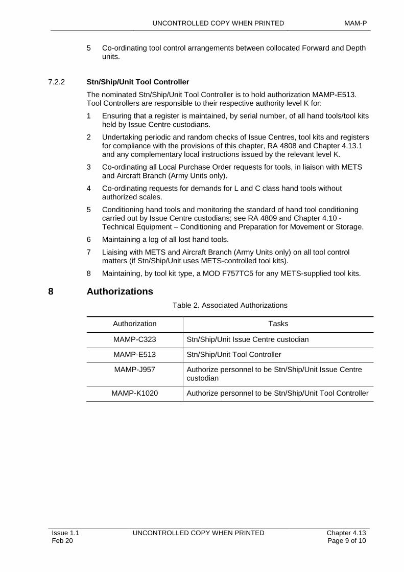
UNCONTROLLED COPY WHEN PRINTED MAM-P
Issue 1.1 Feb 20
UNCONTROLLED COPY WHEN PRINTED Chapter 4.13 Page 9 of 10
5 Co-ordinating tool control arrangements between collocated Forward and Depth units.
7.2.2 Stn/Ship/Unit Tool Controller
The nominated Stn/Ship/Unit Tool Controller is to hold authorization MAMP-E513. Tool Controllers are responsible to their respective authority level K for:
1 Ensuring that a register is maintained, by serial number, of all hand tools/tool kits held by Issue Centre custodians.
2 Undertaking periodic and random checks of Issue Centres, tool kits and registers for compliance with the provisions of this chapter, RA 4808 and Chapter 4.13.1 and any complementary local instructions issued by the relevant level K.
3 Co-ordinating all Local Purchase Order requests for tools, in liaison with METS and Aircraft Branch (Army Units only).
4 Co-ordinating requests for demands for L and C class hand tools without authorized scales.
5 Conditioning hand tools and monitoring the standard of hand tool conditioning carried out by Issue Centre custodians; see RA 4809 and Chapter 4.10 - Technical Equipment – Conditioning and Preparation for Movement or Storage.
6 Maintaining a log of all lost hand tools.
7 Liaising with METS and Aircraft Branch (Army Units only) on all tool control matters (if Stn/Ship/Unit uses METS-controlled tool kits).
8 Maintaining, by tool kit type, a MOD F757TC5 for any METS-supplied tool kits.
8 Authorizations
Table 2. Associated Authorizations
Authorization Tasks
MAMP-C323 Stn/Ship/Unit Issue Centre custodian
MAMP-E513 Stn/Ship/Unit Tool Controller
MAMP-J957 Authorize personnel to be Stn/Ship/Unit Issue Centre custodian
MAMP-K1020 Authorize personnel to be Stn/Ship/Unit Tool Controller
MAM-P UNCONTROLLED COPY WHEN PRINTED
Chapter 4.13 Page 10 of 10
UNCONTROLLED COPY WHEN PRINTED Issue 1.1 Feb 20
Intentionally Blank for Print Pagination
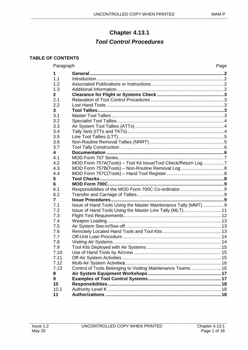
UNCONTROLLED COPY WHEN PRINTED MAM-P
Issue 1.2 May 20
UNCONTROLLED COPY WHEN PRINTED Chapter 4.13.1 Page 1 of 18
.......................................................................................................................................................................................................................................................................
........................................................
...............................................................................
s......................................................................................................................................................
............................................................................................................................
...............................................................................................................................................................
.......................................................................................................................
..................................................................................................................................................................
.............................................
..........................................................................................................................................................
..........................................................................................................................
...........................................................................................................................................
.................................................
...........................................................................................................................................................................
.........................................................................................................................................
...........................................................................................................................................................
......................................................................................................................................................
.......................................................................................................................................................................................
..................................................................................................................................................
.....................................................................................................................................
..........................................................................................................................................................
.......................................................................................................
Chapter 4.13.1
Tool Control Procedures
TABLE OF CONTENTS
Paragraph Page
1 General 21.1 Introduction 21.2 Associated Publications or Instructions 21.3 Additional Information 22 Clearance for Flight or Systems Check 32.1 Relaxation of Tool Control Procedures 32.2 Lost Hand Tools 33 Tool Tallies 33.1 Master Tool Tallies 33.2 Specialist Tool Tallies 43.3 Air System Tool Tallies (ATTs) 43.4 Tally Sets (ITTs and TKTs) 43.5 Line Tool Tallies (LTT) 53.6 Non-Routine Removal Tallies (NRRT) 53.7 Tool Tally Construction 64 Documentation 64.1 MOD Form 707 Series 74.2 MOD Form 757A(Tools) – Tool Kit Issue/Tool Check/Return Log 74.3 MOD Form 757B(Tools) – Non-Routine Removal Log 84.4 MOD Form 757C(Tools) – Hand Tool Register 85 Tool Checks 86 MOD Form 700C 96.1 Responsibilities of the MOD Form 700C Co-ordinator 96.2 Transfer and Carriage of Tallies 97 Issue Procedures 97.1 Issue of Hand Tools Using the Master Maintenance Tally (MMT) 97.2 Issue of Hand Tools Using the Master Line Tally (MLT) 117.3 Flight Test Requirements 127.4 Weapon Loading 137.5 Air System See-in/See-off 137.6 Remotely Located Hand Tools and Tool Kits 137.7 Off-Unit Loan Procedure 147.8 Visiting Air Systems 147.9 Tool Kits Deployed with Air Systems 157.10 Use of Hand Tools by Aircrew 157.11 Off-Air System Activities 157.12 Multi-Air System Activities 167.13 Control of Tools Belonging to Visiting Maintenance Teams 168 Air System Equipment Workshops 179 Examples of Tool Control Systems 1710 Responsibilities 1810.1 Authority Level K 1811 Authorizations 18
MAM-P UNCONTROLLED COPY WHEN PRINTED
Chapter 4.13.1 Page 2 of 18
UNCONTROLLED COPY WHEN PRINTED Issue 1.2 May 20
....................................................................................................................
....................................................................................................................
LIST OF FIGURES
Figure 1. Issue of Hand Tools Using the MMT 10Figure 2. Issue of Hand Tools Using the MLT 12
LIST OF TABLES
Table 1. Non-routine Removal Tally Identification Codes 6Table 2. Associated Authorizations 18
1 General
1.1 Introduction
No single procedure could fulfil all of the tool control requirements within the Defence Air Environment (DAE) but there are some mandatory measures that apply to all Station (Stn)/Ship/Units. This chapter details these together with a set of optional procedures from which Stn/Ship/Unit can select those elements needed to control tools within their operating environment. A Squadron/Unit may opt to use one system for recording the issue of hand tools from the Issue Centre when operating from its parent Stn/Ship/Unit but have a modified system when embarked or deployed. Paragraph 9 provides examples of how the procedures within this chapter may be employed.
Details concerning the management and provisioning of hand tools are contained in RA 4808 and Chapter 4.13 – Management of Hand Tools and Test and Measuring Equipment.
For hand tools used in Air System equipment workshops refer to Paragraph 8.
1.2 Associated Publications or Instructions
1 RA 4808 – Equipment, Tools and Material (MRP 145.A.40)
2 Manual of Airworthiness Maintenance – Documentation (MAM-D)
1.3 Additional Information
Some of the procedures within this chapter are mandatory and are to be used by all units within the DAE; the other procedures will only be used if required by the unit concerned. The relevant individual holding authority level K is to decide which procedures best suit their Stn/Ship/Unit, the type of tool tallies that are to be used and the method of identifying that a hand tool has been issued. These decisions are to be promulgated in Stn/Ship/Unit Aviation Engineering Standing Orders (AESO) or equivalent.
1.3.1 Terms Used
Throughout this chapter:
1 ‘Line activities’ refers to those activities relating to pre/post-flight servicing and preparation for flight. This includes such activities as flight servicing or Air System refuelling, but excludes weapon loading/unloading.
2 The term MOD Form 700C is used to denote both the hard copy MOD Air System Maintenance document and any Type Airworthiness Authority (TAA) approved electronic equivalent.
UNCONTROLLED COPY WHEN PRINTED MAM-P
Issue 1.2 May 20
UNCONTROLLED COPY WHEN PRINTED Chapter 4.13.1 Page 3 of 18
3 References to Maintenance documentation, forms and certificates include any TAA approved electronic equivalents hosted on an electronic Information System (IS).
2 Clearance for Flight or Systems Check
Before clearing an Air System for flight, the MOD Form 700C co-ordinator is to ensure that all hand tools used on the Air System have been accounted for. Additionally, the supervisor of a task is to ensure that the Air System is not subjected to any system check, which would present a hazard if a hand tool had been inadvertently left in the Air System, until all hand tools in use on the Air System have been accounted for.
2.1 Relaxation of Tool Control Procedures
Away from Air System or Air System equipment Maintenance organizations, tool control measures may be relaxed. Where the general principles of tool control are to be relaxed, the relevant individual holding authority level K is to assess the Flight Safety risk and determine the hand tool control procedures that are to be applied.
2.2 Lost Hand Tools
If a hand tool is lost, or is suspected of being lost, in an Air System or Air Systems associated equipment area, action is to be taken iaw Chapter 4.14 – Loose Articles. If a hand tool is lost in any other area, a person holding level G Authorizations is to decide the extent of any search made.
3 Tool Tallies
Tool tallies are an essential part of a tool control system and are to be used to identify when hand tools are in use. There are 6 classes of tally within the hierarchy of tool tallies, comprising:
1 Master Tool Tallies.
2 Specialist Tool Tallies.
3 Aircraft Tool Tallies (ATT).
4 Tally sets, consisting of either:
4.1 Individual Tool Tallies (ITT).
4.2 Tool Kit Tallies (TKTs).
5 Line Tool Tallies (LTT).
6 Non-Routine Removal Tallies (NRRT).
The construction and marking of tool tallies is detailed at Paragraph 3.7. The relevant individual holding authority level K is to determine who may issue and control the master and specialist tallies, eg MOD Form 700C co-ordinator.
3.1 Master Tool Tallies
There are 2 types of master tool tally in use: the Master Maintenance Tally (MMT) and the Master Line Tally (MLT). Use of the MMT is mandatory whilst use of the MLT is only required when tools are held forward of the Issue Centre under the control of the line controller.
1 MMT – Each Air System is to be allocated an MMT. Before hand tools may be used to carry out Maintenance of an Air System, a Tradesman is to take control of the MMT, raise an entry in the Air System MOD Form 700C to this effect using the appropriate MOD Form 707 series and take it to the Issue Centre. Whenever the
MAM-P UNCONTROLLED COPY WHEN PRINTED
Chapter 4.13.1 Page 4 of 18
UNCONTROLLED COPY WHEN PRINTED Issue 1.2 May 20
MMT is in the Issue Centre it indicates that tools may be issued for use on that Air System. Use of the MMT is detailed in Paragraph 7.1.
2 MLT – When hand tools used for line activities are held at the line control rather than the main Issue Centre, each Air System is to be allocated an MLT. Use of the MLT is detailed in Paragraph 7.2.
In derogation to the above, MMTs or MLTs are not required when hand tools are to be used for:
1 Flight-testing – Paragraphs 2 and 7.3.
2 Weapon loading – Paragraphs 7.4.
3 Air System see-in/see-off – Paragraph 7.5.
4 Aircrew Maintenance – Paragraph 7.10.
5 Off - Air System activities – Paragraph 7.11.
3.2 Specialist Tool Tallies
In addition to the MMT and MLT, it may be necessary for units to use the following tallies:
1 Flight Test Tally (FTT) – When it is necessary for hand tools to be used for flight test purposes, each Air System is to be allocated with an FTT. When issued to a user the FTT permits the user to draw only those hand tools required to support the flight test. Procedures for FTT use are at Paragraph 7.3.
2 Weapon Loading Tally (WLT) – Whenever hand tools are to be used to undertake the loading/unloading of explosive armament stores, a WLT is to be used to permit the user to draw the hand tools. Procedures for WLT use are detailed at Paragraph 7.4.
3.3 Air System Tool Tallies (ATTs)
Each Air System is to be allocated a set of ATTs: they are to be held in the Issue Centre and activated whenever an Air System's MMT is in the Issue Centre. The Tradesman who initially takes the MMT to the Issue Centre is to be allocated the first ATT. When allocated, the ATT is to be placed next to a set of ITTs or a tool kit key location, thus linking the Air System to that set of ITTs or tool kit. Subsequent ATTs are to be allocated if another Tradesman requires hand tools or if another tool kit is required.
3.4 Tally Sets (ITTs and TKTs)
An ITT or TKT set is to be used to record the issue of a hand tool or number of hand tools. Use of ITTs or TKTs is to be determined by the relevant individual holding authority level K.
3.4.1 Individual Tool Tallies (ITTs) sets
When used, sets of ITTs are to remain within the Issue Centre and are to be allocated to a Tradesman whenever hand tools are required. Tool issue procedure using ITTs is as follows:
1 Upon receipt in the Issue Centre, the MMT is to be placed adjacent to the set of ATTs to activate them.
2 An ATT is to be placed adjacent to the set of ITTs designated to the Tradesman concerned.
3 When every hand tool within the Issue Centre has its own unique storage location, an ITT is placed adjacent to the hand tool’s storage location and the hand tool is issued to the Tradesman.
UNCONTROLLED COPY WHEN PRINTED MAM-P
Issue 1.2 May 20
UNCONTROLLED COPY WHEN PRINTED Chapter 4.13.1 Page 5 of 18
4 When it is not possible to place the ITT adjacent to the hand tool’s storage location, the ITT is to be placed on a suitable tally board and the MOD Form 757C(Tools) is to be used to record the exchange of an ITT for a hand tool. In this instance a maximum of 4 hand tools may be drawn against a single tool tally.
5 When a tool kit is issued using an ITT, the ITT is to replace the tool kit key and the MOD Form 757A(Tools) is to be used to record the issue of the tool kit.
Once allocated, an ITT set is to remain within the Issue Centre at all times. The relevant individual holding authority level K is to determine the number of tallies that are contained in an ITT set, up to a maximum of 20.
Notes:
1 When ITT and TKT sets are in use on a Squadron/Unit, tool kits are only to be issued by exchanging the tool kit key for an ATT.
2 Where large tool kits are held forward of the Issue Centre, eg in Depth organizations, it may be necessary for such tool kits to contain a system which identifies the Tradesman to whom a hand tool has been issued, for example an ITT set. The relevant individual holding authority level K is to determine the requirement for these tallies.
3.4.2 Tool Kit Tally (TKT) Sets
When a tally set is contained within a tool kit, it forms part of that tool kit and is to be accounted for during 100% tool checks of the tool kit. TKTs are to be used to supplement the tool kit and are to be exchanged, at the Issue Centre, for hand tools. When a TKT is exchanged for a hand tool, the TKT is to be either:
1 Exchanged for the hand tool on a one-for-one basis, with the TKT being placed adjacent to the hand tool’s storage location and the hand tool issued to the Tradesman.
2 Placed on a suitable tally board with the MOD Form 757C(Tools) used to record the exchange of the TKT for a hand tool. In this instance a maximum of 4 hand tools may be drawn against a single TKT.
Note:
When TKT sets are in use on a Squadron/Unit, tool kits are to only be issued by exchanging the tool kit key for an ATT.
3.5 Line Tool Tallies (LTT)
LTTs are to be used in conjunction with line tool kits to permit additional tools to be used to supplement line tool kits. LTTs are to be used iaw either of the following methods:
1 An LTT is to be exchanged for a hand tool on a one-for-one basis and the name of the individual to whom the LTT has been issued is to be clearly identified at the LTT’s normal storage position.
2 The issue of a hand tool against an LTT is to be recorded using MOD Form 757C(Tools).
3.6 Non-Routine Removal Tallies (NRRT)
The non-routine removal of a hand tool from its storage location is to be recorded on the relevant deficiency list and/or the appropriate MOD Form 757B(Tools) as defined in local orders. When practicable, the hand tool is to be replaced by an NRRT.
MAM-P UNCONTROLLED COPY WHEN PRINTED
Chapter 4.13.1 Page 6 of 18
UNCONTROLLED COPY WHEN PRINTED Issue 1.2 May 20
Each NRRT is to be identified by a code, see Table 1, and serial number. In addition, NRRTs used for temporary loan to/from another unit on the same Stn/Ship is to be identified with the unit identifier.
Table 1. Non-routine Removal Tally Identification Codes
Code Reason for removal
U/S Indicates that the tool is Unserviceable and/or a replacement is on demand.
CAL The tool is undergoing calibration.DET The tool has been temporarily removed and taken on detachment.
LOAN Represents the loan of a hand tool to/from another unit on the same Stn/Ship.
3.7 Tool Tally Construction
As a minimum, tool tallies are to be:
1 Made from either a plastic or metal material.
2 Permanently marked as follows:
2.1 MMT – MMT and military Air System registration number or MMT, visiting Air System identifier and serial number, eg MMT/ZE697 or MMT/Visit/1.
2.2 MLT – MLT and military Air System registration number or MLT, visiting Air System identifier and serial number, eg MLT/ZE697 or MLT/Visit/1.
2.3 FTT – FTT and military Air System registration number, eg FTT/ZE697.
2.4 WLT – WLT, unit identifier and a serial number, eg WLT/20(R)/1, WLT/20(R)/2, etc.
2.5 ATTs – ATT, Squadron/Unit identifier, set number and a serial number, eg ATT/771 NAS/Set 1/1, ATT/771 NAS/Set 2/2, etc, up to the total number in the set.
2.6 ITTs – ITT set serial number, such that all tallies in the set have the same number.
2.7 TKTs – Tool kit identifier and a serial number, eg HA355/1, HA355/2, etc.
2.8 LTTs – Tool kit identifier and a serial number, eg HA457/1, HA457/2, etc.
2.9 NRRTs – See Paragraph 3.6.
4 Documentation
The following documentation is to be used for the control of hand tools:
1 Relevant MOD Form 707 series – see Paragraph 4.1.
2 MOD Form 757A(Tools) – Tool Kit Issue/Tool Check/Return Log; see Paragraph 4.2.
3 MOD Form 757B(Tools) – Non-Routine Removal Log; see Paragraph 4.3.
4 MOD Form 757C(Tools) – Hand Tool Register; see Paragraph 4.4.
The forms detailed above are to be retained when complete in order to maintain a hand tool Audit trail. The period of retention is detailed in MAM-D Part 1 Chapter 2.3 - Retention of Maintenance Records.
Serial numbered forms MOD Form 757A(Tools) and MOD Form 757C(Tools), if applicable, is to be contained in a binder system to record the issue and receipt of hand tools and tool kits for the following:
UNCONTROLLED COPY WHEN PRINTED MAM-P
Issue 1.2 May 20
UNCONTROLLED COPY WHEN PRINTED Chapter 4.13.1 Page 7 of 18
1 Each Air System.
2 Off-Air System.
Additionally, when hand tools are held remotely from an Issue Centre, a MOD Form 757A(Tools) is to be held within the tool kit or remote location to permit tool checks to be carried out at the remote location, iaw Paragraph 7.6.
4.1 MOD Form 707 Series
Whenever an MMT is required to permit the use of hand tools on an Air System, an entry is to be raised in the appropriate MOD Form 707 series as follows:
‘Tools in use on Air System and Master Maintenance Tally issued’
On completion of all Maintenance and once all hand tools have been returned to the Issue Centre, the open entry in the appropriate MOD Form 707 series is to be closed with the following:
‘No hand tools currently allocated to this Air System and Master Maintenance Tally returned in accordance with MAM-P Chapter 4.13.1’
Notes:
1 The above entries may be hand written, typed or produced by a stamp.
2 Electronic IS recording is not required for this entry.
3 There is no requirement to raise a separate MOD Form 707 series specifically to record the issue/receipt of the MMT; these entries could instead be included on a MOD Form 707 series used to record another Maintenance activity. However, if there are several Maintenance tasks to be undertaken, it may be useful to record issue/receipt of the MMT on a separate MOD Form 707 series.
The Tradesman returning the MMT is to complete the ‘Tradesman’ block of the appropriate MOD Form 707 series. Certification of the appropriate MOD Form 707 series by the user signifies that:
1 They have ensured that all MOD Form 757A(Tools) entries relating to the issue of tool kits for use on that Air System have been closed and any tool kits returned.
2 No hand tools are booked out to that Air System using either ITTs or TKTs, cross-referring to the MOD Form 757C(Tools) if applicable.
3 All ATTs have been returned to their normal location.
4 They have returned the MMT.
The individual who is responsible for the control of the MMT, eg MOD Form 700C co-ordinator, is to complete the ‘Supervisor’ block of the appropriate MOD Form 707 series entry. Certification of the ‘Supervisor’ block signifies that the MMT has been returned to their custody.
4.2 MOD Form 757A(Tools) – Tool Kit Issue/Tool Check/Return Log
4.2.1 MOD Form 757A(Tools) Purpose
MOD F757A(Tools) is a mandatory multi-purpose form located in Issue Centres, flight lines and within tool kits. It is used to record:
1 The removal of a tool kit from, and its subsequent return to, an Issue Centre or flight line.
2 The removal of a remotely located hand tool storage or tool kit key from, and its subsequent return to, an Issue Centre.
3 A tool check.
MAM-P UNCONTROLLED COPY WHEN PRINTED
Chapter 4.13.1 Page 8 of 18
UNCONTROLLED COPY WHEN PRINTED Issue 1.2 May 20
4 Any other opening of the tool kit within an Issue Centre; such as to replace a deficient tool, to carry out tool/tool kit Maintenance or Quality Assurance checks etc.
4.2.2 MOD Form 757A(Tools) Completion
Certification of the MOD Form 757A(Tools) signifies that a 100% tool check has been carried out iaw Paragraph 5. The MOD Form 757A(Tools) is to be completed as follows:
1 Initial issue – The user is to complete Columns A to F, identifying initial issue in Column B. When single-Service policy or local orders mandate, a member of the Issue Centre staff, the on-coming user or another individual, other than the individual completing Column F, is to complete Column G.
2 Tool checks – The off-going user is to complete Columns H to L, identifying a tool check in Column J and either a member of the Issue Centre staff, the on-coming user or another individual, other than the individual completing Column L, is to complete Column M. On recommencement of work, the on-coming user is to complete Columns A to F, identifying a tool check in Column B. When single-Service policy or local orders mandate, a member of the Issue Centre staff, the on-coming user or another individual, other than the individual completing Column F, is to complete Column G.
3 Returning hand tools – The individual returning the tool kit is to complete Columns H to L, identifying that they are returning the hand tools in Column J and another individual, normally a member of the Issue Centre staff, is to complete Column M. Certification of Columns L and M signifies that both individuals have carried out a 100% tool check of the tool kit.
4.3 MOD Form 757B(Tools) – Non-Routine Removal Log
MOD Form 757B(Tools) is a mandatory multi-purpose form used to record the removal of a hand tool from an Issue Centre for any purpose other than a routine issue.
4.4 MOD Form 757C(Tools) – Hand Tool Register
MOD Form 757C(Tools) is an optional form used to record the issue of hand tools to an individual when hand tools are issued against TKTs, ITTs or LTTs. The MOD Form 757C(Tools) is to be completed as follows:
1 Issue – The user is to complete Columns A to E. When single-Service policy or local orders mandate, a member of the Issue Centre staff is to complete Column F.
2 Return – The user is to complete Columns G to J, another individual, normally an Issue Centre staff member is to complete Column K.
3 Certification of Columns E, F (if required), J and K signifies that the tools indicated at Column C are complete and accounted for at the time of issue and return.
5 Tool Checks
A 100% tool check is to be carried out at the start of a shift, at shift handover and at the end of the working day. The 100% tool check ensures that all in-use hand tools, tool kits, TKTs or ITTs, as appropriate, are complete and accounted for, and that any Unserviceable hand tools have been identified to the Issue Centre staff. If any hand tools have been identified as Unserviceable, a member of the Issue Centre staff is to carry out the non-routine removal procedure, iaw Paragraph 3.6.
Additionally, checks of all hand tools in use on an Air Systems or item of Air System equipment is to be carried out as follows:
UNCONTROLLED COPY WHEN PRINTED MAM-P
Issue 1.2 May 20
UNCONTROLLED COPY WHEN PRINTED Chapter 4.13.1 Page 9 of 18
1 On completion of any task, when the hand tools are not being returned to the Issue Centre.
2 Before fitting any component that, once fitted, will restrict access.
3 Prior to subjecting the Air System to system checks, where the loss of a hand tool may present a hazard to the Air System or personnel.
4 At the discretion of the supervisor at convenient stages during protracted Maintenance activities.
When a 100% tool check identifies that a hand tool is missing, the procedures detailed in Chapter 4.14 - Loose Articles - Precautions and Recovery Procedures are to be followed.
6 MOD Form 700C
6.1 Responsibilities of the MOD Form 700C Co-ordinator
Before an Air System is cleared for flight or handed over to another Maintenance organization, a check is to be made by the individual clearing the Air System for flight or transferring responsibility to another Maintenance organization to confirm that all hand tools drawn against the Air System have been accounted for.
Prior to clearing the Air System for flight the MOD Form 700C co-ordinator is to ensure that:
1 The user has closed the relevant MOD Form 707 series entry relating to tool control and the MMT has been returned.
2 Any hand tools issued for line activities have been accounted for, the MLT has been returned and the appropriate paperwork has been completed.
3 If the FTT is in use, a corresponding MOD Form 707 series entry has been raised, see Paragraph 7.3.
4 If the WLT is in use, the appropriate MOD Form 705 series or MOD Form 706 series has been completed, see Paragraph 7.4.
6.2 Transfer and Carriage of Tallies
Whenever an Air System is transferred between units it is to be accompanied by its MMT and, if applicable, its MLT or FTT.
When it is necessary for the MOD Form 700C to be carried in its parent Air System, its associated MMT, and if applicable its MLT or FTT, is to be stored within the MOD Form 700C in order to permit hand tools to be issued for use on that Air System at any subsequent location, other than its parent unit.
7 Issue Procedures
7.1 Issue of Hand Tools Using the Master Maintenance Tally (MMT)
Whenever an MMT is required to permit the use of hand tools on an Air System, an entry is to be made in the MOD Form 707 series, as detailed in Paragraph 4.1, and the individual making that entry is to take control of the MMT. The procedure to be followed for the issue of a tool kit or ITT set(s) and hand tools using the MMT is shown in Figure 1.
The issue of a tool kit is to be recorded by an entry on a MOD Form 757A(Tools) at the Issue Centre. On return of the tool kit to the Issue Centre, the user and another individual, normally a member of the Issue Centre staff, is to undertake and certify as having completed a 100% check of the tool kit iaw the provisions of Paragraph 5.
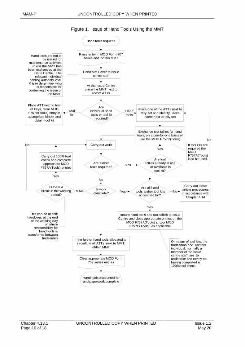
MAM-P UNCONTROLLED COPY WHEN PRINTED
Chapter 4.13.1 Page 10 of 18
UNCONTROLLED COPY WHEN PRINTED Issue 1.2 May 20
Figure 1. Issue of Hand Tools Using the MMT
Hand tools required
Are individual handtools or tool kit
required?
At the Issue Centre place the MMT next to
row of ATTs
Place ATT next to tool kit keys, raise MOD
F757A(Tools) entry in appropriate binder and
obtain tool kit
Place one of the ATTs next to tally set and identify user's
name next to tally set
Carry out work
Raise entry in MOD Form 707 series and obtain MMT
Are further tools required?
Are tooltallies already in use
or available intool kit?
No
Yes
Are all handtools and/or tool kits
accounted for?
Carry out loose article procedures in accordance with
Chapter 4.14
Is work complete?
Carry out 100% tool check and complete
appropriate MOD F757A(Tools) entries
No No
Return hand tools and tool tallies to Issue Centre and close appropriate entries on the
MOD F757A(Tools) and/or MOD F757C(Tools), as applicable
Clear appropriate MOD Form 707 series entries
Hand tools accounted for and paperwork complete
Is there abreak in the working
period?
No
Yes
Yes
Yes
Exchange tool tallies for hand tools, on a one-for-one basis or
use the MOD F757C(Tools)
Yes
Hand tools are not to be issued for
maintenance activities unless the MMT has
been exchanged at the Issue Centre. The relevant individual
holding authority level K is to determine who
is responsible for controlling the issue of
the MMT.
Toolkit
This can be at shift handover, at the end
of the working day or where
responsibility for hand tools is
transferred between tradesmen
Hand MMT over to issue centre staff
Hand tools
No
If tool kits are required the MOD F757A(Tools) is to be used.
If no further hand tools allocated to aircraft, ie all ATTs next to MMT,
obtain MMT
On return of tool kits, the tradesman and another individual, normally a member of the issue centre staff, are to undertake and certify as having completed a 100% tool check.
UNCONTROLLED COPY WHEN PRINTED MAM-P
Issue 1.2 May 20
UNCONTROLLED COPY WHEN PRINTED Chapter 4.13.1 Page 11 of 18
7.2 Issue of Hand Tools Using the Master Line Tally (MLT)
A Squadron/Unit may choose to list in AESOs those tools that may be used for line activities and drawn without the use of the MMT. In such situations, each Air System is to be allocated a MLT, which is to be used to identify that line hand tools are in use on that Air System. The designated line tools are to be assembled as line tool kits and, together with any supplementary hand tools required for flight servicing (eg tyre inflation rigs) held either within line control or in a designated area of the Issue Centre. The MLT can be issued without an entry in the relevant MOD Form 707 series and permits the user access to a line tool kit and a number of additional LTTs to allow the issue of supplementary hand tools. When line tool kits are being used, corresponding MOD Form 757A(Tools) entries are to be used to record the issue and return of tool kits. Certification of the MOD Form 705 series by a Tradesman signifies that any hand tools, used for that aspect of the flight servicing they have undertaken, have been accounted for. The procedure for the use of the MLT is shown in Figure 2.

MAM-P UNCONTROLLED COPY WHEN PRINTED
Chapter 4.13.1 Page 12 of 18
UNCONTROLLED COPY WHEN PRINTED Issue 1.2 May 20
Figure 2. Issue of Hand Tools Using the MLT
Hand tools required for line activity
Exchange MLT for tool kit key and additional
LTTs. Complete MOD F757A(Tools) for tool
kit.
Carry out work
Are further tools required?
No
Are all hand tools and/or tool kits accounted
for?
Carry out loose article procedures in
accordance with Chapter 4.14
Is work complete?
Carry out a 100% tool check and
complete appropriate MOD F757A(Tools)
entries
No No
Return hand tools, LTTs and tool kit to flight line control, close the appropriate entries on the MOD
F757A(Tools), and MOD F757C(Tools), if applicable, and obtain MLT
Complete appropriate MOD Form 705 series
Hand tools accounted for and paperwork complete
Is there abreak in the
working period?
No
Yes
Yes
Hand tools are not to be issued for line
activities unless an MLT has been issued. The relevant individual holding authority level
is K is to determine who is responsible for controlling the issue of
the MLT.
Yes
If hand tools are still in use, transfer
responsibility between tradesmen and inform
MLT controller.
Obtain MLT
LTTs may either be contained in the tool kit or located next to the tool kit key storage.
Exchange LTTs for hand tools
Yes
Return MLT
7.3 Flight Test Requirements
The relevant individual holding authority level K is to determine who is responsible for controlling the issue of FTTs. Whenever hand tools are required for flight test purposes, the user is to be issued with an FTT and a corresponding entry, identifying which hand tools (or tool kits) are in use, is to be raised in the appropriate MOD Form 707 series as follows:
‘[Insert details of hand tools] in use on Air System for flight test purposes, SNOW [insert SNOW relating to the flight test requirement] refers’
On completion of the flight test and subsequent return of the FTT, the MOD Form 707 series entry is to be cleared as follows:
UNCONTROLLED COPY WHEN PRINTED MAM-P
Issue 1.2 May 20
UNCONTROLLED COPY WHEN PRINTED Chapter 4.13.1 Page 13 of 18
‘[Insert details of hand tools] removed from Air System post-flight test at SNOW [insert SNOW relating to flight test requirement] and Flight Test Tally returned in
accordance with MAM-P Chapter 4.13.1’
Notes:
1 The entries may be hand written, typed or produced by a stamp with the 'blanks' completed in handwriting or type.
2 When use of the hand tools imposes a limitation on the use of the Air System a separate MOD Form 703 entry is to also be raised.
On production of the FTT at the Issue Centre, the user is to take only those hand tools necessary to undertake the flight test and is to complete the appropriate MOD Form 757A(Tools) or MOD Form 757C(Tools) for that Air System. When the FTT is in use, the user is responsible for the control of the hand tools at all times during the flight test. If necessary, the MOD Form 757A(Tools) is to be used during the period of the flight test whenever a tool check is carried out.
7.4 Weapon Loading
The relevant individual holding authority level K is to determine who is responsible for controlling the issue of WLTs. Whenever hand tools are to be used to undertake the loading/unloading of explosive armament stores, a WLT is to be used. When issued to a weapon loading team, the WLT is to be exchanged at the Issue Centre for either a set of ITTs or the relevant tool kit key. Issue of the tool kit is to be certified using the MOD Form 757A(Tools). To permit the issue of supplementary hand tools, ITTs or TKTs may be used.
Once issued, the tool kit and/or hand tools may be used to undertake the loading/unloading of explosive armament stores of any number of Air System. Certification of the appropriate loading/unloading documentation iaw Chapter 8.2.1 - Armament Engineering Documentation signifies that all hand tools used in loading/unloading the Air System have been accounted for.
7.5 Air System See-in/See-off
If any tools are required to see-in/see-off an Air System, they are to be constituted as Air System see-in/see-off tool kits. All see-in/see-off tool kits in use on a Stn/Ship/Unit are to be of a standard design for each Air System type/mark and the number of tools they contain is to be kept to a minimum. However, the relevant individual holding authority level K may authorize the inclusion of the tools required to rectify any commonly occurring pre-flight Faults, whose rectification has been approved by the TAA and detailed in the Air System Document Set (such as the Topic 2(N/A/R)1) or by a person holding Authorization MAMP–G702.
Air System see-in/see-off tool kits are to be serial numbered and, on issue/return, the user is to complete a MOD Form 757A(Tools).
7.6 Remotely Located Hand Tools and Tool Kits
For those hand tools or tool kits located remotely from an Issue Centre:
1 The key for the hand tool storage or tool kit is to be secured in the Issue Centre; its removal is to be recorded by:
1.1 Raising an entry on the MOD Form 757A(Tools) in the Issue Centre.
1.2 Exchanging either an ITT or ATT for the tool kit key.
2 A MOD Form 757A(Tools) binder is to be contained in the hand tool storage or tool kit.
MAM-P UNCONTROLLED COPY WHEN PRINTED
Chapter 4.13.1 Page 14 of 18
UNCONTROLLED COPY WHEN PRINTED Issue 1.2 May 20
3 100% tool checks are to be carried out at the start of a shift, at shift handover or at the end of the working day iaw Paragraph 5 and recorded on the MOD Form 757A(Tools) within the hand tool storage or tool kit.
Note:
Where it is impracticable to secure the key in an Issue Centre, when the tools are not in use, local arrangements are to be made for the key’s custody, safekeeping and issue.
Unless the remotely located hand tools are for use on a particular Air System only, once the key has been issued and the 100% tool check carried out, hand tools may be issued to individuals in exchange for a tool tally; see Paragraph 3.4.
7.7 Off-Unit Loan Procedure
The following procedure is to be adopted whenever a hand tool is to be loaned to/from another Sqn/Unit on the same Stn/Ship/Unit:
1 The user requiring the tool is to draw a loan tally (see Paragraph 3.6) at their Issue Centre, certifying its issue using a MOD Form 757B(Tools).
2 The user is to request the loan of the required hand tool from the loaning unit and, if agreed, they are to exchange their loan tally for the required hand tool at the loaning unit’s Issue Centre.
3 The user is to complete a MOD Form 757B(Tools) entry at the loaning unit’s Issue Centre.
4 If practicable, the loaning unit is to replace the hand tool with the borrowing unit’s loan tally.
5 The loaned hand tool is to be returned to the borrowing unit’s Issue Centre.
6 The loaned hand tool may then be issued from the borrowing unit’s Issue Centre by use of either a TKT or ITT, as appropriate.
Note:
During the period of the loan the borrowing unit’s Issue Centre custodian is responsible for the safe custody of the hand tool and also any calibration or testing requirements that may arise during the period of the loan.
The procedure for returning the hand tool to the loaning unit is the reverse of the procedure detailed above.
If loans between Units at different Stn/Ship are likely, the required procedure is to be defined in local orders to ensure the appropriate MOD Form 757B(Tools) of the loaning unit correctly records the approved removal, and the receiving unit places the received item under tool control. The supply system is to be used to ensure custody is formally transferred.
7.8 Visiting Air Systems
There are two scenarios associated with the arrival of a visiting Air System at a Stn/Ship/Unit; either:
1 The MOD Form 700C has accompanied the Air System.
2 The MOD Form 700C has been retained by the parent unit.
When the MOD Form 700C has accompanied the Air System, the appropriate tallies will have been despatched with the MOD Form 700C, see Paragraph 6.2, and normal tool control procedures are to be followed, with a set of ATTs being allocated to the visiting Air System.

UNCONTROLLED COPY WHEN PRINTED MAM-P
Issue 1.2 May 20
UNCONTROLLED COPY WHEN PRINTED Chapter 4.13.1 Page 15 of 18
When the MOD Form 700C has been retained by the parent unit, it will be necessary for visiting Air System MMTs, MLTs, if used, and ATTs to be made available at the hosting unit. Therefore, all units are to allocate a sufficient number of MMTs, MLTs, if appropriate, and ATTs to permit the Maintenance of visiting Air Systems to be carried out.
7.9 Tool Kits Deployed with Air Systems
When it is necessary for a tool kit, other than Aircrew Land-away Turn round tool Kits (ALTKits), to be carried within an Air System to facilitate Maintenance at subsequent locations (eg an Air System ground engineer’s tool kits), the following procedure is to be followed:
1 The key for the tool kit is to be replaced with the appropriate NRRT iaw Paragraph 3.6.
2 On completion of a 100% tool check an initial MOD Form 757A(Tools) entry is to be completed at the Issue Centre.
3 A MOD Form 757A(Tools) is to accompany the tool kit.
4 Prior to the tool kit being used, a 100% tool check is to be carried out and an entry raised on the accompanying MOD Form 757A(Tools).
5 On completion of any Maintenance, a 100% tool check is to be carried out and the MOD Form 757A(Tools) entry closed. Aircrew are to complete Column M of the MOD Form 757A(Tools) when another Tradesman is not available.
6 On return to its parent unit the tool kit is to be returned to the Issue Centre and the original MOD Form 757A(Tools) entry is to be completed.
7 All MOD Form 757A(Tools) used during the deployment is to be retained with the MOD Form 707 series documentation covering the deployed period.
7.10 Use of Hand Tools by Aircrew
Aircrew are to complete the relevant MOD Form 757A(Tools) or MOD Form 757C(Tools) when it is necessary for hand tools to be issued to Aircrew, eg night flying torches or ALTKits. On return of the hand tools, the Aircrew are to complete the MOD Form 757A(Tools) or MOD Form 757C(Tools). There is no need to use an MMT or MLT to record the issue of these tools (see Paragraph 3.1).
When an ALTKit forms part of an Air Systems inventory and is stored permanently on the Air System it is to be fastened with a tell-tale lock and checked periodically. If an Aircrew member uses an ALTKit then on completion of the task they are to carry out a 100% tool check and certify the ALTKit’s completeness on a MOD Form 757A(Tools) contained within the ALTKit. They are to then report the ALTKit’s use to the Maintenance organization at the earliest opportunity.
7.11 Off-Air System Activities
An individual may draw tools for use on non-Air System Products, Parts and Appliances. Additionally, within a Squadron/Unit maintaining Air Systems there may be a need to draw hand tools for work on Air System Products, Parts and Appliances not yet assigned to a particular Air System. In these instances, issue of tool kits or hand tools is to be recorded in the MOD Form 757A(Tools) or MOD Form 757C(Tools), as appropriate, contained in the off-Air System binder. The relevant individual holding authority level K is to determine whether additional control measures are required, such as off-Air System master tallies, and promulgate these procedures in local orders.
MAM-P UNCONTROLLED COPY WHEN PRINTED
Chapter 4.13.1 Page 16 of 18
UNCONTROLLED COPY WHEN PRINTED Issue 1.2 May 20
7.12 Multi-Air System Activities
When it is necessary for a Maintenance activity to be carried out consecutively on a number of Air Systems by a single individual using the same hand tools, the following procedure is to be followed:
1 The MMT for each Air System on which the Maintenance is required is to be issued in the normal manner and the MMT is to be placed next to its ATT set at the Issue Centre.
2 An ATT from each Air System is to be grouped together and either:
2.1 Placed next to a single ITT set, with ITTs then being used to allow hand tools to be issued for use.
2.2 Exchanged for the key to a tool kit.
Hand tools issued in this way may then be used on any of the Air Systems to which they have been issued. Once the work has been completed the hand tools are to be returned to the Issue Centre and on completion of the appropriate tool checks the ATTs may be returned to their stowage next to the corresponding MMT. If it is necessary for a single Air System to be cleared of hand tools before the work has been completed on all Air Systems, all hand tools for that activity are to be returned to the Issue Centre and a tool check carried out. If all hand tools in use for the multi-Air System activity are accounted for, the ATT for the Air System being cleared may be returned.
7.13 Control of Tools Belonging to Visiting Maintenance Teams
There are occasions when visiting Maintenance teams, such as 42(ES)Wing or 1710 Naval Air Squadron (1710 NAS) personnel, bring their own specialist tools with them. These tools may be taken on charge by the hosting Squadron/Unit’s Issue Centre and controlled in the same way as the Squadron/Unit’s own tools. Alternatively, if these tools are not to be stored in, and controlled by, the hosting Squadron/Unit’s Issue Centre, the following procedure is to be adopted:
1 On departure from its home base the visiting team is to certify that its tool kit(s) is/are complete, using each tool kit’s MOD Form 757A(Tools).
2 On arrival at the work location the visiting team is to ensure that the Air System on which they intend to work is on tool control (eg there is an open MOD Form 707 series entry iaw Paragraph 4.1) and the MMT is located in the Issue Centre.
3 The visiting team is then to go to the Squadron/Unit’s Issue Centre where the Issue Centre custodian is to:
3.1 Allocate an ATT to the team; the ATT is to be removed from its storage location and not returned until the visiting team has accounted for its tools on completion of its work.
3.2 Raise an entry in the Air Systems MOD Form 757A(Tools) (detailed at Paragraph 4.2) to record the allocation of the visiting team’s tool kit(s) to that Air System.
4 The team may then take its tools to the Air System and start its task. The team is wholly responsible for its own tools and, if the task lasts for more than one day, its daily tool checks are to be certified on each tool kit’s MOD Form 757A(Tools).
5 On completion of its task, the visiting team is to check that its tool kits are complete, and the Issue Centre custodian is to:
5.1 Satisfy them that all of the visiting team’s tools have been accounted for.
UNCONTROLLED COPY WHEN PRINTED MAM-P
Issue 1.2 May 20
UNCONTROLLED COPY WHEN PRINTED Chapter 4.13.1 Page 17 of 18
5.2 In conjunction with a member of the visiting team, close the Air Systems MOD Form 757A(Tools) entry recording the allocation of the team’s tools to the Air System by signing columns K and L.
5.3 Return the visiting team’s ATT to its normal storage location.
Note:
All of the visiting Maintenance team’s tools are to be constituted into kits and each kit is to contain a MOD Form 757A(Tools) to record tool checks.
8 Air System Equipment Workshops
In Air System equipment workshops, hand tools and tool kits are to be controlled using the MOD Form 757A(Tools), which is to be completed at the start of a shift, at shift handover and at the end of the working day. Once the tool kit has been issued, dependent upon the size and nature of the workshop, either of the following procedures may be adopted:
1 Provided that the 100% tool checks are carried out iaw Paragraph 5, no additional action is required to record the removal of a hand tool from its storage location for use within that workshop area.
2 Each individual is to be allocated an ITT set, which permits the individual to remove hand tools from the hand tool storage or tool kit on a one-for-one basis. Tally sets and hand tools are to be accounted for as part of the 100% tool checks detailed in Paragraph 5.
A tally set is to be made available within the workshop, which will permit additional tools to be obtained from a location outside the workshop iaw Paragraph 7.7.
9 Examples of Tool Control Systems
The following outlines example tool control systems that reference the procedures detailed within this chapter. These example systems may be adopted in full, or adapted in local orders to meet specific operating conditions, within the constraints of this chapter:
1 MMT for each Air System.
2 MLT for each Air System, if hand tools to be held in the line control.
3 FTT for each Air System, if hand tools are required for flight test.
4 ATT set for each Air System.
5 WLT if hand tools are required for weapon loading activities.
6 MOD Form 757A(Tools) to record the issue of tool kits.
7 MOD Form 757B(Tools) to record the non-routine removal of hand tools.
8 And depending upon conditions the most appropriate option of either:
8.1 Use of MOD Form 757C(Tools) to record the issue of hand tools against a TKT, ITT or LTT; or
8.2 Hand tools exchanged for a TKT, ITT or LTT on a one-for-one basis, with the hand tool being replaced by the relevant tally.
MAM-P UNCONTROLLED COPY WHEN PRINTED
Chapter 4.13.1 Page 18 of 18
UNCONTROLLED COPY WHEN PRINTED Issue 1.2 May 20
10 Responsibilities
10.1 Authority Level K
The relevant individual holding authority level K of the Stn/Ship/Unit is responsible for determining:
1 Which procedures are best suited to their organization, the type of tool tallies that are to be used and the method of identifying that a hand tool has been issued (eg MOD Form 757C(Tools)) or exchange of tallies.
2 Who may issue and control the master and specialist tallies (eg MOD Form 700C co-ordinator).
3 For off-Air System work, whether additional control measures are required, such as off-Air System master tallies.
4 Whether, away from Air System or Air System equipment Maintenance sections, tool control measures may be relaxed.
5 The authority level that may draw and return hand tools.
6 Which tools may be included in a see-in/see-off tool kit for the purpose of rectifying commonly occurring pre-flight faults.
11 Authorizations
Table 2. Associated Authorizations
Authorization Task
MAMP-B213Sign 1st signature for tasked work within trade boundary.
MAMP-C323 Stn/Ship/Unit Issue Centre custodian.
MAMP-G702 Authorize corrective Maintenance of pre-flight Faults.
MAMP-J928
Authorize personnel to sign as 1st or 2nd signature for work both inside and outside their trade boundaries and to co-ordinate MWOs and MOD Form 700C/Technical Log.
MAMP-J957Authorize personnel to be Stn/Ship/Unit Issue Centre custodian.
Note:
1 Personnel required to draw and return hand tools are to hold Authorization MAMP-B213 unless relaxed tool control procedures are in operation (see Paragraph 2.1).
2 The authority level for returning hand tools or tool kits may be increased to authority level C at the discretion of the relevant individual holding authority level K.
UNCONTROLLED COPY WHEN PRINTED MAM-P
Issue 1.1 Feb 20
UNCONTROLLED COPY WHEN PRINTED Chapter 4.13.2 Page 1 of 2
...........................................................................
.....................................................................................................................................................
.....................................................................................................................................................................
..............................................................................................................................................................................
.......................................................................................................................................
.........................................................................................................................................................................................................
Chapter 4.13.2
Usage and Management of Remote Viewing Aid Equipment
TABLE OF CONTENTS
Paragraph Page
1 General 11.1 Introduction 11.2 Associated Publications and Instructions 11.3 Additional Information 12 Training and Authorization 12.1 Training 13 Responsibilities 23.1 User Stations/Ships/Units 23.2 Tri-Service School of NDT (TSSNDT) 24 Authorizations 2
LIST OF TABLES
Table 1. Associated Authorizations 2
1 General
1.1 Introduction
Remote Viewing Aid (RVA) equipment is the collective term for the optical equipment, video camera system or video viewing aid system used to assist with the visual inspection of Air System structures, engines and Air System components. The integrity of such inspections depends on the ability of the Tradesman and on the Serviceability and suitability of the RVA equipment. This chapter outlines the responsibilities for the training and authorization of Tradesmen required to use RVA equipment.
1.2 Associated Publications and Instructions
1 RA 4806 - Personnel Requirements (MRP 145.A.30)
1.3 Additional Information
An RVA system is defined as a complete collection of RVA equipment required to provide assistance with a visual inspection, eg endoscopes, light guide and light source box or Flexible Probe Video Viewing Aid.
2 Training and Authorization
2.1 Training
2.1.1 RVA Trainer Training
To deliver work place training in the use of RVA equipment, an individual must hold MAMP-C319. To gain MAMP-C319, an individual must:
1 Be qualified to deliver work place training in accordance with the relevant Single Service policy.
2 Hold MAMP-B215.
MAM-P UNCONTROLLED COPY WHEN PRINTED
Chapter 4.13.2 Page 2 of 2
UNCONTROLLED COPY WHEN PRINTED Issue 1.1 Feb 20
3 Have completed manufacturer’s RVA type-specific training (where previsioned) or be deemed SQEP by the appropriate holder of MAMP-J938.
MAMP-C319 must be granted by an individual holding authorization MAMP-J938 in accordance with RA 4806 and Chapter 2.1 of this MAM-P.
2.1.2 RVA Operator Training
The use of RVA equipment to assist with any visual inspection is part of the routine work of all Air System Tradesmen. However, only a fundamental knowledge of RVA equipment is included in initial trade training; hence, Tradesmen required to use RVA equipment are to hold Authorization MAMP-B215 and have completed training in the care and use of equipment prior to use. MAMP-B215 must be awarded by an individual holding authorization MAMP-J938 in accordance with RA 4806 and Chapter 2.1 of this MAM-P, having satisfied him/herself that the subject has:
1 Successfully completed the RVA Handling and Safety Course (CN3207) available on the DLE.
2 Has received platform/RVA equipment-specific familiarisation training delivered by an individual holding authorisation MAMP-C319.
3 Responsibilities
3.1 User Stations/Ships/Units
At Stns/Ships/Units where RVA equipment is used, the relevant individual holding MAMP-J938 is to ensure that:
1 Stns/Ships/Units within their responsibility have sufficient Aircraft RVA Operator-trainer personnel holding authorisation MAMP-C319 to carry out in-house familiarization training on RVA equipment.
2 Tradesmen and their supervisors receive local familiarization training in the care and use of RVA equipment prior to first use.
3 Stores personnel responsible for the control of Stn/Ship/Unit RVA equipment successfully complete the RVA Handling and Safety Course available on the DLE.
3.2 Tri-Service School of NDT (TSSNDT)
The TSSNDT is responsible for the maintenance of the RVA Handling and Safety Course.
4 Authorizations
Table 1. Associated Authorizations
Authorization Task
MAMP-B215 Use RVA equipment
MAMP-C319 Deliver RVA equipment Operator training at Stns/Ships/Units
MAMP-J938 Authorize Stn/Ship/Unit personnel to deliver RVA equipment operator training and to use RVA equipment
UNCONTROLLED COPY WHEN PRINTED MAM-P
...........................................................................
........................................................................................................................................................................................
...................................................................................................................................................................
.................................................................................................................................................................
.........................................................................................................................................................
.......................................................................................................................................
...................................................................................................................................................................................
..........................................................................................................................................................
.......................................................................................................
Chapter 4.14
Loose Articles – Precautions and Recovery Procedures
TABLE OF CONTENTS
Paragraph Page
1 General 11.1 Introduction 1 1.2 Associated Publications or Instructions 1 1.3 Applicability 1 1.4 Additional Information 2 2 Precautions to Prevent Loose Articles 2 2.1 Personal Precautions 2 2.2 Tool Control Procedures 2 2.3 Aero-Engine Maintenance 2 3 Loose Article Recovery Procedure 3 3.1 Purpose 3 3.2 Sequence of Searches 3 3.3 Conduct of Searches 3 3.4 Certification of Air System Release 3 4 Unknown Loose Article Found In/On an Air System 5 5 Authorizations 5
LIST OF TABLES
Table 1. Associated Authorizations 6
1 General
1.1 Introduction
Loose articles are classified as any items that have been dropped, lost, become detached or unaccounted for in and around the Air System, creating a potential hazard to the Air System. Typical loose articles include items such as hand tools, pens, coins, nuts, bolts, washers and split pins which, when lost within an Air System, could cause control restrictions and system malfunctions. In addition, engine compressors can also ingest loose articles, leading to significant damage or catastrophic failure. This chapter details the policy and procedures to manage and minimize loose article incidents.
1.2 Associated Publications or Instructions
1 RA 1400 – Flight Safety
2 RA 1410 – Occurrence Reporting and Management
3 RA 4253 – Loose Article - Recovery Procedures
4 RA 4808 – Equipment Tools and Material
5 RA 4812 – Certification of Air System Release and Component Release
1.3 Applicability
This chapter is applicable to all personnel operating or employed on the Maintenance of UK Military Registered Air System or associated equipment.
Issue 1.4 Apr 21
UNCONTROLLED COPY WHEN PRINTED Chapter 4.14 Page 1 of 6
MAM-P UNCONTROLLED COPY WHEN PRINTED
1.4 Additional Information
A loose article that is not recovered may then become Foreign Object Debris (FOD). FOD is defined as any item or material, other than birds or wildlife, that originates from any source, either external to, or part of, an Air System and which then has the potential to cause damage. Propellers, rotor blades and aero-engines are particularly vulnerable to FOD during ground runs, taxiing and take-off. Great care is to be exercised in keeping flight decks, runways, Aircraft manoeuvring and work areas clear of all debris to reduce the potential risk of damage.
2 Precautions to Prevent Loose Articles
2.1 Personal Precautions
When working on Air System or Air System equipment, personnel are to ensure that:
1 They are free from potential sources of loose articles, such as jewellery, coins, etc.
2 Work areas are kept free of loose articles and debris.
3 Only those items necessary to undertake the task in hand are used in the work area (eg tools, nuts, bolts etc) and are to be accounted for at all times. The issue and return of hand tools is carried out in accordance with (iaw) RA 4808 and Chapter 4.13.1 Tool Control Procedures.
4 On completion of the task a loose article check is carried out in the vicinity of the work area and all loose articles and debris removed.
2.2 Tool Control Procedures
Correct tool control procedures are to be maintained at all times when undertaking Maintenance of Air Systems and associated equipment. Whenever a hand tool is suspected of becoming a loose article, the procedures detailed within this chapter are to be followed. The principles and procedures for the control of hand tools are detailed in RA 4808 and Chapter 4.13.1 Tool Control Procedures.
2.3 Aero-Engine Maintenance
The following precautions are to be taken to prevent the ingestion of loose articles by Aircraft aero-engines:
1 Intake, auxiliary intake and exhaust blanks and covers are to be fitted, except when necessary to meet operational or Maintenance requirements. Blanks and covers are to be examined prior to being fitted to ensure that they are Serviceable and free of loose articles.
2 Uninstalled engines mounted in uninstalled engine test facilities are to be treated in the same manner as installed engines.
3 Uninstalled engines, engine modules and components are to be protected with blanks and covers.
4 Loose article searches are to be carried out at relevant stages during engine build and before turning rotating assemblies.
5 Air intakes are not to be used as footholds or ledges on which to place hand tools or equipment.
6 Aircraft marshallers and ground running supervisors are to ensure that, wherever possible, jet efflux or propeller wash is not directed towards other Aircraft, particularly those that are not fitted with intake blanks or covers.
Chapter 4.14 Page 2 of 6
UNCONTROLLED COPY WHEN PRINTED Issue 1.4 Apr 21
UNCONTROLLED COPY WHEN PRINTED MAM-P
3 Loose Article Recovery Procedure
3.1 Purpose
The purpose of a loose article search is to recover an item that has been lost or is suspected of having been lost, or to confirm to a high degree of probability that the item is not in or on the Air System. Whenever a loose article is reported, an entry is to be made in the MOD Form 700 or equivalent electronic IS, of the affected Air System, detailing the item that is missing and the potential search area, if known. The procedures to be implemented to recover a loose article are described in Paragraphs 3.2, 3.3 and 3.4.
3.2 Sequence of Searches
The number and extent of searches required will depend on the nature of the potential hazard and degree of risk. The extent of the search may be as follows:
1 Initial search, with panels removed if appropriate. This may include functional checks to prove full and free movement of control runs after examination of the control run.
2 Follow-up searches, by different tradesmen where possible.
3 Further, deeper searches with more equipment removed.
4 X-ray or other NDT inspection as applicable, if necessary and appropriate.
5 Loose article airborne check as detailed at Paragraph 3.4.2 if appropriate.
3.3 Conduct of Searches
Searches are to be systematic Maintenance activities and recorded as such iaw Chapter 2.4 Certification and Management of Maintenance Documentation. The area to be searched is to be made as accessible as reasonably practicable by the removal of panels, components, etc. The extent to which panels and components are removed and the Air System dismantled is at the discretion of the authorized person, see Paragraph 5, who may defer the search in that area and release the Air System for flight, iaw Paragraph 3.4. The authorized person is to take into account the following:
1 The danger to the Air System of the item being left in place.
2 The danger to the Aircraft of the item moving during flight, taking into account the likely attitude of the Aircraft during flight and possible migration routes.
3 The degree of difficulty in reaching the suspected location, perhaps in terms of mandatory checks or inspections after refit of any removed components.
4 The ability to restrain the item in place, preventing its movement.
5 The operational need for the Air System.
6 Whether the loose article is known to have been lost on the Air System or it is suspected that the loose article is on the Air System.
3.4 Certification of Air System Release
If the loose article is recovered, the Certificate of Air System Release can be certified in the normal manner. However, if the appropriate searches detailed at Paragraph 3.2 have been completed and the loose article has not been found, an individual holding Authorization MAMP-J980 is to consider the flight safety risk before releasing the Air System for flight and:
1 Continue the search until the loose article is either recovered or the flight safety risk is reduced to an acceptable level iaw Paragraph 3.3.
Issue 1.4 Apr 21
UNCONTROLLED COPY WHEN PRINTED Chapter 4.14 Page 3 of 6
MAM-P UNCONTROLLED COPY WHEN PRINTED
2 Carry out a loose article airborne check iaw Paragraph 3.4.2.
3 Release the Air System for flight subject to a further sequence of searches at a more appropriate opportunity iaw Paragraph 3.4.3.
4 Release the Air System for unrestricted flight iaw Paragraph 3.4.4.
3.4.1 Further Searches
If it is not appropriate to defer further searches, different tradesmen to those who carried out the initial search are to carry them out, wherever possible.
3.4.2 Loose Article Airborne Checks
If a loose article is thought to be in an area where inverted flight or other manoeuvres may dislodge and reveal it, an individual holding Authorization MAMP-J980 may authorize a loose article airborne check, when the following mandatory list is followed:
1 The aircrew officer authorizing the flight has agreed the details of the loose article airborne check.
2 The flight is authorized solely for the purpose of recovering the loose article.
3 The flight authorizing officer is advised of the need to terminate the flight immediately after the specified manoeuvres if the article is not revealed or if the article is revealed but cannot be recovered and secured during the flight.
4 The loose article airborne check has been documented in the Air System’s MOD Form 700, or equivalent, iaw the appropriate instructions for use.
If the loose article airborne check fails to reveal the loose article, the authorized person is to detail a further search of the suspect area before releasing the Air System for flight iaw Paragraph 3.4.
3.4.3 Loose Article Search Deferment
If the initial search significantly reduces the risk of a loose article being present, or if it is deemed to have been secured in a safe area, further searches or recovery may be deferred by an individual holding Authorization MAMP-J980 until a more appropriate opportunity. The deferral period will depend on a number of circumstances related to those influencing the deferral decision as above, but options include:
1 The next Maintenance opportunity of an appropriate depth to retrieve the item.
2 At the end of a particular exercise or detachment.
3 At the next appropriate component removal.
The deferral of a loose article search is to be recorded on the Maintenance documentation and is to be closed by cross-referring to an entry on the Acceptable Deferred Faults Log (ADF Log) (MOD Form 704), or Loose Article Register (MOD Form 704LA), if platform approved, iaw RA 4812 and Chapter 4.8 Deferment and Concession of Maintenance.
In operational or combat conditions it may be appropriate to tolerate additional risk to improve Air System availability. In these circumstances, if the loose article is potentially in a high-risk area and the decision is to fly the Air System, the deferral period is to be as short as possible. In addition, an entry is to be made in the ADF Log or the Limitations Log (Lim Log) (MOD Form 703), as appropriate. The deferral is to be signed by an authorized person and is to have the flight authorizing officer’s agreement to any imposed limitation.
3.4.4 Unrestricted Release
Chapter 4.14 Page 4 of 6
UNCONTROLLED COPY WHEN PRINTED Issue 1.4 Apr 21
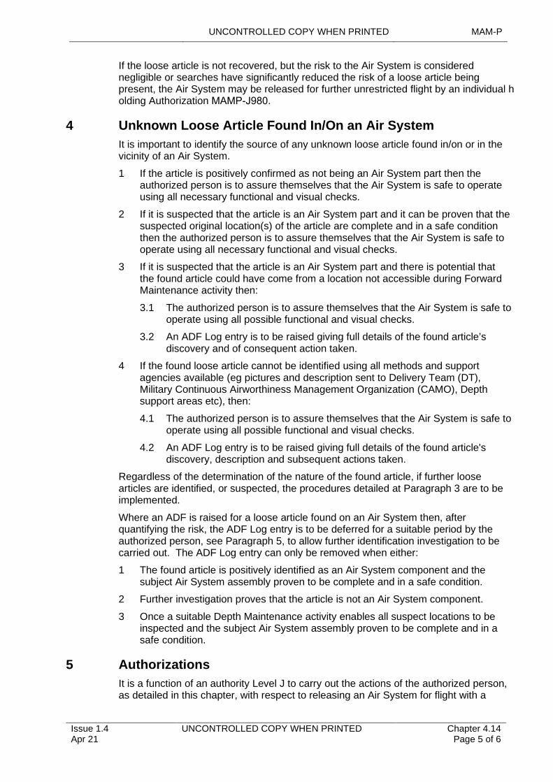
UNCONTROLLED COPY WHEN PRINTED MAM-P
If the loose article is not recovered, but the risk to the Air System is considered negligible or searches have significantly reduced the risk of a loose article being present, the Air System may be released for further unrestricted flight by an individual holding Authorization MAMP-J980.
4 Unknown Loose Article Found In/On an Air System
It is important to identify the source of any unknown loose article found in/on or in the vicinity of an Air System.
1 If the article is positively confirmed as not being an Air System part then the authorized person is to assure themselves that the Air System is safe to operate using all necessary functional and visual checks.
2 If it is suspected that the article is an Air System part and it can be proven that the suspected original location(s) of the article are complete and in a safe condition then the authorized person is to assure themselves that the Air System is safe to operate using all necessary functional and visual checks.
3 If it is suspected that the article is an Air System part and there is potential that the found article could have come from a location not accessible during Forward Maintenance activity then:
3.1 The authorized person is to assure themselves that the Air System is safe to operate using all possible functional and visual checks.
3.2 An ADF Log entry is to be raised giving full details of the found article’s discovery and of consequent action taken.
4 If the found loose article cannot be identified using all methods and support agencies available (eg pictures and description sent to Delivery Team (DT), Military Continuous Airworthiness Management Organization (CAMO), Depth support areas etc), then:
4.1 The authorized person is to assure themselves that the Air System is safe to operate using all possible functional and visual checks.
4.2 An ADF Log entry is to be raised giving full details of the found article's discovery, description and subsequent actions taken.
Regardless of the determination of the nature of the found article, if further loose articles are identified, or suspected, the procedures detailed at Paragraph 3 are to be implemented.
Where an ADF is raised for a loose article found on an Air System then, after quantifying the risk, the ADF Log entry is to be deferred for a suitable period by the authorized person, see Paragraph 5, to allow further identification investigation to be carried out. The ADF Log entry can only be removed when either:
1 The found article is positively identified as an Air System component and the subject Air System assembly proven to be complete and in a safe condition.
2 Further investigation proves that the article is not an Air System component.
3 Once a suitable Depth Maintenance activity enables all suspect locations to be inspected and the subject Air System assembly proven to be complete and in a safe condition.
5 Authorizations
It is a function of an authority Level J to carry out the actions of the authorized person, as detailed in this chapter, with respect to releasing an Air System for flight with a
Issue 1.4 Apr 21
UNCONTROLLED COPY WHEN PRINTED Chapter 4.14 Page 5 of 6
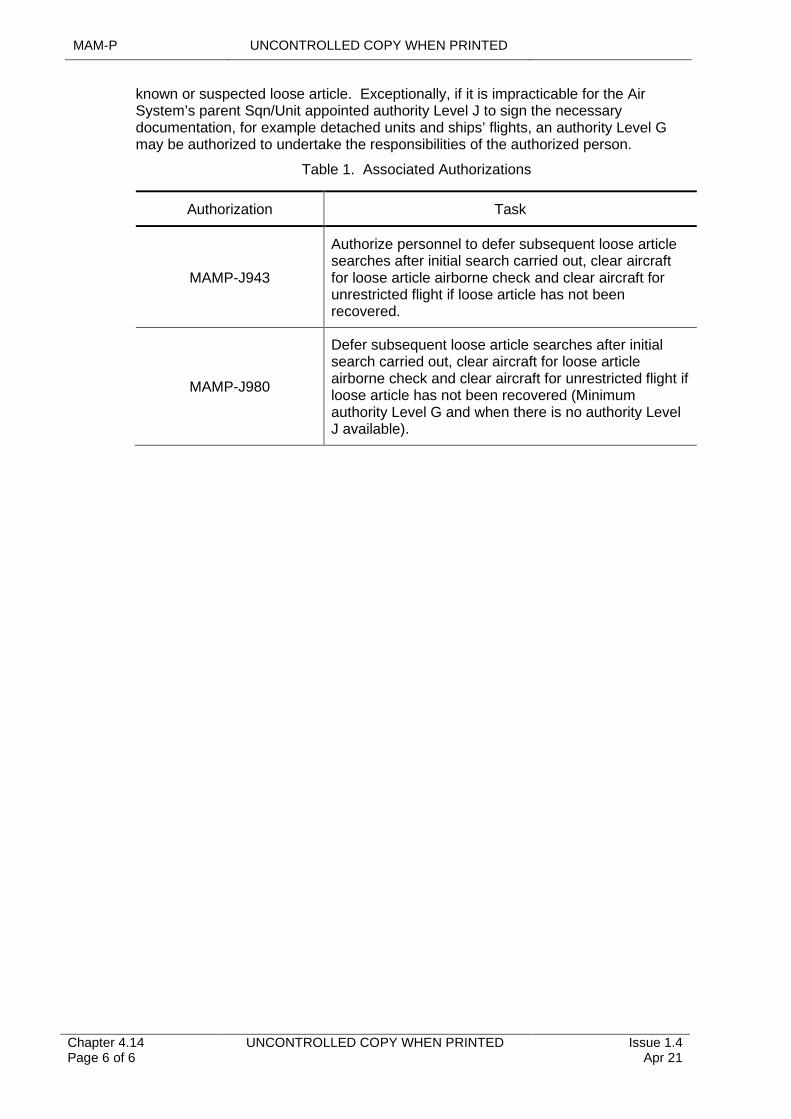
MAM-P UNCONTROLLED COPY WHEN PRINTED
Chapter 4.14 Page 6 of 6
UNCONTROLLED COPY WHEN PRINTED Issue 1.4 Apr 21
known or suspected loose article. Exceptionally, if it is impracticable for the Air System’s parent Sqn/Unit appointed authority Level J to sign the necessary documentation, for example detached units and ships’ flights, an authority Level G may be authorized to undertake the responsibilities of the authorized person.
Table 1. Associated Authorizations
Authorization Task
MAMP-J943
Authorize personnel to defer subsequent loose article searches after initial search carried out, clear aircraft for loose article airborne check and clear aircraft for unrestricted flight if loose article has not been recovered.
MAMP-J980
Defer subsequent loose article searches after initial search carried out, clear aircraft for loose article airborne check and clear aircraft for unrestricted flight if loose article has not been recovered (Minimum authority Level G and when there is no authority Level J available).
UNCONTROLLED COPY WHEN PRINTED MAM-P
Issue 1.2 May 20
UNCONTROLLED COPY WHEN PRINTED Chapter 4.15 Page 1 of 13
.........................................................................
.......................................................................................
..........................................................................................
....................
........................................................................................................
................................................................................
................................................................................................................................................................
..............................................
.....................
.................................................................................................
..........................
..........................................
................................................................................
...................................................................................................................
.................................................................................................
.......................................................................................................................................
.........................................................................................................................................................................................................
Chapter 4.15
Independent Inspections
TABLE OF CONTENTS
Paragraph Page
1 General 11.1 Introduction 11.2 Associated Publications and Instructions 21.3 Additional Information 22 Identification of Systems that Require Independent Inspections 22.1 General Guidance 22.2 Second Signature Responsibilities 33 Conduct of an Independent Inspection 33.1 Occasions When an Independent Inspection Is To Be Done 33.2 Content of an Independent Inspection 34 Raising, Specifying and Undertaking Independent Inspections 44.2 Raising the Requirement for an Independent Inspection 54.3 Selection of Individuals to Specify or Undertake Independent Inspections 54.4 Considerations When Specifying an Independent Inspection 55 Independent Inspections on Helicopter Main Rotor Blade and Tail Pylon
Fold/Spread Systems 65.1 Procedures and Clearances for Flight After Aircrew Acceptance 75.2 Helicopters with Automatic Main Rotor Folding/Spreading Systems and
Automatic Pylon Systems or Pylon Spread Interlock Systems 75.3 Helicopters with Automatic Main Rotor Folding/Spreading Systems and
Manual Pylon Spread with Interlock Systems 76 Recording Independent Inspections 86.1 General 86.2 Methods of Recording Independent Inspections 86.3 Procedure for Recording Independent Inspections 86.4 Independent Inspections Recorded on the MOD Form 707 Series Certificate
of Work 96.5 Independent Inspections Recorded on the MOD Form 707C(Ind) 106.6 Independent Inspections Recorded on the MOD Form 707C-M series 116.7 Independent Inspections Recorded on the MOD Form 707C(Glider type) 127 Authorizations 127.1 Authorizations to Specify and Undertake Independent Inspections 127.2 Additional Authorizations 12
LIST OF TABLES
Table 1. Associated Authorizations 13
1 General
1.1 Introduction
The integrity of Air System control systems is vital to the Safety of an Air System and its occupants. This chapter details the process for carrying out and recording Independent Inspections as well as identifying types of Air System control systems
MAM-P UNCONTROLLED COPY WHEN PRINTED
Chapter 4.15 Page 2 of 13
UNCONTROLLED COPY WHEN PRINTED Issue 1.2 May 20
that require Independent Inspections following Maintenance activities, including any action that could affect the correct functioning of the system.
Note:
This chapter does not apply to Independent Inspections of Aircraft Assisted Escape Systems (AAES) as these are detailed in RA 4600.
1.2 Associated Publications and Instructions
1 RA 4051 – Airborne Checks
2 RA 4600 – Aircraft Assisted Escape Systems – Safety and Maintenance Procedures
3 RA 4810 – Technical Information (MRP 145.A.45).
4 RA 4815 – Maintenance Procedures and Safety and Quality Policy (MRP 145.A.65).
1.3 Additional Information
The chain of command, the Duty Holder Chief Air Engineer, Military Continuing Airworthiness Management Organization (Mil CAMO) and the Air System Technical Information (TI) may mandate the requirement for an Independent Inspection on any system. Additionally, a supervisor may require an Independent Inspection of a system if they consider it justified by the nature or circumstances of the Maintenance work done. An Independent Inspection is a self-supervised activity and is to be conducted in accordance with (iaw) Chapter 2.5 – Self-Supervision.
2 Identification of Systems that Require Independent Inspections
2.1 General Guidance
Unless otherwise specified in TI Independent Inspections are required whenever Maintenance work involves disconnection, replacement, connection, assembly or adjustment of any element of an Air Systems control system. This is to be interpreted as meaning any system, whether electrical, mechanical or optical, operated by user input or automation, by which an Air Systems speed, direction, flight attitude or propulsive force are changed in the air or on the ground or by which the undercarriage is retracted or lowered. The term includes power operated and assisted controls, including the immediate connections between those controls and their power systems, and may further be extended to the systems that provide power to such controls. Automatic systems that can be instantly overridden by the pilot are not considered to be Air System control systems within the meaning of this chapter unless their failure, either in the air or on the ground, would place life or the Air System at Risk.
Any elements of a system, including attachment points to the Air System structure, linking the appropriate pilot’s control to any of the following is to be considered as an Air System control system. Although the list is not exhaustive, examples of Air System control systems are:
1 Primary flying controls and reaction control systems.
2 Tabs, flaps, slats and airbrakes.
3 Wing sweep control actuators.
4 Primary power unit control mechanisms, including those for throttles, variable intakes, reverse thrust, high-pressure fuel cocks, propeller constant speed units and rotating nozzles.
UNCONTROLLED COPY WHEN PRINTED MAM-P
Issue 1.2 May 20
UNCONTROLLED COPY WHEN PRINTED Chapter 4.15 Page 3 of 13
5 Primary power unit attachment points, including trunnions, swinging links, couplings and mountings.
6 Helicopter rotor blade transmission and tail rotor transmission and pitch change mechanisms.
7 Undercarriage retraction and lowering and undercarriage steering mechanisms.
8 Air System wheel brakes.
9 Automatic flight control systems.
10 Automatic or semi-automatic pylon and blade-fold systems (See Note).
Note:
Provided the spreading/folding system has not been disturbed by Maintenance, an Independent Inspection of these systems after spreading is not required.
2.2 Second Signature Responsibilities
Depending on the nature or circumstances of the Maintenance work, there may be a requirement for additional Independent Inspections to be carried out on other systems, uninstalled partial systems or major components. In this case, it is the responsibility of the task supervisor to identify the requirement. When the need for such additional Independent Inspections is likely to arise repeatedly, an Unsatisfactory Feature Report, MOD Form 765 is to be raised iaw the instructions described in RA 4810(3) and Chapter 10.1- Management and Amendment of Technical Information, in order to amend the relevant publication.
3 Conduct of an Independent Inspection
3.1 Occasions When an Independent Inspection Is To Be Done
Normally, Independent Inspections are required following the disturbance of an Air System control system. Disturbance of a system will occur when Maintenance work involves disconnection, replacement, connection or assembly of any element in that system, and may also occur when such a system is adjusted. Additionally, disturbance will occur when Maintenance work on other systems results in the movement of any component of the Air System control system from its normal installed position, irrespective of whether or not any connections to the component have been disconnected.
An Independent Inspection is not required following Maintenance work activities that do not disturb a system, eg lubrication, replenishment, examination or operation.
3.2 Content of an Independent Inspection
An Independent Inspection consists of 2 elements:
1 An inspection for correct assembly – this inspection cannot be waived.
2 A functional test – the level of disturbance to the system determines the requirement for, and extent of, the functional test; however, iaw the provisions detailed in Paragraph 4.4.1, the requirement for an independent functional test may be waived.
3.2.1 Inspection for Correct Assembly
The term “inspect for correct assembly” means an inspection of the system that has been disturbed and the individual is to examine, as appropriate:
1 To make sure that the specified system/sub-system has been assembled iaw the correct Maintenance procedure.
MAM-P UNCONTROLLED COPY WHEN PRINTED
Chapter 4.15 Page 4 of 13
UNCONTROLLED COPY WHEN PRINTED Issue 1.2 May 20
2 For correct locking.
3 For correct routeing – to include movement of the controls, if necessary.
4 For correct mechanical, electrical, optical, fuel, pneumatic and hydraulic connection.
5 For the absence of leaks.
6 To make sure that the results of any calculations used in setting up the system, including tolerances, are correct.
3.2.2 Functional Test
An independent functional test is to provide the fullest check of the operation of all parts of the system that could have been affected by the Maintenance task that necessitates the Independent Inspection. It may include, but is not limited to, checks for:
1 Correct operation in all modes.
2 Freedom and range of movement.
3 Operation in the correct sense.
4 Friction loading.
5 Synchronization.
6 Rate of operation.
7 Cable tensions.
8 Gauge indications.
9 Correct clearances.
10 Backlash tolerances.
11 Compression checks.
12 Absence of leaks.
13 Other tests or checks as deemed necessary by those referenced in Paragraph 1.3.
Prior to undertaking functional tests, structure and panels surrounding the control run and elements of the Air System control system are to, wherever possible, be re-fitted to ensure that they do not restrict operation of the system. When functional tests are done without all covers fitted, the person undertaking the functional test is to consider repeating the check when the Air System is in a normal flight condition.
4 Raising, Specifying and Undertaking Independent Inspections
The Independent Inspection procedure involves 3 activities:
1 Raising the requirement for an Independent Inspection.
2 The inspection for correct assembly, which involves 2 sub-activities:
2.1 Specifying the extent of the inspection.
2.2 Undertaking the inspection as specified.
3 The independent functional test, which involves 2 sub-activities:
3.1 Specifying the requirement for, and extent of, the independent functional test.
UNCONTROLLED COPY WHEN PRINTED MAM-P
Issue 1.2 May 20
UNCONTROLLED COPY WHEN PRINTED Chapter 4.15 Page 5 of 13
3.2 Undertaking the independent functional test as specified.
Notes:
1 The sub-activities of specifying and undertaking independent functional tests are to be immediately consecutive.
2 A single individual may do activities at 2 and 3 above.
3 When the same individual does not do the sub-activities, the recording of the Independent Inspection is to reflect this on the MOD Form 707C series or equivalent.
4.2 Raising the Requirement for an Independent Inspection
The supervisor of the Maintenance task that necessitates the Independent Inspection is responsible for raising the requirement for an Independent Inspection at the earliest opportunity after the system has been disturbed. The requirement is to be raised on the appropriate form, as detailed in Paragraph 6.
In some instances, it may not be possible to inspect all parts of a system because some parts may become obscured or inaccessible when assembled. In such cases, the requirement for an Independent Inspection is to be raised so that the inspection for correct assembly can be done before those parts are obscured or become inaccessible.
4.3 Selection of Individuals to Specify or Undertake Independent Inspections
Generally, the individual undertaking or specifying the extent of an Independent Inspection is to be authorized iaw Paragraph 7 and is not to have been the supervisor of, nor taken part in, the originating Maintenance task. However, where the Maintenance work includes a clearly defined and documented task of disassembly, an individual who participated in that disassembly task, but not in any of the subsequent Maintenance or re-assembly work, may be appointed to specify and/or undertake the Independent Inspection following re-assembly.
Exceptionally in the Forward environment, when no other authorized individual is available in a timeframe that will allow the Air System to meet operational commitments, an individual holding Authorization MAMP-K1002 may specially authorize an individual who has taken part in, or supervised, the originating Maintenance task to specify the extent of the Independent Inspection. Such special authority is to be granted for a limited and specified period or for a specific occurrence and the Authorization is to be recorded against the specifying entry.
4.4 Considerations When Specifying an Independent Inspection
4.4.1 General Considerations
The individual who specifies the Independent Inspection is to review the complete Maintenance task, as detailed in the appropriate Maintenance procedure or publication. The extent of an Independent Inspection is to be based upon the degree of disturbance to the system. In assessing the scope of the Independent Inspection, they are to make reference to the Air System’s MOD Form 700, or equivalent, documentation and any other reference sources they think appropriate.
In specifying the extent of an Independent Inspection, the individual is to take account of the full extent of work undertaken and not simply the immediate area of disturbance. This is to ensure that distant or remote parts of the system that may have been affected by the disturbance are also subject to Independent Inspection. Where work has been undertaken on other systems in the vicinity of the system subject to Independent Inspection for any other reason, eg as a Safety precaution or to enhance
MAM-P UNCONTROLLED COPY WHEN PRINTED
Chapter 4.15 Page 6 of 13
UNCONTROLLED COPY WHEN PRINTED Issue 1.2 May 20
accessibility, the effect of that work on the Independent Inspection is to be considered. The following criteria may be used as guidance:
1 Where the disturbance has been such as to cause no possible change to range and freedom of movement, independent functional tests may be restricted to tests relevant to the disturbance.
2 Where the disturbance has been minor and caused no possible change in the function of the system, or where no functional test can physically be carried out, independent functional tests may be waived.
3 Inspection of the system on either side of the area known to have been disturbed is to be at least as far as the next undisturbed connection or Line Replaceable Unit (LRU). Where the next connection point is inaccessible, eg within a major assembly, checking either side of a disconnection point may be impossible. In this case, it is acceptable to raise the Independent Inspection for correct assembly from the disconnection point.
4 The system is to be considered as a whole and, if necessary, the Independent Inspection is to be extended to include undisturbed areas in order to ensure full system integrity.
When the full functionality of a system cannot be checked in the area of the Maintenance activity, either for Safety or other practical reasons, eg no test facility available within a Maintenance organization or when engine starting, rotors running or an Airborne Check is required, the individual specifying the Independent Inspection is to ensure the requirement is identified on either:
1 A Certification of Component Release (MOD Form 731 or equivalent), to ensure that the requirement for a functional test of a system is transferred between Maintenance facilities/levels.
2 A MOD Form 707B (or equivalent) for a ground run to be carried out.
3 A MOD Form 707B(AFRC) for a flying requirement to be carried out.
4 Raised as an airborne or taxi check iaw the instructions in RA 4051 and Chapter 3.1 – Flight Testing of Aircraft.
4.4.2 Grouping of Independent Inspections
Before specifying the extent of the inspection for correct assembly and the requirement for, and extent of, the functional test, the individual is to take account of other work activities on the Air System that may also require Independent Inspections. Where appropriate, a single, all-encompassing, Independent Inspection may be specified.
On occasions when more than one trade works on a system, resulting in each trade requiring an identical or similar independent functional test, a single independent functional test may be done. To ensure that the functional test meets the requirements of each trade, the individual specifying the all-encompassing functional test is to consult with similarly authorized personnel of the appropriate trades.
5 Independent Inspections on Helicopter Main Rotor Blade and Tail Pylon Fold/Spread Systems
Independent Inspections after the manual spreading of helicopter main rotor blade and tail pylons, without pylon spread interlocks, are to be carried out as detailed in paragraph 3.1. Automatic and semi-automatic fold/spread systems, with integral indication and interlock systems to ensure system integrity after spreading do not

UNCONTROLLED COPY WHEN PRINTED MAM-P
Issue 1.2 May 20
UNCONTROLLED COPY WHEN PRINTED Chapter 4.15 Page 7 of 13
require Independent Inspection after spreading, provided that they have not been disturbed for Maintenance, but may require confirmatory checks.
There are specific circumstances when operations dictate that Independent Inspections of manual helicopter main rotor blade and tail pylon fold/spread systems cannot be carried out until after Aircrew acceptance. In such cases, the procedures at paragraph 5.1 are to be followed. In addition, Commands may permit the undertaking of such Independent Inspections for other than operational reasons, such as a training activity to maintain skill levels.
5.1 Procedures and Clearances for Flight After Aircrew Acceptance
1 Whenever manual main rotor blades or tail pylon are folded the Air System is to be placed Unserviceable in the MOD Form 700C or equivalent.
2 On spreading:
2.1 An Independent Inspection is to be carried out iaw paragraph 3.2.1 (Independent Inspection for correct assembly).
2.2 An independent functional test is not required and may be waived iaw paragraph 4.4.1.
3 The Air System may be cleared for flight and accepted by the pilot on the MOD Form 705 (or equivalent) with the above entry open, subject to:
3.1 The flying requirement Serial Number Of Work being annotated on the MOD Form 705 (or equivalent).
3.2 The MOD Form 700C (or equivalent) entries being cleared as soon as possible (normally before take off).
3.3 The individual undertaking the Independent Inspection positively indicating to the pilot that the inspection is complete and that all items associated with folding and spreading operations are properly secured and locked. The pilot is to acknowledge the report before engaging the rotors.
5.2 Helicopters with Automatic Main Rotor Folding/Spreading Systems and Automatic Pylon Systems or Pylon Spread Interlock Systems
On spreading the main rotor blades, an authorized individual is to check visually from the ground that the geometry of the spread blades is correct and that no obvious malfunction has occurred. These checks are to be done on the following occasions:
1 If the blades are already spread – immediately before the Air System is manned.
2 If the blades are folded when the Air System is manned – after spreading.
3 If the blades are refolded after the Air System is manned – after re-spreading.
On completion of these checks, an authorized individual is to indicate to the pilot that the geometry of the blades/pylon is correct and that no obvious malfunction has occurred. The pilot is to acknowledge the report before attempting to engage the rotors.
The checks may be done by individuals of any Air System trade authorized, by type, to flight service iaw Chapter 2.1 – Engineering Authorizations.
5.3 Helicopters with Automatic Main Rotor Folding/Spreading Systems and Manual Pylon Spread with Interlock Systems
For Air Systems fitted with pylon spread interlock systems, the following additional checks are to be done. On spreading the tail pylon, an authorized individual is to
MAM-P UNCONTROLLED COPY WHEN PRINTED
Chapter 4.15 Page 8 of 13
UNCONTROLLED COPY WHEN PRINTED Issue 1.2 May 20
check that the pylon locking pins are fully engaged, the warning flag is housed and, by attempting to turn the tail rotor, that the drive coupling is positively engaged.
6 Recording Independent Inspections
6.1 General
Whenever a system subject to Independent Inspection is disturbed:
1 The requirement for an Independent Inspection is to be raised.
2 The system is to be Independently inspected to the extent deemed necessary.
This section details the procedure for recording these activities, which collectively constitute the Independent Inspection process. Individual roles and responsibilities are detailed above.
6.2 Methods of Recording Independent Inspections
Independent Inspections are to be recorded using either a form specified in the TI or using the wording detailed in the following paragraphs. The entries may be hand written, typed or produced by a stamp with the 'blanks' completed in handwriting or type. Where an electronic IS is used, the TI will contain the procedures that are wholly equivalent.
Note:
Where the Technical Information provided is derived from non-UK sources, such as the USA, terminology will differ from that used below. In such cases the TI will ensure that there is no ambiguity with equivalent requirements.
6.3 Procedure for Recording Independent Inspections
The supervisor of the Maintenance task that necessitates the Independent Inspection is to record the requirement for an Independent Inspection on either the appropriate work order or job report.
The Independent Inspection may be recorded on either the F707 series Certificate of Work, F707C(Ind) or F707C-M series forms, however the following conventions are to be observed:
1 When the individual(s) specifies the extent of, and carries out, each activity, the Independent Inspection ►can◄ be recorded on the appropriate MOD Form 707 series Certificate of Work or equivalent.
2 When the individual who specifies the extent of either the inspection for correct assembly and/or the independent functional test does not undertake the activity, the Independent Inspection is to be recorded on the MOD Form 707C series.
3 When Independent Inspections are required on multiple inter-linked systems, the Independent Inspections may be recorded on the MOD Form 707C-M series.
4 When glider school personnel have assembled a glider, the Independent Inspections may be recorded on MOD Form 707C(Viking) or MOD Form 707C(Vigilant) as appropriate.
The following paragraphs 6.4, 6.5 & 6.6 detail the method for recording Independent Inspections on the F707 Certificate of Work, F707C and F707C-M series of forms.
Note:
For the purposes of this Chapter, the MOD Form 707C series comprises the MOD Form 707C(Ind) and the MOD Form 707C-M series, which itself comprises the MOD
UNCONTROLLED COPY WHEN PRINTED MAM-P
Issue 1.2 May 20
UNCONTROLLED COPY WHEN PRINTED Chapter 4.15 Page 9 of 13
Form 707C-M1(Ind), MOD Form 707C-M2(Ind), MOD Form 707C-M3(Ind) and MOD Form 707C-M4(Ind). It does not include the MOD Form 707C(Glider type).
6.4 Independent Inspections Recorded on the MOD Form 707 Series Certificate of Work
6.4.1 Certification of Independent Inspections
The individual closing an Independent Inspection entry, whether completing the full inspection or undertaking a delegated or deferred element of the inspection, is to complete both the 1st and 2nd signature blocks of relevant documentation with original signatures and printed name. Where inspections are recorded electronically, an equivalent process is to be used.
6.4.2 Raising the Requirement for an Independent Inspection
The supervisor of the Maintenance task that necessitates the Independent Inspection is to raise the requirement for an Independent Inspection, using the following entries and wording in the Work Required column of the appropriate form:
1 Inspection for correct assembly:
'Independent Inspection for correct assembly required on ...[insert clear description of the system or sub-system]... system in respect of work at ...[insert clear reference to the appropriate Sheet No and Line No]…’
2 Functional test:
'Independent functional test required on ...[insert clear description of the system or sub-system]... system in respect of work at ...[insert clear reference to the appropriate Sheet No and Line No]…'
Notes:
1 To provide a clear Audit trail, the above 2 entries are to be recorded in the MOD Form 707 series documentation or equivalent as immediately consecutive entries. Where there are multiple inspections for correct assembly, the functional test entry is to follow immediately after the last correct assembly entry.
2 The wording of the Work Requirements for correct assembly and functional test may be combined into a single stamp provided that, after stamping and making any necessary deletions, the final wording is as per the appropriate entry above and is legible.
6.4.3 Specifying and Undertaking an Independent Inspection
When specifying an Independent Inspection, the individual is responsible for recording the extent of the work done.
When a single all-encompassing Independent Inspection has been specified to take account of other work activities on the Air System, each entry raised for the constituent Independent Inspection elements are to be cross-referenced to it. The signature closing each entry raised for the constituent Independent Inspections certifies that the extent of the single all-encompassing Independent Inspection is acceptable. Similarly, when an all-encompassing entry has been raised for an independent functional test, the signature closing each entry for constituent trade-specific independent functional tests certifies that the extent of the single all-encompassing independent functional test is acceptable.
6.4.4 Specifying and Undertaking an Independent Inspection for Correct Assembly
MAM-P UNCONTROLLED COPY WHEN PRINTED
Chapter 4.15 Page 10 of 13
UNCONTROLLED COPY WHEN PRINTED Issue 1.2 May 20
……………...
…………………..…. ……........ ………………
When an individual specifies and undertakes an Independent Inspection for correct assembly, they are to close the entry raising the requirement for the Independent Inspection, using the following wording in the Work Done column:
'Independent Inspection for correct assembly on …..[insert clear description of the system or sub-system] system from to …iaw/for*
satisfactorily completed.'
*Delete as appropriate
When recording details of the Independent Inspection for correct assembly, the individual may refer to the appropriate section of the Technical Information (TI) (such as the Topic 1) or may record the activities in a narrative format, eg “for correct assembly of item A and inspection for the correct tolerance between point 1 and point 2.”
6.4.5 Specifying and Undertaking an Independent Functional Test
When an individual specifies and undertakes an independent functional test, they are to close the entries raising the requirement for the Independent Inspection, using the following wording in the Work Done column:
'Independent functional test for iaw [where TI has specific work cards for functional checks of systems] satisfactorily completed.'
When recording details of the independent functional test the individual may refer to the appropriate section of the TI (such as the Topic 1) or may record the activities in a narrative format.
6.4.6 Waiving the Independent Functional Test
When an individual specifies the extent of an Independent Inspection for correct assembly, but waives the requirement for an independent functional test, they are to close the entry raising the requirement for the independent functional test, using the following wording in the Work Done column:
'Independent functional test waived iaw MAM-P Chapter 4.15 Paragraph 4.4.1.’
Note:
The wording in Paragraphs 6.4.5 and 6.4.6 may be combined into a single stamp provided that, after stamping and making any necessary deletions, the final wording is as per the appropriate entry above and is legible.
6.5 Independent Inspections Recorded on the MOD Form 707C(Ind)
The MOD F707C(Ind) is to be used as a continuation sheet to the appropriate MOD Form 707.
The MOD Form 707C(Ind) is to be completed iaw the instructions for use on the back of the form, using equivalent words to those detailed above to record the scope, or waiving, of the inspection activities. Transferring the inspection onto the MOD Form 707C(Ind) is to be recorded as detailed below:
6.5.1 When the requirement for Independent Inspection has already been raised on the MOD Form 707 series Certificate of Work, and a MOD Form 707C(Ind) is to be used.
When the requirement for the Independent Inspection has already been raised on the appropriate work order or job report using the two work required entries at paragraph 6.4.2, and a MOD Form 707C(Ind) is to be initiated by the supervisor, the supervisor is to close the two open entries using the following wording in the work done column of the appropriate form:
UNCONTROLLED COPY WHEN PRINTED MAM-P
Issue 1.2 May 20
UNCONTROLLED COPY WHEN PRINTED Chapter 4.15 Page 11 of 13
.......................................................
……………………………………'Independent Inspection for correct assembly/independent functional test* recorded on MOD Form 707C(Ind) sheet number …'
*Delete as appropriate.
6.5.2 When the requirement for Independent Inspection has not already been raised on the MOD Form 707 series Certificate of Work, and a MOD Form 707C(Ind) is to be used.
When the requirement for the Independent Inspection has not already been raised on the appropriate work order or job report, and a Mod Form 707C(Ind) is to be initiated by the supervisor, the supervisor is to insert the following wording on the appropriate work order or job report:
1 Work Required Column:
'Independent inspection for correct assembly and independent functional test required, in respect of work at ...[insert clear reference to the appropriate Sheet No and Line No]….'
2 Work Done Column:
'Recorded on MOD F707C(Ind) sheet number.
Note:
‘
1. The wording of the Work Done Column in Paragraphs 6.5.2 and 6.6 may be combined into a single stamp provided that, after stamping and making any necessary deletions, the final wording is as per the appropriate entry above and is legible.
6.6 Independent Inspections Recorded on the MOD Form 707C-M series
The pre-printed MOD Form 707C-M series may be used as a continuation of the appropriate work order or job report. When the MOD Form 707C-M series are used, they are to be completed iaw the instructions on MOD Form 799(Ind). Transferring the inspection onto the MOD Form 707C-M series is to be recorded as detailed below:
1 Work Required Column:
'Independent inspection for correct assembly and independent functional test required, in respect of work at ...[insert clear reference to the appropriate Sheet No and Line No]….'
2 Work Done Column:
'Recorded on MOD F707C-M? (where ‘?’ is replaced by 1, 2, 3 or 4, as appropriate) …[insert clear reference to the appropriate SNOW, Sheet No and Entry No]…’.
Note:
1. The wording of the Work Done Column in Paragraphs 6.5.2 and 6.6 may be combined into a single stamp provided that, after stamping and making any necessary deletions, the final wording is as per the appropriate entry above and is legible.
6.6.1 Additional Recording Requirement
When an individual is specially authorized by an individual holding Authorization MAMP-K1002 to specify the extent of an Independent Inspection for Maintenance work that they have supervised or taken part in, they are to record that they hold
MAM-P UNCONTROLLED COPY WHEN PRINTED
Chapter 4.15 Page 12 of 13
UNCONTROLLED COPY WHEN PRINTED Issue 1.2 May 20
MAMP-F604 in Field 1, Block B of the MOD Form 707C series, or as part of the appropriate specifying entry on the appropriate work order or job report.
6.7 Independent Inspections Recorded on the MOD Form 707C(Glider type)
Independent Inspections may be recorded on the MOD Form 707C(Viking) or MOD Form 707C(Vigilant) when, following glider assembly by glider school personnel, the MOD Form 707C(Glider type) is to be used as a continuation sheet of the appropriate work order or job report to record Independent Inspections and functional tests detailed in the relevant TI. The MOD Form 707C(Glider type) is to not be used by RAF glider Maintenance personnel, who are to record Independent Inspections iaw the procedures detailed above.
7 Authorizations
7.1 Authorizations to Specify and Undertake Independent Inspections
An Independent Inspection is, by its nature, a self-supervised activity. Tradesmen required to specify or to undertake Independent Inspections are to hold the following Authorizations:
1 Specifying the extent of Independent Inspections:
1.1 In source trade: MAMP-F601.
1.2 Outside source trade: MAMP-F603.
1.3 Having participated in original Maintenance task: MAMP-F604.
2 Undertaking Independent Inspections:
2.1 In source trade: MAMP-E501.
2.2 Outside source trade: MAMP-E506.
Authority is to be granted iaw Chapter 2.1 – Engineering Authorizations by an appropriately authorized individual holding authority level J. These are standard authorities for work within own trade, with special authorities required for work outside of own trade.
7.2 Additional Authorizations
Within the limitations detailed in Paragraph 4.3, an individual may be specially authorized (Authorization MAMP-F604) by an individual holding Authorization MAMP-K1002 to specify the extent of an Independent Inspection when they have been the supervisor of, or taken part in, the originating Maintenance task.
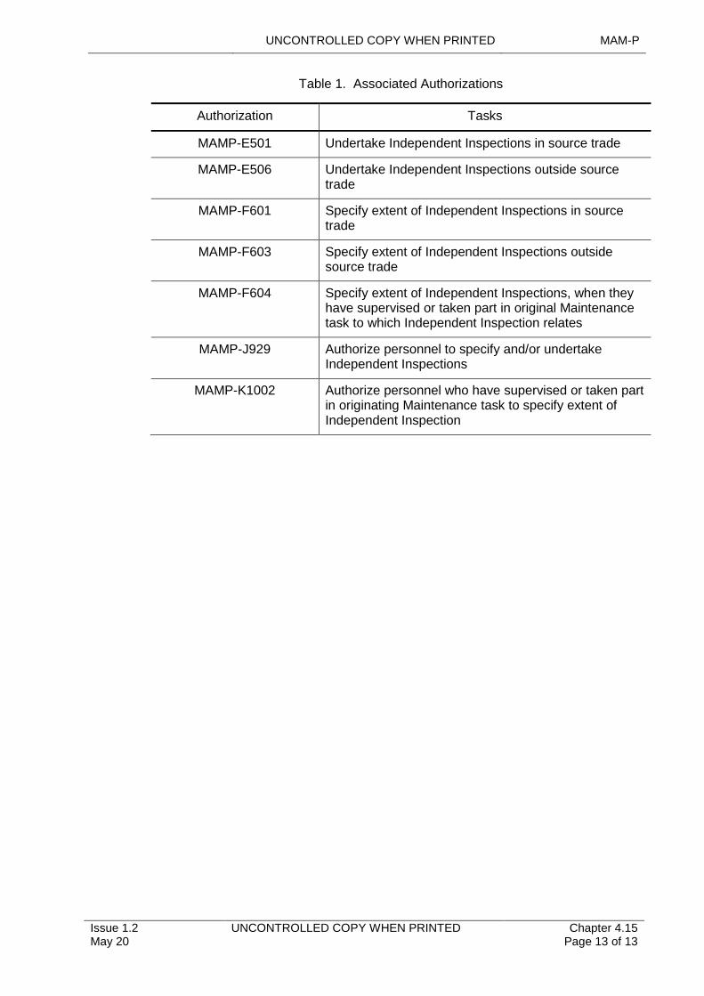
UNCONTROLLED COPY WHEN PRINTED MAM-P
Issue 1.2 May 20
UNCONTROLLED COPY WHEN PRINTED Chapter 4.15 Page 13 of 13
Table 1. Associated Authorizations
Authorization Tasks
MAMP-E501 Undertake Independent Inspections in source trade
MAMP-E506 Undertake Independent Inspections outside source trade
MAMP-F601 Specify extent of Independent Inspections in source trade
MAMP-F603 Specify extent of Independent Inspections outside source trade
MAMP-F604 Specify extent of Independent Inspections, when they have supervised or taken part in original Maintenance task to which Independent Inspection relates
MAMP-J929 Authorize personnel to specify and/or undertake Independent Inspections
MAMP-K1002 Authorize personnel who have supervised or taken part in originating Maintenance task to specify extent of Independent Inspection
UNCONTROLLED COPY WHEN PRINTED MAM-P
Initial Issue Nov 19
UNCONTROLLED COPY WHEN PRINTED Chapter 4.16 Page 1 of 4
...........................................................................
..................................................................................................................................
........................................................................................
.......................................................................................................
............................................................................................................................................
....................................................................................................
.........................................................................................................................................................................................................
Chapter 4.16
Maintenance of Air Systems in Multi-Service Environments
TABLE OF CONTENTS
Paragraph Page
1 General 11.1 Introduction 11.2 Associated Publications and Instructions 12 Multi-Service Maintenance Environments 13 Augmentation by Maintenance Personnel from other UK Armed
Services 24 Visiting Aircraft from other UK Armed Services 24.1 Corrective Maintenance undertaken on Air Systems from other UK Armed
Services 25 Military Aircraft belonging to Foreign Countries (Aircraft Cross-
Servicing (ACS)) 26 Civil Aircraft at UK Military Air Establishments 27 Authorizations 3
LIST OF TABLES
Table 1. Associated Authorizations 3
1 General
1.1 Introduction
This chapter details the conditions to be satisfied prior to personnel from one UK Armed Service undertaking any Maintenance on an Air System of another UK Armed Service or on a foreign Air System. It does not address Ground Handling or Fuelling operations, which is to be carried out iaw RA 4054, Chapter 3.4 - Ground Operations and Chapter 3.4.1 - Fuelling Operations for Aircraft on the Ground.
1.2 Associated Publications and Instructions
1 RA 4054 – Ground Handling Operations
2 RA 4806 – Personnel Requirements (MRP 145.A.30)
3 STANAG 3430 – Responsibilities for Aircraft Cross-Servicing (ACS)
2 Multi-Service Maintenance Environments
There are a number of situations where personnel of one UK Armed Service may maintain an Air System belonging to another UK Armed Service. Such multi-Service Maintenance environments can include:
1 The inter-Service loan of an Air System where the receiving Service is wholly responsible for Maintenance.
2 The augmentation of a unit by personnel from another UK Armed Service.
3 Visiting Aircraft.
MAM-P UNCONTROLLED COPY WHEN PRINTED
Chapter 4.16 Page 2 of 4
UNCONTROLLED COPY WHEN PRINTED Initial Issue Nov 19
3 Augmentation by Maintenance Personnel from other UK Armed Services
Augmented personnel, who are trained and Competent on Air System type, will need to be re-Authorized by the receiving unit Level J, holding MAMP-J916, prior to the commencement of any Maintenance activity. Whilst extant Authorizations will not be valid in this scenario, they will assist in demonstrating Competence.
Before Authorizing any augmented personnel, the receiving unit Level J is to satisfy themselves that the individual is suitably trained and assessed as Competent for the tasks they are required to carry out.
Unless there are over-riding reasons to restrict the augmentee’s activities, the receiving unit level J is to Authorize an augumentee up to the maximum authority level that they held within the parent Service. The receiving unit Level J is not to restrict the augumentee to the maximum authority level allowed for a Tradesman of the equivalent rank within the receiving Service.
4 Visiting Aircraft from other UK Armed Services
Stations(Stns)/Ships/Units receiving Air Systems from another UK Armed Service are only to provide flight servicing assistance to the Aircrew/travelling ground crew; they are not permitted to undertake or sign for flight servicing activities on the Air System unless they are Authorized to do so.
4.1 Corrective Maintenance undertaken on Air Systems from other UK Armed Services
Corrective Maintenance may be undertaken on Air Systems from another UK Armed Service, by personnel who are not type trained, provided that:
1 There is agreement between the Aircraft Military Continuing Airworthiness Management Organisation (Mil CAMO) and hosting Accountable Manager (Maintenance) on the extent of the task.
2 The Tradesmen undertaking the task have access to the necessary Technical Information(TI).
3 The Tradesmen undertaking the task are authorized by the individual holding MAMP-K1006 of the hosting Stn/Ship/Unit.
4 Host Stn/Ship/Unit personnel continue to operate within their own procedures.
5 Military Aircraft belonging to Foreign Countries (Aircraft Cross-Servicing (ACS))
ACS is the flight servicing of Air Systems belonging to one nation by personnel of a different nation. Within NATO, under the ACE ACS Programme, STANAG 3430 sets out details of agreed cross-servicing arrangements.
6 Civil Aircraft at UK Military Air Establishments
The Maintenance of civil registered Aircraft landing on/at MOD Stn/Ships/Unit is not to be undertaken by Service personnel except when specifically authorized by respective Commands.
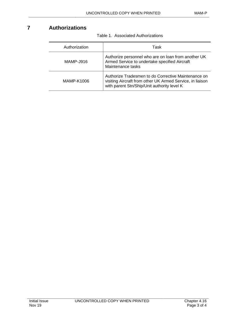
UNCONTROLLED COPY WHEN PRINTED MAM-P
Initial Issue Nov 19
UNCONTROLLED COPY WHEN PRINTED Chapter 4.16 Page 3 of 4
7 Authorizations
Table 1. Associated Authorizations
Authorization Task
MAMP-J916 Authorize personnel who are on loan from another UK Armed Service to undertake specified Aircraft Maintenance tasks
MAMP-K1006Authorize Tradesmen to do Corrective Maintenance on visiting Aircraft from other UK Armed Service, in liaison with parent Stn/Ship/Unit authority level K

MAM-P UNCONTROLLED COPY WHEN PRINTED
Chapter 4.16 Page 4 of 4
UNCONTROLLED COPY WHEN PRINTED Initial Issue Nov 19
Intentionally Blank for Print Pagination
UNCONTROLLED COPY WHEN PRINTED MAM-P
Initial Issue Nov 19
UNCONTROLLED COPY WHEN PRINTED Chapter 4.17 Page 1 of 2
...........................................................................................................................................................................................
.......................................................................................................................
...............................................................................................................
............................................................................................................
.............................................................................................................................
.........................................................................................................................................................................................................
Chapter 4.17
Chemical, Biological, Radiological and Nuclear Decontamination
TABLE OF CONTENTS
Paragraph Page
1 General 11.1 Introduction 11.2 Associated Publications and Instructions 12 Decontamination Methods 12.1 Technical Information (TI) and/or the Air System Equipment 13 Sources of Advice 13.1 1710 Naval Air Squadron (1710 NAS) 13.2 RAF FP Force HQ Counter-CBRN Staff 23.3 Defence Chemical Biological Radiological and Nuclear Centre (DCBRNC),
Winterbourne Gunner 23.4 Defence Science Technology Laboratories (DSTL) 24 Responsibilities 24.1 Commands 2
1 General
1.1 Introduction
Chemical, Biological, Radiological and Nuclear (CBRN) contamination of Air Systems presents health and Safety Risks to personnel, disrupts operational capability and degrades the performance of the Air System, Air System equipment, systems and structures. Prompt and appropriate action following incidences of CBRN contamination of Air Systems and Air System equipment reduces Risks and effects by absorbing, destroying, neutralizing, making harmless or removing CBRN elements and/or agents. Effective decontamination will return the Air Systems and Air System equipment to a Tolerable Safety state and minimize the spread of agents.
1.2 Associated Publications and Instructions
1 BR 2170 (2) – Ship CBRNDC Manual Volume 2 - CBRN Defence
2 JDP 3-61 – Counter-CBRN
2 Decontamination Methods
2.1 Technical Information (TI) and/or the Air System Equipment
Technical Information will detail the equipment, materials and procedures to be used to decontaminate the Air System and/or Air System equipment for each agent and category of decontamination identified by the Defence Science and Technology Laboratory (DSTL). Air System and Air System equipment is only to be decontaminated in accordance with the techniques detailed in the TI.
3 Sources of Advice
3.1 1710 Naval Air Squadron (1710 NAS)
1710 NAS will provide advice and investigations on the effect of contaminant and decontamination materials and procedures on Air System materials.
MAM-P UNCONTROLLED COPY WHEN PRINTED
Chapter 4.17 Page 2 of 2
UNCONTROLLED COPY WHEN PRINTED Initial Issue Nov 19
3.2 RAF FP Force HQ Counter-CBRN Staff
RAF FP C-CBRN Staff can provide advice on the decontamination of sensitive equipment.
3.3 Defence Chemical Biological Radiological and Nuclear Centre (DCBRNC), Winterbourne Gunner
The DCBRNC will provide advice on decontamination of common Ground Support Equipment (GSE).
3.4 Defence Science Technology Laboratories (DSTL)
DSTL can provide advice on all aspects of decontamination via REACHBACK through Project VAMPER. This is reached through Permanent Joint Head Quarters (PJHQ) on operational tasking.
4 Responsibilities
4.1 Commands
Commands are to ensure that:
1 The correct CBRN decontamination equipment is made available to Station/Ship/Units as required.
2 Station/Ship/Units understand the procedures for obtaining the correct CBRN decontamination equipment.

UNCONTROLLED COPY WHEN PRINTED MAM-P
Initial Issue Nov 19
UNCONTROLLED COPY WHEN PRINTED Chapter 4.18 Page 1 of 4
....................................................................................................................................................................................................
......................................................................................................................................................................
..............................................................................................................................................................
...........................................................................................................................................................................................................
....................................................................................................................................................................
...................................................................................................................................................................................
.......................................................................................................................................................
.......................................................................................................
Chapter 4.18
Removal of Bodily Fluids Contamination from Aircraft
TABLE OF CONTENTS
Paragraph Page
1 General 11.1 Introduction 11.2 Associated Publications and Instructions 11.3 Applicability 11.4 Additional Information 22 Decontamination Procedure 22.1 Initial Actions 22.2 Spillage Assessment and Control 22.3 Post-decontamination Procedure 22.4 Timescales and Deferment 33 Responsibilities 33.1 Decontamination Commander 33.2 Maintenance Organization 44 Authorizations 4
LIST OF TABLES
Table 1. Risk to Aircraft Materials, Structures and Components Posed by Bodily Fluids. 3Table 2. Associated Authorizations 4
1 General
1.1 Introduction
Bodily fluids may present a biological hazard and a significant corrosive hazard to Aircraft structures and materials. Precautions and preventive measures, appropriate to the role and use of the Aircraft are to be taken to prevent any spillage of bodily fluids leaking into Aircraft structures. Additionally, where leakage occurs, timely, safe and effective removal of such substances is essential to minimise the risk to personal health and prevent Aircraft corrosion. This chapter details the Maintenance procedures required to recover an Aircraft following the spillage of bodily fluids.
1.2 Associated Publications and Instructions
1 RA 4103 – Removal of Body Fluid Contamination from Aircraft
2 JSP 375 – Management of Health and Safety in Defence
3 JSP 800 Vol 3 – Movement of Materiel
1.3 Applicability
This chapter concentres on Maintenance actions to remove visible fluid spillages from Aircraft structure and equipment to reduce potential corrosive effects. It is not intended to provide detailed procedures for Aircraft sterilization after viral or bacterial contamination, but general principles are provided; in the case of likely contagion, specific guidance should be sought from JSP 800, Vol 3 - Movement of Materiel and the relevant Technical Information (TI), where appropriate.
MAM-P UNCONTROLLED COPY WHEN PRINTED
Chapter 4.18 Page 2 of 4
UNCONTROLLED COPY WHEN PRINTED Initial Issue Nov 19
1.4 Additional Information
Delivery Duty Holder (DDH) Chief Air Engineers (CAEs) will promulgate orders and procedures to achieve timely, safe and effective removal of bodily fluid contamination.
2 Decontamination Procedure
Decontamination procedures will vary, depending upon Aircraft type; however, the following generic procedure is provided for guidance.
2.1 Initial Actions
On initial discovery of a bodily fluid spillage, a Decontamination Commander (see Paragraph 3 for responsibilities), is to be nominated. Access to the contaminated area is to be controlled to ensure the minimum number of personnel are exposed to any potential health risks, until decontamination is complete. Prior to commencing the decontamination process, it is advised that the Decontamination Commander liaises with the appropriate Station (Stn)/Ship/Unit) medical personnel to carry out a health hazard assessment of the spillage (if required).
Note:
Bodily fluids include materials such as saliva, blood, vomit, urine and faeces from all human and animal sources. In all circumstances personnel are to assume all human and animal bodily fluids to be potentially infectious.
2.2 Spillage Assessment and Control
Following the receipt of medical advice (if required), a spillage assessment is to be carried out and is to include the following actions as a minimum.
1 Determine the location and extent of the primary contamination.
2 Remove appropriate panels to gain access in order to determine the extent of any secondary contamination.
3 Determine the potential risk to Aircraft structure and components.
4 When safe to do so, initial cleaning is to be carried out in accordance with (iaw) with TI.
5 Take every reasonable precaution to prevent direct contact with any spilled bodily fluid during this process. If contact occurs, wash the affected area thoroughly with soap and water and seek medical advice as soon as possible.
6 Document the details of any spillage of bodily fluids and the initial actions relating to the spillage by means of an entry in the MOD Form 700C or equivalent.
7 If no further contamination is suspected, a person holding Authorization MAMP-G705 may authorize this initial action as sufficient and clear the MOD Form 700C or equivalent entry:
“No further decontamination required”.
2.3 Post-decontamination Procedure
The following procedure is to be followed on completion of the decontamination procedure:
1 The Aircraft is to be thoroughly checked by the Decontamination Commander to ensure that all bodily fluids, bodily remains, cleaning materials, waste cleaning fluid, absorbent materials and water have been removed.
2 A person holding Authorization MAMP-G705 is to certify completion of Aircraft decontamination.
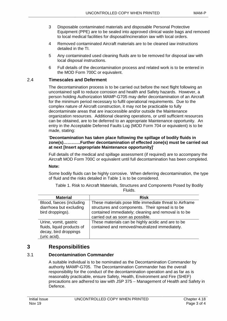
UNCONTROLLED COPY WHEN PRINTED MAM-P
Initial Issue Nov 19
UNCONTROLLED COPY WHEN PRINTED Chapter 4.18 Page 3 of 4
…………
3 Disposable contaminated materials and disposable Personal Protective Equipment (PPE) are to be sealed into approved clinical waste bags and removed to local medical facilities for disposal/incineration iaw with local orders.
4 Removed contaminated Aircraft materials are to be cleaned iaw instructions detailed in the TI.
5 Any contaminated used cleaning fluids are to be removed for disposal iaw with local disposal instructions.
6 Full details of the decontamination process and related work is to be entered in the MOD Form 700C or equivalent.
2.4 Timescales and Deferment
The decontamination process is to be carried out before the next flight following an uncontained spill to reduce corrosion and health and Safety hazards. However, a person holding Authorization MAMP-G705 may defer decontamination of an Aircraft for the minimum period necessary to fulfil operational requirements. Due to the complex nature of Aircraft construction, it may not be practicable to fully decontaminate areas that are inaccessible and/or outside the Maintenance organization resources. Additional cleaning operations, or until sufficient resources can be obtained, are to be deferred to an appropriate Maintenance opportunity. An entry in the Acceptable Deferred Faults Log (MOD Form 704 or equivalent) is to be made, stating:
‘Decontamination has taken place following the spillage of bodily fluids in zone(s) Further decontamination of effected zone(s) must be carried out at next [Insert appropriate Maintenance opportunity]’
Full details of the medical and spillage assessment (if required) are to accompany the Aircraft MOD Form 700C or equivalent until full decontamination has been completed.
Note:
Some bodily fluids can be highly corrosive. When deferring decontamination, the type of fluid and the risks detailed in Table 1 is to be considered.
Table 1. Risk to Aircraft Materials, Structures and Components Posed by Bodily Fluids.
Material RiskBlood, faeces (including diarrhoea but excluding bird droppings).
These materials pose little immediate threat to Airframe structures and components. Their spread is to be contained immediately; cleaning and removal is to be carried out as soon as possible.
Urine, vomit, gastric fluids, liquid products of decay, bird droppings (uric acid).
These materials can be highly acidic and are to be contained and removed/neutralized immediately.
3 Responsibilities
3.1 Decontamination Commander
A suitable individual is to be nominated as the Decontamination Commander by authority MAMP-G705. The Decontamination Commander has the overall responsibility for the conduct of the decontamination operation and as far as is reasonably practicable, ensure Safety, Health, Environment and Fire (SHEF) precautions are adhered to iaw with JSP 375 – Management of Health and Safety in Defence.
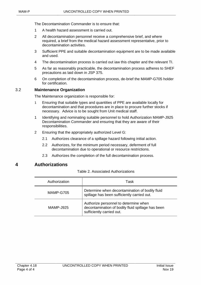
MAM-P UNCONTROLLED COPY WHEN PRINTED
Chapter 4.18 Page 4 of 4
UNCONTROLLED COPY WHEN PRINTED Initial Issue Nov 19
The Decontamination Commander is to ensure that:
1 A health hazard assessment is carried out.
2 All decontamination personnel receive a comprehensive brief, and where required, a brief from the medical hazard assessment representative, prior to decontamination activities.
3 Sufficient PPE and suitable decontamination equipment are to be made available and used.
4 The decontamination process is carried out iaw this chapter and the relevant TI.
5 As far as reasonably practicable, the decontamination process adheres to SHEF precautions as laid down in JSP 375.
6 On completion of the decontamination process, de-brief the MAMP-G705 holder for certification.
3.2 Maintenance Organization
The Maintenance organization is responsible for:
1 Ensuring that suitable types and quantities of PPE are available locally for decontamination and that procedures are in place to procure further stocks if necessary. Advice is to be sought from Unit medical staff.
1 Identifying and nominating suitable personnel to hold Authorization MAMP-J925 Decontamination Commander and ensuring that they are aware of their responsibilities.
2 Ensuring that the appropriately authorized Level G:
2.1 Authorizes clearance of a spillage hazard following initial action.
2.2 Authorizes, for the minimum period necessary, deferment of full decontamination due to operational or resource restrictions.
2.3 Authorizes the completion of the full decontamination process.
4 Authorizations
Table 2. Associated Authorizations
Authorization Task
MAMP-G705 Determine when decontamination of bodily fluid spillage has been sufficiently carried out.
MAMP-J925Authorize personnel to determine when decontamination of bodily fluid spillage has been sufficiently carried out.
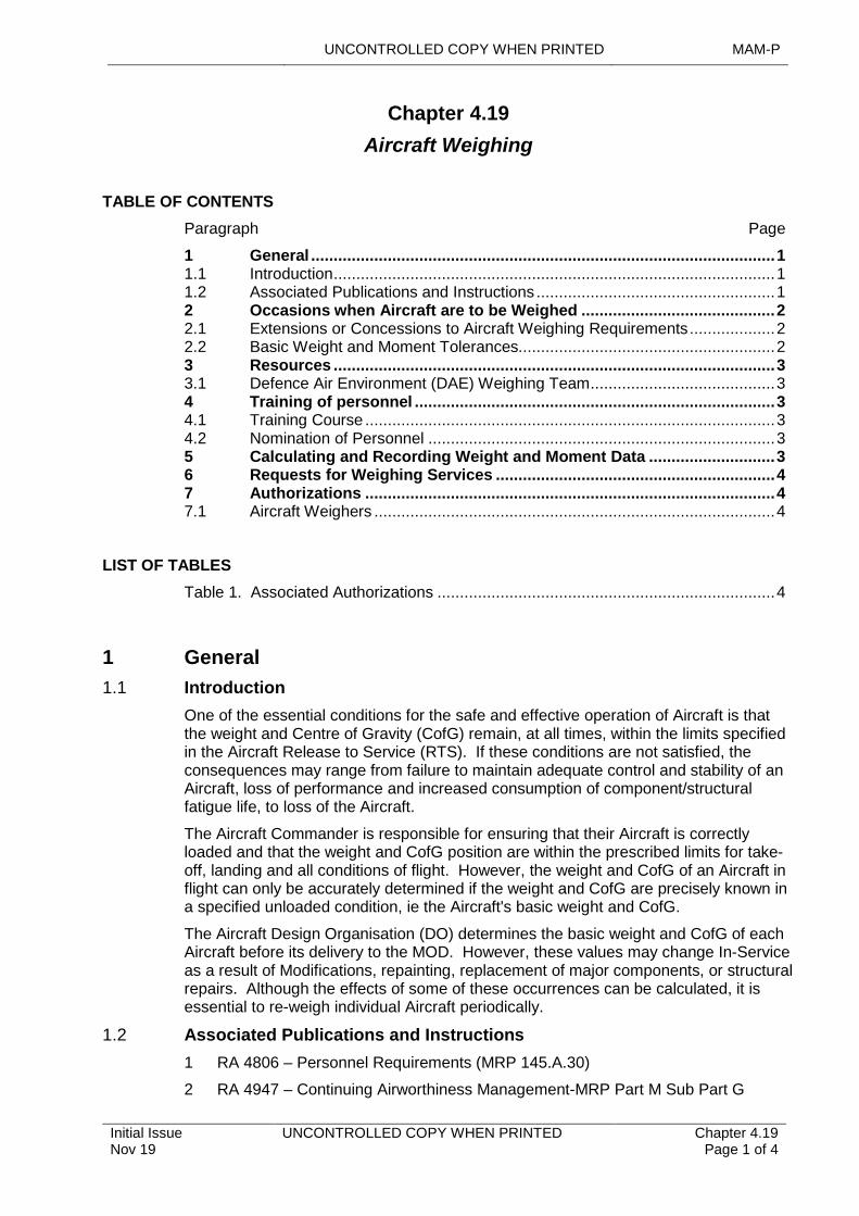
UNCONTROLLED COPY WHEN PRINTED MAM-P
Initial Issue Nov 19
UNCONTROLLED COPY WHEN PRINTED Chapter 4.19 Page 1 of 4
...........................................................................
....................................................................................................................................................................................
..........................................................................................
........................................................................................................................................................................
.........................................................................................................................
...........................................................................................................................................................
..............................................................
.......................................................................................................................................................
.......................................................................................................
Chapter 4.19
Aircraft Weighing
TABLE OF CONTENTS
Paragraph Page
1 General 11.1 Introduction 11.2 Associated Publications and Instructions 12 Occasions when Aircraft are to be Weighed 22.1 Extensions or Concessions to Aircraft Weighing Requirements 22.2 Basic Weight and Moment Tolerances 23 Resources 33.1 Defence Air Environment (DAE) Weighing Team 34 Training of personnel 34.1 Training Course 34.2 Nomination of Personnel 35 Calculating and Recording Weight and Moment Data 36 Requests for Weighing Services 47 Authorizations 47.1 Aircraft Weighers 4
LIST OF TABLES
Table 1. Associated Authorizations 4
1 General
1.1 Introduction
One of the essential conditions for the safe and effective operation of Aircraft is that the weight and Centre of Gravity (CofG) remain, at all times, within the limits specified in the Aircraft Release to Service (RTS). If these conditions are not satisfied, the consequences may range from failure to maintain adequate control and stability of an Aircraft, loss of performance and increased consumption of component/structural fatigue life, to loss of the Aircraft.
The Aircraft Commander is responsible for ensuring that their Aircraft is correctly loaded and that the weight and CofG position are within the prescribed limits for take-off, landing and all conditions of flight. However, the weight and CofG of an Aircraft in flight can only be accurately determined if the weight and CofG are precisely known in a specified unloaded condition, ie the Aircraft's basic weight and CofG.
The Aircraft Design Organisation (DO) determines the basic weight and CofG of each Aircraft before its delivery to the MOD. However, these values may change In-Service as a result of Modifications, repainting, replacement of major components, or structural repairs. Although the effects of some of these occurrences can be calculated, it is essential to re-weigh individual Aircraft periodically.
1.2 Associated Publications and Instructions
1 RA 4806 – Personnel Requirements (MRP 145.A.30)
2 RA 4947 – Continuing Airworthiness Management-MRP Part M Sub Part G
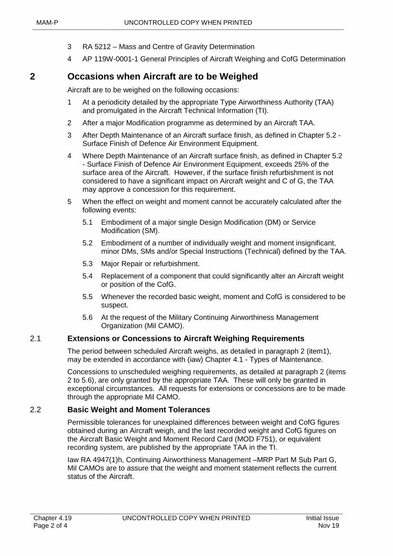
MAM-P UNCONTROLLED COPY WHEN PRINTED
Chapter 4.19 Page 2 of 4
UNCONTROLLED COPY WHEN PRINTED Initial Issue Nov 19
3 RA 5212 – Mass and Centre of Gravity Determination
4 AP 119W-0001-1 General Principles of Aircraft Weighing and CofG Determination
2 Occasions when Aircraft are to be Weighed
Aircraft are to be weighed on the following occasions:
1 At a periodicity detailed by the appropriate Type Airworthiness Authority (TAA) and promulgated in the Aircraft Technical Information (TI).
2 After a major Modification programme as determined by an Aircraft TAA.
3 After Depth Maintenance of an Aircraft surface finish, as defined in Chapter 5.2 - Surface Finish of Defence Air Environment Equipment.
4 Where Depth Maintenance of an Aircraft surface finish, as defined in Chapter 5.2 - Surface Finish of Defence Air Environment Equipment, exceeds 25% of the surface area of the Aircraft. However, if the surface finish refurbishment is not considered to have a significant impact on Aircraft weight and C of G, the TAA may approve a concession for this requirement.
5 When the effect on weight and moment cannot be accurately calculated after the following events:
5.1 Embodiment of a major single Design Modification (DM) or Service Modification (SM).
5.2 Embodiment of a number of individually weight and moment insignificant, minor DMs, SMs and/or Special Instructions (Technical) defined by the TAA.
5.3 Major Repair or refurbishment.
5.4 Replacement of a component that could significantly alter an Aircraft weight or position of the CofG.
5.5 Whenever the recorded basic weight, moment and CofG is considered to be suspect.
5.6 At the request of the Military Continuing Airworthiness Management Organization (Mil CAMO).
2.1 Extensions or Concessions to Aircraft Weighing Requirements
The period between scheduled Aircraft weighs, as detailed in paragraph 2 (item1), may be extended in accordance with (iaw) Chapter 4.1 - Types of Maintenance.
Concessions to unscheduled weighing requirements, as detailed at paragraph 2 (items 2 to 5.6), are only granted by the appropriate TAA. These will only be granted in exceptional circumstances. All requests for extensions or concessions are to be made through the appropriate Mil CAMO.
2.2 Basic Weight and Moment Tolerances
Permissible tolerances for unexplained differences between weight and CofG figures obtained during an Aircraft weigh, and the last recorded weight and CofG figures on the Aircraft Basic Weight and Moment Record Card (MOD F751), or equivalent recording system, are published by the appropriate TAA in the TI.
Iaw RA 4947(1)h, Continuing Airworthiness Management –MRP Part M Sub Part G, Mil CAMOs are to assure that the weight and moment statement reflects the current status of the Aircraft.
UNCONTROLLED COPY WHEN PRINTED MAM-P
Initial Issue Nov 19
UNCONTROLLED COPY WHEN PRINTED Chapter 4.19 Page 3 of 4
If, on completion of an Aircraft weigh, the calculated weight or CofG lies outside the specified tolerances, the personnel weighing the Aircraft are to ascertain that the Aircraft has been correctly prepared and that the MOD F751 or equivalent is accurate.
If the Aircraft is weighed and the Aircraft weigh result is outside the tolerances published in the TI, or the Aircraft has required re-work on weighing preparation, the Aircraft is to be re-weighed. If the Aircraft is still out of tolerance, or if the 2 weights produce consistent results and the variation from tolerance cannot be explained, the Mil CAMO is to be informed. An Aircraft is not to be flown until any discrepancy with its basic weight and moment has been resolved to the satisfaction of the Mil CAMO.
As the use of Low Profile Platforms (LPPs) requires 3 separate weighing operations to be undertaken, there is no requirement to undertake a second set of weighing operations before a consistent discrepancy is referred to the Mil CAMO.
3 Resources
3.1 Defence Air Environment (DAE) Weighing Team
The DAE Weighing Team is part of 71 (Inspection & Repair) Squadron (71(IR)Sqn) within 42 (Expeditionary Support) Wing (42(ES)Wing). The Team is based at RAF Wittering and carries out weighing on Air Systems as required by TAAs or Mil CAMOs. The Weighing Team manages and runs the Aircraft Weighing Training Course (see paragraph 4.1) and team personnel make annual visits to all MOD agencies and Service establishments engaged in Aircraft weighing activities in order to advise on current techniques and practices.
4 Training of personnel
4.1 Training Course
OC 71(IR)Sqn provides the Aircraft Weighing Training Course, CN 3202. Military Aviation Authority Certification Structures and Air System Design Standards (MAA Cert S and ADS) sponsors the course.
4.2 Nomination of Personnel
Nominations of personnel for Aircraft weighing training are to be co-ordinated and controlled by the respective Command.
5 Calculating and Recording Weight and Moment Data
The calculation and subsequent recording of Aircraft weight and moment data is to be carried out by personnel holding authorization MAMP-E511 following:
1 An Aircraft weigh.
2 Any change to the Aircraft basic weight and moment.
3 Any change to the list of equipment included in the Aircraft basic weight, including the record of removing and re-installing these equipments.
4 Any change to the list of equipment not included in the Aircraft basic weight, or the list of variable or expendable loads, including the record of removing and re-installing these equipments.
5 Any change to the Aircraft Current Operating Data.
6 Any change to standard role equipment and/or permanently installed items not included in the Aircraft basic weight.
MAM-P UNCONTROLLED COPY WHEN PRINTED
Chapter 4.19 Page 4 of 4
UNCONTROLLED COPY WHEN PRINTED Initial Issue Nov 19
6 Requests for Weighing Services
Stations/Ships/Units that do not have authorized Aircraft Weighers on site are to task the DAE Weighing Team, giving 7 days' notice under normal conditions. Telephone requests (01780 417242) are to be followed up by an email to 71(IR) SQN-Ac Weigh Team (MULTIUSER) [email protected].
Note
Aircraft must be prepared for weighing iaw TI. The preparation of an Aircraft for weigh must be completed prior to the Weighing Team's arrival. Its subsequent recovery is the responsibility of the Stn/Ship/Unit.
7 Authorizations
7.1 Aircraft Weighers
Aircraft weighing is a self-supervised activity; see RA 4806 and Chapter 2.4 - Certification and Maintenance Documentation. Tradesmen required to weigh Aircraft within the DAE are to hold Authorization MAMP-D408.
If an Aircraft Weigher has not weighed an Aircraft for 2 years, they are to undertake at least one supervised Aircraft weigh before being re-authorized. If an Aircraft Weigher has not carried out an Aircraft weigh for 3 years, they are to undertake the approved Weighing Training Course again before re-authorization. The appropriate individual holding authority level K is to ensure that a record of Aircraft Weigher currency is maintained.
Table 1. Associated Authorizations
Authorization Task
MAMP-D408 Tradesmen required to weigh Aircraft within the DAE
MAMP-E511Calculate and record changes in weight and moment data
UNCONTROLLED COPY WHEN PRINTED MAM-P
Issue 1.2 May 20
UNCONTROLLED COPY WHEN PRINTED Chapter 4.20 Page 1 of 3
......................................................................................................................................................................
.....................................................................................................................................................................................................................................................................................................
...........................................................................................................................
.........................................................................................................................................................................................................
Chapter 4.20
Electrical Bonding and Earthing of Air Systems and Associated Airfield Support Equipment
TABLE OF CONTENTS
Paragraph Page
1 General 11.1 Introduction 11.2 Associated Publications and Instructions 12 Bonding and earthing leads 13 Bonding 24 Earthing 24.1 General Facilities 24.2 Licensed Explosives Facilities 24.3 Air Systems 2
1 General
1.1 Introduction
Air Systems and their associated Airfield Support Equipment (ASE) are electrically bonded and earthed to prevent:
1 The build-up of electrostatic charges.
2 Equipment frames rising to dangerous voltages under fault conditions or, in alternating current systems, when out-of-balance currents flow in neutral lines.
This chapter provides Maintenance Organisations with guidance material for the application of bonding or earthing.
1.2 Associated Publications and Instructions
1 STANAG 7009 / AEP-24 – Aircraft Electrical Hazards on the Flight Line
2 STANAG / AFLP 3682 – Electrostatic Safety Connection Procedures for Aviation Fuel Handling and Liquid Fuel Loading/Unloading Operations During Ground Transfer and Aircraft Fuelling/Defuelling
3 STANAG 3632 / AAEP-02 – Aircraft and Ground Support Equipment Electrical Connections for Static Grounding
4 DAP 113A-0201-1 – Earthing of Aircraft and Ground Support Equipment
5 AP 113A-0307-1 – Aircraft Bonding, Screening and Earth Points
6 JSP 375 – Management of Health and Safety in Defence
7 Topic 5A2 – Hazard and Maintenance Notes
8 Defence Aerodrome Manual
9 Explosives Storage & Transportation Committee (ESTC) Standard No. 6, Part 1 – Electrical
10 DSA 03 OME Part 2 – In-Service and Operational Safety Management of OME
2 Bonding and earthing leads
MAM-P UNCONTROLLED COPY WHEN PRINTED
Chapter 4.20 Page 2 of 3
UNCONTROLLED COPY WHEN PRINTED Issue 1.2 May 20
Unless otherwise directed by an applicable Air System Document Set, bonding and earthing leads must be used in accordance with DAP 113A-0201-1 and must be manufactured and maintained as follows:
1 Aircraft bonding leads must be manufactured in accordance with AP 113A-0307-1.
2 Earthing leads must be manufactured and maintained in accordance with DAP 113A-0201-1.
3 Bonding
Equipment to be used on or around Air Systems should be bonded in accordance with any applicable Technical Information (Air System or Airfield Support Equipment). Equipment requirements may include the following:
1 Bonding of equipment installed in aircraft.
2 Bonding of fuelling equipment during aircraft fuelling (refer to Chapter 3.4.1).
3 Bonding of Aircraft access equipment.
4 Bonding of non-electrical GSE.
5 Bonding of drop or internal ferry tanks to storage racks.
4 Earthing
4.1 General Facilities
STANAG 7009 contains information on earth points, including their siting and testing.
Static earth points (also known as ramp earth points), designed to dissipate an electrostatic charge, should have an impedance of less than 10,000 ohms referenced to earth. Power earth points (also known as main earth points or power ground), designed to protect from power system faults, should have an impedance of less than 10 ohms referenced to earth. A static earth point may not be used as a power earth point. If there is a requirement for both static and power earth, then a power earth point should be used.
The Defence Aerodrome Manual requires earthing points to be checked annually.
4.2 Licensed Explosives Facilities
The earthing requirements for licensed explosives facilities, including Armed Aircraft and Dangerous Air Cargo Parking Slots, are detailed in ESTC Standard No. 6, Part 1 – Electrical (within the Defence Ordnance, Munitions and Explosives Safety Regulator library).
The ESTC Standard No 6 Part 1 – Electrical requires earthing points within licensed explosives facilities, when a TT (terre-terre) earthing system is used, to be checked every 11 months.
4.3 Air Systems
Procedures and limits for earthing Air Systems and Airfield Support Equipment should be contained within applicable Technical Information. Where earth points are not available, or where available earth points do not meet the requirements of applicable Technical Information then any associated airworthiness risk (due to system damage) or Risk to Life (due to power system faults or elevated explosive risk) should be considered for acceptance by the relevant risk owner (Duty Holder or Operational Commander) based on advice from the TAA, CAE and/or an electrical safety advisor, as required. For licensed explosives facilities, the relevant single-Service Inspector of
UNCONTROLLED COPY WHEN PRINTED MAM-P
Issue 1.2 May 20
UNCONTROLLED COPY WHEN PRINTED Chapter 4.20 Page 3 of 3
Explosives should be consulted. Further information is available within associated publications.
UNCONTROLLED COPY WHEN PRINTED MAM-P
Issue 1.2 May 20
UNCONTROLLED COPY WHEN PRINTED Chapter 5.1 Page 1 of 6
.........................................................................................................................................................................................................
......................................................................................................................................................
..................................................................................
.................................................................................................
...........................................................................................................................................................
.............................................................................................................................................
............................................................................................................................................................................................................................................................
.............................................................................................
...........................................................................
Chapter 5.1
Ground Running of Aero-Engines and Auxiliary Power Units
TABLE OF CONTENTS
Paragraph Page
1 General 1Introduction 1Associated Publications and Instructions 1Applicability 1
2 Ground Running General Procedures and Precautions 2General Procedures and Precautions: 2
3 Communications 34 Composition and Responsibilities of the Ground Running Team 3
Supervisor 3Air System/Aero-engine/APU Operator 4Air System/Aero-engine/APU Test Assistant 4Safety Person 4
5 Training and Authorization of Air System/Aero-engine/APU Operators 4Training 4Certificate of Competence 5Occasions for Assessment 5
6 Authorization 5
LIST OF TABLES
Table 1. Associated Authorizations 6
1 General
Introduction
Aero-engines and Auxiliary Power Units (APUs) may need to be started for diagnostic or testing purposes, or to provide Air System services for Maintenance activities when Ground Support Equipment (GSE) is neither available nor suitable. This chapter provides the general orders and procedures for ground running aero-engines and APUs for Maintenance operations.
Associated Publications and Instructions
1 RA 1410 – Occurrence Reporting and Management
2 RA 4510 – Ground Running of Aero-Engines and Auxiliary Power Units.
Applicability
This chapter is applicable to the starting and ground running of aero-engines and APUs installed in Air Systems, aero-engine training facilities and Uninstalled Engine Test Facilities (UETFs) to carry out Maintenance or to provide Air System services; throughout this chapter this practice will be defined as ground running. This chapter is not applicable to the starting and running of aero-engines and APUs in preparation for flight.
MAMP UNCONTROLLED COPY WHEN PRINTED
Chapter 5.1 Page 2 of 6
UNCONTROLLED COPY WHEN PRINTED Issue 1.2 May 20
2 Ground Running General Procedures and Precautions
Aero-engine and APU ground running is to be conducted in accordance with (iaw) appropriate procedures in the relevant Technical Information (TI) and Local Orders. The ground running supervisor is to ensure that all members of a ground running team are briefed on their responsibilities and the general procedures and precautions.
General Procedures and Precautions:
1 Ground running is to be carried out by properly constituted ground running teams.
2 The ground running team supervisor is to ensure that the general precautions are complied with as far as reasonably possible.
3 The Maintenance ground running of the main propulsion engine(s) when installed on an Air System may cause unintended taxi or flight. In such circumstances, it may be necessary or appropriate to use Aircrew.
4 Ground running is to be conducted on an authorized site and, where possible, facing into wind. The Air System and any GSE used is to be adequately restrained against movement as detailed in the relevant equipment TI. This includes fitting undercarriage and other relevant ground locks.
5 For aero-engines in UETFs and engine training facilities, the aero-engine is to be correctly rigged in the test stand and all connections are to be made iaw the relevant TI.
6 For ground running in a Hardened Aircraft Shelter (HAS), the front and rear doors are to be fully open, the ventilation system is to be set to maximum and all personnel are to remain clear of the Air System/aero-engine/APU hazard zones as detailed in the relevant TI.
7 A loose article check is to be carried out on the Air System/aero-engine/APU and surrounding areas. All tools, test equipment and other materiel required for the ground run are to be secured against movement.
8 The Air System/aero-engine/APU is to be properly prepared for ground running iaw the relevant TI. Where there are no instructions in the TI, the ground run supervisor is to ensure that:
8.1 The Air System/aero-engine/APU is in a safe condition for the ground run by physically checking the Air System/aero-engine/APU and associated documentation.
8.2 Debris guards, deflectors and diagnostic/test equipment are fitted.
8.3 All doors, panels, cowlings and filler caps are closed, except where access is required during the ground run.
8.4 Blade tethering gear, covers, blanks, plugs and locking devices are removed and stowed, unless required for restraint or Safety reasons.
8.5 Snow and ice is removed.
8.6 The Air System Assisted Escape Systems are prepared.
9 Adequate lighting is to be provided for a night-time ground run. In particular, the hazard zones, as defined in the relevant TI, are to be illuminated where practicable.
10 All members of the ground running team and other personnel likely to be affected by the ground running are to wear appropriate Personal Protective Equipment (PPE).
UNCONTROLLED COPY WHEN PRINTED MAM-P
Issue 1.2 May 20
UNCONTROLLED COPY WHEN PRINTED Chapter 5.1 Page 3 of 6
3
4
11 When a propeller has to be turned by hand before starting an aero-engine, the aero-engine is always to be treated as potentially live and the ignition switches/magnetos are to be selected off.
12 First Aid Fire Fighting Appliance (FAFFA) of the appropriate type are to be available for immediate use.
13 To eliminate the Risk of a potential collision hazard if the Air System inadvertently moves forward, the area in front of the Air System is to be clear of all obstructions such as vehicles and GSE. Additionally, the Air System is to be secured as a minimum by use of main-wheel chocks.
14 Ground running of aero-engines is to be recorded in the Air System’s MOD Form 724 or Technical Log iaw Chapter 2.4 - Certification and Management of Maintenance Documentation.
Communications
When required by local orders and ground running orders, the ground run supervisor is to notify Air Traffic Control (ATC) of the impending ground running to facilitate any required rapid fire service response. Prior to starting the APU or aero-engine, communications are to be established between the Air System and ATC, using either the Air System's radio or alternative method.
Composition and Responsibilities of the Ground Running Team
The composition of the ground running team is dependent on the Air System type and the ground run to be carried out. However, the person tasking the ground running team is to ensure that the following appointments are filled, and their responsibilities are clearly established as detailed in following paragraphs:
1 Supervisor.
2 Aero-engine Operator.
3 Aero-engine test Assistant if required.
4 Safety Person.
Other personnel may be appointed to meet the specific requirements of the ground running team or to meet local conditions/orders (eg observers, ground equipment operators, fire officers, etc). The responsibilities of the supervisor and aero-engine/APU operator or supervisor and Safety person may be combined, except for helicopter engaged-rotors ground running, where the engine operator is a Tradesman. However, the responsibilities of the aero-engine operator and Safety person are not to be combined.
Supervisor
The responsibilities of the ground running team supervisor include:
1 Briefing the ground running team on the conduct of the ground running. The briefing is to include:
1.1 The duties of ground running team members.
1.2 Safety precautions.
1.3 Emergency procedures.
1.4 Any local orders.
MAMP UNCONTROLLED COPY WHEN PRINTED
Chapter 5.1 Page 4 of 6
UNCONTROLLED COPY WHEN PRINTED Issue 1.2 May 20
2 Ensuring effective communication is maintained between the team members and, where necessary, other personnel in the vicinity of the ground run.
3 Ensuring suitable communication is maintained with ATC or, when embarked, the Bridge/Flyco Co-ordination Office.
4 Liaising with external agencies such as the fire services, where applicable.
5 The supervisor of the ground running may also supervise the associated Maintenance activities that require the ground running of aero-engines and APUs.
Air System/Aero-engine/APU Operator
The Air System/aero-engine/APU operator is to be a Pilot, or an Air System engineering Tradesman authorized iaw Paragraph 6.4. The responsibilities of the Air System/aero-engine/APU operator include starting, operating and stopping aero-engine(s) and APUs iaw the TI.
Where assistance is required to operate systems, the Air System/aero-engine/APU operator is responsible for briefing the assistant(s).
Air System/Aero-engine/APU Test Assistant
The responsibilities of the Air System/aero-engine/APU test assistant include:
1 Recording test data as directed by the supervisor.
2 Informing the supervisor or engine operator of any abnormal indications or readings.
3 When necessary, discharging the approved FAFFA onto the aero-engine or APU, or into the aero-engine or APU compartment, iaw the relevant TI and the Safety brief received from the supervisor.
Safety Person
The Safety person is to be a Tradesman deemed Competent by the supervisor to carry out the following duties and responsibilities:
1 Remain outside the Aircraft during the ground run.
2 Give clearance to the engine operator to start the aero-engine or APU after assessing that it is safe to do so.
3 Restrict access of personnel and vehicles in the vicinity of the Air System while the ground run is in progress.
4 Instruct the engine operator to stop the aero-engine or APU if an emergency arises.
5 When necessary, discharge the approved FAFFA onto the aero-engine or APU, or into the aero-engine or APU compartment, iaw the relevant TI and the Safety brief received from the supervisor.
5 Training and Authorization of Air System/Aero-engine/APU Operators
Training
Personnel required to be Air System/aero-engine/APU operators are to have completed training on the specific Air System/aero-engine/APU type that they will be required to operate. Training is to include an assessment of Competence by an
UNCONTROLLED COPY WHEN PRINTED MAM-P
Issue 1.2 May 20
UNCONTROLLED COPY WHEN PRINTED Chapter 5.1 Page 5 of 6
authorized engineering Tradesman, or by a Qualified Aircrew Instructor. The Competence assessment is to certify that the Tradesman:
1 Understands the relevant procedures, appropriate areas of TI and local orders concerning ground running.
2 Is Competent to operate the engine within the limitations of their training.
Certificate of Competence
On completion of the assessment, a certificate of Competence is to be issued and is to clearly show, (where applicable):
1 The Air System/aero-engine/APU type and mark that they can operate.
2 With or without rotors engaged (helicopters only).
3 Specific aero-engines they can operate on multi-engine Air Systems.
4 The limitations imposed by the ground run as defined in the relevant TI and enhanced by local orders (eg APU only, both aero-engines at flight idle with rotors engaged, reheat/no-reheat etc).
5 The frequency of ground runs required to maintain currency.
Note:
Details of these ground runs are to be recorded.
Occasions for Assessment
Aero-engine/APU operators are to be assessed for Competence in ground running:
1 After aero-engine/APU operator training and prior to being authorized.
2 At least every 12 months; a new certificate of Competence is to be issued iaw Paragraph 5.2.
3 After any period where the aero-engine/APU operator loses currency; a new certificate of Competence is to be issued iaw Paragraph 5.2.
6 Authorization
Personnel required to:
1 Supervise aero-engine/APU ground running teams, on Air Systems or UETFs, are to:
1.1 Hold Authorization MAMP-C306 and have completed the relevant platform training course.
1.2 Hold Authorization MAMP-C306 and have completed the relevant UETF training course.
2 Carry out aero-engine/APU operator duties are to:
2.1 Hold Authorization MAMP-C307 and have completed the relevant air system/aero-engine/APU training courses.
2.2 Have completed the relevant aero-engine operator training.
3 Carry out aero-engine/APU test assistant duties are to:
3.1 Be appropriately authorized for the tasks described in Paragraph 4.3, or as directed by the supervisor.
4 Assess aero-engine/APU operators and issue certificates of Competence are to:
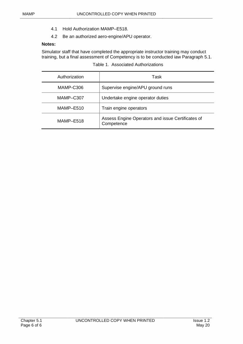
MAMP UNCONTROLLED COPY WHEN PRINTED
Chapter 5.1 Page 6 of 6
UNCONTROLLED COPY WHEN PRINTED Issue 1.2 May 20
4.1 Hold Authorization MAMP–E518.
4.2 Be an authorized aero-engine/APU operator.
Notes:
Simulator staff that have completed the appropriate instructor training may conduct training, but a final assessment of Competency is to be conducted iaw Paragraph 5.1.
Table 1. Associated Authorizations
Authorization Task
MAMP-C306 Supervise engine/APU ground runs
MAMP–C307 Undertake engine operator duties
MAMP–E510 Train engine operators
MAMP–E518Assess Engine Operators and issue Certificates of Competence
UNCONTROLLED COPY WHEN PRINTED MAM-P
Initial Issue Nov 19
UNCONTROLLED COPY WHEN PRINTED Chapter 5.2 Page 1 of 4
.................................................................
............................................
......................................................................................................................................................................................................................................................
........................................................................................................................................................
...............................................................................................
..............................................................................................................................................
.......................................................................................................................................................
.......................................................................................................
Chapter 5.2
Surface Finish of Defence Air Environment Equipment
TABLE OF CONTENTS
Paragraph Page
1 General 11.1 Introduction 11.2 Associated Publications and Instructions 12 Surface Finish (SF) Maintenance 22.1 Control of SF Materials 22.2 Maintenance Definitions for Paint Application 22.3 Maintenance Definitions for Paint Removal 22.4 Maintenance Facilities 33 Training and Authorization 43.1 SF Cleaning Training 43.2 SF Removal Training 43.3 SF Application Training 4
LIST OF TABLES
Table 1. Maintenance Definitions for Paint Applications 2Table 2. Maintenance Definitions for Paint Removal 3Table 3. Types and Descriptions of Surface Finish Maintenance Facilities 3
1 General
1.1 Introduction
The preservation and renewal of surface finishes is essential to the Continuing Airworthiness of Air Systems, Air System components and equipment, and to the quality of associated Ground Support Equipment (GSE).
Throughout this chapter, Surface Finish (SF) relates to paints, primers, temporary protectives, varnishes and some conversion coatings as promulgated in the DAP 119A-0601 series. Well-maintained SF contributes to maintaining the life and Structural Integrity of an Air System. It can also affect conspicuity, reduce electromagnetic properties, provide chemical agent resistance and maintain the cosmetic appearance of equipment. Procedures for protecting SF are detailed in Air System or equipment Technical Information (TI).
1.2 Associated Publications and Instructions
1 RA 5726 – Integrity Management
2 DAP 119A-0601-0A – Surface Finishing and Marking of Service Equipment: Surface Finishing Policy, Organization and Administration.
3 DAP 119A-0601-0B – Surface Finishing and Marking of Service Equipment: Surface Finish Processes, Procedures, Materials and Equipment.
4 DAP 119A-0601-0C – Surface Finishing and Marking of Service Equipment: Surface Finish Restoration Techniques and Repair Schemes.
5 DAP 119A-0601-0D – Surface Finishing and Marking of Service Equipment: Procedures for the Maintenance and Repair of Fabric and Aircraft Trim.
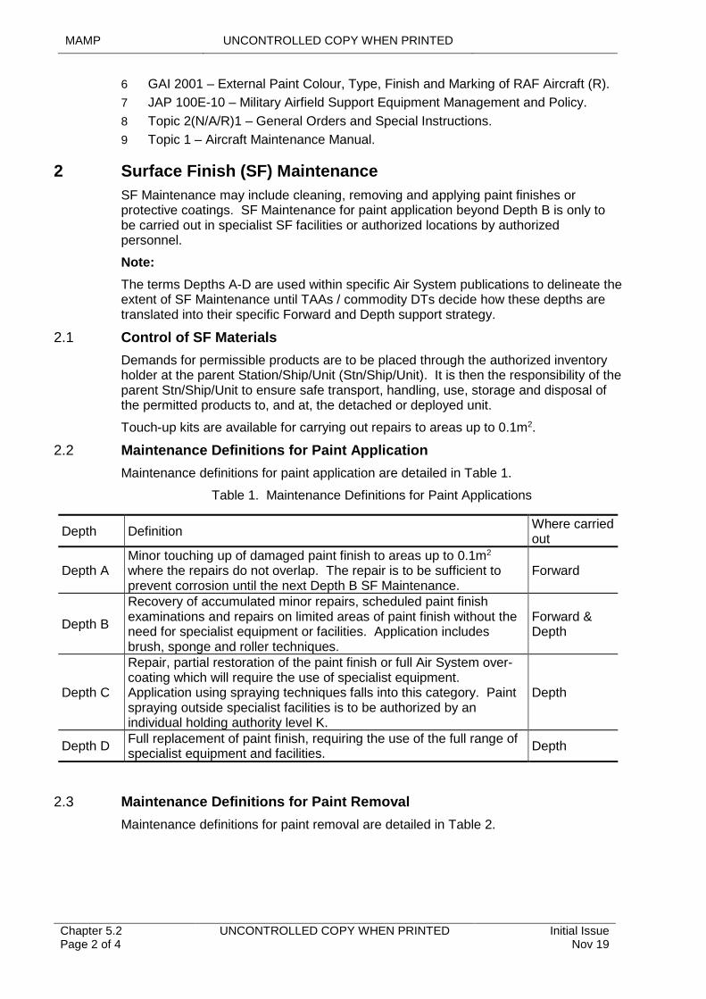
MAMP UNCONTROLLED COPY WHEN PRINTED
Chapter 5.2 Page 2 of 4
UNCONTROLLED COPY WHEN PRINTED Initial Issue Nov 19
6 GAI 2001 – External Paint Colour, Type, Finish and Marking of RAF Aircraft (R).
7 JAP 100E-10 – Military Airfield Support Equipment Management and Policy.
8 Topic 2(N/A/R)1 – General Orders and Special Instructions.
9 Topic 1 – Aircraft Maintenance Manual.
2 Surface Finish (SF) Maintenance
SF Maintenance may include cleaning, removing and applying paint finishes or protective coatings. SF Maintenance for paint application beyond Depth B is only to be carried out in specialist SF facilities or authorized locations by authorized personnel.
Note:
The terms Depths A-D are used within specific Air System publications to delineate the extent of SF Maintenance until TAAs / commodity DTs decide how these depths are translated into their specific Forward and Depth support strategy.
2.1 Control of SF Materials
Demands for permissible products are to be placed through the authorized inventory holder at the parent Station/Ship/Unit (Stn/Ship/Unit). It is then the responsibility of the parent Stn/Ship/Unit to ensure safe transport, handling, use, storage and disposal of the permitted products to, and at, the detached or deployed unit.
Touch-up kits are available for carrying out repairs to areas up to 0.1m2.
2.2 Maintenance Definitions for Paint Application
Maintenance definitions for paint application are detailed in Table 1.
Table 1. Maintenance Definitions for Paint Applications
Depth DefinitionWhere carried out
Depth AMinor touching up of damaged paint finish to areas up to 0.1m2
where the repairs do not overlap. The repair is to be sufficient to prevent corrosion until the next Depth B SF Maintenance.
Forward
Depth B
Recovery of accumulated minor repairs, scheduled paint finish examinations and repairs on limited areas of paint finish without the need for specialist equipment or facilities. Application includes brush, sponge and roller techniques.
Forward & Depth
Depth C
Repair, partial restoration of the paint finish or full Air System over-coating which will require the use of specialist equipment. Application using spraying techniques falls into this category. Paint spraying outside specialist facilities is to be authorized by an individual holding authority level K.
Depth
Depth DFull replacement of paint finish, requiring the use of the full range of specialist equipment and facilities.
Depth
2.3 Maintenance Definitions for Paint Removal
Maintenance definitions for paint removal are detailed in Table 2.
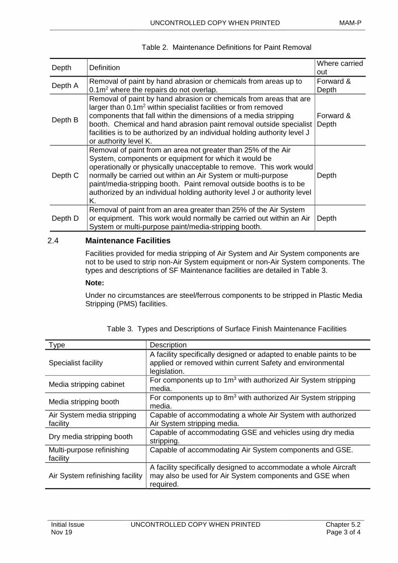
UNCONTROLLED COPY WHEN PRINTED MAM-P
Initial Issue Nov 19
UNCONTROLLED COPY WHEN PRINTED Chapter 5.2 Page 3 of 4
Table 2. Maintenance Definitions for Paint Removal
Depth DefinitionWhere carried out
Depth ARemoval of paint by hand abrasion or chemicals from areas up to 0.1m2 where the repairs do not overlap.
Forward & Depth
Depth B
Removal of paint by hand abrasion or chemicals from areas that are larger than 0.1m2 within specialist facilities or from removed components that fall within the dimensions of a media stripping booth. Chemical and hand abrasion paint removal outside specialist facilities is to be authorized by an individual holding authority level J or authority level K.
Forward & Depth
Depth C
Removal of paint from an area not greater than 25% of the Air System, components or equipment for which it would be operationally or physically unacceptable to remove. This work would normally be carried out within an Air System or multi-purpose paint/media-stripping booth. Paint removal outside booths is to be authorized by an individual holding authority level J or authority level K.
Depth
Depth DRemoval of paint from an area greater than 25% of the Air System or equipment. This work would normally be carried out within an Air System or multi-purpose paint/media-stripping booth.
Depth
2.4 Maintenance Facilities
Facilities provided for media stripping of Air System and Air System components are not to be used to strip non-Air System equipment or non-Air System components. The types and descriptions of SF Maintenance facilities are detailed in Table 3.
Note:
Under no circumstances are steel/ferrous components to be stripped in Plastic Media Stripping (PMS) facilities.
Table 3. Types and Descriptions of Surface Finish Maintenance Facilities
Type Description
Specialist facilityA facility specifically designed or adapted to enable paints to be applied or removed within current Safety and environmental legislation.
Media stripping cabinetFor components up to 1m3 with authorized Air System stripping media.
Media stripping boothFor components up to 8m3 with authorized Air System stripping media.
Air System media stripping facility
Capable of accommodating a whole Air System with authorized Air System stripping media.
Dry media stripping boothCapable of accommodating GSE and vehicles using dry media stripping.
Multi-purpose refinishing facility
Capable of accommodating Air System components and GSE.
Air System refinishing facilityA facility specifically designed to accommodate a whole Aircraft may also be used for Air System components and GSE when required.
MAMP UNCONTROLLED COPY WHEN PRINTED
Chapter 5.2 Page 4 of 4
UNCONTROLLED COPY WHEN PRINTED Initial Issue Nov 19
3 Training and Authorization
RN, Army and RAF engineering personnel who hold a minimum of authority level B may carry out paint application to Depth A (refer to Table 1) and basic paint removal to Depth A (refer to Table 2).
Specialist painter and finisher Tradesmen are trained in all aspects and depths of SF Maintenance within the appropriate facility. SF Maintenance to Depths B, C and D is to be conducted by specialist trained Painter and Finisher Tradesmen who are to hold minimum authority level B.
3.1 SF Cleaning Training
Personnel required to carry out SF cleaning are to be suitably trained.
3.2 SF Removal Training
Tradesmen required to remove SF coatings are to have completed SF removal training for each of the techniques detailed in the relevant Air System or equipment TI. SF specialists are to also complete respiratory protective equipment training every 2 years. Training is to comply with the requirements of Chapter 2.1 – Engineering Authorizations.
Tradesmen required to carry out PMS are to be re-assessed for Competency every 5 years by the training delivery organization.
3.3 SF Application Training
Tradesmen required to apply SF coatings are to have completed SF application training for each of the techniques detailed in the relevant Air System or equipment TI. SF specialists are to also complete respiratory protective equipment training every 2 years.
UNCONTROLLED COPY WHEN PRINTED MAM-P
..............................................................................
...............................................................................................
Issue 2.1 Aug 21
.......................................................................................................
..........................................................................................
UNCONTROLLED COPY WHEN PRINTED Chapter 5.3 Page 1 of 4
...........................................................................................................................................................
..............................................................................................................................................................................
......................................
Chapter 5.3
Composite Materials
...............................................................................................................................
................
TABLE OF CONTENTS
................................
Paragraph
.............................................................................................................................................................
...........................................................................................................
Page
1 General 1 1.1 Introduction 1 1.2 Associated Publications and Instructions 1 2 Maintenance of Composite Materials (CM) 2 2.1 Definition of CM 2 2.2 Factors Affecting CM Durability 2 2.3 Awareness and Husbandry 2 2.4 Repairs of CM 2 3 Health, Safety and Environmental Factors 3 3.1 Disposal 3 4 Types of Training 3 5 Maintenance Documentation - Structural Occurrence Recording 3 6 Responsibilities 4 7 Authorizations 4
LIST OF TABLES
Table 1. Associated Authorizations 4
1 General
1.1 Introduction
Composite Materials (CM) within the Defence Air Environment (DAE) are used because they offer high specific strength (that is, a high strength to weight ratio), high specific stiffness and excellent fatigue resistance, combined with increased design flexibility when compared with traditional aerospace alloys. General Maintenance philosophy is defined in Chapter 4.1 - Types of Maintenance. However, for CM there are aspects that may require more care, additional Husbandry or different processes as compared to those employed in the Maintenance of Aircraft structure and components constructed from more traditional materials.
1.2 Associated Publications and Instructions
1 Health and Safety at Work Act 1974.
2 Classification, Packaging and Labelling of Dangerous Substances Regulations 1984.
3 The Control of Substances Hazardous to Health (COSHH) Regulations 2002.
4 DSA 01.1 – Defence Policy for Health, Safety and Environmental Protection.
5 AP 101A-0601-1 – Employment and Repair of Aircraft Composite Materials.

MAM-P UNCONTROLLED COPY WHEN PRINTED
Chapter 5.3 Page 2 of 4
UNCONTROLLED COPY WHEN PRINTED Issue 2.1 Aug 21
2 Maintenance of Composite Materials (CM)
2.1 Definition of CM
When used in aerospace applications, the term ‘composite structure’ generally refers to structure manufactured from a very broad band of material types, eg metal alloys, metallic honeycomb sandwich structure and fibre reinforced non-metallic matrix systems. When using the term CM, this chapter is concerned with both monolithic and sandwich structures manufactured from fibre reinforced non-metallic matrix systems, eg Glass Reinforced Plastic (GRP), Carbon (graphite) Fibre Reinforced Plastic (CFRP), Boron fibre reinforced plastic, Aramid (Kevlar ®) reinforced plastic or a hybrid. These materials are generically termed Fibre Reinforced Plastics (FRP).
2.2 Factors Affecting CM Durability
Low levels of impact energy (eg dropped tools) can lead to fibre damage and de-lamination. Following a high-energy impact, the surface is likely to exhibit surface evidence of damage; however, lower energy impacts could result in sub-surface damage without leaving any external signs. The strength of FRP can be adversely affected by excess heat and moisture ingress and degradation by fuels, oils, lubricants and Ultra Violet (UV) light. Therefore, it is essential to ensure protection from accidental and environmental damage.
2.3 Awareness and Husbandry
1 When carrying out Maintenance on, or adjacent to components manufactured from FRP, ensure precautions are taken to prevent damage.
2 Panel edges are extremely susceptible to damage. Store FRP components in Special-To-Content Containers (STCCs), protective packaging or racking when not fitted to the Aircraft.
3 FRP is extremely susceptible to crush damage; therefore, ensure correct torque settings for fasteners.
4 Due to UV ageing, if damage to the surface coating of FRP structure occurs, it is to be re-protected as soon as reasonably practicable.
5 Clean chemical/fuel/oil contamination off FRP as soon as practicable and inspect the area for signs of leaching through the surface coating.
6 When chemically stripping the surface finish from metallic structure adjacent to FRP structure, protect the FRP to ensure that it is not contaminated.
7 Keep stored FRP components covered and in a dry and non-humid atmosphere if possible.
8 Take special care when handling damaged FRP components so as not to cause injury to personnel (eg fibre splinters).
9 Ensure any occurrences or signs of damage to FRP, no matter how insignificant the damage may appear are to be reported.
2.4 Repairs of CM
Repairs involving FRPs are to be carried out in accordance with (iaw) Air System Technical Information (TI) by suitably authorized personnel.
2.4.1 Types of Repair.
1 Type 1 repairs include manual resin application to dry fibres at ambient temperature. No specific Authorization required.
UNCONTROLLED COPY WHEN PRINTED MAM-P
Issue 2.1 Aug 21
UNCONTROLLED COPY WHEN PRINTED Chapter 5.3 Page 3 of 4
2 Type 2 repairs include manual resin application, or use of pre-impregnated fibres, which may require a controlled elevated temperature cure. Authorization MAMP-B222 required.
3 Type 3 repairs are as Type 2 but involve novel repairs or repairs that require particularly complicated processes. Authorization MAMP-B222 required.
Notes:
1 Individuals conducting FRP Repair Officer (RO) Specialist duties are required to hold Authorization MAMP-B223.
2 Individuals supervising repairs involving FRPs are required to hold Authorization MAMP-C326.
3 Health, Safety and Environmental Factors
FRP material dust is a health hazard, overheating repair materials could give rise to toxic fumes and/or substances and some associated chemicals and compounds are toxic. Appropriate Personal Protective Equipment (PPE), process control and suitable ventilation and dust extraction systems iaw the material data sheets. Risk and COSHH assessments are to be carried out.
Carbon and boron fibrous dust particles are electrically conductive and can cause short-circuiting in electrical, avionic and computer circuitry. Consequently, all electrical equipment, including sockets, panels and fuses, is to be protected from composite dust and debris.
3.1 Disposal
Disposal advice is to be sought through the appropriate authority and Publications. Discarded CM and uncured resins or adhesives are to be disposed of as dangerous engineering substances.
4 Types of Training
1 Introduction to FRP. Carried out at Phase 2 training.
2 FRP awareness training. At unit level, the Chief Air Engineer (CAE) or responsible authority level K is to ensure that an FRP awareness brief is provided to all engineering1 and support personnel (eg supply staff, bowser drivers, GSE maintainers etc) who regularly come into contact with FRP structure or components.
3 Specific-to type Maintenance training. Specific-to-type Maintenance training is to ensure that it encompasses the FRP awareness module.
4 Generic FRP repair training. There is Tri-Service generic aircraft FRP repair training available. Courses delivered by 71(R)Sqn and HMS Sultan.
5 Specific-to-type FRP repair training. For Air Systems with a specific or unique FRP damage assessment or FRP repair requirement.
5 Maintenance Documentation - Structural Occurrence
Recording
The operational life of FRP structure is directly related to the amount of accidental damage and environmental damage (AD/ED) sustained In-Service. If damage and the subsequent actions are not recorded, future residual strength calculations may be
1 ►Aircraft technicians, who are trained in FRP during Phase 2 training can be considered exempt from this requirement, unless the DDH CAE/Responsible level K identifies a specific need. ◄
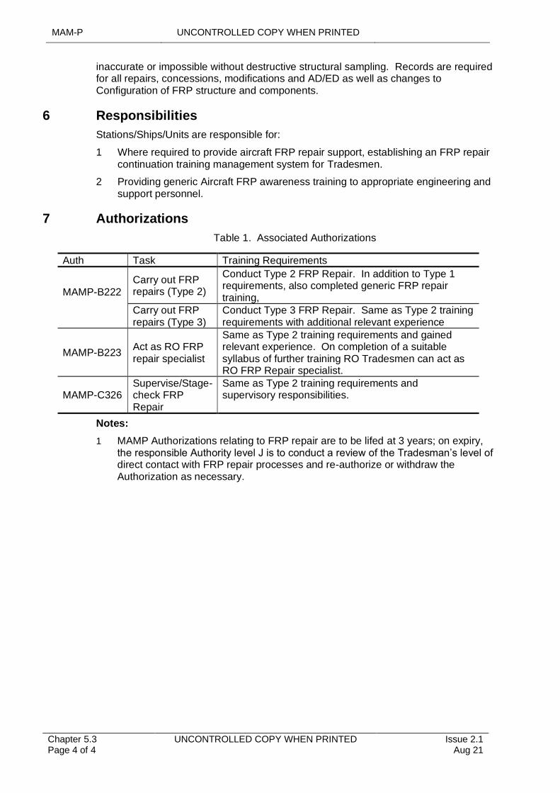
MAM-P UNCONTROLLED COPY WHEN PRINTED
Chapter 5.3 Page 4 of 4
UNCONTROLLED COPY WHEN PRINTED Issue 2.1 Aug 21
inaccurate or impossible without destructive structural sampling. Records are required for all repairs, concessions, modifications and AD/ED as well as changes to Configuration of FRP structure and components.
6 Responsibilities
Stations/Ships/Units are responsible for:
1 Where required to provide aircraft FRP repair support, establishing an FRP repair continuation training management system for Tradesmen.
2 Providing generic Aircraft FRP awareness training to appropriate engineering and support personnel.
7 Authorizations
Table 1. Associated Authorizations
Auth Task Training Requirements
MAMP-B222
Carry out FRP repairs (Type 2)
Conduct Type 2 FRP Repair. In addition to Type 1 requirements, also completed generic FRP repair training,
Carry out FRP repairs (Type 3)
Conduct Type 3 FRP Repair. Same as Type 2 training requirements with additional relevant experience
MAMP-B223Act as RO FRP repair specialist
Same as Type 2 training requirements and gained relevant experience. On completion of a suitable syllabus of further training RO Tradesmen can act as RO FRP Repair specialist.
MAMP-C326Supervise/Stage-check FRP Repair
Same as Type 2 training requirements and supervisory responsibilities.
Notes:
1 MAMP Authorizations relating to FRP repair are to be lifed at 3 years; on expiry, the responsible Authority level J is to conduct a review of the Tradesman’s level of direct contact with FRP repair processes and re-authorize or withdraw the Authorization as necessary.
UNCONTROLLED COPY WHEN PRINTED MAM-P
Initial Issue Nov 19
UNCONTROLLED COPY WHEN PRINTED Chapter 5.4 Page 1 of 4
...........................................................................
...............................................................................................
.................................................................................................
..................................................................................................
..............................................................................................
...................................................................................................................................................
.........................................................................................................................................................................................................
Chapter 5.4
Health and Usage Monitoring
TABLE OF CONTENTS
Paragraph Page
1 General 11.1 Introduction 11.2 Associated Publications and Instructions 12 HUM Support 22.1 Support levels 22.2 Cockpit Voice Recorder (CVR) and Flight Data Recorder (FDR) data 23 Responsibilities 23.1 Station/Ship/Units 23.2 Health and Usage Centres (HUCs) and HUMS Support Cells (HSCs) 24 Training of personnel involved in HUM 25 Authorization of personnel involved in HUM 3
LIST OF TABLES
Table 1. Associated Authorizations 3
1 General
1.1 Introduction
This chapter covers processes relating to the management of Health and Usage Monitoring Systems (HUMS) data, responsibilities, interfaces with other data systems and Authorizations. Instructions for the operation and data Maintenance of specific installations will be detailed in the appropriate Technical Information (TI).
The term Health and Usage Monitoring (HUM) encompasses a variety of techniques including operational load monitoring, vibration analysis, visual inspections, oil and wear debris analysis. The data obtained through such monitoring is used to preserve and enhance the Airworthiness of the platform. HUMS have been developed to support condition-based Maintenance by the acquisition of health and usage data from on–board sensors.
Engine Health and Usage Monitoring Systems (EHUMS) are a sub-set of HUMS applied to the monitoring of aero-engines.
Cockpit Voice Recorders & Flight Data Recorders (CVR/FDR) are crash-protected devices used to record audio data and the general cockpit environment, together with pre-determined flight sensor data.
1.2 Associated Publications and Instructions
1 JSP 440 - Defence Manual of Security, Resilience and Business Continuity
2 RA 4806 - Personnel Requirements (MRP 145.A.30)
MAM-P UNCONTROLLED COPY WHEN PRINTED
Chapter 5.4 Page 2 of 4
UNCONTROLLED COPY WHEN PRINTED Initial Issue Nov 19
2 HUM Support
2.1 Support levels
Support for HUM is provided in 3 levels, as follows:
2.1.1 First level
First-level support comprises all HUM activities that occur in direct support of Air System operations.
2.1.2 Second level
Specialist cells known as Health and Usage Centres (HUC) or HUMS Support Cells (HSC) provide second-level HUM support. These encompass the activities of Vibration Control Cells (VCC) and, in the RAF, Early Failure Detection Centres (EFDC).
2.1.3 Third level
1710 NAS provides the Depth support for HUM and provides advice as required to Forward operators, Type Airworthiness Authorities (TAAs) and Commands.
2.2 Cockpit Voice Recorder (CVR) and Flight Data Recorder (FDR) data
The management and download of CVR data is to be conducted in accordance with (iaw) the Air System TI and JSP 440, appropriate to the classification of the data held. In exceptional circumstances the download of CVR data in support of Service Inquiry or Accident Investigations may be authorized by Commands.
3 Responsibilities
3.1 Station/Ship/Units
Forward Units operating HUM equipment, or managing HUM data at first level, are responsible for providing the following information from HUMS data:
1 An Air System serviceability statement based on HUM data.
2 A description of health and usage alerts including associated values and trend history.
3 A description of the recovery action required.
3.2 Health and Usage Centres (HUCs) and HUMS Support Cells (HSCs)
HUCs and HSCs conduct initial analysis of HUM data, provide advice and technical support to Forward Units and are responsible for:
1 Responding to technical enquiries.
2 Managing and analysing HUM data and producing reports as required.
3 Maintaining liaison with the Depth support to ensure coherent development of HUM.
4 Training of personnel involved in HUM
Personnel operating HUM equipment are to be trained iaw with RA 4806 and Chapter 2.1 – Engineering Authorizations. Personnel operating HUMS Air Systems are to undertake such training as is deemed necessary in agreement between TAAs and the appropriate Commands.
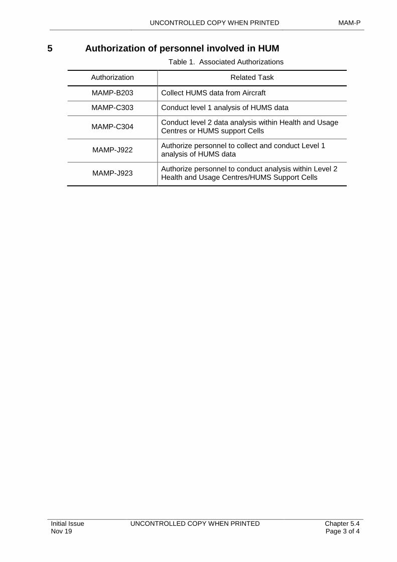
UNCONTROLLED COPY WHEN PRINTED MAM-P
Initial Issue Nov 19
UNCONTROLLED COPY WHEN PRINTED Chapter 5.4 Page 3 of 4
5 Authorization of personnel involved in HUM
Table 1. Associated Authorizations
Authorization Related Task
MAMP-B203 Collect HUMS data from Aircraft
MAMP-C303 Conduct level 1 analysis of HUMS data
MAMP-C304Conduct level 2 data analysis within Health and Usage Centres or HUMS support Cells
MAMP-J922Authorize personnel to collect and conduct Level 1 analysis of HUMS data
MAMP-J923Authorize personnel to conduct analysis within Level 2 Health and Usage Centres/HUMS Support Cells

MAM-P UNCONTROLLED COPY WHEN PRINTED
Chapter 5.4 Page 4 of 4
UNCONTROLLED COPY WHEN PRINTED Initial Issue Nov 19
Intentionally Blank for Print Pagination
UNCONTROLLED COPY WHEN PRINTED MAM-P
Issue 1.2 May 20
UNCONTROLLED COPY WHEN PRINTED Chapter 5.5 Page 1 of 6
.............................................................................................................................................
.........................................................................................................................................................
.............................................................................................................................................................
.......................................................................................................................
...........................................................................................................................................................................
......................................................................................................................................
.....................................................................................................................................................
.......................................................................................................................................
.........................................................................................................................................................................................................
Chapter 5.5
Vibration Control
TABLE OF CONTENTS
Paragraph Page
1 General 11.1 Introduction 11.2 Associated Publications and Instructions 21.3 Additional Information 22 Vibration Equipment (VE) 22.1 Maintenance of VE Assets 22.2 Maintenance of Health and Usage Monitoring Systems (HUMS) VE Assets 33 Static Balance Equipment 34 VC Organization Responsibilities 34.1 Station/Ship/Unit 34.2 Vibration Control Cells 34.3 Health and Usage Centres (HUCs) 44.4 1710 Naval Air Squadron (1710 NAS) 45 Manpower training and Authorization 55.1 Training 55.2 Authorizations 55.3 Authorizations (HUMS RTB function) 6
LIST OF TABLES
Table 1. Summary of VC training courses. 5Table 2. Associated Authorizations 6
1 General
Vibration induced by aerodynamic loads or structural resonance excited by rotating components, such as gas turbines, propellers and helicopter rotors, may induce high levels of stress in parts of the structure or transmission system. These stresses may lead to premature failure through fatigue, including increased secondary damage, such as wear or higher incidence of electronic component failure.
The Design Organization (DO) for each Air System/aero-engine type establishes a datum vibration level at or below which the vibration is judged to be structurally non-damaging.
1.1 Introduction
Vibration Control (VC) is the engineering term given to the suppression of this vibration by analysis and rectification. It is used for helicopter Rotor Track and Balancing (RTB) and propeller balancing. In addition, it may assist the health monitoring of Aircraft engines and other rotating equipment. All equipment used solely for monitoring and controlling vibration is termed Vibration Equipment (VE).
Vibration Analysis (VA) is the process of measuring, recording, and interpreting vibration data. This may lead to the introduction of Corrective Maintenance activities to reduce the vibration to acceptable levels. The extent of the Corrective Maintenance will be dependent on the outcome of the VA and will be detailed in the appropriate Air System Technical Information (TI).
MAM-P UNCONTROLLED COPY WHEN PRINTED
Chapter 5.5 Page 2 of 6
UNCONTROLLED COPY WHEN PRINTED Issue 1.2 May 20
Vibration Control Cells (VCCs) provide a co-ordinated organization for Aircraft vibration control. The evolution of Health and Usage Monitoring Systems (HUMS) is incorporating VCCs into Health and Usage Centres (HUCs).
This chapter describes the associated processes, management structure, training and personnel qualifications required to use VC equipment and to interpret and manage VC data.
1.2 Associated Publications and Instructions
1 AP 119A-20000-2(N/A/R) Part 1 Leaflet 009 – Support Policy Statement (SPS) for Vibration Analysis Equipment.
2 DAP119A-20700-1 – Vibration Analysis Theory and Application.
3 DAP 119A-20713-1 – Rotor Analysis Diagnostic System – Advanced Technology RADS-AT(RN) General and Technical Information.
4 AP119A-20714-1 – Vibration Monitoring Equipment for Aero-Engines. General and Technical Information.
5 AP119A-20714-2(R)1 – Vibration Monitoring Equipment for Aero-Engines. General Orders and Special Instructions.
6 DAP 119A-20720-1 – Rotortuner 5JS+ Operator’s Manual.
7 AP 119A-20721-1 – Universal Static Balance Fixture (USBF).
8 Air System specific Topic 5G1 – Vibration Analysis /Integrated Electronic Technical Publication (IETP) data module.
9 Relevant VA equipment Air Publication.
10 The Management of Test and Measurement Equipment Handbook.
11 AP7400 Order 4501 – Vibration Control.
1.3 Additional Information
Aircraft subject to VC are to be monitored for vibration as promulgated in the Air System TI. The operation of VE and the application of VA techniques are to be conducted by trained personnel and the resultant data managed by key Subject Matter Experts (SME). If the techniques cannot be applied because of operational or Maintenance considerations, the techniques are to be deferred using MOD F704 – Acceptable Deferred Faults Log or equivalent.
2 Vibration Equipment (VE)
2.1 Maintenance of VE Assets
To ensure best use of VE assets, the following procedures are to be applied:
1 All VE is to remain in date for calibration in accordance with (iaw) individual Service procedures. All calibration is to be conducted iaw The Management of Test and Measurement Equipment Handbook.
2 The VCC is the focal point for the supply, diagnosis, repair or calibration of VE for the RN and RAF only. Army Units are to use extant supply procedures. If urgent replacement of VE is necessary and VCC support is not available, normal stores routines apply.
UNCONTROLLED COPY WHEN PRINTED MAM-P
Issue 1.2 May 20
UNCONTROLLED COPY WHEN PRINTED Chapter 5.5 Page 3 of 6
3 Unserviceable equipment is to be returned iaw The Management of Test and Measurement Equipment Handbook.
2.2 Maintenance of Health and Usage Monitoring Systems (HUMS) VE Assets
To ensure best results from HUMS RTB functionality, the following procedures are to be applied:
1 The HUC is the focal point for the supply, diagnosis and repair of all HUMS Ground Station (HGS).
2 1710 NAS will provide a hardware/software Serviceability assessment prior to equipment being sent to depth for repair or rework.
3 1710 NAS will provide specialist database and operating system support to the HUC.
3 Static Balance Equipment
1710 NAS is the technical support organization for the Avion USBF and the Virtual Master Static Balance Facility (VMSBF) held within the rotor blade Maintenance facility at appropriate operating bases. The Air Commodities (AC) Team is responsible for through-life support of this equipment.
Only fully trained personnel are authorized to operate this equipment and all training requirements are to be notified through the 1710 NAS VHUMS.
4 VC Organization Responsibilities
4.1 Station/Ship/Unit
Station(Stn)/Ship/Unit are responsible for:
1 Gathering and maintaining VC data by applying VA techniques by Air System type.
2 The expedient transmission of VC data to the appropriate VCC/HUC.
3 Obtaining vibration measurements:
3.1 After rectification work to reduce vibration, to confirm results.
3.2 After fitting a major assembly, as detailed in the appropriate work card or Maintenance procedure.
3.3 At any time when VA would be of assistance to the maintainer, eg after a heavy landing, blade strike or crew-reported vibration.
3.4 When recommended by VCCs/HUCs.
4.2 Vibration Control Cells
Each VCC, under the direction of an individual holding authority level K, is responsible for:
1 Gathering, monitoring and maintaining vibration data by Air System type, based on operating Unit input.
2 Monitoring the effect of vibration-related Maintenance and providing advice and assistance to operating Units and local engineering command on VC issues.
3 Providing local training on VC techniques.
4 Coordinating/assisting with vibration-related trials and equipment bids.
MAM-P UNCONTROLLED COPY WHEN PRINTED
Chapter 5.5 Page 4 of 6
UNCONTROLLED COPY WHEN PRINTED Issue 1.2 May 20
5 Maintaining a register of technical personnel authorized to conduct VC activities.
6 Ensuring that VC activity is covered within local Quality Management Systems.
7 Providing input to the central vibration database managed by 1710 NAS.
8 Undertaking vibration measurements for Units (RN Only).
9 Co-ordinating local VC training for technical personnel, as required (not Army).
Note:
If no Stn/Ship/Unit VCC exists, Squadrons/Units are to appoint an individual to fulfil the VCC roles at items 1, 2, 5, 6 and 7, as required, with the other elements being supplied by the most appropriate, remote VCC.
4.3 Health and Usage Centres (HUCs)
In addition to the roles for VCCs identified above, HUCs provide additional services specific to Air Systems operating RTB within their HUMS system. The HUCs are additionally responsible for:
1 Maintaining HGS database integrity and user accounts through routine database administration.
2 Maintaining data flow between all levels of HUMS operation.
4.4 1710 Naval Air Squadron (1710 NAS)
1710 NAS is the focal point for all Air Systems condition monitoring associated activities. It provides depth support for vibration control, measurement and analysis. It is responsible for:
1 Providing expert technical advice on all aspects of vibration equipment, techniques and analysis methods in respect of Aircraft vibration problems.
2 Conducting Resonant Frequency Response (RFR) testing of Aircraft structures, components and Modifications.
3 Sponsoring and supporting Air System vibration trials to evaluate new or improved equipment and techniques.
4 Maintaining Helicopter Vibration Control Ground Station (HVCGS) databases for all non-HUMS helicopter types.
5 Providing functional guidance to VCCs/HUCs to enhance their effectiveness.
6 Developing formal VC techniques and advising Type Airworthiness Authority (TAA) on vibration Regulation, AMC, GM and associated processes, including limit reviews and Topic 5G1or equivalent/Interactive Electronic Technical Publication (IETP) amendments.
7 Developing and configuring HVCGS and RADS-AT(RN) script files and Rotortuner 5JS+ data cards.
8 Providing VCC support to Engine Test Houses and Depth Maintenance facilities.
9 Maintaining VE databases for all Air Systems.
10 Providing technical support and training for fixed-wing propeller balancing and engine vibration monitoring.
11 Providing technical support and training for RADS-AT(RN), Rotortuner 5JS+, VME and USBF.
12 Accessing HUMS databases for the purposes of Air System review and analysis as agreed with appropriate stakeholders.
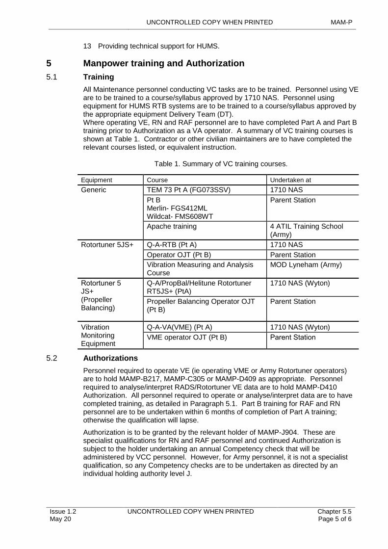
UNCONTROLLED COPY WHEN PRINTED MAM-P
Issue 1.2 May 20
UNCONTROLLED COPY WHEN PRINTED Chapter 5.5 Page 5 of 6
13 Providing technical support for HUMS.
5 Manpower training and Authorization
5.1 Training
All Maintenance personnel conducting VC tasks are to be trained. Personnel using VE are to be trained to a course/syllabus approved by 1710 NAS. Personnel using equipment for HUMS RTB systems are to be trained to a course/syllabus approved by the appropriate equipment Delivery Team (DT). Where operating VE, RN and RAF personnel are to have completed Part A and Part B training prior to Authorization as a VA operator. A summary of VC training courses is shown at Table 1. Contractor or other civilian maintainers are to have completed the relevant courses listed, or equivalent instruction.
Table 1. Summary of VC training courses.
Equipment Course Undertaken at
Generic TEM 73 Pt A (FG073SSV) 1710 NAS
Pt B
Merlin- FGS412ML Wildcat- FMS608WT
Parent Station
Apache training 4 ATIL Training School (Army)
Rotortuner 5JS+ Q-A-RTB (Pt A) 1710 NAS
Operator OJT (Pt B) Parent Station
Vibration Measuring and Analysis Course
MOD Lyneham (Army)
Rotortuner 5JS+ (Propeller Balancing)
Q-A/PropBal/Helitune Rotortuner RT5JS+ (PtA)
1710 NAS (Wyton)
Propeller Balancing Operator OJT (Pt B)
Parent Station
Vibration Monitoring Equipment
Q-A-VA(VME) (Pt A) 1710 NAS (Wyton)
VME operator OJT (Pt B) Parent Station
5.2 Authorizations
Personnel required to operate VE (ie operating VME or Army Rotortuner operators) are to hold MAMP-B217, MAMP-C305 or MAMP-D409 as appropriate. Personnel required to analyse/interpret RADS/Rotortuner VE data are to hold MAMP-D410 Authorization. All personnel required to operate or analyse/interpret data are to have completed training, as detailed in Paragraph 5.1. Part B training for RAF and RN personnel are to be undertaken within 6 months of completion of Part A training; otherwise the qualification will lapse.
Authorization is to be granted by the relevant holder of MAMP-J904. These are specialist qualifications for RN and RAF personnel and continued Authorization is subject to the holder undertaking an annual Competency check that will be administered by VCC personnel. However, for Army personnel, it is not a specialist qualification, so any Competency checks are to be undertaken as directed by an individual holding authority level J.
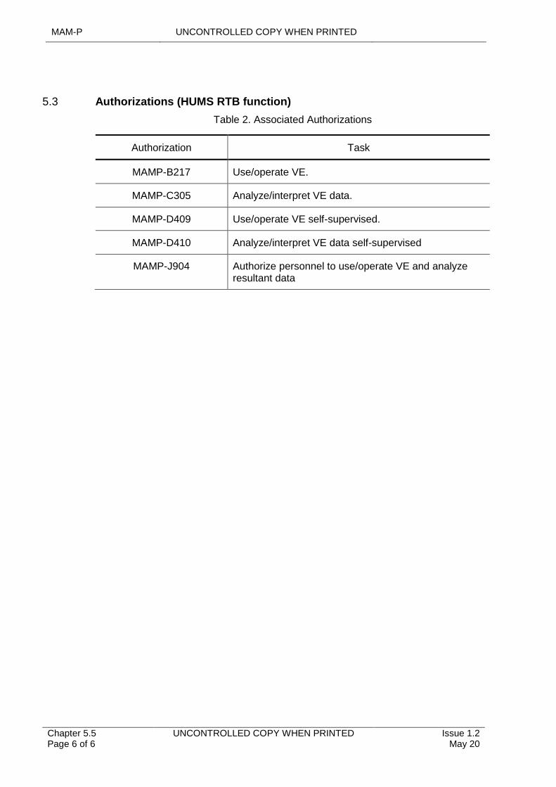
MAM-P UNCONTROLLED COPY WHEN PRINTED
Chapter 5.5 Page 6 of 6
UNCONTROLLED COPY WHEN PRINTED Issue 1.2 May 20
5.3 Authorizations (HUMS RTB function)
Table 2. Associated Authorizations
Authorization Task
MAMP-B217 Use/operate VE.
MAMP-C305 Analyze/interpret VE data.
MAMP-D409 Use/operate VE self-supervised.
MAMP-D410 Analyze/interpret VE data self-supervised
MAMP-J904 Authorize personnel to use/operate VE and analyze resultant data
UNCONTROLLED COPY WHEN PRINTED MAM-P
Initial Issue Nov 19
UNCONTROLLED COPY WHEN PRINTED Chapter 5.6 Page 1 of 8
...........................................................................
.............................................................................................................................................................................................
.................................................................................................................................
...................................................................................................
............................................................................................................
......................................................................................................................................................................
.................................................................................................................................................
...............................................................
.................................................................................................................................................................................
....................................................................................................................................................................................
.......................................................................................................................................................
.......................................................................................................
Chapter 5.6
Wear Debris Monitoring
TABLE OF CONTENTS
Paragraph Page
1 General 11.1 Introduction 11.2 Associated Publications and Instructions 21.3 Additional Information 22 WDM Uses 23 WDM Methods 24 WDM Programmes 24.1 Spectrometric Oil Analysis Programme (SOAP) 24.2 Magnetic Detector Plug (MDP) and Filter Debris Assessment 35 Procedures 35.1 Wear Debris Management System (WDMS) 35.2 Sampling and Distribution 35.3 Sample Analysis 45.4 Sample Results and Maintenance Action Reporting 45.5 Station/Ship/Unit Rejections 56 RAF Early Failure Detection (EFD) Training and Establishments 57 Responsibilities 67.1 RAF Early Failure Detection Centres (EFDCs) 67.2 Stations/Ships/Units 67.3 Commands 78 Authorizations 7
LIST OF TABLES
Table 1. Associated Authorizations 7
1 General
1.1 Introduction
Any components within an oil-wetted system that are in moving contact will generate small particles from the contact surfaces, mainly because of local loading between these surfaces. Excessive friction or abnormal loading of such components will increase the rate of particle generation and may change the nature of wear debris. It is therefore important to recognize the onset and significance of such changes in wear characteristics; such recognition forms the basis of effective Wear Debris Monitoring (WDM).
When correctly applied, monitoring the wear that is occurring in a system can give an assurance of the continued integrity of the monitored system. It achieves this by providing an early indication of abnormal wear, enabling the monitored assemblies to be removed before the onset of excessive damage that could ultimately lead to complete system failure. Apart from preserving the integrity of Aircraft, such monitoring can reduce the costs of repair and replacement of sub-assemblies and components.
1710 NAS have developed and implemented the Wear Debris Monitoring System (WDMS) to bring together and resolve the different procedures used by the RN, Army
MAM-P UNCONTROLLED COPY WHEN PRINTED
Chapter 5.6 Page 2 of 8
UNCONTROLLED COPY WHEN PRINTED Initial Issue Nov 19
and RAF wherever possible. Minor differences remain and are specifically described in this chapter.
1.2 Associated Publications and Instructions
1 AP119A-20006-1 – Royal Air Force Early Failure Detection Centre (EFDC) Manual.
1.3 Additional Information
Oil and wear debris samples are to be taken on the following occasions:
1 For in-service assemblies, in accordance with (iaw) frequencies and procedures required by relevant Air System Technical Information (TI).
2 For new/repaired/reconditioned or disturbed assemblies, as detailed in relevant TI.
3 Iaw recommendations made by 1710 NAS, the Air System type-specific Early Failure Detection Centres (EFDCs) or other Depth support WDM service provider appointed by the Type Airworthiness Authority (TAA).
2 WDM Uses
WDM may be used:
1 To recognize the onset of excessive wear and prevent consequential secondary damage or catastrophic failure.
2 To sustain confidence in the mechanical integrity and performance of a mechanical system.
3 To assess all wear factors in order to optimize in-service life and determine the most cost-effective Maintenance philosophy.
4 To diagnose Faults to component level in order to reduce time and repair costs.
5 To provide better knowledge of failure causes and thereby hasten corrective action.
6 To forecast more accurately the need for Preventive Maintenance and thereby improve equipment availability.
7 As required by the relevant TAA as part of a specific investigation.
8 On any occasion when that the maintainer has doubts concerning the internal integrity of an oil–lubricated assembly/system.
3 WDM Methods
Employing WDM techniques can assess the wear occurring in an enclosed oil-wetted system, such as an Aircraft engine or transmission; these monitoring techniques include:
1 Spectrometric Oil Analysis (SOA).
2 Magnetic Detector Plug (MDP) and filter debris assessment.
4 WDM Programmes
A WDM programme for a specific Aircraft and component type may utilize either, or both, of the techniques described in the following sub-paragraphs.
4.1 Spectrometric Oil Analysis Programme (SOAP)

UNCONTROLLED COPY WHEN PRINTED MAM-P
Initial Issue Nov 19
UNCONTROLLED COPY WHEN PRINTED Chapter 5.6 Page 3 of 8
The presence of fine wear particles suspended in lubricating oil is conducive to detection using SOA. By trending the results against historical data and employing alert criteria, potentially significant changes in the monitored assembly’s wear condition can be determined. This can lead to appropriate Maintenance actions being taken to address wear anomalies. Whilst SOA is sensitive to fine forms of wear, it is relatively insensitive to the presence of the products of other wear modes; for example, surface fatigue, which generates larger debris particles that are outside the range of SOAP detection.
4.2 Magnetic Detector Plug (MDP) and Filter Debris Assessment
WDM can also be achieved by means of the routine extraction, inspection and trending of debris collected by MDPs, chip detectors and oil filters. The debris collected is generally larger than that detectable by SOA. Visual assessment of such debris can be applied to determine increased or abnormal system operation.
Further analysis of debris to determine the material composition is required to allow the probable source and wear criticality to be more accurately assessed.
5 Procedures
5.1 Wear Debris Management System (WDMS)
WDMS is a system for managing the submission, analysis and reporting of wear debris samples. This includes oil, magnetic debris probe and filter samples. Maintainers are to register samples onto the system via a WDMS web page and the sample can be tracked through its analysis and reporting stages. Sample results are available to maintainers and other interested parties via the web pages as soon as the analysis has been completed. The centralized database enables access to all Wear Debris Analysis (WDA) information from anywhere on the MOD intranet system. The system provides a standard way of submitting and reporting WDA information across all Air Systems. The information collected is used for reviewing Aircraft engine and transmission systems with a view to monitoring Fault trends and improving system reliability.
The postal address for WDM is:
Wear Debris Section, 1710 NAS, Unicorn Building, PP88, Unicorn Road, HM Naval Base, PORTSMOUTH. PO1 3GX.
Advice on WDMS use, training and requests for new reports and amendments is available by contacting 1710 NAS.
5.2 Sampling and Distribution
5.2.1 General
1 Station(Stn)/Ship/Unit Air System engineering personnel are responsible for removing and replacing MDPs and filters and sampling lubricating systems, iaw the relevant Air System TI.
2 All sample submissions are to be registered on WDMS and appropriate forms are to be sent by the quickest possible means to 1710 NAS or local EFDC.
3 Samples are not to be retained or batched by the sampling Stn/Ship/Unit to accumulate a ‘cost-effective batch’ for posting.
MAM-P UNCONTROLLED COPY WHEN PRINTED
Chapter 5.6 Page 4 of 8
UNCONTROLLED COPY WHEN PRINTED Initial Issue Nov 19
4 Oil submitted as part of SOAP are to be taken into sample bottles available for the purpose from stores and labelled with “MOD Form 730 (1710 NAS) - Spectrometric Oil Analysis Programme Sample Form and MOD Form 730C - SOAP Sample Label”.
5 All samples requiring posting to 1710 NAS or parent EFDC are to be properly identified, labelled and packaged. To avoid damage/leakage in transit, envelopes or jiffy bags are not to be used for submitting oil samples.
6 Sampling Stns/Ships/Units are to conduct a visual assessment of the debris and decide whether routine or urgent examination is required. Samples requiring urgent analysis (eg as part of an investigation of an operating anomaly) are to be clearly marked “PRIORITY” in red. The sample is also to have the Maintenance record “Unit Priority” raised on the sample registration screen on WDMS.
5.2.2 In-field Preparation of MDP/Filter Samples
Removal of debris from MDPs, following careful de-oiling, is to be carried out using the relevant magnetic plug wipe card. For RN units these wipe cards are available on demand from 1710 NAS. Army Units are to use MOD Form 369 - EFD Sample Card and MOD Form 369A - EFD Sample Card (Multiple).
The process of removing debris from filters for subsequent examination will vary, dependent on filter element type. The surfaces of cleanable filters can be washed, and debris collected using paper filters. Disposable elements cannot be sampled in this manner and the element is to be submitted to 1710 NAS for examination.
5.2.3 RAF
MDPs, filters, filter debris and oil samples are to be forwarded to the Stn/Unit EFDC or 1710 NAS as applicable.
5.2.4 Samples Submitted from Outside the UK
The Ministry of Defence (MOD) has no waiver for customs. Deployed units are to annotate the following statement on the relevant paperwork to prevent delays and associated costs with samples:
‘Samples for testing. Once tested samples will be destroyed - No commercial value’
5.2.5 Out of Hours Emergencies
For out of hours emergencies, advice may be obtained by telephoning the 1710 NAS emergency call-out scientist on 07971 605470.
5.3 Sample Analysis
Samples received at 1710 NAS or at RAF EFDC are to be processed iaw 1710 NAS procedures or AP 119A-20006-1, as appropriate. Diagnoses of wear conditions will take full account of the system’s operational and Maintenance history.
A sample assessment outside 1710 NAS that leads to Maintenance action, eg requires re-sample, increases the sampling requirement, or requires system oil drain and replenish, will be supported by debris material analysis by 1710 NAS.
5.4 Sample Results and Maintenance Action Reporting
Notwithstanding the WDM support arrangements detailed in this chapter, the responsibility for ensuring the continued integrity of the respective Air System remains with the relevant Maintenance organization within the Stn/Ship/Unit, not 1710 NAS or an RAF EFDC. It is therefore incumbent on the Maintenance organization to monitor
UNCONTROLLED COPY WHEN PRINTED MAM-P
Initial Issue Nov 19
UNCONTROLLED COPY WHEN PRINTED Chapter 5.6 Page 5 of 8
progression of those samples for which results have not yet been received and to engage with 1710 NAS or RAF EFDC, as required.
5.4.1 Samples Processed using WDMS
All results for samples processed using the WDMS are available online via the WDMS website. This includes all satisfactory samples and those requiring a Maintenance action.
5.4.2 Samples Processed by 1710 NAS
The results and recommended Maintenance actions will be promulgated back to the originator by signal. Signal details are also available online on the WDMS web site. In cases where abnormal wear is identified, 1710 NAS will, where practicable, contact the relevant Stn/Ship/Unit, Military Continuing Airworthiness Manger (Mil CAM) and the Air System Delivery Team directly, prior to signal release.
5.4.3 Samples Processed by RAF EFDC
The results and recommended Maintenance actions are to be promulgated back to the originator by telephone, supported by an authorized RAF F7158 – EFDC report. If the assessment recommends a component rejection or the imposition of an operational limitation, the RAF Form 7158 – EFDC report is to be countersigned by the responsible Engineering Officer.
5.5 Station/Ship/Unit Rejections
Stns/Ships/Units may reject a component for Early Failure Detection (EFD) reasons; however, prior to receiving 1710 NAS confirmation, the sampling Stn/Ship/Unit, or EFDC, is to adhere to the following procedure:
1 Submit the last Stn/Ship/Unit sample with a copy of any component EFD historical records (if held) to 1710 NAS for detailed analysis without delay, together with a short, written report of any other supporting evidence, ie fluctuating or low oil pressure, noises, over-torque, over-temp or any other characteristics that may help determine the origin of the Fault. Where appropriate, the filter/filter wash is also to be submitted for analysis.
2 Quarantine the component pending result of 1710 NAS analysis and recommendation.
3 Annotate details of the final analysis and recommendations on the MOD Form 731- Equipment Conditioning Label or approved equivalent and on a copy of the report attached to the component.
4 When the above procedure has been completed, return rejected components into the supply chain.
6 RAF Early Failure Detection (EFD) Training and Establishments
Training for EFDC operators to TQA Q-EFD-B is conducted at RAF Cosford. Engineering Officers are to be given theoretical awareness training as part of Engineering Officer Foundation Training.
The EFDC, depending on workload, will normally consist of two people, one to hold Authorization MAMP-C316 and one to hold Authorization MAMP-E504. An operator who has been awarded the TQA Q-EFD-B may also be awarded Authorization MAMP-D412.
EFD required for any deployed operations are to be provided by EFDC personnel. Where there is a need to minimize deployed manpower, suitable posts are to be identified as Q-EFD-B posts and the incumbents’ currency maintained locally.
MAM-P UNCONTROLLED COPY WHEN PRINTED
Chapter 5.6 Page 6 of 8
UNCONTROLLED COPY WHEN PRINTED Initial Issue Nov 19
Exceptionally, personnel able to hold maximum standard Authorization level C and trained by a qualified EFD Operator may be awarded Authorization MAMP-D403, authorized locally by an individual holding authority level K, to be temporary operators and carry out EFD techniques on a specific Air System type to meet an operational requirement.
7 Responsibilities
7.1 RAF Early Failure Detection Centres (EFDCs)
EFDCs are responsible for providing support at Main Operating Base (MOB), Detached Operating Base (DOB) and deployments for:
1 Recording, analysing, and reporting on the WDM of Aircraft propulsion and transmission system components on WDMS.
2 Identifying abnormal wear and submitting samples to 1710 NAS for further analysis and advice, where necessary.
3 Advising Air System operators and station engineering authorities on the serviceability state of monitored systems.
4 Ensuring the integrity and condition of MDPs.
5 Providing personnel for deployed operations.
6 Providing training, currency and Authorization of Q-EFD-B personnel who are required to operate as EFDC on deployed operations.
7 Training and Authorization of non-Q-EFD-B personnel to attain temporary award of Authorization MAMP-D403 to meet exceptional deployment requirements.
7.2 Stations/Ships/Units
Stns/Ships/Units are responsible for:
1 The provision of suitably trained personnel and the extraction and submission to the relevant Depth support organizations of all samples taken as part of WDM programmes.
2 The full and correct completion of WDMS sample registration with each sample, or sample documentation if WDMS is not available.
3 The upkeep of the monitored assembly’s log card to record the submission of such samples and details of any Maintenance actions resulting from the analysis of such samples and for carrying out that Maintenance.
7.2.1 Authority Level J
The relevant Level J is responsible for:
1 Selecting personnel for training and submitting bids accordingly.
2 Initiating WDM scaling bids, including those for Priming Equipment Packs (RAF only).
3 Identifying EFDC manpower requirements and advising HQ Air Command (RAF only).
7.2.2 Authority Level K
The relevant Level K is responsible for:
1 Authorizing the use of locally trained operators to meet exceptional requirements.
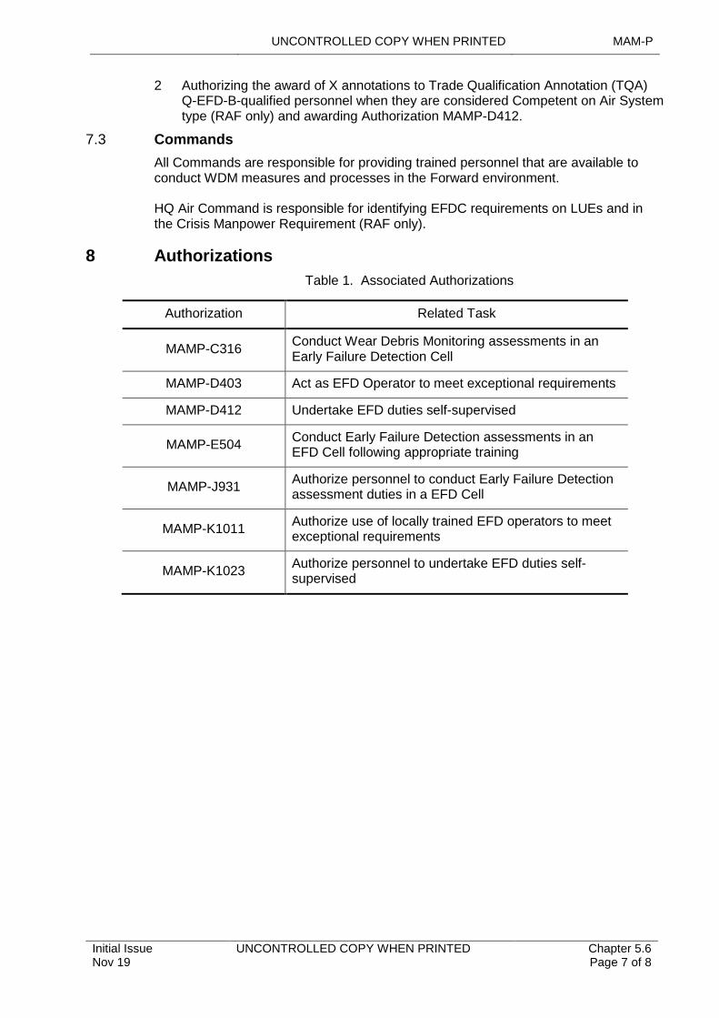
UNCONTROLLED COPY WHEN PRINTED MAM-P
Initial Issue Nov 19
UNCONTROLLED COPY WHEN PRINTED Chapter 5.6 Page 7 of 8
2 Authorizing the award of X annotations to Trade Qualification Annotation (TQA) Q-EFD-B-qualified personnel when they are considered Competent on Air System type (RAF only) and awarding Authorization MAMP-D412.
7.3 Commands
All Commands are responsible for providing trained personnel that are available to conduct WDM measures and processes in the Forward environment.
HQ Air Command is responsible for identifying EFDC requirements on LUEs and in the Crisis Manpower Requirement (RAF only).
8 Authorizations
Table 1. Associated Authorizations
Authorization Related Task
MAMP-C316Conduct Wear Debris Monitoring assessments in an Early Failure Detection Cell
MAMP-D403 Act as EFD Operator to meet exceptional requirements
MAMP-D412 Undertake EFD duties self-supervised
MAMP-E504Conduct Early Failure Detection assessments in an EFD Cell following appropriate training
MAMP-J931Authorize personnel to conduct Early Failure Detection assessment duties in a EFD Cell
MAMP-K1011Authorize use of locally trained EFD operators to meet exceptional requirements
MAMP-K1023Authorize personnel to undertake EFD duties self-supervised
MAM-P UNCONTROLLED COPY WHEN PRINTED
Chapter 5.6 Page 8 of 8
UNCONTROLLED COPY WHEN PRINTED Initial Issue Nov 19
Intentionally Blank for Print Pagination
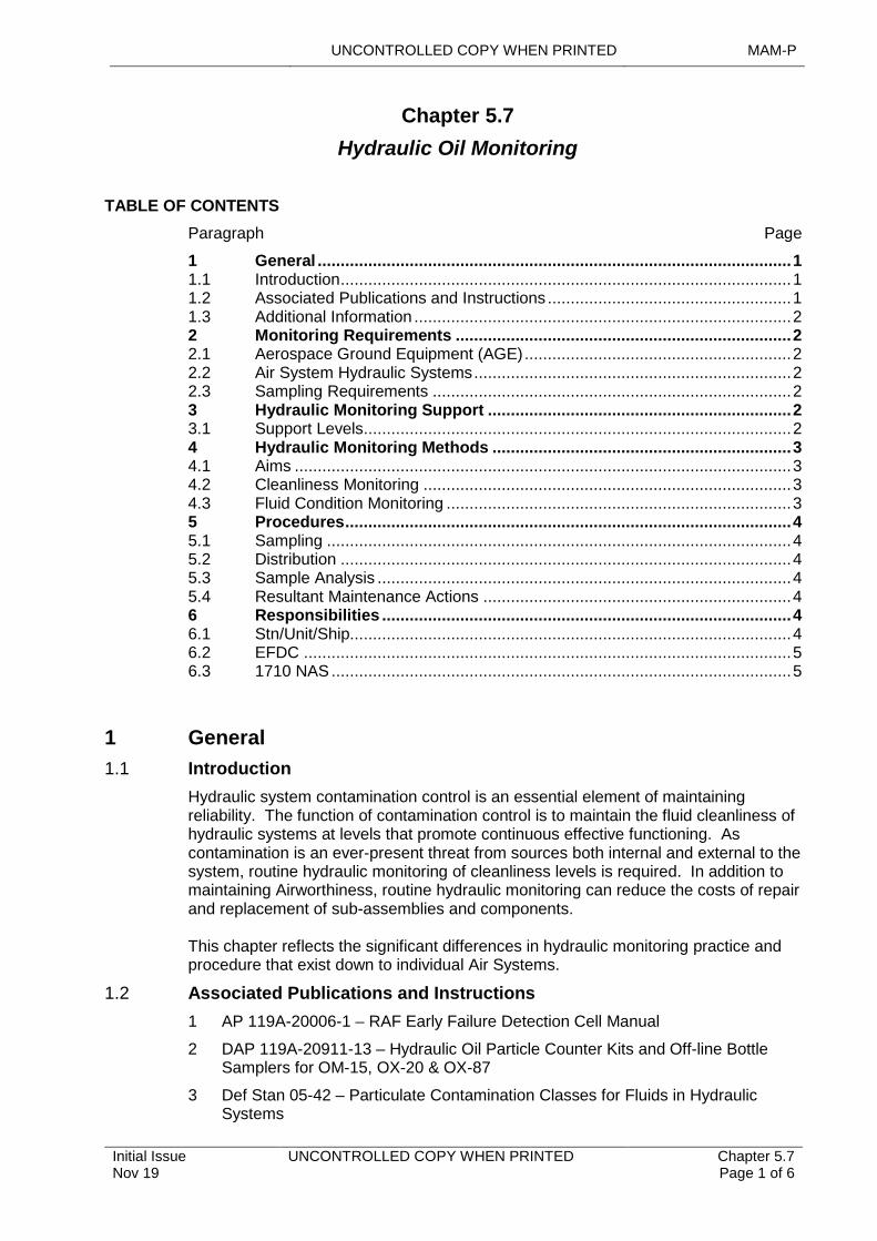
UNCONTROLLED COPY WHEN PRINTED MAM-P
Initial Issue Nov 19
UNCONTROLLED COPY WHEN PRINTED Chapter 5.7 Page 1 of 6
..............................................................................................................................................................................................................
.........................................................................................................................................................................................
.............................................................................................................................................................
.......................................................................................................................................................................................................
............................................................................................................................................................................
............................................................................................................................................................................................
..............................................................................................................................................................
................................................................................................................................................
...............................................................................................................................
...........................................................................................................................................................
.......................................................................................................................................................
.......................................................................................................
Chapter 5.7
Hydraulic Oil Monitoring
TABLE OF CONTENTS
Paragraph Page
1 General 11.1 Introduction 11.2 Associated Publications and Instructions 11.3 Additional Information 22 Monitoring Requirements 22.1 Aerospace Ground Equipment (AGE) 22.2 Air System Hydraulic Systems 22.3 Sampling Requirements 23 Hydraulic Monitoring Support 23.1 Support Levels 24 Hydraulic Monitoring Methods 34.1 Aims 34.2 Cleanliness Monitoring 34.3 Fluid Condition Monitoring 35 Procedures 45.1 Sampling 45.2 Distribution 45.3 Sample Analysis 45.4 Resultant Maintenance Actions 46 Responsibilities 46.1 Stn/Unit/Ship 46.2 EFDC 56.3 1710 NAS 5
1 General
1.1 Introduction
Hydraulic system contamination control is an essential element of maintaining reliability. The function of contamination control is to maintain the fluid cleanliness of hydraulic systems at levels that promote continuous effective functioning. As contamination is an ever-present threat from sources both internal and external to the system, routine hydraulic monitoring of cleanliness levels is required. In addition to maintaining Airworthiness, routine hydraulic monitoring can reduce the costs of repair and replacement of sub-assemblies and components.
This chapter reflects the significant differences in hydraulic monitoring practice and procedure that exist down to individual Air Systems.
1.2 Associated Publications and Instructions
1 AP 119A-20006-1 – RAF Early Failure Detection Cell Manual
2 DAP 119A-20911-13 – Hydraulic Oil Particle Counter Kits and Off-line Bottle Samplers for OM-15, OX-20 & OX-87
3 Def Stan 05-42 – Particulate Contamination Classes for Fluids in Hydraulic Systems
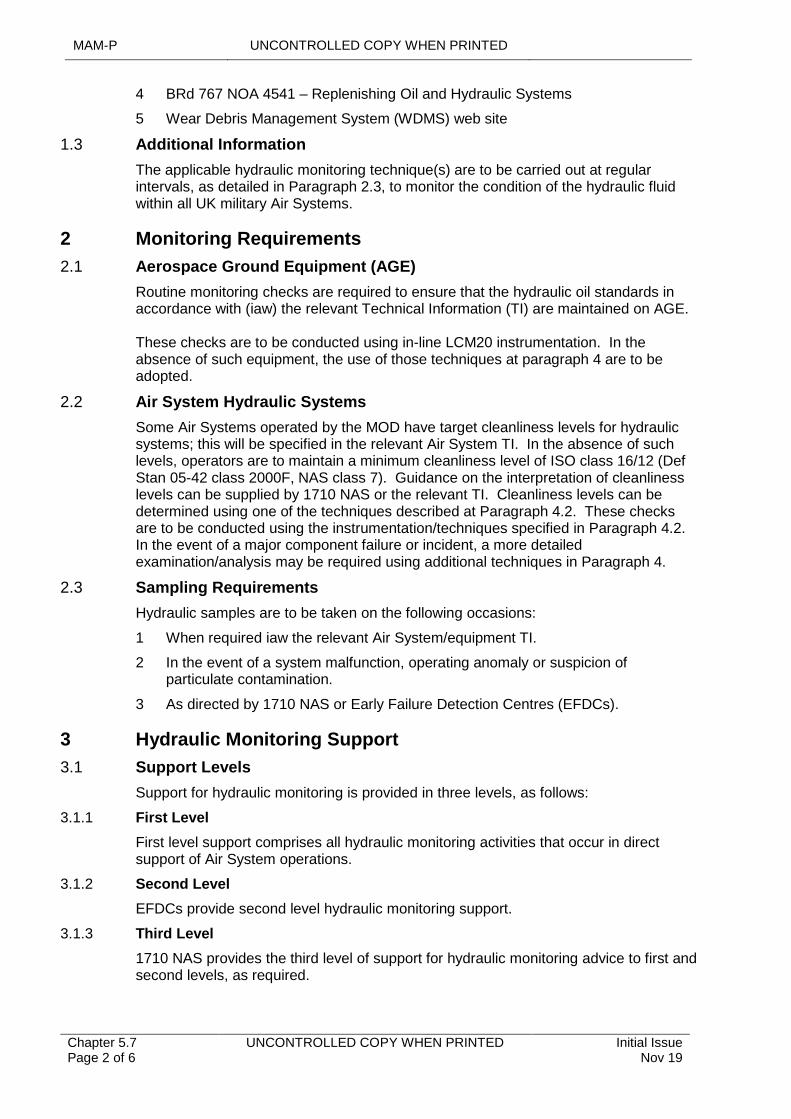
MAM-P UNCONTROLLED COPY WHEN PRINTED
Chapter 5.7 Page 2 of 6
UNCONTROLLED COPY WHEN PRINTED Initial Issue Nov 19
4 BRd 767 NOA 4541 – Replenishing Oil and Hydraulic Systems
5 Wear Debris Management System (WDMS) web site
1.3 Additional Information
The applicable hydraulic monitoring technique(s) are to be carried out at regular intervals, as detailed in Paragraph 2.3, to monitor the condition of the hydraulic fluid within all UK military Air Systems.
2 Monitoring Requirements
2.1 Aerospace Ground Equipment (AGE)
Routine monitoring checks are required to ensure that the hydraulic oil standards in accordance with (iaw) the relevant Technical Information (TI) are maintained on AGE.
These checks are to be conducted using in-line LCM20 instrumentation. In the absence of such equipment, the use of those techniques at paragraph 4 are to be adopted.
2.2 Air System Hydraulic Systems
Some Air Systems operated by the MOD have target cleanliness levels for hydraulic systems; this will be specified in the relevant Air System TI. In the absence of such levels, operators are to maintain a minimum cleanliness level of ISO class 16/12 (Def Stan 05-42 class 2000F, NAS class 7). Guidance on the interpretation of cleanliness levels can be supplied by 1710 NAS or the relevant TI. Cleanliness levels can be determined using one of the techniques described at Paragraph 4.2. These checks are to be conducted using the instrumentation/techniques specified in Paragraph 4.2. In the event of a major component failure or incident, a more detailed examination/analysis may be required using additional techniques in Paragraph 4.
2.3 Sampling Requirements
Hydraulic samples are to be taken on the following occasions:
1 When required iaw the relevant Air System/equipment TI.
2 In the event of a system malfunction, operating anomaly or suspicion of particulate contamination.
3 As directed by 1710 NAS or Early Failure Detection Centres (EFDCs).
3 Hydraulic Monitoring Support
3.1 Support Levels
Support for hydraulic monitoring is provided in three levels, as follows:
3.1.1 First Level
First level support comprises all hydraulic monitoring activities that occur in direct support of Air System operations.
3.1.2 Second Level
EFDCs provide second level hydraulic monitoring support.
3.1.3 Third Level
1710 NAS provides the third level of support for hydraulic monitoring advice to first and second levels, as required.
UNCONTROLLED COPY WHEN PRINTED MAM-P
Initial Issue Nov 19
UNCONTROLLED COPY WHEN PRINTED Chapter 5.7 Page 3 of 6
4 Hydraulic Monitoring Methods
4.1 Aims
Hydraulic monitoring may be used to:
1 Identify the onset of excessive wear that could result in component failure.
2 Check the filter efficiency of the system.
3 Monitor the cleanliness of the replenishment or servicing rig supply.
4 Diagnose system operating anomalies.
4.2 Cleanliness Monitoring
The Maintenance of hydraulic fluid cleanliness is an important assurance as to the correct functioning of the hydraulic system. Debris can be generated both internally through wear or corrosion; or introduced from external sources either during operation or as a result of system disturbance during repair or Maintenance. The following methods can be utilized to ensure that fluid cleanliness meets required limits:
1 In-line LCM20 analysis.
2 Off-line LCM20 bottle sampler analysis.
3 Laboratory/EFDC assessment using an automatic particle counter such as a HIAC™.
4.2.1 The LCM20 Particle Counter
The LCM20 particle counter is the primary tool for conducting measurements of contamination levels in hydraulic fluid systems. The equipment electronically counts the particles present within specific size ranges in a measured liquid sample.
DAP 119A-20911-13 contains details of this method.
4.2.2 Off-line LCM20 Bottle Sampler Analysis
If an in-line sampler is not available, the LCM20, used in conjunction with a turret sampler, allows processing of hydraulic fluid samples by Maintenance organizations.
4.2.3 Laboratory/Early Failure Detection Cell (EFDC) Assessment using HIAC™ Particle Counter
1710 NAS laboratories utilize HIAC™ particle counters for assessing hydraulic sample cleanliness. HIAC™ counters operate using a light obstruction principle, which allows the number and size of particles to be determined in a measured fluid sample. HIAC™ counters are very quick and reliable; however, they still require bottle samples, which increases the risk of cross-contamination.
4.3 Fluid Condition Monitoring
Other techniques can be utilized to assess the condition of hydraulic fluid. These include:
1 Physical and chemical assessments.
2 Water contamination monitoring.
3 Filter examinations.
4.3.1 Water Monitoring
Water content monitoring determinations can be conducted at 1710 NAS, who utilize instrumentation to allow an exact measure of the total water content to be assessed.
MAM-P UNCONTROLLED COPY WHEN PRINTED
Chapter 5.7 Page 4 of 6
UNCONTROLLED COPY WHEN PRINTED Initial Issue Nov 19
If a hydraulic fluid is grossly contaminated with water, this will be visually apparent as cloudiness within the sample. The LCM20 particle counter will also count water droplets as particles and therefore alert the operator to the presence of a potential problem.
4.3.2 Filter Examination
Filter examination can be used to investigate possible system contamination, particularly if the filter ‘tell-tale pop-up’ indicator has been activated. Filters are to be submitted to 1710 NAS or the EFDC for examination iaw the relevant TI. Removal and examination of debris collected by the filter can provide valuable evidence as to the nature and causes of contamination.
5 Procedures
5.1 Sampling
Stn/Ship/Unit Air System engineering personnel are responsible for removing and replacing hydraulic system filters and sampling hydraulic systems iaw the applicable TI.
5.2 Distribution
Once samples are taken, if Stn/Ship/Unit do not have access to a LCM20, samples are to be forwarded to 1710 NAS or EFDC as appropriate. All samples are to be submitted by the quickest possible means. Samples requiring urgent analysis on suspected hydraulic systems and/or advice from higher authority, are to be clearly marked ‘PRIORITY’ in red. All samples are to be properly identified, labelled and packaged for distribution iaw local procedures.
Hydraulic samples are to be taken in purpose-designed bottles. These bottles are to be cleaned to avoid contamination of the sample iaw the relevant TI.
All accompanying paperwork is to be completed correctly and is to include the sample source and the reason for submission.
For ‘out of hours’ emergencies, advice may be obtained by telephoning the 1710 NAS Duty Scientist 07971 605470, who will either deal with the emergency or call in the appropriate specialist.
5.3 Sample Analysis
Samples received at 1710 NAS or the EFDC are to be processed iaw current procedures. Diagnoses of hydraulic system problems are to take full account of the system’s operational and Maintenance history.
5.4 Resultant Maintenance Actions
The results and recommended Maintenance actions are to be promulgated back to the originator by the fastest means possible. Result details are also available online on the WDMS web site. In cases where further information is required, or where abnormalities are identified the relevant Stn/Ship/Unit and Military Continuing Airworthiness Manager (Mil CAM) will be notified by the fastest means.
6 Responsibilities
6.1 Stn/Unit/Ship
The Stn/Ship/Unit is responsible for:
1 Carrying out first level checks iaw the relevant TI.
UNCONTROLLED COPY WHEN PRINTED MAM-P
Initial Issue Nov 19
UNCONTROLLED COPY WHEN PRINTED Chapter 5.7 Page 5 of 6
2 Extracting and sending all hydraulic samples to the relevant second and third level service providers.
3 Correctly completing any documentation accompanying such samples.
4 Ensuring that the monitored assembly’s Engineering Record Card (ERC) is maintained.
6.2 EFDC
The EFDC is responsible for:
1 The day-to-day serviceability of LCM20 equipment.
2 Assessing hydraulic fluid samples against the limits laid down in the relevant Air System TI and for providing ‘GO/NO-GO’ recommendations as to the serviceability of hydraulic systems.
3 Where an EFDC is deployed afloat, that EFDC is to be used in the first instance, with any subsequent analysis, for example the identification of particulate, being sent to:
1710 NAS Unicorn Building Unicorn Road HM Naval Base Portsmouth PO1 3GX
6.3 1710 NAS
For all activities related to second and third level support for hydraulic monitoring, 1710 NAS has the following specific responsibilities:
1 Acting as a focus for each Stn/Ship/Unit, Commands, CAMOs and TAAs for any matter relating to the organization and application of hydraulic monitoring programmes applied to UK military Air Systems.
2 Providing third level hydraulic monitoring programmes for UK military Air Systems and promulgating the analysis results of hydraulic samples back to originators.
3 Providing support to all EFDCs in investigating hydraulic system anomalies.
4 Managing the production and amendment of the EFDC manual for hydraulic monitoring.
5 Providing representation to the Aircraft Integrity Monitoring Equipment Committee on hydraulic monitoring equipment requirements in Depth Maintenance organizations.
6 Overseeing the introduction into service of hydraulic monitoring equipment for MOD-supported Depth Maintenance organizations.

MAM-P UNCONTROLLED COPY WHEN PRINTED
Chapter 5.7 Page 6 of 6
UNCONTROLLED COPY WHEN PRINTED Initial Issue Nov 19
Intentionally Blank for Print Pagination

UNCONTROLLED COPY WHEN PRINTED MAM-P
Issue 1.2 May 20
UNCONTROLLED COPY WHEN PRINTED Chapter 5.8 Page 1 of 6
...........................................................................
............................................................................................................................
.....................................................................................................................................................................................
............................................................................................................................................................................
...............................................................................................................................................................
..................................................................................................................
...............................................................................................................
.......................................................................................................................................................
.......................................................................................................
Chapter 5.8
Non-Destructive Testing
TABLE OF CONTENTS
Paragraph Page
1 General 11.1 Introduction 11.2 Associated Publications and Instructions 11.3 Applicability 22 Delivery of NDT Services within the Defence Air Environment 22.1 Competency 22.2 Use of NDT WIs/Inspections by BS EN4179 Trained Personnel 22.3 Support Organizations 23 NDT Work Instructions 34 Managers of NDT Personnel 35 Tasking 36 Responsibilities 36.1 Stn/Ships/Units 36.2 NDT Specialist Services – 71(IR) Sqn and 1710 NAS 47 Authorizations 5
LIST OF TABLES
Table 1. Associated Authorizations 5
1 General
1.1 Introduction
Non-Destructive Testing (NDT) is the generic term given to those inspection methods that permit the examination of materials, structures and components without causing any damage that may render the material, structure or component unfit for further use. Examples include radiography, ultrasound, eddy current, magnetic particle and penetrant flaw detection.
1.2 Associated Publications and Instructions
1 RA 4806(6) – Personnel Requirements (MRP 145.A.30)
2 RA 5726 – Integrity Management
3 JSP 392 – Management of Radiation Protection in Defence
4 BS EN4179 – Aerospace series; Qualification and Approval of personnel for non-destructive testing
5 JAP(D)100A-4179 – Non-Destructive Testing Management Instructions
6 Aircraft Topic 5G – Non-Destructive Testing Schedule (or equivalent Publication)
7 AP 3392 Volume 2 Leaflet 1553 – Volunteers for Employment on Non-Destructive Testing Duties
MAM-P UNCONTROLLED COPY WHEN PRINTED
Chapter 5.8 Page 2 of 6
UNCONTROLLED COPY WHEN PRINTED Issue 1.2 May 20
1.3 Applicability
This chapter is applicable to personnel employed within Maintenance organisations that have a requirement to conduct NDT techniques/inspections on Air Systems and associated Product, Parts and Appliances.
2 Delivery of NDT Services within the Defence Air Environment
2.1 Competency
Whilst the type and frequency of NDT activity will be detailed within the associated Air System or Product, Parts and Appliances Technical Information (TI), conducting NDT is a specialist activity that may not always be within the scope of the Maintenance organisations. The capability of a Maintenance organisations to conduct NDT activity will be dictated by its ability to maintain Competency levels, which are defined as:
1 Level 1 (L1) - Non-specialist NDT personnel, qualified to conduct NDT techniques/inspections appropriate to the Air System or Product, Parts and Appliances on which they are employed.
2 Level 2 (L2) - Specialist NDT personnel, employed in full-time NDT roles, qualified to conduct and provide subject matter expert guidance on techniques/inspections used on all Air Systems and Product, Parts and Appliances within their area of responsibility.
3 Level 3 (L3) - Specialist NDT personnel, qualified to determine appropriate NDT methods and techniques/inspections required and produce/approve NDT procedures and Work Instructions (WI), in addition to the responsibilities of L1 and L2 personnel.
Note:
Limitations to L1 and L2 may be applied, restricting personnel to a NDT technique (L2 Ltd) or NDT WI (L1 Ltd).
2.2 Use of NDT WIs/Inspections by BS EN4179 Trained Personnel
For personnel qualified under BS EN4179:
1 L1 personnel will be permitted to conduct NDT WIs/inspections designated for NDT Operators.
2 L2/L3 personnel will be permitted to conduct all NDT WIs/inspections.
2.3 Support Organizations
To ensure the relevant levels of Competence and capability are maintained, the following organizations are available for support and are to be consulted for NDT related issues:
1 RNDTT - Full-time NDT specialists trained to level 2 and level 3 Competence, where appropriate.
2 1710 Naval Air Squadron (NAS) - A specialist organization providing support and advice within the Navy Command and Joint Helicopter Command environments.
3 71 Inspection & Repair (IR) Sqn - A specialist organization providing support and advice within the Air Command environment.
4 Tri-Service School of NDT - Organization responsible for the delivery of NDT training for all MOD personnel working within the Defence Air Environment (DAE).
UNCONTROLLED COPY WHEN PRINTED MAM-P
Issue 1.2 May 20
UNCONTROLLED COPY WHEN PRINTED Chapter 5.8 Page 3 of 6
Note:
The functional head and technical leads for the MOD's NDT Organizations are the Responsible Level 3s (RL3). There will be two posts, one for the RAF and one to represent the Navy/Army.
3 NDT Work Instructions
NDT inspections will be documented as WIs and promulgated in the associated Topic 5G or equivalent document under the authority of the appropriate Type Airworthiness Authority (TAA)/Commodity Delivery Team (DT).
Note:
NDT inspections may also be referred to as NDT techniques.
4 Managers of NDT Personnel
Managers and supervisors with direct responsibility for full-time NDT personnel or engineering personnel with responsibility for the development and Authorization of WIs are to complete NDT appreciation training.
5 Tasking
The following task sponsors are authorized to task the relevant NDT organizations:
1 Forward organizations within Stations(Stn)/Ships/Units - through their relevant Command for support and capability tasks.
2 Depth organizations within Stn/Ships/Units - through the relevant DT.
3 Commands.
4 Defence Equipment and Support (DE&S) DTs.
Task sponsors requiring the use of specialist NDT services or facilities are to contact their RNDTT in the first instance, to discuss and determine the urgency/priority of their requirement. The RNDTT will advise at this time on the requirement for, and the detail of, any formal request.
Notes:
1 RNDTTs require a minimum of 48 hours’ notice for any tasking (unless local arrangements have been previously agreed).
2 71(IR) Sqn provides all NDT delivery in Operational Theatres where there is no embedded L1 or embarked capability.
6 Responsibilities
6.1 Stn/Ships/Units
Personnel at Stn/Ship/Unit level will have the following responsibilities:
6.1.1 Authority Level J Holder
The relevant individual holding authority Level J is responsible for:
1 Ensuring that the number of L1 NDT qualified personnel within their area of responsibility is maintained at a suitable level to meet Unit requirements.
MAM-P UNCONTROLLED COPY WHEN PRINTED
Chapter 5.8 Page 4 of 6
UNCONTROLLED COPY WHEN PRINTED Issue 1.2 May 20
2 Ensuring that the L1s are given the opportunity to maintain their currency on the NDT WIs for which they have been qualified, and, ensuring they maintain their logbooks.
3 Requesting L1 proficiency assessments through RNDTTs.
4 Providing supporting services and equipment requested by the RNDTT.
5 Ensuring that the Unit Radiation Safety Officer is informed on each occasion that the RNDTT is tasked to carry out radiography on the Unit.
6.1.2 L1 NDT Qualified Personnel
Personnel qualified to L1 NDT Competence are responsible for:
1 Maintaining currency for the NDT techniques/inspections for which they are qualified.
2 Maintaining their NDT logbooks.
3 Providing assistance to RNDTTs, when required.
6.1.3 Non-Qualified Personnel
There may be occasions when non-NDT qualified personnel are required to provide assistance to RNDTTs. On such occasions, the following points are to be noted:
1 Any assistant is to be conversant with the Air System or Product, Parts and Appliances being tested.
2 If the assistance required relates to a radiography task, such assistants are not to enter radiation controlled areas but may be employed on duties involving supervision of a controlled area barrier. If, exceptionally, an assistant is required to enter a controlled area, they are to be considered as an 'unclassified radiation worker' as defined in JSP 392.
3 The RNDTT member is responsible for supervising the work of the assistant.
4 The assistant is not to sign Maintenance documents relating to the NDT task.
6.2 NDT Specialist Services – 71(IR) Sqn and 1710 NAS
71(IR) Sqn and 1710 (NAS) are responsible for the following:
1 Providing NDT specialist advice to relevant TAAs and commodity DT leads.
2 Providing SME input into NDT policy.
3 Providing support into current NDT research programmes.
4 Identifying future NDT research requirements.
5 Developing NDT WIs.
6 Evaluating emerging NDT methods.
7 Delivery of NDT.
8 Co-ordinating all necessary arrangements when there is a Command requirement for inter-Service NDT support.
9 Providing a Tri-Service NDT training and certification programme. (71(IR) Sqn only)
10 Representing respective Command NDT interests in the DAE.
11 Representing respective Command interests for the acquisition of NDT equipment.
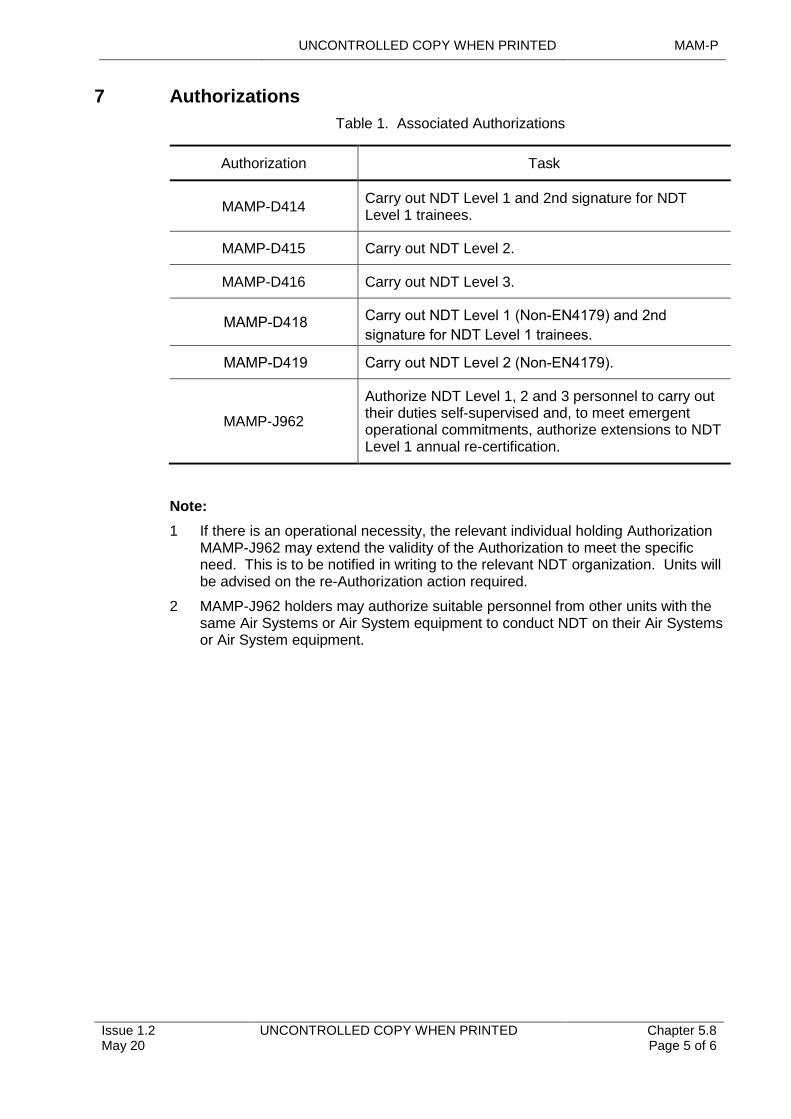
UNCONTROLLED COPY WHEN PRINTED MAM-P
Issue 1.2 May 20
UNCONTROLLED COPY WHEN PRINTED Chapter 5.8 Page 5 of 6
7 Authorizations
Table 1. Associated Authorizations
Authorization Task
MAMP-D414Carry out NDT Level 1 and 2nd signature for NDT Level 1 trainees.
MAMP-D415 Carry out NDT Level 2.
MAMP-D416 Carry out NDT Level 3.
MAMP-D418 Carry out NDT Level 1 (Non-EN4179) and 2nd
signature for NDT Level 1 trainees.
MAMP-D419 Carry out NDT Level 2 (Non-EN4179).
MAMP-J962
Authorize NDT Level 1, 2 and 3 personnel to carry out their duties self-supervised and, to meet emergent operational commitments, authorize extensions to NDT Level 1 annual re-certification.
Note:
1 If there is an operational necessity, the relevant individual holding Authorization MAMP-J962 may extend the validity of the Authorization to meet the specific need. This is to be notified in writing to the relevant NDT organization. Units will be advised on the re-Authorization action required.
2 MAMP-J962 holders may authorize suitable personnel from other units with the same Air Systems or Air System equipment to conduct NDT on their Air Systems or Air System equipment.
MAM-P UNCONTROLLED COPY WHEN PRINTED
Chapter 5.8 Page 6 of 6
UNCONTROLLED COPY WHEN PRINTED Issue 1.2 May 20
Intentionally Blank for Print Pagination
UNCONTROLLED COPY WHEN PRINTED MAM-P
Initial Issue Nov 19
UNCONTROLLED COPY WHEN PRINTED Chapter 5.9 Page 1 of 4
....................................................
.........................
....................................................................................................................
.....................................................................................................................................
...........................................................................................................................................................................
..........................................................................................................................................................
.......................................................................................................
Chapter 5.9
Contaminated Breathing Oxygen
TABLE OF CONTENTS
Paragraph Page
1 General 11.1 Introduction 11.2 Associated Publications or Instructions 22 General Procedures 22.1 Charging Trolleys 22.2 Oxygen Production Units 22.3 Contractor-Supplied Breathing Oxygen 23 Contamination Incident Reporting 44 Responsibilities – Station/Ship/Unit 4
LIST OF FIGURES
Figure 1. Procedure for Managing Contaminated Breathing Oxygen 3
LIST OF TABLES
Table 1. Contaminated Breathing Oxygen Report. 4
1 General
1.1 Introduction
Defence Standard 68-284 details the specification for compressed breathing gases, including oxygen, for UK military Aircraft. JSP 319 and Defence Standard 81-24 detail the identification and marking of transportable gas containers.
The correct identification of gases before they are used in an Aircraft system is essential. If there is any doubt as to the quality of a gas container’s contents, or if the container itself appears Unserviceable, it should be replaced with a Serviceable item. The relevant Safety Data Sheet is always to be read.
Contamination of an Aircraft’s breathing oxygen system due to the ingress of moisture or other foreign bodies can adversely affect Aircrew efficiency and therefore poses a serious flight Safety Hazard. An unexplained odour emanating from breathing oxygen is a common method for identifying contamination of the system. Smells originating from rubber hoses or associated breathing oxygen system components can be ignored but a damp musty smell can indicate moisture contamination and needs to be addressed.
Any other inexplicable odour can indicate contamination of the system, so needs to be investigated as a priority. As soon as contamination has been confirmed, it is imperative that the suspect Aircraft breathing oxygen supply components and associated replenishment systems which may include other Aircraft and onboard generation systems, are quarantined.
An investigation is then to be carried out to identify the source of the contamination and ascertain if any other Aircraft are also affected, with appropriate action taken to eliminate an escalation of the flight Safety Hazard.
MAM-P UNCONTROLLED COPY WHEN PRINTED
Chapter 5.9 Page 2 of 4
UNCONTROLLED COPY WHEN PRINTED Initial Issue Nov 19
1.2 Associated Publications or Instructions
1 JSP 319 – Safety Regulations for the Storage and Handling of LPG and IG.
2 Defence Standard 68-284 – Compressed Breathing Gasses for Aircraft, Diving and Marine Life-Support Applications.
3 Defence Standard 81-24 – Identification Marking of Transportable Containers, Compressed Gas.
4 DAP 107D-0001-1 – General Information on Aircraft Oxygen Equipment.
2 General Procedures
When contamination of breathing oxygen is suspected in an Aircraft system, the procedure at Figure 1 must be carried out.
When contamination of breathing oxygen is suspected in oxygen Ground Support Equipment (GSE), e.g. a charging trolley or production unit, the procedures laid down in the relevant equipment publication and JSP 319 must be followed.
2.1 Charging Trolleys
Where contamination of a charging trolley is confirmed, the relevant individual holding authority Level J must advise the operational commanders of all Aircraft that have or may have been charged from the charging trolley.
2.2 Oxygen Production Units
Whenever contamination of breathing oxygen is found at an oxygen production unit, the relevant individual holding authority Level J at the Station(Stn)/Ship/Unit must ensure that all recipients supplied by that oxygen production unit are informed.
2.3 Contractor-Supplied Breathing Oxygen
Where it is suspected that contractor-supplied breathing oxygen is contaminated, the procedures detailed in JSP 319 must be followed. The gas containers are not to be purged.
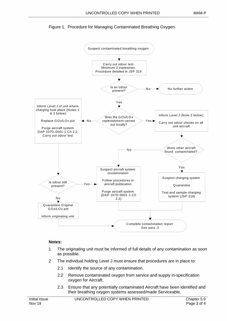
UNCONTROLLED COPY WHEN PRINTED MAM-P
Initial Issue Nov 19
UNCONTROLLED COPY WHEN PRINTED Chapter 5.9 Page 3 of 4
Figure 1. Procedure for Managing Contaminated Breathing Oxygen.
Notes:
1 The originating unit must be informed of full details of any contamination as soon as possible.
2 The individual holding Level J must ensure that procedures are in place to:
2.1 Identify the source of any contamination.
2.2 Remove contaminated oxygen from service and supply in-specification oxygen for Aircraft.
2.3 Ensure that any potentially contaminated Aircraft have been identified and their breathing oxygen systems assessed/made Serviceable.
Suspect contaminated breathing oxygen
Is an odour present?
Yes
Carry out odour test.Minimum 3 tradesmen.
Procedure detailed in JSP 319
No further action
Was the GOx/LO x replenishment carried
out locally?
Complete contamination reportSee para. 3
No
Is odour still present?
Quarantine O riginal G Ox/LOx pot
Inform originating unit
No
Inform Level J of unit where charging took place (Notes 1
& 2 below)
Replace G Ox/LO x pot
Purge aircraft systemDAP 107D-0001-1 Ch 2.2.
Carry out odour test
Suspect aircraft system contamination
Follow procedures in aircraft publication
Purge aircraft system(DAP 107D-0001 -1 Ch
2.2)
Yes
Suspect charging system
Q uarantine
Test and sample charging system (JSP 319)
No
No
Yes
Inform Level J (Note 2 below)
Carry out odour checks on all unit aircraft
Yes
Were other aircraft found contaminated?
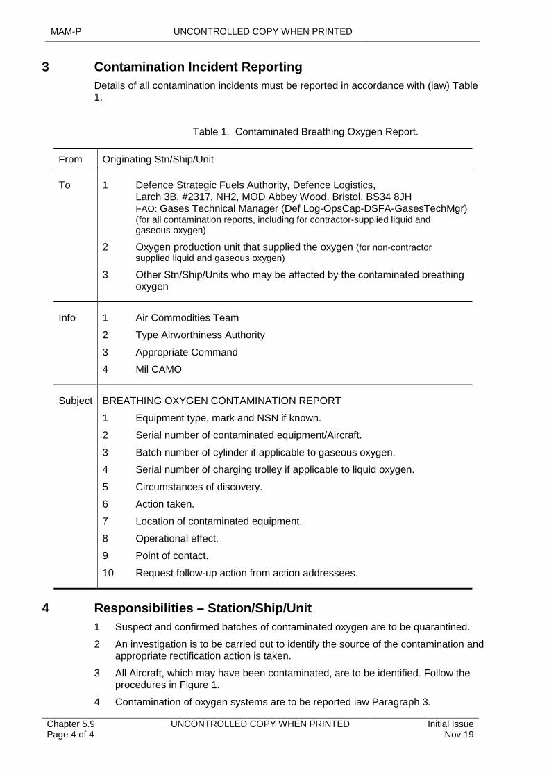
MAM-P UNCONTROLLED COPY WHEN PRINTED
Chapter 5.9 Page 4 of 4
UNCONTROLLED COPY WHEN PRINTED Initial Issue Nov 19
3 Contamination Incident Reporting
Details of all contamination incidents must be reported in accordance with (iaw) Table 1.
Table 1. Contaminated Breathing Oxygen Report.
From Originating Stn/Ship/Unit
To 1
2
3
Defence Strategic Fuels Authority, Defence Logistics, Larch 3B, #2317, NH2, MOD Abbey Wood, Bristol, BS34 8JH FAO: Gases Technical Manager (Def Log-OpsCap-DSFA-GasesTechMgr) (for all contamination reports, including for contractor-supplied liquid and gaseous oxygen)
Oxygen production unit that supplied the oxygen (for non-contractor supplied liquid and gaseous oxygen)
Other Stn/Ship/Units who may be affected by the contaminated breathing oxygen
Info 1
2
3
4
Air Commodities Team
Type Airworthiness Authority
Appropriate Command
Mil CAMO
Subject BREATHING OXYGEN CONTAMINATION REPORT
1 Equipment type, mark and NSN if known.
2 Serial number of contaminated equipment/Aircraft.
3 Batch number of cylinder if applicable to gaseous oxygen.
4 Serial number of charging trolley if applicable to liquid oxygen.
5 Circumstances of discovery.
6 Action taken.
7 Location of contaminated equipment.
8 Operational effect.
9 Point of contact.
10 Request follow-up action from action addressees.
4 Responsibilities – Station/Ship/Unit
1 Suspect and confirmed batches of contaminated oxygen are to be quarantined.
2 An investigation is to be carried out to identify the source of the contamination and appropriate rectification action is taken.
3 All Aircraft, which may have been contaminated, are to be identified. Follow the procedures in Figure 1.
4 Contamination of oxygen systems are to be reported iaw Paragraph 3.
UNCONTROLLED COPY WHEN PRINTED MAM-P
Initial Issue Nov 19
UNCONTROLLED COPY WHEN PRINTED Chapter 5.10 Page 1 of 4
...........................................................................
......................................................................................................................................................................................
.....................................................................................................................................................................
..............................................................................................................................................................
..............................................................................................................................................
........................................................................................................................................................
...........................................................................................................................................
.........................................................................................................................................................................................................
Chapter 5.10
Aircraft Cabin Pressure Testing
TABLE OF CONTENTS
Paragraph Page
1 General 11.1 Introduction 11.2 Associated Publication or Instructions 12 General Precautions 12.1 Medical Requirements 12.2 Uncontrolled Decompression 22.3 Number of Personnel in Cabin 23 Training and Qualification 23.1 Training 23.2 Qualifications Required of a Supervisor 24 Responsibilities 24.1 Individual Responsibilities 24.2 Supervisor’s Responsibilities Prior to the Test 34.3 Supervisor’s Responsibilities During the Test 35 Authorizations 4
LIST OF TABLES
Table 1. Associated Authorizations 4
1 General
1.1 Introduction
Cabin pressure testing is a recurring Maintenance task for all Aircraft that have pressurized cockpits or cabins. Whether pressurization is achieved through use of a ground test rig or the Aircraft’s own engines, the cabin becomes a pressure container during the testing and therefore precautions need to be taken to safeguard both personnel and Aircraft. Cabin pressure testing is a potentially hazardous part of Air System Maintenance and this chapter seeks to minimise the risks involved and ensure that the task is carefully controlled.
1.2 Associated Publication or Instructions
1 RA 4806 – Personnel Requirements (MRP 145.A.30).
2 AP 1269A – Royal Air Force Manual - Assessment of Medical Fitness.
2 General Precautions
2.1 Medical Requirements
Any person who is required to be in a pressurized compartment during cabin pressure testing is to comply with the medical requirements and limitations detailed in AP1269A Leaflet 3-04 Annex J: Industrial Hazards - Pressure Testing Aircraft.
Requests for medical assessment will be to the Station/Ship/Unit Medical Officer (MO). The results are to be recorded in the individual’s medical record and arrangements
MAM-P UNCONTROLLED COPY WHEN PRINTED
Chapter 5.10 Page 2 of 4
UNCONTROLLED COPY WHEN PRINTED Initial Issue Nov 19
made for subsequent routine medical surveillance. The MO will instruct personnel how to clear their eustachian tubes and advise them of the need to do this during pressurization.
2.2 Uncontrolled Decompression
The danger to personnel through explosive decompression increases with the pressure differential involved. All personnel subjected to any uncontrolled rapid decompression are to have immediate medical attention. Details of the duration of the pressurized state and the amounts of pressure applied are to be made available to medical staff.
2.3 Number of Personnel in Cabin
Personnel may be present in a pressurized compartment during cabin pressure testing only if it is necessary for them to be there to carry out some part of the test. If there is a need for personnel to be inside the pressurized compartment, their number is to be kept to the minimum required to undertake the task. However, for Safety reasons, and wherever space permits, there is to be a minimum of 2 personnel in the pressure cabin during testing. One of these is to be the supervisor and the second Tradesman is to be experienced in the test procedure being undertaken. The supervisor may also permit additional persons to be present in the pressurized compartment for familiarization training after their successful completion of formal cabin pressure testing training.
3 Training and Qualification
3.1 Training
All personnel undertaking cabin pressure testing are to be assessed as competent following an approved training course for the type/mark of Air System and are to hold MAMP-B216, authorized by an authority level J. Training may be provided through on-job training in accordance with RA 4806.
3.2 Qualifications Required of a Supervisor
The supervisor of the cabin pressure test is to hold MAMP-C320, authorized by an authority level J holding Authorization MAMP-J958, and be one of the following:
1 An Aircraft Technician (Mechanical).
2 A Ground Engineer.
3 A Tradesman of any trade who has successfully completed an authorized cross-training course that includes pressurization of an Aircraft.
4 Responsibilities
4.1 Individual Responsibilities
All personnel tasked with carrying out cabin pressure testing are to ensure that:
1 They have completed type-specific cabin pressurization testing training.
2 They fully understand the medical requirements and limitations within AP1269A Leaflet 3-04 Annex J: Industrial Hazards - Pressure Testing Aircraft.
3 They are medically cleared to carry out cabin pressure testing.
4 They consider themselves to be medically fit to carry out cabin pressure testing. If they have any doubts about their fitness, eg difficulty in clearing their ears, they are to advise their supervisor and seek medical advice before continuing.
UNCONTROLLED COPY WHEN PRINTED MAM-P
Initial Issue Nov 19
UNCONTROLLED COPY WHEN PRINTED Chapter 5.10 Page 3 of 4
4.2 Supervisor’s Responsibilities Prior to the Test
Prior to the test, the supervisor is to:
1 Brief all team members participating in the cabin pressure test on communication, Safety measures, emergency procedures and personnel positioning. In particular they are to ensure that all personnel are aware:
1.1 That doors, hatches, windows or panels may rupture or open violently under pressure.
1.2 Of the possible trajectories of debris resulting from such an incident, that they are to keep clear of potential danger areas and warn others who approach these areas.
1.3 That no attempt is to be made to open doors, windows, hatches, panels or any other items forming part of the pressurized structure until all pressure has been released from the compartment concerned.
2 Ensure that:
2.1 Suitably worded notices, eg ‘KEEP CLEAR – CABIN PRESSURE TESTING IN PROGRESS’, are positioned around the Aircraft at a suitable distance as a warning to personnel not involved with the test.
2.2 The Aircraft pressurized compartment to be tested is structurally complete, all removable panels, hatches, etc, are fitted and all pressurization system components are fitted and Serviceable.
2.3 Personnel in the pressurized compartment have continuous communication, either by intercom or by hand signals, with a Safety person positioned outside the compartment and that this communication is established before testing begins.
2.4 When a cargo compartment is to be pressurized and it is not possible/desirable to remove the cargo, the cargo custodian is made aware of the maximum pressure and the pressure differential that will be applied and is content for the test to continue.
2.5 Those personnel who will be present inside a pressurized compartment during cabin pressure testing are cleared and medically fit to do so.
4.3 Supervisor’s Responsibilities During the Test
During the test, the supervisor is to ensure that:
1 If unexpected rapid fluctuations in cabin pressure occur, the compartment is to be de-pressurized and the test is to be discontinued. The cause of the malfunction is to be determined and rectified before the test is resumed.
2 If not detailed in the Air System’s TI, initial pressurization testing is to be carried out at minimum cabin differential pressure to allow for obvious leaks or damage to be identified.
3 All personnel remain clear of the possible trajectories of debris caused by doors, hatches, windows or panels rupturing or opening violently.
4 The pressure regulator of any ground test rig used is set to the maximum value specified in the relevant Air System’s TI.
5 They, or the ground test rig operator, monitor the readings of all indicating instruments throughout the test.
MAM-P UNCONTROLLED COPY WHEN PRINTED
Chapter 5.10 Page 4 of 4
UNCONTROLLED COPY WHEN PRINTED Initial Issue Nov 19
5 Authorizations
Table 1. Associated Authorizations
Authorization Task
MAMP-B216 Undertake cabin pressure testing
MAMP-C320 Supervise cabin pressure testing
MAMP-J958 Authorize personnel to undertake and/or supervise cabin pressure testing
UNCONTROLLED COPY WHEN PRINTED MAM-P
Issue 1.3 Feb 21
UNCONTROLLED COPY WHEN PRINTED Chapter 6.1 Page 1 of 2
.........................................................................................................................
.........................................
...................................................................................................................................................
.......................................................................................................................................................
.......................................................................................................
Chapter 6.1
Electrostatic Discharge Sensitive Devices
TABLE OF CONTENTS
Paragraph Page
1 General 11.1 Introduction 11.2 Associated Publications and Instructions 11.3 Additional Information 12 Identification of ESDS Devices 13 Procedure for Handling ESDS Devices and use of Field Service Kit 24 Electrostatic Discharge (ESD) Audit and Auditor 25 Application for ESDS Auditor Course 26 ESD Auditor Responsibilities 2
1 General
1.1 Introduction
Modern avionic equipment may contain many complex components that are susceptible to damage from an Electrostatic Discharge (ESD). These items are known as Electrostatic Discharge Sensitive (ESDS) devices. An ESD may cause either immediate failure or hidden damage, which may subsequently degrade performance, reduce reliability or shorten the device’s operational life. However, when ESDS devices are fitted in a fully assembled Line Replaceable Unit (LRU), other than through contact with exposed connectors, they are, usually, deemed to be protected by the equipment’s case.
Static electricity is generated by friction, or through the contact and/or separation of dissimilar or dielectric materials including the human body, which can result in the generation of electrostatic potentials to a charge of many thousands of volts. This voltage can then be discharged to earth via the ESDS device.
Damage to ESDS devices is easy to induce, difficult to detect and costly to rectify. Specific ESD and handling information dealing with each ESDS device is dealt with in the equipment Technical Information (TI).
1.2 Associated Publications and Instructions
1 AP 116A-0601-1 – Electrostatic Discharge Sensitive Devices
1.3 Additional Information
For the purpose of this chapter, a Printed Circuit Board (PCB) is classed as an ESDS device.
2 Identification of ESDS Devices
Most manufacturers of electronic equipment that contains an ESDS device will make this evident by labelling their equipment. Where space does not allow the use of labels, manufacturers may use a yellow dot or, on PCBs, a yellow module extraction tab. If no identification is visible, refer to the equipment’s TI.

MAM-P UNCONTROLLED COPY WHEN PRINTED
Chapter 6.1 Page 2 of 2
UNCONTROLLED COPY WHEN PRINTED Issue 1.3 Feb 21
3 Procedure for Handling ESDS Devices and use of Field Service Kit
A Field Service Kit (FSK) is a portable ESD Protected Area (EPA) used for the safe handling of ESDS devices at Forward Maintenance locations or when no other suitable EPA is available. Whenever an ESDS device will be handled using a FSK, the following precautions are to be taken:
1 The equipment is to be removed in accordance with (iaw) relevant TI and handled using a FSK.
2 Before the PCB is handled, equal potential is to be achieved by connecting the operator to the equipment using a wrist strap and clip contained in the FSK.
3 Avoid touching the exposed terminals on LRUs that contain, or are thought to contain, an ESDS device or PCB.
4 An anti-static covering iaw the relevant TI is to be fitted to protect any plugs or sockets removed.
5 PCBs are to be placed in ESD protective packaging iaw the relevant TI before being removed from the FSK.
These precautions apply to both Serviceable and Unserviceable equipment. Additional instructions for handling ESDS devices both at Forward and Depth Maintenance locations are contained in AP 116A-0601-1.
4 Electrostatic Discharge (ESD) Audit and Auditor
Stations/Ships/Units that have EPAs or FSKs are to ensure that an Audit of their ESD equipment is carried out on a 6-monthly basis. An ESD auditor is to carry out these audits.
5 Application for ESDS Auditor Course
A course titled ‘ESDS Auditor Course No-CN3049’ is held at the Civilian Technical Training School (CTTS), MOD Sealand (DECA). The course contains both elements of ESDS control and EPA Maintenance. For RAF personnel, this course leads to the accreditation of the qualification Q-ESDS-AUD.
Nominations for course places are to be made via unit training co-ordinators to the learning and development team, DECA, Sealand, Telephone 01244 847611, email: [email protected]. Course places are available to nominated EPA Auditors and their deputies.
6 ESD Auditor Responsibilities
The ESD auditor is responsible for:
1 Carrying out an audit of all ESD devices within their area of responsibility.
2 Maintaining a register of all EPAs and FSKs.
3 Ensuring that all EPAs and FSKs are maintained to the correct specifications and that the correct EPA and FSK practices, including ESD device audits, are adhered to iaw AP 116A-0601-1.
UNCONTROLLED COPY WHEN PRINTED MAM-P
Issue 1.3 Feb 21
UNCONTROLLED COPY WHEN PRINTED Chapter 6.2 Page 1 of 4
...........................................................................
..............................................................................................................................................................................
...................................................................................................................................................................................
..........................................................................................................................
............................................................................................
..........................................................................................................................................................
.......................................................................................................
Chapter 6.2
Precision Termination Tooling
TABLE OF CONTENTS
Paragraph Page
1 General 11.1 Introduction 11.2 Associated Publications or Instructions 12 Precision Termination Tooling Maintenance 13 Precision Termination Process Training 24 Control of PTT Resources 25 Application for PTT Coordinator Course 36 Responsibilities 36.1 Station/Ship/Unit 36.2 Unit PTT Coordinator 37 Authorizations 4
LIST OF TABLES
Table 1. Associated Authorizations 4
1 General
1.1 Introduction
This chapter details the conditions governing the control and use of Precision Termination Tooling (PTT) and the associated Precision Termination Process (PTP). PTP is a reliable, repeatable method of providing a uniform mechanical connection between a termination and an electrical conductor. PTT/PTP play a major role in the integrity of Air System Electrical Wiring Interconnect System (EWIS) serviceability and therefore the control and management of PTT aligned with PTP awareness and continued improvement are essential to the Maintenance of Airworthiness.
This chapter is restricted to the Air System platform, associated Line Replaceable Units (LRUs), aero-engines, auxiliary power units and role equipment. This chapter does not apply to specialist fibre optic PTT/PTP.
1.2 Associated Publications or Instructions
1 RA 4808 – Equipment, Tools and Material (MRP 145.A.40)
2 RA 4809 – Acceptance of Components (MRP 145.A.42)
3 AP120M-0612-1 – Precision Termination Tooling Control, Maintenance and Testing
4 AP101A-0005-1 – Aircraft Wiring Standards and Practices (Aircraft Wiring Husbandry)
2 Precision Termination Tooling Maintenance
All PTT (including wire strippers) are subject to specific Maintenance to ascertain serviceability as follows:
MAM-P UNCONTROLLED COPY WHEN PRINTED
Chapter 6.2 Page 2 of 4
UNCONTROLLED COPY WHEN PRINTED Issue 1.3 Feb 21
1 A before use inspection is to be carried out in accordance with (iaw) the relevant Technical Information (TI) detailed in AP120M-0612-1.
2 Servicing is to be carried out iaw the relevant TI detailed in AP120M-0612-1 on the following occasions:
2.1 Six monthly for in-use tools.
2.2 Removal from controlled store.
2.3 Prior to placing into controlled store.
2.4 Prior to issue of new tool (or tool transferred from another Unit).
3 GO/NO-GO gauges applicable to PTT are to be dimensionally checked annually iaw AP120M-0612-1.
4 If not available within AP120M-0612-1, TI advice is to be sought from the Operational Infrastructure Programme (OIP) or applicable Type Airworthiness Authority (TAA).
5 Where PTT is utilized in a harsh environment, such as sand, dust and saltwater, an increase in Maintenance frequency is to be considered to maintain crimp tool integrity.
3 Precision Termination Process Training
All Air System Tradesmen, who, in the normal course of their duties may be expected to carry out PTP, are to undergo formal training on the common in-use PTT applicable to the Air System or equipment on which they are employed, as follows:
1 Personnel are to complete training prior to or within three months of arrival on the Station/Ship/Unit.
2 Personnel are to complete revalidation training annually.
It is recommended that this training be carried out by the PTT co-ordinator. However, units may wish to subsume this training within their own ground schools or training facilities. The training is to be based on the type of PTT applicable to the platform or equipment on which they are employed. High level training objectives are detailed within AP101A-0005-1 and syllabus content assistance is available from the Air Commodities Team (AC Team).
Personnel who regularly use PTT (more than once daily for common items of PTT and weekly for the less common, ie hydraulic type) may have the authorization requirement for annual training extended to 24 months, at the discretion of the relevant individual holding authority level K.
Personnel may have their Authorization extended by up to six months for operational reasons at the discretion of the relevant individual holding authority level K.
Personnel who have not completed training, and been duly authorized, are not to conduct crimping on Air Systems or Air System equipment. Training is to be recorded, including extensions, as a local engineering Authorization, iaw Chapter 2.1 - Engineering Authorizations.
4 Control of PTT Resources
It is recommended that in order to reduce the requirement for Maintenance of PTT, the relevant individual holding authority level K is to consider placing the control of all the unit's PTT resources under the control of a PTT Co-ordinator, as detailed in Paragraph 6.2, who will then carry out the following:
UNCONTROLLED COPY WHEN PRINTED MAM-P
Issue 1.3 Feb 21
UNCONTROLLED COPY WHEN PRINTED Chapter 6.2 Page 3 of 4
1 Negotiate with all PTT holders and withdraw all PTT that is infrequently used into storage.
2 Devise and implement a system, by which any section may withdraw, at any time, on temporary or permanent loan, any item of PTT for immediate use. A full range of the PTT that could be required by user sections will remain in the store available for immediate issue.
3 Maintain the serviceability of all PTT held in store and be responsible for ensuring that any tool removed from controlled store is subjected to a servicing prior to use.
4 Raise a MOD Form 755C PTT Maintenance and Record card for each item of PTT to record servicing.
5 Review the PTT held in store and remove any that is considered surplus and place into a controlled store. PTT is to undergo a servicing prior to being placed into controlled store and will then not require any servicing whilst in storage.
5 Application for PTT Coordinator Course
A course titled ‘Precision Termination Tooling Co-ordinators Course No-CN3016’ is held at the Learning & Development (L&D) DECA Sealand. The course contains both elements of PTT control and PTP instructional training techniques. For RAF personnel this course leads to the accreditation of the qualification Q-A-PTT.
Nominations for course places are to be made via Unit PTT Co-ordinators to L&D, DECA Sealand via email: [email protected]. Course places are available to nominated PTT Co-ordinators and their deputies.
6 Responsibilities
6.1 Station/Ship/Unit
The relevant individual holding authority level K at each Station/Ship/Unit is to appoint a PTT Co-ordinator who is normally to be a suitably experienced and qualified Air System Avionics/Electrical Tradesman or civilian equivalent holding authority level E. Where practicable, the PTT Co-ordinator is to be both the controller and trainer for both PTT and PTP.
The PTT co-ordinator is to attend the PTT Co-ordinator Course as detailed in Paragraph 5 and the appointment is to be annotated on the Local Unit Establishment (LUE). Units are to consider the appointment of a deputy to act in the absence of the PTT Co-ordinator. It is recommended that the PTT Co-ordinators are considered for additional instructional technique training.
Deployments/detachments which utilise a PTT Co-ordinator are, where practicable, to meet the qualification requirements. Where this is not possible due to roulement timescales or training availability, the minimum standard is to be the nomination of an Air System Avionics Tradesman holding authority level C.
The relevant individual holding authority level K is to oversee a system of training as detailed in Paragraph 3, for all Air System Avionics Tradesmen, who, in the normal course of their duties might be expected to carry out PTP.
6.2 Unit PTT Coordinator
The PTT Coordinator is responsible to the relevant individual holding authority level K for the control of all PTT and, where detailed, the training of PTP. As the unit specialist, the co-ordinator is to be the focal point for PTT. If the PTP or an item of PTT is suspect, then the relevant authority is to be contacted for advice. If a test
MAM-P UNCONTROLLED COPY WHEN PRINTED
Chapter 6.2 Page 4 of 4
UNCONTROLLED COPY WHEN PRINTED Issue 1.3 Feb 21
sample be recommended, then it is to be constructed iaw AP120M-0612-1 and submitted to a test facility as directed by the AC Team.
Additionally, the PTT Co-ordinator is to:
1 Maintain a register/database of all PTT held on the unit, including their GO-NO-GO gauges.
2 Liaise with the unit tool controller to ensure that the unit's system of serial numbering for PTT is correct iaw RA 4808 and Chapter 4.13 – Management of Hand Tools and Test and Measuring Equipment and all PTT is marked with the unit's identity code before being brought into use.
3 Maintain records to show that the Preventive Maintenance of all PTT and annual dimensional checks of their GO-NO-GO gauges has been completed. If there is no other way to confirm tool serviceability and if the AC Team agree that a test sample is required, then it is to be constructed iaw AP120M-0612-1 and submitted to a test facility as directed.
4 Control the Maintenance of PTT by user sections and provide specialist advice on Maintenance procedures.
5 Control the gauge annual dimensional checks iaw AP120M-0612-1.
6 Coordinate and progress the embodiment of Modifications and the satisfaction of Special Instruction (Technical) (SI(T)) pertaining to items of PTT.
7 Be the authorized conditioner of PTT iaw RA 4809 and Chapter 4.10 – Technical Equipment – Conditioning and Preparation for Movement or Storage.
8 Coordinate all supply support actions for PTT iaw Chapter 4.13 – Management of Hand Tools and Test and Measuring Equipment, including routine demands and Low Value Purchase (LVP) action.
9 Inform the relevant tooling authority of LVP action to ensure that the tool is added to AP120M-0612-1.
10 Ensure that all PTT issued through supply or LVP action has equipment or platform Delivery Team Approval.
7 Authorizations
Authorizations relating to PTT/PTP are to be issued as local engineering Authorizations by individual with authority level J.
Table 1. Associated Authorizations
Authorization Task
MAMP-J975 To authorize Local Engineering Authorizations.
UNCONTROLLED COPY WHEN PRINTED MAM-P
Initial Issue Nov 19
UNCONTROLLED COPY WHEN PRINTED Chapter 6.3 Page 1 of 4
...........................................................................
.............................................................................................................................
............................................................................................................................................................
..............................................................................................................................
.................................................................................................................
...................................................................................................................................................................................
..........................................................................................................................................................
.......................................................................................................
Chapter 6.3
Air System TEMPEST Testing
TABLE OF CONTENTS
Paragraph Page
1 General 11.1 Introduction 11.2 Associated Publications or Instructions 11.3 Applicability 11.4 Additional Information 22 Air System TEMPEST Testing 22.1 Occasions for Air System TEMPEST Testing 22.2 Requests for Air System TEMPEST Testing 23 Maintenance Practices 33.1 TEMPEST Assurance Expiry 34 TEMPEST Training 34.1 Specialist Training for Air System TEMPEST Testers 35 Authorizations 4
LIST OF TABLES
Table 1. Associated Authorizations 4
1 General
1.1 Introduction
TEMPEST does not pose an Airworthiness issue but is to be routinely tested to ensure the Information Assurance (IA) and security of each Air System. This chapter describes Air System TEMPEST approved procedures applied to the Military Airborne Communications when exercising Communication Information Systems (CIS) that process Government Security Classification (GSC) SECRET.
1.2 Associated Publications or Instructions
1 RA 4806 - Personnel Requirements (MRP 145.A.30)
2 JSP 440 - The Defence Manual of Security, Resilience and Business Continuity
3 JSP 822 - Defence Direction and Guidance for Training and Education
4 NATO SDIP-27/2 TEMPEST Standard
5 NCSC Information Assurance Implementation Guides – TEMPEST and Electromagnetic Security
1.3 Applicability
This chapter is applicable within the Defence Air Environment (DAE) to the Maintenance of Air Systems fitted with secure CIS that process GSC SECRET information. This chapter is not applicable to ground-based mission support systems or facilities.
MAM-P UNCONTROLLED COPY WHEN PRINTED
Chapter 6.3 Page 2 of 4
UNCONTROLLED COPY WHEN PRINTED Initial Issue Nov 19
1.4 Additional Information
The TEMPEST associated processes for airborne CIS in this chapter are derived from the overarching national TEMPEST policy set by the National Cyber Security Centre (NCSC). SDIP (SECAN Doctrine Information Publication) 27/2 and NCSC Information Assurance Implementation Guides – TEMPEST and Electromagnetic Security - mandate the levels to which a platform is to be tested. Within the DAE, TEMPEST testing of fixed and rotary-wing Air System fitted with secure CIS is to be carried out in accordance with this chapter and JSP 440. JSP 440 Leaflet 18 covers all test types, responsibilities, action on test failures and associated processes for Air System Communications Security (COMSEC) material.
2 Air System TEMPEST Testing
2.1 Occasions for Air System TEMPEST Testing
Air System TEMPEST testing is to be carried out on the following occasions:
1 Prior to the introduction into service of a new Air System type containing, as part of the build standard, secure CIS that process GSC SECRET information.
2 Hardware Modification to CIS or other system that processes GSC SECRET information.
3 When secure CIS is installed in an Air System already in-Service but not previously fitted with a secure CIS capability.
4 Software Modification to CIS or other system that processes GSC SECRET information may also incur a First of Type (FoT) TEMPEST test. An appropriate FoT test house is to be consulted on the TEMPEST impact of the software Modification and the remedial work required to maintain Air System accreditation. 591 Signals Unit (SU) is the only MOD FoT test house, however commercial facilities also exist.
5 When Significant Disturbance (SD) of Air System systems occurs. A SD occurs when cables/looms carrying GSC SECRET information or adjacent cables/ looms are repositioned, or re-routed or repaired. Certain Line Replaceable Units (LRUs) and their associated cables/looms, including secure CIS role Products, Parts and Appliances and LRUs in secure CIS UORs and SMs, may fit this definition. The Air System Delivery Team (DT) will ensure LRUs are listed in the Air System Topic 2(N/A/R).
6 If Air System production is carried out in batches and/or at different locations, the Air System Configuration may change between batches, so further TEMPEST tests are to be carried out on selected Air System, normally the first in each batch, to confirm that the TEMPEST profile of the Air System type and its secure CIS installation is being maintained. Any TEMPEST failures, or significant changes in the TEMPEST profile, are to be investigated and resolved before the Air System type enters service.
7 When detailed as a Preventive Maintenance activity in the Topic 5A1.
8 As directed by the Air System DT following consultation with the appropriate TEMPEST Testing Technical Lead.
2.2 Requests for Air System TEMPEST Testing
Requests for Air System TEMPEST testing will normally be originated by either an Air System DT or the relevant Air System engineering Maintenance manager on Sqns/Units. When DTs initially plan to introduce or modify a CIS capable system they are to consult 591 SU Air TEMPEST and request a TEMPEST Impact Report (TIR).
UNCONTROLLED COPY WHEN PRINTED MAM-P
Initial Issue Nov 19
UNCONTROLLED COPY WHEN PRINTED Chapter 6.3 Page 3 of 4
Air requests are to be submitted direct to 90SU-591SU-Ops CP GpMbx (MULTIUSER). Joint/Naval asset requests to JFCyG-JIACC Tasking Group (MULTIUSER). In all cases the following information is required:
1 Stn/Ship/Unit requesting the Air System TEMPEST activity including the Point of Contact.
2 Local reference or identifying reference that is to be used in all correspondence.
3 Date of when the test is required.
4 Specific Air System details including:
4.1 Type and Mark.
4.2 Tail Number.
4.3 Location.
5 The reason for the request:
5.1 FoT TEMPEST test.
5.2 Post a Modification to CIS capability.
5.3 After a SD.
5.4 Part of Preventive Maintenance including pre-deployment (providing that Certification will expire during expected duration of deployment).
5.5 When directed by DT following consultation with appropriate TEMPEST Testing Technical Lead.
3 Maintenance Practices
3.1 TEMPEST Assurance Expiry
The lapsing of TEMPEST Assurance does not confirm that there is a Risk to information (as per a TEMPEST failure). Lapsing does however, reduce the level of Assurance provided by the previous test. Noting the reduced level of Assurance, an assessment of the likely Risk to information is to be conducted by the relevant stakeholders prior to the Air System being used to process GSC SECRET information (regardless of geographical location of that tasking).
4 TEMPEST Training
4.1 Specialist Training for Air System TEMPEST Testers
Avionics Tradesmen employed in Air System TEMPEST testing are required to complete and pass relevant TEMPEST training courses, arranged by the appropriate Air System TEMPEST Authority, and acquire the Competence to carry out Air System TEMPEST testing. Personnel are to be competent and authorized in compliance with the requirements of RA 4806 and Chapter 2.1 - Engineering Authorizations. There are two TEMPEST training courses appropriate to Air System TEMPEST testing:
1 NCSC Platform Tester Platform Accreditation Scheme - TEMPEST Team Member.
2 NCSC Platform Tester Platform Accreditation Scheme - TEMPEST Team Leader.

MAM-P UNCONTROLLED COPY WHEN PRINTED
Chapter 6.3 Page 4 of 4
UNCONTROLLED COPY WHEN PRINTED Initial Issue Nov 19
5 Authorizations
Table 1. Associated Authorizations
Authorization Task
MAMP-E514Carry out Air System TEMPEST Test activity as a TEMPEST Test Team member.
MAMP-F605Supervise Air System TEMPEST activity as TEMPEST Test Team Leader.
MAMP-K1019Authorize personnel to sign as 1st and 2nd signatories for Air System TEMPEST Test Team activity.
UNCONTROLLED COPY WHEN PRINTED MAM-P
Initial Issue Nov 19
UNCONTROLLED COPY WHEN PRINTED Chapter 6.4 Page 1 of 2
...........................................................................
.............................................................................................................................................................
.........................................................................................................................................................................................................
.................................................................................................................................................................
..................................................................................................................................................................................
.......................................................................................................................................................
.......................................................................................................
Chapter 6.4
Air System COMSEC Material
TABLE OF CONTENTS
Paragraph Page
1 General 11.1 Introduction 11.2 Associated Publications and Instructions 12 Management Procedures 12.1 General 12.2 Security Checks 12.3 Maintenance Work Recording 22.4 Land-Away 22.5 Transfer 23 Authorization to Load Keymat 24 Authorizations 2
LIST OF TABLES
Table 1. Associated Authorizations 2
1 General
1.1 Introduction
This chapter provides guidance on the management of cryptographic equipment installed in an Air System.
1.2 Associated Publications and Instructions
1 JSP 440 - Defence Manual of Security, Resilience and Business Continuity
2 JSP 490 – Defence Crypto Security Operating Instructions
2 Management Procedures
2.1 General
Procedures governing the management of COMSEC material are contained in JSP 490 and JSP 440. Essentially, the processes are as follows:
1 The Station(Stn)/Ship/Unit COMSEC Custodian is responsible for the registration and control of all COMSEC material. Additionally, the custodian is responsible both for the Authorization of all personnel who use COMSEC material and the issue of orders detailing their responsibilities.
2 Authorized holders are issued their COMSEC material and relevant orders by the Stn/Ship/Unit COMSEC Custodian under signature and fulfil their duties as detailed.
2.2 Security Checks
The orders issued by the COMSEC Custodian detail all arrangements for storing, handling and managing cryptographic material held on charge and the frequency of required checks.

MAM-P UNCONTROLLED COPY WHEN PRINTED
Chapter 6.4 Page 2 of 2
UNCONTROLLED COPY WHEN PRINTED Initial Issue Nov 19
2.3 Maintenance Work Recording
2.3.1 Installation, Removal or Replacement of Equipment
The installation, removal or replacement of an item of cryptographic equipment is a normal Maintenance activity that is to be recorded using the MOD Form 700 series documentation or equivalent. The replacement of unserviceable or surplus cryptographic equipment is to be directed through the Stn/Ship/Unit COMSEC Custodian.
2.3.2 Loading of Keying Material (keymat)
For certain types of cryptographic equipment to function properly, it is essential that the correct keymat is loaded. Failure to load the correct keymat may result in systems being limited or unavailable. The loading of incorrect keymat is a serious breach of security and is to be reported to the COMSEC custodian immediately. It is therefore imperative that a record is maintained on the appropriate MOD Form 700 series documentation, or equivalent, and that Aircrew are informed of the status of the cryptographic equipment systems on their Air System.
2.4 Land-Away
If an Air System is required to land away from its normal operating base, the home base COMSEC Custodian is to be provided with the exact details of any COMSEC material that may be carried on that Air System and the anticipated period of the land-away, eg IFF Transponder MK12, Ser No 12875BA, fitted to Air System No XZ247 is going to land away at Edinburgh Airport from 30/11/14 to 05/12/14. The COMSEC Custodian will detail any security requirements to be undertaken at the land-away base.
2.5 Transfer
It is often necessary to transfer the Air System between Stns/Ships/Units. When this occurs, the home Stn/Ship/Unit COMSEC Custodian is to be informed of the exact details of any cryptographic equipment that may be fitted to the transferring Air System. The home Stn/Ship/Unit COMSEC Custodian will then carry out formal transfer accounting action with the receiving Stn/Ship/Unit COMSEC Custodian.
3 Authorization to Load Keymat
Personnel holding Authorization MAMP-B201 may load Keymat. To hold this Authorization, personnel are to be registered with the COMSEC Custodian, hold an in-date Crypto Authorization Certificate, be Security Clearance cleared and crypto-trained prior to Authorization.
4 Authorizations
Table 1. Associated Authorizations
Authorization Task
MAMP-B201Load keymat and sign required Maintenance documentation
MAMP-J932 Authorize personnel to load keymat
UNCONTROLLED COPY WHEN PRINTED MAM-P
Initial Issue Nov 19
UNCONTROLLED COPY WHEN PRINTED Chapter 6.5 Page 1 of 4
...........................................................................
.............................................................................................................................................................................
..........................................................................................................................................................................................
..............................................................................................
...............................................................................................................................
......................................................................................................................................................................
......................................................................................................................................
.........................................................................................................................................................................................................
Chapter 6.5
Maintenance of Aircraft Compass Accuracy
TABLE OF CONTENTS
Paragraph Page
1 General 11.1 Introduction 11.2 Associated Publications and Instructions 12 Compass Calibration 12.1 Compass Bases 12.2 Types of Compass Swing 22.3 Requirement for a Compass Swing 22.4 Compass Swing Documentation 32.5 Calibration and Adjustment Accuracy 33 Demagnetization of Aircraft Struck by Lightning 33.1 Investigation 33.2 Demagnetization 33.3 Post-demagnetization 34 Authorizations 3
LIST OF TABLES
Table 1. Associated Authorisations 4
1 General
1.1 Introduction
Many Aircraft Maintenance actions, including those not directly involving work on compass systems, may cause compass inaccuracies. This chapter describes the engineering responsibilities, procedures and equipment to be used to restore and maintain the accuracy of Aircraft compass systems.
1.2 Associated Publications and Instructions
1 RA 4813 – Maintenance Records (MRP 145.A.55)
2 AP 112B Series – Navigation Equipment
3 AP 112T Series – Instrument Servicing and Test Equipment (Special Purpose)
4 AP 3456 – The Central Flying School (CFS) Manual of Flying
5 DAP 120M-0203-1 – Demagnetizer Units
2 Compass Calibration
2.1 Compass Bases
A compass base is a location used for the calibration of Aircraft compasses and may be established as either Class 1 or Class 2:
1 Class 1 – The maximum permissible magnetic deviation is ±0.1° measured at 1.5m above the ground, used for refined swings.
MAM-P UNCONTROLLED COPY WHEN PRINTED
Chapter 6.5 Page 2 of 4
UNCONTROLLED COPY WHEN PRINTED Initial Issue Nov 19
2 Class 2 – The maximum permissible magnetic deviation is ±0.25° measured at 1.5m above the ground, used for standard swings.
2.2 Types of Compass Swing
Full details of compass swings can be found in AP 3456 Volume 5 Chapters 5-18. There are 4 types of compass.
1 Standard swing: Standard swings are carried out on Aircraft whose compass systems are not used as an input to other navigation or weapon aiming systems. Carried out on either a Class 1 or Class 2 compass.
2 Refined swing: Refined swings are carried out on Aircraft whose compass systems are used to feed heading input to produce navigation or weapon aiming solutions. A refined swing is generally carried out on a Class 1 compass base. If a Class 2 base is used for the refined swing 2 Watts Datum Compasses is to be used. This procedure can be found in AP 3456 Volume 5 Chapter 18.
3 Electrical swing: Electrical swings are essentially the same as the refined swing except that, instead of physically moving the Aircraft onto the appropriate headings, the headings are simulated by a Compass Calibrator.
4 Air swing: It is possible to swing an Aircraft compass in the air; however, it is subject to limitations. The procedure can be found in AP 3456 Volume 5 Chapter 17.
2.3 Requirement for a Compass Swing
The accuracy of an Aircraft compass system can be affected by changes in operating location, physical or electrical disturbances and changes to magnetic signature. The Authority Level J is to consider conducting a compass swing if the accuracy is in doubt or on the following occasions:
1 After a change of compass system components.
2 When an Aircraft has been subjected to severe static electricity, eg a lightning strike.
3 On Aircraft transfer from one theatre of operations to another where latitude is changed, and a high degree of compass accuracy is to be assured.
4 Whenever an Aircraft compass has been subjected to shock, eg after a heavy landing.
5 After an Aircraft has been repaired or subjected to conditions likely to affect the compass system(s).
6 After an Aircraft has been in long-term storage.
7 If it is considered likely that a specific freight load will cause magnetic influence and thereby affect compass readings.
Note:
If the above instructions cannot be adhered to for operational reasons, best endeavours are to be made (such as checks against another Air System’s or ship’s reference) to ensure that compass accuracy remains adequate for navigation and Flight Safety. Where accuracy is in doubt, an appropriate entry is to be made in the Limitation Log (MOD Form 703) or equivalent and a compass swing is to be carried out at the first opportunity.
UNCONTROLLED COPY WHEN PRINTED MAM-P
Initial Issue Nov 19
UNCONTROLLED COPY WHEN PRINTED Chapter 6.5 Page 3 of 4
2.4 Compass Swing Documentation
Compass swings are to be raised, and their completion certified, in the appropriate Maintenance Work Order of the MOD Form 700 or equivalent, in accordance with RA 4813 and Chapter 2.4 – Certification and Maintenance Documentation.
On completion of the swing, the relevant compass log (MOD Form 712A - Compass Calibration Log) and any necessary compass deviation/corrector cards and Electronic Information System (IS) are to be updated.
2.5 Calibration and Adjustment Accuracy
The degree of accuracy to which compass systems are to be calibrated is detailed in the relevant Aircraft TI.
3 Demagnetization of Aircraft Struck by Lightning
Aircraft compasses are to be regarded as unreliable after an Aircraft has been struck by lightning.
3.1 Investigation
Following a report of a lightning strike, a compass swing is to be carried out prior to the next flight. If this is not practicable, a suitable entry is to be made in the Aircraft Limitations Log MOD Form 703 or equivalent. If, during the investigation compass swing, a change of coefficient A, B or C appears to have occurred equal to or greater than 4 times the maximum acceptable residual coefficient for the Aircraft, it is to be assumed that the Aircraft is magnetized.
3.2 Demagnetization
DAP 120M-0203-01 describes the standard equipment used for demagnetizing an Aircraft and details the procedures to be followed. If all attempts to demagnetize an Aircraft are unsuccessful, the relevant individual holding authority level J may apply to the relevant Command for Non-Destructive Testing (NDT) Team assistance.
3.3 Post-demagnetization
After demagnetization has been completed, the Aircraft is to be flown twice in a specified pattern to stabilise the magnetism and is then to be re-swung after two months to ensure that the Aircraft is magnetically stable.
The following entry is to be made in the Aircraft’s Limitation Log MOD Form 703 or equivalent:
‘Aircraft demagnetized on …[insert date]. Changes in Compass Deviation may occur due to magnetic stabilization. A Maintenance Work Order entry must be made whenever compass errors are detected. A full Compass Swing must be undertaken on … [insert date + 2 Months]. MAM-P Chapter 6.5 refers.’
If significant changes in deviation are detected during the check swing, the Limitation Log MOD Form 703 or equivalent entry is to be deferred for a further 28 days.
4 Authorizations
Supervision of Aircraft compass adjustment may only be carried out by:
1 Aircrew holding Authorization MAMP-AM01, in accordance with Chapter 2.3 Authorization of Aircrew to Carry out Aircraft Maintenance work.
2 Avionics Tradesmen holding Authorization MAMP-C317.
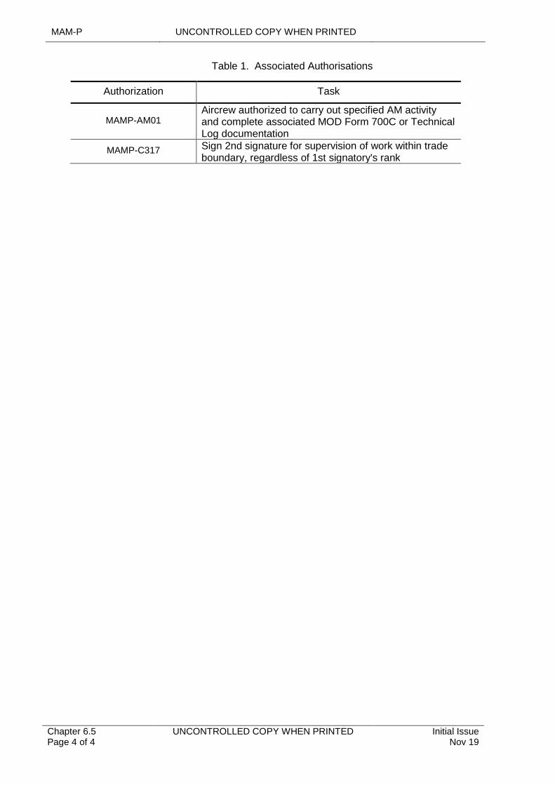
MAM-P UNCONTROLLED COPY WHEN PRINTED
Chapter 6.5 Page 4 of 4
UNCONTROLLED COPY WHEN PRINTED Initial Issue Nov 19
Table 1. Associated Authorisations
Authorization Task
MAMP-AM01Aircrew authorized to carry out specified AM activity and complete associated MOD Form 700C or Technical Log documentation
MAMP-C317 Sign 2nd signature for supervision of work within trade boundary, regardless of 1st signatory's rank
Initial Issue Nov 19
UNCONTROLLED COPY WHEN PRINTED Chapter 6.6 Page 1 of 4
......................................................................................
.................................................................................................................................................................
.....................................................................................................................................................................................
.......................................................................................................................................
.........................................................................................................................................................................................................
Chapter 6.6
Crimped Splice Repairs in Air System Electrical Wiring Interconnect Systems
TABLE OF CONTENTS
Paragraph Page
1 General 11.1 Introduction 11.2 Associated Publications and Instructions 11.3 Additional Information 12 Crimped Splice Repairs 12.1 General 12.2 Exclusions and Conditions 22.3 Permanent Repairs 22.4 Temporary Repairs 3
1 General
1.1 Introduction
This chapter details the conditions governing the use of in-line crimped splices for Repairs in Air System Electrical Wiring Interconnect System (EWIS) installations.
1.2 Associated Publications and Instructions
1 AP 113D-2008-1 – Crimp Splices for Electrical Cables – General and Technical Information
1.3 Additional Information
The insertion of an environmentally sealed, in-line, crimped splice in an electrical wire or cable forming part of an Air System EWIS installation is the accepted method of Repair when replacement of the entire wire or cable is impracticable. Such Repairs are, however, subject to specific restrictions and exclusions and some are permitted only as a temporary measure.
2 Crimped Splice Repairs
2.1 General
The definition of terms, Repair procedures and installation precautions for the use of in-line splices are detailed in AP 113D-2008-1 – Crimp Splices for Electrical Cables – General and Technical Information. The AP 113D-2008-1, details low profile, environmentally sealed, in-line splices for use with wire sizes 26 (001) to 12 (030) Aircraft Wire Gauge (AWG) International Organization Standardization (ISO) and also details splices for wire sizes 10 (050) to 6 (140) AWG; however, these larger splices are not low profile. Providing both splice types are installed as directed in AP 113D-2008-1, they may be considered permanent Repairs, subject to the conditions of this chapter.
Non-environmentally sealed splices are only to be used for temporary Repairs, unless approved by the platform Design Organization and relevant Type Airworthiness Authority (TAA).
MAM-P UNCONTROLLED COPY WHEN PRINTED
Chapter 6.6 Page 2 of 4
UNCONTROLLED COPY WHEN PRINTED Initial Issue Nov 19
2.2 Exclusions and Conditions
In addition to the specific Repair instructions detailed in AP 113D-2008-1, the use of in-line crimped splices is subject to the following general exclusions and conditions (in all cases dissimilar metals are to be avoided):
1 An in-line crimped splice is not to be made in a curved wire or cable form that places undue stress on the splice: the natural lay of the wire or cable is not to be impaired.
2 As far as is practicable, consideration is to be given to existing splices in any one wire or cable in order to keep the number of Repairs to a minimum.
3 The distance between splices in the same wire or cable is to be as large as practicable. Splices are not to be used to salvage wire.
4 Splices are not to be made under clips or ties and the splice is to be physically supported on each side.
5 Where multiple splices are required in close proximity to each other, their position is to be staggered to avoid any increase in loom diameter. Wherever possible, splices are to be positioned on the outside of a loom to allow subsequent identification and inspection.
6 Wires not marked with a circuit coding are to be identified, adjacent to the splice, using printed marker sleeves of the appropriate material.
7 The supervisor is to carry out stage inspections during the splicing process.
8 Wires and cables that have a specified fire resistance rating require special consideration and are not to be Repaired without the authority of the relevant TAA.
9 Repairs to co-axial, data bus or thermocouple cable may affect system performance; therefore, they are only to be carried out as specified by the relevant TAA.
2.3 Permanent Repairs
2.3.1 Where an in-line splice is deemed the most appropriate Repair method, an environmentally sealed variant is always to be used to affect a permanent Repair to an Air System wiring installation. An Acceptable Deferred Fault (ADF) is to be raised pending TAA approval of the permanent Repair.
2.3.2 Wires or cables are not to be permanently Repaired using a splice in the following areas or circuits unless authorized by the TAA or a Design Organisation approved Repair scheme:
1 Larger than size 6 AWG (ISO 140) or carries more than 250 volts Root Mean Square (RMS).
2 The connection between a bonded earth stud and earth terminal block.
3 In a designated fire zone within the Air System.
4 In an area subject to flexing.
5 In fuel tanks.
6 In conduit or within 300 mm of conduit openings.
7 Within 300 mm of a termination device.
8 Part of the Air System armament electrical installation or suspension equipment.
9 Subject to specific exclusion by the relevant TAA.
Initial Issue Nov 19
UNCONTROLLED COPY WHEN PRINTED Chapter 6.6 Page 3 of 4
10 Cable, including data cables, which are designated critical components or are associated with critical components.
2.4 Temporary Repairs
A TAA may authorize a temporary Repair using a low profile environmentally sealed crimped splice on items detailed at Paragraph 2.3. In such cases, users are to notify details of the intended Repair to the platform Delivery Team and copy the information to the Air Commodities Team (AC Team). Once satisfied with the proposal, the TAA is to provide authority for the Repair (copy to the AC Team), giving:
1 Explicit instructions on the Repair method.
2 Details of recording action to be taken.
3 The date or Air System Maintenance activity at which point the wire or cable is to be restored to its pre-fault condition.

MAM-P UNCONTROLLED COPY WHEN PRINTED
Chapter 6.6 Page 4 of 4
UNCONTROLLED COPY WHEN PRINTED Initial Issue Nov 19
Intentionally Blank for Print Pagination
UNCONTROLLED COPY WHEN PRINTED MAM-P
Initial Issue Nov 19
UNCONTROLLED COPY WHEN PRINTED Chapter 6.7 Page 1 of 4
...........................................................................
.................................................................................................................................................................
...........................................................................................................................................................................................
...................................................................................................................................................................
.......................................................................................................................................................................................................
...................................................................................................................................................................................................
......................................................................................................
.........................................................................................................................................................................................................
Chapter 6.7
Air System Fibre Optic Systems
TABLE OF CONTENTS
Paragraph Page
1 General 11.1 Introduction 11.2 Associated Publications and Instructions 12 FO Monitoring, Maintenance and Repair 12.1 Husbandry 22.2 Foot-printing 23 Safety 23.1 Optical Hazard 23.2 Fibre Hazard 23.3 Chemical and Adhesive Hazard 24 Responsibilities 34.1 Commands 34.2 Station/Ship/Unit 35 Training and Authorization 3
LIST OF TABLES
Table 1. Associated Authorizations 3
1 General
1.1 Introduction
Fibre Optic (FO) technology is the science involving transmission of light through transparent materials using total internal reflection. The optical fibre core is typically of a silica construction, with the light source being provided by Light Emitting Diodes (LED) or Vertical Cavity Surface Emitting Lasers (VCSEL). Compared to conventional electrical systems, FO systems offer significant weight saving, greater bandwidth and intrinsic TEMPEST hardening. The purpose of this chapter is to identify the Maintenance requirements and responsibilities associated with FO installations and equipment installed on military Air Systems.
1.2 Associated Publications and Instructions
1 JSP 375 – MOD Health & Safety Handbook
2 JSP 392 – Management of Radiation Protection in Defence
3 AP 101A-0006-1 – Aircraft Fibre Optics: Standards and Practices
2 FO Monitoring, Maintenance and Repair
The monitoring, Maintenance and Repair of FO systems can be time consuming, require specialist tools and also require a high degree of skill from trained maintenance personnel. Some Repair activities may be better suited to an Air System depth Maintenance environment.
MAM-P UNCONTROLLED COPY WHEN PRINTED
Chapter 6.7 Page 2 of 4
UNCONTROLLED COPY WHEN PRINTED Initial Issue Nov 19
2.1 Husbandry
FO cables, connectors and terminations are susceptible to damage due to incorrect handling, excessive bending and contamination. Commands are responsible for ensuring that a FO Husbandry campaign is in place.
2.2 Foot-printing
Foot-printing is an aid to through-life monitoring of a FO system and is a test philosophy that calls for an initial, or baseline, measurement of the individual optical links and associated interconnects, such as insertion loss measurement. These readings are recorded and compared to subsequent measurements throughout the in-service life of the platform to determine performance capability and any system degradation.
3 Safety
Personnel are to be aware of the following particular hazards associated with the Maintenance of FO installations.
1 Optical hazard.
2 Fibre hazard.
3 Chemical and adhesive hazard.
Further information and guidance are available in the Publications detailed in Paragraph 1.2.
3.1 Optical Hazard
Optical cables emit potentially hazardous light energy. Permanent or temporary eye damage may be caused by infrared, ultraviolet, high intensity visible and coherent light. Looking directly at the end of an optical fibre, whether terminated or not, is strictly prohibited when it is transmitting or propagating energy.
Visual inspection microscopes fitted with or without filters are not to be used to examine the end face of a FO termination when it is transmitting or propagating energy. When using optical test equipment the operating instructions, particularly to eye Safety, are to be followed.
Fault location or continuity equipment such as Visual Fault Locators (VFL) or Visual Continuity Tester (VCT) use high intensity light to check the integrity of an optical fibre. This light is typically based upon a class 2 laser therefore, at no time is the emitted beam to be directly looked at when connected or disconnected to a fibre under test.
3.2 Fibre Hazard
Bare optical fibre and waste shards can cause puncture injury to skin and eyes. Particular care is to be taken when handling bare optical fibre with waste being kept to a minimum during the termination process. Waste shards and material are to be collected and disposed of in an appropriate sharps container.
3.3 Chemical and Adhesive Hazard
Processes such as the cleaning and termination of optical fibre require the use of certain chemicals and adhesives that may be hazardous to health. Personnel are to follow all Safety precautions in accordance with instructions and the relevant Control Of Substances Hazardous to Health (COSHH) data sheets.
UNCONTROLLED COPY WHEN PRINTED MAM-P
Initial Issue Nov 19
UNCONTROLLED COPY WHEN PRINTED Chapter 6.7 Page 3 of 4
4 Responsibilities
4.1 Commands
Commands are responsible for ensuring that FO processes at Station/Ship/Unit (Stn/Ship/Unit) under their technical command is applied correctly.
4.2 Station/Ship/Unit
The relevant holder of authority level J at a Station/Ship/Unit is to ensure that a Competent individual is appointed to co-ordinate FO Husbandry within the Station/Ship/Unit.
5 Training and Authorization
Only those personnel who are trained and authorized are to carry out Maintenance to FO systems and components within the DAE. They are to have received formal FO training, normally during Avionics trade training as well as platform/equipment type specific training. Table 1 refers.
Table 1. Associated Authorizations
Authorization Task
MAMP-B221 Maintain Aircraft fibre optic systems and components.
MAMP-J947 Authorize personnel to carry out fibre optic Maintenance.

MAM-P UNCONTROLLED COPY WHEN PRINTED
Chapter 6.7 Page 4 of 4
UNCONTROLLED COPY WHEN PRINTED Initial Issue Nov 19
Intentionally Blank for Print Pagination
UNCONTROLLED COPY WHEN PRINTED MAM-P
Initial Issue Nov 19
UNCONTROLLED COPY WHEN PRINTED Chapter 6.8 Page 1 of 4
...........................................................................
....................................................................................................................................
...............................................................................................
...........................................
....................................................................................................................................................................................
.......................................................................................................
Chapter 6.8
Pitot Static Systems
TABLE OF CONTENTS
Paragraph Page
1 General 11.1 Introduction 11.2 Additional Information 12 Identifying the Requirement for Pitot Static Sense and Leak Tests 13 Repetition of a Pitot Static Sense and Leak Test 24 Recording Pitot Static Sense and Leak Tests 24.1 Basic Pitot Static Sense and Leak Tests 24.2 Repetition of a Pitot Static Sense and Leak Test 25 Authorizations 3
LIST OF TABLES
Table 1. Associated Authorizations 3
1 General
1.1 Introduction
This chapter identifies the Aircraft pitot static system Maintenance activities that may be carried out by the specific trades throughout the Defence Air Environment (DAE). After Maintenance or disturbance, incorrect or badly made pipeline connections may cause false information to be fed to vital flight instruments and other systems. It is therefore essential that certain checks be done following any Maintenance task associated with pitot and static systems. The basic test is a sense and leak test; however, following certain Maintenance tasks, a repeat sense and leak check may also be required.
1.2 Additional Information
The Type Airworthiness Authority (TAA) in consultation with the Military Continuing Airworthiness Management Organization (Mil CAMO) if appropriate, may mandate the requirement for the repetition of a sense and leak test.
2 Identifying the Requirement for Pitot Static Sense and Leak Tests
Although a TAA may mandate additional testing requirements, pitot static sense and leak tests are to be carried out on the following occasions in accordance with the relevant platform Technical Information (TI):
1 Sense and leak tests are to be carried out following the connection of any pitot or static pipeline to another item of equipment, including connection to another pipeline or other system element, and is to test the whole system relating to the specific Maintenance task.
2 A leak test is required, but no sense test, after the operation of opening and closing pitot and static drain traps.
MAM-P UNCONTROLLED COPY WHEN PRINTED
Chapter 6.8 Page 2 of 4
UNCONTROLLED COPY WHEN PRINTED Initial Issue Nov 19
.……….……………………………………
…………………………………………………
…………………………………………….
3 No sense and leak test is required after opening and closing any hinged panel that carries pitot and/or static pipelines, so arranged as to accommodate movement of the panel without damage to the pipelines.
4 Except when opening and closing hinged panels as described above, a basic leak test is to be carried out whenever pitot and/or static pipelines, or their connections, have been disturbed but not disconnected (eg whenever an instrument panel has been moved from, and returned to, its normal position without disconnection of any pitot or static pipelines to instruments mounted thereon).
3 Repetition of a Pitot Static Sense and Leak Test
When repetition of a pitot static sense and leak test is required, it is to be carried out by personnel who have not been involved in either the supervisory function or taken part in the initial sense and leak test.
4 Recording Pitot Static Sense and Leak Tests
4.1 Basic Pitot Static Sense and Leak Tests
4.1.1 Raising the requirement for a pitot static sense and leak test
Where a sense and leak test is listed as a specific activity within a Maintenance procedure, or work card, and certified as an activity within that procedure, there is no requirement to separately record the test.
The supervisor of the work on the pitot static system is responsible for raising the requirement for a sense and leak test. They are to raise the requirement, using the following wording in the Work Required column of the relevant Maintenance Work Order (MWO) (eg MOD Form 707):
‘Sense and Leak* Test required, in respect of work at ...[insert clear reference to the appropriate Sheet No and Line No]
* Delete as appropriate.
Where appropriate, the supervisor is also to raise the requirement for a repetition of the pitot static sense and leak test, as detailed above, raising the entry as detailed in Paragraph 4.2.1.
4.1.2 Undertaking a Pitot Static Sense and Leak Test
The individual who does the sense and leak test is to close the entry recording the requirement for the sense and leak test using the following wording in the Work Done column of the relevant MWO:
‘Sense and Leak* Test satisfactorily completed iaw ...[insert reference to appropriate Air System AP or Topic]
* Delete as appropriate
4.2 Repetition of a Pitot Static Sense and Leak Test
4.2.1 Raising the Requirement for a Repetition of a Pitot Static Sense and Leak Test
Where the repetition of a sense and leak test is required, the supervisor of the Maintenance task that necessitates the repetition of the test on the pitot static system is responsible for raising the requirement, using the following wording in the Work Required column of the relevant MWO:
'Repetition of the sense and leak test carried out at ...[insert clear reference to the appropriate Sheet No and Line No] required.'
’
’
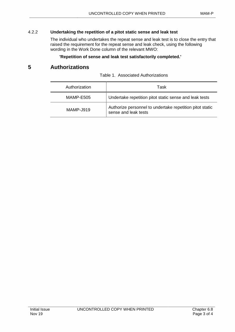
UNCONTROLLED COPY WHEN PRINTED MAM-P
Initial Issue Nov 19
UNCONTROLLED COPY WHEN PRINTED Chapter 6.8 Page 3 of 4
4.2.2 Undertaking the repetition of a pitot static sense and leak test
The individual who undertakes the repeat sense and leak test is to close the entry that raised the requirement for the repeat sense and leak check, using the following wording in the Work Done column of the relevant MWO:
'Repetition of sense and leak test satisfactorily completed.'
5 Authorizations
Table 1. Associated Authorizations
Authorization Task
MAMP-E505 Undertake repetition pitot static sense and leak tests
MAMP-J919 Authorize personnel to undertake repetition pitot static sense and leak tests

MAM-P UNCONTROLLED COPY WHEN PRINTED
Chapter 6.8 Page 4 of 4
UNCONTROLLED COPY WHEN PRINTED Initial Issue Nov 19
Intentionally Blank for Print Pagination
UNCONTROLLED COPY WHEN PRINTED MAM-P
Initial Issue Nov 19
UNCONTROLLED COPY WHEN PRINTED Chapter 7.1 Page 1 of 10
.......................................................................................................................................................
........................................................................................................................................................................
..................................................................................................
.........................................................................................................................................
.....................................................................................................................................................................................
........................................................................................................
........................................................................................................
.......................................................................................................................................................................
.................................................................................................................................
...................................................................................................................................................................
........................................................................................................................................................................................
...........................................................................................................................................................................................
........................................................................................................................................................................
......................................................................................................................................................
.........................................................................................................................................................................................................
Chapter 7.1
Aircraft Assisted Escape Systems
TABLE OF CONTENTS
Paragraph Page
1 General 11.1 Introduction 11.2 Associated Publications and Instructions 21.3 Applicability 21.4 Additional Information 22 Safety Conditions 22.1 General 22.2 Safe for Maintenance 22.3 Safe for Parking 32.4 Safe Condition 32.5 Flight Condition 32.6 Movement of Safety Devices 32.7 Recording of AAES Safety Condition 32.8 Personnel Entering a Cockpit 43 Responsibilities 43.1 Maintenance Supervisor 43.2 Maintenance of in-Situ AAES, Removal or Installation of AAES 43.3 Survival Equipment 54 Mandatory Checks on Aircraft Assisted Escape Systems 54.1 Maintenance Checks 54.2 Vital Checks 54.3 Independent Checks 54.4 Recording of Mandatory Checks 55 Training and Authorization 65.1 General Safety Training 65.2 Training and Authorization in the movement of Safety Devices 75.3 Training and Authorization for AAES Maintenance 75.4 Training and Authorization for Mandatory Checks 86 Authorizations 8
LIST OF TABLES
Table 1. Trades Authorized to Undertake Movement of AAES Safety Devices to/from the Safe for Maintenance Condition 7Table 2. Associated Authorizations 8
1 General
1.1 Introduction
Aircraft Assisted Escape System (AAES) or Crew Escape System (CES) have the potential to cause serious injury or death. This chapter provides general guidance on Air System Maintenance, AAES mandatory checks and associated Authorizations. The specific Safety measures and devices employed to prevent Accidents when using and maintaining AAES and CES are detailed in the Technical Information (TI) for each Air System.
MAM-P UNCONTROLLED COPY WHEN PRINTED
Chapter 7.1 Page 2 of 10
UNCONTROLLED COPY WHEN PRINTED Initial Issue Nov 19
1.2 Associated Publications and Instructions
1 RA1223 – Airworthiness Information Management
2 RA 4600 – Aircraft Assisted Escape Systems – Safety and Maintenance Procedures
3 RA 4801 – Certifying Staff
4 RA 4806 – Personnel Requirements (MRP 145.A.30)
5 DSA 03 OME Part 2 – In-Service and Operational Safety Management of OME
6 JSP 822 – Defence Direction and Guidance for Training and Education
7 DAP 108A-0006-2(N/A/R)1 – Survival Equipment and Aircrew Equipment Assemblies Support Authority General Orders and Special Instructions (Technical).
8 AP 109A-0100-2(N/A/R)1 – General Orders and Special Instructions – Aircraft Assisted Escape Systems – Ejection Seats.
1.3 Applicability
This chapter is applicable to all organizations in the Defence Air Environment (DAE) operating Air Systems fitted with an AAES or CES and/or with responsibilities for the Maintenance of installed and uninstalled AAES, CES and associated components.
1.4 Additional Information
For the purposes of this chapter the following terms have been adopted:
1 Unless otherwise stated, AAES includes both AAES and CES.
2 Cockpit is to be interpreted as meaning any Aircraft cockpit or cabin in which an AAES is installed.
3 AAES trade is the group of Tradesman who are trained to Maintain Air System ordnance, munitions and explosives stores and associated components.
2 Safety Conditions
2.1 General
Dependent upon the type of AAES, the associated Safety devices can be in one of four conditions:
1 Safe for Maintenance – see Paragraph 2.2.
2 Safe for parking – see Paragraph 2.3.
3 Safe condition – see Paragraph 2.4.
4 Flight condition – see Paragraph 2.5.
The positions of Safety devices for the relevant Safety conditions of the AAES are to be published in the appropriate Air System TI.
2.2 Safe for Maintenance
In the safe for Maintenance condition, it is safe to carry out work on or around the AAES, provided that the TI relevant to that particular Air System type is complied with. The safe for Maintenance condition is to be established prior to and for the duration of:
1 Any prolonged period of Air System Unserviceability.
2 Any Preventive Maintenance of an Air System, other than flight servicing, where access to the cockpit is required.
UNCONTROLLED COPY WHEN PRINTED MAM-P
Initial Issue Nov 19
UNCONTROLLED COPY WHEN PRINTED Chapter 7.1 Page 3 of 10
3 Any Maintenance activity that involves working in the vicinity of, or disturbing, the AAES.
4 Parking of the Aircraft in an Air System Maintenance hangar, ashore or afloat. However, the Aircraft can be left in the safe for parking condition, if it is being placed in an Air System Maintenance hangar for parking only.
2.3 Safe for Parking
The safe for parking condition is required at all times other than those listed in Paragraphs 2.2, 2.4 and 2.5; this includes those periods, however brief, when a rapid crew change is being effected. In the safe for parking condition it is safe to enter the cockpit, provided that the TI relevant to the particular Air System type is complied with. No Maintenance, other than flight servicing, is to be carried out on, or around, the AAES.
2.4 Safe Condition
On an AAES where there is no difference between the safe for parking and safe for Maintenance conditions, the AAES are to be in the safe condition at all times when the Air System is not in the flight condition, including those periods, however brief, when a rapid crew change is being effected. In the safe condition it is safe to carry out work on, or around, the AAES, provided that the TI relevant to the particular Air System type is complied with.
2.5 Flight Condition
An AAES is deemed to be in the flight condition when all Safety devices for the AAES have been removed. The AAES are to only be placed into and out of the flight condition immediately before taxiing prior to take-off and following taxiing after landing, in accordance with (iaw) Paragraph 2.6.2. When operating from a Hardened Aircraft Shelter (HAS) or similar, local procedures are to be defined to ensure that the AAES remains in a safe condition whilst under cover. Personnel are not to enter or exit a cockpit before carrying out the actions detailed in Paragraph 2.8.
2.6 Movement of Safety Devices
2.6.1 Safe for Maintenance to/from Safe for Parking
The movement of Safety devices to/from the safe for Maintenance condition is only to be carried out by an individual holding Authorization MAMP-B207 and supervised by an individual holding Authorization MAMP-C313 of the trades stated in Table 1. Normally, Aircrew are permitted to move the Safety devices of an AAES to and from the flight condition only. Exceptionally, when no authorized engineering officer or engineering Tradesman is available, Aircrew that have been awarded Authorization MAMP-AFS01 iaw RA 4806 and Chapter 2.3 – Authorization of Aircrew to Carry out Aircraft Maintenance Work, can be additionally authorized by an individual holding Authorization MAMP-J926 to move Safety devices to and from the safe for Maintenance condition.
2.6.2 Safe for Parking or Safe Condition to/from Flight Condition
The seat occupant for a planned flight is responsible for moving the Safety devices to and from the flight condition, as required; Maintenance personnel can assist. The Responsible Aircrew Member is responsible for ensuring that the AAES Safety devices are moved to and from the flight condition, as required, when non-Aircrew personnel occupy the seat. Maintenance personnel can assist in this activity but are required to give the Air System Commander verbal confirmation when this activity is complete.
2.7 Recording of AAES Safety Condition
The movement of Safety devices from or to the safe for Maintenance condition is a Maintenance task and are therefore to be recorded in the appropriate section of the
MAM-P UNCONTROLLED COPY WHEN PRINTED
Chapter 7.1 Page 4 of 10
UNCONTROLLED COPY WHEN PRINTED Initial Issue Nov 19
Technical Log (eg MOD Form 700C). The requirement to move the Safety devices is to be raised by the supervisor of the Maintenance task. On an AAES where only the safe condition is used, no specific recording action is necessary, since this is the normal state of the AAES when the Air System is on the ground.
2.8 Personnel Entering a Cockpit
2.8.1 Qualified Personnel
Any person entering a cockpit or requiring to work on equipment installed in a cockpit is to, before entering the cockpit, check visually that the AAES is in the appropriate condition for the task being carried out, as detailed in Paragraph 2. If it is necessary to change the condition of the AAES to or from the safe for Maintenance condition, they are to inform the supervisor of the Maintenance task, who is to take the steps detailed at Paragraph 3.1. If the person entering the cockpit discovers that the Safety devices are not in a recognized safe condition, their position is not to be adjusted, but personnel in the vicinity are to be warned that a hazard exists and the person entering the cockpit is to report the occurrence to an individual holding Authorization MAMP-C313 to supervise the movement of AAES Safety devices. The individual holding Authorization MAMP-C313 is to:
1 If possible, request the last known, suitably authorized, seat occupant to move the Safety devices to the correct condition. Where this is not possible, they are to task an appropriately authorized Tradesman to place the Safety devices into the correct position.
2 Report the incident to their Line Manager for further investigation.
2.8.2 Unqualified Personnel
When a person not conversant with the position of Safety devices is authorized to enter a cockpit, they are to be escorted by a suitably authorized individual who is to ensure that:
1 The AAES is in an appropriate Safety condition.
2 The AAES Safety devices are not inadvertently disturbed.
3 Responsibilities
3.1 Maintenance Supervisor
Whenever a Maintenance task is to be undertaken, the supervisor of the task is responsible for the following, with respect to AAES:
1 Ensuring that the AAES is in a safe for parking, safe for Maintenance or safe condition appropriate to the task being carried out, as detailed at Paragraph 2.
2 When it is necessary to change the condition of the AAES to or from the safe for Maintenance condition, tasking an appropriately authorized Tradesman to place the Safety devices in the correct position iaw Paragraph 2.6.1.
3 When Safety devices have been moved at item 2 above, ensuring that the fact has been recorded iaw Paragraph 2.7.
4 Ensuring that all personnel tasked to work in or around the cockpit are trained on the position of the Safety devices iaw Paragraph 5.1. If this is not possible, the requirements of Paragraph 2.8.2 are to be complied with.
3.2 Maintenance of in-Situ AAES, Removal or Installation of AAES
Overall system responsibility for in-situ Maintenance, removal or re-installation of AAES, or Maintenance of a component part of such systems, is vested in the ‘AAES trade’. When required, other trades can be called upon to carry out Maintenance to
UNCONTROLLED COPY WHEN PRINTED MAM-P
Initial Issue Nov 19
UNCONTROLLED COPY WHEN PRINTED Chapter 7.1 Page 5 of 10
those elements of the AAES that fall outside the boundaries of the AAES trade (eg Maintenance of the canopy installation). Where there is a requirement for another trade to undertake this Maintenance, the relevant activity is to be identified in the Maintenance procedure. When more than one trade is engaged jointly on Maintenance of an AAES, or on in-situ Maintenance of a component part of such a system, an individual holding Authorization MAMP-C314 is to be responsible for co-ordinating the work of all the Tradesmen concerned so that Safety of the system and its subsequent correct operation is not impaired.
3.3 Survival Equipment
Notwithstanding Paragraph 3.2 above, Survival Equipment (SE) Tradesmen are responsible for providing specialist assistance as required and for the:
1 Preventive Maintenance of restraint harnesses, parachute assemblies and drogues, personal survival packs or seat survival kits including automatic deployment units, all fabric parts of an ejection seat and all quick-release fittings that are attached to these items.
2 Maintenance, including Preventive Maintenance, of the ‘Aircrew portion’ of personal equipment connectors and Aircrew Equipment Assemblies.
4 Mandatory Checks on Aircraft Assisted Escape Systems
4.1 Maintenance Checks
Maintenance checks are to be carried out whenever an AAES component undergoes any form of Maintenance in a bay or as part of the bay activity in a licensed explosives area. Such checks are for correct assembly, locking and function to ensure the reliable operation of the AAES. These checks are carried out because they cannot be readily undertaken during or after installation or re-installation of the component in an Air System. The relevant Maintenance checks are detailed in the appropriate bay Maintenance schedule.
4.2 Vital Checks
Vital checks are to be carried out at defined stages during the process of installing or re-installing a component part of an AAES in an Air System. Such checks are for correct assembly, routeing, locking and function to ensure the reliable operation of the AAES, which cannot be readily undertaken before installation or re-installation commences, or after it has been completed. Vital checks are to be undertaken at the Air System, or in a licensed explosives area associated with the Air System Maintenance activity. Details of each vital check are contained in the appropriate TI.
4.3 Independent Checks
Independent checks are to be made at the Air System after installation or re-installation of a component part of an AAES. They provide final visual confirmation that all locking, routeing and installation processes have been carried out correctly. The detail of each independent check is contained in the appropriate TI. They can be divided by sub-system, (eg CES independent check, canopy system independent check and ejection seat independent check).
4.4 Recording of Mandatory Checks
4.4.1 Calling Up the Checks
The supervisor of a Maintenance task is responsible for calling up any Maintenance, vital or independent check required. They are to do so by making a separate entry, for each check required, on the appropriate Maintenance Work Order (MWO). Entries for independent checks are to be made when the system is first disturbed. All checks are to be called up in the form:
MAM-P UNCONTROLLED COPY WHEN PRINTED
Chapter 7.1 Page 6 of 10
UNCONTROLLED COPY WHEN PRINTED Initial Issue Nov 19
‘[MAINTENANCE, VITAL or INDEPENDENT as applicable] CHECK REQUIRED AS DETAILED IN … [insert sufficient detail to enable the check to be positively identified]’
The number of checks called up are to accord with the following:
1 All the Maintenance checks applicable to a component part of an AAES are to be made whenever the component has undergone any form of Maintenance in a bay, or as part of the bay activity in a licensed explosives area.
2 All the vital checks applicable to a sub-system within an AAES are to be made whenever a component part of that sub-system is in the process of being installed or re-installed in an Air System.
3 All the independent checks applicable to an AAES sub-system are to be made whenever a component part of that sub-system is installed or re-installed in an Air System, or when any part of that sub-system is disturbed during a Maintenance activity.
4.4.2 Recording completion of the checks (hard copy)
Following satisfactory completion of the Maintenance, vital, or independent check, the person who carried it out is to enter the following statement in the ‘Work Done’ column of the MWO:
‘CERTIFIED [MAINTENANCE, VITAL or INDEPENDENT as applicable] CHECK SATISFACTORILY COMPLETED’
They are to complete the relevant section of the MWO by signing both the ‘Tradesman‘ and ‘Supervisor’ blocks.
4.4.3 Recording completion of the checks (electronic)
If an electronic Information System (IS) is utilised (see RA 1223), the associated TI is to define how the electronic equivalent of the MWO is completed. As a minimum standard, following satisfactory completion of a Maintenance, vital or independent check, the person who carried it out is to enter the following statement in the ‘Work Done’ column of the MWO variant and certify for completion as the ‘Tradesman’ and ‘Supervisor’ iaw the relevant instructions.
‘CERTIFIED [MAINTENANCE, VITAL or INDEPENDENT as applicable] CHECK SATISFACTORILY COMPLETED’
4.4.4 2nd Signature Responsibility
Maintenance, vital or independent checks are to be treated as self-supervised activities and the personnel carrying them out are to be made aware that they assume the responsibilities for both 1st and 2nd signature iaw RA 4806, RA 4801 and Chapter 2.4 – Certification and Maintenance Documentation.
5 Training and Authorization
5.1 General Safety Training
Those Tradesmen required to provide trade assistance and all personnel, including Aircrew, who require access to a cockpit are to receive training by a nominated individual holding Authorization MAMP-E503 to ensure that they are conversant with the Safety devices, Safety conditions and Safety precautions appropriate to that AAES. The training policy for AAES is detailed in AP 109-0100-2(N/A/R)1, which defines the periodicity of initial and subsequent retraining, and provides details of syllabus Operational Performance Statements (OPS) applicable to selected categories of personnel.
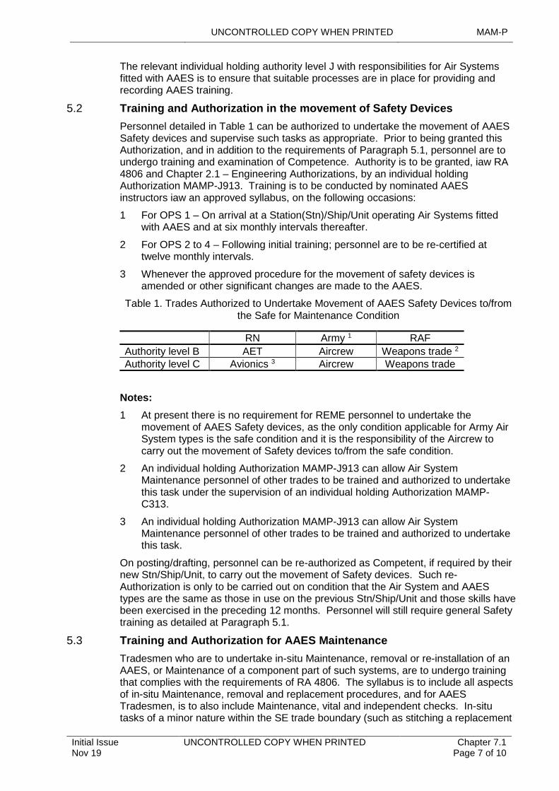
UNCONTROLLED COPY WHEN PRINTED MAM-P
Initial Issue Nov 19
UNCONTROLLED COPY WHEN PRINTED Chapter 7.1 Page 7 of 10
The relevant individual holding authority level J with responsibilities for Air Systems fitted with AAES is to ensure that suitable processes are in place for providing and recording AAES training.
5.2 Training and Authorization in the movement of Safety Devices
Personnel detailed in Table 1 can be authorized to undertake the movement of AAES Safety devices and supervise such tasks as appropriate. Prior to being granted this Authorization, and in addition to the requirements of Paragraph 5.1, personnel are to undergo training and examination of Competence. Authority is to be granted, iaw RA 4806 and Chapter 2.1 – Engineering Authorizations, by an individual holding Authorization MAMP-J913. Training is to be conducted by nominated AAES instructors iaw an approved syllabus, on the following occasions:
1 For OPS 1 – On arrival at a Station(Stn)/Ship/Unit operating Air Systems fitted with AAES and at six monthly intervals thereafter.
2 For OPS 2 to 4 – Following initial training; personnel are to be re-certified at twelve monthly intervals.
3 Whenever the approved procedure for the movement of safety devices is amended or other significant changes are made to the AAES.
Table 1. Trades Authorized to Undertake Movement of AAES Safety Devices to/from the Safe for Maintenance Condition
RN Army 1 RAF
Authority level B AET Aircrew Weapons trade 2
Authority level C Avionics 3 Aircrew Weapons trade
Notes:
1 At present there is no requirement for REME personnel to undertake the movement of AAES Safety devices, as the only condition applicable for Army Air System types is the safe condition and it is the responsibility of the Aircrew to carry out the movement of Safety devices to/from the safe condition.
2 An individual holding Authorization MAMP-J913 can allow Air System Maintenance personnel of other trades to be trained and authorized to undertake this task under the supervision of an individual holding Authorization MAMP-C313.
3 An individual holding Authorization MAMP-J913 can allow Air System Maintenance personnel of other trades to be trained and authorized to undertake this task.
On posting/drafting, personnel can be re-authorized as Competent, if required by their new Stn/Ship/Unit, to carry out the movement of Safety devices. Such re-Authorization is only to be carried out on condition that the Air System and AAES types are the same as those in use on the previous Stn/Ship/Unit and those skills have been exercised in the preceding 12 months. Personnel will still require general Safety training as detailed at Paragraph 5.1.
5.3 Training and Authorization for AAES Maintenance
Tradesmen who are to undertake in-situ Maintenance, removal or re-installation of an AAES, or Maintenance of a component part of such systems, are to undergo training that complies with the requirements of RA 4806. The syllabus is to include all aspects of in-situ Maintenance, removal and replacement procedures, and for AAES Tradesmen, is to also include Maintenance, vital and independent checks. In-situ tasks of a minor nature within the SE trade boundary (such as stitching a replacement
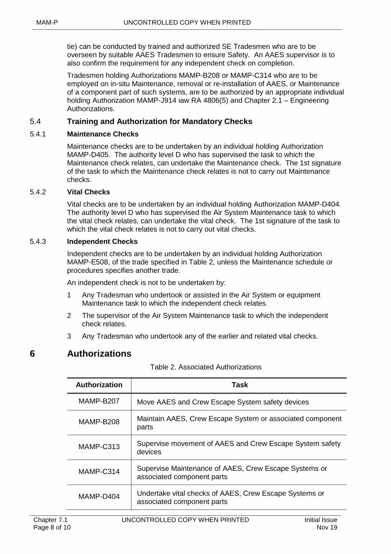
MAM-P UNCONTROLLED COPY WHEN PRINTED
Chapter 7.1 Page 8 of 10
UNCONTROLLED COPY WHEN PRINTED Initial Issue Nov 19
tie) can be conducted by trained and authorized SE Tradesmen who are to be overseen by suitable AAES Tradesmen to ensure Safety. An AAES supervisor is to also confirm the requirement for any independent check on completion.
Tradesmen holding Authorizations MAMP-B208 or MAMP-C314 who are to be employed on in-situ Maintenance, removal or re-installation of AAES, or Maintenance of a component part of such systems, are to be authorized by an appropriate individual holding Authorization MAMP-J914 iaw RA 4806(5) and Chapter 2.1 – Engineering Authorizations.
5.4 Training and Authorization for Mandatory Checks
5.4.1 Maintenance Checks
Maintenance checks are to be undertaken by an individual holding Authorization MAMP-D405. The authority level D who has supervised the task to which the Maintenance check relates, can undertake the Maintenance check. The 1st signature of the task to which the Maintenance check relates is not to carry out Maintenance checks.
5.4.2 Vital Checks
Vital checks are to be undertaken by an individual holding Authorization MAMP-D404. The authority level D who has supervised the Air System Maintenance task to which the vital check relates, can undertake the vital check. The 1st signature of the task to which the vital check relates is not to carry out vital checks.
5.4.3 Independent Checks
Independent checks are to be undertaken by an individual holding Authorization MAMP-E508, of the trade specified in Table 2, unless the Maintenance schedule or procedures specifies another trade.
An independent check is not to be undertaken by:
1 Any Tradesman who undertook or assisted in the Air System or equipment Maintenance task to which the independent check relates.
2 The supervisor of the Air System Maintenance task to which the independent check relates.
3 Any Tradesman who undertook any of the earlier and related vital checks.
6 Authorizations
Table 2. Associated Authorizations
Authorization Task
MAMP-B207 Move AAES and Crew Escape System safety devices
MAMP-B208 Maintain AAES, Crew Escape System or associated component parts
MAMP-C313 Supervise movement of AAES and Crew Escape System safety devices
MAMP-C314 Supervise Maintenance of AAES, Crew Escape Systems or associated component parts
MAMP-D404 Undertake vital checks of AAES, Crew Escape Systems or associated component parts
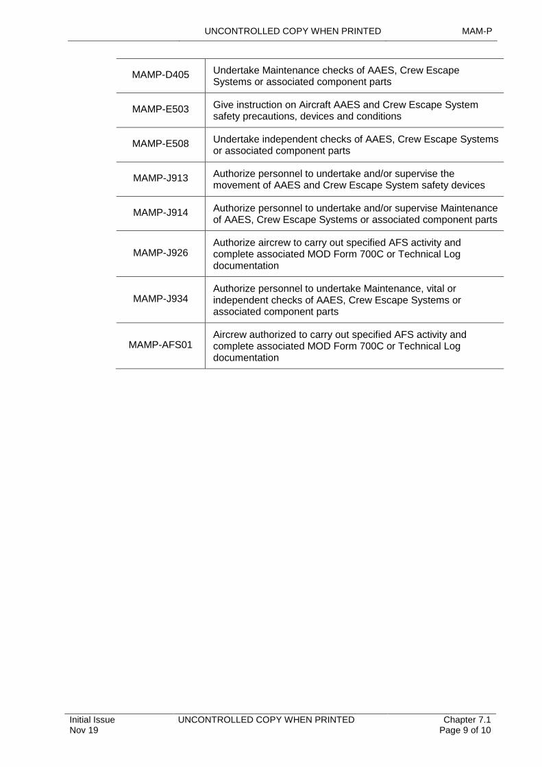
UNCONTROLLED COPY WHEN PRINTED MAM-P
Initial Issue Nov 19
UNCONTROLLED COPY WHEN PRINTED Chapter 7.1 Page 9 of 10
MAMP-D405 Undertake Maintenance checks of AAES, Crew Escape Systems or associated component parts
MAMP-E503 Give instruction on Aircraft AAES and Crew Escape System safety precautions, devices and conditions
MAMP-E508 Undertake independent checks of AAES, Crew Escape Systems or associated component parts
MAMP-J913 Authorize personnel to undertake and/or supervise the movement of AAES and Crew Escape System safety devices
MAMP-J914 Authorize personnel to undertake and/or supervise Maintenance of AAES, Crew Escape Systems or associated component parts
MAMP-J926Authorize aircrew to carry out specified AFS activity and complete associated MOD Form 700C or Technical Log documentation
MAMP-J934Authorize personnel to undertake Maintenance, vital or independent checks of AAES, Crew Escape Systems or associated component parts
MAMP-AFS01Aircrew authorized to carry out specified AFS activity and complete associated MOD Form 700C or Technical Log documentation
MAM-P UNCONTROLLED COPY WHEN PRINTED
Chapter 7.1 Page 10 of 10
UNCONTROLLED COPY WHEN PRINTED Initial Issue Nov 19
Intentionally Blank for Print Pagination
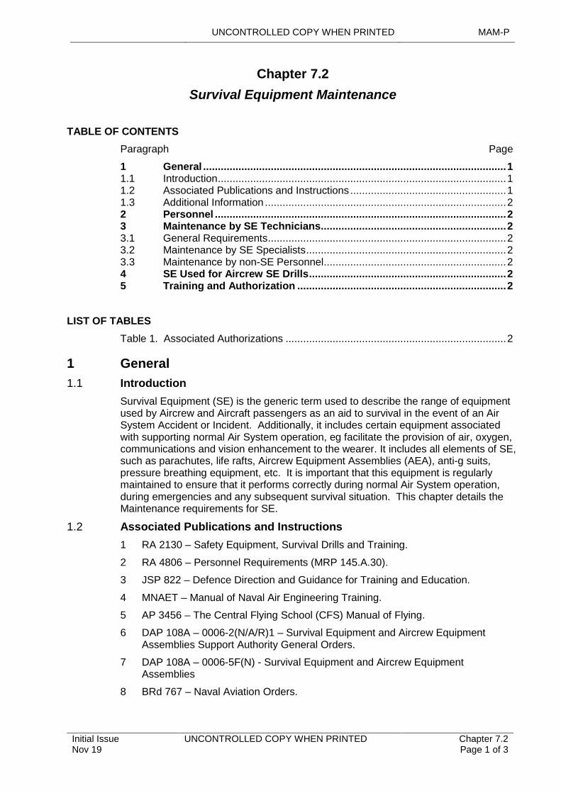
UNCONTROLLED COPY WHEN PRINTED MAM-P
Initial Issue Nov 19
UNCONTROLLED COPY WHEN PRINTED Chapter 7.2 Page 1 of 3
...........................................................................
..........................................................................................................................................
..................................................................................................................................
................................................................................................................................................
.....................................................................................................................................................................................
.......................................................................................................................................................
.......................................................................................................
Chapter 7.2
Survival Equipment Maintenance
TABLE OF CONTENTS
Paragraph Page
1 General 11.1 Introduction 11.2 Associated Publications and Instructions 11.3 Additional Information 22 Personnel 23 Maintenance by SE Technicians 23.1 General Requirements 23.2 Maintenance by SE Specialists 23.3 Maintenance by non-SE Personnel 24 SE Used for Aircrew SE Drills 25 Training and Authorization 2
LIST OF TABLES
Table 1. Associated Authorizations 2
1 General
1.1 Introduction
Survival Equipment (SE) is the generic term used to describe the range of equipment used by Aircrew and Aircraft passengers as an aid to survival in the event of an Air System Accident or Incident. Additionally, it includes certain equipment associated with supporting normal Air System operation, eg facilitate the provision of air, oxygen, communications and vision enhancement to the wearer. It includes all elements of SE, such as parachutes, life rafts, Aircrew Equipment Assemblies (AEA), anti-g suits, pressure breathing equipment, etc. It is important that this equipment is regularly maintained to ensure that it performs correctly during normal Air System operation, during emergencies and any subsequent survival situation. This chapter details the Maintenance requirements for SE.
1.2 Associated Publications and Instructions
1 RA 2130 – Safety Equipment, Survival Drills and Training.
2 RA 4806 – Personnel Requirements (MRP 145.A.30).
3 JSP 822 – Defence Direction and Guidance for Training and Education.
4 MNAET – Manual of Naval Air Engineering Training.
5 AP 3456 – The Central Flying School (CFS) Manual of Flying.
6 DAP 108A – 0006-2(N/A/R)1 – Survival Equipment and Aircrew Equipment Assemblies Support Authority General Orders.
7 DAP 108A – 0006-5F(N) - Survival Equipment and Aircrew Equipment Assemblies
8 BRd 767 – Naval Aviation Orders.

MAM-P UNCONTROLLED COPY WHEN PRINTED
Chapter 7.2 Page 2 of 3
UNCONTROLLED COPY WHEN PRINTED Initial Issue Nov 19
1.3 Additional Information
Throughout this chapter, SE includes all elements of SE and AEA. For further information on the definition of SE and AEA, refer to DAP 108A-0006-2(N/A/R)1.
2 Personnel
Maintenance of SE is to be carried out as specified in the appropriate Technical Information (TI) and is only to be undertaken by those personnel who are correctly trained and authorized.
3 Maintenance by SE Technicians
3.1 General Requirements
The general requirements for maintaining SE are promulgated in DAP 108A-0006-2(N/A/R)1.
SE that is not permanently installed in an Air System is to be removed to approved stowage points or areas after flight. Stowage points or areas for such equipment are to comply with the conditions detailed in the appropriate TI.
3.2 Maintenance by SE Specialists
Personnel of the SE trade may be authorized to carry out Maintenance on all types of SE for which they have been trained. When authorizing personnel of the SE trade, reference is to be made to Chapter 2.1 – Engineering Authorizations to identify the appropriate authority level that they may be granted. Authority is to be granted iaw Paragraph 5.
SE in use by one Service and maintained by correctly trained and authorized personnel of another Service, is permitted without further training; providing that the equipment is common to both Services, as defined in DAP 108A-0006-2(N/A/R)1 and DAP 108A-0006-5F(N). Where the SE is not common to the other Service, additional training is to be completed.
3.3 Maintenance by non-SE Personnel
The deployment of Air System Maintenance personnel gives rise to specific requirements for non-SE trade personnel to work, or supervise work, outside their normal trade boundaries. When this is necessary in support of SE Maintenance, they are to undertake appropriate training on the SE that they will be required to maintain. Authority is to be granted iaw with Paragraph 5.
4 SE Used for Aircrew SE Drills
RA 2130 requires that Aircrew undergo periodic Safety and Survival training. SE used for the conduct of Aircrew Safety and Survival training is to be clearly identified and maintained iaw with DAP 108A-0006-2(N/A/R)1 and DAP 108A-0006-5F(N).
5 Training and Authorization
Table 1. Associated Authorizations
Authorization Task
MAMP-B219Maintain Survival Equipment (SE) and Aircrew Equipment Assemblies
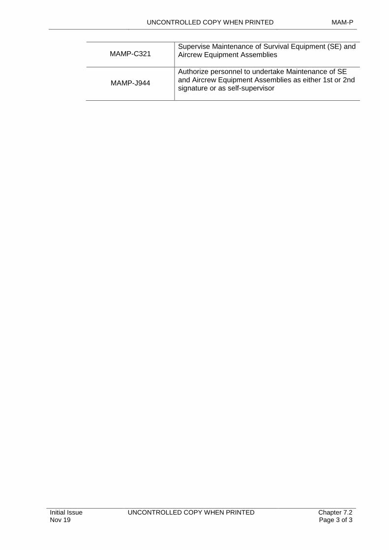
UNCONTROLLED COPY WHEN PRINTED MAM-P
Initial Issue Nov 19
UNCONTROLLED COPY WHEN PRINTED Chapter 7.2 Page 3 of 3
MAMP-C321Supervise Maintenance of Survival Equipment (SE) and Aircrew Equipment Assemblies
MAMP-J944
Authorize personnel to undertake Maintenance of SE and Aircrew Equipment Assemblies as either 1st or 2nd signature or as self-supervisor
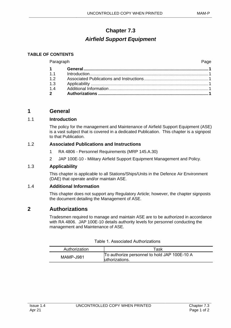
UNCONTROLLED COPY WHEN PRINTED MAM-P
................................................................................................
.............................................................................................................................................................................
......................................................................................................................................................
.........
................................................................................................
Issue 1.4 Apr 21
UNCONTROLLED COPY WHEN PRINTED Chapter 7.3 Page 1 of 2
Airfield Support Equipment
Chapter 7.3
TABLE OF CONTENTS
Paragraph Page
1 General
1 1.1 Introduction 1 1.2 Associated Publications and Instructions 1 1.3 Applicability 1 1.4 Additional Information 1 2 Authorizations 1
1 General
1.1 Introduction
The policy for the management and Maintenance of Airfield Support Equipment (ASE) is a vast subject that is covered in a dedicated Publication. This chapter is a signpost to that Publication.
1.2 Associated Publications and Instructions
1 RA 4806 - Personnel Requirements (MRP 145.A.30)
2 JAP 100E-10 - Military Airfield Support Equipment Management and Policy.
1.3 Applicability
This chapter is applicable to all Stations/Ships/Units in the Defence Air Environment (DAE) that operate and/or maintain ASE.
1.4 Additional Information
This chapter does not support any Regulatory Article; however, the chapter signposts the document detailing the Management of ASE.
2 Authorizations
Tradesmen required to manage and maintain ASE are to be authorized in accordance with RA 4806. JAP 100E-10 details authority levels for personnel conducting the management and Maintenance of ASE.
Table 1. Associated Authorizations
Authorization Task
MAMP-J981To authorize personnel to hold JAP 100E-10 Authorizations.

MAM-P UNCONTROLLED COPY WHEN PRINTED
Intentionally Blank for Print Pagination
Chapter 7.3 Page 2 of 2
UNCONTROLLED COPY WHEN PRINTED Issue 1.4 Apr 21
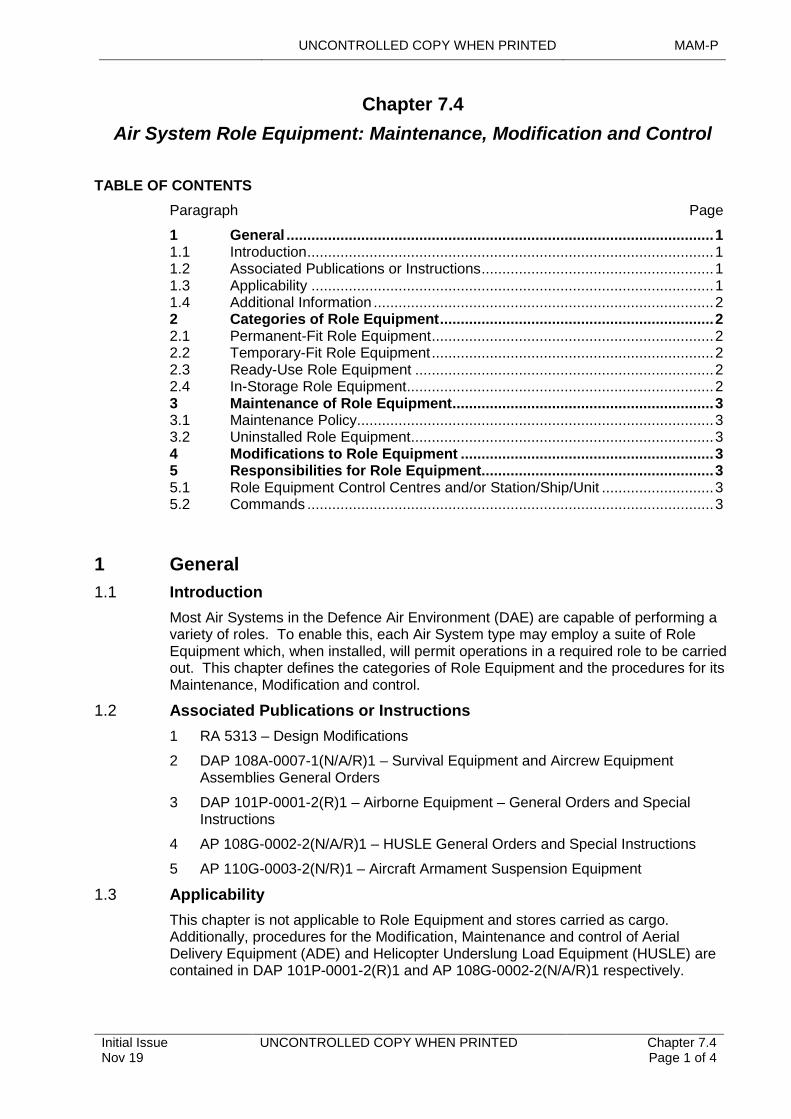
UNCONTROLLED COPY WHEN PRINTED MAM-P
Initial Issue Nov 19
UNCONTROLLED COPY WHEN PRINTED Chapter 7.4 Page 1 of 4
.............................................................................................................................
.....................................................................................................................
...............................................................................................................................................................
.........................................................................................................................................
................................................................................................................................................................................................................
....................................................................................................................................................
.........................................................................................................................................................
.........................................................................................................................................................................................................
Chapter 7.4
Air System Role Equipment: Maintenance, Modification and Control
TABLE OF CONTENTS
Paragraph Page
1 General 11.1 Introduction 11.2 Associated Publications or Instructions 11.3 Applicability 11.4 Additional Information 22 Categories of Role Equipment 22.1 Permanent-Fit Role Equipment 22.2 Temporary-Fit Role Equipment 22.3 Ready-Use Role Equipment 22.4 In-Storage Role Equipment 23 Maintenance of Role Equipment 33.1 Maintenance Policy 33.2 Uninstalled Role Equipment 34 Modifications to Role Equipment 35 Responsibilities for Role Equipment 35.1 Role Equipment Control Centres and/or Station/Ship/Unit 35.2 Commands 3
1 General
1.1 Introduction
Most Air Systems in the Defence Air Environment (DAE) are capable of performing a variety of roles. To enable this, each Air System type may employ a suite of Role Equipment which, when installed, will permit operations in a required role to be carried out. This chapter defines the categories of Role Equipment and the procedures for its Maintenance, Modification and control.
1.2 Associated Publications or Instructions
1 RA 5313 – Design Modifications
2 DAP 108A-0007-1(N/A/R)1 – Survival Equipment and Aircrew Equipment Assemblies General Orders
3 DAP 101P-0001-2(R)1 – Airborne Equipment – General Orders and Special Instructions
4 AP 108G-0002-2(N/A/R)1 – HUSLE General Orders and Special Instructions
5 AP 110G-0003-2(N/R)1 – Aircraft Armament Suspension Equipment
1.3 Applicability
This chapter is not applicable to Role Equipment and stores carried as cargo. Additionally, procedures for the Modification, Maintenance and control of Aerial Delivery Equipment (ADE) and Helicopter Underslung Load Equipment (HUSLE) are contained in DAP 101P-0001-2(R)1 and AP 108G-0002-2(N/A/R)1 respectively.
MAM-P UNCONTROLLED COPY WHEN PRINTED
Chapter 7.4 Page 2 of 4
UNCONTROLLED COPY WHEN PRINTED Initial Issue Nov 19
1.4 Additional Information
The Maintenance and Modification of Role Equipment is to be carried out as directed by the relevant Delivery Team (DT). Role Equipment is an operational fleet asset and as such the responsibility for operational control is vested in the respective Command. This responsibility may be delegated to Role Equipment control centres at a Station(Stn)/Ship/Unit that carry out the day-to-day management of Role Equipment on behalf of their Command.
2 Categories of Role Equipment
Role Equipment is divided into the following categories:
1 Permanent-fit Role equipment.
2 Temporary-fit Role Equipment.
3 Ready-use Role Equipment.
4 In-storage Role Equipment.
2.1 Permanent-Fit Role Equipment
Role Equipment that forms part of the Air System basic fit and/or Air System inventory and is transferred with the Air System is classed as permanent-fit Role Equipment. Under normal conditions it will only be removed from an Air System for Fault rectification, Preventive Maintenance or embodiment of Modifications (including Special Instruction (Technical)), or to facilitate other on-Air System Maintenance activities.
2.2 Temporary-Fit Role Equipment
Role Equipment fitted to an Air System on a temporary basis for a specific sortie or number of sorties in a particular role configuration is classed as temporary-fit Role Equipment and may include:
1 Special Role Equipment – Equipment that is procured in limited quantities to meet special operational commitments is classed as special Role Equipment. It is only held by Stn/Ship/Unit whilst specifically authorized and may be transferred with an Air System when authorized. The equipment is normally held by the relevant Role Equipment control awaiting issue and is to be returned to Role Equipment control on completion of the specific operation.
2 Squadron Role Equipment – Equipment that is fitted by Stn/Ship/Unit to meet specific common role requirements is classed as squadron Role Equipment. It is not to be transferred with the Air System, but is to be permanently held by Stn/Ship/Unit in quantities determined by the relevant Command, in conjunction with the DT.
2.3 Ready-Use Role Equipment
Role Equipment held forward of a Stn supply organization and which, subject only to a minimal pre-issue check, is otherwise ready for immediate Air System use, is classed as ready-use Role Equipment.
2.4 In-Storage Role Equipment
Role Equipment held by the supply organization on a Stn/Ship/Unit as a long-term spare (including items not in current use but retained to meet contingencies) is classed as in-storage Role Equipment.
UNCONTROLLED COPY WHEN PRINTED MAM-P
Initial Issue Nov 19
UNCONTROLLED COPY WHEN PRINTED Chapter 7.4 Page 3 of 4
3 Maintenance of Role Equipment
3.1 Maintenance Policy
Maintenance regimes are to cover the Maintenance activities for both installed and uninstalled Role Equipment, including any specific storage requirements. Aircraft Armament Suspension Equipment (AASE) general orders and special instructions are contained in the appropriate Technical Information (TI) (AASE is defined in Chapter 8.3 – Aircraft Armament System Maintenance).
3.2 Uninstalled Role Equipment
The following actions are to be carried out, as a minimum, where no Maintenance regime exists for uninstalled Role Equipment:
1 It is to be vacuum-sealed in clear polythene, when possible.
2 It is to be examined by appropriate engineering personnel for corrosion or deterioration at six-monthly intervals.
3 It is to be examined, to determine its condition, before issue to a Forward organization. Where Corrective Maintenance is required, the principles of ‘Inspect and Repair As Necessary’ (IRAN) (see Chapter 4.1- Types of Maintenance) are to be applied.
4 Modifications to Role Equipment
Modification action is to be taken, in accordance with (iaw) RA 5313, when the requirement for a Modification to Role Equipment has been identified. For configuration control purposes, Modifications to Role Equipment are to be identified using a unique identifying system, to reflect that the Modification is applicable to the Role Equipment and not an Air System.
5 Responsibilities for Role Equipment
5.1 Role Equipment Control Centres and/or Station/Ship/Unit
The relevant individual holding authority level J or authority level K of a Stn/Ship/Unit and/or Role Equipment control centre, if established, is responsible for:
1 Raising, retaining, compiling and maintaining associated Engineering Record Cards (ERC) and/or Information System (IS) data.
2 Correct storage of uninstalled equipment.
3 Ensuring that uninstalled equipment receives appropriate routine Maintenance and 6-monthly inspections as detailed at Paragraph 3.2.
4 Ensuring that spares and Modification sets are demanded.
5 Ensuring that equipment Modifications are embodied.
6 Ensuring that equipment is Serviceable and Role Equipment sets are complete when issued for installation.
7 Ensuring that equipment transferred to another organization is accompanied by the appropriate documentation.
5.2 Commands
Role Equipment is an operational fleet asset and, as such, overall control of Role Equipment is vested in the appropriate Command, who is responsible for:
1 Approving temporary increases to a Stn/Ship/Unit scale of Role Equipment.
MAM-P UNCONTROLLED COPY WHEN PRINTED
Chapter 7.4 Page 4 of 4
UNCONTROLLED COPY WHEN PRINTED Initial Issue Nov 19
2 Approving temporary loans of Role Equipment to other Commands.
3 Allocating priorities of temporary-fit Role Equipment to scales set by the DT.
4 Re-allocating priorities of short-supply Role Equipment between Stn/Ship/Unit.
5 Reporting Role Equipment deficiencies to the appropriate DT. This may be delegated to a Role Equipment control centre, but the relevant Command is to remain informed.
6 Recommending alterations to Role Equipment scales.

UNCONTROLLED COPY WHEN PRINTED MAM-P
Issue 1.2 May 20
UNCONTROLLED COPY WHEN PRINTED Chapter 8.1 Page 1 of 9
...........................................................................
........................................................................................................................................................................................
................................................................................................................................................
.................................................................................................
.............................................................
..............................................................................................................................
................................................................................................
.............................................................
................................................................................................................................
................................................................................................................................................
............................................................................................................................................................
...................................................................................................................................................
.................................................................................................................................................................
.............................................................................................................
...............................................................................................................................................................................
....................................................................................................................................................................
......................................................
.........................................................................................................................................................
.........................................................................................................................................................................................................
Chapter 8.1
Armed Aircraft Safety Precautions
TABLE OF CONTENTS
Paragraph Page
1 General 11.1 Introduction 11.2 Associated Publications or Instructions 21.3 Applicability 22 Aircraft Weapon Loading/Unloading During Thunderstorm
Level/Thunderstorm Risk Conditions 22.1 General 22.2 Aircraft Weapon Loading/Unloading 22.3 Transport Aircraft 32.4 Acceptance of Risk 33 Preparation of Aircraft to Fly with Guns in the Initially Armed State 33.1 General 34 Parking of Armed Aircraft 35 Warning Notices 36 Safety Devices and Armament States 46.1 Safe Condition 46.2 Live Conditions 47 Maintenance on Armed Aircraft 57.1 General Principles 57.2 Concurrent Loading and Maintenance 57.3 Electrical Testing of Armed Air Systems 57.4 Initially Armed Air Systems 67.5 Final or Combat Armed Air Systems 67.6 Armed Aircraft in Hardened Aircraft Shelter (HAS) or Readiness Buildings 68 Considerations - Authorizing Maintenance on Armed Air Systems 68.1 Risk Assessment 68.2 Additional Safety Precautions 79 Housing of Unarmed/Armed Aircraft 79.1 Unarmed Aircraft Housed for Non-Maintenance Purposes 79.2 Unarmed Aircraft Housed for Maintenance Purposes 89.3 Loading and Unloading of Armament Explosive Stores Afloat 810 Foreign Military Aircraft 810.1 General 810.2 Action when the Aircraft is Declared to be Armed 811 Signal Pistols 912 Authorizations 9
LIST OF TABLES
Table 1. Associated Authorizations 9
1 General
1.1 Introduction
MAM-P UNCONTROLLED COPY WHEN PRINTED
Chapter 8.1 Page 2 of 9
UNCONTROLLED COPY WHEN PRINTED Issue 1.2 May 20
The inadvertent release or firing of an Air System's weapons or other weapon system mishap whilst an Aircraft is on the ground could cause extensive damage and loss of life. Therefore, extreme caution is to be taken when an Aircraft is armed or is in the process of being loaded or unloaded. Caution is also required during any Maintenance activity on an armed Aircraft and where the armed Aircraft can be parked or housed.
1.2 Associated Publications or Instructions
1 RA 4657 – Weapon Loading and Armed Aircraft Maintenance
2 BR 2924 – EMF Hazards in the Naval Service
3 JSP 375 – Management of Health and Safety in Defence
4 DSA 03 OME Part 2 In-Service and Operational Safety Management of OME
5 JSP 465, Part 2, Vol 3 – Guidance on Defence Meteorological Services
6 BRd 862(1) - MOD Maritime Explosives Orders (Surface Ships)
7 Defence Safety Authority’s Dangerous Goods Manual
1.3 Applicability
This chapter is applicable to all organizations involved with the loading and unloading of explosive armament stores, the fitting and removal of explosive components and the ground activities associated with armed Aircraft. Unless specifically stated otherwise, the precautions apply wherever the Aircraft is parked.
Unless stated, this chapter does not apply to transport Aircraft when explosive armament stores or explosive components are being carried as freight.
2 Aircraft Weapon Loading/Unloading During Thunderstorm Level/Thunderstorm Risk Conditions
2.1 General
The imminence or probability of thunderstorms at, or developing at, specific locations is advised by notification of ‘Thunderstorm Level’/’Thunderstorm Risk’. When a Thunderstorm Level/Thunderstorm Risk High and/or Risk Moderate is declared by the responsible meteorological office, there will be limitations/restrictions to the work that can be carried out on Armed Aircraft. (Thunderstorm Level and Risk categories are defined in JSP 465)
2.2 Aircraft Weapon Loading/Unloading
2.2.1 Aircraft in the Open
When a Thunderstorm Level/Risk High is declared, or thunderstorm activity is apparent in the vicinity, all Aircraft weapon loading/unloading in progress, including the return of explosives to their normal storage sites, is be completed as a priority. Thunderstorm Level and Risk categories are defined in JSP 465. No further weapon loading/unloading is to commence unless authorized in accordance with (iaw) Paragraph 2.4.
2.2.2 Aircraft in Hardened Aircraft Shelters (HAS), etc
The loading/unloading of Aircraft in a HAS, or other readiness building fitted with a Lightning Protection System, with main doors closed is exempted from any constraints imposed by Thunderstorm Level/Risk High conditions.
UNCONTROLLED COPY WHEN PRINTED MAM-P
Issue 1.2 May 20
UNCONTROLLED COPY WHEN PRINTED Chapter 8.1 Page 3 of 9
2.3 Transport Aircraft
Where Aircraft transporting explosives as freight are involved, the Safety precautions published in the Defence Safety Authority’s Dangerous Goods Manual, are to be observed.
2.4 Acceptance of Risk
When requested by the relevant individual holding Authorization MAMP-J909, the local operational commander can, after taking account of the weather in the area both visually and aurally, and in consultation with the Met Officer, authorize the loading/unloading of Aircraft in Thunderstorm Level/Risk High conditions. The decision to authorize is to be based on the operational urgency of the task, balanced against the Risks of continuing loading/unloading.
3 Preparation of Aircraft to Fly with Guns in the Initially Armed State
3.1 General
Normally, if an Aircraft that carries an installed gun is not flying on a gun-firing sortie, the gun(s) is/are to be unloaded. However, if an Aircraft is required to fly with gun ammunition loaded but with the gun(s) in the Initially Armed state (eg electrically disconnected or similar inhibition), it may only do so when:
1 Ordered by the officer authorizing the flight who is to ensure that the relevant Duty Holder is cognisant of, and accepts, any additional operating Risk they hold.
2 Such a configuration has been approved by the Air System Type Airworthiness Authority (TAA).
Note:
Any Maintenance conducted on an Initially Armed Aircraft is to remain iaw the procedures detailed in this chapter.
Crew-served Aircraft weapons are to be operated iaw the relevant Air System Technical Information (TI).
4 Parking of Armed Aircraft
Armed Aircraft are only to be parked at locations that have been authorized iaw DSA 03. OME Part 2 and BRd 862. In the case of weapons containing Electro-Explosive Devices (EED) that are known to be susceptible to Radio Hazards (RADHAZ), steps are to be taken to maintain prescribed Safety distances. When parked and during loading or unloading, the Aircraft is to be restrained by either chocks and/or lashings.
The movement of personnel and vehicles, in the areas hazarded by Aircraft directional weapons, are to be restricted to the minimum necessary for operational purposes. Consideration is to be given to determine whether additional restrictive methods are to be used (eg Safety personnel, barriers, warning lights, prohibitive notices) to prevent unauthorized personnel from approaching an armed Aircraft.
• Airborne Radio Installations (ARI), including Electronic Counter Measures and laser equipment, are not to be operated within a licensed HAS housing an armed Aircraft, or otherwise containing explosive armament stores; except when authorized for the particular combination of Aircraft, ARI and each explosive armament store concerned.
5 Warning Notices
MAM-P UNCONTROLLED COPY WHEN PRINTED
Chapter 8.1 Page 4 of 9
UNCONTROLLED COPY WHEN PRINTED Issue 1.2 May 20
Appropriate warning notices are to be displayed, as follows:
1 On flight lines, flight decks or dispersals, notices are to be displayed in, or on, and outside the Aircraft.
2 At HAS or Quick Reaction Alert (QRA) accommodation, notices are to be displayed in, or on, the Aircraft and at vehicular and pedestrian entrances.
3 Air System control column covers are to be fitted and, where practicable, notices displayed in, or on, the Air System.
6 Safety Devices and Armament States
6.1 Safe Condition
All relevant Safety devices are to be set to the safe condition before the loading of explosive armament stores commences and are to remain in that condition until final arming is undertaken, unless authorized procedures dictate otherwise.
When an Aircraft lands with explosive armament stores still fitted, all relevant Safety devices are to be set to the safe condition as soon as it is safe to do so. The setting of Safety devices to the safe condition after flight is to be certified on the armament clearance certificate.
The Master Armament Safety Switch (MASS) in an Air System is to be operated only iaw instructions contained in the relevant Air System TI and Aircrew Flight Reference Cards.
6.2 Live Conditions
6.2.1 Initially Armed, Finally Armed, Combat Armed, Operational/End of Runway Arming.
The setting of Safety devices to allow an Initially Armed Air System to enter the Finally Armed state is to be carried out iaw the relevant TI, shortly before handover of the Air System to the Responsible Aircrew Member, or earlier as authorized by the relevant individual holding Authorization MAMP-H801.
Entry of an Initially Armed Air System into the Finally Armed state is to be certified on the final arming certificate.
The setting of further Safety devices to the live condition to allow a Finally Armed Air System to enter the Combat Armed state is the responsibility of the Air System Commander. When engineering Tradesmen are required to assist in this process, their actions are to be controlled by the appropriate Aircrew member and are to be iaw an authorized Aircrew drill.
In exceptional circumstances such as the lack of safe headings for Aircraft fitted with Forward firing Weapons (FFW) or the inability to meet prescribed Danger Areas for Flare Countermeasures (FCM) or at the request of a Host Nation (HN), it will be necessary to implement a modified arming procedure known as Operational Arming, also known as End of Runway Arming. This procedure permits an Aircraft armed with FFW and/or FCM to taxi in the Finally Armed state to an authorized location with a safe heading, where authorized personnel can remove the FFW/FCM Safety devices on behalf of the Air System Commander. When Operational/End of Runway Arming is authorized, the following measures are to be implemented:
1 Standard Operational/End of Runway Arming procedures are to be promulgated in Station/Ship/Unit Aviation Engineering Standing Orders.
2 Operational/End of Runway Arming is only to be carried out at designated locations/safe headings.
UNCONTROLLED COPY WHEN PRINTED MAM-P
Issue 1.2 May 20
UNCONTROLLED COPY WHEN PRINTED Chapter 8.1 Page 5 of 9
3 Operational/End of Runway Arming is only to be undertaken by personnel who are trained and authorized.
4 Wherever possible, duplicate Safety devices are to be stowed in the Aircraft prior to taxiing to avoid the need to open panels/stowages whilst engines are running. If duplicate Safety devices are not available, Safety devices removed during Operational/End of Runway Arming are to be stowed in the Aircraft iaw TI.
5 Once the Technical Log has been co-ordinated and the Air System Commander has accepted the Air System, there is no requirement for the subsequent movement of Safety devices to be recorded in the Air System MOD Form 700 or equivalent.
Note:
Unless specified in TI an armed Air System is in the Combat Armed state when:
1. The Air System has been accepted by the Aircraft Commander for flight.
2. All safety devices required by aircrew Flight Reference Cards to be set live, before take-off, have been.
The physical setting of individual safety devices may not alter between armed Air System states.
7 Maintenance on Armed Aircraft
7.1 General Principles
Explosive armament stores are normally to be removed from Aircraft before any Maintenance, other than flight servicing is carried out.
Whilst Maintenance activities are permitted on an armed Air System commensurate with its armed state, any decision to do so will require an assessment of the operational requirement against the potential Risk. A Risk Assessment is to be conducted as detailed at Paragraph 8 and any additional Safety precautions are to be specified.
When an Air System has entered the Finally Armed state, it is to be reverted to the Initially Armed state, if applicable, before any Maintenance activities are carried out. When a Responsible Aircrew Member has accepted an Air System, any Maintenance activity is only to be carried out with their consent as detailed at Chapter 4.1 – Types of Maintenance. Once the Air System has been armed, Maintenance activities are to be limited to those detailed in the Air System TI or iaw these instructions.
7.2 Concurrent Loading and Maintenance
The loading or unloading of explosive armament stores to an Aircraft are not to be undertaken concurrently with other Maintenance of the Air System except if approved in TI.
When it is necessary to carry out concurrent Maintenance and loading/unloading of explosive armament stores, effective communication is to be established and maintained between all personnel involved to ensure that Safety is not compromised.
7.3 Electrical Testing of Armed Air Systems
Once the Air System has been armed, electrical testing of the Air System Armament Systems may only take place if either of the following is met:
1 The electrical test forms part of an authorized procedure.
2 The electrical test is part of a Maintenance activity that has been authorized iaw the terms of this chapter.
MAM-P UNCONTROLLED COPY WHEN PRINTED
Chapter 8.1 Page 6 of 9
UNCONTROLLED COPY WHEN PRINTED Issue 1.2 May 20
7.4 Initially Armed Air Systems
The rectification of Faults on Initially Armed Air Systems is only to be carried out if an unacceptable delay or mission abort would occur and when Safety will not be compromised. The following Maintenance on an Initially Armed Air System can be undertaken:
1 Flight servicing, including tasks detailed in the Supplementary Flight Servicing Register.
2 Maintenance activities as authorized by the TAA in conjunction with the Wpns-Eng Delivery Team (DT) and detailed in the Air System TI.
3 Other Maintenance activities as authorized by the Command concerned, seeking advice from the Wpns-Eng DT as appropriate. Exceptionally, to meet an urgent operational need, other Maintenance activities that are not specifically prohibited in the TI can be authorized by the relevant individual holding Authorization MAMP-H801. Where such Maintenance has been authorized, the person authorizing such activities is to carry out a Risk Assessment and specify the Safety precautions that are to be taken, as directed at Paragraph 8.
7.5 Final or Combat Armed Air Systems
Corrective Maintenance on Finally Armed or Combat Armed Air Systems is only to be carried out if an unacceptable delay or a mission abort would occur and when approved by an authorized individual who has conducted a Risk Assessment. No Preventive Maintenance of any sort is to be undertaken on an Air System that is in the Final Armed or Combat Armed state unless the activity has been detailed in the relevant TI.
7.6 Armed Aircraft in Hardened Aircraft Shelter (HAS) or Readiness Buildings
The foregoing restrictions are equally applicable to the Maintenance of armed Aircraft in a licensed HAS and other readiness buildings. When a licensed HAS or other readiness building houses more than one Aircraft, additional precautions are required to safeguard against the further Hazards introduced by the necessity to work on Aircraft in close proximity to each other, when one or more of the Aircraft concerned are in an armed state. Tradesmen are to ensure any local procedures for working in HAS or readiness buildings are followed.
8 Considerations - Authorizing Maintenance on Armed Air Systems
8.1 Risk Assessment
The decision for the relevant individual holding Authorization MAMP-H801 to accept a request to work on an armed Air System is to be based upon standard Risk management techniques (eg the probability of an Incident arising and the consequences if it occurs). Some of the factors to be considered include:
1 The likelihood of an Incident occurring, and the outcome, if the Aircraft were to remain loaded, balanced against the manpower and time to unload/load.
2 The operational pressures (eg imminence or importance of the next sortie).
3 The nature of the weapon load (eg FFW, practice weapons, Hazard Division (HD)).
4 The Risk (eg is the danger of an incident greater because of the unload/load than during the Maintenance activity?).
5 The Safety precautions detailed at Paragraph 8.2.
UNCONTROLLED COPY WHEN PRINTED MAM-P
Issue 1.2 May 20
UNCONTROLLED COPY WHEN PRINTED Chapter 8.1 Page 7 of 9
8.2 Additional Safety Precautions
The following Safety precautions are to be observed:
1 The relevant individual holding Authorization MAMP-H801 is to specify precisely the Maintenance activity and the additional precautions required to reduce Risk and enhance Safety, to suit local conditions or comply with Host Nation regulations. The following is to be considered:
1.1 Enhancing supervision to ensure that the task is closely supervised to its completion.
1.2 Safety implications and Hazards associated with the armament explosive stores loaded, seeking advice from the senior armament Tradesman as required.
1.3 Provision of additional fire and rescue facilities, especially if carrying out Maintenance to the fuel system.
1.4 The necessity for their direct involvement in the supervision of the task.
1.5 Provision of a Safety briefing to all personnel who are to be involved with the Maintenance activity.
1.6 Downloading the weapons if there is the likelihood of a prolonged period of activity within the danger areas.
2 Maintenance activities that require work in the vicinity of loaded directional weapons, including dispensers, are to be kept to an absolute minimum commensurate with the operational requirement. Normally, before any Maintenance activity takes place in the path of loaded directional weapons, that system, or part system, is to revert to the Initially Armed state, if applicable.
3 No relaxation of Electro-Magnetic Compatibility (EMC)/RADHAZ instruction is permitted. If the Risk Assessment reveals EMC implications to the armament system, the Aircraft is to be downloaded before investigation commences. When carrying out functional checks of ARIs, or operating radiating test equipment, any restrictions detailed in Paragraph 4 are to be applied.
9 Housing of Unarmed/Armed Aircraft
9.1 Unarmed Aircraft Housed for Non-Maintenance Purposes
The following requirements and detailed in RA 4657(1) for armament Safety are to be observed for the housing in a building or hangar of unarmed Aircraft for non-Maintenance purposes.
Before housing an Aircraft, all explosive components that are not fitted in an Aircraft system, or held in an authorized Aircraft stowage, and all explosive armament stores, are to be removed to an authorized explosives storage site. An authorized Aircraft stowage is defined as a stowage that has been properly designed and approved for the sole purpose of storing the items concerned and which cannot be used for their operation, firing or release, whichever is applicable. Exceptions to this policy are as follows:
1.1 Signal distress day and night and pyrotechnics can remain in the Aircraft, providing that they are held or contained in an authorized Aircraft stowage and will continue to be so held or contained for the duration of the housing.
1.2 When security of practice ammunition will not be at Risk and if it is considered that the difficulty of off-loading the ammunition, coupled with the intended post-housing use of the Aircraft, justifies such action, the relevant
MAM-P UNCONTROLLED COPY WHEN PRINTED
Chapter 8.1 Page 8 of 9
UNCONTROLLED COPY WHEN PRINTED Issue 1.2 May 20
individual holding Authorization MAMP-K1003 can permit the ammunition to remain in the Aircraft’s containers for a period not exceeding 72 hours, providing that the ammunition feed is disconnected and all rounds forward of the break have been removed.
2 The distance of a housed Aircraft (housed in any building or hangar) from any hazardous Radio Frequency (RF) source is not to be less than the minimum Safety distance for the combination of RF source.
9.2 Unarmed Aircraft Housed for Maintenance Purposes
The following armament Safety precautions apply to the housing of unarmed Aircraft for Maintenance purposes:
1 All the Safety precautions detailed in Paragraph 9.1 are to be implemented.
2 All explosive components that are part of an Aircraft system can remain fitted, or be fitted and removed, iaw the Air System TI, provided that the necessary Safety precautions are obeyed. Uninstalled explosive components are to be stored iaw DSA 03. OME Part 2 and BRd 862(1).
3 If the Command of the unit providing the housing requires additional armament Safety precautions to be implemented, to those specified in the TI, then these are to be detailed only after consultation with the appropriate CAMO. The precautions are to include the removal to an authorized explosives storage site of all explosive components in the Aircraft, except when such removal would impose unacceptable penalties in relation to the nature, depth and duration of the Maintenance work or cause unacceptable delay in returning the Air System to use.
9.3 Loading and Unloading of Armament Explosive Stores Afloat
The regulations for the loading and unloading of explosive armament stores afloat are detailed in BRd 862(1).
10 Foreign Military Aircraft
10.1 General
If a foreign military Aircraft lands at a Stn/Ship/Unit unexpectedly, difficulties can arise in establishing whether the Aircraft is armed. In such cases, it is essential to take adequate precautions to ensure that Accidents or Incidents do not occur. In principle, it is to be assumed that the Aircraft is armed until it has been determined that it is not.
It will be confirmed as unarmed, if the relevant individual holding Authorization MAMP-J948 ascertains this from the Air System Commander or by conducting a visual examination (including internal areas which could be used for the carriage of explosive armament stores) that the Aircraft is not carrying any explosive armament stores other than:
1 Signal cartridges or pyrotechnics contained in authorized Aircraft stowage's.
2 Explosives being properly transported as freight.
10.2 Action when the Aircraft is Declared to be Armed
If declared as armed, the Aircraft is to be handled iaw with this chapter. If Maintenance of the Aircraft is required, including replenishment, the Aircraft is to be in the Initially Armed state. The individual holding Authorization MAMP-J948 is to satisfy themselves that the Aircraft is in the equivalent to, or safer than, the Initially Armed state. Unless personnel have received appropriate cross-servicing training on the Aircraft type, they are to request the Air System Commander to explain the appropriate
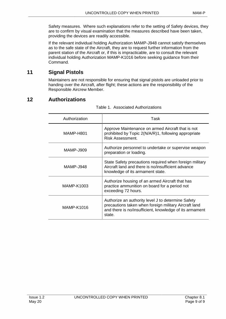
UNCONTROLLED COPY WHEN PRINTED MAM-P
Issue 1.2 May 20
UNCONTROLLED COPY WHEN PRINTED Chapter 8.1 Page 9 of 9
Safety measures. Where such explanations refer to the setting of Safety devices, they are to confirm by visual examination that the measures described have been taken, providing the devices are readily accessible.
If the relevant individual holding Authorization MAMP-J948 cannot satisfy themselves as to the safe state of the Aircraft, they are to request further information from the parent station of the Aircraft or, if this is impracticable, are to consult the relevant individual holding Authorization MAMP-K1016 before seeking guidance from their Command.
11 Signal Pistols
Maintainers are not responsible for ensuring that signal pistols are unloaded prior to handing over the Aircraft, after flight; these actions are the responsibility of the Responsible Aircrew Member.
12 Authorizations
Table 1. Associated Authorizations
Authorization Task
MAMP-H801Approve Maintenance on armed Aircraft that is not prohibited by Topic 2(N/A/R)1, following appropriate Risk Assessment.
MAMP-J909Authorize personnel to undertake or supervise weapon preparation or loading.
MAMP-J948State Safety precautions required when foreign military Aircraft land and there is no/insufficient advance knowledge of its armament state.
MAMP-K1003Authorize housing of an armed Aircraft that has practice ammunition on board for a period not exceeding 72 hours.
MAMP-K1016
Authorize an authority level J to determine Safety precautions taken when foreign military Aircraft land and there is no/insufficient, knowledge of its armament state.
UNCONTROLLED COPY WHEN PRINTED MAM-P
Initial Issue Nov 19
UNCONTROLLED COPY WHEN PRINTED Chapter 8.2 Page 1 of 5
.........................................................................................
...........................................................................................................................................
...................................................................................................
.........................................................................................................................................................
..................................................................................................................
.........................................
...................................................................................................................................................................................
..........................................................................................................................................................
.......................................................................................................
Chapter 8.2
Weapon Preparation and Loading
TABLE OF CONTENTS
Paragraph Page
1 General 11.1 Introduction 11.2 Associated Publications or Instructions 11.3 Applicability 11.4 Additional Information 22 Requirement for Weapon Preparation and Loading Teams 23 Composition of Weapon Preparation and Loading Teams 24 Training of Personnel 24.1 Training of Weapon Preparation and Loading Teams 24.2 Competency Checks 34.3 Training Air Systems and Rigs 34.4 Training for War Fighting or Enduring Armed Operations 45 Authorization of Personnel 45.1 Weapon Preparation and Loading Teams 45.2 Training Personnel 4
LIST OF TABLES
Table 1. Tradesmen Able to Undertake Weapon Preparation and Loading. 2Table 2. Associated Authorizations 4
1 General
1.1 Introduction
Due to the significant Risks associated with explosive armament stores, it is necessary to ensure that all personnel involved with the preparation, loading or unloading of such stores are trained and authorized. These personnel are required to have currency in the procedures for carrying out weapon preparation and loading/unloading tasks, including failure to release procedures, to ensure ongoing Competency and immediate availability of trained personnel when required.
1.2 Associated Publications or Instructions
This chapter is associated with the following publications:
1 RA 4657 – Weapon Loading and Armed Aircraft Maintenance
2 Topic 5A6 – Armament Procedure Sheets (RN), Weapon Loading and Off-loading Procedures (Army/RAF)
1.3 Applicability
This chapter is not applicable to non-Defence Air Environment (DAE) personnel responsible for RN and Army weapon preparation; in these circumstances, the non-DAE personnel will have undergone weapon preparation training and Authorization in accordance with (iaw) the regulations of their own Service and trade.
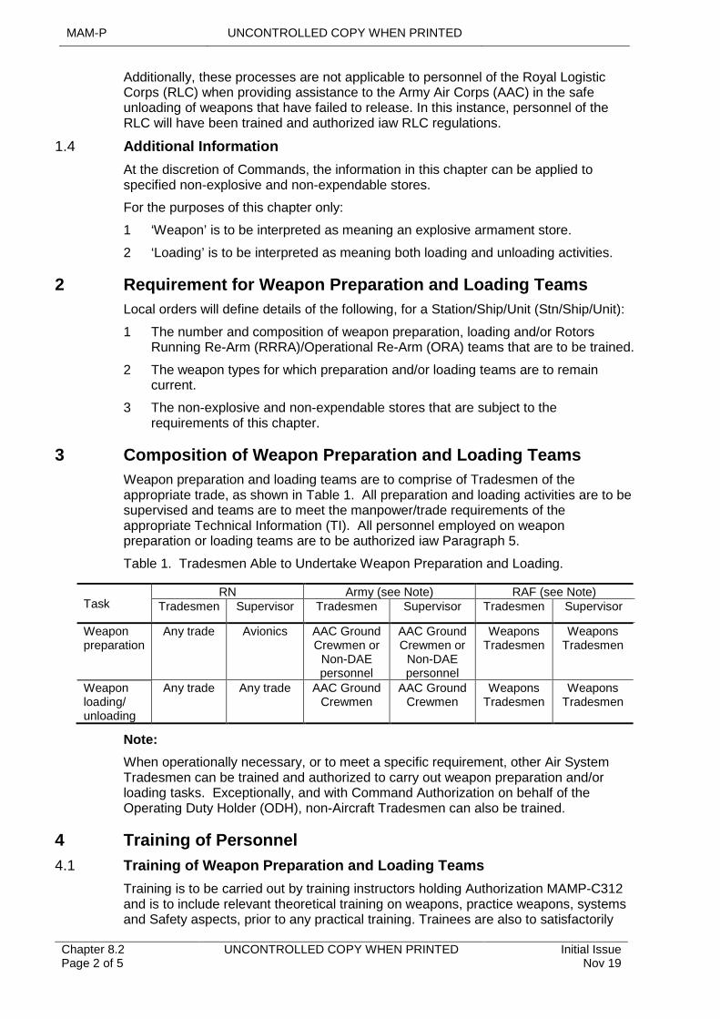
MAM-P UNCONTROLLED COPY WHEN PRINTED
Chapter 8.2 Page 2 of 5
UNCONTROLLED COPY WHEN PRINTED Initial Issue Nov 19
Additionally, these processes are not applicable to personnel of the Royal Logistic Corps (RLC) when providing assistance to the Army Air Corps (AAC) in the safe unloading of weapons that have failed to release. In this instance, personnel of the RLC will have been trained and authorized iaw RLC regulations.
1.4 Additional Information
At the discretion of Commands, the information in this chapter can be applied to specified non-explosive and non-expendable stores.
For the purposes of this chapter only:
1 ‘Weapon’ is to be interpreted as meaning an explosive armament store.
2 ‘Loading’ is to be interpreted as meaning both loading and unloading activities.
2 Requirement for Weapon Preparation and Loading Teams
Local orders will define details of the following, for a Station/Ship/Unit (Stn/Ship/Unit):
1 The number and composition of weapon preparation, loading and/or Rotors Running Re-Arm (RRRA)/Operational Re-Arm (ORA) teams that are to be trained.
2 The weapon types for which preparation and/or loading teams are to remain current.
3 The non-explosive and non-expendable stores that are subject to the requirements of this chapter.
3 Composition of Weapon Preparation and Loading Teams
Weapon preparation and loading teams are to comprise of Tradesmen of the appropriate trade, as shown in Table 1. All preparation and loading activities are to be supervised and teams are to meet the manpower/trade requirements of the appropriate Technical Information (TI). All personnel employed on weapon preparation or loading teams are to be authorized iaw Paragraph 5.
Table 1. Tradesmen Able to Undertake Weapon Preparation and Loading.
TaskRN Army (see Note) RAF (see Note)
Tradesmen Supervisor Tradesmen Supervisor Tradesmen Supervisor
Weapon preparation
Any trade Avionics AAC Ground Crewmen or
Non-DAE personnel
AAC Ground Crewmen or
Non-DAE personnel
Weapons Tradesmen
Weapons Tradesmen
Weapon loading/ unloading
Any trade Any trade AAC Ground Crewmen
AAC Ground Crewmen
Weapons Tradesmen
Weapons Tradesmen
Note:
When operationally necessary, or to meet a specific requirement, other Air System Tradesmen can be trained and authorized to carry out weapon preparation and/or loading tasks. Exceptionally, and with Command Authorization on behalf of the Operating Duty Holder (ODH), non-Aircraft Tradesmen can also be trained.
4 Training of Personnel
4.1 Training of Weapon Preparation and Loading Teams
Training is to be carried out by training instructors holding Authorization MAMP-C312 and is to include relevant theoretical training on weapons, practice weapons, systems and Safety aspects, prior to any practical training. Trainees are also to satisfactorily
UNCONTROLLED COPY WHEN PRINTED MAM-P
Initial Issue Nov 19
UNCONTROLLED COPY WHEN PRINTED Chapter 8.2 Page 3 of 5
answer a written examination on Safety principles and procedures. This is to be carried out to the satisfaction of a training examiner holding Authorization MAMP-E502, who is to certify that the Tradesman is Competent to act as a member of a weapon preparation and/or loading team.
4.2 Competency Checks
4.2.1 Frequency
At least every 12 months, following completion of initial training, personnel are to prepare and/or load the weapon types for which they are authorized. This is to be carried out to the satisfaction of a training examiner, who is to certify that the Tradesman is Competent to act as a member of a weapon preparation and/or loading team. However, the relevant individual holding Authorization MAMP-J909 can increase the frequency of these checks based on the following, non-exhaustive, list of examples:
1 The inexperience of newly qualified personnel.
2 Whenever personnel exhibit unsatisfactory performance or infringe Safety rules during weapon preparation or loading activities. In these circumstances, the personnel concerned are to receive further theoretical and practical training, as considered necessary.
3 Where it is considered that, due to the nature of the working environment, 12 months is too long an interval between checks.
4 Where the preparation and/or loading procedures have been subject to significant amendment.
5 When preparing for war fighting or enduring armed operations, see Paragraph 4.4.
RRRA/ORA - trained personnel are to undertake one full RRRA/ORA, to the satisfaction of a training examiner, at least once every 12 months.
When weapons are being prepared or loaded on a regular basis, such as practice weapons used exclusively for Aircrew training, Commands can promulgate variations to the Competency check regime. Preparation, loading and RRRA/ORA activities carried out during Stn/Ship/Unit exercises meet the Competency check requirement, provided that a training examiner has witnessed the activity and subsequently certifies the Tradesman as Competent.
4.2.2 Recording
A record is to be maintained for each individual carrying out weapon preparation and/or loading, which is to show the date of last Competency check (including details of who performed the check), the date the next Competency check is due and any other circumstances particular to the individual. Provided the individual has successfully passed the Competency check, re-Authorization by the individual holding Authorization MAMP-J909 is not required.
4.3 Training Air Systems and Rigs
Whenever possible, weapon-loading training is to be performed on fully Serviceable Air Systems. However, to avoid imposing unnecessarily severe restrictions on Stn/Ships/Units, the minimum acceptable standard of Air System to be used is to be one in which the relevant Air System armament system is fully Serviceable. Commands, in conjunction with the Type Airworthiness Authority (TAA), can authorize the use of training Air Systems or training rigs, provided that training is representative and can be safely carried out.
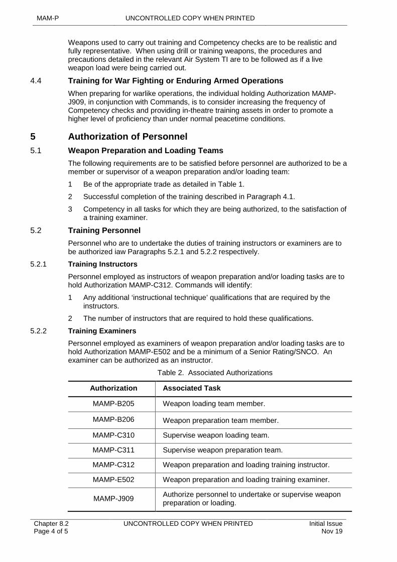
MAM-P UNCONTROLLED COPY WHEN PRINTED
Chapter 8.2 Page 4 of 5
UNCONTROLLED COPY WHEN PRINTED Initial Issue Nov 19
Weapons used to carry out training and Competency checks are to be realistic and fully representative. When using drill or training weapons, the procedures and precautions detailed in the relevant Air System TI are to be followed as if a live weapon load were being carried out.
4.4 Training for War Fighting or Enduring Armed Operations
When preparing for warlike operations, the individual holding Authorization MAMP-J909, in conjunction with Commands, is to consider increasing the frequency of Competency checks and providing in-theatre training assets in order to promote a higher level of proficiency than under normal peacetime conditions.
5 Authorization of Personnel
5.1 Weapon Preparation and Loading Teams
The following requirements are to be satisfied before personnel are authorized to be a member or supervisor of a weapon preparation and/or loading team:
1 Be of the appropriate trade as detailed in Table 1.
2 Successful completion of the training described in Paragraph 4.1.
3 Competency in all tasks for which they are being authorized, to the satisfaction of a training examiner.
5.2 Training Personnel
Personnel who are to undertake the duties of training instructors or examiners are to be authorized iaw Paragraphs 5.2.1 and 5.2.2 respectively.
5.2.1 Training Instructors
Personnel employed as instructors of weapon preparation and/or loading tasks are to hold Authorization MAMP-C312. Commands will identify:
1 Any additional ‘instructional technique’ qualifications that are required by the instructors.
2 The number of instructors that are required to hold these qualifications.
5.2.2 Training Examiners
Personnel employed as examiners of weapon preparation and/or loading tasks are to hold Authorization MAMP-E502 and be a minimum of a Senior Rating/SNCO. An examiner can be authorized as an instructor.
Table 2. Associated Authorizations
Authorization Associated Task
MAMP-B205 Weapon loading team member.
MAMP-B206 Weapon preparation team member.
MAMP-C310 Supervise weapon loading team.
MAMP-C311 Supervise weapon preparation team.
MAMP-C312 Weapon preparation and loading training instructor.
MAMP-E502 Weapon preparation and loading training examiner.
MAMP-J909Authorize personnel to undertake or supervise weapon preparation or loading.
UNCONTROLLED COPY WHEN PRINTED MAM-P
Initial Issue Nov 19
UNCONTROLLED COPY WHEN PRINTED Chapter 8.2 Page 5 of 5
Intentionally Blank for Print Pagination
UNCONTROLLED COPY WHEN PRINTED MAM-P
Issue 1.2 May 20
UNCONTROLLED COPY WHEN PRINTED Chapter 8.2.1 Page 1 of 4
................................................................................................................................................................
.....................................................................................................................................................................
.....................................................................................................................................................................
...........................................................................................................................................................................
....................................................................................................................................
.......................................................................................................................................................
.......................................................................................................
Chapter 8.2.1
Armament Engineering Documentation
TABLE OF CONTENTS
Paragraph Page
1 General 11.1 Introduction 11.2 Associated Publications and Instructions 11.3 Applicability 12 General Requirements for Maintenance Records 12.1 Maintenance 12.2 Preparation and Recovery 22.3 Loading and Unloading 23 Historical Records 24 Transfer of Records 34.1 Maintenance Records 34.2 Historical Records 35 Final Disposal of Records 3
1 General
1.1 Introduction
Armament engineering documentation is an essential aid to the effective and efficient management of armament equipment and stores.
1.2 Associated Publications and Instructions
1 RA 4813 - Maintenance Records (MRP 145.A.55)
2 DSA 03 - OME Part 2 In-Service and Operational Safety Management of OME
3 BRd 862(1) - MOD Maritime Explosives Orders (Surface Ships)
4 Topic 2(N/A/R)1 – General Orders and Special Instructions.
5 Topic 5A6 – Armament Procedure Sheets (RN), Weapon Loading and Off-loading Procedures (Army/RAF).
6 Manual of Airworthiness Maintenance – Documentation (MAM-D)
1.3 Applicability
This chapter is applicable to all personnel in the Defence Air Environment (DAE) who have a responsibility for the Maintenance and storage of explosive armament stores and/or explosive components, their preparation or recovery and the loading/unloading of these items to/from an Aircraft.
This chapter is not applicable to armament ground support equipment.
2 General Requirements for Maintenance Records
2.1 Maintenance
The Maintenance of Aircraft explosive armament stores, explosive components and Aircraft Armament Systems (AAS) is to be recorded in the appropriate MOD Form 707 series of documents or electronic IS equivalent.
MAM-P UNCONTROLLED COPY WHEN PRINTED
Chapter 8.2.1 Page 2 of 4
UNCONTROLLED COPY WHEN PRINTED Issue 1.2 May 20
2.2 Preparation and Recovery
The preparation and recovery of explosive armament stores is to be recorded as detailed in the appropriate Support Policy Statement (SPS) and/or Topic 2(N/A/R)1. Where no current form is specified in the SPS and/or Topic 2(N/A/R)1, RAF Form 2946 – Weapon and Store Preparation and Recovery Log is to be used, except for Storm Shadow, when RAF Form 2946A is to be used.
2.3 Loading and Unloading
The loading and unloading of Aircraft explosive armament stores are to be recorded and certified, iaw their instructions to users, using the following forms as appropriate:
1 RAF Form 2947 – Aircraft Weapon Loading Log.
2 RAF Form 2947A – Aircraft Weapon Loading Log (Smart Weapons).
3 Relevant MOD Form 706.
4 Relevant MOD Form 705.
Once all appropriate documentation, as detailed above, for the loading/unloading of armament explosive stores to/from the Aircraft has been completed, it signifies that:
1 When loading the Aircraft:
1.1 The Aircraft has been loaded as ordered.
1.2 The necessary Safety precautions have been taken.
1.3 The load has been carried out correctly and iaw Technical Information (TI).
1.4 The Aircraft is finally armed and is ready for use, except for the removal of the Safety devices or other action required by the Aircrew, prior to take off, to make the Aircraft Combat Armed.
1.5 All hand tools used during the loading activity have been accounted for.
2 When unloading the Aircraft:
2.1 The explosive armament stores have been unloaded, or the Aircraft made safe if stores have been expended, iaw TI.
2.2 The equipment is safe.
2.3 All appropriate Safety precautions have been taken.
2.4 Flying hours (or other metrics if appropriate) have been recorded for the stores concerned.
2.5 All hand tools used during the unloading activity have been accounted for.
Note:
See Chap 8.1 for the definition of Combat Armed.
3 Historical Records
Historical records are to be maintained as directed by the relevant Delivery Team (DT). Retention Categories of forms and retention periods are given in the MAM-D. These records are to be sufficient so as to record the storage, transfer, Maintenance and usage of the explosive armament store or explosive component throughout its service life.
RAF only – historical records for Aircraft explosive armament stores and explosive components are to be kept on the following forms:
1 RAF Form 6577, Explosives Lot Number Record Card.
UNCONTROLLED COPY WHEN PRINTED MAM-P
Issue 1.2 May 20
UNCONTROLLED COPY WHEN PRINTED Chapter 8.2.1 Page 3 of 4
2 RAF Form 6578, Bin Stock Card.
3 RAF Form 6580, Component History and Maintenance Record.
4 RAF Form 6581, Aircraft/Explosives Record Card.
RAF Forms 6577 and 6578 are to be used for all types of Aircraft explosive armament stores and explosive components; RAF Forms 6580 and 6581 are to be used only when required by the nature of the item concerned.
4 Transfer of Records
4.1 Maintenance Records
Maintenance records, except MOD Form 731 are not to be transferred with equipment unless specific instructions to the contrary have been given.
4.2 Historical Records
Historical records are to accompany the component to which they refer whenever those items are transferred, unless specific instructions to the contrary have been given.
5 Final Disposal of Records
The final disposal of Maintenance and historical records is to be iaw the instructions printed on or issued for them.

MAM-P UNCONTROLLED COPY WHEN PRINTED
Chapter 8.2.1 Page 4 of 4
UNCONTROLLED COPY WHEN PRINTED Issue 1.2 May 20
Intentionally Blank for Print Pagination
UNCONTROLLED COPY WHEN PRINTED MAM-P
Initial Issue Nov 19
UNCONTROLLED COPY WHEN PRINTED Chapter 8.3 Page 1 of 6
........................................................................................................................................
.........................................................................................................................................................................................
....................................................................................................................................................................
...................................................................................................................................................................
..................................................................................................
.................................................................................
.................................................................................................................................................................................
......................................................................................................................................................
.........................................................................................................................................................................................................
Chapter 8.3
Aircraft Armament System Maintenance
TABLE OF CONTENTS
Paragraph Page
1 General 11.1 Introduction 11.2 Associated Publications and Instructions 11.3 Applicability 11.4 Additional Information 12 AAS Testing 22.1 Aircraft Armament Electrical Installation (AAEI) 22.2 Aircraft Armament Suspension Equipment (AASE) 22.3 Armament Role Change Harness (ARCH) 23 Occasions When Testing is Not Required 34 Maintenance Responsibilities, Authorizations and Training
Requirements 34.1 Maintenance Responsibilities 34.2 Authorizations and Training 44.3 Further Training 44.4 Training Tests 45 Authorizations 5
LIST OF TABLES
Table 1. AAS Maintenance Responsibilities. 3Table 2. Associated Authorizations 5
1 General
1.1 Introduction
In the interests of Safety and reliability, the highest standards of Maintenance are to be applied to Aircraft Armament Systems (AAS).
1.2 Associated Publications and Instructions
1 RA 4657 - Weapon Loading and Armed Aircraft Maintenance
2 RA 4806 - Personnel Requirements (MRP 145.A.30)
3 Topic 2(N/A/R)1 - General Orders and Special Instructions
4 Topic 5A1 - Master Maintenance Schedule
1.3 Applicability
This chapter is applicable to all Maintenance organizations that are responsible for the Maintenance of AAS, AAS components or equipment.
1.4 Additional Information
An AAS consists of the following:
1 Aircraft Armament Electrical Installation (AAEI).
MAM-P UNCONTROLLED COPY WHEN PRINTED
Chapter 8.3 Page 2 of 6
UNCONTROLLED COPY WHEN PRINTED Initial Issue Nov 19
2 Aircraft Armament Suspension Equipment (AASE).
3 Armament Role Change Harness (ARCH).
AAEIs that comprise a weapons databus utilize a Mil Std 1760 Aircraft Stores Electrical Interconnection System for interfacing with ‘smart’ weapons or stores. A Mil Std 1760 Aircraft Stores Electrical Interconnection System is to be maintained as part of the AAEI.
2 AAS Testing
2.1 Aircraft Armament Electrical Installation (AAEI)
An AAEI is an installation which comprises those systems that provide control, release, fuzing, firing, monitoring and related data transmission signals of weapons and stores, including counter-measure systems that contain explosives, carried by an Aircraft. Unless defined otherwise in the Air System Topic 1 or 2(N/A/R)1, the installation commences at, and includes, the supply fuses or circuit breakers providing electrical supply to the installation. If, however, the control, release, fuzing, firing, monitoring or related data transmission signals are generated by the Air System main computer, or by other systems having wider functions than those of the AAEI, the installation commences at the interface connections of the line replaceable units generating the signals concerned. Irrespective of where it starts, the AAEI consists of all wiring and equipment making up its circuits to the point where the circuits terminate at the interfaces with the armament weapon suspension equipment, armament role change harness assemblies and weapons or stores.
An AAEI is a safety-critical system and is to be tested in accordance with (iaw) with the Air System Technical Information (TI) and whenever the system has been disturbed following:
1 An electrical connection to/from AAEI components or cables has been disconnected or connected.
2 If, in the opinion of the supervisor, the physical displacement of AAEI cables, or the fitment of securing devices, could have resulted in alteration or damage to the AAS.
2.2 Aircraft Armament Suspension Equipment (AASE)
AASE are those devices (eg, ejector release units (ERU), electro-mechanical release units (EMRU), fuzing/arming units, carriers, adapters, missile rail launchers, missile eject launchers and pylons) used for the carriage on, and release from Aircraft of the following stores:
1 Explosive armament stores, eg, missiles, rockets, bombs, bomb dispensers, gun pods, mines, torpedoes and Electronic Counter Measures (ECM) pods containing explosives.
2 Non-explosive stores, eg, fuel tanks, reconnaissance pods, baggage carriers or ECM pods not containing explosives.
The Maintenance and testing policy for AASE will be promulgated in TI
2.3 Armament Role Change Harness (ARCH)
An ARCH is an item of temporary-fit role equipment that is an umbilical cable assembly, which is used to electrically interconnect the AAEI, AASE and/or air launched/fired munitions.
An ARCH is to be maintained iaw TI by personnel meeting the requirements of this chapter.
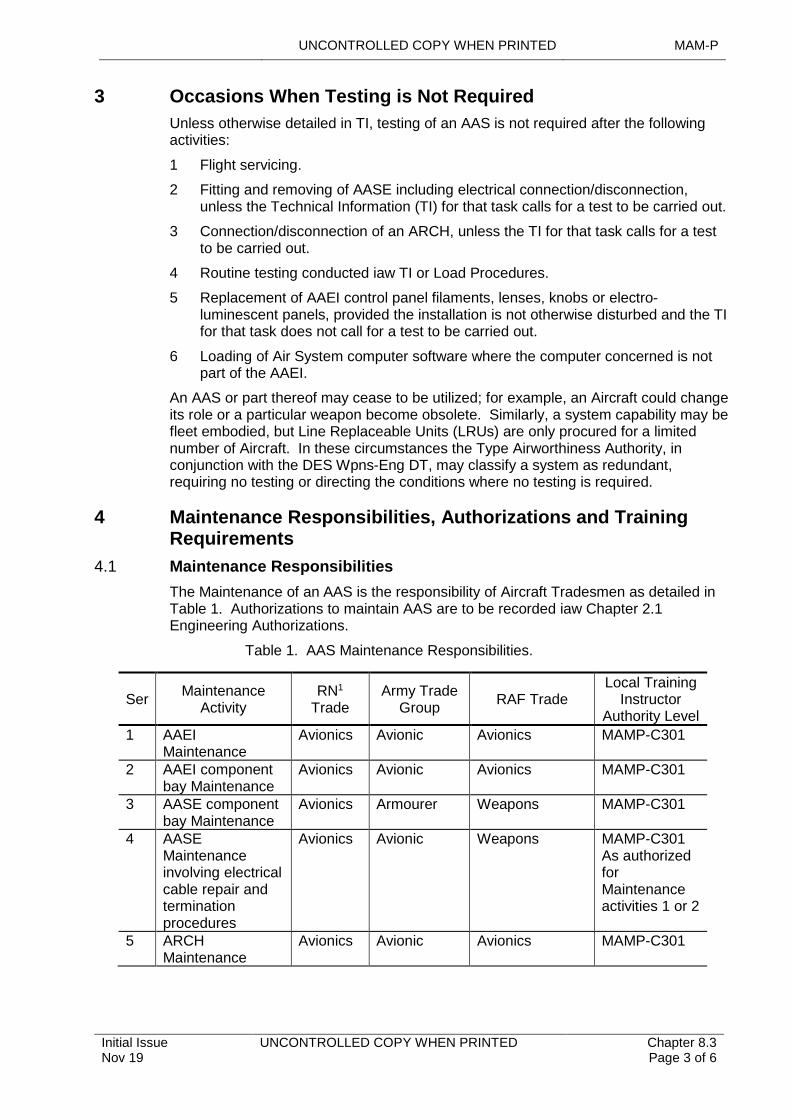
UNCONTROLLED COPY WHEN PRINTED MAM-P
Initial Issue Nov 19
UNCONTROLLED COPY WHEN PRINTED Chapter 8.3 Page 3 of 6
3 Occasions When Testing is Not Required
Unless otherwise detailed in TI, testing of an AAS is not required after the following activities:
1 Flight servicing.
2 Fitting and removing of AASE including electrical connection/disconnection, unless the Technical Information (TI) for that task calls for a test to be carried out.
3 Connection/disconnection of an ARCH, unless the TI for that task calls for a test to be carried out.
4 Routine testing conducted iaw TI or Load Procedures.
5 Replacement of AAEI control panel filaments, lenses, knobs or electro-luminescent panels, provided the installation is not otherwise disturbed and the TI for that task does not call for a test to be carried out.
6 Loading of Air System computer software where the computer concerned is not part of the AAEI.
An AAS or part thereof may cease to be utilized; for example, an Aircraft could change its role or a particular weapon become obsolete. Similarly, a system capability may be fleet embodied, but Line Replaceable Units (LRUs) are only procured for a limited number of Aircraft. In these circumstances the Type Airworthiness Authority, in conjunction with the DES Wpns-Eng DT, may classify a system as redundant, requiring no testing or directing the conditions where no testing is required.
4 Maintenance Responsibilities, Authorizations and Training Requirements
4.1 Maintenance Responsibilities
The Maintenance of an AAS is the responsibility of Aircraft Tradesmen as detailed in Table 1. Authorizations to maintain AAS are to be recorded iaw Chapter 2.1 Engineering Authorizations.
Table 1. AAS Maintenance Responsibilities.
SerMaintenance
ActivityRN1
TradeArmy Trade
GroupRAF Trade
Local Training Instructor
Authority Level
1 AAEI Maintenance
Avionics Avionic Avionics MAMP-C301
2 AAEI component bay Maintenance
Avionics Avionic Avionics MAMP-C301
3 AASE component bay Maintenance
Avionics Armourer Weapons MAMP-C301
4 AASE Maintenance involving electrical cable repair and termination procedures
Avionics Avionic Weapons MAMP-C301 As authorized for Maintenance activities 1 or 2
5 ARCH Maintenance
Avionics Avionic Avionics MAMP-C301
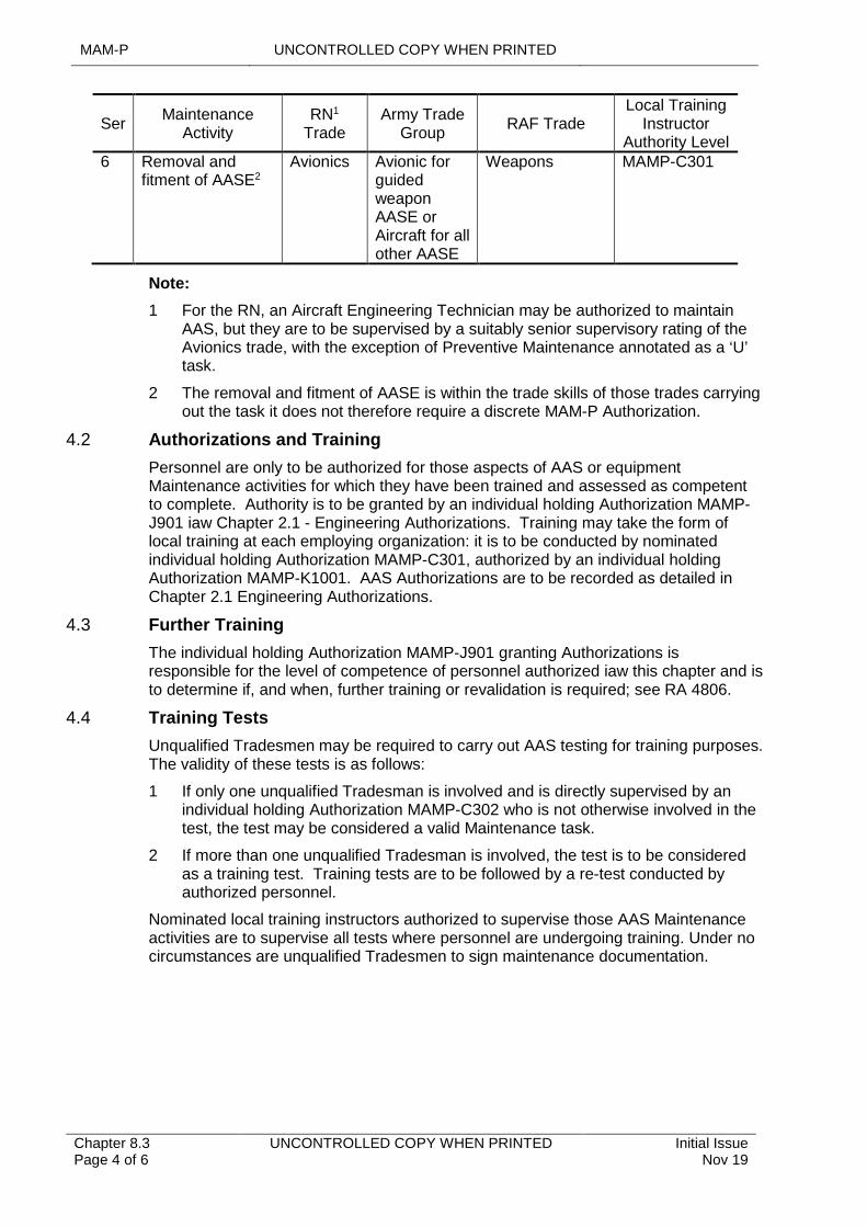
MAM-P UNCONTROLLED COPY WHEN PRINTED
Chapter 8.3 Page 4 of 6
UNCONTROLLED COPY WHEN PRINTED Initial Issue Nov 19
SerMaintenance
ActivityRN1
TradeArmy Trade
GroupRAF Trade
Local Training Instructor
Authority Level6 Removal and
fitment of AASE2Avionics Avionic for
guided weapon AASE or Aircraft for all other AASE
Weapons MAMP-C301
Note:
1 For the RN, an Aircraft Engineering Technician may be authorized to maintain AAS, but they are to be supervised by a suitably senior supervisory rating of the Avionics trade, with the exception of Preventive Maintenance annotated as a ‘U’ task.
2 The removal and fitment of AASE is within the trade skills of those trades carrying out the task it does not therefore require a discrete MAM-P Authorization.
4.2 Authorizations and Training
Personnel are only to be authorized for those aspects of AAS or equipment Maintenance activities for which they have been trained and assessed as competent to complete. Authority is to be granted by an individual holding Authorization MAMP-J901 iaw Chapter 2.1 - Engineering Authorizations. Training may take the form of local training at each employing organization: it is to be conducted by nominated individual holding Authorization MAMP-C301, authorized by an individual holding Authorization MAMP-K1001. AAS Authorizations are to be recorded as detailed in Chapter 2.1 Engineering Authorizations.
4.3 Further Training
The individual holding Authorization MAMP-J901 granting Authorizations is responsible for the level of competence of personnel authorized iaw this chapter and is to determine if, and when, further training or revalidation is required; see RA 4806.
4.4 Training Tests
Unqualified Tradesmen may be required to carry out AAS testing for training purposes. The validity of these tests is as follows:
1 If only one unqualified Tradesman is involved and is directly supervised by an individual holding Authorization MAMP-C302 who is not otherwise involved in the test, the test may be considered a valid Maintenance task.
2 If more than one unqualified Tradesman is involved, the test is to be considered as a training test. Training tests are to be followed by a re-test conducted by authorized personnel.
Nominated local training instructors authorized to supervise those AAS Maintenance activities are to supervise all tests where personnel are undergoing training. Under no circumstances are unqualified Tradesmen to sign maintenance documentation.
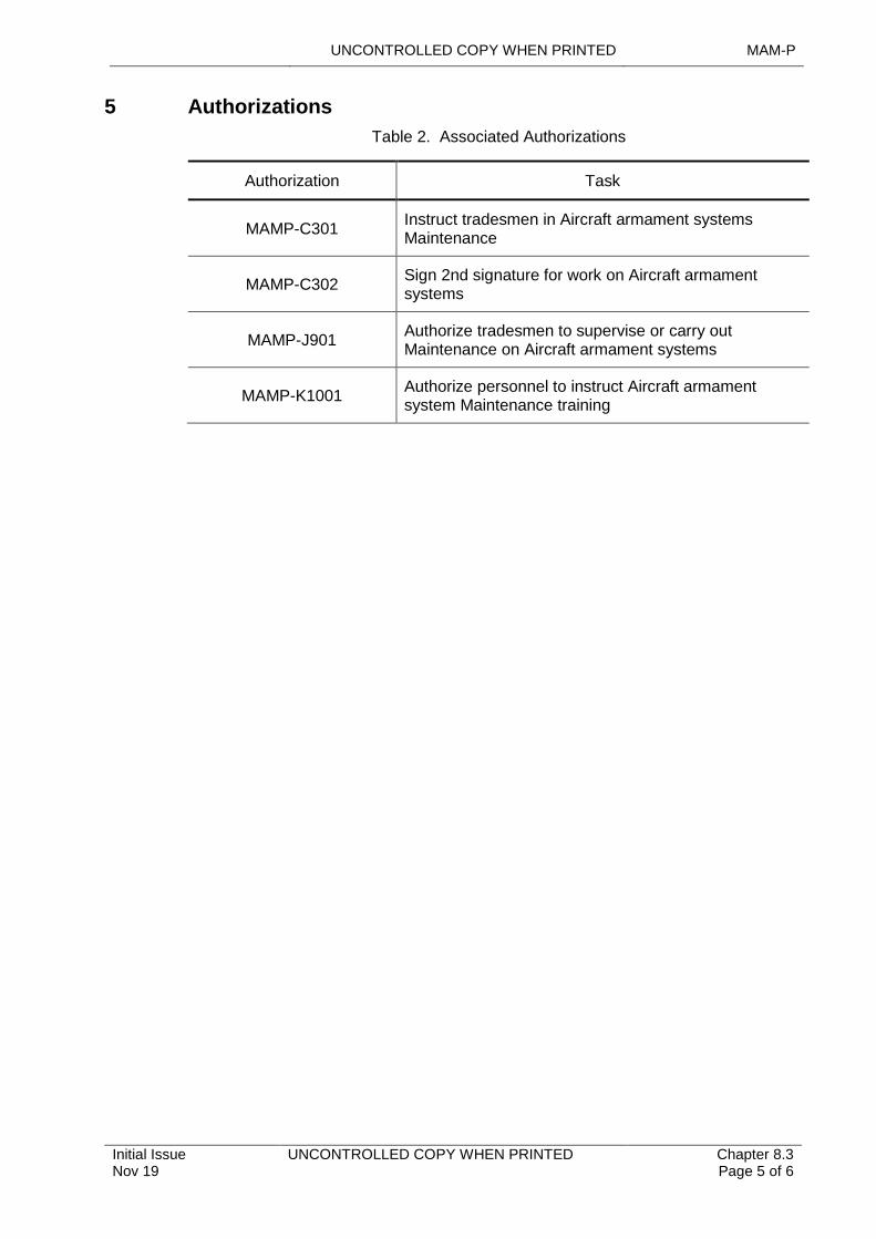
UNCONTROLLED COPY WHEN PRINTED MAM-P
Initial Issue Nov 19
UNCONTROLLED COPY WHEN PRINTED Chapter 8.3 Page 5 of 6
5 Authorizations
Table 2. Associated Authorizations
Authorization Task
MAMP-C301Instruct tradesmen in Aircraft armament systems Maintenance
MAMP-C302Sign 2nd signature for work on Aircraft armament systems
MAMP-J901Authorize tradesmen to supervise or carry out Maintenance on Aircraft armament systems
MAMP-K1001Authorize personnel to instruct Aircraft armament system Maintenance training

MAM-P UNCONTROLLED COPY WHEN PRINTED
Chapter 8.3 Page 6 of 6
UNCONTROLLED COPY WHEN PRINTED Initial Issue Nov 19
Intentionally Blank for Print Pagination
UNCONTROLLED COPY WHEN PRINTED MAM-P
Initial Issue Nov 19
UNCONTROLLED COPY WHEN PRINTED Chapter 8.4 Page 1 of 6
...........................................................................
...................................................................................................................................................
..................................................................................
....................................................................
.........................................................................................................................
........................................................................................................................................................................
......................................................................................................................................
...................................................................................................................................
............................................................
.......................................................................................................................................
.........................................................................................................................................................................................................
Chapter 8.4
Lifing of Explosives and Associated Ancillaries
TABLE OF CONTENTS
Paragraph Page
1 General 11.1 Introduction 11.2 Associated Publications and Instructions 11.3 Additional Information 22 Philosophy on Lifing of Explosives and Associated Ancillaries 23 Initial Determination of Explosives Lives 23.1 Example of Explosives Lifing 24 Promulgation of Explosives Lives 34.2 Changes to Explosives Lives 35 Recording of Life Consumption 35.1 Marking 35.2 Engineering Record Cards (ERC) 45.3 Use and Control of ERCs for Explosives 46 Latitudes to Explosives Lives 46.1 Anticipation of Explosives Lives at Stn/Ship/Unit 46.2 Extension of Explosives Lives by the Delivery Team (DT) 46.3 Extension of Explosives Lives by the Command or Stn/Ship/Unit 56.4 Extension of Maintenance Lives 57 Disposal of Life-Expired Explosives 58 Authorizations 5
LIST OF TABLES
Table 1. Associated Authorizations 5
1 General
1.1 Introduction
Modern explosives are both costly and time-consuming to develop and modify. It is therefore essential to optimize the maximum safe life of explosives to avoid early and expensive replacement or modification. Therefore, explosives and many of their associated ancillary items are subject to lifing procedures. The regulations governing lifing of explosives are both complex and specialist by nature, but are driven by the requirements of DSA 03 - OME Part 1, STANAG 4315 and AOP-46. This chapter seeks to regulate, in basic terms, the philosophy for lifing of explosives (including aerospace components that contain explosives) and associated ancillaries (such as suspension lugs) in the Defence Air Environment (DAE). If further advice is required, the Delivery Team (DT) for the explosive concerned is to be approached. Further information regarding the lifing of aerosystem components can be found in Chapter 4.3 - Lifing of Air System Components.
1.2 Associated Publications and Instructions
1 RA 5405 – Special Instructions (Technical)
2 DSA 02 – Defence Ordnance, Munitions and Explosives (OME) Regulations

MAM-P UNCONTROLLED COPY WHEN PRINTED
Chapter 8.4 Page 2 of 6
UNCONTROLLED COPY WHEN PRINTED Initial Issue Nov 19
3 DSA 03 – OME Part 1 OME Acquisition
4 DSA 03 – OME Part 2 In Service and Operational Safety Management of OME
5 Ammunition and Explosives Regulations
6 STANAG 4315 – The Scientific Basis for the Whole Life Assessment of Munitions
7 Joint Service Munitions Control Register (JSMCR)
8 Topic 2(N/A/R)1 – General Orders and Special Instructions
9 Topic 5A1 – Master Maintenance Schedule
10 Topic 5K IS – Schedule of Component Lives
11 AOP-46 – The Scientific Basis for the Whole Life Assessment of Munitions
1.3 Additional Information
The Service Life may include a Storage Life and/or an Operational Life.
Throughout this chapter the term life extension is used to refer to the increase of the life of an explosive beyond its previously assessed life. Including:
1 Service Life.
2 Storage Life.
3 Operational Life.
4 Air Carriage Life.
5 Standby Life.
6 Disposal Life.
2 Philosophy on Lifing of Explosives and Associated Ancillaries
Explosive stores (including explosives in Aircraft Assisted Escape Systems (AAES)) and components containing explosive stores, and many non-explosive ancillaries such as suspension lugs, are to have an allocated a life, which is known as the Service Life.
3 Initial Determination of Explosives Lives
Where an explosive/ancillary has more than one mode of failure, a different Maintenance activity may be required for each mode, thus giving it a number of lives, eg bay Maintenance life, reconditioning life and disposal life.
3.1 Example of Explosives Lifing
The following shows how an explosive item’s life may be determined:
1 The explosive item has a Service Life of 6 years, a Storage Life of 6 years and an Operational Life of 2 years. Therefore:
1.1 Service Life – The item will remain serviceable and safe for a maximum of 6 years calculated from the first day of the month of the year of filling.
1.2 Storage Life – The item will remain serviceable and safe in storage for a maximum of 6 years calculated from the first day of the month of the year of filling. The date calculated is not to exceed the Service Life.
1.3 Operational Life – The item may be installed in/loaded to a component/weapon/platform at any time during its Service/Storage Life. However, if for example the item is brought into use during the last 2 years
UNCONTROLLED COPY WHEN PRINTED MAM-P
Initial Issue Nov 19
UNCONTROLLED COPY WHEN PRINTED Chapter 8.4 Page 3 of 6
of its Service/Storage Life, some of the Operational Life will be lost. The Operational Life is not to exceed the Service Life.
Note:
The prescribed lifing of an explosive in the DAE may vary if the item concerned is stored/operated in any adverse environment.
4 Promulgation of Explosives Lives
The responsible DT will publish explosives lives in one (or more if appropriate) of the media listed below; however, if the explosive is contained within an Air System component the Type Airworthiness Authority (TAA) will publish the life in the Air System Topic 5A1 or equivalent publication:
1 The Component Life Register (CLR) and Component Replacement List of the relevant Topic 5A1 or equivalent publication.
2 The appropriate Topic 2(N/A/R)1 or Ammunition and Explosive Regulations (A&ER) Pamphlet.
3 Section 2 of the JSMCR.
In the case of lifed explosives with a multi-user application, the DT are to ensure that relevant platform/equipment DTs are advised of any lifing requirements.
Note:
Promulgation of Service/Operational Life to RN Station(Stn)/Ship/Units is also carried out using a Defence Information Notice (DIN).
4.2 Changes to Explosives Lives
The promulgation of amendments to/review of published explosives lives are to be managed by the responsible DT. Stn/Ship/Units may be provided with advanced notification of the changes by issuing one (or more, if appropriate) of the following:
1 Routine Technical Instruction; see RA 5405. Advanced notification may allow units to change and/or segregate explosives pending the receipt of formal amendment to the Topic 5A1. Advanced notification action is particularly important where component lifing details are contained electronically (eg LITS or GOLDesp) and the system affords DTs the ability to amend details centrally.
2 Advanced Information Leaflet to the appropriate Topic 2(N/A/R)1 or A&ER Pamphlet see Chapter 10.1 - Amendment of Technical Information
3 Amendment to the JSMCR.
In the case of lifed explosives with a multi-user application, the DT will ensure that relevant platform/equipment DTs are advised of any revised lifing requirements.
5 Recording of Life Consumption
A record of life consumed is to be maintained for every lifed explosive, component containing an explosive, or associated non-explosive ancillary.
5.1 Marking
With certain exceptions, lifed explosives, when first opened for use (or in the case of AAES explosives, at the point of installation), are to be marked iaw the instructions in the appropriate Topic 2(N/A/R)1 or Technical Information (TI) (eg with the life expiry date and the equipment/platform serial number) using a suitable or specified medium.
MAM-P UNCONTROLLED COPY WHEN PRINTED
Chapter 8.4 Page 4 of 6
UNCONTROLLED COPY WHEN PRINTED Initial Issue Nov 19
5.2 Engineering Record Cards (ERC)
When an explosive, a component containing an explosive, or a non-explosive ancillary is introduced into service, the DT will determine whether the item requires an Engineering Record Card (ERC). The DT will specify ERC requirements and promulgate them in the relevant section of the Topic 5A1 or the appropriate Topic 2(N/A/R)1 or A&ER Pamphlet. Instructions for the use of ERCs for explosives are in Paragraph 5.3. Alternatively, a record of life consumed may be maintained, if appropriate, wholly by an electronic system (such as LITS) and a hard copy of the ERC printed when required.
5.3 Use and Control of ERCs for Explosives
Unless otherwise stated in the Topic 2(N/A/R)1, user units are to maintain the following minimum information on ERCs:
1 Domestic Management Code, Section Reference Number, NATO Stock Number or Ammunition Descriptive Asset Code and Nomenclature.
2 Maker/filler, lot number and date or Batch Key Identity (BKI).
3 Serial number (if appropriate).
4 Where fitted/installed/exposed.
5 Date fitted/installed/exposed.
6 Hours/sorties flown.
7 Date removed/repacked.
When an explosive/ancillary is removed from a platform/equipment for Maintenance, the ERC is to be completed with details of the removal, the life consumed, and the activity undertaken (eg periodic Maintenance, component replacement, etc). If the explosive item/ancillary is sent to another Stn/Ship/Unit, the ERC is to be attached to the MOD Form 731 and dispatched with the item.
6 Latitudes to Explosives Lives
To facilitate Maintenance planning and avoid unnecessary restrictions on system availability, some flexibility in the application of authorized lives to individual explosive items is essential. The latitudes permissible are detailed in Paragraphs 6.1, 6.2, 6.3 and 6.4, though anticipation or extension of Maintenance life may be limited or prohibited by the appropriate specialist regulations, the Command or the responsible DT.
6.1 Anticipation of Explosives Lives at Stn/Ship/Unit
An individual holding Authorization MAMP-J979 may authorize the anticipation of any explosive life expiry unless this action is prohibited in the Topic 2(N/A/R)1. Such anticipation has resource implications; therefore, when anticipating an explosive life expiry, every effort is to be made to ensure that the action does not result in a MOD-wide shortage of the explosive item concerned. Stn/Ship/Units are to liaise with the responsible DT beforehand.
6.2 Extension of Explosives Lives by the Delivery Team (DT)
The DT responsible for the item may, after considering all the relevant factors, authorize extensions to the Service/Operational Lives of explosives. This would normally be based on Designer/Defence Ordnance Safety Group advice, but in certain circumstances (eg where operational capability may otherwise be adversely affected), a DT may authorize an extension to the Service/Operational lives of explosives without such recourse.
UNCONTROLLED COPY WHEN PRINTED MAM-P
Initial Issue Nov 19
UNCONTROLLED COPY WHEN PRINTED Chapter 8.4 Page 5 of 6
6.3 Extension of Explosives Lives by the Command or Stn/Ship/Unit
The extension of an explosive’s Service/Storage or Operational Life at Command or Stn/Ship/Unit level is prohibited regardless of whether it applies to either critical or non-critical failure modes. Requests for life extension are to be made to the appropriate DT, providing the following information:
1 Aircraft/component type and number (CLR reference if applicable) and quantity involved.
2 Maker/filler, lot number and date or BKI.
3 Present life consumed.
4 Type of life due and extension required.
5 Reason for request.
6 Planned date of component change.
7 New expiry date if extension granted.
8 Other considerations that may affect its life, eg storage conditions in a sea environment.
6.4 Extension of Maintenance Lives
Provided extension is permitted in the TI, extensions to Maintenance lives may be authorized iaw TI by an individual holding Authorization MAMP-K1021.
Stn/Ship/Units wishing to extend Maintenance beyond these limits are to apply to the appropriate DT, stating how much extension has already been granted. In consultation with the DT responsible for the explosive concerned, where appropriate, and after considering all the relevant factors, the DT may further extend the Maintenance life.
Note:
Before extending a Maintenance life, a check is to be made to ensure that the extension granted does not compromise the Service/Operational Life of any explosive component fitted.
Critical and non-critical failure modes are described in Manual of Airworthiness Maintenance-Processes (MAM-P) Chapter 4.3 - Lifing of Air System Components
7 Disposal of Life-Expired Explosives
Explosives that have completed their Service/Operational life are an important source of material for life extension trials/proof testing. Stn/Ship/Units therefore are not to dispose of life-expired explosive/ancillary items without prior reference to the DT concerned where no instructions for disposal are detailed in the Topic 2(N/A/R)1. Pending receipt of disposal instructions, Stn/Ship/Units are to store life-expired explosives under the same conditions as new stock.
8 Authorizations
Table 1. Associated Authorizations
Authorization Task
MAMP-J979 Anticipate the removal of lifed components.
MAMP-K1021Authorize extensions to explosives Maintenance lives iaw TI and JSMCR.
MAM-P UNCONTROLLED COPY WHEN PRINTED
Chapter 8.4 Page 6 of 6
UNCONTROLLED COPY WHEN PRINTED Initial Issue Nov 19
Intentionally Blank for Print Pagination
UNCONTROLLED COPY WHEN PRINTED MAM-P
Initial Issue Nov 19
UNCONTROLLED COPY WHEN PRINTED Chapter 8.5 Page 1 of 4
...........................................................................
.....................................................................................................................................................................
...........................................................................................................................................................
................................................................................................................................................................................
...............................................................................................................
......................................................................................................................................................
.........................................................................................................................................................................................................
Chapter 8.5
Examination of In-use Pyrotechnics and Dangerous Goods Issued for use in Survival Equipment and on Airborne Platforms
TABLE OF CONTENTS
Paragraph Page
1 General 11.1 Introduction 11.2 Associated Publications and Instructions 11.3 Applicability 21.4 Additional Information 22 Examination of Pyrotechnics and Dangerous Goods 22.1 Initial Issue 22.2 Preventive Maintenance 22.3 Recording Requirements 23 Training Requirements 23.1 Training and Formalization 24 Authorizations 3
LIST OF TABLES
Table 1. Associated Authorizations 3
1 General
1.1 Introduction
The environmental conditions to which in-use Pyrotechnics and dangerous goods are subjected may cause them to deteriorate more rapidly than those stored in custom-designed storage areas. Additionally, some of the Pyrotechnics and dangerous goods packed in Survival Equipment (SE) may not be readily available at the time of the inspections of explosives. Thus, special arrangements are to be made for the examination of in-use Pyrotechnics and dangerous goods issued for use in SE and on Aircraft. This chapter gives guidance on the recording requirements and details the processes for the examination of in-use Pyrotechnics and dangerous goods.
1.2 Associated Publications and Instructions
1 DAP 108A-0006-2(N/A/R)1 – Survival Equipment and Aircrew Equipment Assemblies Support Authority General Orders and Special Instructions (Technical).
2 DAP 108A-0006-5F(N) – Survival Equipment and Aircrew Equipment Assemblies.
3 DAP 110E-1300-2(R)1 – Defence General Munitions Pyrotechnics, all Types General Orders – Special Instructions.
4 DSA 03 OME Part 2 – In-Service and Operational Safety Management of OME.
5 Defence Logistics Framework (DLF).
MAM-P UNCONTROLLED COPY WHEN PRINTED
Chapter 8.5 Page 2 of 4
UNCONTROLLED COPY WHEN PRINTED Initial Issue Nov 19
1.3 Applicability
This chapter is only applicable to Pyrotechnics and dangerous goods fitted in SE and on Aircraft.
This chapter is not applicable to Pyrotechnics and dangerous goods carried as cargo.
1.4 Additional Information
During the examination of Pyrotechnics and dangerous goods, the stripping of Pyrotechnics and dangerous goods to expose explosive or Pyrotechnic substances is strictly forbidden.
For the purposes of this chapter, the following terms are used:
1 Dangerous goods refer to any article in use that contains non-explosive substances, but which is related by function to explosives.
2 SE includes all items of SE and Aircrew equipment assemblies fitted with Pyrotechnics and/or dangerous goods.
2 Examination of Pyrotechnics and Dangerous Goods
2.1 Initial Issue
Prior to the initial issue of Pyrotechnics and/or dangerous goods for use in SE, they are to be examined to ensure that they are fit for use by an individual holding Authorization MAMP-B220. Completion of the examination is to be recorded iaw Paragraph 2.3 and recorded on the appropriate Maintenance documentation. When transferring Pyrotechnics or dangerous goods it is essential that all records held by the explosive storage area and the SE section, are amended to reflect the new location.
2.2 Preventive Maintenance
Pyrotechnics and dangerous goods installed in SE are to be examined during the Preventive Maintenance of the equipment in which they are installed, as detailed in DAP 108A-0006-2(N/A/R)1 and DAP 108A-0006-5F(N). Examinations are to be conducted by an individual holding Authorization MAMP-B220.
2.3 Recording Requirements
Issues from unit stocks of Pyrotechnics and dangerous goods covered by this chapter are to be recorded iaw DLF. Historical records relating to the Pyrotechnics and dangerous goods are to be maintained iaw Chapter 8.2.1 – Armament Engineering Documentation, using the Maintenance documentation.
3 Training Requirements
3.1 Training and Formalization
All weapons Tradesmen may be authorized to carry out the examination of Pyrotechnics and/or dangerous goods without the need for further formal training. RN and RAF SE personnel required to undertake the examination of those Pyrotechnics and/or dangerous goods specifically issued for use in SE and on Aircraft are to be suitably qualified (RAF: Q-SE-PYRO) or the equivalent embedded in formal basic training. They are then to receive local familiarization training on the items that they will be required to examine.
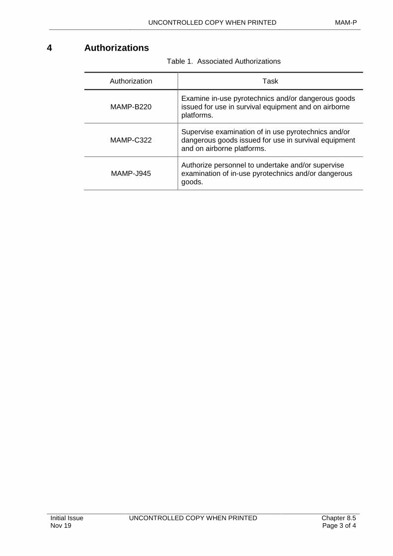
UNCONTROLLED COPY WHEN PRINTED MAM-P
Initial Issue Nov 19
UNCONTROLLED COPY WHEN PRINTED Chapter 8.5 Page 3 of 4
4 Authorizations
Table 1. Associated Authorizations
Authorization Task
MAMP-B220Examine in-use pyrotechnics and/or dangerous goods issued for use in survival equipment and on airborne platforms.
MAMP-C322Supervise examination of in use pyrotechnics and/or dangerous goods issued for use in survival equipment and on airborne platforms.
MAMP-J945Authorize personnel to undertake and/or supervise examination of in-use pyrotechnics and/or dangerous goods.

MAM-P UNCONTROLLED COPY WHEN PRINTED
Chapter 8.5 Page 4 of 4
UNCONTROLLED COPY WHEN PRINTED Initial Issue Nov 19
Intentionally Blank for Print Pagination
UNCONTROLLED COPY WHEN PRINTED MAM-P
Initial Issue Nov 19
UNCONTROLLED COPY WHEN PRINTED Chapter 8.6 Page 1 of 2
...........................................................................
............................................................................................................................................
.................................................................................................
.........................................................................................................................................................
.........................................................................................................................................................................................................
Chapter 8.6
Connecting Electro-Explosive Devices
TABLE OF CONTENTS
Paragraph Page
1 General 11.1 Introduction 11.2 Associated Publications or Instructions 11.3 Applicability 11.4 Terms used 12 Connecting an Electro-Explosive Device 23 Authorizations 2
LIST OF TABLES
Table 1. Associated Authorizations 2
1 General
1.1 Introduction
An Electro-Explosive Device (EED) is an explosive or Pyrotechnic device designed to be initiated by electrical means, which if inadvertently operated or initiated could cause extensive damage and loss of life. To protect the Tradesman who is undertaking the connection of an EED to its Electrical Firing Circuit (EFC) including those personnel and materiel in the vicinity of this activity, it is necessary to carry out a test of the EFC, known as a No-Volts Safety Test (NVST). The purpose of this chapter is to specify the policy to be adopted for carrying out a NVST, prior to connecting an EED.
1.2 Associated Publications or Instructions
1 DEF STAN 07-85 – Design Requirements for Weapons and Associated Systems.
2 DEF STAN 59-114 – Safety Principles for Electrical Circuits in Systems Incorporating Explosive Components.
1.3 Applicability
This chapter is applicable to both on and off-Air System activities undertaken by organizations within the Defence Air Environment (DAE) maintaining Air Systems or Air System components fitted with EEDs. Such devices may be associated with, or form part of, an Explosive Armament Store or may be an Explosive Component in an Air System or equipment system.
1.4 Terms used
Throughout this Chapter:
1 Connection of an EED to its EFC is to be interpreted as also meaning any action that completes an EFC in which the EED is already installed.
2 ‘Schedule’ or ‘procedure concerned’ means the schedule or procedure that calls for, or controls, connection of an EED to its EFC.
3 NVST relates only to a Safety test undertaken as a Safety precaution prior to connecting an EED to its EFC and does not refer to no-volts testing performed for
MAM-P UNCONTROLLED COPY WHEN PRINTED
Chapter 8.6 Page 2 of 2
UNCONTROLLED COPY WHEN PRINTED Initial Issue Nov 19
any other reason, eg as a form of system test; the term is not to be used to describe such tests.
2 Connecting an Electro-Explosive Device
If a NVST is detailed as a requirement in the Air System Technical Information, the following procedures are to be adhered to when connecting an EED to its EFC:
1 The NVST is to be carried out under the same conditions as those determined for the connection of the EED to its EFC.
2 The NVST is to be undertaken by the individual(s) who will personally connect the EED to its EFC. Additionally, the individual holding Authorization MAMP-C302 supervising the activity is to ensure that all conditions detailed within the overall schedule or procedure concerned have been met prior to performing the NVST and that suitable measures have been taken to ensure that no change to the specified conditions occurs until the EED is connected to its EFC.
3 Once a satisfactory NVST has been carried out on an EFC, the EED is to be connected to its EFC as soon as it is practicable to do so.
3 Authorizations
Table 1. Associated Authorizations
Authorization Task
MAMP-C302Sign 2nd signature for work on Aircraft armament systems.
UNCONTROLLED COPY WHEN PRINTED MAM-P
Initial Issue Nov 19
UNCONTROLLED COPY WHEN PRINTED Chapter 8.7 Page 1 of 2
......................................................................................................................................................................................
................................................................................................................................................................................
......................................................................................................................................................
.........................................................................................................................................................................................................
Chapter 8.7
Chaff – Hazards Associated with Spillage
TABLE OF CONTENTS
Paragraph Page
1 General 11.1 Introduction 11.2 Associated Publications and Instructions 11.3 Applicability 12 Personal Safety 13 Recovery of Chaff 24 Disposal Instructions 25 First Aid 2
1 General
1.1 Introduction
Chaff is used by UK military Air Systems as a counter-measure to prevent unwanted detection by RADAR systems. It comprises silvery-grey fibres of various lengths, which are made up of a glass core coated with aluminium. Whilst there is no evidence of a serious health hazard to personnel, chaff is an irritant to the skin and respiratory system when concentrated in a small area. Therefore, any spillage is to be dealt with immediately and in such a way as to minimize the potential hazard to personnel. A spillage is considered to have occurred whenever chaff is inadvertently exposed during transit, loading and unloading procedures or is released from a parked Air System.
1.2 Associated Publications and Instructions
1 RA 1410 – Occurrence Reporting and Management
2 DSA 01.1 Defence Policy for Health, Safety and Environmental Protection
3 RIDDOR 95 – Reporting of Incidents, Diseases and Dangerous Occurrences Regulations
4 Defence Clothing Catalogue
1.3 Applicability
This chapter is applicable to all Station/Ship/Unit that operate, or may be required to handle, military Air Systems fitted with a chaff dispenser system.
2 Personal Safety
Personnel involved in the recovery of spilt chaff are to be aware of the requirement for a risk assessment to be in place, in accordance with DSA 01.1, and are to wear appropriate personal protective equipment, identified in the Defence Clothing Catalogue, as follows:
1 Coveralls.
2 Industrial goggles.
3 Disposable, nuisance/odour, facemask.
MAM-P UNCONTROLLED COPY WHEN PRINTED
Chapter 8.7 Page 2 of 2
UNCONTROLLED COPY WHEN PRINTED Initial Issue Nov 19
4 Rubber gloves.
Personnel not involved in the operation are to be excluded from the contaminated area.
3 Recovery of Chaff
Where practical, the affected area is to be cleared using mechanical sweepers or vacuum cleaners. If this is not possible, the area is to be swept clear by personnel using brooms. Spillages within hangars and hardened aircraft shelters are to be contained by closing doors and shutting down ventilation systems.
4 Disposal Instructions
Chaff is to be placed in plastic bags or paper sacks, which are to be sealed, clearly labelled and disposed of (ideally by incineration) in accordance with local procedures.
5 First Aid
In the event of personal contamination by chaff, affected person(s) are to obtain medical attention as soon as possible. All occurrences are to be reported in accordance with DSA 01.1, RIDDOR and RA 1410.
UNCONTROLLED COPY WHEN PRINTED MAM-P
..........................................................................................
................................................................................................................................................................................
................................................................................................
...........................................................................................
...............................................................................................................................................................
................................................................................................................................
...................................................................................................
.......................................................................................................................................
..................................................................................................................................................
.........................................................................................................................................................................................................
Chapter 9.1
Fault Reporting
TABLE OF CONTENTS
Paragraph Page
1 General 11.1 Introduction1.2 Associated Publications or Instructions
11
2 Fault Reporting 2 2.1 Routine Fault Reporting 2 2.2 Arising from a Ground Maintenance System 2 2.3 Aviation Materiel Received on Transfer in an Unsatisfactory Condition 2 2.4 Faults with Air Publications and Forms in the MOD Form 700 Series 2 2.5 Faulty Packaging 3 3 Serious Faults 3 4 Defence Air Safety Occurrence Report (DASOR) 3 4.1 Components Subject to a DASOR 3 4.2 Identification 3 5 Narrative Fault Reporting 4 6 Equipment Types with Specific Fault Reporting Procedures 4 6.1 Documentation and Disposal of Faulty Equipment Types/Components 4 7 Responsibilities 5 7.1 Stations/Ships/Units 5 8 Authorizations 5
LIST OF TABLES
Table 1. Equipment types with Specific or Modified Reporting Procedures. 4 Table 2. Associated Authorizations. 5
1 General
1.1 Introduction
The accurate and timely reporting of Faults in Air System and Airborne Equipment is essential to ensuring Airworthiness. It enables the cost-effective utilization of assets through improved reliability and maintainability. All Faults are reported through a routine system; some, considered of particular interest, are given an additional reporting route, which ensures that particular attention is paid to the nature of the Fault and possibly to any affected components as well. This chapter describes the various methods of reporting Faults and provides references to detailed reporting procedures.
1.2 Associated Publications or Instructions
1 RA 1410 – Occurrence Reporting and Management
2 RA 4061 – Air Systems Displaying Abnormal Flying Characteristics.
3 RA 4809 – Acceptance of Components (MRP 145.A.42)
4 RA 4810 – Technical Information (MRP 145.A.45)
5 RA 4814 – Occurrence Reporting (MRP 145.A.60)
Issue 1.4 Apr 21
UNCONTROLLED COPY WHEN PRINTED Chapter 9.1 Page 1 of 6
MAM-P UNCONTROLLED COPY WHEN PRINTED
6 RA 4815 – Maintenance Procedures and Safety and Quality Policy (MRP 145.A.65)
7 JSP 440 – The Defence Manual of Security, Resilience and Business Continuity.
8 JAP(D) 100A-0409 -01 – GOLDesp Logistic Information System Procedures Manual.
9 JAP 100C-02 – Maintenance Data System Work Recording.
10 DAP 300A-01 – The Logistics Information Technology System (LITS) Orders and Instructions.
11 Defence Logistics Framework (DLF).
12 DSA 03 OME Part 2 – In Service and Operational Safety Management
2 Fault Reporting
There are a variety of Fault reporting procedures used in the Defence Aviation Environment (DAE). Procedures can be divided broadly into those for particular circumstances and those that are specific to Product, Parts and Appliances types. In practice a combination of methods may be used, eg a Fault that is the subject of an air occurrence would be routinely reported using the appropriate Maintenance Log (eg MOD Form 700 or electronic Information System (IS) equivalent), and also Defence Air Safety Occurrence Report (DASOR) additionally, the fault may warrant a narrative Fault report using the MOD Form 760 procedure.
2.1 Routine Fault Reporting
Faults are routinely reported using the appropriate Maintenance Log (eg MOD Form 700 or electronic IS equivalent), as directed by the relevant Type Airworthiness Authority (TAA). Data gathered from the Fault reporting process can then be used for identifying Fault trends and providing information on equipment performance and reliability. Additional Fault reporting/investigation may be required, as detailed below, when directed by the TAA.
2.2 Arising from a Ground Maintenance System
For Air Systems utilizing a Ground Maintenance System (GMS), an arising indication represents a potential Air System fault or exceedance that may require Corrective Maintenance. The GMS tool may automatically filter arising data, using designer-defined algorithms, to optimize outputs: accurately reflecting the potential maintenance required. An Authorized Arising Manager (AM) MAMP - F607 is to ratify arisings, apply an appropriate status in accordance with (iaw) Technical Information (TI) and report faults using a common MWO or electronic equivalent in order to initiate Maintenance activities.
2.3 Aviation Materiel Received on Transfer in an Unsatisfactory Condition
Specific instructions exist for reporting aviation materiel received in an unsatisfactory condition. This includes items received with Faults that could have been reasonably identified by the dispatching Station/Ship/Unit (Stn/Ship/Unit). The procedure for reporting such instances is at RA 4814 and Chapter 11.1 – Defence Air Environment Quality Policy.
2.4 Faults with Air Publications and Forms in the MOD Form 700 Series
Reporting of Faults and unsatisfactory features of Air Publications and forms in the MOD Form 700 series is mandated by RA 4810 and MOD Form 765 Instructions for Use on the MOD Poster 302 series.
Chapter 9.1 Page 2 of 6
UNCONTROLLED COPY WHEN PRINTED Issue 1.4 Apr 21
UNCONTROLLED COPY WHEN PRINTED MAM-P
2.5 Faulty Packaging
Faulty packaging, including RN air stores, are to be reported iaw) the procedures in Defence Logistic Framework (DLF).
3 Serious Faults
When a Fault is discovered which is considered to be serious it is to be reported using a Serious Fault Report (SFR) and sent directly, by the fastest means available, to the Military Continuing Airworthiness Management Organization (Mil CAMO), TAA and/or commodity Delivery Team (DT). Examples that would warrant serious Fault reporting are those Faults that:
1 Adversely affect the Airworthiness of the Air System or Associated Components.
2 Endanger personnel, Air Systems or Associated Components.
3 Significantly reduce the operational effectiveness or availability of the Air System or associated components.
4 Put at risk the security of airborne communication components.
The procedure for raising a Serious Fault Report (SFR) is at Chapter 9.3. - Serious Fault Reports.
4 Defence Air Safety Occurrence Report (DASOR)
DASORs are raised whenever an actual or potential hazardous occurrence takes place as summarized in RA 1410. Where a DASOR is raised as the result of a technical failure, the equipment suspected of causing or contributing to the occurrence is to be identified and handled in a manner that will allow any interim/final follow-up reports to be completed expeditiously. Serviceable equipment holding original flight data (eg Aircraft Data Recording ADR or Health and Usage Monitoring System (HUMS)) may also require removal for quarantine. Equipment that is the subject of occurrence reports may also require subsequent investigation by an organization responsible for depth Maintenance.
4.1 Components Subject to a DASOR
Components that are suspected of causing, or contributing to the cause of, a DASOR are, if practical, to be investigated with the component in-situ (this is mandated for Uncommanded Flying Control Movement/Control Restriction (UMFC/CR) incidents by RA 4061 and Chapter 3.3 - Management of Aircraft Displaying Abnormal Flying Characteristics) and, if removed, retained by the operating Sqn/Unit until the original Fault has been rectified and any associated functional tests, including flight tests, have been carried out. The retention of components (whether at forward or depth Maintenance level) until the Fault has been positively eliminated will enable the correct component to be identified for investigative reporting. The authority that has ordered the occurrence investigation may require Serviceable components holding original flight data (eg ADR or HUMS) to be removed and quarantined.
4.2 Identification
All engineering documentation raised in support of a DASOR is to be cross-referenced to that DASOR serial number. Components subject to a DASOR that requires further investigation are to be conditioned, as mandated by RA 4809 and Chapter 4.0 - Technical Equipment Conditioning and Preparation for Movement or Storage, and identified by annotating the MOD Form 731, or equivalent with the DASOR serial number and ‘DASOR’ in red ink.
Issue 1.4 Apr 21
UNCONTROLLED COPY WHEN PRINTED Chapter 9.1 Page 3 of 6
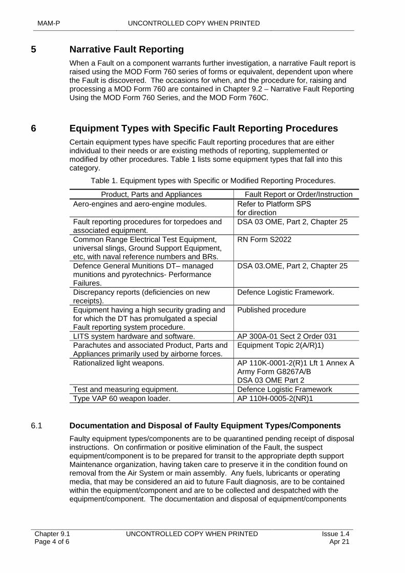
MAM-P UNCONTROLLED COPY WHEN PRINTED
Chapter 9.1 Page 4 of 6
UNCONTROLLED COPY WHEN PRINTED Issue 1.4 Apr 21
5 Narrative Fault Reporting
When a Fault on a component warrants further investigation, a narrative Fault report is raised using the MOD Form 760 series of forms or equivalent, dependent upon where the Fault is discovered. The occasions for when, and the procedure for, raising and processing a MOD Form 760 are contained in Chapter 9.2 – Narrative Fault Reporting Using the MOD Form 760 Series, and the MOD Form 760C.
6 Equipment Types with Specific Fault Reporting Procedures
Certain equipment types have specific Fault reporting procedures that are either individual to their needs or are existing methods of reporting, supplemented or modified by other procedures. Table 1 lists some equipment types that fall into this category.
Table 1. Equipment types with Specific or Modified Reporting Procedures.
Product, Parts and Appliances Fault Report or Order/Instruction
Aero-engines and aero-engine modules. Refer to Platform SPS
for directionFault reporting procedures for torpedoes and associated equipment.
DSA 03 OME, Part 2, Chapter 25
Common Range Electrical Test Equipment, universal slings, Ground Support Equipment, etc, with naval reference numbers and BRs.
RN Form S2022
Defence General Munitions DT– managed munitions and pyrotechnics- Performance Failures.
DSA 03.OME, Part 2, Chapter 25
Discrepancy reports (deficiencies on new receipts).
Defence Logistic Framework.
Equipment having a high security grading and for which the DT has promulgated a special Fault reporting system procedure.
Published procedure
LITS system hardware and software. AP 300A-01 Sect 2 Order 031Parachutes and associated Product, Parts and Appliances primarily used by airborne forces.
Equipment Topic 2(A/R)1)
Rationalized light weapons. AP 110K-0001-2(R)1 Lft 1 Annex A Army Form G8267A/B DSA 03 OME Part 2
Test and measuring equipment. Defence Logistic FrameworkType VAP 60 weapon loader. AP 110H-0005-2(NR)1
6.1 Documentation and Disposal of Faulty Equipment Types/Components
Faulty equipment types/components are to be quarantined pending receipt of disposal instructions. On confirmation or positive elimination of the Fault, the suspect equipment/component is to be prepared for transit to the appropriate depth support Maintenance organization, having taken care to preserve it in the condition found on removal from the Air System or main assembly. Any fuels, lubricants or operating media, that may be considered an aid to future Fault diagnosis, are to be contained within the equipment/component and are to be collected and despatched with the equipment/component. The documentation and disposal of equipment/components
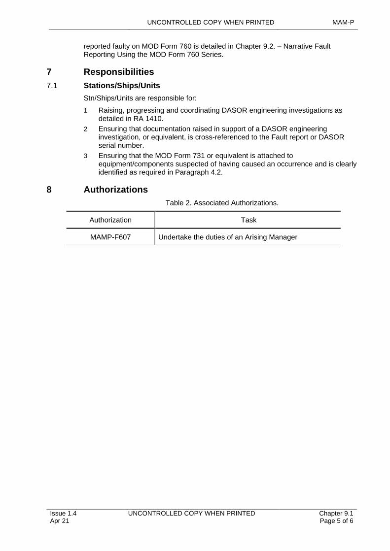
UNCONTROLLED COPY WHEN PRINTED MAM-P
Issue 1.4 Apr 21
UNCONTROLLED COPY WHEN PRINTED Chapter 9.1 Page 5 of 6
reported faulty on MOD Form 760 is detailed in Chapter 9.2. – Narrative Fault Reporting Using the MOD Form 760 Series.
7 Responsibilities
7.1 Stations/Ships/Units
Stn/Ships/Units are responsible for:
1 Raising, progressing and coordinating DASOR engineering investigations as detailed in RA 1410.
2 Ensuring that documentation raised in support of a DASOR engineering investigation, or equivalent, is cross-referenced to the Fault report or DASOR serial number.
3 Ensuring that the MOD Form 731 or equivalent is attached to equipment/components suspected of having caused an occurrence and is clearly identified as required in Paragraph 4.2.
8 Authorizations
Table 2. Associated Authorizations.
Authorization Task
MAMP-F607 Undertake the duties of an Arising Manager
MAM-P UNCONTROLLED COPY WHEN PRINTED
Intentionally Blank for Print Pagination
Chapter 9.1 Page 6 of 6
UNCONTROLLED COPY WHEN PRINTED Issue 1.4 Apr 21
UNCONTROLLED COPY WHEN PRINTED MAM-P
Initial Issue Nov 19
UNCONTROLLED COPY WHEN PRINTED Chapter 9.2 Page 1 of 6
...........................................................................
......................................................................................................................................................................................................
..............................................................................................................................
.....................................................
........................................................................................
...............................................................................................................
..........................................................................................................
..................................................................................................................................................
...............................................................................................................................................
......................................................................................................................................................
.........................................................................................................................................................................................................
Chapter 9.2
Narrative Fault Reporting Using the MOD Form 760 Series
TABLE OF CONTENTS
Paragraph Page
1 General 11.1 Introduction 11.2 Associated Publications and Instructions 11.3 Applicability 22 Classification of Equipment 22.1 Not-in-use (NIU) Equipment 22.2 In-use (IU) Equipment 23 Fault reporting Implementation 23.1 Occasions for Raising a Narrative Fault Report Using the MOD Form 760
Series 23.2 Forms in the MOD Form 760 Series 23.3 Responsibility for Raising MOD Form 760 33.4 Compiling and Progressing MOD Form 760 34 Mandatory Fault Reporting Instruction (MFRI) 35 Handling, Quarantine and Disposal of Faulty Equipment 36 Responsibilities for MOD Form 760 Fault Reporting 46.1 Detached or Embarked Squadron, Unit or Flight 46.2 Parent Stn/Ship/Unit 46.3 Actions by Joint Support Chain (JSC) Logistic Commodities and Services
(LCS) 57 Authorizations 5
LIST OF TABLES
Table 1. Associated Authorizations 5
1 General
1.1 Introduction
Faults with Air Systems and associated equipment in the Defence Air Environment (DAE) are resolved by repair or replacement of components, accompanied by routine reporting procedures as described in RA 4814 and Chapter 9.1 - Fault Reporting. Some Faults, however, warrant a deeper, more detailed investigation to isolate the cause and/or explain an unexpected failure. In addition to routine Fault reporting, the MOD Form 760 Narrative Fault Report is used to provide the additional information needed to undertake this investigation. This chapter describes the occasions for, and methods of, raising Narrative Fault Reports and defines how these reports are to be handled and the Faults investigated.
1.2 Associated Publications and Instructions
1 RA 1220 – Delivery Team Airworthiness and Safety
2 RA 1410 – Occurrence Reporting and Management
3 RA 4814 – Occurrence Reporting (MRP 145.A.60)
MAM-P UNCONTROLLED COPY WHEN PRINTED
Chapter 9.2 Page 2 of 6
UNCONTROLLED COPY WHEN PRINTED Initial Issue Nov 19
4 Defence Logistic Framework (DLF)
5 Air Safety Information Management System (ASIMS)
6 Topic 2(N/A/R)1 – General Orders and Special Instructions
1.3 Applicability
This chapter is applicable to all personnel within the DAE responsible for the compilation and/or handling of the MOD Form 760 Narrative Fault Report.
2 Classification of Equipment
2.1 Not-in-use (NIU) Equipment
Not-in-use (NIU) equipment is defined as equipment that has not been put to its intended use. The term embraces new, reconditioned, recalibrated, or repaired equipment (except equipment repaired by the user) up to the stage of satisfying any initial visual, dimensional, functional or installation checks, including flight testing where appropriate, following its issue from store.
Note:
Where the traditional user repair functions are carried out by non-military personnel under a support contract managed by the responsible Delivery Team (DT), the Delivery Team Leader (DTL) is to publish the exempt from NIU categorization in the appropriate Support Policy.
2.2 In-use (IU) Equipment
In-use (IU) equipment is defined as all equipment that cannot be classed as NIU.
Note:
All Faults on Air System integrity monitoring equipment are to be classified as IU.
3 Fault reporting Implementation
3.1 Occasions for Raising a Narrative Fault Report Using the MOD Form 760 Series
A MOD Form 760 is to be raised on the following occasions:
1 Automatically, in support of a Serous Fault Report (SFR).
2 At the discretion of the responsible officer when it is considered that the Fault may affect Safety, equipment availability or performance or where it is considered worthy of detailed investigation.
3 For any Fault on NIU equipment.
4 On Faults which are considered by local management to merit Military Continuing Airworthiness Management Organization (Mil CAMO), Type Airworthiness Authority (TAA) or commodity DT attention.
5 When instructed to do so by, or on behalf of, a TAA or commodity DT in a Special Instruction (Technical) (SI(T)) or Mandatory Fault Reporting Instruction (MFRI), (Paragraph 4 refers) or in any other instruction.
6 When instructed to do so by a Service Inquiry.
3.2 Forms in the MOD Form 760 Series
The MOD Form 760 Narrative Fault Reporting System comprises the following forms:
1 MOD Form 760 – Narrative Fault Report.
UNCONTROLLED COPY WHEN PRINTED MAM-P
Initial Issue Nov 19
UNCONTROLLED COPY WHEN PRINTED Chapter 9.2 Page 3 of 6
2 MOD Form 760A – Fault Investigation Request.
3 MOD Form 760B – Narrative Fault Report – Request for MFRI Action.
4 MOD Form 760C – Compilation Instructions - MOD Form 760 Narrative Fault Report.
5 MOD Form 760E – Faulty Equipment Label.
6 MOD Form 760F – Narrative Fault Report Transit Folder.
7 MOD Form 761 – Fault Investigation Report.
Where a form is passed by e-mail between organizations for action, a facsimile signature is not to be used in any signature block. Organizations documenting their action are to place a signed copy on file and annotate “File Copy Signed” in the relevant block of the e-mailed version.
3.3 Responsibility for Raising MOD Form 760
The following are responsible for raising a MOD Form 760:
1 The Maintenance organization holding the Faulty Air System or equipment on charge at the time a reportable Fault is discovered.
2 The investigating officer of an Air System Accident or other investigation where equipment or parts of the Air System have been removed for further investigation.
3.4 Compiling and Progressing MOD Form 760
The MOD Form 760 is to be compiled following the instructions given in the MOD Form 760C. The Senior Specialist Officer holding Authorization MAMP-J966 is responsible for ensuring the expeditious dispatch of an accurate and relevant MOD Form 760 from the Station/Ship/Unit) to the relevant TAA and/or DT.
4 Mandatory Fault Reporting Instruction (MFRI)
MFRIs are issued and managed internally by the TAA when MOD Forms 760 are required on specific items of equipment. TAAs may seek the advice of their Maintenance data organization: Log NEC Information Exploitation (IX) Team. Limited Fault statistics may be provided by Maintenance data organizations; hence the use of MFRIs is to be restricted to the following:
1 Monitoring the performance of new equipment.
2 Validating current lifing policies.
3 Monitoring the effectiveness of modifications or SI(T).
4 When further information is required to supplement Fault case histories.
The MOD Form 760B may be used to formally task the person within the DT that is responsible for internal management of MFRIs. An MFRI can be set either for a period of time or for a number of arisings and may be restricted to particular units. TAAs are to publish MFRIs for their Air System in the Topic 2(N/A/R)1.
5 Handling, Quarantine and Disposal of Faulty Equipment
All equipment subject to MOD Form 760 action is to remain quarantined pending receipt of disposal instructions. The MOD Form 760 originator is responsible for quarantining or arranging the quarantine of Faulty items. Items are to be maintained in the condition existing at the time of failure. Blanks are to be fitted to pipeline
MAM-P UNCONTROLLED COPY WHEN PRINTED
Chapter 9.2 Page 4 of 6
UNCONTROLLED COPY WHEN PRINTED Initial Issue Nov 19
connections and orifices and measures taken to protect the items in transit. Samples of foreign matter, fuel, oil, etc, are to be taken, quarantined and despatched with the Faulty equipment. The following forms are to be attached to the Faulty equipment:
1 Completed equipment conditioning label (eg MOD Form 731 or equivalent – to include the serial number of the relevant MOD Form 760).
2 Completed MOD Form 760E – Faulty Equipment Label.
3 A copy of the MOD Form 760, if unclassified.
4 The Engineering Record Card, if applicable.
The TAA are to be contacted for disposal instructions for materiel under quarantine.
6 Responsibilities for MOD Form 760 Fault Reporting
6.1 Detached or Embarked Squadron, Unit or Flight
When a reportable Fault is discovered on an Air System or equipment while detached or embarked, the Sqn/Unit or Flight are to:
1 Carry out an initial investigation of the Fault, consulting the parent Stn/Ship/Unit engineering staff as necessary.
2 Complete as much as possible of the MOD Form 760; if the unit does not hold a MOD Form 760 register, the reference is to be left blank for completion by the parent Stn/Ship/Unit.
3 Dispatch a copy of the MOD Form 760 to the parent Stn/Ship/Unit.
4 If unclassified, attach a copy of the MOD Form 760 to the faulty item.
5 Dispatch the Faulty item to the parent Stn/Ship/Unit for quarantining. Guided weapons are to be returned to the nearest armament depot.
Note:
Where appropriate, detached embarked units/flights may route MOD Forms 760 through their parent squadron who may then complete some of the tasks listed below prior to forwarding the MOD Form 760 to the parent Stn/Ship/Unit for completion.
6.2 Parent Stn/Ship/Unit
Parent Stn/Ship/Units are responsible for:
1 Processing MOD Form 760 for Faults arising on the Stn/Ship/Unit.
2 Processing MOD Form 760 received from detached and embarked Sqns/Units or Flights including the following:
2.1 If required, carrying out further investigation of the Fault.
2.2 Completing the MOD Form 760, if necessary inserting the Fault report reference.
2.3 Distributing the MOD Form 760.
3 Quarantining faulty equipment, including that received from detached or embarked Sqns/Units or Flights, until receipt of disposal instructions.
4 Dispatching Faulty equipment and informing the investigation agency of dispatch details.
UNCONTROLLED COPY WHEN PRINTED MAM-P
Initial Issue Nov 19
UNCONTROLLED COPY WHEN PRINTED Chapter 9.2 Page 5 of 6
6.3 Actions by Joint Support Chain (JSC) Logistic Commodities and Services (LCS)
For NIU equipment, the appropriate JSC LCS repair centre is responsible for providing specialist advice to the TAA. On receipt of the MOD Form 760, and only when instructed by the TAA, the JSC LCS Repair centre are to:
1 Confirm that the MOD Form 760 relates to:
1.1 A NIU item.
1.2 An item that is within the JSC LCS sphere of responsibility.
Note:
If either condition is not met, the TAA is to be informed and the form returned.
2 Provide an initial appraisal of the Fault.
3 Examine existing stock to determine the extent of the Fault and quarantine stock as necessary.
4 Act as an investigation agency and carry out a Fault investigation. Unless the TAA specifically authorizes otherwise, the work done during an investigation is not to exceed the depth of Maintenance normally carried out on an item by the JSC LCS unit.
JSC LCS recommendations are to be recorded on the relevant MOD Form 760, which are to be sent to the TAA. JSC LCS units are not to undertake Fault investigations without direction from the TAA.
7 Authorizations
Table 1. Associated Authorizations
Authorization Task
MAMP-J966 Act as MOD Form 760 Senior Specialist Officer.
MAM-P UNCONTROLLED COPY WHEN PRINTED
Chapter 9.2 Page 6 of 6
UNCONTROLLED COPY WHEN PRINTED Initial Issue Nov 19
Intentionally Blank for Print Pagination
UNCONTROLLED COPY WHEN PRINTED MAM-P
Initial Issue Nov 19
UNCONTROLLED COPY WHEN PRINTED Chapter 9.3 Page 1 of 4
.............................................................................
................................................................................................................................................
..............................................................................................................................
.........................................................................................................................................................................................................
Chapter 9.3
Serious Fault Reports
TABLE OF CONTENTS
Paragraph Page
1 General 11.1 Introduction 11.2 Associated Publications and Instructions 12 Reporting a Serious Fault 13 Implementation 13.1 Serious Fault Report (SFR) Compilation 2
LIST OF TABLES
Table 1. Serious Fault Report Text 3
1 General
1.1 Introduction
Serious Faults are to be initially reported by the most expeditious means available typically using Defence Air Safety Occurrence Report (DASOR) via the Air Safety Information Management System (ASIMS); however, when not available, telephone, e-mail, fax, signal can be used, but the need to confirm receipt by action addressees is to be considered. The Serious Fault Report (SFR) is the method used to notify the discovery of a Fault that may have immediate and serious Airworthiness implications to an Air System.
1.2 Associated Publications and Instructions
1 RA 1410 – Occurrence Reporting and Management
2 RA 4809 – Acceptance of Components (MRP 145.A.42)
3 RA 4814 – Occurrence Reporting (MRP 145.A.60)
4 ACP 117 – NATO Supplement Section 2
2 Reporting a Serious Fault
A SFR is to be raised by the Maintenance organisation responsible for the Air System or Product, Parts and Appliances whenever a Fault is discovered that could:
1 Adversely affect Airworthiness.
2 Endanger personnel.
3 Significantly reduce the operational effectiveness or availability of the Air System.
3 Implementation
A SFR is not to be delayed in order to complete detailed initial investigations other than confirming the presence of the Fault on other local assets. Should further information become available after dispatch, a follow-up report is to be sent to the same addressees. If, following further investigation, it is considered that the SFR was
MAM-P UNCONTROLLED COPY WHEN PRINTED
Chapter 9.3 Page 2 of 4
UNCONTROLLED COPY WHEN PRINTED Initial Issue Nov 19
not warranted, a cancellation report is to be sent to the same addressees as the original report. A Narrative Fault Report (eg MOD Form 760) is to be raised following the dispatch of an SFR. The procedure for raising MOD Form 760 is detailed in Chapter 9.2 – Narrative Fault Reporting Using the MOD Form 760.
3.1 Serious Fault Report (SFR) Compilation
3.1.1 Security Classification
The security classification of a SFR is to be appropriate to the Air System or Product, Parts and Appliances concerned and operational circumstances. Originators are to note that ASIMS is an UNCLASSIFIES system and therefore are to ensure a SFR raised on DASOR is suitably redacted before transmission.
3.1.2 Action Addressees
SFR Action Addressees are to include the:
1 The relevant Military Continuing Airworthiness Management Organization (Mil CAMO).
2 Type Airworthiness Authority (TAA) or commodity Delivery Team (DT) responsible for the subject Air System or Product, Parts and Appliances. If the commodity DT for a particular item of Product, Parts or Appliances cannot be established, SFRs are to be sent to the TAA for the Air System or commodity DT for the other main Product, Parts or Appliances the item forms part of.
3 Command of the originating Station/Ship/Unit (Stn/Ship/Unit).
4 Parent Stn/Ship/Unit if sent from an embarked or detached unit.
5 Appropriate Joint Support Chain (JSC) Logistic Commodities and Services (LCS) if the SFR relates only to Not-In-Use (NIU) Product, Parts and Appliances.
6 DE&S SCIS Henlow/Yeovilton for LITS/GOLDesp, where serious software Faults involving loss or corruption of Air System structure or schedule data are identified and where there is potential for wider applicability.
3.1.3 Information addressees are to include:
1 Common:
1.1 MODUK DE&S for OC [Insert relevant cluster name, eg Combat Air (CA), Air Support (AS), Helicopters (Hels)].
1.2 TAA for the Air System platform if the Fault is on Product, Parts and Appliances.
1.3 Other Commands operating Air System /Product, Parts and Appliances type.
1.4 Defence Accident Investigation Branch (DAIB).
1.5 JHC Operating Duty Holder Chief Aircraft Engineer (CAE) (if applicable).
2 RN:
2.1 Navy Command HQ (NCHQ) for DACOS AE (including serious Faults on Survival Equipment and Aircrew Equipment Assemblies).
3 Army:
3.1 Army HQ for the CAE(Army).
3.2 Relevant Depth Support organization.
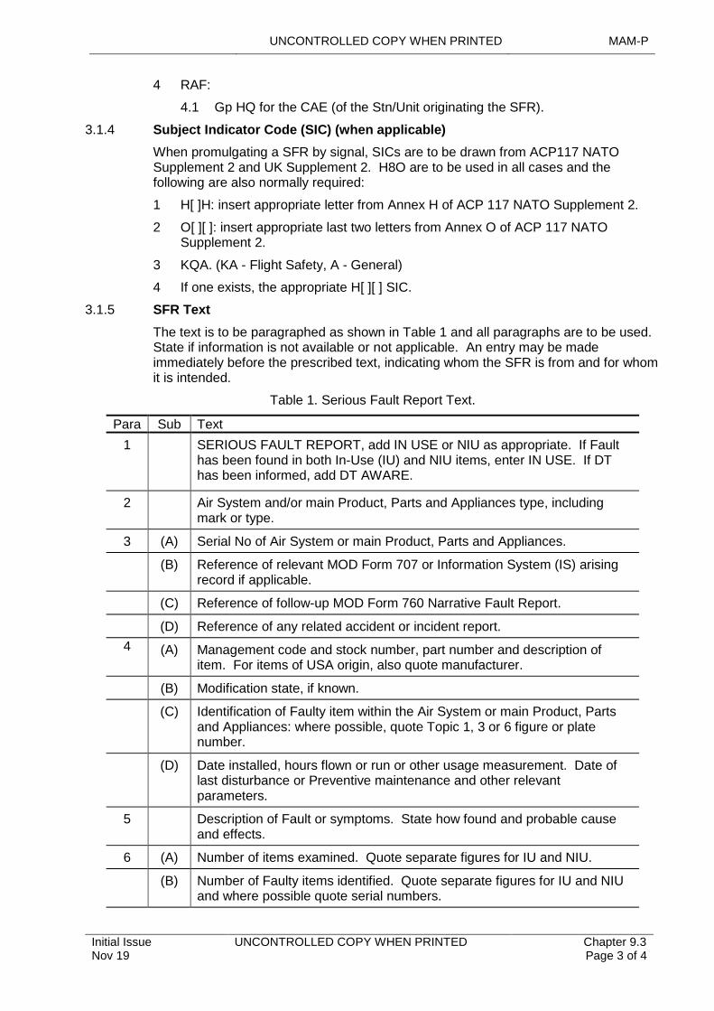
UNCONTROLLED COPY WHEN PRINTED MAM-P
Initial Issue Nov 19
UNCONTROLLED COPY WHEN PRINTED Chapter 9.3 Page 3 of 4
4 RAF:
4.1 Gp HQ for the CAE (of the Stn/Unit originating the SFR).
3.1.4 Subject Indicator Code (SIC) (when applicable)
When promulgating a SFR by signal, SICs are to be drawn from ACP117 NATO Supplement 2 and UK Supplement 2. H8O are to be used in all cases and the following are also normally required:
1 H[ ]H: insert appropriate letter from Annex H of ACP 117 NATO Supplement 2.
2 O[ ][ ]: insert appropriate last two letters from Annex O of ACP 117 NATO Supplement 2.
3 KQA. (KA - Flight Safety, A - General)
4 If one exists, the appropriate H[ ][ ] SIC.
3.1.5 SFR Text
The text is to be paragraphed as shown in Table 1 and all paragraphs are to be used. State if information is not available or not applicable. An entry may be made immediately before the prescribed text, indicating whom the SFR is from and for whom it is intended.
Table 1. Serious Fault Report Text.
Para Sub Text
1 SERIOUS FAULT REPORT, add IN USE or NIU as appropriate. If Fault has been found in both In-Use (IU) and NIU items, enter IN USE. If DT has been informed, add DT AWARE.
2 Air System and/or main Product, Parts and Appliances type, including mark or type.
3 (A) Serial No of Air System or main Product, Parts and Appliances.
(B) Reference of relevant MOD Form 707 or Information System (IS) arising record if applicable.
(C) Reference of follow-up MOD Form 760 Narrative Fault Report.
(D) Reference of any related accident or incident report.
4 (A) Management code and stock number, part number and description of item. For items of USA origin, also quote manufacturer.
(B) Modification state, if known.
(C) Identification of Faulty item within the Air System or main Product, Parts and Appliances: where possible, quote Topic 1, 3 or 6 figure or plate number.
(D) Date installed, hours flown or run or other usage measurement. Date of last disturbance or Preventive maintenance and other relevant parameters.
5 Description of Fault or symptoms. State how found and probable cause and effects.
6 (A) Number of items examined. Quote separate figures for IU and NIU.
(B) Number of Faulty items identified. Quote separate figures for IU and NIU and where possible quote serial numbers.
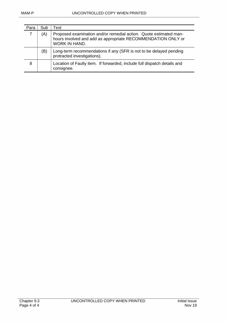
MAM-P UNCONTROLLED COPY WHEN PRINTED
Chapter 9.3 Page 4 of 4
UNCONTROLLED COPY WHEN PRINTED Initial Issue Nov 19
Para Sub Text
7 (A) Proposed examination and/or remedial action. Quote estimated man-hours involved and add as appropriate RECOMMENDATION ONLY or WORK IN HAND.
(B) Long-term recommendations if any (SFR is not to be delayed pending protracted investigations).
8 Location of Faulty item. If forwarded, include full dispatch details and consignee.
UNCONTROLLED COPY WHEN PRINTED MAM-P
Version 2 May 21
UNCONTROLLED COPY WHEN PRINTED Chapter 9.4 Page 1 of 2
.................................................................................................................................................................................................
..........................................................................................................................................................................................
....................................................................................................................................................................................................
......................................................................................................................................................
.........................................................................................................................................................................................................
Chapter 9.4
Digital Signatures
TABLE OF CONTENTS
Paragraph Page
1 General 11.1 Introduction 11.2 Terminology 11.3 Associated Publications and Instructions 11.4 Applicability 21.5 Exceptions 22 Implementation 22.1 Assumptions 22.2 Requirements 23 Procedure 2
1 General
1.1 Introduction
The digital signature’s purpose is identical to that of a handwritten signature or any other form of signature currently accepted or approved by legislation; therefore, the use of digital signatures is approved for certifying Continuing Airworthiness activity in lieu of handwritten signatures unless directed otherwise in local orders. To have the equivalent legal effect of a handwritten signature, digital signatures must possess those qualities and attributes that guarantee a handwritten signature’s authenticity, namely:
1 It is uniquely linked to the signatory.
2 It is capable of identifying the signatory.
3 It is created using electronic signature creation data that the signatory can, with a high level of confidence, use under their sole control.
4 It is linked to the data signed in such a way that any subsequent change in the data is detectable.
1.2 Terminology
The terms Electronic Signature and Digital Signature are often used interchangeably. However, ‘Electronic signature’ is the more generic term covering all soft copy signatures. ‘Digital Signature’ usually implies an Advanced or Qualified signature with encryption and independent authentication properties.
1.3 Associated Publications and Instructions
1 RA 1223 – Airworthiness Information Management
2 RA 1225 – Air Safety Documentation Audit Trail
3 RA 4813 – Maintenance Records
4 RA 4964 – Continuing Airworthiness Management Records
5 Regulation (EU) No 910/2014 Section 4 – Electronic Signatures
MAM-P UNCONTROLLED COPY WHEN PRINTED
Chapter 9.4 Page 2 of 2
UNCONTROLLED COPY WHEN PRINTED Version 2 May 21
6 JSP 441 – Information, Knowledge, Digital and Data in Defence
7 Manual of Airworthiness – Documentation (MAM-D) Part 1 Chap 2.1
1.4 Applicability
This chapter is applicable to all units responsible for operation, Maintenance or Continuing Airworthiness of Air Systems.
1.5 Exceptions
All hard copy MoD Form 700C maintenance documentation that is required to bear original signatures in accordance with MAM-D Part 1 or Mod Form 799 series of forms shall continue to utilize handwritten signatures.
2 Implementation
2.1 Assumptions
Adobe Acrobat Reader is a readily available, Industry standard tool widely used within the MAE, and recognised by most external stakeholders. Whilst Adobe Acrobat Reader does not provide full assurance through electronic signatures alone, overall document review, approval, certification, authority, and authenticity assurance is maintained and JSP 441 requirements satisfied when the requirements at Paragraph 2.2 are met.
2.2 Requirements
A database of electronic signature details for personnel shall be held in a SharePoint or similar system by each organisation, to allow validation of the electronic signature by all parties concerned.
This database should be controlled by a nominated person or team within the organisation who can validate digital signatures on documentation, of personnel from their database, at the request of external organisations.
To obtain and use a digital signature, personnel must have the following:
1 Access to Adobe Acrobat 2017 (or later).
2 Access to the signature database described in Paragraph 2.2.1.
3 A valid organization email address.
4 Access to the private signature file (.pfx).
3 Procedure
Personnel that are required to certify documentation with a digital signature or to validate digital signatures should follow the procedures promulgated in the respective single Service publications as follows:
1 RN: BRd 767 - Naval Aviation Orders.
2 Army: AP 7400 - Continuing Airworthiness Engineering (Army).
3 RAF: AP 100B-01 - Royal Air Force Engineering Policy.
UNCONTROLLED COPY WHEN PRINTED MAM-P
Initial Issue Nov 19
UNCONTROLLED COPY WHEN PRINTED Chapter 10.1 Page 1 of 4
..............................................................................................................................................................................................
......................................................................................................................................................................
.............................................................................................................................................................................
.................................................................................................................................................................
...............................................................................................
..........................................................................................................................................................
............................................................................................................................
.......................................................................................................................................................
.......................................................................................................
Chapter 10.1
Management and Amendment of Technical Information
TABLE OF CONTENTS
Paragraph Page
1 General 11.1 Introduction 11.2 Associated Publications and Instructions 11.3 Applicability 22 Maintaining and Amending Technical Information (TI) 22.1 General 22.2 Criteria for Raising Amendment Proposals 22.3 Considerations when Submitting TI Amendment Requests 22.4 Urgent Amendment Proposals 23 Promulgation of Amendments to TI 33.1 General 33.2 Urgent Amendments 34 Responsibilities 44.1 All Personnel 44.2 Subject Matter Expert (SME) 44.3 TI Sponsor 45 Authorizations 4
1 General
1.1 Introduction
Technical Information (TI) is the descriptive or procedural information necessary to operate, maintain, repair, support and dispose of equipment throughout its life. In order to maintain accurate and relevant TI, personnel need to be aware of the approved processes in place for the management and amendment of TI.
This chapter aims to provide guidance on the fundamental requirements of management and amendment of TI within the Defence Air Environment (DAE).
Note:
The information contained within this chapter is equally applicable to the development of new TI.
1.2 Associated Publications and Instructions
1 RA 1003 – Delegation of Airworthiness Authority and Notification of Air Safety Responsibility
2 RA 1310 – Air System Document Set
3 RA 4810 – Technical Information (MRP 145.A.45)
4 RA 4948 – Documentation - MRP Part M Sub Part G
5 RA 5401 – Provision of Technical Information
6 JSP 440 – Defence Manual of Security, Resilience and Business Continuity
7 Topic 2(N/A/R)1 - General Orders and Special Instructions
MAM-P UNCONTROLLED COPY WHEN PRINTED
Chapter 10.1 Page 2 of 4
UNCONTROLLED COPY WHEN PRINTED Initial Issue Nov 19
1.3 Applicability
This chapter is applicable to all TI used in the DAE, regardless of its format.
Note:
Additional guidance regarding amendment proposals to electronic Information Systems (IS) may be found in the relevant support policy document.
2 Maintaining and Amending Technical Information (TI)
2.1 General
All personnel working in the DAE are responsible for proposing amendments to TI whenever an unsatisfactory feature, error or omission is identified. Amendment proposals are to be considered by the TI sponsor, Subject Matter Expert (SME) and Publication Organization (PO) as detailed. All amendment proposals and subsequent actions are to be recorded using the approved reporting method, eg MOD Form 765, as endorsed by the associated Type Airworthiness Authority (TAA), TI sponsor and/or Publication Organization (PO).
2.2 Criteria for Raising Amendment Proposals
An amendment proposal is to be submitted whenever:
1 Factual errors, conflicts, omissions or obscurities are found in TI.
2 When it is considered that there is a better way of undertaking a task than that described.
3 When the TI content or design is found to present problems in use.
2.3 Considerations when Submitting TI Amendment Requests
Individual amendment processes will have their own associated instructions or orders that are to be followed. However, in all cases, individuals are to apply the following when considering the submission of a TI amendment request:
1 Only use the approved TI amendment process, as endorsed by the associated TAA, TI sponsor and/or PO.
2 The amendment request is to be reviewed and endorsed by an SME, prior to forwarding to the appropriate TI sponsor.
3 If the amendment request is considered to be urgent (eg time taken for amendment action could increase a Risk to Life (RtL) or damage to associated Air Systems or equipment), an alternative, more expedient amendment proposal process may be utilized, in consultation with the SME and TI sponsor (see Paragraph 2.4).
4 Irrespective of a TI shortfall or error, deviation from a published TI is not to be undertaken, unless approved by an appropriately authorized individual. Further guidance is provided in Chapter 4.8 – Deferment and Concession of Maintenance.
2.4 Urgent Amendment Proposals
The means of submitting an urgent amendment will be determined by the relevant TAA or TI sponsor. As a suggested minimum, the information required to affect an urgent amendment is:
1 Contact details for the individual submitting the request.
2 Reference number, title and amendment state of associated TI.
UNCONTROLLED COPY WHEN PRINTED MAM-P
Initial Issue Nov 19
UNCONTROLLED COPY WHEN PRINTED Chapter 10.1 Page 3 of 4
3 Details of where the error/issue has been identified (eg Chapter XX, Para X, Sub-Para XX).
4 Details of the unsatisfactory feature.
5 Proposed amendment.
3 Promulgation of Amendments to TI
3.1 General
The time taken for amendments to be incorporated will vary and is dependent upon:
1 Perceived priority (Airworthiness risk, RtL etc).
2 Contractual agreements.
3 Publication cycles.
4 Requirement for further TI development, in addition to the original request.
Note:
Where appropriate, process owners may implement timeframes for incorporation of amendments to their TI. Personnel are to note that timeframes will be specific to the affected TI and promulgated by the TAA, TI sponsor or PO, as appropriate.
3.2 Urgent Amendments
3.2.1 General
If the TI sponsor considers the amendment requirement to be urgent, they may initiate an expedited amendment process, such as the Advance Information Leaflet (AIL) or Service Amendment Leaflet (SAL).
3.2.2 AIL
An AIL is used to promulgate advance information of a change to the associated TI and can be used as an authority to carry out local amendments to the Publication, such as a handwritten amendment.
The incorporation of an AIL is to be recorded on the "Record of AIL Incorporation" sheet contained within the preliminary pages of the TI. Although an AIL is not a formal amendment, its content is binding and is to be acted upon in place of the information that it replaces. An AIL is superseded by the issue of a formal amendment.
3.2.3 SAL
A SAL is used to promulgate new information relating to a Service Modification (SM), which has not been cover-modified by the Design Organisation (DO) and cannot result in any changes to the associated TI.
The incorporation of a SAL is to be recorded on the "Record of SAL Incorporation" sheet contained within the preliminary pages of the TI. Although a SAL is not a formal amendment, its content is binding and is to be acted upon when working with the equipment to which it refers:
Notes:
1 The SAL replaced the Aircraft Branch Temporary Amendment Leaflet (ABTAL), RAFTAL and RNTAL for all future SMs. Extant ABTAL, RAFTAL and RNTAL need not be replaced by a SAL until they are reviewed or amended.
2 A SAL may be re-issued because of an amendment proposal.
MAM-P UNCONTROLLED COPY WHEN PRINTED
Chapter 10.1 Page 4 of 4
UNCONTROLLED COPY WHEN PRINTED Initial Issue Nov 19
3 SALs may subsequently be replaced by cover modification(s), or remain extant for the life of the SM.
4 The SAL is issued as an insertion to the affected TI and is not to require permanent alteration or defacement of the TI by adhesion, ink annotation or other means.
4 Responsibilities
4.1 All Personnel
All personnel have a responsibility to:
1 Highlight any discrepancies in TI and follow the approved amendment method, if required.
2 Consult with a SME prior to submitting an amendment request to the TI sponsor.
3 Provide as much information as possible, in support of an amendment request.
4 Provide recommended changes to the affected TI.
5 Consider if the recommended changes will have implications on other TI, and submit further amendment requests, where appropriate.
4.2 Subject Matter Expert (SME)
SMEs have a responsibility to:
1 Review TI amendment requests and determine if the proposed changes are valid.
2 Endorse, amend or reject TI amendment proposals, as appropriate.
3 Consult with the TI sponsor and, if a proposed amendment is considered to be urgent, initiate an expedited amendment process.
4 Liaise with the TI sponsor, as required, during the amendment process.
5 Provide feedback to the originator. If an amendment request has been rejected, a detailed narrative is to be provided, explaining the reasons for rejection.
4.3 TI Sponsor
TI sponsors have a responsibility to provide feedback to the originator and the SME. If an amendment request has been rejected, a detailed narrative is to be provided, explaining the reasons for rejection.
5 Authorizations
Although there are no MAM-P Authorizations specifically related to the management and amendment of TI, amendments to the scope or content of the Air System Document Set shall only be approved by:
1 Individuals holding Letters of Authority or an appropriately approved DO under privilege, in accordance with RA 1310 – Air System Document Set.
2 Individuals with delegated Airworthiness authority, issued with a Letter of Airworthiness Authority, in accordance with RA 1003 – Delegation of Airworthiness Authority and Notification of Air Safety Responsibility.
UNCONTROLLED COPY WHEN PRINTED MAM-P
Issue 1.1 Feb 20
UNCONTROLLED COPY WHEN PRINTED Chapter 11.1 Page 1 of 9
...................................................
...............................................................................................................
.............................................................................................................................................................
.................................................................................................................................
.......................................................................................................................................
....................................................................................................................................................................................
................................................................................................................................................................................
.......................................................................................................................................................
.....................................................................................
...................................................................................................................................................................................................................................................................................
.........................................................................................................................
.........................................................................................................................................................................................................
Chapter 11.1
Defence Air Environment Quality Policy
TABLE OF CONTENTS
Paragraph Page
1 General 11.1 Introduction 11.2 Associated Publications and Instructions 12 Quality Management System 22.1 Quality Policy 22.2 Quality Roles 23 Quality Assurance 23.1 Types of Assurance 23.2 Types of Audit 34 Quality Audit Management Process 34.1 Audit Programmes 34.2 Audit Preparation 44.3 Audit Constitution 44.4 Audit Reporting 44.5 Internal Quality Audit/Self Audit 44.6 Organizational Responsibilities 54.7 Quality Assurance Documentation 55 Quality Occurrence Reporting 55.1 Alternative Reporting Methods 55.2 Conditions of Use 55.3 Quality Occurrence Reporting Process 65.4 Actions on receipt of QOR/QOIR forms 9
Figure 1. Quality Occurrence Reporting Process - Stn/Unit/Ship 7Figure 2. Quality Occurrence Reporting Process - Tasking Organisation 8
1 General
1.1 Introduction
This chapter outlines core Quality Management System (QMS) requirements, including key roles and assurance activity, and signposts to single-Service Quality Policy, which provides the Acceptable Means of Compliance (AMC) and Guidance Material (GM) to effectively manage Quality in the Defence Air Environment (DAE).
1.2 Associated Publications and Instructions
1 RA 4806 – Personnel Requirements (MRP 145.A.30)
2 RA 4814 – Occurrence Reporting (MRP 145.A.60)
3 RA 4815 – Maintenance Procedures and Safety and Quality Policy (MRP 145.A.65)
4 RA 4951 – Quality System - MRP Part M Sub Part G
5 JSP 940 – MOD Policy for Quality
6 Manual of Airworthiness Maintenance – Documentation (MAM-D)
MAM-P UNCONTROLLED COPY WHEN PRINTED
Chapter 11.1 Page 2 of 9
UNCONTROLLED COPY WHEN PRINTED Issue 1.1 Feb 20
7 Defence Logistics Framework (DLF)
8 AP100C-10 – RAF Quality Management System Policy
9 AP7400 – Continuing Airworthiness Engineering (Army)
10 BRd 763 – Naval Aviation Quality Manual
11 BRd 767 – Naval Aviation Order 4815 – Quality Assurance Policy
12 JHC CI EngPol 4080 – JHC Air Engineering Assurance Team Audit Scope
2 Quality Management System
2.1 Quality Policy
Quality policy outlines the organizations overall policy, vision and mission and provides a framework for the setting of Quality objectives. The QMS consists of activities by which the organization identifies its objectives and determines the processes and resources required to achieve desired results. An organization's Quality policy and its QMS is held within the organization's Quality Manual.
2.2 Quality Roles
There are 3 main roles within the QMS organization:
1 Quality System Owner (QSO). The QSO provides overall leadership and direction on the establishment, implementation and maintenance of the QMS. They ensure that the QMS is efficient and effective to deliver support to the needs of the organization and its outputs.
2 Quality System Manager (QSM). The QSM is responsible to the QSO for the implementation and management of the QMS within their Area of Responsibility (AoR). The QSM ensures that QMS processes and Assurance activity adequately supports the needs of the organization.
3 Quality System Coordinator (QSC). The QSC is responsible to the QSO for the overall maintenance and coordination of the QMS. The QSC is the focal point for the co-ordination of internal and external Assurance activity and the efficient progression of Quality reports.
Note:
Each of these roles and their requirements are further refined in single-Service Quality publications.
3 Quality Assurance
3.1 Types of Assurance
Assurance is adequate confidence and evidence, through due process, that Safety requirements have been met. There are 3 types of Assurance:
1 1st Party Assurance (1PA). Assurance conducted wholly within the same organization, for example: within the same level Aviation Duty Holder (ADH) or ADH-facing organization (at the Delivery Duty Holder (DDH), Operating Duty Holder (ODH) or Senior Duty Holder (SDH) level), Military Continuing Airworthiness Management Organization (Mil CAMO), Delivery Team (DT) or delivery ‘arm’ of a company.
2 2nd Party Assurance (2PA). Assurance conducted by an organization that is separated from the activities being assured but where a vested ‘customer-supplier’ interest remains (eg superior organizations that do not belong to the same level ADH (ODH assuring DDH, SDH assuring ODH or DDH), commander, Mil CAMO, DT, or delivery arm of the company conducting the activity).
UNCONTROLLED COPY WHEN PRINTED MAM-P
Issue 1.1 Feb 20
UNCONTROLLED COPY WHEN PRINTED Chapter 11.1 Page 3 of 9
3 3rd Party Assurance (3PA). Assurance conducted by an organization that is separated from, and maintains no vested interest in, the auditee organisation (so far as practicable).
3.2 Types of Audit
Auditing is an essential part of any QMS. It is used to provide feedback and Assurance to management at all levels on the effectiveness of policies, plans, processes and documented procedures.
The following types of Audit are to be used:
1 External Quality Audit (EQA). A 2PA activity which is conducted by an external organization, such as the Command QA authority, to provide Assurance to superior organizations on the effectiveness of an organization's QMS. EQA is a system-based Audit with an element of compliance auditing, as necessary.
2 Internal Quality Audit (IQA). A 1PA activity which is conducted by an organization on itself to ensure compliance with the QMS and to assess the effectiveness of that system. It may form the basis for an organization’s self-declaration of conformity.
3 Self-Audit (SA). A 1PA activity which supports an organization in its delivery of IQA at sub-unit level to determine compliance with the QMS and demonstrate the effectiveness of that system. SA provides documentary evidence that will be reviewed during EQA or IQA activity.
4 Task/Product/Independent Audit. These types of Audit may be conducted on specific tasks/processes/activities that are identified as a particular concern but fall outside the programmed Audit schedule.
5 Government Quality Assurance Representatives (GQAR) Surveillance Audits. These are tasked by the DT or CAMO on perceived contractual risks and are carried out within contracted organizations.
Note:
Audit requirements are further refined in single-Service Quality publications.
4 Quality Audit Management Process
4.1 Audit Programmes
Audit programmes are to be generated by Commands for EQA and by the respective Station(Stn)/Ship/Unit for IQA. Where possible, Commands are to plan and co-ordinate their respective EQA activity to ensure that all elements of the management system are reviewed, without omission, and avoid unnecessary overlap or duplication with other Assurance agencies. Audits are to be carried out as follows:
1 EQA – at least every 2 years.
2 IQA – at least every 2 years and as mandated by single-Service policy and the relevant QSM.
3 SA – in accordance with single-Service policy and Quality Manual direction.
4 GQAR – To be generated by the GQAR organization and related to tasking from the DT or CAMO.
Note:
More frequent Audits may be programmed at the discretion of Stn/Ship/Unit, Command, Mil CAMO or DT, particularly where activities are considered to present a
MAM-P UNCONTROLLED COPY WHEN PRINTED
Chapter 11.1 Page 4 of 9
UNCONTROLLED COPY WHEN PRINTED Issue 1.1 Feb 20
higher risk of nonconformity, or where nonconformity could present an Airworthiness concern.
4.2 Audit Preparation
The Audit Team Leader (ATL) is responsible for planning and supervising the Audit activities. Audit preparation is to include:
1 Selecting Audit team member(s) and ensuring personnel are competent.
2 Establishing contact with the organization to arrange the Audit dates, scope of Audit and to confirm administrative arrangements.
3 Issuing written notice of Audit and its requirements.
4 Collating and researching Audit criteria, including policies, procedures, previous Audit reports, Quality Occurrence Reports (QORs), noting any trends/areas for review.
5 Generating an Audit plan. The plan is to be formulated to minimize disruption to the normal working patterns.
4.3 Audit Constitution
The Audit will include the following:
1 An opening meeting to brief the organization on the scope and objectives of the Audit. The meeting introduces the Audit team members to the organization and establishes communication links that are essential to the Audit process.
2 The generation of Audit Records and Reports so that Quality issues can be documented, addressed and resolved.
3 Regular briefings to the organization on the progress of the Audit to discuss findings and areas of concern.
4 Audit team briefings to ensure that the Audit is proceeding to plan and allow the ATL to discuss and direct findings or areas of concern.
4.4 Audit Reporting
Upon completion of the Audit, the ATL is to hold a closing meeting to present the overall Audit findings to the organization. The scope and objectives of the Audit are to be repeated for reference, together with confirmation of any areas or processes not audited as originally planned. All Audit findings are to be discussed.
4.5 Internal Quality Audit/Self Audit
The Audit report (MOD Form 792) is to be produced within 10 working days, summarizing the findings and including details of any QORs, non-compliances, observations or good practices identified. In the event where it is, or becomes, unlikely that the 10-day reporting time-scale can be achieved; authority to delay the report is to be sought from the appropriate QSM/QSO. This decision is to be recorded with appropriate justification and the ADH Chief Air Engineer (CAE) informed, if required.
For EQA, the Audit report timescales will be determined by the respective Command ADH CAE, based upon their Risk-based approach which will be outlined in Command/single-Service policy. The Audit report is to be distributed as follows:
1 EQA: Distribution iaw Command policy.
2 IQA: Distribution determined by the QSC.
3 GQAR: Distribution determined by the GQAR organization and tasking DT or CAMO.
UNCONTROLLED COPY WHEN PRINTED MAM-P
Issue 1.1 Feb 20
UNCONTROLLED COPY WHEN PRINTED Chapter 11.1 Page 5 of 9
4 Task/Product/Independent Audit: Distribution determined by tasking authority.
4.6 Organizational Responsibilities
The organization's management are responsible for ensuring that all QORs and findings are addressed, corrective action undertaken, where necessary, in agreed timescales. To verify that all corrective actions are satisfactorily completed, the ATL is to conduct an Audit follow-up visit.
4.7 Quality Assurance Documentation
All Quality Assurance activity is to be recorded using the MOD Form 792 and MOD Form 791 series.
1 MOD Form 792 Series - Quality Audit Record and Summary Report (found within the MAM-D Part 2. Instructions for Use on the MOD Form 799(QA).
2 MOD Form 791 Series - Quality Occurrence Report (QOR). (found within the MAM-D Part 2. Instructions for Use on the MOD Form 799(QOR).
3 MOD Form F791A Quality Occurrence Investigation Report (QOIR) - (found within the MAM-D Part 2. Instructions for Use on the MOD Form 799(QOR).
Note:
Audit management processes are further refined in single-Service Quality Publications.
5 Quality Occurrence Reporting
5.1 Alternative Reporting Methods
The QOR system must be used to report perceived quality occurrences that cannot be resolved using the following methods:
1 The fault reporting system detailed at MAM-P Chapter 9.1.
2 Reporting unsatisfactory features of technical information as detailed at MAM-P Chapter 10.1 and the MAM-D.
3 Materiel and supply chain discrepancy reporting (including packaging incorrect or inadequate) process detailed in the DLF.
Note:
Where one of the above reports is raised, it may still be appropriate to raise a QOR if the reported fault highlights a deficiency in the respective Quality Management System (QMS). In this instance, a copy of the original report raised should be attached to the QOR.
5.2 Conditions of Use
The QOR system is to be used to report perceived Quality occurrences in the following circumstances:
1 To highlight a deficiency within the QMS and, if deemed appropriate, to highlight potential improvement or good practice.
2 As a result of an Audit where further investigation is required to determine the root cause and initiate the appropriate corrective action.
3 When aviation materiel is received in an unsatisfactory condition resulting from:
3.1 Deviations from the transfer standards detailed by the tasking organization, (eg DT or delegated organization).
3.2 Incomplete inventories.
MAM-P UNCONTROLLED COPY WHEN PRINTED
Chapter 11.1 Page 6 of 9
UNCONTROLLED COPY WHEN PRINTED Issue 1.1 Feb 20
3.3 Loose articles.
3.4 Incomplete or inaccurate documentation.
3.5 Faults not covered by the transfer standards, but which should have been rectified before transfer.
3.6 Repairs or Modifications by an on-site working party when the condition of an Air System is unsatisfactory in relation to the particular work carried out.
4 Where there is a perceived Quality shortfall in the provision of a service that may be attributable to the supplier’s/provider’s arrangements for Quality.
Note:
Aviation materiel includes Aircraft, aero-engines, modules, components, Ground Support Equipment, Airfield Support Equipment, documentation and associated equipment.
5.3 Quality Occurrence Reporting Process
On occasions when a QOR is raised, the process detailed at Figure 1 and Figure 2 should be followed:
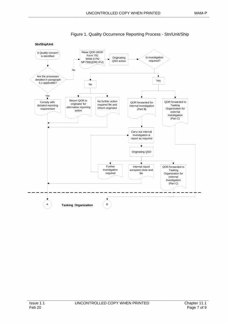
UNCONTROLLED COPY WHEN PRINTED MAM-P
Issue 1.1 Feb 20
UNCONTROLLED COPY WHEN PRINTED Chapter 11.1 Page 7 of 9
Figure 1. Quality Occurrence Reporting Process - Stn/Unit/Ship
A Quality concern is identified
Are the processes detailed in paragraph
5.1 applicable?
Comply with dictated reporting
requirement
Raise QOR (MOD Form 791
MAM-D Pt2 MF799(QOR) IFU)
Originating QSO action
Is investigation required?
Yes
Return QOR to originator for
alternative reporting action
No further action required file and inform originator
QOR forwarded for internal investigation
(Part B)
QOR forwarded to Tasking
Organization for external
investigation(Part C)
No
Yes
Carry out internal investigation &
report as required
Originating QSO
Further investigation
required
Internal report accepted close and
file
QOR forwarded to Tasking
Organization for external
investigation(Part C)
Stn/Ship/Unit
No
A BTasking Organization
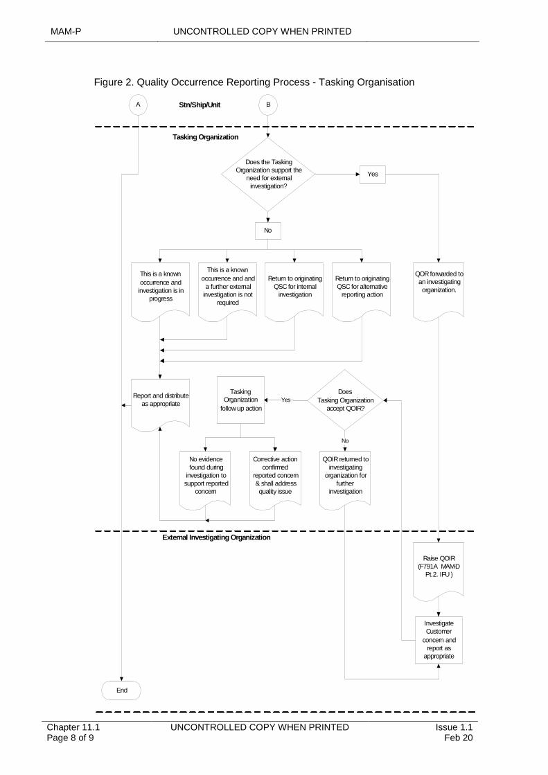
MAM-P UNCONTROLLED COPY WHEN PRINTED
UNCONTROLLED COPY WHEN PRINTED Issue 1.1 Feb 20
Chapter 11.1 Page 8 of 9
Figure 2. Quality Occurrence Reporting Process - Tasking Organisation
Does the Tasking Organization support the
need for external investigation?
No
This is a known
occurrence and investigation is in
progress
This is a known
occurrence and and a further external
investigation is not required
Return to originating QSC for internal
investigation
Return to originating QSC for alternative
reporting action
Yes
Stn/Ship/Unit
External Investigating Organization
A B
Tasking Organization
End
QOR forwarded to an investigating organization.
Report and distribute as appropriate
Raise QOIR (F791A MAM-D
Pt.2. IFU )
Investigate Customer
concern and report as
appropriate
No evidence found during
investigation to support reported
concern
Tasking Organization
follow up action
Yes
Corrective action confirmed
reported concern & shall address quality issue
Does
Tasking Organization accept QOIR?
No
QOIR returned to investigating
organization for further
investigation
UNCONTROLLED COPY WHEN PRINTED MAM-P
Issue 1.1 Feb 20
UNCONTROLLED COPY WHEN PRINTED Chapter 11.1 Page 9 of 9
5.4 Actions on receipt of QOR/QOIR forms
5.4.1 Receipt of a QOR from the originator or tasking organization
On receipt of a QOR, the QSO or nominated representative must determine subsequent action, as appropriate; and reply to the originator within 7 working days.
5.4.2 Receipt of a QOR by an investigating organization
The investigating organization must complete the required investigation within 28 working days of receiving the QOR and provide a report on MOD F791A (QOIR) to the QSC or nominated representative of the tasking organization.
Where the return of aviation materiel is required to aid the QOR investigation, the tasking organization must issue the call-forward/return instruction. The 28-day investigation and reporting period will commence from the date of materiel receipt from the supply chain.
Notes:
1 There is no dedicated QOR labelling for aviation materiel. However, to assist in identification, tracking and retrieval of returned aviation materiel from the supply chain, the respective MOD Form 731 must include the following entry in the ‘Remarks’ box or the ‘Reasons for Removal’ box:
‘QOR [Reference Number]: Return to [Name of the investigating organization]’
2 In any event where it is, or becomes, unlikely that the 28-day QOR investigation/reporting time-scale can be achieved; authority to delay the investigation must be sought from the tasking organization.
On occasions where the investigating organization is unable to confirm a reported concern, it is particularly important that the investigating organization provide as much information as possible, including that of any non-related deficiencies or faults that may have been discovered during the investigation. Such feedback gives the customer an improved understanding of the equipment and systems, and it will also serve to build customer confidence in the supplier’s arrangements for achieving quality.
5.4.3 Receipt of a QOIR by the tasking organization
On receipt of the QOIR, the QSC or nominated representative must determine what action is required and complete part B of the QOIR within 7 working days.