Managing coordination and cooperation in distributed software processes: the GENESIS environment
25
SOFTWARE PROCESS IMPROVEMENT AND PRACTICE Softw. Process Improve. Pract. 2004; 9: 239–263 Published online in Wiley InterScience (www.interscience.wiley.com). DOI: 10.1002/spip.206 Managing Coordination and Cooperation in Distributed Software Processes: the GENESIS Environment Research Section Lerina Aversano, 1 * ,† Andrea De Lucia, 2 Matteo Gaeta, 3 Pierluigi Ritrovato, 3 Silvio Stefanucci 1 and Maria Luisa Villani 1 1 RCOST – Research Center On Software Technology, Department of Engineering, University of Sannio, Via Traiano, Pal.ex-Poste – 82100, Benevento, Italy 2 Dipartimento di Matematica e Informatica University of Salerno, Via Ponte Don Melillo, I-84084 Fisciano(SA), Italy 3 CRMPA – Centro Ricerca in Matematica Pura ed Applicata c/o DIIMA, University of Salerno, Via Ponte Don Melillo, I-84084 Fisciano (SA), Italy We present the GENESIS platform (GEneralised eNvironment for procEsS management in cooperatIve Software engineering), the outcome of a research project aiming at designing and developing a noninvasive and open-source system to support software engineering processes in a highly distributed environment. The system supports the cooperation and coordination in software processes as its process modeling language enables the decomposition of complex processes into subprocesses that can be distributed and executed at different organizational sites. In GENESIS, workflow management technologies have been integrated with artifact management and communication services to meet the necessary requirements of managing the cooperation among distributed teams. Its strengths are a powerful activity management, covering all the main aspects of the life cycle of an activity; an efficient and flexible project monitoring, collecting productivity and quality metrics to show on-demand snapshots of the whole process and of its parts at different levels of detail, and a careful consideration of the process evolution questions, allowing to adequately manage the most common exceptions happening during process execution in a simple and flexible way. Copyright 2004 John Wiley & Sons, Ltd. KEY WORDS: workflow management; process management; process modeling; software process improvement; artifact management ∗ Correspondence to: Lerina Aversano, RCOST, Department of Engineering, University of Sannio, Via Traiano, Pal.ex-Poste – 82100, Benevento, Italy † E-mail: [email protected] Copyright 2004 John Wiley & Sons, Ltd.
-
Upload
independent -
Category
Documents
-
view
3 -
download
0
Transcript of Managing coordination and cooperation in distributed software processes: the GENESIS environment
SOFTWARE PROCESS IMPROVEMENT AND PRACTICESoftw. Process Improve. Pract. 2004; 9: 239–263Published online in Wiley InterScience (www.interscience.wiley.com). DOI: 10.1002/spip.206
Managing Coordinationand Cooperation inDistributed SoftwareProcesses: the GENESISEnvironment Research Section
Lerina Aversano,1*,† Andrea De Lucia,2 Matteo Gaeta,3
Pierluigi Ritrovato,3 Silvio Stefanucci1 and Maria LuisaVillani1
1 RCOST – Research Center On Software Technology, Department ofEngineering, University of Sannio, Via Traiano, Pal.ex-Poste – 82100,Benevento, Italy2 Dipartimento di Matematica e Informatica University of Salerno, ViaPonte Don Melillo, I-84084 Fisciano(SA), Italy3 CRMPA – Centro Ricerca in Matematica Pura ed Applicata c/o DIIMA,University of Salerno, Via Ponte Don Melillo, I-84084 Fisciano (SA), Italy
We present the GENESIS platform (GEneralised eNvironment for procEsS management incooperatIve Software engineering), the outcome of a research project aiming at designing anddeveloping a noninvasive and open-source system to support software engineering processesin a highly distributed environment. The system supports the cooperation and coordinationin software processes as its process modeling language enables the decomposition of complexprocesses into subprocesses that can be distributed and executed at different organizationalsites. In GENESIS, workflow management technologies have been integrated with artifactmanagement and communication services to meet the necessary requirements of managingthe cooperation among distributed teams. Its strengths are a powerful activity management,covering all the main aspects of the life cycle of an activity; an efficient and flexible projectmonitoring, collecting productivity and quality metrics to show on-demand snapshots of thewhole process and of its parts at different levels of detail, and a careful consideration of theprocess evolution questions, allowing to adequately manage the most common exceptionshappening during process execution in a simple and flexible way. Copyright 2004 John Wiley& Sons, Ltd.
KEY WORDS: workflow management; process management; process modeling; software process improvement; artifact management
∗ Correspondence to: Lerina Aversano, RCOST, Department of Engineering, University of Sannio, Via Traiano, Pal.ex-Poste – 82100,Benevento, Italy†E-mail: [email protected]
Copyright 2004 John Wiley & Sons, Ltd.
Research Section L. Aversano et al.
1. INTRODUCTION
The success of large software development andmaintenance projects heavily depends on the atten-tion project managers pay to the coordination,communication, and collaboration of the humanresources involved in the project (Bandinelli et al.1996). This requirement is becoming extremelyimportant because more and more software orga-nizations are moving from a traditional centralizedsoftware factory model to distributed virtual orga-nization models, thanks to the new opportunitiesoffered by Internet technologies (Maurer et al. 2000).
CASE tools typically provide a sequence of phasesto be followed and some mechanism for refining aphase into more detailed phases. However, CASEtools only provide a ‘static view’ of the softwaredevelopment process that does not consider thepractice of the developers, and consequently areinappropriate for the management and executionof the process (Chan and Leung 1997). WorkflowManagement Systems (WfMSs) (Georgakopouloset al. 1995, Workflow Management Coalition 1994)and Process-centered Software Engineering Envi-ronments (PSEEs) (Ambriola et al. 1998, Grefen et al.1999) are effective technologies for improving themanagement of software processes, particularlyby improving the integration, coordination, andcommunication in a cooperative networking envi-ronment. The main difference between these twotypes of environments is the fact that WfMSs havebeen introduced for the modeling and automation ofbusiness and industrial processes, while PSEEs havebeen introduced for the management of softwareprocesses. Advantages of WfMSs are a reducedcomplexity and intrusiveness and a wider domainof applicability (Fuggetta 2000). However, despitethe differences, PSEEs and WfMSs have many com-monalities and in this article we will not distinguishbetween the two classes of systems; other authorsrefer to both with the term Process Support Systems(PSSs) (Casati and Cugola 2001).
Despite the advances made in the field, atthe present workflow management technologieshave mainly been applied to model, improve,and automate business and industrial engineeringprocesses (Aversano et al. 2002a, Huang et al. 2000),while they have only marginally been adopted inthe software industry (Aversano et al. 2002b). Thishas been mainly imputed to different facts:
• software processes are human intensive and aresubject to deviations more than the more sta-ble traditional engineering and administrativeprocesses (Casati and Cugola 2001, Cugola et al.1996);
• software engineers and project managers hadthe perception that the adoption of workflowmanagement technologies in the centralizedsoftware factory model adopted in the past couldonly produce overheads in the management ofthe process without providing real advantages;
• PSEEs and WfMSs generally provide limitedsupport to the management of the artifactsproduced within a software process. Althoughsome PSEEs explicitly consider software arti-facts as process elements (Cugola 1998), they arescarcely integrated with configuration manage-ment and versioning tools that are considered ofhigher importance by industrial software engi-neers and project managers.
However, despite the skepticism of the past, theneed of automatic support to the management ofsoftware processes is being recognized also in thesoftware industry (Aversano et al. 2002b), becausein modern virtual organization models peoplemake substantially more use of network basedcommunication than physical presence to interactand cooperate within a project. Indeed, modernWfMSs are web-based (Ames et al. 1997, Maureret al. 2000) and provide facilities to coordinatedistributed teams. However, although using theweb as an infrastructure makes WfMSs moreappealing in industry, the scalability and the realuse of these systems depend on the ability to exploitdistributed object technologies and middleware toenable the interoperability of workflow enginesdistributed across multiple organizational sites thatoperate both independently and as part of a singleWfMS (Cugola et al. 2001).
In this article we present the GENESIS platform(GEneralised eNvironment for procEsS manage-ment in cooperatIve Software engineering), theoutcome of a research project aiming at design-ing and developing a noninvasive and open-sourcesystem to support software engineering processesin a highly distributed environment. The systemsupports the cooperation and coordination in soft-ware processes as its process modeling languageenables the decomposition of complex processes
Copyright 2004 John Wiley & Sons, Ltd. Softw. Process Improve. Pract., 2004; 9: 239–263
240
Research Section GENESIS Environment
into subprocesses that can be distributed and exe-cuted at different organizational sites. In GENE-SIS, workflow management technologies have beenintegrated with artifact management and communi-cation services to meet the necessary requirementsof managing the cooperation among distributedteams. Its strengths are a powerful activity manage-ment, covering all the main aspects of the life cycleof an activity, an efficient and flexible project mon-itoring, collecting productivity and quality metricsto show on demand snapshots of the whole processand of its parts at different detail levels; and a care-ful consideration of the process evolution questions,allowing to adequately manage the most commonexceptions and deviations happening during pro-cess execution in a simple and flexible way.
The article is organized as follows. Section 2 givesan overview of the GENESIS distributed platformand its subsystems. A description of the main fea-tures of the process modeling language is presentedin Section 3, while project management is illustratedin Section 4. Section 5 discusses the experimenta-tion and evaluation of GENESIS in research andindustrial environments, while Section 6 comparesGENESIS to related works. Finally, Section 7 con-cludes the article.
2. GENESIS OVERVIEW
GENESIS is a distributed environment support-ing cooperative software engineering (Ritrovatoand Gaeta 2002). Cooperation and collaboration insoftware engineering comprises all software engi-neering methods and tools that support teamworkflexibly and effectively. An environment that sup-ports cooperative software engineering must fulfillat least the following features (Ben-Shaul and Kaiser1995):
(a) policy-driven cooperation to manage theaccess to artifacts (policy of locking, sharingof source code and documents, etc.)
(b) informal cooperation to manage both struc-tured and unstructured information (annota-tion for every artifact, automatic notification,etc.).
Both these issues are addressed in the GENE-SIS environment. In addition, GENESIS coversthe communication and coordination requirementswithin a software process that are necessary for
the planning, execution and coordination of alltasks-related, spatially and temporally distributedactivities. GENESIS enables virtual organizationsmodels by allowing cooperation, distribution andcontrol of a software engineering project performedat different sites. The scenario is that of a projectcoordinator site taking the responsibility for thewhole project, and a number of other sites man-aging, or contributing to, specific project work-packages. In general, one or more processes maybe defined for each project or work-package ata site, and distribution of activities of these pro-cesses among other sites is possible. The GENESISplatform has been implemented according to thefollowing guidelines that also match with the indi-cations presented by Fuggetta (Fuggetta 2000) forfuture process-modeling languages:
• full autonomy of sites, i.e. freedom is given toeach site to choose tools and software processmodels for the project;
• powerful Process Definition Language (PDL)that allows for a hierarchical decomposition ofprocesses in terms of subprocesses, and theirexecution at different sites;
• intersite coordination based on distributed eventengines.
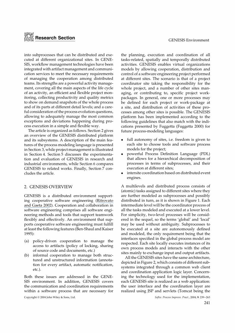
A multilevels and distributed process consists of(atomic) tasks assigned to different sites where theyare further modeled as subprocesses and possiblydistributed in turn, as it is shown in Figure 1. Eachintermediate level will be the coordinator process ofall the tasks modeled and executed at a lower level.For simplicity, two-level processes will be consid-ered in the sequel, so the terms ‘global’ and ‘local’may be used without ambiguity. Subprocesses tobe executed at a site are autonomously definedand modeled, the only requirement being that theinterfaces specified in the global process model arerespected. Each site locally executes instances of itsown process models and interacts with the othersites mainly to exchange input and output artifacts.
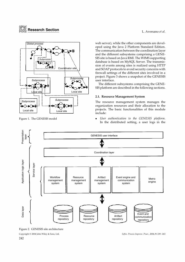
All the GENESIS sites have the same architecture,depicted in Figure 2, which consists of different sub-systems integrated through a common web clientand coordination application logic layer. Concern-ing the technology used for the implementation,each GENESIS site is realized as a web application:the user interface and the coordination layer arerealized using JSP and servlets (Tomcat being the
Copyright 2004 John Wiley & Sons, Ltd. Softw. Process Improve. Pract., 2004; 9: 239–263
241
Research Section L. Aversano et al.
Global process
Subprocess
Subprocess
Subprocess Subprocess
Subprocess
Cooridinator site
Local site
Local site Local site
Local site
Figure 1. The GENESIS model
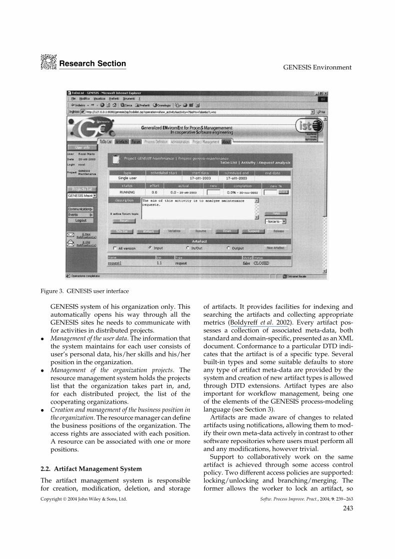
web server), while the other components are devel-oped using the Java 2 Platform Standard Edition.The communication between the coordination layerand the different subsystems comprising a GENE-SIS site is based on Java RMI. The WfMS supportingdatabase is based on MySQL Server. The transmis-sion of events among sites is realized using HTTPand SOAP protocols to avoid security concerns withfirewall settings of the different sites involved in aproject. Figure 3 shows a snapshot of the GENESISuser interface.
The different subsystems comprising the GENE-SIS platform are described in the following sections.
2.1. Resource Management System
The resource management system manages theorganization resources and their allocation to theprojects. The basic functionalities of this moduleinclude:
• User authentication to the GENESIS platform.In the distributed setting, a user logs in the
Coordination layer
GENESIS user interface
Workflow management
system
Resource management
system
Artifactmanagement
system
Event engine and communication
system
Metricengine
Processrepository
Resourcerepository
Artifactrepository
Event and communication
repository
Pre
sent
atio
nla
yer
App
licat
ion
logi
c la
yer
Ser
vice
laye
r
Dat
a la
yer
Figure 2. GENESIS site architecture
Copyright 2004 John Wiley & Sons, Ltd. Softw. Process Improve. Pract., 2004; 9: 239–263
242
Research Section GENESIS Environment
Figure 3. GENESIS user interface
GENESIS system of his organization only. Thisautomatically opens his way through all theGENESIS sites he needs to communicate withfor activities in distributed projects.
• Management of the user data. The information thatthe system maintains for each user consists ofuser’s personal data, his/her skills and his/herposition in the organization.
• Management of the organization projects. Theresource management system holds the projectslist that the organization takes part in, and,for each distributed project, the list of thecooperating organizations.
• Creation and management of the business position inthe organization. The resource manager can definethe business positions of the organization. Theaccess rights are associated with each position.A resource can be associated with one or morepositions.
2.2. Artifact Management System
The artifact management system is responsiblefor creation, modification, deletion, and storage
of artifacts. It provides facilities for indexing andsearching the artifacts and collecting appropriatemetrics (Boldyreff et al. 2002). Every artifact pos-sesses a collection of associated meta-data, bothstandard and domain-specific, presented as an XMLdocument. Conformance to a particular DTD indi-cates that the artifact is of a specific type. Severalbuilt-in types and some suitable defaults to storeany type of artifact meta-data are provided by thesystem and creation of new artifact types is allowedthrough DTD extensions. Artifact types are alsoimportant for workflow management, being oneof the elements of the GENESIS process-modelinglanguage (see Section 3).
Artifacts are made aware of changes to relatedartifacts using notifications, allowing them to mod-ify their own meta-data actively in contrast to othersoftware repositories where users must perform alland any modifications, however trivial.
Support to collaboratively work on the sameartifact is achieved through some access controlpolicy. Two different access policies are supported:locking/unlocking and branching/merging. Theformer allows the worker to lock an artifact, so
Copyright 2004 John Wiley & Sons, Ltd. Softw. Process Improve. Pract., 2004; 9: 239–263
243

Research Section L. Aversano et al.
that he/she alone is allowed to create a new versionof it. If someone tries to lock an already lockedartifact, the system will notify him/her with thename of the user who has locked the artifact. Thesecond policy allows the workers to create a new,branched version. Nested branches are allowed.
Drafts storage is also supported by the sys-tem. The draft is automatically locked and mightundergo to several updates until the final versionis released. Complete versions could be automati-cally reopened for updates if this is specified in theprocess model.
2.3. Workflow Management System
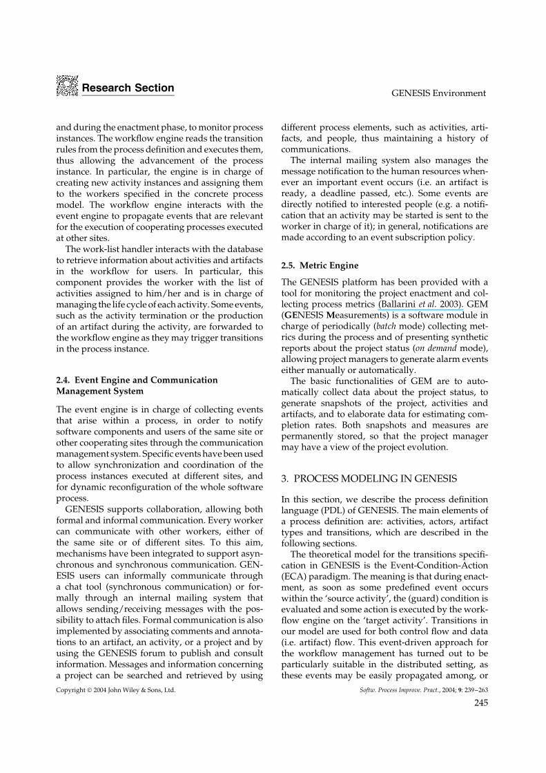
The workflow management system is in chargeof the definition, instantiation, and execution ofsoftware processes. It consists of four main compo-nents sharing a common supporting database (seeFigure 4). Specifically, the process definition tool andthe project management tool allow to define processesand to monitor their execution, whereas the work-flow engine and the work-list handler are the processenactment components.
The process definition in GENESIS happensat two stages. First, an abstract process model iscreated using the process definition tool. This modelconsists of a description of the workflow (includingactivities, actors, artifact types and transitions)independently of the particular project. Interaction
with the artifact management system is requiredto define the types of artifacts to be produced bythe activities. Then, the abstract process model isrefined and customized in the context of a specificproject through the project management tool, thusachieving a concrete (or refined) process model, whichmay be interpreted and enacted by the workflowengine. In fact, the concrete model also containsinformation such as the actual workers, the artifactnames, scheduling etc. The project managementtool interacts, through the coordination layer, withthe resource management system to identify thehuman resources and the sites participating in theproject for activities assignment. Moreover, thistool offers a number of facilities to modify themodel if needed and for handling deviations duringprocess enactment. For a distributed project, theproject management tool implements a protocol forassignment of tasks to other GENESIS sites usingthe event engine, as described in subsection 4.2.
The distinction between abstract and concreteprocess models allows for reuse of the same abstractmodel in different projects. Furthermore, severalprocess instances may be enacted from the sameconcrete model and they may evolve at runtime,independently of one another and of the originatingmodel, as it will be explained in subsection 4.4.
A process visualization tool has been included tobe used by the project manager both in the designphase, to get a picture of the process being modeled,
Othersites
Event engine and communication system
Client Coordinationlayer
WfMS
Resourcemanagement
system
Artifactmanagement
system
Worklisthandler
Processdefinition
tool
Projectmanagement
tool
Workflowengine
Workflowsupport
database
Figure 4. WfMS architecture within the GENESIS environment
Copyright 2004 John Wiley & Sons, Ltd. Softw. Process Improve. Pract., 2004; 9: 239–263
244
Research Section GENESIS Environment
and during the enactment phase, to monitor processinstances. The workflow engine reads the transitionrules from the process definition and executes them,thus allowing the advancement of the processinstance. In particular, the engine is in charge ofcreating new activity instances and assigning themto the workers specified in the concrete processmodel. The workflow engine interacts with theevent engine to propagate events that are relevantfor the execution of cooperating processes executedat other sites.
The work-list handler interacts with the databaseto retrieve information about activities and artifactsin the workflow for users. In particular, thiscomponent provides the worker with the list ofactivities assigned to him/her and is in charge ofmanaging the life cycle of each activity. Some events,such as the activity termination or the productionof an artifact during the activity, are forwarded tothe workflow engine as they may trigger transitionsin the process instance.
2.4. Event Engine and CommunicationManagement System
The event engine is in charge of collecting eventsthat arise within a process, in order to notifysoftware components and users of the same site orother cooperating sites through the communicationmanagement system. Specific events have been usedto allow synchronization and coordination of theprocess instances executed at different sites, andfor dynamic reconfiguration of the whole softwareprocess.
GENESIS supports collaboration, allowing bothformal and informal communication. Every workercan communicate with other workers, either ofthe same site or of different sites. To this aim,mechanisms have been integrated to support asyn-chronous and synchronous communication. GEN-ESIS users can informally communicate througha chat tool (synchronous communication) or for-mally through an internal mailing system thatallows sending/receiving messages with the pos-sibility to attach files. Formal communication is alsoimplemented by associating comments and annota-tions to an artifact, an activity, or a project and byusing the GENESIS forum to publish and consultinformation. Messages and information concerninga project can be searched and retrieved by using
different process elements, such as activities, arti-facts, and people, thus maintaining a history ofcommunications.
The internal mailing system also manages themessage notification to the human resources when-ever an important event occurs (i.e. an artifact isready, a deadline passed, etc.). Some events aredirectly notified to interested people (e.g. a notifi-cation that an activity may be started is sent to theworker in charge of it); in general, notifications aremade according to an event subscription policy.
2.5. Metric Engine
The GENESIS platform has been provided with atool for monitoring the project enactment and col-lecting process metrics (Ballarini et al. 2003). GEM(GENESIS Measurements) is a software module incharge of periodically (batch mode) collecting met-rics during the process and of presenting syntheticreports about the project status (on demand mode),allowing project managers to generate alarm eventseither manually or automatically.
The basic functionalities of GEM are to auto-matically collect data about the project status, togenerate snapshots of the project, activities andartifacts, and to elaborate data for estimating com-pletion rates. Both snapshots and measures arepermanently stored, so that the project managermay have a view of the project evolution.
3. PROCESS MODELING IN GENESIS
In this section, we describe the process definitionlanguage (PDL) of GENESIS. The main elements ofa process definition are: activities, actors, artifacttypes and transitions, which are described in thefollowing sections.
The theoretical model for the transitions specifi-cation in GENESIS is the Event-Condition-Action(ECA) paradigm. The meaning is that during enact-ment, as soon as some predefined event occurswithin the ‘source activity’, the (guard) condition isevaluated and some action is executed by the work-flow engine on the ‘target activity’. Transitions inour model are used for both control flow and data(i.e. artifact) flow. This event-driven approach forthe workflow management has turned out to beparticularly suitable in the distributed setting, asthese events may be easily propagated among, or
Copyright 2004 John Wiley & Sons, Ltd. Softw. Process Improve. Pract., 2004; 9: 239–263
245
Research Section L. Aversano et al.
dispatched to, different workflow engines throughthe GENESIS event engine.
3.1. Modeling Activities
Activities are the work units of the process model.They may be interactive, i.e. requiring humanintervention, automatic, i.e. automatically performedby a tool, or superactivities. Superactivities allowfor a hierarchical decomposition of the processmodel as they correspond to subprocesses that willbe modeled and performed at (possibly) differentGENESIS sites.
In the abstract process model, activities havea name, the performing role(s) in case of aninteractive activity or the tool-type for an automaticactivity, and the output artifact types (artifacts to beproduced and created ex novo). In fact, each activityof the process model is essentially described by theartifacts that it will produce, without additionalinformation on how the activity should actually becarried out. Different artifacts of the same type maybe produced within an activity, and there is no needfor the process modeler to specify the multiplicityof these artifacts beforehand, as their number maynot be known but may be dynamically definedduring the process. On the other hand, the unitarymultiplicity (i.e. exactly one) of an artifact can bespecified by replacing the artifact type with theactual artifact name.
One or more variables may be attached toan activity or to an artifact type, whose values,generally assigned by the worker of the activity,will be an additional data of the process. Variablesmay be used to build conditions for routing thecontrol or data flow of the process instance (seesubsection 3.2).
3.2. Modeling Transitions
Following the standard formalism for ECA process-modeling languages, a transition is defined as atriple (S, t, S’), where S is the source of the transition,which in our case can be either an activity A or anartifact of type α produced by A; S’ is the target of thetransition, which will always be an activity A’, and tis the transition label composed of a set of attributesin the form of e/c/a, where e is the triggering eventof the transition (occurred within A), c is the guardcondition (the default value is ‘true’), and a is theaction on A’.
The following notation may be used for thetransitions:
t : Se/c/a−−−→ S′
We have established a vocabulary for the event andaction types currently supported by the GENESISWfMS, and formulated a set of rules for thedefinition of the transitions. These rules are in partimplemented by the process definition tool and theproject management tool, which guide for a correctdefinition and consistency with respect to the basicconstraints. Details of the language can be found inthe appendix.
The event types we have considered so far arethose essential for the advancement of the processexecution; namely, the start of a (sub)process,closure or (abnormal) termination of an activity,and production or completion of artifacts. It isworth noting that the data flow here is alwaysdefined on the artifact types as, unless otherwisespecified, several artifacts of the same type may beproduced if needed. Also, different draft versionsof the same artifact can be produced until theartifact is produced in a final version (completed).Intermediate versions of artifacts are considered fortransitions where these drafts are read-only for thetarget activities.
Conditions are Boolean expressions on the work-flow control data that permit or inhibit the tran-sition. They involve variables associated with anactivity or, in the case of a produced artifact event,with the artifact type source of that event. A con-dition is defined as a boolean expression composedof elementary relational expressions linked by theAND and OR operators. Each elementary relationalexpression may be a comparison of two variables orof a variable with a constant value.
The action attribute of the transition describesthe system reaction to the occurred event in case ofa true evaluation of the condition. Depending onthe event raised, the action essentially consists ofstarting, or state changing for, an activity, or transferof the source artifact (if any) to the target activity(ies) as read-only or for updates.
3.3. PDL Constructs
We have referred to the standard Unified ModelingLanguage (UML) notation of the activity diagramsfor a graphical view of the transitions. This has been
Copyright 2004 John Wiley & Sons, Ltd. Softw. Process Improve. Pract., 2004; 9: 239–263
246
Research Section GENESIS Environment
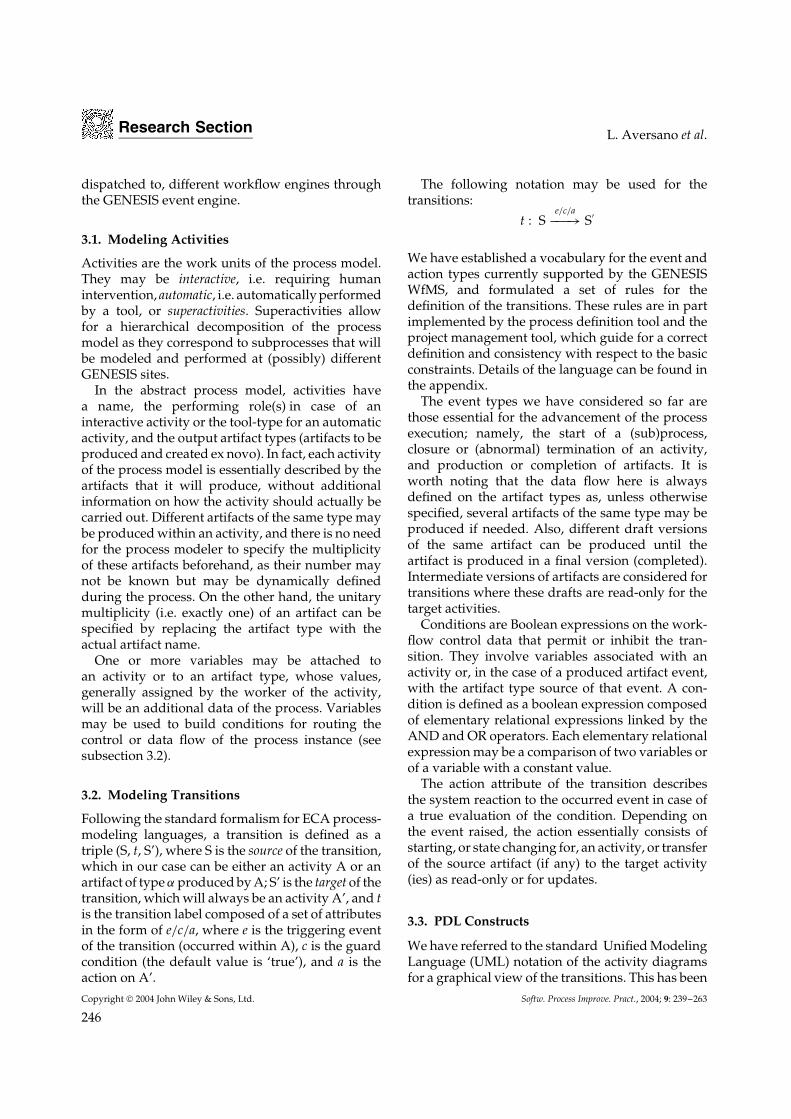
enriched with symbols and data to represent theprocess model according to our (textual) PDL. Anexplanation of the definition and semantics of themain constructs with our PDL follows, which aregraphically represented in Figure 5. For simplicity,some details related to transitions on artifacts havebeen omitted in the figure.
Two basic types of actions have been consideredin the current implementation. We use the term‘flow’ to express both actions, although theirsemantics depends on the transition event and onsome other attributes as explained below.
• Control flow sequence (Figure 5(a)): this constructdefines the execution order of two activities; theevent is concerned with the termination of thefirst activity (A in figure); as an effect, the targetactivity (B) is started.
• Data (and possibly control) flow sequence (Figure5(b)): An artifact of type ar, produced byactivity A, is passed to activity B. Essentially,two action types may be used to model thisconstruct, namely, dataflow only or dataflowwith activation. If B is not yet started at thetime the event is raised, with the first option aninstance of B is created but this will be waitingfor some other event before it can actually start;with the second option, instead, activity B isstarted by the same event.
In general, for transitions of data flow type theprocess modeler needs to specify whether theartifact to be produced is intended as input (i.e.read-only) or as input/output (i.e. update) for thetarget activity. In the latter case, the produced andclosed artifact will be updated by the target activity.
Transitions caused by feedback artifacts areparticular in that, as a consequence, the impactedartifacts might be reopened for corrections by thetarget activity. We have thought of a specific actiontype to this aim:
• Feedback data flow (Figure 5(i)): the triggeringevent is the production of a feedback artifact(of type ar2 by activity B in the figure). Theaction attribute must contain, in this case, alsothe artifact type to which the feedback refers(ar1). The effect will be that the feedback isreceived by A and the impacted artifact will beset to the openable state, i.e. a temporary statewhere the user may decide to reopen the artifactfor updates.
Additionally, we have defined the following twoaction types that allow for a dynamic evolution ofthe process instance:
• Fork and Nest (Figure 5(c) and 5(c)’): the eventis concerned with the production of a closedartifact of the specified type within the source
Figure 5. Graphical view of the constructs
Copyright 2004 John Wiley & Sons, Ltd. Softw. Process Improve. Pract., 2004; 9: 239–263
247
Research Section L. Aversano et al.
activity (A in the figure); for the target activity(B in the figure), a new instance will becreated by the workflow engine. So, subsequentproductions of artifacts of that type by thesource activity would lead to the creation ofactivity instances of the target activity, eachconsuming a different artifact. These instancesmay be running in parallel. In the figure, wehave used the UML notation of * applied to thetarget activity to represent the Fork and Nestaction.
• Join and Reduce (Figures 5(c) and 5(c)’): theevent is concerned with the termination of thesource activity (control flow join and reduce,Figure 5(c)) or the production of an artifact ofthe specified type by that activity (data flow joinand reduce, Figure 5(c)’). In both figures, B isthe source activity. This action is the dual of theFork and Nest action. Its semantics is that all theactivity instances of type of the source activityare joined into one instance of the target activity(C in the figure). For simplicity, in the figure theJoin and Reduce arc has been used immediatelyafter the Fork and Nest action, but this is not aconstraint of the enactment layer.
The Fork and Nest operator is particularly use-ful when the number of artifacts of a given typeproduced by an activity cannot be planned at mod-eling time. An example is the ordinary maintenanceprocess, analyzed in (Aversano et al. 2002b). Thisprocess has the production of a maintenance request(named trouble ticket) as the starting activity: for eachrequest, the actual maintenance process starts, pos-sibly at the client site. The artifacts ‘produced’ bythe trouble ticket production activity are the clients’requests forms, whose number cannot be specifiedbeforehand. So, if A is the trouble ticket activity,the target activity B is modeled as a superactivity,associated with the same site or a different one. Thecorresponding subprocess is then modeled inde-pendently and will consist of some activities, suchas request analysis, maintenance planning, anomalyresolution, etc. After each maintenance subprocesshas ended, the ‘global’ workflow proceeds with therequests closure phase, where data on the resolvedanomaly for each project is stored, and the main-tenance requests will change state from open toclosed.
Figure 5(d–h) shows some of the compositeconstructs. In particular, Figures 5(d) and 5(e) show
the OR/AND split construct, i.e. 5d reads: after aclosure/termination event by activity A, activity B1
is activated under condition c1 and activity B2 isactivated under condition c2. Conditions c1 and c2may be mutually exclusive; instead, 5e reads: eachartifact of type ar produced/updated by activity Ais passed to activity B1 under condition c1, and toactivity B2 under condition c2.
Special attention should be paid to the syn-chronization constructs (AND join), shown inFigure 5(f–h). These are used to express the syn-chronization of events for the control or data flow(i.e. rendezvous of the produced artifacts at thetarget activity). In general, a synchronization con-dition may be attached to the bar, which will beevaluated every time one of the incoming transi-tions has fired. This condition is expressed as aboolean expression involving variables attached tothe (concurrent) activities and/or artifacts, so thatthe control or data flow is blocked at the bar until thecondition becomes true. This construct may also beused for a single transition, for example, to expressa time constraint.
We have identified different types of synchroniza-tion, resulting from considerations on two facts:activity iterations and subsequent productions ofartifacts of the same type by the same activity. Forthese reasons, in fact, concurrency of a group ofactivities may happen more than once during theprocess, and so the same synchronization constructmay be applied several times after the occurrenceof the same event types. A list of the occurredevents from each activity is maintained for this aimby the workflow engine until the synchronizationcondition is satisfied at each iteration.
In this respect, the modeler is asked to specifywhether the events synchronization should hold
• always: i.e. at each iteration, and so a precondi-tion for a correct execution in this case is that thenumber of iterations of the concurrent activitiesis the same; or
• once: i.e. at the first iteration only, and then isrelaxed.
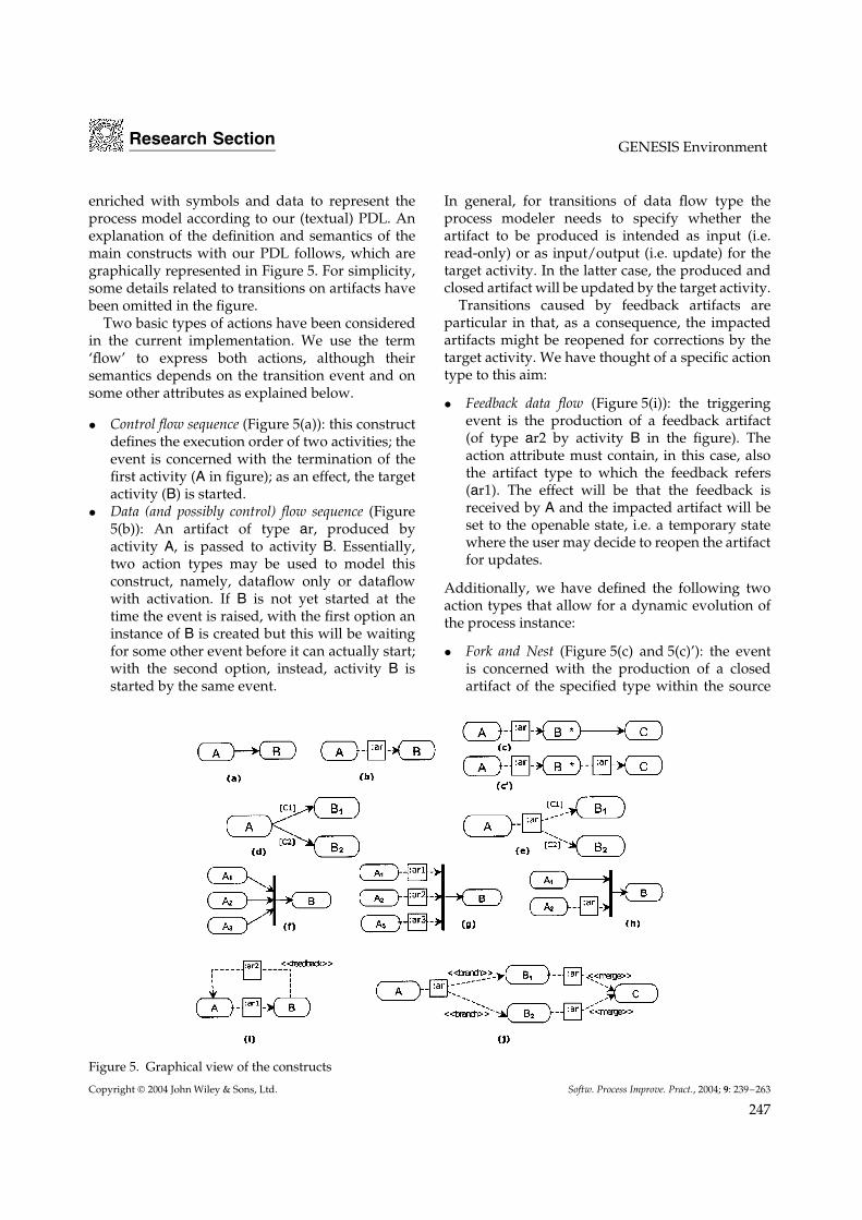
In case of artifacts synchronization (Figure 5(g)),all the produced and closed artifacts for eachtype would normally be transferred to the targetactivity if the synchronization condition holds. Letus consider the example in Figure 6 (taken from(Aversano et al. 2003)), where the Coding activityproduces several artifacts of type ar1, on which test
Copyright 2004 John Wiley & Sons, Ltd. Softw. Process Improve. Pract., 2004; 9: 239–263
248
Research Section GENESIS Environment
Figure 6. Artifacts synchronization
reports will be made by the Unit Testing activity(artifacts of type ar2).
Each time, the Consolidation activity shouldreceive together the code artifacts and the testreport referring to those artifacts. So, each groupof code artifacts will be waiting for their successfultest report to be transferred to the Consolidationactivity. To model this fact, we have thoughtof a type of synchronization based on artifactstraceability. If this is the case, the type of the artifactand the producer activity with respect to which thedependency is originated, should be specified in thesynchronization construct (the ar1 type and Codingactivity in the example).
In general, the link among the artifacts to besynchronized may be expressed through variablesattached to them. In this case, the synchronizationcondition would be that the values of these variablesmust be the same so that only the artifacts satisfyingthis rule, among those already produced, will betransferred together.
Collaborative work on the same artifact bydifferent activities may also be specified in themodel (Figure 5(j)). The artifact of type ar is sentto activities B1 and B2, which will independentlyproduce branched versions of it. A subsequentactivity of the model may eventually be required tomerge the pieces (activity C in the figure).
3.4. Distributed Models
The abstract process model may contain superactiv-ities. At this stage when the process design may becarried out without reference to a particular project,superactivities are simply interpreted as activitieswhose work is still complex and will need to be fur-ther modeled. This is generally used in a distributed
context, where the executing organization may pre-fer to hide the internal structure of the superactivityto the partner organizations of the project. In fact,the conformance with the output artifacts specifiedin the global process will be the only constraint ofthe corresponding subprocess model.
The software process componentization throughsuperactivities may be used to incrementally designthe process in a top–down manner if, for example,its structure is not completely decided beforehand,and also enables integration of (sub) processes in abottom–up fashion, thus leading to process modelsreuse.
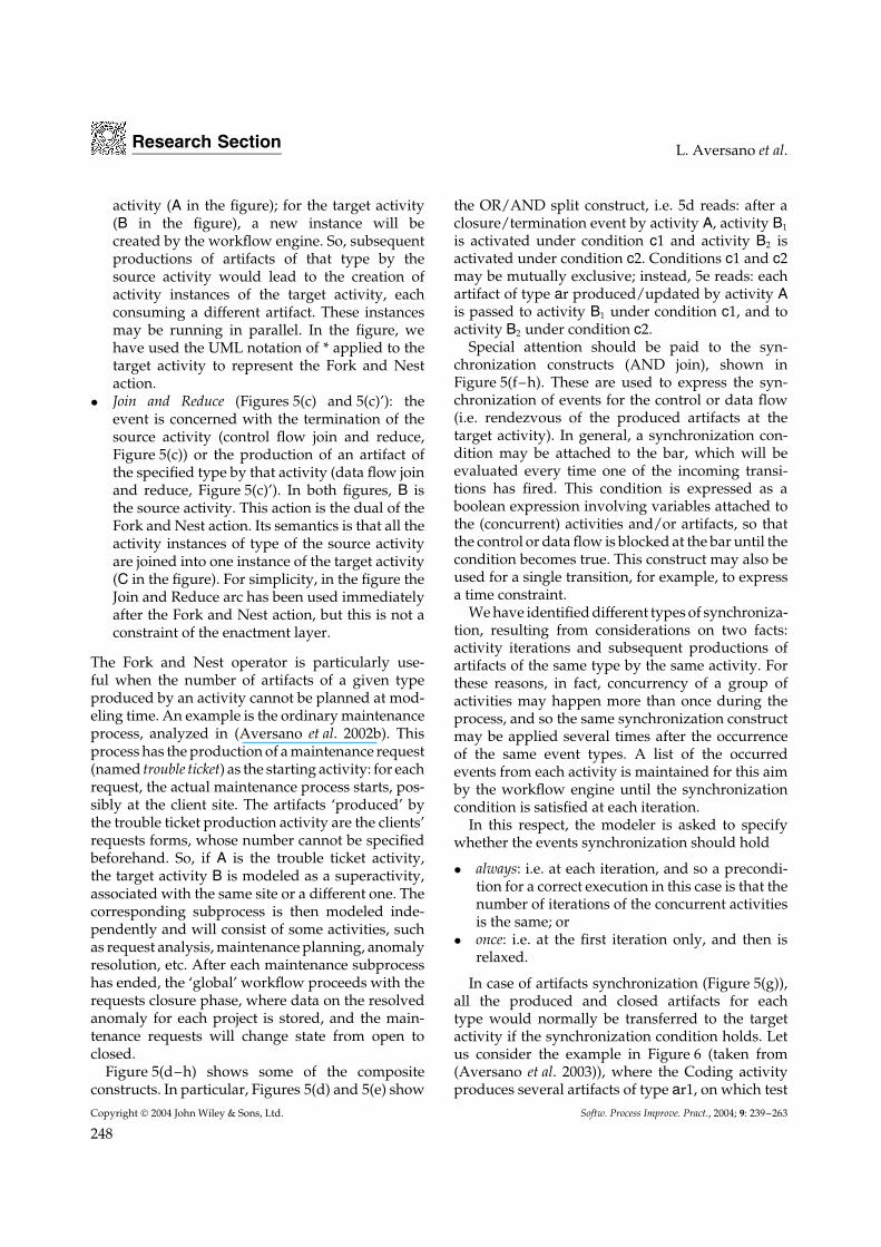
The input transitions for the superactivity in theglobal model are replicated in the subprocess asshown in Figure 7 (where B is a superactivity and(b) is the model of the corresponding subprocess).However, any outgoing control flow transition fromthe superactivity will be determined by the endof the subprocess, and each outgoing data flowtransition will be determined by the production ofthe artifacts by some activities of the subprocess(activity B3 will produce artifacts of type ar2 in thefigure).
During the enactment, synchronization is neededfor consistently maintaining the states of the super-activity at global level and of the correspondingsubprocess at the local GENESIS site. In particu-lar, when a superactivity is triggered by a controlflow transition, this event is propagated throughthe event engine to the corresponding subprocessto trigger one or more local activities. On the otherhand, the end of the local process produces an event
Figure 7. Global process and local process
Copyright 2004 John Wiley & Sons, Ltd. Softw. Process Improve. Pract., 2004; 9: 239–263
249
Research Section L. Aversano et al.
that is forwarded to the global level to terminate thecorresponding superactivity.
If an artifact that is input to a superactivity isproduced, then this event is propagated to thecorresponding subprocess so that the artifact canbe transferred as input to some local activities.Similarly, the production of the local artifacts thatare of interest at global level generates an event thatis propagated to the global process.
4. PROJECT MANAGEMENT
When defining a process model for a project throughthe project management tool, an abstract processmodel is selected from those already available andit is enriched with the project-specific details tomake it automatically executable by the workflowengine. However, the two models are decoupled sothat changes may be made on the concrete modelwithout affecting the original abstract model.
In the concrete model, roles are replaced by theactual human resources, tool types are replaced bythe tools, and a naming convention is chosen forthe artifacts. In case of an undefined multiplicity ofthese, the names of all the artifacts produced of sometype will be decided by the author(s) completing aprefix assigned at this stage by the project manager.
For a multisite project, collaboration may beachieved through superactivities assigned to othersites, that will also keep the control over them, andthrough global activities, whose workers are fromdifferent sites. The project distribution follows aprotocol described in Section 4.2.
The model refinement process may be incremen-tal as the process can start as soon as the neededresources have been assigned to the initial activity,independently of the subsequent activities. In fact,checks are made at enactment time to make surethat the activities have their resources allocatedwhen they need to be started.
4.1. Activity Management
Flexibility is guaranteed by several services pro-vided to the user involved in the process execution;in particular, teamwork management services areprovided at different levels. In this respect, inter-active activities are always associated with groupsof workers and may be labeled as single-user orcollaborative. These teams are established on the
basis of the particular skills required for the role,and they may overlap. Also, each team has a leader.A single-user activity will be normally performedby only one member of the group who volunteersfor that (pool approach). However, the team leaderwill keep the visibility of the activity throughoutits life cycle, he may directly assign the activity toa specific team member (push approach) or replacethe assignee at any time.
Besides the list of output artifacts, a worker of anactivity will be presented with other two lists of arti-facts produced by the preceding activities, namely,input (or read-only) artifacts, and input/output (orupdatable) artifacts. In the latter case, new versionsof the artifacts will be released within the activ-ity. As for output artifacts, different versions of aninput/output artifact can be produced within anactivity until the final version is produced.
For a collaborative activity, all group membersmay be required to work on the same artifacts. Syn-chronization facilities, such as locking/unlockingor branching/merging of artifacts, provided bythe artifact management system are used in thiscase. Collaborative activities essentially providea lightweight alternative to composite constructsof many parallel single-user activities producingbranches of some artifact that will be merged ina subsequent unifying activity (Figure 5(j)). As thisinteractivities collaboration may be complex to han-dle at workflow level, and so is more sensitive todeviations from the model, we think that a coarse-grained definition through a single collaborativeactivity would probably be a better choice in somesituation.
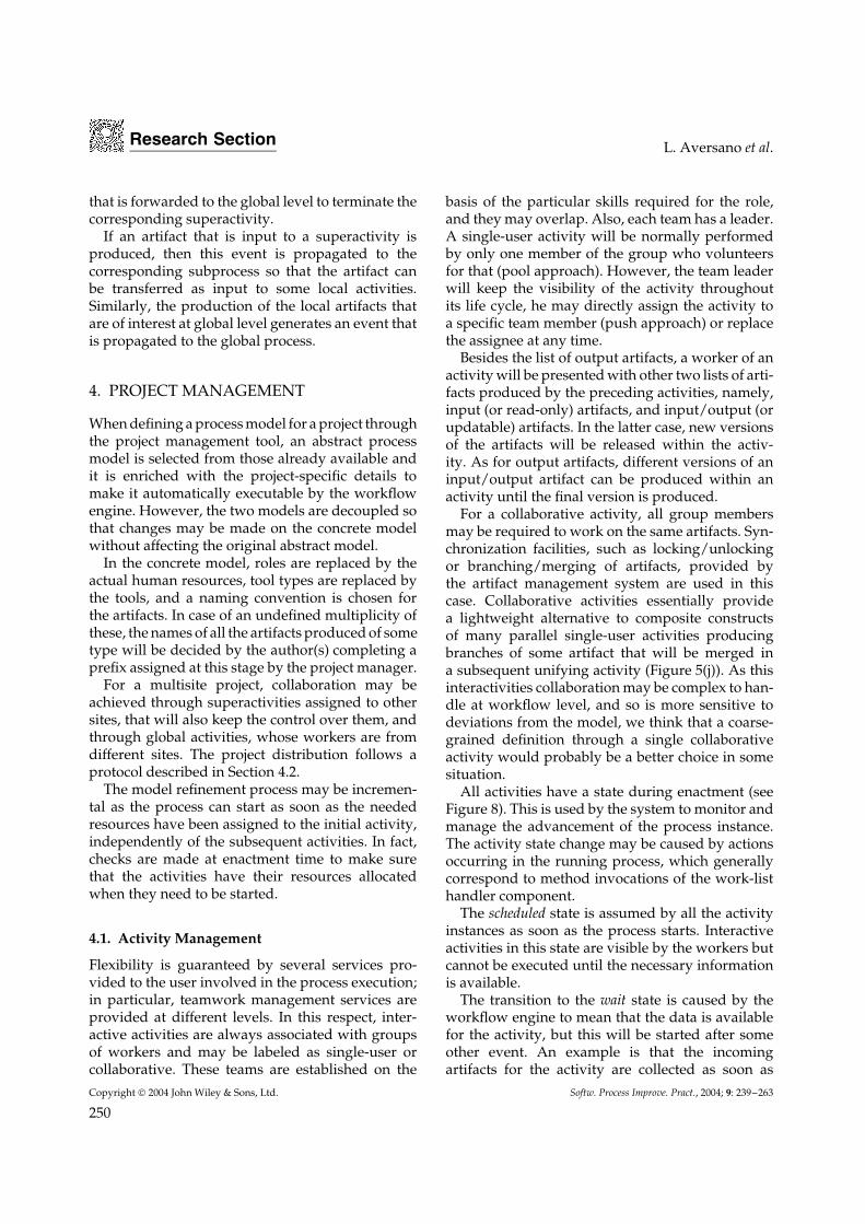
All activities have a state during enactment (seeFigure 8). This is used by the system to monitor andmanage the advancement of the process instance.The activity state change may be caused by actionsoccurring in the running process, which generallycorrespond to method invocations of the work-listhandler component.
The scheduled state is assumed by all the activityinstances as soon as the process starts. Interactiveactivities in this state are visible by the workers butcannot be executed until the necessary informationis available.
The transition to the wait state is caused by theworkflow engine to mean that the data is availablefor the activity, but this will be started after someother event. An example is that the incomingartifacts for the activity are collected as soon as
Copyright 2004 John Wiley & Sons, Ltd. Softw. Process Improve. Pract., 2004; 9: 239–263
250
Research Section GENESIS Environment
Activated Closed
Scheduled
Wait
Running
Terminated
Suspended
Released
Preempted
Figure 8. Activity states during enactment
they are produced by other activities and beforethe activity is actually started through a controlflow transition. The wait state is transparent to theGENESIS users.
In the activated state, the activity is ready to bestarted, thus the activity reaches the running state. Asingle-user activity is canceled from the work listsof the other group members except their leader. Incase of a superactivity, the running state follows thestart of the corresponding subprocess.
The worker of an interactive single-user activitymay decide to suspend and later resume the activity,or simply abandon the activity (change to thereleased state) while this is in progress. Then theactivity can be reassigned by the team leader andcontinued by someone else. The preempted state forthe activity is reached when the team leader takesthe activity to force its assignment to some worker.Normally, the activity will be closed by the workerafter all the due artifacts have been produced orupdated.
A collaborative activity may be started, sus-pended, resumed, and closed only by the teamleader.
Superactivities are suspended, resumed, andclosed according to the state of the correspondingsubprocesses. These states are caused by actionsof the project manager of the subprocess executorsites.
Any activity may be aborted in exceptionalsituations, thus reaching the terminated state. Thisstate change may be a relevant event for theworkflow progress and will be directly handled bythe engine if the exception was foreseen in the modeland a corresponding transition defined. Otherwise,a notification is sent to the project manager whomay force a transition in the process model, thus
causing a ‘deviation’ from the normal control flowof the process instance (see Section 4.4).
Reactivations (or iterations) of an activity usuallyhappen in the case of cycles in the process modelor, more generally, when the activity is closed, butlater a new transition instance fires having that asthe target activity, e.g. new input artifacts are sentby some previous activity of the model.
A log of all activities and process state changesexists and is used for metrics collection.
4.2. Creating Distributed Projects
The GENESIS platform has been designed tospecifically support projects distributed amongdifferent sites. To this aim, the modeling andenactment of processes is also distributed. This hasbeen possible owing to the PDL, which is generalenough to respect the single organization rules, andthus allows keeping low the intrusiveness of theplatform and is still powerful to assure coordinationand control over complex software processes.
Three main phases have to be distinguished: thecreation of the project identifying a coordinator siteand the involved local sites, where the resourcemanagers associate people to the project and selectthe project managers; the definition of the globalprocess involving project managers of the differentsites; and the definition of the local processes,independently defined by the different local projectmanagers.
At the starting of a new project, the resourcemanager of the coordinator site creates a projectusing the resource management tool. This meansthat she/he selects the human resources allocated atthe coordinator site and the local sites participatingin the project. Then, each resource manager of aninvolved local site decides the allocation of thehuman resources and the local project manager.
Once the project has been created on the coordi-nator site, the project manager can start defining therequired concrete process models for the project,starting from the available abstract process models(if a suitable abstract process model is not available,it has to be created first). Local project managers cancollaborate with the project manager of the coordi-nator site for the definition of the global process.
Each superactivity has to be assigned by theproject manager to a site participating in theproject. In this case, information concerning thesuperactivity (start and end date, artifact types, etc.)
Copyright 2004 John Wiley & Sons, Ltd. Softw. Process Improve. Pract., 2004; 9: 239–263
251
Research Section L. Aversano et al.
is sent to the local site and notified to the projectmanager.
The modeling is decentralized in that the processdesigners can edit subprocess models in an asyn-chronous way through the web-based user interfaceof GENESIS. The sites independently create thesubprocess models, the only requirements beingthat the subprocess be available when the corre-sponding superactivity in the global process modelhas to be enacted, and that its interface (in termsof input/output artifacts) conform to that of thesuperactivity, as explained in Section 3.4.
For each global activity, the project manager of thecoordinator site can select for each site the number ofrequired people, and send this information togetherwith the role associated with the global activity,and the work modality (collaborative/single user),to the project manager of the local sites.
A concrete global process can start independentlyof the local subprocess definition status at theparticipating sites. This allows for an incrementalprocess definition and refinement at enactmenttime.
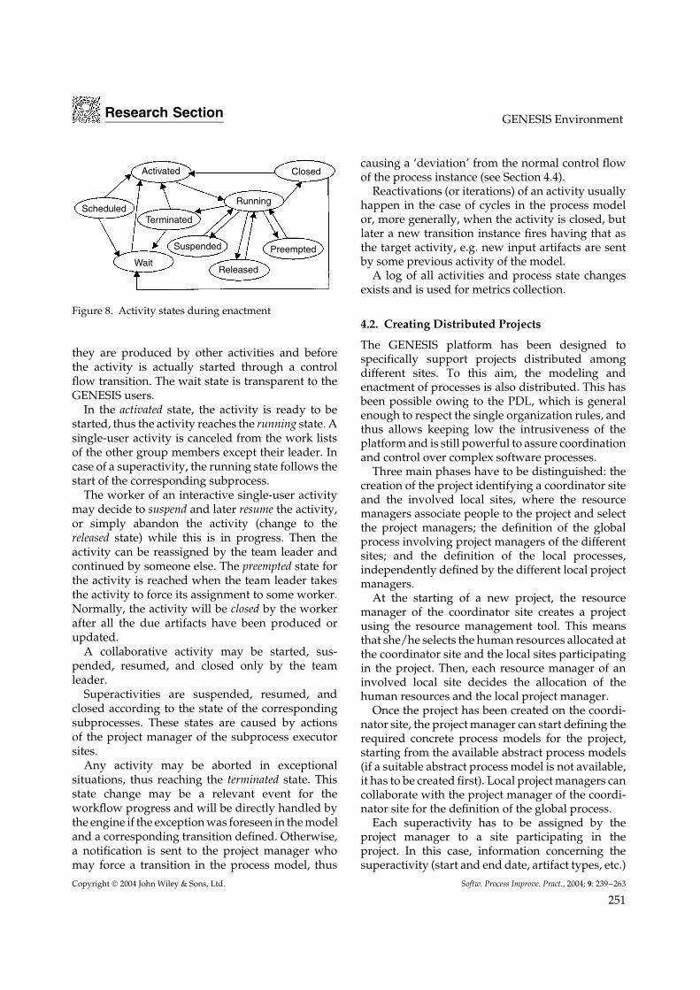
4.3. Project Monitoring
The platform support for project monitoring isprovided by the process visualization tool and by
the GEM tool. Both these modules interpret theprocess data recorded through the work-list handlercomponent during execution.
In particular, the process visualization tool givesa snapshot of the process instance with the cur-rent data, highlighting the state of each activity,the artifacts produced, the current workers, etc.(see Figure 9). The GEM component considers ‘ondemand’ the whole life cycle of each activity, iden-tifying all the actions that have happened, the timeand those responsible. The combination of this datawith the estimation data on the duration of theprocess, effort for each activity, and artifact to beproduced, previously stored through the projectmanagement tool, allows for an effective control ofthe scheduling constraints using an alert messagingmechanism.
4.4. Exception Handling and Deviations
Runtime facilities also include the management ofthe exceptions and mechanisms for the evolutionof the process. Exceptions and failures are some ofthe basic issues addressed during the executionof a software process. In order to explain howexceptions are managed in GENESIS, a referenceto the taxonomy proposed by Chiu et al. (Chiu et al.1999) is made. The authors classify the exceptions
Figure 9. Graphical view of a process instance
Copyright 2004 John Wiley & Sons, Ltd. Softw. Process Improve. Pract., 2004; 9: 239–263
252
Research Section GENESIS Environment
in two dimensions considering the source of theexception and the type of the exception. The sourcecan be as follows:
• External when rising from external componentsparticipating in the WFMS such as the operatingsystem, DBMS, software applications, machinesand equipment, etc.
• Internal sources are related to workflow man-agement issues such as the inability to find aresource or missing a deadline etc.
Exceptions can be of the following types:
• Expected if they are anticipated and alreadyplanned with explicit exception handlers.
• Unexpected if they require human interventionsince it was unforeseen.
The exceptions we have considered in GENESIS areboth the internal expected and the internal unexpectedexceptions. As all the information about the currentprocess instances are stored in the database, it ispossible to manage the expected exceptions throughECA rules, where exception events may be definedand/or added to the PDL and the recovery actionsspecified in the transition description of the concretemodel.
A simple mechanism to handle some unexpectedinternal exceptions consists of automatically sendingnotifications to the interested actors. This is applied,for example, when a transition fires but the targetactivity has no resource assigned yet, or, in case ofa superactivity, the corresponding subprocess hasnot been modeled yet by the local project manager.
The unexpected exceptions can be normallyhandled by the project management tool owing tothe possibility of managing deviations and evolvingthe process model at runtime.
In this respect, dynamic changes are allowed,which cover the most common corrective operationsto a process, from simple adjustments to morecomplex changes to the activity net. In fact, theproject manager can act on
• a single activity: changing state, resources, orthe artifacts to be produced;
• a whole process: modifying the concrete modelby adding or deleting activities and artifactswith the associated transitions, thus obtaining anew model in order for the running instances tobetter match the real process.
Also, the changes may be concerned with a singleprocess instance or all of the running instances ofthat concrete model, e.g. modifying a team workingon several instances of the same activity. In thefirst case, an ad hoc concrete model for that processinstance would be created, while in the second casethe changes are made directly on the old model. Theproject management tool implements mechanismsto ensure that the modified workflow meets thecorrectness criteria.
It is worth noting that the evolution of theprocesses can be effectively supported by thechange operations policy, thus opening the wayto incrementally build the process models. Infact, it is possible to first make a rough processmodel and execute its instances, then to detail theprocess model as soon as more knowledge andinformation are available, e.g. adding activities andtransitions. The corresponding process instanceswill be automatically modified.
5. EXPERIENCE
The GENESIS project was carried out by three aca-demic research institutions: CRMPA – Universityof Salerno (Italy), RCOST – University of Sannio(Italy), and the RISE research group of the Univer-sity of Durham (UK), and three industrial organi-zations: MOMA srl (Italy), LogicDIS (Greece) andSchlumbergerSema (Spain). The three research insti-tutions and MOMA developed the platform: inparticular, RCOST developed the workflow man-agement system, RISE the artifact managementsystem, a research unit of MOMA and CRMPAlocated at the University of Rome (Italy), namely,GEM group, developed the metric engine, whileCRMPA and MOMA developed the resource man-agement system and the event and communicationengine and also integrated the platform.
The two main industrial partners of the project,LogicDIS and SchlumbergerSema, acted as pilotusers, providing real scenarios for the elicitation ofrequirements and validation of the platform. In fact,two simulated projects were run by the companiesin the last four months of the project to experimentthe platform. In order to avoid risks and facilitate theintroduction of the platform in their environment,two projects that were already completed wereexecuted again for these simulations, so to betteranalyze differences from using or not using the
Copyright 2004 John Wiley & Sons, Ltd. Softw. Process Improve. Pract., 2004; 9: 239–263
253
Research Section L. Aversano et al.
platform in the same setting. It is worth notingthat we were not able to integrate the artifactmanagement system developed by RISE in thefirst version of the platform and, therefore, asimplified version developed by CRMPA was usedin the experimentation. The simplified artifactmanagement system provided basic facilities forstoring and retrieving artifacts composed of one ormore files, artifact versioning, locking/unlocking,and branching/merging.
In parallel to the pilot users validation, wedecided to use the same version of the platform tohost the last part of the GENESIS project, consistingof integration and testing of new functionalities andproduction and revision of the final deliverables.In fact, these activities were conducted by allthe Italian research partners from their sites. Thegoal was to use the most advanced features ofthe platform, in particular, concerning the PDLconstructs and distributed management, in orderto better understand the platform limitations andlead to faster improvements and corrections on theway through.
Another opportunity to test the platform on areal project was offered by Elisys s.r.l, a smallItalian company specialized in the production ofelectronic systems, including control and applica-tion software products. The GENESIS platform waschosen to conduct a case study for a methodol-ogy aiming to establish a quality system into thecompany (Aversano et al. 2004). The GENESIS envi-ronment essentially helped to formally define allthe processes of the company, and was used in aproject to validate its formal definition against theactual process.
The GENESIS pilot users validation is summa-rized in Section 5.1; the GENESIS project internalexperience is described in Section 5.2, and the plat-form use on real projects at Elisys s.r.l. in Section 5.3.In each context, a questionnaire was filled by all theparticipants, which provided us with a ground-ing for some qualitative data that we discuss inSection 5.4.
5.1. Pilot Users Validation
The definition of the GENESIS platform require-ments, especially for the process-modeling facilities,followed a strict interaction with the pilot users ofthe GENESIS project.
Both the industrial partners set up test-bed sce-narios based on large-scale distributed softwaredevelopment processes they had used in realprojects, to be able to validate all the essentialrequirements specified at the beginning of theproject. The scenarios were enriched with trackedhistoric details such as incidents and troubles thatoccurred in the original projects, discussions aboutdesign and technical issues, coordination and com-munication mishaps, etc. Also, the same personnelas in the real projects participated in the simula-tions. The main reason for selecting these projectswas that they provided sufficient complexity to jus-tify distributed development teams and so weresuitable for using and evaluating the platform.
The LogicDIS scenario reproduced the develop-ment of an Enterprise Resource Planning (ERP) sys-tem. The activities were carried out by three devel-opment teams located in three different sites. Twodevelopment teams were made of developmentunits delivering cooperating modules/componentsof the ERP that would be later customized by thethird team, according to the specific needs. The sitesnetwork topology consisted of a coordinator sitebased in Thessaloniky, which also implemented themodules customization subprocess, and two devel-opment sites based in Athens in different buildings.The GENESIS platform was evaluated against theactual procedure of the company.
The SchlumbergerSema scenario was based on acomplex distributed software development projectregarding a multimedia satellite-based communica-tions system. In this context, the classical situationof shared and distributed software development(i.e. cooperative development of two softwarecomponents of the project) was reproduced. Thecompanies involved in the project were Schlum-bergerSema and two subcontractors named ‘A’ and‘B’ for sake of privacy. Company A was the coor-dinator site, in charge of the global managementof the project and of the definition of the systemrequirements; SchlumbergerSema worked on soft-ware development of the Network Control Centreand also helped company A with the tuning of thesystem requirements; finally, company B developedthe management of the database. According to thegeographical distribution of the original project, athree-site architecture was used for the test bed, andsome of the original personnel accepted to work onthe simulation.
Copyright 2004 John Wiley & Sons, Ltd. Softw. Process Improve. Pract., 2004; 9: 239–263
254
Research Section GENESIS Environment
The two industrial partners evaluated the GEN-ESIS platform from several aspects: workflow func-tionalities for the different phases of the project,artifact management, and communication. Somefunctionalities were judged to be more useful asthey were nearer to their needs; in particular, thedevelopers much appreciated the To-do List activ-ity information section, the notification function,and the artifact-versioning system. Also, some non-functional aspects were considered, such as usabil-ity, reliability, performance, and user interfaces,although the tested version was still a prototypethat was much improved for the final release.
The main advantages pointed out by the pilotusers about the use of GENESIS were especiallyrelated to the distributed project management facil-ities, i.e. having a common view of the projectand its status by all the involved partners, whilekeeping autonomy for local responsibilities. In par-ticular, the SchlumbergerSema pilot users reportedthat some of the problems they had in the originalproject could have been avoided using the facilitiesof the GENESIS platform, in particular, concern-ing the automatic notification on events occurrence(major and minor project milestones); the inter-nal communication mechanisms that could preventmisunderstandings between partners; the possi-bility to store messages in the artifact repositoryand attach them to deliverables; and the automaticupdate of the logbook.
5.2. Managing the GENESIS Project withGENESIS
An added value to the platform validation wasalso given by its internal usage for the design andexecution of the remaining activities of the GENESISproject. In fact, this offered a real setting for aninterorganizational process, with three differentItalian partners, namely, CRMPA, RCOST, andGEM research groups, that carried out the lastdevelopment activities of the platform for its finalrelease and the project deliverables.
The distributed project consisted of three sites:CRMPA (located in Salerno) acted as coordina-tor, while RCOST (located in Benevento) and GEM(located in Rome) hosted the other two local sites.CRMPA was responsible for the integration ofthe new functionalities introduced in the differentmodules of the GENESIS platform, in particular,the workflow management system developed by
RCOST, the metric engine developed by GEMgroup, and the event and communication systemdeveloped by CRMPA itself. The resource manage-ment system was not modified in the final phaseof the development of the platform, while modi-fications to the artifact management system werenot included in the experimentation of GENESIS.Moreover, the official project deliverables concern-ing the system architecture and the design andimplementation of the platform were updated byall the partners in a collaborative way.
Several motivations lead us to this experimenta-tion. Firstly, we wanted to test the platform in amission-critical setting (the completion of the plat-form was crucial for the project success at the finalreview), while our industrial partners had preferredproject simulations. Also, the time they spent on thetraining was saved in our context.
Secondly, our aim was to test the advancedfeatures of the language, such as iterations, activi-ties/processes with multiple instances, productionof an unforeseen number of different artifacts ofthe same type, and the download/upload capabili-ties of the system for large artifacts (about 10 MB).In particular, some patterns for change manage-ment with feedback arrows and synchronizationconstructs were designed and directly tested. Infact, the testing activity of the integrated platformwas collaboratively performed at the coordinatorsite, as a global activity, producing several changerequests artifacts that were routed to the specificsuperactivities according to the impacted systemcomponents. This model caused a high degree ofparallelism at both activity and subprocess level,where the tracking system for artifacts was highlydesirable. This experience essentially lead to anextension of the language with specific parametersfor re-opening artifacts, and also highlighted theneed for more flexibility to allow recovery actionsand dynamic changes on the process instance, fea-tures implemented for the final release.
Finally, we thought to evaluate by ourselvesthe benefits provided by an integrated environ-ment for modeling, executing, and monitoring soft-ware development processes. Indeed, before usingthe GENESIS platform, the collaborative platformadopted for the GENESIS project was a web-basedtool managing a centralized repository of artifacts,without configuration management and with a lim-ited versioning support. The tool simply consisted
Copyright 2004 John Wiley & Sons, Ltd. Softw. Process Improve. Pract., 2004; 9: 239–263
255
Research Section L. Aversano et al.
of a publish–subscribe notification system inte-grated with the e-mail system that was useful in thefirst phases of the project to organize and reviewthe project deliverables, owing to the possibility ofattaching comments to the documents. However,this tool was not suitable to manage collaborativedevelopment of the system modules. As a result,each development team used his/her own version-ing system for the code, with no global versioningand repository for the software artifacts, and inde-pendently chose the support tools, leading to a bigeffort spent for the integration of the first release.Because of the adoption of the GENESIS platform tomanage the second release of the system, the effortmade to design our process was compensated bythe advantages of having an intersite activity coor-dination and collaboration; this guaranteed thateverybody was working on the same versions ofthe code files and provided an increased awarenessabout who was modifying what and why.
5.3. Experience with a Real Project of a SmallEnterprise
The introduction of the GENESIS platform at Elysiss.r.l. was for a different purpose, that is, supportinga lightweight approach for establishing a qualitysystem at the company, so as to achieve the ISO9001:2000 certification. This consisted of a methodfor redesigning processes and for introducinga software system to control and monitor theexecution of processes.
The company had already developed an ad hocsoftware system to partially support the activitiesof the production processes related to the humanresources management and the supply chain, butno process modeling and workflow automationfacilities were provided. In general, the use ofwell-defined and documented processes could sig-nificantly improve the competitiveness of the enter-prise. However, the definition and modeling of aprocess is a difficult task, if this has the form of atacit knowledge as it is often the case for small tomedium enterprises, and also resource consuming.The GENESIS platform was well accepted for thispurpose, especially because of its operational flexi-bility and the noninvasiveness character. Also, thecost of acquisition of the platform was null, being anopen-source software, while the training costs werelow because some of the developers had acquiredprevious knowledge of the platform during a stage
at the RCOST laboratories of the University of San-nio. A real project, aiming at the realization of a GSMsystem based on satellite technology was executed,which included the realization of software, hard-ware, and mechanical components. The automationand control of the documents’ flow through theplatform allowed for the circulation in the processof stable documents only, and so reducing ambigu-ities that could arise from nonofficial or on-workingdeliverables.
For a Goal/Question/Metrics (GQM) (Solingenand Berghout 1999) based evaluation of the qual-ity system methodology, questionnaires were dis-tributed to the employees involved in the monitoredproject. Answers to specific questions concerningGENESIS aspects were also handled, and theiranalysis lead to results that contributed to the eval-uation discussed in Section 5.4. It turned out thatthe answers concerning functionality and usabilityhad been much influenced by the fact that an earlierversion of the platform had been used, while peoplehad greater expectations with respect to the supportthe tool was supposed to provide. More details canbe found in (Aversano et al. 2004).
5.4. Evaluation Summary
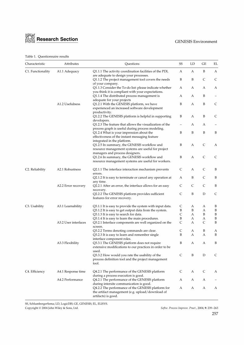
The goals of the different experiences were different:the industrial pilot users of the GENESIS projectexperimented the platform in two pilot projectsused as test beds to check its compliance to therequirements defined earlier in the project; theGENESIS development teams experimented theplatform to test the most advanced features duringthe development of the second release of theplatform itself, while the small Italian enterpriseused the platform in a real industrial project toestablish a quality system and to achieve the ISO9001 certification. Only in the latter case wasa GQM methodology followed that enabled toachieve quantitative results concerning the use ofthe platform (Aversano et al. 2004). From the otherexperiences, we only collected feedbacks from theusers through a questionnaire that we can analyzein a qualitative way. Table 1 shows a representativesubset of the questions of interest, with the answersprovided by each pilot user. Each question refersto an attribute of four quality characteristics ofinterest, namely, functionality, reliability, usability,and efficiency. For each question, four options wereavailable for the answers:
Copyright 2004 John Wiley & Sons, Ltd. Softw. Process Improve. Pract., 2004; 9: 239–263
256
Research Section GENESIS Environment
Table 1. Questionnaire results
Characteristic Attributes Questions SS LD GE EL
C1. Functionality A1.1 Adequacy Q1.1.1 The activity coordination facilities of the PDLare adequate to design your processes.
A A B A
Q1.1.2 The project management tool covers the needsof your company.
B B C C
Q1.1.3 Consider the To-do list: please indicate whetheryou think it is compliant with your expectations.
A A A A
Q1.1.4 The distributed process management isadequate for your projects
A A B –
A1.2 Usefulness Q1.2.1 With the GENESIS platform, we haveexperienced an increased software developmentproductivity.
B A B C
Q1.2.2 The GENESIS platform is helpful in supportingdevelopers.
B A B C
Q1.2.3 The feature that allows the visualization of theprocess graph is useful during process modeling.
– A A –
Q1.2.4 What is your impression about theeffectiveness of the instant messaging featureintegrated in the platform.
B B B B
Q1.2.5 In summary, the GENESIS workflow andresource management systems are useful for projectmanagers and process designers.
B A C A
Q1.2.6 In summary, the GENESIS workflow andresource management systems are useful for workers.
B A C C
C2. Reliability A2.1 Robustness Q2.1.1 The interface interaction mechanism preventserrors.
C A C B
Q2.1.2 It is easy to terminate or cancel any operation atany time.
A B C B
A2.2 Error recovery Q2.2.1 After an error, the interface allows for an easyrecovery.
C C C B
Q2.2.2 The GENESIS platform provides sufficientfeatures for error recovery.
C B D C
C3. Usability A3.1 Learnability Q3.1.1 It is easy to provide the system with input data. C A A BQ3.1.2 It is easy to get output data from the system. B B A BQ3.1.3 It is easy to search for data. C A B BQ3.1.4 It is easy to learn the main procedures. B A A B
A3.2 User interfaces Q3.2.1 Interface components are well organized on thescreen.
C A C B
Q3.2.2 Terms denoting commands are clear. C A B AQ3.2.3 It is easy to learn and remember singleinterface component roles.
B A A B
A3.3 Flexibility Q3.3.1 The GENESIS platform does not requireextensive modifications to our practices in order to beused.
B A A B
Q3.3.2 How would you rate the usability of theprocess definition tool and the project managementtool.
C B D C
C4. Efficiency A4.1 Response time Q4.2.1 The performance of the GENESIS platformduring a process execution is good.
C A C A
A4.2 Performance Q4.2.1 The performance of the GENESIS platformduring intersite communication is good.
A A A –
Q4.2.2 The performance of the GENESIS platform forthe artifact management (e.g. upload/download ofartifacts) is good.
A A A A
SS, SchlumbergerSema; LD, LogicDIS; GE, GENESIS; EL, ELISYS.Copyright 2004 John Wiley & Sons, Ltd. Softw. Process Improve. Pract., 2004; 9: 239–263
257
Research Section L. Aversano et al.
A. I totally agree’, or ‘Excellent’B. ‘I agree’, or ‘Good’C. ‘I disagree’, or ‘Fair’D. ‘I totally disagree’, or ‘Unsatisfactory’
From the table, we can read quite encouragingresults for functionality. In fact, the platformresulted in being fully compliant with the functionalrequirements of the pilot users; however, not all thepotential of the platform was tested by the industrialpartners (in particular, concerning the PDL). Thiswas especially true for Elisys s.r.l., where an evenearlier version with less functionalities was used,for example, without the visualization tool andthe support for distributed execution of processes.Also, the visualization tool could not be used bySchlumbergerSema, and the reason for that was notreally clear. More severe answers came from theGENESIS internal experimentation, as this helpedus to provide insights into the specific featuresto be modified/added for the final release. Theversioning support for both global and local artifactsrevealed to be time saving.
In all cases, a progress with respect to theolder procedures was observed, and the perceptionthat the platform could be easily introduced inthe organization and effectively used to supportsoftware development processes in all their facetswas rather general.
Less positive results concern usability and reli-ability. From the comments of the pilot users, itis clear that although the user interface is easy tounderstand, it could be improved by providingmore global views with all the process informationat the same time. Also, the overall modeling processcould benefit from a graphical editor as in modernworkflow management systems. Little support forerrors recovery was noticed, although this did notmuch affect the correct execution of the processesthat all came to their end. An effort to improvereliability was also spent for the final release.
6. RELATED WORK
Research on workflow management and PSEEs islong dated. Different process-modeling languageshave been defined in the workflow managementliterature. Some of them focus on the specifica-tion of the control flow between activities (Grefenet al. 1999, Workflow Management Coalition 1999)and express other enactment rules, in particular,
concerned with exception handling, using the trig-gering facilities of the supporting database (Casatiet al. 2000). Other approaches are interested inmodeling the data flow of documents and arti-facts produced within the process (Medina-Moraet al. 1992). GENESIS WfMS also adopts the lat-ter approach, as this is more suitable for applyingworkflow management technologies in softwareengineering processes. PSEEs also explicitly con-sider artifact production as triggers for workflowenactment and model them within the process. Forexample, some of them use colored Petri nets asa basic formalism for process modeling and enact-ment (van der Aalst 1998, Bandinelli et al. 1996).Other approaches model a process as activity netswith expression of the data flow (Cugola et al. 1995,Heimann et al. 1996).
Most of the WfMSs and PSEEs of the last decadeare client-server systems, with centralized enact-ment facilities, although they do not exploit theweb as basic infrastructure to ease the accessibil-ity by remote users. Recent research on workflowmanagement is focusing on the use of web tech-nologies. Like GENESIS, MILOS is a web-basedWfMS supporting dynamic coordination of dis-tributed software development teams over theInternet. MILOS allows for dynamic changes onthe project plan during project enactment and pro-vides a notification mechanism that tracks productchanges during project enactment and informs theconcerned people of the change. The workflow con-trol was centralized in the first version and thena strategy for a distributed process enactment wasproposed (Kotting and Maurer 1999), where dif-ferent portions of a process model and data arestored on different workflow engines communicat-ing through a peer-to-peer protocol. In addition toGENESIS, the mechanisms provided by MILOS arebased on the specification of the interfaces betweenprocess and subprocesses. Recent work on MILOSis toward supporting distributed agile softwareprojects (Bowen and Maurer 2002).
In the Ozweb environment, the peer-to-peerparadigm for distribution is adopted (Ben-Shauland Kaiser 1995, Kaiser et al. 1998). In this envi-ronment, a decentralized system consists of inde-pendent subsystems spread among multiple sites.In particular, the authors focus on the processautonomy of each subsystem that should be self-contained and operationally independent. To thisaim, they introduce the concept of ‘treats’ to
Copyright 2004 John Wiley & Sons, Ltd. Softw. Process Improve. Pract., 2004; 9: 239–263
258
Research Section GENESIS Environment
guarantee compliance of the artifacts exchangedbetween subprocesses. In GENESIS, the interfacebetween subprocesses is also specified through theexchanged artifact types.
The Endevors system (Kammer et al. 1998) usesa layered object model to provide for the object-oriented definition and specification of processartifacts, activities, and resources. A coordinationmechanism for distributed process execution andtool integration that uses the Hypertext Trans-fer Protocol (HTTP) is provided. The intent ofdistribution is to support a wide range of con-figurations with varying degrees and kinds ofdistribution. Stand-alone configuration with a basesystem without distributed components and mul-tiuser configuration with a single remote data storeare the configurations experimented for distribu-tion. GENESIS also uses HTTP and SOAP for thecommunication of events among different sites dur-ing distributed process definition and enactment.
Eder and Panagos (Eder and Panagos 1999) pro-pose an approach for the distributed execution thatexploits the central role of an event notificationservice, READY. Workflow participants, both work-flow engines and agents, can subscribe to eventsthat trigger the start of workflow activities andprocesses, and events that describe state changesin the workflow processes they are interested in.Therefore, the configuration of the participants ina workflow can be dynamically changed with-out requiring any modifications to the existingarchitecture. Moreover, time-related constructs foraddressing the time aspects of process manage-ment are provided. In GENESIS, a distributed eventnotification service is used.
PROSYT is an artifact-based PSEE (Cugola 1998).Each artifact produced during the process is aninstance of some artifact type, which describes itsinternal structure and behavior. All the routingin this model is based on the artifact and theoperations on them. Boolean expressions are usedto express the constraints under which operationsare allowed to start. PROSYT also allows fordistributed enactment facilitated by the JEDI event-based middleware (Cugola et al. 2001); the samemiddleware is also used by the OPSS WfMS (Cugolaet al. 2001). However, unlike MILOS and GENESIS,the lack of an activity-based view of the processdoes not allow for a hierarchical decomposition ofa software project, which is generally required forproject management purposes.
The systems discussed so far do not addressthe problem of decentralized process modeling. InGENESIS, facilities for collaborative editing of dis-tributed software processes are provided. Grundyet al. (Grundy et al. 1998) also focus on problemsconcerning the distribution in process modeling.The proposed system provides mechanisms forcollaboratively editing process models both in asynchronous and asynchronous way, together withversion management support. The architecture isbased on a central site maintaining the processmodel and distributed sites enacting portions of themodel.
Another characteristic of GENESIS is that a pro-cess model can be defined at two abstraction levels.This means that there is a one-to-many correspon-dence between abstract models and concrete mod-els, thus increasing the possibility of reusing processmodels. Also, different process instances can be exe-cuted with respect the concrete process model, as itis in most workflow management systems. Most ofthe software process support systems do not pro-vide this separation between models at differentabstraction levels, and, in some cases, there is a one-to-one correspondence between process models andprocess instances. In most cases (e.g. (Cugola et al.2001, Heimann et al. 1996, Maurer et al. 2000)), pro-cess instances are populated copies of the models.This enables the runtime deviations of a single pro-cess instance without affecting the process model.Owing to the one-to-many correspondence betweenconcrete process models and process instances, inGENESIS a copy of a concrete process model is onlymade in case of deviations of a process instance.This enables addressing ad hoc modifications ofa process instance like in other approaches, aswell as runtime modifications of a concrete pro-cess model, causing a selective modification of therelated process instances. A similar approach is alsoused in WIDE (Grefen et al. 1999), while Heimannet al. (Heimann et al. 1996) use graph-rewriting rulesto enact and change the process model at runtime.
Besides runtime modifications of a process model,GENESIS also provides mechanisms to increaseflexibility during process enactment. Other authorsalso recognize the importance of providing flexibleenactment mechanisms. In particular, PROSYTusers are not forced to satisfy the constraints statedin the process model (Cugola 1998). They can invokeoperations even if the associated constraints are notsatisfied. PROSYT keeps track of the results of these
Copyright 2004 John Wiley & Sons, Ltd. Softw. Process Improve. Pract., 2004; 9: 239–263
259
Research Section L. Aversano et al.
deviations and controls the invariants so that theyare not violated as a result of such deviations. InGENESIS, flexibility is provided by distinguishingbetween the roles of the process actors. In particular,features are provided for a flexible managementof activities, such as pull mechanisms that enablemembers of a group to accept activities, as wellas features for team leaders to dynamically changethe person in charge of an activity. Flexibility isalso provided through the maintenance of a degreeof indeterminism on the number of artifacts of agiven type produced by an activity, thus givingthe possibility of deciding this at runtime withoutthe need of changing the process model. Also, it ispossible to create at runtime an undefined numberof instances of a given activity, depending on theartifacts produced during the process.
Finally, the integration with an artifact repositoryis another important aspect provided by GENE-SIS. Other systems, like PROSYT (Cugola 1998) andOZWEB (Ben-Shaul and Kaiser 1995, Kaiser et al.1998) are artifact based and explicitly address themanagement of artifacts. However, it is not clearif configuration management facilities are providedor integrated in these systems. GENESIS integratesboth an activity-based workflow management sys-tem and an artifact management system that pro-vides versioning facilities and the cooperative andconcurrent modification of software artifacts.
7. CONCLUSIONS
In this article, we have presented the GENESIS(GEneralised eNvironment for procEsS manage-ment in cooperatIve Software engineering) plat-form, the outcome of a European research projectaiming at designing and developing a noninva-sive and open-source system to support softwareengineering processes in a highly distributed envi-ronment. In fact, the GENESIS project itself wasrealized by three academic research institutions andthree industrial partners, two of them playing thepilot users. The platform implementation was con-ducted by four development teams from differentsites (each team mainly devoted to a different sub-system), which strictly cooperated and interactedthrough the coordinator site. The project startedin September 2001 and ended in November 2003.The total effort was of 294 man-months and about104,000 lines of code have been produced.
In this article, we focused on the workflow andproject management components; in particular, wehave described the facilities for process definitionand flexible enactment of distributed processes. Theprocess definition language is based on the event-condition-action paradigm that is common to manyWfMS currently used in industry, but we havealso added some new features. We have defineda two-layered view of the process, distinguishingan abstract model as a reference model for projectmanagers and a concrete model that also containsdetails related to a specific software project and itis suitable to be enacted by the workflow engine.A multilevel process definition is obtained throughsuperactivities, which correspond to subprocessesat a lower level and can be assigned and executed atdifferent sites. This choice preserves the autonomyof each site during the process modeling andallows reusing the same PDL in all the GENESISsites, thus simplifying the sites’ interoperability andcommunication within distributed projects. Also,the modeling process may be incremental, andrefinements to the model may be made duringenactment.
The definition of the GENESIS platform require-ments for distribution, especially for the process-modeling facilities, followed a strict interactionwith the pilot users of the GENESIS project. Duringthe project, we collected descriptions of their workmodalities on distributed processes and emergingneeds. We considered the problems expressed bythem and translated them into formal requirementsfor the implementation of the GENESIS platform.
Additionally, we have tried to fulfill the scien-tific objectives of the GENESIS project, such asnoninvasiveness, i.e. the platform supports soft-ware engineering processes without interferingwith the organization practices; dealing with cross-organizational multicompany projects, by provid-ing facilities for collaboration, communication, coor-dination, and monitoring at global and local levelswhere each partner may keep its own developmentpractices; and support for process evolution. Thesefeatures have been evaluated through four differentexperiences: two of them were performed by thepilot users of the GENESIS project, which executedsimulated projects; another experience consisted ofusing the platform to model and execute the remain-ing activities in the last four months of the GENESISproject itself; and the fourth experience was to usethe platform in a real project of a small Italian
Copyright 2004 John Wiley & Sons, Ltd. Softw. Process Improve. Pract., 2004; 9: 239–263
260
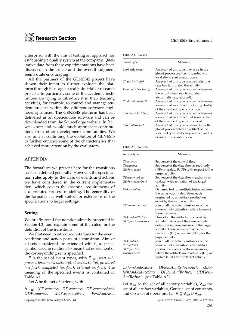
Research Section GENESIS Environment
enterprise, with the aim of testing an approach forestablishing a quality system at the company. Qual-itative data from these experimentations have beendiscussed in the article and the overall judgmentseems quite encouraging.
All the partners of the GENESIS project haveshown their intent to further evaluate the plat-form through its usage in real industrial or researchprojects. In particular, some of the academic insti-tutions are trying to introduce it in their teachingactivities, for example, to control and manage stu-dent projects within the different software engi-neering courses. The GENESIS platform has beendelivered as an open-source software and can bedownloaded from the SourceForge website. In fact,we expect and would much appreciate contribu-tions from other development communities. Wealso aim at continuing the evolution of GENESISto further enhance some of the characteristics thatachieved more attention by the evaluators.
APPENDIX
The formalism we present here for the transitionshas been defined generally. However, the specifica-tion rules apply to the class of events and actionswe have considered in the current implementa-tion, which covers the essential requirements ofa distributed process modeling. The generality ofthe formalism is well suited for extensions of thespecifications to larger settings.
Setting
We briefly recall the notation already presented inSection 4.2, and explain some of the rules for thedefinition of the transitions.
We first need to introduce notations for the event,condition and action parts of a transition. Almostall sets considered are extended with 0, a specialsymbol used in relations to mean that no element ofthe corresponding set is specified.
E is the set of event types, with E ⊇ {start sub-process, terminated (activity), closed (activity), produced(artifact), completed (artifact), external artifact}. Themeaning of the specified events is contained inTable A1.
Let A be the set of actions, with
A ⊇ {CFsequence, DFsequence, DFsequence&act,UDFsequence, UDFsequence&act, ForkAndNest,
Table A1. Events
Event type Meaning
Start subprocess An event of this type may arise in theglobal process and be forwarded to alocal site to start a subprocess.
Closed (activity) An event of this type is raised after theuser has terminated the activity.
Terminated (activity) An event of this type is raised wheneverthe activity has been terminatedabnormally (e.g. aborted).
Produced (artifact) An event of this type is raised whenevera version of an artifact (including drafts)of the specified type is produced.
Completed (artifact) An event of this type is raised whenevera version of an artifact that is not a draft,of the specified type, is produced.
External artifact An event of this type is passed from theglobal process when an artifact of thespecified type has been produced and isneeded for the subprocess.
Table A2. Actions
Action type Meaning
Cfsequence Sequence of the control flow.DfsequenceUDFsequence
Sequence of the data flow as read-only(DF) or update (UDF) with respect to thetarget activity.
DFsequence&actUDFsequence&act
Sequence of the data flow (read-only orupdate) with activation of the targetactivity.
ForkAndNest Dynamic fork of multiple instances fromthe same activity definition, eachoriginated by an artifact productionevent by the source activity.
CFJoinAndReduce Join of all the activity instances of thesame activity definition, after closure ofthese instances.
DFJoinAndReduceUDFJoinAndReduce
Flow of all the artifacts produced byactivity instances of the same activitydefinition into one instance of the targetactivity. These artifacts may be asread-only (DF) or update (UDF) for thetarget activity.
DFJoinAnd-Reduce&actUDFJoinAn-dReduce&act
Join of all the activity instances of thesame activity definition, after artifactproduction events by these instances,where the artifacts are read-only (DF) orupdate (UDF) for the target activity.
CFJoinAndReduce, DFJoinAndReduce&act, UDF-JoinAndReduce&act, DFJoinAndReduce, UDFJoin-AndReduce}. (see Table A2).
Let VAct be the set of all activity variables, VArt theset of all artifact variables, Const a set of constants,and Op a set of operators. Let V ⊆ VAct ∪ VArt.
Copyright 2004 John Wiley & Sons, Ltd. Softw. Process Improve. Pract., 2004; 9: 239–263
261
Research Section L. Aversano et al.
A condition c is defined as c = c (V, Const,Op) or c = ‘true’ if V = {0}. Without goingfurther into technical details, a condition is definedas a boolean expression composed of elementaryrelational expressions linked by the AND andOR operators. A relational expression may be acomparison of two variables or of a variable with aconstant value. We shall denote the set of conditionsby C.
Definition
Let Act be the set of activities, Art the set of artifacttypes, and T a set of labels.
A transition is defined as a triple (S, t, S’) ⊆ (Act ×Art) × T × Act, where: S is the source of the transition,which can be either an activity A (e.g. S = (A, 0))or an artifact of type α produced by A (S = (A, α)),or else an artifact produced outside the process (S= (0, α)); S’ is the target of the transition, which willalways be an activity A’, and t is the transition labelcomposed of attributes in the form of e/c/a, wheree ∈ E is the triggering event of the transition (thatoccurred within A), c ∈ C is the guard condition(the default value is ‘true’), and a ∈ A is the actionon the activity A’.
The following notation may be used for thetransitions:
t : Se/c/a−−−→ S′
A set of rules exists for the definition of thetransitions, to make sure, for example, that when-ever an artifact is specified as source of thetransition, the event and action parts refer tothe data flow. Also, if e = produced (artifact), thena /∈ {UDFsequence, UDFsequence&act, UDFJoinAn-dReduce&act, UDFJoinAndReduce}, i.e. a draft cannotbe transferred to another activity in update mode.Other rules are concerned with composite con-structs like activity or artifact synchronization.
All these rules are in part implemented by theprocess definition tool and the project managementtool, which guide for a correct definition andconsistency with respect to the basic constraints.
REFERENCES
Ambriola V, Conradi R, Fuggetta A. 1998. Assessingprocess-centered software engineering environments.
ACM Transaction on Software Engineering and Methodology6(3): 283–328.
Ames CK, Burleigh SC, Mitchell SJ. 1997. WWWorkflow:world wide web based workflow. Proceedings of the 13thInternational Conference on System Sciences, Maui, Hawaii,397–404.
Aversano L, Canfora G, Capasso G, Di Lucca GA,Visaggio CA. 2004. Introducine quality system insmall and medium enterprises: an experience report.Proceedings of 5th International Conference on Product FocusedSoftware Process Improvement. Springer-Verlag Heidelberg:Kausai Science City, Japan, 131–145.
Aversano L, Canfora G, De Lucia A, Gallucci P.2002a. Business process reengineering and workflowautomation: a technology transfer experience. The Journalof Systems and Software 63(1): 29–44.
Aversano L, Canfora G, De Lucia A, Stefanucci S. 2002b.Automating the management of software maintenanceworkflows. Journal of Software Maintenance and Evolution:Research and Practice 14(4): 229–255.
Aversano L, De Lucia A, Stefanucci S, Villani ML 2003.GENESIS workflow: managing distributed softwareprocesses. In Cooperative Methods and Tools for DistributedSoftware Processes, Cimitile A, De Lucia A, Gall H. (eds.).Franco Angeli: Italy, 87–108.
Ballarini D, Cadoli M, Gaeta M, Mancini T, Mecella M,Ritrovato P, Santucci G. 2003. Cooperative softwaredevelopment in genesis: requirements, conceptual modeland architecture. Cooperative Methods and Tools forDistributed Software Processes. Franco Angeli: Italy, 67–86.
Bandinelli S, Di Nitto E, Fuggetta A. 1996. Supportingcooperation in the SPADE-1 environment. IEEETransactions on Software Engineering 22(12): 841–865.
Ben-Shaul IZ, Kaiser GE. 1995. A paradigm fordecentralized process modeling and its realization in theOz environment. Proceedings of the International Conferenceon Software Engineering, Seattle, USA, ICSE’95.
Boldyreff C, Nutter D, Rank S. 2002. Active artifactmanagement for distributed software engineering.Proceedings of the 26th Annual International ComputerSoftware and Applications Conference, special section on theWorkshop on Cooperative Supports for Distributed SoftwareEngineering Processes. IEEE Computer Society Press:Oxford, UK, 1081–1086.
Bowen S, Maurer F. 2002. Process support and knowledgemanagement for virtual teams doing agile softwaredevelopment. Proceedings of the Workshop on CooperativeSupports for Distributed Software Engineering Processes heldat the 26th IEEE Annual International Computer Softwareand Application Conference, Oxford, UK.
Copyright 2004 John Wiley & Sons, Ltd. Softw. Process Improve. Pract., 2004; 9: 239–263
262
Research Section GENESIS Environment
Casati F, Castano S, Fugini M, Mirbel I, Pernici B. 2000.Using patterns to design rules in workflows. IEEETransactions on Software Engineering 26(8): 760–784.
Casati F, Cugola G 2001. Error handling in processsupport systems. In Advances in Exception HandlingTechniques, LNCS 2022, Romanovsky A, Dony C,Knudsen JL, Tripathi A. (eds.). Springer-Verlag: NewYork, USA.
Chan D, Leung KRPH. 1997. ‘‘A workflow Vista of thesoftware Process’’, IEEE 8th International Workshop onDatabase and Expert Systems Applications (DEXA ‘97).
Chiu DK, Li Q, Karlapalem K. 1999. Exception handlingwith workflow evolution in ADOME-WFMS:a taxonomyand resolution techniques. ACM SIGGROUP Bulletin20(3): 8.
Cugola G, Di Nitto E, Fuggetta A, Ghezzi C. 1995. Howto deal with deviations during process model enactment.ACM Proceedings of the 17th International Conference onSoftware Engineering (ICSE-17), Seattle, USA, 265–273.
Cugola G. 1998. Tolerating deviations in process supportsystems via flexible enactment of process models. IEEETransactions on Software Engineering 24(11): 982–1001.
Cugola G, Di Nitto E, Fuggetta A, Ghezzi C. 1996. Aframework for formalizing inconsistencies and deviationsin human-centered systems. ACM Transactions on SoftwareEngineering and Methodology 5(3): 191–230.
Cugola G, Di Nitto E, Fuggetta A. 2001. The JEDIevent-based infrastructure and Its application to thedevelopment of the OPSS WFMS. IEEE Transactions onSoftware Engineering 27(9): 827–850.
Eder J, Panagos E. 1999. ‘‘Towards Distributed WorkflowProcess Management’’, AT&T Research Labs.
Fuggetta A 2000. Software process: a roadmap. In TheFuture of Software Engineering, Finkelstein A. (ed.). ACMPress: New York, USA, 25–34.
Georgakopoulos D, Hornick H, Sheth A. 1995. Anoverview of workflow management: from processmodeling to workflow automation infrastructure.Distributed and Parallel Databases 3(2): 119–153.
Grefen P, Pernici B, Sanchez G. 1999. Database Supportfor Workflow Management: The WIDE Project. KluwerAcademic Publishers: London (UK).
Grundy JC, Apperley MD, Hosking JG, Mugridge WB.1998. A decentralized architecture for software processmodeling and enactment. IEEE Internet Computing 2(5):53–62.
Heimann P, Joeris G, Krapp CA, Westfechtel B. 1996.DYNAMITE: dynamic task nets for software process
management. Proceedings of the 18th InternationalConference on Software Engineering. IEEE Computer SocietyPress: Berlin, Germany, Los Alamitos (CA), 331–341.
Huang GQ, Huang J, Mak KL. 2000. Agent-basedworkflow management in collaborative productdevelopment on the internet. International Journal ofComputer Aided Design 32(2): 133–144.
Kaiser GE, Dossick SE, Jiang W, Yang JJ, Xi Ye S.1998. WWW-based collaboration environments withdistributed tool services. World Wide Web Journal 1(1):3–25.
Kammer PJ, Bolcer GA, Taylor RN, Hitomi AS. 1998.Supporting distributed workflow using HTTP.Proceedings of the International Conference on SoftwareEngineering ICSE’98, Kyoto, Japan.
Kotting B, Maurer F. 1999. Approaching software supportfor virtual software corporations. Proceedings of theInternational Conference on Software Engineering ICSE ‘99,Los Angeles, California.
Ritrovato P, Gaeta M. 2002. Generalised environmentfor process management in Co-operative software.Proceedings of the 26th Annual International ComputerSoftware and Applications Conference, Special Section on theWorkshop on Cooperative Supports for Distributed SoftwareEngineering Processes. IEEE Computer Society Press:Oxford, UK.
Solingen R, Berghout E. 1999. The Goal/Question/MetricMethod. McGraw-Hill Publishing Company: London, UKISBN 0-07-709553-7.
Maurer F, Dellen B, Bendeck F, Goldmann S, Holz H,Kotting B, Schaaf M. 2000. Merging project planningand web-enabled dynamic workflow for softwaredevelopment. IEEE Internet Computing 4(3): 65–74.
Medina-Mora R, Winograd T, Flores R, Flores F. 1992.The action workflow approach to workflow managementtechnology. Proceedings of 4th Conference on ComputerSupported Cooperative Work, Toronto, Canada.
van der Aalst WMP. 1998. Chapter 10: three good reasonsfor using a Petri-net-based workflow managementsystem. Information and Process Integration in Enterprises:Rethinking Documents 428: 161–182.
Workflow Management Coalition. 1994. Workflow Man-agement Coalition: Reference Model, Doc. no.WFMC-TC-1011, Brussels, Belgium, http://www.aiim.org/wfmc/standards/docs/tc003v11.pdf
Workflow Management Coalition. 1999. WorkflowManagement Coalition Interface 1: Process DefinitionInterchange Process Model, Document no. WFMC-TC-1016-P, http://www.aiim.org/wfmc/standards/docs/if19910v11.pdf
Copyright 2004 John Wiley & Sons, Ltd. Softw. Process Improve. Pract., 2004; 9: 239–263
263