
man1526a_160-4_240-4_man.pdf - Rockford Fosgate
56
-
Upload
khangminh22 -
Category
Documents
-
view
1 -
download
0
Transcript of man1526a_160-4_240-4_man.pdf - Rockford Fosgate


Dear Customer,
Congratulations on your purchase of the world's finest brand of car audio amplifiers.At Rockford Fosgate we are committed to musical reproduction at its best, and we arepleased you chose our product. Through years of engineering expertise, hand crafts-manship and critical testing procedures, we have created a wide range of products thatreproduce music with all the clarity and richness you deserve.
For maximum performance we recommend you have your new Rockford Fosgateproduct installed by an Authorized Rockford Fosgate Dealer, as we provide specializedtraining through Rockford Technical Training Institute (RTTI). Please read yourwarranty and retain your receipt and original carton for possible future use.
To add the finishing touch to your new Rockford Fosgate image order your Rockfordaccessories, which include everything from T-shirts and jackets to hats and sunglasses.
To get a free brochure on Rockford Fosgate products and Rockford accessories, in theU.S. call 602-967-3565 or FAX 602-967-8132. For all other countries, call +001-602-967-3565 or FAX +001-602-967-8132.
The serial number can be found on the outside of the box. Please record it in thespace provided below as your permanent record. This will serve as verificationof your factory warranty and may become useful in recovering your amplifier ifit is ever stolen.
Serial Number: ____________________
Model Number: ____________________
If, after reading your manual, you still have questions regarding this product, werecommend that you see your Rockford Fosgate dealer. If you need furtherassistance, you can call us direct at 1-800-795-2385. Be sure to have your serialnumber, model number and date of purchase available when you call.
PRACTICE SAFE SOUND™CONTINUOUS EXPOSURE TO SOUND PRESSURE LEVELS
OVER 100dB MAY CAUSE PERMANENT HEARING LOSS. HIGH
POWERED AUTO SOUND SYSTEMS MAY PRODUCE SOUND
PRESSURE LEVELS WELL OVER 130dB. USE COMMON SENSE
AND PRACTICE SAFE SOUND.
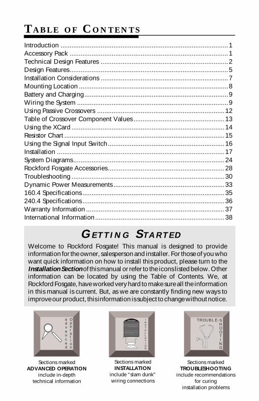
Sections markedADVANCED OPERATION
include in-depthtechnical information
Sections markedTROUBLESHOOTING
include recommendationsfor curing
installation problems
Sections markedINSTALLATION
include “slam dunk”wiring connections
INSTALLATION
® ® TROUBLE-SHOOTING
Welcome to Rockford Fosgate! This manual is designed to provideinformation for the owner, salesperson and installer. For those of you whowant quick information on how to install this product, please turn to theInstallation Section of this manual or refer to the icons listed below. Otherinformation can be located by using the Table of Contents. We, atRockford Fosgate, have worked very hard to make sure all the informationin this manual is current. But, as we are constantly finding new ways toimprove our product, this information is subject to change without notice.
G E T T I N G S TA R T E D
advanced
Operation
TABLE OF CONTENTS
Introduction ............................................................................................1Accessory Pack .......................................................................................1Technical Design Features ......................................................................2Design Features .......................................................................................5Installation Considerations ......................................................................7Mounting Location ..................................................................................8Battery and Charging ...............................................................................9Wiring the System ...................................................................................9Using Passive Crossovers ......................................................................12Table of Crossover Component Values ..................................................13Using the XCard ....................................................................................14Resistor Chart ........................................................................................15Using the Signal Input Switch................................................................16Installation ............................................................................................17System Diagrams...................................................................................24Rockford Fosgate Accessories ................................................................28Troubleshooting ....................................................................................30Dynamic Power Measurements .............................................................33160.4 Specifications ..............................................................................35240.4 Specifications ..............................................................................36Warranty Information ............................................................................37International Information.......................................................................38
I N T R O D U C T I O N
The Punch 160.4 and 240.4 are 4-channel amplifiers which candeliver 160 watts and 240 watts RMS respectively. Both amplifiersutilize a 2/4-channel input switch to eliminate the need for signalsplitters. A pair of internal XCard crossovers allow the amplifiers to beconfigured for use with many popular system designs without theadded cost of external processors. The Punch 160.4 and 240.4 arepowerful 4-channel amplifiers with integrated features which areoffered at a competitive price.
We strongly recommend you have your Authorized Rockford FosgateDealer install the new Punch amplifier. If you do choose to install ityourself, please be sure to read the entire manual before beginning.
ACCESSORY PACK
The accessory pack shipped with the Punch 4-channel amplifierincludes the mounting hardware necessary to secure the amp to thevehicle as well as attach the end caps.
Installation & Operation ManualPunch Verification Certificate(4) Amplifier mounting screws (#8 x 3/4" Phillips)(10) Speaker & power connector screws (3/32" Allen )(4) End cap mounting screws (9/64" Allen)(1) Allen Wrench 9/64"(1) Allen Wrench 3/32"(1) ATC In-line Fuseholder (160.4)(1) AGU In-line Fuseholder (240.4)(1) ATC 30 Amp Fuse (160.4)(1) AGU 50 Amp Fuse (240.4)
– 1 –
TECHNICAL DESIGN FEATURES
– 2 –
TOPAZ (Tracking Operation Pre-Amplifier Zone)
The TOPAZ (Tracking Operation Pre-Amplifier Zone) circuitry solvesground loop noise problems common to automotive amplifier design.This innovative new development allows vastly improved isolation ofthe input signal grounds from the power supply ground of theamplifier. This is accomplished by allowing the source unit to controlthe potential “environment” of the entire input structure or “zone” ofthe amplifier. This process improves the noise rejection of theamplifier by 30-40dB – an astounding 30-100 times better thanamplifiers without TOPAZ.
THE RESULT: Elimination of troublesome ground loop noise betweensource and amplifier.
TRANS•ANA(TRANSconductance Active Nodal Amplifier)
The TRANS•ANA (TRANSconductance Active Nodal Amplifier) is acircuit that allows the audio signal to pass through the amplifier at lowvoltage. The signal is directly level-shifted to the fixed high voltagerails via a pair of driver transistors. Signal linearity is assured by anactive node formed by the drive transistors at ultrasonic frequencies.This allows amplifier performance similar to trans•nova which ishighly stable and linear while utilizing the advantages of a non-floating power supply.
THE RESULT: An extended frequency bandwidth accurately suppliedto the output stages of the amplifier.
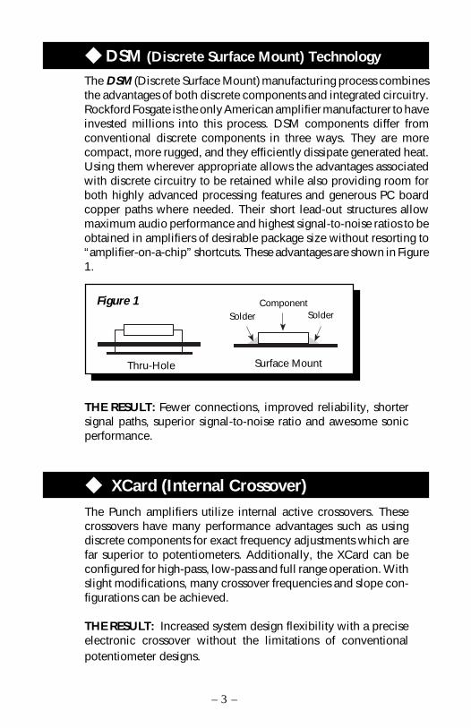
DSM (Discrete Surface Mount) Technology
The DSM (Discrete Surface Mount) manufacturing process combinesthe advantages of both discrete components and integrated circuitry.Rockford Fosgate is the only American amplifier manufacturer to haveinvested millions into this process. DSM components differ fromconventional discrete components in three ways. They are morecompact, more rugged, and they efficiently dissipate generated heat.Using them wherever appropriate allows the advantages associatedwith discrete circuitry to be retained while also providing room forboth highly advanced processing features and generous PC boardcopper paths where needed. Their short lead-out structures allowmaximum audio performance and highest signal-to-noise ratios to beobtained in amplifiers of desirable package size without resorting to“amplifier-on-a-chip” shortcuts. These advantages are shown in Figure1.
Surface MountThru-Hole
Solder SolderComponentFigure 1
THE RESULT: Fewer connections, improved reliability, shortersignal paths, superior signal-to-noise ratio and awesome sonicperformance.
XCard (Internal Crossover)The Punch amplifiers utilize internal active crossovers. Thesecrossovers have many performance advantages such as usingdiscrete components for exact frequency adjustments which arefar superior to potentiometers. Additionally, the XCard can beconfigured for high-pass, low-pass and full range operation. Withslight modifications, many crossover frequencies and slope con-figurations can be achieved.
THE RESULT: Increased system design flexibility with a preciseelectronic crossover without the limitations of conventionalpotentiometer designs.
– 3 –

NOMAD (NOn-Multiplying Advanced Decision)
The Punch amplifiers use an analog computer process to maximizesafe output power under all operating conditions. Rockford Fosgatepioneered and developed RTP (Real Time Protection), a crucialelement in the performance edge of our amplifiers. The innovativeNOMAD (NOn-Multiplying Advanced Decision) system is the mostsophisticated version of this technique ever used, bringing previouslyunavailable levels of accuracy, stability, temperature immunity andreliability to this critical process. NOMAD makes advanced decisionsbased on device voltages to precisely control the awesome levels ofcurrent available in the output MOSFETs to safe values – but onlywhen absolutely needed.
THE RESULT: Extremely fast protection system that always protectsthe amplifier and never degrades the sound.
MOSFET DevicesRockford Fosgate is one of the few manufacturers in the soundcommunity to utilize MOSFET devices in both the power supply andthe output stages. MOSFET (Metal Oxide Semiconductor Field EffectTransistor) devices offer several important inherent advantages overthe 30 year old technology of bi-polar design. These advantagesinclude: thermal stability, switching speed, ultra low output imped-ance and wider bandwidth linearity. In addition, MOSFETs operatevery similar to vacuum tubes in which they are more linear thanbipolar transistors. However, MOSFETs can deliver the midrangeclarity without the limitations of transient response and high fre-quency phase shifting normally associated with tube operation.
THE RESULT: Operational characteristics similar to vacuum tubeswithout the performance limitations of tube designs.
– 4 –
DESIGN FEATURES
1. Cast Aluminum Heatsink – The cast aluminum heatsink of the Punchamplifier dissipates heat generated by the amplifier's circuitry. Theinherent advantage of casting provides a 30% improvement ofcooling over conventional extrusion heatsink designs.
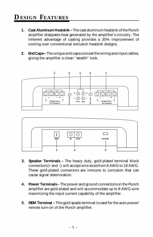
2. End Caps – The unique end caps conceal the wiring and input cables,giving the amplifier a clean “stealth” look.
3. Speaker Terminals – The heavy duty, gold-plated terminal blockconnectors (+ and –) will accept wire sizes from 8 AWG to 18 AWG.These gold-plated connectors are immune to corrosion that cancause signal deterioration.
4. Power Terminals – The power and ground connectors on the Punchamplifier are gold-plated and will accommodate up to 8 AWG wiremaximizing the input current capability of the amplifier.
5. REM Terminal – This gold spade terminal is used for the auto power/remote turn-on of the Punch amplifier.
– 5 –
RearFront
8 86 33
– L +
Rea
r G
ain
Rear SpeakersBridged Mono
L
R
Fron
t G
ain L
R
– R ++ L –
Front SpeakersBridged Mono
+ R –
5 4 9
POWERREM GNDB+
6. RCA Input Jacks – The industry standard RCA jacks provideeasy connections for signal level input. They are gold-plated toresist the signal degradation caused by corrosion.
7. Signal Input Switch – This switch allows selection of 2-channelor 4-channel source unit feed.
8. Input Sensitivity Controls – The input level controls are presetto match the output of most source units. They can be adjustedto match output levels from a variety of source units.
9. LED Power Indicator – The LED illuminates when the unit isturned on.
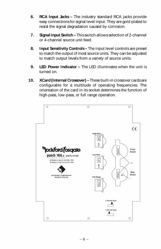
10. XCard (Internal Crossover) – These built-in crossover cards areconfigurable for a multitude of operating frequencies. Theorientation of the card in its socket determines the function ofhigh-pass, low-pass, or full range operation.
– 6 –
Low-Pass
Full Range
High-Pass
HP
LPH
P
LPFU
LL
RearXCard
FrontXCard
2 Channel Input
4 Channel Input
t r a n s • a n a
ROCKFORD CORPORATIONMADE IN THE USA
®
®
20 Watts x 4 into 4Ω at 0.05% THD40 Watts x 4 into 2Ω at 0.1% THD
A M P L I F I E R
XC
ard
1X
Car
d 2
7
10

INSTALLATION CONSIDERATIONS
This section focuses on some of the vehicle considerations for installingyour new Punch amplifier. Checking your battery and present soundsystem, as well as pre-planning your system layout and best wiring routeswill save installation time. When deciding how to lay out your newsystem, be sure that each component will be easily accessible for makingadjustments.
Before beginning any installation, be sure to follow these simple rules:
1. Be sure to carefully read and understand the instructions beforeattempting to install the amplifier.
2. For safety, disconnect the negative lead from the battery prior tobeginning the installation.
3. For easier assembly, we suggest you run all wires prior to mountingyour amplifier in place.
4. Route all of the RCA cables close together and away from any highcurrent wires.
5. Use high quality connectors for a reliable installation and to mini-mize signal or power loss.
6. Think before you drill! Be careful not to cut or drill into gas tanks,fuel lines, brake or hydraulic lines, vacuum lines or electrical wiringwhen working on any vehicle.
7. Never run wires underneath the vehicle. Running the wires inside thevehicle provides the best protection.
8. Avoid running wires over or through sharp edges. Use rubber orplastic grommets to protect any wires routed through metal, espe-cially the firewall.
9. ALWAYS protect the battery and electrical system from damage withproper fusing. Install the appropriate fuseholder and fuse on the+12V power wire within 18” (45.7 cm) of the battery terminal.
10. When grounding to the chassis of the vehicle, scrape all paint fromthe metal to ensure a good, clean ground connection. Groundingconnections should be as short as possible and always be connectedto metal that is welded to the main body, or chassis, of the vehicle.
The following is a list of tools you will need for installing the Punchamplifier:
Allen wrenches 9/64" & 3/32" (included) VoltmeterWire strippers Battery post wrenchElectric hand drill w/assorted bits Wire cuttersWire crimpers Assorted connectors
– 7 –
MOUNTING LOCATION
The mounting location and position of your amplifier will have a greateffect on its ability to dissipate the heat generated during normal opera-tion. The design of our cast aluminum heatsink serves to easily dissipatethe heat generated over a wide range of operating conditions. However,to maximize the performance of your amplifier, care should be taken toensure adequate ventilation.
Trunk MountingMounting the amplifier vertically on a surface with the fin grooves runningup and down will provide the best cooling of the amplifier.
Mounting the amplifier on the floor of the trunk will work but provides lesscooling capability than vertical mounting.
Mounting the amplifier upside down to the rear deck of the trunk will notprovide proper cooling and will severely affect the performance of theamplifier and is not recommended.
Passenger Compartment MountingMounting the amplifier in the passenger compartment will work as longas you provide a sufficient amount of air for the amplifier to cool itself. Ifyou are going to mount the amplifier under the seat of the vehicle, youmust have at least 1" (2.54cm) of air gap around the amplifier's heatsink.
Mounting the amplifier with less than 1" (2.54cm) of air gap around theamplifier's heatsink in the passenger compartment will not provide propercooling and will severely affect the performance of the amplifier and is notrecommended.
Engine Compartment MountingRockford Fosgate amplifiers should never be mounted in the enginecompartment. Not only will this void your warranty but could create anembarrassing situation caused by the ridicule from your friends.
– 8 –

Amplifiers will put an increased load on the vehicle's battery andcharging system. We recommend checking your alternator and batterycondition to ensure that the electrical system has enough capacity tohandle the increased load of your stereo system. Stock electrical systemswhich are in good condition should be able to handle the extra load ofany Rockford amplifier without problems, although battery and alterna-tor life can be reduced slightly. To maximize the performance of yourRockford Fosgate amplifier, we suggest the use of a heavy duty batteryand an energy storage capacitor.
BATTERY AND CHARGING
WIRING THE SYSTEM
CAUTION: Avoid running power wires near the low level input cables,antenna, power leads, sensitive equipment or harnesses. The power wirescarry substantial current and could induce noise into the audio system.
• For safety, disconnect the negative lead from the battery prior tobeginning the installation.
Configure the internal XCard crossovers prior to installation. (Refer topage 14 for more information.)
1. Plan the wire routing. Take care when running signal level RCA cablesto keep them close together but isolated from the amplifier's powercables and any high power auto accessories, especially electricmotors. This is done to prevent coupling the noise from radiatedelectrical fields into the audio signal. When feeding the wires throughthe firewall or any metal barrier, protect them with plastic or rubbergrommets to prevent short circuits. Leave the wires long at this pointto adjust for a precise fit at a later time.
2. Prepare the B+ cable for attachment to the amplifier by stripping 5/8"of insulation from the end of the wire. The use of 8 gauge power cablecan interfere with the installation of the end caps. Proper wire dresscan prevent this from occurring. To prevent the wire from fraying, stripthe insulation at a 45° angle. Insert the bared wire into the B+ terminalwith the long side of the insulation on the top. Bend the cable downat a 90° angle. Tighten the set screw to secure the cable in place.
– 9 –

3. Punch 160.4Trim the power cable to within 18" of the battery and install theprotective rubber boot packed with the fuseholder over the end ofthe wire. Strip 3/8" of insulation from the wire and insert it into theend of the fuseholder, then crimp it in place. Slide the rubber bootinto place to cover the connection. Use the section of cabletrimmed earlier and connect it to the other end of the fuseholder.
Punch 240.4Mount the fuseholder within 18" of the battery using two (2) #8screws. Disassemble the fuseholder. You should have 2 blackplastic end caps, 2 gold-plated fuse clips, a plastic spacer and thefuseholder body. Trim the amplifier power cable to reach thefuseholder and strip the wire 3/8". Slide one of the end caps overthe wire (narrow end first) and insert the wire into one of the fuseclips. Tighten the set screw. Screw the black end cap to thefuseholder body to secure the cable. Use the section of cable thatwas trimmed earlier and connect it to the other end of thefuseholder. Install the plastic spacer in the fuseholder and attachthe cable to the fuseholder body.
NOTE: The B+ cable MUST be fused 18" or less from the vehicle'sbattery. Install the fuseholder under the hood and prepare thecable ends as stated above. Connections should be water tight.
4. Strip 3/8" from the battery end of the power cable and crimp thelarge ring terminal to the cable. Use the ring terminal to connectto the battery positive terminal. Do not install the fuse at this time.
5. Prepare a length of cable to be used for the GND connection. Strip5/8" of insulation from the end of the cable as described previouslyand connect to the appropriate terminal of the amplifier. Preparethe chassis ground by scraping any paint from the metal surfaceand thoroughly clean the area of all dirt and grease. Strip the otherend of the wire and attach a ring connector. Fasten the cable to thechassis using a screw.
– 10 –
6. Prepare the REM turn-on wire for connection to the amplifier bystripping 1/4" of insulation from the wire end and crimping aninsulated spade connector in place. Slide the connector over theREM terminal on the amplifier. Connect the other end of the REMwire to a switched 12 volt positive source. The switched signal isusually taken from the source unit's auto antenna or the accessorylead. If the source unit does not have these outputs available, therecommended solution is to wire a mechanical switch in line witha 12 volt source to activate the amplifier.
7. Connect the source signal to the amplifier by plugging the RCAcables into the input jacks at the amplifier.
8. Connect the speakers. Strip the speaker wires 5/8". Insert the baredwire into the speaker terminal and tighten the set screw to secureinto place. Be sure to maintain proper speaker polarity. DO NOTchassis ground any of the speaker leads as unstable operation mayresult.
9. Perform a final check of the completed system wiring to ensure thatall connections are accurate. Check all power and ground connec-tions for frayed wires and loose connections which could causeproblems.
After the final inspection is complete, install the power fuse andenjoy listening. During the initial listening period, you may needto “fine tune” any phasing and level settings within your particularvehicle. To aid in this procedure, play a track with high musicalcontent and cruise around your neighborhood. After fully evaluat-ing the transient response of your system and making any finaladjustments, all your neighbors within a 1 mile radius will assumethat you have just successfully completed another upgrade to youraudio system for which they will probably spill thumbtacks onyour driveway.
10.
– 11 –
USING PASSIVE CROSSOVERS
A passive crossover is a circuit that uses capacitors and/or coils and isplaced on speaker leads between the amplifier and speaker. Thecrossover delegates a specific range of frequencies to the speaker foroptimum driver performance. A crossover network can perform one ofthree functions: High-Pass (capacitors), Low-Pass (inductors or coils)and Bandpass (combination of capacitor and coil).
The most commonly used passive crossover networks are 6dB/octavesystems. These are easy to construct and require one component perfilter. Placing this filter in series with the circuit will reduce power tothe speaker by 6dB/octave above or below the crossover pointdepending on whether it is a high-pass or low-pass filter. Morecomplex systems such as 12dB/octave or 18dB/octave can causeimpedance problems if not professionally designed.
Passive crossovers are directly dependent upon the speaker's imped-ance and component value for accuracy. When passive crossovercomponents are used in multiple speaker systems, the crossover'seffect on the overall impedance should be taken into considerationalong with the speaker's impedance when determining amplifierloads. CAUTION: The Rockford Fosgate amplifiers are not recom-mended for impedance loads below 2Ω stereo and 4Ω bridged(mono) loads.
advanced
Operation
– 12 –
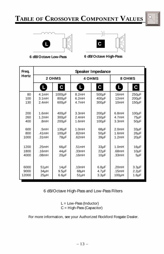
TABLE OF CROSSOVER COMPONENT VALUES
6 dB/Octave Low-Pass 6 dB/Octave High-Pass
Freq.Hertz
Speaker Impedance
80 4.1mH 1000µF 8.2mH 500µF 16mH 250µF100 3.1mH 800µF 6.2mH 400µF 12mH 200µF130 2.4mH 600µF 4.7mH 300µF 10mH 150µF
200 1.6mH 400µF 3.3mH 200µF 6.8mH 100µF260 1.2mH 300µF 2.4mH 150µF 4.7mH 75µF400 .8mH 200µF 1.6mH 100µF 3.3mH 50µF
600 .5mH 136µF 1.0mH 68µF 2.0mH 33µF800 .41mH 100µF .82mH 50µF 1.6mH 26µF
1000 .31mH 78µF .62mH 39µF 1.2mH 20µF
1200 .25mH 66µF .51mH 33µF 1.0mH 16µF1800 .16mH 44µF .33mH 22µF .68mH 10µF4000 .08mH 20µF .16mH 10µF .33mH 5µF
6000 51µH 14µF .10mH 6.8µF .20mH 3.3µF9000 34µH 9.5µF 68µH 4.7µF .15mH 2.2µF
12000 25µH 6.6µF 51µH 3.3µF 100µH 1.6µF
2 OHMS 8 OHMS4 OHMS
L C L C L C
L C
L = Low-Pass (Inductor)C = High-Pass (Capacitor)
For more information, see your Authorized Rockford Fosgate Dealer.
6 dB/Octave High-Pass and Low-Pass Filters
advanced
Operation
– 13 –

USING THE XCARD
The crossover functions are controlled through the use of an XCardand can be set for high-pass, low-pass or full range operation. Eachcrossover card has two faces: one face operates Full Range, the otherhas arrows to indicate the edge for selecting HP (high-pass) or LP (low-pass) operation. Orient the card with the desired operating edge,indicated by the arrow, toward the socket terminals inside theamplifier. Firmly, but carefully, plug the card into the socket.
The crossover point can be altered by changing the 4 resistor values.Use the following formula to select the appropriate resistor value tobe placed on the XCard.
3386fo
= R (in kΩ) for .047µf cap
= R (in kΩ) for .022µf cap7234fo
Where: R = ohmsfo = desired crossover frequencyc = capacitor in faradsex: .047 x 10-6 for .047µf cap
Crossover CardHigh PassLow PassFull Range
R1
R2
R1
R2FULL
The actual formula is:
R = 12πfoc
Low-Pass Full RangeHigh-Pass
FULL HP
LP HP
LP
– 14 –
advanced
Operation
– 15 –
RESISTOR CHART
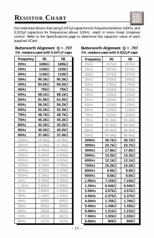
Frequency R1 R220Hz 169kΩ 169kΩ25Hz 133kΩ 133kΩ30Hz 110kΩ 110kΩ35Hz 95.3kΩ 95.3kΩ40Hz 84.5kΩ 84.5kΩ45Hz 75kΩ 75kΩ50Hz 68.1kΩ 68.1kΩ55Hz 61.9kΩ 61.9kΩ60Hz 56.2kΩ 56.2kΩ65Hz 52.3kΩ 52.3kΩ70Hz 48.7kΩ 48.7kΩ75Hz 45.3kΩ 45.3kΩ80Hz 42.2kΩ 42.2kΩ85Hz 40.2kΩ 40.2kΩ90Hz 37.4kΩ 37.4kΩ200Hz 16.9kΩ 16.9kΩ300Hz 11.3kΩ 11.3kΩ400Hz 8.45kΩ 8.45kΩ500Hz 6.65kΩ 6.65kΩ600Hz 5.62kΩ 5.62kΩ700Hz 4.75kΩ 4.75kΩ800Hz 4.22kΩ 4.22kΩ900Hz 3.74kΩ 3.74kΩ1kHz 3.40kΩ 3.40kΩ1.2kHz 2.80kΩ 2.80kΩ2kHz 1.69kΩ 1.69kΩ3kHz 1.10kΩ 1.10kΩ4kHz 845Ω 845Ω5kHz 665Ω 665Ω6kHz 562Ω 562Ω7kHz 487Ω 487Ω8kHz 422Ω 422Ω
Butterworth Alignment Q = .7071% resistors used with 0.047µF caps
Butterworth Alignment Q = .7071% resistors used with 0.022µF caps
Our tests have shown that using 0.047µf capacitors for frequencies below 100Hz, and0.022µf capacitors for frequencies above 100Hz, result in more linear crossovercontrol. Refer to the Specifications page to determine the capacitor value of eachsupplied XCard.
advanced
Operation
Frequency R1 R220Hz 357kΩ 357kΩ25Hz 287kΩ 287kΩ30Hz 237kΩ 237kΩ35Hz 205kΩ 205kΩ40Hz 178kΩ 178kΩ45Hz 162kΩ 162kΩ50Hz 143kΩ 143kΩ55Hz 130kΩ 130kΩ60Hz 121kΩ 121kΩ65Hz 110kΩ 110kΩ70Hz 102kΩ 102kΩ75Hz 95.3kΩ 95.3kΩ80Hz 90.9kΩ 90.9kΩ85Hz 84.5kΩ 84.5kΩ90Hz 80.6kΩ 80.6kΩ200Hz 35.7kΩ 35.7kΩ300Hz 23.7kΩ 23.7kΩ400Hz 17.8kΩ 17.8kΩ500Hz 14.3kΩ 14.3kΩ600Hz 12.1kΩ 12.1kΩ700Hz 10.2kΩ 10.2kΩ800Hz 9.9kΩ 9.9kΩ900Hz 8.6kΩ 8.6kΩ1.0kHz 7.15kΩ 7.15kΩ1.2kHz 6.04kΩ 6.04kΩ2.0kHz 3.57kΩ 3.57kΩ3.0kHz 2.37kΩ 2.37kΩ4.0kHz 1.76kΩ 1.76kΩ5.0kHz 1.43kΩ 1.43kΩ6.0kHz 1.21kΩ 1.21kΩ7.0kHz 1.02kΩ 1.02kΩ8.0kHz 909Ω 909Ω
USING THE SIGNAL INPUT SWITCH
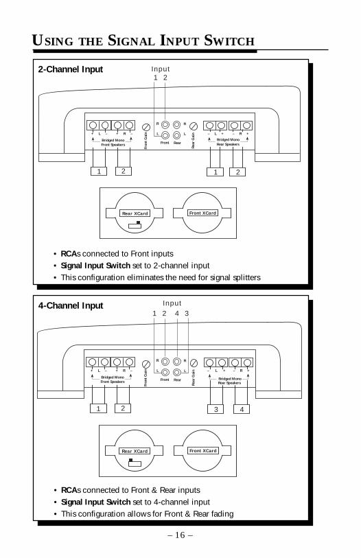
2-Channel Input
4-Channel Input
– 16 –
• RCAs connected to Front inputs• Signal Input Switch set to 2-channel input• This configuration eliminates the need for signal splitters
• RCAs connected to Front & Rear inputs• Signal Input Switch set to 4-channel input• This configuration allows for Front & Rear fading
Rear XCard Front XCard
RearFront
Rea
r G
ainL
R
Fron
t G
ain L
R
Input1 2
1 2 1 2
+ L –
Bridged MonoFront Speakers
+ R – – R +– L +
Bridged MonoRear Speakers
Rear XCard Front XCard
RearFront
Rea
r G
ainL
R
Fron
t G
ain L
R
1 2
1 2 3 4
+ L –
Bridged MonoFront Speakers
+ R –
Input4 3
– R +– L +
Rear SpeakersBridged Mono
INSTALLATION
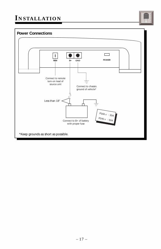
*Keep grounds as short as possible.
Power Connections
– 17 –
POWER
Connect to remoteturn-on lead of
source unit
Connect to B+ of batterywith proper fuse
Connect to chassisground of vehicle*
Less than 18"
P160.4
P240.4
- 30A
- 50A
REM GNDB+
INSTALLATION
® ®
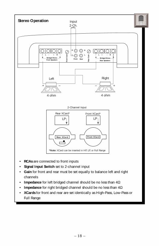
Stereo Operation
• RCAs are connected to front inputs• Signal Input Switch set to 2-channel input• Gain for front and rear must be set equally to balance left and right
channels• Impedance for left bridged channel should be no less than 4Ω• Impedance for right bridged channel should be no less than 4Ω• XCards for front and rear are set identically as High-Pass, Low-Pass or
Full Range
– 18 –
INSTALLATION
® ®
Input2-Ch.
+ – + –
Rear XCard Front XCard
4 ohm 4 ohm
*Note: XCard can be inserted in HP, LP, or Full Range
Rear XCard* Front XCard*
LP LP
2-Channel Input
RearFront
Rea
r G
ainL
R
Fron
t G
ain L
R
– L + – R +
Rear SpeakersBridged Mono
RightLeft
+ L – + R –
Bridged MonoFront Speakers

Mono Operation
– 19 –
• RCAs are connected to front inputs• Signal Input Switch set to 2-channel input• Gain for front and rear operates independently• Impedance for front bridged channel should be no less than 4Ω• Impedance for rear bridged channel should be no less than 4Ω• Front XCard can be set for High-Pass, Low-Pass or Full Range• Rear XCard can be set for High-Pass, Low-Pass or Full Range
Input2-Ch.
+ – + –
Rear XCard Front XCard
4 ohm 4 ohm
*Note: XCard can be inserted in HP, LP, or Full Range
Rear XCard* Front XCard*
LP LP
2-Channel Input
RearFront
Rea
r G
ainL
R
Fron
t G
ain L
R
+ L –
Bridged MonoFront Speakers
+ R – – L + – R +
Rear SpeakersBridged Mono
INSTALLATION
® ®
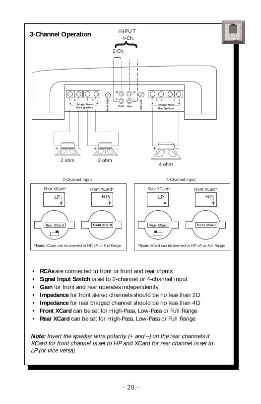
3-Channel Operation
Note: Invert the speaker wire polarity (+ and –) on the rear channels ifXCard for front channel is set to HP and XCard for rear channel is set toLP (or vice versa).
– 20 –
• RCAs are connected to front or front and rear inputs• Signal Input Switch is set to 2-channel or 4-channel input• Gain for front and rear operates independently• Impedance for front stereo channels should be no less than 2Ω• Impedance for rear bridged channel should be no less than 4Ω• Front XCard can be set for High-Pass, Low-Pass or Full Range• Rear XCard can be set for High-Pass, Low-Pass or Full Range
RearFront
Rea
r G
ainL
R
Fron
t G
ain L
R
Rear Speakers
2-Ch.+ – + –
Rear XCard Front XCard
2 ohm4 ohm
*Note: XCard can be inserted in HP, LP, or Full Range
Rear XCard* Front XCard*
LP HP
2-Channel Input
Rear XCard Front XCard
*Note: XCard can be inserted in HP, LP, or Full Range
Rear XCard* Front XCard*
LP HP
4-Channel Input
+ –
4-Ch.INPUT
2 ohm
+ L – + R –
Bridged MonoFront Speakers
Bridged Mono
– R +– L +
INSTALLATION
® ®
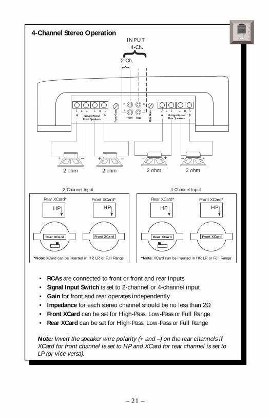
4-Channel Stereo Operation
– 21 –
• RCAs are connected to front or front and rear inputs• Signal Input Switch is set to 2-channel or 4-channel input• Gain for front and rear operates independently• Impedance for each stereo channel should be no less than 2Ω• Front XCard can be set for High-Pass, Low-Pass or Full Range• Rear XCard can be set for High-Pass, Low-Pass or Full Range
Note: Invert the speaker wire polarity (+ and –) on the rear channels ifXCard for front channel is set to HP and XCard for rear channel is set toLP (or vice versa).
Rear XCard Front XCard
*Note: XCard can be inserted in HP, LP, or Full Range
Rear XCard* Front XCard*
HP HP
2-Channel Input
Rear XCard Front XCard
*Note: XCard can be inserted in HP, LP, or Full Range
Rear XCard* Front XCard*
HP HP
4-Channel Input
RearFront
Rea
r G
ainL
R
Fron
t G
ain L
R
2-Ch.
4-Ch.INPUT
– +
2 ohm
– +
2 ohm
+ –
2 ohm
+ –
2 ohm
+ L – + R –
Bridged Mono
– R +– L +
Bridged MonoFront Speakers Rear Speakers
INSTALLATION
® ®
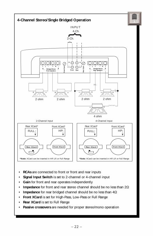
4-Channel Stereo/Single Bridged Operation
• RCAs are connected to front or front and rear inputs• Signal Input Switch is set to 2-channel or 4-channel input• Gain for front and rear operates independently• Impedance for front and rear stereo channel should be no less than 2Ω• Impedance for rear bridged channel should be no less than 4Ω• Front XCard is set for High-Pass, Low-Pass or Full Range• Rear XCard is set to Full Range• Passive crossovers are needed for proper stereo/mono operation
– 22 –
INSTALLATION
® ®
Rear XCard Front XCard
*Note: XCard can be inserted in HP, LP, or Full Range
Rear XCard* Front XCard*
FULL HP
2-Channel Input
Rear XCard Front XCard
*Note: XCard can be inserted in HP, LP, or Full Range
Rear XCard* Front XCard*
FULL HP
4-Channel Input
RearFront
Rea
r G
ainL
RFr
ont
Gai
n L
R
2-Ch.
4-Ch.INPUT
– +
2 ohm
– +
2 ohm
+ –
2 ohm
+ –
2 ohm
4 ohm
+ L – + R –
Bridged Mono
– R +– L +
Bridged MonoFront Speakers Rear Speakers
– +
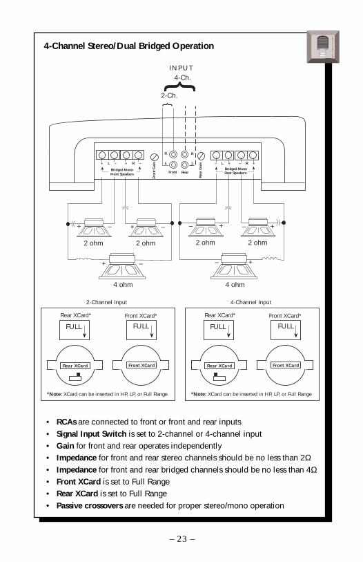
4-Channel Stereo/Dual Bridged Operation
• RCAs are connected to front or front and rear inputs• Signal Input Switch is set to 2-channel or 4-channel input• Gain for front and rear operates independently• Impedance for front and rear stereo channels should be no less than 2Ω• Impedance for front and rear bridged channels should be no less than 4Ω• Front XCard is set to Full Range• Rear XCard is set to Full Range• Passive crossovers are needed for proper stereo/mono operation
– 23 –
RearFront
Rea
r G
ainL
RFr
ont
Gai
n L
R
2-Ch.
4-Ch.INPUT
– +
2 ohm
– +
2 ohm
+ –
Rear XCard Front XCard
2 ohm
*Note: XCard can be inserted in HP, LP, or Full Range
Rear XCard* Front XCard*
FULL FULL
2-Channel Input
Rear XCard Front XCard
*Note: XCard can be inserted in HP, LP, or Full Range
Rear XCard* Front XCard*
FULL FULL
4-Channel Input
+ –
2 ohm
4 ohm4 ohm
+ L – + R –
Bridged Mono
– R +– L +
Bridged MonoFront Speakers Rear Speakers
– ++ –
INSTALLATION
® ®
SYSTEM DIAGRAMS
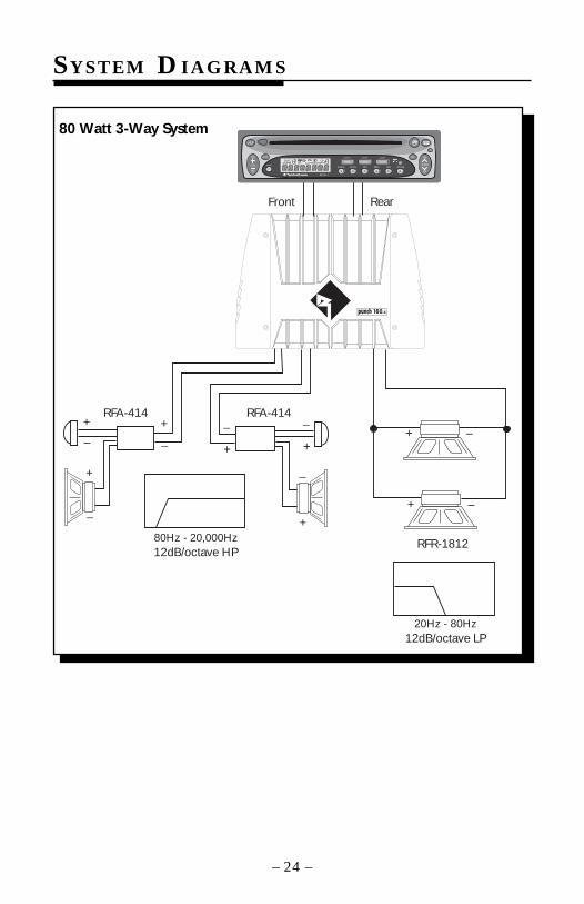
80 Watt 3-Way System
– 24 –
RFR-1812
Front Rear
+ –
+ –
12dB/octave LP20Hz - 80Hz
RFA-414
12dB/octave HP80Hz - 20,000Hz
RFA-414+
–
+
–
+
– +
–+
–
+
–
AUD SEL
1 2 3 4 5 6
RDMRPTSCAN PAUSED.SCN DIM
AMFMCh
RPTLD RDMDISC
ST P.SCN LOUDDSPL
R
CLOCK ILLUM
PWR
AUTO
® ®
VOL TUNE
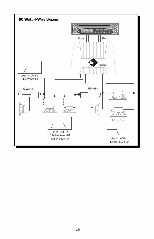
80 Watt 4-Way System
– 25 –
RFA-414
RFR-1812
Front Rear
12dB/octave HP6dB/octave LP
80Hz - 275Hz
12dB/octave LP20Hz - 80Hz
+ –
+ –
RFA-414
6dB/octave HP275Hz - 20kHz
AUD SEL
1 2 3 4 5 6
RDMRPTSCAN PAUSED.SCN DIM
AMFMCh
RPTLD RDMDISC
ST P.SCN LOUDDSPL
R
CLOCK ILLUM
PWR
AUTO
® ®
VOL TUNE
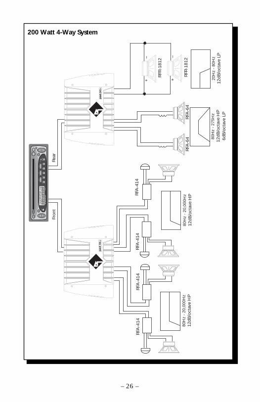
200 Watt 4-Way System
– 26 –
RFR
-181
2
Fron
tR
ear
12dB
/oct
ave
LP20
Hz
- 80
Hz
+
–
+
–
RFA
-414
12dB
/oct
ave
HP
80H
z -
20,0
00H
z
RFA
-414
RFA
-414
RFA
-414
12dB
/oct
ave
HP
80H
z -
20,0
00H
z
12dB
/oct
ave
HP
6dB
/oct
ave
LP
80H
z -
275H
z
RFA
-64
RFA
-64
RFR
-181
2
AU
DSEL
12
34
56
RD
MRPT
SC
AN
PAU
SE
D.S
CN
DIM
AM
FM
Ch
RP
TL
DR
DM
DIS
CS
TP.
SC
NLO
UD
DSPL
R
CLO
CK
ILLU
M
PWR
AU
TO
®®
VO
LTU
NE
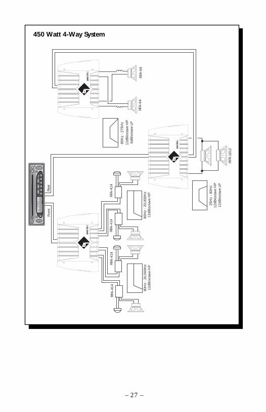
450 Watt 4-Way System
– 27 –
RFA
-414
RFA
-414
12dB
/oct
ave
HP
80H
z -
20,0
00H
z
Fron
tR
ear
RFA
-414
12dB
/oct
ave
HP
80H
z -
20,0
00H
zRFA
-414
12dB
/oct
ave
HP
6dB
/oct
ave
LP
80H
z -
275H
z
RFA
-64
RFA
-64
12dB
/oct
ave
HP
12dB
/oct
ave
LP
25H
z -
80H
z
RFR
-181
2
AU
DSEL
12
34
56
RD
MRPT
SC
AN
PAU
SE
D.S
CN
DIM
AM
FM
Ch
RP
TLD
RD
MD
ISC
ST
P.SC
NLO
UD
DSPL
R
CLO
CK
ILLU
M
PWR
AU
TO
®®
VO
LTU
NE
250.
1
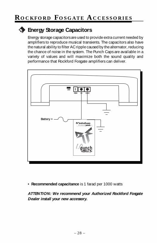
RO C K F O R D FO S G AT E AC C E S S O R I E S
Energy Storage CapacitorsEnergy storage capacitors are used to provide extra current needed byamplifiers to reproduce musical transients. The capacitors also havethe natural ability to filter AC ripple caused by the alternator, reducingthe chance of noise in the system. The Punch Caps are available in avariety of values and will maximize both the sound quality andperformance that Rockford Fosgate amplifiers can deliver.
®
• Recommended capacitance is 1 farad per 1000 watts
ATTENTION: We recommend your Authorized Rockford FosgateDealer install your new accessory.
GNDB+
LED
REM
1.0
®t h e c o n n e c t i n g® ®
1 farad • 20 VDC • 95°C
1.0cappunch
Battery +
– 28 –
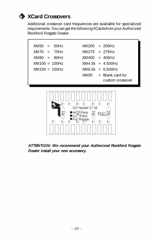
XCard CrossoversAdditional crossover card frequencies are available for specializedrequirements. You can get the following XCards from your AuthorizedRockford Fosgate Dealer.
®
XM50 = 50Hz XM200 = 200Hz
XM70 = 70Hz XM275 = 275Hz
XM80 = 80Hz XM400 = 400Hz
XM100 = 100Hz XM4.5k = 4,500Hz
XM150 = 150Hz XM6.5k = 6,500Hz
XM00 = Blank card forcustom crossover
ATTENTION: We recommend your Authorized Rockford FosgateDealer install your new accessory.
Crossover CardHigh PassLow PassFull Range
R1
R2
R1
R2FULL
– 29 –
TROUBLESHOOTING
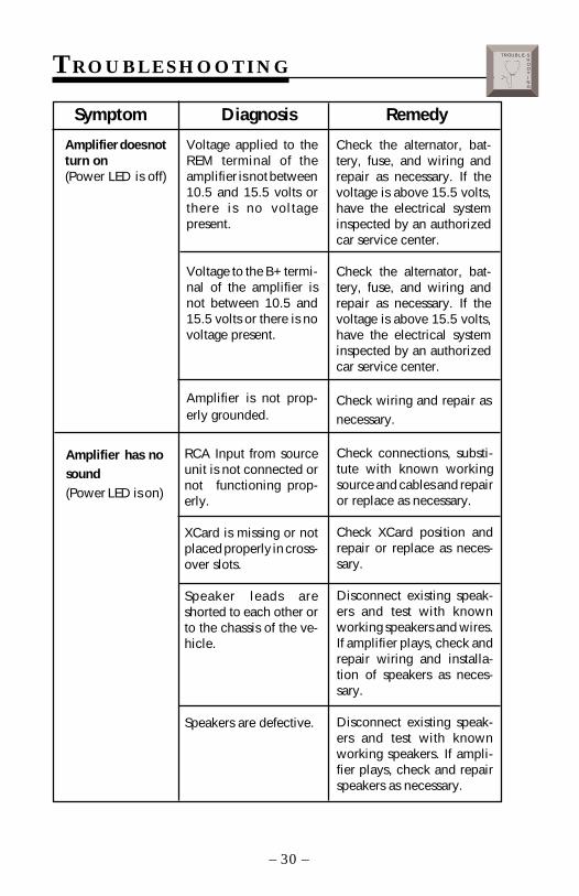
Amplifier does notturn on(Power LED is off)
Symptom Diagnosis Remedy
Voltage applied to theREM terminal of theamplifier is not between10.5 and 15.5 volts orthere is no voltagepresent.
Voltage to the B+ termi-nal of the amplifier isnot between 10.5 and15.5 volts or there is novoltage present.
Amplifier is not prop-erly grounded.
Amplifier has nosound(Power LED is on)
RCA Input from sourceunit is not connected ornot functioning prop-erly.
XCard is missing or notplaced properly in cross-over slots.
Speaker leads areshorted to each other orto the chassis of the ve-hicle.
Speakers are defective.
Check connections, substi-tute with known workingsource and cables and repairor replace as necessary.
Check XCard position andrepair or replace as neces-sary.
Disconnect existing speak-ers and test with knownworking speakers and wires.If amplifier plays, check andrepair wiring and installa-tion of speakers as neces-sary.
Disconnect existing speak-ers and test with knownworking speakers. If ampli-fier plays, check and repairspeakers as necessary.
Check the alternator, bat-tery, fuse, and wiring andrepair as necessary. If thevoltage is above 15.5 volts,have the electrical systeminspected by an authorizedcar service center.
Check the alternator, bat-tery, fuse, and wiring andrepair as necessary. If thevoltage is above 15.5 volts,have the electrical systeminspected by an authorizedcar service center.
Check wiring and repair asnecessary.
– 30 –
TROUBLE-SHOOTING
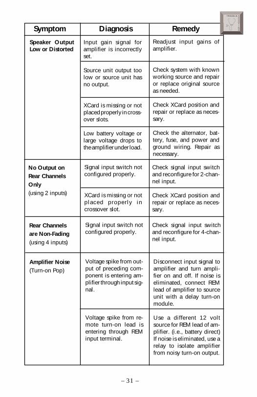
Speaker OutputLow or Distorted
Readjust input gains ofamplifier.
Check system with knownworking source and repairor replace original sourceas needed.
Check XCard position andrepair or replace as neces-sary.
Check the alternator, bat-tery, fuse, and power andground wiring. Repair asnecessary.
Symptom Diagnosis Remedy
Input gain signal foramplifier is incorrectlyset.
Source unit output toolow or source unit hasno output.
XCard is missing or notplaced properly in cross-over slots.
Low battery voltage orlarge voltage drops tothe amplifier under load.
No Output onRear ChannelsOnly(using 2 inputs)
Signal input switch notconfigured properly.
XCard is missing or notplaced properly incrossover slot.
Check signal input switchand reconfigure for 2-chan-nel input.
Check XCard position andrepair or replace as neces-sary.
Rear Channelsare Non-Fading(using 4 inputs)
Signal input switch notconfigured properly.
Check signal input switchand reconfigure for 4-chan-nel input.
Amplifier Noise(Turn-on Pop)
Voltage spike from out-put of preceding com-ponent is entering am-plifier through input sig-nal.
Voltage spike from re-mote turn-on lead isentering through REMinput terminal.
Disconnect input signal toamplifier and turn ampli-fier on and off. If noise iseliminated, connect REMlead of amplifier to sourceunit with a delay turn-onmodule.
Use a different 12 voltsource for REM lead of am-plifier. (i.e., battery direct)If noise is eliminated, use arelay to isolate amplifierfrom noisy turn-on output.
– 31 –
TROUBLE-SHOOTING
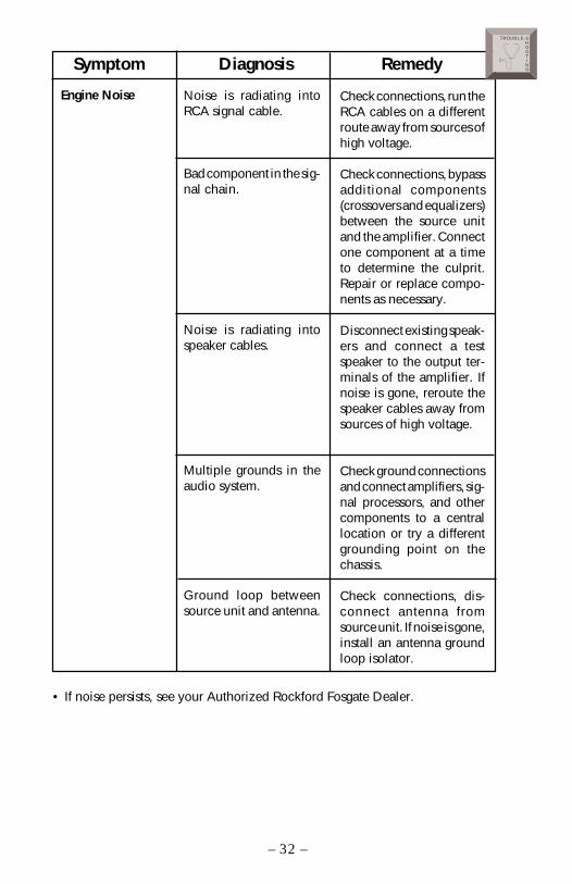
Noise is radiating intoRCA signal cable.
Bad component in the sig-nal chain.
Noise is radiating intospeaker cables.
Multiple grounds in theaudio system.
Ground loop betweensource unit and antenna.
Engine Noise
Symptom Diagnosis Remedy
Check connections, run theRCA cables on a differentroute away from sources ofhigh voltage.
Check connections, bypassadditional components(crossovers and equalizers)between the source unitand the amplifier. Connectone component at a timeto determine the culprit.Repair or replace compo-nents as necessary.
Disconnect existing speak-ers and connect a testspeaker to the output ter-minals of the amplifier. Ifnoise is gone, reroute thespeaker cables away fromsources of high voltage.
Check ground connectionsand connect amplifiers, sig-nal processors, and othercomponents to a centrallocation or try a differentgrounding point on thechassis.
Check connections, dis-connect antenna fromsource unit. If noise is gone,install an antenna groundloop isolator.
• If noise persists, see your Authorized Rockford Fosgate Dealer.
– 32 –
TROUBLE-SHOOTING
DYNAMIC POWER MEASUREMENTS
About the Dynamic Power MeasurementsThe Audio Graph PowerCube is a test instrument used to measure theoutput of an amplifier in accordance with IHF-202 industry standards.The IHF-202 standard is a dynamic power measurement and wasdeveloped as a means of measuring power in a manner that bestrepresents the real world operation of an amplifier. Many manufacturers,including Rockford Fosgate, at times will measure amplifier power into afixed resistor (4 ohm, 2 ohm). While this method is useful in some typesof evaluation and testing, it is not representative of an amplifier that isconnected to a speaker and playing music.
MusicMusic is dynamic; the sound waves are complex and constantly chang-ing. In order to simulate this, the IHF-202 standard calls for the input signalto the amplifier to be a 1kHz bursted tone. This signal is input (on for 20milliseconds) and reduced 20dB for 480 milliseconds. The signal isgradually increased in level until the amplifier's output exceeds 1% TotalHarmonic Distortion (THD). At 1% distortion becomes audible, there-fore, any power produced above that level is considered not usable. Manymanufacturers represent their amplifiers' output power in excess of 10%distortion. They use many names for this measurement, such as TotalMaximum Power or Maximum Output Power. This is not indicative of theactual usable output power.
Listening to Loudspeakers - Not ResistorsA loudspeaker is not a resistor. A resistor's value (resistance measured inohms) is fixed. A loudspeaker's impedance is dynamic. It is constantlychanging in value, dependent upon the frequency of the input signal.Therefore, measuring power with the amplifier loaded into a 4 ohmresistor is not the same as measuring power with the amplifier connectedto a 4 ohm speaker. Most people do not listen to music through a resistor.
A 4 ohm speaker may experience a drop in impedance 4-6 times lower thanits nominal (printed) impedance. A speaker will also create phase shifts inthe signal that is passed through it. These phase shifts happen because aspeaker is an inductor (voice coil) and a capacitor (compliance of thesurround/spider), as well as a resistor (voice coil wire).
To simulate a speaker the Audio Graph PowerCube measures outputpower into 20 different loads. It tests at 8 ohms, 4 ohms, 2 ohms and 1ohm. Each of these impedances is also tested at –60°, –30°, 0°, +30° and+60° phase angles. These different impedances and phase angles repre-sent the shifts in impedance and phase that can occur in a typicalloudspeaker.
– 33 –
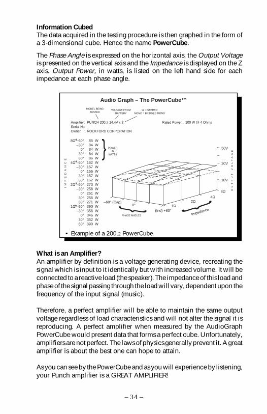
Information CubedThe data acquired in the testing procedure is then graphed in the form ofa 3-dimensional cube. Hence the name PowerCube.
The Phase Angle is expressed on the horizontal axis, the Output Voltageis presented on the vertical axis and the Impedance is displayed on the Zaxis. Output Power, in watts, is listed on the left hand side for eachimpedance at each phase angle.
What is an Amplifier?An amplifier by definition is a voltage generating device, recreating thesignal which is input to it identically but with increased volume. It will beconnected to a reactive load (the speaker). The impedance of this load andphase of the signal passing through the load will vary, dependent upon thefrequency of the input signal (music).
Therefore, a perfect amplifier will be able to maintain the same outputvoltage regardless of load characteristics and will not alter the signal it isreproducing. A perfect amplifier when measured by the AudioGraphPowerCube would present data that forms a perfect cube. Unfortunately,amplifiers are not perfect. The laws of physics generally prevent it. A greatamplifier is about the best one can hope to attain.
As you can see by the PowerCube and as you will experience by listening,your Punch amplifier is a GREAT AMPLIFIER!
–60° (Cap)0°
(Ind) +60°1Ω
2Ω4Ω
Impedance
8Ω
10V
30V
50V
8Ω –60°–30°
0°30°60°
4Ω –60°–30°
0°30°60°
2Ω –60°–30°
0°30°60°
1Ω –60°–30°
0°30°60°
85 W84 W84 W84 W86 W
162 W157 W156 W157 W162 W273 W258 W251 W256 W271 W390 W356 W346 W352 W390 W
Audio Graph – The PowerCube™
Amplifier:Serial No:Owner :
PUNCH 200.2 14.4V x 2
ROCKFORD CORPORATION
Rated Power : 100 W @ 4 Ohms
IM
PE
DA
NC
E
MODEL BEINGTESTED
x2 = STEREOMONO = BRIDGED MONO
VOLTAGE FROMBATTERY
OU
TP
UT
V
OL
TA
GE
*
*
*
*
PHASE ANGLES
POWERIN
WATTS
• Example of a 200.2 PowerCube
– 34 –

160.4 SP E C I F I C AT I O N S
Continuous Power Rating (Competition Standard) – Measured at 13.8VRMS continuous power per channel, all channels 20 Wattsdriven into a 4Ω load from 20-20,000Hz withless than 0.05% Total Harmonic Distortion (THD)
RMS continuous power per channel, all channels 40 Wattsdriven into a 2Ω load from 20-20000Hz, withless than 0.1% Total Harmonic Distortion (THD)
RMS continuous power bridged x 2 into a 4Ω load 80 Wattsfrom 20-20000Hz, with less than 0.1%Total Harmonic Distortion (THD)
Dynamic Power Rating (IHF-202 Standard) – Measured at 14.4V2-Channel bridged into a 4Ω load 120 Wattsper channel into a 2Ω load 60 Wattsper channel into a 4Ω load 40 Watts
Signal-to-Noise Ratio (A-weighted) >100dB
Factory Default Crossover Point 80Hz Butterworth (.047µf)Crossover Alignment 12dB/octaveDimensions 95⁄8"W x 139⁄32"L x 25⁄8"H
(24.4cm) x (33.73cm) x (6.6cm)
Damping Factor @ 4Ω (at output connector) >150Bandwidth 15Hz-100kHz ±3dBFrequency Response 20Hz-20kHz ±0.5dBSlew Rate 30 V/µsIM Distortion (IHF) <0.05%Input Sensitivity Variable from 150mV to 3V
Preset at the factory for 500mVB+ Fuse Size (external to amplifier) 30 amp ATCInput Impedance 20k ohms
– 35 –
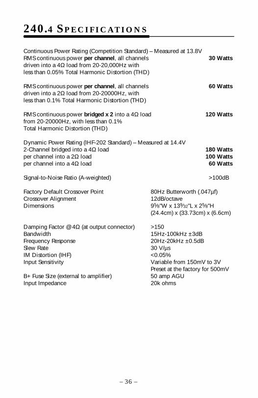
Continuous Power Rating (Competition Standard) – Measured at 13.8VRMS continuous power per channel, all channels 30 Wattsdriven into a 4Ω load from 20-20,000Hz withless than 0.05% Total Harmonic Distortion (THD)
RMS continuous power per channel, all channels 60 Wattsdriven into a 2Ω load from 20-20000Hz, withless than 0.1% Total Harmonic Distortion (THD)
RMS continuous power bridged x 2 into a 4Ω load 120 Wattsfrom 20-20000Hz, with less than 0.1%Total Harmonic Distortion (THD)
Dynamic Power Rating (IHF-202 Standard) – Measured at 14.4V2-Channel bridged into a 4Ω load 180 Wattsper channel into a 2Ω load 100 Wattsper channel into a 4Ω load 60 Watts
Signal-to-Noise Ratio (A-weighted) >100dB
Factory Default Crossover Point 80Hz Butterworth (.047µf)Crossover Alignment 12dB/octaveDimensions 95⁄8"W x 139⁄32"L x 25⁄8"H
(24.4cm) x (33.73cm) x (6.6cm)
Damping Factor @ 4Ω (at output connector) >150Bandwidth 15Hz-100kHz ±3dBFrequency Response 20Hz-20kHz ±0.5dBSlew Rate 30 V/µsIM Distortion (IHF) <0.05%Input Sensitivity Variable from 150mV to 3V
Preset at the factory for 500mVB+ Fuse Size (external to amplifier) 50 amp AGUInput Impedance 20k ohms
240.4 SP E C I F I C AT I O N S
– 36 –

– 37 –
LIMITED WARRANTY INFORMATION
Rockford Corporation offers a limited warranty on Rockford Fosgate products on thefollowing terms:
• Length of Warranty3 years on electronics 90 days on electronic B-stock (receipt required)2 years on source units 30 days on speaker B-stock (receipt required)
• What is CoveredThis warranty applies only to Rockford Fosgate products sold to consumers byAuthorized Rockford Fosgate Dealers in the United States of America or itspossessions. Product purchased by consumers from an Authorized RockfordFosgate Dealer in another country are covered only by that country’s Distributorand not by Rockford Corporation.
• Who is CoveredThis warranty covers only the original purchaser of Rockford product purchasedfrom an Authorized Rockford Fosgate Dealer in the United States. In order toreceive service, the purchaser must provide Rockford with a copy of the receiptstating the customer name, dealer name, product purchased and date of purchase.
• Products found to be defective during the warranty period will be repaired orreplaced (with a product deemed to be equivalent) at Rockford's discretion.
• What is Not Covered1. Damage caused by accident, abuse, improper operations, water, theft2. Any cost or expense related to the removal or reinstallation of product3. Service performed by anyone other than Rockford or an Authorized Rockford
Fosgate Service Center4. Any product which has had the serial number defaced, altered, or removed5. Subsequent damage to other components6. Any product purchased outside the U.S.7. Any product not purchased from an Authorized Rockford Fosgate Dealer
• Limit on Implied WarrantiesAny implied warranties including warranties of fitness for use and merchantabilityare limited in duration to the period of the express warranty set forth above. Somestates do not allow limitations on the length of an implied warranty, so thislimitation may not apply. No person is authorized to assume for Rockford Fosgateany other liability in connection with the sale of the product.
• How to Obtain ServicePlease call 1-800-669-9899 for Rockford Customer Service. You must obtain anRA# (Return Authorization number) to return any product to Rockford Fosgate. Youare responsible for shipment of product to Rockford.
Ship to: SpeakersRockford Acoustic Design(Receiving-speakers)609 Myrtle N.W.Grand Rapids, MI 49504RA#:_________________
Ship to: ElectronicsRockford CorporationWarranty Repair Department2055 E. 5th StreetTempe, AZ 85281RA#:_________________

INTERN
ATION
AL I NFO
RMAT IO
N
– 38 –

LEA DETENIDAMENTE LAS SIGUIENTES INSTRUCCIONES DEINSTALACION DEL PRODUCTO. EVITARA POSIBLES DAÑOS A VD., ALVEHICULO O AL PRODUCTO.
Montaje en el MalateroMonte el amplificador verticalmente con las lineas del radiador orientadasde arriba hacia abajo. De esta manera conseguira la mejor ventilacion.
Montaje en el Compartimento de PasajerosEl montaje en el compartimento de pasajeros sera eficiente en funcionde la ventilacion que tenga el amplificador. Si va a instalar el amplificadorbajo un asiento deberá dejar al menos 2.5cm libres sobre la carcasa delamplificador.
InstalacionPor seguridad, desconecte el terminal negativo de la bateria antes decomenzar la instalacion.
Terminal B+El cable B+ debe ir provisto de un fusible a una distancia no mayor de45cm de la bateria. Prepare el cable e instale el portafusibles en elcompartimento del motor. Las conexiones han de ser impermeables.
Terminal GNDPrepare un trozo de cable para usarlo como toma de masa. Prepare unpunto de masa en el chasis rascando y eliminando la pintura de lasuperficie de metal y limpielo de toda suciedad asegure el cable al chasiscon un tornillo.
Terminal REMConecte el cable REM a un punto de +12V con mutable. La señal se suele cogerde la salida auto antena del radio cassette si este no tiene salida remote.
UBICACIÓN PARA EL MONTAJE
INTRODUCCION
– 39 –
ESPA
ÑO
L
Los Punch 160.4 y 240.4 son amplificadores de 4 canales que ofrecen160 / 240 vatios RMS respectivamente. Ambos amplificadores incorporanun conmutador para entrada de 2 o 4 canales, de manera que no esnecesario utilizar derivadores de linea. Hay un par de tarjetas de filtroXCard que permiten la configuración de los amplificadores para su usocon cualquier sistema de altavoces sin necesidad de procesadoresexternos. Los Punch 160.4 y 240.4 son potentes amplificadores concaracterísticas únicas a un precio competitivo.
Recomendamos que el montaje sea realizado por un instalador autorizadoRockford Fosgate. Si prefiere instalarlo usted mismo asegúrese de leer elmanual en su totalidad.
– 40 –
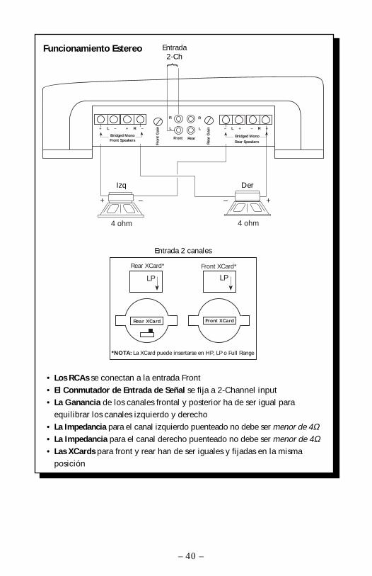
Funcionamiento Estereo
• Los RCAs se conectan a la entrada Front• El Conmutador de Entrada de Señal se fija a 2-Channel input• La Ganancia de los canales frontal y posterior ha de ser igual para
equilibrar los canales izquierdo y derecho• La Impedancia para el canal izquierdo puenteado no debe ser menor de 4Ω• La Impedancia para el canal derecho puenteado no debe ser menor de 4Ω• Las XCards para front y rear han de ser iguales y fijadas en la misma
posición
Input2-Ch.
+ – + –
Rear XCard Front XCard
4 ohm 4 ohm
*Note: XCard can be inserted in HP, LP, or Full Range
Rear XCard* Front XCard*
LP LP
2-Channel Input
RearFront
Rea
r G
ainL
R
Fron
t G
ain L
R
– L + – R +
Rear SpeakersBridged Mono
RightLeft
+ L – + R –
Bridged MonoFront Speakers
Entrada2-Ch
Izq Der
Entrada 2 canales
*NOTA: La XCard puede insertarse en HP, LP o Full Range
– 41 –
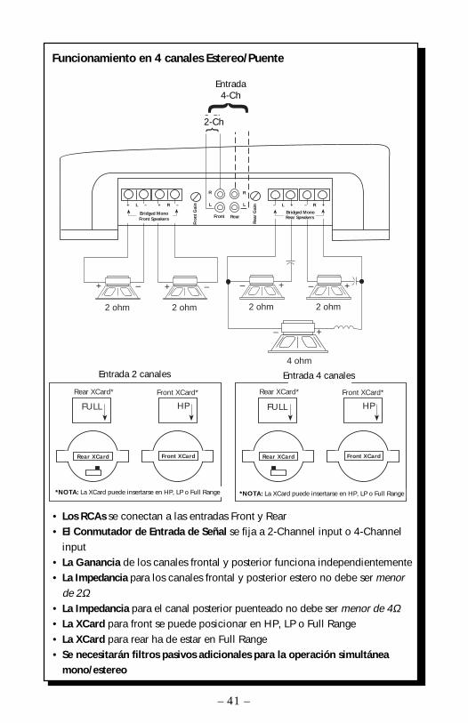
• Los RCAs se conectan a las entradas Front y Rear• El Conmutador de Entrada de Señal se fija a 2-Channel input o 4-Channel
input• La Ganancia de los canales frontal y posterior funciona independientemente• La Impedancia para los canales frontal y posterior estero no debe ser menor
de 2Ω• La Impedancia para el canal posterior puenteado no debe ser menor de 4Ω• La XCard para front se puede posicionar en HP, LP o Full Range• La XCard para rear ha de estar en Full Range• Se necesitarán filtros pasivos adicionales para la operación simultánea
mono/estereo
Funcionamiento en 4 canales Estereo/Puente
Rear XCard Front XCard
*Note: XCard can be inserted in HP, LP, or Full Range
Rear XCard* Front XCard*
FULL HP
2-Channel Input
Rear XCard Front XCard
*Note: XCard can be inserted in HP, LP, or Full Range
Rear XCard* Front XCard*
FULL HP
4-Channel Input
RearFront
Rea
r G
ainL
RFr
ont
Gai
n L
R
2-Ch.
4-Ch.INPUT
– +
2 ohm
– +
2 ohm
+ –
2 ohm
+ –
2 ohm
4 ohm
+ L – + R –
Bridged Mono
– R +– L +
Bridged MonoFront Speakers Rear Speakers
– +
Entrada4-Ch
2-Ch
Entrada 2 canales
*NOTA: La XCard puede insertarse en HP, LP o Full Range
Entrada 4 canales
*NOTA: La XCard puede insertarse en HP, LP o Full Range

ATTENTION: Veuillez lire les instructions suivantes pour l'installation de cetamplificateur. Ne pas les suivre pourrait causer des blessures ou endommagerle véhicule.
Les Punch 160.4 et 240.4 sont des amplificateurs à 4 canaux délivrantrespectivement 160 et 240 watts RMS. Ces 2 amplificateurs utilisent uninterrupteur 2/4 canaux qui élimine le besoin d'un séparateur de signal.Une paire de cartes de filtrage interne permet de configurer l'amplificateurafin d'être utilisé dans la plupart des configuations sans dépensesupplémentaire.
Nous vous recommandons fortement de faire installer votre nouvelamplificateur Punch par un dealer agréé Rockford Fosgate. Si vousdécidez néanmoins de l'installer vous-même, assurez-vous de lirel'entièreté de ce manuel avant de commencer.
INTRODUCTION
Montage dans le coffreMonter l'amplificateur verticalement avec les rainures de haut en bas cequi lui permet de refroidir plus facilement.
Montage dans l'habitacleMonter l'amplificateur dans l'habitacle ne pose aucun problème, dumoment qu'il y ait assez d'air pour le refroidir. Si vous montez l'amplien dessous du siège, prévoyez 3 cm d'air autour du radiateur.
InstallationPour votre sécurité, déconnectez la borne négative de la batterie duvéhicule avant de commencer l'installation.
Terminal B+Il est impératif qu'il y ait un fusible sur le câble pour la connexion à lamasse. Préparez le châssis en grattant la peinture de la surface métalliqueet nettoyez la saleté et l'huile. Attachez le câble au châssis avec une vis.
Terminal GNDPréparez une longueur de câble pour la connexion à la masse. Préparezle châssis en grattant la peinture de la surface métallique et nettoyez lasaleté et l'huile. Attachez le câble au châssis avec une vis.
Terminal REMConnectez le fil REM à une commande 12 volts positive de la source. Lacommande 12 volts est habituellement prise sur la sortie antenneélectrique de la source ou la commande accessoire. Si la source nedispose pas de ces sorties, nous vous recommandons d'installer uninterrupteur qui fournira un positif 12 volts au REM de l'amplificateur.
MONTAGE
– 42 –
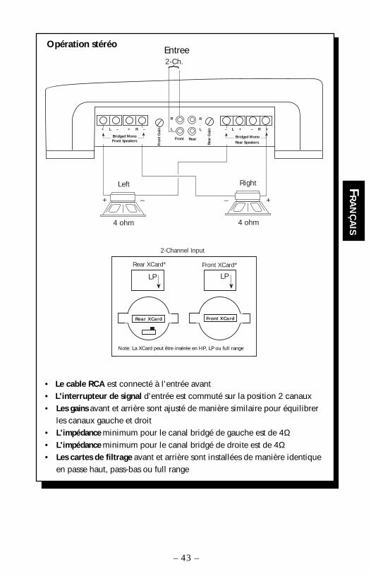
• Le cable RCA est connecté à l'entrée avant• L'interrupteur de signal d'entrée est commuté sur la position 2 canaux• Les gains avant et arrière sont ajusté de manière similaire pour équilibrer
les canaux gauche et droit• L'impédance minimum pour le canal bridgé de gauche est de 4Ω• L'impédance minimum pour le canal bridgé de droite est de 4Ω• Les cartes de filtrage avant et arrière sont installées de manière identique
en passe haut, pass-bas ou full range
Input2-Ch.
+ – + –
Rear XCard Front XCard
4 ohm 4 ohm
*Note: XCard can be inserted in HP, LP, or Full Range
Rear XCard* Front XCard*
LP LP
2-Channel Input
RearFront
Rea
r G
ainL
R
Fron
t G
ain L
R
– L + – R +
Rear SpeakersBridged Mono
RightLeft
+ L – + R –
Bridged MonoFront Speakers
Opération stéréo
– 43 –
FR
AN
ÇA
IS
Note: La XCard peut être insérée en HP, LP ou full range
Entree
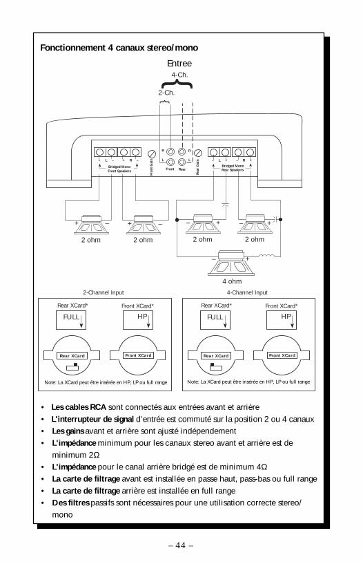
Fonctionnement 4 canaux stereo/mono
• Les cables RCA sont connectés aux entrées avant et arrière• L'interrupteur de signal d'entrée est commuté sur la position 2 ou 4 canaux• Les gains avant et arrière sont ajusté indépendement• L'impédance minimum pour les canaux stereo avant et arrière est de
minimum 2Ω• L'impédance pour le canal arrière bridgé est de minimum 4Ω• La carte de filtrage avant est installée en passe haut, pass-bas ou full range• La carte de filtrage arrière est installée en full range• Des filtres passifs sont nécessaires pour une utilisation correcte stereo/
mono
– 44 –
Rear XCard Front XCard
*Note: XCard can be inserted in HP, LP, or Full Range
Rear XCard* Front XCard*
FULL HP
2-Channel Input
Rear XCard Front XCard
*Note: XCard can be inserted in HP, LP, or Full Range
Rear XCard* Front XCard*
FULL HP
4-Channel Input
RearFront
Rea
r G
ainL
RFr
ont
Gai
n L
R
2-Ch.
4-Ch.INPUT
– +
2 ohm
– +
2 ohm
+ –
2 ohm
+ –
2 ohm
4 ohm
+ L – + R –
Bridged Mono
– R +– L +
Bridged MonoFront Speakers Rear Speakers
– +
Note: La XCard peut être insérée en HP, LP ou full range Note: La XCard peut être insérée en HP, LP ou full range
Entree

BITTE LESEN SIE DIESE GEBRAUCHSANLEITUNG ZUERST SORGFÄLTIGDURCH. DAS KANN SIE VOR DEM FALSCHEN EINSATZ, AUSFALLENODER SOGAR BESCHÄDIGUNG DES PRODUKTES ODER IHRESFAHRZEUGES SCHÜTZEN.
EINBAUORT
Die Punch 160.4 and 240.4 sind 4-Kanal Verstärker, weiche 160 bzw,240 Watt RMS abgeben können. Beide Verstärker einen 2/4-KanalEingangswahlschalter, dadurch werden keine Y-Adapter mehr benötigt.Zwei eingebaute Aktivweichen-Module erlauben es, den Verstärker soanzupassen, das dieser mit den am häufigsten verwendeten Systemenhannoniert, ohne das man externe Prozessoren einsetzen muβ. DiePunch 160.4 und 240.4 sing kraftvolle 4-Kanal Verstärker mit integriertenBesonderheiten, weiche zu einem konkurenzlos günstigen Preisangeboten werdfen.
Wir empfeheln Ihnen, Ihren neuen Verstärker, von einem unsererautorisierten Rockford Hzuandler einbauen zu lassen. Sollten Sie denVerstärker selber einbauen, so beachten Sie bitte diese Hinweise, bevorSie mit dem Einbau beginnen.
EINLEITUNG
Im FahrzeugkofferraumDer vertikale Einbau der Endstufen, das bedeutet, daβ die Kühlrippenvon oben nach unten verlaufen, gibt dem Verstärker die beste Kühlung.
Auf der BeifahrerseiteSollte der Verstärker auf der Beifahrerseite montiert werden, so ist essehr wichtig, für eine ausreichende Kühlung zu sorgen. Sollte derVerstärker z.B. unter dem Beifahrersitz montiert werden, sollte demKühlkörper mindestens ein Luftspalt von 3 cm bleiben, um so für eineausreichende Kühlung zu sorgen.
EinbauZur Sicherheit klemmen Sie den Negativ-Pol der Batterie während desgesamten Einbaues ab.
B+ AnschlussDie Plus-Leitung MUβ ca. 40 cm nach dem Plus-Pol der Batterie abgesichertsein. Preparieren Si die Kabellängen und montieren Sie den Sicherungshalterim Motorraum. ALLE Verbindungen müssen wasserdicht sein.
GND AnschlussPreparieren Sie Ihr Kabel für die Negativ Leitung (Erdung). PreparierenSie die Anschluβstelle des Erdungskabels, indem Sie das Metall gründlichreinigen und vom Lack befreien. Befestigen Sie nun die Erdung an dieserStelle mit einer Schraube.
– 45 –
DEU
TSCH
REM AnschlussVerbinden Sie das Ein-und Ausschaltungskontroll-Kabel mit IhremRadio (12 Volt positiv). Normalerweise verwenden Sie hierfür dieAnt.-Remote Ihres Radios oder ein eigens dafür vorgesehenes Kabel(Amp-Remote). Sollte Ihr Radio diesen Anschluβ nicht besitzen, soverwenden Sie eine 12 Volt Spannung, die Sie durch einen Schalterein- und ausschalten können.
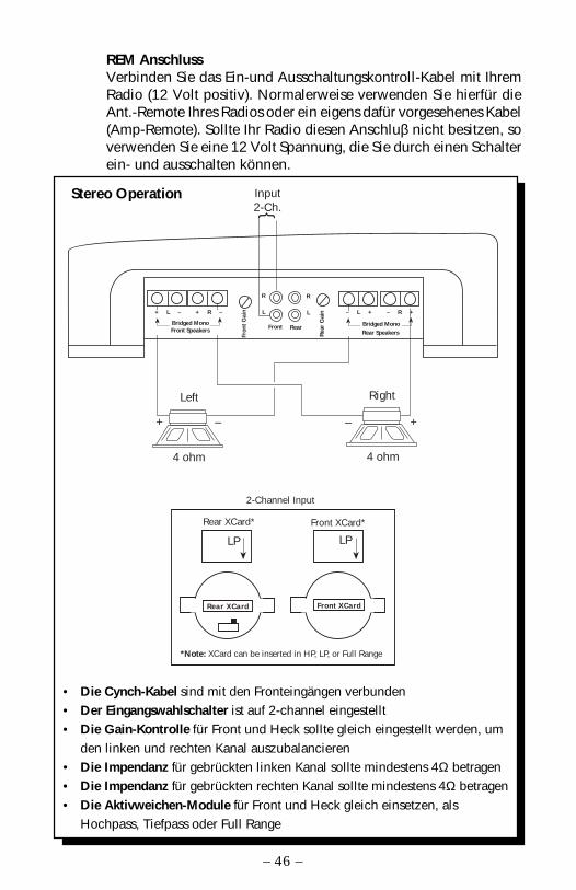
• Die Cynch-Kabel sind mit den Fronteingängen verbunden• Der Eingangswahlschalter ist auf 2-channel eingestellt• Die Gain-Kontrolle für Front und Heck sollte gleich eingestellt werden, um
den linken und rechten Kanal auszubalancieren• Die Impendanz für gebrückten linken Kanal sollte mindestens 4Ω betragen• Die Impendanz für gebrückten rechten Kanal sollte mindestens 4Ω betragen• Die Aktivweichen-Module für Front und Heck gleich einsetzen, als
Hochpass, Tiefpass oder Full Range
Input2-Ch.
+ – + –
Rear XCard Front XCard
4 ohm 4 ohm
*Note: XCard can be inserted in HP, LP, or Full Range
Rear XCard* Front XCard*
LP LP
2-Channel Input
RearFrontR
ear
Gai
nL
R
Fron
t G
ain L
R
– L + – R +
Rear SpeakersBridged Mono
RightLeft
+ L – + R –
Bridged MonoFront Speakers
Stereo Operation
– 46 –
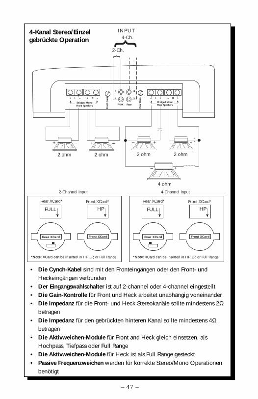
4-Kanal Stereo/Einzelgebrückte Operation
• Die Cynch-Kabel sind mit den Fronteingängen oder den Front- undHeckeingängen verbunden
• Der Eingangswahlschalter ist auf 2-channel oder 4-channel eingestellt• Die Gain-Kontrolle für Front und Heck arbeitet unabhängig voneinander• Die Impedanz für die Front- und Heck Stereokanäle sollte mindestens 2Ω
betragen• Die Impedanz für den gebrückten hinteren Kanal sollte mindestens 4Ω
betragen• Die Aktivweichen-Module für Front and Heck gleich einsetzen, als
Hochpass, Tiefpass oder Full Range• Die Aktivweichen-Module für Heck ist als Full Range gesteckt• Passive Frequenzweichen werden für korrekte Stereo/Mono Operationen
benötigt
– 47 –
Rear XCard Front XCard
*Note: XCard can be inserted in HP, LP, or Full Range
Rear XCard* Front XCard*
FULL HP
2-Channel Input
Rear XCard Front XCard
*Note: XCard can be inserted in HP, LP, or Full Range
Rear XCard* Front XCard*
FULL HP
4-Channel Input
RearFront
Rea
r G
ainL
R
Fron
t G
ain L
R
2-Ch.
4-Ch.INPUT
– +
2 ohm
– +
2 ohm
+ –
2 ohm
+ –
2 ohm
4 ohm
+ L – + R –
Bridged Mono
– R +– L +
Bridged MonoFront Speakers Rear Speakers
– +

ATTENZIONE: SI PREGA DI LEGGERE LE SEGUENTI ISTRUZIONI PERL'INSTALLAZIONE DI QUESTO PRODOTTO. IL NON SEGUIRLE POTREBBERISULTARE SERIAMENTE DANNOSO PER LA PERSONA O PER IL VEICOLO.
I Punch 160.4 e 240.4 sono amplificatori 4 canali in grado di erogarerispettivamente 160 e 240 watt RMS. Entrambi questi amplificatoriimpiegno uno switch di selezione 2/4 canali evitando l'impiego disdoppiatori di segnale. Una coppia di XCard interne permette agliamplificatori di essere impiegati nelle configurazione piú in voga senzarichiedere l'impiego di costosi processori esterni. I Punch 160.4 e 240.4sono potenti amplificatori con caratteristiche integrate che li rendonomolto appetibili, anche da un punto di vista di prezzo.
Raccomandiamo fermamente di fare installare il vostro nuovoamplificatore da un installatore autoizzato Rockford Fosgate. Se sceglietedi procedere da soli con l'installazione assicuratevi di leggereattentamente tutto il manuale prima di procedere.
INTRODUZIONE
Nel BagagliaioMontando l'amplificatore su una superficie in verticale con le alettedirezionate dall'alto verso il basso si garantirá un miglior raffreddamentodell'amplificatore.
Nell'abitacoloMontare l'amplificatore nell'abitacolo si avrá un funzionamento regolarese si garantisce un flusso d'aria sufficiente. Per l'installazione sotto unsedile, é necessario avere uno spazio di almeno 3 cm attorno a tuttol'amplificatore.
InstallazionePer sicurezza, scollegare il polo negativo della batteria dell'auto primadi iniziare l'installazione.
Terminale B+ (cavo positivo)Il cavo positivo deve essere protetto da un fusibile a non piú di 45 cmdalla batteria. Terminare il cavo e installare il fusibile nel vano motore.Tutte le connessioni devono essere a prova d'acqua.
Terminale GND (cavo negativo)Decidere la lunghezza del cavo e terminarlo. Preparare la massagrattando la vernice dal telaio dell'auto ed eliminando tracce di olio osporco. Fissare il cavo di massa al telaio con una vite.
DOVE POSIZIONARLO
– 48 –
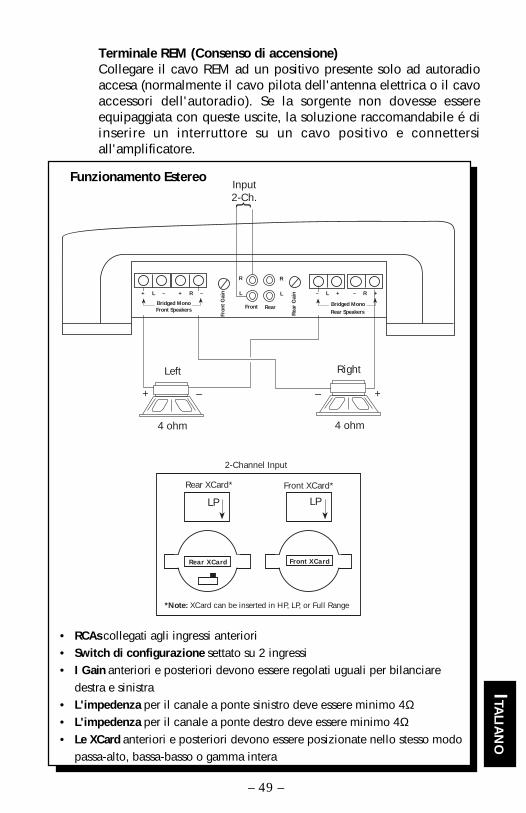
Terminale REM (Consenso di accensione)Collegare il cavo REM ad un positivo presente solo ad autoradioaccesa (normalmente il cavo pilota dell'antenna elettrica o il cavoaccessori dell'autoradio). Se la sorgente non dovesse essereequipaggiata con queste uscite, la soluzione raccomandabile é diinserire un interruttore su un cavo positivo e connettersiall'amplificatore.
• RCAs collegati agli ingressi anteriori• Switch di configurazione settato su 2 ingressi• I Gain anteriori e posteriori devono essere regolati uguali per bilanciare
destra e sinistra• L'impedenza per il canale a ponte sinistro deve essere minimo 4Ω• L'impedenza per il canale a ponte destro deve essere minimo 4Ω• Le XCard anteriori e posteriori devono essere posizionate nello stesso modo
passa-alto, bassa-basso o gamma intera
Funzionamento EstereoInput2-Ch.
+ – + –
Rear XCard Front XCard
4 ohm 4 ohm
*Note: XCard can be inserted in HP, LP, or Full Range
Rear XCard* Front XCard*
LP LP
2-Channel Input
RearFront
Rea
r G
ainL
R
Fron
t G
ain L
R
– L + – R +
Rear SpeakersBridged Mono
RightLeft
+ L – + R –
Bridged MonoFront Speakers
– 49 –
ITALIA
NO
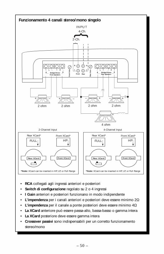
Funzionamento 4 canali stereo/mono singolo
• RCA collegati agli ingressi anteriori e posteriori• Switch di configurazione regolato su 2 o 4 ingressi• I Gain anteriori e posteriori funzionano in modo indipendente• L'impendenza per i canali anteriori e posteriori deve essere minimo 2Ω• L'impendenza per il canale a ponte posteriori deve essere minimo 4Ω• La XCard anteriore puó essere passa-alto, bassa-basso o gamma intera• La XCard posteriore deve essere gamma intera• Crossover passivi sono indispensabili per un corretto funzionamento
stereo/mono
– 50 –
Rear XCard Front XCard
*Note: XCard can be inserted in HP, LP, or Full Range
Rear XCard* Front XCard*
FULL HP
2-Channel Input
Rear XCard Front XCard
*Note: XCard can be inserted in HP, LP, or Full Range
Rear XCard* Front XCard*
FULL HP
4-Channel Input
RearFront
Rea
r G
ainL
R
Fron
t G
ain L
R
2-Ch.
4-Ch.INPUT
– +
2 ohm
– +
2 ohm
+ –
2 ohm
+ –
2 ohm
4 ohm
+ L – + R –
Bridged Mono
– R +– L +
Bridged MonoFront Speakers Rear Speakers
– +

NOTES

Rockford FosgateRockford Corporation
546 South Rockford DriveTempe, Arizona 85281 U.S.A.
In U.S.A., (602) 967-3565In Europe, Fax (49) 4207-801250In Japan, Fax (81) 559-79-1265
9/96MAN-1526-A