ROCKFORD PUBLIC SCHOOLS 205
269
PROJECT MANUAL HILLMAN ELEMENTARY BOILER UPGRADES ROCKFORD PUBLIC SCHOOLS 205 HILLMAN ELEMENTARY SCHOOL 3701 GREEN DALE DR. ROCKFORD, ILLINOIS 61109
-
Upload
khangminh22 -
Category
Documents
-
view
2 -
download
0
Transcript of ROCKFORD PUBLIC SCHOOLS 205

PROJECT MANUAL
HILLMAN ELEMENTARY BOILER UPGRADES
ROCKFORD PUBLIC SCHOOLS 205 HILLMAN ELEMENTARY SCHOOL 3701 GREEN DALE DR. ROCKFORD, ILLINOIS 61109

PROJECT MANUAL FOR
HILLMAN ELEMENTARY BOILER UPGRADES ROCKFORD PUBLIC SCHOOLS 205 HILLMAN ELEMENTARY SCHOOL 3701 GREEN DALE DR. ROCKFORD, ILLINOIS 61109 RPS PROJECT NO.: 2058 LDG PROJECT NO.: 30050 DATE: April 13, 2020 BY: LARSON & DARBY GROUP ARCHITECTURE-ENGINEERING–INTERIORS 4949 HARRISON AVENUE, SUITE 100 ROCKFORD, ILLINOIS 61108 Illinois Design Firm Registration Number: 184-000280
RAED SALEM Registered Professional Engineer LIC. EXPIRES: 11/30/2021
Date
© 2020, LARSON & DARBY GROUP

HILLMAN ELEMENTARY BOILER UPGRADES
ROCKFORD PUBLIC SCHOOLS 205
ROCKFORD, ILLINOIS
RPS 2058, IFB 20-46 PROJECT MANUAL TABLE OF CONTENTS TOC - 1
LDG 30050
TABLE OF CONTENTS
PROCUREMENT AND CONTRACTING DOCUMENTS
DIVISION 00 - PROCUREMENT AND CONTRACTING REQUIREMENTS
By RPS
• Substitution Request (During the Bidding/Negotiating Period) CSI Form 1.5C
• Bid Offer Form
00 73 00 Supplementary Conditions
SPECIFICATIONS
DIVISION 01 - GENERAL REQUIREMENTS
01 10 00 Summary
01 20 00 Price and Payment Procedures
01 30 00 Administrative Requirements
01 40 00 Quality Requirements
01 50 00 Temporary Facilities and Controls
01 60 00 Product Requirements
• Substitution Request (After the Bidding/Negotiating Period) CSI Form 13.1A
01 70 00 Execution and Closeout Requirements
01 78 23 Operation and Maintenance Data
01 78 39 Project Record Documents
DIVISION 23 - HEATING, VENTILATING, AND AIR CONDITIONING (HVAC)
23 05 13 Common Motor Requirements For HVAC Equipment
23 05 16 Expansion Fittings And Loops For HVAC Piping
23 05 17 Sleeves And Sleeve Seals For HVAC Piping
23 05 18 Escutcheons For HVAC Piping
23 05 19 Meters And Gages For HVAC Piping
23 05 23 General-duty Valves For HVAC Piping
23 05 29 Hangers And Supports For HVAC Piping And Equipment
23 05 53 Identification For HVAC Piping And Equipment
23 05 93 Testing, Adjusting, And Balancing For HVAC
23 07 13 Duct Insulation
23 07 16 HVAC Equipment Insulation
23 07 19 HVAC Piping Insulation
23 09 00 Instrumentation And Control For HVAC
23 09 93 Sequence Of Operations For HVAC Controls
23 21 13 Hydronic Piping
23 21 23 Hydronic Pumps
23 25 00 HVAC Water Treatment
23 31 13 Metal Ducts
23 33 00 Air Duct Accessories
23 34 23 HVAC Power Ventilators
23 52 16 Condensing Boilers
23 52 33 Water-tube Boilers

HILLMAN ELEMENTARY BOILER UPGRADES
ROCKFORD PUBLIC SCHOOLS 205
ROCKFORD, ILLINOIS
RPS 2058, IFB 20-46 PROJECT MANUAL TABLE OF CONTENTS TOC - 2
LDG 30050
DIVISION 26 – ELECTRICAL
26 05 00 Basic Electrical Requirements
26 05 19 Low-voltage Electrical Power Conductors And Cables
26 05 29 Hangers And Supports For Electrical Systems
26 05 33 Raceway And Boxes For Electrical Systems
26 05 53 Identification For Electrical Systems
26 08 00 Electrical Demolition For Remodeling
26 28 16 Enclosed Switches And Circuit Breakers
26 29 13 Enclosed Controllers
END OF TABLE OF CONTENTS

© Copyright 2017, CSI, 110 South Union St., Suite 100, Alexandria, VA 22314
Page ___ of ___ Form Version: October 2017CSI Form 1.5C
SUBSTITUTIONREQUEST
(During the Bidding/Negotiating Stage)
Project:
To:
Re:
Substitution Request Number:
From:
Date:
A/E Project Number:
Contract For:
Specification Title:
Section: Page:
Description:
Article/Paragraph:
Proposed Substitution: Manufacturer: Address: Phone: Trade Name: Model No.:
Attached data includes product description, specifications, drawings, photographs, and performance and test data adequate for evaluation of the request; applicable portions of the data are clearly identified.
Attached data also includes a description of changes to the Contract Documents that the proposed substitution will require for its proper installation.
The Undersigned certifies: Proposed substitution has been fully investigated and determined to be equal or superior in all respects to specified product. Same warranty will be furnished for proposed substitution as for specified product. Same maintenance service and source of replacement parts, as applicable, is available. Proposed substitution will have no adverse effect on other trades and will not affect or delay progress schedule. Proposed substitution does not affect dimensions and functional clearances. Payment will be made for changes to building design, including A/E design, detailing, and construction costs caused by the
substitution.
Submitted by:
Signed by:
Firm:
Address:
Telephone:
A/E’s REVIEW AND ACTION
☐ Substitution approved - Make submittals in accordance with Specification Section 01 33 00 Submittal Procedures.☐ Substitution approved as noted - Make submittals in accordance with Specification Section 01 33 00 Submittal Procedures.☐ Substitution rejected - Use specified materials.☐ Substitution Request received too late - Use specified materials.
Signed by: Date:
Supporting Data Attached: ☐ Drawings ☐ Product Data ☐ Samples ☐ Tests ☐ Reports ☐

BOARD OF EDUCATION ROCKFORD SCHOOL DISTRICT NO. 205
BID OFFER FORM
HILLMAN ELEMENTARY BOILER UPGRADES BID OFFER FORM PAGE 1
Bid # 20-46 BOILER UPGRADES Project at HILLMAN ELEMENTARY SCHOOL
BID SUBMITTED BY: _____________________________________________________
Date
The undersigned, having become familiar with the local conditions affecting cost of work and with the Bidding Documents, including the advertisement of the Invitation for Bid, the Instructions and Supplementary Instructions to Bidders, this Bid Offer Form, the General and Supplementary Conditions, the Drawings and Specifications, and Addenda issued thereto, as prepared and issued by the Board of Education of Rockford School District No. 205, Winnebago and Boone Counties, Illinois hereby agrees to furnish all labor, material and equipment necessary to do the Work required for the project and IFB identified above, for the amount shown below:
Note: Contractor to write "No Bid" in the dollar amount section for any line items not bid. BASE BID:
TOTAL: DOLLARS ($ )
ALTERNATE BIDS: ALTERNATE BID NO. 1 Provide High Efficiency Condensing Boiler in lieu of the regular efficiency boiler shown on the base-bid.
(Add to) (Deduct from) the Base Bid the sum of:
TOTAL: DOLLARS ($ )
COMPLETION TIME 1. The Undersigned Bidder states that if awarded the Contract, it shall achieve Final
Completion of the Work in accord with the Contract as follows: a. Start Work: June 1, 2020. b. Substantial Completion: September 15, 2020.
c. Final Completion: September 30, 2020.
ADDENDA RECEIVED
The undersigned acknowledges receipt of Addenda to inclusive.
PRE-BID MEETING ATTENDANCE
A Bidder representative attended the Pre-Bid Meeting? YES OR No .
SITE VISIT
Existing premises and conditions were checked by an on-site inspection on .
CONTRACTOR’S QUALIFICATION STATEMENT A fully completed AIA Document A305-1986 Contractor’s Qualification Statement is required AND MUST BE
SUBMITTED WITH THE BID. Include at least three references from projects completed in the past five (5) years
with phone number, date of completion, description of work, and project architect (or engineer) contact name
BOARD OF EDUCATION ROCKFORD SCHOOL DISTRICT NO. 205
BID OFFER FORM
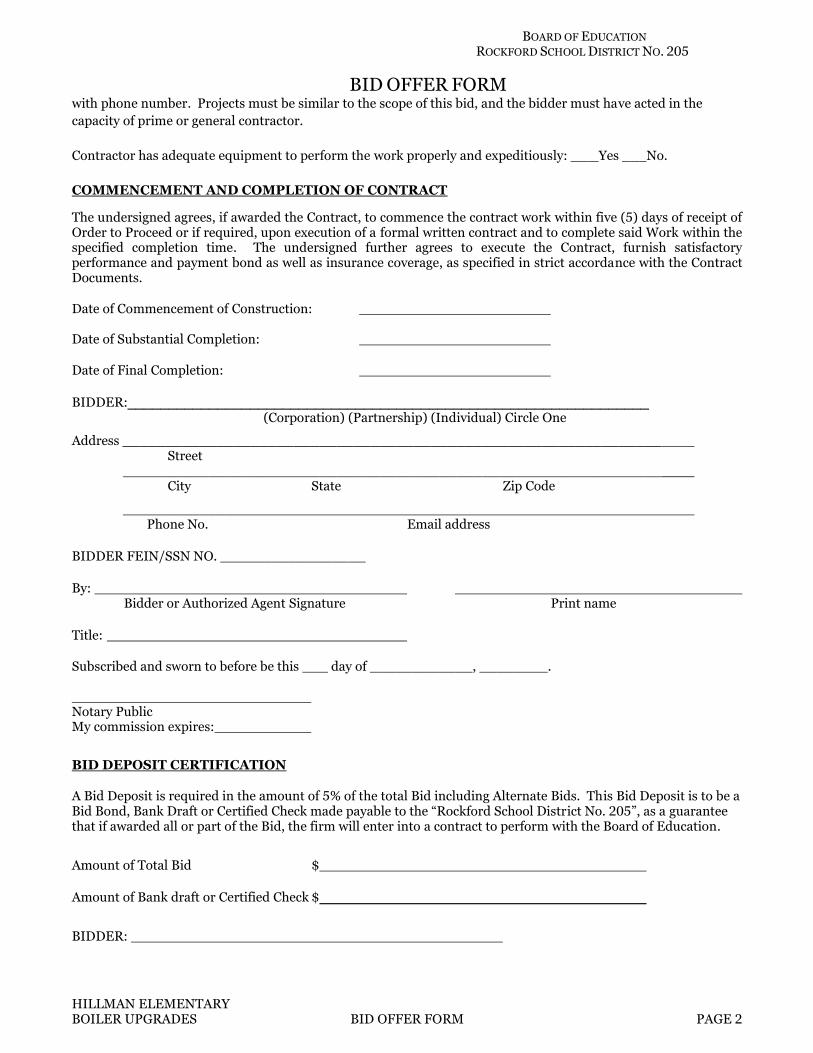
HILLMAN ELEMENTARY BOILER UPGRADES BID OFFER FORM PAGE 2
with phone number. Projects must be similar to the scope of this bid, and the bidder must have acted in the
capacity of prime or general contractor.
Contractor has adequate equipment to perform the work properly and expeditiously: __ Yes __ No.
COMMENCEMENT AND COMPLETION OF CONTRACT
The undersigned agrees, if awarded the Contract, to commence the contract work within five (5) days of receipt of Order to Proceed or if required, upon execution of a formal written contract and to complete said Work within the specified completion time. The undersigned further agrees to execute the Contract, furnish satisfactory performance and payment bond as well as insurance coverage, as specified in strict accordance with the Contract Documents.
Date of Commencement of Construction: Date of Substantial Completion:
Date of Final Completion:
BIDDER:________________________________________________________________ (Corporation) (Partnership) (Individual) Circle One
Address _______________________________________________________________ Street
_______________________________________________________________ City State Zip Code
____________ Phone No. Email address
BIDDER FEIN/SSN NO. _________________ By: Bidder or Authorized Agent Signature Print name Title:
Subscribed and sworn to before be this ___ day of ____________, ________. Notary Public My commission expires:
BID DEPOSIT CERTIFICATION
A Bid Deposit is required in the amount of 5% of the total Bid including Alternate Bids. This Bid Deposit is to be a Bid Bond, Bank Draft or Certified Check made payable to the “Rockford School District No. 205”, as a guarantee that if awarded all or part of the Bid, the firm will enter into a contract to perform with the Board of Education.
Amount of Total Bid $
Amount of Bank draft or Certified Check $
BIDDER:

BOARD OF EDUCATION ROCKFORD SCHOOL DISTRICT NO. 205
BID OFFER FORM
HILLMAN ELEMENTARY BOILER UPGRADES BID OFFER FORM PAGE 3
______________________________________ Signature of Bidder or Authorized Agent
SUBCONTRACTOR LISTING
1. Pursuant to bidding requirements for the Work:
The Bidder, for portions of the Work equaling or exceeding ½ of 1% of the total Contract Sum, proposes to use the following Subcontractors. The Bidder proposes to perform all other portions of the Work with its own forces. The District reserves the right to qualify all Subcontractors. COPY AND ATTACH ADDITIONAL SHEETS AS NECESSARY.
2. Portion of the Work Subcontractor Name and Address
___________________________ ____________________________________
____________________________________
____________________________________
___________________________ ____________________________________
____________________________________
____________________________________
___________________________ ____________________________________
____________________________________
____________________________________
___________________________ ____________________________________
____________________________________
____________________________________
___________________________ ____________________________________
____________________________________
____________________________________
Bidder:
By: Bidder or Authorized Agent Signature
-END OF BID OFFER FORM-

HILLMAN ELEMENTARY BOILER UPGRADES ROCKFORD PUBLIC SCHOOLS 205 ROCKFORD, ILLINOIS
RPS 2058, IFB 20-46 SUPPLEMENTARY CONDITIONS 007300 - 1 LDG 30050
DOCUMENT 007300 – SUPPLEMENTARY CONDITIONS 1. CHANGE ORDER MARK-UPS: Add the following to provisions regarding Change Order mark-
ups in the Conditions of the Contract: A. The combined overhead and profit included in the total cost to the Owner for a change in
the Work shall be based on the following schedule: .1 For the Contractor, for Work performed by the Contractor’s own forces, twelve
percent of the cost. .2 For the Contractor, for Work performed by the Contractor’s Subcontractors, five
percent of the amount due the Subcontractors. .3 For each Subcontractor involved, for Work performed by that Subcontractor’s own
forces, twelve percent of the cost. .4 For each Subcontractor involved, for Work performed by the Subcontractor’s
Subsubcontractors, five percent of the amount due the Sub-subcontractor. .5 In order to facilitate checking of quotations for extras or credits, all proposals,
except those so minor that their propriety can be seen by inspection, shall be accompanied by a complete itemization of costs including labor, materials and Subcontracts. Labor and materials shall be itemized in the manner prescribed above. Where major cost items are Subcontracts, they shall be itemized also.
2. CERTIFIED PAYROLL
A. Pursuant to Prevailing Wage Act the contractor and its subcontractors are obligated to file certified payrolls through IDOL's portal. In addition, the contract documents may require the contractor to provide to the public body copies of all certified payrolls filed through IDOL's portal.
END OF DOCUMENT 007300

HILLMAN ELEMENTARY BOILER UPGRADES ROCKFORD PUBLIC SCHOOLS 205 ROCKFORD, ILLINOIS
RPS 2058, IFB 20-46 SUMMARY 011000 - 1 LDG 30050
SECTION 011000 - SUMMARY
PART 1 - GENERAL
1.1 SUMMARY OF WORK
A. The Work consists of boiler upgrades at Hillman Elementary School.
1.2 WORK RESTRICTIONS
A. Contractor's Use of Premises: During construction, Contractor will have limited use of site and building indicated. Contractor's use of premises is limited only by Owner's right to perform work or employ other contractors on portions of Project and as follows:
1. Owner will occupy premises during construction. Perform construction during normal working hours (7 AM to 4 PM Monday thru Friday, other than holidays), unless otherwise agreed to in advance by Owner. Clean up work areas and return to a useable condition at the end of each work period.
B. Use of Site: Limit use of Project site to Work in areas indicated. Do not disturb portions of Project site beyond areas in which the Work is indicated.
1. Driveways, Walkways and Entrances: Keep driveways loading areas, and entrances serving premises clear and available to Owner, Owner's employees, and emergency vehicles at all times. Do not use these areas for parking or for storage of materials.
C. Condition of Existing Building: Maintain portions of existing building affected by construction operations in a weathertight condition throughout construction period. Repair damage caused by construction operations.
D. Condition of Existing Grounds: Maintain portions of existing grounds, landscaping, and hardscaping affected by construction operations throughout construction period. Repair damage caused by construction operations.
E. Restricted Substances: Use of tobacco products and other controlled substances within the existing building and on Project site is not permitted.
PART 2 - PRODUCTS (Not Applicable)
PART 3 - EXECUTION (Not Applicable)
END OF SECTION 011000

HILLMAN ELEMENTARY BOILER UPGRADES ROCKFORD PUBLIC SCHOOLS 205 ROCKFORD, ILLINOIS
RPS 2058, IFB 20-46 PRICE AND PAYMENT PROCEDURES 012000 - 1 LDG 30050
SECTION 012000 - PRICE AND PAYMENT PROCEDURES
PART 1 - GENERAL
1.1 ALTERNATES
A. An alternate is an amount proposed by bidder for certain work that may be added to or deducted from the Base Bid amount if Owner accepts the Alternate. The cost or credit for each alternate is the net addition to or deduction from the Contract Sum to incorporate the Alternate into the Work. No other adjustments are made to the Contract Sum.
1.2 CONTRACT MODIFICATION PROCEDURES
A. On Owner's approval of a proposal from Contractor on AIA Document G709, Architect will issue a Change Order on AIA Document G701, for all changes to the Contract Sum or the Contract Time.
B. When Owner and Contractor disagree on the terms of a proposal, Architect may issue a Construction Change Directive on AIA Document G714, instructing Contractor to proceed with the change, for subsequent inclusion in a Change Order. Construction Change Directive will contain a description of the change and designate the method to be followed to determine changes to the Contract Sum or the Contract Time.
1.3 PAYMENT PROCEDURES
A. Submit a Schedule of Values at least 10 days before the initial Application for Payment. Break down the Contract Sum into at least one line item for each Specification Section in the Project Manual table of contents. Coordinate the Schedule of Values with Contractor's Construction Schedule.
1. Round amounts to nearest whole dollar; total shall equal the Contract Sum.
2. Provide separate line items in the Schedule of Values for initial cost of materials and for total installed value of that part of the Work.
B. Submit 3 copies of each application for payment on AIA Document G702/703, according to the schedule established in Owner/Contractor Agreement.
1. With each Application for Payment, submit waivers of mechanic's liens from subcontractors, sub-subcontractors, and suppliers for construction period covered by the previous application.
2. Submit final Application for Payment after completion of Project closeout procedures with release of liens and supporting documentation.
a. Include consent of surety to final payment on AIA Document G707 and insurance certificates.
PART 2 - PRODUCTS (Not Applicable)
PART 3 - EXECUTION (Not Applicable)
END OF SECTION 012000

© Copyright 2017, CSI, 110 S. Union St., Suite 100, Alexandria, VA 22314
Page ___ of ___ Form Version: October 2017CSI Form 13.1A
SUBSTITUTIONREQUEST
(After the Bidding/Negotiating Phase)
Project:
To:
Re:
Substitution Request Number:
From:
Date:
A/E Project Number:
Contract For:
Specification Title:
Section: Page:
Description:
Article/Paragraph:
Proposed Substitution:
Manufacturer: Address: Phone:
Trade Name: Model No.:
Installer: Address: Phone:
History: ☐ New product ☐ 1-4 years old ☐ 5-10 years old ☐ More than 10 years old
Differences between proposed substitution and specified product:
☐ Point-by-point comparative data attached — REQUIRED BY A/E
Reason for not providing specified item:
Similar Installation:
Project: Architect:
Address: Owner:
Date Installed:
Proposed substitution affects other parts of Work: ☐ No ☐ Yes; explain
Savings to Owner for accepting substitution: ($ ).
Proposed substitution changes Contract Time: ☐ No ☐ Yes [Add] [Deduct] days.
Supporting Data Attached: ☐Drawings ☐Product Data ☐ Samples ☐ Tests ☐ Reports ☐
SUBSTITUTIONREQUEST

© Copyright 2017, CSI, 110 S. Union St., Suite 100, Alexandria, VA 22314
Page ___ of ___ Form Version: October 2017CSI Form 13.1A
(After the Bidding/Negotiating Phase — Continued)
The Undersigned certifies: Proposed substitution has been fully investigated and determined to be equal or superior in all respects to specified product. Same warranty will be furnished for proposed substitution as for specified product. Same maintenance service and source of replacement parts, as applicable, is available. Proposed substitution will have no adverse effect on other trades and will not affect or delay progress schedule. Cost data as stated above is complete. Claims for additional costs related to accepted substitution which may subsequently become
apparent are to be waived. Proposed substitution does not affect dimensions and functional clearances. Payment will be made for changes to building design, including A/E design, detailing, and construction costs caused by the substitution. Coordination, installation, and changes in the Work as necessary for accepted substitution will be complete in all respects.
Submitted by:
Signed by:
Firm:
Address:
Telephone:
Attachments: ☐
A/E’s REVIEW AND RECOMMENDATION
☐ Approve Substitution - Make submittals in accordance with Specification Section 01 33 00 Submittal Procedures.☐ Approve Substitution as noted - Make submittals in accordance with Specification Section 01 33 00 Submittal Procedures.☐ Reject Substitution - Use specified materials.☐ Substitution Request received too late - Use specified materials.
Signed by: Date:
OWNER'S REVIEW AND ACTION
☐ Substitution approved - Make submittals in accordance with Specification Section 01 33 00 Submittal Procedures. Prepare Change Order.
☐ Substitution approved as noted - Make submittals in accordance with Specification Section 01 33 00 Submittal Procedures. Prepare Change Order.
☐ Substitution rejected - Use specified materials.
Signed by: Date:
Additional Comments: ☐Contractor ☐Subcontractor ☐Supplier ☐Manufacturer ☐A/E

HILLMAN ELEMENTARY BOILER UPGRADES ROCKFORD PUBLIC SCHOOLS 205 ROCKFORD, ILLINOIS
RPS 2058, IFB 20-46 ADMINISTRATIVE REQUIREMENTS 013000 - 1 LDG 30050
SECTION 013000 - ADMINISTRATIVE REQUIREMENTS
PART 1 - GENERAL
1.1 PROJECT MANAGEMENT AND COORDINATION
A. Coordinate construction to ensure efficient and orderly installation of each part of the Work.
B. Schedule and conduct progress meetings at Project site at regular intervals. Notify Owner and Architect of meeting dates and times. Require attendance of each subcontractor or other entity concerned with current progress or involved with planning or coordination of future activities.
1. Record minutes and distribute to everyone concerned, including Owner and Architect.
1.2 SUBMITTAL PROCEDURES
A. Coordinate each submittal with fabrication, purchasing, testing, delivery, other submittals, and related activities that require sequential activity.
1. No extension of the Contract Time will be authorized because of failure to transmit submittals enough in advance of the Work to permit processing, including resubmittals.
2. Submit PDF copies of each submittal. Architect will return with annotations. a. Email address for Submittals: [email protected].
3. Architect will return submittals, without review, received from sources other than Contractor.
B. Place a permanent label or title block on each submittal for identification. Provide a space approximately 6 by 8 inches on label or beside title block to record Contractor's review and approval markings and action taken by Architect. Include the following information on the label:
1. Project name. 2. Date. 3. Name and address of Contractor. 4. Name and address of subcontractor or supplier. 5. Number and title of appropriate Specification Section.
C. Identify deviations from the Contract Documents on submittals.
D. Contractor's Construction Schedule Submittal Procedure: Submit two copies of schedule within 30 days after date established for Commencement of the Work.
PART 2 - PRODUCTS
2.1 ACTION SUBMITTALS
A. Product Data: Mark each copy to show applicable products and options. Include the following:
1. Manufacturer's written recommendations, product specifications, and installation instructions.
2. Wiring diagrams showing factory-installed wiring. 3. Printed performance curves and operational range diagrams. 4. Testing by recognized testing agency. 5. Compliance with specified standards and requirements.

HILLMAN ELEMENTARY BOILER UPGRADES ROCKFORD PUBLIC SCHOOLS 205 ROCKFORD, ILLINOIS
RPS 2058, IFB 20-46 ADMINISTRATIVE REQUIREMENTS 013000 - 2 LDG 30050
B. Shop Drawings: Prepare Project-specific information, drawn accurately to scale. Do not base Shop Drawings on reproductions of the Contract Documents or standard printed data. Submit on sheets at least 8-1/2 by 11 inches but no larger than 30 by 42 inches. Include the following:
1. Dimensions and identification of products. 2. Fabrication and installation drawings and roughing-in and setting diagrams. 3. Wiring diagrams showing field-installed wiring. 4. Notation of coordination requirements. 5. Notation of dimensions established by field measurement.
2.2 INFORMATION SUBMITTALS
A. Qualification Data: Include lists of completed projects with project names and addresses, names and addresses of architects and owners, and other information specified.
B. Product Certificates: Prepare written statements on manufacturer's letterhead certifying that product complies with requirements in the Contract Documents.
2.3 DELEGATED DESIGN
A. Performance and Design Criteria: Where professional design services or certifications by a design professional are specifically required of Contractor by the Contract Documents, provide products and systems complying with specific performance and design criteria indicated.
1. If criteria indicated are not sufficient to perform services or certification required, submit a written request for additional information to Architect.
B. Delegated-Design Submittal: In addition to Shop Drawings, Product Data, and other required submittals, submit three copies of a statement, signed and sealed by the responsible design professional, for each product and system specifically assigned to Contractor to be designed or certified by a design professional.
1. Indicate that products and systems comply with performance and design criteria in the Contract Documents. Include list of codes, loads, and other factors used in performing these services.
2.4 CONTRACTOR'S CONSTRUCTION SCHEDULE
A. Gantt-Chart Schedule: Submit a comprehensive, fully developed, horizontal Gantt-chart-type schedule within 30 days of date established for commencement of the Work.
B. Preparation: Indicate each significant construction activity separately. Identify first workday of each week with a continuous vertical line.
PART 3 - EXECUTION
3.1 SUBMITTAL REVIEW
A. Review each submittal and check for coordination with other Work of the Contract and for compliance with the Contract Documents. Note corrections and field dimensions. Mark with approval stamp before submitting to Architect.
B. Architect will review each action submittal, make marks to indicate corrections or modifications required, stamp and mark as appropriate to indicate action taken, and return PDF with annotations.

HILLMAN ELEMENTARY BOILER UPGRADES ROCKFORD PUBLIC SCHOOLS 205 ROCKFORD, ILLINOIS
RPS 2058, IFB 20-46 ADMINISTRATIVE REQUIREMENTS 013000 - 3 LDG 30050
3.2 CONTRACTOR'S CONSTRUCTION SCHEDULE
A. Distribute copies of approved schedule to Owner, Architect, subcontractors, testing and inspecting agencies, and parties identified by Contractor with a need-to-know schedule responsibility. When revisions are made, distribute updated schedules to the same parties.
B. Updating: At monthly intervals, update schedule to reflect actual construction progress and activities. Issue schedule one week before each regularly scheduled progress meeting.
1. As the Work progresses, indicate Actual Completion percentage for each activity.
END OF SECTION 013000

HILLMAN ELEMENTARY BOILER UPGRADES ROCKFORD PUBLIC SCHOOLS 205 ROCKFORD, ILLINOIS
RPS 2058, IFB 20-46 QUALITY REQUIREMENTS 014000 - 1 LDG 30050
SECTION 014000 - QUALITY REQUIREMENTS
PART 1 - GENERAL
1.1 SECTION REQUIREMENTS
A. Testing and inspecting services are required to verify compliance with requirements specified or indicated. These services do not relieve Contractor of responsibility for compliance with the Contract Document requirements.
1. Testing and inspecting services are specified in other Sections of these Specifications or are required by authorities having jurisdiction and shall be performed by independent testing agencies.
2. Where quality-control services are indicated as Contractor's responsibility, engage a qualified testing agency to perform these services.
3. Contractor is responsible for scheduling times for tests, inspections, and obtaining samples and notifying testing agency.
4. Retesting and Reinspecting: Contractor shall pay for additional testing and inspecting required as a result of tests and inspections indicating noncompliance with requirements.
B. Submittals: Testing agency shall submit a certified written report of each test and inspection to Contractor, Owner, Architect, and to authorities having jurisdiction when they so direct. Reports of each inspection, test, or similar service shall include the following:
1. Name, address, and telephone number of testing agency. 2. Project title and number. 3. Date of issue. 4. Dates and locations of samples and tests or inspections. 5. Record of temperature and weather conditions at time of sample taking and testing and
inspecting. 6. Names of individuals making tests and inspections. 7. Description of the Work and test and inspection method. 8. Complete test or inspection data, test and inspection results, an interpretation of test
results, and comments or professional opinion on whether tested or inspected Work complies with the Contract Document requirements.
9. Recommendations on retesting and reinspecting. 10. Name and signature of laboratory inspector.
C. Testing Agency Qualifications: An independent agency with the experience and capability to conduct testing and inspecting indicated; and where required by authorities having jurisdiction, that is acceptable to authorities.
D. Testing Agency Responsibilities: Testing agency shall cooperate with Architect and Contractor in performing its duties and shall provide qualified personnel to perform inspections and tests.
1. Agency shall promptly notify Architect and Contractor of irregularities or deficiencies in the Work observed during performance of its services.
2. Agency shall not release, revoke, alter, or increase requirements of the Contract Documents nor approve or accept any portion of the Work.
3. Agency shall not perform any duties of Contractor.
E. Auxiliary Services: Cooperate with testing agencies and provide auxiliary services as requested, including the following:
1. Access to the Work. 2. Incidental labor and facilities necessary to facilitate tests and inspections.

HILLMAN ELEMENTARY BOILER UPGRADES ROCKFORD PUBLIC SCHOOLS 205 ROCKFORD, ILLINOIS
RPS 2058, IFB 20-46 QUALITY REQUIREMENTS 014000 - 2 LDG 30050
3. Adequate quantities of materials for testing, and assistance in obtaining samples. 4. Facilities for storage and field curing of test samples. 5. Security and protection for samples and for testing and inspecting equipment.
F. Special Tests and Inspections: Owner will engage a qualified testing agency to conduct special tests and inspections required by authorities having jurisdiction.
G. Special Tests and Inspections: Conducted by a qualified testing agency as required by authorities having jurisdiction, as indicated in individual Specification Sections.
H. Minimum Quantity or Quality Levels: The quantity or quality level shown or specified shall be the minimum provided or performed. The actual installation may comply exactly with the minimum quantity or quality specified, or it may exceed the minimum within reasonable limits.
PART 2 - PRODUCTS (Not Applicable)
PART 3 - EXECUTION (Not Applicable)
END OF SECTION 014000

HILLMAN ELEMENTARY BOILER UPGRADES ROCKFORD PUBLIC SCHOOLS 205 ROCKFORD, ILLINOIS
RPS 2058, IFB 20-46 TEMPORARY FACILITIES AND CONTROLS 015000 - 1 LDG 30050
SECTION 015000 - TEMPORARY FACILITIES AND CONTROLS
PART 1 - GENERAL
1.1 SECTION REQUIREMENTS
A. Use Charges: Cost or use charges for temporary facilities shall be included in the Contract Sum.
B. Use water and electric power from Owner's existing system without metering and without payment of use charges.
C. Electrical Service: Comply with NEMA, NECA, and UL standards and regulations for temporary electric service. Install service to comply with NFPA 70.
PART 2 - PRODUCTS
2.1 EQUIPMENT
A. Heating Equipment: Unless Owner authorizes use of permanent heating system, provide vented, self-contained heaters with thermostatic control.
1. Use of gasoline-burning space heaters, open-flame heaters, or salamander-type heating units is prohibited.
2. Heating Units: Listed and labeled, by a testing agency acceptable to authorities having jurisdiction, and marked for intended use.
PART 3 - EXECUTION
3.1 TEMPORARY UTILITIES
A. General: Arrange with utility company, Owner, and existing users for time when service can be interrupted, if necessary, to make connections for temporary services.
B. Sanitary Facilities: Provide temporary toilets, wash facilities, and drinking-water fixtures. Comply with regulations and health codes for type, number, location, operation, and maintenance of fixtures and facilities.
C. Heating: Provide temporary heating required for curing or drying of completed installations or for protecting installed construction from adverse effects of low temperatures or high humidity. Select equipment that will not have a harmful effect on completed installations or elements being installed.
D. Provide temporary lighting with local switching that provides adequate illumination for construction operations, observations, inspections, and traffic conditions.
3.2 TEMPORARY SUPPORT FACILITIES
A. Provide field offices, storage and fabrication sheds, and other support facilities as necessary for construction operations.

HILLMAN ELEMENTARY BOILER UPGRADES ROCKFORD PUBLIC SCHOOLS 205 ROCKFORD, ILLINOIS
RPS 2058, IFB 20-46 TEMPORARY FACILITIES AND CONTROLS 015000 - 2 LDG 30050
B. Provide waste-collection containers in sizes adequate to handle waste from construction operations. Collect waste daily and, when containers are full, legally dispose of waste off-site. Comply with requirements of authorities having jurisdiction.
C. Install project identification and other signs in locations approved by Owner to inform the public and persons seeking entrance to Project.
3.3 TEMPORARY SECURITY AND PROTECTION FACILITIES
A. Provide temporary environmental protection, operate temporary facilities, and conduct construction in ways and by methods that comply with environmental regulations and that minimize possible air, waterway, and subsoil contamination or pollution or other undesirable effects.
B. Provide measures to prevent soil erosion and discharge of soil-bearing water runoff and airborne dust to adjacent properties and walkways, according to requirements of authorities having jurisdiction.
C. Provide temporary enclosures for protection of construction and workers from inclement weather and for containment of heat.
D. Comply with requirements of authorities having jurisdiction for erecting structurally adequate barricades, including warning signs and lighting.
E. Furnish and install site enclosure fence in a manner that will prevent people and animals from easily entering site except by entrance gates.
F. Install and maintain temporary fire-protection facilities. Comply with NFPA 241.
3.4 TERMINATION AND REMOVAL
A. Temporary Utilities: At earliest feasible time, when acceptable to Owner, change over from use of temporary service to use of permanent service.
B. Remove temporary facilities and controls no later than Substantial Completion. Personnel remaining after Substantial Completion will be permitted to use permanent facilities, under conditions acceptable to Owner.
END OF SECTION 015000

HILLMAN ELEMENTARY BOILER UPGRADES ROCKFORD PUBLIC SCHOOLS 205 ROCKFORD, ILLINOIS
RPS 2058, IFB 20-46 PRODUCT REQUIREMENTS 016000 - 1 LDG 30050
SECTION 016000 - PRODUCT REQUIREMENTS
PART 1 - GENERAL
1.1 SECTION REQUIREMENTS
A. The term "product" includes the terms "material," "equipment," "system," and terms of similar intent.
B. Product Substitutions: Substitutions include changes in products, materials, equipment, and methods of construction from those required by the Contract Documents and proposed by Contractor after award of the Contract.
1. Submit three copies of each request for product substitution. 2. Submit requests within 10 days after the Notice of Award. 3. Do not submit unapproved substitutions on Shop Drawings or other submittals. 4. Identify product to be replaced and show compliance with requirements for substitutions.
Include a detailed comparison of significant qualities of proposed substitution with those of the Work specified, a list of changes needed to other parts of the Work required to accommodate proposed substitution, and any proposed changes in the Contract Sum or the Contract Time should the substitution be accepted.
5. Architect will review the proposed substitution and notify Contractor of its acceptance or rejection by Change Order.
C. Comparable Product Requests:
1. Submit three copies of each request for comparable product. Do not submit unapproved products on Shop Drawings or other submittals.
2. Identify product to be replaced and show compliance with requirements for comparable product requests. Include a detailed comparison of significant qualities of proposed substitution with those of the Work specified.
3. Architect will review the proposed product and notify Contractor of its acceptance or rejection.
D. Deliver, store, and handle products using means and methods that will prevent damage, deterioration, and loss, including theft. Comply with manufacturer's written instructions.
1. Schedule delivery to minimize long-term storage at Project site and to prevent overcrowding of construction spaces.
2. Deliver products to Project site in manufacturer's original sealed container or packaging, complete with labels and instructions for handling, storing, unpacking, protecting, and installing.
3. Inspect products on delivery to ensure compliance with the Contract Documents and to ensure that products are undamaged and properly protected.
4. Store materials in a manner that will not endanger Project structure. 5. Store products that are subject to damage by the elements, under cover in a weathertight
enclosure above ground, with ventilation adequate to prevent condensation.
E. Warranties specified in other Sections shall be in addition to, and run concurrent with, other warranties required by the Contract Documents. Manufacturer's disclaimers and limitations on product warranties do not relieve Contractor of obligations under requirements of the Contract Documents.

HILLMAN ELEMENTARY BOILER UPGRADES ROCKFORD PUBLIC SCHOOLS 205 ROCKFORD, ILLINOIS
RPS 2058, IFB 20-46 PRODUCT REQUIREMENTS 016000 - 2 LDG 30050
PART 2 - PRODUCTS
2.1 PRODUCT OPTIONS
A. Provide products that comply with the Contract Documents, are undamaged, and are new at the time of installation.
1. Provide products complete with accessories, trim, finish, and other devices and components needed for a complete installation and the intended use and effect.
2. Descriptive, performance, and reference standard requirements in the Specifications establish "salient characteristics" of products.
B. Product Selection Procedures:
1. Where Specifications name a single product or manufacturer, provide the item indicated that complies with requirements.
2. Where Specifications include a list of names of products or manufacturers, provide one of the items indicated that complies with requirements.
3. Where Specifications include a list of names of products or manufacturers, accompanied by the term "available products" or "available manufacturers," provide one of the named items that complies with requirements. Comply with provisions for "comparable product requests" for consideration of an unnamed product.
4. Where Specifications name a product as the "basis-of-design" and include a list of manufacturers, provide the named product. Comply with provisions for "comparable product requests" for consideration of an unnamed product by the other named manufacturers.
5. Where Specifications name a single product as the "basis-of-design" and no other manufacturers are named, provide the named product. Comply with provisions for "comparable product requests" for consideration of an unnamed product by another manufacturer.
C. Unless otherwise indicated, Architect will select color, pattern, and texture of each product from manufacturer's full range of options that includes both standard and premium items.
PART 3 - EXECUTION (Not Applicable)
END OF SECTION 016000

HILLMAN ELEMENTARY BOILER UPGRADES ROCKFORD PUBLIC SCHOOLS 205 ROCKFORD, ILLINOIS
RPS 2058, IFB 20-46 EXECUTION AND CLOSEOUT REQUIREMENTS 017000 - 1 LDG 30050
SECTION 017000 - EXECUTION AND CLOSEOUT REQUIREMENTS
PART 1 - GENERAL
1.1 CLOSEOUT SUBMITTALS
A. Record Drawings: Maintain a set of prints of the Contract Drawings as Record Drawings. Mark to show actual installation where installation varies from that shown originally.
1. Identify and date each Record Drawing; include the designation "PROJECT RECORD DRAWING" in a prominent location.
PART 2 - PRODUCTS (Not Applicable)
PART 3 - EXECUTION
3.1 EXAMINATION AND PREPARATION
A. Examine substrates and conditions for compliance with manufacturer's written requirements including, but not limited to, surfaces that are sound, level, plumb, smooth, clean, and free of deleterious substances; substrates within installation tolerances; and application conditions within environmental limits. Proceed with installation only after unsatisfactory conditions have been corrected.
B. Take field measurements as required to fit the Work properly. Where fabricated products are to be fitted to other construction, verify dimensions by field measurement before fabrication and, when possible, allow for fitting and trimming during installation.
3.2 CUTTING AND PATCHING
A. Cutting: Cut in-place construction by sawing, drilling, breaking, chipping, grinding, and similar operations, including excavation, using methods least likely to damage elements retained or adjoining construction. If possible, review proposed procedures with original Installer; comply with original Installer's written recommendations.
1. In general, use hand or small power tools designed for sawing and grinding, not hammering and chopping. Cut holes and slots neatly to minimum size required, and with minimum disturbance of adjacent surfaces. Temporarily cover openings when not in use.
2. Finished Surfaces: Cut or drill from the exposed or finished side into concealed surfaces. 3. Concrete and Masonry: Cut using a cutting machine, such as an abrasive saw or a
diamond-core drill. 4. Excavating and Backfilling: Comply with requirements in applicable Sections where
required by cutting and patching operations. 5. Mechanical and Electrical Services: Cut off pipe or conduit in walls or partitions to be
removed. Cap, valve, or plug and seal remaining portion of pipe or conduit to prevent entrance of moisture or other foreign matter after cutting.
B. Do not cut structural members or operational elements without prior written approval of Architect.
C. Where existing services/systems are required to be removed, relocated, or abandoned, bypass such services/systems before cutting to prevent interruption to occupied areas.

HILLMAN ELEMENTARY BOILER UPGRADES ROCKFORD PUBLIC SCHOOLS 205 ROCKFORD, ILLINOIS
RPS 2058, IFB 20-46 EXECUTION AND CLOSEOUT REQUIREMENTS 017000 - 2 LDG 30050
D. Patch with durable seams that are as invisible as possible. Provide materials and comply with installation requirements specified in other Sections.
3.3 INSTALLATION
A. Comply with manufacturer's written instructions for installation. Anchor each product securely in place, accurately located and aligned with other portions of the Work. Clean exposed surfaces and protect from damage.
B. Clean Project site and work areas daily, including common areas.
3.4 PROGRESS CLEANING
A. Limiting Exposures: Supervise construction operations to ensure that no part of the construction, completed or in progress, is subject to harmful, dangerous, damaging, or otherwise deleterious exposure during the construction period.
B. Site: Maintain Project site free of waste materials and debris.
C. Waste Disposal: Do not bury or burn waste materials on-site. Do not wash waste materials down sewers or into waterways. Comply with waste disposal requirements in Section 015000 "Temporary Facilities and Controls."
3.5 FINAL CLEANING
A. Complete the following cleaning operations before requesting inspection for certification of Substantial Completion:
1. Remove labels that are not permanent. 2. Clean transparent materials, including mirrors. Remove excess glazing compounds.
Replace chipped or broken glass. 3. Clean exposed finishes to a dust-free condition, free of stains, films, and foreign
substances. Sweep concrete floors broom clean. 4. Wipe surfaces of mechanical and electrical equipment. Remove excess lubrication.
Clean plumbing fixtures. Clean light fixtures, lamps, globes, and reflectors. 5. Clean Project site, yard, and grounds, in areas disturbed by construction activities.
Sweep paved areas; remove stains, spills, and foreign deposits. Rake grounds to a smooth, even-textured surface.
3.6 CLOSEOUT PROCEDURES
A. Substantial Completion: Before requesting Substantial Completion inspection, complete the following:
1. Prepare a list of items to be completed and corrected (punch list), the value of items on the list, and reasons why the Work is not complete.
2. Advise Owner of pending insurance changeover requirements. 3. Submit specific warranties, maintenance service agreements, and similar documents. 4. Obtain and submit releases permitting Owner unrestricted use of the Work and access to
services and utilities. Include occupancy permits, operating certificates, and similar releases.
5. Submit Record Drawings, and similar final record information. 6. Deliver tools, spare parts, extra materials, and similar items. 7. Make final changeover of permanent locks and deliver keys to Owner.
HILLMAN ELEMENTARY BOILER UPGRADES ROCKFORD PUBLIC SCHOOLS 205 ROCKFORD, ILLINOIS
RPS 2058, IFB 20-46 EXECUTION AND CLOSEOUT REQUIREMENTS 017000 - 3 LDG 30050
8. Complete startup testing of systems. 9. Remove temporary facilities and controls. 10. Submit changeover information related to Owner's occupancy, use, operation, and
maintenance. 11. Complete final cleaning requirements. 12. Touch up and otherwise repair and restore marred exposed finishes to eliminate visual
defects.
B. Submit a written request for inspection for Substantial Completion. On receipt of request, Architect will proceed with inspection or advise Contractor of unfulfilled requirements. Architect will prepare the Certificate of Substantial Completion after inspection or will advise Contractor of items that must be completed or corrected before certificate will be issued.
C. Request inspection for Final Completion, once the following are complete:
1. Submit a copy of Substantial Completion inspection list stating that each item has been completed or otherwise resolved for acceptance.
D. Request reinspection when the Work identified in previous inspections as incomplete is completed or corrected.
E. Submit a written request for final inspection for acceptance. On receipt of request, Architect will proceed with inspection or advise Contractor of unfulfilled requirements. Architect will prepare final Certificate for Payment after inspection or will advise Contractor of items that must be completed or corrected before certificate will be issued.
3.7 DEMONSTRATION AND TRAINING
A. Engage qualified instructors to instruct Owner's personnel to adjust, operate, and maintain systems, subsystems, and equipment not part of a system. Include a detailed review of the following:
1. Include instruction for basis of system design and operational requirements, review of documentation, emergency procedures, operations, adjustments, troubleshooting, maintenance, and repairs.
END OF SECTION 017000

HILLMAN ELEMENTARY BOILER UPGRADES
ROCKFORD PUBLIC SCHOOLS 205
ROCKFORD, ILLINOIS
RPS 2058, IFB 20-46 OPERATION AND MAINTENANCE DATA 01 78 23 - 1
LDG 30050
SECTION 01 78 23 - OPERATION AND MAINTENANCE DATA
PART 1 - GENERAL
1.1 SUMMARY
A. Section includes administrative and procedural requirements for preparing operation and
maintenance manuals, including the following:
1. Operation and maintenance documentation directory.
2. Emergency manuals.
3. Operation manuals for systems, subsystems, and equipment.
4. Product maintenance manuals.
1.2 CLOSEOUT SUBMITTALS
A. Manual Content: Operations and maintenance manual content is specified in individual
Specification Sections to be reviewed at the time of Section submittals. Submit reviewed manual
content formatted and organized as required by this Section.
1. Where applicable, clarify and update reviewed manual content to correspond to revisions and
field conditions.
B. Format: Submit operations and maintenance manuals in the following format:
1. PDF electronic file. Assemble each manual into a composite electronically indexed file. Submit
on digital media acceptable to Owner.
a. Name each indexed document file in composite electronic index with applicable item
name. Include a complete electronically linked operation and maintenance directory.
b. Enable inserted reviewer comments on draft submittals.
2. Three paper copies. Include a complete operation and maintenance directory. Enclose title
pages and directories in clear plastic sleeves. Owner will return two copies.
C. Manual Submittal: Submit each manual in final form prior to requesting inspection for Substantial
Completion and at least 15 days before commencing demonstration and training. Owner will
return copy with comments.
1. Correct or revise each manual to comply with Owner's comments. Submit copies of each
corrected manual within 15 days of receipt of Owner's comments and prior to commencing
demonstration and training.
PART 2 - PRODUCTS
2.1 REQUIREMENTS FOR EMERGENCY, OPERATION, AND MAINTENANCE MANUALS
A. Directory: Prepare a single, comprehensive directory of emergency, operation, and maintenance data and materials, listing items and their location to facilitate ready access to desired information.
B. Organization: Unless otherwise indicated, organize each manual into a separate section for each
system and subsystem, and a separate section for each piece of equipment not part of a system.
Each manual shall contain the following materials, in the order listed:
1. Title page.
2. Table of contents.
3. Manual contents.

HILLMAN ELEMENTARY BOILER UPGRADES
ROCKFORD PUBLIC SCHOOLS 205
ROCKFORD, ILLINOIS
RPS 2058, IFB 20-46 OPERATION AND MAINTENANCE DATA 01 78 23 - 2
LDG 30050
C. Title Page: Include the following information:
1. Subject matter included in manual.
2. Name and address of Project.
3. Name and address of Owner.
4. Date of submittal.
5. Name and contact information for Contractor.
6. Name and contact information for Architect.
7. Names and contact information for major consultants to the Owner that designed the
systems contained in the manuals.
8. Cross-reference to related systems in other operation and maintenance manuals.
D. Table of Contents: List each product included in manual, identified by product name, indexed to
the content of the volume, and cross-referenced to Specification Section number in Project
Manual.
E. Manual Contents: Organize into sets of manageable size. Arrange contents alphabetically by
system, subsystem, and equipment. If possible, assemble instructions for subsystems,
equipment, and components of one system into a single binder.
F. Manuals, Electronic Files: Submit manuals in the form of a multiple file composite electronic PDF
file for each manual type required.
1. Electronic Files: Use electronic files prepared by manufacturer where available. Where
scanning of paper documents is required, configure scanned file for minimum readable file
size.
2. File Names and Bookmarks: Enable bookmarking of individual documents based on file
names. Name document files to correspond to system, subsystem, and equipment names
used in manual directory and table of contents. Group documents for each system and
subsystem into individual composite bookmarked files, then create composite manual, so
that resulting bookmarks reflect the system, subsystem, and equipment names in a readily
navigated file tree. Configure electronic manual to display bookmark panel on opening file.
G. Manuals, Paper Copy: Submit manuals in the form of hard copy, bound and labeled volumes.
1. Binders: Heavy-duty, three-ring, vinyl-covered, loose-leaf binders, in thickness necessary
to accommodate contents, sized to hold 8-1/2-by-11-inch paper; with clear plastic sleeve
on spine to hold label describing contents and with pockets inside covers to hold folded
oversize sheets.
a. Identify each binder on front and spine, with printed title "OPERATION AND
MAINTENANCE MANUAL," Project title or name, and subject matter of contents.
Indicate volume number for multiple-volume sets.
2. Dividers: Heavy-paper dividers with plastic-covered tabs for each section of the manual.
Mark each tab to indicate contents. Include typed list of products and major components of
equipment included in the section on each divider, cross-referenced to Specification
Section number and title of Project Manual.
3. Protective Plastic Sleeves: Transparent plastic sleeves designed to enclose diagnostic
software storage media for computerized electronic equipment.
4. Drawings: Attach reinforced, punched binder tabs on drawings and bind with text.
a. If oversize drawings are necessary, fold drawings to same size as text pages and
use as foldouts.
b. If drawings are too large to be used as foldouts, fold and place drawings in labeled
envelopes and bind envelopes in rear of manual. At appropriate locations in manual,
insert typewritten pages indicating drawing titles, descriptions of contents, and
drawing locations.

HILLMAN ELEMENTARY BOILER UPGRADES
ROCKFORD PUBLIC SCHOOLS 205
ROCKFORD, ILLINOIS
RPS 2058, IFB 20-46 OPERATION AND MAINTENANCE DATA 01 78 23 - 3
LDG 30050
2.2 EMERGENCY MANUALS
A. Content: Organize manual into a separate section for each of the following:
1. Type of emergency.
2. Emergency instructions.
3. Emergency procedures.
B. Type of Emergency: Where applicable for each type of emergency indicated below, include
instructions and procedures for each system, subsystem, piece of equipment, and component:
1. Fire.
2. Flood.
3. Gas leak.
4. Water leak.
5. Power failure.
6. Water outage.
7. System, subsystem, or equipment failure.
8. Chemical release or spill.
C. Emergency Instructions: Describe and explain warnings, trouble indications, error messages, and
similar codes and signals. Include responsibilities of Owner's operating personnel for notification
of Installer, supplier, and manufacturer to maintain warranties.
D. Emergency Procedures: Include the following, as applicable:
1. Instructions on stopping.
2. Shutdown instructions for each type of emergency.
3. Operating instructions for conditions outside normal operating limits.
4. Required sequences for electric or electronic systems.
5. Special operating instructions and procedures.
2.3 OPERATION MANUALS
A. Content: In addition to requirements in this Section, include operation data required in individual
Specification Sections and the following information:
1. System, subsystem, and equipment descriptions. Use designations for systems and
equipment indicated on Contract Documents.
2. Performance and design criteria if Contractor is delegated design responsibility.
3. Operating standards.
4. Operating procedures.
5. Operating logs.
6. Wiring diagrams.
7. Control diagrams.
8. Piped system diagrams.
9. Precautions against improper use.
10. License requirements including inspection and renewal dates.
B. Descriptions: Include the following:
1. Product name and model number. Use designations for products indicated on Contract
Documents.
2. Manufacturer's name.
3. Equipment identification with serial number of each component.
4. Equipment function.

HILLMAN ELEMENTARY BOILER UPGRADES
ROCKFORD PUBLIC SCHOOLS 205
ROCKFORD, ILLINOIS
RPS 2058, IFB 20-46 OPERATION AND MAINTENANCE DATA 01 78 23 - 4
LDG 30050
5. Operating characteristics.
6. Limiting conditions.
7. Performance curves.
8. Engineering data and tests.
9. Complete nomenclature and number of replacement parts.
C. Operating Procedures: Include the following, as applicable:
1. Startup procedures.
2. Equipment or system break-in procedures.
3. Routine and normal operating instructions.
4. Regulation and control procedures.
5. Instructions on stopping.
6. Normal shutdown instructions.
7. Seasonal and weekend operating instructions.
8. Required sequences for electric or electronic systems.
9. Special operating instructions and procedures.
D. Systems and Equipment Controls: Describe the sequence of operation, and diagram controls as
installed.
E. Piped Systems: Diagram piping as installed, and identify color-coding where required for
identification.
2.4 PRODUCT MAINTENANCE MANUALS
A. Content: Organize manual into a separate section for each product, material, and finish. Include source information, product information, maintenance procedures, repair materials and sources, and warranties and bonds, as described below.
B. Source Information: List each product included in manual, identified by product name and
arranged to match manual's table of contents. For each product, list name, address, and
telephone number of Installer or supplier and maintenance service agent, and cross-reference
Specification Section number and title in Project Manual.
C. Product Information: Include the following, as applicable:
1. Product name and model number.
2. Manufacturer's name.
3. Color, pattern, and texture.
4. Material and chemical composition.
5. Reordering information for specially manufactured products.
D. Maintenance Procedures: Include manufacturer's written recommendations and the following:
1. Inspection procedures.
2. Types of cleaning agents to be used and methods of cleaning.
3. List of cleaning agents and methods of cleaning detrimental to product.
4. Schedule for routine cleaning and maintenance.
5. Repair instructions.
E. Repair Materials and Sources: Include lists of materials and local sources of materials and related
services.

HILLMAN ELEMENTARY BOILER UPGRADES
ROCKFORD PUBLIC SCHOOLS 205
ROCKFORD, ILLINOIS
RPS 2058, IFB 20-46 OPERATION AND MAINTENANCE DATA 01 78 23 - 5
LDG 30050
F. Warranties and Bonds: Include copies of warranties and bonds and lists of circumstances and
conditions that would affect validity of warranties or bonds.
2.5 SYSTEMS AND EQUIPMENT MAINTENANCE MANUALS
A. Content: For each system, subsystem, and piece of equipment not part of a system, include
source information, manufacturers' maintenance documentation, maintenance procedures,
maintenance and service schedules, spare parts list and source information, maintenance service
contracts, and warranty and bond information, as described below.
B. Source Information: List each system, subsystem, and piece of equipment included in manual,
identified by product name and arranged to match manual's table of contents. For each product,
list name, address, and telephone number of Installer or supplier and maintenance service agent,
and cross-reference Specification Section number and title in Project Manual.
C. Manufacturers' Maintenance Documentation: Manufacturers' maintenance documentation
including the following information for each component part or piece of equipment:
1. Standard maintenance instructions and bulletins.
2. Drawings, diagrams, and instructions required for maintenance, including disassembly and
component removal, replacement, and assembly.
3. Identification and nomenclature of parts and components.
4. List of items recommended to be stocked as spare parts.
D. Maintenance Procedures: Include the following information and items that detail essential
maintenance procedures:
1. Test and inspection instructions.
2. Troubleshooting guide.
3. Precautions against improper maintenance.
4. Disassembly; component removal, repair, and replacement; and reassembly instructions.
5. Aligning, adjusting, and checking instructions.
6. Demonstration and training video recording, if available.
E. Maintenance and Service Schedules: Include service and lubrication requirements, list of required
lubricants for equipment, and separate schedules for preventive and routine maintenance and
service with standard time allotment. Spare Parts List and Source Information: Include lists of
replacement and repair parts, with parts identified and cross-referenced to manufacturers'
maintenance documentation and local sources of maintenance materials and related services.
F. Maintenance Service Contracts: Include copies of maintenance agreements with name and
telephone number of service agent.
G. Warranties and Bonds: Include copies of warranties and bonds and lists of circumstances and
conditions that would affect validity of warranties or bonds.
PART 3 - EXECUTION
3.1 MANUAL PREPARATION
A. Emergency Manual: Assemble a complete set of emergency information indicating procedures
for use by emergency personnel and by Owner's operating personnel for types of emergencies
indicated.

HILLMAN ELEMENTARY BOILER UPGRADES
ROCKFORD PUBLIC SCHOOLS 205
ROCKFORD, ILLINOIS
RPS 2058, IFB 20-46 OPERATION AND MAINTENANCE DATA 01 78 23 - 6
LDG 30050
B. Product Maintenance Manual: Assemble a complete set of maintenance data indicating care and
maintenance of each product, material, and finish incorporated into the Work.
C. Operation and Maintenance Manuals: Assemble a complete set of operation and maintenance
data indicating operation and maintenance of each system, subsystem, and piece of equipment
not part of a system.
D. Manufacturers' Data: Where manuals contain manufacturers' standard printed data, include only
sheets pertinent to product or component installed. Mark each sheet to identify each product or
component incorporated into the Work. If data include more than one item in a tabular format,
identify each item using appropriate references from the Contract Documents. Identify data
applicable to the Work and delete references to information not applicable.
E. Drawings: Prepare drawings supplementing manufacturers' printed data to illustrate the
relationship of component parts of equipment and systems and to illustrate control sequence and
flow diagrams. Coordinate these drawings with information contained in record Drawings to
ensure correct illustration of completed installation.
1. Do not use original project record documents as part of operation and maintenance
manuals.
END OF SECTION 017823

HILLMAN ELEMENTARY BOILER UPGRADES ROCKFORD PUBLIC SCHOOLS 205 ROCKFORD, ILLINOIS
RPS 2058, IFB 20-46 PROJECT RECORD DOCUMENTS 01 78 39 - 1 LDG 30050
SECTION 01 78 39 - PROJECT RECORD DOCUMENTS
PART 1 - GENERAL
1.1 SUMMARY
A. Section includes administrative and procedural requirements for project record documents, including the following: 1. Record Drawings. 2. Record Specifications. 3. Record Product Data.
B. Related Requirements: 1. Section 01 78 23 "Operation and Maintenance Data" for operation and maintenance
manual requirements.
1.2 CLOSEOUT SUBMITTALS
A. Record Drawings: Comply with the following: 1. Number of Copies: Submit copies of record Drawings as follows:
a. Initial Submittal: 1) Submit PDF electronic files of scanned record prints and one set(s) of file
prints. 2) Owner will indicate whether general scope of changes, additional
information recorded, and quality of drafting are acceptable. b. Final Submittal:
1) Submit PDF electronic files of scanned record prints and one set(s) of prints. 2) Print each drawing, whether or not changes and additional information were
recorded.
B. Record Specifications: Submit one paper copy and annotated PDF electronic files of Project's Specifications, including addenda and contract modifications.
C. Record Product Data: Submit one paper copy and annotated PDF electronic files and directories of each submittal.
PART 2 - PRODUCTS
2.1 RECORD DRAWINGS
A. Record Prints: Maintain one set of marked-up paper copies of the Contract Drawings and Shop Drawings, incorporating new and revised Drawings as modifications are issued. 1. Preparation: Mark record prints to show the actual installation where installation varies
from that shown originally. Require individual or entity who obtained record data, whether individual or entity is Installer, subcontractor, or similar entity, to provide information for preparation of corresponding marked-up record prints. a. Give particular attention to information on concealed elements that would be
difficult to identify or measure and record later. b. Record data as soon as possible after obtaining it. c. Record and check the markup before enclosing concealed installations.
2. Mark the Contract Drawings and Shop Drawings completely and accurately. Use personnel proficient at recording graphic information in production of marked-up record prints.

HILLMAN ELEMENTARY BOILER UPGRADES ROCKFORD PUBLIC SCHOOLS 205 ROCKFORD, ILLINOIS
RPS 2058, IFB 20-46 PROJECT RECORD DOCUMENTS 01 78 39 - 2 LDG 30050
3. Mark record sets with erasable, red-colored pencil. Use other colors to distinguish between changes for different categories of the Work at same location.
4. Note Construction Change Directive numbers, alternate numbers, Change Order numbers, and similar identification, where applicable.
B. Record Digital Data Files: Immediately before inspection for Certificate of Substantial Completion, review marked-up record prints with Owner. When authorized, prepare a full set of corrected digital data files of the Contract Drawings, as follows: 1. Format: Annotated PDF electronic file with comment function enabled. 2. Incorporate changes and additional information previously marked on record prints.
Delete, redraw, and add details and notations where applicable. 3. Refer instances of uncertainty to Owner for resolution.
C. Format: Identify and date each record Drawing; include the designation "PROJECT RECORD DRAWING" in a prominent location. 1. Record Prints: Organize record prints and newly prepared record Drawings into
manageable sets. Bind each set with durable paper cover sheets. Include identification on cover sheets.
2. Format: Annotated PDF electronic file with comment function enabled. 3. Record Digital Data Files: Organize digital data information into separate electronic files
that correspond to each sheet of the Contract Drawings. Name each file with the sheet identification. Include identification in each digital data file.
4. Identification: As follows: a. Project name. b. Date. c. Designation "PROJECT RECORD DRAWINGS." d. Name of Owner. e. Name of Contractor.
2.2 RECORD SPECIFICATIONS
A. Preparation: Mark Specifications to indicate the actual product installation where installation varies from that indicated in Specifications, addenda, and contract modifications. 1. Give particular attention to information on concealed products and installations that
cannot be readily identified and recorded later. 2. Mark copy with the proprietary name and model number of products, materials, and
equipment furnished, including substitutions and product options selected. 3. Record the name of manufacturer, supplier, Installer, and other information necessary to
provide a record of selections made. 4. Note related Change Orders, record Product Data, and record Drawings where
applicable.
B. Format: Submit record Specifications as annotated PDF electronic file.
2.3 RECORD PRODUCT DATA
A. Preparation: Mark Product Data to indicate the actual product installation where installation varies substantially from that indicated in Product Data submittal. 1. Give particular attention to information on concealed products and installations that
cannot be readily identified and recorded later. 2. Include significant changes in the product delivered to Project site and changes in
manufacturer's written instructions for installation. 3. Note related Change Orders, record Specifications, and record Drawings where
applicable.

HILLMAN ELEMENTARY BOILER UPGRADES ROCKFORD PUBLIC SCHOOLS 205 ROCKFORD, ILLINOIS
RPS 2058, IFB 20-46 PROJECT RECORD DOCUMENTS 01 78 39 - 3 LDG 30050
B. Format: Submit record Product Data as annotated PDF electronic file.
2.4 MISCELLANEOUS RECORD SUBMITTALS
A. Assemble miscellaneous records required by other Specification Sections for miscellaneous record keeping and submittal in connection with actual performance of the Work. Bind or file miscellaneous records and identify each, ready for continued use and reference.
B. Format: Submit miscellaneous record submittals as PDF electronic file.
PART 3 - EXECUTION
3.1 RECORDING AND MAINTENANCE
A. Recording: Maintain one copy of each submittal during the construction period for project record document purposes. Post changes and revisions to project record documents as they occur; do not wait until end of Project.
B. Maintenance of Record Documents and Samples: Store record documents and Samples in the field office apart from the Contract Documents used for construction. Do not use project record documents for construction purposes. Maintain record documents in good order and in a clean, dry, legible condition, protected from deterioration and loss. Provide access to project record documents for Owner's reference during normal working hours.
END OF SECTION 01 78 39

HILLMAN ELEMENTARY BOILER UPGRADES ROCKFORD PUBLIC SCHOOLS 205 ROCKFORD, ILLINOIS
RPS 2058, IFB 20-46COMMON MOTOR REQUIREMENTS FOR HVAC EQUIPMENT 23 05 13 - 1 LDG 30050
SECTION 23 05 13 - COMMON MOTOR REQUIREMENTS FOR HVAC EQUIPMENT
PART 1 - GENERAL
1.1 RELATED DOCUMENTS
A. Drawings and general provisions of the Contract, including General and Supplementary Conditions, Division 00 Information for Bidders, and Division 01 Specification Sections, apply to this Section.
1.2 SUMMARY
A. Section includes general requirements for single-phase and polyphase, general-purpose, horizontal, small and medium, squirrel-cage induction motors for use on ac power systems up to 600 V and installed at equipment manufacturer's factory or shipped separately by equipment manufacturer for field installation.
1.3 COORDINATION
A. Coordinate features of motors, installed units, and accessory devices to be compatible with the following:
1. Motor controllers. 2. Torque, speed, and horsepower requirements of the load. 3. Ratings and characteristics of supply circuit and required control sequence. 4. Ambient and environmental conditions of installation location.
PART 2 - PRODUCTS
2.1 GENERAL MOTOR REQUIREMENTS
A. Comply with NEMA MG 1 unless otherwise indicated.
B. Comply with IEEE 841 for severe-duty motors.
2.2 MOTOR CHARACTERISTICS
A. Duty: Continuous duty at ambient temperature of 40 deg C and at altitude of 3300 feet above sea level.
B. Capacity and Torque Characteristics: Sufficient to start, accelerate, and operate connected loads at designated speeds, at installed altitude and environment, with indicated operating sequence, and without exceeding nameplate ratings or considering service factor.

HILLMAN ELEMENTARY BOILER UPGRADES ROCKFORD PUBLIC SCHOOLS 205 ROCKFORD, ILLINOIS
RPS 2058, IFB 20-46COMMON MOTOR REQUIREMENTS FOR HVAC EQUIPMENT 23 05 13 - 2 LDG 30050
2.3 POLYPHASE MOTORS
A. Description: NEMA MG 1, Design B, medium induction motor.
B. Efficiency: Energy efficient, as defined in NEMA MG 1.
C. Service Factor: 1.15.
D. Multispeed Motors: Variable torque.
1. For motors with 2:1 speed ratio, consequent pole, single winding. 2. For motors with other than 2:1 speed ratio, separate winding for each speed.
E. Multispeed Motors: Separate winding for each speed.
F. Rotor: Random-wound, squirrel cage.
G. Bearings: Regreasable, shielded, antifriction ball bearings suitable for radial and thrust loading.
H. Temperature Rise: Match insulation rating.
I. Insulation: Class F.
J. Code Letter Designation:
1. Motors 15 HP and Larger: NEMA starting Code F or Code G. 2. Motors Smaller than 15 HP: Manufacturer's standard starting characteristic.
K. Enclosure Material: Cast iron for motor frame sizes 324T and larger; rolled steel for motor frame sizes smaller than 324T.
2.4 POLYPHASE MOTORS WITH ADDITIONAL REQUIREMENTS
A. Motors Used with Reduced-Voltage and Multispeed Controllers: Match wiring connection requirements for controller with required motor leads. Provide terminals in motor terminal box, suited to control method.
B. Motors Used with Variable Frequency Controllers: Ratings, characteristics, and features coordinated with and approved by controller manufacturer.
1. Windings: Copper magnet wire with moisture-resistant insulation varnish, designed and tested to resist transient spikes, high frequencies, and short time rise pulses produced by pulse-width modulated inverters.
2. Energy- and Premium-Efficient Motors: Class B temperature rise; Class F insulation. 3. Inverter-Duty Motors: Class F temperature rise; Class H insulation. 4. Thermal Protection: Comply with NEMA MG 1 requirements for thermally protected
motors.
C. Severe-Duty Motors: Comply with IEEE 841, with 1.15 minimum service factor.

HILLMAN ELEMENTARY BOILER UPGRADES ROCKFORD PUBLIC SCHOOLS 205 ROCKFORD, ILLINOIS
RPS 2058, IFB 20-46COMMON MOTOR REQUIREMENTS FOR HVAC EQUIPMENT 23 05 13 - 3 LDG 30050
2.5 SINGLE-PHASE MOTORS
A. Motors larger than 1/20 hp shall be one of the following, to suit starting torque and requirements of specific motor application:
1. Permanent-split capacitor. 2. Split phase. 3. Capacitor start, inductor run. 4. Capacitor start, capacitor run.
B. Multispeed Motors: Variable-torque, permanent-split-capacitor type.
C. Bearings: Prelubricated, antifriction ball bearings or sleeve bearings suitable for radial and thrust loading.
D. Motors 1/20 HP and Smaller: Shaded-pole type.
E. Thermal Protection: Internal protection to automatically open power supply circuit to motor when winding temperature exceeds a safe value calibrated to temperature rating of motor insulation. Thermal-protection device shall automatically reset when motor temperature returns to normal range.
PART 3 - EXECUTION (Not Applicable)
END OF SECTION 23 05 13

HILLMAN ELEMENTARY BOILER UPGRADES ROCKFORD PUBLIC SCHOOLS 205 ROCKFORD, ILLINOIS
RPS 2058, IFB 20-46 EXPANSION FITTINGS AND LOOPS FOR HVAC PIPING 23 05 16 - 1 LDG 30050
SECTION 23 05 16 - EXPANSION FITTINGS AND LOOPS FOR HVAC PIPING
PART 1 - GENERAL
1.1 RELATED DOCUMENTS
A. Drawings and general provisions of the Contract, including General and Supplementary Conditions, Division 00 Information for Bidders, and Division 01 Specification Sections, apply to this Section.
1.2 SUMMARY
A. Section Includes:
1. Pipe loops and swing connections. 2. Alignment guides and anchors.
1.3 PERFORMANCE REQUIREMENTS
A. Compatibility: Products shall be suitable for piping service fluids, materials, working pressures, and temperatures.
B. Capability: Products to absorb 200 percent of maximum axial movement between anchors.
1.4 ACTION SUBMITTALS
A. Product Data: For each type of product indicated.
1.5 INFORMATIONAL SUBMITTALS
A. Welding certificates.
B. Product Certificates: For each type of expansion joint, from manufacturer.
1.6 CLOSEOUT SUBMITTALS
A. Maintenance Data: For expansion joints to include in maintenance manuals.
1.7 QUALITY ASSURANCE
A. Welding Qualifications: Qualify procedures and personnel according to the following:
1. AWS D1.1/D1.1M, "Structural Welding Code - Steel." 2. ASME Boiler and Pressure Vessel Code: Section IX.

HILLMAN ELEMENTARY BOILER UPGRADES ROCKFORD PUBLIC SCHOOLS 205 ROCKFORD, ILLINOIS
RPS 2058, IFB 20-46 EXPANSION FITTINGS AND LOOPS FOR HVAC PIPING 23 05 16 - 2 LDG 30050
PART 2 - PRODUCTS
2.1 ALIGNMENT GUIDES AND ANCHORS
A. Alignment Guides:
1. Manufacturers: Subject to compliance with requirements, provide products by one of the following:
a. Adsco Manufacturing LLC. b. Advanced Thermal Systems, Inc. c. Flex-Hose Co., Inc. d. Flexicraft Industries. e. Flex-Weld, Inc. f. Hyspan Precision Products, Inc. g. Metraflex, Inc. h. Senior Flexonics Pathway. i. Unisource Manufacturing, Inc. j. U.S. Bellows, Inc.
2. Description: Steel, factory-fabricated alignment guide, with bolted two-section outer cylinder and base for attaching to structure; with two-section guiding spider for bolting to pipe.
B. Anchor Materials:
1. Steel Shapes and Plates: ASTM A 36/A 36M. 2. Bolts and Nuts: ASME B18.10 or ASTM A 183, steel hex head. 3. Washers: ASTM F 844, steel, plain, flat washers. 4. Mechanical Fasteners: Insert-wedge-type stud with expansion plug anchor for use in
hardened portland cement concrete, with tension and shear capacities appropriate for application.
a. Stud: Threaded, zinc-coated carbon steel. b. Expansion Plug: Zinc-coated steel. c. Washer and Nut: Zinc-coated steel.
5. Chemical Fasteners: Insert-type-stud, bonding-system anchor for use with hardened portland cement concrete, with tension and shear capacities appropriate for application.
a. Bonding Material: ASTM C 881/C 881M, Type IV, Grade 3, two-component epoxy resin suitable for surface temperature of hardened concrete where fastener is to be installed.
b. Stud: ASTM A 307, zinc-coated carbon steel with continuous thread on stud unless otherwise indicated.
c. Washer and Nut: Zinc-coated steel.

HILLMAN ELEMENTARY BOILER UPGRADES ROCKFORD PUBLIC SCHOOLS 205 ROCKFORD, ILLINOIS
RPS 2058, IFB 20-46 EXPANSION FITTINGS AND LOOPS FOR HVAC PIPING 23 05 16 - 3 LDG 30050
PART 3 - EXECUTION
3.1 EXPANSION-JOINT INSTALLATION
A. Install expansion joints of sizes matching sizes of piping in which they are installed.
3.2 PIPE LOOP AND SWING CONNECTION INSTALLATION
A. Install pipe loops cold-sprung in tension or compression as required to partly absorb tension or compression produced during anticipated change in temperature.
B. Connect risers and branch connections to mains with at least five pipe fittings including tee in main.
C. Connect risers and branch connections to terminal units with at least four pipe fittings including tee in riser.
D. Connect mains and branch connections to terminal units with at least four pipe fittings including tee in main.
3.3 ALIGNMENT-GUIDE AND ANCHOR INSTALLATION
A. Install alignment guides to guide expansion and to avoid end-loading and torsional stress.
B. Install one guide(s) on each side of pipe expansion fittings and loops. Install guides nearest to expansion joint not more than four pipe diameters from expansion joint.
C. Attach guides to pipe and secure guides to building structure.
D. Install anchors at locations to prevent stresses from exceeding those permitted by ASME B31.9 and to prevent transfer of loading and stresses to connected equipment.
E. Anchor Attachments:
1. Anchor Attachment to Steel Pipe: Attach by welding. Comply with ASME B31.9 and ASME Boiler and Pressure Vessel Code: Section IX, "Welding and Brazing Qualifications."
2. Anchor Attachment to Copper Tubing: Attach with pipe hangers. Use MSS SP-69, Type 24, U-bolts bolted to anchor.
F. Fabricate and install steel anchors by welding steel shapes, plates, and bars. Comply with ASME B31.9 and AWS D1.1/D1.1M.
1. Anchor Attachment to Steel Structural Members: Attach by welding. 2. Anchor Attachment to Concrete Structural Members: Attach by fasteners. Follow
fastener manufacturer's written instructions.
G. Use grout to form flat bearing surfaces for guides and anchors attached to concrete.

HILLMAN ELEMENTARY BOILER UPGRADES ROCKFORD PUBLIC SCHOOLS 205 ROCKFORD, ILLINOIS
RPS 2058, IFB 20-46 EXPANSION FITTINGS AND LOOPS FOR HVAC PIPING 23 05 16 - 4 LDG 30050
END OF SECTION 23 05 16

HILLMAN ELEMENTARY BOILER UPGRADES ROCKFORD PUBLIC SCHOOLS 205 ROCKFORD, ILLINOIS
RPS 2058, IFB 20-46 SLEEVES AND SLEEVE SEALS FOR HVAC PIPING 23 05 17 - 1 LDG 30050
SECTION 23 05 17 - SLEEVES AND SLEEVE SEALS FOR HVAC PIPING
PART 1 - GENERAL
1.1 RELATED DOCUMENTS
A. Drawings and general provisions of the Contract, including General and Supplementary Conditions, Division 00 Information for Bidders, and Division 01 Specification Sections, apply to this Section.
1.2 SUMMARY
A. Section Includes:
1. Sleeves. 2. Sleeve-seal systems. 3. Sleeve-seal fittings. 4. Grout.
1.3 ACTION SUBMITTALS
A. Product Data: For each type of product indicated.
PART 2 - PRODUCTS
2.1 SLEEVES
A. Cast-Iron Wall Pipes: Cast or fabricated of cast or ductile iron and equivalent to ductile-iron pressure pipe, with plain ends and integral waterstop unless otherwise indicated.
B. Galvanized-Steel Wall Pipes: ASTM A 53/A 53M, Schedule 40, with plain ends and welded steel collar; zinc coated.
C. Galvanized-Steel-Pipe Sleeves: ASTM A 53/A 53M, Type E, Grade B, Schedule 40, zinc coated, with plain ends.
D. PVC-Pipe Sleeves: ASTM D 1785, Schedule 40.
E. Galvanized-Steel-Sheet Sleeves: 0.0239-inch minimum thickness; round tube closed with welded longitudinal joint.
2.2 SLEEVE-SEAL SYSTEMS
A. Manufacturers: Subject to compliance with requirements, provide products by one of the following:

HILLMAN ELEMENTARY BOILER UPGRADES ROCKFORD PUBLIC SCHOOLS 205 ROCKFORD, ILLINOIS
RPS 2058, IFB 20-46 SLEEVES AND SLEEVE SEALS FOR HVAC PIPING 23 05 17 - 2 LDG 30050
1. Advance Products & Systems, Inc. 2. CALPICO, Inc. 3. Metraflex Company (The). 4. Pipeline Seal and Insulator, Inc. 5. Proco Products, Inc.
B. Description: Modular sealing-element unit, designed for field assembly, for filling annular space between piping and sleeve.
1. Sealing Elements: EPDM-rubber interlocking links shaped to fit surface of pipe. Include type and number required for pipe material and size of pipe.
2. Pressure Plates: Carbon steel. 3. Connecting Bolts and Nuts: Carbon steel, with corrosion-resistant coating, of length
required to secure pressure plates to sealing elements.
2.3 SLEEVE-SEAL FITTINGS
A. Manufacturers: Subject to compliance with requirements, available manufacturers offering products that may be incorporated into the Work include, but are not limited to, the following:
1. Presealed Systems.
B. Description: Manufactured plastic, sleeve-type, waterstop assembly made for imbedding in concrete slab or wall. Unit has plastic or rubber waterstop collar with center opening to match piping OD.
2.4 GROUT
A. Standard: ASTM C 1107/C 1107M, Grade B, post-hardening and volume-adjusting, dry, hydraulic-cement grout.
B. Characteristics: Nonshrink; recommended for interior and exterior applications.
C. Design Mix: 5000-psi, 28-day compressive strength.
D. Packaging: Premixed and factory packaged.
PART 3 - EXECUTION
3.1 SLEEVE INSTALLATION
A. Install sleeves for piping passing through penetrations in floors, partitions, roofs, and walls.
B. For sleeves that will have sleeve-seal system installed, select sleeves of size large enough to provide 1-inch annular clear space between piping and concrete slabs and walls.
1. Sleeves are not required for core-drilled holes.
C. Install sleeves in concrete floors, concrete roof slabs, and concrete walls as new slabs and walls are constructed.

HILLMAN ELEMENTARY BOILER UPGRADES ROCKFORD PUBLIC SCHOOLS 205 ROCKFORD, ILLINOIS
RPS 2058, IFB 20-46 SLEEVES AND SLEEVE SEALS FOR HVAC PIPING 23 05 17 - 3 LDG 30050
1. Permanent sleeves are not required for holes in slabs formed by molded-PE or -PP sleeves.
2. Cut sleeves to length for mounting flush with both surfaces.
a. Exception: Extend sleeves installed in floors of mechanical equipment areas or other wet areas 2 inches above finished floor level.
3. Using grout, seal the space outside of sleeves in slabs and walls without sleeve-seal system.
D. Install sleeves for pipes passing through interior partitions.
1. Cut sleeves to length for mounting flush with both surfaces. 2. Install sleeves that are large enough to provide 1/4-inch annular clear space between
sleeve and pipe or pipe insulation. 3. Seal annular space between sleeve and piping or piping insulation; use joint sealants
appropriate for size, depth, and location of joint. Comply with requirements for sealants specified in Section 07 92 00 "Joint Sealants."
E. Fire-Barrier Penetrations: Maintain indicated fire rating of walls, partitions, ceilings, and floors at pipe penetrations. Seal pipe penetrations with firestop materials. Comply with requirements for firestopping specified in Section 07 84 13 "Penetration Firestopping."
3.2 SLEEVE-SEAL-SYSTEM INSTALLATION
A. Install sleeve-seal systems in sleeves in exterior concrete walls and slabs-on-grade at service piping entries into building.
B. Select type, size, and number of sealing elements required for piping material and size and for sleeve ID or hole size. Position piping in center of sleeve. Center piping in penetration, assemble sleeve-seal system components, and install in annular space between piping and sleeve. Tighten bolts against pressure plates that cause sealing elements to expand and make a watertight seal.
3.3 SLEEVE-SEAL-FITTING INSTALLATION
A. Install sleeve-seal fittings in new walls and slabs as they are constructed.
B. Assemble fitting components of length to be flush with both surfaces of concrete slabs and walls. Position waterstop flange to be centered in concrete slab or wall.
C. Secure nailing flanges to concrete forms.
D. Using grout, seal the space around outside of sleeve-seal fittings.
3.4 SLEEVE AND SLEEVE-SEAL SCHEDULE
A. Use sleeves and sleeve seals for the following piping-penetration applications:
1. Exterior Concrete Walls above Grade:

HILLMAN ELEMENTARY BOILER UPGRADES ROCKFORD PUBLIC SCHOOLS 205 ROCKFORD, ILLINOIS
RPS 2058, IFB 20-46 SLEEVES AND SLEEVE SEALS FOR HVAC PIPING 23 05 17 - 4 LDG 30050
a. Piping Smaller Than NPS 6: Cast-iron wall sleeves. b. Piping NPS 6 and Larger: Cast-iron wall sleeves.
2. Exterior Concrete Walls below Grade:
a. Piping Smaller Than NPS 6: Cast-iron wall sleeves with sleeve-seal system.
1) Select sleeve size to allow for 1-inch annular clear space between piping and sleeve for installing sleeve-seal system.
b. Piping NPS 6 and Larger: Cast-iron wall sleeves with sleeve-seal system.
1) Select sleeve size to allow for 1-inch annular clear space between piping and sleeve for installing sleeve-seal system.
3. Concrete Slabs-on-Grade:
a. Piping Smaller Than NPS 6: Cast-iron wall sleeves with sleeve-seal system.
1) Select sleeve size to allow for 1-inch annular clear space between piping and sleeve for installing sleeve-seal system.
b. Piping NPS 6 and Larger: Cast-iron wall sleeves with sleeve-seal system.
1) Select sleeve size to allow for 1-inch annular clear space between piping and sleeve for installing sleeve-seal system.
4. Concrete Slabs above Grade:
a. Piping Smaller Than NPS 6: Galvanized-steel-pipe sleeves. b. Piping NPS 6 and Larger: Galvanized-steel-pipe sleeves.
5. Interior Partitions:
a. Piping Smaller Than NPS 6: Galvanized-steel-pipe sleeves. b. Piping NPS 6 and Larger: Galvanized-steel-sheet sleeves.
END OF SECTION 23 05 17

HILLMAN ELEMENTARY BOILER UPGRADES ROCKFORD PUBLIC SCHOOLS 205 ROCKFORD, ILLINOIS
RPS 2058, IFB 20-46 ESCUTCHEONS FOR HVAC PIPING 23 05 18 - 1 LDG 30050
SECTION 23 05 18 - ESCUTCHEONS FOR HVAC PIPING
PART 1 - GENERAL
1.1 RELATED DOCUMENTS
A. Drawings and general provisions of the Contract, including General and Supplementary Conditions, Division 00 Information for Bidders, and Division 01 Specification Sections, apply to this Section.
1.2 SUMMARY
A. Section Includes:
1. Escutcheons. 2. Floor plates.
1.3 ACTION SUBMITTALS
A. Product Data: For each type of product indicated.
PART 2 - PRODUCTS
2.1 ESCUTCHEONS
A. One-Piece, Cast-Brass Type: With polished, chrome-plated and rough-brass finish and setscrew fastener.
B. One-Piece, Deep-Pattern Type: Deep-drawn, box-shaped brass with chrome-plated finish and spring-clip fasteners.
C. One-Piece, Stamped-Steel Type: With chrome-plated finish and spring-clip fasteners.
D. Split-Casting Brass Type: With polished, chrome-plated and rough-brass finish and with concealed hinge and setscrew.
E. Split-Plate, Stamped-Steel Type: With chrome-plated finish, concealed and exposed-rivet hinge, and spring-clip fasteners.
2.2 FLOOR PLATES
A. One-Piece Floor Plates: Cast-iron flange with holes for fasteners.
B. Split-Casting Floor Plates: Cast brass with concealed hinge.

HILLMAN ELEMENTARY BOILER UPGRADES ROCKFORD PUBLIC SCHOOLS 205 ROCKFORD, ILLINOIS
RPS 2058, IFB 20-46 ESCUTCHEONS FOR HVAC PIPING 23 05 18 - 2 LDG 30050
PART 3 - EXECUTION
3.1 INSTALLATION
A. Install escutcheons for piping penetrations of walls, ceilings, and finished floors.
B. Install escutcheons with ID to closely fit around pipe, tube, and insulation of piping and with OD that completely covers opening.
1. Escutcheons for New Piping:
a. Piping with Fitting or Sleeve Protruding from Wall: One-piece, deep-pattern type. b. Chrome-Plated Piping: One-piece, cast-brass or split-casting brass type with
polished, chrome-plated finish. c. Insulated Piping: One-piece, stamped-steel type or split-plate, stamped-steel type
with concealed hinge or split-plate, stamped-steel type with exposed-rivet hinge. d. Bare Piping at Wall and Floor Penetrations in Finished Spaces: One-piece, cast-
brass or split-casting brass type with polished, chrome-plated finish. e. Bare Piping at Wall and Floor Penetrations in Finished Spaces: One-piece,
stamped-steel type or split-plate, stamped-steel type with concealed hinge or split-plate, stamped-steel type with exposed-rivet hinge.
f. Bare Piping at Ceiling Penetrations in Finished Spaces: One-piece, cast-brass or split-casting brass type with polished, chrome-plated finish.
g. Bare Piping at Ceiling Penetrations in Finished Spaces: One-piece, stamped-steel type or split-plate, stamped-steel type with concealed hinge or split-plate, stamped-steel type with exposed-rivet hinge.
h. Bare Piping in Unfinished Service Spaces: One-piece, cast-brass or split-casting brass type with polished, chrome-plated rough-brass finish.
i. Bare Piping in Unfinished Service Spaces: One-piece, stamped-steel type or split-plate, stamped-steel type with concealed hinge or split-plate, stamped-steel type with exposed-rivet hinge.
j. Bare Piping in Equipment Rooms: One-piece, cast-brass or split-casting brass type with polished, chrome-plated rough-brass finish.
k. Bare Piping in Equipment Rooms: One-piece, stamped-steel type or split-plate, stamped-steel type with concealed hinge or split-plate, stamped-steel type with exposed-rivet hinge.
C. Install floor plates for piping penetrations of equipment-room floors.
D. Install floor plates with ID to closely fit around pipe, tube, and insulation of piping and with OD that completely covers opening.
1. New Piping: One-piece, floor-plate type. 2. Existing Piping: Split-casting, floor-plate type.
3.2 FIELD QUALITY CONTROL
A. Replace broken and damaged escutcheons and floor plates using new materials.
END OF SECTION 23 05 18

HILLMAN ELEMENTARY BOILER UPGRADES ROCKFORD PUBLIC SCHOOLS 205 ROCKFORD, ILLINOIS
RPS 2058, IFB 20-46 METERS AND GAGES FOR HVAC PIPING 23 05 19 - 1 LDG 30050
SECTION 23 05 19 - METERS AND GAGES FOR HVAC PIPING
PART 1 - GENERAL
1.1 RELATED DOCUMENTS
A. Drawings and general provisions of the Contract, including General and Supplementary Conditions, Division 00 Information for Bidders, and Division 01 Specification Sections, apply to this Section.
1.2 SUMMARY
A. Section Includes:
1. Filled-system thermometers. 2. Liquid-in-glass thermometers. 3. Thermowells. 4. Dial-type pressure gages. 5. Gage attachments. 6. Test plugs. 7. Test-plug kits.
B. Related Sections:
1. Section 23 11 23 "Facility Natural-Gas Piping" for gas meters.
1.3 ACTION SUBMITTALS
A. Product Data: For each type of product indicated.
1.4 CLOSEOUT SUBMITTALS
A. Operation and Maintenance Data: For meters and gages to include in operation and maintenance manuals.
PART 2 - PRODUCTS
2.1 FILLED-SYSTEM THERMOMETERS
A. Direct-Mounted, Metal-Case, Vapor-Actuated Thermometers:
1. Manufacturers: Subject to compliance with requirements, provide products by one of the following:
a. Ashcroft Inc. b. Marsh Bellofram.

HILLMAN ELEMENTARY BOILER UPGRADES ROCKFORD PUBLIC SCHOOLS 205 ROCKFORD, ILLINOIS
RPS 2058, IFB 20-46 METERS AND GAGES FOR HVAC PIPING 23 05 19 - 2 LDG 30050
c. Miljoco Corporation. d. Palmer Wahl Instrumentation Group. e. REOTEMP Instrument Corporation. f. Trerice, H. O. Co. g. Weiss Instruments, Inc.
2. Standard: ASME B40.200. 3. Case: Sealed type, cast aluminum or drawn steel; 4-1/2-inch nominal diameter. 4. Element: Bourdon tube or other type of pressure element. 5. Movement: Mechanical, dampening type, with link to pressure element and connection
to pointer. 6. Dial: Nonreflective aluminum with permanently etched scale markings graduated in
deg F and deg C. 7. Pointer: Dark-colored metal. 8. Window: Glass or plastic. 9. Ring: Metal. 10. Connector Type(s): Union joint, adjustable, 180 degrees in vertical plane, 360 degrees in
horizontal plane, with locking device rigid, back and rigid, bottom; with ASME B1.1 screw threads.
11. Thermal System: Liquid-filled bulb in copper-plated steel, aluminum, or brass stem and of length to suit installation.
a. Design for Air-Duct Installation: With ventilated shroud. b. Design for Thermowell Installation: Bare stem.
12. Accuracy: Plus or minus 1 percent of scale range.
B. Direct-Mounted, Plastic-Case, Vapor-Actuated Thermometers:
1. Manufacturers: Subject to compliance with requirements, provide products by one of the following:
a. Ashcroft Inc. b. Miljoco Corporation. c. REOTEMP Instrument Corporation.
2. Standard: ASME B40.200. 3. Case: Sealed type, plastic; 4-1/2-inch nominal diameter. 4. Element: Bourdon tube or other type of pressure element. 5. Movement: Mechanical, with link to pressure element and connection to pointer. 6. Dial: Nonreflective aluminum with permanently etched scale markings graduated in
deg F. 7. Pointer: Dark-colored metal. 8. Window: Glass or plastic. 9. Ring: Metal or plastic. 10. Connector Type(s): Union joint, adjustable, 180 degrees in vertical plane, 360 degrees in
horizontal plane, with locking device; with ASME B1.1 screw threads. 11. Thermal System: Liquid-filled bulb in copper-plated steel, aluminum, or brass stem and
of length to suit installation.
a. Design for Air-Duct Installation: With ventilated shroud. b. Design for Thermowell Installation: Bare stem.
12. Accuracy: Plus or minus 1 percent of scale range.

HILLMAN ELEMENTARY BOILER UPGRADES ROCKFORD PUBLIC SCHOOLS 205 ROCKFORD, ILLINOIS
RPS 2058, IFB 20-46 METERS AND GAGES FOR HVAC PIPING 23 05 19 - 3 LDG 30050
2.2 LIQUID-IN-GLASS THERMOMETERS
A. Metal-Case, Compact-Style, Liquid-in-Glass Thermometers:
1. Manufacturers: Subject to compliance with requirements, available manufacturers offering products that may be incorporated into the Work include, but are not limited to, the following:
a. Trerice, H. O. Co.
2. Standard: ASME B40.200. 3. Case: Cast aluminum; 6-inch nominal size. 4. Case Form: Back angle unless otherwise indicated. 5. Tube: Glass with magnifying lens and blue or red organic liquid. 6. Tube Background: Nonreflective aluminum with permanently etched scale markings
graduated in deg F. 7. Window: Glass or plastic. 8. Stem: Aluminum or brass and of length to suit installation.
a. Design for Air-Duct Installation: With ventilated shroud. b. Design for Thermowell Installation: Bare stem.
9. Connector: 3/4 inch, with ASME B1.1 screw threads. 10. Accuracy: Plus or minus 1 percent of scale range or one scale division, to a maximum of
1.5 percent of scale range.
2.3 DUCT-THERMOMETER MOUNTING BRACKETS
A. Description: Flanged bracket with screw holes, for attachment to air duct and made to hold thermometer stem.
2.4 THERMOWELLS
A. Thermowells:
1. Standard: ASME B40.200. 2. Description: Pressure-tight, socket-type fitting made for insertion into piping tee fitting. 3. Material for Use with Copper Tubing: CNR or CUNI. 4. Material for Use with Steel Piping: CRES. 5. Type: Stepped shank unless straight or tapered shank is indicated. 6. External Threads: NPS 1/2, NPS 3/4, or NPS 1, ASME B1.20.1 pipe threads. 7. Internal Threads: 1/2, 3/4, and 1 inch, with ASME B1.1 screw threads. 8. Bore: Diameter required to match thermometer bulb or stem. 9. Insertion Length: Length required to match thermometer bulb or stem. 10. Lagging Extension: Include on thermowells for insulated piping and tubing. 11. Bushings: For converting size of thermowell's internal screw thread to size of
thermometer connection.
B. Heat-Transfer Medium: Mixture of graphite and glycerin.

HILLMAN ELEMENTARY BOILER UPGRADES ROCKFORD PUBLIC SCHOOLS 205 ROCKFORD, ILLINOIS
RPS 2058, IFB 20-46 METERS AND GAGES FOR HVAC PIPING 23 05 19 - 4 LDG 30050
2.5 PRESSURE GAGES
A. Direct-Mounted, Metal-Case, Dial-Type Pressure Gages:
1. Manufacturers: Subject to compliance with requirements, provide products by one of the following:
a. AMETEK, Inc.; U.S. Gauge. b. Ashcroft Inc. c. Ernst Flow Industries. d. Flo Fab Inc. e. Marsh Bellofram. f. Miljoco Corporation. g. Noshok. h. Palmer Wahl Instrumentation Group. i. REOTEMP Instrument Corporation. j. Tel-Tru Manufacturing Company. k. Trerice, H. O. Co. l. Watts Regulator Co.; a div. of Watts Water Technologies, Inc. m. Weiss Instruments, Inc. n. WIKA Instrument Corporation - USA. o. Winters Instruments - U.S.
2. Standard: ASME B40.100. 3. Case: Liquid-filled type(s); cast aluminum or drawn steel; 4-1/2-inch nominal diameter. 4. Pressure-Element Assembly: Bourdon tube unless otherwise indicated. 5. Pressure Connection: Brass, with NPS 1/4, ASME B1.20.1 pipe threads and bottom-
outlet type unless back-outlet type is indicated. 6. Movement: Mechanical, with link to pressure element and connection to pointer. 7. Dial: Nonreflective aluminum with permanently etched scale markings graduated in psi. 8. Pointer: Dark-colored metal. 9. Window: Glass or plastic. 10. Ring: Metal. 11. Accuracy: Grade A, plus or minus 1 percent of middle half of scale range.
2.6 GAGE ATTACHMENTS
A. Snubbers: ASME B40.100, brass; with NPS 1/4 or NPS 1/2, ASME B1.20.1 pipe threads and piston-type surge-dampening device. Include extension for use on insulated piping.
B. Siphons: Loop-shaped section of brass pipe with NPS 1/4 or NPS 1/2 pipe threads.
C. Valves: Brass or stainless-steel needle, with NPS 1/4 or NPS 1/2, ASME B1.20.1 pipe threads.
2.7 TEST PLUGS
A. Manufacturers: Subject to compliance with requirements, provide products by one of the following:
1. Flow Design, Inc. 2. Miljoco Corporation. 3. National Meter, Inc. 4. Peterson Equipment Co., Inc.

HILLMAN ELEMENTARY BOILER UPGRADES ROCKFORD PUBLIC SCHOOLS 205 ROCKFORD, ILLINOIS
RPS 2058, IFB 20-46 METERS AND GAGES FOR HVAC PIPING 23 05 19 - 5 LDG 30050
5. Sisco Manufacturing Company, Inc. 6. Trerice, H. O. Co. 7. Watts Regulator Co.; a div. of Watts Water Technologies, Inc. 8. Weiss Instruments, Inc.
B. Description: Test-station fitting made for insertion into piping tee fitting.
C. Body: Brass or stainless steel with core inserts and gasketed and threaded cap. Include extended stem on units to be installed in insulated piping.
D. Thread Size: NPS 1/4 or NPS 1/2, ASME B1.20.1 pipe thread.
E. Minimum Pressure and Temperature Rating: 500 psig at 200 deg F.
F. Core Inserts: Chlorosulfonated polyethylene synthetic and EPDM self-sealing rubber.
2.8 TEST-PLUG KITS
A. Manufacturers: Subject to compliance with requirements, provide products by one of the following:
1. Flow Design, Inc. 2. Miljoco Corporation. 3. National Meter, Inc. 4. Peterson Equipment Co., Inc. 5. Sisco Manufacturing Company, Inc. 6. Trerice, H. O. Co. 7. Watts Regulator Co.; a div. of Watts Water Technologies, Inc. 8. Weiss Instruments, Inc.
B. Furnish one test-plug kit(s) containing two thermometer(s), one pressure gage and adapter, and carrying case. Thermometer sensing elements, pressure gage, and adapter probes shall be of diameter to fit test plugs and of length to project into piping.
C. Low-Range Thermometer: Small, bimetallic insertion type with 1- to 2-inch- diameter dial and tapered-end sensing element. Dial range shall be at least 25 to 125 deg F.
D. High-Range Thermometer: Small, bimetallic insertion type with 1- to 2-inch- diameter dial and tapered-end sensing element. Dial range shall be at least 0 to 220 deg F.
E. Pressure Gage: Small, Bourdon-tube insertion type with 2- to 3-inch- diameter dial and probe. Dial range shall be at least 0 to 200 psig.
F. Carrying Case: Metal or plastic, with formed instrument padding.
PART 3 - EXECUTION
3.1 INSTALLATION
A. Install thermowells with socket extending a minimum of 2 inches into fluid and in vertical position in piping tees.

HILLMAN ELEMENTARY BOILER UPGRADES ROCKFORD PUBLIC SCHOOLS 205 ROCKFORD, ILLINOIS
RPS 2058, IFB 20-46 METERS AND GAGES FOR HVAC PIPING 23 05 19 - 6 LDG 30050
B. Install thermowells of sizes required to match thermometer connectors. Include bushings if required to match sizes.
C. Install thermowells with extension on insulated piping.
D. Fill thermowells with heat-transfer medium.
E. Install direct-mounted thermometers in thermowells and adjust vertical and tilted positions.
F. Install remote-mounted thermometer bulbs in thermowells and install cases on panels; connect cases with tubing and support tubing to prevent kinks. Use minimum tubing length.
G. Install duct-thermometer mounting brackets in walls of ducts. Attach to duct with screws.
H. Install direct-mounted pressure gages in piping tees with pressure gage located on pipe at the most readable position.
I. Install remote-mounted pressure gages on panel.
J. Install valve and snubber in piping for each pressure gage for fluids (except steam).
K. Install valve and syphon fitting in piping for each pressure gage for steam.
L. Install test plugs in piping tees.
M. Install flow indicators in piping systems in accessible positions for easy viewing.
N. Assemble and install connections, tubing, and accessories between flow-measuring elements and flowmeters according to manufacturer's written instructions.
O. Install flowmeter elements in accessible positions in piping systems.
P. Install wafer-orifice flowmeter elements between pipe flanges.
Q. Install differential-pressure-type flowmeter elements, with at least minimum straight lengths of pipe, upstream and downstream from element according to manufacturer's written instructions.
R. Install permanent indicators on walls or brackets in accessible and readable positions.
S. Install connection fittings in accessible locations for attachment to portable indicators.
T. Mount thermal-energy meters on wall if accessible; if not, provide brackets to support meters.
U. Install thermometers in the following locations:
1. Inlet and outlet of each hydronic zone. 2. Inlet and outlet of each hydronic boiler. 3. Inlet and outlet of each hydronic coil in air-handling units. 4. Outside-, return-, supply-, and mixed-air ducts.
V. Install pressure gages in the following locations:
1. Discharge of each pressure-reducing valve. 2. Inlet and outlet of each chiller chilled-water and condenser-water connection.

HILLMAN ELEMENTARY BOILER UPGRADES ROCKFORD PUBLIC SCHOOLS 205 ROCKFORD, ILLINOIS
RPS 2058, IFB 20-46 METERS AND GAGES FOR HVAC PIPING 23 05 19 - 7 LDG 30050
3. Suction and discharge of each pump.
3.2 CONNECTIONS
A. Install meters and gages adjacent to machines and equipment to allow service and maintenance of meters, gages, machines, and equipment.
3.3 ADJUSTING
A. After installation, calibrate meters according to manufacturer's written instructions.
B. Adjust faces of meters and gages to proper angle for best visibility.
3.4 THERMOMETER SCHEDULE
A. Thermometers at inlet and outlet of each hydronic zone shall be the following:
1. Liquid-filled, bimetallic-actuated type. 2. Direct-mounted, metal-case, vapor-actuated type. 3. Compact-style, liquid-in-glass type. 4. Direct-mounted, light-activated type. 5. Test plug with chlorosulfonated polyethylene synthetic self-sealing rubber inserts.
B. Thermometers at inlet and outlet of each hydronic boiler shall be the following:
1. Liquid-filled, bimetallic-actuated type. 2. Direct-mounted, metal-case, vapor-actuated type. 3. Compact-style, liquid-in-glass type. 4. Direct-mounted, light-activated type. 5. Test plug with chlorosulfonated polyethylene synthetic self-sealing rubber inserts.
C. Thermometers at inlet and outlet of each hydronic coil in air-handling units and built-up central systems shall be the following:
1. Liquid-filled, bimetallic-actuated type. 2. Direct-mounted, metal-case, vapor-actuated type. 3. Compact-style, liquid-in-glass type. 4. Direct-mounted, light-activated type. 5. Test plug with chlorosulfonated polyethylene synthetic self-sealing rubber inserts.
D. Thermometers at outside-, return-, supply-, and mixed-air ducts shall be the following:
1. Liquid-filled, bimetallic-actuated type. 2. Direct-mounted, metal-case, vapor-actuated type. 3. Compact-style, liquid-in-glass type. 4. Direct-mounted, light-activated type.
E. Thermometer stems shall be of length to match thermowell insertion length.

HILLMAN ELEMENTARY BOILER UPGRADES ROCKFORD PUBLIC SCHOOLS 205 ROCKFORD, ILLINOIS
RPS 2058, IFB 20-46 METERS AND GAGES FOR HVAC PIPING 23 05 19 - 8 LDG 30050
3.5 THERMOMETER SCALE-RANGE SCHEDULE
A. Scale Range for Heating, Hot-Water Piping: 0 to 250 deg F.
B. Scale Range for Cooling, Chilled-Water Piping: 0 to 100 deg F.
C. Scale Range for Air Ducts: Minus 40 to plus 110 deg F.
3.6 PRESSURE-GAGE SCHEDULE
A. Pressure gages at discharge of each pressure-reducing valve shall be the following:
1. Liquid-filled Solid-front, pressure-relief, direct-mounted, metal case. 2. Test plug with chlorosulfonated polyethylene synthetic self-sealing rubber inserts.
B. Pressure gages at suction and discharge of each pump shall be the following:
1. Liquid-filled Solid-front, pressure-relief, direct-mounted, metal case. 2. Test plug with chlorosulfonated polyethylene synthetic self-sealing rubber inserts.
3.7 PRESSURE-GAGE SCALE-RANGE SCHEDULE
A. Scale Range for Heating, Hot-Water Piping: 0 to 100 psi.
B. Scale Range for Cooling, Chilled-Water Piping: 0 to 100 psi.
END OF SECTION 23 05 19

HILLMAN ELEMENTARY BOILER UPGRADES ROCKFORD PUBLIC SCHOOLS 205 ROCKFORD, ILLINOIS
RPS 2058, IFB 20-46 GENERAL-DUTY VALVES FOR HVAC PIPING 23 05 23 - 1 LDG 30050
SECTION 23 05 23 - GENERAL-DUTY VALVES FOR HVAC PIPING
PART 1 - GENERAL
1.1 RELATED DOCUMENTS
A. Drawings and general provisions of the Contract, including General and Supplementary Conditions Division 00 Information for Bidders, and Division 01 Specification Sections, apply to this Section.
1.2 SUMMARY
A. Section Includes:
1. Bronze angle valves. 2. Bronze ball valves. 3. Iron, single-flange butterfly valves. 4. Bronze swing check valves. 5. Iron swing check valves. 6. Bronze gate valves. 7. Iron gate valves. 8. Bronze globe valves. 9. Iron globe valves.
B. Related Sections:
1. Section 23 05 53 "Identification for HVAC Piping and Equipment" for valve tags and schedules.
1.3 DEFINITIONS
A. CWP: Cold working pressure.
B. EPDM: Ethylene propylene copolymer rubber.
C. NBR: Acrylonitrile-butadiene, Buna-N, or nitrile rubber.
D. NRS: Nonrising stem.
E. OS&Y: Outside screw and yoke.
F. RS: Rising stem.
1.4 ACTION SUBMITTALS
A. Product Data: For each type of valve indicated.

HILLMAN ELEMENTARY BOILER UPGRADES ROCKFORD PUBLIC SCHOOLS 205 ROCKFORD, ILLINOIS
RPS 2058, IFB 20-46 GENERAL-DUTY VALVES FOR HVAC PIPING 23 05 23 - 2 LDG 30050
1.5 QUALITY ASSURANCE
A. Source Limitations for Valves: Obtain each type of valve from single source from single manufacturer.
B. ASME Compliance:
1. ASME B16.10 and ASME B16.34 for ferrous valve dimensions and design criteria. 2. ASME B31.1 for power piping valves. 3. ASME B31.9 for building services piping valves.
1.6 DELIVERY, STORAGE, AND HANDLING
A. Prepare valves for shipping as follows:
1. Protect internal parts against rust and corrosion. 2. Protect threads, flange faces, grooves, and weld ends. 3. Set angle, gate, and globe valves closed to prevent rattling. 4. Set ball and plug valves open to minimize exposure of functional surfaces. 5. Set butterfly valves closed or slightly open. 6. Block check valves in either closed or open position.
B. Use the following precautions during storage:
1. Maintain valve end protection. 2. Store valves indoors and maintain at higher than ambient dew point temperature. If
outdoor storage is necessary, store valves off the ground in watertight enclosures.
C. Use sling to handle large valves; rig sling to avoid damage to exposed parts. Do not use handwheels or stems as lifting or rigging points.
PART 2 - PRODUCTS
2.1 GENERAL REQUIREMENTS FOR VALVES
A. Refer to HVAC valve schedule articles for applications of valves.
B. Valve Pressure and Temperature Ratings: Not less than indicated and as required for system pressures and temperatures.
C. Valve Sizes: Same as upstream piping unless otherwise indicated.
D. Valve Actuator Types:
1. Handwheel: For valves other than quarter-turn types. 2. Handlever: For quarter-turn valves NPS 6 and smaller except plug valves.
E. Valves in Insulated Piping: With 2-inch stem extensions and the following features:
1. Gate Valves: With rising stem.

HILLMAN ELEMENTARY BOILER UPGRADES ROCKFORD PUBLIC SCHOOLS 205 ROCKFORD, ILLINOIS
RPS 2058, IFB 20-46 GENERAL-DUTY VALVES FOR HVAC PIPING 23 05 23 - 3 LDG 30050
2. Ball Valves: With extended operating handle of non-thermal-conductive material, and protective sleeve that allows operation of valve without breaking the vapor seal or disturbing insulation.
3. Butterfly Valves: With extended neck.
F. Valve-End Connections:
1. Flanged: With flanges according to ASME B16.1 for iron valves. 2. Solder Joint: With sockets according to ASME B16.18. 3. Threaded: With threads according to ASME B1.20.1.
2.2 BRONZE ANGLE VALVES
A. Class 125, Bronze Angle Valves with Bronze Disc:
1. Manufacturers: Subject to compliance with requirements, available manufacturers offering products that may be incorporated into the Work include, but are not limited to, the following:
a. Hammond Valve. b. Milwaukee Valve Company.
2. Description:
a. Standard: MSS SP-80, Type 1. b. CWP Rating: 200 psig. c. Body Material: ASTM B 62, bronze with integral seat and screw-in bonnet. d. Ends: Threaded. e. Stem and Disc: Bronze. f. Packing: Asbestos free. g. Handwheel: Malleable iron, bronze, or aluminum.
B. Class 125, Bronze Angle Valves with Nonmetallic Disc:
1. Manufacturers: Subject to compliance with requirements, available manufacturers offering products that may be incorporated into the Work include, but are not limited to, the following:
a. American Valve, Inc. b. NIBCO INC.
2. Description:
a. Standard: MSS SP-80, Type 2. b. CWP Rating: 200 psig. c. Body Material: ASTM B 62, bronze with integral seat and screw-in bonnet. d. Ends: Threaded. e. Stem: Bronze. f. Disc: PTFE or TFE. g. Packing: Asbestos free. h. Handwheel: Malleable iron, bronze, or aluminum.

HILLMAN ELEMENTARY BOILER UPGRADES ROCKFORD PUBLIC SCHOOLS 205 ROCKFORD, ILLINOIS
RPS 2058, IFB 20-46 GENERAL-DUTY VALVES FOR HVAC PIPING 23 05 23 - 4 LDG 30050
2.3 BRONZE BALL VALVES
A. One-Piece, Reduced-Port, Bronze Ball Valves with Bronze Trim:
1. Manufacturers: Subject to compliance with requirements, provide products by one of the following:
a. American Valve, Inc. b. Conbraco Industries, Inc.; Apollo Valves. c. NIBCO INC.
2. Description:
a. Standard: MSS SP-110. b. CWP Rating: 400 psig. c. Body Design: One piece. d. Body Material: Bronze. e. Ends: Threaded. f. Seats: PTFE or TFE. g. Stem: Bronze. h. Ball: Chrome-plated brass. i. Port: Reduced.
B. Two-Piece, Full-Port, Bronze Ball Valves with Bronze Trim:
1. Manufacturers: Subject to compliance with requirements, provide products by one of the following:
a. American Valve, Inc. b. Conbraco Industries, Inc.; Apollo Valves. c. Crane Co.; Crane Valve Group; Crane Valves. d. Hammond Valve. e. Lance Valves; a division of Advanced Thermal Systems, Inc. f. Legend Valve. g. Milwaukee Valve Company. h. NIBCO INC. i. Red-White Valve Corporation. j. Watts Regulator Co.; a division of Watts Water Technologies, Inc.
2. Description:
a. Standard: MSS SP-110. b. SWP Rating: 150 psig. c. CWP Rating: 600 psig. d. Body Design: Two piece. e. Body Material: Bronze. f. Ends: Threaded. g. Seats: PTFE or TFE. h. Stem: Bronze. i. Ball: Chrome-plated brass. j. Port: Full.
C. Two-Piece, Regular-Port, Bronze Ball Valves with Bronze Trim:

HILLMAN ELEMENTARY BOILER UPGRADES ROCKFORD PUBLIC SCHOOLS 205 ROCKFORD, ILLINOIS
RPS 2058, IFB 20-46 GENERAL-DUTY VALVES FOR HVAC PIPING 23 05 23 - 5 LDG 30050
1. Manufacturers: Subject to compliance with requirements, available manufacturers offering products that may be incorporated into the Work include, but are not limited to, the following:
a. American Valve, Inc. b. Conbraco Industries, Inc.; Apollo Valves. c. Crane Co.; Crane Valve Group; Jenkins Valves. d. Crane Co.; Crane Valve Group; Stockham Division. e. DynaQuip Controls. f. Hammond Valve. g. Lance Valves; a division of Advanced Thermal Systems, Inc. h. Milwaukee Valve Company. i. NIBCO INC.
2. Description:
a. Standard: MSS SP-110. b. SWP Rating: 150 psig. c. CWP Rating: 600 psig. d. Body Design: Two piece. e. Body Material: Bronze. f. Ends: Threaded. g. Seats: PTFE or TFE. h. Stem: Bronze. i. Ball: Chrome-plated brass. j. Port: Regular.
D. Three-Piece, Full-Port, Bronze Ball Valves with Bronze Trim:
1. Manufacturers: Subject to compliance with requirements, provide products by one of the following:
a. Conbraco Industries, Inc.; Apollo Valves. b. DynaQuip Controls. c. Hammond Valve. d. Milwaukee Valve Company. e. NIBCO INC. f. Red-White Valve Corporation.
2. Description:
a. Standard: MSS SP-110. b. SWP Rating: 150 psig. c. CWP Rating: 600 psig. d. Body Design: Three piece. e. Body Material: Bronze. f. Ends: Threaded. g. Seats: PTFE or TFE. h. Stem: Bronze. i. Ball: Chrome-plated brass. j. Port: Full.

HILLMAN ELEMENTARY BOILER UPGRADES ROCKFORD PUBLIC SCHOOLS 205 ROCKFORD, ILLINOIS
RPS 2058, IFB 20-46 GENERAL-DUTY VALVES FOR HVAC PIPING 23 05 23 - 6 LDG 30050
2.4 IRON, SINGLE-FLANGE BUTTERFLY VALVES
A. 150 CWP, Iron, Single-Flange Butterfly Valves with EPDM Seat and Aluminum-Bronze Disc:
1. Manufacturers: Subject to compliance with requirements, provide products by one of the following:
a. ABZ Valve and Controls; a division of ABZ Manufacturing, Inc. b. Bray Controls; a division of Bray International. c. Conbraco Industries, Inc.; Apollo Valves. d. Cooper Cameron Valves; a division of Cooper Cameron Corp. e. Crane Co.; Crane Valve Group; Jenkins Valves. f. Crane Co.; Crane Valve Group; Stockham Division. g. DeZurik Water Controls. h. Hammond Valve. i. Kitz Corporation. j. Milwaukee Valve Company. k. NIBCO INC. l. Norriseal; a Dover Corporation company. m. Red-White Valve Corporation. n. Spence Strainers International; a division of CIRCOR International. o. Tyco Valves & Controls; a unit of Tyco Flow Control. p. Watts Regulator Co.; a division of Watts Water Technologies, Inc.
2. Description:
a. Standard: MSS SP-67, Type I. b. CWP Rating: 150 psig. c. Body Design: Lug type; suitable for bidirectional dead-end service at rated
pressure without use of downstream flange. d. Body Material: ASTM A 126, cast iron or ASTM A 536, ductile iron. e. Seat: EPDM. f. Stem: One- or two-piece stainless steel. g. Disc: Aluminum bronze.
B. 150 CWP, Iron, Single-Flange Butterfly Valves with NBR Seat and Aluminum-Bronze Disc:
1. Manufacturers: Subject to compliance with requirements, provide products by one of the following:
a. ABZ Valve and Controls; a division of ABZ Manufacturing, Inc. b. Bray Controls; a division of Bray International. c. Conbraco Industries, Inc.; Apollo Valves. d. Cooper Cameron Valves; a division of Cooper Cameron Corp. e. Crane Co.; Crane Valve Group; Jenkins Valves. f. Crane Co.; Crane Valve Group; Stockham Division. g. DeZurik Water Controls. h. Hammond Valve. i. Kitz Corporation. j. Milwaukee Valve Company. k. NIBCO INC. l. Norriseal; a Dover Corporation company. m. Red-White Valve Corporation. n. Spence Strainers International; a division of CIRCOR International. o. Tyco Valves & Controls; a unit of Tyco Flow Control.

HILLMAN ELEMENTARY BOILER UPGRADES ROCKFORD PUBLIC SCHOOLS 205 ROCKFORD, ILLINOIS
RPS 2058, IFB 20-46 GENERAL-DUTY VALVES FOR HVAC PIPING 23 05 23 - 7 LDG 30050
p. Watts Regulator Co.; a division of Watts Water Technologies, Inc.
2. Description:
a. Standard: MSS SP-67, Type I. b. CWP Rating: 150 psig. c. Body Design: Lug type; suitable for bidirectional dead-end service at rated
pressure without use of downstream flange. d. Body Material: ASTM A 126, cast iron or ASTM A 536, ductile iron. e. Seat: NBR. f. Stem: One- or two-piece stainless steel. g. Disc: Aluminum bronze.
2.5 BRONZE SWING CHECK VALVES
A. Class 125, Bronze Swing Check Valves with Bronze Disc:
1. Manufacturers: Subject to compliance with requirements, provide products by one of the following:
a. American Valve, Inc. b. Crane Co.; Crane Valve Group; Crane Valves. c. Crane Co.; Crane Valve Group; Jenkins Valves. d. Crane Co.; Crane Valve Group; Stockham Division. e. Hammond Valve. f. Kitz Corporation. g. Milwaukee Valve Company. h. NIBCO INC. i. Powell Valves. j. Red-White Valve Corporation. k. Watts Regulator Co.; a division of Watts Water Technologies, Inc. l. Zy-Tech Global Industries, Inc.
2. Description:
a. Standard: MSS SP-80, Type 3. b. CWP Rating: 200 psig. c. Body Design: Horizontal flow. d. Body Material: ASTM B 62, bronze. e. Ends: Threaded. f. Disc: Bronze.
2.6 IRON SWING CHECK VALVES
A. Class 125, Iron Swing Check Valves with Metal Seats:
1. Manufacturers: Subject to compliance with requirements, provide products by one of the following:
a. Crane Co.; Crane Valve Group; Crane Valves. b. Crane Co.; Crane Valve Group; Jenkins Valves. c. Crane Co.; Crane Valve Group; Stockham Division. d. Hammond Valve.

HILLMAN ELEMENTARY BOILER UPGRADES ROCKFORD PUBLIC SCHOOLS 205 ROCKFORD, ILLINOIS
RPS 2058, IFB 20-46 GENERAL-DUTY VALVES FOR HVAC PIPING 23 05 23 - 8 LDG 30050
e. Kitz Corporation. f. Legend Valve. g. Milwaukee Valve Company. h. NIBCO INC. i. Powell Valves. j. Red-White Valve Corporation. k. Sure Flow Equipment Inc. l. Watts Regulator Co.; a division of Watts Water Technologies, Inc. m. Zy-Tech Global Industries, Inc.
2. Description:
a. Standard: MSS SP-71, Type I. b. NPS 2-1/2 to NPS 12, CWP Rating: 200 psig. c. NPS 14 to NPS 24, CWP Rating: 150 psig. d. Body Design: Clear or full waterway. e. Body Material: ASTM A 126, gray iron with bolted bonnet. f. Ends: Flanged. g. Trim: Bronze. h. Gasket: Asbestos free.
2.7 BRONZE GATE VALVES
A. Class 125, NRS Bronze Gate Valves:
1. Manufacturers: Subject to compliance with requirements, provide products by one of the following:
a. American Valve, Inc. b. Crane Co.; Crane Valve Group; Crane Valves. c. Crane Co.; Crane Valve Group; Jenkins Valves. d. Crane Co.; Crane Valve Group; Stockham Division. e. Hammond Valve. f. Kitz Corporation. g. Milwaukee Valve Company. h. NIBCO INC. i. Powell Valves. j. Red-White Valve Corporation. k. Watts Regulator Co.; a division of Watts Water Technologies, Inc. l. Zy-Tech Global Industries, Inc.
2. Description:
a. Standard: MSS SP-80, Type 1. b. CWP Rating: 200 psig. c. Body Material: ASTM B 62, bronze with integral seat and screw-in bonnet. d. Ends: Threaded or solder joint. e. Stem: Bronze. f. Disc: Solid wedge; bronze. g. Packing: Asbestos free. h. Handwheel: Malleable iron, bronze, or aluminum.
B. Class 125, RS Bronze Gate Valves:

HILLMAN ELEMENTARY BOILER UPGRADES ROCKFORD PUBLIC SCHOOLS 205 ROCKFORD, ILLINOIS
RPS 2058, IFB 20-46 GENERAL-DUTY VALVES FOR HVAC PIPING 23 05 23 - 9 LDG 30050
1. Manufacturers: Subject to compliance with requirements, provide products by one of the following:
a. American Valve, Inc. b. Crane Co.; Crane Valve Group; Crane Valves. c. Crane Co.; Crane Valve Group; Jenkins Valves. d. Crane Co.; Crane Valve Group; Stockham Division. e. Hammond Valve. f. Kitz Corporation. g. Milwaukee Valve Company. h. NIBCO INC. i. Powell Valves. j. Watts Regulator Co.; a division of Watts Water Technologies, Inc. k. Zy-Tech Global Industries, Inc.
2. Description:
a. Standard: MSS SP-80, Type 2. b. CWP Rating: 200 psig. c. Body Material: ASTM B 62, bronze with integral seat and screw-in bonnet. d. Ends: Threaded or solder joint. e. Stem: Bronze. f. Disc: Solid wedge; bronze. g. Packing: Asbestos free. h. Handwheel: Malleable iron, bronze, or aluminum.
2.8 IRON GATE VALVES
A. Class 125, NRS, Iron Gate Valves:
1. Manufacturers: Subject to compliance with requirements, provide products by one of the following:
a. Crane Co.; Crane Valve Group; Crane Valves. b. Crane Co.; Crane Valve Group; Jenkins Valves. c. Crane Co.; Crane Valve Group; Stockham Division. d. Flo Fab Inc. e. Hammond Valve. f. Kitz Corporation. g. Legend Valve. h. Milwaukee Valve Company. i. NIBCO INC. j. Powell Valves. k. Red-White Valve Corporation. l. Watts Regulator Co.; a division of Watts Water Technologies, Inc. m. Zy-Tech Global Industries, Inc.
2. Description:
a. Standard: MSS SP-70, Type I. b. NPS 2-1/2 to NPS 12, CWP Rating: 200 psig. c. NPS 14 to NPS 24, CWP Rating: 150 psig. d. Body Material: ASTM A 126, gray iron with bolted bonnet. e. Ends: Flanged.

HILLMAN ELEMENTARY BOILER UPGRADES ROCKFORD PUBLIC SCHOOLS 205 ROCKFORD, ILLINOIS
RPS 2058, IFB 20-46 GENERAL-DUTY VALVES FOR HVAC PIPING 23 05 23 - 10 LDG 30050
f. Trim: Bronze. g. Disc: Solid wedge. h. Packing and Gasket: Asbestos free.
B. Class 125, OS&Y, Iron Gate Valves:
1. Manufacturers: Subject to compliance with requirements, provide products by one of the following:
a. Crane Co.; Crane Valve Group; Crane Valves. b. Crane Co.; Crane Valve Group; Jenkins Valves. c. Crane Co.; Crane Valve Group; Stockham Division. d. Flo Fab Inc. e. Hammond Valve. f. Kitz Corporation. g. Legend Valve. h. Milwaukee Valve Company. i. NIBCO INC. j. Powell Valves. k. Red-White Valve Corporation. l. Watts Regulator Co.; a division of Watts Water Technologies, Inc. m. Zy-Tech Global Industries, Inc.
2. Description:
a. Standard: MSS SP-70, Type I. b. NPS 2-1/2 to NPS 12, CWP Rating: 200 psig. c. NPS 14 to NPS 24, CWP Rating: 150 psig. d. Body Material: ASTM A 126, gray iron with bolted bonnet. e. Ends: Flanged. f. Trim: Bronze. g. Disc: Solid wedge. h. Packing and Gasket: Asbestos free.
2.9 BRONZE GLOBE VALVES
A. Class 125, Bronze Globe Valves with Bronze Disc:
1. Manufacturers: Subject to compliance with requirements, provide products by one of the following:
a. Crane Co.; Crane Valve Group; Crane Valves. b. Crane Co.; Crane Valve Group; Stockham Division. c. Hammond Valve. d. Kitz Corporation. e. Milwaukee Valve Company. f. NIBCO INC. g. Powell Valves. h. Red-White Valve Corporation. i. Watts Regulator Co.; a division of Watts Water Technologies, Inc. j. Zy-Tech Global Industries, Inc.
2. Description:

HILLMAN ELEMENTARY BOILER UPGRADES ROCKFORD PUBLIC SCHOOLS 205 ROCKFORD, ILLINOIS
RPS 2058, IFB 20-46 GENERAL-DUTY VALVES FOR HVAC PIPING 23 05 23 - 11 LDG 30050
a. Standard: MSS SP-80, Type 1. b. CWP Rating: 200 psig. c. Body Material: ASTM B 62, bronze with integral seat and screw-in bonnet. d. Ends: Threaded or solder joint. e. Stem and Disc: Bronze. f. Packing: Asbestos free. g. Handwheel: Malleable iron, bronze, or aluminum.
B. Class 125, Bronze Globe Valves with Nonmetallic Disc:
1. Manufacturers: Subject to compliance with requirements, provide products by one of the following:
a. Crane Co.; Crane Valve Group; Crane Valves. b. Crane Co.; Crane Valve Group; Stockham Division. c. NIBCO INC. d. Red-White Valve Corporation.
2. Description:
a. Standard: MSS SP-80, Type 2. b. CWP Rating: 200 psig. c. Body Material: ASTM B 62, bronze with integral seat and screw-in bonnet. d. Ends: Threaded or solder joint. e. Stem: Bronze. f. Disc: PTFE or TFE. g. Packing: Asbestos free. h. Handwheel: Malleable iron, bronze, or aluminum.
2.10 IRON GLOBE VALVES
A. Class 125, Iron Globe Valves:
1. Manufacturers: Subject to compliance with requirements, provide products by one of the following:
a. Crane Co.; Crane Valve Group; Crane Valves. b. Crane Co.; Crane Valve Group; Jenkins Valves. c. Crane Co.; Crane Valve Group; Stockham Division. d. Hammond Valve. e. Kitz Corporation. f. Milwaukee Valve Company. g. NIBCO INC. h. Powell Valves. i. Red-White Valve Corporation. j. Watts Regulator Co.; a division of Watts Water Technologies, Inc. k. Zy-Tech Global Industries, Inc.
2. Description:
a. Standard: MSS SP-85, Type I. b. CWP Rating: 200 psig. c. Body Material: ASTM A 126, gray iron with bolted bonnet. d. Ends: Flanged.

HILLMAN ELEMENTARY BOILER UPGRADES ROCKFORD PUBLIC SCHOOLS 205 ROCKFORD, ILLINOIS
RPS 2058, IFB 20-46 GENERAL-DUTY VALVES FOR HVAC PIPING 23 05 23 - 12 LDG 30050
e. Trim: Bronze. f. Packing and Gasket: Asbestos free.
PART 3 - EXECUTION
3.1 EXAMINATION
A. Examine valve interior for cleanliness, freedom from foreign matter, and corrosion. Remove special packing materials, such as blocks, used to prevent disc movement during shipping and handling.
B. Operate valves in positions from fully open to fully closed. Examine guides and seats made accessible by such operations.
C. Examine threads on valve and mating pipe for form and cleanliness.
D. Examine mating flange faces for conditions that might cause leakage. Check bolting for proper size, length, and material. Verify that gasket is of proper size, that its material composition is suitable for service, and that it is free from defects and damage.
E. Do not attempt to repair defective valves; replace with new valves.
3.2 VALVE INSTALLATION
A. Install valves with unions or flanges at each piece of equipment arranged to allow service, maintenance, and equipment removal without system shutdown.
B. Locate valves for easy access and provide separate support where necessary.
C. Install valves in horizontal piping with stem at or above center of pipe.
D. Install valves in position to allow full stem movement.
E. Install check valves for proper direction of flow and as follows:
1. Swing Check Valves: In horizontal position with hinge pin level.
3.3 ADJUSTING
A. Adjust or replace valve packing after piping systems have been tested and put into service but before final adjusting and balancing. Replace valves if persistent leaking occurs.
3.4 GENERAL REQUIREMENTS FOR VALVE APPLICATIONS
A. If valve applications are not indicated, use the following:
1. Shutoff Service: Ball, butterfly, or gate valves. 2. Butterfly Valve Dead-End Service: Single-flange (lug) type. 3. Throttling Service except Steam: Globe , ball, or butterfly valves.

HILLMAN ELEMENTARY BOILER UPGRADES ROCKFORD PUBLIC SCHOOLS 205 ROCKFORD, ILLINOIS
RPS 2058, IFB 20-46 GENERAL-DUTY VALVES FOR HVAC PIPING 23 05 23 - 13 LDG 30050
4. Pump-Discharge Check Valves:
a. NPS 2 and Smaller: Bronze swing check valves with bronze disc. b. NPS 2-1/2 and Larger: Iron swing check valves with lever and weight or with
spring or iron, center-guided, metal-seat check valves.
B. If valves with specified SWP classes or CWP ratings are not available, the same types of valves with higher SWP classes or CWP ratings may be substituted.
C. Select valves, except wafer types, with the following end connections:
1. For Copper Tubing, NPS 2 and Smaller: Threaded ends except where solder-joint valve-end option is indicated in valve schedules below.
2. For Steel Piping, NPS 2 and Smaller: Threaded ends. 3. For Steel Piping, NPS 2-1/2 to NPS 4: Flanged ends except where threaded valve-end
option is indicated in valve schedules below. 4. For Steel Piping, NPS 5 and Larger: Flanged ends.
3.5 HEATING & CHILLED-WATER VALVE SCHEDULE
A. Pipe NPS 2 and Smaller:
1. Bronze Valves: May be provided with solder-joint ends instead of threaded ends. 2. Bronze Angle Valves: Class 125, bronze disc. 3. Ball Valves: Two piece, full port, bronze with bronze trim. 4. Bronze Swing Check Valves: Class 125, bronze disc. 5. Bronze Gate Valves: Class 125, NRS. 6. Bronze Globe Valves: Class 125, bronze disc.
B. Pipe NPS 2-1/2 and Larger:
1. Iron Valves, NPS 2-1/2 to NPS 4: May be provided with threaded ends instead of flanged ends.
2. Iron, Single-Flange Butterfly Valves, NPS 2-1/2 to NPS 12: 200 CWP, EPDM seat, aluminum-bronze disc.
3. Iron, Single-Flange Butterfly Valves, NPS 14 to NPS 24: 150 CWP, EPDM seat, aluminum-bronze disc.
4. Iron Swing Check Valves: Class 125, metal seats. 5. Iron Gate Valves: Class 125, NRS. 6. Iron Globe Valves, NPS 2-1/2 to NPS 12: Class 125.
END OF SECTION 23 05 23

HILLMAN ELEMENTARY BOILER UPGRADES ROCKFORD PUBLIC SCHOOLS 205 ROCKFORD, ILLINOIS
RPS 2058, IFB 20-46HANGERS AND SUPPORTS FOR HVAC PIPING AND EQUIPMENT 23 05 29 - 1 LDG 30050
SECTION 23 05 29 - HANGERS AND SUPPORTS FOR HVAC PIPING AND EQUIPMENT
PART 1 - GENERAL
1.1 RELATED DOCUMENTS
A. Drawings and general provisions of the Contract, including General and Supplementary Conditions, Division 00 Information for Bidders, and Division 01 Specification Sections, apply to this Section.
1.2 SUMMARY
A. Section Includes:
1. Metal pipe hangers and supports. 2. Trapeze pipe hangers. 3. Fiberglass pipe hangers. 4. Metal framing systems. 5. Fiberglass strut systems. 6. Thermal-hanger shield inserts. 7. Fastener systems. 8. Pipe stands. 9. Equipment supports.
B. Related Sections:
1. Section 05 50 00 "Metal Fabrications" for structural-steel shapes and plates for trapeze hangers for pipe and equipment supports.
2. Section 23 05 16 "Expansion Fittings and Loops for HVAC Piping" for pipe guides and anchors.
3. Section 23 31 13 "Metal Ducts" for duct hangers and supports.
1.3 DEFINITIONS
A. MSS: Manufacturers Standardization Society of The Valve and Fittings Industry Inc.
1.4 ACTION SUBMITTALS
A. Product Data: For each type of product indicated.
1.5 INFORMATIONAL SUBMITTALS
A. Welding certificates.

HILLMAN ELEMENTARY BOILER UPGRADES ROCKFORD PUBLIC SCHOOLS 205 ROCKFORD, ILLINOIS
RPS 2058, IFB 20-46HANGERS AND SUPPORTS FOR HVAC PIPING AND EQUIPMENT 23 05 29 - 2 LDG 30050
1.6 QUALITY ASSURANCE
A. Structural Steel Welding Qualifications: Qualify procedures and personnel according to AWS D1.1/D1.1M, "Structural Welding Code - Steel."
B. Pipe Welding Qualifications: Qualify procedures and operators according to ASME Boiler and Pressure Vessel Code.
PART 2 - PRODUCTS
2.1 METAL PIPE HANGERS AND SUPPORTS
A. Carbon-Steel Pipe Hangers and Supports:
1. Description: MSS SP-58, Types 1 through 58, factory-fabricated components. 2. Galvanized Metallic Coatings: Pregalvanized or hot dipped. 3. Nonmetallic Coatings: Plastic coating, jacket, or liner. 4. Padded Hangers: Hanger with fiberglass or other pipe insulation pad or cushion to
support bearing surface of piping. 5. Hanger Rods: Continuous-thread rod, nuts, and washer made of carbon steel.
B. Stainless-Steel Pipe Hangers and Supports:
1. Description: MSS SP-58, Types 1 through 58, factory-fabricated components. 2. Padded Hangers: Hanger with fiberglass or other pipe insulation pad or cushion to
support bearing surface of piping. 3. Hanger Rods: Continuous-thread rod, nuts, and washer made of stainless steel.
2.2 TRAPEZE PIPE HANGERS
A. Description: MSS SP-69, Type 59, shop- or field-fabricated pipe-support assembly made from structural carbon-steel shapes with MSS SP-58 carbon-steel hanger rods, nuts, saddles, and U-bolts.
2.3 THERMAL-HANGER SHIELD INSERTS
A. Manufacturers: Subject to compliance with requirements, provide products by one of the following:
1. Carpenter & Paterson, Inc. 2. Clement Support Services. 3. ERICO International Corporation. 4. National Pipe Hanger Corporation. 5. PHS Industries, Inc. 6. Pipe Shields, Inc.; a subsidiary of Piping Technology & Products, Inc. 7. Piping Technology & Products, Inc. 8. Rilco Manufacturing Co., Inc. 9. Value Engineered Products, Inc.

HILLMAN ELEMENTARY BOILER UPGRADES ROCKFORD PUBLIC SCHOOLS 205 ROCKFORD, ILLINOIS
RPS 2058, IFB 20-46HANGERS AND SUPPORTS FOR HVAC PIPING AND EQUIPMENT 23 05 29 - 3 LDG 30050
B. Insulation-Insert Material for Cold Piping: ASTM C 552, Type II cellular glass with 100-psig or ASTM C 591, Type VI, Grade 1 polyisocyanurate with 125-psig minimum compressive strength and vapor barrier.
C. Insulation-Insert Material for Hot Piping: Water-repellent treated, ASTM C 533, Type I calcium silicate with 100-psig or ASTM C 591, Type VI, Grade 1 polyisocyanurate with 125-psig minimum compressive strength.
D. For Trapeze or Clamped Systems: Insert and shield shall cover entire circumference of pipe.
E. For Clevis or Band Hangers: Insert and shield shall cover lower 180 degrees of pipe.
F. Insert Length: Extend 2 inches beyond sheet metal shield for piping operating below ambient air temperature.
2.4 FASTENER SYSTEMS
A. Powder-Actuated Fasteners: Threaded-steel stud, for use in hardened portland cement concrete with pull-out, tension, and shear capacities appropriate for supported loads and building materials where used.
B. Mechanical-Expansion Anchors: Insert-wedge-type, zinc-coated steel anchors, for use in hardened portland cement concrete; with pull-out, tension, and shear capacities appropriate for supported loads and building materials where used.
2.5 PIPE STANDS
A. General Requirements for Pipe Stands: Shop- or field-fabricated assemblies made of manufactured corrosion-resistant components to support roof-mounted piping.
B. Compact Pipe Stand: One-piece plastic unit with integral-rod roller, pipe clamps, or V-shaped cradle to support pipe, for roof installation without membrane penetration.
C. Low-Type, Single-Pipe Stand: One-piece plastic base unit with plastic roller, for roof installation without membrane penetration.
D. High-Type, Single-Pipe Stand:
1. Description: Assembly of base, vertical and horizontal members, and pipe support, for roof installation without membrane penetration.
2. Base: Plastic. 3. Vertical Members: Two or more cadmium-plated-steel or stainless-steel, continuous-
thread rods. 4. Horizontal Member: Cadmium-plated-steel or stainless-steel rod with plastic or stainless-
steel, roller-type pipe support.
E. High-Type, Multiple-Pipe Stand:
1. Description: Assembly of bases, vertical and horizontal members, and pipe supports, for roof installation without membrane penetration.
2. Bases: One or more; plastic. 3. Vertical Members: Two or more protective-coated-steel channels.

HILLMAN ELEMENTARY BOILER UPGRADES ROCKFORD PUBLIC SCHOOLS 205 ROCKFORD, ILLINOIS
RPS 2058, IFB 20-46HANGERS AND SUPPORTS FOR HVAC PIPING AND EQUIPMENT 23 05 29 - 4 LDG 30050
4. Horizontal Member: Protective-coated-steel channel. 5. Pipe Supports: Galvanized-steel, clevis-type pipe hangers.
F. Curb-Mounted-Type Pipe Stands: Shop- or field-fabricated pipe supports made from structural-steel shapes, continuous-thread rods, and rollers, for mounting on permanent stationary roof curb.
2.6 EQUIPMENT SUPPORTS
A. Description: Welded, shop- or field-fabricated equipment support made from structural carbon-steel shapes.
2.7 MISCELLANEOUS MATERIALS
A. Structural Steel: ASTM A 36/A 36M, carbon-steel plates, shapes, and bars; black and galvanized.
B. Grout: ASTM C 1107, factory-mixed and -packaged, dry, hydraulic-cement, nonshrink and nonmetallic grout; suitable for interior and exterior applications.
1. Properties: Nonstaining, noncorrosive, and nongaseous. 2. Design Mix: 5000-psi, 28-day compressive strength.
PART 3 - EXECUTION
3.1 HANGER AND SUPPORT INSTALLATION
A. Metal Pipe-Hanger Installation: Comply with MSS SP-69 and MSS SP-89. Install hangers, supports, clamps, and attachments as required to properly support piping from the building structure.
B. Metal Trapeze Pipe-Hanger Installation: Comply with MSS SP-69 and MSS SP-89. Arrange for grouping of parallel runs of horizontal piping, and support together on field-fabricated trapeze pipe hangers.
1. Pipes of Various Sizes: Support together and space trapezes for smallest pipe size or install intermediate supports for smaller diameter pipes as specified for individual pipe hangers.
2. Field fabricate from ASTM A 36/A 36M, carbon-steel shapes selected for loads being supported. Weld steel according to AWS D1.1/D1.1M.
C. Thermal-Hanger Shield Installation: Install in pipe hanger or shield for insulated piping.
D. Fastener System Installation:
1. Install powder-actuated fasteners for use in lightweight concrete or concrete slabs less than 4 inches thick in concrete after concrete is placed and completely cured. Use operators that are licensed by powder-actuated tool manufacturer. Install fasteners according to powder-actuated tool manufacturer's operating manual.

HILLMAN ELEMENTARY BOILER UPGRADES ROCKFORD PUBLIC SCHOOLS 205 ROCKFORD, ILLINOIS
RPS 2058, IFB 20-46HANGERS AND SUPPORTS FOR HVAC PIPING AND EQUIPMENT 23 05 29 - 5 LDG 30050
2. Install mechanical-expansion anchors in concrete after concrete is placed and completely cured. Install fasteners according to manufacturer's written instructions.
E. Pipe Stand Installation:
1. Pipe Stand Types except Curb-Mounted Type: Assemble components and mount on smooth roof surface. Do not penetrate roof membrane.
2. Curb-Mounted-Type Pipe Stands: Assemble components or fabricate pipe stand and mount on permanent, stationary roof curb. See Section 07 72 00 "Roof Accessories" for curbs.
F. Install hangers and supports complete with necessary attachments, inserts, bolts, rods, nuts, washers, and other accessories.
G. Equipment Support Installation: Fabricate from welded-structural-steel shapes.
H. Install hangers and supports to allow controlled thermal and seismic movement of piping systems, to permit freedom of movement between pipe anchors, and to facilitate action of expansion joints, expansion loops, expansion bends, and similar units.
I. Install lateral bracing with pipe hangers and supports to prevent swaying.
J. Install building attachments within concrete slabs or attach to structural steel. Install additional attachments at concentrated loads, including valves, flanges, and strainers, NPS 2-1/2 and larger and at changes in direction of piping. Install concrete inserts before concrete is placed; fasten inserts to forms and install reinforcing bars through openings at top of inserts.
K. Load Distribution: Install hangers and supports so that piping live and dead loads and stresses from movement will not be transmitted to connected equipment.
L. Pipe Slopes: Install hangers and supports to provide indicated pipe slopes and to not exceed maximum pipe deflections allowed by ASME B31.9 for building services piping.
M. Insulated Piping:
1. Attach clamps and spacers to piping.
a. Piping Operating above Ambient Air Temperature: Clamp may project through insulation.
b. Piping Operating below Ambient Air Temperature: Use thermal-hanger shield insert with clamp sized to match OD of insert.
c. Do not exceed pipe stress limits allowed by ASME B31.9 for building services piping.
2. Install MSS SP-58, Type 39, protection saddles if insulation without vapor barrier is indicated. Fill interior voids with insulation that matches adjoining insulation.
a. Option: Thermal-hanger shield inserts may be used. Include steel weight-distribution plate for pipe NPS 4 and larger if pipe is installed on rollers.
3. Install MSS SP-58, Type 40, protective shields on cold piping with vapor barrier. Shields shall span an arc of 180 degrees.

HILLMAN ELEMENTARY BOILER UPGRADES ROCKFORD PUBLIC SCHOOLS 205 ROCKFORD, ILLINOIS
RPS 2058, IFB 20-46HANGERS AND SUPPORTS FOR HVAC PIPING AND EQUIPMENT 23 05 29 - 6 LDG 30050
a. Option: Thermal-hanger shield inserts may be used. Include steel weight-distribution plate for pipe NPS 4 and larger if pipe is installed on rollers.
4. Shield Dimensions for Pipe: Not less than the following:
a. NPS 1/4 to NPS 3-1/2: 12 inches long and 0.048 inch thick. b. NPS 4: 12 inches long and 0.06 inch thick. c. NPS 5 and NPS 6: 18 inches long and 0.06 inch thick. d. NPS 8 to NPS 14: 24 inches long and 0.075 inch thick. e. NPS 16 to NPS 24: 24 inches long and 0.105 inch thick.
5. Pipes NPS 8 and Larger: Include wood or reinforced calcium-silicate-insulation inserts of length at least as long as protective shield.
6. Thermal-Hanger Shields: Install with insulation same thickness as piping insulation.
3.2 EQUIPMENT SUPPORTS
A. Fabricate structural-steel stands to suspend equipment from structure overhead or to support equipment above floor.
B. Grouting: Place grout under supports for equipment and make bearing surface smooth.
C. Provide lateral bracing, to prevent swaying, for equipment supports.
3.3 ADJUSTING
A. Hanger Adjustments: Adjust hangers to distribute loads equally on attachments and to achieve indicated slope of pipe.
B. Trim excess length of continuous-thread hanger and support rods to 1-1/2 inches.
3.4 PAINTING
A. Touchup: Clean field welds and abraded areas of shop paint. Paint exposed areas immediately after erecting hangers and supports. Use same materials as used for shop painting. Comply with SSPC-PA 1 requirements for touching up field-painted surfaces.
1. Apply paint by brush or spray to provide a minimum dry film thickness of 2.0 mils.
B. Touchup: Cleaning and touchup painting of field welds, bolted connections, and abraded areas of shop paint on miscellaneous metal are specified in Section 09 91 13 "Exterior Painting"
C. Galvanized Surfaces: Clean welds, bolted connections, and abraded areas and apply galvanizing-repair paint to comply with ASTM A 780.
3.5 HANGER AND SUPPORT SCHEDULE
A. Specific hanger and support requirements are in Sections specifying piping systems and equipment.

HILLMAN ELEMENTARY BOILER UPGRADES ROCKFORD PUBLIC SCHOOLS 205 ROCKFORD, ILLINOIS
RPS 2058, IFB 20-46HANGERS AND SUPPORTS FOR HVAC PIPING AND EQUIPMENT 23 05 29 - 7 LDG 30050
B. Comply with MSS SP-69 for pipe-hanger selections and applications that are not specified in piping system Sections.
C. Use hangers and supports with galvanized metallic coatings for piping and equipment that will not have field-applied finish.
D. Use nonmetallic coatings on attachments for electrolytic protection where attachments are in direct contact with copper tubing.
E. Use carbon-steel pipe hangers and supports and metal framing systems and attachments for general service applications.
F. Use stainless-steel pipe hangers and stainless-steel or corrosion-resistant attachments for hostile environment applications.
G. Use padded hangers for piping that is subject to scratching.
H. Use thermal-hanger shield inserts for insulated piping and tubing.
I. Horizontal-Piping Hangers and Supports: Unless otherwise indicated and except as specified in piping system Sections, install the following types:
1. Adjustable, Steel Clevis Hangers (MSS Type 1): For suspension of noninsulated or insulated, stationary pipes NPS 1/2 to NPS 30.
2. Yoke-Type Pipe Clamps (MSS Type 2): For suspension of up to 1050 deg F, pipes NPS 4 to NPS 24, requiring up to 4 inches of insulation.
3. Carbon- or Alloy-Steel, Double-Bolt Pipe Clamps (MSS Type 3): For suspension of pipes NPS 3/4 to NPS 36, requiring clamp flexibility and up to 4 inches of insulation.
4. Steel Pipe Clamps (MSS Type 4): For suspension of cold and hot pipes NPS 1/2 to NPS 24 if little or no insulation is required.
5. Pipe Hangers (MSS Type 5): For suspension of pipes NPS 1/2 to NPS 4, to allow off-center closure for hanger installation before pipe erection.
6. Adjustable, Swivel Split- or Solid-Ring Hangers (MSS Type 6): For suspension of noninsulated, stationary pipes NPS 3/4 to NPS 8.
7. Adjustable, Steel Band Hangers (MSS Type 7): For suspension of noninsulated, stationary pipes NPS 1/2 to NPS 8.
8. Adjustable Band Hangers (MSS Type 9): For suspension of noninsulated, stationary pipes NPS 1/2 to NPS 8.
9. Adjustable, Swivel-Ring Band Hangers (MSS Type 10): For suspension of noninsulated, stationary pipes NPS 1/2 to NPS 8.
10. Split Pipe Ring with or without Turnbuckle Hangers (MSS Type 11): For suspension of noninsulated, stationary pipes NPS 3/8 to NPS 8.
11. Extension Hinged or Two-Bolt Split Pipe Clamps (MSS Type 12): For suspension of noninsulated, stationary pipes NPS 3/8 to NPS 3.
12. U-Bolts (MSS Type 24): For support of heavy pipes NPS 1/2 to NPS 30. 13. Clips (MSS Type 26): For support of insulated pipes not subject to expansion or
contraction. 14. Pipe Saddle Supports (MSS Type 36): For support of pipes NPS 4 to NPS 36, with steel-
pipe base stanchion support and cast-iron floor flange or carbon-steel plate. 15. Pipe Stanchion Saddles (MSS Type 37): For support of pipes NPS 4 to NPS 36, with
steel-pipe base stanchion support and cast-iron floor flange or carbon-steel plate, and with U-bolt to retain pipe.
16. Adjustable Pipe Saddle Supports (MSS Type 38): For stanchion-type support for pipes NPS 2-1/2 to NPS 36 if vertical adjustment is required, with steel-pipe base stanchion support and cast-iron floor flange.

HILLMAN ELEMENTARY BOILER UPGRADES ROCKFORD PUBLIC SCHOOLS 205 ROCKFORD, ILLINOIS
RPS 2058, IFB 20-46HANGERS AND SUPPORTS FOR HVAC PIPING AND EQUIPMENT 23 05 29 - 8 LDG 30050
17. Single-Pipe Rolls (MSS Type 41): For suspension of pipes NPS 1 to NPS 30, from two rods if longitudinal movement caused by expansion and contraction might occur.
18. Adjustable Roller Hangers (MSS Type 43): For suspension of pipes NPS 2-1/2 to NPS 24, from single rod if horizontal movement caused by expansion and contraction might occur.
19. Complete Pipe Rolls (MSS Type 44): For support of pipes NPS 2 to NPS 42 if longitudinal movement caused by expansion and contraction might occur but vertical adjustment is not necessary.
20. Pipe Roll and Plate Units (MSS Type 45): For support of pipes NPS 2 to NPS 24 if small horizontal movement caused by expansion and contraction might occur and vertical adjustment is not necessary.
21. Adjustable Pipe Roll and Base Units (MSS Type 46): For support of pipes NPS 2 to NPS 30 if vertical and lateral adjustment during installation might be required in addition to expansion and contraction.
J. Vertical-Piping Clamps: Unless otherwise indicated and except as specified in piping system Sections, install the following types:
1. Extension Pipe or Riser Clamps (MSS Type 8): For support of pipe risers NPS 3/4 to NPS 24.
2. Carbon- or Alloy-Steel Riser Clamps (MSS Type 42): For support of pipe risers NPS 3/4 to NPS 24 if longer ends are required for riser clamps.
K. Hanger-Rod Attachments: Unless otherwise indicated and except as specified in piping system Sections, install the following types:
1. Steel Turnbuckles (MSS Type 13): For adjustment up to 6 inches for heavy loads. 2. Steel Clevises (MSS Type 14): For 120 to 450 deg F piping installations. 3. Swivel Turnbuckles (MSS Type 15): For use with MSS Type 11, split pipe rings. 4. Malleable-Iron Sockets (MSS Type 16): For attaching hanger rods to various types of
building attachments. 5. Steel Weldless Eye Nuts (MSS Type 17): For 120 to 450 deg F piping installations.
L. Building Attachments: Unless otherwise indicated and except as specified in piping system Sections, install the following types:
1. Steel or Malleable Concrete Inserts (MSS Type 18): For upper attachment to suspend pipe hangers from concrete ceiling.
2. Top-Beam C-Clamps (MSS Type 19): For use under roof installations with bar-joist construction, to attach to top flange of structural shape.
3. Side-Beam or Channel Clamps (MSS Type 20): For attaching to bottom flange of beams, channels, or angles.
4. Center-Beam Clamps (MSS Type 21): For attaching to center of bottom flange of beams. 5. Welded Beam Attachments (MSS Type 22): For attaching to bottom of beams if loads
are considerable and rod sizes are large. 6. C-Clamps (MSS Type 23): For structural shapes. 7. Top-Beam Clamps (MSS Type 25): For top of beams if hanger rod is required tangent to
flange edge. 8. Side-Beam Clamps (MSS Type 27): For bottom of steel I-beams. 9. Steel-Beam Clamps with Eye Nuts (MSS Type 28): For attaching to bottom of steel I-
beams for heavy loads. 10. Linked-Steel Clamps with Eye Nuts (MSS Type 29): For attaching to bottom of steel I-
beams for heavy loads, with link extensions. 11. Malleable-Beam Clamps with Extension Pieces (MSS Type 30): For attaching to
structural steel.

HILLMAN ELEMENTARY BOILER UPGRADES ROCKFORD PUBLIC SCHOOLS 205 ROCKFORD, ILLINOIS
RPS 2058, IFB 20-46HANGERS AND SUPPORTS FOR HVAC PIPING AND EQUIPMENT 23 05 29 - 9 LDG 30050
12. Welded-Steel Brackets: For support of pipes from below or for suspending from above by using clip and rod. Use one of the following for indicated loads:
a. Light (MSS Type 31): 750 lb. b. Medium (MSS Type 32): 1500 lb. c. Heavy (MSS Type 33): 3000 lb.
13. Side-Beam Brackets (MSS Type 34): For sides of steel or wooden beams. 14. Plate Lugs (MSS Type 57): For attaching to steel beams if flexibility at beam is required. 15. Horizontal Travelers (MSS Type 58): For supporting piping systems subject to linear
horizontal movement where headroom is limited.
M. Saddles and Shields: Unless otherwise indicated and except as specified in piping system Sections, install the following types:
1. Steel-Pipe-Covering Protection Saddles (MSS Type 39): To fill interior voids with insulation that matches adjoining insulation.
2. Protection Shields (MSS Type 40): Of length recommended in writing by manufacturer to prevent crushing insulation.
3. Thermal-Hanger Shield Inserts: For supporting insulated pipe.
N. Spring Hangers and Supports: Unless otherwise indicated and except as specified in piping system Sections, install the following types:
1. Restraint-Control Devices (MSS Type 47): Where indicated to control piping movement. 2. Spring Cushions (MSS Type 48): For light loads if vertical movement does not exceed 1-
1/4 inches. 3. Spring-Cushion Roll Hangers (MSS Type 49): For equipping Type 41, roll hanger with
springs. 4. Spring Sway Braces (MSS Type 50): To retard sway, shock, vibration, or thermal
expansion in piping systems. 5. Variable-Spring Hangers (MSS Type 51): Preset to indicated load and limit variability
factor to 25 percent to allow expansion and contraction of piping system from hanger. 6. Variable-Spring Base Supports (MSS Type 52): Preset to indicated load and limit
variability factor to 25 percent to allow expansion and contraction of piping system from base support.
7. Variable-Spring Trapeze Hangers (MSS Type 53): Preset to indicated load and limit variability factor to 25 percent to allow expansion and contraction of piping system from trapeze support.
8. Constant Supports: For critical piping stress and if necessary to avoid transfer of stress from one support to another support, critical terminal, or connected equipment. Include auxiliary stops for erection, hydrostatic test, and load-adjustment capability. These supports include the following types:
a. Horizontal (MSS Type 54): Mounted horizontally. b. Vertical (MSS Type 55): Mounted vertically. c. Trapeze (MSS Type 56): Two vertical-type supports and one trapeze member.
O. Comply with MSS SP-69 for trapeze pipe-hanger selections and applications that are not specified in piping system Sections.
P. Comply with MFMA-103 for metal framing system selections and applications that are not specified in piping system Sections.

HILLMAN ELEMENTARY BOILER UPGRADES ROCKFORD PUBLIC SCHOOLS 205 ROCKFORD, ILLINOIS
RPS 2058, IFB 20-46HANGERS AND SUPPORTS FOR HVAC PIPING AND EQUIPMENT 23 05 29 - 10 LDG 30050
Q. Use powder-actuated fasteners or mechanical-expansion anchors instead of building attachments where required in concrete construction.
END OF SECTION 23 05 29

HILLMAN ELEMENTARY BOILER UPGRADES ROCKFORD PUBLIC SCHOOLS 205 ROCKFORD, ILLINOIS
RPS 2058, IFB 20-46 IDENTIFICATION FOR HVAC PIPING AND EQUIPMENT 23 05 53 - 1 LDG 30050
SECTION 23 05 53 - IDENTIFICATION FOR HVAC PIPING AND EQUIPMENT
PART 1 - GENERAL
1.1 RELATED DOCUMENTS
A. Drawings and general provisions of the Contract, including General and Supplementary Conditions, Division 00 Information for Bidders, and Division 01 Specification Sections, apply to this Section.
1.2 SUMMARY
A. Section Includes:
1. Equipment labels. 2. Warning signs and labels. 3. Pipe labels. 4. Duct labels. 5. Valve tags. 6. Warning tags.
1.3 ACTION SUBMITTALS
A. Product Data: For each type of product indicated.
B. Samples: For color, letter style, and graphic representation required for each identification material and device.
C. Equipment Label Schedule: Include a listing of all equipment to be labeled with the proposed content for each label.
D. Valve numbering scheme.
E. Valve Schedules: For each piping system to include in maintenance manuals.
1.4 COORDINATION
A. Coordinate installation of identifying devices with completion of covering and painting of surfaces where devices are to be applied.
B. Coordinate installation of identifying devices with locations of access panels and doors.
C. Install identifying devices before installing acoustical ceilings and similar concealment.

HILLMAN ELEMENTARY BOILER UPGRADES ROCKFORD PUBLIC SCHOOLS 205 ROCKFORD, ILLINOIS
RPS 2058, IFB 20-46 IDENTIFICATION FOR HVAC PIPING AND EQUIPMENT 23 05 53 - 2 LDG 30050
PART 2 - PRODUCTS
2.1 EQUIPMENT LABELS
A. Metal Labels for Equipment:
1. Material and Thickness: Brass, 0.032-inch or anodized aluminum, 0.032-inch minimum thickness, and having predrilled or stamped holes for attachment hardware.
2. Minimum Label Size: Length and width vary for required label content, but not less than 2-1/2 by 3/4 inch.
3. Minimum Letter Size: 1/4 inch for name of units if viewing distance is less than 24 inches, 1/2 inch for viewing distances up to 72 inches, and proportionately larger lettering for greater viewing distances. Include secondary lettering two-thirds to three-fourths the size of principal lettering.
4. Fasteners: Stainless-steel rivets. 5. Adhesive: Contact-type permanent adhesive, compatible with label and with substrate.
B. Plastic Labels for Equipment:
1. Material and Thickness: Multilayer, multicolor, plastic labels for mechanical engraving, 1/16 inch thick, and having predrilled holes for attachment hardware.
2. Letter Color: White. 3. Background Color: Black. 4. Maximum Temperature: Able to withstand temperatures up to 160 deg F. 5. Minimum Label Size: Length and width vary for required label content, but not less than
2-1/2 by 3/4 inch. 6. Minimum Letter Size: 1/4 inch for name of units if viewing distance is less than 24
inches, 1/2 inch for viewing distances up to 72 inches, and proportionately larger lettering for greater viewing distances. Include secondary lettering two-thirds to three-fourths the size of principal lettering.
7. Fasteners: Stainless-steel rivets. 8. Adhesive: Contact-type permanent adhesive, compatible with label and with substrate.
C. Label Content: Include equipment's Drawing designation or unique equipment number, Drawing numbers where equipment is indicated (plans, details, and schedules.
2.2 WARNING SIGNS AND LABELS
A. Material and Thickness: Multilayer, multicolor, plastic labels for mechanical engraving, 1/16 inch thick, and having predrilled holes for attachment hardware.
B. Letter Color: Red.
C. Background Color: White.
D. Maximum Temperature: Able to withstand temperatures up to 160 deg F.
E. Minimum Label Size: Length and width vary for required label content, but not less than 2-1/2 by 3/4 inch.
F. Minimum Letter Size: 1/4 inch for name of units if viewing distance is less than 24 inches, 1/2 inch for viewing distances up to 72 inches, and proportionately larger lettering for greater

HILLMAN ELEMENTARY BOILER UPGRADES ROCKFORD PUBLIC SCHOOLS 205 ROCKFORD, ILLINOIS
RPS 2058, IFB 20-46 IDENTIFICATION FOR HVAC PIPING AND EQUIPMENT 23 05 53 - 3 LDG 30050
viewing distances. Include secondary lettering two-thirds to three-fourths the size of principal lettering.
G. Fasteners: Stainless-steel rivets.
H. Adhesive: Contact-type permanent adhesive, compatible with label and with substrate.
I. Label Content: Include caution and warning information, plus emergency notification instructions.
2.3 PIPE LABELS
A. General Requirements for Manufactured Pipe Labels: Preprinted, color-coded, with lettering indicating service, and showing flow direction.
B. Pretensioned Pipe Labels: Precoiled, semirigid plastic formed to cover full circumference of pipe and to attach to pipe without fasteners or adhesive.
C. Self-Adhesive Pipe Labels: Printed plastic with contact-type, permanent-adhesive backing.
D. Pipe Label Contents: Include identification of piping service using same designations or abbreviations as used on Drawings, pipe size, and an arrow indicating flow direction.
1. Flow-Direction Arrows: Integral with piping system service lettering to accommodate both directions, or as separate unit on each pipe label to indicate flow direction.
2. Lettering Size: At least 1-1/2 incheshigh.
2.4 DUCT LABELS
A. Material and Thickness: Multilayer, multicolor, plastic labels for mechanical engraving, 1/16 inch thick, and having predrilled holes for attachment hardware.
B. Letter Color: Blue.
C. Background Color: White .
D. Maximum Temperature: Able to withstand temperatures up to 160 deg F.
E. Minimum Label Size: Length and width vary for required label content, but not less than 2-1/2 by 3/4 inch.
F. Minimum Letter Size: 1/4 inch for name of units if viewing distance is less than 24 inches, 1/2 inch for viewing distances up to 72 inches, and proportionately larger lettering for greater viewing distances. Include secondary lettering two-thirds to three-fourths the size of principal lettering.
G. Fasteners: Stainless-steel rivets or self-tapping screws.
H. Adhesive: Contact-type permanent adhesive, compatible with label and with substrate.
I. Duct Label Contents: Include identification of duct service using same designations or abbreviations as used on Drawings, duct size, and an arrow indicating flow direction.

HILLMAN ELEMENTARY BOILER UPGRADES ROCKFORD PUBLIC SCHOOLS 205 ROCKFORD, ILLINOIS
RPS 2058, IFB 20-46 IDENTIFICATION FOR HVAC PIPING AND EQUIPMENT 23 05 53 - 4 LDG 30050
1. Flow-Direction Arrows: Integral with duct system service lettering to accommodate both directions, or as separate unit on each duct label to indicate flow direction.
2. Lettering Size: At least 1-1/2 incheshigh.
2.5 VALVE TAGS
A. Valve Tags: Stamped or engraved with 1/4-inch letters for piping system abbreviation and 1/2-inch numbers.
1. Tag Material: Brass, 0.032-inch or anodized aluminum, 0.032-inch minimum thickness, and having predrilled or stamped holes for attachment hardware.
2. Fasteners: Brass wire-link or beaded chain; or S-hook.
B. Valve Schedules: For each piping system, on 8-1/2-by-11-inch bond paper. Tabulate valve number, piping system, system abbreviation (as shown on valve tag), location of valve (room or space), normal-operating position (open, closed, or modulating), and variations for identification. Mark valves for emergency shutoff and similar special uses.
1. Valve-tag schedule shall be included in operation and maintenance data.
2.6 WARNING TAGS
A. Warning Tags: Preprinted or partially preprinted, accident-prevention tags, of plasticized card stock with matte finish suitable for writing.
1. Size: 3 by 5-1/4 inches minimum. 2. Fasteners: Brass grommet and wire. 3. Nomenclature: Large-size primary caption such as "DANGER," "CAUTION," or "DO NOT
OPERATE." 4. Color: Yellow background with black lettering.
PART 3 - EXECUTION
3.1 PREPARATION
A. Clean piping and equipment surfaces of substances that could impair bond of identification devices, including dirt, oil, grease, release agents, and incompatible primers, paints, and encapsulants.
3.2 EQUIPMENT LABEL INSTALLATION
A. Install or permanently fasten labels on each major item of mechanical equipment.
B. Locate equipment labels where accessible and visible.

HILLMAN ELEMENTARY BOILER UPGRADES ROCKFORD PUBLIC SCHOOLS 205 ROCKFORD, ILLINOIS
RPS 2058, IFB 20-46 IDENTIFICATION FOR HVAC PIPING AND EQUIPMENT 23 05 53 - 5 LDG 30050
3.3 PIPE LABEL INSTALLATION
A. Locate pipe labels where piping is exposed or above accessible ceilings in finished spaces; machine rooms; accessible maintenance spaces such as shafts, tunnels, and plenums; and exterior exposed locations as follows:
1. Near each valve and control device. 2. Near each branch connection, excluding short takeoffs for fixtures and terminal units.
Where flow pattern is not obvious, mark each pipe at branch. 3. Near penetrations through walls, floors, ceilings, and inaccessible enclosures. 4. At access doors, manholes, and similar access points that permit view of concealed
piping. 5. Near major equipment items and other points of origination and termination. 6. Spaced at maximum intervals of 50 feet along each run. Reduce intervals to 25 feet in
areas of congested piping and equipment. 7. On piping above removable acoustical ceilings. Omit intermediately spaced labels.
B. Pipe Label Color Schedule:
1. Heating Water Piping:
a. Background Color: Yellow. b. Letter Color: Black.
3.4 DUCT LABEL INSTALLATION
A. Install plastic-laminated self-adhesive duct labels with permanent adhesive on air ducts in the following color codes:
1. Blue: For supply ducts. 2. Green: For exhaust-, outside-, relief-, return-, and mixed-air ducts.
B. Locate labels near points where ducts enter into concealed spaces and at maximum intervals of 50 feet in each space where ducts are exposed or concealed by removable ceiling system.
3.5 VALVE-TAG INSTALLATION
A. Install tags on valves and control devices in piping systems, except check valves; valves within factory-fabricated equipment units; shutoff valves; faucets; convenience and lawn-watering hose connections; and HVAC terminal devices and similar roughing-in connections of end-use fixtures and units. List tagged valves in a valve schedule.
B. Valve-Tag Application Schedule: Tag valves according to size, shape, and color scheme and with captions similar to those indicated in the following subparagraphs:
1. Valve-Tag Size and Shape:
a. Hot Water: 1-1/2 inches, round. b. Gas: 1-1/2 inches, round.
2. Valve-Tag Color:

HILLMAN ELEMENTARY BOILER UPGRADES ROCKFORD PUBLIC SCHOOLS 205 ROCKFORD, ILLINOIS
RPS 2058, IFB 20-46 IDENTIFICATION FOR HVAC PIPING AND EQUIPMENT 23 05 53 - 6 LDG 30050
a. Hot Water: Natural. b. Gas: Yellow.
3. Letter Color:
a. Hot Water: Black. b. Gas: Black.
3.6 WARNING-TAG INSTALLATION
A. Write required message on, and attach warning tags to, equipment and other items where required.
END OF SECTION 23 05 53
HILLMAN ELEMENTARY BOILER UPGRADES ROCKFORD PUBLIC SCHOOLS 205 ROCKFORD, ILLINOIS
RPS 2058, IFB 20-46 TESTING, ADJUSTING, AND BALANCING FOR HVAC 23 05 93 - 1 LDG 30050
SECTION 23 05 93 - TESTING, ADJUSTING, AND BALANCING FOR HVAC
PART 1 - GENERAL
1.1 RELATED DOCUMENTS
A. Drawings and general provisions of the Contract, including General and Supplementary Conditions, Division 00 Information for Bidders, and Division 01 Specification Sections, apply to this Section.
1.2 SUMMARY
A. Section Includes:
1. Balancing Hydronic Piping Systems:
a. Constant-flow hydronic systems. b. Primary-secondary hydronic systems.
1.3 DEFINITIONS
A. AABC: Associated Air Balance Council.
B. NEBB: National Environmental Balancing Bureau.
C. TAB: Testing, adjusting, and balancing.
D. TABB: Testing, Adjusting, and Balancing Bureau.
E. TAB Specialist: An entity engaged to perform TAB Work.
1.4 ACTION SUBMITTALS
1.5 INFORMATIONAL SUBMITTALS
A. Certified TAB reports.
B. Sample report forms.
C. Instrument calibration reports, to include the following:
1. Instrument type and make. 2. Serial number. 3. Application. 4. Dates of use. 5. Dates of calibration.

HILLMAN ELEMENTARY BOILER UPGRADES ROCKFORD PUBLIC SCHOOLS 205 ROCKFORD, ILLINOIS
RPS 2058, IFB 20-46 TESTING, ADJUSTING, AND BALANCING FOR HVAC 23 05 93 - 2 LDG 30050
1.6 QUALITY ASSURANCE
A. TAB Contractor Qualifications: Engage a TAB entity certified by AABC NEBB or TABB.
1. TAB Field Supervisor: Employee of the TAB contractor and certified by AABC NEBB or TABB.
2. TAB Technician: Employee of the TAB contractor and who is certified by AABC NEBB or TABB as a TAB technician.
B. Certify TAB field data reports and perform the following:
1. Review field data reports to validate accuracy of data and to prepare certified TAB reports.
2. Certify that the TAB team complied with the approved TAB plan and the procedures specified and referenced in this Specification.
C. TAB Report Forms: Use standard TAB contractor's forms approved by Architect.
D. Instrumentation Type, Quantity, Accuracy, and Calibration: As described in ASHRAE 111, Section 5, "Instrumentation."
E. ASHRAE Compliance: Applicable requirements in ASHRAE 62.1, Section 7.2.2 - "Air Balancing."
F. ASHRAE/IESNA Compliance: Applicable requirements in ASHRAE/IESNA 90.1, Section 6.7.2.3 - "System Balancing."
1.7 PROJECT CONDITIONS
A. Partial Owner Occupancy: Owner may occupy completed areas of building before Substantial Completion. Cooperate with Owner during TAB operations to minimize conflicts with Owner's operations.
1.8 COORDINATION
A. Notice: Provide seven days' advance notice for each test. Include scheduled test dates and times.
B. Perform TAB after leakage and pressure tests on air and water distribution systems have been satisfactorily completed.
PART 2 - PRODUCTS (Not Applicable)
PART 3 - EXECUTION
3.1 EXAMINATION
A. Examine the Contract Documents to become familiar with Project requirements and to discover conditions in systems' designs that may preclude proper TAB of systems and equipment.

HILLMAN ELEMENTARY BOILER UPGRADES ROCKFORD PUBLIC SCHOOLS 205 ROCKFORD, ILLINOIS
RPS 2058, IFB 20-46 TESTING, ADJUSTING, AND BALANCING FOR HVAC 23 05 93 - 3 LDG 30050
B. Examine systems for installed balancing devices, such as test ports, gage cocks, thermometer wells, flow-control devices, balancing valves and fittings, and manual volume dampers. Verify that locations of these balancing devices are accessible.
C. Examine the approved submittals for HVAC systems and equipment.
D. Examine design data including HVAC system descriptions, statements of design assumptions for environmental conditions and systems' output, and statements of philosophies and assumptions about HVAC system and equipment controls.
E. Examine equipment performance data including fan and pump curves.
1. Relate performance data to Project conditions and requirements, including system effects that can create undesired or unpredicted conditions that cause reduced capacities in all or part of a system.
2. Calculate system-effect factors to reduce performance ratings of HVAC equipment when installed under conditions different from the conditions used to rate equipment performance. To calculate system effects for air systems, use tables and charts found in AMCA 201, "Fans and Systems," or in SMACNA's "HVAC Systems - Duct Design." Compare results with the design data and installed conditions.
F. Examine system and equipment installations and verify that field quality-control testing, cleaning, and adjusting specified in individual Sections have been performed.
G. Examine test reports specified in individual system and equipment Sections.
H. Examine HVAC equipment and filters and verify that bearings are greased, belts are aligned and tight, and equipment with functioning controls is ready for operation.
I. Examine terminal units, such as variable-air-volume boxes, and verify that they are accessible and their controls are connected and functioning.
J. Examine strainers. Verify that startup screens are replaced by permanent screens with indicated perforations.
K. Examine three-way valves for proper installation for their intended function of diverting or mixing fluid flows.
L. Examine heat-transfer coils for correct piping connections and for clean and straight fins.
M. Examine system pumps to ensure absence of entrained air in the suction piping.
N. Examine operating safety interlocks and controls on HVAC equipment.
O. Report deficiencies discovered before and during performance of TAB procedures. Observe and record system reactions to changes in conditions. Record default set points if different from indicated values.
3.2 PREPARATION
A. Prepare a TAB plan that includes strategies and step-by-step procedures.
B. Complete system-readiness checks and prepare reports. Verify the following:

HILLMAN ELEMENTARY BOILER UPGRADES ROCKFORD PUBLIC SCHOOLS 205 ROCKFORD, ILLINOIS
RPS 2058, IFB 20-46 TESTING, ADJUSTING, AND BALANCING FOR HVAC 23 05 93 - 4 LDG 30050
1. Permanent electrical-power wiring is complete. 2. Hydronic systems are filled, clean, and free of air. 3. Automatic temperature-control systems are operational. 4. Equipment and duct access doors are securely closed. 5. Balance, smoke, and fire dampers are open. 6. Isolating and balancing valves are open and control valves are operational. 7. Ceilings are installed in critical areas where air-pattern adjustments are required and
access to balancing devices is provided. 8. Windows and doors can be closed so indicated conditions for system operations can be
met.
3.3 GENERAL PROCEDURES FOR TESTING AND BALANCING
A. Perform testing and balancing procedures on each system according to the procedures contained in SMACNA's "HVAC Systems - Testing, Adjusting, and Balancing" and in this Section.
1. Comply with requirements in ASHRAE 62.1, Section 7.2.2 - "Air Balancing."
B. Cut insulation, ducts, pipes, and equipment cabinets for installation of test probes to the minimum extent necessary for TAB procedures.
1. After testing and balancing, patch probe holes in ducts with same material and thickness as used to construct ducts.
2. After testing and balancing, install test ports and duct access doors that comply with requirements in Section 23 33 00 "Air Duct Accessories."
3. Install and join new insulation that matches removed materials. Restore insulation, coverings, vapor barrier, and finish according to Section 23 07 13 "Duct Insulation," Section 23 07 16 "HVAC Equipment Insulation," and Section 23 07 19 "HVAC Piping Insulation."
C. Mark equipment and balancing devices, including damper-control positions, valve position indicators, fan-speed-control levers, and similar controls and devices, with paint or other suitable, permanent identification material to show final settings.
D. Take and report testing and balancing measurements in inch-pound (IP) units.
3.4 GENERAL PROCEDURES FOR HYDRONIC SYSTEMS
A. Prepare test reports with pertinent design data, and number in sequence starting at pump to end of system. Check the sum of branch-circuit flows against the approved pump flow rate. Correct variations that exceed plus or minus 5 percent.
B. Prepare schematic diagrams of systems' "as-built" piping layouts.
C. Prepare hydronic systems for testing and balancing according to the following, in addition to the general preparation procedures specified above:
1. Open all manual valves for maximum flow. 2. Check liquid level in expansion tank. 3. Check makeup water-station pressure gage for adequate pressure for highest vent. 4. Check flow-control valves for specified sequence of operation, and set at indicated flow.

HILLMAN ELEMENTARY BOILER UPGRADES ROCKFORD PUBLIC SCHOOLS 205 ROCKFORD, ILLINOIS
RPS 2058, IFB 20-46 TESTING, ADJUSTING, AND BALANCING FOR HVAC 23 05 93 - 5 LDG 30050
5. Set differential-pressure control valves at the specified differential pressure. Do not set at fully closed position when pump is positive-displacement type unless several terminal valves are kept open.
6. Set system controls so automatic valves are wide open to heat exchangers. 7. Check pump-motor load. If motor is overloaded, throttle main flow-balancing device so
motor nameplate rating is not exceeded. 8. Check air vents for a forceful liquid flow exiting from vents when manually operated.
3.5 PROCEDURES FOR CONSTANT-FLOW HYDRONIC SYSTEMS
A. Adjust pumps to deliver total design gpm.
1. Measure total water flow.
a. Position valves for full flow through coils. b. Measure flow by main flow meter, if installed. c. If main flow meter is not installed, determine flow by pump TDH or exchanger
pressure drop.
2. Measure pump TDH as follows:
a. Measure discharge pressure directly at the pump outlet flange or in discharge pipe prior to any valves.
b. Measure inlet pressure directly at the pump inlet flange or in suction pipe prior to any valves or strainers.
c. Convert pressure to head and correct for differences in gage heights. d. Verify pump impeller size by measuring the TDH with the discharge valve closed.
Note the point on manufacturer's pump curve at zero flow, and verify that the pump has the intended impeller size.
e. With valves open, read pump TDH. Adjust pump discharge valve until design water flow is achieved.
3. Monitor motor performance during procedures and do not operate motor in an overloaded condition.
B. Adjust flow-measuring devices installed in mains and branches to design water flows.
1. Measure flow in main and branch pipes. 2. Adjust main and branch balance valves for design flow. 3. Re-measure each main and branch after all have been adjusted.
C. Adjust flow-measuring devices installed at terminals for each space to design water flows.
1. Measure flow at terminals. 2. Adjust each terminal to design flow. 3. Re-measure each terminal after it is adjusted. 4. Position control valves to bypass the coil, and adjust the bypass valve to maintain design
flow. 5. Perform temperature tests after flows have been balanced.
D. For systems with pressure-independent valves at terminals:
1. Measure differential pressure and verify that it is within manufacturer's specified range. 2. Perform temperature tests after flows have been verified.

HILLMAN ELEMENTARY BOILER UPGRADES ROCKFORD PUBLIC SCHOOLS 205 ROCKFORD, ILLINOIS
RPS 2058, IFB 20-46 TESTING, ADJUSTING, AND BALANCING FOR HVAC 23 05 93 - 6 LDG 30050
E. For systems without pressure-independent valves or flow-measuring devices at terminals:
1. Measure and balance coils by either coil pressure drop or temperature method. 2. If balanced by coil pressure drop, perform temperature tests after flows have been
verified.
F. Verify final system conditions as follows:
1. Re-measure and confirm that total water flow is within design. 2. Re-measure final pumps' operating data, TDH, volts, amps, and static profile. 3. Mark final settings.
G. Verify that memory stops have been set.
3.6 PROCEDURES FOR PRIMARY-SECONDARY HYDRONIC SYSTEMS
A. Balance the primary circuit flow first and then balance the secondary circuits.
3.7 PROCEDURES FOR MOTORS
A. Motors, 1/2 HP and Larger: Test at final balanced conditions and record the following data:
1. Manufacturer's name, model number, and serial number. 2. Motor horsepower rating. 3. Motor rpm. 4. Efficiency rating. 5. Nameplate and measured voltage, each phase. 6. Nameplate and measured amperage, each phase. 7. Starter thermal-protection-element rating.
B. Motors Driven by Variable-Frequency Controllers: Test for proper operation at speeds varying from minimum to maximum. Test the manual bypass of the controller to prove proper operation. Record observations including name of controller manufacturer, model number, serial number, and nameplate data.
3.8 PROCEDURES FOR BOILERS
A. Hydronic Boilers: Measure and record entering- and leaving-water temperatures and water flow.
3.9 TOLERANCES
A. Set HVAC system's air flow rates and water flow rates within the following tolerances:
1. Supply, Return, and Exhaust Fans and Equipment with Fans: Plus or minus 5 percent. 2. Air Outlets and Inlets: Plus or minus 5 percent. 3. Heating-Water Flow Rate: Plus or minus 5 percent.

HILLMAN ELEMENTARY BOILER UPGRADES ROCKFORD PUBLIC SCHOOLS 205 ROCKFORD, ILLINOIS
RPS 2058, IFB 20-46 TESTING, ADJUSTING, AND BALANCING FOR HVAC 23 05 93 - 7 LDG 30050
3.10 REPORTING
A. Initial Construction-Phase Report: Based on examination of the Contract Documents as specified in "Examination" Article, prepare a report on the adequacy of design for systems' balancing devices. Recommend changes and additions to systems' balancing devices to facilitate proper performance measuring and balancing. Recommend changes and additions to HVAC systems and general construction to allow access for performance measuring and balancing devices.
3.11 FINAL REPORT
A. General: Prepare a certified written report; tabulate and divide the report into separate sections for tested systems and balanced systems.
1. Include a certification sheet at the front of the report's binder, signed and sealed by the certified testing and balancing engineer.
2. Include a list of instruments used for procedures, along with proof of calibration.
B. Final Report Contents: In addition to certified field-report data, include the following:
1. Pump curves. 2. Fan curves. 3. Manufacturers' test data. 4. Field test reports prepared by system and equipment installers. 5. Other information relative to equipment performance; do not include Shop Drawings and
product data.
C. General Report Data: In addition to form titles and entries, include the following data:
1. Title page. 2. Name and address of the TAB contractor. 3. Project name. 4. Project location. 5. Architect's name and address. 6. Engineer's name and address. 7. Contractor's name and address. 8. Report date. 9. Signature of TAB supervisor who certifies the report. 10. Table of Contents with the total number of pages defined for each section of the report.
Number each page in the report. 11. Summary of contents including the following:
a. Indicated versus final performance. b. Notable characteristics of systems. c. Description of system operation sequence if it varies from the Contract
Documents.
12. Nomenclature sheets for each item of equipment. 13. Data for terminal units, including manufacturer's name, type, size, and fittings. 14. Notes to explain why certain final data in the body of reports vary from indicated values. 15. Test conditions for fans and pump performance forms including the following:
a. Settings for outdoor-, return-, and exhaust-air dampers. b. Conditions of filters.

HILLMAN ELEMENTARY BOILER UPGRADES ROCKFORD PUBLIC SCHOOLS 205 ROCKFORD, ILLINOIS
RPS 2058, IFB 20-46 TESTING, ADJUSTING, AND BALANCING FOR HVAC 23 05 93 - 8 LDG 30050
c. Cooling coil, wet- and dry-bulb conditions. d. Face and bypass damper settings at coils. e. Fan drive settings including settings and percentage of maximum pitch diameter. f. Inlet vane settings for variable-air-volume systems. g. Settings for supply-air, static-pressure controller. h. Other system operating conditions that affect performance.
D. System Diagrams: Include schematic layouts of air and hydronic distribution systems. Present each system with single-line diagram and include the following:
1. Quantities of outdoor, supply, return, and exhaust airflows. 2. Water and steam flow rates. 3. Duct, outlet, and inlet sizes. 4. Pipe and valve sizes and locations. 5. Terminal units. 6. Balancing stations. 7. Position of balancing devices.
E. Pump Test Reports: Calculate impeller size by plotting the shutoff head on pump curves and include the following:
1. Unit Data:
a. Unit identification. b. Location. c. Service. d. Make and size. e. Model number and serial number. f. Water flow rate in gpm. g. Water pressure differential in feet of head or psig. h. Required net positive suction head in feet of head or psig. i. Pump rpm. j. Impeller diameter in inches. k. Motor make and frame size. l. Motor horsepower and rpm. m. Voltage at each connection. n. Amperage for each phase. o. Full-load amperage and service factor. p. Seal type.
2. Test Data (Indicated and Actual Values):
a. Static head in feet of head or psig. b. Pump shutoff pressure in feet of head or psig. c. Actual impeller size in inches. d. Full-open flow rate in gpm. e. Full-open pressure in feet of head or psig. f. Final discharge pressure in feet of head or psig. g. Final suction pressure in feet of head or psig. h. Final total pressure in feet of head or psig. i. Final water flow rate in gpm. j. Voltage at each connection. k. Amperage for each phase.
F. Instrument Calibration Reports:

HILLMAN ELEMENTARY BOILER UPGRADES ROCKFORD PUBLIC SCHOOLS 205 ROCKFORD, ILLINOIS
RPS 2058, IFB 20-46 TESTING, ADJUSTING, AND BALANCING FOR HVAC 23 05 93 - 9 LDG 30050
1. Report Data:
a. Instrument type and make. b. Serial number. c. Application. d. Dates of use. e. Dates of calibration.
3.12 INSPECTIONS
A. Initial Inspection:
1. After testing and balancing are complete, operate each system and randomly check measurements to verify that the system is operating according to the final test and balance readings documented in the final report.
2. Check the following for each system:
a. Measure airflow of at least 10 percent of air outlets. b. Measure water flow of at least 5 percent of terminals. c. Measure room temperature at each thermostat/temperature sensor. Compare the
reading to the set point. d. Verify that balancing devices are marked with final balance position. e. Note deviations from the Contract Documents in the final report.
B. Final Inspection:
1. After initial inspection is complete and documentation by random checks verifies that testing and balancing are complete and accurately documented in the final report, request that a final inspection be made by Architect.
2. The TAB contractor's test and balance engineer shall conduct the inspection in the presence of Architect.
3. Architect shall randomly select measurements, documented in the final report, to be rechecked. Rechecking shall be limited to either 10 percent of the total measurements recorded or the extent of measurements that can be accomplished in a normal 8-hour business day.
4. If rechecks yield measurements that differ from the measurements documented in the final report by more than the tolerances allowed, the measurements shall be noted as "FAILED."
5. If the number of "FAILED" measurements is greater than 10 percent of the total measurements checked during the final inspection, the testing and balancing shall be considered incomplete and shall be rejected.
C. TAB Work will be considered defective if it does not pass final inspections. If TAB Work fails, proceed as follows:
1. Recheck all measurements and make adjustments. Revise the final report and balancing device settings to include all changes; resubmit the final report and request a second final inspection.
2. If the second final inspection also fails, Owner may contract the services of another TAB contractor to complete TAB Work according to the Contract Documents and deduct the cost of the services from the original TAB contractor's final payment.
D. Prepare test and inspection reports.

HILLMAN ELEMENTARY BOILER UPGRADES ROCKFORD PUBLIC SCHOOLS 205 ROCKFORD, ILLINOIS
RPS 2058, IFB 20-46 TESTING, ADJUSTING, AND BALANCING FOR HVAC 23 05 93 - 10 LDG 30050
3.13 ADDITIONAL TESTS
A. Within 90 days of completing TAB, perform additional TAB to verify that balanced conditions are being maintained throughout and to correct unusual conditions.
END OF SECTION 23 05 93

HILLMAN ELEMENTARY BOILER UPGRADES ROCKFORD PUBLIC SCHOOLS 205 ROCKFORD, ILLINOIS
RPS 2058, IFB 20-46 DUCT INSULATION 23 07 13 - 1 LDG 30050
SECTION 23 07 13 - DUCT INSULATION
PART 1 - GENERAL
1.1 RELATED DOCUMENTS
A. Drawings and general provisions of the Contract, including General and Supplementary Conditions, Division 00 Information for Bidders, and Division 01 Specification Sections, apply to this Section.
1.2 SUMMARY
A. Section includes insulating the following duct services:
1. Indoor, concealed supply and outdoor air. 2. Indoor, exposed supply and outdoor air. 3. Indoor, concealed return located in unconditioned space. 4. Indoor, exposed return located in unconditioned space. 5. Indoor, concealed exhaust between isolation damper and penetration of building exterior. 6. Indoor, exposed exhaust between isolation damper and penetration of building exterior.
B. Related Sections:
1. Division 23 Section "HVAC Equipment Insulation." 2. Division 23 Section "HVAC Piping Insulation." 3. Division 23 Section "Metal Ducts" for duct liners.
1.3 ACTION SUBMITTALS
A. Product Data: For each type of product indicated. Include thermal conductivity, water-vapor permeance thickness, and jackets (both factory- and field-applied if any).
1.4 QUALITY ASSURANCE
A. Surface-Burning Characteristics: For insulation and related materials, as determined by testing identical products according to ASTM E 84, by a testing agency acceptable to authorities having jurisdiction. Factory label insulation and jacket materials and adhesive, mastic, tapes, and cement material containers, with appropriate markings of applicable testing agency.
1. Insulation Installed Indoors: Flame-spread index of 25 or less, and smoke-developed index of 50 or less.
2. Insulation Installed Outdoors: Flame-spread index of 75 or less, and smoke-developed index of 150 or less.

HILLMAN ELEMENTARY BOILER UPGRADES ROCKFORD PUBLIC SCHOOLS 205 ROCKFORD, ILLINOIS
RPS 2058, IFB 20-46 DUCT INSULATION 23 07 13 - 2 LDG 30050
1.5 DELIVERY, STORAGE, AND HANDLING
A. Packaging: Insulation material containers shall be marked by manufacturer with appropriate ASTM standard designation, type and grade, and maximum use temperature.
1.6 COORDINATION
A. Coordinate sizes and locations of supports, hangers, and insulation shields specified in Division 23 Section "Hangers and Supports for HVAC Piping and Equipment."
B. Coordinate clearance requirements with duct Installer for duct insulation application. Before preparing ductwork Shop Drawings, establish and maintain clearance requirements for installation of insulation and field-applied jackets and finishes and for space required for maintenance.
C. Coordinate installation and testing of heat tracing.
1.7 SCHEDULING
A. Schedule insulation application after pressure testing systems and, where required, after installing and testing heat tracing. Insulation application may begin on segments that have satisfactory test results.
B. Complete installation and concealment of plastic materials as rapidly as possible in each area of construction.
PART 2 - PRODUCTS
2.1 INSULATION MATERIALS
A. Comply with requirements in "Duct Insulation Schedule, General," "Indoor Duct and Plenum Insulation Schedule," and "Aboveground, Outdoor Duct and Plenum Insulation Schedule" articles for where insulating materials shall be applied.
B. Products shall not contain asbestos, lead, mercury, or mercury compounds.
C. Products that come in contact with stainless steel shall have a leachable chloride content of less than 50 ppm when tested according to ASTM C 871.
D. Insulation materials for use on austenitic stainless steel shall be qualified as acceptable according to ASTM C 795.
E. Foam insulation materials shall not use CFC or HCFC blowing agents in the manufacturing process.
F. Mineral-Fiber Blanket Insulation: Mineral or glass fibers bonded with a thermosetting resin. Comply with ASTM C 553, Type II and ASTM C 1290, Type III with factory-applied FSK jacket. Factory-applied jacket requirements are specified in "Factory-Applied Jackets" Article.
1. Products: Subject to compliance with requirements, provide one of the following:

HILLMAN ELEMENTARY BOILER UPGRADES ROCKFORD PUBLIC SCHOOLS 205 ROCKFORD, ILLINOIS
RPS 2058, IFB 20-46 DUCT INSULATION 23 07 13 - 3 LDG 30050
a. CertainTeed Corp.; SoftTouch Duct Wrap. b. Johns Manville; Microlite. c. Knauf Insulation; Friendly Feel Duct Wrap. d. Manson Insulation Inc.; Alley Wrap. e. Owens Corning; SOFTR All-Service Duct Wrap.
G. Mineral-Fiber Board Insulation: Mineral or glass fibers bonded with a thermosetting resin. Comply with ASTM C 612, Type IA or Type IB. For duct and plenum applications, provide insulation with factory-applied ASJ. Factory-applied jacket requirements are specified in "Factory-Applied Jackets" Article.
1. Products: Subject to compliance with requirements, provide one of the following:
a. CertainTeed Corp.; Commercial Board. b. Fibrex Insulations Inc.; FBX. c. Johns Manville; 800 Series Spin-Glas. d. Knauf Insulation; Insulation Board. e. Manson Insulation Inc.; AK Board. f. Owens Corning; Fiberglas 700 Series.
2.2 ADHESIVES
A. Materials shall be compatible with insulation materials, jackets, and substrates and for bonding insulation to itself and to surfaces to be insulated unless otherwise indicated.
B. Flexible Elastomeric and Polyolefin Adhesive: Comply with MIL-A-24179A, Type II, Class I.
1. Products: Subject to compliance with requirements, provide one of the following:
a. Aeroflex USA, Inc.; Aeroseal. b. Armacell LLC; Armaflex 520 Adhesive. c. Foster Brand, Specialty Construction Brands, Inc., a business of H. B. Fuller
Company; 85-75. d. K-Flex USA; R-373 Contact Adhesive.
2. For indoor applications, adhesive shall have a VOC content of 50 g/L or less when calculated according to 40 CFR 59, Subpart D (EPA Method 24).
3. Adhesive shall comply with the testing and product requirements of the California Department of Health Services' "Standard Practice for the Testing of Volatile Organic Emissions from Various Sources Using Small-Scale Environmental Chambers."
C. Mineral-Fiber Adhesive: Comply with MIL-A-3316C, Class 2, Grade A.
1. Products: Subject to compliance with requirements, provide one of the following:
a. Childers Brand, Specialty Construction Brands, Inc., a business of H. B. Fuller Company; CP-127.
b. Eagle Bridges - Marathon Industries; 225. c. Foster Brand, Specialty Construction Brands, Inc., a business of H. B. Fuller
Company; 85-60/85-70. d. Mon-Eco Industries, Inc.; 22-25.
2. For indoor applications, adhesive shall have a VOC content of 80 g/L or less when calculated according to 40 CFR 59, Subpart D (EPA Method 24).

HILLMAN ELEMENTARY BOILER UPGRADES ROCKFORD PUBLIC SCHOOLS 205 ROCKFORD, ILLINOIS
RPS 2058, IFB 20-46 DUCT INSULATION 23 07 13 - 4 LDG 30050
3. Adhesive shall comply with the testing and product requirements of the California Department of Health Services' "Standard Practice for the Testing of Volatile Organic Emissions from Various Sources Using Small-Scale Environmental Chambers."
D. ASJ Adhesive, and FSK Jacket Adhesive: Comply with MIL-A-3316C, Class 2, Grade A for bonding insulation jacket lap seams and joints.
1. Products: Subject to compliance with requirements, provide one of the following:
a. Childers Brand, Specialty Construction Brands, Inc., a business of H. B. Fuller Company; CP-82.
b. Eagle Bridges - Marathon Industries; 225. c. Foster Brand, Specialty Construction Brands, Inc., a business of H. B. Fuller
Company; 85-50. d. Mon-Eco Industries, Inc.; 22-25.
2. For indoor applications, adhesive shall have a VOC content of 50 g/L or less when calculated according to 40 CFR 59, Subpart D (EPA Method 24).
3. Adhesive shall comply with the testing and product requirements of the California Department of Health Services' "Standard Practice for the Testing of Volatile Organic Emissions from Various Sources Using Small-Scale Environmental Chambers."
2.3 MASTICS
A. Materials shall be compatible with insulation materials, jackets, and substrates; comply with MIL-PRF-19565C, Type II.
1. For indoor applications, use mastics that have a VOC content of 50 g/L or less when calculated according to 40 CFR 59, Subpart D (EPA Method 24).
B. Vapor-Barrier Mastic: Water based; suitable for indoor use on below ambient services.
1. Products: Subject to compliance with requirements, available products that may be incorporated into the Work include, but are not limited to, the following:
a. Foster Brand, Specialty Construction Brands, Inc., a business of H. B. Fuller Company; 30-80/30-90.
b. Vimasco Corporation; 749.
2. Water-Vapor Permeance: ASTM E 96/E 96M, Procedure B, 0.013 perm at 43-mil dry film thickness.
3. Service Temperature Range: Minus 20 to plus 180 deg F. 4. Solids Content: ASTM D 1644, 58 percent by volume and 70 percent by weight. 5. Color: White.
C. Vapor-Barrier Mastic: Solvent based; suitable for indoor use on below ambient services.
1. Products: Subject to compliance with requirements, provide one of the following:
a. Childers Brand, Specialty Construction Brands, Inc., a business of H. B. Fuller Company; CP-30.
b. Eagle Bridges - Marathon Industries; 501.

HILLMAN ELEMENTARY BOILER UPGRADES ROCKFORD PUBLIC SCHOOLS 205 ROCKFORD, ILLINOIS
RPS 2058, IFB 20-46 DUCT INSULATION 23 07 13 - 5 LDG 30050
c. Foster Brand, Specialty Construction Brands, Inc., a business of H. B. Fuller Company; 30-35.
d. Mon-Eco Industries, Inc.; 55-10.
2. Water-Vapor Permeance: ASTM F 1249, 0.05 perm at 35-mil dry film thickness. 3. Service Temperature Range: 0 to 180 deg F. 4. Solids Content: ASTM D 1644, 44 percent by volume and 62 percent by weight. 5. Color: White.
D. Vapor-Barrier Mastic: Solvent based; suitable for outdoor use on below ambient services.
1. Products: Subject to compliance with requirements, provide one of the following:
a. Childers Brand, Specialty Construction Brands, Inc., a business of H. B. Fuller Company; Encacel.
b. Eagle Bridges - Marathon Industries; 570. c. Foster Brand, Specialty Construction Brands, Inc., a business of H. B. Fuller
Company; 60-95/60-96.
2. Water-Vapor Permeance: ASTM F 1249, 0.05 perm at 30-mil dry film thickness. 3. Service Temperature Range: Minus 50 to plus 220 deg F. 4. Solids Content: ASTM D 1644, 33 percent by volume and 46 percent by weight. 5. Color: White.
E. Breather Mastic: Water based; suitable for indoor and outdoor use on above ambient services.
1. Products: Subject to compliance with requirements, provide one of the following:
a. Childers Brand, Specialty Construction Brands, Inc., a business of H. B. Fuller Company; CP-10.
b. Eagle Bridges - Marathon Industries; 550. c. Foster Brand, Specialty Construction Brands, Inc., a business of H. B. Fuller
Company; 46-50. d. Mon-Eco Industries, Inc.; 55-50. e. Vimasco Corporation; WC-1/WC-5.
2. Water-Vapor Permeance: ASTM F 1249, 1.8 perms at 0.0625-inch dry film thickness. 3. Service Temperature Range: Minus 20 to plus 180 deg F. 4. Solids Content: 60 percent by volume and 66 percent by weight. 5. Color: White.
2.4 LAGGING ADHESIVES
A. Description: Comply with MIL-A-3316C, Class I, Grade A and shall be compatible with insulation materials, jackets, and substrates.
1. For indoor applications, use lagging adhesives that have a VOC content of 50 g/L or less when calculated according to 40 CFR 59, Subpart D (EPA Method 24).
2. Products: Subject to compliance with requirements, provide one of the following:
a. Childers Brand, Specialty Construction Brands, Inc., a business of H. B. Fuller Company; CP-50 AHV2.
b. Foster Brand, Specialty Construction Brands, Inc., a business of H. B. Fuller Company; 30-36.

HILLMAN ELEMENTARY BOILER UPGRADES ROCKFORD PUBLIC SCHOOLS 205 ROCKFORD, ILLINOIS
RPS 2058, IFB 20-46 DUCT INSULATION 23 07 13 - 6 LDG 30050
c. Vimasco Corporation; 713 and 714.
3. Fire-resistant, water-based lagging adhesive and coating for use indoors to adhere fire-resistant lagging cloths over duct insulation.
4. Service Temperature Range: 0 to plus 180 deg F. 5. Color: White.
2.5 SEALANTS
A. FSK and Metal Jacket Flashing Sealants:
1. Products: Subject to compliance with requirements, provide one of the following:
a. Childers Brand, Specialty Construction Brands, Inc., a business of H. B. Fuller Company; CP-76.
b. Eagle Bridges - Marathon Industries; 405. c. Foster Brand, Specialty Construction Brands, Inc., a business of H. B. Fuller
Company; 95-44. d. Mon-Eco Industries, Inc.; 44-05.
2. Materials shall be compatible with insulation materials, jackets, and substrates. 3. Fire- and water-resistant, flexible, elastomeric sealant. 4. Service Temperature Range: Minus 40 to plus 250 deg F. 5. Color: Aluminum. 6. For indoor applications, sealants shall have a VOC content of 420 g/L or less when
calculated according to 40 CFR 59, Subpart D (EPA Method 24). 7. Sealants shall comply with the testing and product requirements of the California
Department of Health Services' "Standard Practice for the Testing of Volatile Organic Emissions from Various Sources Using Small-Scale Environmental Chambers."
B. ASJ Flashing Sealants, and Vinyl and PVC Jacket Flashing Sealants:
1. Products: Subject to compliance with requirements, available products that may be incorporated into the Work include, but are not limited to, the following:
a. Childers Brand, Specialty Construction Brands, Inc., a business of H. B. Fuller Company; CP-76.
2. Materials shall be compatible with insulation materials, jackets, and substrates. 3. Fire- and water-resistant, flexible, elastomeric sealant. 4. Service Temperature Range: Minus 40 to plus 250 deg F. 5. Color: White. 6. For indoor applications, sealants shall have a VOC content of 420 g/L or less when
calculated according to 40 CFR 59, Subpart D (EPA Method 24). 7. Sealants shall comply with the testing and product requirements of the California
Department of Health Services' "Standard Practice for the Testing of Volatile Organic Emissions from Various Sources Using Small-Scale Environmental Chambers."
2.6 FACTORY-APPLIED JACKETS
A. Insulation system schedules indicate factory-applied jackets on various applications. When factory-applied jackets are indicated, comply with the following:

HILLMAN ELEMENTARY BOILER UPGRADES ROCKFORD PUBLIC SCHOOLS 205 ROCKFORD, ILLINOIS
RPS 2058, IFB 20-46 DUCT INSULATION 23 07 13 - 7 LDG 30050
1. ASJ: White, kraft-paper, fiberglass-reinforced scrim with aluminum-foil backing; complying with ASTM C 1136, Type I.
2. ASJ-SSL: ASJ with self-sealing, pressure-sensitive, acrylic-based adhesive covered by a removable protective strip; complying with ASTM C 1136, Type I.
3. FSK Jacket: Aluminum-foil, fiberglass-reinforced scrim with kraft-paper backing; complying with ASTM C 1136, Type II.
4. FSP Jacket: Aluminum-foil, fiberglass-reinforced scrim with polyethylene backing; complying with ASTM C 1136, Type II.
2.7 TAPES
A. ASJ Tape: White vapor-retarder tape matching factory-applied jacket with acrylic adhesive, complying with ASTM C 1136.
1. Products: Subject to compliance with requirements, provide one of the following:
a. ABI, Ideal Tape Division; 428 AWF ASJ. b. Avery Dennison Corporation, Specialty Tapes Division; Fasson 0836. c. Compac Corporation; 104 and 105. d. Venture Tape; 1540 CW Plus, 1542 CW Plus, and 1542 CW Plus/SQ.
2. Width: 3 inches. 3. Thickness: 11.5 mils. 4. Adhesion: 90 ounces force/inch in width. 5. Elongation: 2 percent. 6. Tensile Strength: 40 lbf/inch in width. 7. ASJ Tape Disks and Squares: Precut disks or squares of ASJ tape.
B. FSK Tape: Foil-face, vapor-retarder tape matching factory-applied jacket with acrylic adhesive; complying with ASTM C 1136.
1. Products: Subject to compliance with requirements, provide one of the following:
a. ABI, Ideal Tape Division; 491 AWF FSK. b. Avery Dennison Corporation, Specialty Tapes Division; Fasson 0827. c. Compac Corporation; 110 and 111. d. Venture Tape; 1525 CW NT, 1528 CW, and 1528 CW/SQ.
2. Width: 3 inches. 3. Thickness: 6.5 mils. 4. Adhesion: 90 ounces force/inch in width. 5. Elongation: 2 percent. 6. Tensile Strength: 40 lbf/inch in width. 7. FSK Tape Disks and Squares: Precut disks or squares of FSK tape.
C. Aluminum-Foil Tape: Vapor-retarder tape with acrylic adhesive.
1. Products: Subject to compliance with requirements, provide one of the following:
a. ABI, Ideal Tape Division; 488 AWF. b. Avery Dennison Corporation, Specialty Tapes Division; Fasson 0800. c. Compac Corporation; 120. d. Venture Tape; 3520 CW.

HILLMAN ELEMENTARY BOILER UPGRADES ROCKFORD PUBLIC SCHOOLS 205 ROCKFORD, ILLINOIS
RPS 2058, IFB 20-46 DUCT INSULATION 23 07 13 - 8 LDG 30050
2. Width: 2 inches. 3. Thickness: 3.7 mils. 4. Adhesion: 100 ounces force/inch in width. 5. Elongation: 5 percent. 6. Tensile Strength: 34 lbf/inch in width.
2.8 SECUREMENTS
A. Bands:
1. Products: Subject to compliance with requirements, available products that may be incorporated into the Work include, but are not limited to, the following:
a. ITW Insulation Systems; Gerrard Strapping and Seals. b. RPR Products, Inc.; Insul-Mate Strapping, Seals, and Springs.
2. Stainless Steel: ASTM A 167 or ASTM A 240/A 240M, Type 304 or Type 316; 0.015 inch thick, 1/2 inch wide with wing seal or closed seal.
3. Aluminum: ASTM B 209, Alloy 3003, 3005, 3105, or 5005; Temper H-14, 0.020 inch thick, 1/2 inch wide with wing seal or closed seal.
4. Springs: Twin spring set constructed of stainless steel with ends flat and slotted to accept metal bands. Spring size determined by manufacturer for application.
B. Insulation Pins and Hangers:
1. Capacitor-Discharge-Weld Pins: Copper- or zinc-coated steel pin, fully annealed for capacitor-discharge welding, 0.106-inch- diameter shank, length to suit depth of insulation indicated.
a. Products: Subject to compliance with requirements, provide one of the following:
1) AGM Industries, Inc.; CWP-1. 2) GEMCO; CD. 3) Midwest Fasteners, Inc.; CD. 4) Nelson Stud Welding; TPA, TPC, and TPS.
2. Cupped-Head, Capacitor-Discharge-Weld Pins: Copper- or zinc-coated steel pin, fully annealed for capacitor-discharge welding, 0.106-inch- diameter shank, length to suit depth of insulation indicated with integral 1-1/2-inch galvanized carbon-steel washer.
a. Products: Subject to compliance with requirements, provide one of the following:
1) AGM Industries, Inc.; CHP-1. 2) GEMCO; Cupped Head Weld Pin. 3) Midwest Fasteners, Inc.; Cupped Head. 4) Nelson Stud Welding; CHP.
3. Metal, Adhesively Attached, Perforated-Base Insulation Hangers: Baseplate welded to projecting spindle that is capable of holding insulation, of thickness indicated, securely in position indicated when self-locking washer is in place. Comply with the following requirements:
a. Products: Subject to compliance with requirements, provide one of the following:

HILLMAN ELEMENTARY BOILER UPGRADES ROCKFORD PUBLIC SCHOOLS 205 ROCKFORD, ILLINOIS
RPS 2058, IFB 20-46 DUCT INSULATION 23 07 13 - 9 LDG 30050
1) AGM Industries, Inc.; Tactoo Perforated Base Insul-Hangers. 2) GEMCO; Perforated Base. 3) Midwest Fasteners, Inc.; Spindle.
b. Baseplate: Perforated, galvanized carbon-steel sheet, 0.030 inch thick by 2 inches square.
c. Spindle: Copper- or zinc-coated, low-carbon steel, fully annealed, 0.106-inch- diameter shank, length to suit depth of insulation indicated.
d. Adhesive: Recommended by hanger manufacturer. Product with demonstrated capability to bond insulation hanger securely to substrates indicated without damaging insulation, hangers, and substrates.
4. Nonmetal, Adhesively Attached, Perforated-Base Insulation Hangers: Baseplate fastened to projecting spindle that is capable of holding insulation, of thickness indicated, securely in position indicated when self-locking washer is in place. Comply with the following requirements:
a. Products: Subject to compliance with requirements, available products that may be incorporated into the Work include, but are not limited to, the following:
1) GEMCO; Nylon Hangers. 2) Midwest Fasteners, Inc.; Nylon Insulation Hangers.
b. Baseplate: Perforated, nylon sheet, 0.030 inch thick by 1-1/2 inches in diameter. c. Spindle: Nylon, 0.106-inch- diameter shank, length to suit depth of insulation
indicated, up to 2-1/2 inches. d. Adhesive: Recommended by hanger manufacturer. Product with demonstrated
capability to bond insulation hanger securely to substrates indicated without damaging insulation, hangers, and substrates.
5. Self-Sticking-Base Insulation Hangers: Baseplate welded to projecting spindle that is capable of holding insulation, of thickness indicated, securely in position indicated when self-locking washer is in place. Comply with the following requirements:
a. Products: Subject to compliance with requirements, provide one of the following:
1) AGM Industries, Inc.; Tactoo Self-Adhering Insul-Hangers. 2) GEMCO; Peel & Press. 3) Midwest Fasteners, Inc.; Self Stick.
b. Baseplate: Galvanized carbon-steel sheet, 0.030 inch thick by 2 inches square. c. Spindle: Copper- or zinc-coated, low-carbon steel, fully annealed, 0.106-inch-
diameter shank, length to suit depth of insulation indicated. d. Adhesive-backed base with a peel-off protective cover.
6. Insulation-Retaining Washers: Self-locking washers formed from 0.016-inch- thick, galvanized-steel sheet, with beveled edge sized as required to hold insulation securely in place but not less than 1-1/2 inches in diameter.
a. Products: Subject to compliance with requirements, provide one of the following:
1) AGM Industries, Inc.; RC-150. 2) GEMCO; R-150. 3) Midwest Fasteners, Inc.; WA-150. 4) Nelson Stud Welding; Speed Clips.

HILLMAN ELEMENTARY BOILER UPGRADES ROCKFORD PUBLIC SCHOOLS 205 ROCKFORD, ILLINOIS
RPS 2058, IFB 20-46 DUCT INSULATION 23 07 13 - 10 LDG 30050
b. Protect ends with capped self-locking washers incorporating a spring steel insert to ensure permanent retention of cap in exposed locations.
7. Nonmetal Insulation-Retaining Washers: Self-locking washers formed from 0.016-inch- thick nylon sheet, with beveled edge sized as required to hold insulation securely in place but not less than 1-1/2 inches in diameter.
a. Manufacturers: Subject to compliance with requirements, available manufacturers offering products that may be incorporated into the Work include, but are not limited to, the following:
1) GEMCO. 2) Midwest Fasteners, Inc.
C. Staples: Outward-clinching insulation staples, nominal 3/4-inch- wide, stainless steel or Monel.
D. Wire: 0.080-inch nickel-copper alloy.
1. Manufacturers: Subject to compliance with requirements, available manufacturers offering products that may be incorporated into the Work include, but are not limited to, the following:
a. C & F Wire.
2.9 CORNER ANGLES
A. PVC Corner Angles: 30 mils thick, minimum 1 by 1 inch, PVC according to ASTM D 1784, Class 16354-C. White or color-coded to match adjacent surface.
PART 3 - EXECUTION
3.1 EXAMINATION
A. Examine substrates and conditions for compliance with requirements for installation tolerances and other conditions affecting performance of insulation application.
1. Verify that systems to be insulated have been tested and are free of defects. 2. Verify that surfaces to be insulated are clean and dry.
B. Proceed with installation only after unsatisfactory conditions have been corrected.
3.2 PREPARATION
A. Surface Preparation: Clean and dry surfaces to receive insulation. Remove materials that will adversely affect insulation application.

HILLMAN ELEMENTARY BOILER UPGRADES ROCKFORD PUBLIC SCHOOLS 205 ROCKFORD, ILLINOIS
RPS 2058, IFB 20-46 DUCT INSULATION 23 07 13 - 11 LDG 30050
3.3 GENERAL INSTALLATION REQUIREMENTS
A. Install insulation materials, accessories, and finishes with smooth, straight, and even surfaces; free of voids throughout the length of ducts and fittings.
B. Install insulation materials, vapor barriers or retarders, jackets, and thicknesses required for each item of duct system as specified in insulation system schedules.
C. Install accessories compatible with insulation materials and suitable for the service. Install accessories that do not corrode, soften, or otherwise attack insulation or jacket in either wet or dry state.
D. Install insulation with longitudinal seams at top and bottom of horizontal runs.
E. Install multiple layers of insulation with longitudinal and end seams staggered.
F. Keep insulation materials dry during application and finishing.
G. Install insulation with tight longitudinal seams and end joints. Bond seams and joints with adhesive recommended by insulation material manufacturer.
H. Install insulation with least number of joints practical.
I. Where vapor barrier is indicated, seal joints, seams, and penetrations in insulation at hangers, supports, anchors, and other projections with vapor-barrier mastic.
1. Install insulation continuously through hangers and around anchor attachments. 2. For insulation application where vapor barriers are indicated, extend insulation on anchor
legs from point of attachment to supported item to point of attachment to structure. Taper and seal ends at attachment to structure with vapor-barrier mastic.
3. Install insert materials and install insulation to tightly join the insert. Seal insulation to insulation inserts with adhesive or sealing compound recommended by insulation material manufacturer.
J. Apply adhesives, mastics, and sealants at manufacturer's recommended coverage rate and wet and dry film thicknesses.
K. Install insulation with factory-applied jackets as follows:
1. Draw jacket tight and smooth. 2. Cover circumferential joints with 3-inch- wide strips, of same material as insulation jacket.
Secure strips with adhesive and outward clinching staples along both edges of strip, spaced 4 inches o.c.
3. Overlap jacket longitudinal seams at least 1-1/2 inches. Clean and dry surface to receive self-sealing lap. Staple laps with outward clinching staples along edge at 2 inches o.c.
a. For below ambient services, apply vapor-barrier mastic over staples.
4. Cover joints and seams with tape, according to insulation material manufacturer's written instructions, to maintain vapor seal.
5. Where vapor barriers are indicated, apply vapor-barrier mastic on seams and joints and at ends adjacent to duct flanges and fittings.

HILLMAN ELEMENTARY BOILER UPGRADES ROCKFORD PUBLIC SCHOOLS 205 ROCKFORD, ILLINOIS
RPS 2058, IFB 20-46 DUCT INSULATION 23 07 13 - 12 LDG 30050
L. Cut insulation in a manner to avoid compressing insulation more than 75 percent of its nominal thickness.
M. Finish installation with systems at operating conditions. Repair joint separations and cracking due to thermal movement.
N. Repair damaged insulation facings by applying same facing material over damaged areas. Extend patches at least 4 inches beyond damaged areas. Adhere, staple, and seal patches similar to butt joints.
3.4 PENETRATIONS
A. Insulation Installation at Roof Penetrations: Install insulation continuously through roof penetrations.
1. Seal penetrations with flashing sealant. 2. For applications requiring only indoor insulation, terminate insulation above roof surface
and seal with joint sealant. For applications requiring indoor and outdoor insulation, install insulation for outdoor applications tightly joined to indoor insulation ends. Seal joint with joint sealant.
3. Extend jacket of outdoor insulation outside roof flashing at least 2 inches below top of roof flashing.
4. Seal jacket to roof flashing with flashing sealant.
B. Insulation Installation at Interior Wall and Partition Penetrations (That Are Not Fire Rated): Install insulation continuously through walls and partitions.
C. Insulation Installation at Floor Penetrations:
1. Duct: For penetrations through fire-rated assemblies, terminate insulation at fire damper sleeves and externally insulate damper sleeve beyond floor to match adjacent duct insulation. Overlap damper sleeve and duct insulation at least 2 inches.
2. Seal penetrations through fire-rated assemblies. Comply with requirements in Division 07 Section "Penetration Firestopping."
3.5 INSTALLATION OF MINERAL-FIBER INSULATION
A. Blanket Insulation Installation on Ducts and Plenums: Secure with adhesive and insulation pins.
1. Apply adhesives according to manufacturer's recommended coverage rates per unit area, for 100 percent coverage of duct and plenum surfaces.
2. Apply adhesive to entire circumference of ducts and to all surfaces of fittings and transitions.
3. Install either capacitor-discharge-weld pins and speed washers or cupped-head, capacitor-discharge-weld pins on sides and bottom of horizontal ducts and sides of vertical ducts as follows:
a. On duct sides with dimensions 18 inches and smaller, place pins along longitudinal centerline of duct. Space 3 inches maximum from insulation end joints, and 16 inches o.c.
b. On duct sides with dimensions larger than 18 inches, place pins 16 inches o.c. each way, and 3 inches maximum from insulation joints. Install additional pins to hold insulation tightly against surface at cross bracing.

HILLMAN ELEMENTARY BOILER UPGRADES ROCKFORD PUBLIC SCHOOLS 205 ROCKFORD, ILLINOIS
RPS 2058, IFB 20-46 DUCT INSULATION 23 07 13 - 13 LDG 30050
c. Pins may be omitted from top surface of horizontal, rectangular ducts and plenums.
d. Do not overcompress insulation during installation. e. Impale insulation over pins and attach speed washers. f. Cut excess portion of pins extending beyond speed washers or bend parallel with
insulation surface. Cover exposed pins and washers with tape matching insulation facing.
4. For ducts and plenums with surface temperatures below ambient, install a continuous unbroken vapor barrier. Create a facing lap for longitudinal seams and end joints with insulation by removing 2 inches from one edge and one end of insulation segment. Secure laps to adjacent insulation section with 1/2-inch outward-clinching staples, 1 inch o.c. Install vapor barrier consisting of factory- or field-applied jacket, adhesive, vapor-barrier mastic, and sealant at joints, seams, and protrusions.
a. Repair punctures, tears, and penetrations with tape or mastic to maintain vapor-barrier seal.
b. Install vapor stops for ductwork and plenums operating below 50 deg F at 18-foot intervals. Vapor stops shall consist of vapor-barrier mastic applied in a Z-shaped pattern over insulation face, along butt end of insulation, and over the surface. Cover insulation face and surface to be insulated a width equal to two times the insulation thickness, but not less than 3 inches.
5. Overlap unfaced blankets a minimum of 2 inches on longitudinal seams and end joints. At end joints, secure with steel bands spaced a maximum of 18 inches o.c.
6. Install insulation on rectangular duct elbows and transitions with a full insulation section for each surface. Install insulation on round and flat-oval duct elbows with individually mitered gores cut to fit the elbow.
7. Insulate duct stiffeners, hangers, and flanges that protrude beyond insulation surface with 6-inch- wide strips of same material used to insulate duct. Secure on alternating sides of stiffener, hanger, and flange with pins spaced 6 inches o.c.
B. Board Insulation Installation on Ducts and Plenums: Secure with adhesive and insulation pins.
1. Apply adhesives according to manufacturer's recommended coverage rates per unit area, for 100 percent coverage of duct and plenum surfaces.
2. Apply adhesive to entire circumference of ducts and to all surfaces of fittings and transitions.
3. Install either capacitor-discharge-weld pins and speed washers or cupped-head, capacitor-discharge-weld pins on sides and bottom of horizontal ducts and sides of vertical ducts as follows:
a. On duct sides with dimensions 18 inches and smaller, place pins along longitudinal centerline of duct. Space 3 inches maximum from insulation end joints, and 16 inches o.c.
b. On duct sides with dimensions larger than 18 inches, space pins 16 inches o.c. each way, and 3 inches maximum from insulation joints. Install additional pins to hold insulation tightly against surface at cross bracing.
c. Pins may be omitted from top surface of horizontal, rectangular ducts and plenums.
d. Do not overcompress insulation during installation. e. Cut excess portion of pins extending beyond speed washers or bend parallel with
insulation surface. Cover exposed pins and washers with tape matching insulation facing.

HILLMAN ELEMENTARY BOILER UPGRADES ROCKFORD PUBLIC SCHOOLS 205 ROCKFORD, ILLINOIS
RPS 2058, IFB 20-46 DUCT INSULATION 23 07 13 - 14 LDG 30050
4. For ducts and plenums with surface temperatures below ambient, install a continuous unbroken vapor barrier. Create a facing lap for longitudinal seams and end joints with insulation by removing 2 inches from one edge and one end of insulation segment. Secure laps to adjacent insulation section with 1/2-inch outward-clinching staples, 1 inch o.c. Install vapor barrier consisting of factory- or field-applied jacket, adhesive, vapor-barrier mastic, and sealant at joints, seams, and protrusions.
a. Repair punctures, tears, and penetrations with tape or mastic to maintain vapor-barrier seal.
b. Install vapor stops for ductwork and plenums operating below 50 deg F at 18-foot intervals. Vapor stops shall consist of vapor-barrier mastic applied in a Z-shaped pattern over insulation face, along butt end of insulation, and over the surface. Cover insulation face and surface to be insulated a width equal to two times the insulation thickness, but not less than 3 inches.
5. Install insulation on rectangular duct elbows and transitions with a full insulation section for each surface. Groove and score insulation to fit as closely as possible to outside and inside radius of elbows. Install insulation on round and flat-oval duct elbows with individually mitered gores cut to fit the elbow.
6. Insulate duct stiffeners, hangers, and flanges that protrude beyond insulation surface with 6-inch- wide strips of same material used to insulate duct. Secure on alternating sides of stiffener, hanger, and flange with pins spaced 6 inches o.c.
3.6 FIELD QUALITY CONTROL
A. Tests and Inspections:
1. Inspect ductwork, randomly selected by Architect, by removing field-applied jacket and insulation in layers in reverse order of their installation. Extent of inspection shall be limited to one location(s) for each duct system defined in the "Duct Insulation Schedule, General" Article.
B. All insulation applications will be considered defective Work if sample inspection reveals noncompliance with requirements.
3.7 DUCT INSULATION SCHEDULE, GENERAL
A. Plenums and Ducts Requiring Insulation:
1. Indoor, concealed supply and outdoor air. 2. Indoor, exposed supply and outdoor air. 3. Indoor, concealed return located in unconditioned space. 4. Indoor, exposed return located in unconditioned space. 5. Indoor, concealed exhaust between isolation damper and penetration of building exterior. 6. Indoor, exposed exhaust between isolation damper and penetration of building exterior.
B. Items Not Insulated:
1. Fibrous-glass ducts. 2. Metal ducts with duct liner of sufficient thickness to comply with energy code and
ASHRAE/IESNA 90.1. 3. Factory-insulated flexible ducts. 4. Factory-insulated plenums and casings.

HILLMAN ELEMENTARY BOILER UPGRADES ROCKFORD PUBLIC SCHOOLS 205 ROCKFORD, ILLINOIS
RPS 2058, IFB 20-46 DUCT INSULATION 23 07 13 - 15 LDG 30050
5. Flexible connectors. 6. Vibration-control devices. 7. Factory-insulated access panels and doors.
3.8 INDOOR DUCT AND PLENUM INSULATION SCHEDULE
A. Concealed, round and flat-oval, supply-air duct insulation shall be one of the following:
1. Mineral-Fiber Blanket: 2 inches thick and 0.75-lb/cu. ft. nominal density. 2. Mineral-Fiber Board: 1-1/2 inches thick and 2-lb/cu. ft. nominal density.
B. Concealed, round and flat-oval, return-air duct insulation shall be one of the following:
1. Mineral-Fiber Blanket: 2 inches thick and 0.75-lb/cu. ft. nominal density. 2. Mineral-Fiber Board: 1-1/2 inches thick and 2-lb/cu. ft. nominal density.
C. Concealed, round and flat-oval, outdoor-air duct insulation shall be one of the following:
1. Mineral-Fiber Blanket: 2 inches thick and 0.75-lb/cu. ft. nominal density. 2. Mineral-Fiber Board: 1-1/2 inches thick and 2-lb/cu. ft. nominal density.
D. Concealed, round and flat-oval, exhaust-air duct insulation shall be one of the following:
1. Mineral-Fiber Blanket: 2 inches thick and 0.75-lb/cu. ft. nominal density. 2. Mineral-Fiber Board: 1-1/2 inches thick and 2-lb/cu. ft. nominal density.
E. Concealed, rectangular, supply-air duct insulation shall be one of the following:
1. Mineral-Fiber Blanket: 2 inches thick and 0.75-lb/cu. ft. nominal density. 2. Mineral-Fiber Board: 1-1/2 inches thick and 2-lb/cu. ft. nominal density.
F. Concealed, rectangular, return-air duct insulation shall be one of the following:
1. Mineral-Fiber Blanket: 2 inches thick and 0.75-lb/cu. ft. nominal density. 2. Mineral-Fiber Board: 1-1/2 inches thick and 2-lb/cu. ft. nominal density.
G. Concealed, rectangular, outdoor-air duct insulation shall be one of the following:
1. Mineral-Fiber Blanket: 2 inches thick and 0.75-lb/cu. ft. nominal density. 2. Mineral-Fiber Board: 1-1/2 inches thick and 2-lb/cu. ft. nominal density.
H. Concealed, rectangular, exhaust-air duct insulation between isolation damper and penetration of building exterior shall be one of the following:
1. Mineral-Fiber Blanket: 2 inches thick and 0.75-lb/cu. ft. nominal density. 2. Mineral-Fiber Board: 1-1/2 inches thick and 2-lb/cu. ft. nominal density.
I. Exposed, round and flat-oval, supply-air duct insulation shall be one of the following:
1. Mineral-Fiber Board: 1-1/2 inches thick and 2-lb/cu. ft. nominal density.
J. Exposed, round and flat-oval, return-air duct insulation shall be one of the following:

HILLMAN ELEMENTARY BOILER UPGRADES ROCKFORD PUBLIC SCHOOLS 205 ROCKFORD, ILLINOIS
RPS 2058, IFB 20-46 DUCT INSULATION 23 07 13 - 16 LDG 30050
1. Mineral-Fiber Board: 1-1/2 inches thick and 2-lb/cu. ft. nominal density.
K. Exposed, round and flat-oval, outdoor-air duct insulation shall be one of the following:
1. Mineral-Fiber Board: 1-1/2 inches thick and 2-lb/cu. ft. nominal density.
L. Exposed, round and flat-oval, exhaust-air duct insulation shall be one of the following:
1. Mineral-Fiber Board: 1-1/2 inches thick and 2-lb/cu. ft. nominal density.
M. Exposed, rectangular, supply-air duct insulation shall be one of the following:
1. Mineral-Fiber Board: 1-1/2 inches thick and 2-lb/cu. ft. nominal density.
N. Exposed, rectangular, return-air duct insulation shall be one of the following:
1. Mineral-Fiber Board: 1-1/2 inches thick and 2-lb/cu. ft. nominal density.
O. Exposed, rectangular, outdoor-air duct insulation shall be one of the following:
1. Mineral-Fiber Board: 1-1/2 inches thick and 2-lb/cu. ft. nominal density.
P. Exposed, rectangular, exhaust-air duct insulation shall be one of the following:
1. Mineral-Fiber Board: 1-1/2 inches thick and 2-lb/cu. ft. nominal density.
END OF SECTION 23 07 13

HILLMAN ELEMENTARY BOILER UPGRADES ROCKFORD PUBLIC SCHOOLS 205 ROCKFORD, ILLINOIS
RPS 2058, IFB 20-46 HVAC EQUIPMENT INSULATION 23 07 16 - 1 LDG 30050
SECTION 23 07 16 - HVAC EQUIPMENT INSULATION
PART 1 - GENERAL
1.1 RELATED DOCUMENTS
A. Drawings and general provisions of the Contract, including General and Supplementary Conditions, Division 00 Information for Bidders, and Division 01 Specification Sections, apply to this Section.
1.2 SUMMARY
A. Section includes insulating the following HVAC equipment that is not factory insulated:
1. Expansion/compression tanks. 2. Air separators.
B. Related Sections:
1. Division 23 Section "Duct Insulation." 2. Division 23 Section "HVAC Piping Insulation."
1.3 ACTION SUBMITTALS
A. Product Data: For each type of product indicated. Include thermal conductivity, water-vapor permeance thickness, and jackets (both factory- and field-applied if any).
1.4 QUALITY ASSURANCE
A. Surface-Burning Characteristics: For insulation and related materials, as determined by testing identical products according to ASTM E 84, by a testing agency acceptable to authorities having jurisdiction. Factory label insulation and jacket materials and adhesive, mastic, tapes, and cement material containers, with appropriate markings of applicable testing agency.
1. Insulation Installed Indoors: Flame-spread index of 25 or less, and smoke-developed index of 50 or less.
2. Insulation Installed Outdoors: Flame-spread index of 75 or less, and smoke-developed index of 150 or less.
1.5 DELIVERY, STORAGE, AND HANDLING
A. Packaging: Insulation material containers shall be marked by manufacturer with appropriate ASTM standard designation, type and grade, and maximum use temperature.

HILLMAN ELEMENTARY BOILER UPGRADES ROCKFORD PUBLIC SCHOOLS 205 ROCKFORD, ILLINOIS
RPS 2058, IFB 20-46 HVAC EQUIPMENT INSULATION 23 07 16 - 2 LDG 30050
1.6 COORDINATION
A. Coordinate sizes and locations of supports, hangers, and insulation shields specified in Division 23 Section "Hangers and Supports for HVAC Piping and Equipment."
B. Coordinate clearance requirements with equipment Installer for equipment insulation application.
C. Coordinate installation and testing of heat tracing.
1.7 SCHEDULING
A. Schedule insulation application after pressure testing systems and, where required, after installing and testing heat tracing. Insulation application may begin on segments that have satisfactory test results.
B. Complete installation and concealment of plastic materials as rapidly as possible in each area of construction.
PART 2 - PRODUCTS
2.1 INSULATION MATERIALS
A. Comply with requirements in "Breeching Insulation Schedule" and "Equipment Insulation Schedule" articles for where insulating materials shall be applied.
B. Products shall not contain asbestos, lead, mercury, or mercury compounds.
C. Products that come in contact with stainless steel shall have a leachable chloride content of less than 50 ppm when tested according to ASTM C 871.
D. Insulation materials for use on austenitic stainless steel shall be qualified as acceptable according to ASTM C 795.
E. Foam insulation materials shall not use CFC or HCFC blowing agents in the manufacturing process.
F. Flexible Elastomeric Insulation: Closed-cell, sponge- or expanded-rubber materials. Comply with ASTM C 534, Type I for tubular materials and Type II for sheet materials.
1. Products: Subject to compliance with requirements, provide one of the following:
a. Aeroflex USA, Inc.; Aerocel. b. Armacell LLC; AP Armaflex. c. K-Flex USA; Insul-Sheet and K-FLEX LS.
G. Mineral-Fiber Blanket Insulation: Mineral or glass fibers bonded with a thermosetting resin. Comply with ASTM C 553, Type II and ASTM C 1290, Type I. Factory-applied jacket requirements are specified in "Factory-Applied Jackets" Article.
1. Products: Subject to compliance with requirements, provide one of the following:

HILLMAN ELEMENTARY BOILER UPGRADES ROCKFORD PUBLIC SCHOOLS 205 ROCKFORD, ILLINOIS
RPS 2058, IFB 20-46 HVAC EQUIPMENT INSULATION 23 07 16 - 3 LDG 30050
a. CertainTeed Corp.; SoftTouch Duct Wrap. b. Johns Manville; Microlite. c. Knauf Insulation; Friendly Feel Duct Wrap. d. Manson Insulation Inc.; Alley Wrap. e. Owens Corning; SOFTR All-Service Duct Wrap.
H. High-Temperature, Mineral-Fiber Blanket Insulation: Mineral or glass fibers bonded with a thermosetting resin. Comply with ASTM C 553, Type V, without factory-applied jacket.
1. Products: Subject to compliance with requirements, provide one of the following:
a. Industrial Insulation Group (IIG); MinWool-1200 Flexible Batt. b. Johns Manville; HTB 26 Spin-Glas. c. Roxul Inc.; Roxul RW.
I. Mineral-Fiber, Preformed Pipe Insulation:
1. Products: Subject to compliance with requirements, provide one of the following:
a. Fibrex Insulations Inc.; Coreplus 1200. b. Johns Manville; Micro-Lok. c. Knauf Insulation; 1000-Degree Pipe Insulation. d. Manson Insulation Inc.; Alley-K. e. Owens Corning; Fiberglas Pipe Insulation.
2. Type I, 850 Deg F Materials: Mineral or glass fibers bonded with a thermosetting resin. Comply with ASTM C 547, Type I, Grade A, without factory-applied jacket. Factory-applied jacket requirements are specified in "Factory-Applied Jackets" Article.
J. Mineral-Fiber, Pipe and Tank Insulation: Mineral or glass fibers bonded with a thermosetting resin. Semirigid board material with factory-applied ASJ complying with ASTM C 1393, Type II or Type IIIA Category 2, or with properties similar to ASTM C 612, Type IB. Nominal density is 2.5 lb/cu. ft. or more. Thermal conductivity (k-value) at 100 deg F is 0.29 Btu x in./h x sq. ft. x deg F or less. Factory-applied jacket requirements are specified in "Factory-Applied Jackets" Article.
1. Products: Subject to compliance with requirements, provide one of the following:
a. CertainTeed Corp.; CrimpWrap. b. Johns Manville; MicroFlex. c. Knauf Insulation; Pipe and Tank Insulation. d. Manson Insulation Inc.; AK Flex. e. Owens Corning; Fiberglas Pipe and Tank Insulation.
2.2 INSULATING CEMENTS
A. Mineral-Fiber Insulating Cement: Comply with ASTM C 195.
1. Products: Subject to compliance with requirements, available products that may be incorporated into the Work include, but are not limited to, the following:

HILLMAN ELEMENTARY BOILER UPGRADES ROCKFORD PUBLIC SCHOOLS 205 ROCKFORD, ILLINOIS
RPS 2058, IFB 20-46 HVAC EQUIPMENT INSULATION 23 07 16 - 4 LDG 30050
a. Ramco Insulation, Inc.; Super-Stik.
B. Mineral-Fiber, Hydraulic-Setting Insulating and Finishing Cement: Comply with ASTM C 449.
1. Products: Subject to compliance with requirements, available products that may be incorporated into the Work include, but are not limited to, the following:
a. Ramco Insulation, Inc.; Ramcote 1200 and Quik-Cote.
2.3 ADHESIVES
A. Materials shall be compatible with insulation materials, jackets, and substrates and for bonding insulation to itself and to surfaces to be insulated unless otherwise indicated.
B. Flexible Elastomeric and Polyolefin Adhesive: Comply with MIL-A-24179A, Type II, Class I.
1. Products: Subject to compliance with requirements, provide one of the following:
a. Aeroflex USA, Inc.; Aeroseal. b. Armacell LLC; Armaflex 520 Adhesive. c. Foster Brand, Specialty Construction Brands, Inc., a business of H. B. Fuller
Company; 85-75. d. K-Flex USA; R-373 Contact Adhesive.
2. For indoor applications, adhesive shall have a VOC content of 50 g/L or less when calculated according to 40 CFR 59, Subpart D (EPA Method 24).
3. Adhesive shall comply with the testing and product requirements of the California Department of Health Services' "Standard Practice for the Testing of Volatile Organic Emissions from Various Sources Using Small-Scale Environmental Chambers."
C. Mineral-Fiber Adhesive: Comply with MIL-A-3316C, Class 2, Grade A.
1. Products: Subject to compliance with requirements, provide one of the following:
a. Childers Brand, Specialty Construction Brands, Inc., a business of H. B. Fuller Company; CP-127.
b. Eagle Bridges - Marathon Industries; 225. c. Foster Brand, Specialty Construction Brands, Inc., a business of H. B. Fuller
Company; 85-60/85-70. d. Mon-Eco Industries, Inc.; 22-25.
2. For indoor applications, adhesive shall have a VOC content of 80 g/L or less when calculated according to 40 CFR 59, Subpart D (EPA Method 24).
3. Adhesive shall comply with the testing and product requirements of the California Department of Health Services' "Standard Practice for the Testing of Volatile Organic Emissions from Various Sources Using Small-Scale Environmental Chambers."
D. ASJ Adhesive, and FSK and PVDC Jacket Adhesive: Comply with MIL-A-3316C, Class 2, Grade A for bonding insulation jacket lap seams and joints.
1. Products: Subject to compliance with requirements, provide one of the following:

HILLMAN ELEMENTARY BOILER UPGRADES ROCKFORD PUBLIC SCHOOLS 205 ROCKFORD, ILLINOIS
RPS 2058, IFB 20-46 HVAC EQUIPMENT INSULATION 23 07 16 - 5 LDG 30050
a. Childers Brand, Specialty Construction Brands, Inc., a business of H. B. Fuller Company; CP-82.
b. Eagle Bridges - Marathon Industries; 225. c. Foster Brand, Specialty Construction Brands, Inc., a business of H. B. Fuller
Company; 85-50. d. Mon-Eco Industries, Inc.; 22-25.
2. For indoor applications, adhesive shall have a VOC content of 50 g/L or less when calculated according to 40 CFR 59, Subpart D (EPA Method 24).
3. Adhesive shall comply with the testing and product requirements of the California Department of Health Services' "Standard Practice for the Testing of Volatile Organic Emissions from Various Sources Using Small-Scale Environmental Chambers."
E. PVC Jacket Adhesive: Compatible with PVC jacket.
1. Products: Subject to compliance with requirements, provide one of the following:
a. Dow Corning Corporation; 739, Dow Silicone. b. Johns Manville; Zeston Perma-Weld, CEEL-TITE Solvent Welding Adhesive. c. P.I.C. Plastics, Inc.; Welding Adhesive. d. Speedline Corporation; Polyco VP Adhesive.
2. For indoor applications, adhesive shall have a VOC content of 50 g/L or less when calculated according to 40 CFR 59, Subpart D (EPA Method 24).
3. Adhesive shall comply with the testing and product requirements of the California Department of Health Services' "Standard Practice for the Testing of Volatile Organic Emissions from Various Sources Using Small-Scale Environmental Chambers."
2.4 MASTICS
A. Materials shall be compatible with insulation materials, jackets, and substrates; comply with MIL-PRF-19565C, Type II.
1. For indoor applications, use mastics that have a VOC content of 50 g/L or less when calculated according to 40 CFR 59, Subpart D (EPA Method 24).
B. Vapor-Barrier Mastic: Water based; suitable for indoor and outdoor use on below ambient services.
1. Products: Subject to compliance with requirements, available products that may be incorporated into the Work include, but are not limited to, the following:
a. Foster Brand, Specialty Construction Brands, Inc., a business of H .B. Fuller Company; 30-80/30-90.
b. Vimasco Corporation; 749.
2. Water-Vapor Permeance: ASTM E 96/E 96M, Procedure B, 0.013 perm at 43-mil dry film thickness.
3. Service Temperature Range: Minus 20 to plus 180 deg F. 4. Solids Content: ASTM D 1644, 58 percent by volume and 70 percent by weight. 5. Color: White.
C. Vapor-Barrier Mastic: Solvent based; suitable for indoor use on below ambient services.

HILLMAN ELEMENTARY BOILER UPGRADES ROCKFORD PUBLIC SCHOOLS 205 ROCKFORD, ILLINOIS
RPS 2058, IFB 20-46 HVAC EQUIPMENT INSULATION 23 07 16 - 6 LDG 30050
1. Products: Subject to compliance with requirements, provide one of the following:
a. Childers Brand, Specialty Construction Brands, Inc., a business of H. B. Fuller Company; CP-30.
b. Eagle Bridges - Marathon Industries; 501. c. Foster Brand, Specialty Construction Brands, Inc., a business of H. B. Fuller
Company; 30-35. d. Mon-Eco Industries, Inc.; 55-10.
2. Water-Vapor Permeance: ASTM F 1249, 0.05 perm at 35-mil dry film thickness. 3. Service Temperature Range: 0 to 180 deg F. 4. Solids Content: ASTM D 1644, 44 percent by volume and 62 percent by weight. 5. Color: White.
D. Vapor-Barrier Mastic: Solvent based; suitable for outdoor use on below ambient services.
1. Products: Subject to compliance with requirements, provide one of the following:
a. Childers Brand, Specialty Construction Brands, Inc., a business of H. B. Fuller Company; Encacel.
b. Eagle Bridges - Marathon Industries; 570. c. Foster Brand, Specialty Construction Brands, Inc., a business of H. B. Fuller
Company; 60-95/60-96.
2. Water-Vapor Permeance: ASTM F 1249, 0.05 perm at 30-mil dry film thickness. 3. Service Temperature Range: Minus 50 to plus 220 deg F. 4. Solids Content: ASTM D 1644, 33 percent by volume and 46 percent by weight. 5. Color: White.
E. Breather Mastic: Water based; suitable for indoor and outdoor use on above ambient services.
1. Products: Subject to compliance with requirements, provide one of the following:
a. Childers Brand, Specialty Construction Brands, Inc., a business of H. B. Fuller Company; CP-10.
b. Eagle Bridges - Marathon Industries; 550. c. Foster Brand, Specialty Construction Brands, Inc., a business of H. B. Fuller
Company; 46-50. d. Mon-Eco Industries, Inc.; 55-50. e. Vimasco Corporation; WC-1/WC-5.
2. Water-Vapor Permeance: ASTM F 1249, 1.8 perms at 0.0625-inch dry film thickness. 3. Service Temperature Range: Minus 20 to plus 180 deg F. 4. Solids Content: 60 percent by volume and 66 percent by weight. 5. Color: White.
2.5 LAGGING ADHESIVES
A. Description: Comply with MIL-A-3316C, Class I, Grade A and shall be compatible with insulation materials, jackets, and substrates.
1. For indoor applications, use lagging adhesives that have a VOC content of 50 g/L or less when calculated according to 40 CFR 59, Subpart D (EPA Method 24).
2. Products: Subject to compliance with requirements, provide one of the following:

HILLMAN ELEMENTARY BOILER UPGRADES ROCKFORD PUBLIC SCHOOLS 205 ROCKFORD, ILLINOIS
RPS 2058, IFB 20-46 HVAC EQUIPMENT INSULATION 23 07 16 - 7 LDG 30050
a. Childers Brand, Specialty Construction Brands, Inc., a business of H. B. Fuller Company; CP-50 AHV2.
b. Foster Brand, Specialty Construction Brands, Inc., a business of H. B. Fuller Company; 30-36.
c. Vimasco Corporation; 713 and 714.
3. Fire-resistant, water-based lagging adhesive and coating for use indoors to adhere fire-resistant lagging cloths over equipment insulation.
4. Service Temperature Range: 0 to plus 180 deg F. 5. Color: White.
2.6 SEALANTS
A. Joint Sealants:
1. Materials shall be compatible with insulation materials, jackets, and substrates. 2. Permanently flexible, elastomeric sealant. 3. Service Temperature Range: Minus 100 to plus 300 deg F. 4. Color: White or gray. 5. For indoor applications, sealants shall have a VOC content of 420 g/L or less when
calculated according to 40 CFR 59, Subpart D (EPA Method 24). 6. Sealants shall comply with the testing and product requirements of the California
Department of Health Services' "Standard Practice for the Testing of Volatile Organic Emissions from Various Sources Using Small-Scale Environmental Chambers."
B. FSK and Metal Jacket Flashing Sealants:
1. Products: Subject to compliance with requirements, provide one of the following:
a. Childers Brand, Specialty Construction Brands, Inc., a business of H. B. Fuller Company; CP-76.
b. Eagle Bridges - Marathon Industries; 405. c. Foster Brand, Specialty Construction Brands, Inc., a business of H. B. Fuller
Company; 95-44. d. Mon-Eco Industries, Inc.; 44-05.
2. Materials shall be compatible with insulation materials, jackets, and substrates. 3. Fire- and water-resistant, flexible, elastomeric sealant. 4. Service Temperature Range: Minus 40 to plus 250 deg F. 5. Color: Aluminum. 6. For indoor applications, sealants shall have a VOC content of 420 g/L or less when
calculated according to 40 CFR 59, Subpart D (EPA Method 24). 7. Sealants shall comply with the testing and product requirements of the California
Department of Health Services' "Standard Practice for the Testing of Volatile Organic Emissions from Various Sources Using Small-Scale Environmental Chambers."
C. ASJ Flashing Sealants, and Vinyl, PVDC, and PVC Jacket Flashing Sealants:
1. Products: Subject to compliance with requirements, available products that may be incorporated into the Work include, but are not limited to, the following:
a. Childers Brand, Specialty Construction Brands, Inc., a business of H. B. Fuller Company; CP-76.

HILLMAN ELEMENTARY BOILER UPGRADES ROCKFORD PUBLIC SCHOOLS 205 ROCKFORD, ILLINOIS
RPS 2058, IFB 20-46 HVAC EQUIPMENT INSULATION 23 07 16 - 8 LDG 30050
2. Materials shall be compatible with insulation materials, jackets, and substrates. 3. Fire- and water-resistant, flexible, elastomeric sealant. 4. Service Temperature Range: Minus 40 to plus 250 deg F. 5. Color: White. 6. For indoor applications, sealants shall have a VOC content of 420 g/L or less when
calculated according to 40 CFR 59, Subpart D (EPA Method 24). 7. Sealants shall comply with the testing and product requirements of the California
Department of Health Services' "Standard Practice for the Testing of Volatile Organic Emissions from Various Sources Using Small-Scale Environmental Chambers."
2.7 FACTORY-APPLIED JACKETS
A. Insulation system schedules indicate factory-applied jackets on various applications. When factory-applied jackets are indicated, comply with the following:
1. ASJ: White, kraft-paper, fiberglass-reinforced scrim with aluminum-foil backing; complying with ASTM C 1136, Type I.
2. ASJ-SSL: ASJ with self-sealing, pressure-sensitive, acrylic-based adhesive covered by a removable protective strip; complying with ASTM C 1136, Type I.
3. FSK Jacket: Aluminum-foil, fiberglass-reinforced scrim with kraft-paper backing; complying with ASTM C 1136, Type II.
4. FSP Jacket: Aluminum-foil, fiberglass-reinforced scrim with polyethylene backing; complying with ASTM C 1136, Type II.
2.8 FIELD-APPLIED JACKETS
A. Field-applied jackets shall comply with ASTM C 921, Type I, unless otherwise indicated.
B. FSK Jacket: Aluminum-foil-face, fiberglass-reinforced scrim with kraft-paper backing.
C. PVC Jacket: High-impact-resistant, UV-resistant PVC complying with ASTM D 1784, Class 16354-C; thickness as scheduled; roll stock ready for shop or field cutting and forming. Thickness is indicated in field-applied jacket schedules.
1. Products: Subject to compliance with requirements, provide one of the following:
a. Johns Manville; Zeston. b. P.I.C. Plastics, Inc.; FG Series. c. Proto Corporation; LoSmoke. d. Speedline Corporation; SmokeSafe.
2. Adhesive: As recommended by jacket material manufacturer. 3. Color: White. 4. Factory-fabricated tank heads and tank side panels.
2.9 TAPES
A. ASJ Tape: White vapor-retarder tape matching factory-applied jacket with acrylic adhesive, complying with ASTM C 1136.
1. Products: Subject to compliance with requirements, provide one of the following:

HILLMAN ELEMENTARY BOILER UPGRADES ROCKFORD PUBLIC SCHOOLS 205 ROCKFORD, ILLINOIS
RPS 2058, IFB 20-46 HVAC EQUIPMENT INSULATION 23 07 16 - 9 LDG 30050
a. ABI, Ideal Tape Division; 428 AWF ASJ. b. Avery Dennison Corporation, Specialty Tapes Division; Fasson 0836. c. Compac Corporation; 104 and 105. d. Venture Tape; 1540 CW Plus, 1542 CW Plus, and 1542 CW Plus/SQ.
2. Width: 3 inches. 3. Thickness: 11.5 mils. 4. Adhesion: 90 ounces force/inch in width. 5. Elongation: 2 percent. 6. Tensile Strength: 40 lbf/inch in width. 7. ASJ Tape Disks and Squares: Precut disks or squares of ASJ tape.
B. FSK Tape: Foil-face, vapor-retarder tape matching factory-applied jacket with acrylic adhesive; complying with ASTM C 1136.
1. Products: Subject to compliance with requirements, provide one of the following:
a. ABI, Ideal Tape Division; 491 AWF FSK. b. Avery Dennison Corporation, Specialty Tapes Division; Fasson 0827. c. Compac Corporation; 110 and 111. d. Venture Tape; 1525 CW NT, 1528 CW, and 1528 CW/SQ.
2. Width: 3 inches. 3. Thickness: 6.5 mils. 4. Adhesion: 90 ounces force/inch in width. 5. Elongation: 2 percent. 6. Tensile Strength: 40 lbf/inch in width. 7. FSK Tape Disks and Squares: Precut disks or squares of FSK tape.
C. PVC Tape: White vapor-retarder tape matching field-applied PVC jacket with acrylic adhesive; suitable for indoor and outdoor applications.
1. Products: Subject to compliance with requirements, provide one of the following:
a. ABI, Ideal Tape Division; 370 White PVC tape. b. Compac Corporation; 130. c. Venture Tape; 1506 CW NS.
2. Width: 2 inches. 3. Thickness: 6 mils. 4. Adhesion: 64 ounces force/inch in width. 5. Elongation: 500 percent. 6. Tensile Strength: 18 lbf/inch in width.
2.10 SECUREMENTS
A. Bands:
1. Products: Subject to compliance with requirements, available products that may be incorporated into the Work include, but are not limited to, the following:
a. ITW Insulation Systems; Gerrard Strapping and Seals. b. RPR Products, Inc.; Insul-Mate Strapping, Seals, and Springs.

HILLMAN ELEMENTARY BOILER UPGRADES ROCKFORD PUBLIC SCHOOLS 205 ROCKFORD, ILLINOIS
RPS 2058, IFB 20-46 HVAC EQUIPMENT INSULATION 23 07 16 - 10 LDG 30050
2. Stainless Steel: ASTM A 167 or ASTM A 240/A 240M, Type 304 or Type 316; 0.015 inch thick, 1/2 inch wide with wing seal or closed seal.
3. Aluminum: ASTM B 209, Alloy 3003, 3005, 3105, or 5005; Temper H-14, 0.020 inch thick, 1/2 inch wide with wing seal or closed seal.
4. Springs: Twin spring set constructed of stainless steel with ends flat and slotted to accept metal bands. Spring size determined by manufacturer for application.
B. Insulation Pins and Hangers:
1. Capacitor-Discharge-Weld Pins: Copper- or zinc-coated steel pin, fully annealed for capacitor-discharge welding, 0.106-inch- diameter shank, length to suit depth of insulation indicated.
a. Products: Subject to compliance with requirements, provide one of the following:
1) AGM Industries, Inc.; CWP-1. 2) GEMCO; CD. 3) Midwest Fasteners, Inc.; CD. 4) Nelson Stud Welding; TPA, TPC, and TPS.
2. Metal, Adhesively Attached, Perforated-Base Insulation Hangers: Baseplate welded to projecting spindle that is capable of holding insulation, of thickness indicated, securely in position indicated when self-locking washer is in place.
a. Products: Subject to compliance with requirements, provide one of the following:
1) AGM Industries, Inc.; Tactoo Perforated Base Insul-Hangers. 2) GEMCO; Perforated Base. 3) Midwest Fasteners, Inc.; Spindle.
b. Baseplate: Perforated, galvanized carbon-steel sheet, 0.030 inch thick by 2 inches square.
c. Spindle: Copper- or zinc-coated, low-carbon steel, fully annealed, 0.106-inch- diameter shank, length to suit depth of insulation indicated.
d. Adhesive: Recommended by hanger manufacturer. Product with demonstrated capability to bond insulation hanger securely to substrates indicated without damaging insulation, hangers, and substrates.
3. Nonmetal, Adhesively Attached, Perforated-Base Insulation Hangers: Baseplate fastened to projecting spindle that is capable of holding insulation, of thickness indicated, securely in position indicated when self-locking washer is in place.
a. Products: Subject to compliance with requirements, available products that may be incorporated into the Work include, but are not limited to, the following:
1) GEMCO; Nylon Hangers. 2) Midwest Fasteners, Inc.; Nylon Insulation Hangers.
b. Baseplate: Perforated, nylon sheet, 0.030 inch thick by 1-1/2 inches in diameter. c. Spindle: Nylon, 0.106-inch- diameter shank, length to suit depth of insulation
indicated, up to 2-1/2 inches. d. Adhesive: Recommended by hanger manufacturer. Product with demonstrated
capability to bond insulation hanger securely to substrates indicated without damaging insulation, hangers, and substrates.

HILLMAN ELEMENTARY BOILER UPGRADES ROCKFORD PUBLIC SCHOOLS 205 ROCKFORD, ILLINOIS
RPS 2058, IFB 20-46 HVAC EQUIPMENT INSULATION 23 07 16 - 11 LDG 30050
4. Self-Sticking-Base Insulation Hangers: Baseplate welded to projecting spindle that is capable of holding insulation, of thickness indicated, securely in position indicated when self-locking washer is in place.
a. Products: Subject to compliance with requirements, provide one of the following:
1) AGM Industries, Inc.; Tactoo Self-Adhering Insul-Hangers, Series. 2) GEMCO; Peel & Press. 3) Midwest Fasteners, Inc.; Self Stick.
b. Baseplate: Galvanized carbon-steel sheet, 0.030 inch thick by 2 inches square. c. Spindle: Copper- or zinc-coated, low-carbon steel, fully annealed, 0.106-inch-
diameter shank, length to suit depth of insulation indicated. d. Adhesive-backed base with a peel-off protective cover.
5. Insulation-Retaining Washers: Self-locking washers formed from 0.016-inch- thick, galvanized-steel sheet, with beveled edge sized as required to hold insulation securely in place but not less than 1-1/2 inches in diameter.
a. Products: Subject to compliance with requirements, provide one of the following:
1) AGM Industries, Inc.; RC-150. 2) GEMCO; R-150. 3) Midwest Fasteners, Inc.; WA-150. 4) Nelson Stud Welding; Speed Clips.
b. Protect ends with capped self-locking washers incorporating a spring steel insert to ensure permanent retention of cap in exposed locations.
6. Nonmetal Insulation-Retaining Washers: Self-locking washers formed from 0.016-inch- thick nylon sheet, with beveled edge sized as required to hold insulation securely in place but not less than 1-1/2 inches in diameter.
a. Manufacturers: Subject to compliance with requirements, available manufacturers offering products that may be incorporated into the Work include, but are not limited to, the following:
1) GEMCO. 2) Midwest Fasteners, Inc.
C. Staples: Outward-clinching insulation staples, nominal 3/4-inch- wide, stainless steel or Monel.
D. Wire: 0.080-inch nickel-copper alloy.
1. Manufacturers: Subject to compliance with requirements, available manufacturers offering products that may be incorporated into the Work include, but are not limited to, the following:
a. C & F Wire.

HILLMAN ELEMENTARY BOILER UPGRADES ROCKFORD PUBLIC SCHOOLS 205 ROCKFORD, ILLINOIS
RPS 2058, IFB 20-46 HVAC EQUIPMENT INSULATION 23 07 16 - 12 LDG 30050
2.11 CORNER ANGLES
A. PVC Corner Angles: 30 mils thick, minimum 1 by 1 inch, PVC according to ASTM D 1784, Class 16354-C. White or color-coded to match adjacent surface.
PART 3 - EXECUTION
3.1 EXAMINATION
A. Examine substrates and conditions for compliance with requirements for installation tolerances and other conditions affecting performance of insulation application.
1. Verify that systems and equipment to be insulated have been tested and are free of defects.
2. Verify that surfaces to be insulated are clean and dry.
B. Proceed with installation only after unsatisfactory conditions have been corrected.
3.2 PREPARATION
A. Surface Preparation: Clean and dry surfaces to receive insulation. Remove materials that will adversely affect insulation application.
B. Surface Preparation: Clean and prepare surfaces to be insulated. Before insulating, apply a corrosion coating to insulated surfaces as follows:
1. Stainless Steel: Coat 300 series stainless steel with an epoxy primer 5 mils thick and an epoxy finish 5 mils thick if operating in a temperature range between 140 and 300 deg F. Consult coating manufacturer for appropriate coating materials and application methods for operating temperature range.
2. Carbon Steel: Coat carbon steel operating at a service temperature between 32 and 300 deg F with an epoxy coating. Consult coating manufacturer for appropriate coating materials and application methods for operating temperature range.
C. Coordinate insulation installation with the trade installing heat tracing. Comply with requirements for heat tracing that apply to insulation.
D. Mix insulating cements with clean potable water; if insulating cements are to be in contact with stainless-steel surfaces, use demineralized water.
3.3 GENERAL INSTALLATION REQUIREMENTS
A. Install insulation materials, accessories, and finishes with smooth, straight, and even surfaces; free of voids throughout the length of equipment.
B. Install insulation materials, forms, vapor barriers or retarders, jackets, and thicknesses required for each item of equipment as specified in insulation system schedules.

HILLMAN ELEMENTARY BOILER UPGRADES ROCKFORD PUBLIC SCHOOLS 205 ROCKFORD, ILLINOIS
RPS 2058, IFB 20-46 HVAC EQUIPMENT INSULATION 23 07 16 - 13 LDG 30050
C. Install accessories compatible with insulation materials and suitable for the service. Install accessories that do not corrode, soften, or otherwise attack insulation or jacket in either wet or dry state.
D. Install insulation with longitudinal seams at top and bottom of horizontal runs.
E. Install multiple layers of insulation with longitudinal and end seams staggered.
F. Keep insulation materials dry during application and finishing.
G. Install insulation with tight longitudinal seams and end joints. Bond seams and joints with adhesive recommended by insulation material manufacturer.
H. Install insulation with least number of joints practical.
I. Where vapor barrier is indicated, seal joints, seams, and penetrations in insulation at hangers, supports, anchors, and other projections with vapor-barrier mastic.
1. Install insulation continuously through hangers and around anchor attachments. 2. For insulation application where vapor barriers are indicated, extend insulation on anchor
legs from point of attachment to supported item to point of attachment to structure. Taper and seal ends at attachment to structure with vapor-barrier mastic.
3. Install insert materials and install insulation to tightly join the insert. Seal insulation to insulation inserts with adhesive or sealing compound recommended by insulation material manufacturer.
4. Cover inserts with jacket material matching adjacent insulation. Install shields over jacket, arranged to protect jacket from tear or puncture by hanger, support, and shield.
J. Apply adhesives, mastics, and sealants at manufacturer's recommended coverage rate and wet and dry film thicknesses.
K. Install insulation with factory-applied jackets as follows:
1. Draw jacket tight and smooth. 2. Cover circumferential joints with 3-inch- wide strips, of same material as insulation jacket.
Secure strips with adhesive and outward clinching staples along both edges of strip, spaced 4 inches o.c.
3. Overlap jacket longitudinal seams at least 1-1/2 inches. Clean and dry surface to receive self-sealing lap. Staple laps with outward clinching staples along edge at 4 inches o.c.
a. For below ambient services, apply vapor-barrier mastic over staples.
4. Cover joints and seams with tape, according to insulation material manufacturer's written instructions, to maintain vapor seal.
5. Where vapor barriers are indicated, apply vapor-barrier mastic on seams and joints.
L. Cut insulation in a manner to avoid compressing insulation more than 75 percent of its nominal thickness.
M. Finish installation with systems at operating conditions. Repair joint separations and cracking due to thermal movement.

HILLMAN ELEMENTARY BOILER UPGRADES ROCKFORD PUBLIC SCHOOLS 205 ROCKFORD, ILLINOIS
RPS 2058, IFB 20-46 HVAC EQUIPMENT INSULATION 23 07 16 - 14 LDG 30050
N. Repair damaged insulation facings by applying same facing material over damaged areas. Extend patches at least 4 inches beyond damaged areas. Adhere, staple, and seal patches similar to butt joints.
O. For above ambient services, do not install insulation to the following:
1. Vibration-control devices. 2. Testing agency labels and stamps. 3. Nameplates and data plates. 4. Manholes. 5. Handholes. 6. Cleanouts.
3.4 INSTALLATION OF EQUIPMENT, TANK, AND VESSEL INSULATION
A. Mineral-Fiber, Pipe and Tank Insulation Installation for Tanks and Vessels: Secure insulation with adhesive and anchor pins and speed washers.
1. Apply adhesives according to manufacturer's recommended coverage rates per unit area, for 100 percent coverage of tank and vessel surfaces.
2. Groove and score insulation materials to fit as closely as possible to equipment, including contours. Bevel insulation edges for cylindrical surfaces for tight joints. Stagger end joints.
3. Protect exposed corners with secured corner angles. 4. Install adhesively attached or self-sticking insulation hangers and speed washers on
sides of tanks and vessels as follows:
a. Do not weld anchor pins to ASME-labeled pressure vessels. b. Select insulation hangers and adhesive that are compatible with service
temperature and with substrate. c. On tanks and vessels, maximum anchor-pin spacing is 3 inches from insulation
end joints, and 16 inches o.c. in both directions. d. Do not overcompress insulation during installation. e. Cut and miter insulation segments to fit curved sides and domed heads of tanks
and vessels. f. Impale insulation over anchor pins and attach speed washers. g. Cut excess portion of pins extending beyond speed washers or bend parallel with
insulation surface. Cover exposed pins and washers with tape matching insulation facing.
5. Secure each layer of insulation with stainless-steel or aluminum bands. Select band material compatible with insulation materials.
6. Where insulation hangers on equipment and vessels are not permitted or practical and where insulation support rings are not provided, install a girdle network for securing insulation. Stretch prestressed aircraft cable around the diameter of vessel and make taut with clamps, turnbuckles, or breather springs. Place one circumferential girdle around equipment approximately 6 inches from each end. Install wire or cable between two circumferential girdles 12 inches o.c. Install a wire ring around each end and around outer periphery of center openings, and stretch prestressed aircraft cable radially from the wire ring to nearest circumferential girdle. Install additional circumferential girdles along the body of equipment or tank at a minimum spacing of 48 inches o.c. Use this network for securing insulation with tie wire or bands.
7. Stagger joints between insulation layers at least 3 inches.

HILLMAN ELEMENTARY BOILER UPGRADES ROCKFORD PUBLIC SCHOOLS 205 ROCKFORD, ILLINOIS
RPS 2058, IFB 20-46 HVAC EQUIPMENT INSULATION 23 07 16 - 15 LDG 30050
8. Install insulation in removable segments on equipment access doors, manholes, handholes, and other elements that require frequent removal for service and inspection.
9. Bevel and seal insulation ends around manholes, handholes, ASME stamps, and nameplates.
10. For equipment with surface temperatures below ambient, apply mastic to open ends, joints, seams, breaks, and punctures in insulation.
B. Flexible Elastomeric Thermal Insulation Installation for Tanks and Vessels: Install insulation over entire surface of tanks and vessels.
1. Apply 100 percent coverage of adhesive to surface with manufacturer's recommended adhesive.
2. Seal longitudinal seams and end joints.
3.5 FIELD-APPLIED JACKET INSTALLATION
A. Where glass-cloth jackets are indicated, install directly over bare insulation or insulation with factory-applied jackets.
1. Draw jacket smooth and tight to surface with 2-inch overlap at seams and joints. 2. Embed glass cloth between two 0.062-inch- thick coats of lagging adhesive. 3. Completely encapsulate insulation with coating, leaving no exposed insulation.
B. Where FSK jackets are indicated, install as follows:
1. Draw jacket material smooth and tight. 2. Install lap or joint strips with same material as jacket. 3. Secure jacket to insulation with manufacturer's recommended adhesive. 4. Install jacket with 1-1/2-inch laps at longitudinal seams and 3-inch- wide joint strips at end
joints. 5. Seal openings, punctures, and breaks in vapor-retarder jackets and exposed insulation
with vapor-barrier mastic.
C. Where PVC jackets are indicated, install with 1-inch overlap at longitudinal seams and end joints; for horizontal applications, install with longitudinal seams along top and bottom of tanks and vessels. Seal with manufacturer's recommended adhesive.
1. Apply two continuous beads of adhesive to seams and joints, one bead under lap and the finish bead along seam and joint edge.
3.6 BREECHING INSULATION SCHEDULE
A. Round, exposed breeching and connector insulation shall be the following: 1. High-Temperature Mineral-Fiber Blanket: 3 inches thick and 3-lb/cu. ft. nominal density.
B. Round, concealed breeching and connector insulation shall be the following:
1. High-Temperature Mineral-Fiber Blanket: 3 inches thick and 3-lb/cu. ft. nominal density.
C. Rectangular, exposed breeching and connector insulation shall be the following:
1. High-Temperature Mineral-Fiber Blanket: 3 inches thick and 3-lb/cu. ft. nominal density.

HILLMAN ELEMENTARY BOILER UPGRADES ROCKFORD PUBLIC SCHOOLS 205 ROCKFORD, ILLINOIS
RPS 2058, IFB 20-46 HVAC EQUIPMENT INSULATION 23 07 16 - 16 LDG 30050
D. Rectangular, concealed breeching and connector insulation shall be the following:
1. High-Temperature Mineral-Fiber Blanket: 3 inches thick and 3-lb/cu. ft. nominal density.
3.7 EQUIPMENT INSULATION SCHEDULE
A. Insulation materials and thicknesses are identified below. If more than one material is listed for a type of equipment, selection from materials listed is Contractor's option.
B. Insulate indoor and outdoor equipment that is not factory insulated.
C. Heating-hot-water expansion/compression tank insulation shall be one of the following:
1. Mineral-Fiber Pipe and Tank: 1 inch thick.
D. Heating-hot-water air-separator insulation shall be one of the following:
1. Mineral-Fiber Pipe and Tank: 2 inches thick.
3.8 INDOOR, FIELD-APPLIED JACKET SCHEDULE
A. Install jacket over insulation material. For insulation with factory-applied jacket, install the field-applied jacket over the factory-applied jacket.
B. If more than one material is listed, selection from materials listed is Contractor's option.
C. Equipment, Concealed:
1. None.
D. Equipment, Exposed, up to 48 Inches in Diameter or with Flat Surfaces up to 72 Inches:
1. PVC.
E. Equipment, Exposed, Larger Than 48 Inches in Diameter or with Flat Surfaces Larger Than 72 Inches:
1. PVC.
END OF SECTION 23 07 16

HILLMAN ELEMENTARY BOILER UPGRADES ROCKFORD PUBLIC SCHOOLS 205 ROCKFORD, ILLINOIS
RPS 2058, IFB 20-46 HVAC PIPING INSULATION 23 07 19 - 1 LDG 30050
SECTION 23 07 19 - HVAC PIPING INSULATION
PART 1 - GENERAL
1.1 RELATED DOCUMENTS
A. Drawings and general provisions of the Contract, including General and Supplementary Conditions, Division 00 Information for Bidders, and Division 01 Specification Sections, apply to this Section.
1.2 SUMMARY
A. Section includes insulating the following HVAC piping systems:
1. Heating hot-water piping, indoors.
B. Related Sections:
1. Division 23 Section "HVAC Equipment Insulation." 2. Division 23 Section "Duct Insulation."
1.3 ACTION SUBMITTALS
A. Product Data: For each type of product indicated. Include thermal conductivity, water-vapor permeance thickness, and jackets (both factory and field applied if any).
1.4 QUALITY ASSURANCE
A. Surface-Burning Characteristics: For insulation and related materials, as determined by testing identical products according to ASTM E 84, by a testing and inspecting agency acceptable to authorities having jurisdiction. Factory label insulation and jacket materials and adhesive, mastic, tapes, and cement material containers, with appropriate markings of applicable testing agency.
1. Insulation Installed Indoors: Flame-spread index of 25 or less, and smoke-developed index of 50 or less.
2. Insulation Installed Outdoors: Flame-spread index of 75 or less, and smoke-developed index of 150 or less.
1.5 DELIVERY, STORAGE, AND HANDLING
A. Packaging: Insulation material containers shall be marked by manufacturer with appropriate ASTM standard designation, type and grade, and maximum use temperature.

HILLMAN ELEMENTARY BOILER UPGRADES ROCKFORD PUBLIC SCHOOLS 205 ROCKFORD, ILLINOIS
RPS 2058, IFB 20-46 HVAC PIPING INSULATION 23 07 19 - 2 LDG 30050
1.6 COORDINATION
A. Coordinate sizes and locations of supports, hangers, and insulation shields specified in Division 23 Section "Hangers and Supports for HVAC Piping and Equipment."
B. Coordinate clearance requirements with piping Installer for piping insulation application. Before preparing piping Shop Drawings, establish and maintain clearance requirements for installation of insulation and field-applied jackets and finishes and for space required for maintenance.
C. Coordinate installation and testing of heat tracing.
1.7 SCHEDULING
A. Schedule insulation application after pressure testing systems and, where required, after installing and testing heat tracing. Insulation application may begin on segments that have satisfactory test results.
B. Complete installation and concealment of plastic materials as rapidly as possible in each area of construction.
PART 2 - PRODUCTS
2.1 INSULATION MATERIALS
A. Comply with requirements in "Piping Insulation Schedule, General," "Indoor Piping Insulation Schedule," "Outdoor, Aboveground Piping Insulation Schedule," and "Outdoor, Underground Piping Insulation Schedule" articles for where insulating materials shall be applied.
B. Products shall not contain asbestos, lead, mercury, or mercury compounds.
C. Products that come in contact with stainless steel shall have a leachable chloride content of less than 50 ppm when tested according to ASTM C 871.
D. Insulation materials for use on austenitic stainless steel shall be qualified as acceptable according to ASTM C 795.
E. Foam insulation materials shall not use CFC or HCFC blowing agents in the manufacturing process.
F. Mineral-Fiber, Preformed Pipe Insulation:
1. Products: Subject to compliance with requirements, provide one of the following:
a. Fibrex Insulations Inc.; Coreplus 1200. b. Johns Manville; Micro-Lok. c. Knauf Insulation; 1000-Degree Pipe Insulation. d. Manson Insulation Inc.; Alley-K. e. Owens Corning; Fiberglas Pipe Insulation.

HILLMAN ELEMENTARY BOILER UPGRADES ROCKFORD PUBLIC SCHOOLS 205 ROCKFORD, ILLINOIS
RPS 2058, IFB 20-46 HVAC PIPING INSULATION 23 07 19 - 3 LDG 30050
2. Type I, 850 deg F Materials: Mineral or glass fibers bonded with a thermosetting resin. Comply with ASTM C 547, Type I, Grade A, with factory-applied ASJ. Factory-applied jacket requirements are specified in "Factory-Applied Jackets" Article.
3. Type II, 1200 deg F Materials: Mineral or glass fibers bonded with a thermosetting resin. Comply with ASTM C 547, Type II, Grade A, with factory-applied ASJ. Factory-applied jacket requirements are specified in "Factory-Applied Jackets" Article.
G. Mineral-Fiber, Pipe Insulation Wicking System: Preformed pipe insulation complying with ASTM C 547, Type I, Grade A, with absorbent cloth factory-applied to the entire inside surface of preformed pipe insulation and extended through the longitudinal joint to outside surface of insulation under insulation jacket. Factory apply a white, polymer, vapor-retarder jacket with self-sealing adhesive tape seam and evaporation holes running continuously along the longitudinal seam, exposing the absorbent cloth.
1. Products: Subject to compliance with requirements, available products that may be incorporated into the Work include, but are not limited to, the following:
a. Knauf Insulation; Permawick Pipe Insulation. b. Owens Corning; VaporWick Pipe Insulation.
H. Mineral-Fiber, Pipe and Tank Insulation: Mineral or glass fibers bonded with a thermosetting resin. Semirigid board material with factory-applied FSK jacket complying with ASTM C 1393, Type II or Type IIIA Category 2, or with properties similar to ASTM C 612, Type IB. Nominal density is 2.5 lb/cu. ft. or more. Thermal conductivity (k-value) at 100 deg F is 0.29 Btu x in./h x sq. ft. x deg F or less. Factory-applied jacket requirements are specified in "Factory-Applied Jackets" Article.
1. Products: Subject to compliance with requirements, provide one of the following:
a. CertainTeed Corp.; CrimpWrap. b. Johns Manville; MicroFlex. c. Knauf Insulation; Pipe and Tank Insulation. d. Manson Insulation Inc.; AK Flex. e. Owens Corning; Fiberglas Pipe and Tank Insulation.
2.2 INSULATING CEMENTS
A. Mineral-Fiber Insulating Cement: Comply with ASTM C 195.
1. Products: Subject to compliance with requirements, available products that may be incorporated into the Work include, but are not limited to, the following:
a. Ramco Insulation, Inc.; Super-Stik.
B. Expanded or Exfoliated Vermiculite Insulating Cement: Comply with ASTM C 196.
1. Products: Subject to compliance with requirements, available products that may be incorporated into the Work include, but are not limited to, the following:
a. Ramco Insulation, Inc.; Thermokote V.
C. Mineral-Fiber, Hydraulic-Setting Insulating and Finishing Cement: Comply with ASTM C 449.

HILLMAN ELEMENTARY BOILER UPGRADES ROCKFORD PUBLIC SCHOOLS 205 ROCKFORD, ILLINOIS
RPS 2058, IFB 20-46 HVAC PIPING INSULATION 23 07 19 - 4 LDG 30050
1. Products: Subject to compliance with requirements, available products that may be incorporated into the Work include, but are not limited to, the following:
a. Ramco Insulation, Inc.; Ramcote 1200 and Quik-Cote.
2.3 ADHESIVES
A. Materials shall be compatible with insulation materials, jackets, and substrates and for bonding insulation to itself and to surfaces to be insulated unless otherwise indicated.
B. Mineral-Fiber Adhesive: Comply with MIL-A-3316C, Class 2, Grade A.
1. Products: Subject to compliance with requirements, provide one of the following:
a. Childers Brand, Specialty Construction Brands, Inc., a business of H. B. Fuller Company; CP-127.
b. Eagle Bridges - Marathon Industries; 225. c. Foster Brand, Specialty Construction Brands, Inc., a business of H. B. Fuller
Company; 85-60/85-70. d. Mon-Eco Industries, Inc.; 22-25.
2. For indoor applications, adhesive shall have a VOC content of 80 g/L or less when calculated according to 40 CFR 59, Subpart D (EPA Method 24).
3. Adhesive shall comply with the testing and product requirements of the California Department of Health Services' "Standard Practice for the Testing of Volatile Organic Emissions from Various Sources Using Small-Scale Environmental Chambers."
C. ASJ Adhesive, and FSK Jacket Adhesive: Comply with MIL-A-3316C, Class 2, Grade A for bonding insulation jacket lap seams and joints.
1. Products: Subject to compliance with requirements, provide one of the following:
a. Childers Brand, Specialty Construction Brands, Inc., a business of H. B. Fuller Company; CP-82.
b. Eagle Bridges - Marathon Industries; 225. c. Foster Brand, Specialty Construction Brands, Inc., a business of H. B. Fuller
Company; 85-50. d. Mon-Eco Industries, Inc.; 22-25.
2. For indoor applications, adhesive shall have a VOC content of 50 g/L or less when calculated according to 40 CFR 59, Subpart D (EPA Method 24).
3. Adhesive shall comply with the testing and product requirements of the California Department of Health Services' "Standard Practice for the Testing of Volatile Organic Emissions from Various Sources Using Small-Scale Environmental Chambers."
D. PVC Jacket Adhesive: Compatible with PVC jacket.
1. Products: Subject to compliance with requirements, provide one of the following:
a. Dow Corning Corporation; 739, Dow Silicone. b. Johns Manville; Zeston Perma-Weld, CEEL-TITE Solvent Welding Adhesive. c. P.I.C. Plastics, Inc.; Welding Adhesive. d. Speedline Corporation; Polyco VP Adhesive.

HILLMAN ELEMENTARY BOILER UPGRADES ROCKFORD PUBLIC SCHOOLS 205 ROCKFORD, ILLINOIS
RPS 2058, IFB 20-46 HVAC PIPING INSULATION 23 07 19 - 5 LDG 30050
2. For indoor applications, adhesive shall have a VOC content of 50 g/L or less when calculated according to 40 CFR 59, Subpart D (EPA Method 24).
3. Adhesive shall comply with the testing and product requirements of the California Department of Health Services' "Standard Practice for the Testing of Volatile Organic Emissions from Various Sources Using Small-Scale Environmental Chambers."
2.4 MASTICS
A. Materials shall be compatible with insulation materials, jackets, and substrates; comply with MIL-PRF-19565C, Type II.
1. For indoor applications, use mastics that have a VOC content of 50 g/L or less when calculated according to 40 CFR 59, Subpart D (EPA Method 24).
B. Vapor-Barrier Mastic: Water based; suitable for indoor use on below-ambient services.
1. Products: Subject to compliance with requirements, available products that may be incorporated into the Work include, but are not limited to, the following:
a. Foster Brand, Specialty Construction Brands, Inc., a business of H. B. Fuller Company; 30-80/30-90.
b. Vimasco Corporation; 749.
2. Water-Vapor Permeance: ASTM E 96/E 96M, Procedure B, 0.013 perm at 43-mil dry film thickness.
3. Service Temperature Range: Minus 20 to plus 180 deg F. 4. Solids Content: ASTM D 1644, 58 percent by volume and 70 percent by weight. 5. Color: White.
C. Vapor-Barrier Mastic: Solvent based; suitable for indoor use on below-ambient services.
1. Products: Subject to compliance with requirements, provide one of the following:
a. Childers Brand, Specialty Construction Brands, Inc., a business of H. B. Fuller Company; CP-30.
b. Eagle Bridges - Marathon Industries; 501. c. Foster Brand, Specialty Construction Brands, Inc., a business of H. B. Fuller
Company; 30-35. d. Mon-Eco Industries, Inc.; 55-10.
2. Water-Vapor Permeance: ASTM F 1249, 0.05 perm at 35-mil dry film thickness. 3. Service Temperature Range: 0 to 180 deg F. 4. Solids Content: ASTM D 1644, 44 percent by volume and 62 percent by weight. 5. Color: White.
D. Vapor-Barrier Mastic: Solvent based; suitable for outdoor use on below-ambient services.
1. Products: Subject to compliance with requirements, provide one of the following:
a. Childers Brand, Specialty Construction Brands, Inc., a business of H. B. Fuller Company; Encacel.
b. Eagle Bridges - Marathon Industries; 570.

HILLMAN ELEMENTARY BOILER UPGRADES ROCKFORD PUBLIC SCHOOLS 205 ROCKFORD, ILLINOIS
RPS 2058, IFB 20-46 HVAC PIPING INSULATION 23 07 19 - 6 LDG 30050
c. Foster Brand, Specialty Construction Brands, Inc., a business of H. B. Fuller Company; 60-95/60-96.
2. Water-Vapor Permeance: ASTM F 1249, 0.05 perm at 30-mil dry film thickness. 3. Service Temperature Range: Minus 50 to plus 220 deg F. 4. Solids Content: ASTM D 1644, 33 percent by volume and 46 percent by weight. 5. Color: White.
E. Breather Mastic: Water based; suitable for indoor and outdoor use on above-ambient services.
1. Products: Subject to compliance with requirements, provide one of the following:
a. Childers Brand, Specialty Construction Brands, Inc., a business of H. B. Fuller Company; CP-10.
b. Eagle Bridges - Marathon Industries; 550. c. Foster Brand, Specialty Construction Brands, Inc., a business of H. B. Fuller
Company; 46-50. d. Mon-Eco Industries, Inc.; 55-50. e. Vimasco Corporation; WC-1/WC-5.
2. Water-Vapor Permeance: ASTM F 1249, 1.8 perms at 0.0625-inch dry film thickness. 3. Service Temperature Range: Minus 20 to plus 180 deg F. 4. Solids Content: 60 percent by volume and 66 percent by weight. 5. Color: White.
2.5 LAGGING ADHESIVES
A. Description: Comply with MIL-A-3316C, Class I, Grade A and shall be compatible with insulation materials, jackets, and substrates.
1. For indoor applications, use lagging adhesives that have a VOC content of 50 g/L or less when calculated according to 40 CFR 59, Subpart D (EPA Method 24).
2. Products: Subject to compliance with requirements, provide one of the following:
a. Childers Brand, Specialty Construction Brands, Inc., a business of H. B. Fuller Company; CP-50 AHV2.
b. Foster Brand, Specialty Construction Brands, Inc., a business of H. B. Fuller Company; 30-36.
c. Vimasco Corporation; 713 and 714.
3. Fire-resistant, water-based lagging adhesive and coating for use indoors to adhere fire-resistant lagging cloths over pipe insulation.
4. Service Temperature Range: 0 to plus 180 deg F. 5. Color: White.
2.6 SEALANTS
A. Joint Sealants:
1. Joint Sealants for Cellular-Glass, Phenolic, and Polyisocyanurate Products: Subject to compliance with requirements, provide one of the following:

HILLMAN ELEMENTARY BOILER UPGRADES ROCKFORD PUBLIC SCHOOLS 205 ROCKFORD, ILLINOIS
RPS 2058, IFB 20-46 HVAC PIPING INSULATION 23 07 19 - 7 LDG 30050
a. Childers Brand, Specialty Construction Brands, Inc., a business of H. B. Fuller Company; CP-76.
b. Eagle Bridges - Marathon Industries; 405. c. Foster Brand, Specialty Construction Brands, Inc., a business of H. B. Fuller
Company; 30-45. d. Mon-Eco Industries, Inc.; 44-05. e. Pittsburgh Corning Corporation; Pittseal 444.
2. Materials shall be compatible with insulation materials, jackets, and substrates. 3. Permanently flexible, elastomeric sealant. 4. Service Temperature Range: Minus 100 to plus 300 deg F. 5. Color: White or gray. 6. For indoor applications, sealants shall have a VOC content of 420 g/L or less when
calculated according to 40 CFR 59, Subpart D (EPA Method 24). 7. Sealants shall comply with the testing and product requirements of the California
Department of Health Services' "Standard Practice for the Testing of Volatile Organic Emissions from Various Sources Using Small-Scale Environmental Chambers."
B. FSK and Metal Jacket Flashing Sealants:
1. Products: Subject to compliance with requirements, provide one of the following:
a. Childers Brand, Specialty Construction Brands, Inc., a business of H. B. Fuller Company; CP-76.
b. Eagle Bridges - Marathon Industries; 405. c. Foster Brand, Specialty Construction Brands, Inc., a business of H. B. Fuller
Company; 95-44. d. Mon-Eco Industries, Inc.; 44-05.
2. Materials shall be compatible with insulation materials, jackets, and substrates. 3. Fire- and water-resistant, flexible, elastomeric sealant. 4. Service Temperature Range: Minus 40 to plus 250 deg F. 5. Color: Aluminum. 6. For indoor applications, sealants shall have a VOC content of 420 g/L or less when
calculated according to 40 CFR 59, Subpart D (EPA Method 24). 7. Sealants shall comply with the testing and product requirements of the California
Department of Health Services' "Standard Practice for the Testing of Volatile Organic Emissions from Various Sources Using Small-Scale Environmental Chambers."
C. ASJ Flashing Sealants, and Vinyl, PVDC, and PVC Jacket Flashing Sealants:
1. Products: Subject to compliance with requirements, available products that may be incorporated into the Work include, but are not limited to, the following:
a. Childers Brand, Specialty Construction Brands, Inc., a business of H. B. Fuller Company; CP-76.
2. Materials shall be compatible with insulation materials, jackets, and substrates. 3. Fire- and water-resistant, flexible, elastomeric sealant. 4. Service Temperature Range: Minus 40 to plus 250 deg F. 5. Color: White. 6. For indoor applications, sealants shall have a VOC content of 420 g/L or less when
calculated according to 40 CFR 59, Subpart D (EPA Method 24).

HILLMAN ELEMENTARY BOILER UPGRADES ROCKFORD PUBLIC SCHOOLS 205 ROCKFORD, ILLINOIS
RPS 2058, IFB 20-46 HVAC PIPING INSULATION 23 07 19 - 8 LDG 30050
7. Sealants shall comply with the testing and product requirements of the California Department of Health Services' "Standard Practice for the Testing of Volatile Organic Emissions from Various Sources Using Small-Scale Environmental Chambers."
2.7 FACTORY-APPLIED JACKETS
A. Insulation system schedules indicate factory-applied jackets on various applications. When factory-applied jackets are indicated, comply with the following:
1. ASJ: White, kraft-paper, fiberglass-reinforced scrim with aluminum-foil backing; complying with ASTM C 1136, Type I.
2. FSK Jacket: Aluminum-foil, fiberglass-reinforced scrim with kraft-paper backing; complying with ASTM C 1136, Type II.
2.8 FIELD-APPLIED JACKETS
A. Field-applied jackets shall comply with ASTM C 921, Type I, unless otherwise indicated.
B. PVC Jacket: High-impact-resistant, UV-resistant PVC complying with ASTM D 1784, Class 16354-C; thickness as scheduled; roll stock ready for shop or field cutting and forming. Thickness is indicated in field-applied jacket schedules.
1. Products: Subject to compliance with requirements, provide one of the following:
a. Johns Manville; Zeston. b. P.I.C. Plastics, Inc.; FG Series. c. Proto Corporation; LoSmoke. d. Speedline Corporation; SmokeSafe.
2. Adhesive: As recommended by jacket material manufacturer. 3. Color: White. 4. Factory-fabricated fitting covers to match jacket if available; otherwise, field fabricate.
a. Shapes: 45- and 90-degree, short- and long-radius elbows, tees, valves, flanges, unions, reducers, end caps, soil-pipe hubs, traps, mechanical joints, and P-trap and supply covers for lavatories.
2.9 TAPES
A. ASJ Tape: White vapor-retarder tape matching factory-applied jacket with acrylic adhesive, complying with ASTM C 1136.
1. Products: Subject to compliance with requirements, provide one of the following:
a. ABI, Ideal Tape Division; 428 AWF ASJ. b. Avery Dennison Corporation, Specialty Tapes Division; Fasson 0836. c. Compac Corporation; 104 and 105. d. Venture Tape; 1540 CW Plus, 1542 CW Plus, and 1542 CW Plus/SQ.
2. Width: 3 inches. 3. Thickness: 11.5 mils.

HILLMAN ELEMENTARY BOILER UPGRADES ROCKFORD PUBLIC SCHOOLS 205 ROCKFORD, ILLINOIS
RPS 2058, IFB 20-46 HVAC PIPING INSULATION 23 07 19 - 9 LDG 30050
4. Adhesion: 90 ounces force/inch in width. 5. Elongation: 2 percent. 6. Tensile Strength: 40 lbf/inch in width. 7. ASJ Tape Disks and Squares: Precut disks or squares of ASJ tape.
B. FSK Tape: Foil-face, vapor-retarder tape matching factory-applied jacket with acrylic adhesive; complying with ASTM C 1136.
1. Products: Subject to compliance with requirements, provide one of the following:
a. ABI, Ideal Tape Division; 491 AWF FSK. b. Avery Dennison Corporation, Specialty Tapes Division; Fasson 0827. c. Compac Corporation; 110 and 111. d. Venture Tape; 1525 CW NT, 1528 CW, and 1528 CW/SQ.
2. Width: 3 inches. 3. Thickness: 6.5 mils. 4. Adhesion: 90 ounces force/inch in width. 5. Elongation: 2 percent. 6. Tensile Strength: 40 lbf/inch in width. 7. FSK Tape Disks and Squares: Precut disks or squares of FSK tape.
C. PVC Tape: White vapor-retarder tape matching field-applied PVC jacket with acrylic adhesive; suitable for indoor and outdoor applications.
1. Products: Subject to compliance with requirements, provide one of the following:
a. ABI, Ideal Tape Division; 370 White PVC tape. b. Compac Corporation; 130. c. Venture Tape; 1506 CW NS.
2. Width: 2 inches. 3. Thickness: 6 mils. 4. Adhesion: 64 ounces force/inch in width. 5. Elongation: 500 percent. 6. Tensile Strength: 18 lbf/inch in width.
D. Aluminum-Foil Tape: Vapor-retarder tape with acrylic adhesive.
1. Products: Subject to compliance with requirements, provide one of the following:
a. ABI, Ideal Tape Division; 488 AWF. b. Avery Dennison Corporation, Specialty Tapes Division; Fasson 0800. c. Compac Corporation; 120. d. Venture Tape; 3520 CW.
2. Width: 2 inches. 3. Thickness: 3.7 mils. 4. Adhesion: 100 ounces force/inch in width. 5. Elongation: 5 percent. 6. Tensile Strength: 34 lbf/inch in width.

HILLMAN ELEMENTARY BOILER UPGRADES ROCKFORD PUBLIC SCHOOLS 205 ROCKFORD, ILLINOIS
RPS 2058, IFB 20-46 HVAC PIPING INSULATION 23 07 19 - 10 LDG 30050
2.10 SECUREMENTS
A. Bands:
1. Products: Subject to compliance with requirements, available products that may be incorporated into the Work include, but are not limited to, the following:
a. ITW Insulation Systems; Gerrard Strapping and Seals. b. RPR Products, Inc.; Insul-Mate Strapping, Seals, and Springs.
2. Stainless Steel: ASTM A 167 or ASTM A 240/A 240M, Type 304 or Type 316; 0.015 inch thick, 1/2 inch wide with wing seal or closed seal.
3. Springs: Twin spring set constructed of stainless steel with ends flat and slotted to accept metal bands. Spring size determined by manufacturer for application.
B. Staples: Outward-clinching insulation staples, nominal 3/4-inch-wide, stainless steel or Monel.
C. Wire: 0.080-inch nickel-copper alloy.
1. Manufacturers: Subject to compliance with requirements, available manufacturers offering products that may be incorporated into the Work include, but are not limited to, the following:
a. C & F Wire.
PART 3 - EXECUTION
3.1 EXAMINATION
A. Examine substrates and conditions for compliance with requirements for installation tolerances and other conditions affecting performance of insulation application.
1. Verify that systems to be insulated have been tested and are free of defects. 2. Verify that surfaces to be insulated are clean and dry. 3. Proceed with installation only after unsatisfactory conditions have been corrected.
3.2 PREPARATION
A. Surface Preparation: Clean and dry surfaces to receive insulation. Remove materials that will adversely affect insulation application.
B. Coordinate insulation installation with the trade installing heat tracing. Comply with requirements for heat tracing that apply to insulation.
C. Mix insulating cements with clean potable water; if insulating cements are to be in contact with stainless-steel surfaces, use demineralized water.

HILLMAN ELEMENTARY BOILER UPGRADES ROCKFORD PUBLIC SCHOOLS 205 ROCKFORD, ILLINOIS
RPS 2058, IFB 20-46 HVAC PIPING INSULATION 23 07 19 - 11 LDG 30050
3.3 GENERAL INSTALLATION REQUIREMENTS
A. Install insulation materials, accessories, and finishes with smooth, straight, and even surfaces; free of voids throughout the length of piping including fittings, valves, and specialties.
B. Install insulation materials, forms, vapor barriers or retarders, jackets, and thicknesses required for each item of pipe system as specified in insulation system schedules.
C. Install accessories compatible with insulation materials and suitable for the service. Install accessories that do not corrode, soften, or otherwise attack insulation or jacket in either wet or dry state.
D. Install insulation with longitudinal seams at top and bottom of horizontal runs.
E. Install multiple layers of insulation with longitudinal and end seams staggered.
F. Do not weld brackets, clips, or other attachment devices to piping, fittings, and specialties.
G. Keep insulation materials dry during application and finishing.
H. Install insulation with tight longitudinal seams and end joints. Bond seams and joints with adhesive recommended by insulation material manufacturer.
I. Install insulation with least number of joints practical.
J. Where vapor barrier is indicated, seal joints, seams, and penetrations in insulation at hangers, supports, anchors, and other projections with vapor-barrier mastic.
1. Install insulation continuously through hangers and around anchor attachments. 2. For insulation application where vapor barriers are indicated, extend insulation on anchor
legs from point of attachment to supported item to point of attachment to structure. Taper and seal ends at attachment to structure with vapor-barrier mastic.
3. Install insert materials and install insulation to tightly join the insert. Seal insulation to insulation inserts with adhesive or sealing compound recommended by insulation material manufacturer.
4. Cover inserts with jacket material matching adjacent pipe insulation. Install shields over jacket, arranged to protect jacket from tear or puncture by hanger, support, and shield.
K. Apply adhesives, mastics, and sealants at manufacturer's recommended coverage rate and wet and dry film thicknesses.
L. Install insulation with factory-applied jackets as follows:
1. Draw jacket tight and smooth. 2. Cover circumferential joints with 3-inch-wide strips, of same material as insulation jacket.
Secure strips with adhesive and outward clinching staples along both edges of strip, spaced 4 inches o.c.
3. Overlap jacket longitudinal seams at least 1-1/2 inches. Install insulation with longitudinal seams at bottom of pipe. Clean and dry surface to receive self-sealing lap. Staple laps with outward clinching staples along edge at 4 inches o.c.
a. For below-ambient services, apply vapor-barrier mastic over staples.

HILLMAN ELEMENTARY BOILER UPGRADES ROCKFORD PUBLIC SCHOOLS 205 ROCKFORD, ILLINOIS
RPS 2058, IFB 20-46 HVAC PIPING INSULATION 23 07 19 - 12 LDG 30050
4. Cover joints and seams with tape, according to insulation material manufacturer's written instructions, to maintain vapor seal.
5. Where vapor barriers are indicated, apply vapor-barrier mastic on seams and joints and at ends adjacent to pipe flanges and fittings.
M. Cut insulation in a manner to avoid compressing insulation more than 75 percent of its nominal thickness.
N. Finish installation with systems at operating conditions. Repair joint separations and cracking due to thermal movement.
O. Repair damaged insulation facings by applying same facing material over damaged areas. Extend patches at least 4 inches beyond damaged areas. Adhere, staple, and seal patches similar to butt joints.
P. For above-ambient services, do not install insulation to the following:
1. Vibration-control devices. 2. Testing agency labels and stamps. 3. Nameplates and data plates. 4. Manholes. 5. Handholes. 6. Cleanouts.
3.4 PENETRATIONS
A. Insulation Installation at Roof Penetrations: Install insulation continuously through roof penetrations.
1. Seal penetrations with flashing sealant. 2. For applications requiring only indoor insulation, terminate insulation above roof surface
and seal with joint sealant. For applications requiring indoor and outdoor insulation, install insulation for outdoor applications tightly joined to indoor insulation ends. Seal joint with joint sealant.
3. Extend jacket of outdoor insulation outside roof flashing at least 2 inches below top of roof flashing.
4. Seal jacket to roof flashing with flashing sealant.
B. Insulation Installation at Underground Exterior Wall Penetrations: Terminate insulation flush with sleeve seal. Seal terminations with flashing sealant.
C. Insulation Installation at Aboveground Exterior Wall Penetrations: Install insulation continuously through wall penetrations.
1. Seal penetrations with flashing sealant. 2. For applications requiring only indoor insulation, terminate insulation inside wall surface
and seal with joint sealant. For applications requiring indoor and outdoor insulation, install insulation for outdoor applications tightly joined to indoor insulation ends. Seal joint with joint sealant.
3. Extend jacket of outdoor insulation outside wall flashing and overlap wall flashing at least 2 inches.
4. Seal jacket to wall flashing with flashing sealant.

HILLMAN ELEMENTARY BOILER UPGRADES ROCKFORD PUBLIC SCHOOLS 205 ROCKFORD, ILLINOIS
RPS 2058, IFB 20-46 HVAC PIPING INSULATION 23 07 19 - 13 LDG 30050
D. Insulation Installation at Interior Wall and Partition Penetrations (That Are Not Fire Rated): Install insulation continuously through walls and partitions.
E. Insulation Installation at Fire-Rated Wall and Partition Penetrations: Install insulation continuously through penetrations of fire-rated walls and partitions.
1. Comply with requirements in Division 07 Section "Penetration Firestopping" for firestopping and fire-resistive joint sealers.
F. Insulation Installation at Floor Penetrations:
1. Pipe: Install insulation continuously through floor penetrations. 2. Seal penetrations through fire-rated assemblies. Comply with requirements in
Division 07 Section "Penetration Firestopping."
3.5 GENERAL PIPE INSULATION INSTALLATION
A. Requirements in this article generally apply to all insulation materials except where more specific requirements are specified in various pipe insulation material installation articles.
B. Insulation Installation on Fittings, Valves, Strainers, Flanges, and Unions:
1. Install insulation over fittings, valves, strainers, flanges, unions, and other specialties with continuous thermal and vapor-retarder integrity unless otherwise indicated.
2. Insulate pipe elbows using preformed fitting insulation or mitered fittings made from same material and density as adjacent pipe insulation. Each piece shall be butted tightly against adjoining piece and bonded with adhesive. Fill joints, seams, voids, and irregular surfaces with insulating cement finished to a smooth, hard, and uniform contour that is uniform with adjoining pipe insulation.
3. Insulate tee fittings with preformed fitting insulation or sectional pipe insulation of same material and thickness as used for adjacent pipe. Cut sectional pipe insulation to fit. Butt each section closely to the next and hold in place with tie wire. Bond pieces with adhesive.
4. Insulate valves using preformed fitting insulation or sectional pipe insulation of same material, density, and thickness as used for adjacent pipe. Overlap adjoining pipe insulation by not less than two times the thickness of pipe insulation, or one pipe diameter, whichever is thicker. For valves, insulate up to and including the bonnets, valve stuffing-box studs, bolts, and nuts. Fill joints, seams, and irregular surfaces with insulating cement.
5. Insulate strainers using preformed fitting insulation or sectional pipe insulation of same material, density, and thickness as used for adjacent pipe. Overlap adjoining pipe insulation by not less than two times the thickness of pipe insulation, or one pipe diameter, whichever is thicker. Fill joints, seams, and irregular surfaces with insulating cement. Insulate strainers so strainer basket flange or plug can be easily removed and replaced without damaging the insulation and jacket. Provide a removable reusable insulation cover. For below-ambient services, provide a design that maintains vapor barrier.
6. Insulate flanges and unions using a section of oversized preformed pipe insulation. Overlap adjoining pipe insulation by not less than two times the thickness of pipe insulation, or one pipe diameter, whichever is thicker.
7. Cover segmented insulated surfaces with a layer of finishing cement and coat with a mastic. Install vapor-barrier mastic for below-ambient services and a breather mastic for above-ambient services. Reinforce the mastic with fabric-reinforcing mesh. Trowel the mastic to a smooth and well-shaped contour.

HILLMAN ELEMENTARY BOILER UPGRADES ROCKFORD PUBLIC SCHOOLS 205 ROCKFORD, ILLINOIS
RPS 2058, IFB 20-46 HVAC PIPING INSULATION 23 07 19 - 14 LDG 30050
8. For services not specified to receive a field-applied jacket except for flexible elastomeric and polyolefin, install fitted PVC cover over elbows, tees, strainers, valves, flanges, and unions. Terminate ends with PVC end caps. Tape PVC covers to adjoining insulation facing using PVC tape.
9. Stencil or label the outside insulation jacket of each union with the word "union." Match size and color of pipe labels.
C. Insulate instrument connections for thermometers, pressure gages, pressure temperature taps, test connections, flow meters, sensors, switches, and transmitters on insulated pipes. Shape insulation at these connections by tapering it to and around the connection with insulating cement and finish with finishing cement, mastic, and flashing sealant.
3.6 INSTALLATION OF MINERAL-FIBER INSULATION
A. Insulation Installation on Straight Pipes and Tubes:
1. Secure each layer of preformed pipe insulation to pipe with wire or bands and tighten bands without deforming insulation materials.
2. Where vapor barriers are indicated, seal longitudinal seams, end joints, and protrusions with vapor-barrier mastic and joint sealant.
3. For insulation with factory-applied jackets on above-ambient surfaces, secure laps with outward-clinched staples at 6 inches o.c.
4. For insulation with factory-applied jackets on below-ambient surfaces, do not staple longitudinal tabs. Instead, secure tabs with additional adhesive as recommended by insulation material manufacturer and seal with vapor-barrier mastic and flashing sealant.
B. Insulation Installation on Pipe Flanges:
1. Install preformed pipe insulation to outer diameter of pipe flange. 2. Make width of insulation section same as overall width of flange and bolts, plus twice the
thickness of pipe insulation. 3. Fill voids between inner circumference of flange insulation and outer circumference of
adjacent straight pipe segments with mineral-fiber blanket insulation. 4. Install jacket material with manufacturer's recommended adhesive, overlap seams at
least 1 inch, and seal joints with flashing sealant.
C. Insulation Installation on Pipe Fittings and Elbows:
1. Install preformed sections of same material as straight segments of pipe insulation when available.
2. When preformed insulation elbows and fittings are not available, install mitered sections of pipe insulation, to a thickness equal to adjoining pipe insulation. Secure insulation materials with wire or bands.
D. Insulation Installation on Valves and Pipe Specialties:
1. Install preformed sections of same material as straight segments of pipe insulation when available.
2. When preformed sections are not available, install mitered sections of pipe insulation to valve body.
3. Arrange insulation to permit access to packing and to allow valve operation without disturbing insulation.
4. Install insulation to flanges as specified for flange insulation application.

HILLMAN ELEMENTARY BOILER UPGRADES ROCKFORD PUBLIC SCHOOLS 205 ROCKFORD, ILLINOIS
RPS 2058, IFB 20-46 HVAC PIPING INSULATION 23 07 19 - 15 LDG 30050
3.7 FIELD-APPLIED JACKET INSTALLATION
A. Where PVC jackets are indicated, install with 1-inch overlap at longitudinal seams and end joints; for horizontal applications. Seal with manufacturer's recommended adhesive.
1. Apply two continuous beads of adhesive to seams and joints, one bead under lap and the finish bead along seam and joint edge.
3.8 PIPING INSULATION SCHEDULE, GENERAL
A. Acceptable preformed pipe and tubular insulation materials and thicknesses are identified for each piping system and pipe size range. If more than one material is listed for a piping system, selection from materials listed is Contractor's option.
B. Items Not Insulated: Unless otherwise indicated, do not install insulation on the following:
1. Drainage piping located in crawl spaces. 2. Underground piping. 3. Chrome-plated pipes and fittings unless there is a potential for personnel injury.
3.9 INDOOR PIPING INSULATION SCHEDULE
A. Heating-Hot-Water Supply and Return, 200 Deg F and Below:
1. NPS 1.25 and Smaller: Insulation shall be the following:
a. Mineral-Fiber, Preformed Pipe, Type I: 1-1/2 inches thick.
2. NPS 1.5 and Larger: Insulation shall be the following:
a. Mineral-Fiber, Preformed Pipe, Type I or Pipe and Tank Insulation: 2 inches thick.
3.10 INDOOR, FIELD-APPLIED JACKET SCHEDULE
A. Install jacket over insulation material. For insulation with factory-applied jacket, install the field-applied jacket over the factory-applied jacket.
B. If more than one material is listed, selection from materials listed is Contractor's option.
C. Piping, Concealed:
1. None.
D. Piping, Exposed (within 6’-0” from finished floor):
1. PVC: 20 mils thick.
END OF SECTION 23 07 19

HILLMAN ELEMENTARY BOILER UPGRADES ROCKFORD PUBLIC SCHOOLS 205 ROCKFORD, ILLINOIS
RPS 2058, IFB 20-46 INSTRUMENTATION AND CONTROL FOR HVAC 230900 - 1 L&D #30050
SECTION 23 09 00 - INSTRUMENTATION AND CONTROL FOR HVAC
PART 1 - GENERAL
1.1 RELATED DOCUMENTS
A. Drawings and general provisions of the Contract, including General and Supplementary Conditions, Division 00 Information for Bidders, and Division 01 Specification Sections, apply to this Section.
1.2 SUMMARY
A. This Section includes control equipment for HVAC systems and components, including control components for terminal heating and cooling units not supplied with factory-wired controls.
B. Related Sections include the following: 1. Section 23 05 19 "Meters and Gages for HVAC Piping" for measuring equipment that
relates to this Section. 2. Section 23 09 93 "Sequence of Operations for HVAC Controls" for requirements that
relate to this Section.
1.3 SCOPE OF WORK
A. Expand and modify the existing temperature control system as required to include the new equipment and sequence of operation shown and described in the construction documents.
1.4 DEFINITIONS
A. DDC: Direct digital control.
B. I/O: Input/output.
C. LonWorks: A control network technology platform for designing and implementing interoperable control devices and networks.
D. PC: Personal computer.
E. PID: Proportional plus integral plus derivative.
F. RTD: Resistance temperature detector.
1.5 SYSTEM PERFORMANCE
A. Comply with the following performance requirements: 1. Graphic Display: Display graphic with minimum 20 dynamic points with current data
within 10 seconds. 2. Graphic Refresh: Update graphic with minimum 20 dynamic points with current data
within 8 seconds. 3. Object Command: Reaction time of less than two seconds between operator command
of a binary object and device reaction. 4. Object Scan: Transmit change of state and change of analog values to control units or
workstation within six seconds.

HILLMAN ELEMENTARY BOILER UPGRADES ROCKFORD PUBLIC SCHOOLS 205 ROCKFORD, ILLINOIS
RPS 2058, IFB 20-46 INSTRUMENTATION AND CONTROL FOR HVAC 230900 - 2 L&D #30050
5. Alarm Response Time: Annunciate alarm at workstation within 45 seconds. Multiple workstations must receive alarms within five seconds of each other.
6. Program Execution Frequency: Run capability of applications as often as five seconds, but selected consistent with mechanical process under control.
7. Performance: Programmable controllers shall execute DDC PID control loops, and scan and update process values and outputs at least once per second.
8. Reporting Accuracy and Stability of Control: Report values and maintain measured variables within tolerances as follows: a. Water Temperature: Plus or minus 1 deg F. b. Water Flow: Plus or minus 5 percent of full scale. c. Water Pressure: Plus or minus 2 percent of full scale. d. Space Temperature: Plus or minus 1 deg F. e. Ducted Air Temperature: Plus or minus 1 deg F. f. Outside Air Temperature: Plus or minus 2 deg F. g. Dew Point Temperature: Plus or minus 3 deg F. h. Temperature Differential: Plus or minus 0.25 deg F. i. Relative Humidity: Plus or minus 5 percent. j. Airflow (Pressurized Spaces): Plus or minus 3 percent of full scale. k. Airflow (Measuring Stations): Plus or minus 5 percent of full scale. l. Airflow (Terminal): Plus or minus 10 percent of full scale. m. Air Pressure (Space): Plus or minus 0.01-inch wg. n. Air Pressure (Ducts): Plus or minus 0.1-inch wg. o. Carbon Monoxide: Plus or minus 5 percent of reading. p. Carbon Dioxide: Plus or minus 50 ppm. q. Electrical: Plus or minus 5 percent of reading.
1.6 ACTION SUBMITTALS
A. Product Data: Include manufacturer's technical literature for each control device. Indicate dimensions, capacities, performance characteristics, electrical characteristics, finishes for materials, and installation and startup instructions for each type of product indicated. 1. DDC System Hardware: Bill of materials of equipment indicating quantity, manufacturer,
and model number. Include technical data for operator workstation equipment, interface equipment, control units, transducers/transmitters, sensors, actuators, valves, relays/switches, control panels, and operator interface equipment.
2. Control System Software: Include technical data for operating system software, operator interface, color graphics, and other third-party applications.
3. Controlled Systems: Instrumentation list with element name, type of device, manufacturer, model number, and product data. Include written description of sequence of operation including schematic diagram.
B. Shop Drawings: Detail equipment assemblies and indicate dimensions, weights, loads, required clearances, method of field assembly, components, and location and size of each field connection. 1. Bill of materials of equipment indicating quantity, manufacturer, and model number. 2. Schematic flow diagrams showing fans, pumps, coils, dampers, valves, and control
devices. 3. Wiring Diagrams: Power, signal, and control wiring. 4. Details of control panel faces, including controls, instruments, and labeling. 5. Written description of sequence of operation. 6. Schedule of dampers including size, leakage, and flow characteristics. 7. Schedule of valves including flow characteristics. 8. DDC System Hardware:
a. Wiring diagrams for control units with termination numbers. b. Schematic diagrams and floor plans for field sensors and control hardware.

HILLMAN ELEMENTARY BOILER UPGRADES ROCKFORD PUBLIC SCHOOLS 205 ROCKFORD, ILLINOIS
RPS 2058, IFB 20-46 INSTRUMENTATION AND CONTROL FOR HVAC 230900 - 3 L&D #30050
c. Schematic diagrams for control, communication, and power wiring, showing trunk data conductors and wiring between operator workstation and control unit locations.
9. Control System Software: List of color graphics indicating monitored systems, data (connected and calculated) point addresses, output schedule, and operator notations.
10. Controlled Systems: a. Schematic diagrams of each controlled system with control points labeled and
control elements graphically shown, with wiring. b. Scaled drawings showing mounting, routing, and wiring of elements including
bases and special construction. c. Written description of sequence of operation including schematic diagram. d. Points list.
1.7 INFORMATIONAL SUBMITTALS
A. Data Communications Protocol Certificates: Certify that each proposed DDC system component complies with ASHRAE 135.
B. Data Communications Protocol Certificates: Certify that each proposed DDC system component complies with LonWorks.
C. Qualification Data: For Installer and manufacturer.
D. Software Upgrade Kit: For Owner to use in modifying software to suit future systems revisions or monitoring and control revisions.
E. Field quality-control test reports.
1.8 CLOSEOUT SUBMITTALS
A. Operation and Maintenance Data: For HVAC instrumentation and control system to include in emergency, operation, and maintenance manuals. In addition to items specified in Section 01 78 23 "Operation and Maintenance Data," include the following: 1. Maintenance instructions and lists of spare parts for each type of control device and
compressed-air station. 2. Interconnection wiring diagrams with identified and numbered system components and
devices. 3. Keyboard illustrations and step-by-step procedures indexed for each operator function. 4. Inspection period, cleaning methods, cleaning materials recommended, and calibration
tolerances. 5. Calibration records and list of set points.
B. Software and Firmware Operational Documentation: Include the following: 1. Software operating and upgrade manuals. 2. Program Software Backup: On a magnetic media or compact disc, complete with data
files. 3. Device address list. 4. Printout of software application and graphic screens. 5. Software license required by and installed for DDC workstations and control systems.
1.9 QUALITY ASSURANCE
A. Installer Qualifications: Automatic control system manufacturer's authorized representative who is trained and approved for installation of system components required for this Project.

HILLMAN ELEMENTARY BOILER UPGRADES ROCKFORD PUBLIC SCHOOLS 205 ROCKFORD, ILLINOIS
RPS 2058, IFB 20-46 INSTRUMENTATION AND CONTROL FOR HVAC 230900 - 4 L&D #30050
B. Electrical Components, Devices, and Accessories: Listed and labeled as defined in NFPA 70, Article 100, by a testing agency acceptable to authorities having jurisdiction, and marked for intended use.
1.10 DELIVERY, STORAGE, AND HANDLING
A. Factory-Mounted Components: Where control devices specified in this Section are indicated to be factory mounted on equipment, arrange for shipping of control devices to equipment manufacturer.
B. System Software: Update to latest version of software at Project completion.
1.11 COORDINATION
A. Coordinate location of thermostats, humidistats, and other exposed control sensors with plans and room details before installation.
B. Coordinate supply of conditioned electrical branch circuits for control units.
C. Coordinate equipment with Section 26 24 16 "Panelboards" to achieve compatibility with starter coils and annunciation devices.
D. Coordinate equipment with Section 26 24 19 "Motor-Control Centers" to achieve compatibility with motor starters and annunciation devices.
E. Coordinate size and location of concrete bases. Cast anchor-bolt inserts into bases. Concrete, reinforcement, and formwork requirements are specified in Section 03 30 00 "Cast-in-Place Concrete."
PART 2 - PRODUCTS
2.1 MANUFACTURERS
A. In other Part 2 articles where titles below introduce lists, the following requirements apply to product selection: 1. Available Manufacturers: Subject to compliance with requirements, manufacturers
offering products that may be incorporated into the Work include, but are not limited to, manufacturers specified.
2. Manufacturers: Subject to compliance with requirements, provide products by one of the manufacturers specified.
2.2 CONTROL SYSTEM
A. Manufacturers:
1. Honeywell - WEBS Jace-AX. 2. Tridium-Niagara-Vykon Jace-AX 3. Siemens – Talon-Jace AX. 4. Distech-EC-NET-Jace-AX. 5. Schneider Electric –I/A Series-Jace AX 6. Circon 7. Johnson Controls

HILLMAN ELEMENTARY BOILER UPGRADES ROCKFORD PUBLIC SCHOOLS 205 ROCKFORD, ILLINOIS
RPS 2058, IFB 20-46 INSTRUMENTATION AND CONTROL FOR HVAC 230900 - 5 L&D #30050
B. The control equipment shall incorporate BacNet or LonMark technology at the controller level and Niagara Frame AX version technology at the network device level and as network device level and as network management tool.
C. Control system shall consist of sensors, indicators, actuators, final control elements, interface equipment, other apparatus, accessories, and software connected to distributed controllers operating in multiuser, multitasking environment on token-passing network and programmed to control mechanical systems. All graphics associated with the controls work will be created and implemented under a separate contract by the school district’s existing service provider. 1. The system installed shall seamless connect devices other than HVAC throughout the
building regardless of subsystem type, i.e. HVAC, lighting and security devices should easily coexist on the same network channel without the need for gateways.
2.3 DDC EQUIPMENT
A. Control Units: Modular, comprising processor board with programmable, nonvolatile, random-access memory; local operator access and display panel; integral interface equipment; and backup power source. 1. Units monitor or control each I/O point; process information; execute commands from
other control units, devices, and operator stations; and download from or upload to operator workstation or diagnostic terminal unit.
2. Stand-alone mode control functions operate regardless of network status. Functions include the following: a. Global communications. b. Discrete/digital, analog, and pulse I/O. c. Monitoring, controlling, or addressing data points. d. Software applications, scheduling, and alarm processing. e. Testing and developing control algorithms without disrupting field hardware and
controlled environment. 3. Standard Application Programs:
a. Electric Control Programs: Demand limiting, duty cycling, automatic time scheduling, start/stop time optimization, night setback/setup, on-off control with differential sequencing, staggered start, antishort cycling, PID control, DDC with fine tuning, and trend logging.
b. HVAC Control Programs: Optimal run time, supply-air reset, and enthalpy switchover.
c. Programming Application Features: Include trend point; alarm processing and messaging; weekly, monthly, and annual scheduling; energy calculations; run-time totalization; and security access.
d. Remote communications. e. Maintenance management. f. Units of Measure: Inch-pound and SI (metric).
4. Local operator interface provides for download from or upload to operator workstation or diagnostic terminal unit.
5. ASHRAE 135 Compliance: Control units shall use ASHRAE 135 protocol and communicate using ISO 8802-3 (Ethernet) datalink/physical layer protocol.
6. LonWorks Compliance: Control units shall use LonTalk protocol and communicate using EIA/CEA 709.1 datalink/physical layer protocol.
B. Local Control Units: Modular, comprising processor board with electronically programmable, nonvolatile, read-only memory; and backup power source. 1. Units monitor or control each I/O point, process information, and download from or
upload to operator workstation or diagnostic terminal unit. 2. Stand-alone mode control functions operate regardless of network status. Functions
include the following:

HILLMAN ELEMENTARY BOILER UPGRADES ROCKFORD PUBLIC SCHOOLS 205 ROCKFORD, ILLINOIS
RPS 2058, IFB 20-46 INSTRUMENTATION AND CONTROL FOR HVAC 230900 - 6 L&D #30050
a. Global communications. b. Discrete/digital, analog, and pulse I/O. c. Monitoring, controlling, or addressing data points.
3. Local operator interface provides for download from or upload to operator workstation or diagnostic terminal unit.
4. ASHRAE 135 Compliance: Control units shall use ASHRAE 135 protocol and communicate using ISO 8802-3 (Ethernet) datalink/physical layer protocol.
5. LonWorks Compliance: Control units shall use LonTalk protocol and communicate using EIA/CEA 709.1 datalink/physical layer protocol.
C. I/O Interface: Hardwired inputs and outputs may tie into system through controllers. Protect points so that shorting will cause no damage to controllers. 1. Binary Inputs: Allow monitoring of on-off signals without external power. 2. Pulse Accumulation Inputs: Accept up to 10 pulses per second. 3. Analog Inputs: Allow monitoring of low-voltage (0- to 10-V dc), current (4 to 20 mA), or
resistance signals. 4. Binary Outputs: Provide on-off or pulsed low-voltage signal, selectable for normally open
or normally closed operation with three-position (on-off-auto) override switches and status lights.
5. Analog Outputs: Provide modulating signal, either low voltage (0- to 10-V dc) or current (4 to 20 mA) with status lights, two-position (auto-manual) switch, and manually adjustable potentiometer.
6. Tri-State Outputs: Provide two coordinated binary outputs for control of three-point, floating-type electronic actuators.
7. Universal I/Os: Provide software selectable binary or analog outputs.
D. Power Supplies: Transformers with Class 2 current-limiting type or overcurrent protection; limit connected loads to 80 percent of rated capacity. DC power supply shall match output current and voltage requirements and be full-wave rectifier type with the following: 1. Output ripple of 5.0 mV maximum peak to peak. 2. Combined 1 percent line and load regulation with 100-mic.sec. response time for 50
percent load changes. 3. Built-in overvoltage and overcurrent protection and be able to withstand 150 percent
overload for at least 3 seconds without failure.
E. Power Line Filtering: Internal or external transient voltage and surge suppression for workstations or controllers with the following: 1. Minimum dielectric strength of 1000 V. 2. Maximum response time of 10 nanoseconds. 3. Minimum transverse-mode noise attenuation of 65 dB. 4. Minimum common-mode noise attenuation of 150 dB at 40 to 100 Hz.
2.4 UNITARY CONTROLLERS
A. Unitized, capable of stand-alone operation with sufficient memory to support its operating system, database, and programming requirements, and with sufficient I/O capacity for the application. 1. Configuration: Local keypad and display; diagnostic LEDs for power, communication,
and processor; wiring termination to terminal strip or card connected with ribbon cable; memory with bios; and 72-hour battery backup.
2. Operating System: Manage I/O communication to allow distributed controllers to share real and virtual object information and allow central monitoring and alarms. Perform scheduling with real-time clock. Perform automatic system diagnostics; monitor system and report failures.

HILLMAN ELEMENTARY BOILER UPGRADES ROCKFORD PUBLIC SCHOOLS 205 ROCKFORD, ILLINOIS
RPS 2058, IFB 20-46 INSTRUMENTATION AND CONTROL FOR HVAC 230900 - 7 L&D #30050
3. ASHRAE 135 Compliance: Communicate using read (execute and initiate) and write (execute and initiate) property services defined in ASHRAE 135. Reside on network using MS/TP datalink/physical layer protocol and have service communication port for connection to diagnostic terminal unit.
4. LonWorks Compliance: Communicate using EIA/CEA 709.1 datalink/physical layer protocol using LonTalk protocol.
5. Enclosure: Dustproof rated for operation at 32 to 120 deg F. 6. Enclosure: Waterproof rated for operation at 40 to 150 deg F.
2.5 ANALOG CONTROLLERS
A. Step Controllers: 6- or 10-stage type, with heavy-duty switching rated to handle loads and operated by electric motor.
B. Electric, Outdoor-Reset Controllers: Remote-bulb or bimetal rod-and-tube type, proportioning action with adjustable throttling range, adjustable set point, scale range minus 10 to plus 70 deg F, and single- or double-pole contacts.
C. Electronic Controllers: Wheatstone-bridge-amplifier type, in steel enclosure with provision for remote-resistance readjustment. Identify adjustments on controllers, including proportional band and authority. 1. Single controllers can be integral with control motor if provided with accessible control
readjustment potentiometer.
D. Fan-Speed Controllers: Solid-state model providing field-adjustable proportional control of motor speed from maximum to minimum of 55 percent and on-off action below minimum fan speed. Controller shall briefly apply full voltage, when motor is started, to rapidly bring motor up to minimum speed. Equip with filtered circuit to eliminate radio interference.
E. Receiver Controllers: Single- or multiple-input models with control-point adjustment, direct or reverse acting with mechanical set-point adjustment with locking device, proportional band adjustment, authority adjustment, and proportional control mode. 1. Remote-control-point adjustment shall be plus or minus 20 percent of sensor span, input
signal of 3 to 13 psig. 2. Proportional band shall extend from 2 to 20 percent for 5 psig. 3. Authority shall be 20 to 200 percent. 4. Air-supply pressure of 18 psig, input signal of 3 to 15 psig, and output signal of zero to
supply pressure. 5. Gages: 1-1/2 inches in diameter, 2.5 percent wide-scale accuracy, and range to match
transmitter input or output pressure.
2.6 TIME CLOCKS
A. Manufacturers: 1. ATC-Diversified Electronics. 2. Grasslin Controls Corporation. 3. Paragon Electric Co., Inc. 4. Precision Multiple Controls, Inc. 5. SSAC Inc.; ABB USA. 6. TCS/Basys Controls. 7. Theben AG - Lumilite Control Technology, Inc. 8. Time Mark Corporation.
B. Seven-day, programming-switch timer with synchronous-timing motor and seven-day dial; continuously charged, nickel-cadmium-battery-driven, eight-hour, power-failure carryover;

HILLMAN ELEMENTARY BOILER UPGRADES ROCKFORD PUBLIC SCHOOLS 205 ROCKFORD, ILLINOIS
RPS 2058, IFB 20-46 INSTRUMENTATION AND CONTROL FOR HVAC 230900 - 8 L&D #30050
multiple-switch trippers; minimum of two and maximum of eight signals per day with two normally open and two normally closed output contacts.
C. Solid-state, programmable time control with 4 separate programs each with up to 100 on-off operations; 1-second resolution; lithium battery backup; keyboard interface and manual override; individual on-off-auto switches for each program; 365-day calendar with 20 programmable holidays; choice of fail-safe operation for each program; system fault alarm; and communications package allowing networking of time controls and programming from PC.
2.7 ELECTRONIC SENSORS
A. Description: Vibration and corrosion resistant; for wall, immersion, or duct mounting as required.
B. Thermistor Temperature Sensors and Transmitters: 1. Manufacturers:
a. BEC Controls Corporation. b. Ebtron, Inc. c. Heat-Timer Corporation. d. I.T.M. Instruments Inc. e. MAMAC Systems, Inc. f. RDF Corporation.
2. Accuracy: Plus or minus 0.5 deg F at calibration point. 3. Wire: Twisted, shielded-pair cable. 4. Insertion Elements in Ducts: Single point, 8 inches long; use where not affected by
temperature stratification or where ducts are smaller than 9 sq. ft.. 5. Averaging Elements in Ducts: 36 inches long, flexible; use where prone to temperature
stratification or where ducts are larger than 10 sq. ft.. 6. Insertion Elements for Liquids: Brass or stainless-steel socket with minimum insertion
length of 2-1/2 inches. 7. Room Sensor Cover Construction: Plain stainless steel wall plate with 10k Type II
thermistor. a. Set-Point Adjustment: Concealed. b. Set-Point Indication: Concealed. c. Thermometer: Concealed. d. Orientation: Vertical.
8. Outside-Air Sensors: Watertight inlet fitting, shielded from direct sunlight. 9. Room Security Sensors: Stainless-steel cover plate with insulated back and security
screws.
C. RTDs and Transmitters: 1. Manufacturers:
a. BEC Controls Corporation. b. MAMAC Systems, Inc. c. RDF Corporation.
2. Accuracy: Plus or minus 0.2 percent at calibration point. 3. Wire: Twisted, shielded-pair cable. 4. Insertion Elements in Ducts: Single point, 8 inches long; use where not affected by
temperature stratification or where ducts are smaller than 9 sq. ft.. 5. Averaging Elements in Ducts: 18 inches long, rigid; use where prone to temperature
stratification or where ducts are larger than 9 sq. ft.; length as required. 6. Insertion Elements for Liquids: Brass socket with minimum insertion length of 2-1/2
inches. 7. Room Sensor Cover Construction: Plain stainless steel wall plate with 10k Type II
thermistor.

HILLMAN ELEMENTARY BOILER UPGRADES ROCKFORD PUBLIC SCHOOLS 205 ROCKFORD, ILLINOIS
RPS 2058, IFB 20-46 INSTRUMENTATION AND CONTROL FOR HVAC 230900 - 9 L&D #30050
a. Set-Point Adjustment: Concealed. b. Set-Point Indication: Concealed. c. Thermometer: Concealed. d. Orientation: Vertical.
8. Outside-Air Sensors: Watertight inlet fitting, shielded from direct sunlight. 9. Room Security Sensors: Stainless-steel cover plate with insulated back and security
screws.
D. Humidity Sensors: Bulk polymer sensor element. 1. Manufacturers:
a. BEC Controls Corporation. b. General Eastern Instruments. c. MAMAC Systems, Inc. d. ROTRONIC Instrument Corp. e. TCS/Basys Controls. f. Vaisala.
2. Accuracy: 2 percent full range with linear output. 3. Room Sensor Range: 20 to 80 percent relative humidity. 4. Room Sensor Cover Construction: Manufacturer's standard locking covers.
a. Set-Point Adjustment: Concealed. b. Set-Point Indication: Concealed. c. Thermometer: Concealed. d. Orientation: Vertical.
5. Duct Sensor: 20 to 80 percent relative humidity range with element guard and mounting plate.
6. Outside-Air Sensor: 20 to 80 percent relative humidity range with mounting enclosure, suitable for operation at outdoor temperatures of 32 to 120 deg F.
7. Duct and Sensors: With element guard and mounting plate, range of 0 to 100 percent relative humidity.
E. Pressure Transmitters/Transducers: 1. Manufacturers:
a. BEC Controls Corporation. b. General Eastern Instruments. c. MAMAC Systems, Inc. d. ROTRONIC Instrument Corp. e. TCS/Basys Controls. f. Vaisala.
2. Static-Pressure Transmitter: Nondirectional sensor with suitable range for expected input, and temperature compensated. a. Accuracy: 2 percent of full scale with repeatability of 0.5 percent. b. Output: 4 to 20 mA. c. Building Static-Pressure Range: 0- to 0.25-inch wg. d. Duct Static-Pressure Range: 0- to 5-inch wg.
3. Water Pressure Transducers: Stainless-steel diaphragm construction, suitable for service; minimum 150-psig operating pressure; linear output 4 to 20 mA.
4. Water Differential-Pressure Transducers: Stainless-steel diaphragm construction, suitable for service; minimum 150-psig operating pressure and tested to 300-psig; linear output 4 to 20 mA.
5. Differential-Pressure Switch (Air or Water): Snap acting, with pilot-duty rating and with suitable scale range and differential.
6. Pressure Transmitters: Direct acting for gas, liquid, or steam service; range suitable for system; linear output 4 to 20 mA.
F. Room Sensor Cover Construction: Plain stainless steel wall plate with 10k Type II thermistor.

HILLMAN ELEMENTARY BOILER UPGRADES ROCKFORD PUBLIC SCHOOLS 205 ROCKFORD, ILLINOIS
RPS 2058, IFB 20-46 INSTRUMENTATION AND CONTROL FOR HVAC 230900 - 10 L&D #30050
a. Set-Point Adjustment: Concealed. b. Set-Point Indication: Concealed. c. Thermometer: Concealed. d. Orientation: Vertical.
G. Room sensor accessories include the following: 1. Insulating Bases: For sensors located on exterior walls. 2. Guards: Locking; heavy-duty, transparent plastic; mounted on separate base. 3. Adjusting Key: As required for calibration and cover screws.
2.8 STATUS SENSORS
A. Status Inputs for Fans: Differential-pressure switch with pilot-duty rating and with adjustable range of 0- to 5-inch wg.
B. Status Inputs for Electric Motors: Comply with ISA 50.00.01, current-sensing fixed- or split-core transformers with self-powered transmitter, adjustable and suitable for 175 percent of rated motor current.
C. Voltage Transmitter (100- to 600-V ac): Comply with ISA 50.00.01, single-loop, self-powered transmitter, adjustable, with suitable range and 1 percent full-scale accuracy.
D. Power Monitor: 3-phase type with disconnect/shorting switch assembly, listed voltage and current transformers, with pulse kilowatt hour output and 4- to 20-mA kW output, with maximum 2 percent error at 1.0 power factor and 2.5 percent error at 0.5 power factor.
E. Current Switches: Self-powered, solid-state with adjustable trip current, selected to match current and system output requirements.
F. Electronic Valve/Damper Position Indicator: Visual scale indicating percent of travel and 2- to 10-V dc, feedback signal.
2.9 THERMOSTATS
A. Manufacturers: 1. Erie Controls. 2. Danfoss Inc.; Air-Conditioning and Refrigeration Div. 3. Heat-Timer Corporation. 4. Sauter Controls Corporation. 5. tekmar Control Systems, Inc. 6. Theben AG - Lumilite Control Technology, Inc.
B. Combination Thermostat and Fan Switches: Line-voltage thermostat with push-button or lever-operated fan switch. 1. Label switches "FAN HIGH-MED-LOW-OFF". 2. Mount on single electric switch box.
C. Electric, solid-state, microcomputer-based room thermostat with remote sensor. 1. Automatic switching from heating to cooling. 2. Preferential rate control to minimize overshoot and deviation from set point. 3. Set up for four separate temperatures per day. 4. Instant override of set point for continuous or timed period from 1 hour to 31 days. 5. Short-cycle protection. 6. Programming based on every day of week.

HILLMAN ELEMENTARY BOILER UPGRADES ROCKFORD PUBLIC SCHOOLS 205 ROCKFORD, ILLINOIS
RPS 2058, IFB 20-46 INSTRUMENTATION AND CONTROL FOR HVAC 230900 - 11 L&D #30050
7. Selection features include degree F or degree C display, 12- or 24-hour clock, keyboard disable, remote sensor, and fan on-auto.
8. Battery replacement without program loss. 9. Thermostat display features include the following:
a. Time of day. b. Actual room temperature. c. Programmed temperature. d. Programmed time. e. Duration of timed override. f. Day of week. g. System mode indications include "heating," "off," "fan auto," and "fan on."
D. Low-Voltage, On-Off Thermostats: NEMA DC 3, 24-V, bimetal-operated, mercury-switch type, with adjustable or fixed anticipation heater, concealed set-point adjustment, 55 to 85 deg F set-point range, and 2 deg F maximum differential.
E. Line-Voltage, On-Off Thermostats: Bimetal-actuated, open contact or bellows-actuated, enclosed, snap-switch or equivalent solid-state type, with heat anticipator; listed for electrical rating; with concealed set-point adjustment, 55 to 85 deg F set-point range, and 2 deg F maximum differential. 1. Electric Heating Thermostats: Equip with off position on dial wired to break ungrounded
conductors. 2. Selector Switch: Integral, manual on-off-auto.
F. Remote-Bulb Thermostats: On-off or modulating type, liquid filled to compensate for changes in ambient temperature; with copper capillary and bulb, unless otherwise indicated. 1. Bulbs in water lines with separate wells of same material as bulb. 2. Bulbs in air ducts with flanges and shields. 3. Averaging Elements: Copper tubing with either single- or multiple-unit elements,
extended to cover full width of duct or unit; adequately supported. 4. Scale settings and differential settings are clearly visible and adjustable from front of
instrument. 5. On-Off Thermostat: With precision snap switches and with electrical ratings required by
application. 6. Modulating Thermostats: Construct so complete potentiometer coil and wiper assembly
is removable for inspection or replacement without disturbing calibration of instrument.
G. Airstream Thermostats: Two-pipe, fully proportional, single-temperature type; with adjustable set point in middle of range, adjustable throttling range, plug-in test fitting or permanent pressure gage, remote bulb, bimetal rod and tube, or averaging element.
H. Electric, Low-Limit Duct Thermostat: Snap-acting, single-pole, single-throw, manual- or automatic- reset switch that trips if temperature sensed across any 12 inches of bulb length is equal to or below set point. 1. Bulb Length: Minimum 20 feet. 2. Quantity: One thermostat for every 20 sq. ft. of coil surface.
I. Electric, High-Limit Duct Thermostat: Snap-acting, single-pole, single-throw, manual- or automatic- reset switch that trips if temperature sensed across any 12 inches of bulb length is equal to or above set point. 1. Bulb Length: Minimum 20 feet. 2. Quantity: One thermostat for every 20 sq. ft. of coil surface.

HILLMAN ELEMENTARY BOILER UPGRADES ROCKFORD PUBLIC SCHOOLS 205 ROCKFORD, ILLINOIS
RPS 2058, IFB 20-46 INSTRUMENTATION AND CONTROL FOR HVAC 230900 - 12 L&D #30050
J. Heating/Cooling Valve-Top Thermostats: Proportional acting for proportional flow, with molded-rubber diaphragm, remote-bulb liquid-filled element, direct and reverse acting at minimum shutoff pressure of 25 psig, and cast housing with position indicator and adjusting knob.
2.10 ACTUATORS
A. Electric Motors: Size to operate with sufficient reserve power to provide smooth modulating action or two-position action. 1. Comply with requirements in Section 23 05 13 "Common Motor Requirements for HVAC
Equipment." 2. Permanent Split-Capacitor or Shaded-Pole Type: Gear trains completely oil immersed
and sealed. Equip spring-return motors with integral spiral-spring mechanism in housings designed for easy removal for service or adjustment of limit switches, auxiliary switches, or feedback potentiometer.
3. Nonspring-Return Motors for Dampers Larger Than 25 Sq. Ft.: Size for running torque of 150 in. x lbf and breakaway torque of 300 in. x lbf.
4. Spring-Return Motors for Dampers Larger Than 25 Sq. Ft.: Size for running and breakaway torque of 150 in. x lbf.
B. Electronic Actuators: Direct-coupled type designed for minimum 60,000 full-stroke cycles at rated torque. 1. Available Manufacturers:
a. Belimo Aircontrols (USA), Inc. 2. Dampers: Size for running torque calculated as follows:
a. Parallel-Blade Damper with Edge Seals: 7 inch-lb/sq. ft. of damper. b. Opposed-Blade Damper with Edge Seals: 5 inch-lb/sq. ft. of damper. c. Parallel-Blade Damper without Edge Seals: 4 inch-lb/sq. ft of damper. d. Opposed-Blade Damper without Edge Seals: 3 inch-lb/sq. ft. of damper. e. Dampers with 2- to 3-Inch wg of Pressure Drop or Face Velocities of 1000 to 2500
fpm: Increase running torque by 1.5. f. Dampers with 3- to 4-Inch wg of Pressure Drop or Face Velocities of 2500 to 3000
fpm: Increase running torque by 2.0. 3. Coupling: V-bolt and V-shaped, toothed cradle. 4. Overload Protection: Electronic overload or digital rotation-sensing circuitry. 5. Fail-Safe Operation: Mechanical, spring-return mechanism. Provide external, manual
gear release on nonspring-return actuators. 6. Power Requirements (Two-Position Spring Return): 24-V ac. 7. Power Requirements (Modulating): Maximum 10 VA at 24-V ac or 8 W at 24-V dc. 8. Proportional Signal: 2- to 10-V dc or 4 to 20 mA, and 2- to 10-V dc position feedback
signal. 9. Temperature Rating: Minus 22 to plus 122 deg F. 10. Temperature Rating (Smoke Dampers): Minus 22 to plus 250 deg F. 11. Run Time: 12 seconds open, 5 seconds closed.
2.11 DAMPERS
A. Manufacturers: 1. Air Balance Inc. 2. Don Park Inc.; Autodamp Div. 3. TAMCO (T. A. Morrison & Co. Inc.). 4. United Enertech Corp. 5. Vent Products Company, Inc.
B. Dampers: AMCA-rated, parallel or opposed-blade design; 0.108-inch- minimum thick, galvanized-steel or 0.125-inch- minimum thick, extruded-aluminum frames with holes for duct

HILLMAN ELEMENTARY BOILER UPGRADES ROCKFORD PUBLIC SCHOOLS 205 ROCKFORD, ILLINOIS
RPS 2058, IFB 20-46 INSTRUMENTATION AND CONTROL FOR HVAC 230900 - 13 L&D #30050
mounting; damper blades shall not be less than 0.064-inch- thick galvanized steel with maximum blade width of 8 inches and length of 48 inches. 1. Secure blades to 1/2-inch- diameter, zinc-plated axles using zinc-plated hardware, with
oil-impregnated sintered bronze blade bearings, blade-linkage hardware of zinc-plated steel and brass, ends sealed against spring-stainless-steel blade bearings, and thrust bearings at each end of every blade.
2. Operating Temperature Range: From minus 40 to plus 200 deg F. 3. Edge Seals, Standard Pressure Applications: Closed-cell neoprene. 4. Edge Seals, Low-Leakage Applications: Use inflatable blade edging or replaceable
rubber blade seals and spring-loaded stainless-steel side seals, rated for leakage at less than 10 cfm per sq. ft. of damper area, at differential pressure of 4-inch wg when damper is held by torque of 50 in. x lbf; when tested according to AMCA 500D.
2.12 CONTROL CABLE
A. Electronic and fiber-optic cables for control wiring are specified in Section 27 15 00 "Communications Horizontal Cabling."
PART 3 - EXECUTION
3.1 EXAMINATION
A. Verify that conditioned power supply is available to control units and operator workstation.
B. Verify that pneumatic piping and duct-, pipe-, and equipment-mounted devices are installed before proceeding with installation.
3.2 INSTALLATION
A. Install software in control units and operator workstation(s). Implement all features of programs to specified requirements and as appropriate to sequence of operation.
B. Connect and configure equipment and software to achieve sequence of operation specified.
C. Verify location of thermostats, humidistats, and other exposed control sensors with Drawings and room details before installation. Install devices 60 inches above the floor. 1. Install averaging elements in ducts and plenums in crossing or zigzag pattern.
D. Install guards on thermostats in the following locations: 1. Entrances. 2. Public areas. 3. Where indicated.
E. Install automatic dampers according to Section 23 33 00 "Air Duct Accessories."
F. Install damper motors on outside of duct in warm areas, not in locations exposed to outdoor temperatures.
G. Install labels and nameplates to identify control components according to Section 23 05 53 "Identification for HVAC Piping and Equipment."
H. Install electronic and fiber-optic cables according to Section 27 15 00 "Communications Horizontal Cabling."

HILLMAN ELEMENTARY BOILER UPGRADES ROCKFORD PUBLIC SCHOOLS 205 ROCKFORD, ILLINOIS
RPS 2058, IFB 20-46 INSTRUMENTATION AND CONTROL FOR HVAC 230900 - 14 L&D #30050
3.3 ELECTRICAL WIRING AND CONNECTION INSTALLATION
A. Install raceways, boxes, and cabinets according to Section 26 05 33 "Raceways and Boxes for Electrical Systems."
B. Install building wire and cable according to Section 26 05 19 "Low-Voltage Electrical Power Conductors and Cables."
C. Install signal and communication cable according to Section 27 15 00 "Communications Horizontal Cabling." 1. Conceal cable, except in mechanical rooms and areas where other conduit and piping
are exposed. 2. Install exposed cable in raceway. 3. Install concealed cable in raceway. 4. Bundle and harness multiconductor instrument cable in place of single cables where
several cables follow a common path. 5. Fasten flexible conductors, bridging cabinets and doors, along hinge side; protect against
abrasion. Tie and support conductors. 6. Number-code or color-code conductors for future identification and service of control
system, except local individual room control cables. 7. Install wire and cable with sufficient slack and flexible connections to allow for vibration of
piping and equipment.
D. Connect manual-reset limit controls independent of manual-control switch positions. Automatic duct heater resets may be connected in interlock circuit of power controllers.
E. Connect hand-off-auto selector switches to override automatic interlock controls when switch is in hand position.
3.4 FIELD QUALITY CONTROL
A. Manufacturer's Field Service: Engage a factory-authorized service representative to inspect, test, and adjust field-assembled components and equipment installation, including connections, and to assist in field testing. Report results in writing.
B. DDC Verification: 1. Verify that instruments are installed before calibration, testing, and loop or leak checks. 2. Check instruments for proper location and accessibility. 3. Check instrument installation for direction of flow, elevation, orientation, insertion depth,
and other applicable considerations. 4. Check instrument tubing for proper fittings, slope, material, and support. 5. Check installation of air supply for each instrument. 6. Check flow instruments. Inspect tag number and line and bore size, and verify that inlet
side is identified and that meters are installed correctly. 7. Check pressure instruments, piping slope, installation of valve manifold, and self-
contained pressure regulators. 8. Check temperature instruments and material and length of sensing elements. 9. Check control valves. Verify that they are in correct direction. 10. Check air-operated dampers. Verify that pressure gages are provided and that proper
blade alignment, either parallel or opposed, has been provided. 11. Check DDC system as follows:
a. Verify that DDC controller power supply is from emergency power supply, if applicable.
b. Verify that wires at control panels are tagged with their service designation and approved tagging system.
HILLMAN ELEMENTARY BOILER UPGRADES ROCKFORD PUBLIC SCHOOLS 205 ROCKFORD, ILLINOIS
RPS 2058, IFB 20-46 INSTRUMENTATION AND CONTROL FOR HVAC 230900 - 15 L&D #30050
c. Verify that spare I/O capacity has been provided. d. Verify that DDC controllers are protected from power supply surges.
C. Replace damaged or malfunctioning controls and equipment and repeat testing procedures.
3.5 ADJUSTING
A. Calibrating and Adjusting: 1. Calibrate instruments. 2. Make three-point calibration test for both linearity and accuracy for each analog
instrument. 3. Calibrate equipment and procedures using manufacturer's written recommendations and
instruction manuals. Use test equipment with accuracy at least double that of instrument being calibrated.
4. Control System Inputs and Outputs: a. Check analog inputs at 0, 50, and 100 percent of span. b. Check analog outputs using milliampere meter at 0, 50, and 100 percent output. c. Check digital inputs using jumper wire. d. Check digital outputs using ohmmeter to test for contact making or breaking. e. Check resistance temperature inputs at 0, 50, and 100 percent of span using a
precision-resistant source. 5. Flow:
a. Set differential pressure flow transmitters for 0 and 100 percent values with 3-point calibration accomplished at 50, 90, and 100 percent of span.
b. Manually operate flow switches to verify that they make or break contact. 6. Pressure:
a. Calibrate pressure transmitters at 0, 50, and 100 percent of span. b. Calibrate pressure switches to make or break contacts, with adjustable differential
set at minimum. 7. Temperature:
a. Calibrate resistance temperature transmitters at 0, 50, and 100 percent of span using a precision-resistance source.
b. Calibrate temperature switches to make or break contacts. 8. Stroke and adjust control valves and dampers without positioners, following the
manufacturer's recommended procedure, so that valve or damper is 100 percent open and closed.
9. Stroke and adjust control valves and dampers with positioners, following manufacturer's recommended procedure, so that valve and damper is 0, 50, and 100 percent closed.
10. Provide diagnostic and test instruments for calibration and adjustment of system. 11. Provide written description of procedures and equipment for calibrating each type of
instrument. Submit procedures review and approval before initiating startup procedures.
B. Adjust initial temperature and humidity set points.
C. Occupancy Adjustments: When requested within 12 months of date of Substantial Completion, provide on-site assistance in adjusting system to suit actual occupied conditions. Provide up to three visits to Project during other than normal occupancy hours for this purpose.
3.6 DEMONSTRATION
A. Engage a factory-authorized service representative to train Owner's maintenance personnel to adjust, operate, and maintain HVAC instrumentation and controls. Refer to Section 01 79 00 "Demonstration and Training."
END OF SECTION 23 09 00R

HILLMAN ELEMENTARY BOILER UPGRADES ROCKFORD PUBLIC SCHOOLS 205 ROCKFORD, ILLINOIS
RPS 2058, IFB 20-46 SEQUENCE OF OPERATIONS FOR HVAC CONTROLS 23 09 93 - 1 LDG 30050
SECTION 23 09 93 - SEQUENCE OF OPERATIONS FOR HVAC CONTROLS
PART 1 - GENERAL
1.1 RELATED DOCUMENTS
A. Drawings and general provisions of the Contract, including General and Supplementary Conditions, Division 00 Information for Bidders, and Division 01 Specification Sections, apply to this Section.
1.2 SUMMARY
A. This Section includes control sequences for HVAC systems, subsystems, and equipment.
B. Related Sections include the following:
1. Section 230900 "Instrumentation and Control for HVAC" for control equipment and devices and for submittal requirements.
1.3 DEFINITIONS
A. DDC: Direct digital control.
1.4 BOILERS (HEATING WATER RESET CONTROL) AND HW CIRCULATING PUMPS (PRIMARY/SECONDARY):
A. The DDC controller shall enable the hot water system at an outside air temperature below 60F
(adjustable) during occupied mode, below 50F (adjustable) during unoccupied mode or as required by system demands. Heating water supply temperature set point shall be in
accordance with an outdoor air reset schedule (adjustable): 110F heating supply water at 60F
outside air and 180F at -10F.
B. Secondary Pumps: The lead hot water system pump shall start by a signal from the DDC controller. If the lead hot water system pump is started and no flow is proven, signal alarm and start lag hot water system pump. The DDC controller shall automatically switch the lead/lag pump every 14 days (adjustable).
C. Each boiler shall have an associated run around pump, which will operate whenever the boiler is in operation. The boilers control panel (provided by the boiler manufacturer) shall automatically switch lead/lag boiler and associated pump every 30 days (adjustable). Once flow is proven at the secondary pump, if the hot water supply temperature is less than set point temperature, the boilers shall be enabled by a signal from the DDC controller. The boiler control panel shall sequence the boilers as required by the system demand. The lead boiler internal controller shall start the associated pump. If no flow is proven, the boiler shall be disabled and an alarm shall be generated. The lag boiler shall then be enabled.
D. Once flow is proven for both the secondary pump and primary pump, the boiler controller shall start the lead boiler to maintain the hot water supply temperature set point. The DDC controller

HILLMAN ELEMENTARY BOILER UPGRADES ROCKFORD PUBLIC SCHOOLS 205 ROCKFORD, ILLINOIS
RPS 2058, IFB 20-46 SEQUENCE OF OPERATIONS FOR HVAC CONTROLS 23 09 93 - 2 LDG 30050
shall receive inputs from the supply and return temperature transmitters provided by the TCC and installed in the supply and return main pipes by the mechanical contractor.
E. The boiler manufacturer shall provide interface boiler capacity modulation. As system demand increases, the DDC controller shall start the primary pump and associated boiler in sequence, for example, Boiler No. 1, then Boiler No. 2 and monitor/stage firing for both boilers. As system demand decreases, stop boiler and associated pump in reverse order until only the lead boiler and primary pump are in operation.
F. Once in operation, the boilers individual operating and safety controls shall be in place for proper firing. The DDC controller shall signal alarm upon boiler failure and enable the second boiler.
G. The boiler(s) will continue to operate until shut down either manually or by remote control. Failure of any piece of equipment shall result in immediate shut down of that equipment, and associated equipment, and indication of the alarm. Failure alarms shall be manually reset by the operator.
H. Refer to Specifications for equipment furnished controls.
I. Boiler and pump flow switch(es) shall be furnished by the TCC, installed by the M.C. and wired by the T.C.C. If system is enabled and no flow is proven, alarm shall be issued and the boilers shall be disabled.
1.5 DIFFERENTIAL PRESSURE CONTROL (HYDRONIC SYSTEMS)
A. Maintain constant pressure differential between supply and return mains with pumps by varying motor speed through variable speed drive control of variable flow secondary (system) pump.
B. Differential pressure transmitters shall be installed at multiple locations to maintain the system constant differential pressure. Actual number of transmitters shall be field determined and located by TCC with three transmitters as minimum.
C. Differential pressure transmitters shall be furnished by TCC, installed by the M.C. and wired by the T.C.C.
D. The DDC controller shall receive signals from each transmitter and shall determine the optimum pump speed accordingly considering the minimum flow of any critical or major equipment.
E. Variable speed drives shall be provided and programmed by TCC.
PART 2 - PRODUCTS (Not Applicable)
PART 3 - EXECUTION (Not Applicable)
END OF SECTION 23 09 93

HILLMAN ELEMENTARY BOILER UPGRADES ROCKFORD PUBLIC SCHOOLS 205 ROCKFORD, ILLINOIS
RPS 2058, IFB 20-46 HYDRONIC PIPING 23 21 13 - 1 LDG 30050
SECTION 23 21 13 - HYDRONIC PIPING
PART 1 - GENERAL
1.1 RELATED DOCUMENTS
A. Drawings and general provisions of the Contract, including General and Supplementary Conditions, Division 00 Information for Bidders, and Division 01 Specification Sections, apply to this Section.
1.2 SUMMARY
A. This Section includes pipe and fitting materials, joining methods, special-duty valves, and specialties for the following:
1. Hot-water heating piping. 2. Chilled-water cooling piping. 3. Makeup-water piping. 4. Condensate-drain piping. 5. Air-vent piping. 6. Safety-valve-inlet and -outlet piping.
B. Related Sections include the following:
1. Section 23 21 23 "Hydronic Pumps" for pumps, motors, and accessories for hydronic piping.
1.3 DEFINITIONS
A. PTFE: Polytetrafluoroethylene.
B. RTRF: Reinforced thermosetting resin (fiberglass) fittings.
C. RTRP: Reinforced thermosetting resin (fiberglass) pipe.
1.4 PERFORMANCE REQUIREMENTS
A. Hydronic piping components and installation shall be capable of withstanding the following minimum working pressure and temperature:
1. Hot-Water Heating Piping: 125 psig at 200 deg F. 2. Chilled-Water Cooling Piping: 125 psig at 200 deg F. 3. Makeup-Water Piping: 80 psig at 150 deg F. 4. Condensate-Drain Piping: 150 deg F. 5. Air-Vent Piping: 200 deg F. 6. Safety-Valve-Inlet and -Outlet Piping: Equal to the pressure of the piping system to
which it is attached.

HILLMAN ELEMENTARY BOILER UPGRADES ROCKFORD PUBLIC SCHOOLS 205 ROCKFORD, ILLINOIS
RPS 2058, IFB 20-46 HYDRONIC PIPING 23 21 13 - 2 LDG 30050
1.5 ACTION SUBMITTALS
A. Product Data: For each type of the following:
1. Valves. Include flow and pressure drop curves based on manufacturer's testing for calibrated-orifice balancing valves and automatic flow-control valves.
2. Air control devices. 3. Chemical treatment. 4. Hydronic specialties.
1.6 CLOSEOUT SUBMITTALS
A. Operation and Maintenance Data: For air control devices, hydronic specialties, and special-duty valves to include in emergency, operation, and maintenance manuals.
1.7 MAINTENANCE MATERIAL SUBMITTALS
A. Water-Treatment Chemicals: Furnish enough chemicals for initial system startup and for preventive maintenance for one year from date of Substantial Completion.
B. Differential Pressure Meter: For each type of balancing valve and automatic flow control valve, include flowmeter, probes, hoses, flow charts, and carrying case.
1.8 QUALITY ASSURANCE
A. Steel Support Welding: Qualify processes and operators according to AWS D1.1/D1.1M, "Structural Welding Code - Steel."
B. Welding: Qualify processes and operators according to ASME Boiler and Pressure Vessel Code: Section IX.
1. Comply with provisions in ASME B31 Series, "Code for Pressure Piping." 2. Certify that each welder has passed AWS qualification tests for welding processes
involved and that certification is current.
C. ASME Compliance: Comply with ASME B31.9, "Building Services Piping," for materials, products, and installation. Safety valves and pressure vessels shall bear the appropriate ASME label. Fabricate and stamp air separators and expansion tanks to comply with ASME Boiler and Pressure Vessel Code: Section VIII, Division 1.
PART 2 - PRODUCTS
2.1 COPPER TUBE AND FITTINGS
A. Drawn-Temper Copper Tubing: ASTM B 88, Type L.
B. Annealed-Temper Copper Tubing: ASTM B 88, Type K.
C. DWV Copper Tubing: ASTM B 306, Type DWV.

HILLMAN ELEMENTARY BOILER UPGRADES ROCKFORD PUBLIC SCHOOLS 205 ROCKFORD, ILLINOIS
RPS 2058, IFB 20-46 HYDRONIC PIPING 23 21 13 - 3 LDG 30050
D. Wrought-Copper Fittings: ASME B16.22.
E. Wrought-Copper Unions: ASME B16.22.
2.2 STEEL PIPE AND FITTINGS
A. Steel Pipe: ASTM A 53/A 53M, black steel with plain ends; type, grade, and wall thickness as indicated in Part 3 "Piping Applications" Article.
B. Cast-Iron Threaded Fittings: ASME B16.4; Classes 125 and 250 as indicated in Part 3 "Piping Applications" Article.
C. Malleable-Iron Threaded Fittings: ASME B16.3, Classes 150 and 300 as indicated in Part 3 "Piping Applications" Article.
D. Malleable-Iron Unions: ASME B16.39; Classes 150, 250, and 300 as indicated in Part 3 "Piping Applications" Article.
E. Cast-Iron Pipe Flanges and Flanged Fittings: ASME B16.1, Classes 25, 125, and 250; raised ground face, and bolt holes spot faced as indicated in Part 3 "Piping Applications" Article.
F. Wrought-Steel Fittings: ASTM A 234/A 234M, wall thickness to match adjoining pipe.
G. Wrought Cast- and Forged-Steel Flanges and Flanged Fittings: ASME B16.5, including bolts, nuts, and gaskets of the following material group, end connections, and facings:
1. Material Group: 1.1. 2. End Connections: Butt welding. 3. Facings: Raised face.
H. Steel Pipe Nipples: ASTM A 733, made of same materials and wall thicknesses as pipe in which they are installed.
2.3 JOINING MATERIALS
A. Pipe-Flange Gasket Materials: Suitable for chemical and thermal conditions of piping system contents.
1. ASME B16.21, nonmetallic, flat, asbestos free, 1/8-inch maximum thickness unless thickness or specific material is indicated.
a. Full-Face Type: For flat-face, Class 125, cast-iron and cast-bronze flanges. b. Narrow-Face Type: For raised-face, Class 250, cast-iron and steel flanges.
B. Flange Bolts and Nuts: ASME B18.2.1, carbon steel, unless otherwise indicated.
C. Solder Filler Metals: ASTM B 32, lead-free alloys. Include water-flushable flux according to ASTM B 813.
D. Brazing Filler Metals: AWS A5.8, BCuP Series, copper-phosphorus alloys for joining copper with copper; or BAg-1, silver alloy for joining copper with bronze or steel.

HILLMAN ELEMENTARY BOILER UPGRADES ROCKFORD PUBLIC SCHOOLS 205 ROCKFORD, ILLINOIS
RPS 2058, IFB 20-46 HYDRONIC PIPING 23 21 13 - 4 LDG 30050
E. Welding Filler Metals: Comply with AWS D10.12/D10.12M for welding materials appropriate for wall thickness and chemical analysis of steel pipe being welded.
F. Gasket Material: Thickness, material, and type suitable for fluid to be handled and working temperatures and pressures.
2.4 DIELECTRIC FITTINGS
A. General Requirements: Assembly of copper alloy and ferrous materials with separating nonconductive insulating material. Include end connections compatible with pipes to be joined.
B. Dielectric Unions:
1. Manufacturers: Subject to compliance with requirements, provide products by one of the following:
a. Capitol Manufacturing Company. b. Central Plastics Company. c. Hart Industries International, Inc. d. Jomar International Ltd. e. Matco-Norca, Inc. f. McDonald, A. Y. Mfg. Co. g. Watts Regulator Co.; a division of Watts Water Technologies, Inc. h. Wilkins; a Zurn company.
2. Description:
a. Standard: ASSE 1079. b. Pressure Rating: 150 psig. c. End Connections: Solder-joint copper alloy and threaded ferrous.
C. Dielectric Flanges:
1. Manufacturers: Subject to compliance with requirements, provide products by one of the following:
a. Capitol Manufacturing Company. b. Central Plastics Company. c. Matco-Norca, Inc. d. Watts Regulator Co.; a division of Watts Water Technologies, Inc. e. Wilkins; a Zurn company.
2. Description:
a. Standard: ASSE 1079. b. Factory-fabricated, bolted, companion-flange assembly. c. Pressure Rating: 125 psig minimum at 180 deg F. d. End Connections: Solder-joint copper alloy and threaded ferrous; threaded solder-
joint copper alloy and threaded ferrous.
D. Dielectric-Flange Insulating Kits:

HILLMAN ELEMENTARY BOILER UPGRADES ROCKFORD PUBLIC SCHOOLS 205 ROCKFORD, ILLINOIS
RPS 2058, IFB 20-46 HYDRONIC PIPING 23 21 13 - 5 LDG 30050
1. Manufacturers: Subject to compliance with requirements, provide products by one of the following:
a. Advance Products & Systems, Inc. b. Calpico, Inc. c. Central Plastics Company. d. Pipeline Seal and Insulator, Inc.
2. Description:
a. Nonconducting materials for field assembly of companion flanges. b. Pressure Rating: 150 psig. c. Gasket: Neoprene or phenolic. d. Bolt Sleeves: Phenolic or polyethylene. e. Washers: Phenolic with steel backing washers.
E. Dielectric Nipples:
1. Manufacturers: Subject to compliance with requirements, provide products by one of the following:
a. Elster Perfection. b. Grinnell Mechanical Products. c. Matco-Norca, Inc. d. Precision Plumbing Products, Inc. e. Victaulic Company.
2. Description:
a. Standard: IAPMO PS 66 b. Electroplated steel nipple. complying with ASTM F 1545. c. Pressure Rating: 300 psig at 225 deg F. d. End Connections: Male threaded or grooved. e. Lining: Inert and noncorrosive, propylene.
2.5 VALVES
A. Gate, Globe, Check, Ball, and Butterfly Valves: Comply with requirements specified in Section 23 05 23 "General-Duty Valves for HVAC Piping."
B. Automatic Temperature-Control Valves, Actuators, and Sensors: Comply with requirements specified in Section 23 09 00 "Instrumentation and Control for HVAC."
C. Bronze, Calibrated-Orifice, Balancing Valves:
1. Manufacturers: Subject to compliance with requirements, provide products by one of the following:
a. Armstrong Pumps, Inc. b. Bell & Gossett Domestic Pump; a division of ITT Industries. c. Flow Design Inc. d. Gerand Engineering Co. e. Griswold Controls.

HILLMAN ELEMENTARY BOILER UPGRADES ROCKFORD PUBLIC SCHOOLS 205 ROCKFORD, ILLINOIS
RPS 2058, IFB 20-46 HYDRONIC PIPING 23 21 13 - 6 LDG 30050
f. Taco.
2. Body: Bronze, ball or plug type with calibrated orifice or venturi. 3. Ball: Brass or stainless steel. 4. Plug: Resin. 5. Seat: PTFE. 6. End Connections: Threaded or socket. 7. Pressure Gage Connections: Integral seals for portable differential pressure meter. 8. Handle Style: Lever, with memory stop to retain set position. 9. CWP Rating: Minimum 125 psig. 10. Maximum Operating Temperature: 250 deg F.
D. Cast-Iron or Steel, Calibrated-Orifice, Balancing Valves:
1. Manufacturers: Subject to compliance with requirements, provide products by one of the following:
a. Armstrong Pumps, Inc. b. Bell & Gossett Domestic Pump; a division of ITT Industries. c. Flow Design Inc. d. Gerand Engineering Co. e. Griswold Controls. f. Taco. g. Tour & Andersson; available through Victaulic Company.
2. Body: Cast-iron or steel body, ball, plug, or globe pattern with calibrated orifice or venturi.
3. Ball: Brass or stainless steel. 4. Stem Seals: EPDM O-rings. 5. Disc: Glass and carbon-filled PTFE. 6. Seat: PTFE. 7. End Connections: Flanged or grooved. 8. Pressure Gage Connections: Integral seals for portable differential pressure meter. 9. Handle Style: Lever, with memory stop to retain set position. 10. CWP Rating: Minimum 125 psig. 11. Maximum Operating Temperature: 250 deg F.
E. Diaphragm-Operated, Pressure-Reducing Valves:
1. Manufacturers: Subject to compliance with requirements, provide products by one of the following:
a. Amtrol, Inc. b. Armstrong Pumps, Inc. c. Bell & Gossett Domestic Pump; a division of ITT Industries. d. Conbraco Industries, Inc. e. Spence Engineering Company, Inc. f. Watts Regulator Co.; a division of Watts Water Technologies, Inc.
2. Body: Bronze or brass. 3. Disc: Glass and carbon-filled PTFE. 4. Seat: Brass. 5. Stem Seals: EPDM O-rings. 6. Diaphragm: EPT. 7. Low inlet-pressure check valve.

HILLMAN ELEMENTARY BOILER UPGRADES ROCKFORD PUBLIC SCHOOLS 205 ROCKFORD, ILLINOIS
RPS 2058, IFB 20-46 HYDRONIC PIPING 23 21 13 - 7 LDG 30050
8. Inlet Strainer: removable without system shutdown. 9. Valve Seat and Stem: Noncorrosive. 10. Valve Size, Capacity, and Operating Pressure: Selected to suit system in which installed,
with operating pressure and capacity factory set and field adjustable.
F. Diaphragm-Operated Safety Valves:
1. Manufacturers: Subject to compliance with requirements, provide products by one of the following:
a. Amtrol, Inc. b. Armstrong Pumps, Inc. c. Bell & Gossett Domestic Pump; a division of ITT Industries. d. Conbraco Industries, Inc. e. Spence Engineering Company, Inc. f. Watts Regulator Co.; a division of Watts Water Technologies, Inc.
2. Body: Bronze or brass. 3. Disc: Glass and carbon-filled PTFE. 4. Seat: Brass. 5. Stem Seals: EPDM O-rings. 6. Diaphragm: EPT. 7. Wetted, Internal Work Parts: Brass and rubber. 8. Inlet Strainer: removable without system shutdown. 9. Valve Seat and Stem: Noncorrosive. 10. Valve Size, Capacity, and Operating Pressure: Comply with ASME Boiler and Pressure
Vessel Code: Section IV, and selected to suit system in which installed, with operating pressure and capacity factory set and field adjustable.
G. Automatic Flow-Control Valves:
1. Available Manufacturers: Subject to compliance with requirements, manufacturers offering products that may be incorporated into the Work include, but are not limited to, the following:
a. Flow Design Inc. b. Griswold Controls.
2. Body: Brass or ferrous metal. 3. Piston and Spring Assembly: Corrosion resistant, tamper proof, self cleaning, and
removable. 4. Combination Assemblies: Include bonze or brass-alloy ball valve. 5. Identification Tag: Marked with zone identification, valve number, and flow rate. 6. Size: Same as pipe in which installed. 7. Performance: Maintain constant flow, plus or minus 5 percent over system pressure
fluctuations. 8. Minimum CWP Rating: 175 psig. 9. Maximum Operating Temperature: 200 deg F.
2.6 AIR CONTROL DEVICES
A. Manufacturers: Subject to compliance with requirements, provide products by one of the following:

HILLMAN ELEMENTARY BOILER UPGRADES ROCKFORD PUBLIC SCHOOLS 205 ROCKFORD, ILLINOIS
RPS 2058, IFB 20-46 HYDRONIC PIPING 23 21 13 - 8 LDG 30050
1. Amtrol, Inc. 2. Armstrong Pumps, Inc. 3. Bell & Gossett Domestic Pump; a division of ITT Industries. 4. Taco.
B. Manual Air Vents:
1. Body: Bronze. 2. Internal Parts: Nonferrous. 3. Operator: Screwdriver or thumbscrew. 4. Inlet Connection: NPS 1/2. 5. Discharge Connection: NPS 1/8. 6. CWP Rating: 150 psig. 7. Maximum Operating Temperature: 225 deg F.
C. Automatic Air Vents:
1. Body: Bronze or cast iron. 2. Internal Parts: Nonferrous. 3. Operator: Noncorrosive metal float. 4. Inlet Connection: NPS 1/2. 5. Discharge Connection: NPS 1/4. 6. CWP Rating: 150 psig. 7. Maximum Operating Temperature: 240 deg F.
D. Expansion Tanks:
1. Tank: Welded steel, rated for 125-psig working pressure and 375 deg F maximum operating temperature, with taps in bottom of tank for tank fitting and taps in end of tank for gage glass. Tanks shall be factory tested with taps fabricated and labeled according to ASME Boiler and Pressure Vessel Code: Section VIII, Division 1.
2. Air-Control Tank Fitting: Cast-iron body, copper-plated tube, brass vent tube plug, and stainless-steel ball check, 100-gal. unit only; sized for compression-tank diameter. Provide tank fittings for 125-psig working pressure and 250 deg F maximum operating temperature.
3. Tank Drain Fitting: Brass body, nonferrous internal parts; 125-psig working pressure and 240 deg F maximum operating temperature; constructed to admit air to compression tank, drain water, and close off system.
4. Gage Glass: Full height with dual manual shutoff valves, 3/4-inch- diameter gage glass, and slotted-metal glass guard.
E. Bladder-Type Expansion Tanks:
1. Tank: Welded steel, rated for 125-psig working pressure and 375 deg F maximum operating temperature. Factory test with taps fabricated and supports installed and labeled according to ASME Boiler and Pressure Vessel Code: Section VIII, Division 1.
2. Bladder: Securely sealed into tank to separate air charge from system water to maintain required expansion capacity.
3. Air-Charge Fittings: Schrader valve, stainless steel with EPDM seats.
F. Tangential-Type Air Separators:
1. Tank: Welded steel; ASME constructed and labeled for 125-psig minimum working pressure and 375 deg F maximum operating temperature.

HILLMAN ELEMENTARY BOILER UPGRADES ROCKFORD PUBLIC SCHOOLS 205 ROCKFORD, ILLINOIS
RPS 2058, IFB 20-46 HYDRONIC PIPING 23 21 13 - 9 LDG 30050
2. Air Collector Tube: Perforated stainless steel, constructed to direct released air into expansion tank.
3. Tangential Inlet and Outlet Connections: Threaded for NPS 2 and smaller; flanged connections for NPS 2-1/2 and larger.
4. Blowdown Connection: Threaded. 5. Size: Match system flow capacity.
G. Air Purgers:
1. Body: Cast iron with internal baffles that slow the water velocity to separate the air from solution and divert it to the vent for quick removal.
2. Maximum Working Pressure: 150 psig. 3. Maximum Operating Temperature: 250 deg F.
2.7 CHEMICAL TREATMENT
A. Bypass Chemical Feeder: Welded steel construction; 125-psig working pressure; 5-gal. capacity; with fill funnel and inlet, outlet, and drain valves.
1. Chemicals: Specially formulated, based on analysis of makeup water, to prevent accumulation of scale and corrosion in piping and connected equipment.
2.8 HYDRONIC PIPING SPECIALTIES
A. Y-Pattern Strainers:
1. Body: ASTM A 126, Class B, cast iron with bolted cover and bottom drain connection. 2. End Connections: Threaded ends for NPS 2 and smaller; flanged ends for NPS 2-1/2
and larger. 3. Strainer Screen: 60-mesh startup strainer, and perforated stainless-steel basket with 50
percent free area. 4. CWP Rating: 125 psig.
B. Stainless-Steel Bellow, Flexible Connectors:
1. Body: Stainless-steel bellows with woven, flexible, bronze, wire-reinforcing protective jacket.
2. End Connections: Threaded or flanged to match equipment connected. 3. Performance: Capable of 3/4-inch misalignment. 4. CWP Rating: 150 psig. 5. Maximum Operating Temperature: 250 deg F.
C. Spherical, Rubber, Flexible Connectors:
1. Body: Fiber-reinforced rubber body. 2. End Connections: Steel flanges drilled to align with Classes 150 and 300 steel flanges. 3. Performance: Capable of misalignment. 4. CWP Rating: 150 psig. 5. Maximum Operating Temperature: 250 deg F.
D. Expansion fittings are specified in Section 23 05 16 "Expansion Fittings and Loops for HVAC Piping."
HILLMAN ELEMENTARY BOILER UPGRADES ROCKFORD PUBLIC SCHOOLS 205 ROCKFORD, ILLINOIS
RPS 2058, IFB 20-46 HYDRONIC PIPING 23 21 13 - 10 LDG 30050
PART 3 - EXECUTION
3.1 PIPING APPLICATIONS
A. Chilled-water cooling piping, aboveground, NPS 2 and smaller, shall be any of the following:
1. Type L, drawn-temper copper tubing, wrought-copper fittings, and soldered joints. 2. Schedule 40 steel pipe; Class 125, cast-iron fittings; cast-iron flanges and flange fittings;
and threaded joints.
B. Chilled-water cooling piping, aboveground, NPS 2-1/2 and larger, shall be the following:
1. Schedule 40 steel pipe, wrought-steel fittings and wrought-cast or forged-steel flanges and flange fittings, and welded and flanged joints.
C. Hot-water heating piping, aboveground, NPS 2 and smaller, shall be any of the following:
1. Type L, drawn-temper copper tubing, wrought-copper fittings, and soldered joints. 2. Schedule 40 steel pipe; Class 125, cast-iron fittings; cast-iron flanges and flange fittings;
and threaded joints.
D. Hot-water heating piping, aboveground, NPS 2-1/2 and larger, shall be the following:
1. Schedule 40 steel pipe, wrought-steel fittings and wrought-cast or forged-steel flanges and flange fittings, and welded and flanged joints.
E. Makeup-water piping installed aboveground shall be the following:
1. Type L, drawn-temper copper tubing, wrought-copper fittings, and soldered joints.
F. Condensate-Drain Piping: Type DWV, drawn-temper copper tubing, wrought-copper fittings, and soldered joints or Schedule 40 PVC plastic pipe and fittings and solvent-welded joints.
G. Blowdown-Drain Piping: Same materials and joining methods as for piping specified for the service in which blowdown drain is installed.
H. Air-Vent Piping:
1. Inlet: Same as service where installed with metal-to-plastic transition fittings for plastic piping systems according to the piping manufacturer's written instructions.
2. Outlet: Type K, annealed-temper copper tubing with soldered or flared joints.
I. Safety-Valve-Inlet and -Outlet Piping for Hot-Water Piping: Same materials and joining methods as for piping specified for the service in which safety valve is installed with metal-to-plastic transition fittings for plastic piping systems according to the piping manufacturer's written instructions.
3.2 VALVE APPLICATIONS
A. Install shutoff-duty valves at each branch connection to supply mains, and at supply connection to each piece of equipment.

HILLMAN ELEMENTARY BOILER UPGRADES ROCKFORD PUBLIC SCHOOLS 205 ROCKFORD, ILLINOIS
RPS 2058, IFB 20-46 HYDRONIC PIPING 23 21 13 - 11 LDG 30050
B. Install calibrated-orifice, balancing valves at each branch connection to return main.
C. Install Automatic Flow Control valves in the return pipe of each heating or cooling terminal.
D. Install check valves at each pump discharge and elsewhere as required to control flow direction.
E. Install safety valves at hot-water generators and elsewhere as required by ASME Boiler and Pressure Vessel Code. Install drip-pan elbow on safety-valve outlet and pipe without valves to the outdoors; and pipe drain to nearest floor drain or as indicated on Drawings. Comply with ASME Boiler and Pressure Vessel Code: Section VIII, Division 1, for installation requirements.
F. Install pressure-reducing valves at makeup-water connection to regulate system fill pressure.
3.3 PIPING INSTALLATIONS
A. Drawing plans, schematics, and diagrams indicate general location and arrangement of piping systems. Indicate piping locations and arrangements if such were used to size pipe and calculate friction loss, expansion, pump sizing, and other design considerations. Install piping as indicated unless deviations to layout are approved on Coordination Drawings.
B. Install piping in concealed locations, unless otherwise indicated and except in equipment rooms and service areas.
C. Install piping indicated to be exposed and piping in equipment rooms and service areas at right angles or parallel to building walls. Diagonal runs are prohibited unless specifically indicated otherwise.
D. Install piping above accessible ceilings to allow sufficient space for ceiling panel removal.
E. Install piping to permit valve servicing.
F. Install piping at indicated slopes.
G. Install piping free of sags and bends.
H. Install fittings for changes in direction and branch connections.
I. Install piping to allow application of insulation.
J. Select system components with pressure rating equal to or greater than system operating pressure.
K. Install groups of pipes parallel to each other, spaced to permit applying insulation and servicing of valves.
L. Install drains, consisting of a tee fitting, NPS 3/4 ball valve, and short NPS 3/4 threaded nipple with cap, at low points in piping system mains and elsewhere as required for system drainage.
M. Install piping at a uniform grade of 0.2 percent upward in direction of flow.
N. Reduce pipe sizes using eccentric reducer fitting installed with level side up.

HILLMAN ELEMENTARY BOILER UPGRADES ROCKFORD PUBLIC SCHOOLS 205 ROCKFORD, ILLINOIS
RPS 2058, IFB 20-46 HYDRONIC PIPING 23 21 13 - 12 LDG 30050
O. Install branch connections to mains using tee fittings in main pipe, with the branch connected to the bottom of the main pipe. For up-feed risers, connect the branch to the top of the main pipe.
P. Install valves according to Section 23 05 23 "General-Duty Valves for HVAC Piping."
Q. Install unions in piping, NPS 2 and smaller, adjacent to valves, at final connections of equipment, and elsewhere as indicated.
R. Install flanges in piping, NPS 2-1/2 and larger, at final connections of equipment and elsewhere as indicated.
S. Install strainers on inlet side of each control valve, pressure-reducing valve, solenoid valve, in-line pump, and elsewhere as indicated. Install NPS 3/4 nipple and ball valve in blowdown connection of strainers NPS 2 and larger. Match size of strainer blowoff connection for strainers smaller than NPS 2.
T. Install expansion loops, expansion joints, anchors, and pipe alignment guides as specified in Section 23 05 16 "Expansion Fittings and Loops for HVAC Piping."
U. Identify piping as specified in Section 23 05 53 "Identification for HVAC Piping and Equipment."
V. Install sleeves for piping penetrations of walls, ceilings, and floors. Comply with requirements for sleeves specified in Section 23 05 17 "Sleeves and Sleeve Seals for HVAC Piping."
W. Install sleeve seals for piping penetrations of concrete walls and slabs. Comply with requirements for sleeve seals specified in Section 23 05 17 "Sleeves and Sleeve Seals for HVAC Piping."
X. Install escutcheons for piping penetrations of walls, ceilings, and floors. Comply with requirements for escutcheons specified in Section 23 05 18 "Escutcheons for HVAC Piping."
3.4 HANGERS AND SUPPORTS
A. Hanger, support, and anchor devices are specified in Section 23 05 29 "Hangers and Supports for HVAC Piping and Equipment." Comply with the following requirements for maximum spacing of supports.
B. Seismic restraints are specified in Section 23 05 48 "Vibration and Seismic Controls for HVAC Piping and Equipment."
C. Install the following pipe attachments:
1. Adjustable steel clevis hangers for individual horizontal piping less than 20 feet long. 2. Adjustable roller hangers and spring hangers for individual horizontal piping 20 feet or
longer. 3. Pipe Roller: MSS SP-58, Type 44 for multiple horizontal piping 20 feet or longer,
supported on a trapeze. 4. Spring hangers to support vertical runs. 5. Provide copper-clad hangers and supports for hangers and supports in direct contact with
copper pipe. 6. On plastic pipe, install pads or cushions on bearing surfaces to prevent hanger from
scratching pipe.

HILLMAN ELEMENTARY BOILER UPGRADES ROCKFORD PUBLIC SCHOOLS 205 ROCKFORD, ILLINOIS
RPS 2058, IFB 20-46 HYDRONIC PIPING 23 21 13 - 13 LDG 30050
D. Install hangers for steel piping with the following maximum spacing and minimum rod sizes:
1. NPS 3/4: Maximum span, 7 feet; minimum rod size, 1/4 inch. 2. NPS 1: Maximum span, 7 feet; minimum rod size, 1/4 inch. 3. NPS 1-1/2: Maximum span, 9 feet; minimum rod size, 3/8 inch. 4. NPS 2: Maximum span, 10 feet; minimum rod size, 3/8 inch. 5. NPS 2-1/2: Maximum span, 11 feet; minimum rod size, 3/8 inch. 6. NPS 3: Maximum span, 12 feet; minimum rod size, 3/8 inch. 7. NPS 4: Maximum span, 14 feet; minimum rod size, 1/2 inch. 8. NPS 6: Maximum span, 17 feet; minimum rod size, 1/2 inch.
E. Install hangers for drawn-temper copper piping with the following maximum spacing and minimum rod sizes:
1. NPS 3/4: Maximum span, 5 feet; minimum rod size, 1/4 inch. 2. NPS 1: Maximum span, 6 feet; minimum rod size, 1/4 inch. 3. NPS 1-1/2: Maximum span, 8 feet; minimum rod size, 3/8 inch. 4. NPS 2: Maximum span, 8 feet; minimum rod size, 3/8 inch.
F. Support vertical runs at roof, at each floor, and at 10-foot intervals between floors.
3.5 PIPE JOINT CONSTRUCTION
A. Ream ends of pipes and tubes and remove burrs. Bevel plain ends of steel pipe.
B. Remove scale, slag, dirt, and debris from inside and outside of pipe and fittings before assembly.
C. Soldered Joints: Apply ASTM B 813, water-flushable flux, unless otherwise indicated, to tube end. Construct joints according to ASTM B 828 or CDA's "Copper Tube Handbook," using lead-free solder alloy complying with ASTM B 32.
D. Brazed Joints: Construct joints according to AWS's "Brazing Handbook," "Pipe and Tube" Chapter, using copper-phosphorus brazing filler metal complying with AWS A5.8.
E. Threaded Joints: Thread pipe with tapered pipe threads according to ASME B1.20.1. Cut threads full and clean using sharp dies. Ream threaded pipe ends to remove burrs and restore full ID. Join pipe fittings and valves as follows:
1. Apply appropriate tape or thread compound to external pipe threads unless dry seal threading is specified.
2. Damaged Threads: Do not use pipe or pipe fittings with threads that are corroded or damaged. Do not use pipe sections that have cracked or open welds.
F. Welded Joints: Construct joints according to AWS D10.12/D10.12M, using qualified processes and welding operators according to Part 1 "Quality Assurance" Article.
G. Flanged Joints: Select appropriate gasket material, size, type, and thickness for service application. Install gasket concentrically positioned. Use suitable lubricants on bolt threads.

HILLMAN ELEMENTARY BOILER UPGRADES ROCKFORD PUBLIC SCHOOLS 205 ROCKFORD, ILLINOIS
RPS 2058, IFB 20-46 HYDRONIC PIPING 23 21 13 - 14 LDG 30050
3.6 HYDRONIC SPECIALTIES INSTALLATION
A. Install manual air vents at high points in piping, at heat-transfer coils, and elsewhere as required for system air venting.
B. Install automatic air vents at high points of system piping in mechanical equipment rooms only. Manual vents at heat-transfer coils and elsewhere as required for air venting.
C. Install piping from boiler air outlet, air separator, or air purger to expansion tank with a 2 percent upward slope toward tank.
D. Install tangential air separator in pump suction. Install blowdown piping with gate or full-port ball valve; extend full size to nearest floor drain.
E. Install bypass chemical feeders in each hydronic system where indicated, in upright position with top of funnel not more than 48 inches above the floor. Install feeder in minimum NPS 3/4 bypass line, from main with full-size, full-port, ball valve in the main between bypass connections. Install NPS 3/4 pipe from chemical feeder drain, to nearest equipment drain and include a full-size, full-port, ball valve.
F. Install expansion tanks on the floor. Vent and purge air from hydronic system, and ensure tank is properly charged with air to suit system Project requirements.
3.7 TERMINAL EQUIPMENT CONNECTIONS
A. Sizes for supply and return piping connections shall be the same as or larger than equipment connections.
B. Install control valves in accessible locations close to connected equipment.
C. Install ports for pressure gages and thermometers at coil inlet and outlet connections according to Section 23 05 19 "Meters and Gages for HVAC Piping."
3.8 CHEMICAL TREATMENT
A. Perform an analysis of makeup water to determine type and quantities of chemical treatment needed to keep system free of scale, corrosion, and fouling, and to sustain the following water characteristics:
1. pH: 9.0 to 10.5. 2. "P" Alkalinity: 100 to 500 ppm. 3. Boron: 100 to 200 ppm. 4. Chemical Oxygen Demand: Maximum 100 ppm. Modify this value if closed system
contains glycol. 5. Corrosion Inhibitor:
a. Sodium Nitrate: 1000 to 1500 ppm. b. Molybdate: 200 to 300 ppm. c. Chromate: 200 to 300 ppm. d. Sodium Nitrate Plus Molybdate: 100 to 200 ppm each. e. Chromate Plus Molybdate: 50 to 100 ppm each.

HILLMAN ELEMENTARY BOILER UPGRADES ROCKFORD PUBLIC SCHOOLS 205 ROCKFORD, ILLINOIS
RPS 2058, IFB 20-46 HYDRONIC PIPING 23 21 13 - 15 LDG 30050
6. Soluble Copper: Maximum 0.20 ppm. 7. Tolyiriazole Copper and Yellow Metal Corrosion Inhibitor: Minimum 10 ppm. 8. Total Suspended Solids: Maximum 10 ppm. 9. Ammonia: Maximum 20 ppm. 10. Free Caustic Alkalinity: Maximum 20 ppm. 11. Microbiological Limits:
a. Total Aerobic Plate Count: Maximum 1000 organisms/ml. b. Total Anaerobic Plate Count: Maximum 100 organisms/ml. c. Nitrate Reducers: 100 organisms/ml. d. Sulfate Reducers: Maximum 0 organisms/ml. e. Iron Bacteria: Maximum 0 organisms/ml.
B. Fill system with fresh water and add liquid alkaline compound with emulsifying agents and detergents to remove grease and petroleum products from piping. Circulate solution for a minimum of 24 hours, drain, clean strainer screens, and refill with fresh water.
C. Add initial chemical treatment and maintain water quality in ranges noted above for the first year of operation.
3.9 FIELD QUALITY CONTROL
A. Prepare hydronic piping according to ASME B31.9 and as follows:
1. Leave joints, including welds, uninsulated and exposed for examination during test. 2. Provide temporary restraints for expansion joints that cannot sustain reactions due to test
pressure. If temporary restraints are impractical, isolate expansion joints from testing. 3. Flush hydronic piping systems with clean water; then remove and clean or replace
strainer screens. 4. Isolate equipment from piping. If a valve is used to isolate equipment, its closure shall be
capable of sealing against test pressure without damage to valve. Install blinds in flanged joints to isolate equipment.
5. Install safety valve, set at a pressure no more than one-third higher than test pressure, to protect against damage by expanding liquid or other source of overpressure during test.
B. Perform the following tests on hydronic piping:
1. Use ambient temperature water as a testing medium unless there is risk of damage due to freezing. Another liquid that is safe for workers and compatible with piping may be used.
2. While filling system, use vents installed at high points of system to release air. Use drains installed at low points for complete draining of test liquid.
3. Isolate expansion tanks and determine that hydronic system is full of water. 4. Subject piping system to hydrostatic test pressure that is not less than 1.5 times the
system's working pressure. Test pressure shall not exceed maximum pressure for any vessel, pump, valve, or other component in system under test. Verify that stress due to pressure at bottom of vertical runs does not exceed 90 percent of specified minimum yield strength or 1.7 times "SE" value in Appendix A in ASME B31.9, "Building Services Piping."
5. After hydrostatic test pressure has been applied for at least 10 minutes, examine piping, joints, and connections for leakage. Eliminate leaks by tightening, repairing, or replacing components, and repeat hydrostatic test until there are no leaks.
6. Prepare written report of testing.

HILLMAN ELEMENTARY BOILER UPGRADES ROCKFORD PUBLIC SCHOOLS 205 ROCKFORD, ILLINOIS
RPS 2058, IFB 20-46 HYDRONIC PIPING 23 21 13 - 16 LDG 30050
C. Perform the following before operating the system:
1. Open manual valves fully. 2. Inspect pumps for proper rotation. 3. Set makeup pressure-reducing valves for required system pressure. 4. Inspect air vents at high points of system and determine if all are installed and operating
freely (automatic type), or bleed air completely (manual type). 5. Set temperature controls so all coils are calling for full flow. 6. Inspect and set operating temperatures of hydronic equipment, such as boilers, chillers,
cooling towers, to specified values. 7. Verify lubrication of motors and bearings.
END OF SECTION 23 21 13

HILLMAN ELEMENTARY BOILER UPGRADES ROCKFORD PUBLIC SCHOOLS 205 ROCKFORD, ILLINOIS
RPS 2058, IFB 20-46 HYDRONIC PUMPS 23 21 23 - 1 LDG 30050
SECTION 23 21 23 - HYDRONIC PUMPS
PART 1 - GENERAL
1.1 RELATED DOCUMENTS
A. Drawings and general provisions of the Contract, including General and Supplementary Conditions, Division 00 Information for Bidders, and Division 01 Specification Sections, apply to this Section.
1.2 SUMMARY
A. Section Includes:
1. Close-coupled, in-line centrifugal pumps. 2. Separately coupled, base-mounted, end-suction centrifugal pumps. 3. Automatic condensate pump units.
1.3 DEFINITIONS
A. Buna-N: Nitrile rubber.
B. EPT: Ethylene propylene terpolymer.
1.4 ACTION SUBMITTALS
A. Product Data: For each type of pump. Include certified performance curves and rated capacities, operating characteristics, furnished specialties, final impeller dimensions, and accessories for each type of product indicated. Indicate pump's operating point on curves.
1.5 CLOSEOUT SUBMITTALS
A. Operation and Maintenance Data: For pumps to include in emergency, operation, and maintenance manuals.
PART 2 - PRODUCTS
2.1 CLOSE-COUPLED, IN-LINE CENTRIFUGAL PUMPS
A. Manufacturers: Subject to compliance with requirements, provide products by one of the following:
1. Armstrong Pumps Inc. 2. ITT Corporation; Bell & Gossett. 3. PACO Pumps.

HILLMAN ELEMENTARY BOILER UPGRADES ROCKFORD PUBLIC SCHOOLS 205 ROCKFORD, ILLINOIS
RPS 2058, IFB 20-46 HYDRONIC PUMPS 23 21 23 - 2 LDG 30050
4. TACO Incorporated.
B. Description: Factory-assembled and -tested, centrifugal, overhung-impeller, close-coupled, in-line pump as defined in HI 1.1-1.2 and HI 1.3; designed for installation with pump and motor shafts mounted horizontally or vertically.
C. Pump Construction:
1. Casing: Radially split, cast iron, with threaded gage tappings at inlet and outlet, replaceable bronze wear rings, and threaded companion-flange connections.
2. Impeller: ASTM B 584, cast bronze; statically and dynamically balanced, keyed to shaft, and secured with a locking cap screw. For constant-speed pumps, trim impeller to match specified performance.
3. Pump Shaft: Steel, with copper-alloy shaft sleeve. 4. Seal: Mechanical seal consisting of carbon rotating ring against a ceramic seat held by a
stainless-steel spring, and Buna-N bellows and gasket. Include water slinger on shaft between motor and seal.
5. Seal: Packing seal consisting of stuffing box with a minimum of four rings of graphite-impregnated braided yarn with bronze lantern ring between center two graphite rings, and bronze packing gland.
6. Pump Bearings: Permanently lubricated ball bearings.
D. Motor: Single speed and rigidly mounted to pump casing.
1. Electrical Components, Devices, and Accessories: Listed and labeled as defined in NFPA 70, by a qualified testing agency, and marked for intended location and application.
2. Comply with NEMA designation, temperature rating, service factor, and efficiency requirements for motors specified in Section 23 05 13 "Common Motor Requirements for HVAC Equipment."
a. Enclosure: Open, dripproof. b. Enclosure Materials: Cast iron. c. Motor Bearings: Permanently lubricated ball bearings. d. Efficiency: Premium efficient.
2.2 SEPARATELY COUPLED, BASE-MOUNTED, END-SUCTION CENTRIFUGAL PUMPS
A. Manufacturers: Subject to compliance with requirements, provide products by one of the following:
1. Armstrong Pumps Inc. 2. ITT Corporation; Bell & Gossett. 3. PACO Pumps. 4. TACO Incorporated.
B. Description: Factory-assembled and -tested, centrifugal, overhung-impeller, separately coupled, end-suction pump as defined in HI 1.1-1.2 and HI 1.3; designed for base mounting, with pump and motor shafts horizontal.
C. Pump Construction:

HILLMAN ELEMENTARY BOILER UPGRADES ROCKFORD PUBLIC SCHOOLS 205 ROCKFORD, ILLINOIS
RPS 2058, IFB 20-46 HYDRONIC PUMPS 23 21 23 - 3 LDG 30050
1. Casing: Radially split, cast iron, with replaceable bronze wear rings, threaded gage tappings at inlet and outlet, drain plug at bottom and air vent at top of volute, and flanged connections.
2. Impeller: ASTM B 584, cast bronze; statically and dynamically balanced, keyed to shaft, and secured with a locking cap screw. For pumps not frequency-drive controlled, trim impeller to match specified performance.
3. Pump Shaft: Steel, with copper-alloy shaft sleeve. 4. Seal: Mechanical seal consisting of carbon rotating ring against a ceramic seat held by a
stainless-steel spring, and Buna-N bellows and gasket. 5. Seal: Packing seal consisting of stuffing box with a minimum of four rings of graphite-
impregnated braided yarn with bronze lantern ring between center two graphite rings, and bronze packing gland.
6. Pump Bearings: Grease-lubricated ball bearings in cast-iron housing with grease fittings.
D. Shaft Coupling: Molded-rubber insert and interlocking spider capable of absorbing vibration. Couplings shall be drop-out type to allow disassembly and removal without removing pump shaft or motor.
E. Coupling Guard: Dual rated; ANSI B15.1, Section 8; OSHA 1910.219 approved; steel; removable; attached to mounting frame.
F. Mounting Frame: Welded-steel frame and cross members, factory fabricated from ASTM A 36/A 36M channels and angles. Fabricate to mount pump casing, coupling guard, and motor.
G. Motor: Single speed, secured to mounting frame, with adjustable alignment.
1. Electrical Components, Devices, and Accessories: Listed and labeled as defined in NFPA 70, by a qualified testing agency, and marked for intended location and application.
2. Comply with NEMA designation, temperature rating, service factor, and efficiency requirements for motors specified in Section 23 05 13 "Common Motor Requirements for HVAC Equipment."
a. Enclosure: Open, dripproof. b. Enclosure Materials: Cast iron. c. Motor Bearings: Permanently lubricated ball bearings. d. Efficiency: Premium efficient.
2.3 AUTOMATIC CONDENSATE PUMP UNITS
A. Manufacturers: Subject to compliance with requirements, provide products by one of the following:
1. Beckett Corporation. 2. Hartell Pumps Div.; Milton Roy Co. 3. Little Giant Pump Co.
B. Description: Packaged units with corrosion-resistant pump, plastic tank with cover, and automatic controls. Include factory- or field-installed check valve and a 72-inch- minimum, electrical power cord with plug.

HILLMAN ELEMENTARY BOILER UPGRADES ROCKFORD PUBLIC SCHOOLS 205 ROCKFORD, ILLINOIS
RPS 2058, IFB 20-46 HYDRONIC PUMPS 23 21 23 - 4 LDG 30050
2.4 PUMP SPECIALTY FITTINGS
A. Suction Diffuser:
1. Angle pattern. 2. 175-psig pressure rating, cast-iron body and end cap, pump-inlet fitting. 3. Bronze startup and bronze or stainless-steel permanent strainers. 4. Bronze or stainless-steel straightening vanes. 5. Drain plug. 6. Factory-fabricated support.
B. Triple-Duty Valve:
1. Angle or straight pattern. 2. 175-psig pressure rating, cast-iron body, pump-discharge fitting. 3. Drain plug and bronze-fitted shutoff, balancing, and check valve features. 4. Brass gage ports with integral check valve and orifice for flow measurement.
PART 3 - EXECUTION
3.1 EXAMINATION
A. Examine equipment foundations and anchor-bolt locations for compliance with requirements for installation tolerances and other conditions affecting performance of the Work.
B. Examine roughing-in for piping systems to verify actual locations of piping connections before pump installation.
C. Examine foundations and inertia bases for suitable conditions where pumps are to be installed.
D. Proceed with installation only after unsatisfactory conditions have been corrected.
3.2 PUMP INSTALLATION
A. Comply with HI 1.4.
B. Install pumps to provide access for periodic maintenance including removing motors, impellers, couplings, and accessories.
C. Independently support pumps and piping so weight of piping is not supported by pumps and weight of pumps is not supported by piping.
D. Automatic Condensate Pump Units: Install units for collecting condensate and extend to open drain.
E. Equipment Mounting: Install base-mounted pumps on cast-in-place concrete equipment bases. Comply with requirements for equipment bases specified in Section 03 30 53 "Miscellaneous Cast-in-Place Concrete."
1. Coordinate sizes and locations of concrete bases with actual equipment provided.

HILLMAN ELEMENTARY BOILER UPGRADES ROCKFORD PUBLIC SCHOOLS 205 ROCKFORD, ILLINOIS
RPS 2058, IFB 20-46 HYDRONIC PUMPS 23 21 23 - 5 LDG 30050
2. Construct bases to withstand, without damage to equipment, seismic force required by code.
3. Construct concrete bases 4 inches high and extend base not less than 6 inches in all directions beyond the maximum dimensions of base-mounted pumps unless otherwise indicated or unless required for seismic-anchor support.
4. Minimum Compressive Strength: 5000 psi at 28 days.
F. Equipment Mounting: Install in-line pumps with continuous-thread hanger rods and elastomeric hangers of size required to support weight of in-line pumps.
1. Comply with requirements for seismic-restraint devices specified in Section 23 05 48 "Vibration and Seismic Controls for HVAC Piping and Equipment."
2. Comply with requirements for hangers and supports specified in Section 23 05 29 "Hangers and Supports for HVAC Piping and Equipment."
3.3 ALIGNMENT
A. Engage a factory-authorized service representative to perform alignment service.
B. Comply with requirements in Hydronics Institute standards for alignment of pump and motor shaft. Add shims to the motor feet and bolt motor to base frame. Do not use grout between motor feet and base frame.
C. Comply with pump and coupling manufacturers' written instructions.
D. After alignment is correct, tighten foundation bolts evenly but not too firmly. Completely fill baseplate with nonshrink, nonmetallic grout while metal blocks and shims or wedges are in place. After grout has cured, fully tighten foundation bolts.
3.4 CONNECTIONS
A. Comply with requirements for piping specified in Section 23 22 13 "Steam and Condensate Heating Piping." Drawings indicate general arrangement of piping, fittings, and specialties.
B. Where installing piping adjacent to pump, allow space for service and maintenance.
C. Connect piping to pumps. Install valves that are same size as piping connected to pumps.
D. Install suction and discharge pipe sizes equal to or greater than diameter of pump nozzles.
E. Install triple-duty valve on discharge side of pumps.
F. Install suction diffuser and shutoff valve on suction side of pumps.
G. Install flexible connectors on suction and discharge sides of base-mounted pumps between pump casing and valves.
H. Install pressure gages on pump suction and discharge or at integral pressure-gage tapping, or install single gage with multiple-input selector valve.
I. Install check valve and gate or ball valve on each condensate pump unit discharge.

HILLMAN ELEMENTARY BOILER UPGRADES ROCKFORD PUBLIC SCHOOLS 205 ROCKFORD, ILLINOIS
RPS 2058, IFB 20-46 HYDRONIC PUMPS 23 21 23 - 6 LDG 30050
J. Ground equipment according to Section 26 05 26 "Grounding and Bonding for Electrical Systems."
K. Connect wiring according to Section 26 05 19 "Low-Voltage Electrical Power Conductors and Cables."
3.5 STARTUP SERVICE
A. Engage a factory-authorized service representative to perform startup service.
1. Complete installation and startup checks according to manufacturer's written instructions. 2. Check piping connections for tightness. 3. Clean strainers on suction piping. 4. Perform the following startup checks for each pump before starting:
a. Verify bearing lubrication. b. Verify that pump is free to rotate by hand and that pump for handling hot liquid is
free to rotate with pump hot and cold. If pump is bound or drags, do not operate until cause of trouble is determined and corrected.
c. Verify that pump is rotating in the correct direction.
5. Prime pump by opening suction valves and closing drains, and prepare pump for operation.
6. Start motor. 7. Open discharge valve slowly.
3.6 DEMONSTRATION
A. Train Owner's maintenance personnel to adjust, operate, and maintain hydronic pumps.
END OF SECTION 23 21 23

HILLMAN ELEMENTARY BOILER UPGRADES ROCKFORD PUBLIC SCHOOLS 205 ROCKFORD, ILLINOIS
RPS 2058, IFB 20-46 HVAC WATER TREATMENT 232500 - 1 LDG 30050
SECTION 232500 - HVAC WATER TREATMENT
PART 1 - GENERAL
1.1 RELATED DOCUMENTS
A. Drawings and general provisions of the Contract, including General and Supplementary Conditions, Division 00 Information for Bidders, and Division 01 Specification Sections, apply to this Section.
1.2 SUMMARY
A. This Section includes the following HVAC water-treatment systems:
1. Bypass chemical-feed equipment and controls. 2. HVAC water-treatment chemicals.
1.3 DEFINITIONS
A. EEPROM: Electrically erasable, programmable read-only memory.
B. Low Voltage: As defined in NFPA 70 for circuits and equipment operating at less than 50 V or for remote-control, signaling power-limited circuits.
C. TDS: Total dissolved solids.
1.4 PERFORMANCE REQUIREMENTS
A. Water quality for HVAC systems shall minimize corrosion, scale buildup, and biological growth for optimum efficiency of HVAC equipment without creating a hazard to operating personnel or the environment.
B. Base HVAC water treatment on quality of water available at Project site, HVAC system equipment material characteristics and functional performance characteristics, operating personnel capabilities, and requirements and guidelines of authorities having jurisdiction.
C. Closed hydronic systems, including hot-water heating, shall have the following water qualities:
1. pH: Maintain a value within 9.0 to 10.5. 2. "P" Alkalinity: Maintain a value within 100 to 500 ppm. 3. Boron: Maintain a value within 100 to 200 ppm. 4. Chemical Oxygen Demand: Maintain a maximum value of 100 ppm. 5. Soluble Copper: Maintain a maximum value of 0.20 ppm. 6. TDS: Maintain a maximum value of 10 ppm. 7. Ammonia: Maintain a maximum value of 20 ppm. 8. Free Caustic Alkalinity: Maintain a maximum value of 20 ppm. 9. Microbiological Limits:

HILLMAN ELEMENTARY BOILER UPGRADES ROCKFORD PUBLIC SCHOOLS 205 ROCKFORD, ILLINOIS
RPS 2058, IFB 20-46 HVAC WATER TREATMENT 232500 - 2 LDG 30050
a. Total Aerobic Plate Count: Maintain a maximum value of 1000 organisms/ml. b. Total Anaerobic Plate Count: Maintain a maximum value of 100 organisms/ml. c. Nitrate Reducers: Maintain a maximum value of 100 organisms/ml. d. Sulfate Reducers: Maintain a maximum value of 0 organisms/ml. e. Iron Bacteria: Maintain a maximum value of 0 organisms/ml.
1.5 ACTION SUBMITTALS
A. Product Data: Include rated capacities, operating characteristics, furnished specialties, and accessories for the following products:
1. Bypass feeders. 2. Water meters. 3. Chemical solution tanks. 4. Chemical test equipment. 5. Chemical material safety data sheets. 6. Self-cleaning strainers.
B. Shop Drawings: Pretreatment and chemical treatment equipment showing tanks, maintenance space required, and piping connections to HVAC systems. Include plans, elevations, sections, details, and attachments to other work.
1. Wiring Diagrams: Power and control wiring.
1.6 CLOSEOUT SUBMITTALS
A. Operation and Maintenance Data: For sensors, injection pumps, and controllers to include in emergency, operation, and maintenance manuals.
1.7 QUALITY ASSURANCE
A. HVAC Water-Treatment Service Provider Qualifications: An experienced HVAC water-treatment service provider capable of analyzing water qualities, installing water-treatment equipment, and applying water treatment as specified in this Section.
B. Electrical Components, Devices, and Accessories: Listed and labeled as defined in NFPA 70, Article 100, by a testing agency acceptable to authorities having jurisdiction, and marked for intended use.
1.8 MAINTENANCE SERVICE
A. Scope of Maintenance Service: Provide chemicals and service program to maintain water conditions required above to inhibit corrosion, scale formation, and biological growth for heating, hot-water piping and equipment. Services and chemicals shall be provided for a period of one year from date of Substantial Completion, and shall include the following:
1. Initial water analysis and HVAC water-treatment recommendations. 2. Startup assistance for Contractor to flush the systems, clean with detergents, and initially
fill systems with required chemical treatment prior to operation. 3. Periodic field service and consultation.

HILLMAN ELEMENTARY BOILER UPGRADES ROCKFORD PUBLIC SCHOOLS 205 ROCKFORD, ILLINOIS
RPS 2058, IFB 20-46 HVAC WATER TREATMENT 232500 - 3 LDG 30050
4. Customer report charts and log sheets. 5. Laboratory technical analysis. 6. Analyses and reports of all chemical items concerning safety and compliance with
government regulations.
PART 2 - PRODUCTS
2.1 MANUFACTURERS
A. Manufacturers: Subject to compliance with requirements, provide products by one of the following:
1. Ampion Corp. 2. Anderson Chemical Co, Inc. 3. Aqua-Chem, Inc.; Cleaver-Brooks Div. 4. Barclay Chemical Co.; Water Management, Inc. 5. Boland Trane Services 6. GE Betz. 7. GE Osmonics. 8. H-O-H Chemicals, Inc. 9. Metro Group. Inc. (The); Metropolitan Refining Div. 10. ONDEO Nalco Company. 11. Watcon, Inc.
2.2 MANUAL CHEMICAL-FEED EQUIPMENT
A. Bypass Feeders: Steel, with corrosion-resistant exterior coating, minimum 3-1/2-inch fill opening in the top, and NPS 3/4 bottom inlet and top side outlet. Quarter turn or threaded fill cap with gasket seal and diaphragm to lock the top on the feeder when exposed to system pressure in the vessel.
1. Capacity: 5 gal.. 2. Minimum Working Pressure: 175 psig.
2.3 STAINLESS-STEEL PIPES AND FITTINGS
A. Stainless-Steel Tubing: Comply with ASTM A 269, Type 316.
B. Stainless-Steel Fittings: Complying with ASTM A 815/A 815M, Type 316, Grade WP-S.
C. Two-Piece, Full-Port, Stainless-Steel Ball Valves: ASTM A 351, Type 316 stainless-steel body; ASTM A 276, Type 316 stainless-steel stem and vented ball, carbon-filled TFE seats, threaded body design with adjustable stem packing, threaded ends, and 250-psig SWP and 600-psig CWP ratings.
D. Three-Piece, Full-Port, Stainless-Steel Ball Valves: ASTM A 351, Type 316 stainless-steel body; ASTM A 276, Type 316 stainless-steel stem and vented ball, threaded body design with adjustable stem packing, threaded ends, and 150-psig SWP and 600-psig CWP rating.

HILLMAN ELEMENTARY BOILER UPGRADES ROCKFORD PUBLIC SCHOOLS 205 ROCKFORD, ILLINOIS
RPS 2058, IFB 20-46 HVAC WATER TREATMENT 232500 - 4 LDG 30050
2.4 CHEMICAL TREATMENT TEST EQUIPMENT
A. Test Kit: Manufacturer-recommended equipment and chemicals in a wall-mounting cabinet for testing pH, TDS, inhibitor, chloride, alkalinity, and hardness; sulfite and testable polymer tests for high-pressure boilers, and oxidizing biocide test for open cooling systems.
B. Sample Cooler:
1. Tube: Sample.
a. Size: NPS 1/4 tubing. b. Material: ASTM A 666, Type 316 stainless steel. c. Pressure Rating: Minimum 2000 psig. d. Temperature Rating: Minimum 850 deg F.
2. Shell: Cooling water.
a. Material: ASTM A 666, Type 304 stainless steel. b. Pressure Rating: Minimum 250 psig. c. Temperature Rating: Minimum 450 deg F.
C. Corrosion Test-Coupon Assembly: Constructed of corrosive-resistant material, complete with piping, valves, and mild steel and copper coupons. Locate copper coupon downstream from mild steel coupon in the test-coupon assembly.
1. Two-station rack for closed-loop systems.
2.5 CHEMICALS
A. Chemicals shall be as recommended by water-treatment system manufacturer that are compatible with piping system components and connected equipment, and that can attain water quality specified in Part 1 "Performance Requirements" Article.
PART 3 - EXECUTION
3.1 WATER ANALYSIS
A. Perform an analysis of supply water to determine quality of water available at Project site.
3.2 INSTALLATION
A. Install chemical application equipment on concrete bases, level and plumb. Maintain manufacturer's recommended clearances. Arrange units so controls and devices that require servicing are accessible. Anchor chemical tanks and floor-mounting accessories to substrate.
B. Install seismic restraints for equipment and floor-mounting accessories and anchor to building structure. Refer to Section 230548 "Vibration and Seismic Controls for HVAC Piping and Equipment" for seismic restraints.
C. Install water testing equipment on wall near water chemical application equipment.

HILLMAN ELEMENTARY BOILER UPGRADES ROCKFORD PUBLIC SCHOOLS 205 ROCKFORD, ILLINOIS
RPS 2058, IFB 20-46 HVAC WATER TREATMENT 232500 - 5 LDG 30050
D. Install interconnecting control wiring for chemical treatment controls and sensors.
E. Mount sensors and injectors in piping circuits.
F. Bypass Feeders: Install in closed hydronic systems, including hot-water heating, and equipped with the following:
1. Install bypass feeder in a bypass circuit around circulating pumps, unless otherwise indicated on Drawings.
2. Install water meter in makeup water supply. 3. Install test-coupon assembly in bypass circuit around circulating pumps, unless otherwise
indicated on Drawings. 4. Install a gate or full-port ball isolation valves on inlet, outlet, and drain below feeder inlet. 5. Install a swing check on inlet after the isolation valve.
3.3 CONNECTIONS
A. Piping installation requirements are specified in other Sections. Drawings indicate general arrangement of piping, fittings, and specialties.
B. Install piping adjacent to equipment to allow service and maintenance.
C. Make piping connections between HVAC water-treatment equipment and dissimilar-metal piping with dielectric fittings. Dielectric fittings are specified in Section 232113 "Hydronic Piping."
D. Install shutoff valves on HVAC water-treatment equipment inlet and outlet. Metal general-duty valves are specified in Section 230523 "General-Duty Valves for HVAC Piping."
E. Refer to Section 221119 "Domestic Water Piping Specialties" for backflow preventers required in makeup water connections to potable-water systems.
F. Confirm applicable electrical requirements in electrical Sections for connecting electrical equipment.
G. Ground equipment according to Section 260526 "Grounding and Bonding for Electrical Systems."
H. Connect wiring according to Section 260519 "Low-Voltage Electrical Power Conductors and Cables."
3.4 FIELD QUALITY CONTROL
A. Manufacturer's Field Service: Engage a factory-authorized service representative to inspect, test, and adjust components, assemblies, and equipment installations, including connections. Report results in writing.
B. Perform tests and inspections and prepare test reports.
1. Manufacturer's Field Service: Engage a factory-authorized service representative to inspect components, assemblies, and equipment installations, including connections, and to assist in testing.

HILLMAN ELEMENTARY BOILER UPGRADES ROCKFORD PUBLIC SCHOOLS 205 ROCKFORD, ILLINOIS
RPS 2058, IFB 20-46 HVAC WATER TREATMENT 232500 - 6 LDG 30050
C. Tests and Inspections:
1. Inspect field-assembled components and equipment installation, including piping and electrical connections.
2. Inspect piping and equipment to determine that systems and equipment have been cleaned, flushed, and filled with water, and are fully operational before introducing chemicals for water-treatment system.
3. Do not enclose, cover, or put piping into operation until it is tested and satisfactory test results are achieved.
4. Test for leaks and defects. If testing is performed in segments, submit separate report for each test, complete with diagram of portion of piping tested.
5. Leave uncovered and unconcealed new, altered, extended, and replaced water piping until it has been tested and approved. Expose work that has been covered or concealed before it has been tested and approved.
6. Cap and subject piping to static water pressure of 50 psig above operating pressure, without exceeding pressure rating of piping system materials. Isolate test source and allow test pressure to stand for four hours. Leaks and loss in test pressure constitute defects.
7. Repair leaks and defects with new materials and retest piping until no leaks exist.
D. Remove and replace malfunctioning units and retest as specified above.
E. Sample boiler water at one-week intervals after boiler startup for a period of five weeks, and prepare test report advising Owner of changes necessary to adhere to Part 1 "Performance Requirements" Article for each required characteristic. Sample boiler water at four-week intervals following the testing noted above to show that automatic chemical-feed systems are maintaining water quality within performance requirements specified in this Section.
F. At four-week intervals following Substantial Completion, perform separate water analyses on hydronic systems to show that automatic chemical-feed systems are maintaining water quality within performance requirements specified in this Section. Submit written reports of water analysis advising Owner of changes necessary to adhere to Part 1 "Performance Requirements" Article.
G. Comply with ASTM D 3370 and with the following standards:
1. Silica: ASTM D 859. 2. Steam System: ASTM D 1066. 3. Acidity and Alkalinity: ASTM D 1067. 4. Iron: ASTM D 1068. 5. Water Hardness: ASTM D 1126.
3.5 DEMONSTRATION
A. Engage a factory-authorized service representative to train Owner's maintenance personnel to adjust, operate, and maintain HVAC water-treatment systems and equipment. Refer to Section 017900 "Demonstration and Training."
B. Training: Provide a "how-to-use" self-contained breathing apparatus video that details exact operating procedures of equipment.
END OF SECTION 232500

HILLMAN ELEMENTARY BOILER UPGRADES ROCKFORD PUBLIC SCHOOLS 205 ROCKFORD, ILLINOIS
RPS 2058, IFB 20-46 METAL DUCTS 23 31 13 - 1 LDG 30050
SECTION 23 31 13 - METAL DUCTS
PART 1 - GENERAL
1.1 RELATED DOCUMENTS
A. Drawings and general provisions of the Contract, including General and Supplementary Conditions, Division 00 Information for Bidders, and Division 01 Specification Sections, apply to this Section.
1.2 SUMMARY
A. Section Includes:
1. Single-wall rectangular ducts and fittings. 2. Sheet metal materials. 3. Sealants and gaskets. 4. Hangers and supports.
B. Related Sections:
1. Division 23 Section "Testing, Adjusting, and Balancing for HVAC" for testing, adjusting, and balancing requirements for metal ducts.
2. Division 23 Section "Air Duct Accessories" for dampers, sound-control devices, duct-mounting access doors and panels, turning vanes, and flexible ducts.
1.3 PERFORMANCE REQUIREMENTS
A. Delegated Duct Design: Duct construction, including sheet metal thicknesses, seam and joint construction, reinforcements, and hangers and supports, shall comply with SMACNA's "HVAC Duct Construction Standards - Metal and Flexible" and performance requirements and design criteria indicated in "Duct Schedule" Article.
B. Airstream Surfaces: Surfaces in contact with the airstream shall comply with requirements in ASHRAE 62.1.
1.4 ACTION SUBMITTALS
A. Product Data: For each type of the following products:
1. Liners and adhesives. 2. Sealants and gaskets.
1.5 INFORMATIONAL SUBMITTALS
A. Coordination Drawings: Plans, drawn to scale, on which the following items are shown and coordinated with each other, using input from installers of the items involved:

HILLMAN ELEMENTARY BOILER UPGRADES ROCKFORD PUBLIC SCHOOLS 205 ROCKFORD, ILLINOIS
RPS 2058, IFB 20-46 METAL DUCTS 23 31 13 - 2 LDG 30050
1. Duct installation in congested spaces, indicating coordination with general construction, building components, and other building services. Indicate proposed changes to duct layout.
2. Suspended ceiling components. 3. Structural members to which duct will be attached. 4. Size and location of initial access modules for acoustical tile. 5. Penetrations of smoke barriers and fire-rated construction. 6. Items penetrating finished ceiling including the following:
a. Lighting fixtures. b. Air outlets and inlets. c. Speakers. d. Sprinklers. e. Access panels. f. Perimeter moldings.
1.6 QUALITY ASSURANCE
A. Welding Qualifications: Qualify procedures and personnel according to the following:
1. AWS D1.1/D1.1M, "Structural Welding Code - Steel," for hangers and supports. 2. AWS D1.2/D1.2M, "Structural Welding Code - Aluminum," for aluminum supports. 3. AWS D9.1M/D9.1, "Sheet Metal Welding Code," for duct joint and seam welding.
B. ASHRAE Compliance: Applicable requirements in ASHRAE 62.1, Section 5 - "Systems and Equipment" and Section 7 - "Construction and System Start-up."
C. ASHRAE/IESNA Compliance: Applicable requirements in ASHRAE/IESNA 90.1, Section 6.4.4 - "HVAC System Construction and Insulation."
PART 2 - PRODUCTS
2.1 SINGLE-WALL RECTANGULAR DUCTS AND FITTINGS
A. General Fabrication Requirements: Comply with SMACNA's "HVAC Duct Construction Standards - Metal and Flexible" based on indicated static-pressure class unless otherwise indicated.
B. Transverse Joints: Select joint types and fabricate according to SMACNA's "HVAC Duct Construction Standards - Metal and Flexible," Figure 2-1, "Rectangular Duct/Transverse Joints," for static-pressure class, applicable sealing requirements, materials involved, duct-support intervals, and other provisions in SMACNA's "HVAC Duct Construction Standards - Metal and Flexible."
C. Longitudinal Seams: Select seam types and fabricate according to SMACNA's "HVAC Duct Construction Standards - Metal and Flexible," Figure 2-2, "Rectangular Duct/Longitudinal Seams," for static-pressure class, applicable sealing requirements, materials involved, duct-support intervals, and other provisions in SMACNA's "HVAC Duct Construction Standards - Metal and Flexible."

HILLMAN ELEMENTARY BOILER UPGRADES ROCKFORD PUBLIC SCHOOLS 205 ROCKFORD, ILLINOIS
RPS 2058, IFB 20-46 METAL DUCTS 23 31 13 - 3 LDG 30050
D. Elbows, Transitions, Offsets, Branch Connections, and Other Duct Construction: Select types and fabricate according to SMACNA's "HVAC Duct Construction Standards - Metal and Flexible," Chapter 4, "Fittings and Other Construction," for static-pressure class, applicable sealing requirements, materials involved, duct-support intervals, and other provisions in SMACNA's "HVAC Duct Construction Standards - Metal and Flexible."
2.2 SHEET METAL MATERIALS
A. General Material Requirements: Comply with SMACNA's "HVAC Duct Construction Standards - Metal and Flexible" for acceptable materials, material thicknesses, and duct construction methods unless otherwise indicated. Sheet metal materials shall be free of pitting, seam marks, roller marks, stains, discolorations, and other imperfections.
B. Galvanized Sheet Steel: Comply with ASTM A 653/A 653M.
1. Galvanized Coating Designation: G60. 2. Finishes for Surfaces Exposed to View: Mill phosphatized.
C. Reinforcement Shapes and Plates: ASTM A 36/A 36M, steel plates, shapes, and bars; black and galvanized.
1. Where black- and galvanized-steel shapes and plates are used to reinforce aluminum ducts, isolate the different metals with butyl rubber, neoprene, or EPDM gasket materials.
D. Tie Rods: Galvanized steel, 1/4-inch minimum diameter for lengths 36 inches or less; 3/8-inch minimum diameter for lengths longer than 36 inches.
2.3 SEALANT AND GASKETS
A. General Sealant and Gasket Requirements: Surface-burning characteristics for sealants and gaskets shall be a maximum flame-spread index of 25 and a maximum smoke-developed index of 50 when tested according to UL 723; certified by an NRTL.
B. Two-Part Tape Sealing System:
1. Tape: Woven cotton fiber impregnated with mineral gypsum and modified acrylic/silicone activator to react exothermically with tape to form hard, durable, airtight seal.
2. Tape Width: 3 inches. 3. Sealant: Modified styrene acrylic. 4. Water resistant. 5. Mold and mildew resistant. 6. Maximum Static-Pressure Class: 10-inch wg, positive and negative. 7. Service: Indoor and outdoor. 8. Service Temperature: Minus 40 to plus 200 deg F. 9. Substrate: Compatible with galvanized sheet steel (both PVC coated and bare), stainless
steel, or aluminum. 10. For indoor applications, sealant shall have a VOC content of 250 g/L or less when
calculated according to 40 CFR 59, Subpart D (EPA Method 24). 11. Sealant shall comply with the testing and product requirements of the California
Department of Health Services' "Standard Practice for the Testing of Volatile Organic Emissions from Various Sources Using Small-Scale Environmental Chambers."
C. Water-Based Joint and Seam Sealant:

HILLMAN ELEMENTARY BOILER UPGRADES ROCKFORD PUBLIC SCHOOLS 205 ROCKFORD, ILLINOIS
RPS 2058, IFB 20-46 METAL DUCTS 23 31 13 - 4 LDG 30050
1. Application Method: Brush on. 2. Solids Content: Minimum 65 percent. 3. Shore A Hardness: Minimum 20. 4. Water resistant. 5. Mold and mildew resistant. 6. VOC: Maximum 75 g/L (less water). 7. Maximum Static-Pressure Class: 10-inch wg, positive and negative. 8. Service: Indoor or outdoor. 9. Substrate: Compatible with galvanized sheet steel (both PVC coated and bare), stainless
steel, or aluminum sheets.
D. Solvent-Based Joint and Seam Sealant:
1. Application Method: Brush on. 2. Base: Synthetic rubber resin. 3. Solvent: Toluene and heptane. 4. Solids Content: Minimum 60 percent. 5. Shore A Hardness: Minimum 60. 6. Water resistant. 7. Mold and mildew resistant. 8. For indoor applications, sealant shall have a VOC content of 250 g/L or less when
calculated according to 40 CFR 59, Subpart D (EPA Method 24). 9. VOC: Maximum 395 g/L. 10. Sealant shall comply with the testing and product requirements of the California
Department of Health Services' "Standard Practice for the Testing of Volatile Organic Emissions from Various Sources Using Small-Scale Environmental Chambers."
11. Maximum Static-Pressure Class: 10-inch wg, positive or negative. 12. Service: Indoor or outdoor. 13. Substrate: Compatible with galvanized sheet steel (both PVC coated and bare), stainless
steel, or aluminum sheets.
E. Flanged Joint Sealant: Comply with ASTM C 920.
1. General: Single-component, acid-curing, silicone, elastomeric. 2. Type: S. 3. Grade: NS. 4. Class: 25. 5. Use: O. 6. For indoor applications, sealant shall have a VOC content of 250 g/L or less when
calculated according to 40 CFR 59, Subpart D (EPA Method 24). 7. Sealant shall comply with the testing and product requirements of the California
Department of Health Services' "Standard Practice for the Testing of Volatile Organic Emissions from Various Sources Using Small-Scale Environmental Chambers."
F. Flange Gaskets: Butyl rubber, neoprene, or EPDM polymer with polyisobutylene plasticizer.
G. Round Duct Joint O-Ring Seals:
1. Seal shall provide maximum leakage class of 3 cfm/100 sq. ft. at 1-inch wg and shall be rated for 10-inch wg static-pressure class, positive or negative.
2. EPDM O-ring to seal in concave bead in coupling or fitting spigot. 3. Double-lipped, EPDM O-ring seal, mechanically fastened to factory-fabricated couplings
and fitting spigots.

HILLMAN ELEMENTARY BOILER UPGRADES ROCKFORD PUBLIC SCHOOLS 205 ROCKFORD, ILLINOIS
RPS 2058, IFB 20-46 METAL DUCTS 23 31 13 - 5 LDG 30050
2.4 HANGERS AND SUPPORTS
A. Hanger Rods for Noncorrosive Environments: Cadmium-plated steel rods and nuts.
B. Hanger Rods for Corrosive Environments: Electrogalvanized, all-thread rods or galvanized rods with threads painted with zinc-chromate primer after installation.
C. Strap and Rod Sizes: Comply with SMACNA's "HVAC Duct Construction Standards - Metal and Flexible," Table 5-1, "Rectangular Duct Hangers Minimum Size," and Table 5-2, "Minimum Hanger Sizes for Round Duct."
D. Duct Attachments: Sheet metal screws, blind rivets, or self-tapping metal screws; compatible with duct materials.
E. Trapeze and Riser Supports:
1. Supports for Galvanized-Steel Ducts: Galvanized-steel shapes and plates. 2. Supports for Stainless-Steel Ducts: Stainless-steel shapes and plates. 3. Supports for Aluminum Ducts: Aluminum or galvanized steel coated with zinc chromate.
PART 3 - EXECUTION
3.1 DUCT INSTALLATION
A. Drawing plans, schematics, and diagrams indicate general location and arrangement of duct system. Indicated duct locations, configurations, and arrangements were used to size ducts and calculate friction loss for air-handling equipment sizing and for other design considerations. Install duct systems as indicated unless deviations to layout are approved on Shop Drawings and Coordination Drawings.
B. Install ducts according to SMACNA's "HVAC Duct Construction Standards - Metal and Flexible" unless otherwise indicated.
C. Install round and flat-oval ducts in maximum practical lengths.
D. Install ducts with fewest possible joints.
E. Install factory- or shop-fabricated fittings for changes in direction, size, and shape and for branch connections.
F. Unless otherwise indicated, install ducts vertically and horizontally, and parallel and perpendicular to building lines.
G. Install ducts close to walls, overhead construction, columns, and other structural and permanent enclosure elements of building.
H. Install ducts with a clearance of 1 inch, plus allowance for insulation thickness.
I. Route ducts to avoid passing through transformer vaults and electrical equipment rooms and enclosures.

HILLMAN ELEMENTARY BOILER UPGRADES ROCKFORD PUBLIC SCHOOLS 205 ROCKFORD, ILLINOIS
RPS 2058, IFB 20-46 METAL DUCTS 23 31 13 - 6 LDG 30050
J. Where ducts pass through non-fire-rated interior partitions and exterior walls and are exposed to view, cover the opening between the partition and duct or duct insulation with sheet metal flanges of same metal thickness as the duct. Overlap openings on four sides by at least 1-1/2 inches.
K. Where ducts pass through fire-rated interior partitions and exterior walls, install fire dampers. Comply with requirements in Division 23 Section "Air Duct Accessories" for fire and smoke dampers.
L. Protect duct interiors from moisture, construction debris and dust, and other foreign materials. Comply with SMACNA's "IAQ Guidelines for Occupied Buildings Under Construction," Appendix G, "Duct Cleanliness for New Construction Guidelines."
3.2 INSTALLATION OF EXPOSED DUCTWORK
A. Protect ducts exposed in finished spaces from being dented, scratched, or damaged.
B. Trim duct sealants flush with metal. Create a smooth and uniform exposed bead. Do not use two-part tape sealing system.
C. Grind welds to provide smooth surface free of burrs, sharp edges, and weld splatter. When welding stainless steel with a No. 3 or 4 finish, grind the welds flush, polish the exposed welds, and treat the welds to remove discoloration caused by welding.
D. Maintain consistency, symmetry, and uniformity in the arrangement and fabrication of fittings, hangers and supports, duct accessories, and air outlets.
E. Repair or replace damaged sections and finished work that does not comply with these requirements.
3.3 DUCT SEALING
A. Seal ducts for duct static-pressure, seal classes, and leakage classes specified in "Duct Schedule" Article according to SMACNA's "HVAC Duct Construction Standards - Metal and Flexible."
B. Seal ducts to the following seal classes according to SMACNA's "HVAC Duct Construction Standards - Metal and Flexible":
1. Comply with SMACNA's "HVAC Duct Construction Standards - Metal and Flexible." 2. Outdoor, Supply-Air Ducts: Seal Class A. 3. Outdoor, Exhaust Ducts: Seal Class C. 4. Outdoor, Return-Air Ducts: Seal Class C. 5. Unconditioned Space, Supply-Air Ducts in Pressure Classes 2-Inch wg and Lower: Seal
Class B. 6. Unconditioned Space, Supply-Air Ducts in Pressure Classes Higher Than 2-Inch wg:
Seal Class A. 7. Unconditioned Space, Exhaust Ducts: Seal Class C. 8. Unconditioned Space, Return-Air Ducts: Seal Class B. 9. Conditioned Space, Supply-Air Ducts in Pressure Classes 2-Inch wg and Lower: Seal
Class C. 10. Conditioned Space, Supply-Air Ducts in Pressure Classes Higher Than 2-Inch wg: Seal
Class B.

HILLMAN ELEMENTARY BOILER UPGRADES ROCKFORD PUBLIC SCHOOLS 205 ROCKFORD, ILLINOIS
RPS 2058, IFB 20-46 METAL DUCTS 23 31 13 - 7 LDG 30050
11. Conditioned Space, Exhaust Ducts: Seal Class B. 12. Conditioned Space, Return-Air Ducts: Seal Class C.
3.4 HANGER AND SUPPORT INSTALLATION
A. Comply with SMACNA's "HVAC Duct Construction Standards - Metal and Flexible," Chapter 5, "Hangers and Supports."
B. Building Attachments: Concrete inserts, powder-actuated fasteners, or structural-steel fasteners appropriate for construction materials to which hangers are being attached.
1. Where practical, install concrete inserts before placing concrete. 2. Install powder-actuated concrete fasteners after concrete is placed and completely cured. 3. Use powder-actuated concrete fasteners for standard-weight aggregate concretes or for
slabs more than 4 inches thick. 4. Do not use powder-actuated concrete fasteners for lightweight-aggregate concretes or for
slabs less than 4 inches thick. 5. Do not use powder-actuated concrete fasteners for seismic restraints.
C. Hanger Spacing: Comply with SMACNA's "HVAC Duct Construction Standards - Metal and Flexible," Table 5-1, "Rectangular Duct Hangers Minimum Size," and Table 5-2, "Minimum Hanger Sizes for Round Duct," for maximum hanger spacing; install hangers and supports within 24 inches of each elbow and within 48 inches of each branch intersection.
D. Hangers Exposed to View: Threaded rod and angle or channel supports.
E. Support vertical ducts with steel angles or channel secured to the sides of the duct with welds, bolts, sheet metal screws, or blind rivets; support at each floor and at a maximum intervals of 16 feet.
F. Install upper attachments to structures. Select and size upper attachments with pull-out, tension, and shear capacities appropriate for supported loads and building materials where used.
3.5 CONNECTIONS
A. Make connections to equipment with flexible connectors complying with Division 23 Section "Air Duct Accessories."
B. Comply with SMACNA's "HVAC Duct Construction Standards - Metal and Flexible" for branch, outlet and inlet, and terminal unit connections.
3.6 PAINTING
A. Paint interior of metal ducts that are visible through registers and grilles and that do not have duct liner. Apply one coat of flat, black, latex paint over a compatible galvanized-steel primer. Paint materials and application requirements are specified in Division 09 painting Sections.

HILLMAN ELEMENTARY BOILER UPGRADES ROCKFORD PUBLIC SCHOOLS 205 ROCKFORD, ILLINOIS
RPS 2058, IFB 20-46 METAL DUCTS 23 31 13 - 8 LDG 30050
3.7 FIELD QUALITY CONTROL
A. Perform tests and inspections.
B. Leakage Tests:
1. Comply with SMACNA's "HVAC Air Duct Leakage Test Manual." Submit a test report for each test.
2. Disassemble, reassemble, and seal segments of systems to accommodate leakage testing and for compliance with test requirements.
3. Test for leaks before applying external insulation. 4. Conduct tests at static pressures equal to maximum design pressure of system or section
being tested. If static-pressure classes are not indicated, test system at maximum system design pressure. Do not pressurize systems above maximum design operating pressure.
5. Give seven days' advance notice for testing.
C. Duct System Cleanliness Tests:
1. Visually inspect duct system to ensure that no visible contaminants are present. 2. Test sections of metal duct system, chosen randomly by Owner, for cleanliness
according to "Vacuum Test" in NADCA ACR, "Assessment, Cleaning and Restoration of HVAC Systems."
a. Acceptable Cleanliness Level: Net weight of debris collected on the filter media shall not exceed 0.75 mg/100 sq. cm.
D. Duct system will be considered defective if it does not pass tests and inspections.
E. Prepare test and inspection reports.
3.8 START UP
A. Air Balance: Comply with requirements in Division 23 Section "Testing, Adjusting, and Balancing for HVAC."
3.9 DUCT SCHEDULE
A. Fabricate ducts with galvanized sheet steel except as otherwise indicated and as follows:
B. Supply Ducts:
1. Ducts Connected to Fan Coil Units, Furnaces, Heat Pumps, and Terminal Units:
a. Pressure Class: Positive 1-inch wg. b. Minimum SMACNA Seal Class: A. c. SMACNA Leakage Class for Rectangular: 12. d. SMACNA Leakage Class for Round and Flat Oval: 12.
2. Ducts Connected to Constant-Volume Air-Handling Units:

HILLMAN ELEMENTARY BOILER UPGRADES ROCKFORD PUBLIC SCHOOLS 205 ROCKFORD, ILLINOIS
RPS 2058, IFB 20-46 METAL DUCTS 23 31 13 - 9 LDG 30050
a. Pressure Class: Positive 3-inch wg. b. Minimum SMACNA Seal Class: A. c. SMACNA Leakage Class for Rectangular: 6. d. SMACNA Leakage Class for Round and Flat Oval: 6.
3. Ducts Connected to Variable-Air-Volume Air-Handling Units:
a. Pressure Class: Positive 4-inch wg. b. Minimum SMACNA Seal Class: A. c. SMACNA Leakage Class for Rectangular: 3. d. SMACNA Leakage Class for Round and Flat Oval: 3.
4. Ducts Connected to Equipment Not Listed Above:
a. Pressure Class: Positive 3-inch wg. b. Minimum SMACNA Seal Class: A. c. SMACNA Leakage Class for Rectangular: 3. d. SMACNA Leakage Class for Round and Flat Oval: 3.
C. Return Ducts:
1. Ducts Connected to Fan Coil Units, Furnaces, Heat Pumps, and Terminal Units:
a. Pressure Class: Positive or negative 1-inch wg. b. Minimum SMACNA Seal Class: A. c. SMACNA Leakage Class for Rectangular: 12. d. SMACNA Leakage Class for Round and Flat Oval: 12.
2. Ducts Connected to Air-Handling Units:
a. Pressure Class: Positive or negative 2-inch wg. b. Minimum SMACNA Seal Class: A. c. SMACNA Leakage Class for Rectangular: 6. d. SMACNA Leakage Class for Round and Flat Oval: 6.
3. Ducts Connected to Equipment Not Listed Above:
a. Pressure Class: Positive or negative 2-inch wg. b. Minimum SMACNA Seal Class: A. c. SMACNA Leakage Class for Rectangular: 3. d. SMACNA Leakage Class for Round and Flat Oval: 3.
D. Exhaust Ducts:
1. Ducts Connected to Fans Exhausting (ASHRAE 62.1, Class 1 and 2) Air:
a. Pressure Class: Negative 1-inch wg. b. Minimum SMACNA Seal Class: A if negative pressure, and A if positive pressure. c. SMACNA Leakage Class for Rectangular: 12. d. SMACNA Leakage Class for Round and Flat Oval: 6.
2. Ducts Connected to Air-Handling Units:
a. Pressure Class: Positive or negative 2-inch wg.

HILLMAN ELEMENTARY BOILER UPGRADES ROCKFORD PUBLIC SCHOOLS 205 ROCKFORD, ILLINOIS
RPS 2058, IFB 20-46 METAL DUCTS 23 31 13 - 10 LDG 30050
b. Minimum SMACNA Seal Class: A if negative pressure, and A if positive pressure. c. SMACNA Leakage Class for Rectangular: 6. d. SMACNA Leakage Class for Round and Flat Oval: 3.
3. Ducts Connected to Commercial Kitchen Hoods: Comply with NFPA 96.
a. Exposed to View: Type 304, stainless-steel sheet, No. 4 finish. b. Concealed: Type 304, stainless-steel sheet, No. 2D finish or Carbon-steel sheet. c. Welded seams and joints. d. Pressure Class: Positive or negative 2-inch wg. e. Minimum SMACNA Seal Class: Welded seams, joints, and penetrations. f. SMACNA Leakage Class: 3.
4. Ducts Connected to Dishwasher Hoods:
a. Type 304, stainless-steel sheet. b. Exposed to View: No. 4 finish. c. Concealed: No. 2D finish. d. Welded seams and flanged joints with watertight EPDM gaskets. e. Pressure Class: Positive or negative 2-inch wg. f. Minimum SMACNA Seal Class: Welded seams, joints, and penetrations. g. SMACNA Leakage Class: 3.
5. Ducts Connected to Equipment Not Listed Above:
a. Pressure Class: Positive or negative 2-inch wg. b. Minimum SMACNA Seal Class: A if negative pressure, and A if positive pressure. c. SMACNA Leakage Class for Rectangular: 6. d. SMACNA Leakage Class for Round and Flat Oval: 3.
E. Outdoor-Air (Not Filtered, Heated, or Cooled) Ducts:
1. Ducts Connected to Fan Coil Units, Furnaces, Heat Pumps, and Terminal Units:
a. Pressure Class: Positive or negative 1-inch wg. b. Minimum SMACNA Seal Class: A. c. SMACNA Leakage Class for Rectangular: 12. d. SMACNA Leakage Class for Round and Flat Oval: 6.
2. Ducts Connected to Air-Handling Units:
a. Pressure Class: Positive or negative 2-inch wg. b. Minimum SMACNA Seal Class: A. c. SMACNA Leakage Class for Rectangular: 6. d. SMACNA Leakage Class for Round and Flat Oval: 3.
3. Ducts Connected to Equipment Not Listed Above:
a. Pressure Class: Positive or negative 2-inch wg. b. Minimum SMACNA Seal Class: A. c. SMACNA Leakage Class for Rectangular: 3. d. SMACNA Leakage Class for Round and Flat Oval: 3.
F. Intermediate Reinforcement:

HILLMAN ELEMENTARY BOILER UPGRADES ROCKFORD PUBLIC SCHOOLS 205 ROCKFORD, ILLINOIS
RPS 2058, IFB 20-46 METAL DUCTS 23 31 13 - 11 LDG 30050
1. Galvanized-Steel Ducts: Galvanized steel.
G. Elbow Configuration:
1. Rectangular Duct: Comply with SMACNA's "HVAC Duct Construction Standards - Metal and Flexible," Figure 4-2, "Rectangular Elbows."
a. Radius Type RE 1 with minimum 1.5 radius-to-diameter ratio. b. Radius Type RE 3 with minimum 1.0 radius-to-diameter ratio and two vanes. c. Mitered Type RE 2 with vanes complying with SMACNA's "HVAC Duct
Construction Standards - Metal and Flexible," Figure 4-3, "Vanes and Vane Runners," and Figure 4-4, "Vane Support in Elbows."
2. Round Duct: Comply with SMACNA's "HVAC Duct Construction Standards - Metal and Flexible," Figure 3-4, "Round Duct Elbows."
a. Minimum Radius-to-Diameter Ratio and Elbow Segments: Comply with SMACNA's "HVAC Duct Construction Standards - Metal and Flexible," Table 3-1, "Mitered Elbows." Elbows with less than 90-degree change of direction have proportionately fewer segments. 1) Radius-to Diameter Ratio: 1.5.
b. Round Elbows, 12 Inches and Smaller in Diameter: Stamped or pleated. c. Round Elbows, 14 Inches and Larger in Diameter: Standing seam.
H. Branch Configuration:
1. Rectangular Duct: Comply with SMACNA's "HVAC Duct Construction Standards - Metal and Flexible," Figure 4-6, "Branch Connection."
a. Rectangular Main to Rectangular Branch: 45-degree entry. b. Rectangular Main to Round Branch: Spin in.
2. Round and Flat Oval: Comply with SMACNA's "HVAC Duct Construction Standards - Metal and Flexible," Figure 3-5, "90 Degree Tees and Laterals," and Figure 3-6, "Conical Tees." Saddle taps are permitted in existing duct.
a. Velocity 1000 fpm or Lower: 90-degree tap. b. Velocity 1000 to 1500 fpm: Conical tap. c. Velocity 1500 fpm or Higher: 45-degree lateral.
END OF SECTION 23 31 13

HILLMAN ELEMENTARY BOILER UPGRADES ROCKFORD PUBLIC SCHOOLS 205 ROCKFORD, ILLINOIS
RPS 2058, IFB 20-46 AIR DUCT ACCESSORIES 23 33 00 - 1 LDG 30050
SECTION 23 33 00 - AIR DUCT ACCESSORIES
PART 1 - GENERAL
1.1 RELATED DOCUMENTS
A. Drawings and general provisions of the Contract, including General and Supplementary Conditions, Division 00 Information for Bidders, and Division 01 Specification Sections, apply to this Section.
1.2 SUMMARY
A. Section Includes:
1. Backdraft and pressure relief dampers. 2. Barometric relief dampers. 3. Manual volume dampers. 4. Control dampers. 5. Flange connectors. 6. Turning vanes. 7. Duct-mounted access doors. 8. Flexible connectors. 9. Flexible ducts. 10. Duct accessory hardware.
1.3 CLOSEOUT SUBMITTALS
A. Operation and Maintenance Data: For air duct accessories to include in operation and maintenance manuals.
PART 2 - PRODUCTS
2.1 ASSEMBLY DESCRIPTION
A. Comply with NFPA 90A, "Installation of Air Conditioning and Ventilating Systems," and with NFPA 90B, "Installation of Warm Air Heating and Air Conditioning Systems."
B. Comply with SMACNA's "HVAC Duct Construction Standards - Metal and Flexible" for acceptable materials, material thicknesses, and duct construction methods unless otherwise indicated. Sheet metal materials shall be free of pitting, seam marks, roller marks, stains, discolorations, and other imperfections.
2.2 MATERIALS
A. Galvanized Sheet Steel: Comply with ASTM A 653/A 653M.

HILLMAN ELEMENTARY BOILER UPGRADES ROCKFORD PUBLIC SCHOOLS 205 ROCKFORD, ILLINOIS
RPS 2058, IFB 20-46 AIR DUCT ACCESSORIES 23 33 00 - 2 LDG 30050
1. Galvanized Coating Designation: G60. 2. Exposed-Surface Finish: Mill phosphatized.
B. Stainless-Steel Sheets: Comply with ASTM A 480/A 480M, Type 304, and having a No. 2 finish for concealed ducts and for exposed ducts.
C. Aluminum Sheets: Comply with ASTM B 209, Alloy 3003, Temper H14; with mill finish for concealed ducts and standard, 1-side bright finish for exposed ducts.
D. Extruded Aluminum: Comply with ASTM B 221, Alloy 6063, Temper T6.
E. Reinforcement Shapes and Plates: Galvanized-steel reinforcement where installed on galvanized sheet metal ducts; compatible materials for aluminum and stainless-steel ducts.
F. Tie Rods: Galvanized steel, 1/4-inch minimum diameter for lengths 36 inches or less; 3/8-inch minimum diameter for lengths longer than 36 inches.
2.3 BACKDRAFT AND PRESSURE RELIEF DAMPERS
A. Manufacturers: Subject to compliance with requirements, provide products by one of the following:
1. Air Balance Inc.; a division of Mestek, Inc. 2. American Warming and Ventilating; a division of Mestek, Inc. 3. Cesco Products; a division of Mestek, Inc. 4. Greenheck Fan Corporation. 5. Lloyd Industries, Inc. 6. Nailor Industries Inc. 7. NCA Manufacturing, Inc. 8. Pottorff. 9. Ruskin Company. 10. Vent Products Company, Inc.
B. Description: Gravity balanced.
C. Maximum Air Velocity: 1000 fpm.
D. Frame: Hat-shaped, 0.094-inch- thick, galvanized sheet steel, with welded corners or mechanically attached and mounting flange.
E. Blades: Multiple single-piece blades, center pivoted, maximum 6-inch width, 0.025-inch- thick, roll-formed aluminum with sealed edges.
F. Blade Action: Parallel.
G. Blade Seals: Felt.
H. Blade Axles:
1. Material: Nonferrous metal. 2. Diameter: 0.20 inch.
I. Tie Bars and Brackets: Aluminum.

HILLMAN ELEMENTARY BOILER UPGRADES ROCKFORD PUBLIC SCHOOLS 205 ROCKFORD, ILLINOIS
RPS 2058, IFB 20-46 AIR DUCT ACCESSORIES 23 33 00 - 3 LDG 30050
J. Return Spring: Adjustable tension.
K. Bearings: Steel ball or synthetic pivot bushings.
L. Accessories:
1. Adjustment device to permit setting for varying differential static pressure. 2. Counterweights and spring-assist kits for vertical airflow installations. 3. Electric actuators. 4. Chain pulls. 5. Screen Mounting: Front mounted in sleeve.
a. Sleeve Thickness: 20 gage minimum. b. Sleeve Length: 6 inches minimum.
6. Screen Mounting: Rear mounted. 7. Screen Material: Aluminum. 8. Screen Type: Insect. 9. 90-degree stops.
2.4 BAROMETRIC RELIEF DAMPERS
A. Manufacturers: Subject to compliance with requirements, provide products by one of the following:
1. Air Balance Inc.; a division of Mestek, Inc. 2. American Warming and Ventilating; a division of Mestek, Inc. 3. Cesco Products; a division of Mestek, Inc. 4. Greenheck Fan Corporation. 5. Lloyd Industries, Inc. 6. Nailor Industries Inc. 7. NCA Manufacturing, Inc. 8. Pottorff. 9. Ruskin Company. 10. Vent Products Company, Inc.
B. Suitable for horizontal or vertical mounting.
C. Maximum Air Velocity: 1000 fpm.
D. Frame: Hat-shaped, 0.094-inch- thick, galvanized sheet steel, with welded corners or mechanically attached and mounting flange.
E. Blades:
1. Multiple, 0.025-inch- thick, roll-formed aluminum. 2. Maximum Width: 6 inches. 3. Action: Parallel. 4. Balance: Gravity. 5. Eccentrically pivoted.
F. Blade Seals: Vinyl.

HILLMAN ELEMENTARY BOILER UPGRADES ROCKFORD PUBLIC SCHOOLS 205 ROCKFORD, ILLINOIS
RPS 2058, IFB 20-46 AIR DUCT ACCESSORIES 23 33 00 - 4 LDG 30050
G. Blade Axles: Nonferrous metal.
H. Tie Bars and Brackets:
1. Material: Aluminum. 2. Rattle free with 90-degree stop.
I. Return Spring: Adjustable tension.
J. Bearings: Synthetic.
K. Accessories:
1. Flange on intake. 2. Adjustment device to permit setting for varying differential static pressures.
2.5 MANUAL VOLUME DAMPERS
A. Low-Leakage, Aluminum, Manual Volume Dampers:
1. Manufacturers: Subject to compliance with requirements, provide products by one of the following:
a. Air Balance Inc.; a division of Mestek, Inc. b. American Warming and Ventilating; a division of Mestek, Inc. c. McGill AirFlow LLC. d. Nailor Industries Inc. e. Pottorff. f. Ruskin Company. g. Trox USA Inc. h. Vent Products Company, Inc.
2. Comply with AMCA 500-D testing for damper rating. 3. Low-leakage rating, with linkage outside airstream, and bearing AMCA's Certified Ratings
Seal for both air performance and air leakage. 4. Suitable for horizontal or vertical applications. 5. Frames: Hat-shaped, 0.10-inch- thick, aluminum sheet channels; frames with flanges for
attaching to walls and flangeless frames for installing in ducts. 6. Blades:
a. Multiple or single blade. b. Parallel- or opposed-blade design. c. Roll-Formed Aluminum Blades: 0.10-inch- thick aluminum sheet. d. Extruded-Aluminum Blades: 0.050-inch- thick extruded aluminum.
7. Blade Axles: Nonferrous metal. 8. Bearings:
a. Oil-impregnated bronze. b. Dampers in ducts with pressure classes of 3-inch wg or less shall have axles full
length of damper blades and bearings at both ends of operating shaft.
9. Blade Seals: Felt.

HILLMAN ELEMENTARY BOILER UPGRADES ROCKFORD PUBLIC SCHOOLS 205 ROCKFORD, ILLINOIS
RPS 2058, IFB 20-46 AIR DUCT ACCESSORIES 23 33 00 - 5 LDG 30050
10. Jamb Seals: Cambered aluminum. 11. Tie Bars and Brackets: Aluminum. 12. Accessories:
a. Include locking device to hold single-blade dampers in a fixed position without vibration.
B. Jackshaft:
1. Size: 0.5-inch diameter. 2. Material: Galvanized-steel pipe rotating within pipe-bearing assembly mounted on
supports at each mullion and at each end of multiple-damper assemblies. 3. Length and Number of Mountings: As required to connect linkage of each damper in
multiple-damper assembly.
C. Damper Hardware:
1. Zinc-plated, die-cast core with dial and handle made of 3/32-inch- thick zinc-plated steel, and a 3/4-inch hexagon locking nut.
2. Include center hole to suit damper operating-rod size. 3. Include elevated platform for insulated duct mounting.
2.6 CONTROL DAMPERS
A. Manufacturers: Subject to compliance with requirements, provide products by one of the following:
1. American Warming and Ventilating; a division of Mestek, Inc. 2. Arrow United Industries; a division of Mestek, Inc. 3. Cesco Products; a division of Mestek, Inc. 4. Greenheck Fan Corporation. 5. Lloyd Industries, Inc. 6. McGill AirFlow LLC. 7. Metal Form Manufacturing, Inc. 8. Nailor Industries Inc. 9. NCA Manufacturing, Inc. 10. Pottorff. 11. Ruskin Company. 12. Vent Products Company, Inc. 13. Young Regulator Company.
B. Low-leakage rating, with linkage outside airstream, and bearing AMCA's Certified Ratings Seal for both air performance and air leakage.
C. Frames:
1. Hat shaped. 2. 0.094-inch- thick, galvanized sheet steel. 3. Mitered and welded corners.
D. Blades:
1. Multiple blade with maximum blade width of 6 inches. 2. Parallel- and opposed-blade design.

HILLMAN ELEMENTARY BOILER UPGRADES ROCKFORD PUBLIC SCHOOLS 205 ROCKFORD, ILLINOIS
RPS 2058, IFB 20-46 AIR DUCT ACCESSORIES 23 33 00 - 6 LDG 30050
3. Galvanized-steel. 4. 0.064 inch thick single skin or 0.0747-inch- thick dual skin. 5. Blade Edging: Closed-cell neoprene. 6. Blade Edging: Inflatable seal blade edging, or replaceable rubber seals.
E. Blade Axles: 1/2-inch- diameter; nonferrous metal; blade-linkage hardware of zinc-plated steel and brass; ends sealed against blade bearings.
1. Operating Temperature Range: From minus 40 to plus 200 deg F.
F. Bearings:
1. Oil-impregnated bronze. 2. Dampers in ducts with pressure classes of 3-inch wg or less shall have axles full length of
damper blades and bearings at both ends of operating shaft. 3. Thrust bearings at each end of every blade.
2.7 FLANGE CONNECTORS
A. Manufacturers: Subject to compliance with requirements, provide products by one of the following:
1. Ductmate Industries, Inc. 2. Nexus PDQ; Division of Shilco Holdings Inc. 3. Ward Industries, Inc.; a division of Hart & Cooley, Inc.
B. Description: Add-on or roll-formed, factory-fabricated, slide-on transverse flange connectors, gaskets, and components.
C. Material: Galvanized steel.
D. Gage and Shape: Match connecting ductwork.
2.8 TURNING VANES
A. Manufacturers: Subject to compliance with requirements, provide products by one of the following:
1. Ductmate Industries, Inc. 2. Duro Dyne Inc. 3. Elgen Manufacturing. 4. METALAIRE, Inc. 5. SEMCO Incorporated. 6. Ward Industries, Inc.; a division of Hart & Cooley, Inc.
B. Manufactured Turning Vanes for Metal Ducts: Curved blades of galvanized sheet steel; support with bars perpendicular to blades set; set into vane runners suitable for duct mounting.
1. Acoustic Turning Vanes: Fabricate airfoil-shaped aluminum extrusions with perforated faces and fibrous-glass fill.

HILLMAN ELEMENTARY BOILER UPGRADES ROCKFORD PUBLIC SCHOOLS 205 ROCKFORD, ILLINOIS
RPS 2058, IFB 20-46 AIR DUCT ACCESSORIES 23 33 00 - 7 LDG 30050
C. Manufactured Turning Vanes for Nonmetal Ducts: Fabricate curved blades of resin-bonded fiberglass with acrylic polymer coating; support with bars perpendicular to blades set; set into vane runners suitable for duct mounting.
D. General Requirements: Comply with SMACNA's "HVAC Duct Construction Standards - Metal and Flexible"; Figures 4-3, "Vanes and Vane Runners," and 4-4, "Vane Support in Elbows."
E. Vane Construction: Single wall.
F. Vane Construction: Single wall for ducts up to 48 inches wide and double wall for larger dimensions.
2.9 DUCT-MOUNTED ACCESS DOORS
A. Manufacturers: Subject to compliance with requirements, provide products by one of the following:
1. American Warming and Ventilating; a division of Mestek, Inc. 2. Cesco Products; a division of Mestek, Inc. 3. Ductmate Industries, Inc. 4. Elgen Manufacturing. 5. Flexmaster U.S.A., Inc. 6. Greenheck Fan Corporation. 7. McGill AirFlow LLC. 8. Nailor Industries Inc. 9. Pottorff. 10. Ventfabrics, Inc. 11. Ward Industries, Inc.; a division of Hart & Cooley, Inc.
B. Duct-Mounted Access Doors: Fabricate access panels according to SMACNA's "HVAC Duct Construction Standards - Metal and Flexible"; Figures 7-2, "Duct Access Doors and Panels," and 7-3, "Access Doors - Round Duct."
1. Door:
a. Double wall, rectangular. b. Galvanized sheet metal with insulation fill and thickness as indicated for duct
pressure class. c. Vision panel. d. Hinges and Latches: 1-by-1-inchbutt or piano hinge and cam latches. e. Fabricate doors airtight and suitable for duct pressure class.
2. Frame: Galvanized sheet steel, with bend-over tabs and foam gaskets. 3. Number of Hinges and Locks:
a. Access Doors Less Than 12 Inches Square: No hinges and two sash locks. b. Access Doors up to 18 Inches Square: Two hinges and two sash locks. c. Access Doors up to 24 by 48 Inches: Three hinges and two compression
latches with outside and inside handles. d. Access Doors Larger Than 24 by 48 Inches: Four hinges and two compression
latches with outside and inside handles.
C. Pressure Relief Access Door:

HILLMAN ELEMENTARY BOILER UPGRADES ROCKFORD PUBLIC SCHOOLS 205 ROCKFORD, ILLINOIS
RPS 2058, IFB 20-46 AIR DUCT ACCESSORIES 23 33 00 - 8 LDG 30050
1. Door and Frame Material: Galvanized sheet steel. 2. Door: Single wall with metal thickness applicable for duct pressure class. 3. Operation: Open outward for positive-pressure ducts and inward for negative-pressure
ducts. 4. Factory set at 3.0- to 8.0-inch wg. 5. Doors close when pressures are within set-point range. 6. Hinge: Continuous piano. 7. Latches: Cam. 8. Seal: Neoprene or foam rubber. 9. Insulation Fill: 1-inch- thick, fibrous-glass or polystyrene-foam board.
2.10 DUCT ACCESS PANEL ASSEMBLIES
A. Manufacturers: Subject to compliance with requirements, provide products by one of the following:
1. Ductmate Industries, Inc. 2. Flame Gard, Inc. 3. 3M.
B. Labeled according to UL 1978 by an NRTL.
C. Panel and Frame: Minimum thickness 0.0528-inch carbon steel.
D. Fasteners: Carbon steel. Panel fasteners shall not penetrate duct wall.
E. Gasket: Comply with NFPA 96; grease-tight, high-temperature ceramic fiber, rated for minimum 2000 deg F.
F. Minimum Pressure Rating: 10-inch wg, positive or negative.
2.11 FLEXIBLE CONNECTORS
A. Manufacturers: Subject to compliance with requirements, provide products by one of the following:
1. Ductmate Industries, Inc. 2. Duro Dyne Inc. 3. Elgen Manufacturing. 4. Ventfabrics, Inc. 5. Ward Industries, Inc.; a division of Hart & Cooley, Inc.
B. Materials: Flame-retardant or noncombustible fabrics.
C. Coatings and Adhesives: Comply with UL 181, Class 1.
D. Metal-Edged Connectors: Factory fabricated with a fabric strip 3-1/2 inches wide attached to two strips of 2-3/4-inch- wide, 0.028-inch- thick, galvanized sheet steel or 0.032-inch- thick aluminum sheets. Provide metal compatible with connected ducts.
E. Indoor System, Flexible Connector Fabric: Glass fabric double coated with neoprene.

HILLMAN ELEMENTARY BOILER UPGRADES ROCKFORD PUBLIC SCHOOLS 205 ROCKFORD, ILLINOIS
RPS 2058, IFB 20-46 AIR DUCT ACCESSORIES 23 33 00 - 9 LDG 30050
1. Minimum Weight: 26 oz./sq. yd.. 2. Tensile Strength: 480 lbf/inch in the warp and 360 lbf/inch in the filling. 3. Service Temperature: Minus 40 to plus 200 deg F.
F. Thrust Limits: Combination coil spring and elastomeric insert with spring and insert in compression, and with a load stop. Include rod and angle-iron brackets for attaching to fan discharge and duct.
1. Frame: Steel, fabricated for connection to threaded rods and to allow for a maximum of 30 degrees of angular rod misalignment without binding or reducing isolation efficiency.
2. Outdoor Spring Diameter: Not less than 80 percent of the compressed height of the spring at rated load.
3. Minimum Additional Travel: 50 percent of the required deflection at rated load. 4. Lateral Stiffness: More than 80 percent of rated vertical stiffness. 5. Overload Capacity: Support 200 percent of rated load, fully compressed, without
deformation or failure. 6. Elastomeric Element: Molded, oil-resistant rubber or neoprene. 7. Coil Spring: Factory set and field adjustable for a maximum of 1/4-inch movement at
start and stop.
2.12 FLEXIBLE DUCTS
A. Manufacturers: Subject to compliance with requirements, provide products by one of the following:
1. Flexmaster U.S.A., Inc. 2. McGill AirFlow LLC. 3. Ward Industries, Inc.; a division of Hart & Cooley, Inc.
B. Noninsulated, Flexible Duct: UL 181, Class 1, 2-ply vinyl film supported by helically wound, spring-steel wire.
1. Pressure Rating: 10-inch wg positive and 1.0-inch wg negative. 2. Maximum Air Velocity: 4000 fpm. 3. Temperature Range: Minus 10 to plus 160 deg F.
C. Insulated, Flexible Duct: UL 181, Class 1, 2-ply vinyl film supported by helically wound, spring-steel wire; fibrous-glass insulation; polyethylene vapor-barrier film.
1. Pressure Rating: 10-inch wg positive and 1.0-inch wg negative. 2. Maximum Air Velocity: 4000 fpm. 3. Temperature Range: Minus 10 to plus 160 deg F. 4. Insulation R-value: Comply with ASHRAE/IESNA 90.1.
D. Flexible Duct Connectors:
1. Clamps: Stainless-steel band with cadmium-plated hex screw to tighten band with a worm-gear action in sizes 3 through 18 inches, to suit duct size.
2. Non-Clamp Connectors: Adhesive.

HILLMAN ELEMENTARY BOILER UPGRADES ROCKFORD PUBLIC SCHOOLS 205 ROCKFORD, ILLINOIS
RPS 2058, IFB 20-46 AIR DUCT ACCESSORIES 23 33 00 - 10 LDG 30050
2.13 DUCT ACCESSORY HARDWARE
A. Instrument Test Holes: Cast iron or cast aluminum to suit duct material, including screw cap and gasket. Size to allow insertion of pitot tube and other testing instruments and of length to suit duct-insulation thickness.
B. Adhesives: High strength, quick setting, neoprene based, waterproof, and resistant to gasoline and grease.
PART 3 - EXECUTION
3.1 INSTALLATION
A. Install duct accessories according to applicable details in SMACNA's "HVAC Duct Construction Standards - Metal and Flexible" for metal ducts and in NAIMA AH116, "Fibrous Glass Duct Construction Standards," for fibrous-glass ducts.
B. Install duct accessories of materials suited to duct materials; use galvanized-steel accessories in galvanized-steel and fibrous-glass ducts, stainless-steel accessories in stainless-steel ducts, and aluminum accessories in aluminum ducts.
C. Install backdraft dampers at inlet of exhaust fans or exhaust ducts as close as possible to exhaust fan unless otherwise indicated.
D. Install volume dampers at points on supply, return, and exhaust systems where branches extend from larger ducts. Where dampers are installed in ducts having duct liner, install dampers with hat channels of same depth as liner, and terminate liner with nosing at hat channel.
1. Install steel volume dampers in steel ducts. 2. Install aluminum volume dampers in aluminum ducts.
E. Set dampers to fully open position before testing, adjusting, and balancing.
F. Install test holes at fan inlets and outlets and elsewhere as indicated.
G. Install duct access doors on sides of ducts to allow for inspecting, adjusting, and maintaining accessories and equipment at the following locations:
1. On both sides of duct coils. 2. Upstream and downstream from duct filters. 3. At outdoor-air intakes and mixed-air plenums. 4. At drain pans and seals. 5. Downstream from manual volume dampers, control dampers, backdraft dampers, and
equipment. 6. At each change in direction and at maximum 50-foot spacing. 7. Upstream and downstream from turning vanes. 8. Control devices requiring inspection. 9. Elsewhere as indicated.
H. Install access doors with swing against duct static pressure.

HILLMAN ELEMENTARY BOILER UPGRADES ROCKFORD PUBLIC SCHOOLS 205 ROCKFORD, ILLINOIS
RPS 2058, IFB 20-46 AIR DUCT ACCESSORIES 23 33 00 - 11 LDG 30050
I. Access Door Sizes:
1. One-Hand or Inspection Access: 8 by 5 inches. 2. Two-Hand Access: 12 by 6 inches. 3. Head and Hand Access: 18 by 10 inches. 4. Head and Shoulders Access: 21 by 14 inches. 5. Body Access: 25 by 14 inches. 6. Body plus Ladder Access: 25 by 17 inches.
J. Label access doors according to Section 23 05 53 "Identification for HVAC Piping and Equipment" to indicate the purpose of access door.
K. Install flexible connectors to connect ducts to equipment.
L. For fans developing static pressures of 5-inch wg and more, cover flexible connectors with loaded vinyl sheet held in place with metal straps.
M. Connect terminal units to supply ducts directly or with maximum 12-inch lengths of flexible duct. Do not use flexible ducts to change directions.
N. Connect diffusers or light troffer boots to ducts directly or with maximum 60-inch lengths of flexible duct clamped or strapped in place.
O. Connect flexible ducts to metal ducts with adhesive plus sheet metal screws.
P. Install duct test holes where required for testing and balancing purposes.
Q. Install thrust limits at centerline of thrust, symmetrical on both sides of equipment. Attach thrust limits at centerline of thrust and adjust to a maximum of 1/4-inch movement during start and stop of fans.
3.2 FIELD QUALITY CONTROL
A. Tests and Inspections:
1. Operate dampers to verify full range of movement. 2. Inspect locations of access doors and verify that purpose of access door can be
performed. 3. Inspect turning vanes for proper and secure installation.
END OF SECTION 23 33 00

HILLMAN ELEMENTARY BOILER UPGRADES ROCKFORD PUBLIC SCHOOLS 205 ROCKFORD, ILLINOIS
RPS 2058, IFB 20-46 HVAC POWER VENTILATORS 23 34 23 - 1 LDG 30050
SECTION 23 34 23 - HVAC POWER VENTILATORS
PART 1 - GENERAL
1.1 RELATED DOCUMENTS
A. Drawings and general provisions of the Contract, including General and Supplementary Conditions, Division 00 Information for Bidders, and Division 01 Specification Sections, apply to this Section.
1.2 SUMMARY
A. Section Includes:
1. Centrifugal roof ventilators. 2. Ceiling-mounted ventilators. 3. In-line centrifugal fans.
1.3 PERFORMANCE REQUIREMENTS
A. Project Altitude: Base fan-performance ratings on actual Project site elevations.
B. Operating Limits: Classify according to AMCA 99.
1.4 ACTION SUBMITTALS
A. Product Data: For each type of product indicated. Include rated capacities, operating characteristics, and furnished specialties and accessories. Also include the following:
1. Certified fan performance curves with system operating conditions indicated. 2. Certified fan sound-power ratings. 3. Motor ratings and electrical characteristics, plus motor and electrical accessories. 4. Material thickness and finishes, including color charts. 5. Dampers, including housings, linkages, and operators. 6. Roof curbs. 7. Fan speed controllers.
1.5 CLOSEOUT SUBMITTALS
A. Operation and Maintenance Data: For power ventilators to include in emergency, operation, and maintenance manuals.
1.6 MAINTENANCE MATERIAL SUBMITTALS
A. Furnish extra materials that match products installed and that are packaged with protective covering for storage and identified with labels describing contents.

HILLMAN ELEMENTARY BOILER UPGRADES ROCKFORD PUBLIC SCHOOLS 205 ROCKFORD, ILLINOIS
RPS 2058, IFB 20-46 HVAC POWER VENTILATORS 23 34 23 - 2 LDG 30050
1. Belts: One set(s) for each belt-driven unit.
1.7 QUALITY ASSURANCE
A. Electrical Components, Devices, and Accessories: Listed and labeled as defined in NFPA 70, by a qualified testing agency, and marked for intended location and application.
B. AMCA Compliance: Fans shall have AMCA-Certified performance ratings and shall bear the AMCA-Certified Ratings Seal.
C. UL Standards: Power ventilators shall comply with UL 705. Power ventilators for use for restaurant kitchen exhaust shall also comply with UL 762.
1.8 COORDINATION
A. Coordinate size and location of structural-steel support members.
B. Coordinate sizes and locations of concrete bases with actual equipment provided.
C. Coordinate sizes and locations of roof curbs, equipment supports, and roof penetrations with actual equipment provided.
PART 2 - PRODUCTS
2.1 CENTRIFUGAL ROOF VENTILATORS
A. Manufacturers: Subject to compliance with requirements, provide products by one of the following:
1. Acme Engineering & Manufacturing Corporation. 2. Broan-NuTone LLC. 3. Broan-NuTone LLC; NuTone Inc. 4. Carnes Company. 5. Greenheck Fan Corporation. 6. Hartzell Fan Incorporated. 7. JencoFan. 8. Loren Cook Company. 9. PennBarry.
B. Housing: Removable, spun-aluminum, dome top and outlet baffle; square, one-piece, aluminum base with venturi inlet cone.
1. Upblast Units: Provide spun-aluminum discharge baffle to direct discharge air upward, with rain and snow drains and grease collector.
2. Hinged Subbase: Galvanized-steel hinged arrangement permitting service and maintenance.
C. Fan Wheels: Aluminum hub and wheel with backward-inclined blades.
D. Belt Drives:
HILLMAN ELEMENTARY BOILER UPGRADES ROCKFORD PUBLIC SCHOOLS 205 ROCKFORD, ILLINOIS
RPS 2058, IFB 20-46 HVAC POWER VENTILATORS 23 34 23 - 3 LDG 30050
1. Resiliently mounted to housing. 2. Fan Shaft: Turned, ground, and polished steel; keyed to wheel hub. 3. Shaft Bearings: Permanently lubricated, permanently sealed, self-aligning ball bearings. 4. Pulleys: Cast-iron, adjustable-pitch motor pulley. 5. Fan and motor isolated from exhaust airstream.
E. Accessories:
1. Variable-Speed Controller: Solid-state control to reduce speed from 100 to less than 50 percent.
2. Disconnect Switch: Nonfusible type, with thermal-overload protection mounted outside fan housing, factory wired through an internal aluminum conduit.
3. Bird Screens: Removable, 1/2-inch mesh, aluminum or brass wire. 4. Dampers: Counterbalanced, parallel-blade, backdraft dampers mounted in curb base;
factory set to close when fan stops. 5. Motorized Dampers: Parallel-blade dampers mounted in curb base with electric actuator;
wired to close when fan stops.
F. Roof Curbs: Galvanized steel; mitered and welded corners; 1-1/2-inch- thick, rigid, fiberglass insulation adhered to inside walls; and 1-1/2-inch wood nailer. Size as required to suit roof opening and fan base.
1. Configuration: Self-flashing without a cant strip, with mounting flange. 2. Overall Height: 8 inches. 3. Sound Curb: Curb with sound-absorbing insulation. 4. Pitch Mounting: Manufacture curb for roof slope. 5. Metal Liner: Galvanized steel. 6. Mounting Pedestal: Galvanized steel with removable access panel. 7. Vented Curb: Unlined with louvered vents in vertical sides.
2.2 CEILING-MOUNTED VENTILATORS
A. Manufacturers: Subject to compliance with requirements, provide products by one of the following:
1. Broan-NuTone LLC. 2. Broan-NuTone LLC; NuTone Inc. 3. Carnes Company. 4. Greenheck Fan Corporation. 5. JencoFan. 6. Loren Cook Company. 7. PennBarry.
B. Housing: Steel, lined with acoustical insulation.
C. Fan Wheel: Centrifugal wheels directly mounted on motor shaft. Fan shrouds, motor, and fan wheel shall be removable for service.
D. Grille: Plastic, louvered grille with flange on intake and thumbscrew attachment to fan housing.
E. Electrical Requirements: Junction box for electrical connection on housing and receptacle for motor plug-in.
F. Accessories:

HILLMAN ELEMENTARY BOILER UPGRADES ROCKFORD PUBLIC SCHOOLS 205 ROCKFORD, ILLINOIS
RPS 2058, IFB 20-46 HVAC POWER VENTILATORS 23 34 23 - 4 LDG 30050
1. Variable-Speed Controller: Solid-state control to reduce speed from 100 to less than 50 percent.
2. Manual Starter Switch: Single-pole rocker switch assembly with cover and pilot light. 3. Time-Delay Switch: Assembly with single-pole rocker switch, timer, and cover plate. 4. Motion Sensor: Motion detector with adjustable shutoff timer. 5. Ceiling Radiation Damper: Fire-rated assembly with ceramic blanket, stainless-steel
springs, and fusible link. 6. Filter: Washable aluminum to fit between fan and grille. 7. Isolation: Rubber-in-shear vibration isolators. 8. Manufacturer's standard roof jack or wall cap, and transition fittings.
2.3 IN-LINE CENTRIFUGAL FANS
A. Manufacturers: Subject to compliance with requirements, provide products by one of the following:
1. Acme Engineering & Manufacturing Corporation. 2. Carnes Company. 3. Greenheck Fan Corporation. 4. Hartzell Fan Incorporated. 5. JencoFan. 6. Loren Cook Company. 7. PennBarry.
B. Housing: Split, spun aluminum with aluminum straightening vanes, inlet and outlet flanges, and support bracket adaptable to floor, side wall, or ceiling mounting.
C. Direct-Drive Units: Motor mounted in airstream, factory wired to disconnect switch located on outside of fan housing; with wheel, inlet cone, and motor on swing-out service door.
D. Belt-Driven Units: Motor mounted on adjustable base, with adjustable sheaves, enclosure around belts within fan housing, and lubricating tubes from fan bearings extended to outside of fan housing.
E. Fan Wheels: Aluminum, airfoil blades welded to aluminum hub.
F. Accessories:
1. Variable-Speed Controller: Solid-state control to reduce speed from 100 to less than 50 percent.
2. Volume-Control Damper: Manually operated with quadrant lock, located in fan outlet. 3. Companion Flanges: For inlet and outlet duct connections. 4. Fan Guards: 1/2- by 1-inch mesh of galvanized steel in removable frame. Provide guard
for inlet or outlet for units not connected to ductwork. 5. Motor and Drive Cover (Belt Guard): Epoxy-coated steel.
2.4 MOTORS
A. Comply with NEMA designation, temperature rating, service factor, enclosure type, and efficiency requirements for motors specified in Section 23 05 13 "Common Motor Requirements for HVAC Equipment."

HILLMAN ELEMENTARY BOILER UPGRADES ROCKFORD PUBLIC SCHOOLS 205 ROCKFORD, ILLINOIS
RPS 2058, IFB 20-46 HVAC POWER VENTILATORS 23 34 23 - 5 LDG 30050
1. Motor Sizes: Minimum size as indicated. If not indicated, large enough so driven load will not require motor to operate in service factor range above 1.0.
B. Enclosure Type: Totally enclosed, fan cooled.
2.5 SOURCE QUALITY CONTROL
A. Certify sound-power level ratings according to AMCA 301, "Methods for Calculating Fan Sound Ratings from Laboratory Test Data." Factory test fans according to AMCA 300, "Reverberant Room Method for Sound Testing of Fans." Label fans with the AMCA-Certified Ratings Seal.
B. Certify fan performance ratings, including flow rate, pressure, power, air density, speed of rotation, and efficiency by factory tests according to AMCA 210, "Laboratory Methods of Testing Fans for Aerodynamic Performance Rating." Label fans with the AMCA-Certified Ratings Seal.
PART 3 - EXECUTION
3.1 INSTALLATION
A. Install power ventilators level and plumb.
B. Secure roof-mounted fans to roof curbs with cadmium-plated hardware. See Section 07 72 00 "Roof Accessories" for installation of roof curbs.
C. Ceiling Units: Suspend units from structure; use steel wire or metal straps.
D. Support suspended units from structure using threaded steel rods and elastomeric hangers having a static deflection of 1 inch. Vibration-control devices are specified in Section 23 05 48 "Vibration and Seismic Controls for HVAC Piping and Equipment."
E. Install units with clearances for service and maintenance.
F. Label units according to requirements specified in Section 23 05 53 "Identification for HVAC Piping and Equipment."
3.2 CONNECTIONS
A. Drawings indicate general arrangement of ducts and duct accessories. Make final duct connections with flexible connectors. Flexible connectors are specified in Section 23 33 00 "Air Duct Accessories."
B. Install ducts adjacent to power ventilators to allow service and maintenance.
C. Ground equipment according to Section 26 05 26 "Grounding and Bonding for Electrical Systems."
D. Connect wiring according to Section 26 05 19 "Low-Voltage Electrical Power Conductors and Cables."

HILLMAN ELEMENTARY BOILER UPGRADES ROCKFORD PUBLIC SCHOOLS 205 ROCKFORD, ILLINOIS
RPS 2058, IFB 20-46 HVAC POWER VENTILATORS 23 34 23 - 6 LDG 30050
3.3 FIELD QUALITY CONTROL
A. Perform tests and inspections.
1. Manufacturer's Field Service: Engage a factory-authorized service representative to inspect components, assemblies, and equipment installations, including connections, and to assist in testing.
B. Tests and Inspections:
1. Verify that shipping, blocking, and bracing are removed. 2. Verify that unit is secure on mountings and supporting devices and that connections to
ducts and electrical components are complete. Verify that proper thermal-overload protection is installed in motors, starters, and disconnect switches.
3. Verify that cleaning and adjusting are complete. 4. Disconnect fan drive from motor, verify proper motor rotation direction, and verify fan
wheel free rotation and smooth bearing operation. Reconnect fan drive system, align and adjust belts, and install belt guards.
5. Adjust belt tension. 6. Adjust damper linkages for proper damper operation. 7. Verify lubrication for bearings and other moving parts. 8. Verify that manual and automatic volume control and fire and smoke dampers in
connected ductwork systems are in fully open position. 9. Disable automatic temperature-control operators, energize motor and adjust fan to
indicated rpm, and measure and record motor voltage and amperage. 10. Shut unit down and reconnect automatic temperature-control operators. 11. Remove and replace malfunctioning units and retest as specified above.
C. Test and adjust controls and safeties. Replace damaged and malfunctioning controls and equipment.
D. Prepare test and inspection reports.
3.4 ADJUSTING
A. Adjust damper linkages for proper damper operation.
B. Adjust belt tension.
C. Comply with requirements in Section 23 05 93 "Testing, Adjusting, and Balancing for HVAC" for testing, adjusting, and balancing procedures.
D. Replace fan and motor pulleys as required to achieve design airflow.
E. Lubricate bearings.
END OF SECTION 23 34 23

HILLMAN ELEMENTARY BOILER UPGRADES ROCKFORD PUBLIC SCHOOLS 205 ROCKFORD, ILLINOIS
RPS 2058, IFB 20-46 CONDENSING BOILERS 235216 - 1 LDG 30050
SECTION 235216 - CONDENSING BOILERS (ALTERNATE-BID)
PART 1 - GENERAL
1.1 RELATED DOCUMENTS
A. Drawings and general provisions of the Contract, including General and Supplementary Conditions and Division 01 Specification Sections, apply to this Section.
1.2 SUMMARY
A. Section includes packaged, factory-fabricated and -assembled, gas-fired, fire-tube condensing boilers, trim, and accessories for generating hot water.
1.3 ACTION SUBMITTALS
A. Product Data: Include performance data, operating characteristics, furnished specialties, and accessories.
1.4 INFORMATIONAL SUBMITTALS
A. Warranty: Special warranty specified in this Section.
B. Other Informational Submittals:
1. ASME Stamp Certification and Report: Submit "A," "S," or "PP" stamp certificate of authorization, as required by authorities having jurisdiction, and document hydrostatic testing of piping external to boiler.
1.5 CLOSEOUT SUBMITTALS
A. Operation and Maintenance Data: For boilers to include in emergency, operation, and maintenance manuals.
1.6 QUALITY ASSURANCE
A. Electrical Components, Devices, and Accessories: Listed and labeled as defined in NFPA 70, Article 100, by a testing agency acceptable to authorities having jurisdiction, and marked for intended use.
B. ASME Compliance: Fabricate and label boilers to comply with ASME Boiler and Pressure Vessel Code.
C. ASHRAE/IESNA 90.1 Compliance: Boilers shall have minimum efficiency according to "Gas and Oil Fired Boilers - Minimum Efficiency Requirements."

HILLMAN ELEMENTARY BOILER UPGRADES ROCKFORD PUBLIC SCHOOLS 205 ROCKFORD, ILLINOIS
RPS 2058, IFB 20-46 CONDENSING BOILERS 235216 - 2 LDG 30050
D. UL Compliance: Test boilers for compliance with UL 795, "Commercial-Industrial Gas Heating Equipment." Boilers shall be listed and labeled by a testing agency acceptable to authorities having jurisdiction.
1.7 COORDINATION
A. Coordinate size and location of concrete bases. Cast anchor-bolt inserts into bases. Concrete, reinforcement, and formwork requirements are specified with concrete.
1.8 WARRANTY
A. Special Warranty: Manufacturer's standard form in which manufacturer agrees to repair or replace components of boilers that fail in materials or workmanship within specified warranty period.
1. Warranty Period for Fire-Tube Condensing Boilers:
a. Leakage and Materials: 10 years from date of Substantial Completion. b. Heat Exchanger Damaged by Thermal Stress and Corrosion: Nonprorated for five
years from date of Substantial Completion.
PART 2 - PRODUCTS
2.1 FIRE-TUBE CONDENSING BOILERS
A. Manufacturers: Subject to compliance with requirements, provide products by one of the following:
1. AERCO International. 2. Fulton Boiler Works Inc. 3. Lochinvar 4. Viessmann Manufacturing Co. (US) Inc
B. Description: Factory-fabricated, -assembled, and -tested, fire-tube condensing boiler with heat exchanger sealed pressure tight, built on a steel base; including insulated jacket; flue-gas vent; combustion-air intake connections; water supply, return, and condensate drain connections; and controls. Water heating service only.
C. Heat Exchanger: Nonferrous, corrosion-resistant combustion chamber.
D. Pressure Vessel: Carbon steel with welded heads and tube connections.
E. Burner: Natural gas, forced draft.
F. Blower: Centrifugal fan to operate during each burner firing sequence and to prepurge and postpurge the combustion chamber.
1. Motors: Comply with requirements specified in Section 230513 "Common Motor Requirements for HVAC Equipment."

HILLMAN ELEMENTARY BOILER UPGRADES ROCKFORD PUBLIC SCHOOLS 205 ROCKFORD, ILLINOIS
RPS 2058, IFB 20-46 CONDENSING BOILERS 235216 - 3 LDG 30050
a. Motor Sizes: Minimum size as indicated. If not indicated, large enough so driven load will not require motor to operate in service factor range above 1.0.
G. Gas Train: Combination gas valve with manual shutoff and pressure regulator.
H. Ignition: Spark ignition with 100 percent main-valve shutoff with electronic flame supervision.
I. Casing:
1. Jacket: Sheet metal, with snap-in or interlocking closures. 2. Control Compartment Enclosures: NEMA 250, Type 1A. 3. Insulation: Minimum 2-inch- thick, mineral-fiber insulation surrounding the heat
exchanger. 4. Combustion-Air Connections: Inlet and vent duct collars. 5. Mounting base to secure boiler.
2.2 TRIM
A. Include devices sized to comply with ANSI B31.9, "Building Services Piping."
B. Aquastat Controllers: Operating, firing rate, and high limit.
C. Safety Relief Valve: ASME rated.
D. Pressure and Temperature Gage: Minimum 3-1/2-inch- diameter, combination water-pressure and -temperature gage. Gages shall have operating-pressure and -temperature ranges so normal operating range is about 50 percent of full range.
E. Boiler Air Vent: Automatic.
F. Drain Valve: Minimum NPS 3/4 hose-end gate valve.
2.3 CONTROLS
A. Boiler operating controls shall include the following devices and features:
1. Control transformer. 2. Set-Point Adjust: Set points shall be adjustable.
B. Burner Operating Controls: To maintain safe operating conditions, burner safety controls limit burner operation.
1. High Cutoff: Manual reset stops burner if operating conditions rise above maximum boiler design temperature.
2. Low-Water Cutoff Switch: Electronic probe shall prevent burner operation on low water. Cutoff switch shall be manual-reset type.
3. Blocked Inlet Safety Switch: Manual-reset pressure switch field mounted on boiler combustion-air inlet.
4. Audible Alarm: Factory mounted on control panel with silence switch; shall sound alarm for above conditions.

HILLMAN ELEMENTARY BOILER UPGRADES ROCKFORD PUBLIC SCHOOLS 205 ROCKFORD, ILLINOIS
RPS 2058, IFB 20-46 CONDENSING BOILERS 235216 - 4 LDG 30050
C. Building Automation System Interface: Factory install hardware and software to enable building automation system to monitor, control, and display boiler status and alarms.
1. A communication interface with building automation system shall enable building automation system operator to remotely control and monitor the boiler from an operator workstation. Control features available, and monitoring points displayed, locally at boiler control panel shall be available through building automation system.
2.4 ELECTRICAL POWER
A. Single-Point Field Power Connection: Factory-installed and -wired switches, motor controllers, transformers, and other electrical devices necessary shall provide a single-point field power connection to boiler.
1. House in NEMA 250, Type 1 enclosure. 2. Wiring shall be numbered and color-coded to match wiring diagram. 3. Install factory wiring outside of an enclosure in a metal raceway. 4. Field power interface shall be to nonfused disconnect switch. 5. Provide branch power circuit to each motor and to controls with a disconnect switch or
circuit breaker. 6. Provide each motor with overcurrent protection.
2.5 VENTING KITS
A. Kit: Complete system, ASTM A 959, Type 29-4C stainless steel, pipe, vent terminal, thimble, indoor plate, vent adapter, condensate trap and dilution tank, and sealant.
B. Combustion-Air Intake: Complete system, stainless steel, pipe, vent terminal with screen, inlet air coupling, and sealant.
2.6 SOURCE QUALITY CONTROL
A. Burner and Hydrostatic Test: Factory adjust burner to eliminate excess oxygen, carbon dioxide, oxides of nitrogen emissions, and carbon monoxide in flue gas and to achieve combustion efficiency; perform hydrostatic test.
B. Test and inspect factory-assembled boilers, before shipping, according to ASME Boiler and Pressure Vessel Code.
PART 3 - EXECUTION
3.1 EXAMINATION
A. Before boiler installation, examine roughing-in for concrete equipment bases, anchor-bolt sizes and locations, and piping and electrical connections to verify actual locations, sizes, and other conditions affecting boiler performance, maintenance, and operations.
1. Final boiler locations indicated on Drawings are approximate. Determine exact locations before roughing-in for piping and electrical connections.

HILLMAN ELEMENTARY BOILER UPGRADES ROCKFORD PUBLIC SCHOOLS 205 ROCKFORD, ILLINOIS
RPS 2058, IFB 20-46 CONDENSING BOILERS 235216 - 5 LDG 30050
B. Examine mechanical spaces for suitable conditions where boilers will be installed.
C. Proceed with installation only after unsatisfactory conditions have been corrected.
3.2 BOILER INSTALLATION
A. Equipment Mounting:
1. Install boilers on cast-in-place concrete equipment base(s). Comply with requirements for equipment bases and foundations specified in Section 033000 "Cast-in-Place Concrete."
B. Install gas-fired boilers according to NFPA 54.
C. Assemble and install boiler trim.
D. Install electrical devices furnished with boiler but not specified to be factory mounted.
E. Install control wiring to field-mounted electrical devices.
3.3 CONNECTIONS
A. Piping installation requirements are specified in other Sections. Drawings indicate general arrangement of piping, fittings, and specialties.
B. Install piping adjacent to boiler to allow service and maintenance.
C. Install piping from equipment drain connection to nearest floor drain. Piping shall be at least full size of connection. Provide an isolation valve if required.
D. Connect piping to boilers, except safety relief valve connections, with flexible connectors of materials suitable for service. Flexible connectors and their installation are specified in Section 232116 Hydronic Piping Specialties."
E. Connect gas piping to boiler gas-train inlet with union. Piping shall be at least full size of gas train connection. Provide a reducer if required.
F. Connect hot-water piping to supply- and return-boiler tappings with shutoff valve and union or flange at each connection.
G. Install piping from safety relief valves to nearest floor drain.
H. Boiler Venting:
1. Install flue venting kit and combustion-air intake. 2. Connect full size to boiler connections.
I. Ground equipment according to Section 260526 "Grounding and Bonding for Electrical Systems."
J. Connect wiring according to Section 260519 "Low-Voltage Electrical Power Conductors and Cables."

HILLMAN ELEMENTARY BOILER UPGRADES ROCKFORD PUBLIC SCHOOLS 205 ROCKFORD, ILLINOIS
RPS 2058, IFB 20-46 CONDENSING BOILERS 235216 - 6 LDG 30050
3.4 FIELD QUALITY CONTROL
A. Manufacturer's Field Service: Engage a factory-authorized service representative to test and inspect components, assemblies, and equipment installations, including connections.
B. Remove and replace malfunctioning units and retest as specified above.
C. Prepare test and inspection reports.
D. Occupancy Adjustments: When requested within 12 months of date of Substantial Completion, provide on-site assistance in adjusting system to suit actual occupied conditions. Provide up to two visits to Project during other than normal occupancy hours for this purpose.
3.5 DEMONSTRATION
A. Train Owner's maintenance personnel to adjust, operate, and maintain boilers. Video training sessions. Refer to Section 017900 "Demonstration and Training."
END OF SECTION 235216

HILLMAN ELEMENTARY BOILER UPGRADES ROCKFORD PUBLIC SCHOOLS 205 ROCKFORD, ILLINOIS
RPS 2058, IFB 20-46 WATER-TUBE BOILERS 235233 - 1 LDG 30050
SECTION 235233 - WATER-TUBE BOILERS (BASE-BID)
PART 1 - GENERAL
1.1 RELATED DOCUMENTS
A. Drawings and general provisions of the Contract, including General and Supplementary Conditions and Division 01 Specification Sections, apply to this Section.
1.2 SUMMARY
A. This Section includes packaged, factory-fabricated and -assembled, gas-fired, finned water-tube boilers, trim, and accessories for generating hot water.
B. This Section includes packaged, water-tube boilers, trim, and accessories for generating hot water with the following configurations, burners, and outputs:
1. Factory assembled. 2. Forced-draft gas burner.
1.3 ACTION SUBMITTALS
A. Product Data: Include performance data, operating characteristics, furnished specialties, and accessories.
1.4 INFORMATIONAL SUBMITTALS
A. Warranty: Special warranty specified in this Section.
1.5 CLOSEOUT SUBMITTALS
A. Operation and Maintenance Data: For boilers, components, and accessories to include in emergency, operation, and maintenance manuals.
1.6 QUALITY ASSURANCE
A. Electrical Components, Devices, and Accessories: Listed and labeled as defined in NFPA 70, Article 100, by a testing agency acceptable to authorities having jurisdiction, and marked for intended use.
B. ASME Compliance: Fabricate and label boilers to comply with ASME Boiler and Pressure Vessel Code.
C. ASHRAE/IESNA 90.1 Compliance: Boilers shall have minimum efficiency according to "Gas and Oil Fired Boilers - Minimum Efficiency Requirements."

HILLMAN ELEMENTARY BOILER UPGRADES ROCKFORD PUBLIC SCHOOLS 205 ROCKFORD, ILLINOIS
RPS 2058, IFB 20-46 WATER-TUBE BOILERS 235233 - 2 LDG 30050
D. I=B=R Compliance: Boilers shall be tested and rated according to HI's "Rating Procedure for Heating Boilers" and "Testing Standard for Commercial Boilers," with I=B=R emblem on a nameplate affixed to boiler.
E. UL Compliance: Test boilers for compliance with UL 795, "Commercial-Industrial Gas Heating Equipment." Boilers shall be listed and labeled by a testing agency acceptable to authorities having jurisdiction.
1.7 COORDINATION
A. Coordinate size and location of concrete bases. Cast anchor-bolt inserts into bases. Concrete, reinforcement, and formwork requirements are specified with concrete.
1.8 WARRANTY
A. Special Warranty: Manufacturer's standard form in which manufacturer agrees to repair or replace heat exchangers damaged by thermal shock and vent dampers of boilers that fail in materials or workmanship within specified warranty period.
1. Warranty Period for Heat Exchangers: 10 years from date of Substantial Completion.
PART 2 - PRODUCTS
2.1 FINNED WATER-TUBE BOILERS
A. Manufacturers: Subject to compliance with requirements, provide products by one of the following:
1. Lochinvar Corporation. 2. Patterson-Kelley. 3. Precision Boilers. 4. Raypak. 5. RBI Water Heaters. 6. Smith, A. O. Water Products Company. 7. Thermal Solutions
B. Description: Factory-fabricated, -assembled, and -tested boiler with tubes sealed into headers pressure tight, and set on a steel base; including insulated jacket, flue-gas vent, combustion-air intake connections, water supply and return connections, and controls.
C. Heat Exchanger:
1. Finned copper tubing with stainless-steel baffles. 2. Cast-iron headers. 3. Single or Two-pass, horizontal vertical coil configuration. 4. Tubes shall be sealed in header by mechanically rolling tubes in header.
D. Combustion Chamber Internal Insulation: Interlocking panels of refractory insulation, high-temperature cements, mineral fiber, and ceramic refractory tile for service temperatures to 2000 deg F.

HILLMAN ELEMENTARY BOILER UPGRADES ROCKFORD PUBLIC SCHOOLS 205 ROCKFORD, ILLINOIS
RPS 2058, IFB 20-46 WATER-TUBE BOILERS 235233 - 3 LDG 30050
E. Casing:
1. Jacket: Sheet metal, with snap-in or interlocking closures. 2. Control Compartment Enclosure: NEMA 250, Type 1A. 3. Finish: Baked enamel over primer. 4. Insulation: Minimum 1-inch- thick, mineral-fiber insulation surrounding the heat
exchanger. 5. Combustion-Air Connection: Inlet duct collar and sheet metal closure over burner
compartment. 6. Mounting base to secure boiler.
F. Burner:
1. Burner Tubes and Orifices: Stainless steel, for natural gas.
a. Sealed Combustion: Factory-mounted centrifugal fan to draw outside air into boiler and discharge into burner compartment.
b. Direct Vent: Factory-mounted centrifugal fan to draw flue gas out of boiler and discharge into boiler vent.
2. Vertical Burner:
a. Ceramic to fire in a 360-degree pattern. b. Burner shall have a viewing port for observation of burner operation and a factory-
mounted centrifugal fan to supply outside air through a replaceable 99 percent efficient (1-micrometer particles) filter to boiler burner.
c. Fan shall be controlled to prepurge and postpurge the combustion chamber before firing.
3. Gas Train: Control devices and full-modulation control sequence shall comply with requirements in AGA. In addition to these requirements, include shutoff cock, pressure regulator, and control valve.
4. Pilot: Hot-surface pilot ignition with 100 percent main-valve and pilot-safety shutoff with electronic supervision of burner flame.
5. Flue-Gas Recirculation Fans: Centrifugal fans on burner assembly to recirculate flue gas to decrease oxides of nitrogen emissions to less than 30 ppm.
a. Motors: Comply with requirements specified in Section 230513 "Common Motor Requirements for HVAC Equipment."
G. Trim:
1. Aquastat Controllers: Operating, firing rate, and high limit. 2. Safety Relief Valve: ASME rated. 3. Pressure and Temperature Gage: Minimum 3-1/2-inch- diameter, combination water-
pressure and -temperature gage. Gages shall have operating-pressure and -temperature ranges so normal operating range is about 50 percent of full range.
4. Boiler Air Vent: Automatic. 5. Drain Valve: Minimum NPS 3/4 hose-end gate valve.
H. Controls: 1. Boiler operating controls shall include the following devices and features:
a. Control transformer.

HILLMAN ELEMENTARY BOILER UPGRADES ROCKFORD PUBLIC SCHOOLS 205 ROCKFORD, ILLINOIS
RPS 2058, IFB 20-46 WATER-TUBE BOILERS 235233 - 4 LDG 30050
b. Motorized Vent Damper: Interlocked with burner to open before burner starts. If damper fails to open, stop burner operation.
c. Set-Point Adjust: Set points shall be remotely adjustable through 0-10V or 4-20mA signals.
d. Include automatic, alternating-firing sequence for multiple boilers to ensure maximum system efficiency throughout the load range and to provide equal runtime for boilers.
2. Burner Operating Controls: To maintain safe operating conditions, burner safety controls limit burner operation.
a. High Cutoff: Automatic reset stops burner if operating conditions rise above maximum boiler design temperature.
b. Water Flow Switch: Automatic-reset paddle-switch shall prevent burner operation on low water flow.
c. Audible Alarm: Factory mounted on control panel with silence switch; shall sound alarm for above conditions.
3. Building Automation System Interface: Factory install hardware and software to enable building automation system to monitor, control, and display boiler status and alarms. a. A communication interface with building automation system shall enable building
automation system operator to remotely control and monitor the boiler from an operator workstation. Control features available, and monitoring points displayed, locally at boiler control panel shall be available through building automation system.
2.2 ELECTRICAL POWER
A. Controllers, Electrical Devices, and Wiring: Electrical devices and connections are specified in electrical Sections.
B. Single-Point Field Power Connection: Factory-installed and -wired switches, motor controllers, transformers, and other electrical devices necessary shall provide a single-point field power connection to boiler.
1. House in NEMA 250, Type 1 enclosure. 2. Wiring shall be numbered and color-coded to match wiring diagram. 3. Install factory wiring outside of an enclosure in a metal raceway. 4. Field power interface shall be to nonfused disconnect switch. 5. Provide branch power circuit to each motor and to controls with disconnect switch or
circuit breaker. 6. Provide each motor with overcurrent protection.
2.3 VENTING KITS
A. Vent Damper: Motorized, UL listed for use on atmospheric burner boiler equipped with draft hood; motor to open and close damper; stainless-steel vent coupling and damper blade; keyed wiring harness connector plug; and dual-position switches to permit burner operation.
B. Kit: Complete system, ASTM A 959, Type 29-4C stainless steel, pipe, vent terminal, thimble, indoor plate, vent adapter, condensate trap, and sealant.
HILLMAN ELEMENTARY BOILER UPGRADES ROCKFORD PUBLIC SCHOOLS 205 ROCKFORD, ILLINOIS
RPS 2058, IFB 20-46 WATER-TUBE BOILERS 235233 - 5 LDG 30050
C. Combustion-Air Intake: Stainless steel, pipe, vent terminal with screen, inlet air coupling, and sealant.
2.4 SOURCE QUALITY CONTROL
A. Test and inspect factory-assembled boilers, before shipping, according to ASME Boiler and Pressure Vessel Code.
B. Burner and Hydrostatic Test: Factory adjust burner to eliminate excess oxygen, carbon dioxide, oxides of nitrogen emissions, and carbon monoxide in flue gas and to achieve combustion efficiency; perform hydrostatic test.
PART 3 - EXECUTION
3.1 EXAMINATION
A. Before boiler installation, examine roughing-in for concrete equipment bases, anchor-bolt sizes and locations, and piping and electrical connections to verify actual locations, sizes, and other conditions affecting boiler performance, maintenance, and operations.
1. Final boiler locations indicated on Drawings are approximate. Determine exact locations before roughing-in for piping and electrical connections.
B. Examine mechanical spaces for suitable conditions where boilers will be installed.
C. Proceed with installation only after unsatisfactory conditions have been corrected.
3.2 BOILER INSTALLATION
A. Equipment Mounting:
1. Install boilers on cast-in-place concrete equipment base(s). Comply with requirements for equipment bases and foundations specified in Section 033000 "Cast-in-Place Concrete."
B. Install gas-fired boilers according to NFPA 54.
C. Install electrical devices furnished with boiler but not specified to be factory mounted.
D. Install control wiring to field-mounted electrical devices.
3.3 CONNECTIONS
A. Piping installation requirements are specified in other Sections. Drawings indicate general arrangement of piping, fittings, and specialties.
B. Install piping adjacent to boiler to allow service and maintenance.

HILLMAN ELEMENTARY BOILER UPGRADES ROCKFORD PUBLIC SCHOOLS 205 ROCKFORD, ILLINOIS
RPS 2058, IFB 20-46 WATER-TUBE BOILERS 235233 - 6 LDG 30050
C. Connect gas piping to boiler gas-train inlet with union. Piping shall be at least full size of gas train connection. Provide a reducer if required.
D. Connect hot-water piping to supply- and return-boiler tappings with shutoff valve and union or flange at each connection.
E. Install piping from safety relief valves to nearest floor drain.
F. Boiler Flue Venting:
1. Install venting kit and combustion-air intake. 2. Connect full size to boiler connections.
G. Ground equipment according to Section 260526 "Grounding and Bonding for Electrical Systems."
H. Connect wiring according to Section 260519 "Low-Voltage Electrical Power Conductors and Cables."
3.4 FIELD QUALITY CONTROL
A. Perform tests and inspections and prepare test reports.
1. Manufacturer's Field Service: Engage a factory-authorized service representative to inspect components, assemblies, and equipment installations, including connections, and to assist in testing.
B. Tests and Inspections:
1. Perform installation and startup checks according to manufacturer's written instructions. 2. Leak Test: Hydrostatic test. Repair leaks and retest until no leaks exist. 3. Operational Test: Start units to confirm proper motor rotation and unit operation. Adjust
air-fuel ratio and combustion. 4. Test and adjust controls and safeties. Replace damaged and malfunctioning controls
and equipment. a. Check and adjust initial operating set points and high- and low-limit safety set
points of fuel supply, water level, and water temperature. b. Set field-adjustable switches and circuit-breaker trip ranges as indicated.
C. Remove and replace malfunctioning units and retest as specified above.
D. Occupancy Adjustments: When requested within 12 months of date of Substantial Completion, provide on-site assistance in adjusting system to suit actual occupied conditions. Provide up to two visits to Project during other than normal occupancy hours for this purpose.
3.5 DEMONSTRATION
A. Train Owner's maintenance personnel to adjust, operate, and maintain boilers. . Refer to Section 017900 "Demonstration and Training."
END OF SECTION 235233

HILLMAN ELEMENTARY BOILER UPGRADES ROCKFORD PUBLIC SCHOOLS 205 ROCKFORD, ILLINOIS
RPS 2058, IFB 20-46 BASIC ELECTRICAL REQUIREMENTS 26 05 00 - 1 LDG 30050
SECTION 26 05 00 - BASIC ELECTRICAL REQUIREMENTS
PART 1 - GENERAL
1.1 WORK INCLUDED
A. Drawings and general provisions of the Contract, including General and Supplementary Conditions and Division 01 Specification Sections, apply to this section.
1.2 DEFINITIONS
A. Provide all required products and execution for a complete and fully operational Electrical System. Such work includes, but is not limited to, that which is identified on the contract documents. For the purpose of this specification, the following terms are defined: 1. “Contract documents” include the most current project drawings and specification. 2. “Provide” includes furnishing and installation. 3. “Furnish” includes purchasing and transporting new equipment, as specified, to the job
site. 4. Install” includes mounting or setting equipment in place, in specified location, making all
required electrical connections for a working product. 5. “Electrical System” includes all distribution of power, lighting, fire protection and any
other information, electrical in nature, identified on the Contract Documents, from the point(s) of service to utilization device(s).
6. “Connecting” means providing a power source, overcurrent devices, raceways, conductors, terminations, insulation supports, and other materials and equipment required for the operation and control of the relevant operation.
B. Provide materials, equipment, installation or testing identified on the drawings but not specified herein; or that which is specified herein, but not identified on the drawings shall be provided at no additional cost to the Owner.
C. Provide materials or equipment including minor items, accessories, or devices as necessary for the completion and proper operation of any systems or products identified on the Contract Documents.
1.3 QUALITY ASSURANCE
A. Discovery of any conflicting design information or any design intentions which are not readily interpreted shall be referred to the Architect/Engineer for further description or illustration prior to any product selection or execution of work.
B. Discovery of any materials or equipment which are damaged, unsuitable, incompatible, or non-compliant with any applicable codes, laws, ordinances, or other regulations shall be brought to the direct attention of the Architect/Engineer.
C. Generally, the Drawings establish the location, quantity and relationship of the parts of the work, and the specifications define the type and quality of materials and workmanship. Work shown in the drawings and not mentioned in the specifications, or required by the specifications and not shown on the drawings, shall be provided as if fully provided for in both. In the case of conflicts between the drawings and specifications, or within either document, the Architect/Engineer shall determine the intent. In such cases, in general, the more stringent requirement concerning greater quantity, quality, and/or resulting in a higher cost shall govern without further cost to the Owner.

HILLMAN ELEMENTARY BOILER UPGRADES ROCKFORD PUBLIC SCHOOLS 205 ROCKFORD, ILLINOIS
RPS 2058, IFB 20-46 BASIC ELECTRICAL REQUIREMENTS 26 05 00 - 2 LDG 30050
D. The equipment list contained in this specification includes only the major equipment requirements. Verify the completeness and suitability of device to meet the intent of the specifications. Any additional equipment required, even if not specifically mentioned herein, shall be provided without claim for additional payment; it being understood that a complete operating system, satisfactory to the Engineer and the Owner, is required in all cases.
1.4 REGULATORY REQUIREMENTS
A. Where governing codes indicate the Drawings and Specifications do not comply with the minimum requirements of applicable codes, the Contractor shall either notify the Architect/Engineer in writing during the bidding period identifying the revisions required to meet code requirements or provide an installation which will comply with the code requirements.
B. All material, equipment, installation and testing should be in accordance with all applicable codes, laws, and ordinances of Federal, State and local governing bodies having jurisdiction.
C. In case of differences between building codes, Federal and State laws, local ordinances and utility company regulations and the Contract Documents, the most stringent shall govern.
D. Where any materials, equipment or installation is not in compliance with the more stringent of the applicable codes, laws, ordinances, regulations and contract documents, they shall be entirely removed, replaced, modified or otherwise corrected at no additional cost to the Owner.
E. Materials, equipment, installation and testing shall conform to the latest editions of the applicable following codes: 1. NEC National Electrical Code. 2. State of Illinois Building Code. 3. NFPA 72 National Fire Protection Association. 4. IBC International Building Code. 5. Local Code Amendments
F. All product materials and work shall comply with all local codes, including but not limited to the following codes and standards as applicable, in addition to any codes and standards referenced within individual specification sections. These codes and standards shall apply to all Division 26 Sections as applicable. 1. ANSI American National Standards Institute. 2. ASTM American Society for Testing Materials. 3. CBM Certified Ballast Manufacturers. 4. ETL Electrical Testing Laboratories. 5. IEEE Institute of Electrical and Electronic Engineers. 6. NBS National Bureau of Standards. 7. NEMA National Electrical Manufacturer’s Association. 8. NFPA National Fire Protection Association. 9. OSHA Occupation Safety and Health Act. 10. UL Underwriters Laboratories. 11. ADA Americans with Disabilities Act. 12. NEC National Electrical Code. 13. IBC International Building Code. 14. IEC International Electrical Code. 15. IFC International Fire Code.
G. Where a UL standard is available, the equipment supplied for the project shall be UL listed and shall bear the UL label.

HILLMAN ELEMENTARY BOILER UPGRADES ROCKFORD PUBLIC SCHOOLS 205 ROCKFORD, ILLINOIS
RPS 2058, IFB 20-46 BASIC ELECTRICAL REQUIREMENTS 26 05 00 - 3 LDG 30050
H. Notify the Architect/Engineer of any materials or apparatus believed to be inadequate, unsuitable, in violation of laws, ordinances, rules or regulations of authorities having jurisdiction.
I. In every installation where regulations of electric utility company apply, conformance with their regulations is mandatory and any costs involved shall be included in the Contract, with the exception of extra facility and other charges which are directly paid by the Owner.
1.5 APPROVALS
A. Prepare shop drawings and obtain approvals from inspection authorities for emergency and exit lighting, fire alarm and life safety systems, and other electrical installations requiring specific approval.
B. Prepare shop drawings and obtain approvals from governmental agencies and utility companies for applicable electrical installations requiring approval.
C. Copies of the final approved drawings shall be delivered to the Architect/Engineer. Approvals shall be obtained before commencement of related work.
1.6 PERMIT AND INSPECTION
A. Permit: Obtain and pay for all permits, bonds, license, tap-in fees, etc. required by local City, State, or other authority having jurisdiction over the work.
B. Inspections: Arrange and pay for all inspections required by the above when they become due as part of the work of sections affected. Conceal no work until approved by these governing authorities.
C. Engineer inspections include one above ceiling review and report before ceiling conceal work, one substantial review report and one final review report.
1.7 FEES
A. Pay fees and other charges incidental to electrical work and obtain and pay for required insurance, permits, licenses, inspections and taxes. Arrange for required inspections and delivery certificates and approvals for same to the Architect/Engineer.
1.8 SUBMITTALS
A. Shop Drawings: As soon as practical and before any material or equipment is purchased, the Contractor shall submit shop drawings. A complete list in one category (example: all fixtures) of all shop drawings catalog cuts, material lists, etc. are to be submitted by this Contractor at one time. No consideration will be given to partial shop drawings submitted from time to time. 1. Extended time for submitting special shop drawings may be requested; however, any
extension of time approved does not relieve this Contractor of his responsibility of executing his work in accordance with this contract.
2. Any listed materials, fixtures, apparatus, or equipment that are not in accordance with specifications requirements can and will be rejected for use in this installation and construction. Substitutions will not be permitted.
3. Any materials, fixtures, apparatus or equipment installed without stamped or written approval shall be removed by the Contractor and replaced with specified equipment at the direction of the Architect/Engineer and without recourse for additional compensation.
B. As Built Drawings:

HILLMAN ELEMENTARY BOILER UPGRADES ROCKFORD PUBLIC SCHOOLS 205 ROCKFORD, ILLINOIS
RPS 2058, IFB 20-46 BASIC ELECTRICAL REQUIREMENTS 26 05 00 - 4 LDG 30050
1. Provide “as-built” drawings.
C. Operation and Maintenance Data: Refer to Division 1 General Requirements and Division 26 Sections. Submit four copies of maintenance manuals in hardbound covers containing approved shop drawings and manufacturer’s repair manuals, guarantees, operating instructions, wiring diagram and part lists.
1.9 ALTERNATES
A. Accepted alternates, if any, may affect portions of the Base Bid Work.
B. Acceptance of alternates shall include provisions necessary to alter, adjust or otherwise modify work affected by the alteration.
C. Shop drawings shall include alternate work and shall reflect changes necessitated to other work.
1.10 GUARANTEE
A. Electrical work shall be guaranteed for both materials and labor for a period of one year.
B. On-the-premises maintenance shall be provided at no cost to the purchaser for one year from the date of an operational and accepted installation unless damage is caused by misuse or abuse.
C. Guarantee all wiring and equipment to be free from inherent and mechanical defects due to workmanship and materials used for the period of one full year from date of operational and accepted installation. Replacement of all or part of the equipment and/or correction of such defects, including labor, shall be rendered without cost to the Owner with the guarantee period.
D. Manufacturer's equipment guarantees or warranties for periods of more than one year shall be included in the Operation and Maintenance Data
1.11 WARRANTY
A. Warranty period shall be one year after final acceptance of the system. Repairs or replacements made under the warranty shall bear an additional 1-year warranty dated from final acceptance of the repair or replacement. The Owner shall receive the benefit of all warranties furnished by manufacturers.
1.12 PROJECT/SITE CONDITIONS
A. Carefully examine the contract documents, visit the site, and thoroughly become familiar with the local conditions relating to the work prior to bidding. Failure to do so will not relieve the contractor of the obligations of the Contract.
B. Install Work in locations shown on Drawings, unless prevented by Project conditions.
C. Prepare drawings showing proposed rearrangement of Work to meet Project conditions, including changes to Work specified in other Sections. Obtain permission of Architect/Engineer before proceeding.
1.13 CONTRACTOR’S RESPONSIBILITY TO VERIFY EQUIPMENT DIMENSIONS
HILLMAN ELEMENTARY BOILER UPGRADES ROCKFORD PUBLIC SCHOOLS 205 ROCKFORD, ILLINOIS
RPS 2058, IFB 20-46 BASIC ELECTRICAL REQUIREMENTS 26 05 00 - 5 LDG 30050
A. The drawings, schedules and specifications have been prepared using one manufacturer for each piece of equipment as the basis for dimensional design. If the Contractor purchases equipment listed as a specified Acceptable Manufacturer but is not the scheduled manufacturer used for the base design, the Contractor shall be responsible for checking all the dimensions of the equipment to verify that it will fit in the space shown on the Drawings. Minor deviations in dimensions will be permitted, provided the ratings meet what was shown on the drawings and equipment will physically fit into the space allocated with suitable access around equipment for operation and maintenance on the equipment.
B. Contractor and/or manufacturer shall verify that the capacity and duty specified meets the characteristics of the equipment he submits for review.
C. If equipment is submitted for review and does not meet the physical size or arrangement of what was scheduled and specified, Contractor shall pay for all alternations required to accommodate such equipment at no additional cost to the Owner. Contractor shall also pay all costs for additional work required by other Contractors, Owner, Architect or Engineer to make changes which would allow the equipment to fit in the space.
PART 2 - PRODUCTS
2.1 MATERIALS AND EQUIPMENT
A. Proposal shall be based upon the furnishing of all materials and equipment as specified, which in every case shall be new and, where not specifically referred to by manufacturer’s name, of the best grade and quality available.
B. Equipment and material shall be without blemish or defect and shall not be used for temporary light or power purposes, including lamps, without the Architect/ Engineer’s written authorization.
C. Where two or more makes or kinds of materials or equipment are specified, indicate which of these choices will be used. This information shall be included with the list of manufacturers for equipment and materials to be submitted to the Architect/Engineer.
D. Manufacturers of equipment shall be firms regularly engaged in manufacturing factory-fabricated systems and equipment whose products have been in satisfactory use in similar service for not less than 5 years.
2.2 MANUFACTURERS NAMEPLATES
A. Each major electrical component such as panelboards, circuit breakers, disconnect switches, etc. shall have the manufacturer’s name, address, catalog number, model number, rating, and any other required specified markings on a plate or label located inside the cover or otherwise inconspicuously but readily accessible.
PART 3 - EXECUTION
3.1 DELIVERY AND STORAGE
A. Receive, handle, and store electrical items and materials at the project site. Materials and electrical items shall be so placed that they are protected from damage and deterioration.
B. Existing equipment which is to be reused shall be cleaned and protected against damage. Equipment which is removed and stored for reuse shall be stacked, boxed or crated in such a

HILLMAN ELEMENTARY BOILER UPGRADES ROCKFORD PUBLIC SCHOOLS 205 ROCKFORD, ILLINOIS
RPS 2058, IFB 20-46 BASIC ELECTRICAL REQUIREMENTS 26 05 00 - 6 LDG 30050
manner as to prevent damage. The cost to repair/replace this equipment due to damage incurred during its removal, storage or reinstallation shall be borne by the Contractor.
C. The Contractor shall bear full responsibility for equipment judged unacceptable due to his failure to comply with these specifications.
3.2 INSTALLATION
A. The Drawings for work under Division 26 are diagrammatic and are intended to convey the scope of work and indicate the general arrangement of conduit, boxes, equipment, fixtures and other work included in the Contract.
B. Location of items required by the Drawings or specifications not definitely fixed by dimensions are approximate only and exact locations necessary to secure the best conditions and results shall be determined at the site and shall be subject to the approval of the Architect/Engineer.
C. Follow Drawings in laying out work, check drawings of other trades to verify spaces in which work will be installed, and maintain maximum headroom and space conditions at all points. 1. Where headroom or space conditions appear inadequate, the Architect/Engineer shall be
notified before proceeding with installation. 2. Minor conduit rerouting and changes shall be made at no additional cost to the Owner.
D. Perform all work with skilled mechanics of the particular trade involved in a neat and workmanlike manner.
E. Perform all work in cooperation with other trades and schedule.
F. Perform all work in accordance with the manufacturer’s recommendations.
G. Furnish other trades advance information on locations and sizes of frames, boxes, sleeves and openings needed for the work, and also furnish information and shop drawings necessary to permit trades affected to install their work properly and without delay.
H. Where there is evidence that work of one trade will interfere with the work of other trades, all trades shall assist in working out space allocations to make satisfactory adjustments and shall be prepared to submit and revise coordinated shop drawings.
I. With the approval of the Architect/Engineer and without additional cost to the Owner, make minor modifications in the work as required by structural interferences, by interferences with work of other trades or for proper execution of the work.
J. Work installed before coordinating with other trades so as to cause interference with the work of such other trades shall be changed to correct such condition without additional cost to the Owner and as directed by the Architect/Engineer.
K. Architect/Engineer reserves the right to change location of electrical equipment or device within 10’-0” radius before work is installed without extra charge.
L. Electrical Contractor shall cooperate with other trades and coordinate work so that conflicts with other work are eliminated.
M. Equipment shall be installed with adequate space allowed for removal, repair or changes to equipment. Ready accessibility to removable parts of equipment and to wiring shall be provided without moving other equipment which is to be installed or which is in place. Electrical

HILLMAN ELEMENTARY BOILER UPGRADES ROCKFORD PUBLIC SCHOOLS 205 ROCKFORD, ILLINOIS
RPS 2058, IFB 20-46 BASIC ELECTRICAL REQUIREMENTS 26 05 00 - 7 LDG 30050
Contractor shall verify measurements. Discrepancies shall be brought to the Architect/Engineer's attention for interpretation.
N. Location of electrical outlets, fixture, panels, cabinets, equipment, etc. is approximate and exact locations shall be determined at the project.
O. Electrical Contractor shall refer to contract documents for details, reflected ceiling plans, and large scale drawings.
P. Equipment specified under other divisions and requiring electrical supply shall be erected, aligned, leveled and prepared for operation. Provide required controls and accessories along with installation instructions, diagrams, dimensions and supervision of installation and start-up. Provide the required electrical rough-ins and connections and confirm the electrical controls and accessories furnished under the specifications for the other divisions. Install those controls and accessories not located in the mechanical piping and ductwork. Provide additional electrical controls, accessories, fittings and devices not specified under the equipment but required for a finished, operating job. Make all final electrical connections. Participate in the start-up and test procedure.
Q. Electrical Contractor shall weatherproof all openings and penetrations through foundations and exterior walls created by fixtures and conduits to prevent moisture from entering through.
R. Contractor shall furnish other trades advance information and/or shop drawings on locations and sizes of conduits, raceways, equipment, frames, boxes, sleeves and openings, etc. needed for their work to install their work properly and without delay.
S. Contractor shall refer to all other trades’ drawings (before submitting their bids) to familiarize themselves with the extent of the general contractors work, ceiling heights and clearance for installing their work.
T. The locations shown for all lighting fixtures and ceiling mounted electrical equipment are diagrammatic. Exact location shall be determined from the reflected ceiling plans and/or on the job site by the construction manager. It shall be the contractor’s responsibility to maintain code required spacing.
U. Contractor shall be required to maintain the fire rated integrity of floors and/or wall partitions. All penetrations through fire rated building elements shall be effectively sealed using approved materials and methods.
V. This contractor shall be responsible for furnishing all labor and material required to patch all openings in existing floors, walls, ceilings and fire separations created by the removal of this trades material and equipment where these openings are not to be reused.
3.3 COOPERATION
A. Where jurisdictional rules require the assistance of electrical mechanics in the moving and setting of electrically power equipment, provide such assistance.
B. Where work covered by this section connects to equipment furnished under other sections, verify electrical work involved in the field and make proper connection to such equipment.
3.4 CUTTING AND PATCHING

HILLMAN ELEMENTARY BOILER UPGRADES ROCKFORD PUBLIC SCHOOLS 205 ROCKFORD, ILLINOIS
RPS 2058, IFB 20-46 BASIC ELECTRICAL REQUIREMENTS 26 05 00 - 8 LDG 30050
A. Do drilling, cutting, fitting and patching necessary for the installation of conduits, wireways, and other electrical equipment, and provide supports necessary for same and for bracing and anchorage of work. No cutting of structural work or of fireproofing shall be done without the written consent of the Architect/Engineer.
B. Conduits passing through roofs or other surfaces exposed to weather shall be properly flashed as specified in roofing and waterproofing sections. This flashing work shall be paid for as part of the electrical work.
3.5 WALL CHASES
A. Provide templates or details of wall chases, where conduits, pull boxes, cabinets, and other items of equipment are to be concealed or recessed, before the work of other trades is performed in the respective areas. Show exact locations and sizes of such equipment.
3.6 EXECUTION, CORRELATION AND INTENT OF DOCUMENTS
A. In the event that conflicts, if any, cannot be settled promptly and amicably between the affected trades, with work proceeding in a workmanlike manner, then the Architect/Engineer shall decide which work is to be relocated and his judgment shall be final and binding on this Contractor.
3.7 ADJUSTMENTS
A. The primary adjustments of the system(s) shall be accomplished by the Contractor to the complete satisfaction of the Owner and Architect/Engineer at the time of completion of the installation.
3.8 TESTING
A. General: Furnish meters, instruments, cable connections, equipment or apparatus necessary for making all tests.
B. Insulation Tests: 1. After being pulled in place and before being connected, test all service and feeder cables
with 1000 volt, 60 Hz insulation tester for one minute to determine that conductor insulation resistance to ground is not less than that recommended by the manufacturer. Test all branch circuit conductors for lighting, receptacle and miscellaneous loads prior to connection of loads. Tests shall not register less than one megohm to ground during an insulation test as described above for service and feeder cables. Remove, replace and retest all cable failing insulation test.
2. Measure insulation resistance of electrical wiring with a self-contained instrument such as direct-indicating ohmmeter of the generator battery of electronic type.
3. When using any type of d-c voltage source, it is essential that the output voltage is steady to prevent fluctuations in charging current. Where protective resistors are used in test instruments, take into account their effect on the magnitude of the voltage applied to the insulation under test. Properly maintain the instrument used in insulation resistant testing. Make periodic checks to insure that rated voltage is delivered and that the instrument is in calibration.
4. Unless otherwise specified, the insulation resistance shall be approximately one megohm for each 1000 volts of operating voltage with a minimum value of one megohm.
C. Test all motors under load, with ammeter readings taken in each phase and the RPM of motors recorded at the time. Test all motors for correct direction of rotation.

HILLMAN ELEMENTARY BOILER UPGRADES ROCKFORD PUBLIC SCHOOLS 205 ROCKFORD, ILLINOIS
RPS 2058, IFB 20-46 BASIC ELECTRICAL REQUIREMENTS 26 05 00 - 9 LDG 30050
D. Documentation: Keep records of all tests, in tabulated, permanent, reproducible form, completely indexed and explained, indicating the specific test performed, environmental conditions such as temperature and humidity, date of performance, results obtained, corrective actions taken (if any), final results, and comments, if required. Copies of all tests shall be delivered to the Architect/Engineer prior to this final project review.
3.9 MOUNTING HEIGHTS 1. General Receptacles - 18" to C.L. 2. General Toggle Switches - 44" to C.L. 3. Individual Disconnects and Starters - 60" to C.L. 4. Grouped Disconnects and Starters > 12" to C.L. < 72" to C.L. 5. Panelboard Overcurrent Devices > 12" to C.L. < 72" to C.L.
END OF SECTION 26 05 00

HILLMAN ELEMENTARY BOILER UPGRADES ROCKFORD PUBLIC SCHOOLS 205 ROCKFORD, ILLINOIS
RPS 2058, IFB 20-46LOW-VOLTAGE ELECTRICAL POWER CONDUCTORS AND CABLES 26 05 19 - 1 LDG 30050
SECTION 26 05 19 - LOW-VOLTAGE ELECTRICAL POWER CONDUCTORS AND CABLES
PART 1 - GENERAL
1.1 RELATED DOCUMENTS
A. Drawings and general provisions of the Contract, including General and Supplementary Conditions and Division 01 Specification Sections, apply to this Section.
1.2 DEFINITIONS
A. EPDM: Ethylene-propylene-diene terpolymer rubber.
1.3 SUBMITTALS
A. Product Data: For each type of product indicated.
B. Field quality-control test reports.
1.4 QUALITY ASSURANCE
A. Electrical Components, Devices, and Accessories: Listed and labeled as defined in NFPA 70, Article 100, by a testing agency acceptable to authorities having jurisdiction, and marked for intended use.
B. Comply with NFPA 70.
PART 2 - PRODUCTS
2.1 CONDUCTORS AND CABLES
A. Manufacturers: Subject to compliance with requirements, provide products by one of the following: 1. Alcan Products Corporation; Alcan Cable Division. 2. American Insulated Wire Corp.; a Leviton Company. 3. General Cable Corporation. 4. Senator Wire & Cable Company. 5. Southwire Company.
B. Copper Conductors: Comply with NEMA WC 70.
C. Conductor Insulation: Comply with NEMA WC 70 for Types THHN-THWN.
2.2 CONNECTORS AND SPLICES
A. Manufacturers: Subject to compliance with requirements, provide products by one of the following: 1. AFC Cable Systems, Inc. 2. Hubbell Power Systems, Inc. 3. O-Z/Gedney; EGS Electrical Group LLC. 4. 3M; Electrical Products Division. 5. Tyco Electronics Corp.

HILLMAN ELEMENTARY BOILER UPGRADES ROCKFORD PUBLIC SCHOOLS 205 ROCKFORD, ILLINOIS
RPS 2058, IFB 20-46LOW-VOLTAGE ELECTRICAL POWER CONDUCTORS AND CABLES 26 05 19 - 2 LDG 30050
B. Description: Factory-fabricated connectors and splices of size, ampacity rating, material, type, and class for application and service indicated.
2.3 ADDITIONAL ACCESSORIES
A. In the event that conduit and wire sizes increase beyond the motor or equipment manufacturer’s normal provisions for conduit and wire terminations, due to voltage-drop or other considerations in motor branch-circuit designs, provide necessary auxiliary termination facilities with adequate boxes, lugs, terminals, and other components as may be required. Consult with the suppliers of motors and other items to insure that the equipment is furnished with suitable components to accept the required conduits and wires.
PART 3 - EXECUTION
3.1 CONDUCTOR MATERIAL APPLICATIONS
A. Copper. Solid for No. 10 AWG and smaller; stranded for No. 8 AWG and larger.
3.2 CONDUCTOR INSULATION AND MULTICONDUCTOR CABLE APPLICATIONS AND WIRING METHODS
A. Branch Circuit and Feeder: Type THHN-THWN, single conductors in raceway.
3.3 INSTALLATION OF CONDUCTORS AND CABLES
A. Use manufacturer-approved pulling compound or lubricant where necessary; compound used must not deteriorate conductor or insulation. Do not exceed manufacturer's recommended maximum pulling tensions and sidewall pressure values.
B. Use pulling means, including fish tape, cable, rope, and basket-weave wire/cable grips, that will not damage cables or raceway.
C. Install exposed cables parallel and perpendicular to surfaces of exposed structural members, and follow surface contours where possible.
D. Support cables according to Division 26 Section "Hangers and Supports for Electrical Systems."
E. Identify and color-code conductors and cables according to Division 26 Section "Identification for Electrical Systems."
3.4 CONNECTIONS
A. Tighten electrical connectors and terminals according to manufacturer's published torque-tightening values. If manufacturer's torque values are not indicated, use those specified in UL 486A and UL 486B.
B. Make splices and taps that are compatible with conductor material and that possess equivalent or better mechanical strength and insulation ratings than unspliced conductors.
C. Wiring at Outlets: Install conductor at each outlet, with at least 6 inches of slack.
3.5 INSTALLATION
A. Completely and thoroughly swab raceway before installing wire.

HILLMAN ELEMENTARY BOILER UPGRADES ROCKFORD PUBLIC SCHOOLS 205 ROCKFORD, ILLINOIS
RPS 2058, IFB 20-46LOW-VOLTAGE ELECTRICAL POWER CONDUCTORS AND CABLES 26 05 19 - 3 LDG 30050
B. Install cable in accordance with the NECA "Standard of Installation."
C. Pull all conductors into raceway at same time.
D. Feeders shall be installed as continuous conductors without splices whenever possible. Where feeder splices are required, the contractor shall submit a request for approval in writing to the engineer indicating the feeder and splice location. Where splices are installed without written approval, the engineer reserves the right to have the contractor replace the spliced conductors with continuous conductors at no additional cost to the Owner.
E. Use suitable cable fittings, connectors, and supports. 1. Cable supports shall be as required by Code and shall be compatible with the wire and
cable type and the associated conduit size. a. Manufacturer: OZ/Gedney or Thomas & Betts.
F. Increase conductor size as required to compensate for voltage drop. Minimum feeder conductor sizes are shown on Drawings. If increased, be responsible for associated feeder conduit size and increased ground conductor size per NEC.
G. Provide conductors of the same size from the protective device to the last load.
H. Make conductor length identical for parallel feeders.
I. Provide slack wire for all future connections with ends of wires taped and blank box covers installed.
J. Do not bend cables, either permanently or temporarily during installation, to radii less than that recommended by the manufacturer.
K. Use conductors with 90C insulation when wiring is within seven feet of, passing over or attached to the following: 1. Boilers. 2. Hot water heaters. 3. Other heat producing equipment.
L. Neatly train and lace wiring inside boxes, equipment, and panelboards.
M. Splices, Taps and Terminations: 1. Make splices and taps in wiring #10 AWG and smaller mechanically and electrically
secure with mechanical pressure type splicing devices. 2. Make splices and taps of conductors #8 AWG or larger and all splices in motor terminal
boxes using compression connectors requiring the use of compression tools for securing the conductors in the connectors. Termination of conductors at all distribution equipment, except transformers, shall be made using mechanical lugs. Connectors shall be of high conductivity, corrosion-resistant material and have actual contact area that shall provide at least the current carrying capacity of the wire or cable. For conductors #1/0 and larger, connector lugs shall be of the two-hole type. Connector lugs shall be bolted to bussing using Belleville washers in combination with flat washers and nuts.
3. Each conductor lug or bus shall be individually made with separate lug and/or bolt as required for the termination.
4. Provide insulated connectors for splices and taps with a self-fusing rubber insulating tape that is non-corrosive to the connector and the conductor. Insulation tape shall have a minimum of 350 volts per mil dielectric strength. Friction or vinyl tape shall be applied directly over rubber insulating tape equal to 3M Scotch 88 type.

HILLMAN ELEMENTARY BOILER UPGRADES ROCKFORD PUBLIC SCHOOLS 205 ROCKFORD, ILLINOIS
RPS 2058, IFB 20-46LOW-VOLTAGE ELECTRICAL POWER CONDUCTORS AND CABLES 26 05 19 - 4 LDG 30050
N. Tighten electrical connectors and terminals, including screws and bolts, in accordance with manufacturer’s published torque tightening values. Where manufacturer’s torquing requirements are not indicated, tighten connector and terminals to comply with tightening torques specified in UL Standards 486A and B.
O. Identify and color code wire and cable under provisions of Section 26 05 53. Identify each conductor with its circuit number or other designation indicated. Wire color coding shall be as follows or as required by local codes:
Normal Power 120/208 Volts: Phase A – Black Phase B – Red Phase C – Blue Neutral – White Ground – Green MAXIMUM BRANCH CIRCUIT LENGTHS
3.6 PENETRATIONS
A. Apply firestopping to electrical penetrations of fire-rated floor and wall assemblies to restore original fire-resistance rating of assembly according to Division 07 Section "Penetration Firestopping."
B. Apply joint sealants to cable penetrations of non-fire rated floor and wall penetrations using sealants specified in Section 07 92 00 – Joint Sealants.
3.7 FIELD QUALITY CONTROL
A. Testing Agency: Engage a qualified testing agency to perform tests and inspections and prepare test reports.
B. Perform tests and inspections and prepare test reports.
C. Testing: Upon installation of wires and cables and before electrical circuitry has been energized, demonstrate product capability and compliance with requirements. 1. Procedures: Perform each visual and mechanical inspection and electrical test stated in
NETA Acceptance Testing Specification, Section 7.3.1. Certify compliance with test parameters.
D. Correct malfunctioning products at site, where possible, and retest to demonstrate compliance; otherwise remove and replace with new units, and retest.
E. Inspection: Inspect wire and cable for physical damage and proper connection.
F. Insulation Resistance Test: Prior to energization of circuitry, check installed wires and cables with megohm meter to ensure insulation resistance requirements are fulfilled.
G. Continuity Test: Perform continuity test on all power and equipment branch circuit conductors. Verify proper phasing connections. Correct if necessary.
H. Branch Circuits with Receptacles: Branch circuit receptacle wiring shall be tested using a Daniel Woodhead Co. circuit tester Model #1750.
.

HILLMAN ELEMENTARY BOILER UPGRADES ROCKFORD PUBLIC SCHOOLS 205 ROCKFORD, ILLINOIS
RPS 2058, IFB 20-46LOW-VOLTAGE ELECTRICAL POWER CONDUCTORS AND CABLES 26 05 19 - 5 LDG 30050
I. Test Reports: Prepare a written report to record the following: 1. Test procedures used. 2. Test results that comply with requirements. 3. Test results that do not comply with requirements and corrective action taken to achieve
compliance with requirements.
J. Remove and replace malfunctioning units and retest as specified above.
END OF SECTION 26 05 19

HILLMAN ELEMENTARY BOILER UPGRADES ROCKFORD PUBLIC SCHOOLS 205 ROCKFORD, ILLINOIS
RPS 2058, IFB 20-46 HANGERS AND SUPPORTS FOR ELECTRICAL SYSTEMS 26 05 29 - 1 LDG 30050
SECTION 26 05 29 - HANGERS AND SUPPORTS FOR ELECTRICAL SYSTEMS
PART 1 - GENERAL
1.1 RELATED DOCUMENTS
A. Drawings and general provisions of the Contract, including General and Supplementary Conditions and Division 01 Specification Sections, apply to this Section.
1.2 PERFORMANCE REQUIREMENTS
A. Design supports for multiple raceways capable of supporting combined weight of supported systems and its contents.
B. Rated Strength: Adequate in tension, shear, and pullout force to resist maximum loads calculated or imposed for this Project, with a minimum structural safety factor of five times the applied force.
1.3 QUALITY ASSURANCE
A. Comply with NFPA 70 and all local codes
1.4 COORDINATION
A. Coordinate size and location of concrete bases. Cast anchor-bolt inserts into bases. Concrete, reinforcement, and formwork requirements are specified in Division 03.
B. Coordinate installation of roof curbs, equipment supports, and roof penetrations. These items are specified in Division 07 Section "Roof Accessories."
PART 2 - PRODUCTS
2.1 SUPPORT, ANCHORAGE, AND ATTACHMENT COMPONENTS
A. Steel Slotted Support Systems: Comply with MFMA-4, factory-fabricated components for field assembly. 1. Manufacturers: Subject to compliance with requirements, provide products by one of the
following: a. Allied Tube & Conduit. b. Cooper B-Line, Inc.; a division of Cooper Industries. c. ERICO International Corporation. d. GS Metals Corp. e. Thomas & Betts Corporation. f. Unistrut; Tyco International, Ltd. g. Wesanco, Inc.
2. Metallic Coatings: Hot-dip galvanized after fabrication and applied according to MFMA-4. 3. Nonmetallic Coatings: Manufacturer's standard PVC, polyurethane, or polyester coating
applied according to MFMA-4. 4. Painted Coatings: Manufacturer's standard painted coating applied according to MFMA-
4. 5. Channel Dimensions: Selected for applicable load criteria.
B. Raceway and Cable Supports: As described in NECA 1 and NECA 101.

HILLMAN ELEMENTARY BOILER UPGRADES ROCKFORD PUBLIC SCHOOLS 205 ROCKFORD, ILLINOIS
RPS 2058, IFB 20-46 HANGERS AND SUPPORTS FOR ELECTRICAL SYSTEMS 26 05 29 - 2 LDG 30050
C. Conduit and Cable Support Devices: Steel hangers, clamps, and associated fittings, designed for types and sizes of raceway or cable to be supported.
D. Support for Conductors in Vertical Conduit: Factory-fabricated assembly consisting of threaded body and insulating wedging plug or plugs for non-armored electrical conductors or cables in riser conduits. Plugs shall have number, size, and shape of conductor gripping pieces as required to suit individual conductors or cables supported. Body shall be malleable iron.
E. Structural Steel for Fabricated Supports and Restraints: ASTM A 36/A 36M, steel plates, shapes, and bars; black and galvanized.
F. Materials and Finishes: Provide adequate corrosion resistance.
G. Provide materials, sizes, and types of anchors, fasteners and supports to carry the loads of equipment and conduit. Consider weight of wire in conduit when selecting products. Design of supports and methods of fastening to building structures shall be acceptable to the Architect/Engineer.
H. Anchors and Fasteners: For point of attachment weight of 100 pounds or less. 1. Concrete Structural Elements: Use precast insert system, expansion anchors, and
preset inserts. 2. Steel Structural Elements: Use beam clamps. 3. Concrete Surfaces: Use self-drilling anchors and expansion anchors. 4. Hollow Masonry, Plaster, and Gypsum Board Partitions: Use toggle bolts. 5. Solid Masonry Walls: Use expansion anchors and preset inserts. 6. Sheet Metal: Use sheet metal screws. 7. Wood Elements: Use wood screws.
I. Anchors and Fasteners: For point of attachment weight of 100 pounds or more, obtain direction and approval from Architect/Engineer.
J. Mounting, Anchoring, and Attachment Components: Items for fastening electrical items or their supports to building surfaces include the following: 1. Powder-Actuated Fasteners: Threaded-steel stud, for use in hardened portland cement
concrete, steel, or wood, with tension, shear, and pullout capacities appropriate for supported loads and building materials where used. a. Manufacturers: Subject to compliance with requirements, provide products by one
of the following: 1) Hilti Inc. 2) ITW Ramset/Red Head; a division of Illinois Tool Works, Inc. 3) MKT Fastening, LLC. 4) Simpson Strong-Tie Co., Inc.; Masterset Fastening Systems Unit.
2. Mechanical-Expansion Anchors: Insert-wedge-type, zinc-coated steel, for use in hardened portland cement concrete with tension, shear, and pullout capacities appropriate for supported loads and building materials in which used. a. Manufacturers: Subject to compliance with requirements, provide products by one
of the following: 1) Cooper B-Line, Inc.; a division of Cooper Industries. 2) Empire Tool and Manufacturing Co., Inc. 3) Hilti Inc. 4) ITW Ramset/Red Head; a division of Illinois Tool Works, Inc. 5) MKT Fastening, LLC.
3. Concrete Inserts: Steel or malleable-iron, slotted support system units similar to MSS Type 18; complying with MFMA-4 or MSS SP-58.

HILLMAN ELEMENTARY BOILER UPGRADES ROCKFORD PUBLIC SCHOOLS 205 ROCKFORD, ILLINOIS
RPS 2058, IFB 20-46 HANGERS AND SUPPORTS FOR ELECTRICAL SYSTEMS 26 05 29 - 3 LDG 30050
4. Clamps for Attachment to Steel Structural Elements: MSS SP-58, type suitable for attached structural element.
5. Through Bolts: Structural type, hex head, and high strength. Comply with ASTM A 325. 6. Toggle Bolts: All-steel springhead type. 7. Hanger Rods: Threaded steel.
2.2 VIBRATION ISOLATION
A. Suspended vibration producing equipment shall have spring elements in the hanger rods or isolation pads under the equipment.
PART 3 - EXECUTION
3.1 APPLICATION
A. Comply with NECA 1 and NECA 101 for application of hangers and supports for electrical equipment and systems except if requirements in this Section are stricter.
B. Maximum Support Spacing and Minimum Hanger Rod Size for Raceway: Space supports for EMT, IMC, and RMC as required by NFPA 70 and local codes. Minimum rod size shall be 1/4 inch in diameter.
C. Spring-steel clamps designed for supporting single conduits without bolts may be used for 1-1/2-inch and smaller raceways serving branch circuits and communication systems above suspended ceilings and for fastening raceways to trapeze supports.
3.2 SUPPORT INSTALLATION
A. Comply with NECA 1 and NECA 101 for installation requirements except as specified in this Article.
B. Raceway Support Methods: In addition to methods described in NECA 1, EMT may be supported by openings through structure members, as permitted in NFPA 70.
C. Strength of Support Assemblies: Where not indicated, select sizes of components so strength will be adequate to carry present and future static loads within specified loading limits. Minimum static design load used for strength determination shall be weight of supported components plus 200 lb.
D. Mounting and Anchorage of Surface-Mounted Equipment and Components: Anchor and fasten electrical items and their supports to building structural elements by the following methods unless otherwise indicated by code: 1. To Wood: Fasten with lag screws or through bolts. 2. To New Concrete: Bolt to concrete inserts. 3. To Masonry: Approved toggle-type bolts on hollow masonry units and expansion anchor
fasteners on solid masonry units. 4. To Existing Concrete: Expansion anchor fasteners. 5. Instead of expansion anchors, powder-actuated driven threaded studs provided with lock
washers and nuts may be used in existing standard-weight concrete 4 inches thick or greater. Do not use for anchorage to lightweight-aggregate concrete or for slabs less than 4 inches thick.
6. To Steel: Beam clamps (MSS Type 19, 21, 23, 25, or 27) complying with MSS SP-69. 7. To Light Steel: Sheet metal screws.

HILLMAN ELEMENTARY BOILER UPGRADES ROCKFORD PUBLIC SCHOOLS 205 ROCKFORD, ILLINOIS
RPS 2058, IFB 20-46 HANGERS AND SUPPORTS FOR ELECTRICAL SYSTEMS 26 05 29 - 4 LDG 30050
8. Items Mounted on Hollow Walls and Nonstructural Building Surfaces: Mount cabinets, panelboards, disconnect switches, control enclosures, pull and junction boxes, and other devices on slotted-channel racks attached to substrate.
E. Drill holes for expansion anchors in concrete at locations and to depths that avoid reinforcing bars.
F. Install products in accordance with manufacturer's instructions.
G. Provide anchors, fasteners, and supports in accordance with NECA "Standard of Installation”.
H. Do not fasten supports to pipes, ducts, mechanical equipment, and conduit.
I. Do not use ceiling system components for support.
J. Connections to vibration producing equipment shall be made with flexible conduit.
K. Obtain permission from Architect/Engineer before using spring steel clamps.
L. Obtain permission from Architect/Engineer before using powder-actuated anchors.
M. Obtain permission from Architect/Engineer before drilling or cutting structural members.
N. Fabricate supports from structural steel or steel channel. Rigidly weld members or use hexagon head bolts to present neat appearance with adequate strength and rigidity. Use spring lock washers under all nuts.
O. In wet and damp locations use steel channel supports to stand cabinets and panelboards one inch off wall.
P. Support surface or pendant lighting fixtures: 1. From an outlet box by means of an interposed metal strap, where weight is less than 5
pounds. 2. From an outlet box by means of a hickey or other direct threaded connection, where
weight is from 5 to 50 pounds. 3. Directly from structural slab, deck, or framing member, where weight exceeds 50 pounds.
Provide weight-distributing facilities, where required, so as not to exceed the load-bearing capabilities of floors or walls that bear the weight of, or support, electrical items.
3.3 PAINTING
A. Touchup: Clean field welds and abraded areas of shop paint. Paint exposed areas immediately after erecting hangers and supports. Use same materials as used for shop painting. Comply with SSPC-PA 1 requirements for touching up field-painted surfaces. 1. Apply paint by brush or spray to provide minimum dry film thickness of 2.0 mils.
B. Galvanized Surfaces: Clean welds, bolted connections, and abraded areas and apply galvanizing-repair paint to comply with ASTM A 780.
END OF SECTION 26 05 29

HILLMAN ELEMENTARY BOILER UPGRADES ROCKFORD PUBLIC SCHOOLS 205 ROCKFORD, ILLINOIS
RPS 2058, IFB 20-46 RACEWAY AND BOXES FOR ELECTRICAL SYSTEMS 26 05 33 - 1 LDG 30050
SECTION 26 05 33 - RACEWAY AND BOXES FOR ELECTRICAL SYSTEMS
PART 1 - GENERAL
1.1 RELATED DOCUMENTS
A. Drawings and general provisions of the Contract, including General and Supplementary Conditions and Division 01 Specification Sections, apply to this Section.
1.2 DEFINITIONS
A. EMT: Electrical metallic tubing.
B. ENT: Electrical nonmetallic tubing.
C. EPDM: Ethylene-propylene-diene terpolymer rubber.
D. FMC: Flexible metal conduit.
E. IMC: Intermediate metal conduit.
F.
G. LFMC: Liquidtight flexible metal conduit.
H. LFNC: Liquidtight flexible nonmetallic conduit.
1.3 SUBMITTALS
A. Product Data: For surface raceways, wireways and fittings, floor boxes, hinged-cover enclosures, and cabinets.
B. Shop Drawings: For the following raceway components. Include plans, elevations, sections, details, and attachments to other work. 1. Custom enclosures and cabinets.
C. Qualification Data: For professional engineer and testing agency.
D. Source quality-control test reports.
1.4 QUALITY ASSURANCE
A. Electrical Components, Devices, and Accessories: Listed and labeled as defined in NFPA 70, Article 100, by a testing agency acceptable to authorities having jurisdiction, and marked for intended use.
B. Comply with NFPA 70 and all other local codes.
C. Armored (BX) Cables are not allowed.

HILLMAN ELEMENTARY BOILER UPGRADES ROCKFORD PUBLIC SCHOOLS 205 ROCKFORD, ILLINOIS
RPS 2058, IFB 20-46 RACEWAY AND BOXES FOR ELECTRICAL SYSTEMS 26 05 33 - 2 LDG 30050
PART 2 - PRODUCTS
2.1 CONDUIT SCHEDULE . From 0V Above 50V Above 250V Conduit up thru up thru up thru Location 50V 250V 600V Above an < 2 1/2"EMT < 2 1/2" EMT < 2 1/2" EMT Accessible > 3" IMC > 3" IMC > 3" IMC Ceiling Concealed < 2 1/2"EMT < 2 1/2"EMT < 2 1/2"EMT in Walls > 3" IMC > 3" IMC > 3" IMC Exposed < 2 1/2"EMT < 2 1/2" EMT < 2 1/2" EMT Interior > 3" IMC > 3" IMC > 3" IMC Concealed < 1"EMT < 1" EMT < 1" EMT in Slab > 1 1/4" IMC > 1 1/4" IMC > 1 1/4" IMC Below IMC/PVC IMC/PVC IMC/PVC Slab Exposed HWG HWG HWG Exterior Below HWG/PVC HWG/PVC HWG/PVC Grade * All voltages are line-to-line or line-to-neutral. ** Conduit in slab is not allowed for slabs which are not on grade.
2.2 CONDUIT REQUIREMENTS
A. Minimum Size: 3/4 inch except conduits to switches and receptacles having 5 or less #12 conductors shall be ½” C unless noted otherwise.
B. Final connections to motors shall be made through UL listed liquid tight flexible steel conduits, 1/2 inch minimum size unless otherwise indicated.
C. Flexible connections, where required, shall be made with flexible metallic tubing 1/2 inch minimum size or sized in accordance with code, except in areas where such connections will be exposed to oil, grease, water, or where installed out of doors. In those areas of adverse exposure, flexible connections shall be made with UL listed liquid tight flexible steel conduit. Grounding conductors with green colored insulation shall be extended through all flexible connections including fixture "whips", and fastened to terminals within the first junction boxes on either side of the flexible length.
2.3 METAL CONDUIT AND TUBING
A. Manufacturers: Subject to compliance with requirements, provide products by one of the following: 1. AFC Cable Systems, Inc. 2. Alflex Inc. 3. Allied Tube & Conduit; a Tyco International Ltd. Co. 4. Anamet Electrical, Inc.; Anaconda Metal Hose. 5. Electri-Flex Co. 6. Manhattan/CDT/Cole-Flex.

HILLMAN ELEMENTARY BOILER UPGRADES ROCKFORD PUBLIC SCHOOLS 205 ROCKFORD, ILLINOIS
RPS 2058, IFB 20-46 RACEWAY AND BOXES FOR ELECTRICAL SYSTEMS 26 05 33 - 3 LDG 30050
7. Maverick Tube Corporation. 8. O-Z Gedney; a unit of General Signal. 9. Wheatland Tube Company.
B. IMC: ANSI C80.6.
C. EMT: ANSI C80.3.
D. FMC: Zinc-coated steel.
E. LFMC: Flexible steel conduit with PVC jacket.
F. Fittings for Conduit (Including all Types and Flexible and Liquidtight), EMT, and Cable: NEMA FB 1; listed for type and size raceway with which used, and for application and environment in which installed. 1. Fittings for EMT: Steel, compression type.
G. ENT: NEMA TC 13.
H. RNC: NEMA TC 2, Type EPC-40-PVC, unless otherwise indicated.
I. LFNC: UL 1660.
J. Fittings for ENT and RNC: NEMA TC 3; match to conduit or tubing type and material.
K. Fittings for LFNC: UL 514B.
2.4 BUSHINGS
A. Bushings for conduits 1 inch and smaller shall be self-extinguishing thermoplastic grounding type – 150 degrees C. and insulating type.
B. Bushings for conduits 1 ¼ inch and larger shall be malleable iron body with 150 degree C. insulating ring and shall be grounding type. Insulating material shall be locked in place and non-removable.
2.5 METAL WIREWAYS
A. Manufacturers: Subject to compliance with requirements, provide products by one of the following: 1. Cooper B-Line, Inc. 2. Eaton 3. GE 4. Hoffman. 5. Siemens 6. Square D; Schneider Electric.
B. Description: Sheet metal sized and shaped as indicated, NEMA 250, Type 1, unless otherwise indicated.
C. Fittings and Accessories: Include couplings, offsets, elbows, expansion joints, adapters, hold-down straps, end caps, and other fittings to match and mate with wireways as required for complete system.
D. Wireway Covers: Screw-cover type.

HILLMAN ELEMENTARY BOILER UPGRADES ROCKFORD PUBLIC SCHOOLS 205 ROCKFORD, ILLINOIS
RPS 2058, IFB 20-46 RACEWAY AND BOXES FOR ELECTRICAL SYSTEMS 26 05 33 - 4 LDG 30050
E. Finish: Manufacturer's standard enamel finish.
2.6 BOXES, ENCLOSURES, AND CABINETS
A. Manufacturers: Subject to compliance with requirements, provide products by one of the following: 1. Cooper Crouse-Hinds; Div. of Cooper Industries, Inc. 2. EGS/Appleton Electric. 3. Erickson Electrical Equipment Company. 4. Hoffman. 5. Hubbell Incorporated; Killark Electric Manufacturing Co. Division. 6. O-Z/Gedney; a unit of General Signal. 7. RACO; a Hubbell Company. 8. Robroy Industries, Inc.; Enclosure Division. 9. Thomas & Betts Corporation. 10. Walker Systems, Inc.; Wiremold Company (The). 11. Woodhead, Daniel Company; Woodhead Industries, Inc. Subsidiary.
B. Sheet Metal Outlet and Device Boxes: NEMA OS 1. 1. Luminaire and Equipment Supporting Boxes: Rated for weight of equipment supported;
include 1/2 inch male fixture studs where required. 2. Concrete Ceiling Boxes: Concrete type.
C. Cast-Metal Outlet and Device Boxes: NEMA FB 1, aluminum, Type FD, with gasketed cover and threaded hubs.
D. Metal Floor Boxes: NEMA OS 1 Cast metal, fully adjustable, rectangular, 1-1/2 inch deep.
E. Small Sheet Metal Pull and Junction Boxes: NEMA OS 1.
F. Cast-Metal Access, Pull, and Junction Boxes: NEMA FB 1, cast aluminum with gasketed cover.
G. Outlet boxes shall be minimum of 2 gang and shall be sized to accommodate number of wires inside the box.
H. Outlet boxes for telephone and data outlets shall be minimum of 2 gang and shall be 2.75” deep.
PART 3 - EXECUTION
3.1 INSTALLATION - CONDUIT
A. Arrange conduit to maintain headroom and present neat appearance.
B. Route conduit parallel and perpendicular to walls.
C. Do not cross conduits in slab.
D. Maintain adequate clearance, minimum of 12 inches, between conduit and piping.
E. Maintain 12 inch clearance between conduit and surfaces with temperatures exceeding 104 degrees F.
F. Cut conduit square using saw or pipe cutter; de-burr cut ends.

HILLMAN ELEMENTARY BOILER UPGRADES ROCKFORD PUBLIC SCHOOLS 205 ROCKFORD, ILLINOIS
RPS 2058, IFB 20-46 RACEWAY AND BOXES FOR ELECTRICAL SYSTEMS 26 05 33 - 5 LDG 30050
G. Install no more than equivalent of three 90-degree bends between boxes. Use conduit bodies to make sharp changes in direction, as around beams. Use hydraulic one-shot bender to fabricate bends in metal conduit larger than 2 inch (50 mm) size, or provide factory elbows.
H. Provide suitable pull string in each empty conduit except sleeves and nipples.
I. Ground and bond conduit under provisions of Section 26 05 26.
J. Identify conduit under provisions of Section 26 05 53.
K. In general, conduits in finished areas shall be run concealed. Where exposed conduit runs are shown or required, they shall be run parallel to building construction and shall be suitably supported at required intervals.
L. In equipment spaces, such as fan rooms, plenums, etc., conduits and outlets may be exposed, but shall avoid interference with ventilating ducts, piping, etc.
M. Exposed conduit installed on or adjacent to ventilating ducts shall be installed after the ducts are in place, and shall be run from ceiling or wall junction boxes in such manner as to retain accessibility to junction box covers and to permit future removal or replacement of ducts.
N. All underground conduit work shall be water-tight using water-tight compounds and fittings.
O. Comply with NECA 1 for installation requirements applicable to products specified in Part 2 except where requirements on Drawings or in this Article are stricter.
P. Arrange stub-ups so curved portions of bends are not visible above the finished slab.
Q. Threaded Conduit Joints, Exposed to Wet, Damp, Corrosive, or Outdoor Conditions: Apply listed compound to threads of raceway and fittings before making up joints. Follow compound manufacturer's written instructions.
R. Raceway Terminations at Locations Subject to Moisture or Vibration: Use insulating bushings to protect conductors, including conductors smaller than No. 4 AWG.
S. Install pull wires in empty raceways. Use polypropylene or monofilament plastic line with not less than 200-lb tensile strength. Leave at least 12 inches of slack at each end of pull wire.
T. Flexible Conduit Connections: Use maximum of 72 inches of flexible conduit for recessed and semirecessed lighting fixtures, equipment subject to vibration, noise transmission, or movement; and for transformers and motors. 1. Use LFMC in damp or wet locations subject to severe physical damage. 2. Use LFMC in damp or wet locations not subject to severe physical damage.
3.2 INSTALLATION FITTINGS
A. Use conduit hubs or sealing locknuts to fasten conduit to sheet metal boxes in damp and wet locations and to cast boxes.
B. Avoid moisture traps; provide junction box with drain fitting at low points in conduit system.
C. Use suitable caps to protect installed conduit against entrance of dirt and moisture.

HILLMAN ELEMENTARY BOILER UPGRADES ROCKFORD PUBLIC SCHOOLS 205 ROCKFORD, ILLINOIS
RPS 2058, IFB 20-46 RACEWAY AND BOXES FOR ELECTRICAL SYSTEMS 26 05 33 - 6 LDG 30050
D. Ends of conduits shall be equipped with insulating bushings for 1 inch and smaller and insulated metallic bushings for 1-1/4 inches and larger. Ends of conduit shall be temporarily capped prior to installation and during construction to exclude foreign material.
.
E. Provide wall flanges and gasketing on conduits entering fan housings to minimize air leakage at points of penetration of housing.
3.3 INSTALLATION – SUPPORTS
A. Support conduit using coated steel or malleable iron straps, lay-in adjustable hangers, clevis hangers, and split hangers.
B. Fasten conduit supports to building structure and surfaces under provisions of Section 26 05 29.
C. Do not support conduit with wire or perforated pipe straps. Remove wire used for temporary supports.
D. Bring conduit to shoulder of fittings; fasten securely.
E. Conduit risers shall be rigidly supported on the building structure, using appropriate supports only.
F. Conduits and other electrical items shall not be fastened to or supported from ventilating ducts, but shall be separately supported. The method of supporting and details of the supporting members shall be reviewed by the Architect/Engineer. In no case shall screws penetrate the sheet metal of the ducts.
G. Exposed conduits run on surfaces shall be supported according to code and within 3 feet of each outlet, junction box, or cabinet, by galvanized malleable conduit clamps and clamp backs. Suspended conduits shall be supported every 5 feet by conduit hangers and round rods, or where 2 or more conduits are run parallel, by trapeze hangers suitably braced to prevent swaying.
H. Cadmium plated steel screws may be used for interior unexposed dry locations only.
3.4 INTERFACE WITH OTHER PRODUCTS
A. Install conduit to preserve fire resistance rating of partitions and other elements, using materials and methods specified in Division 7.
3.5 INSTALLATION OF BOXES
A. Box sizes shall not be smaller than that required by Code A for the number and size of wires and/or conduits to be installed.
B. Maintain headroom and present neat mechanical appearance.
C. Use flush mounting outlet box in finished areas.
D. Support boxes independently of conduit.
E. Use cast outlet box in exterior locations and wet locations.

HILLMAN ELEMENTARY BOILER UPGRADES ROCKFORD PUBLIC SCHOOLS 205 ROCKFORD, ILLINOIS
RPS 2058, IFB 20-46 RACEWAY AND BOXES FOR ELECTRICAL SYSTEMS 26 05 33 - 7 LDG 30050
3.6 RACEWAY PENETRATIONS
A. Apply firestopping to electrical penetrations of fire-rated floor and wall assemblies to restore original fire-resistance rating of assembly. Firestopping materials and installation requirements are specified in Division 07 Section "Penetration Firestopping."
B. Apply joint sealants to electrical penetrations of non-fire rated floor and wall penetrations using sealants specified in Section 07 92 00 “Joint Sealants”.
3.7 PROTECTION
A. Provide final protection and maintain conditions that ensure coatings, finishes, and cabinets are without damage or deterioration at time of Substantial Completion. 1. Repair damage to galvanized finishes with zinc-rich paint recommended by
manufacturer.
END OF SECTION 26 05 33

HILLMAN ELEMENTARY BOILER UPGRADES ROCKFORD PUBLIC SCHOOLS 205 ROCKFORD, ILLINOIS
RPS 2058, IFB 20-46 IDENTIFICATION FOR ELECTRICAL SYSTEMS 26 05 53 - 1 LDG 30050
SECTION 26 05 53 - IDENTIFICATION FOR ELECTRICAL SYSTEMS
PART 1 - GENERAL
1.1 RELATED DOCUMENTS
A. Drawings and general provisions of the Contract, including General and Supplementary Conditions and Division 01 Specification Sections, apply to this Section.
1.2 SUBMITTALS
A. Product Data: For each electrical identification product indicated.
1.3 QUALITY ASSURANCE
A. Comply with ANSI A13.1 and ANSI C2.
B. Comply with NFPA 70 and all local codes.
C. Comply with 29 CFR 1910.145.
1.4 COORDINATION
A. Coordinate identification names, abbreviations, colors, and other features with requirements in the Contract Documents, Shop Drawings, manufacturer's wiring diagrams, and the Operation and Maintenance Manual, and with those required by codes, standards, and 29 CFR 1910.145. Use consistent designations throughout Project.
B. Coordinate installation of identifying devices with completion of covering and painting of surfaces where devices are to be applied.
C. Coordinate installation of identifying devices with location of access panels and doors.
D. Install identifying devices before installing acoustical ceilings and similar concealment.
PART 2 - PRODUCTS
2.1 CONDUCTOR IDENTIFICATION MATERIALS
A. Marker Tapes: Vinyl or vinyl-cloth, self-adhesive wraparound type, with circuit identification legend machine printed by thermal transfer or equivalent process.
2.2 EQUIPMENT IDENTIFICATION LABELS
A. Engraved, Laminated Acrylic or Melamine Label: Adhesive backed, with white letters on a dark-gray background. Minimum letter height shall be 3/8 inch.
B. Size: 1 1/4 inch by 3 inch minimum.
C. Location: Each electrical distribution and control equipment enclosure: panelboards, motor starters, disconnect switches, circuit breakers, and associated apparatus.

HILLMAN ELEMENTARY BOILER UPGRADES ROCKFORD PUBLIC SCHOOLS 205 ROCKFORD, ILLINOIS
RPS 2058, IFB 20-46 IDENTIFICATION FOR ELECTRICAL SYSTEMS 26 05 53 - 2 LDG 30050
2.3 MISCELLANEOUS IDENTIFICATION PRODUCTS
A. Cable Ties: Fungus-inert, self-extinguishing, 1-piece, self-locking, Type 6/6 nylon cable ties. 1. Minimum Width: 3/16 inch. 2. Tensile Strength: 50 lb, minimum. 3. Temperature Range: Minus 40 to plus 185 deg F. 4. Color: Black, except where used for color-coding.
B. Paint: Paint materials and application requirements are specified in Division 09 painting Sections. 1. Interior Zinc-Coated Metal (except Raceways):
a. Semi gloss Acrylic-Enamel Finish: Two finish coat(s) over a primer. 1) Primer: Interior zinc-coated metal primer. 2) Finish Coats: Interior semi gloss acrylic enamel.
C. Fasteners for Labels and Signs: Self-tapping, stainless-steel screws or stainless-steel machine screws with nuts and flat and lock washers.
2.4 PANELBOARD DIRECTORIES
A. Description: Type written directory of branch circuit loads.
B. Location: At branch circuit panelboards.
C. Legend: circuit number - load location and description.
PART 3 - EXECUTION
3.1 APPLICATION
A. Power-Circuit Conductor Identification: For conductors No. 1/0 AWG and larger use color-coding conductor tape. Identify source and circuit number of each set of conductors. For single conductor cables, identify phase in addition to the above.
B. Branch-Circuit Conductor Identification: Where there are conductors for more than three branch circuits in same junction or pull box, use write-on tags. Identify each ungrounded conductor according to source and circuit number.
C. Auxiliary Electrical Systems Conductor Identification: Identify field-installed alarm, control, signal, sound, intercommunications, voice, and data connections. 1. Identify conductors, cables, and terminals in enclosures and at junctions, terminals, and
pull points. Identify by system and circuit designation. 2. Use system of marker tape designations that is uniform and consistent with system used
by manufacturer for factory-installed connections. 3. Coordinate identification with Project Drawings, manufacturer's wiring diagrams, and
Operation and Maintenance Manual.
D. Equipment Identification Labels: On each unit of equipment, install unique designation label that is consistent with wiring diagrams, schedules, and Operation and Maintenance Manual. Apply labels to disconnect switches and protection equipment, central or master units, control panels, control stations, terminal cabinets, and racks of each system. Systems include power, lighting, control, communication, signal, monitoring, and alarm systems unless equipment is provided with its own identification. 1. Labeling Instructions:

HILLMAN ELEMENTARY BOILER UPGRADES ROCKFORD PUBLIC SCHOOLS 205 ROCKFORD, ILLINOIS
RPS 2058, IFB 20-46 IDENTIFICATION FOR ELECTRICAL SYSTEMS 26 05 53 - 3 LDG 30050
a. Indoor Equipment: Self-adhesive, engraved, laminated acrylic or melamine label. Unless otherwise indicated, provide a single line of text with 1/2-inch- high letters on 1-1/2-inch- high label; where 2 lines of text are required, use labels 2 inches high.
b. Outdoor Equipment: Engraved, laminated acrylic or melamine label. c. Elevated Components: Increase sizes of labels and letters to those appropriate for
viewing from the floor.
2. Equipment to Be Labeled:
a. Panelboards, electrical cabinets, and enclosures. b. Disconnect switches. c. Enclosed circuit breakers. d. Motor starters. e. Push-button stations.
3.2 INSTALLATION
A. Secure nameplate to equipment front using screws or rivets.
B. Verify identity of each item before installing identification products.
C. Location: Install identification materials and devices at locations for most convenient viewing without interference with operation and maintenance of equipment.
D. Apply identification devices to surfaces that require finish after completing finish work.
E. Self-Adhesive Identification Products: Clean surfaces before application, using materials and methods recommended by manufacturer of identification device.
F. Color-Coding for Phase and Voltage Level Identification, 600 V and Less: Use the colors listed below for ungrounded service, feeder, and branch-circuit conductors. 1. Color shall be factory applied or, for sizes larger than No. 1/0 AWG if authorities having
jurisdiction permit, field applied. 2. Colors for 208/120-V Circuits:
a. Phase A: Black. b. Phase B: Red. c. Phase C: Blue.
3. Field-Applied, Color-Coding Conductor Tape: Apply in half-lapped turns for a minimum distance of 6 inches from terminal points and in boxes where splices or taps are made. Locate bands to avoid obscuring factory cable markings.
G. Aluminum Wraparound Marker Labels and Metal Tags: Secure tight to surface of conductor or cable at a location with high visibility and accessibility.
H. Painted Identification: Prepare surface and apply paint according to Division 09 painting Sections.
END OF SECTION 26 05 53

HILLMAN ELEMENTARY BOILER UPGRADES ROCKFORD PUBLIC SCHOOLS 205 ROCKFORD, ILLINOIS
RPS 2058, IFB 20-46 ELECTRICAL DEMOLITION FOR REMODELING 26 08 00 - 1 LDG 30050
SECTION 26 08 00 –ELECTRICAL DEMOLITION FOR REMODELING
PART 1 - GENERAL
1.1 RELATED DOCUMENTS
A. Drawings and general provisions of the Contract, including General and Supplementary Conditions and Division 01 Specification Sections, apply to this Section.
1.2 SECTION INCLUDES
A. Electrical demolition: The work specified in this section includes providing labor, material, equipment, and services necessary for electrical demolition as shown on the drawings and as herein specified to accommodate new construction. The project includes demolition, relocation and replacement of existing electrical equipment, devices, feeders, branch wiring, signal cables, etc. with new work. Contractor shall remove, reinstall or relocate that portion of the existing equipment, system, wiring, fixtures and drawings which are a part of or which applies to the electrical trade.
B. Selective demolition including: 1. Non-destructive removal of materials and equipment for reuse or salvage as indicated. 2. Dismantling electrical materials and equipment made obsolete by these installations.
1.3 REQUIREMENTS
A. Contractor shall provide caution and warning signs at all hazardous areas and at all door entries to construction rooms and areas during the entire construction period per IEPA law and regulations.
1.4 SEQUENCING
A. Sequence the Work in the following order: 1. Complete new or temporary system as specified. 2. Cut-over to new or temporary system.
a. Schedule with Owner at least one week in advance. 3. Remove items as shown on drawings.
1.5 SCHEDULING
A. Schedule work to coincide with other trades and project schedule.
B. Cease operations immediately when structure appears to be in danger and notify Architect/ Engineer. Do not resume operations until directed.
1.6 COORDINATION
A. Conduct demolition to minimize interference with adjacent and occupied building areas.
B. Coordinate demolition work with the construction manager and other related trades.
C. Coordinate and sequence demolition so as not to cause shutdown of operation of surrounding areas.

HILLMAN ELEMENTARY BOILER UPGRADES ROCKFORD PUBLIC SCHOOLS 205 ROCKFORD, ILLINOIS
RPS 2058, IFB 20-46 ELECTRICAL DEMOLITION FOR REMODELING 26 08 00 - 2 LDG 30050
D. Shut-down periods: 1. Arrange timing of shut-down with Owner. Do not shut down any system, without prior
written approval. 2. Keep shut-down period to minimum or use intermittent period as directed by the Owner. 3. Maintain life-safety system in full operation in occupied facilities, or provide notice
minimum 15 working days in advance.
1.7 MAINTAIN CONTINUITY OF SERVICE
A. Any downtime time period shall be at the convenience of the Owner and approved by the General Contractor. Contractor shall give a minimum of 15 working days prior written notice to the General Contractor in advance of any desired shutdown. Prior written notice shall include a schedule for downtime, work to be performedCoordinate an overall schedule that is to be submitted and approved by the General Contractor.
1.8 PROTECTION
A. Perform removal of equipment and related components, in such manner as to eliminate hazards to persons and property; to minimize interference with use of adjacent areas, utilities and structures or interruption of use of such utilities; and to provide free passage to and from such adjacent areas of structures.
PART 2 - PRODUCTS
2.1 MATERIALS AND EQUIPMENT
A. Materials and equipment for patching and extending work: As specified in individual Sections.
PART 3 - EXECUTION
3.1 EXAMINATION
A. Verify field measurements and circuiting arrangements.
B. Verify that abandoned wiring and equipment serve only abandoned facilities.
C. Demolition Drawings are based on casual field observation and existing record documents. Report discrepancies to Architect/Engineer before disturbing existing installation. Verify existing conditions before performing any work.
D. Beginning of demolition means installer accepts existing conditions.
E. Contractor shall verify existing circuit feeding each receptacle in demolition and remodeled area and document in the panelboard directory on record drawings. Contractor shall identify to Architect/ Engineer any wiring in poor condition or overload condition which exists.
3.2 PREPARATION
A. Disconnect electrical systems in walls, floors, and ceilings scheduled for removal.
B. Provide temporary wiring and connections to maintain existing systems in service during construction. When work must be performed on energized equipment or circuits, use personnel experienced in such operations.

HILLMAN ELEMENTARY BOILER UPGRADES ROCKFORD PUBLIC SCHOOLS 205 ROCKFORD, ILLINOIS
RPS 2058, IFB 20-46 ELECTRICAL DEMOLITION FOR REMODELING 26 08 00 - 3 LDG 30050
C. Existing Electrical System: Maintain existing system in service until new system is ready for installation. Obtain permission from Owner at least 15 working days before completely disabling system. Make temporary connections to maintain service in areas adjacent to work area while switchovers are completed.
D. Existing Fire Alarm System: Maintain existing system in service until new system is accepted. Disable system only to make switchovers and connections. Notify Owner and local fire service at least 24 hours before partially or completely disabling system. Minimize outage duration. Make connections to maintain service in existing areas not to be remodeled.
E. Protect adjacent materials that are to remain. Install and maintain dust and noise barriers to keep dirt, dust and noise from being transmitted to adjacent areas. Remove protection and barriers after demolition operations are complete.
F. Locate, identify, and protect electrical services passing through demolition areas and serving other areas outside the demolition limits. Maintain services to areas outside demolition lines. When services must be interrupted or relocated, install temporary and/or permanent services for affected areas. Services originating within demolition limits and serving areas outside demolition limits shall be maintained.
3.3 DEMOLITION AND EXTENSION OF EXISTING ELECTRICAL WORK
A. Demolish and extend existing electrical work under provisions of Division 1 General Requirements and this Section.
B. Remove, relocate, and extend existing installations to accommodate new construction.
C. Remove abandoned wiring to source of supply.
D. Remove exposed abandoned conduit, including abandoned conduit Cut concealed conduit flush with walls and floors, and patch surfaces. Remove conduit within walls to be removed. Provide cap on abandoned conduits on each end. If the existing concealed conduits are in conflict with new work remove them.
E. Disconnect abandoned outlets and remove devices. Remove abandoned outlets if conduit servicing them is abandoned and removed. Provide blank cover for abandoned outlets which are not removed.
F. Disconnect and remove electrical devices and equipment serving utilization equipment that has been removed.
G. Disconnect and remove abandoned luminaires. Remove brackets, stems, hangers, and other accessories.
H. Maintain access to existing electrical installations which remain active. Modify installation or provide access panel as appropriate.
I. Extend existing installations and provide alterations using acceptable materials and methods compatible with existing electrical installations and in accordance with the equipment manufacturer’s recommendations.
J. Remove, demount, and disconnect existing electrical materials and equipment indicated to be moved and salvaged, and deliver materials and equipment to the location designated for

HILLMAN ELEMENTARY BOILER UPGRADES ROCKFORD PUBLIC SCHOOLS 205 ROCKFORD, ILLINOIS
RPS 2058, IFB 20-46 ELECTRICAL DEMOLITION FOR REMODELING 26 08 00 - 4 LDG 30050
storage. Salvaged material shall be stacked, boxed or crated in such a manner as to prevent damage.
K. Any existing circuits or equipment not shown on drawings and which are logically expected to be continued in service and which may be interrupted or disturbed during construction shall be reconnected in an approved manner. Check and maintain continuity for all existing devices/equipment to remain. In addition, any existing circuits or equipment which may require relocation or rerouting as a result of the work of this project shall be done by the this Contractor with no additional compensation. Provide blank cover plates on empty outlets which are to remain.
L. Owner shall have the option of selecting any or all of the items, including copper wiring, which are designated to be removed by the contractor as salvage for the Owner. Contractor shall remove such items with extreme care and return such items to the Owner. Any equipment which the Owner does not want will become the property of the contractor and promptly removed from the site.
M. All cutting and patching, relocating of any equipment, lighting fixtures, conduit, piping, etc., necessary for any work under this contract will be by the respective contractors unless noted otherwise in the architectural sections.
N. Preference shall be given to Owner to keep any removed device, fixture or equipment. If Owner does not want to keep any of them, dispose them as required.
O. Before disconnecting, verify with Owner removal or relocation of all existing devices/equipment. No additional cost will be permitted for lack of such verification.
P. All existing outlet, junction boxes, conduit and wire which is supported by the existing ceiling system will be resupported to the building construction. New wiring and outlets will be supported from the building construction.
Q. This contractor shall coordinate all his work with the other contractors at the job site before removing existing electrical and installing new items.
R. Equipment removal in certain locations may require the installation of a junction box to reconnect circuits that remain in operation. Extend conduit and wiring as required to maintain power to remaining equipment.
S. It is the intent of the electrical demolition drawing(s) to indicate areas in which electrical equipment, conduit, lighting fixtures, devices, etc. are to be removed to allow for the renovation phase of construction. The electrical demolition plan is for reference purposes only and it is not intended to be the sole source of existing conditions.
T. Electrical Contractor shall be responsible for his own clean-up throughout the course of the demolition work. In the event he fails to provide such clean-up the Architect/Engineer will direct the clean-up to be performed by another contractor and the electrical contractor will be back-charged as deemed appropriate by Architect/Engineer.
U. The contractor performing the demolition work, shall remove no more than 8” of building material around each device being demolished.
V. Disconnect all electrical connections to mechanical, plumbing and architectural equipment for removal by others. Remove all starters, disconnect switches and related conduit and wiring

HILLMAN ELEMENTARY BOILER UPGRADES ROCKFORD PUBLIC SCHOOLS 205 ROCKFORD, ILLINOIS
RPS 2058, IFB 20-46 ELECTRICAL DEMOLITION FOR REMODELING 26 08 00 - 5 LDG 30050
serving such equipment which is indicated to be removed. Refer to mechanical, plumbing and architectural drawings for exact requirements.
W. It shall be the contractor’s option to reuse existing concealed conduit and flush mounted backboxes where applicable. If existing conduit and/or backboxes are utilized it shall be the electrical contractor’s responsibility to provide additional supports and fittings required to conform to the specification.
X. Remove all exposed abandoned and exposed non-required conduits together with their associated wires. Remove inaccessible conduits together with all their wires if they are in conflict with renovation work.
Y. Where wiring devices, telephone, intercom, fixture, motor, starter, disconnect switch, etc. is noted to be removed, install appropriate blank coverplates on junction boxes recessed in walls which are to remain. Provide for wiring continuity for existing circuits which remain.
Z. All unused conduit and wiring which is existing in the remodeled areas and is abandoned shall be removed along with conduit and wire caused to be abandoned due to this remodeling.
3.4 CLEANING AND REPAIR
A. Clean and repair existing materials and equipment which remain or are to be reused.
B. Panelboards: Clean exposed surfaces and check tightness of electrical connections. Replace damaged circuit breakers and provide closure plates for vacant positions. Provide typed circuit directory showing revised, existing circuiting arrangement and room numbers served.
C. Luminaires: Remove existing luminaires for cleaning. Use mild detergent to clean all exterior and interior surfaces; rinse with clean water and wipe dry. Replace lamps, ballasts, and broken electrical parts.
D. Cabinets and Cover Plates: Where existing cabinets and cover plates are to be used for installation of new panelboard interiors, contractor shall clean exposed surfaces and paint area near cabinet and cover plates, removed from panelboard, to match existing condition. Contractor shall replace cabinet or coverplate if necessary to accommodate new work.
3.5 FLOOR AND WALL OPENINGS
A. Opening through floors and walls where piping or equipment has been removed shall be sealed to maintain any fire ratings and to seal off cold, smoke and toxic fumes. Use appropriate sealing materials and methods to maintain existing rating of the floor and wall.
3.6 DAMAGE TO OTHER WORK
A. The Contractor shall be held responsible for any damage caused to existing installations not pertinent to the Contract. The cost of repairs to such damaged work shall be charged against the Contractor.
3.7 CLEAN-UP
A. On completion of work of this section and after removal of all debris, site shall be left in clean condition satisfactory to the Construction Manager. Clean-up shall include off the premises disposal of all items and materials not required to remain the property of the Contractor as well as all debris and rubbish resulting from demolition operations.

HILLMAN ELEMENTARY BOILER UPGRADES ROCKFORD PUBLIC SCHOOLS 205 ROCKFORD, ILLINOIS
RPS 2058, IFB 20-46 ELECTRICAL DEMOLITION FOR REMODELING 26 08 00 - 6 LDG 30050
B. Debris, including brick, asphalt, concrete, stone and similar materials shall become property of Contractor and shall be disposed of by the Contractor, off the property. Remove concrete foundations, conduits, anchor bolts, and all appurtenances.
3.8 INSTALLATION
A. Install relocated materials and equipment under the provisions of Division 1 General Requirements.
END OF SECTION 26 08 00

HILLMAN ELEMENTARY BOILER UPGRADES ROCKFORD PUBLIC SCHOOLS 205 ROCKFORD, ILLINOIS
RPS 2058, IFB 20-46 ENCLOSED SWITCHES AND CIRCUIT BREAKERS 26 28 16 - 1 LDG 30050
SECTION 26 28 16 - ENCLOSED SWITCHES AND CIRCUIT BREAKERS
PART 1 - GENERAL
1.1 RELATED DOCUMENTS
A. Drawings and general provisions of the Contract, including General and Supplementary Conditions and other Division 01 Specification Sections, apply to this Section.
1.2 SUMMARY
A. This Section includes the following individually mounted, enclosed switches and circuit breakers: 1. Fusible switches. 2. Nonfusible switches. 3. Molded-case circuit breakers. 4. Enclosures.
1.3 DEFINITIONS
A. GD: General duty.
B. GFCI: Ground-fault circuit interrupter.
C. HD: Heavy duty.
D. RMS: Root mean square.
E. SPDT: Single pole, double throw.
1.4 SUBMITTALS
A. Product Data: For each type of enclosed switch, circuit breaker, accessory, and component indicated. Include dimensioned elevations, sections, weights, and manufacturers' technical data on features, performance, electrical characteristics, ratings, and finishes. 1. Enclosure types and details for types other than NEMA 250, Type 1. 2. Current and voltage ratings. 3. Short-circuit current rating. 4. Features, characteristics, ratings, and factory settings of individual overcurrent protective
devices and auxiliary components.
B. Shop Drawings: Diagram power, signal, and control wiring.
C. Operation and Maintenance Data: For enclosed switches and circuit breakers to include in emergency, operation, and maintenance manuals. In addition to items specified in Division 01 Section "Operation and Maintenance Data," include the following: 1. Manufacturer's written instructions for testing and adjusting enclosed switches and circuit
breakers. 2. Time-current curves, including selectable ranges for each type of circuit breaker.

HILLMAN ELEMENTARY BOILER UPGRADES ROCKFORD PUBLIC SCHOOLS 205 ROCKFORD, ILLINOIS
RPS 2058, IFB 20-46 ENCLOSED SWITCHES AND CIRCUIT BREAKERS 26 28 16 - 2 LDG 30050
1.5 QUALITY ASSURANCE
A. Electrical Components, Devices, and Accessories: Listed and labeled as defined in NFPA 70, Article 100, by a testing agency acceptable to authorities having jurisdiction, and marked for intended use.
B. Comply with NFPA 70.
1.6 PROJECT CONDITIONS
A. Environmental Limitations: Rate equipment for continuous operation under the following conditions, unless otherwise indicated: 1. Ambient Temperature: Not less than minus 22 deg F and not exceeding 104 deg F. 2. Altitude: Not exceeding 6600 feet
1.7 COORDINATION
A. Coordinate layout and installation of switches, circuit breakers, and components with other construction, including conduit, piping, equipment, and adjacent surfaces. Maintain required workspace clearances and required clearances for equipment access doors and panels.
PART 2 - PRODUCTS
2.1 FUSIBLE AND NONFUSIBLE SWITCHES
A. Manufacturers: 1. Eaton Corporation; Cutler-Hammer Products. 2. General Electric Co.; Electrical Distribution & Control Division. 3. Siemens Energy & Automation, Inc. 4. Square D/Group Schneider.
B. Fusible Switch, 600 A and Smaller: NEMA KS 1, Type HD, with clips or bolt pads to accommodate specified fuses, lockable handle with capability to accept two padlocks, and interlocked with cover in closed position.
C. Nonfusible Switch, 600 A and Smaller: NEMA KS 1, Type HD, lockable handle with capability to accept two padlocks, and interlocked with cover in closed position.
D. Accessories: 1. Equipment Ground Kit: Internally mounted and labeled for copper and aluminum ground
conductors.
2.2 MOLDED-CASE CIRCUIT BREAKERS AND SWITCHES
A. Manufacturers: 1. Eaton Corporation; Cutler-Hammer Products. 2. General Electric Co.; Electrical Distribution & Control Division. 3. Siemens Energy & Automation, Inc. 4. Square D/Group Schneider.
B. Molded-Case Circuit Breaker: NEMA AB 1, with interrupting capacity to meet available fault currents.

HILLMAN ELEMENTARY BOILER UPGRADES ROCKFORD PUBLIC SCHOOLS 205 ROCKFORD, ILLINOIS
RPS 2058, IFB 20-46 ENCLOSED SWITCHES AND CIRCUIT BREAKERS 26 28 16 - 3 LDG 30050
1. Thermal-Magnetic Circuit Breakers: Inverse time-current element for low-level overloads and instantaneous magnetic trip element for short circuits. Adjustable magnetic trip setting for circuit-breaker frame sizes 250 A and larger.
2. Adjustable Instantaneous-Trip Circuit Breakers: Magnetic trip element with front-mounted, field-adjustable trip setting.
3. Electronic Trip-Unit Circuit Breakers: RMS sensing; field-replaceable rating plug; with the following field-adjustable settings: a. Instantaneous trip. b. Long- and short-time pickup levels. c. Long- and short-time time adjustments. d. Ground-fault pickup level, time delay, and I2t response.
4. Current-Limiting Circuit Breakers: Frame sizes 400 A and smaller and let-through ratings less than NEMA FU 1, RK-5.
5. GFCI Circuit Breakers: Single- and two-pole configurations with 5-mA trip sensitivity.
2.3 ENCLOSURES
A. NEMA AB 1 and NEMA KS 1 to meet environmental conditions of installed location. 1. Outdoor Locations: NEMA 250, Type 3R. 2. Kitchen Areas: NEMA 250, Type 4X, stainless steel. 3. Other Wet or Damp Indoor Locations: NEMA 250, Type 4.
PART 3 - EXECUTION
3.1 EXAMINATION
A. Examine elements and surfaces to receive enclosed switches and circuit breakers for compliance with installation tolerances and other conditions affecting performance.
B. Proceed with installation only after unsatisfactory conditions have been corrected.
3.2 INSTALLATION
A. Comply with applicable portions of NECA 1, NEMA PB 1.1, and NEMA PB 2.1 for installation of enclosed switches and circuit breakers.
B. Mount individual wall-mounting switches and circuit breakers with tops at uniform height, unless otherwise indicated. Anchor floor-mounting switches to concrete base.
C. Temporary Lifting Provisions: Remove temporary lifting eyes, channels, and brackets and temporary blocking of moving parts from enclosures and components.
3.3 IDENTIFICATION
A. Identify field-installed conductors, interconnecting wiring, and components; provide warning signs as specified in Division 26 Section "Identification for Electrical Systems."
B. Enclosure Nameplates: Label each enclosure with engraved metal or laminated-plastic nameplate as specified in Division 26 Section "Identification for Electrical Systems."
3.4 FIELD QUALITY CONTROL
A. Prepare for acceptance testing as follows: 1. Inspect mechanical and electrical connections.

HILLMAN ELEMENTARY BOILER UPGRADES ROCKFORD PUBLIC SCHOOLS 205 ROCKFORD, ILLINOIS
RPS 2058, IFB 20-46 ENCLOSED SWITCHES AND CIRCUIT BREAKERS 26 28 16 - 4 LDG 30050
2. Verify switch and relay type and labeling verification. 3. Verify rating of installed fuses. 4. Inspect proper installation of type, size, quantity, and arrangement of mounting or
anchorage devices complying with manufacturer's certification.
3.5 ADJUSTING
A. Set field-adjustable switches and circuit-breaker trip ranges.
3.6 CLEANING
A. On completion of installation, vacuum dirt and debris from interiors; do not use compressed air to assist in cleaning.
B. Inspect exposed surfaces and repair damaged finishes.
END OF SECTION 26 28 16

HILLMAN ELEMENTARY BOILER UPGRADES ROCKFORD PUBLIC SCHOOLS 205 ROCKFORD, ILLINOIS
RPS 2058, IFB 20-46 ENCLOSED CONTROLLERS 26 29 13 - 1 LDG 30050
SECTION 26 29 13 - ENCLOSED CONTROLLERS
PART 1 - GENERAL
1.1 RELATED DOCUMENTS
A. Drawings and general provisions of the Contract, including General and Supplementary Conditions and Division 01 Specification Sections, apply to this Section.
1.2 SUBMITTALS
A. Product Data: For each type of enclosed controller. Include dimensions and manufacturer's technical data on features, performance, electrical characteristics, ratings, and finishes.
B. Shop Drawings: For each enclosed controller. 1. Include dimensioned plans, elevations, sections, and details, including required
clearances and service space around equipment. Show tabulations of installed devices, equipment features, and ratings. Include the following: a. Each installed unit's type and details. b. Nameplate legends. c. Short-circuit current rating of integrated unit. d. Features, characteristics, ratings, and factory settings of individual overcurrent
protective devices in combination controllers. 2. Wiring Diagrams: Power, signal, and control wiring.
C. Field quality-control test reports.
D. Operation and Maintenance Data: For enclosed controllers to include in emergency, operation, and maintenance manuals. In addition to items specified in Division 01 Section "Operation and Maintenance Data," include the following: 1. Routine maintenance requirements for enclosed controllers and all installed components. 2. Manufacturer's written instructions for testing and adjusting overcurrent protective
devices.
E. Load-Current and Overload-Relay Heater List: Compile after motors have been installed and arrange to demonstrate that selection of heaters suits actual motor nameplate full-load currents.
1.3 QUALITY ASSURANCE
A. Manufacturer Qualifications: A qualified manufacturer. Maintain, within 100 miles of Project site, a service center capable of providing training, parts, and emergency maintenance and repairs.
B. Source Limitations: Obtain enclosed controllers of a single type through one source from a single manufacturer.
C. Electrical Components, Devices, and Accessories: Listed and labeled as defined in NFPA 70, Article 100, by a testing agency acceptable to authorities having jurisdiction, and marked for intended use.
D. Comply with NFPA 70 and all local codes.

HILLMAN ELEMENTARY BOILER UPGRADES ROCKFORD PUBLIC SCHOOLS 205 ROCKFORD, ILLINOIS
RPS 2058, IFB 20-46 ENCLOSED CONTROLLERS 26 29 13 - 2 LDG 30050
1.4 DELIVERY, STORAGE, AND HANDLING
A. Store enclosed controllers indoors in clean, dry space with uniform temperature to prevent condensation. Protect enclosed controllers from exposure to dirt, fumes, water, corrosive substances, and physical damage.
B. If stored in areas subject to weather, cover enclosed controllers to protect them from weather, dirt, dust, corrosive substances, and physical damage. Remove loose packing and flammable materials from inside controllers; install electric heating of sufficient wattage to prevent condensation.
1.5 COORDINATION
A. Coordinate layout and installation of enclosed controllers with other construction including conduit, piping, equipment, and adjacent surfaces. Maintain required workspace clearances and required clearances for equipment access doors and panels.
B. Coordinate size and location of concrete bases. Cast anchor-bolt inserts into bases. Concrete, reinforcement, and formwork requirements are specified in Division 03 Section "Cast-in-Place Concrete."
C. Coordinate installation of roof curbs, equipment supports, and roof penetrations. These items are specified in Division 07 Section "Roof Accessories."
D. Coordinate features of enclosed controllers and accessory devices with pilot devices and control circuits to which they connect.
E. Coordinate features, accessories, and functions of each enclosed controller with ratings and characteristics of supply circuit, motor, required control sequence, and duty cycle of motor and load.
PART 2 - PRODUCTS
2.1 MANUFACTURERS
A. Manufacturers: Subject to compliance with requirements, provide products by one of the following: 1. Eaton Corporation; Cutler-Hammer Products. 2. General Electrical Company; GE Industrial Systems. 3. Siemens/Furnas Controls. 4. Square D.
B. Size: The starter shall be large enough to serve the motor being served.
C. Minimum Starter Size: NEMA 1.
2.2 ACROSS-THE-LINE ENCLOSED CONTROLLERS
A. Manual Controller: NEMA ICS 2, general purpose, Class A, with "quick-make, quick-break" toggle or pushbutton action, and marked to show whether unit is "OFF," "ON," or "TRIPPED." 1. Overload Relay: Ambient-compensated type with inverse-time-current characteristics and
NEMA ICS 2, Class 10 tripping characteristics. Relays shall have heaters and sensors in each phase, matched to nameplate, full-load current of specific motor to which they connect and shall have appropriate adjustment for duty cycle.

HILLMAN ELEMENTARY BOILER UPGRADES ROCKFORD PUBLIC SCHOOLS 205 ROCKFORD, ILLINOIS
RPS 2058, IFB 20-46 ENCLOSED CONTROLLERS 26 29 13 - 3 LDG 30050
B. Magnetic Controller: NEMA ICS 2, Class A, full voltage, nonreversing, across the line, unless otherwise indicated.
C. Combination Magnetic Controller: Factory-assembled combination controller and disconnect switch. 1. Fusible Disconnecting Means: NEMA KS 1, heavy-duty, fusible switch with rejection-type
fuse clips rated for fuses. Select and size fuses to provide Type 2 protection according to IEC 947-4-1, as certified by an NRTL. Fuses shall be Class RK-1, dual element, time delay.
2.3 ENCLOSURES
A. Description: Flush- or surface-mounting cabinets as indicated. NEMA 250, Type 1, unless otherwise indicated to comply with environmental conditions at installed location. 1. Outdoor Locations: NEMA 250, Type 3R. 2. Other Wet or Damp Indoor Locations: NEMA 250, Type 4.
2.4 ACCESSORIES
A. Devices shall be heavy duty type and shall be factory installed in controller enclosure, unless otherwise indicated.
B. Push-Button Stations, Green Running “On”, Pilot Lights, and Selector Switches: NEMA ICS 2, heavy-duty type.
C. HOA switch: Rotary, heavy duty type.
D. Elapsed Time Meters: Heavy duty with digital readout in hours.
E. Phase-Failure and Undervoltage Relays: Solid-state sensing circuit with isolated output contacts for hard-wired connection. Provide adjustable undervoltage setting.
F. 120-volt control transformer with fused protection in primary and in secondary. Bond unfused legs of secondary to enclosure.
G. Overload relay in each phase.
H. One N.O. and one N.C. auxiliary contact.
I. Cover mounted recessed overload reset button.
2.5 FACTORY FINISHES
A. Finish: Manufacturer's standard paint applied to factory-assembled and -tested enclosed controllers before shipping.
PART 3 - EXECUTION
3.1 EXAMINATION
A. Examine areas and surfaces to receive enclosed controllers for compliance with requirements, installation tolerances, and other conditions affecting performance. 1. Proceed with installation only after unsatisfactory conditions have been corrected.

HILLMAN ELEMENTARY BOILER UPGRADES ROCKFORD PUBLIC SCHOOLS 205 ROCKFORD, ILLINOIS
RPS 2058, IFB 20-46 ENCLOSED CONTROLLERS 26 29 13 - 4 LDG 30050
3.2 APPLICATIONS
A. Verify the actual manufacture, size and location of each motor provided to determine final connection, control. and overcurrent protection selection.
B. Select features of each enclosed controller to coordinate with ratings and characteristics of supply circuit and motor; required control sequence; duty cycle of motor, controller, and load; and configuration of pilot device and control circuit affecting controller functions.
C. Select horsepower rating of controllers to suit motor controlled.
3.3 INSTALLATION
A. Perform work in accordance with NECA standards.
B. For control equipment at walls, bolt units to wall or mount on lightweight structural-steel channels bolted to wall. For controllers not at walls, provide freestanding racks complying with Division 26 Section "Hangers and Supports for Electrical Systems."
C. Enclosed Controller Fuses: Install fuses in each fusible switch. Comply with requirements in Division 26 Section "Fuses."
3.4 IDENTIFICATION
A. Identify enclosed controller, components, and control wiring according to Division 26 Section "Identification for Electrical Systems."
3.5 CONTROL WIRING INSTALLATION
A. Install wiring between enclosed controllers according to Division 26 Section "Low-Voltage Electrical Power Conductors and Cables."
B. Bundle, train, and support wiring in enclosures.
C. Connect hand-off-automatic switch and other automatic-control devices where applicable. 1. Connect selector switches to bypass only manual- and automatic-control devices that
have no safety functions when switch is in hand position.
3.6 FIELD QUALITY CONTROL
A. Prepare for acceptance tests as follows: 1. Test insulation resistance for each enclosed controller element, bus, component,
connecting supply, feeder, and control circuit. 2. Test continuity of each circuit.
B. Perform the following field tests and inspections and prepare test reports: 1. Perform each electrical test and visual and mechanical inspection, except optional tests,
stated in NETA ATS, "Motor Control - Motor Starters." Certify compliance with test parameters.
2. Correct malfunctioning units on-site, where possible, and retest to demonstrate compliance; otherwise, replace with new units and retest.

HILLMAN ELEMENTARY BOILER UPGRADES ROCKFORD PUBLIC SCHOOLS 205 ROCKFORD, ILLINOIS
RPS 2058, IFB 20-46 ENCLOSED CONTROLLERS 26 29 13 - 5 LDG 30050
3.7 ADJUSTING
A. Set field-adjustable switches and circuit-breaker trip ranges.
3.8 DEMONSTRATION
A. Engage a factory-authorized service representative to train Owner's maintenance personnel to adjust, operate, and maintain enclosed controllers. Refer to Division 01 Section "Demonstration and Training."
END OF SECTION 26 29 13