


Maintenance Manual - Stryker Medical - Tech Web
222
For Parts or Technical Assistance: USA: 1-800-327-0770 (option 2) Canada: 1-888-233-6888 ZOOM ® Critical Care Bed Model 2040 Maintenance Manual 2010/04 2040-409-002 REV B www.stryker.com
-
Upload
khangminh22 -
Category
Documents
-
view
0 -
download
0
Transcript of Maintenance Manual - Stryker Medical - Tech Web

For Parts or Technical Assistance:USA: 1-800-327-0770 (option 2)Canada: 1-888-233-6888
ZOOM® Critical Care Bed
Model 2040
Maintenance Manual
2010/04 2040-409-002 REV B www.stryker.com

www.stryker.com 2040-409-002 REV B 3
Table of Contents
Introduction . . . . . . . . . . . . . . . . . . . . . . . . . . . . . . . . . . . . . . . . . . . . . . . . . . . . . . . . . . . . . . . . . . . . . . . . . . . . . . 7
Intended Use . . . . . . . . . . . . . . . . . . . . . . . . . . . . . . . . . . . . . . . . . . . . . . . . . . . . . . . . . . . . . . . . . . . . . . . . . . 7
Specifications . . . . . . . . . . . . . . . . . . . . . . . . . . . . . . . . . . . . . . . . . . . . . . . . . . . . . . . . . . . . . . . . . . . . . . . . . 7
Mattress Specifications . . . . . . . . . . . . . . . . . . . . . . . . . . . . . . . . . . . . . . . . . . . . . . . . . . . . . . . . . . . . . . . . . . 7
Warning / Caution / Note Definition. . . . . . . . . . . . . . . . . . . . . . . . . . . . . . . . . . . . . . . . . . . . . . . . . . . . . . . . . . 8
Symbols . . . . . . . . . . . . . . . . . . . . . . . . . . . . . . . . . . . . . . . . . . . . . . . . . . . . . . . . . . . . . . . . . . . . . . . . . . . . . . . . . 9
Summary of Safety Precautions . . . . . . . . . . . . . . . . . . . . . . . . . . . . . . . . . . . . . . . . . . . . . . . . . . . . . . . . . . . . . . 10
iBED Awareness Option . . . . . . . . . . . . . . . . . . . . . . . . . . . . . . . . . . . . . . . . . . . . . . . . . . . . . . . . . . . . . . . . . 13
Setup Procedures. . . . . . . . . . . . . . . . . . . . . . . . . . . . . . . . . . . . . . . . . . . . . . . . . . . . . . . . . . . . . . . . . . . . . . . . . 14
Optional iBED Awareness Maintenance Menu Guide . . . . . . . . . . . . . . . . . . . . . . . . . . . . . . . . . . . . . . . . . . . . . . . 15
Maintenance Menu Screen . . . . . . . . . . . . . . . . . . . . . . . . . . . . . . . . . . . . . . . . . . . . . . . . . . . . . . . . . . . . . . 15
Maintenance Menu Items . . . . . . . . . . . . . . . . . . . . . . . . . . . . . . . . . . . . . . . . . . . . . . . . . . . . . . . . . . . . . . . . 15
Preventative Maintenance . . . . . . . . . . . . . . . . . . . . . . . . . . . . . . . . . . . . . . . . . . . . . . . . . . . . . . . . . . . . . . . . . . . 22
Nurse Call Battery . . . . . . . . . . . . . . . . . . . . . . . . . . . . . . . . . . . . . . . . . . . . . . . . . . . . . . . . . . . . . . . . . . . . . 22
Main Power Circuit Breaker . . . . . . . . . . . . . . . . . . . . . . . . . . . . . . . . . . . . . . . . . . . . . . . . . . . . . . . . . . . . . . 22
Battery Charger Circuit Breaker . . . . . . . . . . . . . . . . . . . . . . . . . . . . . . . . . . . . . . . . . . . . . . . . . . . . . . . . . . . 22
Checklist . . . . . . . . . . . . . . . . . . . . . . . . . . . . . . . . . . . . . . . . . . . . . . . . . . . . . . . . . . . . . . . . . . . . . . . . . . . . 23
Cleaning. . . . . . . . . . . . . . . . . . . . . . . . . . . . . . . . . . . . . . . . . . . . . . . . . . . . . . . . . . . . . . . . . . . . . . . . . . . . . . . . 24
Troubleshooting Guide . . . . . . . . . . . . . . . . . . . . . . . . . . . . . . . . . . . . . . . . . . . . . . . . . . . . . . . . . . . . . . . . . . . . . 25
iBED Awareness System Error Codes . . . . . . . . . . . . . . . . . . . . . . . . . . . . . . . . . . . . . . . . . . . . . . . . . . . . . . . . . . 32
Error Handling . . . . . . . . . . . . . . . . . . . . . . . . . . . . . . . . . . . . . . . . . . . . . . . . . . . . . . . . . . . . . . . . . . . . . . . 32
Logged Errors . . . . . . . . . . . . . . . . . . . . . . . . . . . . . . . . . . . . . . . . . . . . . . . . . . . . . . . . . . . . . . . . . . . . . . . . 32
Error Messages . . . . . . . . . . . . . . . . . . . . . . . . . . . . . . . . . . . . . . . . . . . . . . . . . . . . . . . . . . . . . . . . . . . . . . . 33
Quick Reference Replacement Parts List . . . . . . . . . . . . . . . . . . . . . . . . . . . . . . . . . . . . . . . . . . . . . . . . . . . . . . . 36
Electrical System Information . . . . . . . . . . . . . . . . . . . . . . . . . . . . . . . . . . . . . . . . . . . . . . . . . . . . . . . . . . . . . . . . 39
Standard CPU Board = 3002-407-950 / iBED Awareness CPU Board - 3003-407-900 . . . . . . . . . . . . . . . . . . 39
Software Configuration. . . . . . . . . . . . . . . . . . . . . . . . . . . . . . . . . . . . . . . . . . . . . . . . . . . . . . . . . . . . . . . . . . 41
Power Supply - 0000-059-157 . . . . . . . . . . . . . . . . . . . . . . . . . . . . . . . . . . . . . . . . . . . . . . . . . . . . . . . . . . . . 43
Inverter - Charger Board - 3002-001-030 . . . . . . . . . . . . . . . . . . . . . . . . . . . . . . . . . . . . . . . . . . . . . . . . . . . . 44
Display/CPU - 2040-031-910 . . . . . . . . . . . . . . . . . . . . . . . . . . . . . . . . . . . . . . . . . . . . . . . . . . . . . . . . . . . . . 45
AC Crossover Board - 2040-031-900 . . . . . . . . . . . . . . . . . . . . . . . . . . . . . . . . . . . . . . . . . . . . . . . . . . . . . . . 46
DC Motor Power Board - 2040-001-900 . . . . . . . . . . . . . . . . . . . . . . . . . . . . . . . . . . . . . . . . . . . . . . . . . . . . . 47
Inverter Protection Features . . . . . . . . . . . . . . . . . . . . . . . . . . . . . . . . . . . . . . . . . . . . . . . . . . . . . . . . . . . . . . 48
Service information. . . . . . . . . . . . . . . . . . . . . . . . . . . . . . . . . . . . . . . . . . . . . . . . . . . . . . . . . . . . . . . . . . . . . . . . 51
Static Discharge Precautions . . . . . . . . . . . . . . . . . . . . . . . . . . . . . . . . . . . . . . . . . . . . . . . . . . . . . . . . . . . . . 51
Static Protection Equipment . . . . . . . . . . . . . . . . . . . . . . . . . . . . . . . . . . . . . . . . . . . . . . . . . . . . . . . . . . . . . . 51
Brake Pedal Replacement . . . . . . . . . . . . . . . . . . . . . . . . . . . . . . . . . . . . . . . . . . . . . . . . . . . . . . . . . . . . . . . 52
Lift Motor And Capacitor Removal and Replacement. . . . . . . . . . . . . . . . . . . . . . . . . . . . . . . . . . . . . . . . . . . . 53
Lift Housing Removal And Replacement . . . . . . . . . . . . . . . . . . . . . . . . . . . . . . . . . . . . . . . . . . . . . . . . . . . . . 54
Lift Potentiometer Replacement and Adjustment . . . . . . . . . . . . . . . . . . . . . . . . . . . . . . . . . . . . . . . . . . . . . . . 55
Lift Potentiometer “Burn-In” (Standard Bed) . . . . . . . . . . . . . . . . . . . . . . . . . . . . . . . . . . . . . . . . . . . . . . . . . . 56
Lift Potentiometer “Burn-In” (iBED Awareness Option). . . . . . . . . . . . . . . . . . . . . . . . . . . . . . . . . . . . . . . . . . . 56
Lift Motor Coupler Replacement . . . . . . . . . . . . . . . . . . . . . . . . . . . . . . . . . . . . . . . . . . . . . . . . . . . . . . . . . . . 57

4 2040-409-002 REV B www.stryker.com
Table of Contents
Power and Sensor Coil Cord Replacement . . . . . . . . . . . . . . . . . . . . . . . . . . . . . . . . . . . . . . . . . . . . . . . . . . . 58
Battery Removal and Replacement . . . . . . . . . . . . . . . . . . . . . . . . . . . . . . . . . . . . . . . . . . . . . . . . . . . . . . . . . 60
DC Motor Board Removal and Replacement . . . . . . . . . . . . . . . . . . . . . . . . . . . . . . . . . . . . . . . . . . . . . . . . . . 61
Drive Motor Removal and Replacement . . . . . . . . . . . . . . . . . . . . . . . . . . . . . . . . . . . . . . . . . . . . . . . . . . . . . 62
Drive Wheel Removal and Replacement . . . . . . . . . . . . . . . . . . . . . . . . . . . . . . . . . . . . . . . . . . . . . . . . . . . . . 63
Load Cell Replacement . . . . . . . . . . . . . . . . . . . . . . . . . . . . . . . . . . . . . . . . . . . . . . . . . . . . . . . . . . . . . . . . . 64
Scale System Diagnostics and Calibration . . . . . . . . . . . . . . . . . . . . . . . . . . . . . . . . . . . . . . . . . . . . . . . . . . . 65
Head Motor Removal and Replacement . . . . . . . . . . . . . . . . . . . . . . . . . . . . . . . . . . . . . . . . . . . . . . . . . . . . . 67
Knee Motor Removal and Replacement . . . . . . . . . . . . . . . . . . . . . . . . . . . . . . . . . . . . . . . . . . . . . . . . . . . . . 68
Power Supply Removal and Replacement . . . . . . . . . . . . . . . . . . . . . . . . . . . . . . . . . . . . . . . . . . . . . . . . . . . . 69
CPU Board Removal and Replacement. . . . . . . . . . . . . . . . . . . . . . . . . . . . . . . . . . . . . . . . . . . . . . . . . . . . . . 69
Fowler Potentiometer Replacement . . . . . . . . . . . . . . . . . . . . . . . . . . . . . . . . . . . . . . . . . . . . . . . . . . . . . . . . 70
Fowler Potentiometer “Burn-In” Procedure . . . . . . . . . . . . . . . . . . . . . . . . . . . . . . . . . . . . . . . . . . . . . . . . . . . 70
Fowler Potentiometer “Burn-In” Procedure (iBED Awareness Option). . . . . . . . . . . . . . . . . . . . . . . . . . . . . . . . 71
AC Crossover Board Replacement . . . . . . . . . . . . . . . . . . . . . . . . . . . . . . . . . . . . . . . . . . . . . . . . . . . . . . . . . 72
Display/CPU Board Replacement . . . . . . . . . . . . . . . . . . . . . . . . . . . . . . . . . . . . . . . . . . . . . . . . . . . . . . . . . . 72
Control Bar Potentiometer Replacement . . . . . . . . . . . . . . . . . . . . . . . . . . . . . . . . . . . . . . . . . . . . . . . . . . . . . 73
Control Bar Potentiometer “Burn-In” Procedure. . . . . . . . . . . . . . . . . . . . . . . . . . . . . . . . . . . . . . . . . . . . . . . . 74
Optional Smart TV Interface “Burn-in” Procedure . . . . . . . . . . . . . . . . . . . . . . . . . . . . . . . . . . . . . . . . . . . . . . 75
Optional Smart TV Interface “Burn-In” Procedure (iBED Awareness Option) . . . . . . . . . . . . . . . . . . . . . . . . . . 76
Siderail Cover Removal . . . . . . . . . . . . . . . . . . . . . . . . . . . . . . . . . . . . . . . . . . . . . . . . . . . . . . . . . . . . . . . . . 77
Molded Siderail Replacement. . . . . . . . . . . . . . . . . . . . . . . . . . . . . . . . . . . . . . . . . . . . . . . . . . . . . . . . . . . . . 78
Foot Board Lid Removal . . . . . . . . . . . . . . . . . . . . . . . . . . . . . . . . . . . . . . . . . . . . . . . . . . . . . . . . . . . . . . . . . 80
Foot Board Module Replacement . . . . . . . . . . . . . . . . . . . . . . . . . . . . . . . . . . . . . . . . . . . . . . . . . . . . . . . . . . 81
Foot Board Interface Plug Replacement . . . . . . . . . . . . . . . . . . . . . . . . . . . . . . . . . . . . . . . . . . . . . . . . . . . . . 82
Assembly Drawings . . . . . . . . . . . . . . . . . . . . . . . . . . . . . . . . . . . . . . . . . . . . . . . . . . . . . . . . . . . . . . . . . . . . . . . 83
Base Assembly and Options. . . . . . . . . . . . . . . . . . . . . . . . . . . . . . . . . . . . . . . . . . . . . . . . . . . . . . . . . . . . . . 83
Brake Plate Assembly . . . . . . . . . . . . . . . . . . . . . . . . . . . . . . . . . . . . . . . . . . . . . . . . . . . . . . . . . . . . . . . . . . 90
Lift Assembly . . . . . . . . . . . . . . . . . . . . . . . . . . . . . . . . . . . . . . . . . . . . . . . . . . . . . . . . . . . . . . . . . . . . . . . . . 92
Motor Isolation Plate Assembly. . . . . . . . . . . . . . . . . . . . . . . . . . . . . . . . . . . . . . . . . . . . . . . . . . . . . . . . . . . . 96
Brake Shaft Assembly, Left . . . . . . . . . . . . . . . . . . . . . . . . . . . . . . . . . . . . . . . . . . . . . . . . . . . . . . . . . . . . . . 97
Brake Shaft Assembly, Right . . . . . . . . . . . . . . . . . . . . . . . . . . . . . . . . . . . . . . . . . . . . . . . . . . . . . . . . . . . . . 97
Brake Crank Assembly . . . . . . . . . . . . . . . . . . . . . . . . . . . . . . . . . . . . . . . . . . . . . . . . . . . . . . . . . . . . . . . . . . 98
Brake Bar Assembly. . . . . . . . . . . . . . . . . . . . . . . . . . . . . . . . . . . . . . . . . . . . . . . . . . . . . . . . . . . . . . . . . . . . 99
6” Caster Assembly . . . . . . . . . . . . . . . . . . . . . . . . . . . . . . . . . . . . . . . . . . . . . . . . . . . . . . . . . . . . . . . . . . . 100
6” Molded Wheel Assembly . . . . . . . . . . . . . . . . . . . . . . . . . . . . . . . . . . . . . . . . . . . . . . . . . . . . . . . . . . . . . 101
ZOOM® Base Assembly . . . . . . . . . . . . . . . . . . . . . . . . . . . . . . . . . . . . . . . . . . . . . . . . . . . . . . . . . . . . . . . . 102
Drive Wheel Lift Lever Assembly . . . . . . . . . . . . . . . . . . . . . . . . . . . . . . . . . . . . . . . . . . . . . . . . . . . . . . . . . 112
Foot End Bottom Cover . . . . . . . . . . . . . . . . . . . . . . . . . . . . . . . . . . . . . . . . . . . . . . . . . . . . . . . . . . . . . . . . 113
Head End Bottom Cover. . . . . . . . . . . . . . . . . . . . . . . . . . . . . . . . . . . . . . . . . . . . . . . . . . . . . . . . . . . . . . . . 113
Optional ZOOM® Drive Train Assembly . . . . . . . . . . . . . . . . . . . . . . . . . . . . . . . . . . . . . . . . . . . . . . . . . . . . . 114
Optional ZOOM® Battery Tray Assembly . . . . . . . . . . . . . . . . . . . . . . . . . . . . . . . . . . . . . . . . . . . . . . . . . . . . 115
Service Information (Continued)

www.stryker.com 2040-409-002 REV B 5
Table of Contents
Optional ZOOM® Base Power Assembly . . . . . . . . . . . . . . . . . . . . . . . . . . . . . . . . . . . . . . . . . . . . . . . . . . . . 116
Litter Assembly . . . . . . . . . . . . . . . . . . . . . . . . . . . . . . . . . . . . . . . . . . . . . . . . . . . . . . . . . . . . . . . . . . . . . . 117
Actuator Box Cover Assembly . . . . . . . . . . . . . . . . . . . . . . . . . . . . . . . . . . . . . . . . . . . . . . . . . . . . . . . . . . . 133
Fowler Brake Kit Assembly. . . . . . . . . . . . . . . . . . . . . . . . . . . . . . . . . . . . . . . . . . . . . . . . . . . . . . . . . . . . . . 134
Litter Assembly, iBED Awareness Option, Standard Components. . . . . . . . . . . . . . . . . . . . . . . . . . . . . . . . . . 135
Litter Assembly, iBED Awareness Option w/Scale & Bed Exit . . . . . . . . . . . . . . . . . . . . . . . . . . . . . . . . . . . . 142
Litter Ass’y, iBED Awareness Option w/Scale/Bed Exit/Zone Cntrl . . . . . . . . . . . . . . . . . . . . . . . . . . . . . . . . . 144
ZOOM® Litter Assembly . . . . . . . . . . . . . . . . . . . . . . . . . . . . . . . . . . . . . . . . . . . . . . . . . . . . . . . . . . . . . . . . 146
No Optional 110V Outlet. . . . . . . . . . . . . . . . . . . . . . . . . . . . . . . . . . . . . . . . . . . . . . . . . . . . . . . . . . . . . . . . 154
Optional 110V Outlet Assembly. . . . . . . . . . . . . . . . . . . . . . . . . . . . . . . . . . . . . . . . . . . . . . . . . . . . . . . . . . . 155
110V Box Assembly . . . . . . . . . . . . . . . . . . . . . . . . . . . . . . . . . . . . . . . . . . . . . . . . . . . . . . . . . . . . . . . . . . . 158
Head End Siderail Assembly. . . . . . . . . . . . . . . . . . . . . . . . . . . . . . . . . . . . . . . . . . . . . . . . . . . . . . . . . . . . . 167
Head End Siderail Outer Panel Assembly . . . . . . . . . . . . . . . . . . . . . . . . . . . . . . . . . . . . . . . . . . . . . . . . . . . 168
Head End Siderail Inner Panel Assembly . . . . . . . . . . . . . . . . . . . . . . . . . . . . . . . . . . . . . . . . . . . . . . . . . . . 169
Timing Link Assembly, Head End, Left . . . . . . . . . . . . . . . . . . . . . . . . . . . . . . . . . . . . . . . . . . . . . . . . . . . . . 170
Timing Link Assembly, Head End, Right . . . . . . . . . . . . . . . . . . . . . . . . . . . . . . . . . . . . . . . . . . . . . . . . . . . . 171
Siderail Bypass Detent Clip Assembly. . . . . . . . . . . . . . . . . . . . . . . . . . . . . . . . . . . . . . . . . . . . . . . . . . . . . . 172
Siderail Assembly, iBED Awareness Option, Head End, Left . . . . . . . . . . . . . . . . . . . . . . . . . . . . . . . . . . . . . 173
Siderail Assembly, iBED Awareness Option, Head End, Right . . . . . . . . . . . . . . . . . . . . . . . . . . . . . . . . . . . . 174
Switch Assembly, iBED Awareness Option, Head End . . . . . . . . . . . . . . . . . . . . . . . . . . . . . . . . . . . . . . . . . . 175
Foot End Siderail Assembly . . . . . . . . . . . . . . . . . . . . . . . . . . . . . . . . . . . . . . . . . . . . . . . . . . . . . . . . . . . . . 176
Timing Link Assembly, Foot End, Left . . . . . . . . . . . . . . . . . . . . . . . . . . . . . . . . . . . . . . . . . . . . . . . . . . . . . . 180
Timing Link Assembly, Foot End, Right . . . . . . . . . . . . . . . . . . . . . . . . . . . . . . . . . . . . . . . . . . . . . . . . . . . . . 181
Siderail Release Lever Assembly, Left . . . . . . . . . . . . . . . . . . . . . . . . . . . . . . . . . . . . . . . . . . . . . . . . . . . . . 182
Siderail Assembly, iBED Awareness Option, Foot End, Left . . . . . . . . . . . . . . . . . . . . . . . . . . . . . . . . . . . . . . 184
Siderail Assembly, iBED Awareness Option, Foot End, RIght . . . . . . . . . . . . . . . . . . . . . . . . . . . . . . . . . . . . . 185
Switch Assembly, iBED Awareness Option, Foot End . . . . . . . . . . . . . . . . . . . . . . . . . . . . . . . . . . . . . . . . . . 186
Head Board Assembly . . . . . . . . . . . . . . . . . . . . . . . . . . . . . . . . . . . . . . . . . . . . . . . . . . . . . . . . . . . . . . . . . 187
Foot Board Assembly . . . . . . . . . . . . . . . . . . . . . . . . . . . . . . . . . . . . . . . . . . . . . . . . . . . . . . . . . . . . . . . . . . 188
Foot Board Assembly, No Options . . . . . . . . . . . . . . . . . . . . . . . . . . . . . . . . . . . . . . . . . . . . . . . . . . . . . . . . 189
Foot Board Assembly, Scale Option . . . . . . . . . . . . . . . . . . . . . . . . . . . . . . . . . . . . . . . . . . . . . . . . . . . . . . . 190
Foot Board Assembly, Bed Exit Option . . . . . . . . . . . . . . . . . . . . . . . . . . . . . . . . . . . . . . . . . . . . . . . . . . . . . 191
Foot Board Assembly, Bed Exit w/Zone Control Option . . . . . . . . . . . . . . . . . . . . . . . . . . . . . . . . . . . . . . . . . 192
Foot Board Assembly, Bed Exit/Scale Option . . . . . . . . . . . . . . . . . . . . . . . . . . . . . . . . . . . . . . . . . . . . . . . . 193
Foot Board Assembly, Scale/Bed Exit w/Zone Control Option . . . . . . . . . . . . . . . . . . . . . . . . . . . . . . . . . . . . 194
Foot Board Main Module Assembly . . . . . . . . . . . . . . . . . . . . . . . . . . . . . . . . . . . . . . . . . . . . . . . . . . . . . . . 195
Optional Foot Board Emergency Drop/Cardiac Chair Module. . . . . . . . . . . . . . . . . . . . . . . . . . . . . . . . . . . . . 196
Optional Foot Board Bed Exit Module . . . . . . . . . . . . . . . . . . . . . . . . . . . . . . . . . . . . . . . . . . . . . . . . . . . . . . 197
Optional Foot Board Bed Exit Module Option . . . . . . . . . . . . . . . . . . . . . . . . . . . . . . . . . . . . . . . . . . . . . . . . 198
Optional Foot Board Scale Module Assembly . . . . . . . . . . . . . . . . . . . . . . . . . . . . . . . . . . . . . . . . . . . . . . . . 199
Foot Board Assembly, iBED Awareness Option, Std. Comp.. . . . . . . . . . . . . . . . . . . . . . . . . . . . . . . . . . . . . . 200
Foot Board Assembly, iBED Awareness Option w/Bed Exit . . . . . . . . . . . . . . . . . . . . . . . . . . . . . . . . . . . . . . 202
Assembly Drawings (Continued)

6 2040-409-002 REV B www.stryker.com
Table of Contents
Foot Board Assembly, iBED Awareness Option w/Zone Control . . . . . . . . . . . . . . . . . . . . . . . . . . . . . . . . . . . 203
Optional Removable I.V. Pole Assembly . . . . . . . . . . . . . . . . . . . . . . . . . . . . . . . . . . . . . . . . . . . . . . . . . . . . 204
Optional 2 Stage I.V. Mounting Assembly . . . . . . . . . . . . . . . . . . . . . . . . . . . . . . . . . . . . . . . . . . . . . . . . . . . 205
Optional Head End 2-Stage I.V. Assembly . . . . . . . . . . . . . . . . . . . . . . . . . . . . . . . . . . . . . . . . . . . . . . . . . . . 206
Optional Dual Head End I.V. Assembly . . . . . . . . . . . . . . . . . . . . . . . . . . . . . . . . . . . . . . . . . . . . . . . . . . . . . 207
2 Stage I.V. Pole . . . . . . . . . . . . . . . . . . . . . . . . . . . . . . . . . . . . . . . . . . . . . . . . . . . . . . . . . . . . . . . . . . . . . 208
I.V. Pole Latch Assembly . . . . . . . . . . . . . . . . . . . . . . . . . . . . . . . . . . . . . . . . . . . . . . . . . . . . . . . . . . . . . . . 209
Optional X-Ray Cassette Tray Assembly . . . . . . . . . . . . . . . . . . . . . . . . . . . . . . . . . . . . . . . . . . . . . . . . . . . . 210
Optional I.V. Pole Transducer Mount Assembly . . . . . . . . . . . . . . . . . . . . . . . . . . . . . . . . . . . . . . . . . . . . . . . 211
Optional Defibrillator Tray Assembly . . . . . . . . . . . . . . . . . . . . . . . . . . . . . . . . . . . . . . . . . . . . . . . . . . . . . . . 212
Optional Pump Rack Assembly. . . . . . . . . . . . . . . . . . . . . . . . . . . . . . . . . . . . . . . . . . . . . . . . . . . . . . . . . . . 213
Optional Pleur-Evac Rack with Defibrillator Tray . . . . . . . . . . . . . . . . . . . . . . . . . . . . . . . . . . . . . . . . . . . . . . 214
Optional Pleur-Evac Rack Assembly . . . . . . . . . . . . . . . . . . . . . . . . . . . . . . . . . . . . . . . . . . . . . . . . . . . . . . . 215
Optional Upright Oxygen Bottle Holder . . . . . . . . . . . . . . . . . . . . . . . . . . . . . . . . . . . . . . . . . . . . . . . . . . . . . 216
Optional Bed Extender Pad . . . . . . . . . . . . . . . . . . . . . . . . . . . . . . . . . . . . . . . . . . . . . . . . . . . . . . . . . . . . . 217
Optional Siderail Pad Set . . . . . . . . . . . . . . . . . . . . . . . . . . . . . . . . . . . . . . . . . . . . . . . . . . . . . . . . . . . . . . . 218
Warranty . . . . . . . . . . . . . . . . . . . . . . . . . . . . . . . . . . . . . . . . . . . . . . . . . . . . . . . . . . . . . . . . . . . . . . . . . . . . . . 219
Limited Warranty . . . . . . . . . . . . . . . . . . . . . . . . . . . . . . . . . . . . . . . . . . . . . . . . . . . . . . . . . . . . . . . . . . . . . 219
To Obtain Parts and Service . . . . . . . . . . . . . . . . . . . . . . . . . . . . . . . . . . . . . . . . . . . . . . . . . . . . . . . . . . . . 219
Service Contract Coverage . . . . . . . . . . . . . . . . . . . . . . . . . . . . . . . . . . . . . . . . . . . . . . . . . . . . . . . . . . . . . 219
Service Contract Programs . . . . . . . . . . . . . . . . . . . . . . . . . . . . . . . . . . . . . . . . . . . . . . . . . . . . . . . . . . . . . 220
Return Authorization. . . . . . . . . . . . . . . . . . . . . . . . . . . . . . . . . . . . . . . . . . . . . . . . . . . . . . . . . . . . . . . . . . . 220
Damaged Merchandise . . . . . . . . . . . . . . . . . . . . . . . . . . . . . . . . . . . . . . . . . . . . . . . . . . . . . . . . . . . . . . . . 220
International Warranty Clause. . . . . . . . . . . . . . . . . . . . . . . . . . . . . . . . . . . . . . . . . . . . . . . . . . . . . . . . . . . . 220
Assembly Drawings (Continued)

www.stryker.com 2040-409-002 REV B 7
Intended Use
This manual is designed to assist you with the maintenance of Stryker Model 2040 Zoom® Critical Care Bed. Carefully read this manual thoroughly before using the equipment or beginning maintenance on it. To ensure safe operation of this equipment, it is recommended that methods and procedures be established for educating and training staff on the safe operation of this bed.
Introduction
Return To Table of Contents
Specifications
Safe Working Load
Note: Safe Working Load indicates the sum of the patient, mattress, and accessory weight.
500 lbs 227 kg
Scale System Capacity (optional equipment). Loads weighing up to 500 lbs 227 kg
Scale System Accuracy (optional equipment) ±1 pound of total patient weight at any bed position1 (patients weighing 100 pounds or less)±1% of total patient weight at any bed po-sition1 (patients weighing greater than 100 pounds)
Overall Length/Width Length 93” 236 cm
Width 42.5” 108 cm
Minimum Bed Height 18” 46 cm
Maximum Bed Height (Standard)Maximum Bed Height (Enhanced)
30” to 31” 32” to 33”
76.2 cm. to 78.7 cm81.2 cm. to 83.8 cm.
Fluoroscopy Access 16” 41 cm
Knee Gatch Angle 0° to 30°
Back Angle 0° to 90°
Trendelenburg/Reverse Trendelenburg +10° to -12° ±1°
Electrical Requirements 115 VAC, 60 Hz, 7.0 A
Battery Voltage 24V, 31 Ah
Outlet Option 125 VAC, 5A, 60 Hz1 If the bed is equipped with the enhanced height option, the scale accuracy is as described above for litter angles from 0° to ±5° Trend.
Mattress Specifications
Thickness 6” 15.2 cm
Width >= 35” >= 88.9 cm
Length >= 84” >= 213.4 cm
ILD 80 lbs 36.3 kg
The above stated mattress specifications assist in ensuring the product conforms to HBSW and IEC specifications.
Stryker reserves the right to change specifications without notice.Specifications listed are approximate and may vary slightly from unit to unit or by power supply fluctuations.

8 2040-409-002 REV B www.stryker.com
Warning / Caution / Note DefinitionThe words WARNING, CAUTION, and NOTE carry special meanings and should be carefully reviewed.
WARNING
Alerts the reader about a situation, which, if not avoided, could result in death or serious injury. It may also describe potential serious adverse reactions and safety hazards.
CAUTION
Alerts the reader of a potentially hazardous situation, which, if not avoided, may result in minor or moderate injury to the user or patient or damage to the equipment or other property. This includes special care necessary for the safe and effective use of the device and the care necessary to avoid damage to a device that may occur as a result of use or misuse.
NoteThis provides special information to make maintenance easier or important instructions clearer.
Introduction
Return To Table of Contents
www.stryker.com 2040-409-002 REV B 9
Symbols
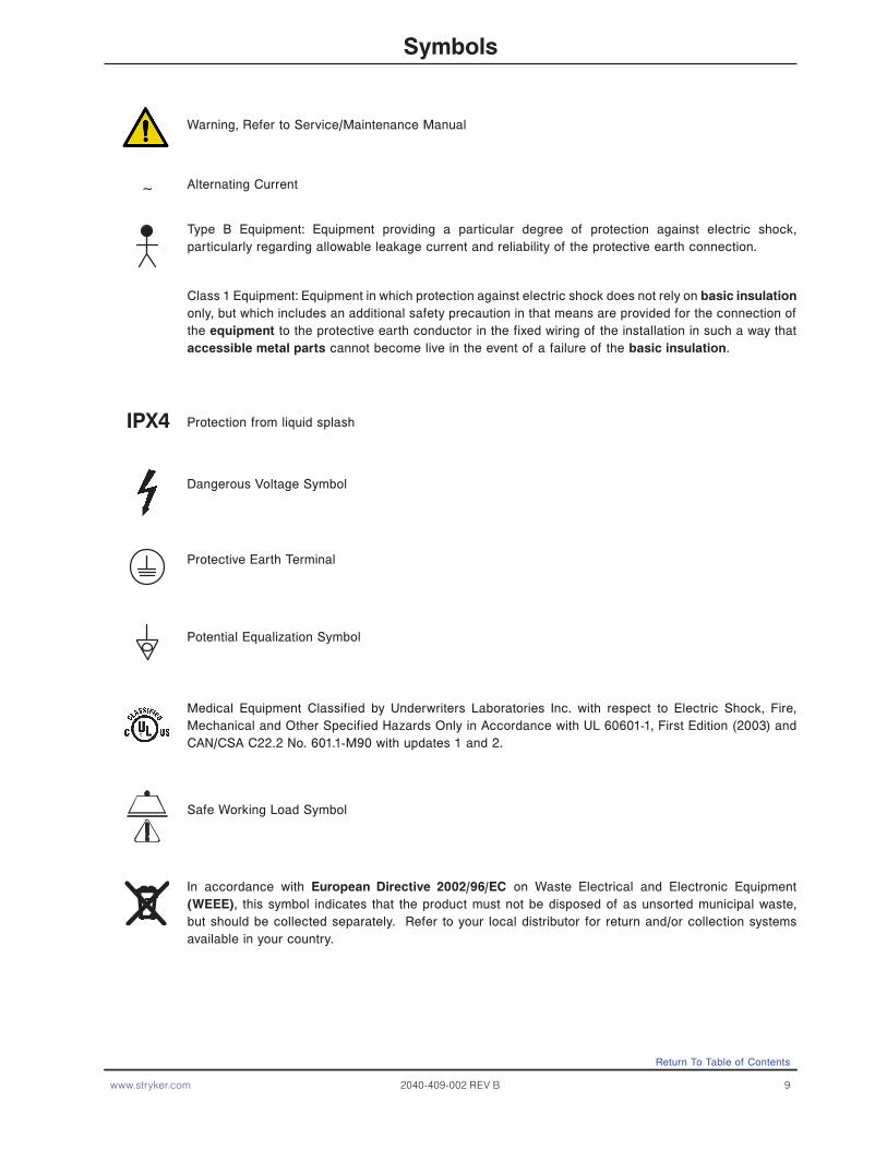
Warning, Refer to Service/Maintenance Manual
Type B Equipment: Equipment providing a particular degree of protection against electric shock, particularly regarding allowable leakage current and reliability of the protective earth connection.
Alternating Current
Class 1 Equipment: Equipment in which protection against electric shock does not rely on basic insulation only, but which includes an additional safety precaution in that means are provided for the connection of the equipment to the protective earth conductor in the fixed wiring of the installation in such a way that accessible metal parts cannot become live in the event of a failure of the basic insulation.
Protection from liquid splash
Dangerous Voltage Symbol
Protective Earth Terminal
Medical Equipment Classified by Underwriters Laboratories Inc. with respect to Electric Shock, Fire, Mechanical and Other Specified Hazards Only in Accordance with UL 60601-1, First Edition (2003) and CAN/CSA C22.2 No. 601.1-M90 with updates 1 and 2.
Safe Working Load Symbol
In accordance with European Directive 2002/96/EC on Waste Electrical and Electronic Equipment (WEEE), this symbol indicates that the product must not be disposed of as unsorted municipal waste, but should be collected separately. Refer to your local distributor for return and/or collection systems available in your country.
Potential Equalization Symbol
~
IPX4
Return To Table of Contents
10 2040-409-002 REV B www.stryker.com
Safety Tips and Guidelines
Before operating the 2040 Patient Transport Frame, it is important to read and understand all information in this manual. Carefully read and strictly follow the safety guidelines listed on this page. To ensure safe operation of the transport frame, methods and procedures must be established for educating and training hospital staff on the intrinsic risks associated with the usage of motorized electric units
WARNINGS
• The 2040 Patient Transport Frame is equipped with a hospital grade plug for protection against shock hazard. It must be plugged directly into a properly grounded three-prong receptacle. Grounding reliability can be achieved only when a hospital grade receptacle is used.
• Serious injury can result if caution is not used when operating the unit. Operate the unit only when all persons are clear of the electrical and mechanical systems.
• To help reduce the number and severity of falls by patients, always leave the bed in the lowest position when the patient is unattended.
• When raising the siderails, listen for the “click” that indicates the siderail has locked in the up position. Pull firmly on the siderail to ensure it is locked into position. Siderails are not intended to be a patient restraint device. It is the responsibility of attending medical personnel to determine the degree of restraint and the siderail positioning necessary to ensure a patient will remain safely in bed.
• Always apply the caster brakes when a patient is getting on or off the bed. Always keep the caster brakes applied when a patient is on the bed (except during transport). Injury could result if the bed moves while a patient is getting in or out of bed.
• Ensure the brakes are completely released prior to attempting to move the unit. Attempting to move the unit with the brakes actuated could result in injury to the user and/or patient.
• Put the drive wheel in the neutral position and release the brakes before pushing the unit manually. Do not attempt to push the unit manually with the drive wheel engaged. The unit will be difficult to push and injury could result.
• The CPR emergency release requires assistance to lower the Back if the angle of the Back is above 80°. Attempting to lower the Back in this position without assistance may result in injury to the operator.
• The power save mode is activated after one hour on battery power with no motion release switch activation. Functions, including Bed Exit scale and motion, will cease to operate when the unit enters the power save mode. Injury to the patient could occur if proper patient monitoring protocol is not observed.
• The Bed Exit System is intended only to aid in the detection of a patient exiting the unit. It is not intended to replace patient monitoring protocol. The bed exit system signals when a patient is about to exit. Adding or subtracting objects from the frame after arming the bed exit system may cause a reduction in the sensitivity of the bed exit system.
• To avoid pinching your fingers, place the I.V. pole in the upright position before using the drive handle.• Always unplug the power cord and push the battery power on/off switch to the “Off” position before service or
cleaning. When working under the frame, always place blocks under the litter frame to prevent injuries in case the Bed Down switch is accidently activated.
• Battery posts, terminals and related accessories contain lead and lead compounds, chemicals known to the State of California to cause cancer and birth defects or other reproductive harm. Wash hands after handling.
• The 2040 Patient Transport Frame is intended for use by trained hospital personnel only.
Service only by qualified personnel. Refer to maintenance manual.
• Do not modify the 2040 Patient Transport Frame. Modifying the unit can cause unpredictable operation resulting in injury to the patient or operator. Modifying the unit will also void its warranty.
• When using any mattress and/or mattress overlay that increases the overall height greater than 6” extra caution and/or operator supervision is required to help reduce the likelihood of a patient fall occurring.
Summary of Safety Precautions
Return To Table of Contents

www.stryker.com 2040-409-002 REV B 11
Safety Tips and Guidelines (Continued)
To avoid possible injury and to assure proper operation when using a powered mattress replacement system such as XPRT:• Confirm proper scale system operation following mattress installation. For best results, secure the therapy mattress
power cord to prevent damage to the cord or interference with the bed frame and the scale system.• Do not zero bed scales or weigh patient with Percussion, Vibration, Rotation or Turn-Assist active. Patient motion
and position resulting from the dynamic therapy mattress may adversely affect scale system performance.• Do not initialize (“Arm”) bed exit with Percussion, Vibration, Rotation or Turn-Assist active. The patient motion and
position resulting from the dynamic therapy mattress may adversely affect bed exit system performance.• When using an XPRT Therapy Mattress extra caution and/or operator supervision is required to help reduce the
likelihood of a patient fall occurring.
CAUTIONS
• Use caution while maneuvering the unit with the drive wheel activated. Always ensure there are no obstacles near the unit while the drive wheel is activated. Injury to the patient, user, bystanders or damage to the frame or surrounding equipment could occur if the unit collides with an obstacle.
• Use caution when transporting the unit down halls, through doors, in and out of elevators, etc. Damage to the siderails or other parts of the unit could occur if the unit comes in contact with walls or door frames.
• If unanticipated motion occurs, unplug the power cord from the wall socket, push the battery power on/off switch to the “Off” position (the LED will not be illuminated) and actuate the drive wheel pedal to the neutral position.
• The siderails are not intended to be used as a pushing device. Damage to the siderails could occur.• The use of a mattress overlay may reduce the effectiveness of the siderail.• When attaching equipment to the frame, ensure it will not impede normal operation. I.E.: Hooks on hanging
equipment must not actuate control buttons, equipment must not hide the nurse call button, etc.• Use caution when lowering the bed with items attached to the optional accessory rail. If caution is not used, items
may contact the floor resulting in damage to the items and/or injury to the patient or user.• The lockout buttons on the foot board lock the Fowler, Gatch and Bed Up/Down functions and prevent motion of
the bed. It is the responsibility of attending medical personnel to determine whether these functions should be locked and to use the buttons accordingly.
• Scale function may be affected by siderail/caster interference. With the litter fully lowered or lowered in Reverse Trendelenburg, the siderails tucked under the litter in the storage position and the casters turned, there is the potential for interference between the siderail and the caster. Raise the siderails when lowering the litter to the full down position to prevent the interference from causing the bed’s scale system to weigh inaccurately.
• If large fluid spills occur in the area of the circuit boards or motors, immediately unplug the power cord from the wall socket and push the battery power on/off switch to the “Off” position. Remove the patient from the unit and clean up the fluid. Have maintenance completely check the unit. Fluids can short out controls and may cause the unit to operate erratically or make some functions completely inoperable. Component failure caused by fluids could even cause the unit to operate unpredictably and could cause injury to the patient. Do not put the unit back into service until it is completely dry and has been thoroughly tested for safe operation.
• Preventative maintenance should be performed at a minimum of annually to ensure all features are functioning as designed. Close attention should be given to safety features including, but not limited to: • Safety side latching mechanisms,• Caster braking systems, • Leakage current 300 microamps max.• No controls or cabling entangLED in frame mechanisms. • Frayed electrical cords and components.• All controls return to off or neutral position when released
• The battery tray assembly weighs 50 pounds. Take care when removing the two hexagonal head screws securing it to the base frame or personal injury could result.
• The 2040 Patient Transport Frame is not intended for pediatric use or for patients under 50 pounds.
Summary of Safety Precautions
Return To Table of Contents
12 2040-409-002 REV B www.stryker.com
Summary of Safety Precautions
Return To Table of Contents
Safety Tips and Guidelines (Continued)
• Because individual beds may have different options, foot boards should not be moved from one bed to another. Interchanging foot boards between beds could result in unpredictable bed operation.
• The weight of the I.V. bags should not exceed 40 pounds.• Do not add or remove weight when the bed exit system is armed.• The cleanliness and integrity of both ground chains must be maintained to minimize static build up and
discharge.• I.V. Poles should not be used as a bed push/pull device.
The following Caution statements apply to the optional 110V outlet:• Maximum total load 5A receptacle rating: 125 VAC, 5A, 60 Hz.• The total system chassis risk current should not exceed 300 uA.• Grounding continuity should be checked periodically.• Do not use for life-sustaining equipment.• Use only hospital-grade equipment with electrical outlet.• Unplug free-standing equipment before transporting the bed.
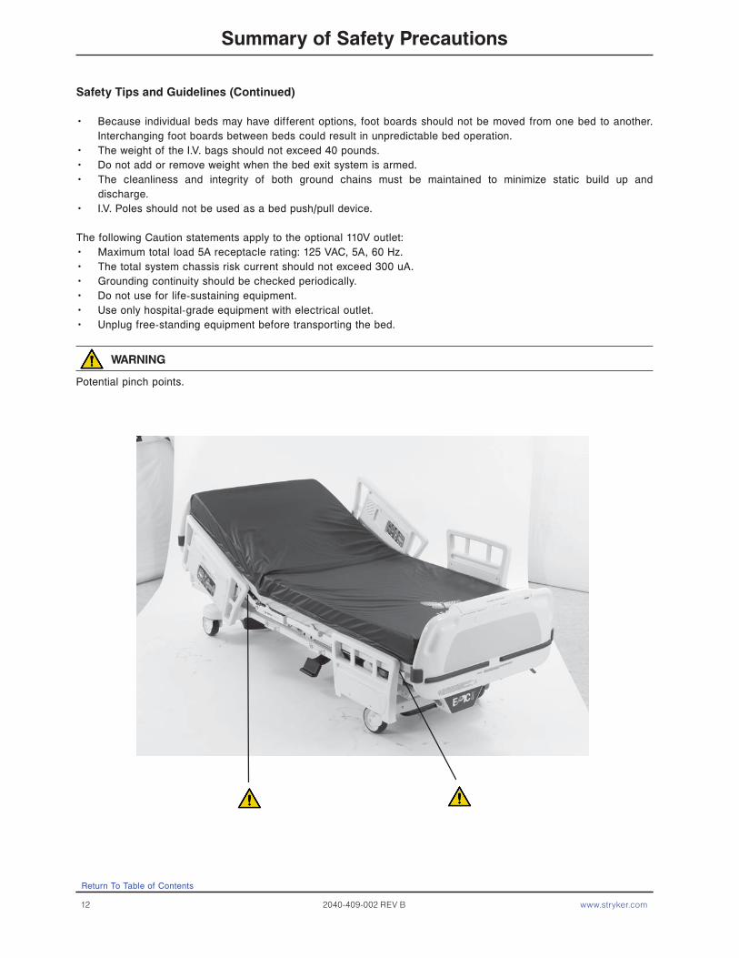
WARNING
Potential pinch points.
www.stryker.com 2040-409-002 REV B 13
iBED Awareness Option
In addition to the previous warnings and cautions, all of the following warnings and cautions apply to units equipped with the iBED Awareness option.
WARNING
• The optional iBED Awareness system only indicates the siderail position, it does NOT indicate if the siderail is locked. It is the caregiver’s responsibility to ensure that the siderails are locked after every move and also before leaving a patient in the room.
• The optional iBED Awareness system indicator lights are only an aid to the caregiver but in no way replace the caregiver’s responsibility of checking on patients. Caregivers should not rely on the lights to perform their duties.
• Before arming the optional iBED Awareness system, the nurse must physically verify that siderails are locked.• •
CAUTION
• If the optional iBED Awareness system is being used; ensure the bed is in the desirable state iBED Awareness ON and with the light Green) before leaving the room.
• If the optional iBED Awareness system is being used and the iBED Awareness is alerting, do not turn off iBED Awareness as the display information to troubleshoot the bed will get lost.
• If the optional iBED Awareness system is being used; use of accessories that cover the alert light are not recommended.
Summary of Safety Precautions
Return To Table of Contents
14 2040-409-002 REV B www.stryker.com
It is important that the 2040 Patient Transport Frame is working properly before it is put into service. The following list will help ensure that each part of the transport frame is checked.
• Plug the power cord into a properly grounded, hospital grade wall receptacle.
WARNING
The 2040 Patient Transport Frame is equipped with a hospital grade plug for protection against shock hazard. It must be plugged directly into a properly grounded three-prong receptacle. Grounding reliability can be achieved only when a hospital grade receptacle is used.
• Depress the pedal at either side of the transport frame fully to set the four wheel brakes and ensure all four casters lock. Depress the pedal again to release the brakes.
• Ensure the siderails raise and lower smoothly and lock in the up and intermediate positions.• Run through each function on the foot board control panel and ensure that each is working properly.• Ensure all functions are working properly on the siderail controls.• Ensure all motion functions are working properly at the head end of the transport frame.• Raise the Back up to approximately 60°. Squeeze the CPR release handle and ensure the Back and Knee will drop
with minimal effort.• Unplug the power cord from the wall socket. Push the battery power switch located on the lower left corner of the
head end to the “On” position. Again, verify each function on the foot board and siderails is operating properly.• With the battery power switch in the “On” position and the brakes engaged, ensure the “Release Brakes” LED on
the head end control panel is illuminated.• With the battery power switch in the “On” position and the drive wheel disengaged (not touching the floor), ensure
the “Engage Drive Wheel” LED on the head end control panel is illuminated.• Run through the operation of the drive wheel to ensure it is operating properly.• If the bed is equipped with the Nurse Call option, verify it is functioning properly prior to patient use.
Setup Procedures
Return To Table of Contents

www.stryker.com 2040-409-002 REV B 15
Maintenance Menu Screen
The Maintenance Menu contains all of the non-regularly accessible features of the product. This menu provides an interface to the user and/or service personnel in order to provide the ability to control and access maintenance features.
Maintenance Menu Items
The following are menu items listed in the maintenance menu screen: 1. Calib. Scale (Calibrate Scale)2. TV Config. (TV Configuration)3. Scale Info. (Scale Info/Stats)4. Clear Statistics (Clear Scale Stats)5. Error Log (View Error Log) 6. Clear Errors (Clear Error Log)7. Scale Units (Lock Scale Units)8. About (About Product)9. Exit Menu (Exit Maintenance)
• Each of the menu items provide the operator with a different function. • Using the up and down menu buttons you can scroll though the menu items. • To select a menu item, scroll to the desired menu item using the Up and Down menu button. When the desired
feature is highlighted, press the Enter/Check button. Depending on the feature the display will move into the sequence for the feature selected.
Load Cell Check
• This feature automatically checks all four load cells to make sure they are working properly.• The purpose of this feature is to provide a self diagnostic of the load cells.• When maintenance is entered a self-diagnostic feature should run and display results.• While procedure is running the following message is displayed “Load Cell Check”.• Any load cell errors will be displayed as a message “Load Cell Error” and then depending on the error an HL,
HR, FL or FR will be displayed below the message. (Refer to the Error Handling Section). • If no errors are present then the Maintenance Menu screen will be displayed and menu items 1-9 above may
be accessed.
Calibrate Scale
• This feature allows the operator to calibrate the scale system. • This calibration is used to provide the system with a weight offset that occurs when the product is put into
trend and reverse trend. • This calibration does not calibrate the load cells, the load cells are pre-calibrated.
To calibrate the scale system:1. In the Maintenance Menu select the Calibrate Scale item then press and hold the Enter/Check button.2. The display should present the following message:
“Do Not Touch Bed”. The message should be flashing.3. Use the up and down arrow to select the proper weight (50lbs is the default).4. Press the “Enter/Check” button when the display shows the proper weight.5. The display should present the following message:
“Place Weight in Center”.6. Place the weight in the center of the bed.
Return To Table of Contents
Optional iBED Awareness Maintenance Menu Guide

16 2040-409-002 REV B www.stryker.com
7. Press the “Enter/Check” button when completed.8. The display should present the following message:
“Press Reverse Trend”.9. Press the reverse trend button.10. The display should present the following message when the bed in the proper position:
“Release Button”. The message should be flashing.11. Release the button and do not touch the bed. When the button is released the following message will be
displayed: “Do Not Touch Bed”. The message should be flashing.12. The display should present the following message when the bed is ready to continue:
“Press Reverse Trend”.13. Press the reverse trend button.14. The display should present the following message when the bed is ready to continue:
“Release Button”. The message should be flashing.15. Release the button and do not touch the bed. When the button is released the following message will be
displayed: “Do Not Touch Bed”. The message should be flashing.16. The display should present the following message when the bed is ready to continue:
“Press Trend”.17. Press the trend button.18. The display should present the following message when the bed in the proper position:
“Release Button”. The message should be flashing.19. Release the button and do not touch the bed. When the button is released the following message will be
displayed: “Do Not Touch Bed”. The message should be flashing.20. The display should present the following message when the bed is ready to continue:
“Press Trend”.21. Press the trend button.22. The display should present the following message when the bed is ready to continue:
“Release Button”. The message should be flashing.23. Release the button and do not touch the bed. When the button is released the following message will be
displayed: “Do Not Touch Bed”. The message should be flashing.24. The display should present the Select Weight Screen. 25. Use the up and down arrow to select the proper weight (200lbs is the default).26. Press the “Enter/Check” button when the display shows the proper weight.27. The display should present the following message:
“Place Weight in Center”.28. Place the weight in the center of the bed.29. Press the “Enter/Check” button when completed.30. The display should present the following message:
“Press Reverse Trend”.31. Press the reverse trend button.32. The display should present the following message when the bed in the proper position:
“Release Button”. The message should be flashing.33. Release the button and do not touch the bed. When the button is released the following message will be
displayed: “Do Not Touch Bed”. The message should be flashing.34. The display should present the following message when the bed is ready to continue:
“Press Reverse Trend”.35. Press the reverse trend button.
Maintenance Menu (Continued)
Calibrate Scale (Continued)
Return To Table of Contents
Optional iBED Awareness Maintenance Menu Guide
www.stryker.com 2040-409-002 REV B 17
36. The display should present the following message when the bed is ready to continue: “Release Button”. The message should be flashing.
37. Release the button and do not touch the bed. When the button is released the following message will be displayed: “Do Not Touch Bed”. The message should be flashing.
38. The display should present the following message when the bed is ready to continue: “Press Trend”.
39. Press the trend button.40. The display should present the following message when the bed in the proper position:
“Release Button”. The message should be flashing.41. Release the button and do not touch the bed. When the button is released the following message will be
displayed: “Do Not Touch Bed”. The message should be flashing.42. The display should present the following message when the bed is ready to continue:
“Press Trend”.43. Press the trend button.44. The display should present the following message when the bed is ready to continue:
“Release Button”. The message should be flashing.45. Release the button and do not touch the bed. When the button is released the following message will be
displayed: “Do Not Touch Bed”. The message should be flashing.46. The display should present the following message when the bed is ready to continue:
“Save Calibration?” “Check – Save” “X – Cancel”.47. Press the “Enter/Check” button to save the calibration.48. The display should present the following message when the bed is ready to continue:
“Save Successful”.
Note: • If an error occurs during the procedure the display will show an error message “Calibration Error” for 4
seconds.• This procedure should be used after any load cell is replaced
TV Configuration
• This feature allows the operator to set up the TV configuration. • This configuration provides the product with the information to communicate with the proper entertainment
system.
To Configure the System: 1. In the Maintenance Menu select the TV Configuration item then press and hold the Enter/Check button.2. The TV Configuration Screen will be displayed. The current TV selection will be highlighted.3. Use the up and down arrow buttons to highlight the desired item.4. Press the “Enter/Check” button to select the new setting. 5. The following message will be shown on the display screen when the new setting is saved:
“Save Successful”.6. The TV Configuration screen should reappear after 2 seconds and the new setting should be highlighted.7. Pressing the Exit/X button or if the screen remains dormant for more than 30 seconds, the display will return
you to the Maintenance Menu screen, without saving any changes.
Return To Table of Contents
Maintenance Menu (Continued)
Calibrate Scale (Continued)
Optional iBED Awareness Maintenance Menu Guide
18 2040-409-002 REV B www.stryker.com
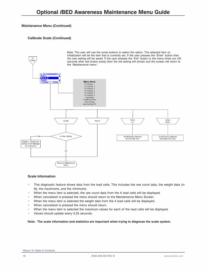
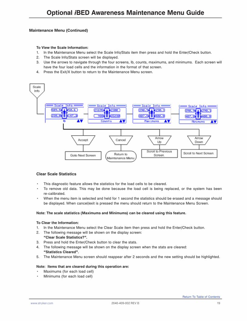
Scale Information
• This diagnostic feature shows data from the load cells. This includes the raw count data, the weight data (in lb), the maximums, and the minimums.
• When the menu item is selected, the raw count data from the 4 load cells will be displayed. • When cancel/exit is pressed the menu should return to the Maintenance Menu Screen.• When the menu item is selected the weight data from the 4 load cells will be displayed. • When cancel/exit is pressed the menu should return.• When the menu item is selected the maximum values for each of the load cells will be displayed.• Values should update every 0.25 seconds.
Note: The scale information and statistics are important when trying to diagnose the scale system.
Return To Table of Contents
Maintenance Menu (Continued)
Calibrate Scale (Continued)
Optional iBED Awareness Maintenance Menu Guide
Note: The user will use the arrow buttons to select the option. The selected item on initialization will be the item that is currently set. If the user presses the ‘Enter’ button then the new setting will be saved. If the user presses the ‘Exit’ button or the menu times out (30 seconds after last button press) then the old setting will remain and the screen will return to the ‘Maintenance menu’.
www.stryker.com 2040-409-002 REV B 19
To View the Scale Information:1. In the Maintenance Menu select the Scale Info/Stats item then press and hold the Enter/Check button.2. The Scale Info/Stats screen will be displayed.3. Use the arrows to navigate through the four screens, lb, counts, maximums, and minimums. Each screen will
have the four load cells and the information in the format of that screen. 4. Press the Exit/X button to return to the Maintenance Menu screen.
Clear Scale Statistics
• This diagnostic feature allows the statistics for the load cells to be cleared.• To remove old data. This may be done because the load cell is being replaced, or the system has been
re-calibrated.• When the menu item is selected and held for 1 second the statistics should be erased and a message should
be displayed. When cancel/exit is pressed the menu should return to the Maintenance Menu Screen.
Note: The scale statistics (Maximums and Minimums) can be cleared using this feature.
To Clear the Information:1. In the Maintenance Menu select the Clear Scale item then press and hold the Enter/Check button.2. The following message will be shown on the display screen:
“Clear Scale Statistics?”.3. Press and hold the Enter/Check button to clear the stats.4. The following message will be shown on the display screen when the stats are cleared:
“Statistics Cleared”.5. The Maintenance Menu screen should reappear after 2 seconds and the new setting should be highlighted.
Note: Items that are cleared during this operation are:• Maximums (for each load cell)• Minimums (for each load cell)
Maintenance Menu (Continued)
Return To Table of Contents
Optional iBED Awareness Maintenance Menu Guide

20 2040-409-002 REV B www.stryker.com
View Error Log
• This feature allows the operator to view the Error Log.• This log provides information pertaining to the error system and any errors that are logged during product
use.
To view the error log: 1. In the Maintenance Menu select the View Error Log item then press and hold the Enter/Check button.2. The Error Log Screen will be displayed. The most recent error will be at the top.3. Use the up and down arrow buttons to view any errors that are not shown on the screen. 4. Pressing the Exit/X button will return you to the Maintenance Menu screen without saving any changes.5. If the screen remains dormant for more than 30 seconds, you will be returned to the Maintenance Menu
screen without saving any changes.
Clear Error Log
This feature allows the user to clear the error log.
To clear the error log:1. In the Maintenance Menu select the Clear Error Log item then press and hold the Enter/Check button.2. The following confirmation screen will be displayed:
Clear Error Log? “Enter” to Accept, “Exit” to Cancel.3. If “Exit” is chosen, then you will be returned to the Maintenance Menu screen.4. If “Enter’ is chosen, then the error log is cleared and a message is displayed: “Error Log Cleared” and you
will be returned to the Maintenance Menu screen.
Maintenance Menu (Continued)
Return To Table of Contents
Optional iBED Awareness Maintenance Menu Guide
www.stryker.com 2040-409-002 REV B 21
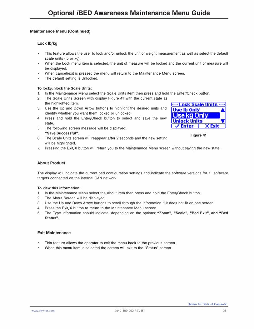
Lock lb/kg
• This feature allows the user to lock and/or unlock the unit of weight measurement as well as select the default scale units (lb or kg).
• When the Lock menu item is selected, the unit of measure will be locked and the current unit of measure will be displayed.
• When cancel/exit is pressed the menu will return to the Maintenance Menu screen.• The default setting is Unlocked.
To lock/unlock the Scale Units:1. In the Maintenance Menu select the Scale Units item then press and hold the Enter/Check button.2. The Scale Units Screen with display Figure 41 with the current state as
the highlighted item.3. Use the Up and Down Arrow buttons to highlight the desired units and
identify whether you want them locked or unlocked. 4. Press and hold the Enter/Check button to select and save the new
state. 5. The following screen message will be displayed:
“Save Successful”.6. The Scale Units screen will reappear after 2 seconds and the new setting
will be highlighted.7. Pressing the Exit/X button will return you to the Maintenance Menu screen without saving the new state.
About Product
The display will indicate the current bed configuration settings and indicate the software versions for all software targets connected on the internal CAN network.
To view this information: 1. In the Maintenance Menu select the About item then press and hold the Enter/Check button.2. The About Screen will be displayed. 3. Use the Up and Down Arrow buttons to scroll through the information if it does not fit on one screen. 4. Press the Exit/X button to return to the Maintenance Menu screen.5. The Type information should indicate, depending on the options: “Zoom”, “Scale”, “Bed Exit”, and “Bed
Status”.
Exit Maintenance
• This feature allows the operator to exit the menu back to the previous screen. • When this menu item is selected the screen will exit to the “Status” screen.
Maintenance Menu (Continued)
Return To Table of Contents
Optional iBED Awareness Maintenance Menu Guide
Figure 41

22 2040-409-002 REV B www.stryker.com
WARNING
Service only by qualified personnel. Refer to the Maintenance Manual. Ensure the power cord is unplugged and the battery power switch is turned to the off position before servicing.
Nurse Call Battery
To prevent a low battery condition when the power cord is not plugged in, position the cord out switch at the head end to the off position. The switch is identified by the label shown below. If the switch is not positioned as shown below and the power cord and pendant cord are unplugged, the life of the backup battery will be significantly reduced.
If the foot board power LED is flashing, the Nurse Call battery needs to be replaced. The battery is located on the patient’s left side under the litter frame. No tools are required to replace the battery. Unplug the power cord from the wall socket and replace the battery. After replacing the battery, verify the foot board power LED is no longer flashing. Properly dispose of the old battery in accordance with local regulations.
Main Power Circuit Breaker
In the event of a loss of electric function, unplug the power cord from the wall socket and reset the circuit breaker(s) located under the head end of the litter on the patient’s left side. Plug the power cord into a properly grounded wall receptacle and follow the setup procedures.
Battery Charger Circuit Breaker
If the battery charger circuit breaker(s) located under the litter on the patient’s head end, left side are tripped, refer to the troubleshooting section of the maintenance manual.
Preventative Maintenance
Return To Table of Contents

www.stryker.com 2040-409-002 REV B 23
Bed Serial Number:
Completed by: _______________________________________ Date: _________________
Preventative Maintenance
Return To Table of Contents
Checklist
_____ All fasteners secure.
_____ Engage brake pedal and push on the frame to ensure all casters lock securely.
_____ Inspect the brake assembly (Brake Cam, Brake Plate Body, Brake Ratchet Spring and Brake Bar) for
degradation or signs of wear at the foot end and head end of the bed. Ensure brake assembly components
are functioning properly.
_____ Engage drive wheel and ensure it is operating properly.
_____ Motion release switches working properly.
_____ Confirm Head End Control Panel functionality.
_____ Confirm battery powered functionality.
_____ Siderails move, latch and stow properly.
_____ All functions on siderails working properly (including LED’s).
_____ Manual CPR release working properly.
_____ Optional foot prop intact and working properly.
_____ I.V. pole working properly.
_____ Foley bag hooks intact.
_____ Chart rack intact and working properly.
_____ CPR board not cracked or damaged and stores properly.
_____ No cracks or splits in head and foot boards.
_____ All functions on footboard working properly (including LED’s).
_____ No rips or cracks in mattress cover.
_____ Scale and Bed Exit system calibrated properly.
_____ Power cord not frayed.
_____ No cables worn or pinched.
_____ All electrical connections tight.
_____ All grounds secure to the frame.
_____ Ground impedance not more than 100 milliohms.
_____ Current leakage not more than 300 microamps.
_____ Apply grease to the bed grease points including the fowler clutch and brake cam.
_____ Ensure ground chains are clean, intact, and have at least two links touching the floor.
_____ “Brake” LED on the foot board (iBED Awareness option only) blinks when brakes are not engaged.
_____ Siderail switches working properly (iBED Awareness option).
_____ iBED Awareness Light Bar LEDs working properly (iBED Awareness option).
_____ iBED Awareness Side Indicator LEDs working properly (iBED Awareness option).
_____ Inspect footboard control labeling for signs of degradation. (iBED Awareness option).
_____ Fowler functioning properly.
Beds require an effective maintenance program, we recommend checking these items annually. Use this sheet for your records. Keep on file.

24 2040-409-002 REV B www.stryker.com
Cleaning
Return To Table of Contents
Hand wash all surfaces of the bed with warm water and mild detergent. Dry thoroughly. Do not steam clean or hose off the bed. Using these methods of cleaning is not recommended and may void this product’s warranty. Do not immerse any part of the bed. Some of the internal parts of the bed are electric and may be damaged by exposure to water. Suggested cleaners for bed surfaces:
• Quaternary Cleaners (active ingredient - ammonium chloride).• Phenolic Cleaners (active ingredient - o-phenylphenol).• Chlorinated Bleach Solution (5.25% - less than 1 part bleach to 100 parts water).
Avoid oversaturation and ensure the product does not stay wet longer than the chemical manufacturer’s guidelines for proper disinfecting.
CAUTION
SOME CLEANING PRODUCTS ARE CORROSIVE IN NATURE AND MAY CAUSE DAMAGE TO THE PRODUCT IF USED IMPROPERLY. If the products suggested above are used to clean Stryker patient care equipment, measures must be taken to insure the bed is wiped with a damp cloth soaked in clean water and thoroughly dried following cleaning. Failure to properly rinse and dry the bed will leave a corrosive residue on the surface of the bed, possibly causing premature corrosion of critical components. Failure to follow the above directions when using these types of cleaners may void this product’s warranty.
For mattress cleaning instructions, please see the tag on the mattress, or contact the mattress manufacturer.
Clean Velcro® after each use. Saturate Velcro® with disinfectant and allow disinfectant to evaporate. (Appropriate disinfectant for nylon Velcro® should be determined by the hospital).

www.stryker.com 2040-409-002 REV B 25
Problem / Failure Recommended Action
No power to bed. A. Verify the power cord connections at the wall and the bed.
B. Check circuit breakers, under the Litter/Fowler section on the patient left side. If the circuit breaker is tripped, reset it by pushing in.
C. Check for 120 VAC at J1 on the power supply, Pin 1 (brown) and Pin 2 (blue).
D. Check for DC voltages on J2 (Pins 1, 2, 3 & 6) on power supply. See Software Configuration for power supply voltage test points.a. If voltage is present, check connector W on
the CPU board and check for the same DC voltages. If OK, go to step E.
b. If voltage is not present, unplug connector W on the CPU board and recheck for DC voltages at J2 on the power supply. 1. If voltages come back, reconnect cable
W to the CPU board, and go to step c.2. If DC voltage does not come back, replace
the power supply.c. Unplug all connectors except for F, FF, O, and
W from the CPU board and recheck voltages on connector W.1. If DC voltages come back, plug the cable
connections back in until problem comes back, isolate the problem to a component or assembly.
2. If DC voltages do not come back, replace the CPU board.
E. Check for 120 VAC at connector O on the CPU board. a. If voltage is present, replace the CPU board.
F. Verify bed function and return to service.
NoteSee Electrical System Information Section for an outline of bed PCB’s and voltage test points.
Troubleshooting Guide
Return To Table of Contents

26 2040-409-002 REV B www.stryker.com
Problem / Failure Recommended Action
No bed down motion. A. Enter diagnostics (Refer to Scale System Diagnostics and Calibration Section) and press bed down.a. If motion is not present, verify there is a
two-pin shunt present on connector Y, closest to the center of the bed, if not, install shunt (0059-137-000).1. Test bed down motion, if motion is present
then go to step D.b. If motion is present, re-burn lift potentiometer
limits (Refer to Lift Potentiometer “Burn-in” Procedure Section).
B. Check for 5 VDC on TP 9 (HL) and TP 7 (FL) referencing ground test point while pressing bed down.a. If 5 VDC is present, go to step C.b. If 5 VDC is not present, replace CPU board.
C. Check for 120 VAC power on connector N (HL) and G (FL), pin 1 (white) and pin 3 (black), of the CPU board, while pressing bed motion up.a. If voltage is not present, replace CPU board. b. If voltage is present:
1. Verify the motors are running, if so, replace lift couplers.
2. If motors are not running, check voltage at motor connection.
3. If voltage is present at motor, check capacitors or motors.
D. Verify bed function and return to service.
No bed up motion. A. Enter diagnostics, (Refer to Scale System Diagnostics and Calibration Section) and press bed up.a. If motion is not present, go to step B. b. If motion is present, re-burn lift potentiometer
limits, (Refer to Lift Potentiometer “Burn-in” Procedure Section).
B. Check for 5 VDC on TP 10 (HL) and TP 8 (FL) on the CPU board referencing ground test point while pressing bed up.a. If 5 VDC is present, go to step C. b. If 5 VDC is not present, replace CPU board.
C. Check for 120 VAC power on connector N (HL) and G (FL), pin 1 (white) and pin 6 (red), of the CPU board while pressing bed motion up.a. If voltage is not present, replace CPU board.b. If voltage is present:
1. Verify the motors are running, if so, replace lift couplers.
2. If motors are not running, check voltage at motor connection.
3. If voltage is present at motor, check capacitors or motors.
D. Verify bed function and return to service.
Troubleshooting Guide
Return To Table of Contents

www.stryker.com 2040-409-002 REV B 27
Problem / Failure Recommended Action
No Gatch down motion. A. Check for 5 VDC on TP 5 on the CPU board referencing ground test point while pressing gatch down.a. If 5 VDC is present, go to step B. b. If 5 VDC is not present, replace CPU board.
B. Check for 120 VAC power on connector CC, pin 2 (red) and pin 3 (white), of the CPU board while pressing gatch down.a. If voltage is not present, replace the CPU board.b. If 120 VAC is present, check the capacitor and
motor.C. Verify bed function and return to service.
No Gatch up motion. A. Check for 5 VDC on TP 6 on the CPU board referencing ground test point while pressing gatch up.a. If 5 VDC is present, go to step B.b. If 5 VDC is not present, replace CPU board.
B. Check for 120 VAC on connector CC, pin 1 (black) and pin 3 (white), of the CPU board while pressing gatch up.a. If voltage is not present, replace the CPU board.b. If 120 VAC is present, check the capacitor and
motor.C. Verify bed function and return to service.
No Fowler up/or uneven motion. A. Check for 5 VDC on TP 3 on the CPU board referencing ground test point while pressing Fowler up.a. If 5 VDC is present, go to step B.b. If 5 VDC is not present, replace CPU board.
B. Check for 120 VAC on connector GG, Pin 1 (white) and pin 2 (black), of the CPU board while pressing Fowler up.a. If voltage is not present, replace the CPU board.b. If 120 VAC is present, check the capacitor and
motor.C. Refer to Fowler Mechanism Customer Guide
(2030-009-028).D. Verify bed function and return to service.
No Fowler down/or uneven motion. A. Check for 5 VDC on TP 4 on the CPU board referencing ground test point while pressing Fowler down.a. If 5 VDC is present, go to step B.b. If 5 VDC is not present, replace CPU board.
B. Check for 120 VAC on connector GG, Pin 1 (white) and pin 3 (red), of the CPU board while pressing Fowler up.a. If voltage is not present, replace the CPU board.b. If 120 VAC is present, check the capacitor and
motor.C. Refer to Fowler Mechanism Customer Guide
(2030-009-028).D. Verify bed function and return to service.
Troubleshooting Guide
Return To Table of Contents

28 2040-409-002 REV B www.stryker.com
Problem / Failure Possible Cause Recommended Action
ON/OFF switch is in the on position but the power LED is off and the bed does not function.
No DC voltage from the batteries.
A. Check the fuse (F1) on the power board, (Refer to Ac Crossover Board section) replace if necessary (0000-059-730).
B. Verify the battery voltage is greater than 24 VDC.
C. Check the battery fuse - replace if necessary (2040-001-802).
D. Check the cable connections from the batteries to the display board.
E. Check the ON/OFF switch and cabling.
ON/OFF switch is in the on position, the power LED is on but the bed does not function.
Display board is not functioning or is locking out all functions.
A. Check the safety switches on the drive bar.
B. Verify the battery voltage is greater than 24 VDC.
C. Verify the display board is functioning (see note below).
D. Check all cable connections on the display and power boards.
ON/OFF switch is in the on position, the power LED is on, the ZOOM® drive works but the battery backup does not work.
The thermostat on the inverter/charger board has tripped, indicating a temperature above 110°C (230° F).
A. Wait approximately 3 to 5 minutes to allow the inverter, changer board to cool down.
The ZOOM® drive does not work - The bed does not drive - but all other functions are working.
ZOOM® drive circuitry is not responding.
A. Verify the display board is functioning (see note below).
B. Perform the control bar potentiometer “burn-in” procedure (Refer to Control Bar Potentiometer “Burn-in” Procedure Section).
C. Check the control bar potentiometer. When the bar is centered, there should be 2.25 VDC to 2.75 VDC between pin 1 and pin 2 on header 1 on the display, CPU board (Refer to Inverter/Charger Board section).
D. Check all cable connections on the display and power boards.
E. Verify the power board is functioning.F. Verify the drive wheel is functioning.
This section of the troubleshooting guide includes the ZOOM® self-propelled drive and the battery backup functions. When using this guide, assume the bed is functioning properly when powered by the AC line cord with the exception of the battery charging components.
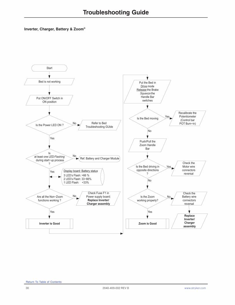
NoteThe display board will display the state of battery charge when the bed is first powered using the ON/OFF switch:Three LED’s flash = 66% - 100% charged.Two LED’s flash = 33% - 66% charged.One LED flashes = Less than 33% charged.No LED’s flash = No significant charge remaining.
Troubleshooting Guide
Return To Table of Contents

www.stryker.com 2040-409-002 REV B 29
Problem / Failure Possible Cause Recommended Action
The ZOOM® drive does work - the bed will drive - but all other bed functions are not working.
No AC power from the ZOOM® base.
A. Check AC voltage coming out of the inverter. It should be 120 VAC between pin 1 and pin 4 on header 5 on the AC crossover board (Refer to Display/CPU section).
B. Check all cable connections from the batteries to the converter.
C. Check the AC crossover board.
The bed power cord is plugged in but the battery does not charge.
The battery charger is not functioning.
A. Check the circuit breakers on the ZOOM® litter (Refer to NA 0000-059-179 Item) Circuit Breaker 2.
B. Check the battery charger.C. Check all cable connections on the
charger.
Troubleshooting Guide
Return To Table of Contents
30 2040-409-002 REV B www.stryker.com
Bed is not working
Is the Power LED ON ?
Are all the Non−Zoomfunctions working ?
Is the Bed moving
Display board: Battery status3 LED’s Flash: >66 %2 LED’s Flash: 33−66%1 LED Flash: <33%
Put the Bed inDrive mode
Release the BrakeSqueeze theHandle Barswitches
Inverter is Good
Check Fuse F1 inPower supply board:Replace Inverter/
Charger assembly
Isat least one LEDFlashing
during start−up process?
Recalibrate thePotentiometer(Control bar
POT Burn−in)
Is the Bed driving inopposite directions
?
Check theMotor wireconnectors
reversal
Push/Pull theZoom Handle
Bar
Is the Zoomworking properly?
Check theBattery wireconnectors
reversal
ReplaceInverter/Charger
assembly
Put ON/OFF Switch inON position
Zoom is Good
Ref. Battery and Charger Module
Yes
No
Yes
Yes
Yes
Yes
Yes
No
No
No
Start
No
Refer to Bed Troubleshooting GUide
No
Troubleshooting Guide
Inverter, Charger, Battery & Zoom®
Return To Table of Contents
www.stryker.com 2040-409-002 REV B 31
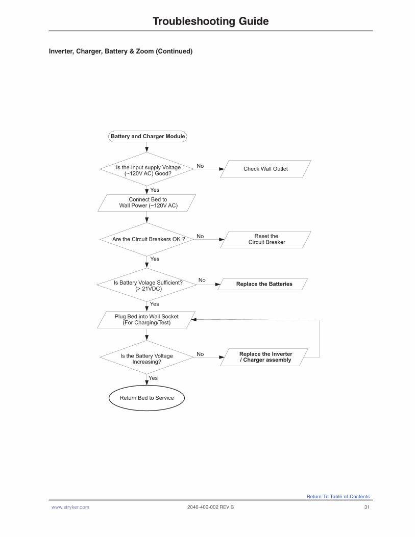
Inverter, Charger, Battery & Zoom (Continued)
INVERTER/CHARGER, BATTERY & ZOOM TROUBLESHOOTING GUIDE
Connect Bed toWall Power (~120V AC)
Replace the Inverter/ Charger assembly
Are the Circuit Breakers OK ? Reset theCircuit Breaker
Is the Input supply Voltage(~120V AC) Good?
Is the Battery VoltageIncreasing?
Is Battery Volage Sufficient?(> 21VDC)
Replace the Batteries
Battery and Charger Module
No
Yes
No
Yes
No
Yes
Yes
Check Wall OutletNo
Plug Bed into Wall Socket(For Charging/Test)
Return Bed to Service
Return To Table of Contents
Troubleshooting Guide

32 2040-409-002 REV B www.stryker.com
Return To Table of Contents
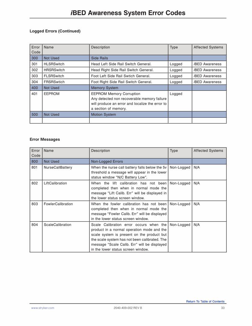
iBED Awareness System Error Codes
Error Handling
• The error handling system provides a mechanism for capturing errors known to the product and providing feedback to the operator through logged errors or message errors.
• All Logged errors generate a generic blinking error message which will be displayed on the status screen in the lower area: “Error XXX Call Service”, where XXX is the error code.
• Errors will only be logged if the error log does not already contain the error.• In the event multiple errors are displayed on the status screen, the error code is used to identify the priority. The
lowest code has the highest priority.• All logged errors and message errors are persistent until the power is cycled, or the condition is fixed. • The details for each logged error and error message are detailed in the table below.
Logged Errors
Error Code
Name Description Type Affected Systems
100 Not Used Highest Priority Errors
102 StuckSafetyRelay This error is checked while the product is “On”. If the safety relay signal is “On” and there is no button press on the product then set this error after 1 minute.” Note: This should not be checked when in Auto-Cycle Mode.
Logged Motion
103 InputTimer If any footboard motion or side rail/pendant input is sensed to be “On” continuously for a total of 5 minutes then provide an exception message. Note: This should not be checked when in Auto-Cycle Mode.
Logged Motion
200 Not Used Scale System
201 HL-Load Cell Patient Head Left Load Cell. Under/Over range.
Logged Scale, Bed Exit,iBED Awareness
202 HR-Load Cell Patient Head Right Load Cell. Under/Over range.
Logged Scale, Bed Exit,iBED Awareness
203 FL-Load Cell Patient Foot Left Load Cell. Under/Over range.
Logged Scale, Bed Exit,iBED Awareness
204 FR-Load Cell Patient Foot Right Load Cell. Under/Over range.
Logged Scale, Bed Exit,iBED Awareness
206 CS5533Fatal Non-Recoverable Communication Error. CS5533 Fatal occurs when the CPU fails to communicate to the External ADC for the Load cells and cannot recover.
Logged Scale, Bed Exit, iBED Awareness
207 ZeroFail Zero Fail error occurs when the system can-not provide a stable zero value for three con-secutive attempts at zeroing the product.
Logged Scale, Bed Exit, iBED Awareness
Return To Table of Contents
www.stryker.com 2040-409-002 REV B 33
Return To Table of Contents
iBED Awareness System Error Codes
Error Code
Name Description Type Affected Systems
300 Not Used Side Rails
301 HLSRSwitch Head Left Side Rail Switch General. Logged iBED Awareness
302 HRSRSwitch Head Right Side Rail Switch General. Logged iBED Awareness
303 FLSRSwitch Foot Left Side Rail Swtich General. Logged iBED Awareness
304 FRSRSwtich Foot Right Side Rail Switch General. Logged iBED Awareness
400 Not Used Memory System
401 EEPROM EEPROM Memory Corruption Any detected non recoverable memory failure will produce an error and localize the error to a section of memory.
Logged
500 Not Used Motion System
Error Messages
Error Code
Name Description Type Affected Systems
800 Not Used Non-Logged Errors
801 NurseCallBattery When the nurse call battery falls below the 5v threshold a message will appear in the lower status window “N/C Battery Low”.
Non-Logged N/A
802 LiftCalibration When the lift calibration has not been completed then when in normal mode the message “Lift Calib. Err” will be displayed in the lower status screen window.
Non-Logged N/A
803 FowlerCalibration When the fowler calibration has not been completed then when in normal mode the message “Fowler Calib. Err” will be displayed in the lower status screen window.
Non-Logged N/A
804 ScaleCalibration Scale Calibration error occurs when the product in a normal operation mode and the scale system is present on the product but the scale system has not been calibrated. The message “Scale Calib. Err” will be displayed in the lower status screen window.
Non-Logged N/A
Logged Errors (Continued)
Return To Table of Contents

34 2040-409-002 REV B www.stryker.com
iBED Awareness System Error Codes
Error Code
Name Description Type Affected Systems
900 Not Used Message Errors- When the timeout for the message error has expired the display should return to the status screen unless otherwise noted or unless a higher priority screen is being handled.
901 ScaleSystem When turning on the Scale system, using the Scale Button, if a “Logged” error is present that affects the scale system (see affected systems column) the message “Function Disabled - Call Service” will blink.
System N/A
902 BedExitSystem When turning on the Bed Exit system if a “Logged” error is present that affects the scale or bed exit systems (see affected systems column) the message “Function Disabled - Call Service” will blink.
Bed Exit will alarm if Bed Exit is armed and a 200 level exception occurs. The message will be displayed “Turn off Bed Exit - Call Service”. When the system is disarmed, the display will go back to the status screen. Since the bed exit alarm has the highest priority, if the Bed Exit alarm is tripped due to the error condition this message will not be seen.
Message N/A
903 LBSSystem When turning on the iBED Awareness system if a “Logged” error is present that affects the iBED Awareness system (see affected systems column) the message “Function Disabled - Call Service” will blink.
iBED Awareness will alarm if iBED Awareness is “On” and a 200 or 300 level Logged error occurs. The message will be displayed “Turn off Bed Status - Call Service”, When the system is turned off, the display will go back to the status screen.
Message N/A
904 UnknownBedType Unknown bed type occurs when the configuration switch bank does not contain a value that is recognized by the software. This will cause the product to stop all function and product a message screen indicating the error number and the message “Unknown Bed Type - Call Service”
Message N/A
Error Messages (Continued)
NOTE: The 900 error codes are not logged.
Return To Table of Contents

www.stryker.com 2040-409-002 REV B 35
iBED Awareness System Error Codes
Error Code
Name Description Type Affected Systems
905 CANConnectivity If the footboard does not see the Main board Heart beat within 10 seconds then the mes-sage “Communication Failed - Call Service”
Message N/A
906 ScaleFeatures A message will be displayed when user tries to activate any scale function (Ex. Gain/Loss, Change Equipment…) that is disabled due to a logged scale exception (200 Series). Message “Function Disabled - Call Service” at 0.8 Hz (70% Duty Cycle) for 4 seconds.
Message N/A
907 ZeroAttemptFailed The “Unable to Zero - Try Again” message will flash be displayed when the user tries to zero the bed and the scale system cannot stabilize the weight in time. Note: This applies to any use of the zeroing feature, even if that is within another scale function.
If a zero attempt has failed then the scale system will be suspended until a successful zero is saved or the power is cycled. If the scale button is pressed the “Function Not Available - Zero Bed” message will flash.
Message N/A
910 LoadCellCheck The load cells will be checked when the maintenance menu is entered and a message will be displayed if any load cell errors are detected. The message should be displayed “Load Cell Error – HL HR FL FR”. Note: Only the load cells that are in error will be displayed. This message will be persistent until any of the menu type buttons are pressed.
Message N/A
911 MenuException If the footboard menu system is provided with data that is out of range the display will pres-ent “Menu Error – Call Service”. The message will persist until a menu state is correct.
Message N/A
912 CalibrationException If the scale calibration routine fails then the message “Calibration Error” will be displayed for 4 seconds and then return to the mainte-nance menu.
Message Motion
Logged Errors (Continued)
Return To Table of Contents

36 2040-409-002 REV B www.stryker.com
Part Name Part Number
Electrical Components
AC Crossover Board 2040-031-900
Foot Board Keyboard (S/R Lights, Lockouts, etc.) 3001-500-028
Foot Board Scale Display 3001-507-900
Foot Board Scale Keyboard 3001-507-910
Foot Board Bed Exit Keyboard 3001-508-900
CPU Board 3002-407-950
Display/CPU Board 2040-031-910
Inverter/Charger Board (Optional) 2030-001-030
Motor Control Board 2040-001-900
Power Supply 0000-059-157
Siderail Boards
Inside Board 3001-400-930
Outside Board 2035-400-900
Speaker W/Cable 3000-403-831
Other Components
Adhesive, Head & Foot Board “C” Bumpers. 0072-002-071
Battery Kit 2040-700-013
Capacitor, Fowler & Gatch 0000-059-779
Capacitor, Fowler & Gatch, 230V 0000-059-153
Capacitor, Lift 0000-059-778
Capacitor, Lift, 230V 3221-200-243
Caster, 6” 3001-200-060
Caster, Steer, 6” 3001-200-050
Coil Cord, Lift Power 3001-200-864
Coil Cord, Lift Sensor 3001-200-815
Communications Tester 3002-045-700
Foot Prop Retrofit Kit 2030-700-106
Grease, Single Tube 0300-200-700
Quick Reference Replacement Parts List
NoteThe parts and accessories listed on this page are all currently available for purchase. Some of the parts identified on the assembly drawing parts in this manual may not be individually available for purchase. Please call Stryker Customer Service USA: 1-800-327-0770 (Option 2), Canada: 1-888-233-6888 for availability and pricing.
Return To Table of Contents

www.stryker.com 2040-409-002 REV B 37
Part Name Part Number
Other Components (Continued)
Load Cell 3002-307-057
Motor Coupler Kit, Lift 3000-200-725
Motor, Drive Wheel 3002-001-072
Motor, Fowler & Gatch W/Clutch 3001-300-560
Motor, Fowler & Gatch W/Clutch, 230V 3221-300-705
Motor, Lift (Same For Head And Foot End) 3000-200-213
Motor, Lift, 230V (Same For Head And Foot End) 3221-200-213
Paint, Touch-up, Opal, Bottle W/brush 7000-001-321
Paint, Touch-up, Opal, Spray Can 7000-001-318
Potentiometer, Control Bar 2040-031-804
Potentiometer, Foot End 3001-200-230
Potentiometer, Foot End 2035-032-803
Potentiometer, Head End 3001-200-240
Power Cord 3002-700-049
Restraint Strap, 2 pieces 0390-019-000
iBED Awareness Components
Foot End Siderail Switch, Right 2032-030-010
Foot End Siderail Switch, Left 2032-030-025
Head End Siderail Switch, Right 2032-030-020
Head End Siderail Switch, Left 2032-030-015
LBS Light Indicator, Right 3004-300-225
LBS Light Indicator, Left 3004-300-230
CPU Board 3003-407-900
Quick Reference Replacement Parts List
Return To Table of Contents

www.stryker.com 2040-409-002 REV B 39
Electrical System Information
CPU BOARD − 3002−407−950
Return To Table of Contents
Standard CPU Board = 3002-407-950 / iBED Awareness CPU Board - 3003-407-900

40 2040-409-002 REV B www.stryker.com
Electrical System Information
Cable Location Voltage Positive LED Negative LED Description
W +12 VDC Pin 1 Pin 4 or 5Relays & Siderails
Light Voltage
W +5 VDC Pin 2 & 3 Pin 4 or 5 +5 VDC from Power Supply
W -12 VDC Pin 6 Pin 4 or 5Relays & Siderails
Light Voltage
J +5 VDC Pin 4 (Green) Pin 2 (Black) +5 VDC for Head Lift Pot
J 1-5 VDC Pin 3 (Red) Pin 2 (Black) Head Lift Pot Wiper
C +5 VDC Pin 1 (Blue) Pin 2 (White) +5 VDC for Foot Lift Pot
C 1-5 VDC Pin 3 (Black) Pin 2 (White) Foot Lift Pot Wiper
GG0 VAC W/O Switch 120 VAC W/Switch
Pin 1 (Black) Pin 3 (White) Fowler Up
GG0 VAC W/O Switch 120 VAC W/Switch
Pin 2 (Red) Pin 3 (White) Fowler Down
CC0 VAC W/O Switch 120 VAC W/Switch
Pin 2 (Black) Pin 1 (White) Gatch Up
CC0 VAC W/O Switch 120 VAC W/Switch
Pin 3 (Red) Pin 1 (White) Gatch Down
O 110 VAC Pin 1 Pin 2 Line Voltage to Bed
N0 VAC W/O Switch 120 VAC W/Switch
Pin 3 (Black) Pin 1 (White) Head Lift Down
N0 VAC W/O Switch 120 VAC W/Switch
Pin 6 (Red) Pin 1 (White) Head Lift Up
G0 VAC W/O Switch 120 VAC W/Switch
Pin 3 (Black) Pin 1 (White) Foot Lift Down
G0 VAC W/W Switch 120 VAC W/Switch
Pin 6 (Red) Pin 1 (White) Foot Lift Up
ZZ +5 VDC Pin 1 (Red) Pin 4 (Black) +5 VDC for Fowler Pot
ZZ 1-5 VDC Pin 3 (Green) Pin 4 (Black) Fowler Pot Wiper
V 9 VDC Pin 2 (Red) Pin 1 (Black) Nurse Call Backup Battery
JJ12 VDC when Bed Exit is Alarming
Pin 1 (Red) Pin 2 (Black) Bed Exit Beeper
Return To Table of Contents
Standard CPU Board = 3002-407-950 / iBED Awareness CPU Board - 3003-407-900 (Continued)
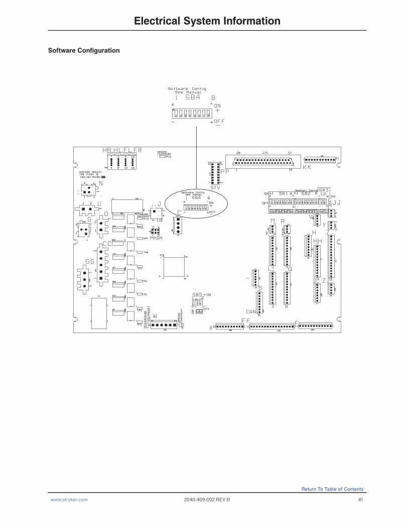
www.stryker.com 2040-409-002 REV B 41
Electrical System Information
Software Configuration
Return To Table of Contents
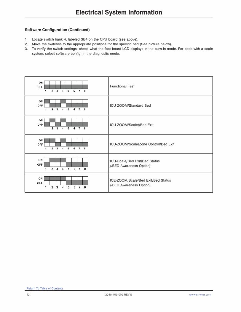
42 2040-409-002 REV B www.stryker.com
Electrical System Information
Software Configuration (Continued)
1. Locate switch bank 4, labeled SB4 on the CPU board (see above).2. Move the switches to the appropriate positions for the specific bed (See picture below).3. To verify the switch settings, check what the foot board LCD displays in the burn-in mode. For beds with a scale
system, select software config. in the diagnostic mode.
Return To Table of Contents
Functional Test
ICU-ZOOM/Standard Bed
ICU-ZOOM/Scale//Bed Exit
ICU-ZOOM/Scale/Zone Control/Bed Exit
ICU-Scale/Bed Exit/Bed Status(iBED Awareness Option)
ICE-ZOOM/Scale/Bed Exit/Bed Status(iBED Awareness Option)

www.stryker.com 2040-409-002 REV B 43
Electrical System Information
Power Supply - 0000-059-157
POWER SUPPLY − P/N 59−157
CONNECTOR LOCATION VOLTAGE POSITIVE LEAD NEGATIVE LEAD
J1 110V Pin 1 Pin 2
J2 12V Pin 1 Pin 4 or 5
J2 5V Pin 2 Pin 4 or 5
J2 5V Pin 3 Pin 4 or 5
J2 GND Pin 4 Pin 4 or 5
J2 GND Pin 5 Pin 4 or 5
J2 -12V Pin 6 Pin 4 or 5
Return To Table of Contents

44 2040-409-002 REV B www.stryker.com
Electrical System Information
Inverter - Charger Board - 3002-001-030
CONNECTOR LOCATION
VOLTAGE POSITIVE LEAD NEGATIVE LEAD DESCRIPTION
HDR 4 26 VDC Pin 2 Red Pin 1 Black From Battery - unplugged
HDR 1 22 VAC Pin 3 Red Pin 2 Secondary from Transformer - plugged in
HDR 1 34 VAC Pin 1 Green Pin 2 Brown Secondary from Transformer - plugged in
HDR 2 110-140 VAC Pin 4 BrownInverter Module
Pin 3 BlueUnplugged
HDR 2 110V Pin 2 Brown Pin 1 Blue From Wall - plugged in
HDR 3 120V Pin 2 Plug-In Pin 1 Wall Voltage - plugged in
INVERTER/CHARGER BOARD − PART NUMBER 3002−1−30
Return To Table of Contents

www.stryker.com 2040-409-002 REV B 45
Electrical System Information
Display/CPU - 2040-031-910
CONNECTOR LOCATION
VOLTAGE POSITIVE LEAD NEGATIVE LEAD DESCRIPTION
HDR 1 (H) 0-5VDC Pin 1 Pin 2 Control Pot Wiper Voltage (with Switch On)
HDR 6 (J)Battery voltage around 26 VDC
Pin 1 Pin 5Battery Voltage Return from On - Off Switch (with Switch On)
HDR 4 (L) 5 VDC Pin 9 Pin 1 Voltage from CPU
HDR 1 5 VDC Pin 1 Pin 3 DC Voltage to Pot
HDR 7 Continuity Pin 1 Pin 4 Right Hand Switch
HDR 3 Continuity Pin 1 Pin 4 Left Hand Switch
HDR 2 26 VDC Pin 3 Pin 1 Battery Voltage
DISPLAY/CPU − P/N 2040−31−910
Return To Table of Contents

46 2040-409-002 REV B www.stryker.com
Electrical System Information
AC Crossover Board - 2040-031-900
AC CROSSOVER BOARD − P/N 2040−31−900
CONNECTOR LOCATION
VOLTAGE POSITIVE LEAD NEGATIVE LEAD DESCRIPTION
HDR 5 (A) 120 VAC Pin 4 Pin 1AC Input to Board from the Inverter with the Power Cord Unplugged
HDR 1 (C) 120 VAC Pin 3 Pin 1AC Input to Board from the Wall Receptacle
HDR 2 (B) 120 VAC Pin 2 Pin 1 AC Output of Board to Main Power
HDR 4 (E) +5 VDC Pin 4 Pin 1+5 VDC when AC is Unplugged from the Wall Receptacle
Return To Table of Contents

www.stryker.com 2040-409-002 REV B 47
Electrical System Information
DC Motor Power Board - 2040-001-900
DC MOTOR POWER BOARD − P/N 2040−1−900
CONNECTOR LOCATION
VOLTAGE POSITIVE LEAD NEGATIVE LEAD DESCRIPTION
HDR 1 (P)Battery voltage around 26 VDC
Pin 3 Red Pin 1 BlackBattery Voltage out to the Display/CPU Board
HDR 2 (Q)5 VDC Disengaged
0 VDC EngagedPin 1 Red Pin 3 Black Drive Wheel
HDR 2 (Q)5 VDC Disengaged
0 VDC EngagedPin 2 Red Pin 3 Black Brakes
Return To Table of Contents

48 2040-409-002 REV B www.stryker.com
Electrical System Information
The inverter has several features to prevent internal damage:
1. Low Battery Voltage - If the battery voltage at the inverter drops below the low voltage cut-off, the inverter will
shut off.
2. Over-Temperature - If the inverter gets too hot, it will shut off. The over heating may be caused by high ambient
temperature, blocked air flow or an overload condition. When the inverter reaches an acceptable temperature, it
will restart.
3. Over-Power - The inverter will source up to its maximum power rating. If the load requires more, the output voltage
will shut down. Turning the power switch off and on will reset the inverter. Plugging the bed power cord into the
wall socket to charge the battery will reset the inverter.
WARNING
The inverter generates 115 VAC, the same as a wall receptacle. To prevent injury, do not put anything into the electrical outlets other than an appliance power cord. Keep the outlets covered when not in use. Do not submerge the unit or subject into moisture.
Inverter Protection Features
Return To Table of Contents
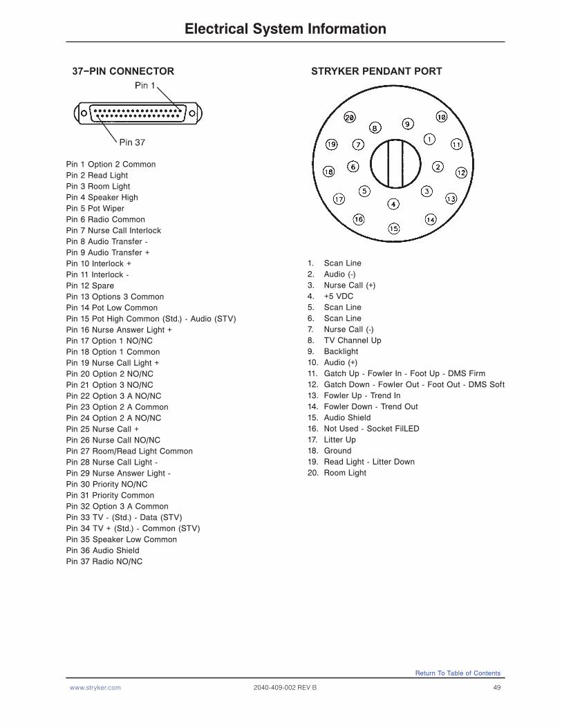
www.stryker.com 2040-409-002 REV B 49
Electrical System Information
37−PIN CONNECTOR
Pin 1 Option 2 CommonPin 2 Read LightPin 3 Room LightPin 4 Speaker HighPin 5 Pot WiperPin 6 Radio CommonPin 7 Nurse Call InterlockPin 8 Audio Transfer -Pin 9 Audio Transfer +Pin 10 Interlock +Pin 11 Interlock -Pin 12 SparePin 13 Options 3 CommonPin 14 Pot Low CommonPin 15 Pot High Common (Std.) - Audio (STV)Pin 16 Nurse Answer Light +Pin 17 Option 1 NO/NCPin 18 Option 1 CommonPin 19 Nurse Call Light +Pin 20 Option 2 NO/NCPin 21 Option 3 NO/NCPin 22 Option 3 A NO/NCPin 23 Option 2 A CommonPin 24 Option 2 A NO/NCPin 25 Nurse Call +Pin 26 Nurse Call NO/NCPin 27 Room/Read Light CommonPin 28 Nurse Call Light -Pin 29 Nurse Answer Light -Pin 30 Priority NO/NCPin 31 Priority CommonPin 32 Option 3 A CommonPin 33 TV - (Std.) - Data (STV)Pin 34 TV + (Std.) - Common (STV)Pin 35 Speaker Low CommonPin 36 Audio ShieldPin 37 Radio NO/NC
STRYKER PENDANT PORT
1. Scan Line2. Audio (-)3. Nurse Call (+)4. +5 VDC5. Scan Line6. Scan Line7. Nurse Call (-)8. TV Channel Up9. Backlight10. Audio (+)11. Gatch Up - Fowler In - Foot Up - DMS Firm12. Gatch Down - Fowler Out - Foot Out - DMS Soft13. Fowler Up - Trend In14. Fowler Down - Trend Out15. Audio Shield16. Not Used - Socket FilLED17. Litter Up18. Ground19. Read Light - Litter Down20. Room Light
Return To Table of Contents

50 2040-409-002 REV B www.stryker.com
Electrical System Information
Item Part No. Part Name Qty.
A 3002-045-805 BCT Unit 1 B 3001-303-825 37-Pin Cable 1 C 3002-045-806 Instructions 1 D 3000-303-871 9V Battery 1
Item Part No. Part Name Qty.1tinU TCB508−54−2003A
B 3001−303−825 37−Pin Cable 1C 3002−45−806 Instructions 1D 3000−303−871 9V Battery 1
Return To Table of Contents

www.stryker.com 2040-409-002 REV B 51
Service information
Static Discharge Precautions
The electronic circuits in the 2040 are completely protected from static electricity damage only while the bed is
assembled. It is extremely important that all service personnel always use adequate static protection when servicing
the electronic systems of the Secure II. Whenever you are touching wires, you should be using static protection.
Static Protection Equipment
The necessary equipment for proper static protection is:
• 1 static wrist strap; 3M part number 2214 or equivalent,
• 1 grounding plug; 3M part number 61038 or equivalent,
• 1 test lead with a banana plug on one end and an alligator clip on the other; Smith part number N132B699 or
equivalent
CAUTION
All electronic service parts will be shipped in static shielding bags. Do not open the bags until you have completed steps 2 and 3 of the following procedure. Do not place unprotected circuit boards on the floor. All circuit boards to be returned to Stryker Medical should be shipped in the static shielding bags the new boards were shipped in.
Static Protection Procedure
1. Unplug the power cord from the wall receptacle.2. Insert the grounding plug into a properly grounded hospital grade wall receptacle. Plug the banana plug of the
test lead into the receptacle on the grounding plug. Connect the alligator clip on the other end of the test lead to a ground point on the bed.
3. Place the static control wrist strap on your wrist. Connect the alligator clip at the other end of the wrist strap cord to a ground point on the bed.
BED
GROUNDING DIAGRAM
Return To Table of Contents
52 2040-409-002 REV B www.stryker.com
Brake Pedal Replacement
Tools Required:
• 5/16” Hex Allen Wrench.• Torque Wrench.• Loctite 242.• Hammer.• Punch.• #2 Phillips Screwdriver.• Bungee Cords (or Equivalent).
Procedure:1. Raise the litter to the full up position. 2. Unplug the power cord from the wall socket and push the battery power on/off switch to the “Off” position.3. Using a #2 Phillips screwdriver, remove the four screws holding the base hood to the frame. If necessary, hold the
covers out of the way by using bungee cords (or the equivalent) to secure them to the litter top.4. Using a 5/16” hex Allen wrench, remove the two bolts holding the brake pedal to the brake rod.5. Using a hammer and punch, remove the roll pins holding the brake shaft crank to the brake rod on both the head
and the foot end.6. Push the brake rod through the frame until the brake pedal is clear. Remove the brake pedal.7. Reverse steps 1 - 6 to attach the new brake pedal.
NoteUse Loctite 242 when reinstalling the bolts and torque the bolts to 25 foot-pounds.
Service Information
Return To Table of Contents

www.stryker.com 2040-409-002 REV B 53
Lift Motor And Capacitor Removal and Replacement
Tools Required:
• 3/8” Socket Wrench W/Extension.• 5/16” Socket Wrench.• Floor Jack.• Side Cutters.• 7/16” Open End Wrench.• 2 x 4 (or Equivalent).
Procedure:
NoteIf you need more space to work under the base frame, place a 2 x 4 across the base frame rails and use a floor jack to raise the base frame off the floor.
1. Unplug the power cord from the wall socket and push the battery power on/off switch to the “Off” position.2. Using a 5/16” socket wrench, remove the five bolts holding the lower lift cover to the base and remove the cover.3. Disconnect the two connectors (A) at the motor capacitor.4. Disconnect the white connector (B) from the power cord.5. Using side cutters, cut the cable ties holding the capacitor (C) to the base and remove the capacitor.6. Using a 3/8” socket wrench, remove the four screws (D) holding the motor assembly in the lift housing and remove
the motor assembly.7. Reverse steps 1 - 6 to install the new motor.
NoteThe drive shaft on the new motor might need to be turned with a 7/16” open end wrench to align with the coupler. The procedure for lift motor and capacitor removal and replacement is the same for both ends of the bed.
ABD FOOT END
C
Service information
Return To Table of Contents

54 2040-409-002 REV B www.stryker.com
Lift Housing Removal And Replacement
Tools Required:
• #2 Phillips Screwdriver.• Bungee Cord (or Equivalent).• 5/16” Socket Wrench.• Side Cutters.• 9/16” Socket Wrench.• Floor Jack.• 7/32” Hex Allen Socket Wrench.• Sawhorses (or Equivalent).• 2 x 4 (or Equivalent).• 3/8” Socket Wrench (W/6” extension).Procedure:
NoteIf you need more space to work under the base frame, place a 2 x 4 across the base frame rails and use a floor jack to raise the base frame off the floor.1. Unplug the power cord from the wall socket and push the battery power on/off switch to the “Off” position.2. Using a 5/16” socket wrench, remove the five bolts holding the lower lift cover to the base and remove the cover.3. Using a #2 Phillips screwdriver, remove the three screws holding the upper lift cover to the base. If necessary,
hold the upper and lower covers out of the way by using bungee cords (or the equivalent) to secure them to the litter top.
4. Remove the lift motor and capacitor (refer to the Brake Pedal Replacement procedure).5. Remove the lift potentiometer (refer to the Lift Potentiometer Replacement and Adjustment procedure).6. Using a 5/16” socket wrench, remove the cable clamps holding the power and sensor coil cords on top of the lift
housing assembly. Cut the cable ties and disconnect the coil cords from under the lift housing. The power and sensor coil cords are now free of the lift housing assembly. Drape them up out of the way.
7. Using a 7/32” hex Allen socket, remove the two screws holding the lift screws to the header crossbar plate.8. Lift the litter top up and support it about 6” above the lift screws on sawhorses or the equivalent.9. Under the base, using a 9/16” socket, remove the four nuts (A) holding the lift housing to the base.10. Lift up and out on the lift housing assembly to remove it from the base.
CAUTION
To ensure proper reattachment of the power and sensor coil cords, refer to the Lift Motor Coupler Replacement procedure. Refer to the Lift Potentiometer Replacement and Adjustment procedure for reattachment of the lift potentiometer.
11. Reverse steps 1 - 10 to reinstall the lift housing assembly after service is completed.
NoteThe procedure for lift housing removal and replacement is the same for both ends of the bed.
A
FOOT END − BOTTOM VIEW
Service Information
Return To Table of Contents

www.stryker.com 2040-409-002 REV B 55
Lift Potentiometer Replacement and Adjustment
Tools Required:
• #2 Phillips Screwdriver.• Bungee Cord (or equivalent).• 5/16” Socket Wrench.• 3/8” Open End Wrench.• Side Cutters.
Procedure:1. Raise the litter to the full up position.2. Unplug the power cord from the wall socket and push the battery power on/off switch to the “Off” position.3. Using a 5/16” socket wrench, remove the five bolts holding the lower lift cover to the base and remove the cover.
If necessary, hold the covers out of the way by using bungee cords (or the equivalent) to secure them to the litter top.
4. Using a #2 Phillips screwdriver, remove the three screws holding the upper lift cover to the base. If necessary, hold the covers out of the way by using bungee cords (or the equivalent) to secure them to the litter.
5. Using side cutters, cut the cable tie (A) holding the potentiometer cable to the coil cord.6. Unplug the potentiometer cable from the sensor coil cord. If replacing a potentiometer at the head end of the bed,
unplug the cables attached to the brake sensor switch.7. Pull the potentiometer cable up through the base.8. Using a 3/8” open end wrench, remove the two bolts (B) holding the potentiometer housing (C) to the lift
housing. 9. Lift up and out on the potentiometer housing assembly to remove it from the lift housing.10. Before installing the new potentiometer on the bed, turn it clockwise until it stops. Turn it back counterclockwise
two full (360°) revolutions. This allows a ”window” position for proper upper and lower limits.11. Reverse steps 4 - 9 to install the new potentiometer and potentiometer housing assembly.12. After installing the new potentiometer, the “burn-in” procedure below must be followed.
NoteBe sure to maintain the pot position while installing.
B
C
A
B
Service information
Return To Table of Contents

56 2040-409-002 REV B www.stryker.com
Lift Potentiometer “Burn-In” (Standard Bed)
Note
It requires two people to enable the diagnostics mode for the bed.
1. Unplug the bed power cord from the wall socket.
2. On the foot board control panel, hold down the Bed Motion Lock button and the button to lock out the siderail
controls for the knee. While still holding the buttons, plug the bed power cord into the wall socket. Release the foot
board buttons. The siderail control lights LED should be flashing to indicate the bed is in diagnostics mode.
3. To “burn in” the Bed Up/Down limits, raise the bed completely up until it can’t go any farther. Press and hold
the “Bed Motion Lock” button. The “Bed Motion Lock” LED will light. Continue to hold the “Bed Motion Lock”
button until the “Bed Motion Lock” LED flashes. The flashing LED indicates the limits have been set. Release the
“Bed Motion Lock” button and unplug the power cord from the wall socket to complete the “burn-in” mode.
4. Plug the power cord into the wall socket and verify the lift limits are set properly before returning the bed to
service.
5. If your bed has an I.V. Caddy, a lower limit must be burned in. Run the litter down to 19.5 inches. Hold the Bed
Up/Down Lock button until the light flashes.
Lift Potentiometer “Burn-In” (iBED Awareness Option)
Note
1. It requires two people to enable the diagnostics mode for the bed. Unplug the bed power cord from the wall
socket.
2. On the foot board control panel, hold down the Patient Fowler Lock button and the Patient Bed Up/Down Lock
button. While still holding the buttons, plug the bed power cord into the wall socket. Release the foot board
buttons.
3. To “burn in” the Bed Up/Down limits, raise the bed completely up until it can’t go any farther. Press and hold the
“Bed Motion Lock” button. A message appears on the screen “Hold to Set Height Limits”. Continue to hold the
button untill the “Bed Motion Lock” LED’s on the footboard and dashboard start flashing. A message appears
“Release Button”. Release the “Bed Motion Lock” button. A message appears on the screen “Height Limits
Set”.Plug the power cord into the wall socket and verify the lift limits are set properly before returning the bed to
service.
4. If your bed has an I.V. Caddy, a lower limit must be burned in. Run the litter down to 19.5 inches. Hold the Bed
Up/Down Lock button until the light flashes.
CAUTION
For both procedures above, do not run the litter all the way down while in the diagnostics mode. Damage to the bottom
lift covers could result.
Service Information
Return To Table of Contents

www.stryker.com 2040-409-002 REV B 57
Lift Motor Coupler Replacement
Tools Required:
• 5/16” Socket Wrench.• 3/8” Socket Wrench (W/6” Extension).• Floor Jack.• 2 x 4 (or Equivalent).
Procedure:
NoteIf you need more space to work under the base frame, place a 2 x 4 across the base frame rails and use a floor jack to raise the base frame off the floor.
1. Unplug the power cord from the wall socket and push the battery power on/off switch to the “Off” position.2. Using a 5/16” socket wrench, remove the five bolts holding the lower lift cover to the base and remove the cover.3. Using a 3/8” socket with an extension, remove the four bolts (A) holding the isolation plate (B) to the lift housing
and lower the lift motor and isolation plate assembly to allow access to the coupler (C).4. The motor coupler can now be removed from the lift housing.5. Reverse steps 1 - 4 to install the new motor coupler and bushings.
B
A
C
A
Service information
Return To Table of Contents
58 2040-409-002 REV B www.stryker.com
Tools Required:
• #2 Phillips Screwdriver.• Side Cutters.• 5/16” Socket Wrench.• Bungee Cord (or equivalent).• 5/16” Nut Driver.• Floor Jack.• 2 x 4 (or Equivalent).
Procedure:
NoteIf you need more space to work under the base frame, place a 2 x 4 across the base frame rails and use a floor jack to raise the base frame off the floor.
1. Unplug the power cord from the wall socket and push the battery power on/off switch to the “Off” position.2. Using a 5/16” socket wrench, remove the five bolts holding the lower lift cover to the base and remove the cover.3. Using a #2 Phillips screwdriver, remove the three screws holding the upper lift cover to the base. If necessary, hold
the covers out of the way by using bungee cords (or the equivalent) to secure them to the litter top.4. Using side cutters, cut the cable ties holding the power and sensor coil cords to the base. Remove the ground wire
coming from the sensor cord that is attached to the base (note the star washer arrangement).5. Disconnect the cables going to the motor and the lift potentiometer (at the head end, the sensor cord is also
attached to the brake switch sensor).6. Pull both cords up through the frame of the bed and the lift housing.7. Using a 5/16” socket wrench, remove the two screws (A) holding the cable clamps to the top of the lift housing.8. Using a 5/16” socket wrench, remove the two screws (B) securing the cable clamps to the underside of the header
crossbar assembly.9. Pull both coil cords up through the header crossbar assembly.10. Disconnect the power and sensor coil cords from the connectors.11. The cords should now be completely removed from the bed. Reverse the above steps to install the new power and
sensor cords.
CAUTION
When the power and sensor coil cords are being replaced, secure the cable clamps to the cords at the first coil both on the top and on the bottom to ensure there is not too much slack in the cords between the top of the lift housing assembly and the bottom of the header crossbar. Be sure the clamps are fastened at exactly the correct angle, as shown by the arrows in the illustration on the next page. Arrange the cords exactly as shown in the illustration (left in front of right). If this is not done correctly, damage to the cords will result.
Power and Sensor Coil Cord Replacement
Service Information
Return To Table of Contents

www.stryker.com 2040-409-002 REV B 59
A
B
A
B
VIEW FROM CENTER OF BED
Service information
Return To Table of Contents
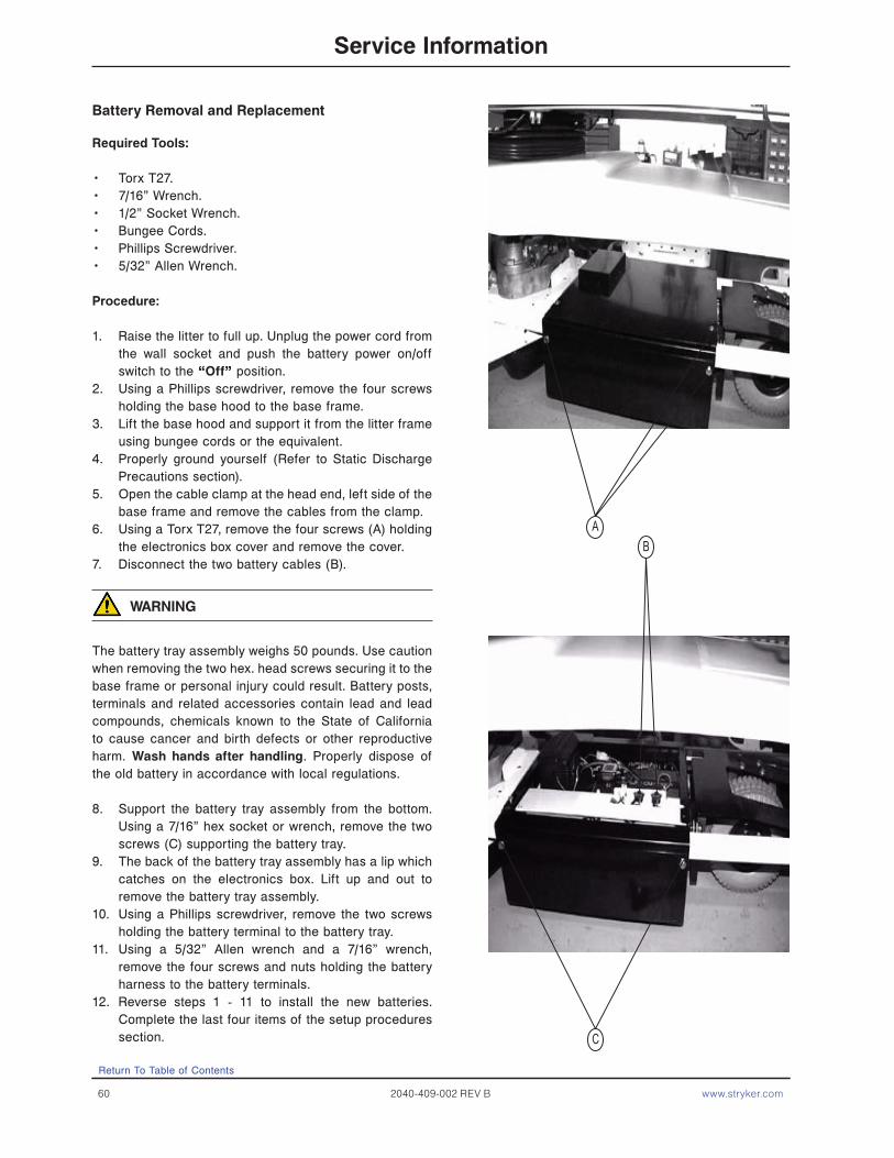
60 2040-409-002 REV B www.stryker.com
Battery Removal and Replacement
Required Tools:
• Torx T27.• 7/16” Wrench.• 1/2” Socket Wrench.• Bungee Cords.• Phillips Screwdriver.• 5/32” Allen Wrench.
Procedure:
1. Raise the litter to full up. Unplug the power cord from the wall socket and push the battery power on/off switch to the “Off” position.
2. Using a Phillips screwdriver, remove the four screws holding the base hood to the base frame.
3. Lift the base hood and support it from the litter frame using bungee cords or the equivalent.
4. Properly ground yourself (Refer to Static Discharge Precautions section).
5. Open the cable clamp at the head end, left side of the base frame and remove the cables from the clamp.
6. Using a Torx T27, remove the four screws (A) holding the electronics box cover and remove the cover.
7. Disconnect the two battery cables (B).
WARNING
The battery tray assembly weighs 50 pounds. Use caution when removing the two hex. head screws securing it to the base frame or personal injury could result. Battery posts, terminals and related accessories contain lead and lead compounds, chemicals known to the State of California to cause cancer and birth defects or other reproductive harm. Wash hands after handling. Properly dispose of the old battery in accordance with local regulations.
8. Support the battery tray assembly from the bottom. Using a 7/16” hex socket or wrench, remove the two screws (C) supporting the battery tray.
9. The back of the battery tray assembly has a lip which catches on the electronics box. Lift up and out to remove the battery tray assembly.
10. Using a Phillips screwdriver, remove the two screws holding the battery terminal to the battery tray.
11. Using a 5/32” Allen wrench and a 7/16” wrench, remove the four screws and nuts holding the battery harness to the battery terminals.
12. Reverse steps 1 - 11 to install the new batteries. Complete the last four items of the setup procedures section.
B
C
A
Service Information
Return To Table of Contents
www.stryker.com 2040-409-002 REV B 61
DC Motor Board Removal and Replacement
Tools Required:
• Phillips Screwdriver.• 1/8” Allen Wrench.• Bungee Cords.• T27 Torx.
Procedure:
1. Raise the litter to the full up position.
2. Unplug the power cord from the wall socket and push the battery power on/off switch to the “Off” position.
3. Using a Phillips screwdriver, remove the four screws holding the base hood to the base frame.
4. Open the cable clamp at the head end, left side of the base frame and remove the cables from the clamp.
5. Lift the base hood and support it from the litter frame using bungee cords or the equivalent.
6. Using a T27 Torx, remove the four screws holding the cover to the side of the electronics box.
7. Properly ground yourself (Refer the Static Discharge Precautions Section).
8. Using a 1/8” Allen wrench, remove the four bolts and standoffs holding the motor board to the electronics box.
9. Remove all cables from the motor board and remove the board.
Note
Note the locations of the cables so you can connect them properly to the new motor board.
10. Reverse steps 1 - 8 to install the new motor board.
Service Information
Return To Table of Contents
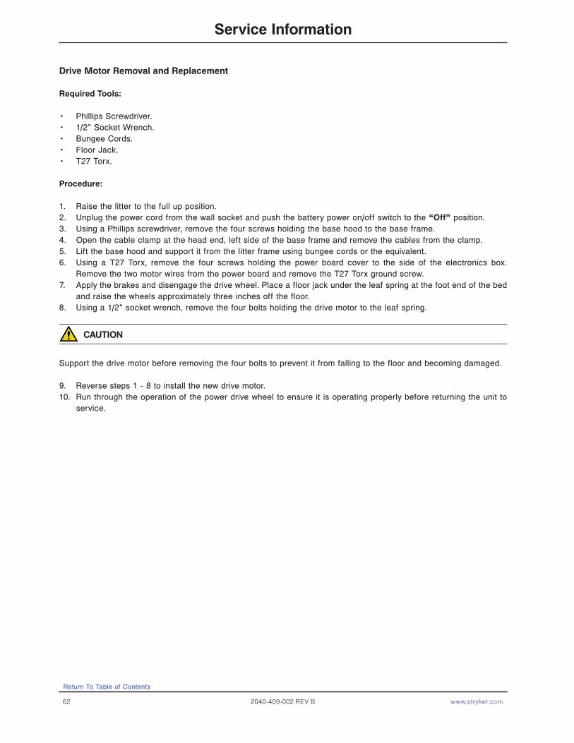
62 2040-409-002 REV B www.stryker.com
Drive Motor Removal and Replacement
Required Tools:
• Phillips Screwdriver.• 1/2” Socket Wrench.• Bungee Cords.• Floor Jack.• T27 Torx.
Procedure:
1. Raise the litter to the full up position.2. Unplug the power cord from the wall socket and push the battery power on/off switch to the “Off” position.3. Using a Phillips screwdriver, remove the four screws holding the base hood to the base frame.4. Open the cable clamp at the head end, left side of the base frame and remove the cables from the clamp.5. Lift the base hood and support it from the litter frame using bungee cords or the equivalent.6. Using a T27 Torx, remove the four screws holding the power board cover to the side of the electronics box.
Remove the two motor wires from the power board and remove the T27 Torx ground screw.7. Apply the brakes and disengage the drive wheel. Place a floor jack under the leaf spring at the foot end of the bed
and raise the wheels approximately three inches off the floor.8. Using a 1/2” socket wrench, remove the four bolts holding the drive motor to the leaf spring.
CAUTION
Support the drive motor before removing the four bolts to prevent it from falling to the floor and becoming damaged.
9. Reverse steps 1 - 8 to install the new drive motor.10. Run through the operation of the power drive wheel to ensure it is operating properly before returning the unit to
service.
Return To Table of Contents
Service Information

www.stryker.com 2040-409-002 REV B 63
Drive Wheel Removal and Replacement
Required Tools:
• Phillips Screwdriver.• 1/2” Socket Wrench.• Bungee Cords.• Floor Jack.• T27 Torx.
Procedure:
1. Remove the drive motor (Refer to Drive Motor Removal and Replacement Section).2. Using a 1/2” socket wrench, remove the bolt holding the wheel to the drive motor.3. Slide the wheel off the motor shaft.4. Reverse steps 1 - 3 to install the new drive wheel and reinstall the drive motor.
Return To Table of Contents
Service information
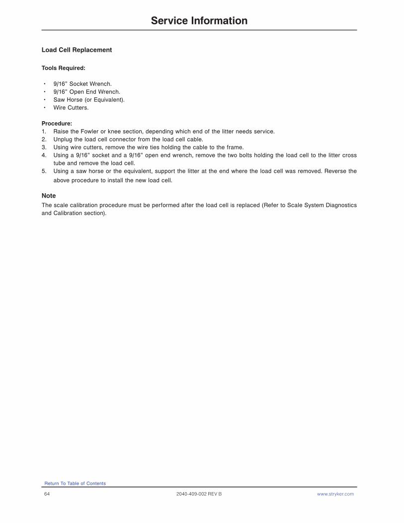
64 2040-409-002 REV B www.stryker.com
Load Cell Replacement
Tools Required:
• 9/16” Socket Wrench.• 9/16” Open End Wrench.• Saw Horse (or Equivalent).• Wire Cutters.
Procedure:1. Raise the Fowler or knee section, depending which end of the litter needs service.2. Unplug the load cell connector from the load cell cable.3. Using wire cutters, remove the wire ties holding the cable to the frame.4. Using a 9/16” socket and a 9/16” open end wrench, remove the two bolts holding the load cell to the litter cross
tube and remove the load cell.5. Using a saw horse or the equivalent, support the litter at the end where the load cell was removed. Reverse the
above procedure to install the new load cell.
NoteThe scale calibration procedure must be performed after the load cell is replaced (Refer to Scale System Diagnostics and Calibration section).
Service Information
Return To Table of Contents
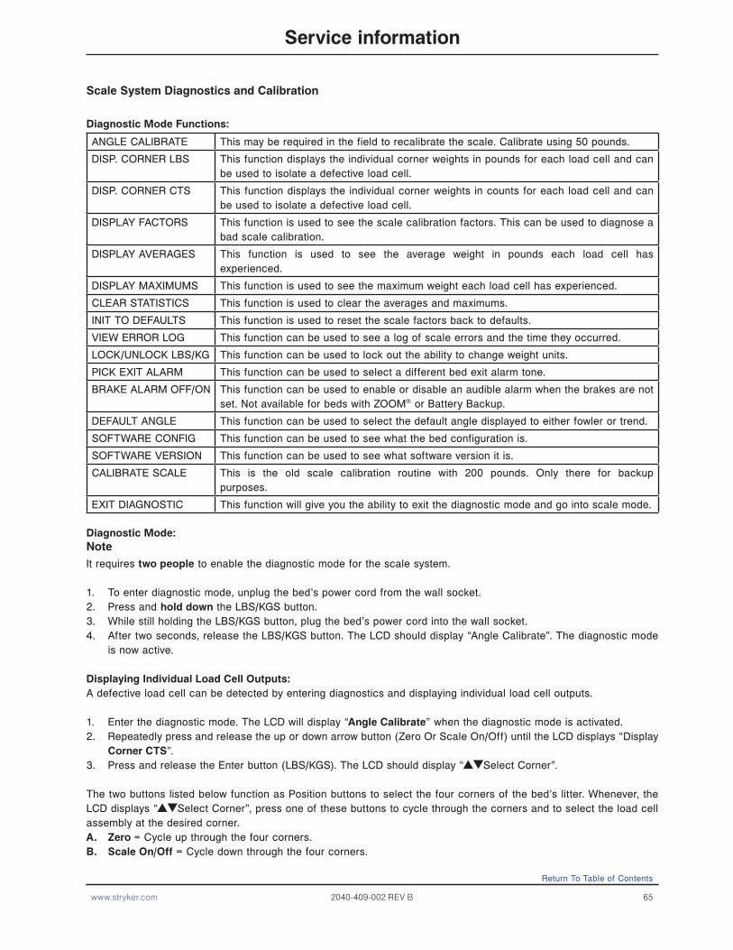
www.stryker.com 2040-409-002 REV B 65
Scale System Diagnostics and Calibration
Diagnostic Mode Functions:
ANGLE CALIBRATE This may be required in the field to recalibrate the scale. Calibrate using 50 pounds.
DISP. CORNER LBS This function displays the individual corner weights in pounds for each load cell and can be used to isolate a defective load cell.
DISP. CORNER CTS This function displays the individual corner weights in counts for each load cell and can be used to isolate a defective load cell.
DISPLAY FACTORS This function is used to see the scale calibration factors. This can be used to diagnose a bad scale calibration.
DISPLAY AVERAGES This function is used to see the average weight in pounds each load cell has experienced.
DISPLAY MAXIMUMS This function is used to see the maximum weight each load cell has experienced.
CLEAR STATISTICS This function is used to clear the averages and maximums.
INIT TO DEFAULTS This function is used to reset the scale factors back to defaults.
VIEW ERROR LOG This function can be used to see a log of scale errors and the time they occurred.
LOCK/UNLOCK LBS/KG This function can be used to lock out the ability to change weight units.
PICK EXIT ALARM This function can be used to select a different bed exit alarm tone.
BRAKE ALARM OFF/ON This function can be used to enable or disable an audible alarm when the brakes are not set. Not available for beds with ZOOM® or Battery Backup.
DEFAULT ANGLE This function can be used to select the default angle displayed to either fowler or trend.
SOFTWARE CONFIG This function can be used to see what the bed configuration is.
SOFTWARE VERSION This function can be used to see what software version it is.
CALIBRATE SCALE This is the old scale calibration routine with 200 pounds. Only there for backup purposes.
EXIT DIAGNOSTIC This function will give you the ability to exit the diagnostic mode and go into scale mode.
Diagnostic Mode:NoteIt requires two people to enable the diagnostic mode for the scale system.
1. To enter diagnostic mode, unplug the bed’s power cord from the wall socket.2. Press and hold down the LBS/KGS button.3. While still holding the LBS/KGS button, plug the bed’s power cord into the wall socket.4. After two seconds, release the LBS/KGS button. The LCD should display “Angle Calibrate”. The diagnostic mode
is now active.
Displaying Individual Load Cell Outputs:A defective load cell can be detected by entering diagnostics and displaying individual load cell outputs.
1. Enter the diagnostic mode. The LCD will display “Angle Calibrate” when the diagnostic mode is activated.2. Repeatedly press and release the up or down arrow button (Zero Or Scale On/Off) until the LCD displays “Display
Corner CTS”.3. Press and release the Enter button (LBS/KGS). The LCD should display “Select Corner”.
The two buttons listed below function as Position buttons to select the four corners of the bed’s litter. Whenever, the LCD displays “Select Corner”, press one of these buttons to cycle through the corners and to select the load cell assembly at the desired corner.A. Zero = Cycle up through the four corners.B. Scale On/Off = Cycle down through the four corners.
Return To Table of Contents
Service information
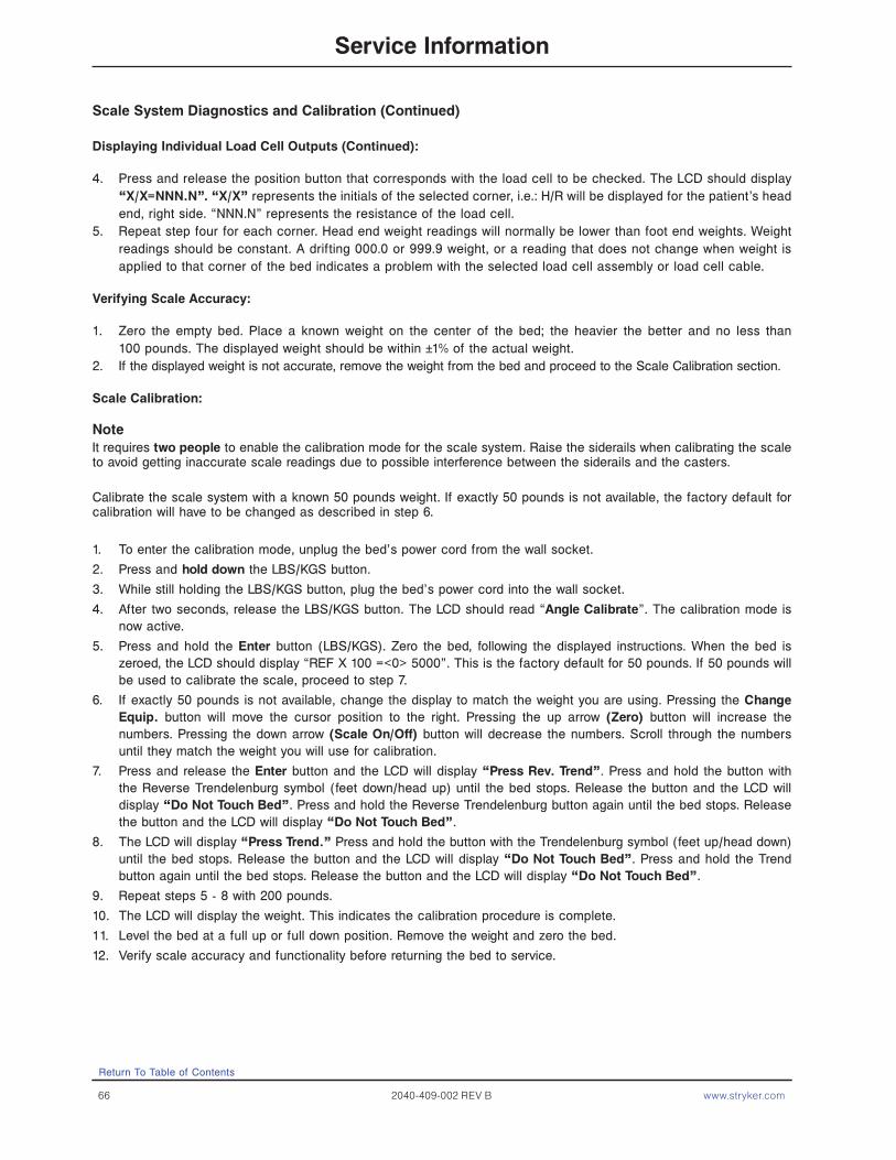
66 2040-409-002 REV B www.stryker.com
Scale System Diagnostics and Calibration (Continued)
Displaying Individual Load Cell Outputs (Continued):
4. Press and release the position button that corresponds with the load cell to be checked. The LCD should display “X/X=NNN.N”. “X/X” represents the initials of the selected corner, i.e.: H/R will be displayed for the patient’s head end, right side. “NNN.N” represents the resistance of the load cell.
5. Repeat step four for each corner. Head end weight readings will normally be lower than foot end weights. Weight readings should be constant. A drifting 000.0 or 999.9 weight, or a reading that does not change when weight is applied to that corner of the bed indicates a problem with the selected load cell assembly or load cell cable.
Verifying Scale Accuracy:
1. Zero the empty bed. Place a known weight on the center of the bed; the heavier the better and no less than 100 pounds. The displayed weight should be within ±1% of the actual weight.
2. If the displayed weight is not accurate, remove the weight from the bed and proceed to the Scale Calibration section.
Scale Calibration:
NoteIt requires two people to enable the calibration mode for the scale system. Raise the siderails when calibrating the scale to avoid getting inaccurate scale readings due to possible interference between the siderails and the casters.
Calibrate the scale system with a known 50 pounds weight. If exactly 50 pounds is not available, the factory default for calibration will have to be changed as described in step 6.
1. To enter the calibration mode, unplug the bed’s power cord from the wall socket.
2. Press and hold down the LBS/KGS button.
3. While still holding the LBS/KGS button, plug the bed’s power cord into the wall socket.
4. After two seconds, release the LBS/KGS button. The LCD should read “Angle Calibrate”. The calibration mode is now active.
5. Press and hold the Enter button (LBS/KGS). Zero the bed, following the displayed instructions. When the bed is zeroed, the LCD should display “REF X 100 =<0> 5000”. This is the factory default for 50 pounds. If 50 pounds will be used to calibrate the scale, proceed to step 7.
6. If exactly 50 pounds is not available, change the display to match the weight you are using. Pressing the Change Equip. button will move the cursor position to the right. Pressing the up arrow (Zero) button will increase the numbers. Pressing the down arrow (Scale On/Off) button will decrease the numbers. Scroll through the numbers until they match the weight you will use for calibration.
7. Press and release the Enter button and the LCD will display “Press Rev. Trend”. Press and hold the button with the Reverse Trendelenburg symbol (feet down/head up) until the bed stops. Release the button and the LCD will display “Do Not Touch Bed”. Press and hold the Reverse Trendelenburg button again until the bed stops. Release the button and the LCD will display “Do Not Touch Bed”.
8. The LCD will display “Press Trend.” Press and hold the button with the Trendelenburg symbol (feet up/head down) until the bed stops. Release the button and the LCD will display “Do Not Touch Bed”. Press and hold the Trend button again until the bed stops. Release the button and the LCD will display “Do Not Touch Bed”.
9. Repeat steps 5 - 8 with 200 pounds.
10. The LCD will display the weight. This indicates the calibration procedure is complete.
11. Level the bed at a full up or full down position. Remove the weight and zero the bed.
12. Verify scale accuracy and functionality before returning the bed to service.
Return To Table of Contents
Service Information

www.stryker.com 2040-409-002 REV B 67
Head Motor Removal and Replacement
Required Tools:
• T27 Torx.• 7/16” Socket Wrench.• Wire Cutters.
Procedure:
1. Run the litter to the full up position and remove the mattress from the litter.2. Fold the foot section back toward the head end. Electrically run the knee section to full up. If the knee section will
not move electrically, pull the foot section toward the head end while pulling the CPR release handle (located at the head end of the bed). The knee section will raise.
3. Using a T27 Torx, remove the four screws holding the cover to the actuator box and remove the cover.4. Remove the two CPR release cables from the CPR release bracket. Using a T27 Torx underneath the actuator box,
remove the two bolts holding the release bracket to the actuator box and remove the bracket from the actuator box.
5. Disconnect all the electrical connections to the head motor and move aside any wiring that interferes with the removal of the motor.
6. Using a 7/16” socket wrench underneath the actuator box, remove the four bolts holding the motor mounting bracket to the actuator box. Lift up and out on the motor to remove it.
7. Remove the motor mounting bracket from the old motor and install it on the replacement motor.8. Reverse steps 3 through 6 to install the replacement motor.9. Verify the unit is working properly before returning it to service.
Return To Table of Contents
Service information
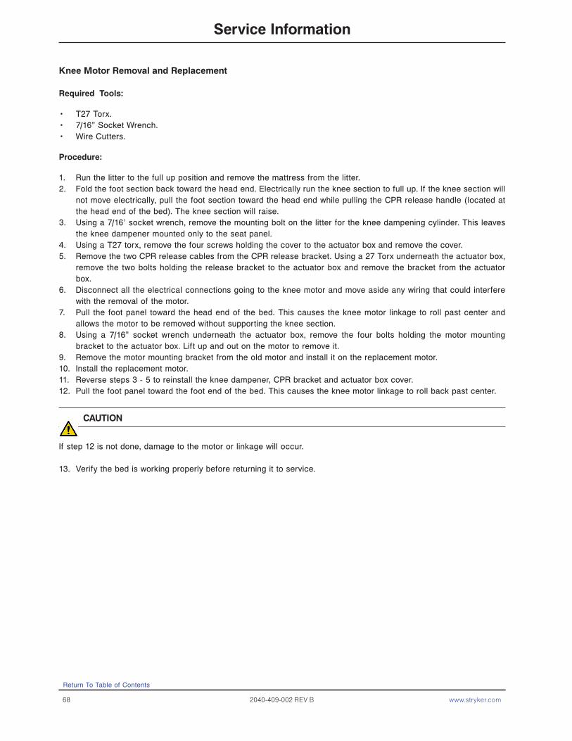
68 2040-409-002 REV B www.stryker.com
Knee Motor Removal and Replacement
Required Tools:
• T27 Torx.• 7/16” Socket Wrench.• Wire Cutters.
Procedure:
1. Run the litter to the full up position and remove the mattress from the litter.2. Fold the foot section back toward the head end. Electrically run the knee section to full up. If the knee section will
not move electrically, pull the foot section toward the head end while pulling the CPR release handle (located at the head end of the bed). The knee section will raise.
3. Using a 7/16’ socket wrench, remove the mounting bolt on the litter for the knee dampening cylinder. This leaves the knee dampener mounted only to the seat panel.
4. Using a T27 torx, remove the four screws holding the cover to the actuator box and remove the cover.5. Remove the two CPR release cables from the CPR release bracket. Using a 27 Torx underneath the actuator box,
remove the two bolts holding the release bracket to the actuator box and remove the bracket from the actuator box.
6. Disconnect all the electrical connections going to the knee motor and move aside any wiring that could interfere with the removal of the motor.
7. Pull the foot panel toward the head end of the bed. This causes the knee motor linkage to roll past center and allows the motor to be removed without supporting the knee section.
8. Using a 7/16” socket wrench underneath the actuator box, remove the four bolts holding the motor mounting bracket to the actuator box. Lift up and out on the motor to remove it.
9. Remove the motor mounting bracket from the old motor and install it on the replacement motor.10. Install the replacement motor.11. Reverse steps 3 - 5 to reinstall the knee dampener, CPR bracket and actuator box cover.12. Pull the foot panel toward the foot end of the bed. This causes the knee motor linkage to roll back past center.
CAUTION
If step 12 is not done, damage to the motor or linkage will occur.
13. Verify the bed is working properly before returning it to service.
Return To Table of Contents
Service Information
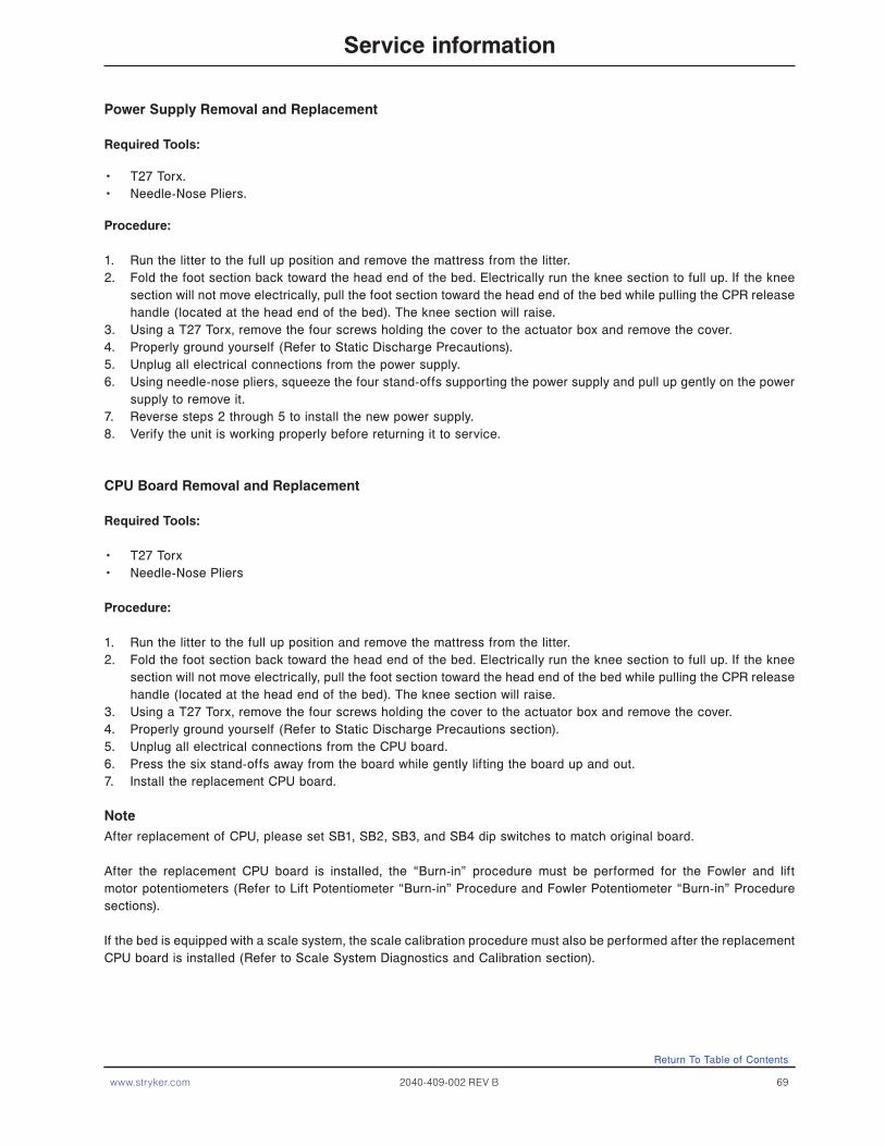
www.stryker.com 2040-409-002 REV B 69
Power Supply Removal and Replacement
Required Tools:
• T27 Torx.• Needle-Nose Pliers.
Procedure:
1. Run the litter to the full up position and remove the mattress from the litter.2. Fold the foot section back toward the head end of the bed. Electrically run the knee section to full up. If the knee
section will not move electrically, pull the foot section toward the head end of the bed while pulling the CPR release handle (located at the head end of the bed). The knee section will raise.
3. Using a T27 Torx, remove the four screws holding the cover to the actuator box and remove the cover.4. Properly ground yourself (Refer to Static Discharge Precautions).5. Unplug all electrical connections from the power supply.6. Using needle-nose pliers, squeeze the four stand-offs supporting the power supply and pull up gently on the power
supply to remove it.7. Reverse steps 2 through 5 to install the new power supply.8. Verify the unit is working properly before returning it to service.
CPU Board Removal and Replacement
Required Tools:
• T27 Torx• Needle-Nose Pliers
Procedure:
1. Run the litter to the full up position and remove the mattress from the litter.2. Fold the foot section back toward the head end of the bed. Electrically run the knee section to full up. If the knee
section will not move electrically, pull the foot section toward the head end of the bed while pulling the CPR release handle (located at the head end of the bed). The knee section will raise.
3. Using a T27 Torx, remove the four screws holding the cover to the actuator box and remove the cover.4. Properly ground yourself (Refer to Static Discharge Precautions section).5. Unplug all electrical connections from the CPU board.6. Press the six stand-offs away from the board while gently lifting the board up and out.7. Install the replacement CPU board.
NoteAfter replacement of CPU, please set SB1, SB2, SB3, and SB4 dip switches to match original board.
After the replacement CPU board is installed, the “Burn-in” procedure must be performed for the Fowler and lift motor potentiometers (Refer to Lift Potentiometer “Burn-in” Procedure and Fowler Potentiometer “Burn-in” Procedure sections).
If the bed is equipped with a scale system, the scale calibration procedure must also be performed after the replacement CPU board is installed (Refer to Scale System Diagnostics and Calibration section).
Return To Table of Contents
Service information

70 2040-409-002 REV B www.stryker.com
Fowler Potentiometer Replacement
Required Tools:
• T27 Torx.• Wire Cutters.• 1/2” Open End Wrench.• 7/64” Allen Wrench.
Procedure:
1. Manually crank the knee section up until it stops.2. Using a T27 Torx, remove the four screws holding the litter access cover to the litter and remove the cover.3. Using a 7/64” Allen wrench, loosen the screw holding the linkage to the potentiometer shaft and remove the linkage
from the shaft.4. Using a 1/2” open end wrench, remove the nut holding the potentiometer to the frame.5. Using wire cutters, remove the cable ties from the cable. Unplug the cable from the CPU and remove the
potentiometer.6. Reverse the above procedure to install the replacement potentiometer.7. The new potentiometer must be calibrated after it has been installed.8. The Fowler potentiometer should be set at 150 ohms (±10 ohms) in the full down position. This reading must be
taken from pins 3 and 4 on the connector with the potentiometer unplugged from the board. After the correct ohm reading is achieved, tighten the screw on the linkage.
9. Perform the “Burn-in” procedure for the Fowler potentiometer (Refer to Fowler Potentiometer “Burn-in” Procedure).
Fowler Potentiometer “Burn-In” Procedure
NoteIt requires two people to enable the diagnostics mode for the bed.
1. Unplug the bed power cord from the wall socket.2. On the foot board control panel, hold down the bed motion lock button and the button to lock out the siderail
controls for the knee. While still holding the buttons, plug the bed power cord into the wall socket. Release the foot board buttons. The siderail control lights LED should be flashing to indicate the bed is in diagnostics mode.
3. Using the foot board controls, run the Fowler up to 90°. Press and hold the button on the foot board to lock out the siderail controls for the back until the padlock LED flashes. Release the button.
4. Using the foot board controls, run the Fowler down to 0°. Press and hold the button on the foot board to lock out the siderail controls for the knee until the padlock LED flashes. Release the button.
Return To Table of Contents
Service Information
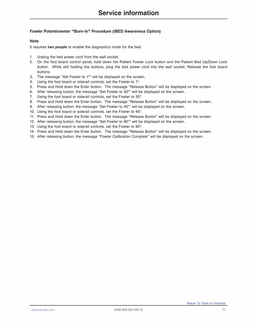
www.stryker.com 2040-409-002 REV B 71
Return To Table of Contents
Service information
Fowler Potentiometer “Burn-In” Procedure (iBED Awareness Option)
NoteIt requires two people to enable the diagnostics mode for the bed.
1. Unplug the bed power cord from the wall socket.2. On the foot board control panel, hold down the Patient Fowler Lock button and the Patient Bed Up/Down Lock
button. While still holding the buttons, plug the bed power cord into the wall socket. Release the foot board buttons.
3. The message “Set Fowler to 10” will be displayed on the screen.4. Using the foot board or siderail controls, set the Fowler to 10.5. Press and Hold down the Enter button. The message “Release Button” will be displayed on the screen.6. After releasing button, the message “Set Fowler to 300” will be displayed on the screen.7. Using the foot board or siderail controls, set the Fowler to 300.8. Press and Hold down the Enter button. The message “Release Button” will be displayed on the screen.9. After releasing button, the message “Set Fowler to 450” will be displayed on the screen.10. Using the foot board or siderail controls, set the Fowler to 450.11. Press and Hold down the Enter button. The message “Release Button” will be displayed on the screen.12. After releasing button, the message “Set Fowler to 900” will be displayed on the screen.13. Using the foot board or siderail controls, set the Fowler to 900.14. Press and Hold down the Enter button. The message “Release Button” will be displayed on the screen.15. After releasing button, the message “Fowler Calibration Complete” will be displayed on the screen.

72 2040-409-002 REV B www.stryker.com
Return To Table of Contents
Service Information
AC Crossover Board Replacement
Required Tools:
• T27 Torx.• 1/2” Box End Wrench.• #2 Phillips Screwdriver.• Wire Cutters.• Small Flat Blade Screwdriver.• Needle Nose Pliers.• 5/16” Nut Driver.
Procedure:
1. Follow steps 1 - 9 of the control bar potentiometer replacement procedure on Control Bar Potentiometer Replacement Section.
2. Using a T-27 Torx, remove the 2 bolts holding the AC crossover board cover to the head end frame and remove the cover.
3. Disconnect all wires from the AC crossover board.4. Using needle nose pliers, release the four mounting stand-offs from the board and remove the board.5. Reverse steps 1 - 4 to install the new board.6. Reverse steps 1 - 9 of the control bar potentiometer replacement procedure section to reassemble the bed.
Display/CPU Board Replacement
Required Tools:
• T27 Torx.• 1/2” Box End Wrench.• #2 Phillips Screwdriver.• Wire Cutters.• Small Flat Blade Screwdriver.• Needle Nose Pliers.• 5/16” Nut Driver.
Procedure:
1. Follow steps 1 - 9 of the control bar potentiometer replacement procedure section.2. Disconnect all wires from the display/CPU board.3. Using a #2 Phillips screwdriver, remove the six screws holding the display/CPU board to the control bar cover and
remove the board.4. Reverse steps 2 & 3 to install the new board. After the new board has been instalLED, the potentiometer “Burn-in”
procedure must be performed (refer to Control Bar Potentiometer “Burn-in” Procedure Section).5. Reverse steps 1 - 9 of the Control Bar Potentiometer Replacement Procedure section to reassemble the bed.
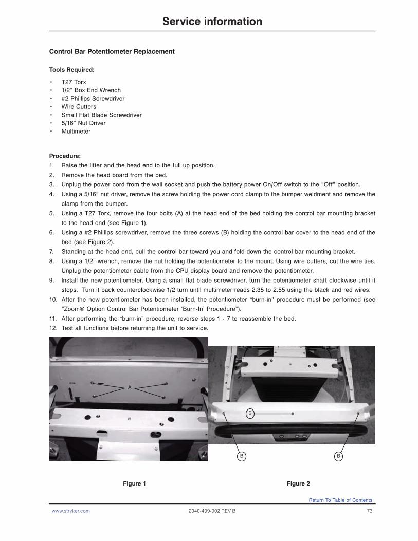
www.stryker.com 2040-409-002 REV B 73
Return To Table of Contents
Service information
Tools Required:
• T27 Torx • 1/2” Box End Wrench• #2 Phillips Screwdriver• Wire Cutters• Small Flat Blade Screwdriver• 5/16” Nut Driver• Multimeter
Procedure:
1. Raise the litter and the head end to the full up position.
2. Remove the head board from the bed.
3. Unplug the power cord from the wall socket and push the battery power On/Off switch to the “Off” position.
4. Using a 5/16” nut driver, remove the screw holding the power cord clamp to the bumper weldment and remove the
clamp from the bumper.
5. Using a T27 Torx, remove the four bolts (A) at the head end of the bed holding the control bar mounting bracket
to the head end (see Figure 1).
6. Using a #2 Phillips screwdriver, remove the three screws (B) holding the control bar cover to the head end of the
bed (see Figure 2).
7. Standing at the head end, pull the control bar toward you and fold down the control bar mounting bracket.
8. Using a 1/2” wrench, remove the nut holding the potentiometer to the mount. Using wire cutters, cut the wire ties.
Unplug the potentiometer cable from the CPU display board and remove the potentiometer.
9. Install the new potentiometer. Using a small flat blade screwdriver, turn the potentiometer shaft clockwise until it
stops. Turn it back counterclockwise 1/2 turn until multimeter reads 2.35 to 2.55 using the black and red wires.
10. After the new potentiometer has been installed, the potentiometer “burn-in” procedure must be performed (see
“Zoom® Option Control Bar Potentiometer ‘Burn-In’ Procedure”).
11. After performing the “burn-in” procedure, reverse steps 1 - 7 to reassemble the bed.
12. Test all functions before returning the unit to service.
Figure 1 Figure 2
Control Bar Potentiometer Replacement
A
B
B B

74 2040-409-002 REV B www.stryker.com
Return To Table of Contents
Tools Required:
• T27 Torx • 1/2” Box End Wrench• # 2 Phillips Screwdriver• Wire Cutters• Small Flat Blade Screwdriver• 5/16” Nut Driver
Procedure:
1. If it has not already been done, follow steps 1 - 7 of the “Zoom® Option Control Bar Potentiometer Replacement
Procedure on previous page.
2. Ensure the battery on/off switch is in the “Off” position (LED is Off).
3. Hold down the yellow button on the back of the display CPU board.
4. With the switch depressed, move the battery power on/off switch to the “ON” position (LED will light) and continue
holding for three seconds.
5. Press and hold the yellow button on the back of the display CPU board.
6. Move the battery power on/off switch to the “on” position (LED will light) and continue holding switch for three
seconds.
7. Verify the “Engage Drive Wheel” led at the head end display housing is flashing.
8. Move the battery power on/off switch back to the “Off” position (all LED’s will go out).
9. Close the drive box.
10. Ensure the control bar is in the center of travel by pushing and pulling the bar, then returning the bar to the neutral
position.
11. With no objects touching the control bar, turn the battery power on/off switch to the “On” position.
12. The three LED’s on the front of the bed will flash initially to show the battery voltage of the bed by lighting zero,
one, two, or three LED’s.
13. After the battery charge has been displayed by the three LED’s, all three LED’s will flash twice.
14. After all three LED’s have flashed twice, push the drive handle to the full forward position. Hold the drive handle
in the full forward position until all three LED’s flash twice again (3 seconds).
15. The “ENGAGE DRIVE WHEEL” LED will flash once.
16. The control bar potentiometer is calibrated.
17. Return the control bar to the neutral position.
18. Grasp the control bar and squeeze either motion switch without moving the control bar forward or backward.
19. Verify the bed does not move.
20. Standing at the head end of the bed, grasp the control bar and squeeze either motion switch, then push the control
bar forward.
21. Verify the bed moves forward.
22. Standing at the head end of the bed, grasp the control bar and squeeze either motion switch, then pull the control
bar backwards.
23. Verify the bed moves backward.
24. Move the battery power on/off switch “Off”, wait a few seconds, then back “On” again.
25. Repeat steps 18-23 to verify that the burn in procedure was performed correctly.
Control Bar Potentiometer “Burn-In” Procedure
Service information

www.stryker.com 2040-409-002 REV B 75
Optional Smart TV Interface “Burn-in” Procedure
This procedure is used for selecting the style of TV interface desired for your bed. If traditional TV is desired, no calibration is required. If optional Smart TV is available on the bed, select one of the TV manufacturers listed in the table below.
SETUPEnsure the communication cable is connected between the bed and the Db37 wall port or the pillow speaker port of the Nurse Call System. If available, a bed communication tester can be used instead of the hospital wiring.
PROCEDURE1. Place the bed in the lift potentiometer “Burn-In” mode Refer to Lift Potentiometer “Burn-In” Procedure section.2. Notice the Nurse Call LED (yellow) is flashing. Notice the Nurse Answer LED (green) is flashing on/off slowly.3. Press and release the TV On/Off switch on the bed’s siderail once. Notice the Nurse Call LED flashes once. This
is the first selection of TV manufacturers for the Smart TV mode. Notice the Nurse Answer LED (green) is flashing On/Off slowly. The Nurse Answer LED will only light when the Nurse Call LED (yellow) is flashing.
4. Press and release the TV On/Off switch on the bed’s siderail to scroll to other TV manufacturers. Notice the number of times the Nurse Call LED flashes matches the number listed in the table below and represents the TV manufacturer selected.
5. When the desired TV manufacturer has been selected, unplug the bed power cord from the wall socket and plug it back in to complete the Smart TV “Burn-In” procedure.
Note
If the bed is connected to a television during the “Burn-In” procedure, the television will turn on when the correct setting is selected.
TV MANUFACTURER SELECTION FOR SMART TV BURN-IN PROCEDURE
Press and release TV ON/OFF switch Nurse Call LED (Yellow) TV Manufacturer
One time One flash RCA 1
Two times Two flashes RCA 2
Three times Three flashes Zenith 1
Four times Four flashes Zenith 2
Five times Five flashes Philips/Magnavox
Six times Six flashes Magnavox (models 9120, 9220, 9320)
Seven times Seven flashes Traditional TV
Eight times Eight flashes Traditional Plus
Nine times Nine flashes Auto Detect: Smart TV
Ten times Ten flashes Auto Detect W/Digital Volume Smart TV
Return To Table of Contents
Service information

Return To Table of Contents
76 2040-309-002 REV B www.stryker.com
This procedure is used for selecting the style of TV interface needed for your bed. If traditional TV is desired, no calibration is required. If optional Smart TV is available on the bed, select one of the TV Mode/Brands listed in the table below.
PROCEDURE1. Press and Hold the “Enter” button. While Holding, cycle bed power. Continue to hold until display flashes “Load
Cell Check”. Release.2. The display should present the Maintenance Menu. Ensure the “TV config” element is highlighted and press
“Enter”.3. The display should present the “TV config” Screen. The current TV selection will be highlighted. (Default selection
is Traditional)4. Use the up and down arrow buttons to highlight the desired “TV config”. See Table below for Model/Selection
list.5. Press the “Enter” button to select the new setting. 6. The display should present the following message when the new setting is saved “Save Successful”.7. The “TV config” screen should reappear after 2 seconds and the new setting should be highlighted.
TV Configuration Menu Settings
TV Mode / Brand Display TV Menu Select
RCA 1 TV Config. 1
RCA 2 TV Config. 2
Zenith 1 TV Config. 3
Zenith 2 TV Config. 4
Philips TV Config. 5
Magnavox TV Config. 6
Traditional Traditional
Traditional Plus Traditional Plus
Auto-Configure Auto-Configure
Auto-Configure DV Auto-Configure DV
Service Information
Optional Smart TV Interface “Burn-In” Procedure (iBED Awareness Option)

www.stryker.com 2040-409-002 REV B 77
Siderail Cover Removal
Required Tools:
• #2 Phillips Screwdriver.
Head End Siderail Cover Removal:
Procedure:
1. Unplug the bed power cord from the wall receptacle.2. Using a #2 Phillips screwdriver, remove the 8 screws (A) holding the covers (B) to the siderail.
CAUTION
There are two cables connecting the head end siderail outside covers to the head end siderails. Be careful not to pull on them when removing the cover or damage could occur.
3. Disconnect the cables from the siderail. Note the proper location for the cables.
4. Reverse the above steps to reattach the cover.
CAUTION
Do not snag or pinch the cables when reinstalling the head end siderail covers or damage could occur.
Return To Table of Contents
Service Information
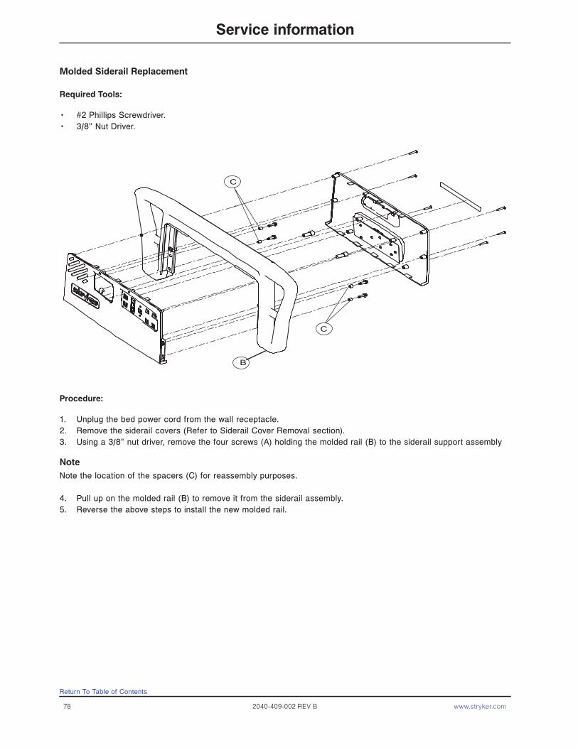
78 2040-409-002 REV B www.stryker.com
Molded Siderail Replacement
Required Tools:
• #2 Phillips Screwdriver.• 3/8” Nut Driver.
Procedure:
1. Unplug the bed power cord from the wall receptacle.2. Remove the siderail covers (Refer to Siderail Cover Removal section).3. Using a 3/8” nut driver, remove the four screws (A) holding the molded rail (B) to the siderail support assembly
NoteNote the location of the spacers (C) for reassembly purposes.
4. Pull up on the molded rail (B) to remove it from the siderail assembly.5. Reverse the above steps to install the new molded rail.
B
C
C
Return To Table of Contents
Service information
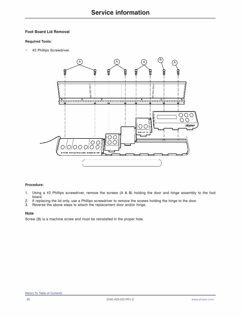
80 2040-409-002 REV B www.stryker.com
Foot Board Lid Removal
Required Tools:
• #2 Phillips Screwdriver.
Procedure:
1. Using a #2 Phillips screwdriver, remove the screws (A & B) holding the door and hinge assembly to the foot board.
2. If replacing the lid only, use a Phillips screwdriver to remove the screws holding the hinge to the door.3. Reverse the above steps to attach the replacement door and/or hinge.
NoteScrew (B) is a machine screw and must be reinstalled in the proper hole.
AAA BA
Return To Table of Contents
Service information
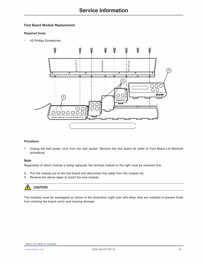
www.stryker.com 2040-409-002 REV B 81
A
A
A
Foot Board Module Replacement
Required Tools:
• #2 Phillips Screwdriver.
Procedure:
1. Unplug the bed power cord from the wall socket. Remove the foot board lid (refer to Foot Board Lid Removal procedure).
NoteRegardless of which module is being replaced, the farthest module to the right must be removed first.
2. Pull the module out of the foot board and disconnect the cable from the module (A).3. Reverse the above steps to install the new module.
CAUTION
The modules must be overlapped as shown in the illustration (right over left) when they are installed to prevent fluids from entering the board cavity and causing damage.
Return To Table of Contents
Service Information
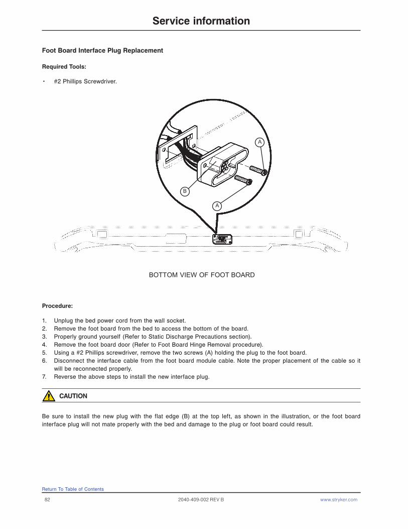
82 2040-409-002 REV B www.stryker.com
Foot Board Interface Plug Replacement
Required Tools:
• #2 Phillips Screwdriver.
Procedure:
1. Unplug the bed power cord from the wall socket.2. Remove the foot board from the bed to access the bottom of the board.3. Properly ground yourself (Refer to Static Discharge Precautions section).4. Remove the foot board door (Refer to Foot Board Hinge Removal procedure).5. Using a #2 Phillips screwdriver, remove the two screws (A) holding the plug to the foot board.6. Disconnect the interface cable from the foot board module cable. Note the proper placement of the cable so it
will be reconnected properly.7. Reverse the above steps to install the new interface plug.
CAUTION
Be sure to install the new plug with the flat edge (B) at the top left, as shown in the illustration, or the foot board interface plug will not mate properly with the bed and damage to the plug or foot board could result.
BOTTOM VIEW OF FOOT BOARD
A
B
A
Return To Table of Contents
Service information

www.stryker.com 2040-409-002 REV B 83
Base Assembly and Options
Return To Table of Contents
For Reference Only: 3002-200-003
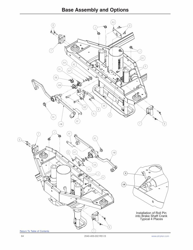
84 2040-409-002 REV B www.stryker.com
Base Assembly and Options
Return To Table of Contents
Installation of Roll Pininto Brake Shaft Crank
Typical 4 Places
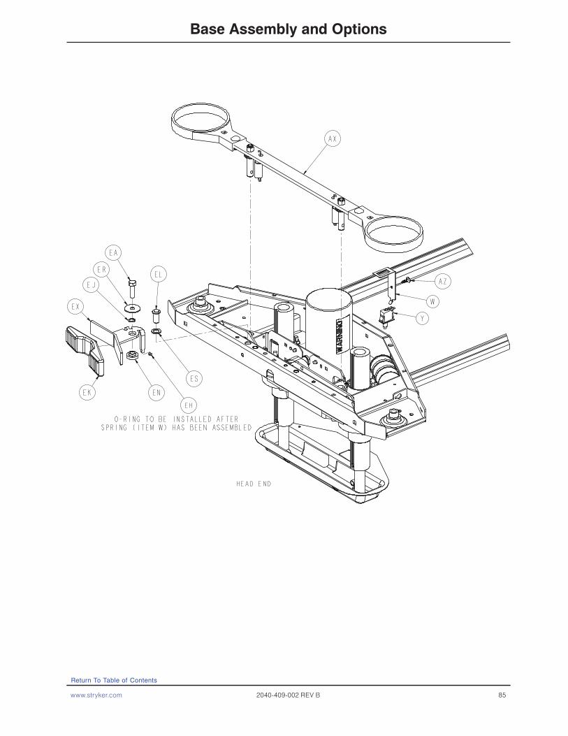
www.stryker.com 2040-409-002 REV B 85
Base Assembly and Options
Return To Table of Contents
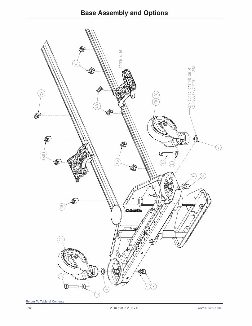
86 2040-409-002 REV B www.stryker.com
Base Assembly and Options
Return To Table of Contents
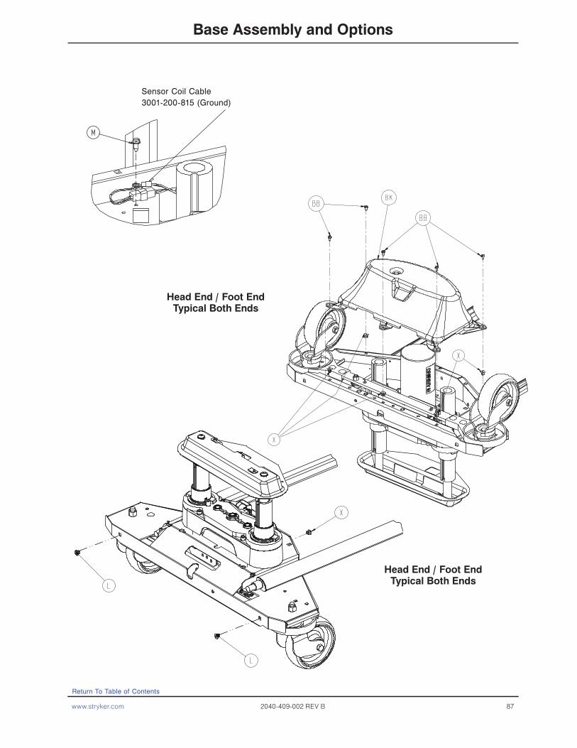
www.stryker.com 2040-409-002 REV B 87
Base Assembly and Options
Return To Table of Contents
Head End / Foot EndTypical Both Ends
Head End / Foot EndTypical Both Ends
Sensor Coil Cable 3001-200-815 (Ground)

88 2040-409-002 REV B www.stryker.com
Base Assembly and Options
Base Assembly Common Components - Part Number 3002-200-003 (Reference Only)
Item Part No. Part Name Qty.
B 0003-122-000 Hex Washer Head Screw 8 D 0007-052-000 Truss Head Torx 4 E 0011-310-000 Washer 4 G 0011-343-000 Washer 4 H 0016-002-000 Nylock Nut 8 J 0016-098-000 Hex Flange Nut 8 K 0016-049-000 Nylock Nut 4 L 0018-036-000 Plastic Clip Nut 4 M 0003-224-000 Hex Washer Head Screw 2 N 0026-014-000 Roll Pin 4 P 0038-151-000 Cable Tie 4 R 3002-200-316 Brake Track Roller 1 S 3000-200-305 Brake Shaft Bushing, Right 2 T 3000-200-328 Brake Guide Bushing 4 U 3000-200-331 Brake Shaft Bushing, Left 2 W 3000-200-343 Brake Switch Bracket 1 X 3000-300-002 Plastic Clip Nut 10 Y 3000-300-058 Plunger Switch 1 Z 3000-300-113 8” Cable Tie 6 AA 3000-200-349 Washer 2 AB 3002-301-201 Head End Lift Assembly 1 AC 3002-301-251 Foot End Lift Assembly 1 AD 3001-200-306 Brake Pedal Shaft Bearing 4 AE 3001-200-317 Brake Cam Shaft Bushing 4 AF 3001-200-334 Brake Return Extension Spring 2 AG 3001-200-340 Brake Shaft Ass’y, Left (pg. 97) 1 AH 3001-200-345 Brake Shaft Ass’y, Right (pg. 97) 1 AJ 3002-201-301 Brake Ratchet Track 1 AK 3002-200-302 Brake Ratchet Link Assembly 1 AL 3002-200-305 Brake Ratchet Crank, Left 1 AM 3002-200-306 Brake Ratchet Crank, Right 1 AN 3002-200-307 Brake Latch Spring 1 AP 3002-200-308 Brake Ratchet Crank Pin 1 AU 3002-200-314 Brake Mounting Bracket 2 AW 3002-201-330 Brake Crank Assembly (pg. 98) 2 AX 3002-200-335 Brake Bar Assembly (pg. 99) 2 AZ 3000-300-115 Stand-Off 1 GB 0003-074-000 Hex Head Bolt 2 GC 0016-028-000 Nylock Nut 2 GD 3002-316-000 Steer Cable Retaining Clip 1
Return To Table of Contents

www.stryker.com 2040-409-002 REV B 89
Base Assembly and Options
Base Assembly, ZOOM ICU Bed - Part Number 2040-244-003 (Reference Only)
Item Part No. Part Name Qty. C 0003-333-000 Hex Head Cap Screw 4 AB 2040-343-200 Head End Lift Assembly (pg. 92) 1 AC 2040-343-250 Foot End Lift Assembly (pg. 92) 1 BL 3002-200-102 Base Weldment 1 CA 3000-300-115 Stand-Off 1 CB 0013-018-000 External Tooth Lock Washer 1 CE 2025-031-805 Ground Strap 1 CF 3000-200-343 Brake Switch Bracket 1 CG 3000-300-058 Switch Plunger 1 CH 3001-200-306 Brake Pedal Shaft Bearing 4 GA 2030-000-101 Bellows 2
6” Caster Option, ZOOM - 2040-999-138 (Ref.)
Item Part No. Part Name Qty.
FA 3001-200-052 6” Ground Chain 1 FC 3001-200-060 6” Caster Assembly (pg. 100) 4 2040-244-010 Base ICU Zoom Option - 6” Caster 1
Return To Table of Contents

90 2040-409-002 REV B www.stryker.com
Brake Plate Assembly
Item Part No. Part Name Qty.A 0011-193-000 Heavy Flat Washer 2B 3006-200-352 Brake Plate Spring 4C 3006-200-354 Brake Plate, Fork Assembly 4D 3006-200-356 Gill Brake Plate, Body 4E 3006-200-362 Hex Head Cap Screw, LH 2
Return To Table of Contents
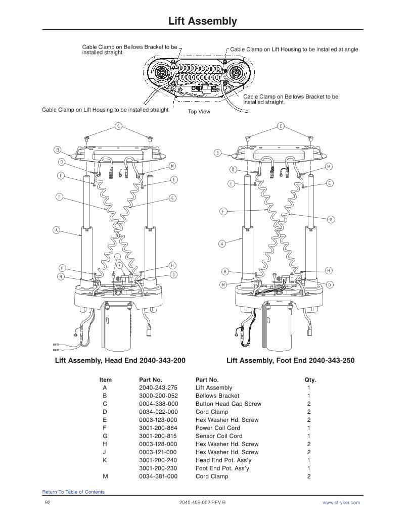
92 2040-409-002 REV B www.stryker.com
Lift Assembly
Lift Assembly, Head End 2040-343-200 Lift Assembly, Foot End 2040-343-250
A 2040-243-275 Lift Assembly 1B 3000-200-052 Bellows Bracket 1C 0004-338-000 Button Head Cap Screw 2D 0034-022-000 Cord Clamp 2E 0003-123-000 Hex Washer Hd. Screw 2F 3001-200-864 Power Coil Cord 1G 3001-200-815 Sensor Coil Cord 1H 0003-128-000 Hex Washer Hd. Screw 2J 0003-121-000 Hex Washer Hd. Screw 2K 3001-200-240 Head End Pot. Ass’y 1 3001-200-230 Foot End Pot. Ass’y 1M 0034-381-000 Cord Clamp 2
Return To Table of Contents
Top View
Item Part No. Part No. Qty.

Return To Table of Contents
Lift Assembly
For Reference Only: 3000-200-275 (Standard Height)2040-243-275 (Enhanced Fluoro Height Option)
www.stryker.com 2040-409-002 REV B 93
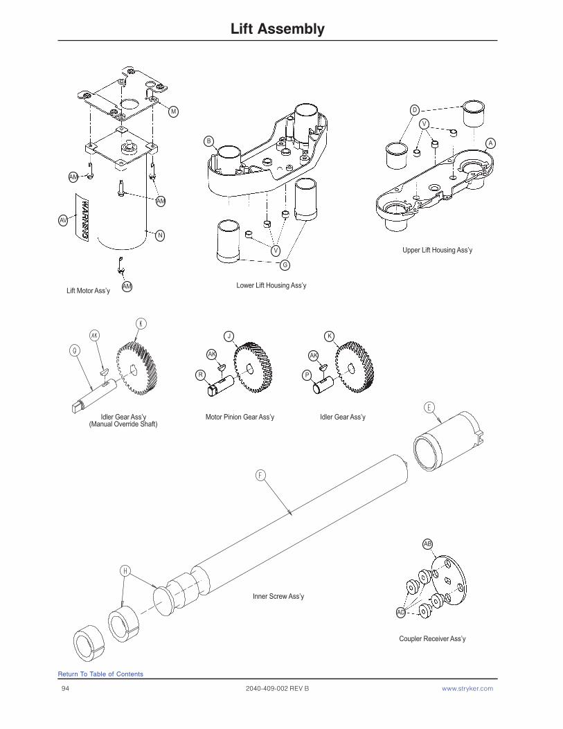
94 2040-409-002 REV B www.stryker.com
Lift Assembly
Lower Lift Housing Ass’y
Upper Lift Housing Ass’y
Inner Screw Ass’y
Idler Gear Ass’y(Manual Override Shaft)
Motor Pinion Gear Ass’y Idler Gear Ass’y
Coupler Receiver Ass’y
M
AM
AM
AM
AV
N
B
V
G
D
V
AK AK
J
R
K
P
AB
AD
A
Lift Motor Ass’y
Return To Table of Contents

Return To Table of Contents
Lift Assembly
Item Part No. Part Name Qty. A 3000-200-201 Upper Lift Housing 1 B 3000-200-202 Lower Lift Housing 1 C 3000-200-251 Outer Screw 2 D 3000-200-204 Upper Housing Sleeve 2 E 3000-200-205 Upper Stage Nut 2 F 3000-200-249 Inner Screw 2 G 3000-200-207 Lower Stage Nut 2 H 3000-200-208 Glide Bushing 4 J 3000-200-209 Motor Pinion Gear 1 K 3000-200-210 Idler Gear 2 L 3000-200-252 Output Gear 2 M 3000-200-214 Motor Isolation Plate Ass’y (pg. 96) 1 N 3000-200-213 Lift Motor 1 3221-200-213 230V Lift Motor 1 P 3000-200-218 Idler Shaft, Lift 1 Q 3002-200-235 Idler Man. Over. Shaft 1 R 3000-200-220 Input Pinion Shaft 1 S 3000-200-223 Output Gear Thr. Washer 4 T 3000-200-224 Input Gear Thr. Washer 2 U 0081-212-000 Thrust Needle Roller Brg. 1 V 3000-200-226 Pinion Shaft Bushing 6 W 3001-200-228 Mounting Standoff 4 Z 3001-300-019 Isolation Sleeve 4 AA 3000-200-233 Lift Motor Coupler 1 AB 3000-200-234 Coupler Receiver 1 AC 3000-200-241 Crush Washer 2 AD 3000-300-455 Isolation Bushing 4 AE 3000-200-245 Gear Washer 5 AF 3000-200-246 Nylon Washer 1 AG 0011-408-000 Flat Washer 4 AH 0003-082-000 Hex Hd. Cap Screw 4 AJ 0004-213-000 Soc. Hd. Cap Screw 4 AK 0058-044-000 Woodruff Key 3 AM 0003-331-000 Hex Washer Hd. Screw 4 AP 0028-121-000 Retaining Ring 2 AQ 0028-097-000 Retaining Ring 1 AS 0011-308-000 Serrated Belleville Washer 4 AV 3000-300-604 Warning Label 1 AX 3000-200-239 Potentiometer Drive Gear Shaft 1 AY 3000-200-216 Potentiometer Drive Gear 1
Lift Assembly (Standard Height) - Part Number 3000-200-275 (Reference Only)Lift Assembly (Enhanced Fluoro Height Option) - Part Number 2040-243-275 (Reference Only)
www.stryker.com 2040-409-002 REV B 95

Motor Isolation Plate Assembly
A 3001-200-213 Isolation Plate 1 B 3000-300-442 Grommet 4
Item Part No. Part Name Qty.
For Reference Only: 3001-200-214
Return To Table of Contents
96 2040-409-002 REV B www.stryker.com

Return To Table of Contents
Brake Shaft Assembly, Left
Item Part No. Part Name Qty.A 3000-200-314 Brake Shaft 1B 3001-200-325 Brake Pedal 1C 0004-270-000 Soc. Hd. Cap Screw 2
Brake Shaft Assembly, Right
A
B
C
A
B
C
3001-200-340
3001-200-345
www.stryker.com 2040-409-002 REV B 97

98 2040-409-002 REV B www.stryker.com
Return To Table of Contents
Brake Crank Assembly
Item Part No. Part Name Qty.
A 3002-201-309 Brake Cam Shaft Crank 1 B 0014-004-000 Washer 2 C 3002-200-331 Brake Link 1 D 3002-200-332 Dog Leg Brake Link 1 E 0002-108-000 Socket Hd. Shoulder Screw 2
3002-201-330

www.stryker.com 2040-409-002 REV B 99
Return To Table of Contents
Brake Bar Assembly
Item Part No. Part Name Qty.
A 0005-018-000 Carriage Bolt 2 B 0016-035-000 Nylock Hex Nut 6 C 3000-200-318 Guide Pin 2 D 3000-200-321 Brake Ring 2 E 3000-200-323 Brake Bar 1 F 3000-200-324 Brake Bar Bumper 2 G 3002-200-310 Brake Bar Return Spring 2
3002-200-335
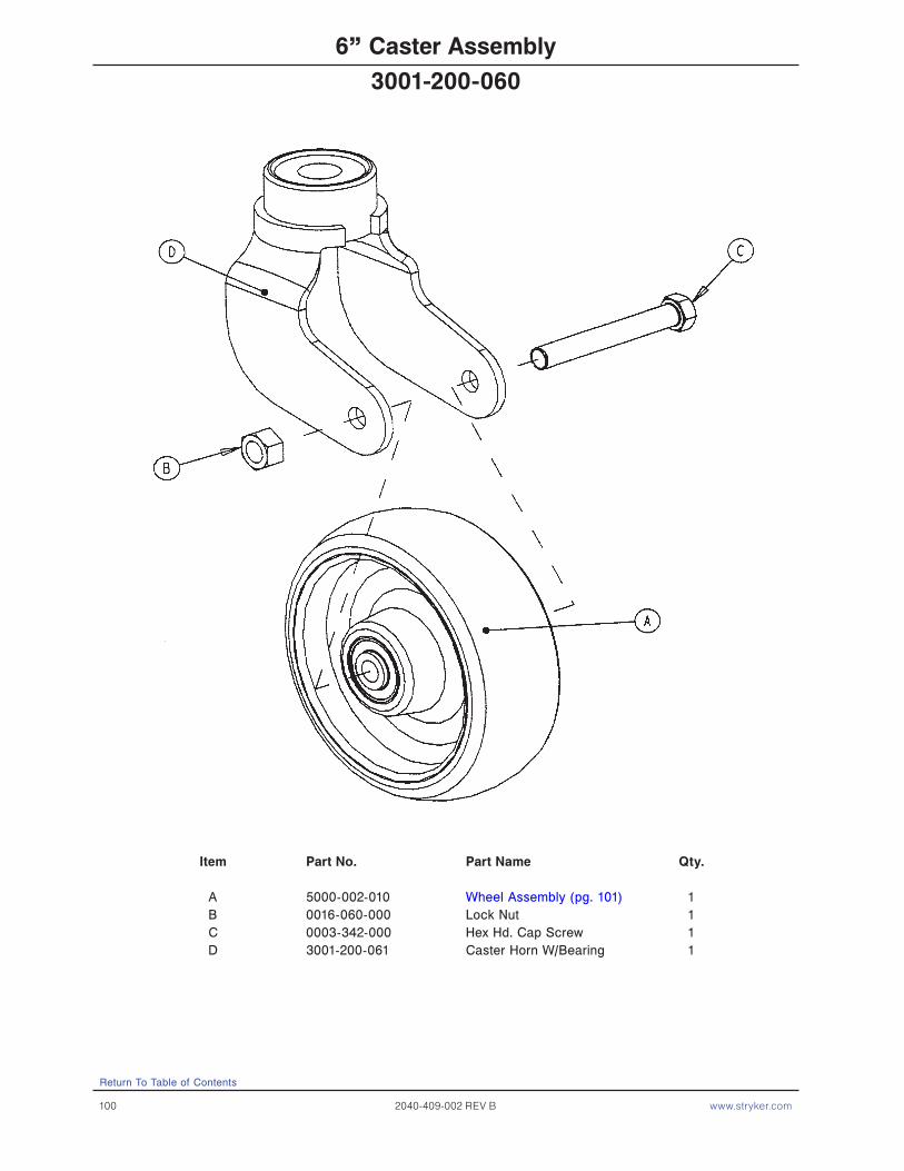
100 2040-409-002 REV B www.stryker.com
Return To Table of Contents
6” Caster Assembly
Item Part No. Part Name Qty.
A 5000-002-010 Wheel Assembly (pg. 101) 1 B 0016-060-000 Lock Nut 1 C 0003-342-000 Hex Hd. Cap Screw 1 D 3001-200-061 Caster Horn W/Bearing 1
3001-200-060

www.stryker.com 2040-409-002 REV B 101
Return To Table of Contents
6” Molded Wheel Assembly
Item Part No. Part Name Qty.
A 0081-226-000 Bearing 2 B 0715-001-255 Wheel Bushing 2 C 5000-002-020 Molded Wheel 1 D 6060-002-046 Bearing Spacer 1
5000-002-010

102 2040-409-002 REV B www.stryker.com
Return To Table of Contents
ZOOM® Base Assembly
HEAD END

www.stryker.com 2040-409-002 REV B 103
Return To Table of Contents
ZOOM® Base Assembly
HEAD END
3001−200−306
See Detail A
3001−200−306
DETAIL A

104 2040-409-002 REV B www.stryker.com
Return To Table of Contents
ZOOM® Base Assembly
HEAD END
HEAD END
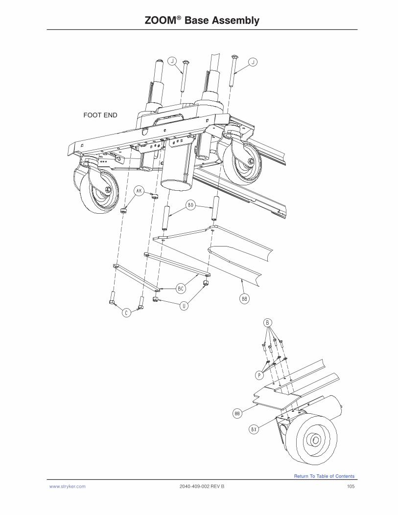
www.stryker.com 2040-409-002 REV B 105
Return To Table of Contents
ZOOM® Base Assembly
FOOT END
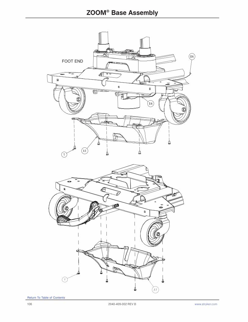
106 2040-409-002 REV B www.stryker.com
Return To Table of Contents
ZOOM® Base Assembly
FOOT END
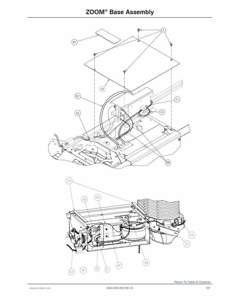
www.stryker.com 2040-409-002 REV B 107
Return To Table of Contents
ZOOM® Base Assembly

108 2040-409-002 REV B www.stryker.com
Return To Table of Contents
ZOOM® Base Assembly

www.stryker.com 2040-409-002 REV B 109
Return To Table of Contents
ZOOM® Base Assembly
Item Part No. Part Name Qty. A 0003-032-000 Hex Hd. Cap Screw 4C 0003-120-000 Hex Hd. Cap Screw 2D 0004-039-000 Soc. Hd. Cap Screw 1E 0004-160-000 Soc. Hd. Cap Screw 1F 0004-301-000 Pan Hd. Machine Screw 1G 0004-307-000 Soc. But. Hd. Cap Screw 1H 0005-017-000 Carriage Bolt 1J 0005-031-000 Carriage Bolt 2K 0007-052-000 Truss Hd. Torx 12L 0007-063-000 Truss Hd. Torx 2M 0008-049-000 Soc. Hd. Shoulder Bolt 2N 0011-063-000 Washer 7P 0012-020-000 Lock Washer 4Q 0013-010-000 Ext. Tooth Star Washer 5R 0014-003-000 Plastic Washer 8S 0016-003-000 Nylock Nut 1T 0016-028-000 Nylock Nut 1U 0016-035-000 Nylock Nut 2W 0016-036-000 Nylock Nut 2X 0021-022-000 Set Screw 1Y 0023-025-000 Hex Washer Hd. Screw 10Z 0023-281-000 Self-Tapping Screw 4AA 0025-079-000 Pop Rivet 1AB 0026-261-000 Groove Pin 1AC 0026-277-000 Clevis Pin 1AD 0026-297-000 Clevis Pin 1AE 0027-021-000 Rue Ring Cotter 1AF 0027-022-000 Rue Ring Cotter 1AG 0030-038-000 Split Bushing 1AH 0030-040-000 E-A-R Grommet 1AK 0042-006-000 Collar 2AL 0042-020-000 Lock Collar 1AM 0058-090-000 Threaded Stud 1AN 0059-133-000 Push-Mount Wire Clip 1AP 0059-192-000 Split Ferrite 1AQ 0059-194-000 Split Ferrite 3AR 0081-245-000 Bronze Bushing 2AS 1210-201-153 Butterfly “V” Pedal 1AT 1210-201-251 Insert Bushing 1AU 1210-201-671 Damper 1AW 2040-001-012 Drive Whl. Lift Lever Ass’y (pg. 112) 1AX 2040-001-017 Foot End Bottom Cover (pg. 113) 1AY 2040-001-017 Head End Bottom Cover (pg. 113) 1AZ 2040-001-051 Pedal Crank Weldment 1BA 2040-001-053 Damper Crank Weldment 1BB 2040-001-060 Leaf Spring 1BC 2040-001-061 Tie Down Strap 2BD 2040-001-062 Reinforcement Tube 2
ZOOM® Option Common Components - Part Number 3002-001-001 (Reference Only)

110 2040-409-002 REV B www.stryker.com
Return To Table of Contents
ZOOM® Base Assembly
BE 2040-001-082 Pedal Rod 1BF 2040-001-083 Pedal Crank Roller 1BG 2040-001-084 Pedal Rod Pivot Bracket 1BH 2040-001-098 Lift Lever Spacer 1BJ 2040-001-100 Drive Whl. Position Label 1BK 2040-001-101 Charger Box Cover 1BL 2040-001-102 Power Bd. Cover Label 1BM 2040-001-103 Charger Box Sw. Brkt. Cov. 1BN 2040-001-801 Base Switch Cable 1BP 2040-001-804 Pwr. Bd. DC Pwr. Cable 1BQ 3000-200-601 Brake Label 2BR 3000-200-602 Stryker Logo Label 1BS 3000-300-058 Limit Switch 1BT 3000-300-428 Gatch Link Sleeve 4BU 3000-300-113 Wire Ties 2BW 3001-001-010 Transformer 1BX 3002-001-014 Drive Train Assembly (pg. 114) 1BY 3002-001-015 Battery Tray Assembly (pg. 115) 1BZ 3002-001-018 Hood Assembly 1CA 3002-001-030 Base Power Assembly 1CB 3002-001-050 Charger Box Weldment 1CC 3002-001-068 Power PCB Cover 1CD 3002-001-071 Charger/Inverter Cover 1CE 3002-001-078 Hood Slot Trim 1CF 3002-001-079 Hood Slot Trim Bracket 1CG 3002-001-802 Inverter/Battery Cable 1CH 7000-001-326 Foam Tape (10”) 2CJ 0059-144-000 Split Ferrite 1
ZOOM® Option Common Components (Continued) - Part Number 3002-001-001 (Reference Only)
ZOOM® Base, 6” Casters - 2040-244-010 (Ref.)
Item Part No. Part Name Qty.B 0003-085-000 Hex Hd. Cap Screw 4DA 2040-201-809 Umbilical Cable Ass’y 1

112 2040-409-002 REV B www.stryker.com
Return To Table of Contents
Drive Wheel Lift Lever Assembly
Item Part No. Part Name Qty.
A 0011-003-000 Washer 3 B 0026-297-000 Clevis Pin 1 C 0027-021-000 Rue Ring 2 D 0045-232-000 O-Ring 1 E 0081-070-000 Flange Bearing 1 F 2040-201-013 Drive Wheel Lift Plate Ass’y 1 G 2040-001-087 Lift Lever Roller 1 H 2040-001-099 Lift Lever Guide 1
For Reference Only: 2040-001-012
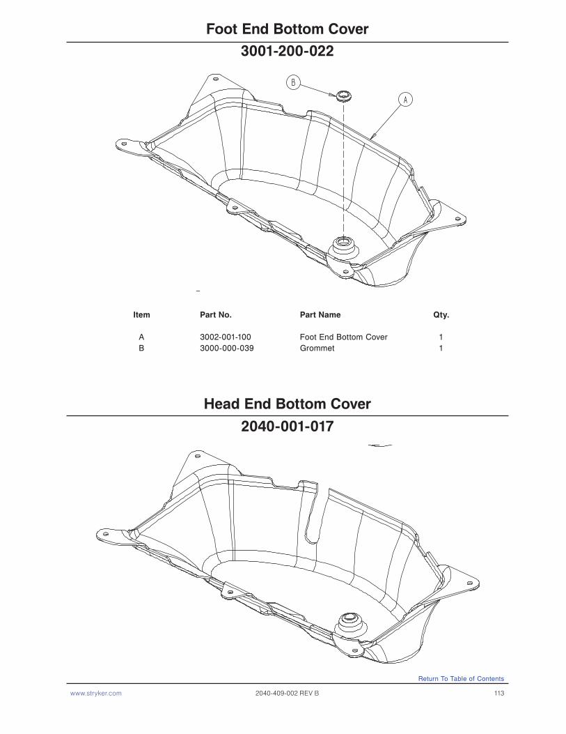
www.stryker.com 2040-409-002 REV B 113
Return To Table of Contents
Foot End Bottom Cover
Item Part No. Part Name Qty.
A 3002-001-100 Foot End Bottom Cover 1 B 3000-000-039 Grommet 1
Head End Bottom Cover
3001-200-022
2040-001-017

114 2040-409-002 REV B www.stryker.com
Return To Table of Contents
Optional ZOOM® Drive Train Assembly
Item Part No. Part Name Qty.
A 8839-793-700 Hex Hd. Cap Screw 1 B 0004-245-000 Flanged But. Hd. Cap Screw 6 C 0011-262-000 Washer 1 D 0003-054-000 Hex Hd. Cap Screw 2 E 3002-001-072 Drive Train Motor 1 F 2040-001-073 Gear Box 1 G 2040-001-074 Drive Train Wheel 1 H 2040-001-075 Motor Mounting Bracket 1 J 2040-001-097 Square Key 1 K 3000-300-113 Wire Tie 1 L 0013-010-000 Star Washer 2
3002-001-014

www.stryker.com 2040-409-002 REV B 115
Return To Table of Contents
Optional ZOOM® Battery Tray Assembly
WIRING VIEW
Item Part No. Part Name Qty.
A 0004-046-000 But. Hd. Cap Screw 4 B 0016-028-000 Nylock Nut 4 C 0023-256-000 Pan Hd. Screw 2 D 0038-151-000 Cable Tie 1 E 2040-001-070 Battery 2 F 2040-001-802 Battery Jumper Cable 1 G 3000-300-002 Push Nut 2 H 3002-001-069 Battery Tray 1 J 3002-001-091 Terminal Guard 1 K 3002-001-803 Battery Harness Cable 2 L 3002-101-043 Foam Spacer 2
For Reference Only: 3002-001-015
Replacement Kit Part Number (Batteries Only) - 2040-700-013
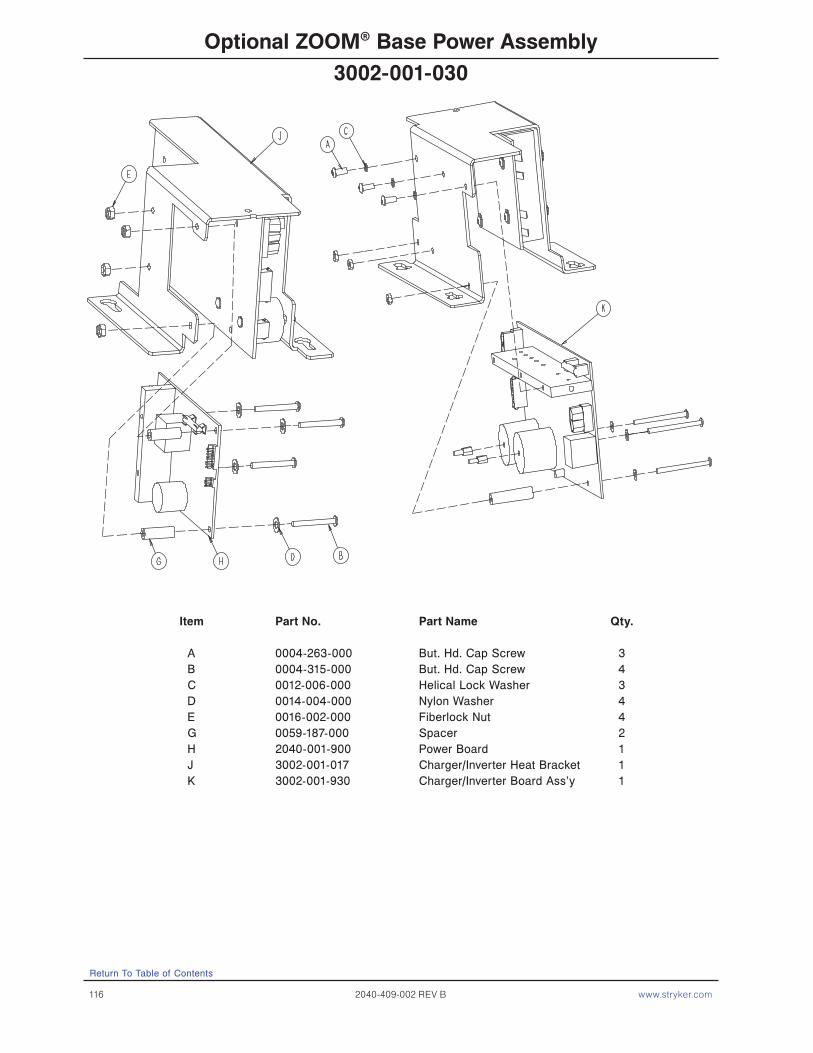
116 2040-409-002 REV B www.stryker.com
Return To Table of Contents
Optional ZOOM® Base Power Assembly
Item Part No. Part Name Qty.
A 0004-263-000 But. Hd. Cap Screw 3 B 0004-315-000 But. Hd. Cap Screw 4 C 0012-006-000 Helical Lock Washer 3 D 0014-004-000 Nylon Washer 4 E 0016-002-000 Fiberlock Nut 4 G 0059-187-000 Spacer 2 H 2040-001-900 Power Board 1 J 3002-001-017 Charger/Inverter Heat Bracket 1 K 3002-001-930 Charger/Inverter Board Ass’y 1
3002-001-030

www.stryker.com 2040-409-002 REV B 117
Return To Table of Contents
Litter Assembly
For Reference Only: 2032-231-010

118 2040-409-002 REV B www.stryker.com
Return To Table of Contents
Litter Assembly

www.stryker.com 2040-409-002 REV B 119
Return To Table of Contents
Litter Assembly

120 2040-409-002 REV B www.stryker.com
Return To Table of Contents
Litter Assembly

www.stryker.com 2040-409-002 REV B 121
Return To Table of Contents
Litter Assembly

122 2040-409-002 REV B www.stryker.com
Return To Table of Contents
Litter Assembly

www.stryker.com 2040-409-002 REV B 123
Return To Table of Contents
Litter Assembly
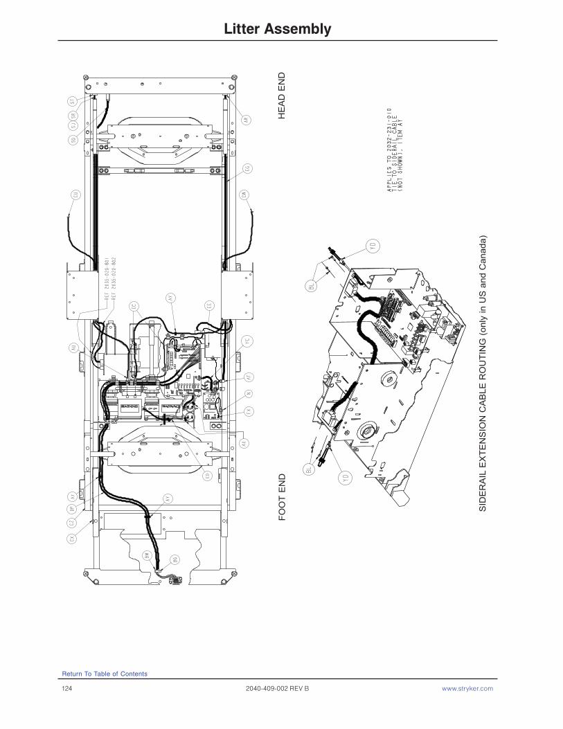
124 2040-409-002 REV B www.stryker.com
Return To Table of Contents
Litter Assembly
HE
AD
EN
DFO
OT
EN
D
SID
ER
AIL
EX
TEN
SIO
N C
AB
LE R
OU
TIN
G (o
nly
in U
S a
nd C
anad
a)
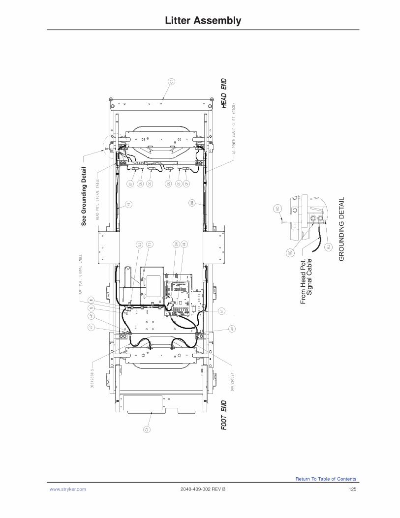
www.stryker.com 2040-409-002 REV B 125
Return To Table of Contents
Litter Assembly
GR
OU
ND
ING
DET
AIL
See
Gro
un
din
g D
etai
l

126 2040-409-002 REV B www.stryker.com
Return To Table of Contents
Litter Assembly
2040 Head Wall View
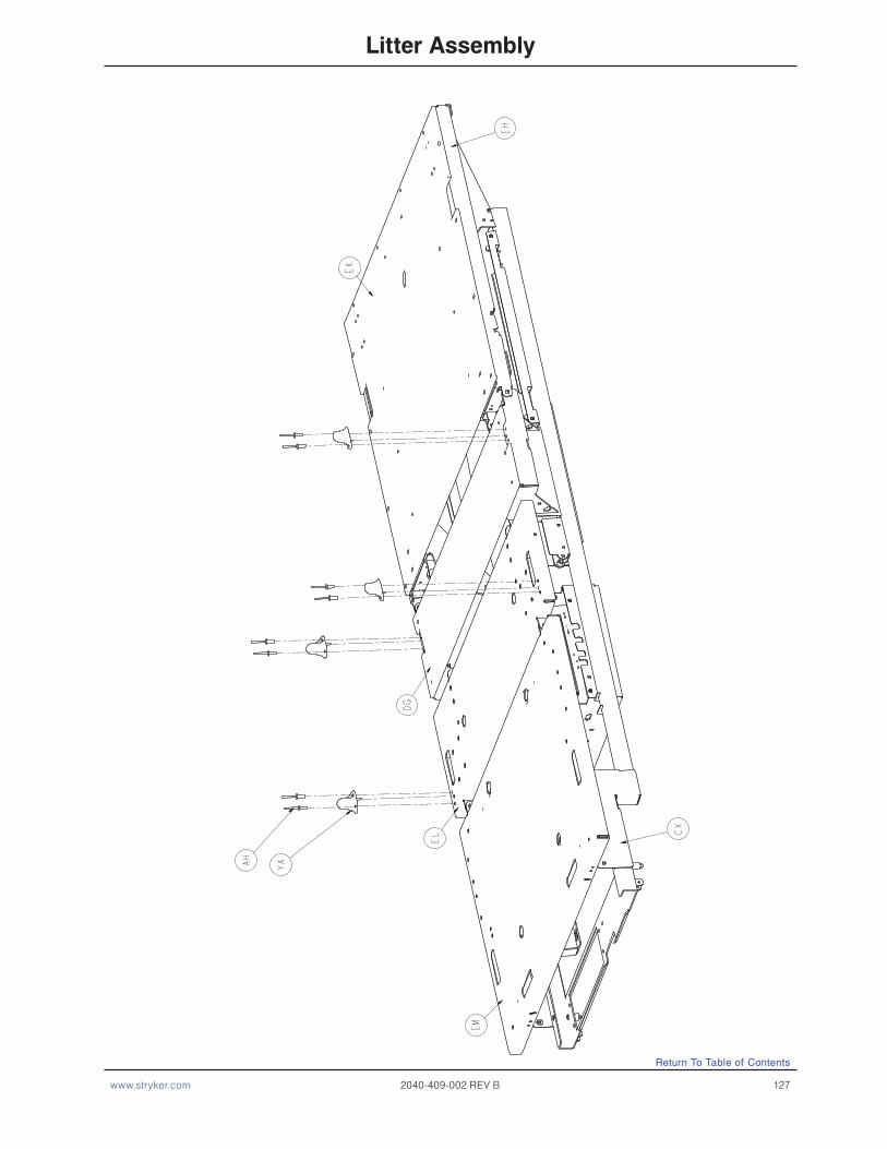
www.stryker.com 2040-409-002 REV B 127
Return To Table of Contents
Litter Assembly
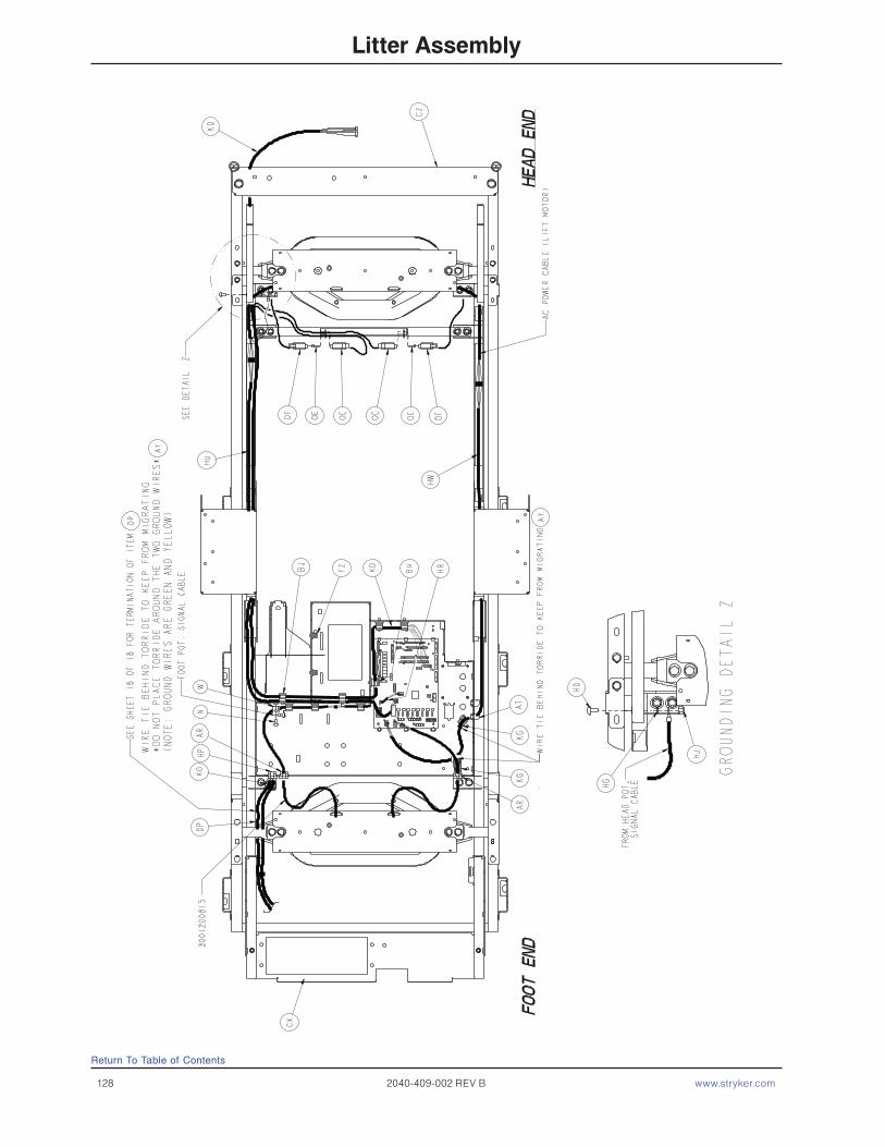
128 2040-409-002 REV B www.stryker.com
Litter Assembly
Return To Table of Contents

www.stryker.com 2040-409-002 REV B 129
Litter Assembly
Return To Table of Contents
2032-231-010 EPIC II® Domestic, EPIC II® +, and ZOOM® Common Litter Components
Item Part No. Part Name Qty. Item Part No. Part Name Qty.B 0003-074-000 Hex Hd. Cap Screw 2C 0003-078-000 Hex Hd. Cap Screw 44D 0003-214-000 Hex Hd. Cap Screw 8E 0003-347-000 Hex Hd. Cap Screw 4F 0004-032-000 Soc. Hd. Cap Screw 4G 0004-085-000 Soc. Hd. Cap Screw 2H 0004-101-000 Soc. Hd. Cap Screw 1J 0005-019-000 Carriage Bolt 18K 0005-024-000 Carriage Bolt 4L 0005-023-000 Carriage Bolt 3M 0007-058-000 Truss Hd. Torx 5N 0007-063-000 Truss Hd. Torx 20P 0007-065-000 Truss Hd. Torx 16S 0011-053-000 Washer 10T 0011-063-000 Washer 37U 0011-158-000 Washer 22W 0013-010-000 Ext. Tooth Lock Washer 17X 0013-018-000 Ext. Tooth Lock Washer 14Y 0013-032-000 Ext. Tooth Lock Washer 2Z 0014-007-000 Washer 2AB 0016-003-000 Nylock Nut 4AC 0016-028-000 Nylock Nut 21AD 0016-035-000 Nylock Nut 8AE 0016-102-000 Nylock Nut 7AF 0003-224-000 Hex Washer Hd. Screw 16AH 0025-142-000 Rivet 37AJ 0025-147-000 Rivet 4AK 0026-012-000 Roll Pin 2AL 0026-168-000 Spiral Pin 2AN 0027-017-000 Cotter Pin 21AP 0028-120-000 Ext. Retaining Ring 3AR 0030-030-045 Strain Relief 3AS 0030-036-000 Grommet 4AT 0030-047-000 Right Angle Strain Relief 2AU 0030-052-000 Snap Bushing 4AX 0038-111-000 Cable Tie 10AY 0038-151-000 Cable Tie 17AZ 0038-382-000 Compression Spring 2BA 0044-029-000 Black Foam Tape 1BB 0044-032-000 1” Wide Poly Tape 50”BC 0052-104-000 Cable Clamp 1BD 0052-759-000 Flange Bearing 2BE 0052-762-000 Nyliner Bushing 2BG 0058-076-000 Drive Fastener 2BH 0059-133-000 Push-Mount Wire Clip 1BJ 0059-135-000 Push-Mount Wire Clip 7BK 0059-157-000 Power Supply 1BL 0059-727-000 Jack Screw 4BM 0059-743-000 Wire Harness Clip 2BN 0059-751-000 Locking Circuit Bd. Supt. 6BP 0059-767-000 Cable Clamp 2
BR 0059-773-000 Push Spacer 4BS 0059-774-000 Locking PCB Support 1BT 0081-268-000 Flange Bearing 15 BU 0715-001-333 Rel. Valve Stop Sleeve 18BW 0988-002-708 Shock Caution Label 1BX 2020-0340758 Rest-Calf Section 1BY 2025-031-062 Pot. Actuator Link 1BZ 2025-031-880 Ground Jumper 4CA 3002-300-870 Ground Strap 8CB 2025-032-068 Flange Bearing 2CD 2025-032-076 Ball Bearing 2CE 2025-032-077 Fowler Actuator Link 2CF 2025-032-082 Hydraulic Dampener 2CG 2025-032-084 Fowler Screw Up Stop 1CH 2025-032-085 Fowler Screw Down Stop 1CJ 2025-032-086 Thrust Washer 5CK 2025-032-087 Roller Cage Bearing 2CL 2025-231-061 Pot. Timing Clamp 1CM 2025-231-088 Fowler Link 1CN 2025-231-090 Torque Tube Pivot Brg. 2CP 2025-231-099 Bed Extender Rel. Lever 2CR 2025-231-112 Bed Extender Pin Lock 2CS 2025-232-089 Fowler Nut Box 1CT 2025-232-090 Fowler Ball Screw 1CU 2035-031-048 Short CPR Cable 1CW 2035-031-049 Long CPR Cable 1CX 2032-031-050 Scale Frame Weldment 1CY 2035-031-051 Torque Tube Weldment 1CZ 2035-031-054 Iso. Frame Weldment 1DA 2035-031-055 Head End Crosstube 1DB 2035-031-057 Bed Extender Weldment 1DC 2035-031-064 Torq. Tube Ret. Brkt., Lt. 1DD 2035-031-065 Torq. Tube Ret. Brkt., Rt. 1DE 2035-031-066 Torque Block Channel 2DF 2035-031-094 Foot Support Cover 1DG 2032-031-097 Seat Section Skin 1DH 2035-031-100 Wire Channel Cover 2DJ 2035-031-115 Roller Bracket Cover, Rt. 1DK 2035-031-116 Roller Bracket Cover, Lt. 1DL 2035-031-126 Protective Sleeve 2DM 2035-031-127 Nylon Stop 2DN 2035-031-801 Inlet/Fuse Cable 1 DP 2035-031-802 Footboard/CPU Cable 1DR 2035-032-052 Gatch Trigger Weldment 1DS 2035-032-054 CPR Rel. Wldmt. Brkt. 1DT 2035-032-072 CPR Release Pivot Brkt. 1DU 2035-032-077 Gatch Actuator Link 2DW 2035-032-079 Act. Box Swch. Brk. 2DX 2035-032-084 Gatch Screw Up Stop 1DY 2035-032-085 Gatch Screw Down Stop 1DZ 2035-032-088 Act. Box Motor Mtg. Brkt. 2

130 2040-409-002 REV B www.stryker.com
Litter Assembly
Return To Table of Contents
2032-231-010 EPIC II® Domestic, EPIC II® +, and ZOOM® Common Litter Components (Continued)
Item Part No. Part Name Qty. Item Part No. Part Name Qty.EA 2035-032-090 Gatch Ball Screw Ass’y 1EB 2035-032-096 Ball Screw Cover 1EC 2035-032-801 Gatch Limit Switch Cable 1ED 2035-032-802 Fowler/CPU Jmpr Cable 1EE 2035-032-803 Fowler Pot. Cable 1EF 2035-032-804 Fuse/PCB Cable 1EH 2032-033-050 Fowler Frame Weldment 1EJ 2035-033-062 CPR Release Slide Brkt. 2EK 2035-033-063 Fowler Skin 1EL 2032-034-050 Thigh Section Weldment 1EM 2032-035-050 Foot Section Weldment 1EP 2035-231-085 Seat Section Cover 2ER 2035-233-064 Quick Drop Rel. Brkt., Lt. 1ES 2035-233-065 Quick Drop Rel. Brkt., Rt. 1ET 2035-400-565 Siderail Guide Bracket 2EU 2035-432-075 Actuator Box Cover Ass’y (pg. 133 1EW 2040-090-100 500 Lb. Label 2EX 3000-300-058 Switch Plunger 2EY 3000-300-099 Modified Bushing 9EZ 3000-300-115 Standoff 4FA 3000-300-349 Head/Footboard Post Cap 4FB 3000-300-353 Roller 4FC 3000-300-442 Fowler Drive Grommet 16FD 3000-300-455 CPR Isolation Bushing 4FE 3000-300-456 CPR Isolator 2FF 3000-300-461 CPR Decoupler 2FG 3000-300-462 CPR Wing 2JFH 3000-300-464 CPR Engagement Spring 4FJ 3000-300-473 Clevis Pin 2FK 3000-300-477 CPR Conduit Stud 6FL 3000-300-478 CPR Conduit Clamp 6FM 3001-200-228 Mounting Standoff 2FM 3001-200-228 Mounting Standoff 2FN 3001-300-008 Thigh Bumper 4 FP 3001-300-099 Flange Bearing 10FR 3001-300-603 CPR Release Label 2FS 3001-300-663 Velcro Strip 10FT 3001-300-877 Siderail Extension Cable 1FW 5000-030-366 Fowler Nut Adapter 1FX 5010-080-007 Power Supply Gd. Cable 1FY 8800-380-000 Neoprene Sponge 18”FZ 8815-001-100 Wire Mount Clip 4GA 0011-310-000 Washer 2GB 0011-002-000 Washer 5GC 0007-052-000 Truss Hd. Torx 4GD 0013-038-000 Ext. Tooth Lock Washer 2GE 2025-231-089 Fowler Litter Link 1GF 0059-194-000 Split Ferrite 1HA 0003-347-000 Hex Hd. Cap Screw 8
HB 0004-338-000 Flanged But. Hd. Screw 4HC 0005-029-000 Rd. Hd. Sq. Neck Bolt 4HD 0007-058-000 Truss Hd. Torx 1HE 0011-539-000 Washer 32HF 0011-063-000 Washer 8HG 0013-010-000 Ext. Tooth Lock Washer 1HH 0013-032-000 Ext. Tooth Lock Washer 4HJ 0016-006-000 Kep Nut 9HK 0016-035-000 Nylock Nut 8HL 0025-050-000 Rivet 24HP 0059-106-000 Strain Relief 1HR 2030-031-801 Foot Pot. Exten. Cable 1HU 2030-031-802 Head Pot. Exten. Cable 1HW 2030-031-803 Head Lift Motor Ext. 1HX 2040-031-056 Foley Bag Hanger 6HY 3001-300-004 Spacer 8JD 0016-014-000 Nylock Nut 1JH 0034-021-000 Cord Clamp 1NG 3002-407-950 CPU 1YA 3003-300-033 Mattress Retainer 4YC 2035-032-805 Cable CPU/Power Supply 1YD 2035-020-805 Siderail LS Bypass Cable 2YE 0003-005-000 Hex Head Cap Screw 1
HS 2030-331-052 Head End Header Wldmt. 1HT 2030-331-053 Foot End Header Wldmt. 1
HS 2040-031-252 Head End Header Wldmt. 1HT 2040-031-253 Foot End Header Wldmt. 1
2040-032-020 Zoom®/EPIC II®/EPIC II® +Standard Height Option
Item Part No Part Name Qty.
Item Part No Part Name Qty.
2040-032-021 Zoom®/EPIC II®/EPIC II+® Enhanced Height Option
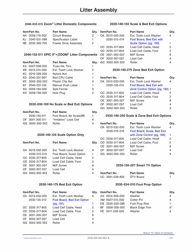
www.stryker.com 2040-409-002 REV B 131
Litter Assembly
Return To Table of Contents
2040-032-015 Zoom® Litter Domestic Components
Item Part No. Part Name Qty.NA 0059-179-000 Circuit Breaker 2KJ 2040-031-098 Specification Label 1NE 2035-300-705 Fowler Drive Assembly 2
2040-132-011 EPIC II®+/ZOOM® Litter Components
Item Part No. Part Name Qty.KA 0007-058-000 Truss Hd. Torx 1 KB 0013-010-000 Ext. Tooth Lock Washer 2KC 0016-028-000 Nylock Nut 1KD 2040-231-807 Bed CPU Cable 1KE 3000-300-002 Plastic Clip Nut 3KF 2040-031-100 Manual Push Label 1KG 0059-194-000 Split Ferrite 3KH 0059-738-000 Hole Plug 2
2030-030-100 No Scale or Bed Exit Options
Item Part No. Part Name Qty. 2030-135-011 Foot Board, No Scale/BE 1OF 3001-300-511 “Imitation” Load Cell 4GG 3000-300-353 Roller 4
2030-140-125 Scale Option Only
Item Part No. Part Name Qty
OA 0013-032-000 Ext. Tooth Lock Washer 4 2030-015-013 Foot Board, Scale Option 1OC 2035-317-805 Load Cell Cable, Head 2OD 2035-317-804 Load Cell Cable, Foot 2OE 3001-300-007 M/F Screw 8OF 3002-307-057 Load Cell 4GG 3002-300-353 Roller 4
2030-140-175 Bed Exit Option
Item Part No. Part Name Qty.OA 0013-032-000 Ext. Tooth Lock Washer 4 2030-135-012 Foot Board, Bed Exit Option (pg. 191) 1OC 2035-317-805 Load Cell Cable, Head 2OD 2035-317-804 Load Cell Cable, Foot 2OE 3001-300-007 M/F Screw 8OF 3002-307-057 Load Cell 4GG 3002-300-353 Roller 4
2030-140-150 Scale & Bed Exit Options
Item Part No. Part Name Qty.OA 0013-032-000 Ext. Tooth Lock Washer 4 2030-015-014 Foot Board, Bed Exit with Scale Option (pg. 193) 1OC 2035-317-805 Load Cell Cable, Head 2OD 2035-317-804 Load Cell Cable, Foot 2OE 3001-300-007 M/F Screw 8OF 3002-307-057 Load Cell 4GG 3002-300-353 Roller 4
2030-140-275 Zone Bed Exit Option
Item Part No. Part Name Qty.OA 0013-032-000 Ext. Tooth Lock Washer 4 2030-135-015 Foot Board, Bed Exit with Zone Control Option (pg. 192) 1OC 2035-317-805 Load Cell Cable, Head 2OD 2035-317-804 Load Cell Cable, Foot 2OE 3001-300-007 M/F Screw 8OF 3002-307-057 Load Cell 4GG 3002-300-353 Roller 4
2030-140-250 Scale & Zone Bed Exit Options
Item Part No. Part Name Qty.OA 0013-032-000 Ext. Tooth Lock Washer 4 2030-015-016 Foot Board, Scale, Bed Exit with Zone Control (pg. 194) 1OC 2035-317-805 Load Cell Cable, Head 2OD 2035-317-804 Load Cell Cable, Foot 2OE 3001-300-007 M/F Screw 8OF 3002-307-057 Load Cell 4GG 3002-300-353 Roller 4
2035-130-207 Smart TV Option
Item Part No. Part Name Qty.UC 3001-039-800 STV Board 1
2030-034-010 Foot Prop Option
Item Part No. Part Name Qty.AA 0014-008-000 Washer 4AM 0027-015-000 Cotter Pin 4EN 2035-035-096 Foot Prop Rod 1BF 0058-056-000 Black Edge Trim 6”HE 0011-539-000 Washer 4

132 2040-409-002 REV B www.stryker.com
Litter Assembly
Return To Table of Contents
2040-030-200 EPIC II® Head Wall Communication Option
Item Part No. Part Name Qty.SG 2035-031-806 Head Wall Interface Cable 1SH 0059-710-000 Static Cap 1 2040-031-200 ZOOM® Head Wall w/Comm. 1SP 5010-080-020 9V Battery Box Cable 1ST 0030-046-000 Strain Relief 1
2040-030-201 Head Wall Communication w/Nurse Call Option
Item Part No. Part Name QtySA 0001-087-000 Flat Hd. Mach. Screw 2SF 0052-783-000 U Clip 2SG 2035-031-806 Head Wall Interface Cable 1SH 0059-710-000 Static Cap 1 2040-031-201 ZOOM® Head Wall w/NC 1SP 5010-080-209 9V Battery Box w/Cable 1ST 0030-046-000 Strain Relief 1
2040-030-202 Head Wall Comm. with Nurse Call and 1 Stryker Port Option
Item Part No. Part Name QtySA 0001-087-000 Flat Hd. Mach. Screw 2SE 0030-039-000 Strain Relief Grommet 1SF 0052-783-000 U Clip 2SG 2035-031-806 Head Wall Interface Cable 1SH 0059-710-000 Static Cap 1 2040-031-202 ZOOM® Head Wall w/NC and 1 Port 1SP 5010-080-209 9V Battery Box w/Cable 1SR 2035-030-804 Pendant Port Cable 1ST 0030-046-000 Strain Relief 1
2040-030-203 Head Wall w/Nurse Call and 2 Stryker Ports Option
Item Part No. Part Name QtySA 0001-087-000 Flat Hd. Mach. Screw 2SE 0030-027-000 Strain Relief Grommet 1SF 0052-783-000 U Clip 2SG 2035-031-806 Head Wall Interface Cable 1SH 0059-710-000 Static Cap 1 2040-031-203 ZOOM® Head Wall w/NC and 2 Ports 1SJ 2035-030-805 Dual Pendant Port Cable 1SP 5010-080-209 9V Battery Box w/Cable 1ST 0030-046-000 Strain Relief 1
030-30-251 High-Sounding Beeper Option
Item Part No. Part Name Qty.PA 3001-508-870 High-Sound Beeper Cable 1

www.stryker.com 2040-409-002 REV B 133
Actuator Box Cover Assembly
Item Part No. Part Name Qty.
A 2035-332-075 Main Actuator Box Cover 1 B 2035-332-076 Actuator Box Side Cover 1 C 0007-058-000 Truss Hd. Torx 2
For Reference Only: 2035-432-075
Return To Table of Contents
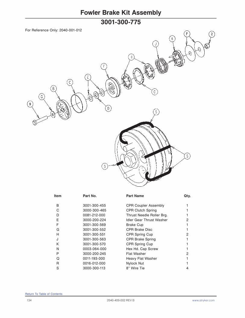
134 2040-409-002 REV B www.stryker.com
Fowler Brake Kit Assembly
Item Part No. Part Name Qty.
B 3001-300-455 CPR Coupler Assembly 1 C 3000-300-465 CPR Clutch Spring 1 D 0081-212-000 Thrust Needle Roller Brg. 1 E 3000-200-224 Idler Gear Thrust Washer 2 F 3001-300-569 Brake Cup 1 G 3001-300-552 CPR Brake Disc 1 H 3001-300-551 CPR Spring Cup 2 J 3001-300-563 CPR Brake Spring 1 K 3001-300-570 CPR Spring Cup 1 N 0003-064-000 Hex Hd. Cap Screw 1 P 3000-200-245 Flat Washer 2 Q 0011-193-000 Heavy Flat Washer 1 R 0016-012-000 Nylock Nut 1 S 3000-300-113 8” Wire Tie 4
Return To Table of Contents
For Reference Only: 2040-001-012
3001-300-775
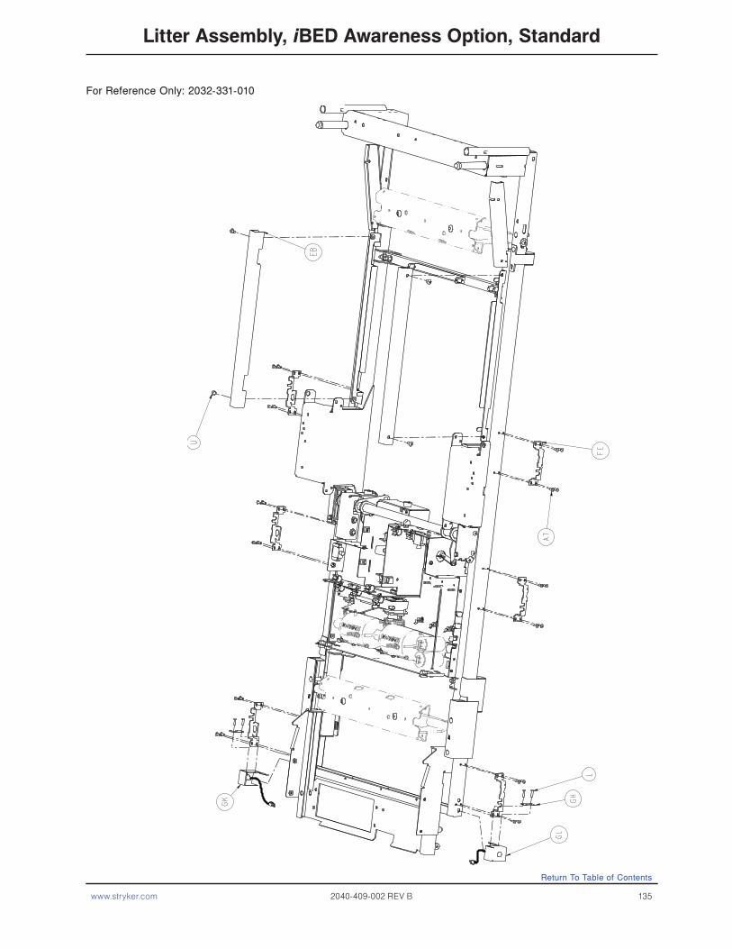
www.stryker.com 2040-409-002 REV B 135
Litter Assembly, iBED Awareness Option, Standard
For Reference Only: 2032-331-010
Return To Table of Contents

136 2040-409-002 REV B www.stryker.com
Litter Assembly, iBED Awareness Option, Std. Components
Return To Table of Contents

www.stryker.com 2040-409-002 REV B 137
Litter Assembly, iBED Awareness Option, Std. Components
See Detail A
Return To Table of Contents

138 2040-409-002 REV B www.stryker.com
Litter Assembly, iBED Awareness Option, Std. Components
To S
ider
ail
To S
ider
ail
Return To Table of Contents

www.stryker.com 2040-409-002 REV B 139
Litter Assembly, iBED Awareness Option, Std. Components
2035
-020
-801
2035
-020
-801
Return To Table of Contents

140 2040-409-002 REV B www.stryker.com
Litter Assembly, iBED Awareness Option, Std. Components
Return To Table of Contents
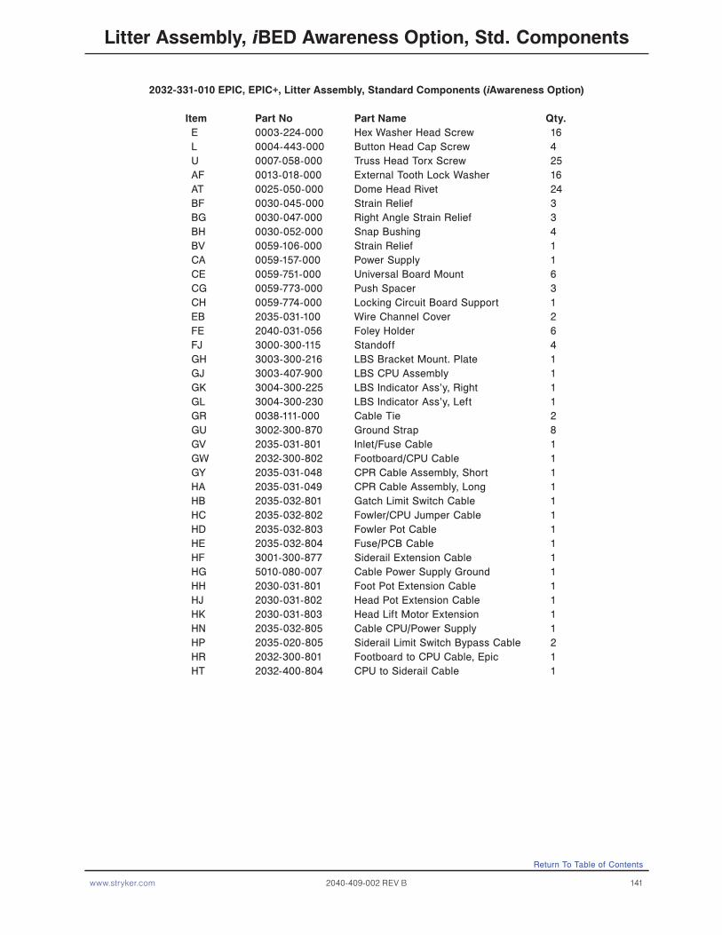
www.stryker.com 2040-409-002 REV B 141
2032-331-010 EPIC, EPIC+, Litter Assembly, Standard Components (iAwareness Option)
Item Part No Part Name Qty.E 0003-224-000 Hex Washer Head Screw 16L 0004-443-000 Button Head Cap Screw 4U 0007-058-000 Truss Head Torx Screw 25AF 0013-018-000 External Tooth Lock Washer 16AT 0025-050-000 Dome Head Rivet 24BF 0030-045-000 Strain Relief 3BG 0030-047-000 Right Angle Strain Relief 3BH 0030-052-000 Snap Bushing 4BV 0059-106-000 Strain Relief 1CA 0059-157-000 Power Supply 1CE 0059-751-000 Universal Board Mount 6CG 0059-773-000 Push Spacer 3CH 0059-774-000 Locking Circuit Board Support 1EB 2035-031-100 Wire Channel Cover 2FE 2040-031-056 Foley Holder 6FJ 3000-300-115 Standoff 4GH 3003-300-216 LBS Bracket Mount. Plate 1GJ 3003-407-900 LBS CPU Assembly 1GK 3004-300-225 LBS Indicator Ass’y, Right 1GL 3004-300-230 LBS Indicator Ass’y, Left 1GR 0038-111-000 Cable Tie 2GU 3002-300-870 Ground Strap 8GV 2035-031-801 Inlet/Fuse Cable 1GW 2032-300-802 Footboard/CPU Cable 1GY 2035-031-048 CPR Cable Assembly, Short 1HA 2035-031-049 CPR Cable Assembly, Long 1HB 2035-032-801 Gatch Limit Switch Cable 1HC 2035-032-802 Fowler/CPU Jumper Cable 1HD 2035-032-803 Fowler Pot Cable 1HE 2035-032-804 Fuse/PCB Cable 1HF 3001-300-877 Siderail Extension Cable 1HG 5010-080-007 Cable Power Supply Ground 1HH 2030-031-801 Foot Pot Extension Cable 1HJ 2030-031-802 Head Pot Extension Cable 1HK 2030-031-803 Head Lift Motor Extension 1HN 2035-032-805 Cable CPU/Power Supply 1HP 2035-020-805 Siderail Limit Switch Bypass Cable 2HR 2032-300-801 Footboard to CPU Cable, Epic 1HT 2032-400-804 CPU to Siderail Cable 1
Litter Assembly, iBED Awareness Option, Std. Components
Return To Table of Contents

142 2040-409-002 REV B www.stryker.com
Litter Assembly, iBED Awareness Option w/Scale & Bed Exit2032-140-150
Return To Table of Contents

www.stryker.com 2040-409-002 REV B 143
Item Part No. Part Name Qty.A 0013-032-000 External Tooth Lock Washer 4B 2030-317-804 Foot End Load Cell Cable 2C 2030-317-805 Head End Load Cell Cable 2D 2032-500-012 iAwareness, Bed Exit, Foot Board Ass’y (pg. 202) 1E 3001-300-007 Screw 8F 3002-300-353 Roller 4G 3002-307-057 Load Cell 4
2032-140-150Litter Assembly, iBED Awareness Option w/Scale & Bed Exit
Return To Table of Contents

144 2040-409-002 REV B www.stryker.com
Litter Ass’y, iBED Awareness Option w/Scale/Bed Exit/Zone Cntrl2032-140-250
Return To Table of Contents

www.stryker.com 2040-409-002 REV B 145
Item Part No. Part Name Qty.
A 0013-032-000 External Tooth Lock Washer 4B 2030-317-804 Foot End Load Cell Cable 2C 2030-317-805 Head End Load Cell Cable 2D 2032-500-011 iAwarenss, Zone Control, Foot Board Ass’y (pg. 203) 1E 3001-300-007 Screw 8F 3002-300-353 Roller 4G 3002-307-057 Load Cell 4
2032-140-250Litter Ass’y, iBED Awareness Option w/Scale/Bed Exit/Zone Cntrl
Return To Table of Contents
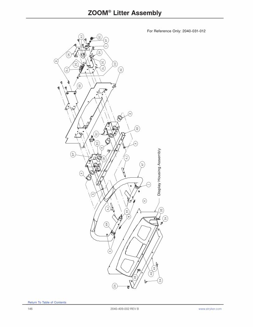
146 2040-409-002 REV B www.stryker.com
ZOOM® Litter Assembly
Return To Table of Contents
For Reference Only: 2040-031-012
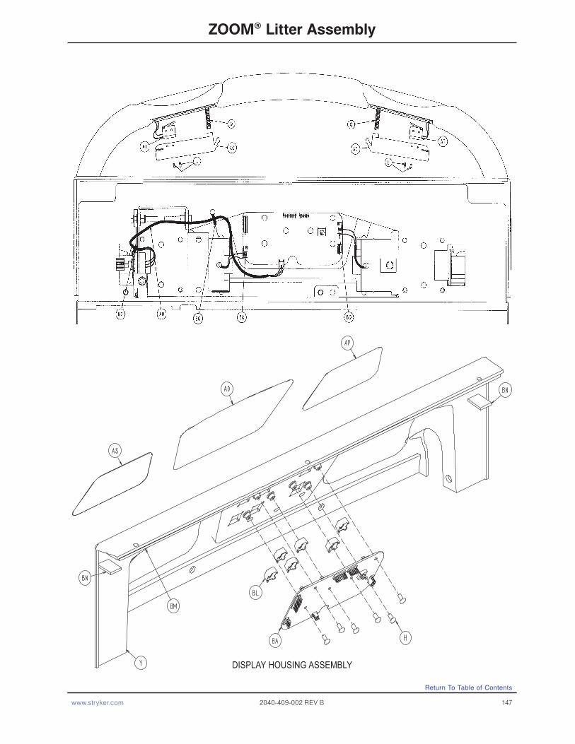
www.stryker.com 2040-409-002 REV B 147
ZOOM® Litter Assembly
DISPLAY HOUSING ASSEMBLY
Return To Table of Contents
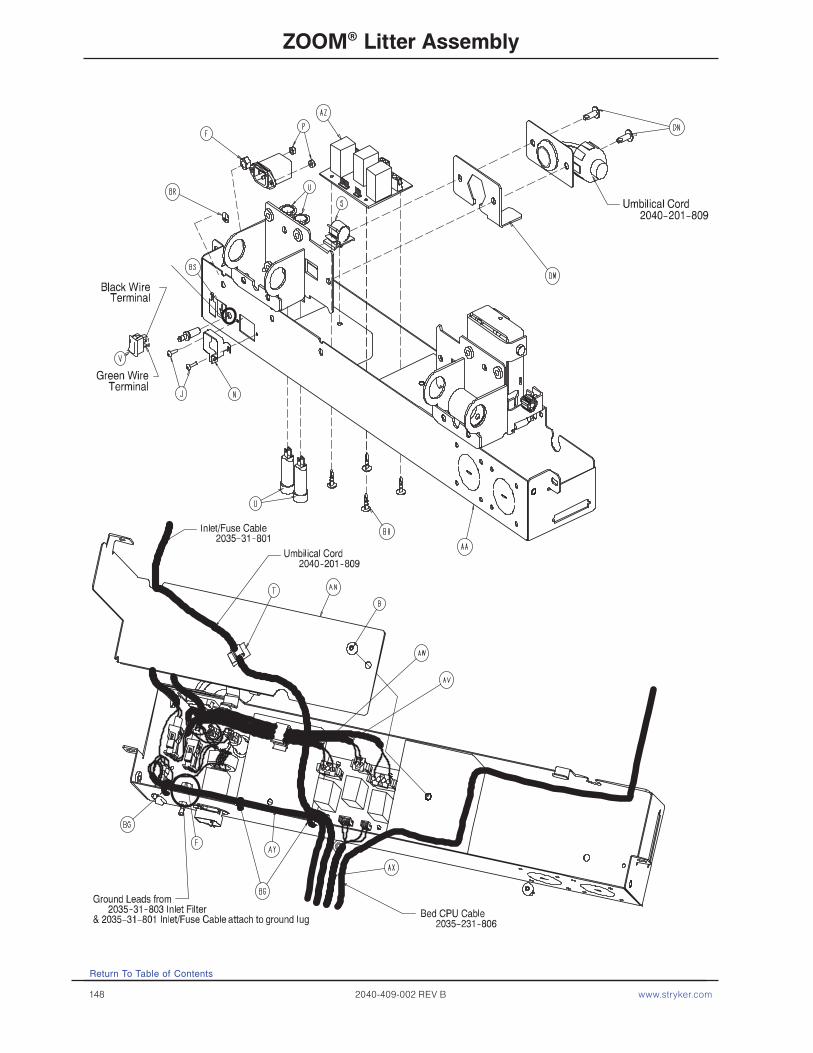
148 2040-409-002 REV B www.stryker.com
ZOOM® Litter Assembly
Return To Table of Contents
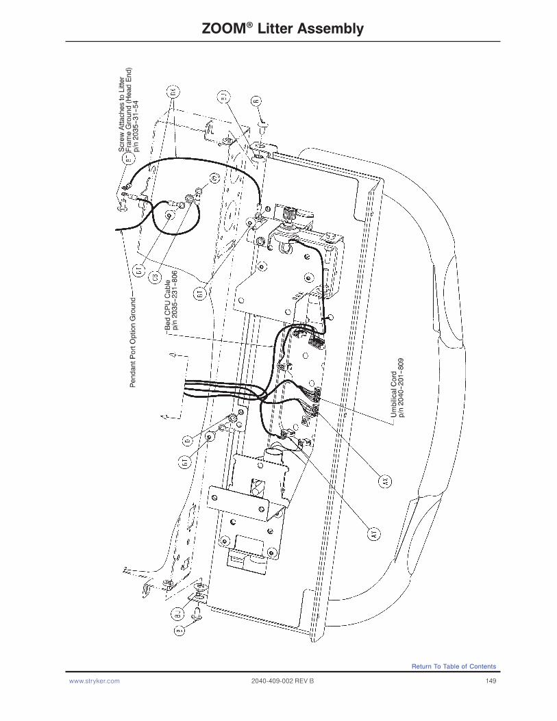
www.stryker.com 2040-409-002 REV B 149
ZOOM® Litter Assembly
Return To Table of Contents

150 2040-409-002 REV B www.stryker.com
ZOOM® Litter Assembly
Return To Table of Contents

www.stryker.com 2040-409-002 REV B 151
ZOOM® Litter Assembly
Return To Table of Contents

152 2040-409-002 REV B www.stryker.com
Return To Table of Contents
ZOOM® Litter Assembly
2040-031-200 Head Wall Communication Option 2040-031-201 Head Wall Comm. W/Nurse Call
Item Part No. Part Name Qty. Item Part No. Part Name Qty.
CD 3001-300-007 M/F Screw 2 CD 3001-300-007 M/F Screw 2CF 0030-038-000 Grommet 1 CF 0030-038-000 Grommet 1
2040-031-202 HW Comm. W/NC & 1 Stryker Port 2040-031-203 W Comm. W/NC & 2 Stryker Ports
Item Part No. Part Name Qty. Item Part No. Part Name Qty.
CA 0004-307-000 But. Hd. Cap Screw 4 CA 0004-307-000 But. Hd. Cap Screw 8CB 0013-010-000 Ext. Tooth Lock Washer 2 CB 0013-010-000 Ext. Tooth Lock Washer 2CC 2040-031-104 Cord Out Label 1 CC 2040-031-104 Cord Out Label 1CD 3001-300-007 M/F Screw 2 CD 3001-300-007 M/F Screw 2CE 3001-314-920 Head Wall Pend. Port PCB 1 CE 3001-314-920 Head Wall Pend. Port PCB 2CF 0030-038-000 Grommet 1 CF 0030-038-000 Grommet 1
2040-031-204 No Head Wall Option
Item Part No. Part Name Qty.
CG 0037-030-000 Hole Plug 1

www.stryker.com 2040-409-002 REV B 153
Return To Table of Contents
ZOOM® Litter Assembly
Item Part No. Part Name Qty. Item Part No. Part Name Qty.
A 0004-142-000 Soc. Hd. Cap Screw 2 AV 2040-031-807 Bed AC Pwr. Jump. Cbl. 1B 0007-052-000 Truss Hd. Torx 18 AW 2040-031-808 Charger AC Jumper 1C 0011-193-000 Flat Washer 1 AX 2040-031-809 CPU/Crossover PCB 1D 0013-010-000 Ext. Tooth Lock Washer 5 AY 2040-031-810 On/Off Cable 1F 0016-033-000 Kep Nut 2 AZ 2040-031-900 AC/Switchover PCB 1G 0023-080-000 Truss Hd. Screw 3 BA 2040-031-910 Display/CPU PCB 1H 0023-112-000 Hi-Low Tapping Screw 6 BB 2040-231-075 Reinforcement Brkt. Hd. 1J 0050-032-000 Pan Hd. Mach. Screw 2 BC 2040-031-110 Pivot Bracket, Right 1K 0021-140-000 Set Screw 4 BD 2040-031-111 Pivot Bracket, Left 1L 0026-303-000 Roll Pin 4 BE 2040-031-106 Pot. Worm Gear 1M 0027-022-000 Rue Ring Cotter 2 BF 3000-200-253 Pot. Worm Gear Retainer 1N 0059-205-000 Connector Lock 1 BG 3000-300-114 Wire Tie 5P 0016-023-000 Nylock Nut 2 BH 3000-300-115 Standoff 4Q 0038-448-000 Switch Handle Ret. Spring 2 BJ 3001-300-099 Pivot Bearing 4R 0052-762-000 Flange Bearing 4 BK 3001-300-870 Ground Strap 2S 0059-133-000 Push-Mount Wire Clip 1 BL 3001-400-953 Switch Cap 6T 0059-136-000 Push-Mount Wire Clip 1 BM 8800-380-000 Foam Tape (26.25”) 1U 0059-195-000 3.0 Amp Circuit Breaker 2 BN 8800-380-000 Foam Tape (1.25”) 2V 0059-191-000 On/Off Switch 1 BP 0044-032-000 Press. Sens. Tape (1.5”) 4Y 2040-031-011 Top Display Housing 1 BQ 0059-781-000 4-Position Connector 2Z 2040-031-051 Pot. Collar Weldment 1 BR 0036-046-000 Ground Label 1AA 2040-031-053 Hd. End Bottom Encl. 1 BS 0036-115-000 Ground Label 1AB 2040-031-054 Bumper Attachment Wldmt. 1 BT 0007-058-000 T Russ Hd. Torx 4AD 2040-031-062 Display Label 1 BU 7000-001-326 Foam Tape (26.75”) 1AE 2040-031-063 Hd. End Top Enclosure 1 BV 1550-090-001 Hosp. Grade Plug Label 1AF 2040-231-064 Control Bar 1 BW 2011-001-104 Anesthetics Danger Label 1AG 2040-031-068 Handle Switch 2 BX 0034-022-000 Cord Clamp 1AH 2040-231-069 Display Bumper 1 BY 0023-025-000 Hex Washer Hd. Screw 1AJ 2040-031-073 Stop Pin 2 BZ 0039-254-000 Power Cord 1AK 2040-031-074 Control Bar Ret. Spring 2 DA 0007-063-000 Truss Hd. Torx 4AL 2040-031-077 Cover Plate 1 DB 0055-027-000 “U” Type Nut 4AM 2040-031-082 Potentiometer Collar 1 DD 0003-050-000 Hex Hd. Cap Screw 2AN 2040-031-092 Hd. End Electronics Cvr. 1 DE 0004-325-000 Soc. Hd. Cap Screw 1AP 2040-031-101 Drive Instruction Label 1 DG 0016-028-000 Nylock Nut 2AQ 2040-031-102 Drive Warning Label 1 DH 0038-482-000 Extension Spring 1AR 2040-031-103 Power Label 1 DK 2040-031-108 Potentiometer Mount 1AS 2040-031-105 Logo Label 1 DL 2040-031-109 Reinforcement Bracket 1AT 2040-031-803 Contact Switch Cable 2 DM 2040-031-085 Umbilical Cord Supt. Plate 1AU 2040-031-804 Potentiometer Cable 1 DN 0007-065-000 Truss Hd. Torx 2 DP 2035-031-806 Headwall Interface Cable 1
2040-031-010 ZOOM® Litter Assembly, Common Components

154 2040-409-002 REV B www.stryker.com
For Reference Only: 2040-320-061
No Optional 110V Outlet
Item Part No. Part Name Qty. A 0007-063-000 Truss Hd. Screw 2 C 2035-031-203 Foot Cross Brace Cover 1 D 2035-031-880 Power Inlet Cable 1 E 0037-085-000 Heyco Hole Plug 2 F 2011-001-215 Lug 1 G 2040-031-808 Charger, AC Jumper 1
Return To Table of Contents
2035−31−801

www.stryker.com 2040-409-002 REV B 155
Optional 110V Outlet Assembly
For Reference Only: 2040-320-060Assembly part number 2040−320−60(reference only)
Return To Table of Contents
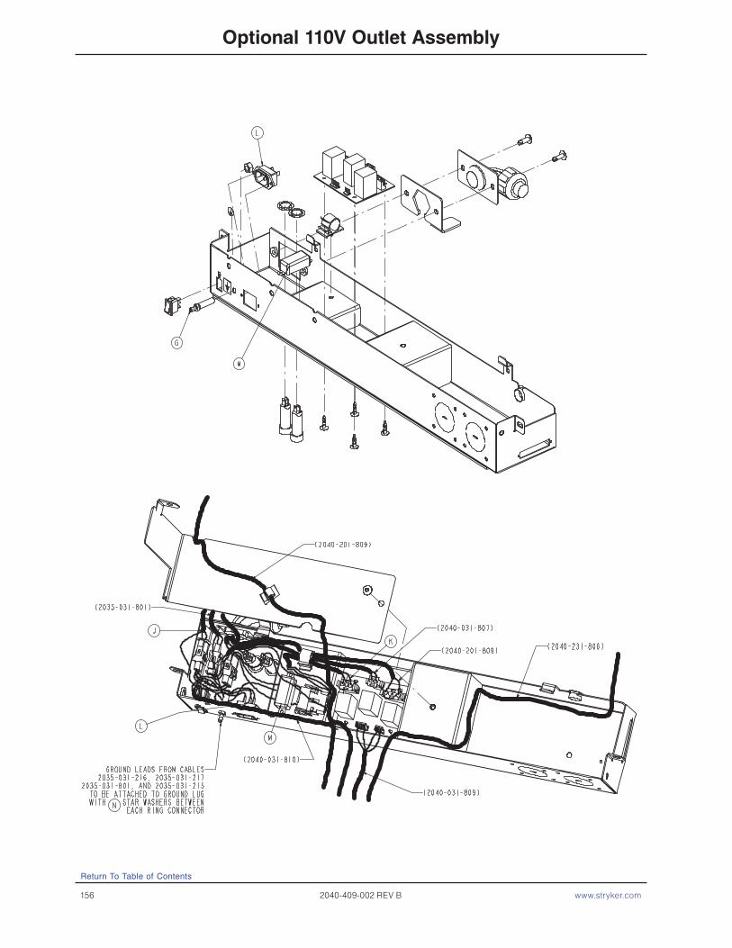
156 2040-409-002 REV B www.stryker.com
Optional 110V Outlet Assembly
Return To Table of Contents

www.stryker.com 2040-409-002 REV B 157
Optional 110V Outlet Assembly
Item Part No. Part Name Qty. A 0007-058-000 Truss Hd. Screw 4 B 0013-010-000 External Tooth Lock Washer 7 C 0059-106-000 HEYCO 1 D 2035-031-220 110V Box Assembly (pg. 159) 1 E 2035-031-204 110V Outlet Caution Label 2 F 2035-031-206 ZOOM® Box Label 1 G 2030-001-215 Lug 1 H 0030-047-000 HEYCO 2 J 2035-031-215 Cable, 110V Supply 1 K 2040-031-811 AC Jumper Charger 1 L 2035-031-216 Cable, 110V Head End 1 M 2035-031-217 Filter, 110V ZOOM® 1 N 0012-038-000 Washer 3
Return To Table of Contents
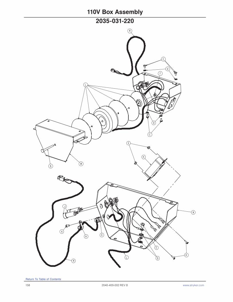
158 2040-409-002 REV B www.stryker.com
Return To Table of Contents
110V Box Assembly
2035-031-220

www.stryker.com 2040-409-002 REV B 159
Return To Table of Contents
Item Part No. Part Name Qty. A 0004-442-000 But. Hd. Cap Screw 1 B 0005-043-000 Carriage Bolt 1 C 0007-058-000 Truss Hd. Mach. Screw 5 D 0013-038-000 Ext. Tooth Lock Washer 6 E 0016-023-000 FIberlock Hex Nut 2 F 0016-036-000 Nylock Hex Nut 1 G 0030-047-000 Heyco 1 H 0034-022-000 Cord Clamp 1 J 0059-043-000 5 Amp. Circuit Breaker 2 K 0059-732-000 HG Duplex Receptacle 1 L 2030-001-009 Transformer 1 M 2030-031-201 110V Box Cover 1 N 2035-031-202 110V Box 1 P 2035-031-214 110V Ground Cable 1 R 2035-031-219 110V Supply Cable 1
110V Box Assembly
2035-031-220
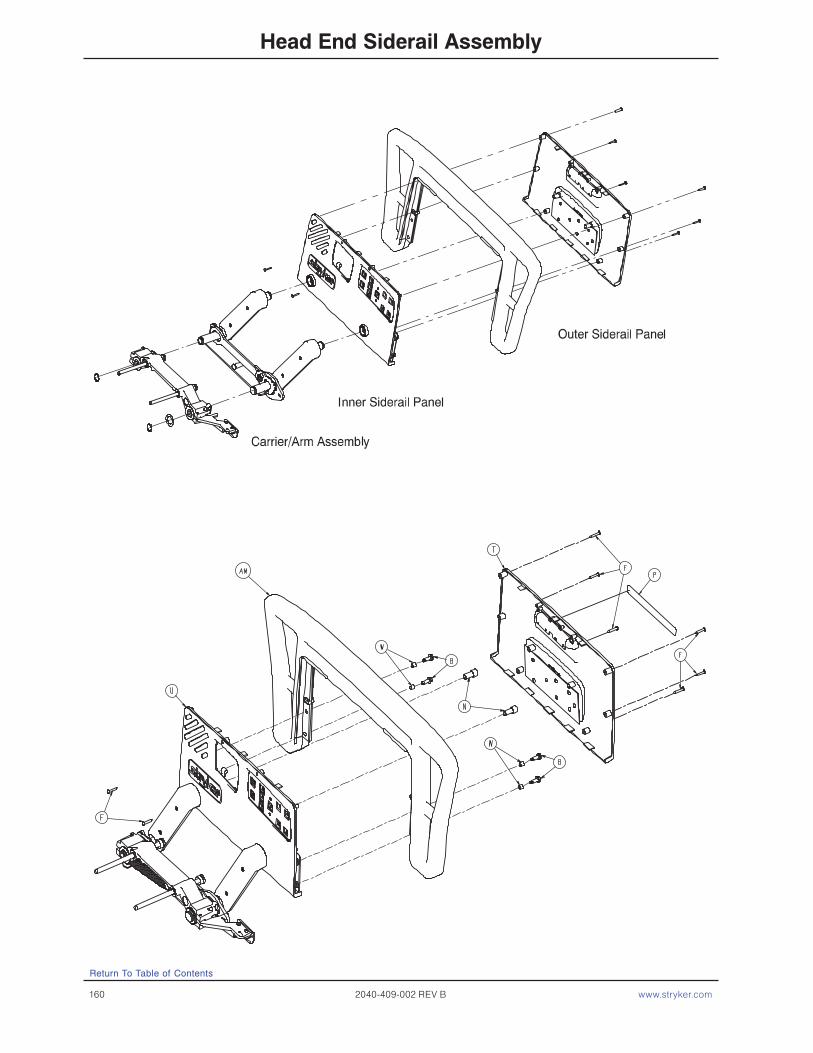
160 2040-409-002 REV B www.stryker.com
Return To Table of Contents
Head End Siderail Assembly
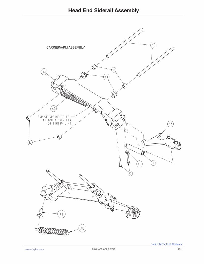
www.stryker.com 2040-409-002 REV B 161
Return To Table of Contents
Head End Siderail Assembly
CARRIER/ARM ASSEMBLY
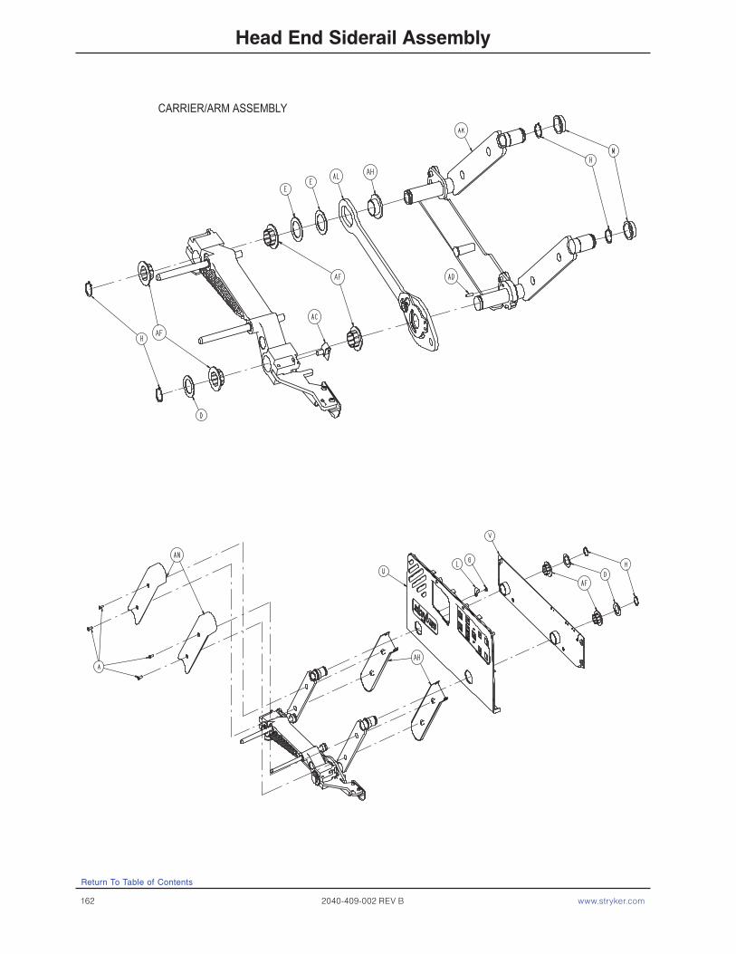
162 2040-409-002 REV B www.stryker.com
Head End Siderail Assembly
CARRIER/ARM ASSEMBLY
Return To Table of Contents
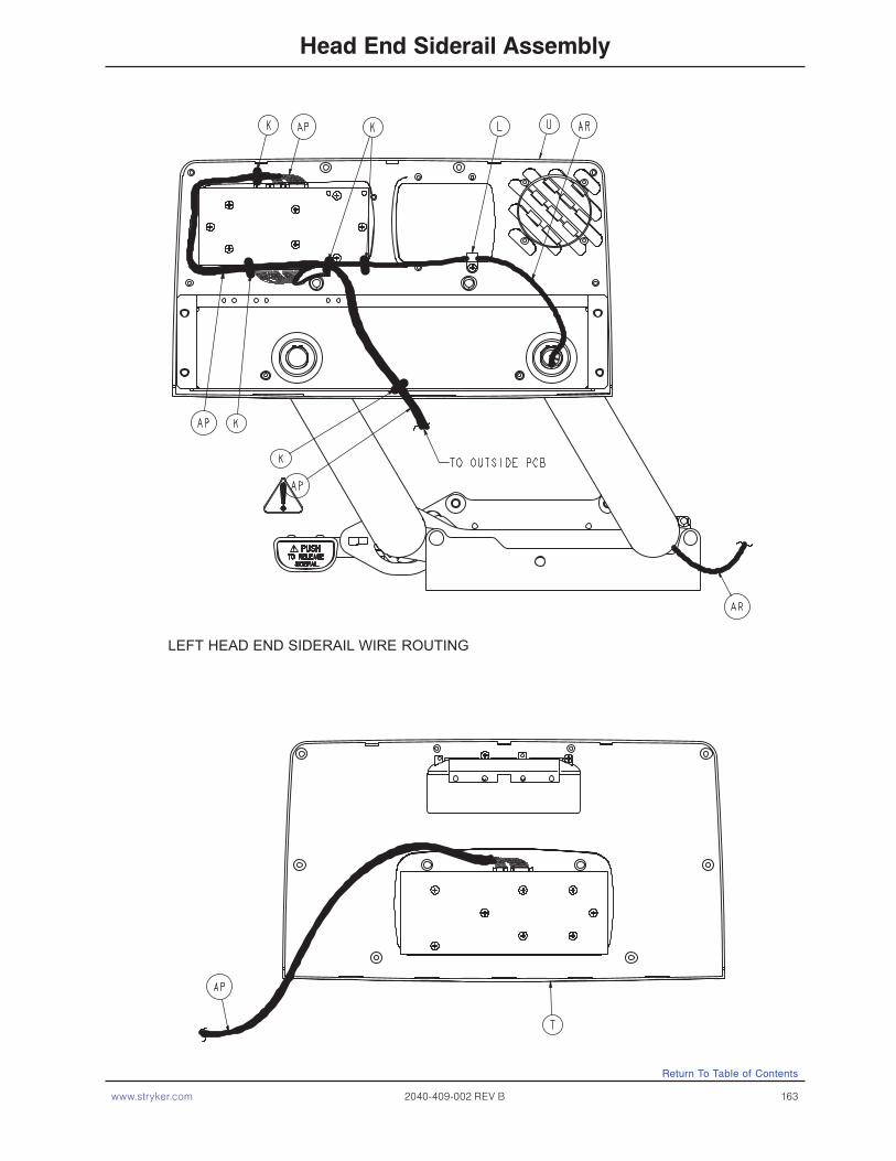
www.stryker.com 2040-409-002 REV B 163
Return To Table of Contents
Head End Siderail Assembly
LEFT HEAD END SIDERAIL WIRE ROUTING

164 2040-409-002 REV B www.stryker.com
Return To Table of Contents
Head End Siderail Assembly
LEFT HEAD END SIDERAIL WIRE ROUTING

www.stryker.com 2040-409-002 REV B 165
Head End Siderail Assembly
Return To Table of Contents
RIGHT HEAD END SIDERAIL WIRE ROUTING
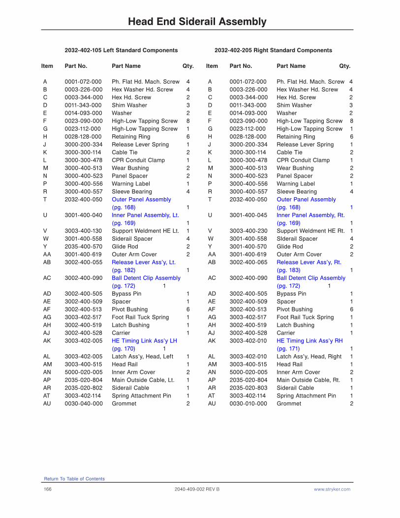
166 2040-409-002 REV B www.stryker.com
Head End Siderail Assembly
2032-402-105 Left Standard Components 2032-402-205 Right Standard Components
Item Part No. Part Name Qty. Item Part No. Part Name Qty.
A 0001-072-000 Ph. Flat Hd. Mach. Screw 4 A 0001-072-000 Ph. Flat Hd. Mach. Screw 4 B 0003-226-000 Hex Washer Hd. Screw 4 B 0003-226-000 Hex Washer Hd. Screw 4 C 0003-344-000 Hex Hd. Screw 2 C 0003-344-000 Hex Hd. Screw 2 D 0011-343-000 Shim Washer 3 D 0011-343-000 Shim Washer 3 E 0014-093-000 Washer 2 E 0014-093-000 Washer 2 F 0023-090-000 High-Low Tapping Screw 8 F 0023-090-000 High-Low Tapping Screw 8 G 0023-112-000 High-Low Tapping Screw 1 G 0023-112-000 High-Low Tapping Screw 1 H 0028-128-000 Retaining Ring 6 H 0028-128-000 Retaining Ring 6 J 3000-200-334 Release Lever Spring 1 J 3000-200-334 Release Lever Spring 1 K 3000-300-114 Cable Tie 2 K 3000-300-114 Cable Tie 2 L 3000-300-478 CPR Conduit Clamp 1 L 3000-300-478 CPR Conduit Clamp 1 M 3000-400-513 Wear Bushing 2 M 3000-400-513 Wear Bushing 2 N 3000-400-523 Panel Spacer 2 N 3000-400-523 Panel Spacer 2 P 3000-400-556 Warning Label 1 P 3000-400-556 Warning Label 1 R 3000-400-557 Sleeve Bearing 4 R 3000-400-557 Sleeve Bearing 4 T 2032-400-050 Outer Panel Assembly T 2032-400-050 Outer Panel Assembly (pg. 168) 1 (pg. 168) 1 U 3001-400-040 Inner Panel Assembly, Lt. U 3001-400-045 Inner Panel Assembly, Rt. (pg. 169) 1 (pg. 169) 1 V 3003-400-130 Support Weldment HE Lt. 1 V 3003-400-230 Support Weldment HE Rt. 1 W 3001-400-558 Siderail Spacer 4 W 3001-400-558 SIderail Spacer 4 Y 2035-400-570 Glide Rod 2 Y 3001-400-570 Glide Rod 2 AA 3001-400-619 Outer Arm Cover 2 AA 3001-400-619 Outer Arm Cover 2 AB 3002-400-055 Release Lever Ass’y, Lt. AB 3002-400-065 Release Lever Ass’y, Rt. (pg. 182) 1 (pg. 183) 1 AC 3002-400-090 Ball Detent Clip Assembly AC 3002-400-090 Ball Detent Clip Assembly (pg. 172) 1 (pg. 172) 1 AD 3002-400-505 Bypass Pin 1 AD 3002-400-505 Bypass Pin 1 AE 3002-400-509 Spacer 1 AE 3002-400-509 Spacer 1 AF 3002-400-513 Pivot Bushing 6 AF 3002-400-513 Pivot Bushing 6 AG 3003-402-517 Foot Rail Tuck Spring 1 AG 3003-402-517 Foot Rail Tuck Spring 1 AH 3002-400-519 Latch Bushing 1 AH 3002-400-519 Latch Bushing 1 AJ 3002-400-528 Carrier 1 AJ 3002-400-528 Carrier 1 AK 3003-402-005 HE Timing Link Ass’y LH AK 3003-402-010 HE Timing Link Ass’y RH (pg. 170) 1 (pg. 171) 1 AL 3003-402-005 Latch Ass’y, Head, Left 1 AL 3003-402-010 Latch Ass’y, Head, Right 1 AM 3003-400-515 Head Rail 1 AM 3003-400-515 Head Rail 1 AN 5000-020-005 Inner Arm Cover 2 AN 5000-020-005 Inner Arm Cover 2 AP 2035-020-804 Main Outside Cable, Lt. 1 AP 2035-020-804 Main Outside Cable, Rt. 1 AR 2035-020-802 Siderail Cable 1 AR 2035-020-803 Siderail Cable 1 AT 3003-402-114 Spring Attachment Pin 1 AT 3003-402-114 Spring Attachment Pin 1 AU 0030-040-000 Grommet 2 AU 0030-010-000 Grommet 2
Return To Table of Contents

www.stryker.com 2040-409-002 REV B 167
Return To Table of Contents
Head End Siderail Assembly
2030-020-011 Standard Siderail
Item Part No. Part Name Qty.
CA 2035-000-100 Label, Standard, Left 1 CA 2035-000-200 Label, Standard, Right 1 CC 3001-400-953 Switch Cap 28 CD 3001-400-522 Filler Cap 18 CE 3001-400-517 Speaker Seal 2 CF 3001-400-535 Inner Panel Blank Module 2 CH 2030-000-300 Label, Standard, Left 1 CH 2030-000-400 Label, Standard, Right 1
2030-020-012 Standard Siderail with Nurse Call
Item Part No. Part Name Qty.
CA 2035-000-101 Label, Standard, NC, Left 1 CA 2035-000-201 Label, Standard, NC, Right 1 CC 3001-400-953 Switch Cap 32 CD 3001-400-522 Filler Cap 14 CE 3001-403-831 Speaker with Cable 2 CF 3001-400-535 Inner Panel Blank Module 2 CH 2030-000-301 Label, Standard, NC, Left 1 CH 2030-000-401 Label, Standard, NC, Right 1
2030-020-015 Standard Siderail W/NC & Comm.
Item Part No. Part Name Qty.
CA 2035-000-102 Label, Standard, Left 1 CA 2035-000-202 Label, Standard, Right 1 CC 3001-400-953 Switch Cap 42 CD 3001-400-522 Filler Cap 4 CE 3001-403-831 Speaker with Cable 2 CF 3001-400-535 Inner Panel Blank Module 2 CH 2030-000-301 Label, Standard, NC, Lt. 1 CH 2030-000-401 Label, Standard, NC, Rt. 1
Right Inner Siderail Label
Right Outer Siderail Label
Right Inner Siderail Label
Right Outer Siderail Label
Right Inner Siderail Label
Right Outer Siderail Label

168 2040-409-002 REV B www.stryker.com
Head End Siderail Outer Panel Assembly
Item Part No. Part Name Qty. A 0023-112-000 Hi-Low Tapping Screw 2 B 2035-400-102 Outer Panel 1 C 3001-400-599 Handle Insert 1
Return To Table of Contents
For Reference Only: 2032−400−050
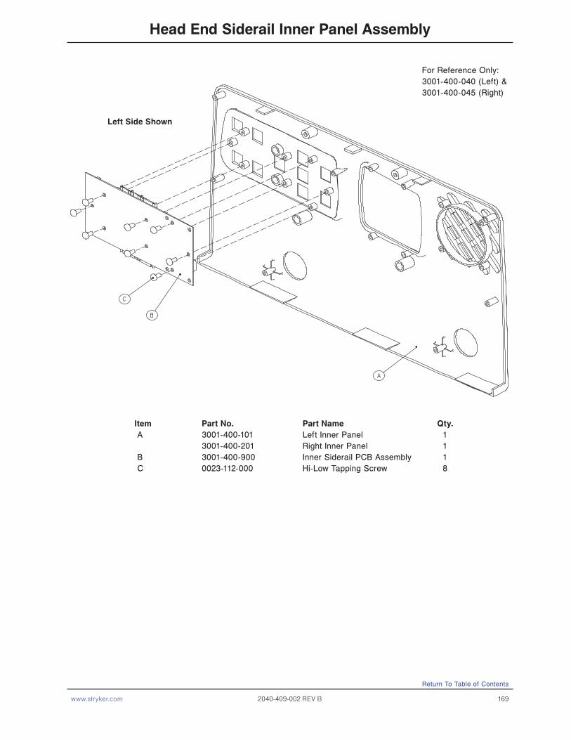
www.stryker.com 2040-409-002 REV B 169
For Reference Only: 3001-400-040 (Left) & 3001-400-045 (Right)
Head End Siderail Inner Panel Assembly
Item Part No. Part Name Qty. A 3001-400-101 Left Inner Panel 1 3001-400-201 Right Inner Panel 1 B 3001-400-900 Inner Siderail PCB Assembly 1 C 0023-112-000 Hi-Low Tapping Screw 8
Return To Table of Contents
Left Side Shown

170 2040-409-002 REV B www.stryker.com
Timing Link Assembly, Head End, Left
Item Part No. Part Name Qty. A 0011-377-000 Washer 2 B 0011-491-000 Washer 2 C 3001-400-501 Siderail Linkage Rivot 2 D 3003-401-001 Bushing 2 E 3003-402-112 Timing Link 1 F 3003-402-127 Arm Weldment - LHF 1 G 3003-402-128 Arm Weldment - LHH 1
Return To Table of Contents
3003-402-005

www.stryker.com 2040-409-002 REV B 171
Timing Link Assembly, Head End, Right
Item Part No. Part Name Qty. A 0011-377-000 Washer 2 B 0011-491-000 Washer 2 C 3001-400-501 Siderail Linkage Rivot 2 D 3003-401-001 Bushing 2 E 3003-402-117 Timing Link 1 F 3003-402-227 Arm Weldment - LHF 1 G 3003-402-228 Arm Weldment - LHH 1
Return To Table of Contents
3003-402-010

172 2040-409-002 REV B www.stryker.com
Siderail Bypass Detent Clip Assembly
Assembly part number 3002−400−090 (reference only)
Item Part No. Part Name Qty. A 0031-137-000 Steel Ball 1 B 0038-464-000 Compression Spring 1 C 3002-400-524 Bypass Detent Housing 1
Return To Table of Contents
3002-400-599 (Not Included)
For Reference Only: 3002-400-090

www.stryker.com 2040-409-002 REV B 173
Return To Table of Contents
Siderail Assembly, iBED Awareness Option, Head End, Left
Item Part No. Part Name Qty.A 0003-344-000 Hex Head Mounting Screw 2B 2032-030-015 Siderail Switch Assembly, HE, Left (pg. 175) 1C 2032-402-105 Siderail Assembly, HE, Left (pg. 166) 1D 0011-062-000 Washer 2
2032-403-105

174 2040-409-002 REV B www.stryker.com
Return To Table of Contents
Item Part No. Part Name Qty.A 0003-344-000 Hex Head Mounting Screw 2B 2032-030-020 Siderail Switch Assembly, HE, Right (pg. 175) 1C 2032-402-205 Siderail Assembly, HE, Right (pg. 166) 1D 0011-062-000 Washer 2
Siderail Assembly, iBED Awareness Option, Head End, Right
2032-403-205

www.stryker.com 2040-409-002 REV B 175
Return To Table of Contents
LEFT SHOWN
HEAD END LEFT - 2032-030-015 / HEAD END RIGHT - 2032-030-020
Item Part No. Part Name Qty.A 0023-294-000 High-Low Tapping Screw 1B 3003-400-300 Switch Holder, Left 1 3003-400-400 Switch Holder, Right 1C 3003-400-500 Switch Holder, Spring Blade 1D 2032-400-802 Epic Head, Siderail Switch Cable 1
Switch Assembly, iBED Awareness Option, Head End

176 2040-409-002 REV B www.stryker.com
Foot End Siderail Assembly
Return To Table of Contents
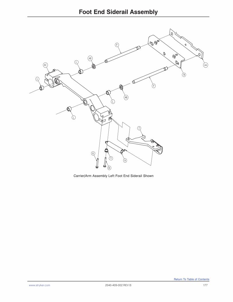
www.stryker.com 2040-409-002 REV B 177
Foot End Siderail Assembly
Carrier/Arm Assembly Left Foot End Siderail Shown
Return To Table of Contents

178 2040-409-002 REV B www.stryker.com
Foot End Siderail Assembly
Return To Table of Contents

www.stryker.com 2040-409-002 REV B 179
Foot End Siderail Assembly
2032-401-305 Left Common Components 2032-401-405 Right Common Components
Item Part No. Part Name Qty. Item Part No. Part Name Qty.
A 0001-072-000 Ph. Flat Hd. Mach. Screw 4 A 0001-072-000 Ph. Flat Hd. Mach. Screw 4 B 0003-344-000 Hex Hd. Cap Screw 2 B 0003-344-000 Hex Hd. Cap Screw 2 C 0011-185-000 Washer 1 C 0011-185-000 Washer 1 D 0011-343-000 Shim Washer 3 D 0011-343-000 Shim Washer 3 E 0014-093-000 Washer 2 E1 0004-093-000 Washer 2 F 0023-090-000 Pan Hd. Tapping Screw 4 F 0023-090-000 Pan Hd. Tapping Screw 4 G 0028-128-000 Retaining Ring 6 G 0028-128-000 Retaining Ring 6 H 3000-200-334 Extension Spring 1 H 3000-200-334 Extension Spring 1 J 3000-400-513 Wear Bushing 2 J 3000-400-513 Wear Bushing 2 K 3000-400-523 Panel Spacer 2 K 3000-400-523 Panel Spacer 2 L 3000-400-557 Sleeve Bearing 4 L 3000-400-557 Sleeve Bearing 4 M 3001-400-527 Outer Rail 1 M 3001-400-527 Outer Rail 1 N 3001-400-555 Mounting Bracket 1 N 3001-400-555 Mounting Bracket 1 P 3001-400-564 Glide Rod 2 P 3001-400-564 Glide Rod 2 R 3001-400-619 Outer Arm Cover 2 R 3001-400-619 Outer Arm Cover 2 T 3002-400-055 Release Lever Ass’y, Lt. T 3002-400-065 Release Lever Ass’y, Rt. (pg. ) 1 (pg. 183) 1 U 3002-400-090 Ball Detent Clip Ass’y U 3002-400-090 Ball Detent Clip Ass’y (pg. 172) 1 (pg. 172) 1 V 3002-400-501 Latch 1 V 3002-400-501 Latch 1 W 3002-400-505 Bypass Pin 1 W 3002-400-505 Bypass Pin 1 Y 3002-400-509 Bypass Bushing Spacer 1 Y 3002-400-509 Bypass Bushing Spacer 1 AA 3002-400-511 Glide Rod Bumper Pad 1 AA 3002-400-511 Glide Rod Bumper Pad 1 AB 3002-400-512 Bumper Washer 2 AB 3002-400-512 Bumper Washer 2 AC 3002-400-513 Pivot Bushing 6 AC 3002-400-513 Pivot Bushing 6 AD 3002-400-519 Latch Bushing 1 AD 3002-400-519 Latch Bushing 1 AE 3002-400-528 Siderail Carrier 1 AE 3002-400-528 Siderail Carrier 1 AF 3003-400-526 Inner Panel 1 AF 3003-400-526 Inner Panel 1 AG 2032-401-030 FE Timing Link Ass’y, LH AG 2032-401-025 FE Timing Link Ass’y, RH (pg. 180) 1 (pg. 181) 1 AH 3003-400-520 Foot Rail 1 AH 3003-400-520 Foot Rail 1 AJ 5000-020-005 Inner Arm Cover 2 AJ 5000-020-005 Inner Arm Cover 2 AK 0003-226-000 Hex Washer Head Screw 4 AK 0003-226-000 Hex Washer Head Screw 4 AL 3001-400-558 Spacer 4 AL 3001-400-558 Spacer 4 AM 3003-400-580 Weldment, FE Support Plate 1 AM 3003-400-580 Weldment, FE Support Plate 1
Return To Table of Contents

180 2040-409-002 REV B www.stryker.com
Timing Link Assembly, Foot End, Left
Item Part No. Part Name Qty. A 0011-377-000 Washer 2 B 0011-491-000 Washer 2 C 3001-400-501 Siderail Linkage Rivet 2 D 3003-400-011 Timing Link 1 E 3003-401-327 Arm Weldment - LHH 1 F 2032-401-328 Arm Weldment - LHF 1
2032-401-030
Return To Table of Contents

www.stryker.com 2040-409-002 REV B 181
Timing Link Assembly, Foot End, Right
Item Part No. Part Name Qty. A 0011-377-000 Washer 2 B 0011-491-000 Washer 2 C 3001-400-501 Siderail Linkage Rivet 2 D 3003-400-011 Timing Link 1 E 3003-401-427 Arm Weldment - RHH 1 F 2032-401-428 Arm Weldment - RHF 1
2032-401-025
Return To Table of Contents
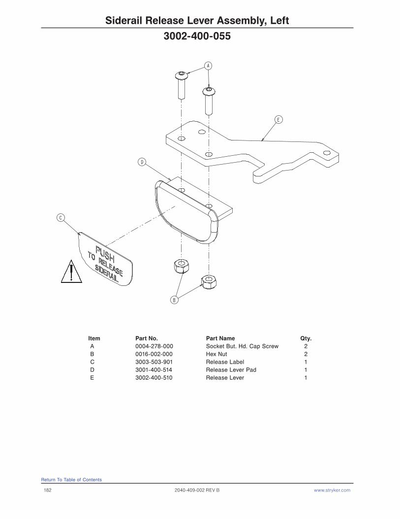
182 2040-409-002 REV B www.stryker.com
Siderail Release Lever Assembly, Left
Item Part No. Part Name Qty. A 0004-278-000 Socket But. Hd. Cap Screw 2 B 0016-002-000 Hex Nut 2 C 3003-503-901 Release Label 1 D 3001-400-514 Release Lever Pad 1 E 3002-400-510 Release Lever 1
Return To Table of Contents
3002-400-055

www.stryker.com 2040-409-002 REV B 183
Siderail Release Lever Assembly, Right
Item Part No. Part Name Qty. A 0004-278-000 Socket But. Hd. Cap Screw 2 B 0016-002-000 Hex Nut 2 C 3003-503-901 Release Label 1 D 3001-400-514 Release Lever Pad 1 E 3002-400-510 Release Lever 1
Return To Table of Contents
3002-400-065

184 2040-409-002 REV B www.stryker.com
Return To Table of Contents
Siderail Assembly, iBED Awareness Option, Foot End, Left
Item Part No. Part Name Qty.A 0003-344-000 Hex Head Mounting Screw 2B 2032-030-025 Siderail Switch Assembly, FE, Left (pg. 186) 1C 2032-401-305 Siderail Assembly, FE, Left (pg. 179) 1D 0011-062-000 Washer 2E 0034-443-000 Cord Clamp 1F 0003-221-000 Hex Washer Head Screw 1
2032-403-305
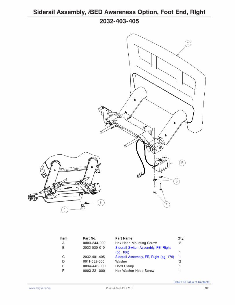
www.stryker.com 2040-409-002 REV B 185
Siderail Assembly, iBED Awareness Option, Foot End, RIght
Item Part No. Part Name Qty.A 0003-344-000 Hex Head Mounting Screw 2B 2032-030-010 Siderail Switch Assembly, FE, Right (pg. 186) 1C 2032-401-405 Siderail Assembly, FE, Right (pg. 179) 1D 0011-062-000 Washer 2E 0034-443-000 Cord Clamp 1F 0003-221-000 Hex Washer Head Screw 1
2032-403-405
Return To Table of Contents
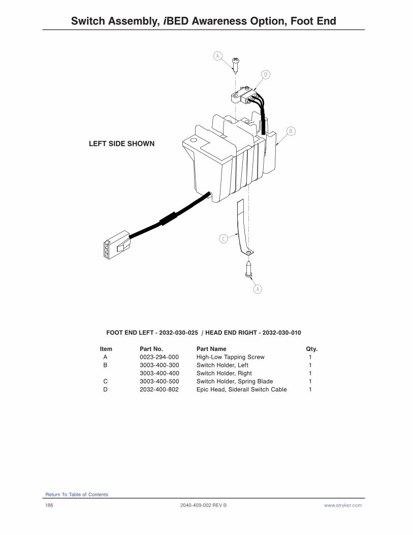
186 2040-409-002 REV B www.stryker.com
Switch Assembly, iBED Awareness Option, Foot End
LEFT SIDE SHOWN
FOOT END LEFT - 2032-030-025 / HEAD END RIGHT - 2032-030-010
Item Part No. Part Name Qty.A 0023-294-000 High-Low Tapping Screw 1B 3003-400-300 Switch Holder, Left 1 3003-400-400 Switch Holder, Right 1C 3003-400-500 Switch Holder, Spring Blade 1D 2032-400-802 Epic Head, Siderail Switch Cable 1
Return To Table of Contents

www.stryker.com 2040-409-002 REV B 187
Return To Table of Contents
Head Board Assembly
Item Part No. Part Name Qty. A 0023-088-000 Pan Hd. Screw 2 B 2035-500-007 Dark Blue “C” Bumper 2 C 3000-526-001 CPR Board 1 D 3000-526-002 CPR Board Clip 1 E 3000-526-003 CPR Board Label 1 F 3000-600-010 Head Board Clam Shell Ass’y 1 G 3000-600-056 Beige Head Board Laminate 1
2035-130-010

188 2040-409-002 REV B www.stryker.com
Foot Board Assembly
part number 2030−000−151 part number 2035−000−153
part number 2035−000−155
2030-135-010 Foot Board Standard Components Item Part No. Part Name Qty.
A 0023-118-000 Phil. Pan Hd. Tap. Screw 2 B 0023-103-000 Pan Hd. Hi/Lo Tap. Screw 7 C 0050-038-000 Pan Hd. Mach. Screw 2 D 0050-039-000 Pan Hd. Mach. Screw 2 F 3000-500-008 Chart Rack Cover 1 G 3000-500-029 Hazard Label 1 H 2035-235-020 Main Module (pg. 195) 1 J 3001-500-064 Hinge Plate 1 K 3001-500-001 Lid Assembly 1 L 3001-500-010 Clamshell Assembly 1 M 3001-500-801 Foot Board Drawer Cable 1 N 3000-500-025 Lid Label 1 P 2035-500-007 Blue “C” Bumper 2 R 2035-500-008 Strip Bumper 2 S 3000-500-056 Beige Laminate 1 T 2025-136-021 E-Drop/Card. Ch. Module (pg. 196) 1 U 2035-000-155 E-Drop/Card. Ch. Label 1 W 2025-136-801 E-Drop/Card. Ch. Cable 1
Return To Table of Contents

www.stryker.com 2040-409-002 REV B 189
Return To Table of Contents
Item Part No. Part Name Qty. AA 3000-500-004 End Module 1 AB 2035-500-101 Foot Board Blank Label 4 AC 3000-500-027 Blank End Label 1 AD 3001-500-003 Blank Module 3 AE 3000-500-026 Blank Module Label 3
Foot Board Assembly, No Options
2030-135-011

190 2040-409-002 REV B www.stryker.com
Return To Table of Contents
part number 2030−000−902
Item Part No. Part Name Qty. AA 2035-500-101 Foot Board Blank Label 1 AB 3001-500-003 Blank Module 1 AC 3002-015-001 Scale Module Assembly 1 AD 2030-000-902 Scale Module Label 1 AE 3002-507-011 Scale Lid Label 1 AF 3000-500-026 Blank Label 1
Foot Board Assembly, Scale Option
2030-015-013
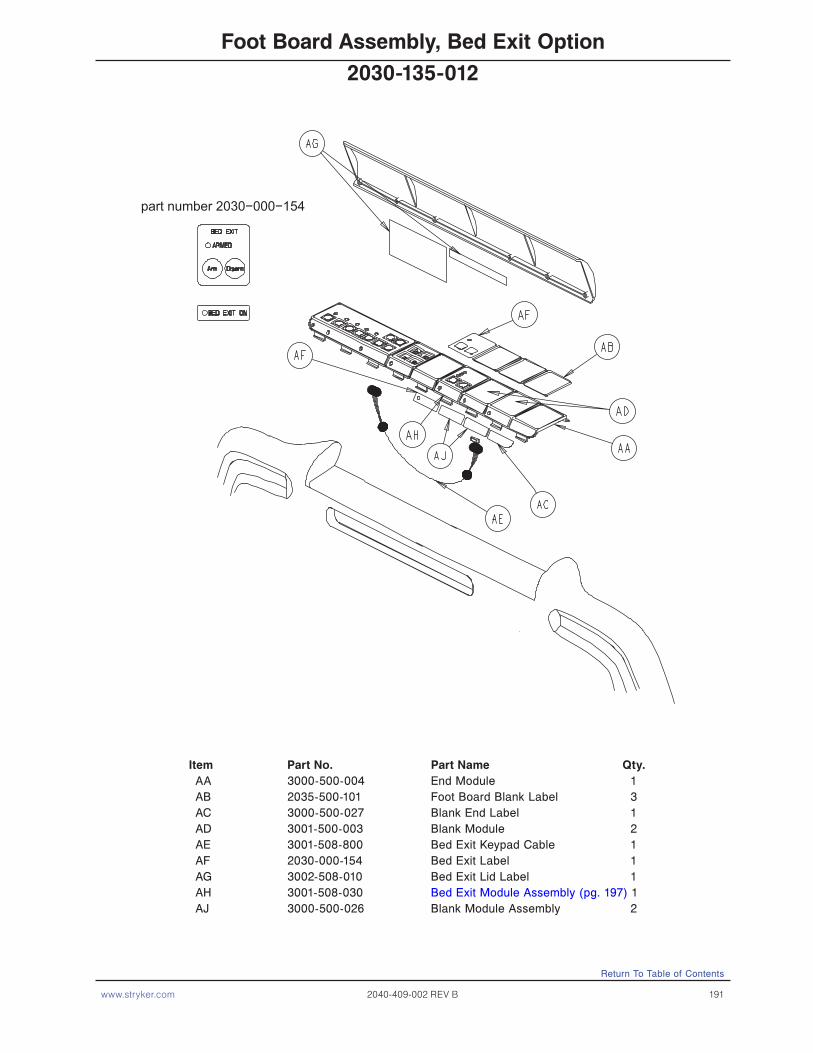
www.stryker.com 2040-409-002 REV B 191
Return To Table of Contents
part number 2030−000−154
Item Part No. Part Name Qty. AA 3000-500-004 End Module 1 AB 2035-500-101 Foot Board Blank Label 3 AC 3000-500-027 Blank End Label 1 AD 3001-500-003 Blank Module 2 AE 3001-508-800 Bed Exit Keypad Cable 1 AF 2030-000-154 Bed Exit Label 1 AG 3002-508-010 Bed Exit Lid Label 1 AH 3001-508-030 Bed Exit Module Assembly (pg. 197) 1 AJ 3000-500-026 Blank Module Assembly 2
Foot Board Assembly, Bed Exit Option
2030-135-012

192 2040-409-002 REV B www.stryker.com
Return To Table of Contents
part number 2030−000−156
Item Part No. Part Name Qty. AA 3000-500-004 End Module 1 AB 2035-500-101 Foot Board Blank Label 3 AC 3000-500-027 Blank End Label 1 AD 3001-500-003 Blank Module 2 AE 2030-000-156 Chaperone II Module Label 1 AF 3002-508-012 Chaperone II Label 1 AG 3002-508-800 Zone Control Keypad Cable 1 AH 3002-508-030 Bed Exit Module Assembly (pg. 198) 1 AJ 3000-500-026 Blank Module Label 2
Foot Board Assembly, Bed Exit w/Zone Control Option
2030-135-015
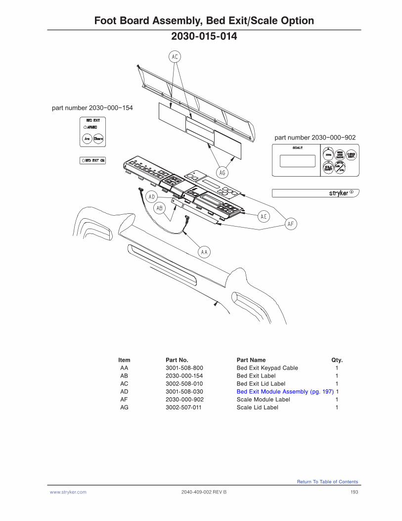
www.stryker.com 2040-409-002 REV B 193
Return To Table of Contents
part number 2030−000−154
part number 2030−000−902
Item Part No. Part Name Qty. AA 3001-508-800 Bed Exit Keypad Cable 1 AB 2030-000-154 Bed Exit Label 1 AC 3002-508-010 Bed Exit Lid Label 1 AD 3001-508-030 Bed Exit Module Assembly (pg. 197) 1 AF 2030-000-902 Scale Module Label 1 AG 3002-507-011 Scale Lid Label 1
Foot Board Assembly, Bed Exit/Scale Option
2030-015-014

194 2040-409-002 REV B www.stryker.com
Return To Table of Contents
part number 2030−000−902
part number 2030−000−156
Item Part No. Part Name Qty. AA 3002-015-001 Scale Module Assembly (pg. 199) 1 AB 2030-000-902 Scale Module Label 1 AC 3002-507-011 Scale Lid Label 1 AD 2030-000-156 Bed Exit Module Label 1 AE 3002-508-012 Bed Exit Label Lid 1 AF 3002-508-800 Zone Control Keypad Cable 1 AG 3001-508-030 Bed Exit Module Assembly (pg. 197) 1
Foot Board Assembly, Scale/Bed Exit w/Zone Control Option
2030-015-016
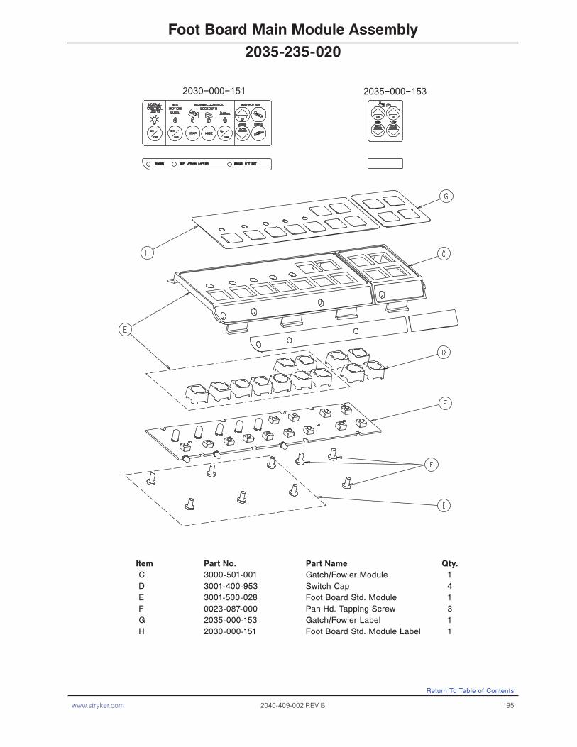
www.stryker.com 2040-409-002 REV B 195
Return To Table of Contents
Foot Board Main Module Assembly
2030−000−151 2035−000−153
Item Part No. Part Name Qty. C 3000-501-001 Gatch/Fowler Module 1 D 3001-400-953 Switch Cap 4 E 3001-500-028 Foot Board Std. Module 1 F 0023-087-000 Pan Hd. Tapping Screw 3 G 2035-000-153 Gatch/Fowler Label 1 H 2030-000-151 Foot Board Std. Module Label 1
2035-235-020

196 2040-409-002 REV B www.stryker.com
Return To Table of Contents
Optional Foot Board Emergency Drop/Cardiac Chair Module
Item Part No. Part Name Qty. A 3000-508-001 Bed Exit Module Panel 1 B 3001-400-953 Switch Cap 2 C 2025-136-900 CPR Drop/Card. Ch. Keypad 1 D 0023-087-000 Hi-Low Tapping Screw 3
2025-136-021
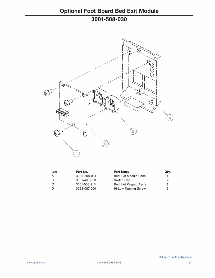
www.stryker.com 2040-409-002 REV B 197
Return To Table of Contents
Optional Foot Board Bed Exit Module
Item Part No. Part Name Qty. A 3000-508-001 Bed Exit Module Panel 1 B 3001-400-953 Switch Cap 2 C 3001-508-910 Bed Exit Keypad Ass’y 1 D 0023-087-000 Hi-Low Tapping Screw 3
3001-508-030

198 2040-409-002 REV B www.stryker.com
Return To Table of Contents
Optional Foot Board Bed Exit Module Option
Item Part No. Part Name Qty. A 0023-087-000 Hi-Low Tapping Screw 3 B 3000-508-001 End Exit Module Panel 1 C 3001-400-953 Switch Cap 2 D 3002-508-900 Bed Exit Board 1
3002-508-030
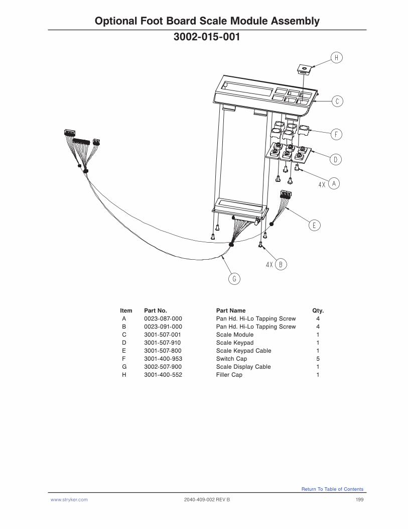
www.stryker.com 2040-409-002 REV B 199
Return To Table of Contents
Optional Foot Board Scale Module Assembly
Item Part No. Part Name Qty. A 0023-087-000 Pan Hd. Hi-Lo Tapping Screw 4 B 0023-091-000 Pan Hd. Hi-Lo Tapping Screw 4 C 3001-507-001 Scale Module 1 D 3001-507-910 Scale Keypad 1 E 3001-507-800 Scale Keypad Cable 1 F 3001-400-953 Switch Cap 5 G 3002-507-900 Scale Display Cable 1 H 3001-400-552 Filler Cap 1
3002-015-001
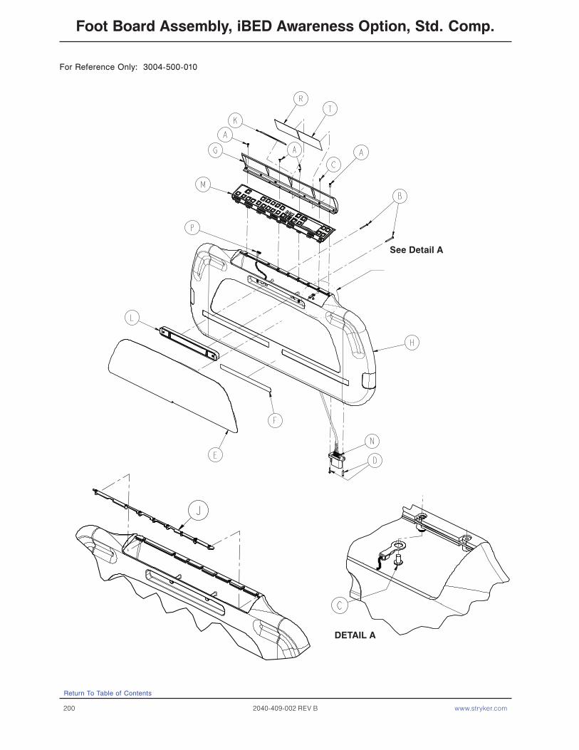
200 2040-409-002 REV B www.stryker.com
Return To Table of Contents
Foot Board Assembly, iBED Awareness Option, Std. Comp.
DETAIL A
See Detail A
For Reference Only: 3004-500-010

www.stryker.com 2040-409-002 REV B 201
Return To Table of Contents
Foot Board Assembly, iBED Awareness Option, Std. Comp.
3004-500-010 Foot Board Assembly, Standard Components, (iAwareness Option)
Item Part No. Part Name Qty.A 0023-103-000 Pan Head Hi - Low Tapping Screw 4B 0023-118-000 Pan Head Screw 2C 0050-039-000 Pan Head Screw 2D 0050-039-000 Pan Head Screw 2E 3000-050-400 Foot Board Laminate 1F 3000-500-029 Hazard Label 1G 3001-500-001 Lid Assembly 1H 3001-500-010 Foot Board Assembly 1J 3001-500-064 Hinge Plate 1K 3002-500-025 Lid Label 1L 3004-500-008 LBS Foot Board Indicator Light, Ass’y. 1M 3004-553-011 LBS Foot Board PCB Assembly 1N 3003-500-801 Foot Board CAN Cable 1P 3003-500-804 Lens Foot Board Cable 1R 3003-508-007 Scale Label 1T 3003-508-008 Bed Status Label 1
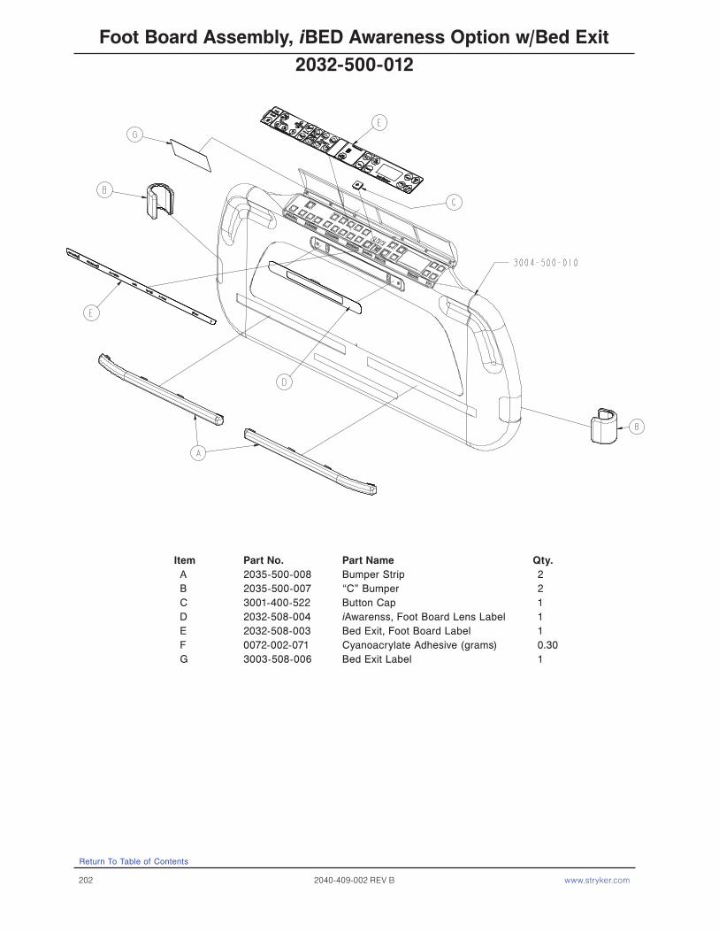
202 2040-409-002 REV B www.stryker.com
Return To Table of Contents
Foot Board Assembly, iBED Awareness Option w/Bed Exit
Item Part No. Part Name Qty.A 2035-500-008 Bumper Strip 2B 2035-500-007 “C” Bumper 2C 3001-400-522 Button Cap 1D 2032-508-004 iAwarenss, Foot Board Lens Label 1E 2032-508-003 Bed Exit, Foot Board Label 1F 0072-002-071 Cyanoacrylate Adhesive (grams) 0.30G 3003-508-006 Bed Exit Label 1
2032-500-012

www.stryker.com 2040-409-002 REV B 203
Return To Table of Contents
Foot Board Assembly, iBED Awareness Option w/Zone Control
Item Part No. Part Name Qty.A 2035-500-008 Bumper Strip 2B 2035-500-007 “C” Bumper 2C 3001-400-953 Switch Cap 1D 2032-508-004 iAwareness, Foot Board Lens Label 1E 2032-508-002 Zone Control, Foot Board Label 1F 0072-002-071 Cyanoacrylate Adhesive (grams) 0.30G 3003-508-009 Bed Exit With Zone Control Label 1
2032-500-011

204 2040-409-002 REV B www.stryker.com
Return To Table of Contents
Optional Removable I.V. Pole Assembly
Item Part No. Part Name Qty.A 3000-300-081 Outer Tube 1B 3000-300-089 Label 1C 0024-050-000 Fluted Knob 1D 0052-017-000 Spacer 2E 0007-040-000 Phillips Truss Hd. Screw 1F 1010-059-016 I.V. Hook 2G 3000-300-085 Inner Tube Assembly 1
3000-300-080
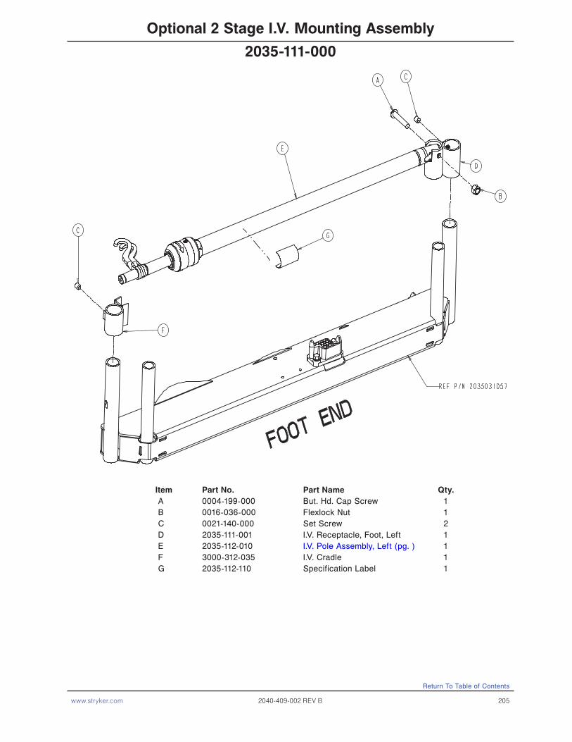
www.stryker.com 2040-409-002 REV B 205
Return To Table of Contents
Optional 2 Stage I.V. Mounting Assembly
Item Part No. Part Name Qty. A 0004-199-000 But. Hd. Cap Screw 1 B 0016-036-000 Flexlock Nut 1 C 0021-140-000 Set Screw 2 D 2035-111-001 I.V. Receptacle, Foot, Left 1 E 2035-112-010 I.V. Pole Assembly, Left (pg. ) 1 F 3000-312-035 I.V. Cradle 1 G 2035-112-110 Specification Label 1
2035-111-000
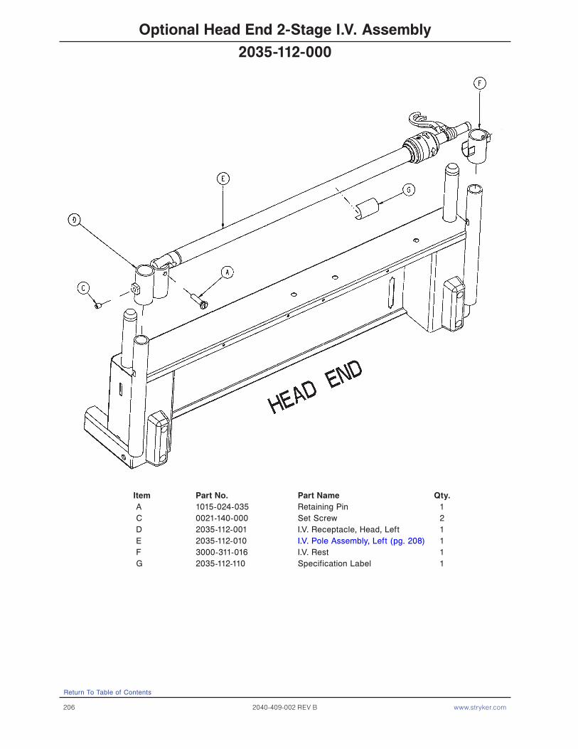
206 2040-409-002 REV B www.stryker.com
Return To Table of Contents
Optional Head End 2-Stage I.V. Assembly
Item Part No. Part Name Qty. A 1015-024-035 Retaining Pin 1 C 0021-140-000 Set Screw 2 D 2035-112-001 I.V. Receptacle, Head, Left 1 E 2035-112-010 I.V. Pole Assembly, Left (pg. 208) 1 F 3000-311-016 I.V. Rest 1 G 2035-112-110 Specification Label 1
2035-112-000
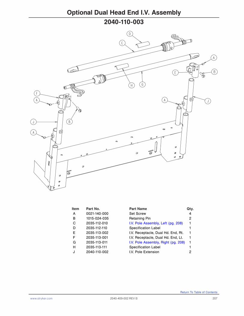
www.stryker.com 2040-409-002 REV B 207
Return To Table of Contents
Optional Dual Head End I.V. Assembly
Item Part No. Part Name Qty. A 0021-140-000 Set Screw 4 B 1015-024-035 Retaining Pin 2 C 2035-112-010 I.V. Pole Assembly, Left (pg. 208) 1 D 2035-112-110 Specification Label 1 E 2035-113-002 I.V. Receptacle, Dual Hd. End, Rt. 1 F 2035-113-001 I.V. Receptacle, Dual Hd. End, Lt. 1 G 2035-113-011 I.V. Pole Assembly, Right (pg. 208) 1 H 2035-113-111 Specification Label 1 J 2040-110-002 I.V. Pole Extension 2
2040-110-003
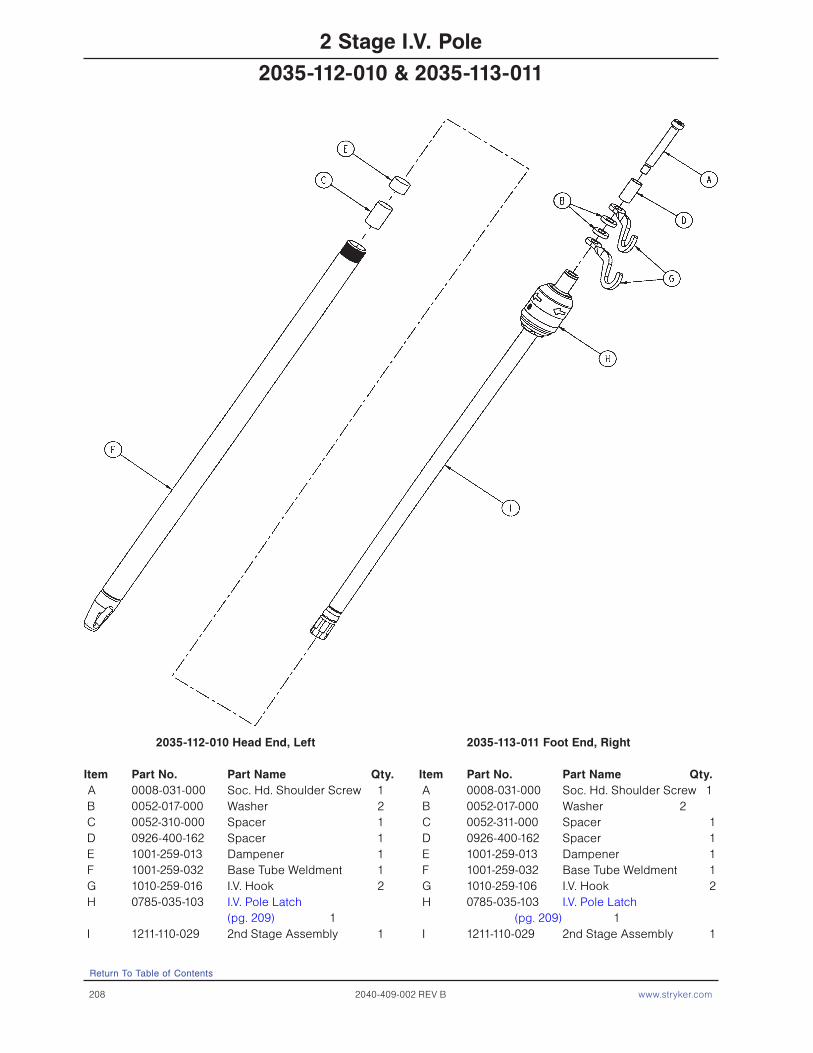
208 2040-409-002 REV B www.stryker.com
Return To Table of Contents
2 Stage I.V. Pole
2035-112-010 Head End, Left 2035-113-011 Foot End, Right
Item Part No. Part Name Qty. Item Part No. Part Name Qty. A 0008-031-000 Soc. Hd. Shoulder Screw 1 A 0008-031-000 Soc. Hd. Shoulder Screw 1 B 0052-017-000 Washer 2 B 0052-017-000 Washer 2 C 0052-310-000 Spacer 1 C 0052-311-000 Spacer 1 D 0926-400-162 Spacer 1 D 0926-400-162 Spacer 1 E 1001-259-013 Dampener 1 E 1001-259-013 Dampener 1 F 1001-259-032 Base Tube Weldment 1 F 1001-259-032 Base Tube Weldment 1 G 1010-259-016 I.V. Hook 2 G 1010-259-106 I.V. Hook 2 H 0785-035-103 I.V. Pole Latch H 0785-035-103 I.V. Pole Latch (pg. 209) 1 (pg. 209) 1 I 1211-110-029 2nd Stage Assembly 1 I 1211-110-029 2nd Stage Assembly 1
2035-112-010 & 2035-113-011

www.stryker.com 2040-409-002 REV B 209
Return To Table of Contents
I.V. Pole Latch Assembly
Item Part No. Part Name Qty. A 0028-167-000 Retaining Ring 1 B 0031-004-000 Steel Ball 2 C 0038-392-000 Wave Spring 1 D 0785-035-023 I.V. Latch ID Housing 1 E 0785-035-024 I.V. Latch OD Housing 1 F 0785-035-029 I.V. Release Label 2 G 1211-011-018 I.V. Latch Seal 2 H 1211-110-020 Washer 2 J 1211-110-021 I.V. Latch Locking Pin 2 K 1211-110-022 I.V. Latch Guide 1 L 1211-110-035 Washer 1 M 1211-110-036 Self-Tapping Screw 2
0785-035-103

210 2040-409-002 REV B www.stryker.com
Return To Table of Contents
Optional X-Ray Cassette Tray Assembly
Assembly part number 2032−140−10 (reference only)
Item Part No. Part Name Qty. A 0001-020-000 Flat C’sunk Hd. Mach Scr. 2 B 0004-049-000 H. Soc. But. Hd. Cap Scr. 4 C 0004-149-000 H. Soc. But. Hd. Cap Scr. 4 D 0014-003-000 Washer 1 E 0016-003-000 Hex Nut 4 F 0038-122-000 Spring 1S1020-23-21 Knob 1 G 0926-023-064 Tray Post 2 H 0926-023-069 Cassette Washer 1 J 0926-023-070 Cassette Block Subass’y 1 L 1010-023-019 Instruction Label 1 M 1010-023-028 Tray Angle 1 N 1010-023-037 Cassette Rod Guide 2 P 1020-023-016 Cassette Post Housing 1 Q 1020-023-019 Tray Hinge Wldmt., Rt. 1 R 0020-023-020 Tray Hinge Wldmt., Lt. 1 T 0000-042-013 Collar W/Set Screw 2 V 2025-140-002 Cassette Actuating Rod 2 W 2035-140-025 Specification Label 1 K 0926-023-071 Cassette Bushing 1 X 2032-140-099 Cassette Tray 1
2035-140-000

www.stryker.com 2040-409-002 REV B 211
Return To Table of Contents
Optional I.V. Pole Transducer Mount Assembly
Item Part No. Part Name Qty. A 0024-063-000 T-Knob 1 B 0024-064-000 Thumb Screw 2 C 2035-018-011 Transducer Mount 1
2035-018-010

212 2040-409-002 REV B www.stryker.com
Return To Table of Contents
Optional Defibrillator Tray Assembly
Item Part No. Part Name Qty. A 0008-049-000 Soc. Hd. Shoulder Bolt 2 B 0014-020-000 Thrust Washer 2 D 0016-028-000 Fiberlock Nut 2 E 0021-017-000 Set Screw 4 F 0037-214-000 Hole Plug 4 H 0038-133-000 Spring 1 J 0052-017-000 Spacer 2 K 1010-050-019 “Push/Pull” Label 1 L 1010-050-021 Long Strap 1 M 1010-050-050 Knob 1 N 1010-050-057 Max. Weight Label 4 P 1010-050-242 Lock Pin 1 R 2025-120-005 Equipment Label 1 S 2025-120-006 Specification Label 1 T 2025-120-018 Tray Assembly 1 W 2025-120-025 Pivot Weldment Frame 1
2025-120-010

www.stryker.com 2040-409-002 REV B 213
Return To Table of Contents
Optional Pump Rack Assembly
Item Part No. Part Name Qty. A 0058-087-000 End Cap 2 B 2030-140-002 Pump Rack Label 1 C 2040-111-005 Pump Rack Tube 1
2040-111-000

214 2040-409-002 REV B www.stryker.com
Return To Table of Contents
Optional Pleur-Evac Rack with Defibrillator Tray
B
Item Part No. Part Name Qty. A 0008-049-000 Soc. Hd. Shoulder Bolt 2 B 0014-020-000 Thrust Washer 2 D 0016-028-000 Fiberlock Nut 2 E 0021-017-000 Set Screw 4 F 0037-214-000 Hole Plug 4 G 0038-133-000 Spring 1 H 0052-017-000 Spacer 2 J 1010-050-019 “Push/Pull” Label 1 K 1010-050-021 Long Strap 1 L 1010-050-050 Knob 1 M 1010-050-057 “Max. Weight” Label 4 N 1010-050-242 Lock Pin 1 P 2025-120-005 Equipment Label 1 R 2025-120-018 Tray Assembly 1 S 2040-090-001 Warning Label 1 T 2040-090-005 Specification Label 1 U 2040-120-003 Rack Weldment 1
2040-120-004
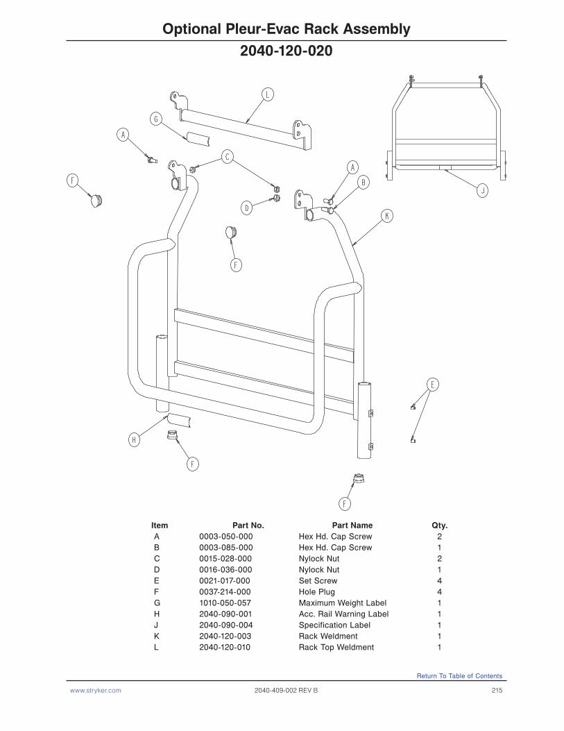
www.stryker.com 2040-409-002 REV B 215
Return To Table of Contents
Optional Pleur-Evac Rack Assembly
Item Part No. Part Name Qty. A 0003-050-000 Hex Hd. Cap Screw 2 B 0003-085-000 Hex Hd. Cap Screw 1 C 0015-028-000 Nylock Nut 2 D 0016-036-000 Nylock Nut 1 E 0021-017-000 Set Screw 4 F 0037-214-000 Hole Plug 4 G 1010-050-057 Maximum Weight Label 1 H 2040-090-001 Acc. Rail Warning Label 1 J 2040-090-004 Specification Label 1 K 2040-120-003 Rack Weldment 1 L 2040-120-010 Rack Top Weldment 1
2040-120-020

216 2040-409-002 REV B www.stryker.com
Return To Table of Contents
Optional Upright Oxygen Bottle Holder
Item Part No. Part Name Qty. A 0024-055-000 Knob 1 B 1010-030-011 Upright Bottle Holder 1 C 2025-150-001 Adaptor Sleeve 1 D 2025-150-002 Specification Label 1 E 0026-005-000 Spring Pin 1 F 2025-150-003 End Stop Bushing 1 G 2040-110-002 Hd. End Dual I.V. Pole Collar 1
2040-150-010

www.stryker.com 2040-409-002 REV B 217
Return To Table of Contents
Optional Bed Extender Pad
2025-040-010
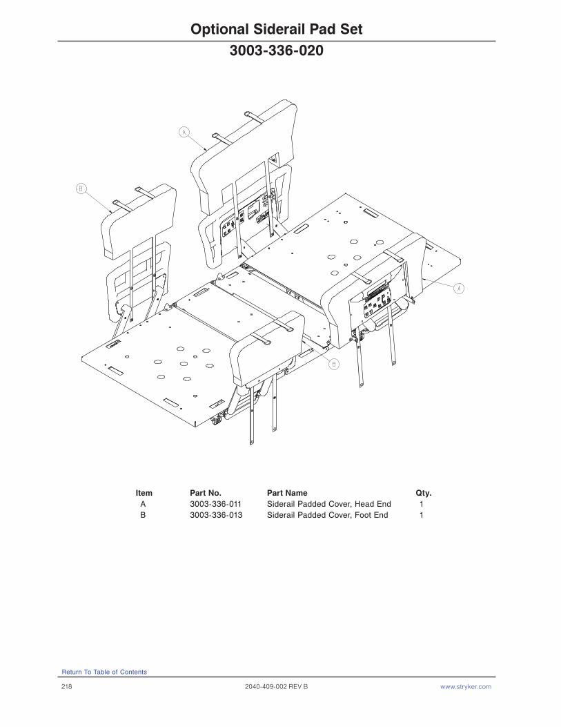
218 2040-409-002 REV B www.stryker.com
Return To Table of Contents
Optional Siderail Pad Set
Item Part No. Part Name Qty.A 3003-336-011 Siderail Padded Cover, Head End 1B 3003-336-013 Siderail Padded Cover, Foot End 1
3003-336-020

www.stryker.com 2040-409-002 REV B 219
Return To Table of Contents
Limited Warranty
Stryker Medical Division, a division of Stryker Corporation, warrants to the original purchaser the ZOOM® Critical Care Beds to be free from defects in material and workmanship for a period of One (1) years after date of delivery. Stryker’s obligation under this warranty is expressly limited to supplying replacement parts and labor for, or replacing, at its option, any product which is, in the sole discretion of Stryker, found to be defective. If requested by Stryker, products or parts for which a warranty claim is made shall be returned prepaid to the factory. Any improper use or any alteration or repair by others in such manner as in Stryker’s judgment affects the product materially and adversely shall void this warranty. Any repair of Stryker products using parts not provided or authorized by Stryker shall void this warranty. No employee or representative of Stryker is authorized to change this warranty in any way.
Stryker Medical Bed products are designed for a 15 year expected service life under normal use, conditions, and with appropriate periodic maintenance as described in the maintenance manual for each device. Stryker warrants to the original purchaser that the welds on its Bed products will be free from structural defects for the expected 15 years life of the Bed product as long as the original purchaser owns the product.
This statement constitutes Stryker’s entire warranty with respect to the aforesaid equipment. Stryker makes no other warranty or representation, either expressed or implied, except as set forth herein. There is no warranty of merchantability and there are no warranties of fitness for any particular purpose. In no event shall Stryker be liable here under for incidental or consequential damages arising from or in any manner related to sales or use of any such equipment.
To Obtain Parts and Service
Stryker products are supported by a nationwide network of dedicated Stryker Field Service Representatives. These representatives are factory trained, available locally, and carry a substantial spare parts inventory to minimize repair time. Simply call your local representative, or call Stryker Customer Service USA at 1-800-327−0770, Canada 1-888-233-6888.
Service Contract Coverage
Stryker has developed a comprehensive program of service contract options designed to keep your equipment operating at peak performance at the same time it eliminates unexpected costs. We recommend that these programs be activated before the expiration of the new product warranty to eliminate the potential of additional equipment upgrade charges.
A Service Contract helps to:
• Ensure equipment reliability.• Stabilize maintenance budgets.• Diminish downtime.• Establish documentation for JCAHO.• Increase product life.• Enhance trade-in value.• Address risk management and safety.
Warranty
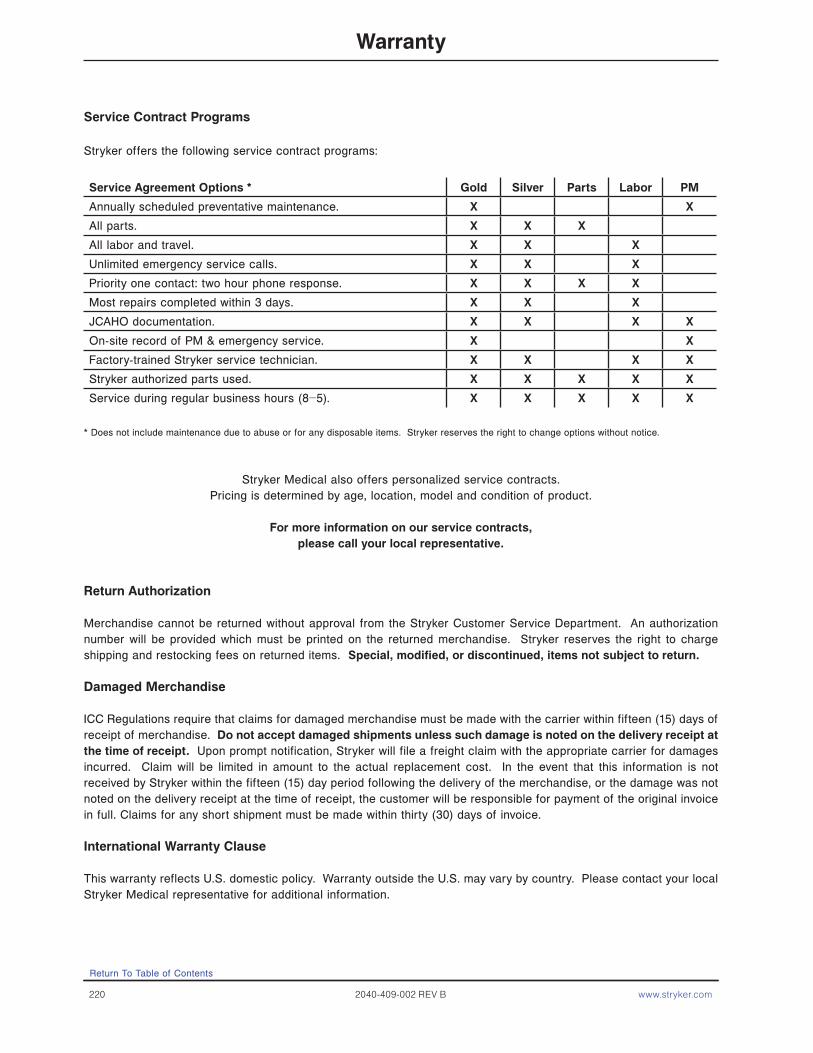
220 2040-409-002 REV B www.stryker.com
Service Contract Programs
Stryker offers the following service contract programs:
Service Agreement Options * Gold Silver Parts Labor PM
Annually scheduled preventative maintenance. X X
All parts. X X X
All labor and travel. X X X
Unlimited emergency service calls. X X X
Priority one contact: two hour phone response. X X X X
Most repairs completed within 3 days. X X X
JCAHO documentation. X X X X
On-site record of PM & emergency service. X X
Factory-trained Stryker service technician. X X X X
Stryker authorized parts used. X X X X X
Service during regular business hours (8−5). X X X X X
* Does not include maintenance due to abuse or for any disposable items. Stryker reserves the right to change options without notice.
Stryker Medical also offers personalized service contracts.Pricing is determined by age, location, model and condition of product.
For more information on our service contracts, please call your local representative.
Return Authorization
Merchandise cannot be returned without approval from the Stryker Customer Service Department. An authorization number will be provided which must be printed on the returned merchandise. Stryker reserves the right to charge shipping and restocking fees on returned items. Special, modified, or discontinued, items not subject to return.
Damaged Merchandise
ICC Regulations require that claims for damaged merchandise must be made with the carrier within fifteen (15) days of receipt of merchandise. Do not accept damaged shipments unless such damage is noted on the delivery receipt at the time of receipt. Upon prompt notification, Stryker will file a freight claim with the appropriate carrier for damages incurred. Claim will be limited in amount to the actual replacement cost. In the event that this information is not received by Stryker within the fifteen (15) day period following the delivery of the merchandise, or the damage was not noted on the delivery receipt at the time of receipt, the customer will be responsible for payment of the original invoice in full. Claims for any short shipment must be made within thirty (30) days of invoice.
International Warranty Clause
This warranty reflects U.S. domestic policy. Warranty outside the U.S. may vary by country. Please contact your local Stryker Medical representative for additional information.
Warranty
Return To Table of Contents


CANADAStryker Canada45 Innovation DriveHamilton, Ontario CanadaL9H 7L8
European RepresentativeStryker FranceZAC Satolas Green PusignanAv. De Satolas Green69881 MEYZIEU CedexFrance
EC REP
2006/XX XXXX-XXX-XXX REV X www.stryker.com
UNITED STATESStryker Medical3800 E. Centre Ave.,Portage, Michigan USA49002
CANADAStryker Canada45 Innovation DriveHamilton, Ontario CanadaL9H 7L8
European RepresentativeStryker FranceZAC Satolas Green PusignanAv. De Satolas Green69881 MEYZIEU CedexFrance
EC REP
UNITED STATESStryker Medical3800 E. Centre Ave.,Portage, Michigan USA49002
2010/04 2040-409-002 REV B www.stryker.com