Magnifer® 50 - Ed Fagan Inc.
14
ThyssenKrupp VDM Magnifer ® 50 Material Data Sheet No. 9002 August 2002 Edition A company of ThyssenKrupp Stainless TK Magnifer ® 50 ifer 50 r ® 50 Magnifer ® 50 Mag Magnifer ® 50 Magnifer ® 50 Magnifer ® 50 Magnifer ® 50 Soft-magnetic nickel-iron alloy Soft-magnetic nickel-iron alloy
-
Upload
khangminh22 -
Category
Documents
-
view
3 -
download
0
Transcript of Magnifer® 50 - Ed Fagan Inc.
ThyssenKrupp VDM
Magnifer® 50Material Data Sheet No. 9002August 2002 Edition
A company ofThyssenKrupp
Stainless
TK
Magnifer® 50
ifer 50r ® 50
Magnifer® 50
MagMagnifer® 50Magnifer® 50
Magnifer ® 50
Magnifer® 50Soft-magnetic nickel-iron alloySoft-magnetic nickel-iron alloy
2 Magnifer® 50
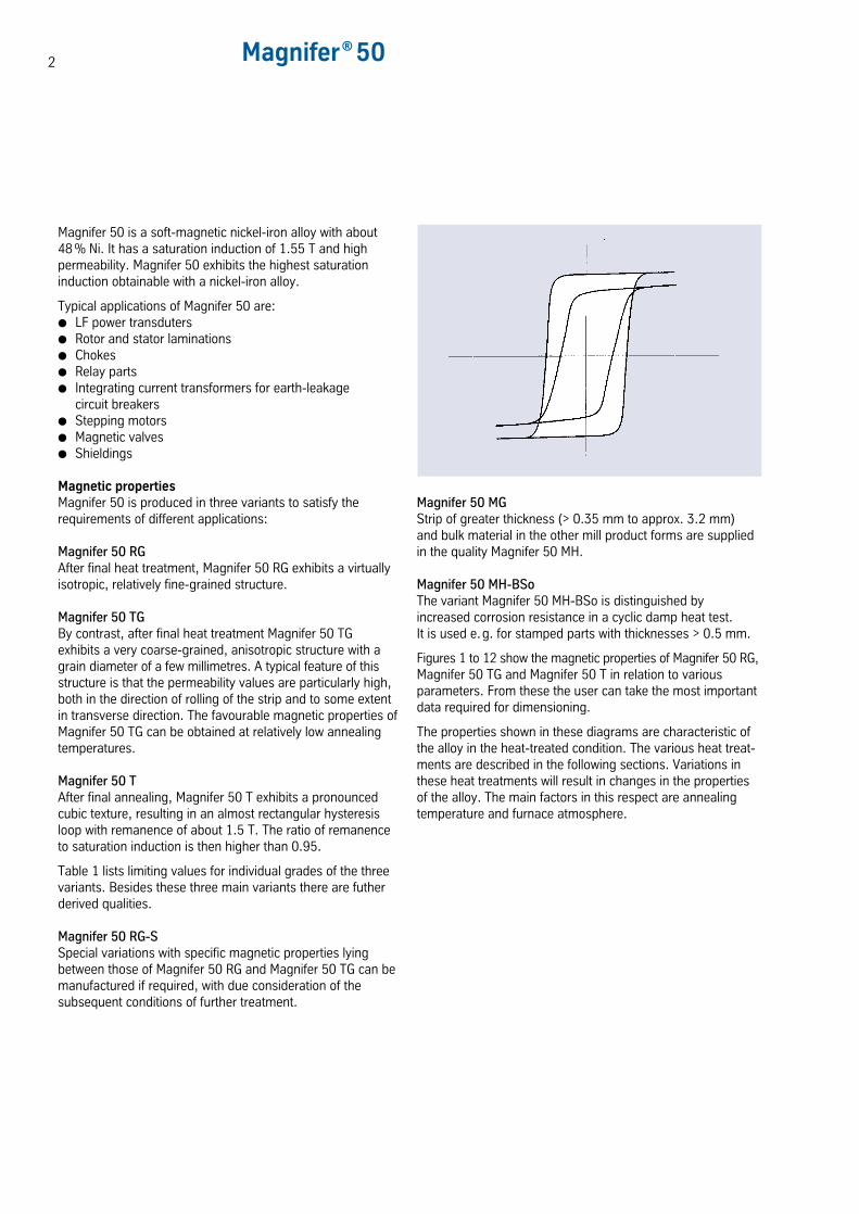
Magnifer 50 is a soft-magnetic nickel-iron alloy with about48 % Ni. It has a saturation induction of 1.55 T and highpermeability. Magnifer 50 exhibits the highest saturationinduction obtainable with a nickel-iron alloy.
Typical applications of Magnifer 50 are: LF power transduters Rotor and stator laminations Chokes Relay parts Integrating current transformers for earth-leakage
circuit breakers Stepping motors Magnetic valves Shieldings
Magnetic propertiesMagnifer 50 is produced in three variants to satisfy therequirements of different applications:
Magnifer 50 RGAfter final heat treatment, Magnifer 50 RG exhibits a virtuallyisotropic, relatively fine-grained structure.
Magnifer 50 TGBy contrast, after final heat treatment Magnifer 50 TGexhibits a very coarse-grained, anisotropic structure with agrain diameter of a few millimetres. A typical feature of thisstructure is that the permeability values are particularly high,both in the direction of rolling of the strip and to some extentin transverse direction. The favourable magnetic properties ofMagnifer 50 TG can be obtained at relatively low annealingtemperatures.
Magnifer 50 TAfter final annealing, Magnifer 50 T exhibits a pronouncedcubic texture, resulting in an almost rectangular hysteresisloop with remanence of about 1.5 T. The ratio of remanenceto saturation induction is then higher than 0.95.
Table 1 lists limiting values for individual grades of the threevariants. Besides these three main variants there are futherderived qualities.
Magnifer 50 RG-SSpecial variations with specific magnetic properties lyingbetween those of Magnifer 50 RG and Magnifer 50 TG can bemanufactured if required, with due consideration of thesubsequent conditions of further treatment.
Magnifer 50 MGStrip of greater thickness (> 0.35 mm to approx. 3.2 mm)and bulk material in the other mill product forms are suppliedin the quality Magnifer 50 MH.
Magnifer 50 MH-BSoThe variant Magnifer 50 MH-BSo is distinguished byincreased corrosion resistance in a cyclic damp heat test.It is used e.g. for stamped parts with thicknesses > 0.5 mm.
Figures 1 to 12 show the magnetic properties of Magnifer 50 RG,Magnifer 50 TG and Magnifer 50 T in relation to variousparameters. From these the user can take the most importantdata required for dimensioning.
The properties shown in these diagrams are characteristic ofthe alloy in the heat-treated condition. The various heat treat-ments are described in the following sections. Variations inthese heat treatments will result in changes in the propertiesof the alloy. The main factors in this respect are annealingtemperature and furnace atmosphere.
3
Heat treatmentHeavily worked stock may need to be soft-annealed beforecarrying out any further deformation. This annealing is bestperformed at between 800 °C and 1000 °C. The annealingtime – not longer than 1 hour – can be kept shorter the higherthe temperature is.
Temperature and annealing time are guided by the desiredfinal condition, which is adjusted in accordance with subse-quent working operations. Annealing should be carried out inhydrogen, cracked ammonia or a clean inert gas atmosphere.
Final annealing for obtainingoptimum magnetic propertiesThe magnetic properties quoted in this Data Sheet areobtainable only after a special final annealing treatment.Annealing must take place in dry hydrogen or crackedammonia (dew point < -40 °C). The appropriate annealingtemperature for Magnifer 50 RG and Magnifer 50 TG is between1050 and 1250 °C, with an annealing time of 2 to 8 hours.
After this final annealing, the stock must be furnace-cooled toabout 450 °C over a period of 5 to 7 hours. Further cooling isthen not critical.
Final annealing of Magnifer 50 T is usually carried out attemperatures around 1000 °C. The required data forannealing temperature, holding time and cooling are quotedfor each individual batch delivered. The final annealing ofparts produced from Magnifer 50 T should preferably becarried out in our factory.
After the final heat treatment, the parts must not be subjectedto further mechanical stress, as any plastic deformationresults in a considerable loss of magnetic properties.
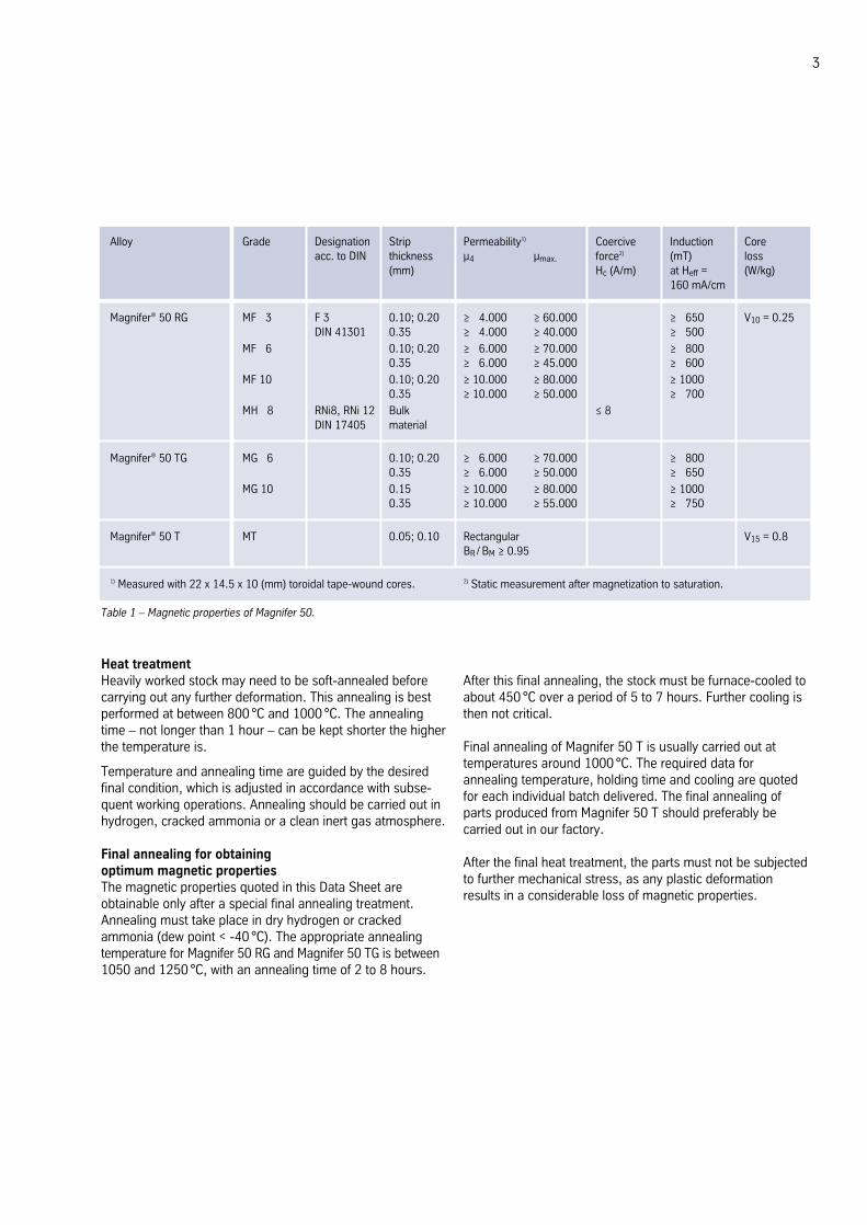
Magnifer® 50 RG MF 13 F 3 0.10; 0.20 ≥ 14.000 ≥ 60.000 ≥ 1650 V10 = 0.25DIN 41301 0.35 ≥ 14.000 ≥ 40.000 ≥ 1500
MF 16 0.10; 0.20 ≥ 16.000 ≥ 70.000 ≥ 18000.35 ≥ 16.000 ≥ 45.000 ≥ 1600
MF 10 0.10; 0.20 ≥ 10.000 ≥ 80.000 ≥ 10000.35 ≥ 10.000 ≥ 50.000 ≥ 1700
MH 18 RNi8, RNi 12 Bulk ≤ 8DIN 17405 material
Magnifer® 50 TG MG 16 0.10; 0.20 ≥ 16.000 ≥ 70.000 ≥ 18000.35 ≥ 16.000 ≥ 50.000 ≥ 1650
MG 10 0.15 ≥ 10.000 ≥ 80.000 ≥ 10000.35 ≥ 10.000 ≥ 55.000 ≥ 1750
Magnifer® 50 T MT 0.05; 0.10 Rectangular V15 = 0.8BR / BM ≥ 0.95
1) Measured with 22 x 14.5 x 10 (mm) toroidal tape-wound cores. 2) Static measurement after magnetization to saturation.
Alloy Grade Designation Strip Permeability1) Coercive Induction Coreacc. to DIN thickness µ4 µmax. force2) (mT) loss
(mm) Hc (A/m) at Heff = (W/kg)160 mA/cm
Table 1 – Magnetic properties of Magnifer 50.
4
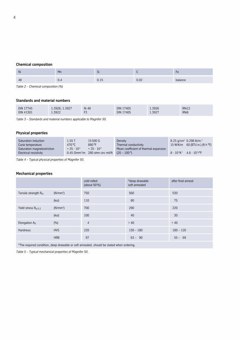
Chemical composition
Ni Mn Si C Fe
48 0.4 0.15 0.02 balance
Table 2 – Chemical composition (%)
Mechanical properties
cold rolled *deep drawable after final anneal(about 50 %) soft annealed
Tensile strength Rm (N/mm2) 750 560 530
(ksi) 110 080 075
Yield stress Rp 0.2 (N/mm2) 700 290 220
(ksi) 100 0 40 0 30
Elongation A5 (%) 704 > 40 > 40
Hardness HV5 220 130 – 180 100 – 120
HRB 297 163 – 190 1 55 – 169
*The required condition, deep drawable or soft annealed, should be stated when ordering.
Table 5 – Typical mechanical properties of Magnifer 50.
Standards and material numbers
DIN 17745 1.3926; 1.3927 Ni 48 DIN 17405 1.3926 RNi12DIN 41301 1.3922 F3 DIN 17405 1.3927 RNi8
Table 3 – Standards and material numbers applicable to Magnifer 50.
Physical properties
Saturation induction 1.55 T 15 500 G Density 8.25 g/cm3 0.298 lb/in.3
Curie temperature 470 °C 880 °F Thermal conductivity 15 W/K/m 60 (BTU in.) (ft h °F)Saturation magnetostriction + 25 · 10-6 + 25 · 10-6 Mean coefficient of thermal expansionElectrical resistivity 0.45 Ωmm2/m 280 ohm circ mil/ft (20 – 100 °) 8 · 10-6K-1 4.6 · 10-6/°F
Table 4 – Typical physical properties of Magnifer 50.
5
FabricationWorkingThe conventional processes can be used. Fabrication datamay be obtained from the table of mechanical properties. Inthe “deep drawable” condition, the minimum Erichsen depthis 8 for sheets of 1 mm thickness. The magnetic finalannealed condition is only the final condition in the fabricationof certain parts. It is not suitable as the initial condition for anyworking operation, as the magnetic properties would bedrastically impaired. The cold-rolled state is the most suitablefor stamping.
MachiningThe cold-worked condition is best suited for machining opera-tions. The behaviour of the alloy is similar to that of stainlesssteels. Low cutting speeds, cooling cutting oils, and carbide orhigh-speed tools are necessary. The latter must be kept sharp.After machining is completed, residual oil, grease or dirt filmsmust be entirely removed before annealing the parts.
WeldingThe best process is usually resistance spot welding, althoughin principle other processes are also applicable. We arepleased to advice on the best process in specific cases.
Corrosion resistanceCorrosion resistance in a humid atmosphere is low.Higher corrosion resistance can be obtained with the qualityMagnifer 50 MH-BSo.
Forms suppliedMill productsStrip, ribbon, sheet, bar and wire.
Fabricated partsToroidal tape-wound cores, core sheets, relay parts and otherstamped and bent parts.
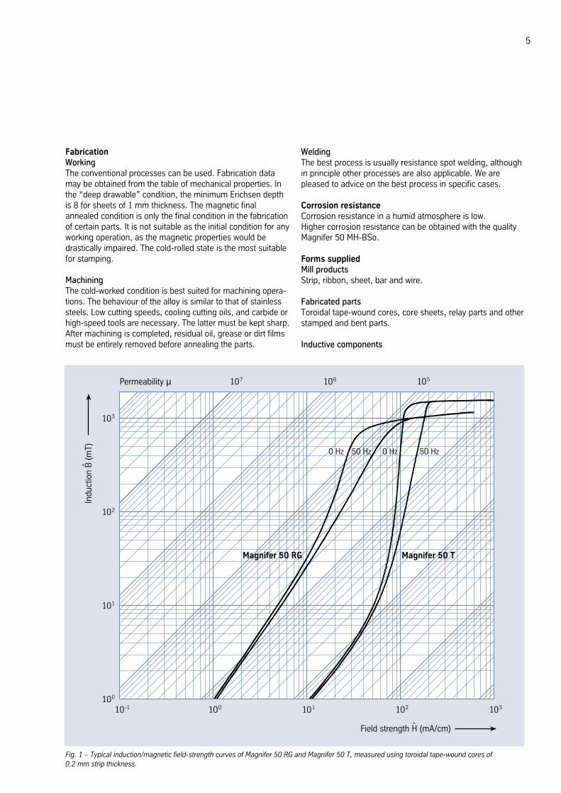
Inductive components
Fig. 1 – Typical induction/magnetic field-strength curves of Magnifer 50 RG and Magnifer 50 T, measured using toroidal tape-wound cores of0.2 mm strip thickness.
10-1 100 101 102 103100
101
102
103
107 106 105Permeability µ
Magnifer 50 RG Magnifer 50 T
0 Hz 50 Hz 0 Hz 50 Hz
Field strength H (mA/cm)ˆ
Indu
ctio
n B
(m
T)ˆ
6 Magnifer® 50
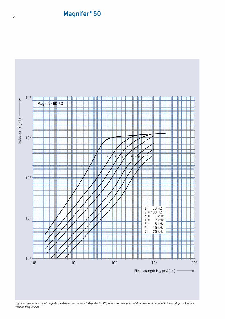
Fig. 2 – Typical induction/magnetic field-strength curves of Magnifer 50 RG, measured using toroidal tape-wound cores of 0.2 mm strip thickness atvarious frequencies.
100 101 102 103 104100
101
102
103
Field strength Heff (mA/cm)
104
Magnifer 50 RG
1 = 450 HZ2 = 400 HZ3 = 401 kHz4 = 402 kHz5 = 405 kHz6 = 410 kHz7 = 420 kHz
1 2 3 4 5 76
Indu
ctio
n B
(m
T)ˆ
7
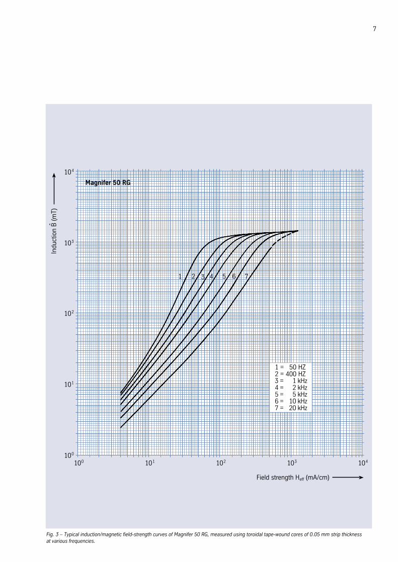
Fig. 3 – Typical induction/magnetic field-strength curves of Magnifer 50 RG, measured using toroidal tape-wound cores of 0.05 mm strip thickness at various frequencies.
100 101 102 103 104100
101
102
103
Field strength Heff (mA/cm)
104
Magnifer 50 RG
1 = 450 HZ2 = 400 HZ3 = 401 kHz4 = 402 kHz5 = 405 kHz6 = 410 kHz7 = 420 kHz
1 2 3 4 5 76
Indu
ctio
n B
(m
T)ˆ
8 Magnifer® 50
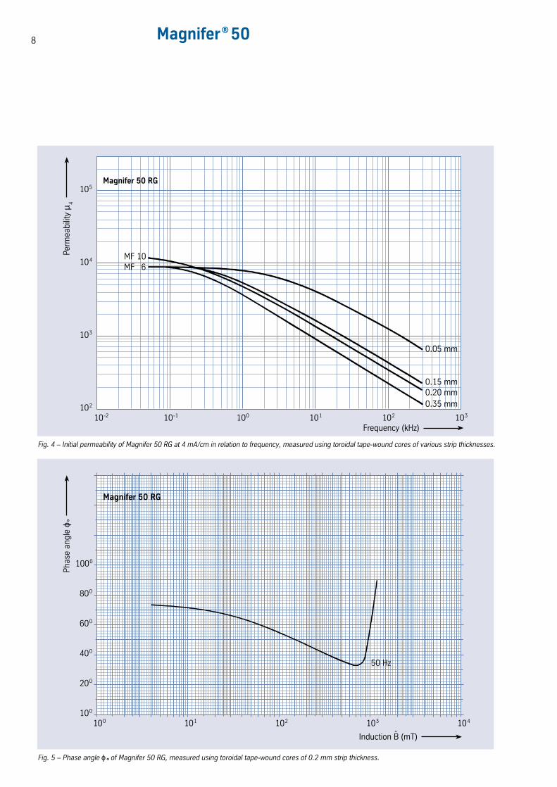
Fig. 4 – Initial permeability of Magnifer 50 RG at 4 mA/cm in relation to frequency, measured using toroidal tape-wound cores of various strip thicknesses.
10-2 10-1102
Perm
eabi
lity
µ 4
Frequency (kHz)
Magnifer 50 RG
100 101 102 103
103
104
105
MF 10MF 6
0.05 mm
0.15 mm0.20 mm0.35 mm
Fig. 5 – Phase angle ϕ° of Magnifer 50 RG, measured using toroidal tape-wound cores of 0.2 mm strip thickness.
100100
Phas
e an
gle
ϕ °
101 102 103 104
200
400
600
800
1000
Magnifer 50 RG
50 Hz
Induction B (mT)ˆ
9
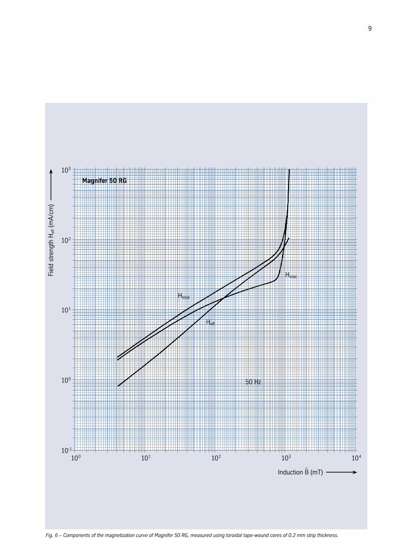
Fig. 6 – Components of the magnetization curve of Magnifer 50 RG, measured using toroidal tape-wound cores of 0.2 mm strip thickness.
100 101 102 103 10410-1
100
101
102
103
Magnifer 50 RG
Fiel
d st
reng
th H
eff (
mA
/cm
)
Htotal
Heff
Hreac
50 Hz
Induction B (mT)ˆ
10 Magnifer® 50
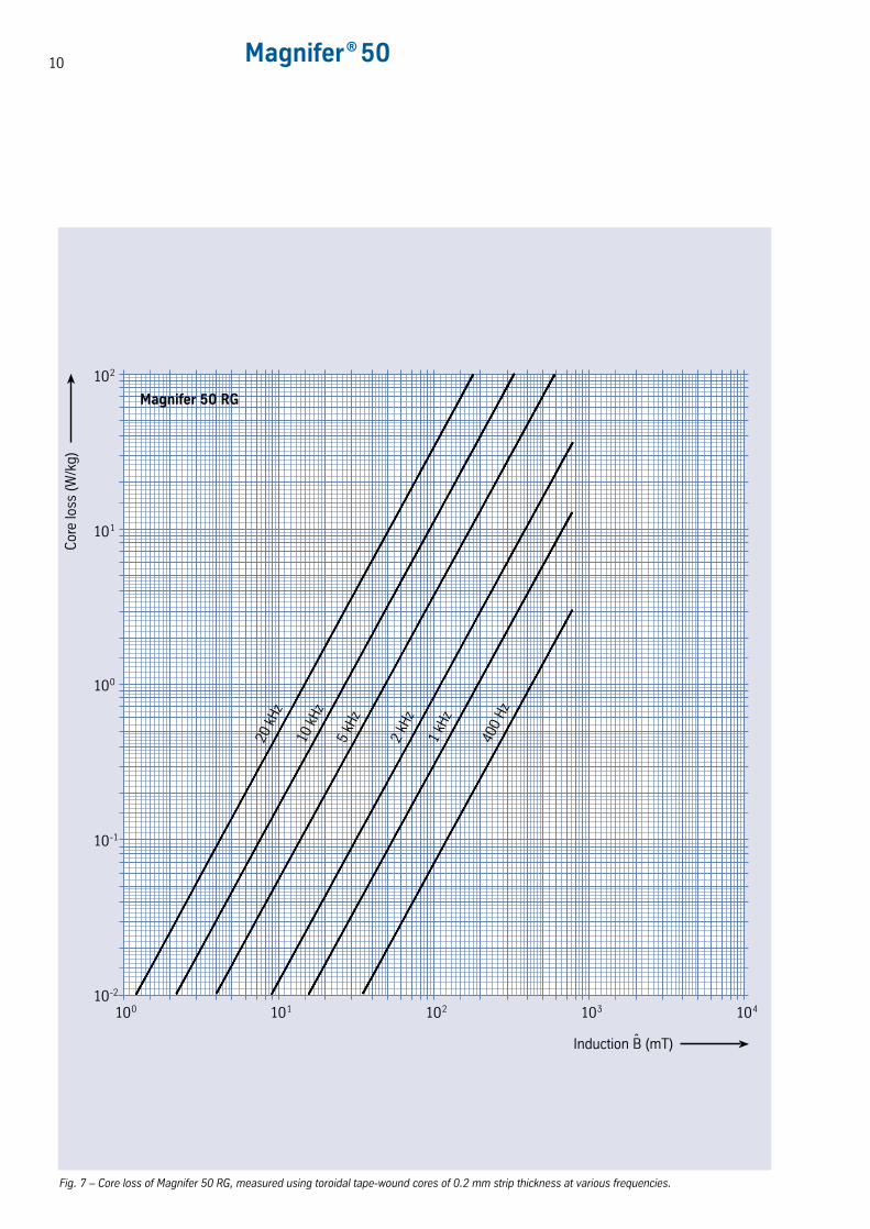
Fig. 7 – Core loss of Magnifer 50 RG, measured using toroidal tape-wound cores of 0.2 mm strip thickness at various frequencies.
100 101 102 103 10410-2
10-1
100
101
102
Magnifer 50 RG
Cor
e lo
ss (
W/k
g)
20 k
Hz
10 k
Hz
5 kH
z
2 kH
z
1 kH
z
400
Hz
Induction B (mT)ˆ
11
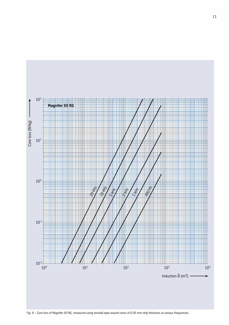
Fig. 8 – Core loss of Magnifer 50 RG, measured using toroidal tape-wound cores of 0.05 mm strip thickness at various frequencies.
100 101 102 103 10410-2
10-1
100
101
102
Magnifer 50 RG
Cor
e lo
ss (
W/k
g)
20 k
Hz
10 k
Hz
5 kH
z
2 kH
z
1 kH
z
400
Hz
Induction B (mT)ˆ
12 Magnifer® 50
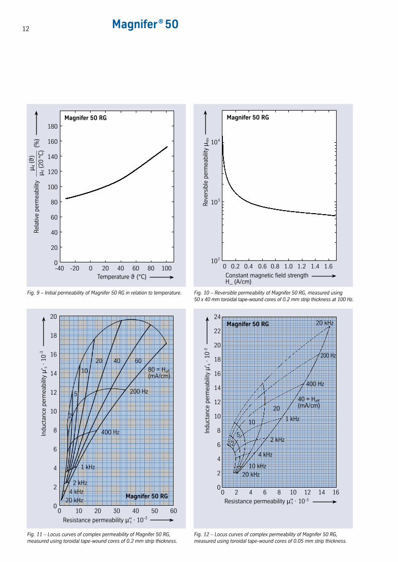
Fig. 9 – Initial permeability of Magnifer 50 RG in relation to temperature. Fig. 10 – Reversible permeability of Magnifer 50 RG, measured using50 x 40 mm toroidal tape-wound cores of 0.2 mm strip thickness at 100 Hz.
0-40
Temperature ϑ (°C)
Magnifer 50 RG
-20 0 20 40 60 80 100
20
40
60
80
100
120
140
160
180
Rel
ativ
e pe
rmea
bilit
y
(
%)
µ 4 (ϑ)
µ 4 (
20°C
)
102
0
Constant magnetic field strengthH_ (A/cm)
Magnifer 50 RG
0.2 0.4 0.6 0.8 1.0 1.2 1.4
103
104
Rev
ersi
ble
perm
eabi
lity
µ rev
1.6
Fig. 11 – Locus curves of complex permeability of Magnifer 50 RG,measured using toroidal tape-wound cores of 0.2 mm strip thickness.
Fig. 12 – Locus curves of complex permeability of Magnifer 50 RG,measured using toroidal tape-wound cores of 0.05 mm strip thickness.
0
2
4
6
8
10
12
14
16
18
20
0 10 20 30 40 50 60
Magnifer 50 RG
Indu
ctan
ce p
erm
eabi
lity
µ's ·
10
-3
Resistance permeability µ''s · 10-3
20 40 60
10
5
2
20 kHz4 kHz
2 kHz
1 kHz
400 Hz
200 Hz
80 = Heff(mA/cm)
0
2
4
6
8
10
12
14
16
18
20
0 2 4 6 8 10 12
Indu
ctan
ce p
erm
eabi
lity
µ's ·
10
-3
Resistance permeability µ''s · 10-3
Magnifer 50 RG22
24
14 16
20 kHz10 kHz
4 kHz
2 kHz
1 kHz
40 = Heff(mA/cm)
200 Hz
20 kHz
20
10
5
2
400 Hz
13
The information contained in this data sheet is based on results of research anddevelopment work available at the time of printing and does not provide anyguarantee of particular characteristics or fit. ThyssenKrupp VDM reserves the rightto make changes without notice. The data sheet has been compiled to the best knowledge of ThyssenKrupp VDM and is given without any liability on the part ofThyssenKrupp VDM. ThyssenKrupp VDM is only liable according to the terms of thesales contract and in particular to the General Conditions of Sales in case of anydelivery from ThyssenKrupp VDM.As updates of data sheets are not automatically send out, when issued,ThyssenKrupp VDM recommends to request the latest edition of required datasheets either by phone +49 (0) 23 92 55 2493, by fax +49 (0) 23 92 55 2111 orby E-mail under [email protected] 2002 Edition.This edition supersedes material data sheet no. 9002, dated November 1990.
Technical publicationThe alloy Magnifer 50 is the subject of the followingThyssenKrupp VDM technical publication:
H. Hattendorf:A 48% Ni-Fe alloy of low coercivity and improved corrosionresistance in a cyclic damp heat test, Journal of Magnetismand Magnetic Materials 231 (2001) L29 – L32.
ThyssenKrupp VDM GmbHPlettenberger Strasse 258791 WerdohlP.O. Box 18 2058778 WerdohlGermanyPhone: +49 (23 92) 55-0Fax: +49 (23 92) 55-22 17E-Mail: [email protected]
MagniMagnifer