MP3-50 Manual - Gilderfluke
127
Mp3-50, Mp3-50/8, Mp3-50/40 Audio & Show Control Systems Preliminary - printed September 19, 2003 The Mp3-50 is a complete, stand alone Mp3 Audio playback system. Just add a power supply and your speakers, and it will play Mp3 audio from the SmartMedia card. The Mp3-50/8 & Mp3-50/40 add eight or forty digital Show Control outputs, DMX-512, MIDI or networked RS-422 serial port input and DMX-512 output to a Mp3-50 player. The Mp3-50/8 & Mp3-50/40 are complete audio and Show Control solutions. The Mp3-50/8C & Mp3-50/40C adds WWV synchronized scheduling. This gives you Atomic clock accuracy for carillons, schools, churches, bell towers & industrial annunciator systems. GILDERFLUKE & CO . 205 SOUTH FLOWER STREET BURBANK , CALIFORNIA 91502 818/840-9484 800/776-5972 FAX 818/840-9485 EAST COAST /FLORIDA OFFICE 7041 GRAND NATIONAL DRIVE SUITE 128d ORLANDO , FL. 32819 407/354-5954 FAX 407/354-5955 i of vii
-
Upload
khangminh22 -
Category
Documents
-
view
1 -
download
0
Transcript of MP3-50 Manual - Gilderfluke

Mp3-50, Mp3-50/8, Mp3-50/40Audio & Show Control Systems
Preliminary - printed September 19, 2003
The Mp3-50 is a complete, stand alone Mp3 Audio playbacksystem. Just add a power supply and your speakers, and it willplay Mp3 audio from the SmartMedia card.
The Mp3-50/8 & Mp3-50/40 add eight or forty digital ShowControl outputs, DMX-512, MIDI or networked RS-422 serial portinput and DMX-512 output to a Mp3-50 player. The Mp3-50/8 &Mp3-50/40 are complete audio and Show Control solutions.
The Mp3-50/8C & Mp3-50/40C adds WWV synchronizedscheduling. This gives you �Atomic� clock accuracy for carillons,schools, churches, bell towers & industrial annunciator systems.
GILDERFLUKE & CO .� 205 SOUTH FLOWER STREET � BURBANK , CALIFORNIA 91502 � 818/840-9484 � 800/776-5972 � FAX 818/840-9485EAST COAST /FLORIDA OFFICE � 7041 GRAND NATIONAL DRIVE � SUITE 128d � ORLANDO , FL. 32819 � 407/354-5954 � FAX 407/354-5955
i of vii

Safety Disclaimer: Any electronic or mechanicalsystem has the potential to fail. Certain applica-tions using Gilderfluke & Company equipment mayinvolve potential risks of death, personal injury orsevere property or environmental damage (�Criti-cal Application�).
Gilderfluke & Company equipment is not de-signed, intended, authorized or warranted to besuitable in life support applications, devices orsystems or other critical applications. Inclusion ofGilderfluke & Company products in such applica-tions is understood to be fully at the risk of the cus-tomer. In order to minimize risks associated withthe customer's applications, adequate design andoperating safeguards should be provided by thecustomer to minimize inherent or procedural haz-ards.
Gilderfluke & Company assumes no liability forapplications assistance, customer produced de-sign, software performance, or infringement ofpatents or copyrights. Nor does Gilderfluke &Company warrant or represent that any license, ei-ther express or implied, is granted under anypatent right, copyright, mask work right, or other in-tellectual property right of Gilderfluke & Companycovering or relating to any combination, machine,or process in which Gilderfluke & Company prod-ucts or services might be or are used.
GILDERFLUKE & CO .� 205 SOUTH FLOWER STREET � BURBANK , CALIFORNIA 91502 � 818/840-9484 � 800/776-5972 � FAX 818/840-9485EAST COAST /FLORIDA OFFICE � 7041 GRAND NATIONAL DRIVE � SUITE 128d � ORLANDO , FL. 32819 � 407/354-5954 � FAX 407/354-5955
ii of vii

Mp3-50, Mp3-50/8 or Mp3-50/40 Overview ........ 1
Mp3-50/8 or Mp3-50/40 Indicators ..................... 5Mp3 Heart ............................................................................. 6Mp3 Run ............................................................................... 6Right ..................................................................................... 6Left ........................................................................................ 6Show Control Heart .............................................................. 6Run ....................................................................................... 6DMX/MIDI/Serial ................................................................... 6Board Error ........................................................................... 7J8 �A�, �B�, �C�, & �D� Input LEDs ............................................. 7Output LEDs .......................................................................... 7Fuses .................................................................................... 8
Mp3-50, Mp3-50/8 or Mp3-50/40 Connections .. 9RS-232 Serial Port ................................................................. 9USB ....................................................................................... 9Power Supply ...................................................................... 10DMX-512/MIDI Serial In ...................................................... 10
DMX-512 ....................................................................... 11MIDI Notes ..................................................................... 12Net Serial ....................................................................... 13IR Mode ......................................................................... 14None ............................................................................. 16
DMX-512/MIDI Output ........................................................ 16Status Output ...................................................................... 18Left Speaker Output ............................................................ 18Right Speaker Output .......................................................... 18�1/4 J6� Inputs/Outputs ....................................................... 18
Mp3-50 ......................................................................... 18Mp3-50/8 ...................................................................... 19Mp3-50/40 .................................................................... 19
Left Line Output ................................................................... 20Right Line Output ................................................................ 20J8 �A�, �B�, �C� & �D� inputs .................................................. 20
�A�, �B�, �C� & �D� Binary ..................................................... 21�J6� Digital Outputs ............................................................. 24
Mp3-50/CC-10 Card Cage ............................... 29
Shows for Mp3-50/8 ........................................... 32Show Capacities ................................................ 32
GILDERFLUKE & CO .� 205 SOUTH FLOWER STREET � BURBANK , CALIFORNIA 91502 � 818/840-9484 � 800/776-5972 � FAX 818/840-9485EAST COAST /FLORIDA OFFICE � 7041 GRAND NATIONAL DRIVE � SUITE 128d � ORLANDO , FL. 32819 � 407/354-5954 � FAX 407/354-5955
iii of vii

Mp3-50/8 Show Configurations ............................. 32One Combined Show Control/Mp3 Control Channel ......... 32One Show Control, One Mp3 Control Channel .................. 34One Audio Level Control Channel ...................................... 35Two Audio Level Control Channels ..................................... 37DMX-512 w/Overlapping Channels .................................... 39Sixteen DMX-512 Channels ................................................ 40
Shows for Mp3-50/40 ......................................... 43Show Capacities ................................................ 43Mp3-50/40 Show Configurations ........................... 43
One Combined Show Control/Mp3 Control Channel ......... 43Five Show Control, One Mp3 Control Channel .................. 45One Audio Level Control Channel ...................................... 46Two Audio Level Control Channels ..................................... 48DMX-512 w/Overlapping Channels .................................... 50Sixteen DMX-512 Channels ................................................ 52
Preparing Animation Data for AutoDownloads 54
Serial Port Commands ...................................... 58Echo Commands ................................................................ 58
Echo On ........................................................................ 58Echo Off ........................................................................ 58
Card Status ......................................................................... 59Card Reset ......................................................................... 61Start Commands ................................................................. 61
Start Track ...................................................................... 61Start Global ................................................................... 61
Stop Commands ................................................................. 61Stop Track ...................................................................... 61Stop Global ................................................................... 61
Loop Commands ................................................................ 62Loop Track ..................................................................... 62Loop Global ................................................................... 62
Stop at End Commands ...................................................... 62Stop at End Track ........................................................... 62Stop at End Global ......................................................... 62
Select Show Commands ..................................................... 62Select Show Track .......................................................... 62Select Show Global ........................................................ 62
Select Sound Commands ................................................... 63Select Sound Track ........................................................ 63
GILDERFLUKE & CO .� 205 SOUTH FLOWER STREET � BURBANK , CALIFORNIA 91502 � 818/840-9484 � 800/776-5972 � FAX 818/840-9485EAST COAST /FLORIDA OFFICE � 7041 GRAND NATIONAL DRIVE � SUITE 128d � ORLANDO , FL. 32819 � 407/354-5954 � FAX 407/354-5955
iv of vii

Select Sound Global ...................................................... 63Show Pause Commands ..................................................... 63
Pause Show ................................................................... 63Continue Show .............................................................. 63
AutoDownload .................................................................... 63RealTime Update ................................................................. 63
Serial Command Summary .................................. 65
Hardware Configuration ................................... 66Internal/External Power ...................................................... 66RS-422/Optoisolated ........................................................... 66
Serial Configuration .......................................... 67Play a Sound ....................................................................... 71Display Config. from SmartMedia ...................................... 71
Serial Address ................................................................ 71MIDI channel ................................................................. 71MIDI 1st Note ................................................................. 72Repeater Control Channel ............................................ 72Left Level Control ........................................................... 72Right Level Control ........................................................ 72First Animation Channel ................................................. 72eeFlag0 ......................................................................... 72eeFlag1 ......................................................................... 73eeFlag2 ......................................................................... 73
Show Info ............................................................................ 73Set Time .............................................................................. 74Stop at End .......................................................................... 74Loop a Show ....................................................................... 74Play a Show ........................................................................ 75Stop Playing ........................................................................ 75Verify Shows ....................................................................... 75
Software Installation .......................................... 76
Software/Firmware Versions ............................. 78
What to do with a new SmartMedia Card ........ 79
Mp3-50 Configurator ......................................... 81default settings .................................................. 83Track Setup ........................................................ 85
Change Track Number ....................................................... 85Reload Track List From Directory ........................................ 85
GILDERFLUKE & CO .� 205 SOUTH FLOWER STREET � BURBANK , CALIFORNIA 91502 � 818/840-9484 � 800/776-5972 � FAX 818/840-9485EAST COAST /FLORIDA OFFICE � 7041 GRAND NATIONAL DRIVE � SUITE 128d � ORLANDO , FL. 32819 � 407/354-5954 � FAX 407/354-5955
v of vii

At End ................................................................................. 86Stop .............................................................................. 86Next Higher Selection ..................................................... 86Play Random Selection .................................................. 86Specific AudioFile .......................................................... 86
Can Step On Track with a new Play request ....................... 86Track to Play at PowerUp .................................................... 87
PlayList Setup ..................................................... 88Audio Setup ....................................................... 89
Main Volume Level ............................................................. 89Half Mute ............................................................................ 89RealTime Level Control ....................................................... 90EQ Settings ......................................................................... 90Enable Power Amplifier ...................................................... 90
Input Setup ........................................................ 91Binary Select ...................................................... 92
Playback Level .................................................................... 92Do not change Playback Level ....................................... 93Fade to Full In ................................................................ 93Fade to Zero In .............................................................. 93Fade to �Half Mute� In ..................................................... 93
Start Playing ....................................................................... 93Whatever is Next ............................................................ 94Next Higher Track ........................................................... 94The Same Track Again .................................................... 94Random Track ............................................................... 94Specific AudioFile .......................................................... 94
Stop Playing ........................................................................ 94Stop Now ....................................................................... 95Stop at End .................................................................... 95
MPU Input Setup ................................................. 96Binary Select ...................................................... 97
Playback Level .................................................................... 97Do not change Playback Level ....................................... 98Fade to Full In ................................................................ 98Fade to Zero In .............................................................. 98Fade to �Half Mute� In ..................................................... 98
Start Playing ....................................................................... 98Whatever is Next ............................................................ 99Next Higher Track ........................................................... 99The Same Track Again .................................................... 99
GILDERFLUKE & CO .� 205 SOUTH FLOWER STREET � BURBANK , CALIFORNIA 91502 � 818/840-9484 � 800/776-5972 � FAX 818/840-9485EAST COAST /FLORIDA OFFICE � 7041 GRAND NATIONAL DRIVE � SUITE 128d � ORLANDO , FL. 32819 � 407/354-5954 � FAX 407/354-5955
vi of vii

Random Track ............................................................... 99Specific AudioFile .......................................................... 99
Stop Playing ........................................................................ 99Stop Now ..................................................................... 100Stop at End .................................................................. 100
MPU Control Setup ............................................ 101Enable DMX-512 Transmission ......................................... 101Enable DMX-512 Reception .............................................. 102Enable DMX-512 Checksums ........................................... 103Enable MIDI Reception ..................................................... 103MIDI Notes Trigger Animation Playback ........................... 104MIDI Channel Number ..................................................... 105MIDI First Note Number .................................................... 105Net Serial Mode ................................................................ 105IR Trigger Mode ................................................................ 106Repeater MPU Control Channel ....................................... 108First Animation Channel ................................................... 108Enable Animation From Flash ........................................... 109Disable Outputs When Stopped ........................................ 109Write Protect Flash Memory ............................................. 109Available Files for Download ............................................ 109Always Download Current File to Flash on Boot ............... 110
�Atomic� Clock Setup .......................................... 111Disable Schedule Starts .................................................... 114Reset Clock ...................................................................... 114
Care & Feeding of an �Atomic� Clock .................... 116alarms .............................................................................. 117
HEXadecimal to Decimal to Percentage ....... 119
GILDERFLUKE & CO .� 205 SOUTH FLOWER STREET � BURBANK , CALIFORNIA 91502 � 818/840-9484 � 800/776-5972 � FAX 818/840-9485EAST COAST /FLORIDA OFFICE � 7041 GRAND NATIONAL DRIVE � SUITE 128d � ORLANDO , FL. 32819 � 407/354-5954 � FAX 407/354-5955
vii of vii

A note about this manual:
This manual covers the specifics of theMp3-50, Mp3-50/8 or Mp3-50/40. To programthe Mp3-50, Mp3-50/8 or Mp3-50/40 you willneed to also need the PC�MACs manual sec-tions that cover the PC�MACs software.
The Mp3-50, Mp3-50/8 or Mp3-50/40 istypically programmed in �Software-only� or�Hardwareless RealTime� mode. If you areusing the PC�MACs MACs-USB for program-ming your Mp3-50, Mp3-50/8 or Mp3-50/40through the DMX-512 input, please refer to thePC�MACs �Unlimited� mode.
The full PC�MACs manual can be down-loaded from our web site at:
http:/ /www.gilderfluke.com
GILDERFLUKE & CO .� 205 SOUTH FLOWER STREET � BURBANK , CALIFORNIA 91502 � 818/840-9484 � 800/776-5972 � FAX 818/840-9485EAST COAST /FLORIDA OFFICE � 7041 GRAND NATIONAL DRIVE � SUITE 128d � ORLANDO , FL. 32819 � 407/354-5954 � FAX 407/354-5955
viii of viii

Mp3-50, Mp3-50/8 or Mp3-50/40 OverviewThe Mp3-30 is a complete audio playback box. It uses a
SmartMedia card to hold audio files stored in the standard Mp3format. With no moving parts to wear out, the Mp3-50 should welloutlast the speakers it is attached to. The Mp3-50 can be usedsingly, or in combination with additional Mp3-50s, Mp3-50/8s orMp3-50/40s, BR-SmartMedia cards or any Gilderfluke & Co.equipment. It can provide the audio for animated shows anddisplays, fountains, fireworks, safety announcements, advertising,alarm systems, window displays special effects, signs, clocksand carillons, or anything else that needs a sound to be playedback upon command.
Audio is loaded onto the Mp3-50 by first converting it to aMp3 format file. There are a number of shareware programs fordoing this, as well as Mp3 encoders included as part of mostaudio editing programs 1 . The AudioFiles are moved to the Mp3-50�s SmartMedia card by temporarily moving the SmartMediacard to an appropriate slot or reader attached to your comput-er, or plugging in a USB cable to the front of the Mp3-50 fromyour computer. In the later case, the Mp3-50 will appear as a �re-movable disk drive� on your computer. You can then �drag anddrop� your audio files onto to the SmartMedia card.
The Mp3-50/8 and Mp3-50/40 are complete stand-aloneShow Control and Audio Playback Systems. The Mp3-50/8s orMp3-50/40s can be used singly, or in combination with addition-al Mp3-50s, Mp3-50/8s or Mp3-50/40s, BR-SmartMedia cards orany Gilderfluke & Co. equipment. It can be used to control ani-mated shows and displays, fountains, fireworks, lighting, soundsystems, simulators, slide and movie projectors, fiber optics, win-dow displays, motors, pneumatic and hydraulic systems, neonspecial effects, signs, machines and machine tools in processcontrol, or anything else that can be controlled by an electrical
GILDERFLUKE & CO .� 205 SOUTH FLOWER STREET � BURBANK , CALIFORNIA 91502 � 818/840-9484 � 800/776-5972 � FAX 818/840-9485EAST COAST /FLORIDA OFFICE � 7041 GRAND NATIONAL DRIVE � SUITE 128d � ORLANDO , FL. 32819 � 407/354-5954 � FAX 407/354-5955
1 of 119
1 Contact our sales staff for current Mp3 file converter recommendations.

signal.
The Show Control side of the Mp3-50/8 or Mp3-50/40 is pro-grammed using our PC�MACs Show Control software. While pro-gramming, data can be sent to the Mp3-50/8 or Mp3-50/40through its DMX-512 input, �Net Serial� RS-422 port, or RS-232 seri-al port. Once programed, data is sent to the Mp3-50/8 or Mp3-50/40 through the PC�s serial port or loaded onto the SmartMediacard for permanent storage. The Mp3-50/8 or Mp3-50/40 canthen be disconnected from the PC and it will run all by itself.
When used with a �Hardwareless RealTime� licensed copy ofPC�MACs software, Mp3-50/8s or Mp3-50/40s can have theiroutputs programmed and updated in real time with just a PCand a serial connection. When used with the PC�MACs hard-ware (MACs-SMP or MACs-USB Smpte Card), up to sixty-four Mp3-50/8s or Mp3-50/40s can be updated in RealTime through theDMX-512 port.
Features of the Mp3-50/8 or Mp3-50/40 include:� Stand alone stereo playback of standard Mp3 audio files. Up to
255 different AudioFiles can be selected and played. Sound ca-pacity is only limited by the size of the SmartMedia card installed.Player supports all standard Mp3 encoding rates, including �vari-able�.
� Two line level outputs (RCA Jacks), or you can use the powerful11 watt/channel onboard amplifier. In most applications, this am-plifier means that all you need to add are appropriate speakers, aSmartMedia card and a power supply to get up and running.
� Audio data is stored in standard SmartMedia cards. You can usethe built-in USB port to temporarily attach the Mp3-50 to yourcomputer as a �removable hard drive� or move the SmartMediacard itself to your computer for high speed �drag-n-drop� down-loading. As a bonus feature, you can also use a USB connectedMp3-50 to download photos from your digital camera, or pro-gram SmartMedia cards for any other devices that need them.This includes the BR-SmartMedia.
� All configuration is done through a user friendly Windows-basedprogram. You can set the volume, EQ, and what each of sixteen
GILDERFLUKE & CO .� 205 SOUTH FLOWER STREET � BURBANK , CALIFORNIA 91502 � 818/840-9484 � 800/776-5972 � FAX 818/840-9485EAST COAST /FLORIDA OFFICE � 7041 GRAND NATIONAL DRIVE � SUITE 128d � ORLANDO , FL. 32819 � 407/354-5954 � FAX 407/354-5955
2 of 119

trigger inputs does. Eight of the inputs are from the outside worldthrough optoisolators, The other eight inputs come directly fromthe Show Control side of the Mp3-50/8 or Mp3-50/40, if theseoptions are installed. Any of the inputs can be used to rampaudio to preset levels, select and play specific AudioFiles or selectAudioFiles from a preset list or randomizer. Shows can be selecteddirectly by an input, or using a binary pattern to allow access toall 255 different possible audio files.
� Mounts stand alone, in 2-3/4� Augat Snap Track, or up to 10 in aMp3-50/CC10 cage (Mp3-50 only).
� Runs on any voltage from 12 to 24 volts DC. The Mp3-50s, Mp3-50/8s or Mp3-50/40s can even be run from batteries! For maxi-mum output with the onboard amplifier, use 24 volts, and addapproximately 25 Watts (for amplifier) plus your loads when select-ing your power supply.
Features of the Mp3-50/8 and Mp3-50/40 include:� Adds eight (Mp3-50/8) or forty (Mp3-50/40) digital (on/off) Show
Control outputs to a Mp3-50.
� DMX-512 input for programming or controlling the audio play-back. DMX-512 output for sixteen channel from onboard ShowControl memory or when running from RealTime updates throughthe RS-232 serial port.
� Automatic �program in place� download through the serial port onyour PC or through the SmartMedia card. There are no Eproms toprogram or install! The amount of time it takes to download showsthe Mp3-50/8 or Mp3-50/40 depends on the length of theshow(s). Short shows take only seconds. Shows that fill the entireMp3-50/8s or Mp3-50/40s memory will take about ten minutes todownload. Show audio and animation data can be distributed toclients by sending out preloaded SmartMedia cards.
� 512 KBytes of nonvolatile Show Control memory. Using all fortyMp3-50/40 Show Control outputs, this gives a show capacity ofabout an hour at thirty updates per second! About five hours forthe Mp3-50/8 using all eight of its outputs! Once downloaded,show data is retained for approximately forty years, with or withoutpower applied. Up to 255 individual shows can be loaded onto aMp3-50/8 or Mp3-50/40 at one time.
� Mp3 Audio files can be selected, played and audio levels con-trolled from the Show Control System. Left and Right audio out-
GILDERFLUKE & CO .� 205 SOUTH FLOWER STREET � BURBANK , CALIFORNIA 91502 � 818/840-9484 � 800/776-5972 � FAX 818/840-9485EAST COAST /FLORIDA OFFICE � 7041 GRAND NATIONAL DRIVE � SUITE 128d � ORLANDO , FL. 32819 � 407/354-5954 � FAX 407/354-5955
3 of 119

puts can be controlled individually, or assigned to the sameanalog control channel.
� Two hundred fifty-five shows can be loaded onto a Mp3-50/8 orMp3-50/40 at one time. Shows can be accessed sequentially ordirectly using the four optoisolated inputs or serial commandssent through the RS-422 serial port. The �Next� show can be set forthe end of any show, allowing you to loop a single show or build�chains� of shows.
� The Mp3-50/8 or Mp3-50/40 supports update rates from oneframe per second to a maximum of one hundred frames per sec-ond. Different shows can each be programmed at different framerates. This allows you to program �delay� shows that tick along at alow frame rate between your main shows, and use very littlememory.
� Four optoisolated inputs to synchronize Mp3-50/8s or Mp3-50/40s with pushbuttons or other real-time events. Multiple Mp3-50/8s or Mp3-50/40s can be triggered simultaneously or sequen-tially. Each Mp3-50/8 or Mp3-50/40 input can be set to start,stop, pause, continue, or directly select and play a specific show.Different actions can be requested on each inputs� opening orclosing edges. If not used for anything else, the four optically iso-lated inputs can be used to select and play up to fifteen shows atrandom through using a binary weighted pattern.
� Shows can also be triggered via the RS-232 or RS-422 serial ports,MIDI �notes�, or IR Triggers.
� Each of the thirty-two outputs is rated for a continuous load of150 ma., or 500 ma. peak. This is enough to drive small solenoidvalves, relays, LEDs and similar loads. Relays can be used to con-trol higher current or voltage loads (DRV-03 or SSR-FS). If morethan forty outputs are needed, additional Mp3-50/8s or Mp3-50/40s can be added to give you as many outputs as you need.
� The outputs from a Mp3-50/8 or Mp3-50/40 can be fed to Digitalto Analog converters (like our single channel DAC-08 or fourchannel DAC-QUAD) wherever you need 0-10 volt analog controlsignals.
� When programming, or when installed as a permanent part of alarger control system, the Mp3-50/8 or Mp3-50/40 accepts datathrough its DMX-512 and RS-422 serial port. This data is used toupdate the outputs, and takes precedence over the on boardFlash memory.
GILDERFLUKE & CO .� 205 SOUTH FLOWER STREET � BURBANK , CALIFORNIA 91502 � 818/840-9484 � 800/776-5972 � FAX 818/840-9485EAST COAST /FLORIDA OFFICE � 7041 GRAND NATIONAL DRIVE � SUITE 128d � ORLANDO , FL. 32819 � 407/354-5954 � FAX 407/354-5955
4 of 119

Mp3-50/8 or Mp3-50/40 IndicatorsThere are only a small number of connections, indicators, and configu-
ration switches on each Mp3-50, Mp3-50/8, Mp3-50/40.Mp3-50 (audio only):
6"
0.25" 0.25"
AAAA
AAAA
A
A
AA
2.75" .187" dia.4 places
0.25"
0.25"
2.25"
5.5"
1.3"
0
0
Trigger Power(switch on bottom)externa
l
internal
USB
MP3 Heart
MP3 Run
Right
Left
MP3-50Gilderfluke & Company � Burbank, California
01234567
Fuse
Pow
er
9-24 vdc
Spe
ake
rLe
ftSp
ea
ker
Right
Pow
er
9-24 vdc
Status
Out
Mp3-50/8 (audio & eight Show Control Outputs):
6"
0.25" 0.25"
2.75" .187" dia.4 places
0.25"
0.25"
2.25"
5.5"
1.3"
RS-422isolated
externalinternal
'A'
'B'
'C'
'D'
0
0
Trigger Power(switch on bottom)
DMX/MIDI input(switch on bottom)
Error
Show Control Heart
RunDMX/MIDI/Serial
USBMP3 Heart
MP3 Run
Right
Left
RS-232
MP3-50/8Gilderfluke & Company � Burbank, California
01234567
Fuse
Pow
er
9-24 vdc
Spe
ake
rLe
ftSp
ea
ker
Right
DM
X/M
IDI
In
DM
X/M
IDI
Out
Pow
er
9-24 vdc
Mp3-50/40 (audio & forty Show Control Outputs):
6"
0.25" 0.25"
2.75" .187" dia.4 places
0.25"
0.25"
2.25"
5.5"
1.3"
RS-422isolated
externalinternal
'A'
'B'
'C'
'D'
Pow
er
9-24 vdc
Spe
ake
rLe
ftSp
ea
ker
Right
DM
X/M
IDI
In
DM
X/M
IDI
Out
4
4
Trigger Power(switch on bottom)
76543210
Fuse
76543210
Fuse
3 2 1 0
3 2 1 0MP3-50/40
Gilderfluke & Company � Burbank, California
Error
Show Control Heart
RunDMX/MIDI/Serial
USBMP3 Heart
MP3 Run
Right
Left
RS-232
DMX/MIDI input(switch on bottom)
01234567
Fuse
Pow
er
9-24 vdc
There are up to fifty-seven Status LEDs on the Mp3-50, Mp3-50/8 orMp3-50/40:
GILDERFLUKE & CO .� 205 SOUTH FLOWER STREET � BURBANK , CALIFORNIA 91502 � 818/840-9484 � 800/776-5972 � FAX 818/840-9485EAST COAST /FLORIDA OFFICE � 7041 GRAND NATIONAL DRIVE � SUITE 128d � ORLANDO , FL. 32819 � 407/354-5954 � FAX 407/354-5955
5 of 119
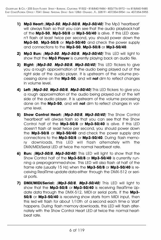
1) Mp3 Heart: (Mp3-50, Mp3-50/8, Mp3-50/40) The Mp3 �heartbeat�will always flash so that you can see that the audio playback halfof the Mp3-50, Mp3-50/8 or Mp3-50/40 is alive. If this LED does-n�t flash at least twice per second, you should power down theMp3-50, Mp3-50/8 or Mp3-50/40 and check the power supplyand connections to the Mp3-50, Mp3-50/8 or Mp3-50/40.
2) Mp3 Run: (Mp3-50, Mp3-50/8, Mp3-50/40) This LED will light toshow that the Mp3 Player is currently playing back an audio file.
3) Right: (Mp3-50, Mp3-50/8, Mp3-50/40) This LED flickers to giveyou a rough approximation of the audio being played out of theright side of the audio player. It is upstream of the volume pro-cessing done on the Mp3-50, and will not dim to reflect changesin volume level.
4) Left: (Mp3-50, Mp3-50/8, Mp3-50/40) This LED flickers to give youa rough approximation of the audio being played out of the leftside of the audio player. It is upstream of the volume processingdone on the Mp3-50, and will not dim to reflect changes in vol-ume level.
5) Show Control Heart: (Mp3-50/8, Mp3-50/40) The Show Control�heartbeat� will always flash so that you can see that the ShowControl half of the Mp3-50/8 or Mp3-50/40 is alive. If this LEDdoesn�t flash at least twice per second, you should power downthe Mp3-50/8 or Mp3-50/40 and check the power supply andconnections to the Mp3-50/8 or Mp3-50/40. During flash memo-ry downloads, this LED wil l f lash alternately with theDMX/MIDI/Serial LED at twice the normal heartbeat rate.
6) Run: (Mp3-50/8, Mp3-50/40) This LED will light to show that theShow Control half of the Mp3-50/8 or Mp3-50/40 is currently run-ning a preprogrammed show. This LED will also flash at half of theframe rate (usually 15 Hz) when the Mp3-50/8 or Mp3-50/40 is re-ceiving RealTime update data either through the DMX-512 or seri-al ports.
7) DMX/MIDI/Serial: (Mp3-50/8, Mp3-50/40) This LED will light toshow that the Mp3-50/8 or Mp3-50/40 is receiving RealTime Up-date data through the DMX-512, MIDI or serial ports. If the Mp3-50/8 or Mp3-50/40 is receiving show starts from MIDI input, thenthis led will flash for about 1/10th of a second each time a �start�happens. During flash memory downloads, this LED will flash alter-nately with the Show Control Heart LED at twice the normal heart-beat rate.
GILDERFLUKE & CO .� 205 SOUTH FLOWER STREET � BURBANK , CALIFORNIA 91502 � 818/840-9484 � 800/776-5972 � FAX 818/840-9485EAST COAST /FLORIDA OFFICE � 7041 GRAND NATIONAL DRIVE � SUITE 128d � ORLANDO , FL. 32819 � 407/354-5954 � FAX 407/354-5955
6 of 119

8) Board Error: (Mp3-50/8, Mp3-50/40) This LED will flash to showyou that the Mp3-50/8 or Mp3-50/40 has sensed one of the fol-lowing errors:
a) Just booted: Lights for a short period each time the Mp3-50/8 or Mp3-50/40�s microcontroller starts up.
b) RealTime DMX-512 Update Error: The optional checksum inthe DMX-512 RealTime update didn�t agree with the datareceived.
c) RealTime Serial Update Error: The checksum in the RS-422serial port RealTime update didn�t agree with the data re-ceived.
d) Download Error: There was an error in the data beingdownloaded to the Mp3-50/8 or Mp3-50/40.
e) Download Timeout: If the data being downloaded to theMp3-50/8 or Mp3-50/40 stops mid-stream, this LED will flashas the Mp3-50/8 or Mp3-50/40 returns itself to normal oper-ating mode.
f) Data Verification Failure: If you ask the Mp3-50/8 or Mp3-50/40 to verify the data in its flash memory, and it finds anerror, it will flash this LED as well as displaying an error mes-sage on your computer screen.
g) Memory locked: If you try to clear the flash memory orsend a show to the Mp3-50/8 or Mp3-50/40 while the WriteProtect is in the �locked� position.
9) J8 �A�, �B�, �C�, & �D� Input LEDs: (Mp3-50/8, Mp3-50/40) Thesefour LED will light to show current is flowing through the four ShowControl Trigger inputs. These LEDs are on the input side of the op-toisolators, so a dim glow may indicate an input is getting a cur-rent, but not necessarily enough to trigger an action. These fourtrigger inputs are the only way to use a switch closure input tostart the animated sequence playing on a Mp3-50/8 or Mp3-50/40.
10) Output LEDs (8 LEDs on Mp3-50, 8 LEDs on Mp3-50/8, 40 LEDson Mp3-50/40): These LEDs show the current status of the ShowControl digital outputs. If a LED is lit, then that output is �ON�. Be-cause the outputs of a Mp3-50/8 or Mp3-50/40 are �Open Col-lector, Switch To Ground�, you can ground out any output pin,and the appropriate LED will light. This can be useful when diag-nosing output wiring problems. If you are commanding �on� an
GILDERFLUKE & CO .� 205 SOUTH FLOWER STREET � BURBANK , CALIFORNIA 91502 � 818/840-9484 � 800/776-5972 � FAX 818/840-9485EAST COAST /FLORIDA OFFICE � 7041 GRAND NATIONAL DRIVE � SUITE 128d � ORLANDO , FL. 32819 � 407/354-5954 � FAX 407/354-5955
7 of 119

output and you don�t see a LED, then the output is probably draw-ing too much current and the output is �self protecting�. Discon-nect the load and see if the LED now lights. If it does, then it defi-nitely is an overload problem. If it does not, then try turning �on�some of the other outputs. If they light OK, then the output drivermight be damaged. If they do not, then verify your addressingand retest.
A Mp3-50 has eight optically isolated trigger inputs which canbe used to select, start and change the audio levels of the audiohalf of the Mp3-50 player. These LEDs will light to show trigger in-puts being sent into the audio half of the Mp3-50. The only out-put channel on a Mp3-50/8, and the last output channel on aMp3-50/40 are shared with these audio trigger inputs. Normallythese are not used to trigger the audio on a Mp3-50/8 or Mp3-50/40. The �hidden� MPU trigger inputs from the Show Control halfof the Mp3-50/8 or Mp3-50/40 are normally used instead. Thisleaves these eight outputs free to be used as outputs.
11) Fuses (1 LED on Mp3-50, 1 LED on Mp3-50/8, 5 LEDs on Mp3-50/40): The eight inputs of a Mp3-50 and the eight outputs of theMp3-50/8 or Mp3-50/40 make one, eight-bit wide �channel�. Theforty outputs of the Mp3-50/8 or Mp3-50/40 are divided into five,eight-bit wide �channels�.
The eight inputs of a Mp3-50, eight outputs of a Mp3-50/8,and last channel of a Mp3-50/40 are shared with the eight opti-cally isolated inputs to the audio half of the Mp3-50/8 or Mp3-50/40. This channel, and only this channel can be switched be-tween using �internal� and �external� power using the switch on thebottom of the unit. This will be lit when there is an external voltagesource present between pins #1 and #10 of the 1/4 J6 input,when the switch is in the �external� position. If the fuse LED is off forthis channel, check to make sure that this switch is not in the �ex-ternal� position if you are not feeding this channel an externalvoltage source.
Each channel is fused for approximately one Amp of continu-ous current. These LEDs light to show if the fuses are OK. If any areout, then a short circuit (or too heavy of a load) is dragging theoutputs down and causing the fuse to open. The fuses are actual-ly �PTC fuses�, which act more like circuit breakers. Once the over-load is removed, they reset.
GILDERFLUKE & CO .� 205 SOUTH FLOWER STREET � BURBANK , CALIFORNIA 91502 � 818/840-9484 � 800/776-5972 � FAX 818/840-9485EAST COAST /FLORIDA OFFICE � 7041 GRAND NATIONAL DRIVE � SUITE 128d � ORLANDO , FL. 32819 � 407/354-5954 � FAX 407/354-5955
8 of 119
Mp3-50, Mp3-50/8 or Mp3-50/40 Connections1) RS-232 Serial Port: (Mp3-50/8, Mp3-50/40) The serial command
set is identical to, and compatible with all of the RS-422 SerialPorts used on Gilderfluke & Company products. One differencebetween the Mp3-50/8 or Mp3-50/40 and most of our products isthat the serial port is the primary method used to configure it. AMp3-50/8 or Mp3-50/40 is normally configured through the �Mp3Configurator� program which is also used to configure the Mp3half. This configuration is downloaded to the Show Control half ofthe Mp3-50/8 or Mp3-50/40 each time the Mp3-50/8 or Mp3-50/40 is turned on. The Mp3-50/8 or Mp3-50/40 has a serial �con-figuration� mode which will allow you to check and modify the sta-tus and configuration of the Show Control half of the Mp3-50/8or Mp3-50/40. This is used to configure the animation half of aMp3-50/8 or Mp3-50/40 if the audio half is not yet, or never isgoing to be used.
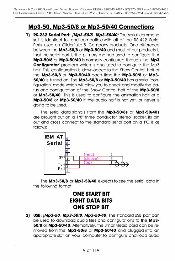
The serial data signals from the Mp3-50/8s or Mp3-50/40sare brought out on a 1/8� three conductor �stereo� socket. Its pinout and cross connect to the standard serial port on a PC is asfollows:
RxdTxd
gnd
IBM ATSerial
123456789
132(r ing)
( t ip)(sleeve)
The Mp3-50/8 or Mp3-50/40 expects to see the serial data inthe following format:
ONE START BITEIGHT DATA BITS
ONE STOP BIT2) USB: (Mp3-50, Mp3-50/8, Mp3-50/40) The standard USB port can
be used to download audio files and configurations to the Mp3-50/8 or Mp3-50/40. Alternatively, the SmartMedia card can be re-moved from the Mp3-50/8 or Mp3-50/40 and plugged into anappropriate slot on your computer to configure and load audio
GILDERFLUKE & CO .� 205 SOUTH FLOWER STREET � BURBANK , CALIFORNIA 91502 � 818/840-9484 � 800/776-5972 � FAX 818/840-9485EAST COAST /FLORIDA OFFICE � 7041 GRAND NATIONAL DRIVE � SUITE 128d � ORLANDO , FL. 32819 � 407/354-5954 � FAX 407/354-5955
9 of 119

files onto it. Once the Mp3-50/8 or Mp3-50/40 software drivershave been loaded onto your computer, you can plug a USBcable from your computer to the Mp3-50/8 or Mp3-50/40. Aftera few moments the Mp3-50/8 or Mp3-50/40 will appear on yourcomputer as a �removable hard disk drive�. You can then accessthe SmartMedia card in the Mp3-50/8 or Mp3-50/40 just as youwould any disk that is attached to your computer. You can evenuse the Mp3-50/8 or Mp3-50/40 to download pictures from theSmartMedia card you normally use in your digital camera.
3) Power Supply: (Mp3-50, Mp3-50/8, Mp3-50/40) The power sup-ply connections to the Mp3-50, Mp3-50/8 or Mp3-50/40 areavailable on both a 2.1 mm power jack and two of the screw ter-minal positions. For mobile, permanent or higher current applica-tions, you may wish to use the screw terminals instead of the 2.1mm power jack. It is less prone to being accidentally unpluggedor vibrating loose. The screw terminals are also a very convenientplace to �steal� a little �juice� to power the four optically isolated in-puts.
If you are not using the onboard amplifier, the Mp3-50, Mp3-50/8 or Mp3-50/40 can be run from any supply voltage from 9VDC to 24 VDC. If you are using the onboard amplifier and wantto reach the maximum possible power from the amplifier, you willneed to run the Mp3-50, Mp3-50/8 or Mp3-50/40 from 24 VDC.
The Show Control outputs are powered from this supply con-nection as well. If you are driving 24 VDC loads, then run theMp3-50, Mp3-50/8 or Mp3-50/40 on 24 VDC. If your loads re-quire 12 VDC, then run the Mp3-50, Mp3-50/8 or Mp3-50/40 on12 VDC.
The power supply connections are protected from reversedpolarity. An idle Mp3-50, Mp3-50/8 or Mp3-50/40 draws onlyabout ??? milliamperes. The onboard amplifier and loads whichthe Mp3-50, Mp3-50/8 or Mp3-50/40 is controlling will usuallydraw far more current than the Mp3-50, Mp3-50/8 or Mp3-50/40itself. If you are using the onboard amplifier, you should allow atleast 25 Watts for it, in addition to the current for controlling youranimation loads (Mp3-50/8 and Mp3-50/40). If you hear �clicks� orclipping on your amplifier outputs, then your power supply capac-ity may need to be increased.
4) DMX-512/MIDI Serial In: (Mp3-50/8, Mp3-50/40) Two positionScrew Terminals. This input can be selected for RS-422 (high-z) oroptoisolated (low-z) input by a switch on the bottom of the unit.
GILDERFLUKE & CO .� 205 SOUTH FLOWER STREET � BURBANK , CALIFORNIA 91502 � 818/840-9484 � 800/776-5972 � FAX 818/840-9485EAST COAST /FLORIDA OFFICE � 7041 GRAND NATIONAL DRIVE � SUITE 128d � ORLANDO , FL. 32819 � 407/354-5954 � FAX 407/354-5955
10 of 119
DMX-512 is normally used with the �RS-422� position. MIDI will onlywork in the �optoisolated� position. The Net Serial or IR Triggermodes are normally used in the �RS-422� position, but will actuallywork in either position.
If you need to optically isolate the signal, but feed multipleMp3-50/8 or Mp3-50/40, you can use a single Mp3-50/8 orMp3-50/40 as an isolator/buffer: The external signal can be fedinto one of the �optoisolated� DMX/MIDI inputs on any one Mp3-50/8 or Mp3-50/40, and the other units fed in parallel from theDMX/MIDI output from that first unit. All of these other �down-stream� Mp3-50/8s or Mp3-50/40s should have their inputs set forRS-422.
This connection has five possible modes of operation. Theseare selected through the �Mp3 Configurator� program.
a) DMX-512: The switch on the bottom of the Mp3-50 shouldbe in the RS-422/High-z position to be used for DMX-512.The Mp3-50/8 or Mp3-50/40 will stop playing any showsfrom the onboard flash memory as soon as valid DMX-512signal is received.
The DMX-512 standard was developed by the UnitedStates Institute for Theatrical Technology (USITT) for a highspeed (250 KBaud) asynchronous serial data link. Although itwas originally designed for controlling light dimmers, it isnow supported by hundreds of suppliers throughout theworld for controlling all kinds of theatrical equipment.
Even though the DMX-512 standard calls for 512 chan-nels of data, the DMX-512 transmission from PC�MACs islimited to 256 eight-bit wide channels. If you have enabledthe DMX-512 checksum, you can address your DMX-512compatible output devices to respond to any address be-tween 0 and 255. Addresses above the 256th are used inPC�MACs for transmitting a checksum. The Mp3-50/8 orMp3-50/40 can use this to verify that the data receivedfrom PC�MACs has no transmission errors in it. If you ad-dress a light dimmer or other DMX-512 device to addresses256 or 257, you will see this verification data displayed as aflickering pattern.
If you have NOT selected DMX-512 checksums, the�Mp3 Configurator� will allow you to set the addresses forDMX-512 to any address from 1 through 512. Address �1� is
GILDERFLUKE & CO .� 205 SOUTH FLOWER STREET � BURBANK , CALIFORNIA 91502 � 818/840-9484 � 800/776-5972 � FAX 818/840-9485EAST COAST /FLORIDA OFFICE � 7041 GRAND NATIONAL DRIVE � SUITE 128d � ORLANDO , FL. 32819 � 407/354-5954 � FAX 407/354-5955
11 of 119

equivalent to address �0� if you were using checksums.
The DMX-512 checksums should be enabled if the DMX-512 that is sent to the Mp3-50/8 or Mp3-50/40 is comingfrom ANY piece of Gilderfluke & Company equipment. Thechecksums assure that the Mp3-50/8 or Mp3-50/40 will notupdate its outputs on �bad� data.
b) MIDI Notes: The switch on the bottom of the Mp3-50 mustbe in the optoisolated/Low-z position to be used for MIDI.The MIDI should be fed to the Mp3-50/8 or Mp3-50/40 asfollows:
MIDI pin #1 = no connectionMIDI pin #2 = no connectionMIDI pin #3 = no connectionMIDI pin #4 into - DMX/MIDI InMIDI pin #5 into + DMX/MIDI In
The Mp3-50/8 or Mp3-50/40 will respond to MIDI �NoteOn�, �Note Off�, �Reset�, �All Notes Off� and �All Sounds Off�.Running commands for �Note On� and �Note Off� com-mands are accepted. All other defined MIDI commandsshould be received and properly ignored. There are twoways the Mp3-50/8 or Mp3-50/40 can be configured to re-spond to MIDI Note commands.
1) When �MIDI Notes Trigger Animation� checkbox is OFF,then MIDI is used to directly access the Show ControlOutputs and Mp3 audio files:a) Any MIDI notes which are below the number
you have set for the �MIDI Offset� are ignored.b) The next eight (Mp3-50/8) or forty (Mp3-50/40)
MIDI notes are mapped directly to the 8/40Show Control outputs. These can be used toring mechanical bells or control animation di-rectly from MIDI notes.
c) The next eight MIDI notes are sent to the �MPUInterface� to select and trigger audio files,mute, and otherwise control the Mp3 Player.
d) The remaining notes are used to directly selectand play individual AudioFiles stored on theMp3 Player. Only note �On� MIDI commands willhave any effect on selecting and playing Au-dioFiles. The �velocity� of the note will set theplayback level of the triggered AudioFile, if Re-
GILDERFLUKE & CO .� 205 SOUTH FLOWER STREET � BURBANK , CALIFORNIA 91502 � 818/840-9484 � 800/776-5972 � FAX 818/840-9485EAST COAST /FLORIDA OFFICE � 7041 GRAND NATIONAL DRIVE � SUITE 128d � ORLANDO , FL. 32819 � 407/354-5954 � FAX 407/354-5955
12 of 119

alTime level control has been enabled on theMp3 Player.The DMX/MIDI/Serial LED will be lit once MIDI is re-
ceived through this port. This LED will remain on forapproximately 10 seconds after the MIDI is removedfrom the Mp3-50/8 or Mp3-50/40. The Mp3-50/8 orMp3-50/40 will stop playing any shows from the on-board flash memory as soon as valid MIDI signal is re-ceived. It will not restart automatically if the MIDI sig-nal is removed.
2) When �MIDI Notes Trigger Animation� checkbox is ON,then MIDI notes are used to directly access Animationsequences stored in the flash on the Mp3-50/8 orMp3-50/40. These sequences in turn can accessaudio files on the Mp3 Player, as well as controllingthe Show Control outputs. When operating in thismode:a) Any MIDI notes which are below the number
you have set for the �MIDI Offset� are ignored.b) The remaining notes are used to directly select
and play individual animation sequences storedon the Show Control half of the Mp3-50/8 orMp3-50/40. These animation sequences can inturn select and play audio files and controlaudio levels on the Mp3 Player. Only �Note On�commands are used to select and play animat-ed shows when operating in this mode.The DMX/MIDI/Serial LED will be flash for 1/10 sec-
ond each time a preprogrammed show is started by aMIDI note. The Show Control side of the Mp3-50/8 orMp3-50/40 can still accept starts though the serialport and four trigger inputs while operating in thismode.
c) Net Serial: The Optoisolated/RS-422 switch on the bottomof the Mp3-50 can be in either position. If feeding multipleMp3-50/8 or Mp3-50/40, then the �RS-422� position shouldbe used.
One big disadvantage of the RS-232 serial port on theMp3-50/8 or Mp3-50/40 is that only one Mp3-50/8 or Mp3-50/40 can be attached to the same serial port at the sametime. This is the unfortunate nature of a RS-232 port. If youhad a bunch of Mp3-50s in the same system, this could
GILDERFLUKE & CO .� 205 SOUTH FLOWER STREET � BURBANK , CALIFORNIA 91502 � 818/840-9484 � 800/776-5972 � FAX 818/840-9485EAST COAST /FLORIDA OFFICE � 7041 GRAND NATIONAL DRIVE � SUITE 128d � ORLANDO , FL. 32819 � 407/354-5954 � FAX 407/354-5955
13 of 119

quickly chew up a lot of serial ports! Most of our other prod-ucts use RS-422 serial ports. Along with being able to runyour wires up to a mile (RS-232 is limited to about 50 feet ifthe wind is blowing in the right direction), RS-422 allows lotsof devices to be attached to the same serial port at thesame time.
Because it is not uncommon to access and control alarge number of repeaters on the same serial line, the DMX-512/MIDI input can be selected to turn the DMX-512/MIDIport into a multidrop Serial network. This mode parallels thedata received on the DMX-512/MIDI input pins with the seri-al data received on the regular RS-232 serial port. The serialdata is still output from the Mp3-50/8 or Mp3-50/40 stillcomes ONLY through the RS-232 serial port on the front tothe unit.
This serial port can be used to select and play shows,check the status of a card, or AutoDownload shows fromany point on the network. Since it is 100% compatible withthe RS-422 serial ports on all other Gilderfluke & Companyequipment, a multidrop network can consist of up to 256Mp3-50/8 or Mp3-50/40 and any other Gilderfluke & Com-pany devices. The only requirement is that they all be set tounique addresses.
Since RS-422 is probably the most widely used of indus-trial data networks, a myriad of other pieces of equipmentare available which will also work with the Net Serial mode.These allow you to do tricks like controlling the Mp3-50/8 orMp3-50/40 through a wireless modem using off-the-shelfhardware.
A typical application is to use a touch screen operatorinterface to access and play shows. These generally use auser definable graphical interface. You pretty much draw abutton, and then attach a string to it. When this on-screenbutton is pushed, this string is sent out to control the down-stream equipment.
d) IR Mode: The Optoisolated/RS-422 switch on the bottom ofthe Mp3-50 can be in either position, but RS-422 is pre-ferred. This turns on a special serial port mode on the Mp3-50/8 or Mp3-50/40 which allows it to be used with our In-fraRed Transmitters and Receivers. The IR Remote mode istypically used to trigger an animation or sound system
GILDERFLUKE & CO .� 205 SOUTH FLOWER STREET � BURBANK , CALIFORNIA 91502 � 818/840-9484 � 800/776-5972 � FAX 818/840-9485EAST COAST /FLORIDA OFFICE � 7041 GRAND NATIONAL DRIVE � SUITE 128d � ORLANDO , FL. 32819 � 407/354-5954 � FAX 407/354-5955
14 of 119

mounted on a vehicle, turntable, or other installation wherewires can�t be used. The DMX-512 /MIDI port is forced to1200 baud and all serial port commands are disabled onthe DMX-512/MIDI port when this mode is ON. Any binaryshow number received by the serial port for more than tentimes will trigger the requested show. Typically the transmit-ters are placed along the path of the vehicle�s travel to trig-ger the appropriate animation sequences at the appropri-ate times.
The connections to the IR Remote Receiver are as fol-lows (view is facing end of cable with latch up):
NAME COLOR SIGNAL FUNCTIONLEFT Ground WHITE Ground
n/c BLACK no connectionn/c RED no connection
- TxD GREEN - DMX-512/MIDI Input+ TxD YELLOW + DMX-512/MIDI Input
RIGHT Ground BLUE GroundIn addition to these connections, the IR Receiver re-
quires a 7 to 24 volt DC power supply connection. This isnormally attached to the two pads marked �+� and �-� onthe receiver. A jumper option allows you to bring this inthrough the blue wire on the RJ-11 connector.
When in this mode the �Early Starts� for all shows shouldbe set to �NOT Steppable�. If this is not done, then the sameshow will be retriggered over and over again until the vehi-cle moves out of the IR beam from the transmitter.
The IR Transmitter has an eight position dipswitch whichsets which show it selects. The lower nibble of the addressare set with the first four switches, and the upper nibble isset with the last four. Valid show numbers are 01h throughFFh:
GILDERFLUKE & CO .� 205 SOUTH FLOWER STREET � BURBANK , CALIFORNIA 91502 � 818/840-9484 � 800/776-5972 � FAX 818/840-9485EAST COAST /FLORIDA OFFICE � 7041 GRAND NATIONAL DRIVE � SUITE 128d � ORLANDO , FL. 32819 � 407/354-5954 � FAX 407/354-5955
15 of 119

SWITCH #1 SWITCH #2 SWITCH #3 SWITCH #4 LOWER NIBBLE OF ADDRESS
OFF OFF OFF OFF x0hON OFF OFF OFF x1hOFF ON OFF OFF x2hON ON OFF OFF x3hOFF OFF ON OFF x4hON OFF ON OFF x5hOFF ON ON OFF x6hON ON ON OFF x7hOFF OFF OFF ON x8hON OFF OFF ON x9hOFF ON OFF ON xAhON ON OFF ON xBhOFF OFF ON ON xChON OFF ON ON xDhOFF ON ON ON xEhON ON ON ON xFh
SWITCH #5 SWITCH #6 SWITCH #7 SWITCH #8 UPPER NIBBLE OF ADDRESS
OFF OFF OFF OFF 0xhON OFF OFF OFF 1xhOFF ON OFF OFF 2xhON ON OFF OFF 3xhOFF OFF ON OFF 4xhON OFF ON OFF 5xhOFF ON ON OFF 6xhON ON ON OFF 7xhOFF OFF OFF ON 8xhON OFF OFF ON 9xhOFF ON OFF ON AxhON ON OFF ON BxhOFF OFF ON ON CxhON OFF ON ON DxhOFF ON ON ON ExhON ON ON ON Fxh
e) None: If the DMX-512/MIDI input is not being used, then theDMX-512 transmission is enabled on the DMX-512/MIDI out-put terminals.
5) DMX-512/MIDI Output: (Mp3-50/8, Mp3-50/40) Two positionScrew Terminals. If any of the modes where the DMX-512/MIDIinput is being used (DMX-512 Input, MIDI Input, Net Serial or IRTrigger), this pair of screw terminals will retransmit whatever comesin on the DMX-512/MIDI inputs. This works something like the �MIDI
GILDERFLUKE & CO .� 205 SOUTH FLOWER STREET � BURBANK , CALIFORNIA 91502 � 818/840-9484 � 800/776-5972 � FAX 818/840-9485EAST COAST /FLORIDA OFFICE � 7041 GRAND NATIONAL DRIVE � SUITE 128d � ORLANDO , FL. 32819 � 407/354-5954 � FAX 407/354-5955
16 of 119

Through� port on a MIDI device, where no content changes takeplace in the data as it passes through the Mp3-50/8 or Mp3-50/40. The data is simply buffered and retransmitted.
The output levels on these pins is RS-422. It can be used di-rectly to control other RS-422 devices. For MIDI, you should add apair of 220 Ohm resistors in series with the two output wires, butthis is not strictly necessary (there are already resistors in the MIDIdevices which may be receiving this signal).
The MIDI should be wired from the Mp3-50/8 or Mp3-50/40 tothe next MIDI device as follows:
MIDI pin #1 = no connectionMIDI pin #2 = Shield (ground)MIDI pin #3 = no connectionMIDI pin #4 from - DMX/MIDI OutMIDI pin #5 from + DMX/MIDI Out
If none of the serial Receive modes of the Mp3-50/8 or Mp3-50/40 (DMX-512 Input, MIDI Input, Net Serial or IR Trigger) arebeing used, then the serial port is turned around and used totransmit DMX-512. Data for this DMX-512 output stream comesfrom either the RS-232 serial port if the Mp3-50/8 or Mp3-50/40 isbeing fed RealTime update messages, or the Show Control flashmemory, if shows have been programmed into the Mp3-50/8 orMp3-50/40.
DMX-512 transmission is limited to sixteen, eight bit widechannels. The addresses of these DMX-512 channels are set inone of two ways:
a) If running from RealTime updates through the RS-232 serialport, the DMX-512 data will always start with channel �0�(which is channel �1� on most dimmers). Data after the firstchannel will be padded with �0� values through the 256thbyte, and then followed by two checksum bytes.
The Show Control Outputs, Audio Level Control, And Re-peater Control channels typically overlap with some of thelighting control channels when operated in this mode.
b) If running from a show file which has been AutoDownload-ed to the Mp3-50/8 or Mp3-50/40�s Flash memory, the �Firstaddress� of the downloaded data will be the first DMX-512channel to have your programmed data in it. Channels be-fore and after these sixteen channels will be padded with �0�
GILDERFLUKE & CO .� 205 SOUTH FLOWER STREET � BURBANK , CALIFORNIA 91502 � 818/840-9484 � 800/776-5972 � FAX 818/840-9485EAST COAST /FLORIDA OFFICE � 7041 GRAND NATIONAL DRIVE � SUITE 128d � ORLANDO , FL. 32819 � 407/354-5954 � FAX 407/354-5955
17 of 119

values up until the 256th bytes sent, then followed with atwo byte checksum.
The Show Control Outputs, Audio Level Control, And Re-peater Control channels often overlap with some of thelighting control channels when operated in this mode. Ifyou don�t want to do this, you can actually use all sixteenDMX-512 channels for lighting control if you address yourShow Control Outputs, Audio Level Control, and RepeaterControl channels after the sixteen lighting control channels.Of course this will eat up your Flash memory capacitymighty quickly.
6) Status Output: (Mp3-50) Two position Screw Terminals. This outputis the uncommitted collector (+) and emitter (-) of a darlingtonoptoisolator. It can be used as a remote �audio running� indicatorfor an external system. The current capability of this output is onlyabout 50 ma.. It can be used to drive LEDs and solid state relays,but not heavy or inductive loads.
7) Left Speaker Output: (Mp3-50, Mp3-50/8, Mp3-50/40) Two posi-tion Screw Terminals. This is one of the two outputs of the Mp3-50, Mp3-50/8 or Mp3-50/40 �s onboard amplifier. It can be usedwith any speakers from 4 ohms upwards. The amplifier is rated fora maximum output of 11 Watts per channel. This is plenty power-ful for most applications. External amplifiers can be fed from theLine Level Outputs if more power than this is needed.
8) Right Speaker Output: (Mp3-50, Mp3-50/8, Mp3-50/40) Two po-sition Screw Terminals. This is one of the two outputs of the Mp3-50, Mp3-50/8 or Mp3-50/40�s onboard amplifier. It can be usedwith any speakers from 4 ohms upwards. The amplifier is rated fora maximum output of 11 Watts per channel. This is plenty power-ful for most applications. External amplifiers can be fed from theLine Level Outputs if more power than this is needed.
9) �1/4 J6� Inputs/Outputs: Ten Position IDS Connector. This connec-tion serves two completely different functions, using the verysame pins:
Mp3-50: These pins are used to connect to the eight opticallyisolated trigger inputs which are used to select AudioFiles,start, mute, half mute, pause, or unmute the Mp3 Player.What each of these pins will do is set using the �Mp3 Con-figurator� program. These inputs CAN NOT be used to startan animation sequence running on the Show Control half
GILDERFLUKE & CO .� 205 SOUTH FLOWER STREET � BURBANK , CALIFORNIA 91502 � 818/840-9484 � 800/776-5972 � FAX 818/840-9485EAST COAST /FLORIDA OFFICE � 7041 GRAND NATIONAL DRIVE � SUITE 128d � ORLANDO , FL. 32819 � 407/354-5954 � FAX 407/354-5955
18 of 119

of a Mp3-50/8 or Mp3-50/40.
Mp3-50/8: This connector is used for the optically isolated trig-ger inputs of the Mp3 Player, but these are not normallyused to control the Mp3 Player. The same connector is alsoused as the eight Show Control outputs. The inputs to theMp3 Player are typically configured not to do anything,and the �MCU� Show Control Trigger channel is used insteadfor controlling the Mp3 Player. This leaves all eight of thesepins available for Show Control Outputs.
If you need to use a switch input to mute or stop theaudio, it can still be wired into this connector. The input tothe Mp3 Player is then configured for the desired function.The corresponding Show Control output is left unpro-grammed, so that show data does not interfere with the op-eration of the Mp3 Player.
Mp3-50/40: This connector is also used as the optically isolatedtrigger inputs the Mp3 Player, and the last eight of the fortyShow Control outputs. Other than that, it is identical to aMp3-50/8.
SUPPLY (not used)
(Brown) PIN #1
(red) PIN #2
(orange) PIN #3
(yellow) PIN #4
(green) PIN #5
(blue) PIN #6
(violet) PIN #7
(grey) PIN #8
(white) PIN #9
(black) PIN #10
GROUND
DATA BIT 7
DATA BIT 6
DATA BIT 5
DATA BIT 4
DATA BIT 3
DATA BIT 2
DATA BIT 1
DATA BIT 0
+ 5 to 24 VDC SUPPLY
GROUND
DATA BIT 7
DATA BIT 6
DATA BIT 5
DATA BIT 4
DATA BIT 3
DATA BIT 2
DATA BIT 1
DATA BIT 0
Internal PowerExternal Power
(Brown) PIN #1
(red) PIN #2
(orange) PIN #3
(yellow) PIN #4
(green) PIN #5
(blue) PIN #6
(violet) PIN #7
(grey) PIN #8
(white) PIN #9
(black) PIN #10
For a Mp3-50, the 1/4 J6 input is strictly a Mp3 input. It is opti-cally isolated. It can be set to run from an external power sourceor the same power as the Mp3-50, Mp3-50/8 or Mp3-50/40 (de-fault configuration). This is selected by moving the switch on thebottom of the Mp3-50, Mp3-50/8 or Mp3-50/40. The �external�
GILDERFLUKE & CO .� 205 SOUTH FLOWER STREET � BURBANK , CALIFORNIA 91502 � 818/840-9484 � 800/776-5972 � FAX 818/840-9485EAST COAST /FLORIDA OFFICE � 7041 GRAND NATIONAL DRIVE � SUITE 128d � ORLANDO , FL. 32819 � 407/354-5954 � FAX 407/354-5955
19 of 119

setting is used when you want to completely isolate the Mp3-50,Mp3-50/8 or Mp3-50/40 from the switch closures that control it.
On a Mp3-50/8 or Mp3-50/40, this input/output is almost al-ways run in the �Internal� power mode. The only exception to this isif you are going to be running the devices controlled by theseeight Show Control outputs from a different voltage from the restof the Mp3-50/8 or Mp3-50/40. As an example, it the Mp3-50/8or Mp3-50/40 is running from 24 VDC, and you need to controleight 12 VDC relays, you can power this one port from a 12 VDCpower supply separate from the main one (you will need to con-nect the grounds of the two power supplies).
10) Left Line Output: Female RCA jack. This is one of the two line leveloutputs from the Mp3 Player. It is used for attaching an externalamplifier to the Mp3-50, Mp3-50/8 or Mp3-50/40.
11) Right Line Output: Female RCA jack. This is one of the two linelevel outputs from the Mp3 Player. It is used for attaching an ex-ternal amplifier to the Mp3-50, Mp3-50/8 or Mp3-50/40.
12) J8 �A�, �B�, �C� & �D� inputs: These are four optically isolated digitalinputs which can be used to start, stop, pause or select specificshow sequences to play on the Show Control of the Mp3-50/8 orMp3-50/40.
+5 to 24 VDC SUPPLY
Switching Negative Side
+5 to 24 VDC SUPPLY
+5 to 24 VDC SUPPLY
+5 to 24 VDC SUPPLY
+5 to 24 VDC SUPPLY
Switching Positive Side
+5 to 24 VDC SUPPLY
+5 to 24 VDC SUPPLY
+5 to 24 VDC SUPPLY
- 'A'/Green Input
+ 'A'/Green Input
- 'B'/Red Input
+ 'B'/Red Input
- 'C'/Blue Input
+ 'C'/Blue Input
- 'D'/White Input
+ 'D'/White Input
+ 'A'/Green Input
- 'A'/Green Input
+ 'B'/Red Input
+ 'C'/Blue Input
- 'B'/Red Input
- 'C'/Blue Input
+ 'D'/White Input
- 'D'/White Input
GILDERFLUKE & CO .� 205 SOUTH FLOWER STREET � BURBANK , CALIFORNIA 91502 � 818/840-9484 � 800/776-5972 � FAX 818/840-9485EAST COAST /FLORIDA OFFICE � 7041 GRAND NATIONAL DRIVE � SUITE 128d � ORLANDO , FL. 32819 � 407/354-5954 � FAX 407/354-5955
20 of 119

In most cases, you will simply be �borrowing the power forthese switches from the adjacent power terminals:
RS-422isolated
externalinternal
'A'
'B'
'C'
'D'
Pow
er
9-24 vdc
Spe
ake
rLe
ftSp
ea
ker
Right
DM
X/M
IDI
In
DM
X/M
IDI
Out
4
4
Trigger Power(switch on bottom)
76543210
Fuse
76543210
Fuse
3 2 1 0
3 2 1 0 MP3-50/40Gilderfluke & Company � Burbank, California
DMX/MIDI input(switch on bottom)
01234567
Fuse
Pow
er
9-24 vdcground
Switch 'A'
Switch 'B'
Switch 'C'
Switch 'D'
Any event can be triggered on either the �closing� or �opening�edge of any input. A �closing� is when you apply a voltage to aninput. An �opening� is when that voltage is removed. The inputscan be triggered on any voltage from 12 to 24 VDC. If you don�thave an external source of power for these two inputs, you can�steal� some juice from the Mp3-50/8s or Mp3-50/40s power sup-ply connections.The two screw terminals with the Mp3-50�s poweron them are immediately adjacent to these inputs for just this pur-pose.
These four inputs are uncommitted optoisolators. Effectively,you are sending the external control signal into a LED which has aresistor wired in series. This requires external power be suppliedfrom somewhere. If the device you are controlling the input fromsupplies power, then all is well. If you are wiring these inputs tosimple dry switch closures, you will need to �steal� the power forthem from somewhere. Conveniently, there is the �power� screwterminals adjacent. You can pick up whatever power is beingused to run the Mp3-50/8 or Mp3-50/40 from these two screwterminals.
�A�, �B�, �C� & �D� Binary: Firmware versions 1.07 and lateronly. The four optically isolated digital inputs can be used to se-lect up to fifteen different shows directly with a binary weightedpattern of bits. TO do this, you must set all four of these inputs(both opening & closing edges) as �unused� when you generateyour AutoDownload file from PC�MACs. The binary pattern is ap-plied as follows:
GILDERFLUKE & CO .� 205 SOUTH FLOWER STREET � BURBANK , CALIFORNIA 91502 � 818/840-9484 � 800/776-5972 � FAX 818/840-9485EAST COAST /FLORIDA OFFICE � 7041 GRAND NATIONAL DRIVE � SUITE 128d � ORLANDO , FL. 32819 � 407/354-5954 � FAX 407/354-5955
21 of 119
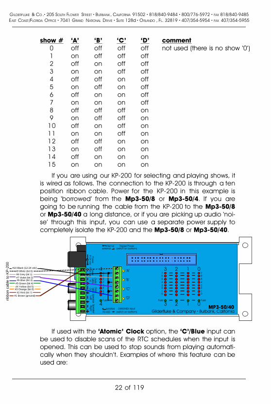
show # �A� �B� �C� �D� comment0 off off off off not used (there is no show �0�)1 on off off off2 off on off off3 on on off off4 off off on off5 on off on off6 off on on off7 on on on off8 off off off on9 on off off on
10 off on off on11 on on off on12 off off on on13 on off on on14 off on on on15 on on on on
If you are using our KP-200 for selecting and playing shows, itis wired as follows. The connection to the KP-200 is through a tenposition ribbon cable. Power for the KP-200 in this example isbeing �borrowed� from the Mp3-50/8 or Mp3-50/4. If you aregoing to be running the cable from the KP-200 to the Mp3-50/8or Mp3-50/40 a long distance, or if you are picking up audio �noi-se� through this input, you can use a separate power supply tocompletely isolate the KP-200 and the Mp3-50/8 or Mp3-50/40.
RS-422isolated
externalinternal
'A'
'B'
'C'
'D'
Pow
er
9-24 vdc
Spe
ake
rLe
ftSp
ea
ker
Right
DM
X/M
IDI
In
DM
X/M
IDI
Out
4
4
Trigger Power(switch on bottom)
76543210
Fuse
76543210
Fuse
3 2 1 0
3 2 1 0MP3-50/40
Gilderfluke & Company � Burbank, CaliforniaDMX/MIDI input
(switch on bottom)
01234567
Fuse
Pow
er
9-24 vdc
#1 Brown (ground) #2 Red (bit 7)
#3 Orange (bit 6) #4 Yellow (bit 5) #5 Green (bit 4) #6 Blue (bit 3) #7 Violet (bit 2) #8 Grey (bit 1) #9 White (bit 0)
#10 Black (12-24 vdc)
ribbo
n ca
ble
to K
P-2
00
If used with the �Atomic� Clock option, the �C�/Blue input canbe used to disable scans of the RTC schedules when the input isopened. This can be used to stop sounds from playing automati-cally when they shouldn�t. Examples of where this feature can beused are:
GILDERFLUKE & CO .� 205 SOUTH FLOWER STREET � BURBANK , CALIFORNIA 91502 � 818/840-9484 � 800/776-5972 � FAX 818/840-9485EAST COAST /FLORIDA OFFICE � 7041 GRAND NATIONAL DRIVE � SUITE 128d � ORLANDO , FL. 32819 � 407/354-5954 � FAX 407/354-5955
22 of 119

a) In a church bell tower, where a simple switch opening canbe used to temporarily disable bells from ringing during aservice.
b) In a Theme Park, where this input can be tied to the existingpower management grid to disable tolling when the park isclosed.
c) If you have a show or sound which should not be interrupt-ed by a scheduled event, or if schedule scans are causingglitches in your show playback. You can set the show/soundso that it �can not� be stepped on, but if you have a particu-larly long schedule that must be scanned, it may cause ahesitation in the show which is running. By using a showcontrol output wired into this input, you can control whenschedule scans can and can not take place during differ-ent parts of the show.
If used with the �Atomic� Clock option, the �D�/White input iswhat is used to resynchronize the RTC with the external �Atomic�Clock. The time which has been entered in the Mp3 Configura-tor must agree with the time set for the alarm on the �Atomic�Clock module. In most cases, the reset time is set about a sec-ond earlier than the �alarm� time, to offset for the slight delays instarting a Mp3 playback.
We are using 3:05:01 as the default resynchronization time.The external �Atomic� Clock MUST be set so that the alarm goesoff at 03:05:00. The extra second we are offsetting by is to allowfor the 1 second lag before a Mp3 SoundFile starts playing after itis triggered. It is at 3:05 AM so that when daylight savings startsand ends, there will be no more than one hour before the Mp3-50/8 or Mp3-50/40 is resynchronized to the appropriate time. Anyearlier, and the daylight savings transition might be missed untilthe next resynchronization time.
A single two conductor cable connects the �Atomic� Clockmodule to the Mp3-50/8 or Mp3-50/40. This wire lands on the�D�/White input to the Mp3-50/8 or Mp3-50/40 (the striped lead isthe positive, bottom most terminal). The input to the Mp3-50/8 orMp3-50/40 is optically isolated. If needed, you can stretch thesewires for hundreds of feet, if needed.
The link between the �Atomic� Clock module and the Mp3-50/8 or Mp3-50/40 can be tested by pressing the �snooze� buttonatop the �Atomic� Clock. This will light the back light on the LCD
GILDERFLUKE & CO .� 205 SOUTH FLOWER STREET � BURBANK , CALIFORNIA 91502 � 818/840-9484 � 800/776-5972 � FAX 818/840-9485EAST COAST /FLORIDA OFFICE � 7041 GRAND NATIONAL DRIVE � SUITE 128d � ORLANDO , FL. 32819 � 407/354-5954 � FAX 407/354-5955
23 of 119

display, as well as the LED indicator for the �D�/White input to theMp3-50/8 or Mp3-50/40. This will also set the RTC inside the Mp3-50/8 or Mp3-50/40 to the completely WRONG time, if the con-nection is working. You must manually set the time within theMp3-50/8 or Mp3-50/40 after testing it in this way. If you don�twant this to happen when testing this connection, power downthe Mp3-50/8 or Mp3-50/40 before doing this test. The LED willlight even with the Mp3-50/8 or Mp3-50/40 off. Power the Mp3-50/8 or Mp3-50/40 back up when you are finished testing.
To permanently prevent such accidental clock 'miss' settingsafter the �Atomic� Clock is installed, you can open the batterycompartment and cut the wire which runs through it. This will dis-able the �snooze� button, and thereby prevent it being hit acci-dentally in the future.
13) �J6� Digital Outputs: Forty Position IDS Connector. Each Mp3-50/40 has forty outputs. This connector is used for the first thirty-two outputs. The last eight appear on the �1/4 J6� connector onthe back of the Mp3-50/40.
These J6 Show Control outputs are just like the standard out-puts used on all Gilderfluke & Company Show Control Systems.Forty and ten position transition connectors are available for theMp3-50/8s or Mp3-50/40s to adapt the ribbon cables to screwterminals.
The output connections for all Gilderfluke & Company ShowControl Systems are through �J-6� output cables. These are fortywire ribbon cables which are made up of four identical eight-bitwide �channels�. A J-6 cable is often split up into four individualchannels. Each �1/4 J-6� ribbon cable is made up of ten wires,and can be used to control eight individual �digital� (off/on) de-vices, or one eight-bit wide �analog� device. Each group of tenwires also includes a common power supply and ground wire.
To simplify wiring to any Gilderfluke animation system, theconnectors used on the 1/4 J-6 cables are what are called �insu-lation displacement� (IDS) connectors. These simply snap on to anentire cable, automatically �displacing� the wire insulation andmaking contact with the wires within. This means that an entireten wire cable can be terminated in seconds. All connectors arepolarized, to keep them from being plugged in backwards. Al-though there are tools made specifically for installing these con-nectors, the tool we find works best is a small bench vise.
GILDERFLUKE & CO .� 205 SOUTH FLOWER STREET � BURBANK , CALIFORNIA 91502 � 818/840-9484 � 800/776-5972 � FAX 818/840-9485EAST COAST /FLORIDA OFFICE � 7041 GRAND NATIONAL DRIVE � SUITE 128d � ORLANDO , FL. 32819 � 407/354-5954 � FAX 407/354-5955
24 of 119

If attaching discrete wires from the J6 ribbon cable connectorpresents a problem, we have forty and ten position transition con-nectors are available for the Mp3-50/8s or Mp3-50/40s to adaptthe ribbon cables to screw terminals. Ribbon cable to screw termi-nal adapters are also available from a number of differentsources.
Any eight digital devices or one eight-bit analog device canbe connected to any 1/4 J-6 cable as shown. The LED betweenthe ground (pin #1 brown) wire and supply (pin #10 black) wireacts as an indicator that is lit if the fuse for that channel is OK.
All outputs are open collector switches to ground. Small fly-back diodes are included in the outputs for driving inductiveloads. Larger inductive loads may require flyback diodes be in-stalled directly across the loads. Power is supplied through a diodeand a solid state circuit breaker to the common pin(s) on the con-nector. A safe level of current is 150 milliamperes simultaneouslyon each output. This is sufficient to drive most small relays, valvesand other similar loads directly. If fewer than eight outputs are onat one time, then the outputs are rated as follows.
typical output typical input
fuseflybackdiode
supply supply
The supply line for each 1/4 J-6 is PTC fused for 1 amp. Youshould treat each 1/4 J-6 as an individual, and not cross the out-puts or supply lines from one channel to the lines from any otherchannel. Doing this won�t cause any damage, but can reducethe protection for the outputs that the fuses normally provide.
The current Output Capacity of each output is as shown inthe following chart:
GILDERFLUKE & CO .� 205 SOUTH FLOWER STREET � BURBANK , CALIFORNIA 91502 � 818/840-9484 � 800/776-5972 � FAX 818/840-9485EAST COAST /FLORIDA OFFICE � 7041 GRAND NATIONAL DRIVE � SUITE 128d � ORLANDO , FL. 32819 � 407/354-5954 � FAX 407/354-5955
25 of 119

400ma.
600ma.
500ma.
300ma.
200ma.
100ma.
2
3
4
5
87
6
Output Duty Cycle
Allo
wab
le P
eak
Col
lect
or C
urre
nt @
70º
C
Peak Collector Current as a function of Output Duty Cycle
10% 20% 30% 40% 50% 60% 70% 80% 90% 100%
Number of outputs conducting
simultaneously
GILDERFLUKE & CO .� 205 SOUTH FLOWER STREET � BURBANK , CALIFORNIA 91502 � 818/840-9484 � 800/776-5972 � FAX 818/840-9485EAST COAST /FLORIDA OFFICE � 7041 GRAND NATIONAL DRIVE � SUITE 128d � ORLANDO , FL. 32819 � 407/354-5954 � FAX 407/354-5955
26 of 119

Each J-6 cable is arranged in the following order:wire number color wire function
1 brown circuit ground2 red channel 0 data bit 73 orange channel 0 data bit 64 yellow channel 0 data bit 55 green channel 0 data bit 46 blue channel 0 data bit 37 violet channel 0 data bit 28 gray channel 0 data bit 19 white channel 0 data bit 0
10 black + VDC unregulated power supply
11 brown circuit ground12 red channel 1 data bit 713 orange channel 1 data bit 614 yellow channel 1 data bit 515 green channel 1 data bit 416 blue channel 1 data bit 317 violet channel 1 data bit 218 gray channel 1 data bit 119 white channel 1 data bit 020 black + VDC unregulated power supply
21 brown circuit ground22 red channel 2 data bit 723 orange channel 2 data bit 624 yellow channel 2 data bit 525 green channel 2 data bit 426 blue channel 2 data bit 327 violet channel 2 data bit 228 gray channel 2 data bit 129 white channel 2 data bit 030 black + VDC unregulated power supply
31 brown circuit ground32 red channel 3 data bit 733 orange channel 3 data bit 634 yellow channel 3 data bit 535 green channel 3 data bit 436 blue channel 3 data bit 337 violet channel 3 data bit 238 gray channel 3 data bit 139 white channel 3 data bit 040 black + VDC unregulated power supply
GILDERFLUKE & CO .� 205 SOUTH FLOWER STREET � BURBANK , CALIFORNIA 91502 � 818/840-9484 � 800/776-5972 � FAX 818/840-9485EAST COAST /FLORIDA OFFICE � 7041 GRAND NATIONAL DRIVE � SUITE 128d � ORLANDO , FL. 32819 � 407/354-5954 � FAX 407/354-5955
27 of 119
Since it is unusual to have more than 50% of the outputs onat any one time, you can usually assume the system has a 250ma output current capacity per output. If you are going to beturning on lots of heavy loads at the same time, you should der-ate this to 150 ma.. This is sufficient to drive the majority of loadswhich will be directly connected to the outputs of the animationsystem. If additional current capacity is needed, or if you need todrive higher voltage loads, you can connect relays as needed tothe outputs of the animation system. Coincidentally, boards fordoing this are available from Gilderfluke & Company. These in-clude:
DPDT relay board: A set of eight electromechanical relays withdouble pole/double throw contacts rated at 5 amps each.
Reed relay board: A set of eight small electromechanical relayswith normally open contacts rated at 150 ma each.
I/O module: A set of eight small solid state relays with normallyopen contacts rated at 3.5 amps each (alternating currentand direct current relays available).
Solid State Relay Fanning Strip: For connecting up to eightpopular �hockey puck� style relays to a 1/4 J-6 output cable.These are available with capacities of up to 75 amps each.
GILDERFLUKE & CO .� 205 SOUTH FLOWER STREET � BURBANK , CALIFORNIA 91502 � 818/840-9484 � 800/776-5972 � FAX 818/840-9485EAST COAST /FLORIDA OFFICE � 7041 GRAND NATIONAL DRIVE � SUITE 128d � ORLANDO , FL. 32819 � 407/354-5954 � FAX 407/354-5955
28 of 119

Mp3-50/CC-10 Card CageThe Mp3-50/CC-10 is a card cage designed to hold up to ten Mp3-
50s in 2U (3-1/2�) of standard 19� rack space. The Mp3-50/CC-10 can alsobe used with Mp3-50/8 or Mp3-50/40, but there is no space between thecards for the animation trigger inputs or Show Control Outputs (Mp3-50/40only). In most cases, you will have to leave every slot adjacent to a Mp3-50/8 or Mp3-50/40 vacant.
Once installed in a Mp3-50/CC-10, the DMX-512/MIDI serial ports onMp3-50/8 or Mp3-50/40 cards are all daisy chained together. These serialports can be used for DMX-512, networked serial, IR Triggers or MIDI input toMp3-50/8 or Mp3-50/40 cards. Mp3-50s do not include the DMX-512/MIDIserial port.
Mp3-50, Mp3-50/8 or Mp3-50/40 cards are installed in a Mp3-50/CC-10 by first removing the two screws which hold the connector card to theend of the Mp3-50. The connector card at the end of the Mp3-50 is thenremoved to be installed in the Mp3-50/CC-10.
GILDERFLUKE & CO .� 205 SOUTH FLOWER STREET � BURBANK , CALIFORNIA 91502 � 818/840-9484 � 800/776-5972 � FAX 818/840-9485EAST COAST /FLORIDA OFFICE � 7041 GRAND NATIONAL DRIVE � SUITE 128d � ORLANDO , FL. 32819 � 407/354-5954 � FAX 407/354-5955
29 of 119

The same two screws which you removed are inserted through thesame holes through the connector card of the Mp3-50, but going the op-posite direction. These two screws are then used to hold the connectorcard into the Mp3-50/CC-10 (the cards and the screws are installedthrough the front of the cage). As the connector card is plugged in to thebackplane, make sure that all twelve pins of J2 are inserted correctly intothe mating connector on the backplane of the Mp3-50/CC-10.
Now the Mp3-50, Mp3-50/8 or Mp3-50/40 can be plugged into thecard cage. Nothing else needs to be removed or changed on the Mp3-50,Mp3-50/8 or Mp3-50/40 before they inserted into the Mp3-50/CC-10.
Power can be wired into any of the card cage positions, or through theheavy current screw terminals. The latter should be used if you are usingthe amplifiers or Show Control outputs on Mp3-50/8 or Mp3-50/40 cards.This is because the total current draw can exceed the capacity of the 2.1mm power connector or smaller screw terminals located on the back ofeach Mp3-50.
The DMX-512/MIDI serial port is daisy chained from higher numbered
GILDERFLUKE & CO .� 205 SOUTH FLOWER STREET � BURBANK , CALIFORNIA 91502 � 818/840-9484 � 800/776-5972 � FAX 818/840-9485EAST COAST /FLORIDA OFFICE � 7041 GRAND NATIONAL DRIVE � SUITE 128d � ORLANDO , FL. 32819 � 407/354-5954 � FAX 407/354-5955
30 of 119

slots towards lower number slots. If a single slot is left unpopulated, or popu-lated with a Mp3-50, will break the daisy chain. This can be used to dividethe backplane into two or more universes.
If you are daisy chaining MIDI, run the MIDI signal into the highest num-bered populated slot in the Mp3-50/CC-10. This card MUST be set for anoptoisolated, current loop input. All of the consecutive cards downstreamof the first card should be set for RS-422 operation.
If you are daisy chaining DMX-512 or networked serial commands, all ofthe cards should be set for RS-422 operation. Again, the signal is wired intothe highest numbered populated slot and will be daisy chained through allof the adjacent lower numbered slots.
An Mp3-50, Mp3-50/8 or Mp3-50/40 can be converted back to stand-alone use by simply reversing the installation process. Remove the twoscrews which hold the connector card into the Mp3-50/CC-10, Plug it backinto the Mp3-50, Mp3-50/8 or Mp3-50/40, and secure it with the twoscrews.
GILDERFLUKE & CO .� 205 SOUTH FLOWER STREET � BURBANK , CALIFORNIA 91502 � 818/840-9484 � 800/776-5972 � FAX 818/840-9485EAST COAST /FLORIDA OFFICE � 7041 GRAND NATIONAL DRIVE � SUITE 128d � ORLANDO , FL. 32819 � 407/354-5954 � FAX 407/354-5955
31 of 119

PC�MACs Shows for Mp3-50/8This section gives some hints for setting up the shows that will be used
by the Show Control side of a Mp3-50/8. There are literally thousands ofpossible configuration arrangements. Most applications will use one of thefollowing configurations. The most common configuration is the �b� option.The �Show Capacities� shown is at 30 frames (updates) per second.
Mp3-50/8: 1st MPU DMX- Vol. Vol. Show# description Anim. Control 512 Right Left Capacitya 8 digitals/MPU 0 x x x x 5 Hoursb 8 digitals, 8 MPU 0 1 x x x 2.5 hoursc 8 digitals, 8 MPU, 1 volume 0 1 x 2 2 97 min.d 8 digitals, 8 MPU, 2 volume 0 1 x 2 3 72 min.e 8 digitals, 8 MPU, DMX-512 0 1 2 x x 18-97 min.f 8 digitals, 8 MPU, 16 DMX 16 17 0 x x 16 min.
Mp3-50/8 Show Configurations: The Mp3-50/8 has eight Show Controloutputs on one eight bit wide channel. Additional channels you maychoose to use are the MPU Trigger channel (so you don�t have to loose anydigital outputs for triggering the Mp3 Player), RealTime Audio Level ControlChannels, and DMX-512 output channels.
In all but the first of the following examples, the eight digitals can beused as one analog channel. The Show Control outputs will need to be fedthrough a Digital to Analog Converter (DAC-08) to convert the digital chan-nels to a single analog voltage output.
a) Mp3-50/8 with One Combined Show Control/Mp3 ControlChannel: At a minimum, all you would need to program is theone eight bit wide Show Control output channel. This would meanthat you would have to give up some number of your digital out-puts to use for triggering the Mp3 Player. The Mp3 Player is con-figured for triggering AudioFile starts on the normal 1/4 J6 inputs.
This configuration gives you a show capacity of approximatelyfive hours in the onboard Flash memory.
Starting with a blank site file, you can create all the channelsyou need by:
1) Open PC�MACs, Create a 'New' show. Go to 'ChannelsPulldown'/'Create Multiple Channels....'.
2) Select eight digital and zero analog channels. The first eightoutputs (on channel �0�) will go to the Show Control Out-puts. These will be used for both Show Control and trigger-
GILDERFLUKE & CO .� 205 SOUTH FLOWER STREET � BURBANK , CALIFORNIA 91502 � 818/840-9484 � 800/776-5972 � FAX 818/840-9485EAST COAST /FLORIDA OFFICE � 7041 GRAND NATIONAL DRIVE � SUITE 128d � ORLANDO , FL. 32819 � 407/354-5954 � FAX 407/354-5955
32 of 119

ing the Mp3 Player.
3) Click �OK� to create these channels.
When you have finished programming your show you willAutoDownload it to the Mp3-50/8. Set the �First Channel� to �0�and the �Last Channel� to �0� on the PC�MACs File Pulldown/Saveas AutoDownload.... window.
In the Mp3 Configurator Program:
1) Track Setup Tab: Point it at your SmartMedia card and set asneeded.
2) PlayLists Tab: Set up as needed, if needed.
3) Audio Tab: Set audio levels and EQ as needed. Disable Re-alTime Audio Level Control. Enable/Disable amplifier asneeded.
4) Input Tab: You will be overlapping this input channel withthe Show Control outputs of the Mp3-50/8. Set up some ofthe inputs to select and start AudioFiles, as needed. Don�tforget to save a few outputs for the Show control!
5) MPU Input Tab: You will be using the Optoisolated inputs inthis case. Disable ALL of the MPU Inputs.
6) Serial Control Tab: The Brick Address is usually set at '0', un-less you will be accessing the card using Net Serial com-mands. The Repeater Control Channel is unused, so it canbe set anywhere. First animation Channel Number must beset to '0'. Disable/Enable Net Serial and IR Trigger modes ifneeded (these are usually disabled)
7) DMX-512 Control Tab: Enable DMX-512 Control, unless youare using MIDI, Net Serial or IR Trigger Modes. Enable DMX-512 checksums if you will be feeding DMX-512 from anyGilderfluke & Company products (usually enabled). The Re-peater Control Channel and First Animation channel num-ber were set on a previous tab.
8) MIDI Control Tab: Disable MIDI, unless you plan to use it.Disable MIDI Notes Trigger Animation Playback, unless youplan to use it. Set MIDI Channel Number and Animation FirstNote number if you will be using MIDI, otherwise, ignorethem.
9) Flash Setup Tab: Enable Animation from Flash, unless youwil l never be using the onboard show storage.
GILDERFLUKE & CO .� 205 SOUTH FLOWER STREET � BURBANK , CALIFORNIA 91502 � 818/840-9484 � 800/776-5972 � FAX 818/840-9485EAST COAST /FLORIDA OFFICE � 7041 GRAND NATIONAL DRIVE � SUITE 128d � ORLANDO , FL. 32819 � 407/354-5954 � FAX 407/354-5955
33 of 119

Enable/Disable outputs when stopped, as needed. Leavethe Write Protect Flash unchecked, or you will not be able tosave the show you are creating to the Mp3-50/8 or Mp3-50/40. Disable it after you have completed programming, ifneeded. The Repeater Control Channel and First Animationchannel number were set on a previous tab.
b) Mp3-50/8 with One Show Control, One Mp3 Control Channel:The most typical installation for a Mp3-50/8 uses one eight bitchannel for Show Control, and a second one for controlling theMp3 playback. This means that none of the Show Control outputsare �lost� to the Mp3 Player. The Mp3 Player is configured for trig-gering AudioFile starts on the MPU input bits.
This configuration gives you a show capacity of approximately2-1/2 hours in the onboard Flash memory.
Starting with a blank site file, you can create all the channelsyou need by:
1) Open PC�MACs, Create a 'New' show. Go to 'ChannelsPulldown'/'Create Multiple Channels....'.
2) Select sixteen digital and zero analog channels. The firsteight outputs (on channel �0�) will go to the Show ControlOutputs. The last eight outputs (on channel �1�) will be usedfor triggering the Mp3 Player.
3) Click �OK� to create these channels.
When you have finished programming your show you willAutoDownload it to the Mp3-50/8. Set the �First Channel� to �0�and the �Last Channel� to �1� on the PC�MACs File Pulldown/Saveas AutoDownload.... window.
In the Mp3 Configurator Program:
1) Track Setup Tab: Point it at your SmartMedia card and set asneeded.
2) PlayLists Tab: Set up as needed, if needed.
3) Audio Tab: Set audio levels and EQ as needed. Disable Re-alTime Audio Level Control. Enable/Disable amplifier asneeded.
4) Input Tab: You will be using the MPU inputs in this case. Dis-able ALL of the Optoisolated Inputs.
GILDERFLUKE & CO .� 205 SOUTH FLOWER STREET � BURBANK , CALIFORNIA 91502 � 818/840-9484 � 800/776-5972 � FAX 818/840-9485EAST COAST /FLORIDA OFFICE � 7041 GRAND NATIONAL DRIVE � SUITE 128d � ORLANDO , FL. 32819 � 407/354-5954 � FAX 407/354-5955
34 of 119

5) MPU Input Tab: Set up the inputs to select and start Au-dioFiles and ramp audio levels, as needed.
6) Serial Control Tab: The Brick Address is usually set at '0', un-less you will be accessing the card using Net Serial com-mands. The Repeater Control Channel must be set to '1'.First animation Channel Number must be set to '0'.Disable/Enable Net Serial and IR Trigger modes as needed(these are usually disabled)
7) DMX-512 Control Tab: Enable DMX-512 Control, unless youare using MIDI, Net Serial or IR Trigger Modes. Enable DMX-512 checksums if you will be feeding DMX-512 from anyGilderfluke & Company products (usually enabled). The Re-peater Control Channel and First Animation channel num-ber were set on a previous tab.
8) MIDI Control Tab: Disable MIDI, unless you plan to use it.Disable MIDI Notes Trigger Animation Playback, unless youplan to use it. Set MIDI Channel Number and Animation FirstNote number if you will be using MIDI, otherwise, ignorethem.
9) Flash Setup Tab: Enable Animation from Flash, unless youwil l never be using the onboard show storage.Enable/Disable outputs when stopped, as needed. Leavethe Write Protect Flash unchecked, or you will not be able tosave the show you are creating to the Mp3-50/8 or Mp3-50/40. Disable it after you have completed programming, ifneeded. The Repeater Control Channel and First Animationchannel number were set on a previous tab.
c) Mp3-50/8 with One Audio Level Control Channel: This configu-ration adds a single analog channel which can be used to con-trol the audio level of the Mp3 Player as a part of the show con-trol file.
This configuration gives you a show capacity of approximately97 minutes in the onboard Flash memory.
Starting with a blank site file, you can create all the channelsyou need by:
1) Open PC�MACs, Create a 'New' show. Go to 'ChannelsPulldown'/'Create Multiple Channels....'.
2) Select sixteen digital and zero analog channels. The firsteight outputs (on channel �0�) will go to the Show Control
GILDERFLUKE & CO .� 205 SOUTH FLOWER STREET � BURBANK , CALIFORNIA 91502 � 818/840-9484 � 800/776-5972 � FAX 818/840-9485EAST COAST /FLORIDA OFFICE � 7041 GRAND NATIONAL DRIVE � SUITE 128d � ORLANDO , FL. 32819 � 407/354-5954 � FAX 407/354-5955
35 of 119

Outputs. The last eight outputs (on channel �1�) will be usedfor triggering the Mp3 Player.
3) Click �OK� to create these channels.
4) Go to PC�MACs 'Channels Pulldown'/'Create Multiple Chan-nels....'.
5) Select zero digital and one 8 bit analog channel. This will beyour audio level control channel at address �2�.
6) Click �OK� to create this channel.
When you have finished programming your show you willAutoDownload it to the Mp3-50/8. Set the �First Channel� to �0�and the �Last Channel� to �2� on the PC�MACs File Pulldown/Saveas AutoDownload.... window.
In the Mp3 Configurator Program:
1) Track Setup Tab: Point it at your SmartMedia card and set asneeded.
2) PlayLists Tab: Set up as needed, if needed.
3) Audio Tab: Set audio levels and EQ as needed. Enable Real-Time Audio Level Control. You can control one or both out-puts from the analog channel you have created. Set theaddresses of the Level Control Channels to �2�.Enable/Disable amplifier as needed.
4) Input Tab: You will be using the MPU inputs in this case. Dis-able ALL of the Optoisolated Inputs.
5) MPU Input Tab: Set up the inputs to select and start Au-dioFiles and ramp audio levels, as needed.
6) Serial Control Tab: The Brick Address is usually set at '0', un-less you will be accessing the card using Net Serial com-mands. The Repeater Control Channel must be set to '1'.First animation Channel Number must be set to '0'.Disable/Enable Net Serial and IR Trigger modes as needed(these are usually disabled)
7) DMX-512 Control Tab: Enable DMX-512 Control, unless youare using MIDI, Net Serial or IR Trigger Modes. Enable DMX-512 checksums if you will be feeding DMX-512 from anyGilderfluke & Company products (usually enabled). The Re-peater Control Channel and First Animation channel num-ber were set on a previous tab.
GILDERFLUKE & CO .� 205 SOUTH FLOWER STREET � BURBANK , CALIFORNIA 91502 � 818/840-9484 � 800/776-5972 � FAX 818/840-9485EAST COAST /FLORIDA OFFICE � 7041 GRAND NATIONAL DRIVE � SUITE 128d � ORLANDO , FL. 32819 � 407/354-5954 � FAX 407/354-5955
36 of 119

8) MIDI Control Tab: Disable MIDI, unless you plan to use it.Disable MIDI Notes Trigger Animation Playback, unless youplan to use it. Set MIDI Channel Number and Animation FirstNote number if you will be using MIDI, otherwise, ignorethem.
9) Flash Setup Tab: Enable Animation from Flash, unless youwil l never be using the onboard show storage.Enable/Disable outputs when stopped, as needed. Leavethe Write Protect Flash unchecked, or you will not be able tosave the show you are creating to the Mp3-50/8 or Mp3-50/40. Disable it after you have completed programming, ifneeded. The Repeater Control Channel and First Animationchannel number were set on a previous tab.
d) Mp3-50/8 with Two Audio Level Control Channels: This configu-ration adds two analog channels which can be used to indepen-dently control the left and right audio levels of the Mp3 Player asa part of the show control file.
This configuration gives you a show capacity of approximately72 minutes in the onboard Flash memory.
Starting with a blank site file, you can create all the channelsyou need by:
1) Open PC�MACs, Create a 'New' show. Go to 'ChannelsPulldown'/'Create Multiple Channels....'.
2) Select sixteen digital and zero analog channels. The firsteight outputs (on channel �0�) will go to the Show ControlOutputs. The last eight outputs (on channel �1�) will be usedfor triggering the Mp3 Player.
3) Click �OK� to create these channels.
4) Go to PC�MACs 'Channels Pulldown'/'Create Multiple Chan-nels....'.
5) Select zero digital and two, 8 bit analog channel. These willbe your audio level control channels at addresses �2� and�3�.
6) Click �OK� to create these channels.
When you have finished programming your show you willAutoDownload it to the Mp3-50/8. Set the �First Channel� to �0�and the �Last Channel� to �3� on the PC�MACs File Pulldown/Save
GILDERFLUKE & CO .� 205 SOUTH FLOWER STREET � BURBANK , CALIFORNIA 91502 � 818/840-9484 � 800/776-5972 � FAX 818/840-9485EAST COAST /FLORIDA OFFICE � 7041 GRAND NATIONAL DRIVE � SUITE 128d � ORLANDO , FL. 32819 � 407/354-5954 � FAX 407/354-5955
37 of 119

as AutoDownload.... window.
In the Mp3 Configurator Program:
1) Track Setup Tab: Point it at your SmartMedia card and set asneeded.
2) PlayLists Tab: Set up as needed, if needed.
3) Audio Tab: Set audio levels and EQ as needed. Enable Real-Time Audio Level Control. Each audio output has its ownanalog channel to control it. Set the addresses of the LevelControl Channels to �2� and �3�. Enable/Disable amplifier asneeded.
4) Input Tab: You will be using the MPU inputs in this case. Dis-able ALL of the Optoisolated Inputs.
5) MPU Input Tab: Set up the inputs to select and start Au-dioFiles and ramp audio levels, as needed.
6) Serial Control Tab: The Brick Address is usually set at '0', un-less you will be accessing the card using Net Serial com-mands. The Repeater Control Channel must be set to '1'.First animation Channel Number must be set to '0'.Disable/Enable Net Serial and IR Trigger modes as needed(these are usually disabled)
7) DMX-512 Control Tab: Enable DMX-512 Control, unless youare using MIDI, Net Serial or IR Trigger Modes. Enable DMX-512 checksums if you will be feeding DMX-512 from anyGilderfluke & Company products (usually enabled). The Re-peater Control Channel and First Animation channel num-ber were set on a previous tab.
8) MIDI Control Tab: Disable MIDI, unless you plan to use it.Disable MIDI Notes Trigger Animation Playback, unless youplan to use it. Set MIDI Channel Number and Animation FirstNote number if you will be using MIDI, otherwise, ignorethem.
9) Flash Setup Tab: Enable Animation from Flash, unless youwil l never be using the onboard show storage.Enable/Disable outputs when stopped, as needed. Leavethe Write Protect Flash unchecked, or you will not be able tosave the show you are creating to the Mp3-50/8 or Mp3-50/40. Disable it after you have completed programming, ifneeded. The Repeater Control Channel and First Animationchannel number were set on a previous tab.
GILDERFLUKE & CO .� 205 SOUTH FLOWER STREET � BURBANK , CALIFORNIA 91502 � 818/840-9484 � 800/776-5972 � FAX 818/840-9485EAST COAST /FLORIDA OFFICE � 7041 GRAND NATIONAL DRIVE � SUITE 128d � ORLANDO , FL. 32819 � 407/354-5954 � FAX 407/354-5955
38 of 119
e) Mp3-50/8 with DMX-512 w/Overlapping Channels: This configu-ration goes back to the typical installation (�b� above) and addsone or more channels of DMX-512 output. If you are using SerialRealTime Update mode during programming, this is the only con-figuration which will allow you to access ALL of the Show controland DMX-512 channels through the serial port.
The DMX-512 transmission always starts with the first channelstored in the Flash memory, and transmits the first sixteen consec-utive channels. The two channels of Show Control (one for thedigital outputs and one for the MPU control) are sent out throughthe first two channels of DMX-512 (you probably don�t want to puta dimmer on these channels). This leaves somewhere betweenone and fourteen channels of DMX-512 output for lighting, mov-ing lights, or whatever.
Depending on the number of DMX channels you need, thisconfiguration gives a capacity of between 97 and 18 minutes inthe onboard Flash memory.
Starting with a blank site file, you can create all the channelsyou need by:
1) Open PC�MACs, Create a 'New' show. Go to 'ChannelsPulldown'/'Create Multiple Channels....'.
2) Select sixteen digital and zero analog channels. The firsteight outputs (on channel �0�) will go to the Show ControlOutputs. The last eight outputs (on channel �1�) will be usedfor triggering the Mp3 Player.
3) Click �OK� to create these channels.
4) Go to PC�MACs 'Channels Pulldown'/'Create Multiple Chan-nels....'.
5) Select zero digital and between one and fourteen, 8 bitanalog channels. These will be your DMX-512 channelsstarting at address �2� and going to a maximum of �15�.
6) Click �OK� to create these channels.
When you have finished programming your show you willAutoDownload it to the Mp3-50/8. Set the �First Channel� to �0�and the �Last Channel� to between �2� and �15� on the PC�MACsFile Pulldown/Save as AutoDownload.... window.
In the Mp3 Configurator Program:
1) Track Setup Tab: Point it at your SmartMedia card and set as
GILDERFLUKE & CO .� 205 SOUTH FLOWER STREET � BURBANK , CALIFORNIA 91502 � 818/840-9484 � 800/776-5972 � FAX 818/840-9485EAST COAST /FLORIDA OFFICE � 7041 GRAND NATIONAL DRIVE � SUITE 128d � ORLANDO , FL. 32819 � 407/354-5954 � FAX 407/354-5955
39 of 119

needed.
2) PlayLists Tab: Set up as needed, if needed.
3) Audio Tab: Set audio levels and EQ as needed. Disable Re-alTime Audio Level Control. Enable/Disable amplifier asneeded.
4) Input Tab: You will be using the MPU inputs in this case. Dis-able ALL of the Optoisolated Inputs.
5) MPU Input Tab: Set up the inputs to select and start Au-dioFiles and ramp audio levels, as needed.
6) Serial Control Tab: The Brick Address is usually set at '0', un-less you will be accessing the card using Net Serial com-mands. The Repeater Control Channel must be set to '1'.First Animation Channel Number must be set to '0'. DisableNet Serial and IR Trigger modes.
7) DMX-512 Control Tab: Disable DMX-512 Control. The Re-peater Control Channel and First Animation channel num-ber were set on a previous tab.
8) MIDI Control Tab: Disable MIDI and MIDI Notes Trigger Ani-mation Playback. Disregard MIDI Channel Number and Ani-mation First Note number.
9) Flash Setup Tab: Enable Animation from Flash, unless youwil l never be using the onboard show storage.Enable/Disable outputs when stopped, as needed. Leavethe Write Protect Flash unchecked, or you will not be able tosave the show you are creating to the Mp3-50/8 or Mp3-50/40. Disable it after you have completed programming, ifneeded. The Repeater Control Channel and First Animationchannel number were set on a previous tab.
f) Mp3-50/8 with Sixteen DMX-512 Channels: This configurationgoes back to the typical installation (�b� above) and adds sixteenchannels of DMX-512 output. If you are using Serial RealTime Up-date mode during programming, you will only be able to accessthe DMX-512 channels through the serial port. The show controlports are located above sixteen channels, so they will not be up-dated in RealTime.
The DMX-512 transmission always starts with the first channelstored in the Flash memory, and transmits the first sixteen consec-utive channels. This is where the DMX-512 data will live.
GILDERFLUKE & CO .� 205 SOUTH FLOWER STREET � BURBANK , CALIFORNIA 91502 � 818/840-9484 � 800/776-5972 � FAX 818/840-9485EAST COAST /FLORIDA OFFICE � 7041 GRAND NATIONAL DRIVE � SUITE 128d � ORLANDO , FL. 32819 � 407/354-5954 � FAX 407/354-5955
40 of 119

This configuration consumes eighteen channels of Flash. Thisgives a capacity of 16 minutes in the onboard Flash memory.
Starting with a blank site file, you can create all the channelsyou need by:
1) Open PC�MACs, Create a 'New' show. Go to 'ChannelsPulldown'/'Create Multiple Channels....'.
2) Select sixteen digital and sixteen analog channels. The six-teen analog channels which will be sent tout through theDMX-512 output are located at channels �0� through �15�.The first eight digital outputs (on channel �16�) will go to theShow Control Outputs. The last eight outputs (on channel�17�) will be used for triggering the Mp3 Player.
3) Click �OK� to create these channels.
When you have finished programming your show you willAutoDownload it to the Mp3-50/8. Set the �First Channel� to �0�and the �Last Channel� to �17� on the PC�MACs File Pulldown/Saveas AutoDownload.... window.
In the Mp3 Configurator Program:
1) Track Setup Tab: Point it at your SmartMedia card and set asneeded.
2) PlayLists Tab: Set up as needed, if needed.
3) Audio Tab: Set audio levels and EQ as needed. Disable Re-alTime Audio Level Control. Enable/Disable amplifier asneeded.
4) Input Tab: You will be using the MPU inputs in this case. Dis-able ALL of the Optoisolated Inputs.
5) MPU Input Tab: Set up the inputs to select and start Au-dioFiles and ramp audio levels, as needed.
6) Serial Control Tab: The Brick Address is usually set at '0', un-less you will be accessing the card using Net Serial com-mands. The Repeater Control Channel must be set to �17�.First Animation Channel Number must be set to �16�. DisableNet Serial and IR Trigger modes.
7) DMX-512 Control Tab: Disable DMX-512 Control. The Re-peater Control Channel and First Animation channel num-ber were set on a previous tab.
8) MIDI Control Tab: Disable MIDI and MIDI Notes Trigger Ani-
GILDERFLUKE & CO .� 205 SOUTH FLOWER STREET � BURBANK , CALIFORNIA 91502 � 818/840-9484 � 800/776-5972 � FAX 818/840-9485EAST COAST /FLORIDA OFFICE � 7041 GRAND NATIONAL DRIVE � SUITE 128d � ORLANDO , FL. 32819 � 407/354-5954 � FAX 407/354-5955
41 of 119

mation Playback. Disregard MIDI Channel Number and Ani-mation First Note number.
9) Flash Setup Tab: Enable Animation from Flash, unless youwil l never be using the onboard show storage.Enable/Disable outputs when stopped, as needed. Leavethe Write Protect Flash unchecked, or you will not be able tosave the show you are creating to the Mp3-50/8 or Mp3-50/40. Disable it after you have completed programming, ifneeded. The Repeater Control Channel and First Animationchannel number were set on a previous tab.
GILDERFLUKE & CO .� 205 SOUTH FLOWER STREET � BURBANK , CALIFORNIA 91502 � 818/840-9484 � 800/776-5972 � FAX 818/840-9485EAST COAST /FLORIDA OFFICE � 7041 GRAND NATIONAL DRIVE � SUITE 128d � ORLANDO , FL. 32819 � 407/354-5954 � FAX 407/354-5955
42 of 119

PC�MACs Shows for Mp3-50/40This section gives some hints for setting up the shows that will be used
by the Show Control side of a Mp3-50/40. There are literally thousands ofpossible configuration arrangements. Most applications will use one of thefollowing configurations. The most common configuration is the �b� option.The �Show Capacities� shown is at 30 frames (updates) per second.
Mp3-50/40: 1st MPU DMX- Vol. Vol. Show# description Anim. Control 512 Right Left Capacitya 40 digitals/MPU 0 4 x x x 1 Hourb 40 digitals, 8 MPU 0 5 x x x 48 min.c 40 digitals, 8 MPU, 1 volume 0 5 x 6 6 41 min.d 40 digitals, 8 MPU, 2 volume 0 5 x 6 7 36 min.e 40 digitals, 8 MPU, DMX-512 0 5 6 x x 18-41 min.f 40 digitals, 8 MPU, 16 DMX 16 17 0 x x 13 min.
Mp3-50/40 Show Configurations: The Mp3-50/40 has forty Show Con-trol outputs on five eight bit wide channel. Additional channels you maychoose to use are the MPU Trigger channel (so you don�t have to loose anydigital outputs for triggering the Mp3 Player), RealTime Audio Level ControlChannels, and DMX-512 output channels.
The forty Show Control outputs are normally used for digital outputs onthe Mp3-50/40. Using an external Digital to Analog converter (DAC-08 orDAC-Quad), one or more of the analog channels can be used for analogfunctions. In the following descriptions, you are creating forty digital outputsfor use on the forty digital Show Control outputs. The digitals can be com-bined with analog functions in any of the following combinations:
1 analog and 32 digitals2 analogs and 24 digitals3 analogs and 16 digitals4 analogs and 8 digitals5 analogs and 0 digitals
a) Mp3-50/40 with One Combined Show Control/Mp3 ControlChannel: At a minimum, all you would need to program is fiveeight bit wide Show Control output channels. This would meanthat you would have to give up some number of your last chan-nel�s digital outputs to use for triggering the Mp3 Player. The Mp3Player is configured for triggering AudioFile starts on the normal1/4 J6 inputs.
This configuration gives you a show capacity of approximatelyone hour in the onboard Flash memory.
GILDERFLUKE & CO .� 205 SOUTH FLOWER STREET � BURBANK , CALIFORNIA 91502 � 818/840-9484 � 800/776-5972 � FAX 818/840-9485EAST COAST /FLORIDA OFFICE � 7041 GRAND NATIONAL DRIVE � SUITE 128d � ORLANDO , FL. 32819 � 407/354-5954 � FAX 407/354-5955
43 of 119
Starting with a blank site file, you can create all the channelsyou need by:
1) Open PC�MACs, Create a 'New' show. Go to 'ChannelsPulldown'/'Create Multiple Channels....'.
2) Select forty digital and zero analog channels. The digitalsthat come out of the J6 connector are addressed from �0�through �3�. The digitals that will come out of the 1/4 J6 areaddressed at �4�.
3) Click �OK� to create these channels.
When you have finished programming your show you willAutoDownload it to the Mp3-50/8. Set the �First Channel� to �0�and the �Last Channel� to �4� on the PC�MACs File Pulldown/Saveas AutoDownload.... window.
In the Mp3 Configurator Program:
1) Track Setup Tab: Point it at your SmartMedia card and set asneeded.
2) PlayLists Tab: Set up as needed, if needed.
3) Audio Tab: Set audio levels and EQ as needed. Disable Re-alTime Audio Level Control. Enable/Disable amplifier asneeded.
4) Input Tab: You will be overlapping this input channel withthe Show Control outputs of the Mp3-50/8. Set up some ofthe inputs to select and start AudioFiles, as needed. Don�tforget to save a few outputs for the Show control!
5) MPU Input Tab: You will be using the Optoisolated inputs inthis case. Disable ALL of the MPU Inputs.
6) Serial Control Tab: The Brick Address is usually set at '0', un-less you will be accessing the card using Net Serial com-mands. The Repeater Control Channel is unused, so it canbe set anywhere. First animation Channel Number must beset to '0'. Disable/Enable Net Serial and IR Trigger modes ifneeded (these are usually disabled)
7) DMX-512 Control Tab: Enable DMX-512 Control, unless youare using MIDI, Net Serial or IR Trigger Modes. Enable DMX-512 checksums if you will be feeding DMX-512 from anyGilderfluke & Company products (usually enabled). The Re-peater Control Channel and First Animation channel num-ber were set on a previous tab.
GILDERFLUKE & CO .� 205 SOUTH FLOWER STREET � BURBANK , CALIFORNIA 91502 � 818/840-9484 � 800/776-5972 � FAX 818/840-9485EAST COAST /FLORIDA OFFICE � 7041 GRAND NATIONAL DRIVE � SUITE 128d � ORLANDO , FL. 32819 � 407/354-5954 � FAX 407/354-5955
44 of 119

8) MIDI Control Tab: Disable MIDI, unless you plan to use it.Disable MIDI Notes Trigger Animation Playback, unless youplan to use it. Set MIDI Channel Number and Animation FirstNote number if you will be using MIDI, otherwise, ignorethem.
9) Flash Setup Tab: Enable Animation from Flash, unless youwil l never be using the onboard show storage.Enable/Disable outputs when stopped, as needed. Leavethe Write Protect Flash unchecked, or you will not be able tosave the show you are creating to the Mp3-50/8 or Mp3-50/40. Disable it after you have completed programming, ifneeded. The Repeater Control Channel and First Animationchannel number were set on a previous tab.
b) Mp3-50/40 with Five Show Control, One Mp3 Control Channel:The most typical installation for a Mp3-50/8 uses five eight bitchannel for Show Control, and a final channel for controlling theMp3 playback. This means that none of the Show Control outputsare �lost� to the Mp3 Player. The Mp3 Player is configured for trig-gering AudioFile starts on the MPU input bits.
This configuration gives you a show capacity of approximately48 minutes in the onboard Flash memory.
Starting with a blank site file, you can create all the channelsyou need by:
1) Open PC�MACs, Create a 'New' show. Go to 'ChannelsPulldown'/'Create Multiple Channels....'.
2) Select forty-eight digital and zero analog channels. The digi-tals that come out of the J6 connector are addressed from�0� through �3�. The digitals that will come out of the 1/4 J6are addressed at �4�. The last eight outputs (on address �5�)will be used for triggering the Mp3 Player.
3) Click �OK� to create these channels.
When you have finished programming your show you willAutoDownload it to the Mp3-50/8. Set the �First Channel� to �0�and the �Last Channel� to �5� on the PC�MACs File Pulldown/Saveas AutoDownload.... window.
In the Mp3 Configurator Program:
1) Track Setup Tab: Point it at your SmartMedia card and set asneeded.
GILDERFLUKE & CO .� 205 SOUTH FLOWER STREET � BURBANK , CALIFORNIA 91502 � 818/840-9484 � 800/776-5972 � FAX 818/840-9485EAST COAST /FLORIDA OFFICE � 7041 GRAND NATIONAL DRIVE � SUITE 128d � ORLANDO , FL. 32819 � 407/354-5954 � FAX 407/354-5955
45 of 119
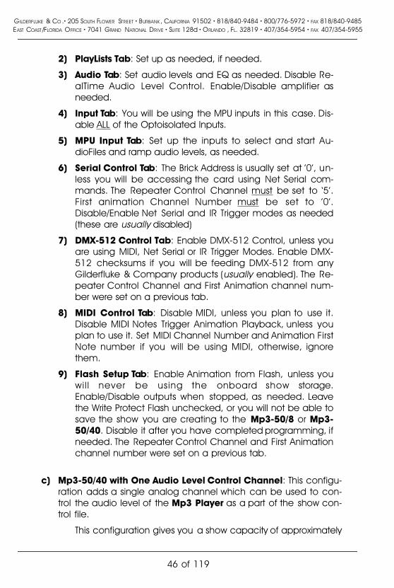
2) PlayLists Tab: Set up as needed, if needed.
3) Audio Tab: Set audio levels and EQ as needed. Disable Re-alTime Audio Level Control. Enable/Disable amplifier asneeded.
4) Input Tab: You will be using the MPU inputs in this case. Dis-able ALL of the Optoisolated Inputs.
5) MPU Input Tab: Set up the inputs to select and start Au-dioFiles and ramp audio levels, as needed.
6) Serial Control Tab: The Brick Address is usually set at '0', un-less you will be accessing the card using Net Serial com-mands. The Repeater Control Channel must be set to �5�.First animation Channel Number must be set to '0'.Disable/Enable Net Serial and IR Trigger modes as needed(these are usually disabled)
7) DMX-512 Control Tab: Enable DMX-512 Control, unless youare using MIDI, Net Serial or IR Trigger Modes. Enable DMX-512 checksums if you will be feeding DMX-512 from anyGilderfluke & Company products (usually enabled). The Re-peater Control Channel and First Animation channel num-ber were set on a previous tab.
8) MIDI Control Tab: Disable MIDI, unless you plan to use it.Disable MIDI Notes Trigger Animation Playback, unless youplan to use it. Set MIDI Channel Number and Animation FirstNote number if you will be using MIDI, otherwise, ignorethem.
9) Flash Setup Tab: Enable Animation from Flash, unless youwil l never be using the onboard show storage.Enable/Disable outputs when stopped, as needed. Leavethe Write Protect Flash unchecked, or you will not be able tosave the show you are creating to the Mp3-50/8 or Mp3-50/40. Disable it after you have completed programming, ifneeded. The Repeater Control Channel and First Animationchannel number were set on a previous tab.
c) Mp3-50/40 with One Audio Level Control Channel: This configu-ration adds a single analog channel which can be used to con-trol the audio level of the Mp3 Player as a part of the show con-trol file.
This configuration gives you a show capacity of approximately
GILDERFLUKE & CO .� 205 SOUTH FLOWER STREET � BURBANK , CALIFORNIA 91502 � 818/840-9484 � 800/776-5972 � FAX 818/840-9485EAST COAST /FLORIDA OFFICE � 7041 GRAND NATIONAL DRIVE � SUITE 128d � ORLANDO , FL. 32819 � 407/354-5954 � FAX 407/354-5955
46 of 119

41 minutes in the onboard Flash memory.
Starting with a blank site file, you can create all the channelsyou need by:
1) Open PC�MACs, Create a 'New' show. Go to 'ChannelsPulldown'/'Create Multiple Channels....'.
2) Select forty-eight digital and zero analog channels. The digi-tals that come out of the J6 connector are addressed from�0� through �3�. The digitals that will come out of the 1/4 J6are addressed at �4�. The last eight outputs (on channel �5�)will be used for triggering the Mp3 Player.
3) Click �OK� to create these channels.
4) Go to PC�MACs 'Channels Pulldown'/'Create Multiple Chan-nels....'.
5) Select zero digital and one 8 bit analog channel. This will beyour audio level control channel at address �6�.
6) Click �OK� to create this channel.
When you have finished programming your show you willAutoDownload it to the Mp3-50/8. Set the �First Channel� to �0�and the �Last Channel� to �6� on the PC�MACs File Pulldown/Saveas AutoDownload.... window.
In the Mp3 Configurator Program:
1) Track Setup Tab: Point it at your SmartMedia card and set asneeded.
2) PlayLists Tab: Set up as needed, if needed.
3) Audio Tab: Set audio levels and EQ as needed. Enable Real-Time Audio Level Control. You can control one or both out-puts from the analog channel you have created. Set theaddresses of the Level Control Channels to �6�.Enable/Disable amplifier as needed.
4) Input Tab: You will be using the MPU inputs in this case. Dis-able ALL of the Optoisolated Inputs.
5) MPU Input Tab: Set up the inputs to select and start Au-dioFiles and ramp audio levels, as needed.
6) Serial Control Tab: The Brick Address is usually set at '0', un-less you will be accessing the card using Net Serial com-mands. The Repeater Control Channel must be set to �5�.First animation Channel Number must be set to �0�.
GILDERFLUKE & CO .� 205 SOUTH FLOWER STREET � BURBANK , CALIFORNIA 91502 � 818/840-9484 � 800/776-5972 � FAX 818/840-9485EAST COAST /FLORIDA OFFICE � 7041 GRAND NATIONAL DRIVE � SUITE 128d � ORLANDO , FL. 32819 � 407/354-5954 � FAX 407/354-5955
47 of 119

Disable/Enable Net Serial and IR Trigger modes as needed(these are usually disabled)
7) DMX-512 Control Tab: Enable DMX-512 Control, unless youare using MIDI, Net Serial or IR Trigger Modes. Enable DMX-512 checksums if you will be feeding DMX-512 from anyGilderfluke & Company products (usually enabled). The Re-peater Control Channel and First Animation channel num-ber were set on a previous tab.
8) MIDI Control Tab: Disable MIDI, unless you plan to use it.Disable MIDI Notes Trigger Animation Playback, unless youplan to use it. Set MIDI Channel Number and Animation FirstNote number if you will be using MIDI, otherwise, ignorethem.
9) Flash Setup Tab: Enable Animation from Flash, unless youwil l never be using the onboard show storage.Enable/Disable outputs when stopped, as needed. Leavethe Write Protect Flash unchecked, or you will not be able tosave the show you are creating to the Mp3-50/8 or Mp3-50/40. Disable it after you have completed programming, ifneeded. The Repeater Control Channel and First Animationchannel number were set on a previous tab.
d) Mp3-50/40 with Two Audio Level Control Channels: This config-uration adds two analog channels which can be used to inde-pendently control the left and right audio levels of the Mp3 Play-er as a part of the show control file.
This configuration gives you a show capacity of approximately36 minutes in the onboard Flash memory.
Starting with a blank site file, you can create all the channelsyou need by:
1) Open PC�MACs, Create a 'New' show. Go to 'ChannelsPulldown'/'Create Multiple Channels....'.
2) Select forty-eight digital and zero analog channels. The digi-tals that come out of the J6 connector are addressed from�0� through �3�. The digitals that will come out of the 1/4 J6are addressed at �4�. The last eight outputs (on channel �5�)will be used for triggering the Mp3 Player.
3) Click �OK� to create these channels.
4) Go to PC�MACs 'Channels Pulldown'/'Create Multiple Chan-
GILDERFLUKE & CO .� 205 SOUTH FLOWER STREET � BURBANK , CALIFORNIA 91502 � 818/840-9484 � 800/776-5972 � FAX 818/840-9485EAST COAST /FLORIDA OFFICE � 7041 GRAND NATIONAL DRIVE � SUITE 128d � ORLANDO , FL. 32819 � 407/354-5954 � FAX 407/354-5955
48 of 119

nels....'.
5) Select zero digital and two, 8 bit analog channel. These willbe your audio level control channels at addresses �6� and�7�.
6) Click �OK� to create these channels.
When you have finished programming your show you willAutoDownload it to the Mp3-50/8. Set the �First Channel� to �0�and the �Last Channel� to �7� on the PC�MACs File Pulldown/Saveas AutoDownload.... window.
In the Mp3 Configurator Program:
1) Track Setup Tab: Point it at your SmartMedia card and set asneeded.
2) PlayLists Tab: Set up as needed, if needed.
3) Audio Tab: Set audio levels and EQ as needed. Enable Real-Time Audio Level Control. Each audio output has its ownanalog channel to control it. Set the addresses of the LevelControl Channels to �6� and �7�. Enable/Disable amplifier asneeded.
4) Input Tab: You will be using the MPU inputs in this case. Dis-able ALL of the Optoisolated Inputs.
5) MPU Input Tab: Set up the inputs to select and start Au-dioFiles and ramp audio levels, as needed.
6) Serial Control Tab: The Brick Address is usually set at '0', un-less you will be accessing the card using Net Serial com-mands. The Repeater Control Channel must be set to �5�.First animation Channel Number must be set to �0�.Disable/Enable Net Serial and IR Trigger modes as needed(these are usually disabled)
7) DMX-512 Control Tab: Enable DMX-512 Control, unless youare using MIDI, Net Serial or IR Trigger Modes. Enable DMX-512 checksums if you will be feeding DMX-512 from anyGilderfluke & Company products (usually enabled). The Re-peater Control Channel and First Animation channel num-ber were set on a previous tab.
8) MIDI Control Tab: Disable MIDI, unless you plan to use it.Disable MIDI Notes Trigger Animation Playback, unless youplan to use it. Set MIDI Channel Number and Animation FirstNote number if you will be using MIDI, otherwise, ignore
GILDERFLUKE & CO .� 205 SOUTH FLOWER STREET � BURBANK , CALIFORNIA 91502 � 818/840-9484 � 800/776-5972 � FAX 818/840-9485EAST COAST /FLORIDA OFFICE � 7041 GRAND NATIONAL DRIVE � SUITE 128d � ORLANDO , FL. 32819 � 407/354-5954 � FAX 407/354-5955
49 of 119

them.
9) Flash Setup Tab: Enable Animation from Flash, unless youwil l never be using the onboard show storage.Enable/Disable outputs when stopped, as needed. Leavethe Write Protect Flash unchecked, or you will not be able tosave the show you are creating to the Mp3-50/8 or Mp3-50/40. Disable it after you have completed programming, ifneeded. The Repeater Control Channel and First Animationchannel number were set on a previous tab.
e) Mp3-50/40 with DMX-512 w/Overlapping Channels: This config-uration goes back to the typical installation (�b� above) and addsone or more channels of DMX-512 output. If you are using SerialRealTime Update mode during programming, this is the only con-figuration which will allow you to access ALL of the Show controland DMX-512 channels through the serial port.
The DMX-512 transmission always starts with the first channelstored in the Flash memory, and transmits the first sixteen consec-utive channels. The six channels of Show Control (five for the digi-tal outputs and one for the MPU control) are sent out through thefirst six channels of DMX-512 (you probably don�t want to put adimmer on these channels). This leaves somewhere between oneand ten channels of DMX-512 output for lighting, moving lights,or whatever.
Depending on the number of DMX channels you need, thisconfiguration gives a capacity of between 41 and 18 minutes inthe onboard Flash memory.
Starting with a blank site file, you can create all the channelsyou need by:
1) Open PC�MACs, Create a 'New' show. Go to 'ChannelsPulldown'/'Create Multiple Channels....'.
2) Select forty-eight digital and zero analog channels. The digi-tals that come out of the J6 connector are addressed from�0� through �3�. The digitals that will come out of the 1/4 J6are addressed at �4�. The last eight outputs (on channel �5�)will be used for triggering the Mp3 Player.
3) Click �OK� to create these channels.
4) Go to PC�MACs 'Channels Pulldown'/'Create Multiple Chan-nels....'.
GILDERFLUKE & CO .� 205 SOUTH FLOWER STREET � BURBANK , CALIFORNIA 91502 � 818/840-9484 � 800/776-5972 � FAX 818/840-9485EAST COAST /FLORIDA OFFICE � 7041 GRAND NATIONAL DRIVE � SUITE 128d � ORLANDO , FL. 32819 � 407/354-5954 � FAX 407/354-5955
50 of 119

5) Select zero digital and between one and ten, 8 bit analogchannels. These will be your DMX-512 channels starting ataddress �6� and going to a maximum of �15�.
6) Click �OK� to create these channels.
When you have finished programming your show you willAutoDownload it to the Mp3-50/8. Set the �First Channel� to �0�and the �Last Channel� between �6� and �15� on the PC�MACs FilePulldown/Save as AutoDownload.... window.
In the Mp3 Configurator Program:
1) Track Setup Tab: Point it at your SmartMedia card and set asneeded.
2) PlayLists Tab: Set up as needed, if needed.
3) Audio Tab: Set audio levels and EQ as needed. Disable Re-alTime Audio Level Control. Enable/Disable amplifier asneeded.
4) Input Tab: You will be using the MPU inputs in this case. Dis-able ALL of the Optoisolated Inputs.
5) MPU Input Tab: Set up the inputs to select and start Au-dioFiles and ramp audio levels, as needed.
6) Serial Control Tab: The Brick Address is usually set at '0', un-less you will be accessing the card using Net Serial com-mands. The Repeater Control Channel must be set to '1'.First Animation Channel Number must be set to '0'. DisableNet Serial and IR Trigger modes.
7) DMX-512 Control Tab: Disable DMX-512 Control. The Re-peater Control Channel and First Animation channel num-ber were set on a previous tab.
8) MIDI Control Tab: Disable MIDI and MIDI Notes Trigger Ani-mation Playback. Disregard MIDI Channel Number and Ani-mation First Note number.
9) Flash Setup Tab: Enable Animation from Flash, unless youwil l never be using the onboard show storage.Enable/Disable outputs when stopped, as needed. Leavethe Write Protect Flash unchecked, or you will not be able tosave the show you are creating to the Mp3-50/8 or Mp3-50/40. Disable it after you have completed programming, ifneeded. The Repeater Control Channel and First Animationchannel number were set on a previous tab.
GILDERFLUKE & CO .� 205 SOUTH FLOWER STREET � BURBANK , CALIFORNIA 91502 � 818/840-9484 � 800/776-5972 � FAX 818/840-9485EAST COAST /FLORIDA OFFICE � 7041 GRAND NATIONAL DRIVE � SUITE 128d � ORLANDO , FL. 32819 � 407/354-5954 � FAX 407/354-5955
51 of 119

f) Mp3-50/40 with Sixteen DMX-512 Channels: This configurationgoes back to the typical installation (�b� above) and adds sixteenchannels of DMX-512 output. If you are using Serial RealTime Up-date mode during programming, you will only be able to accessthe DMX-512 channels through the serial port. The show controlports are located above sixteen channels, so they will not be up-dated in RealTime.
The DMX-512 transmission always starts with the first channelstored in the Flash memory, and transmits the first sixteen consec-utive channels. This is where the DMX-512 data will live.
This configuration consumes eighteen channels of Flash. Thisgives a capacity of 13 minutes in the onboard Flash memory.
Starting with a blank site file, you can create all the channelsyou need by:
1) Open PC�MACs, Create a 'New' show. Go to 'ChannelsPulldown'/'Create Multiple Channels....'.
2) Select forty-eight digital and sixteen analog channels. Theanalogs are on channels �0� through �15�. The digitals thatcome out of the J6 connector are addressed from �16�through �19�. The digitals that will come out of the 1/4 J6 areaddressed at �20�. The last eight outputs (on channel �21�)will be used for triggering the Mp3 Player.
3) Click �OK� to create these channels.
When you have finished programming your show you willAutoDownload it to the Mp3-50/8. Set the �First Channel� to �0�and the �Last Channel� to �21� on the PC�MACs File Pulldown/Saveas AutoDownload.... window.
In the Mp3 Configurator Program:
1) Track Setup Tab: Point it at your SmartMedia card and set asneeded.
2) PlayLists Tab: Set up as needed, if needed.
3) Audio Tab: Set audio levels and EQ as needed. Disable Re-alTime Audio Level Control. Enable/Disable amplifier asneeded.
4) Input Tab: You will be using the MPU inputs in this case. Dis-able ALL of the Optoisolated Inputs.
5) MPU Input Tab: Set up the inputs to select and start Au-
GILDERFLUKE & CO .� 205 SOUTH FLOWER STREET � BURBANK , CALIFORNIA 91502 � 818/840-9484 � 800/776-5972 � FAX 818/840-9485EAST COAST /FLORIDA OFFICE � 7041 GRAND NATIONAL DRIVE � SUITE 128d � ORLANDO , FL. 32819 � 407/354-5954 � FAX 407/354-5955
52 of 119

dioFiles and ramp audio levels, as needed.
6) Serial Control Tab: The Brick Address is usually set at '0', un-less you will be accessing the card using Net Serial com-mands. The Repeater Control Channel must be set to �17�.First Animation Channel Number must be set to �16�. DisableNet Serial and IR Trigger modes.
7) DMX-512 Control Tab: Disable DMX-512 Control. The Re-peater Control Channel and First Animation channel num-ber were set on a previous tab.
8) MIDI Control Tab: Disable MIDI and MIDI Notes Trigger Ani-mation Playback. Disregard MIDI Channel Number and Ani-mation First Note number.
9) Flash Setup Tab: Enable Animation from Flash, unless youwil l never be using the onboard show storage.Enable/Disable outputs when stopped, as needed. Leavethe Write Protect Flash unchecked, or you will not be able tosave the show you are creating to the Mp3-50/8 or Mp3-50/40. Disable it after you have completed programming, ifneeded. The Repeater Control Channel and First Animationchannel number were set on a previous tab.
GILDERFLUKE & CO .� 205 SOUTH FLOWER STREET � BURBANK , CALIFORNIA 91502 � 818/840-9484 � 800/776-5972 � FAX 818/840-9485EAST COAST /FLORIDA OFFICE � 7041 GRAND NATIONAL DRIVE � SUITE 128d � ORLANDO , FL. 32819 � 407/354-5954 � FAX 407/354-5955
53 of 119

Preparing Animation Data for AutoDownloadsThe Eprom Memories used for the original 'Brick' products manufactured
by Gilderfluke & Company each contained one channel (eight-bits) worthof data. As memory sizes increased, later products used Eproms which con-tained several channels each. The Flash Memories used on the Mp3-50/8or Mp3-50/40, BR-MultiBrick32, BR-ANA, BR-EFB and BR-SmartMedia usea MultiChannel format with a complex data header to allow them to beAutoDownloaded from PC�MACs. The following instructions apply to all ofcards that use AutoDownload files.
After you have finished programming your show(s), files are AutoDown-loaded from PC�MACs by:
1) Selecting the 'Save as AutoDownload...' command from the 'File'pulldown.
2) Use the �Add� button to select any additional show(s) you wouldlike to be saved into this AutoDownload file.
3) Use the �Promote� and �Demote� buttons to move selected show(s)into the order you would like to save them in the Flash Memory.
4) Select the �first show� and what will happen to the Mp3-50/8 orMp3-50/40 on power up. If you have set the Mp3-50/8 or Mp3-50/40 to �wait� at power up, then the first frame of the show youhave selected will be output as soon as power is applied to theMp3-50/8 or Mp3-50/40.
5) Set what will happen on each of the four �J8� optoisolated inputs.You can set different actions for both the opening and closingedges.
6) Select each show to be downloaded one at a time and set whatwill happen at the end of each show and whether it can be�stepped on�. Any show which �can be stepped upon� can be in-terrupted mid-show by a new show start coming in. Any showwhich �can not be stepped upon� will ignore all additional startcommands while it is still playing.
7) Set the �Brick Serial Address� to send the AutoDownload file to. Thisis the serial address of the Mp3-50/8 or Mp3-50/40 you want it tobe received by. All other cards will ignore the data being sent tothis one card. With Mp3-50/8 or Mp3-50/40, the address is usual-ly the same as the �start� channel set in the next step.
8) Set the 'first channel' and 'last channel' boxes to set the numberchannels you want to go into this AutoDownload file. If you are
GILDERFLUKE & CO .� 205 SOUTH FLOWER STREET � BURBANK , CALIFORNIA 91502 � 818/840-9484 � 800/776-5972 � FAX 818/840-9485EAST COAST /FLORIDA OFFICE � 7041 GRAND NATIONAL DRIVE � SUITE 128d � ORLANDO , FL. 32819 � 407/354-5954 � FAX 407/354-5955
54 of 119

using one of the �sample� configurations shown in the previoussection of this manual, the numbers for these values are shownthere for each sample configuration. Use those numbers
A Mp3-50/8 or Mp3-50/40 holds between one and 255channels worth of data. The more channels you send to theMp3-50/8 or Mp3-50/40, the less show �time� you will have avail-able to you.
If you are not doing RealTime audio level control or transmit-ting DMX-512, a Mp3-50/8 is typically loaded with two channelsworth of data. The first channel is sent to the 1/4 J6 Show ControlOutputs, and the second channel is sent to the Audio TriggerChannel. The �start� address is for this situation is set to �0�. The�end� address is set to �1�.
If you are not doing RealTime audio level control or transmit-ting DMX-512, a Mp3-50/40 is typically loaded with six channelsworth of data. The first four channels are sent to the J6 ShowControl Outputs. The next channel is sent to the 1/4 J6 outputs.The final channel is sent to the Audio Trigger Channel. The �start�address is for this situation is set to �0�. The �end� address is set to�5�.
If you are transmitting DMX-512 from the Mp3-50/8 or Mp3-50/40, you will also need to allow for these channels. If this is thefirst (or only) Mp3-50/8 or Mp3-50/40 in the system, the �start� ad-dress is typically set for �0�. The �end� address depends on whatyou are doing with your Mp3-50/8 or Mp3-50/40 and how muchdata you will be storing on it.
9) The �Calculate Brick Start Frames� checkbox must always bechecked.
10) The �Save Brick Starts� checkbox should never be checked.
11) You can quickly test if the Mp3-50/8 or Mp3-50/40 is attached tothe serial port properly by hitting the �Reset MiniBrick� button. Ofcourse, this will also erase any show data that was already in theMp3-50/8s or Mp3-50/40s flash memory. PC�MACs will report ifthe Reset was successful or not.
12) Press the �Build� or �Download� button to begin the saving process.A �Build� will just save the AutoDownload file to your disk, withoutsending it to the Mp3-50/8 or Mp3-50/40. A �Download� will savethe file to disk and send it to the Mp3-50/8 or Mp3-50/40. A stan-dard file save dialog will open. Double check the Directory loca-
GILDERFLUKE & CO .� 205 SOUTH FLOWER STREET � BURBANK , CALIFORNIA 91502 � 818/840-9484 � 800/776-5972 � FAX 818/840-9485EAST COAST /FLORIDA OFFICE � 7041 GRAND NATIONAL DRIVE � SUITE 128d � ORLANDO , FL. 32819 � 407/354-5954 � FAX 407/354-5955
55 of 119
tion and name the file as desired (it defaults to the name of thefirst show in the list). You can tell Windows to save the file to a dif-ferent directory, if needed. PC�MACs will warn you if a file alreadyexists in this location with this same name. Hit OK (or change thename & hit OK if you want to preserve the older file) to save thedata to a file.
After doing an AutoDownload, if you press the �Report� button,PC�MACs will display the information about the AutoDownload file you justsaved. This information is also saved in a text file with the same name as theFlash Memories, but with the extension of �.set�. You can open this file withany text editor (like Notepad or Wordpad). The �Eprom Memory start� and�Eprom Memory end� are the actual locations of the shows in the FlashMemory set. The number shown for the �Eprom Memory End� for the lastshow in this file set is the last byte which will be saved into the Flash Memo-ry. If your Flash Memory is smaller than this number, you will need to use ex-ternal show data storage (such as a BR-SmartMedia).
The AutoDownload file that PC�MACs automatically generates will havethe extension of filename.Ann. The 'A' in the extension flags it as a'AutoDownload' file. The 'nn' is the HEXadecimal address of the first channelin the AutoDownload set. If you are AutoDownloading to a number of differ-ent cards, you can use the same name for all of them without fear of over-writing the others since they will automatically have different �extensions�.This file can be sent to any other Mp3-50/8 or Mp3-50/40 at any time usinga computer and a terminal program like terminal.exe or our GilderTerm. Hy-perTerm.exe will not work for this, because it randomly alters values above128 in the AutoDownload file.
The address of the data sent out from Flash memory may be differentfrom what you saw when programming through the DMX-512 or serialinput. This is a question of the address selected for the Mp3-50/8 or Mp3-50/40 and address range selected for the data when sending theAutoDownload file. The Mp3-50/8 or Mp3-50/40 always uses the addresssaved in the AutoDownload file for its outputs. This is normally what youwant to do.
The Mp3-50/8 and Mp3-50/40 have the ability to download AutoDown-load files stored on the SmartMedia card to the Show Control half of theMp3-50/8 or Mp3-50/40. This is a convenient way to distribute show data,configurations and audio to a number of different shows in different loca-tions.
To do this, just drag and drop the AutoDownload file from wherever youtold PC�MACs to save it onto your SmartMedia card (you can actually savethe file right to the SmartMedia card, if you have the Mp3-50/8 or Mp3-
GILDERFLUKE & CO .� 205 SOUTH FLOWER STREET � BURBANK , CALIFORNIA 91502 � 818/840-9484 � 800/776-5972 � FAX 818/840-9485EAST COAST /FLORIDA OFFICE � 7041 GRAND NATIONAL DRIVE � SUITE 128d � ORLANDO , FL. 32819 � 407/354-5954 � FAX 407/354-5955
56 of 119

50/40 plugged into the USB port when you do your �Save asAutoDownload...�). You will then need to open the configuration file for thiscard using the Mp3 Configurator. When you click on the �Flash� tab, youwill see that the �Download� checkbox has been �checked�. This is becausethe show data has changed. Save the current configuration and the nexttime the Mp3-50/8 or Mp3-50/40 is powered up, the AutoDownload file willbe sent to the Flash memory on the Show Control half of the Mp3-50/8 orMp3-50/40. If the configuration is set with the �always Download� checkboxclicked, then the last steps of opening the configuration file and saving itwill be unnecessary. The Mp3-50/8 or Mp3-50/40 will automatically down-load the Show Control data every time the unit is turned on.
GILDERFLUKE & CO .� 205 SOUTH FLOWER STREET � BURBANK , CALIFORNIA 91502 � 818/840-9484 � 800/776-5972 � FAX 818/840-9485EAST COAST /FLORIDA OFFICE � 7041 GRAND NATIONAL DRIVE � SUITE 128d � ORLANDO , FL. 32819 � 407/354-5954 � FAX 407/354-5955
57 of 119

Mp3-50/8 or Mp3-50/40 Serial Port Commands:The Mp3-50/8 or Mp3-50/40 can be accessed through the serial port
from any computer running just about any modem or terminal program.The computer you are using doesn�t even need to have any PC�MACs soft-ware installed on it.
Most Gilderfluke & Company products can be controlled through theirRS-422 Serial ports. Up to 256 different cards and devices can be attachedto the same serial lines, to form a complete RS-422 �multi Drop� network.Anywhere on this network you can attach operator panels to access andcontrol it, or you can use a telephone or Internet modem so that it can beaccessed from around the block or around the world. Commands can beaddressed to a single card on the network, or all of the cards simultaneous-ly.
One of the easiest and most flexible types of operator interfaces for ac-cessing the serial network are the many touch screen operator panels.These are available from a number of different suppliers, and most of themwill easily attach right to our serial network. Most of these allow you to �draw�whatever buttons and user interface icons on their screens (using a provid-ed Windows program), attach ASCII strings to these �buttons�, and thendownload the final configuration to the operator panel so the PC can betaken away.
Typical modem programs you can use are Terminal.exe (which camewith Windows 3.1) and HyperTerm.exe (which comes later versions of Win-dows), or GilderTerm.
GilderTerm is available free from Gilderfluke & Co. for use with all of ourproducts. It can be downloaded from our web page, and is included on allof our CD-ROMs. GilderTerm has been optimized for use with all Gilderfluke& Company equipment. All the commands are built in, and it will even letyou use your mouse to select commands by simply clicking on them.
To use the Mp3-50/8 or Mp3-50/40 with a terminal program, just con-figure it for 9600 baud, no parity, eight data bits, one stop bit and �xon/xoff�handshaking. If you are using GilderTerm, all the settings are fixed at the ap-propriate settings. All you will need to do is select the appropriate �COM�port.
Echo Commands:�a� [nn] (card address) Echo On:�b� Echo Off:
The �Echo ON� command will turn on a special mode that will
GILDERFLUKE & CO .� 205 SOUTH FLOWER STREET � BURBANK , CALIFORNIA 91502 � 818/840-9484 � 800/776-5972 � FAX 818/840-9485EAST COAST /FLORIDA OFFICE � 7041 GRAND NATIONAL DRIVE � SUITE 128d � ORLANDO , FL. 32819 � 407/354-5954 � FAX 407/354-5955
58 of 119

cause all the other serial port commands to echo on the selectedcard. This used when you are setting up serial commands so youcan verify all the commands you are issuing are being receivedcorrectly (the �echo� responses are shown in italics):
If you send �a00�, the echo mode will be turned ON:
card 00h/__0, echo mode on
If you send �*03� to request a specific show:
card 00h/__0, requested show 03h/__3 CHEEBURG
If you send �t00� to start the requested show playing on a specificcard:
card 00h/__0, starting show 03h/__3 CHEEBURG
If you send �!00� to start a show looping on a specific card:
card 00h/__0, looping show 04h/__4 FRUTCAKE
If you send �u� to stop a show playing:
card 00h/__0, stopped show 05h/__5 IGETARND
If you send �u� to stop a card that is already stopped, it will giveyou an error message:
card 00h/__0, error: not playing or looping 05h/__5 IGETARND
Similar error messages will be returned whenever you ask the cardto do something that it can not do at the current time.
The �Echo OFF� command will turn off the echo mode on allthe cards in the system.
�i� [nn] (card address) Card Status:When the Mp3-50/8 or Mp3-50/40 receives this command, it
will respond with the following information:
a) Gilderfluke & Company, product name, Firmware revisionnumber and copyright.
b) Card serial address and if the Flash is write protected.
c) Amount of Flash memory installed.
d) The current status of the four optically isolated inputs.
e) Whether the card is running, stopped, looping or paused.
f) Information on the currently loaded AutoDownload file:
1) AutoDownload file name (in DOS 8.3 format).
GILDERFLUKE & CO .� 205 SOUTH FLOWER STREET � BURBANK , CALIFORNIA 91502 � 818/840-9484 � 800/776-5972 � FAX 818/840-9485EAST COAST /FLORIDA OFFICE � 7041 GRAND NATIONAL DRIVE � SUITE 128d � ORLANDO , FL. 32819 � 407/354-5954 � FAX 407/354-5955
59 of 119

2) Number of shows in the AutoDownload file.3) Number of channels in the AutoDownload file.4) Offset to the first channel in the AutoDownload file.
The following shows a Mp3-50/8 or Mp3-50/40 information status re-sponse if there are no shows loaded (Mp3-50s with the RealTime �Atomic�Clock option often don�t have any shows loaded on them):
-Gilderfluke & Co. Mp3-50/40 Audio/Show Controller ver. 1.15 copyright 2003 DCM-Card at 00h/__0 | 4 Mbits (512KBytes) memory | i:Y p:N s:NA/Green: OpenB/Red: OpenC/Blue: ClosedD/White: Openno shows loaded
(Sample data: Your show data will differ from what is shown.)
The following shows a Mp3-50/8 or Mp3-50/40 information status re-sponse if there are shows loaded:
-Gilderfluke & Co. Mp3-50/40 Audio/Show Controller ver. 1.15 copyright 2003 DCM-Card at 00h/__0 | 4 Mbits (512KBytes) memory | i:Y p:N s:NA/Green: OpenB/Red: OpenC/Blue: ClosedD/White: Openshow 01h/__1 stopped @ frame 000000h/______0FileName: LIFETE~3.A00 | #shows: 11h/_17 | #channels: 01h/__1 | offset: 00h/__0
(Sample data: Your show data will differ from what is shown.)
The three flags �i�, �p�, and �s� are used to help in diagnosing problems:
i) Shows �Y� if interface between the Show Control and Mp3 Playersides of the Mp3-50/8 or Mp3-50/40 is active. If this is �N�, theMp3 player side of the unit is probably not running. Either it hasnot booted (most common causes of this is either no SmartMediacard installed, or SmartMedia card which needs to be �blessed�),or is busy being a hard drive via the USB port.
p) This indicates if a Mp3 file is being played or not. A �Y� indicatesthat sound is being played. A �N� indicates that sound is not beingplayed.
s) This indicates a �stuck� byte in the show control to Mp3 Player in-terface. It will normally be �N�. If it is �Y�, it is because the ShowControl side has sent a command to the Mp3 player, and theMp3 player has not responded in a timely manner.
The status screen is a snapshot image of the current status ofthe Mp3-50/8 or Mp3-50/40. If you want to update the status in-formation displayed, you must hit the �Card Status� command a
GILDERFLUKE & CO .� 205 SOUTH FLOWER STREET � BURBANK , CALIFORNIA 91502 � 818/840-9484 � 800/776-5972 � FAX 818/840-9485EAST COAST /FLORIDA OFFICE � 7041 GRAND NATIONAL DRIVE � SUITE 128d � ORLANDO , FL. 32819 � 407/354-5954 � FAX 407/354-5955
60 of 119

second time.
�j5AA5� [nn] (card address) Card Reset:This command will erase the 'Flash' memory on the Mp3-50/8
or Mp3-50/40. The Mp3-50/8 or Mp3-50/40 will also determinethe type and quantity of memory chips installed and report thisand the software revision number when it accepts this command.
Start Commands:�t� [nn] (card address) Start Track:�u� Start Global:
These commands start the animation playing on the Mp3-50/8 or Mp3-50/40 (s) addressed by the command. The shows willalways start from the beginning. If an addressed Mp3-50/8 orMp3-50/40 is looping shows, it will have the �LOOPING SHOWS�flag reset.
If the Mp3-50/8 or Mp3-50/40 receives a start commandafter it has received a request for a specific show, it will play thatshow. Otherwise it will play the show that has been set as the�next� show for the show which is currently playing (or most recent-ly played show if it is not currently playing). If this is the first showplayed after a Mp3-50/8 or Mp3-50/40 is reset, it will play theshow which has been set as the �first� show during the AutoDown-load. Requests for specific shows can come only from the serialport.
When shows are downloaded to the Mp3-50/8 or Mp3-50/40,they can be set to ignore additional start commands while theyare playing. This allows individual shows to be �stepped� upon ornot. If the Mp3-50/8 or Mp3-50/40 is already playing a showwhich has this option set, it will ignore this command.
Stop Commands:�x� [nn] (card address) Stop Track:�y� Stop Global:
These commands stop the selected Mp3-50/8 or Mp3-50/40(s) unconditionally. The stop takes place at the current framebeing played.
GILDERFLUKE & CO .� 205 SOUTH FLOWER STREET � BURBANK , CALIFORNIA 91502 � 818/840-9484 � 800/776-5972 � FAX 818/840-9485EAST COAST /FLORIDA OFFICE � 7041 GRAND NATIONAL DRIVE � SUITE 128d � ORLANDO , FL. 32819 � 407/354-5954 � FAX 407/354-5955
61 of 119

Loop Commands:�!� [nn] (card address) Loop Track:��� Loop Global:
These command acts much like the START commands, exceptthat they also set the �LOOPING SHOWS� flag. With this flag set, it ispossible to set a sequence of shows playing in any order. Sincethe �next� show can be any show you ask for, one show can beplayed over and over again, or you can set up a sequence ofshows which will be repeated until the Mp3-50/8 or Mp3-50/40 istold to stop.
Stop at End Commands:�%� [nn] (card address) Stop at End Track:�&� Stop at End Global:
These commands reset the �LOOPING SHOWS� flag in the se-lected Mp3-50/8 or Mp3-50/40 (s). What this does is to stop themplaying when the end of the current show is reached. These com-mands are used when you want the shows to finish gracefully.The STOP commands are used when you want to stop a show im-mediately.
Select Show Commands:�)� [nn] (Card Address) [nn] (show#) Select Show Track:�*� [nn] (show#) Select Show Global:
Up to two hundred fifty-five different animated shows can bestored on a single Mp3-50/8 or Mp3-50/40. These commandscan be used to select an individual show on the selected Mp3-50/8 or Mp3-50/40 (s). Individual shows can be requested with arange of 01 to FFH. Once a show is selected, it will be played onthe next serial port START or LOOP command.
If a show selection has been made inadvertently, it can becleared by sending a request for show number 00.
A special mode is available with this command for users whojust need to trigger audio files through the serial port. If NO showsare loaded onto the Mp3-50/8 or Mp3-50/40, This command willstart the selected audio track immediately. No additional �start� or�play� commands are needed to start the sounds playing.
GILDERFLUKE & CO .� 205 SOUTH FLOWER STREET � BURBANK , CALIFORNIA 91502 � 818/840-9484 � 800/776-5972 � FAX 818/840-9485EAST COAST /FLORIDA OFFICE � 7041 GRAND NATIONAL DRIVE � SUITE 128d � ORLANDO , FL. 32819 � 407/354-5954 � FAX 407/354-5955
62 of 119
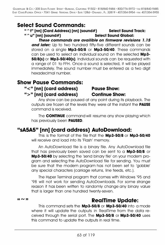
Select Sound Commands:�^t� [nn] (Card Address) [nn] (sound#) Select Sound Track:�^u� [nn] (sound#) Select Sound Global:
These commands are availible on firmware revisions 1.15and later: Up to two hundred fifty-five different sounds can bestored on a single Mp3-50/8 or Mp3-50/40. These commandscan be used to select an individual sound on the selected Mp3-50/8(s) or Mp3-50/40(s). Individual sounds can be requested witha range of 01 to FFH. Once a sound is selected, it will be playedimmediately. The sound number must be entered as a two digithexadecimal number.
Show Pause Commands:�<� [nn] (card address) Pause Show:�>� [nn] (card address) Continue Show:
Any show can be paused at any point during its playback. Theoutputs are frozen at the levels they were at the instant the PAUSEcommand is received.
The CONTINUE command will resume any show playing whichhas previously been PAUSED.
�sA5A5� [nn] (card address) AutoDownload:This is the format of the file that the Mp3-50/8 or Mp3-50/40
will receive and load into its 'Flash' memory.
An AutoDownload file is a binary file. Any AutoDownload filethat has previously been saved can be sent to a Mp3-50/8 orMp3-50/40 by selecting the �send binary file� on your modem pro-gram and selecting the AutoDownload file for sending. You mustbe sure that the modem program has not been set to �gobble�any special characters (carriage returns, line feeds, etc.).
The Hyper Terminal program that comes with Windows �95 and�98 will not work for sending AutoDownloads. For some strangereason it has been written to randomly change any binary valuethat is larger than one hundred twenty-seven.
�~� RealTime Update:This command sets the Mp3-50/8 or Mp3-50/40 into a mode
where it will update the outputs in RealTime from the data re-ceived through the serial port. The Mp3-50/8 or Mp3-50/40 usesthis command to update the outputs in real time.
GILDERFLUKE & CO .� 205 SOUTH FLOWER STREET � BURBANK , CALIFORNIA 91502 � 818/840-9484 � 800/776-5972 � FAX 818/840-9485EAST COAST /FLORIDA OFFICE � 7041 GRAND NATIONAL DRIVE � SUITE 128d � ORLANDO , FL. 32819 � 407/354-5954 � FAX 407/354-5955
63 of 119

The maximum frame rate supported by this function is thirtyframes per second. Any faster than this just won�t fit through thePC�s serial port.
GILDERFLUKE & CO .� 205 SOUTH FLOWER STREET � BURBANK , CALIFORNIA 91502 � 818/840-9484 � 800/776-5972 � FAX 818/840-9485EAST COAST /FLORIDA OFFICE � 7041 GRAND NATIONAL DRIVE � SUITE 128d � ORLANDO , FL. 32819 � 407/354-5954 � FAX 407/354-5955
64 of 119

Serial Command Summary
Echo Commands:�a� [nn] (card address) Echo On:�b� Echo Off:
�i� [nn] (card address) Card Status:
�j5AA5� [nn] (card address) Card Reset:
Start Commands:�t� [nn] (card address) Start Track:�u� Start Global:
Stop Commands:�x� [nn] (card address) Stop Track:�y� Stop Global:
Loop Commands:�!� [nn] (card address) Loop Track:��� Loop Global:
Stop at End Commands:�%� [nn] (card address) Stop at End Track:�&� Stop at End Global:
Select Show Commands:�)� [nn] (Card Address) [nn] (show#) Select Show Track:�*� [nn] (show#) Select Show Global:
Select Sound Commands:�^t� [nn] (Card Address) [nn] (sound#) Select Sound Track:�^u� [nn] (sound#) Select Sound Global:
Show Pause Commands:�<� [nn] (card address) Pause Show:�>� [nn] (card address) Continue Show:
�sA5A5� [nn] (card address) AutoDownload:
�~� RealTime Update:
GILDERFLUKE & CO .� 205 SOUTH FLOWER STREET � BURBANK , CALIFORNIA 91502 � 818/840-9484 � 800/776-5972 � FAX 818/840-9485EAST COAST /FLORIDA OFFICE � 7041 GRAND NATIONAL DRIVE � SUITE 128d � ORLANDO , FL. 32819 � 407/354-5954 � FAX 407/354-5955
65 of 119

Mp3-50/8 or Mp3-50/40 Hardware ConfigurationJust about all of the Mp3-50/8 or Mp3-50/40 configuration is done
using the �Mp3 Configurator� program or during the AutoDownload of theshows from PC�MACs. The only two hardware configuration options are:
a) Internal/External Power: This switch (located on the bottom ofthe Mp3-50/8 or Mp3-50/40) is used to switch the power from the1/4 J6 connector between an internal source, and an externalsource that must be fed from outside the Mp3-50/8 or Mp3-50/40. For a Mp3-50, this is the trigger input to the Mp3 Player,and either position can be used as determined by your applica-tion. For the Mp3-50/8 or Mp3-50/40, this is also the first or lastShow Control output channel. Only the �Internal� position shouldbe used.
b) RS-422/Optoisolated: This switch (located on the bottom of theMp3-50/8 or Mp3-50/40) is used to switch the DMX-512/MIDI seri-al port between using RS-422 input signal levels to an optoisolat-ed current loop. If receiving DMX-512, you must use the �RS-422�setting. For MIDI, you must use the �optoisolated� position. For NetSerial or IR Trigger modes, you can use either position, but �RS-422� is normally used unless you need to optically isolate theinput.
GILDERFLUKE & CO .� 205 SOUTH FLOWER STREET � BURBANK , CALIFORNIA 91502 � 818/840-9484 � 800/776-5972 � FAX 818/840-9485EAST COAST /FLORIDA OFFICE � 7041 GRAND NATIONAL DRIVE � SUITE 128d � ORLANDO , FL. 32819 � 407/354-5954 � FAX 407/354-5955
66 of 119

Mp3-50/8 or Mp3-50/40 Serial ConfigurationMp3-50/8 or Mp3-50/40 is configured through the USB port (or Smart-
Media card installed in any compatible hole in your computer) using the�Mp3 Configurator� program. As a backup, or for those of you who havenot configured or installed your SmartMedia card, there is a series of config-uration commands available on the Mp3-50/8 or Mp3-50/40 that will allowyou to configure the Show Control half of the device. Once the Smart-Media card is configured and inserted into the Mp3-50/8 or Mp3-50/40,the configuration you have set on using the �Mp3 Configurator� programwill overwrite any configuration you have made directly through the serialport.
The Mp3-50/8 or Mp3-50/40 can be accessed through the RS-232 seri-al port from any computer running just about any modem or terminal pro-gram. The computer you are using doesn�t even need to have anyPC�MACs software installed on it.
The Mp3-50/8 or Mp3-50/40 is normally accessed through its RS-232serial port. A configuration option available through the �Mp3 Configurator�program is to take over the DMX-512/MIDI serial port to use it as a RS-422receive-only serial port. This is called �Net Serial� mode. Selection this optiondisables DMX-512 in and out, MIDI in, and IR Trigger in. Up to 256 differentcards and devices can be attached to the same serial lines, to form a com-plete RS-422 �multi Drop� network. Anywhere on this network you can attachoperator panels to access and control it, or you can use a telephone or In-ternet modem so that it can be accessed from around the block or aroundthe world. Commands can be addressed to a single card on the network,or all the cards simultaneously. When in �Net Serial� mode, any serial re-sponses from the Mp3-50/8 or Mp3-50/40 will be sent out through the nor-mal RS-232 serial port. You will not get responses on the DMX-512/MIDI outterminals.
Typical modem programs you can use with Gilderfluke & Companyequipment are Terminal.exe (which came with Windows 3.1) and HyperT-erm.exe (which comes with later versions of Windows), or our favorite,GilderTerm.
GilderTerm is available free from Gilderfluke & Co. for use with all of ourproducts. It can be downloaded from our web page, and is included on allof our CD-ROMs. GilderTerm has been optimized for use with all Gilderfluke& Company equipment. All of the commands are built in, and it will evenlet you use your mouse to select commands.
To use the Mp3-50/8 or Mp3-50/40 with a terminal program, just con-figure it for 9600 baud, no parity, eight data bits, one stop bit and �xon/xoff�
GILDERFLUKE & CO .� 205 SOUTH FLOWER STREET � BURBANK , CALIFORNIA 91502 � 818/840-9484 � 800/776-5972 � FAX 818/840-9485EAST COAST /FLORIDA OFFICE � 7041 GRAND NATIONAL DRIVE � SUITE 128d � ORLANDO , FL. 32819 � 407/354-5954 � FAX 407/354-5955
67 of 119

handshaking. If you are using GilderTerm, all the settings are fixed at the ap-propriate settings. All you will need to do is select the appropriate �COM�port.
If your terminal emulation program supports VT-52 terminal emulation(they all do!), you should enable it on the Mp3-50/8 or Mp3-50/40. This willallow faster screen redraws. You should set your program NOT to insert anextra LineFeed (LF) character after each Carriage Return (CR) it receives.You should also tell it NOT to scroll automatically after the eightieth columnis filled. If either of these are on, the screen will be displayed 'doublespaced'. This won't cause any problem, but will make it hard to see thewhole screen at one time.
If you have hooked up the Mp3-50/8 or Mp3-50/40 to your computerand it still doesn't seem to respond to the keyboard, the first thing to checkis that you are attached to the right serial port. The easiest way to do this isto disconnect the Mp3-50/8 or Mp3-50/40 and short between the Tx dataout and Rx data in pins on the serial port connector on the back of yourcomputer. On all IBMs and compatibles this means sticking a piece of wire,paper clip, or similar tool between pins 2 and 3 on the 'Com.' connector.While still running the modem program, anything you type should be shownon the screen while this paper clip is in place, while nothing will appearwhen you remove it. If your computer passes this test, then you are usingthe right serial port and the problem is most likely the baud rate setting or inyour wiring to the Mp3-50/8 or Mp3-50/40. If you get characters on thescreen even with the paper clip removed from the serial port, it means youprobably need to set the 'echo' mode to 'none' or 'full duplex' and try thistest again.
To enter the configuration mode you need to type the following. The(address) is replaced by the �Serial Address� set in the Mp3 Configuratorprogram:
m5AA5(Card Address)If any other card is in configuration mode (or even if it just thinks anoth-
er card is in configuration), the Mp3-50/8 or Mp3-50/40 won't be able toenter configuration mode. To exit any other card from configuration type'XN'. You can then try entering configuration again.
When you enter configuration the Mp3-50/8 or Mp3-50/40 will displaythe following screen if no shows are loaded:
GILDERFLUKE & CO .� 205 SOUTH FLOWER STREET � BURBANK , CALIFORNIA 91502 � 818/840-9484 � 800/776-5972 � FAX 818/840-9485EAST COAST /FLORIDA OFFICE � 7041 GRAND NATIONAL DRIVE � SUITE 128d � ORLANDO , FL. 32819 � 407/354-5954 � FAX 407/354-5955
68 of 119

-Gilderfluke & Co. Mp3-50/40 Audio/Show Controller ver. 1.15 copyright 2003 DCM-
Card at 00h/__0 | 4 Mbits (512KBytes) memory | i:Y p:N s:N
A/Green: OpenB/Red: OpenC/Blue: Open (disable RTC schedules)D/White: Open (close sets clock to 03:05:01)
no shows loaded
a) play A soundc) STMP Configh) set time (schedule loaded- Y)
v) Verifyx) eXit
11:52:04 2 03/24/03 sc:dis Command-
(Sample data: Your show data will differ from what is shown.)
When you enter configuration the Mp3-50/8 or Mp3-50/40 will displaythe following screen if shows are loaded:
-Gilderfluke & Co. Mp3-50/40 Audio/Show Controller ver. 1.15 copyright 2003 DCM-
Card at 00h/__0 | 4 Mbits (512KBytes) memory | i:Y p:N s:N
A/Green: OpenB/Red: OpenC/Blue: Closed (enable RTC schedules)D/White: Open (close sets clock to 03:05:01)
show 01h/__1 looping @ frame 1E240h/_123456FileName: LIFETES3.A00 | #shows: 11h/_17 | #channels: 01h/__1 | offset: 00h/__0
a) play A soundc) STMP Configh) set time (schedule loaded- Y)i) show Infoe) stop at Endl) Loop showp) Play shows) Stop showv) Verifyx) eXit
11:52:04 2 03/24/03 sc:123 Command-
(Sample data: Your show data will differ from what is shown.)
To redraw the screen at any time, just press the <ESC>ape key or<SPACE> bar.
The three flags �i�, �p�, and �s� are used to help in diagnosing problems:
i) Shows �Y� if interface between the Show Control and Mp3 Playersides of the Mp3-50/8 or Mp3-50/40 is active. If this is �N�, theMp3 player side of the unit is probably not running. Either it has
GILDERFLUKE & CO .� 205 SOUTH FLOWER STREET � BURBANK , CALIFORNIA 91502 � 818/840-9484 � 800/776-5972 � FAX 818/840-9485EAST COAST /FLORIDA OFFICE � 7041 GRAND NATIONAL DRIVE � SUITE 128d � ORLANDO , FL. 32819 � 407/354-5954 � FAX 407/354-5955
69 of 119

not booted (most common causes of this is either no SmartMediacard installed, or SmartMedia card which needs to be �blessed�),or is busy being a hard drive via the USB port.
p) This indicates if a Mp3 file is being played or not. A �Y� indicatesthat sound is being played. A �N� indicates that sound is not beingplayed.
s) This indicates a �stuck� byte in the show control to Mp3 Player in-terface. It will normally be �N�. If it is �Y�, it is because the ShowControl side has sent a command to the Mp3 player, and theMp3 player has not responded in a timely manner.
If the Real Time �Atomic� Clock option has been installed in the Mp3-50/8 or Mp3-50/40:
a) The current time will start displaying on the command line. Thereis a delay of approximately 5 seconds after any command beforethe time will return to displaying. The time is displayed first(nn:nn:nn), followed by the day of week (1-7, with Sunday =1),date (mm/dd/yy), and then the schedule number (0=none, 1-255) being used for the day/DOW.
b) The option to �set time� will be available.
c) A �N� after the �set time� command indicates that no schedule filehas been loaded onto the Mp3-50/8 or Mp3-50/40. A �Y� indi-cates that the Schedule file for the RealTime �Atomic� Clock hasbeen loaded.
d) If the option to enable/disable the Real Time �Atomic� Clock hasbeen selected from the Mp3 Configurator, the line which showsthe status of the �C/Blue� input will also show whether the clock iscurrently enabled or not. A closure on the �C/Blue� input will en-able the Real Time �Atomic� Clock.
e) If the option to resynchronize the Real Time �Atomic� Clock hasbeen selected from the Mp3 Configurator, the time it will bereset to is shown on the line which shows the �D/White� input sta-tus. A closure on the �D/White� input will resynchronize the internalRealTime clock to to this time. This keeps the Mp3-50/8s or Mp3-50/40s internal clock synchronized to the external �Atomic�Clock.
f) When the Real Time �Atomic� Clock starts a sound or show, thiswill be displayed on the command line for approximately five sec-onds before the current time starts displaying again.
GILDERFLUKE & CO .� 205 SOUTH FLOWER STREET � BURBANK , CALIFORNIA 91502 � 818/840-9484 � 800/776-5972 � FAX 818/840-9485EAST COAST /FLORIDA OFFICE � 7041 GRAND NATIONAL DRIVE � SUITE 128d � ORLANDO , FL. 32819 � 407/354-5954 � FAX 407/354-5955
70 of 119

Play a SoundThis command is availible on firmware revisions 1.15 and
later: This prompts you for a spiel number to play. Numbers mustbe entered as a two digit hexadecimal number.
Display Config. from SmartMediaThis displays the configuration which was downloaded from
the SmartMedia card when the Mp3 half of the Mp3-50/8 orMp3-50/40 is powered up:
-Gilderfluke & Co. Mp3-50/40 Audio/Show Controller ver. 1.15 copyright 2003 DCM-
Configuration....
1) serial: 00h/__0
Midi:2) chan:00h/__03) 1st: 00h/__0
4) MCU: 005h/__5 | i:Y p:N s:N5) Lft: 002h/__26) Rt: 003h/__37) 1st: 000h/__0
8) eeFlag0: 91h/145 / 10010001b / DMX-512 Rx9) eeFlag1: 99h/153 / 10011001ba) eeFlag2: 00h/__0 / 00000000bb) eeFlag3: 00h/__0 / 00000000b
m) main menux) eXit
11:52:04 2 03/24/03 sc:__1 Command-
These numbers should agree with what you set using the�Mp3 Configurator� program. If they do not, you can doublecheck that it is not receiving the configuration by changing oneof these numbers, powering the Mp3-50/8 or Mp3-50/40 down,waiting 10 seconds, and powering it back up again. If the Mp3side of the Mp3-50/8 or Mp3-50/40 has successfully booted(heart is flashing), the values you changed should have revertedto whatever is in the configuration set by the �Mp3 Configurator�program.
1) Serial Address: This is the address of the Mp3-50/8 or Mp3-50/40 on the RS-422 serial multidrop serial buss. Eventhough the Mp3-50/8 or Mp3-50/40 is normally accessedthrough the RS-232 serial port, the address is still needed toaccess the Mp3-50/8 or Mp3-50/40. Valid address valuesare from 00h to FFh (0 to 255 using decimal numbers).
2) MIDI channel: This is the MIDI instrument number used toaccess the Mp3-50/8 or Mp3-50/40 through the MIDI port.
GILDERFLUKE & CO .� 205 SOUTH FLOWER STREET � BURBANK , CALIFORNIA 91502 � 818/840-9484 � 800/776-5972 � FAX 818/840-9485EAST COAST /FLORIDA OFFICE � 7041 GRAND NATIONAL DRIVE � SUITE 128d � ORLANDO , FL. 32819 � 407/354-5954 � FAX 407/354-5955
71 of 119

Valid address ranges are 00h through 0Fh (0 through 15 indecimal numbers).
3) MIDI 1st Note: Legal MIDI notes are numbered from 00hthrough 7Fh (0 through 127 in decimal numbers). The onlyproblem is that if you are actually using a keyboard to ac-cess the Mp3-50/8 or Mp3-50/40, no keyboards actuallyhave all 128 keys. A real piano only has 88. �Middle C� is lo-cated at 3Ch (or 60 in decimal numbers) on all MIDI key-boards. You can count to the South and North of �Middle C�to determine what numbers your keyboard will actually gen-erate.
Numbers below the value you set for the �MIDI Note Off-set� will be ignored. If you wanted to start accessing the fea-tures of the Mp3-50/8 or Mp3-50/40 at �Middle C�, youwould set this offset to 3Ch (or 60 in decimal numbers).
4) Repeater Control Channel: This is the Show Control chan-nel which is set to the Mp3 Player to select and play tracks,ramp audio to a level, stop and pause. If this address is larg-er than 255/0FFh, then it will be displayed with a �+256� no-tation. Valid values are from 00h to FFh (0 to 255 usingdecimal numbers). This is normally set to a channel which isnot used for any of the Show Control outputs, but it can beif this suits your application.
5) Left Level Control: If using audio control from the ShowControl side of the Mp3-50/8 or Mp3-50/40, then this is theShow Control channel which will control the left audio out-put level. Valid values are from 00h to FFh (0 to 255 usingdecimal numbers). If this address is larger than 255/0FFh,then it will be displayed with a �+256� notation.
6) Right Level Control: If using audio control from the ShowControl side of the Mp3-50/8 or Mp3-50/40, then this is theShow Control channel which will control the right audio out-put level. Valid values are from 00h to FFh (0 to 255 usingdecimal numbers).
7) First Animation Channel: This is the first channel of ShowControl data which will be sent to the first Show ControlOutputs. Valid values are from 00h to FFh (0 to 255 usingdecimal numbers). If this address is larger than 255/0FFh,then it will be displayed with a �+256� notation.
8) eeFlag0: These are the binary �flag� settings from the �Mp3
GILDERFLUKE & CO .� 205 SOUTH FLOWER STREET � BURBANK , CALIFORNIA 91502 � 818/840-9484 � 800/776-5972 � FAX 818/840-9485EAST COAST /FLORIDA OFFICE � 7041 GRAND NATIONAL DRIVE � SUITE 128d � ORLANDO , FL. 32819 � 407/354-5954 � FAX 407/354-5955
72 of 119

Configurator� program. Valid values are from 00h to FFh (0to 255 using decimal numbers). You really shouldn�t muckwith these. Following this line are the DMX/MIDI serial portsettings. These are controlled by the bits in eeFlag0. Theywill show:
a) DMX Tx: DMX-512 transmission is enabled.b) DMX Rx: DMX-512 reception is enabled.c) MIDI Rx: MIDI reception is enabled.d) Net Serial Rx: Net Serial reception is enabled.e) IR Mode Rx: IR Mode reception is enabled.
9) eeFlag1: These are the binary �flag� settings from the �Mp3Configurator� program. Valid values are from 00h to FFh (0to 255 using decimal numbers). You really shouldn�t muckwith these.
a) eeFlag2: These are the binary �flag� settings from the �Mp3Configurator� program. Valid values are from 00h to FFh (0to 255 using decimal numbers). You really shouldn�t muckwith these.
These can be modified by entering the number/letter adja-cent to each setting. This is not normally done, since the Mp3Player will override any changes you have made here with thesettings you have made in the �Mp3 Configurator� program.
About the only time you will need to modify these settings areif you have not yet configured or installed the SmartMedia card inthe Mp3-50/8 or Mp3-50/40. These can be used to do initialbring-up and testing on a Show Control System.
Show InfoThis displays the vitals of the shows which have been down-
loaded to the Mp3-50/8 or Mp3-50/40:
GILDERFLUKE & CO .� 205 SOUTH FLOWER STREET � BURBANK , CALIFORNIA 91502 � 818/840-9484 � 800/776-5972 � FAX 818/840-9485EAST COAST /FLORIDA OFFICE � 7041 GRAND NATIONAL DRIVE � SUITE 128d � ORLANDO , FL. 32819 � 407/354-5954 � FAX 407/354-5955
73 of 119

-Gilderfluke & Co. Mp3-50/40 Audio/Show Controller ver. 1.15 copyright 2003 DCM-
Header: 00 B4 22 00 01 11 00 01 01 00 01 00 01 00 01 00 01 00 01 00 01 00 01 00
show number/name Start Length Flags "next" show01h/__1 LIFETEST: 000000h/______0 | 000384h/____900 | C8h | whatever is next02h/__2 LI955D~1: 000384h/____900 | 000384h/____900 | C8h | whatever is next03h/__3 LIFE_D~2: 000708h/___1800 | 00003Ch/_____60 | C0h | whatever is next04h/__4 LIFE_D~3: 000744h/___1860 | 00003Ch/_____60 | C0h | whatever is next05h/__5 LIFE_D~4: 000780h/___1920 | 00003Ch/_____60 | C0h | whatever is next06h/__6 LI881D~1: 0007BCh/___1980 | 00003Ch/_____60 | C0h | whatever is next07h/__7 LI8C1D~1: 0007F8h/___2040 | 00003Ch/_____60 | C0h | whatever is next08h/__8 LI802D~1: 000834h/___2100 | 00003Ch/_____60 | C0h | whatever is next09h/__9 LI842D~1: 000870h/___2160 | 00003Ch/_____60 | C0h | whatever is next0Ah/_10 LIFETE~1: 0008ACh/___2220 | 000384h/____900 | C8h | 09h/__9 LI842D~1.sho0Bh/_11 LIFETE~2: 000C30h/___3120 | 000384h/____900 | C8h | whatever is next0Ch/_12 LIFETE~3: 000FB4h/___4020 | 000384h/____900 | C8h | whatever is next0Dh/_13 LIFETE~4: 001338h/___4920 | 000384h/____900 | C8h | whatever is next0Eh/_14 LI994D~1: 0016BCh/___5820 | 000384h/____900 | C8h | whatever is next0Fh/_15 LI9D4D~1: 001A40h/___6720 | 000384h/____900 | C8h | 0Fh/_15 LI9D4D~1.sho10h/_16 LI915D~1: 001DC4h/___7620 | 000384h/____900 | C8h | whatever is next11h/_17 LIFE_D~1: 002148h/___8520 | 00003Ch/_____60 | C0h | whatever is next
hit any key
These will help you confirm that the shows are the ones youthought they were and that they are in the order you expectedthem to be in.
Set TimeAvailable only if the RealTime �Atomic� Clock option has
been found on the Mp3-50/8 or Mp3-50/40.: This is used to setthe Real Time Clock (RTC) manually. It MUST be used at leastonce to �roughly� set the date and time, before the external�Atomic� Clock can take over.
The RTC must be set using one or two digit numbers, as need-ed. A value for the month of March, for instance, must be en-tered as �03�.
Stop at EndThis clears the �looping� flag, so the currently running show (if
any) will stop at the end and wait for the next start command. DoNOT use this command for controlling the Mp3-50/8 or Mp3-50/40 except during testing. Use the equivalent Serial Port com-mand instead.
Loop a ShowThis command is used to request and play a specific show
with the �looping� flag set. If the currently running show (if any) isNOT steppable, The Mp3-50/8 or Mp3-50/40 will confirm with youthat you do indeed want to start another show. At the end of the
GILDERFLUKE & CO .� 205 SOUTH FLOWER STREET � BURBANK , CALIFORNIA 91502 � 818/840-9484 � 800/776-5972 � FAX 818/840-9485EAST COAST /FLORIDA OFFICE � 7041 GRAND NATIONAL DRIVE � SUITE 128d � ORLANDO , FL. 32819 � 407/354-5954 � FAX 407/354-5955
74 of 119

show (if it has been configured to do so), the next show will play.This will continue until the Mp3-50/8 or Mp3-50/40 is told to�Stop�, �Stop at end� or a different show with is started with a �start�command. Do NOT use this command for controlling the Mp3-50/8 or Mp3-50/40 except during testing. Use the equivalent Seri-al Port command instead.
Play a ShowThis command is used to request and play a specific show
with the �looping� flag cleared. If the currently running show (ifany) is NOT steppable, The Mp3-50/8 or Mp3-50/40 will confirmwith you that you do indeed want to start another show. At theend of the show the Mp3-50/8 or Mp3-50/40 will sit and wait forthe next �start� or �loop� command. Do NOT use this command forcontrolling the Mp3-50/8 or Mp3-50/40 except during testing.Use the equivalent Serial Port command instead.
Stop PlayingThis command stops any show witch is playing or looping im-
mediately. The Mp3-50/8 or Mp3-50/40 will sit and wait for thenext �start� or �loop� command. Do NOT use this command forcontrolling the Mp3-50/8 or Mp3-50/40 except during testing.Use the equivalent Serial Port command instead.
Verify ShowsThis command is used to test the show data which has been
downloaded to the Mp3-50/8 or Mp3-50/40. This will take any-where from a few seconds to several minutes, depending of thesize of the AutoDownload file that must be tested. It you have the�Atomic� Clock option installed in your Mp3-50/8 or Mp3-50/40,it will give you the option of verifying the schedule or shows, ifboth have been downloaded, If no shows have been download-ed, but a schedule file has, then this command will automaticallyverify the schedule.
ExitThis is used to exit the configuration mode. It will ask you to
press �y� or �n� before completing the command.
GILDERFLUKE & CO .� 205 SOUTH FLOWER STREET � BURBANK , CALIFORNIA 91502 � 818/840-9484 � 800/776-5972 � FAX 818/840-9485EAST COAST /FLORIDA OFFICE � 7041 GRAND NATIONAL DRIVE � SUITE 128d � ORLANDO , FL. 32819 � 407/354-5954 � FAX 407/354-5955
75 of 119

Mp3-50, Mp3-50/8 or Mp3-50/40 Software InstallationThere are three pieces of software that you will need to install on your
computer to use the Mp3-50, Mp3-50/8 or Mp3-50/40. These are:
1) �StMp3Format.exe�: This is used to format the SmartMedia cardthrough the USB port. After installation, this ends up in �c:/ProgramFiles/SigmaTel/STMp3400�. A shortcut can be found under the�Start� button under �Programs/SigmaTel StMp3400 Mp3Player/StMp3Format�.
2) �StMp3Update.exe�: This program is used to send the firmware tothe SmartMedia card that the Mp3-50, Mp3-50/8 or Mp3-50/40needs to operate. After installation, this ends up in �c:/ProgramFiles/SigmaTel/STMp3400�. A shortcut can be found under the�Start� button under �Programs/SigmaTel StMp3400 Mp3Player/StMp3Update�.
3) �Mp3 Config.exe�: This is the Gilderfluke Program that you will usethe most. It is used to configure what all the trigger inputs do onthe Mp3-player, what the volume levels are, and all the other set-tings for the Mp3-50, Mp3-50/8 or Mp3-50/40.
The software for the Mp3 half of the Mp3-50, Mp3-50/8 or Mp3-50/40is distributed from Gilderfluke & Company on CD-ROM, or can be down-loaded or emailed to you. If you download it or get it via email, it will proba-bly be zipped, and you will need to decompress it before it can be installed.In any case, you will end up with a folder called �Gilder Mp3 Installer� some-where on your computer.
If you need to decompress the installer, it will be in a file called �GilderMp3 Installer.zip�. To decompress any zip files you will need to have softwareto decompress .zip files already installed on your computer (PkZip or WinZip).It comes with most versions of Windows, so it is probably already installed. Ifyou do not have any decompressor software, it can be downloaded from�http://www.pkware.com� or �http://www.winzip.com�. You do not need to usethe versions that they charge for. Just download the �free� version of thesoftware.
1) It Double click on the �Gilder Mp3 Installer.zip� file.2) Press the �Install� button if you have one. This will decompress and
install the software. If you don�t see an �Install� button, press the�Unzip� button.
3) Direct it to store the decompressed files somewhere on your com-puter. usually the easiest thing to do is direct it to the �desktop�.
4) Make sure that it is set to extract �all files� and �Use Folder names�5) Press �Extract� again to start it unzipping.
GILDERFLUKE & CO .� 205 SOUTH FLOWER STREET � BURBANK , CALIFORNIA 91502 � 818/840-9484 � 800/776-5972 � FAX 818/840-9485EAST COAST /FLORIDA OFFICE � 7041 GRAND NATIONAL DRIVE � SUITE 128d � ORLANDO , FL. 32819 � 407/354-5954 � FAX 407/354-5955
76 of 119

6) This should leave the extracted folder on your desktop (orwherever you directed it to place the files.
Once the installer is decompressed, you can start the installation of thesoftware. If you have a previous version of the Mp3-50, Mp3-50/8 or Mp3-50/40 software on your compute, first unplug any Mp3-50, Mp3-50/8 orMp3-50/40 players from your computer, run the �uninstaller� to get rid of oldfiles, and reboot.
Double click on the �setup.exe� program in the �Gilder Mp3 Installer� fold-er. This will install the programs:
1) �c:/Program Files/SigmaTel/STMp3400/StMp3Format.exe�
2) �c:/Program Files/SigmaTel/STMp3400/StMp3Update.exe�
A shortcut to these can be found under the �Start� button under �Pro-grams/SigmaTel StMp3400 Mp3 Player�.
The Mp3-50, Mp3-50/8 or Mp3-50/40 Configurator program, �Mp3Config.exe�, is shipped separately from the Mp3 drivers. You will need tomove this to somewhere you can find it again. Usually, this is in the samefolder as the other Mp3 programs: �c:/Program Files/SigmaTel/STMp3400/�.You will want to add a shortcut to this on your desktop and/or �start� menu.Do this by �left clicking� in the Mp3 Config.exe and dragging and dropping iton the desktop or �start� menu. When you release the left mouse button,Windows will ask you what you want to do there. Tell it to make a �shortcut�.
GILDERFLUKE & CO .� 205 SOUTH FLOWER STREET � BURBANK , CALIFORNIA 91502 � 818/840-9484 � 800/776-5972 � FAX 818/840-9485EAST COAST /FLORIDA OFFICE � 7041 GRAND NATIONAL DRIVE � SUITE 128d � ORLANDO , FL. 32819 � 407/354-5954 � FAX 407/354-5955
77 of 119

Software/Firmware VersionsThere are three different pieces of software and firmware used in a
Mp3-50, Mp3-50/8 or Mp3-50/40:
Mp3 Configurator: This program lives on your PC. It can be easily up-dated by replacing the program on your PC. You should only usea Mp3 Configurator which has the same revision number as theMp3 Player Firmware. The software revision number is foundunder the �Help� pulldown under the �about�:
Mp3 Player Firmware: This resides on the SmartMedia card alongwith your Mp3 files. It is cleverly hidden, but it is there. You shouldonly use a configurator which has the same revision number asthe Mp3 Configurator. To determine the revision of this firmware,plug the player into the USB port on your computer (the softwaremust have been previously installed on your PC) and run the Mp3Updater It is found under the �Start� button �Programs/SigmaTelStMp3400 Mp3 Player/StMp3Update�. The current firmware revi-sion number on your computer, and that on the Mp3-50, Mp3-50/8 or Mp3-50/40 will be shown. If your computer has a moreup-to-date version, the card should be updated to bring it intoline with the Mp3 Configurator program.
Show Control Firmware: This is the least likely to need updating. Itresides in a socketed microcontroller on the Mp3-50/8 or Mp3-50/40. The player will need to be returned to the factory for up-dating this chip, or we can send a revised firmware chip whichcan be swapped out in the field. The revision number of thisfirmware is shown at the top of all of the configuration screensaccessed through the serial port of the Mp3-50/8 or Mp3-50/40.
GILDERFLUKE & CO .� 205 SOUTH FLOWER STREET � BURBANK , CALIFORNIA 91502 � 818/840-9484 � 800/776-5972 � FAX 818/840-9485EAST COAST /FLORIDA OFFICE � 7041 GRAND NATIONAL DRIVE � SUITE 128d � ORLANDO , FL. 32819 � 407/354-5954 � FAX 407/354-5955
78 of 119

What to do with a new SmartMedia CardSmartMedia cards need a slight amount of preparation before they can
be used with the Mp3-50, Mp3-50/8 or Mp3-50/40. They are normallyshipped in a format which is ready to use with the Mp3-50, Mp3-50/8 orMp3-50/40. They only need to be �blessed�, which adds all of the firmwareand stuff that the Mp3 Players need to actually operate. This can only bedone on a computer which has had the Mp3-50 software installed on it,and has an available USB port.
If a SmartMedia card has been formatted in a PC, the original formatwill have been destroyed. It will not work in the Mp3-50, Mp3-50/8 or Mp3-50/40 until the format is restored.
If you insert a SmartMedia card in an Mp3-50, Mp3-50/8 or Mp3-50/40and the Mp3 heart does not begin to flash soon after power is reapplied,then there is most probably a problem in either the format or firmware in-stalled on the SmartMedia card.
To format a SmartMedia card, plug the Mp3-50, Mp3-50/8 or Mp3-50/40 into the USB port on your computer. After a few moments, an hour-glass should appear once or twice while Windows digests this addition. Afterthat, open the Mp3 Formatter under the �Start� button �Programs/SigmaTelStMp3400 Mp3 Player/StMp2Format�.
Select the appropriate disk drive. Windows will assign the Mp3-50, Mp3-50/8 or Mp3-50/40 SmartMedia card as the next available disk drive. Thefiles system for SmartMedia cards of up to 64 MBytes should be �FAT12�.
GILDERFLUKE & CO .� 205 SOUTH FLOWER STREET � BURBANK , CALIFORNIA 91502 � 818/840-9484 � 800/776-5972 � FAX 818/840-9485EAST COAST /FLORIDA OFFICE � 7041 GRAND NATIONAL DRIVE � SUITE 128d � ORLANDO , FL. 32819 � 407/354-5954 � FAX 407/354-5955
79 of 119

SmartMedia cards of 128 MBytes and larger should use �FAT32�. In mostcases a �quick format� should be sufficient. You can uncheck �quick format�to do a full format if you want to be sure that the SmartMedia card is com-pletely reformatted. If the drive capacity is not what you think it should be,then you should do a full format on the SmartMedia card.
Press �Start� to format your SmartMedia card, or cancel if you don�t wantto. All data which was on the SmartMedia card will be erased.
Once a SmartMedia card has been formatted, it then needs to be�blessed�. This installs the firmware the Mp3-50, Mp3-50/8 or Mp3-50/40needs to run onto the SmartMedia card. Open the Mp3 Updater under the�Start� button �Programs/SigmaTel StMp3400 Mp3 Player/StMp3Update�.
The Mp3 Updater will show you both the current firmware version on theSmartMedia card, and the firmware revision number that you will be updat-ing it to. If the current revision is larger, then you probably shouldn�t �down-grade� to an older revision. press �Start� to update and/or install the firmwareon the SmartMedia card.
Sometimes the StMp3Update program wants to reformat the card atthe same time as it puts the new firmware on it. If you have already loadedyour new Mp3 AudioFiles on the SmartMedia card, you may loose themduring a firmware update. If you have AudioFiles on your SmartMedia, drag-n-drop them to your hard disk before running the StMp3Update program.After the �blessing� ceremony has completed, you can just drag-n-dropthem back onto the SmartMedia card.
GILDERFLUKE & CO .� 205 SOUTH FLOWER STREET � BURBANK , CALIFORNIA 91502 � 818/840-9484 � 800/776-5972 � FAX 818/840-9485EAST COAST /FLORIDA OFFICE � 7041 GRAND NATIONAL DRIVE � SUITE 128d � ORLANDO , FL. 32819 � 407/354-5954 � FAX 407/354-5955
80 of 119

Mp3-50 ConfiguratorThe �Mp3 Configurator� program is used to do the vast majority of the
Mp3-50, Mp3-50/8 or Mp3-50/40 configuration. To use it, you must firsthave inserted the SmartMedia card into your computer so that you can ac-cess it. The two ways you can do this are:
1) Plug in a USB cable from your computer to the Mp3-50, Mp3-50/8 or Mp3-50/40 player. A few seconds later, an hourglassshould appear to indicate that the Mp3-50, Mp3-50/8 or Mp3-50/40 has been mounted as what the PC thinks is a standard �Re-movable Disk�.
2) Insert the SmartMedia card into any suitable hole in your comput-er. In most cases, this means that you are using a laptop with abuilt-in PCMCIA card slot, and have a PCMCIA to SmartMediaadapter. A few seconds after inserting the SmartMedia, an hour-glass should appear to indicate that the it is being mounted aswhat the PC thinks is a standard �Removable Disk�.
In either case, you can then navigate over to the disk that Windows hasassigned to the SmartMedia card. This is done just as you would on any Win-dows disk drive. Double click on �My Computer�, then the disk drive that Win-dows has assigned to the SmartMedia card. Drag and drop all the Mp3audio files you want to use over to the SmartMedia card. If you need aShow Control file to AutoDownload to the Show Control half of an Mp3-50/8 or Mp3-50/40, then drag it over to the SmartMedia card too.
If this SmartMedia card has been configured for use in an Mp3-50,Mp3-50/8 or Mp3-50/40, there should be a �Mp3-50.cfg� file on it. Youshould be able to double click on it to open the �Mp3 Configurator� pro-gram.
If you open the �Mp3 Configurator� program directly, it will want toknow where your Mp3 files are located. It will display the following screen:
GILDERFLUKE & CO .� 205 SOUTH FLOWER STREET � BURBANK , CALIFORNIA 91502 � 818/840-9484 � 800/776-5972 � FAX 818/840-9485EAST COAST /FLORIDA OFFICE � 7041 GRAND NATIONAL DRIVE � SUITE 128d � ORLANDO , FL. 32819 � 407/354-5954 � FAX 407/354-5955
81 of 119

Just navigate over to your Mp3 player (assuming it is plugged into a USBport and is acting as a hard drive for your computer) or whatever folder youare using to hold your Mp3 files. Either open an existing configuration �Mp3-50.cfg� file, or do a �Save As...� to create one.
The �Mp3 Configurator� program has all the standard Windows pull-downs for opening and saving shows:
The Under the �Type� Pulldown, you should select whether you are con-figuring a Mp3-50 (Audio only) or a Mp3-50/8 or Mp3-50/40 (Audio andShow Control), or a Mp3-50/8 or Mp3-50/40 with the �Atomic� clock optioninstalled. The audio-only Mp3-50 configuration uses only the first four tabsof the �Mp3 Configurator� program. The Audio & Show Control Mp3-50/8and Mp3-50/40 use six tabs tabs. With the �Atomic� clock option, all seventabs are used.
You can manually configure your Mp3-50, Mp3-50/8 or Mp3-50/40player, but for the majority of users the defaults will do everything they
GILDERFLUKE & CO .� 205 SOUTH FLOWER STREET � BURBANK , CALIFORNIA 91502 � 818/840-9484 � 800/776-5972 � FAX 818/840-9485EAST COAST /FLORIDA OFFICE � 7041 GRAND NATIONAL DRIVE � SUITE 128d � ORLANDO , FL. 32819 � 407/354-5954 � FAX 407/354-5955
82 of 119

need and more. Once you have selected the player type, reset the config-uration to defaults using the �Reset Everything� command under the �Edit�pulldown:
The default settings are as follows:
Mp3-50 (audio only): Volume to defaults. All sounds do nothing at end.Play lists unused. Amplifier Enabled. STMP Opto Inputs set as following:
a) 1-8 audio tracks in the Mp3 folder: Bit 0=SoundFile 1, Bit1=SoundFile 2, Bit 2=SoundFile 3, Bit 3=SoundFile 4, Bit4=SoundFile 5, Bit 5=SoundFile 6, Bit 6=SoundFile 7, Bit7=SoundFile 8. If seven or less SoundFiles are found, then bit 7becomes Stop. If six or less SoundFiles are found, then bit 6 be-comes full mute in 1 sec. on closing. If five or less SoundFiles arefound, then bit 5 becomes half mute in 1 sec. on closing. If fouror less SoundFiles are found, then bit 4 becomes unmute in 1sec. on closing.
b) 9+ audio tracks in the folder: Bits 0-? are used to binary addressthe available SoundFiles. If 127 or less SoundFiles are found, thenbit 7 becomes Stop. If 63 or less SoundFiles are found, then bit 6becomes full mute in 1 sec. on closing. If 31 or less SoundFilesare found, then bit 5 becomes half mute in 1 sec. on closing. If15 or less SoundFiles are found, then bit 4 becomes unmute in 1sec. on closing.
Mp3-50/8: Serial address to 00h, First animation output at 00h, MPU trig-gers at 01h, Volume left @ 02h (but disabled), Volume right @ 03h (but dis-abled), DMX Rx Enabled, AutoDownload next time, auto Download on everyboot, Flash enabled, DMX Checksum Enabled, All STMP opto inputs DIS-ABLED, all MCU inputs set as following:
a) 1-8 audio tracks in the Mp3 folder: Bit 0=SoundFile 1, Bit1=SoundFile 2, Bit 2=SoundFile 3, Bit 3=SoundFile 4, Bit4=SoundFile 5, Bit 5=SoundFile 6, Bit 6=SoundFile 7, Bit7=SoundFile 8. If seven or less SoundFiles are found, then bit 7becomes Stop. If six or less SoundFiles are found, then bit 6 be-comes full mute in 1 sec. on closing. If five or less SoundFiles arefound, then bit 5 becomes half mute in 1 sec. on closing. If four
GILDERFLUKE & CO .� 205 SOUTH FLOWER STREET � BURBANK , CALIFORNIA 91502 � 818/840-9484 � 800/776-5972 � FAX 818/840-9485EAST COAST /FLORIDA OFFICE � 7041 GRAND NATIONAL DRIVE � SUITE 128d � ORLANDO , FL. 32819 � 407/354-5954 � FAX 407/354-5955
83 of 119

or less SoundFiles are found, then bit 4 becomes unmute in 1sec. on closing.
b) 9+ audio tracks in the folder: Bits 0-? are used to binary addressthe available SoundFiles. If 127 or less SoundFiles are found, thenbit 7 becomes Stop. If 63 or less SoundFiles are found, then bit 6becomes full mute in 1 sec. on closing. If 31 or less SoundFilesare found, then bit 5 becomes half mute in 1 sec. on closing. If15 or less SoundFiles are found, then bit 4 becomes unmute in 1sec. on closing.
Mp3-50/40: All settings the same as the Mp3-50/8, except: MPU triggersaddressed at 05h, Volume left @ 06h (but disabled), Volume right @ 07h(but disabled).
Mp3-50/8 w/clock: All settings the same as the Mp3-50/08. Reset theRTC enabled and set for 3:05:01 AM, and the Schedule disable on C/Blue isdisabled.
Mp3-50/40 w/clock: All settings the same as the Mp3-50/40. Reset theRTC enabled and set for 3:05:01 AM, and the Schedule disable on C/Blue isdisabled.
GILDERFLUKE & CO .� 205 SOUTH FLOWER STREET � BURBANK , CALIFORNIA 91502 � 818/840-9484 � 800/776-5972 � FAX 818/840-9485EAST COAST /FLORIDA OFFICE � 7041 GRAND NATIONAL DRIVE � SUITE 128d � ORLANDO , FL. 32819 � 407/354-5954 � FAX 407/354-5955
84 of 119

Mp3-50 Configurator: Track Setup(Mp3-50, Mp3-50/8, and Mp3-50/40)
The Mp3 audio tracks are entered and sorted on this menu tab of the�Mp3 Configurator� program. To find your Mp3 files, you must point it to thedisk that contains your Mp3 files. This is usually the SmartMedia Card that is,or will be inserted in the Mp3-50, Mp3-50/8 or Mp3-50/40. Up to 255 Mp3audio files can be loaded onto the Mp3-50, Mp3-50/8 or Mp3-50/40�sSmartMedia card at the same time.
Change Track Number: You must have previously selected one ofthe AudioFiles from your list at the bottom of this window to usethis command. The AudioFiles are loaded in alphabetical order bydefault. This button allows you to select and renumber any of theaudio tracks on the SmartMedia card. The current track number isshown just to the left of the This button is used to refresh the list oftracks loaded on the SmartMedia card. It is used when you havechanged the name or number of AudioFiles loaded on the Smart-Media card.
Reload Track List From Directory: This button is used to refresh the listof tracks loaded on the SmartMedia card. It is used when youhave changed the name or number of AudioFiles loaded on the
GILDERFLUKE & CO .� 205 SOUTH FLOWER STREET � BURBANK , CALIFORNIA 91502 � 818/840-9484 � 800/776-5972 � FAX 818/840-9485EAST COAST /FLORIDA OFFICE � 7041 GRAND NATIONAL DRIVE � SUITE 128d � ORLANDO , FL. 32819 � 407/354-5954 � FAX 407/354-5955
85 of 119

SmartMedia card.
At End: You must have previously selected one of the AudioFiles fromyour list at the bottom of this window to use this command. Youcan set what will happen at the end of any Mp3 AudioFile. It caneither sit there and wait for the next input, or delay between 0and 999.9 seconds (16.65 minutes) and play another track:
After the delay (or immediately), you can set to it to do any ofthe following:
1) Stop: No AudioFile is selected or played at the end.
2) Next Higher Selection: This plays the next AudioFile sequen-tially. This settings is used to play tracks �round robin�. Youcan choose if the next track will be selected from all the Au-dioFiles loaded on the SmartMedia card, or from one of theeight track lists. At the end of the list, the first track will beplayed again. As an option, you can delay the start of theaudio from 0 to 999.9 seconds (16.65 minutes) before itplays.
3) Play Random Selection: This plays an AudioFile picked atrandom from the entire card or one of the eight track lists.As an option, you can delay the start of the audio from 0 to999.9 seconds (16.65 minutes) before it plays.
4) Specific AudioFile: This selects and plays a specific Au-dioFile. This is how you would choose to loop a single anyaudio file. This selection ignores the �on SmartMediaCard/From PlayList� settings. As an option, you can delay thestart of the audio from 0 to 999.9 seconds (16.65 minutes)before it plays.
Can Step On Track with a new Play request: You must have previ-ously selected one of the AudioFiles from your list at the bottomof this window to use this command. When checked, the selectedtrack can be interrupted mid-play by a request for another Mp3
GILDERFLUKE & CO .� 205 SOUTH FLOWER STREET � BURBANK , CALIFORNIA 91502 � 818/840-9484 � 800/776-5972 � FAX 818/840-9485EAST COAST /FLORIDA OFFICE � 7041 GRAND NATIONAL DRIVE � SUITE 128d � ORLANDO , FL. 32819 � 407/354-5954 � FAX 407/354-5955
86 of 119

AudioFile to begin playing. If not checked, any requests of otheraudio files to start will be ignored. The only way to interrupt a Au-dioFile which can�t be interrupted is to stop it.
Track to Play at PowerUp: Whatever track you select will automatical-ly begin playing as soon as the Mp3-50, Mp3-50/8 or Mp3-50/40is powered up. This is used to start tracks looping that will just con-tinue to run as long as power is applied to the unit.
GILDERFLUKE & CO .� 205 SOUTH FLOWER STREET � BURBANK , CALIFORNIA 91502 � 818/840-9484 � 800/776-5972 � FAX 818/840-9485EAST COAST /FLORIDA OFFICE � 7041 GRAND NATIONAL DRIVE � SUITE 128d � ORLANDO , FL. 32819 � 407/354-5954 � FAX 407/354-5955
87 of 119

Mp3-50 Configurator: PlayList Setup(Mp3-50, Mp3-50/8, and Mp3-50/40)
You can create up to eight lists of AudioFiles. Any AudioFile stored onthe Mp3-50, Mp3-50/8 or Mp3-50/40� SmartMedia card (shown on the�Track Setup� tab) can be added to any list. AudioFiles can appear in thesame PlayList more than once.
The lists can be accessed from the trigger inputs or at the end of anyAudioFile. In most cases, tracks can be selected to play �round robin� or ran-domly from a list.
A typical application would have one input triggering AudioFiles fromone list randomly, while another input triggers the AudioFiles on another listin a �round robin� fashion.
To create a �PlayList�:
1) select the list you are editing (using the eight radio buttons).
2) Move the AudioFiles you want in the list to the right column usingthe �move selected tracks to PlayList� button.
3) Rearrange the list if needed using the �move up�, �move down�and �delete� buttons.
GILDERFLUKE & CO .� 205 SOUTH FLOWER STREET � BURBANK , CALIFORNIA 91502 � 818/840-9484 � 800/776-5972 � FAX 818/840-9485EAST COAST /FLORIDA OFFICE � 7041 GRAND NATIONAL DRIVE � SUITE 128d � ORLANDO , FL. 32819 � 407/354-5954 � FAX 407/354-5955
88 of 119

Mp3-50 Configurator: Audio Setup(Mp3-50/8, and Mp3-50/40)
This tab is where you set the audio output levels for the Mp3-50, Mp3-50/8 or Mp3-50/40.
Main Volume Level: This sets the normal audio level for the two out-puts from the Mp3-50, Mp3-50/8 or Mp3-50/40. It controls boththe line level outputs, and the on board amplifier�s output levels.This level is overridden if the Mp3-50, Mp3-50/8 or Mp3-50/40has been set to use RealTime Level Controls from DMX-512, MIDI,or Show Control data as soon as that data starts arriving. Beforeany RealTime level information arrives, then this will set the �de-fault level� for the outputs.
Half Mute: This sets the normal audio level for the two outputs fromthe Mp3-50, Mp3-50/8 or Mp3-50/40 when the unit has beentold to �Half Mute� its outputs. It controls both the line level out-puts, and the on board amplifier�s output levels. The �Half Mute�level is generally used to duck the audio output to some reducedlevel during PA or maintenance so that the audio plays at a morecomfortable level. Although it is usually set to a level lower thanthe �Main Volume Level�, it can be set anywhere, including higher
GILDERFLUKE & CO .� 205 SOUTH FLOWER STREET � BURBANK , CALIFORNIA 91502 � 818/840-9484 � 800/776-5972 � FAX 818/840-9485EAST COAST /FLORIDA OFFICE � 7041 GRAND NATIONAL DRIVE � SUITE 128d � ORLANDO , FL. 32819 � 407/354-5954 � FAX 407/354-5955
89 of 119

values.
If the Mp3-50, Mp3-50/8 or Mp3-50/40 has been set to useRealTime Level Controls from DMX-512, MIDI, or Show Controldata, then the �half mute� level is scaled from whatever levelthese RealTime controls are setting as the �full volume� levels.
RealTime Level Control: When enabled, Audio Levels can be con-trolled from:
1) DMX-512 data received through the DMX-512/MIDI serialport (if DMX-512 reception is enabled).
2) RealTime Serial data received through the RS-232 serialport.
3) RealTime Serial data received through the DMX-512/MIDI se-rial port (if net Serial is enabled).
4) MIDI data received through the DMX-512/MIDI serial port (ifMIDI is enabled, and �MIDI notes trigger animation playback�is NOT selected).
In the first three cases above, the �level Control Channels� setwhere the data for controlling the left and right outputs comesfrom. These can be set to different addresses, or the same ad-dress if you want a single analog channel to control both left andright outputs.
To control output levels when triggering AudioFiles from MIDI,the �Note On� velocity is used. Note velocity values from 1 though127 translate into audio levels 0-100%. If an AudioFile is startedwith a high �Note On� velocity, it will play loudly. If it is started witha low velocity, it will play more softly.
EQ Settings: You should always try to adjust your EQ before recordingyour AudioFiles. This equalizer is used to make up for sins in thestudio by allowing you to adjust the overall EQ of the Mp3-50,Mp3-50/8 or Mp3-50/40.
Enable Power Amplifier: This is used to turn on and off the onboardpower amplifier. If you are not using the power amplifier, youshould turn it off. If you are using it, you won�t hear much comingout of it until you turn it ON.
GILDERFLUKE & CO .� 205 SOUTH FLOWER STREET � BURBANK , CALIFORNIA 91502 � 818/840-9484 � 800/776-5972 � FAX 818/840-9485EAST COAST /FLORIDA OFFICE � 7041 GRAND NATIONAL DRIVE � SUITE 128d � ORLANDO , FL. 32819 � 407/354-5954 � FAX 407/354-5955
90 of 119

Mp3-50 Configurator: Input Setup(Mp3-50/8, and Mp3-50/40)
The Mp3-50, Mp3-50/8 or Mp3-50/40 has eight optically isolated trig-ger inputs that feed directly into the Mp3 Player. If you are using a Mp3-50/8 or Mp3-50/40, These inputs are shared with eight of the Show Controloutputs. You will probably want to set all of these inputs for �Unused�, anduse the trigger inputs from the MPU instead.
You can set any of the eight inputs as unused, an independent control,or part of a binary address:
GILDERFLUKE & CO .� 205 SOUTH FLOWER STREET � BURBANK , CALIFORNIA 91502 � 818/840-9484 � 800/776-5972 � FAX 818/840-9485EAST COAST /FLORIDA OFFICE � 7041 GRAND NATIONAL DRIVE � SUITE 128d � ORLANDO , FL. 32819 � 407/354-5954 � FAX 407/354-5955
91 of 119

A Binary Select pattern can be used to directly access all possible 255SoundFiles which can be loaded onto a Mp3-50, Mp3-50/8 or Mp3-50/40.If you are assigning inputs as part of a binary address, you should start byassigning �bit 0�. It is on this input that you will be able to tell the Mp3-50,Mp3-50/8 or Mp3-50/40 to start, stop, or change volumes (fade in or out).The other inputs can then be assigned as binary bits �1�, �2�, �3� etc.. Thenumber of bits used will determine how many SoundFiles can be directly se-lected through the inputs:
# of binary bits bits used
1 0-0 = 1 SoundFile2 0-1 = 3 SoundFiles3 0-2 = 7 SoundFiles4 0-3 = 15 SoundFiles5 0-4 = 31 SoundFiles6 0-5 = 63 SoundFiles7 0-6 = 127 SoundFiles8 0-7 = 255 SoundFiles
It is pointless to assign more bits than you have SoundFiles. i.e.: If youhave 12 SoundFiles, don�t assign any bits numbers above �3�.
When a group of inputs are acting as binary selects, any change in theinputs is considered a �closing�. All of the inputs going to �zero� value simulta-neously is considered an �opening�.
Any input can be used as any bit number. You are not limited to assign-ing input �3� as bit �3� in the binary input pattern. This allows you to do mis-wire the inputs, and correct it in the configuration.
As a shortcut, buttons are available to quickly set the inputs as �All un-used�, �All Independent� or �All Binary�. If any bits are assigned as binary bits,these will be shown below these buttons.
For each independent input, you can set a different action for the�closing� edges (when power starts flowing through the optoisolators on theinputs) and �opening� edges (when current stops lowing through the op-toisolators).
Playback Level: This popup allows you to select a change inaudio level on the outputs on this input/edge. Your options
GILDERFLUKE & CO .� 205 SOUTH FLOWER STREET � BURBANK , CALIFORNIA 91502 � 818/840-9484 � 800/776-5972 � FAX 818/840-9485EAST COAST /FLORIDA OFFICE � 7041 GRAND NATIONAL DRIVE � SUITE 128d � ORLANDO , FL. 32819 � 407/354-5954 � FAX 407/354-5955
92 of 119

are:
1) Do not change Playback Level: This leaves the audiolevels where they were before.
2) Fade to Full In: This ramps the audio towards the �full�level. The �In� in the command refers to the time it willtake to ramp to the selected level. Ramp rates avail-able are between 0 and 9.9 seconds. The audio levelis set on the Audio tab, or by the RealTime level con-trol, if this option has been selected.
3) Fade to Zero In: This ramps the audio back towardsthe a fully muted level. The �In� in the command refersto the time it will take to ramp to the selected level.Ramp rates available are between 0 and 9.9 sec-onds.
4) Fade to �Half Mute� In: This ramps the audio towardsthe level which has been set for the �half muted� level.The �In� in the command refers to the time it will taketo ramp to the selected level. Ramp rates availableare between 0 and 9.9 seconds. The audio level is seton the Audio tab, or scaled from the RealTime levelcontrol, if this option has been selected.
Start Playing: This series of popups allows you to select and playan AudioFile on this input/edge. The tracks can me selectedform all of those on the SmartMedia card, or from one ofthe eight PlayLists:
Within the PlayList or SmartMedia card you selected in the last
GILDERFLUKE & CO .� 205 SOUTH FLOWER STREET � BURBANK , CALIFORNIA 91502 � 818/840-9484 � 800/776-5972 � FAX 818/840-9485EAST COAST /FLORIDA OFFICE � 7041 GRAND NATIONAL DRIVE � SUITE 128d � ORLANDO , FL. 32819 � 407/354-5954 � FAX 407/354-5955
93 of 119

step, you can select:
1) Whatever is Next: This plays what the current/last Au-dioFile has set as the �next� AudioFile to play at its end.This is set on the Track Setup tab. This selection ig-nores the �on SmartMedia Card/From PlayList� settings.As an option, you can delay the start of the audiofrom 0 to 999.9 seconds (16.65 minutes) before itplays.
2) Next Higher Track: This plays the next AudioFile se-quentially. This settings is used to play tracks �roundrobin�. You can choose if the next track will be select-ed from all the AudioFiles loaded on the SmartMediacard, or from one of the eight track lists. At the end ofthe list, the first track will be played again. As an op-tion, you can delay the start of the audio from 0 to999.9 seconds (16.65 minutes) before it plays.
3) The Same Track Again: The audio track which justplayed is started again. As an option, you can delaythe start of the audio from 0 to 999.9 seconds (16.65minutes) before it plays.
4) A Random Track: This plays an AudioFile picked atrandom from the entire card or one of the eight tracklists. As an option, you can delay the start of theaudio from 0 to 999.9 seconds (16.65 minutes) be-fore it plays.
5) Specific AudioFile: This selects and plays a specificAudioFile. This selection ignores the �on SmartMediaCard/From PlayList� settings. As an option, you candelay the start of the audio from 0 to 999.9 seconds(16.65 minutes) before it plays.
Stop Playing: This popup allows you to stop an AudioFile playingon this input/edge.
GILDERFLUKE & CO .� 205 SOUTH FLOWER STREET � BURBANK , CALIFORNIA 91502 � 818/840-9484 � 800/776-5972 � FAX 818/840-9485EAST COAST /FLORIDA OFFICE � 7041 GRAND NATIONAL DRIVE � SUITE 128d � ORLANDO , FL. 32819 � 407/354-5954 � FAX 407/354-5955
94 of 119

Your options are:
1) Stop Now: This immediately stops any AudioFile play-ing this input/edge.
2) Stop at End: The current audio file plays through to itsend normally. At the end of this AudioFile, the Mp3-50, Mp3-50/8 or Mp3-50/40 will stop and wait for thenext command before it plays the next AudioFile. Anytrack which would have been played automaticallywill be ignored. This is used to stop a looping trackgracefully. It can be combined with a fade out to stopan audio track without the abrupt cutoff that a StopNow command would have.
GILDERFLUKE & CO .� 205 SOUTH FLOWER STREET � BURBANK , CALIFORNIA 91502 � 818/840-9484 � 800/776-5972 � FAX 818/840-9485EAST COAST /FLORIDA OFFICE � 7041 GRAND NATIONAL DRIVE � SUITE 128d � ORLANDO , FL. 32819 � 407/354-5954 � FAX 407/354-5955
95 of 119

Mp3-50 Configurator: MPU Input Setup(Mp3-50/8, and Mp3-50/40)
The Mp3-50/8 and Mp3-50/40 have eight �hidden� outputs which canbe sent to the Mp3 Player to trigger and control it. These are in addition tothe eight optically isolated inputs the Mp3 Player has on its own. In mostcases, you will disable the Mp3 Players� optically isolated inputs and usethese inputs instead to trigger and control the Mp3 Player from the ShowControl side of the Mp3-50/8 or Mp3-50/40.
You can set any of the eight inputs as unused, an independent control,or part of a binary address:
GILDERFLUKE & CO .� 205 SOUTH FLOWER STREET � BURBANK , CALIFORNIA 91502 � 818/840-9484 � 800/776-5972 � FAX 818/840-9485EAST COAST /FLORIDA OFFICE � 7041 GRAND NATIONAL DRIVE � SUITE 128d � ORLANDO , FL. 32819 � 407/354-5954 � FAX 407/354-5955
96 of 119

A Binary Select pattern can be used to directly access all possible 255SoundFiles which can be loaded onto a Mp3-50/8 or Mp3-50/40. If you areassigning inputs as part of a binary address, you should start by assigning�bit 0�. It is on this input that you will be able to tell the Mp3-50/8 or Mp3-50/40 to start, stop, or change volumes (fade in or out). The other inputscan then be assigned as binary bits �1�, �2�, �3� etc.. The number of bits usedwill determine how many SoundFiles can be directly selected through theinputs:
# of binary bits Bit#
1 0 = 1 SoundFile2 1 = 3 SoundFiles3 2 = 7 SoundFiles4 3 = 15 SoundFiles5 4 = 31 SoundFiles6 5 = 63 SoundFiles7 6 = 127 SoundFiles8 7 = 255 SoundFiles
It is pointless to assign more bits than you have SoundFiles. i.e.: If youhave 12 SoundFiles, don�t assign any bits numbers above �3�.
When a group of inputs are acting as binary selects, any change in theinputs is considered a �closing�. All of the inputs going to �zero� value simulta-neously is considered an �opening�.
Any input can be used as any bit number. You are not limited to assign-ing input �3� as bit �3� in the binary input pattern. This allows you to do mis-wire the inputs, and correct it in the configuration.
As a shortcut, buttons are available to quickly set the inputs as �All un-used�, �All Independent� or �All Binary�. If any bits are assigned as binary bits,these will be shown below these buttons.
For each independent input, you can set a different action for the�closing� edges (when power starts flowing through the optoisolators on theinputs) and �opening� edges (when current stops lowing through the op-toisolators).
Playback Level: This popup allows you to select a change inaudio level on the outputs on this input/edge. Your options
GILDERFLUKE & CO .� 205 SOUTH FLOWER STREET � BURBANK , CALIFORNIA 91502 � 818/840-9484 � 800/776-5972 � FAX 818/840-9485EAST COAST /FLORIDA OFFICE � 7041 GRAND NATIONAL DRIVE � SUITE 128d � ORLANDO , FL. 32819 � 407/354-5954 � FAX 407/354-5955
97 of 119

are:
1) Do not change Playback Level: This leaves the audiolevels where they were before.
2) Fade to Full In: This ramps the audio towards the �full�level. The �In� in the command refers to the time it willtake to ramp to the selected level. Ramp rates avail-able are between 0 and 9.9 seconds. The audio levelis set on the Audio tab, or by the RealTime level con-trol, if this option has been selected.
3) Fade to Zero In: This ramps the audio back towardsthe a fully muted level. The �In� in the command refersto the time it will take to ramp to the selected level.Ramp rates available are between 0 and 9.9 sec-onds.
4) Fade to �Half Mute� In: This ramps the audio towardsthe level which has been set for the �half muted� level.The �In� in the command refers to the time it will taketo ramp to the selected level. Ramp rates availableare between 0 and 9.9 seconds. The audio level is seton the Audio tab, or scaled from the RealTime levelcontrol, if this option has been selected.
Start Playing: This series of popups allows you to select and playan AudioFile on this input/edge. The tracks can me selectedform all of those on the SmartMedia card, or from one ofthe eight PlayLists:
Within the PlayList or SmartMedia card you selected in the last
GILDERFLUKE & CO .� 205 SOUTH FLOWER STREET � BURBANK , CALIFORNIA 91502 � 818/840-9484 � 800/776-5972 � FAX 818/840-9485EAST COAST /FLORIDA OFFICE � 7041 GRAND NATIONAL DRIVE � SUITE 128d � ORLANDO , FL. 32819 � 407/354-5954 � FAX 407/354-5955
98 of 119

step, you can select:
1) Whatever is Next: This plays what the current/last Au-dioFile has set as the �next� AudioFile to play at its end.This is set on the Track Setup tab. This selection ig-nores the �on SmartMedia Card/From PlayList� settings.As an option, you can delay the start of the audiofrom 0 to 999.9 seconds (16.65 minutes) before itplays.
2) Next Higher Track: This plays the next AudioFile se-quentially. This settings is used to play tracks �roundrobin�. You can choose if the next track will be select-ed from all the AudioFiles loaded on the SmartMediacard, or from one of the eight track lists. At the end ofthe list, the first track will be played again. As an op-tion, you can delay the start of the audio from 0 to999.9 seconds (16.65 minutes) before it plays.
3) The Same Track Again: The audio track which justplayed is started again. As an option, you can delaythe start of the audio from 0 to 999.9 seconds (16.65minutes) before it plays.
4) A Random Track: This plays an AudioFile picked atrandom from the entire card or one of the eight tracklists. As an option, you can delay the start of theaudio from 0 to 999.9 seconds (16.65 minutes) be-fore it plays.
5) Specific AudioFile: This selects and plays a specificAudioFile. This selection ignores the �on SmartMediaCard/From PlayList� settings. As an option, you candelay the start of the audio from 0 to 999.9 seconds(16.65 minutes) before it plays.
Stop Playing: This popup allows you to stop an AudioFile playing onthis input/edge.
GILDERFLUKE & CO .� 205 SOUTH FLOWER STREET � BURBANK , CALIFORNIA 91502 � 818/840-9484 � 800/776-5972 � FAX 818/840-9485EAST COAST /FLORIDA OFFICE � 7041 GRAND NATIONAL DRIVE � SUITE 128d � ORLANDO , FL. 32819 � 407/354-5954 � FAX 407/354-5955
99 of 119

Your options are:
1) Stop Now: This immediately stops any AudioFile play-ing this input/edge.
2) Stop at End: The current audio file plays through to itsend normally. At the end of this AudioFile, the Mp3-50/8 or Mp3-50/40 will stop and wait for the nextcommand before it plays the next AudioFile. Any trackwhich would have been played automatically will beignored. This is used to stop a looping track gracefully.It can be combined with a fade out to stop an audiotrack without the abrupt cutoff that a Stop Now com-mand would have.
GILDERFLUKE & CO .� 205 SOUTH FLOWER STREET � BURBANK , CALIFORNIA 91502 � 818/840-9484 � 800/776-5972 � FAX 818/840-9485EAST COAST /FLORIDA OFFICE � 7041 GRAND NATIONAL DRIVE � SUITE 128d � ORLANDO , FL. 32819 � 407/354-5954 � FAX 407/354-5955
100 of 119

Mp3-50 Configurator: MPU Control Setup(Mp3-50/8, and Mp3-50/40)
This window is used to setup:
1) Modes for the DMX-512/MIDI serial port.2) RS-232 Serial Port Address.3) Show Control Channel used for the MPU Control Channel.4) First Show Control channel sent out the Show Control Outputs.5) Settings for the Show Control Flash Memory.6) Show Control file to send to the flash, and when it should be sent.
DMX/MIDI/Serial Setup: The DMX-512/MIDI serial port is used bythe Show Control side of the Mp3-50/8 or Mp3-50/40. It can beset up to receive data, or transmit data, but not to do both at thesame time. If receiving data, the DMX-512/MIDI serial port outputwill buffer and repeat whatever is received on the input.
Enable DMX-512 Transmission: Turning this mode on disablesDMX-512, MIDI, IR Triggers and Net Serial input on the DMX-512/MIDI serial port.
Data for this DMX-512 output stream comes from eitherthe RS-232 serial port if the Mp3-50/8 or Mp3-50/40 is
GILDERFLUKE & CO .� 205 SOUTH FLOWER STREET � BURBANK , CALIFORNIA 91502 � 818/840-9484 � 800/776-5972 � FAX 818/840-9485EAST COAST /FLORIDA OFFICE � 7041 GRAND NATIONAL DRIVE � SUITE 128d � ORLANDO , FL. 32819 � 407/354-5954 � FAX 407/354-5955
101 of 119

being fed RealTime update messages, or the Show Controlflash memory, if shows have been programmed into theMp3-50/8 or Mp3-50/40.
DMX-512 transmission is limited to sixteen, eight bit widechannels. The addresses of these DMX-512 channels areset in one of two ways:
a) If running from RealTime updates through the RS-232serial port, the DMX-512 data will always start withchannel �0� (which is channel �1� on most dimmers).Data after the first channel will be padded with �0� val-ues through the 256th byte, and then followed by twochecksum bytes.
The Show Control Outputs, Audio Level Control,And Repeater Control channels typically overlap withsome of the lighting control channels when operatedin this mode.
b) If running from a show file which has been AutoDown-loaded to the Mp3-50/8 or Mp3-50/40�s Flash memo-ry, the �First address� of the downloaded data will bethe first DMX-512 channel to have your programmeddata in it. Channels before and after these sixteenchannels will be padded with �0� values up until the256th bytes sent, then followed with a two bytechecksum.
The Show Control Outputs, Audio Level Control,And Repeater Control channels often overlap withsome of the lighting control channels when operatedin this mode. If you don�t want to do this, you can ac-tually use all sixteen DMX-512 channels for lightingcontrol if you address your Show Control Outputs,Audio Level Control, and Repeater Control channelsafter the sixteen lighting control channels. Of coursethis will eat up your Flash memory capacity mightyquickly
Enable DMX-512 Reception: Turning this mode on disablesMIDI, IR Triggers and Net Serial input on the DMX-512/MIDIserial port. Data output from the DMX-512/MIDI serial portwill be buffered and repeated, but otherwise an unalteredversion of what is received on the input.
When this mode is enabled, any valid DMX-512 will take
GILDERFLUKE & CO .� 205 SOUTH FLOWER STREET � BURBANK , CALIFORNIA 91502 � 818/840-9484 � 800/776-5972 � FAX 818/840-9485EAST COAST /FLORIDA OFFICE � 7041 GRAND NATIONAL DRIVE � SUITE 128d � ORLANDO , FL. 32819 � 407/354-5954 � FAX 407/354-5955
102 of 119

over the Show Control side of the Mp3-50/8 or Mp3-50/40.Show Control outputs can be controlled, start and levelcontrol signals sent to the Mp3 Player through the incom-ing DMX-512.
DMX-512, when enabled, has the highest priority of allinputs to the Show Control side of the Mp3-50/8 or Mp3-50/40. DMX-512 arriving will override the Show data storedon the flash and serial RealTime updates.
If the DMX-512 signal drops out, the Mp3-50/8 or Mp3-50/40 will return to normal operations after a delay of tenseconds.
Enable DMX-512 Checksums: When this checkbox is en-abled, DMX-512 addresses are limited to 256 chan-nels. Valid channel addresses are numbered from 0through 255. Any frame of data will be checked forvalidity before it is sent to the outputs by comparing asixteen bit checksum located in bytes 256 and 257 ofthe DMX-512 data stream. If being controlled by anyGilderfluke & Company equipment, you should al-ways keep the DMX-512 checksums enabled.
If DMX-512 Checksums are OFF, then the full 512channels of DMX-512 can be received by the Mp3-50/8 or Mp3-50/40. Valid address ranges are from 1to 512,
Enable MIDI Reception: Turning this mode on disables DMX-512, IR Triggers and Net Serial input on the DMX-512/MIDIserial port. Data output from the DMX-512/MIDI serial portwill be buffered and repeated, but otherwise an unalteredversion of what is received on the input.
This window is used to set the few settings for MIDI re-ception through the DMX-512/MIDI serial port. MIDI inputhas a lower priority than RealTime updates received throughthe RS-232 serial port. If the �MIDI Notes Trigger AnimationPlayback� checkbox is OFF, then MIDI takes precedenceover Show Control data stored in the Flash memory.
When this mode is enabled, any valid MIDI will take overthe Show Control side of the Mp3-50/8 or Mp3-50/40.Show Control outputs can be controlled, start and levelcontrol signals sent to the Mp3 Player through the incom-ing MIDI.
GILDERFLUKE & CO .� 205 SOUTH FLOWER STREET � BURBANK , CALIFORNIA 91502 � 818/840-9484 � 800/776-5972 � FAX 818/840-9485EAST COAST /FLORIDA OFFICE � 7041 GRAND NATIONAL DRIVE � SUITE 128d � ORLANDO , FL. 32819 � 407/354-5954 � FAX 407/354-5955
103 of 119

If the MIDI signal drops out, the Mp3-50/8 or Mp3-50/40will return to normal operations after a delay of ten sec-onds.
MIDI Notes Trigger Animation Playback: MIDI has two dif-ferent modes of operation on the Mp3-50/8 or Mp3-50/40:
1) The first, selected if this checkbox is NOTchecked, is used if you want to use the Mp3-50/8 or Mp3-50/40 as an output device whollycontrolled by the MIDI coming in. Once a validM I D I n o t e h a s b e e n r e c e i v e d , t h eDMX/MIDI/Serial LED will light and stay lit until tenseconds after the MIDI has gone away. Startingwith the first MIDI note set by the �Animation FirstNote Number:
a) The first eight (for a Mp3-50/8) or forty(Mp3-50/40) MIDI notes are sent to theShow Control Outputs.
b) The next eight notes are sent to the �MPUControl� Channel. These can be used tostart and stop Mp3 audio playback, andramp the audio output between normal,muted and half muted levels.
c) The remaining notes are used to selectAudioFiles on the Mp3 Player directly.The first of these notes selects the firstMp3 AudioFile, and so on. If RealTimeAudio Level Controls have been en-abled, the �Note On� velocity is used toset the audio playback level. The MIDI�Note On� velocity of 1 through 127translates to volume levels from 0%through 100%.
d) Notes after the last AudioFile are ig-nored.
2) The second mode, selected when this check-box has been checked, uses MIDI to trigger pre-programmed animated shows stored in theShow Control Flash memory. The shows are pro-grammed normally, using PC�MACs, anddownloaded to the Mp3-50/8 or Mp3-50/40
GILDERFLUKE & CO .� 205 SOUTH FLOWER STREET � BURBANK , CALIFORNIA 91502 � 818/840-9484 � 800/776-5972 � FAX 818/840-9485EAST COAST /FLORIDA OFFICE � 7041 GRAND NATIONAL DRIVE � SUITE 128d � ORLANDO , FL. 32819 � 407/354-5954 � FAX 407/354-5955
104 of 119

before this mode will work. Each time a show isstarted, the DMX/MIDI/Serial LED fill flash for aninstant. Starting with the first MIDI note set bythe �Animation First Note Number:
a) The very first �Note� will trigger the ShowControl side of the Mp3-50/8 or Mp3-50/40 with a �whatever is next� show re-quest. The �Whatever is Next� is set foreach show at the time the show files aredownloaded from PC�MACs.
b) Each note will trigger a specific animat-ed show. Up to 127 shows can be ac-cessed in this way.
c) Show numbers beyond the last showloaded on the Mp3-50/8 or Mp3-50/40are ignored.
MIDI Channel Number: A MIDI data stream can be ad-dressed to any of sixteen different addresses. Theseare typically set to choose which �instrument� the datais being sent to. This sets which of these sixteen ad-dresses the Mp3-50/8 or Mp3-50/40 will be sent to.Valid values are from 1 through 16. Potentially, up tosixteen Mp3-50/8 or Mp3-50/40 can be controlled onthe same MIDI line.
MIDI First Note Number: Legal MIDI notes are numberedfrom 00h through 7Fh (0 through 127 in decimalnumbers). The only problem is that if you are actuallyusing a keyboard to access the Mp3-50/8 or Mp3-50/40, no keyboards actually have all 128 keys. A realpiano has only 88. �Middle C� is located at 3Ch (or 60in decimal numbers) on all MIDI keyboards. You cancount to the South and North of �Middle C� to deter-mine what numbers your keyboard will actually gener-ate.
Numbers below the value you set for the �MIDINote Offset� will be ignored. If you wanted to start ac-cessing the features of the Mp3-50/8 or Mp3-50/40at �Middle C�, you would set this offset to 3Ch (or 60 indecimal numbers).
Net Serial Mode: Turning this mode on disables DMX-512, MIDIand IR Trigger input on the DMX-512/MIDI serial port. Data
GILDERFLUKE & CO .� 205 SOUTH FLOWER STREET � BURBANK , CALIFORNIA 91502 � 818/840-9484 � 800/776-5972 � FAX 818/840-9485EAST COAST /FLORIDA OFFICE � 7041 GRAND NATIONAL DRIVE � SUITE 128d � ORLANDO , FL. 32819 � 407/354-5954 � FAX 407/354-5955
105 of 119

output from the DMX-512/MIDI serial port will be bufferedand repeated, but otherwise an unaltered version of what isreceived on the input.
This enables a mode which sets the DMX-512/MIDI serialport to 9600 baud and parallels the data received with thatfrom the RS-232 serial port. This mode allows just about anynumber of Mp3-50/8 and Mp3-50/40s to be controlled inparallel off the same RS-422 serial port.
All the standard serial port commands are valid throughthe Net Serial port. Since it is only a networked �receive�port, you will not get any echoes or response through theDMX-512/MIDI out port. If you do attach a RS-232 serial ter-minal to the normal RS-232 serial port, you will see all re-sponses and menus displayed there just as if the com-mands had come in through the RS-232 serial port.
At 9600 baud, the input can use the optoisolated or RS-422 switch settings for the DMX-512/MIDI ports.
IR Trigger Mode: Turning this mode on disables DMX-512, MIDIand Net Serial input on the DMX-512/MIDI serial port. Dataoutput from the DMX-512/MIDI serial port will be bufferedand repeated, but otherwise an unaltered version of what isreceived on the input.
When this mode is enabled, it sets the DMX-512/MIDIport to 1200 baud, and listens for commands transmittedby the Gilderfluke & Company IR transmitter and receiver.The IR Remote is typically used to trigger an animation orsound system mounted on a vehicle, turntable, or other in-stallation where wires can�t be used.
The connections to the IR Remote Receiver are as fol-lows (view is facing end of cable with latch up):
NAME COLOR SIGNAL FUNCTIONLEFT GROUND WHITE SIGNAL GROUND
n/c BLACK no connectionn/c RED no connection
- TxD GREEN - DATA IN to Rack Smart Brick Brain+ TxD YELLOW + DATA IN to Rack Smart Brick Brain
RIGHT GROUND BLUE SIGNAL GROUND
In addition to these connections, the IR Receiver re-quires a 7 to 24 volt DC power supply connection. This is
GILDERFLUKE & CO .� 205 SOUTH FLOWER STREET � BURBANK , CALIFORNIA 91502 � 818/840-9484 � 800/776-5972 � FAX 818/840-9485EAST COAST /FLORIDA OFFICE � 7041 GRAND NATIONAL DRIVE � SUITE 128d � ORLANDO , FL. 32819 � 407/354-5954 � FAX 407/354-5955
106 of 119

normally attached to the two pads marked �+� and �-� onthe receiver. A jumper option allows you to bring this inthrough the blue wire on the RJ-11 connector.
The IR Transmitter has an eight position dipswitch whichsets which show it selects. The lower nibble of the addressare set with the first four switches, and the upper nibble isset with the last four. Valid show numbers are 01h throughFFh:
SWITCH #1 SWITCH #2 SWITCH #3 SWITCH #4 LOWER NIBBLE OF ADDRESS
OFF OFF OFF OFF x0hON OFF OFF OFF x1hOFF ON OFF OFF x2hON ON OFF OFF x3hOFF OFF ON OFF x4hON OFF ON OFF x5hOFF ON ON OFF x6hON ON ON OFF x7hOFF OFF OFF ON x8hON OFF OFF ON x9hOFF ON OFF ON xAhON ON OFF ON xBhOFF OFF ON ON xChON OFF ON ON xDhOFF ON ON ON xEhON ON ON ON xFh
GILDERFLUKE & CO .� 205 SOUTH FLOWER STREET � BURBANK , CALIFORNIA 91502 � 818/840-9484 � 800/776-5972 � FAX 818/840-9485EAST COAST /FLORIDA OFFICE � 7041 GRAND NATIONAL DRIVE � SUITE 128d � ORLANDO , FL. 32819 � 407/354-5954 � FAX 407/354-5955
107 of 119

SWITCH #5 SWITCH #6 SWITCH #7 SWITCH #8 UPPER NIBBLE OF ADDRESS
OFF OFF OFF OFF 0xhON OFF OFF OFF 1xhOFF ON OFF OFF 2xhON ON OFF OFF 3xhOFF OFF ON OFF 4xhON OFF ON OFF 5xhOFF ON ON OFF 6xhON ON ON OFF 7xhOFF OFF OFF ON 8xhON OFF OFF ON 9xhOFF ON OFF ON AxhON ON OFF ON BxhOFF OFF ON ON CxhON OFF ON ON DxhOFF ON ON ON ExhON ON ON ON Fxh
When in this mode the �EARLY STARTS� should be set to�IGNORE� on all of your shows. Any binary show number re-ceived by the serial port for more than ten times will triggerthat show. Typically the transmitters are placed along thepath of the vehicle�s travel to trigger the appropriate anima-tion and audio sequences at the appropriate times.
Brick Address: This sets the serial address which will be used to ac-cess the Mp3-50/8 or Mp3-50/40 through the serial port. Al-though it is often set to the same addresses the First AnimationChannel, it can be set to any value form 0 to 255. If more thanon Mp3-50/8 or Mp3-50/40 is on the same serial port, they mustall have unique addresses. When accessing the Mp3-50/8 orMp3-50/40 through GilderTerm, this is the value you enter for the�Card Address�.
Repeater MPU Control Channel: This sets the address of the datawhich will be sent from the Show Control side of the Mp3-50/8 orMp3-50/40 to the �MPU Input� to control the Mp3 Player. Valid ad-dress ranges are from 0-255 if �DMX Checksums� are ON. Address-es from 1-512 can be used if �DMX Checksums� are OFF.
First Animation Channel: This sets the address of the data which willbe sent out the Show Control outputs. Valid address ranges arefrom 0-255 if �DMX Checksums� are ON. Addresses from 1-512can be used if �DMX Checksums� are OFF.
On a Mp3-50/8, the channel entered will be sent out the 1/4
GILDERFLUKE & CO .� 205 SOUTH FLOWER STREET � BURBANK , CALIFORNIA 91502 � 818/840-9484 � 800/776-5972 � FAX 818/840-9485EAST COAST /FLORIDA OFFICE � 7041 GRAND NATIONAL DRIVE � SUITE 128d � ORLANDO , FL. 32819 � 407/354-5954 � FAX 407/354-5955
108 of 119

J6 port on the back of the unit.
On a Mp3-50/40, the address entered will be sent outthrough channel �0� of the J6 connector. The next four consecu-tive channels will be sent out through the remaining J6 channelsand the 1/4 J6 output
Flash Setup: The Flash memory on the Mp3-50/8 or Mp3-50/40 isused to store the Show Control data which is normally output onthe Show Control Outputs, MPU Control channel, Audio Levelcontrol channels, and DMX-512 outputs. The show data is typical-ly programmed using our PC�MACs software, and downloaded tothe Mp3-50/8 or Mp3-50/40 through the RS-232 serial port orSmartMedia card.
Although the flash memory has a capacity for 256 channelsof data to be stored on it, this would limit your show capacity toabout one minute (at 30 updates per second). More typically, aMp3-50/8 (without DMX-512 output) will need one or two chan-nels of data stored on it. This will give a capacity of 2-1/2 to 5hours for show data storage in the Flash memory (at 30 FPS). AMp3-50/40 (without DMX-512 output) will need one to six chan-nels of show data stored on it. This will give a capacity of aboutan hour for show data storage in the Flash memory (at 30 FPS). Ifyou are using the DMX-512 outputs, this can add between oneand sixteen more channels of data that need to be stored, andwill reduce the available capacity accordingly.
Enable Animation From Flash: This checkbox is normally left�checked�. If it is unchecked, it will disable the playback ofanimation data from the Flash memory.
Disable Outputs When Stopped: This checkbox is normally left�unchecked�. If it is checked, it will disable the Show Controloutputs if there is no show running on the Show Control sideof the Mp3-50/8 or Mp3-50/40. This feature is used if thereis a chance that a show will be stopped in the middle, andit may damage something that the Mp3-50/8 or Mp3-50/40 is controlling if the outputs are left on for an extend-ed period of time.
Write Protect Flash Memory: This checkbox allows you to �lock�the Show Control Flash memory against accidental erasure.If this is checked, then any downloads or writes to the flashwill be ignored.
Available Files for Download: When checked, the AutoDown-
GILDERFLUKE & CO .� 205 SOUTH FLOWER STREET � BURBANK , CALIFORNIA 91502 � 818/840-9484 � 800/776-5972 � FAX 818/840-9485EAST COAST /FLORIDA OFFICE � 7041 GRAND NATIONAL DRIVE � SUITE 128d � ORLANDO , FL. 32819 � 407/354-5954 � FAX 407/354-5955
109 of 119

load file found on the SmartMedia card will be downloadedto the Show Controller�s Flash memory the next time theMp3-50/8 or Mp3-50/40 is reset. The names of the last filedownloaded to the Flash is shown, as well as the currentname of the AutoDownload file found on the SmartMediaCard. The Mp3 Configurator will try to figure out if theAutoDownload file has changed in any way, and will auto-matically check this checkbox if it thinks that it has.
Always Download Current File to Flash on Boot: Whenchecked, the AutoDownload file found on the SmartMediacard will be downloaded to the Show Controller�s Flashmemory EVERY time the Mp3-50/8 or Mp3-50/40 is reset.This will take an extra bit of time each time the Mp3-50/8 orMp3-50/40 reboots for the download to take place. Sincethis usually only happens when power is first applied to ashow, it shouldn�t be too inconvenient in most cases. Thischeckbox is also used if you will be distributing a series ofshows to multiple locations. Since the shows download oneach reboot, swapping cards in and out of the Mp3-50/8 orMp3-50/40 won�t cause any problems.
GILDERFLUKE & CO .� 205 SOUTH FLOWER STREET � BURBANK , CALIFORNIA 91502 � 818/840-9484 � 800/776-5972 � FAX 818/840-9485EAST COAST /FLORIDA OFFICE � 7041 GRAND NATIONAL DRIVE � SUITE 128d � ORLANDO , FL. 32819 � 407/354-5954 � FAX 407/354-5955
110 of 119

Mp3-50 Configurator: �Atomic� Clock Setup(Mp3-50/8 or Mp3-50/40 with RealTime Clock)
The RealTime �Atomic� Clock is an option which is available on theMp3-50/8 and Mp3-50/40. This option consist on two parts:
1) A Mp3-50/8 or Mp3-50/40 which has had a Real Time Clock(RTC) added. A small lithium battery keeps this clock running,even when the Mp3-50/8 or Mp3-50/40 is powered down formonths. Even without the �Atomic� Clock kick, this RTC is lasertrimmed for an accuracy rated at +5/-10 PPM.
2) A commercially available �Atomic� Clock module. This is a �radiocontrolled� clock which receives and locks to the signals broad-cast from the Naval Observatory atomic clock in Colorado. Thisclock is accurate to within a second every billion years. Specialmodifications allow this clock to send a synchronizing signal to theMp3-50/8 or Mp3-50/40 to keep them in sync. A rechargeableNi-Cad battery keeps this clock running during power outages.
A single two conductor cable connects the �Atomic� Clock module tothe Mp3-50/8 or Mp3-50/40. This wire lands on the �D�/White input to theMp3-50/8 or Mp3-50/40 (the striped lead is the positive, bottom most termi-
GILDERFLUKE & CO .� 205 SOUTH FLOWER STREET � BURBANK , CALIFORNIA 91502 � 818/840-9484 � 800/776-5972 � FAX 818/840-9485EAST COAST /FLORIDA OFFICE � 7041 GRAND NATIONAL DRIVE � SUITE 128d � ORLANDO , FL. 32819 � 407/354-5954 � FAX 407/354-5955
111 of 119

nal). The Mp3-50/8 or Mp3-50/40 is powered as you would normally. The�Atomic� Clock is powered by the included 12 VDC power supply.
As with just about everything on a Mp3-50/8 or Mp3-50/40, the config-uration for the �Atomic� Clock option is done through the Mp3 Configura-tor Program. The main screen for configuring this option appears as a 365day calendar. This is used to access the schedules you have set up. Therecan be up to 255 different schedules. Any schedule can be set to play onone or more day (any specific date of the year), or on one or more days ofthe week (DOWs = Sunday through Saturday).
Any schedule which is set to play on a specific day of the year will takeprecedence over a schedule which is set to play on a specific weekday.This allows you to set a schedule which plays Monday through Friday, butset a special holiday schedules for Christmas, Fourth of July, and Cinco deMayo. This pattern of schedules will repeat year in and year out until theconfiguration is changed to do something else.
Specific days (dates) or days of the week (DOWs) can be selected bysimply clicking on them. If you want to select a range of days, justclick+drag or shift+click on any other day. In the example screen above,the dates from June 3 through June 20th have been selected. If youshift+click on the weekdays, all of the same days of the week will be select-ed for all intervening months. The �clear selection� button is used to dese-lect the date(s)/DOW(s).
In most cases, you will want to set most of your schedules to play usingthe DOWs, rather than specific dates. This allows you to set schedules whichwon�t have to be reprogrammed each year. For example, for a school an-nunciator system, you will set the same schedule to play Monday throughFriday for the months where school is in session. This same setup could playfor years without modifications. If you were to select the specific days, all ofthese would need to be reprogrammed each year.
Once one or more date(s)/DOW(s) are selected, the popup at the rightof the window will show the name of the schedule which is assigned tothese date(s)/DOW(s), if there is one. If the selected date(s)/DOW(s) havebeen assigned to different schedules, �multiple schedules� will be displayedin the popup. A schedule can be assigned to the selected date(s)/DOW(s)by popping up the desired schedule. You can also select �none� to removethe schedule from the selected date(s)/DOW(s), or �create new schedule� to
GILDERFLUKE & CO .� 205 SOUTH FLOWER STREET � BURBANK , CALIFORNIA 91502 � 818/840-9484 � 800/776-5972 � FAX 818/840-9485EAST COAST /FLORIDA OFFICE � 7041 GRAND NATIONAL DRIVE � SUITE 128d � ORLANDO , FL. 32819 � 407/354-5954 � FAX 407/354-5955
112 of 119

create a new schedule and assign it to the selected date(s)/DOW(s), or �du-plicate schedule� to create a new schedule using the current schedule as abase and assign it to the selected date(s)/DOW(s). If you are changing theschedule assignment for any date(s)/DOW(s), then a confirmation dialog willbe displayed.
If a schedule is selected, but no date(s)/DOW(s) are selected, all of thedate(s)/DOW(s) which use this schedule will be highlighted.
Once a schedule is selected, you can use the �edit� button to modify it.You can also double click on any date(s)/DOW(s) which has a schedule as-signed to it to edit that schedule. The following schedule shows the West-minster chimes on each quarter hour, with tolls on the full hours.
You can name any schedule anything you wish. Buttons are availableto add a �new entry�, �edit� and existing entry, or �delete� an existing entry.Double clicking on any existing entry will also open it for editing.
The following simple dialog is used to enter or edit any schedule entry.The time is entered in hours and minutes (time is entered in �24 hour� �mili-tary� time). As you are typing it in,you can use a space in place of the �:�.You have the choice of starting any specific audio track or show at the timeselected.
GILDERFLUKE & CO .� 205 SOUTH FLOWER STREET � BURBANK , CALIFORNIA 91502 � 818/840-9484 � 800/776-5972 � FAX 818/840-9485EAST COAST /FLORIDA OFFICE � 7041 GRAND NATIONAL DRIVE � SUITE 128d � ORLANDO , FL. 32819 � 407/354-5954 � FAX 407/354-5955
113 of 119

This dialog lets you select any specific sound or show to play at anyspecific time. If you want to play a �random� sound, configure one of theMCU inputs to play a �random� sound, and instead of starting the sound di-rectly, start a short �show� which in turn triggers this request for the randomsound through the MCU input.
You could use the same trick if you wanted some sounds to play at a�half� muted level. Configure one of the MCU inputs to �half mute� thesound. Then use the RTC to start a short �show� which triggers this MCUinput.
The last two settings available for the Mp3-50/8 or Mp3-50/40 with theRealTime �Atomic� Clock option have to do with the optically isolated trig-ger inputs to the Show Control half of the unit.
Disable Schedule Starts on �C�/Blue Input: This input can be used todisable scans of the RTC schedules when the input is opened.This can be used to stop sounds from playing automatically whenthey shouldn�t. Examples of where this feature can be used are:
a) In a church bell tower, where a simple switch closure canbe used to temporarily disable bells from ringing during aservice.
b) In a Theme Park, where this input can be tied to the existingpower management grid to disable tolling when the park isclosed.
c) If you have a show or sound which should not be interrupt-ed by a scheduled event, or if schedule scans are causingglitches in your show playback. You can set the show/soundso that it �can not� be stepped on, but if you have a particu-larly long schedule that must be scanned, it may cause ahesitation in the show which is running. By using a showcontrol output wired into this input, you can control whenschedule scans can and can not take place during differ-ent parts of the show.
Reset Clock on �D�/White Input: This input is what is used to resyn-chronize the RTC with the external �Atomic� Clock. The timewhich has been entered must agree with the time set for thealarm on the �Atomic� Clock. In most cases, the reset time is set
GILDERFLUKE & CO .� 205 SOUTH FLOWER STREET � BURBANK , CALIFORNIA 91502 � 818/840-9484 � 800/776-5972 � FAX 818/840-9485EAST COAST /FLORIDA OFFICE � 7041 GRAND NATIONAL DRIVE � SUITE 128d � ORLANDO , FL. 32819 � 407/354-5954 � FAX 407/354-5955
114 of 119

about a second earlier than the �alarm� time, to offset for theslight delays in starting a Mp3 playback.
We are using 3:05:01 as the default resynchronization time.The external �Atomic� Clock MUST be set so that the alarm goesoff at 03:05:00. The extra second we are offsetting by is to allowfor the 1 second lag before a Mp3 SoundFile starts playing after itis triggered. It is at 3:05 AM so that when daylight savings startsand ends, there will be no more than one hour before the Mp3-50/8 or Mp3-50/40 is resynchronized to the appropriate time. Anyearlier, and the daylight savings transition might be missed untilthe next resynchronization time.
If used with an external �Atomic� Clock, then this featureMUST be enabled.
GILDERFLUKE & CO .� 205 SOUTH FLOWER STREET � BURBANK , CALIFORNIA 91502 � 818/840-9484 � 800/776-5972 � FAX 818/840-9485EAST COAST /FLORIDA OFFICE � 7041 GRAND NATIONAL DRIVE � SUITE 128d � ORLANDO , FL. 32819 � 407/354-5954 � FAX 407/354-5955
115 of 119

Care & Feeding of an �Atomic� Clock(Mp3-50/8 or Mp3-50/40 with RealTime Clock)
The �Atomic� Clock we are currently using is manufactured by OregonScientific. We have modified it to allow it to run from a wall mounted powersupply, and output a resynchronizing pulse to the Mp3-50/8 or Mp3-50/40.The internal battery on the clock module has been replaced by a Ni-Cad,which receives a trickle charge whenever the �Atomic� Clock module ispowered up.
A single two conductor cable connects the �Atomic� Clock module tothe Mp3-50/8 or Mp3-50/40. This wire lands on the �D�/White input to theMp3-50/8 or Mp3-50/40 (the striped lead is the positive, bottom most termi-nal). The input to the Mp3-50/8 or Mp3-50/40 is optically isolated. If need-ed, you can stretch these wires for hundreds of feet, if needed.
The link between the �Atomic� Clock module and the Mp3-50/8 orMp3-50/40 can be tested by pressing the �snooze� button atop the �Atomic�Clock. This will light the back light on the LCD display, as well as the LED in-dicator for the �D�/White input to the Mp3-50/8 or Mp3-50/40. This will alsoset the RTC inside the Mp3-50/8 or Mp3-50/40 to the completely WRONGtime, if the connection is working. You must manually set the time withinthe Mp3-50/8 or Mp3-50/40 after testing it in this way. If you don�t want thisto happen when testing this connection, power down the Mp3-50/8 orMp3-50/40 before doing this test. The LED will light even with the Mp3-50/8or Mp3-50/40 off. Power the Mp3-50/8 or Mp3-50/40 back up when youare finished testing.
To permanently prevent such accidental clock 'miss' settings after the�Atomic� Clock is installed, you can open the battery compartment andcut the wire which runs through it. This will disable the �snooze� button, andthereby prevent it being hit accidentally in the future.
The Mp3-50/8 or Mp3-50/40 is powered as you would normally (12 or24 VDC is normally used). The �Atomic� Clock is powered by the included12 VDC �wall wart� power supply.
The batteries in the �Atomic� Clock module and Mp3-50/8 or Mp3-50/40 are meant to be used as backups during power outages. These unitsshould remain powered up 24 hours a day, once the installation is complet-ed. If left unpowered for an extended period, remove the batteries.
The �Atomic� Clock should be placed as high as possible, preferablynear a window which faces Colorado, and as far away from other sourcesof interference (computers, radios, televisions, etc.) as possible. This is aradio signal which varies in quality with the weather (and sunspots). It may
GILDERFLUKE & CO .� 205 SOUTH FLOWER STREET � BURBANK , CALIFORNIA 91502 � 818/840-9484 � 800/776-5972 � FAX 818/840-9485EAST COAST /FLORIDA OFFICE � 7041 GRAND NATIONAL DRIVE � SUITE 128d � ORLANDO , FL. 32819 � 407/354-5954 � FAX 407/354-5955
116 of 119

take some time, but it should eventually pick up anywhere in North Ameri-ca. Even under ideal conditions, it may take days for the �Atomic� Clock topick up the signals from Colorado. Usually it will have picked up and lockedto the Atomic clock in Colorado within 24 hours. A clock which has suc-cessfully locked will be shown by the small antenna symbol at the left of theLCD display being on solidly, with all five signal bars fixed ON. As it is search-ing for the radio signal, these signal bars will show the current signal level asthe antenna mast flashes.
To force the �Atomic� Clock to start searching for the radio signal fromColorado, you can press and hold the �up� arrow for about five seconds.The antenna mast will begin to flash and the signal bars will show the cur-rent signal strength as it searches.
The �Atomic� Clock must have a few things setup before it will operateproperly. The first of these are the two alarms. Both of these should be set to3:05 AM. To do this:
1) Press the �alarm� button once, the upper �weekday� alarm symbolshould light.
2) If the alarm hasn�t been set, then �-:--� will be displayed. Otherwise,the current time it is set to will be displayed. If it is already at 3:05AM, you can skip to step 8.
3) Press and hold the �alarm� button. The �Hour� digit shouldbegin flashing.
4) Use the �up� and �down� buttons to set the hour to 3 AM.
5) Press the �alarm� button again. The �minutes� digits shouldbegin flashing.
6) Use the �up� and �down� buttons to set the minutes to 05.
7) Press the �alarm� button again. The �weekday� alarm shouldnow be set to 3:05 AM.
8) Press the �alarm� button once, the lower �single� alarm symbolshould light.
9) If the alarm hasn�t been set, then �-:--� will be displayed. Oth-erwise, the current time it is set to will be displayed. If it is al-ready at 3:05 AM, you can skip to step 15.
10) Press and hold the �alarm� button. The �Hour� digit shouldbegin flashing.
11) Use the �up� and �down� buttons to set the hour to 3 AM.
12) Press the �alarm� button again. The �minutes� digits should
GILDERFLUKE & CO .� 205 SOUTH FLOWER STREET � BURBANK , CALIFORNIA 91502 � 818/840-9484 � 800/776-5972 � FAX 818/840-9485EAST COAST /FLORIDA OFFICE � 7041 GRAND NATIONAL DRIVE � SUITE 128d � ORLANDO , FL. 32819 � 407/354-5954 � FAX 407/354-5955
117 of 119

begin flashing.
13) Use the �up� and �down� buttons to set the minutes to 05.
14) Press the �alarm� button again. The �weekday� alarm shouldnow be set to 3:05 AM.
15) Press the �alarm� button again to return to displaying the currenttime.
If you press the �mode� button three times, the �Atomic� Clock will dis-play the time in Greenwich, England (�Zulu� time) and the offset to the localtime zone. In North America:
1) West Coast time is -82) Mountain time is -73) Central time is -64) East Coast time is -5
If you need to change the current setting for your time zone:
1) Press & hold the �mode� button. The offset from �Zulu� time will startflashing.
2) Use the �up� and �down� buttons to set the offset as needed.
3) Press the �alarm� button to return to displaying the current time(you can also press the �mode� button again and manually set thedate and time on the clock).
If you manually set the time on the �Atomic� Clock (press & hold the�mode� button), you have the option of setting the time to display in 12hour or 24 hour �military� time. We usually set the �Atomic� Clocks for thelatter, because the schedules are also set in 24 hour �military� time.
Setting the date and time on the Mp3-50/8 or Mp3-50/40: You mustmanually set the date and time in the Mp3-50/8 or Mp3-50/40 when it isfirst installed. This is because the signal from the �Atomic� Clock only setsthe hour and minutes. The month day and year must be set manuallythrough the serial port.
The serial cable for connecting the Mp3-50/8 or Mp3-50/40 is normallyincluded as part of the �Atomic� Clock �package�. If you ordered the �Atom-ic� Clock option separately as an upgrade, you may need to order the seri-al cable separately as well.
GILDERFLUKE & CO .� 205 SOUTH FLOWER STREET � BURBANK , CALIFORNIA 91502 � 818/840-9484 � 800/776-5972 � FAX 818/840-9485EAST COAST /FLORIDA OFFICE � 7041 GRAND NATIONAL DRIVE � SUITE 128d � ORLANDO , FL. 32819 � 407/354-5954 � FAX 407/354-5955
118 of 119
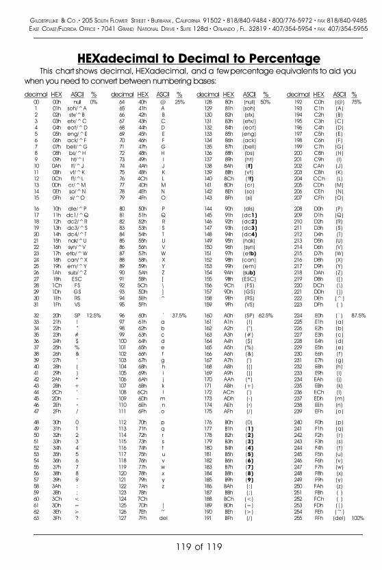
HEXadecimal to Decimal to PercentageThis chart shows decimal, HEXadecimal, and a few percentage equivalents to aid you
when you need to convert between numbering bases:
decimal HEX ASCII % decimal HEX ASCII % decimal HEX ASCII % decimal HEX ASCII %00 00h null 0% 64 40h @ 25% 128 80h (null) 50% 192 C0h (@) 75%1 01h soh/^A 65 41h A 129 81h (soh) 193 C1h (A)2 02h stx/^B 66 42h B 130 82h (stx) 194 C2h (B)3 03h etx/^C 67 43h C 131 83h (etx/) 195 C3h (C)4 04h eot/^D 68 44h D 132 84h (eot) 196 C4h (D)5 05h eng/^E 69 45h E 133 85h (eng) 197 C5h (E)6 06h ack/^F 70 46h F 134 86h (ack) 198 C6h (F)7 07h bell/^G 71 47h G 135 87h (bell) 199 C7h (G)8 08h bs/^H 72 48h H 136 88h (bs) 200 C8h (H)9 09h ht/^I 73 49h I 137 89h (ht) 201 C9h (I)10 0Ah lf/^J 74 4Ah J 138 8Ah (lf) 202 CAh (J)11 0Bh vt/^K 75 4Bh K 139 8Bh (vt) 203 CBh (K)12 0Ch ff/^L 76 4Ch L 140 8Ch ( ff) 204 CCh (L)13 0Dh cr/^M 77 4Dh M 141 8Dh (cr) 205 CDh (M)14 0Eh so/^N 78 4Eh N 142 8Eh (so) 206 CEh (N)15 0Fh si/^O 79 4Fh O 143 8Fh (si) 207 CFh (O)
16 10h dle/^P 80 50h P 144 90h (dls) 208 D0h (P)17 11h dc1/^Q 81 51h Q 145 91h (dc1) 209 D1h (Q)18 12h dc2/^R 82 52h R 146 92h (dc2) 210 D2h (R)19 13h dc3/^S 83 53h S 147 93h (dc3) 211 D3h (S)20 14h dc4/^T 84 54h T 148 94h (dc4) 212 D4h (T)21 15h nak/^U 85 55h U 149 95h (nak) 213 D5h (U)22 16h syn/^V 86 56h V 150 96h (syn) 214 D6h (V)23 17h etb/^W 87 57h W 151 97h (etb) 215 D7h (W)24 18h can/^X 88 58h X 152 98h (can) 216 D8h (X)25 19h em/^Y 89 59h Y 153 99h (em) 217 D9h (Y)26 1Ah sub/^Z 90 5Ah Z 154 9Ah (sub) 218 DAh (Z)27 1Bh ESC 91 5Bh [ 155 9Bh (ESC) 219 DBh ( [ )28 1Ch FS 92 5Ch \ 156 9Ch (FS) 220 DCh (\ )29 1Dh GS 93 5Dh ] 157 9Dh (GS) 221 DDh ( ] )30 1Eh RS 94 5Eh ^ 158 9Eh (RS) 222 DEh (^)31 1Fh VS 95 5Fh 159 9Fh (VS) 223 DFh ( )
32 20h SP 12.5% 96 60h ` 37.5% 160 A0h (SP) 62.5% 224 E0h (`) 87.5%33 21h ! 97 61h a 161 A1h (!) 225 E1h (a)34 22h � 98 62h b 162 A2h (�) 226 E2h (b)35 23h # 99 63h c 163 A3h (#) 227 E3h (c)36 24h $ 100 64h d 164 A4h ($) 228 E4h (d)37 25h % 101 65h e 165 A5h (%) 229 E5h (e)38 26h & 102 66h f 166 A6h (&) 230 E6h (f )39 27h � 103 67h g 167 A7h (�) 231 E7h (g)40 28h ( 104 68h h 168 A8h ( ( ) 232 E8h (h)41 29h ) 105 69h i 169 A9h ( ) ) 233 E9h (i)42 2Ah * 106 6Ah j 170 AAh (*) 234 EAh (j)43 2Bh + 107 6Bh k 171 ABh (+) 235 EBh (k)44 2Ch � 108 6Ch l 172 ACh (�) 236 ECh (l)45 2Dh - 109 6Dh m 173 ADh (-) 237 EDh (m)46 2Eh � 110 6Eh n 174 AEh (�) 238 EEh (n)47 2Fh / 111 6Fh o 175 AFh (/ ) 239 EFh (o)
48 30h 0 112 70h p 176 B0h (0) 240 F0h (p)49 31h 1 113 71h q 177 B1h (1) 241 F1h (q)50 32h 2 114 72h r 178 B2h (2) 242 F2h ( r )51 33h 3 115 73h s 179 B3h (3) 243 F3h (s)52 34h 4 116 74h t 180 B4h (4) 244 F4h (t )53 35h 5 117 75h u 181 B5h (5) 245 F5h (u)54 36h 6 118 76h v 182 B6h (6) 246 F6h (v)55 37h 7 119 77h w 183 B7h (7) 247 F7h (w)56 38h 8 120 78h x 184 B8h (8) 248 F8h (x)57 39h 9 121 79h y 185 B9h (9) 249 F9h (y)58 3Ah : 122 7Ah z 186 BAh (:) 250 FAh (z)59 3Bh ; 123 7Bh 187 BBh (; ) 251 FBh ( )60 3Ch < 124 7Ch 188 BCh (<) 252 FCh ( )61 3Dh = 125 7Dh | 189 BDh (=) 253 FDh (|)62 3Eh > 126 7Eh ~ 190 BEh (>) 254 FEh (~)63 3Fh ? 127 7Fh del 191 BFh (/ ) 255 FFh (del) 100%
GILDERFLUKE & CO .� 205 SOUTH FLOWER STREET � BURBANK , CALIFORNIA 91502 � 818/840-9484 � 800/776-5972 � FAX 818/840-9485EAST COAST /FLORIDA OFFICE � 7041 GRAND NATIONAL DRIVE � SUITE 128d � ORLANDO , FL. 32819 � 407/354-5954 � FAX 407/354-5955
119 of 119