Magnetostatic behaviour of antidot arrays under the local influence of nanopillars
8
Magnetostatic behaviour of antidot arrays under the local influence of nanopillars This article has been downloaded from IOPscience. Please scroll down to see the full text article. 2012 J. Phys. D: Appl. Phys. 45 505002 (http://iopscience.iop.org/0022-3727/45/50/505002) Download details: IP Address: 143.106.97.70 The article was downloaded on 26/11/2012 at 14:58 Please note that terms and conditions apply. View the table of contents for this issue, or go to the journal homepage for more Home Search Collections Journals About Contact us My IOPscience
Transcript of Magnetostatic behaviour of antidot arrays under the local influence of nanopillars

Magnetostatic behaviour of antidot arrays under the local influence of nanopillars
This article has been downloaded from IOPscience. Please scroll down to see the full text article.
2012 J. Phys. D: Appl. Phys. 45 505002
(http://iopscience.iop.org/0022-3727/45/50/505002)
Download details:
IP Address: 143.106.97.70
The article was downloaded on 26/11/2012 at 14:58
Please note that terms and conditions apply.
View the table of contents for this issue, or go to the journal homepage for more
Home Search Collections Journals About Contact us My IOPscience

IOP PUBLISHING JOURNAL OF PHYSICS D: APPLIED PHYSICS
J. Phys. D: Appl. Phys. 45 (2012) 505002 (7pp) doi:10.1088/0022-3727/45/50/505002
Magnetostatic behaviour of antidotarrays under the local influence ofnanopillarsFanny Beron, Marcelo Knobel and Kleber R Pirota
Instituto de Fısica Gleb Wataghin, Universidade Estadual de Campinas (Unicamp), 13083-859,Campinas (SP), Brazil
E-mail: [email protected]
Received 26 July 2012, in final form 11 October 2012Published 20 November 2012Online at stacks.iop.org/JPhysD/45/505002
AbstractWe fabricated highly ordered patterned Permalloy nanometric structures by means of ion beamsputtering on top of an anodic aluminium oxide nanoporous template. First-order reversalcurve (FORC) results and micromagnetic simulations indicate the presence of Permalloyinside one side of the pores, leading to a nanopillar array anisotropically arranged combinedwith an antidot array. The strong shape anisotropy of the pillar forces it to maintain themagnetization along its axis, even for a large in-plane applied field. This phenomenon inducesout-of-plane hysteresis, as well as in-plane anisotropic behaviour. Depending on the in-planeapplied field direction, the presence of nanopillars differently modifies the regular domainpattern, and therefore they could act as a new parameter for tailoring of magnetic anisotropy inantidot arrays.
S Online supplementary data available from stacks.iop.org/JPhysD/45/505002/mmedia
(Some figures may appear in colour only in the online journal)
1. Introduction
Patterning of thin magnetic films allows the designing of novelmaterials that exhibit unique static and dynamic magneticproperties. It is a fabrication technique where the dimensionscan be easily reduced to the sub-micrometre scale, whichconfers it a technological advantage over other fabricationprocesses. Among the diverse applications, promising resultshave been obtained to achieve magnetic and spin wave-basedlogic devices [1, 2], high-density memories [3], as well as,in the emerging area of magnonics, wave guides [4] andmagnonic crystals [5]. They can similarly act as photoniccrystals, prohibiting the propagation of certain frequencies,but for spin waves instead of electromagnetic waves. Aparticularly functional configuration is obtained with antidotarrays, i.e. thin films patterned with holes. They constitutea highly promising type of structure for both non-volatilememories [6–9] and magnonic devices [10, 11]. In the caseof magnonic devices, the antidot arrays take advantage of thenaturally formed pattern of multiple crossed wire arrays for
spin wave propagation, leading to an anisotropic spin waveband structure [12, 13].
In order to achieve large area of nanoscaled magneticantidot arrays, a simple method consists in depositing a thinmagnetic film on a patterned substrate. For this purpose,anodic aluminium oxide (AAO) templates are typically used,being a low-cost substrate with controllable pore dimensionsand order [14]. However, it has recently been reportedthat, during the deposition, magnetic materials may slightlyenter into the substrate pores [15], creating a complextridimensional nanostructure composed of a tiny magneticpillar array connected to the antidot film. Our aim is to employthese pillars to control the antidot anisotropy and therefore thespin wave propagation. Here we focus on the local influenceof anisotropically arranged nanopillars on the antidot array’smagnetostatic behaviour.
We compare the experimental results of the local influenceof nanopillars, obtained through the first-order reversalcurve (FORC) method [16], with micromagnetic simulationsmimicking the antidot film geometry, with and without the
0022-3727/12/505002+07$33.00 1 © 2012 IOP Publishing Ltd Printed in the UK & the USA

J. Phys. D: Appl. Phys. 45 (2012) 505002 F Beron et al
pillars. Both characterizations were performed along both out-of-plane (OOP) and in-plane (IP) directions, with reference tothe antidot film.
2. Experimental details
We fabricated a highly ordered AAO template (35 nm indiameter with 105 nm interpore distance) following the well-known two-step anodization process [14]. 80 nm of Permalloy(Py) was deposited by ion beam sputtering on the top surfaceof the AAO template [17]. The 5 mm by 5 mm substratewas arranged parallel to the target. A slight lateral deviationfrom the beam centre leads to a slightly inclined deposition,favouring the Py to enter one side of the pores. Rutherfordbackscattering (RBS) measurements performed on similarsamples show a Py penetration up to 75 nm below theAAO surface [15], which remains indiscernible in scanningelectron microscopy (SEM) images of the antidot top surface(figure 1(a)).
The FORC technique is based on the classical Preisachmodel, where hysteresis is modelled as a set of elementaryand independent square hysteresis operators [18], calledmathematical hysterons, each one characterized by a coercivityHc and a bias field Hu. The objective of the techniqueconsists in retrieving the FORC distribution function ρ [16],which represents the hysterons’ statistical distribution in agiven system. Experimentally, this is achieved through themeasurement of a set of FORCs, i.e. minor magnetizationM hysteresis curves describing a path going from differentreversal fields Hr until the saturation field [16]. The positiveρ values of the extrapolated [19] FORC diagrams range fromlight blue (ρ = 0) to red (ρmax) on a log scale, while negativeρ values are denoted by darker regions (see the right-hand sideinset of figure 2). The FORC technique proved to be adequateto probe and characterize the different local magnetizationreversal processes occurring in a magnetic antidot array [20].
The influence of nanopillars on the antidot local magneticbehaviour was confirmed by means of micromagneticsimulations, using the freely available OOMMF code [21].A Py antidot array was modelled (1000 × 1000 × 80 nm,Ms = 860 × 103 A m−1, A = 13 × 10−12 J m−1, takenfrom experimental measurements performed on a thin film),adjusting the pore diameter to 35 nm from the AAO topsurface SEM image (figure 1(b)) [20]. Simulations wereperformed using 4 × 4 × 5 nm cells, with and withoutanisotropic 50 nm high, 10 nm wide nanopillars all locatedon the same pore side (inset of figure 1(b)). Figure 1(c)shows a tridimensional representation of the investigatednanostructure, i.e. the combination of an antidot array withanisotropically arranged nanopillars (all the nanopillars arelocated on the same side of the antidot pores).
3. Results
3.1. Experimental results
3.1.1. Out-of-plane behaviour. The out-of-plane experimen-tal hysteresis curve consists of two distinctive contributions: a
Figure 1. Antidot array representation. Top surface view: (a) SEM,(b) mask used for micromagnetic simulations with nanopillars(black = Permalloy). Inset: y-cross-section view (taken along thewhite dashed line) showing a nanopillar (all dimensions in nm).Tridimensional view: (c) schematic illustration from the structurebottom.
2
J. Phys. D: Appl. Phys. 45 (2012) 505002 F Beron et al
Figure 2. Out-of-plane experimental major hysteresis curve. Leftinset: low field zoom; right inset: FORC diagram. The distributionassociated with the nanopillars is encircled.
reversible part at high fields and an irreversible one at lowerfields (figure 2). They are associated with the reversal of theantidot film and the nanopillar array, respectively. The experi-mental FORC diagram presents a more detailed representationof the irreversible processes occurring along the OOP direc-tion (right-hand side inset of figure 2). Three distributionsare clearly distinguishable: two narrow ones located at lowcoercivity (around 60 and 360 Oe) and a harder one (650 Oe)exhibiting a small elongation along the Hu axis (i.e. perpen-dicular to the Hc axis). This elongation is characteristic ofa dipolar interaction field, typical of nanopillar arrays mea-sured along their axis, with their shape anisotropy yieldingsimilar local coercivity and their high density leading to aperceptible dipolar interaction field, despite the pillars’ smallvolume [22].
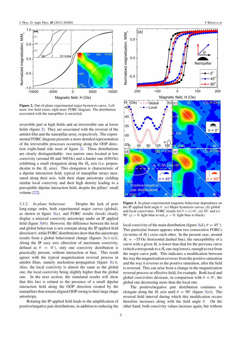
3.1.2. In-plane behaviour. Despite the lack of porelong-range order, both experimental major curves (global),as shown in figure 3(a), and FORC results (local) clearlydisplay a uniaxial coercivity anisotropy under an IP appliedfield (figure 3(b)). However, the difference between the localand global behaviour is not constant along the IP applied fielddirection θ , while FORC distributions show that this anisotropyresults from a global behavioural change (figures 3(c)–(e)).Along the IP easy axis (direction of maximum coercivity,defined as θ = 0◦), only one coercivity distribution ispractically present, without interaction or bias. This resultagrees with the typical magnetization reversal process inantidot films, namely nucleation–propagation (figure 3(c)).Also, the local coercivity is almost the same as the globalone, the local coercivity being slightly higher than the globalone. In the next section, the simulated results will showthat this fact is related to the presence of a small dipolarinteraction field along the OOP direction created by thenanopillars that remain aligned OOP owing to their large shapeanisotropy.
Rotating the IP applied field leads to the amplification ofpositive/negative pair distributions, in addition to reducing the
Figure 3. In-plane experimental magnetic behaviour dependence onthe IP applied field angle θ . (a) Major hysteresis curves, (b) globaland local coercivities. FORC results for θ = (c) 0◦, (d) 45◦ and (e)90◦ (ρ > 0: light blue to red, ρ < 0: light blue to black).
local coercivity of the main distribution (figure 3(d), θ = 45◦).This particular feature appears when two consecutive FORCs(in terms of Hr) cross each other. In the present case, aroundHr = −55 Oe (horizontal dashed line), the susceptibility of acurve with a given Hr is lower than that for the previous curve(which corresponds to a Hr one step lower), enough to exit fromthe major curve path. This indicates a modification betweenthe way the magnetization reverses from the positive saturationand the way it reverses to the positive saturation, after the fieldis reversed. This can arise from a change in the magnetizationreversal process or effective field, for example. Both local andglobal coercivities decrease, in comparison with θ = 0◦, theglobal one decreasing more than the local one.
The positive/negative pair distribution continues toelongate along the Hr axis until θ = 90◦ (figure 3(e)). Thereversal field interval during which this modification occurstherefore increases along with the field angle θ . On theother hand, both coercivity values increase again, but without
3

J. Phys. D: Appl. Phys. 45 (2012) 505002 F Beron et al
Figure 4. Out-of-plane simulated behaviour. (a) Bottom view of thesimulated remanent magnetization configuration after a field appliedalong the z > 0 direction. (The representation of the magnetizationdirection is graphically depicted in the inset, according to thefollowing code: MOOP = white to black, as indicated by thecylinder, MIP = colour code given by the torus. The principalmagnetization directions are emphasized by the dark arrows.)(b) Nanopillars’ influence on major hysteresis curves. Right axis:difference between the major hysteresis curves with and withoutnanopillars; inset: low field zoom.
reaching the level they had at θ = 0◦. The clear differencebetween the local and global coercivities will subsequently beexplained in terms of a larger dipolar field created by the pillararray.
3.2. Simulated results
3.2.1. Out-of-plane behaviour (Hz). The simulatedremanent magnetization representation clearly shows OOPalignment within the pillars, whose magnetization remainseither parallel or antiparallel to the applied field (appearing,respectively, as white and black in figure 4(a), the completesimulation result is presented in the online supplementaryvideo 1 (stacks.iop.org/JPhysD/45/505002/mmedia)). Bycomparing the micromagnetic simulation hysteresis curveswith and without pillars, one can see that it inducesirreversibility in the system behaviour (figure 4(b)). Whilean antidot film alone would display a quasi-anhysteretic
magnetization curve, the presence of pillars introduceshysteresis at low magnetic fields. The nanopillars’ magneticbehaviour can be clearly described by plotting the differencebetween the simulated hysteresis curves with and withoutpillars (figure 4(b), right axis).
3.2.2. In-plane behaviour (Hx and Hy). We performedmicromagnetic simulations along the two distinctive directionscreated by the non-circular pillars’ shape, i.e. parallel andperpendicular to the pillar edge. In both cases, despite theIP applied field, the pillars’ magnetization quickly orientatesalong their axes (z direction), owing to their large shapeanisotropy. The simulations were performed on a relativelysmall area (1 µm2), which yields hysteresis curves with astep-like aspect when the magnetization reversal occurredby domain wall nucleation–propagation. However, theircomparison leads to interesting observations.
For fields parallel to the pillars’ edge (x direction),decreasing the field from positive saturation results in aconfiguration where half of the pillars align up (white) andhalf down (black) (figure 5(a), the complete simulationresult is presented in the online supplementary video 2(stacks.iop.org/JPhysD/45/505002/mmedia)). During themagnetization reversal, some pillars reverse, but in a wayof maintaining the up/down ratio constant, thus yielding analmost null net magnetization along the z direction (Mz).The pillars seem to only increase the susceptibility, withoutmodifying the coercivity, in comparison with the pure antidotfilm (figure 5(b), left-hand side).
On the other hand, applying the field perpendicularto the pillar edge (y direction) leads to a preferentialdirection for the axial magnetization (majority of up(white) nanopillars in figure 5(c), the complete simulationresult is presented in the online supplementary video 3(stacks.iop.org/JPhysD/45/505002/mmedia)). Therefore,almost all nanopillars tend towards the same direction aftersaturating the system in the plane, creating non-null Mz. Inthis case, both the susceptibility and coercivity decrease as aconsequence of the nanopillars’ presence (figure 5(b), right-hand side).
Along both principal directions, the magnetizationconfiguration qualitatively appears identical with and withoutnanopillars for an applied field slightly below saturation,displaying a well-defined magnetization domain pattern(figures 6(a) and (b), top). Despite this similarity, thefrustration consequences can be emphasized by plotting thedifference between them. The bottom parts of figures 6(a) and(b) are obtained by taking 1000 times the square of differencebetween the hue (H ) and value (V ) in the hue–saturation–value(HSV) colour system [23], for the IP and OOP magnetizationvariation, respectively. The antidot regions undergoing amagnetization direction variation appear in white, while blacksignifies no modification.
4. Discussion
The system investigated, an antidot array coupled withnanopillars, represents a complex system in itself. Its
4

J. Phys. D: Appl. Phys. 45 (2012) 505002 F Beron et al
Figure 5. In-plane applied field direction influence on simulatednanopillars’ behaviour. (a), (c) Bottom view of the magnetizationconfiguration for H = 2000 Oe: (a) Hx , (c) Hy . Insets: x (top) andy (bottom) cross-section views (same colour legend as infigure 4(a)). (b) Nanopillars’ influence along the applied fielddirection on simulated major hysteresis curves. Top + right axes: Mz
component of the major hysteresis curves with nanopillars. Rightside = Hx , left side = Hy .
experimental fabrication yielded an even more complicatedsystem to model, mostly due to surface patterning (comingfrom the anodization process) and the large scale effectsinvolved, such as the dipolar interaction field. Therefore,we performed the simulations using a simplified system(flat surface, small area) with the specific objective ofunderstanding the nanopillars’ influence, without carryingout a direct comparison between experimental and simulatedresults.
Figure 6. Nanopillars’ influence on the simulated magnetizationconfiguration (bottom view of the antidot array, H = 2000 Oe) for x(a) and y (b) applied field directions. In clockwise direction:magnetization configuration with and without pillars (same colourlegend as in figure 4(a)), out-of-plane and in-plane variations of themagnetization configuration induced by the pillars’ presence(greyscale ranging from black, where no modification of themagnetization direction occured, to white, indicating the placeswhere the largest modification of magnetization directiontook place).
4.1. Out-of-plane
The situation observed experimentally is similar to themicromagnetic simulation results for a system with pillars.The lack of magnetocrystalline anisotropy in a Py antidotarray leads one to expect a purely reversible magnetizationreversal along the OOP direction, as it is a hard magnetic
5

J. Phys. D: Appl. Phys. 45 (2012) 505002 F Beron et al
axis. On the other hand, the elongated shape of the pillarscreates a non-negligible local shape anisotropy, favouring anOOP magnetization alignment for the nanopillars. The OOPnormalized remanence obtained for the simulated system withpillars (Mr/Ms = 0.020) suggests that almost all nanopillarsremain aligned parallel to the applied field direction at zerofield, as can be verified visually in figure 4(a). In fact, thenanopillars’ volume percentage (1.7%), taking into account thewhole system, matches with the pillars’ normalized remanencevalue, after subtracting the value without pillars (Mr/Ms =0.003).
The first striking characteristic of the simulated nanopil-lars’ magnetic behaviour is the clockwise tilt of the differencehysteresis curve, denoting a susceptibility decrease induced bythe presence of pillars (figure 4(b), right axis). The nanopil-lars, which are located below the antidot film, induce a dipolarinteraction field, which is not constant along the z direction.This fact can explain the non-linearity of the curve. Its ratherlarge coercivity (Hc = 950 Oe) is consistent with the theo-retical coercivity of individual Py nanopillars not connectedto a magnetic film. By approximating the simulated pillarsto rectangles, we calculated a demagnetizing factor along theaxis of about 0.134, which leads to a shape anisotropy field of1450 Oe [24]. The observed coercivity decrease can be expla-ined by the presence of the Py film in the simulated system,which helps the start of the magnetization reversal of the pillars.
The experimental coercivity of individual pillars issomewhat lower than the simulated one (650 Oe versus950 Oe), indicating that the pillars may be thicker than theshape used in the simulation. However, the main point is therather good homogeneity of the experimental pillar coercivityvalues, suggesting that the fabrication method achieved ananopillar array with good shape uniformity. The interactionfield value extracted from the FORC diagram (around 250 Oe)represents the dipolar field at the nanopillar level. Finally, itcan be seen in figure 1(a) that the antidot film surface is notflat. Around each pore, six crests appear in the magnetic film,because it follows the surface of the alumina template patternedby the anodization process. This surface non-uniformity couldexplain the presence of the two extra coercivity distributionson the experimental FORC diagram.
4.2. In-plane
The experimental IP behaviour of the antidot film with pillarsexhibits a macroscopic uniaxial anisotropy, thus not related tothe local six-fold anisotropy of the antidot film. Therefore,we associated it with the presence of pillars, being the onlyfeature in the experimental system that presents this kind ofanisotropy. In fact, we found that the relative orientation ofthe applied field to the pillars’ location is the one that governsthe overall magnetic behaviour, and not their asymmetricalshape, as could be expected.
A magnetic field applied parallel to the pillars’ edgeyielded a half/half pillar configuration. This is attributedto the lack of preference towards one direction or the otherfor pillar magnetization, as both situations induce frustrationnear the pillar/antidot film interface, as can be seen on the
x-cross-section (top right inset of figure 5(a)). This pillarconfiguration leads to a negligible dipolar field during thewhole magnetization reversal, the interaction field created bythe upward nanopillars being mostly compensated by the onecreated by the downward ones. The frustration generated bythe pillars on the antidot film, by preventing the magnetizationreversal of the latter, could explain the susceptibility increaseinduced by the pillars. Therefore, we associated the global easyaxis (θ = 0◦), characterized by uniform magnetic behaviourand a higher coercivity, with a field applied parallel to thepillars’ edge (x direction).
When the field is applied perpendicular to the pillars’ edge,the IP magnetization of the antidot film favours an up or downpillar alignment depending on positive or negative saturation,respectively, in order to minimize the magnetostatic energy atthe pillar/film interface (bottom right inset of figure 5(c)). Thisparticular configuration yields a non-null dipolar field, whichcontributes in the z direction to the effective field present inthe antidot film. As a consequence, it lowers its coercivity,as compared with the θ = 0◦ direction. The reversiblemagnetization reversal of the antidot film induced by thedipolar field contributes to further lower the global coercivity,in comparison with the local one. Therefore, the presence of adipolar interaction field at an applied field near the coercivityexplains the discrepancy observed between the coercivityvalues (figure 3(b)). This discrepancy almost vanishes inthe case without a dipolar field (θ = 0◦). The presenceof the OOP demagnetizating dipolar field also explains boththe susceptibility and coercivity decrease generated by thenanopillars, in comparison with the antidot film.
Magnetization rotation of the antidot film relaxes thepreferential alignment, leading to a half/half configuration(and thus null dipolar field) just before negative saturation.It decreases the z component of the effective field, leadingto a higher field required to switch back the antidot filmmagnetization. This changes drastically when the IP field isstrong enough to align the magnetization of the pillars along theplane. A new configuration of all aligned nanopillars appearswhen one increases the field again, producing a non-nulldipolar field and thus a lower switching field. The modificationof this situation yields a field region where the FORCs crosseach other, clearly indicated by the positive/negative pairdistributions on the FORC results (figure 3).
The previous results show that the pillars, by theiranisotropic position regarding the pores, yield a uniaxialanisotropy system. The IP field angle can therefore be used totailor the desired coercivity. However, the pillars’ influence isnot restricted to this consequence, as shown in the detailedanalysis of the micromagnetic simulation results with andwithout pillars.
For both applied field directions, the in-plane magnetiza-tion component is locally modified next to the two lateral ext-remities of the pillars, where the magnetization linked to thepillars is not aligned with the applied field direction. While itextends until the next nearest pore for the Hx field (figure 6(a),bottom left), it remains near the pore for the Hy field, themagnetic domains not stretching out to the neighbour pores(figure 6(b), bottom left). The situation changes radically when
6

J. Phys. D: Appl. Phys. 45 (2012) 505002 F Beron et al
looking at the regions, where it is the out-of-plane magnetiza-tion component that varies. The magnetization variation foran x applied field clearly indicates the magnetic frustrationoccurring on one side of the pillars (figure 6(a), bottom right).Under the y applied field, the magnetization just near the pillarsis affected, as expected. However, the region opposite to it isalso influenced on a large area between the pores, but lesspronounced than in the Hx case (figure 6(b), bottom right).The dipolar field created by each nanopillar could explain thislong-range influence.
Recently, it has been shown that the spin waveresonance modes are sensitive to small changes in themagnetization configuration near antidot pores [25]. Ourresults demonstrated that the anisotropic nanopillar array givesan extra ability to control this magnetization configuration, andhence, the spin wave modes.
5. Conclusion
In conclusion, we demonstrated that the magnetic materialslightly entering into one side of the pores during the depositionprocess strongly influences the antidot magnetic behaviour, forboth out-of-plane and in-plane applied magnetic fields. Thenanopillars’ large shape anisotropy and preferential positionmainly yield an out-of-plane hysteresis and an in-planeanisotropy. Moreover, the nanopillars may influence the spinwave propagation, by preventing the in-plane magnetizationrotation, leading to an interesting mechanism to take intoaccount in the design of new magnonic crystals.
Acknowledgments
This work was financially supported in part by the FondsQuebecois de Recherche sur la Nature et les Technologies(FQRNT), Canada, and the Fundacao de Amparo a Pesquisado Estado de Sao Paulo (FAPESP), Brazil, and ConselhoNacional de Desenvolvimento Cientıfico e Tecnologico(CNPq), Brazil. The authors thank P Prieto (UniversidadAutonoma de Madrid) for providing the sample.
References
[1] Allwood D A, Xiong G, Faulkner C C, Atkinson D, Petit Dand Cowburn R P 2005 Science 309 1688–92
[2] Schneider T, Serga A A, Leven B, Hillebrands B, Stamps R Land Kostylev M P 2008 Appl. Phys. Lett. 92 022505
[3] Ross C A, Smith H I, Savas T, Schattenburg M,Farhoud M, Hwang M, Walsh M, Abraham M C andRam R J 1999 J. Vac. Sci. Technol. B 17 3168–76
[4] Topp J, Podbielski J, Heitmann D and Grundler D 2008 Phys.Rev. B 78 024431
[5] Wang Z K, Zhang V L, Lim H S, Ng S C, Kuok M H, Jain Sand Adeyeye A O 2010 ACS Nano 4 643–8
[6] Cowburn R P, Adeyeye A O and Bland J A C 1997 Appl. Phys.Lett. 70 2309–11
[7] Torres L, Lopez-Diaz L and Iniguez J 1998 Appl. Phys. Lett.73 3766–8
[8] Toporov A Yu, Langford R M and Petford-Long A K 2000Appl. Phys. Lett. 77 3063–5
[9] Wang C C, Adeyeye A O and Singh N 2006 Nanotechnology17 1629–36
[10] Kostylev M, Gubbiotti G, Carlotti G, Socino G, Tacchi S,Wang C, Singh N, Adeyeye A O and Stamps R L 2008J. Appl. Phys. 103 07C507
[11] Neusser S, Botters B and Grundler D 2008 Phys. Rev. B78 054406
[12] Neusser S, Botters B, Becherer M, Schmitt-Landsiedel D andGrundler D 2008 Appl. Phys. Lett. 93 122501
[13] Neusser S, Duerr G, Bauer H G, Tacchi S, Madami M,Woltersdorf G, Gubbiotti G, Back C H and Grundler D2010 Phys. Rev. Lett. 105 067208
[14] Masuda H and Fukuda K 1995 Science 268 1466–8[15] Prieto P, Pirota K R, Climent-Font A, Vazquez M
and Sanza J M 2011 Surf. Interfac. Anal.43 1417–22
[16] Mayergoyz I D 1986 Phys. Rev. Lett. 56 1518–21[17] Prieto P, Pirota K R, Vazquez M and Sanza J M 2008
Phys. Stat. Sol. A 205 363–7[18] Preisach F 1935 Z. Phys. 94 277–302[19] Beron F, Clime L, Ciureanu M, Cochrane R W, Menard D
and Yelon A 2007 J. Appl. Phys. 101 09J107[20] Beron F, Pirota K R, Vega V, Prida V M, Fernandez A,
Hernando B and Knobel M 2011 New J. Phys. 13 013035[21] The Object Oriented Micromagnetic Framework developed at
NIST, Gaithersburg, http://mathnistgov/oommf/[22] Beron F, Clime L, Ciureanu M, Cochrane R W,
Menard D and Yelon A 2008 J. Nanos. Nanotechnol.8 2944–54
[23] Joblove G H and Greenberg D 1978 Computer Graphics(SIGGRAPH ’78 Proc. 5th annual conference on computergraphics and interactive techniques) vol 12 (New York:ACM) p 20
[24] Aharoni A 1998 J. Appl. Phys. 83 3432[25] Hu C-L, Magaraggia R, Yuan H-Y, Chang C S, Kostylev M,
Tripathy D, Adeyeye A O and Stamps R L 2011 Appl. Phys.Lett. 98 262508
7