Lynx Smart BMS - Solet Technics
41
Lynx Smart BMS rev 01 05/2021 ENGLISH
-
Upload
khangminh22 -
Category
Documents
-
view
2 -
download
0
Transcript of Lynx Smart BMS - Solet Technics

Lynx Smart BMS
rev 01 05/2021
ENGLISH

Table of Contents1. Safety Precautions . . . . . . . . . . . . . . . . . . . . . . . . . . . . . . . . . . . . . . . . . . . . . . . . . . . . . . . . . . . . . . . . . . . . . . . . . . . . . . . . . . . . . . . . . . . . . . . . . . . . . . . . . . . . . . . . . . . 1
1.1. Safety Warnings Lynx Distribution System .. . . . . . . . . . . . . . . . . . . . . . . . . . . . . . . . . . . . . . . . . . . . . . . . . . . . . . . . . . . . . . . . . . . . . . . . . . . . . . 11.2. Transport and Storage . . . . . . . . . . . . . . . . . . . . . . . . . . . . . . . . . . . . . . . . . . . . . . . . . . . . . . . . . . . . . . . . . . . . . . . . . . . . . . . . . . . . . . . . . . . . . . . . . . . . . . 1
2. Introduction . . . . . . . . . . . . . . . . . . . . . . . . . . . . . . . . . . . . . . . . . . . . . . . . . . . . . . . . . . . . . . . . . . . . . . . . . . . . . . . . . . . . . . . . . . . . . . . . . . . . . . . . . . . . . . . . . . . . . . . . . . . 22.1. The Lynx Smart BMS .. . . . . . . . . . . . . . . . . . . . . . . . . . . . . . . . . . . . . . . . . . . . . . . . . . . . . . . . . . . . . . . . . . . . . . . . . . . . . . . . . . . . . . . . . . . . . . . . . . . . . . 22.2. VictronConnect App . . . . . . . . . . . . . . . . . . . . . . . . . . . . . . . . . . . . . . . . . . . . . . . . . . . . . . . . . . . . . . . . . . . . . . . . . . . . . . . . . . . . . . . . . . . . . . . . . . . . . . . . . 22.3. GX device . . . . . . . . . . . . . . . . . . . . . . . . . . . . . . . . . . . . . . . . . . . . . . . . . . . . . . . . . . . . . . . . . . . . . . . . . . . . . . . . . . . . . . . . . . . . . . . . . . . . . . . . . . . . . . . . . . . . 22.4. Lithium Smart Batteries . . . . . . . . . . . . . . . . . . . . . . . . . . . . . . . . . . . . . . . . . . . . . . . . . . . . . . . . . . . . . . . . . . . . . . . . . . . . . . . . . . . . . . . . . . . . . . . . . . . . . 32.5. The Lynx Distribution System .. . . . . . . . . . . . . . . . . . . . . . . . . . . . . . . . . . . . . . . . . . . . . . . . . . . . . . . . . . . . . . . . . . . . . . . . . . . . . . . . . . . . . . . . . . . . . 3
3. Features . . . . . . . . . . . . . . . . . . . . . . . . . . . . . . . . . . . . . . . . . . . . . . . . . . . . . . . . . . . . . . . . . . . . . . . . . . . . . . . . . . . . . . . . . . . . . . . . . . . . . . . . . . . . . . . . . . . . . . . . . . . . . . . . 43.1. Internal parts and wiring diagram Lynx Smart BMS .. . . . . . . . . . . . . . . . . . . . . . . . . . . . . . . . . . . . . . . . . . . . . . . . . . . . . . . . . . . . . . . . . . . . 43.2. Contactor . . . . . . . . . . . . . . . . . . . . . . . . . . . . . . . . . . . . . . . . . . . . . . . . . . . . . . . . . . . . . . . . . . . . . . . . . . . . . . . . . . . . . . . . . . . . . . . . . . . . . . . . . . . . . . . . . . . . . 43.3. Remote on/off switch . . . . . . . . . . . . . . . . . . . . . . . . . . . . . . . . . . . . . . . . . . . . . . . . . . . . . . . . . . . . . . . . . . . . . . . . . . . . . . . . . . . . . . . . . . . . . . . . . . . . . . . . 43.4. Pre-charge circuit . . . . . . . . . . . . . . . . . . . . . . . . . . . . . . . . . . . . . . . . . . . . . . . . . . . . . . . . . . . . . . . . . . . . . . . . . . . . . . . . . . . . . . . . . . . . . . . . . . . . . . . . . . . . 53.5. Fans . . . . . . . . . . . . . . . . . . . . . . . . . . . . . . . . . . . . . . . . . . . . . . . . . . . . . . . . . . . . . . . . . . . . . . . . . . . . . . . . . . . . . . . . . . . . . . . . . . . . . . . . . . . . . . . . . . . . . . . . . . . 53.6. Battery Management System .. . . . . . . . . . . . . . . . . . . . . . . . . . . . . . . . . . . . . . . . . . . . . . . . . . . . . . . . . . . . . . . . . . . . . . . . . . . . . . . . . . . . . . . . . . . . . 53.7. Battery Monitor (shunt) . . . . . . . . . . . . . . . . . . . . . . . . . . . . . . . . . . . . . . . . . . . . . . . . . . . . . . . . . . . . . . . . . . . . . . . . . . . . . . . . . . . . . . . . . . . . . . . . . . . . . 63.8. Alarm relay . . . . . . . . . . . . . . . . . . . . . . . . . . . . . . . . . . . . . . . . . . . . . . . . . . . . . . . . . . . . . . . . . . . . . . . . . . . . . . . . . . . . . . . . . . . . . . . . . . . . . . . . . . . . . . . . . . . 63.9. AUX connection . . . . . . . . . . . . . . . . . . . . . . . . . . . . . . . . . . . . . . . . . . . . . . . . . . . . . . . . . . . . . . . . . . . . . . . . . . . . . . . . . . . . . . . . . . . . . . . . . . . . . . . . . . . . . 6
4. Communication and interfacing . . . . . . . . . . . . . . . . . . . . . . . . . . . . . . . . . . . . . . . . . . . . . . . . . . . . . . . . . . . . . . . . . . . . . . . . . . . . . . . . . . . . . . . . . . . . . . . . . . . 84.1. The VictronConnect App . . . . . . . . . . . . . . . . . . . . . . . . . . . . . . . . . . . . . . . . . . . . . . . . . . . . . . . . . . . . . . . . . . . . . . . . . . . . . . . . . . . . . . . . . . . . . . . . . . . . 84.2. GX Device . . . . . . . . . . . . . . . . . . . . . . . . . . . . . . . . . . . . . . . . . . . . . . . . . . . . . . . . . . . . . . . . . . . . . . . . . . . . . . . . . . . . . . . . . . . . . . . . . . . . . . . . . . . . . . . . . . . . 84.3. VRM Portal . . . . . . . . . . . . . . . . . . . . . . . . . . . . . . . . . . . . . . . . . . . . . . . . . . . . . . . . . . . . . . . . . . . . . . . . . . . . . . . . . . . . . . . . . . . . . . . . . . . . . . . . . . . . . . . . . . . 84.4. Lynx Distributor fuse monitoring . . . . . . . . . . . . . . . . . . . . . . . . . . . . . . . . . . . . . . . . . . . . . . . . . . . . . . . . . . . . . . . . . . . . . . . . . . . . . . . . . . . . . . . . . . . 84.5. DVCC .. . . . . . . . . . . . . . . . . . . . . . . . . . . . . . . . . . . . . . . . . . . . . . . . . . . . . . . . . . . . . . . . . . . . . . . . . . . . . . . . . . . . . . . . . . . . . . . . . . . . . . . . . . . . . . . . . . . . . . . . 84.6. Actions taken when certain battery conditions occur . . . . . . . . . . . . . . . . . . . . . . . . . . . . . . . . . . . . . . . . . . . . . . . . . . . . . . . . . . . . . . . . . . . . 84.7. NMEA2000 . . . . . . . . . . . . . . . . . . . . . . . . . . . . . . . . . . . . . . . . . . . . . . . . . . . . . . . . . . . . . . . . . . . . . . . . . . . . . . . . . . . . . . . . . . . . . . . . . . . . . . . . . . . . . . . . . . . 9
5. System Design . . . . . . . . . . . . . . . . . . . . . . . . . . . . . . . . . . . . . . . . . . . . . . . . . . . . . . . . . . . . . . . . . . . . . . . . . . . . . . . . . . . . . . . . . . . . . . . . . . . . . . . . . . . . . . . . . . . . . . 105.1. Lynx distribution system parts . . . . . . . . . . . . . . . . . . . . . . . . . . . . . . . . . . . . . . . . . . . . . . . . . . . . . . . . . . . . . . . . . . . . . . . . . . . . . . . . . . . . . . . . . . . . 10
5.1.1. Interconnecting Lynx modules . . . . . . . . . . . . . . . . . . . . . . . . . . . . . . . . . . . . . . . . . . . . . . . . . . . . . . . . . . . . . . . . . . . . . . . . . . . . . . . . . 105.1.2. Orientation of Lynx modules . . . . . . . . . . . . . . . . . . . . . . . . . . . . . . . . . . . . . . . . . . . . . . . . . . . . . . . . . . . . . . . . . . . . . . . . . . . . . . . . . . . 105.1.3. System example - Lynx Smart BMS, 2x Lynx Distributor and lithium batteries . . . . . . . . . . . . . . . . . . . . . . . . . . 115.1.4. System example - Lynx Smart BMS, 1x Lynx Distributor and lithium batteries . . . . . . . . . . . . . . . . . . . . . . . . . . 125.1.5. System Example - Lynx Smart BMS only . . . . . . . . . . . . . . . . . . . . . . . . . . . . . . . . . . . . . . . . . . . . . . . . . . . . . . . . . . . . . . . . . . . . 13
5.2. System sizing . . . . . . . . . . . . . . . . . . . . . . . . . . . . . . . . . . . . . . . . . . . . . . . . . . . . . . . . . . . . . . . . . . . . . . . . . . . . . . . . . . . . . . . . . . . . . . . . . . . . . . . . . . . . . . 135.2.1. Current rating Lynx Smart BMS .. . . . . . . . . . . . . . . . . . . . . . . . . . . . . . . . . . . . . . . . . . . . . . . . . . . . . . . . . . . . . . . . . . . . . . . . . . . . . . 135.2.2. Fusing . . . . . . . . . . . . . . . . . . . . . . . . . . . . . . . . . . . . . . . . . . . . . . . . . . . . . . . . . . . . . . . . . . . . . . . . . . . . . . . . . . . . . . . . . . . . . . . . . . . . . . . . . . . . 135.2.3. Cabling . . . . . . . . . . . . . . . . . . . . . . . . . . . . . . . . . . . . . . . . . . . . . . . . . . . . . . . . . . . . . . . . . . . . . . . . . . . . . . . . . . . . . . . . . . . . . . . . . . . . . . . . . . . 14
6. Installation . . . . . . . . . . . . . . . . . . . . . . . . . . . . . . . . . . . . . . . . . . . . . . . . . . . . . . . . . . . . . . . . . . . . . . . . . . . . . . . . . . . . . . . . . . . . . . . . . . . . . . . . . . . . . . . . . . . . . . . . . . . 156.1. Mechanical connections . . . . . . . . . . . . . . . . . . . . . . . . . . . . . . . . . . . . . . . . . . . . . . . . . . . . . . . . . . . . . . . . . . . . . . . . . . . . . . . . . . . . . . . . . . . . . . . . . . 15
6.1.1. Lynx module connection features . . . . . . . . . . . . . . . . . . . . . . . . . . . . . . . . . . . . . . . . . . . . . . . . . . . . . . . . . . . . . . . . . . . . . . . . . . . . . 156.1.2. Mounting and interconnecting Lynx modules . . . . . . . . . . . . . . . . . . . . . . . . . . . . . . . . . . . . . . . . . . . . . . . . . . . . . . . . . . . . . . . . 15
6.2. Electrical connections . . . . . . . . . . . . . . . . . . . . . . . . . . . . . . . . . . . . . . . . . . . . . . . . . . . . . . . . . . . . . . . . . . . . . . . . . . . . . . . . . . . . . . . . . . . . . . . . . . . . . 166.2.1. Connect DC wires . . . . . . . . . . . . . . . . . . . . . . . . . . . . . . . . . . . . . . . . . . . . . . . . . . . . . . . . . . . . . . . . . . . . . . . . . . . . . . . . . . . . . . . . . . . . . . . 166.2.2. Connect RJ10 cable(s) . . . . . . . . . . . . . . . . . . . . . . . . . . . . . . . . . . . . . . . . . . . . . . . . . . . . . . . . . . . . . . . . . . . . . . . . . . . . . . . . . . . . . . . . . 166.2.3. Connect BMS cables . . . . . . . . . . . . . . . . . . . . . . . . . . . . . . . . . . . . . . . . . . . . . . . . . . . . . . . . . . . . . . . . . . . . . . . . . . . . . . . . . . . . . . . . . . . 176.2.4. Connect the Multi connector . . . . . . . . . . . . . . . . . . . . . . . . . . . . . . . . . . . . . . . . . . . . . . . . . . . . . . . . . . . . . . . . . . . . . . . . . . . . . . . . . . . 176.2.5. Connect the GX device . . . . . . . . . . . . . . . . . . . . . . . . . . . . . . . . . . . . . . . . . . . . . . . . . . . . . . . . . . . . . . . . . . . . . . . . . . . . . . . . . . . . . . . . . 18
6.3. Configuration and settings . . . . . . . . . . . . . . . . . . . . . . . . . . . . . . . . . . . . . . . . . . . . . . . . . . . . . . . . . . . . . . . . . . . . . . . . . . . . . . . . . . . . . . . . . . . . . . . . 196.3.1. Power up for the first time . . . . . . . . . . . . . . . . . . . . . . . . . . . . . . . . . . . . . . . . . . . . . . . . . . . . . . . . . . . . . . . . . . . . . . . . . . . . . . . . . . . . . . 196.3.2. Update firmware . . . . . . . . . . . . . . . . . . . . . . . . . . . . . . . . . . . . . . . . . . . . . . . . . . . . . . . . . . . . . . . . . . . . . . . . . . . . . . . . . . . . . . . . . . . . . . . . . 196.3.3. Settings Lynx Smart BMS .. . . . . . . . . . . . . . . . . . . . . . . . . . . . . . . . . . . . . . . . . . . . . . . . . . . . . . . . . . . . . . . . . . . . . . . . . . . . . . . . . . . . . 206.3.4. Battery monitor settings . . . . . . . . . . . . . . . . . . . . . . . . . . . . . . . . . . . . . . . . . . . . . . . . . . . . . . . . . . . . . . . . . . . . . . . . . . . . . . . . . . . . . . . . 216.3.5. Settings Lynx Distributor . . . . . . . . . . . . . . . . . . . . . . . . . . . . . . . . . . . . . . . . . . . . . . . . . . . . . . . . . . . . . . . . . . . . . . . . . . . . . . . . . . . . . . . . 23
7. Commissioning the Lynx Smart BMS .. . . . . . . . . . . . . . . . . . . . . . . . . . . . . . . . . . . . . . . . . . . . . . . . . . . . . . . . . . . . . . . . . . . . . . . . . . . . . . . . . . . . . . . . . 24
Lynx Smart BMS

8. Operation Lynx Smart BMS .. . . . . . . . . . . . . . . . . . . . . . . . . . . . . . . . . . . . . . . . . . . . . . . . . . . . . . . . . . . . . . . . . . . . . . . . . . . . . . . . . . . . . . . . . . . . . . . . . . . . . 258.1. Powering up . . . . . . . . . . . . . . . . . . . . . . . . . . . . . . . . . . . . . . . . . . . . . . . . . . . . . . . . . . . . . . . . . . . . . . . . . . . . . . . . . . . . . . . . . . . . . . . . . . . . . . . . . . . . . . . . 258.2. BMS operation . . . . . . . . . . . . . . . . . . . . . . . . . . . . . . . . . . . . . . . . . . . . . . . . . . . . . . . . . . . . . . . . . . . . . . . . . . . . . . . . . . . . . . . . . . . . . . . . . . . . . . . . . . . . . 258.3. Battery monitor operation . . . . . . . . . . . . . . . . . . . . . . . . . . . . . . . . . . . . . . . . . . . . . . . . . . . . . . . . . . . . . . . . . . . . . . . . . . . . . . . . . . . . . . . . . . . . . . . . . 268.4. Battery care . . . . . . . . . . . . . . . . . . . . . . . . . . . . . . . . . . . . . . . . . . . . . . . . . . . . . . . . . . . . . . . . . . . . . . . . . . . . . . . . . . . . . . . . . . . . . . . . . . . . . . . . . . . . . . . . 268.5. LED indications alarms and errors . . . . . . . . . . . . . . . . . . . . . . . . . . . . . . . . . . . . . . . . . . . . . . . . . . . . . . . . . . . . . . . . . . . . . . . . . . . . . . . . . . . . . . 26
9. Troubleshooting and Support . . . . . . . . . . . . . . . . . . . . . . . . . . . . . . . . . . . . . . . . . . . . . . . . . . . . . . . . . . . . . . . . . . . . . . . . . . . . . . . . . . . . . . . . . . . . . . . . . . . 309.1. Lynx Smart BMS does not power up . . . . . . . . . . . . . . . . . . . . . . . . . . . . . . . . . . . . . . . . . . . . . . . . . . . . . . . . . . . . . . . . . . . . . . . . . . . . . . . . . . . . 309.2. Lynx Smart BMS operational issues . . . . . . . . . . . . . . . . . . . . . . . . . . . . . . . . . . . . . . . . . . . . . . . . . . . . . . . . . . . . . . . . . . . . . . . . . . . . . . . . . . . . 319.3. BMS issues . . . . . . . . . . . . . . . . . . . . . . . . . . . . . . . . . . . . . . . . . . . . . . . . . . . . . . . . . . . . . . . . . . . . . . . . . . . . . . . . . . . . . . . . . . . . . . . . . . . . . . . . . . . . . . . . 31
9.3.1. The BMS frequently disables the battery charger . . . . . . . . . . . . . . . . . . . . . . . . . . . . . . . . . . . . . . . . . . . . . . . . . . . . . . . . . . . 319.3.2. The BMS is prematurely turning chargers off . . . . . . . . . . . . . . . . . . . . . . . . . . . . . . . . . . . . . . . . . . . . . . . . . . . . . . . . . . . . . . . . 319.3.3. The BMS is prematurely turning loads off . . . . . . . . . . . . . . . . . . . . . . . . . . . . . . . . . . . . . . . . . . . . . . . . . . . . . . . . . . . . . . . . . . . . 319.3.4. The pre-alarm setting is missing in VictronConnect . . . . . . . . . . . . . . . . . . . . . . . . . . . . . . . . . . . . . . . . . . . . . . . . . . . . . . . . . 329.3.5. BMS is displaying alarm while all cell voltages are within range . . . . . . . . . . . . . . . . . . . . . . . . . . . . . . . . . . . . . . . . . . . 329.3.6. How to test if the BMS is functional . . . . . . . . . . . . . . . . . . . . . . . . . . . . . . . . . . . . . . . . . . . . . . . . . . . . . . . . . . . . . . . . . . . . . . . . . . . 329.3.7. System in sleep or hibernate mode . . . . . . . . . . . . . . . . . . . . . . . . . . . . . . . . . . . . . . . . . . . . . . . . . . . . . . . . . . . . . . . . . . . . . . . . . . . 339.3.8. Battery communication error . . . . . . . . . . . . . . . . . . . . . . . . . . . . . . . . . . . . . . . . . . . . . . . . . . . . . . . . . . . . . . . . . . . . . . . . . . . . . . . . . . . 33
9.4. Battery monitor issues . . . . . . . . . . . . . . . . . . . . . . . . . . . . . . . . . . . . . . . . . . . . . . . . . . . . . . . . . . . . . . . . . . . . . . . . . . . . . . . . . . . . . . . . . . . . . . . . . . . . 339.4.1. Incomplete current reading . . . . . . . . . . . . . . . . . . . . . . . . . . . . . . . . . . . . . . . . . . . . . . . . . . . . . . . . . . . . . . . . . . . . . . . . . . . . . . . . . . . . . 339.4.2. Incorrect state of charge reading . . . . . . . . . . . . . . . . . . . . . . . . . . . . . . . . . . . . . . . . . . . . . . . . . . . . . . . . . . . . . . . . . . . . . . . . . . . . . . 349.4.3. State of charge is missing . . . . . . . . . . . . . . . . . . . . . . . . . . . . . . . . . . . . . . . . . . . . . . . . . . . . . . . . . . . . . . . . . . . . . . . . . . . . . . . . . . . . . . 349.4.4. State of charge does not increase fast enough or too fast when charging . . . . . . . . . . . . . . . . . . . . . . . . . . . . . . . 349.4.5. Synchronisation issues . . . . . . . . . . . . . . . . . . . . . . . . . . . . . . . . . . . . . . . . . . . . . . . . . . . . . . . . . . . . . . . . . . . . . . . . . . . . . . . . . . . . . . . . . 34
9.5. VictronConnect issues . . . . . . . . . . . . . . . . . . . . . . . . . . . . . . . . . . . . . . . . . . . . . . . . . . . . . . . . . . . . . . . . . . . . . . . . . . . . . . . . . . . . . . . . . . . . . . . . . . . . 349.6. GX device issues . . . . . . . . . . . . . . . . . . . . . . . . . . . . . . . . . . . . . . . . . . . . . . . . . . . . . . . . . . . . . . . . . . . . . . . . . . . . . . . . . . . . . . . . . . . . . . . . . . . . . . . . . . 35
10. Warranty . . . . . . . . . . . . . . . . . . . . . . . . . . . . . . . . . . . . . . . . . . . . . . . . . . . . . . . . . . . . . . . . . . . . . . . . . . . . . . . . . . . . . . . . . . . . . . . . . . . . . . . . . . . . . . . . . . . . . . . . . . . . 36
11. Technical specifications Lynx Smart BMS .. . . . . . . . . . . . . . . . . . . . . . . . . . . . . . . . . . . . . . . . . . . . . . . . . . . . . . . . . . . . . . . . . . . . . . . . . . . . . . . . . . 37
12. Appendix . . . . . . . . . . . . . . . . . . . . . . . . . . . . . . . . . . . . . . . . . . . . . . . . . . . . . . . . . . . . . . . . . . . . . . . . . . . . . . . . . . . . . . . . . . . . . . . . . . . . . . . . . . . . . . . . . . . . . . . . . . . 38
Lynx Smart BMS

1. Safety Precautions
1.1. Safety Warnings Lynx Distribution System• Do not work on live busbars. Ensure that the busbar is unpowered by disconnecting all positive battery
poles prior to removing the Lynx front cover.• Work on batteries should be carried out by qualified personnel only. Observe the battery safety warnings as
listed in the battery manual.
1.2. Transport and StorageStore this product in a dry environment.
The storage temperature should be: -40°C to +65°C.
No liability can be accepted for damage in transit if the equipment is not transported in its original packaging.
Lynx Smart BMS
Page 1 Safety Precautions

2. Introduction
2.1. The Lynx Smart BMSThe Lynx Smart BMS is a dedicated Battery Management System for Victron Lithium Smart Batteries. It contains a positive and anegative busbar, a BMS, a contactor and a battery monitor. It is part of the Lynx Distribution system.
The Lynx Smart BMS has a status LED and a Bluetooth LED.
The Lynx Smart BMS can communicate via Bluetooth with the VictronConnect app and can communicate via VE.Can with an GXdevice.
The Lynx Smart BMS - with and without cover
The Lynx Smart BMS ships together with two VE.Can RJ45 terminators.
Two RJ45 VE.Can terminators
2.2. VictronConnect AppThe Lynx Smart BMS and up to 4 connected Lynx Distributors can be monitored and setup with the VictronConnect App.
For more information see the VictronConnect App download page and the VictronConnect manual.
2.3. GX deviceThe Lynx Smart BMS and up to 4 connected Lynx Distributors can be monitored with a GX device.
For more information on the GX device see the GX device product page.
The GX device can be connected to the VRM portal allowing for remote monitoring.
For more information on the VRM portal see the VRM page.
Lynx Smart BMS
Page 2 Introduction

GX devices: CCGX, Cerbo GX & GX Touch, Venus GX and Octo GX
2.4. Lithium Smart BatteriesThe Lynx Smart BMS is a dedicated BMS for the Victron Energy range of Lithium Smart batteries. These batteries are lithium ironphosphate (LiFePO4) batteries and are available in 12.8V or 25.6V and in a variety of capacities. They can be connected inseries, parallel and series/parallel so a battery bank for system voltages of 12V, 24V or 48V can be created. Up to four 12.8Vbatteries or two 25.6V batteries can be connected in series. Up to 5 batteries or battery series strings can be connected inparallel.
For more information about these batteries see the Lithium Smart battery product page.
A Lithium Smart Battery
2.5. The Lynx Distribution SystemThe Lynx Distribution System is a modular busbar system that incorporates DC connections, distribution, fusing, batterymonitoring and/or Lithium battery management. For more information also see the DC Distribution Systems product page.
The Lynx Distribution System consist of the following parts:
• Lynx Power In - A positive and negative busbar with 4 connections for batteries or DC equipment.• Lynx Distributor - A positive and negative busbar with 4 fused connections for batteries or DC equipment together with fuse
monitoring.• Lynx Shunt VE.Can - A positive busbar with a space for a main system fuse and a negative busbar with a shunt for battery
monitoring. It has VE.Can communication for monitoring and setup with a GX device.• Lynx Smart BMS - For use together with Victron Energy Smart Lithium batteries. It contains a positive busbar with a contactor
that is driven by a battery management system (BMS) and a negative busbar with a shunt for battery monitoring. It hasBluetooth communication for monitoring and setup via the VictronConnect App and VE.Can communication for monitoring witha GX device and the VRM portal.
The Lynx modules: Lynx Power In, Lynx Distributor, Lynx Shunt VE.Can and Lynx Smart BMS
Lynx Smart BMS
Page 3 Introduction

3. Features
3.1. Internal parts and wiring diagram Lynx Smart BMSThe internal physical parts and the wiring diagram of the Lynx Smart BMS indicating the following parts:
• Positive busbar• Negative busbar• Contactor• Shunt
Positive terminalBattery
Positive terminalDC sytem
Negative terminalBattery
Negative terminalDC sytem
Contactor
Shunt
The Internal physical parts of the Lynx Smart BMS
Contactor
Shunt
+
-
+
-
Battery monitor
BMS
The internal wiring diagram of the Lynx Smart BMS
3.2. ContactorThe contactor is situated in the positive busbar.
It protects the batteries when the ATC (allowed to charge) and ATD (allowed to discharge) signals fail and the battery voltagebecomes too low or too high. It is only opened by the BMS in critical situations. In normal use it's always closed.
The contactor can also be used as a system on/off switch driven by the remote on/off signal.
• The contactor closes when the Lynx Smart BMS is powered, the batteries are okay and the remote on/off switch is switched on.• The contactor opens when the Lynx Smart BMS is de-powered, when there is an issue with the battery or when the remote
on/off switch has been switched off.
3.3. Remote on/off switchThe remote on/off connection terminals can be used to remotely switch the Lynx Smart BMS on or off.
Lynx Smart BMS
Page 4 Features

When the Lynx Smart BMS is switched off the following happens:
• The ATC (allowed to charge) and ATD (allowed to discharge) signals are turned off, so that all loads and chargers are turnedoff.
• When the battery current is low enough the contactor will open so that the DC system is disconnected from the batteries.• The AUX terminal will de-power so that a connected GX device will also de-power.• The Lynx Smart BMS goes into hibernation mode.• Bluetooth will remain active.
There are 3 ways to operate the remote on/off feature:
• A switch wired between the L and H pins. When the switch is open, the Lynx Smart BMS is off and when the switch is closed,the Lynx Smart BMS is on.
• A switch wired between the battery positive (or a voltage exceeding 2Vdc) and the H pin. When the switch is open, the LynxSmart BMS is off and when the switch is closed, the Lynx Smart BMS is on.
• A switch wired between the battery negative (or GND) and the L pin. When the switch is open the Lynx Smart BMS is off andwhen the switch is closed Lynx Smart BMS is on.
3.4. Pre-charge circuitThe Lynx Smart BMS is equipped with a pre-charge circuit. This will pre charge capacitive loads such as inverters or inverter/chargers before the contactor closes.
Checks are performed during pre-charge cycle. If the connected load is less than 20 Ohm, the current is too large or if pre-chargeis taking too long, the contactor will not close and an error will be generated.
If a pre-charge error has occurred, the Lynx Smart BMS will wait for 30 seconds and then will try again try to perform a pre-charge. It will repeat this for maximum of 20 times.
The lynx Smart BMS pre-charge circuit has more advantages than other BMS designs that simply use a fuse.
3.5. FansThe Lynx Smart BMS has two built-in fans. These turn on shortly during startup, when the loads are pre-charged.
In normal operation the fans will also turn on when:
• The temperature exceeds 60°C (140°F).• The current exceeds 320A.• The dissipation in the contactor is too high (to prevent contactor overheating).
3.6. Battery Management SystemPre-alarm
The Lithium Smart battery sends a pre-alarm signal to the Lynx Smart BMS when one of its cell voltages drops below a setthreshold. The pre-alarm voltage threshold is set in the battery via the VictronConnect app.
When the Lynx Smart BMS receives a pre-alarm signal, it will activate its alarm relay and it will generate an alarm message. Thealarm message is generated at least 30 seconds before the loads are shut down via the ATD signal.
A requirement for pre-alarm to be active, is that batteries are used that support this feature. Older batteries did not have thisfeature. To check if the battery is equipped with pre-alarm; connect to the battery with the VictronConnect app and see if the pre-alarm feature is supported by the app. If the pre alarm setting is missing from the VictronConenct app, then the battery does notsupport pre-alarm.
A shutdown of the DC system can cause a safety risk. This is especially the case in a boat. Always make sureto act on a pre-alarm warning, for example turn on a generator, so that the batteries are recharged.
Allow-to-charge and Allow-to-discharge
The Allow-to-charge and Allow-to-discharge contacts control the chargers and loads in the system:
• When the battery is fully charged and the battery voltage gets too high or the temperature is to low, the allow-to-charge contactis opened and charging has to stop.
• When battery voltage is low, the BMS adds a 30s delay before opening ATD if pre-alarm is not supported. An alarm messagewill be sent immediately.
For this feature to operate correctly, it is essential that the loads and chargers are able to be controlled by the allow-to-charge andallow-to-discharge signals. Ideally wire the signal to a devices remote on/off connector, or if that is not available a BatteryProtector Cyrix-Li relay can be used.
Lynx Smart BMS
Page 5 Features

The maximum current rating of the allow-to-charge and allow-to-discharge ports is 0.5A and the ports are protected by aresettable fuse.
Charge and discharge control via DVCC
If a GX device is connected to the Lynx Smart BMS and "DVCC capable" Victron devices are connected to the same GX device,the Lynx Smart BMS will control the charge and discharge functionality of these devices. This takes place via the GX deviceDVCC feature (Distributed Voltage and Current Control). It is then is not necessary to wire the ATD and ATC contacts to thesedevices, the GX device connection is used instead.
The Smart Lynx BMS will control the following:
• Set the charge current and charge voltages of the connected devices• Stop discharge when there is a low cell voltage or low battery voltage• Stop charging when a cell voltage or the battery voltage is too high• Stop charging when the battery temperature to low or too high
Contactor
If charging or discharging is not stopped and the battery voltage gets even higher or lower, the safety contactor will open todisconnect the entire DC system. This will only happen when the batteries are critically low or when the batteries are beingovercharged.
3.7. Battery Monitor (shunt)The Lynx Smart BMS battery monitor operates in a similar fashion as the other Victron Energy battery monitors. It contains ashunt and battery monitor electronics.
Readout of the battery monitor data is via Bluetooth using the VictronConnect App or via a GX device or the VRM portal.
3.8. Alarm relayThe Lynx Smart BMS is equipped with an alarm relay that will activate in case there is an alarm. With the exception of choosingcontinuous or intermittent (0.8s on and 0.8s off) operation, the relay is not configurable.
The alarm relay will activate under these circumstances:
• Pre-alarm• Any alarm or error
The alarm relay is an SPDT relay, this means that it has 3 contacts, Common (COM), Normally open (NO) and normally closed(NC). See below image.
COMNC
NO
No Alarm
COMNC
NO
AlarmAlarm relay functionality
3.9. AUX connectionThe Lynx Smart BMS is equipped with an auxiliary power supply. This supply outputs the same voltage as the system batteryvoltage and is rated at a maximum continuous current rating of 1.1A and is protected by a resettable fuse.
The AUX output is active when the Lynx Smart BMS is powered up, is switched on via the remote on/off switch and when thebatteries are okay.
The AUX output is inactive when the Lynx Smart BMS is un-powered, when the battery is almost empty (cell voltage below 2.6V)or when switched off via the remote on/off terminal.
It is recommended that the system contains a GX device, that it is powered from the AUX terminal. This so the GX deviceremains powered when the contactor is open.
Lynx Smart BMS
Page 6 Features

Never power the GX device from the battery side or it will keep consuming power when the battery is low,when the battery voltage is low, which can cause damage to the batteries when they are further discharged.
Lynx Smart BMS
Page 7 Features

4. Communication and interfacing
4.1. The VictronConnect AppThe VictronConnect App communicates via Bluetooth. It is used for changing settings, monitoring the Lynx Smart BMS and up to4 connected Lynx Distributors. For more information on the VictronConnect App see the VictronConnect manual.
4.2. GX DeviceThe Lynx Smart BMS can be connected to a GX device via VE.Can. The GX device will show all measured parameters,operational state, battery SoC and alarms.
4.3. VRM PortalIf the Lynx Smart BMS is connected to a GX device, and the GX device is connected to the internet, all measured parameters,operational state, battery SoC and alarms can be accessed remotely via the VRM Portal.
4.4. Lynx Distributor fuse monitoringUp to 4 Lynx Distributors can be connected to a Lynx Smart BMS. They communicate via the RJ10 cable. The Lynx Distributorscommunicate fuse status and operational status to the Lynx Smart BMS. The Lynx Smart BMS can be used to read out the LynxDistributors, generate alarms in case a fuse is blown or communication is lost.
4.5. DVCCDVCC allows the Lynx Smart BMS to control Victron Energy inverter/chargers and solar chargers via a GX device.
The Lynx Smart BMS will automatically adjust discharge current, charge current and charge voltage depending on the batterystate. For the action taken for each battery state, see below table.
DVCC is automatically activated. The following parameters are implemented:
Fixed parameters:
• Absorption voltage is set at 14.2V• Storage/float voltage is set at 13.5V• Max charge current is set at 1C• Charge current at low cell voltage is set at 0.1C
User configurable via the VictronConnect app:
• Absorption time• State of charge (SoC) threshold (A new charge cycle will be initiated as soon as the the battery state of charge drops below this
threshold)• Repeated absorption time (The number of days after which a new charge cycle is initiated, even though the battery state of
charge is still above the state of charge threshold)
For more information on DVCC and to find out which Victron Energy products can be controlled via DVCC, see the GX devicemanual.
4.6. Actions taken when certain battery conditions occur
Battery condition Allowed todischarge
signal
Allowedto charge
signal
DVCC action
A battery cell voltage is below5°C.
This is a low temperature alarm.
High Low The charge current is reduced by lowering the chargevoltage to battery voltage minus 0.15V. This willreduce the charge current to 0A.
The battery is signalling a lowvoltage pre-alarm.
High High This is user selectable. Can be set to reduce thedischarge current to 0A, or to take no action.
Lynx Smart BMS
Page 8 Communication and interfacing

Battery condition Allowed todischarge
signal
Allowedto charge
signal
DVCC action
A battery cell voltage is too low.
This is a under-voltage alarm
Low High The discharge current is reduced to 0A. Once theunder-voltage alarm is cleared it will be set back to600A.
The charge voltage is reduced until the charge currentis 0.1C. Once the under-voltage alarm is cleared thecharge voltage will go back to 14.2V (28.4V or 56.8V).
A battery cell voltage is too lowand the temperature is too low(below 5°C)
Low Low The charge current is reduced by lowering the chargevoltage to battery voltage minus 0.15V. This willreduce the charge current to 0A.
A battery cell voltage is too highor the temperature is too highand the battery voltage is below13.5V (27.0V).
This is interpreted as an overtemperature alarm.
High Low The charge current is reduced by lowering the chargevoltage to battery voltage minus 0.15V. This willreduce the charge current to 0A.
Once the temperature alarm has been cleared thecharge voltage will return to normal.
A battery cell voltage is too highor the temperature is too highand the battery voltage is above13.5V (27.0V).
This is interpreted as an over-voltage alarm.
A probable cause is anunbalance in the battery cells.
High Low The charge current is reduced by lowering the chargevoltage to battery voltage minus 0.15V. This willreduce the charge current to 0A.
Once the over-voltage alarm has been cleared, thecharge voltage will be set to 13.6V (27.2V). Thecharge voltage will increase by 0.2V increments oncethe charge current has dropped below 1.5A for 2minutes. This is repeated until the charge voltage hasreached 14.2V (28.4V) at which point the chargevoltage will return to normal.
This special charge sequence has been designed torebalance the battery cells.
4.7. NMEA2000Communication with a NMEA2000 network can be established via the Lynx Smart BMS VE.Can connection together with aVE.Can to NMEA2000 micro-C male cable.
Supported NMEA 2000 PGNs:
Product Information – PGN 126996
DC detailed Status – PGN 127506
DC/Battery Status – PGN 127508
Switch Bank Status - PGN 127501
- Status 1: Relay
- Status 2: Alarm
- Status 3: Battery voltage low
- Status 4: Battery voltage high
Class and function:
N2K device class: Electrical generation
N2K device function : Battery
For more information see the NMEA2000 & MFD integration guide.
Lynx Smart BMS
Page 9 Communication and interfacing

5. System Design
5.1. Lynx distribution system partsA Lynx distribution system consists of a single Lynx Smart BMS module.
Then, single, multiple or a combination of Lynx Distributor modules and/or Lynx Power In modules are added.
Together they form a continuous negative and positive busbar with DC connections and, depending on the configuration,integrated fuses, a battery monitor and/or lithium battery management.
5.1.1. Interconnecting Lynx modulesEach Lynx module can connect to other Lynx modules on the left side (M8 hole) and on the right side (M8 bolt).
If the Lynx module is the first in line, the last in line or is used by itself, it is possible to connect batteries, loads or chargers directlyto these connections. However, we do not generally recommend this beacuse aditional insulation and fusing is needed.
Lynx connections: The arrows indicate where the other Lynx modules can connect
The example below shows a Lynx system consisting out of a Lynx distributor, Lynx Smart BMS and another Lynx Distributor.Together they form a continuous busbar, with fused battery connections, battery monitor, BMS system, contactor and fused loadconnections
Fused battery connections Fused DC loads and charge connectionsBattery monitor, BMS and contactor
Interconnected Lynx modules: Lynx Distributor, Lynx Smart BMS and another Lynx Distributor
5.1.2. Orientation of Lynx modulesIf the Lynx System contains a Lynx Smart BMS, the batteries always have to be connected to the left side of the Lynx System andthe rest of the DC system (loads and chargers) connect to the right side. This, so the battery state of charge can be correctlycalculated.
Lynx Smart BMS
Page 10 System Design

From battery bankTo DC system,
All DC loads and DC charge sources
Example of Lynx module orientation: the batteries connect to the left side and all loads and chargers connect on the right side
The Lynx modules can be mounted in any orientation. Should they be mounted upside down, so that the text on the front of theunits is upside down as well, use the special stickers are included with each Lynx module, so that the text is orientated the correctway.
From battery bankTo DC system,
All DC loads and DC charge sources
Example of Lynx modules mounted upside down: the batteries connect to the right side, all loads and chargers connect to the leftside and the upside down stickers are affixed.
5.1.3. System example - Lynx Smart BMS, 2x Lynx Distributor and lithium batteriesThis system contains the following components:
• Lynx Distributor with 2 fused paralleled Lithium Smart batteries with identical cable lengths for each battery (up to 5 paralleledseries strings can be used per system).
• Lynx Smart BMS with BMS, contactor and battery monitor.• Lynx Distributor provides fused connections for inverter/charger(s), loads and chargers. Additional modules can be added if
more connections are needed.• A CCGX (or other GX device) to read out the Lynx Smart BMS and Lynx Distributor data.
Lynx Smart BMS
Page 11 System Design

2 batteries in parallel
DC loads
Inverter/charger
Solar charger
CCGX
VE.Bus
VE.DirectVE.Can
RJ10 cable
BMScables
Lynx Distributor Lynx Smart BMS Lynx Distributor
RJ10 cable
BatteryProtect
Allowed to discharge signal
System with Lithium batteries, Lynx Smart BMS and two Lynx Distributors
5.1.4. System example - Lynx Smart BMS, 1x Lynx Distributor and lithium batteriesIt is possible to connect the lithium battery directly to the input of a Lynx Smart BMS. This is usefull if only a single Lithium batteryor a single series string of lithium batteries is used.
When connecting batteries directly to the output of the Lynx Smart BMS make sure to fuse the incoming battery supply. Refer tothe Lithium Smart Battery manual on how to fuse the battery bank.
DC loads
Inverter/charger
Solar charger
CCGX
VE.Bus
VE.DirectVE.Can
RJ10 cable
BMS cables
Lynx Smart BMS Lynx DistributorFuse
BatteryProtect
Allowed to discharge signal
System with a Lynx Smart BMS and a Lynx Distributor
Lynx Smart BMS
Page 12 System Design

5.1.5. System Example - Lynx Smart BMS onlyFor a very slim line system, the Lynx Smart BMS can be used just by itself. This is usefull if the system contains a single Lithiumbattery or a single series string of lithium batteries together with a simple DC system.
Figure 1.
DC System
BMS cables
Lynx Smart BMSFuse BatteryProtect
Allowed to discharge signal
System with a Lynx Smart BMS, without other Lynx modules.
5.2. System sizing
5.2.1. Current rating Lynx Smart BMSThe Lynx Smart BMS is available in a 500A model.
The Lynx Smart BMS is rated to a specific current. Do not exceed this current rating.
The Lynx Smart BMS is equipped with an over-current protection. The 500A Lynx Smart BMS will allow 600A for 5 minutes. Butas soon as the current or the time has been exceeded, an alarm will be generated. The contactor will not open. An over currentalarm will be generated and ATC or ATD (depending on current direction) is disabled after 30s delay.
It is not possible to parallel multiple Lynx Smart BMS modules. Only a single Lynx Smart BMS can be used per system.
The table below gives an idea of how much power a Lynx Smart BMS is rated for at different voltages. This will give you anindication how big the connected inverter/charger system can be. Do keep in mind, that if inverters or inverter/chargers are used,both the AC and the DC system will be powered from the batteries.
Table 1. Current and power rating Lynx Smart BMS
12V 24V 48V
500A 6kW 12kW 24kW
1000A 12kW 24kW 48kW
A 1000A model will be added late 2021
5.2.2. FusingThe Lynx Smart BMS does not contain a fuse. Fusing needs to be done externally. This can be done by connecting LynxDistributor modules to the Lynx Smart BMS or by using external fuse holders and fuses.
Always use fuses with the correct voltage and current rating. Match the fuse rating to the maximum voltages and currents thatpotentially can occur in the fused circuit. For more information on fuse ratings and fuse current calculations see the WiringUnlimited book.
Lynx Smart BMS
Page 13 System Design

The total value of the fuses of all circuits should not be more than the current rating of the Lynx module, or theLynx model with the lowest current rating in case of multiple Lynx modules are used.
5.2.3. CablingThe current rating of the wires or cables used to connect the Lynx Smart BMS to batteries and/or the DC loads has to be rated forthe maximum currents that can occur in the connected circuits. Use cabling with a sufficient core surface area to match themaximum current rating of the circuit.
For more information on cabling and cable thickness calculations see the Wiring Unlimited book.
Lynx Smart BMS
Page 14 System Design

6. Installation
6.1. Mechanical connections
6.1.1. Lynx module connection featuresThe Lynx module can be opened up by unscrewing 2 cover screws.
The contacts on the left side are covered by a removable rubber sleeve.
Red is the positive busbar and black is the negative busbar.
Cover screw
Cover screw
Removable sleevePositive busbar
Removable sleeveNegative busbar
Location of front cover screws and the removable sleeves
6.1.2. Mounting and interconnecting Lynx modulesThis paragraph explains how to attach several Lynx modules to each other and how to mount the Lynx assembly into its finallocation.
For a mechanical drawing of the housing, with dimensions and the location of the mounting holes, see the appendix of thismanual.
These are the points to take into consideration when interconnecting and mounting Lynx modules:
• If Lynx modules are going to be connected to the right and if the Lynx module is fitted with a plastic barrier on the right side,remove the black plastic barrier. If the Lynx module is located as the most right module, leave the black plastic barrier in place.
• If Lynx modules are going to be connected to the left, remove the red and black rubber sleeves. If the Lynx module is locatedas the most left module, leave the red and black rubber sleeves in place.
• If the Lynx system contains a Lynx Smart BMS or Lynx Shunt VE.Can, the left side is the battery side and the right side is theDC system side.
• Connect all Lynx modules to each other using the M8 holes and bolts on the left and right. Take care that the modules correctlyslot into the rubber joiner recesses.
• Place the washer, spring washer and nut on the bolts and tighten the bolts using a torque of 14Nm.• Mount the Lynx assembly in its final location using the 5mm mounting holes.
Lynx Smart BMS
Page 15 Installation

Figure 2. Connection sequence when connecting two Lynx modules
Lynx module
M8 bolt
M8 Spring washer
M8 Washer
Lynx module
Correct placement of the M8 washer, spring washer and nut.
6.2. Electrical connections
6.2.1. Connect DC wiresThis chapter might not apply if the Lynx module is connected to other Lynx modules, like can be the case for the Lynx Smart BMSor the Lynx Shunt VE.Can.
For all DC connections the following applies:
• All cables and wires connected to the Lynx module need to have been fitted with M8 cable lugs.• Pay attention to the correct placement of the cable lug, washer, spring washer and nut on each bolt when attaching the cable to
the bolt.• Tighten the nuts with a torque moment of 14Nm.
Figure 3. Correct mounting sequence DC wires
M8 bolt
M8 Spring washer
M8 Washer
Cable lug
Lynx module
Correct placement of the M8 Cable lug, washer, spring washer and nut
6.2.2. Connect RJ10 cable(s)These instructions only apply if the system contains Lynx distributor(s) together with a Lynx Smart BMS or a Lynx Shunt VE.Can.
There are two RJ10 connectors in each Lynx Distributor, one on the left and one on the right. See below drawing.
RJ10 connectorRJ10 connector
RJ10 connector
Recess
RJ10 connector
Recess
RJ10 connector RJ10 connector
Recess Recess
Locations of the RJ10 connectors and RJ10 cable recesses on the Lynx Distributor, Lynx Smart BMS and the Lynx VE.Can
To connect the RJ10 cables between the various Lynx modules do the following:
• Plug one side of the RJ10 cable in the RJ10 connector of the Lynx distributor, with the retainer clip of the RJ10 connector facingaway from you.
• Feed the RJ10 cable through the recess at the bottom of the Lynx Distributor, see above picture.• To connect to a Lynx Smart BMS, plug the RJ10 cable into the RJ10 connector at the bottom of the Lynx Smart BMS.
Lynx Smart BMS
Page 16 Installation

Connection example Lynx Smart BMS system - RJ10 cables indicated in yellow
6.2.3. Connect BMS cablesConnect the BMS cables from the Lithium battery to the BMS connectors on the Lynx Smart BMS.
BMS connectors
Location of the BMS cable connectors
In case multiple batteries are used, first interconnect the battery BMS cables and then connect the BMS cable from the first andlast battery to the BMS connectors on the Lynx Smart BMS.
If the BMS cables are too short use BMS extension cables.
Lynx Smart BMS battery BMS cable connection examples
6.2.4. Connect the Multi connectorThe multi connector is the green connector situated on the bottom of the Lynx Smart BMS. The connector has 11 contacts. Thecontacts are numbered from left to right, starting with Pin 1, up to pin 11.
Table 2. Pin-out of the multi connector
Pin Name Type Function
1 AUX voltage output+
System voltagepositive
The positive connection to power auxiliary devices, like a GX device.
2 AUX voltage output-
System voltagenegative
The negative (ground) connection to power auxiliary devices, like aGX device.
Lynx Smart BMS
Page 17 Installation
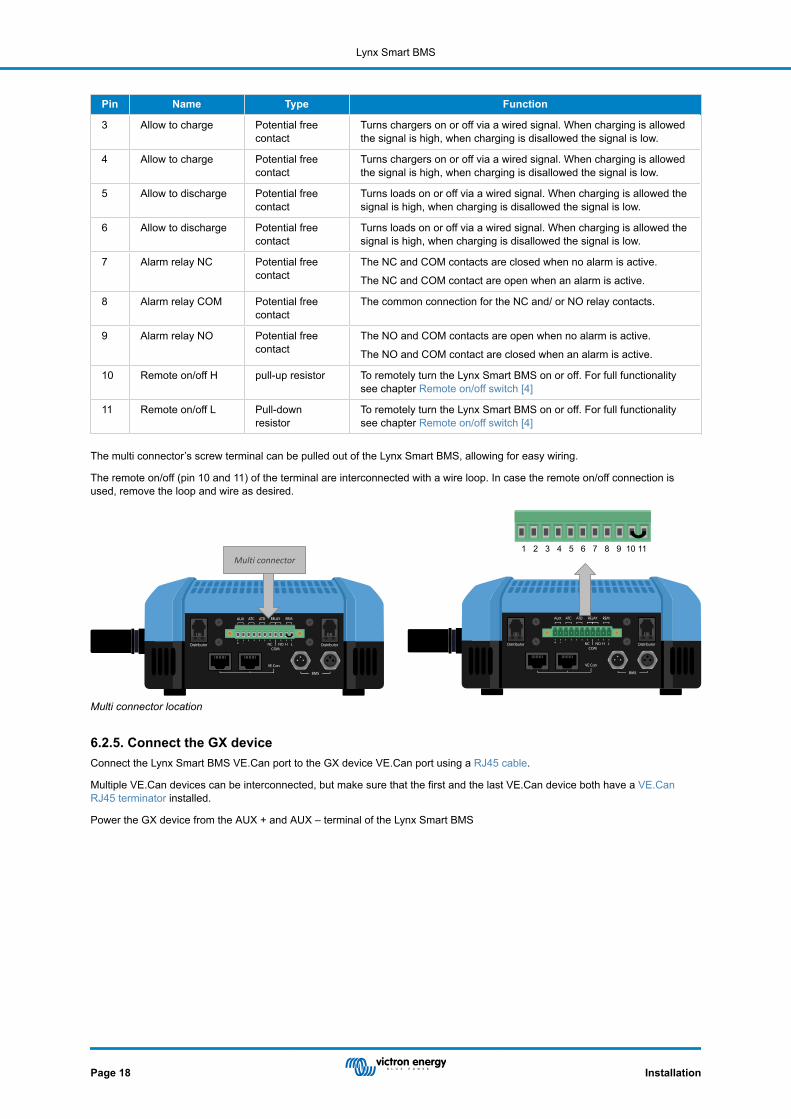
Pin Name Type Function
3 Allow to charge Potential freecontact
Turns chargers on or off via a wired signal. When charging is allowedthe signal is high, when charging is disallowed the signal is low.
4 Allow to charge Potential freecontact
Turns chargers on or off via a wired signal. When charging is allowedthe signal is high, when charging is disallowed the signal is low.
5 Allow to discharge Potential freecontact
Turns loads on or off via a wired signal. When charging is allowed thesignal is high, when charging is disallowed the signal is low.
6 Allow to discharge Potential freecontact
Turns loads on or off via a wired signal. When charging is allowed thesignal is high, when charging is disallowed the signal is low.
7 Alarm relay NC Potential freecontact
The NC and COM contacts are closed when no alarm is active.
The NC and COM contact are open when an alarm is active.
8 Alarm relay COM Potential freecontact
The common connection for the NC and/ or NO relay contacts.
9 Alarm relay NO Potential freecontact
The NO and COM contacts are open when no alarm is active.
The NO and COM contact are closed when an alarm is active.
10 Remote on/off H pull-up resistor To remotely turn the Lynx Smart BMS on or off. For full functionalitysee chapter Remote on/off switch [4]
11 Remote on/off L Pull-downresistor
To remotely turn the Lynx Smart BMS on or off. For full functionalitysee chapter Remote on/off switch [4]
The multi connector’s screw terminal can be pulled out of the Lynx Smart BMS, allowing for easy wiring.
The remote on/off (pin 10 and 11) of the terminal are interconnected with a wire loop. In case the remote on/off connection isused, remove the loop and wire as desired.
1 2 3 4 5 6 7 8 9 10 11Multi connector
Multi connector location
6.2.5. Connect the GX deviceConnect the Lynx Smart BMS VE.Can port to the GX device VE.Can port using a RJ45 cable.
Multiple VE.Can devices can be interconnected, but make sure that the first and the last VE.Can device both have a VE.CanRJ45 terminator installed.
Power the GX device from the AUX + and AUX – terminal of the Lynx Smart BMS
Lynx Smart BMS
Page 18 Installation

VE.Can RJ45 terminator
VE.Can RJ45 terminator
RJ45 UTP cable
GX device power cables
Wiring example Lynx Smart BMS and GX device
RJ45 VE.Can connectors
Location VE.Can connectors Lynx Smart BMS
6.3. Configuration and settings
6.3.1. Power up for the first timeThe Lynx Smart BMS will power up when a battery is connected to the battery terminals and the remote on/off switch is turned on(or the wire loop is placed in the remote on/off connections). This will be the case once the battery pole has been connected. Orthe battery fuses have been placed.
On first power up (or after a reset to factory defaults) the Lynx Smart BMS will automatically determine the system voltage bymeasuring the battery voltage and stores this in its memory. In a system where multiple batteries have been connected in series,it is essential that each individual battery has been fully charged, prior to connecting them in series.
On first power up (or after a reset to factory defaults) the Lynx Smart BMS will also automatically detect if the connected battery isequipped with the pre-alarm hardware and stores this in its memory (Older batteries might not have pre-alarm hardware). It isessential that the battery BMS cables are connected to the Lynx Smart BMS before power up.
6.3.2. Update firmwareOn a new install, it is recommended to update the firmware of the Lynx Smart BMSor its Bluetooth interface. If there is a newerfirmware version available, the VictronConnect app will notify you of this as soon as a connection with the Lynx Smart BMS ismade.
To check if the firmware is up to date or to manually update firmware, connect to the Lynx Smart BMS using the VictronConnectapp and follow below steps:
Lynx Smart BMS
Page 19 Installation

• Navigate to the product settings by clicking the "cog" symbol in the top right hand of the product status screen.• Click on the "3 dots" symbol in the top right hand of the settings screen.• Select "Product info" from the pop-up menu.• The firmware version will be displayed. It is mentioned if this is the latest firmware version (or not). If a newer firmware version
is available, an "UPDATE" button will be displayed.• To update the firmware, press the "UPDATE" button.
On a new install is also recommended to check and update the firmware of each connected Smart Lithium battery. This is donevia Bluetooth using the VictronConnect app in a similar manner as described above.
6.3.3. Settings Lynx Smart BMSOnce powered up the VictronConnect app is used to make essential and custom settings.
Set battery voltage:
• This would have been detected automatically, but check it anyway, just to make sure.
Set battery capacity:
• Enter the battery capacity of the connected battery bank.
Set pre-alarm:
• Check if the pre-alarm is enabled. This would have been detected automatically, but check it anyway, just to make sure. Notethat this setting is only available if the connected batteries have the necessary pre-alarm hardware. (older batteries might nothave the pre-alarm feature).
• The pre-alarm voltage setting is set in the battery (not in the Lynx Smart BMS). If multiple batteries are used, the pre-alarmvoltage setting needs to be set at the same value in each battery.
Alarm relay:
• The operation state of the Alarm relay can be set to continuous or intermittent operation. In intermittent operation the relayswitches on and off every 0.8 seconds.
DVCC settings:
• The discharge current limit at pre-alarm setting is set by default set to "no". This can be changed to "yes".• The absorption time is set by default to 2hours. This can be adjusted if required.• The state of charge (SoC) threshold is set by default to 70%. This is the threshold at which the Lynx Smart BMS starts a new
full charging cycle. This can be adjusted if required.• The repeated absorption time in days at which a new full charging cycle is started if the battery state of charge does not fall
below the SoC threshold. The default is every 30 days and can be adjusted if required.
Battery Monitor settings:
• The charged voltage is the voltage at above which the battery monitor synchronises and resets the state of charge to 100%.For synchronisation to happen, the tail current and charged detection time conditions need to have been met as well. Thedefault is set to 14.0V and can be adjusted if required.
• The tail current is the current at below which the battery monitor synchronises and resets the state of charge to 100%. Forsynchronisation to happen, the charged voltage and charge detection time conditions need to have been met as well. Thedefault is set to 4.00% and can be adjusted if required.
• The charged detection time is the time passed after which the battery monitor synchronises and resets the state of charge to100%. For synchronisation to happen, the charged voltage and charged current conditions need to have been met as well. Thedefault is set to 3 minutes and can be adjusted if required.
Lynx Smart BMS
Page 20 Installation

VictronConnect setting Lynx Smart BMS
6.3.4. Battery monitor settingsThis chapter explains all battery monitor settings. In addition to this we also have a video available explaining these settings andhow the interact with each other to achieve accurate battery monitoring for both lead-acid and lithium batteries.
https://www.youtube.com/embed/mEN15Z_S4kE
Special note on the Lynx Smart BMS battery monitor settingsUnlike other battery monitors, the Lynx Smart BMS battery monitor settings are mostly fixed settings and are not customizable.The reason for this is that the Lynx Smart BMS is always used together with Victron Energy Smart Lithium batteries and a lot ofbattery monitor parameters are therefore known because they relate to the battery type.
To give an overview of the status of each battery setting:
These battery monitor settings are adjustable:
• Battery capacity: by default set at 200Ah, needs to be set on first install.• Charged Voltage: by default set at 14.0V (12V system), 28.0V (24V system) and 56.0V (48V system).• Tail current: by default set at 4% (as a fraction of the battery capacity).• Charged detection time: by default set at 3 minutes.
These battery monitor settings are automatic settings:
• Zero current calibration: Is done automatically each time at power up.
These battery monitor settings are fixed:
• Peukert exponent: 1.05• Charge efficiency factor: 99% • Current threshold: 0.1A• Discharge floor: 15%• Delta T: 1• SOC cycle end: 90%• SOC Cycle: 65%• SOC full discharge: 5%
The meaning of each battery monitor parameter is explained in next chapter.
Battery capacityThis parameter is used to tell the battery monitor how big the battery is. This setting should already have been done during theinitial installation.
The setting is the battery capacity in Amp hours (Ah).
Lynx Smart BMS
Page 21 Installation

Default setting Range Step size
200 Ah 1 - 9999 Ah 1 Ah
Charged voltageThe battery voltage must be above this voltage level to consider the battery as fully charged. As soon as the battery monitordetects that the voltage of the battery has reached the “charged voltage” and the current has dropped below the “tail current” for acertain amount of time, the battery monitor will set the state of charge to 100%.
Default setting Range Step size
14.0V (12V system)
28.0V (24V system)
56.0V (48V system)
0 - 60V 0.1V
The “charged voltage” parameter should be set to 0.2V or 0.3V below the float voltage of the charger.
Tail currentThe battery is considered as “fully charged” once the charge current has dropped to less than the set “Tail current” parameter.The “Tail current” parameter is expressed as a percentage of the battery capacity.
Remark: Some battery chargers stop charging when the current drops below a set threshold. In these cases, the tail current mustbe set higher than this threshold.
As soon as the battery monitor detects that the voltage of the battery has reached the set “Charged voltage” parameter and thecurrent has dropped below the “Tail current” for a certain amount of time, the battery monitor will set the state of charge to 100%.
Default setting Range Step size
4.00% 0.50 - 10.00% 0.1%
Charged detection timeThis is the time the “Charged voltage” and “Tail current” must be met in order to consider the battery fully charged.
Default setting Range Step size
3 minutes 0 - 100 minutes 1 minute
Peukert exponentThe Peukert exponent for Lithium Smart batteries is 1.05. This is a fixed setting and cannot be changed.
Charge efficiency factorThe “Charge Efficiency Factor” compensates for the capacity (Ah) losses during charging. A setting of 100% means that there areno losses.
A charge efficiency of 95% means that 10Ah must be transferred to the battery to get 9.5Ah actually stored in the battery. Thecharge efficiency of a battery depends on battery type, age and usage. The battery monitor takes this phenomenon into accountwith the charge efficiency factor.
The charge efficiency factor for Lithium Smart batteries is 99% This is a fixed setting and cannot be changed.
Current thresholdWhen the current measured falls below the “Current threshold” value it will be considered zero. The “Current threshold” is used tocancel out very small currents that can negatively affect the long-term state of charge readout in noisy environments. Forexample, if the actual long-term current is 0.0A and, due to injected noise or small offsets, the battery monitor measures 0.05Athe batery monitor might, in the long term, incorrectly indicate that the battery is empty or will need to be recharged. When thecurrent threshold in this example is set to 0.1A, the battery monitor calculates with 0.0A so that errors are eliminated.
The current threshold is fixed at 0.1A
Discharge floorThe “Discharge floor” parameter is used in the time remaining calculation. The battery monitor calculates the time it takes until theset “discharge floor” has been reached. It is also used to set the state of charge alarm defaults.
The discharge floor parameter is fixed at 15%.
SoC cycle endThe state of charge cycle end setting is used to ......
This setting is fixed at 90%.
Lynx Smart BMS
Page 22 Installation
SoC cycleThe state of charge cycle setting is used to ......
This setting is fixed at 65%.
SoC full dischargeThe state of charge full discharge setting is used to ......
This setting is fixed at 5%.
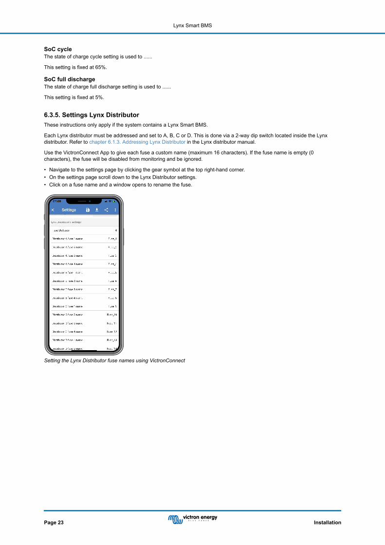
6.3.5. Settings Lynx DistributorThese instructions only apply if the system contains a Lynx Smart BMS.
Each Lynx distributor must be addressed and set to A, B, C or D. This is done via a 2-way dip switch located inside the Lynxdistributor. Refer to chapter 6.1.3. Addressing Lynx Distributor in the Lynx distributor manual.
Use the VictronConnect App to give each fuse a custom name (maximum 16 characters). If the fuse name is empty (0characters), the fuse will be disabled from monitoring and be ignored.
• Navigate to the settings page by clicking the gear symbol at the top right-hand corner.• On the settings page scroll down to the Lynx Distributor settings.• Click on a fuse name and a window opens to rename the fuse.
Setting the Lynx Distributor fuse names using VictronConnect
Lynx Smart BMS
Page 23 Installation

7. Commissioning the Lynx Smart BMS
Commissioning sequence:
• Check polarity of all battery cables.• Check cross sectional area of all battery cables.• Check that each battery has the most up to date firmware.• Check that if batteries have been connected in series, that each battery has been fully pre-charged (refer to battery manual).• Check if all battery cable lugs have been crimped correctly. Check if all battery cable connections are tight (don’t exceed
maximum torque). Tug slightly on each battery cable and see if the connections are tight.• Check all BMS cable connections and make sure the connector screw rings are screwed all the way down.• Check if each paralleled battery is fused or that each paralleled battery series string is fused.• If a GX device is used, check if the VE.Can cables and terminator have been placed and the device is powered from the AUX
voltage output of the Lynx Smart BMS.• Power the Lynx Smart BMS by connecting the battery supply or placing the battery fuses and, if applicable, by switching the
remote on/off switch to “on”.• Check if the load pre-charge is completed and if the contactor closes and the loads are powered.• Connect with VictronConnect and verify that the Lynx Smart BMS has the most up to date firmware and that all setting have
been made, especially if the battery capacity is set correctly.• Check that the system voltage has been set correctly.• Check if the fuse names of the Lynx Distributor (if applicable) are correctly named.• If a GX device is connected, check that it is powered from the AUX voltage output.• Check that the Lynx Smart BMS displays correctly on the GX device. Check that DVCC has been enabled.• Disconnect a random BMS cable and verify that the BMS is turning off all charge sources and all loads. Reconnect the BMS
cable.• Turn on a load and check that the current is a negative current displayed on the GX device or the VictronConnect app.• Charge batteries fully and check that a 100% state of charge is displayed
Lynx Smart BMS
Page 24 Commissioning the Lynx Smart BMS

8. Operation Lynx Smart BMS
8.1. Powering upThe Lynx Smart BMS will power up when a battery is connected to the battery terminals and the remote on/off switch is turned on(or the wire loop is placed in the remote on/off terminal).
The power up sequence follows these steps:
• System check: A self-check together checking the connected batteries and Lynx Distributor modules.• Pre-charge loads: The pre-charge circuit prevents very high inrush currents that can damage the contactor.• Contactor closes: The Lynx Smart BMS is operational and the power to the Lynx distributor(s) is turned on.
Hibernation mode
The Lynx Smart BMS is in hibernation mode when the Lynx Smart BMS has turned itself off because of a low battery event orwhen it has been turned off via the remote on/off switch.
In hibernation mode, the contactor and most of the electronic circuits are turned off and the power consumption is very low(0.8mA). The status LED is off.
The power to the Lynx distributor(s) is turned off.
Bluetooth is still active during hibernation mode. The blue Bluetooth LED is either flashing every 3 seconds or is on, depending onwhether there is an active Bluetooth connection with the VictronConnect app.
The Lynx Smart BMS will come out of hibernation mode when the remote on/off switch is switched on or the batteries arecharged.
Remote on/off switch
The contactor is driven by the BMS and also by the remote on/off signal. This way the Lynx Smart BMS can act as main systemon/off switch. For example, before leaving the boat or camper van, the system can be switched off so that the batteries are notfurther discharged. Although the power consumption in hibernation mode is very low, it is good practice to first fully charge thebatteries before switching the system off. However, if the system is left for a very long time without being charged, it will be betterto disconnect the positive battery pole.
Operational
Once powered up the contactor is closed. The green status LED and the blue Bluetooth LEDs on the Lynx Smart BMS and thegreen power LED on Lynx Distributor(s) are illuminated.
Status LED Bluetooth LED
Lynx Smart BMS LEDs
8.2. BMS operationThe BMS in the Lynx Smart BMS communicates with the batteries and will safeguard them against under voltage and overvoltage and low temperatures.
Sleep mode
The Lynx Smart BMS will go into sleep mode when one of the battery cells is low and no charge voltage has been supplied for 2hours. The contactor and most internal electronic is turned off, status LED is off, the power consumption is very low (0.8mA).Bluetooth is still active and the blue LED is either on or flashing every 3 seconds depending on whether there is an activeconnection with the VictronConnect app.
The Lynx Smart BMS will come out of sleep mode when:
• A charge voltage is supplied to the system side of the Lynx Smart BMS 0.5V higher than the battery voltage.• The battery voltage is higher than 12.8V (25.6V).
Lynx Smart BMS
Page 25 Operation Lynx Smart BMS

• The Lynx Smart BMS is switched off and then back on again via the remote on/off switch.
Standby switch via the VictronConenct app
This is a "soft" remote switch and is accessible via the VictronConnect app.
When the Lynx Smart BMS has been switched to standby mode, the contactor will be opened and the DC system will bedisconnected. Bluetooth, VE.Can and the AUX port will remain active.
Pre-alarm
When the cell voltage drops and reaches the pre alarm threshold the alarm relay will activate. This will give an advanced warningof an impending empty battery and before the loads are disabled. Pre-alarm is indicated by the red LED flashing 3 times every 4seconds
Do not discharge
If the cell voltage becomes too low and if it has reached the low cell voltage threshold, the ATD contact (allowed to discharge) willturn off all loads. If the Lynx Smart BMS is connected to a GX device and DVCC is enabled, the inverters of the devices that areconnected to the same GX device will be turned off as well.
BMS do not charge
If the cell voltage becomes too high and has reached the high cell voltage threshold, or if the low temperature threshold has beenreached, the ATC contact (allowed to charge) will turn of all chargers. If the Lynx Smart BMS is connected to a GX device andDVCC is enabled, the chargers of the devices that are connected to the same GX device will be turned off as well.
BMS contactor operation
If the batteries are even further discharged or overcharged the Lynx Smart BMS will physically disconnect DC system from thebatteries via the contactor. This to safeguard the batteries against total discharge or extreme overcharge. The contactor will alsoopen if the ATC or the ATD signal have not worked and the Lynx Smart BMS has detected that current is still flowing into or out ofthe battery.
The contactor will re-engage after a low voltage event as soon as a suitable charge voltage is measured on the Lynx Smart BMSoutput (the system side).
The contactor will re-engage after high voltage event as soon as the cell voltage has dropped.
8.3. Battery monitor operationThe Lynx Smart BMS has a built-in battery monitor. It measures battery voltage and current. Based on these measurements itcalculates state of charge, time to go and keeps track of historical data, such as deepest discharge, average discharge andnumber of cycles.
8.4. Battery careOnce the Lynx Smart BMS is in operation it is important to take care of the batteries.
These are the basic guidelines:
• Prevent total battery discharge at all times.• Familiarize yourself with the pre-alarm feature and act when pre-alarm is active to prevent a DC system shutdown.• If the pre-alarm is active, or if the BMS has disabled the loads, make sure that the batteries are recharged as soon as possible.• Minimise the time the batteries spend in a far discharged state as much as possible.• The batteries need to spend at least 2 hours in absorption charge mode each month to ensure sufficient time in balancing
mode.• When leaving the system unattended for some time, make sure to either keep the batteries charged during that time, or make
sure the batteries are (almost) full and then disconnect the DC system from the battery. Do this by disconnecting the positivebattery pole.
8.5. LED indications alarms and errorsLEDs
The Lynx Smart BMS is equipped with two LEDS, the “Bluetooth” LED and the “Status” LED. These LEDS will indicate theoperation mode and the fault mode in case there is a fault.
Bluetooth LED Description
Off No system power
Blue on A Bluetooth device is connected to the Lynx Smart BMS
Lynx Smart BMS
Page 26 Operation Lynx Smart BMS

Bluetooth LED Description
Blue flashing Bluetooth is active but no devices are connected
Blue flashing at 3 seconds interval The Lynx Smart BMS is in hibernation mode but is still accessible over Bluetooth
Status LED Description
Off The Lynx Smart BMS is in hibernation or sleep mode
Orange on Initializing or shutdown
Orange blinking Delayed shutdown due to cooling down the pre-charge circuit
Green on Running, the contactor is closed
Green blinking Pre-charging
Green flashing at 3 seconds interval The Lynx Smart BMS is in standby mode
Green and red alternating System in bootloader mode (updating firmware)
Red flashing 1 time every 4 seconds Warning, see VictronConnect for more information
Red flashing 2 times every 4 seconds Battery communication error, check battery BMS cables
Red flashing 3 times every 4 seconds Undervoltage or overvoltage detected
Red flashing 4 times every 4 seconds Under-temperature or over-temperature detected
Red flashing 5 times every 4 seconds Pre-charge time out
Red flashing 6 times every 4 seconds Pre-charge high current
Red flashing 7 times every 4 seconds Probably wrong system voltage
Red flashing 8 times every 4 seconds Contactor current too high
Red flashing 9 times every 4 seconds Initializations error
Red flashing 10 times every 4 seconds Safety contactor failure
Red flashing 12 times every 4 seconds Internal supply error
Red flashing 14 times every 4 seconds Battery voltage not allowed
Alarm and error codes
The Lynx Smart BMS is equipped with Bluetooth for easy monitoring and setup via the VictronConnect app.
Lynx Smart BMS status VictronConnect
Lynx Smart BMS
Page 27 Operation Lynx Smart BMS

If the Lynx Smart BMS is connected to a GX device it can be monitored via the GX device and the VRM portal. This also includesreceiving alarms signals.
Lynx Smart BMS alarms on the VictronConnect App and GX device
This is a list of the alarm and error codes. For an explanation of these alarms and what to do on case of one of these errors oralarms, consult the Troubleshooting and Support chapter [30].
Table 3. Lynx BMS alarm codes
Alarm Description
#100 High pre-charge current
#101 Over temperature
#102 Battery over voltage
#103 Battery under voltage
#104 Pre-alarm
#105 High charge current
#106 High discharge current
#107 Battery temperature
#108 Hardware failure
#110 Pre-alarm/under voltage warning
#112 High contactor voltage
Table 4. Lynx BMS error codes
Error Description
#9 Battery voltage not allowed
#11 Supply error or hardware error
#25 Pre-charge error
#26 Contactor error
Lynx Smart BMS
Page 28 Operation Lynx Smart BMS

Error Description
#30 Calibration lost
#31 Setting invalid
#32 BMS cable error
#34 Wrong system voltage
#35 Pre-charge timeout
Lynx Smart BMS
Page 29 Operation Lynx Smart BMS

9. Troubleshooting and Support
Consult this chapter in case of unexpected behaviour or if you suspect a product fault.
The correct troubleshooting and support process is to first consult the common issues as described in this chapter.
Should this fail to resolve the issue, contact the point of purchase for technical support. If the point of purchase is unknown, referto the Victron Energy Support webpage.
9.1. Lynx Smart BMS does not power upThis can be caused by one of the following reasons:
No battery supply
No LEDs are illuminated on the Lynx Smart BMS. Check the battery supply voltage into the Lynx Smart BMS. Check cables andfuses on the battery side. It could also be that the Lynx Smart BMS is in hibernation mode. For more info on that see paragraphPowering up [25].
Reverse battery supply
Check the polarity of the supply voltage into the Lynx Smart BMS. If reverse polarity, correct polarity mistake. Unit should nowpower up.
Remote on/off switched off or wire loop missing
The remote on/off switch needs to be turned on (or the wire loop is placed in the remote on/off connections).
Battery voltage issues
The Lynx Smart BMS, on first install will auto detect the battery voltage. It will be set to either 12V, 24V or 48V. Each set voltagehas a specific battery voltage range (threshold). If the Lynx Smart BMS measures a voltage that is outside this threshold one ofthese alarms will be generated:
• Probably wrong system voltage - the red LED flashing 7 times every 4 seconds.This is generated when the system voltage cannot be determined or when the DC system voltage is much higher than the setsystem voltage.
• Battery voltage not allowed - the red LED flashing 14 times every 4 seconds.
To fix, check the battery settings or check the battery voltage.
This table indicates the voltage thresholds for each system voltage:
System voltage Voltage threshold
12V Between 9V and 15V
24V Between 16V and 30V
48V Between 32V and 60V
Pre-charge errors
The Lynx Smart BMS pre-charges the connected load. Once pre-charge is complete, the contactor is closed and the Lynx SmartBMS is operational. There are two specific error that can be generated during the pre-charge process:
• Pre-charge high current – the red LED flashing 6 times every 4 seconds. The pre-charged energy or current has beenexceeded.
• Pre-charge timeout – the red LED flashing 5 times every 4 seconds. It has taken too long for the pre-charge process tocomplete.
Pre-charge faults are mostly caused by:
• A short circuit on the load output – potentially caused by a malfunctioning load or if there is a wiring issue like a short circuit.• Loads with a too high capacitance or too low resistance (less than 20 Ohm) have been connected to the load output.
To remedy these faults, switch off, or remove some loads or chargers and rule out wiring issues or short circuits.
Internal error
Contact your Victron supplier if one of the following errors are occurring:
• Internal supply error - Red LED flashing 12 times every 4 seconds• Initialization error - Red LED flashing 9 times every 4 seconds
Lynx Smart BMS
Page 30 Troubleshooting and Support
• Contactor failure - Red LED flashing 10 times every 4 seconds• Hardware error - GX device alarm Calibration lost - GX device alarm
9.2. Lynx Smart BMS operational issuesHigh discharge current
A high current alarm is given when the current is more than 600A for more than 5 minutes. The red LED flashing 8 times every 4seconds. Reduce the loads connected to the Lynx Smart BMS so that the current through the Lynx Smart BMS will be below500A.
High charge current
A high current alarm is giving when the current is more than 600A for more than 5 minutes. The red LED flashing 8 times every 4seconds. Turn chargers off so that the current through the Lynx Smart BMS will be below 500A.
Contactor (relay) issues
The Lynx Smart BMS is equipped with 3 protections:
Over current protection: An alarm is generated when the current exceeds 600A for 5 minutes.
Contactor voltage monitoring: An alarm is generated when the voltage over the contactor is higher than 0,5V. A high voltageindicates high resistance and high power dissipation indicating a bad contactor.
Electrical/mechanical protection: There are 2 thermal switches mounted on the busbar. The contactor opens and an alarm isgenerated when the temperature of the busbars becomes higher than 130°C.
High BMS temperature
Check ambient temperature and check if the fans are running. Reduce the ambient temperature.
Settings invalid
Settings data is corrupt, reset to factory defaults.
9.3. BMS issues
9.3.1. The BMS frequently disables the battery chargerA well-balanced battery does not disable the charger, even when the batteries are fully charged. But when the BMS frequentlydisables the charger, this is an indication of cell imbalance.
In case of moderate or large cell imbalance it is an expected behaviour that BMS frequently disables the battery charger. This isthe mechanism behind this behaviour:
As soon as one cell reaches 3.75V the BMS disables the charger. Whilst the charger is disabled the cell balancing process stillcontinues, moving energy from the highest cell into adjacent cells. The highest cell voltage will drop, and once it has fallen below3.6V the charger will be enabled again. This cycling typically takes between one and three minutes. The voltage of the highestcell will rise again quickly (this can be in a matter of seconds) after which, the charger will be disabled again, and so forth. Thisdoes not indicate a problem with the battery or the cells. It will continue with this behaviour until all cells are fully charged andbalanced. This process might take several hours. It depends on the level of imbalance. In case of serious imbalance this processcan take up to 12 hours. Balancing will continue throughout this process and balancing even takes place when the charger isdisabled. The continued enabling and disabling of the charger can appear strange but rest assured that there is no problem. TheBMS is merely protecting the cells from over voltage.
9.3.2. The BMS is prematurely turning chargers offThis could be because of a cell imbalance. One cell in the battery has a cell voltage above 3.75V. Check the cell voltages of allthe batteries that are connected to the BMS.
9.3.3. The BMS is prematurely turning loads offThis could be because of a cell imbalance.
If a cell has a cell voltage below the "Allowed to Discharge" setting in the battery the BMS will turn the load off. The "Allowed toDischarge" level can be set between 2.6V and 2.8V. The default is 2.8V.
Check the cell voltages of all the batteries that are connected to the BMS using the VictronConnect app. Also check if all batterieshave the same "Allowed to Discharge" settings.
Once the loads have been turned off due to low cell voltage, the cell voltage of all cells needs to be 3.2V or higher before theBMS will turn the loads back on.
Lynx Smart BMS
Page 31 Troubleshooting and Support

9.3.4. The pre-alarm setting is missing in VictronConnectPre-alarm is only available if the battery supports it. The current battery models all support it, but older batteries do not have thehardware necessary for the pre-alarm feature.
9.3.5. BMS is displaying alarm while all cell voltages are within rangeA possible cause is a loose or damaged BMS cable or connector. Check all BMS cables and their connections.
First rule out that the cell voltages and temperature of all connected batteries are in range. If they are all in range, then follow oneof the following procedures.
Also consider that once there has been a cell under voltage alarm, the cell voltage of all cells need to be increased to 3.2V beforethe battery clears the under voltage alarm.
A way to rule out if a fault is originating from a faulty BMS or from a faulty battery, is to check the BMS using one of the followingBMS test procedures:
Single battery and BMS check:
• Disconnect both BMS cables from the BMS.• Connect a single BMS extension cable between both BMS cable connectors. The BMS cable should be connected in a loop, as
in below diagram. The loop tricks the BMS in thinking that there is a battery connected without any alarms.• If the alarm is still active after the loop has been placed, the BMS is faulty.• If the BMS has cleared the alarm after the loop has been placed the battery is faulty and the BMS is not faulty.
Testing a Lynx Smart BMS by connecting a single BMS extension cable to both BMS cable connections
Multiple batteries and BMS check:
• Bypass one of the batteries by disconnecting both its BMS cables• Connect the BMS cables of the neighbouring batteries (or battery and BMS) to each other, effectively bypassing the battery.• Check if the BMS has cleared its alarm.• If the alarm has not been cleared, repeat this for the next battery.• If the alarm is still active after all batteries have been bypassed, the BMS is faulty.• If the BMS cleared its alarm when a particular battery was bypassed, that particular battery is faulty.
BMS
Eliminating a BMS error by bypassing a suspect battery
9.3.6. How to test if the BMS is functionalTo test if the BMS is functional, disconnect one of the BMS cables and see if the BMS will go into alarm mode.
Lynx Smart BMS
Page 32 Troubleshooting and Support

BMS
Check BMS functionality by deliberately loosening a BMS cable
9.3.7. System in sleep or hibernate modeThis is indicated by the status LED off and the Bluetooth LED flashing every 3 seconds.
The Lynx Smart BMS goes into sleep or hibernation mode once the battery or a battery cell has been deeply discharged. TheLynx Smart BMS will conserve as much power as possible, to not discharge the battery much further. Bluetooth is still active, butother non-essential circuits are turned off, including the power to the Lynx Distributor(s).
Check the voltages of the connected batteries and if they are low, charge the batteries. As soon as the Lynx Smart BMS sees acharge voltage it will automatically re-activate and close its contactor to allow for battery charging.
9.3.8. Battery communication errorThis is indicated by the red LED flashing 2 times every 4 seconds or with the GX device BMS cable error. A batterycommunication error occurs when the Lynx Smart BMS is not connected to the battery BMS communication cables, or if there isan issue with the BMS cables. To remedy this error, check the following:
• Check if both battery cables are connected to the Lynx Smart BMS.• In case of a multiple battery setup , check if all batteries are interconnected• Check for loose connections, the male connector needs to screw “hand tight” into the female connector.
9.4. Battery monitor issues
9.4.1. Incomplete current readingThe negatives of all the loads and the charge sources in the system must be connected to the system minus side of the LynxSmart BMS.
If the negative of a load or a charge source is connected directly to the negative battery terminal or the “battery minus” side on theLynx Smart BMS, their current will not flow through the battery monitor and will be excluded from the overall current reading andthe state of charge reading.
The SmartShunt will display a higher state of charge than the actual state of charge of the battery.
Lynx Smart BMS
Page 33 Troubleshooting and Support

9.4.2. Incorrect state of charge readingAn incorrect state of charge can be caused by a variety of reasons.
Incorrect battery settings
The following parameter(s) will have an effect on the state of charge calculations if they have been set up incorrectly:
• Battery capacity
Incorrect state of charge due to a synchronisation issue:
The state of charge is a calculated value and will need to be reset (synchronised) every now and then.
The synchronisation process is automatic will be performed each time the battery is fully charged. The battery monitor determinesthat battery is fully charged when all 3 "charged" conditions have been met. The "charged" conditions are:
• Charged voltage (Voltage)• Tail current (% of battery capacity)• Charge detection time (minutes)
Practical example the conditions that need to be met before a synchronisation will take place:
• The battery voltage has to be above 13.8V• The charge current has to be less than 0.04 x battery capacity (Ah). For a 200Ah battery this is 0.04 x 200 = 8A• Both above conditions have to be stable for 3 minutes
If the battery is not fully charged or if the automatic synchronisation does not happen, the state of charge value will start to driftand will eventually not represent the actual state of charge of the battery.
The following parameter(s) will have an effect on automatic synchronisation if they have been set incorrectly:
• Charged voltage• Tail current• Charged detection time• Not occasionally fully charging the battery
For more information on these parameters see the chapter: "Battery settings".
Incorrect state of charge due to incorrect current reading:
The state of charge is calculated by looking at how much current flows in and out of the battery. If the current reading is incorrect,the state of charge will also be incorrect. See paragraph Incomplete current reading [33]
9.4.3. State of charge is missingThis means that the battery monitor is in an unsynchronised state. This can occur when the Lynx Smart BMS has just beeninstalled or after the Lynx Smart BMS has been unpowered for some time and is being powered up again.
To fix this, fully charge the battery. Once the battery is close to a full charge, the battery monitor should synchronise automatically.If that doesn't work, review the synchronisation settings.
9.4.4. State of charge does not increase fast enough or too fast when chargingThis can happen when the battery monitor thinks the battery is bigger or smaller than in reality. Check if the battery capacity hasbeen set correctly.
9.4.5. Synchronisation issuesIf the battery monitor does not synchronise automatically, one possibility could be that the battery never reaches a fully chargedstate. Fully charge the battery and see if the state of charge eventually indicates 100%.
9.5. VictronConnect issuesCannot connect with the VictronConnect App
It is highly unlikely that the Bluetooth interface is faulty. These are some pointers to try before seeking support:
• Is the battery voltage still high enough? If the battery voltage drops to a very low level, the Lynx Smart BMS will eventually turnits internal electronics off, including Bluetooth communication.
• Is there already another phone or tablet connected to the product? Only one phone or tablet can be connected at any giventime. Make sure no other devices are connected and try again.
• Are you close enough to the product? In open space the maximum distance is about 20 meters.
Lynx Smart BMS
Page 34 Troubleshooting and Support

• Are you using the Windows version of the VictronConnect App? The Windows version cannot use Bluetooth. Use an Android,iOS or macOS device instead.
• Has Bluetooth been disabled in the VictronConnect settings?• Does VictronConnect have an issue? Try to connect to another Victron product, does this work? If that also does not work, then
there probably is an issue with the phone or tablet. Refer to the troubleshooting section of the VictronConnect manual.
Pin code lost
If you have lost the PIN code, you will need to reset the PIN code to its default PIN code. This is done in the VictronConnect App.
• Navigate to the device list of the VictronConnect App. Click on the option symbol next to the product listing.• A new window will open which allows you to reset the PIN code back to its default: 000000.• Enter the batteries unique PUK code as printed on the product information sticker on the product.• More information and specific instructions can be found in the VictronConnect manual.
Interrupted firmware update
This is recoverable, just try to update the firmware again.
9.6. GX device issuesThis chapter only describes the most common issues. If this chapter does not solve your issue, consult the manual of the GXdevice.
Incorrect CAN-bus profile selected
Check that VE.Can is set to use the correct CAN-bus profile. Navigate to settings/services/VE.Can port and check if it is set to"VE.Can and Lynx Ion BMS 250kb.
RJ45 terminator or cable issue
VE.Can devices connect in "daisy chain" to each other and a RJ45 terminator needs to be used with the first and last device inthe chain.
When connecting VE.Can device always use "manufactured" RJ45 UTP cables. Do not manufacture these cables yourself. Manycommunication and other seemingly unrelated product issues are caused by faulty home made cables.
Lynx Smart BMS
Page 35 Troubleshooting and Support
10. Warranty
This product has a 5-year limited warranty. This limited warranty covers defects in materials and workmanship in this product andlasts for five years from the date of original purchase of this product. To claim warranty the customer must return the producttogether with the receipt of purchase to the point of purchase. This limited warranty does not cover damage, deterioration ormalfunction resulting from alteration, modification, improper or unreasonable use or misuse, neglect, exposure to excessmoisture, fire, improper packing, lightning, power surges, or other acts of nature. This limited warranty does not cover damage,deterioration or malfunction resulting from repairs attempted by anyone unauthorized by Victron Energy to make such repairs.Non-compliance with the instructions in this manual will render the warranty void. Victron Energy is not liable for anyconsequential damages arising from the use of this product. The maximum liability of Victron Energy under this limited warrantyshall not exceed the actual purchase price of the product.
Lynx Smart BMS
Page 36 Warranty

11. Technical specifications Lynx Smart BMS
Power
Supply voltage range 9 – 58Vdc
Supported system voltages 12, 24 or 48V
Reverse polarity protection No
Main safety contactor continuous current rating 500A continuous
Main safety contactor peak current rating 600A for 5 minutes
Power consumption hibernate or standby mode Approximately 10.4mW (0.8mA at 13V)
Power consumption in active mode Approximately 2.6W (200mA at 13V) depending on the state of therelays
Minium load resistance for pre-charging 10Ω and above for 12V systems
20Ω and above for 24V and 48V systems
AUX output maximum current rating 1.1A continuous, protected by resettabel fuse
Allow-to-charge port
Maximum current rating
0.5A at 60Vdc, protected by resettabel fuse
Allow-to-discharge port
Maximum current rating
0.5A at 60Vdc, protected by resettabel fuse
Alarm relay (SPDT)
Maximum current rating
2A at 60Vdc
Connections
Busbar M8
VE.Can RJ45 and RJ45 terminator
I/O Screw terminals
Battery BMS cables Male and female circular 3-pole connector with M8 screw ring
Lynx distributor (up to 4 modules) RJ10 (cable ships with each Lynx Distributor)
Physical
Enclosure material ABS
Enclosure dimensions (hxwxd) 190 x 180 x 80mm
Unit weight 1.9 kg
Busbar material Tinned copper
Busbar dimensions (hxw) 8 x 30mm
Environmental
Operating temperature range -40°C to +60°
Storage temperature range -40°C to +60°
Humidity Max. 95% (non-condensing)
Protection class IP22
Lynx Smart BMS
Page 37Technical specifications Lynx Smart
BMS

12. Appendix
Lynx Smart BMS
Page 38 Appendix