LW Longitudinal Seam Welder Manual 1-2015 revised - Miller ...
55
OM-LW-01-2015 January 2015 Read this manual carefully before installing, Commissioning, or operating this product. Miller Welding Automation, 281 E. Lies Rd., Carol Stream, Il 60188 Telephone: (949) 951-1515 • Fax: (949) 951-9237 Web site: www.jetline.com • E-mail: [email protected] OPERATION MANUAL for External Longitudinal Seam Welders IMPORTANT
-
Upload
khangminh22 -
Category
Documents
-
view
4 -
download
0
Transcript of LW Longitudinal Seam Welder Manual 1-2015 revised - Miller ...
OM-LW-01-2015
January 2015
Read this manual carefully before installing,
Commissioning, or operating this product.
Miller Welding Automation, 281 E. Lies Rd., Carol Stream, Il 60188
Telephone: (949) 951-1515 • Fax: (949) 951-9237
Web site: www.jetline.com • E-mail: [email protected]
OPERATION MANUAL
for External Longitudinal Seam
Welders
IMPORTANT

Components or parts manufactured directly by Miller Electric Mfg. Co. are subject to Miller’s True Blue® Warranty set
forth at www.millerwelds.com/support/warranty. Seller does not make any warranties for components or parts not
manufactured directly by Jetline Engineering, Miller Welding Automation, and Panasonic Welding Systems Company;
such components or parts are subject to the warranty terms of the respective manufacturer. Components and parts
manufactured by Jetline Engineering, Miller Welding Automation, and Panasonic Welding Systems Company are
subject to the following warranty terms. Terms and Conditions of Sale Seller warrants to Purchaser that the
components or parts manufactured by Seller or Panasonic Welding Systems Company shall be free from defects in
material and workmanship, and shall conform to the Seller’s specifications for the following periods:
a. 12 months from the date of shipment of the Products for components and equipment manufactured by
Panasonic Welding Systems Company including robot manipulator, controller and connecting cables; external
axis components (external axis base unit, servo amplifiers, motors, connecting cables and pre-engineered
positioners); peripheral devices (high voltage touch sensors, thru arc seam trackers); welding power sources
(internally built into the robot controller cabinet); wire feeders (separated design or integrated design, i.e.
Active Wire Torch/Feeder); or
b. 12 months from date of shipment of the Products for equipment manufactured by Jetline Engineering or
Miller Welding Automation.
In the event of a breach of the warranties set forth above, Seller will, at Seller’s option and as Seller’s sole liability and
Purchaser’s sole remedy, repair, replace or credit Purchaser’s account for, any Product that fails to conform to the
above warranty, provided that (i) during the applicable warranty period Seller is promptly notified in writing upon
discovery of such failure with a detailed explanation of any alleged deficiencies; (ii) Seller is given a reasonable
opportunity to investigate all claims; and (iii) Seller’s examination of such Product confirms the alleged deficiencies and
that the deficiencies were not caused by accident, misuse, neglect, improper installment, unauthorized alteration or
repair or improper testing. No Products may be returned to Seller until inspection and approval by Seller. All warranty
work performed shall be FOB Seller’s facility (Incoterms 2010) and freight for returned Products shall be paid for by
Purchaser. The above warranty against defects does not apply to: (1) consumable components or ordinary wear items
including but not limited to torches; or (2) defects due to (i) failure to install and perform maintenance set forth in
Product documentation, (ii) the use of components, parts, peripherals, attachments, accessories, or perishable tooling
not approved by Seller, (iii) accident, misuse, neglect, abuse, mishandling, misapplication, modification, alteration, acts
of God, or (iv) improper installation, service or maintenance. Purchaser and/or the operator of the Products are in full
control of the weld process. Seller makes no warranty regarding the quality or the success of the welds on the Products
due to factors under Purchaser’s and/or operator’s control including but not limited to welding procedures, material
types, material coatings, joint/part fit, part geometry, metallurgy, welding gases, proper machine/process
maintenance, and operator skill. EXCEPT AS SET FORTH ABOVE, SELLER MAKES NO WARRANTY OR REPRESENTATION
OF ANY KIND, EXPRESS OR IMPLIED (INCLUDING NO WARRANTY OF MERCHANTABILITY OR FITNESS FOR ANY
PARTICULAR PURPOSE).
- See more at: https://www.millerwelds.com/automation-terms-of-sale#sthash.l5oRebWB.dpuf
LIMITED WARRANTY

The installation, operation and maintenance guidelines set out in this manual will enable you to maintain the equipment in peak condition and achieve maximum efficiency with your welding operation. Please read these instructions carefully to become aware of every advantage.
Only experienced personnel familiar with the operation and
safe practice of welding equipment should install and/or
use this equipment.
NOTICE
CAUTION

CONTENTSCONTENTSCONTENTSCONTENTS
SECTION I .......................................................................................................................... 1
SAFETY PRECAUTIONS – READ BEFORE USING (som 2013-09) ...................................... 1
1.1 Symbol Usage ........................................................................................................... 1
1.2 Arc Welding Hazards ................................................................................................ 1
1.3 Additional Symbols for Installation, Operation, And Maintenance ........................ 4
1.4 California Proposition 65 Warnings ........................................................................ 6
1.5 Principal Safety Standards ....................................................................................... 6
1.6 EMF Information ...................................................................................................... 6
SECTION II ......................................................................................................................... 7
INTRODUCTION ............................................................................................................... 7
SECTION III ........................................................................................................................ 8
INITIAL INSPECTION ....................................................................................................... 8
SECTION IV ...................................................................................................................... 10
SPECIFICATIONS ........................................................................................................... 10
A. Input Requirements ........................................................................................... 10
B. Carriage Speed Ranges ....................................................................................... 10
C. Chill Bar Selection – GTAW ................................................................................. 15
D. Chill Bar Selection - GMAW ................................................................................. 16
E. Distance Between Finger Tips ............................................................................ 17
F. Air Regulator Settings ........................................................................................ 17
Section V .......................................................................................................................... 19
Installation ........................................................................................................................ 19
A. System Operating Conditions .............................................................................. 19
B. Mechanical Installation ........................................................................................ 19
C. Electrical Installation ............................................................................................ 22
Section VI ......................................................................................................................... 23
Theory of Operation .......................................................................................................... 23

- 2 -
A. Mechanical Operation ........................................................................................ 23
B. Base Section ........................................................................................................ 23
C. Mainstay .............................................................................................................. 23
D. Mandrel ............................................................................................................... 24
E. Tabletop .............................................................................................................. 24
F. Track ................................................................................................................... 25
G. Carriage Control ................................................................................................. 25
Section VII ........................................................................................................................ 28
Start up and Operation ..................................................................................................... 28
A. Initial Setup .......................................................................................................... 28
B. Operation ............................................................................................................. 28
Section VIII ....................................................................................................................... 30
Troubleshooting ................................................................................................................ 30
A. Fixture ................................................................................................................ 30
B. GTAW Process .................................................................................................... 31
Section IX Mechanical Maitanance ................................................................................... 34
A. Adjustment and Replacement of the Clamping Fingers ....................................... 34
B. Replacement of the Clamping Hoses .................................................................. 35
C. Replacement of the Mandrel................................................................................ 35
D. Adjustment of the Mandrel ................................................................................... 38
E. Adjustment to the Track to the Insert ................................................................... 38
F. Preventative Maintenance ................................................................................... 39
Section X .......................................................................................................................... 40
Parts List ........................................................................................................................... 40
Section XII ........................................................................................................................ 48
Electrical Drawings ........................................................................................................... 48

1
SECTION I
SAFETY PRECAUTIONS – READ BEFORE USING (som 2013-09)
1.1 Symbol Usage
DANGER! − Indicates a hazardous situa$on which, if not avoided, will result in death or serious injury. The possible hazards are shown in the
adjoining symbols or explained in the text.
Indicates a hazardous situation which, if not avoided, could result in death or serious injury. The possible hazards are shown in the adjoining symbols or
explained in the text.
NOTICE − Indicates statements not related to personal injury.
� Indicates special instructions.
This group of symbols means: Warning! Watch Out! ELECTRIC SHOCK, MOVING PARTS, and HOT PARTS hazards.
Consult symbols and related instructions below for necessary actions to avoid the hazards.
1.2 Arc Welding Hazards
The symbols shown below are used throughout this manual to call attention to and identify possible hazards. When you see the symbol,
watch out, and follow the related instructions to avoid the hazard. The safety information given below is only a summary of the more
complete safety information found in the Safety Standards listed in Section 1-5. Read and follow all Safety Standards.
Only qualified persons should install, operate, maintain, and repair this unit.
During operation, keep everybody, especially children, away.
Touching live electrical parts can cause fatal shocks or severe burns. The electrode and work circuit is electrically live whenever the output is
on. The input power circuit and machine internal circuits are also live when power is on. In semiautomatic or automatic wire welding, the wire,
wire reel, drive roll housing, and all metal parts touching the welding wire are electrically live. Incorrectly installed or improperly grounded
equipment is a hazard.
• Do not touch live electrical parts.
• Wear dry, hole-free insulating gloves and body protection.
• Insulate yourself from work and ground using dry insulating mats or covers big enough to prevent any physical contact with the work
or ground.
• Do not use AC output in damp areas, if movement is confined, or if there is a danger of falling.
• Use AC output ONLY if required for the welding process.
• If AC output is required, use remote output control if present on unit.
• Additional safety precautions are required when any of the following electrically hazardous conditions are present: in damp locations
or while wearing wet clothing; on metal structures such as floors, gratings, or scaffolds; when in cramped positions such as sitting,
kneeling, or lying; or when there is a high risk of unavoidable or accidental contact with the work piece or ground. For these
conditions, use the following equipment in order presented: 1) a semiautomatic DC constant voltage (wire) welder, 2) a DC manual
(stick) welder, or 3) an AC welder with reduced open-circuit voltage. In most situations, use of a DC, constant voltage wire welder is
recommended. And, do not work alone!
• Disconnect input power or stop engine before installing or servicing this equipment. Lockout/tagout input power according to OSHA
29 CFR 1910.147 (see Safety Standards).
• Properly install, ground, and operate this equipment according to its Owner’s Manual and national, state, and local codes.
• Always verify the supply ground − check and be sure that input power cord ground wire is properly connected to ground terminal in
disconnect box or that cord plug is connected to a properly grounded receptacle outlet.
• When making input connections, attach proper grounding conductor first − double-check connections.
• Keep cords dry, free of oil and grease, and protected from hot metal and sparks.
• Frequently inspect input power cord and ground conductor for damage or bare wiring – replace immediately if damaged – bare
wiring can kill.
• Turn off all equipment when not in use.
• Do not use worn, damaged, undersized, or repaired cables.
Protect yourself and others from injury – read, follow and save these important safety precautions and operating instructions.
ELECTRIC SHOCK can kill.

2
• Do not drape cables over your body.
• If earth grounding of the workpiece is required, ground it directly with a separate cable.
• Do not touch electrode if you are in contact with the work, ground, or another electrode from a different machine.
• Do not touch electrode holders connected to two welding machines at the same time since double open-circuit voltage will be
present.
• Use only well-maintained equipment. Repair or replace damaged parts at once. Maintain unit according to manual.
• Wear a safety harness if working above floor level.
• Keep all panels and covers securely in place.
• Clamp work cable with good metal-to-metal contact to workpiece or worktable as near the weld as practical.
• Insulate work clamp when not connected to workpiece to prevent contact with any metal object.
• Do not connect more than one electrode or work cable to any single weld output terminal. Disconnect cable for process not in use.
• Use GFCI protection when operating auxiliary equipment in damp or wet locations.
SIGNIFICANT DC VOLTAGE exists in inverter welding power sources AFTER removal of input power.
• Turn Off inverter, disconnect input power, and discharge input capacitors according to instructions in Maintenance Section before
touching any parts.
• Do not touch hot parts bare handed.
• Allow cooling period before working on equipment.
• To handle hot parts, use proper tools and/or wear heavy, insulated welding gloves and clothing to prevent burns.
Welding produces fumes and gases. Breathing these fumes and gases can be hazardous to your health.
• Keep your head out of the fumes. Do not breathe the fumes.
• If inside, ventilate the area and/or use local forced ventilation at the arc to remove welding fumes and gases. The recommended way
to determine adequate ventilation is to sample for the composition and quantity of fumes and gases to which personnel are
exposed.
• If ventilation is poor, wear an approved air-supplied respirator.
• Read and understand the Safety Data Sheets (SDSs) and the manufacturer’s instructions for adhesives, coatings, cleaners,
consumables, coolants, degreasers, fluxes, and metals.
• Work in a confined space only if it is well ventilated, or while wearing an air-supplied respirator. Always have a trained watch-person
nearby. Welding fumes and gases can displace air and lower the oxygen level causing injury or death. Be sure the breathing air is
safe.
• Do not weld in locations near degreasing, cleaning, or spraying operations. The heat and rays of the arc can react with vapors to
form highly toxic and irritating gases.
• Do not weld on coated metals, such as galvanized, lead, or cadmium plated steel, unless the coating is removed from the weld area,
the area is well ventilated, and while wearing an air-supplied respirator. The coatings and any metals containing these elements can
give off toxic fumes if welded.
Arc rays from the welding process produce intense visible and invisible (ultraviolet and infrared) rays that can burn eyes and skin. Sparks fly off
from the weld.
• Wear an approved welding helmet fitted with a proper shade of filter lenses to protect your face and eyes from arc rays and sparks
when welding or watching (see ANSI Z49.1 and Z87.1 listed in Safety Standards).
• Wear approved safety glasses with side shields under your helmet.
• Use protective screens or barriers to protect others from flash,glare and sparks; warn others not to watch the arc.
• Wear body protection made from durable, flame−resistant material (leather, heavy cotton, wool). Body protection includes oil-free
clothing such as leather gloves, heavy shirt, cuffless trousers, high shoes, and a cap.
HOT PARTS can burn.
ARC RAYS can burn eyes and skin.
FUMES AND GASES can be hazardous.

3
Welding on closed containers, such as tanks, drums, or pipes, can cause them to blow up. Sparks can fly off from the welding arc. The flying
sparks, hot workpiece, and hot equipment can cause fires and burns. Accidental contact of electrode to metal objects can cause sparks,
explosion, overheating, or fire. Check and be sure the area is safe before doing any welding.
• Remove all flammables within 35 ft (10.7 m) of the welding arc. If this is not possible, tightly cover them with approved covers.
• Do not weld where flying sparks can strike flammable material.
• Protect yourself and others from flying sparks and hot metal.
• Be alert that welding sparks and hot materials from welding can easily go through small cracks and openings to adjacent areas.
• Watch for fire, and keep a fire extinguisher nearby.
• Be aware that welding on a ceiling, floor, bulkhead, or partition can cause fire on the hidden side.
• Do not weld on containers that have held combustibles, or on closed containers such as tanks, drums, or pipes unless they are
properly prepared according to AWS F4.1 and AWS A6.0 (see Safety Standards).
• Do not weld where the atmosphere may contain flammable dust, gas, or liquid vapors (such as gasoline).
• Connect work cable to the work as close to the welding area as practical to prevent welding current from traveling long, possibly
unknown paths and causing electric shock, sparks, and fire hazards.
• Do not use welder to thaw frozen pipes.
• Remove stick electrode from holder or cut off welding wire at contact tip when not in use.
• Wear body protection made from durable, flame−resistant material (leather, heavy coMon, wool). Body protecNon includes oil-free
clothing such as leather gloves, heavy shirt, cuffless trousers, high shoes, and a cap.
• Remove any combustibles, such as a butane lighter or matches, from your person before doing any welding.
• After completion of work, inspect area to ensure it is free of sparks, glowing embers, and flames.
• Use only correct fuses or circuit breakers. Do not oversize or bypass them.
• Follow requirements in OSHA 1910.252 (a) (2) (iv) and NFPA 51B for hot work and have a fire watcher and extinguisher nearby.
Read and understand the Safety Data Sheets (SDSs) and the manufacturer’s instructions for adhesives, coatings, cleaners, consumables,
coolants, degreasers, fluxes, and metals.
• Welding, chipping, wire brushing, and grinding cause sparks and flying metal. As welds cool, they can throw off slag.
• Wear approved safety glasses with side shields even under your welding helmet.
• Shut off compressed gas supply when not in use.
• Always ventilate confined spaces or use approved air-supplied respirator.
• Wearers of Pacemakers and other Implanted Medical Devices should keep away.
• Implanted Medical Device wearers should consult their doctor and the device manufacturer before going near arc welding, spot
welding, gouging, plasma arc cutting, or induction heating operations.
• Noise from some processes or equipment can damage hearing.
• Wear approved ear protection if noise level is high.
WELDING can cause fire or explosion.
FLYING METAL or DIRT can injure eyes.
BUILDUP OF GAS can injure or kill.
ELECTRIC AND MAGNETIC FIELDS (EMF) can affect Implanted Medical Devices.
NOISE can damage hearing.

4
Compressed gas cylinders contain gas under high pressure. If damaged, a cylinder can explode. Since gas cylinders are normally part of the
welding process, be sure to treat them carefully.
• Protect compressed gas cylinders from excessive heat, mechanical shocks, physical damage, slag, open flames, sparks, and arcs.
• Install cylinders in an upright position by securing to a stationary support or cylinder rack to prevent falling or tipping.
• Keep cylinders away from any welding or other electrical circuits.
• Never drape a welding torch over a gas cylinder.
• Never allow a welding electrode to touch any cylinder.
• Never weld on a pressurized cylinder − explosion will result.
• Use only correct compressed gas cylinders, regulators, hoses, and fittings designed for the specific application; maintain them and
associated parts in good condition.
• Turn face away from valve outlet when opening cylinder valve. Do not stand in front of or behind the regulator when opening the
valve.
• Keep protective cap in place over valve except when cylinder is in use or connected for use.
• Use the right equipment, correct procedures, and sufficient number of persons to lift and move cylinders.
• Read and follow instructions on compressed gas cylinders, associated equipment, and Compressed Gas Association (CGA) publication
P-1 listed in Safety Standards.
1.3 Additional Symbols for Installation, Operation, And Maintenance
• Do not install or place unit on, over, or near combustible surfaces.
• Do not install unit near flammables.
• Do not overload building wiring − be sure power supply system is properly sized, rated, and protected to handle this unit.
• Use lifting eye to lift unit only, NOT running gear, gas cylinders, or any other accessories.
• Use equipment of adequate capacity to lift and support unit.
• If using lift forks to move unit, be sure forks are long enough to extend beyond opposite side of unit.
• Keep equipment (cables and cords) away from moving vehicles when working from an aerial location.
• Follow the guidelines in the Applications Manual for the Revised NIOSH Lifting Equation (Publication No. 94−110) when manually
lifting heavy parts or equipment.
• Allow cooling period; follow rated duty cycle.
• Reduce current or reduce duty cycle before starting to weld again.
• Do not block or filter airflow to unit.
• Wear a face shield to protect eyes and face.
• Shape tungsten electrode only on grinder with proper guards in a safe location wearing proper face, hand, and body protection.
• Sparks can cause fires — keep flammables away.
• Put on grounded wrist strap BEFORE handling boards or parts.
• Use proper static-proof bags and boxes to store, move, or ship PC boards.
CYLINDERS can explode if damaged.
FIRE OR EXPLOSION hazard.
FALLING EQUIPMENT can injure.
OVERUSE can cause OVERHEATING
FLYING SPARKS can injure.
STATIC (ESD) can damage PC boards.
MOVING PARTS can injure.

5
• Keep away from moving parts.
• Keep away from pinch points such as drive rolls.
• Do not press gun trigger until instructed to do so.
• Do not point gun toward any part of the body, other people, or any metal when threading welding wire.
• Do not use welder to charge batteries or jump start vehicles unless it has a battery charging feature designed for this purpose.
• Keep away from moving parts such as fans.
• Keep all doors, panels, covers, and guards closed and securely in place.
• Have only qualified persons remove doors, panels, covers, or guards for maintenance and troubleshooting as necessary.
• Reinstall doors, panels, covers, or guards when maintenance is finished and before reconnecting input power.
• Read and follow all labels and the Owner’s Manual carefully before installing, operating, or servicing unit. Read the safety
information at the beginning of the manual and in each section.
• Use only genuine replacement parts from the manufacturer.
• Perform maintenance and service according to the Owner’s Manuals, industry standards, and national, state, and local codes.
• High-frequency (H.F.) can interfere with radio navigation, safety services, computers, and communications equipment.
• Have only qualified persons familiar with electronic equipment perform this installation.
• The user is responsible for having a qualified electrician promptly correct any interference problem resulting from the installation.
• If notified by the FCC about interference, stop using the equipment at once.
• Have the installation regularly checked and maintained.
• Keep high-frequency source doors and panels tightly shut, keep spark gaps at correct setting, and use grounding and shielding to
minimize the possibility of interference.
• Electromagnetic energy can interfere with sensitive electronic equipment such as computers and computer-driven equipment such
as robots.
• Be sure all equipment in the welding area is electromagnetically compatible.
• To reduce possible interference, keep weld cables as short as possible, close together, and down low, such as on the floor.
• Locate welding operation 100 meters from any sensitive electronic equipment.
• Be sure this welding machine is installed and grounded according to this manual.
• If interference still occurs, the user must take extra measures such as moving the welding machine, using shielded cables, using line
filters, or shielding the work area.
WELDING WIRE can injure.
BATTERY EXPLOSION can injure.
MOVING PARTS can injure.
READ INSTRUCTIONS.
H.F. RADIATION can cause interference.
ARC WELDING can cause interference.
6
1.4 California Proposition 65 Warnings Welding or cutting equipment produces fumes or gases which contain chemicals known to the State of California to cause birth defects
and, in some cases, cancer. (California Health & Safety Code Section 25249.5 et seq.)
This product contains chemicals, including lead, known to the state of California to cause cancer, birth defects, or other reproductive
harm. Wash hands after use.
1.5 Principal Safety Standards Safety in Welding, Cutting, and Allied Processes, ANSI Standard Z49.1, is available as a free download from the American Welding Society at
http://www.aws.org or purchased from Global Engineering Documents (phone: 1-877-413-5184, website: www.global.ihs.com).
Safe Practices for the Preparation of Containers and Piping for Welding and Cutting, American Welding Society Standard AWS F4.1, from Global
Engineering Documents (phone: 1-877-413-5184, website: www.global.ihs.com).
Safe Practices for Welding and Cutting Containers that have Held Combustibles, American Welding Society Standard AWS A6.0, from Global
EngineeringDocuments (phone: 1-877-413-5184, website: www.global.ihs.com).
National Electrical Code, NFPA Standard 70, from National Fire Protection Association, Quincy, MA 02269 (phone: 1-800-344-3555, website:
www.nfpa.org and www. sparky.org).
Safe Handling of Compressed Gases in Cylinders, CGA Pamphlet P-1, from Compressed Gas Association, 14501 George Carter Way, Suite 103,
Chantilly, VA 20151 (phone: 703-788-2700, website:www.cganet.com).
Safety in Welding, Cutting, and Allied Processes, CSA Standard W117.2, from Canadian Standards Association, Standards Sales, 5060 Spectrum Way,
Suite 100, Ontario, Canada L4W 5NS (phone: 800-463-6727, website: www.csa-international.org).
Safe Practice For Occupational And Educational Eye And Face Protection, ANSI Standard Z87.1, from American National Standards Institute, 25 West
43rd Street, New York, NY 10036 (phone: 212-642-4900, web-site: www.ansi.org).
Standard for Fire Prevention During Welding, Cutting, and Other Hot Work, NFPA Standard 51B, from National Fire Protection Association, Quincy,
MA 02269 (phone: 1-800-344-3555, website: www.nfpa.org.
OSHA, Occupational Safety and Health Standards for General Industry, Title 29, Code of Federal Regulations (CFR), Part 1910, Subpart Q, and Part
1926, Subpart J, from U.S. Government Printing Office, Superintendent of Documents, P.O. Box 371954, Pittsburgh, PA 15250-7954 (phone: 1-866-
512-1800) (there are 10 OSHA Regional Offices— phone for Region 5, Chicago, is 312-353-2220, website: www.osha.gov).
Applications Manual for the Revised NIOSH Lifting Equation, The National Institute for Occupational Safety and Health (NIOSH), 1600 Clifton Rd,
Atlanta, GA 30333 (phone: 1-800-232-4636, website: www.cdc.gov/NIOSH).
1.6 EMF Information Electric current flowing through any conductor causes localized electric and magnetic fields (EMF). The current from arc welding (and allied processes
including spot welding, gouging, plasma arc cutting, and induction heating operations) creates an EMF field around the welding circuit. EMF fields
may interfere with some medical implants, e.g. pacemakers. Protective measures for persons wearing medical implants have to be taken. For
example, restrict access for passers−by or conduct individual risk assessment for welders. All welders should use the following procedures in order to
minimize exposure to EMF fields from the welding circuit:
1. Keep cables close together by twisting or taping them, or using a cable cover.
2. Do not place your body between welding cables. Arrange cables to one side and away from the operator.
3. Do not coil or drape cables around your body.
4. Keep head and trunk as far away from the equipment in the welding circuit as possible.
5. Connect work clamp to workpiece as close to the weld as possible.
6. Do not work next to, sit or lean on the welding power source.
7. Do not weld whilst carrying the welding power source or wire feeder.
About Implanted Medical Devices:
Implanted Medical Device wearers should consult their doctor and the device manufacturer before performing or going near arc welding, spot
welding, gouging, plasma arc cutting, or induction heating operations. If cleared by your doctor, then following the above procedures is recom-
mended.

7
SECTION II
INTRODUCTION
Congratulations on your purchase of a Miller
Welding Automation Longitudinal Seam
Welder. Its quality workmanship will bring
many years of dependable service and
consistent high quality seam welds.
The Miller Welding Automation seam welder
uses the chill shunt principle of tooling to
conduct heat away from the part and
minimize burn-through, warping, or
excessive distortion.
Miller Welding Automation seam welders
are designed to clamp a part with a butt-
joint type seam. A motorized carriage on
which a torch is mounted welds the seam.
Variables or factors that determine the
design include type of material to be used,
minimum and maximum material
thicknesses, and type of weld process. The
seam welder can be designed to handle a
variety of shapes and sizes. Seam welders
can accommodate part lengths from 3
inches to 40 feet (76 mm to 12 m),
dependent on the model ordered.
Prior to welding, the part is positioned on
the mandrel insert, clamped, and is then
welded in a stationary position. A welding
torch is mounted to the side beam carriage
with a torch holder and bracket. This allows
the torch and carriage to traverse the entire
length of the part while performing the
weld.
The clamping of the part ensures that the
joint is aligned down the centerline of the
machine. With the part on center and the
torch mounted above the weld joint, in
many applications the welding of a butt-joint
becomes a simple operation without the
necessity of tack welding prior to welding.
Miller Welding Automation longitudinal
seam welders are comprised of several
integral assemblies: a base/mainstay,
mandrel, tabletop, track, carriage, and a
control panel. See Figure 1. These
assemblies combined create an efficient
welding unit. The base is made of tubular
steel and serves as the main support for the
system. The mainstay houses all of the
plumbing and electrical clamping control
boxes. Attached to the mainstay is a
mandrel on which is mounted an insert; this
can be water cooled as an option. The
tabletop is mounted to the top of the
mainstay. This is where the hold down
clamping fingers are mounted.
Mounted directly on the tabletop are two or
three track supports, depending on the
welding length of the tabletop. These track
supports hold up the main track assembly
which extends the entire length of the
tabletop. Riding on the track assembly is a
motorized carriage. The control panel
controlling the carriage speed and weld time
is mounted to the carriage face thus making
the Miller Welding Automation longitudinal
seam welder a well- integrated system.

8
SECTION III
INITIAL INSPECTION
Upon receipt of the equipment, examine the
shipping crate for freight damage. If the
crate appears to have suffered major
damage, the unit should be examined
carefully for possible damage and/or
possible misalignment in the track and
mandrel.
Although Miller Welding Automation has
packaged your equipment well, long and/or
extremely rough shipping can have an
adverse effect on the equipment. As a result,
please spend a few extra minutes to insure
that the assembly pieces are in good order.
The crate in which the seam welder has
arrived will have to be dismantled. Be
careful to dismantle the equipment safely.
Damage to the unit and personal injury can
occur during unpacking, therefore follow all
safety precautions.
Your seam welder was thoroughly tested
and verified it met specifications before
shipping. After receipt, visual inspection of
all adjustment points should be made. See
Figure 1.
If a cable carrier assembly was purchased as
an option, the carrier may have been
removed from the track and packed
separately. Verify that it too has arrived in
good condition before proceeding with its
installation.
The carriage assembly is normally shipped
mounted on the track and requires only the
removal of the temporary mounting bracket.
If the seam welder has an optional riser (for
larger diameters than standard) the carriage
was removed before the seam welder was
shipped. If this is the case, the carriage will
be mounted on the crate deck next to the
seam welder. Verify there is no apparent
damage to it or to the equipment mounted
to it.
After this initial inspection is completed,
installation of the longitudinal seam welder
can begin.

9
Figure 1
Longitudinal Seam Welder
10
SECTION IV
SPECIFICATIONS
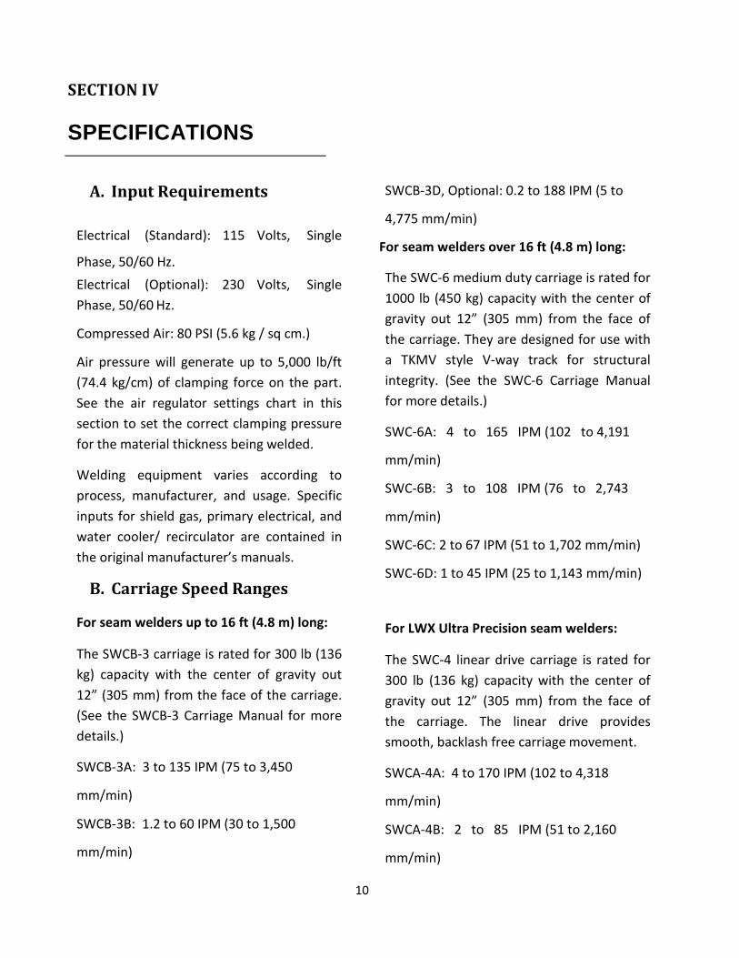
A. Input Requirements
Electrical (Standard):
Phase, 50/60 Hz.
115 Volts, Single
Electrical (Optional):
Phase, 50/60 Hz.
230 Volts, Single
Compressed Air: 80 PSI (5.6 kg / sq cm.)
Air pressure will generate up to 5,000 lb/ft
(74.4 kg/cm) of clamping force on the part.
See the air regulator settings chart in this
section to set the correct clamping pressure
for the material thickness being welded.
Welding equipment varies according to
process, manufacturer, and usage. Specific
inputs for shield gas, primary electrical, and
water cooler/ recirculator are contained in
the original manufacturer’s manuals.
B. Carriage Speed Ranges
For seam welders up to 16 ft (4.8 m) long:
The SWCB-3 carriage is rated for 300 lb (136
kg) capacity with the center of gravity out
12” (305 mm) from the face of the carriage.
(See the SWCB-3 Carriage Manual for more
details.)
SWCB-3A: 3 to 135 IPM (75 to 3,450
mm/min)
SWCB-3B: 1.2 to 60 IPM (30 to 1,500
mm/min)
SWCB-3D, Optional: 0.2 to 188 IPM (5 to
4,775 mm/min)
For seam welders over 16 ft (4.8 m) long:
The SWC-6 medium duty carriage is rated for
1000 lb (450 kg) capacity with the center of
gravity out 12” (305 mm) from the face of
the carriage. They are designed for use with
a TKMV style V-way track for structural
integrity. (See the SWC-6 Carriage Manual
for more details.)
SWC-6A: 4 to 165 IPM (102 to 4,191
mm/min)
SWC-6B: 3 to 108 IPM (76 to 2,743
mm/min)
SWC-6C: 2 to 67 IPM (51 to 1,702 mm/min)
SWC-6D: 1 to 45 IPM (25 to 1,143 mm/min)
For LWX Ultra Precision seam welders:
The SWC-4 linear drive carriage is rated for
300 lb (136 kg) capacity with the center of
gravity out 12” (305 mm) from the face of
the carriage. The linear drive provides
smooth, backlash free carriage movement.
SWCA-4A: 4 to 170 IPM (102 to 4,318
mm/min)
SWCA-4B: 2 to 85 IPM (51 to 2,160
mm/min)

11
SWCA-4C, Optional: 0.32 to 160 IPM (8 to
4,060 mm/min)
SWCA-4D, Optional: 0.22 to 106 IPM (5 to
2,700 mm/min)

12
*Model
“A”
Welding
Length
in/mm
“B”
**Min.
Dia Part
in/mm
“C”
***Min.
Dia. Part
in/mm
“D”
Overall
length
in/mm
“E”
Overall
Width
in/mm
“F”
Overall
height
in/mm
Approx.
Ship
Weight
Lb/Kg
LW-24 24/609 2.63/67 32/800 70/1765 40/1003 69/1753 2300/1040
LW-36 36/914 3.5/89 32/800 82/2070 40/1003 69/1753 2600/1180
LW-48 48/1219 4.25/108 32/800 94/2372 40/1003 69/1753 4000/1810
LW-60 60/1524 5.25/133 32/800 106/2677 40/1003 69/1753 4700/2130
LW-72 72/1829 6/152 32/800 118/2981 40/1003 69/1753 5300/2400
LW-84 81/2134 6.87/175 32/800 130/3286 40/1003 69/1753 5900/2680
LW-96 96/2438 7.25/184 32/800 142/3591 40/1003 69/1753 6400/2900
LW-120 120/3048 9.5/241 32/800 176/4470 42/1054 76/1930 12000/5440
LW-144 144/3658 12.25/311 32/800 200/5080 42/1054 76/1930 1300085890
LW-168 168/4267 15.25/387 32/800 224/5689 42/1054 76/1930 14000/6330
LW-192 192/4877 18.5/464 32/800 248/6300 42/1054 76/1930 15000/6780
LW-216 216/5486 21.25/539 32/800 272/6910 42/1054 76/1930 16000/7240
LW-240 240/6096 24.25/616 32/800 296/7518 42/1054 76/1930 17000/7690
Letters “A” through “F” in table above refer to Figure 2.
* Prefix taken from model as noted below.
** Can be modified at any time by purchasing new mandrel.
*** Can be increased to any convenient height by using optional riser block.
LWS Standard Seam Welder
Application: 0.020" to 3/8" (0.5 to 10 mm) – all weldable metals
Travel Accuracy: "0.015" (0.4 mm)
per 10 ft (3 m)
Carriage Drive: Rack and Pinion

13
LWP Precision Seam Welder
Application: 0.005" to 3/8" (0.1 to 10 mm) - all weldable metals
Travel Accuracy: "0.005" (0.1 mm)
per 10 ft (3 m)
Carriage Drive: Rack and Pinion
LWX Ultra-Precision Seam Welder
Application: For critical applications 0.005" to 3/8" (0.1 to 10 mm) - all weldable
metals
Travel Accuracy: "0.005" (0.1 mm)
per 10 ft (3 m)
Carriage Drive: Linear Drive

14
Figure 2
Dimensions - Longitudinal Seam Welder
15
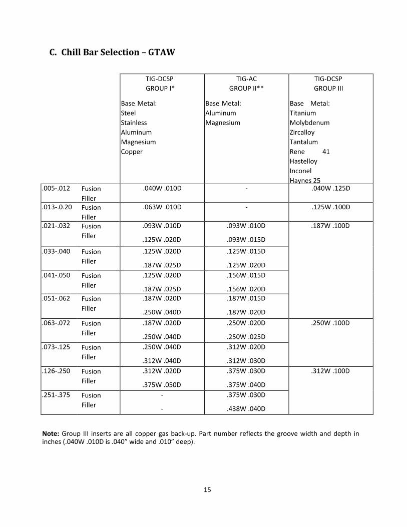
C. Chill Bar Selection – GTAW
TIG-DCSP
GROUP I*
Base Metal:
Steel
Stainless
Aluminum
Magnesium
Copper
TIG-AC
GROUP II**
Base Metal:
Aluminum
Magnesium
TIG-DCSP
GROUP III
Base Metal:
Titanium
Molybdenum
Zircalloy
Tantalum
Rene 41
Hastelloy
Inconel
Haynes 25 .005-.012 Fusion
Filler
.040W .010D
-
-
-
.040W .125D
.013-.0.20 Fusion
Filler
.063W .010D
-
-
-
.125W .100D
.021-.032 Fusion
Filler
.093W .010D
.125W .020D
.093W .010D
.093W .015D
.187W .100D
.033-.040 Fusion
Filler
.125W .020D
.187W .025D
.125W .015D
.125W .020D
.041-.050 Fusion
Filler
.125W .020D
.187W .025D
.156W .015D
.156W .020D
.051-.062 Fusion
Filler
.187W .020D
.250W .040D
.187W .015D
.187W .020D
.063-.072 Fusion
Filler
.187W .020D
.250W .040D
.250W .020D
.250W .025D
.250W .100D
.073-.125 Fusion
Filler
.250W .040D
.312W .040D
.312W .020D
.312W .030D
.126-.250 Fusion
Filler
.312W .020D
.375W .050D
.375W .030D
.375W .040D
.312W .100D
.251-.375 Fusion
Filler
-
-
.375W .030D
.438W .040D
Note: Group III inserts are all copper gas back-up. Part number reflects the groove width and depth in inches (.040W .010D is .040” wide and .010” deep).
16
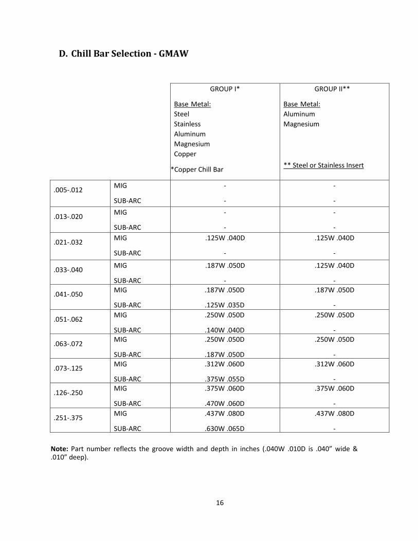
D. Chill Bar Selection - GMAW
GROUP I*
Base Metal:
Steel
Stainless
Aluminum
Magnesium
Copper
*Copper Chill Bar
GROUP II**
Base Metal:
Aluminum
Magnesium
** Steel or Stainless Insert
.005-.012 MIG
SUB-ARC
-
-
-
-
.013-.020 MIG
SUB-ARC
-
-
-
-
.021-.032 MIG
SUB-ARC
.125W .040D
-
.125W .040D
-
.033-.040 MIG
SUB-ARC
.187W .050D
-
.125W .040D
-
.041-.050 MIG
SUB-ARC
.187W .050D
.125W .035D
.187W .050D
-
.051-.062 MIG
SUB-ARC
.250W .050D
.140W .040D
.250W .050D
-
.063-.072 MIG
SUB-ARC
.250W .050D
.187W .050D
.250W .050D
-
.073-.125 MIG
SUB-ARC
.312W .060D
.375W .055D
.312W .060D
-
.126-.250 MIG
SUB-ARC
.375W .060D
.470W .060D
.375W .060D
-
.251-.375 MIG
SUB-ARC
.437W .080D
.630W .065D
.437W .080D
-
Note: Part number reflects the groove width and depth in inches (.040W .010D is .040” wide & .010” deep).

17
E. Distance Between Finger Tips
GROUP I*
Base Metal:
Steel
Stainless
Aluminum
Magnesium
Copper
GROUP II**
Base Metal:
Aluminum
Magnesium
.005-.012" (0.1-0.3 mm) .063" (1.6 mm) -
.013-.024" (0.3-0.6 mm) .100" (2.5 mm) -
.025-.032" (0.6-0.8 mm) .125" (3.2 mm) .312" (8 mm)
.033-.040" (0.8-1.0 mm) .187" (4.8 mm) .375" (10 mm)
.041-.050" (1.0-1.3 mm) .250" (6 mm) .500" (12.7 mm)
.051-.080" (1.3-2.0 mm) .375" (10 mm) .625" (16 mm)
.081-.125" (2.0-3.2 mm) .438" (11 mm) .750" (19 mm)
.126-.250" (3.2-6.3 mm) .500" (12.7 mm) .875" (22 mm)
.251-.375" (6.3-10 mm) .565" (14 mm) 1.0" (25 mm)
F. Air Regulator Settings
Material Thickness Regulator Settings
.005-.012" (0.1-0.3 mm) 10 PSI (4.5 kg/sq mm)
.013-.024" (0.3-0.6 mm) 15 PSI (6.8 kg/sq mm)
.025-.032" (0.6-0.8 mm) 20 PSI (9 kg/sq mm)
.033-.050" (0.8-1.3 mm) 25 PSI (11 kg/sq mm)
.051-.080" (1.3-2.0 mm) 37 PSI (17 kg/sq mm)
.081-.125" (3.2-6.3 mm) 50 PSI (22.7 kg/sq mm)
.126-.250" (3.2-6.3 mm) 75 PSI (34 kg/sq mm)
Use these settings as a guide only. When the material to be welded has been formed to match well and lay flat, less hold-down pressure is required. Always use the least amount necessary.
NOTE

18
19
SECTION V
INSTALLATION
A. System Operating
Conditions Temperature range: 0 to 40C
Humidity: 5 to 95% RH non condensation
Altitude: Up to 1000 meters
Mounting: Secured to reinforced concrete floor
Electrical Input:
Export:
400VAC, 3 phase, 50 Hz nominal
USA: 460 VAC, 3 phase 60 Hz
Export:
Single Phase, 220VAC, 50 Hz
USA: 120VAC, 60 Hz domestic Compressed
Air:
Clean, dry air at 80 PSI (5.6 kg/sq cm) Welding
Gas:
Bottled or bulk supply at 100 PSI (7 kg/sq cm)
minimum pressure
Transportation, Storage:
-20 C Degrees to 60 C Degrees
-4 F Degrees to 140 F Degrees Vibration, Shock:
1G rms 5 to 500 Hz
B. Mechanical Installation Tools Required:
Typically a forklift or overhead crane with at
least 7000 pounds (3125 Kg) capacity. For larger
systems greater capacity lifting is required.
Two lifting straps rated for 4000 pounds (1800
Kb). For larger systems greater capacity lifting is
required.
General hand tools – claw hammer, screw
driver(s), hex keys or allen wrenches, set of box
end wrenches, and adjustable wrench.
Air or electric impact drill if concrete anchoring
bolts needed.
Digital VOM electrical meter.
Installation personnel should be trained and
experienced and locally qualified in moving
heavy loads, setting up electrical/mechanical
systems. Familiarity with local procedures and
standards is necessary. A licensed electrician
should be involved in making primary
connections.
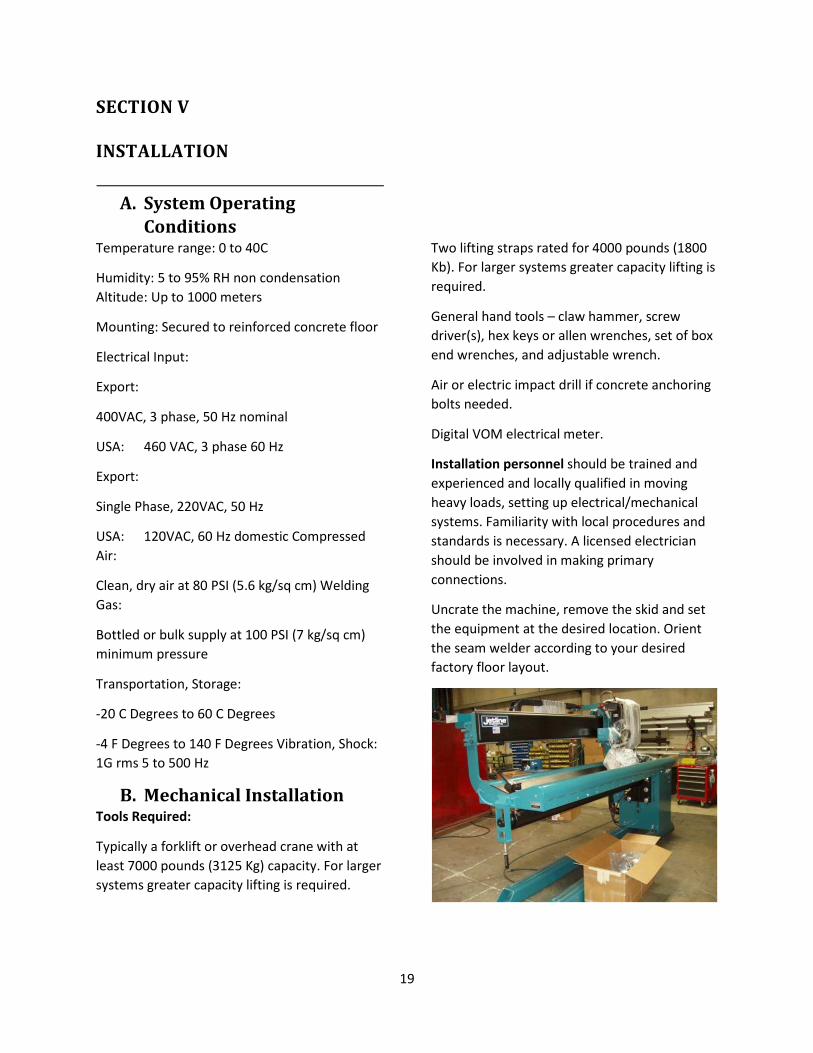
Uncrate the machine, remove the skid and set
the equipment at the desired location. Orient
the seam welder according to your desired
factory floor layout.

20
One of four mounting holes for use with
overhead crane. Two are located at each end of
the tabletop.
CAUTION
When moving the seam welder by fork lift
truck, do not put the forks under the mandrel
or the track. Always move the seam welder by
placing the forks under the base or through the
base structural tubes from the mainstay end of
the machine.
The fixture is free-standing and can be placed
on floor without anchoring it to concrete. The
seam welder base should be secured to
concrete floor if (a) the seamer is integrated
with a conveyor system or (b) a riser is being
used to weld large diameter shells. In these two
cases the seamer base must be secured to
reinforce concrete floor by the use of anchor
bolts/red heads.
After the fixture has been removed and placed
in its location in your factory, it can be anchored
to the floor using 10 mm concrete anchors.
Carriage Installation Procedure
The welding head and carriage are fitted to the
side beam track and require the removal of one
shipping bracket. The shipping bracket is bolted
to the carriage and the track, keeping the
carriage from moving during shipment. The
bracket is located on the top portion of the
track and carriage and is held in place with two
bolts.
Removed this shipping bracket from the
carriage and discard. Look for tag as shown
below.
If the carriage has been removed for shipment,
use the following procedure:
At each end of the track are two mechanical
stops. These stops serve as a safety device to
prevent the carriage from falling off the end of
the track. Remove the carriage angle stops from
the top end of the track. Rotate the cam
handles so that the motor pinion is disengaged.
We recommend using a crane or fork lift truck
to hoist the carriage up to the track (see Figure
1). When lifting the carriage, you will find a ½-
13 tapped hole on top of the carriage. This hole,
along with an eye bolt (not supplied), can be
used for lifting the carriage.
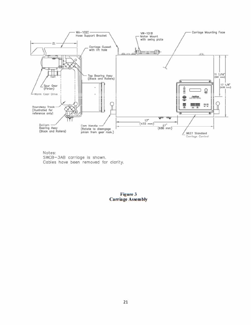
As an alternative, use the lift holes located in
the gussets at either end of the carriage to slide
the carriage onto the track. Refer to Figure 3 to
verify it is correctly aligned.
Once the carriage is mounted on the track,
replace the mechanical stop on the end of the
track to its original position.
21
22
The wire feeder is often removed for shipping
purposes and put in a separate box. The wire
feeder should be installed onto the mounting
brackets located on the carriage.
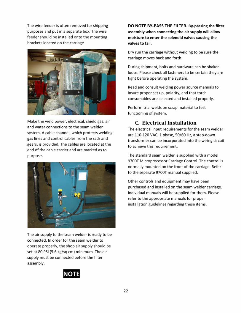
Make the weld power, electrical, shield gas, air
and water connections to the seam welder
system. A cable channel, which protects welding
gas lines and control cables from the rack and
gears, is provided. The cables are located at the
end of the cable carrier and are marked as to
purpose.
The air supply to the seam welder is ready to be
connected. In order for the seam welder to
operate properly, the shop air supply should be
set at 80 PSI (5.6 kg/sq cm) minimum. The air
supply must be connected before the filter
assembly.
NOTE
DO NOTE BY-PASS THE FILTER. By-passing the filter
assembly when connecting the air supply will allow
moisture to enter the solenoid valves causing the
valves to fail.
Dry run the carriage without welding to be sure the
carriage moves back and forth.
During shipment, bolts and hardware can be shaken
loose. Please check all fasteners to be certain they are
tight before operating the system.
Read and consult welding power source manuals to
insure proper set up, polarity, and that torch
consumables are selected and installed properly.
Perform trial welds on scrap material to test
functioning of system.
C. Electrical Installation The electrical input requirements for the seam welder
are 110-120 VAC, 1 phase, 50/60 Hz, a step-down
transformer can be incorporated into the wiring circuit
to achieve this requirement.
The standard seam welder is supplied with a model
9700T Microprocessor Carriage Control. The control is
normally mounted on the front of the carriage. Refer
to the separate 9700T manual supplied.
Other controls and equipment may have been
purchased and installed on the seam welder carriage.
Individual manuals will be supplied for them. Please
refer to the appropriate manuals for proper
installation guidelines regarding these items.

23
SECTION VI
THEORY OF OPERATION
A. Mechanical Operation
The seam welder is comprised of several main
assemblies. Each assembly is integrated to form
a complete system. The system consists of the
following components: base/mainstay, mandrel,
tabletop, track, carriage, and control panel.
Miller Welding Automation seam welders use
the chill shunt principle of tooling to conduct
heat away from the part. This process minimizes
burn through, warping and excessive distortion
when performing butt- joint welding.
The edges of the part are clamped on the top
centerline of the mandrel and insert. (The inserts
are made of copper, stainless steel or steel,
dependent upon the material type being
welded.) The part is clamped against the insert
by two banks of aluminum clamping fingers,
each bank fitted with copper tips (see Figure 4).
This clamping concept allows the seam to be
welded but restricts the heat from passing
through the part. The heat is absorbed by the
fingers and the mandrel. The seam welder
maintains sufficient force to hold parts with a
wall thickness up to 0.375" (10 mm). However,
dependent upon the welding process used, edge
preparation may be required and, on thicker
materials, multi-pass welds may be required as
well.
Optional designs to handle thicker parts are
available. For welding of material above .375”
(10 mm), the application needs to be
communicated before manufacture of the seam
welder.
The LWS, LWP and LWX seam welders are
designed to perform butt-joint welds by arc
welding on all conventional metals. Some of the
arc welding processes include Gas Tungsten Arc
Welding (GTAW), Gas Metal Arc Welding (GMAW),
Shielded Metal Arc Welding
(SMAW), Submerged Arc Welding (SAW) and Plasma
Arc Welding (PAW). Materials that can be welded
include stainless steel, weldable aluminum,
magnesium alloys, zirconium, molybdenum,
titanium, mild steel and low carbon steels. Some of
these metals require a preparatory edge process in
order to be welded successfully.
Part configurations which the seam welder can
handle are cylinders, cones, truncated cones, open
ended boxes, double bowl sinks, flat plates and
sheets.
B. Base Section The base is made from a rigid tube steel structure
which provides stability and safety during
operation. The base is equipped with mounting
holes to ensure stability of the equipment on
uneven surfaces.
The base houses the electrical toe-touch clamping
switches. These switches run the entire length of
the base. When facing the front of the seam welder,
the switch closest to the operator controls the front
bank of clamping fingers. The switch next in line
controls the rear bank of clamping fingers. The third
switch controls the rear clamping fingers only. To
activate one of the switches, merely touch the
switch with your toe. This will either clamp or
unclamp a bank of clamping fingers.
C. Mainstay The primary purpose for the mainstay is to support
the tabletop. On the standard seam welder, the
mainstay is high enough to accommodate an
approximate 32" (800 mm) diameter part. As an
option a riser can be made for diameters greater than
32" (800 mm).
The mainstay also houses the control box (FCP- 10B)
for the toe-touch switches, the pneumatic valves,
24
water lines if applicable, and electrical solenoids
which operate the pressure hose assemblies.
The air hose connection, filter, ground lug and
electrical box are located on the back side of the
mainstay. If a need for 460 volts is required, a
step down transformer will be mounted on the
mainstay as well.
D. Mandrel The mandrel is mounted to the mainstay and is
typically round, but can be designed to meet the
demands of the application. The mandrel must
support the part’s weight, along with supporting
the clamping forces exerted by the clamping
fingers. In most cases, the mandrel is designed to
be supported at the mainstay and at the latch
end.
The mandrel is designed to support a back-up
insert and may have optional water cooling
capability. Depending on the thickness of the
material to be welded and the welding process,
the insert will have a specific groove dimension
(width and depth) machined into it. When several
different thicknesses of materials are to be
welded on the same seam welder, additional
inserts may be required to obtain a quality weld.
The inserts may also be designed to provide gas
back-up to the part. This option provides backing
gas to the penetration side (bottom) of the weld.
Backing gas is required for welding refractory
metals and is recommended for stainless steel
materials.
In high production environments, and/or when
welding with high current, an optional water-
cooled mandrel is required. The water-cooled
mandrel provides cooling of the insert using a
separate water circulator. This helps to maintain a
consistent temperature and weld throughout the
production run.
E. Tabletop The tabletop houses the two banks of clamping
fingers, and supports the side beam track and
carriage.
One of the most outstanding features of the tabletop
design is the ability to view the weld in progress via
the naked eye (with weld shield) or with a video
camera.
The two banks of clamping fingers are set and
mounted within the tabletop. The tabletop section will
differ in size and weight as the welding length of the
seam welder increases. The tabletop is designed to
withstand the clamping forces generated by the
clamping fingers.
On both sides of the tabletop are adjusting screws
used to adjust the finger spacing (see Figure 4). There
are several screws that are used to adjust the location
of the fingers relative to the insert groove. These
screws should be adjusted symmetrically to the
groove to provide an even chilling effect.
The finger spacing as a standard depends largely on
the material thickness being welded. See Section IV
for Miller Welding Automation’s recommendation. As
a safety note, after the adjustments have been
completed, there should not be a gap greater than
1/8" (3.2 mm) between fingertip and part when the
bank of fingers is in its unclamped state. This
adjustment is made to minimize a pinch point
condition between the fingers and part being welded.
The fingers on a Miller Welding Automation seam
welder are 3" (75 mm) wide and are made of
aluminum. At the end of each finger is a copper or
optional stainless steel fingertip screwed to the
aluminum finger
body. These tips are reversible and should be changed
if damaged or worn.
The latch assembly is mounted on the opposite end of
the mainstay. The latch must be closed during the
clamping of the fingers, thus securing and supporting
the mandrel. If the clamping forces are exerted on the
mandrel without the latch support, there is a potential
for mandrel damage. As a result, we have installed a
safety switch which prevents clamping without the
latch being closed.

25
WARNING
This safety switch should not be by-passed.
F. Track
Two or three track supports, depending on the
welding length of the seam welder, are mounted
to the tabletop. The side beam track is bolted
securely and mounted to these track supports.
There are no supports in the welding area of the
seam welder. The track is positioned in such a
way that it is suspended over the welding area.
See Figure 5.
Typically a TKSA style track is adequate to span
distances under 192" (4875 mm) of weld length.
For longer distances, the TKMV medium duty
track is used. These Miller Welding Automation
tracks ensure a tracking accuracy of the carriage
along the track of "0.015" (0.4 mm) in both
planes.
G. Carriage Control
The carriage is driven by the 9700T
Microprocessor Control which is designed for
automatic sequencing of carriage travel and
power supply starting and stopping. The control
is equipped with a two line display which guides
the operator through setup and displays travel
speed during the weld procedure. The separate
9700T manual contains complete operating
instructions.
For more advanced systems, a 9900 Computer
Controller is used to control the weld process
and carriage travel.
Carriage Layout with 9600 travel control and GMAW gear
GTAW Carriage Layout with 9900 Computer Controller
GTAW Carriage Layout with standard 9700 Series Controls – travel, wire, alc
26
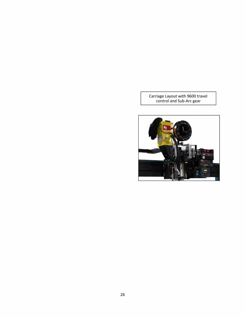
Carriage Layout with 9600 travel control and Sub-Arc gear

27
Figure 5
Track Support Assembly
28
SECTION VII
START UP AND OPERATION
A. Initial Setup 1. Edge Preparation
It is important that the part edges are
prepared so that when they are brought
together in the seam welder any
resulting joint gap is less than 10% of
the part’s thickness. Ideally, when using
the GTAW or PAW process, the edges
are as tight together as possible at the
beginning of the weld to minimize burn
through.
2. Finger Pressure
The finger pressure should be set based
on material thickness and the actual
application. The Specifications section
of this manual gives some
recommended pressures for different
material thicknesses.
3. Back-up Insert
Your back-up insert is designed
specifically for certain material types
and material thickness ranges. The
backup inserts can weld a variety of
material types and material thickness
spans. Welding a wide range of material
types and thicknesses will require
additional inserts. The Specifications
section of this manual gives
recommendations for back-up inserts.
These inserts are readily available from
Miller Welding Automation.
The back-up insert, sitting inside the
mandrel, should be parallel to the track.
Refer to Section X.
4. Distance Between Fingers
The distance between the front and
rear banks of fingers is adjustable. Only
adjust when fingers are in the up
position. It is best to adjust each screw
an equal distance and then to close the
fingers to inspect the finger distance
from the insert groove. One full turn of
each screw will move the fingers 1/16"
(1.6 mm). Each bank of fingers should
be an equal distance from the
centerline of the back-up insert.
The closer that the fingers are to the
groove of the back-up insert, the more
chilling effect they wills are apart, the
less chilling effect is provided. Fingers
that are adjusted close to the groove
can increase the control of welding heat
input, while wider spaced fingers can
tend to give increased travel speeds.
Therefore, it is important to set the
finger distance based on your specific
part.
The chart in the Specifications section
gives initial recommendations for finger
spacing.
B. Operation
NOTE
The latch should be completely closed before
welding.
1. Begin with both sets of fingers in the
unclamped (up) position. (Seam
welders that utilize any automatic
loading or centering may need to be
cycled in order to start at the beginning
of a cycle.)
2. The centering devices should be pushed
down and toggled over. Check to make
sure that the blade is located over the
center of the back-up insert. The back
side of the centering device blades
should be located on the centerline of
the back-up insert. (Or very slightly to
the front of center).
If the seam welder is equipped with
more than two centering devices, use
only two, preferably spaced as far apart
as possible for your particular part.
29
3. The part should be loaded into the rear
of the seam welder first. Push the edge
of the part up against the centering
device blades. Once you are sure that
the part is located properly, depress the
rear finger toe touch strip. This will
cause the rear pressure hose to fill,
clamping the rear bank of fingers and
securing the part in the seam welder.
Try to space the part in the seam
welder so that the ends of the part are
at least half covered by a finger at each
end. If the end is being covered by less
than half of a finger, then the finger
could tilt and result in insufficient chill.
If there is difficulty with burn through at
the beginning or end of the part, this
could be the cause. To solve the
problem simply move the part so that
the finger coverage is correct or insert a
small tab underneath the troublesome
finger so the finger bridges evenly
between the end of your part and the
small tab.
4. Now retract the centering devices.
5. Load the front side (edge) of the part
and butt it up against the edge of the
part that is already clamped by the rear
finger bank. Be sure that the ends are
even.
6. Depress the front fingers’ toe touch
strip and clamp the front fingers on the
part. The front fingers should always be
closed last because these are the “push-
in” fingers. These fingers push in slightly
as clamping pressure is applied,
ensuring a good fit at the joint.
7. Now that the part is loaded, you can
prepare to weld.
8. If limit switches are used to determine
the start and stop points of the weld, it
is best to set up on a practice part.
Move the carriage and torch at the
desired starting point, then slide the
“home” limit switch cam until it
contacts the “home” limit switch. Now
test this starting point by jogging the
carriage forward (12 or more inches if
possible) and then returning the
carriage to the “home” position. This
will indicate the true starting point.
To set the end of weld limit switch, use
a similar process. First manually set the
contact location, then test it by
reversing travel, then moving the
carriage to the end of weld.
9. Welding
Each and every welding application
requires its own unique set of welding
parameters. Wire speeds, voltages,
travel speeds, gas types, flow rates,
back-up bar size, type, finger spacing,
clamping pressures, material type,
material thickness and joint preparation
are some of the many variables that
need to be adjusted in order to provide
the most robust welding procedure for
a particular application.
Weld development is the sole responsibility of
the owner of the equipment and not the
responsibility of Miller Welding Automation.
10. Once the seam has been welded
successfully, release both sets of
fingers, open the latch if needed, and
carefully remove the part.

30
SECTION VIII TROUBLESHOOTING
A. Fixture Problem Cause and Correction
1. Misalignment of torch to the weld joint
(insert groove centerline).
a. The track and carriage not aligned parallel to
inside groove; readjust as per Section X
b. Alignment devices not adjusted to centerline of
insert. Clamp a straight edge or a length of
material over centerline of insert groove and
adjust the alignment devices by loosening the
locking nut on the Allen adjusting screw at the
top of the telescoping arm. Adjust the Allen
screw so that the device blades contact the
straight edge and tighten the lock nut.
c. The part is not against the two alignment device
blades when the part is clamped by the fingers.
Unclamp, align, and clamp.
d. Gibbs loose on the weld head cross seam slide;
adjust as needed.
e. If an arc length control is incorporated on the
fixture, check the ways and wheels in the drive
(actuator) for play and adjust.
2. Carriage will not travel a. The main items to check are:
- Input power to carriage control
- Control fuse
- Check the drive motor brushes, brush
springs and caps.
- Be sure the clutch is engaged.
- Fiber gear in gear head motor may be
stripped.
b. Refer to the supplied carriage control manual for
wiring.
3. Travel speed readout with optional
tach generator fluctuates.
a. Check the belt that connects the carriage drive
motor shaft to the tach generator. Replace the
belt if worn or loose.
b. Check for binding between the carriage wheels
and the rails on the track. Readjust the wheels if
required; see supplied carriage manual.
c. Refer to supplied control manual for wiring
information.
4. Clamping fingers will not clamp. a. Check air supply to fixture.
b. Check clamping pressure air regulator for proper
pressure (see Section IV).
c. Check fuse in the FCP-10B toe-touch panel.
d. Check toe-touch strip for short. If shorted,

31
replace with new.
e. Check relays and transformer and toe-touch
panel.
f. Shop line pressure is too low to actuate the pilot
actuated air solenoid valve.
5. Can hear air leaking in the vertical riser. Open hinge door and check:
a. White poly flow tubing for leaks.
b. Internal air hoses for leaks.
c. Clamping hoses for leaks.
6. Cannot establish tight, even butt-up of
final sheared parts.
a. When worn or misaligned, the shear knives can
produce a concave cut, convex cut, or shear drag
(burr). Once the cut-off shear blades are
readjusted, sharpened, or replaced, the
straightness of the part should be checked
against a straight edge.
B. GTAW Process
Problem Cause and Correction
1. Cannot initiate an arc when using
GTAW welding equipment.
a. Remove the torch cap which retains the collet
and electrode. If the weld tip of the electrode is
blue or contaminated, sharpen it or replace with
a new sharpened electrode. If the bore of the
collet is worn or does not provide a tight grip of
the electrode when installed in the torch,
replace collet with a new one.
b. A blue finish to the surface of the tungsten
implies oxygen contamination. This can be
caused by too short of a post flow time, a loose
gas fitting, a contaminated gas supply, air
turbulence at the weld zone, too small a shield
cup on the torch, or too low of a flow rate of
gas.
c. Check shield gas pressure (PSI) at the regulator
and flow (CFH) at the flowmeter. The PSI should
not be less than 50 and the CFH should coincide
with established welding parameters.
d. Make sure the “high frequency” control at the
power supply is switched to the proper mode of
“start” for D.C.S.P. welding or continuous for
A.C.H.F. welding.
2. If an arc still will not establish, check
the following steps.
a. Increase the high frequency intensity
potentiometer on the power source.
b. Amperage setting at the power supply may be
too low to initiate an arc. Raise the amperage
setting.
c. Material to be welded may contain coated or
32
scaled surface. Remove coating or scale by using
a fine emery cloth.
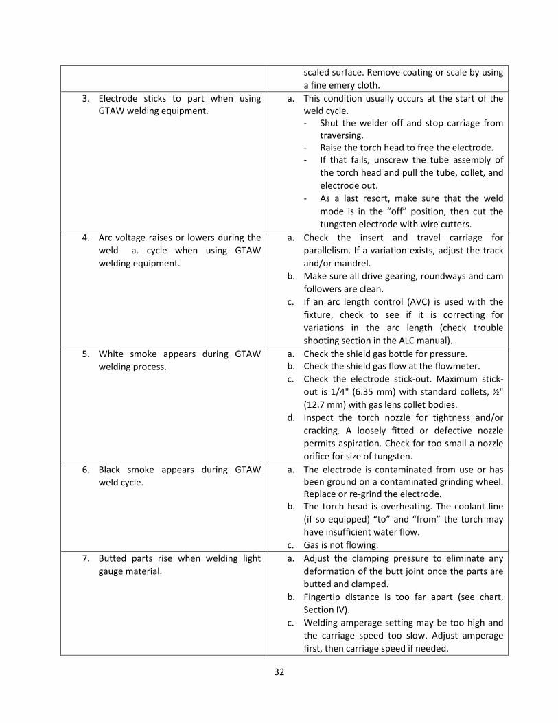
3. Electrode sticks to part when using
GTAW welding equipment.
a. This condition usually occurs at the start of the
weld cycle.
- Shut the welder off and stop carriage from
traversing.
- Raise the torch head to free the electrode.
- If that fails, unscrew the tube assembly of
the torch head and pull the tube, collet, and
electrode out.
- As a last resort, make sure that the weld
mode is in the “off” position, then cut the
tungsten electrode with wire cutters.
4. Arc voltage raises or lowers during the
weld a. cycle when using GTAW
welding equipment.
a. Check the insert and travel carriage for
parallelism. If a variation exists, adjust the track
and/or mandrel.
b. Make sure all drive gearing, roundways and cam
followers are clean.
c. If an arc length control (AVC) is used with the
fixture, check to see if it is correcting for
variations in the arc length (check trouble
shooting section in the ALC manual).
5. White smoke appears during GTAW
welding process.
a. Check the shield gas bottle for pressure.
b. Check the shield gas flow at the flowmeter.
c. Check the electrode stick-out. Maximum stick-
out is 1/4" (6.35 mm) with standard collets, ½"
(12.7 mm) with gas lens collet bodies.
d. Inspect the torch nozzle for tightness and/or
cracking. A loosely fitted or defective nozzle
permits aspiration. Check for too small a nozzle
orifice for size of tungsten.
6. Black smoke appears during GTAW
weld cycle.
a. The electrode is contaminated from use or has
been ground on a contaminated grinding wheel.
Replace or re-grind the electrode.
b. The torch head is overheating. The coolant line
(if so equipped) “to” and “from” the torch may
have insufficient water flow.
c. Gas is not flowing.
7. Butted parts rise when welding light
gauge material.
a. Adjust the clamping pressure to eliminate any
deformation of the butt joint once the parts are
butted and clamped.
b. Fingertip distance is too far apart (see chart,
Section IV).
c. Welding amperage setting may be too high and
the carriage speed too slow. Adjust amperage
first, then carriage speed if needed.
33
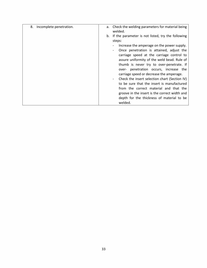
8. Incomplete penetration. a. Check the welding parameters for material being
welded.
b. If the parameter is not listed, try the following
steps:
- Increase the amperage on the power supply.
- Once penetration is attained, adjust the
carriage speed at the carriage control to
assure uniformity of the weld bead. Rule of
thumb is never try to over-penetrate. If
over- penetration occurs, increase the
carriage speed or decrease the amperage.
- Check the insert selection chart (Section IV)
to be sure that the insert is manufactured
from the correct material and that the
groove in the insert is the correct width and
depth for the thickness of material to be
welded.

34
SECTION IX
MECHANICAL MAITANANCE
Once a month, check all the hoses and fittings for
leaks or deterioration. A leaking hose can cause
loss of clamping pressure and result in poor quality
work. Blow out water from the air filter on the side
of the mainstay by opening the drain valve at the
bottom of the filter while the shop air is
connected. See Figure 1.
Re-machine or replace, if necessary, the copper
finger tips or continuous strips when they become
marred by dents or excessive impression marks.
Both the finger tips and the continuous strips are
reversible for extended life.
A. Adjustment and Replacement
of the Clamping Fingers Both left and right banks of fingers can be adjusted
in or out by means of screws located on each side
of the tabletop. Each screw applies pressure to the
finger adjusting bar which applies proportional
pressure against the finger bank assembly.
Each finger bank must be adjusted parallel to the
insert groove. The distance from the groove to the
finger tips must be the same on each side. Always
start adjustment with the screws located at the
center of the machine. Turn the screws a
maximum of one revolution at a time, working
towards both ends. Repeat until proper setting is
reached.
To remove a finger assembly, first loosen the
slotted flat head screw from the bottom side of the
finger. Once the screw is loose in the countersink,
move it towards the front of the finger and pass
the head of the screw through the clearance hole.
The finger can now be removed from the fixture.
Avoid removing the screw completely from the
spring and nut assembly.
CAUTION
Do not inter-exchange the front fingers with the
rear fingers, as they are of a different design.
When all the fingers are removed, the clamping
hose will hang loose from the tabletop; this is
normal.
To replace the fingers, start at the mainstay and
work toward the latch end of the seam welder.
Fasten a “C” clamp onto the nesting bar to keep
the finger adjusting bar from rolling out of the
nesting bar when the fingers are removed. See
Figure 4.
Install the aluminum only end of the finger into the
nesting bar. Guide the finger adjusting screw
through the clearance hole in the finger and pull
the screw back until it seats into the countersink.
Tighten the screw until the finger contacts the lip
of the tabletop. Continue to install the fingers in
the above manner until all are in place. The screw
in the last finger can be guided through the finger
with a screwdriver. Tighten all the fingers
proportionately so that they all return against the
tabletop lip when the air is exhausted from the
hoses.
The aluminum fingers are three inches wide and
have replaceable, reversible copper finger tips. (As
an option, they are available made from 300 series
stainless steel.) The copper finger tips, in addition
to clamping the part against the back-up insert,
also act as a heat sink to absorb heat created by
the welding process. If a fingertip is subject to
nicks or gouges at the point it contacts the part, it
can affect its ability to act as a heat sink and should
be dressed or replaced.
To remove a fingertip from the finger body,
remove the two Allen head screws which hold it to
the finger. These screws are located on the bottom
of the finger tip. Place the fingertip in a vice and,
using a flat file, draw the file over the clamping
surface of the finger tip. The maximum which can
be filed off the tip is 0.05" (1.3 mm). The tip is
reversible and, if the tip cannot be dressed, replace
the tip using the opposing side. When both sides
are beyond dressing, replace the tip.
35
B. Replacement of the Clamping
Hoses The clamping movement of the fingers is caused by
inflating the pressure hose located between the
tabletop and the upper surface of the fingers. Over
a period of time, the hose may become damaged
from extreme heat, weld spatter or deterioration
of the rubber in the hose. Should this happen, the
hose cannot be repaired but must be replaced.
To replace the hose, use the following procedure:
Disconnect the 115 volts AC and air supply to the
seam welder. Remove the finger adjusting
channels which are located at the latch end of the
machine. The channels are located between the
left and right first finger assemblies and the front
plate. Once the finger adjusting channel is
removed, the end of the pneumatic hose and hose
clamps will be exposed. The three hose clamp bolts
serve two purposes. They clamp the ends of the
hoses together and attach the ends of the hoses to
the tabletop. Remove the three bolts from each
clamp and remove the clamps from the hoses. Tie
an electrician’s fish tape to this end of one of the
hoses.
At the opposite end of the machine, open the
hinged door at the rear of the mainstay. On the
interior of the door is mounted the FCP-10B foot
control panel. The hoses and controls for the
clamping system are located inside the mainstay.
Remove the small white vinyl high pressure tube
from the tee by pushing the tube locking collet and
remove the tube from the collet. Remove the
larger pneumatic hose from the air solenoid valves.
(See Figure 6.) Pull the pressure hose out of the
tabletop from the mainstay, making sure the fish
tape is pulled through the tabletop. If there is an
orange spatter shield around the hose, pull it out
with the hose.
ut a new pressure hose the same length as the old.
Pre-drill the three holes in the end of the new hose
for the hose clamp. Re-install the round plug using
two new H40 worm drive clamps. Use No. 2
Permatex as a sealant for both ends of the hose
when assembling.
Pull the fish tape and the new hose through the
tabletop from the latch end of the machine. If
there is a spatter shield to be installed, it must be
pulled through with the hose. The seam of the
spatter shield must be either on the top or bottom
surface of the hose. The clamping fingers may have
to be loosened when installing hose with a spatter
shield.
Reconnect the high pressure tube and pneumatic
hoses. Be sure to allow the Permatex to set up
before connecting to the shop air. Pressurize the
hoses and check for air leaks. Replace the finger
adjusting channels and, using the set screws,
adjust the channels for proper clearance and
spacing.
C. Replacement of the Mandrel To ease installation of a mandrel in a Miller
Welding Automation Longitudinal Seam Welder, it
is recommended that a Miller Welding Automation
Mandrel Cart be used. Installing the mandrel can
also be done using a suitable lifting device such as
a fork lift truck.
Before doing the installation, a number of actions
must be done first.
On one end of the mandrel there is the mounting
plate which has four tapped holes and a number of
slots. In the four tapped holes there are four
square head bolts, used as “jacking screws”.
Welded on the front of mainstay, are two vertical
bars and one horizontal bar. One vertical bar and
the horizontal bar have adjusting screws. These
screws must be backed off to allow clearance for
the mandrel plate to fit between them. Ensure that
the nuts and washers have been removed from the
mandrel anchor bars which protrude through the
front face of the mainstay. Raise the latch
assembly.

36
Using either the mandrel cart or fork lift truck,
move the mandrel mounting plate close to the
ends of the anchor bar screws that protrude
through the mainstay. Align the slots in the
mandrel mounting plate with the anchor bar
screws and push the mandrel over them and up to
the mainstay front face.
Replace the washers and nuts onto the anchor bar
screws. Lightly tighten them to hold the mandrel
against the mainstay face so that the mandrel
plate lies between the two vertical bars and above
the horizontal bar. The cart, or similar device, can
now be removed.

37
Figure 6
Pneumatic System

38
D. Adjustment of the Mandrel Once the mandrel has been fitted to the seam
welder, it then has to be adjusted to be positioned
correctly relative to the fingers and tabletop
assembly. The adjustment procedure is made
easier by having the insert installed in its machined
groove in the top of the mandrel.
With the mandrel anchor bar nuts slightly loose,
the first adjustment is to make the mandrel and
insert parallel with the underside of the clamping
fingers. Based upon welding a 1/8" material
thickness (or less) as an example for adjusting the
machine, first, use the horizontal bar with 1" screw
to coarse adjust the mandrel vertically. Using a
scale, adjust the mandrel up until there is an
approximate 3/16" space between the finger tips
and the highest point of the insert. Use the square
head “jacking screws” in the mandrel plate to pitch
the mandrel until its full length is parallel with the
clamping finger tips. View the mandrel from the
side and using a scale measure the gap at the
mainstay end and the latch end. Both
measurements should be equal.
Next, adjust the insert groove parallel with the
centerline of the tabletop. Viewing from above the
tabletop, first measure and determine the
centerline distance between the formed tabletop
edges. Starting at the mainstay end of the
mandrel, use the two screws in the vertical bar
that is welded to the front of the mainstay to move
the mandrel until the insert groove is on centerline
of the formed tabletop. Then use a combination of
the four square head “jacking screws” to move the
latch end of the insert groove to centerline as well
as maintain parallelism to the finger tips.
The seam welder is designed to accommodate
different material thicknesses and the actual
vertical position of the mandrel is governed by
this. For the machine to work efficiently, the gap
between the fingers and insert should be the
material thickness plus 1/16" (3 mm).
After these adjustments have been made, the
mandrel anchor nuts can now be tightened. After
tightening the nuts, check and readjust as
required.
E. Adjustment to the Track to
the Insert Once the back-up mandrel and insert have been
adjusted to the tabletop, the track will require
adjustment relative to the insert groove and face.
The vertical distance between the insert face and
the welding torch (mounted on the travel carriage)
should vary no more than 0.08" (2 mm) at full
clamping pressure. The tracking accuracy (track to
insert groove) should be ".015" (0.4 mm) per 10 ft
(3 m) of track length for the standard machine. For
the precision machines (LWP, LWX), tracking
accuracy (track to insert groove) should be ".005"
(0.13 mm) per 10 ft (3 m) of track length.
To check the vertical height accuracy, move the
carriage to the end of its travel, towards the
mainstay end of the machine. Actuate and clamp
both finger banks at 40 PSI against the backup
insert. Mount a machinist’s dial indicator to the
travel carriage and align the stem against the face
of the back-up insert. Set the indicator dial at zero,
and then manually move the carriage towards the
latch of the machine. Correct adjustment of the
track is obtained when the indicator also reads
zero at the latch end of the machine. If the
indicator does not read zero, vertical track
adjustment is required. Note that it is typical for
the mandrel to deflect approximately 0.040" (1
mm) between each end due to the clamping
pressure exerted.
1. Vertical Track Adjustment
If vertical adjustment of the track is
required, only make adjustment at the
latch end of the machine. Loosen the four
3/4" track mounting bolts that are located
at the backside of the track. The track

39
mounting bracket is slotted allowing
vertical adjustment using the lever arm
mounted on its side.
Using an Allen wrench, turn the vertical
adjusting bolt counter-clockwise to lower
the track (clockwise to raise). The amount
of adjustment is determined by watching
the dial indicator mounted on the carriage,
trying to “match” the zero reading from
the mainstay end of the machine. After the
track is adjusted, tighten the four 3/4"
bolts on the track bracket.
2. Horizontal Adjustment
Using the ground torch electrode or the
welding wire as a pointer, adjust either so
that it just clears the upper surface of the
insert. Adjust the pointer horizontally so
that it is right over the tangent point
where the edge of the machined groove
meets the flat surface on the insert. The
machined edge of the groove will be used
as the reference point for the electrode or
wire to track the insert groove. Starting at
the mainstay end of the machine, manually
traverse the carriage along the track and
stop at the latch end of the machine.
Observe if the track requires adjustment
and if so, which direction the pointer must
move in relation to the machined edge of
the insert.
On the mounting bracket above the
vertical adjusting lever are four 3/4" bolts.
For adjustment, loosen the four bolts
noting that the bracket is slotted in the
horizontal direction. At the rear of the
bracket is a single 3/4" adjustment screw.
When the adjustment screw is rotated
clockwise, the track will move away from
the insert centerline. Rotating counter
clockwise will move the track towards the
insert centerline. Once the track is
adjusted parallel to the machined edge of
the insert, tighten the four 3/4" bolts.
F. Preventative Maintenance 1. Daily Mechanical
a. Inspect roundway or v-way rails of the
track, clean and coat with WD-40 or
equal.
b. Inspect finger tips for excess weld
spatter. Remove by wire brushing.
c. Inspect inserts for oxides and foreign
matter. Clear with wire brush, MEK or
Acetone.
d. Drain the air filter at the rear of the
mainstay by turning the valve at the
bottom of the bowl.
2. Weekly Mechanical
a. Inspect track and mandrel alignment
for accuracy.
b. Check v-way wheels on SWC-6 series
carriage for proper adjustment (see
SWC-6 operation manual).
3. Monthly Mechanical
a. Check all bolts and components of the
alignment devices to be sure that they
are tight.
b. Check coolant level in torch water
recirculator.
c. Check all hoses, gas, water, and air for
leaks and deterioration.
4. Bi-annual Mechanical
a. Check oil level on SWC-6 series
carriage gear box (see SWC-6
operators manual).
5. Quarterly Mechanical
a. Check all welding and exposed cables.
b. Check carriage motor brushes.
6. Bi-annual Electrical
a. Check welding power source for dust
and dirt.
b. Check all pushbutton emergency
switches.

40
SECTION X
PARTS LIST
The following pages provide a detailed parts list of
all the elements of the longitudinal seam welder.
They are arranged so the parts list on the right
hand page corresponds to the assembly illustrated
on the left hand page. Item numbers shown in the
parts list refer to those numbers contained in the
balloon in the drawing. The quantities shown are
the number of items used in that particular
assembly.
Two columns are included in the list to show the
spare parts which are recommended to be stocked
by the user. The two levels can be defined as
follows:
Level 1 These are the spares recommended for US
domestic users whose use of the product does not
exceed 2000 hours per year.
Level 2 These are the spares recommended for
international use of the product or for US domestic
users who will use the product in excess of 2000
hours per year.
The following parts lists are included in this
manual. Their appropriate page numbers are
listed:
Longitudinal Seam Welder ....................... 46/47
Foot Control.............................................. 48/49
Retractable Centering Device ................... 50/51
Common Spare Parts 52

41

42
Longitudinal Seam Welder
Recommended Item Part Level Level
No. No. Description Qty I II
1
Track ................................................................................ 1
2 Track Arm ........................................................................ 2
3 Pressure Gauge ............................................................... 1
4 Tabletop .......................................................................... 1
5 Mainstay .......................................................................... 1
6 Base ................................................................................. 1
7 Electrical Cord, 116 VAC .................................................. 1
8 Switch, Finger Actuation ................................................. 3
9 CBS Mandrel ........................................................................... 1
10 Latch Assembly................................................................ 1
11 Mounting Plate Nuts ....................................................... 4
12 Mandrel Plate Adjustment Screws .................................. 4
13 Finger Adjustment Screws .............................. as required
14 Air Filter ........................................................................... 1
15 SWCB-3 Carriage Assembly, standard .......................................... 1
16 9700T Control Panel Assembly, standard .................................. 1
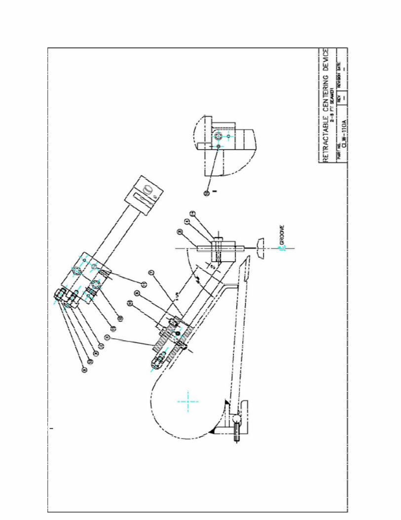
43

44
Retractable Centering Device
CLW-110A
Item
Part
Recommende
d Level Level
No. No. Description Qty I II
2
CL-200 End Piece ......................................................................... 1
3 CL-201 Pivot Stop, regular and thin ....................................... 1 ea
4 CL-202 Pivot Block ....................................................................... 1
5 CL-203 Spacer Plate ..................................................................... 1
6 CL-204 Guide Block ..................................................................... 1
7 CL-205A Extension Arm ................................................................. 1
8 3/8-16x3/4 Button Head Screw ......................................................... 1
9 3/8-16x1 Socket Set Screw ............................................................. 1
10 3/8-16x2 Hex Head Cap Screw ....................................................... 2
11 3/8-16,5-10LB Ball Plunger ..................................................................... 1
12 3/8-16,2-4LB Ball Plunger ..................................................................... 1
13 3/8-16 Hex Jam Nut .................................................................... 1
14 3/8x3/4 Socket Head Shoulder Screw .......................................... 1
15 3/16x1/2 Roll Pin ............................................................................ 2
16 5/16x3/4 Brass Socket Set Screw .................................................... 2
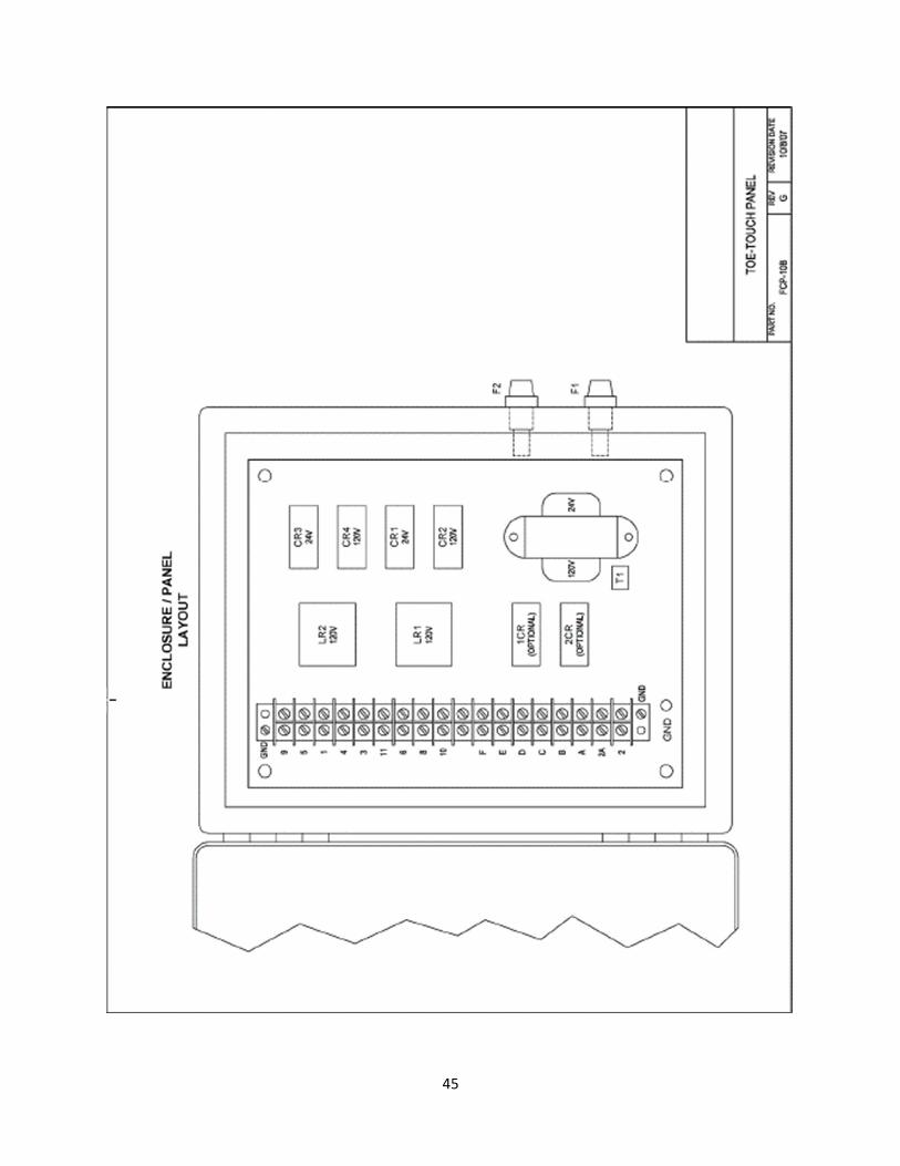
45

46
Foot Control Panel
FCP-10B
Recommended
Item No. Part No. Description Qty Level I Level II
2 A10N84 Nema I Enclosure 1
3 FCP-10B=3 Foot Control PCB 1 1
4 RY2LS-120A 120 VAC Latch Relay 2 1 1
5 RY2S-U-24A 24 VAC DPDT Latch Relay 2 1 1
6 RY2S-U-120A 120 VAC DPDT Latch Relay 2 1 1
7 J74 202A Jumper 1
8 SYSF-51F1 LR1, LR2, Spring Hold 1
9 SYSF-02F1 CR1,2,3,4/CR2, Spring Hold 6
10 28F027 Fuse Holder 1
11 GGC-3 Fuse, 3A 1 1 1

47

48
SECTION XII
ELECTRICAL DRAWINGS
Each longitudinal seam welder made by Miller Welding
Automation has an electrical control schematic. These
drawings are identified by job number and are part of
the document package shipped with your system.
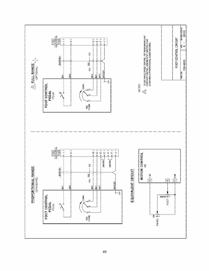
49

50